Volume 02—Commercial Distribution
268234-Attachment 268234-Attachment 268234-Attachment 782113 Batch5 unilog cesco-content
104281-Attachment 104281-Attachment 104281-Attachment 782114 Batch6 unilog cesco-content
104281-Attachment 104281-Attachment 104281-Attachment 786685 Batch6 unilog cesco-content
116798-Attachment 116798-Attachment 116798-Attachment 782113 Batch7 unilog cesco-content
116798-Attachment 116798-Attachment 116798-Attachment 786685 Batch7 unilog cesco-content
2014-10-17
: Pdf 128139-Attachment 128139-Attachment Batch10 unilog
Open the PDF directly: View PDF ![]() .
.
Page Count: 694 [warning: Documents this large are best viewed by clicking the View PDF Link!]

Electrical Sector Solutions
Volume 2 Commercial Distribution
Eaton Corporation
Electrical Sector
1111 Superior Ave.
Cleveland, OH 44114
United States
877-ETN-CARE (877-386-2273)
Eaton.com
© 2010 Eaton Corporation
All other trademarks are property
of their respective owners.
All Rights Reserved
Printed in USA
Publication No. CA08100003E / MSC
December 2010
Volume 2:
Commercial
Distribution
Volume 2—Commercial Distribution
Tab 1—Switching Devices . . . . . . . . . . . . . . . . . . . . . . . . . . V2-T1-1
Tab 2—Transformers . . . . . . . . . . . . . . . . . . . . . . . . . . . . . . V2-T2-1
Tab 3—Panelboards and Lighting Control . . . . . . . . . . . . . V2-T3-1
Tab 4—Switchboards . . . . . . . . . . . . . . . . . . . . . . . . . . . . . V2-T4-1
Tab 5—Transfer Switches . . . . . . . . . . . . . . . . . . . . . . . . . . V2-T5-1
Tab 6—Low Voltage Busway . . . . . . . . . . . . . . . . . . . . . . . V2-T6-1
Appendix 1—Eaton Terms & Conditions . . . . . . . . . . . . . . V2-A1-1
Appendix 2—Catalog Parent Number Index . . . . . . . . . . . V2-A2-1
Appendix 3—Alphabetical Product Index . . . . . . . . . . . . . V2-A3-1
2

Copyright
Dimensions, Weights and Ratings
Dimensions, weights and ratings given in this catalog are approximate and should not
be used for construction purposes. Drawings containing exact dimensions are available
upon request. All listed product specifications and ratings are subject to change without
notice. Photographs are representative of production units.
Terms and Conditions
All prices and discounts are subject to change without notice. When price changes
occur, they are published in Eaton’s Price and Availability Digest (PAD). All orders
accepted by Eaton’s Electrical Sector are subject to the general terms and conditions
as set forth in Appendix 1—Eaton Terms & Conditions.
Technical and Descriptive Publications
This catalog contains brief technical data for proper selection of products. Further
information is available in the form of technical information publications and illustrated
brochures. If additional product information is required, contact your local Eaton
Products Distributor, call 1-800-525-2000 or visit our website at www.eaton.com.
Compliance with Nuclear Regulation 10 CFR 21
Eaton products are sold as commercial grade products not intended for application in
facilities or activities licensed by the United States Nuclear Regulatory Commission
for atomic purposes, under 10 CFR 21. Further certification will be required for use of
these products in a safety-related application in any nuclear facility licensed by the
U.S. Nuclear Regulatory Commission.
WARNING
The installation and use of Eaton products should be in accordance with the provisions
of the U.S. National Electrical Code® and/or other local codes or industry standards that
are pertinent to the particular end use. Installation or use not in accordance with these
codes and standards could be hazardous to personnel and/or equipment.
Copyright ©2014 Eaton, All Rights Reserved.
These catalog pages do not purport to cover all details or variations in equipment, nor to provide for
every possible contingency to be met in connection with installation, operation or maintenance.
Should further information be desired or should particular problems arise which are not covered
sufficiently for the purchaser’s purposes, the matter should be referred to the local Eaton Products
Distributor or Sales Office. The contents of this catalog shall not become part of or modify any prior
or existing agreement, commitment or relationship. The sales contract contains the entire
obligation of Eaton’s Electrical Sector. The warranty contained in the contract between the parties
is the sole warranty of Eaton. Any statements contained herein do not create new warranties or
modify the existing warranty.

Volume 2—Commercial Distribution CA08100003E—April 2014 www.eaton.com i
Introduction
Eaton is a global leader in power distribution, power quality,
control and automation, and monitoring products.
At Eaton, we believe a reliable, efficient and safe power system is the foundation of every
successful enterprise. Through innovative technologies, cutting-edge products and our highly
skilled services team, we empower businesses around the world to achieve a powerful advantage.
In addition, Eaton is committed to creating and maintaining powerful customer relationships built
on a foundation of excellence. From the products we manufacture to our dedicated customer
service and support, we know what’s important to you.
Solutions
Eaton takes the complexity out of power systems management with a holistic and strategic
approach, leveraging our industry-leading technology, solutions and services. We focus on
the following three areas in all we do:
●Reliability—maintain the
appropriate level of power
continuity without
disruption or unexpected
downtime
●Efficiency—minimize
energy usage, operating
costs, equipment footprint
and environmental impact
●Safety—identify and
mitigate electrical hazards
to protect what you value
most
Using the Eaton Catalog Library
As we grow, it becomes increasingly difficult to include all products in one or two comprehensive
catalogs. Knowing that each user has their specific needs, we have created a library of catalogs for our
products that when complete, will contain 15 volumes. Since the volumes will continuously be a work
in progress and updated, each volume will stand alone. Refer to our volume directory, MZ08100001E,
for a quick glance of where to look for the products you need. The 15 volumes include:
●Volume 1—Residential
and Light Commercial
(CA08100002E)
●Volume 2—Commercial
Distribution (CA08100003E)
●Volume 3—Power
Distribution and Control
Assemblies (CA08100004E)
●Volume 4—Circuit
Protection (CA08100005E)
●Volume 5—Motor Control
and Protection
(CA08100006E)
●Volume 6—Solid-State
Motor Control
(CA08100007E)
●Volume 7—Logic Control,
Operator Interface and
Connectivity Solutions
(CA08100008E)
●Volume 8—Sensing
Solutions (CA08100010E)
●Volume 9—Original
Equipment Manufacturer
(CA08100011E)
●Volume 10—Enclosed
Control (CA08100012E)
●Volume 11—Vehicle and
Commercial Controls
(CA08100013E)
●Volume 12—Aftermarket,
Renewal Parts and Life
Extension Solutions
(CA08100014E)
●Volume 13—Counters,
Timers and Tachometers
(CA08100015E)—Available
in electronic format only
●Volume 14—Fuses
(CA08100016E)—Available
in electronic format only
●Volume 15—Solar Inverters
and Electrical Balance of
System (CA08100018E)
These volumes are not all-inclusive of every product, but they are meant to be an overview
of our product lines. For our full range of product solutions and additional product information,
consult Eaton.com/electrical and other catalogs and product guides in our literature library.
These references include:
●The Consulting Application
Guide (CA08104001E)
●The Eaton Power Quality
Product Guide (COR01FYA)
If you don’t have the volume that contains the product or information that you are looking for,
not to worry. You can access every volume of the catalog library at Eaton.com/electrical in the
Literature Library.
By installing our Automatic Tab Updater (ATU), you can be sure you always have the most recent
version of each volume and tab.

ii Volume 2—Commercial Distribution CA08100003E—April 2014 www.eaton.com
Introduction
Icons
Green Leaf
Eaton Green Solutions are products, systems or solutions that represent Eaton
benchmarks for environmental performance. The green leaf symbol is our
promise that the solution has been reviewed and documented as offering
exceptional, industry-leading environmental benefits to customers, consumers
and our communities. Though all of Eaton’s products and solutions are
designed to meet or exceed applicable government standards related to
protecting the environment, our products with the Green Leaf designation
further provide “exceptional environmental benefit.”
Learn Online
When you see the Learn Online icon, go to Eaton.com/electrical and search for
the product or training page. There you will find 100-level training courses,
podcasts, webcasts or games and puzzles to learn more.
Drawings Online
When you see the Drawings Online icon, go to Eaton.com/electrical and find the
products page. There you will find a tab that includes helpful product drawings
and illustrations.
Contact Us
If you need additional help, you can find contact information
under the Customer Care heading of Eaton.com/electrical.
Volume 2—Commercial Distribution CA08100003E—April 2014 www.eaton.com V2-T1-1
1
1
1
1
1
1
1
1
1
1
1
1
1
1
1
1
1
1
1
1
1
1
1
1
1
1
1
1
1
1
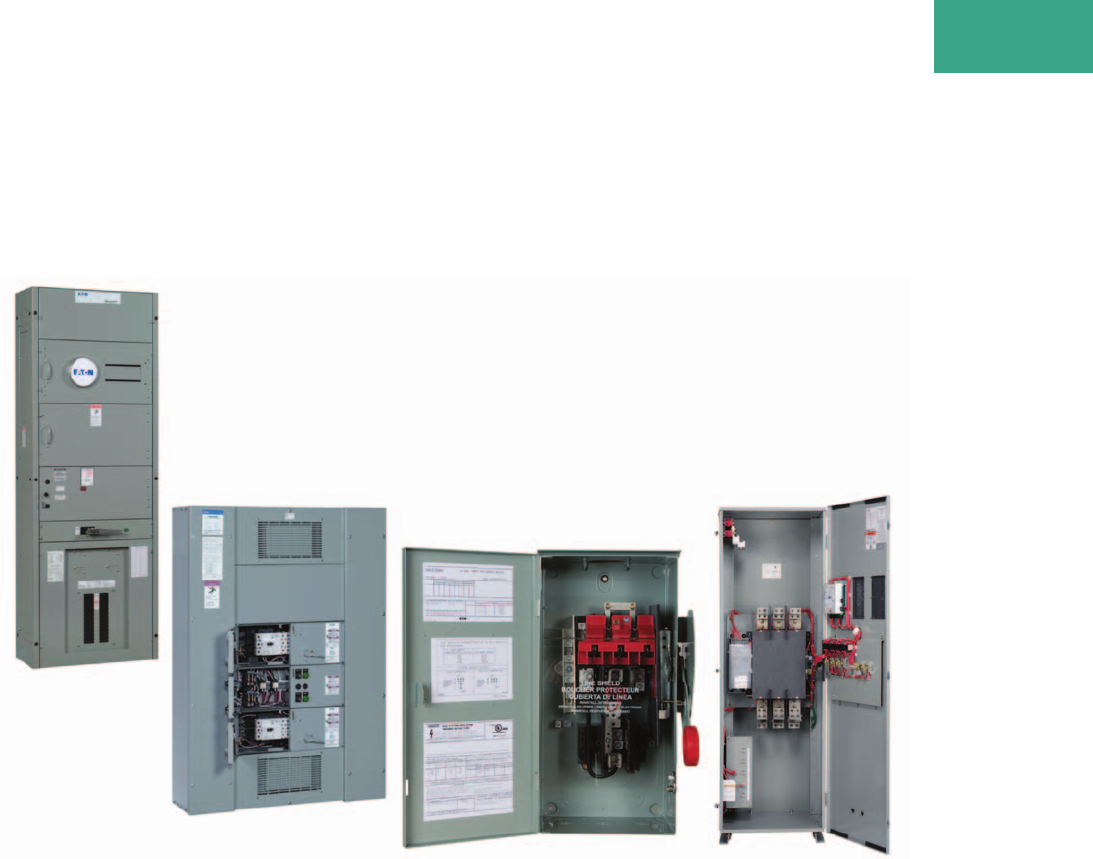
Switching Devices
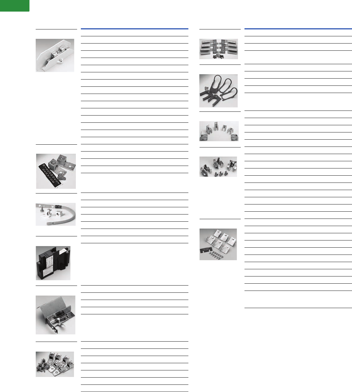
DH362NRK Safety Switch
1.1 Safety Switches
Product Overview . . . . . . . . . . . . . . . . . . . . . . . . . . . . . . . . . . . . . . . . V2-T1-3
Cross-Reference. . . . . . . . . . . . . . . . . . . . . . . . . . . . . . . . . . . . . . . V2-T1-5
Catalog Number Selection . . . . . . . . . . . . . . . . . . . . . . . . . . . . . . . V2-T1-13
Options and Accessories . . . . . . . . . . . . . . . . . . . . . . . . . . . . . . . . V2-T1-14
Modifications—Flex Center . . . . . . . . . . . . . . . . . . . . . . . . . . . . . . V2-T1-16
Standard Lug Capacities. . . . . . . . . . . . . . . . . . . . . . . . . . . . . . . . . V2-T1-20
General Duty . . . . . . . . . . . . . . . . . . . . . . . . . . . . . . . . . . . . . . . . . . . . V2-T1-26
Heavy-Duty . . . . . . . . . . . . . . . . . . . . . . . . . . . . . . . . . . . . . . . . . . . . . V2-T1-31
Six-Pole Switches. . . . . . . . . . . . . . . . . . . . . . . . . . . . . . . . . . . . . . . . . V2-T1-43
Double-Throw Switches . . . . . . . . . . . . . . . . . . . . . . . . . . . . . . . . . . . V2-T1-45
EnviroLine—Stainless Steel Switch. . . . . . . . . . . . . . . . . . . . . . . . . . . V2-T1-53
EnviroLine—Upper and Lower Window Switches. . . . . . . . . . . . . . . . V2-T1-56
EnviroLine—Receptacle Switches. . . . . . . . . . . . . . . . . . . . . . . . . . . . V2-T1-59
EnviroLine—Non-Metallic KRYDON Switch . . . . . . . . . . . . . . . . . . . . V2-T1-61
NEMA 7/9—Hazardous Location Disconnect Switch . . . . . . . . . . . . . V2-T1-63
Quick Connect Switches . . . . . . . . . . . . . . . . . . . . . . . . . . . . . . . . . . . V2-T1-65
Solar Disconnect Switch . . . . . . . . . . . . . . . . . . . . . . . . . . . . . . . . . . . V2-T1-67
Solar Combiner Box—Source Combiner and Array Combiner. . . . . . . V2-T1-69
316-Grade Stainless Steel Safety Switches. . . . . . . . . . . . . . . . . . . . . V2-T1-72
Mill-Duty Rated, Heavy-Duty, Fusible, Non-Fusible, Single-Throw . . . V2-T1-76
Heavy-Duty Fusible Safety Switches Accepting Cube Fuses . . . . . . . V2-T1-78
Elevator Control Switch . . . . . . . . . . . . . . . . . . . . . . . . . . . . . . . . . . . . V2-T1-81
Auxiliary Power Heavy-Duty Safety Switch . . . . . . . . . . . . . . . . . . . . . V2-T1-83
Left-Handed Safety Switch . . . . . . . . . . . . . . . . . . . . . . . . . . . . . . . . . V2-T1-86
200% Neutral Safety Switches . . . . . . . . . . . . . . . . . . . . . . . . . . . . . . V2-T1-87
Pringle Bolted Pressure Switch . . . . . . . . . . . . . . . . . . . . . . . . . . . . . . V2-T1-88
Type DS, Fusible and Non-Fusible . . . . . . . . . . . . . . . . . . . . . . . . . . . . V2-T1-91
Type Visi-Flex DE-ION . . . . . . . . . . . . . . . . . . . . . . . . . . . . . . . . . . . . . V2-T1-94
Flange Mounted—Variable Depth . . . . . . . . . . . . . . . . . . . . . . . . . . . . V2-T1-98
Flange Mounted—Fixed Depth . . . . . . . . . . . . . . . . . . . . . . . . . . . . . . V2-T1-102
1.2 Enclosed Circuit Breakers
Product Description. . . . . . . . . . . . . . . . . . . . . . . . . . . . . . . . . . . . . . . V2-T1-104
Application Description . . . . . . . . . . . . . . . . . . . . . . . . . . . . . . . . . . . . V2-T1-104
Features, Benefits and Functions . . . . . . . . . . . . . . . . . . . . . . . . . . . . V2-T1-105
Standards and Certifications . . . . . . . . . . . . . . . . . . . . . . . . . . . . . . . . V2-T1-105
Cross-Reference . . . . . . . . . . . . . . . . . . . . . . . . . . . . . . . . . . . . . . . . . V2-T1-106
Product Selection . . . . . . . . . . . . . . . . . . . . . . . . . . . . . . . . . . . . . . . . V2-T1-108
Accessories . . . . . . . . . . . . . . . . . . . . . . . . . . . . . . . . . . . . . . . . . . . . . V2-T1-110
Flex Center . . . . . . . . . . . . . . . . . . . . . . . . . . . . . . . . . . . . . . . . . . . . . V2-T1-112
Technical Data and Specifications . . . . . . . . . . . . . . . . . . . . . . . . . . . . V2-T1-113
Dimensions . . . . . . . . . . . . . . . . . . . . . . . . . . . . . . . . . . . . . . . . . . . . . V2-T1-115
1.3 Enclosed Rotary Disconnects
Product Overview . . . . . . . . . . . . . . . . . . . . . . . . . . . . . . . . . . . . . . . . V2-T1-122
Product Selection . . . . . . . . . . . . . . . . . . . . . . . . . . . . . . . . . . . . . . . . V2-T1-123
Dimensions . . . . . . . . . . . . . . . . . . . . . . . . . . . . . . . . . . . . . . . . . . . . . V2-T1-124
Learn
Online
V2-T1-2 Volume 2—Commercial Distribution CA08100003E—April 2014 www.eaton.com
1
1
1
1
1
1
1
1
1
1
1
1
1
1
1
1
1
1
1
1
1
1
1
1
1
1
1
1
1
1
1.1
Switching Devices
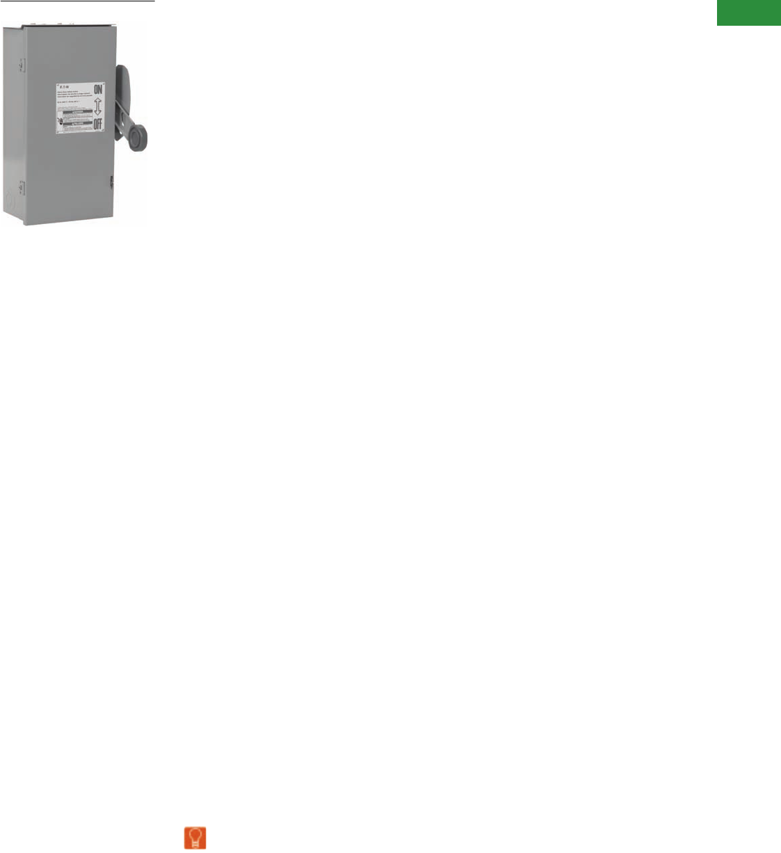
Safety Switches
General-Duty Safety Switch
Contents
Description Page
Product Overview
Product Selection Guide . . . . . . . . . . . . . . . . . . . . V2-T1-3
Standards and Certifications . . . . . . . . . . . . . . . . . V2-T1-4
Cross-Reference . . . . . . . . . . . . . . . . . . . . . . . . . . V2-T1-5
Catalog Number Selection . . . . . . . . . . . . . . . . . . V2-T1-13
Options and Accessories. . . . . . . . . . . . . . . . . . . . V2-T1-14
Modifications—Flex Center. . . . . . . . . . . . . . . . . . V2-T1-16
Technical Data and Specifications . . . . . . . . . . . . . V2-T1-20
Dimensions . . . . . . . . . . . . . . . . . . . . . . . . . . . . . . V2-T1-24
General Duty. . . . . . . . . . . . . . . . . . . . . . . . . . . . . . . . V2-T1-26
Heavy-Duty . . . . . . . . . . . . . . . . . . . . . . . . . . . . . . . . . V2-T1-31
Six-Pole Switches . . . . . . . . . . . . . . . . . . . . . . . . . . . . V2-T1-43
Double-Throw Switches . . . . . . . . . . . . . . . . . . . . . . . V2-T1-45
EnviroLine—Stainless Steel Switch . . . . . . . . . . . . . . V2-T1-53
EnviroLine—Upper and Lower Window Switches . . . V2-T1-56
EnviroLine—Receptacle Switches . . . . . . . . . . . . . . . V2-T1-59
EnviroLine—Non-Metallic KRYDON Switch . . . . . . . . V2-T1-61
NEMA 7/9—Hazardous Location Disconnect Switch . V2-T1-63
Quick Connect Switches. . . . . . . . . . . . . . . . . . . . . . . V2-T1-65
Solar Disconnect Switch . . . . . . . . . . . . . . . . . . . . . . . V2-T1-67
Solar Combiner Box—Source Combiner and
Array Combiner . . . . . . . . . . . . . . . . . . . . . . . . . . . . V2-T1-69
316-Grade Stainless Steel Safety Switches . . . . . . . . V2-T1-72
Mill-Duty Rated, Heavy-Duty, Fusible, Non-Fusible,
Single-Throw. . . . . . . . . . . . . . . . . . . . . . . . . . . . . . . V2-T1-76
Heavy-Duty Fusible Safety Switches Accepting
Cube Fuses . . . . . . . . . . . . . . . . . . . . . . . . . . . . . . . V2-T1-78
Elevator Control Switch. . . . . . . . . . . . . . . . . . . . . . . . V2-T1-81
Auxiliary Power Heavy-Duty Safety Switch. . . . . . . . . V2-T1-83
Left-Handed Safety Switch . . . . . . . . . . . . . . . . . . . . . V2-T1-86
200% Neutral Safety Switches. . . . . . . . . . . . . . . . . . V2-T1-87
Pringle Bolted Pressure Switch. . . . . . . . . . . . . . . . . . V2-T1-88
Type DS, Fusible and Non-Fusible. . . . . . . . . . . . . . . . V2-T1-91
Type Visi-Flex DE-ION . . . . . . . . . . . . . . . . . . . . . . . . . V2-T1-94
Flange Mounted—Variable Depth. . . . . . . . . . . . . . . . V2-T1-98
Flange Mounted—Fixed Depth. . . . . . . . . . . . . . . . . . V2-T1-102
Volume 2—Commercial Distribution CA08100003E—April 2014 www.eaton.com V2-T1-3
1
1
1
1
1
1
1
1
1
1
1
1
1
1
1
1
1
1
1
1
1
1
1
1
1
1
1
1
1
1
1.1
Switching Devices
Safety Switches
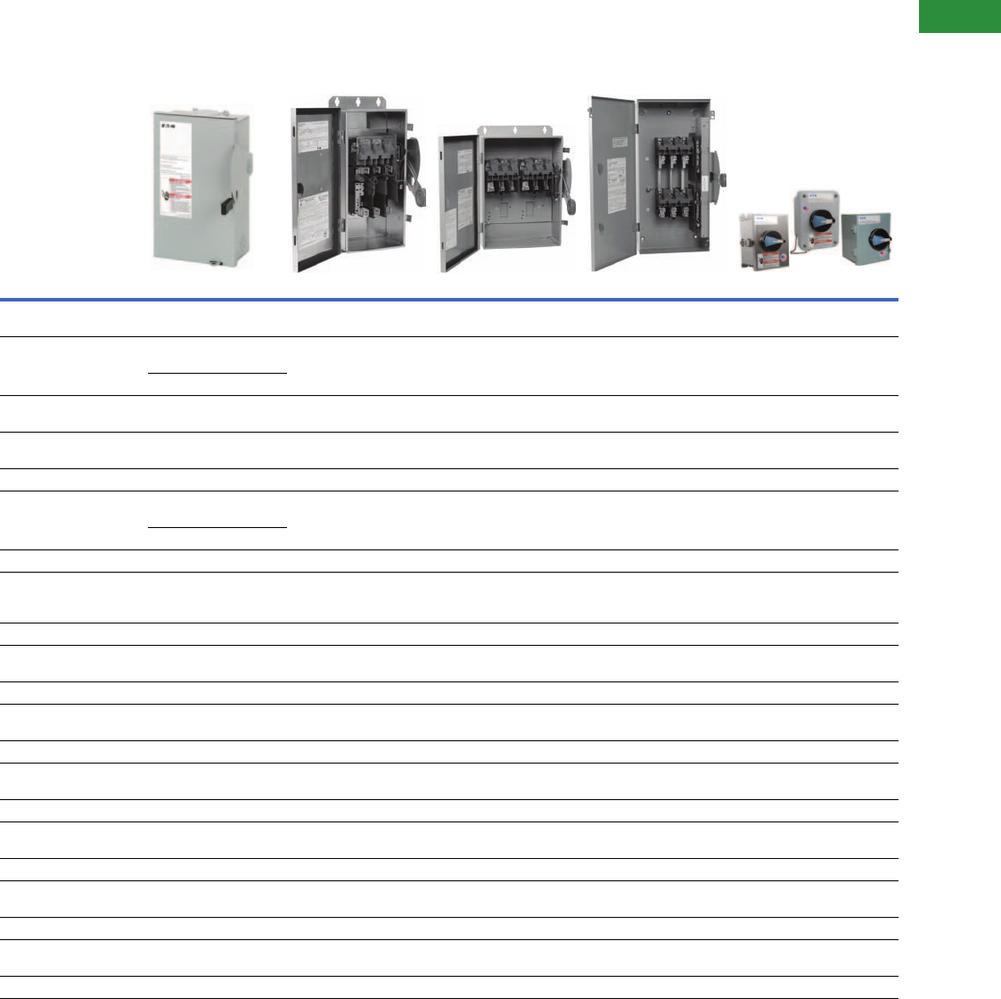
Product Overview
Product Selection Guide
Safety Switch
Notes
1See specific catalog number page for Fuse Class details. Enclosed rotary switches are non-fusible only.
2NEMA Type 12 enclosures (30–800A) can be field modified to meet NEMA 3R rainproof requirements when a factory provided drain screw is removed.
3Class J fuse clips provided.
Description General-Duty Heavy-Duty Six-Pole Motor Circuit Double-Throw Enclosed Rotary Switches
Type
Single-throw maximum
240 Vac horsepower rated
Single-throw maximum
600V AC/DC horsepower rated
Single-throw maximum
600 Vac
Maximum 600 Vac
horsepower rated
Maximum 600 Vac
Fuse type
Fusible Plug Cartridge Cartridge Cartridge —
Cartridge
Fuse class
Fusible 11 1 1 1
Ampere rating
Fusible 30–600 30–1200 30–200 30–1200 —
Non-fusible 30–600 30–1200 30–200 30–1200 16–125
Number of poles
Fusible 1, 2 and 3 2, 3 and 4 6 2 and 3 —
2 and 3
Non-
fusible
2 and 3 2, 3, 4 and 6 6 2, 3, 4 and 6 3 and 4
Enclosure types
NEMA® 1
Fusible Yes Yes — Yes Yes
Non-
fusible
Yes Yes — Yes Yes
NEMA 3R
Fusible Yes Yes — Yes Yes
Non-
fusible
Yes Yes Yes Yes Yes 2
NEMA 12
Fusible — Yes 2Yes, up to 200A 2Yes Yes
Non-
fusible
— Yes, up to 1200A 2Yes 2Yes, up to 400A Yes 2
NEMA 4 painted steel
Fusible — Yes, 400–800A — — —
Non-
fusible
— Yes, 400–800A — — —
NEMA 4X stainless steel
Fusible — Yes Yes, up to 200A Yes Yes
Non-
fusible
— Yes, up to 1200A Yes Yes, up to 400A Yes
NEMA 4X non-metallic
Fusible — Yes, up to 200A — — Yes
Non-
fusible
— Yes, up to 200A — — Yes
NEMA 7/9
Fusible — Yes, up to 100A — — —
Non-
fusible
— Yes, up to 100A 3—— —

V2-T1-4 Volume 2—Commercial Distribution CA08100003E—April 2014 www.eaton.com
1
1
1
1
1
1
1
1
1
1
1
1
1
1
1
1
1
1
1
1
1
1
1
1
1
1
1
1
1
1
1.1
Switching Devices
Safety Switches
Product Description
●Used to open or close
a circuit
●Non-fusible safety
switches provide a means
to manually connect or
disconnect the load from
the source
●Fusible safety switches
provide a means to
manually open and close
a circuit and overcurrent
protection by means of
installed fuses
●Also commonly referred
to as a disconnect switch
or disconnect
●Available from 30 to 1200A
Standards and Certifications
●UL 98
●UL 50
●NEMA KS-1

Volume 2—Commercial Distribution CA08100003E—April 2014 www.eaton.com V2-T1-5
1
1
1
1
1
1
1
1
1
1
1
1
1
1
1
1
1
1
1
1
1
1
1
1
1
1
1
1
1
1
1.1
Switching Devices
Safety Switches
Cross-Reference
General-Duty General-Duty, continued
Notes
1Separate neutral kit required.
Always verify the number of poles and wires required since catalog numbers may appear in
multiple tables.
Ampere
Rating
Catalog Number
Eaton General Electric Siemens Square D
Plug Fuse, Single-Pole, Two-Wire, 120 Vac, NEMA 1
30 DP111NGB TPF130 LF111N D211N
Plug Fuse, Two-Pole, Three-Wire, 240 Vac, NEMA 1
30 DP221NGB TPF230 LF211N D211N
Fusible, Two-Pole, Three-Wire, 240 Vac, NEMA 1
30 DG221NGB TG3221 GF221N D221N
60 DG222NGB TG3222 GF222N D222N
100 DG223NGB TG3223 GF223N D223N
200 DG224NGK TG3224 GF224N D224N
400 DG225NGK TG3225 GF225N D225N
600 DG226NGK TG3226 GF226N D226N
Fusible, Three-Pole, Three-Wire, 240 Vac, NEMA 1
30 DG321NGB TG4321 GF321N D321N
60 DG322NGB TG4322 GF322N D322N
100 DG323NGB TG4323 GF323N D323N
200 DG324NGK TG4324 GF324N D324N
400 DG325FGK TG3325 GF325N D325N
600 DG326FGK TG3326 GF326N D326N
Fusible, Three-Pole, Four-Wire, 240 Vac, NEMA 1
30 DG321NGB TG4321 GF321N D321N
60 DG322NGB TG4322 GF322N D322N
100 DG323NGB TG4323 GF323N D323N
200 DG324NGK TG4324 GF324N D324N
400 DG325NGK TG4325 GF325N D325N
600 DG326NGK TG4326 GF326N D326N
Non-Fusible, Two-Pole, Two-Wire, 240 Vac, NEMA 1
30 DG221UGB TGN3321 N/A N/A
60 DG222UGB TGN3322 N/A QO260NATS
100 DG223UGB TGN3323 N/A QO2000NS
200 DG324UGK TGN3324 N/A DU324
400 DG325UGK TGN3325 N/A DU325
600 DG326UGK TGN3326 N/A DU326
Non-Fusible, Three-Pole, Three-Wire, 240 Vac, NEMA 1
30 DG321UGB TGN3321 GNF321 DU321
60 DG322UGB TGN3322 GNF322 DU322
100 DG323UGB TGN3323 GNF323 DU323
200 DG324UGK TGN3324 GNF324 DU324
400 DG325UGK TGN3325 GNF325 DU325
600 DG326UGK TGN3326 GNF326 DU326
Ampere
Rating
Catalog Number
Eaton General Electric Siemens Square D
Fusible, Two-Pole, Three-Wire, 240 Vac, NEMA 3R
30 DG221NRB TG3221R GF221NR D221NRB
60 DG222NRB TG3222R GF222NR D222NRB
100 DG223NRB TG3223R GF223NR D223NRB
200 DG224NRK TG3224R GF224NR D224NRB
400 DG225NRK TG3225R GF225NR D225NR
600 DG226NRK TG3226R GF226NR D226NR
Fusible, Three-Pole, Three-Wire, 240 Vac, NEMA 3R
30 DG321NRB TG4321R GF321NR D321NRB
60 DG322NRB TG4322R GF322NR D322NRB
100 DG323NRB TG4323R GF323NR D323NRB
200 DG324NRK TG4324R GF324NR D324NRB
400 DG325FRK TG3325R GF325NR D325NR
600 DG326FRK TG3326R GF326NR D326NR
Fusible, Three-Pole, Four-Wire, 240 Vac, NEMA 3R
30 DG321NRB TG4321R GF321NR D321NRB
60 DG322NRB TG4322R GF322NR D322NRB
100 DG323NRB TG4323R GF323NR D323NRB
200 DG324NRK TG4324R GF324NR D324NRB
400 DG325NRK TG3325R 1GF325NR D325NR
600 DG326NRK TG3326R 1GF326NR D326NR
Non-Fusible, Two-Pole, Two-Wire, 240 Vac, NEMA 3R
30 DG221URB TGN3321R GNF321R DU221RB
60 DG222URB TGN3322R GNF322R DU222RB
100 DG223URB TGN3323R GNF323R QO2000NRB
200 DG324URK TGN3324R GNF324R DU324RB
Non-Fusible, Three-Pole, Three-Wire, 240 Vac, NEMA 3R
30 DG321URB TGN3321R GNF321R DU321RB
60 DG322URB TGN3322R GNF322R DU322RB
100 DG323URB TGN3323R GNF323R DU323RB
200 DG324URK TGN3324R GNF324R DU324RB
400 DG325URK N/A N/A N/A
600 DG326URK N/A N/A N/A

V2-T1-6 Volume 2—Commercial Distribution CA08100003E—April 2014 www.eaton.com
1
1
1
1
1
1
1
1
1
1
1
1
1
1
1
1
1
1
1
1
1
1
1
1
1
1
1
1
1
1
1.1
Switching Devices
Safety Switches
Heavy-Duty Heavy-Duty, continued
Notes
1Separate neutral kit required.
2600V switch.
Always verify the number of poles and wires required since catalog numbers may appear in
multiple tables.
Ampere
Rating
Catalog Number
Eaton General Electric Siemens Square D
Fusible, Two-Pole, Two-Wire, 240 Vac, NEMA 1
30 DH221FGK TH3221 N/A H221N
60 DH222NGK TH3222 N/A H222N
100 DH223NGK TH3223 N/A H223N
200 DH224NGK TH3224 N/A H224N
400 DH225FGK TH3225 N/A H225
600 DH226FGK TH3226 N/A H226
800 DH227FGK TC72267 N/A H227
1200 DH328FGK TC72268 N/A H228
Fusible, Two-Pole, Three-Wire, 240 Vac, NEMA 1
30 DH221NGK TH3221 HF221N H221N
60 DH222NGK TH3222 HF222N H222N
100 DH223NGK TH3223 HF223N H223N
200 DH224NGK TH3224 HF224N H224N
400 DH225NGK TH3225 HF225N H225N
600 DH226NGK TH3226 HF226N H226N
800 DH227NGK TC72267 1HF227N H227N
1200 DH328NGK TC72268 1HF228N H228N
Fusible, Three-Pole, Three-Wire, 240 Vac, NEMA 1
30 DH321FGK TH4321 N/A H321N
60 DH322FGK TH4322 N/A H322N
100 DH323FGK TH4323 N/A H323N
200 DH324FGK TH4324 N/A H324N
400 DH325FGK TH3325 N/A H325
600 DH326FGK TH3326 N/A H326
800 DH327FGK TC72367 N/A H327
1200 DH328FGK TC72368 N/A H328
Fusible, Three-Pole, Four-Wire, 240 Vac, NEMA 1
30 DH321NGK TH4321 HF321N H321N
60 DH322NGK TH4322 HF322N H322N
100 DH323NGK TH4323 HF323N H323N
200 DH324NGK TH4324 HF324N H324N
400 DH325NGK TH4325 HF325N H325N
600 DH326NGK TH4326 HF326N H326N
800 DH327NGK TC72367 1HF327N H327N
1200 DH328NGK TC72368 1HF328N H328N
Fusible, Four-Pole, Four-Wire, 240 Vac, NEMA 1
30 DH421FGK N/A F421 H461 2
60 DH422FGK N/A F422 H462 2
100 DH423FGK N/A F423 H463 2
200 DH424FGK N/A F424 H464 2
400 DH425FGK N/A F425 H465 2
600 DH426FGK N/A F426 H466 2
Ampere
Rating
Catalog Number
Eaton General Electric Siemens Square D
Non-Fusible, Three-Pole, Three-Wire, 240 Volt/600 Vac, NEMA 1
30 DH361UGK THN3361 HNF361 HU361
60 DH362UGK THN3362 HNF362 HU362
100 DH363UGK THN3363 HNF363 HU363
200 DH364UGK THN3364 HNF364 HU364
400 DH365UGK THN3365 HNF365 HU365
600 DH366UGK THN3366 HNF366 HU366
800 DH367UGK TC36367 HNF367 HU367
1200 DH368UGK TC36368 HNF368 HU368
Fusible, Three-Pole, Two-Wire, 240 Vac, NEMA 3R
30 DH221NRK TH3221R N/A H221NRB
60 DH222NRK TH3222R N/A H222NRB
100 DH223NRK TH3223R N/A H223NRB
200 DH224NRK TH3224R N/A H224NRB
400 DH225FRK TH3225R N/A H225R
600 DH226FRK TH3226R N/A H226R
800 DH227NRK TC72267R N/A H227R
1200 DH328FRK TC72268R N/A H228R
Fusible, Two-Pole, Three-Wire, 240 Vac, NEMA 3R
30 DH221NRK TH3221R HF221NR H221NRB
60 DH222NRK TH3222R HF222NR H222NRB
100 DH223NRK TH3223R HF223NR H223NRB
200 DH224NRK TH3224R HF224NR H224NRB
400 DH225NRK TH3225R HF225NR H225NR
600 DH226NRK TH3226R HF226NR H226NR
800 DH227NRK TC72267R 1HF227NR H227NR
1200 DH328NRK TC72268R 1HF228NR H228NR
Fusible, Three-Pole, Three-Wire, 240 Vac, NEMA 3R
30 DH321FRK TH4321R N/A H321NRB
60 DH322FRK TH4322R N/A H322NRB
100 DH323FRK TH4323R N/A H323NRB
200 DH324FRK TH4324R N/A H324NRB
400 DH325FRK TH3325R N/A H325NR
600 DH326FRK TH3326R N/A H326NR
800 DH327FRK TC72367R N/A H327NR
1200 DH328FRK TC72368R N/A H328NR

Volume 2—Commercial Distribution CA08100003E—April 2014 www.eaton.com V2-T1-7
1
1
1
1
1
1
1
1
1
1
1
1
1
1
1
1
1
1
1
1
1
1
1
1
1
1
1
1
1
1
1.1
Switching Devices
Safety Switches
Heavy-Duty, continued Heavy-Duty, continued
Notes
1Separate neutral kit required.
Always verify the number of poles and wires required since catalog numbers may appear in
multiple tables.
Ampere
Rating
Catalog Number
Eaton General Electric Siemens Square D
Fusible, Three-Pole, Four-Wire, 240 Vac, NEMA 3R
30 DH321NRK TH4321R HF321NR H321NRB
60 DH322NRK TH4322R HF322NR H322NRB
100 DH323NRK TH4323R HF323NR H323NRB
200 DH324NRK TH4324R HF324NR H324NRB
400 DH325NRK TH3325R 1HF325NR H325R
600 DH326NRK TH3326R 1HF326NR H326R
800 DH327NRK TC72367R 1HF327NR H327R
1200 DH328NRK TC72368R 1HF328NR H328R
Non-Fusible, Three-Pole, Three-Wire, 240 Volt/600 Vac, NEMA 3R
30 DH361URK THN3361R HNF361R HU361RB
60 DH362URK THN3362R HNF362R HU362RB
100 DH363URK THN3363R HNF363R HU363RB
200 DH364URK THN3364R HNF364R HU364RB
400 DH365URK THN3365R HNF365R HU365R
600 DH366URK THN3366R HNF366R HU366R
800 DH367URK N/A HNF367R HU367R
1200 DH368URK N/A HNF368R HU368R
Fusible, Two-Pole, Two-Wire, 240 Vac, NEMA 4/4X
30 DH221NWK TH2221SS HF221S H221DS
60 DH222NWK TH2222SS HF222S H222DS
100 DH223NWK TH3223SS HF223S H223DS
200 DH224NWK TH3224SS HF224S H224DS
400 DH225FWK TH3225SS HF325S H225DS
600 DH226FWK TH3226SS HF326S H226DS
Fusible, Two-Pole, Three-Wire, 240 Vac, NEMA 4/4X
30 DH221NWK TH3221SS HF321S 1H221DS 1
60 DH222NWK TH3222SS HF322S 1H222DS 1
100 DH223NWK TH3223SS HF323S 1H223DS 1
200 DH224NWK TH3224SS HF324S 1H224DS 1
400 DH225NWK TH3225SS HF325S 1H225NDS
600 DH226NWK TH3226SS HF326S 1H226NDS
800 DH227NWK N/A HF327S 1N/A
Fusible, Three-Pole, Three-Wire, 240 Vac, NEMA 4/4X
30 DH321FWK TH3321SS HF321S H321DS
60 DH322FWK TH3322SS HF322S H322DS
100 DH323NWK TH4323SS HF323S H323DS
200 DH324NWK TH4324SS HF324S H324DS
400 DH325FWK TH4325SS HF325S H325DS
600 DH326FWK TH4326SS HF326S H326DS
800 DH327FWK N/A HF327S N/A
Fusible, Three-Pole, Four-Wire, 240 Vac, NEMA 4/4X
30 DH321NWK TH4321SS HF321S 1H321DS 1
60 DH322NWK TH4322SS HF322S 1H322DS 1
100 DH323NWK TH4323SS HF323S 1H323DS 1
200 DH324NWK TH4324SS HF324S 1H324DS 1
400 DH325NWK TH4325SS HF325S 1H325NDS
600 DH326NWK TH4326SS HF326S 1H326NDS
Ampere
Rating
Catalog Number
Eaton General Electric Siemens Square D
Fusible, Two-Pole, Two-Wire, 240 Vac, NEMA 12
30 DH221NDK TH2221J HF221J H221AWK
60 DH222NDK TH2222J HF222J H222AWK
100 DH223NDK TH3223J HF223J H223AWK
200 DH224NDK TH3224J HF224J H224AWK
400 DH225FDK TH3225J HF325J H225AWK
600 DH226FDK TH3226J HF326J H226AWK
800 DH227FDK N/A HF327J H227AWK
1200 N/A N/A N/A H228AWK
Fusible, Two-Pole, Three-Wire, 240 Vac, NEMA 12
30 DH221NDK TH3221J HF221J 1H221AWK
60 DH222NDK TH3222J HF222J 1H222AWK
100 DH223NDK TH3223J HF223J 1H223AWK
200 DH224NDK TH3224J HF224J 1H224AWK
400 DH225NDK TH3225J HF325J 1H225NAWK
600 DH226NDK TH3226J HF326J 1H226NAWK
800 DH227NDK N/A HF327J 1H227NAWK
1200 N/A N/A N/A H228NAWK
Fusible, Three-Pole, Three-Wire, 240 Vac, NEMA 12
30 DH321FDK TH3321J HF321J H321AWK
60 DH322FDK TH3322J HF322J H322AWK
100 DH323FDK TH4323J HF323J H323AWK
200 DH324FDK TH4324J HF324J H324AWK
400 DH325FDK TH4325J HF325J H325AWK
600 DH326FDK TH4326J HF326J H326AWK
800 DH327FDK N/A HF327J H327AWK
1200 N/A N/A N/A H328AWK
Fusible, Three-Pole, Four-Wire, 240 Vac, NEMA 12
30 DH321NDK TH4321J HF321J 1H321AWK 1
60 DH322NDK TH4322J HF322J 1H322AWK 1
100 DH323NDK TH4323J HF323J 1H323AWK 1
200 DH324NDK TH4324J HF324J 1H324AWK 1
400 DH325NDK TH4325J HF325J 1H325NAWK
600 DH326NDK TH4326J HF326J 1H326NAWK
800 N/A N/A HF327J 1H327NAWK
1200 N/A N/A N/A H328NAWK
Fusible, Four-Pole, Four-Wire, 240 Vac, NEMA 12
30 DH421FDK N/A N/A N/A
60 DH422FDK N/A N/A N/A
100 DH423FDK N/A N/A N/A
200 DH424FDK N/A N/A N/A

V2-T1-8 Volume 2—Commercial Distribution CA08100003E—April 2014 www.eaton.com
1
1
1
1
1
1
1
1
1
1
1
1
1
1
1
1
1
1
1
1
1
1
1
1
1
1
1
1
1
1
1.1
Switching Devices
Safety Switches
Heavy-Duty, continued Heavy-Duty, continued
Notes
1Separate neutral kit required.
Always verify the number of poles and wires required since catalog numbers may appear in
multiple tables.
Ampere
Rating
Catalog Number
Eaton General Electric Siemens Square D
Fusible, Two-Pole, Two-Wire, 600 Vac, NEMA 1
30 DH261FGK TH2261DC HF261 H361
60 DH262FGK TH2262DC HF262 H362
100 DH263FGK TH2263DC HF263 H363
200 DH264FGK N/A N/A H364
400 DH265FGK N/A HF265 H265
600 DH266FGK N/A HF266 H266
800 DH267FGK N/A N/A H267
1200 N/A N/A N/A H268
Fusible, Three-Pole, Three-Wire, 600 Vac, NEMA 1
30 DH361FGK TH3361 HF361 H361
60 DH362FGK TH3362 HF362 H362
100 DH363FGK TH3363 HF363 H363
200 DH364FGK TH3364 HF364 H364
400 DH365FGK TH3365 HF365 H365
600 DH366FGK TH3366 HF366 H366
800 DH367FGK TC72367 HF367 H367
1200 DH368FGK TC72368 HF368 H368
Fusible, Three-Pole, Four-Wire, 600 Vac, NEMA 1
30 DH361NGK TH3361 1HF361N H361N
60 DH362NGK TH3362 1HF362N H362N
100 DH363NGK TH3363 1HF363N H363N
200 DH364NGK TH3364 1HF364N H364N
400 DH365NGK TH3365 1HF365N H365N
600 DH366NGK TH3366 1HF366N H366N
800 DH367NGK TC72367 1HF367N H367N
1200 DH368NGK TC72368 1HF368 1H368N
Fusible, Four-Pole, Four-Wire, 600 Vac, NEMA 1
30 DH461FGK TH6661 N/A H461
60 DH462FGK TH6662 N/A H462
100 DH463FGK TH6663 N/A H463
200 DH464FGK TH6664 N/A H464
400 DH465FGK N/A N/A H465
600 DH466FGK N/A N/A H466
Non-Fusible, Two-Pole, Two-Wire, 600 Vac, NEMA 1
30 DH261UGK THN2261DC HNF261 HU361
60 DH362UGK THN2262DC HNF262 HU362
100 DH263UGK THN2263DC HNF263 HU363
200 DH364UGK N/A N/A HU364
400 DH265UGK N/A HNF265 HU265
600 DH266UGK N/A HNF266 HU266
800 DH267UGK N/A N/A HU267
1200 N/A N/A N/A HU268
Ampere
Rating
Catalog Number
Eaton General Electric Siemens Square D
Non-Fusible, Four-Pole, Four-Wire, 600 Vac, NEMA 1
30 DH461UGK THN6661 N/A HU461
60 DH462UGK THN6662 N/A HU462
100 DH463UGK THN6663 N/A HU463
200 DH464UGK THN6664 N/A HU464
400 DH465UGK N/A N/A HU465
600 DH466UGK N/A N/A HU466
Fusible, Two-Pole, Two-Wire, 600 Vac, NEMA 3R
30 DH361FRK TH2261RDC HF261R H361RB
60 DH362FRK TH2262RDC HF262R H362RB
100 DH363FRK TH2263RDC HF263R H363RB
200 DH364FRK N/A N/A H364RB
400 DH365FRK N/A N/A H265R
600 DH366FRK N/A HF265R H266R
800 DH367FRK N/A HF266R H267R
1200 DH368FRK N/A N/A H268R
Fusible, Three-Pole, Three-Wire, 600 Vac, NEMA 3R
30 DH361FRK TH3361R HF361R H361RB
60 DH362FRK TH3362R HF362R H362RB
100 DH363FRK TH3363R HF363R H363RB
200 DH364FRK TH3364R HF364R H364RB
400 DH365FRK TH3365R HF365R H365R
600 DH366FRK TH3366R HF366R H366R
800 DH367FRK TC72367R HF367R H367R
1200 DH368FRK TC72368R HF368R H368R
Fusible, Three-Pole, Four-Wire, 600 Vac, NEMA 3R
30 DH361NRK TH3361R 1HF361NR H361NRB
60 DH362NRK TH3362R 1HF362NR H362NRB
100 DH363NRK TH3363R 1HF363NR H363NRB
200 DH364NRK TH3364R 1HF364NR H364NRB
400 DH365NRK TH3365R 1HF365NR H365NR
600 DH366NRK TH3366R 1HF366NR H366NR
800 DH367NRK TC72367R 1HF367NR H367NR
1200 DH368NRK TC72368R 1HF368R H368NR
Non-Fusible, Three-Pole, Three-Wire, 600 Vac, NEMA 3R
30 DH361URK THN2261RDC HNF261R HU361RB
60 DH362URK THN2262RDC HNF262R HU362RB
100 DH363URK THN2263RDC HNF263R HU363RB
200 DH364URK N/A N/A HU364RB
400 DH365URK N/A HNF265R HU265R
600 DH366URK N/A HNF266R HU266R
800 DH367URK N/A N/A HU267R
1200 DH368URK N/A N/A HU268R

Volume 2—Commercial Distribution CA08100003E—April 2014 www.eaton.com V2-T1-9
1
1
1
1
1
1
1
1
1
1
1
1
1
1
1
1
1
1
1
1
1
1
1
1
1
1
1
1
1
1
1.1
Switching Devices
Safety Switches
Heavy-Duty, continued Heavy-Duty, continued
Notes
1Separate neutral kit required.
Always verify the number of poles and wires required since catalog numbers may appear in
multiple tables.
Ampere
Rating
Catalog Number
Eaton General Electric Siemens Square D
Non-Fusible, Four-Pole, Four-Wire, 600 Vac, NEMA 3R
30 DH461UDK THN6661 N/A N/A
60 DH462UDK THN6662 N/A N/A
100 DH463UDK THN6663 N/A N/A
200 DH464UDK THN6664 N/A N/A
Fusible, Two-Pole, Two-Wire, 600 Vac, NEMA 4/4X Stainless Steel
30 DH261FWK TH2261SSDC HF261S H361DS
60 DH362FWK TH2262SSDC HF262S H362DS
100 DH363FWK TH2263SSDC HF263S H363DS
200 DH264FWK N/A N/A H364DS
400 DH365FWK N/A HF265S H265DS
600 DH366FWK N/A HF266S H266DS
800 DH367FWK N/A N/A N/A
Fusible, Three-Pole, Three-Wire, 600 Vac, NEMA 4/4X Stainless Steel
30 DH361FWK TH3361SS HF361S H361DS
60 DH362FWK TH3362SS HF362S H362DS
100 DH363FWK TH3363SS HF363S H363DS
200 DH364FWK TH3364SS HF364S H364DS
400 DH365FWK TH3365SS HF365S H365DS
600 DH366FWK TH3366SS HF366S H366DS
800 DH367FWK N/A HF367S N/A
Fusible, Three-Pole, Four-Wire, 600 Vac, NEMA 4/4X Stainless Steel
30 DH361NWK TH3361SS 1HF361S 1H361DS 1
60 DH362NWK TH3362SS 1HF362S 1H362DS 1
100 DH363NWK TH3363SS 1HF363S 1H363DS 1
200 DH364NWK TH3364SS 1HF364S 1H364NDS
400 DH365NWK TH3365SS 1HF365S 1H365NDS
600 DH366NWK TH3366SS 1HF366S 1H366NDS
Non-Fusible, Two-Pole, Two-Wire, 600 Vac, NEMA 4/4X Stainless Steel
30 DH361UWK THN2261SSDC HNF261S HU361DS
60 DH362UWK THN2262SSDC HNF262S HU362DS
100 DH363UWK THN2263SSDC HNF263S HU363DS
200 DH364UWK N/A N/A HU364DS
400 DH365UWK N/A HNF265S HU265DS
600 DH366UWK N/A HNF266S HU266DS
800 DH367UWK N/A N/A N/A
Non-Fusible, Three-Pole, Three-Wire, 600 Vac, NEMA 4/4X Stainless Steel
30 DH361UWK THN3361SS HNF361S HU361DS
60 DH362UWK THN3362SS HNF362S HU362DS
100 DH363UWK THN3363SS HNF363S HU363DS
200 DH364UWK THN3364SS HNF364S HU364DS
400 DH365UWK THN3365SS HNF365S HU365DS
600 DH366UWK THN3366SS HNF366S HU366DS
800 DH367UWK N/A HNF367S N/A
Ampere
Rating
Catalog Number
Eaton General Electric Siemens Square D
Non-Fusible, Four-Pole, Four-Wire, 600 Vac, NEMA 4/4X Stainless Steel
30 DH461UWK N/A N/A HU461DS
60 N/A N/A N/A HU462DS
100 N/A N/A N/A HU464DS
200 N/A N/A N/A HU464DS
Fusible, Two-Pole, Two-Wire, 600 Vac, NEMA 12
30 DH261FDK TH2261JDC HF261J H361AWK
60 DH262FDK TH2262JDC HF262J H362AWK
100 DH263FDK TH2263JDC HF263J H363AWK
200 DH264FDK N/A N/A H364AWK
400 DH265FDK N/A HF265J H265AWK
600 DH266FDK N/A HF266J H266AWK
800 DH267FDK N/A N/A H267AWK
1200 N/A N/A N/A H268AWK
Fusible, Three-Pole, Three-Wire, 600 Vac, NEMA 12
30 DH361FDK TH3361J HF361J H361AWK
60 DH362FDK TH3362J HF362J H362AWK
100 DH363FDK TH3363J HF363J H363AWK
200 DH364FDK TH3364J HF364J H364AWK
400 DH365FDK TH3365J HF365J H365AWK
600 DH366FDK TH3366J HF366J H366AWK
800 DH367FDK N/A HF367J H367AWK
1200 N/A N/A N/A H368AWK
Fusible, Three-Pole, Four-Wire, 600 Vac, NEMA 12
30 DH361NDK THN3361J 1HF361J 1H361AWK 1
60 DH362NDK THN3362J 1HF362J 1H362AWK 1
100 DH363NDK THN3363J 1HF363J 1H363AWK 1
200 DH364NDK THN3364J 1HF364J 1H364NAWK
400 DH365NDK THN3365J 1HF365J 1H365NAWK
600 DH366NDK THN3366J 1HF366J 1H366NAWK
800 DH367NDK N/A HF367J 1H367NAWK
1200 N/A N/A N/A H368NAWK
Fusible, Four-Pole, Four-Wire, 600 Vac, NEMA 12
30 N/A TH6661 N/A H461AWK
60 N/A TH6662 N/A H462AWK
100 DH463FDK TH6663 N/A H463AWK
200 DH464FDK TH6664 N/A H464AWK
400 N/A N/A N/A H465AWK

V2-T1-10 Volume 2—Commercial Distribution CA08100003E—April 2014 www.eaton.com
1
1
1
1
1
1
1
1
1
1
1
1
1
1
1
1
1
1
1
1
1
1
1
1
1
1
1
1
1
1
1.1
Switching Devices
Safety Switches
Heavy-Duty, continued Heavy-Duty Six-Pole
Note
Always verify the number of poles and wires required since catalog numbers may appear in
multiple tables.
Ampere
Rating
Catalog Number
Eaton General Electric Siemens Square D
Non-Fusible, Two-Pole, Two-Wire, 600 Vac, NEMA 12
30 DH261UDK THN2261JDC HNF261J HU361AWK
60 DH262UDK THN2262JDC HNF262J HU362AWK
100 DH263UDK THN2263JDC HNF263J HU363AWK
200 DH264UDK N/A N/A HU364AWK
400 DH265UDK N/A HNF265J HU265AWK
600 DH266UDK N/A HNF266J HU266AWK
800 DH267UDK N/A N/A HU267AWK
1200 N/A N/A N/A HU268AWK
Non-Fusible, Three-Pole, Three-Wire, 600 Vac, NEMA 12
30 DH361UDK THN3361J HNF361J HU361AWK
60 DH362UDK THN3362J HNF362J HU362AWK
100 DH363UDK THN3363J HNF363J HU363AWK
200 DH364UDK THN3364J HNF364J HU364AWK
400 DH365UDK THN3365J HNF365J HU365AWK
600 DH366UDK THN3366J HNF366J HU366AWK
800 DH367UDK N/A HNF367J HU367AWK
1200 N/A N/A N/A HU368AWK
Non-Fusible, Four-Pole, Four-Wire, 600 Vac, NEMA 12
30 DH461UDK THN6661 N/A HU461AWK
60 DH462UDK THN6662 N/A HU462AWK
100 DH463UDK THN6663 N/A HU463AWK
200 DH464UDK THN6664 N/A HU464AWK
400 N/A N/A N/A HU465AWK
Ampere
Rating
Catalog Number
Eaton General Electric Siemens Square D
Fusible, Six-Pole, Six-Wire, 600 Vac, NEMA 3R
30 DH661FDK TH6661 F651H N/A
60 DH662FDK TH6662 F652H N/A
100 DH663FDK TH6663 F653H N/A
200 DH664FDK TH6664 N/A N/A
Fusible, Six-Pole, Six-Wire, 600 Vac, NEMA 12
30 DH661FDK TH6661 F651H N/A
60 DH662FDK TH6662 F652H N/A
100 DH663FDK TH6663 F653H H663AWK
200 DH664FDK TH6664 N/A H664RWK
Fusible, Six-Pole, Six-Wire, 600 Vac, NEMA 4X
30 N/A N/A F651SS N/A
60 N/A N/A F652SS N/A
100 N/A N/A F653SS H663DS
200 N/A N/A N/A H664DS
Non-Fusible, Six-Pole, Six-Wire, 600 Vac, NEMA 3R
30 DH661UDK THN6661 NF651H N/A
60 DH662UDK THN6662 NF652H N/A
100 DH663UDK THN6663 NF653H N/A
200 DH664UDK THN6664 N/A N/A
Non-Fusible, Six-Pole, Six-Wire, 600 Vac, NEMA 12
30 DH661UDK THN6661 NF651H HU661AWK
60 DH662UDK THN6662 NF652H HU662AWK
100 DH663UDK THN6663 NF653H HU663AWK
200 DH664UDK THN6664 N/A HU664RWK
Non-Fusible, Six-Pole, Six-Wire, 600 Vac, NEMA 4X
30 DH661UWK N/A NF651SS HU661DS
60 DH662UWK N/A NF652SS HU662DS
100 DH663UWK N/A NF653SS HU663DS
200 DH664UWK N/A N/A HU664DS

Volume 2—Commercial Distribution CA08100003E—April 2014 www.eaton.com V2-T1-11
1
1
1
1
1
1
1
1
1
1
1
1
1
1
1
1
1
1
1
1
1
1
1
1
1
1
1
1
1
1
1.1
Switching Devices
Safety Switches
Double-Throw Double-Throw, continued
Note
Always verify the number of poles and wires required since catalog numbers may appear in
multiple tables.
Ampere
Rating
Catalog Number
Eaton General Electric Siemens Square D
Fusible, Two-Pole, Two-Wire, 240 Vac, NEMA 1
30 DT321FGK TDT3321 N/A N/A
60 DT322FGK TDT3322 N/A N/A
100 DT323FGK TDT3323 N/A DT223
200 DT224FGK TDT3324 DTF224 DT224
400 DT325FGK TDT3325 N/A N/A
600 DT326FGK TDT3326 N/A N/A
Fusible, Three-Pole, Three-Wire, 240 Vac, NEMA 1
30 DT321FGK TDT3321 DTF321 DT321
60 DT322FGK TDT3322 DTF322 DT322
100 DT323FGK TDT3323 DTF323 DT323
200 DT324FGK TDT3324 DTF324 DT324
400 DT325FGK TDT3325 DTF325 N/A
600 DT326FGK TDT3326 DTF326 N/A
Non-Fusible, Two-Pole, Two-Wire, 240 Vac, NEMA 1
30 DT221UGK N/A DTNF221 92251
60 DT222UGK N/A DTNF222 DTU222
100 DT223UGK N/A DTNF223 DTU223
200 DT224UGK N/A DTNF224 DTU224
400 DT225UGK N/A DTNF225 92255
600 DT226UGK N/A DTNF226 N/A
800 DT227UGK N/A N/A N/A
Non-Fusible, Three-Pole, Three-Wire, 240 Vac, NEMA 1
30 DT321UGK TC35321 DTNF321 DTU321
60 DT322UGK TC35322 DTNF322 DTU322
100 DT323UGK TC35323 DTNF323 DTU323
200 DT324UGK TC35324 DTNF324 DTU324
400 DT325UGK TC35325 DTNF325 92355
600 DT326UGK TC35326 DTNF326 92356
800 DT327UGK N/A DTNF327 N/A
Fusible, Three-Pole, Three-Wire, 600 Vac, NEMA 1
30 DT361FGK TDT3361 DTF361 DT361
60 DT362FGK TDT3362 DTF362 DT362
100 DT363FGK TDT3363 DTF363 DT363
200 DT364FGK TDT3364 DTF364 DT364
400 DT365FGK TDT3365 DTF365 N/A
600 N/AN/A N/A N/A
Non-Fusible, Two-Pole, Two-Wire, 600 Vac, NEMA 1
30 DT261UGK N/A DTNF261 N/A
60 DT262UGK N/A DTNF262 82342
100 DT263UGK N/A DTNF263 82343
200 DT264UGK N/A DTNF264 82344
400 DT265UGK N/A DTNF265 92345
600 DT266UGK N/A DTNF266 92346
Ampere
Rating
Catalog Number
Eaton General Electric Siemens Square D
Non-Fusible, Three-Pole, Three-Wire, 600 Vac, NEMA 1
30 DT361UGK TC35361 DTNF361 DTU361
60 DT362UGK TC35362 DTNF362 DTU362
100 DT363UGK TC35363 DTNF363 DTU363
200 DT364UGK TC35364 DTNF364 DTU364
400 DT365UGK TC35365 DTNF365 92345
600 DT366UGK TC35366 DTNF366 92346
800 DT367UGK N/A DTNF367 N/A
1200 N/A N/A N/A N/A
Non-Fusible, Four-Pole, Four-Wire, 600 Vac, NEMA 1
30 N/A N/A N/A N/A
60 N/A N/A N/A DTU462
100 N/A N/A N/A DTU463
200 DT464UGK N/A NF454DTK DTU464
400 DT465UGK N/A NF455DTK 92445
600 DT466UGK N/A NF456DTK 92446
800 DT467UGK N/A NF457DTK N/A
Fusible, Two-Pole, Two-Wire, 240 Vac, NEMA 3R
30 DT321FRK TDT3321R N/A N/A
60 DT322FRK TDT3322R N/A N/A
100 DT323FRK TDT3323R N/A DT223RB
200 DT224FRK TDT3324R DTF224R DT224RB
Fusible, Three-Pole, Three-Wire, 240 Vac, NEMA 3R
30 DT321FRK TDT3321R DTF321R DT321RB
60 DT322FRK TDT3322R DTF322R DT322RB
100 DT323FRK TDT3323R DTF323R DT323RB
200 DT324FRK TDT3324R DTF324R DT324RB
400 DT325FRK N/A FR325DTK N/A
600 DT326FRK N/A FR326DTK N/A
Non-Fusible, Two-Pole, Two-Wire, 240 Vac, NEMA 3R
30 N/A N/A N/A N/A
60 N/A N/A N/A N/A
100 DT223URK N/A N/A DTU223RB
200 DT224URK N/A DTNF224R DTU224RB
400 DT225URK N/A DTNF225R 92255R
Non-Fusible, Three-Pole, Three-Wire, 240 Vac, NEMA 3R
30 N/A N/A N/A N/A
60 N/AN/A N/A N/A
100 DT323URK N/A DTNF323R DTU323RB
200 DT324URK N/A DTNF324R DTU324RB
400 DT325URK N/A N/A 92355R
600 N/A N/A N/A 92356R

V2-T1-12 Volume 2—Commercial Distribution CA08100003E—April 2014 www.eaton.com
1
1
1
1
1
1
1
1
1
1
1
1
1
1
1
1
1
1
1
1
1
1
1
1
1
1
1
1
1
1
1.1
Switching Devices
Safety Switches
Double-Throw, continued Double-Throw, continued
Notes
1Eaton and Siemens switches shown are 600V switches.
Always verify the number of poles and wires required since catalog numbers may appear in
multiple tables.
Ampere
Rating
Catalog Number
Eaton General Electric Siemens Square D
Fusible, Three-Pole, Three-Wire, 600 Vac, NEMA 3R
30 N/A N/A N/A DT361RB
60 N/A N/A N/A DT362RB
100 DT363FRK N/A DTF363R DT363RB
200 DT364FRK N/A DTF364R DT364RB
400 DT365FRK N/A FR355DTK N/A
Non-Fusible, Two-Pole, Two-Wire, 600 Vac, NEMA 3R
30 N/A N/A N/A N/A
60 N/A N/A N/A 82342RB
100 N/A N/A N/A 82343RB
200 DT264URK N/A DTNF264R 82344RB
400 DT265URK N/A DTNF265R 92345RB
600 DT266URK N/A NFR256DTK 92346RB
Non-Fusible, Three-Pole, Three-Wire, 600 Vac, NEMA 3R
30 DT361URK N/A DTNF361R DTU361RB
60 DT362URK N/A DTNF362R DTU362RB
100 DT363URK N/A DTNF363R DTU363RB
200 DT364URK N/A DTNF364R DTU364RB
400 DT365URK N/A DTNF365R 92345RB
600 DT366URK N/A DTNF366R 92346RB
800 DT367URK N/A DTNF367R N/A
Non-Fusible, Four-Pole, Four-Wire, 600 Vac, NEMA 3R
30 DT461URK N/A NFR451DTK N/A
60 DT462URK N/A NFR452DTK 92442RB
100 DT463URK N/A NFR453DTK 92443RB
200 DT464URK N/A NFR454DTK 92444RB
400 DT465URK N/A NFR455DTK 92445R
600 DT466URK N/A NFR456DTK 92446R
800 DT467URK N/A NFR457DTK N/A
Non-Fusible, Six-Pole, Six-Wire, 600 Vac, NEMA 3R
30 DT661URK N/A NFR651DTK N/A
60 DT662URK N/A NFR652DTK N/A
100 DT663URK N/A NFR653DTK N/A
Non-Fusible, Two-Pole, Two-Wire, 240 Vac, NEMA 12 1
30 DT361UDK N/A DTNF361J H92251
60 DT362UDK N/A DTNF362J H82252
100 DT363UDK N/A DTNF363J H82253
200 DT364UDK N/A DTNF364J H82254
400 DT365UDK N/A NF355HDTK H92255
Non-Fusible, Three-Pole, Three-Wire, 240 Vac, NEMA 12 1
30 DT361UDK N/A DTNF361J H92351
60 DT362UDK N/A DTNF362J DTU362AWK
100 DT363UDK N/A DTNF363J DTU363AWK
200 DT364UDK N/A DTNF364J DTU364AWK
400 DT365UDK N/A NF355HDTK H92355
600 N/A N/A N/A H92356
Non-Fusible, Four-Pole, Four-Wire, 240 Vac, NEMA 12
30 N/A N/A N/A H92451
60 N/A N/A N/A DTU462AWK
100 N/A N/A N/A DTU463AWK
200 N/A N/A N/A DTU464AWK
400 N/A N/A N/A H92455
600 N/A N/A N/A H92456
Ampere
Rating
Catalog Number
Eaton General Electric Siemens Square D
Non-Fusible, Two-Pole, Two-Wire, 600 Vac, NEMA 12
30 DT361UDK N/A DTNF361J N/A
60 DT362UDK N/A DTNF362J H82342
100 DT363UDK N/A DTNF363J H82343
200 DT364UDK N/A DTNF364J H82344
400 DT365UDK N/A NF355HDTK H92345
600 N/A N/A N/A H92346
Non-Fusible, Three-Pole, Three-Wire, 600 Vac, NEMA 12
30 DT361UDK N/A DTNF361J N/A
60 DT362UDK N/A DTNF362J DTU362AWK
100 DT363UDK N/A DTNF363J DTU363AWK
200 DT364UDK N/A DTNF364J DTU364AWK
400 DT365UDK N/A NF355HDTK H92345
600 N/A N/A N/A H92346
Non-Fusible, Four-Pole, Four-Wire, 600 Vac, NEMA 12
30 N/A N/A N/A N/A
60 N/A N/A N/A DTU462AWK
100 N/A N/A N/A DTU463AWK
200 N/A N/A N/A DTU464AWK
400 N/A N/A N/A H92445
600 N/A N/A N/A H92446
Non-Fusible, Two-Pole, Two-Wire, 600 Vac, NEMA 4X
30 DT361UWK N/A DTNF361S N/A
60 DT362UWK N/A DTNF362S 82342DS
100 DT363UWK N/A DTNF363S 82343DS
200 DT364UWK N/A DTNF364S 82344DS
400 DT365UWK N/A NF355SSDTK N/A
Non-Fusible, Three-Pole, Three-Wire, 600 Vac, NEMA 4X
30 DT361UWK N/A DTNF361S N/A
60 DT362UWK N/A DTNF362S DTU362DS
100 DT363UWK N/A DTNF363S DTU363DS
200 DT364UWK N/A DTNF364S DTU364DS
400 DT365UWK N/A NF355SSDTK N/A
Non-Fusible, Four-Pole, Four-Wire, 600 Vac, NEMA 4X
30 N/A N/A N/A N/A
60 N/A N/A N/A DTU462DS
100 N/A N/A N/A DTU463DS
200 N/A N/A N/A DTU464DS
Fusible, Three-Pole, Three-Wire, 600 Vac, NEMA 4X
30 DT361FWK N/A F351SSDTK N/A
60 DT362FWK N/A F352SSDTK N/A
100 DT363FWK N/A F353SSDTK N/A
200 DT364FWK N/A F354SSDTK N/A
400 DT365FWK N/A F355SSDTK N/A

Volume 2—Commercial Distribution CA08100003E—April 2014 www.eaton.com V2-T1-13
1
1
1
1
1
1
1
1
1
1
1
1
1
1
1
1
1
1
1
1
1
1
1
1
1
1
1
1
1
1
1.1
Switching Devices
Safety Switches
Catalog Number Selection
Safety Switch
Notes
1See Pages V2-T1-16 through V2-T1-19 for additional Flex Center options.
2Effective August 2003, 30–100A window switches are replaced by a full view window that allows blade position verification and blown fuse indication. See Page V2-T1-39 for catalog numbers.
This table is intended for use in breaking down existing catalog numbers. It is not intended for building new catalog numbers.
A factory-installed ground lug is supplied on all NEMA 4, 4X and 12 safety switches, as well as all 400A and higher NEMA 1 and 3R safety switches. A factory-installed ground lug is also supplied on
all heavy-duty NEMA 1 and 3R 30–200A switches that do NOT have a factory-installed neutral.
Series
K= Design all general-duty switches
above 200A and all heavy-duty
switches incorporate K-Series
switch design features listed below
B= Design general-duty 30–100A
H= General-duty double-throw switch
(compact design 30–100A)
Fusible/Non-Fusible or Neutral
F = Fusible without neutral
U = Non-fusible
N = Fusible with neutral
NEMA Enclosure Ratings
G= NEMA 1
R= NEMA 3R
D= NEMA 12 or 12/3R
P= NEMA 4 (painted steel)
W= NEMA 4X (corrosion-resistant
(304 Grade stainless steel)
C= NEMA 4X non-metallic
(for Type DH)
X= NEMA 7/9 (for Type DS)
X= NEMA 4X non-metallic
(for Type DR)
Switch Type
DP = General-duty/plug fuse
DG = General-duty/cartridge fuse
DH = Heavy-duty
DT = Double-throw
DR = Rotary switch
DS = Classified location with
DS interior
Voltage
1 = 120 Vac
2 = 240 Vac
6 = 600 Vac
Ampere Rating
1= 30A
2 = 60A
3 = 100A
4 = 200A
5 = 400A
6 = 600A
7 = 800A
8 = 1200A
Options 1
W= Upper viewing window 2
LW = Lower viewing window 2
X= EnviroLine stainless
(enclosure and mechanism)
GCL = Mill-duty
Poles/Blades
1 = 1-pole
2 = 2-pole
3 = 3-pole
4 = 4-pole
6 = 6-pole
DH 3 6 1 N D K LW
V2-T1-14 Volume 2—Commercial Distribution CA08100003E—April 2014 www.eaton.com
1
1
1
1
1
1
1
1
1
1
1
1
1
1
1
1
1
1
1
1
1
1
1
1
1
1
1
1
1
1
1.1
Switching Devices
Safety Switches
Options and Accessories
Safety Switches Safety Switches, continued
Notes
1Ground bar kit is not listed on device publications.
2Order one kit for three poles.
3Order one kit for each pole.
4Order one kit per switch.
5Receptacle switches.
630A Class J available as factory option only.
7If Class J fuse kit is not listed, then switch will accept Class J fusing by repositioning either
fuse base or fuse clips. No drilling required.
8Order one kit for six poles.
Accessories are not applicable to NEMA 7/9 switches unless indicated otherwise.
A factory-installed ground lug is supplied on all NEMA 4, 4X and 12 safety switches, as well
as all 400A and higher NEMA 1 and 3R safety switches. A factory-installed ground lug is also
supplied on all heavy-duty NEMA 1 and 3R 30–200A switches that do NOT have a factory-
installed neutral.
Description Catalog Number
Neutral Kits/Ground Kits
30A DG DG030NB
60–100A DG DG100NB
200A DG, DH (NEMA 1, 3R enclosures) DG200NK
30–60A DH DH030NK
100A DH DH100NK
200A DH (NEMA 4X, 12 enclosures) DH200NK
400A DG, DH DS400NK
600A DG, DH DS600NK
400–600A fusible DT, 800–1200A DH DS800NK
30–100A DT DT100NK
200A DT DT200NK
400A non-fusible DT DT400NK
600A non-fusible DT DT600NK
800A DT DT800NK
1200A DT DT1200NK
Ground Lug Kits
30–100A DG DG030GB
30–100A DH, DT 1DS100GK
200A DG, DH, DT DS200GK
400–600A DG, 400–1200A DH, 400–800A DT DS468GK
Switching Neutral Bonding Kits 4
30–100A DT, 3P, 4P non-fusible DT100BK
200A DT, 3P, 4P non-fusible DT200BK
400A DT, 3P, 4P non-fusible DT400BK
600A DT, 3P, 4P non-fusible DT600BK
800–1200A DT, 3P, 4P non-fusible DT800BK
Control Pole Kit (For 2P, 3P Switches)
400–600A DG, 30–1200A DH, 30–800A DT DS16CP
Auxiliary Contact Kits
All switches (except 30–100A DG) 1NO/1NC DS200EK1
All switches (except 30–100A DG) 2NO/2NC DS200EK2
NEMA 7/9 switches (30–100A) 1NO/1NC 178C265G05
NEMA 7/9 switches (30–100A) 2NO/2NC 178C265G06
Copper Lug Kits
30A DH, DT 2DS16CL
60A DH, DT 2DS16CL
100A DH, DT 2DS36CL
200A DH 2DS46CL
400A DH (NEMA 4, 4X, 12 enclosures) 3DS56CL
600–800A DH (NEMA 4, 4X, 12 enclosures) 3DS66CL
DH030NK
DS200GK
DT100BK
DS16CP
DS200EK1
DS36CL
Description Catalog Number
Crimp Lug Pad Kit (NEMA 4, 4X, 12 Enclosures)
400–600A DH 2DS56CK
800A DH 3DS76CK
400–800A neutral DH 4DS800CNK
Fuse Puller Kits
30–60A DH 2DS30FP
30–60A DH 5DS60FP
100A DH 2DS100FP
200A DH 2DS200FP
“J” Fuse Adapter Kits 67
60A 240V DH 2DS22JK
60A DH, DT and receptacle switches 2DS26JK
400A 600V DT 8DT400JK
600A 240–600V DH, 600A DG 3DS600JK
“R” Fuse Adapter Kits 2
30A DG DG030RB
100A DG DG100RB
30A 240V DH, DT DS12FK
30A 600V DH, DT, 60A 240V DH, DT, 60A DG DS16FK
60A 600V DH, DT DS26FK
100A 240–600V DH, DT DS36FK
200A 240–600V DH, DT, 200A DG DS46FK
400A 240–600V DH, 240V DT, 400A DG DS56FK
600A 240–600V DH, DT, 600A DG DS66FK
“T” Fuse Adapter Kits
200A 240V DH 2DS426TK
200A 600V DH 2DS466TK
400A 240V DG, DH, DT 3DS526TK
400A 600V DH 3DS566TK
600A 240V DG, DH 3DS626TK
600A 600V DH 3DS666TK
800A 240V DH 3DS726TK
800A 600V DH, DT 3DS766TK
Hookstick handle DH800HSH
Lubricating grease for safety switch blades and
contacts (each kit contains three 30 cc tubes of
lubricating grease)
DSLUBEKIT
DS56CK
DS60FP
DS22JK
DS12FK
DS426TK
Volume 2—Commercial Distribution CA08100003E—April 2014 www.eaton.com V2-T1-15
1
1
1
1
1
1
1
1
1
1
1
1
1
1
1
1
1
1
1
1
1
1
1
1
1
1
1
1
1
1
1.1
Switching Devices
Safety Switches
Approximate Dimensions in Inches (mm)
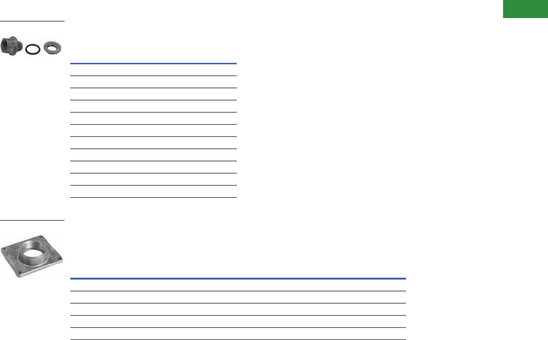
Myers Type Hubs
NEMA 3R (400A and above)
NEMA 4, 4X (stainless steel), 12
Plate Type Hubs
For NEMA 3R enclosures (up to 200A)
Catalog number DS900AP adapter kit
permits Installation of Group 1 hubs on
200A type general-duty, heavy-duty and
double-throw switches.
Contact the Flex Center at 1-888-329-9272 or
FlexSwitches@eaton.com for information on
hubs for non-metallic NEMA 4X switches.
Catalog Number Conduit Size
DS050MH 0.50 (12.7)
DS075MH 0.75 (19.1)
DS100MH 1.00 (25.4)
DS125MH 1.25 (31.8)
DS150MH 1.50 (38.1)
DS200MH 2.00 (50.8)
DS250MH 2.50 (63.5)
DS300MH 3.00 (76.2)
DS350MH 3.50 (88.9)
DS400MH 4.00 (101.6)
DS500MH 5.00 (127.0)
Group 1
General-Duty, Heavy-Duty,
Double-Throw Through 100A
Group 2
General-Duty, Heavy-Duty,
Double-Throw—200A
Catalog Number Conduit Size Catalog Number Conduit Size
DS075H1 0.75 (19.1) DS200H2 2.00 (50.8)
DS100H1 1.00 (25.4) DS250H2 2.50 (63.5)
DS125H1 1.25 (31.8) DS300H2 3.00 (76.2)
DS150H1 1.50 (38.1) ——
DS200H1 2.00 (50.8) ——
DS050MH
DS075H1

V2-T1-16 Volume 2—Commercial Distribution CA08100003E—April 2014 www.eaton.com
1
1
1
1
1
1
1
1
1
1
1
1
1
1
1
1
1
1
1
1
1
1
1
1
1
1
1
1
1
1
1.1
Switching Devices
Safety Switches
Modifications—Flex Center
Introduction
The Safety Switch Flex
Center is a special facility
at the site of our Cleveland,
Tennessee, plant that is
dedicated to providing
customized safety switches
that meet customer’s
challenging applications.
Eaton’s Flex Center is
a solutions center that
provides real value:
●A dedicated and
knowledgeable
engineering/
manufacturing/customer
service team to meet
your needs
●A production facility
stocked with a full arsenal
of equipment to get the
job done
●The industry’s shortest
lead-time
●Easy ordering through
our distributors
Description Suffix Item
Nameplates NP 1
Fungus proofing FP 2
Special paint 3
Lock-on provisions on
heavy-duty safety
switches for most
enclosure types
LO 4
Trapped key interlock
systems
TK 5
Upper cover viewing
window
W6
Lower cover viewing
window
LW 7
Neutral assemblies
factory installed for
double-throw safety
switches
N8
Class “R” fuse clips
factory installed for
heavy-duty switches
5 or 6 9
Class “T” fuse clips
factory installed for
heavy-duty switches
T10
Class “J” fuse clips
factory installed for
heavy-duty and double-
throw safety switches
J11
Fuse pullers factory
installed
FE 12
Special crimp lug pads
factory installed for
general-duty and heavy-
duty switches
CK 13
Copper lugs factory
installed
CL 14
Equipment ground lugs
factory installed
G15
Custom lug
configurations
L16
Auxiliary contacts
factory installed
2 or 3 17
Control pole factory
installed
CP 18
Switching neutral
double-throw
SN 19
Neutral assemblies
factory installed for
single-throw non-fusible
safety switches
N20
How to order 21
How to price 22
1. Nameplates
Price covers up to three
lines of text with a maximum
of 25 characters per line.
Standard nameplates are
laser-engraved plastic and
have black letters on a white
background. Rotary-engraved
phenolic nameplates are
also available at a premium.
Additional color combinations
and larger nameplates are
available. Contact the
Flex Center for price and
availability for these special
requirements. Customer
must specify the text when
placing an order.
Item 1
2. Fungus Proofing
All non-metallic components
of the switch are coated
with a moisture and fungus-
resistant varnish. The
inhibitor used meets military
specification: MIL-V-173C for
MOISTURE AND FUNGUS-
RESISTANT TREATMENT.
The treated switch meets
military specification:
MIL-T-152E for MOISTURE
AND FUNGUS-RESISTANT
TREATMENT OF
COMMUNICATIONS,
ELECTRONICS AND
ASSOCIATED EQUIPMENT.
Not UL listed.
Item 2
To order, add Suffix FP
to standard safety switch
catalog number. Example:
DH363FGKFP.
3. Special Paint
Special paint colors are
available for order quantities
of five or more switches.
Colors available are red,
orange, yellow, green, black
and white. Custom color is
applied over the standard
ANSI-61 gray finish.
Minimum quantity of five of
the same color is required.
Order by description. For
quantities less than five,
higher ampere ratings,
or other color request,
contact the Safety Switch
Flex Center.
Item 3
4. Lock-On Provisions
on Heavy-Duty Safety
Switches for Most
Enclosure Types
Available on 30–800A heavy-
duty and double-throw safety
switches.
Provision will
accept a single lock.
To order, add Suffix LO to
the standard catalog number.
Example: DH362FRKLO.
Description
Plastic nameplate—up to three lines
Phenolic nameplate—up to three lines
Ampere Rating
30
60
100
200
400
600
800
1200
Ampere Rating
30
60
100
200
400
600

Volume 2—Commercial Distribution CA08100003E—April 2014 www.eaton.com V2-T1-17
1
1
1
1
1
1
1
1
1
1
1
1
1
1
1
1
1
1
1
1
1
1
1
1
1
1
1
1
1
1
1.1
Switching Devices
Safety Switches
5. Trapped Key
Interlock Systems
Available only on heavy-duty
and double-throw safety
switches. Trapped key
systems are used on
safety switches to prevent
unauthorized operations
or to predetermine a series
of power transfers by an
authorized operator.
Before system construction
can begin, the following
information must be provided
to the Flex Center:
●User—name, address and
telephone number
●Complete coordination
(lock scheme) required
with order
To order, add Suffix TK to
the standard catalog number.
Example: DH363FWKTK.
Item 5
6. Upper Cover
Viewing Window
Upper viewing window is
centered over the switching
contacts to provide visual
verification of ON/OFF status.
Available on most heavy-duty
NEMA 4X stainless steel and
NEMA 12/3R and double-
throw enclosures. Not
available on non-metallic
enclosures. To order, add
Suffix W to the standard
catalog number.
Note: 30–100A window switches
are now provided with a full
view cover window for blade
verification and blown
fuse indication.
7. Lower Cover
Viewing Window
Lower viewing window is
positioned over fuses and
provides visual verification
of blown fuse indicators
for Littelfuse, Inc.™ fuses.
Available in 200–600A, two-
and three-pole heavy-duty
NEMA 4X stainless steel and
NEMA 12/3R enclosures.
Not available on nonmetallic
enclosures. To order, add
Suffix LW to standard
catalog number.
Note: 30–100A window switches
are now provided with a full
view cover window for blade
verification and blown
fuse indication.
Items 6 and 7
Contact the Safety Switch
Flex Center for lead-time.
8. Neutral Assemblies
Factory Installed for Double-
Throw Safety Switches
Item 8
To order, add Suffix N on
non-fusible switches OR
replace 6th character F with N
on fusible switches. The total
price is the standard switch
price plus the price adder.
Example 1: DT361URKN
non-fusible double-throw,
three-pole, 30A switch
with factory-installed
neutral assembly.
Example 2: DT363NRK
fusible double-throw,
three-pole, 100A switch
with factory-installed
neutral assembly.
Ampere
Rating
Switch
Type
30–1200 Heavy-duty
30–800 Double-throw
Viewing Window (Upper or Lower)
Ampere Rating
30–200
400–800
Ampere
Rating
Switch Type
Two- and Three-Pole
30 Fusible and non-fusible
60 Fusible and non-fusible
100 Fusible and non-fusible
200 Fusible and non-fusible
400 Non-fusible
600 Non-fusible
400 Fusible
600 Fusible
800 Non-fusible
9. Class “R” Fuse Clips
Factory Installed for
Heavy-Duty Switches
Item 9
To order, add Suffix 5 to
the standard catalog number
for 240V application.
Add Suffix 6 to standard
catalog number for 600V
application. Total price is
the standard catalog number
price plus the price adder
from the table above
depending on the number
of safety switch poles.
Example: DH324FRK5 heavy-
duty, three-pole, 200A switch
at 240V with factory-installed
Class “R” fuse clips.
10. Class “T” Fuse Clips
Factory Installed for
Heavy-Duty Switches
Item 10
To order, add Suffix T to
the standard catalog number
(catalog number identifies
voltage). Total price is the
standard catalog number
price plus the price adder
depending on the number
of safety switch poles.
Example: DH364FGKT heavy-
duty, three-pole, 200A fusible
switch at 480V with factory-
installed Class “T” Fuse Clips.
11. Class “J” Fuse Clips
Factory Installed for
Heavy-Duty and Double-
Throw Safety Switches
Item 11
Total price is the standard
catalog number price plus
the price adder from the
table above depending on
the number of safety poles.
Order by description. A table
of common 30A heavy-duty
switches with “J” fuse clips
factory installed is shown on
Page V2-T1-18 (field
modification kits are not
available for 30A heavy-
duty switches).
Ampere
Rating Voltage
30 240 and 600
60 240 and 600
100 240 and 600
200 240 and 600
400 240 and 600
600 240 and 600
Ampere
Rating Voltage
200 240
600
400 240
600
600 240
600
800 240
600
1200 240
600
Ampere
Rating Voltage
Switch
Type
30 240 Heavy-duty and
double-throw
600 Heavy-duty and
double-throw
60 240 Heavy-duty and
double-throw
600 Heavy-duty and
double-throw
100 240 Heavy-duty and
double-throw
600 Heavy-duty and
double-throw
200 240 Heavy-duty and
double-throw
600 Heavy-duty and
double-throw
400 600 Double-throw
600 240 Heavy-duty
600 Heavy-duty

V2-T1-18 Volume 2—Commercial Distribution CA08100003E—April 2014 www.eaton.com
1
1
1
1
1
1
1
1
1
1
1
1
1
1
1
1
1
1
1
1
1
1
1
1
1
1
1
1
1
1
1.1
Switching Devices
Safety Switches
Common 30A Heavy-Duty
Switches with “J” Fuse
Clips Factory Installed
To order, add Suffix J to
the standard catalog number
(catalog number identifies
voltage). Total price is the
standard catalog number
price plus the price adder
depending on the number
of safety switch poles.
Example: DH363FGKJ heavy-
duty, three-pole, 200A fusible
switch at 480V with factory-
installed Class “J” fuse clips.
12. Fuse Pullers
Factory Installed
Item 12
To order, add Suffix FE to
the standard catalog number.
Example: DH361FRKFE.
Note: Standard NEMA 12/3R,
4 and 4X switches through
200A are supplied with fuse
pullers from the factory.
13. Special Crimp Lug
Pads Factory Installed for
General-Duty and Heavy-
Duty Switches (Crimp
Lugs are Not Included)
To order add Suffix CK
to the standard safety
switch catalog number.
Item 13
Heavy-duty Type DH
switches, 30–200A are
adaptable to crimp lugs,
simply remove the box lugs.
14. Copper Lugs
Factory Installed
Item 14
To order, add Suffix CL to the
standard safety switch catalog
number. The total price is the
standard switch price plus the
price adder.
Example: DH221FGKCL
heavy-duty, two-pole, 30A
fusible switch at 240V with
copper lugs factory installed.
15. Equipment Ground Lugs
Factory Installed for
General-Duty and Heavy-
Duty Switches
Item 15
To order, add Suffix G to the
standard Safety Switch Catalog
Number. The total price is the
standard switch price plus the
price adder.
Voltage
Switch Type
Three-Pole
Catalog
Number
240 NEMA 1 DH321FGKJ
NEMA 3R DH321FRKJ
NEMA 12 DH321FDKJ
NEMA 4X DH321FWKJ
600 NEMA 1 DH361FGKJ
NEMA 3R DH361FRKJ
NEMA 12 DH361FDKJ
NEMA 4X DH361FWKJ
Ampere
Rating
Switch
Type
30–60 Heavy-duty
100 Heavy-duty
200 General-duty and heavy-duty
Ampere Rating
400–600
800
Ampere
Rating
Switch
Type
30 Heavy-duty
Double-throw
60 Heavy-duty
Double-throw
100 Heavy-duty
Double-throw
200 Heavy-duty
400 General-duty and heavy-duty
600 General-duty and heavy-duty
Ampere Rating
30–100
200
400–1200
16. Custom Lug
Configurations
Customer-specified lug
arrangements are available on
heavy-duty and double-throw
safety switches. Contact the
Safety Switch Flex Center for
price and lead-time.
17. Auxiliary Contacts
Factory Installed Provide
Early-Make/Early-Break
Operation
Item 17
To order 1NO/1NC
contacts, add Suffix 2
to the standard safety
switch catalog number.
To order 2NO/2NC
contacts, add Suffix 3
to the standard safety
switch catalog number.
The total price is the
standard switch price plus the
price adder.
Example: DH423FGK2
Heavy-duty, four-pole, 100A
fusible switch at 240V with
factory-installed 1NO/1NC
contacts.
Example: DT324FGK22
double-throw, three-pole,
200A fusible switch at 240V
with two factory-installed
contacts (one installed in
the normal ON position and
one installed in the auxiliary
ON position).
18. Control Pole Factory
Installed Provides
Late-Make/Early-Break
Operation
The K-Series control pole
provides one normally open
contact, late-make, early-
break operation. It mounts in
the exact location as the
neutral block using the same
pre-drilled holes. This is
directly connected to the
power pole operating shaft.
Direct connection and visible
blades provide more secure
electrical interlocking than
handle linkage operation of a
snap/switch type interlock.
This reliability meets the
requirements of many
specifications for four-pole
switches when the fourth
pole is required for secure
electrical interlocking.
Item 18
To order, add Suffix CP to
the standard safety switch
catalog number. The total price
is the standard switch price
plus the price adder.
Example: DH267FGKCP
heavy-duty, two-pole, 800A
fusible switch at 480V with
factory-installed control pole.
General-Duty Switches 200–600A,
Non-Metallic 30–200A,
Heavy-Duty 30–1200A
and
Double-Throw Switches 30–800A
Ampere
Rating Description
30–200 1NO/1NC
2NO/2NC
400–1200 1NO/1NC
2NO/2NC
Ampere
Rating
Switch
Type
30–1200 Heavy-duty
30–200 Double-throw
400–600 General-duty

Volume 2—Commercial Distribution CA08100003E—April 2014 www.eaton.com V2-T1-19
1
1
1
1
1
1
1
1
1
1
1
1
1
1
1
1
1
1
1
1
1
1
1
1
1
1
1
1
1
1
1.1
Switching Devices
Safety Switches
19. Switching Neutral
Double-Throw
UL listed for three-pole and
four-pole non-fusible double-
throw safety switches.
Switching neutrals are
required for separately
derived systems when
bonding the neutral of the
generator to a grounding
system at the generator.
Item 19
To order, add Suffix SN to
the standard safety switch
catalog number. The total
price is the standard switch
price plus the price adder.
Example: DT324URKSN
non-fusible double-throw,
three-pole, 200A switch
with factory-installed
switching neutral.
20. Neutral Assemblies
Factory Installed for
Single-Throw Non-Fusible
Safety Switches
Available on 200–600A
general-duty safety switches
and 30–1200A heavy-duty
safety switches.
Item 20
To order, add Suffix N to
the standard safety switch
catalog number.
Example: DH364UWKN
Heavy-duty, three-pole, 200A,
NEMA 4X.
21. How to Order
Step One: Contact the Safety
Switch Flex Center for price
and delivery on product being
modified. An authorized
negotiation (TSP) number
will be provided to track
your order.
Safety Switch Flex Center
Phone: 1-888-329-9272 or
FlexSwitches@eaton.com
Fax: 1-423-478-0270
Step Two: Enter the order on
VISTALINE™ by description
(with catalog number if it
applies) and reference the
authorized negotiation
(TSP) number.
Vista suffix will be “ETS.”
Product code will be “BE90.”
For order entry assistance,
contact CSC at:
Phone: 1-800-356-1243
Fax: 1-800-752-8602
22. How to Price
Step One: Select catalog
number from Pages V2-T1-
14 through V2-T1-83 of this
catalog or Vista of the switch
that needs to be modified.
Step Two: Use the correct
price (from Vista or the
current Price and Availability
Digest) of the switch that
needs to be modified. If no
price exists, Flex Center will
provide one.
Step Three: Refer to the
modification on Pages V2-T1-
16 through V2-T1-19 for price
additions.
Example: DT363URK
Options: factory installed
Neutral (N)
Copper lugs (CL)
(3 x 120.00)
Step Four: Contact the
Safety Switch Flex Center
for authorized price and
lead-time.
Note: Existing DSP, CSP and DOP
pricing does not apply.
For application, availability or
pricing questions, contact the
Safety Switch Flex Center at
1-888-329-9272 or
FlexSwitches@eaton.com.
Additional Safety Switch Flex
Center Design Offerings
●Left-hand design
(30–200A)
●Cover-mounted status
lights and selector
switches
●Integrated:
●Transient Voltage Surge
Suppression (TVSS)
●Current transformers
●Double-throw
receptacle switches
●200% neutrals
●Seam-welded
stainless steel
●Gang-operated kits:
●Mechanically interlocks
two or three separate
switches
●Cam-Lok® and Posi-Lok®
receptacles
●Reverse feed
●Integrated wattmeter
●Custom enclosures
●Double-throw switches
with windows
●316 grade stainless steel
●Breather/drains
●Voltage/phase monitor
Literature
The Safety Switch Flex
Center’s innovative approach
to flexible engineering,
manufacturing and customer
service provides the shortest
production, design and
delivery cycle in the industry.
Find out more about how the
Safety Switch Flex Center
can give you the safety
switch solution you
need...when you
need them.
Order Sales Aid SA00801002E
from Eaton’s Literature
Fulfillment Center by calling
1-800-957-7050.
Ampere Rating
30–200
400
600
800
Ampere Rating
30–60
100
200 NEMA 4, 4X, 12
200 NEMA 1, 3R
400
600
800
1200

V2-T1-20 Volume 2—Commercial Distribution CA08100003E—April 2014 www.eaton.com
1
1
1
1
1
1
1
1
1
1
1
1
1
1
1
1
1
1
1
1
1
1
1
1
1
1
1
1
1
1
1.1
Switching Devices
Safety Switches
Technical Data and Specifications
Standard Lug Capacities
Notes
1Single barrel lug that accepts one or two cables per phase as detailed above.
2The maximum size aluminum or copper-clad aluminum wire allowable for applications where the conductor enters
or leaves the enclosure through the wall opposite its terminal is #1 gauge.
3Double barrel lug that accepts two cables per phase as detailed above.
Although certain lug capacities are larger than required, only minimum wire bending space is provided per the
requirements noted in NEC® Tables 373.6 (a) and (b) for respective ampere ratings.
A factory-installed ground lug is supplied on all NEMA 4, 4X and 12 safety switches, as well as all 400A and higher NEMA 1 and 3R safety switches.
A factory-installed ground lug is also supplied on all heavy-duty NEMA 1 and 3R 30–200A switches that do NOT have a factory-installed neutral.
Description
Minimum
Wire Size
Maximum
Wire Size Wire Type
30A DP #14
#12
#10
#10
Cu or 1
Al
30A DG #14 #6 Cu/Al
30A DH, DT #14 #2 Cu/Al
60A DG #14 #1/0 Cu/Al
60A DH, DT #14 #2 Cu/Al
100A DG 2#14 #1/0 Cu/Al
100A DH, DT #14 #1/0 Cu/Al
200A DG, DT #6 250 kcmil Cu/Al
200A DH Type 1 and 3R #6 250 kcmil Cu/Al
200A DH Type 4 and 12 #6 300 kcmil Cu/Al
400A DG, DH, DT (2) #1/0
(1) #1/0
(2) 300 kcmil
(1) 750 kcmil
Cu/Al or 1
Cu/Al
600A DG, DH, fusible DT (1) #2
(1) #1/0
(1) 600 kcmil
(1) 750 kcmil
Cu/Al and 3
Cu/Al
600A non-fusible DT (2) #250 (2) 500 kcmil Cu/Al
800A DH (4) #1/0 (4) 750 kcmil Cu/Al
800A DT (3) #250 (3) 500 kcmil Cu/Al
1200A DH, DT (4) #1/0 (4) 750 kcmil Cu/Al
Copper-Bodied Lugs
30A Cu #14 #6 Cu
60A Cu #14 #4 Cu
100A Cu #6 #1/0 Cu
200A Cu #6 250 kcmil Cu
400A Cu #1/0 500 kcmil Cu
600–800A Cu (2) #1/0 (2) 500 kcmil Cu

Volume 2—Commercial Distribution CA08100003E—April 2014 www.eaton.com V2-T1-21
1
1
1
1
1
1
1
1
1
1
1
1
1
1
1
1
1
1
1
1
1
1
1
1
1
1
1
1
1
1
1.1
Switching Devices
Safety Switches
General-Duty
Short-Circuit Ratings Using Class “R”, “J” or “T” Fusing
Where Applicable 1
Shunt Trip Safety Switch
Short-Circuit Ratings Using Class “R,” “J/L” or “T” Fusing 2
Heavy-Duty
Short-Circuit Ratings Using Class “R,” “J” or “T” Fusing
Where Applicable 1
Double Throw
Short-Circuit Ratings Using Class “R,” “J” or “T” Fusing
where Applicable 45678
Notes
1Class “H” fuse clips supplied as standard for 30–600A. Rated at 10,000A rms symmetrical
when using Class “H” fuses.
2Non-fusible values are based on combination rating with upstream device
(see TD00801005E).
3Class “L” fuse connectors supplied as standard for 800A and 1200A.
4Class “H” fuse clips supplied as standard for 30–600A, except Class “T” for 400A at 600V
and 600A at 240V. Rated at 10,000A rms symmetrical when using Class “H” fuses.
5Class “L” fuse connectors supplied as standard for 800A and 1200A.
6Safety switch short-circuit ratings are applicable to AC only.
7Safety switch I2t and Ip values are identical to UL maximum acceptable I2t and Ip values for
the corresponding class fuse.
8Table above is not applicable to the compact design shown on Page V2-T1-47. The compact
design is suitable for use on a circuit capable of delivering not more than 10,000 rms
symmetrical amperes.
Ampere
Rating
Short-Circuit Ratings (Amperes)
Type 1 Type 3R
30 100k at 240V 100k at 240V
60 100k at 240V 100k at 240V
100 100k at 240V 100k at 240V
200 100k at 240V 100k at 240V
400 100k at 250V 100k at 250V
600 100k at 250V 100k at 250V
Ampere
Rating 480V 600V
30 200 kAIC 200 kAIC
60 200 kAIC 200 kAIC
100 200 kAIC 200 kAIC
200 200 kAIC 100 kAIC
400 200 kAIC 100 kAIC
600 200 kAIC 100 kAIC
800 200 kAIC 200 kAIC
Ampere
Rating
Short-Circuit Ratings (Amperes)
Type 1 Type 3R Type 12 Type 4 and 4X
30 200k at 600V 200k at 600V 200k at 600V 200k at 600V
60 200k at 600V 200k at 600V 200k at 600V 200k at 600V
100 200k at 480V
100k at 600V
200k at 480V
100k at 600V
200k at 600V 200k at 600V
200 200k at 600V 200k at 600V 200k at 600V 200k at 600V
400 200k at 480V
100k at 600V
200k at 480V
100k at 600V
200k at 480V
100k at 600V
200k at 480V
100k at 600V
600 200k at 480V
100k at 600V
200k at 480V
100k at 600V
200k at 480V
100k at 600V
200k at 480V
100k at 600V
800 3200k at 480V
100k at 600V
200k at 480V
100k at 600V
200k at 480V
100k at 600V
200k at 480V
100k at 600V
1200 3200k at 600V 200k at 600V 200k at 600V 200k at 600V
Ampere
Rating
Short-Circuit Ratings (Amperes) (600V)
Type 1 Type 3R Type 12 Type 4 and 4X
30 100k 100k 100k 100k
60 100k 100k 100k 100k
100 100k 100k 100k 100k
200 100k 100k 100k 100k
400 100k 100k 100k 100k
600 100k 100k 100k 100k
800 100k 100k — —
1200 100k 100k — —

V2-T1-22 Volume 2—Commercial Distribution CA08100003E—April 2014 www.eaton.com
1
1
1
1
1
1
1
1
1
1
1
1
1
1
1
1
1
1
1
1
1
1
1
1
1
1
1
1
1
1
1.1
Switching Devices
Safety Switches
Short-Circuit Ratings of Non-Fusible Switches
The UL listed short-circuit
ratings for Eaton non-fusible
switches are based on the
switches being properly
protected by overcurrent
protective devices. For
applications that require a UL
listed short-circuit rating of
10,000 rms symmetrical
amperes or less, an Eaton
non-fusible switch must be
properly protected by any
overcurrent protective device
rated no greater than the
ampere rating of the switch.
For applications that require a
UL listed short-circuit rating
of greater than 10,000 rms
symmetrical amperes, an
Eaton non-fusible switch
must be properly protected
by the appropriate class and
size fusing noted. Otherwise,
this non-fusible switch must
be replaced with an Eaton
fusible switch that uses the
appropriate fusing required.
Molded-case circuit breaker
protection of non-fusible
Eaton switches for
applications that require a
short-circuit rating of greater
than 10,000 rms symmetrical
amperes has been evaluated
and is summarized below.
Refer to the reference tables
for typical Eaton fusible
switch UL listed short-circuit
ratings.
UL Recognized Safety Switch/Circuit Breaker
Series-Connected Ratings
Safety
Switch
Ampere
Rating
Maximum
System
Voltage AC
Circuit Breaker
Maximum
Short-Circuit
Rating (rms
Symmetrical)
Circuit Breaker
Frame(s)
30 and
60
600 25,000
18,000
14,000
FDC, HFD, HFDE, EGH
FD, EGE
FDB
100 600 25,000
18,000
14,000
FDC, HFD, HFDE, EGH
FD, EGE
FDB
480 35,000 EGH, EGS
200 600 25,000
18,000
14,000
FDC, HFD, HFDE, HJD, JGH
FD, JD, JGE
FDB
480 65,000 HFD, HFDE, HJD, JGH
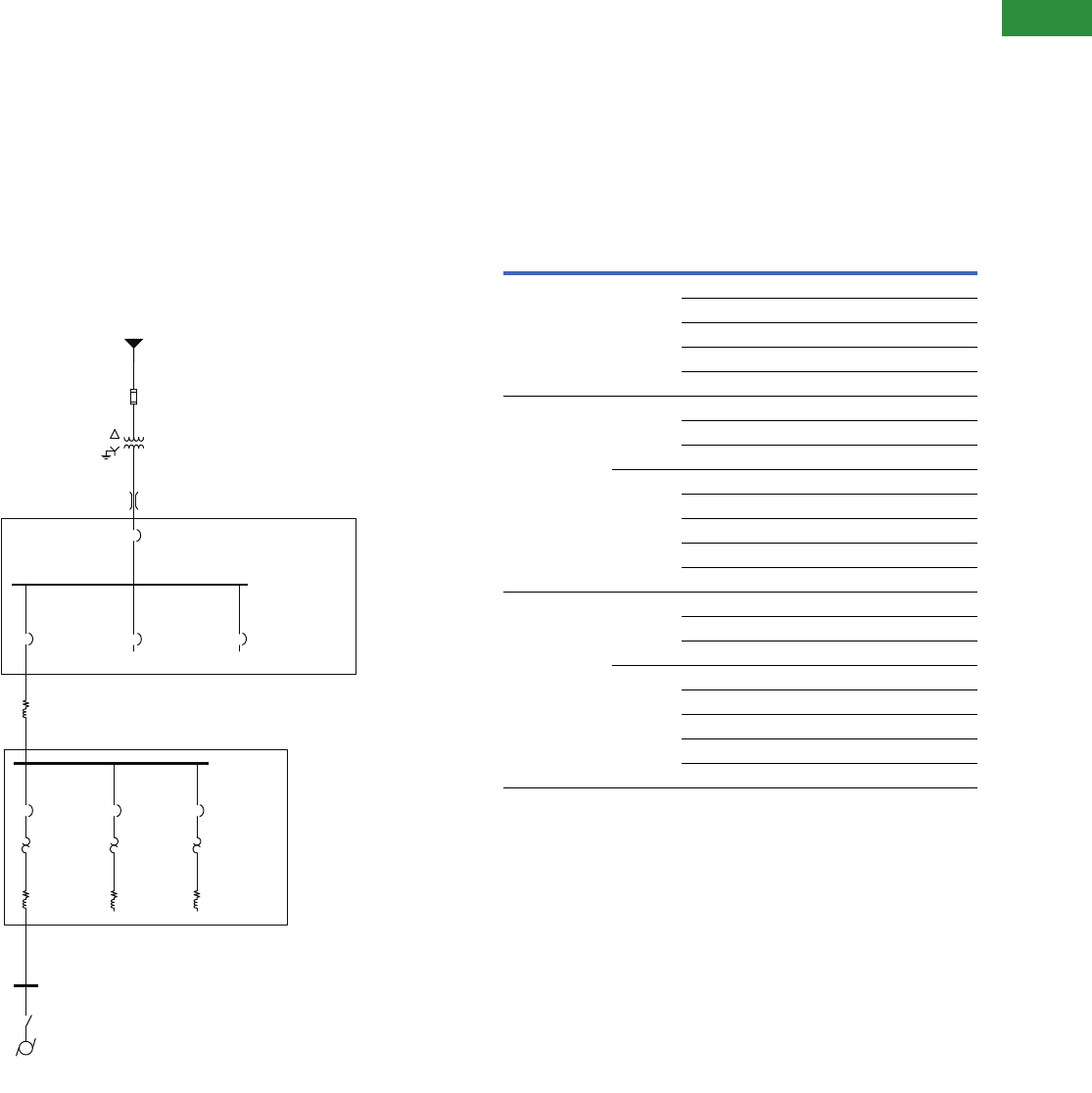
Volume 2—Commercial Distribution CA08100003E—April 2014 www.eaton.com V2-T1-23
1
1
1
1
1
1
1
1
1
1
1
1
1
1
1
1
1
1
1
1
1
1
1
1
1
1
1
1
1
1
1.1
Switching Devices
Safety Switches
Product Enhancement
Eaton non-fusible safety
switches, per table below,
within the noted ampere
ratings, now carry series
combination short-circuit
ratings as shown when
combined with the identified
MCCB or fuse type. With this
listed rating, the safety
switch shown in the one-line
diagram, can be correctly
applied when the motor
feeder Eaton HMCP circuit
breaker is replaced with an
Eaton molded-case circuit
breaker properly sized for the
motor hp rating. This is a
significant enhancement to
the product’s performance
rating. To achieve these
ratings, the switches have
been tested in combination
with all of the overcurrent
devices shown. Furthermore,
the applicable combination
ratings are marked on the
inside of the switch door,
ensuring inspector approval.
One-Line Diagram
Transformer Fused Switch
Overload Fuse Links, 15.5 kV
125A
S
PPower Transformer
2500 kVA 12,470/
480V 5.75% Z
Bus Duct–0001
1–#3200, 5 ft
Utility 12,470V
SC 3P 100 MVA
Main Switchgear
Eaton Magnum DS,
DT 520
3000A/3000A
MCC3 FDR
Magnum DS,
DT 520
800A/800A
MCC1 FDR
Magnum DS,
DT 520
800A/800A
Cable–0001
2–#500, 35 ft
MCC1
480V
32.91 kA
MTR FDR
HMCP
MTR O/L
Class 20
Cable–0002
1–#4, 50 ft
Motor Disconnect
480V
13.5 kA
Motor
50 hp
MCC2 FDR
Magnum DS,
DT 520
800A/800A
MTR FDR
HMCP
MTR O/L
Class 20
MTR FDR
HMCP
MTR O/L
Class 20
LV Motor Control Center
LV Switchgear
Main
Switchgear
480V
36.66 kA
Information and Application
The circuit breaker or fuse
rating is not to exceed the
ampere rating of the non-
fusible switch. When used on
systems with greater than
10 kA short-circuit rating
available, the UL Listed short-
circuit rating of the non-
fusible switch is based upon
the switch being used in
combination with fuses or
molded-case circuit breakers
identified in the table below.
Non-Fusible Safety Switches
Notes
1For use on NEMA 1, 3R, 12/3R and 4X switches.
2Fuse or circuit breaker rating is not to exceed switch rating.
3NEMA 12, 4/4X only. NEMA 1, 3R are 100 kAIC at 600 Vac.
Eaton Non-Fusible
Safety Switch
Ampere Rating 1
Maximum
System
Voltage AC
Maximum
Short-Circuit
Rating
Upstream Device 2
Fuse Class Breaker Frame
30 and 60 600 10,000 H, K Any circuit breaker
14,000 FDB
18,000 FD, EGE
25,000 FDC, HFD, HFDE, EGH
200,000 R, T, J, L
100 480 10,000 H, K Any circuit breaker
35,000 EGH, EGS
200,000 R, T, J, L
600 10,000 H, K Any circuit breaker
14,000 FDB
18,000 FD, EGE
25,000 FDC, HFD, HFDE, EGH
200,000 3R, T, J, L
200 480 10,000 H, K Any circuit breaker
65,000 HFD, HFDE, HJD, JGH
200,000 R, T, J, L
600 10,000 H, K Any circuit breaker
14,000 FDB
18,000 FD, JD, JGE
25,000 FDC, HFD, HFDE, HJD, JGH
200,000 R, T, J, L
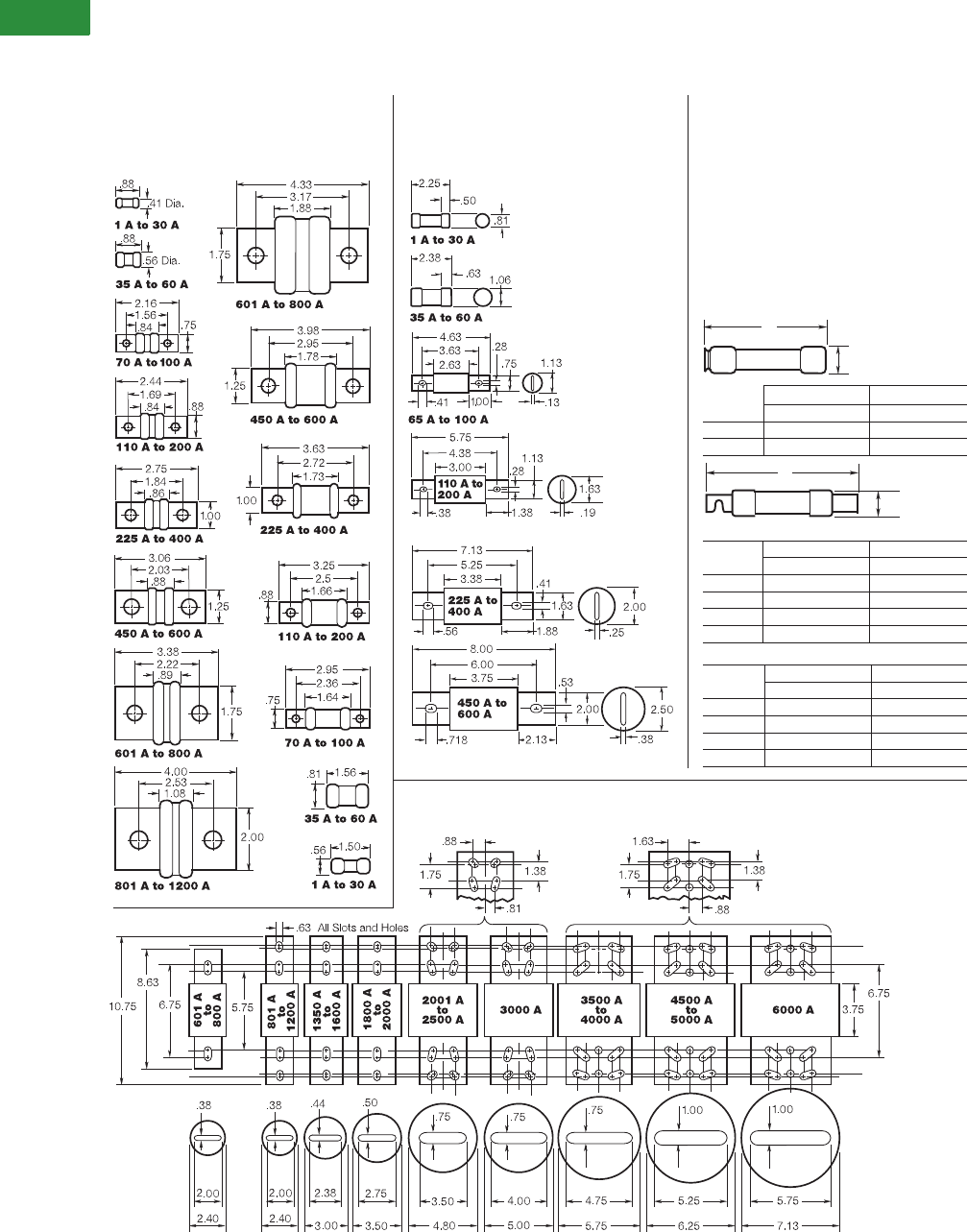
V2-T1-24 Volume 2—Commercial Distribution CA08100003E—April 2014 www.eaton.com
1
1
1
1
1
1
1
1
1
1
1
1
1
1
1
1
1
1
1
1
1
1
1
1
1
1
1
1
1
1
1.1
Switching Devices
Safety Switches
Dimensions
Typical Fuse Dimensions in Inches
Note: For typical fuse dimensions in millimeters, see Page V2-T1-25.
A
B
250V 600V
Ampere A B A B
1/10–30 2.00 0.56 5.00 0.81
35–60 3.00 0.81 5.50 1.06
250V 600V
Ampere A B A B
70–100 5.88 1.06 7.88 1.34
110–200 7.13 1.56 9.63 1.84
225–400 8.63 2.06 11.63 2.59
450–600 10.38 2.59 13.38 3.13
250V 600V
Ampere A B A B
110–200 7.13 1.66 9.63 1.66
225–400 8.63 2.38 11.63 2.38
450–600 10.38 2.88 13.38 2.88
A
B
T-Tron™ Fuses
JJN (300V) JJS (600V)
Class J Class RK5 and RK1, Class H
(Dimensions Apply)
Low-Peak
®
and Limitron
®
Fuses
LPJ & JKS (600V)
Class L
Low-Peak and Limitron Fuses
KRP-C, KTU & KLU (601–4000A) (600V)
Note: KRP-CL (150–600A) fuses
have same dimensions as 601–800A
case size. KTU (200–600A) have
same dimensions, except tube
3-inch lgth. x 2-inch dia.; terminal
1.63-inch width x 1.25-inch thick.
Class T
Fusetron
®
, Low-Peak and
Limitron Fuses (250 and 600V)
FRN-R and FRS-R; LPN-RK
and LPS-RK; KTN-R and KTS-R
Basic dimensions are same as Class H
(formerly NEC) ONE-TIME (NON and NOS)
and SUPERLAG Renewable RES and
REN fuses.
Note: These fuses can be used to replace
existing Class H, RK1 and RK5 fuses relating
to dimensional compatibility.
70–100 5.88 1.16 7.88 1.16
Low-Peak
Fusetron and Limitron
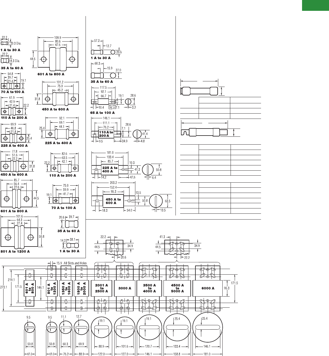
Volume 2—Commercial Distribution CA08100003E—April 2014 www.eaton.com V2-T1-25
1
1
1
1
1
1
1
1
1
1
1
1
1
1
1
1
1
1
1
1
1
1
1
1
1
1
1
1
1
1
1.1
Switching Devices
Safety Switches
Typical Fuse Dimensions in Millimeters
A
B
T-Tron Fuses
JJN (300V) JJS (600V)
Class J
Low-Peak and Limitron Fuses
LPJ and JKS (600V)
Class L
Low-Peak and Limitron Fuses
KRP-C, KTU and KLU (601–4000A) (600V)
Note: KRP-CL (150–600A) fuses
have same dimensions as 601–800A
case size. KTU (200–600A) have
samedimensions, except tube
76.2 mm lgth. x 50.8 mm dia.; terminal
41.3 mm width x 31.8 mm thick.
250V 600V
Ampere A B A B
1/10–30 50.8 14.3 127.0 20.6
35–60 76.2 20.6 139.7 27.0
250V 600V
Ampere A B A B
70–100 149.2 26.9 200.0 34.0
110–200 181.0 39.6 244.5 46.7
225–400 219.1 52.3 295.3 65.8
450–600 263.5 65.8 339.7 79.5
250V 600V
Ampere A B A B
70–100 149.2 29.5 200.0 29.5
110–200 181.0 42.2 244.5 42.2
225–400 219.1 60.5 295.3 60.5
450–600 263.5 73.2 339.7 73.2
A
B
Class T
Fusetron, Low-Peak and
Limitron Fuses (250 and 600V)
FRN-R and FRS-R; LPN-RK
and LPS-RK; KTN-R and KTS-R
Basic dimensions are same as Class H
(formerly NEC) ONE-TIME (NON and NOS)
and SUPERLAG Renewable RES and REN fuses.
Note: These fuses can be used to replace
existing Class H, RK1 and RK5 fuses relating
to dimensional compatibility.
Fusetron and Limitron
Low-Peak
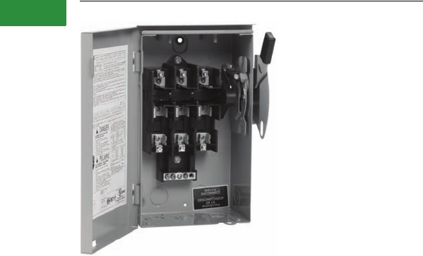
V2-T1-26 Volume 2—Commercial Distribution CA08100003E—April 2014 www.eaton.com
1
1
1
1
1
1
1
1
1
1
1
1
1
1
1
1
1
1
1
1
1
1
1
1
1
1
1
1
1
1
1.1
Switching Devices
Safety Switches
Cartridge Fuse General-Duty Safety Switch
Contents
Description Page
Product Overview . . . . . . . . . . . . . . . . . . . . . . . . . . . . V2-T1-3
General Duty. . . . . . . . . . . . . . . . . . . . . . . . . . . . . . . . V2-T1-26
Standards and Certifications . . . . . . . . . . . . . . . . . V2-T1-27
Product Selection . . . . . . . . . . . . . . . . . . . . . . . . . V2-T1-28
Dimensions . . . . . . . . . . . . . . . . . . . . . . . . . . . . . . V2-T1-30
Heavy-Duty . . . . . . . . . . . . . . . . . . . . . . . . . . . . . . . . . V2-T1-31
Six-Pole Switches . . . . . . . . . . . . . . . . . . . . . . . . . . . . V2-T1-43
Double-Throw Switches . . . . . . . . . . . . . . . . . . . . . . . V2-T1-45
EnviroLine—Stainless Steel Switch . . . . . . . . . . . . . . V2-T1-53
EnviroLine—Upper and Lower Window Switches . . . V2-T1-56
EnviroLine—Receptacle Switches . . . . . . . . . . . . . . . V2-T1-59
EnviroLine—Non-Metallic KRYDON Switch . . . . . . . . V2-T1-61
NEMA 7/9—Hazardous Location Disconnect Switch . V2-T1-63
Quick Connect Switches. . . . . . . . . . . . . . . . . . . . . . . V2-T1-65
Solar Disconnect Switch . . . . . . . . . . . . . . . . . . . . . . . V2-T1-67
Solar Combiner Box—Source Combiner and
Array Combiner . . . . . . . . . . . . . . . . . . . . . . . . . . . . V2-T1-69
316-Grade Stainless Steel Safety Switches . . . . . . . . V2-T1-72
Mill-Duty Rated, Heavy-Duty, Fusible, Non-Fusible,
Single-Throw. . . . . . . . . . . . . . . . . . . . . . . . . . . . . . . V2-T1-76
Heavy-Duty Fusible Safety Switches Accepting
Cube Fuses . . . . . . . . . . . . . . . . . . . . . . . . . . . . . . . . .
V2-T1-78
Elevator Control Switch. . . . . . . . . . . . . . . . . . . . . . . . V2-T1-81
Auxiliary Power Heavy-Duty Safety Switch. . . . . . . . . V2-T1-83
Left-Handed Safety Switch . . . . . . . . . . . . . . . . . . . . . V2-T1-86
200% Neutral Safety Switches. . . . . . . . . . . . . . . . . . V2-T1-87
Pringle Bolted Pressure Switch. . . . . . . . . . . . . . . . . . V2-T1-88
Type DS, Fusible and Non-Fusible. . . . . . . . . . . . . . . . V2-T1-91
Type Visi-Flex DE-ION . . . . . . . . . . . . . . . . . . . . . . . . . V2-T1-94
Flange Mounted—Variable Depth. . . . . . . . . . . . . . . . V2-T1-98
Flange Mounted—Fixed Depth. . . . . . . . . . . . . . . . . . V2-T1-102
General Duty
Product Description
●30–600A
●Suitable for service
entrance applications
unless otherwise noted
●Fusible and non-fusible
switches are 100% load
break and 100% load
make rated
●The continuous load
current of fusible switches
is not to exceed 80%
of the rating of fuses
employed in other than
motor circuits. Non-fusible
switches are 100%
fully rated
●200–600A features
K-Series design
●Horsepower rated
●Fusible and non-fusible
switches. Single-pole
S/N through four-wire;
120/240, and 240 Vac
●With Class R fuses,
switches may be
used
on systems capable of
delivering
100,000A rms
symmetrical
Note: Plug fuse switches are not
service entrance rated.
●
Bolt-on hub provision.
Provided for general-duty
switches in a NEMA 3R
enclosure. See
Page
V2-T1-
15
for selection
Application Description
For residential and
commercial applications.
Suitable for light-duty motor
circuits and service entrance.
Features, Benefits and Functions
General-Duty (Cartridge Fuse)
●Ample wire bending
space provides for
easier installation
●Visible double-break quick-
make, quick-break rotary
blade mechanism
●Side opening door on
all enclosures
●Mechanically interlocked
cover to prevent easy
access when the switch
is in the ON position
●With Class R fuses,
switches may be used
on systems capable of
delivering 100,000A rms
symmetrical
●Clearly visible and
accessible neutral
where applicable
●Visible ON/OFF indication
●Tangential knockouts on
30–60A designs
●Ample wiring space
●Double padlocking
capability on 30–100A
●Triple padlocking capability
on 200–600A
●Additional door locking
capability
●Bilingual English/Spanish
door label on 30–100A
●Tri-lingual nameplates

Volume 2—Commercial Distribution CA08100003E—April 2014 www.eaton.com V2-T1-27
1
1
1
1
1
1
1
1
1
1
1
1
1
1
1
1
1
1
1
1
1
1
1
1
1
1
1
1
1
1
1.1
Switching Devices
Safety Switches
All general-duty switches
above 100A and all heavy-
duty switches incorporate
these K-Series switch
design features.
●Two points of contact
provide a positive
open and close, easier
operation, and also help
prevent contact burning
for longer contact life
Visible Double-Break Rotary
Blade Mechanism
●Protects against accidental
contact with energized
parts. Probe holes enable
the user to test if the line
side is energized without
removing the shield.
Not typically provided
on general-duty switches,
but available as a field kit
or factory installed
Clear Line Shield
●Provide easy removal
of fuses
Built-In Fuse Pullers (NEMA 12
and 4X 30–200A Only)
Clearly Visible Handle
●The position (ON or OFF)
can be clearly seen from
a distance and the length
provides for easy operation
Triple Padlocking Capability
●Personnel safety feature
because the large hasp can
accommodate up to
three 3/8-inch (9.5 mm)
shank locks
Additional Locking Capability
●Cabinet door can be further
padlocked at the top and
bottom as applicable
Interlocking Mechanism
●Door cannot be opened
when the handle is in the
ON position. Front and
side operable defeater
mechanism provides
for user access when
necessary on single-
throw switches
Tangential Knockouts
●An ample number are
provided on the top,
bottom and sides of both
NEMA Types 1 and 3R
enclosures through 200A
Bolt-On Hub Kits
●For switches in a NEMA
Type 3R, 30–200A. Use
a Myers type hub for
all others
Standards and Certifications
●UL listed File No. E5239
●Meets UL 98 for enclosed
switches and NEMA Std.
KS-1
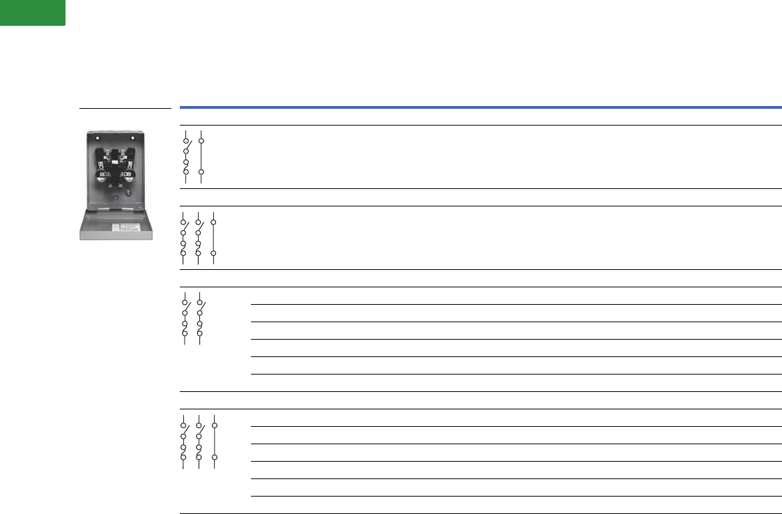
V2-T1-28 Volume 2—Commercial Distribution CA08100003E—April 2014 www.eaton.com
1
1
1
1
1
1
1
1
1
1
1
1
1
1
1
1
1
1
1
1
1
1
1
1
1
1
1
1
1
1
1.1
Switching Devices
Safety Switches
Product Selection
120/240 Vac General-Duty, Fusible, Single-Throw
Notes
1 Maximum hp ratings apply only when dual element time delay fuses are used.
2 These switches do not have an interlock that prevents door from being opened when switch is in the ON position.
3 Use three-wire catalog numbers below.
4 Solid neutral bars are not included. Order separately from table on Page V2-T1-14.
5 WARNING! Switch is not approved for service entrance unless a neutral kit is installed.
6 Grounded B phase rating, UL listed.
All general-duty safety switches are individually packaged.
Accessories are limited in scope on general-duty safety switches. See Page V2-T1-14 for availability. In addition, clear line shields are available as an accessory
on 200–600A general-duty switches. Catalog Numbers: 200A = 70-7759-11, 400A = 70-8063-8, 600A = 70-8064-8.
System
Ampere
Rating
Fuse Type
Provision
Maximum Horsepower Ratings 1
NEMA 1
Enclosure Indoor
Catalog Number
NEMA 3R
Enclosure Rainproof
Catalog Number
Single-Phase AC Three-Phase AC DC
120V 240V 240V 250V
Plug Type—Two-Wire (One Blade, One Fuse, S/N)—120 Vac 2
30 Plug
(Type S,
T or W)
1/2–2 — — — DP111NGB 2—
Plug Type—Three-Wire (Two Blades, Two Fuses, S/N)—120/240 Vac
30 Plug
(Type S,
T or W)
1/2–2 1-1/2–3 — — DP221NGB 2Use cartridge-type
fuse catalog number
DG221NRB 2
Cartridge Type—Two-Pole Two-Wire (Two Blades, Two Fuses)—240 Vac
30 — — 1-1/2–3 3–7-1/2 — 33
60 — — 3–10 7-1/2–15 — 33
100 — — 7-1/2–15 15–30 — 33
200 H — 15 25–60 — DG224FGK 45 DG224FRK 45
400 H — — 50–125 — DG225FGK 45 DG225FRK 45
600 H — — 75–200 — DG226FGK 45 DG226FRK 45
Cartridge Type—Three-Wire (Two Blades, Two Fuses, S/N)—120/240 Vac
30 H — 1-1/2–3 3–7-1/2 6—DG221NGB 2DG221NRB 2
60 H — 3–10 7-1/2–15 6—DG222NGB 2DG222NRB 2
100 H — 7-1/2–15 15–30 6—DG223NGB 2DG223NRB 2
200 H — 15 25–60 6—DG224NGK DG224NRK
400 H — — 50–125 650 DG225NGK DG225NRK
600 H — — 75–200 6—DG226NGK DG226NRK
DP221NGB
S/N
S/N
S/N
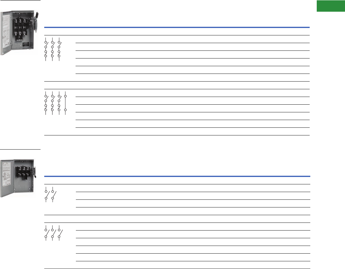
Volume 2—Commercial Distribution CA08100003E—April 2014 www.eaton.com V2-T1-29
1
1
1
1
1
1
1
1
1
1
1
1
1
1
1
1
1
1
1
1
1
1
1
1
1
1
1
1
1
1
1.1
Switching Devices
Safety Switches
120/240 Vac General-Duty, Fusible, Single-Throw, continued
120/240 Vac General-Duty, Non-Fusible, Single-Throw
Notes
1 Maximum hp ratings apply only when dual element time delay fuses are used.
2 Use four-wire catalog numbers below.
3 Solid neutral bars are not included. Order separately from table on Page V2-T1-14.
4 WARNING! Switch is not approved for service entrance unless a neutral kit is installed.
5 These switches do not have an interlock that prevents door from being opened when switch is in the ON position.
6 Use three-wire catalog numbers below.
7 Drilled to accept field installed neutral kits.
All general-duty safety switches are individually packaged.
Accessories are limited in scope on general-duty safety switches. See Page V2-T1-14 for availability. In addition, clear line shields are available as an accessory
on 200–600A general-duty switches. Catalog Numbers: 200A = 70-7759-11, 400A = 70-8063-8, 600A = 70-8064-8.
System
Ampere
Rating
Fuse Type
Provision
Maximum Horsepower Ratings 1
NEMA 1
Enclosure Indoor
Catalog Number
NEMA 3R
Enclosure Rainproof
Catalog Number
Single-Phase AC Three-Phase AC DC
120V 240V 240V 250V
Cartridge Type—Three-Pole, Three-Wire (Three Blades, Three Fuses)—240 Vac
30 — — — — — 22
60 — — — — — 22
100 — — — — — 22
200 H — 15 25–60 — DG324FGK 34 2
400 H — — 50–125 — DG325FGK 34 DG325FRK 34
600 H — — 75–200 — DG326FGK 34 DG326FRK 34
Cartridge Type—Four-Wire (Three Blades, Three Fuses, S/N)—120/240 Vac
30 H — 1-1/2–3 3–7-1/2 — DG321NGB 5DG321NRB 5
60 H — 3–10 7-1/2–15 — DG322NGB 5DG322NRB 5
100 H — 7-1/2–15 15–30 — DG323NGB 5DG323NRB 5
200 H — 15 25–60 — DG324NGK DG324NRK
400 H — — 50–125 — DG325NGK DG325NRK
600 H — — 75–200 — DG326NGK DG326NRK
System
Ampere
Rating
Maximum Horsepower Ratings NEMA 1
Enclosure Indoor
Catalog Number
NEMA 3R
Enclosure Rainproof
Catalog Number
Single-Phase AC Three-Phase AC DC
120V 240V 240V 250V
Two-Pole, Two-Wire (Two Blades)—240 Vac
30 2 3 — — DG221UGB 45 DG221URB 45
60 3 10 — — DG222UGB 45 DG222URB 45
100 — 15 — — DG223UGB 45 DG223URB 45
200 — 15 — — 46 DG224URK 4
Three-Pole, Three-Wire (Three Blades)—240 Vac
30 2 3 7-1/2 — DG321UGB 45 DG321URB 45
60 3 10 15 — DG322UGB 45 DG322URB 45
100 — 15 30 — DG323UGB 45 DG323URB 45
200 — 15 60 — DG324UGK 4DG324URK 4
400 — — 125 — DG325UGK 7DG325URK 7
600 — — 200 — DG326UGK 7DG326URK 7
DG321NRB
S/N
DG322URB
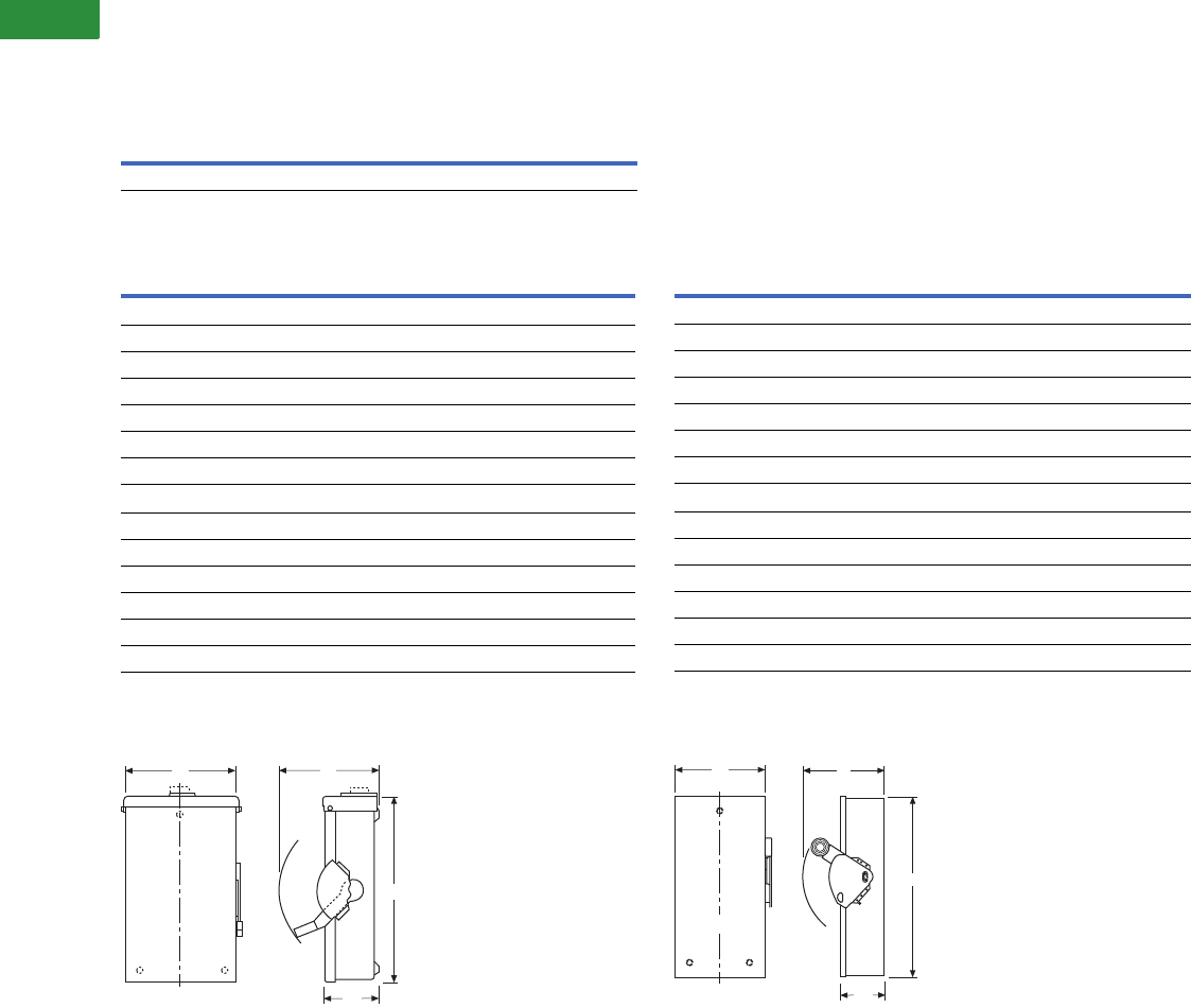
V2-T1-30 Volume 2—Commercial Distribution CA08100003E—April 2014 www.eaton.com
1
1
1
1
1
1
1
1
1
1
1
1
1
1
1
1
1
1
1
1
1
1
1
1
1
1
1
1
1
1
1.1
Switching Devices
Safety Switches
Dimensions
Approximate Dimensions in Inches (mm)
Plug Fuse, 120, 120/240V, Single-, Two-Pole Solid Neutral,
Single-Throw
General-Duty, Non-Fusible, 240V, Three-Pole, Single-Throw 1
NEMA 1-3R 30–100A General-Duty
Non-Fusible and Fusible Single-Throw 2
General-Duty, Fusible, 240V, Three-Pole Solid Neutral,
Single-Throw 1
NEMA 1-3R 200–600A General-Duty
Non-Fusible and Fusible Single-Throw
Notes
1Dimensions are for estimating purposes only.
2Figure is not applicable to plug fuse.
Ampere
Rating
NEMA 1
Height Width Depth
30 6.88 (174.8) 4.94 (125.5) 3.44 (87.4)
Ampere
Rating Width (W) Height (H) Depth (D) Depth (D2)
Weight
Lbs (kg)
NEMA 1
30 6.38 (162.1) 10.69 (271.5) 6.88 (174.8) 3.75 (95.2) 6 (2.724)
60 8.69 (220.7) 14.19 (360.4) 7.38 (187.5) 4.21 (106.9) 9 (4.086)
100 9.13 (231.9) 18.81 (477.8) 7.38 (187.5) 4.23 (107.4) 12 (5.448)
200 16.00 (406.4) 24.75 (628.7) 11.25 (285.8) 6.14 (156.0) 48 (21.792)
400 23.00 (584.2) 44.75 (1136.7) 12.63 (320.8) 7.27 (184.7) 100 (45.4)
600 24.00 (609.6) 52.25 (1327.2) 14.25 (362.0) 8.95 (227.3) 130 (59.02)
NEMA 3R
30 6.38 (162.1) 10.81 (274.6) 6.88 (174.8) 3.75 (95.2) 6 (2.724)
60 8.69 (220.7) 14.38 (365.3) 7.38 (187.5) 4.21 (106.9) 9 (4.086)
100 9.13 (231.9) 19.25 (489.0) 7.38 (187.5) 4.23 (107.4) 12 (5.448)
200 16.00 (406.4) 25.50 (647.7) 11.25 (285.8) 6.14 (156.0) 55 (24.97)
400 23.00 (584.2) 45.19 (1147.8) 12.63 (320.8) 7.27 (184.7) 105 (47.67)
600 24.00 (609.6) 52.70 (1338.6) 14.25 (362.0) 8.95 (227.3) 135 (61.29)
H
WD
D2
Ampere
Rating Width (W) Height (H) Depth (D) Depth (D2)
Weight
Lbs (kg)
NEMA 1
30 6.38 (162.1) 10.69 (271.5) 6.88 (174.8) 3.75 (95.2) 6 (2.724)
60 8.69 (220.7) 14.19 (360.4) 7.38 (187.5) 4.21 (106.9) 10 (4.54)
100 9.13 (231.9) 18.81 (477.8) 7.38 (187.5) 4.23 (107.4) 14 (6.356)
200 16.00 (406.4) 24.75 (628.7) 11.25 (285.8) 6.14 (156.0) 48 (21.792)
400 23.00 (584.2) 44.75 (1136.7) 12.63 (320.8) 7.27 (184.7) 110 (49.94)
600 24.00 (609.6) 52.25 (1327.2) 14.25 (362.0) 8.95 (227.3) 145 (65.83)
NEMA 3R
30 6.38 (162.1) 10.81 (274.6) 6.88 (174.8) 3.75 (95.2) 6 (2.724)
60 8.69 (220.7) 14.38 (365.3) 7.38 (187.5) 4.21 (106.9) 10 (4.54)
100 9.13 (231.9) 19.25 (489.0) 7.38 (187.5) 4.23 (107.4) 14 (6.356)
200 16.00 (406.4) 25.50 (647.7) 11.25 (285.8) 6.14 (156.0) 55 (24.97)
400 23.00 (584.2) 45.19 (1147.8) 12.63 (320.8) 7.27 (184.7) 115 (52.21)
600 24.00 (609.6) 52.70 (1338.6) 14.25 (362.0) 8.95 (227.3) 150 (68.1)
W
H
C
L
D2
D
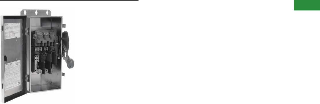
Volume 2—Commercial Distribution CA08100003E—April 2014 www.eaton.com V2-T1-31
1
1
1
1
1
1
1
1
1
1
1
1
1
1
1
1
1
1
1
1
1
1
1
1
1
1
1
1
1
1
1.1
Switching Devices
Safety Switches
Heavy-Duty Safety Switch
Contents
Description Page
Product Overview . . . . . . . . . . . . . . . . . . . . . . . . . . . . V2-T1-3
General Duty . . . . . . . . . . . . . . . . . . . . . . . . . . . . . . . . V2-T1-26
Heavy-Duty
Standards and Certifications . . . . . . . . . . . . . . . . . V2-T1-32
Product Selection. . . . . . . . . . . . . . . . . . . . . . . . . . V2-T1-33
Dimensions . . . . . . . . . . . . . . . . . . . . . . . . . . . . . . V2-T1-42
Six-Pole Switches. . . . . . . . . . . . . . . . . . . . . . . . . . . . . V2-T1-43
Double-Throw Switches . . . . . . . . . . . . . . . . . . . . . . . V2-T1-45
EnviroLine—Stainless Steel Switch. . . . . . . . . . . . . . . V2-T1-53
EnviroLine—Upper and Lower Window Switches. . . . V2-T1-56
EnviroLine—Receptacle Switches. . . . . . . . . . . . . . . . V2-T1-59
EnviroLine—Non-Metallic KRYDON Switch . . . . . . . . V2-T1-61
NEMA 7/9—Hazardous Location Disconnect Switch . V2-T1-63
Quick Connect Switches . . . . . . . . . . . . . . . . . . . . . . . V2-T1-65
Solar Disconnect Switch . . . . . . . . . . . . . . . . . . . . . . . V2-T1-67
Solar Combiner Box—Source Combiner and
Array Combiner. . . . . . . . . . . . . . . . . . . . . . . . . . . . . V2-T1-69
316-Grade Stainless Steel Safety Switches. . . . . . . . . V2-T1-72
Mill-Duty Rated, Heavy-Duty, Fusible, Non-Fusible,
Single-Throw . . . . . . . . . . . . . . . . . . . . . . . . . . . . . . . V2-T1-76
Heavy-Duty Fusible Safety Switches Accepting
Cube Fuses . . . . . . . . . . . . . . . . . . . . . . . . . . . . . . . .
V2-T1-78
Elevator Control Switch . . . . . . . . . . . . . . . . . . . . . . . . V2-T1-81
Auxiliary Power Heavy-Duty Safety Switch . . . . . . . . . V2-T1-83
Left-Handed Safety Switch . . . . . . . . . . . . . . . . . . . . . V2-T1-86
200% Neutral Safety Switches . . . . . . . . . . . . . . . . . . V2-T1-87
Pringle Bolted Pressure Switch . . . . . . . . . . . . . . . . . . V2-T1-88
Type DS, Fusible and Non-Fusible . . . . . . . . . . . . . . . . V2-T1-91
Type Visi-Flex DE-ION . . . . . . . . . . . . . . . . . . . . . . . . . V2-T1-94
Flange Mounted—Variable Depth . . . . . . . . . . . . . . . . V2-T1-98
Flange Mounted—Fixed Depth . . . . . . . . . . . . . . . . . . V2-T1-102
Heavy-Duty
Product Description
●30–1200A
●600 Vac, 600 Vdc
maximum
●Horsepower rated
●Fusible and non-fusible
switches are 100% load
break and 100% load
make rated
●The continuous load
current of fusible switches
is not to exceed 80%
of the rating of fuses
employed in other than
motor circuits. Non-fusible
switches are 100%
fully rated
●Suitable for service
entrance applications
unless otherwise noted
●For factory modifications,
refer to Pages V2-T1-16
through V2-T1-19
Application Description
For heavy commercial and
industrial applications where
reliable performance and
service continuity are critical.
For the toughest heavy
commercial and industrial
applications, refer to
Page V2-T1-76 for catalog
information on our
mill-duty safety switch
Features, Benefits and Functions
●Deionizing arc chutes;
arc chutes confine and
suppress the arcs
produced by opening
contacts under load
●Mechanically interlocked
cover to prevent easy
access when the switch
is in the ON position
●Clearly visible palm fitting
red handle
●Complete accessory and
renewal parts data shown
on inner door label.
●30–800A NEMA 12
designs convertible to
NEMA 3R by opening
factory-installed drain hole
●30–1200A switches are
seismic qualified and
exceed the requirements
of the Uniform Building
Code® (UBC) and California
Code Title 24
●Tri-lingual nameplates
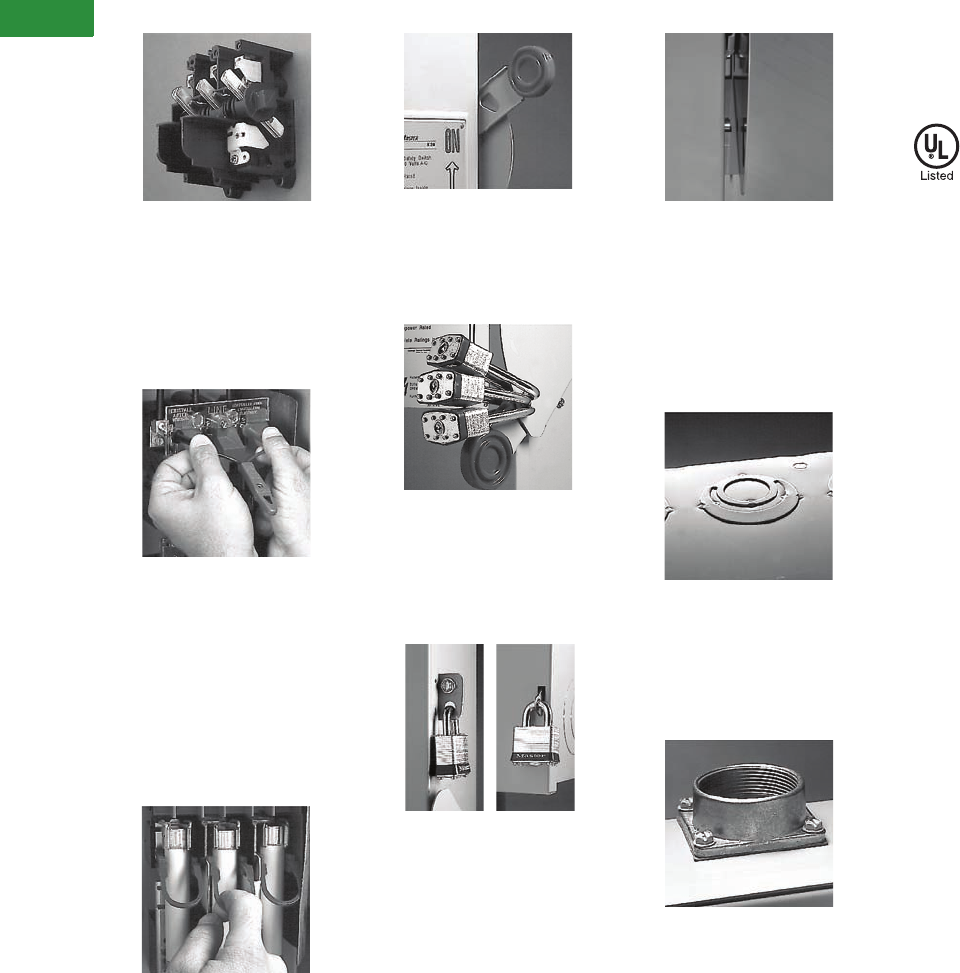
V2-T1-32 Volume 2—Commercial Distribution CA08100003E—April 2014 www.eaton.com
1
1
1
1
1
1
1
1
1
1
1
1
1
1
1
1
1
1
1
1
1
1
1
1
1
1
1
1
1
1
1.1
Switching Devices
Safety Switches
Visible Double-Break Rotary
Blade Mechanism
●Two points of contact
provide a positive
open and close, easier
operation, and also help
prevent contact burning
for longer contact life
Clear Line Shield
●Protects against accidental
contact with energized
parts. Probe holes enable
the user to test if the line
side is energized without
removing the shield.
Not typically provided
on general-duty switches,
but available as a field kit
or factory installed
Built-In Fuse Pullers (NEMA 12
and 4X 30–200A Only)
●Provide easy removal
of fuses
Clearly Visible Handle
●The position (ON or OFF)
can be clearly seen from
a distance and the length
provides for easy operation
Triple Padlocking Capability
●Personnel safety feature
because the large hasp can
accommodate up to
three 3/8-inch (9.5 mm)
shank locks
Additional Locking Capability
●Cabinet door can be further
padlocked at the top and
bottom as applicable
Interlocking Mechanism
●Door cannot be opened
when the handle is in the
ON position. Front and
side operable defeater
mechanism provides
for user access when
necessary on single-
throw switches
Tangential Knockouts
●An ample number are
provided on the top,
bottom and sides of both
NEMA Types 1 and 3R
enclosures through 200A
Bolt-On Hub Kits
●For switches in a NEMA
Type 3R, 30–200A. Use
a Myers type hub for
all others
Standards and Certifications
●UL listed File No. E5239
●Meets UL 98 for enclosed
switches and NEMA
Std. KS-1
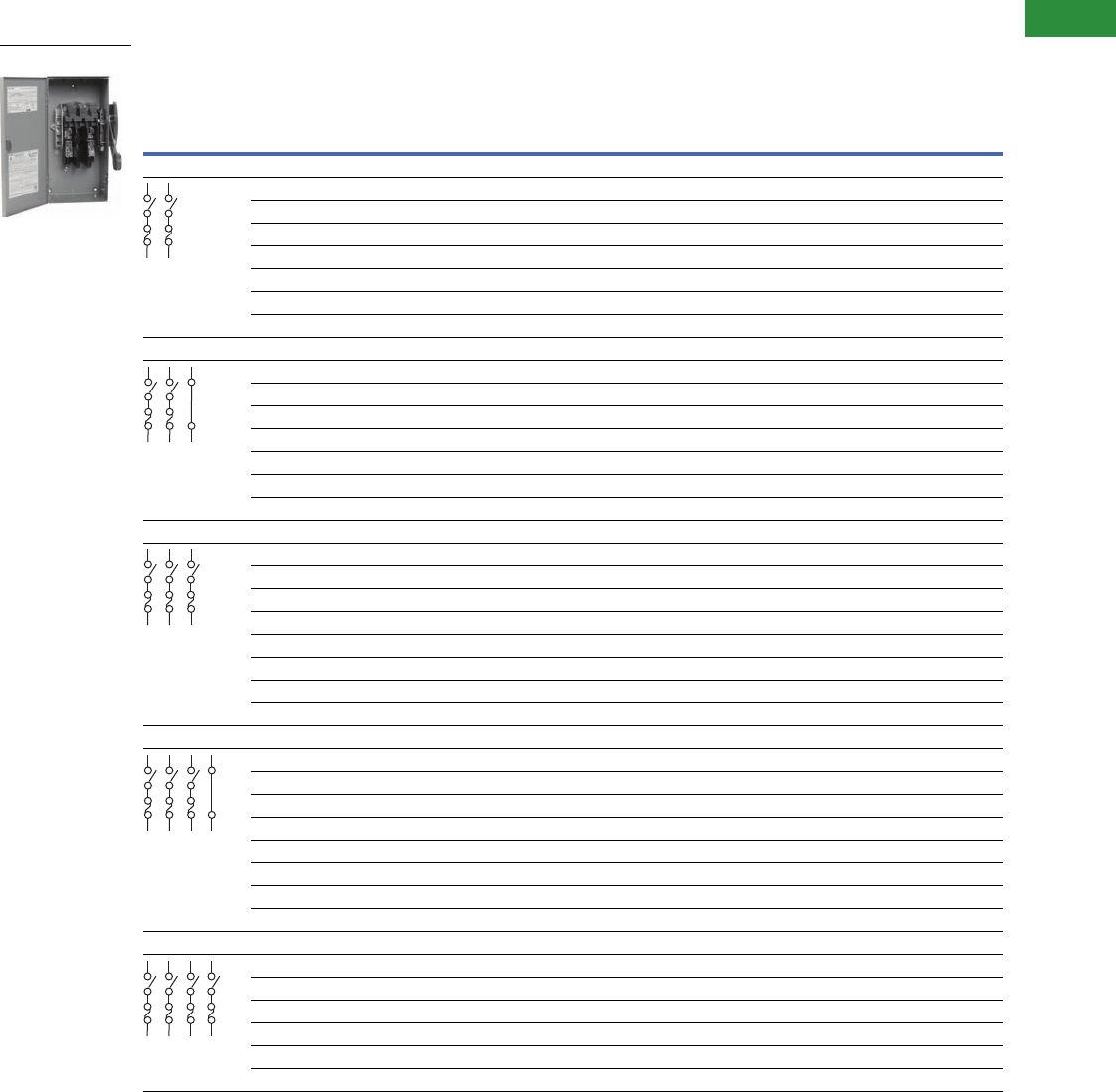
Volume 2—Commercial Distribution CA08100003E—April 2014 www.eaton.com V2-T1-33
1
1
1
1
1
1
1
1
1
1
1
1
1
1
1
1
1
1
1
1
1
1
1
1
1
1
1
1
1
1
1.1
Switching Devices
Safety Switches
Product Selection
240 Vac Heavy-Duty, Fusible, Single-Throw, Fusible—NEMA 1, 3R
Notes
1 Horsepower ratings apply only when neutral is field installed and switch is used on a grounded B phase system.
2 Use three-pole catalog numbers below.
3 Grounded B phase ratings, UL listed.
4 Use NEMA 12. NEMA 12 enclosures (30–1200A) can be field modified to meet NEMA 3R rainproof requirements when a factory provided drain hole is opened.
5 Contact the Safety Switch Flex Center (1-888-329-9272 or FlexSwitches@eaton.com) for availability of this product.
30A heavy-duty switches with Type J fuse provisions are available from the factory only. See table on Page V2-T1-18 for catalog numbers.
Suitable for service entrance use, except four-pole switches.
System
Ampere
Rating
Fuse Type
Provision
Maximum Horsepower Ratings NEMA 1
Enclosure
Indoor
Catalog
Number
NEMA 3R
Enclosure
Rainproof
Catalog
Number
AC
DC
250V
Standard Fuse Time Delay
Single-Phase Three-Phase Single-Phase Three-Phase
Two-Pole—240 Vac, 250 Vdc (Suitable for Service Entrance Use with a Neutral Kit Installed)
30 H 1-1/2 — — — 5 DH221FGK 2
60 — — — — — — 22
100 — — — — — — 22
200 — — — — — — 22
400 H — 50 1— 125 150 DH225FGK DH225FRK
600 H — 75 1— 200 1—DH226FGK DH226FRK
800 L — 100 1———DH227FGK —
Three-Wire (Two Blades, Two Fuses, S/N)—240 Vac, 250 Vdc
30 H 1-1/2 3 337-1/2
35DH221NGK DH221NRK
60 H 3 7-1/2 310 15 310 DH222NGK DH222NRK
100 H 7-1/2 15 315 30 320 DH223NGK DH223NRK
200 H 15 25 315 60 340 DH224NGK DH224NRK
400 H — 50 3— 125 350 DH225NGK DH225NRK
600 H — 75 3— 200 3—DH226NGK DH226NRK
800 L — 100 3———DH227NGK DH227NRK
Three-Pole—240 Vac, 250 Vdc (Suitable for Service Entrance Use with a Neutral Kit Installed)
30 H 1-1/2 3 3 7-1/2 5 DH321FGK DH321FRK
60 H 3 7-1/2 10 15 10 DH322FGK DH322FRK
100 H 7-1/2 15 15 30 20 DH323FGK DH323FRK
200 H 15 25 15 60 40 DH324FGK DH324FRK
400 H — 50 — 125 50 DH325FGK DH325FRK
600 H — 75 — 200 — DH326FGK DH326FRK
800 L — 100 — — — DH327FGK DH327FRK
1200 L — — — — — DH328FGK DH328FRK
Four-Wire (Three Blades, Three Fuses, S/N)—240 Vac, 250 Vdc
30 H 1-1/2 3 3 7-1/2 5 DH321NGK DH321NRK
60 H 3 7-1/2 10 15 10 DH322NGK DH322NRK
100 H 7-1/2 15 15 30 20 DH323NGK DH323NRK
200 H 15 25 15 60 40 DH324NGK DH324NRK
400 H — 50 — 125 50 DH325NGK DH325NRK
600 H — 75 — 200 — DH326NGK DH326NRK
800 L — 100 — — — DH327NGK DH327NRK
1200 L — — — — — DH328NGK DH328NRK
Four-Pole—240 Vac, 250 Vdc
30 H 3 3 10 7-1/2 5 DH421FGK 4
60 H 7-1/2 7-1/2 20 15 10 DH422FGK 4
100 H 15 15 30 30 20 DH423FGK 4
200 H 30 25 50 60 40 DH424FGK 4
400 H 50 50 — 125 50 DH425FGK 45
600 H — 75 — 200 — DH426FGK 45
DH221NRK
S/N
S/N

V2-T1-34 Volume 2—Commercial Distribution CA08100003E—April 2014 www.eaton.com
1
1
1
1
1
1
1
1
1
1
1
1
1
1
1
1
1
1
1
1
1
1
1
1
1
1
1
1
1
1
1.1
Switching Devices
Safety Switches
240 Vac Heavy-Duty, Fusible, Single-Throw, Fusible—NEMA 12, 4
Notes
1Horsepower ratings apply only when neutral is field installed and switch is used on a grounded B phase system.
2Grounded B phase ratings, UL listed.
3Use three-pole catalog numbers below.
4NEMA 12 enclosures (30–1200A) can be field modified to meet NEMA 3R rainproof requirements when a factory provided drain hole is opened.
5Contact the Safety Switch Flex Center (1-888-329-9272 or FlexSwitches@eaton.com) for availability of this product.
30A heavy-duty switches with Type J fuse provisions are available from the factory only. See table on Page V2-T1-18 for catalog numbers.
Suitable for service entrance use, except four-pole switches.
System
Ampere
Rating
Fuse Type
Provision
Maximum Horsepower Ratings NEMA 12
Enclosure
Industrial,
Dust-Tight
Catalog
Number
NEMA 4
Enclosure
Watertight,
Painted Steel
Catalog
Number
AC
DC
250V
Standard Fuse Time Delay
Single-Phase Three-Phase Single-Phase Three-Phase
Two-Pole—240 Vac, 250 Vdc (Suitable for Service Entrance Use with a Neutral Kit Installed)
30 H 1-1/2 — — — 5 3—
60 — — — — — — 3—
100 — — — — — — 3—
200 — — — — — — 3—
400 H — 50 1—125
150 DH225FDK 4DH225FPK
600 H — 75 1—200
1—DH226FDK 4DH226FPK
800 L — 100 1———DH227FDK 4—
Three-Wire (Two Blades, Two Fuses, S/N)—240 Vac, 250 Vdc
30 H 1-1/2 3 237-1/2
25DH221NDK 4—
60 H 3 7-1/2 210 15 210 DH222NDK 4—
100 H 7-1/2 15 215 30 220 DH223NDK 4—
200 H 15 25 215 60 240 DH224NDK 4—
400 H — 50 2—125
250 DH225NDK 4DH225NPK
600 H — 75 2—200
2—DH226NDK 4DH226NPK
800 L — 100 2———DH227NDK 4DH227NPK
Three-Pole—240 Vac, 250 Vdc (Suitable for Service Entrance Use with a Neutral Kit Installed)
30 H 1-1/2 3 3 7-1/2 5 DH321FDK 4—
60 H 3 7-1/2 10 15 10 DH322FDK 4—
100 H 7-1/2 15 15 30 20 DH323FDK 4—
200H1525156040DH324FDK 4—
400 H — 50 — 125 50 DH325FDK 4DH325FPK
600 H — 75 — 200 — DH326FDK 4DH326FPK
800 L — 100 — — — DH327FDK 4DH327FPK
1200L—————DH328FDK 4—
Four-Wire (Three Blades, Three Fuses, S/N)—240 Vac, 250 Vdc
30 H 1-1/2 3 3 7-1/2 5 DH321NDK 4—
60 H 3 7-1/2 10 15 10 DH322NDK 4—
100 H 7-1/2 15 15 30 20 DH323NDK 4—
200H1525156040DH324NDK 4—
400 H — 50 — 125 50 DH325NDK 4DH325NPK
600 H — 75 — 200 — DH326NDK 4DH326NPK
800 L — 100 — — — DH327NDK 45 —
1200L—————DH328NDK 4—
Four-Pole—240 Vac, 250 Vdc
30 H 3 3 10 7-1/2 5 DH421FDK 4—
60 H 7-1/2 7-1/2 20 15 10 DH422FDK 4—
100H1515303020DH423FDK 4—
200H3025506040DH424FDK 4—
400 H 50 50 — 125 50 45 —
600 H — 75 — 200 — 45 —
S/N
S/N
Volume 2—Commercial Distribution CA08100003E—April 2014 www.eaton.com V2-T1-35
1
1
1
1
1
1
1
1
1
1
1
1
1
1
1
1
1
1
1
1
1
1
1
1
1
1
1
1
1
1
1.1
Switching Devices
Safety Switches
240 Vac Heavy-Duty, Fusible, Single-Throw, Fusible—NEMA 4X
Notes
1 Horsepower ratings apply only when neutral is field installed and switch is used on a grounded B phase system.
2 Grounded B phase ratings, UL listed.
3 Use three-pole catalog numbers below.
4 Contact the Safety Switch Flex Center (1-888-329-9272 or FlexSwitches@eaton.com) for availability of this product.
30A heavy-duty switches with Type J fuse provisions are available from the factory only. See table on Page V2-T1-18 for catalog numbers.
Suitable for service entrance use, except four-pole switches.
System
Ampere
Rating
Fuse Type
Provision
Maximum Horsepower Ratings NEMA 4X
Enclosure
Corrosion-
Resistant,
Stainless Steel
Catalog
Number
AC
DC
250V
Standard Fuse Time Delay
Single-Phase Three-Phase Single-Phase Three-Phase
Two-Pole—240 Vac, 250 Vdc (Suitable for Service Entrance Use with a Neutral Kit Installed)
30H1-1/2—— —5
3
60—— —— ——
3 or 4
100—— —— ——
4
200—— —— ——
4
400 H — 50 1— 125 150 4
600 H — 75 1— 200 1—4
800 L — 100 1———
4
Three-Wire (Two Blades, Two Fuses, S/N)—240 Vac, 250 Vdc
30 H 1-1/2 3 237-1/2
25DH221NWK
60 H 3 7-1/2 210 15 210 DH222NWK
100 H 7-1/2 15 215 30 220 DH223NWK
200 H 15 25 215 60 240 DH224NWK
400 H — 50 2— 125 250 DH225NWK
600 H — 75 2— 200 2—DH226NWK
800 L — 100 2———DH227NWK
Three-Pole—240 Vac, 250 Vdc (Suitable for Service Entrance Use with a Neutral Kit Installed)
30 H 1-1/2 3 3 7-1/2 5 DH321FWK
60 H 3 7-1/2 10 15 10 DH322FWK
100 H 7-1/2 15 15 30 20 4
200 H 15 25 15 60 40 DH324FWK
400 H — 50 — 125 50 DH325FWK
600 H — 75 — 200 — DH326FWK
800 L — 100 — — — DH327FWK
1200 L — — — — — DH328FWK
Four-Wire (Three Blades, Three Fuses, S/N)—240 Vac, 250 Vdc
30 H 1-1/2 3 3 7-1/2 5 DH321NWK
60 H 3 7-1/2 10 15 10 DH322NWK
100 H 7-1/2 15 15 30 20 DH323NWK
200 H 15 25 15 60 40 DH324NWK
400 H — 50 — 125 50 DH325NWK
600 H — 75 — 200 — DH326NWK
800 L — 100 — — — 4
1200 L — — — — — DH328NWK
Four-Pole—240 Vac, 250 Vdc
30 H 3 3 10 7-1/2 5 4
60 H 7-1/2 7-1/2 20 15 10 4
100 H 15 15 30 30 20 4
200 H 30 25 50 60 40 4
400 H 50 50 — 125 50 4
600 H — 75 — 200 — 4
DH322FWK
S/N
S/N
V2-T1-36 Volume 2—Commercial Distribution CA08100003E—April 2014 www.eaton.com
1
1
1
1
1
1
1
1
1
1
1
1
1
1
1
1
1
1
1
1
1
1
1
1
1
1
1
1
1
1
1.1
Switching Devices
Safety Switches
600 Vac Heavy-Duty, Fusible, Single-Throw, 277/480–600V—NEMA 1, 3R
Notes
1 DC rating for 800A switches is 250V.
2 Contact the Safety Switch Flex Center (1-888-329-9272 or FlexSwitches@eaton.com) for availability of this product.
3 Ratings are for two-phase AC.
4 Use NEMA 12. NEMA 12 enclosures (30–1200A) can be field modified to meet NEMA 3R rainproof requirements when a factory provided drain hole is opened.
30A heavy-duty switches with Type J fuse provisions are available from the factory only. See table on Page V2-T1-18 for catalog numbers.
Suitable for service entrance use, except 1200A on 480Y/277 or 600Y/347 grounded wye systems, per NEC 215.10 and 230.95, and four-pole switches.
System
Ampere
Rating
Fuse Class
Provision
Maximum Horsepower Ratings with Time Delay Fuses NEMA 1
Enclosure
Indoor
Catalog Number
NEMA 3R
Enclosure
Rainproof
Catalog Number
Single-Phase AC Three-Phase AC DC
480V 600V 480V 600V 250V 600V
Two-Pole—480 Vac—600 Vac or Vdc 1 (Suitable for Service Entrance Use with a Neutral Kit Installed)
30 H 7-1/2 10 — — — 15 DH261FGK DH261FRK
60 H 2025———25DH262FGK DH262FRK
100 H 30 40 — — 20 25 DH263FGK DH263FRK
200 H 50 50 — — 40 50 DH264FGK DH264FRK
400 H ————50—DH265FGK DH265FRK
600 H ————50—DH266FGK DH266FRK
800 L ——————DH267FGK DH267FRK
1200 L — — — — — — 2—
Three-Pole—480 Vac—600 Vac, 250 Vdc (Suitable for Service Entrance Use with a Neutral Kit Installed)
30 H 7-1/2 10 15 20 — — DH361FGK DH361FRK
60 H 20253050——DH362FGK DH362FRK
100 H 30 40 60 75 — — DH363FGK DH363FRK
200 H 50 50 125 150 — — DH364FGK DH364FRK
400 H — — 250 350 — — DH365FGK DH365FRK
600 H — — 400 500 — — DH366FGK DH366FRK
800 L — — 500 500 — — DH367FGK DH367FRK
1200 L — — 500 500 — — DH368FGK DH368FRK
Four-Wire (Three Blades, Three Fuses, S/N) 480 Vac—600 Vac, 250 Vdc
30 H 7-1/2 10 15 20 — — DH361NGK DH361NRK
60 H 20253050——DH362NGK DH362NRK
100 H 30 40 60 75 — — DH363NGK DH363NRK
200 H 50 50 125 150 — — DH364NGK DH364NRK
400 H — — 250 350 — — DH365NGK DH365NRK
600 H — — 400 500 — — DH366NGK DH366NRK
800 L — — 500 500 — — DH367NGK DH367NRK
1200 L — — 500 500 — — DH368NGK DH368NRK
Four-Pole—480 Vac—600 Vac, 250 Vdc
30 H 20 325 315 20 — — DH461FGK 4
60 H 40 350 330 50 — — DH462FGK 4
100 H 50 350 360 75 — — DH463FGK 4
200 H — — 125 150 40 — DH464FGK 4
400 H — — 250 350 50 — DH465FGK 24
600 H — — 400 500 — — DH466FGK 24
800 L ——————
224
DH362NRK
S/N
Volume 2—Commercial Distribution CA08100003E—April 2014 www.eaton.com V2-T1-37
1
1
1
1
1
1
1
1
1
1
1
1
1
1
1
1
1
1
1
1
1
1
1
1
1
1
1
1
1
1
1.1
Switching Devices
Safety Switches
600 Vac Heavy-Duty, Fusible, Single-Throw, 277/480–600V—NEMA 12, 4
Notes
1 DC rating for 800A switches is 250V.
2 Use NEMA 12. NEMA 12 enclosures (30–1200A) can be field modified to meet NEMA 3R rainproof requirements when a factory provided drain hole is opened.
3 Contact the Safety Switch Flex Center (1-888-329-9272 or FlexSwitches@eaton.com) for availability of this product.
4 Use three-pole catalog numbers below for 600 Vac, 250 Vdc maximum applications.
5 Ratings are for two-phase AC.
30A heavy-duty switches with Type J fuse provisions are available from the factory only. See table on Page V2-T1-18 for catalog numbers.
Suitable for service entrance use, except 1200A on 480Y/277 or 600Y/347 grounded wye systems, per NEC 215.10 and 230.95, and four-pole switches.
System
Ampere
Rating
Fuse Class
Provision
Maximum Horsepower Ratings with Time Delay Fuses NEMA 12
Enclosure
Industrial,
Dust-Tight
Catalog Number
NEMA 4
Enclosure
Watertight,
Painted Steel
Catalog Number
Single-Phase AC Three-Phase AC DC
480V 600V 480V 600V 250V 600V
Two-Pole—480 Vac—600 Vac or Vdc 1 (Suitable for Service Entrance Use with a Neutral Kit Installed)
30 H 7-1/2 10 — — — 15 DH261FDK 2—
60 H 20 25 — — — 25 DH262FDK 2—
100 H 30 40 — — 20 — DH263FDK 2—
200 H 50 50 — — — 50 DH264FDK 2—
400 H — — ——50—DH265FDK 24
600 H — — ————DH266FDK 24
800 L — — ————DH267FDK 24
1200 L — — — — — — 3—
Three-Pole—480 Vac—600 Vac, 250 Vdc (Suitable for Service Entrance Use with a Neutral Kit Installed)
30 H 7-1/2 10 15 20 — — DH361FDK 2—
60 H 20 25 3050——DH362FDK 2—
100 H 30 40 60 75 — — DH363FDK 2—
200 H 50 50 125 150 — — DH364FDK 2—
400 H — — 250 350 — — DH365FDK 2DH365FPK
600 H — — 400 500 — — DH366FDK 2DH366FPK
800 L — — 500 500 — — DH367FDK 2DH367FPK
1200 L — — 500 500 — — DH368FDK —
Four-Wire (Three Blades, Three Fuses, S/N) 480 Vac—600 Vac, 250 Vdc
30 H 7-1/2 10 15 20 — — DH361NDK 2—
60 H 20 25 3050——DH362NDK 2—
100 H 30 40 60 75 — — DH363NDK 2—
200 H 50 50 125 150 — — DH364NDK 2—
400 H — — 250 350 — — DH365NDK 2DH365NPK
600 H — — 400 500 — — DH366NDK 2DH366NPK
800 L — — 500 500 — — 23 —
1200 L — — 500 500 — — DH368NDK —
Four-Pole—480 Vac—600 Vac, 250 Vdc
30 H 20 525 515 20 — — 23 —
60 H 40 550 530 50 — — 23 —
100 H 50 550 560 75 — — DH463FDK 2—
200 H — — 125 150 40 — DH464FDK 2—
400 H — — 250 350 50 — 23 —
600 H — — 400 500 — — 23 —
800 L — — ————
23 —
DH361NDK
S/N

V2-T1-38 Volume 2—Commercial Distribution CA08100003E—April 2014 www.eaton.com
1
1
1
1
1
1
1
1
1
1
1
1
1
1
1
1
1
1
1
1
1
1
1
1
1
1
1
1
1
1
1.1
Switching Devices
Safety Switches
600 Vac Heavy-Duty, Fusible, Single-Throw, 277/480–600V—NEMA 4X
Notes
1DC rating for 800A switches is 250V.
2Contact the Safety Switch Flex Center (1-888-329-9272 or FlexSwitches@eaton.com) for availability of this product.
3Use three-pole catalog numbers below for 600 Vac, 250 Vdc maximum applications.
4Ratings are for two-phase AC.
30A heavy-duty switches with Type J fuse provisions are available from the factory only. See table on Page V2-T1-18 for catalog numbers.
Suitable for service entrance use, except 1200A on 480Y/277 or 600Y/347 grounded wye systems, per NEC 215.10 and 230.95, and four-pole switches.
System
Ampere
Rating
Fuse Class
Provision
Maximum Horsepower Ratings with Time Delay Fuses NEMA 4X
Enclosure
Corrosion-
Resistant,
Stainless Steel
Catalog
Number
Single-Phase AC Three-Phase AC DC
480V 600V 480V 600V 250V 600V
Two-Pole—480 Vac—600 Vac or Vdc 1 (Suitable for Service Entrance Use with a Neutral Kit Installed)
30 H 7-1/2 10 — — — 15 DH261FWK
60 H 20 25 — — — 25 2 or 3
100 H 30 40 — — 20 — 2 or 3
200 H 50 50 — — — 50 DH264FWK
400 H — — — — 50 — 2 or 3
600 H — — — — — — 2 or 3
800 L — — — — — — 2 or 3
1200 L — — — — — — 3
Three-Pole—480 Vac—600 Vac, 250 Vdc (Suitable for Service Entrance Use with a Neutral Kit Installed)
30 H 7-1/2 10 15 20 — — DH361FWK
60 H 20253050——DH362FWK
100 H 30406075——DH363FWK
200 H 50 50 125 150 — — DH364FWK
400 H — — 250 350 — — DH365FWK
600 H — — 400 500 — — DH366FWK
800 L — — 500 500 — — DH367FWK
1200 L — — 500 500 — — DH368FWK
Four-Wire (Three Blades, Three Fuses, S/N) 480 Vac—600 Vac, 250 Vdc
30 H 7-1/2 10 15 20 — — DH361NWK
60 H 20253050——DH362NWK
100 H 30406075——DH363NWK
200 H 50 50 125 150 — — DH364NWK
400 H — — 250 350 — — DH365NWK
600 H — — 400 500 — — DH366NWK
800 L — — 500 500 — — DH367NWK 2
1200 L — — 500 500 — — DH368NWK
Four-Pole—480 Vac—600 Vac, 250 Vdc
30 H 20 425 415 20 — — 2
60 H 40 450 430 50 — — 2
100 H 50 450 460 75 — — 2
200 H — — 125 150 40 — 2
400 H — — 250 350 50 — 2
600 H — — 400 500 — — 2
800 L — — — — — — 2
S/N
Volume 2—Commercial Distribution CA08100003E—April 2014 www.eaton.com V2-T1-39
1
1
1
1
1
1
1
1
1
1
1
1
1
1
1
1
1
1
1
1
1
1
1
1
1
1
1
1
1
1
1.1
Switching Devices
Safety Switches
600 Vac Heavy-Duty, Non-Fusible, Single-Throw, 277/480–600V—NEMA 1, 3R
Notes
1 DC rating for 800A switches is 250V.
2 Contact the Safety Switch Flex Center (1-888-329-9272 or FlexSwitches@eaton.com) for availability of this product.
3 Ratings are for two-phase AC.
4 Use NEMA 12. NEMA 12 enclosures (30–1200A) can be field modified to meet NEMA 3R rainproof requirements when a factory provided drain hole is opened.
Suitable for service entrance use, except 1200A on 480Y/277 or 600Y/347 grounded wye systems, per NEC 215.10 and 230.95, and four-pole switches.
System
Ampere
Rating
Maximum Horsepower Ratings NEMA 1
Enclosure
Indoor
Catalog Number
NEMA 3R
Enclosure
Rainproof
Catalog Number
Single-Phase AC Three-Phase AC DC
240V 480V 600V 240V 480V 600V 250V 600V
Two-Pole—480 Vac—600 Vac or Vdc 1 (Suitable for Service Entrance Use with a Neutral Kit Installed)
30 3 7-1/210————15 DH261UGK DH261URK
60 1020 25 ————25 DH262UGK DH262URK
100203040———2025DH263UGK DH263URK
200155050————50DH264UGK DH264URK
400 ——————5050 DH265UGK DH265URK
600 ———————50DH266UGK DH266URK
800 ————————DH267UGK DH267URK
1200————————2—
Three-Pole—480 Vac—600 Vac, 250 Vdc (Suitable for Service Entrance Use with a Neutral Kit Installed)
30 3 7-1/2 10 10 20 30 5 — DH361UGK DH361URK
60 10 20 25 20 50 60 10 — DH362UGK DH362URK
100204050407510020—DH363UGK DH363URK
2001550506012515040—DH364UGK DH364URK
400 — — — 125 250 350 50 — DH365UGK DH365URK
600 — — — 200 400 500 — — DH366UGK DH366URK
800 ————500500——DH367UGK DH367URK
1200————500500——DH368UGK DH368URK
Four-Pole—480 Vac—600 Vac, 250 Vdc
30 10 320 325 310 20 30 5 — DH461UGK 4
60 20 340 350 320 50 60 10 — DH462UGK 4
100 40 350 350 340 75 100 20 — DH463UGK 4
200 50 350 350 360 125 150 40 — DH464UGK 4
400 50 3— — 125 250 350 50 — DH465UGK 24
600 — — — 200 400 500 — — DH466UGK 24
800 ————————224
DH362UGK

V2-T1-40 Volume 2—Commercial Distribution CA08100003E—April 2014 www.eaton.com
1
1
1
1
1
1
1
1
1
1
1
1
1
1
1
1
1
1
1
1
1
1
1
1
1
1
1
1
1
1
1.1
Switching Devices
Safety Switches
600 Vac Heavy-Duty, Non-Fusible, Single-Throw, 277/480–600V—NEMA 12, 4
Notes
1DC rating for 800A switches is 250V.
2NEMA 12 enclosures (30–1200A) can be field modified to meet NEMA 3R rainproof requirements when a factory provided drain hole is opened.
3Contact the Safety Switch Flex Center (1-888-329-9272 or FlexSwitches@eaton.com) for availability of this product.
4Use three-pole catalog numbers below for 600 Vac, 250 Vdc maximum applications. For 600 Vdc, see note 3.
5Ratings are for two-phase AC.
Suitable for service entrance use, except 1200A on 480Y/277 or 600Y/347 grounded wye systems, per NEC 215.10 and 230.95, and four-pole switches.
System
Ampere
Rating
Maximum Horsepower Ratings NEMA 12
Enclosure
Industrial,
Dust-Tight
Catalog Number
NEMA 4
Enclosure
Watertight,
Painted Steel
Catalog Number
Single-Phase AC Three-Phase AC DC
240V 480V 600V 240V 480V 600V 250V 600V
Two-Pole—480 Vac—600 Vac or Vdc 1 (Suitable for Service Entrance Use with a Neutral Kit Installed)
30 3 7-1/210————15DH261UDK 2—
60 102025————25 DH262UDK 2—
100 203040———2025 DH263UDK 2—
200 155050————50DH264UDK 2—
400 ——————50—DH265UDK 24
600 ————————DH266UDK 24
800 ————————DH267UDK 24
1200————————3—
Three-Pole—480 Vac—600 Vac, 250 Vdc (Suitable for Service Entrance Use with a Neutral Kit Installed)
30 3 7-1/2 10 10 20 30 5 — DH361UDK 2—
60 10 20 25 20 50 60 10 — DH362UDK 2—
100 204050407510020—DH363UDK 2—
200 1550506012515040—DH364UDK 2—
400 — — — 125 250 350 50 — DH365UDK 2DH365UPK
600 — — — 200 400 500 — — DH366UDK 2DH366UPK
800 ————500500——DH367UDK 2DH367UPK
1200————500500——DH368UDK —
Four-Pole—480 Vac—600 Vac, 250 Vdc
30 10 520 525 510 20 30 5 — DH461UDK 2—
60 20 540 550 520 50 60 10 — DH462UDK 2—
100 40 550 550 540 75 100 20 — DH463UDK 2—
200 50 550 550 560 125 150 40 — DH464UDK 2—
400 50 5— — 125 250 350 50 — 23 —
600 — — — 200 400 500 — — 23 —
800 ————————23 —
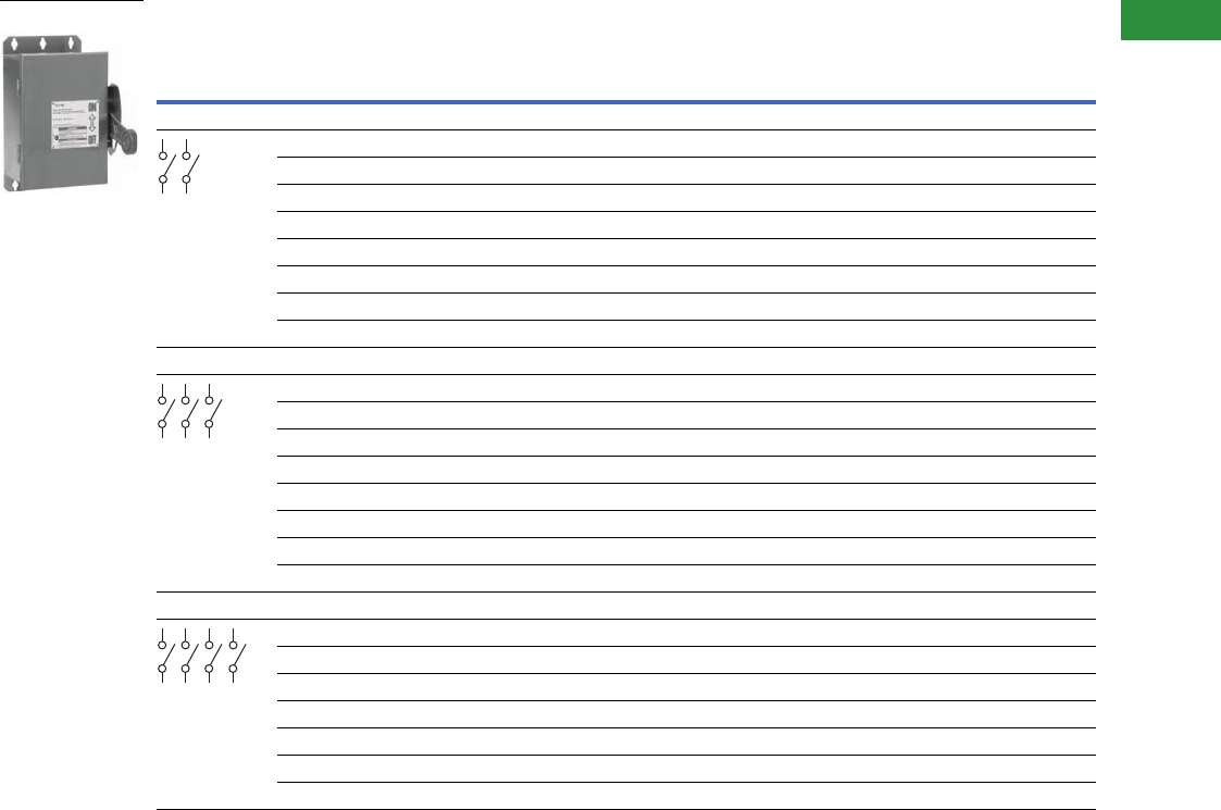
Volume 2—Commercial Distribution CA08100003E—April 2014 www.eaton.com V2-T1-41
1
1
1
1
1
1
1
1
1
1
1
1
1
1
1
1
1
1
1
1
1
1
1
1
1
1
1
1
1
1
1.1
Switching Devices
Safety Switches
600 Vac Heavy-Duty, Non-Fusible, Single-Throw, 277/480–600V—NEMA 4X
Notes
1 DC rating for 800A switches is 250V.
2 Contact the Safety Switch Flex Center (1-888-329-9272 or FlexSwitches@eaton.com) for availability of this product.
3 Use three-pole catalog numbers below for 600 Vac, 250 Vdc maximum applications. For 600 Vdc, see note 2.
4 Ratings are for two-phase AC.
Suitable for service entrance use, except 1200A on 480Y/277 or 600Y/347 grounded wye systems, per NEC 215.10 and 230.95, and four-pole switches.
System
Ampere
Rating
Maximum Horsepower Ratings NEMA 4X Enclosure
Corrosion-Resistant,
Stainless Steel
Catalog Number
Single-Phase AC Three-Phase AC DC
240V 480V 600V 240V 480V 600V 250V 600V
Two-Pole—480 Vac—600 Vac or Vdc 1 (Suitable for Service Entrance Use with a Neutral Kit Installed)
30 3 7-1/210————152 or 3
60 102025————252 or 3
100 203040———20252 or 3
200 155050————502 or 3
400 ——————50—2 or 3
600 ————————2 or 3
800 ————————2 or 3
1200————————2
Three-Pole—480 Vac—600 Vac, 250 Vdc (Suitable for Service Entrance Use with a Neutral Kit Installed)
30 3 7-1/2 10 10 20 30 5 — DH361UWK
60 10 20 25 20 50 60 10 — DH362UWK
100 204050407510020—DH363UWK
200 1550506012515040—DH364UWK
400 — — — 125 250 350 50 — DH365UWK
600 — — — 200 400 500 — — DH366UWK
800 — — — — 500 500 — — DH367UWK
1200 — — — — 500 500 — — DH368UWK
Four-Pole—480 Vac—600 Vac, 250 Vdc
30 10 420 425 410 20 30 5 — DH461UWK
60 20 440 450 420 50 60 10 — 2
100 40 450 450 440 75 100 20 — 2
200 50 450 450 460 125 150 40 — 2
400 50 4— — 125 250 350 50 — 2
600 — — — 200 400 500 — — 2
800 ————————2
DH361UWK
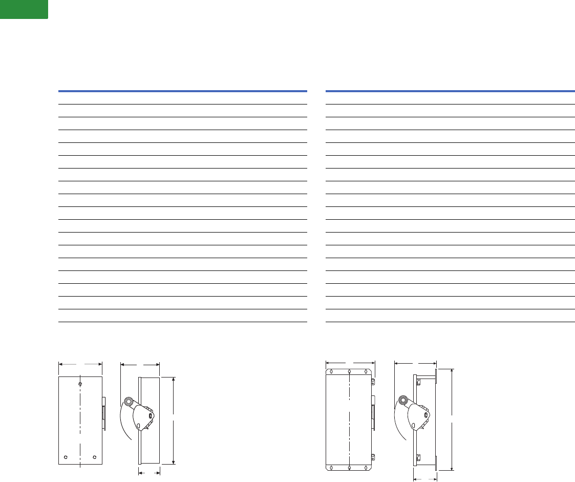
V2-T1-42 Volume 2—Commercial Distribution CA08100003E—April 2014 www.eaton.com
1
1
1
1
1
1
1
1
1
1
1
1
1
1
1
1
1
1
1
1
1
1
1
1
1
1
1
1
1
1
1.1
Switching Devices
Safety Switches
Dimensions
Approximate Dimensions in Inches (mm)
Note: Dimensions are for estimating purposes only.
Heavy-Duty, Non-Fusible, 600V, Three-Pole, Single-Throw
NEMA 1-3R Heavy-Duty 30–1200A
Heavy-Duty, Fusible, 240V and 600V, Three-Pole
Solid Neutral, Single-Throw
NEMA 4, 4X and 12 Heavy-Duty 30–1200A
Note: A factory-installed ground lug is supplied on all NEMA 4, 4X and
12 safety switches, as well as all 400A and higher NEMA 1 and 3R safety
switches. A factory-installed ground lug is also supplied on all heavy-duty
NEMA 1 and 3R 30–200A switches that do NOT have a factory-installed
neutral.
Ampere
Rating Width (W) Height (H) Depth (D) Depth (D2)
Weight
Lbs (kg)
NEMA 1, 3R
30 8.13 (206.5) 15.88 (403.4) 10.00 (254.0) 5.25 (133.3) 16 (7.264)
60 8.13 (206.5) 15.88 (403.4) 10.00 (254.0) 5.25 (133.3) 16 (7.264)
100 11.13 (282.7) 21.69 (550.9) 10.00 (254.0) 5.25 (133.3) 22 (9.988)
200 16.00 (406.4) 27.63 (701.8) 11.25 (285.8) 6.14 (156.0) 46 (20.884)
400 23.00 (584.2) 45.19 (1147.8) 12.63 (320.8) 7.27 (184.7) 110 (49.94)
600 24.00 (609.6) 52.70 (1338.6) 14.25 (362.0) 8.95 (227.3) 135 (61.29)
800 25.38 (644.7) 56.69 (1439.9) 14.25 (362.0) 8.95 (227.3) 158 (71.732)
1200 41.47 (1053.3) 70.31 (1785.9) 19.94 (506.5) 12.44 (316.0) 430 (195.22)
NEMA 12, 4X Stainless Steel, 4
30 8.13 (206.5) 12.13 (308.1) 10.00 (254.0) 5.50 (139.7) 17 (7.718)
60 8.13 (206.5) 12.13 (308.1) 10.00 (254.0) 5.50 (139.7) 17 (7.718)
100 11.13 (282.7) 24.00 (609.6) 10.25 (260.4) 5.50 (139.7) 28 (12.712)
200 16.00 (406.4) 34.38 (873.3) 11.50 (292.1) 6.44 (163.6) 55 (24.97)
400 23.00 (584.2) 57.63 (1463.8) 12.63 (320.8) 7.19 (182.6) 125 (56.75)
600 24.00 (609.6) 63.00 (1600.2) 14.25 (362.0) 8.88 (225.6) 167 (75.818)
800 25.38 (644.7) 71.75 (1822.5) 14.25 (362.0) 8.88 (225.6) 175 (79.45)
1200 41.47 (1053.3) 70.31 (1785.9) 19.94 (506.5) 13.51 (343.2) 475 (215.65)
W
H
C
L
D2
D
Ampere
Rating Width (W) Height (H) Depth (D) Depth (D2)
Weight
Lbs (kg)
NEMA 1, 3R
30 8.13 (206.5) 15.88 (403.4) 10.00 (254.0) 5.25 (133.3) 20 (9.08)
60 8.13 (206.5) 15.88 (403.4) 10.00 (254.0) 5.25 (133.3) 20 (9.08)
100 11.13 (282.7) 21.69 (550.9) 10.00 (254.0) 5.25 (133.3) 27 (12.258)
200 16.00 (406.4) 27.63 (701.8) 11.25 (285.8) 6.14 (156.0) 52 (23.608)
400 23.00 (584.2) 45.19 (1147.8) 12.63 (320.8) 7.27 (184.7) 120 (54.48)
600 24.00 (609.6) 52.70 (1338.6) 14.25 (362.0) 8.95 (227.3) 153 (69.462)
800 25.38 (644.7) 56.69 (1439.9) 14.25 (362.0) 8.95 (227.3) 168 (76.272)
1200 41.47 (1053.3) 70.31 (1785.9) 19.94 (506.5) 12.44 (316.0) 465 (211.11)
NEMA 12, 4X Stainless Steel, 4
30 8.13 (206.5) 17.88 (454.2) 10.00 (254.0) 5.50 (139.7) 22 (9.988)
60 8.13 (206.5) 17.88 (454.2) 10.00 (254.0) 5.50 (139.7) 22 (9.988)
100 11.13 (282.7) 24.00 (609.6) 10.25 (260.4) 5.50 (139.7) 30 (13.62)
200 16.00 (406.4) 34.38 (873.3) 11.50 (292.1) 6.44 (163.6) 61 (27.694)
400 23.00 (584.2) 57.63 (1463.8) 12.63 (320.8) 7.19 (182.6) 135 (61.29)
600 24.00 (609.6) 63.00 (1600.2) 14.25 (362.0) 8.88 (225.6) 203 (92.162)
800 25.38 (644.7) 71.75 (1822.5) 14.25 (362.0) 8.88 (225.6) 213 (96.702)
1200 41.47 (1053.3) 70.31 (1785.9) 19.94 (506.5) 13.51 (343.2) 510 (231.54)
D
W
C
L
H
D2
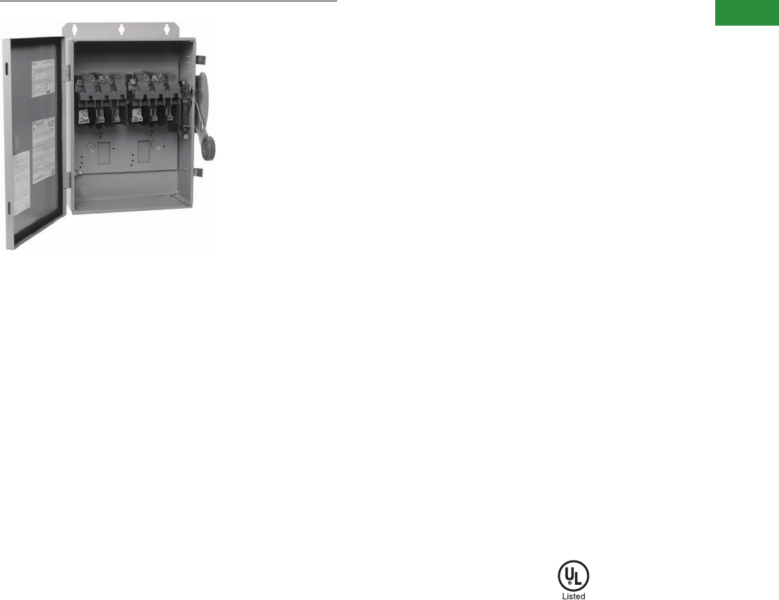
Volume 2—Commercial Distribution CA08100003E—April 2014 www.eaton.com V2-T1-43
1
1
1
1
1
1
1
1
1
1
1
1
1
1
1
1
1
1
1
1
1
1
1
1
1
1
1
1
1
1
1.1
Switching Devices
Safety Switches
Six-Pole Motor Circuit
Contents
Description Page
Product Overview . . . . . . . . . . . . . . . . . . . . . . . . . . . . V2-T1-3
General Duty . . . . . . . . . . . . . . . . . . . . . . . . . . . . . . . . V2-T1-26
Heavy-Duty . . . . . . . . . . . . . . . . . . . . . . . . . . . . . . . . . V2-T1-31
Six-Pole Switches
Product Selection. . . . . . . . . . . . . . . . . . . . . . . . . . V2-T1-44
Double-Throw Switches . . . . . . . . . . . . . . . . . . . . . . . V2-T1-45
EnviroLine—Stainless Steel Switch. . . . . . . . . . . . . . . V2-T1-53
EnviroLine—Upper and Lower Window Switches. . . . V2-T1-56
EnviroLine—Receptacle Switches. . . . . . . . . . . . . . . . V2-T1-59
EnviroLine—Non-Metallic KRYDON Switch . . . . . . . . V2-T1-61
NEMA 7/9—Hazardous Location Disconnect Switch . V2-T1-63
Quick Connect Switches . . . . . . . . . . . . . . . . . . . . . . . V2-T1-65
Solar Disconnect Switch . . . . . . . . . . . . . . . . . . . . . . . V2-T1-67
Solar Combiner Box—Source Combiner and
Array Combiner. . . . . . . . . . . . . . . . . . . . . . . . . . . . . V2-T1-69
316-Grade Stainless Steel Safety Switches. . . . . . . . . V2-T1-72
Mill-Duty Rated, Heavy-Duty, Fusible, Non-Fusible,
Single-Throw . . . . . . . . . . . . . . . . . . . . . . . . . . . . . . . V2-T1-76
Heavy-Duty Fusible Safety Switches Accepting
Cube Fuses . . . . . . . . . . . . . . . . . . . . . . . . . . . . . . . .
V2-T1-78
Elevator Control Switch . . . . . . . . . . . . . . . . . . . . . . . . V2-T1-81
Auxiliary Power Heavy-Duty Safety Switch . . . . . . . . . V2-T1-83
Left-Handed Safety Switch . . . . . . . . . . . . . . . . . . . . . V2-T1-86
200% Neutral Safety Switches . . . . . . . . . . . . . . . . . . V2-T1-87
Pringle Bolted Pressure Switch . . . . . . . . . . . . . . . . . . V2-T1-88
Type DS, Fusible and Non-Fusible . . . . . . . . . . . . . . . . V2-T1-91
Type Visi-Flex DE-ION . . . . . . . . . . . . . . . . . . . . . . . . . V2-T1-94
Flange Mounted—Variable Depth . . . . . . . . . . . . . . . . V2-T1-98
Flange Mounted—Fixed Depth . . . . . . . . . . . . . . . . . . V2-T1-102
Six-Pole Switches
Product Description
●600 Vac, 250 Vdc
maximum
●30–800A
●Fusible or non-fusible
Application Description
A compact safety switch
that’s ideal for use in heavy
industry...when an “in sight”
disconnecting means is
required for two-speed
motors that are remote from
their motor control devices.
Features, Benefits
and Functions
●Trunk-type latches keep the
cover tightly closed and a
neoprene gasket seals out
moisture and dust from the
switch assembly
●Visible double-break quick-
make, quick-break rotary
blade mechanism. Two
points of contact provide
a positive open and close,
easier operation, and
also help prevent contact
burning for longer
contact life
●Clear line shield protection
●Built-in fuse pullers
●Clearly visible handle
●Triple padlocking capability;
cabinet door can be
further padlocked at the
top and bottom
●Deionizing arc chutes;
arc chutes confine and
suppress the arcs
produced by opening
contacts under load
●For factory modifications,
refer to Pages V2-T1-16
through V2-T1-19
Standards and Certifications
●UL listed File No. E5239
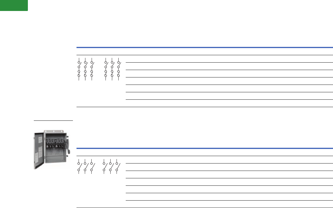
V2-T1-44 Volume 2—Commercial Distribution CA08100003E—April 2014 www.eaton.com
1
1
1
1
1
1
1
1
1
1
1
1
1
1
1
1
1
1
1
1
1
1
1
1
1
1
1
1
1
1
1.1
Switching Devices
Safety Switches
Product Selection
600 Vac Heavy-Duty, Fusible, Six-Pole, Single-Throw
600 Vac Heavy-Duty, Non-Fusible, Six-Pole, Single-Throw
Notes
1 NEMA 12 enclosures (30–800A) can be field modified to meet NEMA 3R rainproof requirements when a factory provided drain hole is opened.
2 Contact the Safety Switch Flex Center (1-888-329-9272 or FlexSwitches@eaton.com) for availability of this product.
3 600 Vdc rating requires that the switch be wired per the wiring diagram on the device publication.
30A heavy-duty switches with Type J fuse provisions are available from the factory only. See table on Page V2-T1-18 for catalog numbers.
System
Ampere
Rating
Maximum Horsepower Ratings, Three-Phase AC
(Higher Rating with Time Delay Fuses) NEMA 12 Enclosure
Industrial, Dust-Tight
Catalog Number
NEMA 4X Enclosure
Corrosion-Resistant,
Stainless Steel
Catalog Number240V 480V 600V
600 Vac with Fuse Clips—250 Vdc
30 3–7-1/2 5–15 7-1/2–20 DH661FDK 12
60 7-1/2–15 15–30 15–50 DH662FDK 12
100 15–30 25–60 30–75 DH663FDK 12
200 25–60 50–125 60–150 DH664FDK 12
400 — — — 22
600 — — — 22
800 — — — 22
System
Ampere
Rating
Maximum Horsepower Ratings
NEMA 12 Enclosure
Industrial, Dust-Tight
Catalog Number
NEMA 4X Enclosure
Corrosion-Resistant,
Stainless Steel
Catalog Number
Three-Phase AC Three-Phase DC
240V 480V 600V 250V 600V 3
600 Vac—250 Vdc
30 10 20 30 5 15 DH661UDK 1DH661UWK
60 20 50 60 10 25 DH662UDK 1DH662UWK
100 40 75 100 20 25 DH663UDK 1DH663UWK
200 60 125 150 40 50 DH664UDK 1DH664UWK
400—————22
600—————22
800—————22
DH661UDK
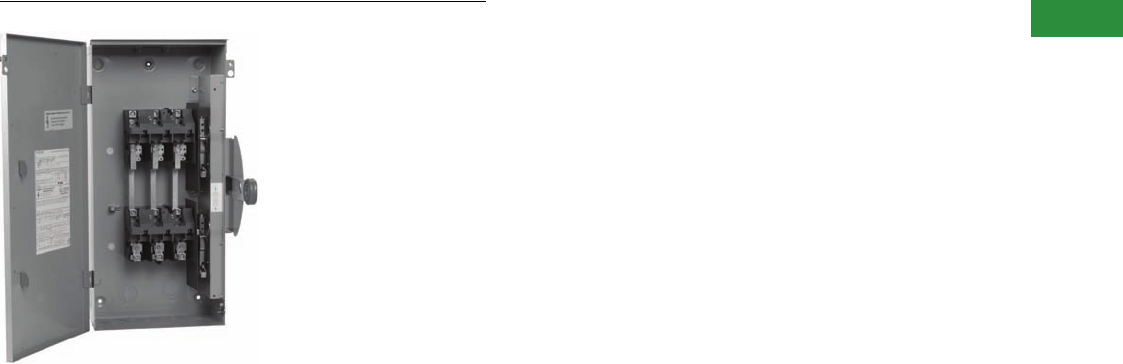
Volume 2—Commercial Distribution CA08100003E—April 2014 www.eaton.com V2-T1-45
1
1
1
1
1
1
1
1
1
1
1
1
1
1
1
1
1
1
1
1
1
1
1
1
1
1
1
1
1
1
1.1
Switching Devices
Safety Switches
Heavy-Duty Double-Throw
Contents
Description Page
Product Overview . . . . . . . . . . . . . . . . . . . . . . . . . . . . V2-T1-3
General Duty . . . . . . . . . . . . . . . . . . . . . . . . . . . . . . . . V2-T1-26
Heavy-Duty . . . . . . . . . . . . . . . . . . . . . . . . . . . . . . . . . V2-T1-31
Six-Pole Switches. . . . . . . . . . . . . . . . . . . . . . . . . . . . . V2-T1-43
Double-Throw Switches
Features, Benefits and Functions. . . . . . . . . . . . . . V2-T1-46
Standards and Certifications . . . . . . . . . . . . . . . . . V2-T1-46
Product Selection. . . . . . . . . . . . . . . . . . . . . . . . . . V2-T1-47
Technical Data and Specifications . . . . . . . . . . . . . V2-T1-51
Dimensions . . . . . . . . . . . . . . . . . . . . . . . . . . . . . . V2-T1-51
EnviroLine—Stainless Steel Switch. . . . . . . . . . . . . . . V2-T1-53
EnviroLine—Upper and Lower Window Switches. . . . V2-T1-56
EnviroLine—Receptacle Switches. . . . . . . . . . . . . . . . V2-T1-59
EnviroLine—Non-Metallic KRYDON Switch . . . . . . . . V2-T1-61
NEMA 7/9—Hazardous Location Disconnect Switch . V2-T1-63
Quick Connect Switches . . . . . . . . . . . . . . . . . . . . . . . V2-T1-65
Solar Disconnect Switch . . . . . . . . . . . . . . . . . . . . . . . V2-T1-67
Solar Combiner Box—Source Combiner and
Array Combiner. . . . . . . . . . . . . . . . . . . . . . . . . . . . . V2-T1-69
316-Grade Stainless Steel Safety Switches. . . . . . . . . V2-T1-72
Mill-Duty Rated, Heavy-Duty, Fusible, Non-Fusible,
Single-Throw . . . . . . . . . . . . . . . . . . . . . . . . . . . . . . . V2-T1-76
Heavy-Duty Fusible Safety Switches Accepting
Cube Fuses . . . . . . . . . . . . . . . . . . . . . . . . . . . . . . . .
V2-T1-78
Elevator Control Switch . . . . . . . . . . . . . . . . . . . . . . . . V2-T1-81
Auxiliary Power Heavy-Duty Safety Switch . . . . . . . . . V2-T1-83
Left-Handed Safety Switch . . . . . . . . . . . . . . . . . . . . . V2-T1-86
200% Neutral Safety Switches . . . . . . . . . . . . . . . . . . V2-T1-87
Pringle Bolted Pressure Switch . . . . . . . . . . . . . . . . . . V2-T1-88
Type DS, Fusible and Non-Fusible . . . . . . . . . . . . . . . . V2-T1-91
Type Visi-Flex DE-ION . . . . . . . . . . . . . . . . . . . . . . . . . V2-T1-94
Flange Mounted—Variable Depth . . . . . . . . . . . . . . . . V2-T1-98
Flange Mounted—Fixed Depth . . . . . . . . . . . . . . . . . . V2-T1-102
Double-Throw Switches
Product Description
Used to transfer service from
a normal power source to
an alternate source...or to
switch from one load circuit
to another.
●30–1200A
●Horsepower rated
●600 Vac, 250 Vdc
maximum
●800–1200A fusible utilize
common set of fuses; two
Source 1 load applications
●Fusible or non-fusible
●Fusible and non-fusible
switches are 100% load
break and 100% load
make rated
●Suitable for service
entrance applications
unless otherwise noted
●The continuous load
current of fusible switches
is not to exceed 80% of
the rating of fuses
employed in other than
motor circuits. Non-fusible
switches are 100%
fully rated
●Approved for service
entrance with neutral or
ground lug kit installed
●Wiring configuration from
factory allows a single load
to be supplied by a normal
or alternate source. Can be
field modified to allow two
loads to be alternately
supplied by a single
power source
240 Vac General-Duty, Non-
Fusible, Compact Design,
Double-Throw
●30–100A
●Suitable for service
entrance use with neutral
kit installed
●Non-fusible
240 Vac General-Duty, Non-
Fusible, Double-Throw
●30–400A
●Horsepower rated
●Suitable for service
entrance use with neutral
kit installed
●Non-fusible
●Quick-make, quick-break
operating mechanism
240 Vac Heavy-Duty, Fusible,
Non-Fusible, Double-Throw
●30–800A
●Horsepower rated
●Suitable for service
entrance use with
neutral kit installed
●Fusible and non-fusible
●For factory modifications,
refer to Pages V2-T1-16
through V2-T1-19

V2-T1-46 Volume 2—Commercial Distribution CA08100003E—April 2014 www.eaton.com
1
1
1
1
1
1
1
1
1
1
1
1
1
1
1
1
1
1
1
1
1
1
1
1
1
1
1
1
1
1
1.1
Switching Devices
Safety Switches
Features, Benefits and Functions
●Ample wire bending space
provides for easier
installation
●Visible double-break quick-
make, quick-break rotary
blade mechanism. Two
points of contact provide a
positive open and close,
easier operation, and also
help prevent contact
burning for longer
contact life
●Triple padlocking capability.
Personnel safety feature
since the large hasp can
accommodate up to three
3/8-inch (9.5 mm) shank
locks. Clearly visible
handle. The position
(ON or OFF) can be clearly
seen from a distance
●Deionizing arc chutes;
arc chutes confine and
suppress the arcs
produced by opening
contacts under load
●Additional locking
capability; cabinet door
can be further padlocked
at the top and bottom
●Clear line shield (provided
on fusible double-throw)
protects against accidental
contact with energized
parts. Probe holes enable
the user to test if the line
side is energized without
removing the shield
●Tangential knockouts on
sides, top and bottom.
Enables any size of conduit
to be mounted close to the
wall, providing for cable
installation closer to the
wall and a neat appearance
Standards and Certifications
●UL listed switching neutral
capability is available on
three-pole and four-pole
non-fusible double-throw
switches with the
installation of the proper
bonding kit shown on
Page V2-T1-14
●Suitable for use as a
manually operated switch
per 2005 NEC Article 702
●UL listed File No. E5239
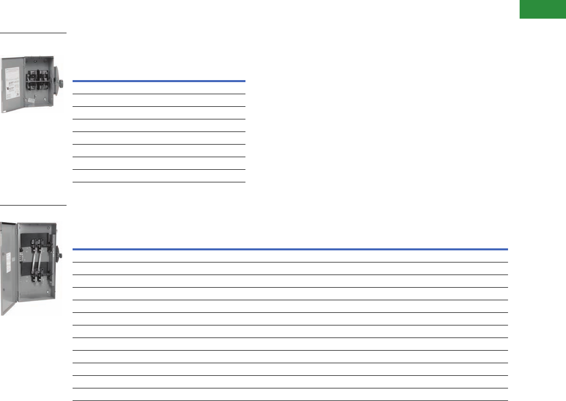
Volume 2—Commercial Distribution CA08100003E—April 2014 www.eaton.com V2-T1-47
1
1
1
1
1
1
1
1
1
1
1
1
1
1
1
1
1
1
1
1
1
1
1
1
1
1
1
1
1
1
1.1
Switching Devices
Safety Switches
Product Selection
240 Vac General-Duty, Non-Fusible,
Compact Design, Double-Throw
240 Vac General-Duty, Non-Fusible, Compact Design, Double-Throw
Ampere Rating
Main and Standby
NEMA 3R Enclosure
Rainproof
Catalog Number
Two-Pole—240 Vac
30 DT221URH
60 DT222URH
100 DT223URH
Two-Pole, Three-Wire—240 Vac—Solid Neutral
30 DT221URH-N
60 DT222URH-N
100 DT223URH-N
Ampere Rating
Main and Standby
Maximum Horsepower Ratings
NEMA 3R Enclosure
Rainproof
Catalog Number
Single-Phase AC Three-Phase AC DC
240V 480V 600V 240V 480V 600V 250V
Two-Pole—240 Vac—250 Vdc
30 3 —————5DT221URKPS
60 1 —————10DT222URKPS
100 20 —————20DT223URKPS
200 15 —————40DT224URKPS
400 ——————50DT225URKPS
Two-Pole, Three-Wire—240 Vac—250 Vdc, Solid Neutral
30 3 —————5DT221URK-NPS
60 10 —————10DT222URK-NPS
100 20 —————20DT223URK-NPS
200 15 —————40DT224URK-NPS
400 ——————50DT225URK-NPS
DT223URH-N
Compact Design
DT224URK-NPS

V2-T1-48 Volume 2—Commercial Distribution CA08100003E—April 2014 www.eaton.com
1
1
1
1
1
1
1
1
1
1
1
1
1
1
1
1
1
1
1
1
1
1
1
1
1
1
1
1
1
1
1.1
Switching Devices
Safety Switches
240 Vac Heavy-Duty, Fusible, Double-Throw
240 Vac Heavy-Duty, Non-Fusible, Double-Throw
Notes
1Only available for use with fast-acting fuses. Standard hp rating is shown.
2Field-installable neutral kit is not available. If a neutral is required, order the catalog number shown in the table with “N” suffix.
3Contact the Safety Switch Flex Center (1-888-329-9272 or FlexSwitches@eaton.com) for availability of this product.
UL listed switching neutral capability is available on three-pole and four-pole non-fusible double-throw switches with the installation of the proper bonding kit shown on Page V2-T1-14.
See Page V2-T1-18 for factory installation from the Flex Center.
Ampere Rating
Main and Standby
Fuse Class
Provision
Maximum Horsepower Ratings with Time Delay Fuses NEMA 1
Enclosure
Indoor
Catalog Number
NEMA 3R
Enclosure
Rainproof
Catalog Number
Single-Phase AC Three-Phase AC DC
240V 480V 600V 240V 480V 600V 250V
Two-Pole—240 Vac—250 Vdc
200 H 15 —————40DT224FGK DT224FRK
Three-Pole—240 Vac—250 Vdc
30 H 3 — — 7-1/2 — — 5 DT321FGK DT321FRK
60 H 10——15——10DT322FGK DT322FRK
100 H 15 — — 30 — — 20 DT323FGK DT323FRK
200 H 15 — — 60 — — 40 DT324FGK DT324FRK
400 H ———125——50DT325FGK DT325FRK
600 1T———50——50DT326FGK DT326FRK
800 L ———————DT327FGK DT327FRK
1200 L ———————DT328FGK DT328FRK
Ampere Rating
Main and Standby
Maximum Horsepower Ratings NEMA 1
Enclosure
Indoor
Catalog Number
NEMA 3R
Enclosure
Rainproof
Catalog Number
Single-Phase AC Three-Phase AC DC
240V 480V 600V 240V 480V 600V 250V
Two-Pole—240 Vac—250 Vdc
30 3 —————5DT221UGK 3
60 10 — — — — — 10 DT222UGK 3
100 20 —————20DT223UGK 3
200 15 —————40DT224UGK DT224URK
400 ——————50DT225UGK DT225URK
600 ———————DT226UGK 3
800 ———————DT227UGK DT227URK
1200 ———————DT228UGK DT228URK
Three-Pole—240 Vac—250 Vdc
30 3 ——10 ——5DT321UGK 3
60 10 — — 20 — — 10 DT322UGK 3
100 20 ——40 ——20DT323UGK DT323URK
200 15 ——60 ——40DT324UGK DT324URK
400 — — — 125 — — 50 DT325UGK DT325URK
600 — — — 125 — — 50 DT326UGK 3
800 — — — 125 — — 50 DT327UGK 2DT327URK
800 — — — 125 — — 50 DT327UGK-N DT328URK
1200 ———125——50DT328UGK —
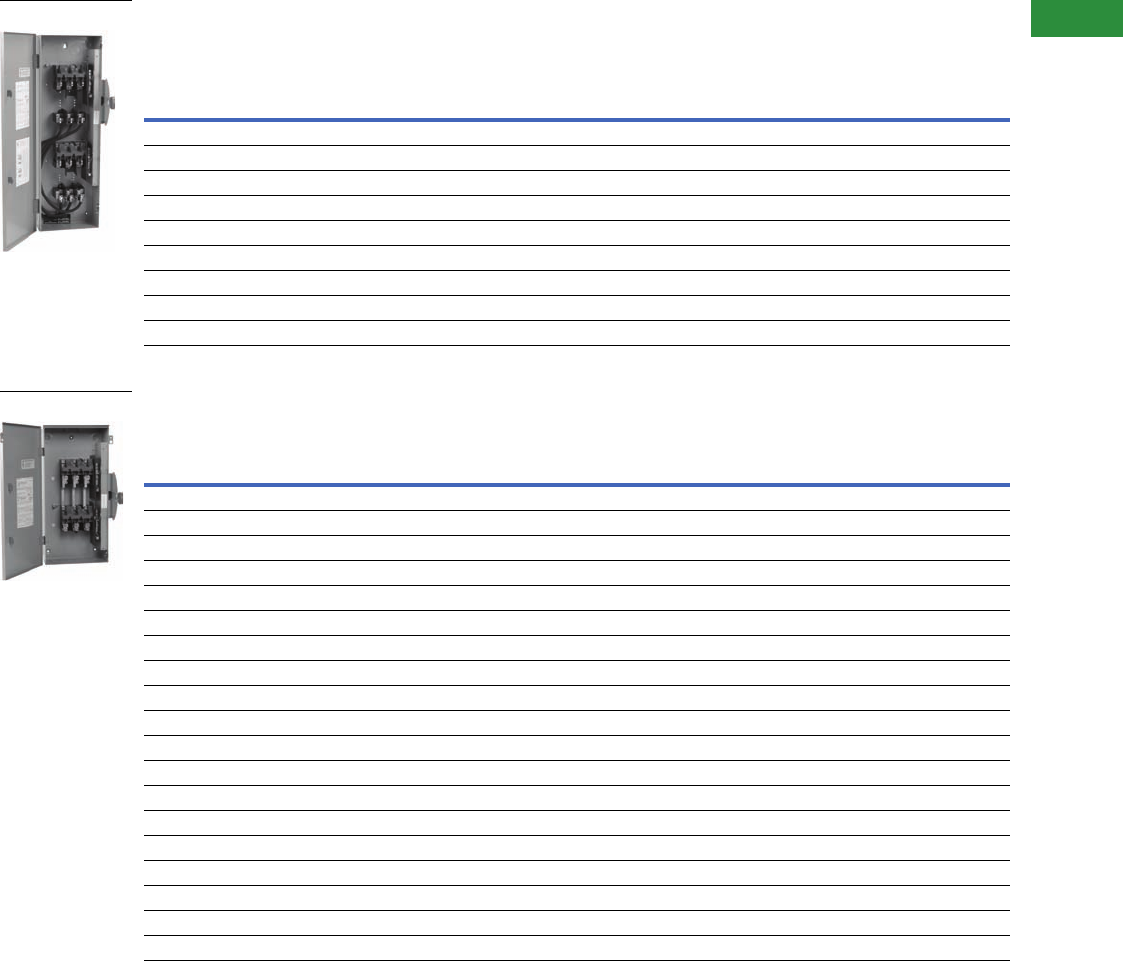
Volume 2—Commercial Distribution CA08100003E—April 2014 www.eaton.com V2-T1-49
1
1
1
1
1
1
1
1
1
1
1
1
1
1
1
1
1
1
1
1
1
1
1
1
1
1
1
1
1
1
1.1
Switching Devices
Safety Switches
600 Vac Heavy-Duty, Fusible, Double-Throw
600 Vac Heavy-Duty, Non-Fusible, Double-Throw
Notes
1 Contact the Safety Switch Flex Center (1-888-329-9272 or FlexSwitches@eaton.com) for availability of this product.
2 Rated 600 Vdc, 50 hp in addition to ratings shown in table.
3 Field installable neutral kit is not available. If a neutral is required, order the catalog number shown in the table with “N” suffix.
4 NEMA 12 enclosures (30–1200A) can be field modified to meet NEMA 3R rainproof requirements when a factory provided drain hole is opened.
5 Also available in 240 Vac catalog number DT325UDK.
UL listed switching neutral capability is available on three-pole and four-pole non-fusible double-throw switches with the installation of the proper bonding kit shown on
Page V2-T1-14. See Page V2-T1-18 for factory installation from the Flex Center.
Ampere
Rating
Main and
Standby
Fuse
Class
Provision
Maximum Horsepower Ratings
with Time Delay Fuses NEMA 1
Enclosure
Indoor
Catalog Number
NEMA 3R
Enclosure
Rainproof
Catalog Number
NEMA 12
Enclosure
Industrial, Dust-Tight
Catalog Number
NEMA 4X Enclosure
Corrosion-Resistant,
Stainless Steel
Catalog Number
Single-Phase
AC
Three-Phase
AC DC
480V 600V 480V 600V 250V
Three-Pole—600 Vac—250 Vdc
30 H 7-1/2 10 15 20 — DT361FGK 11 DT361FWK
60 H 20253050—DT362FGK 11 DT362FWK
100 H 30406075—DT363FGK DT363FRK 1DT363FWK
200 H 50 50 125 150 40 DT364FGK DT364FRK 1DT364FWK
400 T — — 250 350 50 DT365FGK DT365FRK 1DT365FWK
600 T — — — — — DT366FGK DT366FRK 11
800 L — — — — — DT367FGK DT367FRK 11
1200 L — — — — — DT368FGK DT368FRK 11
Ampere
Rating
Main and
Standby
Maximum Horsepower Ratings NEMA 1
Enclosure
Indoor
Catalog Number
NEMA 3R
Enclosure
Rainproof
Catalog Number
NEMA 12
Enclosure
Industrial, Dust-Tight
Catalog Number
NEMA 4X Enclosure
Corrosion-Resistant,
Stainless Steel
Catalog Number
Single-Phase AC Three-Phase AC DC
480V 600V 480V 600V 250V
Two-Pole—600 Vac—250 Vdc
30 7-1/2 10 — — 5 DT261UGK 1——
60 20 25 — — 10 DT262UGK 1——
100 40 50 — — 20 DT263UGK 1——
200 50 50 — — 40 DT264UGK 2DT264URK 2——
400 — — — — 50 DT265UGK DT265URK — —
600 — — — — 50 DT266UGK DT266URK — —
800 — — — — 50 DT267UGK DT267URK — —
1200 — — — — 50 DT268UGK DT268URK — —
Three-Pole—600 Vac—250 Vdc
30 7-1/21020305 DT361UGK DT361URK DT361UDK 4DT361UWK
60 20 25 50 60 10 DT362UGK DT362URK DT362UDK 4DT362UWK
100 40 50 75 100 20 DT363UGK DT363URK DT363UDK 4DT363UWK
200 50 50 125 150 40 DT364UGK DT364URK DT364UDK 4DT364UWK
400 — — 250 350 50 DT365UGK DT365URK DT365UDK 45 DT365UWK
600 — — 250 350 50 DT366UGK DT366URK 14 1
800 — — 250 350 50 DT367UGK 3DT367URK 314 1
800 — — 250 350 50 DT367UGKN DT367URKN 14 1
1200 — — 250 350 50 DT368UGK DT368URK 14 1
DT363FGK
DT363URK
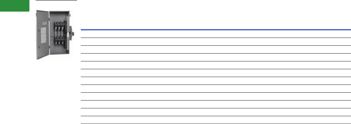
V2-T1-50 Volume 2—Commercial Distribution CA08100003E—April 2014 www.eaton.com
1
1
1
1
1
1
1
1
1
1
1
1
1
1
1
1
1
1
1
1
1
1
1
1
1
1
1
1
1
1
1.1
Switching Devices
Safety Switches
600 Vac Heavy-Duty, Non-Fusible, Double-Throw
Notes
1 Field installable neutral kit is not available. If a neutral is required, order the catalog number shown in the table with “N” suffix.
2 Contact the Safety Switch Flex Center (1-888-329-9272 or FlexSwitches@eaton.com) for availability of this product.
UL listed switching neutral capability is available on three-pole and four-pole non-fusible double-throw switches with the installation of the proper bonding kit shown on
Page V2-T1-14. See Page V2-T1-18 for factory installation from the Flex Center.
Ampere
Rating
Main and
Standby
Maximum Horsepower Ratings NEMA 1
Enclosure
Indoor
Catalog Number
NEMA 3R
Enclosure
Rainproof
Catalog Number
NEMA 12
Enclosure
Industrial, Dust-Tight
Catalog Number
NEMA 4X Enclosure
Corrosion-Resistant,
Stainless Steel
Catalog Number
Single-Phase AC Three-Phase AC DC
480V 600V 480V 600V 250V
Four-Pole—600 Vac—250 Vdc 1
30 7-1/2 10 20 30 5 2DT461URK 22
60 20 25 50 60 10 2DT462URK 22
100 40 50 75 100 20 2DT463URK 22
200 — 50 125 150 40 DT464UGK DT464URK 22
400 — — 250 350 50 DT465UGK DT465URK 22
600 — — 250 350 50 DT466UGK DT466URK 22
800 — — 250 350 50 DT467UGK DT467URK 22
Six-Pole—600 Vac—250 Vdc 1
30 7-1/2 10 15 30 5 2DT661URK 22
60 20 25 50 60 10 2DT662URK 22
100 40 50 75 100 20 2DT663URK 22
DT363URK
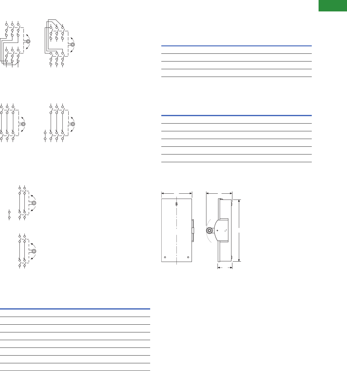
Volume 2—Commercial Distribution CA08100003E—April 2014 www.eaton.com V2-T1-51
1
1
1
1
1
1
1
1
1
1
1
1
1
1
1
1
1
1
1
1
1
1
1
1
1
1
1
1
1
1
1.1
Switching Devices
Safety Switches
Technical Data and Specifications
Typical Fusible, Double-Throw Schematic Diagram
Typical Non-Fusible, Double-Throw Schematic Diagram
Typical General-Duty, Double-Throw Schematic Diagrams
(with and without factory-installed neutral)
Short-Circuit Ratings Using Class “R”, “J” or “T” Fusing
Where Applicable
Dimensions
Approximate Dimensions in Inches (mm)
General-Duty, Non-Fusible, 240V, Two-Pole Solid Neutral,
Double-Throw, Compact Design
General-Duty, Non-Fusible, 240V, Two-Pole Solid Neutral,
Double-Throw, Quick-Make, Quick-Break Design
NEMA 3R, 30–400A, General-Duty, Non-Fusible,
Double-Throw
Notes
1Class “H” fuse clips supplied as standard for 30–600A. Rated at 10,000 rms symmetrical
when using Class “H” fuses.
Class “H” fuse clips supplied as standard for 30–600A except Class “T” for 400A at 600V and
600A at 240V. Rated at 10,000 rms symmetrical when using Class “H” fuses.
Table is not applicable to the compact design shown on Page V2-T1-47. The compact design is
suitable for use on a circuit capable of delivering not more than 10,000 rms symmetrical amperes.
Class “R” fuse adapter kits are shown on Page V2-T1-14. Individual adapter kits are applicable as
shown on Page V2-T1-14 and yield the short-circuit ratings per the tables above when Class “R”
fuses are installed. When installed, Class “R” fuse adapter kits reject all fuses except Class “R.”
Class “J” fuse provisions can be obtained on most 60–400A safety switches by moving the fuse
base to a new position as instructed by the device publication label. Class “J” fuse adapter kits,
where needed, are shown on Page V2-T1-14 and yield the short-circuit ratings per the tables
above when Class “J” fuses are installed. Class “J” fuse provisions must be factory installed on
30A heavy-duty switches. Catalog numbers are shown in table on Page V2-T1-18. Class “J” fusing
is not applicable on 30–200A general-duty switches, 30–100A double-throw switches, 600A
double-throw switches, and any switch higher than 600A.
Class “T” fuse adapter kits are shown on Page V2-T1-14. Individual adapter kits are applicable
to 200–800A switches as shown on Page V2-T1-14 and yield the short-circuit ratings per the
tables to the left when Class “T” fuses are installed. On 1200A switches, Class “T” fuse provisions
can be obtained by moving the fuse base to a new position as instructed by the device publication
label.
Ampere
Rating
Voltage Ratings
Type 1 Type 3R Type 12 Type 4 and 4X
30 100k at 600 100k at 600 100k at 600 100k at 600
60 100k at 600 100k at 600 100k at 600 100k at 600
100 100k at 600 100k at 600 100k at 600 100k at 600
200 100k at 600 100k at 600 100k at 600 100k at 600
400 100k at 600 100k at 600 100k at 600 100k at 600
600 100k at 600 100k at 600 100k at 600 100k at 600
800 100k at 600 100k at 600 — —
1200 100k at 600 100k at 600 — —
Fusible Three-Pole
Two Sources
Fusible Three-
Pole Two Loads
ON
ON
OFF
ON
ON
OFF
ON
ON
OFF
ON
ON
OFF
S/N
Non-Fusible Three-
Pole Two Sources
or Two Loads
Non-Fusible Three-
Pole Two Sources
or Two Loads
Two Sources
ON
OFF
ON
ON
OFF
ON
S/N
Ampere
Rating Height (H) Width (W) Depth (D)
Depth (D2)
Weight
Lbs (kg)
NEMA 3R
30 14.69 (373.1) 9.63 (244.6) 10.81 (274.6) 5.23 (132.8) 12 (5.5)
60 14.69 (373.1) 9.63 (244.6) 10.81 (274.6) 5.23 (132.8) 12 (5.5)
100 14.69 (373.1) 9.63 (244.6) 10.81 (274.6) 5.23 (132.8) 12 (5.5)
Ampere
Rating Height (H) Width (W) Depth (D)
Depth (D2)
Weight
Lbs (kg)
NEMA 3R
30 24.63 (625.6) 11.94 (303.3) 9.88 (251.0) 5.38 (136.7) 34 (15.4)
60 24.63 (625.6) 11.94 (303.3) 9.88 (251.0) 5.38 (136.7) 34 (15.4
100 24.63 (625.6) 11.94 (303.3) 9.88 (251.0) 5.38 (136.7) 34 (15.4)
200 37.38 (949.5) 19.56 (496.8) 11.25 (285.8) 6.10 (154.9) 80 (36.3)
400 53.81 (1366.8) 23.13 (587.5) 12.50 (317.6) 8.88 (225.6) 140 (63.6)
W
C
LH
D
D2
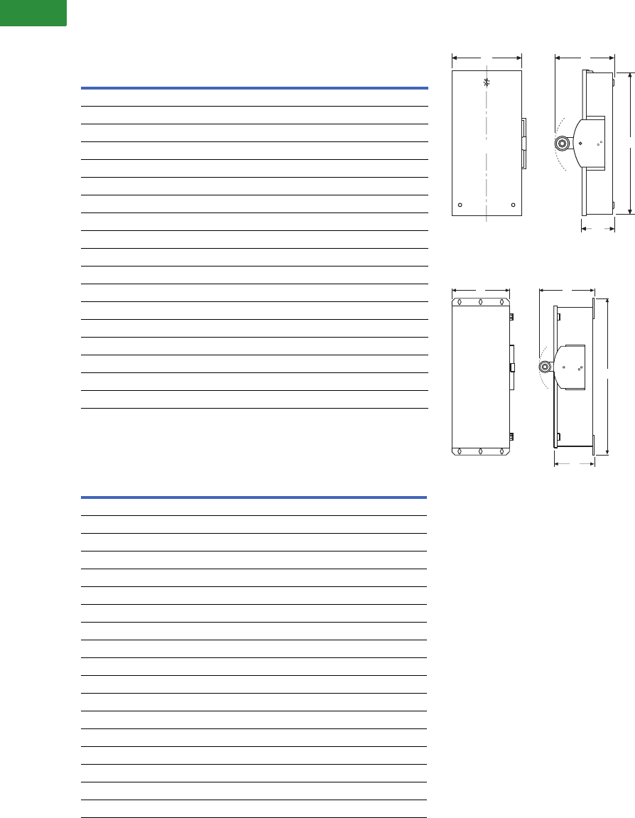
V2-T1-52 Volume 2—Commercial Distribution CA08100003E—April 2014 www.eaton.com
1
1
1
1
1
1
1
1
1
1
1
1
1
1
1
1
1
1
1
1
1
1
1
1
1
1
1
1
1
1
1.1
Switching Devices
Safety Switches
Approximate Dimensions in Inches (mm)
Heavy-Duty, Non-Fusible, 240V and 600V, Three-Pole,
Double-Throw
Heavy-Duty, Fusible, 240V and 600V, Three-Pole,
Double-Throw
NEMA 1-3R Double-Throw 30–800A
NEMA 12-4X Double-Throw 30–400A
Ampere
Rating Width (W) Height (H) Depth (D) Depth (D2)
Weight
Lbs (kg)
NEMA 1, 3R
30 11.94 (303.3) 24.63 (625.6) 9.88 (251.0) 5.38 (136.7) 34 (15.436)
60 11.94 (303.3) 24.63 (625.6) 9.88 (251.0) 5.38 (136.7) 34 (15.436)
100 11.94 (303.3) 24.63 (625.6) 9.88 (251.0) 5.38 (136.7) 34 (15.436)
200 19.56 (496.8) 37.38 (949.5) 11.25 (285.8) 6.10 (154.9) 80 (36.32)
400 23.13 (587.5) 53.81 (1366.8) 12.50 (317.5) 7.25 (184.2) 140 (63.56)
600 24.13 (612.9) 63.31 (1608.1) 14.13 (358.9) 8.88 (225.6) 175 (79.45)
800 24.13 (612.9) 63.31 (1608.1) 14.13 (358.9) 8.88 (225.6) 175 (79.45)
1200 42.62 (1082.5) 78.11 (1984.0) 25.62 (650.7) 20.47 (519.9) —
NEMA 12, 4X Stainless Steel
30 12.00 (304.8) 25.88 (657.4) 10.25 (260.4) 5.50 (139.7) 60 (27.24)
60 12.00 (304.8) 25.88 (657.4) 10.25 (260.4) 5.50 (139.7) 60 (27.24)
100 12.00 (304.8) 25.88 (657.4) 10.25 (260.4) 5.50 (139.7) 60 (27.24)
200 19.50 (495.3) 41.00 (1041.4) 11.63 (295.4) 6.48 (164.6) 105 (47.67)
400 23.00 (584.2) 57.50 (1460.5) 12.50 (317.5) 7.25 (184.2) 185 (83.99)
600———— —
800———— —
1200 — — — — —
Ampere
Rating Width (W) Height (H) Depth (D) Depth (D2)
Weight
Lbs (kg)
NEMA 1, 3R
30 11.94 (303.3) 36.63 (930.4) 9.88 (251.0) 5.38 (136.7) 44 (19.976)
60 11.94 (303.3) 36.63 (930.4) 9.88 (251.0) 5.38 (136.7) 44 (19.976)
100 11.94 (303.3) 36.63 (930.4) 9.88 (251.0) 5.38 (136.7) 44 (19.976)
200 19.56 (496.8) 50.88 (1292.4) 11.25 (285.8) 6.10 (154.9) 95 (43.13)
400 25.38 (644.7) 74.75 (1898.7) 14.13 (358.9) 8.88 (225.6) 230 (104.42)
600 27.44 (697.0) 86.13 (2187.7) 14.13 (358.9) 8.88 (225.6) 320 (145.28)
800 28.12 (714.2) 58.86 (1495.0) 25.62 (650.7) 20.47 (519.9) —
1200 42.62 (1082.5) 78.11 (1984.0) 25.62 (650.7) 20.47 (519.9) —
NEMA 12, 4X Stainless Steel, 4
30 12.00 (304.8) 39.81 (1011.2) 10.25 (260.4) 5.50 (139.7) 45 (20.43)
60 12.00 (304.8) 39.81 (1011.2) 10.25 (260.4) 5.50 (139.7) 45 (20.43)
100 12.00 (304.8) 39.81 (1011.2) 10.25 (260.4) 5.50 (139.7) 45 (20.43)
200 19.56 (496.8) 55.63 (1413.0) 11.63 (295.4) 6.46 (164.1) 100 (45.4)
400 25.38 (644.7) 74.75 (1898.7) 14.13 (358.9) 8.92 (226.6) 260 (118.04)
600 — — — — —
800 — — — — —
1200 — — — — —
W
C
LH
D
D2
W
H
D
D2
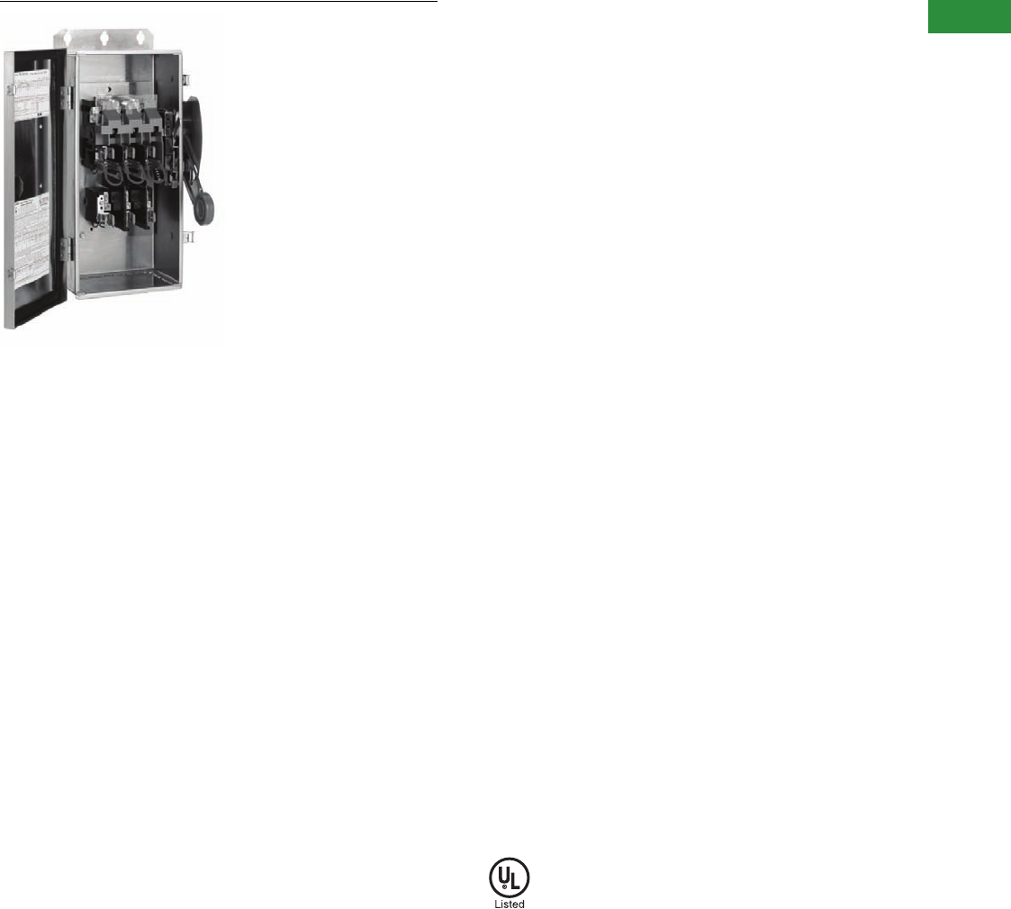
Volume 2—Commercial Distribution CA08100003E—April 2014 www.eaton.com V2-T1-53
1
1
1
1
1
1
1
1
1
1
1
1
1
1
1
1
1
1
1
1
1
1
1
1
1
1
1
1
1
1
1.1
Switching Devices
Safety Switches
EnviroLine/Stainless Steel Switch
Contents
Description Page
Product Overview . . . . . . . . . . . . . . . . . . . . . . . . . . . . V2-T1-3
General Duty . . . . . . . . . . . . . . . . . . . . . . . . . . . . . . . . V2-T1-26
Heavy-Duty . . . . . . . . . . . . . . . . . . . . . . . . . . . . . . . . . V2-T1-31
Six-Pole Switches. . . . . . . . . . . . . . . . . . . . . . . . . . . . . V2-T1-43
Double-Throw Switches . . . . . . . . . . . . . . . . . . . . . . . V2-T1-45
EnviroLine—Stainless Steel Switch
Product Selection. . . . . . . . . . . . . . . . . . . . . . . . . . V2-T1-54
EnviroLine—Upper and Lower Window Switches. . . . V2-T1-56
EnviroLine—Receptacle Switches. . . . . . . . . . . . . . . . V2-T1-59
EnviroLine—Non-Metallic KRYDON Switch . . . . . . . . V2-T1-61
NEMA 7/9—Hazardous Location Disconnect Switch . V2-T1-63
Quick Connect Switches . . . . . . . . . . . . . . . . . . . . . . . V2-T1-65
Solar Disconnect Switch . . . . . . . . . . . . . . . . . . . . . . . V2-T1-67
Solar Combiner Box—Source Combiner and
Array Combiner. . . . . . . . . . . . . . . . . . . . . . . . . . . . . V2-T1-69
316-Grade Stainless Steel Safety Switches. . . . . . . . . V2-T1-72
Mill-Duty Rated, Heavy-Duty, Fusible, Non-Fusible,
Single-Throw . . . . . . . . . . . . . . . . . . . . . . . . . . . . . . . V2-T1-76
Heavy-Duty Fusible Safety Switches Accepting
Cube Fuses . . . . . . . . . . . . . . . . . . . . . . . . . . . . . . . .
V2-T1-78
Elevator Control Switch . . . . . . . . . . . . . . . . . . . . . . . . V2-T1-81
Auxiliary Power Heavy-Duty Safety Switch . . . . . . . . . V2-T1-83
Left-Handed Safety Switch . . . . . . . . . . . . . . . . . . . . . V2-T1-86
200% Neutral Safety Switches . . . . . . . . . . . . . . . . . . V2-T1-87
Pringle Bolted Pressure Switch . . . . . . . . . . . . . . . . . . V2-T1-88
Type DS, Fusible and Non-Fusible . . . . . . . . . . . . . . . . V2-T1-91
Type Visi-Flex DE-ION . . . . . . . . . . . . . . . . . . . . . . . . . V2-T1-94
Flange Mounted—Variable Depth . . . . . . . . . . . . . . . . V2-T1-98
Flange Mounted—Fixed Depth . . . . . . . . . . . . . . . . . . V2-T1-102
EnviroLine—Stainless Steel Switch
Product Description
Primarily for use in the meat
packing and food processing
industries or any application
where water is frequently
used to hose down
equipment. In addition to
the stainless steel NEMA 4X
enclosure, the interior
mechanism, backpan and
springs are stainless steel.
Ratings for these heavy-duty
switches are 30–400A, 240–
600 Vac, available as fusible
and non-fusible switches.
Features
●Stainless steel enclosure
(304 grade)
●Stainless steel mechanism
(304 grade)
●30–400A
●Horsepower rated
●Suitable for service
entrance use
Standards and Certifications
●Upper and lower window
UL listed and NEMA
approved
●UL 98
●UL listed under
Section 508
●UL listed File No. E165150
and E5239
\
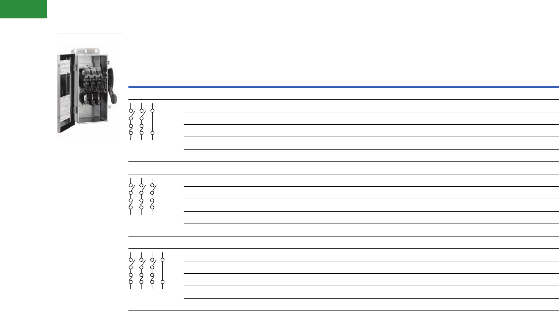
V2-T1-54 Volume 2—Commercial Distribution CA08100003E—April 2014 www.eaton.com
1
1
1
1
1
1
1
1
1
1
1
1
1
1
1
1
1
1
1
1
1
1
1
1
1
1
1
1
1
1
1.1
Switching Devices
Safety Switches
Product Selection
240 Vac Heavy-Duty, Fusible, Single-Throw Stainless Steel Enclosure and Operating Mechanism
Notes
1 Contact the Safety Switch Flex Center (1-888-329-9272 or FlexSwitches@eaton.com) for availability of this product.
30A heavy-duty switches with Type J fuse provisions are available from the factory only. See table on Page V2-T1-18 for catalog numbers.
System
Ampere
Rating
Fuse
Class
Provision
Maximum Horsepower Ratings with Time Delay Fuses
DC
250V
NEMA 4X Enclosure
Corrosion-Resistant,
Stainless Steel
Catalog Number
AC
Standard Fuse Time Delay
Single-Phase Three-Phase Single-Phase Three-Phase
Three-Wire (Two Blades, Two Fuses, S/N), 240 Vac—250 Vdc
30 H 1-1/2 3 3 7-1/2 5 DH221NWKX
60 H 3 7-1/2 10 15 10 DH222NWKX
100 H 7-1/2 15 15 30 20 DH223NWKX
200 H 15 25 15 60 40 DH224NWKX
400 H — 50 — 125 50 DH225NWKX
Three-Pole, 240 Vac—250 Vdc (Suitable for Service Entrance Use with a Neutral Kit Installed)
30 H 1-1/2 3 — 7-1/2 — DH321FWKX
60 H 3 7-1/2 — 15 — DH322FWKX
100H—————
1
200 H 15 25 — 60 40 DH324FWKX
400 H — 50 — 125 50 DH325FWKX
Four-Wire (Three Blades, Three Fuses, S/N), 240 Vac—250 Vdc
30 H — 3 — 7-1/2 — DH321NWKX
60 H — 7-1/2 — 15 — DH322NWKX
100 H — 15 — 30 20 DH323NWKX
200 H — 25 — 60 — DH324NWKX
400 H — 50 — 125 50 DH325NWKX
DH321NWKX
S/N
S/N
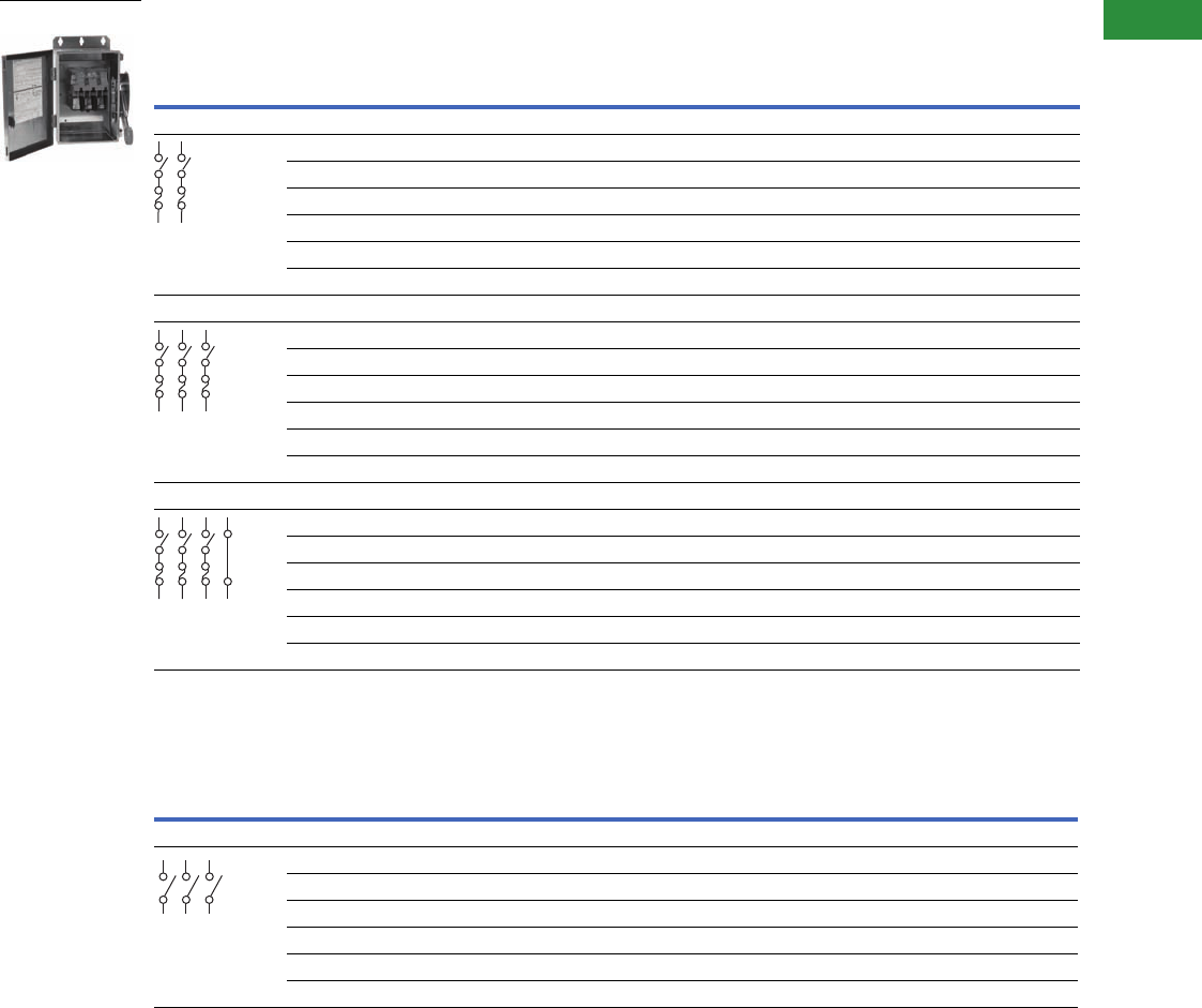
Volume 2—Commercial Distribution CA08100003E—April 2014 www.eaton.com V2-T1-55
1
1
1
1
1
1
1
1
1
1
1
1
1
1
1
1
1
1
1
1
1
1
1
1
1
1
1
1
1
1
1.1
Switching Devices
Safety Switches
600 Vac Heavy-Duty, Fusible 277/480V, Single-Throw Stainless Steel Enclosure and Operating Mechanism
600 Vac Heavy-Duty, Non-Fusible 277/480V, Single-Throw Stainless Steel Enclosure and Operating Mechanism
Notes
1 Contact the Safety Switch Flex Center (1-888-329-9272 or FlexSwitches@eaton.com) for availability of this product.
2 DC rating for 400A switches is 250V.
30A heavy-duty switches with Type J fuse provisions are available from the factory only. See table on Page V2-T1-18 for catalog numbers.
System
Ampere
Rating
Fuse
Class
Provision
Maximum Horsepower Ratings with Time Delay Fuses NEMA 4X Enclosure
Corrosion-Resistant,
Stainless Steel
Catalog Number
Single-Phase AC Three-Phase AC DC
480V 600V 480V 600V 250V 600V
Two-Pole, 480 Vac—600 Vac or Vdc 2 (Suitable for Service Entrance Use with a Neutral Kit Installed)
30 H 7-1/2 10 — — — 15 DH261FWKX
60 H ——————1
100 H ——————1
200 H 50 50 — — — 50 DH264FWKX
400 H ——————1
600 H —————50DH265FWKX
Three-Pole, 480 Vac—600 Vac, 250 Vdc (Suitable for Service Entrance Use with a Neutral Kit Installed)
30 H 7-1/2 10 15 20 — — DH361FWKX
60 H 20253050——DH362FWKX
100 H 30 30 60 75 — — DH363FWKX
200 H 50 50 125 150 — — DH364FWKX
400 H — — 250 350 — — DH365FWKX
600 H — — 250 350 — — DH366FWKX
Four-Wire (Three Blades, Three Fuses, S/N) 480 Vac—600 Vac, 250 Vdc
30 H 7-1/2 10 20 30 — — DH361NWKX
60 H 20255060——DH362NWKX
100 H 40 50 75 100 — — DH363NWKX
200 H 50 50 125 150 — — DH364NWKX
400 H — — 250 350 — — DH365NWKX
600 H — — 250 350 — — DH366NWKX
System
Ampere
Rating
Maximum Horsepower Ratings NEMA 4X Enclosure
Corrosion-Resistant,
Stainless Steel
Catalog Number
Single-Phase AC Three-Phase AC DC
480V 600V 480V 600V 250V 600V
Three-Pole, 480 Vac—600 Vac, 250 Vdc (Suitable for Service Entrance Use with a Neutral Kit Installed)
30 7-1/2 10 20 30 5 — DH361UWKX
60 20 25 50 60 10 — DH362UWKX
100 40 50 75 100 20 — DH363UWKX
200 50 50 125 150 40 — DH364UWKX
400 — — 250 350 50 — DH365UWKX
600 — — 250 350 50 — DH366UWKX
DH31UWKX
S/N
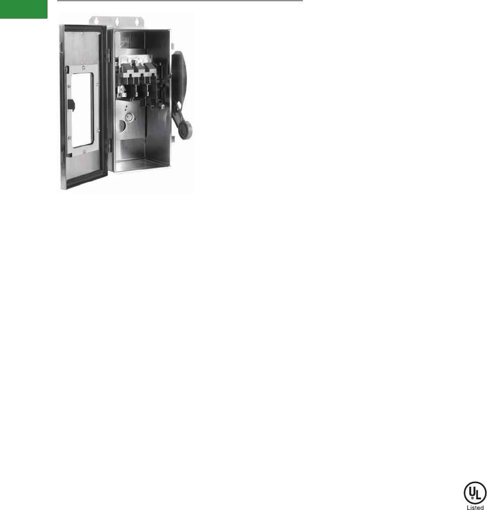
V2-T1-56 Volume 2—Commercial Distribution CA08100003E—April 2014 www.eaton.com
1
1
1
1
1
1
1
1
1
1
1
1
1
1
1
1
1
1
1
1
1
1
1
1
1
1
1
1
1
1
1.1
Switching Devices
Safety Switches
EnviroLine/Window Switch
Contents
Description Page
Product Overview . . . . . . . . . . . . . . . . . . . . . . . . . . . . V2-T1-3
General Duty. . . . . . . . . . . . . . . . . . . . . . . . . . . . . . . . V2-T1-26
Heavy-Duty . . . . . . . . . . . . . . . . . . . . . . . . . . . . . . . . . V2-T1-31
Six-Pole Switches . . . . . . . . . . . . . . . . . . . . . . . . . . . . V2-T1-43
Double-Throw Switches . . . . . . . . . . . . . . . . . . . . . . . V2-T1-45
EnviroLine—Stainless Steel Switch . . . . . . . . . . . . . . V2-T1-53
EnviroLine—Upper and Lower Window Switches
Product Selection . . . . . . . . . . . . . . . . . . . . . . . . . V2-T1-57
EnviroLine—Receptacle Switches . . . . . . . . . . . . . . . V2-T1-59
EnviroLine—Non-Metallic KRYDON Switch . . . . . . . . V2-T1-61
NEMA 7/9—Hazardous Location Disconnect Switch . V2-T1-63
Quick Connect Switches. . . . . . . . . . . . . . . . . . . . . . . V2-T1-65
Solar Disconnect Switch . . . . . . . . . . . . . . . . . . . . . . . V2-T1-67
Solar Combiner Box—Source Combiner and
Array Combiner . . . . . . . . . . . . . . . . . . . . . . . . . . . . V2-T1-69
316-Grade Stainless Steel Safety Switches . . . . . . . . V2-T1-72
Mill-Duty Rated, Heavy-Duty, Fusible, Non-Fusible,
Single-Throw. . . . . . . . . . . . . . . . . . . . . . . . . . . . . . . V2-T1-76
Heavy-Duty Fusible Safety Switches Accepting
Cube Fuses . . . . . . . . . . . . . . . . . . . . . . . . . . . . . . . . .
V2-T1-78
Elevator Control Switch. . . . . . . . . . . . . . . . . . . . . . . . V2-T1-81
Auxiliary Power Heavy-Duty Safety Switch. . . . . . . . . V2-T1-83
Left-Handed Safety Switch . . . . . . . . . . . . . . . . . . . . . V2-T1-86
200% Neutral Safety Switches. . . . . . . . . . . . . . . . . . V2-T1-87
Pringle Bolted Pressure Switch. . . . . . . . . . . . . . . . . . V2-T1-88
Type DS, Fusible and Non-Fusible. . . . . . . . . . . . . . . . V2-T1-91
Type Visi-Flex DE-ION . . . . . . . . . . . . . . . . . . . . . . . . . V2-T1-94
Flange Mounted—Variable Depth. . . . . . . . . . . . . . . . V2-T1-98
Flange Mounted—Fixed Depth. . . . . . . . . . . . . . . . . . V2-T1-102
EnviroLine—Upper and Lower Window Switches
Product Description
The new
enlarged window on
30–100A
ratings allows visual
blade position verification and
blown fuse indication without
opening the door. Higher
ampere ratings continue to
use the upper and lower
window design. The upper
window switch provides
visual verification of ON/OFF
status (blade position), while
the lower window design
shows fuse status on fuses
with blown fuse indicators.
Overall ratings are 30–800A,
240–600 Vac, fusible and non-
fusible. Available in NEMA
12/3R, 4X stainless steel
enclosures.
Features
Upper Window
●30–800A
●Blade visibility when
door closed
●240V and 600V, fusible
and non-fusible
●Suitable for service
entrance use
●NEMA 12, 4 and 4X
enclosures
Lower Window
●30–600A
●Power plugs not supplied
with the receptacle
●Lower viewing window
over fuses to allow visual
verification of blown
fuse indicators for
Littelfuse, Inc. fuses
●240V and 600V, fusible
●Suitable for service
entrance use
●NEMA 12, 4 and
4X enclosures
Standards and Certifications
●Upper and lower window
UL listed and NEMA
approved
●UL 98
●UL listed under
Section 508
●UL listed File No. E165150
and E5239
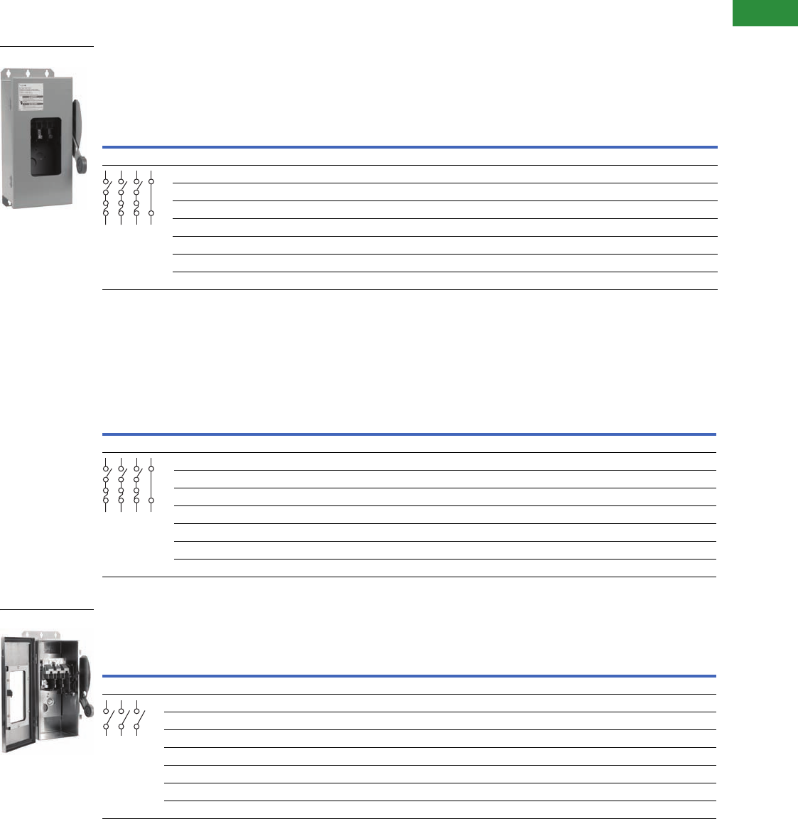
Volume 2—Commercial Distribution CA08100003E—April 2014 www.eaton.com V2-T1-57
1
1
1
1
1
1
1
1
1
1
1
1
1
1
1
1
1
1
1
1
1
1
1
1
1
1
1
1
1
1
1.1
Switching Devices
Safety Switches
Product Selection
240 Vac Heavy-Duty, Fusible Single-Throw with Upper Viewing Window
600 Vac Heavy-Duty, Fusible Single-Throw with Upper Viewing Window
600 Vac Heavy-Duty, Non-Fusible Single-Throw with Upper Viewing Window
Notes
1 For two-pole applications, use outside poles of three-pole switch.
2 NEMA 12 enclosures (30–800A) can be field modified to meet NEMA 3R rainproof requirements when a factory provided drain hole is opened.
30A heavy-duty switches with Type J fuse provisions are available from the factory only. See table on Page V2-T1-18 for catalog numbers.
Effective August 2003, 30–100A window switches offer visible blade verification and blown fuse indication in a single design as shown in the photos.The window is
replaceable. Higher ampere ratings will continue to be manufactured with a non-replaceable epoxy affixed design with visible blade verification only.
System
Ampere
Rating
Fuse
Class
Provision
Maximum Horsepower Ratings with Time Delay Fuses
NEMA 12
Enclosure
Industrial,
Dust-Tight
Catalog
Number
NEMA 4
Enclosure
Watertight,
Painted Steel
Catalog
Number
NEMA 4X
Enclosure
Corrosion-
Resistant,
Stainless Steel
Catalog
Number
AC
DC
250V
Standard Fuse Time Delay
Single-
Phase
Three-
Phase
Single-
Phase
Three-
Phase
Four-Wire (Three Blades, Three Fuses, S/N), 240 Vac—250 Vdc 1
30 H — 3 — 7-1/2 — DH321NDKW 2—DH321NWKW
60 H — 7-1/2 — 15 — DH322NDKW 2—DH322NWKW
100 H — 15 — 30 20 DH323NDKW 2—DH323NWKW
200 H — 25 — 60 — DH324NDKW 2—DH324NWKW
400 H — 50 — 125 50 DH325NDKW 2DH325NPKW DH325NWKW
600 H — 75 — 200 — DH326NDKW 2DH326NPKW DH326NWKW
800 L — 100 — 250 — DH327NDKW 2DH327NPKW DH327NWKW
System
Ampere
Rating
Fuse
Class
Provision
Maximum Horsepower Ratings with Time Delay Fuses
NEMA 12
Enclosure
Industrial,
Dust-Tight
Catalog
Number
NEMA 4
Enclosure
Watertight,
Painted Steel
Catalog
Number
NEMA 4X
Enclosure
Corrosion-
Resistant,
Stainless
Steel
Catalog
Number
Single-Phase AC Three-Phase AC
DC
250V
600V480V 600V 480V 600V
Four-Wire (Three Blades, Three Fuses, S/N), 600 Vac—250 Vdc 1
30 H 7-1/2 10 15 20 — DH361NDKW 2—DH361NWKW
60 H 20253050—DH362NDKW 2—DH362NWKW
100 H 30 40 60 75 — DH363NDKW 2—DH363NWKW
200 H 50 50 125 150 — DH364NDKW 2—DH364NWKW
400 H — — 250 350 — DH365NDKW 2DH365NPKW DH365NWKW
600 H — — 400 500 — DH366NDKW 2DH366NPKW DH366NWKW
800 L — — 500 500 — DH367NDKW 2DH367NPKW DH367NWKW
System
Ampere
Rating
Maximum Horsepower Ratings
NEMA 12 Enclosure
Industrial, Dust-Tight
Catalog Number
NEMA 4 Enclosure
Watertight,
Painted Steel
Catalog Number
NEMA 4X Enclosure
Corrosion-Resistant,
Stainless Steel
Catalog Number
Single-Phase AC Three-Phase AC DC
480V 600V 480V 600V 250V 600V
Three-Pole—600 Vac, 250 Vdc 1 (Suitable for Service Entrance Use with a Neutral or Ground Lug Kit Installed)
30 7-1/2 10 20 30 5 — DH361UDKW 2— DH361UWKW
60 20 25 50 60 10 — DH362UDKW 2— DH362UWKW
100 40 50 75 100 20 — DH363UDKW 2— DH363UWKW
200 50 50 125 150 40 — DH364UDKW 2— DH364UWKW
400 — — 250 350 50 — DH365UDKW 2DH365UPKW DH365UWKW
600 — — 400 500 — — DH366UDKW 2DH366UPKW DH366UWKW
800 — — 500 500 — — DH367UDKW 2DH367UPKW DH367UWKW
DH361UDKW
S/N
S/N
DH361UWKW
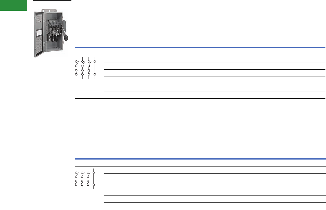
V2-T1-58 Volume 2—Commercial Distribution CA08100003E—April 2014 www.eaton.com
1
1
1
1
1
1
1
1
1
1
1
1
1
1
1
1
1
1
1
1
1
1
1
1
1
1
1
1
1
1
1.1
Switching Devices
Safety Switches
240 Vac Heavy-Duty, Fusible, Single-Throw with Lower Viewing Window
600 Vac Heavy-Duty, Fusible, Single-Throw with Lower Viewing Window
Notes
1 For two-pole applications, use outside poles of three-pole switch.
2 NEMA 12 enclosures (30–600A) can be field modified to meet NEMA 3R rainproof requirements when a factory provided drain hole is opened.
Effective August 2003, 30–100A window switches are replaced by a full view window that allows blade position verification and blown fuse indication.
See table on Page V2-T1-18 for catalog numbers.
System
Ampere
Rating
Fuse
Class
Provision
Maximum Horsepower Ratings with Time Delay Fuses
NEMA 12
Enclosure
Industrial,
Dust-Tight
NEMA 4
Enclosure
Watertight,
Painted Steel
NEMA 4X
Enclosure
Corrosion-
Resistant,
Stainless
Steel
AC
DC
250V
Standard Fuse Time Delay
Single-
Phase
Three-
Phase
Single-
Phase
Three-
Phase
Catalog
Number
Catalog
Number
Catalog
Number
Four-Wire (Three Blades, Three Fuses, S/N), 240 Vac—250 Vdc 1
30 H — 3 — 7-1/2 —
DH321NDKW
2— DH321NWKW
60 H — 7-1/2 — 15 —
DH322NDKW
2— DH322NWKW
100 H — 15 — 30 20
DH323NDKW
2— DH323NWKW
200 H — 25 — 60 —
DH324NDKLW
2— DH324NWKLW
400 H — 50 — 125 50
DH325NDKLW
2DH325NPKLW DH325NWKLW
600 H — 75 — 200 —
DH326NDKLW
2DH326NPKLW DH326NWKLW
System
Ampere
Rating
Fuse
Class
Provision
Maximum Horsepower Ratings with Time Delay Fuses
NEMA 12
Enclosure
Industrial,
Dust-Tight
NEMA 4
Enclosure
Watertight,
Painted Steel
NEMA 4X
Enclosure
Corrosion-
Resistant,
Stainless
SteelSingle-Phase AC Three-Phase AC
DC
250V480V 600V 480V 600V
Catalog
Number
Catalog
Number
Catalog
Number
Four-Wire (Three Blades, Three Fuses, S/N), 600 Vac—250 Vdc 1
30 H 7-1/2 10 15 20 —
DH361NDKW
2— DH361NWKW
60 H 20 25 30 50 —
DH362NDKW
2— DH362NWKW
100 H 30 40 60 75 —
DH363NDKW
2— DH363NWKW
200 H 50 50 125 150 —
DH364NDKLW
2— DH364NWKLW
400 H — — 250 350 —
DH365NDKLW
2
DH365NPKLW
DH365NWKLW
600 H — — 400 500 — DH366NDKLW 2DH366NPKLW DH366NWKLW
DH324NDKLW
S/N
S/N
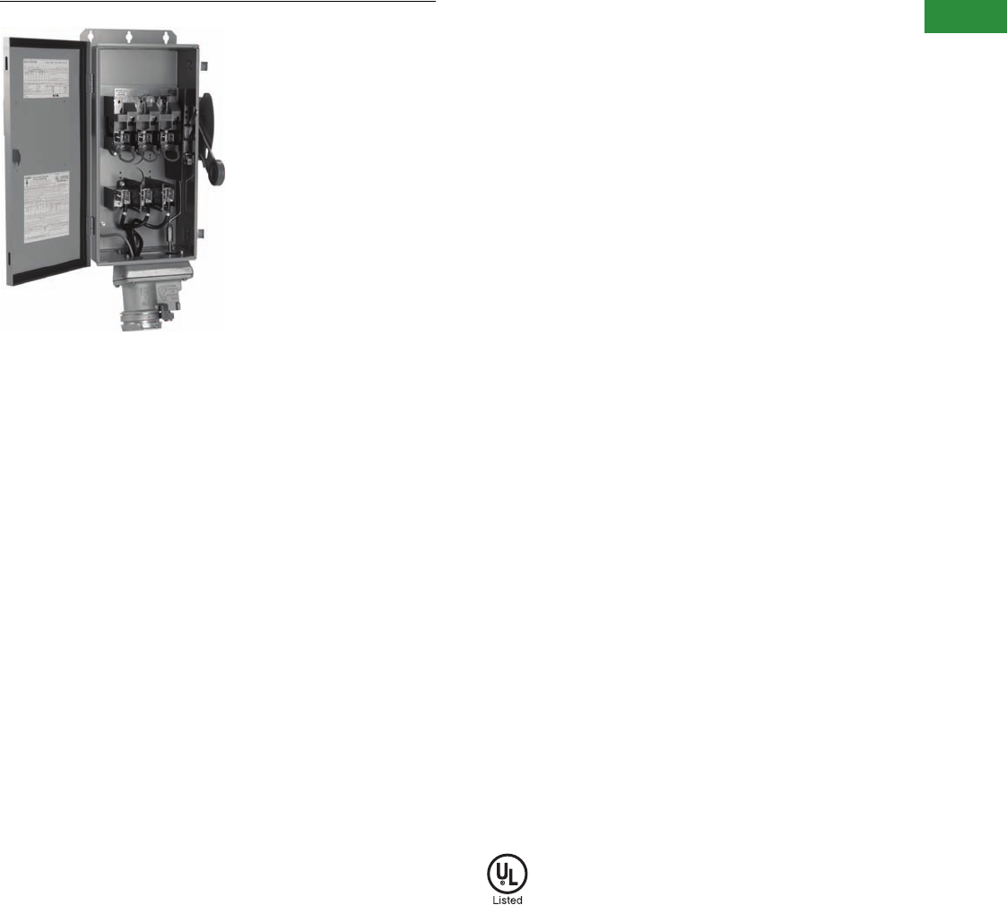
Volume 2—Commercial Distribution CA08100003E—April 2014 www.eaton.com V2-T1-59
1
1
1
1
1
1
1
1
1
1
1
1
1
1
1
1
1
1
1
1
1
1
1
1
1
1
1
1
1
1
1.1
Switching Devices
Safety Switches
EnviroLine/Receptacle Switch
Contents
Description Page
Product Overview . . . . . . . . . . . . . . . . . . . . . . . . . . . . V2-T1-3
General Duty . . . . . . . . . . . . . . . . . . . . . . . . . . . . . . . . V2-T1-26
Heavy-Duty . . . . . . . . . . . . . . . . . . . . . . . . . . . . . . . . . V2-T1-31
Six-Pole Switches. . . . . . . . . . . . . . . . . . . . . . . . . . . . . V2-T1-43
Double-Throw Switches . . . . . . . . . . . . . . . . . . . . . . . V2-T1-45
EnviroLine—Stainless Steel Switch. . . . . . . . . . . . . . . V2-T1-53
EnviroLine—Upper and Lower Window Switches. . . . V2-T1-56
EnviroLine—Receptacle Switches
Product Selection. . . . . . . . . . . . . . . . . . . . . . . . . . V2-T1-60
EnviroLine—Non-Metallic KRYDON Switch . . . . . . . . V2-T1-61
NEMA 7/9—Hazardous Location Disconnect Switch . V2-T1-63
Quick Connect Switches . . . . . . . . . . . . . . . . . . . . . . . V2-T1-65
Solar Disconnect Switch . . . . . . . . . . . . . . . . . . . . . . . V2-T1-67
Solar Combiner Box—Source Combiner and
Array Combiner. . . . . . . . . . . . . . . . . . . . . . . . . . . . . V2-T1-69
316-Grade Stainless Steel Safety Switches. . . . . . . . . V2-T1-72
Mill-Duty Rated, Heavy-Duty, Fusible, Non-Fusible,
Single-Throw . . . . . . . . . . . . . . . . . . . . . . . . . . . . . . . V2-T1-76
Heavy-Duty Fusible Safety Switches Accepting
Cube Fuses . . . . . . . . . . . . . . . . . . . . . . . . . . . . . . . .
V2-T1-78
Elevator Control Switch . . . . . . . . . . . . . . . . . . . . . . . . V2-T1-81
Auxiliary Power Heavy-Duty Safety Switch . . . . . . . . . V2-T1-83
Left-Handed Safety Switch . . . . . . . . . . . . . . . . . . . . . V2-T1-86
200% Neutral Safety Switches . . . . . . . . . . . . . . . . . . V2-T1-87
Pringle Bolted Pressure Switch . . . . . . . . . . . . . . . . . . V2-T1-88
Type DS, Fusible and Non-Fusible . . . . . . . . . . . . . . . . V2-T1-91
Type Visi-Flex DE-ION . . . . . . . . . . . . . . . . . . . . . . . . . V2-T1-94
Flange Mounted—Variable Depth . . . . . . . . . . . . . . . . V2-T1-98
Flange Mounted—Fixed Depth . . . . . . . . . . . . . . . . . . V2-T1-102
EnviroLine—Receptacle Switches
Product Description
These heavy-duty switches
are pre-wired and interlocked
to polarized receptacles for
three-phase, three-wire,
grounded type power plugs.
Receptacles are interlocked
to handle mechanisms so
that power plugs may not be
inserted or removed when
the switch is in the ON
position unless noted
otherwise. Ratings are 30–
100A, 600 Vac, NEMA 12/3R,
4X stainless steel enclosures.
●30–100A
●Power plugs not supplied
with the receptacle
Application Description
These are used for portable
power applications such as
welders, infrared ovens,
batch feeders, conveyors,
truck and marine docks.
Standards and Certifications
●Upper and lower window
UL listed and NEMA
approved
●UL 98
●UL listed under
Section 508
●UL listed File No. E165150
and E5239
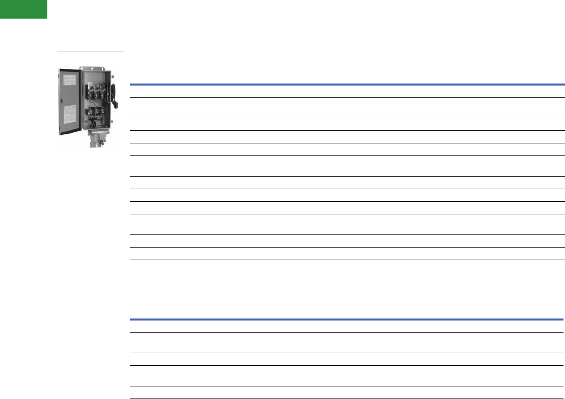
V2-T1-60 Volume 2—Commercial Distribution CA08100003E—April 2014 www.eaton.com
1
1
1
1
1
1
1
1
1
1
1
1
1
1
1
1
1
1
1
1
1
1
1
1
1
1
1
1
1
1
1.1
Switching Devices
Safety Switches
Product Selection
600 Vac Heavy-Duty, Single-Throw with Receptacle, Fusible, Non-Fusible
Safety Switch with Receptacle K-Series, Three-Pole, 600 Volt Fuse Clips—Fusible
Safety Switch with Receptacle K-Series, Three-Pole, 600 Volt Fuse Clips—Non-Fusible
Notes
Contact the Safety Switch Flex Center (1-888-329-9272 or FlexSwitches@eaton.com) for additional options including viewing windows and other receptacle manufacturers.
Power plugs are not available through Eaton.
Ampere Rating
Power Plug
NEMA 12/3R Enclosure NEMA 4X Enclosure
Switch Receptacle Catalog Number Catalog Number
Crouse-Hinds ARKTITET Receptacle
30 30
Accepts Crouse-Hinds®
APJ3485 DH361FDK2WR DH361FWK2WR
60 60 APJ6485 DH362FDK2WR DH362FWK2WR
100 100 APJ10487 DH363FDK2WR DH363FWK2WR
M-R-S (Russellstoll) MAX-GARD® Receptacle
30 30
Accepts Russellstoll
DS3404MP DH361FD3WRK DH361FW3WRK
60 60 DS6404MP DH362FD3WRK DH362FW3WRK
100 100 DS1404MP DH363FD3WRK DH363FW3WRK
Appleton POWERTITE® Receptacle
30 30
Accepts Appleton
ACP3034BC DH361FD5WRK DH361FW5WRK
60 60 ACP6034BC DH362FD5WRK DH362FW5WRK
100 100 ACP1034CD DH363FD5WRK DH363FW5WRK
Ampere Rating
Power Plug
NEMA 12/3R Enclosure NEMA 4X Enclosure
Switch Receptacle Catalog Number Catalog Number
Crouse-Hinds ARKTITE Receptacle
60 60
Accepts Crouse-Hinds
APJ6485 DH362UDK2WR DH362UWK2WR
Appleton POWERTITE Receptacle
30 30
Accepts Appleton
ACP3034BC DH361UD5WRK —
60 60 ACP6034BC DH362UD5WRK DH362UW5WRK
DH362FDK2WR
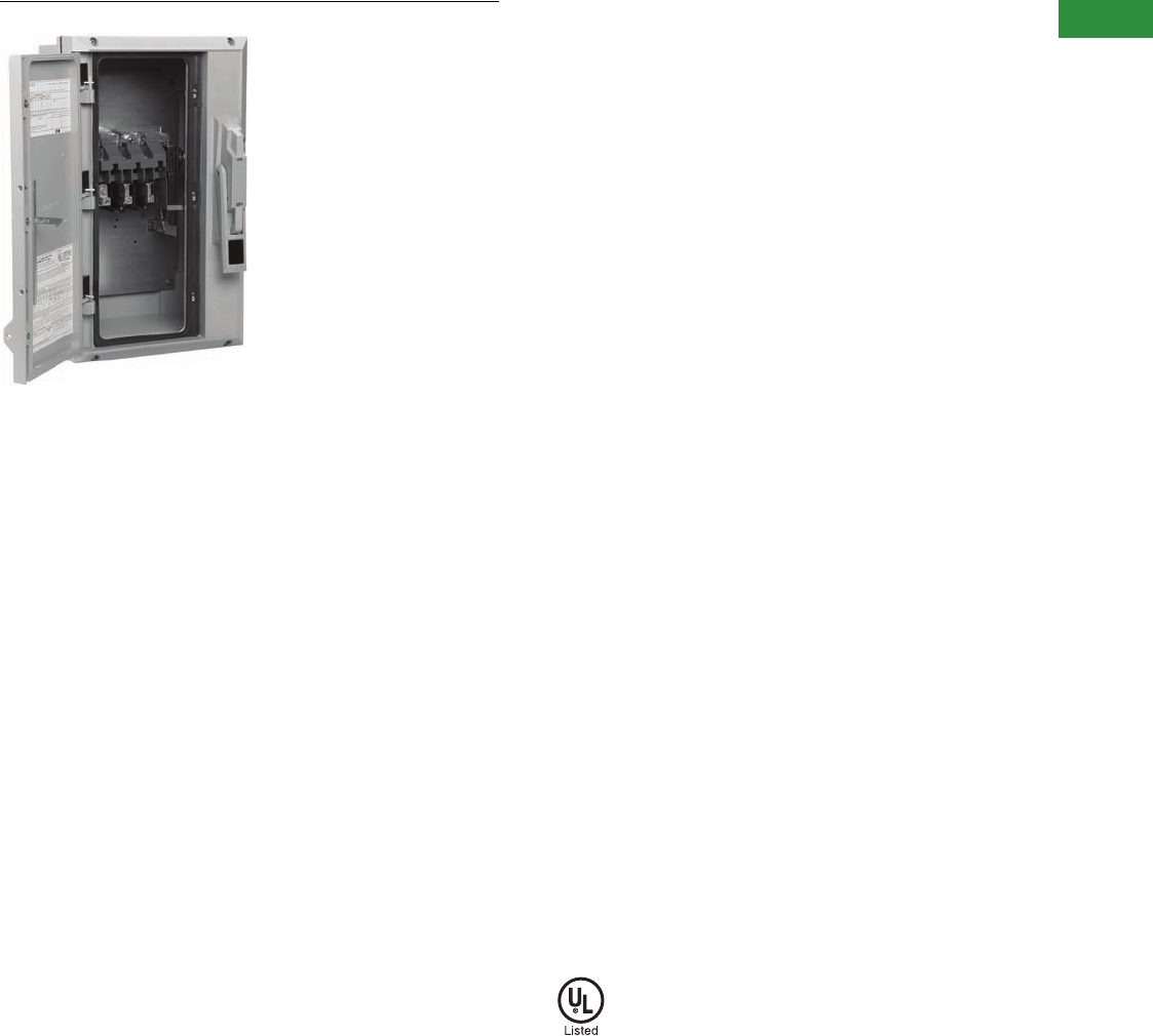
Volume 2—Commercial Distribution CA08100003E—April 2014 www.eaton.com V2-T1-61
1
1
1
1
1
1
1
1
1
1
1
1
1
1
1
1
1
1
1
1
1
1
1
1
1
1
1
1
1
1
1.1
Switching Devices
Safety Switches
EnviroLine/Non-Metallic KRYDON Switch
Contents
Description Page
Product Overview . . . . . . . . . . . . . . . . . . . . . . . . . . . . V2-T1-3
General Duty . . . . . . . . . . . . . . . . . . . . . . . . . . . . . . . . V2-T1-26
Heavy-Duty . . . . . . . . . . . . . . . . . . . . . . . . . . . . . . . . . V2-T1-31
Six-Pole Switches. . . . . . . . . . . . . . . . . . . . . . . . . . . . . V2-T1-43
Double-Throw Switches . . . . . . . . . . . . . . . . . . . . . . . V2-T1-45
EnviroLine—Stainless Steel Switch. . . . . . . . . . . . . . . V2-T1-53
EnviroLine—Upper and Lower Window Switches. . . . V2-T1-56
EnviroLine—Receptacle Switches. . . . . . . . . . . . . . . . V2-T1-59
EnviroLine—Non-Metallic KRYDON Switch
Product Selection. . . . . . . . . . . . . . . . . . . . . . . . . . V2-T1-62
NEMA 7/9—Hazardous Location Disconnect Switch . V2-T1-63
Quick Connect Switches . . . . . . . . . . . . . . . . . . . . . . . V2-T1-65
Solar Disconnect Switch . . . . . . . . . . . . . . . . . . . . . . . V2-T1-67
Solar Combiner Box—Source Combiner and
Array Combiner. . . . . . . . . . . . . . . . . . . . . . . . . . . . . V2-T1-69
316-Grade Stainless Steel Safety Switches. . . . . . . . . V2-T1-72
Mill-Duty Rated, Heavy-Duty, Fusible, Non-Fusible,
Single-Throw . . . . . . . . . . . . . . . . . . . . . . . . . . . . . . . V2-T1-76
Heavy-Duty Fusible Safety Switches Accepting
Cube Fuses . . . . . . . . . . . . . . . . . . . . . . . . . . . . . . . .
V2-T1-78
Elevator Control Switch . . . . . . . . . . . . . . . . . . . . . . . . V2-T1-81
Auxiliary Power Heavy-Duty Safety Switch . . . . . . . . . V2-T1-83
Left-Handed Safety Switch . . . . . . . . . . . . . . . . . . . . . V2-T1-86
200% Neutral Safety Switches . . . . . . . . . . . . . . . . . . V2-T1-87
Pringle Bolted Pressure Switch . . . . . . . . . . . . . . . . . . V2-T1-88
Type DS, Fusible and Non-Fusible . . . . . . . . . . . . . . . . V2-T1-91
Type Visi-Flex DE-ION . . . . . . . . . . . . . . . . . . . . . . . . . V2-T1-94
Flange Mounted—Variable Depth . . . . . . . . . . . . . . . . V2-T1-98
Flange Mounted—Fixed Depth . . . . . . . . . . . . . . . . . . V2-T1-102
EnviroLine—Non-Metallic KRYDON Switch
Product Description
This switch has a KRYDON™
enclosure. These are
compression molded
fiberglass reinforced
polyester enclosure, which
is capable of withstanding
almost any corrosive
environment. Ratings are
30–200A, 240–600 Vac, fusible
and non-fusible. Enclosure is
NEMA 4X rated.
Features
●30–200A
●KRYDON high-impact
strength fiberglass
reinforced polyester
material
●Horsepower rated
●Suitable for service
entrance use
●Fusible and non-fusible
Standards and Certifications
●Upper and lower window
UL listed and NEMA
approved
●UL 98
●UL listed under
Section 508
●UL listed File No. E165150
and E5239
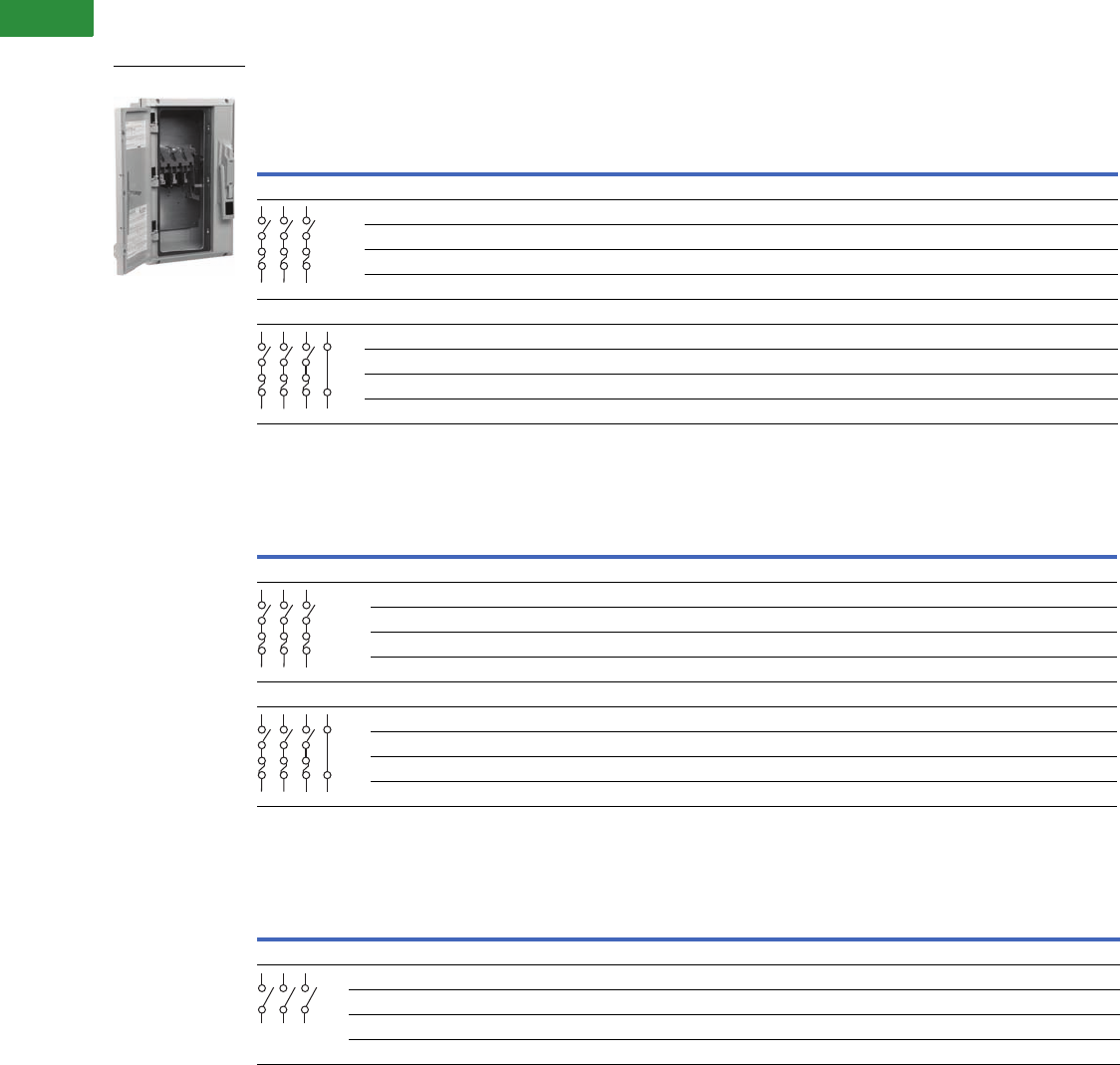
V2-T1-62 Volume 2—Commercial Distribution CA08100003E—April 2014 www.eaton.com
1
1
1
1
1
1
1
1
1
1
1
1
1
1
1
1
1
1
1
1
1
1
1
1
1
1
1
1
1
1
1.1
Switching Devices
Safety Switches
Product Selection
240 Vac Heavy-Duty Non-Metallic Fusible
240 Vac Heavy-Duty Non-Metallic Fusible
240 Vac Heavy-Duty Non-Metallic Non-Fusible 277/480–600V
Note
30A heavy-duty switches with Type J fuse provisions are available from the factory only. See table on Page V2-T1-18 for catalog numbers.
System
Ampere
Rating
Fuse Class
Provision
Maximum Horsepower Ratings
NEMA 4X Enclosure
Corrosion-Resistant,
Non-Metallic
Catalog Number
AC
DC
250V
Standard Fuse Time Delay
Single-Phase Three-Phase Single-Phase Three-Phase
Three-Pole, 240 Vac—250 Vdc (Suitable for Service Entrance Use with a Neutral Kit Installed)
30 H 1-1/2 3 — 7-1/2 — DH321FCK
60 H 3 7-1/2 — 15 — DH322FCK
100 H 7-1/2 15 — 30 20 DH323FCK
200 H 15 25 — 60 40 DH324FCK
Four-Wire (Three Blades, Three Fuses, S/N), 240 Vac—250 Vdc
30 H — 3 — 7-1/2 — DH321NCK
60 H — 7-1/2 — 15 — DH322NCK
100 H — 15 — 30 20 DH323NCK
200 H — 25 — 60 — DH324NCK
System
Ampere
Rating
Fuse Class
Provision
Maximum Horsepower Ratings with Time Delay Fuses NEMA 4X Enclosure
Corrosion-Resistant, Non-Metallic
Catalog Number
Single-Phase AC Three-Phase AC DC
480V 600V 480V 600V 250V 600V
Three-Pole, 480 Vac—600 Vac, 250 Vdc (Suitable for Service Entrance Use with a Neutral Kit Installed)
30 H 7-1/2 10 15 20 — — DH361FCK
60 H 20253050——DH362FCK
100 H 30 30 60 75 — — DH363FCK
200 H 50 50 125 150 — — DH364FCK
Four-Wire (Three Blades, Three Fuses, S/N), 480 Vac—600 Vac, 250 Vdc
30 H 7-1/2 10 15 20 — — DH361NCK
60 H 20253050——DH362NCK
100 H 30 30 60 75 — — DH363NCK
200 H 50 50 125 150 — — DH364NCK
System
Ampere
Rating
Maximum Horsepower Ratings with Time Delay Fuses NEMA 4X Enclosure
Corrosion-Resistant, Non-Metallic
Catalog Number
Single-Phase AC Three-Phase AC DC
240V 480V 600V 240V 480V 600V 250V 600V
Three-Pole, 480 Vac—600 Vac, 250 Vdc (Suitable for Service Entrance Use with a Neutral Kit Installed)
30 3 7-1/2 10 10 20 30 5 — DH361UCK
60 10 20 25 20 50 60 10 — DH362UCK
100204050407510020—DH363UCK
2001550506012515040—DH364UCK
DH361UCK
S/N
S/N
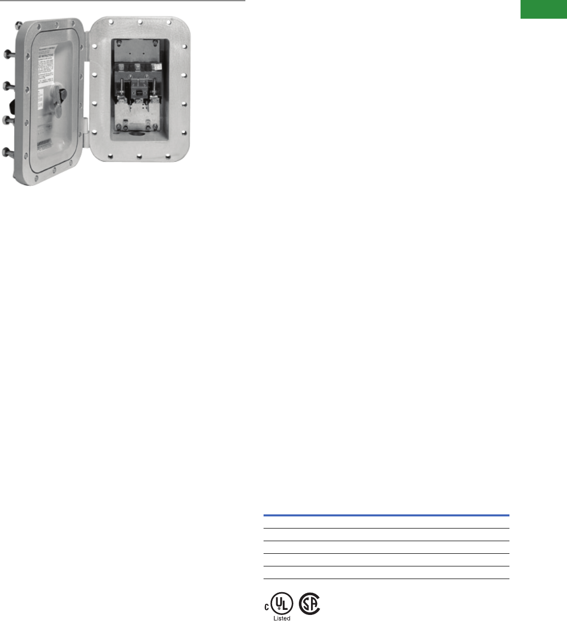
Volume 2—Commercial Distribution CA08100003E—April 2014 www.eaton.com V2-T1-63
1
1
1
1
1
1
1
1
1
1
1
1
1
1
1
1
1
1
1
1
1
1
1
1
1
1
1
1
1
1
1.1
Switching Devices
Safety Switches
DS361UX
Contents
Description Page
Product Overview . . . . . . . . . . . . . . . . . . . . . . . . . . . . V2-T1-3
General Duty . . . . . . . . . . . . . . . . . . . . . . . . . . . . . . . . V2-T1-26
Heavy-Duty . . . . . . . . . . . . . . . . . . . . . . . . . . . . . . . . . V2-T1-31
Six-Pole Switches. . . . . . . . . . . . . . . . . . . . . . . . . . . . . V2-T1-43
Double-Throw Switches . . . . . . . . . . . . . . . . . . . . . . . V2-T1-45
EnviroLine—Stainless Steel Switch. . . . . . . . . . . . . . . V2-T1-53
EnviroLine—Upper and Lower Window Switches. . . . V2-T1-56
EnviroLine—Receptacle Switches. . . . . . . . . . . . . . . . V2-T1-59
EnviroLine—Non-Metallic KRYDON Switch . . . . . . . . V2-T1-61
NEMA 7/9—Hazardous Location Disconnect Switch
Product Selection. . . . . . . . . . . . . . . . . . . . . . . . . . V2-T1-64
Dimensions . . . . . . . . . . . . . . . . . . . . . . . . . . . . . . V2-T1-64
Quick Connect Switches . . . . . . . . . . . . . . . . . . . . . . . V2-T1-65
Solar Disconnect Switch . . . . . . . . . . . . . . . . . . . . . . . V2-T1-67
Solar Combiner Box—Source Combiner and
Array Combiner. . . . . . . . . . . . . . . . . . . . . . . . . . . . . V2-T1-69
316-Grade Stainless Steel Safety Switches. . . . . . . . . V2-T1-72
Mill-Duty Rated, Heavy-Duty, Fusible, Non-Fusible,
Single-Throw . . . . . . . . . . . . . . . . . . . . . . . . . . . . . . . V2-T1-76
Heavy-Duty Fusible Safety Switches Accepting
Cube Fuses . . . . . . . . . . . . . . . . . . . . . . . . . . . . . . . .
V2-T1-78
Elevator Control Switch . . . . . . . . . . . . . . . . . . . . . . . . V2-T1-81
Auxiliary Power Heavy-Duty Safety Switch . . . . . . . . . V2-T1-83
Left-Handed Safety Switch . . . . . . . . . . . . . . . . . . . . . V2-T1-86
200% Neutral Safety Switches . . . . . . . . . . . . . . . . . . V2-T1-87
Pringle Bolted Pressure Switch . . . . . . . . . . . . . . . . . . V2-T1-88
Type DS, Fusible and Non-Fusible . . . . . . . . . . . . . . . . V2-T1-91
Type Visi-Flex DE-ION . . . . . . . . . . . . . . . . . . . . . . . . . V2-T1-94
Flange Mounted—Variable Depth . . . . . . . . . . . . . . . . V2-T1-98
Flange Mounted—Fixed Depth . . . . . . . . . . . . . . . . . . V2-T1-102
NEMA 7/9—Hazardous Location Disconnect Switch
Product Description
Eaton’s Type DS switch is
used as the switching device.
Ratings are 30–100A, 600 Vac,
fusible and non-fusible.
Application Description
The cast aluminum enclosure
is ideally suited for harsh
industrial applications
including petrochemical
facilities, mining operations,
pharmaceutical plants and
wastewater treatment
facilities.
Features
●30–100A
●600 Vac fusible and
non-fusible
●See Page V2-T1-63 for
information
●For factory modifications,
refer to Pages V2-T1-16
through V2-T1-19
Standards and Certifications
●Upper and lower window
UL listed and NEMA
approved
●UL 98
●UL listed under
Section 508
●UL listed File No. E165150
and E5239
Compliances
UL Classified—
Standard 886 File No. E84577
CSA Certified—
Standard C22.2 File No. LR 42131-6
Class I, Division 1 and 2, Groups B, C and D Class I, Division 1 and 2, Groups B, C and D
Class II, Division 1 and 2, Groups E, F and G Class II, Division 1 and 2, Groups E, F and G
Class III, Division 1 and 2 Class III, Division 1 and 2
NEMA 7/9 NEMA 7/9
Zone 1, IIB + H2Zone 1, IIB + H2
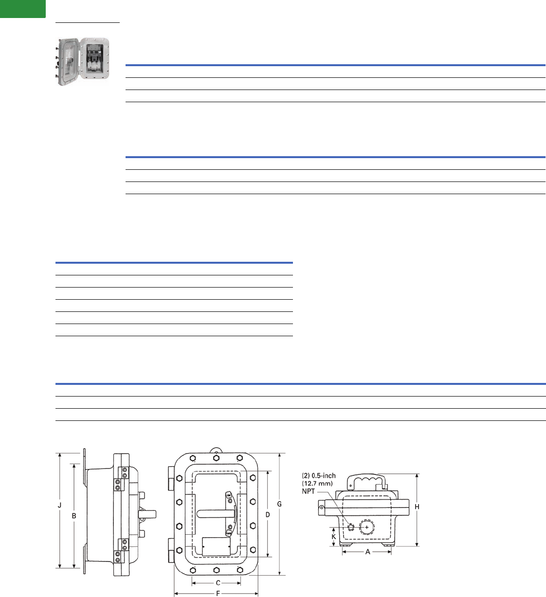
V2-T1-64 Volume 2—Commercial Distribution CA08100003E—April 2014 www.eaton.com
1
1
1
1
1
1
1
1
1
1
1
1
1
1
1
1
1
1
1
1
1
1
1
1
1
1
1
1
1
1
1.1
Switching Devices
Safety Switches
Product Selection
NEMA 7/9 Enclosure Sizes—Fusible
NEMA 7/9 Enclosure Sizes—Non-Fusible
Dimensions
Approximate Dimensions in Inches (mm)
NEMA 7/9 Enclosure Sizes
NEMA 7/9 1
NEMA 7/9—30–100A 2
Notes
1Accessories and modifications shown on Pages V2-T1-16 through V2-T1-19 are NOT applicable to NEMA 7/9 disconnect switches.
2Dual three- and four-point mounting available as standard on enclosures 1 and 2.
Ampere
Rating
Maximum Horsepower Ratings
Fuse Class
Provision
Number
of Poles Voltage
Enclosure
Number
Catalog
Number
Three-Phase AC DC
480V 600V 250V
30 15 20 5 J 3 600 Vac, 125/250 Vdc 1 DS361FX
60 30 50 10 J 3 600 Vac, 125/250 Vdc 2 DS362FX
100 60 75 20 J 3 600 Vac, 125/250 Vdc 3 DS363FX
Ampere
Rating
Maximum Horsepower Ratings
Fuse Class
Provision
Number
of Poles Voltage
Enclosure
Number
Catalog
Number
Three-Phase AC DC
480V 600V 250V
30 15 20 5 — 3 600 Vac, 125/250 Vdc 1 DS361UX
60 30 50 10 — 3 600 Vac, 125/250 Vdc 1 DS362UX
100 60 75 20 — 3 600 Vac, 125/250 Vdc 2 DS363UX
Catalog Number Standard Conduit Size
DS361FX 1.50 (38.1)
DS362FX 2.00 (50.8)
DS363FX 2.50 (63.5)
DS361UX 1.50 (38.1)
DS362UX 1.50 (38.1)
DS363UX 2.00 (50.8)
Enclosure
Number
Mounting Dimensions Inside Dimensions Outside Dimensions Number
of Outlets Dimension K
Approximate
Weight Lbs (kg)ABJ CDF GH
1 5.50 (139.7) 13.13 (333.5) 14.13 (358.9) 5.94 (150.9) 10.75 (273.1) 10.63 (270.0) 15.25 (387.4) 8.84 (224.5) 2 2.00 (50.8) 38 (17)
2 6.00 (152.4) 18.00 (457.2) 19.00 (482.6) 6.50 (165.1) 16.00 (406.4) 11.00 (279.4) 20.50 (520.7) 8.97 (227.8) 2 2.31 (58.6) 57 (26)
3 10.25 (260.4) 22.63 (574.8) — 11.75 (298.4) 20.00 (508.0) 16.38 (416.1) 25.13 (638.3) 9.59 (243.6) 2 3.50 (88.9) 104 (47)
DS361UX
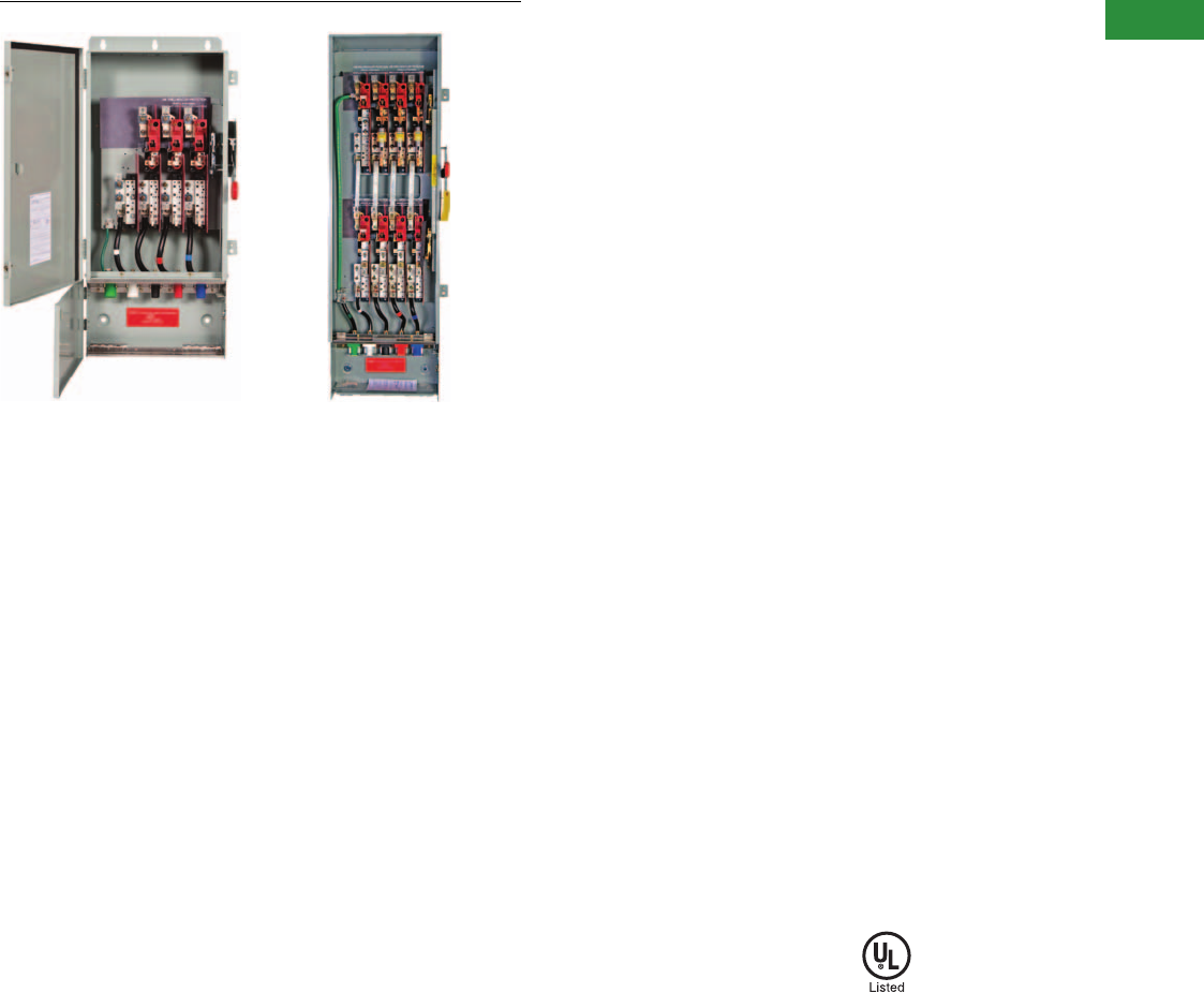
Volume 2—Commercial Distribution CA08100003E—April 2014 www.eaton.com V2-T1-65
1
1
1
1
1
1
1
1
1
1
1
1
1
1
1
1
1
1
1
1
1
1
1
1
1
1
1
1
1
1
1.1
Switching Devices
Safety Switches
DH3665NURKLP and Quick Connect Double Throw Switches
Contents
Description Page
Product Overview . . . . . . . . . . . . . . . . . . . . . . . . . . . . V2-T1-3
General Duty . . . . . . . . . . . . . . . . . . . . . . . . . . . . . . . . V2-T1-26
Heavy-Duty . . . . . . . . . . . . . . . . . . . . . . . . . . . . . . . . . V2-T1-31
Six-Pole Switches. . . . . . . . . . . . . . . . . . . . . . . . . . . . . V2-T1-43
Double-Throw Switches . . . . . . . . . . . . . . . . . . . . . . . V2-T1-45
EnviroLine—Stainless Steel Switch. . . . . . . . . . . . . . . V2-T1-53
EnviroLine—Upper and Lower Window Switches. . . . V2-T1-56
EnviroLine—Receptacle Switches. . . . . . . . . . . . . . . . V2-T1-59
EnviroLine—Non-Metallic KRYDON Switch . . . . . . . . V2-T1-61
NEMA 7/9—Hazardous Location Disconnect Switch . V2-T1-63
Quick Connect Switches
Catalog Number Selection . . . . . . . . . . . . . . . . . . . V2-T1-66
Solar Combiner Box—Source Combiner and
Array Combiner. . . . . . . . . . . . . . . . . . . . . . . . . . . . . V2-T1-69
316-Grade Stainless Steel Safety Switches. . . . . . . . . V2-T1-72
Mill-Duty Rated, Heavy-Duty, Fusible, Non-Fusible,
Single-Throw . . . . . . . . . . . . . . . . . . . . . . . . . . . . . . . V2-T1-76
Heavy-Duty Fusible Safety Switches Accepting
Cube Fuses . . . . . . . . . . . . . . . . . . . . . . . . . . . . . . . .
V2-T1-78
Elevator Control Switch . . . . . . . . . . . . . . . . . . . . . . . . V2-T1-81
Auxiliary Power Heavy-Duty Safety Switch . . . . . . . . . V2-T1-83
Left-Handed Safety Switch . . . . . . . . . . . . . . . . . . . . . V2-T1-86
200% Neutral Safety Switches . . . . . . . . . . . . . . . . . . V2-T1-87
Pringle Bolted Pressure Switch . . . . . . . . . . . . . . . . . . V2-T1-88
Type DS, Fusible and Non-Fusible . . . . . . . . . . . . . . . . V2-T1-91
Type Visi-Flex DE-ION . . . . . . . . . . . . . . . . . . . . . . . . . V2-T1-94
Flange Mounted—Variable Depth . . . . . . . . . . . . . . . . V2-T1-98
Flange Mounted—Fixed Depth . . . . . . . . . . . . . . . . . . V2-T1-102
Quick Connect Switches
Product Description
240V, 600 Vac Heavy-Duty,
Single-Throw with Cam-Lok or
Posi-Lok Receptacles, Fusible,
Non-Fusible
●30–800A
●NEMA 1 or 3R enclosures
●Provision for 200% neutral
●Non-magnetic metal
mounting plate
●Crouse-Hinds “J” Power
Series E1015, E1016, E1017
cam connectors
●Crouse-Hinds E200, E400
Posi-Lok panels
●Connector plugs are
typically not provided, but
may be special ordered
Features
Eaton’s individual cable
connector receptacle switches
provide a convenient and safe
way to quickly connect and
disconnect portable equipment.
The load side terminals are
factory wired to individual
receptacles located behind
an interlocked door for added
safety. The switch cannot
be turned to the ON position
without first closing the
receptacle compartment door.
A spring-loaded flap door in
the receptacle compartment
allows the cables to exit the
compartment, but seals the
compartment when the
switch is not in use. For
outdoor applications, this
will reduce the possibility of
insects building nests in the
receptacle compartment.
●Available in double-throw
and single-throw designs
●Single-throw receptacles
can wire to line or load side
●Service entrance rated
An additional flap door on the
main compartment allows for
quick connection in the event
that the appropriate plugs are
not readily available.
Standards and Certifications
●UL listed File No. E5239
●UL listed short-circuit
rating of 10,000A rms
symmetrical
Product Selection
For price and availability,
contact the Switching
Device Flex Center at
1-888-329-9272 or
FlexSwitches@eaton.com.
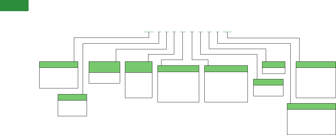
V2-T1-66 Volume 2—Commercial Distribution CA08100003E—April 2014 www.eaton.com
1
1
1
1
1
1
1
1
1
1
1
1
1
1
1
1
1
1
1
1
1
1
1
1
1
1
1
1
1
1
1.1
Switching Devices
Safety Switches
Catalog Number Selection
Quick Connect Double-Throw
Notes
1When upper and lower switches are the same, the switch configuration is consolidated in one letter (e.g., “U” not “UU”). Also, a switch with a neutral will have either a solid neutral or a switched
neutral, not both. Lastly, a switched neutral pole is never fused.
2This field is only used when a switch is completely non-fused.
This table is intended for use in breaking down existing catalog numbers. It is not intended for building new catalog numbers.
Switch Type
DT = Heavy-duty
double-throw
DH = Heavy-duty
single-throw
Poles
2 = Two-pole
3 = Three-pole
4 = Four-pole
Maximum
Voltage
2 = 240 Vac
6 = 600 Vac
Switch
Ampacity
3 = 100A
4 = 200A
5 = 400A
6 = 600A
7 = 800A
Upper Switch 1
U= Unfused
F= Fusible
N= Fusible with
solid neutral
SN = Fusible with
switched neutral
Series
K= K
DT 3 6 5 N U R K LC
Enclosure
G = NEMA 1
R= NEMA 3R
Receptacle Type
LC = Cam-Lok
LCR = Cam-Lok
reverse pin
LP =Posi-Lok
LPR = Posi-Lok
reverse pin
Neutral
Blank = No neutral or
incl. with switch
designation
N= Solid neutral
SN = Switched neutral
Lower Switch 2
U= Unfused
F= Fusible
N= Fusible with
solid neutral
SN = Fusible with
switched neutral
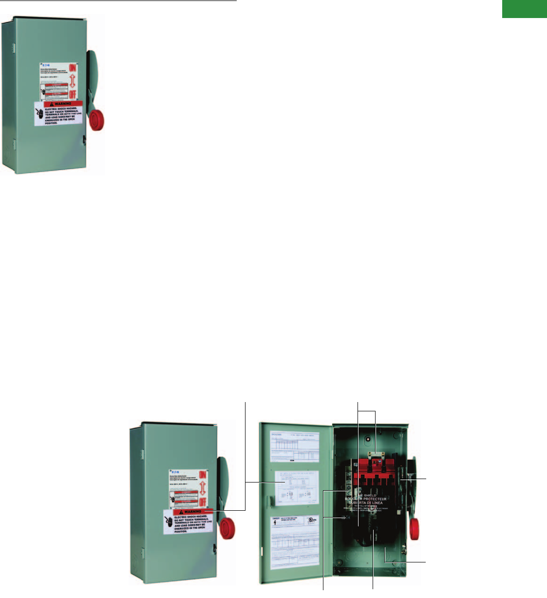
Volume 2—Commercial Distribution CA08100003E—April 2014 www.eaton.com V2-T1-67
1
1
1
1
1
1
1
1
1
1
1
1
1
1
1
1
1
1
1
1
1
1
1
1
1
1
1
1
1
1
1.1
Switching Devices
Safety Switches
Solar Disconnect Switch
Contents
Description Page
Product Overview . . . . . . . . . . . . . . . . . . . . . . . . . . . . V2-T1-3
General Duty . . . . . . . . . . . . . . . . . . . . . . . . . . . . . . . . V2-T1-26
Heavy-Duty . . . . . . . . . . . . . . . . . . . . . . . . . . . . . . . . . V2-T1-31
Six-Pole Switches. . . . . . . . . . . . . . . . . . . . . . . . . . . . . V2-T1-43
Double-Throw Switches . . . . . . . . . . . . . . . . . . . . . . . V2-T1-45
EnviroLine—Stainless Steel Switch. . . . . . . . . . . . . . . V2-T1-53
EnviroLine—Upper and Lower Window Switches. . . . V2-T1-56
EnviroLine—Receptacle Switches. . . . . . . . . . . . . . . . V2-T1-59
EnviroLine—Non-Metallic KRYDON Switch . . . . . . . . V2-T1-61
NEMA 7/9—Hazardous Location Disconnect Switch . V2-T1-63
Quick Connect Switches . . . . . . . . . . . . . . . . . . . . . . . V2-T1-65
Solar Disconnect Switch
Standards and Certifications . . . . . . . . . . . . . . . . . V2-T1-68
Product Selection. . . . . . . . . . . . . . . . . . . . . . . . . . V2-T1-68
Solar Combiner Box—Source Combiner and
Array Combiner. . . . . . . . . . . . . . . . . . . . . . . . . . . . . V2-T1-69
316-Grade Stainless Steel Safety Switches. . . . . . . . . V2-T1-72
Mill-Duty Rated, Heavy-Duty, Fusible, Non-Fusible,
Single-Throw . . . . . . . . . . . . . . . . . . . . . . . . . . . . . . . V2-T1-76
Heavy-Duty Fusible Safety Switches Accepting
Cube Fuses . . . . . . . . . . . . . . . . . . . . . . . . . . . . . . . .
V2-T1-78
Elevator Control Switch . . . . . . . . . . . . . . . . . . . . . . . . V2-T1-81
Auxiliary Power Heavy-Duty Safety Switch . . . . . . . . . V2-T1-83
Left-Handed Safety Switch . . . . . . . . . . . . . . . . . . . . . V2-T1-86
200% Neutral Safety Switches . . . . . . . . . . . . . . . . . . V2-T1-87
Pringle Bolted Pressure Switch . . . . . . . . . . . . . . . . . . V2-T1-88
Type DS, Fusible and Non-Fusible . . . . . . . . . . . . . . . . V2-T1-91
Type Visi-Flex DE-ION . . . . . . . . . . . . . . . . . . . . . . . . . V2-T1-94
Flange Mounted—Variable Depth . . . . . . . . . . . . . . . . V2-T1-98
Flange Mounted—Fixed Depth . . . . . . . . . . . . . . . . . . V2-T1-102
Solar Disconnect Switch
Product Description
600 Vdc Heavy-Duty Fusible
and Non-Fusible
●30–600A
●Single-pole switch
capable of switching
1-600 Vdc circuit
Features
●Clear line-shield covering
all live parts
●For factory modifications,
refer to Pages V2-T1-16
through V2-T1-19
600 Vdc Heavy-Duty Fusible and Non-Fusible
NEC Required Labeling Factory-Installed Jumpers
Standard K-Switch
Mechanism
Clear Deadfront Shield
(covering all potentially
live parts)
Fused Center Pole (isolates fuse clips
from potential back feed—only one
fuse required per switch)
Factory Installed Isolated Ground
and Equipment Ground Lug
V2-T1-68 Volume 2—Commercial Distribution CA08100003E—April 2014 www.eaton.com
1
1
1
1
1
1
1
1
1
1
1
1
1
1
1
1
1
1
1
1
1
1
1
1
1
1
1
1
1
1
1.1
Switching Devices
Safety Switches
Standards and Certifications
●UL 98 listed, File No. E5239 and marked suitable
for NEC Article 690 applications to UL 1741
Product Selection
NEMA 3R
NEMA 12
NEMA 4X
Ampere Rating Catalog Number Fuse Class
30 DH161NRK R
30 DH161URKN R
60 DH162NRK R
60 DH162URKN R
100 DH163NRK R
100 DH163URKN R
200 DH164NRK R
200 DH164URKN R
400 DH165NRK R
400 DH165URKN R
600 DH166NRK R
600 DH166URKN R
Ampere Rating Catalog Number Fuse Class
30 DH161NDK R
30 DH161UDKN R
60 DH162NDK R
60 DH162UDKN R
100 DH163NDK R
100 DH163UDKN R
200 DH164NDK R
200 DH164UDKN R
400 DH165NDK R
400 DH165UDKN R
600 DH166NDK R
600 DH166UDKN R
Ampere Rating Catalog Number Fuse Class
30 DH161NWK R
30 DH161UWKN R
60 DH162NWK R
60 DH162UWKN R
100 DH163NWK R
100 DH163UWKN R
200 DH164NWK R
200 DH164UWKN R
400 DH165NWK R
400 DH165UWKN R
600 DH166NWK R
600 DH166UWKN R
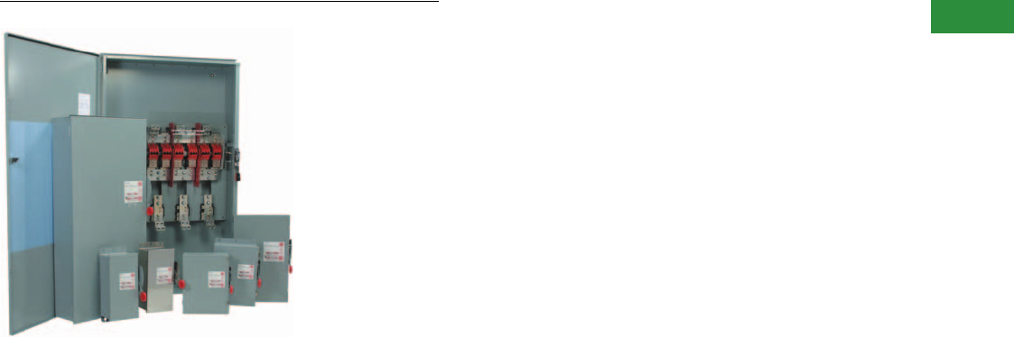
Volume 2—Commercial Distribution CA08100003E—April 2014 www.eaton.com V2-T1-69
1
1
1
1
1
1
1
1
1
1
1
1
1
1
1
1
1
1
1
1
1
1
1
1
1
1
1
1
1
1
1.1
Switching Devices
Safety Switches
Solar Combiner Boxes
Contents
Description Page
Product Overview . . . . . . . . . . . . . . . . . . . . . . . . . . . . V2-T1-3
General Duty . . . . . . . . . . . . . . . . . . . . . . . . . . . . . . . . V2-T1-26
Heavy-Duty . . . . . . . . . . . . . . . . . . . . . . . . . . . . . . . . . V2-T1-31
Six-Pole Switches. . . . . . . . . . . . . . . . . . . . . . . . . . . . . V2-T1-43
Double-Throw Switches . . . . . . . . . . . . . . . . . . . . . . . V2-T1-45
EnviroLine—Stainless Steel Switch. . . . . . . . . . . . . . . V2-T1-53
EnviroLine—Upper and Lower Window Switches. . . . V2-T1-56
EnviroLine—Receptacle Switches. . . . . . . . . . . . . . . . V2-T1-59
EnviroLine—Non-Metallic KRYDON Switch . . . . . . . . V2-T1-61
NEMA 7/9—Hazardous Location Disconnect Switch . V2-T1-63
Quick Connect Switches . . . . . . . . . . . . . . . . . . . . . . . V2-T1-65
Solar Disconnect Switch . . . . . . . . . . . . . . . . . . . . . . . V2-T1-67
Solar Combiner Box—Source Combiner and
Array Combiner. . . . . . . . . . . . . . . . . . . . . . . . . . . . . . . . .
V2-T1-69
Features . . . . . . . . . . . . . . . . . . . . . . . . . . . . . . . . . V2-T1-70
Standards and Certifications . . . . . . . . . . . . . . . . . V2-T1-70
Product Selection. . . . . . . . . . . . . . . . . . . . . . . . . . V2-T1-71
Dimensions . . . . . . . . . . . . . . . . . . . . . . . . . . . . . . V2-T1-71
316-Grade Stainless Steel Safety Switches. . . . . . . . . V2-T1-72
Mill-Duty Rated, Heavy-Duty, Fusible, Non-Fusible,
Single-Throw . . . . . . . . . . . . . . . . . . . . . . . . . . . . . . . V2-T1-76
Heavy-Duty Fusible Safety Switches Accepting
Cube Fuses . . . . . . . . . . . . . . . . . . . . . . . . . . . . . . . .
V2-T1-78
Elevator Control Switch . . . . . . . . . . . . . . . . . . . . . . . . V2-T1-81
Auxiliary Power Heavy-Duty Safety Switch . . . . . . . . . V2-T1-83
Left-Handed Safety Switch . . . . . . . . . . . . . . . . . . . . . V2-T1-86
200% Neutral Safety Switches . . . . . . . . . . . . . . . . . . V2-T1-87
Pringle Bolted Pressure Switch . . . . . . . . . . . . . . . . . . V2-T1-88
Type DS, Fusible and Non-Fusible . . . . . . . . . . . . . . . . V2-T1-91
Type Visi-Flex DE-ION . . . . . . . . . . . . . . . . . . . . . . . . . V2-T1-94
Flange Mounted—Variable Depth . . . . . . . . . . . . . . . . V2-T1-98
Flange Mounted—Fixed Depth . . . . . . . . . . . . . . . . . . V2-T1-102
Solar Combiner Box—Source Combiner and Array Combiner
Product Description
Photovoltaic (PV) systems
contain many separate DC
source circuits that must be
combined into a single circuit
prior to inversion into clean,
usable AC power for the
electric grid.
Solar combiner boxes
aggregate the many DC
source circuits present in
a solar PV system, and
provide the overcurrent
protection requirements of
the National Electrical Code.
Containing input fuse holders
for source protection, the
load sides of the fuse holders
are connected together on a
common bus that contains
the output lugs, allowing
multiple circuits to be
combined into one
outgoing circuit.
Eaton’s combiner boxes
are available in two styles—
source combiners and
array combiners. Source
combiners are located closer
to the source, or the solar
panels. They have smaller
input fuse holders and lower
output currents.
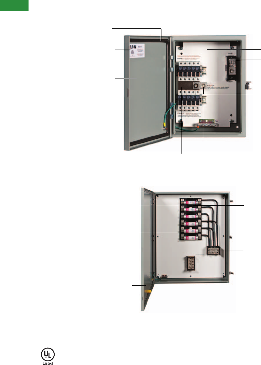
V2-T1-70 Volume 2—Commercial Distribution CA08100003E—April 2014 www.eaton.com
1
1
1
1
1
1
1
1
1
1
1
1
1
1
1
1
1
1
1
1
1
1
1
1
1
1
1
1
1
1
1.1
Switching Devices
Safety Switches
Features
Source Combiner Features
Array Combiner Features
Standards and Certifications
●ETL listed to UL 1741
ETL Listed to UL 1741 Standard
Tou c h - S a fe Mid g et C l a s s Fu s e
Holders (non load-break) are Rated
for 600 Vdc Continuous Duty
Poured-in-Place Gaskets for
Superior Moisture Resistance
Suitable for Either Positive or
Negative Grounded Arrays
Available in 8, 10, 12, 16 and
24 Circuit Configurations
NEMA 3R or NEMA 4 Powder-
Coated Steel Enclosures
194°F (90ºC) Rated Output Terminals
White Backpan with High-Contrast
Labeling for Easier, Faster Installation
Padlockable Latch
ETL Listed to UL 1741 Standard
Rated for 600 Vdc Continuous Duty
Poured-in-Place Gaskets for
Superior Moisture
Resistance
Suitable for Either Positive or
Negative Grounded Arrays
Available in 6 and 12 Circuit Configurations
100 or 200A Input Fuse Holders (Class R)
Note: Fuses not included.

Volume 2—Commercial Distribution CA08100003E—April 2014 www.eaton.com V2-T1-71
1
1
1
1
1
1
1
1
1
1
1
1
1
1
1
1
1
1
1
1
1
1
1
1
1
1
1
1
1
1
1.1
Switching Devices
Safety Switches
Product Selection
Source Combiners
Array Combiners
Dimensions
Approximate Dimensions in Inches (mm)
Source Combiners
Array Combiners
Notes
1Fuses not included.
2Total installed fuse capacity shall not exceed maximum continuous DC current rating.
Number
of Circuits
Maximum
Fuse Size 1
Incoming
Wire Range
Output
Conductors
Maximum
Continuous
DC Current
NEMA 3R
Catalog Number
NEMA 4
Catalog Number
8 30 #16–#4 1–#6 to 350 kcmil 310 SC8R SC8P
10 30 #16–#4 1–#6 to 350 kcmil 310 SC10R SC10P
12 30 #16–#4 1–#6 to 350 kcmil 310 SC12R SC12P
16 30 #16–#4 2–#6 to 350 kcmil 400 SC16R SC16P
24 20 2#16–#4 2–#6 to 350 kcmil 400 2SC24R SC24P
Number
of Circuits
Maximum
Fuse Size 1
Incoming
Wire Range
Output
Conductors
Maximum
Continuous
DC Current
NEMA 3R
Catalog Number
NEMA 4
Catalog Number
6 100 #6–2/0 2–#4 to 500 kcmil 720 AC6100R AC6100P
12 100 #6–2/0 4–#4 to 500 kcmil 1520 AC12100R AC12100P
6 200 #6–4/0 4–#4 to 500 kcmil 1520 AC6200R AC6200P
12 200 2#6–4/0 4–#4 to 500 kcmil 1520 2AC12200R AC12200P
NEMA 3R
Catalog Number
NEMA 4
Catalog Number
Dimensions Weight in
Lbs (kg)Height Width Depth
SC8R SC8P 16.00 (406.4) 12.00 (304.8) 6.00 (152.4) 30 (13.6)
SC10R SC10P 16.00 (406.4) 12.00 (304.8) 6.00 (152.4) 30 (13.6)
SC12R SC12P 16.00 (406.4) 12.00 (304.8) 6.00 (152.4) 30 (13.6)
SC16R SC16P 16.00 (406.4) 12.00 (304.8) 6.00 (152.4) 36 (16.3)
SC24R SC24P 20.00 (508.0) 20.00 (508.0) 6.00 (152.4) 45 (20.4)
NEMA 3R
Catalog Number
NEMA 4
Catalog Number
Dimensions Weight in
Lbs (kg)Height Width Depth
AC6100R AC6100P 36.00 (914.4) 36.00 (914.4) 8.00 (203.2) 156 (70.8)
AC12100R AC12100P 48.00 (1219.2) 36.00 (914.4) 8.00 (203.2) 227 (103.0)
AC6200R AC6200P 42.00 (1066.8) 36.00 (914.4) 8.00 (203.2) 206 (93.5)
AC12200R AC12200P 48.00 (1219.2) 36.00 (914.4) 8.00 (203.2) 278 (126.2)
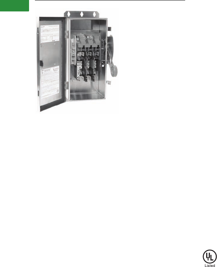
V2-T1-72 Volume 2—Commercial Distribution CA08100003E—April 2014 www.eaton.com
1
1
1
1
1
1
1
1
1
1
1
1
1
1
1
1
1
1
1
1
1
1
1
1
1
1
1
1
1
1
1.1
Switching Devices
Safety Switches
DH362NWK316
Contents
Description Page
Product Overview . . . . . . . . . . . . . . . . . . . . . . . . . . . . V2-T1-3
General Duty. . . . . . . . . . . . . . . . . . . . . . . . . . . . . . . . V2-T1-26
Heavy-Duty . . . . . . . . . . . . . . . . . . . . . . . . . . . . . . . . . V2-T1-31
Six-Pole Switches . . . . . . . . . . . . . . . . . . . . . . . . . . . . V2-T1-43
Double-Throw Switches . . . . . . . . . . . . . . . . . . . . . . . V2-T1-45
EnviroLine—Stainless Steel Switch . . . . . . . . . . . . . . V2-T1-53
EnviroLine—Upper and Lower Window Switches . . . V2-T1-56
EnviroLine—Receptacle Switches . . . . . . . . . . . . . . . V2-T1-59
EnviroLine—Non-Metallic KRYDON Switch . . . . . . . . V2-T1-61
NEMA 7/9—Hazardous Location Disconnect Switch . V2-T1-63
Quick Connect Switches. . . . . . . . . . . . . . . . . . . . . . . V2-T1-65
Solar Disconnect Switch . . . . . . . . . . . . . . . . . . . . . . . V2-T1-67
Solar Combiner Box—Source Combiner and
Array Combiner . . . . . . . . . . . . . . . . . . . . . . . . . . . . . V2-T1-69
316-Grade Stainless Steel Safety Switches
Product Selection . . . . . . . . . . . . . . . . . . . . . . . . . V2-T1-73
Mill-Duty Rated, Heavy-Duty, Fusible, Non-Fusible,
Single-Throw
. . . . . . . . . . . . . . . . . . . . . . . . . . . . . . . V2-T1-76
Heavy-Duty Fusible Safety Switches Accepting
Cube Fuses . . . . . . . . . . . . . . . . . . . . . . . . . . . . . . . V2-T1-78
Elevator Control Switch. . . . . . . . . . . . . . . . . . . . . . . . V2-T1-81
Auxiliary Power Heavy-Duty Safety Switch. . . . . . . . . V2-T1-83
Left-Handed Safety Switch . . . . . . . . . . . . . . . . . . . . . V2-T1-86
200% Neutral Safety Switches. . . . . . . . . . . . . . . . . . V2-T1-87
Pringle Bolted Pressure Switch. . . . . . . . . . . . . . . . . . V2-T1-88
Type DS, Fusible and Non-Fusible. . . . . . . . . . . . . . . . V2-T1-91
Type Visi-Flex DE-ION . . . . . . . . . . . . . . . . . . . . . . . . . V2-T1-94
Flange Mounted—Variable Depth. . . . . . . . . . . . . . . . V2-T1-98
Flange Mounted—Fixed Depth. . . . . . . . . . . . . . . . . . V2-T1-102
316-Grade Stainless Steel Safety Switches
Product Description
Premium 316-Grade stainless
steel enclosures are available
through the Flex Center. In
general, 316-Grade stainless
steel offers better corrosion
resistance in the presence of
most chemicals, salts and
acids, and is more resistant to
marine atmospheres. Pitting
corrosion is also reduced in
environments where brines,
halogen salts and chlorides are
present. 316-Grade stainless
steel is often a desirable choice
for waste-water treatment
plants and petrochemical
facilities.
Features
●Stainless steel enclosure
(316-Grade)
●30–1200A
●Horsepower rated
●Suitable for service
entrance use
●For factory modifications,
refer to Pages V2-T1-16
through V2-T1-19
Standards and Certifications
●UL listed File No. E5239

Volume 2—Commercial Distribution CA08100003E—April 2014 www.eaton.com V2-T1-73
1
1
1
1
1
1
1
1
1
1
1
1
1
1
1
1
1
1
1
1
1
1
1
1
1
1
1
1
1
1
1.1
Switching Devices
Safety Switches
Product Selection
240 Vac Fusible—316 Grade Stainless Steel NEMA 4X
Notes
1Grounded B phase ratings, UL listed.
2Contact the Safety Switch Flex Center (1-888-329-9272 or FlexSwitches@eaton.com) for availability of this product.
Operating mechanism is standard plated steel. For type 304 stainless steel operating mechanism, contact the Safety Switch Flex Center (1-888-329-9272 or FlexSwitches@eaton.com).
System
Ampere
Rating
Fuse Type
Provision
Maximum Horsepower Ratings
NEMA 4X Enclosure
Corrosion-Resistant,
Stainless Steel
Catalog Number
AC
DC
250V
Standard Fuse Time Delay
Single-Phase Three-Phase Single-Phase Three-Phase
Three-Wire (Two Blades, Two Fuses, S/N)—240 Vac, 250 Vdc
30 H 1-1/2 3 137-1/2 15DH221NWK316
60 H 3 7-1/2 110 15 110 DH222NWK316
100 H 7-1/2 15 115 30 120 DH223NWK316
200 H 15 25 115 60 140 DH224NWK316
400 H — 50 115 125 150 DH225NWK316
600 H — 75 1—200 1—DH226NWK316
800 L — 100 1———DH227NWK316
Three-Pole—240 Vac, 250 Vdc (Suitable for Service Entrance Use with a Neutral Kit Installed)
30 H 1-1/2 3 — 7-1/2 — DH321FWK316
60 H 3 7-1/2 — 15 — DH322FWK316
100 H 7-1/2 15 — 30 20 2
200 H 15 25 — 60 40 DH324FWK316
400 H — 50 — 125 50 DH325FWK316
600 H — 75 — 200 — DH326FWK316
800L—100—250—DH327FWK316
1200 L — — — — — DH328FWK316
Four-Wire (Three Blades, Three Fuses, S/N)—240 Vac, 250 Vdc
30 H — 3 — 7-1/2 — DH321NWK316
60 H — 7-1/2 — 15 — DH322NWK316
100 H — 15 — 30 20 DH323NWK316
200 H — 25 — 60 — DH324NWK316
400 H — 50 — 125 50 DH325NWK316
600 H — 75 — 200 — DH326NWK316
800L—100—250—
2
1200 L — — — — — DH328NWK316
S/N
S/N
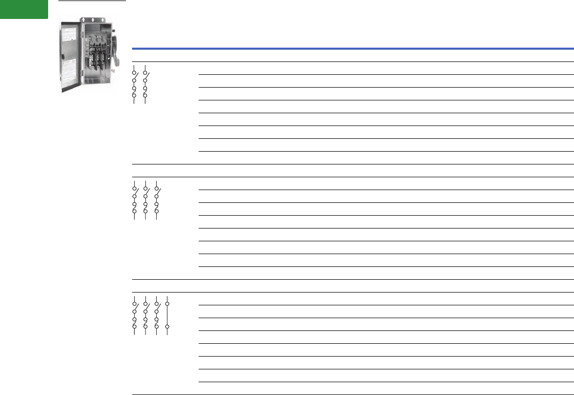
V2-T1-74 Volume 2—Commercial Distribution CA08100003E—April 2014 www.eaton.com
1
1
1
1
1
1
1
1
1
1
1
1
1
1
1
1
1
1
1
1
1
1
1
1
1
1
1
1
1
1
1.1
Switching Devices
Safety Switches
600 Vac Fusible—316 Grade Stainless Steel NEMA 4X
Notes
1 DC rating for 400–800A switches is 250V.
2 Use three-pole catalog numbers below for 600 Vac, 250 Vdc maximum applications. For 600 Vdc, see note 3.
3 Contact the Safety Switch Flex Center (1-888-329-9272 or FlexSwitches@eaton.com) for availability of this product.
System
Ampere
Rating
Fuse Class
Provision
Maximum Horsepower Ratings with Time Delay Fuses NEMA 4X Enclosure
Corrosion-Resistant,
Stainless Steel
Catalog Number
Single-Phase AC Three-Phase AC DC
480V 600V 480V 600V 250V 600V
Two-Pole—480 Vac—600 Vac or DC 1 (Suitable for Service Entrance Use with a Neutral Kit Installed)
30 H 7-1/2 10 — — — 15 DH261FWK316
60 H 20 25 — — — 25 2 or 3
100 H 30 40 — — 20 — 2 or 3
200 H 50 50 — — — 50 DH264FWK316
400H — — ——50—
2 or 3
600H — — ————
2 or 3
800L — — ————
2 or 3
1200 L — — — — — — 3
Three-Pole—480 Vac—600 Vac, 250 Vdc (Suitable for Service Entrance Use with a Neutral Kit Installed)
30 H 7-1/2 10 15 20 — — DH361FWK316
60H 20253050——DH362FWK316
100 H 30 40 60 75 — — DH363FWK316
200 H 50 50 125 150 — — DH364FWK316
400 H — — 250 350 — — DH365FWK316
600 H — — 400 500 — — DH366FWK316
800 L — — 500 500 — — DH367FWK316
1200 L — — — — — — DH368FWK316
Four-Wire (Three Blades, Three Fuses, S/N) 480 Vac—600 Vac, 250 Vdc
30 H 7-1/2 10 15 20 — — DH361NWK316
60H 20253050——DH362NWK316
100 H 30 40 60 75 — — DH363NWK316
200 H 50 50 125 150 — — DH364NWK316
400 H — — 250 350 — — DH365NWK316
600 H — — 400 500 — — DH366NWK316
800 L — — 500 500 — — 3
1200 L — — — — — — DH368NWK316
DH362NWK316
S/N

Volume 2—Commercial Distribution CA08100003E—April 2014 www.eaton.com V2-T1-75
1
1
1
1
1
1
1
1
1
1
1
1
1
1
1
1
1
1
1
1
1
1
1
1
1
1
1
1
1
1
1.1
Switching Devices
Safety Switches
600 Vac Non-Fusible Three-Pole—316 Grade Stainless Steel NEMA 4X
600 Vac Non-Fusible Four-Pole—316 Grade Stainless Steel NEMA 4X
Note
1Contact the Safety Switch Flex Center (1-888-329-9272 or FlexSwitches@eaton.com) for availability of this product.
System
Ampere
Rating
Maximum Horsepower Ratings NEMA 4X Enclosure
Corrosion-Resistant,
Stainless Steel
Catalog Number
Single-Phase AC Three-Phase AC DC
240V 480V 600V 240V 480V 600V 250V 600V
Three-Pole—480 Vac—600 Vac, 250 Vdc (Suitable for Service Entrance Use with a Neutral Kit Installed)
30 3 7-1/2 10 10 20 30 5 — DH361UWK316
60 10 20 25 20 50 60 10 — DH362UWK316
100 20 40 50 40 75 100 20 — DH363UWK316
200 15 50 50 60 125 150 40 — DH364UWK316
400 — — — 125 250 350 50 — DH365UWK316
600 — — — 200 400 500 — — DH366UWK316
800 — — — — 500 500 — — DH367UWK316
1200————————DH368UWK316
System
Ampere
Rating
Maximum Horsepower Ratings NEMA 4X Enclosure
Corrosion-Resistant,
Stainless Steel
Catalog Number
Two-Phase AC Three-Phase AC DC
240V 480V 600V 240V 480V 600V 250V 600V
Four-Pole—480 Vac—600 Vac, 250 Vdc
30 10 20 25 10 20 30 5 — DH461UWK316
60 20 40 50 20 50 60 10 — 1
100 40 50 50 40 75 100 20 — 1
200 50 50 50 60 125 150 40 — 1
400 50 — — 125 250 350 — — 1
600 — — — 200 400 500 — — 1
800 ————————1
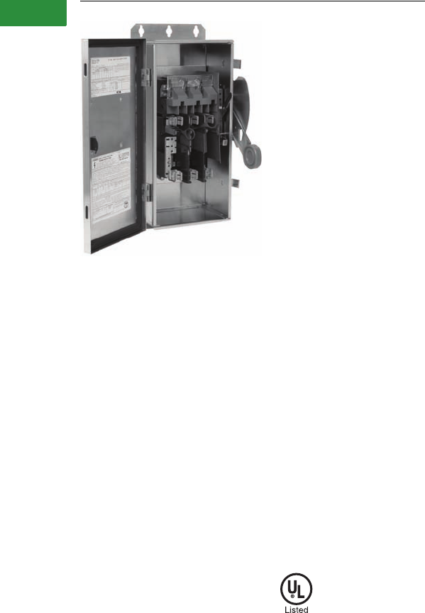
V2-T1-76 Volume 2—Commercial Distribution CA08100003E—April 2014 www.eaton.com
1
1
1
1
1
1
1
1
1
1
1
1
1
1
1
1
1
1
1
1
1
1
1
1
1
1
1
1
1
1
1.1
Switching Devices
Safety Switches
DH361FWK-GCL
Contents
Description Page
Product Overview . . . . . . . . . . . . . . . . . . . . . . . . . . . . V2-T1-3
General Duty. . . . . . . . . . . . . . . . . . . . . . . . . . . . . . . . V2-T1-26
Heavy-Duty . . . . . . . . . . . . . . . . . . . . . . . . . . . . . . . . . V2-T1-31
Six-Pole Switches . . . . . . . . . . . . . . . . . . . . . . . . . . . . V2-T1-43
Double-Throw Switches . . . . . . . . . . . . . . . . . . . . . . . V2-T1-45
EnviroLine—Stainless Steel Switch . . . . . . . . . . . . . . V2-T1-53
EnviroLine—Upper and Lower Window Switches . . . V2-T1-56
EnviroLine—Receptacle Switches . . . . . . . . . . . . . . . V2-T1-59
EnviroLine—Non-Metallic KRYDON Switch . . . . . . . . V2-T1-61
NEMA 7/9—Hazardous Location Disconnect Switch . V2-T1-63
Quick Connect Switches. . . . . . . . . . . . . . . . . . . . . . . V2-T1-65
Solar Disconnect Switch . . . . . . . . . . . . . . . . . . . . . . . V2-T1-67
Solar Combiner Box—Source Combiner and
Array Combiner . . . . . . . . . . . . . . . . . . . . . . . . . . . . . V2-T1-69
316-Grade Stainless Steel Safety Switches . . . . . . . . V2-T1-72
Mill-Duty Rated, Heavy-Duty, Fusible, Non-Fusible,
Single-Throw
Product Selection . . . . . . . . . . . . . . . . . . . . . . . . . V2-T1-77
Heavy-Duty Fusible Safety Switches Accepting
Cube Fuses . . . . . . . . . . . . . . . . . . . . . . . . . . . . . . . V2-T1-78
Elevator Control Switch. . . . . . . . . . . . . . . . . . . . . . . . V2-T1-81
Auxiliary Power Heavy-Duty Safety Switch. . . . . . . . . V2-T1-83
Left-Handed Safety Switch . . . . . . . . . . . . . . . . . . . . . V2-T1-86
200% Neutral Safety Switches. . . . . . . . . . . . . . . . . . V2-T1-87
Pringle Bolted Pressure Switch. . . . . . . . . . . . . . . . . .
Type DS, Fusible and Non-Fusible. . . . . . . . . . . . . . . . V2-T1-91
Type Visi-Flex DE-ION . . . . . . . . . . . . . . . . . . . . . . . . . V2-T1-94
Flange Mounted—Variable Depth. . . . . . . . . . . . . . . . V2-T1-98
Flange Mounted—Fixed Depth. . . . . . . . . . . . . . . . . . V2-T1-102
Mill-Duty Rated, Heavy-Duty, Fusible, Non-Fusible, Single-Throw
Product Description
240V, 600 Vac Heavy-Duty,
Fusible, Non-Fusible,
Single-Throw
●30–600A
●Horsepower rated
●Suitable for service
entrance use
●Factory-installed copper
ground lug
●Copper terminal lugs
●Fuse pullers through 200A
●For factory modifications,
refer to Pages V2-T1-16
through V2-T1-19
Standards and Certifications
●UL listed File No. E5239
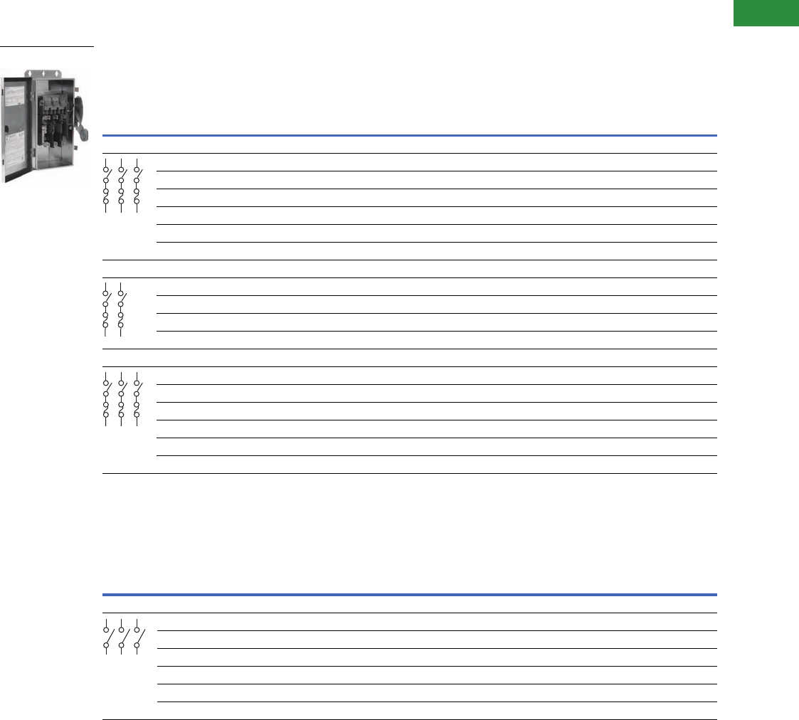
Volume 2—Commercial Distribution CA08100003E—April 2014 www.eaton.com V2-T1-77
1
1
1
1
1
1
1
1
1
1
1
1
1
1
1
1
1
1
1
1
1
1
1
1
1
1
1
1
1
1
1.1
Switching Devices
Safety Switches
Product Selection
Fusible
Non-Fusible 277/480–600V
Notes
1 Contact the Safety Switch Flex Center (1-888-329-9272 or FlexSwitches@eaton.com) for copper neutrals.
2 NEMA 12 enclosures (30–600A) can be field modified to meet NEMA 3R rainproof requirements when a factory provided drain hole is opened.
3 Contact the Safety Switch Flex Center (1-888-329-9272 or FlexSwitches@eaton.com) for availability of this product.
4 Use three-pole catalog numbers below for 600 Vac, 250 Vdc maximum applications. For 600 Vdc, see note 3.
5 DC rating for 400–600A switches is 250V.
6 For two-pole applications, use outside poles of three-pole switch.
System
Ampere
Rating
Fuse
Class
Provision
Maximum Horsepower Ratings with Time Delay Fuses
NEMA 12 Enclosure
Industrial, Dust-Tight
Catalog Number
NEMA 4X Enclosure
Corrosion-Resistant,
Stainless Steel
Catalog Number
AC
DCStandard Fuse Time Delay
Single-
Phase
Three-
Phase
Single-
Phase
Three-
Phase 250V 600V
Three-Pole—240 Vac, 250 Vdc (Suitable for Service Entrance Use with a Neutral Kit Installed) 1
30 H 1-1/2 3 — 7-1/2 — — DH321FDK-GCL 2DH321FWK-GCL
60 H 3 7-1/2 — 15 — — DH322FDK-GCL 2DH322FWK-GCL
100 H 7-1/2 15 — 30 20 — DH323FDK-GCL 23
200 H 15 25 — 60 40 — DH324FDK-GCL 2DH324FWK-GCL
400 H — 50 — 125 50 — DH325FDK-GCL 2DH325FWK-GCL
600 H — 75 — 200 — — DH326FDK-GCL 2DH326FWK-GCL
Two-Pole—480 Vac—600 Vac or DC 5 (Suitable for Service Entrance Use with a Neutral Kit Installed) 1
30 H 7-1/2 10 — — — 15 DH261FDK-GCL 2DH261FWK-GCL
60 H 20 25 — — — 25 DH262FDK-GCL 23
or 4
100 H 30 40 — — — 25 DH263FDK-GCL 23
or 4
200 H 50 50 — — — 50 DH264FDK-GCL 2DH264FWK-GCL
Three-Pole—480 Vac—600 Vac, 250 Vdc (Suitable for Service Entrance Use with a Neutral Kit Installed) 1
30 H 7-1/2 10 15 20 — — DH361FDK-GCL 2DH361FWK-GCL
60 H 20 25 30 50 — — DH362FDK-GCL 2DH362FWK-GCL
100 H 30 40 60 75 — — DH363FDK-GCL 2DH363FWK-GCL
200 H 50 50 125 150 — — DH364FDK-GCL 2DH364FWK-GCL
400 H — — 250 350 — — DH365FDK-GCL 2DH365FWK-GCL
600 H — — 400 500 — — DH366FDK-GCL 2DH366FWK-GCL
System
Ampere
Rating
Fuse
Class
Provision
Maximum Horsepower Ratings
NEMA 12 Enclosure
Industrial, Dust-Tight
Catalog Number
NEMA 4X Enclosure
Corrosion-Resistant,
Stainless Steel
Catalog Number
AC
DCStandard Fuse Time Delay
Single-
Phase
Three-
Phase
Single-
Phase
Three-
Phase 250V 600V
Three-Pole—480 Vac—600 Vac, 250 Vdc 6 (Suitable for Service Entrance use with a Neutral Kit Installed) 1
30 — 7-1/2 10 20 30 5 — DH361UDK-GCL 2DH361UWK-GCL
60—2025506010—DH362UDK-GCL 2DH362UWK-GCL
100 — 40 50 75 100 20 — DH363UDK-GCL 2DH363UWK-GCL
200 — 50 50 125 150 40 — DH364UDK-GCL 2DH364UWK-GCL
400 — — — 250 350 50 — DH365UDK-GCL 2DH365UWK-GCL
600 — — — 400 500 — — DH366UDK-GCL 2DH366UWK-GCL
DH361FWK-GCL
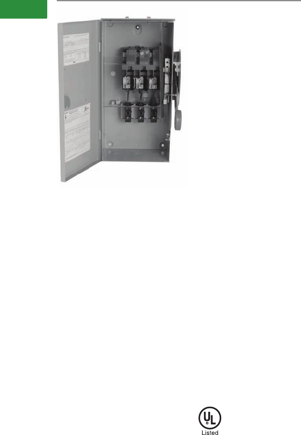
V2-T1-78 Volume 2—Commercial Distribution CA08100003E—April 2014 www.eaton.com
1
1
1
1
1
1
1
1
1
1
1
1
1
1
1
1
1
1
1
1
1
1
1
1
1
1
1
1
1
1
1.1
Switching Devices
Safety Switches
DH361FRKCB
Contents
Description Page
Product Overview . . . . . . . . . . . . . . . . . . . . . . . . . . . . V2-T1-3
General Duty. . . . . . . . . . . . . . . . . . . . . . . . . . . . . . . . V2-T1-26
Heavy-Duty . . . . . . . . . . . . . . . . . . . . . . . . . . . . . . . . . V2-T1-31
Six-Pole Switches . . . . . . . . . . . . . . . . . . . . . . . . . . . . V2-T1-43
Double-Throw Switches . . . . . . . . . . . . . . . . . . . . . . . V2-T1-45
EnviroLine—Stainless Steel Switch . . . . . . . . . . . . . . V2-T1-53
EnviroLine—Upper and Lower Window Switches . . . V2-T1-56
EnviroLine—Receptacle Switches . . . . . . . . . . . . . . . V2-T1-59
EnviroLine—Non-Metallic KRYDON Switch . . . . . . . . V2-T1-61
NEMA 7/9—Hazardous Location Disconnect Switch . V2-T1-63
Quick Connect Switches. . . . . . . . . . . . . . . . . . . . . . . V2-T1-65
Solar Disconnect Switch . . . . . . . . . . . . . . . . . . . . . . . V2-T1-67
Solar Combiner Box—Source Combiner and
Array Combiner . . . . . . . . . . . . . . . . . . . . . . . . . . . . . V2-T1-69
316-Grade Stainless Steel Safety Switches . . . . . . . . V2-T1-72
Mill-Duty Rated, Heavy-Duty, Fusible, Non-Fusible,
Single-Throw
. . . . . . . . . . . . . . . . . . . . . . . . . . . . . . . V2-T1-76
Heavy-Duty Fusible Safety Switches Accepting
Cube Fuses
Product Selection . . . . . . . . . . . . . . . . . . . . . . . . . V2-T1-79
Elevator Control Switch. . . . . . . . . . . . . . . . . . . . . . . . V2-T1-81
Auxiliary Power Heavy-Duty Safety Switch. . . . . . . . . V2-T1-83
Left-Handed Safety Switch . . . . . . . . . . . . . . . . . . . . . V2-T1-86
200% Neutral Safety Switches. . . . . . . . . . . . . . . . . . V2-T1-87
Pringle Bolted Pressure Switch. . . . . . . . . . . . . . . . . . V2-T1-88
Type DS, Fusible and Non-Fusible. . . . . . . . . . . . . . . . V2-T1-91
Type Visi-Flex DE-ION . . . . . . . . . . . . . . . . . . . . . . . . . V2-T1-94
Flange Mounted—Variable Depth. . . . . . . . . . . . . . . . V2-T1-98
Flange Mounted—Fixed Depth. . . . . . . . . . . . . . . . . . V2-T1-102
Heavy-Duty Fusible Safety Switches Accepting Cube Fuses
Product Description
600 Vac Heavy-Duty,
Fusible, Single-Throw
Cube fuses installed in a
safety switch provide finger-
safe protection, Class J time
delay electrical performance
with a smaller footprint than
Class J or CC fusing, and
blown fuse indication.
●30–100A
●Horsepower rated
●For factory modifications,
refer to Pages V2-T1-16
through V2-T1-19
Standards and Certifications
●UL listed File No. E5239
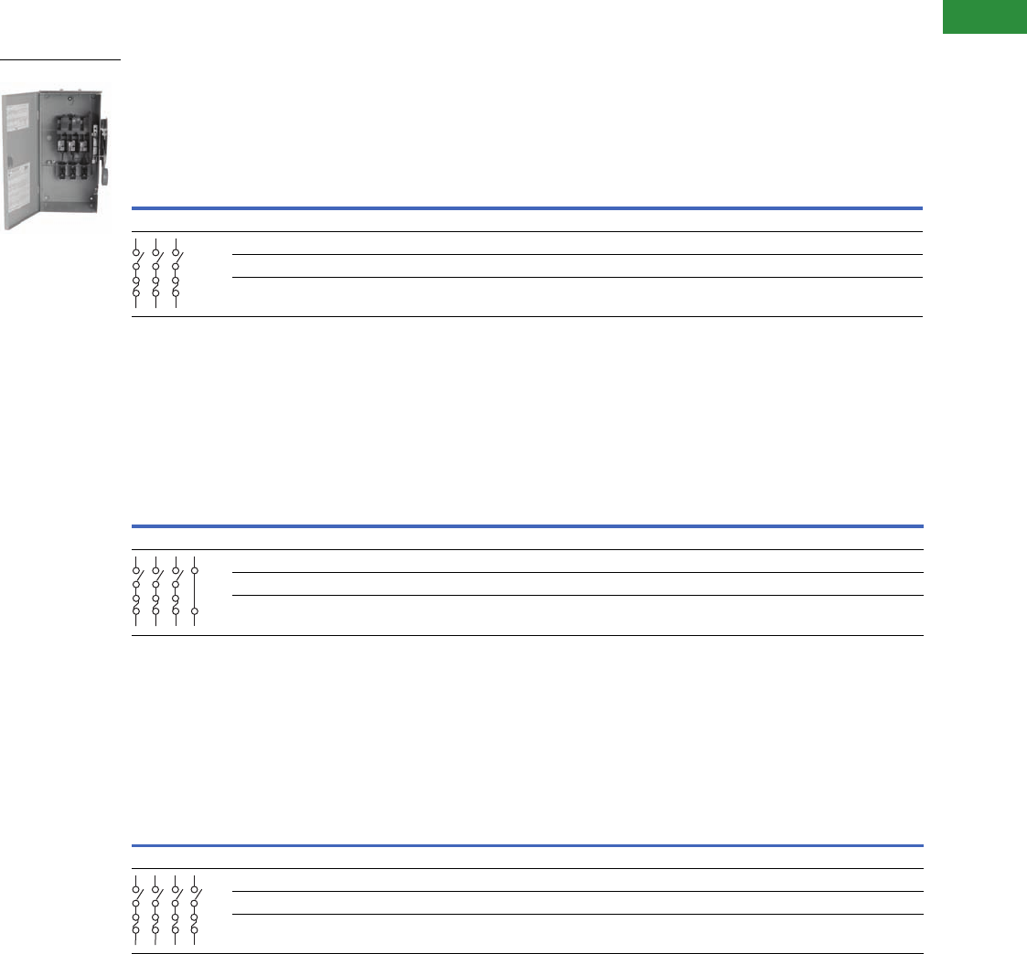
Volume 2—Commercial Distribution CA08100003E—April 2014 www.eaton.com V2-T1-79
1
1
1
1
1
1
1
1
1
1
1
1
1
1
1
1
1
1
1
1
1
1
1
1
1
1
1
1
1
1
1.1
Switching Devices
Safety Switches
Product Selection
Fusible 277/480–600V
Fusible 277/480–600V
Fusible 277/480–600V
Notes
1 NEMA 12 enclosures (30–100A) can be field modified to meet NEMA 3R rainproof requirements when a factory provided drain hole is opened.
2 Contact the Safety Switch Flex Center (1-888-329-9272 or FlexSwitches@eaton.com) for availability of this product.
System
Ampere
Rating
Fuse
Class
Provision
Maximum Horsepower Ratings
DC
NEMA 1
Enclosure
Indoor
NEMA 3R
Enclosure
Rainproof
NEMA 12
Enclosure
Industrial,
Dust-Tight
NEMA 4X
Enclosure
Corrosion-
Resistant,
Stainless
Steel
Single-
Phase AC
Three-
Phase AC
480V 600V 480V 600V 250V
Catalog
Number
Catalog
Number
Catalog
Number
Catalog
Number
Three-Pole—480 Vac—600 Vac, 250 Vdc (Suitable for Service Entrance Use with a Neutral Kit Installed)
30 Cube 7-1/2 10 15 20 — DH361FGKCB DH361FRKCB DH361FDKCB 1DH361FWKCB
60 Cube 20 25 30 50 — DH362FGKCB DH362FRKCB DH362FDKCB 1DH362FWKCB
100 Cube 30406075—DH363FGKCB DH363FRKCB DH363FDKCB 1DH363FWKCB
System
Ampere
Rating
Fuse
Class
Provision
Maximum Horsepower Ratings
DC
NEMA 1
Enclosure
Indoor
NEMA 3R
Enclosure
Rainproof
Blades, 3-Fuses S/N 480 Vac—600 Vac
NEMA 12
Enclosure
Industrial,
Dust-Tight
NEMA 4X
Enclosure
Corrosion-
Resistant,
Stainless
Steel
Single-
Phase AC
Three-
Phase AC
480V 600V 480V 600V 250V
Catalog
Number
Catalog
Number
Catalog
Number
Catalog
Number
Four-Wire (Three Blades, Three Fuses, S/N) 480 Vac—600 Vac, 250 Vdc
30 Cube 7-1/2 10 15 20 — DH361NGKCB DH361NRKCB DH361NDKCB 1DH361NWKCB
60 Cube 20 25 30 50 — DH362NGKCB DH362NRKCB DH362NDKCB 1DH362NWKCB
100 Cube 30406075—DH363NGKCB DH363NRKCB DH363NDKCB 1DH363NWKCB
System
Ampere
Rating
Fuse
Class
Provision
Maximum Horsepower Ratings
DC
NEMA 1
Enclosure
Indoor
NEMA 3R
Enclosure
Rainproof
Vac—600 Vac, 250 Vac
NEMA 12
Enclosure
Industrial,
Dust-Tight
NEMA 4X
Enclosure
Corrosion-
Resistant,
Stainless
Steel
Two-
Phase AC
Three-
Phase AC
480V 600V 480V 600V 250V
Catalog
Number
Catalog
Number
Catalog
Number
Catalog
Number
Four-Pole—480 Vac—600 Vac, 250 Vdc
30 Cube 20 25 15 20 — DH461FGKCB 112 2
60 Cube 40 50 30 50 — DH462FGKCB 112 2
100 Cube 50506075—DH463FGKCB 1DH463FDKCB 12
DH361FRKCB
S/N

V2-T1-80 Volume 2—Commercial Distribution CA08100003E—April 2014 www.eaton.com
1
1
1
1
1
1
1
1
1
1
1
1
1
1
1
1
1
1
1
1
1
1
1
1
1
1
1
1
1
1
1.1
Switching Devices
Safety Switches
Fusible with Window 277/480–600V
Notes
1NEMA 12 enclosures (30–100A) can be field modified to meet NEMA 3R rainproof requirements when a factory provided drain hole is opened.
Fuses are supplied as separate items.
System
Ampere
Rating
Fuse
Class
Provision
Maximum Horsepower Ratings
NEMA 12 Enclosure
Industrial, Dust-Tight
Catalog Number
NEMA 4X Enclosure
Corrosion-Resistant,
Stainless Steel
Catalog Number
Single-Phase AC Three-Phase AC DC
480V 600V 480V 600V 250V/600V
Four-Wire (Three Blades, Three Fuses, S/N), 600 Vac—250 Vdc 1
30
Cube
7-1/2 10 15 20 — DH361NDKWCB 1DH361NWKWCB
60
Cube
20 25 30 50 — DH362NDKWCB 1DH362NWKWCB
100
Cube
30 40 60 75 — DH363NDKWCB 1DH363NWKWCB
S/N
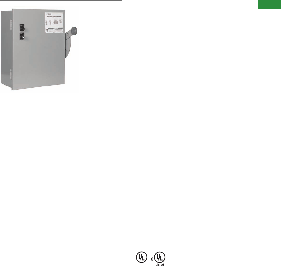
Volume 2—Commercial Distribution CA08100003E—April 2014 www.eaton.com V2-T1-81
1
1
1
1
1
1
1
1
1
1
1
1
1
1
1
1
1
1
1
1
1
1
1
1
1
1
1
1
1
1
1.1
Switching Devices
Safety Switches
Elevator Control Switch
Contents
Description Page
Product Overview . . . . . . . . . . . . . . . . . . . . . . . . . . . . V2-T1-3
General Duty . . . . . . . . . . . . . . . . . . . . . . . . . . . . . . . . V2-T1-26
Heavy-Duty . . . . . . . . . . . . . . . . . . . . . . . . . . . . . . . . . V2-T1-31
Six-Pole Switches. . . . . . . . . . . . . . . . . . . . . . . . . . . . . V2-T1-43
Double-Throw Switches . . . . . . . . . . . . . . . . . . . . . . . V2-T1-45
EnviroLine—Stainless Steel Switch. . . . . . . . . . . . . . . V2-T1-53
EnviroLine—Upper and Lower Window Switches. . . . V2-T1-56
EnviroLine—Receptacle Switches. . . . . . . . . . . . . . . . V2-T1-59
EnviroLine—Non-Metallic KRYDON Switch . . . . . . . . V2-T1-61
NEMA 7/9—Hazardous Location Disconnect Switch . V2-T1-63
Quick Connect Switches . . . . . . . . . . . . . . . . . . . . . . . V2-T1-65
Solar Disconnect Switch . . . . . . . . . . . . . . . . . . . . . . . V2-T1-67
Solar Combiner Box—Source Combiner and
Array Combiner. . . . . . . . . . . . . . . . . . . . . . . . . . . . . V2-T1-69
316-Grade Stainless Steel Safety Switches. . . . . . . . . V2-T1-72
Mill-Duty Rated, Heavy-Duty, Fusible, Non-Fusible,
Single-Throw . . . . . . . . . . . . . . . . . . . . . . . . . . . . . . . V2-T1-76
Heavy-Duty Fusible Safety Switches Accepting
Cube Fuses . . . . . . . . . . . . . . . . . . . . . . . . . . . . . . . .
V2-T1-78
Elevator Control Switch
Catalog Number Selection . . . . . . . . . . . . . . . . . . . V2-T1-82
Technical Data and Specifications . . . . . . . . . . . . . V2-T1-82
Dimensions . . . . . . . . . . . . . . . . . . . . . . . . . . . . . . V2-T1-82
Auxiliary Power Heavy-Duty Safety Switch . . . . . . . . . V2-T1-83
Left-Handed Safety Switch . . . . . . . . . . . . . . . . . . . . . V2-T1-86
200% Neutral Safety Switches . . . . . . . . . . . . . . . . . . V2-T1-87
Pringle Bolted Pressure Switch . . . . . . . . . . . . . . . . . . V2-T1-88
Type DS, Fusible and Non-Fusible . . . . . . . . . . . . . . . . V2-T1-91
Type Visi-Flex DE-ION . . . . . . . . . . . . . . . . . . . . . . . . . V2-T1-94
Flange Mounted—Variable Depth . . . . . . . . . . . . . . . . V2-T1-98
Flange Mounted—Fixed Depth . . . . . . . . . . . . . . . . . . V2-T1-102
Elevator Control Switch
Features, Benefits and Functions
Standard Features
●30–400A, 600 Vac three-
phase fused power switch
●200,000A rms short-circuit
current rating
●Shunt trip 120V
●Control power
terminal block
●Ground lug per NEC
●Class J Fuse mounting only
(Class J Fuses
not included)
●Key to test switch 120V
●Mechanically interlocked
auxiliary contact for
hydraulic elevators with
automatic recall (5A,
120 Vac rated) 1NO, 1NC
Optional Features
●Control power transformer
with fuses and blocks
●Fire safety interface relay
●Pilot light—ON
●Isolated neutral lug
(oversized 200% rated
neutral option available
where required by
excessive nonlinear loads)
●Fire alarm voltage
monitoring relay (to
monitor shunt trip voltage)
●NEMA 3R, 4 and 12
enclosures available
through 200A
●Phase failure and
undervoltage relay
available, consult factory
●For added protection,
use Eaton fuse covers
to improve maintenance
personnel protection,
through 200A (OSHA
1910.333, Paragraph C)
Standards and Certifications
●UL 98 Enclosed and
Deadfront Switch
Guide 96NK3917,
File No. E182262
●NEMA 1, UL 50,
listed enclosure
●cUL® per Canadian
Standards C22.2,
No. 0-M91-CAN/CSA®
C22.2, No. 4-M89
Enclosed Switch
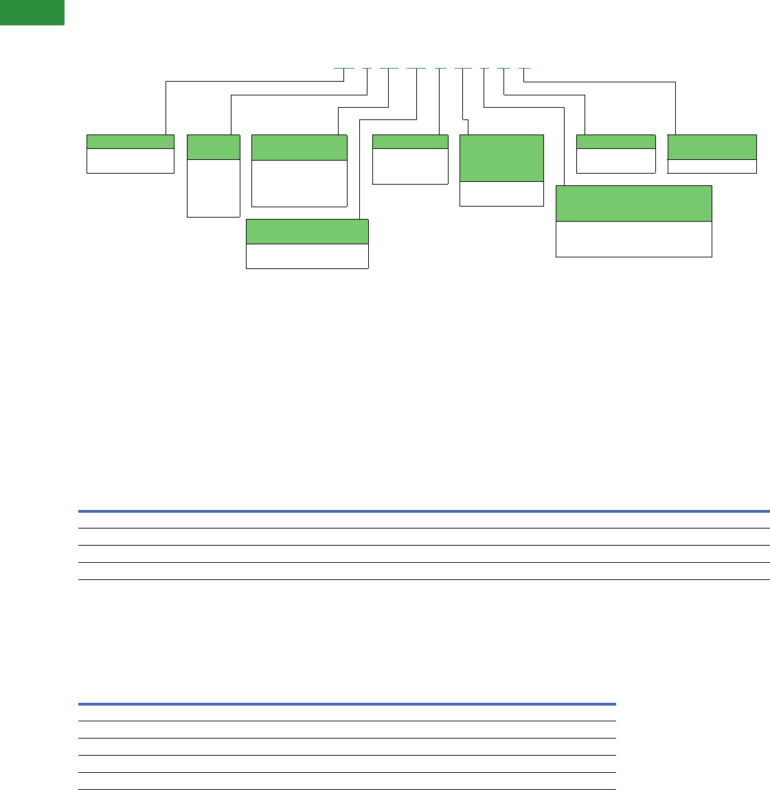
V2-T1-82 Volume 2—Commercial Distribution CA08100003E—April 2014 www.eaton.com
1
1
1
1
1
1
1
1
1
1
1
1
1
1
1
1
1
1
1
1
1
1
1
1
1
1
1
1
1
1
1.1
Switching Devices
Safety Switches
Catalog Number Selection
Elevator Control Switch
Catalog Number Example: ES3T1R1GF3
●100A S.T. switch 480V-3P—ES3
●480–120V CPT—T1
●120 Vac coil fire safety interface relay—R1
●Pilot light—ON (Green)—G
●Fire alarm voltage monitoring relay (three-pole)—F3
Technical Data and Specifications
Elevator Control Switch Maximum hp Rating—Sizing Based on Motor Type
Dimensions
Approximate Dimensions in Inches (mm)
Elevator Control Switch Dimensions and Lug Data
Notes
1Standard oversize enclosure to mount control power transformer fire safety interface relay and control terminal blocks.
2Contact factory for dimensions for NEMA 4 enclosure.
3Optional neutral lug size same as line and load.
Voltage Rating
(Vac Three-Phase)
Ampere Rating
30A, ES1 60A, ES2 100A, ES3 200A, ES4 400A, ES5
ABCABCABCABCABC
208 553101010201515404030———
240 555101010202015504030———
280 1010103025205040301007575———
600 151510303025605040125100100———
Ampere
Rating
NEMA 1 1NEMA 3R, 12 2
Lug Size 3
Catalog
NumberHeight Width Depth Height Width Depth
30 20.00 (508.0) 16.00 (406.4) 8.63 (219.2) 20.00 (508.0) 20.00 (508.0) 8.00 (203.2) #14–#8 Al or Cu ES1
60 20.00 (508.0) 16.00 (406.4) 8.63 (219.2) 20.00 (508.0) 20.00 (508.0) 8.00 (203.2) #14–#2 Al or Cu ES2
100 20.00 (508.0) 16.00 (406.4) 8.63 (219.2) 20.00 (508.0) 20.00 (508.0) 8.00 (203.2) #8–1/0 Al or Cu ES3
200 30.00 (762.0) 20.00 (508.0) 8.63 (219.2) 30.00 (762.0) 24.00 (609.6) 8.00 (203.2) #6–250 kcmil Al or Cu ES4
400 52.00 (320.8) 25.00 (635.0) 8.00 (203.2) 52.00 (1320.8) 25.00 (635.0) 8.00 (203.2) (2) I/O–(1) 750 ES5
Prefix
ES = Elevator control
switch
Ampere
Rating
1 = 30A
2 = 60A
3 = 100A
4 = 200A
5 = 400A
Control
Transformer 1
T2 = 208V
T3 = 240V
T1 = 480V
T4 = 600V
Fire Safety Interface Relay
(3PDT, 10A, 120V)
R2 = 24 Vdc coil
R1 = 120 Vac coil
Pilot Light ON
G=Green
R=Red
W=White
Fire Alarm Voltage
Monitoring Relay
(To Monitor Shunt
Trip Voltage)
F1 = Single-pole
F3 = Three-pole Enclosure Options
(NEMA 1 Standard With No
Suffix Designation Required)
3= NEMA 3R
D= NEMA 12
P= NEMA 4 painted steel
ES 1 T2 R2 G F1 3 N B
Neutral Lug
N = Isolated
full capacity
Auxiliary Contacts
1NO/1NC
B = Main switch
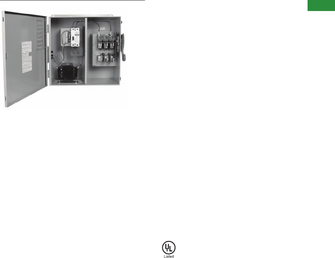
Volume 2—Commercial Distribution CA08100003E—April 2014 www.eaton.com V2-T1-83
1
1
1
1
1
1
1
1
1
1
1
1
1
1
1
1
1
1
1
1
1
1
1
1
1
1
1
1
1
1
1.1
Switching Devices
Safety Switches
DH323FRKA1240
Contents
Description Page
Product Overview . . . . . . . . . . . . . . . . . . . . . . . . . . . . V2-T1-3
General Duty . . . . . . . . . . . . . . . . . . . . . . . . . . . . . . . . V2-T1-26
Heavy-Duty . . . . . . . . . . . . . . . . . . . . . . . . . . . . . . . . . V2-T1-31
Six-Pole Switches. . . . . . . . . . . . . . . . . . . . . . . . . . . . . V2-T1-43
Double-Throw Switches . . . . . . . . . . . . . . . . . . . . . . . V2-T1-45
EnviroLine—Stainless Steel Switch. . . . . . . . . . . . . . . V2-T1-53
EnviroLine—Upper and Lower Window Switches. . . . V2-T1-56
EnviroLine—Receptacle Switches. . . . . . . . . . . . . . . . V2-T1-59
EnviroLine—Non-Metallic KRYDON Switch . . . . . . . . V2-T1-61
NEMA 7/9—Hazardous Location Disconnect Switch . V2-T1-63
Quick Connect Switches . . . . . . . . . . . . . . . . . . . . . . . V2-T1-65
Solar Disconnect Switch . . . . . . . . . . . . . . . . . . . . . . . V2-T1-67
Solar Combiner Box—Source Combiner and
Array Combiner. . . . . . . . . . . . . . . . . . . . . . . . . . . . . V2-T1-69
316-Grade Stainless Steel Safety Switches. . . . . . . . . V2-T1-72
Mill-Duty Rated, Heavy-Duty, Fusible, Non-Fusible,
Single-Throw . . . . . . . . . . . . . . . . . . . . . . . . . . . . . . . V2-T1-76
Heavy-Duty Fusible Safety Switches Accepting
Cube Fuses . . . . . . . . . . . . . . . . . . . . . . . . . . . . . . . .
V2-T1-78
Elevator Control Switch . . . . . . . . . . . . . . . . . . . . . . . . V2-T1-81
Auxiliary Power Heavy-Duty Safety Switch
Product Selection. . . . . . . . . . . . . . . . . . . . . . . . . . V2-T1-84
Left-Handed Safety Switch . . . . . . . . . . . . . . . . . . . . . V2-T1-86
200% Neutral Safety Switches . . . . . . . . . . . . . . . . . . V2-T1-87
Pringle Bolted Pressure Switch . . . . . . . . . . . . . . . . . .
Type DS, Fusible and Non-Fusible . . . . . . . . . . . . . . . . V2-T1-91
Type Visi-Flex DE-ION . . . . . . . . . . . . . . . . . . . . . . . . . V2-T1-94
Flange Mounted—Variable Depth . . . . . . . . . . . . . . . . V2-T1-98
Flange Mounted—Fixed Depth . . . . . . . . . . . . . . . . . . V2-T1-102
Auxiliary Power Heavy-Duty Safety Switch
Product Description
NEC Article 210.63 requires
that a 125V, single-phase,
15 or 20A rated receptacle
outlet be installed at an
accessible location for the
servicing of heating, air-
conditioning and refrigeration
equipment. The receptacle
must be located on the
same level and within 25 ft
(7.5m) of the heating, air-
conditioning and refrigeration
equipment. Eaton’s heavy-
duty safety switch is an
ideal solution for these
applications, including
elimination of the need for
running a separate 120V
circuit to the rooftop.
Features
●30–200A
●Horsepower rated
●NEMA 3R outdoor
enclosure standard
●15A ground fault
receptacle standard
●For factory modifications,
refer to Pages V2-T1-16
through V2-T1-19
Standards and Certifications
●UL listed File No. E5239
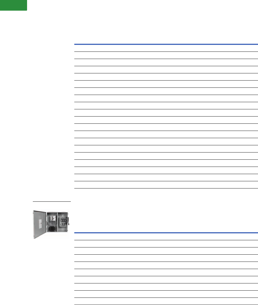
V2-T1-84 Volume 2—Commercial Distribution CA08100003E—April 2014 www.eaton.com
1
1
1
1
1
1
1
1
1
1
1
1
1
1
1
1
1
1
1
1
1
1
1
1
1
1
1
1
1
1
1.1
Switching Devices
Safety Switches
Product Selection
Non-Fusible 208 Vac—240 Vac—480 Vac—600 Vac—Three-Pole
Fusible 208 Vac—240 Vac—Three-Pole
Note
Contact the Safety Switch Flex Center (1-888-329-9272 or FlexSwitches@eaton.com) for additional options,
including 20A GFI receptacles.
Ampere
Rating
Maximum Horsepower Ratings
Catalog Number
Single-Phase AC Three-Phase AC
240V 480V 600V 240V 480V 600V
208 Vac
30 ——————DH321URKA1208
60 ——————DH322URKA1208
100 ——————DH323URKA1208
200 ——————DH324URKA1208
240 Vac
30 3 ——10 ——DH321URKA1240
60 10 ——20 ——DH322URKA1240
100 20——40 ——DH323URKA1240
200 15——60 ——DH324URKA1240
480 Vac
30 3 7-1/2 10 10 20 30 DH361URKA1480
60 10 20 25 20 50 60 DH362URKA1480
100 2040504075100DH363URKA1480
200 15 50 50 60 125 150 DH364URKA1480
600 Vac
30 3 7-1/2 10 10 20 30 DH361URKA1600
60 10 20 25 20 50 60 DH362URKA1600
100 2040504075100DH363URKA1600
200 15 50 50 60 125 150 DH364URKA1600
Ampere
Rating
Fuse Type
Provision
Maximum Horsepower Ratings
Catalog Number
AC
Standard Fuse Time Delay
Single-Phase Three-Phase Single-Phase Three-Phase
208 Vac
30 H — — — — DH321FRKA1208
60 H — — — — DH322FRKA1208
100 H — — — — DH323FRKA1208
200 H — — — — DH324FRKA1208
240 Vac
30 H 1-1/2 3 — 7-1/2 DH321FRKA1240
60 H 3 7-1/2 — 15 DH322FRKA1240
100 H 7-1/2 15 — 30 DH323FRKA1240
200 H 15 25 — 60 DH324FRKA1240
DH323FRKA1240

Volume 2—Commercial Distribution CA08100003E—April 2014 www.eaton.com V2-T1-85
1
1
1
1
1
1
1
1
1
1
1
1
1
1
1
1
1
1
1
1
1
1
1
1
1
1
1
1
1
1
1.1
Switching Devices
Safety Switches
Fusible 480 Vac—600 Vac—Three-Pole
Fusible 208 Vac—240 Vac—Three-Pole
Fusible 480 Vac—600 Vac—Three-Pole
Note
Contact the Safety Switch Flex Center (1-888-329-9272 or FlexSwitches@eaton.com) for additional options, including 20A GFI receptacles.
Ampere
Rating
Fuse Type
Provision
Maximum Horsepower Ratings with Time Delay Fuses
Catalog Number
Single-Phase AC Three-Phase AC
480V 600V 480V 600V
480 Vac
30 H 7-1/2 10 15 20 DH361FRKA1480
60H 20253050DH362FRKA1480
100H 30406075DH363FRKA1480
200 H 50 50 125 150 DH364FRKA1480
600 Vac
30 H 7-1/2 10 15 20 DH361FRKA1600
60H 20253050DH362FRKA1600
100H 30406075DH363FRKA1600
200 H 50 50 125 150 DH364FRKA1600
Ampere
Rating
Fuse Type
Provision
Maximum Horsepower Ratings
Catalog Number
AC
Standard Fuse Time Delay
Single-Phase Three-Phase Single-Phase Three-Phase
208 Vac
30 H — — — — DH321NRKA1208
60 H — — — — DH322NRKA1208
100 H — — — — DH323NRKA1208
200 H — — — — DH324NRKA1208
240 Vac
30 H 1-1/2 3 — 7-1/2 DH321NRKA1240
60 H 3 7-1/2 — 15 DH322NRKA1240
100 H 7-1/2 15 — 30 DH323NRKA1240
200 H 15 25 — 60 DH324NRKA1240
Ampere
Rating
Fuse Type
Provision
Maximum Horsepower Ratings with Time Delay Fuses
Catalog Number
Single-Phase AC Three-Phase AC
480V 600V 480V 600V
480 Vac
30 H 7-1/2 10 15 20 DH361NRKA1480
60 H 20 25 30 50 DH362NRKA1480
100 H 30 40 60 75 DH363NRKA1480
200 H 50 50 125 150 DH364NRKA1480
600 Vac
30 H 7-1/2 10 15 20 DH361NRKA1600
60 H 20 25 30 50 DH362NRKA1600
100 H 30 40 60 75 DH363NRKA1600
200 H 50 50 125 150 DH364NRKA1600
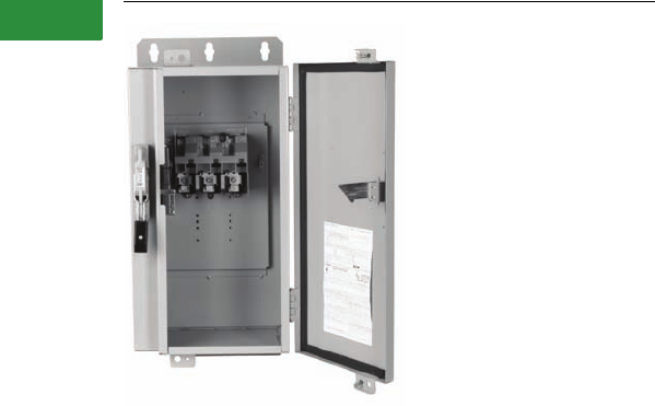
V2-T1-86 Volume 2—Commercial Distribution CA08100003E—April 2014 www.eaton.com
1
1
1
1
1
1
1
1
1
1
1
1
1
1
1
1
1
1
1
1
1
1
1
1
1
1
1
1
1
1
1.1
Switching Devices
Safety Switches
Left-Handed Safety Switch
Contents
Description Page
Product Overview . . . . . . . . . . . . . . . . . . . . . . . . . . . . V2-T1-3
General Duty. . . . . . . . . . . . . . . . . . . . . . . . . . . . . . . . V2-T1-26
Heavy-Duty . . . . . . . . . . . . . . . . . . . . . . . . . . . . . . . . . V2-T1-31
Six-Pole Switches . . . . . . . . . . . . . . . . . . . . . . . . . . . . V2-T1-43
Double-Throw Switches . . . . . . . . . . . . . . . . . . . . . . . V2-T1-45
EnviroLine—Stainless Steel Switch . . . . . . . . . . . . . . V2-T1-53
EnviroLine—Upper and Lower Window Switches . . . V2-T1-56
EnviroLine—Receptacle Switches . . . . . . . . . . . . . . . V2-T1-59
EnviroLine—Non-Metallic KRYDON Switch . . . . . . . . V2-T1-61
NEMA 7/9—Hazardous Location Disconnect Switch . V2-T1-63
Quick Connect Switches. . . . . . . . . . . . . . . . . . . . . . . V2-T1-65
Solar Disconnect Switch . . . . . . . . . . . . . . . . . . . . . . . V2-T1-67
Solar Combiner Box—Source Combiner and
Array Combiner . . . . . . . . . . . . . . . . . . . . . . . . . . . . V2-T1-69
316-Grade Stainless Steel Safety Switches . . . . . . . . V2-T1-72
Mill-Duty Rated, Heavy-Duty, Fusible, Non-Fusible,
Single-Throw. . . . . . . . . . . . . . . . . . . . . . . . . . . . . . . V2-T1-76
Heavy-Duty Fusible Safety Switches Accepting
Cube Fuses . . . . . . . . . . . . . . . . . . . . . . . . . . . . . . . . .
V2-T1-78
Elevator Control Switch. . . . . . . . . . . . . . . . . . . . . . . . V2-T1-81
Auxiliary Power Heavy-Duty Safety Switch. . . . . . . . . V2-T1-83
Left-Handed Safety Switch
200% Neutral Safety Switches. . . . . . . . . . . . . . . . . . V2-T1-87
Pringle Bolted Pressure Switch. . . . . . . . . . . . . . . . . . V2-T1-88
Type DS, Fusible and Non-Fusible. . . . . . . . . . . . . . . . V2-T1-91
Type Visi-Flex DE-ION . . . . . . . . . . . . . . . . . . . . . . . . . V2-T1-94
Flange Mounted—Variable Depth. . . . . . . . . . . . . . . . V2-T1-98
Flange Mounted—Fixed Depth. . . . . . . . . . . . . . . . . . V2-T1-102
Left-Handed Safety Switch
Product Selection
Ordering Information
Step One: Left-handed safety
switches are available from
30–200A for applications
requiring an operating
handle on the left side of
the enclosure. Select the
standard safety switch from
the catalog and add Suffix
LH to the catalog number.
Step Two: Contact the
Safety Switch Flex Center for
complete pricing and delivery
information. The Flex Center
will provide a list price. An
authorized negotiation (TSP)
number will be provided to
track your order.
Safety Switch Flex Center
Phone: 1-888-329-9272 or
FlexSwitches@eaton.com
Fax: 1-423-478-0270
Step Three: Enter the order
on VISTALINE by description
(with catalog number as
applicable) and reference
the authorized negotiation
(TSP) number.
Vista suffix will be “ETS.”
Product code will be “BE90.”
For order entry assistance,
contact CSC at:
Phone: 1-800-356-1243
Fax: 1-800-752-8602
Note: Left-handed safety
switches are supplied with
a C361H1 handle.

Volume 2—Commercial Distribution CA08100003E—April 2014 www.eaton.com V2-T1-87
1
1
1
1
1
1
1
1
1
1
1
1
1
1
1
1
1
1
1
1
1
1
1
1
1
1
1
1
1
1
1.1
Switching Devices
Safety Switches
Contents
Description Page
Product Overview . . . . . . . . . . . . . . . . . . . . . . . . . . . . V2-T1-3
General Duty . . . . . . . . . . . . . . . . . . . . . . . . . . . . . . . . V2-T1-26
Heavy-Duty . . . . . . . . . . . . . . . . . . . . . . . . . . . . . . . . . V2-T1-31
Six-Pole Switches. . . . . . . . . . . . . . . . . . . . . . . . . . . . . V2-T1-43
Double-Throw Switches . . . . . . . . . . . . . . . . . . . . . . . V2-T1-45
EnviroLine—Stainless Steel Switch. . . . . . . . . . . . . . . V2-T1-53
EnviroLine—Upper and Lower Window Switches. . . . V2-T1-56
EnviroLine—Receptacle Switches. . . . . . . . . . . . . . . . V2-T1-59
EnviroLine—Non-Metallic KRYDON Switch . . . . . . . . V2-T1-61
NEMA 7/9—Hazardous Location Disconnect Switch . V2-T1-63
Quick Connect Switches . . . . . . . . . . . . . . . . . . . . . . . V2-T1-65
Solar Disconnect Switch . . . . . . . . . . . . . . . . . . . . . . . V2-T1-67
Solar Combiner Box—Source Combiner and
Array Combiner. . . . . . . . . . . . . . . . . . . . . . . . . . . . . V2-T1-69
316-Grade Stainless Steel Safety Switches. . . . . . . . . V2-T1-72
Mill-Duty Rated, Heavy-Duty, Fusible, Non-Fusible,
Single-Throw . . . . . . . . . . . . . . . . . . . . . . . . . . . . . . . V2-T1-76
Heavy-Duty Fusible Safety Switches Accepting
Cube Fuses . . . . . . . . . . . . . . . . . . . . . . . . . . . . . . . .
V2-T1-78
Elevator Control Switch . . . . . . . . . . . . . . . . . . . . . . . . V2-T1-81
Auxiliary Power Heavy-Duty Safety Switch . . . . . . . . . V2-T1-83
Left-Handed Safety Switch . . . . . . . . . . . . . . . . . . . . . V2-T1-86
200% Neutral Safety Switches
Pringle Bolted Pressure Switch . . . . . . . . . . . . . . . . . . V2-T1-88
Type DS, Fusible and Non-Fusible . . . . . . . . . . . . . . . . V2-T1-91
Type Visi-Flex DE-ION . . . . . . . . . . . . . . . . . . . . . . . . . V2-T1-94
Flange Mounted—Variable Depth . . . . . . . . . . . . . . . . V2-T1-98
Flange Mounted—Fixed Depth . . . . . . . . . . . . . . . . . . V2-T1-102
200% Neutral Safety Switches
Product Selection
Ordering Information
Step One: Safety switches
with 200% neutrals are
available from 30–600A.
Select the standard safety
switch from the catalog
and add Suffix 200 to the
catalog number.
Step Two: Contact the
Safety Switch Flex Center for
complete pricing and delivery
information. The Flex Center
will provide a list price and
specifications for the
200% neutral. An authorized
negotiation (TSP) number
will be provided to track
your order.
Safety Switch Flex Center
Phone: 1-888-329-9272 or
FlexSwitches@eaton.com
Fax: 1-423-478-0270
Step Three: Enter the order
on VISTALINE by description
(with catalog number as
applicable) and reference
the authorized negotiation
(TSP) number.
Vista suffix will be “ETS.”
Product code will be “BE90.”
For order entry assistance,
contact CSC at:
Phone: 1-800-356-1243
Fax: 1-800-752-8602
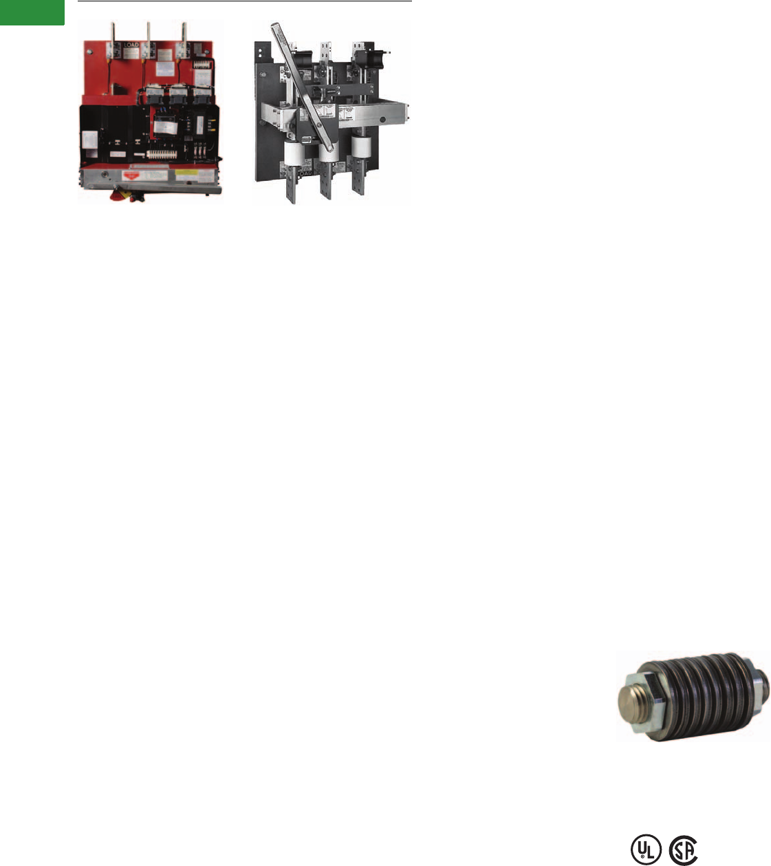
V2-T1-88 Volume 2—Commercial Distribution CA08100003E—April 2014 www.eaton.com
1
1
1
1
1
1
1
1
1
1
1
1
1
1
1
1
1
1
1
1
1
1
1
1
1
1
1
1
1
1
1.1
Switching Devices
Safety Switches
Pringle Bolted Pressure Switches
CBC Type Switch QA Type Switch
Contents
Description Page
Product Overview . . . . . . . . . . . . . . . . . . . . . . . . . . . . V2-T1-3
General Duty. . . . . . . . . . . . . . . . . . . . . . . . . . . . . . . . V2-T1-26
Heavy-Duty . . . . . . . . . . . . . . . . . . . . . . . . . . . . . . . . . V2-T1-31
Six-Pole Switches . . . . . . . . . . . . . . . . . . . . . . . . . . . . V2-T1-43
Double-Throw Switches . . . . . . . . . . . . . . . . . . . . . . . V2-T1-45
EnviroLine—Stainless Steel Switch . . . . . . . . . . . . . . V2-T1-53
EnviroLine—Upper and Lower Window Switches . . . V2-T1-56
EnviroLine—Receptacle Switches . . . . . . . . . . . . . . . V2-T1-59
EnviroLine—Non-Metallic KRYDON Switch . . . . . . . . V2-T1-61
NEMA 7/9—Hazardous Location Disconnect Switch . V2-T1-63
Quick Connect Switches. . . . . . . . . . . . . . . . . . . . . . . V2-T1-65
Solar Disconnect Switch . . . . . . . . . . . . . . . . . . . . . . . V2-T1-67
Solar Combiner Box—Source Combiner and
Array Combiner . . . . . . . . . . . . . . . . . . . . . . . . . . . . V2-T1-69
316-Grade Stainless Steel Safety Switches . . . . . . . . V2-T1-72
Mill-Duty Rated, Heavy-Duty, Fusible, Non-Fusible,
Single-Throw. . . . . . . . . . . . . . . . . . . . . . . . . . . . . . . V2-T1-76
Heavy-Duty Fusible Safety Switches Accepting
Cube Fuses . . . . . . . . . . . . . . . . . . . . . . . . . . . . . . . . .
V2-T1-78
Elevator Control Switch. . . . . . . . . . . . . . . . . . . . . . . . V2-T1-81
Auxiliary Power Heavy-Duty Safety Switch. . . . . . . . . V2-T1-83
Left-Handed Safety Switch . . . . . . . . . . . . . . . . . . . . . V2-T1-86
200% Neutral Safety Switches. . . . . . . . . . . . . . . . . . V2-T1-87
Pringle Bolted Pressure Switch
Catalog Number Selection . . . . . . . . . . . . . . . . . . V2-T1-89
Product Selection . . . . . . . . . . . . . . . . . . . . . . . . . V2-T1-90
Reference Information. . . . . . . . . . . . . . . . . . . . . . V2-T1-90
Technical Data and Specifications . . . . . . . . . . . . . V2-T1-90
Type DS, Fusible and Non-Fusible. . . . . . . . . . . . . . . . V2-T1-91
Type Visi-Flex DE-ION . . . . . . . . . . . . . . . . . . . . . . . . . V2-T1-94
Flange Mounted—Variable Depth. . . . . . . . . . . . . . . . V2-T1-98
Flange Mounted—Fixed Depth. . . . . . . . . . . . . . . . . . V2-T1-102
Pringle Bolted Pressure Switch
Product Description
Eaton Pringle® switches have
helped pioneer development
of high-quality electrical
products for commercial and
industrial applications since
1891. Eaton’s commitment to
engineering excellence and
reputation for quality have
made us a recolonized leader
in the electrical industry, and
today you’ll find our electrical
products in use throughout
the U.S., Canada and most of
the world’s major markets.
Eaton Pringle bolted contact
switches were the first in the
industry and are a worldwide
standard in high-current
switching applications. They
are custom-built and used in
many heavy-duty applications,
and are suitable for use in
UL 891 switchboards.
Bolted Pressure Contacts
All Pringle switches feature
bolted pressure contacts. The
result: blade contact surfaces
are bolted closed at a
pressure of 600 PSI—at both
the hinge and jaw ends. The
benefit: current conducting
efficiency is the equivalent of
a bolted bus bar connection.
Features
●480V UL
●600V CSA
●800–4000 Amperes
●5000–6000 Amperes
(not UL listed)
●200 kAIC and 100% rated
with Class “L” fuses
●Top or bottom feed
●Two, three- or four-pole
●Optional blown fuse
detection and protection
●Quick-positive switching
action
●Manual or electrically
operated mechanism
●6X Make/12X Break
contact rating
●Pringle Flex Center can
offer custom assemblies;
for quotes, call 1-888-329-
9272 option 2
●Many options available,
see following page
Spring Mechanism
All quick action switches use
a unique spring mechanism
for improved reliability over
traditional coil springs.
The unique spring design
is created by a series of
concave-convex washers.
The paired-washer spring
design provides a higher
force/distance ratio, making
it easier to operate the
mechanism.
Should any pair of washers
become inoperable for any
reason, the entire spring
assembly will still be operable
by means of the remaining
pairs. This is unlike the
situation if a coil spring were
to fracture or fatigue.
Sample Spring Configuration
Standards and Certifications
●480V UL
●600V CSA
Volume 2—Commercial Distribution CA08100003E—April 2014 www.eaton.com V2-T1-89
1
1
1
1
1
1
1
1
1
1
1
1
1
1
1
1
1
1
1
1
1
1
1
1
1
1
1
1
1
1
1.1
Switching Devices
Safety Switches
Catalog Number Selection
Pringle Bolted Pressure Switch
Pringle Mill Switch 8
(NEMA 1/3R/12 Enclosed)
Notes
1Not UL listed. A separate control box may be required when adding accessories.
2Not an option with QA type switches. GF option includes control power transformer.
3110 Vdc and 125 Vdc also available. Please contact the Cleveland, TN plant.
4For different system voltage requirements, please contact the Cleveland, TN plant.
5For QA switches, use 480V system catalog number when referencing a 208V system.
6Only applicable if ordering a CPT only, without ground fault.
7Only available with QA switches and in a top-feed configuration.
8Does not carry UL listing.
9Additional available accessories/options—door interlock, special nameplates,
custom dimensions, special paint and auxiliary contacts. Please inquire with the Cleveland, TN plant.
j250 Vdc.
k480 Vac.
Switch
CB = CBC
QA = QA
FP = FP
EO = EO 1
Additional
Option
NF = Non-fused 7
Amperes
08 = 800A
12 = 1200A
16 = 1600A
20 = 2000A
25 = 2500A
30 = 3000A
40 = 4000A
50 = 5000A 8
60 = 6000A 8
Poles
2 = Two-pole
3 = Three-pole
4 = Four-pole
Wire
2 = Two-wire
3 = Three-wire
4 = Four-wire
Feed
B= Bottom
T= Top
Options
6 = With handle
suitable to meet
6’6” requirements
Auxiliary Contact
6 = 1NO/1NC
7 = 2NO/2NC
Interlock
K = Key interlock
provisions
System Voltage 4
208 = 208V 5
480 = 480V
600 = 600V
Blown Fuse Detector (BFD)
A= BFD with three normally ON
lights (does NOT trip)
AO = BFD with three normally OFF lights
(does NOT trip)
AX = BFD with NO lights (trips switch)
A9 = BFD with three normally ON
lights (trips switch)
AR = BFD with three normally OFF lights
(trips switch)
CB 08 3 3 B 120 480 KGRAO CT 5NF
Voltage Control 2
120 = 120V 3
Control Power Transformer 2
CT = With control
power transformer 6
Phase Failure Relay 2
R = Single-phase voltage relay with
capacitor trip device (SPVR)
Ground Fault 2
G = Ground fault with
control power
transformer
GNX = Ground fault without
control power
transformer
Switch
PMS = Pringle Mill Switch
Option 9
W = With viewing window
Amperes
08 = 800A
12 = 1200A
16 = 1600A
20 = 2000A
25 = 2500A
30 = 3000A
40 = 4000A
Poles
2 = Two-pole j
3 = Three-pole k
Feed Exit
B = Bottom
T = Top
PMS 08 33NF T B W
Feed Entry
B = Bottom
T = Top
Wire
2 = Two-wire j
3 = Three-wire k
Fusing
F= Fusible
NF = Non-fusible

V2-T1-90 Volume 2—Commercial Distribution CA08100003E—April 2014 www.eaton.com
1
1
1
1
1
1
1
1
1
1
1
1
1
1
1
1
1
1
1
1
1
1
1
1
1
1
1
1
1
1
1.1
Switching Devices
Safety Switches
Product Selection
Manually Operated (QA)—
UL Listed
Manually operated contact
switch with quick positive
switching action. Can be top
or bottom fed.
Electrical Trip (CBC)—UL Listed
Contact switch with charge-
before-close mechanism. Can
be manually or electrically
tripped. Optional blown fuse
detector and phase failure
relay with capacitor trip
available.
Fault Protector Electrical Trip
(FP)—UL Listed
The FP combines the
features of a CBC switch
but includes an integrated
zero-sequence sensor and
ground fault.
Electrically Operated Electric
Trip (EO)—Not UL Listed
The EO combines the
features of a CBC switch,
but includes an operator
with a linear motor that
electrically closes the switch
while charging the stored
energy mechanism for stored
energy trip.
Pringle Mill Switch (PMS)—
Not UL Listed
Manually operated contact
switch with quick-positive
switching action. Comes in
a NEMA 1/3R/12 enclosure
with a side-operated
mechanism. Can be fusible
or non-fusible, two- or three-
pole configurations.
Service
Eaton’s Pringle switches
have always been
manufactured with precision-
made parts, and, like any
mechanical device, they do
require routine maintenance
in order to operate at the
optimal level. Over time,
contact surfaces may be
exposed to dirt and other
contaminants, which could
result in improper mechanical
and/or electrical operation of
the switch.
Eaton maintains a dedicated
service team that has over
100 years of combined
experience in the exclusive
service and repair of Pringle
switches. A service call
performed by a certified
technician ensures that your
equipment is cleaned, lubed,
adjusted and repaired, and a
one-year extended warranty
is granted. General
maintenance, repair/
refurbishment and
troubleshooting are just some
of the services provided.
In-House Service
Eaton also offers in-house
inspection, service and repair
at our manufacturing facility
in Cleveland, TN.
Aftermarket Parts
Eaton has a full line of factory-
specified aftermarket parts
for Pringle switches, as well
as complete, form, fit,
function, drop-in replacement
switches. Aftermarket part
information can be found in
publication TD00808001E.
‘Flex’ Custom Capabilities
Custom solutions are
standard throughout Eaton’s
switching device product line
and bolted pressure contact
switches are no exception.
When a standard product will
not meet the customer’s
need, Eaton’s engineering
and marketing teams can
develop and offer solutions
built to the customer’s
expectation.
Engineered-to-Order, or
‘Flex’, Non-Load-Break
switch solutions with bolted
pressure contact technology
vary as noted below.
●Motor operated:
800 to 6000A
●High current:
6000 to 35,000A+
●Medium voltage:
5 kV, 15 kV+
●DC voltages:
250 Vdc to 3000 Vdc+
●Transit applications:
single-, two-or three-pole
DC rated
●Manual transfer switches
●Live front switches
Reference Information
For service questions,
or to schedule service:
1.888.329.9272, option 2
pringle@eaton.com
For aftermarket replacement
parts: 1.877.ETN.CARE,
option 2, option 1,
1.877.386.2273, option 2,
option 1, TRC@eaton.com
for existing in the field.
Product brochures available
via Eaton.com
●Pringle Product Brochure—
BR00808001E
●Pringle Mill Switch—
PA00808001E
●Pringle Replacement Parts
Guide—TD00808001E
●Pringle Service—
DM00808002E
Technical Data and
Specifications
●800–4000A
●5000 and 6000A available
(not UL listed)
●200 kAIC and 100% rated
with Class L fuses

Volume 2—Commercial Distribution CA08100003E—April 2014 www.eaton.com V2-T1-91
1
1
1
1
1
1
1
1
1
1
1
1
1
1
1
1
1
1
1
1
1
1
1
1
1
1
1
1
1
1
1.1
Switching Devices
Safety Switches
Contents
Description Page
Product Overview . . . . . . . . . . . . . . . . . . . . . . . . . . . . V2-T1-3
General Duty . . . . . . . . . . . . . . . . . . . . . . . . . . . . . . . . V2-T1-26
Heavy-Duty . . . . . . . . . . . . . . . . . . . . . . . . . . . . . . . . . V2-T1-31
Six-Pole Switches. . . . . . . . . . . . . . . . . . . . . . . . . . . . . V2-T1-43
Double-Throw Switches . . . . . . . . . . . . . . . . . . . . . . . V2-T1-45
EnviroLine—Stainless Steel Switch. . . . . . . . . . . . . . . V2-T1-53
EnviroLine—Upper and Lower Window Switches. . . . V2-T1-56
EnviroLine—Receptacle Switches. . . . . . . . . . . . . . . . V2-T1-59
EnviroLine—Non-Metallic KRYDON Switch . . . . . . . . V2-T1-61
NEMA 7/9—Hazardous Location Disconnect Switch . V2-T1-63
Quick Connect Switches . . . . . . . . . . . . . . . . . . . . . . . V2-T1-65
Solar Disconnect Switch . . . . . . . . . . . . . . . . . . . . . . . V2-T1-67
Solar Combiner Box—Source Combiner and
Array Combiner. . . . . . . . . . . . . . . . . . . . . . . . . . . . . V2-T1-69
316-Grade Stainless Steel Safety Switches. . . . . . . . . V2-T1-72
Mill-Duty Rated, Heavy-Duty, Fusible, Non-Fusible,
Single-Throw . . . . . . . . . . . . . . . . . . . . . . . . . . . . . . . V2-T1-76
Heavy-Duty Fusible Safety Switches Accepting
Cube Fuses . . . . . . . . . . . . . . . . . . . . . . . . . . . . . . . .
V2-T1-78
Elevator Control Switch . . . . . . . . . . . . . . . . . . . . . . . . V2-T1-81
Auxiliary Power Heavy-Duty Safety Switch . . . . . . . . . V2-T1-83
Left-Handed Safety Switch . . . . . . . . . . . . . . . . . . . . . V2-T1-86
200% Neutral Safety Switches . . . . . . . . . . . . . . . . . . V2-T1-87
Pringle Bolted Pressure Switch . . . . . . . . . . . . . . . . . . V2-T1-88
Type DS, Fusible and Non-Fusible
Product Selection. . . . . . . . . . . . . . . . . . . . . . . . . . V2-T1-92
Options and Accessories . . . . . . . . . . . . . . . . . . . . V2-T1-92
Technical Data and Specifications . . . . . . . . . . . . . V2-T1-93
Type Visi-Flex DE-ION . . . . . . . . . . . . . . . . . . . . . . . . . V2-T1-94
Flange Mounted—Variable Depth . . . . . . . . . . . . . . . . V2-T1-98
Flange Mounted—Fixed Depth . . . . . . . . . . . . . . . . . . V2-T1-102
Type DS, Fusible and Non-Fusible
Product Description
Type DS disconnect is
a compact load break
switch using the DE-ION
arc-quenching principle
and quick make/quick
break over center toggle
mechanism. It has visible
contacts, is UL listed and is
available either as a fusible
or non-fusible switch.
Note: Switches through 200A
are UL listed as miscellaneous
switches; 400 and 600A switches
are recognized under the
component program of
Underwriters Laboratories.
Application Description
Maximum switch-fuse
application based on short-
circuit current withstand
(symmetrical amperes).
Short-Circuit Ratings
Standards and Certifications
●UL 98
●CSA (see table on
Page V2-T1-92)
Reference Information
●Technical data: 29-420
●Dimensions and drilling
plans: DS 29-470
●30, 60, 100A instruction
leaflet: I.L. 14857C
●30, 60, 100A auxiliary
switch instruction leaflet:
I.L. 14471C
●200A instruction leaflet:
I.L. 15014A
●200A auxiliary switch
instruction leaflet:
I.L. 14486A
●Handle mechanisms:
TD 29-520
Note
1480V maximum.
Switch
Rating
Amperes
Maximum Application
at 240, 480 or 600 Vac
Class R
Fuses
Current Limiting
Fuse Class J
30 200,000 200,000
60 200,000 200,000
100 200,000 200,000
400 100,000 1200,000
600 100,000 1200,000

V2-T1-92 Volume 2—Commercial Distribution CA08100003E—April 2014 www.eaton.com
1
1
1
1
1
1
1
1
1
1
1
1
1
1
1
1
1
1
1
1
1
1
1
1
1
1
1
1
1
1
1.1
Switching Devices
Safety Switches
Product Selection
DS Type Switch
Switch Ordering Information
Options and Accessories
Base Mounting Hardware
Note: Order separately when required. No charge when ordered
with switch.
Base Mounting Hardware
Auxiliary Switch Kits
Note: Permits field mounting of an auxiliary switch for separate control
circuit applications. Each switch includes three soldered, identified leads.
Rated 250V maximum.
Auxiliary Switch Kits
Class R Fuse Clip Conversion Kits for Type DS Switches
Notes
1600V ratings are suitable for Class J fuses.
2Switches with Catalog Number Suffix R are UL listed for use with Class R fuses when fuse
clip conversion kits shown on this page are used.
3Switches with Catalog Number Suffix R or U are CSA listed.
4Rated 600V.
5Supplied as unfused switch with separate fuse blocks.
6Not UL listed.
Switch
Rating
Fuse Clip Rating Catalog
Number 23
Ampere Type Volts 1
30 No fuse 4—DS16U
30 30 NEC 250 DS121R
30 30 NEC 600 DS161R
30 60 NEC 250 DS122
30 60 NEC 600 DS162
60 No fuse 4—DS26U
60 60 NEC 250 DS222R
60 60 NEC 600 DS262R
60 100 NEC 250/600 DS263
100 No fuse 4—DS36U
100 100 NEC 250/600 DS363R
100 5200 NEC 250/600 DS364
400 No fuse 4—DS56U
400 400 NEC 250/600 DS565R
600 No fuse 4—DS66U
600 600 NEC 250/600 DS666R
Description Catalog Number
30, 60, 100A non-fusible 624B375G17
30, 60, 100A fusible 624B375G17
400 or 600A non-fusible 673B125G04
400 or 600A Fusible 673B125G05
Switch Used With Contact Arrangement Kit Catalog Number
30, 60, 100A 1A-1B 178C265G05
30, 60, 100A 2As-2Bs 178C265G06
Switch Rating
Kit Catalog NumberAmperes Volts
30 250 RFK121
30 600 RFK161
60 250 RFK222
60 600 RFK262
100 250/600 RFK464
400 250/600 RFK666
600 250/600 RFK666

Volume 2—Commercial Distribution CA08100003E—April 2014 www.eaton.com V2-T1-93
1
1
1
1
1
1
1
1
1
1
1
1
1
1
1
1
1
1
1
1
1
1
1
1
1
1
1
1
1
1
1.1
Switching Devices
Safety Switches
Technical Data and Specifications
Maximum Horsepower
Terminal Data
Note
Terminals are suitable for either copper or aluminum cable.
Type
Switch
Maximum Horsepower Ratings
120 Vac 240 Vac 480 Vac 600 Vac
250 VdcStandard Time Delay Standard Time Delay Standard Time Delay Standard Time Delay
DS16U 5 — 10 — 20 — 25 — 7-1/2
DS121R1-1/23 3 7-1/2————5
DS1223 —7-1/2—————5
DS161R — — — — 5 15 7-1/2 20 5
DS162 — — — — 15 — 15 — 5
DS26U 10 — 20 — 40 — 60 — 15
DS222R3 7-1/27-1/215 ————10
DS262R————1530155010
DS263 — — 15 — 25 — 30 — 10
DS36U 15 — 30 — 75 — 75 — 25
DS363R——15302560307520
DS364 — — 25 — 50 — 60 — 20
DS56U — — 100 — 250 — 350 — —
DS565R — — 50 100 100 250 125 350 —
DS66U — — 100 — 400 — 500 — —
DS666R — — 75 100 150 400 200 500 —
Switch Rating
Wire Range
Copper Aluminum
30 #14–#2 #12–#2
60 #14–#2 #12–#2
100 #14–1/0 #12–1/0
400 (1) #4–600 kcmil or (2) 1/0–3/0 (1) #4–600 kcmil or (2) 1/0–250 kcmil
600 Same as 400A except two terminals per pole —
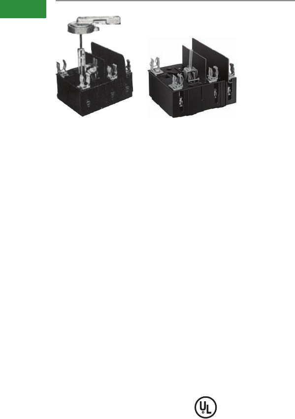
V2-T1-94 Volume 2—Commercial Distribution CA08100003E—April 2014 www.eaton.com
1
1
1
1
1
1
1
1
1
1
1
1
1
1
1
1
1
1
1
1
1
1
1
1
1
1
1
1
1
1
1.1
Switching Devices
Safety Switches
Type Visi-Flex DE-ION
Contents
Description Page
Product Overview . . . . . . . . . . . . . . . . . . . . . . . . . . . . V2-T1-3
General Duty. . . . . . . . . . . . . . . . . . . . . . . . . . . . . . . . V2-T1-26
Heavy-Duty . . . . . . . . . . . . . . . . . . . . . . . . . . . . . . . . . V2-T1-31
Six-Pole Switches . . . . . . . . . . . . . . . . . . . . . . . . . . . . V2-T1-43
Double-Throw Switches . . . . . . . . . . . . . . . . . . . . . . . V2-T1-45
EnviroLine—Stainless Steel Switch . . . . . . . . . . . . . . V2-T1-53
EnviroLine—Upper and Lower Window Switches . . . V2-T1-56
EnviroLine—Receptacle Switches . . . . . . . . . . . . . . . V2-T1-59
EnviroLine—Non-Metallic KRYDON Switch . . . . . . . . V2-T1-61
NEMA 7/9—Hazardous Location Disconnect Switch . V2-T1-63
Quick Connect Switches. . . . . . . . . . . . . . . . . . . . . . . V2-T1-65
Solar Disconnect Switch . . . . . . . . . . . . . . . . . . . . . . . V2-T1-67
Solar Combiner Box—Source Combiner and
Array Combiner . . . . . . . . . . . . . . . . . . . . . . . . . . . . V2-T1-69
316-Grade Stainless Steel Safety Switches . . . . . . . . V2-T1-72
Mill-Duty Rated, Heavy-Duty, Fusible, Non-Fusible,
Single-Throw. . . . . . . . . . . . . . . . . . . . . . . . . . . . . . . V2-T1-76
Heavy-Duty Fusible Safety Switches Accepting
Cube Fuses . . . . . . . . . . . . . . . . . . . . . . . . . . . . . . . . .
V2-T1-78
Elevator Control Switch. . . . . . . . . . . . . . . . . . . . . . . . V2-T1-81
Auxiliary Power Heavy-Duty Safety Switch. . . . . . . . . V2-T1-83
Left-Handed Safety Switch . . . . . . . . . . . . . . . . . . . . . V2-T1-86
200% Neutral Safety Switches. . . . . . . . . . . . . . . . . . V2-T1-87
Pringle Bolted Pressure Switch. . . . . . . . . . . . . . . . . . V2-T1-88
Type DS, Fusible and Non-Fusible. . . . . . . . . . . . . . . . V2-T1-91
Type Visi-Flex DE-ION
Product Selection . . . . . . . . . . . . . . . . . . . . . . . . . V2-T1-95
Options and Accessories. . . . . . . . . . . . . . . . . . . . V2-T1-96
Technical Data and Specifications . . . . . . . . . . . . . V2-T1-97
Flange Mounted—Variable Depth. . . . . . . . . . . . . . . . V2-T1-98
Flange Mounted—Fixed Depth. . . . . . . . . . . . . . . . . . V2-T1-102
Type Visi-Flex DE-ION
Product Description
Complete Model A switch
styles with fuse or non-fuse
kits mounted are UL listed.
Refer to “Electrical
Construction Materials List,”
miscellaneous switches.
Switches only, no fuse,
fuse clip kit and all Model T
switches are recognized
under the component
program of Underwriters
Laboratories. The external
operating handle of Model A
can be padlocked in the
OFF position with up to
three padlocks.
Terminal Data
●30, Spec. 60A switches:
#14–#4 Cu cable only
●60, 100A switches #14–1/0
Cu cable only
Standards and Certifications
●UL 98
Reference Information
●Technical data: 29-420
●Dimension sheet: 29-470
●30, Special 60A Model A
drilling instructions:
I.L. 15051
●60, 100A Model A drilling
instructions: I.L. 15052A
●30, Special 60, 100A Model
A and T auxiliary switch:
I.L. 12641C
●60, 100A Model A and T
fuse kit: I.S. 12565C
●No fuse kit cover
mounting: I.S. 12942B
●Fuse clip kits for Class R
(1226C94G01-G05):
I.L. 15491
●Fuse clip kits for Class R
(1226C94G06-G11):
I.L. 15492
●200 ampere instruction
leaflet: I.L. 12505
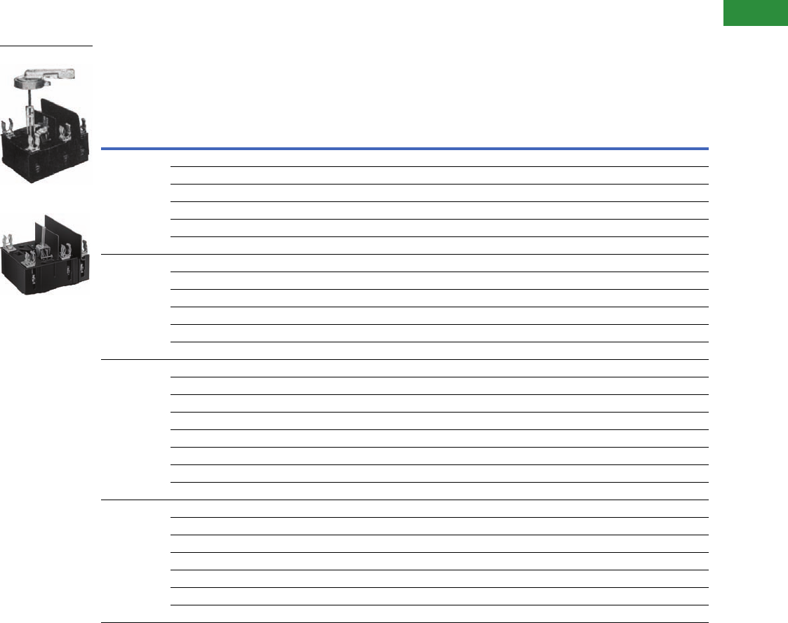
Volume 2—Commercial Distribution CA08100003E—April 2014 www.eaton.com V2-T1-95
1
1
1
1
1
1
1
1
1
1
1
1
1
1
1
1
1
1
1
1
1
1
1
1
1
1
1
1
1
1
1.1
Switching Devices
Safety Switches
Product Selection
Switch Ordering Information
Notes
1 Model A shipped as basic switch, operating handle, shaft and fuse or no-fuse kit. Model T shipped as basic switch and fuse or no-fuse kit.
2 External operating handle, shaft and fuse or no-fuse kit required.
3 Fuse or no-fuse kit required.
4 Includes fuse clips and Micarta barriers.
5 Will also accept non-rejection type current limiting fuses:
Bussmann: 15–60A type KTN and KTS (ferrule type), 65–200A type KTN and KTS (blade type)
Chase Shawmut: 15–60A type 1 (ferrule type), 65–200A type 3 (blade type)
Federal Pacific Electric®: 15–200A types NCL and SCL
6 Rated 600V.
7 Special 60A switch has same dimension as 30A Visi-Flex switch. Standard 60A switch has same dimension as 100A Visi-Flex switch.
Continuous
Ampere
Rating
Fuse or
No-Fuse Kit
(see photos
on Page V2-T1-
96)
Model A, Adjustable Depth Model T,
Toggle Operated
Switch Only 3
Catalog Number
(see fuse kit
at right)
Fuse Clip Kits for Model A or T NEC and Standard
Time Delay 45 (No-Fuse Kit—See Below)
Complete
Unit
Catalog
Number 1
Switch Only 2
Catalog Number
(see handle and
shaft below,
fuse kit at right)
Clips for Class K
or H Fuses
Catalog Number
Clips for Class R
Fuses Only
Catalog Number
30 No fuse 62607D89G01 2607D63G02 371D392G02 — —
30A/250V 2607D89G02 2607D63G01 371D392G01 313C590G08 1226C94G01
60A/250V 2607D89G03 2607D63G01 371D392G01 313C590G09 1226C94G03
100A/250V 2607D89G04 2607D63G01 371D392G01 313C590G13 1226C94G05
30A/600V 2607D89G05 2607D63G01 371D392G01 313C590G10 1226C94G02
60A/600V 2607D89G06 2607D63G01 371D392G01 313C590G11 1226C94G04
Special 60 7No fuse 62607D89G07 2607D63G06 371D392G06 — —
30A/250V 2607D89G08 2607D63G05 371D392G05 313C590G08 1226C94G01
60A/250V 2607D89G09 2607D63G05 371D392G05 313C590G09 1226C94G03
100A/250V 2607D89G10 2607D63G05 371D392G05 313C590G13 1226C94G05
30A/600V 2607D89G11 2607D63G05 371D392G05 313C590G10 1226C94G02
60A/600V 2607D89G12 2607D63G05 371D392G05 313C590G11 1226C94G04
60 7No fuse 62607D90G01 2607D66G14 657D780G12 — —
30A/250V 2607D90G02 2607D66G13 657D780G11 177C880G23 1226C94G06
60A/250V 2607D90G03 2607D66G13 657D780G11 177C880G12 1226C94G08
100A/250V 2607D90G04 2607D66G13 657D780G11 177C880G13 1226C94G10
200A/250V 2607D90G05 2607D66G13 657D780G11 177C880G14 —
30A/600V 2607D90G06 2607D66G13 657D780G11 177C880G24 1226C94G07
60A/600V 2607D90G07 2607D66G13 657D780G11 177C880G15 1226C94G09
100A/600V 2607D90G08 2607D66G13 657D780G11 177C880G16 1226C94G11
100 No fuse 62607D91G07 2607D66G18 657D780G16 — —
60A/250V 2607D91G08 2607D66G17 — 177C880G12 1226C94G08
100A/250V 2607D91G09 2607D66G17 657D780G15 177C880G13 1226C94G10
20A/250V 2607D91G10 2607D66G17 657D780G15 177C880G14 —
60A/600V 2607D91G11 2607D66G17 — 177C880G15 1226C94G09
100A/600V 2607D91G12 2607D66G17 657D780G15 177C880G16 1226C94G11
200A/600V 2607D91G13 2607D66G17 657D780G15 177C880G18 —
Model A
Model T
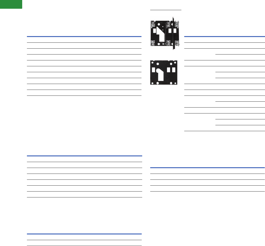
V2-T1-96 Volume 2—Commercial Distribution CA08100003E—April 2014 www.eaton.com
1
1
1
1
1
1
1
1
1
1
1
1
1
1
1
1
1
1
1
1
1
1
1
1
1
1
1
1
1
1
1.1
Switching Devices
Safety Switches
Special Switches and Fuse Clips
Visi-Flex Switches with Auxiliary Switch Internally Mounted
Note: Basic switch only. Also order no-fuse kit, fuse kit, operating handle
and shaft as required.
Special Fuse Kits
Current Limiting, Class J
Note: For Model A and/or T switches. Order in
place of standard fuse clips.
Options and Accessories
Fuse Kits and Shaft
Auxiliary Switch Kits for Model A and T Switches
Note: Permits field mounting of an auxiliary switch for separate control
circuit applications. Provides an SPDT switch with 1A and/or 1B contacts.
Includes three identified 18-inch soldered leads.
Extra Long Vari-Depth Shaft for Model A Switches
Note: Order in place of standard shaft when required.
Notes
1For use with panels 5.06–8.19 inches (128.5–208.0 mm) deep.
2For use with panels 5.19–9.97 inches (131.8–253.2 mm) deep.
3Order Instruction Sheet 12641.
4For panel depth of 8.19–9.94 inches (208.0–252.5 mm), a minimum of 1.75 inch must be cut
from bottom of shaft.
Ampere
Rating
Catalog Number
(for use without fuses)
Catalog Number
(for use with fuses)
Model A
30 2607D63G04 2607D63G03
Special 60 2607D63G08 2607D63G07
60 2607D66G16 2607D66G15
100 2607D66G20 2607D66G19
Model T
30 371D392G04 371D392G03
Special 60 371D392G08 371D392G07
60 657D780G14 657D780G13
100 657D780G18 657D780G17
Switch Type,
Rating
Fuse Kit
Rating Catalog Number
Model A
30 30A/600V 503C690G01
Special 60 60A/600V 503C690G02
100A/600V 503C690G03
60 30A/600V 503C690G15
100 60A/600V 503C690G16
100A/600V 503C690G17
200A/600V 503C690G18
Model T
30 30A/600V 503C690G04
Special 60 60A/600V 503C690G05
100A/600V 503C690G06
60 30A/600V 503C690G19
100 60A/600V 503C690G20
100A/600V 503C690G21
200A/600V 503C690G22
Fuse Clip Kit
No Fuse Kit
Description Catalog Number
No fuse kits (for Models A or T)
30, special 60A switches 313C590G14
60, 100A switches 313C363G11
Model A external operating handle 504C323G07
Model A Standard Shaft
30, special 60A switches 2607D64G01 1
60, 100A switches 2607D65G01 2
For Use With
Complete Kit
Catalog Number
30 and special 60A switch 315C293G01 3
60 and 100A switch 315C293G01 3
Switch
Ampere Rating
Panel Depth in Inches (mm)
Long Shaft Catalog Number
30 8.19–13.06 (208.0–331.7) 42607D65G02
Special 60 8.19–13.06 (208.0–331.7) 42607D65G02
60 9.41–14.3 (239.0–358.9) 2607D65G02
100 9.41–14.3 (239.0–358.9) 2607D65G02

Volume 2—Commercial Distribution CA08100003E—April 2014 www.eaton.com V2-T1-97
1
1
1
1
1
1
1
1
1
1
1
1
1
1
1
1
1
1
1
1
1
1
1
1
1
1
1
1
1
1
1.1
Switching Devices
Safety Switches
Technical Data and Specifications
Maximum Horsepower Ratings
Note
1Does not apply to special 60A switch since these fuse clips cannot be added.
Fuse Clip
Ratings
Maximum Horsepower Ratings
120 Vac 240 Vac 480 Vac 600 Vac
250 VdcStandard Time Delay Standard Time Delay Standard Time Delay Standard Time Delay
30A Switch
Unfused 3 — 7-1/2 — 20 — 25 — 5
30A/250V 1-1/2 3 3 7-1/2 — — — — 5
60A/250V 3 — 5 — — — — — 5
100A/250V 3 — 5 — — — — — 5
30A/600V — — — — 5 15 7-1/2 20 5
60A/600V — — — — 15 — 20 — 5
60A Switch (and Special 60 Ampere Switch)
Unfused 7-1/2 — 20 — 40 — 50 — 10
30A/250V 1-1/2 3 3 7-1/2 — — — — 5
60A/250V 3 7-1/2 7-1/2 15 — — — — 10
100A/250V — — 15 — — — — — 10
200A/250V 1——15——————
30A/600V — — — — 5 15 7-1/2 20 5
60A/600V — — — — 15 30 15 50 10
100A/600V 1——15—2530305010
100A Switch
Unfused 15 — 30 — 60 — 75 — 20
30A/250V 1-1/2 3 3 7-1/2 — — — — 5
60A/250V 3 7-1/2 7-1/2 15 — — — — 10
100A/250V 15 15 15 30 — — — — 20
200A/250V 15 15 15 30 — — — — 20
30A/600V — — — — 5 15 7-1/2 20 —
60A/600V — — — — 15 30 15 50 —
100A/600V — — — — 25 60 30 75 —
200A/600V — — — — 25 60 30 75 —
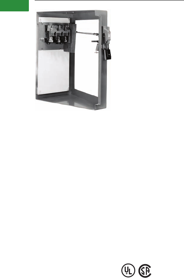
V2-T1-98 Volume 2—Commercial Distribution CA08100003E—April 2014 www.eaton.com
1
1
1
1
1
1
1
1
1
1
1
1
1
1
1
1
1
1
1
1
1
1
1
1
1
1
1
1
1
1
1.1
Switching Devices
Safety Switches
Complete Operating Mechanism—C361NE1
Contents
Description Page
Product Overview . . . . . . . . . . . . . . . . . . . . . . . . . . . . V2-T1-3
General Duty. . . . . . . . . . . . . . . . . . . . . . . . . . . . . . . . V2-T1-26
Heavy-Duty . . . . . . . . . . . . . . . . . . . . . . . . . . . . . . . . . V2-T1-31
Six-Pole Switches . . . . . . . . . . . . . . . . . . . . . . . . . . . . V2-T1-43
Double-Throw Switches . . . . . . . . . . . . . . . . . . . . . . . V2-T1-45
EnviroLine—Stainless Steel Switch . . . . . . . . . . . . . . V2-T1-53
EnviroLine—Upper and Lower Window Switches . . . V2-T1-56
EnviroLine—Receptacle Switches . . . . . . . . . . . . . . . V2-T1-59
EnviroLine—Non-Metallic KRYDON Switch . . . . . . . . V2-T1-61
NEMA 7/9—Hazardous Location Disconnect Switch . V2-T1-63
Quick Connect Switches. . . . . . . . . . . . . . . . . . . . . . . V2-T1-65
Solar Disconnect Switch . . . . . . . . . . . . . . . . . . . . . . . V2-T1-67
Solar Combiner Box—Source Combiner and
Array Combiner . . . . . . . . . . . . . . . . . . . . . . . . . . . . V2-T1-69
316-Grade Stainless Steel Safety Switches . . . . . . . . V2-T1-72
Mill-Duty Rated, Heavy-Duty, Fusible, Non-Fusible,
Single-Throw. . . . . . . . . . . . . . . . . . . . . . . . . . . . . . . V2-T1-76
Heavy-Duty Fusible Safety Switches Accepting
Cube Fuses . . . . . . . . . . . . . . . . . . . . . . . . . . . . . . . . .
V2-T1-78
Elevator Control Switch. . . . . . . . . . . . . . . . . . . . . . . . V2-T1-81
Auxiliary Power Heavy-Duty Safety Switch. . . . . . . . . V2-T1-83
Left-Handed Safety Switch . . . . . . . . . . . . . . . . . . . . . V2-T1-86
200% Neutral Safety Switches. . . . . . . . . . . . . . . . . . V2-T1-87
Pringle Bolted Pressure Switch. . . . . . . . . . . . . . . . . . V2-T1-88
Type DS, Fusible and Non-Fusible. . . . . . . . . . . . . . . . V2-T1-91
Type Visi-Flex DE-ION . . . . . . . . . . . . . . . . . . . . . . . . . V2-T1-94
Flange Mounted—Variable Depth
Product Selection . . . . . . . . . . . . . . . . . . . . . . . . . V2-T1-99
Accessories. . . . . . . . . . . . . . . . . . . . . . . . . . . . . . V2-T1-100
Dimensions . . . . . . . . . . . . . . . . . . . . . . . . . . . . . . V2-T1-101
Flange Mounted—Fixed Depth. . . . . . . . . . . . . . . . . . V2-T1-102
Flange Mounted—Variable Depth
Product Description
Type C361 disconnect
switches are suitable for
installation in control
enclosures having a right-
hand flange. Fusible
disconnect switches will
accept R fuses as standard.
Field installable rejection kits
are supplied as standard on
100 and 200A clips. For 30
and 60A rejection clips, see
footnote 4 on next page. The
switch is UL component
recognized for use on
systems with up to 200,000
rms symmetrical amperes
available fault current when
Class R clips are supplied.
Standards and Certifications
●UL—Component File
E55492
●CSA—LR353-439
Volume 2—Commercial Distribution CA08100003E—April 2014 www.eaton.com V2-T1-99
1
1
1
1
1
1
1
1
1
1
1
1
1
1
1
1
1
1
1
1
1
1
1
1
1
1
1
1
1
1
1.1
Switching Devices
Safety Switches
Product Selection
Operating Mechanism Variable Depth with Disconnect Switch—Right-Hand Mounting
Handle Only
Notes
1 Dimension shown is from panel to flange surface.
2 Refers to rating of switch only.
3 Components individually boxed and shipped in overpack carton.
4 For rejection clips, add Suffix Letter R to listed Catalog Number. Example: C361SC121R.
Disconnect
Switch Size
(Amperes)
Variable
Depth
Mtg. Range
Min./Max.
(Inches) 1
Maximum Horsepower Ratings 2
Fuse Clip Rating
(Amperes) Non-
Interchangeable
Type for Class
H, J, K or R Type
Fuses Only
Switch and
Operating
Mechanism Only
DOES NOT
Include Handle
Switch and Operating Mechanism
with 4-Inch Handle 3
AC System Volts
(Motor Volts) DC
Using
Two Poles
250V Max.
For NEMA 1 or 12
Enclosure
For NEMA 4
Enclosure
208
(200)
240
(230)
480
(460)
600
(575) 250V 600V
Catalog
Number
Catalog
Number
Catalog
Number
30 7 to 16 7-1/2 7-1/2 15 20 5 Non-fusible C361NC C361NC1 C361NC2
30 — C361SC21 C361SC121 4C361SC221 4
60 30 C361SC61 C361SC161 4C361SC261 4
60 7 to 16 15 15 30 50 10 Non-fusible C361ND C361ND1 C361ND2
60 30 C361SD22 C361SD122 4C361SD222 4
—60 C361SD62 C361SD162 4C361SD262 4
100 7 to 16 25 30 60 75 20 Non-fusible C361NE C361NE1 C361NE2
100 100 C361SE263 C361SE1263 C361SE2263
200 7 to 16 40 60 125 150 40 Non-fusible C361NF1 C361NF1 C361NF2
200 200 C361SF264 C361SF1264 C361SF2264
Application
Operating Handle
Length in Inches (mm)
NEMA Type
Enclosure
Catalog
Number
For use with 30, 60
100 and 200A
disconnect switches
4.00 (101.6) 1-12 C361H1
4.00 (101.6) 4 C361H2
6.00 (152.4) 1-12 C361H3
6.00 (152.4) 4 C361H4
C361NE1
C361H1

V2-T1-100 Volume 2—Commercial Distribution CA08100003E—April 2014 www.eaton.com
1
1
1
1
1
1
1
1
1
1
1
1
1
1
1
1
1
1
1
1
1
1
1
1
1
1
1
1
1
1
1.1
Switching Devices
Safety Switches
Accessories
Type C361 NEMA 12 Safety Door Hardware
Type C361 door hardware kits
are designed to function with
all C361 and C371 disconnect
switches and circuit breaker
operating mechanisms.
These kits are designed for
use with small enclosures
up to 40 inches (1016 mm),
intermediate 40–60 inches
(1016–1524 mm) or larger
floor cases over 60 inches
(1524 mm) to provide
enclosure sealing and
protection against
unauthorized entry.
These kits can be used
on enclosure flanges with
material thickness ranging
from 16 gauge through
3/16 inches with flanges
on the right side only. Door
hardware kits are to be
installed in a commercially
available enclosure. Consult
the enclosure manufacturer
application data for proper
kit selection.
Type C361 NEMA 12 Safety
Door Hardware
Handle Length (Inches) Catalog Number 1
4C361KJ4
6C361KJ6
Roller Latch 2C361KR
NEMA 12 Safety
Door Hardware
Interlocks and Connecting Rod
Electrical Interlocks
Connecting Rods—Increase Maximum Allowable Depth
by 5 Inches
Notes
1The 1/4-inch x 1/2-inch standard mill rectangular locking bar is not supplied with these kits.
2Third roller latch for use with 4 or 6-inch handle when three-point latching is required.
Circuit Catalog Number
1NO-1NC DS200EK1
2NO-2NC DS200EK2
Application Catalog Number
Disconnect switches 30, 60, 100 and 200A
Circuit breakers 150, 250 and 400A
C371CS1
Circuit breakers 600, 800 and 1200A C371CS2
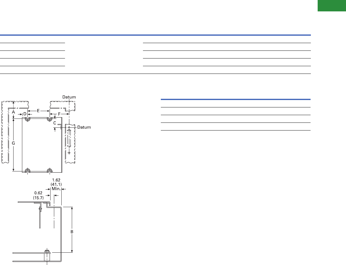
Volume 2—Commercial Distribution CA08100003E—April 2014 www.eaton.com V2-T1-101
1
1
1
1
1
1
1
1
1
1
1
1
1
1
1
1
1
1
1
1
1
1
1
1
1
1
1
1
1
1
1.1
Switching Devices
Safety Switches
Dimensions
Approximate Dimensions in Inches (mm)
Mounting Dimension Requirements in Inches (mm)
Mounting Dimension Requirements Line Lug Data
Dimension A = The required wire bending spacing selected
from Article 430.10 of the National Electrical Code.
Dimension B = Minimum or maximum depth from inside of
flange holding operating handle to panel where disconnect
switch is mounted (variable 7 to 16 inches).
Disconnect Switch Type A B C D E F G
30A and 60A non-fusible See dimensions
below
See dimensions
below
1.56 (39.6) 0.96 (24.4) 4.00 (101.6) 3.50 (88.9) 7.12 (180.8)
30A and 60A fusible 1.56 (39.6) 0.96 (24.4) 4.00 (101.6) 3.50 (88.9) 9.75 (247.7)
100A non-fusible 1.75 (44.5) 1.10 (27.9) 5.50 (139.7) 3.38 (85.9) 7.12 (180.8)
100A fusible 1.75 (44.5) 1.10 (27.9) 5.50 (139.7) 3.38 (85.9) 11.88 (301.8)
200A non-fusible and fusible 3.34 (84.8) 0.63 (16.0) 8.50 (215.9) 1.84 (46.7) 15.50 (393.7)
Disconnect Switch Size Wire Size
30A #2–14 Cu/Al
60A #2–14 Cu/Al
100A 1/0–14 Cu/Al
200A 250 kcmil–#6 Cu/Al
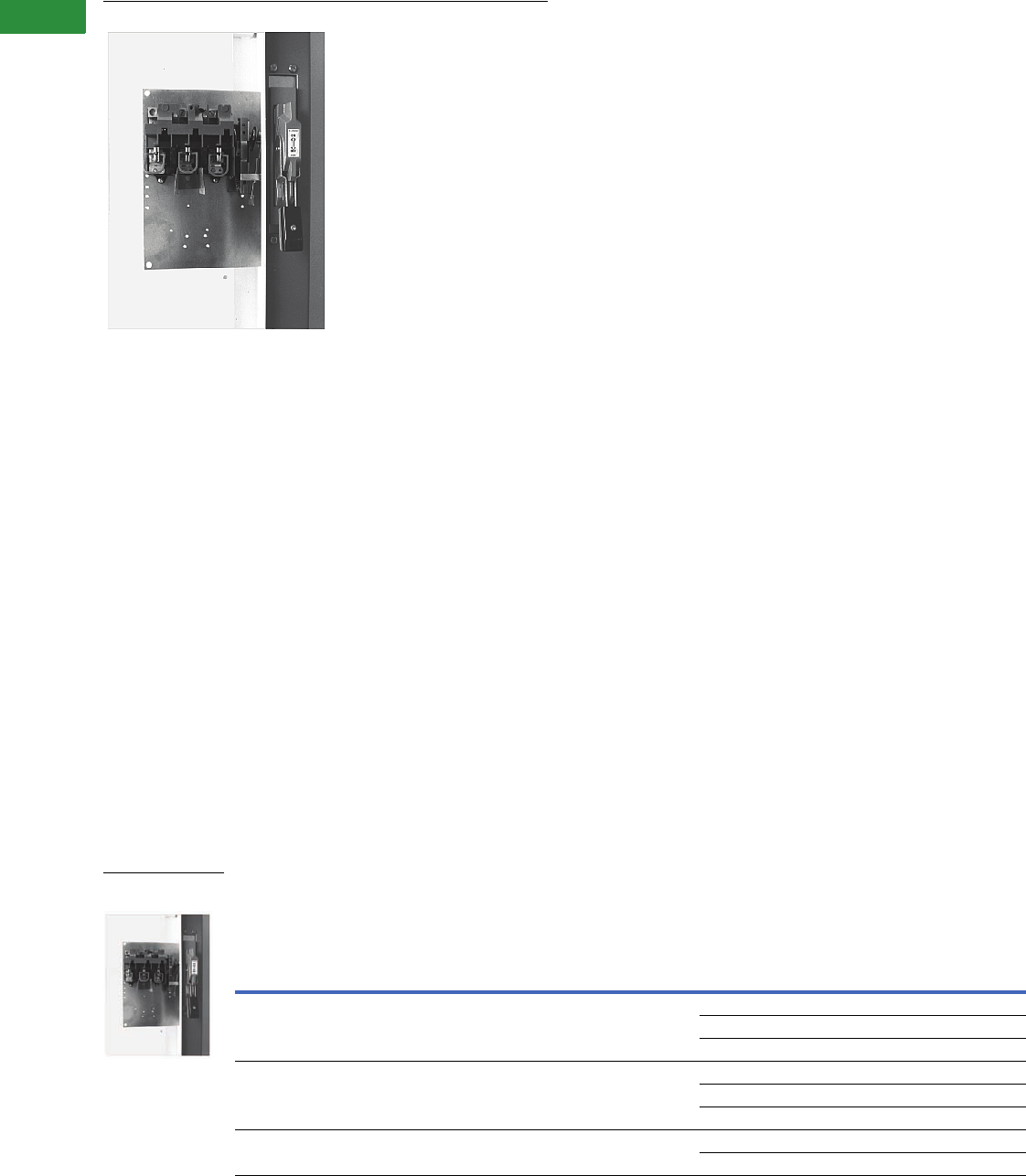
V2-T1-102 Volume 2—Commercial Distribution CA08100003E—April 2014 www.eaton.com
1
1
1
1
1
1
1
1
1
1
1
1
1
1
1
1
1
1
1
1
1
1
1
1
1
1
1
1
1
1
1.1
Switching Devices
Safety Switches
Fixed Depth Application
Contents
Description Page
Product Overview . . . . . . . . . . . . . . . . . . . . . . . . . . . . V2-T1-3
General Duty. . . . . . . . . . . . . . . . . . . . . . . . . . . . . . . . V2-T1-26
Heavy-Duty . . . . . . . . . . . . . . . . . . . . . . . . . . . . . . . . . V2-T1-31
Six-Pole Switches . . . . . . . . . . . . . . . . . . . . . . . . . . . . V2-T1-43
Double-Throw Switches . . . . . . . . . . . . . . . . . . . . . . . V2-T1-45
EnviroLine—Stainless Steel Switch . . . . . . . . . . . . . . V2-T1-53
EnviroLine—Upper and Lower Window Switches . . . V2-T1-56
EnviroLine—Receptacle Switches . . . . . . . . . . . . . . . V2-T1-59
EnviroLine—Non-Metallic KRYDON Switch . . . . . . . . V2-T1-61
NEMA 7/9—Hazardous Location Disconnect Switch . V2-T1-63
Quick Connect Switches. . . . . . . . . . . . . . . . . . . . . . . V2-T1-65
Solar Disconnect Switch . . . . . . . . . . . . . . . . . . . . . . . V2-T1-67
Solar Combiner Box—Source Combiner and
Array Combiner . . . . . . . . . . . . . . . . . . . . . . . . . . . . V2-T1-69
316-Grade Stainless Steel Safety Switches . . . . . . . . V2-T1-72
Mill-Duty Rated, Heavy-Duty, Fusible, Non-Fusible,
Single-Throw. . . . . . . . . . . . . . . . . . . . . . . . . . . . . . . V2-T1-76
Heavy-Duty Fusible Safety Switches Accepting
Cube Fuses . . . . . . . . . . . . . . . . . . . . . . . . . . . . . . . . .
V2-T1-78
Elevator Control Switch. . . . . . . . . . . . . . . . . . . . . . . . V2-T1-81
Auxiliary Power Heavy-Duty Safety Switch. . . . . . . . . V2-T1-83
Left-Handed Safety Switch . . . . . . . . . . . . . . . . . . . . . V2-T1-86
200% Neutral Safety Switches. . . . . . . . . . . . . . . . . . V2-T1-87
Pringle Bolted Pressure Switch. . . . . . . . . . . . . . . . . . V2-T1-88
Type DS, Fusible and Non-Fusible. . . . . . . . . . . . . . . . V2-T1-91
Type Visi-Flex DE-ION . . . . . . . . . . . . . . . . . . . . . . . . . V2-T1-94
Flange Mounted—Variable Depth. . . . . . . . . . . . . . . . V2-T1-98
Flange Mounted—Fixed Depth
Accessories. . . . . . . . . . . . . . . . . . . . . . . . . . . . . . V2-T1-103
Technical Data and Specifications . . . . . . . . . . . . . V2-T1-103
Flange Mounted—Fixed Depth
Product Description
Type C361 disconnect
switches are suitable for
installation in control
enclosures having a right-
hand flange. Fusible
disconnect switches will
accept R fuses as standard.
Field installable rejection kits
are supplied as standard on
100 and 200A clips. For 30
and 60A rejection clips, see
Page V2-T1-99. The switch is
UL component recognized for
use on systems for use on
systems with up to 200,000
rms symmetrical amperes
available fault current when
Class R clips are supplied.
●Minimum depth—flange
to panel
●30–60A: 6.50 inches
●100A: 7 inches
Product Selection
Operating Mechanism Fixed Depth with Disconnect Switch—Right-Hand Mounting
Disconnect
Switch Size
(Amperes)
Maximum Horsepower Ratings 1
Fuse Clip Rating (Amperes)
Non-Interchangeable Type for
Class H, J, K or R Type Fuses Only
Switch and Operating
Mechanism with
4-Inch Handle
For NEMA 1 or 12
EnclosureAC System Volts (Motor Volts) DC Using
Two Poles
250V Maximum208 (200) 240 (230) 480 (460) 600 (575) 250V 600V Catalog Number
30 7-1/2 7-1/2 15 20 5 Non-fusible C361FNC1
30 — C361FSC121 2
60 30 C361FSC161 2
60 15 15 30 50 10 Non-fusible C361FND1
60 30 C361FSD122 2
—60C361FSD162 2
100 25 30 60 75 20 Non-fusible C361FNE1
100 100 C361FSE1263
Fixed Depth
Application
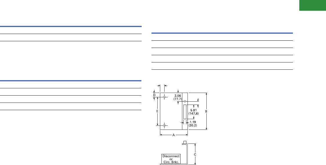
Volume 2—Commercial Distribution CA08100003E—April 2014 www.eaton.com V2-T1-103
1
1
1
1
1
1
1
1
1
1
1
1
1
1
1
1
1
1
1
1
1
1
1
1
1
1
1
1
1
1
1.1
Switching Devices
Safety Switches
Accessories
Electrical Interlocks
Technical Data and Specifications
Line Lug Data
Dimensions
Approximate Dimensions in Inches (mm)
Frame Size
Approximate Dimensions
Notes
1Refers to rating of switch only.
2For Rejection Clips, add Suffix Letter R to listed Catalog Number. Example: C361FSC121R.
Circuit Catalog Number
1NO-1NC DS200EK1
2NO-2NC DS200EK2
Disconnect Switch Size Wire Size
30A #2–14 Cu/Al
60A #2–14 Cu/Al
100A 1/0–14 Cu/Al
200A 250 kcmil–#6 Cu/Al
Description A B C D E
30–60A disconnect switch 8.63 (219.2) 11.38 (289.1) 6.50 (165.1) 1.50 (38.1) 9.50 (241.3)
150A circuit breaker 8.63 (219.2) 11.38 (289.1) 6.50 (165.1) 1.50 (38.1) 9.50 (241.3)
100A disconnect switch 9.88 (251.0) 13.38 (339.9) 7.00 (177.8) 1.25 (31.8) 11.75 (298.5)
250A circuit breaker 9.88 (251.0) 13.38 (339.9) 7.00 (177.8) 1.25 (31.8) 11.75 (298.5)
400A circuit breaker 9.88 (251.0) 13.38 (339.9) 7.00 (177.8) 1.25 (31.8) 11.75 (298.5)
0.31 (7.9)
0.38
(9.7)
0.38 (9.7) Dia. Holes
for Panel Support
if Necessary
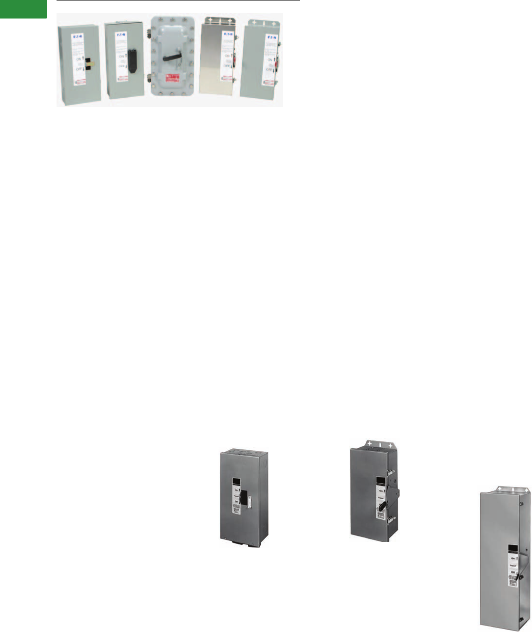
V2-T1-104 Volume 2—Commercial Distribution CA08100003E—April 2014 www.eaton.com
1
1
1
1
1
1
1
1
1
1
1
1
1
1
1
1
1
1
1
1
1
1
1
1
1
1
1
1
1
1
1.2
Switching Devices
Enclosed Circuit Breakers
Enclosed Circuit Breakers
Contents
Description Page
Features, Benefits and Functions . . . . . . . . . . . . . V2-T1-105
Standards and Certifications . . . . . . . . . . . . . . . . . V2-T1-105
Cross-Reference . . . . . . . . . . . . . . . . . . . . . . . . . . V2-T1-106
Product Selection . . . . . . . . . . . . . . . . . . . . . . . . . V2-T1-108
Accessories. . . . . . . . . . . . . . . . . . . . . . . . . . . . . . V2-T1-110
Flex Center . . . . . . . . . . . . . . . . . . . . . . . . . . . . . . V2-T1-112
Technical Data and Specifications . . . . . . . . . . . . . V2-T1-113
Dimensions . . . . . . . . . . . . . . . . . . . . . . . . . . . . . . V2-T1-115
Product Description
●15–1200A
●Enclosed device used to
open and close a circuit
Application Description
NEMA 1 General Purpose
Surface or Flush Mounting
15–1200A, 600 Vac, 500 Vdc
NEMA 1 enclosed breakers
are designed for indoor
use in commercial buildings,
apartment buildings and
other areas where a general
purpose enclosure is
applicable. The breaker is
front operable and is capable
of being padlocked in the
OFF position. Ratings
through 1200A are listed with
Underwriters Laboratories as
suitable for service entrance
application. Both surface and
flush mounted enclosures
are available.
NEMA 1 General Purpose
NEMA 3R Rainproof
Surface Mounting 1
Interchangeable Hubs (through
400A) 15–1200A, 600 Vac, 500 Vdc
This general purpose outdoor
service center employs a
circuit breaker inside a
weatherproof sheet steel
enclosure to serve as a main
disconnect and protective
device for feeder circuits.
The breaker is front operable
and is capable of being
padlocked in the OFF position.
Ratings through 1200A are
listed by Underwriters
Laboratories as suitable for
service entrance application.
NEMA 3R Rainproof Surface Mounting
Note
1SFDN enclosed breakers do not have a
door interlock to prevent door from being
opened when breaker is “ON.”
NEMA 4/4X, 5 Water
and Dustproof
Stainless Steel—Type 304
Surface Mounting 15–1200A,
600 Vac, 500 Vdc
This enclosure meets NEMA
4/4X and 5 requirements
for water and dustproof
applications and has no
knockouts or other openings.
It is particularly well suited for
use in dairies, borax mines,
breweries, paper mills and
other process industries.
The operating handle can be
padlocked in the OFF position,
and is interlocked to prevent
the door from opening
when the breaker is ON.
Ratings through 1200A are
Underwriters Laboratories
listed as suitable for service
entrance application.
NEMA 4/4X Water and Dustproof
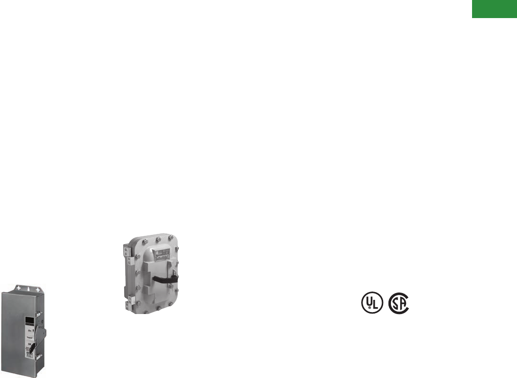
Volume 2—Commercial Distribution CA08100003E—April 2014 www.eaton.com V2-T1-105
1
1
1
1
1
1
1
1
1
1
1
1
1
1
1
1
1
1
1
1
1
1
1
1
1
1
1
1
1
1
1.2
Switching Devices
Enclosed Circuit Breakers
NEMA 12 Dustproof
Surface Mounting
No Knockouts or Other Openings
15–1200A, 600 Vac,
500 Vdc
The Type 12 enclosure
is designed in line with
specifications for special
industry application where
unusually severe conditions
involving oil, coolant, dust and
other foreign materials exist
in the operating atmosphere.
The handle padlocks in the
OFF position and the cover is
interlocked with the handle
mechanism to prevent
opening the cover with the
circuit breaker in the ON
position. Ratings through
1200A are UL listed as
suitable for service entrance
application. A NEMA 12
semi-dust-tight design that
includes knockouts is
available. These units are
rated 15–400A, 600 Vac,
500 Vdc.
NEMA 12 Dustproof Surface Mounting
NEMA 7/9 Hazardous
Location
Cast Aluminum, Explosion-proof
Surface Mounting 15–1200A,
600 Vac, 250 Vdc
Hazardous location, Type 7:
Class I, Groups B, C, D;
Type 9: Class II, Groups E,
F, G. This special service
cast aluminum enclosure
is supplied with a wide,
machined flanged cover
to prevent igniting outside
atmospheres by arcing from
inside the enclosure. Front
operable, the handle
padlocks in the OFF position.
Enclosures rated 600A and
above have lift-off hinges for
ease of assembly.
Note: XFDN050B is not
Group B compliant.
NEMA 7/9 Hazardous Location
Features, Benefits
and Functions
●Side-opening door on
NEMA 3R enclosures
●Padlockable in the
OFF position
●Surface or flush mounted
enclosures available
through 400A on
NEMA 1 enclosures
●Interlocked handle on
NEMA 3R, 4/4X, 5 and
12 enclosures to prevent
opening when the breaker
is in the ON position
●Interchangeable hubs
●Numerous factory options
Standards and
Certifications
●UL 489
●CSA 22.2
●NEMA 250
NEMA 1 General Purpose
●UL File No. E7819
●CSA File No. LR84319
NEMA 3R Rainproof
Surface Mounting
●UL File No. E7819
●CSA File No. LR84319
NEMA 4/4X, 5 Water
and Dustproof
●UL File No. E7819
●CSA File No. LR84319
NEMA 12 Dustproof
Surface Mounting
●UL File No. E7819
●CSA File No. LR84319
NEMA 7/9 Hazardous Location
●UL File No. E84577
●CSA File No. LR42131-6

V2-T1-106 Volume 2—Commercial Distribution CA08100003E—April 2014 www.eaton.com
1
1
1
1
1
1
1
1
1
1
1
1
1
1
1
1
1
1
1
1
1
1
1
1
1
1
1
1
1
1
1.2
Switching Devices
Enclosed Circuit Breakers
Cross-Reference
Enclosed Circuit Breaker Competitive Catalog Numbers
Notes
1Maximum wire size 4/0.
2Maximum wire size 500 kcmil.
NEMA
Rating
Catalog Number
Eaton Square D Siemens General Electric
Enclosure Breaker Enclosure Breaker Enclosure Breaker Enclosure Breaker
1 surface SGDN100 GHC3100 EHB125NS EHB34100 — — — —
1 flush ——EHB125NF EHB34100 — — — —
3R RGDN100 GHC3100 EHB125NRB EHB34100 — — — —
12 JGDN100 GHC3100 ————— —
12K DGDN100 GHC3100 ————— —
4/4X WGDN100 GHC3100 ————— —
1 surface SFDN100 EHD3100L FA100S FAL34100 E2N1S ED43B100 TE100S TED134100WL
1 flush FFDN100 EHD3100L FA100F FAL34100 E2N1F ED43B100 TE100F TED134100WL
3R RFDN100 EHD3100L FA100RB FAL34100 E2N3R ED43B100 TE100R TED134100WL
12/3R ——FA100AWK FAL34100 — — — —
12 JFDN100 EHD3100L — — E2N12 ED43B100 TE100J/SE100J TED134100WL
12K DFDN100 EHD3100L FA100A FAL34100 E2N12 ED43B100 TE100D/ ______ TED134100WL
4/4X WFDN100 EHD3100L FA100DS FAL34100 ED6SS4 ED43B100 TE100CS/SE100CS TED134100WL
7/9 XFDN050 EHD3050L FA060X FAL34060 EA ED43B100 — —
9——FA060Y FAL34060 — — — —
7/9 XFDN225B 1FD3225L FA100X FAL34100 EB ED43B100 — —
9——FA100Y FAL34100 — — — —
1 surface SFDN225 1FDB3150L — — E2N1S ED43B125 TE150S TED134150WL
1 flush FFDN225 1FDB3150L — — E2N1F ED43B125 TE150F TED134150WL
3R RFDN225 1FDB3150L — — E2N3R ED43B125 TE150R TED134150WL
12 JFDN225 1FDB3150L — — E2N12 ED43B125 — —
12K DFDN225 1FDB3150L — — E2N12 ED43B125 — —
4/4X WFDN225 1FDB3150L — — ED6SS4 ED43B125 — —
7/9 XFDN225B 1FDB3150L ————— —
1 surface SFDN225 1FD3225L ————— —
1 flush FFDN225 1FD3225L ————— —
3R RFDN225 1FD3225L ————— —
12 JFDN225 1FD3225L ————— —
12K DFDN225 1FD3225L ————— —
4/4X WFDN225 1FD3225L ————— —
7/9 XFDN225B 1FD3225L ————— —
1 surface SJDN250 JDB3250 KA225S KAL36250 F6N1S FXD63B250 TF225S TFJ236225WL
1 flush FJDN250 JDB3250 KA225F KAL36250 F6N1F FXD63B250 TF225F TFJ236225WL
3R RJDN250 JDB3250 KA225RB KAL36250 F6N3R FXD63B250 TF225R TFJ236225WL
12/3R — JDB3250 KA225AWK KAL36250 — — — —
12 JJDN250 JDB3250 — — F6N12 FXD63B250 TF225J/SF250J TFJ236225WL
12K DJDN250 JDB3250 KA225A KAL36250 F6N12 FXD63B250 ______ /SF250D TFJ236225WL
4/4X WJDN250 JDB3250 KA225DS KAL36250 FD6SS4 FXD63B250 TF225CS/SF250CS TFJ236225WL
7/9 XJDN250B — KA225X KAL36250 EC2 FXD63B250 — —
9——KA225Y KAL36250 — — — —

Volume 2—Commercial Distribution CA08100003E—April 2014 www.eaton.com V2-T1-107
1
1
1
1
1
1
1
1
1
1
1
1
1
1
1
1
1
1
1
1
1
1
1
1
1
1
1
1
1
1
1.2
Switching Devices
Enclosed Circuit Breakers
Enclosed Circuit Breaker Competitive Catalog Numbers, continued
Notes
1Maximum wire size 500 kcmil.
2Through-feed only.
NEMA
Rating
Catalog Number
Eaton Square D Siemens General Electric
Enclosure Breaker Enclosure Breaker Enclosure Breaker Enclosure Breaker
1 surface SKDN400 1KDB3400 LA400S LAL36400 J6N1 JXD63B400 TJ400S/SG400S TJK436400WL
1 flush FKDN400 1KDB3400 LA400F LAL36400 — — TJ400F/SG400F TJK436400WL
3R RKDN400 1KDB3400 LA400R LAL36400 J6N3R JXD63B400 TJ400R/SG400R TJK436400WL
12/3R ——LA400AWK LAL36400 — — — —
12 JKDN400 1KDB3400 — — J6N12 JXD63B400 TJ400J/SG400J TJK436400WL
12K DKDN400 1KDB3400 — — J6N12 JXD63B400 ______ /SG400D TJK436400WL
4/4X WKDN400 1KDB3400 LA400DS LAL36400 — — TJ400CS/SG400CS TJK436400WL
7/9 XKDN400B 21 KDB3400 — — EE JXD63B400 — —
1 surface SLDN600 LDB3600 MA1000S MAL36600 LD6N1 LXD63B600 TJ600S/SG600S TJK636600WL
1 flush ——MA1000F MAL36600 — — TJ600F/SG600F TJK636600WL
3R RLDN600 LDB3600 — — LD6N3R LXD63B600 TJ600R/SG600R TJK636600WL
12/3R ——MA1000AWK MAL36600 — — — —
12 JLDN600 LDB3600 — — LD6N12 LXD63B600 TJ600J/SG600J TJK636600WL
4/4X WLDN600 LDB3600 MA1000DS MAL36600 LD6SS4 LXD63B600 TJ600CS TJK636600WL
7/9 XMCN800B LDB3600 — — ED6 LXD63B600 — —
1 surface SNDN1200 MDL3800 MA1000S MAL36800 LMD1 MXD63B800 TK4V1200S TKMA836800WL
1 flush ——MA1000F MAL36800 — — TK4V1200F TKMA836800WL
3R RNDN1200 MDL3800 — — LMD3R MXD63B800 TKV41200R TKMA836800WL
12/3R ——MA1000AWK MAL36800 — — — —
12 JNDN1200 MDL3800 — — LMD12 MXD63B800 TK4V1200J/SK1200 TKMA836800WL
4/4X WNDN1200 MDL3800 MA1000DS MAL36800 — — — —
7/9 XMCN800B MDL3800 ————— —
1 surface SNDN1200 ND312T33W MA1000S MAL361000 — — — —
1 flush ——MA1000F MAL361000 — — — —
3R RNDN1200 ND312T33W ————— —
12/3R ——MA1000AWK MAL361000 — — — —
12 JNDN1200 ND312T33W ————— —
4/4X WNDN1200 ND312T33W MA1000DS MAL361000 — — — —
1 surface SNDN1200 ND312T33W — — MND61 NXD63B120 TK4V1200S TKMA31200WL
12 ——— — — — TK4V1200F TKMA31200WL
3R RNDN1200 ND312T33W — — MND63 NXD63B120 TKV41200R TKMA31200WL
1 surface ——NA1200AWK NAL361200 — — — —
12 JNDN1200 ND312T33W — — MND612 NXD63B120 TK4V1200J/SK1200 TKMA31200WL
4/4X WNDN1200 ND312T33W ————— —
7/9 XNDN1200B 2ND312T33W ————— —

V2-T1-108 Volume 2—Commercial Distribution CA08100003E—April 2014 www.eaton.com
1
1
1
1
1
1
1
1
1
1
1
1
1
1
1
1
1
1
1
1
1
1
1
1
1
1
1
1
1
1
1.2
Switching Devices
Enclosed Circuit Breakers
Product Selection
1. Use the data on Page V2-
T1-119 to determine type
of enclosure required.
2. Use the data on Page V2-
T1-113 and V2-T1-114 to
determine circuit breaker
required.
3. Pages V2-T1-115
through V2-T1-121
include rough-in
dimensional information.
Enclosure Only
Notes
1Suitable for use with single-pole breaker. Base mounting plate kit. QCCBP required.
2Maximum wire size: 4/0.
3Can be field converted to NEMA Type 3R.
Breaker Frame
Breaker
Ampere Range
Enclosure
NEMA Class Catalog Number
Series C Breakers
GHC, GD (two- and three-pole only)
GHCGFEP (single-pole only)
15–100 1 surface SGDN100 1
3R RGDN100
12 JGDN100
12K DGDN100
4/4X, 5 stainless steel WGDN100
EHD, FD, FDB, HFD 15–100 1 surface SFDN100
1 flush FFDN100
3R RFDN100
12 JFDN100
12K DFDN100
4/4X, 5 stainless steel WFDN100
EHD, FD, FDB 15–50 7/9 cast aluminum XFDN050B
HFD, FDC 60–225 27/9 cast aluminum XFDN225B
FD, FDB, HFD, ED, EDH, EDC, FDC (15–225A) 125–225 1 surface SFDN225
1 flush FFDN225
3R RFDN225
12 JFDN225
12K DFDN225
4/4X, 5 stainless steel WFDN225
JD, JDB, HJD, JDC 125–250 1 surface SJDN250
1 flush FJDN250
3R RJDN250
12 JJDN250
12K DJDN250
4/4X, 5 stainless steel WJDN250
JD, JDB, HJD, JDC 125–250 7/9 cast aluminum XJDN250B

Volume 2—Commercial Distribution CA08100003E—April 2014 www.eaton.com V2-T1-109
1
1
1
1
1
1
1
1
1
1
1
1
1
1
1
1
1
1
1
1
1
1
1
1
1
1
1
1
1
1
1.2
Switching Devices
Enclosed Circuit Breakers
Enclosure Only, continued
Notes
1Short-circuit ratings are limited for high interrupting rated breakers. Refer to Page V2-T1-113.
2Can be field converted to NEMA Type 3R.
Breaker Frame
Breaker
Ampere Range
Enclosure
NEMA Class Catalog Number
Series C Breakers, continued
KD, KDB, HKD, KDC, DK 125–400 1 surface SKDN400
1 flush FKDN400
3R RKDN400
12 JKDN400
12K DKDN400
4/4X, 5 stainless steel WKDN400
KD, KDB, HKD, KDC, DK 125–400 7/9 cast aluminum XKDN400B
LGE, LGS, LGH 250–600 1 surface SLG630
3R RLG630
12 JLG630 2
4/4X, 5 stainless steel WLG630
LD, LDB, HLD 1300–600 1 surface SLDN600
3R RLDN600
12 JLDN600
4/4X, 5 stainless steel WLDN600
7/9 cast aluminum XLDN600B
MDL, HMDL 400–800 7/9 cast aluminum XMCN800B
MDL, HMDL, ND, HND 1400–1200 1 surface SNDN1200
3R RNDN1200
12 JNDN1200
4/4X, 5 stainless steel WNDN1200
ND, HND — 7/9 cast aluminum XNDN1200B
Earth Leakage Breakers
ELFD, ELHFD and ELFDC (three-pole only) 15–100 1 surface SFD100E
1 flush FFD100E
3R RFDN100E
12 JFDN100E
12K DFDN100E
4/4X WFDN100E
LGE, LGS, LGH used with ELLBN 250–600 1 surface SLG630E
3R RLG630
12 JLG630 2
4/4X, 5 stainless steel WLG630
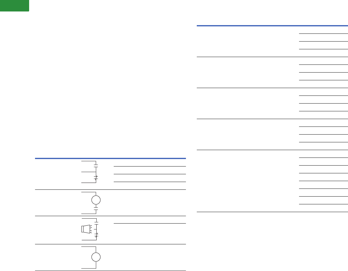
V2-T1-110 Volume 2—Commercial Distribution CA08100003E—April 2014 www.eaton.com
1
1
1
1
1
1
1
1
1
1
1
1
1
1
1
1
1
1
1
1
1
1
1
1
1
1
1
1
1
1
1.2
Switching Devices
Enclosed Circuit Breakers
Accessories
Nameplates Applied
Customer must provide
nameplate legend at the time
of order.
Key Interlock Systems
Interlocks are used to prevent
an authorized operation.
Before system construction
can begin, the following
information must be known:
1. User—name, address
and telephone number.
2. Complete lock scheme
required.
Neutral Assemblies Installed
Ampere ratings: 100, 250,
400, 600, 800 and 1200.
Separate Ground Lug
Installed
Ampere ratings: 100, 250,
400, 600 and 1200.
Special Paint Finish
Contact the Safety Switch
Flex Center (1-888-329-9272)
or FlexSwitches@eaton.com.
Pilot Light On NEMA 1
Enclosure
Pilot light
Stainless Steel Flush Covers
Frames: P, J and K.
Assembled Enclosed Circuit Breakers
Accessories Modifications Breaker Frame Description
Auxiliary switches
(specify voltage and Hz)
G, F, J, K, L, M, N 1A, 1B
G, F, J, K, L, M, N 2A, 2B
K, L, M, N 3A, 3B
R1A, 1B
Shunt trips
(specify voltage and Hz)
G, F, J, K, L, M, N, R —
Alarm switches
(specify voltage and Hz)
G, F, J, K, L, M, N 1 Make, 1 Break
F, K, L, M, N 2 Make, 2 Break
Undervoltage release
(specify voltage and Hz)
G, F, J, K, L, M, N, R —
a
b
a
ST
Make
Break
ST
Electronic Trip Options
Notes
1Ground fault application not available with NEMA 7/9. Contact Eaton’s Customer
Support Center.
2Add to the appropriate RD RMS 310 adder.
Frame Type Number of Poles Description
KD, HKD 3 RMS 310 LS
RMS 310 LSI
RMS 310 LSG 1
RMS 310 LSIG 1
LD, HLD 3 RMS 310 LS
RMS 310 LSI
RMS 310 LSG 1
RMS 310 LSIG 1
MDL, HMDL 3 RMS 310 LS
RMS 310 LSI
RMS 310 LSG 1
RMS 310 LSIG 1
ND 3 RMS 310 LS
RMS 310 LSI
RMS 310 LSG 1
RMS 310 LSIG 1
RD 3 RMS 310 LS
RMS 310 LSI
RMS 310 LSG
RMS 310 LSIG
RMS 510 LS 2
RMS 610 LS 2
RMS 810 LS 2
RMS 910 LS 2

Volume 2—Commercial Distribution CA08100003E—April 2014 www.eaton.com V2-T1-111
1
1
1
1
1
1
1
1
1
1
1
1
1
1
1
1
1
1
1
1
1
1
1
1
1
1
1
1
1
1
1.2
Switching Devices
Enclosed Circuit Breakers
Raintight Hubs
All rainproof enclosures 30–400A are shipped with plate over
cutout. Hubs are not supplied with screws on 30–400A
enclosures. Use screws from plate.
Raintight Tubs
Breather and Drain, Hazardous Enclosures
A Universal Breather/Drain Fitting is installed in the top of an
enclosure to provide ventilation to minimize condensation and in
the bottom to allow drainage of accumulated condensation while
maintaining explosion-proof integrity.
Neutral Kits, Insulated and Groundable
Modifications
Allowable accessory combinations can be reviewed in Eaton’s
Circuit Breaker Product Guide: PG.74.A.01.T.E. Verify final
application with the Customer Support Center.
Special RD Modifications and Accessories
Hubs
Hub Diameter Catalog
NumberInches mm
Small
For use with RGDN and RFDN 0.75 19.1 DS075H1
1.00 25.4 DS100H1
1.25 31.8 DS125H1
1.50 38.1 DS150H1
2.00 50.8 DS200H1
Large
For use with RJDN.
RKDN has two cutouts
2.00 50.8 DS200H2
2.50 63.5 DS250H2
3.00 76.2 DS300H2
Required if using small DS hubs on
RJDN and RKDN enclosures.
DS900AP
Type
Compliance Conduit
Opening
Catalog
NumberNEMA 7 NEMA 9
BD Class I, Groups C, D; Class I,
Zone 1, Group IIB
Class II, Groups
F, G
1/2 XPBD2
DBB Class I, Groups B, C, D; Class I,
Zone 1, Group IIB + Hydrogen
Class II, Groups
E, F, G
1/2 XPDBB50
Maximum Enclosure
Rating (A)
Main Lug Size
Cu/Al
Catalog
Number
100 SFDN100
RFDN100
(1) 14–1/0 DH100NK
100 (all others) (1) 14–1/0 INK100
250 (1) 4–350 kcmil INK250
400 (1) 4–600 kcmil or
(2) 1/0–250 kcmil
INK400
600 (2) 250–500 kcmil INK600
1200 (4) 3/0–750 kcmil DS800NK
Raintight Hubs
Description
1600A neutral assembly (aluminum)
2000A neutral assembly (aluminum)
2500A neutral assembly (aluminum)
1600A neutral assembly (copper)
2000A neutral assembly (copper)
2500A neutral assembly (copper)
Adjustable rating plug
Lockoff, padlockable
Key interlock
Phase failure protection (includes shunt trip)
Zero sequence gfp (including shunt trip and test panel)
NEMA 3R flat roof
Heater package (includes cpt, heater, thermostat and disconnect)
Special sized enclosures
Standard is 90-inch H x 30-inch W x 30-inch D (2286 x 762 x 762 mm)
IQ metering
Non-standard terminations

V2-T1-112 Volume 2—Commercial Distribution CA08100003E—April 2014 www.eaton.com
1
1
1
1
1
1
1
1
1
1
1
1
1
1
1
1
1
1
1
1
1
1
1
1
1
1
1
1
1
1
1.2
Switching Devices
Enclosed Circuit Breakers
Flex Center
Introduction
The Safety Switch Flex
Center is a special facility
at the site of our Cleveland,
Tennessee, plant that is
dedicated to providing
customized enclosed
circuit breakers that meet
customers’ challenging
applications.
The Flex Center is a
solutions center that
provides real value:
●A dedicated and
knowledgeable
engineering/
manufacturing/customer
service team to meet
your needs
●A production facility
stocked with a full arsenal
of equipment to get the
job done
●The industry’s shortest
lead-time
●Easy ordering through
our distributors
●Factory-installed
modifications include
(but are not limited to)
the following:
●Special size enclosure
●Special nameplates
●Stainless steel flush
cover
●Special paint
●Lock-on provisions
●Neutral assemblies—
factory installed
●Equipment ground
lugs—factory installed
●Cover control (pilot
lights, pushbuttons,
selector switches, etc.)
●Factory-installed
G-Frame breakers
●For application, availability
or pricing questions,
contact the Safety
Switch Flex Center
at 1-888-329-9272 or
FlexSwitches@eaton.com
Satellite Plants
Atlanta
7000 Highlands Parkway SE
#102
Smyrna, GA 30082
Fax (770) 433-1863
Phone (678) 309-4260
Baltimore
6671 Santa Barbara Court
Suite A
Elk Ridge, MD 21075
Fax (410) 796-7755
Phone (410) 796-7777
Chicago
959 AEC Drive
Wood Dale, IL 60191
Fax (630) 860-3569
Phone (630) 860-3500
Cleveland
5565 Venture Drive
Unit B
Parma, OH 44130
Fax (216) 433-0545
Phone (216) 433-0616
Dallas
631 Westport Pkwy
Suite 100
Grapevine, TX 76051
Fax (817) 251-6249
Phone (817) 251-6797
Denver
14101 East 33rd Place
Suite F
Aurora, CO 80011
Fax (303) 371-4175
Phone (303) 371-7844
Hartford
625 Day Hill Road
Windsor, CT 06095
Fax (860) 688-4982
Phone (860) 688-5330
Houston
10810 West Little York
Suite 100
Houston, TX 77041
Fax (713) 688-3764
Phone (713) 688-8430
Los Angeles
5590 Jurupa Street
Ontario, CA 91761
Fax (909) 390-8884
Phone (909) 390-8853
New Jersey
96 Stemmers Lane
Westampton, NJ 08060
Fax (609) 835-4777
Phone (609) 835-4230
Orlando
3827 St. Valentine Way
Orlando, FL 32811
Fax (407) 841-9135
Phone (407) 843-3863
Phoenix
921 South Park Lane
Suite 1
Tempe, AZ 85281-5119
Fax (480) 449-4223
Phone (480) 449-4222
Raleigh
2933 S. Miami Blvd.
Suite 111
Durham, NC 27703
Fax (919) 572-9751
Phone (919) 544-7074
St. Louis
12947 Gravois Road
St. Louis, MO 63127
Fax (314) 842-2552
Phone (314) 842-7797
San Francisco
20923 Cabot Boulevard
Hayward, CA 94545
Fax (510) 784-8980
Phone (510) 784-8981
Seattle
18657 72nd Avenue S.
Kent, WA 98032
Fax (425) 251-0079
Phone (425) 251-9081
Satellite Service Locations
•
•
•
•
•
•
•
•
•
•
•
★
•
•
•
★
SEATTLE
SAN FRANCISCO
LOS ANGELES
DENVER
DALLAS
GRAND PRAIRIE
HOUSTON
CHICAGO
BALTIMORE
ATLANTA
ST. LOUIS
HARTFORD
SUMTER
CLEVELAND
•
RALEIGH
•PHOENIX
ORLANDO
NEW JERSE
Y

Volume 2—Commercial Distribution CA08100003E—April 2014 www.eaton.com V2-T1-113
1
1
1
1
1
1
1
1
1
1
1
1
1
1
1
1
1
1
1
1
1
1
1
1
1
1
1
1
1
1
1.2
Switching Devices
Enclosed Circuit Breakers
Technical Data and Specifications
Industrial Circuit Breaker Selection
Notes
1N.I.T.U. is non-interchangeable trip unit and I.T.U. is interchangeable trip unit.
2Two-pole circuit breaker, or two poles of three-pole circuit breaker at 250 Vdc.
3Not defined in W-C-375b.
4Not suitable for use with 100A enclosures.
Circuit
Breaker
Type
Continuous
Ampere
Rating
at 40°C
Number
of
Poles Vac Vdc
Type of
Trip 1
Federal
Spec.
W-C-375b
UL Listed Interrupting Rating rms Symmetrical Amperes
Vac Ratings Vdc Ratings 2
120 120/240 240 277 480 600 125 250 125/250
G-Frame
GHC 15–100 1 120 125 N.I.T.U. 12c, 13a 65,000 — — — — — 14,000 — —
GHC 15–100 2, 3 240 125/250 N.I.T.U. 13b — — 65,000 — — — — — 14,000
GHC 15–100 1 277 125 N.I.T.U. 12c, 13a — — — 14,000 — — 14,000 — —
GHC 15–100 2, 3 277/480 215/250 N.I.T.U. 13b — — — 14,000 14,000 — — — 14,000
GD 15–100 3 480 250 N.I.T.U. 13b — — 65,000 — 22,000 — — 10,000 —
F-Frame
ED 100–225 2, 3 240 125 N.I.T.U. 12b — — 65,000 — — — 10,000 — —
EDH 100–225 2, 3 240 125 N.I.T.U. 14b — — 100,000 — — — 10,000 — —
EDC 100–225 2, 3 240 125 N.I.T.U. 1 — — 200,000 — — — 10,000 — —
EHD 15–100 1 277 125 N.I.T.U. 13a — — — 14,000 — — 10,000 — —
EHD 15–100 2, 3 480 250 N.I.T.U. 13b — — 18,000 — 14,000 — — 10,000 —
FDB 15–150 2, 3 600 250 N.I.T.U. 18a — — 18,000 — 14,000 14,000 — 10,000 —
FDB 15–150 4 600 250 N.I.T.U. 3— — 18,000 — 14,000 14,000 — 10,000 —
FD 15–225 1 277 125 N.I.T.U. 13a — — — 25,000 — — 10,000 — —
FD 15–225 2, 3 600 250 N.I.T.U. 22a — — 65,000 — 25,000 18,000 — 10,000 —
FD 15–225 4 600 250 N.I.T.U. 3— — 65,000 — 25,000 18,000 — 10,000 —
HFD 15–225 1 277 125 N.I.T.U. 13a — — — 65,000 — — 10,000 — —
HFD 15–225 2, 3 600 250 N.I.T.U. 22a — — 100,000 — 65,000 25,000 — 20,000 —
HFD 15–225 4 600 250 N.I.T.U. 3— — 100,000 — 65,000 25,000 — 20,000 —
FDC 15–225 42, 3 600 250 N.I.T.U. 24a — — 200,000 — 100,000 35,000 — 20,000 —
FDC 15–225 4 600 250 N.I.T.U. 3— — 200,000 — 100,000 35,000 — 20,000 —
J-Frame
JDB 70–250 2, 3 600 250 N.I.T.U. 22a — — 65,000 — 35,000 18,000 — 10,000 —
JD 70–250 2, 3, 4 600 250 I.T.U. 22a — — 65,000 — 35,000 18,000 — 10,000 —
HJD 70–250 2, 3, 4 600 250 I.T.U. 22a — — 100,000 — 65,000 25,000 — 22,000 —
JDC 70–250 2, 3, 4 600 250 I.T.U. 22a — — 200,000 — 100,000 35,000 — 22,000 —
K-Frame
DK 250–400 2, 3 240 250 N.I.T.U. 14b — — 65,000 — — — — 10,000 —
KDB 100–400 2, 3 600 250 N.I.T.U. 23a — — 65,000 — 35,000 25,000 — 10,000 —
KD 100–400 2, 3, 4 600 250 I.T.U. 23a — — 65,000 — 35,000 25,000 — 10,000 —
HKD 100–400 2, 3, 4 600 250 I.T.U. 23a — — 100,000 — 65,000 35,000 — 22,000 —
KDC 100–400 2, 3, 4 600 250 I.T.U. 23a — — 200,000 — 100,000 50,000 — 22,000 —
LG-Frame
LGE 250–600 3, 4 600 250 I.T.U. 23a — — 65,000 — 35,000 18,000 — 22,000 —
LGS 250–600 3, 4 600 250 I.T.U. 23a — — 85,000 — 50,000 25,000 — 22,000 —
LGH 250–600 3, 4 600 250 I.T.U. 23a — — 100,000 — 65,000 35,000 — 42,000 —

V2-T1-114 Volume 2—Commercial Distribution CA08100003E—April 2014 www.eaton.com
1
1
1
1
1
1
1
1
1
1
1
1
1
1
1
1
1
1
1
1
1
1
1
1
1
1
1
1
1
1
1.2
Switching Devices
Enclosed Circuit Breakers
Industrial Circuit Breaker Selection, continued
Notes
1N.I.T.U. is non-interchangeable trip unit and I.T.U. is interchangeable trip unit.
2Two-pole circuit breaker, or two poles of three-pole circuit breaker at 250 Vdc.
3HLD: NEMA 1 enclosed: 240 Vac = 100 kA, 480 Vac = 65 kA, 600 Vac = 35 kA, 250 Vdc = 20 kA, 500 Vdc = 25 kA.
NEMA 3R enclosed: 240 Vac = 65 kA, 480 Vac = 50 kA, 600 Vac = 25 kA, 250 Vdc = 20 kA, 500 Vdc = 25 kA.
4HMDL and HND: NEMA 1 and 3R enclosed: 240 Vac = 100 kA, 480 Vac = 65 kA, 600 Vac = 35 kA, 250 Vdc = 30 kA, 500 Vdc = 30 kA.
Circuit
Breaker
Type
Continuous
Ampere
Rating
at 40°C
Number
of
Poles Vac Vdc
Type of
Trip 1
Federal
Spec.
W-C-375b
UL Listed Interrupting Rating rms Symmetrical Amperes
Vac Ratings Vdc Ratings 2
120 120/240 240 277 480 600 125 250 125/250
L-Frame
LDB 300–600 2, 3 600 250 N.I.T.U. 23a — — 65,000 — 35,000 25,000 — 22,000 —
LD 300–600 2, 3, 4 600 250 I.T.U. 23a — — 65,000 — 35,000 25,000 — 22,000 —
HLD 3300–600 2, 3, 4 600 250 I.T.U. 23a — — 100,000 — 65,000 35,000 — 25,000 —
M-Frame
MDL 300–800 2, 3 600 250 I.T.U. 23a — — 65,000 — 50,000 25,000 — 22,000 —
HMDL 4300–800 2, 3 600 250 I.T.U. 23a — — 100,000 — 65,000 35,000 — 25,000 —
N-Frame
ND 600–1200 3, 4 600 — N.I.T.U. 23a — — 65,000 — 50,000 25,000 — —
HND 4600–1200 3, 4 600 — N.I.T.U. 23a — — 100,000 — 65,000 35,000 — —
R-Frame
RD 800–2500 3, 4 600 — N.I.T.U. 24a — — 125,000 — 65,000 35,000 — — —
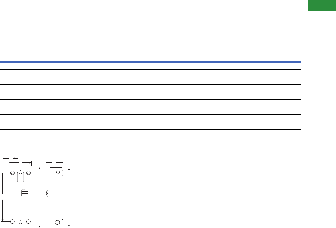
Volume 2—Commercial Distribution CA08100003E—April 2014 www.eaton.com V2-T1-115
1
1
1
1
1
1
1
1
1
1
1
1
1
1
1
1
1
1
1
1
1
1
1
1
1
1
1
1
1
1
1.2
Switching Devices
Enclosed Circuit Breakers
Dimensions
Approximate Dimensions in Inches (mm)
NEMA 1, 12, 12K, 3R
Note: Not to be used for construction purposes unless approved.
NEMA 1 Surface Mounted
NEMA 1 Surface Mounted
Notes
1SFDN100 Series “B” released 9/15/01.
2Maximum wire size: 4/0.
3Total width, including door clip is 9.95 inches (253 mm).
4Single centered mounting hole provided.
5Maximum wire size: 500 kcmil.
Frame
Maximum
Amperes A B C D E F
Approximate Weight
in Lbs (kg)
G 100 17.50 (444.5) 8.56 (217.4) 6.28 (159.5) 13.03 (331.0) 1.20 (30.5) 17.19 (436.6) 12 (5)
F 1100 19.13 (485.9) 9.13 (231.9) 35.20 (132.1) 17.00 (431.8) N/A 418.81 (477.8) 13 (6)
Earth leakage 100 23.25 (590.6) 8.56 (217.4) 6.28 (159.5) 18.75 (476.3) 1.20 (30.5) 22.94 (582.7) 15 (7)
F 2225 23.25 (590.6) 8.56 (217.4) 6.28 (159.5) 18.75 (476.3) 1.20 (30.5) 22.94 (582.7) 15 (7)
J 250 34.70 (881.4) 10.92 (277.4) 7.20 (182.9) 30.00 (762.0) 1.88 (47.8) 34.39 (873.5) 31 (14)
K 5400 38.81 (985.8) 11.06 (280.9) 10.94 (277.9) 34.00 (863.6) 1.25 (31.8) 38.50 (977.9) 53 (24)
LG 600 51.06 (1296.9) 21.87 (555.5) 9.96 (253.0) 51.63 (1311.5) 1.94 (49.3) 50.13 (1273.3) 90 (41)
Earth leakage 600 51.06 (1296.9) 21.87 (555.5) 9.96 (253.0) 51.63 (1311.5) 1.94 (49.3) 50.13 (1273.3) 90 (41)
L 600 45.88 (1165.4) 14.31 (363.5) 12.38 (314.5) 46.56 (1182.6) 1.91 (48.5) 45.56 (1157.2) 81 (37)
M, N 1200 61.22 (1555.0) 21.44 (544.6) 15.41 (391.4) 61.84 (1570.7) 1.97 (50.0) 60.91 (1547.1) 178 (81)
E
DA
C
B
F
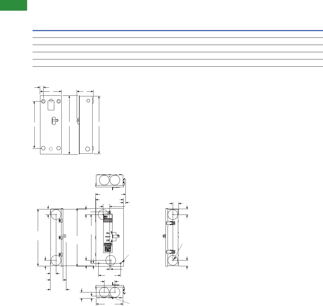
V2-T1-116 Volume 2—Commercial Distribution CA08100003E—April 2014 www.eaton.com
1
1
1
1
1
1
1
1
1
1
1
1
1
1
1
1
1
1
1
1
1
1
1
1
1
1
1
1
1
1
1.2
Switching Devices
Enclosed Circuit Breakers
Approximate Dimensions in Inches (mm)
NEMA 1 Flush Mounted
NEMA 1 Flush Mounted
NEMA 1 Surface Mounted SFDN100 Series “B”
Notes
1Maximum wire size: 4/0.
2Maximum wire size: 500 kcmil.
Frame
Maximum
AmperesABCDE F
Approximate Weight
in Lbs (kg)
F 100 18.81 (477.8) 9.72 (246.9) 6.28 (159.5) 13.03 (331.0) 1.86 (47.2) 18.50 (469.9) 12 (5)
Earth leakage 100 24.56 (623.8) 9.72 (246.9) 6.28 (159.5) 18.75 (476.3) 1.86 (47.2) 24.25 (616.0) 15 (7)
F 1225 24.56 (623.8) 9.72 (246.9) 6.28 (159.5) 18.75 (476.3) 1.86 (47.2) 24.25 (616.0) 15 (7)
J 250 36.02 (914.9) 12.23 (310.6) 7.20 (182.9) 30.00 (762.0) 1.88 (47.8) 35.70 (906.8) 32 (15)
K 2400 40.13 (1019.3) 12.38 (314.5) 10.94 (277.9) 34.00 (863.6) 2.94 (74.7) 39.81 (1011.2) 53 (24)
D
E
BC
AF
NEED ART
DWG...95-1562
MARK SCHMIDT
FROM
18.81
(478.0)
1.84
(46.7)
1.84
(46.7)
1.91
(48.5) 4.23
(107.4)
5.20
(132.0)
19.12
(485.6)
1.78
(45.2)
1.78
(45.2)
17.00
(431.8)
0.81
(20.6)
0.38
(9.7)
7.25
(184.1)
3.50 (89.0)
1.91
(48.5)
0.69
(17.5)
8.82
(224.0) 0.281 (7.1) Diameter
Knockout Quantity: 2
0.27 (6.8) Diameter
3 Mounting Holes
9.13 (232.0)
9.95 (252.7)
0.71
(18.0)
2.13
(54.1)
1.91
(48.5)
1.84
(46.7)
Concentric Knockouts
for 1, 1-1/4, 1-1/2
(25.4, 31.8, 38.1)
2 Conduit
Quantity: 10
1.84
(46.7)
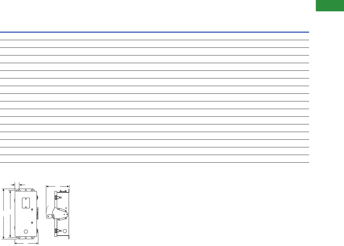
Volume 2—Commercial Distribution CA08100003E—April 2014 www.eaton.com V2-T1-117
1
1
1
1
1
1
1
1
1
1
1
1
1
1
1
1
1
1
1
1
1
1
1
1
1
1
1
1
1
1
1.2
Switching Devices
Enclosed Circuit Breakers
Approximate Dimensions in Inches (mm)
NEMA 12, 12K Dustproof
NEMA 12, 12K Dustproof
Notes
1Maximum wire size: 4/0.
2Maximum wire size: 500 kcmil.
Frame
Maximum
Amperes A B C D E
Approximate Weight
in Lbs (kg)
G, F 100 19.91 (505.7) 9.16 (232.7) 9.31 (236.5) 18.53 (470.7) 1.70 (43.2) 16 (7)
Earth leakage 100 19.91 (505.7) 9.16 (232.7) 9.31 (236.5) 18.53 (470.7) 1.70 (43.2) 19 (9)
FBP, FCL 100 25.66 (651.8) 9.16 (232.7) 9.31 (236.5) 24.28 (616.7) 1.70 (43.2) 19 (9)
F 1225 25.66 (651.8) 9.16 (232.7) 9.31 (236.5) 24.28 (616.7) 1.70 (43.2) 19 (9)
J 250 37.53 (953.3) 11.88 (301.8) 10.22 (259.6) 35.77 (908.6) 1.94 (49.3) 37 (17)
K 2400 41.69 (1058.9) 12.31 (312.7) 14.06 (357.1) 39.94 (1014.5) 1.97 (50.0) 58 (26)
LG 600 53.37 (1355.6) 23.06 (585.7) 14.10 (358.1) 51.63 (1311.4) 1.94 (49.3) 94 (43)
Earth leakage 600 53.37 (1355.6) 23.06 (585.7) 14.10 (358.1) 51.63 (1311.4) 1.94 (49.3) 94 (43)
L 600 48.31 (1227.1) 15.56 (395.2) 15.50 (393.7) 46.56 (1182.6) 1.92 (48.8) 84 (38)
NBP 800 63.59 (1615.2) 22.63 (574.8) 17.63 (447.8) — — 110 (50)
M, N 1200 63.59 (1615.2) 22.63 (574.8) 17.63 (447.8) 61.84 (1570.7) 1.97 (50.0) 175 (80)
G, F 100 19.91 (505.7) 9.16 (232.7) 9.31 (236.5) — — 16 (7)
Earth leakage 100 19.91 (505.7) 9.16 (232.7) 9.31 (236.5) — — 19 (9)
FBP, FCL 100 25.66 (651.8) 9.16 (232.7) 9.31 (236.5) — — 19 (9)
F 1225 25.66 (651.8) 9.16 (232.7) 9.31 (236.5) — — 19 (9)
J 250 37.53 (953.3) 11.88 (301.8) 10.22 (259.6) — — 37 (17)
K 2400 41.69 (1058.9) 12.31 (312.7) 14.06 (357.1) — — 58 (26)
ON
OFF
EC
AD
B
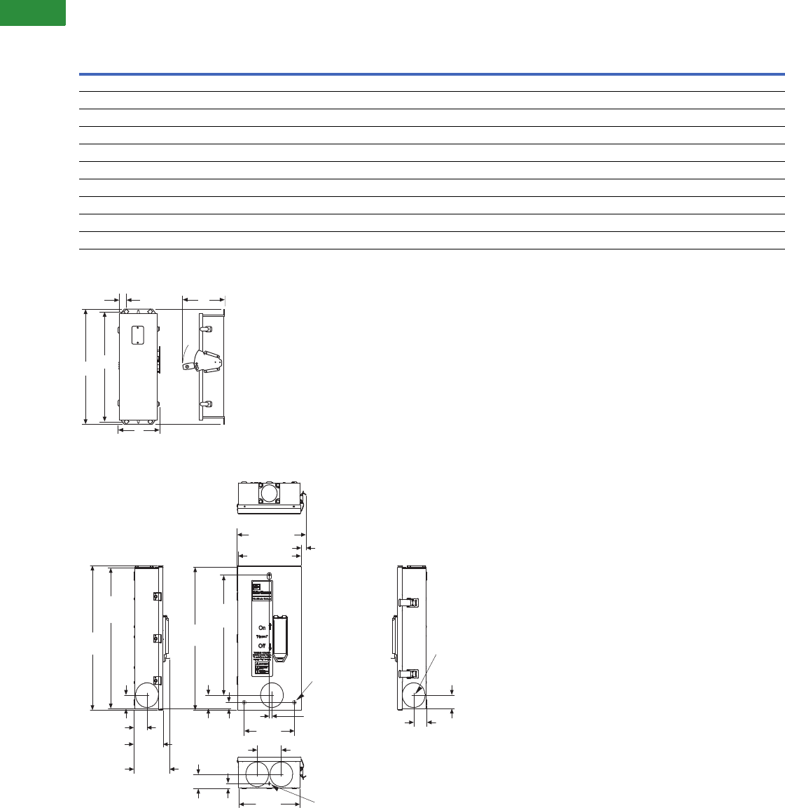
V2-T1-118 Volume 2—Commercial Distribution CA08100003E—April 2014 www.eaton.com
1
1
1
1
1
1
1
1
1
1
1
1
1
1
1
1
1
1
1
1
1
1
1
1
1
1
1
1
1
1
1.2
Switching Devices
Enclosed Circuit Breakers
Approximate Dimensions in Inches (mm)
NEMA 3R Rainproof
NEMA 3R Rainproof 5
NEMA 3R Rainproof RFDN100 Series “B”
Notes
1RFDN100 Series “B” released 9/15/01.
2Single centered mounting hole provided on RFDN100, Series “B.”
3Maximum wire size: 4/0.
4Maximum wire size: 500 kcmil.
5All NEMA 3R except RFDN100.
Frame
Maximum
Amperes A B C D E
Approximate Weight
in Lbs (kg)
G, F 1100 19.91 (505.7) 9.16 (232.7) 9.31 (236.5) 18.53 (470.7) 1.70 (43.2) 216 (7)
Earth leakage 100 19.91 (505.7) 9.19 (232.7) 9.31 (236.5) 18.53 (470.7) 1.70 (43.2) 19 (9)
FBP, FCL 100 25.66 (651.8) 9.16 (232.7) 9.31 (236.5) 24.28 (616.7) 1.70 (43.2) 19 (9)
F 3225 25.66 (651.8) 9.16 (232.7) 9.31 (236.5) 24.28 (616.7) 1.70 (43.2) 19 (9)
J 250 37.50 (952.5) 11.88 (301.8) 10.22 (259.6) 35.77 (908.6) 1.94 (49.3) 37 (17)
K 4400 41.69 (1058.9) 12.31 (312.7) 14.06 (357.1) 39.94 (1014.5) 1.97 (50.0) 58 (26)
LG 600 53.37 (1355.6) 23.06 (585.7) 14.10 (358.1) 51.63 (1311.4) 1.94 (49.3) 94 (43)
Earth leakage 600 53.37 (1355.6) 23.06 (585.7) 14.10 (358.1) 51.63 (1311.4) 1.94 (49.3) 94 (43)
L 600 48.31 (1227.1) 15.56 (395.2) 15.50 (393.7) 46.56 (1182.6) 1.92 (48.8) 84 (38)
M, N 1200 63.59 (1615.2) 22.63 (574.8) 17.63 (447.8) 61.84 (1570.7) 1.97 (50.0) 175 (80)
C
ON
OFF
E
AD
B
NEED ART
DWG...95-1562
MARK SCHMIDT
FROM
Concentric Knockouts
for 1, 1-1/4, 1-1/2
(25.4, 31.8, 38.1)
2 Conduit
Quantity: 5
1.84
(46.7)
1.91
(48.5)
7.25
(184.0)
0.27 (6.8) Diameter
3 Mounting Holes
0.38
(9.7)
3.50 (89.0)
19.12
(485.6)
1.78
(45.2)
17.00
(431.8)
0.81
(20.6)
1.91
(48.5)
0.69
(17.5)
8.82
(224.0) 0.281 (7.1) Diameter
Knockout Quantity: 2
1.84
(46.7)
1.91
(48.5) 4.23
(107.4)
5.20
(132.0)
19.27
(489.4)
18.81
(478.0)
9.13 (232.0)
9.95 (252.7)
0.71
(18.0)
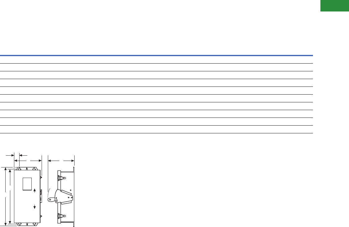
Volume 2—Commercial Distribution CA08100003E—April 2014 www.eaton.com V2-T1-119
1
1
1
1
1
1
1
1
1
1
1
1
1
1
1
1
1
1
1
1
1
1
1
1
1
1
1
1
1
1
1.2
Switching Devices
Enclosed Circuit Breakers
Approximate Dimensions in Inches (mm)
NEMA 4/4X, 5, 7/9
Note: Not to be used for construction purposes unless approved.
NEMA 4/4X, 5 Stainless Steel
NEMA 4/4X, 5 Stainless Steel
Notes
1Maximum wire size: 4/0.
2Maximum wire size: 500 kcmil.
Frame
Maximum
Amperes A B C D E
Approximate Weight
in Lbs (kg)
G, F 100 19.91 (505.7) 8.84 (224.5) 9.31 (236.5) 18.53 (470.7) 1.70 (43.2) 16 (7)
Earth leakage 100 19.91 (505.7) 8.84 (224.5) 9.31 (236.5) 18.53 (470.7) 1.70 (43.2) 20 (9)
FBP, FCL 100 25.66 (651.8) 8.84 (224.5) 9.31 (236.5) 24.28 (616.7) 1.70 (43.2) 20 (9)
F 1225 25.66 (651.8) 8.84 (224.5) 9.31 (236.5) 24.28 (616.7) 1.70 (43.2) 20 (9)
J 250 37.50 (952.5) 11.56 (293.6) 10.22 (259.6) 35.77 (908.6) 1.94 (49.3) 39 (18)
K 2400 41.69 (1058.9) 11.75 (298.5) 14.06 (357.1) 39.94 (1014.5) 1.97 (50.0) 60 (27)
LG 600 53.38 (1355.9) 23.06 (585.7) 14.11 (358.4) 51.64 (1311.7) 1.94 (49.3) 96 (44)
Earth leakage 600 53.38 (1355.9) 23.06 (585.7) 14.11 (358.4) 51.64 (1311.7) 1.94 (49.3) 96 (44)
L 600 48.31 (1227.1) 14.91 (378.7) 15.50 (393.7) 46.56 (1182.6) 1.92 (48.8) 88 (40)
M, N 1200 63.59 (1615.2) 22.00 (558.8) 17.63 (447.8) 61.84 (1570.7) 1.97 (50.0) 185 (84)
E
B
D
A
ON
OFF
C
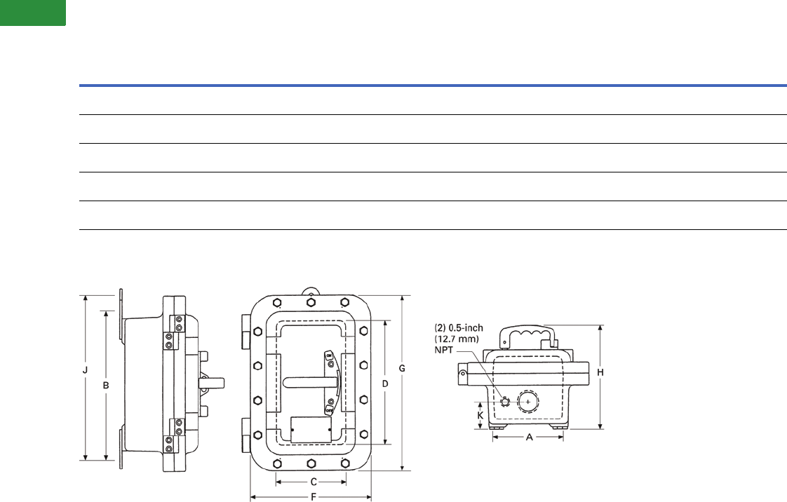
V2-T1-120 Volume 2—Commercial Distribution CA08100003E—April 2014 www.eaton.com
1
1
1
1
1
1
1
1
1
1
1
1
1
1
1
1
1
1
1
1
1
1
1
1
1
1
1
1
1
1
1.2
Switching Devices
Enclosed Circuit Breakers
Approximate Dimensions in Inches (mm)
NEMA 7/9 Cast Aluminum with Weather-Resistant Seals—15–250A
NEMA 7/9 Cast Aluminum with Weather-Resistant Seals—Dual Three- and Four-Point Mounting
Available as Standard on F-Frame 100A and Below
Note
1Maximum wire size: 4/0.
Breaker
Frame
Breaker
Size
Amperes
Number
of
Outlets
Mounting 1Inside 1Outside 1
K 1
Dim
Standard
Conduit
Size 1
Approximate
Weight in
Lbs (kg)ABJCDE F GH
F
XFDN050B
15–50 4 5.50
(139.7)
13.13
(333.5)
14.13
(358.9)
6.13
(155.7)
10.75
(273.1)
5.25
(133.4)
10.63
(270.0)
15.25
(387.4)
8.88
(225.6)
2.00
(50.8)
1.50
(38.1)
38 (17)
F 1
XFDN100B
60–100 4 6.00
(152.4)
18.00
(457.2)
19.00
(482.6)
6.50
(165.1)
16.00
(406.4)
5.50
(139.7)
11.00
(279.4)
20.50
(520.7)
9.00
(228.6)
2.31
(58.7)
2.00
(50.8)
57 (26)
F 1
XFDN225B
125–225 4 10.25
(260.4)
22.63
(574.8)
— 11.38
(289.1)
20.00
(508.0)
6.38
(162.1)
16.38
(416.1)
25.13
(638.3)
9.63
(244.6)
3.50
(88.9)
2.50
(63.5)
104 (47)
J
XJDN225B
70–225 4 8.50
(215.9)
27.13
(689.1)
— 11.25
(285.8)
29.88
(759.0)
7.38
(187.5)
16.00
(406.4)
29.50
(749.3)
12.31
(312.7)
4.00
(101.6)
3.00
(76.2)
145 (66)
J
XJDN250B
250 4 9.50
(241.3)
27.25
(692.2)
— 11.25
(285.8)
29.88
(759.0)
8.06
(204.7)
16.38
(416.1)
35.00
(889.0)
12.38
(314.5)
4.19
(106.4)
4.00
(101.6)
170 (77)
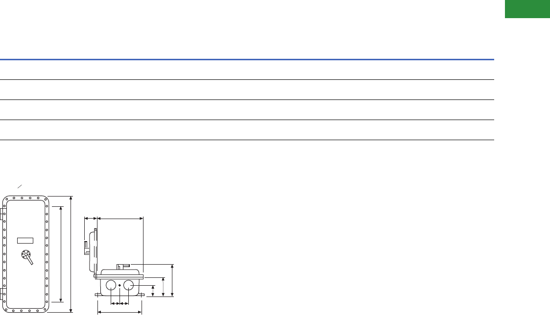
Volume 2—Commercial Distribution CA08100003E—April 2014 www.eaton.com V2-T1-121
1
1
1
1
1
1
1
1
1
1
1
1
1
1
1
1
1
1
1
1
1
1
1
1
1
1
1
1
1
1
1.2
Switching Devices
Enclosed Circuit Breakers
Approximate Dimensions in Inches (mm)
7/9 Cast Aluminum with Weather-Resistant Seals—400–1200A
NEMA 7/9 Cast Aluminum with Weather-Resistant Seals
Conduit Openings
Refer to outline dimensions for size and location of standard
conduit openings. In addition, 1/2-inch (12.7 mm) openings are
drilled and tapped for breather and drain. Unless ordered with
breather and drain, these openings are plugged. Refer to Eaton
for price of breather and drain.
Notes
1Maximum wire size: 500 kcmil.
2Power cables must enter and leave from opposite ends (through-feed).
Breaker
Frame
Breaker
Size
Amperes
Overall Enclosure Enclosure Mounting Conduit Hinged Cover Standard Conduit
Weight
Lbs (kg)ABCDE F GHI J SizeLocation
K 1
XKDN400B
400 35.00
(889.0)
16.38
(416.1)
12.63
(320.8)
7.13
(181.1)
9.50
(241.3)
27.25
(692.2)
.50
(12.7)
3.00
(76.2)
4.19
(106.4)
5.50
(139.7)
4.00
(101.6)
1, 3 and
6, 8
170 (77)
L
XLDN600B
600 37.88
(962.2)
23.88
(606.6)
14.25
(362.0)
8.25
(209.6)
16.00
(406.4)
45.38
(1152.7)
.50
(12.7)
4.00
(101.6)
5.00
(127.0)
6.00
(152.4)
4.00
(101.6)
1, 3 and
6, 8
419 (190)
M
XMCN800B
800 47.88
(1216.2)
13.63
(346.2)
12.81
(325.4)
6.81
(173.0)
16.13
(409.7)
40.75
(1035.1)
.50
(12.7)
4.00
(101.6)
4.00
(101.6)
6.00
(152.4)
4.00
(101.6)
1, 3 and
6, 8
228 (104)
N 2
XNDN1200B
1200 64.00
(1625.6)
26.00
(660.4)
21.38
(543.1)
14.38
(365.3)
27.56
(700.0)
38.63
(981.2)
.50
(12.7)
6.50
(165.1)
4.38
(111.3)
7.00
(177.8)
4.00
(101.6)
1, 3 and
6, 8
567 (257)
CONDUIT POSITION NO.
123
G-MTG.
HOLES (4)
F-MTG.
A
8 7 6
I
D
C
JB
HH
E-MT
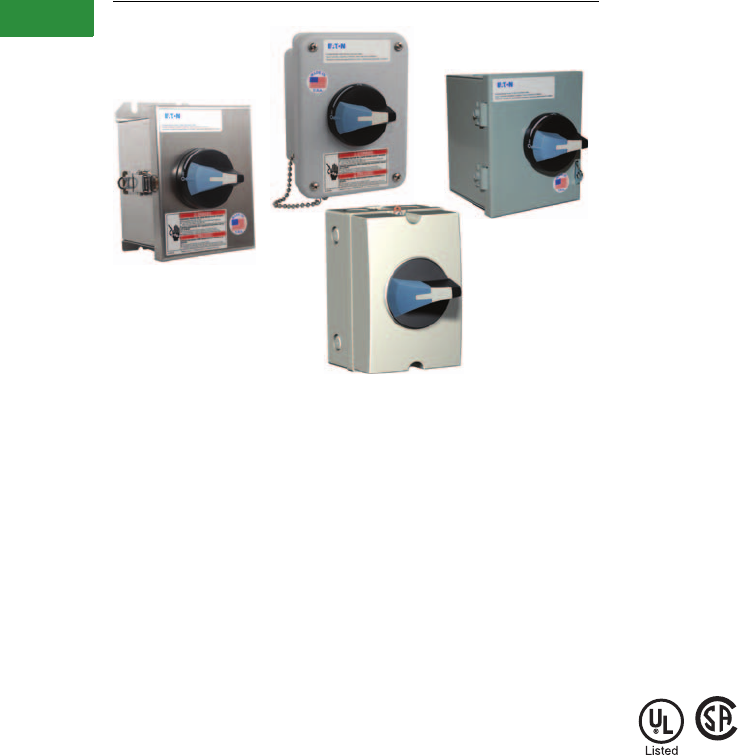
V2-T1-122 Volume 2—Commercial Distribution CA08100003E—April 2014 www.eaton.com
1
1
1
1
1
1
1
1
1
1
1
1
1
1
1
1
1
1
1
1
1
1
1
1
1
1
1
1
1
1
1.3
Switching Devices
Enclosed Rotary Disconnects
Enclosed Rotary Disconnects
Contents
Description Page
Product Overview . . . . . . . . . . . . . . . . . . . . . . . . . V2-T1-122
Features, Benefits and Functions . . . . . . . . . . . . . V2-T1-122
Standards and Certifications . . . . . . . . . . . . . . . . . V2-T1-122
Product Selection . . . . . . . . . . . . . . . . . . . . . . . . . V2-T1-123
Dimensions . . . . . . . . . . . . . . . . . . . . . . . . . . . . . . V2-T1-124
Product Overview
Provide users with the ability
to lock directly wired motor
loads in the OFF position to
comply with OSHA lockout/
tagout regulations. Also for
machine applications that
require compact, economical
disconnect switches.
Enclosed rotary disconnect
switches allow safe control
and safe disconnect of any
motor application.
Features, Benefits
and Functions
●Padlockable in the OFF
position (up to three
padlocks) to meet OSHA
lockout requirements
●Available in 16–80A ratings
●600 Vac, three- and four-
pole non-fusible device
●Rated for making and
breaking loads
●Accepts auxiliary contacts;
capability to signal PLC
controllers
●Ground lug connection
provided
●Possibility of adding one
power pole and one
auxiliary contact
●NEMA® Type 1, 3R, 12,
4, 4X
Open rotary disconnects can
be found in Volume 5, Tab 3
titled: NEMA Manual Starters.
Standards and Certifications
●Meets NEC® Article 430
requirements for a
separate disconnect
means within sight
of all motor loads
●UL® listed under
Section 508
●UL listed File No. E165150
●CSA® listed under 22.2
No. 14, File 162136

Volume 2—Commercial Distribution CA08100003E—April 2014 www.eaton.com V2-T1-123
1
1
1
1
1
1
1
1
1
1
1
1
1
1
1
1
1
1
1
1
1
1
1
1
1
1
1
1
1
1
1.3
Switching Devices
Enclosed Rotary Disconnects
Product Selection
Enclosed Rotary Non-Fusible
Accessories for Enclosed Rotary Disconnects 56
Notes
1For CSA listed switches, add prefix letter “C” to the front of the catalog number.
2NEMA Type 12 enclosures (16–80A) can be field modified to meet NEMA Type 3R rainproof requirements when a factory-provided drain hole is opened.
3GB suffix = Gray cover, Black handle. GR suffix = Gray cover, Red handle. YR suffix = Yellow cover, Red handle.
4cULus only.
5Ordered and shipped as separate components—not integral to enclosed device.
6Enclosed disconnects can accept one power pole, neutral or up to two auxiliary contacts (one mounted on either side of switch).
Contact the Safety Switch Flex Center (1-888-329-9272 or FlexSwitches@eaton.com) for factory-installed accessories or other special modifications.
Ampere
Rating
Maximum Horsepower Ratings
NEMA 1 1
Enclosure
Indoor
NEMA 12 1 2
Enclosure
Dust-Tight/
Rainproof
NEMA 4X 1
Enclosure
Corrosion-Resistant,
Stainless Steel
NEMA 4X 1
Enclosure
Corrosion-Resistant,
Non-Metallic
NEMA 4X
Enclosure
Polycarbonate-
Non-MetallicThree-Phase AC
208V 240V 480V 600V Catalog Number Catalog Number Catalog Number Catalog Number Catalog Number
Three-Pole, 600 Vac
16 3 5 10 10 ER53016UG ER53016UD ER53016UW ER53016UX —
25 7-1/2 7-1/2 15 20 ER53025UG ER53025UD ER53025UW ER53025UX —
30 7-1/2 7-1/2 15 20 ER53030UG ER53030UD ER53030UW ER53030UX ER53030UPGB 34
40 7-1/2 7-1/2 20 25 ER53040UG ER53040UD ER53040UW ER53040UX —
60 15 15 30 30 ER53060UG ER53060UD ER53060UW ER53060UX ER53060UPGB 34
80 15 20 40 40 ER53080UG ER53080UD ER53080UW ER53080UX —
Four-Pole, 600 Vac
16 3 5 10 10 ER54016UG ER54016UD ER54016UW ER54016UX —
25 7-1/2 7-1/2 15 20 ER54025UG ER54025UD ER54025UW ER54025UX —
30 7-1/2 7-1/2 20 25 ER54030UG ER54030UD ER54030UW ER54030UX —
40 7-1/2 7-1/2 20 25 ER54040UG ER54040UD ER54040UW ER54040UX —
Disconnect
Ampere Rating
Switched
Fourth Pole
Unswitched
Neutral Pole
Auxiliary Contacts
(Choose one)
Terminal
Shrouds
16 S4PR516 UNMR5A 1NO + 1NC
AC1NONC
2NC
AC2NC
Single-pole
TS1R5A
Three-pole
TS3R5A
25 S4PR525
30 S4PR530
40 S4PR540
60 S4PR560 UNMR5B Single-pole
TS1R5B
Three-pole
TS3R5B
80 S4PR580
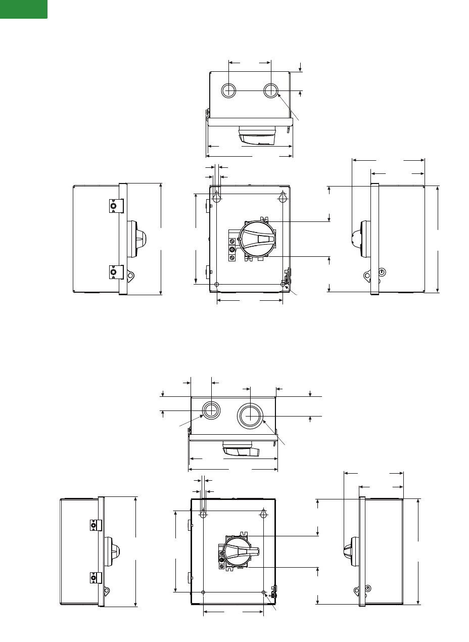
V2-T1-124 Volume 2—Commercial Distribution CA08100003E—April 2014 www.eaton.com
1
1
1
1
1
1
1
1
1
1
1
1
1
1
1
1
1
1
1
1
1
1
1
1
1
1
1
1
1
1
1.3
Switching Devices
Enclosed Rotary Disconnects
Dimensions
Approximate Dimensions in Inches (mm)
NEMA Type 1 (16–40A)
NEMA Type 1 (60–80A)
Note:
Wire range of switch lugs for 16–25A is #6–#10 copper, and for 30–40A is #8–#14.
Wire range of ground lugs is #2–#14 copper or aluminum.
8.47
(215.1) 6.86
(174.2)
0.31
(7.9)
2 Mounting Holes
2.68
(68.1)
2.68
(68.1)
0.27
(6.9) 0.56
(14.2)
3.20
(81.3)
1.44
(36.6)
Concentric knockouts for
0.5-, 0.75-inch conduit,
quantity 4, knockout
locations same in top
and bottom
6.42
(163.1) 6.55
(166.4) 5.50
(139.7)
4.11
(104.4)
8.11
(206.0)
5.00
(127.0)
8.42
(213.9) 8.56
(217.4)
0.27
(6.9) 0.56
(14.2)
7.75
(196.9)
3.50
(88.9)
10.47
(265.9)
5.67
(144.0)
4.23
(107.4)
1.96
(49.8)
1.32
(33.5) 2.46
(62.5)
1.86
(47.2)
Concentric knockout
for 0.5, 0.75, 1 conduit,
quantity 2, knockout
location same in top
and bottom
Concentric knockout
for 1.25, 1.5, 2 conduit,
quantity 2, knockout
location same in top
and bottom
5.75
(146.1) 0.31
(7.9)
2 Mounting Holes
3.53
(89.7)
10.11
(256.8)
Note:
Wire range of switch lugs is #1–#14 copper.
Wire range of ground lugs is #2–#14 copper or aluminum.
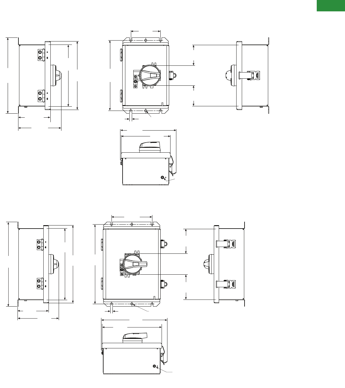
Volume 2—Commercial Distribution CA08100003E—April 2014 www.eaton.com V2-T1-125
1
1
1
1
1
1
1
1
1
1
1
1
1
1
1
1
1
1
1
1
1
1
1
1
1
1
1
1
1
1
1.3
Switching Devices
Enclosed Rotary Disconnects
Approximate Dimensions in Inches (mm)
NEMA Type 12/3R (16–40A)
NEMA Type 12/3R (60–80A)
n 0.31
(7.9) Hole
2.68
(68.1)
9.26
(235.2)
9.98
(253.5)
8.14
(206.8)
8.99
(228.3)
3.91
(99.3)
2.68
(68.1)
0.31
(7.9)
7.35
(186.7) 6.45
(163.8)
5.66
(143.8)
4.26
(108.0)
Screw to be removed when
used as Type 3R device
Note:
Wire range of switch lugs for 16–25A is #6–#10
copper, and for 30–40A is #8–#14 copper or aluminum.
11.98
(304.3)
5.81
(147.6)
4.38
(111.3)
10.14
(257.6)
10.99
(279.1)
11.26
(286.0)
5.75
(146.1)
3.50
(88.9)
3.53
(89.7)
0.31
(7.9) n 0.31
(7.9) Hole
9.35
(237.5)
8.45
(214.6)
Screw to be removed when used as Type 3R device
Notes:
Wire range of switch lugs is #1–#14 copper.
Wire range of ground lugs is #2–#14 copper or aluminum.
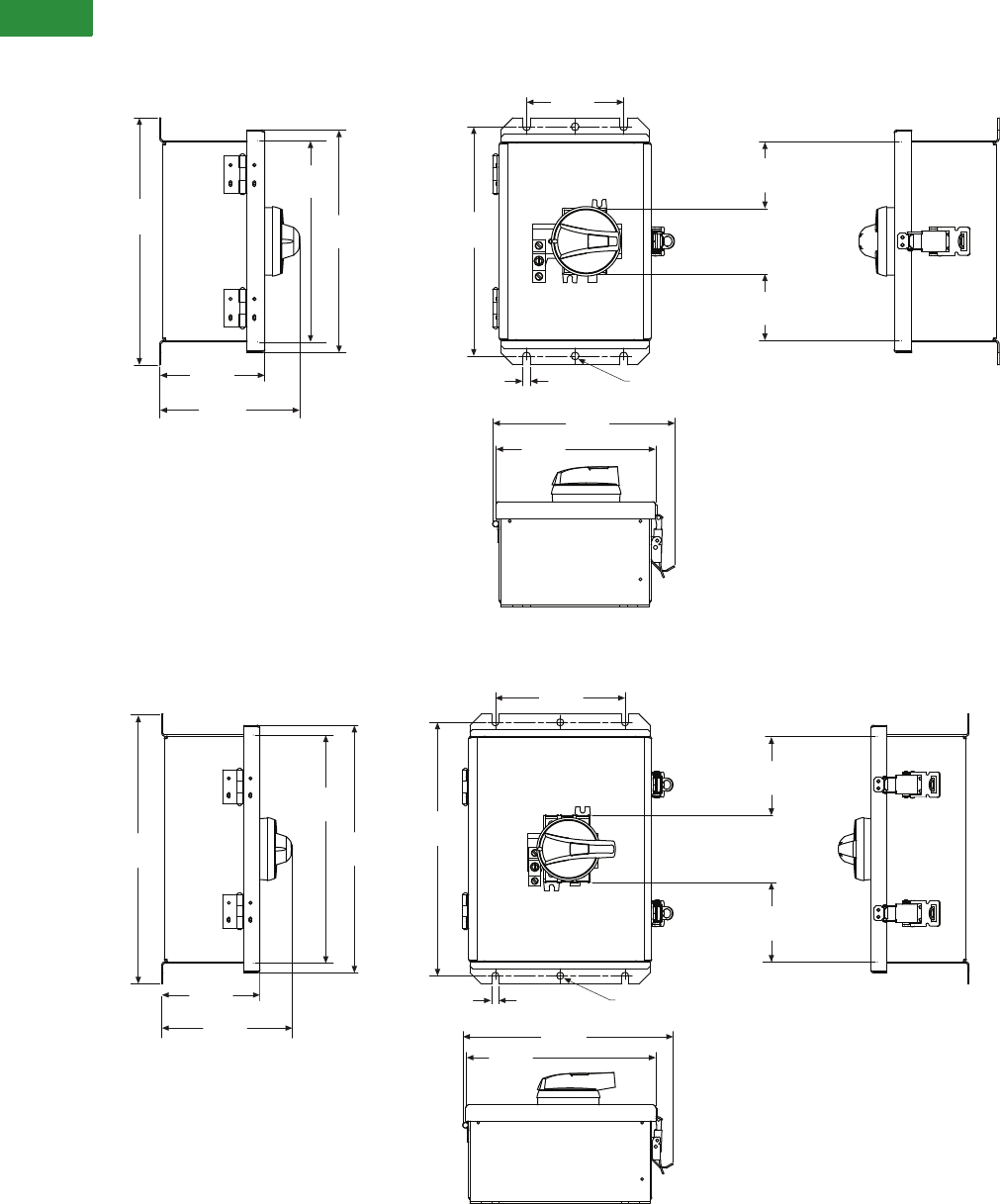
V2-T1-126 Volume 2—Commercial Distribution CA08100003E—April 2014 www.eaton.com
1
1
1
1
1
1
1
1
1
1
1
1
1
1
1
1
1
1
1
1
1
1
1
1
1
1
1
1
1
1
1.3
Switching Devices
Enclosed Rotary Disconnects
Approximate Dimensions in Inches (mm)
NEMA Type 4X Stainless (16–40A)
NEMA Type 4X Stainless (60–80A)
9.95
(252.7)
4.23
(107.4)
5.63
(143.0)
8.11
(206.0)
8.97
(227.8)
9.23
(234.4)
6.43
(163.3)
7.33
(186.2)
3.91
(99.3)
2.68
(68.1)
2.68
(68.1)
0.31
(7.9) n 0.31
(7.9) Hole
Notes:
Wire range of switch lugs for 16–25A is
#6–#10 copper, and for 30–40A is #8–#14.
Wire range of ground lugs is #2–#14
copper or aluminum.
4.35
(110.5)
5.78
(146.8)
10.11
(256.8)
10.97
(278.6)
11.95
(303.6)
8.43
(214.1)
9.32
(236.7)
11.23
(285.2)
5.75
(146.1)
3.50
(88.9)
3.53
(89.7)
0.31
(7.9)
Notes:
Wire range of switch lugs is #4–#14 copper.
Wire range of ground lugs is #2–#14 copper
or aluminum.
n 0.31
(7.9) Hole
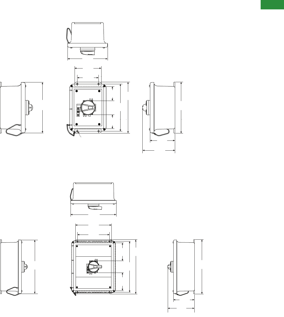
Volume 2—Commercial Distribution CA08100003E—April 2014 www.eaton.com V2-T1-127
1
1
1
1
1
1
1
1
1
1
1
1
1
1
1
1
1
1
1
1
1
1
1
1
1
1
1
1
1
1
1.3
Switching Devices
Enclosed Rotary Disconnects
Approximate Dimensions in Inches (mm)
NEMA Type 4X Thermoset Polyester (16–40A)
NEMA Type 4X Thermoset Polyester (60–80A)
Four Mounting Holes
4.70
(119.4)
6.10
(154.9)
9.63
(244.6)
2.65
(67.3)
2.65
(67.3)
8.88
(225.6)
0.31
(7.9)
4.00
(101.6)
5.00
(127.0)
7.52
(191.0)
9.52
(241.8) 9.63
(245.0)
Notes:
Wire range of switch lugs for 16–25A is #6–#10 copper, and for 30–40A is #8–#14.
Wire range of ground lugs is #2–#14 copper or aluminum.
13.41
(340.6)
11.43
(290.3)
9.00
(228.6)
8.00
(203.2)
4.48
(113.8)
13.56
(344.4)
12.75
(323.8)
4.51
(114.6)
13.56
(344.4)
5.24
(133.1)
6.67
(169.4)
Notes:
Wire range of switch lugs is #1–#14 copper.
Wire range of ground lugs is #2–#14 copper or aluminum.
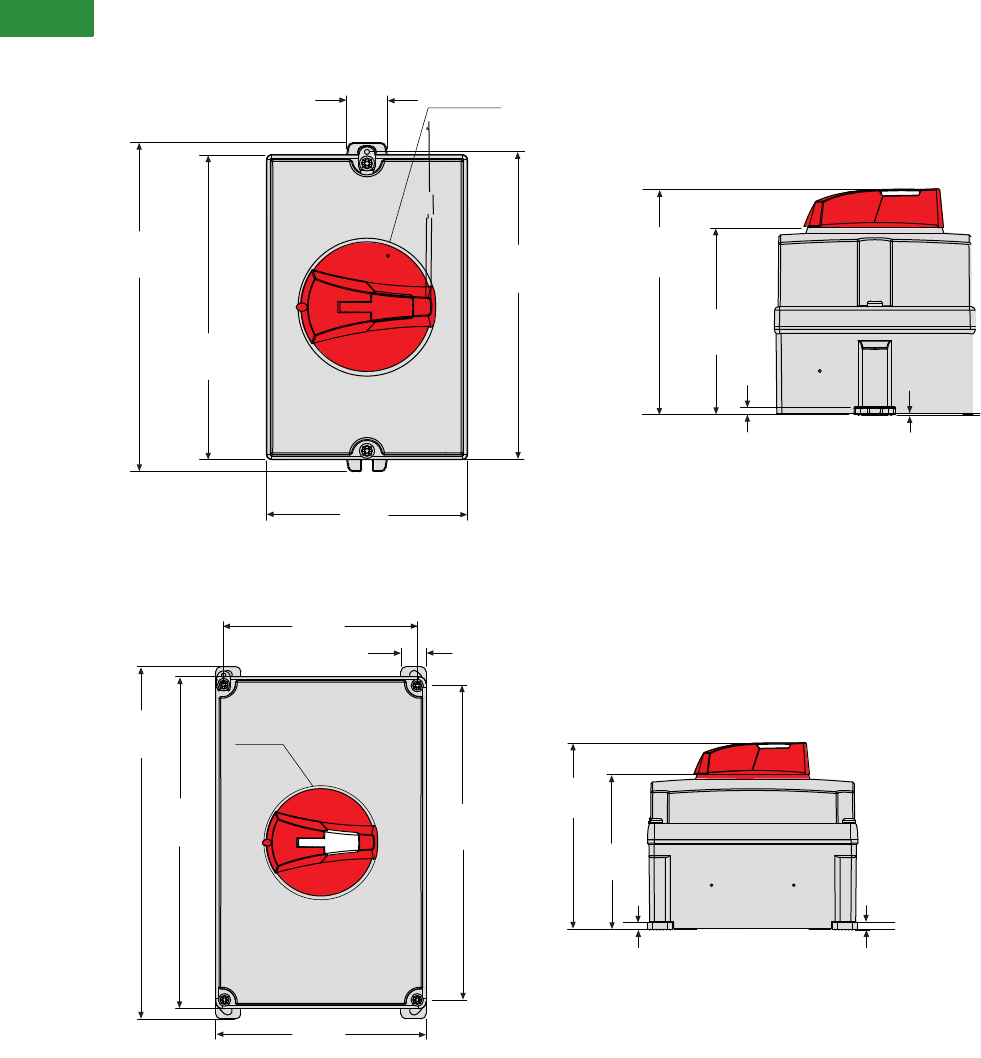
V2-T1-128 Volume 2—Commercial Distribution CA08100003E—April 2014 www.eaton.com
1
1
1
1
1
1
1
1
1
1
1
1
1
1
1
1
1
1
1
1
1
1
1
1
1
1
1
1
1
1
1.3
Switching Devices
Enclosed Rotary Disconnects
Approximate Dimensions in Inches (mm)
NEMA Type 4X—Polycarbonate (30A)
NEMA Type 4X—Polycarbonate (60A)
0.13
(3.3)
0.02
(0.5)
3.62
(91.9)
4.37
(111.0)
6.00
(152.4)
6.38
(162.1)
5.90
(149.9)
0.79
(20.1)
3.90
(99.1)
Ø2.68
(68.1)
7.32
(185.9)
7.80
(198.1)
0.16
(4.1)
0.02
(0.5)
3.62
(91.9)
4.37
(111.0)
8.27
(210.0)
0.59
(15.0)
4.45
(113.0)
4.94
(125.5)
Ø2.67
(67.8)

Volume 2—Commercial Distribution CA08100003E—June 2014 www.eaton.com V2-T2-1
2
2
2
2
2
2
2
2
2
2
2
2
2
2
2
2
2
2
2
2
2
2
2
2
2
2
2
2
2
2
Transformers
Dry-Type Transformer Family
2.1 NEMA TP-1 Energy-Efficient Transformers
Product Description. . . . . . . . . . . . . . . . . . . . . . . . . . . . . . . . . . . . . . . V2-T2-2
Application Description . . . . . . . . . . . . . . . . . . . . . . . . . . . . . . . . . . . . V2-T2-2
Features, Benefits and Functions . . . . . . . . . . . . . . . . . . . . . . . . . . . . V2-T2-3
Standards and Certifications . . . . . . . . . . . . . . . . . . . . . . . . . . . . . . . . V2-T2-3
Catalog Number Selection . . . . . . . . . . . . . . . . . . . . . . . . . . . . . . . . . V2-T2-4
Product Selection . . . . . . . . . . . . . . . . . . . . . . . . . . . . . . . . . . . . . . . . V2-T2-4
Accessories . . . . . . . . . . . . . . . . . . . . . . . . . . . . . . . . . . . . . . . . . . . . . V2-T2-50
Technical Data and Specifications . . . . . . . . . . . . . . . . . . . . . . . . . . . . V2-T2-50
2.2 NEMA Premium and E3 Super Efficient Transformers
NEMA Premium® Efficient Transformers . . . . . . . . . . . . . . . . . . . . . . V2-T2-61
E3 Super Efficient Transformers . . . . . . . . . . . . . . . . . . . . . . . . . . . . . V2-T2-66
2.3 Energy-Efficient Harmonic Mitigating Transformers
Product Description. . . . . . . . . . . . . . . . . . . . . . . . . . . . . . . . . . . . . . . V2-T2-71
Features and Benefits . . . . . . . . . . . . . . . . . . . . . . . . . . . . . . . . . . . . . V2-T2-71
Standards and Certifications . . . . . . . . . . . . . . . . . . . . . . . . . . . . . . . . V2-T2-72
Catalog Number Selection . . . . . . . . . . . . . . . . . . . . . . . . . . . . . . . . . V2-T2-72
Product Selection . . . . . . . . . . . . . . . . . . . . . . . . . . . . . . . . . . . . . . . . V2-T2-73
Accessories . . . . . . . . . . . . . . . . . . . . . . . . . . . . . . . . . . . . . . . . . . . . . V2-T2-89
Technical Data and Specifications . . . . . . . . . . . . . . . . . . . . . . . . . . . . V2-T2-89
2.4 General-Purpose Encapsulated Transformers
Product Description. . . . . . . . . . . . . . . . . . . . . . . . . . . . . . . . . . . . . . . V2-T2-93
Application Description . . . . . . . . . . . . . . . . . . . . . . . . . . . . . . . . . . . . V2-T2-93
Features, Benefits and Functions . . . . . . . . . . . . . . . . . . . . . . . . . . . . V2-T2-93
Standards and Certifications . . . . . . . . . . . . . . . . . . . . . . . . . . . . . . . . V2-T2-93
Catalog Number Selection . . . . . . . . . . . . . . . . . . . . . . . . . . . . . . . . . V2-T2-94
Product Selection . . . . . . . . . . . . . . . . . . . . . . . . . . . . . . . . . . . . . . . . V2-T2-94
Accessories . . . . . . . . . . . . . . . . . . . . . . . . . . . . . . . . . . . . . . . . . . . . . V2-T2-109
Technical Data and Specifications . . . . . . . . . . . . . . . . . . . . . . . . . . . . V2-T2-109
2.5 Distribution Transformers
Motor Drive Isolation Transformers. . . . . . . . . . . . . . . . . . . . . . . . . . . V2-T2-111
Mini–Power Centers . . . . . . . . . . . . . . . . . . . . . . . . . . . . . . . . . . . . . . V2-T2-119
Totally Enclosed Non-Ventilated Transformers . . . . . . . . . . . . . . . . . . V2-T2-124
Class I, Division 2, Hazardous Location Transformers. . . . . . . . . . . . . V2-T2-127
Open-Type Core and Coil Assembly Transformers . . . . . . . . . . . . . . . V2-T2-130
Marine Duty Transformers. . . . . . . . . . . . . . . . . . . . . . . . . . . . . . . . . . V2-T2-133
Buck-Boost and Low Voltage Lighting Transformers . . . . . . . . . . . . . . V2-T2-144
Medium Voltage Distribution Transformers. . . . . . . . . . . . . . . . . . . . . V2-T2-173
2.6 Transformer Standards, Technical Data and Accessories
Standards and Certifications . . . . . . . . . . . . . . . . . . . . . . . . . . . . . . . . V2-T2-186
Catalog Number Selection . . . . . . . . . . . . . . . . . . . . . . . . . . . . . . . . . V2-T2-187
Product Selection . . . . . . . . . . . . . . . . . . . . . . . . . . . . . . . . . . . . . . . . V2-T2-189
Options and Accessories. . . . . . . . . . . . . . . . . . . . . . . . . . . . . . . . . . . V2-T2-191
Technical Data and Specifications . . . . . . . . . . . . . . . . . . . . . . . . . . . . V2-T2-194
Glossary of Transformer Terms . . . . . . . . . . . . . . . . . . . . . . . . . . . . . . V2-T2-210
Frequently Asked Questions About Transformers. . . . . . . . . . . . . . . . V2-T2-213
2.7 Dimensions
Dimensions . . . . . . . . . . . . . . . . . . . . . . . . . . . . . . . . . . . . . . . . . . . . . V2-T2-215
Learn
Online
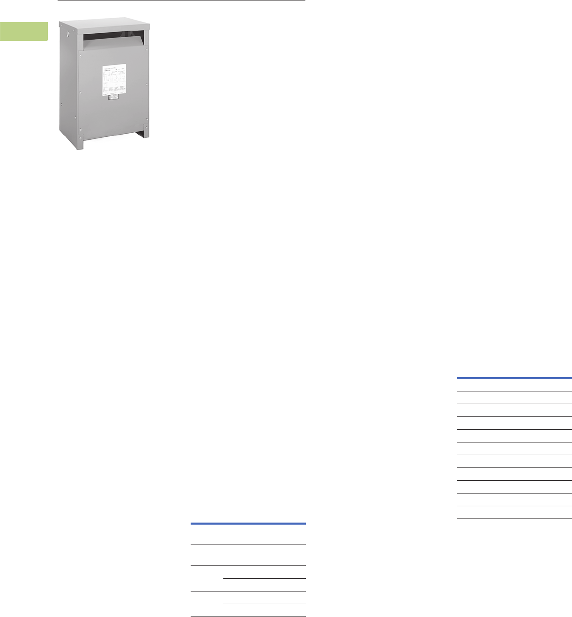
V2-T2-2 Volume 2—Commercial Distribution CA08100003E—June 2014 www.eaton.com
2
2
2
2
2
2
2
2
2
2
2
2
2
2
2
2
2
2
2
2
2
2
2
2
2
2
2
2
2
2
2.1
Transfor mers
NEMA TP-1 Energy-Efficient Transformers
Type DT-3
Contents
Description Page
NEMA TP-1 Energy-Efficient Transformers
Features, Benefits and Functions. . . . . . . . . . . V2-T2-3
Standards and Certifications . . . . . . . . . . . . . . V2-T2-3
Catalog Number Selection . . . . . . . . . . . . . . . . V2-T2-4
Product Selection. . . . . . . . . . . . . . . . . . . . . . . V2-T2-4
Single-Phase Aluminum . . . . . . . . . . . . . . . . V2-T2-4
Single-Phase Copper . . . . . . . . . . . . . . . . . . . V2-T2-6
Single-Phase Shielded Aluminum . . . . . . . . . V2-T2-8
Single-Phase Shielded Copper . . . . . . . . . . . V2-T2-10
Three-Phase Aluminum . . . . . . . . . . . . . . . . . V2-T2-12
Three-Phase Copper . . . . . . . . . . . . . . . . . . . V2-T2-23
Three-Phase Shielded Aluminum . . . . . . . . . V2-T2-34
Three-Phase Shielded Copper . . . . . . . . . . . . V2-T2-42
Accessories . . . . . . . . . . . . . . . . . . . . . . . . . . . V2-T2-50
Technical Data and Specifications . . . . . . . . . . V2-T2-50
K-Factor . . . . . . . . . . . . . . . . . . . . . . . . . . . . . . V2-T2-51
Aluminum . . . . . . . . . . . . . . . . . . . . . . . . . . . V2-T2-52
Copper. . . . . . . . . . . . . . . . . . . . . . . . . . . . . . V2-T2-57
Product Description
Note: The following pages
provide listings for most standard
transformer ratings and styles.
For other ratings or styles not
shown, or for special enclosure
types (including stainless steel),
refer to Eaton.
Types DS-3, DT-3
●Ventilated, NEMA 2
enclosure standard
●Suitable for indoor
applications, outdoors
when weathershields
are also installed
●Upright mounting only
●220ºC insulation system
●150ºC rise standard;
115°C or 80°C rise optional
●Available in single-phase
ratings 15–167 kVA,
600 volts primary (DS-3)
●Available in three-phase
ratings 15–1500 kVA
and up to 600 volts
primary (DT-3)
Application Description
NEMA TP-1-2002 compliant
energy-efficient transformers
are specifically designed to
meet the energy efficiency
standards set forth in NEMA
Standards publication, TP-1-
2002, “Guide for Determining
Energy Efficiency for
Distribution Transformers.”
Surveys have shown that
the average loading of low
voltage dry-type distribution
transformers, over a 24-hour
period, is approximately
35%. NEMA TP-1 compliant
transformers are optimized to
offer maximum efficiency at
35% of nameplate rating.
The range of products covered
by NEMA TP-1-2002 are:
NEMA TP-1-2002
Product Range
Transformers that are
currently specifically excluded
from the scope of NEMA
Standard TP-1-2002 include:
●Liquid-filled transformers
below 10 kVA
●Dry-type transformers
below 15 kVA
●AC and DC drives
transformers
●Rectifier transformers
designed for high
harmonics
●Autotransformers
●Non-distribution
transformers, such as
UPS transformers
●Special impedance or
regulation transformers
●Regulating transformers
●Sealed and non-ventilated
transformers
●Machine tool transformers
●Welding transformers
●Transformers with tap
ranges greater than 15%
●Transformers with a
frequency other than 60 Hz
●Grounding transformers
●Testing transformers
Efficiency levels set forth in
NEMA TP-1-2002.
NEMA TP-1-2002
Efficiency Levels
Rating
Voltage
Class Voltage
Primary
voltage
34.5 kV and
below
Secondary
voltage
600V and
below
Dry-Type
Rating
Single-phase 10–833 kVA
Three-phase 15–2500 kVA
Liquid
Rating
Single-phase 10–833 kVA
Three-phase 15–2500 kVA
Tables of Energy Efficiency
NEMA Class 1 Efficiency Levels
Dry-Type Distribution Transformers—
Low Voltage (600V and below)
Single-Phase Three-Phase
kVA Efficiency kVA Efficiency
15 97.7 15 97.0
25 98.0 30 97.5
37.5 98.2 45 97.7
50 98.3 75 98.0
75 98.5 112.5 98.2
100 98.6 150 98.3
167 98.7 225 98.5
250 98.8 300 98.6
333 98.9 500 98.7
— — 750 98.8
— — 1000 98.9

Volume 2—Commercial Distribution CA08100003E—June 2014 www.eaton.com V2-T2-3
2
2
2
2
2
2
2
2
2
2
2
2
2
2
2
2
2
2
2
2
2
2
2
2
2
2
2
2
2
2
2.1
Transfor mers
NEMA TP-1 Energy-Efficient Transformers
Features, Benefits
and Functions
●60 Hz operation (except
as noted)
●Short-term overload
capability as required
by ANSI
●Meet NEMA ST-20
sound levels
●Meet federal energy
efficiency requirements
for low voltage dry-type
distribution transformers
effective as of
January 1, 2007
Standards and
Certifications
●UL listed
Industry Standards
All Eaton dry-type distribution
and control transformers are
built and tested in accordance
with applicable NEMA, ANSI
and IEEE Standards. All
600 volt class transformers
are UL listed unless
otherwise noted.
Seismically Qualified
Eaton manufactured dry-type
distribution transformers are
seismically qualified and
exceed requirements of the
Uniform Building Code (UBC),
International Building Code
(IBC) and California Code
Title 24.

V2-T2-4 Volume 2—Commercial Distribution CA08100003E—June 2014 www.eaton.com
2
2
2
2
2
2
2
2
2
2
2
2
2
2
2
2
2
2
2
2
2
2
2
2
2
2
2
2
2
2
2.1
Transfor mers
NEMA TP-1 Energy-Efficient Transformers
Catalog Number Selection
Please refer to Section 2.7 Page V2-T2-187.
Product Selection
Additional Product Selection information begins on Page V2-T2-189.
Single-Phase—Type DS-3 60 Hz NEMA TP-1 Energy-Efficient—Aluminum Windings
208 Volts to 120/240 Volts
240 x 480 Volts to 120/240 Volts
Notes
1Weights subject to change.
21 at +5%, 2 at –5% at 240 volts primary; 2 at +2.5%, 4 at –2.5% at 480 volts primary.
3480 volt primary only.
For other ratings or styles not shown, or for special enclosure types (including stainless steel), refer to Eaton. Frame drawings/dimensions information begins on Page V2-T2-215.
kVA
Full Capacity Taps
Type
ºC Temp.
Rise Frame
Wiring Diagram
Number
Weight
Lbs (kg) 1Weathershield Style NumberFCAN FCBN
15 2 at +2.5% 4 at –2.5% DS-3 150 816 260A 226 (103) WS11 T29M11S15EE
25 2 at +2.5% 4 at –2.5% DS-3 150 818 260A 346 (157) WS11 T29M11S25EE
37.5 2 at +2.5% 4 at –2.5 DS-3 150 818 260A 374 (170) WS11 T29M11S37EE
50 2 at +2.5% 4 at –2.5% DS-3 150 819 260A 545 (247) WS16 T29M11S50EE
75 1 at +5% 2 at –5% DS-3 150 819 551A 568 (258) WS16 T29R11S75EE
100 1 at +5% 2 at –5% DS-3 150 814E 449A 1178 (535) WS13 T29R11S99EE
kVA
Full Capacity Taps
Type
ºC Temp.
Rise Frame
Wiring Diagram
Number
Weight
Lbs (kg) 1Weathershield Style NumberFCAN FCBN
15 22 DS-3 150 842 3XA 196 (89) WS45 T20P11S15AEE
25 22 DS-3 150 842 3XA 261 (118) WS45 T20P11S25AEE
37.5 22 DS-3 150 843 3XA 304 (138) WS43 T20P11S37AEE
50 22 DS-3 150 843 3XA 396 (180) WS43 T20P11S50AEE
75 22 DS-3 150 844 3XA 688 (312) WS44 T20P11S75AEE
100 22 DS-3 150 844 3XA 699 (317) WS44 T20P11S99AEE
167 2 at +2.5% 4 at –2.5% DS-3 150 814E 288A 1294 (587) WS13 T48M11S67EE 3
15 22 DS-3 115 816 3XA 246 (112) WS11 T20P11F15EE
25 22 DS-3 115 818 3XA 373 (169) WS11 T20P11F25EE
37.5 22 DS-3 115 818 3XA 380 (173) WS11 T20P11F37EE
50 22 DS-3 115 819 3XA 590 (268) WS16 T20P11F50EE
75 22 DS-3 115 820 3XA 691 (314) WS16 T20P11F75EE
100 22 DS-3 115 821 3XA 844 (383) WS13 T20P11F99EE
15 22 DS-3 80 818 3XA 360 (163) WS11 T20P11B15EE
25 22 DS-3 80 818 3XA 370 (168) WS11 T20P11B25EE
37.5 22 DS-3 80 819 3XA 565 (257) WS16 T20P11B37EE
50 22 DS-3 80 820 3XA 680 (309) WS16 T20P11B50EE
75 22 DS-3 80 821 3XA 900 (409) WS13 T20P11B75EE

Volume 2—Commercial Distribution CA08100003E—June 2014 www.eaton.com V2-T2-5
2
2
2
2
2
2
2
2
2
2
2
2
2
2
2
2
2
2
2
2
2
2
2
2
2
2
2
2
2
2
2.1
Transfor mers
NEMA TP-1 Energy-Efficient Transformers
Single-Phase—Type DS-3 60 Hz NEMA TP-1 Energy-Efficient—Aluminum Windings
277 Volts to 120/240 Volts
208 x 416 Volts to 120/240 Volts
600 Volts to 120/240 Volts
Notes
1Weights subject to change.
2Contact your local Eaton sales office for these details.
31 at +5%, 2 at –5% at 208 volts primary; 2 at +2.5%, 4 at –2.5% at 416 volts primary.
For other ratings or styles not shown, or for special enclosure types (including stainless steel), refer to Eaton. Frame drawings/dimensions information begins on Page V2-T2-215.
kVA
Full Capacity Taps
Type
ºC Temp.
Rise Frame
Wiring Diagram
Number
Weight
Lbs (kg) 1Weathershield Style NumberFCAN FCBN
15 2 at +2.5% 4 at –2.5% DS-3 150 816 262C 220 (100) WS11 T27M11S15EE
25 2 at +2.5% 4 at –2.5% DS-3 150 818 262C 346 (157) WS11 T27M11S25EE
37.5 2 at +2.5% 4 at –2.5% DS-3 150 818 262C 391 (178) WS11 T27M11S37EE
50 2 at +2.5% 4 at –2.5% DS-3 150 819 262C 555 (252) WS16 T27M11S50EE
75 1 at +5% 2 at –5% DS-3 150 819 2568 (258) WS16 T27R11S75EE
100 1 at +5% 2 at –5% DS-3 150 814E 21178 (535) WS13 T27R11S99EE
kVA
Full Capacity Taps
Type
ºC Temp.
Rise Frame
Wiring Diagram
Number
Weight
Lbs (kg) 1Weathershield Style NumberFCAN FCBN
15 33 DS-3 150 816 3XF 246 (112) WS11 T18P11S15EE
25 33 DS-3 150 818 3XF 359 (163) WS11 T18P11S25EE
37.5 33 DS-3 150 818 3XF 374 (170) WS11 T18P11S37EE
50 33 DS-3 150 819 3XF 555 (252) WS16 T18P11S50EE
75 33 DS-3 150 820 3XF 665 (302) WS16 T18P11S75EE
100 33 DS-3 150 821 3XF 841 (382) WS13 T18P11S99EE
kVA
Full Capacity Taps
Type
ºC Temp.
Rise Frame
Wiring Diagram
Number
Weight
Lbs (kg) 1Weathershield Style NumberFCAN FCBN
15 2 at +2.5% 4 at –2.5% DS-3 150 816 262B 243 (110) WS11 T60M11S15EE
25 2 at +2.5% 4 at –2.5% DS-3 150 818 262B 355 (161) WS11 T60M11S25EE
37.5 2 at +2.5% 4 at –2.5% DS-3 150 818 262B 375 (170) WS11 T60M11S37EE
50 2 at +2.5% 4 at –2.5% DS-3 150 819 262B 594 (270) WS16 T60M11S50EE
75 2 at +2.5% 4 at –2.5% DS-3 150 820 262B 755 (343) WS16 T60M11S75EE
100 2 at +2.5% 4 at –2.5% DS-3 150 821 262B 865 (393) WS13 T60M11S99EE

V2-T2-6 Volume 2—Commercial Distribution CA08100003E—June 2014 www.eaton.com
2
2
2
2
2
2
2
2
2
2
2
2
2
2
2
2
2
2
2
2
2
2
2
2
2
2
2
2
2
2
2.1
Transfor mers
NEMA TP-1 Energy-Efficient Transformers
Single-Phase—Type DS-3 60 Hz NEMA TP-1 Energy-Efficient—Copper Windings
208 Volts to 120/240 Volts
240 x 480 Volts to 120/240 Volts
277 Volts to 120/240 Volts
Notes
1Weights subject to change.
21 at +5%, 2 at –5% at 240 volts primary; 2 at +2.5%, 4 at –2.5% at 480 volts primary.
3480 volt primary only.
4Contact your local Eaton sales office for these details.
For other ratings or styles not shown, or for special enclosure types (including stainless steel), refer to Eaton. Frame drawings/dimensions information begins on Page V2-T2-215.
kVA
Full Capacity Taps
Type
ºC Temp.
Rise Frame
Wiring Diagram
Number
Weight
Lbs (kg) 1Weathershield Style NumberFCAN FCBN
15 2 at +2.5% 4 at –2.5% DS-3 150 816 260A 275 (125) WS11 T29M11S15CUEE
25 2 at +2.5% 4 at –2.5% DS-3 150 818 260A 390 (177) WS11 T29M11S25CUEE
37.5 2 at +2.5% 4 at –2.5% DS-3 150 818 260A 440 (200) WS11 T29M11S37CUEE
50 2 at +2.5% 4 at –2.5% DS-3 150 819 260A 661 (300) WS16 T29M11S50CUEE
75 1 at +5% 2 at –5% DS-3 150 820 551A 805 (365) WS16 T29R11S75CUEE
100 1 at +5% 2 at –5% DS-3 150 821 449A 970 (440) WS13 T29R11S99CUEE
kVA
Full Capacity Taps
Type
ºC Temp.
Rise Frame
Wiring Diagram
Number
Weight
Lbs (kg) 1Weathershield Style NumberFCAN FCBN
15 22 DS-3 150 816 3XA 270 (123) WS11 T20P11S15CUEE
25 22 DS-3 150 818 3XA 406 (184) WS11 T20P11S25CUEE
37.5 22 DS-3 150 818 3XA 453 (206) WS11 T20P11S37CUEE
50 22 DS-3 150 819 3XA 657 (298) WS16 T20P11S50CUEE
75 22 DS-3 150 820 3XA 803 (365) WS16 T20P11S75CUEE
100 22 DS-3 150 821 3XA 960 (436) WS13 T20P11S99CUEE
167 2 at +2.5% 4 at –2.5% DS-3 150 814E 288A 1665 (756) WS13 T48M11S67CUEE 3
15 22 DS-3 115 816 3XA 264 (120) WS11 T20P11F15CUEE
25 22 DS-3 115 818 3XA 420 (191) WS11 T20P11F25CUEE
37.5 22 DS-3 115 818 3XA 450 (204) WS11 T20P11F37CUEE
50 22 DS-3 115 819 3XA 703 (319) WS16 T20P11F50CUEE
75 22 DS-3 115 820 3XA 793 (360) WS16 T20P11F75CUEE
100 22 DS-3 115 821 3XA 1085 (493) WS13 T20P11F99CUEE
15 22 DS-3 80 818 3XA 407 (185) WS11 T20P11B15CUEE
25 22 DS-3 80 818 3XA 430 (195) WS11 T20P11B25CUEE
37.5 22 DS-3 80 819 3XA 685 (311) WS16 T20P11B37CUEE
50 22 DS-3 80 820 3XA 799 (363) WS16 T20P11B50CUEE
75 22 DS-3 80 821 3XA 1056 (479) WS13 T20P11B75CUEE
kVA
Full Capacity Taps
Type
ºC Temp.
Rise Frame
Wiring Diagram
Number
Weight
Lbs (kg) 1Weathershield Style NumberFCAN FCBN
15 2 at +2.5% 4 at –2.5% DS-3 150 816 262C 275 (125) WS11 T27M11S15CUEE
25 2 at +2.5% 4 at –2.5% DS-3 150 818 262C 390 (177) WS11 T27M11S25CUEE
37.5 2 at +2.5% 4 at –2.5% DS-3 150 818 262C 440 (200) WS11 T27M11S37CUEE
50 2 at +2.5% 4 at –2.5% DS-3 150 819 262C 661 (300) WS16 T27M11S50CUEE
75 1 at +5% 2 at –5% DS-3 150 820 4805 (365) WS16 T27R11S75CUEE
100 1 at +5% 2 at –5% DS-3 150 821 4970 (440) WS13 T27R11S99CUEE

Volume 2—Commercial Distribution CA08100003E—June 2014 www.eaton.com V2-T2-7
2
2
2
2
2
2
2
2
2
2
2
2
2
2
2
2
2
2
2
2
2
2
2
2
2
2
2
2
2
2
2.1
Transfor mers
NEMA TP-1 Energy-Efficient Transformers
Single-Phase—Type DS-3 60 Hz NEMA TP-1 Energy-Efficient—Copper Windings
208 x 416 Volts to 120/240 Volts
600 Volts to 120/240 Volts
Notes
11 at +5%, 2 at –5% at 208 volts primary; 2 at +2.5%, 4 at –2.5% at 416 volts primary.
2Weights subject to change.
For other ratings or styles not shown, or for special enclosure types (including stainless steel), refer to Eaton. Frame drawings/dimensions information begins on Page V2-T2-215.
kVA
Full Capacity Taps
Type
ºC Temp.
Rise Frame
Wiring Diagram
Number
Weight
Lbs (kg) 2Weathershield Style NumberFCAN FCBN
15 11 DS-3 150 816 3XF 275 (125) WS11 T18P11S15CUEE
25 11 DS-3 150 818 3XF 390 (177) WS11 T18P11S25CUEE
37.5 11 DS-3 150 818 3XF 440 (200) WS11 T18P11S37CUEE
50 11 DS-3 150 819 3XF 661 (300) WS16 T18P11S50CUEE
75 11 DS-3 150 820 3XF 805 (365) WS16 T18P11S75CUEE
100 11 DS-3 150 821 3XF 970 (440) WS13 T18P11S99CUEE
kVA
Full Capacity Taps
Type
ºC Temp.
Rise Frame
Wiring Diagram
Number
Weight
Lbs (kg) 2Weathershield Style NumberFCAN FCBN
15 2 at +2.5% 4 at –2.5% DS-3 150 816 262B 290 (132) WS11 T60M11S15CUEE
25 2 at +2.5% 4 at –2.5% DS-3 150 818 262B 465 (211) WS11 T60M11S25CUEE
37.5 2 at +2.5% 4 at –2.5% DS-3 150 818 262B 495 (225) WS11 T60M11S37CUEE
50 2 at +2.5% 4 at –2.5% DS-3 150 819 262B 775 (352) WS16 T60M11S50CUEE
75 2 at +2.5% 4 at –2.5% DS-3 150 820 262B 900 (409) WS16 T60M11S75CUEE
100 2 at +2.5% 4 at –2.5% DS-3 150 821 262B 1195 (543) WS13 T60M11S99CUEE

V2-T2-8 Volume 2—Commercial Distribution CA08100003E—June 2014 www.eaton.com
2
2
2
2
2
2
2
2
2
2
2
2
2
2
2
2
2
2
2
2
2
2
2
2
2
2
2
2
2
2
2.1
Transfor mers
NEMA TP-1 Energy-Efficient Transformers
Single-Phase—Type DS-3 60 Hz NEMA TP-1 Energy-Efficient Electrostatically Shielded—Aluminum Windings
208 Volts to 120/240 Volts
240 x 480 Volts to 120/240 Volts
277 Volts to 120/240 Volts
Notes
1Weights subject to change.
21 at +5%, 2 at –5% at 240 volts primary; 2 at +2.5%, 4 at –2.5% at 480 volts primary.
3480 volt primary only.
4Contact your local Eaton sales office for these details.
For other ratings or styles not shown, or for special enclosure types (including stainless steel), refer to Eaton. Frame drawings/dimensions information begins on Page V2-T2-215.
kVA
Full Capacity Taps
Type
ºC Temp.
Rise Frame
Wiring Diagram
Number
Weight
Lbs (kg) 1Weathershield Style NumberFCAN FCBN
15 2 at +2.5% 4 at –2.5% DS-3 150 816 264A 275 (125) WS11 T29M11E15EE
25 2 at +2.5% 4 at –2.5% DS-3 150 818 264A 390 (177) WS11 T29M11E25EE
37.5 2 at +2.5% 4 at –2.5% DS-3 150 818 264A 440 (200) WS11 T29M11E37EE
50 2 at +2.5% 4 at –2.5% DS-3 150 819 264A 661 (300) WS16 T29M11E50EE
75 1 at +5% 2 at –5% DS-3 150 820 450A 805 (366) WS16 T29R11E75EE
100 1 at +5% 2 at –5% DS-3 150 821 450A 970 (440) WS13 T29R11E99EE
kVA
Full Capacity Taps
Type
ºC Temp.
Rise Frame
Wiring Diagram
Number
Weight
Lbs (kg) 1Weathershield Style NumberFCAN FCBN
15 22 DS-3 150 816 261A 246 (112) WS11 T20P11E15EE
25 22 DS-3 150 818 261A 359 (163) WS11 T20P11E25EE
37.5 22 DS-3 150 818 261A 374 (170) WS11 T20P11E37EE
50 22 DS-3 150 819 261A 555 (252) WS16 T20P11E50EE
75 22 DS-3 150 820 261A 740 (336) WS16 T20P11E75EE
100 22 DS-3 150 821 261A 841 (382) WS13 T20P11E99EE
167 2 at +2.5% 4 at –2.5% DS-3 150 814E 227A 1294 (587) WS13 T48M11E67EE 3
15 22 DS-3 115 816 261A 246 (112) WS11 T20P11F15EEES
25 22 DS-3 115 818 261A 373 (169) WS11 T20P11F25EEES
37.5 22 DS-3 115 818 261A 380 (173) WS11 T20P11F37EEES
50 22 DS-3 115 819 261A 590 (268) WS16 T20P11F50EEES
75 22 DS-3 115 820 261A 691 (314) WS16 T20P11F75EEES
100 22 DS-3 115 821 261A 844 (383) WS13 T20P11F99EEES
15 22 DS-3 80 818 261A 360 (163) WS11 T20P11B15EEES
25 22 DS-3 80 818 261A 370 (168) WS11 T20P11B25EEES
37.5 22 DS-3 80 819 261A 565 (257) WS16 T20P11B37EEES
50 22 DS-3 80 820 261A 680 (309) WS16 T20P11B50EEES
75 22 DS-3 80 821 261A 900 (409) WS13 T20P11B75EEES
kVA
Full Capacity Taps
Type
ºC Temp.
Rise Frame
Wiring Diagram
Number
Weight
Lbs (kg) 1Weathershield Style NumberFCAN FCBN
15 2 at +2.5% 4 at –2.5% DS-3 150 816 4275 (125) WS11 T27M11E15EE
25 2 at +2.5% 4 at –2.5% DS-3 150 818 4390 (177) WS11 T27M11E25EE
37.5 2 at +2.5% 4 at –2.5% DS-3 150 818 4440 (200) WS11 T27M11E37EE
50 2 at +2.5% 4 at –2.5% DS-3 150 819 4661 (300) WS16 T27M11E50EE
75 1 at +5% 2 at –5% DS-3 150 820 4805 (366) WS16 T27R11E75EE
100 1 at +5% 2 at –5% DS-3 150 821 4970 (440) WS13 T27R11E99EE

Volume 2—Commercial Distribution CA08100003E—June 2014 www.eaton.com V2-T2-9
2
2
2
2
2
2
2
2
2
2
2
2
2
2
2
2
2
2
2
2
2
2
2
2
2
2
2
2
2
2
2.1
Transfor mers
NEMA TP-1 Energy-Efficient Transformers
Single-Phase—Type DS-3 60 Hz NEMA TP-1 Energy-Efficient Electrostatically Shielded—Aluminum Windings
208 x 416 Volts to 120/240 Volts
600 Volts to 120/240 Volts
Notes
11 at +5%, 2 at –5% at 208 volts primary; 2 at +2.5%, 4 at –2.5% at 416 volts primary.
2Weights subject to change.
3Contact your local Eaton sales office for these details.
For other ratings or styles not shown, or for special enclosure types (including stainless steel), refer to Eaton. Frame drawings/dimensions information begins on Page V2-T2-215.
kVA
Full Capacity Taps
Type
ºC Temp.
Rise Frame
Wiring Diagram
Number
Weight
Lbs (kg) 2Weathershield Style NumberFCAN FCBN
15 11 DS-3 150 816 243H 275 (125) WS11 T43P11E15EE
25 11 DS-3 150 818 243H 390 (177) WS11 T43P11E25EE
37.5 11 DS-3 150 818 243H 440 (200) WS11 T43P11E37EE
50 11 DS-3 150 819 243H 661 (300) WS16 T43P11E50EE
75 11 DS-3 150 820 3805 (366) WS16 T43P11E75EE
100 11 DS-3 150 821 3970 (440) WS13 T43P11E99EE
kVA
Full Capacity Taps
Type
ºC Temp.
Rise Frame
Wiring Diagram
Number
Weight
Lbs (kg) 2Weathershield Style NumberFCAN FCBN
15 2 at +2.5% 4 at –2.5% DS-3 150 816 259A 275 (125) WS11 T60M11E15EE
25 2 at +2.5% 4 at –2.5% DS-3 150 818 259A 390 (177) WS11 T60M11E25EE
37.5 2 at +2.5% 4 at –2.5% DS-3 150 818 259A 440 (200) WS11 T60M11E37EE
50 2 at +2.5% 4 at –2.5% DS-3 150 819 259A 661 (300) WS16 T60M11E50EE
75 1 at +5% 2 at –5% DS-3 150 820 3805 (366) WS16 T60R11E75EE
100 1 at +5% 2 at –5% DS-3 150 821 3970 (440) WS13 T60R11E99EE

V2-T2-10 Volume 2—Commercial Distribution CA08100003E—June 2014 www.eaton.com
2
2
2
2
2
2
2
2
2
2
2
2
2
2
2
2
2
2
2
2
2
2
2
2
2
2
2
2
2
2
2.1
Transfor mers
NEMA TP-1 Energy-Efficient Transformers
Single-Phase—Type DS-3 60 Hz NEMA TP-1 Energy-Efficient Electrostatically Shielded—Copper Windings
208 Volts to 120/240 Volts
240 x 480 Volts to 120/240 Volts
277 Volts to 120/240 Volts
Notes
1Weights subject to change.
21 at +5%, 2 at –5% at 240 volts primary; 2 at +2.5%, 4 at –2.5% at 480 volts primary.
3Contact your local Eaton sales office for these details.
For other ratings or styles not shown, or for special enclosure types (including stainless steel), refer to Eaton. Frame drawings/dimensions information begins on Page V2-T2-215.
kVA
Full Capacity Taps
Type
ºC Temp.
Rise Frame
Wiring Diagram
Number
Weight
Lbs (kg) 1Weathershield Style NumberFCAN FCBN
15 2 at +2.5% 4 at –2.5% DS-3 150 816 264A 270 (123) WS11 T29M11E15CUEE
25 2 at +2.5% 4 at –2.5% DS-3 150 818 264A 423 (192) WS11 T29M11E25CUEE
37.5 2 at +2.5% 4 at –2.5% DS-3 150 818 264A 437 (198) WS11 T29M11E37CUEE
50 2 at +2.5% 4 at –2.5% DS-3 150 819 264A 620 (281) WS16 T29M11E50CUEE
75 1 at +5% 2 at –5% DS-3 150 820 450A 810 (368) WS16 T29R11E75CUEE
100 1 at +5% 2 at –5% DS-3 150 821 450A 980 (445) WS13 T29R11E99CUEE
kVA
Full Capacity Taps
Type
ºC Temp.
Rise Frame
Wiring Diagram
Number
Weight
Lbs (kg) 1Weathershield Style NumberFCAN FCBN
15 22 DS-3 150 816 261A 270 (123) WS11 T20P11E15CUEE
25 22 DS-3 150 818 261A 423 (192) WS11 T20P11E25CUEE
37.5 22 DS-3 150 818 261A 437 (198) WS11 T20P11E37CUEE
50 22 DS-3 150 819 261A 620 (281) WS16 T20P11E50CUEE
75 22 DS-3 150 820 261A 810 (368) WS16 T20P11E75CUEE
100 22 DS-3 150 821 261A 980 (445) WS13 T20P11E99CUEE
15 22 DS-3 115 816 261A 254 (115) WS11 T20P11F15CUEEES
25 22 DS-3 115 818 261A 453 (206) WS11 T20P11F25CUEEES
37.5 22 DS-3 115 818 261A 480 (218) WS11 T20P11F37CUEEES
50 22 DS-3 115 819 261A 718 (326) WS16 T20P11F50CUEEES
75 22 DS-3 115 820 261A 793 (360) WS16 T20P11F75CUEEES
100 22 DS-3 115 821 261A 1000 (454) WS13 T20P11F99CUEEES
15 22 DS-3 80 818 261A 240 (109) WS11 T20P11B15CUEEES
25 22 DS-3 80 818 261A 430 (195) WS11 T20P11B25CUEEES
37.5 22 DS-3 80 819 261A 700 (318) WS16 T20P11B37CUEEES
50 22 DS-3 80 820 261A 738 (335) WS16 T20P11B50CUEEES
75 22 DS-3 80 821 261A 960 (436) WS13 T20P11B75CUEEES
kVA
Full Capacity Taps
Type
ºC Temp.
Rise Frame
Wiring Diagram
Number
Weight
Lbs (kg) 1Weathershield Style NumberFCAN FCBN
15 2 at +2.5% 4 at –2.5% DS-3 150 816 3270 (123) WS11 T27M11E15CUEE
25 2 at +2.5% 4 at –2.5% DS-3 150 818 3423 (192) WS11 T27M11E25CUEE
37.5 2 at +2.5% 4 at –2.5% DS-3 150 818 3437 (198) WS11 T27M11E37CUEE
50 2 at +2.5% 4 at –2.5% DS-3 150 819 3620 (281) WS16 T27M11E50CUEE
75 1 at +5% 2 at –5% DS-3 150 820 3810 (368) WS16 T27R11E75CUEE
100 1 at +5% 2 at –5% DS-3 150 821 3980 (445) WS13 T27R11E99CUEE

Volume 2—Commercial Distribution CA08100003E—June 2014 www.eaton.com V2-T2-11
2
2
2
2
2
2
2
2
2
2
2
2
2
2
2
2
2
2
2
2
2
2
2
2
2
2
2
2
2
2
2.1
Transfor mers
NEMA TP-1 Energy-Efficient Transformers
Single-Phase—Type DS-3 60 Hz NEMA TP-1 Energy-Efficient Electrostatically Shielded—Copper Windings
208 x 416 Volts to 120/240 Volts
600 Volts to 120/240 Volts
Notes
11 at +5%, 2 at –5% at 208 volts primary; 2 at +2.5%, 4 at –2.5% at 416 volts primary.
2Weights subject to change.
3Contact your local Eaton sales office for these details.
For other ratings or styles not shown, or for special enclosure types (including stainless steel), refer to Eaton. Frame drawings/dimensions information begins on Page V2-T2-215.
kVA
Full Capacity Taps
Type
ºC Temp.
Rise Frame
Wiring Diagram
Number
Weight
Lbs (kg) 2Weathershield Style NumberFCAN FCBN
15 11 DS-3 150 816 243H 270 (123) WS11 T43P11E15CUEE
25 11 DS-3 150 818 243H 423 (192) WS11 T43P11E25CUEE
37.5 11 DS-3 150 818 243H 437 (198) WS11 T43P11E37CUEE
50 11 DS-3 150 819 243H 620 (281) WS16 T43P11E50CUEE
75 11 DS-3 150 820 3810 (368) WS16 T43P11E75CUEE
100 11 DS-3 150 821 3980 (445) WS13 T43P11E99CUEE
kVA
Full Capacity Taps
Type
ºC Temp.
Rise Frame
Wiring Diagram
Number
Weight
Lbs (kg) 2Weathershield Style NumberFCAN FCBN
15 2 at +2.5% 4 at –2.5% DS-3 150 816 259A 270 (123) WS11 T60M11E15CUEE
25 2 at +2.5% 4 at –2.5% DS-3 150 818 259A 423 (192) WS11 T60M11E25CUEE
37.5 2 at +2.5% 4 at –2.5% DS-3 150 818 259A 437 (198) WS11 T60M11E37CUEE
50 2 at +2.5% 4 at –2.5% DS-3 150 819 259A 620 (281) WS16 T60M11E50CUEE
75 1 at +5% 2 at –5% DS-3 150 820 3810 (368) WS16 T60R11E75CUEE
100 1 at +5% 2 at –5% DS-3 150 821 3980 (445) WS13 T60R11E99CUEE

V2-T2-12 Volume 2—Commercial Distribution CA08100003E—June 2014 www.eaton.com
2
2
2
2
2
2
2
2
2
2
2
2
2
2
2
2
2
2
2
2
2
2
2
2
2
2
2
2
2
2
2.1
Transfor mers
NEMA TP-1 Energy-Efficient Transformers
Three-Phase—Type DT-3 60 Hz NEMA TP-1 Energy-Efficient—Aluminum Windings
208 Delta Volts to 208Y/120 Volts
Notes
1Weights subject to change.
For other ratings or styles not shown, or for special enclosure types (including stainless steel), refer to Eaton. Frame drawings/dimensions information begins on Page V2-T2-215.
kVA
Full Capacity Taps
Type
ºC Temp.
Rise Frame
Wiring Diagram
Number
Weight
Lbs (kg) 1Weathershield Style NumberFCAN FCBN
15 2 at +2.5% 4 at –2.5% DT-3 150 912D 280E 218 (99) WS38 V29M28T15EE
30 2 at +2.5% 4 at –2.5% DT-3 150 912D 280E 299 (136) WS38 V29M28T30EE
45 2 at +2.5% 4 at –2.5% DT-3 150 912D 280E 376 (171) WS38 V29M28T45EE
75 2 at +2.5% 4 at –2.5% DT-3 150 914F 280E 564 (256) WS39 V29M28T75EE
112.5 1 at +5% 2 at –5% DT-3 150 916A 324A 930 (422) WS19 V29R28T12EE
150 1 at +5% 2 at –5% DT-3 150 916A 324A 1013 (460) WS19 V29R28T49EE
225 1 at +5% 2 at –5% DT-3 150 918A 324A 1443 (655) WS34 V29R28T22EE
300 1 at +5% 2 at –5% DT-3 150 919E 289D 1697 (770) WS35 V29R28T33EE
500 1 at +5% 2 at –5% DT-3 150 920E 289D 2690 (1221) WS35 V29R28T55EE
15 2 at +2.5% 4 at –2.5% DT-3 115 912D 280E 240 (109) WS38 V29M28F15EE
30 2 at +2.5% 4 at –2.5% DT-3 115 912D 280E 320 (145) WS38 V29M28F30EE
45 2 at +2.5% 4 at –2.5% DT-3 115 912D 280E 396 (180) WS38 V29M28F45EE
75 2 at +2.5% 4 at –2.5% DT-3 115 914F 280E 607 (276) WS39 V29M28F75EE
112.5 1 at +5% 2 at –5% DT-3 115 916A 324A 960 (436) WS19 V29R28F12EE
150 1 at +5% 2 at –5% DT-3 115 916A 324A 1060 (481) WS19 V29R28F49EE
225 1 at +5% 2 at –5% DT-3 115 918A 324A 1500 (681) WS34 V29R28F22EE
300 1 at +5% 2 at –5% DT-3 115 919E 289D 1800 (817) WS35 V29R28F33EE
500 1 at +5% 2 at –5% DT-3 115 920E 289D 2900 (1317) WS35 V29R28F55EE
15 2 at +2.5% 4 at –2.5% DT-3 80 912D 280E 280 (127) WS38 V29M28B15EE
30 2 at +2.5% 4 at –2.5% DT-3 80 912D 280E 350 (159) WS38 V29M28B30EE
45 2 at +2.5% 4 at –2.5% DT-3 80 914F 280E 560 (254) WS39 V29M28B45EE
75 2 at +2.5% 4 at –2.5% DT-3 80 916A 280E 810 (368) WS19 V29M28B75EE
112.5 2 at +2.5% 4 at –2.5% DT-3 80 916A 280E 950 (431) WS19 V29M28B12EE
150 1 at +5% 2 at –5% DT-3 80 918A 324A 1430 (649) WS34 V29R28B49EE
225 1 at +5% 2 at –5% DT-3 80 919E 289D 1750 (795) WS35 V29R28B22EE
300 1 at +5% 2 at –5% DT-3 80 920E 289D 2400 (1090) WS35 V29R28B33EE

Volume 2—Commercial Distribution CA08100003E—June 2014 www.eaton.com V2-T2-13
2
2
2
2
2
2
2
2
2
2
2
2
2
2
2
2
2
2
2
2
2
2
2
2
2
2
2
2
2
2
2.1
Transfor mers
NEMA TP-1 Energy-Efficient Transformers
Three-Phase—Type DT-3 60 Hz NEMA TP-1 Energy-Efficient—Aluminum Windings
208 Delta Volts to 480Y/277 Volts
Notes
1Weights subject to change.
For other ratings or styles not shown, or for special enclosure types (including stainless steel), refer to Eaton. Frame drawings/dimensions information begins on Page V2-T2-215.
kVA
Full Capacity Taps
Type
ºC Temp.
Rise Frame
Wiring Diagram
Number
Weight
Lbs (kg) 1Weathershield Style NumberFCAN FCBN
15 2 at +2.5% 4 at –2.5% DT-3 150 912D 342B 196 (89) WS38 V29M47T15EE
30 2 at +2.5% 4 at –2.5% DT-3 150 912D 342B 296 (134) WS38 V29M47T30EE
45 2 at +2.5% 4 at –2.5% DT-3 150 912D 342B 385 (175) WS38 V29M47T45EE
75 2 at +2.5% 4 at –2.5% DT-3 150 914F 342B 590 (268) WS39 V29M47T75EE
112.5 1 at +5% 2 at –5% DT-3 150 916A 351A 784 (356) WS19 V29R47T12EE
150 1 at +5% 2 at –5% DT-3 150 916A 351A 931 (423) WS19 V29R47T49EE
225 1 at +5% 2 at –5% DT-3 150 918A 333B 1550 (704 WS34 V29R47T22EE
300 1 at +5% 2 at –5% DT-3 150 919E 333B 2274 (1032) WS35 V29R47T33EE
500 1 at +5% 2 at –5% DT-3 150 919E 333B 2869 (1303) WS35 V29R47T55EE
15 2 at +2.5% 4 at –2.5% DT-3 115 912D 342B 215 (98) WS38 V29M47F15EE
30 2 at +2.5% 4 at –2.5% DT-3 115 912D 342B 380 (173) WS38 V29M47F30EE
45 2 at +2.5% 4 at –2.5% DT-3 115 912D 342B 400 (182) WS38 V29M47F45EE
75 2 at +2.5% 4 at –2.5% DT-3 115 914F 342B 585 (266) WS39 V29M47F75EE
112.5 1 at +5% 2 at –5% DT-3 115 916A 351A 800 (363) WS19 V29R47F12EE
150 1 at +5% 2 at –5% DT-3 115 916A 351A 950 (431) WS19 V29R47F49EE
225 1 at +5% 2 at –5% DT-3 115 918A 333B 1591 (722) WS34 V29R47F22EE
300 1 at +5% 2 at –5% DT-3 115 919E 333B 2320 (1053) WS35 V29R47F33EE
500 1 at +5% 2 at –5% DT-3 115 919E 333B 2950 (1339) WS35 V29R47F55EE
15 2 at +2.5% 4 at –2.5% DT-3 80 912D 342B 300 (136) WS38 V29M47B15EE
30 2 at +2.5% 4 at –2.5% DT-3 80 912D 342B 390 (177) WS38 V29M47B30EE
45 2 at +2.5% 4 at –2.5% DT-3 80 914F 342B 550 (249) WS39 V29M47B45EE
75 1 at +5% 2 at –5% DT-3 80 916A 351A 757 (344) WS19 V29R47B75EE
112.5 1 at +5% 2 at –5% DT-3 80 916A 351A 930 (422) WS19 V29R47B12EE
150 1 at +5% 2 at –5% DT-3 80 918A 333B 1550 (704) WS34 V29R47B49EE
225 1 at +5% 2 at –5% DT-3 80 919E 333B 2275 (1033) WS35 V29R47B22EE
300 1 at +5% 2 at –5% DT-3 80 920E 333B 2870 (1303) WS35 V29R47B33EE

V2-T2-14 Volume 2—Commercial Distribution CA08100003E—June 2014 www.eaton.com
2
2
2
2
2
2
2
2
2
2
2
2
2
2
2
2
2
2
2
2
2
2
2
2
2
2
2
2
2
2
2.1
Transfor mers
NEMA TP-1 Energy-Efficient Transformers
Three-Phase—Type DT-3 60 Hz NEMA TP-1 Energy-Efficient—Aluminum Windings
240 Delta Volts to 208Y/120 Volts
Notes
1Weights subject to change.
For other ratings or styles not shown, or for special enclosure types (including stainless steel), refer to Eaton. Frame drawings/dimensions information begins on Page V2-T2-215.
kVA
Full Capacity Taps
Type
ºC Temp.
Rise Frame
Wiring Diagram
Number
Weight
Lbs (kg) 1Weathershield Style NumberFCAN FCBN
15 2 at +2.5% 4 at –2.5% DT-3 150 912D 280C 206 (94) WS38 V24M28T15EE
30 2 at +2.5% 4 at –2.5% DT-3 150 912D 280C 297 (135) WS38 V24M28T30EE
45 2 at +2.5% 4 at –2.5% DT-3 150 912D 280C 332 (151) WS38 V24M28T45EE
75 2 at +2.5% 4 at –2.5% DT-3 150 914F 280C 562 (255) WS39 V24M28T75EE
112.5 2 at +2.5% 4 at –2.5% DT-3 150 916A 280C 760 (345) WS19 V24M28T12EE
150 2 at +2.5% 4 at –2.5% DT-3 150 916A 280C 974 (442) WS19 V24M28T49EE
225 1 at +5% 2 at –5% DT-3 150 917 289A 1460 (663) WS34 V24R28T22EE
300 1 at +5% 2 at –5% DT-3 150 918A 289A 1652 (750) WS34 V24R28T33EE
500 1 at +5% 2 at –5% DT-3 150 919E 289A 2690 (1221) WS35 V24R28T55EE
15 2 at +2.5% 4 at –2.5% DT-3 115 912D 280C 240 (109) WS38 V24M28F15EE
30 2 at +2.5% 4 at –2.5% DT-3 115 912D 280C 389 (177) WS38 V24M28F30EE
45 2 at +2.5% 4 at –2.5% DT-3 115 912D 280C 396 (180) WS38 V24M28F45EE
75 2 at +2.5% 4 at –2.5% DT-3 115 914F 280C 593 (269) WS39 V24M28F75EE
112.5 2 at +2.5% 4 at –2.5% DT-3 115 916A 280C 941 (427) WS19 V24M28F12EE
150 1 at +5% 2 at –5% DT-3 115 916A 280C 1060 (481) WS19 V24R28F49EE
225 1 at +5% 2 at –5% DT-3 115 917 289A 1500 (681) WS34 V24R28F22EE
300 1 at +5% 2 at –5% DT-3 115 918A 289A 1800 (817) WS34 V24R28F33EE
500 1 at +5% 2 at –5% DT-3 115 919E 289A 2900 (1317) WS35 V24R28F55EE
15 2 at +2.5% 4 at –2.5% DT-3 80 912D 280C 280 (127) WS38 V24M28B15EE
30 2 at +2.5% 4 at –2.5% DT-3 80 912D 280C 350 (159) WS38 V24M28B30EE
45 2 at +2.5% 4 at –2.5% DT-3 80 914F 280C 560 (254) WS39 V24M28B45EE
75 2 at +2.5% 4 at –2.5% DT-3 80 916A 280C 883 (401) WS19 V24M28B75EE
112.5 1 at +5% 2 at –5% DT-3 80 916A 280C 950 (431) WS19 V24R28B12EE
150 1 at +5% 2 at –5% DT-3 80 917 289A 1430 (649) WS34 V24R28B49EE
225 1 at +5% 2 at –5% DT-3 80 918A 289A 1750 (795) WS34 V24R28B22EE
300 1 at +5% 2 at –5% DT-3 80 919E 289A 2400 (1090) WS35 V24R28B33EE

Volume 2—Commercial Distribution CA08100003E—June 2014 www.eaton.com V2-T2-15
2
2
2
2
2
2
2
2
2
2
2
2
2
2
2
2
2
2
2
2
2
2
2
2
2
2
2
2
2
2
2.1
Transfor mers
NEMA TP-1 Energy-Efficient Transformers
Three-Phase—Type DT-3 60 Hz NEMA TP-1 Energy-Efficient—Aluminum Windings
240 Delta Volts to 480Y/277 Volts
Notes
1Weights subject to change.
For other ratings or styles not shown, or for special enclosure types (including stainless steel), refer to Eaton. Frame drawings/dimensions information begins on Page V2-T2-215.
kVA
Full Capacity Taps
Type
ºC Temp.
Rise Frame
Wiring Diagram
Number
Weight
Lbs (kg) 1Weathershield Style NumberFCAN FCBN
15 2 at +2.5% 4 at –2.5% DT-3 150 912D 342L 227 (103) WS38 V24M47T15EE
30 2 at +2.5% 4 at –2.5% DT-3 150 912D 342L 306 (139) WS38 V24M47T30EE
45 2 at +2.5% 4 at –2.5% DT-3 150 912D 342L 380 (173) WS38 V24M47T45EE
75 2 at +2.5% 4 at –2.5% DT-3 150 914F 342L 573 (260) WS39 V24M47T75EE
112.5 2 at +2.5% 4 at –2.5% DT-3 150 916A 342L 800 (363) WS19 V24M47T12EE
150 2 at +2.5% 4 at –2.5% DT-3 150 916A 342L 885 (402) WS19 V24M47T49EE
225 1 at +5% 2 at –5% DT-3 150 918A 333A 1612 (732) WS34 V24R47T22EE
300 1 at +5% 2 at –5% DT-3 150 919E 333A 1652 (750) WS35 V24R47T33EE
500 1 at +5% 2 at –5% DT-3 150 919E 333A 2695 (1224) WS35 V24R47T55EE
15 2 at +2.5% 4 at –2.5% DT-3 115 912D 342L 240 (109) WS38 V24M47F15EE
30 2 at +2.5% 4 at –2.5% DT-3 115 912D 342L 389 (177) WS38 V24M47F30EE
45 2 at +2.5% 4 at –2.5% DT-3 115 912D 342L 396 (180) WS38 V24M47F45EE
75 2 at +2.5% 4 at –2.5% DT-3 115 914F 342L 593 (269) WS39 V24M47F75EE
112.5 1 at +5% 2 at –5% DT-3 115 916A 342L 941 (427) WS19 V24R47F12EE
150 1 at +5% 2 at –5% DT-3 115 916A 342L 1060 (481) WS19 V24R47F49EE
225 1 at +5% 2 at –5% DT-3 115 918A 333A 1500 (681) WS34 V24R47F22EE
300 1 at +5% 2 at –5% DT-3 115 919E 333A 1800 (817) WS35 V24R47F33EE
500 1 at +5% 2 at –5% DT-3 115 919E 333A 2900 (1317) WS35 V24R47F55EE
15 2 at +2.5% 4 at –2.5% DT-3 80 912D 342L 280 (127) WS38 V24M47B15EE
30 2 at +2.5% 4 at –2.5% DT-3 80 912D 342L 350 (159) WS38 V24M47B30EE
45 2 at +2.5% 4 at –2.5% DT-3 80 914F 342L 560 (254) WS39 V24M47B45EE
75 2 at +2.5% 4 at –2.5% DT-3 80 916A 342L 883 (401) WS19 V24M47B75EE
112.5 1 at +5% 2 at –5% DT-3 80 916A 342L 950 (431) WS19 V24R47B12EE
150 1 at +5% 2 at –5% DT-3 80 918A 333A 1430 (649) WS34 V24R47B49EE
225 1 at +5% 2 at –5% DT-3 80 919E 333A 1750 (795) WS35 V24R47B22EE
300 1 at +5% 2 at –5% DT-3 80 919E 333A 2400 (1090) WS35 V24R47B33EE

V2-T2-16 Volume 2—Commercial Distribution CA08100003E—June 2014 www.eaton.com
2
2
2
2
2
2
2
2
2
2
2
2
2
2
2
2
2
2
2
2
2
2
2
2
2
2
2
2
2
2
2.1
Transfor mers
NEMA TP-1 Energy-Efficient Transformers
Three-Phase—Type DT-3 60 Hz NEMA TP-1 Energy-Efficient—Aluminum Windings
440 Delta Volts to 220Y/127 Volts
Notes
1Weights subject to change.
Additional voltage combinations are available. Contact your local Eaton sales office for assistance if the voltage you require is not included in this catalog. For other ratings or styles not shown, or for
special enclosure types (including stainless steel), refer to Eaton. Frame drawings/dimensions information begins on Page V2-T2-215.
kVA
Full Capacity Taps
Type
ºC Temp.
Rise Frame
Wiring Diagram
Number
Weight
Lbs (kg) 1Weathershield Style NumberFCAN FCBN
15 2 at +2.5% 4 at –2.5% DT-3 150 912D 280J 204 (93) WS38 V44M31T15EE
30 2 at +2.5% 4 at –2.5% DT-3 150 912D 280J 291 (132) WS38 V44M31T30EE
45 2 at +2.5% 4 at –2.5% DT-3 150 912D 280J 351 (159) WS38 V44M31T45EE
75 2 at +2.5% 4 at –2.5% DT-3 150 914F 280J 553 (251) WS39 V44M31T75EE
112.5 2 at +2.5% 4 at –2.5% DT-3 150 916A 280J 793 (360) WS19 V44M31T12EE
150 2 at +2.5% 4 at –2.5% DT-3 150 916A 280J 913 (415) WS19 V44M31T49EE
225 2 at +2.5% 4 at –2.5% DT-3 150 917 280J 1343 (610) WS34 V44M31T22EE
300 2 at +2.5% 4 at –2.5% DT-3 150 918A 275F 1597 (725) WS34 V44M31T33EE
500 2 at +2.5% 4 at –2.5% DT-3 150 919E 275F 2590 (1176) WS35 V44M31T55EE
15 2 at +2.5% 4 at –2.5% DT-3 115 912D 280J 202 (92) WS38 V44M31F15EE
30 2 at +2.5% 4 at –2.5% DT-3 115 912D 280J 311 (141) WS38 V44M31F30EE
45 2 at +2.5% 4 at –2.5% DT-3 115 912D 280J 418 (190) WS38 V44M31F45EE
75 2 at +2.5% 4 at –2.5% DT-3 115 914F 280J 581 (264) WS39 V44M31F75EE
112.5 2 at +2.5% 4 at –2.5% DT-3 115 916A 280J 829 (376) WS19 V44M31F12EE
150 2 at +2.5% 4 at –2.5% DT-3 115 916A 280J 996 (452) WS19 V44M31F49EE
225 2 at +2.5% 4 at –2.5% DT-3 115 918A 280J 1569 (712) WS34 V44M31F22EE
300 2 at +2.5% 4 at –2.5% DT-3 115 923 280J 1908 (866) WS37 V44M31F33EE
500 2 at +2.5% 4 at –2.5% DT-3 115 920E 275F 3117 (1415) WS35 V44M31F55EE
15 2 at +2.5% 4 at –2.5% DT-3 80 912D 280J 276 (125) WS38 V44M31B15EE
30 2 at +2.5% 4 at –2.5% DT-3 80 912D 280J 350 (159) WS38 V44M31B30EE
45 2 at +2.5% 4 at –2.5% DT-3 80 914F 280J 560 (254) WS39 V44M31B45EE
75 2 at +2.5% 4 at –2.5% DT-3 80 916A 280J 810 (368) WS19 V44M31B75EE
112.5 2 at +2.5% 4 at –2.5% DT-3 80 916A 280J 944 (429) WS19 V44M31B12EE
150 2 at +2.5% 4 at –2.5% DT-3 80 917 280J 1438 (653) WS34 V44M31B49EE
225 2 at +2.5% 4 at –2.5% DT-3 80 923 280J 1746 (793) WS37 V44M31B22EE
300 2 at +2.5% 4 at –2.5% DT-3 80 919E 275F 2400 (1090) WS35 V44M31B33EE

Volume 2—Commercial Distribution CA08100003E—June 2014 www.eaton.com V2-T2-17
2
2
2
2
2
2
2
2
2
2
2
2
2
2
2
2
2
2
2
2
2
2
2
2
2
2
2
2
2
2
2.1
Transfor mers
NEMA TP-1 Energy-Efficient Transformers
Three-Phase—Type DT-3 60 Hz NEMA TP-1 Energy-Efficient—Aluminum Windings
480 Delta Volts to 208Y/120 Volts
Notes
1Weights subject to change.
Additional voltage combinations are available. Contact your local Eaton sales office for assistance if the voltage you require is not included in this catalog. For other ratings or styles not shown, or for
special enclosure types (including stainless steel), refer to Eaton. Frame drawings/dimensions information begins on Page V2-T2-215.
kVA
Full Capacity Taps
Type
ºC Temp.
Rise Frame
Wiring Diagram
Number
Weight
Lbs (kg) 1Weathershield Style NumberFCAN FCBN
15 2 at +2.5% 4 at –2.5% DT-3 150 912D 280B 204 (93) WS38 V48M28T15EE
30 2 at +2.5% 4 at –2.5% DT-3 150 912D 280B 291 (132) WS38 V48M28T30EE
37.5 2 at +2.5% 4 at –2.5% DT-3 150 912D 280B 381 (173) WS38 V48M28T37EE
45 2 at +2.5% 4 at –2.5% DT-3 150 912D 280B 351 (159) WS38 V48M28T45EE
50 2 at +2.5% 4 at –2.5% DT-3 150 914F 280B 531 (241) WS39 V48M28T50EE
75 2 at +2.5% 4 at –2.5% DT-3 150 914F 280B 553 (251) WS39 V48M28T75EE
112.5 2 at +2.5% 4 at –2.5% DT-3 150 916A 280B 793 (360) WS19 V48M28T12EE
150 2 at +2.5% 4 at –2.5% DT-3 150 916A 280B 913 (415) WS19 V48M28T49EE
225 2 at +2.5% 4 at –2.5% DT-3 150 928 657B 1160 (527) WS41 V48M28T22EE
300 2 at +2.5% 4 at –2.5% DT-3 150 929 657B 1415 (642) WS42 V48M28T33EE
500 2 at +2.5% 2 at –2.5% DT-3 150 924 428B 2415 (1097) WS40 V48D28T55EE
750 2 at +2.5% 4 at –2.5% DT-3 150 920E 275A 3340 (1516) WS35 V48M28T77EE
15 2 at +2.5% 4 at –2.5% DT-3 115 912D 280B 202 (92) WS38 V48M28F15EE
30 2 at +2.5% 4 at –2.5% DT-3 115 912D 280B 311 (141) WS38 V48M28F30EE
45 2 at +2.5% 4 at –2.5% DT-3 115 912D 280B 418 (190) WS38 V48M28F45EE
75 2 at +2.5% 4 at –2.5% DT-3 115 914F 280B 581 (264) WS39 V48M28F75EE
112.5 2 at +2.5% 4 at –2.5% DT-3 115 916A 280B 829 (376) WS19 V48M28F12EE
150 2 at +2.5% 4 at –2.5% DT-3 115 916A 280B 996 (452) WS19 V48M28F49EE
225 2 at +2.5% 4 at –2.5% DT-3 115 918A 280B 1569 (712) WS34 V48M28F22EE
300 2 at +2.5% 4 at –2.5% DT-3 115 923 280B 1908 (866) WS37 V48M28F33EE
500 2 at +2.5% 4 at –2.5% DT-3 115 920E 275A 3117 (1415) WS35 V48M28F55EE
15 2 at +2.5% 4 at –2.5% DT-3 80 912D 280B 276 (125) WS38 V48M28B15EE
30 2 at +2.5% 4 at –2.5% DT-3 80 912D 280B 350 (159) WS38 V48M28B30EE
45 2 at +2.5% 4 at –2.5% DT-3 80 914F 280B 560 (254) WS39 V48M28B45EE
75 2 at +2.5% 4 at –2.5% DT-3 80 916A 280B 810 (368) WS19 V48M28B75EE
112.5 2 at +2.5% 4 at –2.5% DT-3 80 916A 280B 944 (429) WS19 V48M28B12EE
150 2 at +2.5% 4 at –2.5% DT-3 80 917 280B 1438 (653) WS34 V48M28B49EE
225 2 at +2.5% 4 at –2.5% DT-3 80 923 280B 1746 (793) WS37 V48M28B22EE
300 2 at +2.5% 4 at –2.5% DT-3 80 919E 275A 2400 (1090) WS35 V48M28B33EE
500 2 at +2.5% 4 at –2.5% DT-3 80 920E 275A 3418 (1552) WS35 V48M28B55EE

V2-T2-18 Volume 2—Commercial Distribution CA08100003E—June 2014 www.eaton.com
2
2
2
2
2
2
2
2
2
2
2
2
2
2
2
2
2
2
2
2
2
2
2
2
2
2
2
2
2
2
2.1
Transfor mers
NEMA TP-1 Energy-Efficient Transformers
Three-Phase—Type DT-3 60 Hz NEMA TP-1 Energy-Efficient—Aluminum Windings
480 Delta Volts to 240 Delta Volts with 120 Volt Lighting Tap on Phase B 1
Notes
1Lighting tap limited to 5% of nameplate full load capacity.
2Weights subject to change.
Additional voltage combinations are available. Contact your local Eaton sales office for assistance if the voltage you require is not included in this catalog. For other ratings or styles not shown, or for
special enclosure types (including stainless steel), refer to Eaton. Frame drawings/dimensions information begins on Page V2-T2-215.
kVA
Full Capacity Taps
Type
ºC Temp.
Rise Frame
Wiring Diagram
Number
Weight
Lbs (kg) 2Weathershield Style NumberFCAN FCBN
15 2 at +2.5% 4 at –2.5% DT-3 150 912D 282B 206 (94) WS38 V48M22T15EE
30 2 at +2.5% 4 at –2.5% DT-3 150 912D 282B 291 (132) WS38 V48M22T30EE
45 2 at +2.5% 4 at –2.5% DT-3 150 912D 282B 378 (172) WS38 V48M22T45EE
75 2 at +2.5% 4 at –2.5% DT-3 150 914F 282B 577 (262) WS39 V48M22T75EE
112.5 2 at +2.5% 4 at –2.5% DT-3 150 916A 282B 790 (359) WS19 V48M22T12EE
150 2 at +2.5% 4 at –2.5% DT-3 150 916A 282B 930 (422) WS19 V48M22T49EE
225 2 at +2.5% 4 at –2.5% DT-3 150 917 291A 1476 (670) WS34 V48M22T22EE
300 2 at +2.5% 4 at –2.5% DT-3 150 923 291A 1898 (862) WS37 V48M22T33EE
500 2 at +2.5% 4 at –2.5% DT-3 150 919E 291A 2590 (1176) WS35 V48M22T55EE
15 2 at +2.5% 4 at –2.5% DT-3 115 912D 282B 206 (94) WS38 V48M22F15EE
30 2 at +2.5% 4 at –2.5% DT-3 115 912D 282B 311 (141) WS38 V48M22F30EE
45 2 at +2.5% 4 at –2.5% DT-3 115 912D 282B 418 (190) WS38 V48M22F45EE
75 2 at +2.5% 4 at –2.5% DT-3 115 914F 282B 581 (264) WS39 V48M22F75EE
112.5 2 at +2.5% 4 at –2.5% DT-3 115 916A 282B 829 (376) WS19 V48M22F12EE
150 2 at +2.5% 4 at –2.5% DT-3 115 916A 282B 1022 (464) WS19 V48M22F49EE
225 2 at +2.5% 4 at –2.5% DT-3 115 918A 282B 1565 (711) WS34 V48M22F22EE
300 2 at +2.5% 4 at –2.5% DT-3 115 923 282B 1795 (815) WS37 V48M22F33EE
500 2 at +2.5% 4 at –2.5% DT-3 115 920E 291A 3120 (1416) WS35 V48M22F55EE
15 2 at +2.5% 4 at –2.5% DT-3 80 912D 282B 278 (126) WS38 V48M22B15EE
30 2 at +2.5% 4 at –2.5% DT-3 80 912D 282B 383 (174) WS38 V48M22B30EE
45 2 at +2.5% 4 at –2.5% DT-3 80 914F 282B 560 (254) WS39 V48M22B45EE
75 2 at +2.5% 4 at –2.5% DT-3 80 916A 282B 810 (368) WS19 V48M22B75EE
112.5 2 at +2.5% 4 at –2.5% DT-3 80 916A 282B 959 (435) WS19 V48M22B12EE
150 2 at +2.5% 4 at –2.5% DT-3 80 917 282B 1287 (584) WS34 V48M22B49EE
225 2 at +2.5% 4 at –2.5% DT-3 80 923 282B 1746 (793) WS37 V48M22B22EE
300 2 at +2.5% 4 at –2.5% DT-3 80 919E 291A 2400 (1090) WS35 V48M22B33EE

Volume 2—Commercial Distribution CA08100003E—June 2014 www.eaton.com V2-T2-19
2
2
2
2
2
2
2
2
2
2
2
2
2
2
2
2
2
2
2
2
2
2
2
2
2
2
2
2
2
2
2.1
Transfor mers
NEMA TP-1 Energy-Efficient Transformers
Three-Phase—Type DT-3 60 Hz NEMA TP-1 Energy-Efficient—Aluminum Windings
480 Delta Volts to 480Y/277 Volts
Notes
1Weights subject to change.
Additional voltage combinations are available. Contact your local Eaton sales office for assistance if the voltage you require is not included in this catalog. For other ratings or styles not shown, or for
special enclosure types (including stainless steel), refer to Eaton. Frame drawings/dimensions information begins on Page V2-T2-215.
kVA
Full Capacity Taps
Type
ºC Temp.
Rise Frame
Wiring Diagram
Number
Weight
Lbs (kg) 1Weathershield Style NumberFCAN FCBN
15 2 at +2.5% 4 at –2.5% DT-3 150 912D 280B 206 (94) WS38 V48M47T15EE
30 2 at +2.5% 4 at –2.5% DT-3 150 912D 280B 281 (128) WS38 V48M47T30EE
45 2 at +2.5% 4 at –2.5% DT-3 150 912D 280B 380 (173) WS38 V48M47T45EE
75 2 at +2.5% 4 at –2.5% DT-3 150 914F 280B 565 (257) WS39 V48M47T75EE
112.5 2 at +2.5% 4 at –2.5% DT-3 150 916A 280B 783 (355) WS19 V48M47T12EE
150 2 at +2.5% 4 at –2.5% DT-3 150 916A 280B 945 (429) WS19 V48M47T49EE
225 2 at +2.5% 4 at –2.5% DT-3 150 917 280B 1413 (642) WS34 V48M47T22EE
300 2 at +2.5% 4 at –2.5% DT-3 150 918A 275A 1910 (867) WS34 V48M47T33EE
500 2 at +2.5% 4 at –2.5% DT-3 150 919E 275A 2673 (1214) WS35 V48M47T55EE
15 2 at +2.5% 4 at –2.5% DT-3 115 912D 280B 240 (109) WS38 V48M47F15EE
30 2 at +2.5% 4 at –2.5% DT-3 115 912D 280B 316 (143) WS38 V48M47F30EE
45 2 at +2.5% 4 at –2.5% DT-3 115 912D 280B 384 (174) WS38 V48M47F45EE
75 2 at +2.5% 4 at –2.5% DT-3 115 914F 280B 670 (304) WS39 V48M47F75EE
112.5 2 at +2.5% 4 at –2.5% DT-3 115 916A 280B 853 (387) WS19 V48M47F12EE
150 2 at +2.5% 4 at –2.5% DT-3 115 916A 280B 982 (446) WS19 V48M47F49EE
225 2 at +2.5% 4 at –2.5% DT-3 115 918A 280B 1559 (708) WS34 V48M47F22EE
300 2 at +2.5% 4 at –2.5% DT-3 115 923 280B 1795 (815) WS37 V48M47F33EE
500 2 at +2.5% 4 at –2.5% DT-3 115 920E 275A 3120 (1416) WS35 V48M47F55EE
15 2 at +2.5% 4 at –2.5% DT-3 80 912D 280B 271 (123) WS38 V48M47B15EE
30 2 at +2.5% 4 at –2.5% DT-3 80 912D 280B 360 (163) WS38 V48M47B30EE
45 2 at +2.5% 4 at –2.5% DT-3 80 914F 280B 563 (256) WS39 V48M47B45EE
75 2 at +2.5% 4 at –2.5% DT-3 80 916A 280B 773 (351) WS19 V48M47B75EE
112.5 2 at +2.5% 4 at –2.5% DT-3 80 916A 280B 954 (433) WS19 V48M47B12EE
150 2 at +2.5% 4 at –2.5% DT-3 80 917 280B 1330 (604) WS34 V48M47B49EE
225 2 at +2.5% 4 at –2.5% DT-3 80 923 280B 1827 (829) WS37 V48M47B22EE
300 2 at +2.5% 4 at –2.5% DT-3 80 919E 275A 2540 (1153) WS35 V48M47B33EE

V2-T2-20 Volume 2—Commercial Distribution CA08100003E—June 2014 www.eaton.com
2
2
2
2
2
2
2
2
2
2
2
2
2
2
2
2
2
2
2
2
2
2
2
2
2
2
2
2
2
2
2.1
Transfor mers
NEMA TP-1 Energy-Efficient Transformers
Three-Phase—Type DT-3 60 Hz NEMA TP-1 Energy-Efficient—Aluminum Windings
600 Delta Volts to 208Y/120 Volts
Notes
1Weights subject to change.
For other ratings or styles not shown, or for special enclosure types (including stainless steel), refer to Eaton. Frame drawings/dimensions information begins on Page V2-T2-215.
kVA
Full Capacity Taps
Type
ºC Temp.
Rise Frame
Wiring Diagram
Number
Weight
Lbs (kg) 1Weathershield Style NumberFCAN FCBN
15 2 at +2.5% 4 at –2.5% DT-3 150 912D 280A 231 (105) WS38 V60M28T15EE
30 2 at +2.5% 4 at –2.5% DT-3 150 912D 280A 309 (140) WS38 V60M28T30EE
45 2 at +2.5% 4 at –2.5% DT-3 150 912D 280A 375 (170) WS38 V60M28T45EE
75 2 at +2.5% 4 at –2.5% DT-3 150 914F 280A 572 (260) WS39 V60M28T75EE
112.5 2 at +2.5% 4 at –2.5% DT-3 150 916A 280A 801 (364) WS19 V60M28T12EE
150 2 at +2.5% 4 at –2.5% DT-3 150 917 280A 1013 (460) WS34 V60M28T49EE
225 2 at +2.5% 4 at –2.5% DT-3 150 918A 280A 1523 (691) WS34 V60M28T22EE
300 2 at +2.5% 4 at –2.5% DT-3 150 919E 280A 1697 (770) WS35 V60M28T33EE
500 2 at +2.5% 4 at –2.5% DT-3 150 920E 280A 2690 (1221) WS35 V60M28T55EE
15 2 at +2.5% 4 at –2.5% DT-3 115 912D 280A 240 (109) WS38 V60M28F15EE
30 2 at +2.5% 4 at –2.5% DT-3 115 912D 280A 320 (145) WS38 V60M28F30EE
45 2 at +2.5% 4 at –2.5% DT-3 115 912D 280A 396 (180) WS38 V60M28F45EE
75 2 at +2.5% 4 at –2.5% DT-3 115 914F 280A 607 (276) WS39 V60M28F75EE
112.5 2 at +2.5% 4 at –2.5% DT-3 115 916A 280A 960 (436) WS19 V60M28F12EE
150 2 at +2.5% 4 at –2.5% DT-3 115 916A 280A 1060 (481) WS19 V60M28F49EE
225 2 at +2.5% 4 at –2.5% DT-3 115 918A 280A 1500 (681) WS34 V60M28F22EE
300 2 at +2.5% 4 at –2.5% DT-3 115 919E 280A 1800 (817) WS35 V60M28F33EE
500 2 at +2.5% 4 at –2.5% DT-3 115 920E 280A 2900 (1317) WS35 V60M28F55EE
15 2 at +2.5% 4 at –2.5% DT-3 80 912D 280A 280 (127) WS38 V60M28B15EE
30 2 at +2.5% 4 at –2.5% DT-3 80 912D 280A 350 (159) WS38 V60M28B30EE
45 2 at +2.5% 4 at –2.5% DT-3 80 914F 280A 560 (254) WS39 V60M28B45EE
75 2 at +2.5% 4 at –2.5% DT-3 80 916A 280A 810 (368) WS19 V60M28B75EE
112.5 2 at +2.5% 4 at –2.5% DT-3 80 916A 280A 950 (431) WS19 V60M28B12EE
150 2 at +2.5% 4 at –2.5% DT-3 80 917 280A 1430 (649) WS34 V60M28B49EE
225 2 at +2.5% 4 at –2.5% DT-3 80 919E 280A 1750 (795) WS35 V60M28B22EE
300 2 at +2.5% 4 at –2.5% DT-3 80 919E 280A 2400 (1090) WS35 V60M28B33EE

Volume 2—Commercial Distribution CA08100003E—June 2014 www.eaton.com V2-T2-21
2
2
2
2
2
2
2
2
2
2
2
2
2
2
2
2
2
2
2
2
2
2
2
2
2
2
2
2
2
2
2.1
Transfor mers
NEMA TP-1 Energy-Efficient Transformers
Three-Phase—Type DT-3 60 Hz NEMA TP-1 Energy-Efficient—Aluminum Windings
600 Delta Volts to 240 Delta Volts with 120 Volt Lighting Tap on Phase B 1
Notes
1Lighting tap limited to 5% of nameplate full load capacity.
2Weights subject to change.
For other ratings or styles not shown, or for special enclosure types (including stainless steel), refer to Eaton. Frame drawings/dimensions information begins on Page V2-T2-215.
kVA
Full Capacity Taps
Type
ºC Temp.
Rise Frame
Wiring Diagram
Number
Weight
Lbs (kg) 2Weathershield Style NumberFCAN FCBN
15 2 at +2.5% 4 at –2.5% DT-3 150 912D 282A 245 (111) WS38 V60M22T15EE
30 2 at +2.5% 4 at –2.5% DT-3 150 912D 282A 313 (142) WS38 V60M22T30EE
45 2 at +2.5% 4 at –2.5% DT-3 150 912D 282A 403 (183) WS38 V60M22T45EE
75 2 at +2.5% 4 at –2.5% DT-3 150 914F 282A 577 (262) WS39 V60M22T75EE
112.5 2 at +2.5% 4 at –2.5% DT-3 150 916A 282A 790 (359) WS19 V60M22T12EE
150 2 at +2.5% 4 at –2.5% DT-3 150 917 282A 1001 (454) WS34 V60M22T49EE
225 2 at +2.5% 4 at –2.5% DT-3 150 918A 282A 1476 (670) WS34 V60M22T22EE
300 2 at +2.5% 4 at –2.5% DT-3 150 919E 282A 1898 (862) WS35 V60M22T33EE
500 2 at +2.5% 4 at –2.5% DT-3 150 920E 282A 2590 (1176) WS35 V60M22T55EE
15 2 at +2.5% 4 at –2.5% DT-3 115 912D 282A 206 (94) WS38 V60M22F15EE
30 2 at +2.5% 4 at –2.5% DT-3 115 912D 282A 311 (141) WS38 V60M22F30EE
45 2 at +2.5% 4 at –2.5% DT-3 115 912D 282A 418 (190) WS38 V60M22F45EE
75 2 at +2.5% 4 at –2.5% DT-3 115 914F 282A 581 (264) WS39 V60M22F75EE
112.5 2 at +2.5% 4 at –2.5% DT-3 115 916A 282A 829 (376) WS19 V60M22F12EE
150 2 at +2.5% 4 at –2.5% DT-3 115 916A 282A 1022 (464) WS19 V60M22F49EE
225 2 at +2.5% 4 at –2.5% DT-3 115 918A 282A 1565 (711) WS34 V60M22F22EE
300 2 at +2.5% 4 at –2.5% DT-3 115 919E 282A 1795 (815) WS35 V60M22F33EE
500 2 at +2.5% 4 at –2.5% DT-3 115 920E 282A 3120 (1416) WS35 V60M22F55EE
15 2 at +2.5% 4 at –2.5% DT-3 80 912D 282A 278 (126) WS38 V60M22B15EE
30 2 at +2.5% 4 at –2.5% DT-3 80 912D 282A 383 (174) WS38 V60M22B30EE
45 2 at +2.5% 4 at –2.5% DT-3 80 914F 282A 560 (254) WS39 V60M22B45EE
75 2 at +2.5% 4 at –2.5% DT-3 80 916A 282A 810 (368) WS19 V60M22B75EE
112.5 2 at +2.5% 4 at –2.5% DT-3 80 916A 282A 959 (435) WS19 V60M22B12EE
150 2 at +2.5% 4 at –2.5% DT-3 80 917 282A 1287 (584) WS34 V60M22B49EE
225 2 at +2.5% 4 at –2.5% DT-3 80 919E 282A 1746 (793) WS35 V60M22B22EE
300 2 at +2.5% 4 at –2.5% DT-3 80 919E 282A 2400 (1090) WS35 V60M22B33EE

V2-T2-22 Volume 2—Commercial Distribution CA08100003E—June 2014 www.eaton.com
2
2
2
2
2
2
2
2
2
2
2
2
2
2
2
2
2
2
2
2
2
2
2
2
2
2
2
2
2
2
2.1
Transfor mers
NEMA TP-1 Energy-Efficient Transformers
Three-Phase—Type DT-3 60 Hz NEMA TP-1 Energy-Efficient—Aluminum Windings
600 Delta Volts to 480Y/277 Volts
Notes
1Weights subject to change.
For other ratings or styles not shown, or for special enclosure types (including stainless steel), refer to Eaton. Frame drawings/dimensions information begins on Page V2-T2-215.
kVA
Full Capacity Taps
Type
ºC Temp.
Rise Frame
Wiring Diagram
Number
Weight
Lbs (kg) 1Weathershield Style NumberFCAN FCBN
15 2 at +2.5% 4 at –2.5% DT-3 150 912D 280A 206 (94) WS38 V60M47T15EE
30 2 at +2.5% 4 at –2.5% DT-3 150 912D 280A 291 (132) WS38 V60M47T30EE
45 2 at +2.5% 4 at –2.5% DT-3 150 912D 280A 382 (173) WS38 V60M47T45EE
75 2 at +2.5% 4 at –2.5% DT-3 150 914F 280A 578 (262) WS39 V60M47T75EE
112.5 2 at +2.5% 4 at –2.5% DT-3 150 916A 280A 811 (368) WS19 V60M47T12EE
150 2 at +2.5% 4 at –2.5% DT-3 150 916A 280A 934 (424) WS19 V60M47T49EE
225 2 at +2.5% 4 at –2.5% DT-3 150 917 280A 1569 (712) WS34 V60M47T22EE
300 2 at +2.5% 4 at –2.5% DT-3 150 923 280A 1997 (907) WS37 V60M47T33EE
500 2 at +2.5% 4 at –2.5% DT-3 150 919E 275C 2641 (1199) WS35 V60M47T55EE
15 2 at +2.5% 4 at –2.5% DT-3 115 912D 280A 206 (94) WS38 V60M47F15EE
30 2 at +2.5% 4 at –2.5% DT-3 115 912D 280A 311 (141) WS38 V60M47F30EE
45 2 at +2.5% 4 at –2.5% DT-3 115 912D 280A 418 (190) WS38 V60M47F45EE
75 2 at +2.5% 4 at –2.5% DT-3 115 914F 280A 581 (264) WS39 V60M47F75EE
112.5 2 at +2.5% 4 at –2.5% DT-3 115 916A 280A 829 (376) WS19 V60M47F12EE
150 2 at +2.5% 4 at –2.5% DT-3 115 916A 280A 1022 (464) WS19 V60M47F49EE
225 2 at +2.5% 4 at –2.5% DT-3 115 917 280A 1565 (7101) WS34 V60M47F22EE
300 2 at +2.5% 4 at –2.5% DT-3 115 923 280A 1795 (815) WS37 V60M47F33EE
500 2 at +2.5% 4 at –2.5% DT-3 115 919E 275C 3120 (1416) WS35 V60M47F55EE
15 2 at +2.5% 4 at –2.5% DT-3 80 912D 280A 278 (126) WS38 V60M47B15EE
30 2 at +2.5% 4 at –2.5% DT-3 80 912D 280A 383 (174) WS38 V60M47B30EE
45 2 at +2.5% 4 at –2.5% DT-3 80 914F 280A 560 (254) WS39 V60M47B45EE
75 2 at +2.5% 4 at –2.5% DT-3 80 916A 280A 810 (368) WS19 V60M47B75EE
112.5 2 at +2.5% 4 at –2.5% DT-3 80 916A 280A 959 (435) WS19 V60M47B12EE
150 2 at +2.5% 4 at –2.5% DT-3 80 917 280A 1287 (584) WS34 V60M47B49EE
225 2 at +2.5% 4 at –2.5% DT-3 80 923 280A 1746 (793) WS37 V60M47B22EE
300 2 at +2.5% 4 at –2.5% DT-3 80 919E 275C 2650 (1203) WS35 V60M47B33EE

Volume 2—Commercial Distribution CA08100003E—June 2014 www.eaton.com V2-T2-23
2
2
2
2
2
2
2
2
2
2
2
2
2
2
2
2
2
2
2
2
2
2
2
2
2
2
2
2
2
2
2.1
Transfor mers
NEMA TP-1 Energy-Efficient Transformers
Three-Phase—Type DT-3 60 Hz NEMA TP-1 Energy-Efficient—Copper Windings
208 Delta Volts to 208Y/120 Volts
Notes
1Weights subject to change.
For other ratings or styles not shown, or for special enclosure types (including stainless steel), refer to Eaton. Frame drawings/dimensions information begins on Page V2-T2-215.
kVA
Full Capacity Taps
Type
ºC Temp.
Rise Frame
Wiring Diagram
Number
Weight
Lbs (kg) 1Weathershield Style NumberFCAN FCBN
15 2 at +2.5% 4 at –2.5% DT-3 150 912D — 236 (107) WS38 V29M28T15CUEE
30 2 at +2.5% 4 at –2.5% DT-3 150 912D — 351 (159) WS38 V29M28T30CUEE
45 2 at +2.5% 4 at –2.5% DT-3 150 912D — 453 (206) WS38 V29M28T45CUEE
75 2 at +2.5% 4 at –2.5% DT-3 150 914F — 687 (312) WS39 V29M28T75CUEE
112.5 1 at +5% 2 at –5% DT-3 150 916A — 930 (422) WS19 V29R28T12CUEE
150 1 at +5% 2 at –5% DT-3 150 916A — 1242 (564) WS19 V29R28T49CUEE
225 1 at +5% 2 at –5% DT-3 150 917 — 1763 (800) WS34 V29R28T22CUEE
300 1 at +5% 2 at –5% DT-3 150 918A — 2300 (1044) WS34 V29R28T33CUEE
500 1 at +5% 2 at –5% DT-3 150 919E — 3590 (1630) WS35 V29R28T55CUEE
15 2 at +2.5% 4 at –2.5% DT-3 115 912D — 265 (120) WS38 V29M28F15CUEE
30 2 at +2.5% 4 at –2.5% DT-3 115 912D — 475 (215) WS38 V29M28F30CUEE
45 2 at +2.5% 4 at –2.5% DT-3 115 912D — 475 (216) WS38 V29M28F45CUEE
75 2 at +2.5% 4 at –2.5% DT-3 115 914F — 700 (318) WS39 V29M28F75CUEE
112.5 1 at +5% 2 at –5% DT-3 115 916A — 935 (424) WS19 V29R28F12CUEE
150 1 at +5% 2 at –5% DT-3 115 916A — 1274 (578) WS19 V29R28F49CUEE
225 1 at +5% 2 at –5% DT-3 115 917 — 1743 (791) WS34 V29R28F22CUEE
300 1 at +5% 2 at –5% DT-3 115 919E — 2350 (1067) WS35 V29R28F33CUEE
500 1 at +5% 2 at –5% DT-3 115 920E — 3690 (1675) WS35 V29R28F55CUEE
15 2 at +2.5% 4 at –2.5% DT-3 80 912D — 381 (173) WS38 V29M28B15CUEE
30 2 at +2.5% 4 at –2.5% DT-3 80 912D — 420 (191) WS38 V29M28B30CUEE
45 2 at +2.5% 4 at –2.5% DT-3 80 912D — 510 (232) WS38 V29M28B45CUEE
75 2 at +2.5% 4 at –2.5% DT-3 80 914F — 940 (427) WS39 V29M28B75CUEE
112.5 2 at +2.5% 4 at –2.5% DT-3 80 916A — 1300 (590) WS19 V29M28B12CUEE
150 1 at +5% 2 at –5% DT-3 80 918A — 1800 (817) WS34 V29R28B49CUEE
225 1 at +5% 2 at –5% DT-3 80 919E — 2400 (1090) WS35 V29R28B22CUEE
300 1 at +5% 2 at –5% DT-3 80 920E — 3800 (1725) WS35 V29R28B33CUEE

V2-T2-24 Volume 2—Commercial Distribution CA08100003E—June 2014 www.eaton.com
2
2
2
2
2
2
2
2
2
2
2
2
2
2
2
2
2
2
2
2
2
2
2
2
2
2
2
2
2
2
2.1
Transfor mers
NEMA TP-1 Energy-Efficient Transformers
Three-Phase—Type DT-3 60 Hz NEMA TP-1 Energy-Efficient—Copper Windings
208 Delta Volts to 480Y/277 Volts
Notes
1Weights subject to change.
For other ratings or styles not shown, or for special enclosure types (including stainless steel), refer to Eaton. Frame drawings/dimensions information begins on Page V2-T2-215.
kVA
Full Capacity Taps
Type
ºC Temp.
Rise Frame
Wiring Diagram
Number
Weight
Lbs (kg) 1Weathershield Style NumberFCAN FCBN
15 2 at +2.5% 4 at –2.5% DT-3 150 912D 342B 236 (107) WS38 V29M47T15CUEE
30 2 at +2.5% 4 at –2.5% DT-3 150 912D 342B 351 (159) WS38 V29M47T30CUEE
45 2 at +2.5% 4 at –2.5% DT-3 150 912D 342B 453 (206) WS38 V29M47T45CUEE
75 2 at +2.5% 4 at –2.5% DT-3 150 914F 342B 687 (312) WS39 V29M47T75CUEE
112.5 2 at +2.5% 4 at –2.5% DT-3 150 916A 351A 930 (422) WS19 V29R47T12CUEE
150 1 at +5% 2 at –5% DT-3 150 916A 351A 1242 (564) WS19 V29R47T49CUEE
225 1 at +5% 2 at –5% DT-3 150 917 333B 1763 (800) WS34 V29R47T22CUEE
300 1 at +5% 2 at –5% DT-3 150 918A 333B 2300 (1044 WS34 V29R47T33CUEE
500 1 at +5% 2 at –5% DT-3 150 919E 333B 3590 (1630) WS35 V29R47T55CUEE
15 2 at +2.5% 4 at –2.5% DT-3 115 912D 342B 265 (120) WS38 V29M47F15CUEE
30 2 at +2.5% 4 at –2.5% DT-3 115 912D 342B 474.6 (215) WS38 V29M47F30CUEE
45 2 at +2.5% 4 at –2.5% DT-3 115 912D 342B 475 (216) WS38 V29M47F45CUEE
75 2 at +2.5% 4 at –2.5% DT-3 115 914F 342B 700 (318) WS39 V29M47F75CUEE
112.5 2 at +2.5% 4 at –2.5% DT-3 115 916A 342B 935 (424) WS19 V29M47F12CUEE
150 1 at +5% 2 at –5% DT-3 115 916A 351A 1274 (578) WS19 V29R47F49CUEE
225 1 at +5% 2 at –5% DT-3 115 917 333B 1743 (791) WS34 V29R47F22CUEE
300 1 at +5% 2 at –5% DT-3 115 919E 333B 2350 (1067) WS35 V29R47F33CUEE
500 1 at +5% 2 at –5% DT-3 115 920E 333B 3690 (1675) WS35 V29R47F55CUEE
15 2 at +2.5% 4 at –2.5% DT-3 80 912D 342B 381 (173) WS38 V29M47B15CUEE
30 2 at +2.5% 4 at –2.5% DT-3 80 912D 342B 420 (191) WS38 V29M47B30CUEE
45 2 at +2.5% 4 at –2.5% DT-3 80 912D 342B 510 (232) WS38 V29M47B45CUEE
75 1 at +5% 2 at –5% DT-3 80 914F 342B 940 (427) WS39 V29R47B75CUEE
112.5 1 at +5% 2 at –5% DT-3 80 916A 342B 1300 (590) WS19 V29R47B12CUEE
150 1 at +5% 2 at –5% DT-3 80 918A 342B 1800 (817) WS34 V29R47B49CUEE
225 1 at +5% 2 at –5% DT-3 80 919E 333B 2400 (1090) WS35 V29R47B22CUEE
300 1 at +5% 2 at –5% DT-3 80 920E 333B 3800 (1725) WS35 V29R47B33CUEE

Volume 2—Commercial Distribution CA08100003E—June 2014 www.eaton.com V2-T2-25
2
2
2
2
2
2
2
2
2
2
2
2
2
2
2
2
2
2
2
2
2
2
2
2
2
2
2
2
2
2
2.1
Transfor mers
NEMA TP-1 Energy-Efficient Transformers
Three-Phase—Type DT-3 60 Hz NEMA TP-1 Energy-Efficient—Copper Windings
240 Delta Volts to 208Y/120 Volts
Notes
1Weights subject to change.
For other ratings or styles not shown, or for special enclosure types (including stainless steel), refer to Eaton. Frame drawings/dimensions information begins on Page V2-T2-215.
kVA
Full Capacity Taps
Type
ºC Temp.
Rise Frame
Wiring Diagram
Number
Weight
Lbs (kg) 1Weathershield Style NumberFCAN FCBN
15 2 at +2.5% 4 at –2.5% DT-3 150 912D 280C 246 (112) — V24M28T15CUEE
30 2 at +2.5% 4 at –2.5% DT-3 150 912D 280C 331 (150) — V24M28T30CUEE
45 2 at +2.5% 4 at –2.5% DT-3 150 912D 280C 289 (131) — V24M28T45CUEE
75 2 at +2.5% 4 at –2.5% DT-3 150 914F 280C 664 (301) — V24M28T75CUEE
112.5 2 at +2.5% 4 at –2.5% DT-3 150 916A 280C — — V24M28T12CUEE
150 2 at +2.5% 4 at –2.5% DT-3 150 916A 280C 1130 (513) — V24M28T49CUEE
225 1 at +5% 2 at –5% DT-3 150 — — — — V24R28T22CUEE
300 1 at +5% 2 at –5% DT-3 150 — — — — V24R28T33CUEE
500 1 at +5% 2 at –5% DT-3 150 — — — — V24R28T55CUEE
15 2 at +2.5% 4 at –2.5% DT-3 115 912D — — — V24M28F15CUEE
30 2 at +2.5% 4 at –2.5% DT-3 115 912D — — — V24M28F30CUEE
45 2 at +2.5% 4 at –2.5% DT-3 115 — — — — V24M28F45CUEE
75 2 at +2.5% 4 at –2.5% DT-3 115 914F 280C 680 (308) — V24M28F75CUEE
112.5 2 at +2.5% 4 at –2.5% DT-3 115 — — — — V24M28F12CUEE
150 1 at +5% 2 at –5% DT-3 115 — — — — V24R28F49CUEE
225 1 at +5% 2 at –5% DT-3 115 — — — — V24R28F22CUEE
300 1 at +5% 2 at –5% DT-3 115 — — — — V24R28F33CUEE
500 1 at +5% 2 at –5% DT-3 115 — — — — V24R28F55CUEE
15 2 at +2.5% 4 at –2.5% DT-3 80 912D 280C 346 (157) — V24M28B15CUEE
30 2 at +2.5% 4 at –2.5% DT-3 80 — — — — V24M28B30CUEE
45 2 at +2.5% 4 at –2.5% DT-3 80 — — — — V24M28B45CUEE
75 2 at +2.5% 4 at –2.5% DT-3 80 — — — — V24M28B75CUEE
112.5 1 at +5% 2 at –5% DT-3 80 — — — — V24R28B12CUEE
150 1 at +5% 2 at –5% DT-3 80 917 289A 1774 (805) — V24R28B49CUEE
225 1 at +5% 2 at –5% DT-3 80 — — — — V24R28B22CUEE
300 1 at +5% 2 at –5% DT-3 80 — — — — V24R28B33CUEE

V2-T2-26 Volume 2—Commercial Distribution CA08100003E—June 2014 www.eaton.com
2
2
2
2
2
2
2
2
2
2
2
2
2
2
2
2
2
2
2
2
2
2
2
2
2
2
2
2
2
2
2.1
Transfor mers
NEMA TP-1 Energy-Efficient Transformers
Three-Phase—Type DT-3 60 Hz NEMA TP-1 Energy-Efficient—Copper Windings
240 Delta Volts to 480Y/277 Volts
Notes
1Weights subject to change.
For other ratings or styles not shown, or for special enclosure types (including stainless steel), refer to Eaton. Frame drawings/dimensions information begins on Page V2-T2-215.
kVA
Full Capacity Taps
Type
ºC Temp.
Rise Frame
Wiring Diagram
Number
Weight
Lbs (kg) 1Weathershield Style NumberFCAN FCBN
15 2 at +2.5% 4 at –2.5% DT-3 150 912D 342L 341 (155) — V24M47T15CUEE
30 2 at +2.5% 4 at –2.5% DT-3 150 912D 342L 436 (198) — V24M47T30CUEE
45 2 at +2.5% 4 at –2.5% DT-3 150 914F 342L 685 (311) — V24M47T45CUEE
75 2 at +2.5% 4 at –2.5% DT-3 150 916A 342L — — V24M47T75CUEE
112.5 2 at +2.5% 4 at –2.5% DT-3 150 — — — — V24M47T12CUEE
150 2 at +2.5% 4 at –2.5% DT-3 150 — — — — V24M47T49CUEE
225 1 at +5% 2 at –5% DT-3 150 — — — — V24R47T22CUEE
300 1 at +5% 2 at –5% DT-3 150 — — — — V24R47T33CUEE
500 1 at +5% 2 at –5% DT-3 150 — — — — V24R47T55CUEE
15 2 at +2.5% 4 at –2.5% DT-3 115 912D — — — V24M47F15CUEE
30 2 at +2.5% 4 at –2.5% DT-3 115 — — — — V24M47F30CUEE
45 2 at +2.5% 4 at –2.5% DT-3 115 — — — — V24M47F45CUEE
75 2 at +2.5% 4 at –2.5% DT-3 115 — — — — V24M47F75CUEE
112.5 1 at +5% 2 at –5% DT-3 115 916A 351C 1009 (458) — V24R47F12CUEE
150 1 at +5% 2 at –5% DT-3 115 — — — — V24R47F49CUEE
225 1 at +5% 2 at –5% DT-3 115 — — — — V24R47F22CUEE
300 1 at +5% 2 at –5% DT-3 115 — — — — V24R47F33CUEE
500 1 at +5% 2 at –5% DT-3 115 — — — — V24R47F55CUEE
15 2 at +2.5% 4 at –2.5% DT-3 80 912D — — — V24M47B15CUEE
30 2 at +2.5% 4 at –2.5% DT-3 80 — — — — V24M47B30CUEE
45 2 at +2.5% 4 at –2.5% DT-3 80 — — — — V24M47B45CUEE
75 2 at +2.5% 4 at –2.5% DT-3 80 — — — — V24M47B75CUEE
112.5 1 at +5% 2 at –5% DT-3 80 — — — — V24R47B12CUEE
150 1 at +5% 2 at –5% DT-3 80 — — — — V24R47B49CUEE
225 1 at +5% 2 at –5% DT-3 80 — — — — V24R47B22CUEE
300 1 at +5% 2 at –5% DT-3 80 — — — — V24R47B33CUEE

Volume 2—Commercial Distribution CA08100003E—June 2014 www.eaton.com V2-T2-27
2
2
2
2
2
2
2
2
2
2
2
2
2
2
2
2
2
2
2
2
2
2
2
2
2
2
2
2
2
2
2.1
Transfor mers
NEMA TP-1 Energy-Efficient Transformers
Three-Phase—Type DT-3 60 Hz NEMA TP-1 Energy-Efficient—Copper Windings
440 Delta Volts to 220Y/127 Volts
Notes
1Weights subject to change.
For other ratings or styles not shown, or for special enclosure types (including stainless steel), refer to Eaton. Frame drawings/dimensions information begins on Page V2-T2-215.
kVA
Full Capacity Taps
Type
ºC Temp.
Rise Frame
Wiring Diagram
Number
Weight
Lbs (kg) 1Weathershield Style NumberFCAN FCBN
15 2 at +2.5% 4 at –2.5% DT-3 150 912D 280J 250 (114) WS38 V44M31T15CUEE
30 2 at +2.5% 4 at –2.5% DT-3 150 912D 280J 350 (159) WS38 V44M31T30CUEE
45 2 at +2.5% 4 at –2.5% DT-3 150 912D 280J 416 (189) WS38 V44M31T45CUEE
75 2 at +2.5% 4 at –2.5% DT-3 150 914F 280J 643 (292) WS39 V44M31T75CUEE
112.5 2 at +2.5% 4 at –2.5% DT-3 150 916A 280J 876 (398) WS19 V44M31T12CUEE
150 2 at +2.5% 4 at –2.5% DT-3 150 916A 280J 1064 (483) WS19 V44M31T49CUEE
225 2 at +2.5% 4 at –2.5% DT-3 150 917 280J 1545 (701) WS34 V44M31T22CUEE
300 2 at +2.5% 4 at –2.5% DT-3 150 923 275F 2050 (931) WS37 V44M31T33CUEE
500 2 at +2.5% 4 at –2.5% DT-3 150 919E 275F 3681 (1671) WS35 V44M31T55CUEE
15 2 at +2.5% 4 at –2.5% DT-3 115 912D 280J 256 (116) WS38 V44M31F15CUEE
30 2 at +2.5% 4 at –2.5% DT-3 115 912D 280J 337 (153) WS38 V44M31F30CUEE
45 2 at +2.5% 4 at –2.5% DT-3 115 912D 280J 446 (202) WS38 V44M31F45CUEE
75 2 at +2.5% 4 at –2.5% DT-3 115 914F 280J 662 (301) WS39 V44M31F75CUEE
112.5 2 at +2.5% 4 at –2.5% DT-3 115 916A 280J 914 (415) WS19 V44M31F12CUEE
150 2 at +2.5% 4 at –2.5% DT-3 115 916A 280J 1132 (514) WS19 V44M31F49CUEE
225 2 at +2.5% 4 at –2.5% DT-3 115 917 280J 2036 (924) WS34 V44M31F22CUEE
300 2 at +2.5% 4 at –2.5% DT-3 115 923 275F 2325 (1056) WS37 V44M31F33CUEE
500 2 at +2.5% 4 at –2.5% DT-3 115 919E 275F 3681 (1671) WS35 V44M31F55CUEE
15 2 at +2.5% 4 at –2.5% DT-3 80 912D 280J 349 (158) WS38 V44M31B15CUEE
30 2 at +2.5% 4 at –2.5% DT-3 80 912D 280J 410 (186) WS38 V44M31B30CUEE
45 2 at +2.5% 4 at –2.5% DT-3 80 912D 280J 504 (229) WS38 V44M31B45CUEE
75 2 at +2.5% 4 at –2.5% DT-3 80 916A 280J 818 (371) WS19 V44M31B75CUEE
112.5 2 at +2.5% 4 at –2.5% DT-3 80 916A 280J 1065 (484) WS19 V44M31B12CUEE
15 2 at +2.5% 4 at –2.5% DT-3 80 917 280J 1410 (640) WS34 V44M31B49CUEE
22 2 at +2.5% 4 at –2.5% DT-3 80 923 280J 2030 (922) WS37 V44M31B22CUEE
300 2 at +2.5% 4 at –2.5% DT-3 80 919E 275F 3041 (1381) WS35 V44M31B33CUEE

V2-T2-28 Volume 2—Commercial Distribution CA08100003E—June 2014 www.eaton.com
2
2
2
2
2
2
2
2
2
2
2
2
2
2
2
2
2
2
2
2
2
2
2
2
2
2
2
2
2
2
2.1
Transfor mers
NEMA TP-1 Energy-Efficient Transformers
Three-Phase—Type DT-3 60 Hz NEMA TP-1 Energy-Efficient—Copper Windings
480 Delta Volts to 208Y/120 Volts
Notes
1Weights subject to change.
For other ratings or styles not shown, or for special enclosure types (including stainless steel), refer to Eaton. Frame drawings/dimensions information begins on Page V2-T2-215.
kVA
Full Capacity Taps
Type
ºC Temp.
Rise Frame
Wiring Diagram
Number
Weight
Lbs (kg) 1Weathershield Style NumberFCAN FCBN
15 2 at +2.5% 4 at –2.5% DT-3 150 912D 280B 250 (114) WS38 V48M28T15CUEE
30 2 at +2.5% 4 at –2.5% DT-3 150 912D 280B 350 (159) WS38 V48M28T30CUEE
37.5 2 at +2.5% 4 at –2.5% DT-3 150 912D 280B 415 (188) WS38 V48M28T37CUEE
45 2 at +2.5% 4 at –2.5% DT-3 150 912D 280B 416 (189) WS38 V48M28T45CUEE
50 2 at +2.5% 4 at –2.5% DT-3 150 914F 280B 647 (294) WS39 V48M28T50CUEE
75 2 at +2.5% 4 at –2.5% DT-3 150 914F 280B 643 (292) WS39 V48M28T75CUEE
112.5 2 at +2.5% 4 at –2.5% DT-3 150 916A 280B 876 (398) WS19 V48M28T12CUEE
150 2 at +2.5% 4 at –2.5% DT-3 150 916A 280B 1064 (483) WS19 V48M28T49CUEE
225 2 at +2.5% 4 at –2.5% DT-3 150 928 657B 1371 (622) WS41 V48M28T22CUEE
300 2 at +2.5% 4 at –2.5% DT-3 150 929 657B 1622 (736) WS42 V48M28T33CUEE
500 2 at +2.5% 2 at –2.5% DT-3 150 924 428B 3681 (1671) WS40 V48D28T55CUEE
750 2 at +2.5% 4 at –2.5% DT-3 150 920E 275A 4891 (2221) WS35 V48M28T77CUEE
15 2 at +2.5% 4 at –2.5% DT-3 115 912D 280B 256 (116) WS38 V48M28F15CUEE
30 2 at +2.5% 4 at –2.5% DT-3 115 912D 280B 337 (153) WS38 V48M28F30CUEE
45 2 at +2.5% 4 at –2.5% DT-3 115 912D 280B 446 (202) WS38 V48M28F45CUEE
75 2 at +2.5% 4 at –2.5% DT-3 115 914F 280B 662 (301) WS39 V48M28F75CUEE
112.5 2 at +2.5% 4 at –2.5% DT-3 115 916A 280B 914 (415) WS19 V48M28F12CUEE
150 2 at +2.5% 4 at –2.5% DT-3 115 916A 280B 1132 (514) WS19 V48M28F49CUEE
225 2 at +2.5% 4 at –2.5% DT-3 115 917 275A 2036 (924) WS34 V48M28F22CUEE
300 2 at +2.5% 4 at –2.5% DT-3 115 923 275A 2325 (1056) WS37 V48M28F33CUEE
500 2 at +2.5% 4 at –2.5% DT-3 115 919 275A 3681 (1671) WS35 V48M28F55CUEE
15 2 at +2.5% 4 at –2.5% DT-3 80 912D 280B 349 (158) WS38 V48M28B15CUEE
30 2 at +2.5% 4 at –2.5% DT-3 80 912D 280B 410 (186) WS38 V48M28B30CUEE
45 2 at +2.5% 4 at –2.5% DT-3 80 912D 280B 504 (229) WS38 V48M28B45CUEE
75 2 at +2.5% 4 at –2.5% DT-3 80 916A 280B 818 (371) WS19 V48M28B75CUEE
112.5 2 at +2.5% 4 at –2.5% DT-3 80 916A 280B 1065 (484) WS19 V48M28B12CUEE
150 2 at +2.5% 4 at –2.5% DT-3 80 917 280B 1410 (640) WS34 V48M28B49CUEE
225 2 at +2.5% 4 at –2.5% DT-3 80 923 275A 2030 (922) WS37 V48M28B22CUEE
300 2 at +2.5% 4 at –2.5% DT-3 80 919E 275A 3041 (1381) WS35 V48M28B33CUEE
500 2 at +2.5% 4 at –2.5% DT-3 80 920E 275A 4696 (2132) WS35 V48M28B55CUEE

Volume 2—Commercial Distribution CA08100003E—June 2014 www.eaton.com V2-T2-29
2
2
2
2
2
2
2
2
2
2
2
2
2
2
2
2
2
2
2
2
2
2
2
2
2
2
2
2
2
2
2.1
Transfor mers
NEMA TP-1 Energy-Efficient Transformers
Three-Phase—Type DT-3 60 Hz NEMA TP-1 Energy-Efficient—Copper Windings
480 Delta Volts to 240 Delta Volts with 120 Volt Lighting Tap on Phase B 1
Notes
1Lighting tap limited to 5% of nameplate full load capacity.
2Weight subject to change.
For other ratings or styles not shown, or for special enclosure types (including stainless steel), refer to Eaton. Frame drawings/dimensions information begins on Page V2-T2-215.
kVA
Full Capacity Taps
Type
ºC Temp.
Rise Frame
Wiring Diagram
Number
Weight
Lbs (kg) 2Weathershield Style NumberFCAN FCBN
15 2 at +2.5% 4 at –2.5% DT-3 150 912D 282B 253 (115) WS38 V48M22T15CUEE
30 2 at +2.5% 4 at –2.5% DT-3 150 912D 282B 352 (160) WS38 V48M22T30CUEE
45 2 at +2.5% 4 at –2.5% DT-3 150 912D 282B 415 (188) WS38 V48M22T45CUEE
75 2 at +2.5% 4 at –2.5% DT-3 150 914F 282B 703 (319) WS39 V48M22T75CUEE
112.5 2 at +2.5% 4 at –2.5% DT-3 150 916A 282B 935 (424) WS19 V48M22T12CUEE
150 2 at +2.5% 4 at –2.5% DT-3 150 916A 282B 1134 (515) WS19 V48M22T49CUEE
225 2 at +2.5% 4 at –2.5% DT-3 150 917 282B 1955 (888) WS34 V48M22T22CUEE
300 2 at +2.5% 4 at –2.5% DT-3 150 923 282B 2450 (1112) WS37 V48M22T33CUEE
500 2 at +2.5% 4 at –2.5% DT-3 150 919E 291A 3547 (1610) WS35 V48M22T55CUEE
15 2 at +2.5% 4 at –2.5% DT-3 115 912D 282B 248 (113) WS38 V48M22F15CUEE
30 2 at +2.5% 4 at –2.5% DT-3 115 912D 282B 410 (186) WS38 V48M22F30CUEE
45 2 at +2.5% 4 at –2.5% DT-3 115 912D 282B 445 (202) WS38 V48M22F45CUEE
75 2 at +2.5% 4 at –2.5% DT-3 115 914F 282B 750 (341) WS39 V48M22F75CUEE
112.5 2 at +2.5% 4 at –2.5% DT-3 115 916A 282B 963 (437) WS19 V48M22F12CUEE
150 2 at +2.5% 4 at –2.5% DT-3 115 916A 282B 1236 (561) WS19 V48M22F49CUEE
225 2 at +2.5% 4 at –2.5% DT-3 115 917 282B 2100 (953) WS34 V48M22F22CUEE
300 2 at +2.5% 4 at –2.5% DT-3 115 923 282B 2600 (1180) WS37 V48M22F33CUEE
500 2 at +2.5% 4 at –2.5% DT-3 115 919E 291A 3700 (1680) WS35 V48M22F55CUEE
15 2 at +2.5% 4 at –2.5% DT-3 80 912D 282B 301 (137) WS38 V48M22B15CUEE
30 2 at +2.5% 4 at –2.5% DT-3 80 912D 282B 460 (209) WS38 V48M22B30CUEE
45 2 at +2.5% 4 at –2.5% DT-3 80 912D 282B 505 (229) WS38 V48M22B45CUEE
75 2 at +2.5% 4 at –2.5% DT-3 80 916A 282B 835 (379) WS19 V48M22B75CUEE
112.5 2 at +2.5% 4 at –2.5% DT-3 80 916A 282B 1050 (477) WS19 V48M22B12CUEE
150 2 at +2.5% 4 at –2.5% DT-3 80 917 282B 2250 (1022) WS34 V48M22B49CUEE
225 2 at +2.5% 4 at –2.5% DT-3 80 923 291A 2900 (1317) WS37 V48M22B22CUEE
300 2 at +2.5% 4 at –2.5% DT-3 80 919E 291A 4000 (1816) WS35 V48M22B33CUEE

V2-T2-30 Volume 2—Commercial Distribution CA08100003E—June 2014 www.eaton.com
2
2
2
2
2
2
2
2
2
2
2
2
2
2
2
2
2
2
2
2
2
2
2
2
2
2
2
2
2
2
2.1
Transfor mers
NEMA TP-1 Energy-Efficient Transformers
Three-Phase—Type DT-3 60 Hz NEMA TP-1 Energy-Efficient—Copper Windings
480 Delta Volts to 480Y/277 Volts
Notes
1Weights subject to change.
For other ratings or styles not shown, or for special enclosure types (including stainless steel), refer to Eaton. Frame drawings/dimensions information begins on Page V2-T2-215.
kVA
Full Capacity Taps
Type
ºC Temp.
Rise Frame
Wiring Diagram
Number
Weight
Lbs (kg) 1Weathershield Style NumberFCAN FCBN
15 2 at +2.5% 4 at –2.5% DT-3 150 912D 280B 257 (117) WS38 V48M47T15CUEE
30 2 at +2.5% 4 at –2.5% DT-3 150 912D 280B 330 (150) WS38 V48M47T30CUEE
45 2 at +2.5% 4 at –2.5% DT-3 150 912D 280B 430 (195) WS38 V48M47T45CUEE
75 2 at +2.5% 4 at –2.5% DT-3 150 914F 280B 675 (306) WS39 V48M47T75CUEE
112.5 2 at +2.5% 4 at –2.5% DT-3 150 916A 280B 900 (409) WS19 V48M47T12CUEE
150 2 at +2.5% 4 at –2.5% DT-3 150 916A 280B 1126 (511) WS19 V48M47T49CUEE
225 2 at +2.5% 4 at –2.5% DT-3 150 917 280B 2038 (925) WS34 V48M47T22CUEE
300 2 at +2.5% 4 at –2.5% DT-3 150 923 280B 2550 (1158) WS37 V48M47T33CUEE
500 2 at +2.5% 4 at –2.5% DT-3 150 919E 275A 3412 (1549) WS35 V48M47T55CUEE
15 2 at +2.5% 4 at –2.5% DT-3 115 912D 280B 258 (117) WS38 V48M47F15CUEE
30 2 at +2.5% 4 at –2.5% DT-3 115 912D 280B 401 (182) WS38 V48M47F30CUEE
45 2 at +2.5% 4 at –2.5% DT-3 115 912D 280B 455 (207) WS38 V48M47F45CUEE
75 2 at +2.5% 4 at –2.5% DT-3 115 914F 280B 678 (308) WS39 V48M47F75CUEE
112.5 2 at +2.5% 4 at –2.5% DT-3 115 916A 280B 676 (307) WS19 V48M47F12CUEE
150 2 at +2.5% 4 at –2.5% DT-3 115 916A 280B 1249 (567) WS19 V48M47F49CUEE
225 2 at +2.5% 4 at –2.5% DT-3 115 917 280B 2107 (957) WS34 V48M47F22CUEE
300 2 at +2.5% 4 at –2.5% DT-3 115 923 280B 2418 (1098) WS37 V48M47F33CUEE
500 2 at +2.5% 4 at –2.5% DT-3 115 919E 275A 3800 (1725) WS35 V48M47F55CUEE
15 2 at +2.5% 4 at –2.5% DT-3 80 912D 280B 369 (168) WS38 V48M47B15CUEE
30 2 at +2.5% 4 at –2.5% DT-3 80 912D 280B 423 (192) WS38 V48M47B30CUEE
45 2 at +2.5% 4 at –2.5% DT-3 80 912D 280B 552 (251) WS38 V48M47B45CUEE
75 2 at +2.5% 4 at –2.5% DT-3 80 916A 280B 920 (418) WS19 V48M47B75CUEE
112.5 2 at +2.5% 4 at –2.5% DT-3 80 916A 280B 1100 (499) WS19 V48M47B12CUEE
150 2 at +2.5% 4 at –2.5% DT-3 80 917 280B 1702 (773) WS34 V48M47B49CUEE
225 2 at +2.5% 4 at –2.5% DT-3 80 923 280B 2313 (1050) WS37 V48M47B22CUEE
300 2 at +2.5% 4 at –2.5% DT-3 80 919E 275A 3100 (1407) WS35 V48M47B33CUEE

Volume 2—Commercial Distribution CA08100003E—June 2014 www.eaton.com V2-T2-31
2
2
2
2
2
2
2
2
2
2
2
2
2
2
2
2
2
2
2
2
2
2
2
2
2
2
2
2
2
2
2.1
Transfor mers
NEMA TP-1 Energy-Efficient Transformers
Three-Phase—Type DT-3 60 Hz NEMA TP-1 Energy-Efficient—Copper Windings
600 Delta Volts to 208Y/120 Volts
Notes
1Weights subject to change.
For other ratings or styles not shown, or for special enclosure types (including stainless steel), refer to Eaton. Frame drawings/dimensions information begins on Page V2-T2-215.
kVA
Full Capacity Taps
Type
ºC Temp.
Rise Frame
Wiring Diagram
Number
Weight
Lbs (kg) 1Weathershield Style NumberFCAN FCBN
15 2 at +2.5% 4 at –2.5% DT-3 150 912D 280A 263 (119) WS38 V60M28T15CUEE
30 2 at +2.5% 4 at –2.5% DT-3 150 912D 280A 368 (167) WS38 V60M28T30CUEE
45 2 at +2.5% 4 at –2.5% DT-3 150 912D 280A 437 (198) WS38 V60M28T45CUEE
75 2 at +2.5% 4 at –2.5% DT-3 150 914F 280A 675 (307) WS39 V60M28T75CUEE
112.5 2 at +2.5% 4 at –2.5% DT-3 150 916A 280A 920 (418) WS19 V60M28T12CUEE
150 2 at +2.5% 4 at –2.5% DT-3 150 916A 280A 1117 (507) WS19 V60M28T49CUEE
225 2 at +2.5% 4 at –2.5% DT-3 150 917 280A 1622 (737 WS34 V60M28T22CUEE
300 2 at +2.5% 4 at –2.5% DT-3 150 923 280A 2153 (977) WS37 V60M28T33CUEE
500 2 at +2.5% 4 at –2.5% DT-3 150 919E 280A 3865 (1755) WS35 V60M28T55CUEE
15 2 at +2.5% 4 at –2.5% DT-3 115 912D 280A 269 (122) WS38 V60M28F15CUEE
30 2 at +2.5% 4 at –2.5% DT-3 115 912D 280A 354 (161) WS38 V60M28F30CUEE
45 2 at +2.5% 4 at –2.5% DT-3 115 912D 280A 468 (213) WS38 V60M28F45CUEE
75 2 at +2.5% 4 at –2.5% DT-3 115 914F 280A 695 (316) WS39 V60M28F75CUEE
112.5 2 at +2.5% 4 at –2.5% DT-3 115 916A 280A 960 (436) WS19 V60M28F12CUEE
150 2 at +2.5% 4 at –2.5% DT-3 115 916A 280A 1189 (540) WS19 V60M28F49CUEE
225 2 at +2.5% 4 at –2.5% DT-3 115 917 280A 2138 (971) WS34 V60M28F22CUEE
300 2 at +2.5% 4 at –2.5% DT-3 115 923 280A 2441 (1108) WS37 V60M28F33CUEE
500 2 at +2.5% 4 at –2.5% DT-3 115 919E 280A 3865 (1755) WS35 V60M28F55CUEE
15 2 at +2.5% 4 at –2.5% DT-3 80 912D 280A 367 (166) WS38 V60M28B15CUEE
30 2 at +2.5% 4 at –2.5% DT-3 80 912D 280A 431 (195) WS38 V60M28B30CUEE
45 2 at +2.5% 4 at –2.5% DT-3 80 912D 280A 529 (240) WS38 V60M28B45CUEE
75 2 at +2.5% 4 at –2.5% DT-3 80 916A 280A 859 (390) WS19 V60M28B75CUEE
112.5 2 at +2.5% 4 at –2.5% DT-3 80 916A 280A 1118 (508) WS19 V60M28B12CUEE
150 2 at +2.5% 4 at –2.5% DT-3 80 917 280A 1481 (672) WS34 V60M28B49CUEE
225 2 at +2.5% 4 at –2.5% DT-3 80 923 280A 2132 (968) WS37 V60M28B22CUEE
300 2 at +2.5% 4 at –2.5% DT-3 80 919E 280A 3193 (1450) WS35 V60M28B33CUEE

V2-T2-32 Volume 2—Commercial Distribution CA08100003E—June 2014 www.eaton.com
2
2
2
2
2
2
2
2
2
2
2
2
2
2
2
2
2
2
2
2
2
2
2
2
2
2
2
2
2
2
2.1
Transfor mers
NEMA TP-1 Energy-Efficient Transformers
Three-Phase—Type DT-3 60 Hz NEMA TP-1 Energy-Efficient—Copper Windings
600 Delta Volts to 240 Delta Volts with 120 Volt Lighting Tap on Phase B 1
Notes
1Lighting tap limited to 5% of nameplate full load capacity.
2Weights subject to change.
For other ratings or styles not shown, or for special enclosure types (including stainless steel), refer to Eaton. Frame drawings/dimensions information begins on Page V2-T2-215.
kVA
Full Capacity Taps
Type
ºC Temp.
Rise Frame
Wiring Diagram
Number
Weight
Lbs (kg) 2Weathershield Style NumberFCAN FCBN
15 2 at +2.5% 4 at –2.5% DT-3 150 912D 282B 263 (119) WS38 V60M22T15CUEE
30 2 at +2.5% 4 at –2.5% DT-3 150 912D 282B 368 (167) WS38 V60M22T30CUEE
45 2 at +2.5% 4 at –2.5% DT-3 150 912D 282B 437 (198) WS38 V60M22T45CUEE
75 2 at +2.5% 4 at –2.5% DT-3 150 914F 282B 675 (307) WS39 V60M22T75CUEE
112.5 2 at +2.5% 4 at –2.5% DT-3 150 916A 282B 920 (418) WS19 V60M22T12CUEE
150 2 at +2.5% 4 at –2.5% DT-3 150 916A 282B 1117 (507) WS19 V60M22T49CUEE
225 2 at +2.5% 4 at –2.5% DT-3 150 917 282B 1622 (737) WS34 V60M22T22CUEE
300 2 at +2.5% 4 at –2.5% DT-3 150 923 282B 2153 (977) WS37 V60M22T33CUEE
500 2 at +2.5% 4 at –2.5% DT-3 150 919E 282B 3865 (1755) WS35 V60M22T55CUEE
15 2 at +2.5% 4 at –2.5% DT-3 115 912D 282B 269 (122) WS38 V60M22F15CUEE
30 2 at +2.5% 4 at –2.5% DT-3 115 912D 282B 354 (161) WS38 V60M22F30CUEE
45 2 at +2.5% 4 at –2.5% DT-3 115 912D 282B 468 (213) WS38 V60M22F45CUEE
75 2 at +2.5% 4 at –2.5% DT-3 115 914F 282B 695 (316) WS39 V60M22F75CUEE
112.5 2 at +2.5% 4 at –2.5% DT-3 115 916A 282B 960 (436) WS19 V60M22F12CUEE
150 2 at +2.5% 4 at –2.5% DT-3 115 916A 282B 1189 (540) WS19 V60M22F49CUEE
225 2 at +2.5% 4 at –2.5% DT-3 115 917 282B 2138 (971) WS34 V60M22F22CUEE
300 2 at +2.5% 4 at –2.5% DT-3 115 923 282B 2441 (1108) WS37 V60M22F33CUEE
500 2 at +2.5% 4 at –2.5% DT-3 115 919E 282B 3865 (1755) WS35 V60M22F55CUEE
15 2 at +2.5% 4 at –2.5% DT-3 80 912D 282B 367 (166) WS38 V60M22B15CUEE
30 2 at +2.5% 4 at –2.5% DT-3 80 912D 282B 431 (195) WS38 V60M22B30CUEE
45 2 at +2.5% 4 at –2.5% DT-3 80 912D 282B 529 (240) WS38 V60M22B45CUEE
75 2 at +2.5% 4 at –2.5% DT-3 80 916A 282B 859 (390) WS19 V60M22B75CUEE
112.5 2 at +2.5% 4 at –2.5% DT-3 80 916A 282B 1119 (508) WS19 V60M22B12CUEE
150 2 at +2.5% 4 at –2.5% DT-3 80 917 282B 1481 (672) WS34 V60M22B49CUEE
225 2 at +2.5% 4 at –2.5% DT-3 80 923 282B 2132 (968) WS37 V60M22B22CUEE
300 2 at +2.5% 4 at –2.5% DT-3 80 919E 282B 3193 (1450) WS35 V60M22B33CUEE

Volume 2—Commercial Distribution CA08100003E—June 2014 www.eaton.com V2-T2-33
2
2
2
2
2
2
2
2
2
2
2
2
2
2
2
2
2
2
2
2
2
2
2
2
2
2
2
2
2
2
2.1
Transfor mers
NEMA TP-1 Energy-Efficient Transformers
Three-Phase—Type DT-3 60 Hz NEMA TP-1 Energy-Efficient—Copper Windings
600 Delta Volts to 480Y/277 Volts
Notes
1Weights subject to change.
For other ratings or styles not shown, or for special enclosure types (including stainless steel), refer to Eaton. Frame drawings/dimensions information begins on Page V2-T2-215.
kVA
Full Capacity Taps
Type
ºC Temp.
Rise Frame
Wiring Diagram
Number
Weight
Lbs (kg) 1Weathershield Style NumberFCAN FCBN
15 2 at +2.5% 4 at –2.5% DT-3 150 912D 280A 283 (128) WS38 V60M47T15CUEE
30 2 at +2.5% 4 at –2.5% DT-3 150 912D 280A 363 (165) WS38 V60M47T30CUEE
45 2 at +2.5% 4 at –2.5% DT-3 150 912D 280A 473 (215) WS38 V60M47T45CUEE
75 2 at +2.5% 4 at –2.5% DT-3 150 914F 280A 743 (337) WS39 V60M47T75CUEE
112.5 2 at +2.5% 4 at –2.5% DT-3 150 916A 280A 990 (449) WS19 V60M47T12CUEE
150 2 at +2.5% 4 at –2.5% DT-3 150 916A 280A 1239 (562) WS19 V60M47T49CUEE
225 2 at +2.5% 4 at –2.5% DT-3 150 917 280A 2242 (1018) WS34 V60M47T22CUEE
300 2 at +2.5% 4 at –2.5% DT-3 150 923 280A 2805 (1273) WS37 V60M47T33CUEE
500 2 at +2.5% 4 at –2.5% DT-3 150 919E 275C 3753 (1704) WS35 V60M47T55CUEE
15 2 at +2.5% 4 at –2.5% DT-3 115 912D 280A 284 (129) WS38 V60M47F15CUEE
30 2 at +2.5% 4 at –2.5% DT-3 115 912D 280A 441 (200) WS38 V60M47F30CUEE
45 2 at +2.5% 4 at –2.5% DT-3 115 912D 280A 501 (227) WS38 V60M47F45CUEE
75 2 at +2.5% 4 at –2.5% DT-3 115 914F 280A 746 (339) WS39 V60M47F75CUEE
112.5 2 at +2.5% 4 at –2.5% DT-3 115 916A 280A 744 (338) WS19 V60M47F12CUEE
150 2 at +2.5% 4 at –2.5% DT-3 115 916A 280A 1374 (624) WS19 V60M47F49CUEE
225 2 at +2.5% 4 at –2.5% DT-3 115 917 280A 2318 (1052) WS34 V60M47F22CUEE
300 2 at +2.5% 4 at –2.5% DT-3 115 923 280A 2660 (1208) WS37 V60M47F33CUEE
500 2 at +2.5% 4 at –2.5% DT-3 115 919E 275C 4180 (1898) WS35 V60M47F55CUEE
15 2 at +2.5% 4 at –2.5% DT-3 80 912D 280A 406 (184) WS38 V60M47B15CUEE
30 2 at +2.5% 4 at –2.5% DT-3 80 912D 280A 465 (211) WS38 V60M47B30CUEE
45 2 at +2.5% 4 at –2.5% DT-3 80 912D 280A 607 (276) WS38 V60M47B45CUEE
75 2 at +2.5% 4 at –2.5% DT-3 80 916A 280A 1012 (459) WS19 V60M47B75CUEE
112.5 2 at +2.5% 4 at –2.5% DT-3 80 916A 280A 1210 (549) WS19 V60M47B12CUEE
150 2 at +2.5% 4 at –2.5% DT-3 80 917 280A 1872 (850) WS34 V60M47B49CUEE
225 2 at +2.5% 4 at –2.5% DT-3 80 923 280A 2544 (1155) WS37 V60M47B22CUEE
300 2 at +2.5% 4 at –2.5% DT-3 80 919E 275C 3410 (1548) WS35 V60M47B33CUEE

V2-T2-34 Volume 2—Commercial Distribution CA08100003E—June 2014 www.eaton.com
2
2
2
2
2
2
2
2
2
2
2
2
2
2
2
2
2
2
2
2
2
2
2
2
2
2
2
2
2
2
2.1
Transfor mers
NEMA TP-1 Energy-Efficient Transformers
Three-Phase—Type DT-3 60 Hz NEMA TP-1 Energy-Efficient Electrostatically Shielded—Aluminum Windings
208 Delta Volts to 208Y/120 Volts
Notes
1Weights subject to change.
For other ratings or styles not shown, or for special enclosure types (including stainless steel), refer to Eaton. Frame drawings/dimensions information begins on Page V2-T2-215.
kVA
Full Capacity Taps
Type
ºC Temp.
Rise Frame
Wiring Diagram
Number
Weight
Lbs (kg) 1Weathershield Style NumberFCAN FCBN
15 2 at +2.5% 4 at –2.5% DT-3 150 912D 283A 220 (100) WS38 V29M28E15EE
30 2 at +2.5% 4 at –2.5% DT-3 150 912D 283A 289 (131) WS38 V29M28E30EE
45 2 at +2.5% 4 at –2.5% DT-3 150 912D 283A 365 (166) WS38 V29M28E45EE
75 2 at +2.5% 4 at –2.5% DT-3 150 914F 283A 570 (259) WS39 V29M28E75EE
112.5 1 at +5% 2 at –5% DT-3 150 916A 287A 930 (422) WS19 V29R28E12EE
150 1 at +5% 2 at –5% DT-3 150 916A 287A 1013 (460) WS19 V29R28E49EE
225 1 at +5% 2 at –5% DT-3 150 918A 287A 1639 (744) WS34 V29R28E22EE
300 1 at +5% 2 at –5% DT-3 150 919E 287A 1697 (770) WS35 V29R28E33EE
500 1 at +5% 2 at –5% DT-3 150 920E 287A 2690 (1221) WS35 V29R28E55EE
15 2 at +2.5% 4 at –2.5% DT-3 115 912D 283A 240 (109) WS38 V29M28F15EEES
30 2 at +2.5% 4 at –2.5% DT-3 115 912D 283A 365 (166) WS38 V29M28F30EEES
45 2 at +2.5% 4 at –2.5% DT-3 115 912D 283A 401 (182) WS38 V29M28F45EEES
75 2 at +2.5% 4 at –2.5% DT-3 115 914F 283A 606 (275) WS39 V29M28F75EEES
112.5 1 at +5% 2 at –5% DT-3 115 916A 287A 960 (436) WS19 V29R28F12EEES
150 1 at +5% 2 at –5% DT-3 115 916A 287A 1060 (481) WS19 V29R28F49EEES
225 1 at +5% 2 at –5% DT-3 115 918A 287A 1500 (681) WS34 V29R28F22EEES
300 1 at +5% 2 at –5% DT-3 115 919E 287A 1800 (817) WS35 V29R28F33EEES
500 1 at +5% 2 at –5% DT-3 115 920E 287A 2900 (1317) WS35 V29R28F55EEES
15 2 at +2.5% 4 at –2.5% DT-3 80 912D 283A 280 (127) WS38 V29M28B15EEES
30 2 at +2.5% 4 at –2.5% DT-3 80 912D 283A 370 (168) WS38 V29M28B30EEES
45 2 at +2.5% 4 at –2.5% DT-3 80 914F 283A 563 (256) WS39 V29M28B45EEES
75 2 at +2.5% 4 at –2.5% DT-3 80 916A 283A 965 (438) WS19 V29M28B75EEES
112.5 2 at +2.5% 4 at –2.5% DT-3 80 916A 283A 950 (431) WS19 V29M28B12EEES
150 1 at +5% 2 at –5% DT-3 80 918A 287A 1430 (649) WS34 V29R28B49EEES
225 1 at +5% 2 at –5% DT-3 80 919E 287A 1750 (795) WS35 V29R28B22EEES
300 1 at +5% 2 at –5% DT-3 80 920E 287A 2400 (1090) WS35 V29R28B33EEES

Volume 2—Commercial Distribution CA08100003E—June 2014 www.eaton.com V2-T2-35
2
2
2
2
2
2
2
2
2
2
2
2
2
2
2
2
2
2
2
2
2
2
2
2
2
2
2
2
2
2
2.1
Transfor mers
NEMA TP-1 Energy-Efficient Transformers
Three-Phase—Type DT-3 60 Hz NEMA TP-1 Energy-Efficient Electrostatically Shielded—Aluminum Windings
208 Delta Volts to 480Y/277 Volts
Notes
1Weights subject to change.
For other ratings or styles not shown, or for special enclosure types (including stainless steel), refer to Eaton. Frame drawings/dimensions information begins on Page V2-T2-215.
kVA
Full Capacity Taps
Type
ºC Temp.
Rise Frame
Wiring Diagram
Number
Weight
Lbs (kg) 1Weathershield Style NumberFCAN FCBN
15 2 at +2.5% 4 at –2.5% DT-3 150 912D 345A 196 (89) WS38 V29M47E15EE
30 2 at +2.5% 4 at –2.5% DT-3 150 912D 345A 296 (134) WS38 V29M47E30EE
45 2 at +2.5% 4 at –2.5% DT-3 150 912D 345A 410 (186) WS38 V29M47E45EE
75 2 at +2.5% 4 at –2.5% DT-3 150 914F 345A 590 (268) WS39 V29M47E75EE
112.5 1 at +5% 2 at –5% DT-3 150 916A 315A 784 (356) WS19 V29R47E12EE
150 1 at +5% 2 at –5% DT-3 150 916A 315A 931 (423) WS19 V29R47E49EE
225 1 at +5% 2 at –5% DT-3 150 918A 315A 1550 (704) WS34 V29R47E22EE
300 1 at +5% 2 at –5% DT-3 150 919E 315A 2274 (1032) WS35 V29R47E33EE
500 1 at +5% 2 at –5% DT-3 150 919E 315A 2869 (1303) WS35 V29R47E55EE
15 2 at +2.5% 4 at –2.5% DT-3 115 912D 345A 215 (98) WS38 V29M47F15EEES
30 2 at +2.5% 4 at –2.5% DT-3 115 912D 345A 380 (173) WS38 V29M47F30EEES
45 2 at +2.5% 4 at –2.5% DT-3 115 912D 345A 400 (182) WS38 V29M47F45EEES
75 2 at +2.5% 4 at –2.5% DT-3 115 914F 345A 585 (266) WS39 V29M47F75EEES
112.5 1 at +5% 2 at –5% DT-3 115 916A 315A 800 (363) WS19 V29R47F12EEES
150 1 at +5% 2 at –5% DT-3 115 916A 315A 950 (431) WS19 V29R47F49EEES
225 1 at +5% 2 at –5% DT-3 115 918A 315A 1591 (722) WS34 V29R47F22EEES
300 1 at +5% 2 at –5% DT-3 115 919E 315A 2320 (1053) WS35 V29R47F33EEES
500 1 at +5% 2 at –5% DT-3 115 919E 315A 2950 (1339) WS35 V29R47F55EEES
15 2 at +2.5% 4 at –2.5% DT-3 80 912D 345A 300 (136) WS38 V29M47B15EEES
30 2 at +2.5% 4 at –2.5% DT-3 80 912D 345A 390 (177) WS38 V29M47B30EEES
45 2 at +2.5% 4 at –2.5% DT-3 80 914F 345A 550 (250) WS39 V29M47B45EEES
75 1 at +5% 2 at –5% DT-3 80 916A 315A 757 (344) WS19 V29R47B75EEES
112.5 1 at +5% 2 at –5% DT-3 80 916A 315A 930 (422) WS19 V29R47B12EEES
150 1 at +5% 2 at –5% DT-3 80 918A 315A 1550 (704) WS34 V29R47B49EEES
225 1 at +5% 2 at –5% DT-3 80 919E 315A 2275 (1033) WS35 V29R47B22EEES
300 1 at +5% 2 at –5% DT-3 80 920E 315A 2870 (1303) WS35 V29R47B33EEES

V2-T2-36 Volume 2—Commercial Distribution CA08100003E—June 2014 www.eaton.com
2
2
2
2
2
2
2
2
2
2
2
2
2
2
2
2
2
2
2
2
2
2
2
2
2
2
2
2
2
2
2.1
Transfor mers
NEMA TP-1 Energy-Efficient Transformers
Three-Phase—Type DT-3 60 Hz NEMA TP-1 Energy-Efficient Electrostatically Shielded—Aluminum Windings
240 Delta Volts to 208Y/120 Volts
Notes
1Weights subject to change.
For other ratings or styles not shown, or for special enclosure types (including stainless steel), refer to Eaton. Frame drawings/dimensions information begins on Page V2-T2-215.
kVA
Full Capacity Taps
Type
ºC Temp.
Rise Frame
Wiring Diagram
Number
Weight
Lbs (kg) 1Weathershield Style NumberFCAN FCBN
15 2 at +2.5% 4 at –2.5% DT-3 150 912D 283G 206 (94) WS38 V24M28E15EE
30 2 at +2.5% 4 at –2.5% DT-3 150 912D 283G 297 (135) WS38 V24M28E30EE
45 2 at +2.5% 4 at –2.5% DT-3 150 912D 283G 332 (151) WS38 V24M28E45EE
75 2 at +2.5% 4 at –2.5% DT-3 150 914F 283G 562 (255) WS39 V24M28E75EE
112.5 2 at +2.5% 4 at –2.5% DT-3 150 916A 283G 760 (345) WS19 V24M28E12EE
150 2 at +2.5% 4 at –2.5% DT-3 150 916A 283G 974 (442) WS19 V24M28E49EE
225 1 at +5% 2 at –5% DT-3 150 917 287B 1460 (663) WS34 V24R28E22EE
300 1 at +5% 2 at –5% DT-3 150 918A 287B 1652 (750) WS34 V24R28E33EE
500 1 at +5% 2 at –5% DT-3 150 919E 287B 2690 (1221) WS35 V24R28E55EE
15 2 at +2.5% 4 at –2.5% DT-3 115 912D 283G 240 (109) WS38 V24M28F15EEES
30 2 at +2.5% 4 at –2.5% DT-3 115 912D 283G 389 (177) WS38 V24M28F30EEES
45 2 at +2.5% 4 at –2.5% DT-3 115 912D 283G 396 (180) WS38 V24M28F45EEES
75 2 at +2.5% 4 at –2.5% DT-3 115 914F 283G 593 (269) WS39 V24M28F75EEES
112.5 2 at +2.5% 4 at –2.5% DT-3 115 916A 283G 941 (427) WS19 V24M28F12EEES
150 1 at +5% 2 at –5% DT-3 115 916A 287B 1060 (481) WS19 V24R28F49EEES
225 1 at +5% 2 at –5% DT-3 115 917 287B 1500 (681) WS34 V24R28F22EEES
300 1 at +5% 2 at –5% DT-3 115 918A 287B 1800 (817) WS34 V24R28F33EEES
500 1 at +5% 2 at –5% DT-3 115 919E 287B 2900 (1317) WS35 V24R28F55EEES
15 2 at +2.5% 4 at –2.5% DT-3 80 912D 283G 280 (127) WS38 V24M28B15EEES
30 2 at +2.5% 4 at –2.5% DT-3 80 912D 283G 350 (159) WS38 V24M28B30EEES
45 2 at +2.5% 4 at –2.5% DT-3 80 914F 283G 560 (254) WS39 V24M28B45EEES
75 2 at +2.5% 4 at –2.5% DT-3 80 916A 283G 883 (401) WS19 V24M28B75EEES
112.5 1 at +5% 2 at –5% DT-3 80 916A 287B 950 (431) WS19 V24R28B12EEES
150 1 at +5% 2 at –5% DT-3 80 917 287B 1430 (649) WS34 V24R28B49EEES
225 1 at +5% 2 at –5% DT-3 80 918A 287B 1750 (795) WS34 V24R28B22EEES
300 1 at +5% 2 at –5% DT-3 80 919E 287B 2400 (1090) WS35 V24R28B33EEES

Volume 2—Commercial Distribution CA08100003E—June 2014 www.eaton.com V2-T2-37
2
2
2
2
2
2
2
2
2
2
2
2
2
2
2
2
2
2
2
2
2
2
2
2
2
2
2
2
2
2
2.1
Transfor mers
NEMA TP-1 Energy-Efficient Transformers
Three-Phase—Type DT-3 60 Hz NEMA TP-1 Energy-Efficient Electrostatically Shielded—Aluminum Windings
240 Delta Volts to 480Y/277 Volts
Notes
1Weights subject to change.
For other ratings or styles not shown, or for special enclosure types (including stainless steel), refer to Eaton. Frame drawings/dimensions information begins on Page V2-T2-215.
kVA
Full Capacity Taps
Type
ºC Temp.
Rise Frame
Wiring Diagram
Number
Weight
Lbs (kg) 1Weathershield Style NumberFCAN FCBN
15 2 at +2.5% 4 at –2.5% DT-3 150 912D 345C 227 (103) WS38 V24M47E15EE
30 2 at +2.5% 4 at –2.5% DT-3 150 912D 345C 312 (142) WS38 V24M47E30EE
45 2 at +2.5% 4 at –2.5% DT-3 150 912D 345C 380 (173) WS38 V24M47E45EE
75 2 at +2.5% 4 at –2.5% DT-3 150 914F 345C 573 (260) WS39 V24M47E75EE
112.5 2 at +2.5% 4 at –2.5% DT-3 150 916A 345C 800 (363) WS19 V24M47E12EE
150 2 at +2.5% 4 at –2.5% DT-3 150 916A 345C 885 (402) WS19 V24M47E49EE
225 1 at +5% 2 at –5% DT-3 150 918A — 1612 (732) WS34 V24R47E22EE
300 1 at +5% 2 at –5% DT-3 150 919E — 1652 (750) WS35 V24R47E33EE
500 1 at +5% 2 at –5% DT-3 150 919E — 2695 (1224) WS35 V24R47E55EE
15 2 at +2.5% 4 at –2.5% DT-3 115 912D 345C 240 (109) WS38 V24M47F15EEES
30 2 at +2.5% 4 at –2.5% DT-3 115 912D 345C 389 (177) WS38 V24M47F30EEES
45 2 at +2.5% 4 at –2.5% DT-3 115 912D 345C 396 (180) WS38 V24M47F45EEES
75 2 at +2.5% 4 at –2.5% DT-3 115 914F 345C 593 (269) WS39 V24M47F75EEES
112.5 1 at +5% 2 at –5% DT-3 115 916A — 941 (427) WS19 V24R47F12EEES
150 1 at +5% 2 at –5% DT-3 115 916A — 1060 (481) WS19 V24R47F49EEES
225 1 at +5% 2 at –5% DT-3 115 918A — 1500 (681) WS34 V24R47F22EEES
300 1 at +5% 2 at –5% DT-3 115 919E — 1800 (817) WS35 V24R47F33EEES
500 1 at +5% 2 at –5% DT-3 115 919E — 2900 (1317) WS35 V24R47F55EEES
15 2 at +2.5% 4 at –2.5% DT-3 80 912D 345C 280 (127) WS38 V24M47B15EEES
30 2 at +2.5% 4 at –2.5% DT-3 80 912D 345C 350 (159) WS38 V24M47B30EEES
45 2 at +2.5% 4 at –2.5% DT-3 80 914F 345C 560 (254) WS39 V24M47B45EEES
75 2 at +2.5% 4 at –2.5% DT-3 80 916A 345C 883 (401) WS19 V24M47B75EEES
112.5 1 at +5% 2 at –5% DT-3 80 916A — 950 (431) WS19 V24R47B12EEES
150 1 at +5% 2 at –5% DT-3 80 918A — 1430 (649) WS34 V24R47B49EEES
225 1 at +5% 2 at –5% DT-3 80 919E — 1750 (795) WS35 V24R47B22EEES
300 1 at +5% 2 at –5% DT-3 80 919E — 2400 (1090) WS35 V24R47B33EEES

V2-T2-38 Volume 2—Commercial Distribution CA08100003E—June 2014 www.eaton.com
2
2
2
2
2
2
2
2
2
2
2
2
2
2
2
2
2
2
2
2
2
2
2
2
2
2
2
2
2
2
2.1
Transfor mers
NEMA TP-1 Energy-Efficient Transformers
Three-Phase—Type DT-3 60 Hz NEMA TP-1 Energy-Efficient Electrostatically Shielded—Aluminum Windings
440 Delta Volts to 220Y/127 Volts
Notes
1Weights subject to change.
For other ratings or styles not shown, or for special enclosure types (including stainless steel), refer to Eaton. Frame drawings/dimensions information begins on Page V2-T2-215.
kVA
Full Capacity Taps
Type
ºC Temp.
Rise Frame
Wiring Diagram
Number
Weight
Lbs (kg) 1Weathershield Style NumberFCAN FCBN
15 2 at +2.5% 4 at –2.5% DT-3 150 912D 283Q 213 (97) WS38 V44M31E15EE
30 2 at +2.5% 4 at –2.5% DT-3 150 912D 283Q 300 (136) WS38 V44M31E30EE
45 2 at +2.5% 4 at –2.5% DT-3 150 912D 283Q 348 (158) WS38 V44M31E45EE
75 2 at +2.5% 4 at –2.5% DT-3 150 914F 283Q 583 (265) WS39 V44M31E75EE
112.5 2 at +2.5% 4 at –2.5% DT-3 150 916A 283Q 807 (366) WS19 V44M31E12EE
150 2 at +2.5% 4 at –2.5% DT-3 150 916A 283Q 950 (431) WS19 V44M31E49EE
225 2 at +2.5% 4 at –2.5% DT-3 150 917 283Q 1364 (619) WS34 V44M31E22EE
300 2 at +2.5% 4 at –2.5% DT-3 150 918A 283Q 1719 (780) WS34 V44M31E33EE
500 2 at +2.5% 4 at –2.5% DT-3 150 919E 283Q 2560 (1162) WS35 V44M31E55EE
15 2 at +2.5% 4 at –2.5% DT-3 115 912D 283Q 204 (93) WS38 V44M31F15EEES
30 2 at +2.5% 4 at –2.5% DT-3 115 912D 283Q 326 (148) WS38 V44M31F30EEES
45 2 at +2.5% 4 at –2.5% DT-3 115 912D 283Q 419 (190) WS38 V44M31F45EEES
75 2 at +2.5% 4 at –2.5% DT-3 115 914F 283Q 560 (254) WS39 V44M31F75EEES
112.5 2 at +2.5% 4 at –2.5% DT-3 115 916A 283Q 805 (365) WS19 V44M31F12EEES
150 2 at +2.5% 4 at –2.5% DT-3 115 916A 283Q 1012 (459) WS19 V44M31F49EEES
225 2 at +2.5% 4 at –2.5% DT-3 115 918A 283Q 1589 (721) WS34 V44M31F22EEES
300 2 at +2.5% 4 at –2.5% DT-3 115 923 283Q 1782 (809) WS37 V44M31F33EEES
500 2 at +2.5% 4 at –2.5% DT-3 115 920E 283Q 3117 (1415) WS35 V44M31F55EEES
15 2 at +2.5% 4 at –2.5% DT-3 80 912D 283Q 294 (133) WS38 V44M31B15EEES
30 2 at +2.5% 4 at –2.5% DT-3 80 912D 283Q 374 (170) WS38 V44M31B30EEES
45 2 at +2.5% 4 at –2.5% DT-3 80 914F 283Q 586 (266) WS39 V44M31B45EEES
75 2 at +2.5% 4 at –2.5% DT-3 80 916A 283Q 807 (366) WS19 V44M31B75EEES
112.5 2 at +2.5% 4 at –2.5% DT-3 80 916A 283Q 1005 (456) WS19 V44M31B12EEES
150 2 at +2.5% 4 at –2.5% DT-3 80 917 283Q 1170 (531) WS34 V44M31B49EEES
225 2 at +2.5% 4 at –2.5% DT-3 80 923 283Q 1764 (801) WS37 V44M31B22EEES
300 2 at +2.5% 4 at –2.5% DT-3 80 919E 283Q 2317 (1052) WS35 V44M31B33EEES

Volume 2—Commercial Distribution CA08100003E—June 2014 www.eaton.com V2-T2-39
2
2
2
2
2
2
2
2
2
2
2
2
2
2
2
2
2
2
2
2
2
2
2
2
2
2
2
2
2
2
2.1
Transfor mers
NEMA TP-1 Energy-Efficient Transformers
Three-Phase—Type DT-3 60 Hz NEMA TP-1 Energy-Efficient Electrostatically Shielded—Aluminum Windings
480 Delta Volts to 208Y/120 Volts
Notes
1Weights subject to change.
For other ratings or styles not shown, or for special enclosure types (including stainless steel), refer to Eaton. Frame drawings/dimensions information begins on Page V2-T2-215.
kVA
Full Capacity Taps
Type
ºC Temp.
Rise Frame
Wiring Diagram
Number
Weight
Lbs (kg) 1Weathershield Style NumberFCAN FCBN
15 2 at +2.5% 4 at –2.5% DT-3 150 912D 283B 213 (97) WS38 V48M28E15EE
30 2 at +2.5% 4 at –2.5% DT-3 150 912D 283B 300 (136) WS38 V48M28E30EE
37.5 2 at +2.5% 4 at –2.5% DT-3 150 912D 283B 345 (157) WS38 V48M28E37EE
45 2 at +2.5% 4 at –2.5% DT-3 150 912D 283B 348 (158) WS38 V48M28E45EE
50 2 at +2.5% 4 at –2.5% DT-3 150 914F 283B 550 (250) WS39 V48M28E50EE
75 2 at +2.5% 4 at –2.5% DT-3 150 914F 283B 583 (265) WS39 V48M28E75EE
112.5 2 at +2.5% 4 at –2.5% DT-3 150 916A 283B 807 (366) WS19 V48M28E12EE
150 2 at +2.5% 4 at –2.5% DT-3 150 916A 283B 950 (431) WS19 V48M28E49EE
225 2 at +2.5% 4 at –2.5% DT-3 150 928 658B 1371 (622) WS41 V48M28E22EE
300 2 at +2.5% 4 at –2.5% DT-3 150 929 658B 1719 (780) WS42 V48M28E33EE
500 2 at +2.5% 2 at –2.5% DT-3 150 924 487A 2560 (1162) WS40 V48D28E55EE
750 2 at +2.5% 4 at –2.5% DT-3 150 920E 292A 3370 (1530) WS35 V48M28E77EE
15 2 at +2.5% 4 at –2.5% DT-3 115 912D 283B 204 (93) WS38 V48M28F15EEES
30 2 at +2.5% 4 at –2.5% DT-3 115 912D 283B 326 (148) WS38 V48M28F30EEES
45 2 at +2.5% 4 at –2.5% DT-3 115 912D 283B 419 (190) WS38 V48M28F45EEES
75 2 at +2.5% 4 at –2.5% DT-3 115 914F 283B 560 (254) WS39 V48M28F75EEES
112.5 2 at +2.5% 4 at –2.5% DT-3 115 916A 283B 805 (365) WS19 V48M28F12EEES
150 2 at +2.5% 4 at –2.5% DT-3 115 916A 283B 1012 (459) WS19 V48M28F49EEES
225 2 at +2.5% 4 at –2.5% DT-3 115 918A 283B 1589 (721) WS34 V48M28F22EEES
300 2 at +2.5% 4 at –2.5% DT-3 115 923 283B 1782 (809) WS37 V48M28F33EEES
500 2 at +2.5% 4 at –2.5% DT-3 115 920E 292A 3117 (1415) WS35 V48M28F55EEES
15 2 at +2.5% 4 at –2.5% DT-3 80 912D 283B 294 (133) WS38 V48M28B15EEES
30 2 at +2.5% 4 at –2.5% DT-3 80 912D 283B 374 (170) WS38 V48M28B30EEES
45 2 at +2.5% 4 at –2.5% DT-3 80 914F 283B 586 (266) WS39 V48M28B45EEES
75 2 at +2.5% 4 at –2.5% DT-3 80 916A 283B 807 (366) WS19 V48M28B75EEES
112.5 2 at +2.5% 4 at –2.5% DT-3 80 916A 283B 1005 (456) WS19 V48M28B12EEES
150 2 at +2.5% 4 at –2.5% DT-3 80 917 283B 1170 (531) WS34 V48M28B49EEES
225 2 at +2.5% 4 at –2.5% DT-3 80 923 283B 1764 (801) WS37 V48M28B22EEES
300 2 at +2.5% 4 at –2.5% DT-3 80 919E 292A 2317 (1052) WS35 V48M28B33EEES
500 2 at +2.5% 4 at –2.5% DT-3 80 920E 292A 3379 (1534) WS35 V48M28B55EEES

V2-T2-40 Volume 2—Commercial Distribution CA08100003E—June 2014 www.eaton.com
2
2
2
2
2
2
2
2
2
2
2
2
2
2
2
2
2
2
2
2
2
2
2
2
2
2
2
2
2
2
2.1
Transfor mers
NEMA TP-1 Energy-Efficient Transformers
Three-Phase—Type DT-3 60 Hz NEMA TP-1 Energy-Efficient Electrostatically Shielded—Aluminum Windings
480 Delta Volts to 240 Delta Volts with 120 Volt Lighting Tap on Phase B 1
Notes
1Lighting tap limited to 5% of nameplate full load capacity.
2Weights subject to change.
For other ratings or styles not shown, or for special enclosure types (including stainless steel), refer to Eaton. Frame drawings/dimensions information begins on Page V2-T2-215.
kVA
Full Capacity Taps
Type
ºC Temp.
Rise Frame
Wiring Diagram
Number
Weight
Lbs (kg) 2Weathershield Style NumberFCAN FCBN
15 2 at +2.5% 4 at –2.5% DT-3 150 912D 284B 220 (100) WS38 V48M22E15EE
30 2 at +2.5% 4 at –2.5% DT-3 150 912D 284B 293 (133) WS38 V48M22E30EE
45 2 at +2.5% 4 at –2.5% DT-3 150 912D 284B 348 (158) WS38 V48M22E45EE
75 2 at +2.5% 4 at –2.5% DT-3 150 914F 284B 554 (252) WS39 V48M22E75EE
112.5 2 at +2.5% 4 at –2.5% DT-3 150 916A 284B 820 (372) WS19 V48M22E12EE
150 2 at +2.5% 4 at –2.5% DT-3 150 916A 284B 940 (427) WS19 V48M22E49EE
225 2 at +2.5% 4 at –2.5% DT-3 150 917 284B 1421 (645) WS34 V48M22E22EE
300 2 at +2.5% 4 at –2.5% DT-3 150 923 284B 1787 (811) WS37 V48M22E33EE
500 2 at +2.5% 4 at –2.5% DT-3 150 919E 293A 2504 (1137) WS35 V48M22E55EE
15 2 at +2.5% 4 at –2.5% DT-3 115 912D 284B 231 (105) WS38 V48M22F15EEES
30 2 at +2.5% 4 at –2.5% DT-3 115 912D 284B 326 (148) WS38 V48M22F30EEES
45 2 at +2.5% 4 at –2.5% DT-3 115 912D 284B 397 (180) WS38 V48M22F45EEES
75 2 at +2.5% 4 at –2.5% DT-3 115 914F 284B 615 (279) WS39 V48M22F75EEES
112.5 2 at +2.5% 4 at –2.5% DT-3 115 916A 284B 805 (365) WS19 V48M22F12EEES
150 2 at +2.5% 4 at –2.5% DT-3 115 916A 284B 1012 (459) WS19 V48M22F49EEES
225 2 at +2.5% 4 at –2.5% DT-3 115 918A 284B 1589 (721) WS34 V48M22F22EEES
300 2 at +2.5% 4 at –2.5% DT-3 115 923 284B 1782 (809) WS37 V48M22F33EEES
500 2 at +2.5% 4 at –2.5% DT-3 115 920E 293A 3117 (1415) WS35 V48M22F55EEES
15 2 at +2.5% 4 at –2.5% DT-3 80 912D 284B 294 (133) WS38 V48M22B15EEES
30 2 at +2.5% 4 at –2.5% DT-3 80 912D 284B 374 (170) WS38 V48M22B30EEES
45 2 at +2.5% 4 at –2.5% DT-3 80 914F 284B 586 (266) WS39 V48M22B45EEES
75 2 at +2.5% 4 at –2.5% DT-3 80 916A 284B 807 (366) WS19 V48M22B75EEES
112.5 2 at +2.5% 4 at –2.5% DT-3 80 916A 284B 1005 (456) WS19 V48M22B12EEES
150 2 at +2.5% 4 at –2.5% DT-3 80 917 284B 1170 (531) WS34 V48M22B49EEES
225 2 at +2.5% 4 at –2.5% DT-3 80 923 284B 1764 (801) WS37 V48M22B22EEES
300 2 at +2.5% 4 at –2.5% DT-3 80 919E 293A 2317 (1052) WS35 V48M22B33EEES

Volume 2—Commercial Distribution CA08100003E—June 2014 www.eaton.com V2-T2-41
2
2
2
2
2
2
2
2
2
2
2
2
2
2
2
2
2
2
2
2
2
2
2
2
2
2
2
2
2
2
2.1
Transfor mers
NEMA TP-1 Energy-Efficient Transformers
Three-Phase—Type DT-3 60 Hz NEMA TP-1 Energy-Efficient Electrostatically Shielded—Aluminum Windings
480 Delta Volts to 480Y/277 Volts
Notes
1Weights subject to change.
For other ratings or styles not shown, or for special enclosure types (including stainless steel), refer to Eaton. Frame drawings/dimensions information begins on Page V2-T2-215.
kVA
Full Capacity Taps
Type
ºC Temp.
Rise Frame
Wiring Diagram
Number
Weight
Lbs (kg) 1Weathershield Style NumberFCAN FCBN
15 2 at +2.5% 4 at –2.5% DT-3 150 912D 283B 220 (100) WS38 V48M47E15EE
30 2 at +2.5% 4 at –2.5% DT-3 150 912D 283B 293 (133) WS38 V48M47E30EE
45 2 at +2.5% 4 at –2.5% DT-3 150 912D 283B 398 (181) WS38 V48M47E45EE
75 2 at +2.5% 4 at –2.5% DT-3 150 914F 283B 554 (252) WS39 V48M47E75EE
112.5 2 at +2.5% 4 at –2.5% DT-3 150 916A 283B 820 (372) WS19 V48M47E12EE
150 2 at +2.5% 4 at –2.5% DT-3 150 916A 283B 940 (427) WS19 V48M47E49EE
225 2 at +2.5% 4 at –2.5% DT-3 150 917 283B 1421 (645) WS34 V48M47E22EE
300 2 at +2.5% 4 at –2.5% DT-3 150 923 283B 1735 (788) WS34 V48M47E33EE
500 2 at +2.5% 4 at –2.5% DT-3 150 919E 292A 2504 (1137) WS35 V48M47E55EE
15 2 at +2.5% 4 at –2.5% DT-3 115 912D 283B 231 (105) WS38 V48M47F15EEES
30 2 at +2.5% 4 at –2.5% DT-3 115 912D 283B 326 (148) WS38 V48M47F30EEES
45 2 at +2.5% 4 at –2.5% DT-3 115 912D 283B 397 (180) WS38 V48M47F45EEES
75 2 at +2.5% 4 at –2.5% DT-3 115 914F 283B 615 (279) WS39 V48M47F75EEES
112.5 2 at +2.5% 4 at –2.5% DT-3 115 916A 283B 805 (365) WS19 V48M47F12EEES
150 2 at +2.5% 4 at –2.5% DT-3 115 916A 283B 1012 (459) WS19 V48M47F49EEES
225 2 at +2.5% 4 at –2.5% DT-3 115 918A 283B 1589 (721) WS34 V48M47F22EEES
300 2 at +2.5% 4 at –2.5% DT-3 115 923 283B 1782 (809) WS37 V48M47F33EEES
500 2 at +2.5% 4 at –2.5% DT-3 115 920E 292A 3117 (1415) WS35 V48M47F55EEES
15 2 at +2.5% 4 at –2.5% DT-3 80 912D 283B 294 (133) WS38 V48M47B15EEES
30 2 at +2.5% 4 at –2.5% DT-3 80 912D 283B 374 (170) WS38 V48M47B30EEES
45 2 at +2.5% 4 at –2.5% DT-3 80 914F 283B 586 (266) WS39 V48M47B45EEES
75 2 at +2.5% 4 at –2.5% DT-3 80 916A 283B 807 (366) WS19 V48M47B75EEES
112.5 2 at +2.5% 4 at –2.5% DT-3 80 916A 283B 1005 (456) WS19 V48M47B12EEES
150 2 at +2.5% 4 at –2.5% DT-3 80 917 283B 1170 (531) WS34 V48M47B49EEES
225 2 at +2.5% 4 at –2.5% DT-3 80 923 283B 1764 (801) WS37 V48M47B22EEES
300 2 at +2.5% 4 at –2.5% DT-3 80 919E 292A 2317 (1052) WS35 V48M47B33EEES

V2-T2-42 Volume 2—Commercial Distribution CA08100003E—June 2014 www.eaton.com
2
2
2
2
2
2
2
2
2
2
2
2
2
2
2
2
2
2
2
2
2
2
2
2
2
2
2
2
2
2
2.1
Transfor mers
NEMA TP-1 Energy-Efficient Transformers
Three-Phase—Type DT-3 60 Hz NEMA TP-1 Energy-Efficient Electrostatically Shielded—Copper Windings
208 Delta Volts to 208Y/120 Volts
Notes
1Weights subject to change.
For other ratings or styles not shown, or for special enclosure types (including stainless steel), refer to Eaton. Frame drawings/dimensions information begins on Page V2-T2-215.
kVA
Full Capacity Taps
Type
ºC Temp.
Rise Frame
Wiring Diagram
Number
Weight
Lbs (kg) 1Weathershield Style NumberFCAN FCBN
15 2 at +2.5% 4 at –2.5% DT-3 150 912D 283A 262 (119) WS38 V29M28E15CUEE
30 2 at +2.5% 4 at –2.5% DT-3 150 912D 283A 351 (159) WS38 V29M28E30CUEE
45 2 at +2.5% 4 at –2.5% DT-3 150 912D 283A 453 (206) WS38 V29M28E45CUEE
75 2 at +2.5% 4 at –2.5% DT-3 150 914F 283A 526 (239) WS39 V29M28E75CUEE
112.5 1 at +5% 2 at –5% DT-3 150 916A 287A 930 (422) WS19 V29R28E12CUEE
150 1 at +5% 2 at –5% DT-3 150 916A 287A 1242 (564) WS19 V29R28E49CUEE
225 1 at +5% 2 at –5% DT-3 150 917 287A 1900 (863) WS34 V29R28E22CUEE
300 1 at +5% 2 at –5% DT-3 150 918A 287A 2300 (1044) WS34 V29R28E33CUEE
500 1 at +5% 2 at –5% DT-3 150 919E 287A 3590 (1630) WS35 V29R28E55CUEE
15 2 at +2.5% 4 at –2.5% DT-3 115 912D 283A 266 (121) WS38 V29M28F15CUEEES
30 2 at +2.5% 4 at –2.5% DT-3 115 912D 283A 476 (215) WS38 V29M28F30CUEEES
45 2 at +2.5% 4 at –2.5% DT-3 115 912D 283A 475 (216) WS38 V29M28F45CUEEES
75 2 at +2.5% 4 at –2.5% DT-3 115 914F 287A 700 (318) WS39 V29M28F75CUEEES
112.5 1 at +5% 2 at –5% DT-3 115 916A 287A 935 (424) WS19 V29R28F12CUEEES
150 1 at +5% 2 at –5% DT-3 115 916A 287A 1274 (578) WS19 V29R28F49CUEEES
225 1 at +5% 2 at –5% DT-3 115 917 287A 1743 (791) WS34 V29R28F22CUEEES
300 1 at +5% 2 at –5% DT-3 115 919E 287A 2350 (1067) WS35 V29R28F33CUEEES
500 1 at +5% 2 at –5% DT-3 115 920E 287A 3690 (1675) WS35 V29R28F55CUEEES
15 2 at +2.5% 4 at –2.5% DT-3 80 912D 283A 381 (173) WS38 V29M28B15CUEEES
30 2 at +2.5% 4 at –2.5% DT-3 80 912D 283A 420 (191) WS38 V29M28B30CUEEES
45 2 at +2.5% 4 at –2.5% DT-3 80 912D 283A 510 (232) WS38 V29M28B45CUEEES
75 2 at +2.5% 4 at –2.5% DT-3 80 914F 283A 940 (427) WS39 V29M28B75CUEEES
112.5 2 at +2.5% 4 at –2.5% DT-3 80 916A 283A 1300 (590) WS19 V29M28B12CUEEES
150 1 at +5% 2 at –5% DT-3 80 918A 287A 1800 (817) WS34 V29R28B49CUEEES
225 1 at +5% 2 at –5% DT-3 80 919E 287A 2400 (1090) WS35 V29R28B22CUEEES
300 1 at +5% 2 at –5% DT-3 80 920E 287A 3800 (1725) WS35 V29R28B33CUEEES

Volume 2—Commercial Distribution CA08100003E—June 2014 www.eaton.com V2-T2-43
2
2
2
2
2
2
2
2
2
2
2
2
2
2
2
2
2
2
2
2
2
2
2
2
2
2
2
2
2
2
2.1
Transfor mers
NEMA TP-1 Energy-Efficient Transformers
Three-Phase—Type DT-3 60 Hz NEMA TP-1 Energy-Efficient Electrostatically Shielded—Copper Windings
208 Delta Volts to 480Y/277 Volts
Notes
1Weights subject to change.
For other ratings or styles not shown, or for special enclosure types (including stainless steel), refer to Eaton. Frame drawings/dimensions information begins on Page V2-T2-215.
kVA
Full Capacity Taps
Type
ºC Temp.
Rise Frame
Wiring Diagram
Number
Weight
Lbs (kg) 1Weathershield Style NumberFCAN FCBN
15 2 at +2.5% 4 at –2.5% DT-3 150 912D 345A 236 (107) WS38 V29M47E15CUEE
30 2 at +2.5% 4 at –2.5% DT-3 150 912D 345A 351 (159) WS38 V29M47E30CUEE
45 2 at +2.5% 4 at –2.5% DT-3 150 912D 345A 453 (206) WS38 V29M47E45CUEE
75 2 at +2.5% 4 at –2.5% DT-3 150 914F 345A 687 (312) WS39 V29M47E75CUEE
112.5 2 at +2.5% 4 at –2.5% DT-3 150 916A 315A 930 (422) WS19 V29R47E12CUEE
150 1 at +5% 2 at –5% DT-3 150 916A 315A 1242 (564) WS19 V29R47E49CUEE
225 1 at +5% 2 at –5% DT-3 150 917 315A 1763 (800) WS34 V29R47E22CUEE
300 1 at +5% 2 at –5% DT-3 150 918A 315A 2300 (1044) WS34 V29R47E33CUEE
500 1 at +5% 2 at –5% DT-3 150 919E 315A 3590 (1630) WS35 V29R47E55CUEE
15 2 at +2.5% 4 at –2.5% DT-3 115 912D 345A 265 (120) WS38 V29M47F15CUEEES
30 2 at +2.5% 4 at –2.5% DT-3 115 912D 345A 475 (215) WS38 V29M47F30CUEEES
45 2 at +2.5% 4 at –2.5% DT-3 115 912D 345A 475 (216) WS38 V29M47F45CUEEES
75 2 at +2.5% 4 at –2.5% DT-3 115 914F 345A 768 (349) WS39 V29M47F75CUEEES
112.5 2 at +2.5% 4 at –2.5% DT-3 115 916A 345A 935 (424) WS19 V29M47F12CUEEES
150 1 at +5% 2 at –5% DT-3 115 916A 315A 1274 (578) WS19 V29R47F49CUEEES
225 1 at +5% 2 at –5% DT-3 115 917 315A 1743 (791) WS34 V29R47F22CUEEES
300 1 at +5% 2 at –5% DT-3 115 919E 315A 2350 (1067) WS35 V29R47F33CUEEES
500 1 at +5% 2 at –5% DT-3 115 920E 315A 3690 (1675) WS35 V29R47F55CUEEES
15 2 at +2.5% 4 at –2.5% DT-3 80 912D 345A 381 (173) WS38 V29M47B15CUEEES
30 2 at +2.5% 4 at –2.5% DT-3 80 912D 345A 420 (191) WS38 V29M47B30CUEEES
45 2 at +2.5% 4 at –2.5% DT-3 80 912D 345A 510 (232) WS38 V29M47B45CUEEES
75 1 at +5% 2 at –5% DT-3 80 914F 315A 940 (427) WS39 V29R47B75CUEEES
112.5 1 at +5% 2 at –5% DT-3 80 916A 315A 1300 (590) WS19 V29R47B12CUEEES
150 1 at +5% 2 at –5% DT-3 80 918A 315A 1800 (817) WS34 V29R47B49CUEEES
225 1at +5% 2 at –5% DT-3 80 919E 315A 2400 (1090) WS35 V29R47B22CUEEES
300 1 at +5% 2 at –5% DT-3 80 920E 315A 3800 (1725) WS35 V29R47B33CUEEES

V2-T2-44 Volume 2—Commercial Distribution CA08100003E—June 2014 www.eaton.com
2
2
2
2
2
2
2
2
2
2
2
2
2
2
2
2
2
2
2
2
2
2
2
2
2
2
2
2
2
2
2.1
Transfor mers
NEMA TP-1 Energy-Efficient Transformers
Three-Phase—Type DT-3 60 Hz NEMA TP-1 Energy-Efficient Electrostatically Shielded—Copper Windings
240 Delta Volts to 208Y/120 Volts
Notes
1Weights subject to change.
For other ratings or styles not shown, or for special enclosure types (including stainless steel), refer to Eaton. Frame drawings/dimensions information begins on Page V2-T2-215.
kVA
Full Capacity Taps
Type
ºC Temp.
Rise Frame
Wiring Diagram
Number
Weight
Lbs (kg) 1Weathershield Style NumberFCAN FCBN
15 2 at +2.5% 4 at –2.5% DT-3 150 912D 283G 262 (119) WS38 V24M28E15CUEE
30 2 at +2.5% 4 at –2.5% DT-3 150 912D 283G 351 (159) WS38 V24M28E30CUEE
45 2 at +2.5% 4 at –2.5% DT-3 150 912D 283G 453 (206) WS38 V24M28E45CUEE
75 2 at +2.5% 4 at –2.5% DT-3 150 914F 283G 526 (239) WS39 V24M28E75CUEE
112.5 2 at +2.5% 4 at –2.5% DT-3 150 916A 283G 930 (422) WS19 V24M28E12CUEE
150 2 at +2.5% 4 at –2.5% DT-3 150 916A 283G 1242 (564) WS19 V24M28E49CUEE
225 1 at +5% 2 at –5% DT-3 150 917 287B 1900 (863) WS34 V24R28E22CUEE
300 1 at +5% 2 at –5% DT-3 150 918A 287B 2300 (1044) WS34 V24R28E33CUEE
500 1 at +5% 2 at –5% DT-3 150 919E 287B 3590 (1630) WS35 V24R28E55CUEE
15 2 at +2.5% 4 at –2.5% DT-3 115 912D 283G 266 (121) WS38 V24M28F15CUEEES
30 2 at +2.5% 4 at –2.5% DT-3 115 912D 283G 475 (215) WS38 V24M28F30CUEEES
45 2 at +2.5% 4 at –2.5% DT-3 115 912D 283G 475 (216) WS38 V24M28F45CUEEES
75 2 at +2.5% 4 at –2.5% DT-3 115 914F 283G 700 (318) WS39 V24M28F75CUEEES
112.5 2 at +2.5% 4 at –2.5% DT-3 115 916A 283G 935 (424) WS19 V24M28F12CUEEES
150 1 at +5% 2 at –5% DT-3 115 916A 287B 1274 (578) WS19 V24R28F49CUEEES
225 1 at +5% 2 at –5% DT-3 115 917 287B 1743 (791) WS34 V24R28F22CUEEES
300 1 at +5% 2 at –5% DT-3 115 918A 287B 2350 (1067) WS34 V24R28F33CUEEES
500 1 at +5% 2 at –5% DT-3 115 919E 287B 3690 (1675) WS35 V24R28F55CUEEES
15 2 at +2.5% 4 at –2.5% DT-3 80 912D 283G 381 (173) WS38 V24M28B15CUEEES
30 2 at +2.5% 4 at –2.5% DT-3 80 912D 283G 420 (191) WS38 V24M28B30CUEEES
45 2 at +2.5% 4 at –2.5% DT-3 80 914F 283G 510 (232) WS39 V24M28B45CUEEES
75 2 at +2.5% 4 at –2.5% DT-3 80 916A 283G 940 (427) WS19 V24M28B75CUEEES
112.5 1 at +5% 2 at –5% DT-3 80 916A 287B 1300 (590) WS19 V24R28B12CUEEES
150 1 at +5% 2 at –5% DT-3 80 917 287B 1800 (817) WS34 V24R28B49CUEEES
225 1 at +5% 2 at –5% DT-3 80 918A 287B 2400 (1090) WS34 V24R28B22CUEEES
300 1 at +5% 2 at –5% DT-3 80 919E 287B 3800 (1725) WS35 V24R28B33CUEEES

Volume 2—Commercial Distribution CA08100003E—June 2014 www.eaton.com V2-T2-45
2
2
2
2
2
2
2
2
2
2
2
2
2
2
2
2
2
2
2
2
2
2
2
2
2
2
2
2
2
2
2.1
Transfor mers
NEMA TP-1 Energy-Efficient Transformers
Three-Phase—Type DT-3 60 Hz NEMA TP-1 Energy-Efficient Electrostatically Shielded—Copper Windings
240 Delta Volts to 480Y/277 Volts
Notes
1Weights subject to change.
For other ratings or styles not shown, or for special enclosure types (including stainless steel), refer to Eaton. Frame drawings/dimensions information begins on Page V2-T2-215.
kVA
Full Capacity Taps
Type
ºC Temp.
Rise Frame
Wiring Diagram
Number
Weight
Lbs (kg) 1Weathershield Style NumberFCAN FCBN
15 2 at +2.5% 4 at –2.5% DT-3 150 912D 345C 262 (119) WS38 V24M47E15CUEE
30 2 at +2.5% 4 at –2.5% DT-3 150 912D 345C 351 (159) WS38 V24M47E30CUEE
45 2 at +2.5% 4 at –2.5% DT-3 150 912D 345C 453 (206) WS38 V24M47E45CUEE
75 2 at +2.5% 4 at –2.5% DT-3 150 914F 345C 526 (239) WS39 V24M47E75CUEE
112.5 2 at +2.5% 4 at –2.5% DT-3 150 916A 345C 930 (422) WS19 V24M47E12CUEE
150 2 at +2.5% 4 at –2.5% DT-3 150 916A 345C 1242 (564) WS19 V24M47E49CUEE
225 1 at +5% 2 at –5% DT-3 150 918A — 1900 (863) WS34 V24R47E22CUEE
300 1 at +5% 2 at –5% DT-3 150 919E — 2300 (1044) WS35 V24R47E33CUEE
500 1 at +5% 2 at –5% DT-3 150 919E — 3590 (1630) WS35 V24R47E55CUEE
15 2 at +2.5% 4 at –2.5% DT-3 115 912D 345C 266 (121) WS38 V24M47F15CUEEES
30 2 at +2.5% 4 at –2.5% DT-3 115 912D 345C 475 (215) WS38 V24M47F30CUEEES
45 2 at +2.5% 4 at –2.5% DT-3 115 912D 345C 475 (216) WS38 V24M47F45CUEEES
75 2 at +2.5% 4 at –2.5% DT-3 115 914F 345C 700 (318) WS39 V24M47F75CUEEES
112.5 1 at +5% 2 at –5% DT-3 115 916A — 935 (424) WS19 V24R47F12CUEEES
150 1 at +5% 2 at –5% DT-3 115 916A — 1274 (578) WS19 V24R47F49CUEEES
225 1 at +5% 2 at –5% DT-3 115 918A — 1743 (791) WS34 V24R47F22CUEEES
300 1 at +5% 2 at –5% DT-3 115 919E — 2350 (1067) WS35 V24R47F33CUEEES
500 1 at +5% 2 at –5% DT-3 115 919E — 3690 (1675) WS35 V24R47F55CUEEES
15 2 at +2.5% 4 at –2.5% DT-3 80 912D 345C 381 (173) WS38 V24M47B15CUEEES
30 2 at +2.5% 4 at –2.5% DT-3 80 912D 345C 420 (191) WS38 V24M47B30CUEEES
45 2 at +2.5% 4 at –2.5% DT-3 80 914F 345C 510 (232) WS39 V24M47B45CUEEES
75 2 at +2.5% 4 at –2.5% DT-3 80 916A 345C 940 (427) WS19 V24M47B75CUEEES
112.5 1 at +5% 2 at –5% DT-3 80 916A — 1300 (590) WS19 V24R47B12CUEEES
150 1 at +5% 2 at –5% DT-3 80 918A — 1800 (817) WS34 V24R47B49CUEEES
225 1 at +5% 2 at –5% DT-3 80 919E — 2400 (1090) WS35 V24R47B22CUEEES
300 1 at +5% 2 at –5% DT-3 80 919E — 3800 (1725) WS35 V24R47B33CUEEES

V2-T2-46 Volume 2—Commercial Distribution CA08100003E—June 2014 www.eaton.com
2
2
2
2
2
2
2
2
2
2
2
2
2
2
2
2
2
2
2
2
2
2
2
2
2
2
2
2
2
2
2.1
Transfor mers
NEMA TP-1 Energy-Efficient Transformers
Three-Phase—Type DT-3 60 Hz NEMA TP-1 Energy-Efficient Electrostatically Shielded—Copper Windings
440 Delta Volts to 220Y/127 Volts
Notes
1Weights subject to change.
For other ratings or styles not shown, or for special enclosure types (including stainless steel), refer to Eaton. Frame drawings/dimensions information begins on Page V2-T2-215.
kVA
Full Capacity Taps
Type
ºC Temp.
Rise Frame
Wiring Diagram
Number
Weight
Lbs (kg) 1Weathershield Style NumberFCAN FCBN
15 2 at +2.5% 4 at –2.5% DT-3 150 912D 283Q 251 (114) WS38 V44M31E15CUEE
30 2 at +2.5% 4 at –2.5% DT-3 150 912D 283Q 353 (160) WS38 V44M31E30CUEE
45 2 at +2.5% 4 at –2.5% DT-3 150 912D 283Q 421 (191) WS38 V44M31E45CUEE
75 2 at +2.5% 4 at –2.5% DT-3 150 914F 283Q 648 (294) WS39 V44M31E75CUEE
112.5 2 at +2.5% 4 at –2.5% DT-3 150 916A 283Q 910 (413) WS19 V44M31E12CUEE
150 2 at +2.5% 4 at –2.5% DT-3 150 916A 283Q 1052 (478) WS19 V44M31E49CUEE
225 2 at +2.5% 4 at –2.5% DT-3 150 917 283Q 1548 (703) WS34 V44M31E22CUEE
300 2 at +2.5% 4 at –2.5% DT-3 150 923 283Q 2029 (921) WS37 V44M31E33CUEE
500 2 at +2.5% 4 at –2.5% DT-3 150 919E 283Q 3680 (1671) WS35 V44M31E55CUEE
15 2 at +2.5% 4 at –2.5% DT-3 115 912D 283Q 239 (109) WS38 V44M31F15CUEEES
30 2 at +2.5% 4 at –2.5% DT-3 115 912D 283Q 363 (165) WS38 V44M31F30CUEEES
45 2 at +2.5% 4 at –2.5% DT-3 115 912D 283Q 442 (201) WS38 V44M31F45CUEEES
75 2 at +2.5% 4 at –2.5% DT-3 115 914F 283Q 676 (307) WS39 V44M31F75CUEEES
112.5 2 at +2.5% 4 at –2.5% DT-3 115 916A 283Q 926 (420) WS19 V44M31F12CUEEES
150 2 at +2.5% 4 at –2.5% DT-3 115 916A 283Q 1246 (566) WS19 V44M31F49CUEEES
225 2 at +2.5% 4 at –2.5% DT-3 115 917 283Q 1692 (768) WS34 V44M31F22CUEEES
500 2 at +2.5% 4 at –2.5% DT-3 115 923 283Q 2325 (1056) WS37 V44M31F33CUEEES
500 2 at +2.5% 4 at –2.5% DT-3 115 919E 283Q 3646 (1655) WS35 V44M31F55CUEEES
15 2 at +2.5% 4 at –2.5% DT-3 80 912D 283Q 331 (150) WS38 V44M31B15CUEEES
30 2 at +2.5% 4 at –2.5% DT-3 80 912D 283Q 390 (177) WS38 V44M31B30CUEEES
45 2 at +2.5% 4 at –2.5% DT-3 80 912D 283Q 545 (247) WS38 V44M31B45CUEEES
75 2 at +2.5% 4 at –2.5% DT-3 80 916A 283Q 956 (434) WS19 V44M31B75CUEEES
112.5 2 at +2.5% 4 at –2.5% DT-3 80 916A 283Q 1045 (474) WS19 V44M31B12CUEEES
150 2 at +2.5% 4 at –2.5% DT-3 80 917 283Q 1425 (647) WS34 V44M31B49CUEEES
225 2 at +2.5% 4 at –2.5% DT-3 80 923 283Q 2082 (945) WS37 V44M31B22CUEEES
300 2 at +2.5% 4 at –2.5% DT-3 80 919E 283Q 3283 (1490) WS35 V44M31B33CUEEES

Volume 2—Commercial Distribution CA08100003E—June 2014 www.eaton.com V2-T2-47
2
2
2
2
2
2
2
2
2
2
2
2
2
2
2
2
2
2
2
2
2
2
2
2
2
2
2
2
2
2
2.1
Transfor mers
NEMA TP-1 Energy-Efficient Transformers
Three-Phase—Type DT-3 60 Hz NEMA TP-1 Energy-Efficient Electrostatically Shielded—Copper Windings
480 Delta Volts to 208Y/120 Volts
Notes
1Weights subject to change.
For other ratings or styles not shown, or for special enclosure types (including stainless steel), refer to Eaton. Frame drawings/dimensions information begins on Page V2-T2-215.
kVA
Full Capacity Taps
Type
ºC Temp.
Rise Frame
Wiring Diagram
Number
Weight
Lbs (kg) 1Weathershield Style NumberFCAN FCBN
15 2 at +2.5% 4 at –2.5% DT-3 150 912D 283B 251 (114) WS38 V48M28E15CUEE
30 2 at +2.5% 4 at –2.5% DT-3 150 912D 283B 353 (160) WS38 V48M28E30CUEE
37.5 2 at +2.5% 4 at –2.5% DT-3 150 912D 283B 415 (188) WS38 V48M28E37CUEE
45 2 at +2.5% 4 at –2.5% DT-3 150 912D 283B 421 (191) WS38 V48M28E45CUEE
50 2 at +2.5% 4 at –2.5% DT-3 150 914F 283B 647 (294) WS39 V48M28E50CUEE
75 2 at +2.5% 4 at –2.5% DT-3 150 914F 283B 648 (294) WS39 V48M28E75CUEE
112.5 2 at +2.5% 4 at –2.5% DT-3 150 916A 283B 910 (413) WS19 V48M28E12CUEE
150 2 at +2.5% 4 at –2.5% DT-3 150 916A 283B 1052 (478) WS19 V48M28E49CUEE
225 2 at +2.5% 4 at –2.5% DT-3 150 928 658B 1548 (703) WS41 V48M28E22CUEE
300 2 at +2.5% 4 at –2.5% DT-3 150 929 658B 1622 (737) WS42 V48M28E33CUEE
500 2 at +2.5% 2 at –2.5% DT-3 150 924 292A 3680 (1671) WS40 V48D28E55CUEE
750 2 at +2.5% 4 at –2.5% DT-3 150 920E 292A 4890 (2220) WS35 V48M28E77CUEE
15 2 at +2.5% 4 at –2.5% DT-3 115 912D 283B 239 (109) WS38 V48M28F15CUEEES
30 2 at +2.5% 4 at –2.5% DT-3 115 912D 283B 363 (165) WS38 V48M28F30CUEEES
45 2 at +2.5% 4 at –2.5% DT-3 115 912D 283B 442 (201) WS38 V48M28F45CUEEES
75 2 at +2.5% 4 at –2.5% DT-3 115 914F 283B 676 (307) WS39 V48M28F75CUEEES
112.5 2 at +2.5% 4 at –2.5% DT-3 115 916A 283B 926 (420) WS19 V48M28F12CUEEES
150 2 at +2.5% 4 at –2.5% DT-3 115 916A 283B 1246 (566) WS19 V48M28F49CUEEES
225 2 at +2.5% 4 at –2.5% DT-3 115 917 292A 1692 (768) WS34 V48M28F22CUEEES
300 2 at +2.5% 4 at –2.5% DT-3 115 923 292A 2325 (1056) WS37 V48M28F33CUEEES
500 2 at +2.5% 4 at –2.5% DT-3 115 919E 292A 3646 (1655) WS35 V48M28F55CUEEES
15 2 at +2.5% 4 at –2.5% DT-3 80 912D 283B 331 (150) WS38 V48M28B15CUEEES
30 2 at +2.5% 4 at –2.5% DT-3 80 912D 283B 390 (177) WS38 V48M28B30CUEEES
45 2 at +2.5% 4 at –2.5% DT-3 80 912D 283B 545 (248) WS38 V48M28B45CUEEES
75 2 at +2.5% 4 at –2.5% DT-3 80 916A 283B 956 (434) WS19 V48M28B75CUEEES
112.5 2 at +2.5% 4 at –2.5% DT-3 80 916A 283B 1045 (474) WS19 V48M28B12CUEEES
150 2 at +2.5% 4 at –2.5% DT-3 80 917 292A 1425 (647) WS34 V48M28B49CUEEES
225 2 at +2.5% 4 at –2.5% DT-3 80 923 292A 2082 (945) WS37 V48M28B22CUEEES
300 2 at +2.5% 4 at– 2.5% DT-3 80 919E 292A 3283 (1490) WS35 V48M28B33CUEEES
500 2 at +2.5% 4 at –2.5% DT-3 80 920E 292A 4800 (2179) WS35 V48M28B55CUEEES

V2-T2-48 Volume 2—Commercial Distribution CA08100003E—June 2014 www.eaton.com
2
2
2
2
2
2
2
2
2
2
2
2
2
2
2
2
2
2
2
2
2
2
2
2
2
2
2
2
2
2
2.1
Transfor mers
NEMA TP-1 Energy-Efficient Transformers
Three-Phase—Type DT-3 60 Hz NEMA TP-1 Energy-Efficient Electrostatically Shielded—Copper Windings
480 Delta Volts to 240 Delta Volts with 120 Volt Lighting Tap on Phase B 1
Notes
1Lighting tap limited to 5% of nameplate full load capacity.
2Weights subject to change.
For other ratings or styles not shown, or for special enclosure types (including stainless steel), refer to Eaton. Frame drawings/dimensions information begins on Page V2-T2-215.
kVA
Full Capacity Taps
Type
ºC Temp.
Rise Frame
Wiring Diagram
Number
Weight
Lbs (kg) 2Weathershield Style NumberFCAN FCBN
15 2 at +2.5% 4 at –2.5% DT-3 150 912D 284B 253 (115) WS38 V48M22E15CUEE
30 2 at +2.5% 4 at –2.5% DT-3 150 912D 284B 352 (160) WS38 V48M22E30CUEE
45 2 at +2.5% 4 at –2.5% DT-3 150 912D 284B 415 (188) WS38 V48M22E45CUEE
75 2 at +2.5% 4 at –2.5% DT-3 150 914F 284B 703 (319) WS39 V48M22E75CUEE
112.5 2 at +2.5% 4 at –2.5% DT-3 150 916A 284B 935 (424) WS19 V48M22E12CUEE
150 2 at +2.5% 4 at –2.5% DT-3 150 916A 284B 1134 (515) WS19 V48M22E49CUEE
225 2 at +2.5% 4 at –2.5% DT-3 150 917 284B 1955 (888) WS34 V48M22E22CUEE
300 2 at +2.5% 4 at –2.5% DT-3 150 923 284B 2450 (1112) WS37 V48M22E33CUEE
500 2 at +2.5% 4 at –2.5% DT-3 150 919E 293A 3547 (1610) WS35 V48M22E55CUEE
15 2 at +2.5% 4 at –2.5% DT-3 115 912D 284B 248 (113) WS38 V48M22F15CUEEES
30 2 at +2.5% 4 at –2.5% DT-3 115 912D 284B 410 (186) WS38 V48M22F30CUEEES
45 2 at +2.5% 4 at –2.5% DT-3 115 912D 284B 445 (202) WS38 V48M22F45CUEEES
75 2 at +2.5% 4 at –2.5% DT-3 115 914F 284B 750 (341) WS39 V48M22F75CUEEES
112.5 2 at +2.5% 4 at –2.5% DT-3 115 916A 284B 963 (437) WS19 V48M22F12CUEEES
150 2 at +2.5% 4 at –2.5% DT-3 115 916A 284B 1236 (561) WS19 V48M22F49CUEEES
225 2 at +2.5% 4 at –2.5% DT-3 115 917 284B 2100 (953) WS34 V48M22F22CUEEES
300 2 at +2.5% 4 at –2.5% DT-3 115 923 284B 2600 (1180) WS37 V48M22F33CUEEES
500 2 at +2.5% 4 at –2.5% DT-3 115 919E 293A 3700 (1680) WS35 V48M22F55CUEEES
15 2 at +2.5% 4 at –2.5% DT-3 80 912D 284B 247 (113) WS38 V48M22B15CUEEES
30 2 at +2.5% 4 at –2.5% DT-3 80 912D 284B 460 (209) WS38 V48M22B30CUEEES
45 2 at +2.5% 4 at –2.5% DT-3 80 912D 284B 505 (229) WS38 V48M22B45CUEEES
75 2 at +2.5% 4 at –2.5% DT-3 80 916A 284B 835 (379) WS19 V48M22B75CUEEES
112.5 2 at +2.5% 4 at –2.5% DT-3 80 916A 284B 1050 (477) WS19 V48M22B12CUEEES
150 2 at +2.5% 4 at –2.5% DT-3 80 917 284B 2250 (1022) WS34 V48M22B49CUEEES
225 2 at +2.5% 4 at –2.5% DT-3 80 923 284B 2900 (1317) WS37 V48M22B22CUEEES
300 2 at +2.5% 4 at –2.5% DT-3 80 919E 293A 4000 (1816) WS35 V48M22B33CUEEES

Volume 2—Commercial Distribution CA08100003E—June 2014 www.eaton.com V2-T2-49
2
2
2
2
2
2
2
2
2
2
2
2
2
2
2
2
2
2
2
2
2
2
2
2
2
2
2
2
2
2
2.1
Transfor mers
NEMA TP-1 Energy-Efficient Transformers
Three-Phase—Type DT-3 60 Hz NEMA TP-1 Energy-Efficient Electrostatically Shielded—Copper Windings
480 Delta Volts to 480Y/277 Volts
Notes
1Weights subject to change.
For other ratings or styles not shown, or for special enclosure types (including stainless steel), refer to Eaton. Frame drawings/dimensions information begins on Page V2-T2-215.
kVA
Full Capacity Taps
Type
ºC Temp.
Rise Frame
Wiring Diagram
Number
Weight
Lbs (kg) 1Weathershield Style NumberFCAN FCBN
15 2 at +2.5% 4 at –2.5% DT-3 150 912D 283B 340 (154) WS38 V48M47E15CUEE
30 2 at +2.5% 4 at –2.5% DT-3 150 912D 283B 340 (154) WS38 V48M47E30CUEE
45 2 at +2.5% 4 at –2.5% DT-3 150 912D 283B 430 (195) WS38 V48M47E45CUEE
75 2 at +2.5% 4 at –2.5% DT-3 150 914F 283B 677 (307) WS39 V48M47E75CUEE
112.5 2 at +2.5% 4 at –2.5% DT-3 150 916A 283B 900 (409) WS19 V48M47E12CUEE
150 2 at +2.5% 4 at –2.5% DT-3 150 916A 283B 1132 (514) WS19 V48M47E49CUEE
225 2 at +2.5% 4 at –2.5% DT-3 150 917 283B 1550 (704) WS34 V48M47E22CUEE
300 2 at +2.5% 4 at –2.5% DT-3 150 923 283B 2550 (1158) WS37 V48M47E33CUEE
500 2 at +2.5% 4 at –2.5% DT-3 150 919E 292A 3412 (1549) WS35 V48M47E55CUEE
15 2 at +2.5% 4 at –2.5% DT-3 115 912D 283B 258 (117) WS38 V48M47F15CUEEES
30 2 at +2.5% 4 at –2.5% DT-3 115 912D 283B 426 (193) WS38 V48M47F30CUEEES
45 2 at +2.5% 4 at –2.5% DT-3 115 912D 283B 446 (202) WS38 V48M47F45CUEEES
75 2 at +2.5% 4 at –2.5% DT-3 115 914F 283B 666 (302) WS39 V48M47F75CUEEES
112.5 2 at +2.5% 4 at –2.5% DT-3 115 916A 283B 912 (414) WS19 V48M47F12CUEEES
150 2 at +2.5% 4 at –2.5% DT-3 115 917 283B 1600 (726) WS19 V48M47F49CUEEES
225 2 at +2.5% 4 at –2.5% DT-3 115 917 283B 2107 (957) WS34 V48M47F22CUEEES
300 2 at +2.5% 4 at –2.5% DT-3 115 923 283B 2418 (1098) WS37 V48M47F33CUEEES
500 2 at +2.5% 4 at –2.5% DT-3 115 919E 292A 3800 (1725) WS35 V48M47F55CUEEES
15 2 at +2.5% 4 at –2.5% DT-3 80 912D 283B 369 (168) WS38 V48M47B15CUEEES
30 2 at +2.5% 4 at –2.5% DT-3 80 912D 283B 430 (195) WS38 V48M47B30CUEEES
45 2 at +2.5% 4 at –2.5% DT-3 80 912D 283B 552 (251) WS38 V48M47B45CUEEES
75 2 at +2.5% 4 at –2.5% DT-3 80 916A 283B 920 (418) WS19 V48M47B75CUEEES
112.5 2 at +2.5% 4 at –2.5% DT-3 80 916A 283B 1210 (549) WS19 V48M47B12CUEEES
150 2 at +2.5% 4 at –2.5% DT-3 80 917 283B 1702 (773) WS34 V48M47B49CUEEES
225 2 at +2.5% 4 at –2.5% DT-3 80 923 283B 2313 (1050) WS37 V48M47B22CUEEES
300 2 at +2.5% 4 at –2.5% DT-3 80 919E 292A 3100 (1407) WS35 V48M47B22CUEEES

V2-T2-50 Volume 2—Commercial Distribution CA08100003E—June 2014 www.eaton.com
2
2
2
2
2
2
2
2
2
2
2
2
2
2
2
2
2
2
2
2
2
2
2
2
2
2
2
2
2
2
2.1
Transfor mers
NEMA TP-1 Energy-Efficient Transformers
Accessories
Please refer to Section 2.7 Page V2-T2-191.
Technical Data and Specifications
Frequency
Eaton standard dry-type
distribution transformers are
designed for 60 Hz operation.
Transformers required for
other frequencies are
available and must be
specifically designed.
Overload Capability
Short-term overload is
designed into transformers as
required by ANSI. Dry-type
distribution transformers will
deliver 200% nameplate load
for one-half hour, 150% load
for one hour and 125% load
for four hours without being
damaged, provided that a
constant 50% load precedes
and follows the overload.
See ANSI C57.96-01.250 for
additional limitations.
Continuous overload capacity
is not deliberately designed
into a transformer because
the design objective is to be
within the allowed winding
temperature rise with
nameplate loading.
Insulation System and
Temperature Rise
Industry standards classify
insulation systems and rise as
shown below:
Insulation System
Classification
The design life of transformers
having different insulation
systems is the same—the
lower-temperature systems
are designed for the same life
as the higher-temperature
systems.
Enclosures
Eaton’s ventilated
transformers, Types DS-3 and
DT-3, use a NEMA 2 rated
(drip-proof) enclosure as
standard, and are rated
NEMA 3R with the addition
of weathershields.
Winding Terminations
Primary and secondary
windings are terminated
in the wiring compartment.
Encapsulated units have
copper leads or stabs
brought out for connections.
Ventilated transformers have
leads brought out to terminals
that are pre-drilled to accept
Cu/Al lugs. Aluminum-wound
transformers have aluminum
terminals; copper-wound
models have copper
terminals. Lugs are not
supplied with these
transformers. Eaton
recommends external cables
be rated 90°C (sized at 75°C
ampacity) for encapsulated
designs and 75°C for
ventilated designs.
Series-Multiple Windings
Series-multiple windings
consist of two similar coils in
each winding that can be
connected in series or parallel
(multiple). Transformers with
series-multiple windings are
designated with an “x” or
“/” between the voltage
ratings, such as voltages of
“120/240” or “240 x 480.”
If the series-multiple winding
is designated by an “x,” the
winding can be connected
only for a series or parallel.
With the “/” designation,
a mid-point also becomes
available in addition to the
series or parallel connection.
As an example, a 120 x 240
winding can be connected
for either 120 (parallel) or
240 (series), but a 120/240
winding can be connected for
120 (parallel), or 240 (series),
or 240 with a 120 mid-point.
For additional information,
please refer to Section 2.7
Page V2-T2-191.
Ambient
+
Winding
Rise
+
Hot
Spot
=
Temp.
Class
40°C 55°C 10°C 105°C
40°C 80°C 30°C 150°C
25°C 135°C 20°C 180°C
40°C 115°C 30°C 185°C
40°C 150°C 30°C 220°C
Sound Levels
All Eaton 600 volt class
general-purpose dry-type
distribution transformers are
designed to meet NEMA
ST-20 sound levels listed
here. These are the sound
levels measured in a
soundproof environment.
Actual sound levels
measured at an installation
will likely be higher (as much
as 15 dB greater) due to
electrical connections and
environmental conditions.
Lower sound levels are
available and should be
specified when the
transformer is going to be
installed in an area where
sound may be a concern.
Average Sound Levels 1
Notes
1Currently being reviewed and revised by NEMA.
For other ratings or styles not shown, or for special enclosure types (including stainless steel),
refer to Eaton.
NEMA ST-20 Average Sound Level in dB
kVA
Up to 1.2 kV Above 1.2 kV
Ventilated Encapsulated Ventilated
0–9404545
10–50455050
51–150 50 55 55
151–300 55 57 58
301–500 60 59 60
501–700 62 61 62
701–1000 64 63 64
1001–1500 65 64 65

Volume 2—Commercial Distribution CA08100003E—June 2014 www.eaton.com V2-T2-51
2
2
2
2
2
2
2
2
2
2
2
2
2
2
2
2
2
2
2
2
2
2
2
2
2
2
2
2
2
2
2.1
Transfor mers
NEMA TP-1 Energy-Efficient Transformers
K-Factor
Product Description
A common industry term for
the amount of harmonics
produced by a given load is
the K-factor. The larger the
K-factor, the more harmonics
are present. Linear loads, for
example, have a K-factor of 1.
Transformers may carry a
K-factor rating to define the
transformer’s ability to
withstand the additional
heating generated by
harmonic currents.
Calculating the K-Factor
All nonlinear waveforms
can be broken down
mathematically into a
fundamental frequency
and its harmonics. IEEE
C57.110 establishes a direct
relationship between these
harmonics and transformer
heating. Underwriters
Laboratories has established
a similar relationship, the
K-factor, which is derived by
summing the square of the
percentage current at a
given harmonic level
multiplied by the square
of the harmonic order.
K = ²(Ih)2(h)2
Ih = Percent Current at
Harmonic h
h = Harmonic Order,
i.e., 3rd, 5th, 7th
For example, a load that is
90% of the fundamental,
30% of the third harmonic,
and 20% of the fifth harmonic
would yield (.9)2(1)2 + (.3)2(3)2
+ (.2)2(5)2 or a K-factor of
2.62. This load would require
an Eaton KT-4 transformer
with a K-factor rating of 4.
Transformers that carry a
K-factor rating define the
transformer’s ability to
withstand a given harmonic
load while operating within
the transformer’s insulation
class.
An analysis of harmonic loads
and a calculation of the
K-factor must be made to
properly apply transformers
in any building or facility.
Note that the calculated
K-factor is not constant
because nonlinear loads
change throughout the day
as equipment and lighting is
turned off and on. These
harmonic loads also change
over the life of the building or
facility as equipment is added
or removed.
Harmonic Currents
Harmonic currents are found
in nonlinear loads. These
currents are generated by
various types of equipment
including switching mode
power supplies that abruptly
switch current on and off
during each line cycle.
Switching mode power
supplies or diode-capacitor
power supplies convert
AC line voltage to low
voltage DC. This process
is accomplished by charging
capacitors during each line
cycle with narrow pluses
of current that are time-
coincident with line voltage
peaks. Examples of this
equipment include electronic
ballasts for fluorescent
lighting, personal computers,
printers, fax machines,
electronic and medical test
equipment, uninterruptible
power supplies, and
solid-state motor drives.
Note: Nonlinear is synonymous
with the term non-sinusoidal.
Harmonic Currents Found in Nonlinear Loads Cause Wave
Shape Distortion and Create Added Stresses on Transformers
Features, Benefits
and Functions
●600 volt class standard
●Three-phase, 480 delta–
208Y/120 volt standard
●Single-phase, 240 x 480
volt–120/240 volt standard
●150°C rise standard, 80°C
and 115ºC available
●Three-phase neutrals sized
for 200% of rated current
●Electrostatic shield
Note: Electrostatic shields
do not reduce harmonic levels.
However, because of the nature
of switching mode loads, these
shields do reduce transient noise
in the system, which may affect
sensitive computer loads.
●Aluminum windings
(copper optional)
●Class 220°C insulation
●Reduced core flux density
Note: Reduced core flux prevents
the core from saturation and
overheating due to voltage
distortions caused by harmonic
currents.
●Indoor enclosures
(weathershields optional,
for outdoor applications)
●Coils designed to minimize
stray losses
●K4, K13 standard
●K9, K20, K30, K40,
K50 optional
●Low sound level (–3 dB,
–5 dB) available as options
●Available with NEMA TP-1
efficiency levels
Standards and Certifications
●UL listed
Industry Standards
All Eaton dry-type distribution
and control transformers are
built and tested in accordance
with applicable NEMA, ANSI
and IEEE Standards. All
600 volt class transformers
are UL listed unless
otherwise noted.
Seismically Qualified
Eaton manufactured dry-type
distribution transformers are
seismically qualified and
exceed requirements of the
Uniform Building Code (UBC),
International Building Code
(IBC) and California Code
Title 24.
Catalog Number Selection
Please refer to Section 2.7
Page V2-T2-187.

V2-T2-52 Volume 2—Commercial Distribution CA08100003E—June 2014 www.eaton.com
2
2
2
2
2
2
2
2
2
2
2
2
2
2
2
2
2
2
2
2
2
2
2
2
2
2
2
2
2
2
2.1
Transfor mers
NEMA TP-1 Energy-Efficient Transformers
Product Selection
Single-Phase—K-Factor Rated 60 Hz NEMA TP-1 Energy-Efficient—Aluminum Windings
K-4 240 x 480 Volts to 120/240 Volts
K-13 240 x 480 Volts to 120/240 Volts
Notes
1Weights subject to change.
21 at +5%, 2 at –5% at 240 volts primary; 2 at +2.5%, 4 at –2.5% at 480 volts primary.
For other ratings or styles not shown, or for special enclosure types (including stainless steel), refer to Eaton. Frame drawings/dimensions information begins on Page V2-T2-215.
kVA
Full Capacity Taps
Type
ºC Temp.
Rise Frame
Wiring Diagram
Number
Weight
Lbs (kg) 1Weathershield Style NumberFCAN FCBN
15 22 DS-3 150 816 261A 222 (101) WS11 HT20P11S15EE
25 22 DS-3 150 818 261A 360 (163) WS11 HT20P11S25EE
37.5 22 DS-3 150 818 261A 365 (166) WS11 HT20P11S37EE
50 22 DS-3 150 819 261A 560 (254) WS16 HT20P11S50EE
75 22 DS-3 150 820 261A 688 (312) WS16 HT20P11S75EE
15 22 DS-3 115 816 261A 229 (104) WS11 HT20P11F15EE
25 22 DS-3 115 818 261A 365 (166) WS11 HT20P11F25EE
37.5 22 DS-3 115 818 261A 380 (172) WS11 HT20P11F37EE
50 22 DS-3 115 819 261A 580 (263) WS16 HT20P11F50EE
75 22 DS-3 115 820 261A 700 (318) WS16 HT20P11F75EE
15 22 DS-3 80 816 261A — WS11 HT20P11B15EE
25 22 DS-3 80 818 261A — WS11 HT20P11B25EE
37.5 22 DS-3 80 819 261A — WS16 HT20P11B37EE
50 22 DS-3 80 820 261A — WS16 HT20P11B50EE
75 22 DS-3 80 821 261A 976 (443) WS13 HT20P11B75EE
kVA
Full Capacity Taps
Type
ºC Temp.
Rise Frame
Wiring Diagram
Number
Weight
Lbs (kg) 1Weathershield Style NumberFCAN FCBN
15 22 DS-3 150 816 261A 247 (112) WS11 NT20P11S15EE
25 22 DS-3 150 818 261A 370 (168) WS11 NT20P11S25EE
37.5 22 DS-3 150 819 261A 580 (263) WS16 NT20P11S37EE
50 22 DS-3 150 820 261A 700 (318) WS16 NT20P11S50EE
75 22 DS-3 150 821 261A 924 (419) WS13 NT20P11S75EE
15 22 DS-3 115 816 261A 260 (118) WS11 NT20P11F15EE
25 22 DS-3 115 818 261A 380 (172) WS11 NT20P11F25EE
37.5 22 DS-3 115 819 261A 590 (268) WS16 NT20P11F37EE
50 22 DS-3 115 820 261A 700 (318) WS16 NT20P11F50EE
75 22 DS-3 115 821 261A 970 (440) WS13 NT20P11F75EE
15 22 DS-3 80 816 261A — WS11 NT20P11B15EE
25 22 DS-3 80 818 261A — WS11 NT20P11B25EE
37.5 22 DS-3 80 819 261A — WS16 NT20P11B37EE
50 22 DS-3 80 820 261A — WS16 NT20P11B50EE
75 22 DS-3 80 821 261A — WS13 NT20P11B75EE

Volume 2—Commercial Distribution CA08100003E—June 2014 www.eaton.com V2-T2-53
2
2
2
2
2
2
2
2
2
2
2
2
2
2
2
2
2
2
2
2
2
2
2
2
2
2
2
2
2
2
2.1
Transfor mers
NEMA TP-1 Energy-Efficient Transformers
Three-Phase—K-Factor Rated 60 Hz NEMA TP-1 Energy-Efficient—Aluminum Windings
K-4 480 Delta Volts to 208Y/120 Volts
Notes
1Weights subject to change.
For other ratings or styles not shown, or for special enclosure types (including stainless steel), refer to Eaton. Frame drawings/dimensions information begins on Page V2-T2-215.
kVA
Full Capacity Taps
Type
ºC Temp.
Rise Frame
Wiring Diagram
Number
Weight
Lbs (kg) 1Weathershield Style NumberFCAN FCBN
15 2 at +2.5% 4 at –2.5% DT-3 150 912D 283B 206 (94) WS38 H48M28T15EE
30 2 at +2.5% 4 at –2.5% DT-3 150 912D 283B 311 (141) WS38 H48M28T30EE
45 2 at +2.5% 4 at –2.5% DT-3 150 912D 283B 400 (182) WS38 H48M28T45EE
75 2 at +2.5% 4 at –2.5% DT-3 150 914F 283B 547 (248) WS39 H48M28T75EE
112.5 2 at +2.5% 4 at –2.5% DT-3 150 916A 283B 800 (363) WS19 H48M28T12EE
150 2 at +2.5% 4 at –2.5% DT-3 150 916A 283B 1010 (459) WS19 H48M28T49EE
225 2 at +2.5% 4 at –2.5% DT-3 150 918A 283B 1680 (763) WS34 H48M28T22EE
300 2 at +2.5% 4 at –2.5% DT-3 150 919E 292A 2122 (963) WS35 H48M28T33EE
500 2 at +2.5% 4 at –2.5% DT-3 150 920E 292A 3201 (1453) WS35 H48M28T55EE
15 2 at +2.5% 4 at –2.5% DT-3 115 912D 283B 307 (139) WS38 H48M28F15EE
30 2 at +2.5% 4 at –2.5% DT-3 115 912D 283B 313 (142) WS38 H48M28F30EE
45 2 at +2.5% 4 at –2.5% DT-3 115 912D 283B 400 (182) WS38 H48M28F45EE
75 2 at +2.5% 4 at –2.5% DT-3 115 914F 283B 587 (266) WS39 H48M28F75EE
112.5 2 at +2.5% 4 at –2.5% DT-3 115 916A 283B 947 (430) WS19 H48M28F12EE
150 2 at +2.5% 4 at –2.5% DT-3 115 917 283B 1243 (564) WS34 H48M28F49EE
225 2 at +2.5% 4 at –2.5% DT-3 115 918A 283B 1680 (763) WS34 H48M28F22EE
300 2 at +2.5% 4 at –2.5% DT-3 115 919E 292A 2480 (1126) WS35 H48M28F33EE
500 2 at +2.5% 4 at –2.5% DT-3 115 920E 292A 3280 (1489) WS35 H48M28F55EE
15 2 at +2.5% 4 at –2.5% DT-3 80 912D 283B 378 (172) WS38 H48M28B15EE
30 2 at +2.5% 4 at –2.5% DT-3 80 912D 283B 365 (166) WS38 H48M28B30EE
45 2 at +2.5% 4 at –2.5% DT-3 80 914F 283B 550 (250) WS39 H48M28B45EE
75 2 at +2.5% 4 at –2.5% DT-3 80 916A 283B 774 (351) WS19 H48M28B75EE
112.5 2 at +2.5% 4 at –2.5% DT-3 80 917 283B 1380 (627) WS34 H48M28B12EE
150 2 at +2.5% 4 at –2.5% DT-3 80 918A 283B 1604 (728) WS34 H48M28B49EE
225 2 at +2.5% 4 at –2.5% DT-3 80 919E 292A 2336 (1061) WS35 H48M28B22EE
300 2 at +2.5% 4 at –2.5% DT-3 80 919E 292A 2689 (1221) WS35 H48M28B33EE

V2-T2-54 Volume 2—Commercial Distribution CA08100003E—June 2014 www.eaton.com
2
2
2
2
2
2
2
2
2
2
2
2
2
2
2
2
2
2
2
2
2
2
2
2
2
2
2
2
2
2
2.1
Transfor mers
NEMA TP-1 Energy-Efficient Transformers
Three-Phase—K-Factor Rated 60 Hz NEMA TP-1 Energy-Efficient—Aluminum Windings
K-13 480 Delta Volts to 208Y/120 Volts
Notes
1Weights subject to change.
For other ratings or styles not shown, or for special enclosure types (including stainless steel), refer to Eaton. Frame drawings/dimensions information begins on Page V2-T2-215.
kVA
Full Capacity Taps
Type
ºC Temp.
Rise Frame
Wiring Diagram
Number
Weight
Lbs (kg) 1Weathershield Style NumberFCAN FCBN
15 2 at +2.5% 4 at –2.5% DT-3 150 912D 283B 271 (123) WS38 N48M28T15EE
30 2 at +2.5% 4 at –2.5% DT-3 150 912D 283B 365 (166) WS38 N48M28T30EE
45 2 at +2.5% 4 at –2.5% DT-3 150 914F 283B 545 (247) WS39 N48M28T45EE
75 2 at +2.5% 4 at –2.5% DT-3 150 916A 283B 812 (369) WS19 N48M28T75EE
112.5 2 at +2.5% 4 at –2.5% DT-3 150 916A 283B 920 (418) WS19 N48M28T12EE
150 2 at +2.5% 4 at –2.5% DT-3 150 917 283B 1221 (554) WS34 N48M28T49EE
225 2 at +2.5% 4 at –2.5% DT-3 150 923 283B 1960 (890) WS37 N48M28T22EE
300 2 at +2.5% 4 at –2.5% DT-3 150 919E 292A 2358 (1071) WS35 N48M28T33EE
500 2 at +2.5% 4 at –2.5% DT-3 150 922 292A 4799 (2179) WS36 N48M28T55EE
15 2 at +2.5% 4 at –2.5% DT-3 115 912D 283B 332 (151) WS38 N48M28F15EE
30 2 at +2.5% 4 at –2.5% DT-3 115 912D 283B 390 (177) WS38 N48M28F30EE
45 2 at +2.5% 4 at –2.5% DT-3 115 914F 283B 548 (249) WS39 N48M28F45EE
75 2 at +2.5% 4 at –2.5% DT-3 115 916A 283B 808 (367) WS19 N48M28F75EE
112.5 2 at +2.5% 4 at –2.5% DT-3 115 916A 283B 990 (449) WS19 N48M28F12EE
150 2 at +2.5% 4 at –2.5% DT-3 115 918A 292A 1769 (803) WS34 N48M28F49EE
225 2 at +2.5% 4 at –2.5% DT-3 115 919E 292A 2306 (1047) WS35 N48M28F22EE
300 2 at +2.5% 4 at –2.5% DT-3 115 919E 292A 3291 (1494) WS35 N48M28F33EE
15 2 at +2.5% 4 at –2.5% DT-3 80 912D 283B 315 (143) WS38 N48M28B15EE
30 2 at +2.5% 4 at –2.5% DT-3 80 912D 283B 408 (185) WS38 N48M28B30EE
45 2 at +2.5% 4 at –2.5% DT-3 80 914F 283B 555 (252) WS39 N48M28B45EE
75 2 at +2.5% 4 at –2.5% DT-3 80 916A 283B 838 (380) WS19 N48M28B75EE
112.5 2 at +2.5% 4 at –2.5% DT-3 80 917 283B 1367 (621) WS34 N48M28B12EE
150 2 at +2.5% 4 at –2.5% DT-3 80 918A 292A 1607 (730) WS34 N48M28B49EE
225 2 at +2.5% 4 at –2.5% DT-3 80 919E 292A 2582 (1172) WS35 N48M28B22EE
300 2 at +2.5% 4 at –2.5% DT-3 80 920E 292A 3228 (1466) WS35 N48M28B33EE

Volume 2—Commercial Distribution CA08100003E—June 2014 www.eaton.com V2-T2-55
2
2
2
2
2
2
2
2
2
2
2
2
2
2
2
2
2
2
2
2
2
2
2
2
2
2
2
2
2
2
2.1
Transfor mers
NEMA TP-1 Energy-Efficient Transformers
Three-Phase—K-Factor Rated 60 Hz NEMA TP-1 Energy-Efficient—Aluminum Windings
K-20 480 Delta Volts to 208Y/120 Volts
Notes
1Weights subject to change.
For other ratings or styles not shown, or for special enclosure types (including stainless steel), refer to Eaton. Frame drawings/dimensions information begins on Page V2-T2-215.
kVA
Full Capacity Taps
Type
ºC Temp.
Rise Frame
Wiring Diagram
Number
Weight
Lbs (kg) 1Weathershield Style NumberFCAN FCBN
15 2 at +2.5% 4 at –2.5% DT-3 150 912D 283B 295 (134) WS38 G48M28T15EE
30 2 at +2.5% 4 at –2.5% DT-3 150 912D 283B 367 (167) WS38 G48M28T30EE
45 2 at +2.5% 4 at –2.5% DT-3 150 914F 283B 563 (256) WS39 G48M28T45EE
75 2 at +2.5% 4 at –2.5% DT-3 150 916A 283B 808 (367) WS19 G48M28T75EE
112.5 2 at +2.5% 4 at –2.5% DT-3 150 917 283B 1379 (626) WS34 G48M28T12EE
150 2 at +2.5% 4 at –2.5% DT-3 150 918A 292A 1559 (708) WS34 G48M28T49EE
225 2 at +2.5% 4 at –2.5% DT-3 150 919E 292A 2600 (1180) WS35 G48M28T22EE
300 2 at +2.5% 4 at –2.5% DT-3 150 919E 292A 2968 (1347) WS35 G48M28T33EE
15 2 at +2.5% 4 at –2.5% DT-3 115 912D 283B 300 (136) WS38 G48M28F15EE
30 2 at +2.5% 4 at –2.5% DT-3 115 912D 283B 403 (183) WS38 G48M28F30EE
45 2 at +2.5% 4 at –2.5% DT-3 115 914F 283B 574 (261) WS39 G48M28F45EE
75 2 at +2.5% 4 at –2.5% DT-3 115 916A 283B 911 (414) WS19 G48M28F75EE
112.5 2 at +2.5% 4 at –2.5% DT-3 115 917 283B 1379 (626) WS34 G48M28F12EE
150 2 at +2.5% 4 at –2.5% DT-3 115 918A 292A — WS34 G48M28F49EE
225 2 at +2.5% 4 at –2.5% DT-3 115 919E 292A — WS35 G48M28F22EE
300 2 at +2.5% 4 at –2.5% DT-3 115 919E 292A — WS35 G48M28F33EE
15 2 at +2.5% 4 at –2.5% DT-3 80 912D 283B 340 (154) WS38 G48M28B15EE
30 2 at +2.5% 4 at –2.5% DT-3 80 912D 283B 405 (184) WS38 G48M28B30EE
45 2 at +2.5% 4 at –2.5% DT-3 80 914F 283B 580 (263) WS39 G48M28B45EE
75 2 at +2.5% 4 at –2.5% DT-3 80 916A 283B 930 (422) WS19 G48M28B75EE
112.5 2 at +2.5% 4 at –2.5% DT-3 80 917 283B 1400 (636) WS34 G48M28B12EE
150 2 at +2.5% 4 at –2.5% DT-3 80 918A 292A — WS34 G48M28B49EE
225 2 at +2.5% 4 at –2.5% DT-3 80 919E 292A — WS35 G48M28B22EE
300 2 at +2.5% 4 at –2.5% DT-3 80 919E 292A — WS35 G48M28B33EE

V2-T2-56 Volume 2—Commercial Distribution CA08100003E—June 2014 www.eaton.com
2
2
2
2
2
2
2
2
2
2
2
2
2
2
2
2
2
2
2
2
2
2
2
2
2
2
2
2
2
2
2.1
Transfor mers
NEMA TP-1 Energy-Efficient Transformers
Single-Phase—K-Factor Rated 60 Hz NEMA TP-1 Energy-Efficient—Copper Windings
K-4 240 x 480 Volts to 120/240 Volts
K-13 240 x 480 Volts to 120/240 Volts
Notes
1Weights subject to change.
21 at +5%, 2 at –5% at 240 volts primary; 2 at +2.5%, 4 at –2.5% at 480 volts primary.
For other ratings or styles not shown, or for special enclosure types (including stainless steel), refer to Eaton. Frame drawings/dimensions information begins on Page V2-T2-215.
kVA
Full Capacity Taps
Type
ºC Temp.
Rise Frame
Wiring Diagram
Number
Weight
Lbs (kg) 1Weathershield Style NumberFCAN FCBN
15 22 DS-3 150 816 261A 280 (127) WS11 HT20P11S15CUEE
25 22 DS-3 150 818 261A 431 (195) WS11 HT20P11S25CUEE
37.5 22 DS-3 150 818 261A 437 (198) WS11 HT20P11S37CUEE
50 22 DS-3 150 819 261A 686 (311) WS16 HT20P11S50CUEE
75 22 DS-3 150 820 261A — WS16 HT20P11S75CUEE
15 22 DS-3 115 816 261A 276 (125) WS11 HT20P11F15CUEE
25 22 DS-3 115 818 261A 435 (197) WS11 HT20P11F25CUEE
37.5 22 DS-3 115 818 261A 440 (200) WS11 HT20P11F37CUEE
50 22 DS-3 115 820 261A 700 (318) WS16 HT20P11F50CUEE
75 22 DS-3 115 821 261A — WS13 HT20P11F75CUEE
15 22 DS-3 80 816 261A — WS11 HT20P11B15CUEE
25 22 DS-3 80 818 261A — WS11 HT20P11B25CUEE
37.5 22 DS-3 80 819 261A — WS16 HT20P11B37CUEE
50 22 DS-3 80 820 261A — WS16 HT20P11B50CUEE
75 22 DS-3 80 821 261A — WS13 HT20P11B75CUEE
kVA
Full Capacity Taps
Type
ºC Temp.
Rise Frame
Wiring Diagram
Number
Weight
Lbs (kg) 1Weathershield Style NumberFCAN FCBN
15 22 DS-3 150 816 261A 283 (128) WS11 NT20P11S15CUEE
25 22 DS-3 150 818 261A 420 (191) WS11 NT20P11S25CUEE
37.5 22 DS-3 150 818 261A 425 (193) WS11 NT20P11S37CUEE
50 22 DS-3 150 820 261A 690 (313) WS16 NT20P11S50CUEE
75 22 DS-3 150 821 261A 1056 (479) WS13 NT20P11S75CUEE
15 22 DS-3 115 818 261A 411 (186) WS11 NT20P11F15CUEE
25 22 DS-3 115 818 261A 427 (194) WS11 NT20P11F25CUEE
37.5 22 DS-3 115 819 261A 435 (197) WS16 NT20P11F37CUEE
50 22 DS-3 115 820 261A 710 (322) WS16 NT20P11F50CUEE
75 22 DS-3 115 821 261A 1100 (499) WS13 NT20P11F75CUEE
15 22 DS-3 80 818 261A — WS11 NT20P11B15CUEE
25 22 DS-3 80 818 261A — WS11 NT20P11B25CUEE
37.5 22 DS-3 80 819 261A — WS16 NT20P11B37CUEE
50 22 DS-3 80 820 261A — WS16 NT20P11B50CUEE
75 22 DS-3 80 821 261A — WS13 NT20P11B75CUEE

Volume 2—Commercial Distribution CA08100003E—June 2014 www.eaton.com V2-T2-57
2
2
2
2
2
2
2
2
2
2
2
2
2
2
2
2
2
2
2
2
2
2
2
2
2
2
2
2
2
2
2.1
Transfor mers
NEMA TP-1 Energy-Efficient Transformers
Three-Phase—K-Factor Rated 60 Hz NEMA TP-1 Energy-Efficient—Copper Windings
K-4 480 Delta Volts to 208Y/120 Volts
Notes
1Weights subject to change.
For other ratings or styles not shown, or for special enclosure types (including stainless steel), refer to Eaton. Frame drawings/dimensions information begins on Page V2-T2-215.
kVA
Full Capacity Taps
Type
ºC Temp.
Rise Frame
Wiring Diagram
Number
Weight
Lbs (kg) 1Weathershield Style NumberFCAN FCBN
15 2 at +2.5% 4 at –2.5% DT-3 150 912D 283B 251 (114) WS38 H48M28T15CUEE
30 2 at +2.5% 4 at –2.5% DT-3 150 912D 283B 326 (148) WS38 H48M28T30CUEE
45 2 at +2.5% 4 at –2.5% DT-3 150 912D 283B 479 (217) WS38 H48M28T45CUEE
75 2 at +2.5% 4 at –2.5% DT-3 150 914F 283B 463 (210) WS39 H48M28T75CUEE
112.5 2 at +2.5% 4 at –2.5% DT-3 150 916A 283B 977 (444) WS19 H48M28T12CUEE
150 2 at +2.5% 4 at –2.5% DT-3 150 916A 283B 1212 (550) WS19 H48M28T49CUEE
225 2 at +2.5% 4 at –2.5% DT-3 150 917 292A 1815 (824) WS34 H48M28T22CUEE
300 2 at +2.5% 4 at –2.5% DT-3 150 923 283B 2400 (1090) WS37 H48M28T33CUEE
15 2 at +2.5% 4 at –2.5% DT-3 115 912D 283B 256 (116) WS38 H48M28F15CUEE
30 2 at +2.5% 4 at –2.5% DT-3 115 912D 283B 341 (155) WS38 H48M28F30CUEE
45 2 at +2.5% 4 at –2.5% DT-3 115 912D 283B 526 (239) WS38 H48M28F45CUEE
75 2 at +2.5% 4 at –2.5% DT-3 115 914F 283B 759 (345) WS39 H48M28F75CUEE
112.5 2 at +2.5% 4 at –2.5% DT-3 115 916A 283B 1030 (468) WS19 H48M28F12CUEE
150 2 at +2.5% 4 at –2.5% DT-3 115 917 283B 1631 (740) WS34 H48M28F49CUEE
225 2 at +2.5% 4 at –2.5% DT-3 115 918A 292A 1965 (892) WS34 H48M28F22CUEE
300 2 at +2.5% 4 at –2.5% DT-3 115 923 283B 2337 (1061) WS37 H48M28F33CUEE
15 2 at +2.5% 4 at –2.5% DT-3 80 912D 283B 365 (166) WS38 H48M28B15CUEE
30 2 at +2.5% 4 at –2.5% DT-3 80 912D 283B 424 (192) WS38 H48M28B30CUEE
45 2 at +2.5% 4 at –2.5% DT-3 80 914F 283B 653 (296) WS39 H48M28B45CUEE
75 2 at +2.5% 4 at –2.5% DT-3 80 916A 283B 640 (291) WS19 H48M28B75CUEE
112.5 2 at +2.5% 4 at –2.5% DT-3 80 916A 283B 1264 (574) WS19 H48M28B12CUEE
150 2 at +2.5% 4 at –2.5% DT-3 80 917 292A 1685 (765) WS34 H48M28B49CUEE
225 2 at +2.5% 4 at –2.5% DT-3 80 923 292A 2096 (952) WS37 H48M28B22CUEE
300 2 at +2.5% 4 at –2.5% DT-3 80 919E 292A 4600 (2087) WS35 H48M28B33CUEE

V2-T2-58 Volume 2—Commercial Distribution CA08100003E—June 2014 www.eaton.com
2
2
2
2
2
2
2
2
2
2
2
2
2
2
2
2
2
2
2
2
2
2
2
2
2
2
2
2
2
2
2.1
Transfor mers
NEMA TP-1 Energy-Efficient Transformers
Three-Phase—K-Factor Rated 60 Hz NEMA TP-1 Energy-Efficient—Copper Windings
K-13 480 Delta Volts to 208Y/120 Volts
Notes
1Weights subject to change.
For other ratings or styles not shown, or for special enclosure types (including stainless steel), refer to Eaton. Frame drawings/dimensions information begins on Page V2-T2-215.
kVA
Full Capacity Taps
Type
ºC Temp.
Rise Frame
Wiring Diagram
Number
Weight
Lbs (kg) 1Weathershield Style NumberFCAN FCBN
15 2 at +2.5% 4 at –2.5% DT-3 150 912D 283B 346 (157) WS38 N48M28T15CUEE
30 2 at +2.5% 4 at –2.5% DT-3 150 912D 283B 390 (177) WS38 N48M28T30CUEE
45 2 at +2.5% 4 at –2.5% DT-3 150 914F 283B 623 (283) WS39 N48M28T45CUEE
75 2 at +2.5% 4 at –2.5% DT-3 150 916A 283B 848 (385) WS19 N48M28T75CUEE
112.5 2 at +2.5% 4 at –2.5% DT-3 150 916A 283B 1080 (490) WS19 N48M28T12CUEE
150 2 at +2.5% 4 at –2.5% DT-3 150 917 292A 1431 (650) WS34 N48M28T49CUEE
225 2 at +2.5% 4 at –2.5% DT-3 150 923 292A 2129 (967) WS37 N48M28T22CUEE
15 2 at +2.5% 4 at –2.5% DT-3 115 912D 283B 341 (155) WS38 N48M28F15CUEE
30 2 at +2.5% 4 at –2.5% DT-3 115 912D 283B 444 (202) WS38 N48M28F30CUEE
45 2 at +2.5% 4 at –2.5% DT-3 115 914F 283B 598 (271) WS39 N48M28F45CUEE
75 2 at +2.5% 4 at –2.5% DT-3 115 916A 283B 894 (406) WS19 N48M28F75CUEE
112.5 2 at +2.5% 4 at –2.5% DT-3 115 916A 283B 1054 (479) WS19 N48M28F12CUEE
150 2 at +2.5% 4 at –2.5% DT-3 115 917 292A 1399 (635) WS34 N48M28F49CUEE
225 2 at +2.5% 4 at –2.5% DT-3 115 923 292A 2088 (948) WS37 N48M28F22CUEE
15 2 at +2.5% 4 at –2.5% DT-3 80 912D 283B 370 (168) WS38 N48M28B15CUEE
30 2 at +2.5% 4 at –2.5% DT-3 80 912D 283B 490 (222) WS38 N48M28B30CUEE
45 2 at +2.5% 4 at –2.5% DT-3 80 914F 283B 635 (288) WS39 N48M28B45CUEE
75 2 at +2.5% 4 at –2.5% DT-3 80 916A 283B 987 (448) WS19 N48M28B75CUEE
112.5 2 at +2.5% 4 at –2.5% DT-3 80 916A 283B 854 (388) WS19 N48M28B12CUEE
150 2 at +2.5% 4 at –2.5% DT-3 80 918A 283B 1134 (515) WS34 N48M28B49CUEE
225 2 at +2.5% 4 at –2.5% DT-3 80 919 292A 4091 (1857) WS35 N48M28B22CUEE

Volume 2—Commercial Distribution CA08100003E—June 2014 www.eaton.com V2-T2-59
2
2
2
2
2
2
2
2
2
2
2
2
2
2
2
2
2
2
2
2
2
2
2
2
2
2
2
2
2
2
2.1
Transfor mers
NEMA TP-1 Energy-Efficient Transformers
Three-Phase—K-Factor Rated 60 Hz NEMA TP-1 Energy-Efficient—Copper Windings
K-20 480 Delta Volts to 208Y/120 Volts
Notes
1Weights subject to change.
For other ratings or styles not shown, or for special enclosure types (including stainless steel), refer to Eaton. Frame drawings/dimensions information begins on Page V2-T2-215.
kVA
Full Capacity Taps
Type
ºC Temp.
Rise Frame
Wiring Diagram
Number
Weight
Lbs (kg) 1Weathershield Style NumberFCAN FCBN
15 2 at +2.5% 4 at –2.5% DT-3 150 912D 283B 390 (177) WS38 G48M28T15CUEE
30 2 at +2.5% 4 at –2.5% DT-3 150 912D 283B 431 (196) WS38 G48M28T30CUEE
45 2 at +2.5% 4 at –2.5% DT-3 150 914F 283B 639 (290) WS39 G48M28T45CUEE
75 2 at +2.5% 4 at –2.5% DT-3 150 916A 283B 905 (411) WS19 G48M28T75CUEE
112.5 2 at +2.5% 4 at –2.5% DT-3 150 916A 283B 1060 (481) WS19 G48M28T12CUEE
150 2 at +2.5% 4 at –2.5% DT-3 150 917 283B 1808 (821) WS34 G48M28T49CUEE
225 2 at +2.5% 4 at –2.5% DT-3 150 923 283B 2386 (1083) WS37 G48M28T22CUEE
15 2 at +2.5% 4 at –2.5% DT-3 115 912D 283B 400 (182) WS38 G48M28F15CUEE
30 2 at +2.5% 4 at –2.5% DT-3 115 912D 283B 450 (204) WS38 G48M28F30CUEE
45 2 at +2.5% 4 at –2.5% DT-3 115 914F 283B 690 (313) WS39 G48M28F45CUEE
75 2 at +2.5% 4 at –2.5% DT-3 115 916A 283B 1148 (521) WS19 G48M28F75CUEE
112.5 2 at +2.5% 4 at –2.5% DT-3 115 917 283B — WS34 G48M28F12CUEE
150 2 at +2.5% 4 at –2.5% DT-3 115 923 283B — WS37 G48M28F49CUEE
225 2 at +2.5% 4 at –2.5% DT-3 115 919E 292A — WS35 G48M28F22CUEE
15 2 at +2.5% 4 at –2.5% DT-3 80 912D 283B 400 (182) WS38 G48M28B15CUEE
30 2 at +2.5% 4 at –2.5% DT-3 80 912D 283B 441 (200) WS38 G48M28B30CUEE
45 2 at +2.5% 4 at –2.5% DT-3 80 914F 283B 676 (307) WS39 G48M28B45CUEE
75 2 at +2.5% 4 at –2.5% DT-3 80 916A 283B 1140 (518) WS19 G48M28B75CUEE
112.5 2 at +2.5% 4 at –2.5% DT-3 80 917 292A — WS34 G48M28B12CUEE
150 2 at +2.5% 4 at –2.5% DT-3 80 923 292A 2417 (1097) WS37 G48M28B49CUEE

V2-T2-60 Volume 2—Commercial Distribution CA08100003E—June 2014 www.eaton.com
2
2
2
2
2
2
2
2
2
2
2
2
2
2
2
2
2
2
2
2
2
2
2
2
2
2
2
2
2
2
2.1
Transfor mers
NEMA TP-1 Energy-Efficient Transformers
Accessories
Please refer to Section 2.7 Page V2-T2-191.
Technical Data and Specifications
Frequency
Eaton standard dry-type
distribution transformers are
designed for 60 Hz operation.
Transformers required for
other frequencies are available
and must be specifically
designed.
Overload Capability
Short-term overload is
designed into transformers
as required by ANSI. Dry-type
distribution transformers will
deliver 200% nameplate load
for one-half hour, 150% load
for one hour, and 125% load
for four hours without being
damaged, provided that a
constant 50% load precedes
and follows the overload.
See ANSI C57.96-01.250 for
additional limitations.
Continuous overload capacity
is not deliberately designed
into a transformer because
the design objective is to be
within the allowed winding
temperature rise with
nameplate loading.
Insulation System and
Temperature Rise
Industry standards classify
insulation systems and rise as
shown below:
Insulation System
Classification
The design life of transformers
having different insulation
systems is the same—the
lower-temperature systems
are designed for the same life
as the higher-temperature
systems.
Enclosures
Eaton ventilated transformers,
Type KT, use a NEMA 2 rated
(drip-proof) enclosure as
standard, and are rated
NEMA 3R with the addition
of weathershields.
Winding Terminations
Primary and secondary
windings are terminated in
the wiring compartment.
Ventilated transformers
have leads brought out to
aluminum pads that are pre-
drilled to accept Cu/Al lugs.
Lugs are not supplied with
these transformers. Eaton
recommends that external
cables be rated 75°C for
ventilated designs.
Ambient
+
Winding
Rise
+
Hot
Spot
=
Temp.
Class
40°C 55°C 10°C 105°C
40°C 80°C 30°C 150°C
25°C 135°C 20°C 180°C
40°C 115°C 30°C 185°C
40°C 150°C 30°C 220°C
Sound Levels
All Eaton 600 volt class
general-purpose dry-type
distribution transformers are
designed to meet NEMA
ST-20 sound levels listed
here. These are the sound
levels measured in a
soundproof environment.
Actual sound levels
measured at an installation
will likely be higher due to
electrical connections and
environmental conditions.
Lower sound levels are
available and should be
specified when the
transformer is going to be
installed in an area where
sound may be a concern.
For additional information,
please refer to Section 2.7
Page V2-T2-194.
Average Sound Levels 1
Notes
1Currently being reviewed and revised by NEMA.
For other ratings or styles not shown, or for special enclosure types (including stainless steel),
refer to Eaton.
NEMA ST-20 Average Sound Level in dB
kVA
Up to 1.2 kV Above 1.2 kV
Ventilated Encapsulated Ventilated
0–9404545
10–50455050
51–150 50 55 55
151–300 55 57 58
301–500 60 59 60
501–700 62 61 62
701–1000 64 63 64
1001–1500 65 64 65

Volume 2—Commercial Distribution CA08100003E—June 2014 www.eaton.com V2-T2-61
2
2
2
2
2
2
2
2
2
2
2
2
2
2
2
2
2
2
2
2
2
2
2
2
2
2
2
2
2
2
2.2
Transfor mers
NEMA Premium and E3 Super Efficient Transformers
Contents
Description Page
NEMA Premium Efficient Transformers
Features, Benefits and Functions . . . . . . . . . . . V2-T2-62
Standards and Certifications. . . . . . . . . . . . . . . V2-T2-62
Catalog Number Selection . . . . . . . . . . . . . . . . V2-T2-63
Product Selection . . . . . . . . . . . . . . . . . . . . . . . V2-T2-63
E3 Super Efficient Transformers . . . . . . . . . . . . . . V2-T2-66
NEMA Premium® Efficient Transformers
Product Description
Note: The following pages
provide listings for most standard
transformer ratings and styles.
For other ratings or styles not
shown, or for special enclosure
types (including stainless steel),
refer to Eaton.
Types DS-3, DT-3
●Ventilated, NEMA 2
enclosure standard
●Suitable for indoor
applications, outdoors
when weathershields
are also installed
●Upright mounting only
●220ºC insulation system
●150ºC rise standard;
115°C or 80°C rise optional
●Available in single-phase
ratings 15–167 kVA,
600 volts primary (DS-3)
●Available in three-phase
ratings 15–1000 kVA
and up to 600 volts
primary (DT-3)
Application Description
NEMA Premium Efficient
compliant energy-efficient
transformers are specifically
designed to meet the energy
efficiency standards set
forth in NEMA publication
“NEMA Premium Efficiency
Transformer Program
Guidelines.” Surveys have
shown that the average
loading of low voltage
dry-type distribution
transformers, over a 24-hour
period, is approximately 35%.
NEMA Premium compliant
transformers are optimized to
offer maximum efficiency at
35% of nameplate rating.
The range of products
covered by NEMA Premium
Efficient are:
NEMA Premium Efficient
Product Range
Transformers that are
currently specifically excluded
from the scope of NEMA
Premium Program include:
●Liquid-filled transformers
below 10 kVA
●Dry-type transformers
below 15 kVA
●AC and DC drives
transformers
●Rectifier transformers
designed for high
harmonics
●Autotransformers
●Non-distribution
transformers, such as
UPS transformers
●Special impedance or
regulation transformers
●Regulating transformers
●Sealed and non-ventilated
transformers
●Machine tool transformers
●Welding transformers
●Transformers with tap
ranges greater than 15%
●Transformers with a
frequency other than 60 Hz
●Grounding transformers
●Testing transformers
NEMA Premium Efficient
Efficiency Levels
Rating
Voltage
Class Voltage
Dry-Type
Rating
Single-phase 15–333 kVA
Three-phase 15–1000 kVA
Tables of Energy Efficiency
NEMA Premium Efficiency Levels
Dry-Type Distribution Transformers—
Low Voltage (600V and below)
Single-Phase Three-Phase
kVA Efficiency kVA Efficiency
15 98.39 15 97.90
25 98.60 30 98.25
37.5 98.74 45 98.39
50 98.81 75 98.60
75 98.95 112.5 98.74
100 99.02 150 98.81
167 99.09 225 98.95
250 99.16 300 99.02
333 99.23 500 99.09
— — 750 99.16
— — 1000 99.23

V2-T2-62 Volume 2—Commercial Distribution CA08100003E—June 2014 www.eaton.com
2
2
2
2
2
2
2
2
2
2
2
2
2
2
2
2
2
2
2
2
2
2
2
2
2
2
2
2
2
2
2.2
Transfor mers
NEMA Premium and E3 Super Efficient Transformers
Features, Benefits
and Functions
●60 Hz operation (except
as noted)
●Short-term overload
capability as required
by ANSI
●Meet NEMA ST-20
sound levels
●Exceed federal energy
efficiency requirements
for low voltage dry-type
distribution transformers
effective as of
January 1, 2007
Standards and Certifications
●UL listed
Industry Standards
All Eaton dry-type distribution
and control transformers are
built and tested in accordance
with applicable NEMA, ANSI
and IEEE Standards. All
600 volt class transformers
are UL listed unless
otherwise noted.
Seismically Qualified
Eaton manufactured dry-type
distribution transformers are
seismically qualified and
exceed requirements of the
Uniform Building Code (UBC),
International Building Code
(IBC) and California Code
Title 24.

Volume 2—Commercial Distribution CA08100003E—June 2014 www.eaton.com V2-T2-63
2
2
2
2
2
2
2
2
2
2
2
2
2
2
2
2
2
2
2
2
2
2
2
2
2
2
2
2
2
2
2.2
Transfor mers
NEMA Premium and E3 Super Efficient Transformers
Catalog Number Selection
Please refer to Section 2.7 Page V2-T2-187.
Product Selection
Additional Product Selection information begins on Page V2-T2-189.
Three-Phase—Type DT-3 60 Hz NEMA Premium Efficient—Copper Windings
K-1 480 Volts to 208Y/120 Volts
Note
For other ratings or styles not shown, or for special enclosure types (including stainless steel), refer to Eaton. Frame drawings/dimensions information begins on Page V2-T2-215.
kVA
Full Capacity Taps
Type
ºC Temp.
Rise Frame
Wiring Diagram
Number
Weight
Lbs (kg) Weathershield Style NumberFCAN FCBN
15 2 at +2.5% 4 at –2.5% DT-3 150 — 283B — — V48M28T15CUN3
30 2 at +2.5% 4 at –2.5% DT-3 150 — 283B — — V48M28T30CUN3
45 2 at +2.5% 4 at –2.5% DT-3 150 — 283B — — V48M28T45CUN3
75 2 at +2.5% 4 at –2.5% DT-3 150 — 283B — — V48M28T75CUN3
112.5 2 at +2.5% 4 at –2.5% DT-3 150 — 283B — — V48M28T12CUN3
150 2 at +2.5% 4 at –2.5% DT-3 150 — 283B — — V48M28T49CUN3
225 2 at +2.5% 4 at –2.5% DT-3 150 — 283B — — V48M28T22CUN3
300 2 at +2.5% 4 at –2.5% DT-3 150 — 283B — — V48M28T33CUN3
15 2 at +2.5% 4 at –2.5% DT-3 115 — 283B — — V48M28F15CUN3
30 2 at +2.5% 4 at –2.5% DT-3 115 — 283B — — V48M28F30CUN3
45 2 at +2.5% 4 at –2.5% DT-3 115 — 283B — — V48M28F45CUN3
75 2 at +2.5% 4 at –2.5% DT-3 115 — 283B — — V48M28F75CUN3
112.5 2 at +2.5% 4 at –2.5% DT-3 115 — 283B — — V48M28F12CUN3
150 2 at +2.5% 4 at –2.5% DT-3 115 — 283B — — V48M28F49CUN3
225 2 at +2.5% 4 at –2.5% DT-3 115 — 283B — — V48M28F22CUN3
300 2 at +2.5% 4 at –2.5% DT-3 115 — 283B — — V48M28F33CUN3
15 2 at +2.5% 4 at –2.5% DT-3 80 — 283B — — V48M28B15CUN3
30 2 at +2.5% 4 at –2.5% DT-3 80 — 283B — — V48M28B30CUN3
45 2 at +2.5% 4 at –2.5% DT-3 80 — 283B — — V48M28B45CUN3
75 2 at +2.5% 4 at –2.5% DT-3 80 — 283B — — V48M28B75CUN3
112.5 2 at +2.5% 4 at –2.5% DT-3 80 — 283B — — V48M28B12CUN3
150 2 at +2.5% 4 at –2.5% DT-3 80 — 283B — — V48M28B49CUN3
225 2 at +2.5% 4 at –2.5% DT-3 80 — 283B — — V48M28B22CUN3

V2-T2-64 Volume 2—Commercial Distribution CA08100003E—June 2014 www.eaton.com
2
2
2
2
2
2
2
2
2
2
2
2
2
2
2
2
2
2
2
2
2
2
2
2
2
2
2
2
2
2
2.2
Transfor mers
NEMA Premium and E3 Super Efficient Transformers
Three-Phase—Type DT-3 60 Hz NEMA Premium Efficient—Copper Windings
K-9 480 Volts to 208Y/120 Volts
Note
For other ratings or styles not shown, or for special enclosure types (including stainless steel), refer to Eaton. Frame drawings/dimensions information begins on Page V2-T2-215.
kVA
Full Capacity Taps
Type
ºC Temp.
Rise Frame
Wiring Diagram
Number
Weight
Lbs (kg) Weathershield Style NumberFCAN FCBN
15 2 at +2.5% 4 at –2.5% DT-3 150 — 283B — — B48M28T15CUN3
30 2 at +2.5% 4 at –2.5% DT-3 150 — 283B — — B48M28T30CUN3
45 2 at +2.5% 4 at –2.5% DT-3 150 — 283B — — B48M28T45CUN3
75 2 at +2.5% 4 at –2.5% DT-3 150 — 283B — — B48M28T75CUN3
112.5 2 at +2.5% 4 at –2.5% DT-3 150 — 283B — — B48M28T12CUN3
150 2 at +2.5% 4 at –2.5% DT-3 150 — 283B — — B48M28T49CUN3
225 2 at +2.5% 4 at –2.5% DT-3 150 — 283B — — B48M28T22CUN3
300 2 at +2.5% 4 at –2.5% DT-3 150 — 283B — — B48M28T33CUN3
15 2 at +2.5% 4 at –2.5% DT-3 115 — 283B — — B48M28F15CUN3
30 2 at +2.5% 4 at –2.5% DT-3 115 — 283B — — B48M28F30CUN3
45 2 at +2.5% 4 at –2.5% DT-3 115 — 283B — — B48M28F45CUN3
75 2 at +2.5% 4 at –2.5% DT-3 115 — 283B — — B48M28F75CUN3
112.5 2 at +2.5% 4 at –2.5% DT-3 115 — 283B — — B48M28F12CUN3
150 2 at +2.5% 4 at –2.5% DT-3 115 — 283B — — B48M28F49CUN3
225 2 at +2.5% 4 at –2.5% DT-3 115 — 283B — — B48M28F22CUN3
300 2 at +2.5% 4 at –2.5% DT-3 115 — 283B — — B48M28F33CUN3
15 2 at +2.5% 4 at –2.5% DT-3 80 — 283B — — B48M28B15CUN3
30 2 at +2.5% 4 at –2.5% DT-3 80 — 283B — — B48M28B30CUN3
45 2 at +2.5% 4 at –2.5% DT-3 80 — 283B — — B48M28B45CUN3
75 2 at +2.5% 4 at –2.5% DT-3 80 — 283B — — B48M28B75CUN3
112.5 2 at +2.5% 4 at –2.5% DT-3 80 — 283B — — B48M28B12CUN3
150 2 at +2.5% 4 at –2.5% DT-3 80 — 283B — — B48M28B49CUN3
225 2 at +2.5% 4 at –2.5% DT-3 80 — 283B — — B48M28B22CUN3

Volume 2—Commercial Distribution CA08100003E—June 2014 www.eaton.com V2-T2-65
2
2
2
2
2
2
2
2
2
2
2
2
2
2
2
2
2
2
2
2
2
2
2
2
2
2
2
2
2
2
2.2
Transfor mers
NEMA Premium and E3 Super Efficient Transformers
Three-Phase—Type DT-3 60 Hz NEMA Premium Efficient—Copper Windings
K-13 480 Delta Volts to 208Y/120 Volts
Note
For other ratings or styles not shown, or for special enclosure types (including stainless steel), refer to Eaton. Frame drawings/dimensions information begins on Page V2-T2-215.
kVA
Full Capacity Taps
Type
ºC Temp.
Rise Frame
Wiring Diagram
Number
Weight
Lbs (kg) Weathershield Style NumberFCAN FCBN
15 2 at +2.5% 4 at -2.5% DT-3 150 — 283C — — N48M28T15CUN3
30 2 at +2.5% 4 at –2.5% DT-3 150 — 283B — — N48M28T30CUN3
45 2 at +2.5% 4 at –2.5% DT-3 150 — 283B — — N48M28T45CUN3
75 2 at +2.5% 4 at –2.5% DT-3 150 — 283B — — N48M28T75CUN3
112.5 2 at +2.5% 4 at –2.5% DT-3 150 — 283B — — N48M28T12CUN3
150 2 at +2.5% 4 at –2.5% DT-3 150 — 283B — — N48M28T49CUN3
225 2 at +2.5% 4 at –2.5% DT-3 150 — 283B — — N48M28T22CUN3
300 2 at +2.5% 4 at –2.5% DT-3 150 — 292A — — N48M28T33CUN3
15 2 at +2.5% 4 at –2.5% DT-3 115 — 283C — — N48M28F15CUN3
30 2 at +2.5% 4 at –2.5% DT-3 115 — 283B — — N48M28F30CUN3
45 2 at +2.5% 4 at –2.5% DT-3 115 — 283B — — N48M28F45CUN3
75 2 at +2.5% 4 at –2.5% DT-3 115 — 283B — — N48M28F75CUN3
112.5 2 at +2.5% 4 at –2.5% DT-3 115 — 283B — — N48M28F12CUN3
150 2 at +2.5% 4 at –2.5% DT-3 115 — 283B — — N48M28F49CUN3
225 2 at +2.5% 4 at –2.5% DT-3 115 — 283B — — N48M28F22CUN3
300 2 at +2.5% 4 at –2.5% DT-3 115 — 292A — — N48M28F33CUN3
15 2 at +2.5% 4 at –2.5% DT-3 80 — 283B — — N48M28B15CUN3
30 2 at +2.5% 4 at –2.5% DT-3 80 — 283B — — N48M28B30CUN3
45 2 at +2.5% 4 at –2.5% DT-3 80 — 283B — — N48M28B45CUN3
75 2 at +2.5% 4 at –2.5% DT-3 80 — 283B — — N48M28B75CUN3
112.5 2 at +2.5% 4 at –2.5% DT-3 80 — 283B — — N48M28B12CUN3
150 2 at +2.5% 4 at –2.5% DT-3 80 — 283B — — N48M28B49CUN3
225 2 at +2.5% 4 at –2.5% DT-3 80 — 292A — — N48M28B22CUN3

V2-T2-66 Volume 2—Commercial Distribution CA08100003E—June 2014 www.eaton.com
2
2
2
2
2
2
2
2
2
2
2
2
2
2
2
2
2
2
2
2
2
2
2
2
2
2
2
2
2
2
2.2
Transfor mers
NEMA Premium and E3 Super Efficient Transformers
Contents
Description Page
NEMA Premium Efficient Transformers . . . . . . . . V2-T2-61
E3 Super Efficient Transformers
Features, Benefits and Functions. . . . . . . . . . . V2-T2-67
Standards and Certifications . . . . . . . . . . . . . . V2-T2-67
Catalog Number Selection . . . . . . . . . . . . . . . . V2-T2-68
Product Selection. . . . . . . . . . . . . . . . . . . . . . . V2-T2-68
E3 Super Efficient Transformers
Product Description
Note: The following pages
provide listings for most standard
transformer ratings and styles.
For other ratings or styles not
shown, or for special enclosure
types (including stainless steel),
refer to Eaton.
Types DS-3, DT-3
●Ventilated, NEMA 2
enclosure standard
●Suitable for indoor
applications, outdoors
when weathershields
are also installed
●Upright mounting only
●220ºC insulation system
●150ºC rise standard;
115°C or 80°C rise optional
●Available in single-phase
ratings 15–167 kVA,
600 volts primary (DS-3)
●Available in three-phase
ratings 15–1000 kVA
and up to 600 volts
primary (DT-3)
Application Description
E3 CSL3-2007energy-
efficient transformers are
specifically designed to meet
the energy efficiency
guidelines as intended in the
U.S. Department of Energy
10 CFR Parts 430 and 431,
dated October 12, 2007.
Surveys have shown that
the average loading of low
voltage dry-type distribution
transformers, over a 24-hour
period, is approximately 35%.
E3 Efficient transformers are
optimized to offer maximum
efficiency at 35% of
nameplate rating.
Additional clarifications
regarding CSL3-2007 can be
found in NEMA’s whitepaper
“Clarifications on the Use of
Department of Energy
Design—Line 6, 7 and 8
transformers contained
within 10 CFR 430 and 431.”
The range of products
covered by E3 Efficient are:
E3 Efficient Product Range
Transformers that are
excluded from the scope
of E3 Efficient transformers
include:
●Liquid-filled transformers
below 10 kVA
●Dry-type transformers
below 15 kVA
●AC and DC drives
transformers
●Rectifier transformers
designed for high
harmonics
●Autotransformers
●Non-distribution
transformers, such as
UPS transformers
●Special impedance or
regulation transformers
●Regulating transformers
●Sealed and non-ventilated
transformers
●Machine tool transformers
●Welding transformers
●Transformers with tap
ranges greater than 15%
●Transformers with a
frequency other than 60 Hz
●Grounding transformers
●Testing transformers
E3 Efficient
Efficiency Levels
Rating
Voltage
Class Voltage
Dry-Type
Rating
Single-phase 15–333 kVA
Three-phase 15–1000 kVA
Tables of Energy Efficiency
E3 Efficiency Levels Dry-Type
Distribution Transformers—
Low Voltage (600V and below)
Single-Phase Three-Phase
kVA Efficiency kVA Efficiency
15 98.23 15 97.97
25 98.44 30 98.29
37.5 98.59 45 98.45
50 98.69 75 98.64
75 98.64 112.5 98.77
100 98.90 150 98.86
167 99.03 225 98.97
250 99.12 300 99.04
333 99.18 500 99.16
— — 750 99.24
— — 1000 99.29

Volume 2—Commercial Distribution CA08100003E—June 2014 www.eaton.com V2-T2-67
2
2
2
2
2
2
2
2
2
2
2
2
2
2
2
2
2
2
2
2
2
2
2
2
2
2
2
2
2
2
2.2
Transfor mers
NEMA Premium and E3 Super Efficient Transformers
Features, Benefits
and Functions
●60 Hz operation (except
as noted)
●Short-term overload
capability as required
by ANSI
●Meet NEMA ST-20
sound levels
●Meet or exceed federal
energy efficiency
requirements for
low voltage dry-type
distribution transformers
as intended in U.S. DOE
Document 10 CFR
Parts 430 and 431, dated
October 12, 2007.
Standards and Certifications
●UL listed
Industry Standards
All Eaton dry-type distribution
and control transformers are
built and tested in accordance
with applicable NEMA, ANSI
and IEEE Standards. All
600 volt class transformers
are UL listed unless
otherwise noted.
Seismically Qualified
Eaton manufactured dry-type
distribution transformers are
seismically qualified and
exceed requirements of the
Uniform Building Code (UBC),
International Building Code
(IBC) and California Code
Title 24.

V2-T2-68 Volume 2—Commercial Distribution CA08100003E—June 2014 www.eaton.com
2
2
2
2
2
2
2
2
2
2
2
2
2
2
2
2
2
2
2
2
2
2
2
2
2
2
2
2
2
2
2.2
Transfor mers
NEMA Premium and E3 Super Efficient Transformers
Catalog Number Selection
Please refer to Section 2.7 Page V2-T2-187.
Product Selection
Additional Product Selection information begins on Page V2-T2-189.
Three-Phase—Type DT-3 60 Hz E3 Super Energy-Efficient—Copper Windings
K-1 480 Volts to 208Y/120 Volts
Note
For other ratings or styles not shown, or for special enclosure types (including stainless steel), refer to Eaton. Frame drawings/dimensions information begins on Page V2-T2-215.
kVA
Full Capacity Taps
Type
ºC Temp.
Rise Frame
Wiring Diagram
Number
Weight
Lbs (kg) Weathershield Style NumberFCAN FCBN
15 2 at +2.5% 4 at –2.5% DT-3 150 — 283B — — V48M28T15CUE3
30 2 at +2.5% 4 at –2.5% DT-3 150 — 283B — — V48M28T30CUE3
45 2 at +2.5% 4 at –2.5% DT-3 150 — 283B — — V48M28T45CUE3
75 2 at +2.5% 4 at –2.5% DT-3 150 — 283B — — V48M28T75CUE3
112.5 2 at +2.5% 4 at –2.5% DT-3 150 — 283B — — V48M28T12CUE3
150 2 at +2.5% 4 at –2.5% DT-3 150 — 283B — — V48M28T49CUE3
225 2 at +2.5% 4 at –2.5% DT-3 150 — 283B — — V48M28T22CUE3
300 2 at +2.5% 4 at –2.5% DT-3 150 — 283B — — V48M28T33CUE3
15 2 at +2.5% 4 at –2.5% DT-3 115 — 283B — — V48M28F15CUE3
30 2 at +2.5% 4 at –2.5% DT-3 115 — 283B — — V48M28F30CUE3
45 2 at +2.5% 4 at –2.5% DT-3 115 — 283B — — V48M28F45CUE3
75 2 at +2.5% 4 at –2.5% DT-3 115 — 283B — — V48M28F75CUE3
112.5 2 at +2.5% 4 at –2.5% DT-3 115 — 283B — — V48M28F12CUE3
150 2 at +2.5% 4 at –2.5% DT-3 115 — 283B — — V48M28F49CUE3
225 2 at +2.5% 4 at –2.5% DT-3 115 — 283B — — V48M28F22CUE3
300 2 at +2.5% 4 at –2.5% DT-3 115 — 283B — — V48M28F33CUE3
15 2 at +2.5% 4 at –2.5% DT-3 80 — 283B — — V48M28B15CUE3
30 2 at +2.5% 4 at –2.5% DT-3 80 — 283B — — V48M28B30CUE3
45 2 at +2.5% 4 at –2.5% DT-3 80 — 283B — — V48M28B45CUE3
75 2 at +2.5% 4 at –2.5% DT-3 80 — 283B — — V48M28B75CUE3
112.5 2 at +2.5% 4 at –2.5% DT-3 80 — 283B — — V48M28B12CUE3
150 2 at +2.5% 4 at –2.5% DT-3 80 — 283B — — V48M28B49CUE3
225 2 at +2.5% 4 at –2.5% DT-3 80 — 283B — — V48M28B22CUE3

Volume 2—Commercial Distribution CA08100003E—June 2014 www.eaton.com V2-T2-69
2
2
2
2
2
2
2
2
2
2
2
2
2
2
2
2
2
2
2
2
2
2
2
2
2
2
2
2
2
2
2.2
Transfor mers
NEMA Premium and E3 Super Efficient Transformers
Three-Phase—Type DT-3 60 Hz E3 Super Energy-Efficient—Copper Windings
K-9 480 Volts to 208Y/120 Volts
Notes
1Weights subject to change.
For other ratings or styles not shown, or for special enclosure types (including stainless steel), refer to Eaton. Frame drawings/dimensions information begins on Page V2-T2-215.
kVA
Full Capacity Taps
Type
ºC Temp.
Rise Frame
Wiring Diagram
Number
Weight
Lbs (kg) 1Weathershield Style NumberFCAN FCBN
15 2 at +2.5% 4 at –2.5% DT-3 150 912D 283B 330 (150) WS38 B48M28T15CUE3
30 2 at +2.5% 4 at –2.5% DT-3 150 912D 283B 400 (182) WS38 B48M28T30CUE3
45 2 at +2.5% 4 at –2.5% DT-3 150 915F 283B 630 (286) WS39 B48M28T45CUE3
75 2 at +2.5% 4 at –2.5% DT-3 150 915F 283B 865 (393) WS39 B48M28T75CUE3
112.5 2 at +2.5% 4 at –2.5% DT-3 150 917 283B 1520 (690) WS34 B48M28T12CUE3
150 2 at +2.5% 4 at –2.5% DT-3 150 917 283B 1650 (749) WS34 B48M28T49CUE3
225 2 at +2.5% 4 at –2.5% DT-3 150 918A 283B 2090 (949) WS34 B48M28T22CUE3
300 2 at +2.5% 4 at –2.5% DT-3 150 919E 283B 3900 (1771) WS35 B48M28T33CUE3
15 2 at +2.5% 4 at –2.5% DT-3 115 912D 283B 335 (152) WS38 B48M28F15CUE3
30 2 at +2.5% 4 at –2.5% DT-3 115 912D 283B 406 (184) WS38 B48M28F30CUE3
45 2 at +2.5% 4 at –2.5% DT-3 115 915F 283B 635 (288) WS39 B48M28F45CUE3
75 2 at +2.5% 4 at –2.5% DT-3 115 915F 283B 870 (395) WS39 B48M28F75CUE3
112.5 2 at +2.5% 4 at –2.5% DT-3 115 917 283B 1526 (693) WS34 B48M28F12CUE3
150 2 at +2.5% 4 at –2.5% DT-3 115 917 283B 1665 (756) WS34 B48M28F49CUE3
225 2 at +2.5% 4 at –2.5% DT-3 115 918A 283B 2094 (951) WS34 B48M28F22CUE3
300 2 at +2.5% 4 at –2.5% DT-3 115 919E 283B 3900 (1771) WS35 B48M28F33CUE3
15 2 at +2.5% 4 at –2.5% DT-3 80 912D 283B 406 (184) WS38 B48M28B15CUE3
30 2 at +2.5% 4 at –2.5% DT-3 80 915F 283B 635 (288) WS39 B48M28B30CUE3
45 2 at +2.5% 4 at –2.5% DT-3 80 915F 283B 870 (395) WS39 B48M28B45CUE3
75 2 at +2.5% 4 at –2.5% DT-3 80 917 283B 1526 (693) WS34 B48M28B75CUE3
112.5 2 at +2.5% 4 at –2.5% DT-3 80 917 283B 1665 (756) WS34 B48M28B12CUE3
150 2 at +2.5% 4 at –2.5% DT-3 80 918A 283B 2094 (951) WS34 B48M28B49CUE3
225 2 at +2.5% 4 at –2.5% DT-3 80 919E 283B 3900 (1771) WS35 B48M28B22CUE3

V2-T2-70 Volume 2—Commercial Distribution CA08100003E—June 2014 www.eaton.com
2
2
2
2
2
2
2
2
2
2
2
2
2
2
2
2
2
2
2
2
2
2
2
2
2
2
2
2
2
2
2.2
Transfor mers
NEMA Premium and E3 Super Efficient Transformers
Three-Phase—Type DT-3 60 Hz E3 Super Energy-Efficient—Copper Windings
K-13 480 Delta Volts to 208Y/120 Volts
Notes
1Weights subject to change.
For other ratings or styles not shown, or for special enclosure types (including stainless steel), refer to Eaton. Frame drawings/dimensions information begins on Page V2-T2-215.
kVA
Full Capacity Taps
Type
ºC Temp.
Rise Frame
Wiring Diagram
Number
Weight
Lbs (kg) 1Weathershield Style NumberFCAN FCBN
15 2 at +2.5% 4 at -2.5% DT-3 150 912D 283C 325 (148) WS38 N48M28T15CUE3
30 2 at +2.5% 4 at –2.5% DT-3 150 912D 283B 370 (168) WS38 N48M28T30CUE3
45 2 at +2.5% 4 at –2.5% DT-3 150 915F 283B 635 (288) WS39 N48M28T45CUE3
75 2 at +2.5% 4 at –2.5% DT-3 150 915F 283B 870 (395) WS39 N48M28T75CUE3
112.5 2 at +2.5% 4 at –2.5% DT-3 150 917 283B 1526 (693) WS34 N48M28T12CUE3
150 2 at +2.5% 4 at –2.5% DT-3 150 917 283B 1665 (756) WS34 N48M28T49CUE3
225 2 at +2.5% 4 at –2.5% DT-3 150 918A 283B 2094 (951) WS34 N48M28T22CUE3
300 2 at +2.5% 4 at –2.5% DT-3 150 919E 292A 3900 (1771) WS35 N48M28T33CUE3
15 2 at +2.5% 4 at –2.5% DT-3 115 912D 283C 325 (148) WS38 N48M28F15CUE3
30 2 at +2.5% 4 at –2.5% DT-3 115 912D 283B 370 (168) WS38 N48M28F30CUE3
45 2 at +2.5% 4 at –2.5% DT-3 115 915F 283B 635 (288) WS39 N48M28F45CUE3
75 2 at +2.5% 4 at –2.5% DT-3 115 915F 283B 870 (395) WS39 N48M28F75CUE3
112.5 2 at +2.5% 4 at –2.5% DT-3 115 917 283B 1526 (693) WS34 N48M28F12CUE3
150 2 at +2.5% 4 at –2.5% DT-3 115 917 283B 1665 (756) WS34 N48M28F49CUE3
225 2 at +2.5% 4 at –2.5% DT-3 115 918A 283B 2094 (951) WS34 N48M28F22CUE3
300 2 at +2.5% 4 at –2.5% DT-3 115 919E 292A 3900 (1771) WS35 N48M28F33CUE3
15 2 at +2.5% 4 at –2.5% DT-3 80 912D 283B 370 (168) WS38 N48M28B15CUE3
30 2 at +2.5% 4 at –2.5% DT-3 80 915F 283B 635 (288) WS39 N48M28B30CUE3
45 2 at +2.5% 4 at –2.5% DT-3 80 915F 283B 870 (395) WS39 N48M28B45CUE3
75 2 at +2.5% 4 at –2.5% DT-3 80 917 283B 1526 (693) WS34 N48M28B75CUE3
112.5 2 at +2.5% 4 at –2.5% DT-3 80 917 283B 1665 (756) WS34 N48M28B12CUE3
150 2 at +2.5% 4 at –2.5% DT-3 80 918A 283B 2094 (951) WS34 N48M28B49CUE3
225 2 at +2.5% 4 at –2.5% DT-3 80 919E 292A 3900 (1771) WS35 N48M28B22CUE3
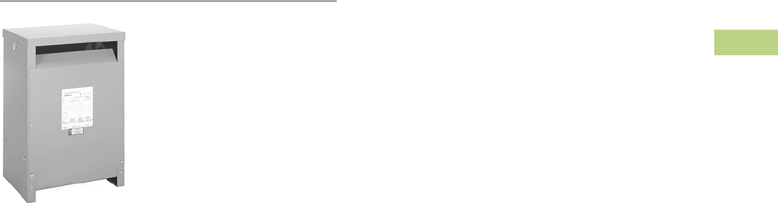
Volume 2—Commercial Distribution CA08100003E—June 2014 www.eaton.com V2-T2-71
2
2
2
2
2
2
2
2
2
2
2
2
2
2
2
2
2
2
2
2
2
2
2
2
2
2
2
2
2
2
2.3
Trans for mers
Energy-Efficient Harmonic Mitigating Transformers
Harmonic Mitigating Transformer
Contents
Description Page
Energy-Efficient Harmonic Mitigating Transformers
Standards and Certifications. . . . . . . . . . . . . . . V2-T2-72
Catalog Number Selection . . . . . . . . . . . . . . . . V2-T2-72
Product Selection . . . . . . . . . . . . . . . . . . . . . . . V2-T2-73
NEMA TP-1 Efficient . . . . . . . . . . . . . . . . . . . V2-T2-73
E3 Super Efficient . . . . . . . . . . . . . . . . . . . . . V2-T2-81
Accessories . . . . . . . . . . . . . . . . . . . . . . . . . . . V2-T2-89
Technical Data and Specifications. . . . . . . . . . . V2-T2-89
Product Description
Note: The following pages
provide listings for most standard
transformer ratings and styles.
For other ratings or styles not
shown, or for special enclosure
types (including stainless steel),
refer to Eaton.
The electrical transformer
has been a staple of electrical
power systems for the past
100+ years. While the types
of electrical loads that are
being added to our systems
today have radically changed,
the transformer has stayed
relatively the same in
design during this time frame.
Eaton’s harmonic mitigating
transformer (HMT)
represents the evolution
of the transformer into
something that will best
provide clean, energy-
efficient electricity to
power the loads of today
and tomorrow. The recent
shift of our electrical loads
from predominately AC
consumers (resistive heating
elements, incandescent
lighting, three-phase motor
load) to DC consumers (such
as computers, fax machines,
printers, down to the
“wall-wart” that recharges
the cell phone) requires that
our electrical infrastructure
changes as well. These new
loads now introduce other
currents and frequencies
into our electrical power
systems—commonly known
as “harmonics.” Harmonic
currents can cause additional
heating, which may cause
transformers, generators
and conductors to become
overloaded. Excessive heat is
one of the major reasons that
standard transformers and
conductors fail prematurely.
These harmonic currents
have various other effects
(such as “loss of ride-through
capability,” reduced lifespan
and mysterious misoperation
of equipment) on the
components and loads of an
electrical distribution system.
Eaton’s HMTs, when used
properly within an electrical
system, will help keep the
loads operating the way the
manufacturer designed
them and keep the facility’s
electrical system free from
voltage distortion.
Three-Phase, Type DT-3
HMT, 60 Hz
●Harmonic mitigating
(cancellation) transformers
are a cost-effective
means of treating harmful
harmonics in an electrical
distribution system
●Reducing harmonic
content in electrical
systems can result in a
more reliable electrical
system, lower
maintenance costs,
less downtime, fewer
equipment malfunctions,
and lower cooling
system capacity
●Available in a variety of
phase-shift configurations
that allow flexibility to
target specific families
of harmonics
●Harmonic treatment via
electromagnetic flux
cancellation
●May be installed as a
stand-alone transformer,
or included in IFS™
●Available in three-phase
ratings, 15–500 kVA, up to
600 volts primary
Features and Benefits
●480 volt to 208/120 volt
standard. Additional voltage
combinations available
●150°C, 115°C or 80°C
temperature rise available
●Copper windings and
terminals standard;
aluminum available
●Meet or exceed NEMA
TP-1 energy-efficiency level
●200% rated neutral
●Single electrostatic shield
for attenuation of common
mode and transverse
mode noise
●Approximately 98%
efficient when operated
in systems with 100%
nonlinear load profiles
●220°C insulation system
●Third-party tested for
harmonic performance
and energy efficiency
●Meet NEMA ST-20
sound standards
●Eliminate circulating
harmonic currents in
primary windings of
transformers
●Enclosures are NEMA 2
drip-proof. The addition of
optional weather-shields
makes the enclosure
NEMA 3R rainproof
●Harmonic cancellation
via electromagnetic flux
cancellation. Filters,
capacitors or other such
devices are not used
●Help meet IEEE 519
harmonic limits
V2-T2-72 Volume 2—Commercial Distribution CA08100003E—June 2014 www.eaton.com
2
2
2
2
2
2
2
2
2
2
2
2
2
2
2
2
2
2
2
2
2
2
2
2
2
2
2
2
2
2
2.3
Transfor mers
Energy-Efficient Harmonic Mitigating Transformers
Standards and Certifications
●UL listed Industry Standards
All Eaton dry-type
transformers are built and
tested in accordance with
applicable NEMA, ANSI and
IEEE standards. Harmonic
mitigating transformers are
UL listed.
IEEE 519-1992
Proper use of Eaton’s harmonic
mitigating
transformers
within your electrical system
will help you to meet the
harmonic distortion limits as
proposed by IEEE 519-1992,
“IEEE Recommended
Practices and Requirements
for Harmonic Control in
Electrical Power Systems.”
Seismic Qualified
Eaton dry-type distribution
transformers are seismically
qualified and exceed the
requirements of the Uniform
Building Code (UBC),
International Building Code
(IBC) and California Code
Title 24.
Catalog Number Selection
Energy-Efficient Harmonic Mitigating Transformers
NEMA TP-1-2002
Efficiency Levels
E3 Efficient
Efficiency Levels
Note
1The most common ratings are shown. Contact Eaton for availability of additional ratings.
Secondary Voltage 1
28 = 208/120 three-phase, four-wire
47 = 480/277 three-phase, four-wire
Modifications 1
T= Single thermal sensor (190°C)
TT = Two thermal sensors
(190°C and 175°C)
X= 50/60 Hz
CU = Copper windings (std.)
EE = ENERGY STAR label (std.)
SS = Grade 304 stainless steel
enclosure
E3 = Super efficient
Primary Voltage 1
48 = 480 three-phase, three-wire
60 = 600 three-phase, three-wire
Phase Shift
NON =0º
THR =–30º
POS =+15º
NEG = –15º
kVA Rating
15 = 15
30 = 30
45 = 45
75 = 75
12 = 112.5
49 = 150
22 = 225
33 = 300
55 = 500
Tap Arrangement
M= 2 at +2.5%, 4 at –2.5%
D= 2 at +2.5%, 2 at –2.5%
Temperature Rise
F= 115°C (standard)
T= 150°C
B= 80°C
X 48 M 28 F 30 TCUEE NEG
Tables of Energy Efficiency
NEMA Class 1 Efficiency Levels
Dry-Type Distribution Transformers—
Low Voltage (600V and below)
Three-Phase
kVA Efficiency
15 97.0
30 97.5
45 97.7
75 98.0
112.5 98.2
150 98.3
225 98.5
300 98.6
500 98.7
750 98.8
1000 98.9
Tables of Energy Efficiency
E3 Efficiency Levels Dry-Type
Distribution Transformers—
Low Voltage (600V and below)
Three-Phase
kVA Efficiency
15 97.97
30 98.29
45 98.45
75 98.64
112.5 98.77
150 98.86
225 98.97
300 99.04
500 99.16
750 99.24
1000 99.29

Volume 2—Commercial Distribution CA08100003E—June 2014 www.eaton.com V2-T2-73
2
2
2
2
2
2
2
2
2
2
2
2
2
2
2
2
2
2
2
2
2
2
2
2
2
2
2
2
2
2
2.3
Trans for mers
Energy-Efficient Harmonic Mitigating Transformers
Product Selection
Three-Phase—Type DT-3 60 Hz NEMA TP-1 Energy-Efficient Harmonic Mitigating
480 Volts to 208Y/120 Volts—Aluminum Windings—Type NON 0-Degree Phase Shift
Note
Frame drawings/dimensions information begins on Page V2-T2-215.
kVA
Full Capacity Taps
Type
ºC Temp.
Rise Frame
Wiring Diagram
Number
Weight
Lbs (kg) Weathershield Style NumberFCAN FCBN
15 2 at +2.5% 4 at –2.5% DT-3 150 912D 200X 290 (132) WS38 X48M28T15EENON
30 2 at +2.5% 4 at –2.5% DT-3 150 912D 200X 365 (166) WS38 X48M28T30EENON
45 2 at +2.5% 4 at –2.5% DT-3 150 915F 200X 560 (254) WS39 X48M28T45EENON
75 2 at +2.5% 4 at –2.5% DT-3 150 916A 200X 800 (363) WS19 X48M28T75EENON
112.5 2 at +2.5% 4 at –2.5% DT-3 150 917 200X 1380 (627) WS34 X48M28T12EENON
150 2 at +2.5% 4 at –2.5% DT-3 150 918A 200X 1560 (708) WS34 X48M28T49EENON
225 2 at +2.5% 4 at –2.5% DT-3 150 919EX 201X 2400 (1090) WS35 X48M28T22EENON
300 2 at +2.5% 4 at –2.5% DT-3 150 919EX 201X 2970 (1348) WS35 X48M28T33EENON
15 2 at +2.5% 4 at –2.5% DT-3 115 912D 200X 360 (163) WS38 X48M28F15EENON
30 2 at +2.5% 4 at –2.5% DT-3 115 912D 200X 405 (184) WS38 X48M28F30EENON
45 2 at +2.5% 4 at –2.5% DT-3 115 915F 200X 575 (261) WS39 X48M28F45EENON
75 2 at +2.5% 4 at –2.5% DT-3 115 916A 200X 900 (409) WS19 X48M28F75EENON
112.5 2 at +2.5% 4 at –2.5% DT-3 115 917 200X 1380 (627) WS34 X48M28F12EENON
150 2 at +2.5% 4 at –2.5% DT-3 115 918A 200X 1600 (726) WS34 X48M28F49EENON
225 2 at +2.5% 4 at –2.5% DT-3 115 919EX 201X 2600 (1180) WS35 X48M28F22EENON
300 2 at +2.5% 4 at –2.5% DT-3 115 919EX 201X 3100 (1407) WS35 X48M28F33EENON
15 2 at +2.5% 4 at –2.5% DT-3 80 912D 200X 380 (173) WS38 X48M28B15EENON
30 2 at +2.5% 4 at –2.5% DT-3 80 915F 200X 560 (254) WS39 X48M28B30EENON
45 2 at +2.5% 4 at –2.5% DT-3 80 915F 200X 800 (363) WS39 X48M28B45EENON
75 2 at +2.5% 4 at –2.5% DT-3 80 916A 200X 1380 (627) WS19 X48M28B75EENON
112.5 2 at +2.5% 4 at –2.5% DT-3 80 917 200X 1560 (708) WS34 X48M28B12EENON
150 2 at +2.5% 4 at –2.5% DT-3 80 918A 200X 2400 (1090) WS34 X48M28B49EENON
225 2 at +2.5% 4 at –2.5% DT-3 80 919EX 201X 2970 (1348) WS35 X48M28B22EENON
300 2 at +2.5% 4 at –2.5% DT-3 80 919EX 201X 3400 (1544) WS35 X48M28B33EENON

V2-T2-74 Volume 2—Commercial Distribution CA08100003E—June 2014 www.eaton.com
2
2
2
2
2
2
2
2
2
2
2
2
2
2
2
2
2
2
2
2
2
2
2
2
2
2
2
2
2
2
2.3
Transfor mers
Energy-Efficient Harmonic Mitigating Transformers
Three-Phase—Type DT-3 60 Hz NEMA TP-1 Energy-Efficient Harmonic Mitigating
480 Volts to 208Y/120 Volts—Copper Windings—Type NON 0-Degree Phase Shift
Note
Frame drawings/dimensions information begins on Page V2-T2-215.
kVA
Full Capacity Taps
Type
ºC Temp.
Rise Frame
Wiring Diagram
Number
Weight
Lbs (kg) Weathershield Style NumberFCAN FCBN
15 2 at +2.5% 4 at –2.5% DT-3 150 912D 200X 335 (152) WS38 X48M28T15CUEENON
30 2 at +2.5% 4 at –2.5% DT-3 150 912D 200X 430 (195) WS38 X48M28T30CUEENON
45 2 at +2.5% 4 at –2.5% DT-3 150 915F 200X 627 (285) WS39 X48M28T45CUEENON
75 2 at +2.5% 4 at –2.5% DT-3 150 916A 200X 926 (420) WS19 X48M28T75CUEENON
112.5 2 at +2.5% 4 at –2.5% DT-3 150 917 200X 1610 (731) WS34 X48M28T12CUEENON
150 2 at +2.5% 4 at –2.5% DT-3 150 918A 200X 1800 (817) WS34 X48M28T49CUEENON
225 2 at +2.5% 4 at –2.5% DT-3 150 919EX 201X 3580 (1625) WS35 X48M28T22CUEENON
300 2 at +2.5% 4 at –2.5% DT-3 150 919EX 201X 3500 (1589) WS35 X48M28T33CUEENON
15 2 at +2.5% 4 at –2.5% DT-3 115 912D 200X 362 (164) WS38 X48M28F15CUEENON
30 2 at +2.5% 4 at –2.5% DT-3 115 912D 200X 430 (195) WS38 X48M28F30CUEENON
45 2 at +2.5% 4 at –2.5% DT-3 115 915F 200X 627 (285) WS39 X48M28F45CUEENON
75 2 at +2.5% 4 at –2.5% DT-3 115 916A 200X 926 (420) WS19 X48M28F75CUEENON
112.5 2 at +2.5% 4 at –2.5% DT-3 115 917 200X 1628 (739) WS34 X48M28F12CUEENON
150 2 at +2.5% 4 at –2.5% DT-3 115 918A 200X 2001 (908) WS34 X48M28F49CUEENON
225 2 at +2.5% 4 at –2.5% DT-3 115 919EX 201X 3596 (1633) WS35 X48M28F22CUEENON
300 2 at +2.5% 4 at –2.5% DT-3 115 919EX 201X 3891 (1767) WS35 X48M28F33CUEENON
15 2 at +2.5% 4 at –2.5% DT-3 80 912D 200X 358 (163) WS38 X48M28B15CUEENON
30 2 at +2.5% 4 at –2.5% DT-3 80 915F 200X 558 (253) WS39 X48M28B30CUEENON
45 2 at +2.5% 4 at –2.5% DT-3 80 915F 200X 630 (286) WS39 X48M28B45CUEENON
75 2 at +2.5% 4 at –2.5% DT-3 80 916A 200X 940 (427) WS19 X48M28B75CUEENON
112.5 2 at +2.5% 4 at –2.5% DT-3 80 917 200X 1628 (739) WS34 X48M28B12CUEENON
150 2 at +2.5% 4 at –2.5% DT-3 80 918A 200X 1800 (817) WS34 X48M28B49CUEENON
225 2 at +2.5% 4 at –2.5% DT-3 80 919EX 201X 3400 (1544) WS35 X48M28B22CUEENON
300 2 at +2.5% 4 at –2.5% DT-3 80 919EX 201X 4377 (1987) WS35 X48M28B33CUEENON

Volume 2—Commercial Distribution CA08100003E—June 2014 www.eaton.com V2-T2-75
2
2
2
2
2
2
2
2
2
2
2
2
2
2
2
2
2
2
2
2
2
2
2
2
2
2
2
2
2
2
2.3
Trans for mers
Energy-Efficient Harmonic Mitigating Transformers
Three-Phase—Type DT-3 60 Hz NEMA TP-1 Energy-Efficient Harmonic Mitigating
480 Volts to 208Y/120 Volts—Aluminum Windings—Type THR 30-Degree Phase Shift
Note
Frame drawings/dimensions information begins on Page V2-T2-215.
kVA
Full Capacity Taps
Type
ºC Temp.
Rise Frame
Wiring Diagram
Number
Weight
Lbs (kg) Weathershield Style NumberFCAN FCBN
15 2 at +2.5% 4 at –2.5% DT-3 150 912D 200X 290 (132) WS38 X48M28T15EETHR
30 2 at +2.5% 4 at –2.5% DT-3 150 912D 200X 365 (166) WS38 X48M28T30EETHR
45 2 at +2.5% 4 at –2.5% DT-3 150 915F 200X 560 (254) WS39 X48M28T45EETHR
75 2 at +2.5% 4 at –2.5% DT-3 150 916A 200X 800 (363) WS19 X48M28T75EETHR
112.5 2 at +2.5% 4 at –2.5% DT-3 150 917 200X 1380 (627) WS34 X48M28T12EETHR
150 2 at +2.5% 4 at –2.5% DT-3 150 918A 200X 1560 (708) WS34 X48M28T49EETHR
225 2 at +2.5% 4 at –2.5% DT-3 150 919EX 201X 2400 (1090) WS35 X48M28T22EETHR
300 2 at +2.5% 4 at –2.5% DT-3 150 919EX 201X 2970 (1348) WS35 X48M28T33EETHR
15 2 at +2.5% 4 at –2.5% DT-3 115 912D 200X 360 (163) WS38 X48M28F15EETHR
30 2 at +2.5% 4 at –2.5% DT-3 115 912D 200X 405 (184) WS38 X48M28F30EETHR
45 2 at +2.5% 4 at –2.5% DT-3 115 915F 200X 575 (261) WS39 X48M28F45EETHR
75 2 at +2.5% 4 at –2.5% DT-3 115 916A 200X 900 (409) WS19 X48M28F75EETHR
112.5 2 at +2.5% 4 at –2.5% DT-3 115 917 200X 1380 (627) WS34 X48M28F12EETHR
150 2 at +2.5% 4 at –2.5% DT-3 115 918A 200X 1600 (726) WS34 X48M28F49EETHR
225 2 at +2.5% 4 at –2.5% DT-3 115 919EX 201X 2600 (1180) WS35 X48M28F22EETHR
300 2 at +2.5% 4 at –2.5% DT-3 115 919EX 201X 3100 (1407) WS35 X48M28F33EETHR
15 2 at +2.5% 4 at –2.5% DT-3 80 912D 200X 380 (173) WS38 X48M28B15EETHR
30 2 at +2.5% 4 at –2.5% DT-3 80 915F 200X 560 (254) WS39 X48M28B30EETHR
45 2 at +2.5% 4 at –2.5% DT-3 80 915F 200X 800 (363) WS39 X48M28B45EETHR
75 2 at +2.5% 4 at –2.5% DT-3 80 916A 200X 1380 (627) WS19 X48M28B75EETHR
112.5 2 at +2.5% 4 at –2.5% DT-3 80 917 200X 1560 (708) WS34 X48M28B12EETHR
150 2 at +2.5% 4 at –2.5% DT-3 80 918A 200X 2400 (1090) WS34 X48M28B49EETHR
225 2 at +2.5% 4 at –2.5% DT-3 80 919EX 201X 2970 (1348) WS35 X48M28B22EETHR
300 2 at +2.5% 4 at –2.5% DT-3 80 919EX 201X 3400 (1544) WS35 X48M28B33EETHR

V2-T2-76 Volume 2—Commercial Distribution CA08100003E—June 2014 www.eaton.com
2
2
2
2
2
2
2
2
2
2
2
2
2
2
2
2
2
2
2
2
2
2
2
2
2
2
2
2
2
2
2.3
Transfor mers
Energy-Efficient Harmonic Mitigating Transformers
Three-Phase—Type DT-3 60 Hz NEMA TP-1 Energy-Efficient Harmonic Mitigating
480 Volts to 208Y/120 Volts—Copper Windings—Type THR 30-Degree Phase Shift
Note
Frame drawings/dimensions information begins on Page V2-T2-215.
kVA
Full Capacity Taps
Type
ºC Temp.
Rise Frame
Wiring Diagram
Number
Weight
Lbs (kg) Weathershield Style NumberFCAN FCBN
15 2 at +2.5% 4 at –2.5% DT-3 150 912D 203X 335 (152) WS38 X48M28T15CUEETHR
30 2 at +2.5% 4 at –2.5% DT-3 150 912D 203X 450 (204) WS38 X48M28T30CUEETHR
45 2 at +2.5% 4 at –2.5% DT-3 150 915F 203X 627 (285) WS39 X48M28T45CUEETHR
75 2 at +2.5% 4 at –2.5% DT-3 150 916A 203X 855 (388) WS19 X48M28T75CUEETHR
112.5 2 at +2.5% 4 at –2.5% DT-3 150 917 203X 1610 (731) WS34 X48M28T12CUEETHR
150 2 at +2.5% 4 at –2.5% DT-3 150 918A 203X 1800 (817) WS34 X48M28T49CUEETHR
225 2 at +2.5% 4 at –2.5% DT-3 150 919EX 203X 3450 (1566) WS35 X48M28T22CUEETHR
300 2 at +2.5% 4 at –2.5% DT-3 150 919EX 203X 3894 (1768) WS35 X48M28T33CUEETHR
15 2 at +2.5% 4 at –2.5% DT-3 115 912D 203X 362 (164) WS38 X48M28F15CUEETHR
30 2 at +2.5% 4 at –2.5% DT-3 115 912D 203X 450 (204) WS38 X48M28F30CUEETHR
45 2 at +2.5% 4 at –2.5% DT-3 115 915F 203X 610 (277) WS39 X48M28F45CUEETHR
75 2 at +2.5% 4 at –2.5% DT-3 115 916A 203X 868 (394) WS19 X48M28F75CUEETHR
112.5 2 at +2.5% 4 at –2.5% DT-3 115 917 203X 1643 (746) WS34 X48M28F12CUEETHR
150 2 at +2.5% 4 at –2.5% DT-3 115 918A 203X 2001 (908) WS34 X48M28F49CUEETHR
225 2 at +2.5% 4 at –2.5% DT-3 115 919EX 203X 3370 (1530) WS35 X48M28F22CUEETHR
300 2 at +2.5% 4 at –2.5% DT-3 115 919EX 203X 3894 (1768) WS35 X48M28F33CUEETHR
15 2 at +2.5% 4 at –2.5% DT-3 80 912D 203X 358 (163) WS38 X48M28B15CUEETHR
30 2 at +2.5% 4 at –2.5% DT-3 80 915F 203X 558 (253) WS39 X48M28B30CUEETHR
45 2 at +2.5% 4 at –2.5% DT-3 80 915F 203X 630 (286) WS39 X48M28B45CUEETHR
75 2 at +2.5% 4 at –2.5% DT-3 80 916A 203X 940 (427) WS19 X48M28B75CUEETHR
112.5 2 at +2.5% 4 at –2.5% DT-3 80 917 203X 1628 (739) WS34 X48M28B12CUEETHR
150 2 at +2.5% 4 at –2.5% DT-3 80 918A 203X 1800 (817) WS34 X48M28B49CUEETHR
225 2 at +2.5% 4 at –2.5% DT-3 80 919EX 203X 3400 (1544) WS35 X48M28B22CUEETHR
300 2 at +2.5% 4 at –2.5% DT-3 80 919EX 203X 4417 (2005) WS35 X48M28B33CUEETHR

Volume 2—Commercial Distribution CA08100003E—June 2014 www.eaton.com V2-T2-77
2
2
2
2
2
2
2
2
2
2
2
2
2
2
2
2
2
2
2
2
2
2
2
2
2
2
2
2
2
2
2.3
Trans for mers
Energy-Efficient Harmonic Mitigating Transformers
Three-Phase—Type DT-3 60 Hz NEMA TP-1 Energy-Efficient Harmonic Mitigating
480 Volts to 208Y/120 Volts—Aluminum Windings—Type NEG –15-Degree Phase Shift
Note
Frame drawings/dimensions information begins on Page V2-T2-215.
kVA
Full Capacity Taps
Type
ºC Temp.
Rise Frame
Wiring Diagram
Number
Weight
Lbs (kg) Weathershield Style NumberFCAN FCBN
15 2 at +2.5% 4 at –2.5% DT-3 150 912D 200X 290 (132) WS38 X48M28T15EENEG
30 2 at +2.5% 4 at –2.5% DT-3 150 912D 200X 365 (166) WS38 X48M28T30EENEG
45 2 at +2.5% 4 at –2.5% DT-3 150 915F 200X 560 (254) WS39 X48M28T45EENEG
75 2 at +2.5% 4 at –2.5% DT-3 150 916A 200X 800 (363) WS19 X48M28T75EENEG
112.5 2 at +2.5% 4 at –2.5% DT-3 150 917 200X 1380 (627) WS34 X48M28T12EENEG
150 2 at +2.5% 4 at –2.5% DT-3 150 918A 200X 1560 (708) WS34 X48M28T49EENEG
225 2 at +2.5% 4 at –2.5% DT-3 150 919EX 201X 2400 (1090) WS35 X48M28T22EENEG
300 2 at +2.5% 4 at –2.5% DT-3 150 919EX 201X 2970 (1348) WS35 X48M28T33EENEG
15 2 at +2.5% 4 at –2.5% DT-3 115 912D 200X 360 (163) WS38 X48M28F15EENEG
30 2 at +2.5% 4 at –2.5% DT-3 115 912D 200X 405 (184) WS38 X48M28F30EENEG
45 2 at +2.5% 4 at –2.5% DT-3 115 915F 200X 575 (261) WS39 X48M28F45EENEG
75 2 at +2.5% 4 at –2.5% DT-3 115 916A 200X 900 (409) WS19 X48M28F75EENEG
112.5 2 at +2.5% 4 at –2.5% DT-3 115 917 200X 1380 (627) WS34 X48M28F12EENEG
150 2 at +2.5% 4 at –2.5% DT-3 115 918A 200X 1600 (726) WS34 X48M28F49EENEG
225 2 at +2.5% 4 at –2.5% DT-3 115 919EX 201X 2600 (1180) WS35 X48M28F22EENEG
300 2 at +2.5% 4 at –2.5% DT-3 115 919EX 201X 3100 (1407) WS35 X48M28F33EENEG
15 2 at +2.5% 4 at –2.5% DT-3 80 912D 200X 380 (173) WS38 X48M28B15EENEG
30 2 at +2.5% 4 at –2.5% DT-3 80 915F 200X 560 (254) WS39 X48M28B30EENEG
45 2 at +2.5% 4 at –2.5% DT-3 80 915F 200X 800 (363) WS39 X48M28B45EENEG
75 2 at +2.5% 4 at –2.5% DT-3 80 916A 200X 1380 (627) WS19 X48M28B75EENEG
112.5 2 at +2.5% 4 at –2.5% DT-3 80 917 200X 1560 (708) WS34 X48M28B12EENEG
150 2 at +2.5% 4 at –2.5% DT-3 80 918A 200X 2400 (1090) WS34 X48M28B49EENEG
225 2 at +2.5% 4 at –2.5% DT-3 80 919EX 201X 2970 (1348) WS35 X48M28B22EENEG
300 2 at +2.5% 4 at –2.5% DT-3 80 919EX 201X 3400 (1544) WS35 X48M28B33EENEG

V2-T2-78 Volume 2—Commercial Distribution CA08100003E—June 2014 www.eaton.com
2
2
2
2
2
2
2
2
2
2
2
2
2
2
2
2
2
2
2
2
2
2
2
2
2
2
2
2
2
2
2.3
Transfor mers
Energy-Efficient Harmonic Mitigating Transformers
Three-Phase—Type DT-3 60 Hz NEMA TP-1 Energy-Efficient Harmonic Mitigating
480 Volts to 208Y/120 Volts—Copper Windings—Type NEG –15-Degree Phase Shift
Note
Frame drawings/dimensions information begins on Page V2-T2-215.
kVA
Full Capacity Taps
Type
ºC Temp.
Rise Frame
Wiring Diagram
Number
Weight
Lbs (kg) Weathershield Style NumberFCAN FCBN
15 2 at +2.5% 4 at –2.5% DT-3 150 912D 200X 335 (152) WS38 X48M28T15CUEENEG
30 2 at +2.5% 4 at –2.5% DT-3 150 912D 200X 430 (195) WS38 X48M28T30CUEENEG
45 2 at +2.5% 4 at –2.5% DT-3 150 915F 200X 627 (285) WS39 X48M28T45CUEENEG
75 2 at +2.5% 4 at –2.5% DT-3 150 916A 200X 926 (420) WS19 X48M28T75CUEENEG
112.5 2 at +2.5% 4 at –2.5% DT-3 150 917 200X 1610 (731) WS34 X48M28T12CUEENEG
150 2 at +2.5% 4 at –2.5% DT-3 150 918A 200X 1800 (817) WS34 X48M28T49CUEENEG
225 2 at +2.5% 4 at –2.5% DT-3 150 919EX 200X 3580 (1625) WS35 X48M28T22CUEENEG
300 2 at +2.5% 4 at –2.5% DT-3 150 919EX 200X 3500 (1589) WS35 X48M28T33CUEENEG
15 2 at +2.5% 4 at –2.5% DT-3 115 912D 200X 353 (160) WS38 X48M28F15CUEENEG
30 2 at +2.5% 4 at –2.5% DT-3 115 912D 200X 430 (195) WS38 X48M28F30CUEENEG
45 2 at +2.5% 4 at –2.5% DT-3 115 915F 200X 627 (285) WS39 X48M28F45CUEENEG
75 2 at +2.5% 4 at –2.5% DT-3 115 916A 200X 926 (420) WS19 X48M28F75CUEENEG
112.5 2 at +2.5% 4 at –2.5% DT-3 115 917 200X 1628 (739) WS34 X48M28F12CUEENEG
150 2 at +2.5% 4 at –2.5% DT-3 115 918A 200X 2001 (908) WS34 X48M28F49CUEENEG
225 2 at +2.5% 4 at –2.5% DT-3 115 919EX 200X 3596 (1633) WS35 X48M28F22CUEENEG
300 2 at +2.5% 4 at –2.5% DT-3 115 919EX 200X 3891 (1767) WS35 X48M28F33CUEENEG
15 2 at +2.5% 4 at –2.5% DT-3 80 912D 200X 358 (163) WS38 X48M28B15CUEENEG
30 2 at +2.5% 4 at –2.5% DT-3 80 915F 200X 558 (253) WS39 X48M28B30CUEENEG
45 2 at +2.5% 4 at –2.5% DT-3 80 915F 200X 630 (286) WS39 X48M28B45CUEENEG
75 2 at +2.5% 4 at –2.5% DT-3 80 916A 200X 940 (427) WS19 X48M28B75CUEENEG
112.5 2 at +2.5% 4 at –2.5% DT-3 80 917 200X 1628 (739) WS34 X48M28B12CUEENEG
150 2 at +2.5% 4 at –2.5% DT-3 80 918A 200X 1800 (817) WS34 X48M28B49CUEENEG
225 2 at +2.5% 4 at –2.5% DT-3 80 919EX 200X 3400 (1544) WS35 X48M28B22CUEENEG
300 2 at +2.5% 4 at –2.5% DT-3 80 920EX 200X 4377 (1987) WS35 X48M28B33CUEENEG

Volume 2—Commercial Distribution CA08100003E—June 2014 www.eaton.com V2-T2-79
2
2
2
2
2
2
2
2
2
2
2
2
2
2
2
2
2
2
2
2
2
2
2
2
2
2
2
2
2
2
2.3
Trans for mers
Energy-Efficient Harmonic Mitigating Transformers
Three-Phase—Type DT-3 60 Hz NEMA TP-1 Energy-Efficient Harmonic Mitigating
480 Volts to 208Y/120 Volts—Aluminum Windings—Type POS +15-Degree Phase Shift
Note
Frame drawings/dimensions information begins on Page V2-T2-215.
kVA
Full Capacity Taps
Type
ºC Temp.
Rise Frame
Wiring Diagram
Number
Weight
Lbs (kg) Weathershield Style NumberFCAN FCBN
15 2 at +2.5% 4 at –2.5% DT-3 150 912D 200X 290 (132) WS38 X48M28T15EEPOS
30 2 at +2.5% 4 at –2.5% DT-3 150 912D 200X 365 (166) WS38 X48M28T30EEPOS
45 2 at +2.5% 4 at –2.5% DT-3 150 915F 200X 560 (254) WS39 X48M28T45EEPOS
75 2 at +2.5% 4 at –2.5% DT-3 150 916A 200X 800 (363) WS19 X48M28T75EEPOS
112.5 2 at +2.5% 4 at –2.5% DT-3 150 917 200X 1380 (627) WS34 X48M28T12EEPOS
150 2 at +2.5% 4 at –2.5% DT-3 150 918A 200X 1560 (708) WS34 X48M28T49EEPOS
225 2 at +2.5% 4 at –2.5% DT-3 150 919EX 201X 2400 (1090) WS35 X48M28T22EEPOS
300 2 at +2.5% 4 at –2.5% DT-3 150 919EX 201X 2970 (1348) WS35 X48M28T33EEPOS
15 2 at +2.5% 4 at –2.5% DT-3 115 912D 200X 360 (163) WS38 X48M28F15EEPOS
30 2 at +2.5% 4 at –2.5% DT-3 115 912D 200X 405 (184) WS38 X48M28F30EEPOS
45 2 at +2.5% 4 at –2.5% DT-3 115 915F 200X 575 (261) WS39 X48M28F45EEPOS
75 2 at +2.5% 4 at –2.5% DT-3 115 916A 200X 900 (409) WS19 X48M28F75EEPOS
112.5 2 at +2.5% 4 at –2.5% DT-3 115 917 200X 1380 (627) WS34 X48M28F12EEPOS
150 2 at +2.5% 4 at –2.5% DT-3 115 918A 200X 1600 (726) WS34 X48M28F49EEPOS
225 2 at +2.5% 4 at –2.5% DT-3 115 919EX 201X 2600 (1180) WS35 X48M28F22EEPOS
300 2 at +2.5% 4 at –2.5% DT-3 115 919EX 201X 3100 (1407) WS35 X48M28F33EEPOS
15 2 at +2.5% 4 at –2.5% DT-3 80 912D 200X 380 (173) WS38 X48M28B15EEPOS
30 2 at +2.5% 4 at –2.5% DT-3 80 915F 200X 560 (254) WS39 X48M28B30EEPOS
45 2 at +2.5% 4 at –2.5% DT-3 80 915F 200X 800 (363) WS39 X48M28B45EEPOS
75 2 at +2.5% 4 at –2.5% DT-3 80 916A 200X 1380 (627) WS19 X48M28B75EEPOS
112.5 2 at +2.5% 4 at –2.5% DT-3 80 917 200X 1560 (708) WS34 X48M28B12EEPOS
150 2 at +2.5% 4 at –2.5% DT-3 80 918A 200X 2400 (1090) WS34 X48M28B49EEPOS
225 2 at +2.5% 4 at –2.5% DT-3 80 919EX 201X 2970 (1348) WS35 X48M28B22EEPOS
300 2 at +2.5% 4 at –2.5% DT-3 80 919EX 201X 3400 (1544) WS35 X48M28B33EEPOS

V2-T2-80 Volume 2—Commercial Distribution CA08100003E—June 2014 www.eaton.com
2
2
2
2
2
2
2
2
2
2
2
2
2
2
2
2
2
2
2
2
2
2
2
2
2
2
2
2
2
2
2.3
Transfor mers
Energy-Efficient Harmonic Mitigating Transformers
Three-Phase—Type DT-3 60 Hz NEMA TP-1 Energy-Efficient Harmonic Mitigating
480 Volts to 208Y/120 Volts—Copper Windings—Type POS +15-Degree Phase Shift
Note
Frame drawings/dimensions information begins on Page V2-T2-215.
kVA
Full Capacity Taps
Type
ºC Temp.
Rise Frame
Wiring Diagram
Number
Weight
Lbs (kg) Weathershield Style NumberFCAN FCBN
15 2 at +2.5% 4 at –2.5% DT-3 150 912D 200X 335 (152) WS38 X48M28T15CUEEPOS
30 2 at +2.5% 4 at –2.5% DT-3 150 912D 200X 430 (195) WS38 X48M28T30CUEEPOS
45 2 at +2.5% 4 at –2.5% DT-3 150 915F 200X 627 (285) WS39 X48M28T45CUEEPOS
75 2 at +2.5% 4 at –2.5% DT-3 150 916A 200X 926 (420) WS19 X48M28T75CUEEPOS
112.5 2 at +2.5% 4 at –2.5% DT-3 150 917 200X 1610 (731) WS34 X48M28T12CUEEPOS
150 2 at +2.5% 4 at –2.5% DT-3 150 918A 200X 1800 (817) WS34 X48M28T49CUEEPOS
225 2 at +2.5% 4 at –2.5% DT-3 150 919EX 201X 3580 (1625) WS35 X48M28T22CUEEPOS
300 2 at +2.5% 4 at –2.5% DT-3 150 919EX 201X 3500 (1589) WS35 X48M28T33CUEEPOS
15 2 at +2.5% 4 at –2.5% DT-3 115 912D 200X 362 (164) WS38 X48M28F15CUEEPOS
30 2 at +2.5% 4 at –2.5% DT-3 115 912D 200X 430 (195) WS38 X48M28F30CUEEPOS
45 2 at +2.5% 4 at –2.5% DT-3 115 915F 200X 627 (285) WS39 X48M28F45CUEEPOS
75 2 at +2.5% 4 at –2.5% DT-3 115 916A 200X 926 (420) WS19 X48M28F75CUEEPOS
112.5 2 at +2.5% 4 at –2.5% DT-3 115 917 200X 1628 (739) WS34 X48M28F12CUEEPOS
150 2 at +2.5% 4 at –2.5% DT-3 115 918A 200X 2001 (908) WS34 X48M28F49CUEEPOS
225 2 at +2.5% 4 at –2.5% DT-3 115 919EX 201X 3596 (1633) WS35 X48M28F22CUEEPOS
300 2 at +2.5% 4 at –2.5% DT-3 115 919EX 201X 3891 (1767) WS35 X48M28F33CUEEPOS
15 2 at +2.5% 4 at –2.5% DT-3 80 912D 200X 358 (163) WS38 X48M28B15CUEEPOS
30 2 at +2.5% 4 at –2.5% DT-3 80 915F 200X 558 (253) WS39 X48M28B30CUEEPOS
45 2 at +2.5% 4 at –2.5% DT-3 80 915F 200X 630 (286) WS39 X48M28B45CUEEPOS
75 2 at +2.5% 4 at –2.5% DT-3 80 916A 200X 940 (427) WS19 X48M28B75CUEEPOS
112.5 2 at +2.5% 4 at –2.5% DT-3 80 917 200X 1628 (739) WS34 X48M28B12CUEEPOS
150 2 at +2.5% 4 at –2.5% DT-3 80 918A 200X 1800 (817) WS34 X48M28B49CUEEPOS
225 2 at +2.5% 4 at –2.5% DT-3 80 919EX 201X 3400 (1544) WS35 X48M28B22CUEEPOS
300 2 at +2.5% 4 at –2.5% DT-3 80 919EX 201X 4377 (1987) WS35 X48M28B33CUEEPOS

Volume 2—Commercial Distribution CA08100003E—June 2014 www.eaton.com V2-T2-81
2
2
2
2
2
2
2
2
2
2
2
2
2
2
2
2
2
2
2
2
2
2
2
2
2
2
2
2
2
2
2.3
Trans for mers
Energy-Efficient Harmonic Mitigating Transformers
Three-Phase—Type DT-3 60 Hz E3 Super Energy-Efficient Harmonic Mitigating
480 Volts to 208Y/120 Volts—Aluminum Windings—Type NON 0-Degree Phase Shift
Note
Frame drawings/dimensions information begins on Page V2-T2-215.
kVA
Full Capacity Taps
Type
ºC Temp
Rise Frame
Wiring Diagram
Number
Weight
Lbs (kg) Weathershield Style NumberFCAN FCBN
15 2 at +2.5% 4 at –2.5% DT-3 150 — 200X — — X48M28T15E3NON
30 2 at +2.5% 4 at –2.5% DT-3 150 — 200X — — X48M28T30E3NON
45 2 at +2.5% 4 at –2.5% DT-3 150 — 200X — — X48M28T45E3NON
75 2 at +2.5% 4 at –2.5% DT-3 150 — 200X — — X48M28T75E3NON
112.5 2 at +2.5% 4 at –2.5% DT-3 150 — 200X — — X48M28T12E3NON
150 2 at +2.5% 4 at –2.5% DT-3 150 — 200X — — X48M28T49E3NON
225 2 at +2.5% 4 at –2.5% DT-3 150 — 201X — — X48M28T22E3NON
300 2 at +2.5% 4 at –2.5% DT-3 150 — 201X — — X48M28T33E3NON
15 2 at +2.5% 4 at –2.5% DT-3 115 — 200X — — X48M28F15E3NON
30 2 at +2.5% 4 at –2.5% DT-3 115 — 200X — — X48M28F30E3NON
45 2 at +2.5% 4 at –2.5% DT-3 115 — 200X — — X48M28F45E3NON
75 2 at +2.5% 4 at –2.5% DT-3 115 — 200X — — X48M28F75E3NON
112.5 2 at +2.5% 4 at –2.5% DT-3 115 — 200X — — X48M28F12E3NON
150 2 at +2.5% 4 at –2.5% DT-3 115 — 200X — — X48M28F49E3NON
225 2 at +2.5% 4 at –2.5% DT-3 115 — 201X — — X48M28F22E3NON
300 2 at +2.5% 4 at –2.5% DT-3 115 — 201X — — X48M28F33E3NON
15 2 at +2.5% 4 at –2.5% DT-3 80 — 200X — — X48M28B15E3NON
30 2 at +2.5% 4 at –2.5% DT-3 80 — 200X — — X48M28B30E3NON
45 2 at +2.5% 4 at –2.5% DT-3 80 — 200X — — X48M28B45E3NON
75 2 at +2.5% 4 at –2.5% DT-3 80 — 200X — — X48M28B75E3NON
112.5 2 at +2.5% 4 at –2.5% DT-3 80 — 200X — — X48M28B12E3NON
150 2 at +2.5% 4 at –2.5% DT-3 80 — 200X — — X48M28B49E3NON
225 2 at +2.5% 4 at –2.5% DT-3 80 — 201X — — X48M28B22E3NON
300 2 at +2.5% 4 at –2.5% DT-3 80 — 201X — — X48M28B33E3NON

V2-T2-82 Volume 2—Commercial Distribution CA08100003E—June 2014 www.eaton.com
2
2
2
2
2
2
2
2
2
2
2
2
2
2
2
2
2
2
2
2
2
2
2
2
2
2
2
2
2
2
2.3
Transfor mers
Energy-Efficient Harmonic Mitigating Transformers
Three-Phase—Type DT-3 60 Hz E3 Super Energy-Efficient Harmonic Mitigating
480 Volts to 208Y/120 Volts—Copper Windings—Type NON 0-Degree Phase Shift
Note
Frame drawings/dimensions information begins on Page V2-T2-215.
kVA
Full Capacity Taps
Type
ºC Temp
Rise Frame
Wiring Diagram
Number
Weight
Lbs (kg) Weathershield Style NumberFCAN FCBN
15 2 at +2.5% 4 at –2.5% DT-3 150 912D 200X 335 (152) WS38 X48M28T15CUE3NON
30 2 at +2.5% 4 at –2.5% DT-3 150 912D 200X 430 (195) WS38 X48M28T30CUE3NON
45 2 at +2.5% 4 at –2.5% DT-3 150 915F 200X 627 (285) WS39 X48M28T45CUE3NON
75 2 at +2.5% 4 at –2.5% DT-3 150 916A 200X 926 (420) WS19 X48M28T75CUE3NON
112.5 2 at +2.5% 4 at –2.5% DT-3 150 917 200X 1610 (731) WS34 X48M28T12CUE3NON
150 2 at +2.5% 4 at –2.5% DT-3 150 918A 200X 1800 (817) WS34 X48M28T49CUE3NON
225 2 at +2.5% 4 at –2.5% DT-3 150 919EX 201X 3580 (1625) WS35 X48M28T22CUE3NON
300 2 at +2.5% 4 at –2.5% DT-3 150 919EX 201X 3500 (1589) WS35 X48M28T33CUE3NON
15 2 at +2.5% 4 at –2.5% DT-3 115 912D 200X 362 (164) WS38 X48M28F15CUE3NON
30 2 at +2.5% 4 at –2.5% DT-3 115 912D 200X 430 (195) WS38 X48M28F30CUE3NON
45 2 at +2.5% 4 at –2.5% DT-3 115 915F 200X 627 (285) WS39 X48M28F45CUE3NON
75 2 at +2.5% 4 at –2.5% DT-3 115 916A 200X 926 (420) WS19 X48M28F75CUE3NON
112.5 2 at +2.5% 4 at –2.5% DT-3 115 917 200X 1628 (739) WS34 X48M28F12CUE3NON
150 2 at +2.5% 4 at –2.5% DT-3 115 918A 200X 2001 (908) WS34 X48M28F49CUE3NON
225 2 at +2.5% 4 at –2.5% DT-3 115 919EX 201X 3596 (1633) WS35 X48M28F22CUE3NON
300 2 at +2.5% 4 at –2.5% DT-3 115 919EX 201X 3891 (1767) WS35 X48M28F33CUE3NON
15 2 at +2.5% 4 at –2.5% DT-3 80 912D 200X 358 (163) WS38 X48M28B15CUE3NON
30 2 at +2.5% 4 at –2.5% DT-3 80 915F 200X 558 (253) WS39 X48M28B30CUE3NON
45 2 at +2.5% 4 at –2.5% DT-3 80 915F 200X 630 (286) WS39 X48M28B45CUE3NON
75 2 at +2.5% 4 at –2.5% DT-3 80 916A 200X 940 (427) WS19 X48M28B75CUE3NON
112.5 2 at +2.5% 4 at –2.5% DT-3 80 917 200X 1628 (739) WS34 X48M28B12CUE3NON
150 2 at +2.5% 4 at –2.5% DT-3 80 918A 200X 1800 (817) WS34 X48M28B49CUE3NON
225 2 at +2.5% 4 at –2.5% DT-3 80 919EX 201X 3400 (1544) WS35 X48M28B22CUE3NON
300 2 at +2.5% 4 at –2.5% DT-3 80 919EX 201X 4377 (1987) WS35 X48M28B33CUE3NON

Volume 2—Commercial Distribution CA08100003E—June 2014 www.eaton.com V2-T2-83
2
2
2
2
2
2
2
2
2
2
2
2
2
2
2
2
2
2
2
2
2
2
2
2
2
2
2
2
2
2
2.3
Trans for mers
Energy-Efficient Harmonic Mitigating Transformers
Three-Phase—Type DT-3 60 Hz E3 Super Energy-Efficient Harmonic Mitigating
480 Volts to 208Y/120 Volts—Aluminum Windings—Type THR 30-Degree Phase Shift
Note
Frame drawings/dimensions information begins on Page V2-T2-215.
kVA
Full Capacity Taps
Type
ºC Temp.
Rise Frame
Wiring Diagram
Number
Weight
Lbs (kg) Weathershield Style NumberFCAN FCBN
15 2 at +2.5% 4 at –2.5% DT-3 150 — 200X — — X48M28T15E3THR
30 2 at +2.5% 4 at –2.5% DT-3 150 — 200X — — X48M28T30E3THR
45 2 at +2.5% 4 at –2.5% DT-3 150 — 200X — — X48M28T45E3THR
75 2 at +2.5% 4 at –2.5% DT-3 150 — 200X — — X48M28T75E3THR
112.5 2 at +2.5% 4 at –2.5% DT-3 150 — 200X — — X48M28T12E3THR
150 2 at +2.5% 4 at –2.5% DT-3 150 — 200X — — X48M28T49E3THR
225 2 at +2.5% 4 at –2.5% DT-3 150 — 201X — — X48M28T22E3THR
300 2 at +2.5% 4 at –2.5% DT-3 150 — 201X — — X48M28T33E3THR
15 2 at +2.5% 4 at –2.5% DT-3 115 — 200X — — X48M28F15E3THR
30 2 at +2.5% 4 at –2.5% DT-3 115 — 200X — — X48M28F30E3THR
45 2 at +2.5% 4 at –2.5% DT-3 115 — 200X — — X48M28F45E3THR
75 2 at +2.5% 4 at –2.5% DT-3 115 — 200X — — X48M28F75E3THR
112.5 2 at +2.5% 4 at –2.5% DT-3 115 — 200X — — X48M28F12E3THR
150 2 at +2.5% 4 at –2.5% DT-3 115 — 200X — — X48M28F49E3THR
225 2 at +2.5% 4 at –2.5% DT-3 115 — 201X — — X48M28F22E3THR
300 2 at +2.5% 4 at –2.5% DT-3 115 — 201X — — X48M28F33E3THR
15 2 at +2.5% 4 at –2.5% DT-3 80 — 200X — — X48M28B15E3THR
30 2 at +2.5% 4 at –2.5% DT-3 80 — 200X — — X48M28B30E3THR
45 2 at +2.5% 4 at –2.5% DT-3 80 — 200X — — X48M28B45E3THR
75 2 at +2.5% 4 at –2.5% DT-3 80 — 200X — — X48M28B75E3THR
112.5 2 at +2.5% 4 at –2.5% DT-3 80 — 200X — — X48M28B12E3THR
150 2 at +2.5% 4 at –2.5% DT-3 80 — 200X — — X48M28B49E3THR
225 2 at +2.5% 4 at –2.5% DT-3 80 — 201X — — X48M28B22E3THR
300 2 at +2.5% 4 at –2.5% DT-3 80 — 201X — — X48M28B33E3THR

V2-T2-84 Volume 2—Commercial Distribution CA08100003E—June 2014 www.eaton.com
2
2
2
2
2
2
2
2
2
2
2
2
2
2
2
2
2
2
2
2
2
2
2
2
2
2
2
2
2
2
2.3
Transfor mers
Energy-Efficient Harmonic Mitigating Transformers
Three-Phase—Type DT-3 60 Hz E3 Super Energy-Efficient Harmonic Mitigating
480 Volts to 208Y/120 Volts—Copper Windings—Type THR 30-Degree Phase Shift
Note
Frame drawings/dimensions information begins on Page V2-T2-215.
kVA
Full Capacity Taps
Type
ºC Temp.
Rise Frame
Wiring Diagram
Number
Weight
Lbs (kg) Weathershield Style NumberFCAN FCBN
15 2 at +2.5% 4 at –2.5% DT-3 150 912D 203X 335 (152) WS38 X48M28T15CUE3THR
30 2 at +2.5% 4 at –2.5% DT-3 150 912D 203X 450 (204) WS38 X48M28T30CUE3THR
45 2 at +2.5% 4 at –2.5% DT-3 150 915F 203X 627 (285) WS39 X48M28T45CUE3THR
75 2 at +2.5% 4 at –2.5% DT-3 150 916A 203X 855 (388) WS19 X48M28T75CUE3THR
112.5 2 at +2.5% 4 at –2.5% DT-3 150 917 203X 1610 (731) WS34 X48M28T12CUE3THR
150 2 at +2.5% 4 at –2.5% DT-3 150 918A 203X 1800 (817) WS34 X48M28T49CUE3THR
225 2 at +2.5% 4 at –2.5% DT-3 150 919EX 203X 3450 (1566) WS35 X48M28T22CUE3THR
300 2 at +2.5% 4 at –2.5% DT-3 150 919EX 203X 3894 (1768) WS35 X48M28T33CUE3THR
15 2 at +2.5% 4 at –2.5% DT-3 115 912D 203X 362 (164) WS38 X48M28F15CUE3THR
30 2 at +2.5% 4 at –2.5% DT-3 115 912D 203X 450 (204) WS38 X48M28F30CUE3THR
45 2 at +2.5% 4 at –2.5% DT-3 115 915F 203X 610 (277) WS39 X48M28F45CUE3THR
75 2 at +2.5% 4 at –2.5% DT-3 115 916A 203X 868 (394) WS19 X48M28F75CUE3THR
112.5 2 at +2.5% 4 at –2.5% DT-3 115 917 203X 1643 (746) WS34 X48M28F12CUE3THR
150 2 at +2.5% 4 at –2.5% DT-3 115 918A 203X 2001 (908) WS34 X48M28F49CUE3THR
225 2 at +2.5% 4 at –2.5% DT-3 115 919EX 203X 3370 (1530) WS35 X48M28F22CUE3THR
300 2 at +2.5% 4 at –2.5% DT-3 115 919EX 203X 3894 (1768) WS35 X48M28F33CUE3THR
15 2 at +2.5% 4 at –2.5% DT-3 80 912D 203X 358 (163) WS38 X48M28B15CUE3THR
30 2 at +2.5% 4 at –2.5% DT-3 80 915F 203X 558 (253) WS39 X48M28B30CUE3THR
45 2 at +2.5% 4 at –2.5% DT-3 80 915F 203X 630 (286) WS39 X48M28B45CUE3THR
75 2 at +2.5% 4 at –2.5% DT-3 80 916A 203X 940 (427) WS19 X48M28B75CUE3THR
112.5 2 at +2.5% 4 at –2.5% DT-3 80 917 203X 1628 (739) WS34 X48M28B12CUE3THR
150 2 at +2.5% 4 at –2.5% DT-3 80 918A 203X 1800 (817) WS34 X48M28B49CUE3THR
225 2 at +2.5% 4 at –2.5% DT-3 80 919EX 203X 3400 (1544) WS35 X48M28B22CUE3THR

Volume 2—Commercial Distribution CA08100003E—June 2014 www.eaton.com V2-T2-85
2
2
2
2
2
2
2
2
2
2
2
2
2
2
2
2
2
2
2
2
2
2
2
2
2
2
2
2
2
2
2.3
Trans for mers
Energy-Efficient Harmonic Mitigating Transformers
Three-Phase—Type DT-3 60 Hz E3 Super Energy-Efficient Harmonic Mitigating
480 Volts to 208Y/120 Volts—Aluminum Windings—Type NEG –15-Degree Phase Shift
Note
Frame drawings/dimensions information begins on Page V2-T2-215.
kVA
Full Capacity Taps
Type
ºC Temp.
Rise Frame
Wiring Diagram
Number
Weight
Lbs (kg) Weathershield Style NumberFCAN FCBN
15 2 at +2.5% 4 at -2.5% DT-3 150 — 200X — — X48M28T15E3NEG
30 2 at +2.5% 4 at –2.5% DT-3 150 — 200X — — X48M28T30E3NEG
45 2 at +2.5% 4 at –2.5% DT-3 150 — 200X — — X48M28T45E3NEG
75 2 at +2.5% 4 at –2.5% DT-3 150 — 200X — — X48M28T75E3NEG
112.5 2 at +2.5% 4 at –2.5% DT-3 150 — 200X — — X48M28T12E3NEG
150 2 at +2.5% 4 at –2.5% DT-3 150 — 200X — — X48M28T49E3NEG
225 2 at +2.5% 4 at –2.5% DT-3 150 — 201X — — X48M28T22E3NEG
300 2 at +2.5% 4 at –2.5% DT-3 150 — 201X — — X48M28T33E3NEG
15 2 at +2.5% 4 at –2.5% DT-3 115 — 200X — — X48M28F15E3NEG
30 2 at +2.5% 4 at –2.5% DT-3 115 — 200X — — X48M28F30E3NEG
45 2 at +2.5% 4 at –2.5% DT-3 115 — 200X — — X48M28F45E3NEG
75 2 at +2.5% 4 at –2.5% DT-3 115 — 200X — — X48M28F75E3NEG
112.5 2 at +2.5% 4 at –2.5% DT-3 115 — 200X — — X48M28F12E3NEG
150 2 at +2.5% 4 at –2.5% DT-3 115 — 200X — — X48M28F49E3NEG
225 2 at +2.5% 4 at –2.5% DT-3 115 — 201X — — X48M28F22E3NEG
300 2 at +2.5% 4 at –2.5% DT-3 115 — 201X — — X48M28F33E3NEG
15 2 at +2.5% 4 at –2.5% DT-3 80 — 200X — — X48M28B15E3NEG
30 2 at +2.5% 4 at –2.5% DT-3 80 — 200X — — X48M28B30E3NEG
45 2 at +2.5% 4 at –2.5% DT-3 80 — 200X — — X48M28B45E3NEG
75 2 at +2.5% 4 at –2.5% DT-3 80 — 200X — — X48M28B75E3NEG
112.5 2 at +2.5% 4 at –2.5% DT-3 80 — 200X — — X48M28B12E3NEG
150 2 at +2.5% 4 at –2.5% DT-3 80 — 200X — — X48M28B49E3NEG
225 2 at +2.5% 4 at –2.5% DT-3 80 — 201X — — X48M28B22E3NEG
300 2 at +2.5% 4 at –2.5% DT-3 80 — 201X — — X48M28B33E3NEG

V2-T2-86 Volume 2—Commercial Distribution CA08100003E—June 2014 www.eaton.com
2
2
2
2
2
2
2
2
2
2
2
2
2
2
2
2
2
2
2
2
2
2
2
2
2
2
2
2
2
2
2.3
Transfor mers
Energy-Efficient Harmonic Mitigating Transformers
Three-Phase—Type DT-3 60 Hz E3 Super Energy-Efficient Harmonic Mitigating
480 Volts to 208Y/120 Volts—Copper Windings—Type NEG –15-Degree Phase Shift
Note
Frame drawings/dimensions information begins on Page V2-T2-215.
kVA
Full Capacity Taps
Type
ºC Temp.
Rise Frame
Wiring Diagram
Number
Weight
Lbs (kg) Weathershield Style NumberFCAN FCBN
15 2 at +2.5% 4 at –2.5% DT-3 150 912D 200X 335 (152) WS38 X48M28T15CUE3NEG
30 2 at +2.5% 4 at –2.5% DT-3 150 912D 200X 430 (195) WS38 X48M28T30CUE3NEG
45 2 at +2.5% 4 at –2.5% DT-3 150 915F 200X 627 (285) WS39 X48M28T45CUE3NEG
75 2 at +2.5% 4 at –2.5% DT-3 150 916A 200X 926 (420) WS19 X48M28T75CUE3NEG
112.5 2 at +2.5% 4 at –2.5% DT-3 150 917 200X 1610 (731) WS34 X48M28T12CUE3NEG
150 2 at +2.5% 4 at –2.5% DT-3 150 918A 200X 1800 (817) WS34 X48M28T49CUE3NEG
225 2 at +2.5% 4 at –2.5% DT-3 150 919EX 200X 3580 (1625) WS35 X48M28T22CUE3NEG
300 2 at +2.5% 4 at –2.5% DT-3 150 919EX 200X 3500 (1589) WS35 X48M28T33CUE3NEG
15 2 at +2.5% 4 at –2.5% DT-3 115 912D 200X 353 (160) WS38 X48M28F15CUE3NEG
30 2 at +2.5% 4 at –2.5% DT-3 115 912D 200X 430 (195) WS38 X48M28F30CUE3NEG
45 2 at +2.5% 4 at –2.5% DT-3 115 915F 200X 627 (285) WS39 X48M28F45CUE3NEG
75 2 at +2.5% 4 at –2.5% DT-3 115 916A 200X 926 (420) WS19 X48M28F75CUE3NEG
112.5 2 at +2.5% 4 at –2.5% DT-3 115 917 200X 1628 (739) WS34 X48M28F12CUE3NEG
150 2 at +2.5% 4 at –2.5% DT-3 115 918A 200X 2001 (908) WS34 X48M28F49CUE3NEG
225 2 at +2.5% 4 at –2.5% DT-3 115 919EX 200X 3596 (1633) WS35 X48M28F22CUE3NEG
300 2 at +2.5% 4 at –2.5% DT-3 115 919EX 200X 3891 (1767) WS35 X48M28F33CUE3NEG
15 2 at +2.5% 4 at –2.5% DT-3 80 912D 200X 358 (163) WS38 X48M28B15CUE3NEG
30 2 at +2.5% 4 at –2.5% DT-3 80 915F 200X 558 (253) WS39 X48M28B30CUE3NEG
45 2 at +2.5% 4 at –2.5% DT-3 80 915F 200X 630 (286) WS39 X48M28B45CUE3NEG
75 2 at +2.5% 4 at –2.5% DT-3 80 916A 200X 940 (427) WS19 X48M28B75CUE3NEG
112.5 2 at +2.5% 4 at –2.5% DT-3 80 917 200X 1628 (739) WS34 X48M28B12CUE3NEG
150 2 at +2.5% 4 at –2.5% DT-3 80 918A 200X 1800 (817) WS34 X48M28B49CUE3NEG
225 2 at +2.5% 4 at –2.5% DT-3 80 919EX 200X 3400 (1544) WS35 X48M28B22CUE3NEG
300 2 at +2.5% 4 at –2.5% DT-3 80 920EX 200X 4377 (1987) WS35 X48M28B33CUE3NEG

Volume 2—Commercial Distribution CA08100003E—June 2014 www.eaton.com V2-T2-87
2
2
2
2
2
2
2
2
2
2
2
2
2
2
2
2
2
2
2
2
2
2
2
2
2
2
2
2
2
2
2.3
Trans for mers
Energy-Efficient Harmonic Mitigating Transformers
Three-Phase—Type DT-3 60 Hz E3 Super Energy-Efficient Harmonic Mitigating
480 Volts to 208Y/120 Volts—Aluminum Windings—Type POS +15-Degree Phase Shift
Note
Frame drawings/dimensions information begins on Page V2-T2-215.
kVA
Full Capacity Taps
Type
ºC Temp.
Rise Frame
Wiring Diagram
Number
Weight
Lbs (kg) Weathershield Style NumberFCAN FCBN
15 2 at +2.5% 4 at –2.5% DT-3 150 — 200X — — X48M28T15E3POS
30 2 at +2.5% 4 at –2.5% DT-3 150 — 200X — — X48M28T30E3POS
45 2 at +2.5% 4 at –2.5% DT-3 150 — 200X — — X48M28T45E3POS
75 2 at +2.5% 4 at –2.5% DT-3 150 — 200X — — X48M28T75E3POS
112.5 2 at +2.5% 4 at –2.5% DT-3 150 — 200X — — X48M28T12E3POS
150 2 at +2.5% 4 at –2.5% DT-3 150 — 200X — — X48M28T49E3POS
225 2 at +2.5% 4 at –2.5% DT-3 150 — 201X — — X48M28T22E3POS
300 2 at +2.5% 4 at –2.5% DT-3 150 — 201X — — X48M28T33E3POS
15 2 at +2.5% 4 at –2.5% DT-3 115 — 200X — — X48M28F15E3POS
30 2 at +2.5% 4 at –2.5% DT-3 115 — 200X — — X48M28F30E3POS
45 2 at +2.5% 4 at –2.5% DT-3 115 — 200X — — X48M28F45E3POS
75 2 at +2.5% 4 at –2.5% DT-3 115 — 200X — — X48M28F75E3POS
112.5 2 at +2.5% 4 at –2.5% DT-3 115 — 200X — — X48M28F12E3POS
150 2 at +2.5% 4 at –2.5% DT-3 115 — 200X — — X48M28F49E3POS
225 2 at +2.5% 4 at –2.5% DT-3 115 — 201X — — X48M28F22E3POS
300 2 at +2.5% 4 at –2.5% DT-3 115 — 201X — — X48M28F33E3POS
15 2 at +2.5% 4 at –2.5% DT-3 80 — 200X — — X48M28B15E3POS
30 2 at +2.5% 4 at –2.5% DT-3 80 — 200X — — X48M28B30E3POS
45 2 at +2.5% 4 at –2.5% DT-3 80 — 200X — — X48M28B45E3POS
75 2 at +2.5% 4 at –2.5% DT-3 80 — 200X — — X48M28B75E3POS
112.5 2 at +2.5% 4 at –2.5% DT-3 80 — 200X — — X48M28B12E3POS
150 2 at +2.5% 4 at –2.5% DT-3 80 — 200X — — X48M28B49E3POS
225 2 at +2.5% 4 at –2.5% DT-3 80 — 201X — — X48M28B22E3POS
300 2 at +2.5% 4 at –2.5% DT-3 80 — 201X — — X48M28B33E3POS

V2-T2-88 Volume 2—Commercial Distribution CA08100003E—June 2014 www.eaton.com
2
2
2
2
2
2
2
2
2
2
2
2
2
2
2
2
2
2
2
2
2
2
2
2
2
2
2
2
2
2
2.3
Transfor mers
Energy-Efficient Harmonic Mitigating Transformers
Three-Phase—Type DT-3 60 Hz E3 Super Energy-Efficient Harmonic Mitigating
480 Volts to 208Y/120 Volts—Copper Windings—Type POS +15-Degree Phase Shift
Note
Frame drawings/dimensions information begins on Page V2-T2-215.
kVA
Full Capacity Taps
Type
ºC Temp.
Rise Frame
Wiring Diagram
Number
Weight
Lbs (kg) Weathershield Style NumberFCAN FCBN
15 2 at +2.5% 4 at –2.5% DT-3 150 912D 200X 335 (152) WS38 X48M28T15CUE3POS
30 2 at +2.5% 4 at –2.5% DT-3 150 912D 200X 430 (195) WS38 X48M28T30CUE3POS
45 2 at +2.5% 4 at –2.5% DT-3 150 915F 200X 627 (285) WS39 X48M28T45CUE3POS
75 2 at +2.5% 4 at –2.5% DT-3 150 916A 200X 926 (420) WS19 X48M28T75CUE3POS
112.5 2 at +2.5% 4 at –2.5% DT-3 150 917 200X 1610 (731) WS34 X48M28T12CUE3POS
150 2 at +2.5% 4 at –2.5% DT-3 150 918A 200X 1800 (817) WS34 X48M28T49CUE3POS
225 2 at +2.5% 4 at –2.5% DT-3 150 919EX 201X 3580 (1625) WS35 X48M28T22CUE3POS
300 2 at +2.5% 4 at –2.5% DT-3 150 919EX 201X 3500 (1589) WS35 X48M28T33CUE3POS
15 2 at +2.5% 4 at –2.5% DT-3 115 912D 200X 362 (164) WS38 X48M28F15CUE3POS
30 2 at +2.5% 4 at –2.5% DT-3 115 912D 200X 430 (195) WS38 X48M28F30CUE3POS
45 2 at +2.5% 4 at –2.5% DT-3 115 915F 200X 627 (285) WS39 X48M28F45CUE3POS
75 2 at +2.5% 4 at –2.5% DT-3 115 916A 200X 926 (420) WS19 X48M28F75CUE3POS
112.5 2 at +2.5% 4 at –2.5% DT-3 115 917 200X 1628 (739) WS34 X48M28F12CUE3POS
150 2 at +2.5% 4 at –2.5% DT-3 115 918A 200X 2001 (908) WS34 X48M28F49CUE3POS
225 2 at +2.5% 4 at –2.5% DT-3 115 919EX 201X 3596 (1633) WS35 X48M28F22CUE3POS
300 2 at +2.5% 4 at –2.5% DT-3 115 919EX 201X 3891 (1767) WS35 X48M28F33CUE3POS
15 2 at +2.5% 4 at –2.5% DT-3 80 912D 200X 358 (163) WS38 X48M28B15CUE3POS
30 2 at +2.5% 4 at –2.5% DT-3 80 915F 200X 558 (253) WS39 X48M28B30CUE3POS
45 2 at +2.5% 4 at –2.5% DT-3 80 915F 200X 630 (286) WS39 X48M28B45CUE3POS
75 2 at +2.5% 4 at –2.5% DT-3 80 916A 200X 940 (427) WS19 X48M28B75CUE3POS
112.5 2 at +2.5% 4 at –2.5% DT-3 80 917 200X 1628 (739) WS34 X48M28B12CUE3POS
150 2 at +2.5% 4 at –2.5% DT-3 80 918A 200X 1800 (817) WS34 X48M28B49CUE3POS
225 2 at +2.5% 4 at –2.5% DT-3 80 919EX 201X 3400 (1544) WS35 X48M28B22CUE3POS
300 2 at +2.5% 4 at –2.5% DT-3 80 919EX 201X 4377 (1987) WS35 X48M28B33CUE3POS

Volume 2—Commercial Distribution CA08100003E—June 2014 www.eaton.com V2-T2-89
2
2
2
2
2
2
2
2
2
2
2
2
2
2
2
2
2
2
2
2
2
2
2
2
2
2
2
2
2
2
2.3
Trans for mers
Energy-Efficient Harmonic Mitigating Transformers
Accessories
Harmonic mitigating
transformers are available
with the same options and
accessories as general-
purpose ventilated
transformers. Please
refer to Section 2.7
Page V2-T2-191.
Technical Data and Specifications
Frequency
Eaton standard dry-type
distribution transformers are
designed for 60 Hz operation.
Transformers required for
other frequencies are
available and must be
specifically designed.
Overload Capacity
Short-term overload is
designed into transformers as
required by ANSI. Dry-type
distribution transformers will
deliver 200% nameplate load
for one-half hour; 150% load
for one hour and 125% load
for four hours without being
damaged, provided that a
constant 50% load precedes
and follows the overload.
See ANSI C57.96-01.250
for additional limitations.
Continuous overload capacity
is not deliberately designed
into a transformer because
the design objective is to be
within the allowed winding
temperature rise with
nameplate loading.
Insulation System and
Temperature Rise
Industry standards classify
insulation systems and rise as
shown below:
Insulation System
Classification
The design life of transformers
having different insulation
systems is the same—the
lower-temperature systems
are designed for the same life
as the higher-temperature
systems.
Enclosures
Eaton ventilated transformers
Types DS-3 and DT-3 use a
NEMA 2 rated (drip-proof)
enclosure as a standard, and
are rated NEMA 3R with the
addition of weathershields.
Ambient
+
Winding
Rise
+
Hot
Spot
=
Temp.
Class
40°C 55°C 10°C 105°C
40°C 80°C 30°C 150°C
25°C 135°C 20°C 180°C
40°C 115°C 30°C 185°C
40°C 150°C 30°C 220°C
Sound Levels
All Eaton 600 volt class
general-purpose dry-type
distribution transformers
are designed to meet
NEMA ST-20 levels listed
here. Lower sound levels
are available and must be
designed specially.
Average Sound Levels 1
Notes
1Currently being reviewed and revised by NEMA.
For other ratings or styles not shown, or for special enclosure types (including stainless steel),
refer to Eaton.
NEMA ST-20 Average Sound Level in dB
kVA
Up to 1.2 kV Above 1.2 kV
Ventilated Encapsulated Ventilated
0–9404545
10–50455050
51–150 50 55 55
151–300 55 57 58
301–500 60 59 60
501–700 62 61 62
701–1000 64 63 64
1001–1500 65 64 65

V2-T2-90 Volume 2—Commercial Distribution CA08100003E—June 2014 www.eaton.com
2
2
2
2
2
2
2
2
2
2
2
2
2
2
2
2
2
2
2
2
2
2
2
2
2
2
2
2
2
2
2.3
Transfor mers
Energy-Efficient Harmonic Mitigating Transformers
Demystifying Harmonic Mitigating Transformer Myths
Aren’t “power factor corrected”
computer power supplies fixing
all harmonics?
The use of power factor
corrected computer power
supplies is a great first start
to reducing harmonic currents
in your facility. These are
becoming prevalent in server
applications, but have not
“crossed-over” into the laptop
computer/business computer.
Remember also that, once the
computer power supply
harmonics are addressed,
you will still need to address
the harmonic currents coming
from the variety of other
equipment in your facility.
Don’t K-rated transformers
fix harmonics?
The K-rated transformer
was created to address
the additional heat being
produced by standard delta-
wye transformers when
feeding nonlinear loads.
The goal of the K-rated
transformer is to dissipate the
heat produced over a larger
area, thus providing
the illusion of correction.
The K-rated transformer
does nothing to reduce
the root issue of harmonic
currents or correct power
quality issues. Because of
their larger size, they also
consume additional energy
to “do the same work” and
are counter-productive to an
energy-efficient electrical
distribution design.
Don’t you need two HMTs for
any correction to occur?
The design of HMTs allows
them to address different
families of harmonic currents
in different ways. A single
HMT will treat the triplen
(3rd, 9th, 15th and so on)
harmonic currents in its
secondary winding. The 5th,
7th, 17th and 19th harmonic
family is treated on a system
basis through a technique
known as “phase shifting.”
This phase shift does occur
between the Type NON and
Type THR, and the Type POS
and Type NEG harmonic
mitigating transformers—and
this can also occur between
a Type NON and a standard
delta-wye transformer (that
is probably already existing
within your facility). See our
Sample HMT Applications
area for additional information.
The cost of HMTs is too high!
While the initial cost of HMTs
is typically 1.5 to 4 times the
cost of a standard transformer
(due to the additional design,
materials and labor involved
in creating the magnetics
necessary to reduce harmonic
impact)—to not use an HMT in
a harmonic environment will
actually cost you 250% more
energy loss in the transformer.
Due to the relatively long life of
a transformer (20–30 years),
these additional energy costs
easily overshadow the initial
one-time first cost increment.
If I use one HMT, don’t I need to
change all my transformers?
Most facilities have only a
percentage (typically 20–25%)
of their electrical system that
really requires the use of an
HMT. This means in a typical
building that only a few areas
are either critical (meaning
high requirements for
“clean” power) or have high
concentrations of electronic,
nonlinear loads—requiring
the use of the HMT in those
specific areas. The harmonic
mitigating transformer is a
weapon in your arsenal in
providing a complete, properly
designed electrical system for
today and tomorrow.
Transformer Technology Table Explanation
In understanding the product
placement of the HMT, it
becomes useful to have
some “rule of thumb”
understanding to compare
products. Looking at one of
the aspects of an HMT—
price—you can see that,
if a standard delta-wye
transformer had a cost of
one unit, a K-13 transformer
would cost about double and
an HMT would cost 1.5 to
4 times the unit cost. What’s
impressive to compare is the
next column of information—
”Energy Savings.” If the
amount of energy used to
power today’s loads is
compared against a standard
delta-wye transformer (that
was never designed to feed
today’s types of loads), you
can easily see that the HMT
is designed to meet the issue
head-on! Referring to the
table’s information, you can
see that it would take 30%
more energy to power the
same computer loads with
a K-13 transformer, whereas
an HMT would take 25% less
energy to feed those same
computer loads. (This is due
to the fact that the HMT
has a different design
than a standard delta-wye
transformer and addresses
the root issue of harmonic
currents.) A good analogy is
to look at the incandescent
light bulb versus a compact
fluorescent lamp—you might
pay a bit more up front, but
because of the large energy
savings (because of the
harmonic loading), you soon
realize that the upfront cost
pales in comparison to the
potential of energy saved.
Eaton would be happy
to provide you with an
estimation calculator to
help you determine the
amount of payback and return
on investment (ROI) based
on the incremental cost of
the HMT. It’s very typical to
return the price differential
between the HMT and a
standard transformer with a
few years—thus using the
additional 20 to 30 years of
energy savings to add to your
bottom line.
Tr a n s f o rm e r Te c h n o l o g y C o m p a r i s o n 1
Note
1Comparing cost, energy savings and power quality performance between the “commonly
used” transformer types.
Transformer Type Cost Energy Savings Power Quality
Standard delta-wye if 1X if 1X Not designed for harmonics
K-13 1.5–2X –0.3X Bulked up—doesn’t help
HMT 2.5X 2.5X Corrects root issue
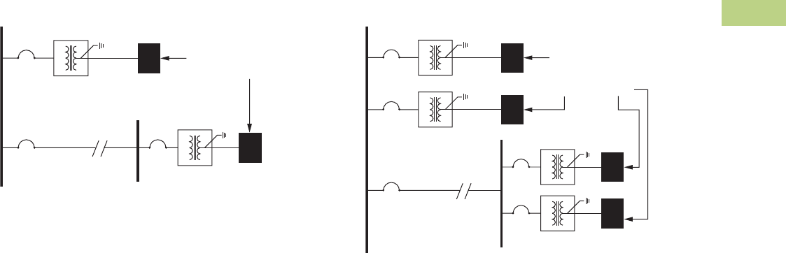
Volume 2—Commercial Distribution CA08100003E—June 2014 www.eaton.com V2-T2-91
2
2
2
2
2
2
2
2
2
2
2
2
2
2
2
2
2
2
2
2
2
2
2
2
2
2
2
2
2
2
2.3
Trans for mers
Energy-Efficient Harmonic Mitigating Transformers
Sample HMT Applications
Typical Application of Type NON Transformer
Installation of a Type NON
transformer provides an
effective treatment of triplen
(3rd, 9th, 15th and so on)
harmonic currents that
are generated by loads
connected to the transformer.
Triplen harmonic currents
are treated in the secondary
windings of the transformer
due to the transformer’s low
zero sequence impedance.
Type NON transformers
do not need to be used in
combination with other
transformers to treat triplen
harmonic currents. A single
Type NON transformer may
be installed, or multiple units
can be applied.
Type NON transformers are
an ideal solution for treating
triplen harmonics generated
by personal computers,
printers, fax machines and
other office equipment,
as well as by single-phase
electronic ballasts, and single-
phase electronic testing or
monitoring devices.
Type NON
Type NON
Long Run
Electrical Bus
Electrical Panel
Feeding Single-Phase
and/or Three-Phase
Nonlinear Loads
Typical Application of Type NON Transformer
with a Standard Delta-Wye Transformer
When a delta-wye transformer
exists in an electrical
distribution system, the
addition of a Type NON
transformer offers an
economical solution for treating
harmonic currents. The 30°
phase-shift created between a
Type NON harmonic mitigating
transformer and a delta-wye
transformer (standard
transformer or K-Factor
transformer) provides
treatment of 5th, 7th, 17th
and 19th harmonic currents.
These harmonic currents are
canceled in the common
electrical bus that feeds the
transformers. Additionally,
triplen (3rd, 9th, 15th and
so on) harmonic currents
generated by the loads
connected to the Type NON
transformer will be treated
in the secondary windings of
the Type NON transformer
due to its low zero sequence
impedance. When using two
or more transformers to treat
harmonics, it is better that the
load be split equally between
the transformers to receive the
maximum benefit.
Note: Triplen currents will still
circulate in the delta-wye
transformer for additional waste.
See figure on Page V2-T2-92 to
correct.
Type NON
-Y Transformer
Type NON
Long Run
-Y Transformer
Electrical Bus
Electrical Panel
Feeding Single-Phase
and/or Three-Phase
Nonlinear Loads
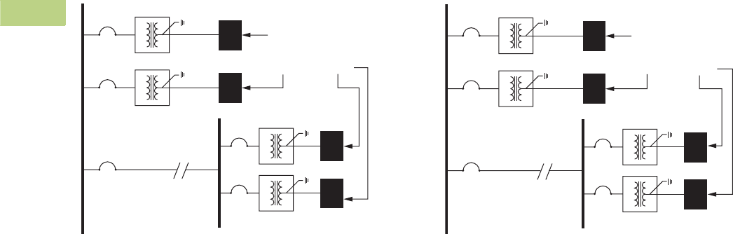
V2-T2-92 Volume 2—Commercial Distribution CA08100003E—June 2014 www.eaton.com
2
2
2
2
2
2
2
2
2
2
2
2
2
2
2
2
2
2
2
2
2
2
2
2
2
2
2
2
2
2
2.3
Transfor mers
Energy-Efficient Harmonic Mitigating Transformers
Optimum Application of Type NON and
Ty p e T H R Tr a n s f o r m e r s
When you’re searching for an
optimum harmonic correction
solution in an electrical
distribution system, the
combination of a Type NON
and Type THR transformer
offers a great solution.
The 30° phase shift created
between Type NON and type
THR harmonic mitigating
transformers provides
treatment of 5th, 7th, 17th
and 19th harmonic currents.
These harmonic currents are
canceled in the common
electrical bus that feeds the
transformers. Additionally,
triplen (3rd, 9th, 15th and
so on) harmonic currents
generated by the loads will
be treated in the secondary
windings of HMTs. This will
ensure that these currents
will not circulate in the
primary of the transformer
creating additional heat,
voltage distortion and wasted
energy loss. When using
two or more transformers to
treat harmonics, it is better
that the load be split equally
between the transformers
to receive the
maximum benefit.
Type NON
Type THR
Type NON
Long Run
Type THR
Electrical Bus
Electrical Panel
Feeding Single-Phase
and/or Three-Phase
Nonlinear Loads
Typical Application of Type NEG and
Type POS Transformers
The combination of a Type
POS (+15° phase-shift)
transformer and a Type NEG
(–15° phase-shift) transformer
effectively treats 5th, 7th,
17th and 19th harmonic
currents. These harmonic
currents are canceled in the
common electrical bus that
feeds the transformers.
Additionally, triplen (3rd, 9th,
15th and so on) harmonic
currents generated by the
loads connected to these
transformers will be treated in
their secondary windings due
to their low zero sequence
impedance. When using two
or more transformers to treat
harmonics, it is better that the
load be split equally between
the transformers to receive
the maximum benefit.
Type NEG
Type POS
Type NEG
Long Run
Type POS
Electrical Bus
Electrical Panel
Feeding Single-Phase
and/or Three-Phase
Nonlinear Loads
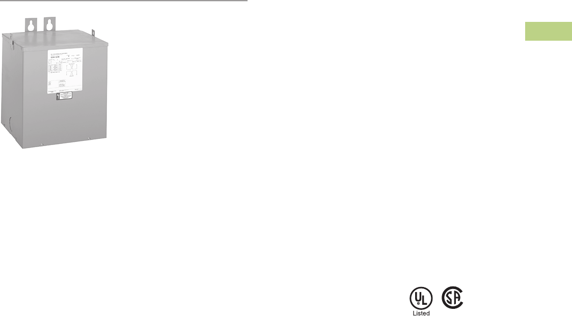
Volume 2—Commercial Distribution CA08100003E—June 2014 www.eaton.com V2-T2-93
2
2
2
2
2
2
2
2
2
2
2
2
2
2
2
2
2
2
2
2
2
2
2
2
2
2
2
2
2
2
2.4
Trans for mers
General-Purpose Encapsulated Transformers
Type EP 3–25 kVA
Contents
Description Page
General-Purpose Encapsulated Transformers
Catalog Number Selection . . . . . . . . . . . . . . . . V2-T2-94
Product Selection . . . . . . . . . . . . . . . . . . . . . . . V2-T2-94
Single-Phase. . . . . . . . . . . . . . . . . . . . . . . . . . V2-T2-94
Three-Phase . . . . . . . . . . . . . . . . . . . . . . . . . V2-T2-100
Accessories . . . . . . . . . . . . . . . . . . . . . . . . . . . V2-T2-109
Technical Data and Specifications. . . . . . . . . . . V2-T2-109
Product Description
Note: The following pages
provide listings for most standard
transformer ratings and styles.
For other ratings or styles not
shown, or for special enclosure
types (including stainless steel),
refer to Eaton.
Type EP and EPT
●Encapsulated design
●Suitable for indoor or
outdoor applications
●Totally enclosed, non-
ventilated enclosures
●Enclosures are
NEMA 3R rated
●Mountable in any position
indoors and upright-only
outdoors
●180ºC insulation system
●115ºC rise standard;
80°C optional
●Available in ratings through
37.5 kVA single-phase;
75 kVA three-phase
Application Description
The basic purpose of a
transformer is voltage
transformation as near as
practically possible to the load
for economy and distribution
of power. Typical loads for
dry-type distribution
transformers include lighting,
heating, air conditioners,
fans and machine tools.
Such loads are found in
commercial, institutional,
industrial and residential
structures.
Features, Benefits
and Functions
●60 Hz operation
(50/60 Hz optional)
●Short-term overload
capability as required
by ANSI
●Meet NEMA ST-20
sound levels
Standards and
Certifications
●UL listed
●CSA certified
Industry Standards
All Eaton dry-type distribution
and control transformers are
built and tested in accordance
with applicable NEMA,
ANSI and IEEE Standards.
All 600 volt class transformers
are UL listed unless otherwise
noted.
Seismically Qualified
Eaton manufactured dry-type
distribution transformers are
seismically qualified and
exceed requirements of
the Uniform Building Code
(UBC), International Building
Code (IBC), and California
Code Title 24.
V2-T2-94 Volume 2—Commercial Distribution CA08100003E—June 2014 www.eaton.com
2
2
2
2
2
2
2
2
2
2
2
2
2
2
2
2
2
2
2
2
2
2
2
2
2
2
2
2
2
2
2.4
Transfor mers
General-Purpose Encapsulated Transformers
Catalog Number Selection
Please refer to Section 2.7 Page V2-T2-187.
Product Selection
Additional Product Selection information begins on Page V2-T2-189.
Single-Phase Encapsulated—Type EP, 60 Hz
120 x 240 Volts to 120/240 Volts 1
208 Volts to 120/240 Volts 1
Notes
1 Contact Eaton for availability of 0.05–0.25 kVA designs.
Contact your local Eaton sales office for CE Mark transformer requirements. For other ratings or styles not shown, or for special enclosure types (including stainless steel),
refer to Eaton. Frame drawings/dimensions information begins on Page V2-T2-215.
kVA
Full Capacity Taps
Type
ºC Temp.
Rise Frame
Wiring Diagram
Number
Weight
Lbs (kg) Weathershield Style NumberFCAN FCBN
0.5 — — EP 115 FR57P 3E 16 (7) Indoor–Outdoor S10N11P51P
1 — — EP 115 FR67P 3E 31 (14) Indoor–Outdoor S10N11P01P
1.5 — — EP 115 FR67P 3E 42 (19) Indoor–Outdoor S10N11P16P
2 — — EP 115 FR68P 3E 42 (19) Indoor–Outdoor S10N11P02P
3 — — EP 115 FR176 3E 55 (25) Indoor–Outdoor S10N11S03N
5 — — EP 115 FR177 3E 113 (51) Indoor–Outdoor S10N11S05N
7.5 — — EP 115 FR178 3E 123 (56) Indoor–Outdoor S10N11S07N
10 — — EP 115 FR179 3E 193 (88) Indoor–Outdoor S10N11S10N
15 — — EP 115 FR180 3E 216 (98) Indoor–Outdoor S10N11S15N
25 — — EP 115 FR182 3E 375 (170) Indoor–Outdoor S10N11S25N
kVA
Full Capacity Taps
Type
ºC Temp.
Rise Frame
Wiring Diagram
Number
Weight
Lbs (kg) Weathershield Style NumberFCAN FCBN
0.5 — — EP 115 FR57P 26A 16 (7) Indoor–Outdoor S29N11P51P
1 — — EP 115 FR67P 26A 31 (14) Indoor–Outdoor S29N11P01P
1.5 — — EP 115 FR67P 26A 42 (19) Indoor–Outdoor S29N11P16P
2 — — EP 115 FR68P 26A 42 (19) Indoor–Outdoor S29N11P02P
3 — — EP 115 FR176 26A 65 (30) Indoor–Outdoor S29N11S03N
5 — — EP 115 FR177 26A 113 (51) Indoor–Outdoor S29N11S05N
7.5 — — EP 115 FR178 26A 123 (56) Indoor–Outdoor S29N11S07N
10 — — EP 115 FR179 26A 193 (88) Indoor–Outdoor S29N11S10N
15 — — EP 115 FR180 26A 216 (98) Indoor–Outdoor S29N11S15N
25 — — EP 115 FR182 26A 395 (179) Indoor–Outdoor S29N11S25N
Type EP 3–37.5 kVA

Volume 2—Commercial Distribution CA08100003E—June 2014 www.eaton.com V2-T2-95
2
2
2
2
2
2
2
2
2
2
2
2
2
2
2
2
2
2
2
2
2
2
2
2
2
2
2
2
2
2
2.4
Trans for mers
General-Purpose Encapsulated Transformers
Single-Phase Encapsulated—Type EP, 60 Hz
277 Volts to 120/240 Volts 1
240 x 480 Volts to 120/240 Volts
Notes
1Contact Eaton for availability of 0.05–0.25 kVA designs.
21 at +10% FCBN at 240 volts; 2 at –5% FCBN at 480 volts.
32 at +5% FCBN at 240 volts; 4 at –2.5% FCBN at 480 volts.
4Floor-mount only.
Contact your local Eaton sales office for CE Mark transformer requirements. For other ratings or styles not shown, or for special enclosure types (including stainless steel), refer to Eaton. Frame
drawings/dimensions information begins on Page V2-T2-215.
kVA
Full Capacity Taps
Type
ºC Temp.
Rise Frame
Wiring Diagram
Number
Weight
Lbs (kg) Weathershield Style NumberFCAN FCBN
0.5 — — EP 115 FR58AP 524A 26 (12) Indoor–Outdoor S27N11P51P
1 — — EP 115 FR59AP 524A 31 (14) Indoor–Outdoor S27N11P01P
1.5 — — EP 115 FR67P 524A 42 (19) Indoor–Outdoor S27N11P16P
2 — — EP 115 FR176P 524A 65 (30) Indoor–Outdoor S27N11P02P
3 — — EP 115 FR176 524A 55 (25) Indoor–Outdoor S27N11S03N
5 — — EP 115 FR177 524A 113 (51) Indoor–Outdoor S27N11S05N
7.5 — — EP 115 FR178 524A 123 (56) Indoor–Outdoor S27N11S07N
10 — — EP 115 FR179 524A 193 (88) Indoor–Outdoor S27N11S10N
15 — — EP 115 FR180 524A 180 (82) Indoor–Outdoor S27N11S15N
25 — — EP 115 FR182 524A 375 (170) Indoor–Outdoor S27N11S25N
kVA
Full Capacity Taps
Type
ºC Temp.
Rise Frame
Wiring Diagram
Number
Weight
Lbs (kg) Weathershield Style NumberFCAN FCBN
0.050 — — EP 115 FR52 3A 7 (3) Indoor–Outdoor S20N11S81N
0.075 — — EP 115 FR54 3A 7 (3) Indoor–Outdoor S20N11S85N
0.100 — — EP 115 FR54 3A 7 (3) Indoor–Outdoor S20N11S82N
0.150 — — EP 115 FR55 3A 8 (4) Indoor–Outdoor S20N11S83N
0.25 — — EP 115 FR57P 3A 12 (5) Indoor–Outdoor S20N11P26P
0.5 — — EP 115 FR57P 3A 16 (7) Indoor–Outdoor S20N11P51P
0.75 — — EP 115 FR58AP 3A 26 (12) Indoor–Outdoor S20N11P76P
1 — — EP 115 FR67P 3A 31 (14) Indoor–Outdoor S20N11P01P
1.5 — — EP 115 FR67P 3A 42 (19) Indoor–Outdoor S20N11P16P
2 — — EP 115 FR68P 3A 42 (19) Indoor–Outdoor S20N11P02P
3 — — EP 115 FR176 3A 65 (30) Indoor–Outdoor S20N11S03N
322EP 115 FR176 3A 65 (30) Indoor–Outdoor S20K11S03N
5 — — EP 115 FR177 3A 113 (51) Indoor–Outdoor S20N11S05N
522EP 115 FR177 9A 105 (48) Indoor–Outdoor S20K11S05N
7.5 — — EP 115 FR178 3A 105 (48) Indoor–Outdoor S20N11S07N
7.5 22EP 115 FR178 9A 123 (56) Indoor–Outdoor S20K11S07N
10 — — EP 115 FR179 3A 193 (88) Indoor–Outdoor S20N11S10N
10 22EP 115 FR179 9A 193 (88) Indoor–Outdoor S20K11S10N
15 — — EP 115 FR180 3A 216 (98) Indoor–Outdoor S20N11S15N
15 33EP 115 FR180 23A 216 (98) Indoor–Outdoor S20L11S15N
25 — — EP 115 FR182 3A 385 (175) Indoor–Outdoor S20N11S25N
25 33EP 115 FR182 23A 375 (170) Indoor–Outdoor S20L11S25N
37.5 33EP 115 FR300A 248A 735 (334) Indoor–Outdoor S20L11S37 4

V2-T2-96 Volume 2—Commercial Distribution CA08100003E—June 2014 www.eaton.com
2
2
2
2
2
2
2
2
2
2
2
2
2
2
2
2
2
2
2
2
2
2
2
2
2
2
2
2
2
2
2.4
Transfor mers
General-Purpose Encapsulated Transformers
Single-Phase Encapsulated—Type EP, 60 Hz
190/200/208/220 x 380/400/416/440 Volts to 110/220 Volts 50/60 Hz—Export Model IP 22 Rated
120/208/240/277 Volts to 120/240 Volts 60 Hz
240 x 480 Volts to 120/240 Volts Stainless Steel 2
Notes
1Refer to your local Eaton sales office.
2NEMA 3R, 304 stainless steel enclosure; 316 stainless steel enclosure available as an option.
Contact your local Eaton sales office for CE Mark transformer requirements. For other ratings or styles not shown, or for special enclosure types (including stainless steel), refer to Eaton. Frame
drawings/dimensions information begins on Page V2-T2-215.
kVA
Full Capacity Taps
Type
ºC Temp.
Rise Frame
Wiring Diagram
Number
Weight
Lbs (kg) Weathershield Style NumberFCAN FCBN
0.5 — — EP 115 FR67 538A 42 (19) Indoor–Outdoor S40N14S51CE
1 — — EP 115 FR67 538A 42 (19) Indoor–Outdoor S40N14S01CE
1.5 — — EP 115 FR176 538A 65 (30) Indoor–Outdoor S40N14S16CE
2 — — EP 115 FR176 538A 65 (30) Indoor–Outdoor S40N14S02CE
3 — — EP 115 FR177 538A 113 (51) Indoor–Outdoor S40N14S03CE
5 — — EP 115 FR178 538A 140 (64) Indoor–Outdoor S40N14S05CE
7.5 — — EP 115 FR179 538A 193 (88) Indoor–Outdoor S40N14S07CE
10 — — EP 115 FR180 538A 216 (98) Indoor–Outdoor S40N14S10CE
15 — — EP 115 FR182 538A 375 (170) Indoor–Outdoor S40N14S15CE
kVA
Full Capacity Taps
Type
ºC Temp.
Rise Frame
Wiring Diagram
Number
Weight
Lbs (kg) Weathershield Style NumberFCAN FCBN
1 — — EP 115 FR67P 142 (19) Indoor–Outdoor S54N11P01
1.5 — — EP 115 FR176P 165 (30) Indoor–Outdoor S54N11P16
2 — — EP 115 FR176P 165 (30) Indoor–Outdoor S54N11P02
3 — — EP 115 FR177 1113 (51) Indoor–Outdoor S54N11S03
5 — — EP 115 FR178 1140 (64) Indoor–Outdoor S54N11S05
7.5 — — EP 115 FR179 1193 (88) Indoor–Outdoor S54N11S07
10 — — EP 115 FR180 1216 (98) Indoor–Outdoor S54N11S10
kVA
Full Capacity Taps
Type
ºC Temp.
Rise Frame
Wiring Diagram
Number
Weight
Lbs (kg) Weathershield Style NumberFCAN FCBN
3 — — EP 115 FR176 3A 65 (30) Indoor–Outdoor S20N11S03SS
5 — — EP 115 FR177 3A 113 (51) Indoor–Outdoor S20N11S05SS
7.5 — — EP 115 FR178 3A 123 (56) Indoor–Outdoor S20N11S07SS
10 — — EP 115 FR179 3A 193 (88) Indoor–Outdoor S20N11S10SS
15 — — EP 115 FR180 3A 205 (93) Indoor–Outdoor S20N11S15SS
25 — — EP 115 FR182 3A 375 (170) Indoor–Outdoor S20N11S25SS

Volume 2—Commercial Distribution CA08100003E—June 2014 www.eaton.com V2-T2-97
2
2
2
2
2
2
2
2
2
2
2
2
2
2
2
2
2
2
2
2
2
2
2
2
2
2
2
2
2
2
2.4
Trans for mers
General-Purpose Encapsulated Transformers
Single-Phase Encapsulated—Type EP, 60 Hz
480 Volts to 120/240 Volts
480 Volts to 120/240 Volts Stainless Steel, Copper Windings 1
600 Volts to 120/240 Volts
Notes
1NEMA 3R, 304 stainless steel enclosure; 316 stainless steel enclosure available as an option.
Contact your local Eaton sales office for CE Mark transformer requirements. For other ratings or styles not shown, or for special enclosure types (including stainless steel), refer to Eaton. Frame
drawings/dimensions information begins on Page V2-T2-215.
kVA
Full Capacity Taps
Type
ºC Temp.
Rise Frame
Wiring Diagram
Number
Weight
Lbs (kg) Weathershield Style NumberFCAN FCBN
1 — 2 at –5% EP 115 FR67P 2D 31 (14) Indoor–Outdoor S48G11P01P
1.5 — 2 at –5% EP 115 FR67P 2D 42 (19) Indoor–Outdoor S48G11P16P
2 — 2 at –5% EP 115 FR68P 2D 42 (19) Indoor–Outdoor S48G11P02P
3 — 2 at –5% EP 115 FR176 2D 65 (30) Indoor–Outdoor S48G11S03N
3 2 at +2.5% 2 at –2.5% EP 115 FR176 16A 65 (30) Indoor–Outdoor S48D11S03N
5 — 2 at –5% EP 115 FR177 2D 113 (51) Indoor–Outdoor S48G11S05N
5 2 at +2.5% 2 at –2.5% EP 115 FR177 16A 113 (51) Indoor–Outdoor S48D11S05N
7.5 — 2 at –5% EP 115 FR178 2D 123 (56) Indoor–Outdoor S48G11S07N
7.5 2 at +2.5% 2 at –2.5% EP 115 FR178 16A 123 (56) Indoor–Outdoor S48D11S07N
10 — 2 at –5% EP 115 FR179 2D 193 (88) Indoor–Outdoor S48G11S10N
10 2 at +2.5% 2 at –2.5% EP 115 FR179 16A 193 (88) Indoor–Outdoor S48D11S10N
15 — 2 at –5% EP 115 FR180 2D 216 (98) Indoor–Outdoor S48G11S15N
15 2 at +2.5% 2 at –2.5% EP 115 FR180 16A 216 (98) Indoor–Outdoor S48D11S15N
25 — 2 at –5% EP 115 FR182 2D 385 (175) Indoor–Outdoor S48G11S25N
25 2 at +2.5% 4 at –2.5% EP 115 FR132 83A 410 (186) Indoor–Outdoor S48M11S25N
kVA
Full Capacity Taps
Type
ºC Temp.
Rise Frame
Wiring Diagram
Number
Weight
Lbs (kg) Weathershield Style NumberFCAN FCBN
10 2 at +2.5% 2 at –2.5% EP 115 FR179 16A 210 (95) Indoor–Outdoor S48D11S10CUSS
15 2 at +2.5% 2 at –2.5% EP 115 FR180 16A 235 (107) Indoor–Outdoor S48D11S15SSCU
25 2 at +2.5% 4 at –2.5% EP 115 FR182 83A 415 (188) Indoor–Outdoor S48M11S25SSCU
kVA
Full Capacity Taps
Type
ºC Temp.
Rise Frame
Wiring Diagram
Number
Weight
Lbs (kg) Weathershield Style NumberFCAN FCBN
0.5 — 2 at –5% EP 115 FR57P 2I 16 (7) Indoor–Outdoor S60G11P51P
0.75 — 2 at –5% EP 115 FR58AP 2I 26 (12) Indoor–Outdoor S60G11P76P
1 — 2 at –5% EP 115 FR67P 2I 31 (14) Indoor–Outdoor S60G11P01P
1.5 — 2 at –5% EP 115 FR67P 2I 42 (19) Indoor–Outdoor S60G11P16P
2 — 2 at –5% EP 115 FR68P 2I 42 (19) Indoor–Outdoor S60G11P02P
3 — 2 at –5% EP 115 FR176 2I 65 (30) Indoor–Outdoor S60G11S03N
5 — 2 at –5% EP 115 FR177 2I 105 (48) Indoor–Outdoor S60G11S05N
7.5 — 2 at –5% EP 115 FR178 2I 123 (56) Indoor–Outdoor S60G11S07N
10 — 2 at –5% EP 115 FR179 2I 193 (88) Indoor–Outdoor S60G11S10N
15 — 4 at –2.5% EP 115 FR180 527A 216 (98) Indoor–Outdoor S60J11S15N
25 — 4 at –2.5% EP 115 FR182 527A 385 (175) Indoor–Outdoor S60J11S25N
25 2 at +2.5% 4 at –2.5% EP 115 FR132 83B 395 (180) Indoor–Outdoor S60M11S25N

V2-T2-98 Volume 2—Commercial Distribution CA08100003E—June 2014 www.eaton.com
2
2
2
2
2
2
2
2
2
2
2
2
2
2
2
2
2
2
2
2
2
2
2
2
2
2
2
2
2
2
2.4
Transfor mers
General-Purpose Encapsulated Transformers
Single-Phase Shielded—Type EP, 60 Hz
120 x 240 Volts to 120/240 Volts
120 Volts to 120 Volts
208 Volts to 120/240 Volts
208 Volts to 208 Volts
Note
Contact your local Eaton sales office for CE Mark transformer requirements. For other ratings or styles not shown, or for special enclosure types (including stainless steel), refer to Eaton. Frame
drawings/dimensions information begins on Page V2-T2-215.
kVA
Full Capacity Taps
Type
ºC Temp.
Rise Frame
Wiring Diagram
Number
Weight
Lbs (kg) Weathershield Style NumberFCAN FCBN
3 — — EP 115 FR176 90B 50 (23) Indoor–Outdoor S10N11E03N
5 — — EP 115 FR177 90B 90 (41) Indoor–Outdoor S10N11E05N
7.5 — — EP 115 FR178 90B 123 (56) Indoor–Outdoor S10N11E07N
10 — — EP 115 FR179 90B 210 (95) Indoor–Outdoor S10N11E10N
15 — — EP 115 FR180 90B 205 (93) Indoor–Outdoor S10N11E15N
25 — — EP 115 FR182 90B 375 (170) Indoor–Outdoor S10N11E25N
kVA
Full Capacity Taps
Type
ºC Temp.
Rise Frame
Wiring Diagram
Number
Weight
Lbs (kg) Weathershield Style NumberFCAN FCBN
3 — — EP 115 FR176 77A 60 (27) Indoor–Outdoor S12N12E03N
5 — — EP 115 FR177 77A 100 (45) Indoor–Outdoor S12N12E05N
7.5 — — EP 115 FR178 77A 123 (56) Indoor–Outdoor S12N12E07N
10 — — EP 115 FR179 77A 180 (82) Indoor–Outdoor S12N12E10N
15 — — EP 115 FR180 77A 216 (98) Indoor–Outdoor S12N12E15N
25 — — EP 115 FR182 77A 375 (170) Indoor–Outdoor S12N12E25N
kVA
Full Capacity Taps
Type
ºC Temp.
Rise Frame
Wiring Diagram
Number
Weight
Lbs (kg) Weathershield Style NumberFCAN FCBN
3 — — EP 115 FR176 578A 60 (27) Indoor–Outdoor S29N11E03N
5 — — EP 115 FR177 578A 135 (61) Indoor–Outdoor S29N11E05N
7.5 — — EP 115 FR178 578A 95 (43) Indoor–Outdoor S29N11E07N
10 — — EP 115 FR179 578A 165 (75) Indoor–Outdoor S29N11E10N
15 — — EP 115 FR180 578A 185 (94) Indoor–Outdoor S29N11E15N
25 — — EP 115 FR182 578A 375 (170) Indoor–Outdoor S29N11E25N
kVA
Full Capacity Taps
Type
ºC Temp.
Rise Frame
Wiring Diagram
Number
Weight
Lbs (kg) Weathershield Style NumberFCAN FCBN
3 — — EP 115 FR176 77B 65 (30) Indoor–Outdoor S29N29E03N
5 — — EP 115 FR177 77B 113 (51) Indoor–Outdoor S29N29E05N
7.5 — — EP 115 FR178 77B 123 (56) Indoor–Outdoor S29N29E07N
10 — — EP 115 FR179 77B 195 (89) Indoor–Outdoor S29N29E10N
15 — — EP 115 FR180 77B 216 (98) Indoor–Outdoor S29N29E15N
25 — — EP 115 FR182 77B 375 (170) Indoor–Outdoor S29N29E25N

Volume 2—Commercial Distribution CA08100003E—June 2014 www.eaton.com V2-T2-99
2
2
2
2
2
2
2
2
2
2
2
2
2
2
2
2
2
2
2
2
2
2
2
2
2
2
2
2
2
2
2.4
Trans for mers
General-Purpose Encapsulated Transformers
Single-Phase Shielded—Type EP, 60 Hz
240 Volts to 240 Volts
277 Volts to 120/240 Volts
240 x 480 Volts to 120/240 Volts
Notes
12 at +5% FCBN at 240 volts; 4 at –2.5% FCBN at 480 volts.
Contact your local Eaton sales office for CE Mark transformer requirements. For other ratings or styles not shown, or for special enclosure types (including stainless steel), refer to Eaton. Frame
drawings/dimensions information begins on Page V2-T2-215.
kVA
Full Capacity Taps
Type
ºC Temp.
Rise Frame
Wiring Diagram
Number
Weight
Lbs (kg) Weathershield Style NumberFCAN FCBN
3 — — EP 115 FR176 77C 65 (30) Indoor–Outdoor S24N24E03N
5 — — EP 115 FR177 77C 113 (51) Indoor–Outdoor S24N24E05N
7.5 — — EP 115 FR178 77C 123 (56) Indoor–Outdoor S24N24E07N
10 — — EP 115 FR179 77C 193 (88) Indoor–Outdoor S24N24E10N
15 — — EP 115 FR180 77C 216 (98) Indoor–Outdoor S24N24E15N
25 — — EP 115 FR182 77C 375 (170) Indoor–Outdoor S24N24E25N
kVA
Full Capacity Taps
Type
ºC Temp.
Rise Frame
Wiring Diagram
Number
Weight
Lbs (kg) Weathershield Style NumberFCAN FCBN
3 — — EP 115 FR176 513B 65 (30) Indoor–Outdoor S27N11E03N
5 — — EP 115 FR177 513B 113 (51) Indoor–Outdoor S27N11E05N
7.5 — — EP 115 FR178 513B 75 (34) Indoor–Outdoor S27N11E07N
10 — — EP 115 FR179 513B 162 (74) Indoor–Outdoor S27N11E10N
15 — — EP 115 FR180 513B 216 (98) Indoor–Outdoor S27N11E15N
25 — — EP 115 FR182 513B 375 (170) Indoor–Outdoor S27N11E25N
kVA
Full Capacity Taps
Type
ºC Temp.
Rise Frame
Wiring Diagram
Number
Weight
Lbs (kg) Weathershield Style NumberFCAN FCBN
0.25 — — EP 115 FR57P 90A 12 (5) Indoor–Outdoor S20N11E26P
0.50 — — EP 115 FR57P 90A 16 (7) Indoor–Outdoor S20N11E51P
0.75 — — EP 115 FR58AP 90A 26 (12) Indoor–Outdoor S20N11E76P
1 — — EP 115 FR67P 90A 31 (14) Indoor–Outdoor S20N11E01P
1.5 — — EP 115 FR67P 90A 42 (19) Indoor–Outdoor S20N11E16P
2 — — EP 115 FR68P 90A 42 (19) Indoor–Outdoor S20N11E02P
3 — — EP 115 FR176 90A 65 (30) Indoor–Outdoor S20N11E03A
5 — — EP 115 FR177 90A 113 (51) Indoor–Outdoor S20N11E05A
7.5 — — EP 115 FR178 90A 123 (56) Indoor–Outdoor S20N11E07A
10 — — EP 115 FR179 90A 166 (75) Indoor–Outdoor S20N11E10A
15 — — EP 115 FR180 90A 216 (98) Indoor–Outdoor S20N11E15A
25 11 EP 115 FR182 526A 375 (170) Indoor–Outdoor S20L11E25A

V2-T2-100 Volume 2—Commercial Distribution CA08100003E—June 2014 www.eaton.com
2
2
2
2
2
2
2
2
2
2
2
2
2
2
2
2
2
2
2
2
2
2
2
2
2
2
2
2
2
2
2.4
Transfor mers
General-Purpose Encapsulated Transformers
Three-Phase Encapsulated—Type EPT, 60 Hz
240 Delta Volts to 208Y/120 Volts
380 Delta Volts to 190Y/110 Volts
380 Delta Volts to 208Y/120 Volts
Notes
1T-T (Scott T) connected secondary.
2Floor-mount only.
Contact your local Eaton sales office for CE Mark transformer requirements. For other ratings or styles not shown, or for special enclosure types (including stainless steel), refer to Eaton. Frame
drawings/dimensions information begins on Page V2-T2-215.
kVA
Full Capacity Taps
Type
ºC Temp.
Rise Frame
Wiring Diagram
Number
Weight
Lbs (kg) Weathershield Style NumberFCAN FCBN
9 — 2 at –5% EPT 115 FR103 70C 190 (86) Indoor–Outdoor Y24G28T09N 1
15 — 2 at –5% EPT 115 FR95 70C 275 (125) Indoor–Outdoor Y24G28T15N 1
30 2 at +2.5% 4 at –2.5% EPT 115 FR243 84C 422 (191) Indoor–Outdoor Y24M28T30N
45 2 at +2.5% 4 at –2.5% EPT 115 FR244 84C 660 (299) Indoor–Outdoor Y24M28T45N
kVA
Full Capacity Taps
Type
ºC Temp.
Rise Frame
Wiring Diagram
Number
Weight
Lbs (kg) Weathershield Style NumberFCAN FCBN
3 — 2 at –5% EPT 115 FR201 70F 116 (53) Indoor–Outdoor Y38G19T03A 1
6 — 2 at –5% EPT 115 FR200 70F 165 (75) Indoor–Outdoor Y38G19T06A 1
9 — 2 at –5% EPT 115 FR95 70F 275 (125) Indoor–Outdoor Y38G19T09A 1
15 — 2 at –5% EPT 115 FR95 72R 275 (125) Indoor–Outdoor Y38G19T15A 1
30 2 at +2.5% 4 at –2.5% EPT 115 FR243 84AC 422 (191) Indoor–Outdoor Y38M19T30A
45 2 at +2.5% 4 at –2.5% EPT 115 FR244 84AC 660 (299) Indoor–Outdoor Y38M19T45A
75 2 at +2.5% 4 at –2.5% EPT 115 FR245 84AC 1275 (580) Indoor–Outdoor Y38M19T75A 2
kVA
Full Capacity Taps
Type
ºC Temp.
Rise Frame
Wiring Diagram
Number
Weight
Lbs (kg) Weathershield Style NumberFCAN FCBN
3 — 2 at –5% EPT 115 FR201 70D 116 (53) Indoor–Outdoor Y38G28T03A 1
6 — 2 at –5% EPT 115 FR200 70F 165 (75) Indoor–Outdoor Y38G28T06A 1
9 — 2 at –5% EPT 115 FR103 70D 185 (84) Indoor–Outdoor Y38G28T09A 1
15 — 2 at –5% EPT 115 FR95 70D 275 (125) Indoor–Outdoor Y38G28T15A 1
30 2 at +2.5% 4 at –2.5% EPT 115 FR243 84H 422 (191) Indoor–Outdoor Y38M28T30A
45 2 at +2.5% 4 at –2.5% EPT 115 FR244 84R 660 (299) Indoor–Outdoor Y38M28T45A
75 2 at +2.5% 4 at –2.5% EPT 115 FR245 84R 1275 (580) Indoor–Outdoor Y38M28T75A 2

Volume 2—Commercial Distribution CA08100003E—June 2014 www.eaton.com V2-T2-101
2
2
2
2
2
2
2
2
2
2
2
2
2
2
2
2
2
2
2
2
2
2
2
2
2
2
2
2
2
2
2.4
Trans for mers
General-Purpose Encapsulated Transformers
Three-Phase Encapsulated—Type EPT, 60 Hz
380 Delta Volts to 220Y/127 Volts
380 Delta Volts to 220 Delta Volts
380 Delta Volts to 380Y/220 Volts
380 Delta Volts to 480Y/277 Volts
Notes
1T-T (Scott T) connected secondary.
2Floor-mount only.
3Refer to your Eaton sales office.
Contact your local Eaton sales office for CE Mark transformer requirements. For other ratings or styles not shown, or for special enclosure types (including stainless steel), refer to Eaton. Frame
drawings/dimensions information begins on Page V2-T2-215.
kVA
Full Capacity Taps
Type
ºC Temp.
Rise Frame
Wiring Diagram
Number
Weight
Lbs (kg) Weathershield Style NumberFCAN FCBN
3 — 2 at –5% EPT 115 FR201 70F 116 (53) Indoor–Outdoor Y38G31T03A 1
6 — 2 at –5% EPT 115 FR200 70F 165 (75) Indoor–Outdoor Y38G31T06A 1
9 — 2 at –5% EPT 115 FR103 70M 195 (89) Indoor–Outdoor Y38G31T09A 1
15 — 2 at –5% EPT 115 FR95 70F 275 (125) Indoor–Outdoor Y38G31T15A 1
30 2 at +2.5% 4 at –2.5% EPT 115 FR243 84R 422 (191) Indoor–Outdoor Y38M31T30A
45 2 at +2.5% 4 at –2.5% EPT 115 FR244 84R 660 (299) Indoor–Outdoor Y38M31T45A
75 2 at +2.5% 4 at –2.5% EPT 115 FR245 84R 1275 (580) Indoor–Outdoor Y38M31T75A 2
kVA
Full Capacity Taps
Type
ºC Temp.
Rise Frame
Wiring Diagram
Number
Weight
Lbs (kg) Weathershield Style NumberFCAN FCBN
3 — 2 at –5% EPT 115 FR201 74K 116 (53) Indoor–Outdoor Y38G25T03A 1
6 — 2 at –5% EPT 115 FR200 74K 180 (82) Indoor–Outdoor Y38G25T06A 1
9 — 2 at –5% EPT 115 FR103 74K 195 (89) Indoor–Outdoor Y38G25T09A 1
15 — 2 at –5% EPT 115 FR95 74K 275 (125) Indoor–Outdoor Y38G25T15A 1
30 2 at +2.5% 4 at –2.5% EPT 115 FR243 3422 (191) Indoor–Outdoor Y38M25T30A
45 2 at +2.5% 4 at –2.5% EPT 115 FR244 3660 (299) Indoor–Outdoor Y38M25T45A
75 2 at +2.5% 4 at –2.5% EPT 115 FR245 31275 (580) Indoor–Outdoor Y38M25T75A 2
kVA
Full Capacity Taps
Type
ºC Temp.
Rise Frame
Wiring Diagram
Number
Weight
Lbs (kg) Weathershield Style NumberFCAN FCBN
3 — 2 at –5% EPT 115 FR201 70D 116 (53) Indoor–Outdoor Y38G37T03A 1
6 — 2 at –5% EPT 115 FR200 70D 165 (75) Indoor–Outdoor Y38G37T06A 1
9 — 2 at –5% EPT 115 FR103 70D 180 (82) Indoor–Outdoor Y38G37T09A 1
15 — 2 at –5% EPT 115 FR95 70D 275 (125) Indoor–Outdoor Y38G37T15A 1
30 2 at +2.5% 4 at –2.5% EPT 115 FR243 84H 422 (191) Indoor–Outdoor Y38M37T30A
45 2 at +2.5% 4 at –2.5% EPT 115 FR244 84H 660 (299) Indoor–Outdoor Y38M37T45A
75 2 at +2.5% 4 at –2.5% EPT 115 FR245 84H 1275 (580) Indoor–Outdoor Y38M37T75A 2
kVA
Full Capacity Taps
Type
ºC Temp.
Rise Frame
Wiring Diagram
Number
Weight
Lbs (kg) Weathershield Style NumberFCAN FCBN
3 — 2 at –5% EPT 115 FR201 70F 116 (53) Indoor–Outdoor Y38G47T03A 1
6 — 2 at –5% EPT 115 FR200 70F 180 (82) Indoor–Outdoor Y38G47T06A 1
9 — 2 at –5% EPT 115 FR103 70F 166 (75) Indoor–Outdoor Y38G47T09A 1
15 — 2 at –5% EPT 115 FR95 70F 275 (125) Indoor–Outdoor Y38G47T15A 1
30 2 at +2.5% 4 at –2.5% EPT 115 FR243 84AB 422 (191) Indoor–Outdoor Y38M47T30A
45 2 at +2.5% 4 at –2.5% EPT 115 FR244 84AB 660 (299) Indoor–Outdoor Y38M47T45A
75 2 at +2.5% 4 at –2.5% EPT 115 FR245 84AB 1275 (580) Indoor–Outdoor Y38M47T75A 2

V2-T2-102 Volume 2—Commercial Distribution CA08100003E—June 2014 www.eaton.com
2
2
2
2
2
2
2
2
2
2
2
2
2
2
2
2
2
2
2
2
2
2
2
2
2
2
2
2
2
2
2.4
Transfor mers
General-Purpose Encapsulated Transformers
Three-Phase Encapsulated—Type EPT, 60 Hz
416 Delta Volts to 208Y/120 Volts
440 Delta Volts to 220Y/127 Volts
480 Delta Volts to 208Y/120 Volts
480 Delta Volts to 208Y/120 Volts—Copper Windings
Notes
1T-T (Scott T) connected secondary.
2Floor-mount only.
3Not CSA certified.
Contact your local Eaton sales office for CE Mark transformer requirements. For other ratings or styles not shown, or for special enclosure types (including stainless steel), refer to Eaton. Frame
drawings/dimensions information begins on Page V2-T2-215.
kVA
Full Capacity Taps
Type
ºC Temp.
Rise Frame
Wiring Diagram
Number
Weight
Lbs (kg) Weathershield Style NumberFCAN FCBN
3 — 2 at –5% EPT 115 FR201 70V 116 (53) Indoor–Outdoor Y43G28T03A 1
6 — 2 at –5% EPT 115 FR200 70V 175 (79) Indoor–Outdoor Y43G28T06A 1
9 — 2 at –5% EPT 115 FR103 70V 190 (86) Indoor–Outdoor Y43G28T09A 1
15 — 2 at –5% EPT 115 FR95 70V 275 (125) Indoor–Outdoor Y43G28T15A 1
30 2 at +2.5% 4 at –2.5% EPT 115 FR243 84I 422 (191) Indoor–Outdoor Y43M28T30A
45 2 at +2.5% 4 at –2.5% EPT 115 FR244 84I 660 (299) Indoor–Outdoor Y43M28T45A
75 2 at +2.5% 4 at –2.5% EPT 115 FR245 84I 1275 (580) Indoor–Outdoor Y43M28T75A 2
kVA
Full Capacity Taps
Type
ºC Temp.
Rise Frame
Wiring Diagram
Number
Weight
Lbs (kg) Weathershield Style NumberFCAN FCBN
3 — 2 at –5% EPT 115 FR201 70G 116 (53) Indoor–Outdoor Y44G31T03A 1
6 — 2 at –5% EPT 115 FR200 70G 165 (75) Indoor–Outdoor Y44G31T06A 1
9 — 2 at –5% EPT 115 FR103 70G 166 (75) Indoor–Outdoor Y44G31T09A 1
15 — 2 at –5% EPT 115 FR95 70G 275 (125) Indoor–Outdoor Y44G31T15A 1
30 2 at +2.5% 4 at –2.5% EPT 115 FR243 84O 422 (191) Indoor–Outdoor Y44M31T30A 2
45 2 at +2.5% 4 at –2.5% EPT 115 FR244 84O 660 (299) Indoor–Outdoor Y44M31T45A
75 2 at +2.5% 4 at –2.5% EPT 115 FR245 84O 1275 (580) Indoor–Outdoor Y44M31T75A 2
kVA
Full Capacity Taps
Type
ºC Temp.
Rise Frame
Wiring Diagram
Number
Weight
Lbs (kg) Weathershield Style NumberFCAN FCBN
3 — 2 at –5% EPT 115 FR201 70A 116 (52) Indoor–Outdoor Y48G28T03N 1
6 — 2 at –5% EPT 115 FR200 70A 165 (75) Indoor–Outdoor Y48G28T06N 1
6 2 at +2.5% 2 at –2.5% EPT 115 FR200 72B 165 (75) Indoor–Outdoor Y48D28T06N 1
9 — 2 at –5% EPT 115 FR103 70A 166 (75) Indoor–Outdoor Y48G28T09N 1
9 — 4 at –2.5% EPT 115 FR103 503A 185 (84) Indoor–Outdoor Y48J28T09N 1
9 2 at +2.5% 2 at –2.5% EPT 115 FR103 72B 185 (84) Indoor–Outdoor Y48D28T09N 1
15 — 2 at –5% EPT 115 FR95 70A 275 (125) Indoor–Outdoor Y48G28T15N 1
15 — 4 at –2.5% EPT 115 FR95 503A 275 (125) Indoor–Outdoor Y48J28T15N 1
15 2 at +2.5% 2 at –2.5% EPT 115 FR95 72B 275 (125) Indoor–Outdoor Y48D28T15N 1
30 2 at +2.5% 4 at –2.5% EPT 115 FR243 84A 422 (191) Indoor–Outdoor Y48M28T30N
45 2 at +2.5% 4 at –2.5% EPT 115 FR244 84A 720 (327) Indoor–Outdoor Y48M28T45N
75 2 at +2.5% 4 at –2.5% EPT 115 FR245 84A 1275 (580) Indoor–Outdoor Y48M28T75N 2
kVA
Full Capacity Taps
Type
ºC Temp.
Rise Frame
Wiring Diagram
Number
Weight
Lbs (kg) Weathershield Style NumberFCAN FCBN
15 2 at +2.5% 2 at –2.5% EPT 115 FR95 72B 300 (136) Indoor–Outdoor Y48D28T15CU 1
30 2 at +2.5% 4 at –2.5% EPT 115 FR243 84A 505 (230) Indoor–Outdoor Y48M28T30CU
45 2 at +2.5% 4 at –2.5% EPT 115 FR244 84A 810 (368) Indoor–Outdoor Y48M28T45CU
75 2 at +2.5% 4 at –2.5% EPT 115 FR245 84A 1450 (659) Indoor–Outdoor Y48M28T75CU 23

Volume 2—Commercial Distribution CA08100003E—June 2014 www.eaton.com V2-T2-103
2
2
2
2
2
2
2
2
2
2
2
2
2
2
2
2
2
2
2
2
2
2
2
2
2
2
2
2
2
2
2.4
Trans for mers
General-Purpose Encapsulated Transformers
Three-Phase Encapsulated—Type EPT, 60 Hz
480 Delta Volts to 208Y/120 Volts Stainless Steel 3
480 Delta Volts to 208Y/120 Volts Stainless Steel—Copper Windings 3
480 Delta Volts to 220Y/127 Volts
480 Delta Volts to 240 Delta Volts
Notes
1T-T connected secondary.
2Floor-mount only.
3NEMA 3R, 304 stainless steel enclosure; 316 stainless steel enclosure available.
4Do not include 120 volt lighting tap.
Contact your local Eaton sales office for CE Mark transformer requirements. For other ratings or styles not shown, or for special enclosure types (including stainless steel), refer to Eaton. Frame
drawings/dimensions information begins on Page V2-T2-215.
kVA
Full Capacity Taps
Type
ºC Temp.
Rise Frame
Wiring Diagram
Number
Weight
Lbs (kg) Weathershield Style NumberFCAN FCBN
3 — 2 at –5% EPT 115 FR201 70A 116 (53) Indoor–Outdoor Y48G28T03SS 1
6 2 at +2.5% 2 at –2.5% EPT 115 FR200 72B 175 (79) Indoor–Outdoor Y48D28T06SS 1
9 2 at +2.5% 2 at –2.5% EPT 115 FR103 72B 185 (84) Indoor–Outdoor Y48D28T09SS 1
15 2 at +2.5% 2 at –2.5% EPT 115 FR95 72B 275 (125) Indoor–Outdoor Y48D28T15SS 1
30 2 at +2.5% 4 at –2.5% EPT 115 FR243 84A 422 (191) Indoor–Outdoor Y48M28T30SS
45 2 at +2.5% 4 at –2.5% EPT 115 FR244 84A 660 (299) Indoor–Outdoor Y48M28T45SS
75 2 at +2.5% 4 at –2.5% EPT 115 FR245 84A 1275 (580) Indoor–Outdoor Y48M28T75SS 2
kVA
Full Capacity Taps
Type
ºC Temp.
Rise Frame
Wiring Diagram
Number
Weight
Lbs (kg) Weathershield Style NumberFCAN FCBN
15 2 at +2.5% 2 at –2.5% EPT 115 FR95 72B 275 (125) Indoor–Outdoor Y48D28T15CUSS 1
30 2 at +2.5% 4 at –2.5% EPT 115 FR243 84A 504 (229) Indoor–Outdoor Y48M28T30CUSS
45 2 at +2.5% 4 at –2.5% EPT 115 FR244 84A 810 (368) Indoor–Outdoor Y48M28T45CUSS
kVA
Full Capacity Taps
Type
ºC Temp.
Rise Frame
Wiring Diagram
Number
Weight
Lbs (kg) Weathershield Style NumberFCAN FCBN
3 — 2 at –5% EPT 115 FR201 70K 116 (53) Indoor–Outdoor Y48G31T03A 1
6 — 2 at –5% EPT 115 FR200 70K 175 (79) Indoor–Outdoor Y48G31T06A 1
9 — 2 at –5% EPT 115 FR103 70A 185 (84) Indoor–Outdoor Y48G31T09A 1
15 — 2 at –5% EPT 115 FR95 70A 275 (125) Indoor–Outdoor Y48G31T15A 1
30 2 at +2.5% 4 at –2.5% EPT 115 FR243 84A 422 (191) Indoor–Outdoor Y48M31T30A
45 2 at +2.5% 4 at –2.5% EPT 115 FR244 84A 660 (299) Indoor–Outdoor Y48M31T45A
75 2 at +2.5% 4 at –2.5% EPT 115 FR245 84K 1275 (580) Indoor–Outdoor Y48M31T75A 2
kVA
Full Capacity Taps
Type
ºC Temp.
Rise Frame
Wiring Diagram
Number
Weight
Lbs (kg) Weathershield Style NumberFCAN FCBN
3 — 2 at –5% EPT 115 FR201 74A 116 (52) Indoor–Outdoor Y48G24T03N 14
6 — 2 at –5% EPT 115 FR200 74A 165 (75) Indoor–Outdoor Y48G24T06N 14
9 — 4 at –2.5% EPT 115 FR103 73A 185 (84) Indoor–Outdoor Y48J24T09N 14
15 — 4 at –2.5% EPT 115 FR95 73A 275 (125) Indoor–Outdoor Y48J24T15N 14
30 2 at +2.5% 4 at –2.5% EPT 115 FR243 85A 422 (191) Indoor–Outdoor Y48M24T30N 4
45 2 at +2.5% 4 at –2.5% EPT 115 FR244 85A 660 (299) Indoor–Outdoor Y48M24T45N 4

V2-T2-104 Volume 2—Commercial Distribution CA08100003E—June 2014 www.eaton.com
2
2
2
2
2
2
2
2
2
2
2
2
2
2
2
2
2
2
2
2
2
2
2
2
2
2
2
2
2
2
2.4
Transfor mers
General-Purpose Encapsulated Transformers
Three-Phase Encapsulated—Type EPT, 60 Hz
480 Delta Volts to 380Y/220 Volts
480 Delta Volts to 380 Delta Volts
480 Delta Volts to 416Y/240 Volts
480 Delta Volts to 440Y/254 Volts
Notes
1T-T connected secondary.
2Floor-mount only.
Contact your local Eaton sales office for CE Mark transformer requirements. For other ratings or styles not shown, or for special enclosure types (including stainless steel), refer to Eaton. Frame
drawings/dimensions information begins on Page V2-T2-215.
kVA
Full Capacity Taps
Type
ºC Temp.
Rise Frame
Wiring Diagram
Number
Weight
Lbs (kg) Weathershield Style NumberFCAN FCBN
3 — 2 at –5% EPT 115 FR201 70A 116 (53) Indoor–Outdoor Y48G37T03A 1
6 — 2 at –5% EPT 115 FR200 70R 165 (75) Indoor–Outdoor Y48G37T06A 1
9 — 2 at –5% EPT 115 FR103 70R 185 (84) Indoor–Outdoor Y48G37T09A 1
15 — 2 at –5% EPT 115 FR95 70R 275 (125) Indoor–Outdoor Y48G37T15A 1
30 2 at +2.5% 4 at –2.5% EPT 115 FR243 84A 422 (191) Indoor–Outdoor Y48M37T30A
45 2 at +2.5% 4 at –2.5% EPT 115 FR244 84A 660 (299) Indoor–Outdoor Y48M37T45A
75 2 at +2.5% 4 at –2.5% EPT 115 FR245 84A 1275 (580) Indoor–Outdoor Y48M37T75A 2
kVA
Full Capacity Taps
Type
ºC Temp.
Rise Frame
Wiring Diagram
Number
Weight
Lbs (kg) Weathershield Style NumberFCAN FCBN
3 — 2 at –5% EPT 115 FR201 74B 116 (53) Indoor–Outdoor Y48G38T03A 1
6 — 2 at –5% EPT 115 FR200 74B 165 (75) Indoor–Outdoor Y48G38T06A 1
9 — 2 at –5% EPT 115 FR103 74B 185 (84) Indoor–Outdoor Y48G38T09A 1
15 — 2 at –5% EPT 115 FR95 74A 275 (125) Indoor–Outdoor Y48G38T15A 1
30 2 at +2.5% 4 at –2.5% EPT 115 FR243 85A 422 (191) Indoor–Outdoor Y48M38T30A
45 2 at +2.5% 4 at –2.5% EPT 115 FR244 85A 660 (299) Indoor–Outdoor Y48M38T45A
75 2 at +2.5% 4 at –2.5% EPT 115 FR245 85A 1275 (580) Indoor–Outdoor Y48M38T75A 2
kVA
Full Capacity Taps
Type
ºC Temp.
Rise Frame
Wiring Diagram
Number
Weight
Lbs (kg) Weathershield Style NumberFCAN FCBN
3 — 2 at –5% EPT 115 FR200 70A 165 (75) Indoor–Outdoor Y48G51T03A 1
6 — 2 at –5% EPT 115 FR200 70A 185 (84) Indoor–Outdoor Y48G51T06A 1
9 — 2 at –5% EPT 115 FR103 70S 185 (84) Indoor–Outdoor Y48G51T09A 1
15 — 2 at –5% EPT 115 FR95 70S 275 (125) Indoor–Outdoor Y48G51T15A 1
30 2 at +2.5% 4 at –2.5% EPT 115 FR243 84A 422 (191) Indoor–Outdoor Y48M51T30A
45 2 at +2.5% 4 at –2.5% EPT 115 FR244 84A 660 (299) Indoor–Outdoor Y48M51T45A
75 2 at +2.5% 4 at –2.5% EPT 115 FR245 84A 1275 (580) Indoor–Outdoor Y48M51T75A 2
kVA
Full Capacity Taps
Type
ºC Temp.
Rise Frame
Wiring Diagram
Number
Weight
Lbs (kg) Weathershield Style NumberFCAN FCBN
3 — 2 at –5% EPT 115 FR201 70A 116 (53) Indoor–Outdoor Y48G35T03A 1
6 — 2 at –5% EPT 115 FR200 70A 185 (84) Indoor–Outdoor Y48G35T06A 1
9 — 2 at –5% EPT 115 FR103 70A 185 (84) Indoor–Outdoor Y48G35T09A 1
15 — 2 at –5% EPT 115 FR95 70A 275 (125) Indoor–Outdoor Y48G35T15A 1
30 2 at +2.5% 4 at –2.5% EPT 115 FR243 84A 422 (191) Indoor–Outdoor Y48M35T30A
45 2 at +2.5% 4 at –2.5% EPT 115 FR244 84A 660 (299) Indoor–Outdoor Y48M35T45A
75 2 at +2.5% 4 at –2.5% EPT 115 FR245 84A 1275 (580) Indoor–Outdoor Y48M35T75A 2

Volume 2—Commercial Distribution CA08100003E—June 2014 www.eaton.com V2-T2-105
2
2
2
2
2
2
2
2
2
2
2
2
2
2
2
2
2
2
2
2
2
2
2
2
2
2
2
2
2
2
2.4
Trans for mers
General-Purpose Encapsulated Transformers
Three-Phase Encapsulated—Type EPT, 60 Hz
480 Delta Volts to 480Y/277 Volts
600 Delta Volts to 208Y/120 Volts
Three-Phase Shielded—Type EPT, 60 Hz
480 Delta Volts to 208Y/120 Volts
480 Delta Volts to 240 Delta Volts
Notes
1T-T connected secondary.
Contact your local Eaton sales office for CE Mark transformer requirements. For other ratings or styles not shown, or for special enclosure types (including stainless steel), refer to Eaton. Frame
drawings/dimensions information begins on Page V2-T2-215.
kVA
Full Capacity Taps
Type
ºC Temp.
Rise Frame
Wiring Diagram
Number
Weight
Lbs (kg) Weathershield Style NumberFCAN FCBN
9 2 at +2.5% 2 at –2.5% EPT 115 FR103 72C 190 (86) Indoor–Outdoor Y48D47T09N 1
15 2 at +2.5% 2 at –2.5% EPT 115 FR95 72C 275 (125) Indoor–Outdoor Y48D47T15N 1
30 2 at +2.5% 4 at –2.5% EPT 115 FR243 84A 422 (191) Indoor–Outdoor Y48M47T30N
45 2 at +2.5% 4 at –2.5% EPT 115 FR244 84A 660 (299) Indoor–Outdoor Y48M47T45N
kVA
Full Capacity Taps
Type
ºC Temp.
Rise Frame
Wiring Diagram
Number
Weight
Lbs (kg) Weathershield Style NumberFCAN FCBN
9 — 2 at –5% EPT 115 FR103 70B 185 (84) Indoor–Outdoor Y60G28T09N 1
15 — 2 at –5% EPT 115 FR95 70B 275 (125) Indoor–Outdoor Y60G28T15N 1
30 2 at +2.5% 4 at –2.5% EPT 115 FR243 84B 422 (191) Indoor–Outdoor Y60M28T30N
45 2 at +2.5% 4 at –2.5% EPT 115 FR244 84B 660 (299) Indoor–Outdoor Y60M28T45N
kVA
Full Capacity Taps
Type
ºC Temp.
Rise Frame
Wiring Diagram
Number
Weight
Lbs (kg) Weathershield Style NumberFCAN FCBN
3 2 at +2.5% 2 at –2.5% EPT 115 FR201 86B 116 (52) Indoor–Outdoor Y48D28E03A 1
6 2 at +2.5% 2 at –2.5% EPT 115 FR200 86B 165 (75) Indoor–Outdoor Y48D28E06A 1
9 2 at +2.5% 2 at –2.5% EPT 115 FR103 86B 190 (86) Indoor–Outdoor Y48D28E09N 1
15 2 at +2.5% 2 at –2.5% EPT 115 FR95 86B 275 (125) Indoor–Outdoor Y48D28E15B 1
kVA
Full Capacity Taps
Type
ºC Temp.
Rise Frame
Wiring Diagram
Number
Weight
Lbs (kg) Weathershield Style NumberFCAN FCBN
3 — 2 at –5% EPT 115 FR201 88A 116 (52) Indoor–Outdoor Y48G24E03A 1
6 — 2 at –5% EPT 115 FR200 88A 165 (75) Indoor–Outdoor Y48G24E06A 1
9 — 4 at –2.5% EPT 115 FR103 505B 195 (89) Indoor–Outdoor Y48J24E09A 1
15 — 4 at –2.5% EPT 115 FR95 505B 275 (125) Indoor–Outdoor Y48J24E15A 1

V2-T2-106 Volume 2—Commercial Distribution CA08100003E—June 2014 www.eaton.com
2
2
2
2
2
2
2
2
2
2
2
2
2
2
2
2
2
2
2
2
2
2
2
2
2
2
2
2
2
2
2.4
Transfor mers
General-Purpose Encapsulated Transformers
NEMA Type 4X Single-Phase Encapsulated—Type EP, 60 Hz, Grade 304 Stainless Steel 1
240 x 480 Volts to 120/240 Volts—Aluminum Windings
Notes
1Grade 304 stainless steel standard. Grade 316 stainless steel available as an option. Replace suffix “SS” with suffix “S6.”
2Copper windings provided as standard.
31 at +10% FCBN at 240 volts; 2 at –5% FCBN at 480 volts.
42 at +5% FCBN at 240 volts; 4 at –2.5% FCBN at 480 volts.
5Floor-mount only.
Contact your local Eaton sales office for voltage combinations not shown in the above table. Other voltages and custom features are available upon request.
kVA
Full Capacity Taps
Type
ºC Temp.
Rise Frame
Wiring Diagram
Number
Weight
Lbs (kg) Weathershield Style NumberFCAN FCBN
0.100 2— — EP 115 FR544X 3A 7 (3) Indoor–Outdoor S20N11S82SS4X
0.015 2— — EP 115 FR554X 3A 9 (4) Indoor–Outdoor S20N11S83SS4X
0.250 2— — EP 115 FR57P4X 3A 15 (7) Indoor–Outdoor S20N11P26SS4X
0.500 2— — EP 115 FR57P4X 3A 14 (6) Indoor–Outdoor S20N11P51SS4X
0.750 2— — EP 115 FR58AP4X 3A 22 (10 ) Indoor–Outdoor S20N11P76SS4X
1 2— — EP 115 FR67P4X 3A 30 (14) Indoor–Outdoor S20N11P01SS4X
1.5 2— — EP 115 FR67P4X 3A 41 (19) Indoor–Outdoor S20N11P16SS4X
2 2— — EP 115 FR68P4X 3A 75 (34) Indoor–Outdoor S20N11P02SS4X
3 — — EP 115 FR1764X 3A 68 (31) Indoor–Outdoor S20N11S03SS4X
333 EP 115 FR1764X 9A 67 (30) Indoor–Outdoor S20K11S03SS4X
5 — — EP 115 FR1774X 3A 107 (49) Indoor–Outdoor S20N11S05SS4X
533 EP 115 FR1774X 9A 105 (48) Indoor–Outdoor S20K11S05SS4X
7.5 — — EP 115 FR1784X 3A 129 (58) Indoor–Outdoor S20N11S07SS4X
7.5 33 EP 115 FR1784X 9A 130 (59) Indoor–Outdoor S20K11S07SS4X
10 — — EP 115 FR1794X 3A 196 (89) Indoor–Outdoor S20N11S10SS4X
10 33 EP 115 FR1794X 9A 198 (90) Indoor–Outdoor S20K11S10SS4X
15 — — EP 115 FR1804X 3A 215 (98) Indoor–Outdoor S20N11S15SS4X
15 33 EP 115 FR1804X 23A 215 (98) Indoor–Outdoor S20L11S15SS4X
25 — — EP 115 FR1824X 3A 393 (178) Indoor–Outdoor S20N11S25SS4X
25 44 EP 115 FR1824X 23A 453 (206) Indoor–Outdoor S20L11S25SS4X
37.5 44 EP 115 FR300A4X 248A 735 (334) Indoor–Outdoor S20L11S37SS4X 5

Volume 2—Commercial Distribution CA08100003E—June 2014 www.eaton.com V2-T2-107
2
2
2
2
2
2
2
2
2
2
2
2
2
2
2
2
2
2
2
2
2
2
2
2
2
2
2
2
2
2
2.4
Trans for mers
General-Purpose Encapsulated Transformers
NEMA Type 4X Single-Phase Encapsulated—Type EP, 60 Hz, Grade 304 Stainless Steel 1
240 x 480 Volts to 120/240 Volts—Copper Windings
Notes
1Grade 304 stainless steel standard. Grade 316 stainless steel available as an option. Replace suffix “SS” with suffix “S6.”
2Copper windings provided as standard.
31 at +10% FCBN at 240 volts; 2 at –5% FCBN at 480 volts.
42 at +5% FCBN at 240 volts; 4 at –2.5% FCBN at 480 volts.
5Floor-mount only.
Contact your local Eaton sales office for voltage combinations not shown in the above table. Other voltages and custom features are available upon request.
kVA
Full Capacity Taps
Type
ºC Temp.
Rise Frame
Wiring Diagram
Number
Weight
Lbs (kg) Weathershield Style NumberFCAN FCBN
0.100 2— — EP 115 FR544X 3A 7 (3) Indoor–Outdoor S20N11S82SS4X
0.015 2— — EP 115 FR554X 3A 9 (4) Indoor–Outdoor S20N11S83SS4X
0.250 2— — EP 115 FR57P4X 3A 15 (7) Indoor–Outdoor S20N11P26SS4X
0.500 2— — EP 115 FR57P4X 3A 14 (6) Indoor–Outdoor S20N11P51SS4X
0.750 2— — EP 115 FR58AP4X 3A 22 (10) Indoor–Outdoor S20N11P76SS4X
1 2— — EP 115 FR67P4X 3A 30 (14) Indoor–Outdoor S20N11P01SS4X
1.5 2— — EP 115 FR68P4X 3A 41 (19) Indoor–Outdoor S20N11P02SS4X
2 2— — EP 115 FR68P4X 3A 36 (16) Indoor–Outdoor S20N11P16SS4X
3 — — EP 115 FR1764X 3A 76 (34) Indoor–Outdoor S20N11S03CUSS4X
333 EP 115 FR1764X 9A 77 (35) Indoor–Outdoor S20K11S03CUSS4X
5 — — EP 115 FR1774X 3A 135 (61) Indoor–Outdoor S20N11S05CUSS4X
533 EP 115 FR1774X 9A 121 (55) Indoor–Outdoor S20K11S05CUSS4X
7.5 — — EP 115 FR1784X 3A 144 (65) Indoor–Outdoor S20N11S07CUSS4X
7.5 33 EP 115 FR1784X 9A 146 (66) Indoor–Outdoor S20K11S07CUSS4X
10 — — EP 115 FR1794X 3A 229 (104) Indoor–Outdoor S20N11S10CUSS4X
10 33 EP 115 FR1794X 9A 219 (99) Indoor–Outdoor S20K11S10CUSS4X
15 — — EP 115 FR1804X 3A 236 (107) Indoor–Outdoor S20N11S15CUSS4X
15 33 EP 115 FR1804X 23A 236 (107) Indoor–Outdoor S20L11S15CUSS4X
25 — — EP 115 FR300A4X 3A 388 (176) Indoor–Outdoor S20N11S25CUSS4X
25 44 EP 115 FR300A4X 23A 388 (176) Indoor–Outdoor S20L11S25CUSS4X
37.5 44 EP 115 FR300A4X 248A 775 (352) Indoor–Outdoor S20L11S37CUSS4X 5

V2-T2-108 Volume 2—Commercial Distribution CA08100003E—June 2014 www.eaton.com
2
2
2
2
2
2
2
2
2
2
2
2
2
2
2
2
2
2
2
2
2
2
2
2
2
2
2
2
2
2
2.4
Transfor mers
General-Purpose Encapsulated Transformers
NEMA Type 4X Three-Phase Encapsulated—Type EPT, 60 Hz, Grade 304 Stainless Steel 1
480 Delta Volts to 208Y/120 Volts—Aluminum Windings
480 Delta Volts to 208Y/120 Volts—Copper Windings
Notes
1Grade 304 stainless steel standard. Grade 316 stainless steel available as an option. Replace suffix “SS” with suffix “S6.”
2T-T connected (Scott T) secondary winding configuration.
3Floor-mount only.
Contact your local Eaton sales office for voltage combinations not shown in the above table. Other voltages and custom features are available upon request.
kVA
Full Capacity Taps
Type
ºC Temp.
Rise Frame
Wiring Diagram
Number
Weight
Lbs (kg) Weathershield Style NumberFCAN FCBN
3 — 2 at –5% EPT 115 FR2014X 70A 125 (57) Indoor–Outdoor Y48G28T03SS4X 2
6 — 2 at –5% EPT 115 FR2004X 70A 165 (75) Indoor–Outdoor Y48G28T06SS4X 2
6 2 at +2.5% 2 at –2.5% EPT 115 FR2004X 72B 171 (78) Indoor–Outdoor Y48D28T06SS4X 2
9 — 2 at –5% EPT 115 FR1034X 70A 180 (82) Indoor–Outdoor Y48G28T09SS4X 2
9 — 4 at –2.5% EPT 115 FR1034X 503A 192 (87) Indoor–Outdoor Y48J28T09SS4X 2
9 2 at +2.5% 2 at –2.5% EPT 115 FR1034X 72B 196 (89) Indoor–Outdoor Y48D28T09SS4X 2
15 2 at +2.5% 2 at –2.5% EPT 115 FR954X 72B 281 (127) Indoor–Outdoor Y48D28T15SS4X 2
15 — 2 at –5% EPT 115 FR954X 70A 269 (122) Indoor–Outdoor Y48G28T15SS4X 2
15 — 4 at –2.5% EPT 115 FR954X 503A 268 (121) Indoor–Outdoor Y48J28T15SS4X 2
30 2 at +2.5% 4 at –2.5% EPT 115 FR2434X 84A 539 (245) Indoor–Outdoor Y48M28T30SS4X
45 2 at +2.5% 4 at –2.5% EPT 115 FR2444X 84A 723 (328) Indoor–Outdoor Y48M28T45SS4X
75 2 at +2.5% 4 at –2.5% EPT 115 FR2454X 84A 1277 (580) Indoor–Outdoor Y48M28T75SS4X 3
kVA
Full Capacity Taps
Type
ºC Temp.
Rise Frame
Wiring Diagram
Number
Weight
Lbs (kg) Weathershield Style NumberFCAN FCBN
3 — 2 at –5% EPT 115 FR2014X 70A 139 (63) Indoor–Outdoor Y48G28T03CUSS4X 2
6 — 2 at –5% EPT 115 FR2004X 70A 187 (84) Indoor–Outdoor Y48G28T06CUSS4X 2
6 2 at +2.5% 2 at –2.5% EPT 115 FR2004X 72B 188 (85) Indoor–Outdoor Y48D28T06CUSS4X 2
9 — 2 at –5% EPT 115 FR1034X 70A 226 (103) Indoor–Outdoor Y48G28T09CUSS4X 2
9 — 4 at –2.5% EPT 115 FR1034X 503A 226 (103) Indoor–Outdoor Y48J28T09CUSS4X 2
9 2 at +2.5% 2 at –2.5% EPT 115 FR1034X 72B 231 (105) Indoor–Outdoor Y48D28T09CUSS4X 2
15 2 at +2.5% 2 at –2.5% EPT 115 FR954X 72B 276 (125) Indoor–Outdoor Y48D28T15CUSS4X 2
15 — 2 at –5% EPT 115 FR954X 70A 283 (128) Indoor–Outdoor Y48G28T15CUSS4X 2
15 — 4 at –2.5% EPT 115 FR954X 503A 299 (136) Indoor–Outdoor Y48J28T15CUSS4X 2
30 2 at +2.5% 4 at –2.5% EPT 115 FR2434X 84A 602 (273) Indoor–Outdoor Y48M28T30CUSS4X
45 2 at +2.5% 4 at –2.5% EPT 115 FR2444X 84A 829 (376) Indoor–Outdoor Y48M28T45CUSS4X
75 2 at +2.5% 4 at –2.5% EPT 115 FR2454X 84A 1452 (659) Indoor–Outdoor Y48M28T75CUSS4X 3

Volume 2—Commercial Distribution CA08100003E—June 2014 www.eaton.com V2-T2-109
2
2
2
2
2
2
2
2
2
2
2
2
2
2
2
2
2
2
2
2
2
2
2
2
2
2
2
2
2
2
2.4
Trans for mers
General-Purpose Encapsulated Transformers
Accessories
Please refer to Section 2.7 Page V2-T2-191.
Technical Data and Specifications
Frequency
Eaton standard dry-type
distribution transformers are
designed for 60 Hz operation.
Transformers required for
other frequencies are
available and must be
specifically designed.
Overload Capability
Short-term overload is
designed into transformers as
required by ANSI. Dry-type
distribution transformers will
deliver 200% nameplate load
for one-half hour, 150% load
for one hour and 125% load
for four hours without being
damaged, provided that a
constant 50% load precedes
and follows the overload.
See ANSI C57.96-01.250 for
additional limitations.
Continuous overload capacity
is not deliberately designed
into a transformer because
the design objective is to be
within the allowed winding
temperature rise with
nameplate loading.
Insulation System and
Temperature Rise
Industry standards classify
insulation systems and rise as
shown below:
Insulation System
Classification
The design life of transformers
having different insulation
systems is the same—the
lower-temperature systems
are designed for the same life
as the higher-temperature
systems.
Enclosures
Eaton encapsulated
transformers, Types EP and
EPT, use a NEMA 3R rated
enclosure as standard. NEMA
4X enclosures (grade 304 or
316 stainless steel) are
available as an option.
Winding Terminations
Primary and secondary
windings are terminated in
the wiring compartment.
Encapsulated units have
copper leads or stabs
brought out for connections.
Ventilated transformers
have leads brought out to
aluminum pads that are pre-
drilled to accept Cu/Al lugs.
Lugs are not supplied with
these transformers. Eaton
recommends that external
cables be rated 90°C
(sized at 75°C ampacity) for
encapsulated designs and
75°C for ventilated designs.
Series-Multiple Windings
Series-multiple windings
consist of two similar coils
in each winding that can be
connected in series or parallel
(multiple). Transformers with
series-multiple windings are
designated with an “x” or
“/” between the voltage
ratings, such as voltages of
“120/240” or “240 x 480.”
If the series-multiple winding
is designated by an “x,” the
winding can be connected
only for a series or parallel.
With the “/” designation,
a mid-point also becomes
available in addition to the
series or parallel connection.
As an example, a 120 x 240
winding can be connected
for either 120 (parallel) or
240 (series), but a 120/240
winding can be connected for
120 (parallel), 240 (series) or
240 with a 120 mid-point.
Ambient
+
Winding
Rise
+
Hot
Spot
=
Temp.
Class
40°C 55°C 10°C 105°C
40°C 80°C 30°C 150°C
25°C 135°C 20°C 180°C
40°C 115°C 30°C 185°C
40°C 150°C 30°C 220°C
Sound Levels
All Eaton 600 volt class
general-purpose dry-type
distribution transformers are
designed to meet NEMA
ST-20 sound levels listed
here. These are the sound
levels measured in a
soundproof environment.
Actual sound levels
measured at an installation
will likely be higher due to
electrical connections and
environmental conditions.
Lower sound levels are
available and should be
specified when the
transformer is going to be
installed in an area where
sound may be a concern.
For additional information,
please refer to Section 2.7
Page V2-T2-194.
Average Sound Levels 1
Notes
1Currently being reviewed and revised by NEMA.
For other ratings or styles not shown, or for special enclosure types (including stainless steel),
refer to Eaton.
NEMA ST-20 Average Sound Level in dB
kVA
Up to 1.2 kV Above 1.2 kV
Ventilated Encapsulated Ventilated
0–9404545
10–50455050
51–150 50 55 55
151–300 55 57 58
301–500 60 59 60
501–700 62 61 62
701–1000 64 63 64
1001–1500 65 64 65

V2-T2-110 Volume 2—Commercial Distribution CA08100003E—June 2014 www.eaton.com
2
2
2
2
2
2
2
2
2
2
2
2
2
2
2
2
2
2
2
2
2
2
2
2
2
2
2
2
2
2
2.5
Transfor mers
Distribution Transformers
Contents
Description Page
Distribution Transformers
Motor Drive Isolation Transformers . . . . . . . . . V2-T2-111
Mini–Power Centers . . . . . . . . . . . . . . . . . . . . V2-T2-119
Totally Enclosed Non-Ventilated Transformers . V2-T2-124
Class I, Division 2, Hazardous Location
Transformers . . . . . . . . . . . . . . . . . . . . . . . . . V2-T2-127
Open-Type Core and Coil Assembly
Transformers . . . . . . . . . . . . . . . . . . . . . . . . . V2-T2-130
Marine Duty Transformers . . . . . . . . . . . . . . . . V2-T2-133
Buck-Boost and Low Voltage Lighting
Transformers . . . . . . . . . . . . . . . . . . . . . . . . . V2-T2-144
Medium Voltage Distribution Transformers . . . V2-T2-173
Volume 2—Commercial Distribution CA08100003E—June 2014 www.eaton.com V2-T2-111
2
2
2
2
2
2
2
2
2
2
2
2
2
2
2
2
2
2
2
2
2
2
2
2
2
2
2
2
2
2
2.5
Trans for mers
Distribution Transformers
Type MD
Contents
Description Page
Motor Drive Isolation Transformers
Catalog Number Selection . . . . . . . . . . . . . . . . V2-T2-112
Product Selection . . . . . . . . . . . . . . . . . . . . . . . V2-T2-112
Accessories . . . . . . . . . . . . . . . . . . . . . . . . . . . V2-T2-118
Technical Data and Specifications. . . . . . . . . . . V2-T2-118
Mini–Power Centers . . . . . . . . . . . . . . . . . . . . . . . V2-T2-119
Totally Enclosed Non-Ventilated Transformers. . . . V2-T2-124
Class I, Division 2, Hazardous Location Transformers V2-T2-127
Open-Type Core and Coil Assembly Transformers V2-T2-130
Marine Duty Transformers. . . . . . . . . . . . . . . . . . . V2-T2-133
Buck-Boost and Low Voltage Lighting Transformers V2-T2-144
Medium Voltage Distribution Transformers . . . . . . V2-T2-173
Motor Drive Isolation Transformers
Product Description
Note: The following pages
provide listings for most standard
transformer ratings and styles.
For other ratings or styles not
shown, or for special enclosure
types (including stainless steel),
refer to Eaton.
●Suitable for indoor or
outdoor applications
(with weathershield)
●Ventilated enclosures
●220°C insulation system
●150°C rise standard (self
extinguishing), 115°C or
80°C rise optional
●Available in ratings from 7.5
through 1500 kVA
Application Description
Drive isolation transformers
are specifically designed
for use with AC and DC
adjustable speed drives.
Two winding drive isolation
transformers provide:
●Electrical isolation
between the incoming
line and the drive circuitry
●Voltage conversion of
input line to standard
drive input voltages
●Minimized line
disturbances caused by
SCR (silicon controlled
rectifiers) firing
●Reduced short-circuit
currents and voltage
line transients
Drive isolation transformers
are specifically sized to the
drive kVA requirements and
are braced to withstand the
mechanical stresses of
current reversals and short
circuits associated with
SCR drives.
Features, Benefits and Functions
●60 Hz operation (50/60 Hz
operation available)
●Short-term overload
capability as required
by ANSI
●Primary and secondary
terminals are front
accessible for fast
and easy connection
●Slotted screw mounting
holes in enclosure
and cover reduce
installation time
●Sound dampening pads,
which isolate the core
and coil from the case,
reduce noise levels to
meet NEMA ST-20
●Core laminations of
precision sheared silicon
steel are hand stacked to
ensure quiet operation
●Terminations are
clearly marked for
easy identification
●Three-phase transformers
have one 5% full capacity
tap above and below
nominal voltage for
incoming source
adjustment
●Units are suitable for
continuous o
peration in a
40°C ambient maximum
●Full current neutral
●Thermoguard protection
embedded in coils of three-
phase models to indicate
that high temperatures
(approximately 190°C) are
present. Thermoguards
consist of a set of NO
dry contacts
●Three coil delta-wye
configurations are used
throughout the product line
Standards and Certifications
●ANSI C89.2
●NEMA ST-20
●UL 506
●UL 1561
Seismic Qualified
All Eaton manufactured dry-
type distribution transformers
are seismically qualified and
exceed requirements of the
International Building Code
(IBC) and California Code
Title 24.

V2-T2-112 Volume 2—Commercial Distribution CA08100003E—June 2014 www.eaton.com
2
2
2
2
2
2
2
2
2
2
2
2
2
2
2
2
2
2
2
2
2
2
2
2
2
2
2
2
2
2
2.5
Transfor mers
Distribution Transformers
Catalog Number Selection
Please refer to Section 2.7 Page V2-T2-187.
Product Selection
Additional Product Selection information begins on Page V2-T2-189.
Three-Phase Drive Isolation
208 Delta Volts to 460Y/266 Volts
Notes
1Contact Eaton.
For other ratings or styles not shown, or for special enclosure types (including stainless steel), refer to Eaton. Frame drawings/dimensions information begins on Page V2-T2-215.
hp kVA
Full Capacity Taps ºC Temp.
Rise Frame
Wiring Diagram
Number
Weight
Lbs (kg) Weathershield Style NumberFCAN FCBN
5 7.5 1 at +5% 1 at –5% 150 912D 347B 158 (72) WS38 MD075E86
7.5 11 1 at +5% 1 at –5% 150 912D 347B 176 (80) WS38 MD11E86
10 14 1 at +5% 1 at –5% 150 912D 347B 149 (68) WS38 MD14E86
15 20 1 at +5% 1 at –5% 150 912D 347B 240 (19) WS38 MD20E86
20 27 1 at +5% 1 at –5% 150 912D 347B 231 (15) WS38 MD27E86
25 34 1 at +5% 1 at –5% 150 912D 347B 310 (141) WS38 MD34E86
30 40 1 at +5% 1 at –5% 150 912D 347B 307 (139) WS38 MD40E86
40 51 1 at +5% 1 at –5% 150 914F 347B 480 (218) WS39 MD51E86
50 63 1 at +5% 1 at –5% 150 914F 347B 485 (220) WS39 MD63E86
60 75 1 at +5% 1 at –5% 150 914F 347B 482 (219) WS39 MD75E86
75 93 1 at +5% 1 at –5% 150 915F 347B 600 (272) WS39 MD93E86
100 118 1 at +5% 1 at –5% 150 916A 347B 658 (299) WS19 MD118E86
125 145 1 at +5% 1 at –5% 150 916A 347B 770 (350) WS19 MD145E86
150 175 1 at +5% 1 at –5% 150 918A 321B 1320 (599) WS34 MD175E86
200 220 1 at +5% 1 at –5% 150 918A 321B 1436 (652) WS34 MD220E86
250 275 1 at +5% 1 at –5% 150 918A 321B 1WS34 MD275E86
300 330 1 at +5% 1 at –5% 150 919E 321B 1WS35 MD330E86
400 440 1 at +5% 1 at –5% 150 920E 321B 1WS35 MD440E86

Volume 2—Commercial Distribution CA08100003E—June 2014 www.eaton.com V2-T2-113
2
2
2
2
2
2
2
2
2
2
2
2
2
2
2
2
2
2
2
2
2
2
2
2
2
2
2
2
2
2
2.5
Trans for mers
Distribution Transformers
Three-Phase Drive Isolation
230 Delta Volts to 230Y/133 Volts
230 Delta Volts to 460Y/266 Volts
Notes
1Contact Eaton.
For other ratings or styles not shown, or for special enclosure types (including stainless steel), refer to Eaton. Frame drawings/dimensions information begins on Page V2-T2-215.
hp kVA
Full Capacity Taps ºC
Temp.
Rise Frame
Wiring
Diagram
Number
Weight
Lbs (kg) Weathershield
Style
NumberFCAN FCBN
5 7.5 1 at +5% 1 at –5% 150 912D 286A 158 (72) WS38 MD075E88
7.5 11 1 at +5% 1 at –5% 150 912D 286A 156 (71) WS38 MD11E88
10 14 1 at +5% 1 at –5% 150 912D 286A 158 (72) WS38 MD14E88
15 20 1 at +5% 1 at –5% 150 912D 286A 216 (98) WS38 MD20E88
20 27 1 at +5% 1 at –5% 150 912D 286A 231 (105) WS38 MD27E88
25 34 1 at +5% 1 at –5% 150 912D 286A 310 (141) WS38 MD34E88
30 40 1 at +5% 1 at –5% 150 912D 286A 310 (141) WS38 MD40E88
40 51 1 at +5% 1 at –5% 150 914F 286A 480 (218) WS39 MD51E88
50 63 1 at +5% 1 at –5% 150 914F 286A 500 (227) WS39 MD63E88
60 75 1 at +5% 1 at –5% 150 914F 286A 538 (244) WS39 MD75E88
75 93 1 at +5% 1 at –5% 150 915F 286A 600 (272) WS39 MD93E88
100 118 1 at +5% 1 at –5% 150 915F 286A 600 (272) WS39 MD118E88
125 145 1 at +5% 1 at –5% 150 916A 286A 868 (394) WS19 MD145E88
150 175 1 at +5% 1 at –5% 150 918A 318D 1320 (599) WS34 MD175E88
200 220 1 at +5% 1 at –5% 150 918A 318D 1332 (605) WS34 MD220E88
250 275 1 at +5% 1 at –5% 150 918A 318D 1350 (613) WS34 MD275E88
300 330 1 at +5% 1 at –5% 150 919E 318D 2336 (1061) WS35 MD330E88
400 440 1 at +5% 1 at –5% 150 920E 318D 1WS35 MD440E88
hp kVA
Full Capacity Taps ºC
Temp.
Rise Frame
Wiring
Diagram
Number
Weight
Lbs (kg) Weathershield
Style
NumberFCAN FCBN
5 7.5 1 at +5% 1 at –5% 150 912D 347A 158 (72) WS38 MD075E89
7.5 11 1 at +5% 1 at –5% 150 912D 347A 158 (72) WS38 MD11E89
10 14 1 at +5% 1 at –5% 150 912D 347A 158 (72) WS38 MD14E89
15 20 1 at +5% 1 at –5% 150 912D 347A 254 (115) WS38 MD20E89
20 27 1 at +5% 1 at –5% 150 912D 347A 231 (105) WS38 MD27E89
25 34 1 at +5% 1 at –5% 150 912D 347A 310 (141) WS38 MD34E89
30 40 1 at +5% 1 at –5% 150 912D 347A 344 (156) WS38 MD40E89
40 51 1 at +5% 1 at –5% 150 914F 347A 480 (218) WS39 MD51E89
50 63 1 at +5% 1 at –5% 150 914F 347A 457 (207) WS39 MD63E89
60 75 1 at +5% 1 at –5% 150 914F 347A 480 (218) WS39 MD75E89
75 93 1 at +5% 1 at –5% 150 915F 347A 600 (272) WS39 MD93E89
100 118 1 at +5% 1 at –5% 150 916A 347A 941 (427) WS19 MD118E89
125 145 1 at +5% 1 at –5% 150 916A 347A 770 (350) WS19 MD145E89
150 175 1 at +5% 1 at –5% 150 917 321A 1326 (602) WS34 MD175E89
200 220 1 at +5% 1 at –5% 150 918A 321A 1332 (605) WS34 MD220E89
250 275 1 at +5% 1 at –5% 150 918A 321A 1350 (613) WS34 MD275E89
300 330 1 at +5% 1 at –5% 150 919E 321A 2400 (1090) WS35 MD330E89
400 440 1 at +5% 1 at –5% 150 920E 321A 1WS35 MD440E89

V2-T2-114 Volume 2—Commercial Distribution CA08100003E—June 2014 www.eaton.com
2
2
2
2
2
2
2
2
2
2
2
2
2
2
2
2
2
2
2
2
2
2
2
2
2
2
2
2
2
2
2.5
Transfor mers
Distribution Transformers
Three-Phase Drive Isolation
460 Delta Volts to 230Y/133 Volts
460 Delta Volts to 400Y/231 Volts
Note
For other ratings or styles not shown, or for special enclosure types (including stainless steel), refer to Eaton. Frame drawings/dimensions information begins on Page V2-T2-215.
hp kVA
Full Capacity Taps ºC Temp.
Rise Frame
Wiring Diagram
Number
Weight
Lbs (kg) Weathershield Style NumberFCAN FCBN
5 7.5 1 at +5% 1 at –5% 150 912D 286D 193 (88) WS38 MD075E91
7.5 11 1 at +5% 1 at –5% 150 912D 286D 158 (72) WS38 MD11E91
10 14 1 at +5% 1 at –5% 150 912D 286D 158 (72) WS38 MD14E91
15 20 1 at +5% 1 at –5% 150 912D 286D 216 (98) WS38 MD20E91
20 27 1 at +5% 1 at –5% 150 912D 286D 231 (105) WS38 MD27E91
25 34 1 at +5% 1 at –5% 150 912D 286D 340 (154) WS38 MD34E91
30 40 1 at +5% 1 at –5% 150 912D 286D 339 (154) WS38 MD40E91
40 51 1 at +5% 1 at –5% 150 914 286D 535 (243) WS39 MD51E91
50 63 1 at +5% 1 at –5% 150 914F 286D 480 (218) WS39 MD63E91
60 75 1 at +5% 1 at –5% 150 914F 286D 469 (213) WS39 MD75E91
75 93 1 at +5% 1 at –5% 150 915F 286D 727 (330) WS39 MD93E91
100 118 1 at +5% 1 at –5% 150 916A 286D 770 (350) WS19 MD118E91
125 145 1 at +5% 1 at –5% 150 916A 286D 770 (350) WS19 MD145E91
150 175 1 at +5% 1 at –5% 150 917 286D 1100 (499) WS34 MD175E91
200 220 1 at +5% 1 at –5% 150 917 286D 1299 (590) WS34 MD220E91
250 275 1 at +5% 1 at –5% 150 918A 286D 1596 (725) WS34 MD275E91
300 330 1 at +5% 1 at –5% 150 919E 318E 2234 (1014) WS35 MD330E91
400 440 1 at +5% 1 at –5% 150 919E 318E 2400 (1090) WS35 MD440E91
hp kVA
Full Capacity Taps ºC Temp.
Rise Frame
Wiring Diagram
Number
Weight
Lbs (kg) Weathershield Style NumberFCAN FCBN
5 7.5 1 at +5% 1 at –5% 150 912D 286D 193 (88) WS38 MD075E75
7.5 11 1 at +5% 1 at –5% 150 912D 286D 158 (72) WS38 MD11E75
10 14 1 at +5% 1 at –5% 150 912D 286D 158 (72) WS38 MD14E75
15 20 1 at +5% 1 at –5% 150 912D 286D 216 (98) WS38 MD20E75
20 27 1 at +5% 1 at –5% 150 912D 286D 231 (105) WS38 MD27E75
25 34 1 at +5% 1 at –5% 150 912D 286D 340 (154) WS38 MD34E75
30 40 1 at +5% 1 at –5% 150 912D 286D 339 (154) WS38 MD40E75
40 51 1 at +5% 1 at –5% 150 914F 286D 535 (243) WS39 MD51E75
50 63 1 at +5% 1 at –5% 150 914F 286D 480 (218) WS39 MD63E75
60 75 1 at +5% 1 at –5% 150 914F 286D 469 (213) WS39 MD75E75
75 93 1 at +5% 1 at –5% 150 915F 286D 727 (330) WS39 MD93E75
100 118 1 at +5% 1 at –5% 150 916A 286D 770 (350) WS19 MD118E75
125 145 1 at +5% 1 at –5% 150 916A 286D 770 (350) WS19 MD145E75
150 175 1 at +5% 1 at –5% 150 917 286D 1100 (499) WS34 MD175E75
200 220 1 at +5% 1 at –5% 150 917 286D 1299 (590) WS34 MD220E75
250 275 1 at +5% 1 at –5% 150 918A 286D 1596 (725) WS34 MD275E75
300 330 1 at +5% 1 at –5% 150 919E 318E 2234 (1014) WS35 MD330E75
400 440 1 at +5% 1 at –5% 150 919E 318E 2400 (1090) WS35 MD440E75

Volume 2—Commercial Distribution CA08100003E—June 2014 www.eaton.com V2-T2-115
2
2
2
2
2
2
2
2
2
2
2
2
2
2
2
2
2
2
2
2
2
2
2
2
2
2
2
2
2
2
2.5
Trans for mers
Distribution Transformers
Three-Phase Drive Isolation
460 Delta Volts to 460Y/266 Volts
Note
For other ratings or styles not shown, or for special enclosure types (including stainless steel), refer to Eaton. Frame drawings/dimensions information begins on Page V2-T2-215.
hp kVA
Full Capacity Taps ºC Temp.
Rise Frame
Wiring Diagram
Number
Weight
Lbs (kg) Weathershield Style NumberFCAN FCBN
5 7.5 1 at +5% 1 at –5% 150 912D 286D 164 (74) WS38 MD075E92
7.5 11 1 at +5% 1 at –5% 150 912D 286D 161 (73) WS38 MD11E92
10 14 1 at +5% 1 at –5% 150 912D 286D 173 (79) WS38 MD14E92
15 20 1 at +5% 1 at –5% 150 912D 286D 231 (105) WS38 MD20E92
20 27 1 at +5% 1 at –5% 150 912D 286D 250 (114) WS38 MD27E92
25 34 1 at +5% 1 at –5% 150 912D 286D 310 (141) WS38 MD34E92
30 40 1 at +5% 1 at –5% 150 912D 286D 310 (141) WS38 MD40E92
40 51 1 at +5% 1 at –5% 150 914F 286D 503 (228) WS39 MD51E92
50 63 1 at +5% 1 at –5% 150 914F 286D 535 (243) WS39 MD63E92
60 75 1 at +5% 1 at –5% 150 914F 286D 535 (243) WS39 MD75E92
75 93 1 at +5% 1 at –5% 150 916A 286D 710 (322) WS19 MD93E92
100 118 1 at +5% 1 at –5% 150 916A 286D 770 (350) WS19 MD118E92
125 145 1 at +5% 1 at –5% 150 916A 286D 866 (393) WS19 MD145E92
150 175 1 at +5% 1 at –5% 150 917 286D 1100 (499) WS34 MD175E92
200 220 1 at +5% 1 at –5% 150 917 286D 1100 (499) WS34 MD220E92
250 275 1 at +5% 1 at –5% 150 918A 286D 1469 (667) WS34 MD275E92
300 330 1 at +5% 1 at –5% 150 919E 318E 2587 (1174) WS35 MD330E92
400 440 1 at +5% 1 at –5% 150 919E 318E 2500 (1135) WS35 MD440E92

V2-T2-116 Volume 2—Commercial Distribution CA08100003E—June 2014 www.eaton.com
2
2
2
2
2
2
2
2
2
2
2
2
2
2
2
2
2
2
2
2
2
2
2
2
2
2
2
2
2
2
2.5
Transfor mers
Distribution Transformers
Three-Phase Drive Isolation
480 Delta Volts to 240 Delta Volts
480 Delta Volts to 480 Delta Volts
Note
For other ratings or styles not shown, or for special enclosure types (including stainless steel), refer to Eaton. Frame drawings/dimensions information begins on Page V2-T2-215.
hp kVA
Full Capacity Taps ºC Temp.
Rise Frame
Wiring Diagram
Number
Weight
Lbs (kg) Weathershield Style NumberFCAN FCBN
5 7.5 1 at +5% 1 at –5% 150 912D 300A 193 (88) WS38 MD075E77
7.5 11 1 at +5% 1 at –5% 150 912D 300A 158 (72) WS38 MD11E77
10 14 1 at +5% 1 at –5% 150 912D 300A 158 (72) WS38 MD14E77
15 20 1 at +5% 1 at –5% 150 912D 300A 185 (84) WS38 MD20E77
20 27 1 at +5% 1 at –5% 150 912D 300A 231 (105) WS38 MD27E77
25 34 1 at +5% 1 at –5% 150 912D 300A 329 (149) WS38 MD34E77
30 40 1 at +5% 1 at –5% 150 912D 300A 339 (154) WS38 MD40E77
40 51 1 at +5% 1 at –5% 150 914F 300A 535 (243) WS39 MD51E77
50 63 1 at +5% 1 at –5% 150 914F 300A 480 (218) WS39 MD63E77
60 75 1 at +5% 1 at –5% 150 914F 300A 469 (213) WS39 MD75E77
75 93 1 at +5% 1 at –5% 150 915F 300A 727 (330) WS39 MD93E77
100 118 1 at +5% 1 at –5% 150 916A 300A 770 (350) WS19 MD118E77
125 145 1 at +5% 1 at –5% 150 916A 300A 770 (350) WS19 MD145E77
150 175 1 at +5% 1 at –5% 150 917 300A 1100 (499) WS34 MD175E77
200 220 1 at +5% 1 at –5% 150 917 300A 1299 (590) WS34 MD220E77
250 275 1 at +5% 1 at –5% 150 918A 300A 1596 (725) WS34 MD275E77
300 330 1 at +5% 1 at –5% 150 919E 348D 2234 (1014) WS35 MD330E77
400 440 1 at +5% 1 at –5% 150 919E 348D 2400 (1090) WS35 MD440E77
hp kVA
Full Capacity Taps ºC Temp.
Rise Frame
Wiring Diagram
Number
Weight
Lbs (kg) Weathershield Style NumberFCAN FCBN
5 7.5 1 at +5% 1 at –5% 150 912D 300A 193 (88) WS38 MD075E99
7.5 11 1 at +5% 1 at –5% 150 912D 300A 158 (72) WS38 MD11E99
10 14 1 at +5% 1 at –5% 150 912D 300A 158 (72) WS38 MD14E99
15 20 1 at +5% 1 at –5% 150 912D 300A 185 (84) WS38 MD20E99
20 27 1 at +5% 1 at –5% 150 912D 300A 231 (105) WS38 MD27E99
25 34 1 at +5% 1 at –5% 150 912D 300A 329 (149) WS38 MD34E99
30 40 1 at +5% 1 at –5% 150 912D 300A 339 (154) WS38 MD40E99
40 51 1 at +5% 1 at –5% 150 914F 300A 535 (243) WS39 MD51E99
50 63 1 at +5% 1 at –5% 150 914F 300A 480 (218) WS39 MD63E99
60 75 1 at +5% 1 at –5% 150 914F 300A 469 (213) WS39 MD75E99
75 93 1 at +5% 1 at –5% 150 915F 300A 727 (330) WS39 MD93E99
100 118 1 at +5% 1 at –5% 150 916A 300A 770 (350) WS19 MD118E99
125 145 1 at +5% 1 at –5% 150 916A 300A 770 (350) WS19 MD145E99
150 175 1 at +5% 1 at –5% 150 917 300A 1100 (499) WS34 MD175E99
200 220 1 at +5% 1 at –5% 150 917 300A 1299 (590) WS34 MD220E99
250 275 1 at +5% 1 at –5% 150 918A 300A 1596 (725) WS34 MD275E99
300 330 1 at +5% 1 at –5% 150 919E 348D 2234 (1014) WS35 MD330E99
400 440 1 at +5% 1 at –5% 150 919E 348D 2400 (1090) WS35 MD440E99

Volume 2—Commercial Distribution CA08100003E—June 2014 www.eaton.com V2-T2-117
2
2
2
2
2
2
2
2
2
2
2
2
2
2
2
2
2
2
2
2
2
2
2
2
2
2
2
2
2
2
2.5
Trans for mers
Distribution Transformers
Three-Phase Drive Isolation
575 Delta Volts to 460Y/266 Volts
575 Delta Volts to 575Y/332 Volts
Note
For other ratings or styles not shown, or for special enclosure types (including stainless steel), refer to Eaton. Frame drawings/dimensions information begins on Page V2-T2-215.
hp kVA
Full Capacity Taps ºC Temp.
Rise Frame
Wiring Diagram
Number
Weight
Lbs (kg) Weathershield Style NumberFCAN FCBN
5 7.5 1 at +5% 1 at –5% 150 912D 286H 158 (72) WS38 MD075E95
7.5 11 1 at +5% 1 at –5% 150 912D 286H 158 (72) WS38 MD11E95
10 14 1 at +5% 1 at –5% 150 912D 286H 158 (72) WS38 MD14E95
15 20 1 at +5% 1 at –5% 150 912D 286H 272 (123) WS38 MD20E95
20 27 1 at +5% 1 at –5% 150 912D 286H 266 (121) WS38 MD27E95
25 34 1 at +5% 1 at –5% 150 912D 286H 360 (163) WS38 MD34E95
30 40 1 at +5% 1 at –5% 150 912D 286H 310 (141) WS38 MD40E95
40 51 1 at +5% 1 at –5% 150 914F 286H 504 (229) WS39 MD51E95
50 63 1 at +5% 1 at –5% 150 914F 286H 506 (230) WS39 MD63E95
60 75 1 at +5% 1 at –5% 150 914F 286H 524 (238) WS39 MD75E95
75 93 1 at +5% 1 at –5% 150 916A 286H 730 (331) WS19 MD93E95
100 118 1 at +5% 1 at –5% 150 916A 286H 770 (350) WS19 MD118E95
125 145 1 at +5% 1 at –5% 150 916A 286H 770 (350) WS19 MD145E95
150 175 1 at +5% 1 at –5% 150 917 286H 1282 (582) WS34 MD175E95
200 220 1 at +5% 1 at –5% 150 917 286H 1201 (545) WS34 MD220E95
250 275 1 at +5% 1 at –5% 150 923 318F 702 (319) WS37 MD275E95
300 330 1 at +5% 1 at –5% 150 919E 318F 2263 (1027) WS35 MD330E95
400 440 1 at +5% 1 at –5% 150 919E 318F 2400 (1090) WS35 MD440E95
hp kVA
Full Capacity Taps ºC Temp.
Rise Frame
Wiring Diagram
Number
Weight
Lbs (kg) Weathershield Style NumberFCAN FCBN
5 7.5 1 at +5% 1 at –5% 150 912D 286H 158 (72) WS38 MD075E96
7.5 11 1 at +5% 1 at –5% 150 912D 286H 158 (72) WS38 MD11E96
10 14 1 at +5% 1 at –5% 150 912D 286H 231 (105) WS38 MD14E96
15 20 1 at +5% 1 at –5% 150 912D 286H 231 (105) WS38 MD20E96
20 27 1 at +5% 1 at –5% 150 912D 286H 231 (105) WS38 MD27E96
25 34 1 at +5% 1 at –5% 150 912D 286H 261 (118) WS38 MD34E96
30 40 1 at +5% 1 at –5% 150 912D 286H 310 (141) WS38 MD40E96
40 51 1 at +5% 1 at –5% 150 914F 286H 480 (218) WS39 MD51E96
50 63 1 at +5% 1 at –5% 150 914F 286H 500 (227) WS39 MD63E96
60 75 1 at +5% 1 at –5% 150 914F 286H 538 (244) WS39 MD75E96
75 93 1 at +5% 1 at –5% 150 916A 286H 600 (272) WS19 MD93E96
100 118 1 at +5% 1 at –5% 150 916A 286H 948 (430) WS19 MD118E96
125 145 1 at +5% 1 at –5% 150 916A 286H 868 (394) WS19 MD145E96
150 175 1 at +5% 1 at –5% 150 917 286H 1320 (599) WS34 MD175E96
200 220 1 at +5% 1 at –5% 150 917 286H 1332 (605) WS34 MD220E96
250 275 1 at +5% 1 at –5% 150 918A 318F 1350 (613) WS34 MD275E96
300 330 1 at +5% 1 at –5% 150 919E 318F 2336 (1061) WS35 MD330E96
400 440 1 at +5% 1 at –5% 150 919E 318F 2500 (1137) WS35 MD440E96

V2-T2-118 Volume 2—Commercial Distribution CA08100003E—June 2014 www.eaton.com
2
2
2
2
2
2
2
2
2
2
2
2
2
2
2
2
2
2
2
2
2
2
2
2
2
2
2
2
2
2
2.5
Transfor mers
Distribution Transformers
Accessories
●Copper windings
●Non-standard voltages
●50/60 Hz designs
●Delta-delta configuration
●80°C or 115°C rise designs
●Encapsulated designs (up
to 34 kVA). Thermoguards
are not available on
encapsulated designs
●Totally enclosed
non-ventilated
●Electrostatic shields
Please refer to Section 2.7
Page V2-T2-191.
Technical Data and Specifications
Frequency
Eaton standard dry-type
distribution transformers are
designed for 60 Hz operation.
Transformers required for
other frequencies are
available and must be
specifically designed.
Overload Capability
Short-term overload is
designed into transformers
as required by ANSI. Dry-type
distribution transformers will
deliver 200% nameplate load
for one-half hour, 150% load
for one hour and 125% load
for four hours without being
damaged, provided that a
constant 50% load precedes
and follows the overload.
See ANSI C57.96-01.250 for
additional limitations.
Continuous overload capacity
is not deliberately designed
into a transformer because
the design objective is to be
within the allowed winding
temperature rise with
nameplate loading.
Insulation System and
Temperature Rise
Industry standards classify
insulation systems and rise as
shown below:
Insulation System
Classification
The design life of transformers
having different insulation
systems is the same—the
lower-temperature systems
are designed for the same life
as the higher-temperature
systems.
Ambient
+
Winding
Rise
+
Hot
Spot
=
Temp.
Class
40°C 55°C 10°C 105°C
40°C 80°C 30°C 150°C
25°C 135°C 20°C 180°C
40°C 115°C 30°C 185°C
40°C 150°C 30°C 220°C
Enclosures
Eaton ventilated transformers,
Type MD, use a NEMA 2
rated (drip-proof) enclosure
as standard, and are rated
NEMA 3R with the addition
of weathershields.
Winding Terminations
Primary and secondary
windings are terminated in
the wiring compartment.
Ventilated transformers
have leads brought out to
aluminum pads that are pre-
drilled to accept Cu/Al lugs.
Lugs are not supplied with
these transformers. Eaton
recommends that external
cables be rated 75°C for
ventilated designs.
Sound Levels
All Eaton 600 volt class
general-purpose dry-type
distribution transformers are
designed to meet NEMA
ST-20 sound levels listed
here. These are the sound
levels measured in a
soundproof environment.
Actual sound levels
measured at an installation
will likely be higher due to
electrical connections and
environmental conditions.
Lower sound levels are
available and should be
specified when the
transformer is going to be
installed in an area where
sound may be a concern.
For additional information,
please refer to Section 2.7
Page V2-T2-194.
Average Sound Levels 1
Notes
1Currently being reviewed and revised by NEMA.
For other ratings or styles not shown, or for special enclosure types (including stainless steel),
refer to Eaton.
NEMA ST-20 Average Sound Level in dB
kVA
Up to 1.2 kV Above 1.2 kV
Ventilated Encapsulated Ventilated
0–9 40 45 45
10–50 45 50 50
51–150 50 55 55
151–300 55 57 58
301–500 60 59 60
501–700 62 61 62
701–1000 64 63 64
1001–1500 65 64 65

Volume 2—Commercial Distribution CA08100003E—June 2014 www.eaton.com V2-T2-119
2
2
2
2
2
2
2
2
2
2
2
2
2
2
2
2
2
2
2
2
2
2
2
2
2
2
2
2
2
2
2.5
Trans for mers
Distribution Transformers
Contents
Description Page
Motor Drive Isolation Transformers . . . . . . . . . . . . V2-T2-111
Mini–Power Centers
Standards and Certifications. . . . . . . . . . . . . . . V2-T2-120
Catalog Number Selection . . . . . . . . . . . . . . . . V2-T2-121
Product Selection . . . . . . . . . . . . . . . . . . . . . . . V2-T2-121
Accessories . . . . . . . . . . . . . . . . . . . . . . . . . . . V2-T2-123
Technical Data and Specifications. . . . . . . . . . . V2-T2-123
Totally Enclosed Non-Ventilated Transformers. . . . V2-T2-124
Class I, Division 2, Hazardous Location Transformers V2-T2-127
Open-Type Core and Coil Assembly Transformers V2-T2-130
Marine Duty Transformers. . . . . . . . . . . . . . . . . . . V2-T2-133
Buck-Boost and Low Voltage Lighting Transformers V2-T2-144
Medium Voltage Distribution Transformers . . . . . . V2-T2-173
Mini–Power Centers
Product Description
Note: The following pages
provide listings for most standard
transformer ratings and styles.
For other ratings or styles not
shown, or for special enclosure
types (including stainless steel),
refer to Eaton.
●Encapsulated design
●Suitable for indoor or
outdoor applications
●180°C insulation system
●115°C rise standard;
80°C rise optional
Application Description
A mini–power center
combines three individual
components into one NEMA
Type 3R enclosure: a main
breaker, an encapsulated
single-phase (Type EP) or
three-phase (EPT) dry-type
transformer, and a secondary
distribution loadcenter with
main breaker. Interconnecting
wiring is completed at the
factory. Mini–power centers
are used wherever there
is a 480 volt or 600 volt
distribution system and
loads requiring 208Y/120 volt,
three-phase or 120/240 volt
single-phase. Typical
installations include:
●Industrial plant
assembly lines
●Plant expansions
●Test equipment
●Temporary construction
site power
●Sewage disposal plants
●Warehouses
●Car washes
●Parking lots
●Commercial buildings
Features, Benefits and Functions
●60 Hz operation
●Indoor/outdoor, NEMA 3R
●Primary main breaker
●Secondary main breaker
(Type BR plug-in and Type
BAB bolt-on feeder
breakers not included)
●All live parts enclosed
for personnel safety
●Cover is hinged to prevent
removal and can be
padlocked
●
Cores are grounded with
a copper lead
●Ground bar is supplied
to permit grounding of
individual secondary
circuits
●Neutral bar is grounded
to case
●Feeder circuits can be
easily added or changed
using Type BR plug-in
breakers and Type BR plug-
in and Type BAB bolt-on
●Suitable for service
entrance
●Wide range of
configurations available:
●Aluminum windings
and plug-in loadcenter
chassis standard
●Copper windings and
plug-in loadcenter
chassis also available
●Copper windings and
bolt-on loadcenter
chassis available
●Short-term overload
capability as required
by ANSI
●Meet NEMA ST-20
sound levels

V2-T2-120 Volume 2—Commercial Distribution CA08100003E—June 2014 www.eaton.com
2
2
2
2
2
2
2
2
2
2
2
2
2
2
2
2
2
2
2
2
2
2
2
2
2
2
2
2
2
2
2.5
Transfor mers
Distribution Transformers
Standards and Certifications
●UL listed
●CSA® certified
Industry Standards
All Eaton dry-type distribution
and control transformers are
built and tested in accordance
with applicable NEMA,
ANSI and IEEE Standards. All
600 volt class transformers
are UL listed unless
otherwise noted.
Seismically Qualified
Eaton manufactured dry-type
distribution transformers
are seismically qualified
and exceed requirements of
the International Building
Code (IBC) and California
Code Title 24.

Volume 2—Commercial Distribution CA08100003E—June 2014 www.eaton.com V2-T2-121
2
2
2
2
2
2
2
2
2
2
2
2
2
2
2
2
2
2
2
2
2
2
2
2
2
2
2
2
2
2
2.5
Trans for mers
Distribution Transformers
Catalog Number Selection
Please refer to Section 2.7 Page V2-T2-187.
Product Selection
Additional Product Selection information begins on Page V2-T2-189.
Single-Phase
480 Volts to 120/240 Volts
600 Volts to 120/240 Volts
Three-Phase
480 Delta Volts to 208Y/120 Volts
600 Delta Volts to 208Y/120 Volts
Notes
1Primary breakers with higher interrupting capacity available. For HFD breaker, add suffix “H.” For FD breaker, add suffix “F.” For FDC breaker, add suffix “C.”
Main breakers are fixed only.
2Combinations can be selected.
3Feeder breakers not included. Use Eaton’s Type BR.
For 304 grade stainless steel enclosure, replace 10th character of catalog number with an “SS” suffix, e.g., P48G11S03SS, or add “SS” suffix before the addition of “CUB.”
For 316 grade stainless steel enclosure, replace 10th character of catalog number with an “S6” suffix, e.g., P48G11S03S6, or add “S6” suffix before the addition of “CUB.”
For other ratings or styles not shown, or for special enclosure types (including stainless steel), refer to Eaton. Frame drawings/dimensions information begins on Page V2-T2-215.
kVA
Full Capacity
Taps FCBN Frame
Wiring
Diagram
Number
Weight
Lbs (kg)
Main Circuit Breaker Feeder Breakers Max. Number 23
Max.
Amp
Style
NumberPrimary 1Secondary Single-Pole Two-Pole
3 2 at –5% FR283 97A3K 105 (47) EHD2015 BR215 8 4 12 P48G11S03P
5 2 at –5% FR284 110A5K 110 (50) EHD2020 BR225 12 6 20 P48G11S05P
7.5 2 at –5% FR284 109A7K 125 (56) EHD2030 BR230 12 6 30 P48G11S07P
10 2 at –5% FR285 108A10K 180 (82) EHD2040 BR250 12 6 40 P48G11S10P
15 2 at –5% FR286 107A15K 215 (98) EHD2060 BR270 20 10 60 P48G11S15P
25 2 at –5% FR287 106A25K 373 (169) EHD2100 BR2125 26 13 100 P48G11S25P
kVA
Full Capacity
Taps FCBN Frame
Wiring
Diagram
Number
Weight
Lbs (kg)
Main Circuit Breaker Feeder Breakers Max. Number 23
Max.
Amp
Style
NumberPrimary 1Secondary Single-Pole Two-Pole
5 2 at –5% FR284 110B5K 110 (50) FDB2015 BR225 12 6 20 P60G11S05P
7.5 2 at –5% FR284 109B7K 125 (56) FDB2030 BR230 12 6 30 P60G11S07P
10 2 at –5% FR285 108B10K 180 (82) FDB2040 BR250 12 6 40 P60G11S10P
15 2 at –5% FR286 107B15K 215 (98) FDB2060 BR270 20 10 60 P60G11S15P
25 2 at –5% FR287 106B25K 373 (169) FDB2100 BR2125 26 13 100 P60G11S25P
kVA
Full Capacity
Taps FCBN Frame
Wiring
Diagram
Number
Weight
Lbs (kg)
Main Circuit Breaker Feeder Breakers Max. Number 23
Max.
Amp
Style
NumberPrimary Secondary Single-Pole Two-Pole Three-Pole
15 2 at –5% FR289A 105A15K 320 (145) EHD3040 BR350 18 9 6 40 P48G28T15P
22.5 2 at –5% FR290A 103A21K 565 (256) EHD3070 BR370 18 9 6 60 P48G28T21P
30 2 at –5% FR291A 104A30K 635 (288) EHD3090 BR3100 24 12 8 80 P48G28T30P
kVA
Full Capacity
Taps FCBN Frame
Wiring
Diagram
Number
Weight
Lbs (kg)
Main Circuit Breaker Feeder Breakers Max. Number 23
Max.
Amp
Style
NumberPrimary Secondary Single-Pole Two-Pole Three-Pole
15 2 at –5% FR289A 105D15K 320 (145) FDB3030 BR350 18 9 6 40 P60G28T15P
22.5 2 at –5% FR290A 103B21K 565 (256) FDB3050 BR370 18 9 6 60 P60G28T21P
30 2 at –5% FR291A 104B30K 635 (288) FDB3070 BR3100 24 12 8 80 P60G28T30P

V2-T2-122 Volume 2—Commercial Distribution CA08100003E—June 2014 www.eaton.com
2
2
2
2
2
2
2
2
2
2
2
2
2
2
2
2
2
2
2
2
2
2
2
2
2
2
2
2
2
2
2.5
Transfor mers
Distribution Transformers
All Copper, Bolt-On Breaker Designs—Single-Phase
480 Volts to 120/240 Volts
600 Volts to 120/240 Volts
Three-Phase
480 Volts to 208Y/120 Volts
600 Volts to 208Y/120 Volts
Notes
1Primary breakers with higher interrupting capacity available. For HFD breaker, add suffix “H.” For FD breaker, add suffix “F.” For FDC breaker, add suffix “C.”
Main breakers are fixed only. UL Listed only, not CSA.
2Combinations can be selected.
3Feeder breakers not included. Use Eaton’s Type BAB.
For 304 grade stainless steel enclosure, replace 10th character of catalog number with an “SS” suffix, e.g., P48G11S03SS, or add “SS” suffix before the addition of “CUB.”
For 316 grade stainless steel enclosure, replace 10th character of catalog number with an “S6” suffix, e.g., P48G11S03S6, or add “S6” suffix before the addition of “CUB.”
For other ratings or styles not shown, or for special enclosure types (including stainless steel), refer to Eaton. Frame drawings/dimensions information begins on Page V2-T2-215.
kVA
Full Capacity
Taps FCBN Frame
Wiring
Diagram
Number
Weight
Lbs (kg)
Main Circuit Breaker Feeder Breakers Max. Number 23
Max.
Amp
Style
NumberPrimary 1Secondary Single-Pole Two-Pole
3 2 at –5% FR306 97A3K 105 (47) EHD2015L BAB2015 8 4 12 P48G11S03CUB
5 2 at –5% FR307 110A5K 110 (50) EHD2020L BAB2025 12 6 20 P48G11S05CUB
7.5 2 at –5% FR307 109A7K 110 (50) EHD2030L BAB2030 12 6 30 P48G11S07CUB
10 2 at –5% FR308 108A10K 180 (82) EHD2040L BAB2050 12 6 40 P48G11S10CUB
15 2 at –5% FR309 108A15K 215 (98) EHD2060L BAB2070 24 12 60 P48G11S15CUB
25 2 at –5% FR310 106A25K 385 (175) EHD2100L BAB2125 26 13 100 P48G11S25CUB
kVA
Full Capacity
Taps FCBN Frame
Wiring
Diagram
Number
Weight
Lbs (kg)
Main Circuit Breaker Feeder Breakers Max. Number 23
Max.
Amp
Style
NumberPrimary 1Secondary Single-Pole Two-Pole
3 2 at –5% FR306 97B3K 105 (47) FDB2015L BAB2015 8 4 12 P60G11S03CUB
5 2 at –5% FR307 110B5K 110 (50) FDB2020L BAB2025 12 6 20 P60G11S05CUB
7.5 2 at –5% FR307 109B7K 110 (50) FDB2030L BAB2030 12 6 30 P60G11S07CUB
10 2 at –5% FR308 108B10K 180 (82) FDB2040L BAB2050 12 6 40 P60G11S10CUB
15 2 at –5% FR309 108B15K 215 (98) FDB2060L BAB2070 24 12 60 P60G11S15CUB
25 2 at –5% FR310 106B25K 385 (175) FDB2100L BAB2125 26 13 100 P60G11S25CUB
kVA
Full Capacity
Taps FCBN Frame
Wiring
Diagram
Number
Weight
Lbs (kg)
Main Circuit Breaker Feeder Breakers Max. Number 23
Max.
Amp
Style
NumberPrimary Secondary Single-Pole Two-Pole Three-Pole
15 2 at –5% FR289A 105A15K 320 (145) EHD3040L BAB3050H 18 9 6 40 P48G28T15CUB
22.5 2 at –5% FR290A 103A21K 565 (257) EHD3070L BAB3070H 18 9 6 60 P48G28T21CUB
30 2 at –5% FR291A 104A30K 635 (288) EHD3090L BAB3100H 24 12 8 80 P48G28T30CUB
kVA
Full Capacity
Taps FCBN Frame
Wiring
Diagram
Number
Weight
Lbs (kg)
Main Circuit Breaker Feeder Breakers Max. Number 23
Max.
Amp
Style
NumberPrimary Secondary Single-Pole Two-Pole Three-Pole
15 2 at –5% FR289A 105D15K 320 (145) FDB3030L BAB3050H 18 9 6 40 P60G28T15CUB
22.5 2 at –5% FR290A 103B21K 565 (257) FDB3050L BAB3070H 18 9 6 60 P60G28T21CUB
30 2 at –5% FR291A 104B30K 635 (288) FDB3070L BAB3100H 24 12 8 80 P60G28T30CUB

Volume 2—Commercial Distribution CA08100003E—June 2014 www.eaton.com V2-T2-123
2
2
2
2
2
2
2
2
2
2
2
2
2
2
2
2
2
2
2
2
2
2
2
2
2
2
2
2
2
2
2.5
Trans for mers
Distribution Transformers
Accessories
Please refer to Section 2.7
Page V2-T2-191.
Technical Data and Specifications
Frequency
Eaton standard dry-type
distribution transformers are
designed for 60 Hz operation.
Transformers required for
other frequencies must be
specifically designed.
Overload Capability
Short-term overload is
designed into transformers as
required by ANSI. Dry-type
distribution transformers will
deliver 200% nameplate load
for one-half hour, 150% load
for one hour and 125% load
for four hours without being
damaged, provided that a
constant 50% load precedes
and follows the overload.
See ANSI C57.96-01.250 for
additional limitations.
Continuous overload capacity
is not deliberately designed
into a transformer because
the design objective is to be
within the allowed winding
temperature rise with
nameplate loading.
Insulation System and
Temperature Rise
Industry standards classify
insulation systems and rise as
shown below:
Insulation System
Classification
The design life of transformers
having different insulation
systems is the same—the
lower-temperature systems
are designed for the same life
as the higher-temperature
systems.
Winding Terminations
Eaton recommends that
external cables be rated 90°C
(sized at 75°C ampacity) for
encapsulated designs and
75°C for ventilated designs.
Ambient
+
Winding
Rise
+
Hot
Spot
=
Temp.
Class
40°C 55°C 10°C 105°C
40°C 80°C 30°C 150°C
25°C 135°C 20°C 180°C
40°C 115°C 30°C 185°C
40°C 150°C 30°C 220°C
Sound Levels
All Eaton 600 volt class
general-purpose dry-type
distribution transformers are
designed to meet NEMA
ST-20 sound levels listed
here. These are the sound
levels measured in a
soundproof environment.
Actual sound levels
measured at an installation
will likely be higher due to
electrical connections and
environmental conditions.
Lower sound levels are
available and should be
specified when the
transformer is going to be
installed in an area where
sound may be a concern.
Average Sound Levels 1
Notes
1Currently being reviewed and revised by NEMA.
For other ratings or styles not shown, or for special enclosure types (including stainless steel),
refer to Eaton. The following pages provide listings for most standard transformer ratings and
styles. For all-copper and bolt-on-breaker designs, contact Eaton.
NEMA ST-20 Average Sound Level in dB
kVA
Up to 1.2 kV Above 1.2 kV
Ventilated Encapsulated Ventilated
0–9404545
10–50455050
51–150 50 55 55
151–300 55 57 58
301–500 60 59 60
501–700 62 61 62
701–1000 64 63 64
1001–1500 65 64 65
V2-T2-124 Volume 2—Commercial Distribution CA08100003E—June 2014 www.eaton.com
2
2
2
2
2
2
2
2
2
2
2
2
2
2
2
2
2
2
2
2
2
2
2
2
2
2
2
2
2
2
2.5
Transfor mers
Distribution Transformers
Three-Phase Type DT-3E Totally Enclosed Non-Ventilated
Contents
Description Page
Motor Drive Isolation Transformers. . . . . . . . . . . . V2-T2-111
Mini–Power Centers . . . . . . . . . . . . . . . . . . . . . . . V2-T2-119
Totally Enclosed Non-Ventilated Transformers
Catalog Number Selection . . . . . . . . . . . . . . . . V2-T2-125
Product Selection. . . . . . . . . . . . . . . . . . . . . . . V2-T2-125
Accessories . . . . . . . . . . . . . . . . . . . . . . . . . . . V2-T2-126
Technical Data and Specifications . . . . . . . . . . V2-T2-126
Class I, Division 2, Hazardous Location Transformers V2-T2-127
Open-Type Core and Coil Assembly Transformers V2-T2-130
Marine Duty Transformers . . . . . . . . . . . . . . . . . . V2-T2-133
Buck-Boost and Low Voltage Lighting Transformers V2-T2-144
Medium Voltage Distribution Transformers. . . . . . V2-T2-173
Totally Enclosed Non-Ventilated Transformers
Product Description
Note: The following pages
provide listings for most standard
transformer ratings and styles.
For other ratings or styles not
shown, or for special enclosure
types (including stainless steel),
refer to Eaton.
●Suitable for indoor or
outdoor applications
●Totally enclosed, non-
ventilated enclosures
rated NEMA 3R
●220°C insulation system
●150°C rise standard;
115°C or 80°C rise optional
Application Description
Totally enclosed non-
ventilated dry-type
transformers are for special
applications, where because
of adverse atmospheric
conditions it is desirable to
use a dry-type non-ventilated
transformer vs. the ventilated
standard unit, which has
openings in its enclosure
to allow air to flow directly
over the core and coil.
In applications where the
atmosphere contains
conductive, corrosive, or
combustible materials, which
might damage a transformer,
or lint and dust flyings that
might block the ventilation
passages, the non-ventilated
transformer is highly suited.
It has no openings in the
enclosure. Heat is dissipated
by radiating from the surface
area of the enclosure.
Consequently, the enclosures
are larger than those of the
standard ventilated type.
Non-ventilated transformers
are suited for application in
the textile, chemical,
automotive, petrochemical,
foundry, cement, food, paper
and other industries.
Features, Benefits
and Functions
●60 Hz operation (50/60 Hz
operation available)
●Short-term overload
capability as required
by ANSI
●Meet NEMA ST-20
sound levels
Standards and Certifications
●UL listed
Industry Standards
All Eaton dry-type distribution
and control transformers are
built and tested in accordance
with applicable NEMA, ANSI
and IEEE Standards.
Seismically Qualified
Eaton manufactured dry-type
distribution transformers are
seismically qualified and
exceed requirements of the
International Building Code
(IBC) and California Code
Title 24.

Volume 2—Commercial Distribution CA08100003E—June 2014 www.eaton.com V2-T2-125
2
2
2
2
2
2
2
2
2
2
2
2
2
2
2
2
2
2
2
2
2
2
2
2
2
2
2
2
2
2
2.5
Trans for mers
Distribution Transformers
Catalog Number Selection
Please refer to Section 2.7 Page V2-T2-187.
Product Selection
Additional Product Selection information begins on Page V2-T2-189.
Single-Phase—Type DS-3E, 60 Hz 1
240 x 480 Volts to 120/240 Volts +1–5%, –2–5% at 240 Volts Primary; +2–2.5%, –4–2.5% at 480 Volts Primary
Three-Phase—Type DT-3E, 60 Hz 1
480 Delta Volts to 208Y/120 Volts +2–2.5% FCAN, 4–2.5% FCBN Taps
Notes
1Transformers Type EPT 75 kVA and smaller three-phase, and Type EP 37.5 kVA and smaller single-phase, are furnished non-ventilated normally, as standard. See general-purpose transformers.
Contact your local Eaton sales office for availability of additional totally enclosed non-ventilated transformers. Contact your local Eaton sales office for CE Mark transformer requirements. For other
ratings or styles not shown, or for special enclosure types (including stainless steel), refer to Eaton. Frame drawings/dimensions information begins on Page V2-T2-215.
kVA Type
°C Temp.
Rise Frame
Wiring Diagram
Number
Weight
Lbs (kg)
Style
Number
15 DS-3E 150 FR817N 3XA 350 (159) T20P11S15NV
25 DS-3E 150 FR818N 3XA 350 (159) T20P11S25NV
37.5 DS-3E 150 FR820N 3XA 600 (274) T20P11S37NV
50 DS-3E 150 FR820N 3XA 720 (329) T20P11S50NV
kVA Type
°C Temp.
Rise Frame
Wiring Diagram
Number
Weight
Lbs (kg)
Style
Number
15 DT-3E 150 FR914FN 280B 480 (217) V48M28T15NV
30 DT-3E 150 FR914FN 280B 480 (217) V48M28T30NV
45 DT-3E 150 FR915FN 280B 600 (272) V48M28T45NV
75 DT-3E 150 FR916AN 280B 760 (344) V48M28T75NV
112.5 DT-3E 150 FR917N 280B 1100 (499) V48M28T12NV
150 DT-3E 150 FR918AN 280B 1300 (589) V48M28T49NV
225 DT-3E 150 FR919EN 275A 2400 (1088) V48M28T22NV
300 DT-3E 150 FR920EN 275A 2900 (1315) V48M28T33NV

V2-T2-126 Volume 2—Commercial Distribution CA08100003E—June 2014 www.eaton.com
2
2
2
2
2
2
2
2
2
2
2
2
2
2
2
2
2
2
2
2
2
2
2
2
2
2
2
2
2
2
2.5
Transfor mers
Distribution Transformers
Accessories
Please refer to Section 2.7 Page V2-T2-191.
Technical Data and Specifications
Frequency
Eaton standard dry-type
distribution transformers are
designed for 60 Hz operation.
Transformers required for
other frequencies are
available and must be
specifically designed.
Overload Capability
Short-term overload is
designed into transformers
as required by ANSI. Dry-type
distribution transformers will
deliver 200% nameplate load
for one-half hour, 150% load
for one hour and 125% load
for four hours without being
damaged, provided that a
constant 50% load precedes
and follows the overload.
See ANSI C57.96-01.250 for
additional limitations.
Continuous overload capacity
is not deliberately designed
into a transformer because
the design objective is to be
within the allowed winding
temperature rise with
nameplate loading.
Insulation System and
Temperature Rise
Industry standards classify
insulation systems and rise as
shown below:
Insulation System
Classification
The design life of transformers
having different insulation
systems is the same—the
lower-temperature systems
are designed for the same life
as the higher-temperature
systems.
Enclosures
Eaton totally enclosed,
non-ventilated transformers,
Types DS-3E and DT-3E,
use a NEMA 3R rated
enclosure as standard.
Winding Terminations
Primary and secondary
windings are terminated
in the wiring compartment.
Totally enclosed non-
ventilated transformers
have leads brought out to
aluminum pads that are
pre-drilled to accept Cu/Al
lugs. Lugs are not supplied
with these transformers.
Eaton recommends external
cables be rated 75°C for
ventilated designs.
Series-Multiple Windings
Series-multiple windings
consist of two similar coils
in each winding that can be
connected in series or parallel
(multiple). Transformers with
series-multiple windings are
designated with an “x” or
“/” between the voltage
ratings, such as voltages of
“120/240” or “240 x 480.”
If the series-multiple winding
is designated by an “x,” the
winding can be connected
only for a series or parallel.
With the “/” designation,
a mid-point also becomes
available in addition to the
series or parallel connection.
As an example, a 120 x 240
winding can be connected
for either 120 (parallel) or
240 (series), but a 120/240
winding can be connected for
120 (parallel), or 240 (series),
or 240 with a 120 mid-point.
Note: The preceding pages
provide listings for most standard
transformer ratings and styles.
For all-copper and bolt-on-breaker
designs, contact Eaton. For other
ratings or styles not shown, or for
special enclosure types (including
stainless steel), refer to Eaton.
Ambient
+
Winding
Rise
+
Hot
Spot
=
Temp.
Class
40°C 55°C 10°C 105°C
40°C 80°C 30°C 150°C
25°C 135°C 20°C 180°C
40°C 115°C 30°C 185°C
40°C 150°C 30°C 220°C
Volume 2—Commercial Distribution CA08100003E—June 2014 www.eaton.com V2-T2-127
2
2
2
2
2
2
2
2
2
2
2
2
2
2
2
2
2
2
2
2
2
2
2
2
2
2
2
2
2
2
2.5
Trans for mers
Distribution Transformers
Single-Phase Type EPZ Encapsulated
Contents
Description Page
Motor Drive Isolation Transformers . . . . . . . . . . . . V2-T2-111
Mini–Power Centers . . . . . . . . . . . . . . . . . . . . . . . V2-T2-119
Totally Enclosed Non-Ventilated Transformers. . . . V2-T2-124
Class I, Division 2, Hazardous Location Transformers
Catalog Number Selection . . . . . . . . . . . . . . . . V2-T2-128
Product Selection . . . . . . . . . . . . . . . . . . . . . . . V2-T2-128
Accessories . . . . . . . . . . . . . . . . . . . . . . . . . . . V2-T2-129
Technical Data and Specifications. . . . . . . . . . . V2-T2-129
Open-Type Core and Coil Assembly Transformers V2-T2-130
Marine Duty Transformers. . . . . . . . . . . . . . . . . . . V2-T2-133
Buck-Boost and Low Voltage Lighting Transformers V2-T2-144
Medium Voltage Distribution Transformers . . . . . . V2-T2-173
Class I, Division 2, Hazardous Location Transformers
Product Description
Note: The following pages
provide listings for most standard
transformer ratings and styles.
For other ratings or styles not
shown, or for special enclosure
types (including stainless steel),
refer to Eaton.
●Encapsulated design
●Suitable for indoor or
outdoor applications
●Totally enclosed, non-
ventilated enclosures
●180°C insulation system
●115°C rise standard;
80°C rise optional
●Mountable in any position
indoors. Upright only
outdoors
●Available in ratings up to
600 volts primary, 25 kVA
single-phase, 75 kVA
three-phase
●Available in NEMA Type 4X
enclosure
Application Description
Type EPZ and EPTZ
transformers are labeled as
“Suitable for use in Class I,
Division 2, Groups A, B, C
and D locations, as defined by
NEC Article 501, with NEC-
recommended installation
procedures for dry-type
transformers rated under
600 volts nominal operation.”
A Class I, Division 2 location
per Section 500 of the NEC is
defined as:
6. A location in which
volatile flammable liquids
or gases are handled,
processed or used, but
that normally will be
confined within closed
containers or systems
from which they can
escape only in case of
accidental rupture or
breakdown of the
container or system.
7. Or, a location where
ignitable concentrations
of gases or vapors are
normally prevented by
positive mechanical
ventilation and that
might become hazardous
through failure of the
ventilation equipment.
8. Or, a location that is
adjacent to a Class I,
Division 1 location and
ignitable concentrations
of gases or vapors might
occasionally enter.
Atmospheres classified by
NEC Section 500 as Group A
includes acetylene. Group B
includes gases such as
hydrogen and formaldehyde.
Group C may contain gases
or vapors such as ethyl ether,
ethylene, or the equivalent.
Atmospheres classified as
Group D may contain gases
or vapors such as acetone,
ammonia, benzene, butane,
cyclopropane, ethanol,
gasoline, hexane, methanol,
methane, natural gas,
naphtha, propane or the
equivalent.
Features, Benefits
and Functions
●NEMA 3R enclosure
●60 Hz operation
●Aluminum windings
(copper optional)
●Short-term overload
capability as required
by ANSI
●Meet NEMA ST-20
sound levels
Standards and Certifications
●UL listed
Industry Standards
All Eaton dry-type distribution
and control transformers are
built and tested in accordance
with applicable NEMA, ANSI
and IEEE Standards.
Seismically Qualified
Eaton manufactured dry-type
distribution transformers are
seismically qualified and
exceed requirements of the
International Building Code
(IBC) and California Code
Title 24.

V2-T2-128 Volume 2—Commercial Distribution CA08100003E—June 2014 www.eaton.com
2
2
2
2
2
2
2
2
2
2
2
2
2
2
2
2
2
2
2
2
2
2
2
2
2
2
2
2
2
2
2.5
Transfor mers
Distribution Transformers
Catalog Number Selection
Please refer to Section 2.7 Page V2-T2-187.
Product Selection
Additional Product Selection information begins on Page V2-T2-189.
Single-Phase—Type EPZ, 60 Hz
480 Volts to 120/240 Volts
Three-Phase—Type EPTZ, 60 Hz
480 Delta Volts to 208Y/120 Volts Three-Phase
480 Delta Volts to 240 Delta Volts with 120 Volt Lighting Tap on B Phase 2
Notes
1Floor-mount only.
2Center Tap capacity limited to 5% of rated kVA.
For 316 grade stainless steel enclosure, replace 10th character of catalog number with an “SS” suffix. Contact your local Eaton sales office for CE Mark transformer requirements. For other ratings or
styles not shown, or for special enclosure types (including stainless steel), refer to Eaton. Frame drawings/dimensions information begins on Page V2-T2-215.
kVA
Full Capacity Taps
Type
°C Temp.
Rise Frame
Wiring Diagram
Number
Weight
Lbs (kg)
Style
NumberFCAN FCBN
0.05 — — EPZ 115 FR57H 524H 13 (6) Z48N11S51A
0.75 — — EPZ 115 FR58H 524H 21 (10) Z48N11S76A
1 — — EPZ 115 FR59H 524H 31 (14) Z48N11S01A
1.5 — — EPZ 115 FR67H 524H 40 (18) Z48N11S16A
2 — — EPZ 115 FR68H 524H 40 (18) Z48N11S02A
3 — — EPZ 115 FR176H 524H 65 (30) Z48N11S03A
5 — — EPZ 115 FR177H 524H 113 (51) Z48N11S05A
7.5 — — EPZ 115 FR178H 524H 123 (56) Z48N11S07A
10 — — EPZ 115 FR179H 524H 193 (88) Z48N11S10A
15 — — EPZ 115 FR180H 524H 216 (98) Z48N11S15A
25 — — EPZ 115 FR182H 524H 375 (170) Z48N11S25A
kVA
Full Capacity Taps
Type
°C Temp.
Rise Frame
Wiring Diagram
Number
Weight
Lbs (kg)
Style
NumberFCAN FCBN
3 — 2 at –5% EPTZ 115 FR201H 70A 116 (53) Z48G28T03A
6 — 2 at –5% EPTZ 115 FR200H 70A 143 (65) Z48G28T06A
9 — 2 at –5% EPTZ 115 FR103H 70A 166 (75) Z48G28T09A
15 — 2 at –5% EPTZ 115 FR95H 70A 275 (125) Z48G28T15A
30 — 2 at –5% EPTZ 115 FR243H 66A 422 (191) Z48G28T30A
45 — 2 at –5% EPTZ 115 FR244H 66A 660 (299) Z48G28T45A
75 — 2 at –5% EPTZ 115 FR245H 66A 1275 (580) Z48G28T75A 1
kVA
Full Capacity Taps
Type
°C Temp.
Rise Frame
Wiring Diagram
Number
Weight
Lbs (kg)
Style
NumberFCAN FCBN
6 — 2 at –5% EPTZ 115 FR102H 95A 115 (52) Z48G22T06A
9 — 2 at –5% EPTZ 115 FR97H 95A 160 (73) Z48G22T09A
15 — 2 at –5% EPTZ 115 FR195H 95A 340 (155) Z48G22T15A
30 — 2 at –5% EPTZ 115 FR243H 62A 422 (191) Z48G22T30A
45 — 2 at –5% EPTZ 115 FR244H 62A 660 (299) Z48G22T45A

Volume 2—Commercial Distribution CA08100003E—June 2014 www.eaton.com V2-T2-129
2
2
2
2
2
2
2
2
2
2
2
2
2
2
2
2
2
2
2
2
2
2
2
2
2
2
2
2
2
2
2.5
Trans for mers
Distribution Transformers
Accessories
Please refer to Section 2.7 Page V2-T2-191.
Technical Data and Specifications
Frequency
Eaton standard dry-type
distribution transformers are
designed for 60 Hz operation.
Transformers required for
other frequencies are
available and must be
specifically designed.
Overload Capability
Short-term overload is
designed into transformers as
required by ANSI. Dry-type
distribution transformers will
deliver 200% nameplate load
for one-half hour, 150% load
for one hour, and 125% load
for four hours without being
damaged, provided that a
constant 50% load precedes
and follows the overload.
See ANSI C57.96-01.250 for
additional limitations.
Continuous overload capacity
is not deliberately designed
into a transformer because
the design objective is to be
within the allowed winding
temperature rise with
nameplate loading.
Insulation System and
Temperature Rise
Industry standards classify
insulation systems and rise as
shown below:
Insulation System
Classification
The design life of transformers
having different insulation
systems is the same—the
lower-temperature systems
are designed for the same life
as the higher-temperature
systems.
Enclosures
Eaton encapsulated
transformers, Types EPZ
and EPTZ, use a NEMA 3R
rated enclosure.
Sound Levels
All Eaton 600 volt class
general-purpose dry-type
distribution transformers are
designed to meet NEMA
ST-20 sound levels listed
here. These are the sound
levels measured in a
soundproof environment.
Actual sound levels
measured at an installation
will likely be higher due to
electrical connections and
environmental conditions.
Lower sound levels are
available and should be
specified when the
transformer is going to be
installed in an area where
sound may be a concern.
Winding Terminations
Lugs are not supplied with
these transformers. Eaton
recommends that external
cables be rated 90°C
sized at 75°C ampacity) for
encapsulated designs and
75°C for ventilated designs.
Nominal and tap leads come
out of the transformer through
pipe elbows. Connections
should be made to an adjacent
explosion-proof junction box.
Unused tap leads must be
properly insulated prior to
energization. EPZ and EPTZ
transformers are UL and
cUL listed.
Series-Multiple Windings
Series-multiple windings
consist of two similar coils in
each winding that can be
connected in series or parallel
(multiple). Transformers with
series-multiple windings are
designated with an “x” or
“/” between the voltage
ratings, such as voltages of
“120/240” or “240 x 480.”
If the series-multiple winding
is designated by an “x,” the
winding can be connected
only for a series or parallel.
With the “/” designation, a
mid-point also becomes
available in addition to the
series or parallel connection.
As an example, a 120 x 240
winding can be connected
for either 120 (parallel) or
240 (series), but a 120/240
winding can be connected for
120 (parallel), 240 (series) or
240 with a 120 mid-point.
Ambient
+
Winding
Rise
+
Hot
Spot
=
Temp.
Class
40°C 55°C 10°C 105°C
40°C 80°C 30°C 150°C
25°C 135°C 20°C 180°C
40°C 115°C 30°C 185°C
40°C 150°C 30°C 220°C

V2-T2-130 Volume 2—Commercial Distribution CA08100003E—June 2014 www.eaton.com
2
2
2
2
2
2
2
2
2
2
2
2
2
2
2
2
2
2
2
2
2
2
2
2
2
2
2
2
2
2
2.5
Transfor mers
Distribution Transformers
Contents
Description Page
Motor Drive Isolation Transformers. . . . . . . . . . . . V2-T2-111
Mini–Power Centers . . . . . . . . . . . . . . . . . . . . . . . V2-T2-119
Totally Enclosed Non-Ventilated Transformers . . . V2-T2-124
Class I, Division 2, Hazardous Location Transformers V2-T2-127
Open-Type Core and Coil Assembly Transformers
Catalog Number Selection . . . . . . . . . . . . . . . . V2-T2-131
Product Selection. . . . . . . . . . . . . . . . . . . . . . . V2-T2-131
Accessories . . . . . . . . . . . . . . . . . . . . . . . . . . . V2-T2-132
Technical Data and Specifications . . . . . . . . . . V2-T2-132
Marine Duty Transformers . . . . . . . . . . . . . . . . . . V2-T2-133
Buck-Boost and Low Voltage Lighting Transformers V2-T2-144
Medium Voltage Distribution Transformers. . . . . . V2-T2-173
Open-Type Core and Coil Assembly Transformers
Product Description
Note: The following pages
provide listings for most standard
transformer ratings and styles.
For other ratings or styles not
shown, or for special enclosure
types (including stainless steel),
refer to Eaton.
●220°C insulation system;
150°C rise standard;
115°C or 80°C optional
●Aluminum windings
(copper optional)
Application Description
The basic purpose of a
transformer is voltage
transformation as near as
practically possible to the
load for economy and
distribution of power.
Typical loads for dry-type
distribution transformers
include lighting, heating, air
conditioners, fans and
machine tools. Such loads
are found in commercial,
institutional, industrial and
residential structures.
Open core and coil
assemblies are typically
used by panel builders and
equipment OEM customers
who incorporate the entire
transformer into their
structures, making these
assemblies a versatile option
to purchasing a standard,
enclosed transformer and
discarding the unneeded
enclosure parts.
Features, Benefits
and Functions
●60 Hz operation standard,
50/60 Hz operation
available
●Short-term overload
capability as required
by ANSI
●Meet NEMA ST-20
sound levels
Standards and Certifications
●UL recognized
Industry Standards
All Eaton dry-type distribution
and control transformers are
built and tested in accordance
with applicable NEMA, ANSI
and IEEE Standards.
Seismically Qualified
All Eaton manufactured dry-
type distribution transformers
are seismically qualified and
exceed requirements of the
International Building Code
and California Code Title 24.

Volume 2—Commercial Distribution CA08100003E—June 2014 www.eaton.com V2-T2-131
2
2
2
2
2
2
2
2
2
2
2
2
2
2
2
2
2
2
2
2
2
2
2
2
2
2
2
2
2
2
2.5
Trans for mers
Distribution Transformers
Catalog Number Selection
Please refer to Section 2.7 Page V2-T2-187.
Product Selection
Additional Product Selection information begins on Page V2-T2-189.
Single-Phase—Type DS-3C, 60 Hz
240 x 480 Volts to 120/240 Volts
Three-Phase—Type DT-3C, 60 Hz
480 Delta Volts to 208Y/120 Volts
Notes
11 at +5%, 2 at –5% at 240 volts primary; 2 at +2.5%, 4 at –2.5% at 480 volts primary.
Contact your local Eaton sales office for availability of additional open-type core and coil assemblies. Contact your local Eaton sales office for CE Mark transformer requirements. For other ratings or
styles not shown, refer to Eaton. Frame drawings/dimensions information begins on Page V2-T2-215.
kVA
Full Capacity Taps
Type
°C Temp.
Rise Frame
Wiring Diagram
Number
Weight
Lbs (kg) Style NumberFCAN FCBN
15 11 DS-3C 150 CS15G103 3XA 246 (112) T20P11S15EEZZ
25 11 DS-3C 150 CS25E103 3XA 359 (163) T20P11S25EEZZ
37.5 11 DS-3C 150 CS37C103 3XA 374 (170) T20P11S37EEZZ
50 11 DS-3C 150 CS50G103 3XA 555 (252) T20P11S50EEZZ
kVA
Full Capacity Taps
Type
°C Temp.
Rise Frame
Wiring Diagram
Number
Weight
Lbs (kg) Style NumberFCAN FCBN
15 2 at +2.5% 4 at –2.5% DT-3C 150 CT15H103 280B 191 (87) V48M28T15EEZZ
30 2 at +2.5% 4 at –2.5% DT-3C 150 CT30E103 280B 251 (114) V48M28T30EEZZ
45 2 at +2.5% 4 at –2.5% DT-3C 150 CT45E103 280B 367 (167) V48M28T45EEZZ
75 2 at +2.5% 4 at –2.5% DT-3C 150 CT75E103 280B 491 (223) V48M28T75EEZZ
112.5 2 at +2.5% 4 at –2.5% DT-3C 150 — 280B 676 (307) V48M28T12EEZZ
150 2 at +2.5% 4 at –2.5% DT-3C 150 — 280B 796 (362) V48M28T49EEZZ

V2-T2-132 Volume 2—Commercial Distribution CA08100003E—June 2014 www.eaton.com
2
2
2
2
2
2
2
2
2
2
2
2
2
2
2
2
2
2
2
2
2
2
2
2
2
2
2
2
2
2
2.5
Transfor mers
Distribution Transformers
Accessories
Please refer to Section 2.7 Page V2-T2-191.
Technical Data and Specifications
Frequency
Eaton standard dry-type
distribution transformers are
designed for 60 Hz operation.
Transformers required
for other frequencies are
available and must be
specifically designed.
Overload Capability
Short-term overload is
designed into transformers
as required by ANSI. Dry-type
distribution transformers will
deliver 200% nameplate load
for one-half hour, 150% load
for one hour, and 125% load
for four hours without being
damaged, provided that a
constant 50% load precedes
and follows the overload.
See ANSI C57.96-01.250
for additional limitations.
Continuous overload capacity
is not deliberately designed
into a transformer because
the design objective is to be
within the allowed winding
temperature rise with
nameplate loading.
Insulation System and
Temperature Rise
Industry standards classify
insulation systems and rise as
shown below:
Insulation System
Classification
The design life of transformers
having different insulation
systems is the same—the
lower-temperature systems
are designed for the same life
as the higher-temperature
systems.
Winding Terminations
Lugs are not supplied with
these transformers. Eaton
recommends that external
cables be rated 90°C
(sized at 75°C ampacity) for
encapsulated designs and
75°C for ventilated designs.
Ambient
+
Winding
Rise
+
Hot
Spot
=
Temp.
Class
40°C 55°C 10°C 105°C
40°C 80°C 30°C 150°C
25°C 135°C 20°C 180°C
40°C 115°C 30°C 185°C
40°C 150°C 30°C 220°C
Series-Multiple Windings
Series-multiple windings
consist of two similar coils in
each winding that can be
connected in series or parallel
(multiple). Transformers with
series-multiple windings are
designated with an “x” or “/”
between the voltage ratings,
such as voltages of “120/240”
or “240 x 480.” If the series-
multiple winding is designated
by an “x,” the winding can
be connected only for a
series or parallel. With the “/”
designation, a mid-point also
becomes available in addition
to the series or parallel
connection. As an example,
a 120 x 240 winding can
be connected for either
120 (parallel) or 240 (series),
but a 120/240 winding can be
connected for 120 (parallel),
240 (series) or 240 with a
120 mid-point.
Sound Levels
All Eaton 600 volt class
general-purpose dry-type
distribution transformers are
designed to meet NEMA
ST-20 sound levels listed
here. These are the sound
levels measured in a
soundproof environment.
Actual sound levels
measured at an installation
will likely be higher due to
electrical connections and
environmental conditions.
Lower sound levels are
available and should be
specified when the
transformer is going to be
installed in an area where
sound may be a concern.
For additional information,
please refer to Section 2.7
Page V2-T2-194.
Average Sound Levels 1
Note
1Currently being reviewed and revised by NEMA.
NEMA ST-20 Average Sound Level in dB
kVA
Up to 1.2 kV Above 1.2 kV
Ventilated Encapsulated Ventilated
0–9 40 45 45
10–50 45 50 50
51–150 50 55 55
151–300 55 57 58
301–500 60 59 60
501–700 62 61 62
701–1000 64 63 64
1001–1500 65 64 65

Volume 2—Commercial Distribution CA08100003E—June 2014 www.eaton.com V2-T2-133
2
2
2
2
2
2
2
2
2
2
2
2
2
2
2
2
2
2
2
2
2
2
2
2
2
2
2
2
2
2
2.5
Trans for mers
Distribution Transformers
Contents
Description Page
Motor Drive Isolation Transformers . . . . . . . . . . . . V2-T2-111
Mini–Power Centers . . . . . . . . . . . . . . . . . . . . . . . V2-T2-119
Totally Enclosed Non-Ventilated Transformers. . . . V2-T2-124
Class I, Division 2, Hazardous Location Transformers V2-T2-127
Open-Type Core and Coil Assembly Transformers V2-T2-130
Marine Duty Transformers
Catalog Number Selection . . . . . . . . . . . . . . . . V2-T2-134
Product Selection . . . . . . . . . . . . . . . . . . . . . . . V2-T2-134
Accessories . . . . . . . . . . . . . . . . . . . . . . . . . . . V2-T2-143
Technical Data and Specifications. . . . . . . . . . . V2-T2-143
Buck-Boost and Low Voltage Lighting Transformers V2-T2-144
Medium Voltage Distribution Transformers . . . . . . V2-T2-173
Marine Duty Transformers
Product Description
Note: The following pages
provide listings for most standard
transformer ratings and styles.
For other ratings or styles not
shown, or for special enclosure
types (including stainless steel),
refer to Eaton.
Types EP, EPT
●Encapsulated design
●Suitable for indoor or
outdoor applications
●Totally enclosed, non-
ventilated enclosures
●Enclosures are NEMA 3R
rated
●Mountable in any position
indoors and upright-only
outdoors
●180ºC insulation system
●115ºC rise standard; 80°C
rise optional
●Copper windings standard
●Available in single-
phase ratings through
37.5 kVA (EP)
●Available in three-
phase ratings through
75 kVA (EPT)
Types DS-3, DT-3
●Ventilated, NEMA 2
enclosure standard
●Suitable for indoor
applications; outdoors
when weathershields
are also installed
●Upright mounting only
●220ºC insulation system
●115ºC rise standard; 150°C
or 80°C rise optional
●Copper windings standard
●Available in single-phase
ratings 15–167 kVA
and up to 4160 volts
primary (DS-3)
●Available in three-phase
ratings 15–1500 kVA
and up to 4160 volts
primary (DT-3)
Application Description
The basic purpose of a
transformer is voltage
transformation as near as
practically possible to the
load for economy and
distribution of power.
Typical loads for dry-type
distribution transformers
include lighting, heating,
air conditioners, fans and
machine tools. Such loads
are found in commercial,
institutional, industrial and
residential structures.
Features, Benefits
and Functions
●Meets ABS (American
Bureau of Shipping)
specification
●ABS Type Approval
Certificate Number
04-TP517621-X
●60 Hz operation
●115°C temperature
rise standard
●Copper windings standard
●Short-term overload
capability as required
by ANSI
●Meet NEMA ST-20
sound levels
Standards and Certifications
●UL listed
Industry Standards
All Eaton dry-type distribution
and control transformers are
built and tested in accordance
with applicable NEMA, ANSI
and IEEE Standards. All
600 volt class transformers
are UL listed unless
otherwise noted.

V2-T2-134 Volume 2—Commercial Distribution CA08100003E—June 2014 www.eaton.com
2
2
2
2
2
2
2
2
2
2
2
2
2
2
2
2
2
2
2
2
2
2
2
2
2
2
2
2
2
2
2.5
Transfor mers
Distribution Transformers
Catalog Number Selection
Please refer to Section 2.7 Page V2-T2-187.
Product Selection
Additional Product Selection information begins on Page V2-T2-189.
Single-Phase—Type EPM Marine Duty Encapsulated NEMA 3R, 60 Hz
240 x 480 Volts to 120/240 Volts—Copper Windings
Frame drawings/dimensions information begins on Page V2-T2-215.
kVA
Full Capacity Taps
Type
°C Temp.
Rise Frame
Wiring Diagram
Number
Weight
Lbs (kg) Weathershield Style NumberFCAN FCBN
0.05 None None EPM 115 FR52 3A050Q 7 (3) — QS20N11S81CU
0.075 None None EPM 115 FR54 3A075Q 7 (3) — QS20N11S85CU
0.1 None None EPM 115 FR54 3A100Q 7 (3) — QS20N11S82CU
0.15 None None EPM 115 FR55 3A150Q 8 (4) — QS20N11S83CU
0.25 None None EPM 115 FR56 3A250Q 12 (5) — QS20N11S26CU
0.5 None None EPM 115 FR57 3A500Q 13 (6) — QS20N11S51CU
0.75 None None EPM 115 FR58A 3A750Q 21 (10) — QS20N11S76CU
1 None None EPM 115 FR59A 3A1Q 31 (14) — QS20N11S01CU
1.5 None None EPM 115 FR67 3A16Q 40 (18) — QS20N11S16CU
2 None None EPM 115 FR68 3A2Q 40 (18) — QS20N11S02CU
3 None None EPM 115 FR176 3A3Q 72 (33) — QS20N11S03CU
5 None None EPM 115 FR177 3A5Q 125 (57) — QS20N11S05CU
7.5 None None EPM 115 FR178 3A7Q 135 (61) — QS20N11S07CU
10 None None EPM 115 FR179 3A10Q 203 (92) — QS20N11S10CU
15 None None EPM 115 FR182 3A15Q 231 (105) — QS20N11S15CU
25 None None EPM 115 FR300A 128A25Q 380 (173) — QS20N11S25CU
37.5 None None EPM 115 FR300A 248A37Q 856 (389) — QS20L11S37CU

Volume 2—Commercial Distribution CA08100003E—June 2014 www.eaton.com V2-T2-135
2
2
2
2
2
2
2
2
2
2
2
2
2
2
2
2
2
2
2
2
2
2
2
2
2
2
2
2
2
2
2.5
Trans for mers
Distribution Transformers
Single-Phase—Type DS-3M Marine Duty 60 Hz NEMA TP-1 Energy-Efficient 1
120 Volts to 120 Volts—Copper Windings
208 Volts to 120/240 Volts—Copper Windings
240 x 480 Volts to 120/240 Volts—Copper Windings
277 Volts to 120/240 Volts—Copper Windings
Notes
1Suitable for installation in onshore, onboard or offshore applications.
21 at +5%, 2 at –5% at 240 volts primary; 2 at +2.5%, 4 at –2.5% at 480 volts primary.
Frame drawings/dimensions information begins on Page V2-T2-215.
kVA
Full Capacity Taps
Type
°C Temp.
Rise Frame
Wiring Diagram
Number
Weight
Lbs (kg) Weathershield Style NumberFCAN FCBN
15 2 at +2.5% 4 at –2.5% DS-3M 115 816 56D15R 275 (125) WS11 RT12M12F15CUEE
25 2 at +2.5% 4 at –2.5% DS-3M 115 818 56D25R 440 (200) WS11 RT12M12F25CUEE
37.5 2 at +2.5% 4 at –2.5% DS-3M 115 818 56D37R 480 (218) WS11 RT12M12F37CUEE
50 2 at +2.5% 4 at –2.5% DS-3M 115 819 56D50R 725 (329) WS16 RT12M12F50CUEE
75 2 at +2.5% 4 at –2.5% DS-3M 115 820 56D75R 820 (372) WS16 RT12M11F75CUEE
100 2 at +2.5% 4 at –2.5% DS-3M 115 821 56D100R 1150 (522) WS13 RT12M11F99CUEE
kVA
Full Capacity Taps
Type
°C Temp.
Rise Frame
Wiring Diagram
Number
Weight
Lbs (kg) Weathershield Style NumberFCAN FCBN
15 2 at +2.5% 4 at –2.5% DS-3M 115 816 260A15R 275 (125) WS11 RT29M11F15CUEE
25 2 at +2.5% 4 at –2.5% DS-3M 115 818 260A25R 440 (200) WS11 RT29M11F25CUEE
37.5 2 at +2.5% 4 at –2.5% DS-3M 115 818 260A37R 480 (218) WS11 RT29M11F37CUEE
50 2 at +2.5% 4 at –2.5% DS-3M 115 819 260A50R 725 (329) WS16 RT29M11F50CUEE
75 1 at +5% 2 at –5% DS-3M 115 820 260A75R 820 (372) WS16 RT29R11F75CUEE
100 1 at +5% 2 at –5% DS-3M 115 821 260A100R 1150 (522) WS13 RT29R11F99CUEE
kVA
Full Capacity Taps
Type
°C Temp.
Rise Frame
Wiring Diagram
Number
Weight
Lbs (kg) Weathershield Style NumberFCAN FCBN
15 22 DS-3M 115 816 3XA15R 264 (120) WS11 RT20P11F15CUEE
25 22 DS-3M 115 818 3XA25R 420 (191) WS11 RT20P11F25CUEE
37.5 22 DS-3M 115 818 3XA37R 450 (204) WS11 RT20P11F37CUEE
50 22 DS-3M 115 819 3XA50R 703 (319) WS16 RT20P11F50CUEE
75 22 DS-3M 115 820 3XA75R 793 (360) WS16 RT20P11F75CUEE
100 22 DS-3M 115 821 3XA100R 1085 (493) WS13 RT20P11F99CUEE
kVA
Full Capacity Taps
Type
°C Temp.
Rise Frame
Wiring Diagram
Number
Weight
Lbs (kg) Weathershield Style NumberFCAN FCBN
15 2 at +2.5% 4 at –2.5% DS-3M 115 816 262C15R 275 (125) WS11 RT27M11F15CUEE
25 2 at +2.5% 4 at –2.5% DS-3M 115 818 262C25R 440 (200) WS11 RT27M11F25CUEE
37.5 2 at +2.5% 4 at –2.5% DS-3M 115 818 262C37R 480 (218) WS11 RT27M11F37CUEE
50 2 at +2.5% 4 at –2.5% DS-3M 115 819 262C50R 725 (329) WS16 RT27M11F50CUEE
75 1 at +5% 2 at –5% DS-3M 115 820 262C75R 820 (372) WS16 RT27M11F75CUEE
100 1 at +5% 2 at –5% DS-3M 115 821 262C100R 1150 (522) WS13 RT27M11F99CUEE

V2-T2-136 Volume 2—Commercial Distribution CA08100003E—June 2014 www.eaton.com
2
2
2
2
2
2
2
2
2
2
2
2
2
2
2
2
2
2
2
2
2
2
2
2
2
2
2
2
2
2
2.5
Transfor mers
Distribution Transformers
Single-Phase—Type DS-3M Marine Duty 60 Hz NEMA TP-1 Energy-Efficient 1
208 x 416 Volts to 120/240 Volts—Copper Windings
600 Volts to 120/240 Volts—Copper Windings
Notes
1Suitable for installation in onshore, onboard or offshore applications.
21 at +5%, 2 at –5% at 208 volts primary; 2 at +2.5%, 4 at –2.5% at 416 volts primary.
Frame drawings/dimensions information begins on Page V2-T2-215.
kVA
Full Capacity Taps
Type
°C Temp.
Rise Frame
Wiring Diagram
Number
Weight
Lbs (kg) Weathershield Style NumberFCAN FCBN
15 22 DS-3M 115 816 3XF15R 264 (120) WS11 RT18P11F15CUEE
25 22 DS-3M 115 818 3XF25R 420 (191) WS11 RT18P11F25CUEE
37.5 22 DS-3M 115 818 3XF37R 450 (204) WS11 RT18P11F37CUEE
50 22 DS-3M 115 819 3XF50R 703 (319) WS16 RT18P11F50CUEE
75 22 DS-3M 115 820 3XF75R 793 (360) WS16 RT18P11F75CUEE
100 22 DS-3M 115 821 3XF100R 1085 (493) WS13 RT18P11F99CUEE
kVA
Full Capacity Taps
Type
°C Temp.
Rise Frame
Wiring Diagram
Number
Weight
Lbs (kg) Weathershield Style NumberFCAN FCBN
15 2 at +2.5% 4 at –2.5% DS-3M 115 816 262B15R 275 (125) WS11 RT60M11F15CUEE
25 2 at +2.5% 4 at –2.5% DS-3M 115 818 262B25R 440 (200) WS11 RT60M11F25CUEE
37.5 2 at +2.5% 4 at –2.5% DS-3M 115 818 262B37R 480 (218) WS11 RT60M11F37CUEE
50 2 at +2.5% 4 at –2.5% DS-3M 115 819 262B50R 725 (329) WS16 RT60M11F50CUEE
75 1 at +5% 2 at –5% DS-3M 115 820 262B75R 820 (372) WS16 RT60M11F75CUEE
100 1 at +5% 2 at –5% DS-3M 115 821 262B100R 1150 (522) WS13 RT60M11F99CUEE

Volume 2—Commercial Distribution CA08100003E—June 2014 www.eaton.com V2-T2-137
2
2
2
2
2
2
2
2
2
2
2
2
2
2
2
2
2
2
2
2
2
2
2
2
2
2
2
2
2
2
2.5
Trans for mers
Distribution Transformers
Three-Phase—Type EPTM Marine Duty Encapsulated NEMA 3R, 60 Hz
480 Delta Volts to 208Y/120 Volts—Copper Windings
480 Delta Volts to 240 Delta Volts—Copper Windings
Three-Phase—Type DT-3M Marine Duty Ventilated NEMA 2, 60 Hz (NEMA 3R with Weathershield Kit Installed)
480 Delta Volts to 208Y/120 Volts—Copper Windings 2
Notes
1T-T (Scott T) connected secondary.
2Not suitable for installation on U.S. or U.S. territory soil. Suitable for offshore or onboard applications.
Frame drawings/dimensions information begins on Page V2-T2-215.
kVA
Full Capacity Taps
Type
°C Temp.
Rise Frame
Wiring Diagram
Number
Weight
Lbs (kg) Weathershield Style NumberFCAN FCBN
3 None 2 at –5% EPTM 115 FR201 70A 132 (60) — LY48G28T03CU 1
6 None 2 at –5% EPTM 115 FR200 70A 182 (83) — LY48G28T06CU 1
9 2 at +2.5% 2 at –2.5% EPTM 115 FR103 72B 221 (100) — LY48D28T09CU 1
15 2 at +2.5% 2 at –2.5% EPTM 115 FR95 72B 296 (135) — LY48D28T15CU 1
30 2 at +2.5% 4 at –2.5% EPTM 115 FR243 84A 612 (278) — LY48M28T30CU
45 2 at +2.5% 4 at –2.5% EPTM 115 FR244 84A 808 (367) — LY48M28T45CU
75 2 at +2.5% 4 at –2.5% EPTM 115 FR245 84A 1450 (659) — LY48M28T75CU
kVA
Full Capacity Taps
Type
°C Temp.
Rise Frame
Wiring Diagram
Number
Weight
Lbs (kg) Weathershield Style NumberFCAN FCBN
3 None 2 at –5% EPTM 115 FR201 74A 132 (60) — LY48G24T03CU 1
6 None 2 at –5% EPTM 115 FR200 74A 182 (83) — LY48G24T06CU 1
9 None 2 at –5% EPTM 115 FR103 74A 221 (100) — LY48G24T09CU 1
15 2 at +2.5% 2 at –2.5% EPTM 115 FR243 230A 612 (278) — LY48D24T15CU 1
kVA
Full Capacity Taps
Type
°C Temp.
Rise Frame
Wiring Diagram
Number
Weight
Lbs (kg) Weathershield Style NumberFCAN FCBN
15 2 at +2.5% 4 at –2.5% DT-3M 115 912D 280B15M 252 (114) WS38 MV48M28F15CU
30 2 at +2.5% 4 at –2.5% DT-3M 115 912D 280B30M 299 (136) WS38 MV48M28F30CU
45 2 at +2.5% 4 at –2.5% DT-3M 115 912D 280B45M 414 (188) WS38 MV48M28F45CU
75 2 at +2.5% 4 at –2.5% DT-3M 115 915F 280B75M 662 (301) WS39 MV48M28F75CU
112.5 2 at +2.5% 4 at –2.5% DT-3M 115 916A 280B112M 927 (421) WS19 MV48M28F12CU
150 2 at +2.5% 4 at –2.5% DT-3M 115 916A 280B49M 994 (451) WS19 MV48M28F49CU
225 2 at +2.5% 4 at –2.5% DT-3M 115 917 280B22M 1839 (835) WS34 MV48M28F22CU
300 2 at +2.5% 4 at –2.5% DT-3M 115 918A 280B33M 2134 (969) WS34 MV48M28F33CU
500 2 at +2.5% 2 at –2.5% DT-3M 115 919E 275A55M 3349 (1520) WS35 MV48M28F55CU
15 2 at +2.5% 4 at –2.5% DT-3M 80 912D 280B15M 295 (134) WS38 MV48M28B15CU
30 2 at +2.5% 4 at –2.5% DT-3M 80 912D 280B30M 367 (167) WS38 MV48M28B30CU
45 2 at +2.5% 4 at –2.5% DT-3M 80 915F 280B45M 585 (266) WS39 MV48M28B45CU
75 2 at +2.5% 4 at –2.5% DT-3M 80 916A 280B75M 903 (410) WS19 MV48M28B75CU
112.5 2 at +2.5% 4 at –2.5% DT-3M 80 916A 280B112M 959 (435) WS19 MV48M28B12CU
150 2 at +2.5% 4 at –2.5% DT-3M 80 917 280B49M 1250 (568) WS34 MV48M28B49CU
225 2 at +2.5% 4 at –2.5% DT-3M 80 918A 280B22M 1861 (845) WS34 MV48M28B22CU
300 2 at +2.5% 4 at –2.5% DT-3M 80 919E 280B33M 3600 (1634) WS19 MV48M28B33CU

V2-T2-138 Volume 2—Commercial Distribution CA08100003E—June 2014 www.eaton.com
2
2
2
2
2
2
2
2
2
2
2
2
2
2
2
2
2
2
2
2
2
2
2
2
2
2
2
2
2
2
2.5
Transfor mers
Distribution Transformers
Three-Phase—Type DT-3M Marine Duty Ventilated NEMA 2, 60 Hz (NEMA 3R with Weathershield Kit Installed)
480 Delta Volts to 240 Delta Volts with 120 Volt Lighting Tap—Copper Windings 1
480 Delta Volts to 120 Delta Volts—Copper Windings 1
Three-Phase—Type DT-3M Marine Duty 60 Hz NEMA TP-1 Energy-Efficient
208 Delta Volts to 208Y/120 Volts—Copper Windings 2
Notes
1Not suitable for installation on U.S. or U.S. territory soil. Suitable for offshore or onboard applications.
2Suitable for installation in onshore, onboard or offshore applications.
Frame drawings/dimensions information begins on Page V2-T2-215.
kVA
Full Capacity Taps
Type
°C Temp.
Rise Frame
Wiring Diagram
Number
Weight
Lbs (kg) Weathershield Style NumberFCAN FCBN
15 2 at +2.5% 4 at –2.5% DT-3M 115 912D 282B15M 252 (114) WS38 MV48M22F15CU
30 2 at +2.5% 4 at –2.5% DT-3M 115 912D 282B30M 301 (137) WS38 MV48M22F30CU
45 2 at +2.5% 4 at –2.5% DT-3M 115 912D 282B45M 382 (173) WS38 MV48M22F45CU
75 2 at +2.5% 4 at –2.5% DT-3M 115 915F 282B75M 550 (250) WS39 MV48M22F75CU
112.5 2 at +2.5% 4 at –2.5% DT-3M 115 916A 282B112M 675 (306) WS19 MV48M22F12CU
150 2 at +2.5% 4 at –2.5% DT-3M 115 916A 282B49M 860 (390) WS19 MV48M22F49CU
225 2 at +2.5% 4 at –2.5% DT-3M 115 917 282B22M 1839 (835) WS34 MV48M22F22CU
300 2 at +2.5% 4 at –2.5% DT-3M 115 918A 282B33M 2134 (969) WS34 MV48M22F33CU
500 2 at +2.5% 2 at –2.5% DT-3M 115 919E 293A55M 3349 (1520) WS35 MV48D22F55CU
kVA
Full Capacity Taps
Type
°C Temp.
Rise Frame
Wiring Diagram
Number
Weight
Lbs (kg) Weathershield Style NumberFCAN FCBN
15 2 at +2.5% 4 at –2.5% DT-3M 115 912D 295B15M 252 (114) WS38 MV48M12F15CU
30 2 at +2.5% 4 at –2.5% DT-3M 115 912D 295B30M 301 (137) WS38 MV48M12F30CU
45 2 at +2.5% 4 at –2.5% DT-3M 115 912D 295B45M 382 (173) WS38 MV48M12F45CU
75 2 at +2.5% 4 at –2.5% DT-3M 115 915F 295B75M 550 (250) WS39 MV48M12F75CU
kVA
Full Capacity Taps
Type
°C Temp.
Rise Frame
Wiring Diagram
Number
Weight
Lbs (kg) Weathershield Style NumberFCAN FCBN
15 2 at +2.5% 4 at –2.5% DT-3M 115 912D 280E15M 265 (120) WS38 MV29M28F15CUEE
30 2 at +2.5% 4 at –2.5% DT-3M 115 912D 280E30M 475 (215) WS38 MV29M28F30CUEE
45 2 at +2.5% 4 at –2.5% DT-3M 115 912D 280E45M 475 (216) WS38 MV29M28F45CUEE
75 2 at +2.5% 4 at –2.5% DT-3M 115 914F 280E75M 700 (318) WS39 MV29M28F75CUEE
112.5 1 at +5% 2 at –5% DT-3M 115 916A 280E112M 935 (424) WS19 MV29M28F12CUEE
150 1 at +5% 2 at –5% DT-3M 115 916A 280E150M 1274 (578) WS19 MV29M28F49CUEE
225 1 at +5% 2 at –5% DT-3M 115 917 280E225M 1743 (791) WS34 MV29M28F22CUEE
300 1 at +5% 2 at –5% DT-3M 115 919E 280E300M 2350 (1067) WS35 MV29M28F33CUEE
500 1 at +5% 2 at –5% DT-3M 115 920E 280E500M 3690 (1675) WS35 MV29M28F55CUEE

Volume 2—Commercial Distribution CA08100003E—June 2014 www.eaton.com V2-T2-139
2
2
2
2
2
2
2
2
2
2
2
2
2
2
2
2
2
2
2
2
2
2
2
2
2
2
2
2
2
2
2.5
Trans for mers
Distribution Transformers
Three-Phase—Type DT-3M Marine Duty 60 Hz NEMA TP-1 Energy-Efficient 1
208 Delta Volts to 480Y/277 Volts—Copper Windings
240 Delta Volts to 208Y/120 Volts—Copper Windings
240 Delta Volts to 480Y/277 Volts—Copper Windings
Notes
1Suitable for installation in onshore, onboard or offshore applications.
Frame drawings/dimensions information begins on Page V2-T2-215.
kVA
Full Capacity Taps
Type
°C Temp.
Rise Frame
Wiring Diagram
Number
Weight
Lbs (kg) Weathershield Style NumberFCAN FCBN
15 2 at +2.5% 4 at –2.5% DT-3M 115 912D 342B15M 265 (120) WS38 MV29M47F15CUEE
30 2 at +2.5% 4 at –2.5% DT-3M 115 912D 342B30M 475 (215) WS38 MV29M47F30CUEE
45 2 at +2.5% 4 at –2.5% DT-3M 115 912D 342B45M 475 (216) WS38 MV29M47F45CUEE
75 2 at +2.5% 4 at –2.5% DT-3M 115 914F 342B75M 700 (318) WS39 MV29M47F75CUEE
112.5 2 at +2.5% 4 at –2.5% DT-3M 115 916A 342B112M 935 (424) WS19 MV29M47F12CUEE
150 1 at +5% 2 at –5% DT-3M 115 916A 351A150M 1274 (578) WS19 MV29R47F49CUEE
225 1 at +5% 2 at –5% DT-3M 115 917 333B225M 1743 (791) WS34 MV29R47F22CUEE
300 1 at +5% 2 at –5% DT-3M 115 919E 333B300M 2350 (1067) WS35 MV29R47F33CUEE
500 1 at +5% 2 at –5% DT-3M 115 920E 333B500M 3690 (1675) WS35 MV29R47F55CUEE
kVA
Full Capacity Taps
Type
°C Temp.
Rise Frame
Wiring Diagram
Number
Weight
Lbs (kg) Weathershield Style NumberFCAN FCBN
15 2 at +2.5% 4 at –2.5% DT-3M 115 912D 280C15M 265 (120) WS38 MV24M28F15CUEE
30 2 at +2.5% 4 at –2.5% DT-3M 115 912D 280C30M 475 (215) WS38 MV24M28F30CUEE
45 2 at +2.5% 4 at –2.5% DT-3M 115 912D 280C45M 475 (216) WS38 MV24M28F45CUEE
75 2 at +2.5% 4 at –2.5% DT-3M 115 914F 280C75M 700 (318) WS39 MV24M28F75CUEE
112.5 2 at +2.5% 4 at –2.5% DT-3M 115 916A 280C112M 1009 (458) WS19 MV24M28F12CUEE
150 1 at +5% 2 at –5% DT-3M 115 916A 289A150M 1274 (578) WS19 MV24R28F49CUEE
225 1 at +5% 2 at –5% DT-3M 115 917 289A225M 1743 (791) WS34 MV24R28F22CUEE
300 1 at +5% 2 at –5% DT-3M 115 919E 289A300M 2350 (1067) WS35 MV24R28F33CUEE
500 1 at +5% 2 at –5% DT-3M 115 920E 289A500M 3690 (1675) WS35 MV24R28F55CUEE
kVA
Full Capacity Taps
Type
°C Temp.
Rise Frame
Wiring Diagram
Number
Weight
Lbs (kg) Weathershield Style NumberFCAN FCBN
15 2 at +2.5% 4 at –2.5% DT-3M 115 912D 342L15M 265 (120) WS38 MV24M47F15CUEE
30 2 at +2.5% 4 at –2.5% DT-3M 115 912D 342L30M 475 (215) WS38 MV24M47F30CUEE
45 2 at +2.5% 4 at –2.5% DT-3M 115 912D 342L45M 475 (216) WS38 MV24M47F45CUEE
75 2 at +2.5% 4 at –2.5% DT-3M 115 914F 342L75M 700 (318) WS39 MV24M47F75CUEE
112.5 1 at +5% 2 at –5% DT-3M 115 916A 351C112M 1009 (458) WS19 MV24R47F12CUEE
150 1 at +5% 2 at –5% DT-3M 115 916A 351C150M 1274 (578) WS19 MV24R47F49CUEE
225 1 at +5% 2 at –5% DT-3M 115 917 333A225M 1743 (791) WS34 MV24R47F22CUEE
300 1 at +5% 2 at –5% DT-3M 115 919E 333A300M 2350 (1067) WS35 MV24R47F33CUEE
500 1 at +5% 2 at –5% DT-3M 115 920E 333A500M 3690 (1675) WS35 MV24R47F55CUEE

V2-T2-140 Volume 2—Commercial Distribution CA08100003E—June 2014 www.eaton.com
2
2
2
2
2
2
2
2
2
2
2
2
2
2
2
2
2
2
2
2
2
2
2
2
2
2
2
2
2
2
2.5
Transfor mers
Distribution Transformers
Three-Phase—Type DT-3M Marine Duty 60 Hz NEMA TP-1 Energy-Efficient 1
440 Delta Volts to 220Y/127 Volts—Copper Windings
480 Delta Volts to 208Y/120 Volts—Copper Windings
480 Delta Volts to 240 Delta Volts with 120 Volt Lighting Tap on Phase B 2—Copper Windings
Notes
1Suitable for installation in onshore, onboard or offshore applications.
2Lighting tap limited to 5% of nameplate full load capacity.
Frame drawings/dimensions information begins on Page V2-T2-215.
kVA
Full Capacity Taps
Type
°C Temp.
Rise Frame
Wiring Diagram
Number
Weight
Lbs (kg) Weathershield Style NumberFCAN FCBN
15 2 at +2.5% 4 at –2.5% DT-3M 115 912D 280J15M 256 (116) WS38 MV44M31F15CUEE
30 2 at +2.5% 4 at –2.5% DT-3M 115 912D 280J30M 337 (153) WS38 MV44M31F30CUEE
45 2 at +2.5% 4 at –2.5% DT-3M 115 912D 280J45M 446 (202) WS38 MV44M31F45CUEE
75 2 at +2.5% 4 at –2.5% DT-3M 115 914F 280J75M 662 (301) WS39 MV44M31F75CUEE
112.5 2 at +2.5% 4 at –2.5% DT-3M 115 916A 280J112M 914 (415) WS19 MV44M31F12CUEE
150 2 at +2.5% 4 at –2.5% DT-3M 115 916A 280J150M 1132 (514) WS19 MV44M31F49CUEE
225 2 at +2.5% 4 at –2.5% DT-3M 115 917 280J225M 2036 (924) WS34 MV44M31F22CUEE
300 2 at +2.5% 4 at –2.5% DT-3M 115 923 275F300M 2325 (1056) WS37 MV44M31F33CUEE
500 2 at +2.5% 4 at –2.5% DT-3M 115 919E 275F500M 3681 (1671) WS35 MV44M31F55CUEE
kVA
Full Capacity Taps
Type
°C Temp.
Rise Frame
Wiring Diagram
Number
Weight
Lbs (kg) Weathershield Style NumberFCAN FCBN
15 2 at +2.5% 4 at –2.5% DT-3M 115 912D 280B15M 256 (116) WS38 MV48M28F15CUEE
30 2 at +2.5% 4 at –2.5% DT-3M 115 912D 280B30M 337 (153) WS38 MV48M28F30CUEE
45 2 at +2.5% 4 at –2.5% DT-3M 115 912D 280B45M 446 (202) WS38 MV48M28F45CUEE
75 2 at +2.5% 4 at –2.5% DT-3M 115 914F 280B75M 662 (301) WS39 MV48M28F75CUEE
112.5 2 at +2.5% 4 at –2.5% DT-3M 115 916A 280B112M 914 (415) WS19 MV48M28F12CUEE
150 2 at +2.5% 4 at –2.5% DT-3M 115 916A 280B150M 1132 (514) WS19 MV48M28F49CUEE
225 2 at +2.5% 4 at –2.5% DT-3M 115 917 275A225M 2036 (924) WS34 MV48M28F22CUEE
300 2 at +2.5% 4 at –2.5% DT-3M 115 923 275A300M 2325 (1056) WS37 MV48M28F33CUEE
500 2 at +2.5% 4 at –2.5% DT-3M 115 919E 275A500M 3681 (1671) WS35 MV48M28F55CUEE
kVA
Full Capacity Taps
Type
°C Temp.
Rise Frame
Wiring Diagram
Number
Weight
Lbs (kg) Weathershield Style NumberFCAN FCBN
15 2 at +2.5% 4 at –2.5% DT-3M 115 912D 282B15M 248 (113) WS38 MV48M22F15CUEE
30 2 at +2.5% 4 at –2.5% DT-3M 115 912D 282B30M 410 (186) WS38 MV48M22F30CUEE
45 2 at +2.5% 4 at –2.5% DT-3M 115 912D 282B45M 445 (202) WS38 MV48M22F45CUEE
75 2 at +2.5% 4 at –2.5% DT-3M 115 914F 282B75M 750 (341) WS39 MV48M22F75CUEE
112.5 2 at +2.5% 4 at –2.5% DT-3M 115 916A 282B112M 963 (437) WS19 MV48M22F12CUEE
150 2 at +2.5% 4 at –2.5% DT-3M 115 916A 282B150M 1236 (561) WS19 MV48M22F49CUEE
225 2 at +2.5% 4 at –2.5% DT-3M 115 917 282B225M 2100 (953) WS34 MV48M22F22CUEE
300 2 at +2.5% 4 at –2.5% DT-3M 115 923 282B300M 2600 (1180) WS37 MV48M22F33CUEE
500 2 at +2.5% 4 at –2.5% DT-3M 115 919E 291A500M 3700 (1680) WS35 MV48M22F55CUEE

Volume 2—Commercial Distribution CA08100003E—June 2014 www.eaton.com V2-T2-141
2
2
2
2
2
2
2
2
2
2
2
2
2
2
2
2
2
2
2
2
2
2
2
2
2
2
2
2
2
2
2.5
Trans for mers
Distribution Transformers
Three-Phase—Type DT-3M Marine Duty 60 Hz NEMA TP-1 Energy-Efficient 1
480 Delta Volts to 480Y/277 Volts—Copper Windings
600 Delta Volts to 208Y/120 Volts—Copper Windings
600 Delta Volts to 240 Delta Volts with 120 Volt Lighting Tap on Phase B 2—Copper Windings
Notes
1Suitable for installation in onshore, onboard or offshore applications.
2Lighting tap limited to 5% of nameplate full load capacity.
Frame drawings/dimensions information begins on Page V2-T2-215.
kVA
Full Capacity Taps
Type
°C Temp.
Rise Frame
Wiring Diagram
Number
Weight
Lbs (kg) Weathershield Style NumberFCAN FCBN
15 2 at +2.5% 4 at –2.5% DT-3M 115 912D 280B15M 258 (117) WS38 MV48M47F15CUEE
30 2 at +2.5% 4 at –2.5% DT-3M 115 912D 280B30M 401 (182) WS38 MV48M47F30CUEE
45 2 at +2.5% 4 at –2.5% DT-3M 115 912D 280B45M 455 (207) WS38 MV48M47F45CUEE
75 2 at +2.5% 4 at –2.5% DT-3M 115 914F 280B75M 678 (308) WS39 MV48M47F75CUEE
112.5 2 at +2.5% 4 at –2.5% DT-3M 115 916A 280B112M 676 (307) WS19 MV48M47F12CUEE
150 2 at +2.5% 4 at –2.5% DT-3M 115 916A 280B150M 1249 (567) WS19 MV48M47F49CUEE
225 2 at +2.5% 4 at –2.5% DT-3M 115 917 275A225M 2107 (957) WS34 MV48M47F22CUEE
300 2 at +2.5% 4 at –2.5% DT-3M 115 923 275A300M 2418 (1098) WS37 MV48M47F33CUEE
500 2 at +2.5% 4 at –2.5% DT-3M 115 919E 275A500M 3800 (1725) WS35 MV48M47F55CUEE
kVA
Full Capacity Taps
Type
°C Temp.
Rise Frame
Wiring Diagram
Number
Weight
Lbs (kg) Weathershield Style NumberFCAN FCBN
15 2 at +2.5% 4 at –2.5% DT-3M 115 912D 280A15M 269 (122) WS38 MV60M28F15CUEE
30 2 at +2.5% 4 at –2.5% DT-3M 115 912D 280A30M 354 (161) WS38 MV60M28F30CUEE
45 2 at +2.5% 4 at –2.5% DT-3M 115 912D 280A45M 468 (213) WS38 MV60M28F45CUEE
75 2 at +2.5% 4 at –2.5% DT-3M 115 914F 280A75M 695 (316) WS39 MV60M28F75CUEE
112.5 2 at +2.5% 4 at –2.5% DT-3M 115 916A 280A112M 960 (436) WS19 MV60M28F12CUEE
150 2 at +2.5% 4 at –2.5% DT-3M 115 916A 280A150M 1189 (540) WS19 MV60M28F49CUEE
225 2 at +2.5% 4 at –2.5% DT-3M 115 917 280A225M 2138 (971) WS34 MV60M28F22CUEE
300 2 at +2.5% 4 at –2.5% DT-3M 115 923 280A300M 2441 (1108) WS37 MV60M28F33CUEE
500 2 at +2.5% 4 at –2.5% DT-3M 115 919E 280A500M 3865 (1755) WS35 MV60M28F55CUEE
kVA
Full Capacity Taps
Type
°C Temp.
Rise Frame
Wiring Diagram
Number
Weight
Lbs (kg) Weathershield Style NumberFCAN FCBN
15 2 at +2.5% 4 at –2.5% DT-3M 115 912D 282B15M 269 (122) WS38 MV60M22F15CUEE
30 2 at +2.5% 4 at –2.5% DT-3M 115 912D 282B30M 354 (161) WS38 MV60M22F30CUEE
45 2 at +2.5% 4 at –2.5% DT-3M 115 912D 282B45M 468 (213) WS38 MV60M22F45CUEE
75 2 at +2.5% 4 at –2.5% DT-3M 115 914F 282B75M 695 (316) WS39 MV60M22F75CUEE
112.5 2 at +2.5% 4 at –2.5% DT-3M 115 916A 282B112M 960 (436) WS19 MV60M22F12CUEE
150 2 at +2.5% 4 at –2.5% DT-3M 115 916A 282B150M 1189 (540) WS19 MV60M22F49CUEE
225 2 at +2.5% 4 at –2.5% DT-3M 115 917 282B225M 2138 (971) WS34 MV60M22F22CUEE
300 2 at +2.5% 4 at –2.5% DT-3M 115 923 282B300M 2441 (1108) WS37 MV60M22F33CUEE
500 2 at +2.5% 4 at –2.5% DT-3M 115 919E 291A500M 3865 (1755) WS35 MV60M22F55CUEE

V2-T2-142 Volume 2—Commercial Distribution CA08100003E—June 2014 www.eaton.com
2
2
2
2
2
2
2
2
2
2
2
2
2
2
2
2
2
2
2
2
2
2
2
2
2
2
2
2
2
2
2.5
Transfor mers
Distribution Transformers
Three-Phase—Type DT-3M Marine Duty 60 Hz NEMA TP-1 Energy-Efficient 1
600 Delta Volts to 480Y/277 Volts—Copper Windings
Notes
1Suitable for installation in onshore, onboard or offshore applications.
Frame drawings/dimensions information begins on Page V2-T2-215.
kVA
Full Capacity Taps
Type
°C Temp.
Rise Frame
Wiring Diagram
Number
Weight
Lbs (kg) Weathershield Style NumberFCAN FCBN
15 2 at +2.5% 4 at –2.5% DT-3M 115 912D 280A15M 284 (129) WS38 MV60M47F15CUEE
30 2 at +2.5% 4 at –2.5% DT-3M 115 912D 280A30M 441 (200) WS38 MV60M47F30CUEE
45 2 at +2.5% 4 at –2.5% DT-3M 115 912D 280A45M 501 (227) WS38 MV60M47F45CUEE
75 2 at +2.5% 4 at –2.5% DT-3M 115 914F 280A75M 746 (339) WS39 MV60M47F75CUEE
112.5 2 at +2.5% 4 at –2.5% DT-3M 115 916A 280A112M 744 (338) WS19 MV60M47F12CUEE
150 2 at +2.5% 4 at –2.5% DT-3M 115 916A 280A150M 1374 (624) WS19 MV60M47F49CUEE
225 2 at +2.5% 4 at –2.5% DT-3M 115 917 280A225M 2318 (1052) WS34 MV60M47F22CUEE
300 2 at +2.5% 4 at –2.5% DT-3M 115 923 280A300M 2660 (1208) WS37 MV60M47F33CUEE
500 2 at +2.5% 4 at –2.5% DT-3M 115 919E 280A500M 4180 (1898) WS35 MV60M47F55CUEE

Volume 2—Commercial Distribution CA08100003E—June 2014 www.eaton.com V2-T2-143
2
2
2
2
2
2
2
2
2
2
2
2
2
2
2
2
2
2
2
2
2
2
2
2
2
2
2
2
2
2
2.5
Trans for mers
Distribution Transformers
Accessories
Please refer to Section 2.7 Page V2-T2-191.
Technical Data and Specifications
Frequency
Eaton standard dry-type
distribution transformers are
designed for 60 Hz operation.
Transformers required for
other frequencies are
available and must be
specifically designed.
Overload Capability
Short-term overload is
designed into transformers as
required by ANSI. Dry-type
distribution transformers will
deliver 200% nameplate load
for one-half hour, 150% load
for one hour, and 125% load
for four hours without being
damaged, provided that a
constant 50% load precedes
and follows the overload.
See ANSI C57.96-01.250 for
additional limitations.
Continuous overload capacity
is not deliberately designed
into a transformer because
the design objective is to be
within the allowed winding
temperature rise with
nameplate loading.
Insulation System and
Temperature Rise
Industry standards classify
insulation systems and rise as
shown below:
Insulation System
Classification
The design life of transformers
having different insulation
systems is the same—the
lower-temperature systems
are designed for the same life
as the higher-temperature
systems.
Enclosures
Eaton ventilated transformers
Types DS-3M and DT-3M use
a NEMA 2 rated (drip-proof)
enclosure as standard, and
are rated NEMA 3R with the
addition of weathershields.
Eaton encapsulated
transformers Types EPM
and EPTM use a NEMA 3R
rated enclosure.
Winding Terminations
Primary and secondary
windings are terminated
in the wiring compartment.
Encapsulated units have
copper leads or stabs
brought out for connections.
Ventilated transformers
have leads brought out to
aluminum pads that are pre-
drilled to accept Cu/Al lugs.
Lugs are not supplied with
these transformers. Eaton
recommends that external
cables be rated 90°C
(sized at 75°C ampacity) for
encapsulated designs and
75°C for ventilated designs.
Series-Multiple Windings
Series-multiple windings
consist of two similar coils
in each winding that can be
connected in series or parallel
(multiple). Transformers with
series-multiple windings are
designated with an “x” or “/”
between the voltage ratings,
such as voltages of “120/240”
or “240 x 480.” If the series-
multiple winding is designated
by an “x,” the winding can be
connected only for a series
or parallel. With the “/”
designation, a mid-point also
becomes available in addition
to the series or parallel
connection. As an example,
a 120 x 240 winding can be
connected for either 120
(parallel) or 240 (series), but
a 120/240 winding can be
connected for 120 (parallel),
240 (series) or 240 with
a 120 mid-point.
Ambient
+
Winding
Rise
+
Hot
Spot
=
Temp.
Class
40°C 55°C 10°C 105°C
40°C 80°C 30°C 150°C
25°C 135°C 20°C 180°C
40°C 115°C 30°C 185°C
40°C 150°C 30°C 220°C
Sound Levels
All Eaton 600 volt class
general-purpose dry-type
distribution transformers are
designed to meet NEMA
ST-20 sound levels listed
here. These are the sound
levels measured in a
soundproof environment.
Actual sound levels
measured at an installation
will likely be higher due to
electrical connections and
environmental conditions.
Lower sound levels are
available and should be
specified when the
transformer is going to be
installed in an area where
sound may be a concern.
For additional information,
please refer to Section 2.7
Page V2-T2-194.
Average Sound Levels 1
Note
1Currently being reviewed and revised by NEMA.
NEMA ST-20 Average Sound Level in dB
kVA
Up to 1.2 kV Above 1.2 kV
Ventilated Encapsulated Ventilated
0–9404545
10–50455050
51–150 50 55 55
151–300 55 57 58
301–500 60 59 60
501–700 62 61 62
701–1000 64 63 64
1001–1500 65 64 65
V2-T2-144 Volume 2—Commercial Distribution CA08100003E—June 2014 www.eaton.com
2
2
2
2
2
2
2
2
2
2
2
2
2
2
2
2
2
2
2
2
2
2
2
2
2
2
2
2
2
2
2.5
Transfor mers
Distribution Transformers
Type EP
Contents
Description Page
Motor Drive Isolation Transformers. . . . . . . . . . . . V2-T2-111
Mini–Power Centers . . . . . . . . . . . . . . . . . . . . . . . V2-T2-119
Totally Enclosed Non-Ventilated Transformers . . . V2-T2-124
Class I, Division 2, Hazardous Location Transformers V2-T2-127
Open-Type Core and Coil Assembly Transformers V2-T2-130
Marine Duty Transformers . . . . . . . . . . . . . . . . . . V2-T2-133
Buck-Boost and Low Voltage Lighting Transformers
Product Selection. . . . . . . . . . . . . . . . . . . . . . . V2-T2-145
Accessories . . . . . . . . . . . . . . . . . . . . . . . . . . . V2-T2-171
Technical Data and Specifications . . . . . . . . . . V2-T2-171
Wiring Diagrams . . . . . . . . . . . . . . . . . . . . . . . V2-T2-172
Medium Voltage Distribution Transformers. . . . . . V2-T2-173
Buck-Boost and Low Voltage Lighting Transformers
Product Description
Note: The following pages
provide listings for most standard
transformer ratings and styles.
For other ratings or styles not
shown, or for special enclosure
types (including stainless steel),
refer to Eaton.
Types EP, EPT
●Encapsulated design
●Suitable for indoor or
outdoor applications
●Totally enclosed, non-
ventilated enclosures
●Enclosures are
NEMA 3R rated
●Mountable in any position
indoors and upright-only
outdoors
●180ºC insulation system
●115°C rise standard;
80°C rise optional
●Available in single-phase
ratings through 7.5 kVA
Application Description
A buck-boost transformer is
used to provide an economical
method of correcting a lower
or higher voltage rating more
suitable for efficient operation
of electrical equipment.
Type EP buck-boost
transformers are small kVA,
single-phase transformers
with dual primary and dual
secondary windings, and
are usually connected as
autotransformers by using
one unit for single-phase
applications and either two
or three units banked for three-
phase operation. They are
primarily used for motor
operation and should not be
used for motor control circuits,
to correct fluctuating line
voltage or to obtain a neutral
on a delta system. Buck-boost
transformers are ideally suited
for use with low voltage
lighting systems, such as
outdoor lighting.
Features, Benefits
and Functions
●60 Hz operation
●600 volt class insulation
●Short-term overload
capability as required
by ANSI
●Meet NEMA ST-20
sound levels
Standards and Certifications
●UL listed
●CSA certified
Industry Standards
All Eaton dry-type distribution
and control transformers are
built and tested in accordance
with applicable NEMA, ANSI
and IEEE Standards. All
600 volt class transformers
are UL listed unless
otherwise noted.
Seismically Qualified
Eaton-manufactured dry-type
distribution transformers are
seismically qualified, and
exceed requirements of the
International Building Code
(IBC) and California Code
Title 24.
Catalog Number Selection
Please refer to Section 2.7
Page V2-T2-187.

Volume 2—Commercial Distribution CA08100003E—June 2014 www.eaton.com V2-T2-145
2
2
2
2
2
2
2
2
2
2
2
2
2
2
2
2
2
2
2
2
2
2
2
2
2
2
2
2
2
2
2.5
Trans for mers
Distribution Transformers
Product Selection
For quick selection data,
refer to the tables on this
and the following pages.
Selection Requirements
You should have the following
information before selecting a
buck-boost transformer:
Line Voltage
The voltage that you want
to buck (decrease) or boost
(increase). This can be found
by measuring the supply line
voltage with a voltmeter.
Load Voltage
The voltage at which your
equipment is designed to
operate. This is listed on
the nameplate of the
load equipment.
Load Amperes or Load kVA
You do not need to know
both—one or the other is
sufficient for selection
purposes. This information
usually can be found on the
nameplate of the equipment
that you want to operate.
Frequency
The supply line frequency
must be the same as the
frequency of the equipment
to be operated—Eaton’s
buck-boost transformers
operate at 60 Hz only.
Phase
The supply line should be
the same as the equipment
to be operated—either single-
or three-phase.
Transformer Interconnection
For three-phase applications,
interconnections of
transformers should be
made in a junction box.
Two or three transformers
may be used depending
on an open delta (2) or
wye (3) connection.
5-Step Selector
The tables that follow will
simplify the selection of the
buck-boost transformers.
There are no calculations
needed; simply follow these
five steps:
1. Refer to the table having
the same output voltage
as the equipment you
want to operate. For
example, if you are
installing a 240 volt
6 kVA single-phase
load use selection table
on the page.
2. Select the available line
voltage across the top of
the chart that is closest
to the actual supply
voltage. Therefore, for
example, if the available
line voltage is 213 volts,
use the 212 volt column.
3. Read down the column
until you reach an output
kVA or amps rating equal
to or greater than the
load requirements. Since
6 kVA, in the example, is
not listed, use the next
higher rating, or 7.5 kVA.
4. Read across to the far
left columns for the
catalog number and
quantity of transformers
for your application. In
this case, you will need
one (1) catalog number
S10N06P01P.
5. Connect the buck-boost
transformer(s) you have
selected in accordance
with the connection
diagram specified at the
bottom of the available
line voltage column. In
this example, Diagram
“F” would be used.
Note: For single-phase
connections and three-phase
open delta connections, inputs
and outputs may be reversed.
kVA capacity remains constant.
Additional Product Selection
information begins on
Page V2-T2-189.
120 x 240 Volts to 12/24 Volts
120 x 240 Volts to 16/32 Volts
240 x 480 Volts to 24/48 Volts
Note
Frame drawings/dimensions information begins on Page V2-T2-215.
kVA °C Temp. Rise Frame Weight Lbs (kg) Style Number
0.05 115 FR52 7 (3) S10N04A81N
0.10 115 FR54 7 (3) S10N04A82N
0.15 115 FR55 8 (4) S10N04A83N
0.25 115 FR57P 12 (5) S10N04P26P
0.50 115 FR57P 13 (5) S10N04P51P
0.75 115 FR58AP 21 (10) S10N04P76P
1 115 FR67P 31 (14) S10N04P01P
1.5 115 FR67P 40 (18) S10N04P16P
2 115 FR68P 40 (18) S10N04P02P
3 115 FR176 65 (29) S10N04A03N
5 115 FR177 113 (51) S10N04A05N
7.5 115 FR178 123 (55) S10N04A07N
kVA °C Temp. Rise Frame Weight Lbs (kg) Style Number
0.05 115 FR52 7 (3) S10N06A81N
0.10 115 FR54 7 (3) S10N06A82N
0.15 115 FR55 8 (4) S10N06A83N
0.25 115 FR57P 12 (5) S10N06P26P
0.50 115 FR57P 13 (5) S10N06P51P
0.75 115 FR58AP 21 (10) S10N06P76P
1 115 FR67P 31 (14) S10N06P01P
1.5 115 FR67P 40 (18) S10N06P16P
2 115 FR68P 40 (18) S10N06P02P
3 115 FR176 65 (29) S10N06A03N
5 115 FR177 113 (51) S10N06A05N
7.5 115 FR178 123 (55) S10N06A07N
kVA °C Temp. Rise Frame Weight Lbs (kg) Style Number
0.05 115 FR52 7 (3) S20N08A81N
0.10 115 FR54 7 (3) S20N08A82N
0.15 115 FR55 8 (4) S20N08A83N
0.25 115 FR57P 12 (5) S20N08P26P
0.50 115 FR57P 13 (5) S20N08P51P
0.75 115 FR58AP 21 (10) S20N08P76P
1 115 FR67P 31 (14) S20N08P01P
1.5 115 FR67P 40 (18) S20N08P16P
2 115 FR68P 40 (18) S20N08P02P
3 115 FR176 65 (29) S20N08A03N
5 115 FR177 113 (51) S20N08A05N
7.5 115 FR178 123 (55) S20N08A07N

V2-T2-146 Volume 2—Commercial Distribution CA08100003E—June 2014 www.eaton.com
2
2
2
2
2
2
2
2
2
2
2
2
2
2
2
2
2
2
2
2
2
2
2
2
2
2
2
2
2
2
2.5
Transfor mers
Distribution Transformers
Single-Phase 115 Volt Output Required, 60 Hz
Notes
1Additional wiring trough may be required.
2Refer to Page V2-T2-172 for buck-boost wiring diagrams.
Output voltage for lower input voltage can be found by: x Input Actual Voltage = Output New Voltage.
Output kVA available at reduced input voltage can be found by: x Output kVA = New kVA Rating.
Frame drawings/dimensions information begins on Page V2-T2-215.
Units
Required 1
Unit
kVA
Input Available Voltage
Style Number
84 91 96 100 102
Output Output Output Output Output
kVA Amps kVA Amps kVA Amps kVA Amps kVA Amps
1 0.05 — — — — 0.24 2.09 — — — — S10N04A81N
1 0.05 0.13 1.14 0.18 1.56 — — 0.31 2.70 0.36 3.13 S10N06A81N
1 0.10 — — — — 0.48 4.17 — — — — S10N04A82N
1 0.10 0.26 2.29 0.36 3.12 — — 0.62 5.41 0.72 6.25 S10N06A82N
1 0.15 — — — — 0.72 6.25 — — — — S10N04A83N
1 0.15 0.39 3.44 0.54 4.69 — — 0.93 8.12 1.08 9.37 S10N06A83N
1 0.25 — — — — 1.2 10.4 — — — — S10N04P26P
1 0.25 0.659 5.73 0.899 7.81 — — 1.56 13.5 1.8 15.6 S10N06P26P
1 0.50 — — — — 2.4 20.8 — — — — S10N04P51P
1 0.50 1.32 11.5 1.8 15.6 — — 3.11 27.1 3.59 31.2 S10N06P51P
1 0.75 — — — — 3.6 31.2 — — — — S10N04P76P
1 0.75 1.98 17.2 2.7 23.4 — — 4.67 40.6 5.39 46.8 S10N06P76P
1 1 ————4.7941.7————S10N04P01P
1 1 2.64 22.9 3.59 31.2 — — 6.23 54.1 7.19 62.5 S10N06P01P
1 1.5————7.262.5————S10N04P16P
1 1.5 3.95 34.4 5.39 46.9 — — 9.34 81.2 10.8 93.7 S10N06P16P
1 2 ————9.5883.3————S10N04P02P
1 2 5.27 45.8 7.19 62.5 — — 12.5 108 14.4 125 S10N06P02P
1 3 ————14.37125.1————S10N04A03N
1 3 7.92 68.7 10.77 93.6 — — 18.69 162.3 21.57 187.5 S10N06A03N
1 5 ————23.95208.5————S10N04A05N
1 5 13.2 115 18 156 — — 31.15 270.5 35.95 312.5 S10N06A05N
1 7.5————36312————S10N04A07N
1 7.5 19.8 172 27 234 — — 46.7 406 53.9 468 S10N06A07N
Connection Diagram 2DBB C A
Rated Output Voltage
Rated Input Voltage
-------------------------------------------------------
Actual Input Voltage
Rated Input Voltage
-----------------------------------------------------

Volume 2—Commercial Distribution CA08100003E—June 2014 www.eaton.com V2-T2-147
2
2
2
2
2
2
2
2
2
2
2
2
2
2
2
2
2
2
2
2
2
2
2
2
2
2
2
2
2
2
2.5
Trans for mers
Distribution Transformers
Single-Phase 115 Volt Output Required, 60 Hz
Notes
1Additional wiring trough may be required.
2Refer to Page V2-T2-172 for buck-boost wiring diagrams.
Output voltage for lower input voltage can be found by: x Input Actual Voltage = Output New Voltage.
Output kVA available at reduced input voltage can be found by: x Output kVA = New kVA Rating.
Frame drawings/dimensions information begins on Page V2-T2-215.
Units
Required 1
Unit
kVA
Input Available Voltage
Style Number
105 127 130 138 146
Output Output Output Output Output
kVA Amps kVA Amps kVA Amps kVA Amps kVA Amps
1 0.05 0.48 4.17 0.54 4.58 — — 0.29 2.5 — — S10N04A81N
1 0.05 — — — — 0.41 3.54 — — 0.23 1.98 S10N06A81N
1 0.10 0.96 8.33 1.1 9.17 — — 0.58 5.0 — — S10N04A82N
1 0.10 — — — — 0.82 7.08 — — 0.46 3.95 S10N06A82N
1 0.15 1.44 12.5 1.6 13.7 — — 0.87 7.5 — — S10N04A83N
1 0.15 — — — — 1.3 10.6 — — 0.69 5.93 S10N06A83N
1 0.25 2.39 20.8 2.63 22.9 — — 1.44 12.5 — — S10N04P26P
1 0.25 — — — — 2.03 17.7 — — 1.14 9.88 S10N06P26P
1 0.50 4.79 41.6 5.27 45.8 — — 2.87 25 — — S10N04P51P
1 0.50 —— — — — 4.07 35.4 — — 2.27 19.8 S10N06P51P
1 0.75 7.19 62.4 7.9 68.7 — — 4.31 37.5 — — S10N04P76P
1 0.75 — — — — 6.1 53.1 — — 3.41 29.6 S10N06P76P
1 1 9.58 83.3 10.5 91.7 — — 5.75 50 — — S10N04P01P
1 1 — — — — 8.14 70.8 — — 4.55 39.5 S10N06P01P
1 1.5 14.4 125 15.8 137 — — 8.62 75 — — S10N04P16P
1 1.5 — — — — 12.2 106 — — 6.82 59.3 S10N06P16P
1 2 19.2 16.7 21.1 183 — — 11.5 100 — — S10N04P02P
1 2 — — — — 16.3 142 — — 9.10 79.2 S10N06P02P
1 3 28.7 249.9 31.5 275.1 — — 17.3 150 — — S10N04A03N
1 3 — — — — 24.4 212.4 — — 13.6 118.5 S10N06A03N
1 5 47.9 416.5 52.5 458.5 — — 28.7 250 — — S10N04A05N
1 5 — — — — 40.7 354 — — 22.7 197.5 S10N06A05N
1 7.5 71.9 624 79 687 — — 43.1 357 — — S10N04A07N
1 7.5 — — — — 61 531 — — 34.1 296 S10N06A07N
Connection Diagram 2AAA B B
Rated Output Voltage
Rated Input Voltage
-------------------------------------------------------
Actual Input Voltage
Rated Input Voltage
-----------------------------------------------------

V2-T2-148 Volume 2—Commercial Distribution CA08100003E—June 2014 www.eaton.com
2
2
2
2
2
2
2
2
2
2
2
2
2
2
2
2
2
2
2
2
2
2
2
2
2
2
2
2
2
2
2.5
Transfor mers
Distribution Transformers
Single-Phase 120 Volt Output Required, 60 Hz
Notes
1Additional wiring trough may be required.
2Refer to Page V2-T2-172 for buck-boost wiring diagrams.
Output voltage for lower input voltage can be found by: x Input Actual Voltage = Output New Voltage.
Output kVA available at reduced input voltage can be found by: x Output kVA = New kVA Rating.
Frame drawings/dimensions information begins on Page V2-T2-215.
Units
Required 1
Unit
kVA
Input Available Voltage
Style Number
88 95 100 104 106
Output Output Output Output Output
kVA Amps kVA Amps kVA Amps kVA Amps kVA Amps
1 0.05 — — — — 0.25 2.09 — — — — S10N04A81N
1 0.05 0.14 1.15 0.19 1.56 — — 0.33 2.70 0.38 3.13 S10N06A81N
1 0.10 — — — — 0.50 4.17 — — — — S10N04A82N
1 0.10 0.28 2.29 0.38 3.12 — — 0.65 5.41 0.75 6.25 S10N06A82N
1 0.15 — — — — 0.75 6.25 — — — — S10N04A83N
1 0.15 0.41 3.44 0.56 4.69 — — 0.98 8.12 1.12 9.37 S10N06A83N
1 0.25— —— —1.2510.4— — — — S10N04P26P
1 0.25 0.687 5.73 0.937 7.81 — — 1.62 13.5 1.87 15.6 S10N06P26P
1 0.50————2.520.8————S10N04P51P
1 0.50 1.37 11.5 1.87 15.6 — — 3.25 27.1 3.75 31.2 S10N06P51P
1 0.75— —— —3.7531.2— — — — S10N04P76P
1 0.75 2.06 17.2 2.82 23.4 — — 4.87 40.6 5.62 46.8 S10N06P76P
1 1 ————5 41.7—————S10N04P01P
1 1 2.75 22.9 3.75 31.2 — — 6.5 54.1 7.5 62.5 S10N06P01P
1 1.5————7.562.5————S10N04P16P
1 1.5 4.12 34.4 5.62 46.9 — — 9.75 81.2 11.2 93.7 S10N06P16P
1 2 ————10 83.3————S10N04P02P
1 2 5.5 45.8 7.5 62.5 — — 13 108 15 125 S10N06P02P
1 3 — — — — 15 125.1 — — — — S10N04A03N
1 3 8.25 68.7 11.25 93.6 — — 19.5 162.3 22.5 187.5 S10N06A03N
1 5 — — — — 25 208.5 — — — — S10N04A05N
1 5 13.75 114.5 18.75 156 — — 32.5 270.5 37.5 312.5 S10N06A05N
1 7.5————37.5312————S10N04A07N
1 7.5 20.6 172 28.2 234 — — 48.7 406 56.2 468 S10N06A07N
Connection Diagram 2DBBCA
Rated Output Voltage
Rated Input Voltage
-------------------------------------------------------
Actual Input Voltage
Rated Input Voltage
-----------------------------------------------------

Volume 2—Commercial Distribution CA08100003E—June 2014 www.eaton.com V2-T2-149
2
2
2
2
2
2
2
2
2
2
2
2
2
2
2
2
2
2
2
2
2
2
2
2
2
2
2
2
2
2
2.5
Trans for mers
Distribution Transformers
Single-Phase 120 Volt Output Required, 60 Hz
Notes
1Additional wiring trough may be required.
2Refer to Page V2-T2-172 for buck-boost wiring diagrams.
Output voltage for lower input voltage can be found by: x Input Actual Voltage = Output New Voltage.
Output kVA available at reduced input voltage can be found by: x Output kVA = New kVA Rating.
Frame drawings/dimensions information begins on Page V2-T2-215.
Units
Required 1
Unit
kVA
Input Available Voltage
Style Number
109 132 136 144 152
Output Output Output Output Output
kVA Amps kVA Amps kVA Amps kVA Amps kVA Amps
1 0.05 0.5 4.17 0.55 4.58 — — 0.3 2.5 — — S10N04A81N
1 0.05 — — — — 0.43 3.54 — — 0.24 1.98 S10N06A81N
1 0.10 1.0 8.33 1.1 9.17 — — 0.6 5.0 — — S10N04A82N
1 0.10 — — — — 0.85 7.08 — — 0.48 3.95 S10N06A82N
1 0.15 1.5 12.5 1.6 13.7 — — 0.9 7.5 — — S10N04A83N
1 0.15 — — — — 1.27 10.6 — — 0.71 5.93 S10N06A83N
1 0.25 2.5 20.8 2.75 22.9 — — 1.5 12.5 — — S10N04P26P
1 0.25 — — — — 2.12 17.7 — — 1.19 9.88 S10N06P26P
1 0.50 5 41.6 5.5 45.8 — — 3 25 — — S10N04P51P
1 0.50 — — — — 4.25 35.4 — — 2.37 19.8 S10N06P51P
1 0.75 7.5 62.4 8.25 68.7 — — 4.5 37.5 — — S10N04P76P
1 0.75 — — — — 6.37 53.1 — — 3.56 29.6 S10N06P76P
1 1 10 83.3 11 91.7 — — 6 50 — — S10N04P01P
1 1 ————8.570.8——4.7539.5S10N06P01P
1 1.5 15 125 16.5 137 — — 9 75 — — S10N04P16P
1 1.5 — — — — 12.7 106 — — 7.12 59.3 S10N06P16P
1 2 20 167 22 183 — — 12 100 — — S10N04P02P
1 2 — — — — 17 142 — — 9.5 79.2 S10N06P02P
1 3 30 249.9 33 275.1 — — 18 150 — — S10N04A03N
1 3 — — — — 25.5 212.4 — — 14.25 118.5 S10N06A03N
1 5 50 416.5 55 458.5 — — 30 250 — — S10N04A05N
1 5 — — — — 42.5 354 — — 23.7 197.5 S10N06A05N
1 7.5 75 624 82.5 687 — — 45 375 — — S10N04A07N
1 7.5 — — — — 63.7 531 — — 35.6 296 S10N06A07N
Connection Diagram 2AAA B B
Rated Output Voltage
Rated Input Voltage
-------------------------------------------------------
Actual Input Voltage
Rated Input Voltage
-----------------------------------------------------

V2-T2-150 Volume 2—Commercial Distribution CA08100003E—June 2014 www.eaton.com
2
2
2
2
2
2
2
2
2
2
2
2
2
2
2
2
2
2
2
2
2
2
2
2
2
2
2
2
2
2
2.5
Transfor mers
Distribution Transformers
Single-Phase 230 Volt Output Required, 60 Hz
Notes
1Additional wiring trough may be required.
2Refer to Page V2-T2-172 for buck-boost wiring diagrams.
Output voltage for lower input voltage can be found by: x Input Actual Voltage = Output New Voltage.
Output kVA available at reduced input voltage can be found by: x Output kVA = New kVA Rating.
Frame drawings/dimensions information begins on Page V2-T2-215.
Units
Required 1
Unit
kVA
Input Available Voltage
Style Number
199 203 207 209 216
Output Output Output Output Output
kVA Amps kVA Amps kVA Amps kVA Amps kVA Amps
1 0.05 — — — — 0.43 1.88 0.48 2.08 — — S10N04A81N
1 0.05 0.31 1.36 0.36 1.56 — — — — 0.72 3.12 S10N06A81N
1 0.10— — — — 0.863.750.964.17— — S10N04A82N
1 0.10 0.62 2.71 0.72 3.12 — — — — 1.44 6.25 S10N06A82N
1 0.15— — — — 1.295.621.446.25— — S10N04A83N
1 0.15 0.93 4.06 1.08 4.69 — — — — 2.16 9.37 S10N06A83N
1 0.25 — — — — 2.15 9.37 2.39 10.4 — — S10N04P26P
1 0.25 1.55 6.77 1.8 7.81 — — — — 3.59 15.6 S10N06P26P
1 0.50— — — — 4.3118.74.7920.8— — S10N04P51P
1 0.50 3.11 13.5 3.6 15.6 — — — — 7.19 31.2 S10N06P51P
1 0.75— — — — 6.4628.27.1931.2— — S10N04P76P
1 0.75 4.66 20.3 5.4 23.4 — — — — 10.8 46.8 S10N06P76P
1 1 — — — — 8.6237.59.5841.7— — S10N04P01P
1 1 6.23 27.1 7.2 31.2 — — — — 14.4 62.5 S10N06P01P
1 1.5 — — — — 12.9 56.2 14.4 62.5 — — S10N04P16P
1 1.5 9.34 40.6 10.8 46.9 — — — — 21.6 93.7 S10N06P16P
1 2 — — — — 17.2 75 19.2 83.3 — — S10N04P02P
1 2 12.5 54.2 14.4 62.5 — — — — 28.7 125 S10N06P02P
1 3 — — — — 25.8 112.5 28.7 125.1 — — S10N04A03N
1 3 18.6 81.3 21.6 93.6 — — — — 43.2 187.5 S10N06A03N
1 5 — — — — 43.1 187.5 47.9 208.5 — — S10N04A05N
1 5 31.1 135.5 36 156 — — — — 72 312.5 S10N06A05N
1 7.5 — — — — 64.6 282 71.9 312 — — S10N04A07N
1 7.5 46.6 203 54 234 — — — — 108 468 S10N06A07N
Connection Diagram 2GF G F E
Rated Output Voltage
Rated Input Voltage
-------------------------------------------------------
Actual Input Voltage
Rated Input Voltage
-----------------------------------------------------

Volume 2—Commercial Distribution CA08100003E—June 2014 www.eaton.com V2-T2-151
2
2
2
2
2
2
2
2
2
2
2
2
2
2
2
2
2
2
2
2
2
2
2
2
2
2
2
2
2
2
2.5
Trans for mers
Distribution Transformers
Single-Phase 230 Volt Output Required, 60 Hz
Notes
1Additional wiring trough may be required.
2Refer to Page V2-T2-172 for buck-boost wiring diagrams.
Output voltage for lower input voltage can be found by: x Input Actual Voltage = Output New Voltage.
Output kVA available at reduced input voltage can be found by: x Output kVA = New kVA Rating.
Frame drawings/dimensions information begins on Page V2-T2-215.
Units
Required 1
Unit
kVA
Input Available Voltage
Style Number
219 242 246 253 260
Output Output Output Output Output
kVA Amps kVA Amps kVA Amps kVA Amps kVA Amps
1 0.05 0.96 4.16 1.0 4.38 — — 0.53 2.29 — — S10N04A81N
1 0.05 — — — — 0.77 3.34 — — 0.41 1.77 S10N06A81N
1 0.10 1.92 8.33 2.01 8.75 — — 1.05 4.58 — — S10N04A82N
1 0.10 — — — — 1.53 6.67 — — 0.82 3.54 S10N06A82N
1 0.15 2.87 12.5 3.02 13.1 — — 1.58 6.87 — — S10N04A83N
1 0.15 — — — — 2.3 10.0 — — 1.22 5.31 S10N06A83N
1 0.25 4.79 20.8 5.03 21.9 — — 2.63 11.5 — — S10N04P26P
1 0.25 — — — — 3.83 16.7 — — 2.04 8.85 S10N06P26P
1 0.50 9.58 41.6 10.1 43.7 — — 5.27 22.9 — — S10N04P51P
1 0.50 — — — — 7.67 33.3 — — 4.07 17.7 S10N06P51P
1 0.75 14.4 62.4 15.1 65.6 — — 7.9 34.4 — — S10N04P76P
1 0.75 — — — — 11.5 50 — — 6.11 26.6 S10N06P76P
1 1 19.2 83.3 20.1 87.5 — — 10.5 45.8 — — S10N04P01P
1 1 ————15.366.7——8.1535.4
S10N06P01P
1 1.5 28.7 125 30.2 131 — — 15.8 68.7 — — S10N04P16P
1 1.5 — — — — 23 100 — — 12.2 53.1 S10N06P16P
1 2 38.3 167 40.2 175 — — 21.1 91.7 — — S10N04P02P
1 2 — — — — 30.7 133 — — 16.3 70.8 S10N06P02P
1 3 57.6 249.9 60.3 262.5 — — 31.5 137.4 — — S10N04A03N
1 3 — — — — 45.9 200.1 — — 24.4 106.2 S10N06A03N
1 5 96 416.5 100.5 437.5 — — 52.5 229 — — S10N04A05N
1 5 — — — — 76.5 333.5 — — 40.7 177 S10N06A05N
1 7.5 144 624 151 656 — — 79 344 — — S10N04A07N
1 7.5 — — — — 115 500 — — 61.1 266 S10N06A07N
Connection Diagram 2EEE F F
Rated Output Voltage
Rated Input Voltage
-------------------------------------------------------
Actual Input Voltage
Rated Input Voltage
-----------------------------------------------------

V2-T2-152 Volume 2—Commercial Distribution CA08100003E—June 2014 www.eaton.com
2
2
2
2
2
2
2
2
2
2
2
2
2
2
2
2
2
2
2
2
2
2
2
2
2
2
2
2
2
2
2.5
Transfor mers
Distribution Transformers
Single-Phase 240 Volt Output Required, 60 Hz
Notes
1Additional wiring trough may be required.
2Refer to Page V2-T2-172 for buck-boost wiring diagrams.
Output voltage for lower input voltage can be found by: x Input Actual Voltage = Output New Voltage.
Output kVA available at reduced input voltage can be found by: x Output kVA = New kVA Rating.
Frame drawings/dimensions information begins on Page V2-T2-215.
Units
Required 1
Unit
kVA
Input Available Voltage
Style Number
208 212 216 218 225
Output Output Output Output Output
kVA Amps kVA Amps kVA Amps kVA Amps kVA Amps
1 0.05 — — — — 0.45 1.88 0.5 2.08 — — S10N04A81N
1 0.05 0.32 1.35 0.38 1.56 — — — — 0.75 3.12 S10N06A81N
1 0.10 — — — — 0.9 3.75 1.0 4.17 — — S10N04A82N
1 0.10 0.65 2.71 0.75 3.12 — — — — 1.5 6.25 S10N06A82N
1 0.15 — — — — 1.35 5.62 1.5 6.25 — — S10N04A83N
1 0.15 0.98 4.06 1.12 4.69 — — — — 2.25 9.37 S10N06A83N
1 0.25 — — — — 2.25 9.37 2.5 10.4 — — S10N04P26P
1 0.25 1.62 6.77 1.87 7.81 — — — — 3.75 15.6 S10N06P26P
1 0.50 — — — — 4.5 18.7 5 20.8 — — S10N04P51P
1 0.50 3.25 13.5 3.75 15.6 — — — — 7.5 31.2 S10N06P51P
1 0.75— — — — 6.7528.27.5 31.2— — S10N04P76P
1 0.75 4.87 20.3 5.62 23.4 — — — — 11.2 46.8 S10N06P76P
1 1 — — — — 9 37.5 10 41.7 — — S10N04P01P
1 1 6.5 27.1 7.5 31.2 — — — — 15 62.5 S10N06A01
1 1.5 — — — — 13.5 56.2 15 62.5 — — S10N04P16P
1 1.5 9.75 40.6 11.2 46.9 — — — — 22.5 93.7 S10N06P16P
1 2 — — — — 18 75 20 83.3 — — S10N04P02P
1 2 13 54.2 15 62.5 — — — — 30 125 S10N06P02P
1 3 — — — — 27 112.5 30 125.1 — — S10N04A03N
1 3 19.5 81.3 22.5 93.6 — — — — 45 187.5 S10N06A03N
1 5 ————45 18750 208——S10N04A05N
1 5 32.5 135 37.5 156 — — — — 75 312 S10N06A05N
1 7.5 — — — — 67.5 282 75 312 — — S10N04A07N
1 7.5 48.7 203 56.2 234 — — — — 112 468 S10N06A07N
Connection Diagram 2GF G F E
Rated Output Voltage
Rated Input Voltage
-------------------------------------------------------
Actual Input Voltage
Rated Input Voltage
-----------------------------------------------------

Volume 2—Commercial Distribution CA08100003E—June 2014 www.eaton.com V2-T2-153
2
2
2
2
2
2
2
2
2
2
2
2
2
2
2
2
2
2
2
2
2
2
2
2
2
2
2
2
2
2
2.5
Trans for mers
Distribution Transformers
Single-Phase 240 Volt Output Required, 60 Hz
Notes
1Additional wiring trough may be required.
2Refer to Page V2-T2-172 for buck-boost wiring diagrams.
Output voltage for lower input voltage can be found by: x Input Actual Voltage = Output New Voltage.
Output kVA available at reduced input voltage can be found by: x Output kVA = New kVA Rating.
Frame drawings/dimensions information begins on Page V2-T2-215.
Units
Required 1
Unit
kVA
Input Available Voltage
Style Number
229 252 256 264 272
Output Output Output Output Output
kVA Amps kVA Amps kVA Amps kVA Amps kVA Amps
1 0.05 1.0 4.16 1.05 4.38 — — 0.55 2.29 — — S10N04A81N
1 0.05 — — — — 0.8 3.33 — — 0.42 1.77 S10N06A81N
1 0.10 2.0 8.33 2.1 8.75 — — 1.1 4.58 — — S10N04A82N
1 0.10 — — — — 1.6 6.67 — — 0.85 3.54 S10N06A82N
1 0.15 3.0 12.5 3.15 13.1 — — 1.65 6.87 — — S10N04A83N
1 0.15 — — — — 2.4 10.0 — — 1.27 5.31 S10N06A83N
1 0.25 5 20.8 5.25 21.9 — — 2.75 11.5 — — S10N04P26P
1 0.25— —— —4 16.7— — 2.128.85S10N06P26P
1 0.50 10 41.6 10.5 43.7 — — 5.5 22.9 — — S10N04P51P
1 0.50 — — — — 8 33.3 — — 4.25 17.7 S10N06P51P
1 0.75 15 62.4 15.7 65.6 — — 8.25 34.4 — — S10N04P76P
1 0.75— —— —12 50 — — 6.3726.6S10N06P76P
1 1 20 83.3 21 87.5 — — 11 45.8 — — S10N04P01P
1 1 ————16 66.7——8.535.4S10N06P01P
1 1.5 30 125 31.5 131 — — 16.5 68.7 — — S10N04P16P
1 1.5 — — — — 24 100 — — 12.7 53.1 S10N06P16P
1 2 40 167 42 175 — — 22 91.7 — — S10N04P02P
1 2 — — — — 32 133 — — 17 70.8 S10N06P02P
1 3 60 249.9 63 262.5 — — 33 137.4 — — S10N04A03N
1 3 — — — — 48 200.1 — — 25.5 106.2 S10N06A03N
1 5 100 416.5 105 437.5 — — 55 229 — — S10N04A05N
1 5 — — — — 80 333 — — 42.5 177 S10N06A05N
1 7.5 150 624 157 656 — — 82.5 344 — — S10N04A07N
1 7.5 — — — — 120 500 — — 63.7 266 S10N06A07N
Connection Diagram 2EEE F F
Rated Output Voltage
Rated Input Voltage
-------------------------------------------------------
Actual Input Voltage
Rated Input Voltage
-----------------------------------------------------

V2-T2-154 Volume 2—Commercial Distribution CA08100003E—June 2014 www.eaton.com
2
2
2
2
2
2
2
2
2
2
2
2
2
2
2
2
2
2
2
2
2
2
2
2
2
2
2
2
2
2
2.5
Transfor mers
Distribution Transformers
Three-Phase Open Delta Connection 230 Volt Output Required, 60 Hz
Notes
1Additional wiring trough may be required.
2Refer to Page V2-T2-172 for buck-boost wiring diagrams.
Output voltage for lower input voltage can be found by: x Input Actual Voltage = Output New Voltage.
Output kVA available at reduced input voltage can be found by: x Output kVA = New kVA Rating.
Frame drawings/dimensions information begins on Page V2-T2-215.
Units
Required 1
Unit
kVA
Input Available Voltage
Style Number
199 203 207 209 216
Output Output Output Output Output
kVA Amps kVA Amps kVA Amps kVA Amps kVA Amps
2 0.05 — — — — 0.75 1.87 0.83 2.08 — — S10N04A81N
2 0.05 0.54 1.35 0.62 1.56 — — — — 1.24 3.12 S10N06A81N
2 0.10 — — — — 1.49 3.75 1.66 4.17 — — S10N04A82N
2 0.10 1.08 2.71 1.24 3.12 — — — — 2.49 6.25 S10N06A82N
2 0.15 — — — — 2.24 5.62 2.49 6.25 — — S10N04A83N
2 0.15 1.62 4.06 1.87 4.69 — — — — 3.73 9.37 S10N06A83N
2 0.25 — — — — 3.3 9.37 4.15 10.4 — — S10N04P26P
2 0.25 2.7 6.77 3.11 7.81 — — — — 6.22 15.6 S10N06P26P
2 0.50 — — — — 7.47 18.7 8.3 20.8 — — S10N04P51P
2 0.50 5.39 13.5 6.22 15.6 — — — — 12.4 31.2 S10N06P51P
2 0.75 — — — — 11.2 28.2 12.4 31.2 — — S10N04P76P
2 0.75 8.09 20.3 9.33 23.4 — — — — 18.7 46.8 S10N06P76P
2 1 — — — — 14.9 37.5 16.6 41.7 — — S10N04P01P
2 1 10.8 27.1 12.4 31.2 — — — — 24.9 62.5 S10N06P01P
2 1.5 — — — — 22.4 56.2 24.9 62.5 — — S10N04P16P
2 1.5 16.2 40.6 18.7 46.9 — — — — 37.3 93.7 S10N06P16P
2 2 — — — — 29.9 75 33.2 83.3 — — S10N04P02P
2 2 21.6 54.2 24.9 62.5 — — — — 49.8 125 S10N06P02P
2 3 — — — — 44.7 112.5 49.8 125.1 — — S10N04A03N
2 3 32.4 81.3 32.7 93.6 — — — — 74.7 187.5 S10N06A03N
2 5 — — — — 74.7 187 83 208 — — S10N04A05N
2 5 53.9 135 62.2 156 — — — — 124 312.5 S10N06A05N
2 7.5 — — — — 112 282 124 312 — — S10N04A07N
2 7.5 80.9 203 93.3 234 — — — — 187 468 S10N06A07N
Connection Diagram 2LKL K I
Rated Output Voltage
Rated Input Voltage
-------------------------------------------------------
Actual Input Voltage
Rated Input Voltage
-----------------------------------------------------

Volume 2—Commercial Distribution CA08100003E—June 2014 www.eaton.com V2-T2-155
2
2
2
2
2
2
2
2
2
2
2
2
2
2
2
2
2
2
2
2
2
2
2
2
2
2
2
2
2
2
2.5
Trans for mers
Distribution Transformers
Three-Phase Open Delta Connection 230 Volt Output Required, 60 Hz
Notes
1Additional wiring trough may be required.
2Refer to Page V2-T2-172 for buck-boost wiring diagrams.
Output voltage for lower input voltage can be found by: x Input Actual Voltage = Output New Voltage.
Output kVA available at reduced input voltage can be found by: x Output kVA = New kVA Rating.
Frame drawings/dimensions information begins on Page V2-T2-215.
Units
Required 1
Unit
kVA
Input Available Voltage
Style Number
219 242 246 253 260
Output Output Output Output Output
kVA Amps kVA Amps kVA Amps kVA Amps kVA Amps
2 0.05 1.66 4.17 1.74 4.37 — — 0.91 2.29 — — S10N04A81N
2 0.05 — — — — 1.33 3.33 — — 0.70 1.77 S10N06A81N
2 0.10 3.32 8.33 3.48 8.75 — — 1.83 4.58 — — S10N04A82N
2 0.10 — — — — 2.65 6.67 — — 1.41 3.54 S10N06A82N
2 0.15 4.98 12.5 5.23 13.1 — — 2.74 6.87 — — S10N04A83N
2 0.15 — — — — 3.98 10.0 — — 2.12 5.13 S10N06A83N
2 0.25 8.3 20.8 8.71 21.9 — — 4.56 11.5 — — S10N04P26P
2 0.25 — — — — 6.64 16.7 — — 3.52 8.85 S10N06P26P
2 0.50 16.6 41.7 17.4 43.7 — — 9.73 22.9 — — S10N04P51P
2 0.50 — — — — 13.3 33.3 — — 7.05 17.7 S10N06P51P
2 0.75 24.9 62.4 26.1 65.6 — — 13.7 34.4 — — S10N04P76P
2 0.75 — — — — 19.9 50 — — 10.6 26.6 S10N06P76P
2 1 33.2 83.3 34.8 87.5 — — 18.3 45.8 — — S10N04P01P
2 1 ————26.566.7——14.135.4S10N06P01P
2 1.5 49.8 125 52.3 131 — — 27.4 68.7 — — S10N04P16P
2 1.5 — — — — 39.8 100 — — 21.2 53.1 S10N06P16P
2 2 66.4 167 69.7 175 — — 36.5 91.7 — — S10N04P02P
2 2 — — — — 53.1 133 — — 28.2 70.8 S10N06P02P
2 3 99.6 249.9 104.4 262.5 — — 54.9 137.4 — — S10N04A03N
2 3 — — — — 79.5 200 — — 42.3 106.2 S10N06A03N
2 5 166 417 174 437 — — 91.3 229 — — S10N04A05N
2 5 — — — — 133 333 — — 70.5 177 S10N06A05N
2 7.5 249 624 261 656 — — 137 344 — — S10N04A07N
2 7.5————199500——106266S10N06A07N
Connection Diagram 2III KK
Rated Output Voltage
Rated Input Voltage
-------------------------------------------------------
Actual Input Voltage
Rated Input Voltage
-----------------------------------------------------

V2-T2-156 Volume 2—Commercial Distribution CA08100003E—June 2014 www.eaton.com
2
2
2
2
2
2
2
2
2
2
2
2
2
2
2
2
2
2
2
2
2
2
2
2
2
2
2
2
2
2
2.5
Transfor mers
Distribution Transformers
Three-Phase Open Delta Connection 240 Volt Output Required, 60 Hz
Notes
1Additional wiring trough may be required.
2Refer to Page V2-T2-172 for buck-boost wiring diagrams.
Output voltage for lower input voltage can be found by: x Input Actual Voltage = Output New Voltage.
Output kVA available at reduced input voltage can be found by: x Output kVA = New kVA Rating.
Frame drawings/dimensions information begins on Page V2-T2-215.
Units
Required 1
Unit
kVA
Input Available Voltage
Style Number
208 212 216 218 225
Output Output Output Output Output
kVA Amps kVA Amps kVA Amps kVA Amps kVA Amps
2 0.05 — — — — 0.73 1.87 0.87 2.08 — — S10N04A81N
2 0.05 0.56 1.35 0.65 1.56 — — — — 1.3 3.12 S10N06A81N
2 0.10 — — — — 1.56 3.75 1.73 4.17 — — S10N04A82N
2 0.10 1.13 2.71 1.3 3.12 — — — — 2.6 6.25 S10N06A82N
2 0.15 — — — — 2.34 5.62 2.6 6.25 — — S10N04A83N
2 0.15 1.69 4.06 1.95 4.69 — — — — 3.9 9.37 S10N06A83N
2 0.25——— — — 3.9 9.374.3310.4— — S10N04P26P
2 0.25 2.81 6.77 3.25 7.81 — — — — 6.49 15.6 S10N06P26P
2 0.50— — — — 7.7918.78.6620.8— — S10N04P51P
2 0.50 5.63 13.5 6.5 15.6 —— — — — 13 31.2 S10N06P51P
2 0.75— — — — 11.728.213 31.2— — S10N04P76P
2 0.75 8.44 20.3 9.75 23.4 — — — — 19.5 46.8 S10N06P76P
2 1 — — — — 15.6 37.5 17.3 41.7 — — S10N04P01P
2 1 11.3 27.1 13 31.2 — — — — 26 62.5 S10N06P01P
2 1.5 — — — — 23.4 56.2 26 62.5 — — S10N04P16P
2 1.5 16.9 40.6 19.5 46.9 — — — — 39 93.7 S10N06P16P
2 2 — — — — 31.2 75 34.6 83.3 — — S10N04P02P
2 2 22.5 54.2 26 62.5 — — — — 52 125 S10N06P02P
2 3 — — — — 46.8 112.5 51.9 125.1 — — S10N04A03N
2 3 33.9 81.3 39 93.6 — — — — 78 187.5 S10N06A03N
2 5 — — — — 77.9 187 86.6 208 — — S10N04A05N
2 5 56.3 135 65 156 — — — — 130 312 S10N06A05N
2 7.5 — — — — 117 282 130 312 — — S10N04A07N
2 7.5 84.4 203 97.5 234 — — — — 195 468 S10N06A07N
Connection Diagram 2LKL K I
Rated Output Voltage
Rated Input Voltage
-------------------------------------------------------
Actual Input Voltage
Rated Input Voltage
-----------------------------------------------------

Volume 2—Commercial Distribution CA08100003E—June 2014 www.eaton.com V2-T2-157
2
2
2
2
2
2
2
2
2
2
2
2
2
2
2
2
2
2
2
2
2
2
2
2
2
2
2
2
2
2
2.5
Trans for mers
Distribution Transformers
Three-Phase Open Delta Connection 240 Volt Output Required, 60 Hz
Notes
1Additional wiring trough may be required.
2Refer to Page V2-T2-172 for buck-boost wiring diagrams.
Output voltage for lower input voltage can be found by: x Input Actual Voltage = Output New Voltage.
Output kVA available at reduced input voltage can be found by: x Output kVA = New kVA Rating.
Frame drawings/dimensions information begins on Page V2-T2-215.
Units
Required 1
Unit
kVA
Input Available Voltage
Style Number
229 252 256 264 272
Output Output Output Output Output
kVA Amps kVA Amps kVA Amps kVA Amps kVA Amps
2 0.05 1.73 4.16 1.82 4.37 — — 0.95 2.29 — — S10N04A81N
2 0.05 — — — — 1.38 3.33 — — 0.74 1.77 S10N06A81N
2 0.10 3.46 8.33 3.64 8.75 — — 1.91 4.58 — — S10N04A82N
2 0.10 — — — — 2.77 6.67 — — 1.47 3.54 S10N06A82N
2 0.15 5.19 12.5 5.45 13.1 — — 2.86 6.87 — — S10N04A83N
2 0.15— — — — 4.1510.0— — 2.215.31S10N06A83N
2 0.25 8.66 20.8 9.09 21.9 — — 4.76 11.5 — — S10N04P26P
2 0.25— — — — 6.9216.7— — 3.688.85S10N06P26P
2 0.50 17.3 41.6 18.2 43.7 — — 9.53 22.9 — — S10N04P51P
2 0.50— — — — 13.833.3— — 7.3617.7S10N06P51P
2 0.75 26 62.4 27.3 65.6 — — 14.3 34.4 — — S10N04P76P
2 0.75 — — — — 20.8 50 — — 11 26.6 S10N06P76P
2 1 34.6 83.3 36.4 87.5 — — 19.1 45.8 — — S10N04P01P
2 1 — — — — 27.7 66.7 — — 14.7 35.4 S10N06P01P
2 1.5 51.9 125 54.5 131 — — 28.6 68.7 — — S10N04P16P
2 1.5 — — — — 41.5 100 — — 22.1 53.1 S10N06P16P
2 2 69.3 167 72.7 175 — — 38.1 91.7 — — S10N04P02P
2 2 — — — — 55.4 133 — — 29.4 70.8 S10N06P02P
2 3 103.8 249.9 109.2 262.5 — — 57.3 137.4 — — S10N04A03N
2 3 — — — — 83.1 200 — — 44.1 106.2 S10N06A03N
2 5 173 416 182 437 — — 95.3 229 — — S10N04A05N
2 5 — — — — 138 333 — — 73.6 177 S10N06A05N
2 7.5 260 624 273 656 — — 143 344 — — S10N04A07N
2 7.5 — — — — 208 500 — — 110 266 S10N06A07N
Connection Diagram 2III KK
Rated Output Voltage
Rated Input Voltage
-------------------------------------------------------
Actual Input Voltage
Rated Input Voltage
-----------------------------------------------------

V2-T2-158 Volume 2—Commercial Distribution CA08100003E—June 2014 www.eaton.com
2
2
2
2
2
2
2
2
2
2
2
2
2
2
2
2
2
2
2
2
2
2
2
2
2
2
2
2
2
2
2.5
Transfor mers
Distribution Transformers
WARNING! Three-phase autotransformers should never be used to obtain four-wire output with three-wire input. Four-wire output
requires four-wire wye input.
Three-Phase Wye Connection 208 Volt Output Required, 60 Hz
Notes
1Additional wiring trough may be required.
2Refer to Page V2-T2-172 for buck-boost wiring diagrams.
Output voltage for lower input voltage can be found by: x Input Actual Voltage = Output New Voltage.
Output kVA available at reduced input voltage can be found by: x Output kVA = New kVA Rating.
Frame drawings/dimensions information begins on Page V2-T2-215.
Units
Required 1
Unit
kVA
Input Available Voltage
Style Number
152 164 173 180 184
Output Output Output Output Output
kVA Amps kVA Amps kVA Amps kVA Amps kVA Amps
3 0.05————0.752.08————S10N04A81N
3 0.05 0.41 1.15 0.56 1.56 — — 0.98 2.71 1.12 3.12 S10N06A81N
3 0.10————1.504.17————S10N04A82N
3 0.10 0.82 2.29 1.12 3.12 — — 1.95 5.41 2.25 6.25 S10N06A82N
3 0.15————2.256.25————S10N04A83N
3 0.15 1.24 3.44 1.69 4.69 — — 2.92 8.12 3.73 9.37 S10N06A83N
3 0.25————3.7510.4————S10N04P26P
3 0.25 2.06 5.73 2.81 7.81 — — 4.87 13.5 5.62 15.6 S10N06P26P
3 0.50————7.520.8————S10N04P51P
3 0.504.1211.55.6215.6— — 9.7527.111.231.2S10N06P51P
3 0.75————11.231.2————S10N04P76P
3 0.756.1917.28.4423.4— — 14.640.616.846.8S10N06P76P
3 1 ————15 41.7————S10N04P01P
3 1 8.25 22.9 11.2 31.2 — — 19.5 54.1 22.5 62.5 S10N06P01P
3 1.5————22.562.5————S10N04P16P
3 1.5 12.4 34.4 16.9 46.9 — — 29.2 81.2 33.7 93.7 S10N06P16P
3 2 ————30 83.3————S10N04P02P
3 2 16.5 45.8 22.5 62.5 — — 39 108 45 125 S10N06P02P
3 3 ————45 125————S10N04A03N
3 3 24.7 68.7 33.6 93.6 — — 58.5 162.3 67.5 187.5 S10N06A03N
3 5 ————75 208————S10N04A05N
3 5 41.2 115 56.2 156 — — 97.5 271 112 312 S10N06A05N
3 7.5————112312————S10N04A07N
3 7.5 61.9 172 84.4 234 — — 146 406 168 468 S10N06A07N
Connection Diagram 2PNN O M
Rated Output Voltage
Rated Input Voltage
-------------------------------------------------------
Actual Input Voltage
Rated Input Voltage
-----------------------------------------------------

Volume 2—Commercial Distribution CA08100003E—June 2014 www.eaton.com V2-T2-159
2
2
2
2
2
2
2
2
2
2
2
2
2
2
2
2
2
2
2
2
2
2
2
2
2
2
2
2
2
2
2.5
Trans for mers
Distribution Transformers
WARNING! Three-phase autotransformers should never be used to obtain four-wire output with three-wire input. Four-wire output
requires four-wire wye input.
Three-Phase Wye Connection 208 Volt Output Required, 60 Hz
Notes
1Additional wiring trough may be required.
2Refer to Page V2-T2-172 for buck-boost wiring diagrams.
Output voltage for lower input voltage can be found by: x Input Actual Voltage = Output New Voltage.
Output kVA available at reduced input voltage can be found by: x Output kVA = New kVA Rating.
Frame drawings/dimensions information begins on Page V2-T2-215.
Units
Required 1
Unit
kVA
Input Available Voltage
Style Number
189 229 236 250 264
Output Output Output Output Output
kVA Amps kVA Amps kVA Amps kVA Amps kVA Amps
3 0.05 1.5 4.16 1.65 4.58 — — 0.9 2.5 — — S10N04A81N
3 0.05 — — — — 1.27 3.54 — — 0.71 1.98 S10N06A81N
3 0.10 3.0 8.33 3.3 9.17 — — 1.8 5.0 — — S10N04A82N
3 0.10 — — — — 2.55 7.08 — — 1.42 3.95 S10N06A82N
3 0.15 4.5 12.5 4.95 13.7 — — 2.7 7.5 — — S10N04A83N
3 0.15 — — — — 3.82 10.6 — — 2.14 5.93 S10N06A83N
3 0.25 7.5 20.8 8.25 22.9 — — 4.5 12.5 — — S10N04P26P
3 0.25 — — — — 6.35 17.7 — — 3.56 9.88 S10N06P26P
3 0.50 15 41.6 16.5 45.8 — — 9 25 — — S10N04P51P
3 0.50 — — — — 12.7 35.4 — 7.12 19.3 S10N06P51P
3 0.75 22.5 62.4 24.7 68.7 — — 13.5 37.5 — — S10N04P76P
3 0.75— —— —19 53.1— — 10.729.3S10N06P76P
3 1 30 83.3 33 91.7 — — 18 50 — — S10N04P01P
3 1 ————25.570.8——14.239.5S10N06P01P
3 1.5 45 125 49.5 137 — — 27 75 — — S10N04P16P
3 1.5 — — — — 38.2 106 — — 21.4 59.3 S10N06P16P
3 2 60 167 66 183 — — 361 100 — — S10N04P02P
3 2 ————51 142——28.579.2S10N06P02P
3 3 90 249.9 99 275.1 — — 54 150 — — S10N04A03N
3 3 — — — — 76.5 212.4 — — 46.2 118.5 S10N06A03N
3 5 150 416 165 458 — — 90 250 — — S10N04A05N
3 5 — — — — 127 354 — — 71.2 198 S10N06A05N
3 7.5 225 624 274 687 — — 135 375 — — S10N04A07N
3 7.5————190531——107293S10N06A07N
Connection Diagram 2MMM N N
Rated Output Voltage
Rated Input Voltage
-------------------------------------------------------
Actual Input Voltage
Rated Input Voltage
-----------------------------------------------------

V2-T2-160 Volume 2—Commercial Distribution CA08100003E—June 2014 www.eaton.com
2
2
2
2
2
2
2
2
2
2
2
2
2
2
2
2
2
2
2
2
2
2
2
2
2
2
2
2
2
2
2.5
Transfor mers
Distribution Transformers
WARNING! Three-phase autotransformers should never be used to obtain four-wire output with three-wire input. Four-wire output
requires four-wire wye input.
Three-Phase Wye Connection 230 Volt Output Required, 60 Hz
Notes
1Additional wiring trough may be required.
2Refer to Page V2-T2-172 for buck-boost wiring diagrams.
Output voltage for lower input voltage can be found by: x Input Actual Voltage = Output New Voltage.
Output kVA available at reduced input voltage can be found by: x Output kVA = New kVA Rating.
Frame drawings/dimensions information begins on Page V2-T2-215.
Units
Required 1
Unit
kVA
Input Available Voltage
Style Number
183 192 199 208 218
Output Output Output Output Output
kVA Amps kVA Amps kVA Amps kVA Amps kVA Amps
3 0.05 — — 0.83 2.08 — — 1.65 4.58 1.66 4.17 S10N04A81N
3 0.05 0.62 1.56 — — 0.54 1.35 — — — — S10N06A81N
3 0.10 — — 1.66 4.17 — — 3.3 9.17 3.32 8.35 S10N04A82N
3 0.10 1.25 3.12 — — 1.08 2.71 — — — — S10N06A82N
3 0.15 — — 2.49 6.25 — — 4.95 13.7 4.98 12.5 S10N04A83N
3 0.15 1.87 4.69 — — 1.62 4.06 — — — — S10N06A83N
3 0.25 — — 4.15 10.4 — — 8.2 22.9 8.3 20.9 S10N04P26P
3 0.25 3.11 7.81 — — 2.70 6.77 — — — — S10N06P26P
3 0.50 — — 8.3 20.8 — — 16.5 45.8 16.6 41.7 S10N04P51P
3 0.50 6.22 15.6 — — 5.39 13.5 — — — — S10N06P51P
3 0.75 — — 12.4 31.2 — — 24.7 68.8 24.9 62.6 S10N04P76P
3 0.75 9.33 23.4 — — 8.09 20.3 — — — — S10N06P76P
3 1 — — 16.6 41.7 — — 33 91.7 33.2 83.5 S10N04P01P
3 1 12.5 31.2 — — 10.8 27.1 — — — — S10N06P01P
3 1.5 — — 24.9 62.5 — — 49.5 137 49.8 125 S10N04P16P
3 1.5 18.7 46.9 — — 16.2 40.6 — — — — S10N06P16P
3 2 — — 33.2 83.3 — — 66 183 66.4 167 S10N04P02P
3 2 24.9 62.5 — — 21.6 54.2 — — — — S10N06P02P
3 3 — — 49.8 125.1 — — 99 275 99.6 250.5 S10N04A03N
3 3 37.5 93.6 — — 32.4 81.3 — — — — S10N06A03N
3 5 — — 83 208 — — 165 458 166 417 S10N04A05N
3 5 62.2 156 — — 53.9 135 — — — — S10N06A05N
3 7.5 — — 124 312 — — 247 688 249 626 S10N04A07N
3 7.5 93.3 234 — — 80.9 203 — — — — S10N06A07N
Connection Diagram 2NNS M Q
Rated Output Voltage
Rated Input Voltage
-------------------------------------------------------
Actual Input Voltage
Rated Input Voltage
-----------------------------------------------------

Volume 2—Commercial Distribution CA08100003E—June 2014 www.eaton.com V2-T2-161
2
2
2
2
2
2
2
2
2
2
2
2
2
2
2
2
2
2
2
2
2
2
2
2
2
2
2
2
2
2
2.5
Trans for mers
Distribution Transformers
WARNING! Three-phase autotransformers should never be used to obtain four-wire output with three-wire input. Four-wire output
requires four-wire wye input.
Three-Phase Wye Connection 230 Volt Output Required, 60 Hz
Notes
1Additional wiring trough may be required.
2Refer to Page V2-T2-172 for buck-boost wiring diagrams.
Output voltage for lower input voltage can be found by: x Input Actual Voltage = Output New Voltage.
Output kVA available at reduced input voltage can be found by: x Output kVA = New kVA Rating.
Frame drawings/dimensions information begins on Page V2-T2-215.
Units
Required 1
Unit
kVA
Input Available Voltage
Style Number
242 245 253 260 265
Output Output Output Output Output
kVA Amps kVA Amps kVA Amps kVA Amps kVA Amps
3 0.05 1.74 4.37 — — 0.91 2.29 — — — — S10N04A81N
3 0.05 — — 1.33 3.33 — — 0.70 1.77 0.62 1.56 S10N06A81N
3 0.10 3.48 8.75 — — 1.83 4.58 — — — — S10N04A82N
3 0.10 — — 2.65 6.67 — — 1.41 3.54 1.25 3.12 S10N06A82N
3 0.15 5.23 13.1 — — 2.74 6.87 — — — — S10N04A83N
3 0.15 — — 3.98 10.0 — — 2.12 5.31 1.87 4.69 S10N06A83N
3 0.25 8.71 21.9 — — 4.56 11.5 — — — — S10N04P26P
3 0.25 — — 6.63 16.7 — — 3.52 8.85 3.11 7.81 S10N06P26P
3 0.50 17.4 43.7 — — 9.31 22.9 — — — — S10N04P51P
3 0.50 — — 13.3 33.3 — — 7.05 17.7 6.22 15.6 S10N06P51P
3 0.75 26.1 65.6 — — 13.7 34.4 — — — — S10N04P76P
3 0.75 — — 19.9 50 — — 10.6 26.6 9.33 23.4 S10N06P76P
3 1 34.8 87.5 — — 18.3 45.8 — — — — S10N04P01P
3 1 — — 26.5 66.7 — — 14.1 35.4 12.5 31.2 S10N06P01P
3 1.5 52.3 131 — — 27.4 68.7 — — — — S10N04P16P
3 1.5 — — 39.8 100 — — 21.2 53.1 18.7 46.9 S10N06P16P
3 2 69.7 175 — — 36.6 91.6 — — — — S10N04P02P
3 2 — — 53.1 133 — — 28.2 70.8 24.9 62.5 S10N06P02P
3 3 104.4 262.5 — — 54.9 137.4 — — — — S10N04A03N
3 3 — — 79.5 200 — — 42.3 106.2 37.5 93.6 S10N06A03N
3 5 174 437 — — 91.3 229 — — — — S10N04A05N
3 5 — — 133 333 — — 70.5 177 62.2 156 S10N06A05N
3 7.5 261 656 — — 137 344 — — — S10N04A07N
3 7.5 — — 199 500 — — 106 266 93.3 234 S10N06A07N
Connection Diagram 2QQR R S
Rated Output Voltage
Rated Input Voltage
-------------------------------------------------------
Actual Input Voltage
Rated Input Voltage
-----------------------------------------------------

V2-T2-162 Volume 2—Commercial Distribution CA08100003E—June 2014 www.eaton.com
2
2
2
2
2
2
2
2
2
2
2
2
2
2
2
2
2
2
2
2
2
2
2
2
2
2
2
2
2
2
2.5
Transfor mers
Distribution Transformers
WARNING! Three-phase autotransformers should never be used to obtain four-wire output with three-wire input. Four-wire output
requires four-wire wye input.
Three-Phase Wye Connection 240 Volt Output Required, 60 Hz
Notes
1Additional wiring trough may be required.
2Refer to Page V2-T2-172 for buck-boost wiring diagrams.
Output voltage for lower input voltage can be found by: x Input Actual Voltage = Output New Voltage.
Output kVA available at reduced input voltage can be found by: x Output kVA = New kVA Rating.
Frame drawings/dimensions information begins on Page V2-T2-215.
Units
Required 1
Unit
kVA
Input Available Voltage
Style Number
190 200 208 218 228
Output Output Output Output Output
kVA Amps kVA Amps kVA Amps kVA Amps kVA Amps
3 0.05 — — 0.86 2.08 — — 0.86 2.08 1.73 4.17 S10N04A81N
3 0.05 0.65 1.65 — — 1.27 3.05 — — — — S10N06A81N
3 0.10 — — 1.73 4.17 — — 1.73 4.17 3.46 8.34 S10N04A82N
3 0.10 1.3 3.12 — — 2.55 6.12 — — — — S10N06A82N
3 0.15 — — 2.59 6.25 — — 2.59 6.25 5.20 12.5 S10N04A83N
3 0.15 1.95 4.69 — — 3.82 9.16 — — — — S10N06A83N
3 0.25 — — 4.32 10.4 — — 4.32 10.4 8.66 20.9 S10N04P26P
3 0.25 3.25 7.81 — — 6.3 15.1 — — — — S10N06P26P
3 0.50 — — 8.65 20.8 — — 8.65 20.8 17.3 41.7 S10N04P51P
3 0.50 6.5 15.6 — — 12.7 30.4 — — — — S10N06P51P
3 0.75 — — 13 31.2 — — 13 31.2 26 62.6 S10N04P76P
3 0.75 9.75 23.4 — — 19.2 46 — — — — S10N06P76P
3 1 — — 17.3 41.7 — — 17.3 41.7 34.6 83.4 S10N04P01P
3 1 13 31.2 — — 25.5 61.2 — — — — S10N06P01P
3 1.5 — — 25.9 62.5 — — 25.9 62.5 52 125 S10N04P16P
3 1.5 19.5 46.9 — — 38.2 91.6 — — — — S10N06P16P
3 2 — — 34.6 83.3 — — 34.6 83.3 69.3 167 S10N04P02P
3 2 26 62.5 — — 51 122.4 — — — — S10N06P02P
3 3 — — 51.9 125.1 — — 51.9 125.1 103.8 250.2 S10N04A03N
3 3 39 93.6 — — 76.5 183.6 — — — — S10N06A03N
3 5 — — 86.5 208 — — 86.5 208 173 417 S10N04A05N
3 5 65 156 — — 127.2 305.2 — — — — S10N06A05N
3 7.5 — — 130 312 — — 130 312 260 626 S10N04A07N
3 7.5 97.5 234 — — 192 460 — — — — S10N06A07N
Connection Diagram 2NNM R Q
Rated Output Voltage
Rated Input Voltage
-------------------------------------------------------
Actual Input Voltage
Rated Input Voltage
-----------------------------------------------------

Volume 2—Commercial Distribution CA08100003E—June 2014 www.eaton.com V2-T2-163
2
2
2
2
2
2
2
2
2
2
2
2
2
2
2
2
2
2
2
2
2
2
2
2
2
2
2
2
2
2
2.5
Trans for mers
Distribution Transformers
WARNING! Three-phase autotransformers should never be used to obtain four-wire output with three-wire input. Four-wire output
requires four-wire wye input.
Three-Phase Wye Connection 240 Volt Output Required, 60 Hz
Notes
1Additional wiring trough may be required.
2Refer to Page V2-T2-172 for buck-boost wiring diagrams.
Output voltage for lower input voltage can be found by: x Input Actual Voltage = Output New Voltage.
Output kVA available at reduced input voltage can be found by: x Output kVA = New kVA Rating.
Frame drawings/dimensions information begins on Page V2-T2-215.
Units
Required 1
Unit
kVA
Input Available Voltage
Style Number
252 256 264 272 277
Output Output Output Output Output
kVA Amps kVA Amps kVA Amps kVA Amps kVA Amps
3 0.05 1.85 4.37 — — 0.95 2.29 — — — — S10N04A81N
3 0.05 — — 1.39 3.33 — — 0.74 1.77 0.65 1.56 S10N06A81N
3 0.10 3.64 8.75 — — 1.91 4.58 — — — — S10N04A82N
3 0.10 — — 2.77 6.67 — — 1.47 3.54 1.3 3.12 S10N06A82N
3 0.15 5.46 13.1 — — 2.86 6.87 — — — — S10N04A83N
3 0.15 — — 4.16 10.0 — — 2.21 5.31 1.95 4.69 S10N06A83N
3 0.25 9.09 21.9 — — 4.76 11.5 — — — — S10N04P26P
3 0.25 — — 6.93 16.7 — — 3.68 8.85 3.25 7.81 S10N06P26P
3 0.50 18.2 43.7 — — 9.53 22.9 — — — — S10N04P51P
3 0.50 — — 13.9 33.3 — — 7.36 17.7 6.5 15.6 S10N06P51P
3 0.75 27.3 65.6 — — 14.3 34.4 — — — — S10N04P76P
3 0.75 — — 20.8 50 — — 11 26.6 9.75 23.4 S10N06P76P
3 1 36.4 87.5 — — 19.1 45.8 — — — — S10N04P01P
3 1 — — 27.7 66.7 — — 14.7 35.4 13 31.2 S10N06P01P
3 1.5 54.6 131 — — 28.6 68.7 — — — — S10N04P16P
3 1.5 — — 41.6 100 — — 22.1 53.1 19.5 46.9 S10N06P16P
3 2 72.8 175 — — 38.1 91.7 — — — — S10N04P02P
3 2 — — 55.4 133 — — 29.5 70.8 26 62.5 S10N06P02P
3 3 109.2 262.5 — — 57.3 137.4 — — — — S10N04A03N
3 3 — — 83.1 200 — — 44.1 106.2 39 93.6 S10N06A03N
3 5 182 437 — — 95.3 229 — — — — S10N04A05N
3 5 — — 139 333 — — 73.6 177 65 156 S10N06A05N
3 7.5 273 656 — — 143 344 — — — — S10N04A07N
3 7.5 — — 208 500 — — 110 266 97.5 234 S10N06A07N
Connection Diagram 2QQR R S
Rated Output Voltage
Rated Input Voltage
-------------------------------------------------------
Actual Input Voltage
Rated Input Voltage
-----------------------------------------------------

V2-T2-164 Volume 2—Commercial Distribution CA08100003E—June 2014 www.eaton.com
2
2
2
2
2
2
2
2
2
2
2
2
2
2
2
2
2
2
2
2
2
2
2
2
2
2
2
2
2
2
2.5
Transfor mers
Distribution Transformers
WARNING! Three-phase autotransformers should never be used to obtain four-wire output with three-wire input. Four-wire output
requires four-wire wye input.
Three-Phase Wye Connection 460 Volt Output Required, 60 Hz
Notes
1Additional wiring trough may be required.
2Refer to Page V2-T2-172 for buck-boost wiring diagrams.
Output voltage for lower input voltage can be found by: x Input Actual Voltage = Output New Voltage.
Output kVA available at reduced input voltage can be found by: x Output kVA = New kVA Rating.
Frame drawings/dimensions information begins on Page V2-T2-215.
Units
Required 1
Unit
kVA
Input Available Voltage
Style Number
406 418 432 438
Output Output Output Output
kVA Amps kVA Amps kVA Amps kVA Amps
3 0.05 — — 1.66 2.08 — — 3.22 4.04 S10N04A81N
3 0.05 1.25 1.57 — — 2.49 3.12 — — S10N06A81N
3 0.10 — — 3.31 4.15 — — 6.62 8.31 S10N04A82N
3 0.10 2.49 3.12 — — 4.97 6.24 — — S10N06A82N
3 0.15 — — 4.97 6.24 — — 9.94 12.48 S10N04A83N
3 0.15 3.73 4.68 — — 7.46 9.36 — — S10N06A83N
3 0.25 — — 8.28 10.39 — — 16.6 20.84 S10N04P26P
3 0.25 6.22 7.81 — — 12.4 15.56 — — S10N06P26P
3 0.50 — — 16.6 20.84 — — 33.2 41.67 S10N04P51P
3 0.50 12.5 15.69 — — 24.69 31.25 — — S10N06P51P
3 0.75 — — 24.8 31.12 — — 49.6 62.25 S10N04P76P
3 0.75 18.7 23.47 — — 37.3 46.82 — — S10N06P76P
3 1 — — 33.1 41.54 — — 66.2 83.09 S10N04P01P
3 1 24.9 31.25 — — 49.7 62.38 — — S10N06P01P
3 1.5 — — 49.7 62.38 — — 99.4 124.75 S10N04P16P
3 1.5 37.3 46.94 — — 74.6 93.63 — — S10N06P16P
3 2 — — 66.3 83.22 — — 133 166.93 S10N04P02P
3 2 49.7 62.38 — — 99.5 124.88 — — S10N06P02P
3 3 — — 99.3 124.64 — — 198.6 249.27 S10N04A03N
3 3 74.6 93.63 — — 149 187.01 — — S10N06A03N
3 5 — — 166 208.35 — — 322 404.16 S10N04A05N
3 5 125 156.89 — — 249 312.53 — — S10N06A05N
3 7.5 — — 248 311 — — 496 622 S10N04A07N
3 7.5 187 235 — — 373 468 — — S10N06A07N
Connection Diagram 2RRQ Q
Rated Output Voltage
Rated Input Voltage
-------------------------------------------------------
Actual Input Voltage
Rated Input Voltage
-----------------------------------------------------

Volume 2—Commercial Distribution CA08100003E—June 2014 www.eaton.com V2-T2-165
2
2
2
2
2
2
2
2
2
2
2
2
2
2
2
2
2
2
2
2
2
2
2
2
2
2
2
2
2
2
2.5
Trans for mers
Distribution Transformers
WARNING! Three-phase autotransformers should never be used to obtain four-wire output with three-wire input. Four-wire output
requires four-wire wye input.
Three-Phase Wye Connection 460 Volt Output Required, 60 Hz
Notes
1Additional wiring trough may be required.
2Refer to Page V2-T2-172 for buck-boost wiring diagrams.
Output voltage for lower input voltage can be found by: x Input Actual Voltage = Output New Voltage.
Output kVA available at reduced input voltage can be found by: x Output kVA = New kVA Rating.
Frame drawings/dimensions information begins on Page V2-T2-215.
Units
Required 1
Unit
kVA
Input Available Voltage
Style Number
424 436 450
Output Output Output
kVA Amps kVA Amps kVA Amps
3 0.05 — 1.7 2.1 — — — S10N04A81N
3 0.05 1.3 1.56 — — 2.6 3.13 S10N06A81N
3 0.10 — — 3.5 4.2 — — S10N04A82N
3 0.10 2.6 3.12 — — 5.2 6.25 S10N06A82N
3 0.15 — 5.2 6.25 — — S10N04A83N
3 0.15 3.9 4.68 — — 7.8 9.38 S10N06A83N
3 0.25 — — 8.7 10.4 — — S10N04P26P
3 0.25 6.5 7.82 — — 13 15.6 S10N06P26P
30.50——17.420.9——S10N04P51P
3 0.501315.6——2631.2S10N06P51P
30.75——2631.2——S10N04P76P
3 0.75 19.5 23.4 — — 39 46.9 S10N06P76P
31——3542——S10N04P01P
3 1 26 31.2 — — 52 62.5 S10N06P01P
3 1.5 — — 52 62.5 — — S10N04P16P
3 1.5 39 46.8 — — 78 93.8 S10N06P16P
32——6982.9——S10N04P02P
3 2 52 62.5 — — 104 125 S10N06P02P
3 3 — — 104 125 — — S10N04A03N
3 3 78 93.8 — — 156 187.6 S10N06A03N
3 5 — — 174 209.2 — — S10N04A05N
3 5 130 156.3 — — 260 312.7 S10N06A05N
3 7.5 — — 260 312 — — S10N04A07N
3 7.5 195 234 — — 390 469 S10N06A07N
Connection Diagram 2RRQ
Rated Output Voltage
Rated Input Voltage
-------------------------------------------------------
Actual Input Voltage
Rated Input Voltage
-----------------------------------------------------

V2-T2-166 Volume 2—Commercial Distribution CA08100003E—June 2014 www.eaton.com
2
2
2
2
2
2
2
2
2
2
2
2
2
2
2
2
2
2
2
2
2
2
2
2
2
2
2
2
2
2
2.5
Transfor mers
Distribution Transformers
Single-Phase Required, 60 Hz
Single-Phase Required, 60 Hz
Notes
1Additional wiring trough may be required.
2Refer to Page V2-T2-172 for buck-boost wiring diagrams.
Output voltage for lower input voltage can be found by: x Input Actual Voltage = Output New Voltage.
Output kVA available at reduced input voltage can be found by: x Output kVA = New kVA Rating.
Frame drawings/dimensions information begins on Page V2-T2-215.
Units
Required 1
Unit
kVA
Input Available Voltage/Output Voltage
Style Number
200/240 230/277 346/380 362/380
Output Output Output Output
kVA Amps kVA Amps kVA Amps kVA Amps
1 0.25 1.25 5.2 1.44 5.2 1.98 5.2 3.95 10.4 S20N08P26P
1 0.50 2.50 10.4 2.88 10.4 3.95 10.4 7.90 20.8 S20N08P51P
1 0.75 3.75 15.6 4.32 15.6 5.93 15.6 11.9 31.2 S20N08P76P
1 1 5.00 20.8 5.76 20.8 7.90 20.8 15.8 41.6 S20N08P01P
1 1.5 7.50 31.2 8.64 31.2 11.9 31.2 23.8 62.5 S20N08P16P
1 2 10.0 41.6 11.5 41.6 15.8 41.6 31.6 83.3 S20N08P02P
1 3 15.0 62.5 17.3 62.5 23.8 62.5 47.5 125.0 S20N08A03N
1 5 25.0 104.0 28.8 104.0 39.5 104.0 79.0 208.0 S20N08A05N
1 7.5 37.5 156.0 43.2 156.0 59.3 156.0 118.6 312.0 S20N08A07N
Connection Diagram 2BBFE
Units
Required 1
Unit
kVA
Input Available Voltage/Output Voltage
Style Number
378/416 416/457 436/480 458/480
Output Output Output Output
kVA Amps kVA Amps kVA Amps kVA Amps
1 0.25 2.16 5.2 2.38 5.2 2.50 5.2 4.99 10.4 S20N08P26P
1 0.50 4.33 10.4 4.76 10.4 4.99 10.4 9.98 20.8 S20N08P51P
1 0.75 6.49 15.6 7.14 15.6 7.49 15.6 15.0 31.2 S20N08P76P
1 1 8.65 20.8 9.52 20.8 9.98 20.8 20.0 41.6 S20N08P01P
1 1.5 13.0 31.2 14.3 31.2 15.0 31.2 30.0 62.5 S20N08P16P
1 2 17.3 41.6 19.0 41.6 20.0 41.6 40.0 83.3 S20N08P02P
1 3 26.0 62.5 28.6 62.5 30.0 62.5 60.0 125.0 S20N08A03N
1 5 43.3 104.0 47.6 104.0 49.9 104.0 99.8 208.0 S20N08A05N
1 7.5 64.9 156.0 71.4 156.0 74.9 156.0 149.8 312.0 S20N08A07N
Connection Diagram 2FFFE
Rated Output Voltage
Rated Input Voltage
-------------------------------------------------------
Actual Input Voltage
Rated Input Voltage
-----------------------------------------------------

Volume 2—Commercial Distribution CA08100003E—June 2014 www.eaton.com V2-T2-167
2
2
2
2
2
2
2
2
2
2
2
2
2
2
2
2
2
2
2
2
2
2
2
2
2
2
2
2
2
2
2.5
Trans for mers
Distribution Transformers
Single-Phase Required, 60 Hz
Notes
1Additional wiring trough may be required.
2Refer to Page V2-T2-172 for buck-boost wiring diagrams.
Output voltage for lower input voltage can be found by: x Input Actual Voltage = Output New Voltage.
Output kVA available at reduced input voltage can be found by: x Output kVA = New kVA Rating.
Frame drawings/dimensions information begins on Page V2-T2-215.
Units
Required 1
Unit
kVA
Input Available Voltage/Output Voltage
Style Number
277/230 480/456 504/480 528/480
Output Output Output Output
kVA Amps kVA Amps kVA Amps kVA Amps
1 0.25 1.44 6.26 5.23 11.4 5.47 11.4 2.75 5.72 S20N08P26P
1 0.50 2.88 12.5 10.4 22.8 10.9 22.8 5.49 11.4 S20N08P51P
1 0.75 4.33 18.8 15.7 34.2 16.4 34.2 8.24 17.2 S20N08P76P
1 1 5.76 25.0 20.9 45.6 21.8 45.6 11.0 22.9 S20N08P01P
1 1.5 8.64 37.6 31.3 68.4 32.8 68.4 16.5 34.3 S20N08P16P
1 2 11.5 50.1 41.8 91.2 43.7 91.2 22.0 45.8 S20N08P02P
1 3 17.3 75.3 62.7 136.0 65.2 136.0 33.0 68.8 S20N08A03N
1 5 28.8 125.3 104.5 227.0 108.0 227.0 54.9 114.4 S20N08A05N
1 7.5 43.2 187.9 156.8 341.0 163.0 341.0 82.4 171.6 S20N08A07N
Connection Diagram 2BEEF
Rated Output Voltage
Rated Input Voltage
-------------------------------------------------------
Actual Input Voltage
Rated Input Voltage
-----------------------------------------------------

V2-T2-168 Volume 2—Commercial Distribution CA08100003E—June 2014 www.eaton.com
2
2
2
2
2
2
2
2
2
2
2
2
2
2
2
2
2
2
2
2
2
2
2
2
2
2
2
2
2
2
2.5
Transfor mers
Distribution Transformers
Three-Phase Required, 60 Hz
Three-Phase Required, 60 Hz
Notes
1Refer to Page V2-T2-172 for buck-boost wiring diagrams.
2Additional wiring trough may be required.
Output voltage for lower input voltage can be found by: x Input Actual Voltage = Output New Voltage.
Output kVA available at reduced input voltage can be found by: x Output kVA = New kVA Rating.
Frame drawings/dimensions information begins on Page V2-T2-215.
Unit
kVA
Input Available Voltage/Output Voltage
Style Number
362/380 346/416 430/473 400/480 436/480
Output Output Output Output Output
kVA Amps kVA Amps kVA Amps kVA Amps kVA Amps
0.25 6.52 10.4 3.75 5.2 4.26 5.2 4.33 5.2 4.33 5.2 S20N08P26P
0.50 13.0 20.8 7.50 10.4 8.52 10.4 8.65 10.4 8.65 10.4 S20N08P51P
0.75 19.6 31.2 11.2 15.6 12.8 15.6 13.0 15.6 13.0 15.6 S20N08P76P
1 26.1 41.6 15.0 20.8 17.0 20.8 17.3 20.8 17.3 20.8 S20N08P01P
1.5 39.1 62.4 22.5 31.2 25.5 31.2 26.0 31.2 26.0 31.2 S20N08P16P
2 52.2 83.2 30.0 41.6 34.1 41.6 34.6 41.6 34.6 41.6 S20N08P02P
3 78.4 125.0 45.0 62.5 51.2 62.5 52.0 62.5 52.0 62.5 S20N08A03N
5 130.4 208.0 75.1 104.0 85.2 104.0 86.6 104.0 86.6 104.0 S20N08A05N
7.5 195.6 312.0 112.6 156.0 127.8 156.0 129.9 156.0 129.9 156.0 S20N08A07N
Connection Diagram 1INKNK
Units Required 223232
Unit
kVA
Input Available Voltage/Output Voltage
Style Number
460/483 457/380 504/480 528/480
Output Output Output Output
kVA Amps kVA Amps kVA Amps kVA Amps
0.25 8.7 10.44.126.259.0810.94.765.72S20N08P26P
0.50 17.420.88.2312.518.221.89.5111.4S20N08P51P
0.75 26.131.212.318.827.232.814.317.2S20N08P76P
1 34.841.616.525.036.343.719.022.9S20N08P01P
1.5 52.262.424.737.554.565.528.534.3S20N08P16P
2 69.683.232.950.072.687.438.045.8S20N08P02P
3 104.6 125.0 49.5 75.2 109.7 131.3 57.2 68.8 S20N08A03N
5 174.0 208.0 82.3 125.1 181.6 218.4 95.1 114.4 S20N08A05N
7.5 261.0 312.0 123.5 187.6 272.4 327.6 142.7 171.6 S20N08A07N
Connection Diagram 1INIK
Units Required 22322
Rated Output Voltage
Rated Input Voltage
-------------------------------------------------------
Actual Input Voltage
Rated Input Voltage
-----------------------------------------------------

Volume 2—Commercial Distribution CA08100003E—June 2014 www.eaton.com V2-T2-169
2
2
2
2
2
2
2
2
2
2
2
2
2
2
2
2
2
2
2
2
2
2
2
2
2
2
2
2
2
2
2.5
Trans for mers
Distribution Transformers
Three-Phase Open Delta Connection 480 Volt Output Required, 60 Hz
Notes
1Additional wiring trough may be required.
2On transformers supplied with standard taps, taps must be placed at nominal settings.
3Refer to Page V2-T2-172 for buck-boost wiring diagrams.
Autotransformers can be used only where local electric codes permit and isolation of the two circuits is not required.
Output voltage for lower input voltage can be found by: x Input Actual Voltage = Output New Voltage.
Output kVA available at reduced input voltage can be found by: x Output kVA = New kVA Rating.
Frame drawings/dimensions information begins on Page V2-T2-215.
Units Required 1
Input Available Voltage
Style Number 2
600 575 575
Output Output Output
kVA Amps kVA Amps kVA Amps
2 4.35.1————S20N11P51P
2 ————4.14.9S60G11P51P
2 6.57.8————S20N11P76P
2 ————6.27.4S60G11P76P
2 8.6 10.3 — — — — S20N11P01P
2 ————8.39.9S60G11P01P
2 13.0 15.6 — — — — S20N11P16P
2 — — — — 12.4 14.9 S60G11P16P
2 17.2 20.6 — — — — S20N11P02P
2 — — — — 16.5 19.8 S60G11P02P
2 25.831 ————S20N11S03N
2 — — — — 24.8 29.8 S60G11P03P
2 43.2 51.9 — — — — S20N11S05N
2 ————41 49.3S60G11S05N
2 65 78.1 — — — — S20N11S07N
2 ————62 74.5S60G11S07N
2 86 103.4 — — — — S20N11S10N
2——8399.8——S60G11S10N
2 130 156.3 — — — — S20N11S15N
2 — — 124 149.1 — — S60N11S15N
2 216 259.8 — — — — T20P11S25EE
2 — — 207 248.9 — — S60J11S25N
2 324 389.7 — — — — T20P11S37EE
2 432 519.6 — — — — T20P11S50EE
Connection Diagram 3IJT
Rated Output Voltage
Rated Input Voltage
-------------------------------------------------------
Actual Input Voltage
Rated Input Voltage
-----------------------------------------------------

V2-T2-170 Volume 2—Commercial Distribution CA08100003E—June 2014 www.eaton.com
2
2
2
2
2
2
2
2
2
2
2
2
2
2
2
2
2
2
2
2
2
2
2
2
2
2
2
2
2
2
2.5
Transfor mers
Distribution Transformers
Single-Phase 480 Volt Output Required, 60 Hz
Notes
1Additional wiring trough may be required.
2On transformers supplied with standard taps, taps must be placed at nominal settings.
3Refer to Page V2-T2-172 for buck-boost wiring diagrams.
Autotransformers can be used only where local electric codes permit and isolation of the two circuits is not required.
Output voltage for lower input voltage can be found by: x Input Actual Voltage = Output New Voltage.
Output kVA available at reduced input voltage can be found by: x Output kVA = New kVA Rating.
Frame drawings/dimensions information begins on Page V2-T2-215.
Units Required 1
Input Available Voltage
Style Number 2
600 575 575
Output Output Output
kVA Amps kVA Amps kVA Amps
1 2.55.2————S20N11P51P
1 ————2.45 S60G11P51P
1 3.77.7————S20N11P76P
1 ————3.67.5S60G11P76P
1 5.010.4————S20N11P01P
1 ————4.810S60G11P01P
1 7.515.6————S20N11P16P
1 ————7.215S60G11P16P
1 1020.8————S20N11P02P
1 ————9.620S60G11P02P
1 1531.2————S20N11S03N
1 — — — — 14.3 29.7 S60G11P03P
1 2552 ————S20N11S05N
1 ————2450 S60G11S05N
1 37.578.1————S20N11S07N
1 ————3675 S60G11S07N
1 50104.1————S20N11S10N
1 — — 43 100 — — S60G11S10N
1 75 156.2 — — — — S20N11S15N
1 — — 72 150 — — S60N11S15N
1 125260.4————T20P11S25EE
1 — — 120 250 — — S60J11S25N
1 187389.6————T20P11S37EE
1 250520.8————T20P11S50EE
Connection Diagram 3EHU
Rated Output Voltage
Rated Input Voltage
-------------------------------------------------------
Actual Input Voltage
Rated Input Voltage
-----------------------------------------------------

Volume 2—Commercial Distribution CA08100003E—June 2014 www.eaton.com V2-T2-171
2
2
2
2
2
2
2
2
2
2
2
2
2
2
2
2
2
2
2
2
2
2
2
2
2
2
2
2
2
2
2.5
Trans for mers
Distribution Transformers
Accessories
Please refer to Section 2.7 Page V2-T2-191.
Technical Data and Specifications
Frequency
Eaton buck-boost
transformers are designed
for 60 Hz operation.
Overload Capability
Short-term overload is
designed into transformers as
required by ANSI. Dry-type
distribution transformers will
deliver 200% nameplate load
for one-half hour, 150% load
for one hour, and 125% load
for four hours without being
damaged, provided that a
constant 50% load precedes
and follows the overload.
See ANSI C57.96-01.250
for additional limitations.
Continuous overload capacity
is not deliberately designed
into a transformer because
the design objective is to be
within the allowed winding
temperature rise with
nameplate loading.
Insulation System and
Temperature Rise
Industry standards classify
insulation systems and rise as
shown below:
Insulation System
Classification
The design life of transformers
having different insulation
systems is the same—the
lower-temperature systems
are designed for the same life
as the higher-temperature
systems.
Enclosures
Eaton encapsulated buck-
boost transformers use a
NEMA 3R rated enclosure.
Winding Terminations
Primary and secondary
windings are terminated in
the wiring compartment.
Encapsulated units have
copper leads or stabs brought
out for connections. Lugs
are not supplied with
these transformers. Eaton
recommends that external
cables be rated 90°C
(sized at 75°C ampacity) for
encapsulated designs.
Series-Multiple Windings
Series-multiple windings
consist of two similar coils
in each winding that can be
connected in series or parallel
(multiple). Transformers with
series-multiple windings are
designated with an “x” or
“/” between the voltage
ratings, such as voltages of
“120/240” or “240 x 480.”
If the series-multiple winding
is designated by an “x,” the
winding can be connected
only for a series or parallel.
With the “/” designation,
a mid-point also becomes
available in addition to the
series or parallel connection.
As an example, a 120 x 240
winding can be connected for
either 120 (parallel) or 240
(series), but a 120/240
winding can be connected for
120 (parallel), 240 (series) or
240 with a 120 mid-point.
Ambient
+
Winding
Rise
+
Hot
Spot
=
Temp.
Class
40°C 55°C 10°C 105°C
40°C 80°C 30°C 150°C
25°C 135°C 20°C 180°C
40°C 115°C 30°C 185°C
40°C 150°C 30°C 220°C
Sound Levels
All Eaton 600 volt class
general-purpose dry-type
distribution transformers are
designed to meet NEMA
ST-20 sound levels listed
here. These are the sound
levels measured in a
soundproof environment.
Actual sound levels
measured at an installation
will likely be higher due to
electrical connections and
environmental conditions.
Lower sound levels are
available and should be
specified when the
transformer is going to be
installed in an area where
sound may be a concern.
For additional information,
please refer to Section 2.7
Page V2-T2-194.
Note: When installation is to be
made on a grounded system,
consideration must be given to
the resulting voltage. Thus, on a
208 grounded wye/120 system,
the voltage can be boosted to 240
volts but the voltage to ground
will be 139 volts. If 240/120 volts
with a mid-point ground is
needed, a standard two-winding
transformer must be used.
The following formulas can
be used to calculate specific
requirements.
For single-phase:
For three-phase:
Average Sound Levels 1
Note
1Currently being reviewed and revised
by NEMA.
LOAD kVA
Load Voltage x
Full Line Amperes
1000
---------------------------------------------=
LOAD kVA
Line Load Voltage x 1.73 x
Full Load Amperes
1000
------------------------------------------------------------------=
NEMA ST-20 Average Sound Level in dB
kVA
Up to 1.2 kV
Encapsulated
0–9 45
10–50 50
51–150 55
151–300 57
301–500 59
501–700 61
701–1000 63
1001–1500 64
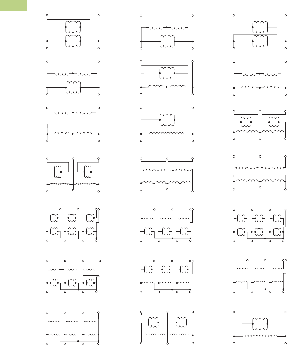
V2-T2-172 Volume 2—Commercial Distribution CA08100003E—June 2014 www.eaton.com
2
2
2
2
2
2
2
2
2
2
2
2
2
2
2
2
2
2
2
2
2
2
2
2
2
2
2
2
2
2
2.5
Transfor mers
Distribution Transformers
Wiring Diagrams
Buck-Boost Transformers Wiring Diagrams
Note
1WARNING! If input is three-wire, “neutral” connection must be isolated and insulated! When used to supply a three-phase, four-wire load, the source must be three-phase, four-wire wye.
H4 H3
H1H2
H4 H3
H1H2
Neutral
H4 H3
H1H2
High Voltage
Low Voltage
X2 X4 X2 X4 X2 X4
X1 X3 X1 X3 X1 X3
Low Voltage Neutral
High Voltage
X3 X4
X1 X2
X3 X4
X1 X2
X3 X4
X1 X2
H3 H1 H3 H1 H3 H1
H2 H4 H2 H4 H2H4
X1
H4 H3
H1H2
H4 H3
H1H2
Neutral
H4 H3
H1H2
X3 X1 X3 X1 X3
Low Voltage
High Voltage
X2 X4 X2 X4 X2 X4
Low Voltage Neutral
High Voltage
X3 X4
X1 X2
H4 H3
H1H2
X3 X4
X1 X2
H4 H3
H1H2
X3 X4
X1 X2
H4 H3
H1H2
X1
Neutral
X2
X3
X4
X1
X2
X3
X4
X1
X2
X3
X4
Low Voltage
High Voltage
H3
H2
H1
H4
H3
H2
H1
H4
H3
H2
H1
H4
High Voltage
Low Voltage
H4 H3 H2 H1 H1 H2 H3 H4
X1 X2 X3 X4 X4 X3 X2 X1
High Voltage
X3 X4
X2X1
H1
H2
Low Voltage
High Voltage
X3 X4
X2X1
H1H2H4 H3
Low Voltage
Low Voltage
High Voltage
X3 X4X2X1
H4 H3
H1H2
Low Voltage
High Voltage
X3 X4
X2X1
H4 H3
H1H2
Low Voltage
X3 X4X2X1
H4 H3
H1H2
High Voltage
Low Voltage
X3 X4X2X1
H1H2H4 H3
High Voltage
Neutral
X2 X4 X2 X4 X2 X4
High Voltage
Low Voltage
H3 H1 H3 H1 H3 H1
H2 H4 H2 H4 H2H4
X1 X3 X1 X3 X1 X3
Low Voltage
X3 X4
X1 X2
H4 H3
H1H2
X3 X4
X1 X2
H4 H3
H1H2
X3 X4
X1 X2
H4 H3
H1H2
Neutral
High Voltage
High Voltage
X3 X4
X2X1
H1
H4
Low Voltage
Low Voltage
X3 X4
X2X1
H4 H3
H1H2
High Voltage
Low Voltage
High Voltage
H4 H3 H2 H1 H1 H2 H3 H4
X4 X3 X2 X1X1 X2 X3 X4
Low Voltage
High Voltage
X3 X4X2X1
H1H2H4 H3
High Voltage
Low Voltage
X4 X3
X1X2
X3 X4
X2X1
H4 H3 H2 H1 H1 H2 H3 H4
High Voltage
Low Voltage
H4 H1 H1 H4
X4 X3
X1X2
X3 X4
X2X1
X4 X3
X3 X4
High Voltage
Low Voltage
H2 H1 H1 H2
X1
X2
X2X1
Diagram A Diagram B Diagram C
Diagram D Diagram E Diagram F
Diagram G Diagram H Diagram I
Diagram J Diagram K Diagram L
Diagram M 1Diagram N 1Diagram O 1
Diagram P 1Diagram Q 1Diagram R 1
Diagram S 1Diagram T Diagram U

Volume 2—Commercial Distribution CA08100003E—June 2014 www.eaton.com V2-T2-173
2
2
2
2
2
2
2
2
2
2
2
2
2
2
2
2
2
2
2
2
2
2
2
2
2
2
2
2
2
2
2.5
Trans for mers
Distribution Transformers
Contents
Description Page
Motor Drive Isolation Transformers . . . . . . . . . . . . V2-T2-111
Mini–Power Centers . . . . . . . . . . . . . . . . . . . . . . . V2-T2-119
Totally Enclosed Non-Ventilated Transformers. . . . V2-T2-124
Class I, Division 2, Hazardous Location Transformers V2-T2-127
Open-Type Core and Coil Assembly Transformers V2-T2-130
Marine Duty Transformers. . . . . . . . . . . . . . . . . . . V2-T2-133
Buck-Boost and Low Voltage Lighting Transformers V2-T2-144
Medium Voltage Distribution Transformers
Features, Benefits and Functions . . . . . . . . . . . V2-T2-174
Standards and Certifications. . . . . . . . . . . . . . . V2-T2-174
Product Description . . . . . . . . . . . . . . . . . . . . . V2-T2-175
Medium Voltage Distribution Transformers
Product Description
Note: The following pages
provide listings for most standard
transformer ratings and styles.
For other ratings or styles not
shown, or for special enclosure
types (including stainless steel),
refer to Eaton.
Single- and Three-Phase
●Ventilated, NEMA 3R
enclosure standard
●Suitable for indoor or
outdoor applications
●Upright mounting only
●220ºC insulation system
●150ºC rise standard;
115°C or 80°C rise optional
●Available in single-phase
ratings 15–333 kVA
●Available in single-phase
ratings 25–167 kVA; in
three-phase ratings
15–1500 kVA
Application Description
U.S. DOE 10 CFR Part 431
compliant energy-efficient
transformers are specifically
designed to meet the energy
efficiency standards set
forth in U.S. DOE 10 CFR Part
431. Compliant transformers
are optimized to offer
maximum efficiency at 50%
of nameplate rating.
Transformers that are
currently specifically excluded
from the scope of DOE 10
CFR Part 431 include:
●Liquid-filled transformers
below 10 kVA
●Dry-type transformers
below 15 kVA
●AC and DC drives
transformers
●Rectifier transformers
designed for high
harmonics
●Autotransformers
●Non-distribution
transformers, such as
UPS transformers
●Special impedance or
regulation transformers
●Regulating transformers
●Sealed and non-ventilated
transformers
●Machine tool transformers
●Welding transformers
●Transformers with tap
ranges greater than 15%
●Transformers with a
frequency other than 60 Hz
●Grounding transformers
●Testing transformers
DOE 10 CFR Part 431
Efficiency Levels
Tables of Energy Efficiency
Dry-Type Distribution Transformers—
20–45 kV BIL
Single-Phase Three-Phase
kVA Efficiency kVA Efficiency
15 98.10 15 97.50
25 98.33 30 97.90
37.5 98.49 45 98.10
50 98.60 75 98.33
75 98.73 112.5 98.49
100 98.82 150 98.60
167 98.96 225 98.73
250 99.07 300 98.82
333 99.14 500 98.96
— — 750 99.07
— — 1000 99.14
— — 1500 99.22

V2-T2-174 Volume 2—Commercial Distribution CA08100003E—June 2014 www.eaton.com
2
2
2
2
2
2
2
2
2
2
2
2
2
2
2
2
2
2
2
2
2
2
2
2
2
2
2
2
2
2
2.5
Transfor mers
Distribution Transformers
Features, Benefits
and Functions
●60 Hz operation (except
as noted)
●Short-term overload
capability as required
by ANSI
●Meet NEMA ST-20
sound levels
●Meet federal energy
efficiency requirements
for dry-type transformers
effective as of
January 1, 2010
Standards and Certifications
●UL listed
Industry Standards
All Eaton dry-type distribution
and control transformers are
built and tested in accordance
with applicable NEMA, ANSI
and IEEE Standards.
Seismically Qualified
Eaton manufactured dry-type
distribution transformers are
seismically qualified and
exceed requirements of the
International Building Code
(IBC) and California Code
Title 24.

Volume 2—Commercial Distribution CA08100003E—June 2014 www.eaton.com V2-T2-175
2
2
2
2
2
2
2
2
2
2
2
2
2
2
2
2
2
2
2
2
2
2
2
2
2
2
2
2
2
2
2.5
Trans for mers
Distribution Transformers
Product Description
Single-Phase—2010 Energy-Efficient
2400 Volts to 120/240 Volts—Aluminum Windings
4160 Volts to 120/240 Volts—Aluminum Windings
Note
Contact your local Eaton sales office for CE Mark transformer requirements. For other ratings or styles not shown, or for special enclosure types (including stainless steel), refer to Eaton.
Frame drawings/dimensions information begins on Page V2-T2-215.
kVA
Full Capacity Taps ºC Temp.
Rise Frame
Wiring Diagram
Number
Weight
Lbs (kg) Weathershield Style NumberFCAN FCBN
25 2 at +2.5% 2 at –2.5% 150 NH6 ——Included T42D11S25E3R
37.5 2 at +2.5% 2 at –2.5% 150 NH3 ——Included T42D11S37E3R
50 2 at +2.5% 2 at –2.5% 150 NH3 ——Included T42D11S50E3R
75 2 at +2.5% 2 at –2.5% 150 NH3 ——Included T42D11S75E3R
100 2 at +2.5% 2 at –2.5% 150 NH4 ——Included T42D11S99E3R
167 2 at +2.5% 2 at –2.5% 150 NJ1 ——Included T42D11S67E3R
25 2 at +2.5% 2 at –2.5% 115 NH6 ——Included T42D11F25E3R
37.5 2 at +2.5% 2 at –2.5% 115 NH3 ——Included T42D11F37E3R
50 2 at +2.5% 2 at –2.5% 115 NH3 ——Included T42D11F50E3R
75 2 at +2.5% 2 at –2.5% 115 NH3 ——Included T42D11F75E3R
100 2 at +2.5% 2 at –2.5% 115 NH4 ——Included T42D11F99E3R
167 2 at +2.5% 2 at –2.5% 115 NJ1 ——Included T42D11F67E3R
25 2 at +2.5% 2 at –2.5% 80 NH3 ——Included T42D11B25E3R
37.5 2 at +2.5% 2 at –2.5% 80 NH3 ——Included T42D11B37E3R
50 2 at +2.5% 2 at –2.5% 80 NH3 ——Included T42D11B50E3R
75 2 at +2.5% 2 at –2.5% 80 NH4 ——Included T42D11B75E3R
100 2 at +2.5% 2 at –2.5% 80 NJ1 ——Included T42D11B99E3R
167 2 at +2.5% 2 at –2.5% 80 NJ1 ——Included T42D11B67E3R
kVA
Full Capacity Taps ºC Temp.
Rise Frame
Wiring Diagram
Number
Weight
Lbs (kg) Weathershield Style NumberFCAN FCBN
25 2 at +2.5% 2 at –2.5% 150 NH6 ——Included T46D11S25E3R
37.5 2 at +2.5% 2 at –2.5% 150 NH3 ——IncludedT46D11S37E3R
50 2 at +2.5% 2 at –2.5% 150 NH3 ——Included T46D11S50E3R
75 2 at +2.5% 2 at –2.5% 150 NH3 ——Included T46D11S75E3R
100 2 at +2.5% 2 at –2.5% 150 NH4 ——Included T46D11S99E3R
167 2 at +2.5% 2 at –2.5% 150 NJ1 ——Included T46D11S67E3R
25 2 at +2.5% 2 at –2.5% 115 NH6 ——Included T46D11F25E3R
37.5 2 at +2.5% 2 at –2.5% 115 NH3 ——Included T46D11F37E3R
50 2 at +2.5% 2 at –2.5% 115 NH3 ——Included T46D11F50E3R
75 2 at +2.5% 2 at –2.5% 115 NH3 ——Included T46D11F75E3R
100 2 at +2.5% 2 at –2.5% 115 NH4 ——Included T46D11F99E3R
167 2 at +2.5% 2 at –2.5% 115 NJ1 ——Included T46D11F67E3R
25 2 at +2.5% 2 at –2.5% 80 NH3 ——Included T46D11B25E3R
37.5 2 at +2.5% 2 at –2.5% 80 NH3 ——Included T46D11B37E3R
50 2 at +2.5% 2 at –2.5% 80 NH3 ——Included T46D11B50E3R
75 2 at +2.5% 2 at –2.5% 80 NH4 ——Included T46D11B75E3R
100 2 at +2.5% 2 at –2.5% 80 NJ1 ——Included T46D11B99E3R
167 2 at +2.5% 2 at –2.5% 80 NJ1 ——Included T46D11B67E3R

V2-T2-176 Volume 2—Commercial Distribution CA08100003E—June 2014 www.eaton.com
2
2
2
2
2
2
2
2
2
2
2
2
2
2
2
2
2
2
2
2
2
2
2
2
2
2
2
2
2
2
2.5
Transfor mers
Distribution Transformers
Single-Phase—2010 Energy-Efficient
2400 Volts to 120/240 Volts—Copper Windings
4160 Volts to 120/240 Volts—Copper Windings
Note
Contact your local Eaton sales office for CE Mark transformer requirements. For other ratings or styles not shown, or for special enclosure types (including stainless steel), refer to Eaton.
Frame drawings/dimensions information begins on Page V2-T2-215.
kVA
Full Capacity Taps ºC Temp.
Rise Frame
Wiring Diagram
Number
Weight
Lbs (kg) Weathershield Style NumberFCAN FCBN
25 2 at +2.5% 2 at –2.5% 150 NH6 ——Included T42D11S25CUE3R
37.5 2 at +2.5% 2 at –2.5% 150 NH3 ——Included T42D11S37CUE3R
50 2 at +2.5% 2 at –2.5% 150 NH3 ——Included T42D11S50CUE3R
75 2 at +2.5% 2 at –2.5% 150 NH3 ——Included T42D11S75CUE3R
100 2 at +2.5% 2 at –2.5% 150 NH4 ——Included T42D11S99CUE3R
167 2 at +2.5% 2 at –2.5% 150 NJ1 ——Included T42D11S67CUE3R
25 2 at +2.5% 2 at –2.5% 115 NH6 ——Included T42D11F25CUE3R
37.5 2 at +2.5% 2 at –2.5% 115 NH3 ——Included T42D11F37CUE3R
50 2 at +2.5% 2 at –2.5% 115 NH3 ——Included T42D11F50CUE3R
75 2 at +2.5% 2 at –2.5% 115 NH3 ——Included T42D11F75CUE3R
100 2 at +2.5% 2 at –2.5% 115 NH4 ——Included T42D11F99CUE3R
167 2 at +2.5% 2 at –2.5% 115 NJ1 ——Included T42D11F67CUE3R
25 2 at +2.5% 2 at –2.5% 80 NH3 ——Included T42D11B25CUE3R
37.5 2 at +2.5% 2 at –2.5% 80 NH3 ——Included T42D11B37CUE3R
50 2 at +2.5% 2 at –2.5% 80 NH3 ——Included T42D11B50CUE3R
75 2 at +2.5% 2 at –2.5% 80 NH4 ——Included T42D11B75CUE3R
100 2 at +2.5% 2 at –2.5% 80 NJ1 ——Included T42D11B99CUE3R
167 2 at +2.5% 2 at –2.5% 80 NJ1 ——Included T42D11B67CUE3R
kVA
Full Capacity Taps ºC Temp.
Rise Frame
Wiring Diagram
Number
Weight
Lbs (kg) Weathershield Style NumberFCAN FCBN
25 2 at +2.5% 2 at –2.5% 150 NH6 ——Included T46D11S25CUE3R
37.5 2 at +2.5% 2 at –2.5% 150 NH3 ——Included T46D11S37CUE3R
50 2 at +2.5% 2 at –2.5% 150 NH3 ——Included T46D11S50CUE3R
75 2 at +2.5% 2 at –2.5% 150 NH3 ——Included T46D11S75CUE3R
100 2 at +2.5% 2 at –2.5% 150 NH4 ——Included T46D11S99CUE3R
167 2 at +2.5% 2 at –2.5% 150 NJ1 ——Included T46D11S67CUE3R
25 2 at +2.5% 2 at –2.5% 115 NH6 ——Included T46D11F25CUE3R
37.5 2 at +2.5% 2 at –2.5% 115 NH3 ——Included T46D11F37CUE3R
50 2 at +2.5% 2 at –2.5% 115 NH3 ——Included T46D11F50CUE3R
75 2 at +2.5% 2 at –2.5% 115 NH3 ——Included T46D11F75CUE3R
100 2 at +2.5% 2 at –2.5% 115 NH4 ——Included T46D11F99CUE3R
167 2 at +2.5% 2 at –2.5% 115 NJ1 ——Included T46D11F67CUE3R
25 2 at +2.5% 2 at –2.5% 80 NH3 ——Included T46D11B25CUE3R
37.5 2 at +2.5% 2 at –2.5% 80 NH3 ——Included T46D11B37CUE3R
50 2 at +2.5% 2 at –2.5% 80 NH3 ——Included T46D11B50CUE3R
75 2 at +2.5% 2 at –2.5% 80 NH4 ——Included T46D11B75CUE3R
100 2 at +2.5% 2 at –2.5% 80 NJ1 ——Included T46D11B99CUE3R
167 2 at +2.5% 2 at –2.5% 80 NJ1 ——Included T46D11B67CUE3R

Volume 2—Commercial Distribution CA08100003E—June 2014 www.eaton.com V2-T2-177
2
2
2
2
2
2
2
2
2
2
2
2
2
2
2
2
2
2
2
2
2
2
2
2
2
2
2
2
2
2
2.5
Trans for mers
Distribution Transformers
Three-Phase—2010 Energy-Efficient
2400 Delta Volts to 480Y/277 Volts—Copper Windings
Note
Contact your local Eaton sales office for CE Mark transformer requirements. For other ratings or styles not shown, or for special enclosure types (including stainless steel), refer to Eaton.
Frame drawings/dimensions information begins on Page V2-T2-215.
kVA
Full Capacity Taps ºC Temp.
Rise Frame
Wiring Diagram
Number
Weight
Lbs (kg) Weathershield Style NumberFCAN FCBN
45 2 at +2.5% 2 at –2.5% 150 NH3 ——Included V42D47T45CUE3R
75 2 at +2.5% 2 at –2.5% 150 NH4 ——Included V42D47T75CUE3R
112.5 2 at +2.5% 2 at –2.5% 150 NH4 ——Included V42D47T12CUE3R
150 2 at +2.5% 2 at –2.5% 150 NJ1 ——Included V42D47T49CUE3R
225 2 at +2.5% 2 at –2.5% 150 NJ1 ——Included V42D47T22CUE3R
300 2 at +2.5% 2 at –2.5% 150 NJ1 ——Included V42D47T33CUE3R
500 2 at +2.5% 2 at –2.5% 150 NJ2 ——Included V42D47T55CUE3R
750 2 at +2.5% 2 at –2.5% 150 NJ3 ——Included V42D47T77CUE3R
45 2 at +2.5% 2 at –2.5% 115 NH3 ——Included V42D47F45CUE3R
75 2 at +2.5% 2 at –2.5% 115 NH4 ——Included V42D47F75CUE3R
112.5 2 at +2.5% 2 at –2.5% 115 NH4 ——Included V42D47F12CUE3R
150 2 at +2.5% 2 at –2.5% 115 NJ1 ——Included V42D47F49CUE3R
225 2 at +2.5% 2 at –2.5% 115 NJ1 ——Included V42D47F22CUE3R
300 2 at +2.5% 2 at –2.5% 115 NJ1 ——Included V42D47F33CUE3R
500 2 at +2.5% 2 at –2.5% 115 NJ2 ——Included V42D47F55CUE3R
750 2 at +2.5% 2 at –2.5% 115 NJ3 ——Included V42D47F77CUE3R
45 2 at +2.5% 2 at –2.5% 80 NH4 ——Included V42D47B45CUE3R
75 2 at +2.5% 2 at –2.5% 80 NH4 ——Included V42D47B75CUE3R
112.5 2 at +2.5% 2 at –2.5% 80 NJ1 ——Included V42D47B12CUE3R
150 2 at +2.5% 2 at –2.5% 80 NJ1 ——Included V42D47B49CUE3R
225 2 at +2.5% 2 at –2.5% 80 NJ1 ——Included V42D47B22CUE3R
300 2 at +2.5% 2 at –2.5% 80 NJ2 ——Included V42D47B33CUE3R
500 2 at +2.5% 2 at –2.5% 80 NJ3 ——Included V42D47B55CUE3R
750 2 at +2.5% 2 at –2.5% 80 NJ3 ——Included V42D47B77CUE3R

V2-T2-178 Volume 2—Commercial Distribution CA08100003E—June 2014 www.eaton.com
2
2
2
2
2
2
2
2
2
2
2
2
2
2
2
2
2
2
2
2
2
2
2
2
2
2
2
2
2
2
2.5
Transfor mers
Distribution Transformers
Three-Phase—2010 Energy-Efficient
4160 Delta Volts to 480Y/277 Volts—Copper Windings
Note
Contact your local Eaton sales office for CE Mark transformer requirements. For other ratings or styles not shown, or for special enclosure types (including stainless steel), refer to Eaton.
Frame drawings/dimensions information begins on Page V2-T2-215.
kVA
Full Capacity Taps ºC Temp.
Rise Frame
Wiring Diagram
Number
Weight
Lbs (kg) Weathershield Style NumberFCAN FCBN
45 2 at +2.5% 2 at –2.5% 150 NH3 ——Included V46D47T45CUE3R
75 2 at +2.5% 2 at –2.5% 150 NH4 ——Included V46D47T75CUE3R
112.5 2 at +2.5% 2 at –2.5% 150 NH4 ——Included V46D47T12CUE3R
150 2 at +2.5% 2 at –2.5% 150 NJ1 ——Included V46D47T49CUE3R
225 2 at +2.5% 2 at –2.5% 150 NJ1 ——Included V46D47T22CUE3R
300 2 at +2.5% 2 at –2.5% 150 NJ1 ——Included V46D47T33CUE3R
500 2 at +2.5% 2 at –2.5% 150 NJ2 ——Included V46D47T55CUE3R
750 2 at +2.5% 2 at –2.5% 150 NJ3 ——Included V46D47T77CUE3R
45 2 at +2.5% 2 at –2.5% 115 NH3 ——Included V46D47F45CUE3R
75 2 at +2.5% 2 at –2.5% 115 NH4 ——Included V46D47F75CUE3R
112.5 2 at +2.5% 2 at –2.5% 115 NH4 ——Included V46D47F12CUE3R
150 2 at +2.5% 2 at –2.5% 115 NJ1 ——Included V46D47F49CUE3R
225 2 at +2.5% 2 at –2.5% 115 NJ1 ——Included V46D47F22CUE3R
300 2 at +2.5% 2 at –2.5% 115 NJ1 ——Included V46D47F33CUE3R
500 2 at +2.5% 2 at –2.5% 115 NJ2 ——Included V46D47F55CUE3R
750 2 at +2.5% 2 at –2.5% 115 NJ3 ——Included V46D47F77CUE3R
45 2 at +2.5% 2 at –2.5% 80 NH4 ——Included V46D47B45CUE3R
75 2 at +2.5% 2 at –2.5% 80 NH4 ——Included V46D47B75CUE3R
112.5 2 at +2.5% 2 at –2.5% 80 NJ1 ——Included V46D47B12CUE3R
150 2 at +2.5% 2 at –2.5% 80 NJ1 ——Included V46D47B49CUE3R
225 2 at +2.5% 2 at –2.5% 80 NJ1 ——Included V46D47B22CUE3R
300 2 at +2.5% 2 at –2.5% 80 NJ2 ——Included V46D47B33CUE3R
500 2 at +2.5% 2 at –2.5% 80 NJ3 ——Included V46D47B55CUE3R
750 2 at +2.5% 2 at –2.5% 80 NJ3 ——Included V46D47B77CUE3R

Volume 2—Commercial Distribution CA08100003E—June 2014 www.eaton.com V2-T2-179
2
2
2
2
2
2
2
2
2
2
2
2
2
2
2
2
2
2
2
2
2
2
2
2
2
2
2
2
2
2
2.5
Trans for mers
Distribution Transformers
Three-Phase—2010 Energy-Efficient
2400 Delta Volts to 208Y/120 Volts—Copper Windings
Note
Contact your local Eaton sales office for CE Mark transformer requirements. For other ratings or styles not shown, or for special enclosure types (including stainless steel), refer to Eaton.
Frame drawings/dimensions information begins on Page V2-T2-215.
kVA
Full Capacity Taps ºC Temp.
Rise Frame
Wiring Diagram
Number
Weight
Lbs (kg) Weathershield Style NumberFCAN FCBN
45 2 at +2.5% 2 at –2.5% 150 NH3 ——Included V42D28T45CUE3R
75 2 at +2.5% 2 at –2.5% 150 NH4 ——Included V42D28T75CUE3R
112.5 2 at +2.5% 2 at –2.5% 150 NH4 ——Included V42D28T12CUE3R
150 2 at +2.5% 2 at –2.5% 150 NJ1 ——Included V42D28T49CUE3R
225 2 at +2.5% 2 at –2.5% 150 NJ1 ——Included V42D28T22CUE3R
300 2 at +2.5% 2 at –2.5% 150 NJ1 ——Included V42D28T33CUE3R
500 2 at +2.5% 2 at –2.5% 150 NJ2 ——Included V42D28T55CUE3R
750 2 at +2.5% 2 at –2.5% 150 NJ3 ——Included V42D28T77CUE3R
45 2 at +2.5% 2 at –2.5% 115 NH3 ——Included V42D28F45CUE3R
75 2 at +2.5% 2 at –2.5% 115 NH4 ——Included V42D28F75CUE3R
112.5 2 at +2.5% 2 at –2.5% 115 NH4 ——Included V42D28F12CUE3R
150 2 at +2.5% 2 at –2.5% 115 NJ1 ——Included V42D28F49CUE3R
225 2 at +2.5% 2 at –2.5% 115 NJ1 ——Included V42D28F22CUE3R
300 2 at +2.5% 2 at –2.5% 115 NJ1 ——Included V42D28F33CUE3R
500 2 at +2.5% 2 at –2.5% 115 NJ2 ——Included V42D28F55CUE3R
750 2 at +2.5% 2 at –2.5% 115 NJ3 ——Included V42D28F77CUE3R
45 2 at +2.5% 2 at –2.5% 80 NH4 ——Included V42D28B45CUE3R
75 2 at +2.5% 2 at –2.5% 80 NH4 ——Included V42D28B75CUE3R
112.5 2 at +2.5% 2 at –2.5% 80 NJ1 ——Included V42D28B12CUE3R
150 2 at +2.5% 2 at –2.5% 80 NJ1 ——Included V42D28B49CUE3R
225 2 at +2.5% 2 at –2.5% 80 NJ1 ——Included V42D28B22CUE3R
300 2 at +2.5% 2 at –2.5% 80 NJ2 ——Included V42D28B33CUE3R
500 2 at +2.5% 2 at –2.5% 80 NJ3 ——Included V42D28B55CUE3R
750 2 at +2.5% 2 at –2.5% 80 NJ3 ——Included V42D28B77CUE3R

V2-T2-180 Volume 2—Commercial Distribution CA08100003E—June 2014 www.eaton.com
2
2
2
2
2
2
2
2
2
2
2
2
2
2
2
2
2
2
2
2
2
2
2
2
2
2
2
2
2
2
2.5
Transfor mers
Distribution Transformers
Three-Phase—2010 Energy-Efficient
4160 Delta Volts to 208Y/120 Volts—Copper Windings
Note
Contact your local Eaton sales office for CE Mark transformer requirements. For other ratings or styles not shown, or for special enclosure types (including stainless steel), refer to Eaton.
Frame drawings/dimensions information begins on Page V2-T2-215.
kVA
Full Capacity Taps ºC Temp.
Rise Frame
Wiring Diagram
Number
Weight
Lbs (kg) Weathershield Style NumberFCAN FCBN
45 2 at +2.5% 2 at –2.5% 150 NH3 ——Included V46D28T45CUE3R
75 2 at +2.5% 2 at –2.5% 150 NH4 ——Included V46D28T75CUE3R
112.5 2 at +2.5% 2 at –2.5% 150 NH4 ——Included V46D28T12CUE3R
150 2 at +2.5% 2 at –2.5% 150 NJ1 ——Included V46D28T49CUE3R
225 2 at +2.5% 2 at –2.5% 150 NJ1 ——Included V46D28T22CUE3R
300 2 at +2.5% 2 at –2.5% 150 NJ1 ——Included V46D28T33CUE3R
500 2 at +2.5% 2 at –2.5% 150 NJ2 ——Included V46D28T55CUE3R
750 2 at +2.5% 2 at –2.5% 150 NJ3 ——Included V46D28T77CUE3R
45 2 at +2.5% 2 at –2.5% 115 NH3 ——Included V46D28F45CUE3R
75 2 at +2.5% 2 at –2.5% 115 NH4 ——Included V46D28F75CUE3R
112.5 2 at +2.5% 2 at –2.5% 115 NH4 ——Included V46D28F12CUE3R
150 2 at +2.5% 2 at –2.5% 115 NJ1 ——Included V46D28F49CUE3R
225 2 at +2.5% 2 at –2.5% 115 NJ1 ——Included V46D28F22CUE3R
300 2 at +2.5% 2 at –2.5% 115 NJ1 ——Included V46D28F33CUE3R
500 2 at +2.5% 2 at –2.5% 115 NJ2 ——Included V46D28F55CUE3R
750 2 at +2.5% 2 at –2.5% 115 NJ3 ——Included V46D28F77CUE3R
45 2 at +2.5% 2 at –2.5% 80 NH4 ——Included V46D28B45CUE3R
75 2 at +2.5% 2 at –2.5% 80 NH4 ——Included V46D28B75CUE3R
112.5 2 at +2.5% 2 at –2.5% 80 NJ1 ——Included V46D28B12CUE3R
150 2 at +2.5% 2 at –2.5% 80 NJ1 ——Included V46D28B49CUE3R
225 2 at +2.5% 2 at –2.5% 80 NJ1 ——Included V46D28B22CUE3R
300 2 at +2.5% 2 at –2.5% 80 NJ2 ——Included V46D28B33CUE3R
500 2 at +2.5% 2 at –2.5% 80 NJ3 ——Included V46D28B55CUE3R
750 2 at +2.5% 2 at –2.5% 80 NJ3 ——Included V46D28B77CUE3R

Volume 2—Commercial Distribution CA08100003E—June 2014 www.eaton.com V2-T2-181
2
2
2
2
2
2
2
2
2
2
2
2
2
2
2
2
2
2
2
2
2
2
2
2
2
2
2
2
2
2
2.5
Trans for mers
Distribution Transformers
Three-Phase—2010 Energy-Efficient
2400 Delta Volts to 480Y/277 Volts—Aluminum Windings
Note
Contact your local Eaton sales office for CE Mark transformer requirements. For other ratings or styles not shown, or for special enclosure types (including stainless steel), refer to Eaton.
Frame drawings/dimensions information begins on Page V2-T2-215.
kVA
Full Capacity Taps ºC Temp.
Rise Frame
Wiring Diagram
Number
Weight
Lbs (kg) Weathershield Style NumberFCAN FCBN
45 2 at +2.5% 2 at –2.5% 150 NH3 ——Included V42D47T45E3R
75 2 at +2.5% 2 at –2.5% 150 NH4 ——Included V42D47T75E3R
112.5 2 at +2.5% 2 at –2.5% 150 NH4 ——Included V42D47T12E3R
150 2 at +2.5% 2 at –2.5% 150 NJ1 ——Included V42D47T49E3R
225 2 at +2.5% 2 at –2.5% 150 NJ1 ——Included V42D47T22E3R
300 2 at +2.5% 2 at –2.5% 150 NJ1 ——Included V42D47T33E3R
500 2 at +2.5% 2 at –2.5% 150 NJ2 ——Included V42D47T55E3R
750 2 at +2.5% 2 at –2.5% 150 NJ3 ——Included V42D47T77E3R
45 2 at +2.5% 2 at –2.5% 115 NH3 ——Included V42D47F45E3R
75 2 at +2.5% 2 at –2.5% 115 NH4 ——Included V42D47F75E3R
112.5 2 at +2.5% 2 at –2.5% 115 NH4 ——Included V42D47F12E3R
150 2 at +2.5% 2 at –2.5% 115 NJ1 ——Included V42D47F49E3R
225 2 at +2.5% 2 at –2.5% 115 NJ1 ——Included V42D47F22E3R
300 2 at +2.5% 2 at –2.5% 115 NJ1 ——Included V42D47F33E3R
500 2 at +2.5% 2 at –2.5% 115 NJ2 ——Included V42D47F55E3R
750 2 at +2.5% 2 at –2.5% 115 NJ3 ——Included V42D47F77E3R
45 2 at +2.5% 2 at –2.5% 80 NH4 ——Included V42D47B45E3R
75 2 at +2.5% 2 at –2.5% 80 NH4 ——Included V42D47B75E3R
112.5 2 at +2.5% 2 at –2.5% 80 NJ1 ——Included V42D47B12E3R
150 2 at +2.5% 2 at –2.5% 80 NJ1 ——Included V42D47B49E3R
225 2 at +2.5% 2 at –2.5% 80 NJ1 ——Included V42D47B22E3R
300 2 at +2.5% 2 at –2.5% 80 NJ2 ——Included V42D47B33E3R
500 2 at +2.5% 2 at –2.5% 80 NJ3 ——Included V42D47B55E3R
750 2 at +2.5% 2 at –2.5% 80 NJ3 ——Included V42D47B77E3R

V2-T2-182 Volume 2—Commercial Distribution CA08100003E—June 2014 www.eaton.com
2
2
2
2
2
2
2
2
2
2
2
2
2
2
2
2
2
2
2
2
2
2
2
2
2
2
2
2
2
2
2.5
Transfor mers
Distribution Transformers
Three-Phase—2010 Energy-Efficient
4160 Delta Volts to 480Y/277 Volts—Aluminum Windings
Note
Contact your local Eaton sales office for CE Mark transformer requirements. For other ratings or styles not shown, or for special enclosure types (including stainless steel), refer to Eaton.
Frame drawings/dimensions information begins on Page V2-T2-215.
kVA
Full Capacity Taps ºC Temp.
Rise Frame
Wiring Diagram
Number
Weight
Lbs (kg) Weathershield Style NumberFCAN FCBN
45 2 at +2.5% 2 at –2.5% 150 NH3 ——Included V46D47T45E3R
75 2 at +2.5% 2 at –2.5% 150 NH4 ——Included V46D47T75E3R
112.5 2 at +2.5% 2 at –2.5% 150 NH4 ——Included V46D47T12E3R
150 2 at +2.5% 2 at –2.5% 150 NJ1 ——Included V46D47T49E3R
225 2 at +2.5% 2 at –2.5% 150 NJ1 ——Included V46D47T22E3R
300 2 at +2.5% 2 at –2.5% 150 NJ1 ——Included V46D47T33E3R
500 2 at +2.5% 2 at –2.5% 150 NJ2 ——Included V46D47T55E3R
750 2 at +2.5% 2 at –2.5% 150 NJ3 ——Included V46D47T77E3R
45 2 at +2.5% 2 at –2.5% 115 NH3 ——Included V46D47F45E3R
75 2 at +2.5% 2 at –2.5% 115 NH4 ——Included V46D47F75E3R
112.5 2 at +2.5% 2 at –2.5% 115 NH4 ——Included V46D47F12E3R
150 2 at +2.5% 2 at –2.5% 115 NJ1 ——Included V46D47F49E3R
225 2 at +2.5% 2 at –2.5% 115 NJ1 ——Included V46D47F22E3R
300 2 at +2.5% 2 at –2.5% 115 NJ1 ——Included V46D47F33E3R
500 2 at +2.5% 2 at –2.5% 115 NJ2 ——Included V46D47F55E3R
750 2 at +2.5% 2 at –2.5% 115 NJ3 ——Included V46D47F77E3R
45 2 at +2.5% 2 at –2.5% 80 NH4 ——Included V46D47B45E3R
75 2 at +2.5% 2 at –2.5% 80 NH4 ——Included V46D47B75E3R
112.5 2 at +2.5% 2 at –2.5% 80 NJ1 ——Included V46D47B12E3R
150 2 at +2.5% 2 at –2.5% 80 NJ1 ——Included V46D47B49E3R
225 2 at +2.5% 2 at –2.5% 80 NJ1 ——Included V46D47B22E3R
300 2 at +2.5% 2 at –2.5% 80 NJ2 ——Included V46D47B33E3R
500 2 at +2.5% 2 at –2.5% 80 NJ3 ——Included V46D47B55E3R
750 2 at +2.5% 2 at –2.5% 80 NJ3 ——Included V46D47B77E3R

Volume 2—Commercial Distribution CA08100003E—June 2014 www.eaton.com V2-T2-183
2
2
2
2
2
2
2
2
2
2
2
2
2
2
2
2
2
2
2
2
2
2
2
2
2
2
2
2
2
2
2.5
Trans for mers
Distribution Transformers
Three-Phase—2010 Energy-Efficient
2400 Delta Volts to 208Y/120 Volts—Aluminum Windings
Note
Contact your local Eaton sales office for CE Mark transformer requirements. For other ratings or styles not shown, or for special enclosure types (including stainless steel), refer to Eaton.
Frame drawings/dimensions information begins on Page V2-T2-215.
kVA
Full Capacity Taps ºC Temp.
Rise Frame
Wiring Diagram
Number
Weight
Lbs (kg) Weathershield Style NumberFCAN FCBN
45 2 at +2.5% 2 at –2.5% 150 NH3 ——Included V42D28T45E3R
75 2 at +2.5% 2 at –2.5% 150 NH4 ——Included V42D28T75E3R
112.5 2 at +2.5% 2 at –2.5% 150 NH4 ——Included V42D28T12E3R
150 2 at +2.5% 2 at –2.5% 150 NJ1 ——Included V42D28T49E3R
225 2 at +2.5% 2 at –2.5% 150 NJ1 ——Included V42D28T22E3R
300 2 at +2.5% 2 at –2.5% 150 NJ1 ——Included V42D28T33E3R
500 2 at +2.5% 2 at –2.5% 150 NJ2 ——Included V42D28T55E3R
750 2 at +2.5% 2 at –2.5% 150 NJ3 ——Included V42D28T77E3R
45 2 at +2.5% 2 at –2.5% 115 NH3 ——Included V42D28F45E3R
75 2 at +2.5% 2 at –2.5% 115 NH4 ——Included V42D28F75E3R
112.5 2 at +2.5% 2 at –2.5% 115 NH4 ——Included V42D28F12E3R
150 2 at +2.5% 2 at –2.5% 115 NJ1 ——Included V42D28F49E3R
225 2 at +2.5% 2 at –2.5% 115 NJ1 ——Included V42D28F22E3R
300 2 at +2.5% 2 at –2.5% 115 NJ1 ——Included V42D28F33E3R
500 2 at +2.5% 2 at –2.5% 115 NJ2 ——Included V42D28F55E3R
750 2 at +2.5% 2 at –2.5% 115 NJ3 ——Included V42D28F77E3R
45 2 at +2.5% 2 at –2.5% 80 NH4 ——Included V42D28B45E3R
75 2 at +2.5% 2 at –2.5% 80 NH4 ——Included V42D28B75E3R
112.5 2 at +2.5% 2 at –2.5% 80 NJ1 ——Included V42D28B12E3R
150 2 at +2.5% 2 at –2.5% 80 NJ1 ——Included V42D28B49E3R
225 2 at +2.5% 2 at –2.5% 80 NJ1 ——Included V42D28B22E3R
300 2 at +2.5% 2 at –2.5% 80 NJ2 ——Included V42D28B33E3R
500 2 at +2.5% 2 at –2.5% 80 NJ3 ——Included V42D28B55E3R
750 2 at +2.5% 2 at –2.5% 80 NJ3 ——Included V42D28B77E3R

V2-T2-184 Volume 2—Commercial Distribution CA08100003E—June 2014 www.eaton.com
2
2
2
2
2
2
2
2
2
2
2
2
2
2
2
2
2
2
2
2
2
2
2
2
2
2
2
2
2
2
2.5
Transfor mers
Distribution Transformers
Three-Phase—2010 Energy-Efficient
4160 Delta Volts to 208Y/120 Volts—Aluminum Windings
Note
Contact your local Eaton sales office for CE Mark transformer requirements. For other ratings or styles not shown, or for special enclosure types (including stainless steel), refer to Eaton.
Frame drawings/dimensions information begins on Page V2-T2-215.
kVA
Full Capacity Taps ºC Temp.
Rise Frame
Wiring Diagram
Number
Weight
Lbs (kg) Weathershield Style NumberFCAN FCBN
45 2 at +2.5% 2 at –2.5% 150 NH3 ——Included V46D28T45E3R
75 2 at +2.5% 2 at –2.5% 150 NH4 ——Included V46D28T75E3R
112.5 2 at +2.5% 2 at –2.5% 150 NH4 ——Included V46D28T12E3R
150 2 at +2.5% 2 at –2.5% 150 NJ1 ——Included V46D28T49E3R
225 2 at +2.5% 2 at –2.5% 150 NJ1 ——Included V46D28T22E3R
300 2 at +2.5% 2 at –2.5% 150 NJ1 ——Included V46D28T33E3R
500 2 at +2.5% 2 at –2.5% 150 NJ2 ——Included V46D28T55E3R
750 2 at +2.5% 2 at –2.5% 150 NJ3 ——Included V46D28T77E3R
45 2 at +2.5% 2 at –2.5% 115 NH3 ——Included V46D28F45E3R
75 2 at +2.5% 2 at –2.5% 115 NH4 ——Included V46D28F75E3R
112.5 2 at +2.5% 2 at –2.5% 115 NH4 ——Included V46D28F12E3R
150 2 at +2.5% 2 at –2.5% 115 NJ1 ——Included V46D28F49E3R
225 2 at +2.5% 2 at –2.5% 115 NJ1 ——Included V46D28F22E3R
300 2 at +2.5% 2 at –2.5% 115 NJ1 ——Included V46D28F33E3R
500 2 at +2.5% 2 at –2.5% 115 NJ2 ——Included V46D28F55E3R
750 2 at +2.5% 2 at –2.5% 115 NJ3 ——Included V46D28F77E3R
45 2 at +2.5% 2 at –2.5% 80 NH4 ——Included V46D28B45E3R
75 2 at +2.5% 2 at –2.5% 80 NH4 ——Included V46D28B75E3R
112.5 2 at +2.5% 2 at –2.5% 80 NJ1 ——Included V46D28B12E3R
150 2 at +2.5% 2 at –2.5% 80 NJ1 ——Included V46D28B49E3R
225 2 at +2.5% 2 at –2.5% 80 NJ1 ——Included V46D28B22E3R
300 2 at +2.5% 2 at –2.5% 80 NJ2 ——Included V46D28B33E3R
500 2 at +2.5% 2 at –2.5% 80 NJ3 ——Included V46D28B55E3R
750 2 at +2.5% 2 at –2.5% 80 NJ3 ——Included V46D28B77E3R
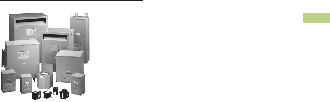
Volume 2—Commercial Distribution CA08100003E—June 2014 www.eaton.com V2-T2-185
2
2
2
2
2
2
2
2
2
2
2
2
2
2
2
2
2
2
2
2
2
2
2
2
2
2
2
2
2
2
2.6
Trans for mers
Transformer Standards, Technical Data and Accessories
Dry-Type Distribution Transformers
Contents
Description Page
Standards and Certifications . . . . . . . . . . . . . . . . . V2-T2-186
Catalog Number Selection. . . . . . . . . . . . . . . . . . . V2-T2-187
Product Selection . . . . . . . . . . . . . . . . . . . . . . . . . V2-T2-189
Options and Accessories. . . . . . . . . . . . . . . . . . . . V2-T2-191
Technical Data and Specifications . . . . . . . . . . . . . V2-T2-194
Glossary of Transformer Terms . . . . . . . . . . . . . . . V2-T2-210
Frequently Asked Questions About Transformers. V2-T2-213
V2-T2-186 Volume 2—Commercial Distribution CA08100003E—June 2014 www.eaton.com
2
2
2
2
2
2
2
2
2
2
2
2
2
2
2
2
2
2
2
2
2
2
2
2
2
2
2
2
2
2
2.6
Transfor mers
Transformer Standards, Technical Data and Accessories
Standards and Certifications
Eaton dry-type distribution transformers are approved, listed, recognized or may comply with the following standards.
Engineering Standards
Notes
1UL 5085 replaces UL 506.
2Applies to 25–50 kVA.
3Applies to 25 kVA.
4Applies to 15–25 kVA.
5Applies to 37.5 kVA.
6Applies to 3 kVA.
7Applies to 5–9 kVA.
8Applies to 30–75 kVA.
9Applies to 30 kVA.
In addition to the above standards, Eaton
dry-type distribution transformers are also
manufactured in compliance with the
applicable standards listed below.
Not all of the following standards apply
to every transformer.
NEC: National Electrical Code
NEMA ST-1: Specialty Transformers (C89.1)
(control transformers).
NEMA ST-20: General-Purpose
Transformers.
NEMA TP-1: Guide for Determining Energy
Efficiency for Distribution Transformers.
NEMA 250: Enclosures for Electrical
Equipment (1000 volts maximum).
IEEE C57.12.01: General Requirements
for Dry-Type Distribution and Power
Transformers (including those with solid-
cast and/or resin-encapsulated windings).
ANSI C57.12.70: Terminal Markings and
Connections for Distribution and Power
Transformers.
ANSI C57.12.91: Standard Test Code
for Dry-Type Distribution and Power
Transformers.
CSA C22 No. 47-M90: Air-Cooled
Transformers (Dry-Type).
CSA C9-M1981: Dry-Type Transformers.
CSA C22.2 No. 66: Specialty Transformers.
CSA 802-94: Maximum Losses for
Distribution, Power and Dry-Type
Transformers.
NEMA TP-2: Standard Test Method for
Measuring the Energy Consumption of
Distribution Transformers.
NEMA TP-3
Catalog
Product
Name
UL
Standard 1
UL/cUL
File
Number
UL Listed
Control
Number
cUL Energy
Efficiency
File Number
CSA
File
Number
Insulation
System
Temp/ºC
kVA
Single-
Phase
kVA
Three-
Phase
Applicable
IEC
Standard
Industrial Control Transformer
MTE 5085 E46323 702X — LR27533 105 0.025–1.5 N/A 61558
MTK 5085 E46323 702X — LR27533 180 0.05–5 N/A 61558
Encapsulated Transformer
AP 5085 E10156 591H — — 180 3–10 N/A 61558
AP 1561 E78389 591H — — 180 15 N/A 61558
EP 5085 E10156 591H — LR60545 180 0.05–10 N/A 61558
EP 1561 E78389 591H EV157 2LR60545 3180 15–50 N/A 61558 4 / 726 5
EPT 5085 E10156 591H — LR60545 180 N/A 3–9 61558 6 / 726 7
EPT 1561 E78389 591H EV157 8LR60545 9180 N/A 15–75 726
MPC 1062 E53449 591H — LR60546 180 3–25 15–30 —
Ventilated Transformer
DS-3 1561 E78389 591H — — 220 15–167 N/A 60726
DT-3 1561 E78389 591H — — 220 N/A 15–750 60726
KT 1561 E78389 591H — — 220 N/A 9–500 N/A
Volume 2—Commercial Distribution CA08100003E—June 2014 www.eaton.com V2-T2-187
2
2
2
2
2
2
2
2
2
2
2
2
2
2
2
2
2
2
2
2
2
2
2
2
2
2
2
2
2
2
2.6
Trans for mers
Transformer Standards, Technical Data and Accessories
Catalog Number Selection
General-Purpose, Energy-Efficient, Mini–Power Center, Shielded Isolation, Nonlinear, Buck-Boost, Marine Duty Transformers—
Example: S20N11S05A
Notes
1Model number is not used on newly
designed/redesigned transformers.
2Copper windings.
3Grade 304 stainless steel enclosure
(does not imply a NEMA 4X rating).
4Open type core and coil assembly.
5Totally enclosed non-ventilated DS-3
or DT-3.
650/60 Hz.
7Low sound design. LS47 indicates low
sound equal to 47 dB; LS42 indicates
42 dB.
8Fungus proof.
9Certified test report of standard
production tests for the specific serial
number to be shipped.
jCertified sound level report.
kCE Marked.
lThermal indicator embedded in center
coil. Suffix “TT” indicates two thermal
indicators of different temperature
ratings, are installed.
mNEMA TP-1 efficient.
n0° phase-shift (used with HMTs).
o+15° phase-shift (used with HMTs).
p–15° phase-shift (used with HMTs).
q–30° phase-shift (used with HMTs).
rCSL3 DOE 2007 energy-efficient.
sNEMA 4X Grade 304 stainless steel
enclosure.
tEasy install base.
BK Grade 316 stainless steel enclosure
(does not imply NEMA 4X rating).
BL Integral 2-inch infrared viewing window.
BM Integral 3-inch infrared viewing window.
BN Integral 4-inch infrared viewing window.
BO NEMA Premium® Efficient.
For Eaton’s industrial control transformers
catalog number selection, see Page
V2-T2-188.
Contact your local Eaton sales office for
voltage combinations not shown. Use table
for catalog number breakdown only.
Do not use to create catalog numbers
because all combinations may not be valid.
Suffix Options
A...Y =1
CU =2
SS =3
ZZ =4
NV =5
X=6
LS_ _ =7
AF =8
TR =9
SR =j
CE =k
T=l
EE =m
NON =n
POS =o
NEG =p
THR =q
E3 =r
SS4X =s
Z=t
S6 =BK
I2 =BL
I3 =BM
I4 =BN
N3 =BO
T S 20 N 11 S 05 A
Prefix Options
C= CSA labeled ventilated transformer
Marine Duty
QS = EPM marine (1-Ph encapsulated)
LY = EPTM Marine (3-Ph encapsulated)
RT = DS-3M marine (1-Ph ventilated)
MV = DT-3M marine (3-Ph ventilated)
Type
S= EP (single-phase encapsulated)
Y= EPT (three-phase encapsulated)
T= DS-3 (single-phase ventilated)
V= DT-3 (three-phase ventilated)
P= Mini–power center
Z= Class 1 Division 2 Groups A, B, C, D
X= Harmonic mitigating
(three-phase ventilated)
Nonlinear
H= KT-4 (three-phase ventilated)
B= KT-9 (three-phase ventilated)
N= KT-13 (three-phase ventilated)
G= KT-20 (three-phase ventilated)
J= KT-30 (three-phase ventilated)
A= KT-40 (three-phase ventilated)
K= KT-50 (three-phase ventilated)
HT = KT-4 (single-phase ventilated)
NT = KT-13 (single-phase ventilated)
GT = KT-20 (single-phase ventilated)
Primary Voltage
13 = 110 x 220
12 =120
10 = 120 x 240
29 =208
72 =200
25 =220
23 =230
24 =240
20 = 240 x 480
27 =277
38 =380
39 =400
43 =416
44 =440
45 =450
48 =480
57 =575
60 =600
42 = 2400
46 = 4160
49 = 4800
40 = Export model
54 = 120/208/240/277
Taps
D= 2 at +2.5%, 2 at –2.5%
E= 1 at +5%, 1 at –5%
F= 1 at –10%
G= 2 at –5%
J= 4 at –2.5%
K= 1 at –10% x 2 at –5%
L= 2 at –5% x 4 at –2.5%
M= 2 at +2.5%, 4 at –2.5%
N=None
R= 1 at +5%, 2 at –5%
P= 1 at +5%, 2 at –5% x
2 at +2.5%, 4 at –2.5%
T= 1 at +4.2%, 1 at –4.2%
U= 1 at +2.5%, 3 at –2.5%
W= 1 at +3.5%, 1 at –3.5%
X= 2 at +3.1%, 2 at –3.1%
Temperature Rise
T= 150°C rise with 220°C
insulation system
(ventilated)
F= 115°C rise with 220°C
insulation system
(ventilated)
B= 80°C rise with 220°C
insulation system
(ventilated)
H= 130°C rise with 200°C
insulation system
(ventilated)
G= 115°C rise with 200°C
insulation system
(ventilated)
J= 80°C rise with 220°C
insulation system
(ventilated)
P= 115°C rise with 130°C
insulation system
(encapsulated)
S= 115°C rise with 180°C
insulation system
(encapsulated and
MPC)
L= 80°C rise with 180°C
insulation system
(encapsulated and
MPC)
kVA
81 =0.05
85 = 0.075
82 =0.10
83 =0.15
26 =0.25
51 =0.50
76 =0.75
01 =1
16 =1.5
02 =2
03 =3
05 =5
06 =6
07 =7.5
09 =9
10 =10
15 =15
21 = 22.5
25 =25
30 =30
37 =37.5
45 =45
50 =50
75 =75
99 =100
12 = 112.5
49 =150
67 =167
22 =225
52 = 250
33 = 300
54 = 333
55 = 500
60 = 600
77 = 750
11 = 1000
14 = 1500
Secondary Voltage
04 = 12/24
06 = 16/32
08 = 24/48
14 = 110/220
12 = 120
10 = 120 x 240
11 = 120/240
54 = 127/254
19 = 190Y/110
28 = 208Y/120
29 = 208
25 = 220 delta
31 = 220Y/127
26 = 220 delta/110 midtap
22 = 240 delta/120 midtap
64 = 240Y/139
24 = 240 delta
20 = 240 x 480
21 = 240/480
27 = 277
38 = 380 delta
37 = 380Y/220
34 = 400Y/231
51 = 416Y/240
35 = 440Y/254
62 = 460Y/266
47 = 480Y/277
48 = 480 delta
60 = 600 delta
61 = 600Y/346
42 = 2400
41 = 4160Y/2400
46 = 4160
49 = 4800
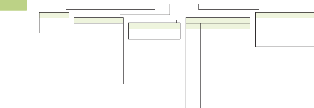
V2-T2-188 Volume 2—Commercial Distribution CA08100003E—June 2014 www.eaton.com
2
2
2
2
2
2
2
2
2
2
2
2
2
2
2
2
2
2
2
2
2
2
2
2
2
2
2
2
2
2
2.6
Transfor mers
Transformer Standards, Technical Data and Accessories
Motor Drive Isolation Transformers—Example: MD145E89B
Notes
1For other tap combinations, contact your local Eaton sales office.
Contact your local Eaton sales office for voltage combinations not shown. Use table for catalog number
breakdown only. Do not use to create catalog numbers because all combinations may not be valid.
Suffix Options
Y= Encapsulated (Type EPT) design
ES = Electrostatic shield
CU= Copper windings
F= 115°C rise
B=80°C rise
X= 50/60 Hz
MD 145 E89 B
Type
MD = DT-3
HD =KT-4
ND =KT-13
kVA
075 =7.5
11 =11
14 =14
20 =20
27 =27
34 =34
40 =40
51 =51
63 =63
75 =75
93 =93
118 =118
145 =145
175 =175
220 =220
275 =275
330 =330
440 =440
550 =550
660 =660
770 =770
880 =880
1000 = 1000
1250 = 1250
1500 = 1500
Voltage
Primary Secondary
82
83
84
85
86
87
88
89
90
91
92
93
94
95
96
97
98
=
=
=
=
=
=
=
=
=
=
=
=
=
=
=
=
=
230 delta
208 delta
240 delta
208 delta
208 delta
208 delta
230 delta
230 delta
230 delta
460 delta
460 delta
460 delta
575 delta
575 delta
575 delta
575 delta
600 delta
208Y/120
208Y/120
480 delta
230Y/133
460Y/266
480 delta
230Y/133
460Y/266
575Y/332
230Y/133
460Y/266
575Y/332
230Y/133
460Y/266
575Y/332
480 delta
480 delta
Taps 1
D=2 at +2.5%, 2 at –2.5%
E=1 at +5%, 1 at –5%

Volume 2—Commercial Distribution CA08100003E—June 2014 www.eaton.com V2-T2-189
2
2
2
2
2
2
2
2
2
2
2
2
2
2
2
2
2
2
2
2
2
2
2
2
2
2
2
2
2
2
2.6
Trans for mers
Transformer Standards, Technical Data and Accessories
Product Selection
Single-Phase Transformers
How to Select Single-Phase Units
1. Determine the primary (source) voltage—the voltage
presently available.
2. Determine the secondary (load) voltage—the voltage
needed at the load.
3. Determine the kVA load:
– If the load is defined in kVA, a transformer can be
selected from the tabulated data
– If the load rating is given in amperes, determine the load
kVA from the chart (below right). To determine kVA when
volts and amperes are known, use the formula:
– If the load is an AC motor, determine the minimum
transformer kVA from the chart at the right
– Select a transformer rating equal to or greater than
the load kVA.
4. Define tap arrangements needed.
5. Define temperature rise.
Using the above procedure, select the transformer from the
listings in this catalog.
Single-Phase AC Motors
Full Load Current in Amperes—Single-Phase Circuits
Notes
1If motors are started more than once per hour, increase minimum transformer kVA by 20%.
When motor service factor is greater than 1, increase full load amperes proportionally.
Example: If service factor is 1.15, increase above ampere values by 15%.
kVA Volts Amperesu
1000
----------------------------------------
=
Horsepower
Full Load Amperes Minimum
Transformer
kVA 1
115 Volts 208 Volts 220 Volts 230 Volts
1/6 4.4 2.4 2.3 2.2 0.53
1/4 5.8 3.2 3.0 2.9 0.70
1/3 7.2 4.0 3.8 3.6 0.87
1/2 9.8 5.4 5.1 4.9 1.18
3/4 13.8 7.6 7.2 6.9 1.66
1 16 8.8 8.4 8 1.92
1-1/2 20 11.0 10.4 10 2.40
2 24 13.2 12.5 12 2.88
3 34 18.7 17.8 17 4.10
5 56 30.8 29.3 28 6.72
7-1/2 80 44 42 40 9.6
10 100 55 52 50 12.0
kVA
Voltage
120 208 220 240 277 480 600 2400 4160
0.25 2.0 1.2 1.1 1.0 0.9 0.5 0.4 0.10 0.06
0.50 4.2 2.4 2.3 2.1 1.8 1.0 0.8 0.21 0.12
0.75 6.3 3.6 3.4 3.1 2.7 1.6 1.3 0.31 0.18
1 8.3 4.8 4.5 4.2 3.6 2.1 1.7 0.42 0.24
1.5 12.5 7.2 6.8 6.2 5.4 3.1 2.5 0.63 0.36
2 16.7 9.6 9.1 8.3 7.2 4.2 3.3 0.83 0.48
3 25 14.4 13.6 12.5 10.8 6.2 5.0 1.2 0.72
5 41 24.0 22.7 20.8 18.0 10.4 8.3 2.1 1.2
7.5 62 36 34 31 27 15.6 12.5 3.1 1.8
10 83 48 45 41 36 20.8 16.7 4.2 2.4
151257268625431256.23.6
25 208 120 114 104 90 52 41 10.4 6.0
37.5 312 180 170 156 135 78 62 15.6 9.0
50 416 240 227 208 180 104 83 20.8 12.0
75 625 360 341 312 270 156 125 31.3 18.0
100 833 480 455 416 361 208 166 41.7 24.0
167 1391 802 759 695 602 347 278 69.6 40.1

V2-T2-190 Volume 2—Commercial Distribution CA08100003E—June 2014 www.eaton.com
2
2
2
2
2
2
2
2
2
2
2
2
2
2
2
2
2
2
2
2
2
2
2
2
2
2
2
2
2
2
2.6
Transfor mers
Transformer Standards, Technical Data and Accessories
Three-Phase Transformers
How to Select Three-Phase Units
1. Determine the primary (source) voltage—the voltage
presently available.
2. Determine the secondary (load) voltage—the voltage
needed at the load.
3. Determine the kVA load:
– If the load is defined in kVA, a transformer can be
selected from the tabulated data
– If the load rating is given in amperes, determine the load
kVA from the chart (below right). To determine kVA when
volts and amperes are known, use the formula:
– If the load is an AC motor, determine the minimum
transformer kVA from the chart at the right
– Select a transformer rating equal to or greater than
the load kVA
4. Define tap arrangements needed.
5. Define temperature rise.
Using the above procedure, select the transformer from the
listings in this catalog.
Three-Phase AC Motors
Full Load Current in Amperes—Three-Phase Circuits
Notes
1If motors are started more than once per hour, increase minimum transformer kVA by 20%.
When motor service factor is greater than 1, increase full load amperes proportionally.
Example: If service factor is 1.15, increase above ampere values by 15%.
kVA Volts Amperes 1.732uu
1000
------------------------------------------------------------
=
Horsepower
Full Load Amperes Minimum
Transformer
kVA 1
208 Volts 230 Volts 380 Volts 460 Volts 575 Volts
0.5 2.2 2.0 1.2 1.0 0.8 0.9
3/4 3.1 2.8 1.7 1.4 1.1 1.2
1 4.0 3.6 2.2 1.8 1.4 1.5
1.5 5.7 5.2 3.1 2.6 2.1 2.1
2 7.5 6.8 4.1 3.4 2.7 2.7
3 10.7 9.6 5.8 4.8 3.9 3.8
5 16.715.29.2 7.6 6.1 6.3
7.5 242214119 9.2
10 31 28 17 14 11 11.2
15 46 42 26 21 17 16.6
20 59 54 33 27 22 21.6
25 75 68 41 34 27 26.6
30 88 80 48 40 32 32.4
40 114 104 63 52 41 43.2
50 143 130 79 65 52 52
60 170 154 93 77 62 64
75 211 192 116 96 77 80
100 273 248 150 124 99 103
125 342 312 189 156 125 130
150 396 360 218 180 144 150
200 528 480 291 240 192 200
kVA
Voltage
208 240 380 480 600 2400 4160
3
6
9
8.3
16.6
25
7.2
14.4
21.6
4.6
9.1
13.7
3.6
7.2
10.8
2.9
5.8
8.6
0.72
1.4
2.2
0.42
0.83
1.2
15
22.5
30
41.7
62.4
83.4
36.1
54.1
72.3
22.8
34.2
45.6
18.0
27.1
36.1
14.4
21.6
28.9
3.6
5.4
7.2
2.1
3.1
4.2
37.5
45
50
104
124
139
90.3
108
120
57.0
68.4
76
45.2
54.2
60.1
36.1
43.4
48.1
9.0
10.8
12.0
5.2
6.3
6.9
75
112.5
150
208
312
416
180
270
360
114
171
228
90
135
180
72
108
144
18.0
27.1
36.1
10.4
15.6
20.8
225
300
500
624
832
1387
541
721
1202
342
456
760
270
360
601
216
288
481
54.2
72.2
120
31.3
41.6
69.4
750
1000
2084
2779
1806
2408
1140
1519
903
1204
723
963
180
241
104
139

Volume 2—Commercial Distribution CA08100003E—June 2014 www.eaton.com V2-T2-191
2
2
2
2
2
2
2
2
2
2
2
2
2
2
2
2
2
2
2
2
2
2
2
2
2
2
2
2
2
2
2.6
Trans for mers
Transformer Standards, Technical Data and Accessories
Options and Accessories
(Order separately)
Weathershield Kit
A weathershield kit
consisting of a front and rear
cover shield must be installed
on all ventilated dry-type
distribution transformers
when the unit is located
outdoors. The shields
protect the transformer top
ventilation openings against
rain but allow for proper
ventilation. Field installation
hardware is not required.
Refer to specific transformer
listing for selection of
weathershield kit. Proper
installation provides a
NEMA 3R rating.
Note: For 304 stainless steel,
add the suffix ‘S’ to the catalog
number.
Weathershield Kit
Fits Frame Size(s) 1
Catalog
Number 2
809, 810, 811, 816, 817, 818 WS11
814, 814E WS13
815 WS15
819, 820 WS16
808, 908, 909, 910, 911, 912, 910A, 911A, 912A WS31
912B, 912Z, 912D WS38
812, 813, 913A, 913B, 914A, 915A, 916, 914B, 915B WS33
914D, 915D, 914F, 915F, 914Z, 915Z WS39
916A, 916B, 912Z WS19
917, 918, 918A WS34
919, 920, 919E, 919EX, 920E, 920EX WS35
922 WS36
923 WS37
842 WS45
843 WS43
844 WS44
Weathershield Kit
Terminal Extension Kit
A terminal extension kit is
used to allow front access
to the rear terminals on most
500 and 750 kVA transformers
(transformers on frames 919
and 920) when insufficient
space is available at the rear
of the transformer. Eaton
recommends a minimum
6-inch clearance from the wall
to maintain proper ventilation.
Terminal Extension Kit
Wall-Mounting Bracket
Wall-mounting brackets are
used to wall-mount most
15 through 75 kVA ventilated
Type DS-3 and DT-3
transformers. See availability
guide. This bracket allows for
a 6-inch clearance from
the wall as recommended
by Eaton.
Wall-mounting brackets are
compatible with the following
frames.
Availability Guide Wall-Mounting
Bracket WMB01
Notes
1 Effective June 1, 2001, frame numbers will have a prefix of
FR, e.g., FR819. Dimensions, accessories and so on are still
applicable as if the FR did not exist.
2 For Grade 304 stainless steel weathershields, add the suffix “S”
to a catalog number, e.g., WS31S.
Fits Frame
Size(s) 1
Bus
Material
Catalog
Number 2
919 Aluminum EXT55AL
919 Copper EXT55CU
920 Aluminum EXT77AL
920 Copper EXT77CU
Frame Sizes 1
Catalog
Number 2
Type DS-3 (Single-Phase Compatible)
809, 810, 811, 812, 813, 815, 816, 817,
818, 835, 836, 837, 814A, 842
WMB01
Type DT-3, K-Factor, Drive Isolation
(Three-Phase Compatible)
908, 909, 910, 911, 912, 910A, 911A, 912A,
912B, 912D, 913A, 913B, 914A, 914B, 914D,
915D, 915A, 915B, 914F, 915F, 912Z, 914Z, 915Z
WMB01
Wall-Mounting
Bracket

V2-T2-192 Volume 2—Commercial Distribution CA08100003E—June 2014 www.eaton.com
2
2
2
2
2
2
2
2
2
2
2
2
2
2
2
2
2
2
2
2
2
2
2
2
2
2
2
2
2
2
2.6
Transfor mers
Transformer Standards, Technical Data and Accessories
Terminal Lug Kits for Type DT-3 Transformers
Rodent Screens Replacement Parts for Mini–Power Centers
Notes
1Effective June 1, 2001, frame numbers will have a prefix of FR, e.g., FR819. Dimensions,
accessories and so on are still applicable as if the FR did not exist.
Lugs are rated Al/Cu and are suitable for use with either aluminum or copper conductors.
Typical Sizing
Terminal Lugs Hardware
Catalog NumberCable Range Quantity Bolt Size Quantity
15–37.5 kVA single-phase
15–45 kVA three-phase
#14–#2
#6–250 kcmil
8
4
1/4-20 x 3/4 8 LKS1
50–75 kVA single-phase
75–112.5 kVA three-phase
#6–250 kcmil 12 1/4-20 x 3/4
1/4-20 x 1-3/4
8
8
LKS2
100–167 kVA single-phase
150–300 kVA three-phase
#6–250 kcmil
#2–600 kcmil
3
22
1/4-20 x 3/4
3/8-16 x 2
3
16
LKS3
500 kVA three-phase #2–600 kcmil 29 3/8-16 x 2 18 LKS4
Description Frame Size(s) 1
Catalog
Number
Rodent screens are used to
discourage entry by birds
or rodents.
908, 909 RS01
910A, 911, 912 RS02
913B, 914B, 915B RS03
916 RS04
917, 918, 918A RS05
919, 920, 919E, 919EX, 920E, 920EX RS06
916A, 916B RS07
922 RS08
923 RS09
814, 821, 814E RS11
815 RS12
816 RS13
817, 818 RS14
819, 820 RS15
842 RS42
843 RS43
844 RS44
912B, 912Z, 912D RS16
914D, 915D, 914F, 915F, 914Z, 915Z RS17
916Z RS07
Frame
Deadfront Cover
(Breaker Cover) Front Cover
283 47-37503 7074C98H04
284 47-37503-2 7074C98H01
285 47-37503-3 7074C98H02
286 47-37503-4 7074C98H02
287 47-37503-5 7074C98H03
289 47-37459 7074C44H01
290 47-37459-2 7074C44H02
291 47-37459-3 7074C44H03
289A 47-42072-1 7074C44H01
290A 47-42072-2 7074C44H02
291A 47-42072-3 7074C44H03

Volume 2—Commercial Distribution CA08100003E—June 2014 www.eaton.com V2-T2-193
2
2
2
2
2
2
2
2
2
2
2
2
2
2
2
2
2
2
2
2
2
2
2
2
2
2
2
2
2
2
2.6
Trans for mers
Transformer Standards, Technical Data and Accessories
Case Parts for Ventilated Units
Notes
1Effective June 1, 2001, frame numbers will have a prefix of FR, e.g., FR819. Dimensions, accessories and so on are still applicable as if the FR did not exist.
Parts listed are for standard catalog listed transformers. Units with modifications may require different parts. (Frame number from transformer nameplate required.) Transformer nameplate and UL label
are not field replaceable.
Frame(s) 1
Front Panel
(Upper)
Front Panel
(Lower)
Back Panel
(Upper)
Back Panel
(Lower)
Front or Back
Panel (Cutout
Cover Plate)
Top
Cover
Side Panel
(Two Required
per Transformer) Bottom
Single-Phase
809 7073C16P03 — 7073C16P03 — — 7073C17P01 7073C18P04 7073C14P03
810 7073C16P01 — 7073C16P01 — — 7073C17P01 7073C18P01 7073C14P01
811 7073C16P01 — 7073C16P01 — — 7073C17P01 7073C18P01 7073C14P01
812 7073C16P02 — 7073C16P02 — — 7073C17P02 7073C18P02 7073C14P02
813 7073C16P02 — 7073C16P02 — — 7073C17P02 7073C18P02 7073C14P02
814, 814E 7073C54P01 — 7073C54P01 — — 7073C17P03 7073C18P05 7073C14P04
815 47-39433 — 47-39433 — — 47-39431 47-39430 47-39429
816 47-40452 — 47-40452 — — 47-40453 47-40451 47-40449
817 47-40457 — 47-40457 — — 47-40458 47-40456 47-40454
818 47-40457 — 47-40457 — — 47-40458 47-40456 47-40454
819 47-40574 — 47-40574 — — 47-40575 47-40573 47-40459
820 47-40574 — 47-40574 — — 47-40575 47-40573 47-40459
842 47-54828-2 — 47-54828-2 — — 47-54829-2 47-54827-2 47-55335-2
843 47-54828-4 — 47-54828-4 — — 47-54829-4 47-54827-4 47-55335-3
844 47-54828-5 — 47-54828-5 — — 47-54829-5 47-54827-5 47-55335-5
Three-Phase
908 7073C37P01 — 7073C37P01 — — 1714C45P01 1714C44P03 7073C20P05
909 7073C37P01 — 7073C37P01 — — 1714C45P01 1714C44P03 7073C20P05
910 1714C46P01 — 1714C46P01 — — 1714C45P01 1714C44P01 7073C20P01
911 1714C46P01 — 1714C46P01 — — 1714C45P01 1714C44P01 7073C20P01
912 1714C46P01 — 1714C46P01 — — 1714C45P01 1714C44P01 7073C20P01
916 1714C60P01 — 1714C60P01 — — 1714C58P01 1714C56P01 7073C20P03
917 47-44973-1 — 47-44973-1 — — 1714C67P01 1714C64P01 7073C20P04
918 47-44973-1 — 47-44973-1 — — 1714C67P01 1714C64P01 7073C20P04
919, 919E, 919EX 2D46331P03 2D46331P04 2D46331P03 2D46331P04 2D46331P01 2D46331P02 2D46332P01 2D46331P04
920, 920E, 920EX 2D46331P03 2D46331P04 2D46331P03 2D46331P04 2D46331P01 2D46331P02 2D46332P01 2D46331P04
922 2D46391H06 2D46391H08 2D46391H03 2D46391H08 2D46391H02 2D46392H01 —
923 47-45927-1 — 47-45927-1 — — 47-45926-1 47-45925-1 47-45759-1
910A 47-40592 — 47-40592 — — 1714C45P01 47-40591 47-40589
911A 47-40592 — 47-40592 — — 1714C45P01 47-40591 47-40589
912A 47-40592 — 47-40592 — — 1714C45P01 47-40591 47-40589
912B 47-49323-1 — 47-49323-1 — — 47-49322-1 47-49321-1 47-49320-1
912D 47-55332-2 — 47-55332-2 — — 47-55331-2 47-55329-2 47-55330-1
912DN 47-55332-4 — 47-55332-4 — — 47-55331-2 47-55329-2 47-55330-3
913A 1714C47P03 — 1714C47P03 — — 1714C45P02 1714C44P07 7073C30P02
913B 47-40580 — 47-40580 — — 1714C45P02 47-40578 47-41792
914A 1714C47P03 — 1714C47P03 — — 1714C45P02 1714C44P07 7073C30P02
914B 47-40580 — 47-40580 — — 1714C45P02 47-40578 47-41792
914D 47-49317-1 — 47-49317-1 — — 47-49316-1 47-49315-1 47-49314-1
914F/915F 47-56915-1 — 47-56915-1 — — 47-56916-1 47-56917-1 47-56918-1
915A 1714C47P03 — 1714C47P03 — — 1714C45P02 1714C44P07 7073C30P02
915B 47-40580 — 47-40580 — — 1714C45P02 47-40578 47-41792
915D 47-49317-1 — 47-49317-1 — — 47-49316-1 47-49315-1 47-49314-1
916A 47-41790 — 47-41790 — — 47-41791 47-41789 47-41788
918A 47-41801 — 47-41801 — — 47-41802 47-41800 47-41802
912Z 47-49323-1 — 47-49323-1 — — 47-49322-1 47-49991-1 47-49989-1
915Z 47-49317-1 — 47-49317-1 — — 47-49316-1 47-49994-1 47-49995-1
916Z 47-49992-1 — 47-49992-1 — — 47-41791 47-49988-1 47-49987-1

V2-T2-194 Volume 2—Commercial Distribution CA08100003E—June 2014 www.eaton.com
2
2
2
2
2
2
2
2
2
2
2
2
2
2
2
2
2
2
2
2
2
2
2
2
2
2
2
2
2
2
2.6
Transfor mers
Transformer Standards, Technical Data and Accessories
Technical Data and Specifications
Customer-Furnished
Connecting Cables
Eaton recommends that
external cables be rated 90°C
(sized at 75°C ampacity) for
encapsulated designs and
75°C for ventilated designs.
Primary and secondary
terminal lugs are not
included. Lug kits are
available separately.
Overload Capability
Short-term overload capacity is
designed
into transformers as
required by ANSI. Dry-type
distribution transformers will
deliver 200% nameplate load
for one-half hour, 150% load
for one hour and 125% load
for four hours without being
damaged, provided that a
constant 50% load precedes
and follows the overload.
See ANSI C57.96-01.250
for additional limitations.
Continuous overload capacity
is not deliberately designed
into a transformer because
the design objective is to be
within the allowed winding
temperature rise with
nameplate loading.
Seismically Qualified
Eaton manufactured dry-type
distribution transformers are
seismically qualified, and
exceed requirements of the
Uniform Building Code (UBC)
and California Code Title 24.
Taps
Primary taps are available
in most ratings to allow
compensation for source
voltage variations.
Series-Multiple Windings
Series-multiple windings
consist of two similar coils in
each winding that can be
connected in series or parallel
(multiple). Transformers with
series-multiple windings are
designated with a “x” or
“/” between the voltage
ratings, such as voltages of
“120/240” or “240 x 480.”
If the series-multiple winding
is designated by an “x,” the
winding can
be connected
only for a series or parallel.
With the “/” designation,
a midpoint also becomes
available in addition to the
series or parallel connection.
As an example, a 120 x 240
winding can be connected
for either 120 (parallel) or
240 (series), but a 120/240
winding can be connected for
120 (parallel), 240 (series) or
240 with a 120 midpoint.
Enclosures
Eaton’s ventilated
transformers—Types DS-3,
DT-3, MD and KT—use a
NEMA 2 rated (drip-proof)
enclosure as standard, and
are rated NEMA 3R with the
addition of weathershields.
Eaton encapsulated—Types
EP, EPT, EPZ and EPTZ—
and totally enclosed, non-
ventilated (Types DS-3E and
DT-3E) transformers use a
NEMA 3R rated enclosure.
Buck-Boost Transformers
An autotransformer has only
one winding, and is therefore
smaller and more economical
than the conventional two-
winding transformer. In an
autotransformer, the primary
and secondary are electrically
and mechanically connected.
The required secondary
voltage is obtained by
“tapping-off” from the
single winding.
Buck-boost autotransformers
are insulated units with
120 x 240 or 240 x 480 volt
primaries and 12/24, 16/32 or
24/48 volt secondaries, and
provide a very economical
method for minor voltage
adjustments where circuit
isolation is not needed.
Autotransformers can be
used only where local
electrical codes permit,
and isolation of the two
circuits is not required.
Nonlinear Ratings
The transformers shall be
specifically designed to
supply circuits with a
harmonic profile equal to
or less than a K-factor of
4 or 13, as described in the
following table, without
exceeding specified
temperature rise.
Nonlinear Ratings
Sound Levels
All Eaton 600 volt class
general-purpose dry-type
distribution transformers are
designed to meet NEMA
ST-20 sound levels listed
here. These are the sound
levels measured in a
soundproof environment.
Actual sound levels
measured at an installation
will likely be higher (up to
15 dB greater) due to
electrical connections and
environmental conditions.
Lower sound levels are
available and should be
specified when the
transformer is going to be
installed in an area where
sound may be a concern.
All Eaton general-purpose
dry-type distribution
transformers are designed
with sound levels lower than
NEMA ST-20 maximum levels.
However, consideration
should be given to the
specific location of the
transformers and their
installation to minimize
the potential for sound
transmission to surrounding
structures and sound
reflection. It is suggested
that the following installation
methods be included:
1. If possible, mount the
transformer away from
corners of walls or
ceilings. For installation
that must be near a
corner, use sound-
absorbing materials on
the walls and ceilings if
necessary to eliminate
reflection.
2. Provide a solid
foundation for mounting
the transformer and
then use vibration
dampening mounts if
not already provided in
the transformer. (Eaton
encapsulated EP/EPT
designs use a special
encapsulation system
and ventilated DS/DT-3
designs contain a built-in
vibration dampening
system to minimize
and isolate sound
transmission.)
3. Provide flexible conduit
to make the connections
to the transformer.
4. Locate the transformer
as far as possible from
areas where high sound
levels are undesirable.
Average Sound Levels 1
Note
1Currently being reviewed and revised by NEMA.
Harmonic K-4 K-13
Fundamental 100.0% 100.0%
3rd 34.0% 70.0%
5th 22.0% 42.0%
7th 3.0% 5.0%
9th 1.0% 3.0%
11th 0.7% 3.0%
13th 0.5% 1.0%
15th 0.3% 0.7%
17th 0.3% 0.6%
NEMA ST-20 Average Sound Level in dB
kVA
Up to 1.2 kV Above 1.2 kV
Ventilated Encapsulated Ventilated
0–9 40 45 45
10–50 45 50 50
51–150 50 55 55
151–300 55 57 58
301–500 60 59 60
501–700 62 61 62
701–1000 64 63 64
1001–1500 65 64 65

Volume 2—Commercial Distribution CA08100003E—June 2014 www.eaton.com V2-T2-195
2
2
2
2
2
2
2
2
2
2
2
2
2
2
2
2
2
2
2
2
2
2
2
2
2
2
2
2
2
2
2.6
Trans for mers
Transformer Standards, Technical Data and Accessories
Typical Data for 600-Volt Class General-Purpose Dry-Type Transformers, Aluminum Wound 1
Type EP 115°C Rise
Type EPT 115°C Rise 3
Notes
1Typical values for aluminum windings. Contact Eaton for values of copper windings. Up-to-date design data is available at www.eaton.com.
2Actual impedance may be ± 7.5%.
3Type EPT transformers 3–15 kVA are T-T connected.
Performance data is based upon 480 volt Delta primary and a 208Y/120 volt secondary for three-phase transformers; 240 x 480 volt primary and a 120/240 volt secondary for single-phase transformers.
All data is subject to future revision. Refer to Eaton for 5 kV class information. All data is subject to future revision.
kVA
Weight Lbs Losses in Watts Efficiency % Regulation % Impedance 2
Sound
Level dBAl Cu
No
Load Total
1/4
Load
1/2
Load
3/4
Load
Full
Load
100%
P.F.
80%
P.F. Min. Max.
0.05 — 7 6 9 65.3 79.6 84.3 85.6 5.9 6.4 5.5 9.5 45
0.075 — 7 7 14 66.0 79.0 82.5 82.8 9.4 9.2 7.5 11.0 45
0.10 — 7 5 15 82.4 86.9 87.7 86.5 10.3 10.6 8.0 12.0 45
0.15 — 8 7 20 83.4 88.2 88.9 87.8 9.0 9.6 8.0 12.0 45
0.25 — 12 14 29 79.0 87.2 89.5 89.6 5.9 7.5 7.5 9.5 45
0.5 — 13 20 47 85.1 90.3 91.4 91.4 5.5 7.0 5.0 7.0 45
0.75 — 20 29 57 86.0 91.3 92.7 92.9 3.9 5.0 4.0 6.0 45
1 — 30 24 60 90.8 93.9 94.5 94.4 3.8 4.9 3.8 5.8 45
1.5 65 40 30 90 92.5 94.7 95.0 94.6 4.1 5.2 2.5 4.5 45
2 113 40 30 100 94.2 95.7 95.8 95.4 3.6 4.7 3.3 5.3 45
3 — 69 61 135 92.0 95.0 95.7 95.7 2.5 3.5 2.5 4.1 45
5 — 120 104 215 91.8 95.0 95.8 95.9 2.3 3.3 2.0 4.6 45
7.5 123 133 129 250 93.2 96.0 96.7 95.9 1.5 2.4 2.4 3.4 45
10 193 208 153 295 93.9 96.3 97.0 97.2 1.5 2.5 2.0 3.3 50
15 216 235 209 435 94.4 96.6 97.1 97.2 1.6 2.8 1.6 3.6 50
25 385 414 191 440 96.8 98.0 98.3 98.4 1.1 2.5 1.6 4.2 50
37.5 735 856 225 370 97.4 98.3 98.5 98.4 1.2 2.6 2.8 4.0 50
kVA
Weight Lbs Losses in Watts Efficiency % Regulation % Impedance 2
Sound
Level dBAl Cu
No
Load Total
1/4
Load
1/2
Load
3/4
Load
Full
Load
100%
P.F.
80%
P.F. Min. Max.
3 116 123 110 165 87.3 92.6 94.3 94.9 2.1 6.1 2.4 8.0 45
6 143 153 145 275 90.9 94.5 95.5 95.7 2.2 3.1 2.9 4.9 45
9 166 178 195 375 91.6 95.0 95.9 96.1 2.0 2.8 2.0 3.6 45
15 275 300 265 545 93.0 95.7 96.5 96.6 1.9 3.1 1.9 3.9 50
30 422 504 250 665 96.5 97.7 98.0 97.9 1.5 2.5 1.8 3.8 50
45 660 745 300 740 97.2 98.2 98.4 98.5 1.0 2.1 1.8 4.0 50
75 1275 1450 400 945 97.7 98.6 98.8 98.8 0.8 1.6 1.7 3.4 55

V2-T2-196 Volume 2—Commercial Distribution CA08100003E—June 2014 www.eaton.com
2
2
2
2
2
2
2
2
2
2
2
2
2
2
2
2
2
2
2
2
2
2
2
2
2
2
2
2
2
2
2.6
Transfor mers
Transformer Standards, Technical Data and Accessories
Typical Data for 600-Volt Class General-Purpose Dry-Type Transformers, Aluminum Wound
Type DS-3 150°C Rise NEMA TP-1 Efficient
Type DS-3 115°C Rise NEMA TP-1 Efficient
Type DS-3 80°C Rise NEMA TP-1 Efficient
Type DT-3 150°C Rise NEMA TP-1 Efficient
kVA Weight
Losses in Watts Efficiency (Trise +20º) % Regulation % Imp.
Trise
+20
X
Trise
+20
R
Trise
+20
Sound
Level dB
TP1
Efficiency
Inrush
No
Load
Total at
Rise +20 25% 50% 75%
Full
Load
100%
PF
80%
PF
Absolute
Max.
Practical
Max.
15 196 80 518 97.5 97.7 97.3 96.7 2.0 2.5 3.46 1.9 2.9 45 97.70 910 303
25 261 110 736 98.2 98.2 97.8 97.3 1.6 2.1 2.97 1.6 2.5 45 98.00 1477 492
38 304 132 1141 98.3 98.1 97.7 97.1 1.8 3.8 4.85 4.0 2.7 45 98.20 1056 352
50 396 145 1699 98.4 98.1 97.5 96.8 2.1 4.2 5.32 4.3 3.1 45 98.30 1078 359
75 688 260 1622 98.4 98.6 98.3 97.9 1.5 2.7 3.46 2.9 1.8 50 98.50 3428 1143
100 699 300 2527 98.5 98.4 98.1 97.6 1.9 4.0 5.17 4.7 2.2 50 98.60 2596 865
167 1610 900 3987 68.7 98.7 98.4 98.0 1.4 6.8 9.70 9.5 1.8 55 98.70 1250 416
kVA Weight
Losses in Watts Efficiency (Trise +20º) % Regulation % Imp.
Trise
+20
X
Trise
+20
R
Trise
+20
Sound
Level dB
TP1
Efficiency
Inrush
No
Load
Total at
Rise +20 25% 50% 75%
Full
Load
100%
PF
80%
PF
Absolute
Max.
Practical
Max.
15 246 80 519 97.8 97.8 97.3 96.8 2.1 3.1 3.9 2.6 2.9 45 97.70 773 244
25 373 300 766 97.7 98.1 98.0 97.7 1.4 2.8 3.3 2.8 1.9 45 98.00 1102 367
37.5 380 125 1182 98.2 98.4 98.1 97.8 2.0 3.1 4.1 2.9 2.8 45 98.20 616 205
50 590 300 417 98.4 98.3 97.9 97.4 1.8 4.1 5.2 5.2 0.2 45 98.30 1553 511
75 689 170 2356 98.5 98.2 97.6 97.0 2.7 5.6 6.9 6.3 2.9 50 98.50 1717 572
kVA Weight
Losses in Watts Efficiency (Trise +20º) % Regulation % Imp.
Trise
+20
X
Trise
+20
R
Trise
+20
Sound
Level dB
TP1
Efficiency
Inrush
No
Load
Total at
Rise +20 25% 50% 75%
Full
Load
100%
PF
80%
PF
Absolute
Max.
Practical
Max.
15 360 115 269 97.4 98.3 98.4 98.4 0.8 1.7 2.0 1.8 1.0 45 97.70 1381 460
25 370 120 580 97.8 98.2 98.0 97.8 1.5 3.2 3.9 3.4 1.8 45 98.00 1046 348
37.5 565 150 834 98.1 98.4 98.1 97.8 1.5 3.3 4.1 3.6 1.8 45 98.20 1471 490
50 680 175 1014 98.4 98.5 98.4 98.1 1.5 3.4 4.2 3.9 1.7 45 98.30 1733 577
75 900 260 1387 98.3 98.6 98.5 98.2 1.4 3.5 4.3 4.0 1.5 50 98.50 2423 807
kVA Weight
Losses in Watts Efficiency (Trise +20º) % Regulation % Imp.
Trise
+20
X
Trise
+20
R
Trise
+20
Sound
Level dB
TP1
Efficiency
Inrush
No
Load
Total at
Rise +20 25% 50% 75%
Full
Load
100%
PF
80%
PF
Absolute
Max.
Practical
Max.
15 204 95 778 96.6 96.7 96.0 95.1 4.8 4.0 4.8 1.4 4.6 45 97.00 382 127
30 291 165 1207 97.2 97.3 96.9 96.2 3.7 5.6 4.6 3.0 3.5 45 97.50 479 159
37.5 381 210 1428 97.5 97.5 97.0 96.4 3.5 5.5 4.5 3.1 3.2 45 97.70 484 161
45 351 210 1911 97.5 97.4 96.7 96.0 3.8 6.3 5.1 3.4 3.8 45 97.70 564 188
50 531 270 1316 97.7 98.1 97.9 97.5 2.2 4.0 3.2 2.4 2.1 45 98.00 999 333
75 553 300 2917 97.9 97.7 97.0 96.3 3.6 6.6 5.3 4.0 3.5 50 98.00 561 187
112.5 793 400 3693 98.0 98.0 97.5 96.9 3.2 7.5 6.0 5.2 2.9 50 98.20 1049 350
150 913 490 4923 98.2 98.0 97.5 96.9 3.2 6.5 5.3 4.4 3.0 50 98.30 1518 506
225 1343 650 6476 98.4 98.2 97.8 97.2 2.8 6.3 5.1 4.4 2.6 55 98.50 2204 734
300 1597 750 8239 98.5 98.3 97.9 97.3 2.9 8.9 7.6 7.2 2.5 55 98.60 2097 699
500 2590 1400 9782 98.6 98.7 98.5 98.1 1.9 8.2 7.2 7.0 1.7 60 98.70 3769 1256
750 3340 1800 12,692 98.8 98.9 98.7 98.4 1.8 8.9 8.0 7.9 1.5 64 98.80 4521 1507

Volume 2—Commercial Distribution CA08100003E—June 2014 www.eaton.com V2-T2-197
2
2
2
2
2
2
2
2
2
2
2
2
2
2
2
2
2
2
2
2
2
2
2
2
2
2
2
2
2
2
2.6
Trans for mers
Transformer Standards, Technical Data and Accessories
Typical Data for 600-Volt Class General-Purpose Dry-Type Transformers, Aluminum Wound
Type DT-3 115°C Rise NEMA TP-1 Efficient
Type DT-3 80°C Rise NEMA TP-1 Efficient
Type KT-4 150°C Rise NEMA TP-1 Efficient
kVA Weight
Losses in Watts Efficiency (Trise +20º) % Regulation % Imp.
Trise
+20
X
Trise
+20
R
Trise
+20
Sound
Level dB
TP1
Efficiency
Inrush
No
Load
Total at
Rise +20 25% 50% 75%
Full
Load
100%
PF
80%
PF
Absolute
Max.
Practical
Max.
15 202 100 743 96.7 96.8 96.2 95.4 4.4 3.9 4.4 1.2 4.3 45 97.00 383 127
30 311 165 1492 97.3 97.1 96.3 95.5 4.5 4.8 4.8 1.8 4.4 45 97.50 411 137
45 418 220 1458 97.8 97.9 97.5 97.0 2.8 5.4 4.6 3.7 2.8 45 97.70 550 183
50 556 270 1211 97.6 98.1 98.0 97.7 1.9 3.7 3.2 2.6 1.9 45 98.00 892 297
75 581 300 2415 97.9 97.9 97.5 96.9 3.0 6.7 5.9 5.1 2.8 50 98.00 758 252
112.5 829 440 3209 98.0 98.1 97.8 97.3 2.6 3.6 3.1 1.9 2.5 50 98.20 1301 433
150 996 530 3781 98.1 98.3 97.9 97.5 2.4 5.8 5.2 4.7 2.2 50 98.30 1534 511
225 1569 720 5205 98.4 98.4 98.1 97.8 2.2 6.8 6.2 5.8 2.0 55 98.50 1875 631
300 1908 830 6926 98.5 98.5 98.2 97.8 2.3 6.0 5.4 4.9 2.0 55 98.60 2678 872
500 3117 1650 6968 98.5 98.9 98.8 98.7 1.2 6.6 6.6 6.5 1.1 60 98.70 3930 1310
750 4884 2000 9335 98.9 99.1 99.0 98.8 1.3 8.7 9.0 8.9 1.0 64 98.80 4458 1486
kVA Weight
Losses in Watts Efficiency (Trise +20º) % Regulation % Imp.
Trise
+20
X
Trise
+20
R
Trise
+20
Sound
Level dB
TP1
Efficiency
Inrush
No
Load
Total at
Rise +20 25% 50% 75%
Full
Load
100%
PF
80%
PF
Absolute
Max.
Practical
Max.
15 276 165 551 96.7 97.4 97.2 96.8 3.4 3.9 3.5 2.3 2.6 45 97.00 358 119
30 350 180 904 97.3 97.8 97.6 97.2 2.5 3.9 3.4 2.5 2.4 45 97.50 337 112
45 540 290 1027 97.7 98.2 98.2 97.9 1.7 3.5 3.3 2.9 1.6 45 97.70 953 317
75 810 360 1782 97.8 98.2 98.0 97.7 0.3 3.5 4.3 3.9 1.9 50 98.00 1006 355
112.5 944 470 2521 98.2 98.4 98.2 97.9 1.9 4.4 4.1 3.7 1.8 50 98.20 1554 518
150 1438 650 2760 98.2 98.6 98.5 98.3 1.5 4.8 4.7 4.5 1.4 50 98.30 1665 555
225 1746 830 4047 98.3 98.6 98.5 98.3 1.6 5.5 5.6 5.4 1.4 55 98.50 2003 667
300 2400 1100 5338 98.6 99.0 99.0 98.9 1.6 5.9 6.1 5.9 1.4 55 98.60 2655 885
500 3418 1800 5858 98.6 99.0 99.0 98.9 0.9 4.9 5.4 5.3 0.8 60 98.70 4462 1487
kVA Weight
Losses in Watts Efficiency (Trise +20º) % Regulation % Imp.
Trise
+20
X
Trise
+20
R
Trise
+20
Sound
Level dB
TP1
Efficiency
Inrush
No
Load
Total at
Rise +20 25% 50% 75%
Full
Load
100%
PF
80%
PF
Absolute
Max.
Practical
Max.
15 206 100 883 96.7 96.5 95.6 94.6 5.5 5.2 5.5 1.8 5.2 45 97.00 375 125
30 311 165 1263 97.2 97.3 96.7 96.0 3.9 7.4 6.0 4.8 3.7 45 97.50 453 151
45 400 220 1554 97.7 97.7 97.3 96.7 3.2 5.9 4.8 3.8 3.0 45 97.70 710 236
75 547 300 2622 97.9 97.8 97.2 96.6 3.3 6.7 5.3 4.4 3.1 50 98.00 995 331
112.5 800 440 3525 98.0 98.0 97.6 97.0 3.0 7.4 6.0 5.3 2.7 50 98.20 1082 360
150 1010 530 4055 98.1 98.2 97.8 97.4 2.6 6.6 5.4 4.8 2.3 50 98.30 1574 524
225 1680 700 5879 98.3 98.3 97.9 97.5 2.6 7.6 6.3 5.9 2.3 55 98.50 1943 647
300 2122 1100 5895 98.4 98.6 98.4 98.1 1.9 6.8 5.9 5.7 1.6 55 98.60 2863 954
500 3201 1800 7054 98.5 98.9 98.8 98.7 1.3 5.9 5.4 5.2 1.1 60 98.70 4588 1529

V2-T2-198 Volume 2—Commercial Distribution CA08100003E—June 2014 www.eaton.com
2
2
2
2
2
2
2
2
2
2
2
2
2
2
2
2
2
2
2
2
2
2
2
2
2
2
2
2
2
2
2.6
Transfor mers
Transformer Standards, Technical Data and Accessories
Typical Data for 600-Volt Class General-Purpose Dry-Type Transformers, Aluminum Wound
Type KT-4 115°C Rise NEMA TP-1 Efficient
Type KT-4 80°C Rise NEMA TP-1 Efficient
Type KT-13 150°C Rise NEMA TP-1 Efficient
kVA Weight
Losses in Watts Efficiency (Trise +20º) % Regulation % Imp.
Trise
+20
X
Trise
+20
R
Trise
+20
Sound
Level dB
TP1
Efficiency
Inrush
No
Load
Total at
Rise +20 25% 50% 75%
Full
Load
100%
PF
80%
PF
Absolute
Max.
Practical
Max.
15 307 135 394 96.3 97.5 97.6 97.5 1.8 2.7 2.2 1.4 1.7 45 97.00 491 163
30 313 165 1344 97.4 97.3 96.6 95.9 4.1 5.1 4.6 2.4 3.9 45 97.50 584 194
45 400 220 1463 97.8 97.9 97.5 97.0 3.0 6.1 5.2 4.4 2.8 45 97.70 591 197
75 587 285 2355 97.9 97.9 97.5 97.0 2.9 6.7 5.9 5.2 2.8 50 98.00 823 274
112.5 947 470 2910 97.9 98.1 97.9 97.5 2.4 5.0 4.3 3.7 2.2 50 98.20 1447 482
150 1243 560 4119 98.1 98.2 97.8 97.4 2.5 6.6 5.7 5.2 2.4 50 98.30 1468 489
225 1680 700 5413 98.3 98.3 98.1 97.7 2.3 7.5 7.0 6.7 2.1 55 98.50 1719 573
300 2480 1100 5735 98.4 98.7 98.5 98.2 1.8 6.7 6.3 6.1 1.5 55 98.60 2547 849
kVA Weight
Losses in Watts Efficiency (Trise +20º) % Regulation % Imp.
Trise
+20
X
Trise
+20
R
Trise
+20
Sound
Level dB
TP1
Efficiency
Inrush
No
Load
Total at
Rise +20 25% 50% 75%
Full
Load
100%
PF
80%
PF
Absolute
Max.
Practical
Max.
15 378 165 416 96.4 97.6 97.7 97.6 1.7 2.9 2.5 1.9 1.7 45 97.00 482 160
30 365 188 877 97.2 97.7 97.6 97.2 2.4 3.9 3.5 2.6 2.3 45 97.50 583 194
45 550 285 1055 97.4 98.1 98.0 97.8 1.8 3.7 3.4 2.9 1.7 45 97.70 708 236
75 774 360 1784 97.8 98.2 98.0 97.7 2.0 4.7 4.5 4.0 1.9 50 98.00 986 328
112.5 1380 550 1872 97.9 98.5 98.5 98.4 1.3 4.2 4.2 4.1 1.2 50 98.20 1577 525
150 1604 700 2728 98.0 98.5 98.5 98.3 1.4 4.4 4.5 4.3 1.4 50 98.30 1880 626
225 2336 850 3728 98.4 98.7 98.6 98.4 1.4 5.0 5.2 5.1 1.3 55 98.50 2647 882
300 2689 1100 4589 98.4 98.8 98.7 98.5 1.4 5.5 5.8 5.6 1.2 55 98.60 2610 870
kVA Weight
Losses in Watts Efficiency (Trise +20º) % Regulation % Imp.
Trise
+20
X
Trise
+20
R
Trise
+20
Sound
Level dB
TP1
Efficiency
Inrush
No
Load
Total at
Rise +20 25% 50% 75%
Full
Load
100%
PF
80%
PF
Absolute
Max.
Practical
Max.
15 271 165 604 96.7 97.3 97.0 96.5 3.1 4.2 3.6 2.1 2.9 45 97.00 379 126
30 365 198 977 97.1 97.6 97.3 96.9 2.7 4.3 3.5 2.4 2.6 45 97.50 565 188
45 545 280 1215 97.5 98.0 97.8 97.4 2.2 4.2 3.3 2.6 2.1 45 97.70 890 277
75 812 360 2139 97.7 98.0 97.8 97.4 2.6 5.9 4.9 4.3 2.4 50 98.00 907 302
112.5 920 490 3059 98.0 98.2 97.8 97.4 2.4 5.0 4.1 3.4 2.3 50 98.20 1513 504
150 1221 530 4297 98.1 98.1 97.7 97.2 2.7 6.5 5.3 4.6 2.5 50 98.30 1790 597
225 1960 830 4461 98.3 98.6 98.3 98.0 1.9 6.6 6.1 5.9 1.6 55 98.50 1771 590
300 2358 1100 5931 98.4 98.6 98.4 98.2 1.9 7.2 6.3 6.0 1.6 55 98.60 2543 847

Volume 2—Commercial Distribution CA08100003E—June 2014 www.eaton.com V2-T2-199
2
2
2
2
2
2
2
2
2
2
2
2
2
2
2
2
2
2
2
2
2
2
2
2
2
2
2
2
2
2
2.6
Trans for mers
Transformer Standards, Technical Data and Accessories
Typical Data for 600-Volt Class General-Purpose Dry-Type Transformers, Aluminum Wound
Type KT-13 115°C Rise NEMA TP-1 Efficient
Type KT-13 80°C Rise NEMA TP-1 Efficient
kVA Weight
Losses in Watts Efficiency (Trise +20º) % Regulation % Imp.
Trise
+20
X
Trise
+20
R
Trise
+20
Sound
Level dB
TP1
Efficiency
Inrush
No
Load
Total at
Rise +20 25% 50% 75%
Full
Load
100%
PF
80%
PF
Absolute
Max.
Practical
Max.
15 332 165 432 96.6 97.6 97.6 97.4 1.9 3.2 2.8 2.2 1.8 45 97.00 409 136
30 390 200 903 97.3 97.8 97.6 97.2 2.5 4.4 3.6 2.8 2.3 45 97.50 420 120
45 548 280 1187 97.5 98.1 98.0 97.7 2.2 — 3.0 2.3 2.0 45 97.70 836 278
75 808 360 1850 97.8 98.1 97.8 97.5 2.4 5.6 4.8 4.3 2.2 50 98.00 805 268
112.5 990 540 2373 97.9 98.3 98.2 98.0 1.8 4.5 4.0 3.6 1.6 50 98.20 1303 434
150 1600 650 2372 98.1 98.5 98.4 98.1 1.3 3.4 3.0 2.8 1.1 50 98.30 1932 644
225 2306 850 4001 98.3 98.7 98.6 98.3 1.6 4.9 5.1 4.9 1.4 55 98.50 2508 836
300 3291 1100 4583 98.4 98.8 98.7 98.5 1.3 6.2 6.3 6.2 1.2 55 98.60 2851 950
kVA Weight
Losses in Watts Efficiency (Trise +20º) % Regulation % Imp.
Trise
+20
X
Trise
+20
R
Trise
+20
Sound
Level dB
TP1
Efficiency
Inrush
No
Load
Total at
Rise +20 25% 50% 75%
Full
Load
100%
PF
80%
PF
Absolute
Max.
Practical
Max.
15 315 165 536 96.4 97.3 97.2 96.9 2.5 3.9 3.6 2.5 2.5 45 97.00 375 125
30 408 188 854 97.4 97.9 97.7 97.3 2.3 4.0 3.6 2.8 2.2 45 97.50 497 166
45 555 280 982 97.6 98.2 98.2 98.0 1.6 3.2 3.0 2.5 1.6 45 97.70 656 218
75 838 400 1289 97.8 98.4 98.5 98.4 1.3 3.0 2.9 2.6 1.2 50 98.00 1624 541
112.5 1367 550 1905 97.9 98.5 98.5 98.4 1.3 4.2 4.4 4.2 1.2 50 98.20 1171 390
150 1607 668 2474 98.2 98.6 98.6 98.4 1.4 4.6 4.7 4.5 1.2 50 98.30 1562 520
225 2582 850 3471 98.3 98.7 98.7 98.5 1.3 5.1 6.3 6.2 1.2 55 98.50 2159 719
300 3228 1100 3978 98.3 98.8 98.8 98.7 1.1 4.2 4.5 4.3 1.0 55 98.60 3255 1085

V2-T2-200 Volume 2—Commercial Distribution CA08100003E—June 2014 www.eaton.com
2
2
2
2
2
2
2
2
2
2
2
2
2
2
2
2
2
2
2
2
2
2
2
2
2
2
2
2
2
2
2.6
Transfor mers
Transformer Standards, Technical Data and Accessories
Typical Data for 600-Volt Class General-Purpose Dry-Type Transformers, Copper Wound
Type DS-3 150°C Rise NEMA TP-1 Efficient
Type DS-3 115°C Rise NEMA TP-1 Efficient
Type DS-3 80°C Rise NEMA TP-1 Efficient
Type DT-3 150°C Rise NEMA TP-1 Efficient
kVA Weight
Losses in Watts Efficiency (Trise +20°) % Regulation
%
Imp. X R
Sound
Level dB
TP1
Efficiency
Inrush
No
Load
Total at
Rise +20 25% 50% 75%
Full
Load
100%
PF
80%
PF
Absolute
Max.
Practical
Max.
15 270 80 605 97.6 97.5 96.9 96.3 3.5 4.2 4.2 2.3 3.5 45 97.70 551 183
25 406 115 732 97.9 98.1 97.7 97.3 — — 3.5 2.5 2.5 45 98.00 1379 459
37.5 453 125 1154 98.2 98.1 97.6 97.0 2.7 3.7 4.8 4.0 2.7 45 98.20 1321 440
50 657 160 1159 98.3 98.4 98.1 97.7 2.0 3.3 3.8 3.8 2.0 45 98.30 1321 440
75 803 175 2259 98.5 98.3 97.7 97.1 2.8 4.8 6.5 5.8 2.8 50 98.50 2133 711
100 960 250 2504 98.6 98.4 98.0 97.5 2.3 4.3 5.5 5.0 2.3 50 98.60 2779 926
167 1665 570 3094 98.7 98.8 98.6 98.3 1.5 6.3 9.0 8.8 1.5 50 98.70 2865 955
kVA Weight
Losses in Watts Efficiency (Trise +20°) % Regulation
%
Imp. X R
Sound
Level dB
TP1
Efficiency
Inrush
No
Load
Total at
Rise +20 25% 50% 75%
Full
Load
100%
PF
80%
PF
Absolute
Max.
Practical
Max.
15 264 80 437 97.8 98.1 97.8 97.3 2.4 2.2 3.3 2.2 2.4 45 97.70 718 239
25 420 110 603 97.9 98.2 98.0 97.7 2.0 2.9 3.2 2.6 2.0 45 98.00 862 287
37.5 450 125 1217 98.2 98.0 97.5 96.9 2.9 4.5 5.9 5.1 2.9 45 98.20 1300 433
50 703 300 1409 98.4 98.4 98.0 97.6 2.2 3.8 4.7 4.1 2.2 — 98.30 1498 499
75 793 175 2178 98.5 98.3 97.8 97.2 2.7 4.7 6.2 5.6 2.7 50 98.50 2107 702
kVA Weight
Losses in Watts Efficiency (Trise +20°) % Regulation
%
Imp. X R
Sound
Level dB
TP1
Efficiency
Inrush
No
Load
Total at
Rise +20 25% 50% 75%
Full
Load
100%
PF
80%
PF
Absolute
Max.
Practical
Max.
15 407 115 293 97.3 98.2 98.3 98.2 1.2 1.7 1.8 1.4 1.2 45 97.70 375 125
25 430 300 679 97.9 98.4 98.3 98.1 1.5 2.6 3.0 2.6 1.5 45 98.00 494 164
37.5 685 300 729 98.1 98.6 98.6 98.5 1.1 2.2 2.6 2.3 1.1 45 98.20 617 205
50 799 180 1013 98.3 98.6 98.4 98.1 1.7 2.9 3.4 2.9 1.7 45 98.30 989 329
75 1042 250 1447 98.3 98.6 98.4 98.1 1.6 3.4 3.8 3.5 1.6 50 98.50 1015 338
kVA Weight
Losses in Watts Efficiency (Trise +20°) % Regulation
%
Imp. X R
Sound
Level dB
TP1
Efficiency
Inrush
No
Load
Total at
Rise +20 25% 50% 75%
Full
Load
100%
PF
80%
PF
Absolute
Max.
Practical
Max.
15 250 150 755 98.9 97.0 96.4 95.7 4.2 5.3 4.8 2.6 4.0 45 97.00 321 107
30 350 165 1100 97.3 97.5 97.0 96.5 3.2 4.5 5.2 4.1 3.1 45 97.50 614 204
37.5 415 210 1382 97.5 97.6 97.1 96.5 3.2 4.8 4.0 2.5 3.1 45 97.70 639 213
45 416 215 1786 97.4 97.4 96.9 96.2 3.6 5.5 4.6 3.0 3.5 45 97.70 637 212
50 647 270 1220 97.7 98.2 98.0 97.7 2.0 3.5 2.8 2.0 1.9 45 98.00 1072 357
75 643 320 2903 97.9 97.5 97.1 96.4 3.6 7.4 4.3 2.5 3.4 50 98.00 1015 338
112.5 876 420 3699 97.9 97.9 97.4 96.8 3.0 6.7 5.1 4.2 2.9 50 98.20 1185 395
150 1064 530 4269 98.1 98.2 97.8 97.3 2.7 5.3 4.3 3.5 2.5 50 98.30 1752 584
225 1569 560 7124 98.4 98.1 97.5 97.0 3.2 8.7 7.4 6.8 2.9 55 98.50 2498 832
300 2050 730 7959 98.4 98.3 97.9 97.4 2.6 6.7 5.5 4.9 2.4 55 98.60 2872 964
500 3681 1400 8292 98.8 98.9 98.7 98.4 1.6 7.4 6.8 6.7 1.4 60 98.70 3839 1279

Volume 2—Commercial Distribution CA08100003E—June 2014 www.eaton.com V2-T2-201
2
2
2
2
2
2
2
2
2
2
2
2
2
2
2
2
2
2
2
2
2
2
2
2
2
2
2
2
2
2
2.6
Trans for mers
Transformer Standards, Technical Data and Accessories
Typical Data for 600-Volt Class General-Purpose Dry-Type Transformers, Copper Wound
Type DT-3 115°C Rise NEMA TP-1 Efficient
Type DT-3 80°C Rise NEMA TP-1 Efficient
Type KT-4 80°C Rise NEMA TP-1 Efficient
kVA Weight
Losses in Watts Efficiency (Trise +20°) % Regulation
%
Imp. X R
Sound
Level dB
TP1
Efficiency
Inrush
No
Load
Total at
Rise +20 25% 50% 75%
Full
Load
100%
PF
80%
PF
Absolute
Max.
Practical
Max.
15 256 95 669 97.7 97.8 97.3 96.7 4.0 5.4 4.8 2.9 3.8 45 97.00 229 76
30 337 180 1077 97.7 97.8 97.3 96.8 3.0 6.2 4.6 3.5 3.0 45 97.50 433 144
45 446 215 1625 97.7 97.7 97.2 96.6 3.2 5.2 4.4 3.1 3.1 45 97.70 658 219
50 630 270 1213 97.8 98.2 98.0 97.7 2.0 3.5 3.0 2.3 1.9 45 98.00 960 320
75 662 320 2346 97.9 98.0 97.6 97.0 2.8 5.4 4.7 3.9 2.7 50 98.00 842 280
112.5 914 400 2953 98.1 98.2 97.9 97.4 2.5 5.7 5.0 4.5 2.3 50 98.20 1036 345
150 1132 530 3364 98.3 98.5 98.2 97.8 2.0 4.8 4.4 4.0 1.9 50 98.30 1605 535
225 2036 650 6445 98.4 98.3 97.8 97.3 2.9 8.8 8.1 7.7 2.6 55 98.50 1572 524
300 2325 830 6038 98.6 98.7 98.4 98.1 2.0 5.7 5.2 4.9 1.7 55 98.60 1860 620
500 3681 1400 7841 98.8 98.9 98.7 98.5 1.4 6.8 6.8 6.6 1.3 60 98.70 4033 1344
kVA Weight
Losses in Watts Efficiency (Trise +20°) % Regulation
%
Imp. X R
Sound
Level dB
TP1
Efficiency
Inrush
No
Load
Total at
Rise +20 25% 50% 75%
Full
Load
100%
PF
80%
PF
Absolute
Max.
Practical
Max.
15 349 135 390 96.6 97.7 97.7 97.6 1.8 2.4 2.1 1.3 1.7 45 97.00 449 150
30 410 210 823 97.3 97.9 97.7 97.4 2.1 3.4 3.0 2.1 2.0 45 97.50 493 164
45 504 200 1308 97.9 98.0 97.7 97.2 2.5 4.5 3.9 3.1 2.5 45 97.70 473 158
75 818 370 1837 97.9 98.2 98.0 97.7 2.0 9.3 4.3 3.8 2.0 50 98.00 937 312
112.5 1065 440 2409 98.1 98.3 98.0 97.6 1.8 3.8 3.3 2.8 1.8 50 98.20 1754 584
150 1410 650 3349 98.3 98.5 98.3 97.9 1.9 3.9 3.7 3.2 1.8 50 98.30 1593 531
225 2030 830 4096 98.4 98.7 98.5 98.3 1.6 5.4 5.4 5.2 1.5 55 98.50 2568 856
300 3041 1100 4646 98.5 98.8 98.7 98.5 1.4 5.6 6.1 6.0 1.2 55 98.60 3753 1251
kVA Weight
Losses in Watts Efficiency (Trise +20°) % Regulation
%
Imp. X R
Sound
Level dB
TP1
Efficiency
Inrush
No
Load
Total at
Rise +20 25% 50% 75%
Full
Load
100%
PF
80%
PF
Absolute
Max.
Practical
Max.
15 251 100 635 96.8 97.1 96.6 96.0 3.7 5.0 4.2 2.1 3.6 45 97.00 265 88
30 326 165 1134 97.4 97.5 97.1 96.5 3.5 5.3 4.3 2.9 3.2 45 97.50 504 168
45 479 220 1505 97.6 97.8 97.3 96.8 3.0 5.6 5.0 4.1 2.9 45 97.70 670 223
75 463 300 2883 97.9 97.7 97.1 96.4 3.6 7.1 5.9 4.7 3.4 50 98.00 975 325
112.5 977 440 2952 98.1 98.2 97.9 97.5 2.6 6.6 5.6 5.1 2.2 50 98.20 1031 344
150 1212 540 3716 98.3 98.4 98.0 97.6 2.4 6.0 5.1 4.6 2.1 50 98.30 1574 524
225 1815 650 5420 98.4 98.5 98.1 97.7 2.4 7.6 6.5 6.2 2.1 55 98.50 1694 565
300 2400 830 6259 98.6 98.6 98.4 98.0 2.2 6.3 5.2 4.9 1.8 55 98.60 2594 864

V2-T2-202 Volume 2—Commercial Distribution CA08100003E—June 2014 www.eaton.com
2
2
2
2
2
2
2
2
2
2
2
2
2
2
2
2
2
2
2
2
2
2
2
2
2
2
2
2
2
2
2.6
Transfor mers
Transformer Standards, Technical Data and Accessories
Typical Data for 600-Volt Class General-Purpose Dry-Type Transformers, Copper Wound
Type KT-4 115°C Rise NEMA TP-1 Efficient
Type KT-4 80°C Rise NEMA TP-1 Efficient
Type KT-13 150°C Rise NEMA TP-1 Efficient
Type KT-13 115°C Rise NEMA TP-1 Efficient
kVA Weight
Losses in Watts Efficiency (Trise +20°) % Regulation
%
Imp. X R
Sound
Level dB
TP1
Efficiency
Inrush
No
Load
Total at
Rise +20 25% 50% 75%
Full
Load
100%
PF
80%
PF
Absolute
Max.
Practical
Max.
15 256 95 702 96.7 96.9 96.3 95.6 4.2 5.7 5.0 2.9 4.0 45 97.00 279 93
30 341 165 1007 97.4 97.6 97.3 96.8 3.0 4.8 4.2 3.1 2.8 45 97.50 466 155
45 526 220 1200 97.9 98.1 97.9 97.5 2.3 5.0 4.1 3.5 2.2 50 97.70 633 211
75 759 300 1715 98.1 98.3 98.1 97.8 1.9 5.0 4.5 4.1 1.9 50 98.00 929 309
112.5 1030 470 2735 98.0 98.3 98.0 97.7 2.2 4.4 3.8 3.2 2.0 50 98.20 1171 390
150 1631 650 3076 98.2 98.5 98.3 98.1 1.7 4.9 4.5 4.2 1.6 50 98.30 1250 416
225 1965 690 4434 98.5 98.6 98.4 98.1 1.9 5.6 5.3 5.0 1.7 55 98.50 1979 659
300 2337 830 6127 98.6 98.7 98.4 98.0 2.0 5.2 4.7 4.3 1.8 55 98.60 2187 729
kVA Weight
Losses in Watts Efficiency (Trise +20°) % Regulation
%
Imp. X R
Sound
Level dB
TP1
Efficiency
Inrush
No
Load
Total at
Rise +20 25% 50% 75%
Full
Load
100%
PF
80%
PF
Absolute
Max.
Practical
Max.
15 365 165 371 97.0 98.0 98.1 98.0 1.5 2.3 2.1 1.5 1.4 45 97.00 499 166
30 424 210 787 97.3 97.9 97.8 97.6 2.0 3.2 2.9 2.2 1.9 45 97.50 659 219
45 653 290 977 97.4 98.1 98.1 98.0 1.6 3.1 3.0 2.5 1.5 45 97.70 925 308
75 640 350 1951 97.8 98.1 97.8 97.5 2.2 5.2 4.9 4.4 2.1 50 98.00 854 284
112.5 1264 560 2009 98.2 98.7 98.6 98.4 1.4 4.3 4.2 4.0 1.3 50 98.20 1449 483
150 1825 650 2873 98.5 98.7 98.5 98.2 1.6 6.1 6.4 6.3 1.5 50 98.30 1288 429
225 2096 890 4449 98.3 98.6 98.4 98.1 1.8 6.5 6.6 6.4 1.6 55 98.50 2292 764
kVA Weight
Losses in Watts Efficiency (Trise +20°) % Regulation
%
Imp. X R
Sound
Level dB
TP1
Efficiency
Inrush
No
Load
Total at
Rise +20 25% 50% 75%
Full
Load
100%
PF
80%
PF
Absolute
Max.
Practical
Max.
15 346 165 461 96.2 97.4 97.5 97.3 2.1 3.0 2.5 1.6 2.0 45 97.00 527 176
30 390 190 908 97.2 97.7 97.5 97.1 2.6 4.0 3.3 2.3 2.4 45 97.50 579 193
45 623 235 1328 97.6 97.9 97.6 97.2 2.5 3.2 2.8 1.4 2.4 45 97.70 854 285
75 848 370 2402 97.7 97.9 97.5 97.0 2.8 5.7 4.5 3.6 2.7 50 98.00 1046 348
112.5 1080 455 2991 98.0 98.2 97.9 97.4 2.4 4.3 3.5 2.7 2.3 50 98.20 1180 393
150 1431 600 3686 98.2 98.3 98.1 97.7 2.3 5.1 4.2 3.7 2.1 50 98.30 1250 416
225 2129 830 4250 98.4 98.6 98.4 98.2 2.0 6.3 5.4 5.1 1.5 55 98.50 2771 923
kVA Weight
Losses in Watts Efficiency (Trise +20°) % Regulation
%
Imp. X R
Sound
Level dB
TP1
Efficiency
Inrush
No
Load
Total at
Rise +20 25% 50% 75%
Full
Load
100%
PF
80%
PF
Absolute
Max.
Practical
Max.
15 341 165 378 96.6 97.8 97.9 97.9 1.5 2.4 2.1 1.6 1.4 45 97.00 472 157
30 444 188 824 97.1 97.8 97.6 97.3 2.2 3.6 3.1 2.2 2.1 45 97.50 620 206
45 598 250 1476 97.4 97.7 97.4 96.9 2.8 4.6 4.0 2.9 2.7 45 97.70 939 313
75 894 350 2128 97.9 98.1 97.9 97.5 1.9 5.1 4.6 4.0 2.4 50 98.00 847 282
112.5 1054 460 2612 98.1 98.3 98.1 97.8 2.0 4.3 3.3 2.6 1.9 50 98.20 1375 458
150 1399 600 3185 98.2 98.5 98.3 98.0 2.0 5.9 5.4 5.1 1.7 50 98.30 1379 460
225 2088 890 4382 98.3 98.6 98.4 98.2 1.8 6.1 5.7 5.5 1.6 55 98.50 2490 830

Volume 2—Commercial Distribution CA08100003E—June 2014 www.eaton.com V2-T2-203
2
2
2
2
2
2
2
2
2
2
2
2
2
2
2
2
2
2
2
2
2
2
2
2
2
2
2
2
2
2
2.6
Trans for mers
Transformer Standards, Technical Data and Accessories
Typical Data for 600-Volt Class General-Purpose Dry-Type Transformers, Copper Wound
Type KT-13 80°C Rise NEMA TP-1 Efficient
Type KT-13 115°C Rise E3 Efficient
Type KT-9 115°C Rise E3 Efficient
kVA Weight
Losses in Watts Efficiency (Trise +20°) % Regulation
%
Imp. X R
Sound
Level dB
TP1
Efficiency
Inrush
No
Load
Total at
Rise +20 25% 50% 75%
Full
Load
100%
PF
80%
PF
Absolute
Max.
Practical
Max.
15 370 165 382 96.7 97.8 97.9 97.8 1.5 2.4 2.2 1.6 1.4 45 97.00 472 157
30 490 188 595 97.4 98.2 98.2 98.1 1.4 3.0 2.8 2.5 1.4 45 97.50 592 197
45 635 290 1189 97.4 97.9 97.8 97.5 2.1 3.9 3.5 2.8 2.0 45 97.70 736 245
75 987 410 1351 97.7 98.9 98.4 98.3 1.4 2.8 2.6 2.3 1.3 50 98.00 1590 530
112.5 854 560 2039 98.1 98.6 98.5 98.3 1.4 4.2 4.3 4.1 1.3 50 98.20 1374 458
150 1807 650 3053 98.0 98.4 98.3 98.0 1.7 4.3 4.0 3.7 1.6 50 98.30 1472 490
225 4091 1200 2364 98.2 98.9 99.1 99.1 0.6 2.7 2.9 2.8 0.5 55 98.50 4321 1440
kVA Weight
Losses in Watts Efficiency (Trise +20°) % Regulation
%
Imp. X R
Sound
Level dB
TP1
Efficiency
Inrush
No
Load
Total at
Rise +20 25% 50% 75%
Full
Load
100%
PF
80%
PF
Absolute
Max.
Practical
Max.
15 3.25 78 359 97.6 98.1 98.0 97.7 2.0 3.7 3.2 2.6 1.9 45 98.00 307 102
30 370 125 636 98.1 98.4 98.3 98.0 1.7 2.7 2.3 1.6 1.7 45 98.30 779 260
45 635 135 1076 98.5 98.5 98.1 97.7 2.2 4.1 3.5 2.8 2.1 45 98.50 617 206
75 870 225 1529 98.5 98.6 98.4 98.0 1.9 4.9 4.4 4.1 1.7 50 98.60 993 331
112.5 1526 350 1768 98.6 98.8 98.7 98.5 1.3 3.5 3.1 2.8 1.3 50 98.80 2447 816
150 1665 350 2419 97.8 98.9 98.7 98.4 1.5 4.5 4.2 3.9 1.4 50 98.90 1976 659
225 2094 650 3650 98.9 98.9 98.8 98.5 1.5 5.4 5.2 5.1 1.3 55 99.00 2686 895
300 3900 750 3731 98.9 99.1 99.0 98.8 1.3 5.2 5.2 5.1 1.0 55 99.04 2990 997
kVA Weight
Losses in Watts Efficiency (Trise +20°) % Regulation
%
Imp. X R
Sound
Level dB
TP1
Efficiency
Inrush
No
Load
Total at
Rise +20 25% 50% 75%
Full
Load
100%
PF
80%
PF
Absolute
Max.
Practical
Max.
15 335 78 353 97.4 98.0 98.0 97.7 2.0 3.7 3.2 2.6 1.8 45 98.00 287 96
30 406 125 670 98.0 98.3 98.1 97.8 1.9 2.7 2.4 1.5 1.8 45 98.30 780 260
45 635 135 1075 98.6 98.5 98.2 97.7 2.3 4.1 3.5 2.8 2.1 45 98.50 603 201
75 870 210 1551 98.5 98.6 98.3 98.0 1.9 4.0 3.6 3.1 1.8 50 98.60 958 319
112.5 1526 350 1583 98.6 98.9 98.8 98.6 1.2 3.0 2.7 2.5 1.1 50 98.80 2480 827
150 1665 350 2463 98.8 98.9 98.7 98.4 1.6 4.5 4.2 4.0 1.4 50 98.90 1930 643
225 2094 650 3766 98.8 98.9 98.7 98.4 1.7 5.5 5.2 5.0 1.4 55 99.00 2778 926

V2-T2-204 Volume 2—Commercial Distribution CA08100003E—June 2014 www.eaton.com
2
2
2
2
2
2
2
2
2
2
2
2
2
2
2
2
2
2
2
2
2
2
2
2
2
2
2
2
2
2
2.6
Transfor mers
Transformer Standards, Technical Data and Accessories
Typical Data for 600-Volt Class General-Purpose Dry-Type Transformers, Copper Wound
Type NON HMT 115°C Rise NEMA TP-1 Efficient
Type THR HMT 115°C Rise NEMA TP-1 Efficient
kVA Weight
Losses in Watts Efficiency (Trise +20°) % Regulation
%
Imp. X R
Sound
Level dB
TP1
Efficiency
Inrush
No
Load
Total at
Rise +20 25% 50% 75%
Full
Load
100%
PF
80%
PF
Absolute
Max.
Practical
Max.
15 362 80 527 97.6 97.7 97.3 96.7 3.2 5.9 5.1 4.2 3.0 45 97.00 — —
30 430 100 1040 98.3 98.0 97.4 96.7 3.2 6.2 5.4 4.4 3.1 45 97.50 — —
45 627 170 1368 98.3 98.2 97.7 97.2 2.8 6.0 5.2 4.4 2.7 45 97.70 — —
75 926 250 2096 98.4 98.3 97.9 97.4 2.6 7.0 6.2 5.7 2.5 50 98.00 — —
112.5 1628 400 2515 98.4 98.5 98.3 97.9 2.0 5.5 4.9 4.5 1.9 50 98.20 — —
150 2001 500 2688 98.5 98.7 98.6 98.3 1.6 5.6 5.2 5.0 1.5 50 98.30 — —
225 3596 590 3310 98.8 98.9 98.8 98.6 1.5 6.2 6.0 5.9 1.2 55 98.50 — —
300 3891 800 4854 98.7 98.9 98.7 98.4 1.7 7.1 7.0 6.8 1.4 55 98.60 — —
kVA Weight
Losses in Watts Efficiency (Trise +20°) % Regulation
%
Imp. X R
Sound
Level dB
TP1
Efficiency
Inrush
No
Load
Total at
Rise +20 25% 50% 75%
Full
Load
100%
PF
80%
PF
Absolute
Max.
Practical
Max.
15 — 80 708 97.1 97.0 96.4 95.5 4.3 7.4 6.3 4.7 4.2 45 97.00 — —
30 450 100 1409 98.0 97.4 96.5 95.6 4.7 8.0 6.8 5.2 4.4 45 97.50 — —
45 610 170 1374 98.2 98.1 97.7 97.1 2.8 4.8 4.2 3.2 2.7 45 97.70 — —
75 868 250 2341 98.2 98.1 97.6 97.0 2.9 6.6 5.8 5.0 2.8 50 98.00 — —
112.5 1643 400 2685 98.3 98.4 98.1 97.7 2.2 5.5 5.0 4.6 2.0 50 98.20 — —
150 — 500 3304 98.5 98.6 98.3 97.9 2.0 6.7 6.3 6.0 1.9 50 98.30 — —
225 3370 590 3712 98.7 98.8 98.7 98.4 1.7 6.6 6.4 6.2 1.4 55 98.50 — —
300 3894 800 4688 98.9 99.0 98.8 98.5 1.7 7.4 7.2 7.1 1.3 55 98.60 — —

Volume 2—Commercial Distribution CA08100003E—June 2014 www.eaton.com V2-T2-205
2
2
2
2
2
2
2
2
2
2
2
2
2
2
2
2
2
2
2
2
2
2
2
2
2
2
2
2
2
2
2.6
Trans for mers
Transformer Standards, Technical Data and Accessories
Typical Specifications—
General-Purpose (1000 kVA and Below)
General
Furnish and install, single-
phase and three-phase
general-purpose individually
mounted dry-type
transformers of the two-
winding type, self-cooled,
with ratings and voltages as
indicated on the drawings.
Transformers shall be
manufactured by Eaton.
Transformers shall be
designed, manufactured and
tested in accordance with all
the latest applicable ANSI,
NEMA and IEEE Standards. All
600-volt class transformers
through 1000 kVA shall be UL
listed and bear the UL label.
Transformers shall be
designed for continuous
operation at rated kVA, for
operation 24 hours a day,
365 days a year, with normal
life expectancy as defined in
ANSI C57.96.
Insulation Systems
Transformers shall be
insulated as follows:
●Type EP or EPT:
0.050 through 75 kVA:
180°C insulation system
●Type DS-3 or DT-3:
15 kVA and above: 220°C
insulation system
Required performance
shall be obtained without
exceeding the above
indicated temperature
rise in a 40°C maximum
ambient, with a 30°C average
over 24 hours.
All insulation materials shall
be flame-retardant and shall
not support combustion as
defined in ASTM Standard
Test Method D635.
Core and Coil Assemblies
Transformer core shall be
constructed with high-grade,
non-aging, silicon steel with
high magnetic permeability,
and low hysteresis and eddy
current losses. Maximum
magnetic flux densities
shall be substantially below
the saturation point. The
transformer core volume shall
allow efficient transformer
operation at 10% above the
nominal tap voltage. The core
laminations shall be tightly
clamped and compressed.
Coils shall be wound of
electrical-grade [aluminum]
[copper] and continuous
wound construction. BIL
(basic impulse level) for all
600-volt class windings shall
be 10 kV.
On encapsulated units
rated [75 kVA and below]
[15 kVA and below] [9 kVA
and below], the core and
coil assembly shall be
completely encapsulated
in a proportioned mixture of
resin or epoxy and aggregate
to provide a moisture-proof,
shock-resistant seal. The
core and coil encapsulation
system shall minimize the
sound level.
On ventilated units rated
[15 kVA and above] [30 kVA
and above] [112.5 kVA
and above], the core and
coil assembly shall be
installed on vibration-
absorbing pads.
Enclosures
The enclosure shall be made
of heavy-gauge steel and
shall be finished using a
continuous process of
degreasing, cleaning and
phosphatizing, followed by
electrostatic deposition of
a thermosetting polyester
powder coating and
subsequent baking. The
coating color shall be ANSI 61
and shall be UL recognized
for outdoor use. The
maximum temperature
on top of the enclosure
shall not exceed 90°C.
On units rated [75 kVA
and below] [15 kVA and
below] [9 kVA and below]
encapsulated, the enclosure
construction shall be totally
enclosed, non-ventilated,
NEMA 3R, with lifting
provisions.
On units rated [15 kVA and
above] [30 kVA and above]
[112.5 kVA and above], the
enclosure construction shall
be ventilated, NEMA 2, drip-
proof, with lifting provisions.
All ventilation openings shall
be protected against falling
dirt. On outdoor units, provide
suitable weathershields over
ventilation openings. To
ensure proper ventilation,
locate the unit at least 6
inches (152.4 mm) from the
adjacent wall or structure.
Tests
The following tests shall be
performed as standard on all
transformers:
1. Ratio tests at the rated
voltage connection and
at all tap connections.
2. Polarity and phase
relation tests on the
rated voltage connection.
3. Applied potential tests.
4. Induced potential test.
5. No-load and excitation
current at rated voltage
on the rated voltage
connection.
Sound Levels
Transformer average sound
levels shall not exceed the
following ANSI and NEMA
levels for self-cooled ratings
measured in accordance with
NEMA ST-20.
Average Sound Levels 1
Note
1Currently being reviewed and revised by NEMA.
NEMA ST-20 Average Sound Level in dB
kVA
Up to 1.2 kV Above 1.2 kV
Ventilated Encapsulated Ventilated
0–9 40 45 45
10–50 45 50 50
51–150 50 55 55
151–300 55 57 58
301–500 60 59 60
501–700 62 61 62
701–1000 64 63 64
1001–1500 65 64 65

V2-T2-206 Volume 2—Commercial Distribution CA08100003E—June 2014 www.eaton.com
2
2
2
2
2
2
2
2
2
2
2
2
2
2
2
2
2
2
2
2
2
2
2
2
2
2
2
2
2
2
2.6
Transfor mers
Transformer Standards, Technical Data and Accessories
Typical Specifications—
Dry-Type Transformers for Nonlinear Loads
General
Furnish and install,
individually mounted dry-type
transformers of the two-
winding type, self-cooled,
with ratings and voltages as
indicated on the drawings.
Transformers shall be
manufactured by Eaton.
Transformers shall be
designed, manufactured
and tested in accordance with
all the latest applicable ANSI,
NEMA and IEEE Standards.
All 600-volt class
transformers through 500
kVA shall be UL listed
as suitable for non-sinusoidal
current loads with K factor
not to exceed [4] [13] [20].
Insulation Systems
Transformers shall be
insulated with a UL
recognized 220°C
insulation system. Winding
temperature rise shall be
[80°C] [115°C] [150°C].
Required performance
shall be obtained without
exceeding the above
indicated temperature rise in
a 40°C maximum ambient,
with a 30°C average.
All insulation materials shall
be flame-retardant and shall
not support combustion as
defined in ASTM Standard
Test Method D635.
Core and Coil Assemblies
Transformer core shall be
constructed with high-grade,
non-aging, silicon steel with
high magnetic permeability,
and low hysteresis and eddy
current losses. Maximum
magnetic flux densities
shall be substantially below
the saturation point. The
transformer core volume shall
allow efficient transformer
operation at 10% above the
nominal tap voltage. The core
laminations shall be tightly
clamped and compressed.
Transformer coils shall be
wound of electrical-grade
[aluminum] [copper]
conductor with continuous
wound construction. An
electrostatic shield consisting
of a single turn of aluminum
shall be placed between the
primary and secondary
winding and grounded to the
transformer core. BIL (basic
impulse level) for all 600-volt
class windings shall be 10 kV.
The core and coil assembly
shall be installed on vibration-
absorbing pads.
The neutral conductor shall
be rated to carry 200% of
normal phase current.
Enclosures
The enclosure shall be made
of heavy gauge steel and
shall be finished utilizing a
continuous process of
degreasing, cleaning and
phosphatizing, followed by
electrostatic deposition of a
polymer polyester powder
coating and baking. The
coating color shall be ANSI 61
and shall be UL recognized
for outdoor use. The
maximum temperature
on top of the enclosure
shall not exceed 90°C.
The enclosure construction
shall be ventilated, NEMA 2,
drip-proof, with lifting
provisions. All ventilation
openings shall be protected
against falling dirt. On
outdoor units, provide
suitable weathershields
over ventilation openings. To
ensure proper ventilation,
locate the unit at least 6
inches (152.4 mm) from the
adjacent wall or structure.
Nonlinear Ratings
The transformers shall be
specifically designed to
supply circuits with a
harmonic profile equal to or
less than a K-factor of 4 or 13
as described below without
exceeding [80°C] [115°C]
[150°C] temperature rise.
Nonlinear Ratings
Tests
The following tests shall be
performed as standard on all
transformers:
1. Ratio tests at the rated
voltage connection and
at all tap connections.
2. Polarity and phase
relation tests on the
rated voltage connection.
3. Applied potential tests.
4. Induced potential test.
5. No-load and excitation
current at rated voltage
on the rated voltage
connection.
Sound Levels
Transformer average sound
levels shall not exceed the
following ANSI and NEMA
levels for self-cooled ratings
measured in accordance with
NEMA ST-20.
Average Sound Levels 1
Note
1Currently being reviewed and revised by NEMA.
Harmonic K-4 K-13
Fundamental 100.0% 100.0%
3rd 34.0% 70.0%
5th 22.0% 42.0%
7th 3.0% 5.0%
9th 1.0% 3.0%
11th 0.7% 3.0%
13th 0.5% 1.0%
15th 0.3% 0.7%
17th 0.3% 0.6%
NEMA ST-20 Average Sound Level in dB
kVA
Up to 1.2 kV Above 1.2 kV
Ventilated Encapsulated Ventilated
0–9 40 45 45
10–50 45 50 50
51–150 50 55 55
151–300 55 57 58
301–500 60 59 60
501–700 62 61 62
701–1000 64 63 64
1001–1500 65 64 65

Volume 2—Commercial Distribution CA08100003E—June 2014 www.eaton.com V2-T2-207
2
2
2
2
2
2
2
2
2
2
2
2
2
2
2
2
2
2
2
2
2
2
2
2
2
2
2
2
2
2
2.6
Trans for mers
Transformer Standards, Technical Data and Accessories
Typical Specification—
AC Adjustable Frequency Drive Isolation Transformers
General
Furnish and install, single-
phase and three-phase
general-purpose individually
mounted dry-type
transformers of the two-
winding type, self-cooled,
with ratings and voltages
for input application as
indicated on the drawings.
Transformers shall be
manufactured by Eaton.
Transformers shall be
designed, manufactured and
tested in accordance with all
the latest applicable ANSI,
NEMA and IEEE Standards. All
600-volt class transformers
through 550 kVA shall be UL
listed and bear the UL label.
Transformers shall be
designed for continuous
operation at rated kVA, for
operation 24 hours a day,
365 days a year, with normal
life expectancy as defined in
ANSI C57.96.
Insulation Systems
Transformers shall be
insulated with a UL
recognized 220°C
insulation system.
Required performance
shall be obtained without
exceeding the above
indicated temperature rise
in a 40°C maximum ambient,
with a 30°C average over
24 hours.
All insulation materials shall
be flame-retardant and shall
not support combustion as
defined in ASTM Standard
Test Method D635.
Core and Coil Assemblies
Transformer core shall be
constructed with high-grade,
non-aging, silicon steel with
high magnetic permeability,
and low hysteresis and eddy
current losses. Maximum
magnetic flux densities shall
be substantially below the
saturation point. The
transformer core volume shall
allow efficient transformer
operation at 10% above the
nominal tap voltage. The core
laminations shall be tightly
clamped and compressed.
Coils shall be wound of
electrical-grade [aluminum]
[copper] and continuous
wound construction. BIL
(basic impulse level) for all
600-volt class windings shall
be 10 kV.
A temperature sensing
device shall be imbedded
in the center coil.
The core and coil assembly
shall be installed on vibration-
absorbing pads.
Enclosures
The enclosure shall be made
of heavy-gauge steel and
shall be finished using a
continuous process of
degreasing, cleaning, and
phosphatizing, followed by
electrostatic deposition of
a thermosetting polyester
powder coating and
subsequent baking. The
coating color shall be ANSI 61
and shall be UL recognized
for outdoor use. The
maximum temperature on
top of the enclosure shall
not exceed 90°C.
The enclosure construction
shall be ventilated, NEMA 2,
drip-proof, with lifting
provisions. All ventilation
openings shall be protected
against falling dirt. To e n s u r e
proper ventilation, locate
the unit at least 6 inches
(152.4 mm) from the
adjacent wall or structure.
On outdoor units, provide
suitable weathershields
over ventilation openings.
Sound Levels
Transformer average sound
levels shall not exceed the
following ANSI and NEMA
levels for self-cooled ratings
measured in accordance with
NEMA ST-20.
The following table lists
the recommended kVA
size of the drive isolation
transformer for a specific
horsepower requirement.
Three-Phase
Average Sound Levels 1
Note
1Currently being reviewed and revised by NEMA.
Horsepower
AC Motor
kVA
Minimum
57.5
7.5 11
10 14
15 20
20 27
25 34
30 40
40 51
50 63
60 75
75 93
100 118
125 145
150 175
200 220
250 275
300 330
400 440
500 550
600 660
700 770
NEMA ST-20 Average Sound Level in dB
kVA
Up to 1.2 kV Above 1.2 kV
Ventilated Encapsulated Ventilated
0–9 40 45 45
10–50 45 50 50
51–150 50 55 55
151–300 55 57 58
301–500 60 59 60
501–700 62 61 62
701–1000 64 63 64
1001–1500 65 64 65

V2-T2-208 Volume 2—Commercial Distribution CA08100003E—June 2014 www.eaton.com
2
2
2
2
2
2
2
2
2
2
2
2
2
2
2
2
2
2
2
2
2
2
2
2
2
2
2
2
2
2
2.6
Transfor mers
Transformer Standards, Technical Data and Accessories
Typical Specifications—
Mini–Power Centers (3–30 kVA)
General
Furnish and install, single-
phase and three-phase
general-purpose individually
mounted mini–power centers
of the two-winding type,
self-cooled, with ratings
and voltages as indicated
on the drawings. Mini–
power centers shall be
manufactured by Eaton.
Units shall be designed,
manufactured and tested in
accordance with all the latest
applicable ANSI, NEMA,
IEEE, CSA and UL standards,
and shall be UL listed and
CSA certified and bear the
UL and CSA labels.
Units shall be designed for
continuous operation at
rated kVA, 24 hours a day,
365 days a year, with normal
life expectancy as defined in
ANSI C57.96.
Each mini–power center shall
include a main primary breaker
with an interrupting rating
of 14 kA at 277/480 volts;
an encapsulated dry-type
transformer and a secondary
panelboard with main breaker
rated 10 kA interrupting rating
at 120/240 volts.
1. All interconnecting wiring
between the primary
breaker and transformer,
secondary main breaker
and transformer, and
distribution section shall
be factory installed. Main
primary, secondary and
feeder breakers shall
be enclosed with a
padlockable hinged door.
2. The secondary
distribution section shall
accommodate one-inch,
plug-in breakers with
10 kA interrupting
capacity.
3. On the all-copper, bolt-on
designs, the secondary
distribution section shall
accommodate bolt-on
breakers with 10 kA
interrupting capacity.
Insulation System
Transformers shall be
insulated with a 180°C
insulation system.
Required performance
shall be obtained without
exceeding the above
indicated temperature rise
in a 40°C maximum ambient,
with a 30°C average over
24 hours.
All insulation materials shall
be flame-retardant and shall
not support combustion as
defined in ASTM Standard
Test Method D635.
Core and Coil Assemblies
Transformer core shall be
constructed with high-grade,
non-aging, silicon steel with
high magnetic permeability,
and low hysteresis and eddy
current losses. Maximum
magnetic flux densities shall
be substantially below the
saturation point.
The transformer core
volume shall allow efficient
transformer operation at
10% above the nominal tap
voltage. The core laminations
shall be tightly clamped and
compressed. Coils shall be
wound of electrical-grade
aluminum (copper) with
continuous wound
construction. BIL (basic
impulse level) for all 600-volt
class windings shall be 10 kV.
The core and coil assembly
shall be completely
encapsulated in a
proportioned mixture
of resin or expoxy and
aggregate to provide a
moisture-proof, shock-
resistant seal. The core
and coil encapsulation
system shall minimize the
sound level.
Enclosures
The enclosure shall be made
of heavy-gauge steel and
shall be finished using a
continuous process of
degreasing, cleaning, and
phosphatizing, followed by
electrostatic deposition of
a thermosetting polymer
polyester powder coating
and subsequent baking. The
coating color shall be ANSI 61
and shall be UL recognized
for outdoor use. Mini–power
centers shall be equipped
with a wiring compartment
suitable for conduit entry
and large enough to allow
convenient wiring. The
maximum temperature on
top of the enclosure shall
not exceed 90°C. The core
of the transformer shall be
grounded to the enclosure.
The enclosure shall be totally
enclosed, non-ventilated,
NEMA 3R, with lifting eyes.
Tests
The following tests shall be
performed as standard on all
transformers:
1. Ratio tests at the rated
voltage connection and
at all tap connections.
2. Polarity and phase
relation tests on the
rated voltage connection.
3. Applied potential tests.
4. Induced potential test.
5. No-load and excitation
current at rated voltage
on the rated voltage
connection.
Sound Levels
Transformer average sound
levels shall not exceed the
following ANSI/NEMA levels
for self-cooled ratings
measured in accordance
with NEMA ST-20.
Average Sound Levels 1
Note
1Currently being reviewed and revised
by NEMA.
kVA
NEMA Average
Sound Level in dB
0–9 45
10–30 50

Volume 2—Commercial Distribution CA08100003E—June 2014 www.eaton.com V2-T2-209
2
2
2
2
2
2
2
2
2
2
2
2
2
2
2
2
2
2
2
2
2
2
2
2
2
2
2
2
2
2
2.6
Trans for mers
Transformer Standards, Technical Data and Accessories
Typical Specification—
NEMA TP-1-2002 Compliant Energy-Efficient Transformers
General
Furnish and install, three-
phase energy-efficient
dry-type transformers that
comply with NEMA Standard
TP-1-2002 and U.S. DOE
10 CFR Parts 430 and 431.
Transformers shall be of the
two-winding type, self-
cooled, with ratings (kVA) as
indicated on the drawings.
Transformer’s losses shall
conform to NEMA TP-1
requirements. Transformers
shall be manufactured
by Eaton.
Transformers shall be
designed, manufactured and
tested in accordance with all
the latest applicable ANSI,
NEMA and IEEE Standards,
and shall be listed by
Underwriters Laboratories
and bear the UL label.
Transformers shall be
designed for continuous
operation at rated kVA, for
24 hours a day, 365 days
a year, with normal life
expectancy as defined in
ANSI C57.96.
Insulation System and
Temperature Rise
Transformers shall be
insulated with a 220°C
insulation system.
Transformers shall be
150°C rise and shall be
capable of carrying a 15%
continuous overload without
exceeding a 150°C rise.
Required performance
shall be obtained without
exceeding the above rise
in a 40°C maximum,
30°C average ambient
temperature.
All insulation materials shall
be flame-retardant and shall
not support combustion as
defined in ASTM Standard
Test Method D635.
Core and Coil Assemblies
Transformer core shall be
constructed with high-grade,
non-aging, silicon steel with
high magnetic permeability,
and low hysteresis and eddy
current losses. Maximum
magnetic flux densities
shall be substantially below
the saturation point.
The transformer core
volume shall allow efficient
transformer operation at
10% above the nominal tap
voltage. The core laminations
shall be tightly clamped and
compressed. Coils shall be
wound of electrical grade
[aluminum] [copper] and
continuous wound
construction. BIL (basic
impulse level) for all 600-volt
class windings shall be 10 kV.
The core and coil assembly
shall be installed on vibration-
absorbing pads.
Enclosures
The enclosure shall be made
of heavy gauge steel and
shall be finished utilizing a
continuous process of
degreasing, cleaning and
phosphatizing, followed by
electrostatic deposition of
a thermosetting polyester
powder coating and
subsequent baking. The
coating color shall be ANSI 61
and shall be UL recognized
for outdoor use.
The enclosure construction
shall be ventilated, NEMA 2,
drip-proof, with lifting
provisions. All ventilation
openings shall be protected
against falling dirt. To e n s u r e
proper ventilation, locate
the unit at least 6 inches
(152.4 mm) from the
adjacent wall or structure.
All transformers shall be
equipped with a wiring
compartment suitable for
conduit entry and large
enough to allow convenient
wiring. The maximum
temperature on top of
the enclosure shall not
exceed 90°C.
Tests
The following tests shall be
performed as standard on all
transformers:
1. Ratio tests at the rated
voltage connection and
at all tap connections.
2. Polarity and phase
relation tests on the
rated voltage connection.
3. Applied potential tests.
4. Induced potential test.
5. No-load and excitation
current at rated voltage
on the rated voltage
connection.
Efficiency
Transformers shall be
energy-efficient with
minimum efficiencies as set
forth per NEMA TP-1-2002
and U.S. DOE 10 CFR Parts
430 and 431 when operated
at 35% of full load capacity.
NEMA TP-1-2002 Efficiency Levels
Sound Levels
Transformer average sound
levels shall not exceed the
following ANSI and NEMA
levels for self-cooled ratings.
Average Sound Levels 1
Note
1Currently being reviewed and revised by NEMA.
Tables of Energy Efficiency
NEMA Class 1 Efficiency Levels
Dry-Type Distribution Transformers—Low Voltage (600 V and below)
Single-Phase Three-Phase
kVA Efficiency kVA Efficiency
15 97.7 15 97.0
25 98.0 30 97.5
37.5 98.2 45 97.7
50 98.3 75 98.0
75 98.5 112.5 98.2
100 98.6 150 98.3
167 98.7 225 98.5
250 98.8 300 98.6
333 98.9 500 98.7
— — 750 98.8
— — 1000 98.9
NEMA ST-20 Average Sound Level in dB
kVA
Up to 1.2 kV Above 1.2 kV
Ventilated Encapsulated Ventilated
0–9404545
10–50455050
51–150 50 55 55
151–300 55 57 58
301–500 60 59 60
501–700 62 61 62
701–1000 64 63 64
1001–1500 65 64 65

V2-T2-210 Volume 2—Commercial Distribution CA08100003E—June 2014 www.eaton.com
2
2
2
2
2
2
2
2
2
2
2
2
2
2
2
2
2
2
2
2
2
2
2
2
2
2
2
2
2
2
2.6
Transfor mers
Transformer Standards, Technical Data and Accessories
Glossary of Transformer Terms
Air cooled: A transformer
that is cooled by the natural
circulation of air around, or
through, the core and coils.
Ambient noise level: The
existing or inherent sound
level of the area surrounding
the transformer, prior to
energizing the transformer.
Measured in decibels.
Ambient temperature:
The temperature of the air
surrounding the transformer
into which the heat of the
transformer is dissipated.
Ampacity: The current-
carrying capacity of an
electrical conductor under
stated thermal conditions.
Expressed in amperes.
Ampere: The practical unit
of electric current.
Attenuation: A decrease
in signal power or voltage.
Unit of measure is dB.
Autotransformer:
A transformer in which part
of the winding is common
to both the primary and the
secondary circuits.
Banked: Two or more single-
phase transformers wired
together to supply a three-
phase load. Three single-
phase transformers can be
“banked” together to support
a three-phase load. For
example, three 10 kVA single-
phase transformers “banked”
together will have a 30 kVA
three-phase capacity.
BIL: Basic impulse level.
The ability of a transformer’s
insulation system to
withstand high voltage
surges. All Eaton 600V-class
transformers have a 10 kV
BIL rating.
BTU: British thermal unit.
In North America, the term
“BTU” is used to describe
the heat value (energy
content) of fuels, and also
to describe the power of
heating and cooling systems,
such as furnaces, stoves,
barbecue grills and air
conditioners. When used
as a unit of power, BTU
“per hour” (BTU/h)
is understood, though this
is often abbreviated to
just “BTU.”
Buck-boost: The name
of a standard, single-phase,
two-winding transformer
application with the low
voltage secondary windings
connected as an
autotransformer for boosting
(increasing) or bucking
(decreasing) voltages in small
amounts. Applications can
either be single-phase or
three-phase.
CE: Mark to indicate third-
party approved or self-
certification to specific
requirements of the
European community.
Celsius (centigrade): Metric
temperature measure.
°F = (1.8 x °C) + 32
°C = (°F-32) / 1.8
Center tap: A tap at the mid-
point of a winding. The center
tap on three-phase delta-delta
transformers is called a
lighting tap. It provides 5%
of the transformer’s kVA for
single-phase loads.
Certified tests: Actual values
taken during production tests
and certified as applying to a
given unit shipped on a
specific order. Certified tests
are serial number–specific.
Common mode: Electrical
noise or voltage fluctuation
that occurs between all of the
line leads and the common
ground, or between ground
and line or neutral.
Compensated transformer:
A transformer with a turns
ratio that provides a higher
than nameplate output
(secondary) voltage at no
load, and nameplate output
(secondary) voltage at rated
load. It is common for small
transformers (2 kVA and less)
to be compensated.
Conductor losses: Losses
(expressed in watts) in
a transformer that are
incidental to carrying a load:
coil resistance, stray loss
due to stray fluxes in the
windings, core clamps, and
the like, as well as circulating
currents (if any) in parallel
windings. Also called load
losses.
Continuous rating: The load
that a transformer can handle
indefinitely without
exceeding its specified
temperature rise.
Core losses: Losses
(expressed in watts) caused
by magnetization of the
core and its resistance to
magnetic flux. Also called
no-load losses or excitation
losses. Core losses are
always present when the
transformer is energized.
CSA: Canadian Standards
Association. The Canadian
equivalent of Underwriters
Laboratories (UL).
CSL3: Candidate Standard
Level 3 (CSL3) design
criteria developed by the
U.S. Department of Energy.
This term is used when
considering the maximum,
practical efficiency of a
transformer.
cUL: Mark to indicate
UL Certification to specific
CSA Standards.
Decibel (dB): Unit of
measure used to express
the magnitude of a change
in signal or sound level.
Delta connection: A
standard three-phase
connection with the ends
of each phase winding
connected in series to form a
closed loop with each phase
120 degrees from the other.
Sometimes referred to as
three-wire.
Dielectric tests: Tests that
consist of the application
of a voltage higher than the
rated voltage for a specified
time for the purpose of
determining the adequacy
against breakdowns of
insulating materials and
spacings under normal
conditions.
Dry-type transformer: A
transformer in which the core
and coils are in a gaseous or
dry compound insulating
medium. A transformer that
is cooled by a medium other
than a liquid, normally by the
circulation of air.
E3: Eaton’s version of a CSL3
transformer.
Eddy currents: The currents
that are induced in the body
of a conducting mass by the
time variation of magnetic
flux or varying magnetic field.
Efficiency: The ratio of the
power output from a
transformer to the total
power input. Typically
expressed as a %.
Electrostatic shield: Copper
or other conducting sheet
placed between primary and
secondary windings, and
grounded to reduce electrical
interference and to provide
additional protection from
line-to-line or line-to-ground
noise. Commonly referred to
as “Faraday shield.”
Encapsulated transformer:
A transformer with its coils
either dipped or cast in
an epoxy resin or other
encapsulating substance.
Enclosure: A surrounding
case or housing used to
protect the contained
equipment against external
conditions and prevent
personnel from accidentally
contacting live parts.
Environmentally preferable
product: A product that has
a lesser or reduced negative
effect on human health
and the environment when
compared to competing
products that serve the same
purpose. This comparison
may consider raw materials
acquisition, production,
manufacturing, packaging,
distribution, reuse, operation,
maintenance and disposal
of the product. This term
includes recyclable products,
recycled products and
reusable products.

Volume 2—Commercial Distribution CA08100003E—June 2014 www.eaton.com V2-T2-211
2
2
2
2
2
2
2
2
2
2
2
2
2
2
2
2
2
2
2
2
2
2
2
2
2
2
2
2
2
2
2.6
Trans for mers
Transformer Standards, Technical Data and Accessories
EPACT: The Energy Policy Act
of 1992 (EPAct) is an
important piece of legislation
for efficiency because it
established minimum
efficiency levels for dry-type
distribution transformers
manufactured or imported
after December 2006. EPAct,
which was based on NEMA
standards, defined a number
of terms, including what
constitutes an energy-
efficient transformer. The
DOE issued a rule that
defines these transformers
and how manufacturers must
comply. DOE EPAct rule
(PDF): Energy Efficiency
Program for Certain
Commercial and Industrial
Equipment: Test Procedures,
Labeling, and the Certification
Requirements for Electric
Motors. Final Rule. 10-CFR
Part 431.
Excitation current: No load
current. The current that
flows in any winding used
to excite the transformer
when all other windings are
open-circuited. It is usually
expressed in percent of the
rated current of a winding in
which it is measured. Also
called magnetizing current.
FCAN: “Full Capacity Above
Nominal” taps. Designates
the transformer will deliver
its rated kVA when
connected to a voltage
source which is higher than
the rated primary voltage.
FCBN: “Full Capacity Below
Nominal” taps. Designates
the transformer will deliver
its rated kVA when
connected to a voltage
source which is lower than
the rated primary voltage.
Frequency: On AC circuits,
designates the number of
times that polarity alternates
from positive to negative and
back again per second, such
as 60 cycles per second.
Typically measured in
Hertz (Hz).
Ground: Connecting one
side of a circuit to the earth
through low resistance or
low impedance paths to help
prevent transmitting electrical
shock to personnel.
Harmonic: A sinusoidal
waveform with a frequency
that is an integral multiple of
the fundamental frequency
(60 Hz).
60 H3 fundamental
120 H3 2nd harmonic
180 H3 3rd harmonic
240 H3 4th harmonic
Harmonic distortion:
Nonlinear distortion of a
system characterized by
the appearance of harmonic
(non-sinusoidal) currents in
the output, when the input
is sinusoidal.
Harmonic distortion, total
(THD): The square root of
the sum of the squares of
all harmonic currents present
in a load, excluding the
fundamental 60 Hz current.
Usually expressed as a
percent of the fundamental.
High voltage windings:
In a two-winding transformer,
the winding intended to
have the greater voltage.
Usually marked with
“H” designations.
HMT: Harmonic Mitigating
Transformer (HMT) is better
able to handle the harmonic
currents present in today’s
electrical power system.
thereby increasing system
capacity, reducing distortion
throughout a facility, help
to minimize downtime and
“mysterious” maintenance
on equipment, and return the
longevity of equipment life
through reduced operational
energy losses, thereby
running cooler.
Hp: Horsepower. The energy
required to raise 33,000
pounds a distance of one foot
in one minute. 1 hp is equal
to 746 watts, or 0.746 kW.
Hi pot: A standard test
on dry-type transformers
consisting of extra-high
potentials (voltages)
connected to the windings.
Used to check the integrity
of insulation materials
and clearances.
Hottest-spot temperature:
The highest temperature
inside the transformer
winding. Is greater than
the measured average
temperature of the coil
conductors, when using the
resistance change method.
Hysteresis: The tendency of
a magnetic substance to
persist in any state of
magnetization.
Impedance: The retarding
forces of current in an AC
circuit; the current-limiting
characteristics of a
transformer. Symbol = Z
Inductance: In electrical
circuits, the opposition
to a change in the flow of
electrical current. Symbol = L
Inducted potential test:
A standard dielectric test
of transformer insulation.
Verifies the integrity of
insulating materials and
electrical clearances.
Inrush current: The initial
high peak of current that
occurs in the first few
cycles of energization, which
can be 30 to 40 times the
rated current.
Insulating transformer:
Another term for an isolating
transformer.
Insulation: Material with a
high electrical resistance.
Insulation materials: Those
materials used to insulate
the transformer’s electrical
windings from each other
and ground.
Integral TVSS or SPD: Major
Standard Change for Surge
Protective Devices (formerly
known as Transient Voltage
Surge Suppressors). The
primary safety standard for
transient voltage surge
suppressors (TVSS) has
undergone major revisions
in the past three years with
mandatory compliance by
manufacturers required by
September 29, 2009. Even
the name of the standard has
changed from UL Standard
for Safety for Transient
Voltage Surge Suppressors,
UL 1449 to UL Standard for
Safety for Surge Protective
Devices, UL 1449. This
means that TVSS listed to
the UL 1449 2nd Edition
standard will no longer be
able to be manufactured after
September 29, 2009. All
Surge Protective Devices
must be designed, tested,
manufactured and listed to
the UL 1449 3rd Edition
standard after this date.
Isolating transformer:
A transformer where the
input (primary) windings
are not connected to the
output (secondary) windings
(i.e., electrically isolated).
K-factor: A common industry
term for the amount of
harmonics produced by a
given load. The larger the
K-factor, the more harmonics
that are present. Also used to
define a transformer’s ability
to withstand the additional
heating generated by
harmonic currents.
kVA: Kilovolt-ampere.
Designates the output that
a transformer can deliver for
a specified time at a rated
secondary voltage and rated
frequency without exceeding
the specified temperature
rise. When multiplied by
the power factor, will give
kilowatts or kW.
1000 VA = 1 kVA
Lamination: Thin sheets
of electrical steel used to
construct the core of a
transformer.
Limiting temperature:
The maximum temperature
at which a component or
material may be operated
continuously with no sacrifice
in normal life expectancy.
Linear load: A load where
the current waveform
conforms to that of the
applied voltage, or a load
where a change in current
is directly proportional to a
change in applied voltage.
Live part: Any component
consisting of an electrically
conductive material that
can be energized under
conditions of normal use.
Load losses: I2R losses
in windings. Also see
conductor losses.

V2-T2-212 Volume 2—Commercial Distribution CA08100003E—June 2014 www.eaton.com
2
2
2
2
2
2
2
2
2
2
2
2
2
2
2
2
2
2
2
2
2
2
2
2
2
2
2
2
2
2
2.6
Transfor mers
Transformer Standards, Technical Data and Accessories
Low voltage winding: In a
two-winding transformer, the
winding intended to have
the lesser voltage. Usually
marked with “X”
designations.
Mid-tap: See center tap.
Noise level: The relative
intensity of sound, measured
in decibels (dB). NEMA
Standard ST-20 outlines
the maximum allowable
noise level for dry-type
transformers.
Nonlinear load: A load
where the current waveform
does not conform to that of
the applied voltage, or where
a change in current is not
proportional to a change in
applied voltage.
Non-ventilated transformer:
A transformer where the core
and coil assembly is mounted
inside an enclosure with no
openings for ventilation. Also
referred to as totally enclosed
non-ventilated (TENV).
No load losses: Losses in a
transformer that is excited at
rated voltage and frequency
but that is not supplying a
load. No load losses include
core losses, dielectric losses
and conductor losses in the
winding due to the exciting
current. Also referred to as
excitation losses.
Overload capability: Short-
term overload capacity is
designed into transformers as
required by ANSI. Continuous
overload capacity is not
deliberately designed into
a transformer because the
design objective is to be
within the allowed winding
temperature rise with
nameplate loading.
Percent IR (% resistance):
Voltage drop due to
resistance at rated current
in percent of rated voltage.
Percent IX (% reactance):
Voltage drop due to reactance
at rated current in percent of
rated voltage.
Percent IZ (% impedance):
Voltage drop due to
impedance at rated current
in percent of rated voltage.
Phase: Type of AC electrical
circuit; usually single-phase
two- or three-wire, or three-
phase three- or four-wire.
Polarity test: A standard test
on transformers to determine
instantaneous direction of
the voltages in the primary
compared to the secondary.
Primary taps: Taps added to
the primary (input) winding.
See Tap.
Primary voltage: The input
circuit voltage.
Power factor: The cosine of
the phase angle between a
voltage and a current.
Ratio test: A standard test of
transformers to determine
the ratio of the input (primary)
voltage to the output
(secondary) voltage.
Reactance: The effect of
inductive and capacitive
components of a circuit
producing other than unity
power factor.
Reactor: A single winding
device with an air or iron
core that produces a
specific amount of inductive
reactance into a circuit.
Normally used to reduce
of control current.
Regulation: Usually
expressed as the percent
change in output voltage
when the load goes from
full load to no load.
Scott T connection:
Connection for three-phase
transformers. Instead of
using three sets of coils
for a three-phase load, the
transformer uses only two
sets of coils.
Series/multiple winding:
A winding consisting of two
or more sections that can
be connected for series
operation or multiple (parallel)
operation. Also called series-
parallel winding.
Short circuit: A low
resistance connection,
usually accidental, across
part of a circuit, resulting in
excessive current flow.
Sound levels: All
transformers make some
sound mainly due to the
vibration generated in its
core by alternating flux. All
Eaton general-purpose dry-
type distribution transformers
are designed with sound
levels lower than NEMA
ST-20 maximum levels.
Star connection: Same as a
wye connection.
Step-down transformer:
A transformer where the
input voltage is greater than
the output voltage.
Step-up transformer:
A transformer where the
input voltage is less than
the output voltage.
T-T connection: See Scott T
connection.
Ta p : A connection brought out
of a winding at some point
between its extremities,
usually to permit changing
the voltage or current ratio.
Taps are typically used to
compensate for above or
below rated input voltage,
in order to provide the rated
output voltage. See FCAN
and FCBN.
Temperature class: The
maximum temperature that
the insulation system of a
transformer can continuously
withstand. The common
insulation classes are 105,
150, 180 (also 185) and 220.
Temperature rise: The
increase over ambient
temperature of the windings
due to energizing and loading
the transformer.
Total losses: The sum
of the no-load losses and
load losses.
Totally enclosed non-
ventilated enclosure: The
core and coil assembly is
installed inside an enclosure
that has no ventilation to
cool the transformer. The
transformer relies on heat
to radiate from the enclosure
for cooling.
Transformer tests:
Per NEMA ST-20, routine
transformer production
tests are performed on
each transformer prior to
shipment. These tests are:
Ratio tests on the rated
voltage connection; Polarity
and Phase Relation tests on
the rated connection; No-
Load and Excitation Current
tests at rated voltage on the
rated voltage connection and
Applied Potential and Induced
Potential tests. Special tests
include sound level testing.
Transverse mode: Electrical
noise or voltage disturbance
that occurs between phase
and neutral, or from spurious
signals across metallic hot
line and the neutral
conductor.
Tu r n s r a t i o : The ratio of the
number of turns in the high
voltage winding to that in the
low voltage winding.
Typical test data: Tests that
were performed on similar
units that were previously
manufactured and tested.
UL (Underwriters
Laboratories): An
independent safety
testing organization.
Universal taps: A
combination of six primary
voltage taps consisting of
2 at +2-1/2% FCAN and
4 at -2-1/2% FCBN.
Watt: A unit of electrical
power when the current in a
circuit is one ampere and the
voltage is one volt.
Wye connection: A standard
three-wire transformer
connection with similar
ends of single-phase coils
connected together. The
common point forms the
electrical neutral point and
may be grounded. Also
referred to as three-phase
four-wire. To obtain the line-
to-neutral voltage, divide the
line voltage by .
3 1.732

Volume 2—Commercial Distribution CA08100003E—June 2014 www.eaton.com V2-T2-213
2
2
2
2
2
2
2
2
2
2
2
2
2
2
2
2
2
2
2
2
2
2
2
2
2
2
2
2
2
2
2.6
Trans for mers
Transformer Standards, Technical Data and Accessories
Frequently Asked Questions About Transformers
Can 60 Hz transformers be used
at other frequencies?
Transformers rated for 60 Hz
can be applied to circuits with
a higher frequency, as long as
the nameplate voltages are
not exceeded. The higher the
frequency that you apply to
a 60 Hz transformer, the
less voltage regulation you
will have. 60 Hz transformers
may be used at lower
frequencies but only at
reduced voltages
corresponding to the
reduction in frequency. For
example, a 480 to 120 volt
60 Hz transformer can carry
rated kVA at 50 Hz but
ONLY when applied as a
400 to 100 volt transformer
(50/60 x 480 = 400).
Can single-phase transformers
be used on a three-phase
source?
Yes. Any single-phase
transformer can be used
on a three-phase source by
connecting the primary
terminals of the single-phase
transformer to any two wires
of a three-phase system. It
does not matter whether the
three-phase source is three-
phase three-wire or three-
phase four-wire. The output
of the transformer will be
single-phase.
Can transformers be used to
create three-phase power from
a single-phase system?
No. Single-phase
transformers alone cannot
be used to create the phase-
shifts required for a three-
phase system. Phase
shifting devices (reactors
or capacitors) or phase
converters in conjunction
with transformers are
required to change single-
phase power to three-phase.
What considerations need to
be taken into account when
operating transformers at
high altitudes?
At altitudes greater than
3300 feet (1000 meters),
the density of the air is less
than at lower elevations. This
reduces the ability of the air
surrounding a transformer to
cool it, so the temperature
rise of the transformer is
increased. Therefore, when a
transformer is being installed
at altitudes greater than
3300 feet above sea level,
it is necessary to derate the
usable capacity of the
transformer. The table below
lists the derating factors.
As an example, a 75 kVA
480V–208Y/120V transformer
installed at 10,000 feet needs
to be derated by 4%. Instead
of 208A output, the usable
current is only 199A.
What considerations need to
be taken into account when
operating transformers where
the ambient temperature
is high?
Eaton’s dry-type transformers
are designed in accordance
with ANSI standards to
operate in areas where the
average maximum ambient
temperature is 40°C. For
operation in ambient
temperatures above 40°C,
there are two options:
1. Order a custom designed
transformer made for the
specific application.
2. Derate the nameplate
kVA of a standard
transformer by 8% for
each 10°C of ambient
above 40°C.
What is the normal life
expectancy of a transformer?
When a transformer is
operated under ANSI/IEEE
basic loading conditions
ANSI C57.96), its normal life
expectancy is 20 years. The
ANSI/IEEE basic loading
conditions are:
A. The transformer is
continuously loaded
at rated kVA and
rated voltages.
B. The average temperature
of the ambient air during
any 24-hour period is
equal to 30°C and at
no time exceeds 40°C.
C. The altitude where the
transformer is installed
does not exceed
3300 feet (1000 meters).
What are insulation classes?
Insulation classes were
originally used to distinguish
insulating materials operating
at different temperatures. In
the past, letters were used
for the different designations.
Recently, insulation system
temperatures (°C) have
replaced the letters’
designations.
Insulation Classes
How do you know if the
enclosure temperature is
too hot?
UL and CSA standards
strictly regulate the
highest temperature that
an enclosure can reach. For
ventilated transformers, the
temperature of the enclosure
should not increase by more
than 50°C in a 40°C ambient
at full rated current. For
encapsulated transformers,
the temperature of the
enclosure should not increase
by more than 65°C in a
25°C ambient at full rated
current. This means that
it is permissible for the
temperature of the enclosure
to reach 90°C (194°F).
Although this temperature is
very warm to the touch, it is
within the allowed standards.
A thermometer should be
used to measure enclosure
temperatures, not your hand.
Can transformers be reverse-
connected (reverse-fed)?
Yes, with limitations. Eaton
single-phase transformers
rated 3 kVA and larger can be
reverse-connected without
any loss of kVA capacity
or any adverse effects.
Transformers rated 2 kVA
and below, because there is a
turns ratio compensation on
the low voltage winding that
adjusts voltage between no
load and full load conditions,
should not be reverse-fed.
Three-phase transformers
with either delta-delta or
delta-wye configurations
can also be reverse-
connected for step-up
operation. When reverse-
feeding a delta-wye
connected transformer,
there are two important
considerations to take into
account: (1) The neutral is
not connected, only the
three-phase wires of the wye
system are connected, and
(2) the ground strap between
X0 and the enclosure must
be removed. Due to high
inrush currents that may be
created in these applications,
it is recommended that
you do not reverse-feed
transformers rated more
than 75 kVA. The preferred
solution is to purchase an
Eaton step-up transformer
designed specifically for
your application.
Altitude
Feet Meters
Current
Rating
Factor
3300 1000 1.00
4000 1200 0.995
5000 1500 0.99
6000 1800 0.985
7000 2100 0.98
8000 2400 0.97
9000 2700 0.965
10,000 3000 0.96
12,000 3600 0.95
14,000 4200 0.935
15,000 4500 0.93
Previous
Designation
Insulation
System
Rating (°C)
Class A 105
Class B 150
Class F 180
Class H 220
Class R 220

V2-T2-214 Volume 2—Commercial Distribution CA08100003E—June 2014 www.eaton.com
2
2
2
2
2
2
2
2
2
2
2
2
2
2
2
2
2
2
2
2
2
2
2
2
2
2
2
2
2
2
2.6
Transfor mers
Transformer Standards, Technical Data and Accessories
Can transformers be connected
in parallel?
Yes, with certain restrictions.
For single-phase transformers
being connected in parallel,
the voltages and impedances
of the transformers must be
equal (impedances must be
within 7.5% of each other).
For three-phase transformers,
the same restrictions apply as
for single-phase transformers,
plus the phase shift of the
transformers must be the
same. For example, a delta-
wye–connected transformer
(30° phase shift) must be
connected in parallel with
another delta-wye–connected
transformer, not a delta-delta
connected–transformer
(0° phase shift).
Why is the impedance of a
transformer important?
The impedance of a
transformer is important
because it is used to
determine the interrupting
rating and trip rating of the
circuit protection devices on
the load or line side of the
transformer. To calculate
the maximum short circuit
current on the load side of
a transformer, use the
following formula:
Maximum Short Circuit =
Load Current (Amps)
Full Load Current (Amps)
Transformer Impedance
Full load current for single-
phase circuits is:
and for three-phase circuits,
the full load current is:
Example: For a standard
three-phase, 75 kVA
transformer, rated 480 volt
delta primary and 208Y/
120 volt secondary (catalog
number V48M28T75J) and
impedance equal to 5.1%,
the full load current is:
The maximum short circuit
load current is:
The circuit breaker or fuse
on the secondary side of this
transformer would have to
have a minimum interrupting
capacity of 4083 amperes at
208 volts. NEMA ST-20 (1992).
A similar transformer with
lower impedance would
require a primary circuit
breaker or fuse with a higher
interrupting capacity.
What clearances are required
around transformers when they
are installed?
All dry-type transformers
depend upon the circulation of
air for cooling; therefore, it is
important that the flow of air
around a transformer not be
impeded. UL 1561 requires
that there be no less than
6 inches (152.4 mm) clearance
between any side transformer
with ventilation openings and
any wall or obstruction.
In compliance with
NEC 450.9, Eaton’s ventilated
transformers have a note on
their nameplates requiring
a minimum of 6 inches
(152.4 mm) clearance from
the ventilation openings and
walls or other obstructions.
This clearance only addresses
the ventilation needs of the
transformer. There may
be additional local codes
and standards that affect
installation clearances.
Transformers should not be
mounted in such a manner
that one unit will contribute
to the additional heating
of another unit, beyond
allowable temperature limits,
for example, where two units
are mounted on a wall one
above the other.
Nameplate Volt-Amps
Load (output) Voltage
------------------------------------------------------
Nameplate Volts-Amps
Load (output) Volts 3
u
-------------------------------------------------------
75,000 VA
208V 1.732
u
------------------------------208.2A=
208.2A
0.051
------------------ 4 082.4A,=
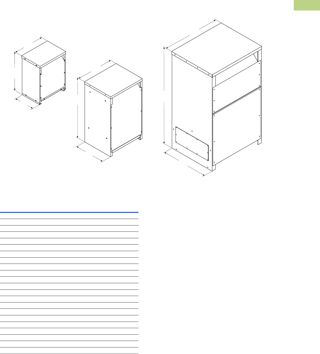
Volume 2—Commercial Distribution CA08100003E—June 2014 www.eaton.com V2-T2-215
2
2
2
2
2
2
2
2
2
2
2
2
2
2
2
2
2
2
2
2
2
2
2
2
2
2
2
2
2
2
2.7
Trans for mers
Dimensions
Dimensions
Approximate Dimensions in Inches (mm)
Enclosure Dimensional Drawings—Ventilated Transformers
Drawing 3
Drawing 2
Drawing 1
Front
Left
Top
Outside
Length
Outside
Height
Outside
Width
Front
Left
Top
Outside
Width
Outside
Height
Outside
Length
Front
Left
Top
Outside
Width
Outside
Height
Outside
Length
Frame
Drawing
Number
Dimensions
Height Width Length
FR816 1 31.30 (795.0) 22.89 (581.4) 18.39 (467.2)
FR818 1 37.59 (954.8) 22.89 (581.4) 20.36 (517.1)
FR819 2 42.03 (1067.6) 24.22 (615.2) 23.84 (605.5)
FR820 2 42.03 (1067.6) 24.22 (615.2) 23.84 (605.5)
FR814 2 62.91 (1597.9) 29.97 (761.2) 33.97 (862.8)
FR842 1 33.75 (857.3) 22.45 (570.2) 17.40 (442.0)
FR843 1 38.70 (983.0) 23.51 (597.2) 24.38 (619.3)
FR844 2 44.92 (1141.0) 26.27 (667.3) 27.12 (688.8)
FR821 2 62.91 (1597.9) 29.97 (761.2) 33.97 (862.8)
FR912D, FR912D 1 30.00 (762.0) 23.00 (584.2) 16.50 (419.1)
FR914D/FR914F 1 39.00 (990.6) 29.00 (736.6) 22.00 (558.8)
FR915D/FR915F 1 39.00 (990.6) 29.00 (736.6) 22.00 (558.8)
FR916A 2 48.56 (1233.4) 28.22 (716.8) 23.42 (594.9)
FR917 2 56.17 (1426.7) 31.44 (798.6) 24.67 (626.6)
FR918A 2 62.18 (1579.4) 31.44 (798.6) 30.68 (779.3)
FR923 2 57.54 (1461.5) 36.69 (931.9) 32.65 (829.3)
FR924 2 68.37 (1736.6) 44.46 (1129.3) 36.44 (925.6)
FR928 2 56.16 (1426.5) 32.93 (836.4) 27.97 (710.4)
FR929 2 59.56 (1512.8) 36.72 (932.7) 32.50 (825.5)
FR919 3 75.00 (1905.0) 44.20 (1122.7) 36.23 (920.2)
FR920 3 75.00 (1905.0) 44.20 (1122.7) 36.23 (920.2)
FR922 3 90.00 (2286.0) 69.26 (1759.2) 42.65 (1083.3)
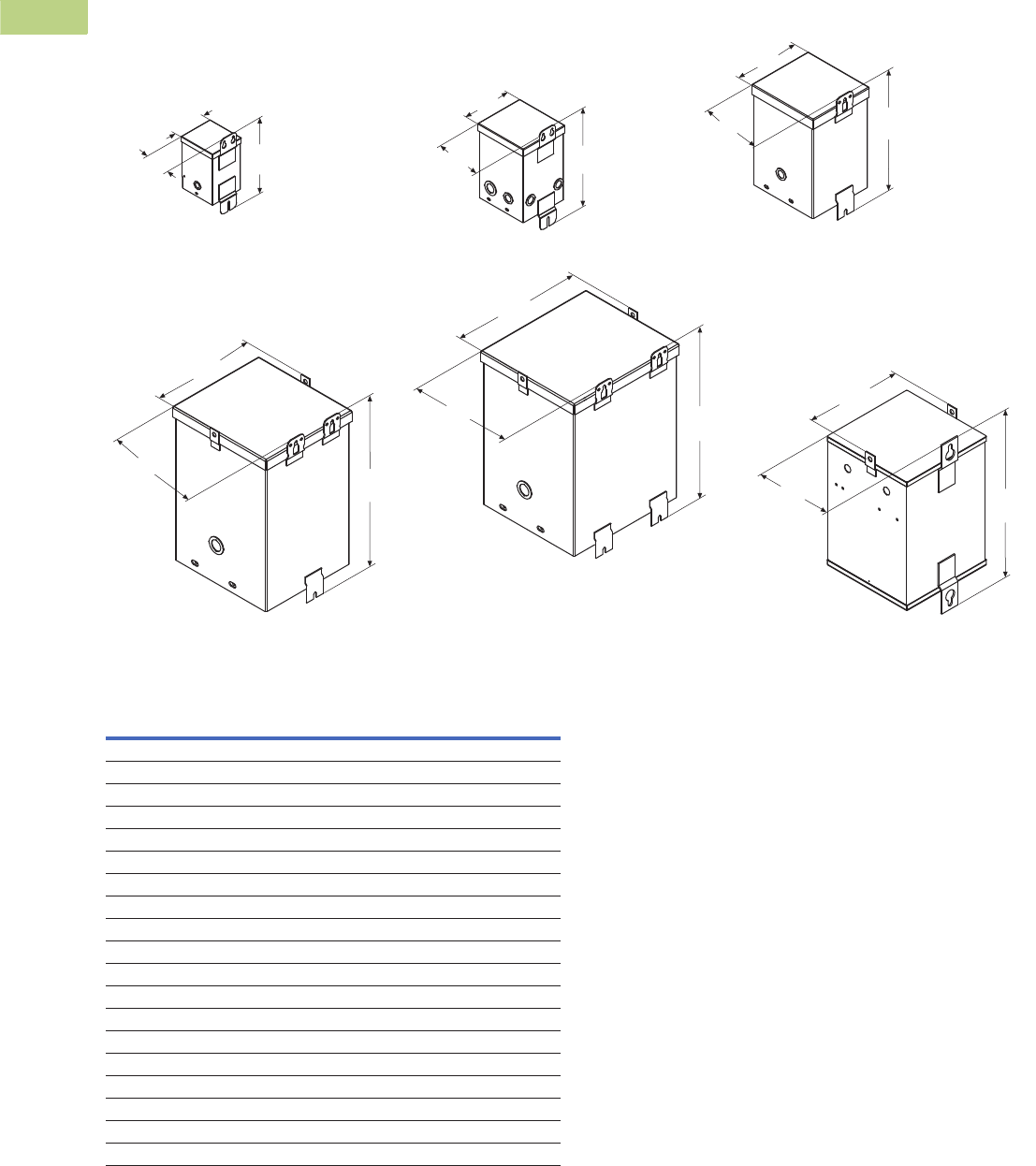
V2-T2-216 Volume 2—Commercial Distribution CA08100003E—June 2014 www.eaton.com
2
2
2
2
2
2
2
2
2
2
2
2
2
2
2
2
2
2
2
2
2
2
2
2
2
2
2
2
2
2
2.7
Transfor mers
Dimensions
Approximate Dimensions in Inches (mm)
Enclosure Dimensional Drawings—Encapsulated Transformers (Type EP)
Right
Top
Drawing 10
Top
Back
Right
Drawing 11
Top
Back
Right
Drawing 6
Top
Right Back
Drawing 7
Top
Right Back
Drawing 8
Top
Right Back
Drawing 9
Outside
Width
Outside
Length
Outside
Height
Outside
Width
Outside
Length
Outside
Height
Outside
Width
Outside
Length
Outside
Height
Outside
Width
Outside
Length Outside
Height
Outside
Width
Outside
Length
Outside
Height
Outside
Width
Outside
Length
Outside
Height
Back
Frame
Drawing
Number
Dimensions
Height Width Length
FR52 6 8.91 (226.3) 4.11 (104.4) 4.00 (101.6)
FR54 6 8.91 (226.3) 4.11 (104.4) 4.00 (101.6)
FR55 6 8.91 (226.3) 4.11 (104.4) 4.00 (101.6)
FR56 7 8.97 (227.8) 4.87 (123.7) 4.06 (103.1)
FR57 7 8.97 (227.8) 4.87 (123.7) 4.91 (124.7)
FR58A 7 11.28 (286.5) 5.99 (152.1) 5.75 (146.1)
FR59A 7 11.28 (286.5) 5.99 (152.1) 5.75 (146.1)
FR67 7 13.41 (340.6) 6.37 (161.8) 6.52 (165.6)
FR68 7 13.41 (340.6) 6.37 (161.8) 6.52 (165.6)
FR176 8 14.25 (361.9) 7.69 (195.3) 8.00 (203.2)
FR177 9 16.00 (406.4) 10.38 (263.7) 9.89 (251.2)
FR301 11 22.26 (565.4) 12.71 (322.8) 12.79 (324.9)
FR178 9 16.00 (406.4) 10.38 (263.7) 9.89 (251.2)
FR302 11 25.26 (641.6) 12.71 (322.8) 12.79 (324.9)
FR304 11 25.26 (641.6) 14.72 (373.9) 14.82 (376.4)
FR179 9 19.00 (482.6) 13.38 (339.9) 10.52 (267.2)
FR180 9 19.00 (482.6) 13.38 (339.9) 10.52 (267.2)
FR182 10 23.31 (592.1) 16.35 (415.3) 14.12 (358.6)
FR190 10 26.31 (668.3) 16.35 (415.3) 14.12 (358.6)
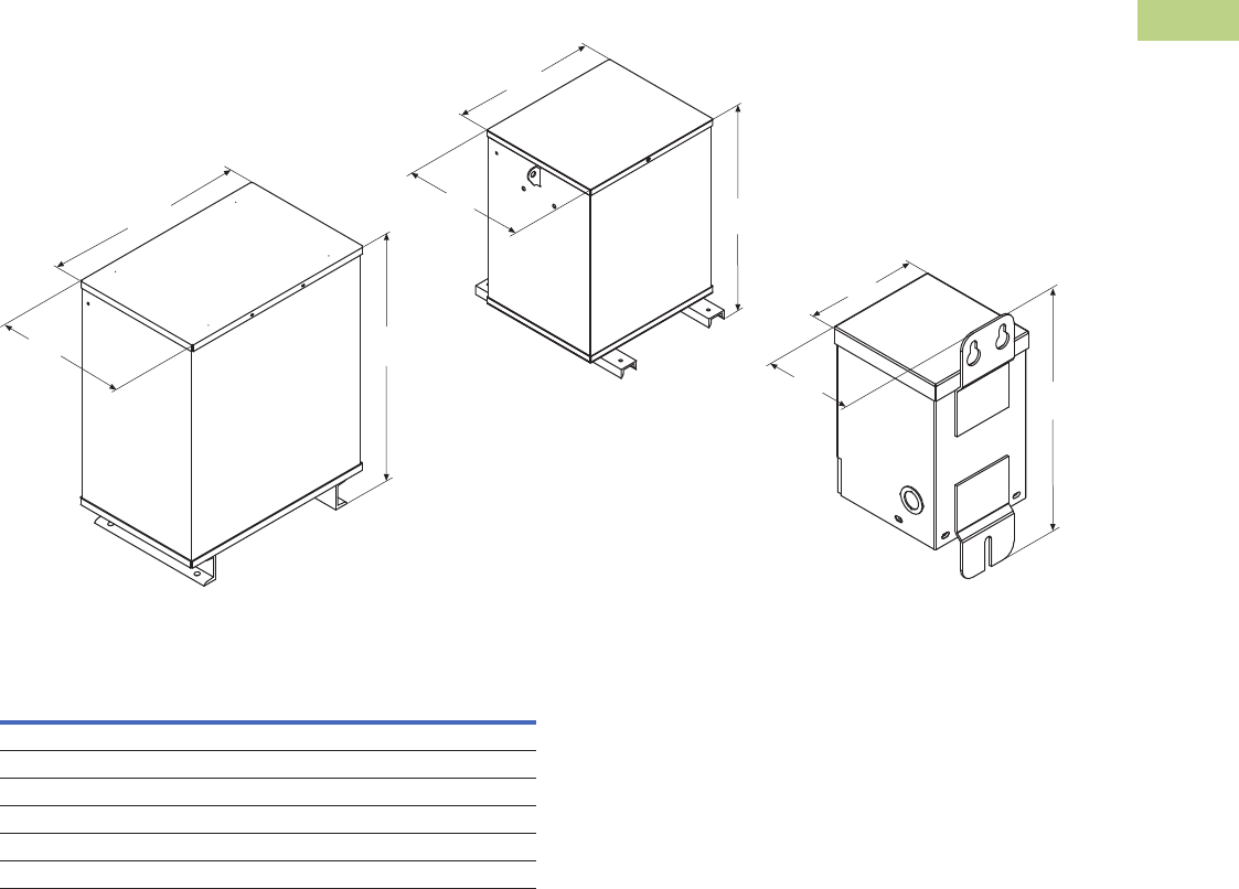
Volume 2—Commercial Distribution CA08100003E—June 2014 www.eaton.com V2-T2-217
2
2
2
2
2
2
2
2
2
2
2
2
2
2
2
2
2
2
2
2
2
2
2
2
2
2
2
2
2
2
2.7
Trans for mers
Dimensions
Approximate Dimensions in Inches (mm)
Enclosure Dimensional Drawings—Encapsulated Transformers Type EP (Single-Phase), continued
Front
Left
Top
Drawing 13
Front
Left
Top
Drawing 12
Top
Back
Right
Drawing 14
Outside
Width
Outside
Length
Outside
Height
Outside
Width
Outside
Length Outside
Height
Outside
Width
Outside
Length
Outside
Height
Frame
Drawing
Number
Dimensions
Height Width Length
FR132 13 20.67 (525.0) 19.02 (483.1) 13.59 (345.2)
FR300A 12 28.24 (717.3) 22.42 (569.5) 14.06 (357.1)
FR57P 14 9.34 (237.2) 4.45 (113.0) 5.18 (131.6)
FR58AP 14 11.68 (296.7) 4.99 (126.7) 5.99 (152.1)
FR567P 14 13.03 (330.9) 5.74 (145.8) 6.56 (166.6)
FR568P 14 13.78 (350.0) 6.22 (158.0) 6.32 (160.5)
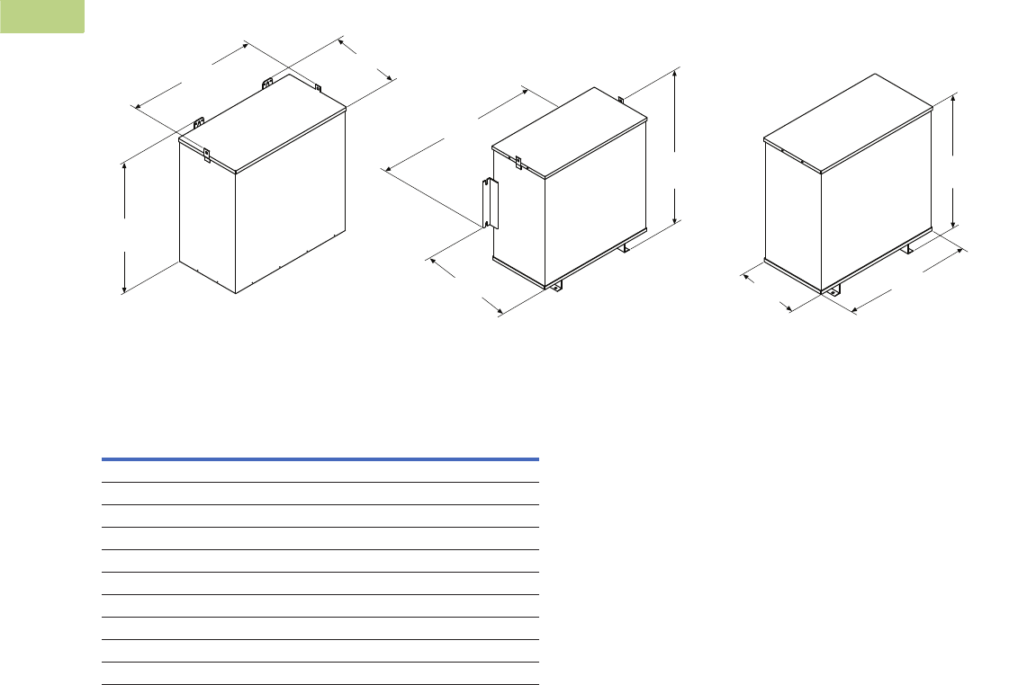
V2-T2-218 Volume 2—Commercial Distribution CA08100003E—June 2014 www.eaton.com
2
2
2
2
2
2
2
2
2
2
2
2
2
2
2
2
2
2
2
2
2
2
2
2
2
2
2
2
2
2
2.7
Transfor mers
Dimensions
Approximate Dimensions in Inches (mm)
Enclosure Dimensional Drawings—Encapsulated Transformers (Type EPT)
Front
Drawing 15 Drawing 16 Drawing 17
Left Front
Left
Top
Front
Left
Top
Outside
Width
Outside
Length
Outside
Height
Outside
Length
Top Outside
Width
Outside
Width
Outside
Length
Outside
Height Outside
Height
Frame
Drawing
Number
Dimensions
Height Width Length
FR201 15 13.40 (340.4) 15.93 (404.6 8.26 (209.8)
FR102 15 13.12 (333.2) 19.59 (497.6) 7.09 (180.1)
FR103 15 15.90 (403.9) 16.93 (430.0) 10.01 (254.3)
FR200 15 15.90 (403.9) 16.93 (430.0) 10.01 (254.3)
FR97 15 15.19 (385.8) 25.68 (652.3) 8.38 (212.9)
FR95 15 17.38 (441.5) 20.00 (508.0) 10.52 (267.2)
FR243 16 17.38 (441.5) 20.00 (508.0) 10.52 (267.2)
FR96 15 16.19 (411.2) 29.68 (753.9) 9.42 (239.3)
FR244 16 28.15 (715.0) 26.58 (675.1) 14.66 (372.4)
FR245 17 32.06 (814.3) 30.29 (769.4) 15.68 (398.3)
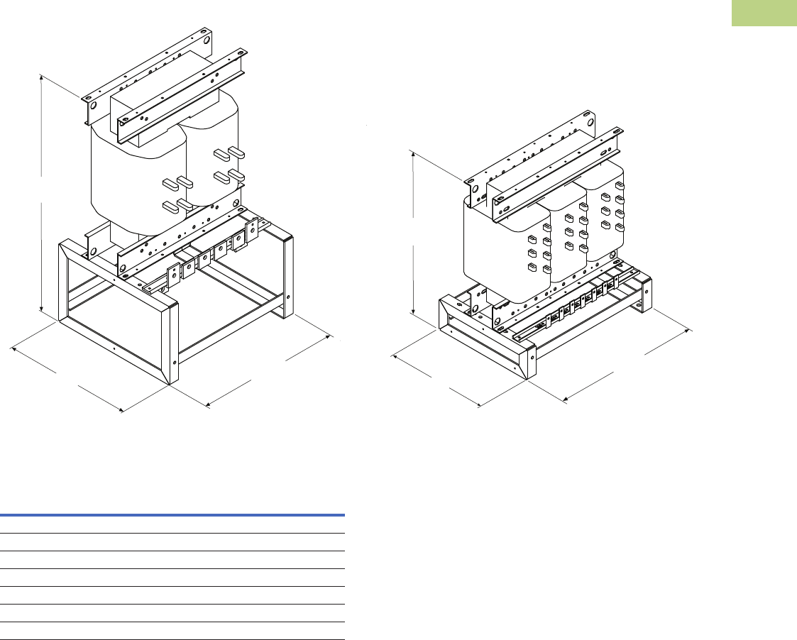
Volume 2—Commercial Distribution CA08100003E—June 2014 www.eaton.com V2-T2-219
2
2
2
2
2
2
2
2
2
2
2
2
2
2
2
2
2
2
2
2
2
2
2
2
2
2
2
2
2
2
2.7
Trans for mers
Dimensions
Approximate Dimensions in Inches (mm)
Enclosure Dimensional Drawings—Core-Coil Transformers
Top
Top
Outside
Height
Outside
Length
Outside
Width
Left
Front
Left
Front
Drawing 4 Drawing 5
Outside
Height
Outside
Length
Outside
Width
Frame
Drawing
Number
Dimensions
Height Width Length
FR817C 4 39.28 (997.7) 21.62 (549.1) 19.51 (495.6)
FR818C 4 39.28 (997.7) 21.62 (549.1) 19.51 (495.6)
FR912C 5 24.75 (628.7) 19.50 (495.3) 14.00 (355.6)
FR914C 5 29.37 (746.0) 25.12 (638.0) 19.00 (482.6)
FR915C 5 31.38 (1067.6) 25.12 (638.0) 19.00 (482.6)
FR9516C 5 41.43 (1052.3) 25.12 (638.0) 20.00 (508.0)
FR916AC 5 43.40 (1102.4) 27.22 (691.4) 22.82 (579.6)
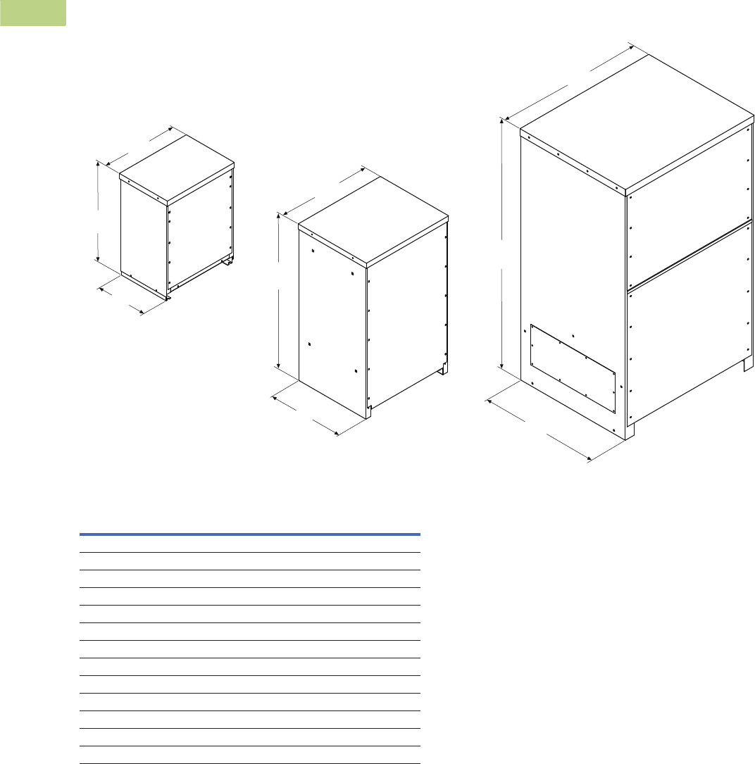
V2-T2-220 Volume 2—Commercial Distribution CA08100003E—June 2014 www.eaton.com
2
2
2
2
2
2
2
2
2
2
2
2
2
2
2
2
2
2
2
2
2
2
2
2
2
2
2
2
2
2
2.7
Transfor mers
Dimensions
Approximate Dimensions in Inches (mm)
Enclosure Dimensional Drawings—Totally Enclosed Nonventilated Transformers
Front
Left
Top
Front
Left
Top
Front
Left
Top
Outside
Width
Outside
Length
Outside
Height
Outside
Width
Outside
Width
Outside
Height
Outside
Height
Outside
Length
Outside
Length
Drawing 28
Drawing 27
Drawing 26
Frame
Drawing
Number
Dimensions
Height Width Length
FR818N 26 37.59 (954.8) 22.89 (581.4) 20.36 (517.1)
FR819N 27 42.03 (1067.6) 24.22 (615.2) 23.84 (605.5)
FR820N 27 42.03 (1067.6) 24.22 (615.2) 23.84 (605.5)
FR814N 27 62.91 (1597.9) 29.97 (761.2) 33.97 (862.8)
FR912DN 26 30.00 (762.0) 23.00 (584.2) 16.50 (419.1)
FR914DN/FR914FN 26 39.18 (995.2) 29.00 (736.6) 22.00 (558.8)
FR915DN/FR915FN 26 39.18 (995.2) 29.00 (736.6) 22.00 (558.8)
FR916AN 27 46.58 (1183.1) 28.22 (716.8) 23.42 (594.9)
FR917N 27 56.18 (1427.0) 31.44 (798.6) 24.67 (626.8)
FR918AN 27 62.18 (1579.4) 31.44 (798.6) 30.68 (779.3)
FR923N 27 57.50 (1460.5) 36.69 (931.9) 32.65 (829.3)
FR919N 28 75.00 (1905.0) 44.21 (1122.9) 36.23 (920.2)
FR920N 28 75.00 (1905.0) 44.21 (1122.9) 36.23 (920.2)
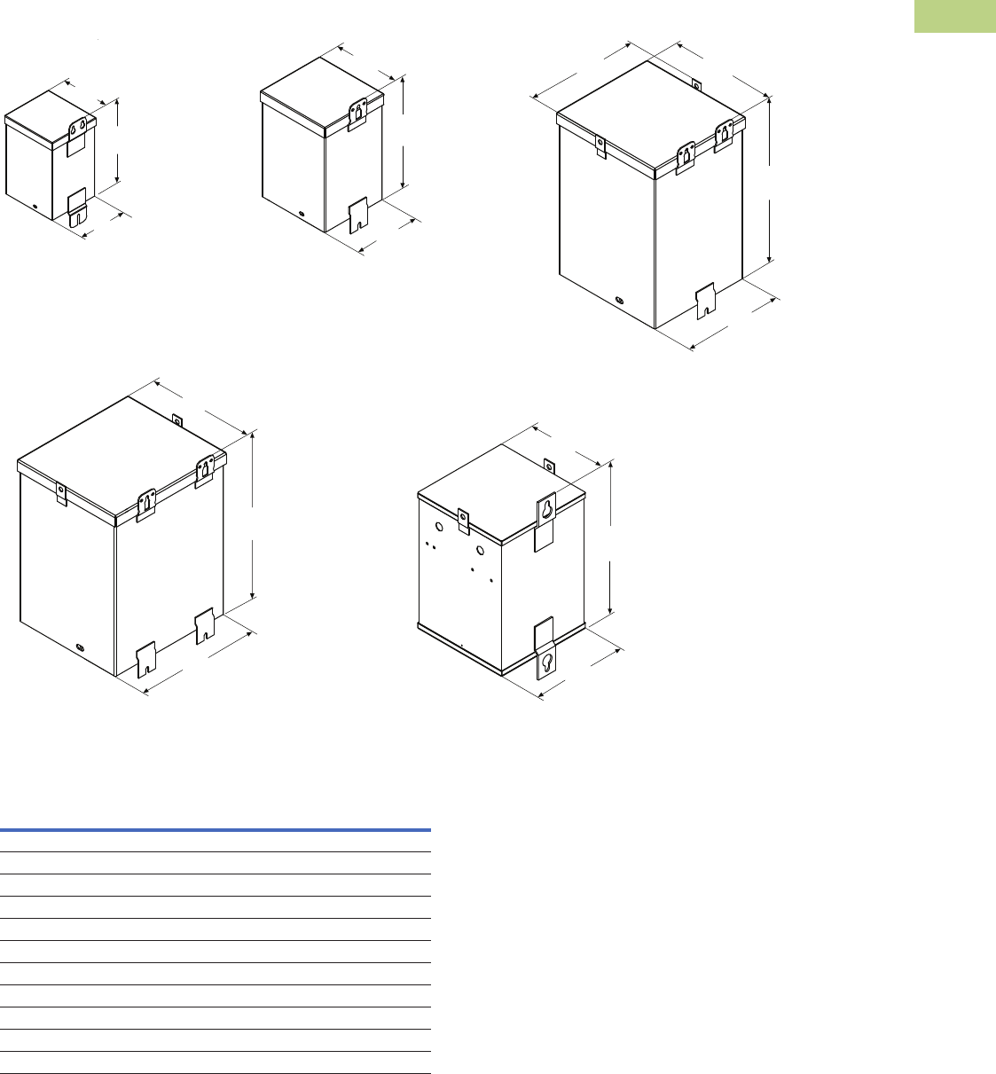
Volume 2—Commercial Distribution CA08100003E—June 2014 www.eaton.com V2-T2-221
2
2
2
2
2
2
2
2
2
2
2
2
2
2
2
2
2
2
2
2
2
2
2
2
2
2
2
2
2
2
2.7
Trans for mers
Dimensions
Approximate Dimensions in Inches (mm)
Enclosure Dimensional Drawings—Hazardous Location Transformers (Type EPZ)
Back
Right
Top
Drawing 24
Outside
Width
Outside
Length
Outside
Height
Top
Back
Right
Drawing 25
Outside
Width
Outside
Length
Outside
Height
Top
Drawing 23
Back
Right
Outside
Width
Outside
Length
Outside
Height
Outside
Width
Top
Back
Right
Drawing 22
Outside
Length
Outside
Height
Outside
Width
Top
Back
Right
Drawing 21
Outside
Length
Outside
Height
Outside
Width
Frame
Drawing
Number
Dimensions
Height Width Length
FR57H 21 8.97 (227.8) 4.87 (123.7) 4.91 (124.7)
FR58H 22 11.28 (286.5) 5.99 (152.1) 5.75 (146.1)
FR59H 22 11.28 (286.5) 5.99 (152.1) 5.75 (146.1)
FR67H 22 13.41 (340.6) 6.37 (161.8) 6.52 (165.6)
FR68H 22 13.41 (340.6) 6.37 (161.8) 6.52 (165.6)
FR176H 23 14.25 (361.9) 7.69 (195.3) 8.00 (203.2)
FR177H 24 16.00 (406.4) 10.38 (263.7) 9.89 (251.2)
FR178H 24 16.00 (406.4) 10.38 (263.7) 9.89 (251.2)
FR179H 24 19.00 (482.6) 13.38 (339.9) 10.52 (267.2)
FR180H 24 19.00 (482.6) 13.38 (339.9) 10.52 (267.2)
FR182H 25 23.31 (592.1) 16.35 (415.3) 14.12 (358.6)
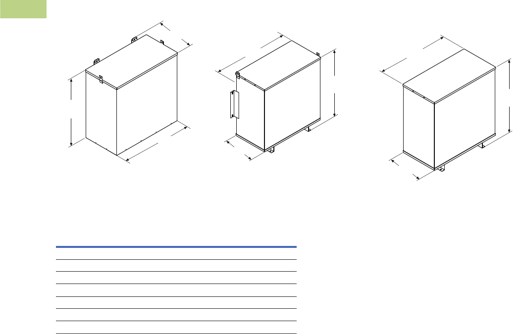
V2-T2-222 Volume 2—Commercial Distribution CA08100003E—June 2014 www.eaton.com
2
2
2
2
2
2
2
2
2
2
2
2
2
2
2
2
2
2
2
2
2
2
2
2
2
2
2
2
2
2
2.7
Transfor mers
Dimensions
Approximate Dimensions in Inches (mm)
Enclosure Dimensional Drawings—Hazardous Location Transformers (Type EPTZ)
Front
Left
Top
Front
Left
Top
Front
Drawing 18 Drawing 19 Drawing 20
Left
Top
Outside
Width
Outside
Length
Outside
Height
Outside
Length
Outside
Length
Outside
Width Outside
Width
Outside
Height Outside
Height
Frame
Drawing
Number
Dimensions
Height Width Length
FR201H 18 13.40 (340.4) 15.93 (404.6) 8.26 (209.8)
FR200H 18 15.90 (403.9) 16.93 (430.0) 10.01 (254.3)
FR103H 18 15.90 (403.9) 16.93 (430.0) 10.01 (254.3)
FR95H 18 17.38 (441.5) 20.00 (508.0) 10.52 (267.2)
FR243H 19 17.38 (441.5) 20.00 (508.0) 10.52 (267.2)
FR244H 19 28.15 (715.0) 26.58 (675.1) 14.66 (372.4)
FR245H 20 32.06 (814.3) 30.29 (769.4) 15.68 (398.3)

Volume 2—Commercial Distribution CA00000000E—April 2014 www.eaton.com V2-T3-1
3
3
3
3
3
3
3
3
3
3
3
3
3
3
3
3
3
3
3
3
3
3
3
3
3
3
3
3
3
3
Panelboards and Lighting Control
Panelboards
3.1 Introduction
Product Selection Guide . . . . . . . . . . . . . . . . . . . . . . . . . . . . . . . . . . . V2-T3-2
3.2 EZ™ Box and EZ Trim
Product Description. . . . . . . . . . . . . . . . . . . . . . . . . . . . . . . . . . . . . . . V2-T3-4
Features. . . . . . . . . . . . . . . . . . . . . . . . . . . . . . . . . . . . . . . . . . . . . . . . V2-T3-4
Standards and Certifications . . . . . . . . . . . . . . . . . . . . . . . . . . . . . . . . V2-T3-5
Product Selection . . . . . . . . . . . . . . . . . . . . . . . . . . . . . . . . . . . . . . . . V2-T3-6
3.3 Pow-R-Line C Panelboards
Product Description. . . . . . . . . . . . . . . . . . . . . . . . . . . . . . . . . . . . . . . V2-T3-7
Application Description . . . . . . . . . . . . . . . . . . . . . . . . . . . . . . . . . . . . V2-T3-8
Standards and Certifications . . . . . . . . . . . . . . . . . . . . . . . . . . . . . . . . V2-T3-10
Technical Data and Specifications . . . . . . . . . . . . . . . . . . . . . . . . . . . . V2-T3-11
Type PRL1a . . . . . . . . . . . . . . . . . . . . . . . . . . . . . . . . . . . . . . . . . . . . . V2-T3-26
Type PRL1aF . . . . . . . . . . . . . . . . . . . . . . . . . . . . . . . . . . . . . . . . . . . . V2-T3-30
Type PRL1a-LX . . . . . . . . . . . . . . . . . . . . . . . . . . . . . . . . . . . . . . . . . . V2-T3-34
Type PRL2a . . . . . . . . . . . . . . . . . . . . . . . . . . . . . . . . . . . . . . . . . . . . . V2-T3-38
Type PRL2aF . . . . . . . . . . . . . . . . . . . . . . . . . . . . . . . . . . . . . . . . . . . . V2-T3-42
Type PRL2a-LX . . . . . . . . . . . . . . . . . . . . . . . . . . . . . . . . . . . . . . . . . . V2-T3-46
Retrofit Panelboard . . . . . . . . . . . . . . . . . . . . . . . . . . . . . . . . . . . . . . . V2-T3-50
Type PRL3a . . . . . . . . . . . . . . . . . . . . . . . . . . . . . . . . . . . . . . . . . . . . . V2-T3-58
Type PRL3E . . . . . . . . . . . . . . . . . . . . . . . . . . . . . . . . . . . . . . . . . . . . . V2-T3-62
Type PRL4 . . . . . . . . . . . . . . . . . . . . . . . . . . . . . . . . . . . . . . . . . . . . . . V2-T3-66
Type PRL4D. . . . . . . . . . . . . . . . . . . . . . . . . . . . . . . . . . . . . . . . . . . . . V2-T3-76
Type PRL5P . . . . . . . . . . . . . . . . . . . . . . . . . . . . . . . . . . . . . . . . . . . . . V2-T3-86
3.4 Elevator Control Panelboard
Elevator Control Panelboard . . . . . . . . . . . . . . . . . . . . . . . . . . . . . . . . V2-T3-96
3.5 Types PRL1a, 2a, 3a, 3E, 4 and Column Modifications
Types PRL1a, 2a, 3a, 3E, 4, Column . . . . . . . . . . . . . . . . . . . . . . . . . . V2-T3-98
Modifications Selection Guide. . . . . . . . . . . . . . . . . . . . . . . . . . . . . . . V2-T3-98
3.6 Pow-R-Command
Product Overview . . . . . . . . . . . . . . . . . . . . . . . . . . . . . . . . . . . . . . . . V2-T3-107
Features. . . . . . . . . . . . . . . . . . . . . . . . . . . . . . . . . . . . . . . . . . . . . . . . V2-T3-108
Product Selection . . . . . . . . . . . . . . . . . . . . . . . . . . . . . . . . . . . . . . . . V2 -T3-111
Accessories . . . . . . . . . . . . . . . . . . . . . . . . . . . . . . . . . . . . . . . . . . . . . V2-T3-120
3.7 Metering Service Sections
Product Description. . . . . . . . . . . . . . . . . . . . . . . . . . . . . . . . . . . . . . . V2-T3-126
Application Description . . . . . . . . . . . . . . . . . . . . . . . . . . . . . . . . . . . . V2-T3-126
Standards and Certifications . . . . . . . . . . . . . . . . . . . . . . . . . . . . . . . . V2-T3-126
Catalog Number Selection . . . . . . . . . . . . . . . . . . . . . . . . . . . . . . . . . V2-T3-127
Product Selection . . . . . . . . . . . . . . . . . . . . . . . . . . . . . . . . . . . . . . . . V2-T3-127
3.8 Pow-R-Stock Plus Program
Pow-R-Stock Plus. . . . . . . . . . . . . . . . . . . . . . . . . . . . . . . . . . . . . . . . . V2-T3-129
3.9 Customer Manufacturing Solution Centers
Customer Manufacturing Solution Centers . . . . . . . . . . . . . . . . . . . . . V2-T3-130
Learn
Online
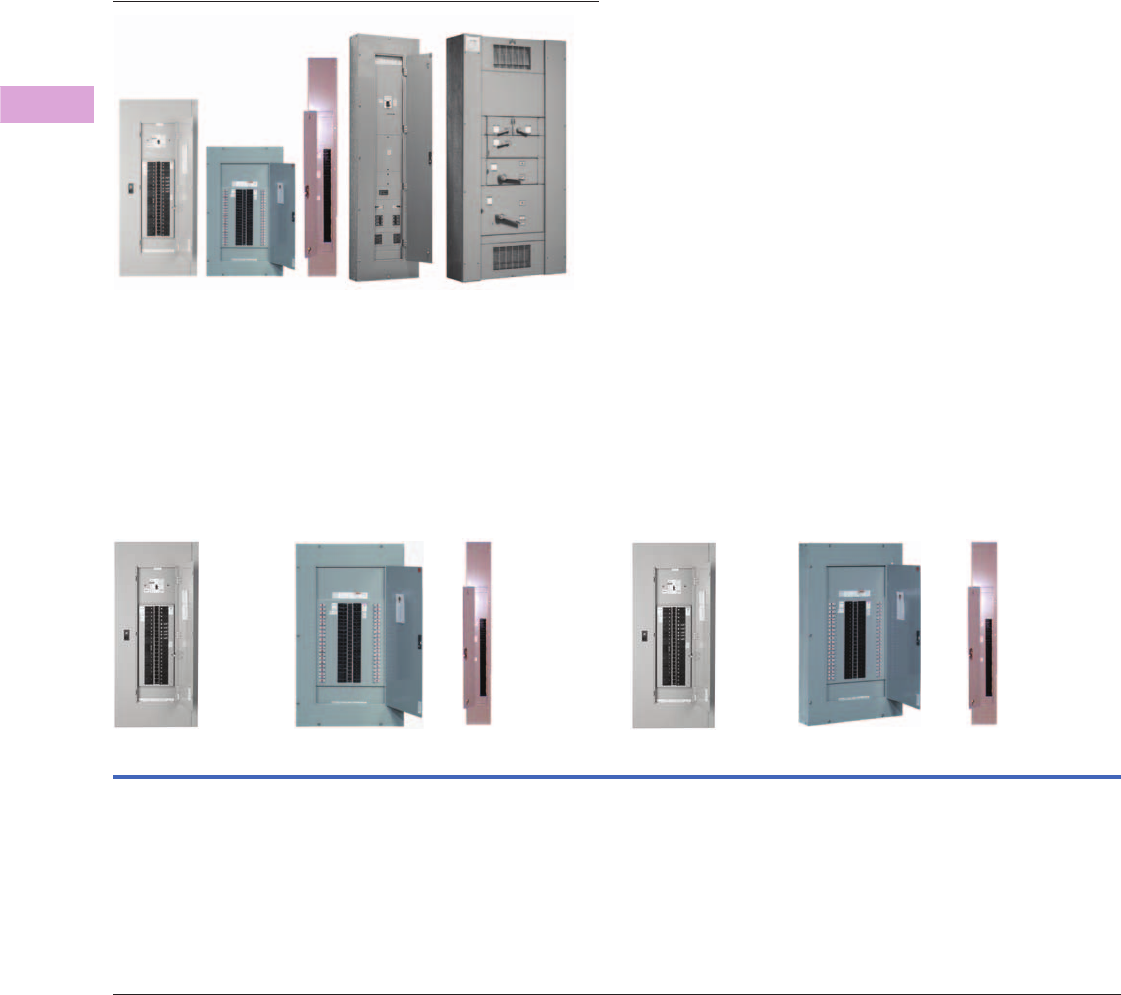
V2-T3-2 Volume 2—Commercial Distribution CA08100003E—April 2014 www.eaton.com
3
3
3
3
3
3
3
3
3
3
3
3
3
3
3
3
3
3
3
3
3
3
3
3
3
3
3
3
3
3
3.1
Panelboards and Lighting Control
Introduction
Panelboards and Lighting Controls
Contents
Description
Product Selection Guide
Product Selection Guide
Product Types
Type PRL1a
Fusible Lighting
Panelboard PRL1aF
Type PRL1a-LX
Column Type Type PRL2a
Fusible Lighting
Panelboard PRL2aF
Type PRL2a-LX,
Column Type
Bolt-On or Plug-On Circuit
Breakers 240 Vac Maximum
Main lugs only
400A maximum
Main Circuit breaker
400A maximum
Branch circuit breakers
100A maximum,
Single-, two- and three-pole
240 and 480Y/277 Vac
Maximum
Main lugs only
400A maximum
Branch overcurrent
protective devices
30A maximum,
Single-, two and three-pole
utilizing Class CC fuses
Bolt-On Circuit Breakers
240 Vac Maximum
Main lugs only
225A maximum
Main circuit breaker
225A maximum
Branch circuit breakers
100A maximum,
Single-, two- and three-pole
Bolt-On Circuit Breakers
240 or 480Y/277 Vac;
125/250 Vdc Maximum
Main lugs only
400A maximum
Main circuit breaker
400A maximum
Branch circuit breakers
100A maximum,
Single-, two- and three-pole
240 and 480Y/277 Vac
Maximum
Main lugs only
400A maximum
Branch overcurrent
protective devices
30A maximum,
Single-, two- and three-pole
utilizing Class CC fuses
Bolt-On Circuit Breakers
240 or 480Y/277 Vac;
125/250 Vdc Maximum
Main lugs only
225A maximum
Main circuit breaker
225A maximum
Branch circuit breakers
100A maximum,
Single-, two- and three-pole
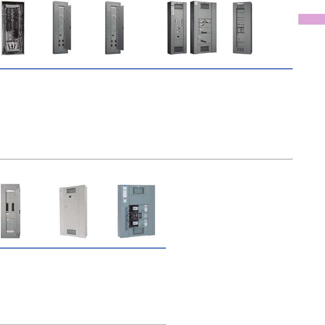
Volume 2—Commercial Distribution CA08100003E—April 2014 www.eaton.com V2-T3-3
3
3
3
3
3
3
3
3
3
3
3
3
3
3
3
3
3
3
3
3
3
3
3
3
3
3
3
3
3
3
3.1
Panelboards and Lighting Control
Introduction
Product Types, continued
Product Types, continued
Retrofit Panelboard
PRL-1R and PRL-2R Type PRL3a Type PRL3E Type PRL4 Type PRL5P
Bolt-On Circuit Breakers
480Y/277 Vac;
240 Vac, 480Y/277 Vac
Main lugs only
225A maximum
Main circuit breaker
225A maximum
Branch circuit breakers
100A maximum,
Single-, two and three-pole
Bolt-On Circuit Breakers
240, 480 or 600 Vac;
250 Vdc Maximum
Main lugs only
800A maximum
Main circuit breaker
600A maximum
Branch circuit breakers
225A maximum,
Single-, two- and three-pole
Bolt-On Circuit Breakers
240, 480Y/277 or 480 Vac;
250 Vdc Maximum
Main lugs only
600A maximum
Main circuit breaker
600A maximum
Branch circuit breakers
125A maximum,
Single-, two- and three-pole
Circuit Breakers or Fusible Switches
240, 480 or 600 Vac; 600 Vdc Maximum
Main lugs only
1200A maximum
Main circuit breaker
1200A maximum
Main fusible switch
1200A maximum
Branch circuit breakers
1200A maximum,
Single-, two- and three-pole
Branch fusible switches
1200A maximum,
two- and three-pole
Plug-On Circuit Breakers
240, 480 or 600 Vac;
250 Vdc Maximum
Main lugs only
1200A maximum
Main circuit breaker
1200A maximum
Branch circuit breakers
1200A maximum,
Single-, two- and three-pole
Pow-R-Command Metering Service Section Elevator Control Panelboard
Bolt-On Circuit Breakers
240 or 480Y/277 Vac
Main lugs only
400A maximum
Main circuit breaker
400A maximum
Branch circuit breakers
225A maximum,
Single-, two- and three-pole
Integral power switching controls
Bolt-On Circuit Breaker or Fusible
Switch 240, 480 or 600 Vac
Service entrance panels combining a
main disconnect with a power
company metering compartment
400–1200A
Bolt-On Fusible Switches
600 Vac Maximum
Controls for up to four elevators
in a single Panelboard
Main lugs only
800A maximum
Branch overcurrent devices
15–200A fusible switches with
Class J fuse clips maximum
Designed to meet specific
sections of various codes
impacting elevators
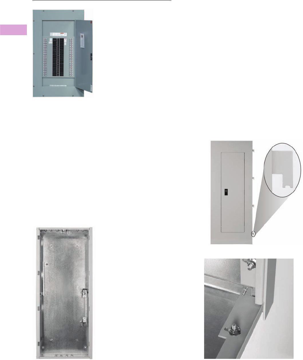
V2-T3-4 Volume 2—Commercial Distribution CA08100003E—April 2014 www.eaton.com
3
3
3
3
3
3
3
3
3
3
3
3
3
3
3
3
3
3
3
3
3
3
3
3
3
3
3
3
3
3
3.2
Panelboards and Lighting Control
EZ Box and EZ Trim
Type PRL1a Panelboard
Contents
Description Page
EZ Box and EZ Trim
Standards and Certifications . . . . . . . . . . . . . . V2-T3-5
Product Selection. . . . . . . . . . . . . . . . . . . . . . . V2-T3-6
Product Description
Eaton’s EZ box and EZ trim
represents the first significant
change in panelboard box and
trim designs in more than a
half-century. The EZ box and
EZ trim have been designed
for faster, more secure and
safer installations. The new
EZ box and EZ trim are
provided standard for Eaton’s
Pow-R-Line 1a and Pow-R-
Line 2a lighting panelboards,
as well as the Pow-R-Line 3a
and Pow-R-Line 3E mid-range
panelboard.
Flange Detail
Features
●Virtually eliminates sharp
edges
●Trim installs in seconds
rather than minutes
●Door-in-door is standard
●Ability to adjust flush box
to wall irregularities
●Trim installs without the
need for tools
●No exposed hardware
(because there is none)
The EZ box flanges are bent
and painted, which virtually
eliminates the sharp edges
associated with traditional
boxes. Additionally, all steel
panelboard chassis parts are
painted. This significantly
reduces potential injury for
material handlers and
installers. Each flange is
adjustable outward up to
3/4-inch (19.1 mm). This
feature allows the installer to
adjust flush box applications
to be level and flat with the
finished wall after the wall
material is installed to help
correct wall irregularities. The
new box flange also provides
the means for attaching the
EZ trim.
Standalone Trim and Bottom Flange Hanger with Notch
Corner Flange Detail
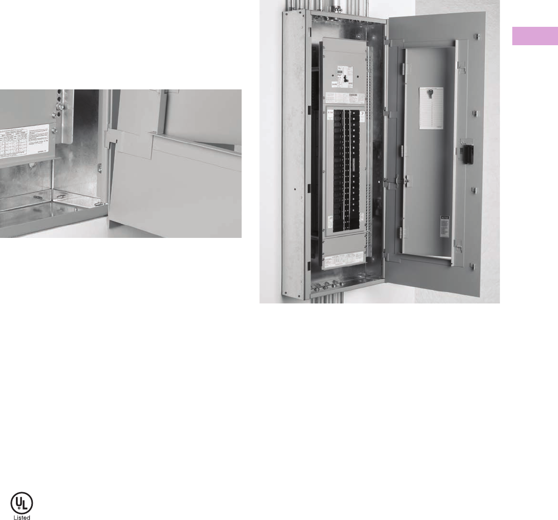
Volume 2—Commercial Distribution CA08100003E—April 2014 www.eaton.com V2-T3-5
3
3
3
3
3
3
3
3
3
3
3
3
3
3
3
3
3
3
3
3
3
3
3
3
3
3
3
3
3
3
3.2
Panelboards and Lighting Control
EZ Box and EZ Trim
Fast Installation
The EZ trim incorporates a groundbreaking design that installs
in seconds, rather than minutes. The standard trim features
include door-in-door construction; no exposed hardware and
no tools are required for installation.
Each EZ trim includes hangers attached on the right side. The
bottom trim hanger has a notch in its base. To install, the bottom
hanger is inserted into the bottom right side box flange opening,
resting the notch on the flange.
Trim Hanger Inserted Into Box Flange
The balance of the hangers are aligned with the other flange
openings and pushed in. When all hangers are in the box flange,
the trim is lifted up slightly to clear the notch on the bottom
hanger, and the trim in self-supported on the EZ box.
The installation is completed by swinging the trim to the closed
position, then lifting and pushing slightly to the right. The trim
will drop into place totally secured. The multi-point catches on
the left side of the trim will lock into the left side box flange
openings.
To prevent the trim from being removed by non-authorized
persons, a unique sliding means automatically latches in place
when the trim door is closed. Along with a new lock, the EZ trim
offers a high degree of door security.
Standards and Certifications
When used with Eaton’s panelboard chassis, EZ boxes and
EZ trims meet the following applicable industry standards:
●UL 50 listed
●NEMA Standard PB1
●Federal specifications
●National Electrical Code
Trim Hanging on Surface Mounted Box

V2-T3-6 Volume 2—Commercial Distribution CA08100003E—April 2014 www.eaton.com
3
3
3
3
3
3
3
3
3
3
3
3
3
3
3
3
3
3
3
3
3
3
3
3
3
3
3
3
3
3
3.2
Panelboards and Lighting Control
EZ Box and EZ Trim
Product Selection
Boxes and Trims Only—Type 1
Types PRL1a, PRL2a and PRL3a (400A Maximum)
Type PRL3a (600A)
Type PRL3a (800A)
Note
1EZ box must be used with EZ trim.
Box Dimensions—Inches (mm) Height
YS Box LT Trim EZ Box 1EZ Trim 1
Catalog
Number
Catalog
Number
Catalog
Number
Catalog
Number
20.00 W x 5.75 D
(508.0 W x 146.1 D)
36.00 (914.4) YS2036 LT2036S or F EZB2036R EZT2036S or F
42.00 (1066.8) YS2042 LT2042S or F EZB2042R EZT2042S or F
48.00 (1219.2) YS2048 LT2048S or F EZB2048R EZT2048S or F
60.00 (1524.0) YS2060 LT2060S or F EZB2060R EZT2060S or F
72.00 (1828.8) YS2072 LT2072S or F EZB2072R EZT2072S or F
90.00 (2286.0) YS2090 LT2090S or F EZB2090R EZT2090S or F
Box Dimensions—Inches (mm) Height
YS Box LT Trim EZ Box 1EZ Trim 1
Catalog
Number
Catalog
Number
Catalog
Number
Catalog
Number
20.00 W x 5.75 D
(508.0 W x 146.1 D)
36.00 (914.4) YS2036 LTV2036S or F EZB2036R EZTV2036S or F
48.00 (1219.2) YS2048 LTV2048S or F EZB2048R EZTV2048S or F
60.00 (1524.0) YS2060 LTV2060S or F EZB2060R EZTV2060S or F
72.00 (1828.8) YS2072 LTV2072S or F EZB2072R EZTV2072S or F
90.00 (2286.0) YS2090 LTV2090S or F EZB2090R EZTV2090S or F
Box Dimensions—Inches (mm) Height
YS Box LT Trim
Catalog
Number
Catalog
Number
28.00 W x 5.75 D 36.00 (914.4) YS2836 LTV2836S or F
48.00 (1219.2) YS2848 LTV2848S or F
60.00 (1524.0) YS2860 LTV2860S or F
72.00 (1828.8) YS2872 LTV2872S or F
90.00 (2286.0) YS2890 LTV2890S or F
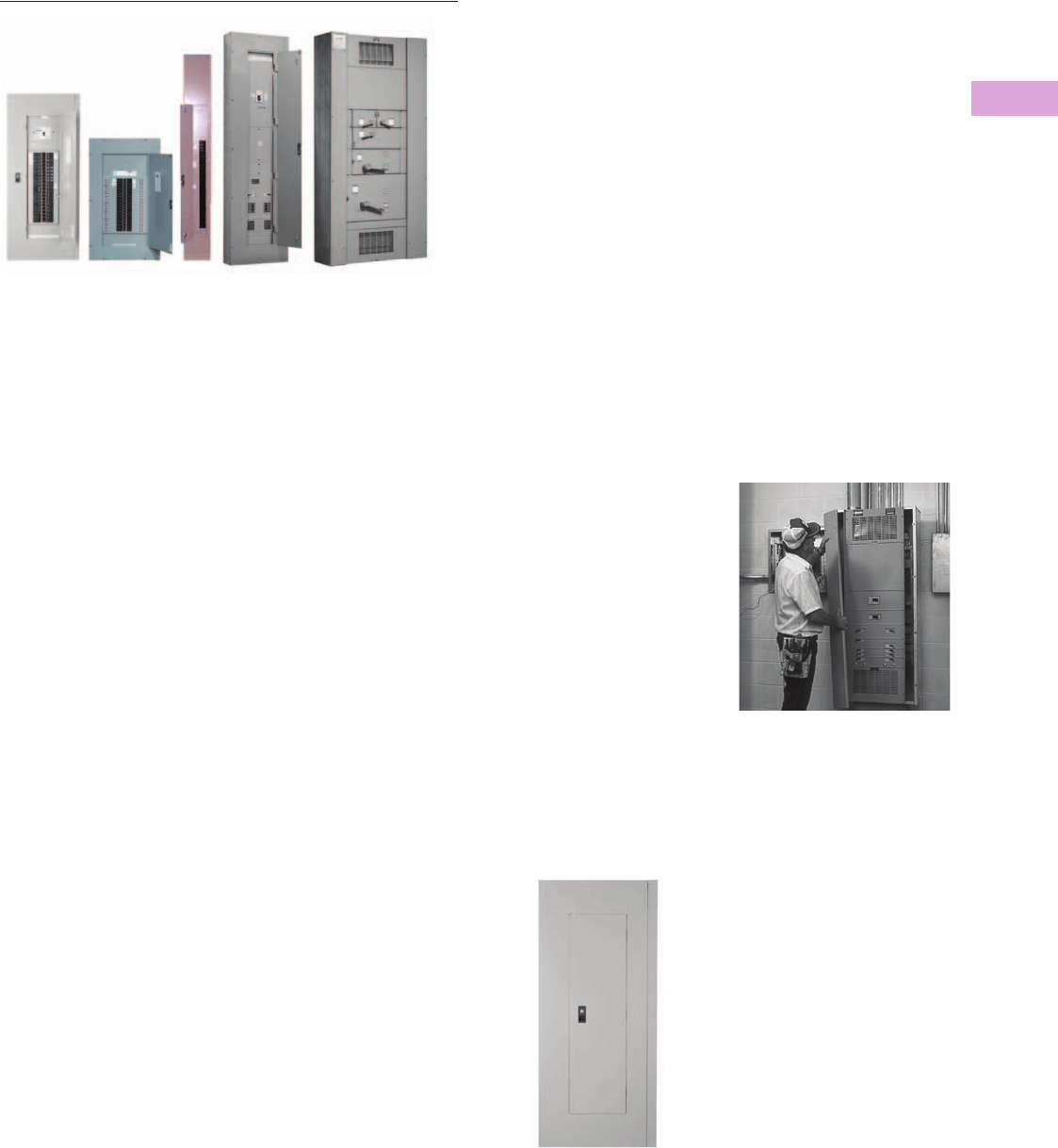
Volume 2—Commercial Distribution CA08100003E—April 2014 www.eaton.com V2-T3-7
3
3
3
3
3
3
3
3
3
3
3
3
3
3
3
3
3
3
3
3
3
3
3
3
3
3
3
3
3
3
3.3
Panelboards and Lighting Control
Pow-R-Line C Panelboards
Pow-R-Line C Panelboards
Contents
Description Page
Application Description . . . . . . . . . . . . . . . . . . . . . V2-T3-8
Standards and Certifications . . . . . . . . . . . . . . . . . V2-T3-10
Technical Data and Specifications . . . . . . . . . . . . . V2-T3-11
Type PRL1a . . . . . . . . . . . . . . . . . . . . . . . . . . . . . . V2-T3-26
Type PRL1aF . . . . . . . . . . . . . . . . . . . . . . . . . . . . . V2-T3-30
Type PRL1a-LX. . . . . . . . . . . . . . . . . . . . . . . . . . . . V2-T3-34
Type PRL2a . . . . . . . . . . . . . . . . . . . . . . . . . . . . . . V2-T3-38
Type PRL2aF . . . . . . . . . . . . . . . . . . . . . . . . . . . . . V2-T3-42
Type PRL2a-LX. . . . . . . . . . . . . . . . . . . . . . . . . . . . V2-T3-46
Retrofit Panelboard . . . . . . . . . . . . . . . . . . . . . . . . V2-T3-50
Type PRL3a . . . . . . . . . . . . . . . . . . . . . . . . . . . . . . V2-T3-58
Type PRL3E . . . . . . . . . . . . . . . . . . . . . . . . . . . . . . V2-T3-62
Type PRL4 . . . . . . . . . . . . . . . . . . . . . . . . . . . . . . . V2-T3-66
Type PRL4D . . . . . . . . . . . . . . . . . . . . . . . . . . . . . . V2-T3-76
Type PRL5P . . . . . . . . . . . . . . . . . . . . . . . . . . . . . . V2-T3-86
Product Description
Lighting and Distribution Panelboards
Eaton’s assembled
panelboards are designed for
sequence phase connection
of branch circuit devices. This
allows complete flexibility of
circuit arrangement (single-,
two- or three-pole) to allow
balance of the electrical load
on each phase.
Sturdy, rigid chassis
assembly ensures accurate
alignment of interior with
panel front; prevents flexing
and minimizes possibility
of loosening or damage to
current carrying parts during
and after installation.
Four-point in-and-out
adjustment of panel interior
is provided to meet critical
depth dimensions on
flush installations. This
compensates for possible
misalignment of box at
installation.
Main lugs are mechanical
solderless type and approved
for copper or aluminum
conductors.
Enclosures
Boxes are code-gauge
galvanized steel, which
include a painted box finished
in ANSI-61 light gray to match
the trim.
Standard panelboard cabinets
are designed for indoor use.
Alternate types are available
for indoor and special
purpose applications.
All enclosures are furnished
in accordance with
Underwriters Laboratories
standards and include wiring
gutters with proper wire
bending space. Special
cabinets can be provided
at an additional charge.
The box dimensions shown
are inside dimensions. For
outside dimensions, add
1/4-inch (6.4 mm).
Standard panelboard boxes are
supplied
without knockouts
(blank endwalls).
Fronts
Fronts (trims) for all
panelboards are made of
code-gauge steel and have a
high durability ANSI-61 light
gray finish applied by a baked-
on polyester powder coating
paint system.
The fronts for lighting and
appliance branch circuit
panelboards and small power
distribution panelboards
include a door with rounded
corners and concealed
hinges. A flush-type latch and
lock assembly is included.
All locks are keyed alike.
These trims are available in
both surface- and flush-
mounted designs.
EZ Trim Features Standard Door-in-Door
with No Exposed Hardware or
Sharp Edges (no Tools are
Required for Installation)
The Three-Piece Trim for Larger Power
Distribution Panelboards Provides for
Easy Handling and Installation
Fronts for power distribution
panelboards utilize a unique
breaker front cover design
in which each device has a
dedicated bolt-on steel cover.
The individual covers form
a single deadfront for the
panelboard that is used in
conjunction with two wiring
gutter covers to complete the
trim. A door is not finished as
part of the standard offering
on these panelboards but can
be provided, for an additional
charge, using a deeper than
standard box.

V2-T3-8 Volume 2—Commercial Distribution CA08100003E—April 2014 www.eaton.com
3
3
3
3
3
3
3
3
3
3
3
3
3
3
3
3
3
3
3
3
3
3
3
3
3
3
3
3
3
3
3.3
Panelboards and Lighting Control
Pow-R-Line C Panelboards
Application Description
Panelboard
Selection Factors
In selecting a panelboard,
the following factors must
be considered:
●Service (voltage and
frequency)
●Interrupting capacity
(fully or series rated)
●Ampere rating of main
●Ampere ratings of
branches
●Environment
Panelboard
Short-Circuit Rating
The short-circuit rating
of Eaton’s assembled
panelboards are test
verified by, and listed with,
Underwriters Laboratories
(UL). Generally, these
ratings are that of the lowest
interrupting rated device in
the panel.
Certain exceptions to this
rule exist where branch
devices have been UL tested
in combination with specific
main devices having a higher
interrupting rating. Where
these defined main devices
and branch breaker
combinations are utilized, the
series short-circuit rating of
the assembled panelboard
will be the same as the
tested rating of the approved
rated main device in series
with the branches. Available
main and branch breaker
combinations are tabulated
starting on Page V2-T3-16.
All combinations shown are
UL tested and listed.
These series ratings apply to
panels having main devices,
or main lug only panelboards
fed remotely by the device
listed in the series ratings
chart as the main, for which
UL listed tests were
conducted.
Service Entrance Equipment
The National Electrical Code
(NEC) requires that:
●A panel used as service
entrance equipment
must be located near
the point where the
supply conductors enter
the building
●A panelboard having main
lugs only shall have a
maximum of six service
disconnects to de-energize
the entire panelboard from
the supply conductors.
Where more than six
disconnects are required,
a main service disconnect
must be provided
●A disconnectable electrical
bond must be provided
between the neutral and
ground
●A service entrance type
UL label must be factory
installed
●Ground fault protection
of equipment shall be
provided for each service
disconnect rated 1000A
or more if the electrical
service is a solidly
grounded wye system of
more than 150V to ground,
but not exceeding 600V
phase-to-phase
Note: Service entrance panels
must be identified as such on
the order.
Panelboard Standards
In 2008, both the National
Electrical Code (Article 408)
and UL 67 were updated
to remove the mandated
42-circuit limitation. Eaton
offers panelboards with more
than 42 circuits for those
jurisdictions that have
adopted the 2008 NEC
or later.
For jurisdictions that have| not
adopted the 2008 or
later version of the National
Electrical Code, the 42-circuit
limitation for Lighting
and Appliance Branch
Panelboards remains in place.
Check with your local code
officials to determine specific
jurisdiction status.
Panelboard Installation
NEC requires that the
operating handle of the
topmost mounted device be
no more than 6 feet 7 inches
(2006.6 mm) above the
finished floor and should be
installed per NEC and
manufacturer’s instructions.
Additional boxes and fronts
are required when the
components required for
one panelboard exceed the
standard box dimensions.
Multi-Section Panelboards
When two or more separate
enclosures are required,
separate fronts for each box
are standard. A common
front can be furnished at
additional charge.
Interconnecting Multi-
Section Panelboards
When a panelboard, for
connection to one feeder,
must be furnished in more
than one section (Box), each
section must be furnished
with main bus and terminals
of the same rating, unless a
main overcurrent device is
provided in each section.
Sub-feed or through-feed
provisions must also be
included (and priced) to
provide connection capability
to the second section.
Note: Sub-feed or through-feed
lugs cannot be used on any
panelboard that is not protected
by a single main overcurrent
device either in the panelboard
or immediately upstream, i.e.,
service entrance panelboards
with main lugs only using the six
disconnect rule.
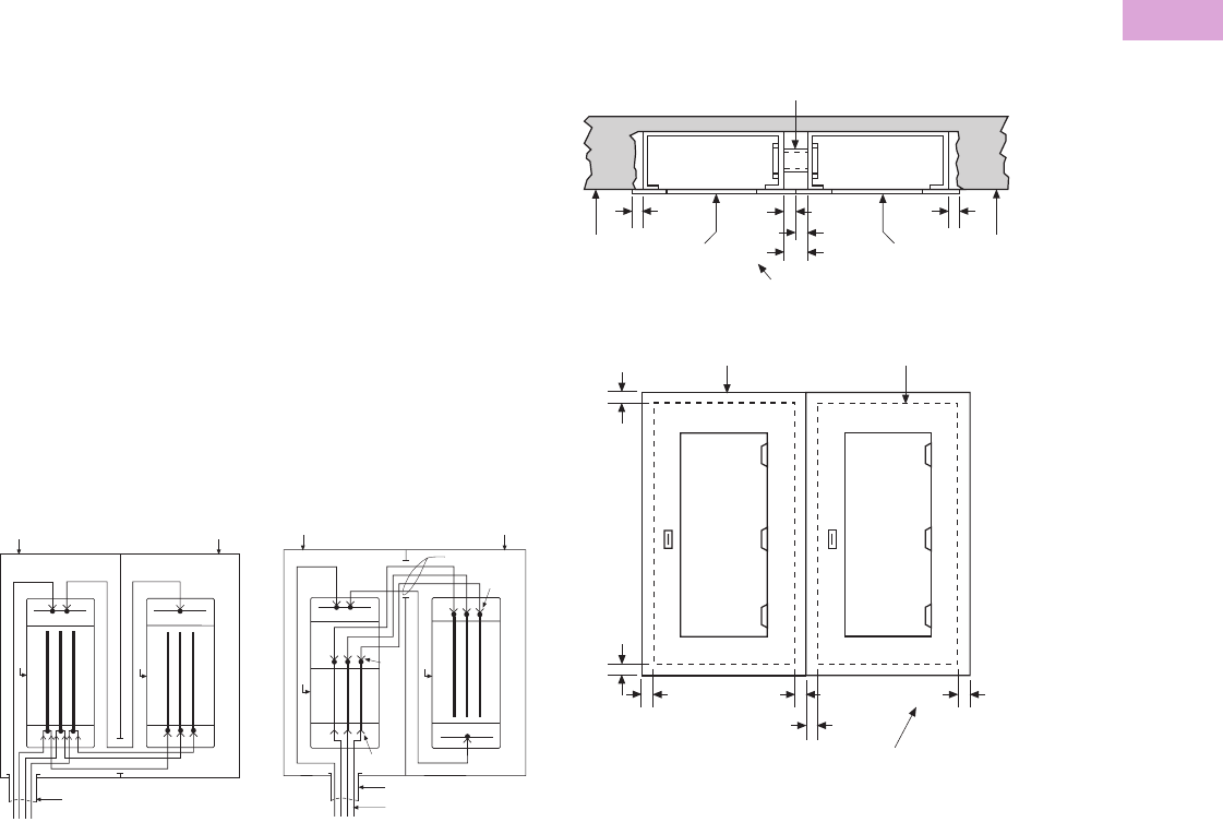
Volume 2—Commercial Distribution CA08100003E—April 2014 www.eaton.com V2-T3-9
3
3
3
3
3
3
3
3
3
3
3
3
3
3
3
3
3
3
3
3
3
3
3
3
3
3
3
3
3
3
3.3
Panelboards and Lighting Control
Pow-R-Line C Panelboards
Sub-Feed Lugs
Sub-feed lugs (see figure
below) are one means of
interconnecting multi-section
panels. The sub-feed (second
set of) lugs are mounted
directly beside the main lugs.
These are required in each
section except the last panel
in the lineup. The feeder
cables are brought into the
wiring gutter of the first
section and connected to
the main lugs. Another set
of the same size cables are
connected to the sub-feed
lugs (Section 1) and are
carried over to the main lugs
of the adjacent panel. Cross
connection cables are not
furnished by Eaton. Sub-feed
lugs are only available on main
lug only panels.
Note: Sub-feed lugs may
not be used on main lug only
(six disconnect rule) service
entrance panels.
Sub-Feed Lugs
Through-Feed Lugs
Through-feed lugs (see figure
below) are another method
to interconnect multi-section
panelboards. The incoming
feeder cables are connected
to the main lugs or main
breaker at the bottom of
panel (Section 1). Another
set of lugs (through-feed)
are located at the opposite
end of the main bus. The
interconnecting cables are
connected to the through-
feed lugs in Section 1 and are
carried over to the main lugs
in Section 2. The connection
arrangement could be
reversed, i.e., main lugs at
top; through-feed lugs at
bottom end of panel. Cross
cables are not furnished
by Eaton.
Note: Through-feed lugs
may not be used on main lug
only (six disconnect rule) service
entrance panels.
Through-Feed Lugs
Box Box
Conduit
Neutral Neutral
Panel
Panel
Section 1 Section 2
Section 1 Section 2
Box Box
Conduit
Neutral
Panel
Panel
Neutral
Main
Lugs
Thru-
Feed
Lugs
Main
Lugs
Cross Cables
Incoming Feeder Cables
Multiple Section Panelboard—Flush Mounted
Shown below is the standard method for flush mounting
multiple section lighting and distribution panelboards using
standard flush trims.
Multiple Section Panelboard Flush Mounted—
Dimensions in Inches (mm)
Overcurrent Protection
The following requirements will be found in the NEC:
Each lighting and appliance branch circuit panelboard shall be
individually protected on the supply side by not more than two
main circuit breakers or two sets of fuses having a combined
rating not greater than that on the panelboard.
Contractor to Mount Boxes
1-1/2-inch (38.1 mm) Apart to
Allow for 3/4-inch (19.1 mm)
Extension on Both Flush Trims
Two Section
Panelboard
(Flush Mounting)
Flush Trim Extends 3/4-inch
(19.1 mm) Beyond Outside
of Box on All Four Sides
Outside Edge of Box
Trim
Wall Wall
Trim Trim
Conduit Nipple for Cross Wiring by Contractor
3/4
(19.1)
3/4
(19.1)
1 1/2
(38.1)
Top Section
View
3/4
(19.1)
3/4
(19.1)
3/4
(19.1)
3/4
(19.1)
3/4
(19.1) 3/4
(19.1)
3/4
(19.1)
3/4
(19.1)
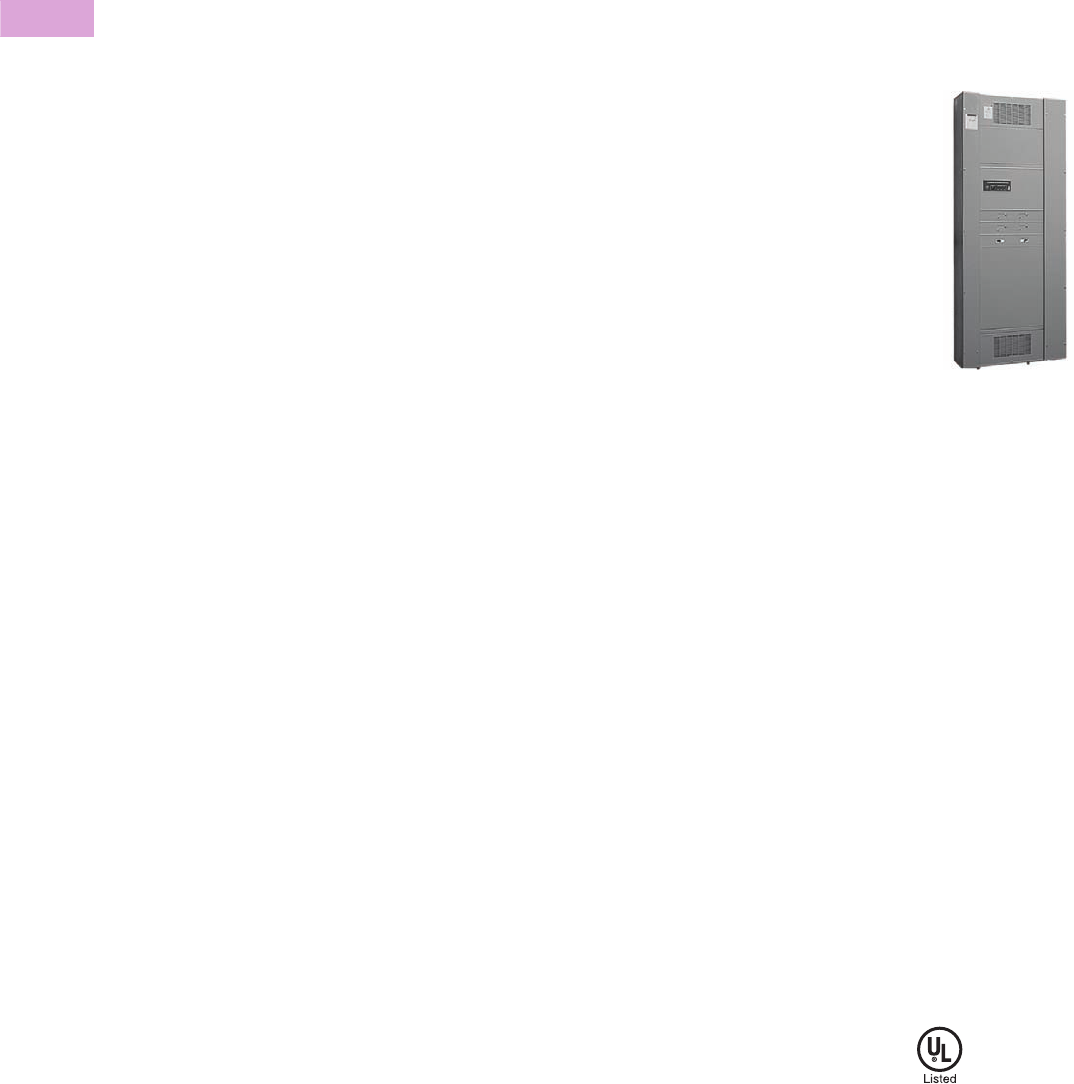
V2-T3-10 Volume 2—Commercial Distribution CA08100003E—April 2014 www.eaton.com
3
3
3
3
3
3
3
3
3
3
3
3
3
3
3
3
3
3
3
3
3
3
3
3
3
3
3
3
3
3
3.3
Panelboards and Lighting Control
Pow-R-Line C Panelboards
Branch Circuit Loading
for Lighting Panels
The size of mains and
branches should be selected
based on the following:
●Motor circuits: NEC
Article 430
●Diversity factor
●Provision for future loading
Exception Number 1:
Individual protection for
a lighting panelboard is not
required when the
panelboard feeder has
overcurrent protection not
greater than that of the
panelboard.
Exception Number 2:
For existing installations,
individual protection for
lighting panelboards is not
required where such
panelboards are used as
service equipment in
supplying an individual
residential occupancy and
where any bus supplying
15 or 20A circuits is protected
on the supply side by an
overcurrent device.
Ambient Temperatures
The primary function of an
overcurrent device is to
protect the conductor
and its insulation against
overheating. In selecting
the size of the devices and
conductors, consideration
should be given to the
ambient temperature
surrounding the conductors
within and external to the
panelboard. Cumulative
heating within the panelboard
may cause premature
operation of the overcurrent
protective devices.
Underwriters Laboratories
test procedures are based,
in part, on 80% loading of
panelboard branch circuit
devices. The NEC limits
the loading of overcurrent
devices in panelboards
to 80% of rating where in
normal operation the load will
continue for three hours or
more. Further derating may
be required, depending on
such factors as ambient
temperature, duty cycle,
frequency or altitude.
Exception: There is one
exception to this rule in both
UL and NEC. It applies to
assemblies and overcurrent
devices that have been listed
for continuous duty at 100%
of its rating.
Special Conditions
Standard panelboards,
assembled with standard
components, are adequate
for most applications.
However, special
consideration should be
given to those required for
application under special
conditions such as:
●Excessive vibration
or shock
●Frequencies above
60 cycles
●Altitudes above 6600 feet
(2011.7m)
●Damp environment
(possible fungus growth)
●Compliance with federal,
state and municipal
electrical codes and
standards
Seismic Considerations
The Uniform Building Code®
and the International Building
Code, as well as local and
state building codes, place
an emphasis on seismic
building design requirements.
Electrical distribution systems
are treated as attachments to
the building and therefore, fall
into this category.
All Eaton panelboards are
seismic qualified at the
highest possible level,
and have been tested in
accordance with ANSI
C37.81. This standard
quantifies actual earthquake
conditions, as well as
equipment seismic capability.
Harmonic Currents
Standard panelboard neutrals
are rated for 100% of the
panelboard current. However,
since harmonic currents can
cause overheated neutrals,
an option is provided for
neutrals to be rated at 200%
(1200A maximum neutral for
600A main bus) of the
panelboard phase current.
Panelboards with the 200%
rated neutral are UL listed as
suitable for use with non-
linear loads.
Prior to specifying the 200%
rated neutral, Eaton
recommends a harmonic
survey be conducted of the
distribution system, be it new
or existing.
Surge Protective Devices
The quality of power feeding
sensitive electronic loads is
critical to the reliable operation
of any facility. In modern
offices, hospitals, and
manufacturing facilities, the
most frequent causes of
microprocessor-based
equipment downtime and
damage are voltage transients
and electrical noise.
Electrical loads and
microprocessor-based
equipment are highly
susceptible to both high and
low energy transients. High
energy transients include
lightning induced surges and
power company switching.
These high energy transients
can destroy components
instantly.
More frequently the electrical
system experiences low
energy transients and high
frequency noise.
The effects of continual low
energy transients and high
frequency noise can cause
erratic equipment
performance or sudden
failure of electronic circuit
board components.
Eaton can provide protective
and diagnostic systems
integral to panelboards.
The surge protective device
(SPD) is integrated into the
panelboards using a “zero
lead length” direct bus bar
connection.
Pow-R-Line 4
The SPD protects sensitive
electronic equipment from the
damaging effects of high and
low energy transients, as well
as high frequency noise.
Standards and
Certifications
Eaton’s panelboards are
designed to meet the
following applicable
industry standards,
except where noted:
●Underwriters Laboratories:
●Panelboards: UL 67
●Cabinets and Boxes:
UL 50
Note: Only panelboards
containing UL listed devices
can be UL labeled.
●National Electrical Code
●NEMA Standards: PB 1
●Federal Specification
W-P-115c:
●Circuit Breakers—
Type I Class I
●Fusible Switch—
Type II Class I

Volume 2—Commercial Distribution CA08100003E—April 2014 www.eaton.com V2-T3-11
3
3
3
3
3
3
3
3
3
3
3
3
3
3
3
3
3
3
3
3
3
3
3
3
3
3
3
3
3
3
3.3
Panelboards and Lighting Control
Pow-R-Line C Panelboards
Technical Data and Specifications
Panelboard Selection Guide
Note
1Fixed mounted only.
Maximum
Voltage Rating
Maximum Main
Rating (Amperes)
AC Interrupting Capacity
rms Symmetrical Amperes (kA)
Panelboard
Type
Device
Type AC DC MLO Main Device
Branch Circuits
Ampere Range
Sub-Feed Breaker
Maximum Amperes Fully Rated Series Rated
PRL1a Breaker 240 — 400 400 15–100 400 10–22 22–100
PRL1R Breaker 240 — 225 225 15–100 — 10–22 22–100
PRL1aF Fusible 240 — 400 400 15–30 400 200 —
PRL1a-LX Breaker 240 — 225 225 15–100 — 10–22 22–100
PRL2a Breaker 240 250 400 400 15–100 400 65 65–200
Breaker 480Y/277 250 400 400 15–100 400 14 22–150
PRL2R Breaker 240 — 225 225 15–100 — 10–22 22–200
Breaker 480Y/277 — 225 225 15–100 — 14 22–100
PRL2aF Fusible 480Y/277 — 400 400 15–30 400 200 —
PRL2a-LX Breaker 240 250 225 225 15–100 — 65 65–200
Breaker 480Y/277 250 225 225 15–100 — 14 22–150
PRL3a Breaker 240 250 800 600 15–225 600 10–200 22–200
Breaker 480 250 800 600 15–225 600 14–100 22–150
Breaker 600 250 800 600 15–225 600 14–35 —
PRL3E Breaker 240 250 600 600 15–125 400 25–100 100–200
Breaker 480Y/277 250 600 600 15–125 400 18–65 65–100
Breaker 480 250 600 600 15–125 400 18–65 65–100
PRL4B Breaker 240 600 1200 1200 15–1200 — 10–200 22–200
Breaker 480 600 1200 1200 15–1200 — 14–200 22–150
Breaker 600 600 1200 1200 15–1200 — 14–200 —
PRL4D Breaker 240 — 1200 1200 1600 — 65–200 —
Breaker 480 — 1200 1200 1600 — 35–100 —
Breaker 600 — 1200 1200 1600 — 18–50 —
PRL4F Fusible 240 250 1200 1200 30–1200 — 100–200 —
Fusible 600 250 1200 1200 30–1200 — 100–200 —
PRL5P Breaker 240 250 1200 1200 15–1200 — 10–200 22–200
Breaker 480 250 1200 1200 15–1200 — 14–200 22–150
Breaker 600 250 1200 1200 15–1200 — 14–200 —
PRC100 PRC25 Breaker 240 — 400 400 15–225 — 10–65 22–100
Breaker 480Y/277 — 400 400 15–225 — 14 65–100
Elevator Control Fusible 240 — 800 800 15–200 — 200 —
Fusible 480Y/277 — 800 800 15–200 — 200 —
Fusible 480 — 800 800 15–200 — 200 —

V2-T3-12 Volume 2—Commercial Distribution CA08100003E—April 2014 www.eaton.com
3
3
3
3
3
3
3
3
3
3
3
3
3
3
3
3
3
3
3
3
3
3
3
3
3
3
3
3
3
3
3.3
Panelboards and Lighting Control
Pow-R-Line C Panelboards
Terminal Wire Ranges, Pressure-Type Al/Cu Terminals Except as Noted
Note: All terminal sizes are based
on wire ampacities corresponding
to those shown in NEC Table
310.16 under the 75°C insulation
columns (75°C wire). The use of
smaller size, (in circular mills),
regardless of insulation
temperature rating, is not
permitted.
Where copper-aluminum
terminals are supplied on
designated panelboard types,
best results are obtained if a
suitable joint compound is
applied when aluminum
conductors are used.
Check Eaton’s standard
terminal sizes versus
customer requirements.
In particular, 400 and 800A
breakers often require
nonstandard lugs.
Optional 750 kcmil
mechanical screw-type
terminals are available
upon request. Panelboard
dimensions may be affected,
refer to Eaton.
Standard Main Lug Terminals
Wire Size Ranges for Ampere Capacity
Panel Type 100A 225A 250A 400A 600A 800A 1200A
PRL1a #12–1/0 #6–300 kcmil — (2) #4–500 kcmil — — —
PRL2a #12–1/0 #6–300 kcmil — (2) #4–500 kcmil — — —
PRL1R #12–1/0 #6–300 kcmil — (2) #4–500 kcmil — — —
PRL2R #12–1/0 #6–300 kcmil — (2) #4–500 kcmil — — —
PRL1aF #12–1/0 #6–300 kcmil — (2) #4–500 kcmil — — —
PRL2aF #12–1/0 #6–300 kcmil — (2) #4–500 kcmil — — —
PRL3a #12–1/0 — #6–350 kcmil (2) #4–500 kcmil (2) #4–500 kcmil (3) #4–500 kcmil —
PRL3E #12–1/0 — #6–350 kcmil (2) #4–500 kcmil (2) #4–500 kcmil — —
PRL4 — — #4–500 kcmil (2) #4–500 kcmil (2) #4–500 kcmil (3) #4–500 kcmil (4) #4–500 kcmil
PRL1a-LX#12–1/0#6–300 kcmil—————
PRL2a-LX#12–1/0#6–300 kcmil—————
PRC100 #12–1/0 — #6–350 kcmil (2) #4–500 kcmil — — —
PRC25 #12–1/0 #6–300 kcmil — (2) #4–500 kcmil — — —
PRL5P———(1) #1/0–500 kcmil
or
(2) #1/0–250 kcmil
(2) #4–500 kcmil (2) #2–500 kcmil
or
(3) #2–400 kcmil
(4) #4–750 kcmil
Elevator Control — — #4–500 kcmil (2) #4/0–500 kcmil (2) #4/0–500 kcmil (3) #4/0–500 kcmil —

Volume 2—Commercial Distribution CA08100003E—April 2014 www.eaton.com V2-T3-13
3
3
3
3
3
3
3
3
3
3
3
3
3
3
3
3
3
3
3
3
3
3
3
3
3
3
3
3
3
3
3.3
Panelboards and Lighting Control
Pow-R-Line C Panelboards
Standard Circuit Breaker Terminals
Breaker Type Ampere Rating Wire Range
BAB, QBHW, BABRSP,
HQP, QPHW
15–70 #14–#4
90–100 #8–1/0
EDB, EDS, ED, EDH, EDC 100–225 #4–4/0 or #6–300 kcmil
EGB, EGE, EGS, EGH 15–50 #14–3/0 AL/CU
60–125 #6–3/0 AL/CU
EHD, FDB, FD,
HFD, FDC, HFDDC 2
15–100 #14–1/0
125–225 #4–4/0
FCL 15–100 #14–1/0
GHB, HGHB, GHQ,
GHQRSP
15–20 #14–#10
25–100 #10–1/0
EGB, EGS, EGH 15–50 #14–1/0
60–125 #6–2/0
JD, HJD, JDC, HJDDC 270–250 #4–350 kcmil
DK 250–350 250–500 kcmil
400 (2) 3/0–250 kcmil or (1) 3/0–500 kcmil
KD,
HKD, KDC, HKDDC, 2
CKD, CHKD
225 (1) #3–350 kcmil
350 (2) 3/0–250 kcmil or
400 (2) 3/0–250 kcmil or (1) 3/0–500 kcmil
LHH 150–400 #2–500 kcmil
150–400 (2) #2–500 kcmil
150–400 (1) 500–750 kcmil
LGE, LGH, LGC,
LGU, LHH 1
250–400 (1) #2–500 kcmil
500–600 (2) #2–500 kcmil
LD, HLD, LDC, HLDDC 2
CLD, CHLD
300–500 (2) 250–350 kcmil
600 (2) 400–500 kcmil
MDL, HMDL, HMDLDC 2
CMDL, CHMDL
400–600 (2) #1–500 kcmil
700–800 (3) 3/0–400 kcmil
ND, HND, CND, CHND, NDC,
CNDC
800–1000 (3) 3/0–400 kcmil
1200 (4) 4/0–500 kcmil
LCL 125–225 (1) #6–350 kcmil
250–400 (1) #4–250 kcmil and (1) 3/0–600 kcmil
FB-P 15–100 #14–1/0
LA-P 70–225 #6–350 kcmil
250–400 (1) #4–250 kcmil and (1) 3/0–600 kcmil
NB-P, NBDC 2300–700 (2) #1–500 kcmil
800 (3) 3/0–400 kcmil
FDPW Switch Terminals
Elevator Control Panel Feeder Terminals
Notes
1LHH is 400A maximum.
2Suitable for DC applications only.
Ampere Rating Wire Range
30 #14–1/0
60 #14–1/0
100 #14–1/0
200 #4–300 kcmil
400 250–750 kcmil or (2) 3/0–250 kcmil
600 (2) #4–600 kcmil or (4) 3/0–250 kcmil
800 (3) 250–750 kcmil or (6) 3/0–250 kcmil
1200 (4) 250–750 kcmil or (8) 3/0–250 kcmil
Ampere Rating Wire Range
30 #14–1/0
60 #14–1/0
100 #14–1/0
200 #4–300 kcmil

V2-T3-14 Volume 2—Commercial Distribution CA08100003E—April 2014 www.eaton.com
3
3
3
3
3
3
3
3
3
3
3
3
3
3
3
3
3
3
3
3
3
3
3
3
3
3
3
3
3
3
3.3
Panelboards and Lighting Control
Pow-R-Line C Panelboards
Selection Guide
Molded Case Circuit Breaker Ratings
Note: Circuit breakers equal or exceed Federal Specification W-C-375b requirements for the particular class associated with each circuit breaker type.
Notes
1DC ratings apply to substantially non-inductive circuits.
215 and 20A single-pole switching duty rated for fluorescent applications.
3Single-, two- and three-pole HACR rated.
4DC rated single-pole, 15–70A only.
5Two- and three-pole HACR rated.
Breaker
Type
Continuous
Ampere Rating
Number
of Poles
Maximum
Voltage
AC
UL Listed Interrupting Ratings—kA Symmetrical Amperes
AC Rating Volts DC Rating Volts 1
120/240 240 277 480 600 125 250
BAB 23, HQP 23 15–70 1 120 10 ——————
15–100 2 120/24010——————
15–100 2, 3 240 — 10—————
BABRP, BABRSP 215–30 1 120 10 ——————
15–30 2 120/24010——————
QBGF, QBGFEP,
QPGF, QPGFEP,
QBAF, QBAG
15–40 1 120 10——————
15–50 2 120/24010——————
15–20 1 120 10——————
15–20 2 120/24010——————
QBHW 23, QPHW 23 15–70 1 120 22——————
15–100 2 120/24022——————
15–100 2, 3 240 — 22—————
QBHGF, QBHGFEP,
QPHGF, QPHGFEP
15–30 1 120 22——————
15–30 2 120/24022——————
GQ, GHQ 2, GHQRSP,
GHB 23
15–20 1 277 65—14 ————
15–100 41 277 65—14——14 —
15–100 42, 3 480Y/277 — 65 — 14 — — 14
HGHB 2,
GHBGFEP
15–30 1 277 65—25 ————
15–60 1 277 ——14————
GHBS 15–30 1 277 65 —14 ————
15–30 2 480Y/277 — 65 — 14 — — —
EHD 23 15–100 1 277 ——14——10—
15–100 2, 3 480 — 18 — 14 — — 10
EGB 15–125 1 277 35 35 18 — — 10 —
15–125 2, 3 480 — 35 — 18 — — 10
EGS 15–125 1 277 100 — 35 — — 35 —
15–125 2, 3 480 — 100 — 35 — — 35
EGH 15–125 1 277 200 — 65 — — 42 —
15–125 2, 3 480 — 200 — 65 — — 42
FDB 5,
FD 23
15–150 2, 3 600 — 18 — 14 14 — 10
15–150 1 277 ——35——10 —
15–225 2, 3 600 — 65 — 35 18 — 10
HFD 23 15–150 1 277 ——65——10—
15–225 2, 3 600 — 100 — 65 25 — 22

Volume 2—Commercial Distribution CA08100003E—April 2014 www.eaton.com V2-T3-15
3
3
3
3
3
3
3
3
3
3
3
3
3
3
3
3
3
3
3
3
3
3
3
3
3
3
3
3
3
3
3.3
Panelboards and Lighting Control
Pow-R-Line C Panelboards
Selection Guide, continued
Molded Case Circuit Breaker Ratings, continued
Note: Circuit breakers equal or exceed Federal Specification W-C-375b requirements for the particular class associated with each circuit breaker type.
Notes
1DC ratings apply to substantially non-inductive circuits.
2Two- and three-pole HACR rated.
3100% rated circuit breaker.
4DC rating not available with electronic trip.
5Available with integral ground fault protection.
6100k based on NEMA test procedure.
Breaker
Type
Continuous
Ampere Rating
Number
of Poles
Volts
AC
UL Listed Interrupting Ratings—kA Symmetrical Amperes
AC Rating Volts DC Rating Volts 1
120/240 240 277 480 600 125 250
FDC 215–225 2, 3 600 — 200 — 100 35 — 22
FCL 15–100 2, 3 480 — 200 — 150 — — —
EDB 2100–225 2, 3 240 —22———10 —
EDS 2100–225 2, 3 240 —42———10 —
ED 2100–225 2, 3 240 —65———10 —
EDH 2100–225 2, 3 240 —100———10 —
EDC 2100–225 2, 3 240 —200———10 —
EGB 215–125 1, 2, 3 240 — 25 — 18 — — —
EGE 215–125 1, 2, 3240 ————18——
EGS 215–125 1, 2, 3 240 — 85 — 35 22 — —
EGH 215–125 1, 2, 3 240 — 100 — 65 25 — —
JD 270–250 2, 3 600 — 65 — 35 18 — 10
HJD 270–250 2, 3 600 — 100 — 65 25 — 22
JDC 270–250 2, 3 600 — 200 — 100 35 — 22
DK 250–400 2, 3 240 —65 ————10
KD, CKD 3100–400 2, 3 600 — 65 — 35 25 — 10 4
HKD, CHKD 3100–400 2, 3 600 — 100 — 65 35 — 22 4
LHH 5150–400 2, 3 480 — 100 — 65 35 — 42
KDC 100–400 2, 3 600 — 200 — 100 65 — 22 4
LCL 5125–400 2, 3 600 — 200 — 200 100 — —
LGE 250–600 3 600 — 65 — 35 18 — 22
LGC 5250–600 2, 3 600 — 200 — 100 50 — 42
LGU 5250–600 2, 3 600 — 200 — 150 65 — 50
LD 5, CLD 35 300–600 2, 3 600 — 65 — 35 25 — 22 4
LGH 250–600 3 600 — 100 — 65 35 — 22
HLD 5, CHLD 35 300–600 2, 3 600 — 100 — 65 35 — 25 4
LDC 5, CLDC 35 300–600 2, 3 600 — 200 — 100 50 — 25 4
MDL 5, CMDL 35 400–800 2, 3 600 — 65 — 50 25 — 22 4
HMDL 5, CHMDL 35 400–800 2, 3 600 — 100 — 65 35 — 25 4
ND 5, CND 35 600–1200 2, 3 600 — 65 — 50 25 — —
HND 5, CHND 35 600–1200 2, 3 600 — 100 — 65 35 — —
NDC 5, CNDC 35 600–1200 2, 3 600 — 200 — 100 65 — —
Integrally Fused, Current Limiting Circuit Breakers
FB-P 15–100 2, 3 600 — 200 — 200 200 — 6
LA-P 70–400 2, 3 600 — 200 — 200 200 — 6
NB-P 300–800 2, 3 600 — 200 — 200 200 — 6

V2-T3-16 Volume 2—Commercial Distribution CA08100003E—April 2014 www.eaton.com
3
3
3
3
3
3
3
3
3
3
3
3
3
3
3
3
3
3
3
3
3
3
3
3
3
3
3
3
3
3
3.3
Panelboards and Lighting Control
Pow-R-Line C Panelboards
Series Rated Combinations
Underwriters Laboratories
permits panelboards to be
labeled with a short-circuit
rating of up to 200 kA
symmetrical where UL listed
combinations of main and
branch circuit breakers
are used.
These combinations consist
of main breakers or fusible
devices connected ahead of,
and in series with approved
conventional breakers used
as branch devices.
Two arrangements are
acceptable and comply
with UL standards for
panelboards. The main
circuit breaker or fusible
switch may be installed in
the panel as a main device,
or it may be mounted
remote, (directly upstream)
from the panel. In either
case, the approved main
and branch combinations
must be followed. These
arrangements are acceptable
and are UL listed having been
tested in accordance with
UL 67 standards.
From the tables that follow,
specific combinations of
main devices (upstream)
and branch devices
(downstream), series
connected and electrically
adjacent in the system, may
be selected to qualify the
assembled panelboard for the
short-circuit ratings shown.
Applying Series Ratings
The following is provided to
use the series rating tables
on the following pages.
1. Determine the available
system voltage and
fault current.
2. Select the appropriate
table using the
system voltage.
3. Use the appropriate
“Series Equipment
Rating” column equal
to, or greater than, the
available fault current, to
determine the allowable
UL recognized
combinations of main
(upstream) and branch
(downstream)
overcurrent devices.
Main devices are shown
in bold/shaded areas.
Respective branch
breakers are shown
directly below their
associated main device.
If a rating is not initially
found in a column, first
look to the columns
to the right for higher
“Series Equipment
Ratings” within the
same table. If still not
found, use ratings from
table of a higher system
voltage (higher
numbered table(s).
Page V2-T3-17
120/240 Vac—Breaker/
Breaker
Page V2-T3-19
240 Vac—Breaker/Breaker
Page V2-T3-21
277 Vac—Breaker/Breaker
Page V2-T3-21
480Y/277 Vac—Breaker/
Breaker
Page V2-T3-22
480 Vac—Breaker/Breaker
Page V2-T3-23
600 Vac—Breaker/Breaker
Page V2-T3-23
120/240 Vac—Fuse/Breaker
Page V2-T3-24
240 Vac—Fuse/Breaker
Page V2-T3-24
277 Vac—Fuse/Breaker
Page V2-T3-25
480Y/277 Vac—Fuse/Breaker
Page V2-T3-25
480 Vac—Fuse/Breaker
Page V2-T3-25
600 Vac—Fuse/Breaker
Page V2-T3-25
Triple Series Ratings

Volume 2—Commercial Distribution CA08100003E—April 2014 www.eaton.com V2-T3-17
3
3
3
3
3
3
3
3
3
3
3
3
3
3
3
3
3
3
3
3
3
3
3
3
3
3
3
3
3
3
3.3
Panelboards and Lighting Control
Pow-R-Line C Panelboards
Series Rating Tables
120/240 Vac—Breaker/Breaker Series Ratings
Main devices are shown at top in shaded area. Respective branch devices shown directly below.
Main Breaker
Maximum Amperes
Series Equipment Rating—kA Symmetrical
18 22 42 65 100 200
100 EHD QBHW GB, GHB FB-P FCL
BA, BAB
BABRP
BABRSP
HQP
QBGF
QBAF
QPHW BA, BAB
BABRP
BABRSP
HQP
QBGF
QPGF
QBAF
QBAG
QBHW
QPHW
BA, BAB
BABRP
BABRSP
HQP
QBGF
QPGF
QBAF
QBAG
QBHW
QPHW
EHD
FD
BA, BAB
BABRP
BABRSP
HQP
QBGF
QPGF
QBAF
QBAG
QBHW
QPHW
GB, GHB
GHQ
EHD
FD
HFD
BA, BAB
HQP
QBGF
QPGF
QBAF
125 FDB EGS
BA, BAB
HQP
QBGF
QBAF
QBAG
GHQ, GHB
150 FDB
BA, BAB
HQP
QBGF
QBAF
QBAG
200 LA-P
BA, BAB
HQP
QBHW
QPHW
EHD
FD
225 EDB EDS ED, FD, FDE EDH, CHH HFD, HFDE FDC FDC
BA, BAB
BABRP
BABRSP
HQP
QBGF
QPGF
QBHGF
QPHGF
QBHW
QPHW
QBAF
QBAG
BA, BAB
BABRP
BABRSP
HQP
QBGF
QPGF
QBHGF
QPHGF
QBHW
QPHW
QBAF
QBAG
BA, BAB
BABRP
BABRSP
HQP
QBGF
QPGF
QBAF
QBAG
QBHW
QBHGF
BA, BAB
BABRP
BABRSP
HQP
QBGF
QPGF
QBAF
QBAG
BA, BAB
HQP
QBGF
QBAF
QBAG
QBHW
QPHW
QBHGF
GB, GHB
GHQ, GHQRSP
EHD
FD, EGS
BA, BAB
HQP
QBHW
QPHW
GB, GHB
GHQ
GHQRSP
EHD
FD
HFD
EGS
EGH
250 JD, JDB HJD JDC HJD JDC JDC
BA (15–70A)
BAB (15–70A)
HQP (15–70A)
QBHW
QPHW
EHD
BA, BAB
HQP
QBHW
QPHW
QBGF
QPGF
QBAF
QBAG
GB, GHB
EHD
FD
EGS
BA, BAB
HQP
QBHW
QPHW
GB, GHB
EHD
FD
HFD
EGS
EGH

V2-T3-18 Volume 2—Commercial Distribution CA08100003E—April 2014 www.eaton.com
3
3
3
3
3
3
3
3
3
3
3
3
3
3
3
3
3
3
3
3
3
3
3
3
3
3
3
3
3
3
3.3
Panelboards and Lighting Control
Pow-R-Line C Panelboards
120/240 Vac—Breaker/Breaker Series Ratings, continued
Main devices are shown at top in shaded area. Respective branch devices shown directly below.
Note
1Not valid with CHKD.
Main Breaker
Maximum Amperes
Series Equipment Rating—kA Symmetrical
18 22 42 65 100 200
400 DK, KD
KDB
DK, KD
KDB, CKD
HKD, CHKD DK, KD
KDB
CKD
EHD
KDC HKD
CHKD
KDC KDC LCL
BA (15–70A)
BAB (15–70A)
BABRP
BABRSP
HQP (15–70A)
QBHW
QPHW
BA (15–70A)
BAB (15–70A)
HQP (15–70A)
QBHW
QPHW
GB, GHB
EHD
FD
HFD
EGS
EGH
BA, BAB
HQP
QBGF
QPGF
QBAF
QBAG
QBHW
QPHW
GB, GHB
EHD
FD
HFD
BA, BAB
BABRP
BABRSP
HQP
QBGF
QPGF
QBAF
QBAG
BA (15–70A)
BAB (15–70A)
BABRP
BABRSP
HQP (15–70A)
QBHW
QPHW
GB, GHB
EHD
FD
EGS 1
600 CHLD, HLD
EHD
800 HMDL
EHD
1200 HND
EHD

Volume 2—Commercial Distribution CA08100003E—April 2014 www.eaton.com V2-T3-19
3
3
3
3
3
3
3
3
3
3
3
3
3
3
3
3
3
3
3
3
3
3
3
3
3
3
3
3
3
3
3.3
Panelboards and Lighting Control
Pow-R-Line C Panelboards
240 Vac—Breaker/Breaker Series Ratings
For single- and two-pole 120/240 volt rated breakers (BA, BAB, HQP, QBHW, QPHW), see Page V2-T3-17.
Main devices are shown at top in shaded area. Respective branch devices shown directly below.
Note
1Valid with BAB_H only.
Main Breaker
Maximum Amperes
Series Equipment Rating—kA Symmetrical
18 22 42 65 100 200
100 EHD QBHW_H GB, GHB FB-P FCL
BAB_H
HQP_H
QPHW_H BAB_H
HQP_H
QBHW_H
QPHW_H
BAB_H
HQP_H
EHD
FDB
FD
BAB_H
HQP_H
QBHW_H
QPHW_H
GB, GHB
EHD
FD, FDE
FDB
HFD, HFDE
BAB_H
HQP_H
125 EGH
GHB
150 FDB
BAB_H
HQP_H
200 LA-P
BAB_H
HQP_H
QBHW_H
QPHW_H
EHD
FDB
FD
JD, JDB
225 EDB EDS ED FD, FDE EDH, EDC HFD, HFDE FDC FDC
HQP_H
BAB_H
QBHW
QPHW
HQP_H
BAB_H
QBHW
QPHW
BAB_H
HQP_H
QBHW_H
BAB_H
HQP_H
QBHW_H
QPHW_H
EHD (15–70A)
FDB
BAB_H
HQP_H
BAB_H
HQP_H
QBHW_H
QPHW_H
GB, GHB
EHD
FDB
FD, FDE
BAB_H
HQP_H
QBHW_H
QPHW_H
GB, GHB
EHD
FDB
FD, FDE
HFD, HFDE
CHH
BAB_H
250 JD, JDB HJD HJD JDC JDC
BAB_H (15–70A)
HQP_H (15–70A)
QBHW_H
QPHW_H
EHD
FDB
BAB_H (15–70A)
HQP_H (15–70A)
QBHW_H
QPHW_H
GB, GHB
EHD
FD
FDB
ED
JD, JDB
EGS
BAB_H
HQP_H
QBHW_H
QPHW_H
GB, GHB
EHD
FD, FDE
FDB
HFD, EDB, EDS, HFDE
ED
EDH
JD, JDB
HJD, EGS, EGH

V2-T3-20 Volume 2—Commercial Distribution CA08100003E—April 2014 www.eaton.com
3
3
3
3
3
3
3
3
3
3
3
3
3
3
3
3
3
3
3
3
3
3
3
3
3
3
3
3
3
3
3.3
Panelboards and Lighting Control
Pow-R-Line C Panelboards
240 Vac—Breaker/Breaker Series Ratings, continued
For single- and two-pole 120/240 volt rated breakers (BA, BAB, HQP, QBHW, QPHW), see Page V2-T3-17.
Main devices are shown at top in shaded area. Respective branch devices shown directly below.
Notes
1Valid on two- and three-pole breakers only. Not valid for single-pole.
2Not valid with CHKD.
Main Breaker
Maximum Amperes
Series Equipment Rating—kA Symmetrical
65 100 200
400 DK, KD, KDB HKD, CHKD KDC KDC LCL
CKD QBHW_H 1
QPHW_H 1
GB, GHB
EHD
FDB, FDE
FD, EDB, EDS
ED
JD, JDB
DK, KD, KDB
EGS 2
QBHW_H
QPHW_H
GB, GHB
EHD
FDB
FD, FDE, HFDE
HFD, EDB, EDS
ED
EDH
JD, JDB
HJD
DK, KD, KDB
HKD
BAB_H
HQP_H
QBHW_H
QPHW_H
GB, GHB
EHD
FDB, FDE, HFDE
FD, HFD, EDB, EDS
ED
EDH
JD, JDB
HJD
DK, KD, KDB
HKD
BAB_H
HQP_H
QBHW_H
QPHW_H
EHD
FDB
500 NB-P
JD, JDB
KD, KDB, DK
CKD
600 HLD, HLDB, CHLD LDC
GB 1, GHB 1
FD, EDB, EDS
ED, EHD
JD, JDB
KD, KDB, DK, CKD
LD, LDB
EDB, EDS, ED
EDH
800 NB-P HMDL
KD, KDB, DK EHD
FD
1200 HND, CHND NDC
EDB, EDS, ED
EHD
EDB, EDS, ED
EDH
2500 RD RDC
EDB, EDS, ED EDB, EDS, ED
EDH

Volume 2—Commercial Distribution CA08100003E—April 2014 www.eaton.com V2-T3-21
3
3
3
3
3
3
3
3
3
3
3
3
3
3
3
3
3
3
3
3
3
3
3
3
3
3
3
3
3
3
3.3
Panelboards and Lighting Control
Pow-R-Line C Panelboards
277 Vac—Breaker/Breaker Series Ratings
Main devices are shown at top in shaded area. Respective branch devices shown directly below.
All ratings in this table apply to single-pole branch breakers only. For two- and three-pole branch breakers, see other tables.
480Y/277 Vac—Breaker/Breaker Series Ratings
Main devices are shown at top in shaded area. Respective branch devices shown directly below.
All ratings in this table apply to two- and three-pole branch breakers only. For single-pole branch breakers, see table above.
Notes
1Not valid with FDE.
2Not valid with HFDE.
Main Breaker
Maximum Amperes
Series Equipment Rating—kA Symmetrical
22 25 35 65 100 150
100 FCL
GHB
GHQ, GHQRSP
EHD
FD
HFD
125 EGS EGH
GHQ
GHB
GHQ
GHB
225 FD, FDE HFD, HFDE FDC
GHB
GHQ
GHQRSP 1
GHB, GHQRSP 2
GHQ
EHD
FD
GHB
EHD
FD
HFD
250 JD, JDB JD, JDB HJD LCL JDC
GHB GHB (15–50A) GHB (15–50A)
EHD
FD
GHBS GHB
EHD
FD
HFD
400 KD, KDB HKD KD, KDB HKD, CHKD KDC LCL
CKD CHKD CKD GHB (15–50A)
EHD
FD
GHB (15–50A)
EHD
FD
HFD
GHB
EHD
FD
HFD
GHB GHB GHB (15–50A)
EHD
FD
Main Breaker
Maximum Amperes
Series Equipment Rating—kA Symmetrical
22 25 35 65 100 150
100 FCL
GHB, GHQRSP
125 EGS EGH
GHB GHB
225 FD, FDE HFD, HFDE FDC
GHB, GHQRSP 1GHB, GHQRSP 2GHB
250 JD, JDB JD, JDB HJD JDC
GHB GHB (15–50A) GHB (15–50A) GHB
400 KD, KDB HKD, CHKD KD, KDB HKD, CHKD KDC LCL
CKD GHB CKD GHB (15–50A) GHB (15–50A) GHB
GHB GHB (15–50A)

V2-T3-22 Volume 2—Commercial Distribution CA08100003E—April 2014 www.eaton.com
3
3
3
3
3
3
3
3
3
3
3
3
3
3
3
3
3
3
3
3
3
3
3
3
3
3
3
3
3
3
3.3
Panelboards and Lighting Control
Pow-R-Line C Panelboards
480 Vac—Breaker/Breaker Series Ratings
Main devices are shown at top in shaded area. Respective branch devices shown directly below.
All ratings in this table apply to two- and three-pole branch breakers only. Not valid for single-pole branch breakers.
Note
1Not valid with HFDE.
Main Breaker
Maximum Amperes
Series Equipment Rating—kA Symmetrical
25 35 65 100 150
100 FB-P FCL
EHD
FDB
FD
HFD
EHD
FDB
FD, FDE
HFD, HFDE
200 LA-P
EHD
FDB
FD
HFD
JD, JDB
HJD
225 FD, FDE HFD, HFDE FDC
EHD
FDB
EHD
FDB
FD, FDE
EGS 1
EHD, EGS, EGH
FDB
FD, FDE
HFD, HFDE
250 JD, JDB HJD JDC LCL
EHD
FDB
EHD
FDB
FD, FDE
JD, JDB, EGS
EHD, EGS, EGH
FDB
FD, FDE
HFD, HFDE
JD, JDB
HJD
FDE, HFDE
400 KD, KDB HKD KDC LA-P LCL
EHD
FDB
EHD
FDB
FD, FDE
JD, JDB
KD, KDB, EGS
EHD, EGS, EGH
FDB
FD, FDE
HFD, HFDE
JD, JDB
HJD
KD, KDB
HKD
JD, JDB
HJD
KD, KDB
HKD
EHD
FDB
FD, FDE
HFD, HFDE
FDC
JD, JDB
HJD
KD, KDB
HKD
500 NB-P
JD, JDB
HJD
KD, KDB
HKD
600 LD, LDB HLD, HLDB
CLD CHLD
JD, JDB FD, FDE
JD, JDB
KD, KDB
LD, LDB

Volume 2—Commercial Distribution CA08100003E—April 2014 www.eaton.com V2-T3-23
3
3
3
3
3
3
3
3
3
3
3
3
3
3
3
3
3
3
3
3
3
3
3
3
3
3
3
3
3
3
3.3
Panelboards and Lighting Control
Pow-R-Line C Panelboards
600 VacXXX—Breaker/Breaker Series Ratings
Main fuse class shown at top in shaded area. Respective branch devices shown directly below.
All ratings in this table apply to two- and three-pole branch breakers only. Not valid for single-pole branch breakers.
120/240 Vac—Fuse/Breaker Series Ratings
Main fuse class shown at top in shaded area. Respective branch devices shown directly below.
Main Breaker
Maximum Amperes
Series Equipment Rating—kA Symmetrical
18 25 35 42 50 100
225 FD HFD FDC
FDB FDB
FD, FDE
FDB
FD, FDE
HFD, HFDE
250 JD, JDB HJD JDC LCL
FDB FDB
FD, FDE
JD, JDB
FDB
FD, FDE
HFD, HFDE
JD, JDB
HJD
FDE, HFDE
400 KD, KDB HKD, CHKD KDC KDC LCL
CKD FDB
FD, FDE
HFD, HFDE
JD, JDB
HJD
FDB
FD, FDE
HFD, HFDE
JD, JDB
HJD
KD, KDB
HKD
FDB
FD, FDE
HFD, HFDE
FDC
JD, JDB
HJD
JDC
KD, KDB
HKD
KDC
FDB
FD, FDE
JD, JDB
600 LD, LDB HLD, HLDB
CLD CHLD
FD, FDE
JD, JDB
KD, KDB
LD, LDB
Main Fuse
Maximum Amperes
Series Equipment Rating—kA Symmetrical
100 200
100 R
BA, BAB
HQP
QBHW
QPHW
GB
GHB
200 R J T
GB
GHB
BA, BAB
HQP
QBHW
QPHW
BA, BAB
HQP
QBHW
QPHW
400 J T J T
BA, BAB
HQP
QBHW
QPHW
BA, BAB
HQP
QBHW
QPHW
GB
GHB
GB
GHB

V2-T3-24 Volume 2—Commercial Distribution CA08100003E—April 2014 www.eaton.com
3
3
3
3
3
3
3
3
3
3
3
3
3
3
3
3
3
3
3
3
3
3
3
3
3
3
3
3
3
3
3.3
Panelboards and Lighting Control
Pow-R-Line C Panelboards
240 Vac—Fuse/Breaker Series Ratings
For single-pole and two-pole 120/240 volt rated breakers (BA, BAB, HQP, QBHW, QPHW), see Page V2-T3-23.
Main fuse class shown at top in shaded area. Respective branch devices shown directly below.
277—Vac Fuse/Breaker Series Ratings
Main fuse class are shown at top in shaded area. Respective branch devices shown directly below.
All ratings in this table apply to single-pole branch breakers only. For two- and three-pole branch breakers, consult other tables.
Note
1Valid on two- and three-pole breakers only. Not valid for single-pole.
Main Fuse
Maximum Amperes
Series Equipment Rating—kA Symmetrical
100 200
100 R
BAB_H
HQP_H
QBHW_H
QPHW_H
GB
GHB
200 R J T R
GB
GHB
BAB_H
HQP_H
QBHW_H
QPHW_H
BAB_H
HQP_H
QBHW_H
QPHW_H
GB 1
GHB 1
400 J T J T
BAB_H
HQP_H
QBHW_H
QPHW_H
BAB_H
HQP_H
QBHW_H
QPHW_H
GB
GHB
GB
GHB
600 L
EHD
FDB
FD, FDE
ED
JD, JDB
DK, KD, KDB
Main Fuse
Maximum Amperes
Series Equipment Rating—kA Symmetrical
65 100 200
100 J T R
GHBS
GHQ
GHQRSP
GHBS
GHQ
GHQRSP
GHB
200 J T J T R
GHBS
GHQ
GHQRSP
GHBS
GHQ
GHQRSP
EHD
FD
HFD
EHD
FD
HFD
GHB
400 J T
GHB GHB

Volume 2—Commercial Distribution CA08100003E—April 2014 www.eaton.com V2-T3-25
3
3
3
3
3
3
3
3
3
3
3
3
3
3
3
3
3
3
3
3
3
3
3
3
3
3
3
3
3
3
3.3
Panelboards and Lighting Control
Pow-R-Line C Panelboards
480Y/277 Vac—Fuse/Breaker Series Ratings
Main fuse class shown at top in shaded area. Respective branch
devices shown directly below. All ratings in this table apply to
two- and three-pole branch breakers only. Not valid for single-
pole branch breakers.
480 Vac—Fuse/Breaker Series Ratings
Main fuse class shown at top in shaded area. Respective branch
devices shown directly below. All ratings in this table apply to
two- and three-pole branch breakers only. Not valid for single-
pole branch breakers.
Main
Fuse
Maximum
Amperes
Series Equipment Rating—kA Symmetrical
65 100 200
100 J T R
GHBS GHBS GHB
200 J T R
GHBS GHBS GHB
400 J T
GHB GHB
600 J T
EHD
FD, FDE
HFD
FDC
HFDE
GHB
EHD
FD, FDE
HFD, HFDE
FDC
JD
HJD
JDC
Main Fuse
Maximum
Amperes
Series Equipment Rating—kA Symmetrical
100 200
100 R
EHD
200 J T
EHD
FD
HFD
FDC
EHD
FD
HFD
FDC
600 Vac—Fuse/Breaker Series Ratings
Main fuse class shown at top in shaded area. Respective branch
devices shown directly below. All ratings in this table apply to
two- and three-pole branch breakers only. Not valid for single-
pole branch breakers.
Triple Series Ratings
Note
1Valid on two- and three-pole breakers only. Not valid for single-pole.
Main
Fuse
Maximum
Amperes
Series Equipment Rating—kA Symmetrical
100 200
100 R
FD, FDE
HFD, HFDE
FDC
200 J T R
FD, FDE
HFD, HFDE
FDC
FD, FDE
HFD, HFDE
FDC
JD
HJD
JDC
400 J T R
JD
HJD
JDC
JD
HJD
JDC
KD
HKD
KDC
600 J T
KD
HKD
KDC
KD
HKD
KDC
Main Fuse
Class and
Maximum
Amperes
Tenant Main
Type
Branch
Type
System
Voltage
Short-
Circuit
Series
Rating
(kA, Sym.)
L-6000 DK, KD, KDB GB, GHB, EHD 1240 100
L-6000 DK, KD, KDB GB, GHB 120/240 100
L-6000 DK, KD, KDB FD 1, FDB 240 100
L-6000 DK, KD, KDB JD, JDB 240 100
L-6000 JD, JDB GB, GHB 240 100
L-6000 JD, JDB GB, GHB 120/240 100
L-6000 FD GB, GHB 240 100
L-6000 FD GB, GHB 120/240 100
L-6000 FD, FDB BAB_H, HQP_H
QBHW_H, QPHW_H
240 100
L-6000 FD, FDB BA, BAB
HQP (15–70A)
120/240 100
L-6000 EHD BAB_H, HQP_H 240 100
L-6000 EHD BA, BAB, HQP 120/240 100
V2-T3-26 Volume 2—Commercial Distribution CA08100003E—April 2014 www.eaton.com
3
3
3
3
3
3
3
3
3
3
3
3
3
3
3
3
3
3
3
3
3
3
3
3
3
3
3
3
3
3
3.3
Panelboards and Lighting Control
Pow-R-Line C Panelboards
Type PRL1a
Contents
Description Page
Product Description. . . . . . . . . . . . . . . . . . . . . . . . V2-T3-7
Application Description . . . . . . . . . . . . . . . . . . . . . V2-T3-8
Standards and Certifications . . . . . . . . . . . . . . . . . V2-T3-10
Technical Data and Specifications . . . . . . . . . . . . . V2-T3-11
Type PRL1a
Product Selection. . . . . . . . . . . . . . . . . . . . . . . V2-T3-27
Box Sizing and Selection . . . . . . . . . . . . . . . . . V2-T3-28
Type PRL1aF . . . . . . . . . . . . . . . . . . . . . . . . . . . . . V2-T3-30
Type PRL1a-LX . . . . . . . . . . . . . . . . . . . . . . . . . . . V2-T3-34
Type PRL2a . . . . . . . . . . . . . . . . . . . . . . . . . . . . . . V2-T3-38
Type PRL2aF . . . . . . . . . . . . . . . . . . . . . . . . . . . . . V2-T3-42
Type PRL2a-LX . . . . . . . . . . . . . . . . . . . . . . . . . . . V2-T3-46
Retrofit Panelboard . . . . . . . . . . . . . . . . . . . . . . . . V2-T3-50
Type PRL3a . . . . . . . . . . . . . . . . . . . . . . . . . . . . . . V2-T3-58
Type PRL4 . . . . . . . . . . . . . . . . . . . . . . . . . . . . . . . V2-T3-66
Type PRL4D . . . . . . . . . . . . . . . . . . . . . . . . . . . . . V2-T3-76
Type PRL5P. . . . . . . . . . . . . . . . . . . . . . . . . . . . . . V2-T3-86
Type PRL1a
Product Description
●240 Vac maximum
●Three-phase four-wire,
three-phase three-wire,
single-phase three-wire,
single-phase two-wire
●400A maximum mains
●100A maximum branch
breakers
●Bolt-on or plug-on branch
breakers
●Each branch connector is
capable of up to a total of
140A maximum by breaker
ampere rating
●Factory assembled
●Refer to Page V2-T3-7 for
additional information
Application Description
●Lighting branch panelboard
●Fully rated or series rated
●Interrupting ratings up to
200 kA symmetrical
●Suitable for use as Service
Entrance Equipment, when
specified on the order
●See Pages V2-T3-7
through V2-T3-23 for
additional information
Standards and Certifications
●UL 67, UL 50
●Federal Specification
W-P-115c
●Refer to Page V2-T3-7 for
additional information
Volume 2—Commercial Distribution CA08100003E—April 2014 www.eaton.com V2-T3-27
3
3
3
3
3
3
3
3
3
3
3
3
3
3
3
3
3
3
3
3
3
3
3
3
3
3
3
3
3
3
3.3
Panelboards and Lighting Control
Pow-R-Line C Panelboards
Product Selection
PRL1a
Ampere
Rating
Interrupting
Rating (kA Sym.)
240 Vac
Breaker
Type
Main Lug Only
100 — —
225 — —
400 — —
Main Breaker
100 10 BAB
100 18 EHD
100 22 QBHW
100 22 EDB
100 42 EDS
100 65 ED
100 65 FD, FDE
100 100 EDH
100 100 HFD, HFDE
225 22 EDB
225 42 EDS
225 65 ED
225 100 EDH
250 65 JD
250 100 HJD
250 200 JDC
400 65 DK
400 65 KD
400 100 HKD
400 100 LHH
400 200 KDC
Type PRL1a
PRL1a Branch Circuit Breakers
Notes
1Single-pole breakers are rated 120 Vac maximum.
250A devices are available as two-pole only.
3GFCI for 5 mA personnel protection.
4GFP for 30 mA equipment protection.
5Arc fault circuit breaker.
6HID (High Intensity Discharge) rated breaker.
7Switching Neutral Breaker. single-pole device requires two-pole space, two-pole device
requires three-pole space.
8Solenoid operated breaker.
Bolt-on = BAB, QBHW, QBGF, QBHGF, QBGFEP, QBHGFEP, QBAF, QBAG, QBHAF, QBHAG
Plug-on = HQP, QPHW, QPGF, QPHGF, QPGFEP, QPHGFEP
Ampere
Rating
Interrupting
Rating (kA Sym.)
240 Vac 1
Breaker
Type
15–60 10 BAB, HQP
70 10 BAB, HQP
80–100 10 BAB, HQP
15–50 210 QBGF, QPGF 3
15–50 210 QBGFEP, QPGFEP 4
15–20 10 QBCAF 5
15–60 10 BAB-D, HQP-D 6
15–30 10 BAB-C, HQP-B 7
15–30 10 BABRP 8
15–30 10 BABRSP 8
15–60 22 QBHW, QPHW
70 22 QBHW, QPHW
80–100 22 QBHW, QPHW
15–30 22 QBHGF, QPHGF 3
15–30 22 QBHGFEP, QPHGFEP 4
15–20 22 QBHCAF 5
Provision — —

V2-T3-28 Volume 2—Commercial Distribution CA08100003E—April 2014 www.eaton.com
3
3
3
3
3
3
3
3
3
3
3
3
3
3
3
3
3
3
3
3
3
3
3
3
3
3
3
3
3
3
3.3
Panelboards and Lighting Control
Pow-R-Line C Panelboards
Box Sizing and Selection
Approximate Dimensions in Inches (mm)
Assembled Circuit
Breaker Panelboards and
Lighting Controls
Box size and box and trim
catalog numbers for all
standard panelboard
types are found on
Page V2-T3-29.
Instructions
1. Using description of the
required panelboard,
select the rating and
type of main required.
2. Count the total number
of branch circuit poles,
including provisions,
required in the
panelboard. Do not
count main breaker
poles. Convert two-
or three-pole branch
breaker to single-poles,
i.e., three-pole breaker,
count as three poles.
Determine sub-feed
breaker or through-feed
lug requirements.
3. Select the main ampere
rating section from table
on Page V2-T3-29.
4. Select panelboard type
from first column, main
breaker frame, if
applicable, from second
column, and sub-feed
breaker frame, if
applicable, from the
third column.
5. From Step #2, determine
the number of branch
circuits in Column 4.
6. Read box size, box and
trim catalog numbers
across columns to the
right. Specify surface
or flush mounting on
the order.
Cabinets
Fronts are code-gauge
steel, ANSI-61 light gray
painted finish.
Boxes are code-gauge
galvanized steel without
knockouts. Standard depth
is 5-3/4 inches (146.1 mm).
Standard width is 20 inches
(508.0 mm). An optional
28-inch (711.2 mm) wide
box is available.
Top and Bottom Gutters
5-1/2 inches (139.7 mm)
minimum.

Volume 2—Commercial Distribution CA08100003E—April 2014 www.eaton.com V2-T3-29
3
3
3
3
3
3
3
3
3
3
3
3
3
3
3
3
3
3
3
3
3
3
3
3
3
3
3
3
3
3
3.3
Panelboards and Lighting Control
Pow-R-Line C Panelboards
Approximate Dimensions in Inches (mm)
PRL1a Panelboard Sizing
Note
1Smaller panelboard box sizes are available if required. Contact Eaton for application information.
Panelboard
Type s
Main Breaker Types
and Mounting Position
(H) = Horizontal
(V) = Vertical
Sub-Feed Breaker Types
and Mounting Position
(H) = Horizontal
(V) = Vertical
Maximum No. of
Branch Circuits
Including
Provisions
Box Dimensions 1
YS Box
Catalog
Number
LT Trim
Catalog
Number
EZ Box
Catalog
Number
EZ Trim
Catalog
NumberHeight Width Depth
100A
Main breaker BAB, QBHW
(H)
—15
36.00 (914.4) 20.00 (508.0) 5.75 (146.1)
YS2036 LT2036S or F EZB2036R EZT2036S or F
—27
48.00 (1219.2) 20.00 (508.0) 5.75 (146.1)
YS2048 LT2048S or F EZB2048R EZT2048S or F
—39
48.00 (1219.2) 20.00 (508.0) 5.75 (146.1)
YS2048 LT2048S or F EZB2048R EZT2048S or F
—42
60.00 (1524.0) 20.00 (508.0) 5.75 (146.1)
YS2060 LT2060S or F EZB2060R EZT2060S or F
Main lugs or
main breaker
EHD
FD, HFD
(V)
—18
36.00 (914.4) 20.00 (508.0) 5.75 (146.1)
YS2036 LT2036S or F EZB2036R EZT2036S or F
—30
48.00 (1219.2) 20.00 (508.0) 5.75 (146.1)
YS2048 LT2048S or F EZB2048R EZT2048S or F
—42
48.00 (1219.2) 20.00 (508.0) 5.75 (146.1)
YS2048 LT2048S or F EZB2048R EZT2048S or F
Main lugs or main
breaker with 100A
through-feed lugs or
sub-feed breaker
EHD
FD
HFD
(V)
EHD
FD
HFD
(V)
18
48.00 (1219.2) 20.00 (508.0) 5.75 (146.1)
YS2048 LT2048S or F EZB2048R EZT2048S or F
30
48.00 (1219.2) 20.00 (508.0) 5.75 (146.1)
YS2048 LT2048S or F EZB2048R EZT2048S or F
42
60.00 (1524.0) 20.00 (508.0) 5.75 (146.1)
YS2060 LT2060S or F EZB2060R EZT2060S or F
225A
Main lugs or
main breaker
EDB, EDS, ED,
EDH, FD, HFD
(V)
—18
36.00 (914.4) 20.00 (508.0) 5.75 (146.1)
YS2036 LT2036S or F EZB2036R EZT2036S or F
—30
48.00 (1219.2) 20.00 (508.0) 5.75 (146.1)
YS2048 LT2048S or F EZB2048R EZT2048S or F
—42
48.00 (1219.2) 20.00 (508.0) 5.75 (146.1)
YS2048 LT2048S or F EZB2048R EZT2048S or F
Main lugs or main
breaker with 225A
throughfeed lugs or
sub-feed breaker
FD, HFD,
EDS, ED,
EDH
(V)
FD, HFD,
EDS, ED,
EDH
(V)
18
48.00 (1219.2) 20.00 (508.0) 5.75 (146.1)
YS2048 LT2048S or F EZB2048R EZT2048S or F
30
60.00 (1524.0) 20.00 (508.0) 5.75 (146.1)
YS2060 LT2060S or F EZB2060R EZT2060S or F
42
60.00 (1524.0) 20.00 (508.0) 5.75 (146.1)
YS2060 LT2060S or F EZB2060R EZT2060S or F
400A
Main breaker DK, KD, HKD,
KDC, LHH
(V)
—18
48.00 (1219.2) 20.00 (508.0) 5.75 (146.1)
YS2048 LT2048S or F EZB2048R EZT2048S or F
—30
60.00 (1524.0) 20.00 (508.0) 5.75 (146.1)
YS2060 LT2060S or F EZB2060R EZT2060S or F
—42
60.00 (1524.0) 20.00 (508.0) 5.75 (146.1)
YS2060 LT2060S or F EZB2060R EZT2060S or F
Main lugs or main
breaker with 225A
through-feed lugs or
sub-feed breaker
DK, KD, HKD,
KDC, LHH
(V)
FD, HFD,
EDS, ED,
EDH
(V)
18
60.00 (1524.0) 20.00 (508.0) 5.75 (146.1)
YS2060 LT2060S or F EZB2060R EZT2060S or F
30
60.00 (1524.0) 20.00 (508.0) 5.75 (146.1)
YS2060 LT2060S or F EZB2060R EZT2060S or F
42 72.00 (1828.8)
20.00 (508.0) 5.75 (146.1)
YS2072 LT2072S or F EZB2072R EZT2072S or F
Main breaker with 400A
through-feed lugs or
sub-feed breaker
DK, KD, HKD,
KDC, LHH
(V)
DK, KD,
HKD, KDC
(V)
18 72.00 (1828.8)
20.00 (508.0) 5.75 (146.1)
YS2072 LT2072S or F EZB2072R EZT2072S or F
30 72.00 (1828.8)
20.00 (508.0) 5.75 (146.1)
YS2072 LT2072S or F EZB2072R EZT2072S or F
42 90.00 (2286.0)
20.00 (508.0) 5.75 (146.1)
YS2090 LT2090S or F EZB2090R EZT2090S or F
V2-T3-30 Volume 2—Commercial Distribution CA08100003E—April 2014 www.eaton.com
3
3
3
3
3
3
3
3
3
3
3
3
3
3
3
3
3
3
3
3
3
3
3
3
3
3
3
3
3
3
3.3
Panelboards and Lighting Control
Pow-R-Line C Panelboards
Type PRL1aF
Contents
Description Page
Product Description. . . . . . . . . . . . . . . . . . . . . . . . V2-T3-7
Application Description . . . . . . . . . . . . . . . . . . . . . V2-T3-8
Standards and Certifications . . . . . . . . . . . . . . . . . V2-T3-10
Technical Data and Specifications . . . . . . . . . . . . . V2-T3-11
Type PRL1a . . . . . . . . . . . . . . . . . . . . . . . . . . . . . . V2-T3-26
Type PRL1aF
Product Selection. . . . . . . . . . . . . . . . . . . . . . . V2-T3-31
Box Sizing and Selection . . . . . . . . . . . . . . . . . V2-T3-32
Type PRL1a-LX . . . . . . . . . . . . . . . . . . . . . . . . . . . V2-T3-34
Type PRL2a . . . . . . . . . . . . . . . . . . . . . . . . . . . . . . V2-T3-38
Type PRL2aF . . . . . . . . . . . . . . . . . . . . . . . . . . . . . V2-T3-42
Type PRL2a-LX . . . . . . . . . . . . . . . . . . . . . . . . . . . V2-T3-46
Retrofit Panelboard . . . . . . . . . . . . . . . . . . . . . . . . V2-T3-50
Type PRL3a . . . . . . . . . . . . . . . . . . . . . . . . . . . . . . V2-T3-58
Type PRL3E. . . . . . . . . . . . . . . . . . . . . . . . . . . . . . V2-T3-62
Type PRL4 . . . . . . . . . . . . . . . . . . . . . . . . . . . . . . . V2-T3-66
Type PRL4D . . . . . . . . . . . . . . . . . . . . . . . . . . . . . V2-T3-76
Type PRL5P. . . . . . . . . . . . . . . . . . . . . . . . . . . . . . V2-T3-86
Type PRL1aF
Product Description
●240 Vac maximum
●400A maximum mains
●Three-phase four-wire,
single-phase three-wire
●30A maximum branch
devices
●Factory assembled
Application Description
●Lighting branch
panelboards
●Instrument protection
●Fully rated
●Interrupting ratings up to
200 kA symmetrical when
protected by fuse
Standards and Certifications
●UL 67, UL 50
Volume 2—Commercial Distribution CA08100003E—April 2014 www.eaton.com V2-T3-31
3
3
3
3
3
3
3
3
3
3
3
3
3
3
3
3
3
3
3
3
3
3
3
3
3
3
3
3
3
3
3.3
Panelboards and Lighting Control
Pow-R-Line C Panelboards
Product Selection
PRL1aF
PRL1aF—Branch Overcurrent Devices
Hybrid breaker/fuse (Class CC) branch device
Ampere Rating
Interrupting
Rating (kA Sym.)
240 Vac Breaker Type
Main Lug Only
100 — —
225 — —
400 — —
Main Breaker
100 18 EHD
100 22 EDB
100 42 EDS
100 65 ED
100 65 FD
100 65 FDE
100 100 EDH
100 100 HFD
100 100 HFDE
225 22 EDB
225 42 EDS
225 65 ED
225 65 FD
225 65 FDE
225 100 EDH
225 100 HFD
225 100 HFDE
400 42 DK
400 65 KD
400 100 HKD
400 200 KDC
400 200 LHH
Ampere Rating Interrupting Rating Breaker Type
30 200 Hybrid
Type PRL1aF

V2-T3-32 Volume 2—Commercial Distribution CA08100003E—April 2014 www.eaton.com
3
3
3
3
3
3
3
3
3
3
3
3
3
3
3
3
3
3
3
3
3
3
3
3
3
3
3
3
3
3
3.3
Panelboards and Lighting Control
Pow-R-Line C Panelboards
Box Sizing and Selection
Approximate Dimensions in Inches (mm)
Assembled Circuit
Breaker Panelboards
Box size and box and trim
catalog numbers for all
standard panelboard
types are found on
Page V2-T3-33.
Instructions
1. Using description of the
required panelboard,
select the rating and
type of main required.
2. Count the total number
of branch circuit poles,
including provisions,
required in the
panelboard.
Determine through-feed
lug requirements.
3. Select the main ampere
rating section from table
on Page V2-T3-33.
4. Select panelboard type
from first column, main
breaker frame.
5. From Step #2, determine
the number of branch
circuits in Column 4.
6. Read box size, box and
trim catalog numbers
across columns to the
right. Specify surface
or flush mounting on
the order.
Cabinets
Fronts are code-gauge
steel, ANSI-61 light gray
painted finish.
Boxes are code-gauge
galvanized steel without
knockouts. Standard depth
is 5-3/4 inches (146.1 mm).
Standard width is 20 inches
(508.0 mm). An optional
28-inch (711.2 mm) wide
box is available.
Top and Bottom Gutters
5-1/2 inches (139.7 mm)
minimum.

Volume 2—Commercial Distribution CA08100003E—April 2014 www.eaton.com V2-T3-33
3
3
3
3
3
3
3
3
3
3
3
3
3
3
3
3
3
3
3
3
3
3
3
3
3
3
3
3
3
3
3.3
Panelboards and Lighting Control
Pow-R-Line C Panelboards
Approximate Dimensions in Inches (mm)
PRL1aF Panelboard Sizing
Note
1Smaller panelboard box sizes are available if required. Contact Eaton for application information.
Panelboard
Type s
Main Breaker Types
and Mounting Position
(H) = Horizontal
(V) = Vertical
Maximum No. of
Branch Circuits
Including
Provisions
Box Dimensions 1
YS Box
Catalog
Number
LT Trim
Catalog
Number
EZ Box
Catalog
Number
EZ Trim
Catalog
NumberHeight Width Depth
100A
Main lugs or
main breaker
EHD
FD, HFD
FDE, HFDE
(V)
18
36.00 (914.4) 20.00 (508.0) 5.75 (146.1)
YS2036 LT2036S or F EZB2036R EZT2036S or F
30
48.00 (1219.2) 20.00 (508.0) 5.75 (146.1)
YS2048 LT2048S or F EZB2048R EZT2048S or F
42
48.00 (1219.2) 20.00 (508.0) 5.75 (146.1)
YS2048 LT2048S or F EZB2048R EZT2048S or F
Main lugs or main
breaker with 100A
through-feed lugs
EHD
FD, FDE
HFD, HFDE
(V)
18
48.00 (1219.2) 20.00 (508.0) 5.75 (146.1)
YS2048 LT2048S or F EZB2048R EZT2048S or F
30
48.00 (1219.2) 20.00 (508.0) 5.75 (146.1)
YS2048 LT2048S or F EZB2048R EZT2048S or F
42
60.00 (1524.0) 20.00 (508.0) 5.75 (146.1)
YS2060 LT2060S or F EZB2060R EZT2060S or F
225A
Main lugs or
main breaker
EDB, EDS, ED,
EDH, FD, HFD
FDE, HFDE
(V)
18
36.00 (914.4) 20.00 (508.0) 5.75 (146.1)
YS2036 LT2036S or F EZB2036R EZT2036S or F
30
48.00 (1219.2) 20.00 (508.0) 5.75 (146.1)
YS2048 LT2048S or F EZB2048R EZT2048S or F
42
48.00 (1219.2) 20.00 (508.0) 5.75 (146.1)
YS2048 LT2048S or F EZB2048R EZT2048S or F
Main lugs or main
breaker with 225A
through-feed lugs
FD, HFD,
EDS, ED,
EDH, FDE, HFDE
(V)
18
48.00 (1219.2) 20.00 (508.0) 5.75 (146.1)
YS2048 LT2048S or F EZB2048R EZT2048S or F
30
60.00 (1524.0) 20.00 (508.0) 5.75 (146.1)
YS2060 LT2060S or F EZB2060R EZT2060S or F
42
60.00 (1524.0) 20.00 (508.0) 5.75 (146.1)
YS2060 LT2060S or F EZB2060R EZT2060S or F
400A
Main breaker DK, KD, HKD,
KDC, LHH
(V)
18
48.00 (1219.2) 20.00 (508.0) 5.75 (146.1)
YS2048 LT2048S or F EZB2048R EZT2048S or F
30
60.00 (1524.0) 20.00 (508.0) 5.75 (146.1)
YS2060 LT2060S or F EZB2060R EZT2060S or F
42
60.00 (1524.0) 20.00 (508.0) 5.75 (146.1)
YS2060 LT2060S or F EZB2060R EZT2060S or F
Main lugs or main
breaker with 225A
through-feed lugs
DK, KD, HKD,
KDC, LHH
(V)
18
60.00 (1524.0) 20.00 (508.0) 5.75 (146.1)
YS2060 LT2060S or F EZB2060R EZT2060S or F
30
60.00 (1524.0) 20.00 (508.0) 5.75 (146.1)
YS2060 LT2060S or F EZB2060R EZT2060S or F
42 72.00 (1828.8)
20.00 (508.0) 5.75 (146.1)
YS2072 LT2072S or F EZB2072R EZT2072S or F
Main breaker with 400A
through-feed lugs
DK, KD, HKD,
KDC, LHH
(V)
18 72.00 (1828.8)
20.00 (508.0) 5.75 (146.1)
YS2072 LT2072S or F EZB2072R EZT2072S or F
30 72.00 (1828.8)
20.00 (508.0) 5.75 (146.1)
YS2072 LT2072S or F EZB2072R EZT2072S or F
42 90.00 (2286.0)
20.00 (508.0) 5.75 (146.1)
YS2090 LT2090S or F EZB2090R EZT2090S or F

V2-T3-34 Volume 2—Commercial Distribution CA08100003E—April 2014 www.eaton.com
3
3
3
3
3
3
3
3
3
3
3
3
3
3
3
3
3
3
3
3
3
3
3
3
3
3
3
3
3
3
3.3
Panelboards and Lighting Control
Pow-R-Line C Panelboards
Type PRL1a-LX, Column Type
Contents
Description Page
Product Description. . . . . . . . . . . . . . . . . . . . . . . . V2-T3-7
Application Description . . . . . . . . . . . . . . . . . . . . . V2-T3-8
Standards and Certifications . . . . . . . . . . . . . . . . . V2-T3-10
Technical Data and Specifications . . . . . . . . . . . . . V2-T3-11
Type PRL1a . . . . . . . . . . . . . . . . . . . . . . . . . . . . . . V2-T3-26
Type PRL1aF . . . . . . . . . . . . . . . . . . . . . . . . . . . . . V2-T3-30
Type PRL1a-LX
Product Selection. . . . . . . . . . . . . . . . . . . . . . . V2-T3-35
Box Sizing and Selection . . . . . . . . . . . . . . . . . V2-T3-36
Type PRL2a . . . . . . . . . . . . . . . . . . . . . . . . . . . . . . V2-T3-38
Type PRL2aF . . . . . . . . . . . . . . . . . . . . . . . . . . . . . V2-T3-42
Type PRL2a-LX . . . . . . . . . . . . . . . . . . . . . . . . . . . V2-T3-46
Retrofit Panelboard . . . . . . . . . . . . . . . . . . . . . . . . V2-T3-50
Type PRL3a . . . . . . . . . . . . . . . . . . . . . . . . . . . . . . V2-T3-58
Type PRL3E. . . . . . . . . . . . . . . . . . . . . . . . . . . . . . V2-T3-62
Type PRL4 . . . . . . . . . . . . . . . . . . . . . . . . . . . . . . . V2-T3-66
Type PRL4D . . . . . . . . . . . . . . . . . . . . . . . . . . . . . V2-T3-76
Type PRL5P. . . . . . . . . . . . . . . . . . . . . . . . . . . . . . V2-T3-86
Type PRL1a-LX
Product Description
●240 Vac maximum
●Three-phase four-wire,
three-phase three-wire,
single-phase three-wire,
single-phase two-wire
●225A maximum mains
●100A maximum branch
breakers
●Bolt-on branch breakers
●Factory assembled
●Refer to Page V2-T3-7 for
additional information
Application Description
●Lighting branch panelboard
●Column mounting width
●Fully rated or series rated
●Interrupting ratings up to
200 kA symmetrical
●See Pages V2-T3-7
through V2-T3-23 for
additional information
Standards and Certifications
●UL 67, UL 50
●Federal Specification
W-P-115c
●Refer to Page V2-T3-7 for
additional information

Volume 2—Commercial Distribution CA08100003E—April 2014 www.eaton.com V2-T3-35
3
3
3
3
3
3
3
3
3
3
3
3
3
3
3
3
3
3
3
3
3
3
3
3
3
3
3
3
3
3
3.3
Panelboards and Lighting Control
Pow-R-Line C Panelboards
Product Selection
PRL1a-LX
Branch Circuit Breakers—PRL1a-LX 1
Pull Box With Extension Trough
Includes pull box with trough extension. For additional trough
extensions, refer to table below.
Neutral Bars
When Column Type panels are furnished with trough extensions
and pull box, the neutral bar will be placed in the pull box unless
otherwise specified.
When troughs and pull box are not furnished, the neutral bar will
be located on the panel at the same end as the main.
Additional Trough Extensions
Width and depth are the same as the panelboard.
Notes
1240V breakers must be used on three-phase, three-wire, 240V delta systems or on the high
leg of a midpoint delta grounded system.
2Single-pole breakers are rated 120 Vac maximum.
350A devices are available as two-pole only.
4GFCI for 5 mA personnel protection.
5GFP for 30 mA equipment protection.
6Arc fault circuit breaker.
7Solenoid operated breaker.
Ampere
Rating
Interrupting
Rating (kA Sym.)
240 Vac
Breaker
Type
Main Lug Only
100 — —
225 — —
Main Breaker
100 10 BAB
100 18 EHD
100 22 QBHW
100 22 EDB
100 42 EDS
100 65 ED
100 65 FD
100 100 EDH
100 100 HFD
255 22 EDB
255 42 EDS
225 65 ED
225 100 EDH
Ampere
Rating
Interrupting
Rating (kA Sym.)
240 Vac 2
Breaker
Type
15–60 10 BAB
70 10 BAB
80–100 10 BAB
15–50 310 QBGF 4
15–50 310 QBGFEP 5
15–20 10 QBCAF 6
15–30 10 BABRP 7
15–30 10 BABRSP 7
15–60 22 QBHW
70 22 QBHW
80–100 22 QBHW
15–30 22 QBHGF 4
15–30 22 QBHGFEP 5
15–20 22 QBHCAF 6
Provision — —
Type PRL1a-LX
Description
Catalog
Number
Pullbox with 36-inch trough XCTXB036
Pullbox with 48-inch trough XCTXB048
Pullbox with 60-inch trough XCTXB060
Pullbox with 72-inch trough XCTXB072
Pullbox with 84-inch trough XCTXB084
Length Catalog
NumberInches (mm)
36.00 (914.4) CTXB036
48.00 (1219.2) CTXB048
60.00 (1524.0) CTXB060
72.00 (1828.8) CTXB072
84.00 (2133.6) CTXB084

V2-T3-36 Volume 2—Commercial Distribution CA08100003E—April 2014 www.eaton.com
3
3
3
3
3
3
3
3
3
3
3
3
3
3
3
3
3
3
3
3
3
3
3
3
3
3
3
3
3
3
3.3
Panelboards and Lighting Control
Pow-R-Line C Panelboards
Box Sizing and Selection
Approximate Dimensions in Inches (mm)
Assembled Circuit Breaker
Panelboards
Box size, box and trim catalog
numbers for standard Column
Type panelboards listed are
available from tables on
Page V2-T3-37.
Instructions
1. Using description of the
required panelboard,
select the rating and
type of main required.
a. 100A panelboards—
Page V2-T3-37.
b. 225A panelboards—
Page V2-T3-37.
2. Count the total number
of branch circuit poles,
including provisions,
required in the
panelboard. Do not count
main breaker poles.
Convert two- or three-
pole branch breaker to
single poles, i.e., three-
pole breaker, count as
three poles. Determine
sub-feed breaker or
through-feed lug
requirements.
3. Select the panelboard
main ampere rating
from tables on
Page V2-T3-37.
4. Panelboard Type from
first column, main
breaker Frame and
Designation, if applicable
from second column, and
sub-feed breaker Frame
and Designation, if
applicable, from the third
column.
5. From Step #2, determine
the number of branch
circuits in Column 4.
6. Read box size, box and
trim catalog numbers
across columns to the
right. All panels are
surface mounted.
Cabinets
Boxes and trims are code-
gauge steel, ANSI-61 light
gray painted finish.
Boxes are furnished without
knockouts. Standard depth
is 6.00 inches (152.4 mm).
Standard width is
8.63 inches (219.1 mm).
Top and Bottom Gutters
4.50 inches (114.3 mm)
minimum.
Left Side Gutter
4.38 inches (111.2 mm)
minimum.
Pull Box
Pull box is furnished without
knockouts. Standard dimensions:
Pull Box Dimensions
PRL1a-LX Trough Extension
Trough Extension
When extension troughs are
used, Section 376 of the
National Electrical Code,
reading as follows, should be
observed: 376. Number of
Conductors. Wireways shall
not contain more than 30
conductors at any cross
section, unless the
conductors are for signal
circuits or are control
conductors between a motor
and its starter and used only
for starting duty. The sum
of the cross-sectional areas of
all contained conductors
at any cross section of a
wireway shall not exceed
20% of the interior cross-
sectional area of the wireway.
Height Width Depth
12.00 (304.8) 16.00 (406.4) 6.00 (152.4)
Additional
Extensions
(If Required)
H
Box
Height
12.00
(304.8)
6.00
(152.4)
16.00
(406.4)
8.63
(219.1)
6.00
(152.4)

Volume 2—Commercial Distribution CA08100003E—April 2014 www.eaton.com V2-T3-37
3
3
3
3
3
3
3
3
3
3
3
3
3
3
3
3
3
3
3
3
3
3
3
3
3
3
3
3
3
3
3.3
Panelboards and Lighting Control
Pow-R-Line C Panelboards
Approximate Dimensions in Inches (mm)
100A Maximum PRL1a-LX Column Type Panelboard Sizing
225A Maximum PRL1a-LX Column Type Panelboard Sizing
Note
1Add suffix B to trim catalog number for bottom fed panelboards (i.e., LTC969SB).
Panelboard
Types
Main Breaker
Types
Mounting:
(H) = Horizontal
(V) = Vertical
Sub-Feed
Breaker Types
Vertical
Mounting
Maximum
Number
of Branch
Circuits
Including
Provisions
Box Dimensions
Box
Catalog
Number
Trim
Catalog
Number 1
Height Width Depth
Main breaker BAB, QBHW
(H)
— 27 69.00 (1752.6) 8.63 (219.2) 6.00 (152.4) YSC969 LTC969S
— 39 81.00 (2057.4) 8.63 (219.2) 6.00 (152.4) YSC981 LTC981S
Main lugs or main breaker EHD, EDB, EDS,
ED, FD, HFD
(V)
— 30 69.00 (1752.6) 8.63 (219.2) 6.00 (152.4) YSC969 LTC969S
— 42 81.00 (2057.4) 8.63 (219.2) 6.00 (152.4) YSC981 LTC981S
Main lugs or main breaker
with 100A through-feed lugs
or sub-feed breaker
EHD, EDB, EDS,
ED, FD, HFD
(V)
EHD, FD, HFD 30 78.00 (1981.2) 8.63 (219.2) 6.00 (152.4) YSC978 LTC978S
42 90.00 (2286.0) 8.63 (219.2) 6.00 (152.4) YSC990 LTC990S
Panelboard
Types
Main Breaker
Types
Sub-Feed
Breaker Types
Maximum
Number
of Branch
Circuits
Including
Provisions
Box Dimensions Inches
Box
Catalog
Number
Trim
Catalog
Number 1
Vertical Mounting Height Width Depth
Main lugs or main breaker EDB, EDS,
ED, EDH
— 30 69.00 (1752.6) 8.63 (219.2) 6.00 (152.4) YSC969 LTC969S
— 42 81.00 (2057.4) 8.63 (219.2) 6.00 (152.4) YSC981 LTC981S
Main lugs or main breaker
with 225A through-feed lugs
or sub-feed breaker
EDB, EDS,
ED, EDH
EHD, FD, HFD, EDB,
EDS, ED, EDH
30 78.00 (1981.2) 8.63 (219.2) 6.00 (152.4) YSC978 LTC978S
42 90.00 (2286.0) 8.63 (219.2) 6.00 (152.4) YSC990 LTC990S
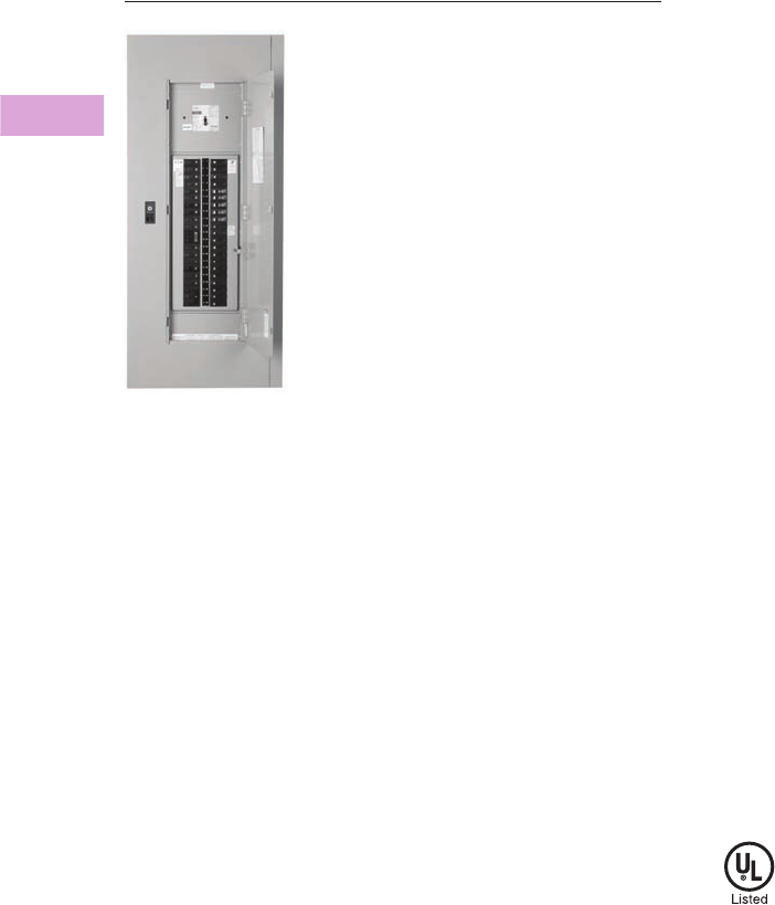
V2-T3-38 Volume 2—Commercial Distribution CA08100003E—April 2014 www.eaton.com
3
3
3
3
3
3
3
3
3
3
3
3
3
3
3
3
3
3
3
3
3
3
3
3
3
3
3
3
3
3
3.3
Panelboards and Lighting Control
Pow-R-Line C Panelboards
Type PRL2a
Contents
Description Page
Product Description. . . . . . . . . . . . . . . . . . . . . . . . V2-T3-7
Application Description . . . . . . . . . . . . . . . . . . . . . V2-T3-8
Standards and Certifications . . . . . . . . . . . . . . . . . V2-T3-10
Technical Data and Specifications . . . . . . . . . . . . . V2-T3-11
Type PRL1a . . . . . . . . . . . . . . . . . . . . . . . . . . . . . . V2-T3-26
Type PRL1aF . . . . . . . . . . . . . . . . . . . . . . . . . . . . . V2-T3-30
Type PRL1a-LX . . . . . . . . . . . . . . . . . . . . . . . . . . . V2-T3-34
Type PRL2a
Product Selection. . . . . . . . . . . . . . . . . . . . . . . V2-T3-39
Box Sizing and Selection . . . . . . . . . . . . . . . . . V2-T3-40
Type PRL2aF . . . . . . . . . . . . . . . . . . . . . . . . . . . . . V2-T3-42
Type PRL2a-LX . . . . . . . . . . . . . . . . . . . . . . . . . . . V2-T3-46
Retrofit Panelboard . . . . . . . . . . . . . . . . . . . . . . . . V2-T3-50
Type PRL3a . . . . . . . . . . . . . . . . . . . . . . . . . . . . . . V2-T3-58
Type PRL3E. . . . . . . . . . . . . . . . . . . . . . . . . . . . . . V2-T3-62
Type PRL4 . . . . . . . . . . . . . . . . . . . . . . . . . . . . . . . V2-T3-66
Type PRL4D . . . . . . . . . . . . . . . . . . . . . . . . . . . . . V2-T3-76
Type PRL5P. . . . . . . . . . . . . . . . . . . . . . . . . . . . . . V2-T3-86
Type PRL2a
Product Description
●480Y/277 Vac maximum
(125 Vdc)
●Three-phase four-wire,
three-phase three-wire,
single-phase three-wire,
single-phase two-wire
●400A maximum mains
●100A maximum branch
breakers
●Bolt-on branch breakers
●Each branch connector is
capable of up to a total of
140A maximum by breaker
ampere rating
●Factory assembled
●Refer to Page V2-T3-7 for
additional information
Application Description
●Lighting branch panelboard
●Fully rated or series rated
●Interrupting ratings up to
200 kA symmetrical
●Suitable for use as Service
Entrance Equipment, when
specified on the order
●See Pages V2-T3-7
through V2-T3-23 for
additional information
Standards and Certifications
●UL 67, UL 50
●Federal Specification
W-P-115c
●Refer to Page V2-T3-7 for
additional information
Volume 2—Commercial Distribution CA08100003E—April 2014 www.eaton.com V2-T3-39
3
3
3
3
3
3
3
3
3
3
3
3
3
3
3
3
3
3
3
3
3
3
3
3
3
3
3
3
3
3
3.3
Panelboards and Lighting Control
Pow-R-Line C Panelboards
Product Selection
PRL2a PRL2a Branch Circuit Breakers
Notes
1Interrupting ratings in this column are applicable to 120 Vac for single-pole breakers.
2Must be used on 480Y/277V grounded wye systems only.
3Remote controllable breaker.
4GFP for 30 mA equipment protection. Requires two-pole spaces. 277 Vac only.
5HID (High Intensity Discharge) rated breaker.
Ampere
Rating
Interrupting Rating
(kA Symmetrical) Breaker
Type240 Vac 480Y/277 Vac 125/250 Vdc
Main Lug Only
100 — — — —
225 — — — —
400 — — — —
Main Breaker
100 65 14 14 GHB
100 18 14 10 EHD
100 65 35 10 FD, FDE
100 100 65 22 HFD, HFDE
100 200 100 22 FDC
225 65 — — ED
225 65 35 10 FD, FDE
225 100 65 22 HFD, HFDE
225 200 100 22 FDC
250 65 35 10 JD
250 100 65 22 HJD
250 200 100 22 JDC
400 65 35 10 KD
400 100 65 22 HKD
400 100 65 — LHH
400 200 100 22 KDC
Type PRL2a
Ampere
Rating
Interrupting Rating
(kA Symmetrical) Breaker
Type240 Vac 1480Y/277 Vac 125/250 Vdc
15–20 65 14 — GHQ 2
15–20 65 14 14 GHB 2
25–60 65 14 14 GHB 2
70–100 65 14 14 GHB 2
15–30 65 25 — HGHB 2
15–20 65 14 — GHQRSP 3
15–30 65 14 — GHBS 23
15–60 — 14 — GHBGFEP 24
15–20 — 14 — GHBHID 25
Provision — — — —

V2-T3-40 Volume 2—Commercial Distribution CA08100003E—April 2014 www.eaton.com
3
3
3
3
3
3
3
3
3
3
3
3
3
3
3
3
3
3
3
3
3
3
3
3
3
3
3
3
3
3
3.3
Panelboards and Lighting Control
Pow-R-Line C Panelboards
Box Sizing and Selection
Approximate Dimensions in Inches (mm)
Assembled Circuit
Breaker Panelboards and
Lighting Controls
Box size and box and trim
catalog numbers for all
standard panelboard
types are found on
Page V2-T3-41.
Instructions
1. Using description of the
required panelboard,
select the rating and
type of main required.
2. Count the total number
of branch circuit poles,
including provisions,
required in the
panelboard. Do not
count main breaker
poles. Convert two-
or three-pole branch
breaker to single-poles,
i.e., three-pole breaker,
count as three poles.
Determine sub-feed
breaker or through-feed
lug requirements.
3. Select the main ampere
rating section from table
on Page V2-T3-41.
4. Select panelboard
type from first column,
main breaker frame, if
applicable, from second
column, and sub-feed
breaker frame, if
applicable, from the
third column.
5. From Step #2, determine
the number of branch
circuits in Column 4.
6. Read box size, box and
trim catalog numbers
across columns to the
right. Specify surface
or flush mounting on
the order.
Cabinets
Fronts are code-gauge
steel, ANSI-61 light gray
painted finish.
Boxes are code-gauge
galvanized steel without
knockouts. Standard depth
is 5-3/4 inches (146.1 mm).
Standard width is 20 inches
(508.0 mm). An optional
28-inch (711.2 mm) wide
box is available.
Top and Bottom Gutters
5-1/2 inches (139.7 mm)
minimum.

Volume 2—Commercial Distribution CA08100003E—April 2014 www.eaton.com V2-T3-41
3
3
3
3
3
3
3
3
3
3
3
3
3
3
3
3
3
3
3
3
3
3
3
3
3
3
3
3
3
3
3.3
Panelboards and Lighting Control
Pow-R-Line C Panelboards
Approximate Dimensions in Inches (mm)
PRL2a Panelboard Sizing
Note
1Smaller panelboard box sizes are available if required. Contact Eaton for application information.
Panelboard
Types
Main Breaker Types
and Mounting Position
(H) = Horizontal
(V) = Vertical
Sub-Feed Breaker Types
and Mounting Position
(H) = Horizontal
(V) = Vertical
Maximum No. of
Branch Circuits
Including
Provisions
Box Dimensions 1
YS Box
Catalog
Number
LT Trim
Catalog
Number
EZ Box
Catalog
Number
EZ Trim
Catalog
NumberHeight Width Depth
100A
Main breaker
GHB
(H)
—15
36.00 (914.4) 20.00 (508.0) 5.75 (146.1)
YS2036 LT2036S or F EZB2036R EZT2036S or F
—27
48.00 (1219.2) 20.00 (508.0) 5.75 (146.1)
YS2048 LT2048S or F EZB2048R EZT2048S or F
—39
48.00 (1219.2) 20.00 (508.0) 5.75 (146.1)
YS2048 LT2048S or F EZB2048R EZT2048S or F
—42
60.00 (1524.0) 20.00 (508.0) 5.75 (146.1)
YS2060 LT2060S or F EZB2060R EZT2060S or F
Main lugs or
main breaker
EHD
FD, HFD, FDE
HFDE
(V)
—18
36.00 (914.4) 20.00 (508.0) 5.75 (146.1)
YS2036 LT2036S or F EZB2036R EZT2036S or F
—30
48.00 (1219.2) 20.00 (508.0) 5.75 (146.1)
YS2048 LT2048S or F EZB2048R EZT2048S or F
—42
48.00 (1219.2) 20.00 (508.0) 5.75 (146.1)
YS2048 LT2048S or F EZB2048R EZT2048S or F
Main lugs or main breaker
with 100A through-feed
lugs or sub-feed breaker
EHD
FD, FDE
HFD, HFDE
(V)
EHD
FD
HFD
(V)
18
48.00 (1219.2) 20.00 (508.0) 5.75 (146.1)
YS2048 LT2048S or F EZB2048R EZT2048S or F
30
48.00 (1219.2) 20.00 (508.0) 5.75 (146.1)
YS2048 LT2048S or F EZB2048R EZT2048S or F
42
60.00 (1524.0) 20.00 (508.0) 5.75 (146.1)
YS2060 LT2060S or F EZB2060R EZT2060S or F
225A
Main lugs or
main breaker
EDB, EDS, ED,
EDH, FD, HFD
FDE, HFDE
(V)
—18
36.00 (914.4) 20.00 (508.0) 5.75 (146.1)
YS2036 LT2036S or F EZB2036R EZT2036S or F
—30
48.00 (1219.2) 20.00 (508.0) 5.75 (146.1)
YS2048 LT2048S or F EZB2048R EZT2048S or F
—42
48.00 (1219.2) 20.00 (508.0) 5.75 (146.1)
YS2048 LT2048S or F EZB2048R EZT2048S or F
JD, HJD
JDC
(V)
—18
60.00 (1524.0) 20.00 (508.0) 5.75 (146.1)
YS2060 LT2060S or F EZB2060R EZT2060S or F
—30
60.00 (1524.0) 20.00 (508.0) 5.75 (146.1)
YS2060 LT2060S or F EZB2060R EZT2060S or F
— 42 72.00 (1828.8)
20.00 (508.0) 5.75 (146.1)
YS2072 LT2072S or F EZB2072R EZT2072S or F
Main lugs or main breaker
with 225A through-feed
lugs or sub-feed breaker
EHD, FD, HFD,
EDB, EDS, ED,
EDH
FDE, HFDE
(V)
EHD, FD, HFD,
EDB, EDS, ED,
EDH (V)
18
48.00 (1219.2) 20.00 (508.0) 5.75 (146.1)
YS2048 LT2048S or F EZB2048R EZT2048S or F
30
48.00 (1219.2) 20.00 (508.0) 5.75 (146.1)
YS2048 LT2048S or F EZB2048R EZT2048S or F
42
60.00 (1524.0) 20.00 (508.0) 5.75 (146.1)
YS2060 LT2060S or F EZB2060R EZT2060S or F
JD, HJD
JDC
(V)
EHD, FD, HFD,
EDB, EDS, ED,
EDH (V)
18
60.00 (1524.0) 20.00 (508.0) 5.75 (146.1)
YS2060 LT2060S or F EZB2060R EZT2060S or F
30 72.00 (1828.8)
20.00 (508.0) 5.75 (146.1)
YS2072 LT2072S or F EZB2072R EZT2072S or F
42 72.00 (1828.8)
20.00 (508.0) 5.75 (146.1)
YS2072 LT2072S or F EZB2072R EZT2072S or F
400A
Main lugs or
main breaker
DK, KD, HKD,
KDC, LHH
(V)
— 18 60.00 (1524.0) 20.00 (508.0) 5.75 (146.1)
YS2060 LT2060S or F EZB2060R EZT2060S or F
— 30 60.00 (1524.0) 20.00 (508.0) 5.75 (146.1)
YS2060 LT2060S or F EZB2060R EZT2060S or F
—42
72.00 (1828.8)
20.00 (508.0) 5.75 (146.1)
YS2072 LT2072S or F EZB2072R EZT2072S or F
Main lugs or main breaker
with 225A through-feed
lugs or sub-feed breaker
DK, KD, HKD,
KDC, LHH
(V)
EHD, FD, HFD,
EDB, EDS, ED,
EDH (V)
18 60.00 (1524.0) 20.00 (508.0) 5.75 (146.1)
YS2060 LT2060S or F EZB2060R EZT2060S or F
30
72.00 (1828.8)
20.00 (508.0) 5.75 (146.1)
YS2072 LT2072S or F EZB2072R EZT2072S or F
42
72.00 (1828.8)
20.00 (508.0) 5.75 (146.1)
YS2072 LT2072S or F EZB2072R EZT2072S or F
Main lugs or main breaker
with 400A through-feed
lugs or sub-feed breaker
DK, KD, HKD,
KDC, LHH
(V)
JD, HJD, JDC,
DK, KD,
HKD, KDC
(V)
18
72.00 (1828.8)
20.00 (508.0) 5.75 (146.1)
YS2072 LT2072S or F EZB2072R EZT2072S or F
30
90.00 (2286.0)
20.00 (508.0) 5.75 (146.1)
YS2090 LT2090S or F EZB2090R EZT2090S or F
42
90.00 (2286.0)
20.00 (508.0) 5.75 (146.1)
YS2090 LT2090S or F EZB2090R EZT2090S or F
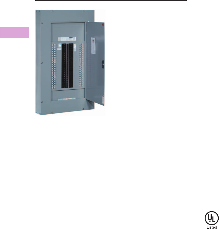
V2-T3-42 Volume 2—Commercial Distribution CA08100003E—April 2014 www.eaton.com
3
3
3
3
3
3
3
3
3
3
3
3
3
3
3
3
3
3
3
3
3
3
3
3
3
3
3
3
3
3
3.3
Panelboards and Lighting Control
Pow-R-Line C Panelboards
Type PRL2aF
Contents
Description Page
Product Description. . . . . . . . . . . . . . . . . . . . . . . . V2-T3-7
Application Description . . . . . . . . . . . . . . . . . . . . . V2-T3-8
Standards and Certifications . . . . . . . . . . . . . . . . . V2-T3-10
Technical Data and Specifications . . . . . . . . . . . . . V2-T3-11
Type PRL1a . . . . . . . . . . . . . . . . . . . . . . . . . . . . . . V2-T3-26
Type PRL1aF . . . . . . . . . . . . . . . . . . . . . . . . . . . . . V2-T3-30
Type PRL1a-LX . . . . . . . . . . . . . . . . . . . . . . . . . . . V2-T3-34
Type PRL2a . . . . . . . . . . . . . . . . . . . . . . . . . . . . . . V2-T3-38
Type PRL2aF
Product Selection. . . . . . . . . . . . . . . . . . . . . . . V2-T3-43
Box Sizing and Selection . . . . . . . . . . . . . . . . . V2-T3-44
Type PRL2a-LX . . . . . . . . . . . . . . . . . . . . . . . . . . . V2-T3-46
Retrofit Panelboard . . . . . . . . . . . . . . . . . . . . . . . . V2-T3-50
Type PRL3a . . . . . . . . . . . . . . . . . . . . . . . . . . . . . . V2-T3-58
Type PRL3E. . . . . . . . . . . . . . . . . . . . . . . . . . . . . . V2-T3-62
Type PRL4 . . . . . . . . . . . . . . . . . . . . . . . . . . . . . . . V2-T3-66
Type PRL4D . . . . . . . . . . . . . . . . . . . . . . . . . . . . . V2-T3-76
Type PRL5P. . . . . . . . . . . . . . . . . . . . . . . . . . . . . . V2-T3-86
Type PRL2aF
Product Description
●240 Vac maximum
●400A maximum mains
●Three-phase four-wire,
single-phase three-wire
●30A maximum branch
devices
●Factory assembled
Application Description
●Lighting branch panelboard
●Instrument protection
●Fully rated
●Interrupting ratings up to
200 kA symmetrical when
protected by fuse
Standards and Certifications
●UL 67, UL 50
Volume 2—Commercial Distribution CA08100003E—April 2014 www.eaton.com V2-T3-43
3
3
3
3
3
3
3
3
3
3
3
3
3
3
3
3
3
3
3
3
3
3
3
3
3
3
3
3
3
3
3.3
Panelboards and Lighting Control
Pow-R-Line C Panelboards
Product Selection
PRL2aF
PRL2aF Branch Overcurrent Devices
Hybrid breaker/fuse (Class CC) branch device
Ampere Rating
Interrupting
Rating (kA Sym.)
480Y/277 Vac Breaker Type
Main Lug Only
100 — —
225 — —
400 — —
Main Breaker
100 14 EHD
100 35 FD
100 35 FDE
100 35 HFD
100 35 HFDE
225 35 FD
225 35 FDE
225 65 HFD
225 65 HFDE
400 35 KD
400 65 HKD
400 100 KDC
400 100 LHH
Ampere Rating
Interrupting
Rating (kA Sym.)
480Y/277 Vac Breaker Type
30 200 Hybrid
Type PRL2aF

V2-T3-44 Volume 2—Commercial Distribution CA08100003E—April 2014 www.eaton.com
3
3
3
3
3
3
3
3
3
3
3
3
3
3
3
3
3
3
3
3
3
3
3
3
3
3
3
3
3
3
3.3
Panelboards and Lighting Control
Pow-R-Line C Panelboards
Box Sizing and Selection
Approximate Dimensions in Inches (mm)
Assembled Circuit
Breaker Panelboards
Box size and box and trim
catalog numbers for all
standard panelboard
types are found on
Page V2-T3-45.
Instructions
1. Using description of the
required panelboard,
select the rating and
type of main required.
2. Count the total number
of branch circuit poles,
including provisions,
required in the
panelboard.
Determine through-feed
lug requirements.
3. Select the main ampere
rating section from table
on Page V2-T3-45.
4. Select panelboard
type from first column,
main breaker frame,
if applicable, from
second column.
5. From Step #2, determine
the number of branch
circuits in Column 4.
6. Read box size, box and
trim catalog numbers
across columns to the
right. Specify surface
or flush mounting on
the order.
Cabinets
Fronts are code-gauge
steel, ANSI-61 light gray
painted finish.
Boxes are code-gauge
galvanized steel without
knockouts. Standard depth
is 5-3/4 inches (146.1 mm).
Standard width is 20 inches
(508.0 mm). An optional
28-inch (711.2 mm) wide
box is available.
Top and Bottom Gutters
5-1/2 inches (139.7 mm)
minimum.

Volume 2—Commercial Distribution CA08100003E—April 2014 www.eaton.com V2-T3-45
3
3
3
3
3
3
3
3
3
3
3
3
3
3
3
3
3
3
3
3
3
3
3
3
3
3
3
3
3
3
3.3
Panelboards and Lighting Control
Pow-R-Line C Panelboards
Approximate Dimensions in Inches (mm)
PRL2aF Panelboard Sizing
Note
1Smaller panelboard box sizes are available if required. Contact Eaton for application information.
Panelboard
Types
Main Breaker Types
and Mounting Position
(H) = Horizontal
(V) = Vertical
Maximum No. of
Branch Circuits
Including
Provisions
Box Dimensions 1
YS Box
Catalog
Number
LT Trim
Catalog
Number
EZ Box
Catalog
Number
EZ Trim
Catalog
NumberHeight Width Depth
100A
Main lugs or
main breaker
EHD
FD, HFD, FDE
HFDE
(V)
18
36.00 (914.4) 20.00 (508.0) 5.75 (146.1)
YS2036 LT2036S or F EZB2036R EZT2036S or F
30
48.00 (1219.2) 20.00 (508.0) 5.75 (146.1)
YS2048 LT2048S or F EZB2048R EZT2048S or F
42
48.00 (1219.2) 20.00 (508.0) 5.75 (146.1)
YS2048 LT2048S or F EZB2048R EZT2048S or F
Main lugs or main breaker
with 100A through-feed
lugs or sub-feed breaker
EHD
FD, FDE
HFD, HFDE
(V)
18
48.00 (1219.2) 20.00 (508.0) 5.75 (146.1)
YS2048 LT2048S or F EZB2048R EZT2048S or F
30
48.00 (1219.2) 20.00 (508.0) 5.75 (146.1)
YS2048 LT2048S or F EZB2048R EZT2048S or F
42
60.00 (1524.0) 20.00 (508.0) 5.75 (146.1)
YS2060 LT2060S or F EZB2060R EZT2060S or F
225A
Main lugs or
main breaker
EDB, EDS, ED,
EDH, FD, HFD
FDE, HFDE
(V)
18
36.00 (914.4) 20.00 (508.0) 5.75 (146.1)
YS2036 LT2036S or F EZB2036R EZT2036S or F
30
48.00 (1219.2) 20.00 (508.0) 5.75 (146.1)
YS2048 LT2048S or F EZB2048R EZT2048S or F
42
48.00 (1219.2) 20.00 (508.0) 5.75 (146.1)
YS2048 LT2048S or F EZB2048R EZT2048S or F
JD, HJD
JDC
(V)
18
60.00 (1524.0) 20.00 (508.0) 5.75 (146.1)
YS2060 LT2060S or F EZB2060R EZT2060S or F
30
60.00 (1524.0) 20.00 (508.0) 5.75 (146.1)
YS2060 LT2060S or F EZB2060R EZT2060S or F
42 72.00 (1828.8)
20.00 (508.0) 5.75 (146.1)
YS2072 LT2072S or F EZB2072R EZT2072S or F
Main lugs or main breaker
with 225A through-feed
lugs
EHD, FD, HFD,
EDB, EDS, ED, EDH
FDE, HFDE
(V)
18
48.00 (1219.2) 20.00 (508.0) 5.75 (146.1)
YS2048 LT2048S or F EZB2048R EZT2048S or F
30
48.00 (1219.2) 20.00 (508.0) 5.75 (146.1)
YS2048 LT2048S or F EZB2048R EZT2048S or F
42
60.00 (1524.0) 20.00 (508.0) 5.75 (146.1)
YS2060 LT2060S or F EZB2060R EZT2060S or F
JD, HJD
JDC
(V)
18
60.00 (1524.0) 20.00 (508.0) 5.75 (146.1)
YS2060 LT2060S or F EZB2060R EZT2060S or F
30 72.00 (1828.8)
20.00 (508.0) 5.75 (146.1)
YS2072 LT2072S or F EZB2072R EZT2072S or F
42 72.00 (1828.8)
20.00 (508.0) 5.75 (146.1)
YS2072 LT2072S or F EZB2072R EZT2072S or F
400A
Main lugs or
main breaker
KD, HKD,
KDC, LHH
(V)
18 60.00 (1524.0) 20.00 (508.0) 5.75 (146.1)
YS2060 LT2060S or F EZB2060R EZT2060S or F
30 60.00 (1524.0) 20.00 (508.0) 5.75 (146.1)
YS2060 LT2060S or F EZB2060R EZT2060S or F
42
72.00 (1828.8)
20.00 (508.0) 5.75 (146.1)
YS2072 LT2072S or F EZB2072R EZT2072S or F
Main lugs or main breaker
with 225A through-feed
lugs
KD, HKD,
KDC, LHH
(V)
18 60.00 (1524.0) 20.00 (508.0) 5.75 (146.1)
YS2060 LT2060S or F EZB2060R EZT2060S or F
30
72.00 (1828.8)
20.00 (508.0) 5.75 (146.1)
YS2072 LT2072S or F EZB2072R EZT2072S or F
42
72.00 (1828.8)
20.00 (508.0) 5.75 (146.1)
YS2072 LT2072S or F EZB2072R EZT2072S or F
Main lugs or main breaker
with 400A through-feed
lugs
KD, HKD,
KDC, LHH
(V)
18
72.00 (1828.8)
20.00 (508.0) 5.75 (146.1)
YS2072 LT2072S or F EZB2072R EZT2072S or F
30
90.00 (2286.0)
20.00 (508.0) 5.75 (146.1)
YS2090 LT2090S or F EZB2090R EZT2090S or F
42
90.00 (2286.0)
20.00 (508.0) 5.75 (146.1)
YS2090 LT2090S or F EZB2090R EZT2090S or F

V2-T3-46 Volume 2—Commercial Distribution CA08100003E—April 2014 www.eaton.com
3
3
3
3
3
3
3
3
3
3
3
3
3
3
3
3
3
3
3
3
3
3
3
3
3
3
3
3
3
3
3.3
Panelboards and Lighting Control
Pow-R-Line C Panelboards
Type PRL2a-LX, Column Type
Contents
Description Page
Product Description. . . . . . . . . . . . . . . . . . . . . . . . V2-T3-7
Application Description . . . . . . . . . . . . . . . . . . . . . V2-T3-8
Standards and Certifications . . . . . . . . . . . . . . . . . V2-T3-10
Technical Data and Specifications . . . . . . . . . . . . . V2-T3-11
Type PRL1a . . . . . . . . . . . . . . . . . . . . . . . . . . . . . . V2-T3-26
Type PRL1aF . . . . . . . . . . . . . . . . . . . . . . . . . . . . . V2-T3-30
Type PRL1a-LX . . . . . . . . . . . . . . . . . . . . . . . . . . . V2-T3-34
Type PRL2a . . . . . . . . . . . . . . . . . . . . . . . . . . . . . . V2-T3-38
Type PRL2aF . . . . . . . . . . . . . . . . . . . . . . . . . . . . . V2-T3-42
Type PRL2a-LX
Product Selection. . . . . . . . . . . . . . . . . . . . . . . V2-T3-47
Box Sizing and Selection . . . . . . . . . . . . . . . . . V2-T3-48
Retrofit Panelboard . . . . . . . . . . . . . . . . . . . . . . . . V2-T3-50
Type PRL3a . . . . . . . . . . . . . . . . . . . . . . . . . . . . . . V2-T3-58
Type PRL3E. . . . . . . . . . . . . . . . . . . . . . . . . . . . . . V2-T3-62
Type PRL4 . . . . . . . . . . . . . . . . . . . . . . . . . . . . . . . V2-T3-66
Type PRL4D . . . . . . . . . . . . . . . . . . . . . . . . . . . . . V2-T3-76
Type PRL5P. . . . . . . . . . . . . . . . . . . . . . . . . . . . . . V2-T3-86
Type PRL2a-LX
Product Description
●480Y/277 Vac maximum
(125 Vdc)
●Three-phase four-wire,
three-phase three-wire,
single-phase three-wire,
single-phase two-wire
●225A maximum mains
●100A maximum branch
breakers
●Bolt-on branch breakers
●Factory assembled
●Refer to Refer to Page V2-
T3-7 for additional
information
Application Description
●Lighting branch panelboard
●Column mounting width
●Fully rated or series rated
●Interrupting ratings up to
200 kA symmetrical
●See Pages V2-T3-7
through V2-T3-23 for
additional information
Standards and Certifications
●UL 67, UL 50
●Federal Specification
W-P-115c
●Refer to Page V2-T3-7 for
additional information

Volume 2—Commercial Distribution CA08100003E—April 2014 www.eaton.com V2-T3-47
3
3
3
3
3
3
3
3
3
3
3
3
3
3
3
3
3
3
3
3
3
3
3
3
3
3
3
3
3
3
3.3
Panelboards and Lighting Control
Pow-R-Line C Panelboards
Product Selection
PRL2a-LX
Branch Circuit Breakers—PRL2a-LX
Ampere
Rating
Interrupting Rating (kA
Symmetrical)
Breaker
Type240 Vac
480Y/277
Vac
125/250
Vdc
Main Lug Only
100 — — — —
225 — — — —
Main Breaker
100 65 14 14 GHB
100 18 14 10 EHD
100 65 35 10 FD, FDE
100 100 65 22 HFD, HFDE
100 200 100 22 FDC
225 65 — — ED
225 65 35 10 FD
225 100 65 22 HFD
225 200 100 22 FDC
Ampere
Rating
Interrupting Rating (kA Symmetrical)
240
Vac 1
480Y/277
Vac
125/250
Vdc
Breaker
Type
15–20 65 14 — GHQ 2
15–20 65 14 14 GHB 2
25–60 65 14 14 GHB 2
70–100 65 14 14 GHB 2
15–30 65 25 — HGHB 2
15–20 65 14 — GHQRSP 3
15–30 65 14 — GHBS 23
15–60 — 14 — GHBGFEP 24
Provision — — — —
Type PRL2a-LX
Pull Box With
Extension Trough
Includes pull box with trough
extension. For additional
trough extensions, refer to
table below.
Neutral Bars
When Column Type panels
are furnished with trough
extensions and pull box, the
neutral bar will be placed in
the pull box unless otherwise
specified.
When troughs and pull box are
not furnished, the neutral bar
will be located on the panel at
the same end as the main.
Additional Trough
Extensions
Width and depth are the
same as the panelboard.
Notes
1Interrupting ratings in this column are
applicable to 120 Vac for single-pole
breakers.
2At 480V, must be used on 480Y/277V
grounded wye systems only.
3Solenoid operated breaker.
4GFP for 30 mA equipment protection.
Requires two pole spaces.
Description
Catalog
Number
Pullbox with 36-inch trough XCTXB036
Pullbox with 48-inch trough XCTXB048
Pullbox with 60-inch trough XCTXB060
Pullbox with 72-inch trough XCTXB072
Pullbox with 84-inch trough XCTXB084
Length Catalog
NumberInches (mm)
36.00 (914.4) CTXB036
48.00 (1219.2) CTXB048
60.00 (1524.0) CTXB060
72.00 (1828.8) CTXB072
84.00 (2133.6) CTXB084
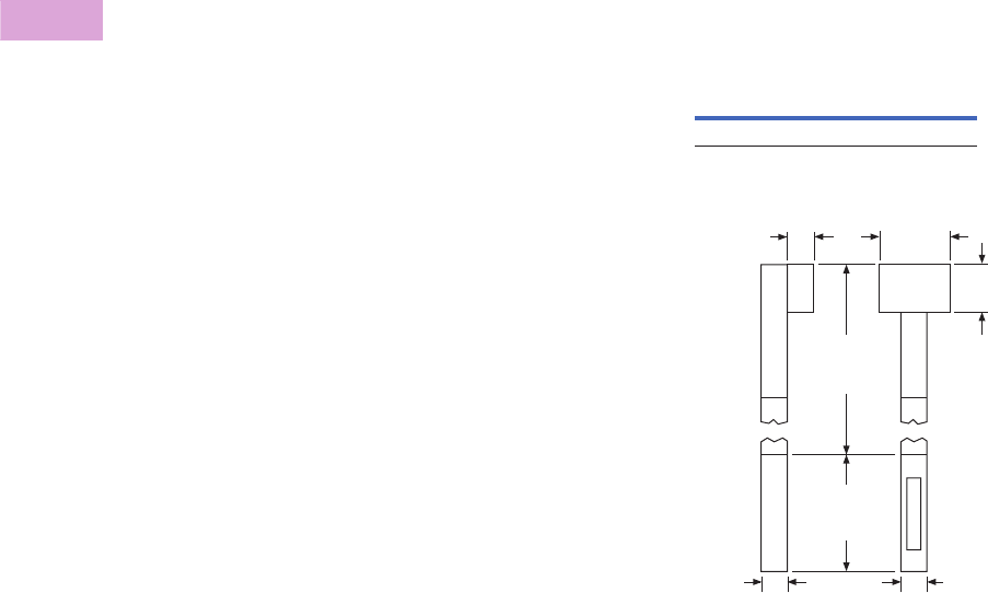
V2-T3-48 Volume 2—Commercial Distribution CA08100003E—April 2014 www.eaton.com
3
3
3
3
3
3
3
3
3
3
3
3
3
3
3
3
3
3
3
3
3
3
3
3
3
3
3
3
3
3
3.3
Panelboards and Lighting Control
Pow-R-Line C Panelboards
Box Sizing and Selection
Approximate Dimensions in Inches (mm)
Assembled Circuit Breaker
Panelboards
Box size, box and trim catalog
numbers for standard column
type panelboards listed are
available from tables on
Page V2-T3-49.
Instructions
1. Using description of the
required panelboard,
select the rating and
type of main required.
a. 100A panelboards—
Page V2-T3-49.
b. 225A panelboards—
Page V2-T3-49.
2. Count the total number
of branch circuit poles,
including provisions,
required in the
panelboard. Do not
count main breaker
poles. Convert two-
or three-pole branch
breaker to single poles,
i.e., three-pole breaker,
count as three poles.
Determine sub-feed
breaker or through-feed
lug requirements.
3. Select the panelboard
main ampere rating
from tables on
Page V2-T3-49.
4. Panelboard Type from
first column, main
breaker Frame and
Designation, if applicable
from second column, and
sub-feed breaker Frame
and Designation, if
applicable, from the third
column.
5. From Step #2, determine
the number of branch
circuits in Column 4.
6. Read box size, box and
trim catalog numbers
across columns to the
right. All panels are
surface mounted.
Cabinets
Boxes and trims are code-
gauge steel, ANSI-61 light
gray painted finish.
Boxes are furnished without
knockouts. Standard depth
is 6.00 inches (152.4 mm).
Standard width is
8.63 inches (219.1 mm).
Top and Bottom Gutters
4.50 inches (114.3 mm)
minimum.
Left Side Gutter
3.31 inches (84.2 mm)
minimum.
Pull Box
Pull box is furnished without
knockouts. Standard dimensions:
Pull Box Dimensions
PRL2a-LX Trough Extension
Trough Extension
When extension troughs are
used, Section 376 of the
National Electrical Code,
reading as follows, should be
observed: 376. Number of
Conductors. Wireways shall
not contain more than 30
conductors at any cross
section, unless the
conductors are for signal
circuits or are control
conductors between a motor
and its starter and used only
for starting duty. The sum
of the cross-sectional areas of
all contained conductors at
any cross section of a
wireway shall not exceed
20% of the interior cross-
sectional area of the wireway.
Height Width Depth
12.00 (304.8) 16.00 (406.4) 6.00 (152.4)
Additional
Extensions
(If Required)
H
Box
Height
12.00
(304.8)
6.00
(152.4)
16.00
(406.4)
8.63
(219.1)
6.00
(152.4)

Volume 2—Commercial Distribution CA08100003E—April 2014 www.eaton.com V2-T3-49
3
3
3
3
3
3
3
3
3
3
3
3
3
3
3
3
3
3
3
3
3
3
3
3
3
3
3
3
3
3
3.3
Panelboards and Lighting Control
Pow-R-Line C Panelboards
Approximate Dimensions in Inches (mm)
100A Maximum PRL2a-LX Column Type Panelboard Sizing
225A Maximum PRL2a-LX Column Type Panelboard Sizing
Note
1Add suffix B to trim catalog number for bottom fed panelboards (i.e., LTC969SB).
Panelboard
Types
Main Breaker
Types
Mounting:
(H) = Horizontal
(V) = Vertical
Sub-Feed
Breaker Types
Vertical
Mounting
Maximum
Number
of Branch
Circuits
Including
Provisions
Box Dimensions
Box
Catalog
Number
Trim
Catalog
Number 1
Height Width Depth
Main breaker GHB
(H)
— 27 69.00 (1752.6) 8.63 (219.2) 6.00 (152.4) YSC969 LTC969S
— 39 81.00 (2057.7) 8.63 (219.2) 6.00 (152.4) YSC981 LTC981S
Main lugs or main breaker EHD, FD
HFD, FDC
(V)
— 30 69.00 (1752.6) 8.63 (219.2) 6.00 (152.4) YSC969 LTC969S
— 42 81.00 (2057.7) 8.63 (219.2) 6.00 (152.4) YSC981 LTC981S
Main lugs or main breaker
with 100A through-feed lugs
or sub-feed breaker
EHD, FD
HFD, FDC
(V)
EHD, FD, HFD 30 78.00 (1981.2) 8.63 (219.2) 6.00 (152.4) YSC978 LTC978S
42 90.00 (2286.0) 8.63 (219.2) 6.00 (152.4) YSC990 LTC990S
Panelboard
Types
Main Breaker
Types
Sub-Feed
Breaker Types
Maximum
Number
of Branch
Circuits
Including
Provisions
Box Dimensions
Box
Catalog
Number
Trim
Catalog
Number 1
Vertical Mounting Height Width Depth
Main lugs or main breaker ED, FD
HFD, FDC
— 30 69.00 (1752.6) 8.63 (219.2) 6.00 (152.4) YSC969 LTC969S
— 42 81.00 (2057.7) 8.63 (219.2) 6.00 (152.4) YSC981 LTC981S
Main lugs or main breaker
with 225A through-feed lugs
or sub-feed breaker
ED, FD
HFD, FDC
EHD, FD, HFD,
ED, EDH
30 78.00 (1981.2) 8.63 (219.2) 6.00 (152.4) YSC978 LTC978S
42 90.00 (2286.0) 8.63 (219.2) 6.00 (152.4) YSC990 LTC990S
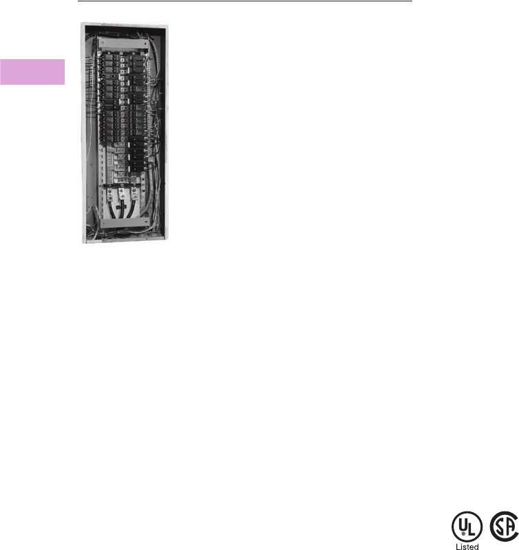
V2-T3-50 Volume 2—Commercial Distribution CA08100003E—April 2014 www.eaton.com
3
3
3
3
3
3
3
3
3
3
3
3
3
3
3
3
3
3
3
3
3
3
3
3
3
3
3
3
3
3
3.3
Panelboards and Lighting Control
Pow-R-Line C Panelboards
Retrofit Panelboard
Contents
Description Page
Product Description. . . . . . . . . . . . . . . . . . . . . . . . V2-T3-7
Application Description . . . . . . . . . . . . . . . . . . . . . V2-T3-8
Standards and Certifications . . . . . . . . . . . . . . . . . V2-T3-10
Technical Data and Specifications . . . . . . . . . . . . . V2-T3-11
Type PRL1a . . . . . . . . . . . . . . . . . . . . . . . . . . . . . . V2-T3-26
Type PRL1aF . . . . . . . . . . . . . . . . . . . . . . . . . . . . . V2-T3-30
Type PRL1a-LX . . . . . . . . . . . . . . . . . . . . . . . . . . . V2-T3-34
Type PRL2a . . . . . . . . . . . . . . . . . . . . . . . . . . . . . . V2-T3-38
Type PRL2aF . . . . . . . . . . . . . . . . . . . . . . . . . . . . . V2-T3-42
Type PRL2a-LX . . . . . . . . . . . . . . . . . . . . . . . . . . . V2-T3-46
Retrofit Panelboard . . . . . . . . . . . . . . . . . . . . . . . . V2-T3-50
Catalog Number Selection . . . . . . . . . . . . . . . . V2-T3-51
Product Selection. . . . . . . . . . . . . . . . . . . . . . . V2-T3-52
Trim Selection . . . . . . . . . . . . . . . . . . . . . . . . . V2-T3-54
Custom Trim Selection. . . . . . . . . . . . . . . . . . . V2-T3-55
Application Guidelines . . . . . . . . . . . . . . . . . . . V2-T3-56
Options and Accessories . . . . . . . . . . . . . . . . . V2-T3-57
Type PRL3a . . . . . . . . . . . . . . . . . . . . . . . . . . . . . . V2-T3-58
Type PRL3E. . . . . . . . . . . . . . . . . . . . . . . . . . . . . . V2-T3-62
Type PRL4 . . . . . . . . . . . . . . . . . . . . . . . . . . . . . . . V2-T3-66
Type PRL4D . . . . . . . . . . . . . . . . . . . . . . . . . . . . . V2-T3-76
Type PRL5P. . . . . . . . . . . . . . . . . . . . . . . . . . . . . . V2-T3-86
Retrofit Panelboard
Product Description
●PRL1R—240 Vac;
PRL2R—480Y/277V
●Single-phase three-wire or
single two-wire
●Three-phase three-wire or
three-phase four-wire
●225A maximum
●100A maximum branch
breakers
●Standard PRL1R fits
existing box depths from
4.50–6.00 inches deep;
Standard PRL2R fits
existing box depths from
4.75–6.00 inches deep
(without additional
accessories)
●Integrally mounted neutral
assembly
●Grounding lug included
●Neutral and ground
convertible from left-right
●Bolt-on branch breakers
●Factory assembled
Application Description
●Lighting branch panelboard
●Fully rated or series rated
●Interrupting capacities to
100 kA symmetrical
●Suitable for use as
Service Entrance
Equipment where
specified on the order
Standards and Certifications
●UL 67
●Federal Specification
W-P-115c
●CSA C22.2 No. 29
Volume 2—Commercial Distribution CA08100003E—April 2014 www.eaton.com V2-T3-51
3
3
3
3
3
3
3
3
3
3
3
3
3
3
3
3
3
3
3
3
3
3
3
3
3
3
3
3
3
3
3.3
Panelboards and Lighting Control
Pow-R-Line C Panelboards
Catalog Number Selection
Retrofit Panelboard
Trim Selection
Notes
1P2R only.
2Flush trims include 1-inch overlap per side.
3Standard trim includes 12-gauge steel painted ANSI 61 grey.
4Stainless trims provided as 304 standard. Optional 316 available.
Panelboard Type
P1R = ≤ 240V
P2R = > 480Y/277V
Main Device
L= MLO
B= Main breaker Bus Type
A = Aluminum
C = Copper
System Type
1 = Single-phase
(three-wire)
3 = Three-phase
(three- or four-wire)
Main Breaker
Blank = MLO
BAB
GHB 1
ED
FD
EHD 1
FD 1
Bus Ampere
Rating
1 = 100A
2 = 225A
Circuits
18 = 18
30 = 30
42 = 42
Main Breaker
Amperes
Blank =MLO
30 =30A
60 =60A
100 =100A
125 =125A
150 =150A
175 =175A
200 =200A
225 =225A
Sub-Feed Device
Blank =None
TL = Through-feed lugs
Feed
B = Bottom fed
T = Top fed
P1R B 1 C 1 30 BAB 100TLB
Renovation
Panelboard
Custom Trim
RCT
Door Style
A= 18-circuit MLO/
branch-mounted MCB
B= 30-circuit MLO/
branch-mounted MCB;
18-circuit F-Frame MCB
C= 42-circuit MLO/
branch-mounted MCB
D= 30-circuit F-Frame MCB
E= 42-circuit F-Frame MCB
Existing Box
Width (Inches)
Existing Box
Width
(Fraction)
00 = None
13 = 1/8
25 = 1/4
38 = 3/8
50 = 1/2
63 = 5/8
75 = 3/4
88 = 7/8
Existing Box
Height (Inches)
Existing Box
Height
(Fraction)
00 = None
13 = 1/8
25 = 1/4
38 = 3/8
50 = 1/2
63 = 5/8
75 = 3/4
88 = 7/8
Trim Style
S = Surface
F = Flush 2
Trim Finish Option 3
Blank = ANSI 61 painted steel
S= Brushed stainless steel 4
P= Custom painted steel
C= Custom painted stainless steel
RCT B20 00 3650FS

V2-T3-52 Volume 2—Commercial Distribution CA08100003E—April 2014 www.eaton.com
3
3
3
3
3
3
3
3
3
3
3
3
3
3
3
3
3
3
3
3
3
3
3
3
3
3
3
3
3
3
3.3
Panelboards and Lighting Control
Pow-R-Line C Panelboards
Product Selection
P1R—Aluminum Bus, Single-Phase or Three-Phase 1
Notes
1 Standard trim included. Select standard trim from Page V2-T3-54. Custom trims are available for an additional charge. Contact your local Satellite for more
information about custom trims.
2 BAB and QBHW main devices consume available circuit space positions. (Two circuits for single-phase; three circuits for three-phase.)
3 Add main breaker ampere rating suffix. May NOT exceed main bus rating.
A neutral assembly is included with the base chassis. For single-phase two-wire systems or for three-phase, three-wire systems, do not connect.
Sum of branch circuit amperes not to exceed 140A.
Ampere
Rating
Number of
Circuits
Interrupting Rating
(kA Sym.) 240 Vac
Main
Breaker
Type
Single-Phase Three-Wire—
Single-Phase Two-Wire
Three-Phase Three-Wire—
Three-Phase Four-Wire
Catalog
Number
Catalog
Number
Main Lug Only
100 18 — MLO
P1RL1A118 P1RL3A118
30 — MLO
P1RL1A130 P1RL3A130
42 — MLO
P1RL1A142 P1RL3A142
225 18 — MLO
P1RL1A218 P1RL3A218
30 — MLO
P1RL1A230 P1RL3A230
42 — MLO
P1RL1A242 P1RL3A242
Main Breaker
100 18 10 BAB
2
P1RB1A118BAB
3
P1RB3A118BAB
3
30 10 BAB
2
P1RB1A130BAB
3
P1RB3A130BAB
3
42 10 BAB
2
P1RB1A142BAB
3
P1RB3A142BAB
3
18 18 EHD
P1RB1A118EHD
3
P1RB3A118EHD
3
30 18 EHD
P1RB1A130EHD
3
P1RB3A130EHD
3
42 18 EHD
P1RB1A142EHD
3
P1RB3A142EHD
3
18 22 QBHW
2
P1RB1A118QBHW
3
P1RB3A118QBHW
3
30 22 QBHW
2
P1RB1A130QBHW
3
P1RB3A130QBHW
3
42 22 QBHW
2
P1RB1A142QBHW
3
P1RB3A142QBHW
3
18 65 ED
P1RB1A118ED
3
P1RB3A118ED
3
30 65 ED
P1RB1A130ED
3
P1RB3A130ED
3
42 65 ED
P1RB1A142ED
3
P1RB3A142ED
3
18 100 EDH
P1RB1A118EDH
3
P1RB3A1-8EDH
3
30 100 EDH
P1RB1A130EDH
3
P1RB3A130EDH
3
42 100 EDH
P1RB1A142EDH
3
P1RB3A142EDH
3
225 18 65 ED
P1RB1A218ED
3
P1RB3A218ED
3
30 65 ED
P1RB1A230ED
3
P1RB3A230ED
3
42 65 ED
P1RB1A242ED
3
P1RB3A242ED
3
18 100 EDH
P1RB1A218EDH
3
P1RB3A218EDH
3
30 100 EDH
P1RB1A230EDH
3
P1RB3A230EDH
3
42 100 EDH
P1RB1A242EDH
3
P1RB3A242EDH
3
Retrofit Panelboard

Volume 2—Commercial Distribution CA08100003E—April 2014 www.eaton.com V2-T3-53
3
3
3
3
3
3
3
3
3
3
3
3
3
3
3
3
3
3
3
3
3
3
3
3
3
3
3
3
3
3
3.3
Panelboards and Lighting Control
Pow-R-Line C Panelboards
P2R—Aluminum Bus, Three-Phase
Notes
1 GHB main devices consume available circuit space positions. (Three circuits for three-phase).
2 Add main breaker ampere rating suffix. May NOT exceed main bus rating.
A neutral assembly is included with the base chassis.
Ampere
Rating
Number of
Circuits
Main Breaker Interrupting
Rating (kA Sym.) 480Y/277 Vac
Main
Breaker
Type
Three-Phase Four-Wire
Catalog
Number
Main Lug Only
100 18 — MLO P2RL3A118
30 — MLO P2RL3A130
42 — MLO P2RL3A142
225 18 — MLO P2RL3A218
30 — MLO P2RL3A230
42 — MLO P2RL3A242
Main Breaker
100 18 14 GHB 1P2RB3A118GHB 2
30 14 GHB 1P2RB3A130GHB 2
42 14 GHB 1P2RB3A142GHB 2
18 14 EHD P2RB3A118EHD 2
30 14 EHD P2RB3A130EHD 2
42 14 EHD P2RB3A142EHD 2
18 35 FD P2RB3A118FD 2
30 35 FD P2RB3A130FD 2
42 35 FD P2RB3A142FD 2
18 65 HFD P2RB3A118HFD 2
30 65 HFD P2RB3A130HFD 2
42 65 HFD P2RB3A142HFD 2
18 100 FDC P2RB3A118FDC 2
30 100 FDC P2RB3A130FDC 2
42 100 FDC P2RB3A142FDC 2
225 18 35 FD P2RB3A218FD 2
30 35 FD P2RB3A230FD 2
42 35 FD P2RB3A242FD 2
18 65 HFD P2RB3A218HFD 2
30 65 HFD P2RB3A230HFD 2
42 65 HFD P2RB3A242HFD 2
18 100 FDC P2RB3A218FDC 2
30 100 FDC P2RB3A230FDC 2
42 100 FDC P2RB3A242FDC 2
Retrofit Panelboard

V2-T3-54 Volume 2—Commercial Distribution CA08100003E—April 2014 www.eaton.com
3
3
3
3
3
3
3
3
3
3
3
3
3
3
3
3
3
3
3
3
3
3
3
3
3
3
3
3
3
3
3.3
Panelboards and Lighting Control
Pow-R-Line C Panelboards
Trim Selection
Instructions
●In order to meet minimum
wire bending space
requirements and to
ensure ease of installation,
minimum enclosure space
dimensions have been
defined for each chassis.
In order to ensure a proper
fit, every panelboard to
be renovated must be
carefully surveyed prior
to installation
●Determine the electrical
requirements of the
panelboard to be renovated
(i.e., main breaker or main
lugs, amperes, interrupting
rating, circuit space, branch
breakers, accessories)
●Using the electrical
requirement data, select
a base chassis and any
required breakers, options
and accessories
●Page V2-T3-56 provides
the minimum dimensions
of the enclosure, in which
each base chassis may
be installed. These
dimensions assume that
the chassis is mounted in
the center of the existing
box, both vertically and
horizontally. Where site
conditions require the
chassis to be offset from
this centrally mounted
position, it is the installer's
responsibility to ensure
wire bending space and
electrical clearance
requirements are met
●Page V2-T3-56 provides a
“Trim Door Size Code.”
Using this code, select a
standard trim from the
tables that will fit the
outside dimensions of the
existing box. Refer to Page
V2-T3-55 to define non-
standard trim requirements
Standard Trim Selection—20-Inch (508.0 mm) Wide Enclosure
Standard Trim Selection—14-Inch (355.6 mm) Wide Enclosure
Trim Door
Size Code
Enclosure Height—
Inches (mm)
Surface Type Flush Type
Catalog
Number
Trim Dimensions—Inches (mm) Catalog
Number
Trim Dimensions—Inches (mm)
Height Width Height Width
A 24.00 (609.6) RTA2024 24.00 (609.6) 20.00 (508.0) RTA2226 26.00 (660.4) 22.00 (558.8)
A 30.00 (762.0) RTA2030 30.00 (762.0) 20.00 (508.0) RTA2232 32.00 (812.8) 22.00 (558.8)
A 36.00 (914.4) RTA2036 36.00 (914.4) 20.00 (508.0) RTA2238 38.00 (965.2) 22.00 (558.8)
B 30.00 (762.0) RTB2030 30.00 (762.0) 20.00 (508.0) RTB2232 32.00 (812.8) 22.00 (558.8)
B 36.00 (914.4) RTB2036 36.00 (914.4) 20.00 (508.0) RTB2238 38.00 (965.2) 22.00 (558.8)
B 42.00 (1066.8) RTB2042 42.00 (1066.8) 20.00 (508.0) RTB2244 44.00 (1117.6) 22.00 (558.8)
C 36.00 (914.4) RTC2036 36.00 (914.4) 20.00 (508.0) RTC2238 38.00 (965.2) 22.00 (558.8)
C 42.00 (1066.8) RTC2042 42.00 (1066.8) 20.00 (508.0) RTC2244 44.00 (1117.6) 22.00 (558.8)
C 48.00 (1219.2) RTC2048 48.00 (1219.2) 20.00 (508.0) RTC2250 50.00 (1270.0) 22.00 (558.8)
D 30.00 (762.0) RTD2030 30.00 (762.0) 20.00 (508.0) RTD2232 32.00 (812.8) 22.00 (558.8)
D 36.00 (914.4) RTD2036 36.00 (914.4) 20.00 (508.0) RTD2238 38.00 (965.2) 22.00 (558.8)
D 42.00 (1066.8) RTD2042 42.00 (1066.8) 20.00 (508.0) RTD2244 44.00 (1117.6) 22.00 (558.8)
E 36.00 (914.4) RTE2036 36.00 (914.4) 20.00 (508.0) RTE2238 38.00 (965.2) 22.00 (558.8)
E 42.00 (1066.8) RTE2042 42.00 (1066.8) 20.00 (508.0) RTE2244 44.00 (1117.6) 22.00 (558.8)
E 48.00 (1219.2) RTE2048 48.00 (219.2) 20.00 (508.0) RTE2250 50.00 (1270.0) 22.00 (558.8)
Trim Door
Size Code
Enclosure Height—
Inches (mm)
Surface Type Flush Type
Catalog
Number
Trim Dimensions—Inches (mm) Catalog
Number
Trim Dimensions—Inches (mm)
Height Width Height Width
A 24.00 (609.6) RTA1424 24.00 (609.6) 14.00 (355.6) RTA1626 26.00 (660.4) 16.00 (406.4)
A 30.00 (762.0) RTA1430 30.00 (762.0) 14.00 (355.6) RTA1632 32.00 (812.8) 16.00 (406.4)
A 36.00 (914.4) RTA1436 36.00 (914.4) 14.00 (355.6) RTA1638 38.00 (965.2) 16.00 (406.4)
B 30.00 (762.0) RTB1430 30.00 (762.0) 14.00 (355.6) RTB1632 32.00 (812.8) 16.00 (406.4)
B 36.00 (914.4) RTB1436 36.00 (914.4) 14.00 (355.6) RTB1638 38.00 (965.2) 16.00 (406.4)
B 42.00 (1066.8) RTB1442 42.00 (1066.8) 14.00 (355.6) RTB1644 44.00 (1117.6) 16.00 (406.4)
C 36.00 (914.4) RTC1436 36.00 (914.4) 14.00 (355.6) RTC1638 38.00 (965.2) 16.00 (406.4)
C 42.00 (1066.8) RTC1442 42.00 (1066.8) 14.00 (355.6) RTC1644 44.00 (1117.6) 16.00 (406.4)
C 48.00 (1219.2) RTC1448 48.00 (1219.2) 14.00 (355.6) RTC1650 50.00 (1270.0) 16.00 (406.4)
D 30.00 (762.0) RTD1430 30.00 (762.0) 14.00 (355.6) RTD1632 32.00 (812.8) 16.00 (406.4)
D 36.00 (914.4) RTD1436 36.00 (914.4) 14.00 (355.6) RTD1638 38.00 (965.2) 16.00 (406.4)
D 42.00 (1066.8) RTD1442 42.00 (1066.8) 14.00 (355.6) RTD1644 44.00 (1117.6) 16.00 (406.4)
E 36.00 (914.4) RTE1436 36.00 (914.4) 14.00 (355.6) RTE1638 38.00 (965.2) 16.00 (406.4)
E 42.00 (1066.8) RTE1442 42.00 (1066.8) 14.00 (355.6) RTE1644 44.00 (1117.6) 16.00 (406.4)
E 48.00 (1219.2) RTE1448 48.00 (1219.2) 14.00 (355.6) RTE1650 50.00 (1270.0) 16.00 (406.4)

Volume 2—Commercial Distribution CA08100003E—April 2014 www.eaton.com V2-T3-55
3
3
3
3
3
3
3
3
3
3
3
3
3
3
3
3
3
3
3
3
3
3
3
3
3
3
3
3
3
3
3.3
Panelboards and Lighting Control
Pow-R-Line C Panelboards
Custom Trim Selection
Instructions
In order to accommodate
instances where the standard
trims do not suit an
installation, custom-sized
trims may be ordered. Since
the trim mounts to the retrofit
chassis, and not the existing
enclosure, custom trims
can solve many problems
encountered with differing
enclosure sizes and
configurations. Contact
your local satellite plant to
ensure manufacturability and
determine lead time required.
Outer Dimensions
The outer dimensions are the
overall OUTSIDE dimensions
of the trim. In surface-
mounted applications, this
is usually the same as the
outside dimensions of the
enclosure to be renovated. For
flush-mounted applications,
an additional amount of trim
material extends beyond the
outer edge of the box, in order
to cover any gap between
the wall material and the
box. Extending the outer
dimensions can cover larger
than normal wall gaps or
imperfections that may be
encountered.

V2-T3-56 Volume 2—Commercial Distribution CA08100003E—April 2014 www.eaton.com
3
3
3
3
3
3
3
3
3
3
3
3
3
3
3
3
3
3
3
3
3
3
3
3
3
3
3
3
3
3
3.3
Panelboards and Lighting Control
Pow-R-Line C Panelboards
Application Guidelines
Instructions
●In order to meet minimum
wire bending space
requirements and to
ensure ease of installation,
minimum enclosure space
dimensions have been
defined for each chassis.
In order to ensure a proper
fit, every panelboard to be
renovated must be
carefully
surveyed prior to installation
●Determine the electrical
requirements of the
panelboard to be renovated
(i.e., main breaker or main
lugs, amperes, interrupting
rating, circuit space, branch
breakers, accessories)
●Using the electrical
requirement data, select
a base chassis and any
required breakers, options
and accessories
●This page provides the
minimum dimensions of
the enclosure, in which
each base chassis may be
installed. These dimensions
assume that the chassis is
mounted in the center of the
existing box, both vertically
and horizontally. Where site
conditions require the
chassis to be offset from
this centrally mounted
position, it is the installer’s
responsibility to ensure wire
bending space and electrical
clearance requirements are
met. Installing chassis offset
from the central position
requires a custom offset
trim. Contact your local
Satellite for pricing and
ordering details
●The table below provides a
“Trim Door Size Code.”
Using this code, select a
standard trim from the
tables that will fit the
outside dimensions of the
existing box. Refer to Page
V2-T3-55 to define non-
standard trim requirements
Minimum Enclosure Sizing
Ampere
Rating
Number of
Circuits
Main Device
Type
Trim Door
Size Code
Minimum Enclosure Dimensions—Inches (mm)
Height Width Depth
Main Lug Only
100 18 MLO A 19.50 (495.3) 14.00 (355.6) 4.50 (114.3)
30 MLO B 26.50 (673.1) 14.00 (355.6) 4.50 (114.3)
42 MLO C 33.50 (850.9) 14.00 (355.6) 4.50 (114.3)
225 18 MLO A 19.50 (495.3) 14.00 (355.6) 4.50 (114.3)
30 MLO B 26.50 (673.1) 14.00 (355.6) 4.50 (114.3)
42 MLO C 33.50 (850.9) 14.00 (355.6) 4.50 (114.3)
Main Breaker
100 18 BAB, GHB A 19.50 (495.3) 14.00 (355.6) 4.50 (114.3)
30 BAB, GHB B 26.50 (673.1) 14.00 (355.6) 4.50 (114.3)
42 BAB, GHB C 33.50 (850.9) 14.00 (355.6) 4.50 (114.3)
18 EHD B 30.00 (762.0) 14.00 (355.6) 4.50 (114.3)
30 EHD D 36.00 (914.4) 14.00 (355.6) 4.50 (114.3)
42 EHD E 42.00 (1066.8) 14.00 (355.6) 4.50 (114.3)
18 QBHW A 19.50 (195.3) 14.00 (355.6) 4.50 (114.3)
30 QBHW B 26.50 (673.1) 14.00 (355.6) 4.50 (114.3)
42 QBHW C 33.50 (850.9) 14.00 (355.6) 4.50 (114.3)
18 ED, FD B 30.00 (762.0) 14.00 (355.6) 4.50 (114.3)
30 ED, FD D 36.00 (914.4) 14.00 (355.6) 4.50 (114.3)
42 ED, FD E 42.00 (1066.8) 14.00 (355.6) 4.50 (114.3)
18 EDH, HFD, FDC B 30.00 (762.0) 14.00 (355.6) 4.50 (114.3)
30 EDH, HFD, FDC D 36.00 (914.4) 14.00 (355.6) 4.50 (114.3)
42 EDH, HFD, FDC E 42.00 (1066.8) 14.00 (355.6) 4.50 (114.3)
225 18 ED, FD B 30.00 (762.0) 14.00 (355.6) 4.50 (114.3)
30 ED, FD D 36.00 (914.4) 14.00 (355.6) 4.50 (114.3)
42 ED, FD E 42.00 (1066.8) 14.00 (355.6) 4.50 (114.3)
18 EDH, HFD, FDC B 30.00 (762.0) 14.00 (355.6) 4.50 (114.3)
30 EDH, HFD, FDC D 36.00 (914.4) 14.00 (355.6) 4.50 (114.3)
42 EDH, HFD, FDC E 42.00 (1066.8) 14.00 (355.6) 4.50 (114.3)

Volume 2—Commercial Distribution CA08100003E—April 2014 www.eaton.com V2-T3-57
3
3
3
3
3
3
3
3
3
3
3
3
3
3
3
3
3
3
3
3
3
3
3
3
3
3
3
3
3
3
3.3
Panelboards and Lighting Control
Pow-R-Line C Panelboards
Options and Accessories
Branch Circuit Breakers—P1R
Branch Breakers—P2R
Copper Main Bus Adder
Copper Terminal Ground Bar for Copper Cable Only
Insulated/Isolated Ground Bus (Separately Mounted)
Neutral Kit (Separately Mounted) l
Depth Adder Kits m
Standard Pow-R-Line 1R—Fits 4.50 to 6.00 inches
Standard Pow-R-Line 2R—Fits 4.75 to 6.00 inches
Box Collar Kits n
Notes
1Single-pole breakers are rated 120 Vac maximum.
250A devices available as two-pole only.
3Remote controllable circuit breaker.
4GFCI for 5 mA personnel protection.
5GFP for 30 mA equipment protection.
6Arc fault circuit breaker.
7HID (High Intensity Discharge) rated breaker.
8Switching neutral breaker. Single-pole device requires two pole spaces; two-pole device
requires three pole spaces.
9GFP for 30 mA equipment protection. Requires two-pole spaces. 277 Vac only.
jHID (High Intensity Discharge) rated breaker.
kTo convert base chassis catalog number from aluminum main bus to copper main bus, change
the 6th digit of the aluminum base chassis catalog number to “C” (e.g., P1RL1A1-42 becomes
P1RL1C1-42).
lEach base chassis includes a neutral bar that contains one connection point for every circuit
space available. Use this kit when additional connection points are required or the neutral
must be separately mounted to meet existing cable locations.
mAllows for panel to be used in boxes deeper than 6.00 inches.
nAllows for panel to be used in boxes less than 4.50 inches.
Ampere
Rating
Interrupting Rating
(kA Sym.) 240 Vac 1
Breaker
Type
15–60 10 BAB
70 10 BAB
80–100 10 BAB
15–30 10 BABRP 3
15–30 10 BABRSP 3
15–50 210 QBGF 4
15–50 210 QBGFEP 5
15–20 10 QBCAF 6
15–60 10 BAB-D 7
15–30 10 BAB-C 9
15–60 22 QBHW
70 22 QBHW
80–100 22 QBHW
15–30 22 QBHGF
15–30 22 QBHGFEP
15–20 22 QBHCAF 6
Provision — —
Ampere
Rating
Interrupting Rating
(kA Sym.) 480Y/277 Vac
Breaker Type
Rating (kA Sym.)
15–20 14 GHQ
15–20 14 GHB
25–60 14 GHB
70–100 14 GHB
15–60 14 GHBGFEP 9
15–20 14 GHB-HID j
15–30 25 HGHB
Provision — —
Main Bus
Ampere Rating
Catalog
Number
100 k
225 k
Catalog
Number
P1RGBC
Aluminum Copper
Catalog
Number
Catalog
Number
P1RGKA P1RNKC
Number of
Termination
Points
Aluminum Copper
Catalog
Number
Catalog
Number
18 P1RNKA18 P1RNKC18
30 P1RNKA30 P1RNKC30
42 P1RNKA42 P1RNKC42
Accessory/Kits
For Use With Box Depth—
Inches (mm) Part Number
1.50 depth adder 6.00–7.50 (152.4–190.5) P1RDA15
3.00 depth adder 7.50–9.00 (190.5–228.6) P1RDA30
4.50 depth adder 9.00–10.50 (228.6–266.7) P1RDA45
6.00 depth adder 10.50–12.00 (266.7–304.8) P1RDA60
Accessory/Kits
For Use With Box Depth—
Inches (mm) Part Number
Box collar 3.50–4.50 (88.9–114.3) P1RBC10
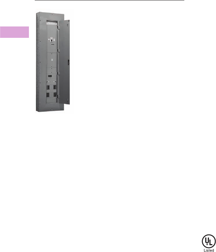
V2-T3-58 Volume 2—Commercial Distribution CA08100003E—April 2014 www.eaton.com
3
3
3
3
3
3
3
3
3
3
3
3
3
3
3
3
3
3
3
3
3
3
3
3
3
3
3
3
3
3
3.3
Panelboards and Lighting Control
Pow-R-Line C Panelboards
Type PRL3a
Contents
Description Page
Product Description. . . . . . . . . . . . . . . . . . . . . . . . V2-T3-7
Application Description . . . . . . . . . . . . . . . . . . . . . V2-T3-8
Standards and Certifications . . . . . . . . . . . . . . . . . V2-T3-10
Technical Data and Specifications . . . . . . . . . . . . . V2-T3-11
Type PRL1a . . . . . . . . . . . . . . . . . . . . . . . . . . . . . . V2-T3-26
Type PRL1aF . . . . . . . . . . . . . . . . . . . . . . . . . . . . . V2-T3-30
Type PRL1a-LX . . . . . . . . . . . . . . . . . . . . . . . . . . . V2-T3-34
Type PRL2a . . . . . . . . . . . . . . . . . . . . . . . . . . . . . . V2-T3-38
Type PRL2aF . . . . . . . . . . . . . . . . . . . . . . . . . . . . . V2-T3-42
Type PRL2a-LX . . . . . . . . . . . . . . . . . . . . . . . . . . . V2-T3-46
Retrofit Panelboard . . . . . . . . . . . . . . . . . . . . . . . . V2-T3-50
Type PRL3a . . . . . . . . . . . . . . . . . . . . . . . . . . . . . . V2-T3-58
Product Selection. . . . . . . . . . . . . . . . . . . . . . . V2-T3-59
Box Sizing and Selection . . . . . . . . . . . . . . . . . V2-T3-61
Type PRL3E. . . . . . . . . . . . . . . . . . . . . . . . . . . . . . V2-T3-62
Type PRL4 . . . . . . . . . . . . . . . . . . . . . . . . . . . . . . . V2-T3-66
Type PRL4D . . . . . . . . . . . . . . . . . . . . . . . . . . . . . V2-T3-76
Type PRL5P. . . . . . . . . . . . . . . . . . . . . . . . . . . . . . V2-T3-86
Type PRL3a
Product Description
●600 Vac maximum
(250 Vdc)
●Three-phase four-wire,
three-phase three-wire,
single-phase three-wire,
single-phase two-wire
●800A maximum main lugs
●600A maximum main
breaker
●225A maximum branch
breakers
●Bolt-on branch breakers
●Factory assembled
●Refer to Page V2-T3-7 for
additional information
Application Description
●Lighting panelboard or
power distribution
panelboard
●Fully rated or series rated
●Interrupting ratings up to
200 kA symmetrical
●Suitable for use as Service
Entrance Equipment, when
specified on the order
●See Pages V2-T3-7
through V2-T3-23 for
additional information
Standards and Certifications
●UL 67, UL 50
●Federal Specification
W-P-115c
●Refer to Page V2-T3-7 for
additional information
Volume 2—Commercial Distribution CA08100003E—April 2014 www.eaton.com V2-T3-59
3
3
3
3
3
3
3
3
3
3
3
3
3
3
3
3
3
3
3
3
3
3
3
3
3
3
3
3
3
3
3.3
Panelboards and Lighting Control
Pow-R-Line C Panelboards
Product Selection
PRL3a
Notes
1 800A MLO requires 28-inch (711.2 mm) wide box.
2 100,000 based on NEMA test procedure.
3 Top feed only.
4 Requires 6.50-inch (165.1 mm) deep box. Not available in Type 3R, 12, 4 and 4X enclosures.
5 100% rated circuit breaker. Requires copper bus. Not available in Type 12, 4 and 4X enclosures.
Ampere
Rating
Interrupting Rating (kA Symmetrical) Breaker
Type240 Vac 480 Vac 600 Vac 250 Vdc
Main Lug Only
100 — — — — —
250 — — — — —
400 — — — — —
600 — — — — —
800 1———— —
Main Breaker
100 18 14 — 10 EHD
100 18 14 14 10 FDB
100 22 — — — EDB
100 42 — — — EDS
100 65 — — — ED
100 100 — — — EDH
100 65 35 18 10 FD, FDE
100 100 65 25 22 HFD, HFDE
100 200 100 35 22 FDC
100 200 150 — — FCL
100 200 200 200 100 2FB-P 3
225 22 — — — EDB
225 42 — — — EDS
225 65 — — — ED
225 100 — — — EDH
225 200 — — — EDC
225 65 35 18 10 FD, FDE
225 100 65 25 22 HFD, HFDE
225 200 100 35 22 FDC
250 65 35 18 10 JD
250 100 65 25 22 HJD
250 200 100 35 22 JDC
400 65 — — 10 DK
400 65 35 25 10 KD
400 100 65 35 22 HKD
400 100 65 — — LHH
400 200 100 65 22 KDC
400 65 — — — LCL 4
400 200 200 200 100 2LA-P 34
600 65 35 18 22 LGE
600 100 65 35 22 LGH
600 200 100 50 42 LGC
600 65 35 25 22 LD
600 100 65 35 25 HLD
600 200 100 50 25 LDC
600 65 35 25 22 CLD 5
600 100 65 35 25 CHLD 5
600 200 100 50 25 CLDC 5
Type PRL3a

V2-T3-60 Volume 2—Commercial Distribution CA08100003E—April 2014 www.eaton.com
3
3
3
3
3
3
3
3
3
3
3
3
3
3
3
3
3
3
3
3
3
3
3
3
3
3
3
3
3
3
3.3
Panelboards and Lighting Control
Pow-R-Line C Panelboards
PRL3a Branch Circuit Breakers PRL3a Branch Circuit Breakers, continued
Notes
150A devices are available as two-pole only.
2Single-pole breaker rated 120 Vac.
3Two-pole breaker rated 120/240 Vac.
4Arc fault circuit breaker.
5HID (High Intensity Discharge) rated breaker.
6Switching Neutral Breaker. single-pole device requires two-pole space, two-pole device
requires three-pole space.
7Solenoid operated breaker.
8Single-pole breaker rated 277 Vac.
9For use on 480Y/277V systems only.
jAIC rating for two- and three-pole breakers only.
kMaximum of six breakers per panel, 175–225A.
Ampere
Rating
Interrupting Rating (kA Symmetrical) Breaker
Type240 Vac 480 Vac 600 Vac 250 Vdc
15–60 10 23 ———BAB
15–6010 ———BAB-H
70 10 23 ———BAB
70 10 ———BAB-H
80–100 10 23 ———BAB
80–10010 ———BAB-H
15–50 110 23 ———QBGF
15–50 110 ———QBGFEP
15–20 10 23 ———QBCAF
4
15–60 10 23 ———BAB-D
5
15–30 10 23 ———BAB-C
6
15–30 10 2———BABRP
7
15–30 10 2———BABRSP
7
15–60 22 23 ———QBHW
15–6022 ———QBHW-H
70 22 23 ———QBHW
70 22 ———QBHW-H
80–100 22 23 ———QBHW
80–10022 ———QBHW-H
15–3022 ———QBHGF
15–3022 ———QBHGFEP
15–20 22 23 ———QBHCAF
4
15–20 65 14 89 — — GHQ
15–20 65 14 89 — 14 GHB
Ampere
Rating
Interrupting Rating (kA Symmetrical) Breaker
Type240 Vac 480 Vac 600 Vac 250 Vdc
25–60 65 14 89 — 14 GHB
70–100 65 14 89 — 14 GHB
15–30 65 25 89 — — HGHB
15–20 65 14 89 — 14 GHQRSP 7
15–30 65 14 89 — 14 GHBS 7
15–60 — 14 89 — — GHBGFEP
15–20 — 14 89 — — GHBHID 5
15–60 18 j14 8— 10 EHD
70–100 18 j14 8— 10 EHD
15–60 18 V14 14 10 FDB
70–10018141410FDB
110–150 18 14 14 10 FDB
15–60 65 j35 818 10 FD, FDE
70–100 65 j35 818 10 FD, FDE
110–225 65 j35 18 10 FD k, FDE
15–60 100 j65 825 22 HFD, HFDE
70–100 100 j65 825 22 HFD, HFDE
110–225 100 j65 25 22 HFD k, HFDE
15–60 200 100 35 22 FDC
70–100 200 100 35 22 FDC
110–225 200 100 35 22 FDC k
100–225 22 — — — EDB k
100–225 42 — — — EDS k
100–22565 ———ED k
100–225 100 — — — EDH k
100–225 200 — — — EDC k
Volume 2—Commercial Distribution CA08100003E—April 2014 www.eaton.com V2-T3-61
3
3
3
3
3
3
3
3
3
3
3
3
3
3
3
3
3
3
3
3
3
3
3
3
3
3
3
3
3
3
3.3
Panelboards and Lighting Control
Pow-R-Line C Panelboards
Box Sizing and Selection
Approximate Dimensions in Inches (mm)
Panel Layout Instructions
1. S e l e c t :
a. Required mains (lugs or breaker).
b. Neutral where required.
c. Branch circuits as required.
2. Layout panel as shown below, using appropriate
“X” dimensions.
3. Using total X units (panel height) find box height in inches
(mm) and box catalog number from table below. (When total
X units come out to an uneven number, use next highest
number; i.e., if total X comes out 25X, use 31X.)
Layout—PRL3a
Notes
1GHB, HGHB and GHQ breakers cannot be mixed on same connector as BAB, QBHW, BABRP
and BABRSP.
2Maximum of six breakers per panel.
3Horizontal mounted 15–150A main breakers EHD, FDB, FD, FDE, HFD, HFDE and FDC, will be
furnished as branch breaker construction. Branch breakers single-, two- or three-pole as
required, may be located opposite these main breakers.
4If optional terminal kit 3TA225FDK is required, use 10X.
5FB-P and LA-P top mounting only.
6LCL or LA-P main breaker requires 6-1/2-inch (165.1 mm) deep box.
Poles
6 - 3X
12 - 5X
18 - 8X
24 - 10X
30 - 13X
36 - 15X
42 - 18X
BAB, QBHW, QBCAF,
BABRP, BABRSP, QBHCAF
GHQ, GHB, HGHB
1
1X
2X
3X
EDB, EDS, ED,
EDH, EDC,
EHD, FDB, FD, FDE,
HFD, FDC, HFDE
150A max. per branch breaker
(300A max. per connector)
2X
2-Pole
EDB, EDS, ED,
EDH, EDC
FD, HFD, FDC,
2 FDE, HFDE
3X
three-pole
Neutral
Section
5X 100–250A
8X 400–800A
11X 800A with through-feed lug
Main Lug
Section
2X 100A
5X 250A
8X 400–600A
14X 800A
Main
Breaker
Section
Horizontal
Mounting
2X
2-Pole
EHD, FDB, FD,
HFD, FDC, FDE, HFDE
3X
three-pole
EDB, EDS, ED,
EDH, EDC 3
Vertical
Mounting
7X EHD, FDB, FD, FDE, HFD, FDC,
HFDE, EDB, EDS, ED, EDH, EDC 4
9X FCL, FB-P 5
14X JD, HJD, JDC
15X DK, KD, HKD, KDC, LHH
17X LD, HLD, LDC, CLD, CHLD, CLDC
18X LGE, LGH, LGC
21X LCL, LA-P 56
1-Pole
2-Pole
1-Pole
2-Pole
1-Pole
2-Pole
3-pole
2- or 3-pole
Layout Example
1. Description of Panel
Type PRL3a three-phase, four-wire, 120/208 Vac flush
mounting. Panel to have short-circuit rating of 22,000
symmetrical amperes. Main breaker 400A, three-pole,
bottom mounting. Branch circuits bolt-on as follows:
12–200A single-pole QBHW
1–200A three-pole ED
1–225A three-pole ED
2. Layout Information from Layout—PRL3a table (left):
a. 400A Neutral . . . . . . . . . . . . = 8X
b. 12-poles of QBHW . . . . . . . = 5X
c. Two three-pole ED breakers . . = 6X
d. Main breaker, 400A,
Three-pole DK . . . . . . . . . . = 15X
Total Height . . . . . . . . . . . . = 34X
3. From Box Tabulation—PRL3a table (below):
a. 34X Height (use 40X box)
b. Box Height 72 inches (1828.8 mm)
c.
Box Catalog Number . . . . . . . .
YS2072 or EZB2072R
Box Tabulation—PRL3a
Cabinets
Fronts are code-gauge steel,
ANSI-61 light gray painted
finish.
Boxes are code-gauge
galvanized steel without
knockouts. Standard depth is
5-3/4 inches (146.1 mm).
Standard widths are:
20-inch (508.0 mm)
100–600A.
28-inch (711.2 mm)
800A.
Standard Depth
5-3/4 inches (146.1 mm).
Top and Bottom Gutters
5-1/2 inches (139.7 mm)
minimum.
Side Gutters
4 inches (101.6 mm)
minimum.
“X”
Units
YS Box
Catalog
Number
LT Trim
Catalog
Number
EZ Box
Catalog
Number
EZ Trim
Catalog
NumberBox Height
100–400A
14X 36.00 (914.4) YS2036 LT2036S or F EZB2036R EZT2036S or F
23X 48.00 (1219.2) YS2048 LT2048S or F EZB2048R EZT2048S or F
31X 60.00 (1524.0) YS2060 LT2060S or F EZB2060R EZT2060S or F
40X 72.00 (1524.0) YS2072 LT2072S or F EZB2072R EZT2072S or F
53X 90.00 (2286.0) YS2090 LT2090S or F EZB2090R EZT2090S or F
600A
23X 48.00 (1219.2) YS2048 LTV2048S or F EZB2048R EZTV2048S or F
31X 60.00 (1524.0) YS2060 LTV2060S or F EZB2060R EZTV2060S or F
40X 72.00 (1524.0) YS2072 LTV2072S or F EZB2072R EZTV2072S or F
53X 90.00 (2286.0) YS2090 LTV2090S or F EZB2090R EZTV2090S or F
800A
23X 48.00 (1219.2) YS2848 LTV2848S or F ——
31X 60.00 (1524.0) YS2860 LTV2860S or F — —
40X 72.00 (1524.0) YS2872 LTV2872S or F — —
53X 90.00 (2286.0) YS2890 LTV2890S or F — —
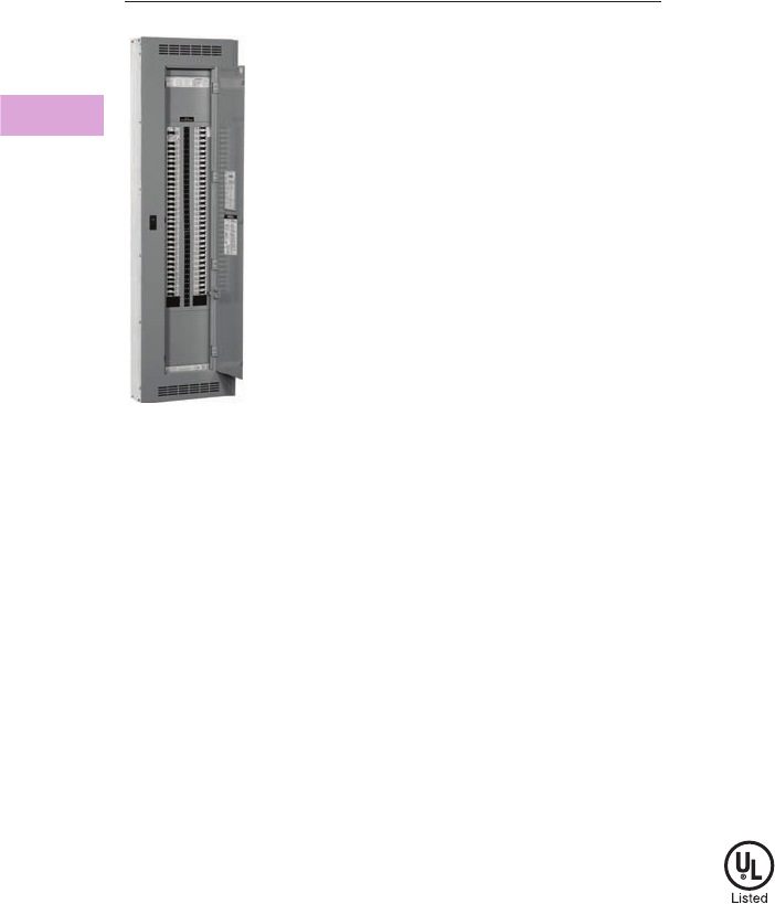
V2-T3-62 Volume 2—Commercial Distribution CA08100003E—April 2014 www.eaton.com
3
3
3
3
3
3
3
3
3
3
3
3
3
3
3
3
3
3
3
3
3
3
3
3
3
3
3
3
3
3
3.3
Panelboards and Lighting Control
Pow-R-Line C Panelboards
Type PRL3E
Contents
Description Page
Product Description. . . . . . . . . . . . . . . . . . . . . . . . V2-T3-7
Application Description . . . . . . . . . . . . . . . . . . . . . V2-T3-8
Standards and Certifications . . . . . . . . . . . . . . . . . V2-T3-10
Technical Data and Specifications . . . . . . . . . . . . . V2-T3-11
Type PRL1a . . . . . . . . . . . . . . . . . . . . . . . . . . . . . . V2-T3-26
Type PRL1aF . . . . . . . . . . . . . . . . . . . . . . . . . . . . . V2-T3-30
Type PRL1a-LX . . . . . . . . . . . . . . . . . . . . . . . . . . . V2-T3-34
Type PRL2a . . . . . . . . . . . . . . . . . . . . . . . . . . . . . . V2-T3-38
Type PRL2aF . . . . . . . . . . . . . . . . . . . . . . . . . . . . . V2-T3-42
Type PRL2a-LX . . . . . . . . . . . . . . . . . . . . . . . . . . . V2-T3-46
Retrofit Panelboard . . . . . . . . . . . . . . . . . . . . . . . . V2-T3-50
Type PRL3a . . . . . . . . . . . . . . . . . . . . . . . . . . . . . . V2-T3-58
Type PRL3E. . . . . . . . . . . . . . . . . . . . . . . . . . . . . . V2-T3-62
Product Selection. . . . . . . . . . . . . . . . . . . . . . . V2-T3-63
Box Sizing and Selection . . . . . . . . . . . . . . . . . V2-T3-64
Type PRL4 . . . . . . . . . . . . . . . . . . . . . . . . . . . . . . . V2-T3-66
Type PRL4D . . . . . . . . . . . . . . . . . . . . . . . . . . . . . V2-T3-76
Type PRL5P. . . . . . . . . . . . . . . . . . . . . . . . . . . . . . V2-T3-86
Type PRL3E
Product Description
●480V Vac maximum
(250 Vdc)
●Three-phase four-wire,
three-phase three-wire,
single-phase three-wire,
single-phase two-wire
●600A main lugs
●600A main breaker
●125A maximum branch
breakers
●Bolt-on branch breakers
●Factory assembled
●Refer to Page V2-T3-7 for
additional information
Application Description
●Lighting and appliance
branch panelboard
●Fully rated or series rated
●Interrupting ratings up to
200 kA symmetrical
●Suitable for use as Service
Entrance Equipment, when
specified on the order
●See Pages V2-T3-7
through V2-T3-23 for
additional information
Standards and Certifications
●UL 67, UL 50
●Federal Specification
W-P-115c
●Refer to Page V2-T3-7 for
additional information
Volume 2—Commercial Distribution CA08100003E—April 2014 www.eaton.com V2-T3-63
3
3
3
3
3
3
3
3
3
3
3
3
3
3
3
3
3
3
3
3
3
3
3
3
3
3
3
3
3
3
3.3
Panelboards and Lighting Control
Pow-R-Line C Panelboards
Product Selection
PRL3E
Ampere
Rating
Interrupting Rating (kA Symmetrical)
Breaker Type 240 Vac 480 Vac 250 Vdc
Main Lug Only
100 — — — —
250 — — — —
400 — — — —
600 — — — —
Main Breaker
125 EGB 35 18 10
125 EGS 100 35 35
125 EGH 200 65 42
225 EDB 22 — —
225 EDS 42 — —
225 ED 65 — —
225 EDH 100 — —
225 EDC 200 — —
225 FD, FDE653510
225 HFD, HFDE 100 65 22
225 FDC 200 100 22
400 DK 65 — —
400 KD 65 35 10
400 HKD 100 65 22
400 LHH 100 65 —
400 KDC 200 100 22
600 LGE 653522
600 LGH 100 65 22
Type PRL3E

V2-T3-64 Volume 2—Commercial Distribution CA08100003E—April 2014 www.eaton.com
3
3
3
3
3
3
3
3
3
3
3
3
3
3
3
3
3
3
3
3
3
3
3
3
3
3
3
3
3
3
3.3
Panelboards and Lighting Control
Pow-R-Line C Panelboards
Box Sizing and Selection
Approximate Dimensions in Inches (mm)
Assembled Circuit Breaker Panelboards and Lighting Controls
Box size and box and trim catalog numbers for all standard panelboard
types are found on Page V2-T3-65.
Instructions
1. Using description of the
required panelboard,
select the rating and
type of main required.
2. Count the total number
of branch circuit poles,
including provisions,
required in the
panelboard. Do not
count main breaker
poles. Convert two-
or three-pole branch
breaker to single-poles,
i.e., three-pole breaker,
count as three poles.
Determine sub-feed
breaker or through-feed
lug requirements.
3. Select the main ampere
rating section from
Page V2-T3-65.
4. Select panelboard type
from first column,
main breaker frame, if
applicable, from second
column, and sub-feed
breaker frame, if
applicable, from the
third column.
5. From Step #2, determine
the number of branch
circuits in Column 4.
6. Read box size, box and
trim catalog numbers
across columns to the
right. Specify surface
or flush mounting on
the order.
Cabinets
Fronts are code-gauge
steel, ANSI-61 light gray
painted finish.
Boxes are code-gauge
galvanized steel without
knockouts. Standard depth
is 5-3/4 inches (146.1 mm).
Standard width is 20 inches
(508.0 mm). An optional
28-inch (711.2 mm) wide
box is available.
Top and Bottom Gutters
5-1/2 inches (139.7 mm)
minimum.

Volume 2—Commercial Distribution CA08100003E—April 2014 www.eaton.com V2-T3-65
3
3
3
3
3
3
3
3
3
3
3
3
3
3
3
3
3
3
3
3
3
3
3
3
3
3
3
3
3
3
3.3
Panelboards and Lighting Control
Pow-R-Line C Panelboards
Approximate Dimensions in Inches (mm)
PRL3E Panelboard Sizing
PRL3E Branch Circuit Breakers
Note
1Smaller panelboard box sizes are available if required. Contact Eaton for application information.
Panelboard
Types
Main Breaker Types
and Mounting Position
(H) = Horizontal
(V) = Vertical
Sub-Feed Breaker Types
and Mounting Position
(H) = Horizontal
(V) = Vertical
Maximum No. of
Branch Circuits
Including
Provisions
Box Dimensions 1
YS Box
Catalog
Number
LT Trim
Catalog
Number
EZ Box
Catalog
Number
EZ Trim
Catalog
NumberHeight Width Depth
125A
Main breaker
EG, EGS, EGH
(H)
—12
36.00 (914.4) 20.00 (508.0) 5.75 (146.1)
YS2036 LT2036S or F EZB2036R EZT2036S or F
—24
36.00 (914.4) 20.00 (508.0) 5.75 (146.1)
YS2036 LT2036S or F EZB2036R EZT2036S or F
—36
36.00 (914.4) 20.00 (508.0) 5.75 (146.1)
YS2036 LT2036S or F EZB2036R EZT2036S or F
—42
42.00 (1066.8) 20.00 (508.0) 5.75 (146.1)
YS2042 LT2042S or F EZB2042R EZT2042S or F
Main lugs or
main breaker
FD, HFD
(V)
—18
36.00 (914.4) 20.00 (508.0) 5.75 (146.1)
YS2036 LT2036S or F EZB2036R EZT2036S or F
—30
42.00 (1066.8) 20.00 (508.0) 5.75 (146.1)
YS2042 LT2042S or F EZB2042R EZT2042S or F
—42
48.00 (1219.2) 20.00 (508.0) 5.75 (146.1)
YS2048 LT2048S or F EZB2048R EZT2048S or F
Main lugs or main
breaker with 125A
through-feed lugs or
sub-feed breaker
FD
HFD
(V)
EHD
FD
HFD
TFL
(V)
18
48.00 (1219.2) 20.00 (508.0) 5.75 (146.1)
YS2048 LT2048S or F EZB2048R EZT2048S or F
30
60.00 (1524.0) 20.00 (508.0) 5.75 (146.1)
YS2060 LT2060S or F EZB2060R EZT2060S or F
42
60.00 (1524.0) 20.00 (508.0) 5.75 (146.1)
YS2060 LT2060S or F EZB2060R EZT2060S or F
250A
Main lugs or
main breaker
EDS, ED,
EDH, FD, HFD
(V)
—18
36.00 (914.4) 20.00 (508.0) 5.75 (146.1)
YS2036 LT2036S or F EZB2036R EZT2036S or F
—30
42.00 (1066.8) 20.00 (508.0) 5.75 (146.1)
YS2042 LT2042S or F EZB2042R EZT2042S or F
—42
48.00 (1219.2) 20.00 (508.0) 5.75 (146.1)
YS2048 LT2048S or F EZB2048R EZT2048S or F
Main lugs or main
breaker with 225A
through-feed lugs or
sub-feed breaker
FD, HFD,
EDS, ED,
EDH (V)
FD, HFD,
EDS, ED,
EDH (V)
18
48.00 (1219.2) 20.00 (508.0) 5.75 (146.1)
YS2048 LT2048S or F EZB2048R EZT2048S or F
30
60.00 (1524.0) 20.00 (508.0) 5.75 (146.1)
YS2060 LT2060S or F EZB2060R EZT2060S or F
42
60.00 (1524.0) 20.00 (508.0) 5.75 (146.1)
YS2060 LT2060S or F EZB2060R EZT2060S or F
400A
Main breaker DK, KD, HKD,
KDC
(V)
— 18 48.00 (1219.2) 20.00 (508.0) 5.75 (146.1)
YS2048 LT2048S or F EZB2048R EZT2048S or F
— 30 60.00 (1524.0) 20.00 (508.0) 5.75 (146.1)
YS2060 LT2060S or F EZB2060R EZT2060S or F
— 42 60.00 (1524.0) 20.00 (508.0) 5.75 (146.1)
YS2060 LT2060S or F EZB2060R EZT2060S or F
Main breaker with 225A
through-feed lugs or
sub-feed breaker
DK, KD, HKD,
KDC
(V)
EHD, FD, HFD,
EDB, EDS, ED,
EDH (V)
18 60.00 (1524.0) 20.00 (508.0) 5.75 (146.1)
YS2060 LT2060S or F EZB2060R EZT2060S or F
30
72.00 (1828.8)
20.00 (508.0) 5.75 (146.1)
YS2072 LT2072S or F EZB2072R EZT2072S or F
42
72.00 (1828.8)
20.00 (508.0) 5.75 (146.1)
YS2072 LT2072S or F EZB2072R EZT2072S or F
Main lugs or main
breaker with 400A
through-feed lugs or
sub-feed breaker
DK, KD, HKD,
KDC
(V)
JD, HJD, JDC,
DK, KD,
HKD, KDC
(V)
18
72.00 (1828.8)
20.00 (508.0) 5.75 (146.1)
YS2072 LT2072S or F EZB2072R EZT2072S or F
30
72.00 (1828.8)
20.00 (508.0) 5.75 (146.1)
YS2072 LT2072S or F EZB2072R EZT2072S or F
42
90.00 (2286.0)
20.00 (508.0) 5.75 (146.1)
YS2090 LT2090S or F EZB2090R EZT2090S or F
Ampere
Rating
Interrupting Rating (kA Symmetrical) Breaker
Type240 Vac 480 Vac 250 Vdc
15–125 25 18 10 EGB
15–125 85 35 35 EGS
15–125 100 65 42 EGH
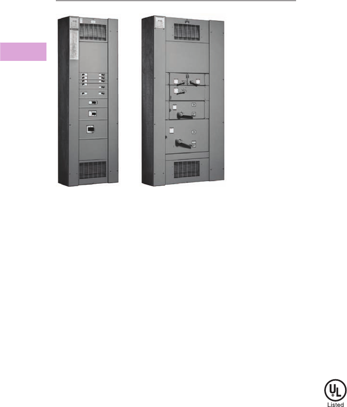
V2-T3-66 Volume 2—Commercial Distribution CA08100003E—April 2014 www.eaton.com
3
3
3
3
3
3
3
3
3
3
3
3
3
3
3
3
3
3
3
3
3
3
3
3
3
3
3
3
3
3
3.3
Panelboards and Lighting Control
Pow-R-Line C Panelboards
Type PRL4B Circuit Breaker and Type PRL4F Fusible Panelboards
Type PRL4
Contents
Description Page
Product Description. . . . . . . . . . . . . . . . . . . . . . . . V2-T3-7
Application Description . . . . . . . . . . . . . . . . . . . . . V2-T3-8
Standards and Certifications . . . . . . . . . . . . . . . . . V2-T3-10
Technical Data and Specifications . . . . . . . . . . . . . V2-T3-11
Type PRL1a . . . . . . . . . . . . . . . . . . . . . . . . . . . . . . V2-T3-26
Type PRL1aF . . . . . . . . . . . . . . . . . . . . . . . . . . . . . V2-T3-30
Type PRL1a-LX . . . . . . . . . . . . . . . . . . . . . . . . . . . V2-T3-34
Type PRL2a . . . . . . . . . . . . . . . . . . . . . . . . . . . . . . V2-T3-38
Type PRL2aF . . . . . . . . . . . . . . . . . . . . . . . . . . . . . V2-T3-42
Type PRL2a-LX . . . . . . . . . . . . . . . . . . . . . . . . . . . V2-T3-46
Retrofit Panelboard . . . . . . . . . . . . . . . . . . . . . . . . V2-T3-50
Type PRL3a . . . . . . . . . . . . . . . . . . . . . . . . . . . . . . V2-T3-58
Type PRL3E. . . . . . . . . . . . . . . . . . . . . . . . . . . . . . V2-T3-62
Typ e PR L 4
Product Selection. . . . . . . . . . . . . . . . . . . . . . . V2-T3-67
Box Sizing and Selection—PRL4B . . . . . . . . . . V2-T3-70
Box Sizing and Selection—PRL4F . . . . . . . . . . V2-T3-73
Type PRL4D . . . . . . . . . . . . . . . . . . . . . . . . . . . . . V2-T3-76
Type PRL5P. . . . . . . . . . . . . . . . . . . . . . . . . . . . . . V2-T3-86
Type PRL4
Product Description
●600 Vac maximum
(600 Vdc)
●Three-phase, four-wire,
three-phase three-wire,
single-phase three-wire,
single-phase two-wire
●PRL4B circuit breaker
panelboard
●PRL4F fusible switch
panelboard
●1200A maximum mains
●1200A maximum branch
devices
●Bolt-on branch devices
●Factory assembled
●Refer to Page V2-T3-7 for
additional information
Application Description
●Power distribution
panelboard
●Fully rated or series rated
●Interrupting ratings up to
200 kA symmetrical
●Suitable for use as Service
Entrance Equipment, when
specified on the order
●See Pages V2-T3-7
through V2-T3-23 for
additional information
Standards and Certifications
●UL 67, UL 50
●Federal Specification
●W-P-115c
●Refer to Page V2-T3-7 for
additional information
Volume 2—Commercial Distribution CA08100003E—April 2014 www.eaton.com V2-T3-67
3
3
3
3
3
3
3
3
3
3
3
3
3
3
3
3
3
3
3
3
3
3
3
3
3
3
3
3
3
3
3.3
Panelboards and Lighting Control
Pow-R-Line C Panelboards
Product Selection
PRL4 Main Lugs and Main Breakers PRL4 Main Fusible Switches
Notes
1For ground fault protection on main devices, see Modification 14—Applies to 310 and
310+ Trip Units on Page V2-T3-102 or Modification 15 on Page V2-T3-102.
2For use on DC systems only.
3100% rated breaker. Requires copper bus. Not available in Type 12, 4 and 4X enclosures.
4Breaker only available in three-pole frame.
5Requires 44-inch (1117.6 mm) wide box.
6For ground fault protection on main devices, see Modification 15 on Page V2-T3-102.
7Fuses not included. Specify required fuse clips on all switches.
8Class J Fuse provisions are applicable only to 600V units. When required, use dimensions of
600V units for all voltages 600 and below.
9No DC rating on 600, 800 and 1200A switches
Ampere
Rating
Interrupting Rating
(kA Symmetrical)
600 Vdc
Breaker
Type240 Vac 480 Vac 600 Vac 250 Vdc
Main Lug Only
250——————
400——————
600——————
800——————
1200 — — — — — —
Main Breaker 1
250 65 35 18 10 — JD
250 100 65 25 22 — HJD
250 — — — 42 35 HJDDC 2
250 200 100 35 22 — JDC
250 200 200 — — — LCL
400 65 — — 10 — DK
400 65 35 25 10 — KD
400 65 35 25 — — CKD 34
400 100 65 35 22 — HKD
400 — — — 42 35 HKDDC 2
400 100 65 35 42 — LHH
400 100 65 35 — — CHKD 34
400 200 100 65 22 — KDC
400 200 200 — — — LCL
400 200 200 200 — — LA-P
600 65 35 18 22 — LGE 1
600 100 65 35 22 — LGH 1
600 200 100 50 42 — LGC
600 200 150 65 50 — LGU
600 65 35 25 22 — LD
600 65 35 25 — — CLD 3
600 100 65 35 25 — HLD
600 — — — 42 35 HLDDC 2
600 100 65 35 — — CHLD 3
600 200 100 50 25 — LDC
600 200 100 50 — — CLDC 3
800 65 50 25 22 — MDL
800 100 65 35 25 — HMDL
800 — — — 42 35 HMDLDC 2
800 65 50 25 — — CMDL 3
800 100 65 35 — — CHMDL 3
800 200 200 200 — — NB-P
800 65 50 25 — — ND
800 100 65 35 — — HND
800 200 100 65 — — NDC
800 65 50 25 — — CND 35
800 100 65 35 — — CHND 35
800 200 100 65 — — CNDC 35
1200 65 50 25 — — ND
1200 100 65 35 — — HND
1200 200 100 65 — — NDC
1200 65 50 25 — — CND 35
1200 100 65 35 — — CHND 35
1200 200 100 65 — — CNDC 35
1200 — — — 42 50 NBDC 2
Type PRL4
Ampere
Rating
Interrupting Rating (kA Symmetrical)
240 Vac 480 Vac Device Type
Main Fusible Switch 240 Vac, 250 Vdc 678
200 See Page V2-T3-69 FDPB
400 FDPW
600 9FDPW
800 9FDPW
1200 9FDPW
Main Fusible Switch 600 Vac 67
200 See Page V2-T3-69 FDPB
400 FDPW
600 9FDPW
800 9FDPW
1200 9FDPW

V2-T3-68 Volume 2—Commercial Distribution CA08100003E—April 2014 www.eaton.com
3
3
3
3
3
3
3
3
3
3
3
3
3
3
3
3
3
3
3
3
3
3
3
3
3
3
3
3
3
3
3.3
Panelboards and Lighting Control
Pow-R-Line C Panelboards
PRL4 Branch Devices PRL4 Branch Devices, continued
Notes
150A devices are available as two-pole only.
2Single-pole breakers rated 120 Vac.
3Two-pole breakers rated 120/240 Vac.
4Arc fault circuit breaker.
5Single-pole breakers rated 277 Vac.
6For use on DC systems only.
7At 480V, must be used on 480Y/277V grounded wye systems only.
8AIC rating for two- and three-pole breakers only.
9100% rated breaker. Requires copper bus. Not available in Type 12, 4 and 4X enclosures.
jBreaker only available in three-pole frame.
kAvailable in single branch mounting only.
Ampere
Rating
Interrupting Rating (kA Symmetrical)
600 Vdc
Breaker
Type240 Vac 480 Vac 600 Vac 250 Vdc
15–60 10 23 — — ——BAB
15–60 10 — — — — BAB-H
70–100 10 23 — — ——BAB
70–100 10 — — — — BAB-H
15–50 110 23 — — ——QBGF
15–20 10 23 — — ——QBCAF
4
15–60 22 23 — — ——QBHW
15–60 22 — — — — QBHW-H
70–100 22 23 — — ——QBHW
70–100 22 — — — — QBHW-H
15–30 22 23 — — ——QBHGF
15–20 22 23 — — — — QBHCAF 4
15–20 65 214 5— ——GHQ 7
15–60 65 214 5—14—GHB 7
70–100 65 214 5—14—GHB 7
15–30 65 225 5— ——HGHB 7
15–60 18 814 5—10—EHD
70–100 18 814 5—10—EHD
15–6018141410—FDB
70–100 18 14 14 10 — FDB
110–150 18 14 14 10 — FDB
15–60 65 835 518 10 — FD, FDE
70–100 65 835 518 10 — FD, FDE
110–225 65 835 18 10 — FD, FDE
15–60 100 865 525 22 — HFD, HFDE
70–100 100 865 525 22 — HFD, HFDE
110–225 100 865 25 22 — HFD, HFDE
15–60 200 100 35 22 — FDC
70–100 200 100 35 22 — FDC
110–225 200 100 35 22 — FDC
15–100 200 150 — — — FCL
15–150 — — — 42 35 HFDDC 6
100–225 22 — — — — EDB
100–225 42 — — — — EDS
100–225 65 — — — — ED
100–225 100 — — — — EDH
100–225 200 — — — — EDC
70–225 65 35 18 10 — JD
25065351810—JD
70–225 100 65 25 22 — HJD
Ampere
Rating
Interrupting Rating (kA Symmetrical)
600 Vdc
Breaker
Type240 Vac 480 Vac 600 Vac 250 Vdc
250 100 65 25 22 — HJD
70–250———42 35 HJDDC 6
70–225 200 100 35 22 — JDC
250 200 100 35 22 — JDC
125–250 200 200 — — — LCL
250–400 65 — — 10 — DK
100–400 65 35 25 10 — KD
100–400 65 35 25 — — CKD 9jk
100–400 100 65 35 22 — HKD
100–400———42 35HKDDC
6
100–400 100 65 35 — — CHKD 9jk
125–400 100 65 35 42 — LHH
100–400 200 100 65 22 — KDC
200–400 200 200 — — — LCL
250–600 65 35 18 22 — LGE
300–600 65 35 25 22 — LD
300–600 65 35 25 — — CLD 9
250–600 100 65 35 22 — LGH
300–600 100 65 35 25 — HLD
300–600———42 35HLDDC
6
300–600 100 65 35 — — CHLD 1
250–600 200 100 35 42 — LGC
300–600 200 100 50 25 — LDC
300–600 200 100 50 25 — CLDC 1
250–600 200 150 65 50 — LGU
400–800 65 50 25 22 — MDL
400–800 100 65 35 25 — HMDL
300–800———42 35HMDLDC
6
400–800 65 50 25 — — CMDL 1
400–800 100 65 35 — — CHMDL 1
400–800 65 50 25 — — ND
400–800 100 65 35 — — HND
400–800 200 100 65 — — NDC
400–800 65 50 25 — — CND 12
400–800 100 65 35 — — CHND 12
400–800 200 100 65 — — CNDC 12
600–1200 65 50 25 — — ND
600–1200 100 65 35 — — HND
600–1200 200 100 65 — — NDC
600–1200 65 50 25 — — CND 12
600–1200 100 65 35 — — CHND 12
600–1200 200 100 65 — — CNDC 12
700–1200———42 50NBDC
6

Volume 2—Commercial Distribution CA08100003E—April 2014 www.eaton.com V2-T3-69
3
3
3
3
3
3
3
3
3
3
3
3
3
3
3
3
3
3
3
3
3
3
3
3
3
3
3
3
3
3
3.3
Panelboards and Lighting Control
Pow-R-Line C Panelboards
PRL4 Branch Devices, continued FDPW and FDPB Switch Ratings, 240 or 600 Vac
Notes
1100 kAIC based on NEMA test procedure.
2Fuses not included. Specify required fuse clips on all switches. (T fuse clips not
available for 200/200 twin switches.)
3When branches of a twin unit are of different ampere ratings, as a 30–60 twin unit, price
and layout as a 60–60 twin unit; when a 60–100 twin unit, price and layout as a 100–100
twin unit.
4No DC rating on 600, 800 and 1200A switches.
5Class J fuse provisions are applicable to 600V units. When required, use price and
dimensions of 600V units for all voltages 600V and below.
6Twin 200A switches are not available with Class R fuse clips at 600V.
7When shunt trip is required, 400–600A switches used with Class R fuses are rated 100 kAIC.
Ampere
Rating
Interrupting Rating (kA Symmetrical) Breaker
Type240 Vac 480 Vac 600 Vac 250 Vdc
Integrally Fused, Current Limiting Circuit Breaker
15–100 200 200 200 1FB-P
125–225 200 200 200 1LA-P
250–400 200 200 200 1LA-P
400–600 200 200 200 1NB-P
700–800 200 200 200 1NB-P
Fusible Switches 240 Vac, 250 Vdc 2
30/30 3See table at the right FDPW-Twin
60/60 3FDPW-Twin
100/100 3FDPW-Twin
200/200 FDPB-Twin
100 FDPW-Single
200 FDPB-Single
400 See table at the right FDPW-Single
600 4FDPW-Single
800 4FDPW-Single
1200 4FDPW-Single
Fusible Switches 600 Vac 2
30/30 3See table at the right FDPW-Twin
60/60 3FDPW-Twin
100/100 3FDPW-Twin
200/200 5FDPB-Twin
100 FDPW-Single
200 FDPB-Single
400 See table at the right FDPW-Single
600 4FDPW-Single
800 4FDPW-Single
1200 4FDPW-Single
Ampere
Rating
Fuse
Class
Used
Short-Circuit
Ratings
(kA Symmetrical)
30–100 R, J 5200
200 Single R, J 5200
200 Twin R 6, J 5, T 200
400, 600 7R 7, J 5, T 200
800, 1200 7L 200
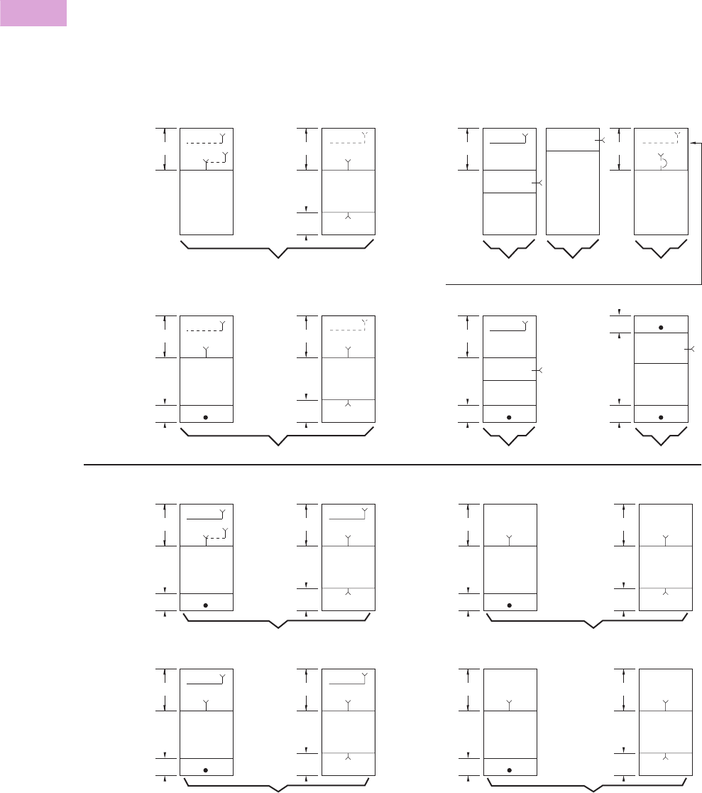
V2-T3-70 Volume 2—Commercial Distribution CA08100003E—April 2014 www.eaton.com
3
3
3
3
3
3
3
3
3
3
3
3
3
3
3
3
3
3
3
3
3
3
3
3
3
3
3
3
3
3
3.3
Panelboards and Lighting Control
Pow-R-Line C Panelboards
Box Sizing and Selection—PRL4B
Approximate Dimensions in Inches (mm)
Main Lug Only (MLO), Main Breaker, Neutral, Through-Feed Lug
(TFL) and Sub-Feed Lug (SFL) “X” Space Requirements. (For
other configurations not shown, refer to Eaton.)
*= Space available for branch devices. For device sizing,
see Page V2-T3-72.
•= Blank means no bus under cover, to meet NEC cable
bending space.
PRL4B Layout
Note
1Sub-feed lugs are available 250–600A. For 600A, use 1200A “A” space.
*
10X
7X Through-
Feed Lugs
*
10X NN
MLO, SFL MLO, TFL
3Ph 4W, 3Ph 3W
250A a, 400A a,
600A a, 800A
Standard Main Lug, Through-Feed and Sub-Feed Lugs a
(500 kcmil Maximum)
Main Breaker with Neutral (when required)
(500 kcmil Maximum)
*
7X
*
NN
3Ph 4W,
3Ph 3W
250A, 400A,
600A, 800A
*
12X
7X Through-
Feed Lugs
*
12X NN
MLO MLO, TFL
3Ph 4W, 3Ph 3W
1200A
36-inch
(914.4 mm)
Minimum
Width
Main Breaker
Main Breaker
*
3Ph 3W3Ph 4W
800A Vertically Mtd. MDL Main Breaker only in 24-inch (609.6 mm) wide box.
Available with 38X and 50X Panel Height only.
19X
Blank
2X
*
7X
*
N
3Ph 3W
1200A
36-inch
(914.4 mm)
Minimum
Width
Main Breaker
3Ph 4W
Blank
2X Blank
2X
Blank
2X
Main Breaker
*
9X Through-
Feed Lugs
*
20X NN
MLO, SFL MLO, TFL
3Ph 4W
250A a, 400A a,
600A a, 800A
Optional Main Lugs, Through-Feed and Sub-Feed Lugs a (750 kcmil Maximum)
*
20X
11X Through-
Feed Lugs
*
20X NN
MLO MLO, TFL
3Ph 4W
1200A
36-inch
(914.4 mm)
Minimum
Width Blank
5X
*
9X Through-
Feed Lugs
*
13X
3Ph 3W
250A, 400A,
600A, 800A
*
15X
11X Through-
Feed Lugs
*
15X
120A
36-inch
(914.4 mm)
Minimum
Width Blank
5X
Blank
20X
Blank
13X
3X
3Ph 3W
3X

Volume 2—Commercial Distribution CA08100003E—April 2014 www.eaton.com V2-T3-71
3
3
3
3
3
3
3
3
3
3
3
3
3
3
3
3
3
3
3
3
3
3
3
3
3
3
3
3
3
3
3.3
Panelboards and Lighting Control
Pow-R-Line C Panelboards
Approximate Dimensions in Inches (mm)
Panel Layout and Dimensions
To determine the dimensions
of a given panelboard
enclosure, make a layout
sketch by fitting together
the main, branch and lug
modules according to the
appropriate tables in the
layout guide. Assign “X”
units to each module as
shown and obtain a total
“X” number.
The height of the enclosure is
related to the total “X” units
in the layout as shown in
table on right. Three standard
box heights are available to
accommodate any and all
layout arrangements. “X”
unit totals that do not exactly
match those in table on right
must be rounded off to the
next highest standard (26X,
38X, 50X).
If a calculated “X” total for a
panel exceeds 50X, the panel
must be split into two or
more separate sections with
“X” space for through-feed
lugs figured in for all but one
section. If a neutral is
required, a separate neutral
bar and appropriate “X”
space must be included in
each section.
Layout Example
●1–PRL4B panelboard,
480Y/277 volt, three-phase
four-wire 65 kA, 800A,
main lug, consisting of:
●12–20A/single-pole HFD
●2–250A/three-pole HJD
●1–400A/three-pole HKD
Reference PRL4B Layout
Example
1. From layout guide, total
“X” height of panel =
26X, (which is a design
standard and no rounding
off is necessary).
2. From table on right,
enclosure height for
26X panel = 57 inches
(1447.8 mm).
3. Width = 24 inches
(609.6 mm)—directly
from layout guide.
4. Enclosure depth =
11.31 inches (287.0 mm)
—standard for all PRL4
panelboards.
PRL4B Layout Example
20A/1P 20A/1P 1X
20A/1P 20A/1P 1X
20A/1P 20A/1P 1X
20A/1P 20A/1P 1X
20A/1P 20A/1P 1X
20A/1P 20A/1P 1X
250A/3P 3X
250A/3P 3X
400A/3P 4X
Main 800A
Lugs
Neutral
10X
Total = 26X
Box Dimensions—PRL4B
Top and Bottom Gutters
10.63-inch (269.9 mm) minimum.
Side Gutters—Minimum
24.00-inch (609.6 mm) wide box—5.00-inch (127.0 mm).
36.00-inch (914.4 mm) wide box—6.00-inch (152.4 mm).
44.00-inch (1117.6 mm) wide box—8.00-inch (203.2 mm).
Notes
1Box depth is 10.40 inches (264.2 mm), cover adds 0.90 inches (22.9 mm) to depth.
800A maximum bus size in 24.00-inch (609.6 mm) wide box. Flush trims
not available on PRL4B panels.
“X”
Units
Catalog
Number Height Width Depth 1
26X BX2457 57.00 (1447.8) 24.00 (609.6) 11.31 (287.0)
38X BX2473 73.50 (1866.9) 24.00 (609.6) 11.31 (287.0)
50X BX2490 90.00 (2286.0) 24.00 (609.6) 11.31 (287.0)
38X BX3673 73.50 (1866.9) 36.00 (914.4) 11.31 (287.0)
50X BX3690 90.00 (2286.0) 36.00 (914.4) 11.31 (287.0)
38X BX4473 73.50 (1866.9) 44.00 (1117.6) 11.31 (287.0)
50X BX4490 90.00 (2286.0) 44.00 (1117.6) 11.31 (287.0)
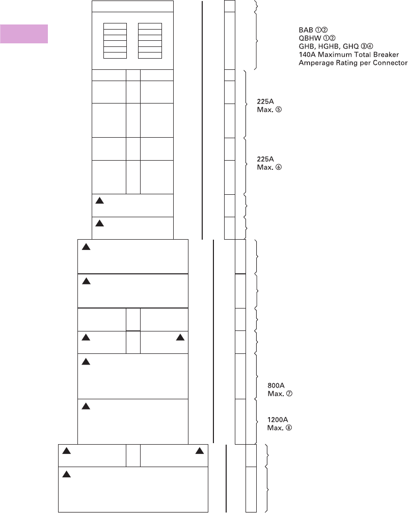
V2-T3-72 Volume 2—Commercial Distribution CA08100003E—April 2014 www.eaton.com
3
3
3
3
3
3
3
3
3
3
3
3
3
3
3
3
3
3
3
3
3
3
3
3
3
3
3
3
3
3
3.3
Panelboards and Lighting Control
Pow-R-Line C Panelboards
Layout for Branch and Horizontally Mounted Main Devices Layout—PRL4B
Notes
1BAB and QBHW breakers with shunt trips require one additional pole space, i.e., single-pole is two-pole size, two-pole is three-pole size, and three-pole is four-pole size.
2If panel contains only BAB or QBHW branch breakers, use a PRL1a panelboard.
3GHB, HGHB or GHQ breakers cannot be mixed on same subchassis as BAB, QBHW.
4If panel contains only GHB, HGHB or GHQ branch breakers, use a PRL2a panelboard.
5When only one single-pole breaker of the group is required on either side of chassis, the single-pole breaker space required changes from 1X to 2X.
6Minimum 36-inch (914.4 mm) wide box is required if optional #6–300 kcmil lug is required.
7MDL main breaker in 24-inch (609.6 mm) wide box, refer to Page V2-T3-70.
8Optional 750 kcmil terminal requires 44-inch (1117.6 mm) wide box.
9For use on DC systems only.
See Page V2-T3-70 for MLO or Neutral and Vertically Mounted Mains space requirements.
Breaker to Fusible Transition, All Widths
3X
3X
6X
6X
4X
6X
1X
12X
20X
1X
2X
3X
2X
4X
3X
3X
4X
Filler
Sub Panel
400 Amp. Maximum Bus Rating
1P 1P
2P 2P
3P 3P
2P 2P
3P 3P
2 or 3P
2 or 3P
3P
Load
2 or 3P 2 or 3P
2 or 3P 2 or 3P
2 or 3P
2 or 3P
2 or 3P 2 or 3P
2 or 3P
EHD,
FDB, FD, FDE
HFD, HFDE, FDC, HFDDC
18
Poles
100A
Max.
DK, KD, HKD,
KDC
EDB, EDS, ED, EDH, EDC
JD, HJD, JDC, HJDDC
250A
Max.
400A
Max.
DK, KD, HKD, KDC, HKDDC
CKD, CHKD, LHH
600A
Max.
LGE, LGH, LGC, LGU
100A
Max. FCL, FB-P
250A
Max. JD, HJD, JDC
400A
Max. LCL, LA-P
MDL, HMDL, HMDLDC
CMDL, CHMDL
ND, HND, NDC
400A
Max.
800A
Max. NB-P, NBDC
44-Inch (1117.6 mm) Wide Box
24-Inch (609.6 mm) Wide Box
36-Inch (914.4 mm) Wide Box
1200A
Max. CND, CHND, CNDC
42
Poles
6X
2 or 3P
Load
600A
Max.
LD, HLD, CLD, CHLD, LDC, HLDDC
9
9
9
9
9
9
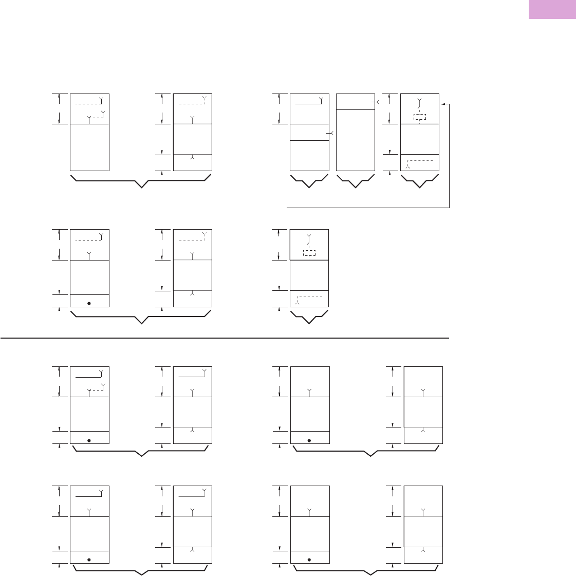
Volume 2—Commercial Distribution CA08100003E—April 2014 www.eaton.com V2-T3-73
3
3
3
3
3
3
3
3
3
3
3
3
3
3
3
3
3
3
3
3
3
3
3
3
3
3
3
3
3
3
3.3
Panelboards and Lighting Control
Pow-R-Line C Panelboards
Box Sizing and Selection—PRL4F
Approximate Dimensions in Inches (mm)
Main Lug (MLO), Main Switch, Neutral, Through-Feed (TFL)
and Sub-Feed Lug (SFL) “X” Space Requirements. (For other
configurations not shown, refer to Eaton.)
*= Space available for branch devices. For device sizing,
see Page V2-T3-75.
•= Blank means no bus under cover, to meet NEC cable
bending space.
PRL4F Layout
Notes
1Sub-feed lugs are available 250–600A. For 600A, use 1200A “A” space.
2800A and 1200A mains available only in vertical mounting.
*
10X
7X Through-
Feed Lugs
*
10X NN
MLO, SFL MLO, TFL
3Ph 4W, 3Ph 3W
250A a, 400A a,
600A a, 800A
Standard Main Lug, Through-Feed and Sub-Feed Lugs a
(500 kcmil Maximum)
Main Switch with Neutral (when required)
(500 kcmil Maximum)
*
7X
*
N
3Ph 4W,
3Ph 3W
200A, 400A,
600A
*
12X
7X
*
12X NN
MLO MLO, TFL
3Ph 4W, 3Ph 3W
1200A
Main Switch
Main Switch
*
3Ph 3W3Ph 4W
400A and 600A Vertically Mounted Main Switch
22X
Blank Through-Feed
Lugs
2X
800A,
1200A
*
9X Through-
Feed Lugs
*
20X NN
MLO, SFL MLO, TFL
3Ph 4W
250A a, 400A a,
600A a, 800A
Optional Main Lugs, Through-Feed and Sub-Feed Lugs a (750 kcmil Maximum)
*
20X
11X Through-
Feed Lugs
*
20X NN
MLO MLO, TFL
3Ph 4W
1200A
Blank
5X
*
9X Through-
Feed Lugs
*
13X
3Ph 3W
250A, 400A,
600A, 800A
*
15X
11X Through-
Feed Lugs
*
15X
1200A
Blank
5X
Blank
20X
Blank
13X
3X
3Ph 3W
N
7X
*
3Ph 4W
800A 25X
1200A 26X
N
7X
800A and 1200A Vertically Mounted
Main Switch b
36-inch (914.4 mm) or
44-inch (1117.6 mm)
Wide Box
3X

V2-T3-74 Volume 2—Commercial Distribution CA08100003E—April 2014 www.eaton.com
3
3
3
3
3
3
3
3
3
3
3
3
3
3
3
3
3
3
3
3
3
3
3
3
3
3
3
3
3
3
3.3
Panelboards and Lighting Control
Pow-R-Line C Panelboards
Approximate Dimensions in Inches (mm)
Panel Layout and Dimensions
To determine the dimensions
of a given panelboard
enclosure, make a layout
sketch by fitting together the
main, branch and lug modules
according to the appropriate
tables in the layout guide.
Assign “X” units to each
module as shown and obtain
a total “X” number.
The height of the enclosure is
related to the total “X” units
in the layout as shown in
table on right. Three standard
box heights are available to
accommodate any and all
layout arrangements. “X”
unit totals that do not exactly
match those in table on
right must be rounded off
to the next higher standard
(38X, 50X).
If a calculated “X” total for a
panel exceeds 50X, the panel
must be split into two or
more separate sections with
“X” space for through-feed
lugs figured in for all but
one section. If a neutral is
required, a separate neutral
bar and appropriate “X”
space must be included in
each section.
Layout Example
●PRL4F, three-phase
four-wire, 208Y/120 volt
complete with 400A main
switch and the following
branches:
●One 200A/three-pole
●Two 100A/three-pole
●Two 30A/three-pole
Panel to have short-circuit
rating of 100 kA symmetrical.
Reference PRL4F Layout
Example
1. From layout guide,
total “X” height of
panel = 43X.
2. Rounded off to next
higher standard = 50X.
3. From table on right,
enclosure height for 50X
panel = 90 inches
(2286.0 mm).
4. Width = 36 inches
(914.4 mm).
5. Enclosure depth is
standard for all PRL4
panelboards = 11.31
inches (287.0 mm).
Type PRL4F
Layout Example
400A Neutral 7X
30A/3P 30A/3P 4X
100A/3P 100A/3P 4X
200A/3P 6X
400A three-pole
Main Switch
(Vertical Mounted)
22X
Total = 43X
Box Dimensions—PRL4F
Top and Bottom Gutters
10.63 inches (269.9 mm) minimum.
Side Gutters—Minimum
●36-inch (914.4 mm) wide box:
●8-inch (203.2 mm)—200A maximum
●6-inch (152.4 mm)—400–1200A maximum
●44-inch (1117.6 mm) wide box:
●10-inch (254.0 mm)—200A maximum
●8-inch (203.2 mm)—400–1200A
Notes
1Box depth is 10.40-inch (264.2 mm), cover adds 0.90-inch (22.8 mm) to depth.
Flush trims not available on PRL4F panels.
“X”
Units
Catalog
Number Height Width Depth 1
38X BX3673 73.50 (1866.9) 36.00 (914.4) 11.31 (287.0)
50X BX3690 90.00 (2286.0) 36.00 (914.4) 11.31 (287.0)
38X BX4473 73.50 (1866.9) 44.00 (1117.6) 11.31 (287.0)
50X BX4490 90.00 (2286.0) 44.00 (1117.6) 11.31 (287.0)
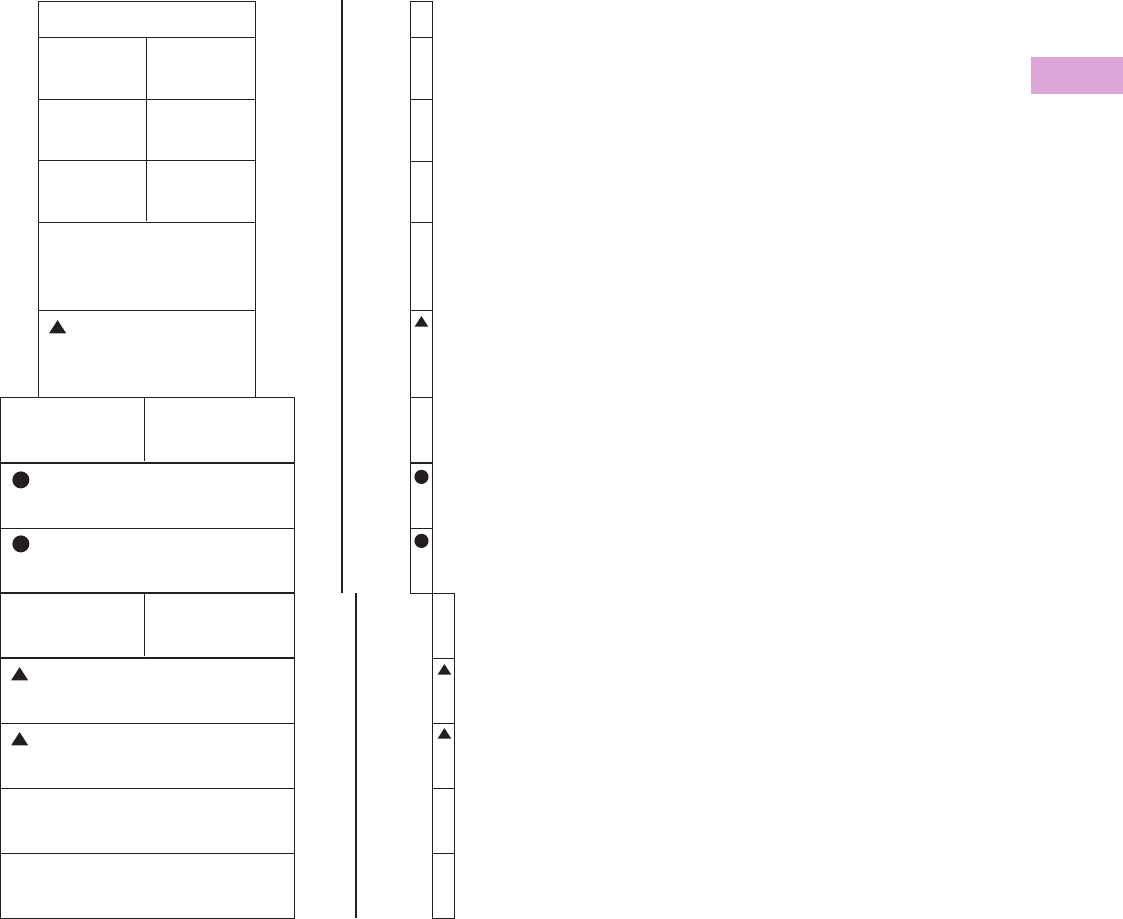
Volume 2—Commercial Distribution CA08100003E—April 2014 www.eaton.com V2-T3-75
3
3
3
3
3
3
3
3
3
3
3
3
3
3
3
3
3
3
3
3
3
3
3
3
3
3
3
3
3
3
3.3
Panelboards and Lighting Control
Pow-R-Line C Panelboards
Layout for Branch and Horizontally Mounted Main Device—PRL4F
▲Fusible switch may be used as horizontally main.
●400 and 600A horizontally mounted feeder switches in 36-inch (914.4 mm) or 44-inch (1117.6 mm) wide box. 400 and 600A horizontally mounted
main switches only in 44-inch (1117.6 mm) wide box. For vertically mounted main, see Page V2-T3-73 for sizing.
Note: See Page V2-T3-73 for MLO or Neutral and Vertically Mounted Main space requirements.
1X
4X
4X
4X
5X
6X
5X
9X
15X
400A
Branch Switch
200A
Main or Branch Switch
100A
Fusible to Breaker Transition
Requires 1X Filler
30A 30A
60A 60A
100A
250V Max.
100A
250V Max.
100A 100A
44-inch (1117.6 mm) Wide Box 36-inch (914.4 mm) Wide Box
600A
Branch Switch
200A 200A
400A
Main or Branch
600A
Main or Branch
800A
Branch
1200A
Branch
9X
11X
11X
(11X With
Shunt Trip)
(11X With
Shunt Trip)
(16X With
Shunt Trip)
(16X With
Shunt Trip)
11X
6X
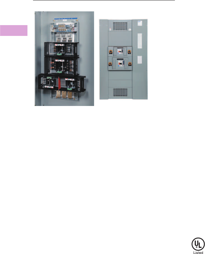
V2-T3-76 Volume 2—Commercial Distribution CA08100003E—April 2014 www.eaton.com
3
3
3
3
3
3
3
3
3
3
3
3
3
3
3
3
3
3
3
3
3
3
3
3
3
3
3
3
3
3
3.3
Panelboards and Lighting Control
Pow-R-Line C Panelboards
Type PRL4D Drawout Molded Case Circuit Breaker Power Panelboard
Type PRL4D
Contents
Description Page
Product Description. . . . . . . . . . . . . . . . . . . . . . . . V2-T3-7
Application Description . . . . . . . . . . . . . . . . . . . . . V2-T3-8
Standards and Certifications . . . . . . . . . . . . . . . . . V2-T3-10
Technical Data and Specifications . . . . . . . . . . . . . V2-T3-11
Type PRL1a . . . . . . . . . . . . . . . . . . . . . . . . . . . . . . V2-T3-26
Type PRL1aF . . . . . . . . . . . . . . . . . . . . . . . . . . . . . V2-T3-30
Type PRL1a-LX . . . . . . . . . . . . . . . . . . . . . . . . . . . V2-T3-34
Type PRL2a . . . . . . . . . . . . . . . . . . . . . . . . . . . . . . V2-T3-38
Type PRL2aF . . . . . . . . . . . . . . . . . . . . . . . . . . . . . V2-T3-42
Type PRL2a-LX . . . . . . . . . . . . . . . . . . . . . . . . . . . V2-T3-46
Retrofit Panelboard . . . . . . . . . . . . . . . . . . . . . . . . V2-T3-50
Type PRL3a . . . . . . . . . . . . . . . . . . . . . . . . . . . . . . V2-T3-58
Type PRL3E. . . . . . . . . . . . . . . . . . . . . . . . . . . . . . V2-T3-62
Type PRL4 . . . . . . . . . . . . . . . . . . . . . . . . . . . . . . . V2-T3-66
Type PRL4D
Product Selection. . . . . . . . . . . . . . . . . . . . . . . V2-T3-77
Box Sizing and Selection—PRL4D . . . . . . . . . . V2-T3-80
Accessories and Modifications . . . . . . . . . . . . V2-T3-83
Type PRL5P. . . . . . . . . . . . . . . . . . . . . . . . . . . . . . V2-T3-86
Type PRL4D
Product Description
●Drawout molded case
circuit breaker power
panelboard
●Front accessible
●Front connected
●Through-the-door design
drawout mechanism
●Visual indication of breaker
status and position
●Large grab handles for
easy removal
●600 Vac maximum
●1200A maximum mains
●600A maximum drawout
molded case feeder
breakers
Application Description
●Interrupting ratings up to
200 kAIC symmetrical
●Feeder power panelboard
●Rated as Service Entrance
Equipment when
appropriately equipped
●Ideal for:
●Data centers
●Industrial facilities
●Process equipment
manufacturing
●Anywhere that requires
quick change of feeder
devices is needed
Benefits
●Ease of maintenance
●Faster to remove and
install
●Less downtime
Standards and Certifications
●UL 67 Listed chassis
●UL 50 Listed box and trim
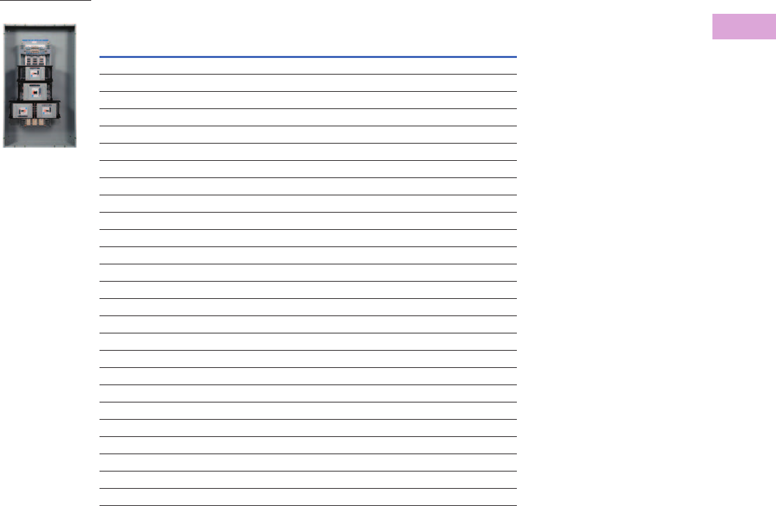
Volume 2—Commercial Distribution CA08100003E—April 2014 www.eaton.com V2-T3-77
3
3
3
3
3
3
3
3
3
3
3
3
3
3
3
3
3
3
3
3
3
3
3
3
3
3
3
3
3
3
3.3
Panelboards and Lighting Control
Pow-R-Line C Panelboards
Product Selection
PRL4D Main Lugs and Main Breakers
Notes
1 For ground fault protection on main devices, see Modification 10—applies to 310 and 310+ trip units only.
2 100% rated circuit breaker.
Ampere
Rating
Interrupting Rating (kA Symmetrical)
240 Vac 480 Vac 600 Vac
Breaker
Type “X” Space
Main Lugs Only (Fixed-Mounted Only)
400 — — — — 10X
600 — — — — 10X
800 — — — — 10X
1200 — — — — 12X
Main Circuit Breaker (Drawout Only) 1
600 65 35 18 LGE 9X
600 100 65 35 LGH 9X
600 200 100 50 LGC 9X
Main Circuit Breaker (Fixed-Mounted Only) 1
600 65 35 18 LGE 4X
600 100 65 35 LGH 4X
600 200 100 50 LGC 4X
600 65 35 25 CLD 26X
600 100 65 35 CHLD 26X
600 200 100 50 CLDC 26X
800 65 50 25 MDL 6X
8001006535HMDL6X
800 65 50 25 CMDL 26X
800 100 65 35 CHMDL 26X
1200 85 50 25 NGS 6X
1200 100 65 35 NGH 6X
1200 200 100 65 NGC 6X
1200 65 50 25 CND 26X
1200 100 65 35 CHND 26X
1200 200 100 65 CNDC 26X
Type PRL4D

V2-T3-78 Volume 2—Commercial Distribution CA08100003E—April 2014 www.eaton.com
3
3
3
3
3
3
3
3
3
3
3
3
3
3
3
3
3
3
3
3
3
3
3
3
3
3
3
3
3
3
3.3
Panelboards and Lighting Control
Pow-R-Line C Panelboards
PRL4D Drawout Branch/Feeder Breakers
Single Mount Two-Pole and Three-Pole
Ampere
Rating
Interrupting Rating (kA Symmetrical)
240 Vac 480 Vac 600 Vac
Breaker
Type “X” Space
Single-Mount Breakers with Thermal-Magnetic Trip Units
70–250853518JGS7X
70–250 100 65 25 JGH 7X
70–250 200 100 35 JGC 7X
250–600 85 35 18 LGS 9X
250–600 100 65 35 LGH 9X
250–600 200 100 50 LGC 9X
Single-Mount Breakers with Electronic 310+ Trip Units (Three-Pole Only)
20–50 85 35 18 JGS 7X
20–50 100 65 25 JGH 7X
20–50 200 100 35 JGC 7X
40–100853518JGS7X
40–100 100 65 25 JGH 7X
40–100 200 100 35 JGC 7X
80–150853518JGS7X
80–150 100 65 25 JGH 7X
80–150 200 100 35 JGC 7X
100–250 85 35 18 JGS 7X
100–250 100 65 25 JGH 7X
100–250 200 100 35 JGC 7X
100–250 85 35 18 LGS 9X
100–250 100 65 35 LGH 9X
100–250 200 100 50 LGC 9X
200–400 85 35 18 LGS 9X
200–400 100 65 35 LGH 9X
200–400 200 100 50 LGC 9X
250–600 85 35 18 LGS 9X
250–600 100 65 35 LGH 9X
250–600 200 100 50 LGC 9X
Provision for Future (Includes Factory-Installed Base Cassette)
20–250 Any JG family branch/feeder breaker 7X
100–600 Any LG family branch/feeder breaker 9X
Type PRL4D
Volume 2—Commercial Distribution CA08100003E—April 2014 www.eaton.com V2-T3-79
3
3
3
3
3
3
3
3
3
3
3
3
3
3
3
3
3
3
3
3
3
3
3
3
3
3
3
3
3
3
3.3
Panelboards and Lighting Control
Pow-R-Line C Panelboards
For Dual/Twin feeder breakers, select any two breakers within the same “Breaker Type.”
Dual/Twin Mount Two-Pole and Three-Pole
Ampere
Rating
Interrupting Rating (kA Symmetrical)
240 Vac 480 Vac 600 Vac
Breaker
Type “X” Space
Dual-/Twin-Mount Breakers with Thermal-Magnetic Trip Units
70–250 85 35 18 JGS 7X
70–250 100 65 25 JGH 7X
70–250 200 100 35 JGC 7X
Dual-/Twin-Mount Breakers with Electronic 310+ Trip Units (Three-Pole Only)
20–50 85 35 18 JGS 7X
20–50 100 65 25 JGH 7X
20–50 200 100 35 JGC 7X
40–100 85 35 18 JGS 7X
40–100 100 65 25 JGH 7X
40–100 200 100 35 JGC 7X
80–150 85 35 18 JGS 7X
80–150 100 65 25 JGH 7X
80–150 200 100 35 JGC 7X
100–250 85 35 18 JGS 7X
100–250 100 65 25 JGH 7X
100–250 200 100 35 JGC 7X
Provision for Future (Includes Factory-Installed Base Cassette)
20–250 Any JG Family Branch/Feeder Breaker 7X
100–600 Any LG Family Branch/Feeder Breaker 9X
Type PRL4D

V2-T3-80 Volume 2—Commercial Distribution CA08100003E—April 2014 www.eaton.com
3
3
3
3
3
3
3
3
3
3
3
3
3
3
3
3
3
3
3
3
3
3
3
3
3
3
3
3
3
3
3.3
Panelboards and Lighting Control
Pow-R-Line C Panelboards
Box Sizing and Selection—PRL4D
Approximate Dimensions in Inches (mm)
Main Lug Only (MLO), Main Breaker, Neutral, Through-Feed Lug
(TFL) and Sub-Feed Lug (SFL) “X” Space Requirements. (For
other configurations not shown, refer to Eaton.)
*= Space available for branch devices. For device sizing,
see Page V2-T3-82.
•= Blank means no bus under cover, to meet NEC cable
bending space.
PRL4D Layout
Note
1Sub-feed lugs are available 250–600A. For 600A, use 1200A “A” space.
*
10X
7X Through-
Feed Lugs
*
10X NN
MLO, SFL MLO, TFL
3Ph 4W, 3Ph 3W
250A a, 400A a,
600A a, 800A
Standard Main Lug, Through-Feed and Sub-Feed Lugs a
(500 kcmil Maximum)
Main Breaker with Neutral (when required)
(500 kcmil Maximum)
*
7X
*
NN
3Ph 4W,
3Ph 3W
250A, 400A,
600A, 800A
*
12X
7X Through-
Feed Lugs
*
12X NN
MLO MLO, TFL
3Ph 4W, 3Ph 3W
1200A
36-inch
(914.4 mm)
Minimum
Width
Main Breaker
Main Breaker
*
3Ph 3W3Ph 4W
800A Vertically Mtd. MDL Main Breaker only in 24-inch (609.6 mm) wide box.
Available with 38X and 50X Panel Height only.
19X
Blank
2X
*
7X
*
N
3Ph 3W
1200A
36-inch
(914.4 mm)
Minimum
Width
Main Breaker
3Ph 4W
Blank
2X Blank
2X
Blank
2X
Main Breaker
*
9X Through-
Feed Lugs
*
20X NN
MLO, SFL MLO, TFL
3Ph 4W
250A a, 400A a,
600A a, 800A
Optional Main Lugs, Through-Feed and Sub-Feed Lugs a (750 kcmil Maximum)
*
20X
11X Through-
Feed Lugs
*
20X NN
MLO MLO, TFL
3Ph 4W
1200A
36-inch
(914.4 mm)
Minimum
Width Blank
5X
*
9X Through-
Feed Lugs
*
13X
3Ph 3W
250A, 400A,
600A, 800A
*
15X
11X Through-
Feed Lugs
*
15X
120A
36-inch
(914.4 mm)
Minimum
Width Blank
5X
Blank
20X
Blank
13X
3X
3Ph 3W
3X
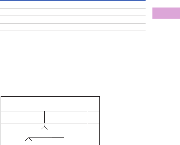
Volume 2—Commercial Distribution CA08100003E—April 2014 www.eaton.com V2-T3-81
3
3
3
3
3
3
3
3
3
3
3
3
3
3
3
3
3
3
3
3
3
3
3
3
3
3
3
3
3
3
3.3
Panelboards and Lighting Control
Pow-R-Line C Panelboards
Approximate Dimensions in Inches (mm)
Panel Layout and Dimensions
To determine the dimensions
of a given panelboard
enclosure, make a layout
sketch by fitting together the
main, branch and lug modules
according to the appropriate
tables in the layout guide.
Assign “X” units to each
module as shown and obtain
a total “X” number.
The height of the enclosure is
related to the total “X” units
in the layout as shown in
table on right. Three standard
box heights are available to
accommodate any and all
layout arrangements. “X”
unit totals that do not exactly
match those in table on
right must be rounded off
to the next higher standard
(38X, 50X).
If a calculated “X” total for a
panel exceeds 50X, the panel
must be split into two or
more separate sections with
“X” space for through-feed
lugs figured in for all but
one section. If a neutral is
required, a separate neutral
bar and appropriate “X”
space must be included in
each section.
Layout Example
●One PRL4D panelboard,
480Y/277 Vac, three-
phase, four-wire, 65 kA,
800A main lugs only with:
●One JGS 200A/
three-pole
●One LGS 400A/
three-pole
●One JGS 150A/
three-pole dual mount
●One JGS 100A/
three-pole dual mount
Reference PRL4D Layout
Example
1. From layout guide,
total “X” height of
panel = 33X.
2. From table on right, 33X
must use minimum 38X
dimensions. Minimum
box height is 73.50
inches (1866.9 mm).
3. From the layout for
branch and main devices,
find minimum box width
requirements for mains
and branch/feeder
devices.
●JGS single minimum
width: 36 inches
●LGS single minimum
width: 36 inches
●JGS dual minimum width:
44 inches
As the JGS duals require a
minimum of a 44-inch-wide
box, the minimum box width
is 44 inches.
4. From PRL4D Layout
Example, the correct
minimum box selection
is BX4473, which is
73.50 inches H x 44.00
inches W x 11.31 inches D
(1866.9 mm H x1117.6
mm W x 287.0 mm D).
Box Dimensions—PRL4D
Top and Bottom Gutters
10.63 inches (269.9 mm) minimum.
Side Gutters—Minimum
●36-inch (914.4 mm) wide box: 6-inch (152.4 mm)
●44-inch (1117.6 mm) wide box: 8-inch (203.2 mm)
Type PRL4D Layout Example
Notes
1Box depth is 10.40-inch (264.2 mm), cover adds 0.90-inch (22.8 mm) to depth.
Flush trims not available on PRL4D panels.
Door-to-door option not available on PRL4D panels.
“X”
Units
Catalog
Number Height Width Depth 1
38X BX3673 73.50 (1866.9) 36.00 (914.4) 11.31 (287.0)
50X BX3690 90.00 (2286.0) 36.00 (914.4) 11.31 (287.0)
38X BX4473 73.50 (1866.9) 44.00 (1117.6) 11.31 (287.0)
50X BX4490 90.00 (2286.0) 44.00 (1117.6) 11.31 (287.0)
JGS 200A three-pole single feeder 7X
LGS 400A three-pole single feeder 9X
JGS 150A
three-pole dual feeder
JGS 150A
three-pole dual feeder
7X
Main Lugs 800A 10X
Total = 33X
Neutral
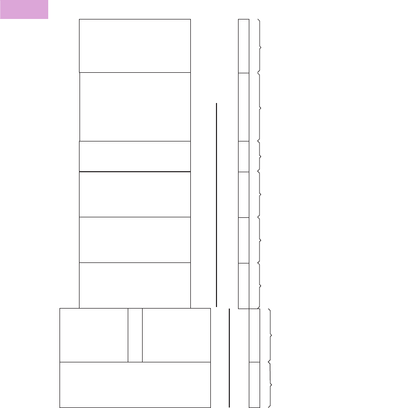
V2-T3-82 Volume 2—Commercial Distribution CA08100003E—April 2014 www.eaton.com
3
3
3
3
3
3
3
3
3
3
3
3
3
3
3
3
3
3
3
3
3
3
3
3
3
3
3
3
3
3
3.3
Panelboards and Lighting Control
Pow-R-Line C Panelboards
Layout for Branch and Horizontally Mounted Main Devices—PRL4D
Instructions
Determine box size by locating all main and feeder devices in your panel. The width of box is determined by the maximum box size
shown for each device. For main lugs, through-feed lugs and sub-feed lugs, refer to Page V2-T3-80.
Notes
1100% rated breaker.
2Optional 750 kcmil terminal requires 44-inch (1117.6 mm) wide box.
3Contact Eaton for availability.
4X
6X
6X
7X
6X
7X
2 or 3P
Feeder Only
Single Drawout
2 or 3P
Main Only
Fixed Mount
2 or 3P
Main Only
Fixed Mount
2 or 3P
Feeder Only
Dual Drawout
2 or 3P
Feeder Only
Dual Drawout
2 or 3P
Main Only
Fixed Mount
JGS, JGH, JGC
250A
Max. JGS, JGH, JGC
600A
Max. LGS, LGH, LGC
600A
Max.
600A
Max.
800A
Max.
1200A
Max.
LGS, LGH, LGC
MDL, HMDL, CMDL ,
CHMDL
NGS , NGH , NGC
250A
Max.
44-Inch (1117.6 mm) Wide Box
36-Inch (914.4 mm) Wide Box
1200A
Max.
9X
2 or 3P
Main or Feeder
Single Drawout
6X
2 or 3P
Main Only
Fixed Mount
2 or 3P
Main Only
Fixed Mount
CLD , CHLD , CLDC
111
1
1
222
NGSC , NGHC , NGCC
33 3

Volume 2—Commercial Distribution CA08100003E—April 2014 www.eaton.com V2-T3-83
3
3
3
3
3
3
3
3
3
3
3
3
3
3
3
3
3
3
3
3
3
3
3
3
3
3
3
3
3
3
3.3
Panelboards and Lighting Control
Pow-R-Line C Panelboards
Accessories and Modifications
PRL4D Modifications
Modification Item Number
Ambient compensating breakers 1
Breaker accessories—internal 2
Complete assembly 3
Compression type lugs 4
Conduit covers 5
Copper lugs/terminals 6
Copper main bus 7
Density rated bus 8
Directory frame—metal 9
Electronic trip units 10
Ground bars 11
Ground fault protection 12
Infrared (IR) viewing windows 13
Handle lock-off device 14
Nameplates 15
Permanent circuit numbers 16
Seismically qualified 17
Service entrance equipment rated 18
Shunt trips 19
Sub-feed lugs 20
Surge protective devices 21
Through-feed lugs 22
Touchup paint 23
1. Ambient Compensating
Breakers
For ambient compensating
breakers (where available) in
lieu of standard breakers, add
10% to panelboard branch
breaker and to main breaker
list prices, if required.
(Not UL Listed.)
2. Breaker Accessories—Internal (Only One Accessory Per Position)
Accessories
Notes
1Accessories wired to a pull-apart terminal block. Right position only.
2Accessories wired to a pull-apart terminal block. Left position only.
3Not available when breaker is equipped with ARMS trip unit.
Breaker
Type
Device
Mounting Internal Breaker Accessory
JG family Drawout 1Auxiliary switch 1A-1B
JG family Drawout 1Auxiliary switch 2A-2B
JG family Drawout 1Bell alarm
JG family Drawout 1High load alarm w/trip
JG family Drawout 1Ground fault alarm w/trip
JG family Drawout 2Undervoltage release
JG family Drawout 2Zone selective interlock
LG family Drawout 1Auxiliary switch 1A-1B
LG family Drawout 1Auxiliary switch 2A-2B
LG family Drawout 1Bell alarm
LG family Drawout 1High load alarm w/trip
LG family Drawout 1Ground fault alarm w/trip
LG family Drawout 2Undervoltage release 3
LG family Drawout 2Zone selective interlock
LG family Fixed Auxiliary switch 1A-1B
LG family Fixed Auxiliary switch 2A-2B
LG family Fixed Bell alarm
LG family Fixed High load alarm w/trip
LG family Fixed Ground fault alarm w/trip
LG family Fixed Undervoltage release 3
LG family Fixed Zone selective interlock
MDL family Fixed Auxiliary switch 1A-1B
MDL family Fixed Auxiliary switch 2A-2B
MDL family Fixed Auxiliary switch 1A-1B w/alarm
MDL family Fixed Auxiliary switch 2A-2B w/alarm
NG family Fixed Auxiliary switch 1A-1B
NG family Fixed Auxiliary switch 2A-2B
NG family Fixed Bell alarm
NG family Fixed High load alarm w/trip
NG family Fixed Ground fault alarm w/trip
NG family Fixed Undervoltage release 3
NG family Fixed Zone selective interlock

V2-T3-84 Volume 2—Commercial Distribution CA08100003E—April 2014 www.eaton.com
3
3
3
3
3
3
3
3
3
3
3
3
3
3
3
3
3
3
3
3
3
3
3
3
3
3
3
3
3
3
3.3
Panelboards and Lighting Control
Pow-R-Line C Panelboards
3. Complete Assembly
Complete assembly of
panelboard box, interior and
trim prior to shipment, when
requested on order.
4. Compression Main Lugs
Al/Cu Burndy Range Taking
Type.
Modification 4
5. Conduit Covers
Fabricated sheet metal to
cover open conduits above
and/or below standard
Type 1 box.
Modification 5
6. Copper Lugs/Terminals
Optional copper mechanical
main lugs only and includes
main incoming neutral lug.
Modification 6
7. Copper Main Busbars
Optional copper busbars are
available in all ampere ratings.
Modification 7
8. Density Rated Bus
Standard main bus ampere
rating is determined by UL
listed temperature rise
testing. Density rated bus is
defined at 750A per square
inch for aluminum bus and
1000A per square inch for
copper bus. Adder for
aluminum density rated bus is
in addition to the base price.
Adder for copper density
rated bus is in addition to
the base price plus the
appropriate adder for copper
bus. See Modification 7.
Modification 8
9. Directory Frame—Metal
Metal directory frame in lieu
of standard non-metallic
pocket directory holder.
Modification 9
10. Electronic Trip Units
Thermal-magnetic trip units
are standard. For electronic
trip units, select appropriate
breaker from the electronic
trip section of Pages
V2-T3-78 and V2-T3-79.
See selection below for
electronic trip units.
Modification 10
Main Lug
Amperes
PRL4D Lug
Wire Range
800 (3) 500–750 kcmil
1200 (4) #2–600 kcmil
(4) 500–750 kcmil
Description
Conduit enclosing shield—open back
Conduit enclosing shield—solid back
Main Lug
Amperes
PRL4D Lug
Wire Range
600 (2) 1/0–600 kcmil
800 (2) 1/0–600 kcmil
1200 (3) 1/0–600 kcmil
Ampere
Range
Bare Copper
Chassis Bus
Silver-Plated
Copper Bus
600
800
1000
1200
Ampere Rating
Aluminum—750A per Square Inch
600
800
1000
1200
Copper—1000A per Square Inch
600
800
1000
1200
Directory Frame Type
Metal frame, plastic cover
Breaker
Frame
Family
Trip Unit
Type
Drawout Feeder
JGS, JGH, JGC
Digitrip 310+ LS
Digitrip 310+ LSI
Digitrip 310+ LSG
Digitrip 310+ LSIG
Drawout Feeder
or Main LGS, LGH,
LGC
Digitrip 310+ LS
Digitrip 310+ LSI
Digitrip 310+ LSG
Digitrip 310+ LSIG
The following electronic trip units integrate Eaton's Arcflash
Reduction Maintenance System within the trip unit.
Electronic Trip Units for Fixed-Mounted Mains Only.
11. Ground Bars
Modification 11
Notes
1L = Adjustable long delay pickup
S = Adjustable short delay pickup w/fixed short delay
I = Adjustable instantaneous pickup
G = Adjustable ground fault pickup
A = Arcflash Reduction Maintenance System
2Trip unit includes Arcflash Reduction Maintenance System.
3Digitrip 310+ is standard for the NGS, NGH and NGC.
4Digitrip 310 is standard for CND, CHND and CNDC.
Breaker Frame Family Trip Unit Type
Drawout Feeder or Main LGS, LGH, LGC Digitrip 310+ ALSI
Digitrip 310+ ALSIG
Breaker Frame Family Trip Unit Type
Trip Unit
Functionality 1
LGS, LGH, LGC Digitrip 310+
Digitrip 310+
Digitrip 310+
Digitrip 310+
Digitrip 310+
Digitrip 310+
LS
LSI
LSG
LSIG
ALSI 2
ALSIG 2
CLD, CHLD, CLDC Digitrip 310
Digitrip 310
Digitrip 310
Digitrip 310
LS
LSI
LSG
LSIG
MDL, HMDL, CMDL, CHMDL Digitrip 310
Digitrip 310
Digitrip 310
Digitrip 310
LS
LSI
LSG
LSIG
NGS, NGH, NGC Digitrip 310+ 3
Digitrip 310+ 3
Digitrip 310+ 3
Digitrip 310+ 3
Digitrip 310+ 3
Digitrip 310+ 3
LS
LSI
LSG
LSIG
ALSI 2
ALSIG 2
CND, CHND, CNDC Digitrip 310 4
Digitrip 310 4
Digitrip 310 4
Digitrip 310 4
LS
LSI
LSG
LSIG
Description Bar Type
Aluminum bar for aluminum
and copper conductors
Standard, attached to box
Insulated/isolated ground bar
Copper bar for use with
copper only conductors
Standard, attached to box
Insulated/isolated bar

Volume 2—Commercial Distribution CA08100003E—April 2014 www.eaton.com V2-T3-85
3
3
3
3
3
3
3
3
3
3
3
3
3
3
3
3
3
3
3
3
3
3
3
3
3
3
3
3
3
3
3.3
Panelboards and Lighting Control
Pow-R-Line C Panelboards
12. Ground Fault Protection
Refer to Modification 10 for
ground fault trip units.
13. Infrared (IR) Viewing
Windows
Infrared viewing windows for
main devices and drawout
single-mounted feeder
devices.
Modification 13
14. Handle Lock-Off Devices for
Breakers
Contact Eaton for a list of
padlockable and non-
padlockable circuit breaker
handle lock-offs.
15. Nameplates, Engraved
Field-attached nameplates.
Modification 15
16. Permanent Circuit Numbers
Permanently attached micarta
circuit numbering.
17. Seismically Qualified
For seismically qualified
PRL4D panelboards, request
seismic labeling on order.
18. Service Entrance Equipment
Service Entrance labeling as
detailed under the “Service
Entrance Equipment” per UL
and NEC. Only panelboards
meeting these requirements
may be labeled as such. The
requirement or service
entrance labeling must be
noted on the order. Includes
neutral disconnect link and
labeling “Suitable For
Use as Service Equipment”
(SUSE). Ground bar must be
ordered separately. See
Modification 11.
19. Shunt Trip for Main or Feeder
Breakers
For tripping breaker from
remote point. Voltage and
frequency must be specified
when ordering shunt trips.
Wiring to terminal block is
included with the drawout
molded case product as
standard. For all others
wired to terminal block,
contact Eaton.
20. Sub-Feed Lugs
Available only on main lug
only panelboards.
Not available on service
entrance panelboards with
main lugs using the six
disconnect rule.
Mechanical Al/Cu lugs.
Compression or copper body
lugs require additional price
adder from Modification 4 or
Modification 6, as
appropriate.
Modification 20
Overcurrent
Device
IR Window
Manufacturer
All fixed mount
mains
Iriss
Hawk (Fluke)
Single drawout
feeder breakers 1
Iriss
Hawk (Fluke)
Description
Mastic back, engraved, black with
white lettering
Mastic back, engraved, colors other
than black
Nameplates, screw attached
Panel
Ampere
Rating
Box Height
Addition
600 4X
800 6X
21. Surge Protective Devices
(SPD)
Package includes SPD unit
and integral circuit breaker
disconnect (30A) connected
to the chassis bus.
Modification 21
22. Through-Feed Lugs
Mechanical Al/Cu lugs.
Compression or copper
lugs require additional price
adder from Modification 4
Compression Lug or
Modification 6 Copper
Lugs/Terminals.
Modification 22
Refer to PRL4D Layout.
23. Touchup Paint
Modification 23
Note
1Available on only single-mounted
drawout. Not available on dual-mounted
feeder devices.
Surge Current Rating 50 80 100 120 160 200 250 300 400
SPD Package Options—Basic Package
LED monitor, L-N, L-G, L-L
and N-G
■■■■■■■■■
Standard Package
LED monitor, L-N, L-G, L-L and
N-G. EMI/RFI filtering. Audible
alarm with disable switch.
Form C relay contact.
■■■■■■■■■
Premium Package
LED monitor, L-N, L-G, L-L and
N-G. EMI/RFI filtering. Audible
alarm with disable switch.
Form C relay contact. Six-digit
LCD display. Counts surges in
all modes. Nonvolatile memory
(no battery backup). Reset
button designed to prevent
accidental resets.
■■■■■■■■■
Panel Main
Ampere
Rating
Box Height
Addition
600 7X
800 7X
1200 9X
Description
12 oz spray can. ANSI-61 light gray indoor
Case lot of 12—12 oz spray can. ANSI-61
light gray indoor
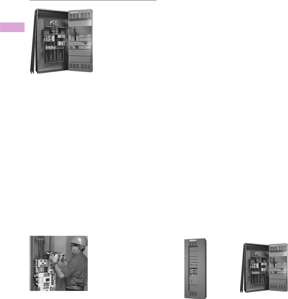
V2-T3-86 Volume 2—Commercial Distribution CA08100003E—April 2014 www.eaton.com
3
3
3
3
3
3
3
3
3
3
3
3
3
3
3
3
3
3
3
3
3
3
3
3
3
3
3
3
3
3
3.3
Panelboards and Lighting Control
Pow-R-Line C Panelboards
Type PRL5P
Contents
Description Page
Product Description. . . . . . . . . . . . . . . . . . . . . . . . V2-T3-7
Application Description . . . . . . . . . . . . . . . . . . . . . V2-T3-8
Standards and Certifications . . . . . . . . . . . . . . . . . V2-T3-10
Technical Data and Specifications . . . . . . . . . . . . . V2-T3-11
Type PRL1a . . . . . . . . . . . . . . . . . . . . . . . . . . . . . . V2-T3-26
Type PRL1aF . . . . . . . . . . . . . . . . . . . . . . . . . . . . . V2-T3-30
Type PRL1a-LX . . . . . . . . . . . . . . . . . . . . . . . . . . . V2-T3-34
Type PRL2a . . . . . . . . . . . . . . . . . . . . . . . . . . . . . . V2-T3-38
Type PRL2aF . . . . . . . . . . . . . . . . . . . . . . . . . . . . . V2-T3-42
Type PRL2a-LX . . . . . . . . . . . . . . . . . . . . . . . . . . . V2-T3-46
Retrofit Panelboard . . . . . . . . . . . . . . . . . . . . . . . . V2-T3-50
Type PRL3a . . . . . . . . . . . . . . . . . . . . . . . . . . . . . . V2-T3-58
Type PRL3E. . . . . . . . . . . . . . . . . . . . . . . . . . . . . . V2-T3-62
Type PRL4 . . . . . . . . . . . . . . . . . . . . . . . . . . . . . . . V2-T3-66
Type PRL4D . . . . . . . . . . . . . . . . . . . . . . . . . . . . . V2-T3-76
Type PRL5P
Product Description . . . . . . . . . . . . . . . . . . . . . V2-T3-88
Application Description . . . . . . . . . . . . . . . . . . V2-T3-88
Standards and Certifications . . . . . . . . . . . . . . V2-T3-88
Product Selection. . . . . . . . . . . . . . . . . . . . . . . V2-T3-89
Technical Data and Specifications . . . . . . . . . . V2-T3-94
Dimensions . . . . . . . . . . . . . . . . . . . . . . . . . . . V2-T3-94
Product Overview
The PRL5P panelboard
incorporates Eaton’s plug-on
power panelboard experience
with modern manufacturing
technology to provide the
most flexible plug-on design
in the industry.
Designed to eliminate the
multitude of parts associated
with other similar products,
the PRL5P panelboard is the
choice for applications where
additions and changes must
be fast and convenient.
Panelboard Installation
Plug-On Mains and
Branches provide the
flexibility to move devices on
factory-assembled panels
after the boards are received
at the job site. The electrician
may move branch devices
and place them into a
configuration that fits the
particular wiring needs of that
installation.
Breakers are mounted to an
adapter that includes the bus
connection hardware. The
breaker to bus bar connection
is positive and secure. This
proven connection has been
utilized by Eaton in plug-on
power panelboards since
1984.
Two Enclosure Widths Provide
Greater Flexibility
30-Inch (762.0 mm) Wide.
The narrowest enclosure in
the industry for an 800A
main, breaker or lug, and up
to 600A branch breakers—
while providing ample wiring
bending space. An industry
exclusive is the ability to
mount two 225A, 480 Vac
breakers on the same adapter
unit. It requires half the space
necessitated by other
products.
Type PRL5P—30-Inch (762.0 mm) Wide
48-Inch (1219.2 mm) Wide.
Provides for mains up to
1200A. The 1200A lug
adapter unit accepts up to
750 kcmil conductors. Two
600A breakers can be
mounted across from one
another. Another exclusive
allows breakers of different
sizes to be mounted across
from one another, providing
the ability to maximize space
within the panel. There are no
restrictions or predetermined
spaces where branch devices
must be placed.
Type PRL5P—48-Inch (1219.2 mm) Wide
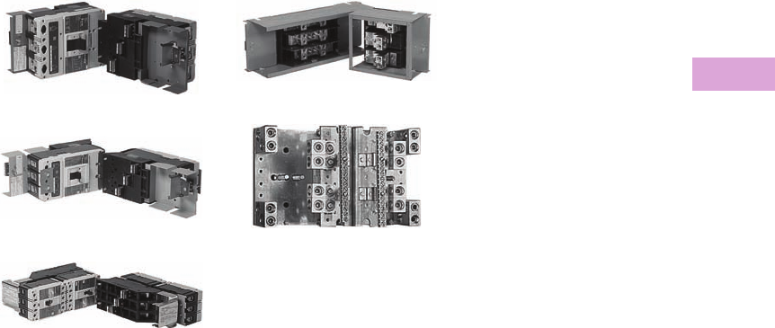
Volume 2—Commercial Distribution CA08100003E—April 2014 www.eaton.com V2-T3-87
3
3
3
3
3
3
3
3
3
3
3
3
3
3
3
3
3
3
3
3
3
3
3
3
3
3
3
3
3
3
3.3
Panelboards and Lighting Control
Pow-R-Line C Panelboards
Circuit Breaker and Lug Adapter Units
Breaker adapter units utilize
molded case circuit breakers
that provide increased
performance in considerably
less space than standard
breakers. They’re available
from 15–1200A at 600 Vac
maximum. A wide range of
integrally mounted breaker
accessories are available.
Main and through-feed lug
adapter units are available
and are mounted similar to
the breakers. Lug units are
available up to 1200A.
Breaker and lug attachment
units can withstand fault
currents up to 200 kA rms
symmetrical.
600A L-Frame Breaker
400A K-Frame Breaker
Dual-Mounted 225A F-Frame Breakers
1200A Main Lug Unit
An Oversized Area is Provided for
Neutral Connections with Ample
Lugs for Ease of Installation
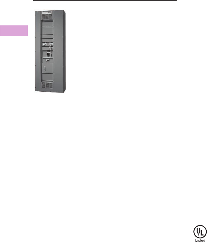
V2-T3-88 Volume 2—Commercial Distribution CA08100003E—April 2014 www.eaton.com
3
3
3
3
3
3
3
3
3
3
3
3
3
3
3
3
3
3
3
3
3
3
3
3
3
3
3
3
3
3
3.3
Panelboards and Lighting Control
Pow-R-Line C Panelboards
Type PRL5P
Contents
Description Page
Product Description. . . . . . . . . . . . . . . . . . . . . . . . V2-T3-7
Application Description . . . . . . . . . . . . . . . . . . . . . V2-T3-8
Standards and Certifications . . . . . . . . . . . . . . . . . V2-T3-10
Technical Data and Specifications . . . . . . . . . . . . . V2-T3-11
Type PRL1a . . . . . . . . . . . . . . . . . . . . . . . . . . . . . . V2-T3-26
Type PRL1aF . . . . . . . . . . . . . . . . . . . . . . . . . . . . . V2-T3-30
Type PRL1a-LX . . . . . . . . . . . . . . . . . . . . . . . . . . . V2-T3-34
Type PRL2a . . . . . . . . . . . . . . . . . . . . . . . . . . . . . . V2-T3-38
Type PRL2aF . . . . . . . . . . . . . . . . . . . . . . . . . . . . . V2-T3-42
Type PRL2a-LX . . . . . . . . . . . . . . . . . . . . . . . . . . . V2-T3-46
Retrofit Panelboard . . . . . . . . . . . . . . . . . . . . . . . . V2-T3-50
Type PRL3a . . . . . . . . . . . . . . . . . . . . . . . . . . . . . . V2-T3-58
Type PRL3E. . . . . . . . . . . . . . . . . . . . . . . . . . . . . . V2-T3-62
Type PRL4 . . . . . . . . . . . . . . . . . . . . . . . . . . . . . . . V2-T3-66
Type PRL4D . . . . . . . . . . . . . . . . . . . . . . . . . . . . . V2-T3-76
Type PRL5P
Product Overview . . . . . . . . . . . . . . . . . . . . . . V2-T3-86
Product Selection. . . . . . . . . . . . . . . . . . . . . . . V2-T3-89
Modifications . . . . . . . . . . . . . . . . . . . . . . . . . . V2-T3-92
Technical Data and Specifications . . . . . . . . . . V2-T3-94
Dimensions . . . . . . . . . . . . . . . . . . . . . . . . . . . V2-T3-94
Type PRL5P
Product Description
●600 Vac maximum
(250 Vdc)
●Three-phase four-wire,
three-phase three-wire,
single-phase three-wire
●1200A maximum mains
●1200A maximum
branch devices
●Plug-on branch devices
●Factory assembled
●Refer to Pages V2-T3-7
and V2-T3-88 for additional
information
Application Description
●Power distribution
panelboard
●Fully rated or series rated
●Interrupting ratings up to
200 kA symmetrical
●Suitable for use as Service
Entrance Equipment, when
specified on the order
●See Pages V2-T3-7
through V2-T3-23 for
additional information
Standards and Certifications
●UL 67, UL 50
●Federal Specification
W-P-115c
●Refer to Page V2-T3-7 for
additional information

Volume 2—Commercial Distribution CA08100003E—April 2014 www.eaton.com V2-T3-89
3
3
3
3
3
3
3
3
3
3
3
3
3
3
3
3
3
3
3
3
3
3
3
3
3
3
3
3
3
3
3.3
Panelboards and Lighting Control
Pow-R-Line C Panelboards
Product Selection
Panelboard Selection and
Layout
Select either single-row or
double-row bus chassis.
Single-row bus chassis—
maximum 800 ampere main
breaker or main lug only.
Select main device and “X”
space from table below.
Select branch devices and
corresponding “X” space
from the following tables.
Refer to layout data from the
following tables. Make a
layout sketch of the main and
branch devices utilizing either
a single-row or double-row
bus chassis indicating the
“X” space for each device.
The maximum total “X”
space cannot exceed 40X for
any panelboard. Should more
than 40X be required, add the
appropriate through-feed lug
adapter or breaker to feed an
additional panelboard.
PRL5P 1
Branch Devices—Single-Pole Breakers in Single Adapter Units—PRL5P
Note
1 Includes aluminum bus chassis, box, trim, main and neutral (if required).
Main
Ampere
Rating
Interrupting Rating (kA Symmetrical) Main
Device
Type
Main
“X”
Space240 Vac 480 Vac 600 Vac 250 Vdc
Main Lug Only Single-Row Bus
400————Lug8X
600————Lug8X
800————Lug8X
Main Lug Only Double-Row Bus
800————Lug7X
1200 — — — — Lug 7X
Main Breaker Single-Row Bus
400 65 — — 10 DK 4X
400 65 35 25 10 KD 4X
400 100 65 35 22 HKD 4X
400 200 100 65 22 KDC 4X
600 35 35 25 22 LD 6X
600 100 65 35 25 HL 6X
600 200 100 35 25 LDC 6X
800 65 50 25 22 MDL 6X
800 100 65 35 25 HMDL 6X
Main Breaker Double-Row Bus
800 65 50 25 22 MDL 6X
800 100 65 35 25 HMDL 6X
1200 65 50 25 — ND 6X
1200 100 65 35 — HND 6X
1200 200 100 65 — NDC 6X
Ampere
Rating
Interrupting Rating (kA Symmetrical) Breaker
Type “X” Type120 Vac 240 Vac 277 Vac 125 Vdc
15–60 14 — 14 10 EHD 2X, 3X
15–60 35 — 35 10 FD 2X, 3X
15–60 65 — 65 10 HFD 2X, 3X
Type PRL5P

V2-T3-90 Volume 2—Commercial Distribution CA08100003E—April 2014 www.eaton.com
3
3
3
3
3
3
3
3
3
3
3
3
3
3
3
3
3
3
3
3
3
3
3
3
3
3
3
3
3
3
3.3
Panelboards and Lighting Control
Pow-R-Line C Panelboards
Branch Devices—Two- and Three-Pole Breakers in Single Adapter Units—PRL5P
Branch Devices—Sub-Feed Lug Units—PRL5P
Note
1For use only in double-row chassis panelboards only.
Ampere
Rating
Interrupting Rating (kA Symmetrical) Breaker
Type
“X”
Space240 Vac 480 Vac 600 Vac 250 Vdc
100–225 22 — — — EDB 3X
100–225 42 — — — EDS 3X
100–225 65 — — — ED 3X
100–225 100 — — — EDH 3X
100–225 200 — — — EDC 3X
15–60 18 14 — 10 EHD 3X
70–100 18 14 — 10 EHD 3X
15–6065351810FD 3X
70–100 65 35 18 10 FD 3X
110–225 65 35 18 10 FD 3X
15–60 100 65 25 22 HFD 3X
70–100 10 65 25 22 HFD 3X
110–225 100 65 25 22 HFD 3X
15–60 200 100 35 22 FDC 3X
70–100 200 100 35 22 FDC 3X
110–225 200 100 35 22 FDC 3X
70–225 65 35 18 10 JD 3X
250 65351810JD 3X
70–225 100 65 25 22 HJD 3X
250 100 65 25 22 HJD 3X
70–225 200 10 35 22 JDC 3X
250 200 100 35 22 JDC 3X
100–400 65 — — — DK 4X
250–400 65 35 25 10 KD 4X
250–400 100 65 35 22 HKD 4X
250–400 200 100 65 22 KDC 4X
300–600 65 35 25 22 LD 6X
300–600 100 65 35 25 HLD 6X
300–600 200 100 50 25 LDC 6X
400–800 65 50 25 22 MDL 16X
400–800 100 65 35 25 HMDL 16X
400–800 65 50 25 — ND 16X
400–800 100 65 35 — HND 16X
400–800 200 100 65 — NDC 16X
600–1200 65 50 25 — ND 16X
600–1200 100 65 35 — HND 16X
600–1200 200 100 65 — NDC 16X
Ampere
Rating
Interrupting Rating (kA Symmetrical) Breaker
Type
“X”
Space240 Vac 480 Vac 600 Vac 250 Vdc
400 — — — — Lug 8X
600 — — — — Lug 8X
800 — — — — Lug 8X
1200 — — — — Lug 17X

Volume 2—Commercial Distribution CA08100003E—April 2014 www.eaton.com V2-T3-91
3
3
3
3
3
3
3
3
3
3
3
3
3
3
3
3
3
3
3
3
3
3
3
3
3
3
3
3
3
3
3.3
Panelboards and Lighting Control
Pow-R-Line C Panelboards
Branch Devices—Dual Breaker Adapters—PRL5P
Note: Any two breakers listed above may be mounted on the same 2X or 3X dual breaker adapter. Dual breaker
adapters may be in single- or double-row chassis. Dual breaker adapters can NOT be mounted across from
another in a double-row chassis.
Ampere
Rating
Interrupting Rating (kA Symmetrical) Breaker
Type
“X”
Space240 Vac 480 Vac 600 Vac 250 Vdc
100–225 65 — — — ED 3X
100–225 100 — — — EDH 3X
100–225 200 — — — EDC 3X
15–60 18 14 — 10 EHD 3X
70–100 18 14 — 10 EHD 3X
15–60 65 35 18 10 FD 3X
70–10065351810FD 3X
110–225 65 35 18 10 FD 3X
15–60 100 65 25 22 HFD 3X
70–100 100 65 25 22 HFD 3X
110–225 100 65 25 22 HFD 3X
15–60 200 100 35 22 FDC 3X
70–100 200 100 35 22 FDC 3X
110–225 200 100 35 22 FDC 3X

V2-T3-92 Volume 2—Commercial Distribution CA08100003E—April 2014 www.eaton.com
3
3
3
3
3
3
3
3
3
3
3
3
3
3
3
3
3
3
3
3
3
3
3
3
3
3
3
3
3
3
3.3
Panelboards and Lighting Control
Pow-R-Line C Panelboards
Modifications
1. Ambient Compensating
Breakers
For ambient compensating
breakers (where available) in
lieu of standard breakers, add
10% to panelboard branch
breaker and to main breaker
list prices, if required.
(Not UL listed.)
2. Bus Density
Main bus ampere rating is
determined by UL listed
temperature test. 1000A per
square inch copper is
available and included in
copper bus price addition.
3. Special Cabinet (Box)
Construction
Modification 3
4. Complete Assembly
Complete assembly of
panelboard box, interior and
trim prior to shipment when
required.
Modification 4
5. Conduit Covers
Fabricated sheet metal to
cover open conduits above
and/or below standard Type 1
box.
Modification 5
6. Copper Main Bus
Modification 6
6a. Silver-Plated Copper
Main Bus
For silver-plated copper
panelboard main bus and/or
connectors, add as follows:
Modification 6a
6b. Copper Neutral
Modification 6b
7. Copper Lugs
Optional copper only
mechanical main lugs
(includes main incoming
neutral lugs).
Modification 7
8. Directory Frame—Metal
Modification 8
9. Trim and Door Modifications
—Special Fronts and Doors
Modification 9
10. Ground Bar
Modification 10
11. Solid-State Trip Units
Modification 11
12. Circuit Breaker Handle
Lockoff Devices
Modification 12
13. Nameplates, Engraved
Modification 13
Modification
Type 3R Enclosure
Add per panel
Description
Add per panel
Cover Type
Conduit enclosing shield (open back)
Panel Construction
Single-bus interior
Double-bus interior
Main Bus Ratings Amperes
Single-bus interior
Double-bus interior
Panel Construction
Single-bus—800A maximum
Double-bus—1200A maximum
Main Lug Amperes
400
600
800
1200
Frame Type
Metal frame, plastic cover
Type
Hinged door over devices for
Type 1 Enclosure
Description
Add per panel
Description
K-, L-, M-Frame Circuit Breaker
Digitrip RMS310 LS
Digitrip RMS310 LSI
Digitrip RMS310 LSG
Digitrip RMS310 LSIG
N-Frame Circuit Breaker
Digitrip RMS310 LS
Digitrip RMS310 LSI
Digitrip RMS310 LSG
Digitrip RMS310 LSIG
Description
Non-padlockable
Padlockable
Type
Mastic back and installed by
purchaser, per nameplate
Fixed to panel trim with two
screws or rivets, per nameplate

Volume 2—Commercial Distribution CA08100003E—April 2014 www.eaton.com V2-T3-93
3
3
3
3
3
3
3
3
3
3
3
3
3
3
3
3
3
3
3
3
3
3
3
3
3
3
3
3
3
3
3.3
Panelboards and Lighting Control
Pow-R-Line C Panelboards
14. Copper Wire Only Terminals for Molded Case Circuit Breakers
To replace standard Al/Cu terminals.
Modification 14
15. Painting and Special
Coatings
Standard boxes are code-
gauge galvanized sheet steel.
Standard trims are code-
gauge sheet steel with a rust
inhibiting phosphatized
coating and finished with
ANSI-61.
Modification 15
16. Permanent Circuit Numbers
Modification 16
17. Service Entrance
To provide a Service Entrance
Label as detailed under the
“Service Entrance
Equipment” in application
considerations. Only
panelboards meeting these
requirements can be labeled
as such. The requirement for
a Service Entrance Label
must be noted on order entry.
Includes neutral disconnect
link and Service Entrance
Equipment Label. (Ground bar
not included—
see Modification 10.)
Modification 17
18. Shunt Trip for Main or Branch
Circuit Breaker
For tripping circuit breaker
from a remote point. Voltage
and frequency must be
specified. Wiring to terminal
blocks is not included.
Standard leads extend 18
inches (457.2 mm) out
of breaker.
Circuit breakers with factory
installed 120, 240 or 480 Vac
shunt trips are available with
UL listing as shown
in table below.
Modification 18
19. Touchup Paint
Modification 19
Breaker
Frame
Maximum Breaker
Ampere Rating
Terminal
Material
Wire
Range
F 225 Copper #4–4/0
J 250 Stainless Steel #4–350
K 225 Copper (1) #3–350
350 Copper (1) 250–500
400 Copper (2) 3/0–250
L 600 Copper (2) 250–500
M 600 Copper (2) #2/0–500
800 Copper (3) #3/0–300
N 700 Copper (2) #2/0–500
1000 Copper (3) #3/0–500
1200 Copper (4) #3/0–400
Description
Painted Boxes (ANSI-61)
Painted Trims or Boxes
(other than ANSI-61)
Description
To provide permanently
attached Micarta circuit numbers.
Description
Add per panel
Description
Add per device
Type
12 oz. spray can ANSI-61
light gray Indoor
Case lot of 12—12 oz. spray cans
ANSI-61 light gray indoor
Single style

V2-T3-94 Volume 2—Commercial Distribution CA08100003E—April 2014 www.eaton.com
3
3
3
3
3
3
3
3
3
3
3
3
3
3
3
3
3
3
3
3
3
3
3
3
3
3
3
3
3
3
3.3
Panelboards and Lighting Control
Pow-R-Line C Panelboards
Technical Data and Specifications
PRL5P Maximum Component Unit Ampere Rating
Main Lug and Sub-Feed Lug Unit—PRL5P
Dimensions
Approximate Dimensions in Inches (mm)
Layout Information—PRL5P Box Sizes
Note
1Deduct “X“ space for main breaker or lugs from the total available “X” spaces listed above.
Bus Chassis Type
Total “X”
Space 1
Maximum Ampere Rating of Plug-on Components
Main Lugs Branch Lugs Main Breaker Branch Breaker
Single-row bus 24X 800 600 800 600
32X 800 600 800 600
40X 800 600 800 600
Double-row bus 24X 1200 1200 1200 1200
32X 1200 1200 1200 1200
40X 1200 1200 1200 1200
Ampere
Rating
“X”
Space
Mechanical Lug Size and Number
Al/Cu Rated
Single Bus Connection
400 8X (1) 1/0–500 kcmil or (2) 1/0–250 kcmil
600 8X (2) #4–500 kcmil
800 8X (2) #2–500 kcmil or (3) #2–400 kcmil
Double Bus Connection
400–1200 7X (4) #4–750 kcmil
Bus Chassis Type
Total “X”
Space 1Box Width Box Height
Single-row bus 24X 30.00 (762.0) 64.00 (1625.6)
32X 30.00 (762.0) 75.00 (1905.0)
40X 30.00 (762.0) 86.00 (2184.4)
Double-row bus 24X 48.00 (1219.2) 64.00 (1625.6)
32X 48.00)1219.2) 75.00 (1905.0)
40X 48.00 (1219.2) 86.00 (2184.4)
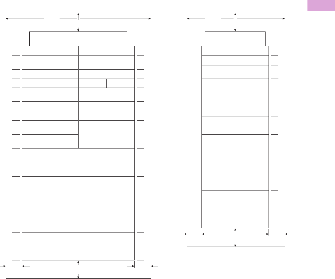
Volume 2—Commercial Distribution CA08100003E—April 2014 www.eaton.com V2-T3-95
3
3
3
3
3
3
3
3
3
3
3
3
3
3
3
3
3
3
3
3
3
3
3
3
3
3
3
3
3
3
3.3
Panelboards and Lighting Control
Pow-R-Line C Panelboards
Chassis Layout
PRL5P Chassis Layout—“X” Unit Layout of Circuit Breaker and Lug Units—X = 1.38 Inches (34.9 mm)
Notes
1Blank wireway fillers are required opposite any dual breaker unit.
2If used as a main device, must be mounted at the neutral end of panel.
3Fixed bus covers are required for unused spaces if NEC six circuit disconnect rule is to be met.
6X
Two-Pole
EHD, FD, HFD, FDC, ED, EDH, EDC
Three-Pole
EHD, FD, HFD, FDC,
ED, EDH, EDC
Two-Pole
EHD, FD, HFD, FDC,
ED, EDH, EDC
Two-Pole
EHD, FD, HFD, FDC,
ED, EDH, EDC
Blank Wireway a
Three-Pole
EHD, FD, HFD, FDC,
ED, EDH, EDC
Three-Pole
EHD, FD, HFD, FDC,
ED, EDH, EDC
Filler Plate
Two- or Three-Pole
JD, HJD, JDC
Two- or Three-Pole
DK, KD, HKD, KDC
Filler Plate
Neutral — No "X" Space Required
Top or Bottom
Two-Pole
EHD, FD, HFD, FDC, ED, EDH, EDC
Three-Pole
EHD, FD, HFD, FDC,
ED, EDH, EDC
Blank Wireway a
Two-Pole
EHD, FD, HFD, FDC,
ED, EDH, EDC
Two-Pole
EHD, FD, HFD, FDC,
ED, EDH, EDC
Blank Wireway a
Two- or Three-Pole
LD, HLD, LDC
800A MDL, HMDL b
Main or Branch
800A ND, HND, NDC b
Main or Branch
1200A ND, HND, NDC b
Main or Branch
Main Lug or Sub-feed Lug Kit
1200A Maximum
2X
3X
2X
2X
3X
4X
3X
3X
6X
6X
6X
7X
2X
3X
2X
2X
3X
4X
6X
6X
6X
7X
10.00
(254.0)
48.00
(1219.2)
10.00
(254.0)
10.00
(254.0)
2X
2X
3X
3X
3X
1X-6X
6X
4X
6X
8X
Neutral — No "X" Space Required
Top or Bottom
Two-Pole
EHD, FD, HFD, FDC, ED, EDH, EDC
Two-Pole
EHD, FD, HFD, FDC, ED,
EDH, EDC
Two-Pole
EHD, FD, HFD, FDC, ED,
EDH, EDC
Three-Pole
EHD, FD, HFD, FDC, ED,
EDH, EDC
Three-Pole
EHD, FD, HFD, FDC, ED,
EDH, EDC
Three-Pole
EHD, FD, HFD, FDC,
EDB, EDS, ED, EDH, EDC
Two- or Three-Pole
JD, HJD, JDC
Bus Cover c
Two- or Three-Pole b
DK, KD, HKD, KDC
Main or Branch
Two- or Three-Pole b
LD, HLD, LDC
Main or Branch
800A MDL, HMDL b
Main Only
Main Lug or Sub-feed Lug Kit b
800A Max.
10.00
(254.0)
10.00
(254.0)
7.00
(177.8)
30.00
(762.0)
Single-Bus Interior in
30-Inch (762.0 mm) Wide Enclosure
Double-Bus Interior Mounted in
48-Inch (1219.2 mm) Wide Enclosure
10.00
(254.0)
10.00
(254.0)
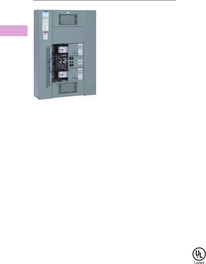
V2-T3-96 Volume 2—Commercial Distribution CA08100003E—April 2014 www.eaton.com
3
3
3
3
3
3
3
3
3
3
3
3
3
3
3
3
3
3
3
3
3
3
3
3
3
3
3
3
3
3
3.4
Panelboards and Lighting Control
Elevator Control Panelboard
Elevator Control Panelboard
Contents
Description Page
Elevator Control Panelboard
Product Selection. . . . . . . . . . . . . . . . . . . . . . . V2-T3-97
Options . . . . . . . . . . . . . . . . . . . . . . . . . . . . . . V2-T3-97
Box Sizing and Selection . . . . . . . . . . . . . . . . . V2-T3-97
Elevator Control Panelboard
Product Description
●600 Vac maximum
●Three-phase four-wire
●800A maximum mains
●30–200A branch devices
●Short-circuit current rating
up to 200 kA rms
symmetrical
●Elevator controls including
shunt trip, CPT, indicating
lights and keyed selector
switch
Application Description
●Instrument protection
●Fully rated
●Interrupting ratings up to
200 kA symmetrical when
protected by fuse
●Provides selective
coordination to 0.01
seconds with the
appropriate upstream
overcurrent protective
device
●Eaton’s Elevator Control
Panelboard provides
significant space savings
in the elevator control
room when compared to
traditional installations
●Factory assembled
Standards and Certifications
●UL 67 panelboards
●UL 50 enclosures
●UL 98 fusible switches
Elevator Control Panelboard
is intended to meet the:
●NFPA 70 (National
Electrical Code)
●NFPA 72 (National Fire
Alarm Code)
●ANSI/ASME A17.1
(Safety Code for Elevators
and Escalators)
●NFPA 13 (Installation of
Sprinkler Systems)

Volume 2—Commercial Distribution CA08100003E—April 2014 www.eaton.com V2-T3-97
3
3
3
3
3
3
3
3
3
3
3
3
3
3
3
3
3
3
3
3
3
3
3
3
3
3
3
3
3
3
3.4
Panelboards and Lighting Control
Elevator Control Panelboard
Product Selection
Elevator Control Panelboard
Branch Elevator Control Modules 2
Options
Elevator Control Options
Notes
1 Fuses provided by others.
2 Standard features include, fused switch with 120 Vac shunt trip, control power terminals ground termination,
120 Vac key test switch, 1NO and 1NC 120 Vac class mechanically interlocked auxiliary contact for hydraulic
elevators with automatic recall.
Box Sizing and Selection
●Refer to Bid Manager™ drawings for your specific configuration
Ampere Rating
Interrupting Rating
(kA Symmetrical) 600 Vac Main Type Fuse Clip 1
Main Lug Only
400 200 — —
600 200 — —
800 200 — —
Main Fusible Switch 600 Vac
400 200 FDPW Class J
600 200 FDPW Class J
800 200 FDPB Class J
Ampere
Interrupting Rating
(kA Symmetrical) Breaker Type Fuse Clip 1
30 200 FDPB Class J
60 200 FDPB Class J
100 200 FDPB Class J
200 200 FDPB Class J
Description
Fused control power transformer
Fire safety interface relay
ON pilot light
Isolated neutral termination
200% isolated neutral termination
Fire alarm voltage monitoring relay (monitors shunt trip voltage)
NEMA Type 3R enclosure
Surge Protective Devices
120 kA Basic
Standard
Standard with surge counter
160 kA Basic
Standard
Standard with surge counter
200 kA Basic
Standard
Standard with surge counter
250 kA Basic
Standard
Standard with surge counter
Elevator Control
Panelboard
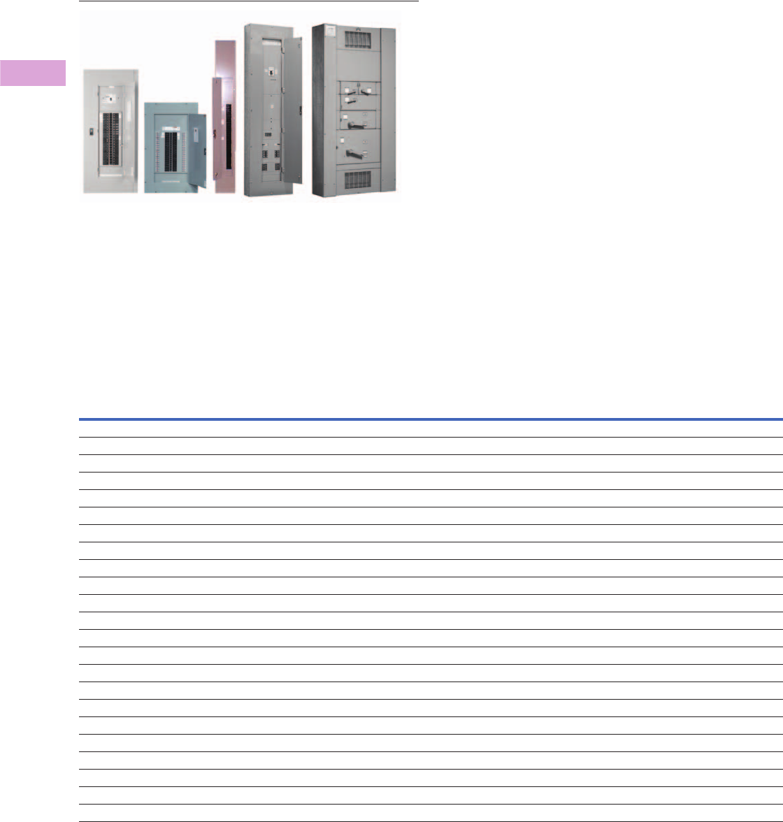
V2-T3-98 Volume 2—Commercial Distribution CA08100003E—April 2014 www.eaton.com
3
3
3
3
3
3
3
3
3
3
3
3
3
3
3
3
3
3
3
3
3
3
3
3
3
3
3
3
3
3
3.5
Panelboards and Lighting Control
Types PRL1a, 2a, 3a, 3E, 4 and Column Modifications
Panelboards and Lighting Controls
Contents
Description
Types PRL1a, 2a, 3a, 3E, 4, Column
Modifications Selection Guide . . . . . . . . . . . . . V2-T3-98
Types PRL1a, 2a, 3a, 3E, 4, Column
Modifications Selection Guide
Modifications—Alphabetical Index
Modification Item
Available on Panelboard Types
PRL1a PRL2a PRL3a PRL3E PRL4B PRL4F Column Type
Ambient compensating breakers 1 No No Yes No Yes — No
Bus density 2 Yes Yes Yes Yes Yes Yes Yes
Cabinets—special: Types 2, 3R, 4, 4X, 12 3 Yes Yes Yes Yes Yes Yes No
Complete assembly 4 YesYesYesYesYesYesYes
Compression type lugs, mains only 5 Yes Yes Yes Yes Yes Yes Yes
Concealed trim clamps (LT trim) 6 Yes Yes Yes Yes No No No
Conduit covers 7 Yes Yes Yes Yes Yes Yes No
Copper lugs 8 Yes Yes Yes Yes Yes Yes Yes
Copper main bus 9, 9a, 9b Yes Yes Yes Yes Yes Yes Standard
Directory frame—metal 10 Yes Yes Yes Yes Yes Yes No
Doors, special 11 Yes Yes Yes Yes Yes Yes Yes
Fungus-proof 12 Yes Yes Yes Yes Yes Yes Yes
Ground bar 13 Yes Yes Yes Yes Yes Yes Yes
Electronic trip units 14 No No No Yes Yes — No
Ground fault protection (zero sequence) 15 No No No No Yes Yes No
Handle lockoff device 16 Yes Yes Yes Yes Yes Std. Yes
Hinges, special (LT trim) 17 Yes Yes Yes Yes Yes Yes No
Increased dimensions 18 Yes Yes Yes Yes No No No
Increased panel bus rating 19 Yes Yes Yes Yes No No No
Interiors to fit existing boxes 20 Yes Yes Yes Yes Yes Yes No
Locks, special (LT trim) 21 Yes Yes Yes Yes Yes Yes No
Molded case switches 22 Yes Yes Yes Yes Yes No Yes
Nameplates engraved 23 Yes Yes Yes Yes Yes Yes Yes

Volume 2—Commercial Distribution CA08100003E—April 2014 www.eaton.com V2-T3-99
3
3
3
3
3
3
3
3
3
3
3
3
3
3
3
3
3
3
3
3
3
3
3
3
3
3
3
3
3
3
3.5
Panelboards and Lighting Control
Types PRL1a, 2a, 3a, 3E, 4 and Column Modifications
Modifications—Alphabetical Index, continued
Modification Item
Available on Panelboard Types
PRL1a PRL2a PRL3a PRL3E PRL4B PRL4F Column Type
Neutral rated 200% 24 Yes Yes Yes Yes Yes Yes Yes
Painting and special coating 25 Yes Yes Yes Yes Yes Yes Yes
Permanent circuit numbers 26 Yes Yes Yes Yes Yes Yes Yes
Remote control switches (ASCO 920) 27 No No Yes Yes No No No
Service entrance 28 Yes Yes Yes Yes Yes Yes No
Shunt trips 29 Yes Yes Yes Yes Yes Yes Yes
Split bus or meter loop 30 No No Yes No No No No
Metering devices 31 No No No Yes Yes Yes No
Sub-metering, IQ Energy Sentinel 32 No No No No Yes No No
Sub-feed breakers 33 Yes Yes Yes Yes No No Yes
Sub-feed lugs 34 Yes Yes Yes Yes Yes Yes No
Tamperproof screws (LT trim) 35 Yes Yes Yes Yes Yes Yes Yes
Through-feed lugs 36 Yes Yes Yes Yes Yes Yes Yes
Time clock space only 37 Yes Yes Yes Yes — — No
Touchup paint 38 Yes Yes Yes Yes Yes Yes Yes
Surge protective device (SPD) 39 Yes Yes Yes Yes Ye Yes No
Terminals, copper only for breakers 40 Yes Yes Yes Yes Yes — Yes

V2-T3-100 Volume 2—Commercial Distribution CA08100003E—April 2014 www.eaton.com
3
3
3
3
3
3
3
3
3
3
3
3
3
3
3
3
3
3
3
3
3
3
3
3
3
3
3
3
3
3
3.5
Panelboards and Lighting Control
Types PRL1a, 2a, 3a, 3E, 4 and Column Modifications
1. Ambient Compensating Breakers
For ambient compensating breakers (where available) in lieu of
standard breakers, add 10 percent to panelboard branch breaker
and to main breaker list prices, if required. (Not UL listed.)
2. Bus Density
Main bus ampere rating is determined by UL listed temperature
test. For 750A per square inch aluminum or 1000A per square inch
copper, make price addition as follows:
Modification 2
3. Special Cabinet (Box) Construction
Modification 3
4. Complete Assembly
Complete assembly of panelboard box, interior and trim prior to
shipment when required.
5. Compression Main Lugs—Al/Cu Burndy Range Taking
For other terminal types and box sizes, refer to Eaton.
Modification 5—Compression Lug Data
Modification 5—Box Height Additions
6. Concealed Trim Clamps—LT Trim
Modification 6
7. Conduit Covers
Fabricated sheet metal to cover open conduits above and/or
below standard Type 1 box.
Modification 7
Note
1At 600A, PRL3a requires the addition of density rated copper bus for Type 3R or 12 enclosure.
Panel Type Maximum Amperes
Aluminum—750A per Square Inch
PRL1a, 2a 100
225
400
PRL3a 250
400
PRL4 400
800
Copper—1000A per Square Inch
PRL1a, 2a 100
225
400
PRL3a 250
600
PRL4 400
1200
Modification
Type 1 Enclosure
28-inch (711.2 mm) wide in place of standard 20-inch
(508.0 mm) wide PRL1a, PRL2a, PRL3a, PRL3E
Type 2 Enclosure
(Drip-proof with gasketed trim) PRL1a, PRL2a, PRL3a, PRL3E 20-inch (508.0 mm) wide
Type 3R Enclosure
PRL1a, PRL2a 20-inch (508.0 mm) wide
PRL1a, PRL2a 28-inch (711.2 mm) wide
PRL3a 1, PRL3E 20-inch (508 mm) wide
(600A maximum)
PRL3a 1, PRL3E 28-inch (711.2 mm) wide
(600A maximum)
PRL4 24-inch (609.6 mm) or 36-inch (914.4) wide only
Type 12 Enclosure
PRL1a, PRL2a 20-inch (508.0 mm) wide
PRL1a, PRL2a 28-inch (711.2 mm) wide
PRL3a 1, PRL3E 20-inch (508 mm) wide
(600A maximum)
PRL3a 1, PRL3E 28-inch (711.2 mm) wide
(600A maximum)
PRL4 24-inch (609.6 mm) or 36-inch (914.4) wide only
Must also add bus density price from Modification 2 for PRL4
Type 4 Enclosure or Type 4X Stainless Steel Enclosure
Refer to Eaton
Main
Amperes
Wire Range by Panel Type
PRL1a and PRL2a PRL3E PRL3a PRL4
100 (1) #1–1/0 or
(1) 2/0–300 kcmil
———
125 — (1) #4–2/0 or
(1) 2/0–300 kcmil
(1) #4–2/0 or
(1) 2/0–300 kcmil
—
225 (1) 2/0–300 kcmil or
(1) 4/0–500 kcmil
———
250 — (1) 2/0–350 kcmil or
(1) 4/0–500 kcmil
(1) 2/0–350 kcmil or
(1) 4/0–500 kcmil
(2) 500–750 kcmil
400 (2) 4/0–300 kcmil or
(2) 500–750 kcmil
(2) 4/0–300 kcmil or
(2) 500–750 kcmil
(2) 4/0–300 kcmil or
(2) 500–750 kcmil
(2) 500–750 kcmil
600 — (2) 2/0–500 kcmil or
(2) 500–750 kcmil
(2) 2/0–500 kcmil or
(2) 500–750 kcmil
(2) 500–750 kcmil
800 — — — (3) 500–750 kcmil
1200 — — — (4) #2–600 kcmil or
(4) 500–750 kcmil
Main Amperes PRL1a, PRL2a
PRL3E, PRL3a without
Neutral
PRL3E, PRL3a with
Neutral
100 0 0X 0X
225 0 — —
250 — 2X 5X
400 0 0X 0X
600 — 0X 0X
Maximum size for PRL1a and PRL2a panels:
1–750 kcmil per phase, or 2–500 kcmil per phase.
For PRL4 panels, see layout pages.
Description
Add per panel PRL1a, PRL2a, PRL3a, PRL3E
Cover Type
Conduit Enclosing Shield (open back)
PRL1a, PRL2a, PRL3a, PRL3E, PRL4—Refer to Eaton
Conduit Enclosure (solid back)
PRL1a, PRL2a, PRL3a, PRL3E, PRL4—Refer to Eaton

Volume 2—Commercial Distribution CA08100003E—April 2014 www.eaton.com V2-T3-101
3
3
3
3
3
3
3
3
3
3
3
3
3
3
3
3
3
3
3
3
3
3
3
3
3
3
3
3
3
3
3.5
Panelboards and Lighting Control
Types PRL1a, 2a, 3a, 3E, 4 and Column Modifications
8. Copper Lugs
Optional copper mechanical main lugs only. (Includes main
incoming neutral lug.)
Modification 8
Modification 8—Box Height Additions
9. Copper Main Bus
Modification 9
Available in PRL1a, PRL2a, PRL3a, PRL3E, PRL4, PRL1aF,
PRL2aF, PRL1R, PRL2R, PRL1a-LX and PRL2a-LX
9a. Silver-Plated Copper Main Bus
Modification 9a
Available in PRL1a, PRL2a, PRL3a, PRL3E, PRL4, PRL1aF,
PRL2aF, PRL1R, PRL2R, PRL1a-LX and PRL2a-LX
9b. Tin-Plated Copper Main Bus (PRL1a, 2a, 3a, Only)
Modification 9b
10. Directory Frame—Metal
Modification 10
11. Trim and Door Modifications—Special Fronts and Doors
Modification 11
12. Fungus Proofing
For fungus proofing external portions of circuit breakers and all
non-metallic parts, add 10 percent of total panelboard list price.
For fungus proofing fusible switches and all non-metallic parts,
add 20 percent of total panelboard list price.
13. Ground Bar
Modification 13
Notes
1Extra depth box is required. Box will be 12.82-inch (325.6 mm) deep.
2For PRL1a, 2a, 3a and Column Type panelboards. The insulated/isolated ground bar includes
a standard ground bar.
Main
Amperes
Wire Range and Number
of Lugs Per Phase
100 (1) #14–1/0
225 (1) #6–250 kcmil
250 (1) #6–250 kcmil
400 (2) #1/0–600 kcmil
600 (2) #1/0–600 kcmil
800 (2) #1/0–600 kcmil
1200 (3) #1/0–600 kcmil
Main
Amperes
PRL1a,
PRL2a
PRL3E, PRL3a
without Neutral
PRL3E, PRL3a
with Neutral PRL4
100 0 0X 0X —
225 0 — — —
250 — 0X 0X 0X
400 0 0X 0X 0X
600 — 1X 1X 0X
800 — — — 0X
1200 — — — 0X
Panel Type
PRL1a, PRL2a, PRL3a, PRL3E
Frame Type
Metal frame, plastic cover
Description
Door-in-door, one door over interior and one which exposes gutter. (LT Trim) (PRL1a, PRL2a,
PRL3a, PRL3E only)
Common trim for two section panels with boxes bolted together. (LT Trim) (PRL1a, PRL2a, PRL3a,
PRL3E only)
Standard flush lock with quarter turn fasteners at top and bottom of trim door (LT Trim) (standard
on doors 48-inch (1219.2 mm) high and over). (PRL1a, PRL2a, PRL3a,
PRL3E only)
To provide a trim with a lockable door for PRL4 panels (door-in-door is standard with this adder).
Includes National lock with standard keying. 1
Add per panel
Description Bar Type
Panel Type
PRL1a
PRL2a
PRL3a
PRL3E
PRL4
Aluminum terminal bar for aluminum or
copper cable
Standard,
insulated/isolated 2
Copper terminal bar for copper cable only Standard,
insulated/isolated 2
Column Type
In Pull Box
In Gutter
Aluminum terminal bar for aluminum or
copper cable
Standard,
insulated/isolated 2
Copper terminal bar for copper cable only Standard,
insulated/isolated 2

V2-T3-102 Volume 2—Commercial Distribution CA08100003E—April 2014 www.eaton.com
3
3
3
3
3
3
3
3
3
3
3
3
3
3
3
3
3
3
3
3
3
3
3
3
3
3
3
3
3
3
3.5
Panelboards and Lighting Control
Types PRL1a, 2a, 3a, 3E, 4 and Column Modifications
14. Electronic Trip Units
Modification 14—Applies to Digitrip 310 and 310+ Trip Units
15. Zero Sequence Ground Fault Protection
For main devices only (circuit breakers or FDPW switch) in PRL4
assembled panels. Available in 250–1200A panels.
Price includes current monitors, ground bar, static sensor, shunt
trip, necessary space, mounting and connecting in panelboards.
Price does not include circuit breaker or FDPW switch.
Zero sequence ground fault is available with the following family
of main devices:
Modification 15
16. Circuit Breaker Handle Lockoff Devices
Modification 16
17. Special Hinges—LT Trim
Piano hinges in lieu of standard hinges.
18. Increased Dimensions (PRL1a, PRL2a, PRL3a and PRL3E Only)
Type 1 Enclosure Only
Modification 18
19. Increased Panel Main Bus Rating (Three-Phase Four-Wire,
Single-Phase Three-Wire)
Modification 19
20. Interior and Fronts to Fit Existing Boxes
Refer to Eaton.
21. Special Locks
Modification 21
Notes
1Main breaker only.
PRL4 with door includes National lock with standard keying. See Modification 11.
Description
K-, L- and M-Frame Circuit Breaker (three-pole only)
Digitrip RMS310 LS
Digitrip RMS310 LSI
Digitrip RMS310 LSG 1
Digitrip RMS310 LSIG 1
N-Frame circuit breaker
Digitrip RMS310 LS
Digitrip RMS310 LSI
Digitrip RMS310 LSG 1
Digitrip RMS310 LSIG 1
Digiview Ammeter for 310+ Trip Unit
Main Device
JD, KD, LD, MDL, ND, LCL, LA-P, NB-P
FDPW switches
(400–1200A)
Breaker Types
Non-Padlockable
BAB, QBHW, GHB, EHD, FDB, FD, ED, EDH, EDC, HQP, QPHW
JD, KD, MDL, ND
Padlockable
EHD, FDB, FD, HFD, FDC, ED, EDH, EDC, GHB, BAB, QBHW, HQP, QPHW, EGB, EGS, EGH
JD, KD, LD, MDL, ND, FDE, HFDE
Description
Increased End Gutters
4 inch (101.6 mm) Top or Bottom
7 inch (177.8 mm) Top or Bottom
12 inch (304.8 mm) Top or Bottom
Increased Side Gutters
4 inch (101.6 mm) Left or Right
7 inch (177.8 mm) Left or Right
12 inch (304.8 mm) Left or Right
Main Bus
Ampere Rating Panel Type
100–225/250 PRL1a, PRL2a, PRL3a, PRL3E
225–400
600 (PRL3a)
250–400 PRL4
400–600
600–800
800–1200
Description
LT Ty p e Tri m
Yale 511S with rosette
Yale 4651S (LL803 Key)
Master keying—above locks or standard lock—per panelboard
Corbin 15767 (Cat. #60 Key)
PRL1a, PRL2a, PRL3a, PRL3E
Tee handle and 3-point catch
PRL1a, PRL2a, PRL3a, PRL3E
COMPX metal lock with standard keying
PRL1a, PRL2a, PRL3a, PRL3E
COMPX metal lock with GE75 keyway
PRL1a, PRL2a, PRL3a, PRL3E, PRL4
EZ Type Trim
Standard Lock, Keyed GE75
Standard Lock, Keyed to Corbin TEU-1
Standard Lock, Keyed to Corbin Cat 60
Standard Lock, Keyed to Corbin WEM1

Volume 2—Commercial Distribution CA08100003E—April 2014 www.eaton.com V2-T3-103
3
3
3
3
3
3
3
3
3
3
3
3
3
3
3
3
3
3
3
3
3
3
3
3
3
3
3
3
3
3
3.5
Panelboards and Lighting Control
Types PRL1a, 2a, 3a, 3E, 4 and Column Modifications
22. Molded Case Switches (Three-Pole, Two-Pole)
Modification 22
23. Nameplates, Engraved
Modification 23
24. Neutral Rated 200%
Modification 24
Modification 24—Box Height Additions
Note: Dimensions based on mechanical lugs. For
compression or copper lugs, refer to Eaton.
For 800 and 1200A PRL4 with 200% neutral, refer to Eaton.
25. Painting and Special Coatings
Standard boxes are code-gauge galvanized sheet steel. Standard
trims are code-gauge sheet steel with a rust inhibiting
phosphatized coating and finished with ANSI-61.
Modification 25
26. Permanent Circuit Numbers
Modification 26
27. Remote Control Switches—ASCO 920 (Three-Pole, Two-Pole)
Electrically operated, mechanically held remote control switch
directly mounted to panelboard bus for total or split bus
switching applications.
(For split bus applications, make price addition from
Modification 30.)
480 Vac maximum short-circuit rating of panelboard is
22 kAIC maximum.
Includes complete installation in the panelboard with a screw
cover over the switch compartment.
Pushbuttons or other control devices are not included.
For control circuit modifications, refer to Eaton.
Modification 27—Remote Control Switches
(PRL3a and PRL3E Only)
Modification 27—Remote Control Switch Modifications
28. Service Entrance
To provide a Service Entrance Label as detailed under the
“Service Entrance Equipment” in application considerations.
Only panelboards meeting these requirements can be labeled as
such. The requirement for a Service Entrance Label must be
noted on order entry. Includes neutral disconnect link and
Service Entrance Equipment Label. (Ground bar not included—
see Modification 13.)
Modification 28
Not UL Listed
Breaker Frame Maximum Volts Maximum Amperes
EHD 480 100
FD 600 225
JD 600 250
DK 240 400
KD 600 400
LD 600 600
MDL 600 800
ND 600 1200
Type
Mastic back and installed by purchaser, per nameplate
Fixed to panel trim with two screws or rivets, per nameplate
PRL1a, PRL2a, PRL3a, PRL3E only
Main Bus Rating Neutral Rating
100 225
225 450
250 500
400 800
600 1200
Main Bus Rating Neutral Rating PRL1a, PRL2a PRL3a, PRL3E PRL4
100 225 0 0X —
225 450 0 — —
250 500 — 3X 0X
400 800 0 3X 0X
600 1200 — 3X 0X
Description
Painted boxes (ANSI-61)
Painted trims or boxes (other than ANSI-61)
Description
To provide permanently attached MicartaT circuit numbers.
Switch Rating Amperes
30, 60, 75, 100, 150, 200, 225
Description
Two-wire control relay
Three-wire control relay
Control power transformer
To provide hinged cover in place of standard screw cover
Panel Type
PRL1a, PRL2a, PRL3a, PRL3E, PRL4

V2-T3-104 Volume 2—Commercial Distribution CA08100003E—April 2014 www.eaton.com
3
3
3
3
3
3
3
3
3
3
3
3
3
3
3
3
3
3
3
3
3
3
3
3
3
3
3
3
3
3
3.5
Panelboards and Lighting Control
Types PRL1a, 2a, 3a, 3E, 4 and Column Modifications
29. Shunt Trip for Main or Branch Circuit Breaker and FDPW Switches
For tripping device from a remote point. Voltage and frequency
must be specified. Wiring to terminal blocks is not included.
Standard leads extend 18-inches (457.2 mm) out of device.
Factory-installed 120, 240 or 480 Vac shunt trips are available
with UL listing as shown in table below. Underwriters
Laboratories listing is not available for shunt trip mounted on
molded case switches.
Modification 29
30. Split Bus or Meter Loop (250A Max.,
3Ph 4W, 3Ph 3W, 1Ph 3W, 1Ph 2W)
Panel type PRL3a only. For enclosure size, refer to Eaton.
Modification 30
31. Metering Devices (PRL4 Only)
IQ digital metering for incoming service. Devices are installed in
chassis mounted compartment with hinged door. Standard CTs
(1200A maximum) are included with devices. Requires copper
bus at 1200A.
Modification 31
32. Sub-Metering IQ Multi-Point Submeter II (PRL4 Only)
Microprocessor-based breaker-mounted device to monitor
power and energy (kW, kWH, kW demand). Device mounts on
the load side of three-pole F-, J- and K-Frame feeder breakers.
Units are shipped with the interior for field installation. Minimum
box width of 36 inches (914.4 mm) is required.
Modification 32
33. Sub-Feed Breakers
Modification 33—Panel Types PRL1a, PRL2a, PRL3a, PRL3E.
One Breaker Per Panel
Note: 225A maximum on Column Type panels. Sub-feed breaker not
available on PRL3a panel with subchassis.
Device
BAB, QBHW
Requires one additional pole space, i.e., single-pole is two-pole size, two-pole is three-pole size
and three-pole is four-pole size.
GHB (three-pole only)
All other circuit breakers
FDPW switch (400–1200A)
Main Bus Amperes
100–250
Device Box Height Addition
IQ 130 with CTs and display 13X
IQ 130 with CTs, no display 13X
IQ 140 with CTs and display 13X
IQ 140 with CTs, no display 13X
IQ 150 with CTs and display 13X
IQ 150 with CTs, no display 13X
IQ 210 with CTs 13X
IQ 220 with CTs 13X
IQ 230 with CTs 13X
IQ 230M with CTs 13X
IQ 250 with CTs and display 13X
IQ 250 with CTs, no display 13X
IQ 260 with CTs and display 13X
IQ 260 with CTs, no display 13X
PXM 2250 with CTs and display 13X
PXM 2250 with CTs, no display 13X
PXM 2260 with CTs and display 13X
PXM 2260 with CTs, no display 13X
PXM 2270 with CTs and display 13X
PXM 2270 with CTs, no display 13X
IQ Energy Sentinel
F-Frame three-pole (150A maximum)
J-Frame three-pole
K-Frame three-pole
Maximum
Amperes
Number
of Poles
Breaker
Type
Interrupting Rating
(kA Symmetrical)
Box Height
Addition
PRL3a240V 480V
100 2 EHD 18 14 NA
150 2 FDB 18 14 NA
225 2 FD 65 35 NA
225 2 HFD 100 65 NA
225 2 FDC 200 100 NA
225 2 EDB 22 — NA
225 2 EDS 42 — NA
225 2 ED 65 — NA
225 2 EDH 100 — NA
225 2 JD 65 35 14X
225 2 HJD 100 65 14X
225 2 JDC 200 100 14X
250 2 JD 65 35 14X
250 2 HJD 100 65 14X
250 2 JDC 200 100 14X
400 2 DK 65 — 15X
400 2 KD 65 35 15X
400 2 HKD 100 65 15X
400 2 KDC 200 100 15X
100 3 EHD 18 14 NA
150 3 FDB 18 14 NA
225 3 FD 65 35 NA
225 3 HFD 100 65 NA
225 3 FDC 200 100 NA
225 3 EDB 22 — NA
225 3 EDS 42 — NA
225 3 ED 65 — NA
225 3 EDH 100 — NA
225 3 JD 65 35 14X
225 3 HJD 100 65 14X
225 3 JDC 200 100 14X
250 3 JD 65 35 14X
250 3 HJD 100 65 14X
250 3 JDC 200 100 14X
400 3 DK 65 — 15X
400 3 KD 65 35 15X
400 3 HKD 100 65 15X
400 3 KDC 200 100 15X

Volume 2—Commercial Distribution CA08100003E—April 2014 www.eaton.com V2-T3-105
3
3
3
3
3
3
3
3
3
3
3
3
3
3
3
3
3
3
3
3
3
3
3
3
3
3
3
3
3
3
3.5
Panelboards and Lighting Control
Types PRL1a, 2a, 3a, 3E, 4 and Column Modifications
Modification 33—Panel Type PRL3a Only. Two Breakers Per
Panel—Twin Mounted
34. Sub-Feed Lugs (3Ph 4W, 3Ph 3W, 1Ph 3W, 1Ph 2W)
Note: Not available on service entrance panels with main lugs only (six
disconnect rule).
Mechanical Al/Cu lugs. Compression or copper lugs requires
additional price adder from Modification 5—Compression Lug
Data or Modification 8 as appropriate.
Available on main lug panels only.
Modification 34
35. Tamperproof Screws—LT Trim
Modification 35
36. Through-Feed Lugs (3Ph 4W, 3Ph 3W, 1Ph 3W, 1Ph 2W)
Note: 225 amperes maximum on Column Type panels. Not available on
service entrance panels with main lugs only (six disconnect rule).
Mechanical Al/Cu lugs. Compression or copper lugs requires
additional price adder from Modification 5—Compression Lug
Data or Modification 8 as appropriate.
Not available on panels with sub-feed breaker.
Modification 36
37. Time Clock Space Only
Includes box, trim, door and mounting pan.
Modification 37
38. Touchup Paint
Modification 38
Notes
1Refer to PRL4 layout.
2Refer to panelboard sizing charts.
Maximum
Amperes
Number
of Poles
Breaker
Type
Interrupting Rating
(kA Symmetrical) Box Height
Addition
PRL3a240 Volts 480 Volts
225 2 JD 65 35 20X
225 2 HJD 100 65 20X
225 2 JDC 200 100 20X
250 2 JD 65 35 20X
250 2 HJD 100 65 20X
250 2 JDC 200 100 20X
225 3 JD 65 35 20X
225 3 HJD 100 65 20X
225 3 JDC 200 100 20X
250 3 JD 65 35 20X
250 3 HJD 100 65 20X
250 3 JDC 200 100 20X
Main Amperes
Box Height
Addition
Panel Types PRL1a, PRL2a
100–225 0X
Panel Type PRL3a, PRL3E
100–250 1X
Panel Type PRL4 1
250–400 0X
600 4X
Description
Tamperproof screws for trims, in lieu of standard screws.
Main Amperes Box Height Addition
Panel Types PRL1a, PRL2a
100 2
225 2
400 2
Panel Type PRL3a, PRL3E
100 2X
250 5X
400 8X
600 8X
800 14X
Panel Type PRL4 2
250 7X
400 7X
600 7X
800 7X
1200 5X
Enclosure Type
Ty p e 1
PRL1a, PRL2a, PRL3a, PRL3E (24-inch (609.6 mm) space)
PRL1a, PRL2a, PRL3a, PRL3E (36-inch (914.4mm) space)
Ty p e 3 R
PRL1a, PRL2a, PRL3a, PRL3E (24-inch (609.6 mm) space)
Description
12 oz. spray can. ANSI-61 light gray indoor
Case Lot of 12—12 oz. spray cans. ANSI-61 light gray indoor single style

V2-T3-106 Volume 2—Commercial Distribution CA08100003E—April 2014 www.eaton.com
3
3
3
3
3
3
3
3
3
3
3
3
3
3
3
3
3
3
3
3
3
3
3
3
3
3
3
3
3
3
3.5
Panelboards and Lighting Control
Types PRL1a, 2a, 3a, 3E, 4 and Column Modifications
39. Surge Protective Device (SPD)
Type PRL1a, PRL2a, PRL 3a and PRL3E Panelboards
Package includes SPD unit connected to the panelboard bus.
Available for all enclosure types.
Sizing:
PRL1a, PRL2a, PRL3E: Add 7 inches (177.8 mm) to the standard
box height.
PRL3a: Add 4X for 100–200 kA SPD
units.
PRL3E: AdVisor/SuperVisor display (200 kA maximum) add 8 inches.
SML TVSS add 7 inches
.
Type PRL4 and Elevator Control Panelboards
Package includes SPD unit and integral circuit breaker
disconnect (30A) connected to the panel bus.
Available for all enclosure types.
The SPD unit and integral circuit breaker disconnect will require
7X of chassis space. (Only available in 36-inches (914.4 mm) or
44-inches (1117.6 mm) wide enclosure.)
Modification 39
Description kA/Phase
Surge Current Rating 50 80 100 120 160 200 250 300 400
SPD Package Options
Basic
LEDs monitor L-N, L-G, L-L and N-G
PRL1a, PRL2a, PRL3a, PRL3E ■■■■■■———
PRL4, Elevator Control Panelboard ■■■■■■■■■
Standard Feature Package
LEDs monitor L-N, L-G, L-L and N-G
EMI/RFI filtering
Audible alarm with disable switch
Form C relay contact
PRL1a, PRL2a, PRL3a, PRL3E ■■■■■■———
PRL4, Elevator Control Panelboard ■■■■■■■■■
Standard Package
LEDs monitor L-N, L-G, L-L and N-G
EMI/RFI filtering
Audible alarm with disable switch
Form C relay contact
Six digit LCD display
Counts surges in all modes
Non-volatile memory (no battery backup)
Reset button designed to prevent
accidental resets
PRL1a, PRL2a, PRL3a, PRL3E ■■■■■■———
PRL4, Elevator Control Panelboard ■■■■■■■■■
40. Copper Wire Only Terminals for Molded Case Circuit Breakers
(To replace standard Al/Cu terminals.)
Modification 40
Note
1Requires 15A branch breaker for cable connection—three-pole (three-phase) or
two-pole (single-phase). (Add breaker separately, not included in price.)
Breaker
Frame
Maximum Breaker
Ampere Rating
Terminal
Material
Wire
Range
F 225 Copper #4–4/0
J 250 Stainless Steel #4–350
K 225 Copper (1) #3–350
350 Copper (1) 250–500
400 Copper (2) 3/0–250
L 600 Copper (2) 250–500
M 600 Copper (2) #2/0–500
800 Copper (3) #3/0–300
N 700 Copper (2) #2/0–500
1000 Copper (3) #3/0–500
1200 Copper (4) #3/0–400
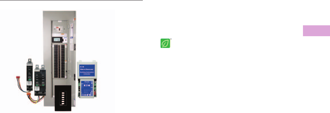
Volume 2—Commercial Distribution CA08100003E—April 2014 www.eaton.com V2-T3-107
3
3
3
3
3
3
3
3
3
3
3
3
3
3
3
3
3
3
3
3
3
3
3
3
3
3
3
3
3
3
3.6
Panelboards and Lighting Control
Pow-R-Command
Pow-R-Command Family
Contents
Description Page
Features. . . . . . . . . . . . . . . . . . . . . . . . . . . . . . . . . V2-T3-108
Product Selection . . . . . . . . . . . . . . . . . . . . . . . . . V2-T3-111
Accessories . . . . . . . . . . . . . . . . . . . . . . . . . . . . . . V2-T3-120
An Eaton
Green Solution
Product Overview
Pow-R-Command™ is a
lighting control and energy
management system that
integrates branch circuit
protection, control (switching
and dimming) and metering
into a single panelboard
enclosure. The integrated
design simplifies electrical
distribution and control
systems design, and
eliminates separate equipment
enclosures and associated
wiring. Other benefits include
reducing equipment wall
space, installation labor and
total installed cost. Pow-R-
Command systems are
designed to meet or exceed
ASHRAE, IECC and LEED®
requirements.
Pow-R-Command Intelligent
Panelboards use Eaton Pow-R-
Line™ 1a and 2a lighting
panelboard platforms to mount
Pow-R-Command electronics
and solenoid-operated
controllable circuit breakers.
Panelboard mains include
100A to 400A main lug and
main circuit breaker
configurations. Available
voltages include 120/240,
208Y/120 and 480Y/277,
single-phase and three-phase.
Panelboard options include
installation of controllable and
non-controllable circuit
breakers, 200% rated neutral,
metering and surge protection
devices (SPDs).
Pow-R-Command Intelligent
Panelboards are assembled in
two basic configurations, Pow-
R-Command Master and
Expansion Panelboard.
Pow-R-Command Master
Panelboards are designed for
standalone and networked
systems. Master Panelboard
components include controller
with low voltage power
supply, Breaker Control Bus
(BCB) and solenoid-operated
controllable circuit breakers.
Expansion Panelboards
(PRCEP) are designed to
directly connect to Master
Panelboard via controller SLAN
communications. Expansion
Panelboard includes BCB and
solenoid-operated controllable
circuit breakers. Pow-R-
Command systems are
scalable using both Master and
Expansion Panelboards to
provide the right amount of
control with reduced
installed cost.
System Electronics
The 5th generation PRC “E”
Series controller family
includes PRC2000E,
PRC1500E, PRC1000E and
PRC750E models. Specifiers
and users select the controller
to meet specific control and
communication requirements.
PRC-E controllers offer a broad
range of schedule and
occupant-based control.
Network options include
RS-485 and Ethernet. PRC-E
controllers communicate with
each other using powerful
Pow-R-Command peer-to-peer
protocol. All PRC-E controllers
can be programmed,
monitored and overridden
using the onboard Web pages
through the controller
maintenance Ethernet port
using an industry standard
patch cable. The PRC2000E
model includes access to
onboard Web pages through
the Ethernet network
connector. Both PRC1500E
and PRC2000E models include
BACnet/IP for simple and
straightforward integration
with building management
systems. All Pow-R-Command
controllers can control up to
168 solenoid-operated
controllable circuit breakers by
connecting PRCEP
panelboards using the
controller SLAN sub-network
communications port.
Breaker Control Bus
electronics come in 9-, 18- and
21-circuit lengths depending
on the size of the panelboard
and are directly mounted to
panelboard interior rails. BCBs
are connected to the controller
SLAN via 4-conductor cable
and act as the interface
between controller and
controllable circuit breaker for
providing status and control.
Onboard power switching
circuitry signals the
controllable circuit breaker
solenoid to switch the
controllable circuit breaker
ON and OFF. Each BCB is
addressable between 1 and 8,
allowing the controller to
monitor and control up to 168
controllable circuit breakers.
Pow-R-Command panelboards
are assembled with one or two
BCBs to offer the right amount
of control.
Controllable Circuit Breakers
Controllable circuit breakers
include standard circuit
protection and control.
Solenoid mechanism provides
control, mechanical and
electronic status and override
lever. Controllable circuit
breakers are available in
15–30A, single-pole and
two-pole configurations
and are suitable for electrical
distribution systems up to
480Y/277 Vac. Special
application controllable circuit
breakers include emergency
and plug load. Emergency
controllable circuit breakers
are used for controlling dual
purpose emergency lighting
fixtures. Plug load controllable
circuit breakers are used to
meet new energy codes
requiring 50% of receptacles
to switched ON and OFF using
schedule- or occupancy-based
control systems. The two-pole
device includes a standard
non-controlled and controllable
circuit breaker pole for
connecting to split
receptacles. The common
handle tie disconnect and
common trip mechanism
allows for shared neutrals
and meets NEC requirements.
Accessories
Pow-R-Command system
accessories include digital
switches (PRCDS) and low
voltage switches (PRCLS) to
provide local occupant override
and light level scene control.
Switches are available in 2-, 4-
and 6-button configurations in
white, black and almond colors.
Software
Programming, monitoring and
control software includes
Lighting Optimization Software
(LOS), Building Graphics
Software (BGS) custom
graphics and Site Server
(WSS).
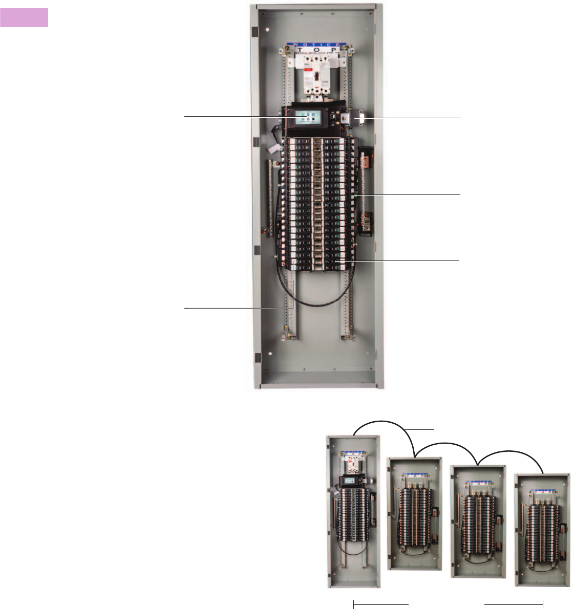
V2-T3-108 Volume 2—Commercial Distribution CA08100003E—April 2014 www.eaton.com
3
3
3
3
3
3
3
3
3
3
3
3
3
3
3
3
3
3
3
3
3
3
3
3
3
3
3
3
3
3
3.6
Panelboards and Lighting Control
Pow-R-Command
Features
Pow-R-Command Master Panelboard Mounted Components
Pow-R-Command Expansion Panelboard
Expansion Panelboard (PRCEP) includes Breaker Control Bus
electronics and solenoid-operated controllable circuit breakers.
Master and Expansion Panelboards are connected via SLAN
communications sub-network to provide a scalable system
architecture for cost-effective control solutions.
PRC-E panelboard system is controlled and
monitored by microprocessor-based controller.
Onboard time clock provides schedule-based
control. Digital inputs are used for connecting low
voltage wallstations and occupancy sensors for
override control. Analog I/O used for dimming
and daylight harvesting control. Light level
sensors are connected to analog inputs. Both
fluorescent and LED lighting fixtures equipped
with 0–10 Vdc dimming circuitry are connected to
controller analog outputs. PRC-E controllers
include backlit color LCD touchscreen and
Maintenance Ethernet port for local
programming, system monitoring and override
control. User can access the controller
preconfigured Web pages or use Pow-R-
Command software using the controller front
Maintenance port. Laptop is connected to the
controller using an industry standard patch cable.
Network connections for RS-485 and Ethernet
provide remote connection options.
Single- and multi-pole solenoid-
operated controllable circuit breakers
provide branch circuit protection and
control of connected loads.
Standard circuit breakers can be mounted
to feed non-controlled loads.
Low voltage regulated power
supply provides stable power for
system electronics and reliable
switching of solenoid-operated
controllable circuit breakers.
Breaker Control Bus (BCB)
electronics provide the control and
monitoring interface between
Pow-R-Command controllers and
solenoid-operated controllable
circuit breakers.
#16 AWG Four-Conductor Alpha 1064
Maximum 150 Feet
SLAN
SLAN
SLAN
Master
Expansion
(PRCEP) PRCEP
PRCEP

Volume 2—Commercial Distribution CA08100003E—April 2014 www.eaton.com V2-T3-109
3
3
3
3
3
3
3
3
3
3
3
3
3
3
3
3
3
3
3
3
3
3
3
3
3
3
3
3
3
3
3.6
Panelboards and Lighting Control
Pow-R-Command
Pow-R-Command Controllers
Pow-R-Command Intelligent
Panelboards integrate branch
circuit protection and control
into a single panelboard
enclosure to eliminate the
need for mounting external
time clocks with contactors
or relay panels. Four 5th
generation PRC-E series
controller models are
available to allow users
and specifiers to select
the controller that best
fits the application.
PRC750E
●Microprocessor-based
programmable lighting
and energy management
system intended for
standalone applications
●Designed with the
electrical contractor in
mind, it offers integral
back-lit color LCD
touchscreen display for
simple, straightforward
commissioning and
startup
●Front panelboard
programming can also be
achieved by connecting the
controller maintenance
port to a laptop using an
industry standard Ethernet
patch cable
●Preconfigured Web pages
or PC software can be
used to program, monitor
and override the system
●Control options include
schedule-based, occupant
override and photocell
control
●Sixteen two-wire low
voltage inputs are available
for connecting wall
stations, occupancy
sensors and photocells
●Each controller can be
connected to three
Expansion Panelboards via
SLAN communications to
control and monitor up to
168 solenoid-operated
circuit breakers
PRC1000E
Includes all the features of
the PRC750E controller with
the addition of:
●Up to 120 controllers can
be connected to the same
Pow-R-Command RS-485
peer-to-peer network
●Powerful peer-to-peer
protocol and network
architecture allows
schedules and external
wiring device signals to be
broadcast over the network
to control any or all of the
solenoid-operated
controllable circuit breakers
connected to the system.
This system capability
eliminates the need for
changing the same
schedule in multiple
panelboards and requiring
additional wiring devices to
be directly connected to
specific controllers
●Eight universal inputs can
be programmed to accept
either digital or analog
external wiring devices.
Compatible with low
voltage digital wiring
devices like wall stations,
occupancy sensors and
photocells when
programmed as digital
inputs. When programmed
as 0–10 Vdc analog inputs,
indoor and outdoor
photosensors can be
connected for dimming
and daylight harvesting
applications
●Eight analog 0–10 Vdc
outputs for connecting to
fluorescent and LED
lighting fixtures equipped
with 0–10 Vdc dimming
circuitry to meet dimming
and daylight harvesting
application requirements
●Compatible with existing
PRC1000 systems
PRC1500E
Includes all the features of
the PRC1000E controller with
the addition of:
●Ethernet communications
●
BACnet/IP communications
protocol for integrating into
building management
systems
●Compatible with existing
PRC2000 systems not
requiring BACnet
communications
PRC2000E
Includes all the features of
the PRC1500E controller with
the addition of:
●Remote access to
preconfigured Web pages
for programming, system
monitoring and override
control via Ethernet
network connection
●Compatible with existing
PRC2000 systems
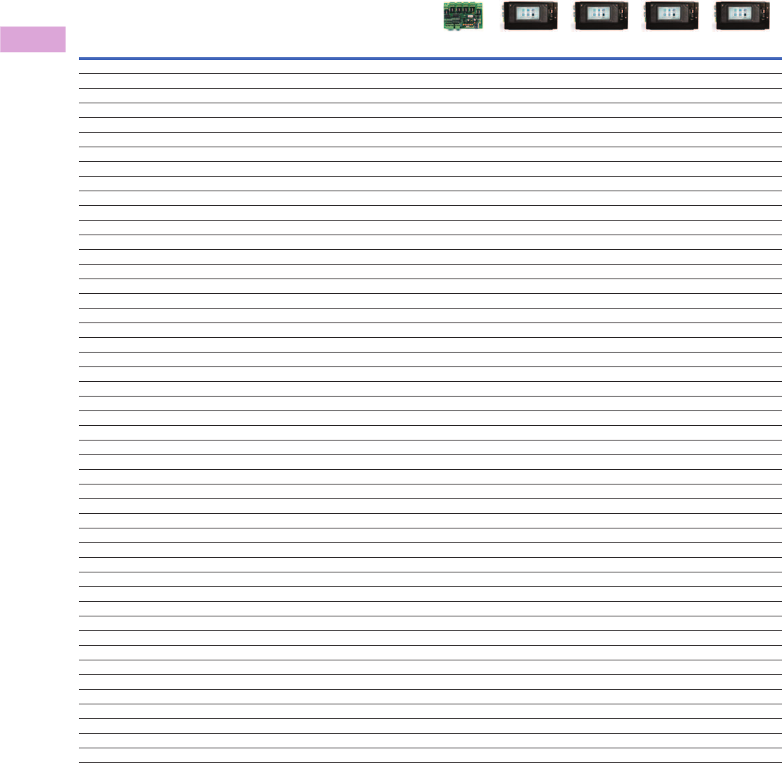
V2-T3-110 Volume 2—Commercial Distribution CA08100003E—April 2014 www.eaton.com
3
3
3
3
3
3
3
3
3
3
3
3
3
3
3
3
3
3
3
3
3
3
3
3
3
3
3
3
3
3
3.6
Panelboards and Lighting Control
Pow-R-Command
PRC-E Controller Features
Note
1Requires software.
Controller PRC25 (MTM) PRC750E PRC1000E PRC1500E PRC2000E
Inputs
Dry contact inputs 6 16 8 8 8
Universal (dry contact or analog 0–10 Vdc) 888
Switch Override Controller (SOC) compatible 60 60 60
Outputs
Analog (0–10 Vdc) 888
Maximum number of dimming ballasts/drivers per analog output 40 40 40
Power supply for external devices (100 mA) 12 Vdc/30 Vac 12 Vdc/30 Vac 12 Vdc/30 Vac
Maximum number of breaker control bus 8 8 8 8
Maximum number of controllable breakers 60 168 168 168 168
Control Logic
Maximum number of logic control groups 6 16 100 100 100
365-day time clock ■■■■
Astronomical time clock with sunrise and sunset offsets ■■■■
Schedules 250 250 250 250
On/Off per schedule per day 250 250 250 250
Holidays 30 30 30 30
Automatic daylight savings time ■■■■
Blink notice ■■■■
Override time for switch inputs (min./max.) 1 min to 10 hrs 1 min to 10 hrs 1 min to 10 hrs 1 min to 10 hrs
Dimming and daylight harvesting ■■■
Configurable source logic using software (OR, AND, XOR, XNOR, NAND, LAST EVENT) 1■■■
Communications
Expansion Panelboard SLAN ■■■■
Digital Switch Network ■■■
Pow-R-Command peer-to-peer RS-485 ■■■
Maximum controllers per RS-485 network 120 120 120
Pow-R-Command peer-to-peer Ethernet ■■
Remote access to preconfigured Web pages using Ethernet network connection (TCP/IP server) ■
BACnet/IP ■■
Front Panelboard Programming
Front Maintenance Port (Ethernet) ■■■■
4.3-inch backlit color LCD touchscreen ■■■■
Access to preconfigured Web pages via maintenance port (TCP/IP) ■■■■
Software ■■■■
Password protection ■■■■
Memory
RAM memory for programs and configuration (MB) 128 128 128 128
Flash memory for kernel, programs and file system (MB) 256 256 256 256
SD card for logs and programming database (GB) 4 4 4 4
USB port for firmware upgrades, etc. ■■■■
On-board capacitor to power clock chip during power outage (days) 10 10 10 10
Standards
UL 916 energy management equipment ■■■■■
California Title 24 ■■■■■
UL 67 panelboards ■■■■■
CSA C22.2 #29 panelboards ■■■■■
UL 489 circuit breakers ■■■■■

Volume 2—Commercial Distribution CA08100003E—April 2014 www.eaton.com V2-T3-111
3
3
3
3
3
3
3
3
3
3
3
3
3
3
3
3
3
3
3
3
3
3
3
3
3
3
3
3
3
3
3.6
Panelboards and Lighting Control
Pow-R-Command
Product Selection
Pow-R-Command “E” Series
controllers are available in
four models and offer a range
of features to meet a broad
range of applications and
meet energy codes. Each
PRC-E controller includes a
backlit color LCD
touchscreen, SLAN
expansion network, schedule-
based controls and two-wire
low voltage inputs for
connecting occupancy
sensors, wallstations and
other building control signals.
The PRC-E Controller
Selection Guide may be used
to quickly identify the
controller that best fits the
application. The PRC-E
Controller Features table on
the previous page provides
greater detail for the specifier
that may be interested in
specific controller details.
PRC-E Controller Selection Guide 12
Notes
1PRC-E controllers are compatible and recommended for existing Pow-R-Command systems
with the same preceding model number, i.e., PRC1000 is compatible with PRC1000E.
2PRC-E controllers require either LCD display or controller blank cover, catalog number
PRCEDFRTCVRD, to be installed for protecting the low voltage compartment.
Description
Catalog
Number
Standalone operation PRC750E
RS-485 network, digital switch network, dimming and daylight
harvesting control
PRC1000E
PRC1000E features plus Ethernet network and BACnet/IP protocol PRC1500E
PRC1500E features plus remote accessible preconfigured Web pages PRC2000E

V2-T3-112 Volume 2—Commercial Distribution CA08100003E—April 2014 www.eaton.com
3
3
3
3
3
3
3
3
3
3
3
3
3
3
3
3
3
3
3
3
3
3
3
3
3
3
3
3
3
3
3.6
Panelboards and Lighting Control
Pow-R-Command
Externally Mounted Controllers
Externally mounted
controllers (PRCEEC) are
available for retrofit and
renovation projects when
existing panelboards do not
have required controller
mounting space. Externally
mounted controllers include
controller and control power
transformer mounted in a
NEMA 1 enclosure. Eaton
Pow-R-Line 1a and 2a lighting
panelboards can be
converted to Pow-R-
Command Expansion
Panelboards (PRCEP) in the
field by mounting Breaker
Control Bus (BCB) and
controllable circuit breakers
directly to the interior.
Externally mounted
controllers are connected to
the retrofitted PRCEP
panelboard using the SLAN
communications network.
PRCE Externally Mounted Controllers
PRC-E Controller Backlit Color LCD Touchscreen
PRC-E controller backlit color
LCD touchscreen display
(PRCELCD) provides the user
with a means for front panel
programming, status
monitoring and override
control. PRCELCD is
compatible with PRC-E
controllers and can be factory
or field installed. Users can
safely access the controller
low voltage compartment by
loosening two captive screws
located on the top corners of
the display and folding the
display down.
PRCELCD features include:
●Mounting plate and
hardware
●High image quality a-Si TFT
LCD module
●Resistive type touch panel
●4.3-inch diagonal display
with 16:9 aspect
●16.7M colors
●High contrast, high
brightness
●Captive screws and hinge
for easy access to
controller low voltage
compartment
PRC-E Controller LCD Touchscreen
Controller Type Connected System Voltage Catalog Number
PRC750E with display 120 Vac PRC750EECD-120
PRC750E with display 277 Vac PRC750EECD-277
PRC1000E without display 120 Vac PRC1000EEC-120
PRC1000E with display 120 Vac PRC1000EECD-120
PRC1000E without display 277 Vac PRC1000EEC-277
PRC1000E with display 277 Vac PRC1000EECD-277
PRC1500E without display 120 Vac PRC1500EEC-120
PRC1500E with display 120 Vac PRC1500EECD-120
PRC1500E without display 277 Vac PRC1500EEC-277
PRC1500E with display 277 Vac PRC1500EECD-277
PRC2000E without display 120 Vac PRC2000EEC-120
PRC2000E with display 120 Vac PRC2000EECD-120
PRC2000E without display 277 Vac PRC2000EEC-277
PRC2000E with display 277 Vac PRC2000EECD-277
PRCE Externally
Mounted Controller
Description Catalog Number
PRCE backlit LCD touchscreen with mounting plate PRCELCD
PRC-E Controller LCD
Touchscreen

Volume 2—Commercial Distribution CA08100003E—April 2014 www.eaton.com V2-T3-113
3
3
3
3
3
3
3
3
3
3
3
3
3
3
3
3
3
3
3
3
3
3
3
3
3
3
3
3
3
3
3.6
Panelboards and Lighting Control
Pow-R-Command
Breaker Control Bus
Breaker Control Bus (BCB)
provides the electronic
interface and power
switching signal between the
controller and solenoid-
operated controllable circuit
breaker. BCB comes in three
lengths to fit standard lighting
panelboards and is mounted
to the panelboard interior
rails. Each BCB has a set
of DIP switches to configure
the device SLAN address
between 1 and 8. BCBs
are connected to the PRC-E
controller using PRC-to-BCB
and BCB-to-BCB SLAN cables
in a daisy-chain network
architecture. RUN, SLAN
and PWR LEDs indicate
BCB operating status.
Breaker Control Bus (BCB)
Controller and Breaker Control Bus SLAN Cables
Controller and BCB SLAN
cables are used for
connecting controllers to
associated BCBs. Each cable
type is made in three lengths
using Alpha 1064 4-conductor
#16 AWG wire. One pair of
wires used for 30 Vac power
with the second pair used to
transmit and receive
communications with
connected controller.
Controller and Breaker Control Bus
SLAN Cables
Description
Controlled
Circuits
Catalog
Number
9-circuit Breaker Control Bus 9 PRC1000BCB-9
18-circuit Breaker Control Bus 18 PRC1000BCB-15
21-circuit Breaker Control Bus 21 PRC1000BCB-21
Breaker Control Bus
(BCB)
Description
Catalog
Number
Controller-to-BCB / 42-circuit PRCSLAN42
Controller-to-BCB / 30-circuit PRCSLAN30
Controller-to-BCB / 18-circuit PRCSLAN18
Controller-to-BCB / 42-circuit with right BCB only PRCSLAN42R
Controller-to-BCB / 30-circuit with right BCB only PRCSLAN30R
Controller-to-BCB / 18-circuit with right BCB only PRCSLAN18R
BCB-to-BCB / 42-circuit PRCSLAN42B
BCB-to-BCB / 30-circuit PRCSLAN30B
BCB-to-BCB / 18-circuit PRCSLAN18B
Controller and Breaker
Control Bus SLAN
Cables
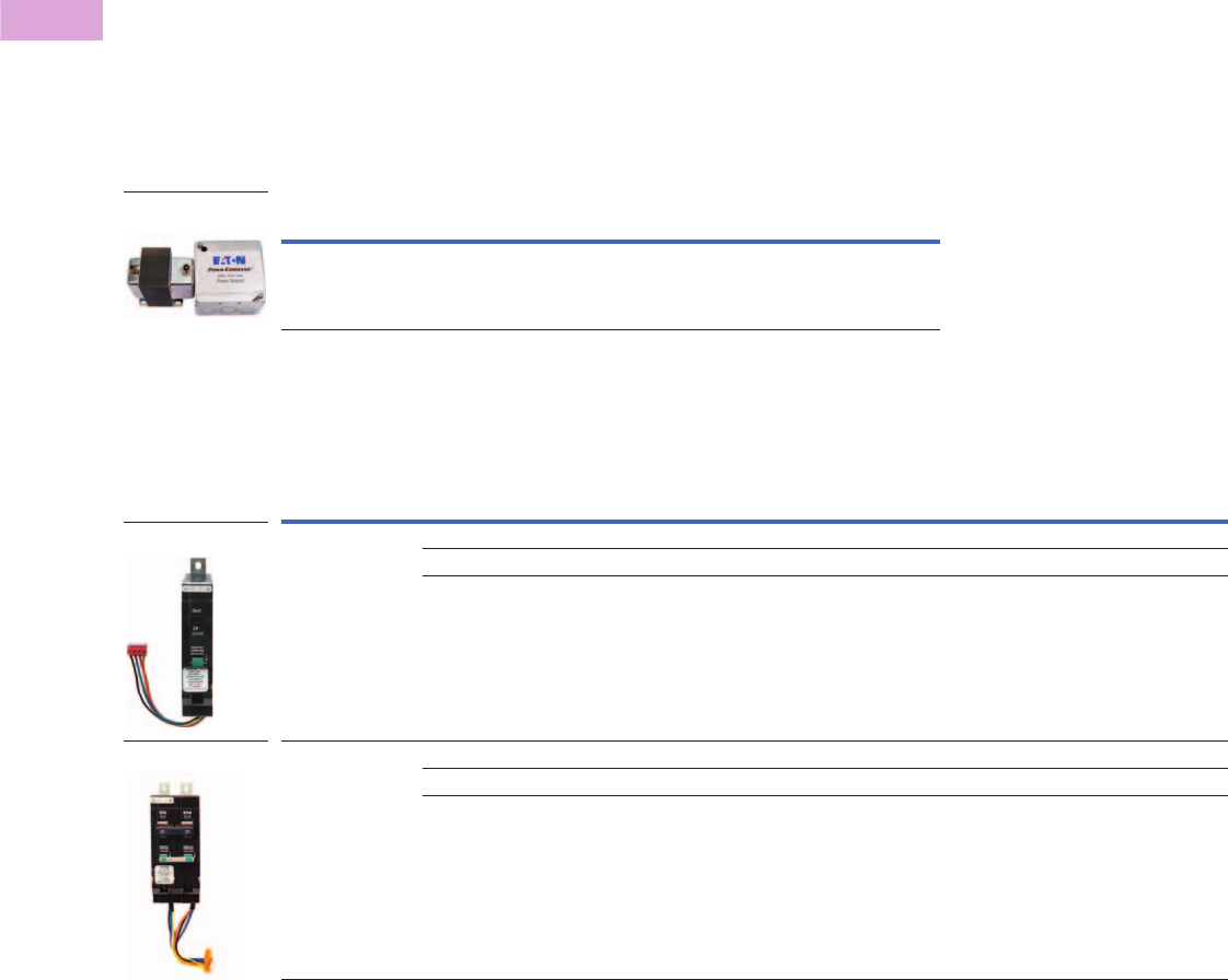
V2-T3-114 Volume 2—Commercial Distribution CA08100003E—April 2014 www.eaton.com
3
3
3
3
3
3
3
3
3
3
3
3
3
3
3
3
3
3
3
3
3
3
3
3
3
3
3
3
3
3
3.6
Panelboards and Lighting Control
Pow-R-Command
Auxiliary Power Supply
Auxiliary Power Supply
(PRCPS) is used to boost
power on the SLAN. Master
and Expansion Panelboards
communicate over the SLAN
via Alpha 1064 4-conductor
#16 AWG cable. Recommended
maximum SLAN length is 150
ft. One pair of wires provides
power to BCB for switching
controllable circuit breakers
with the second pair used for
controller to BCB RS-485
communications. The PRCPS
can be used to power a single
Expansion Panelboard or
extend the SLAN an
additional 150 ft. The SLAN
can be extended up to 4,000
ft by using a PRCPS in each
PRCEP.
Auxiliary Power Supply
Controllable Circuit Breakers
GHQRD 1
Note
1 Not recommended for existing PRC25, PRC100, PRC750, PRC1000 and PRC2000 systems. GHQRSP controllable circuit breakers are compatible with these systems.
Description Catalog Number
PRC power supply 96 VA with 120/277 Vac input and
30 Vac output voltage
PRCPS
Auxiliary Power
Supply
Number of Poles Ampere Rating
Interrupting Capacity (Symmetrical Amperes)
Vac (50/60 Hz)
120 120/240 277 277/480 Catalog Number
1 15 65,000 65,000 14,000 — GHQRD1015
20 65,000 65,000 14,000 — GHQRD1020
30 65,000 65,000 14,000 — GHQRD1030
2
15 65,000 65,000 ---- 14,000 GHQRD2015
20 65,000 65,000 ---- 14,000 GHQRD2020
30 65,000 65,000 ---- 14,000 GHQRD2030
Single-Pole
Two-Pole
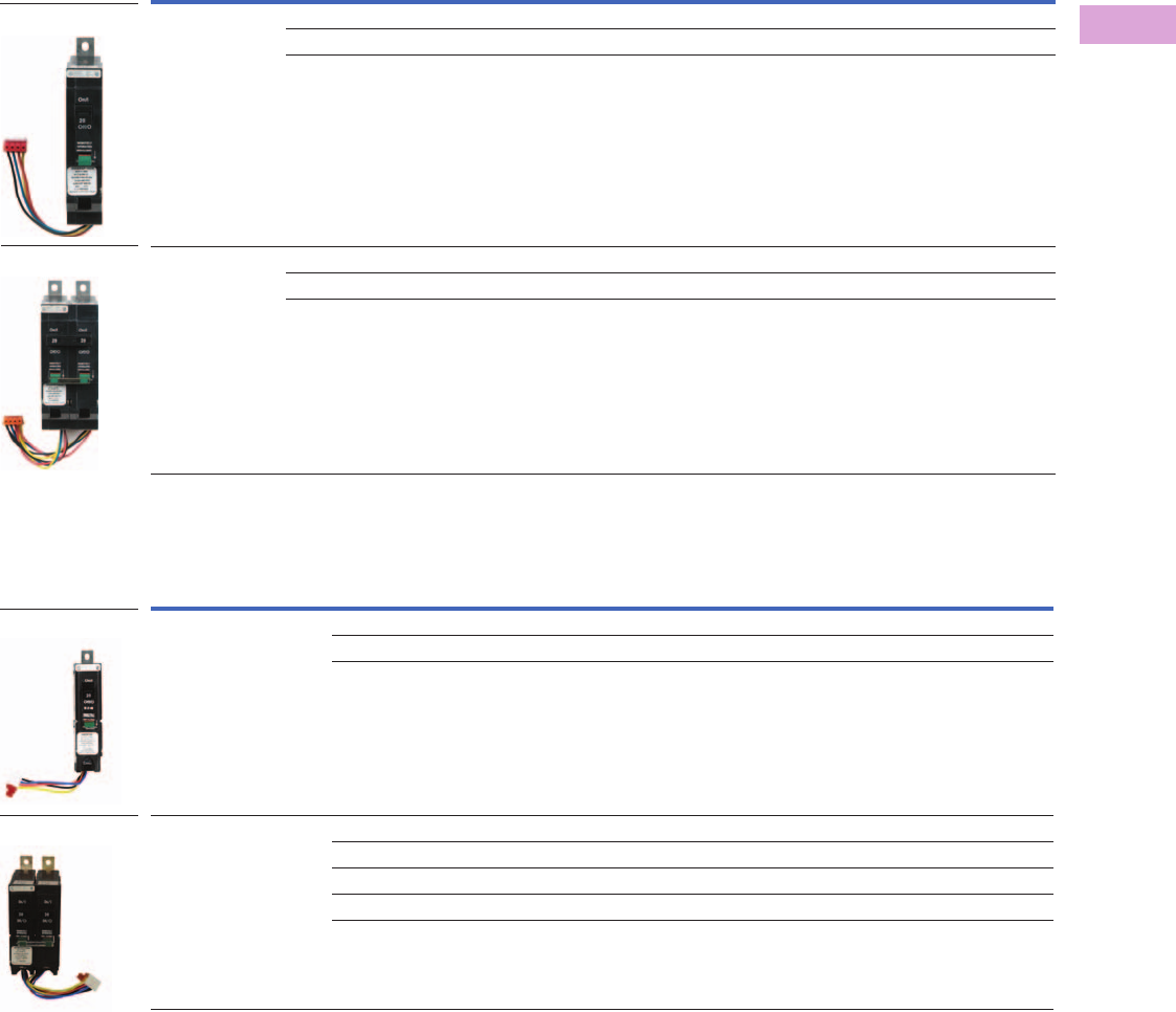
Volume 2—Commercial Distribution CA08100003E—April 2014 www.eaton.com V2-T3-115
3
3
3
3
3
3
3
3
3
3
3
3
3
3
3
3
3
3
3
3
3
3
3
3
3
3
3
3
3
3
3.6
Panelboards and Lighting Control
Pow-R-Command
GHQRSP 1
BABRSP 2
Notes
1 Compatible with existing PRC25, PRC100, PRC750(E), PRC1000(E), PRC1500(E) and PRC2000(E) systems. Recommend using GHQRD controllable
circuit breakers for PRC-E systems.
2 Compatible with PRC25, PRC100, PRC750(E), PRC1000(E), PRC1500(E) and PRC2000(E) systems. Recommend using BABRP controllable
circuit breakers for PRC25 systems.
Number of Poles Ampere Rating
Interrupting Capacity (Symmetrical Amperes)
Vac (50/60 Hz)
120 120/240 277 277/480 Catalog Number
1 15 65,000 65,000 14,000 — GHQRSP1015
20 65,000 65,000 14,000 — GHQRSP1020
30 65,000 65,000 14,000 — GHQRSP1030
2 15 65,000 65,000 — 14,000 GHQRSP2015
20 65,000 65,000 — 14,000 GHQRSP2020
30 65,000 65,000 — 14,000 GHQRSP2030
Number of Poles Ampere Rating
Interrupting Capacity (Symmetrical Amperes)
Vac (50/60 Hz)
120 120/240 Catalog Number
1 15 10,000 — BABRSP1015
20 10,000 — BABRSP1020
30 10,000 — BABRSP1030
2 15 — 10,000 BABRSP2015
20 — 10,000 BABRSP2020
30 — 10,000 BABRSP2030
40 — 10,000 BABRSP2040
50 — 10,000 BABRSP2050
Single-Pole
Two-Pole
Single-Pole
Two-Pole
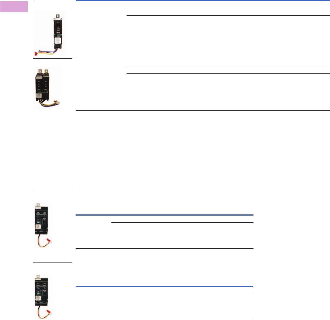
V2-T3-116 Volume 2—Commercial Distribution CA08100003E—April 2014 www.eaton.com
3
3
3
3
3
3
3
3
3
3
3
3
3
3
3
3
3
3
3
3
3
3
3
3
3
3
3
3
3
3
3.6
Panelboards and Lighting Control
Pow-R-Command
BABRP 1
Emergency Circuit Breaker
The GHQRDEL and
GHQRSPEL controllable
circuit breakers are designed
to meet NEC 700.12(F) for
sources of power in unit
equipment used for
emergency lighting
applications. The controllable
circuit breaker includes both
switched circuit for
controlling lighting and
standard non-switched circuit
to provide power to the unit
emergency charging and
detection circuitry. Controllable
circuit breaker includes a
common handle tie and a
common trip mechanism.
GHQRD Emergency Circuit Breaker 2
GHQRSP Emergency Circuit Breaker 3
Notes
1 Not compatible with PRC750(E), PRC1000(E), PRC1500(E) and PRC2000(E) systems.
2 Compatible with PRC750E, PRC1000E, PRC1500E and PRC2000E systems. Not recommended for existing PRC100,
PRC750, PRC1000 and PRC2000 systems. GHQRSPEL controllable circuit breakers are compatible with these systems.
3 Compatible with PRC750(E), PRC1000(E), PRC1500(E) and PRC2000(E) systems. Not recommended for existing PRC100,
PRC750, PRC1000 and PRC2000 systems. GHQRSP controllable circuit breakers are compatible with these systems.
Number of Poles Ampere Rating
Interrupting Capacity (Symmetrical Amperes)
Vac (50/60 Hz)
120 120/240 Catalog Number
1 15 10,000 ---- BABRP1015
20 10,000 ---- BABRP1020
30 10,000 ---- BABRP1030
2 15 ---- 10,000 BABRP2015
20 ---- 10,000 BABRP2020
30 ---- 10,000 BABRP2030
40 ---- 10,000 BABRP2040
Single-Pole
Two-Pole
Number of Poles Ampere Rating
Interrupting Capacity (Symmetrical Amperes)
Vac (50/60 Hz)
277 277/480 Catalog Number
2 15 14,000 — GHQRDEL2015
20 14,000 — GHQRDEL2020
Number of Poles Ampere Rating
Interrupting Capacity (Symmetrical Amperes)
Vac (50/60 Hz)
277 277/480 Catalog Number
2 15 14,000 — GHQRSPEL2015
20 14,000 — GHQRSPEL2020
Emergency Circuit
Breaker
Emergency Circuit
Breaker
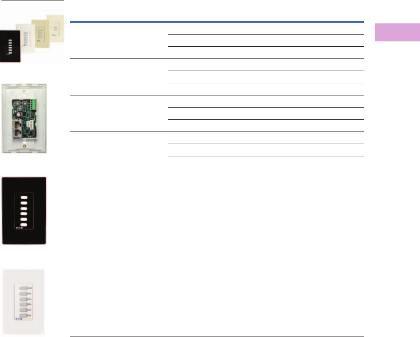
Volume 2—Commercial Distribution CA08100003E—April 2014 www.eaton.com V2-T3-117
3
3
3
3
3
3
3
3
3
3
3
3
3
3
3
3
3
3
3
3
3
3
3
3
3
3
3
3
3
3
3.6
Panelboards and Lighting Control
Pow-R-Command
Pow-R-Command Switches
Digital Switches
Pow-R-Command Digital
Switches (PRCDS) are used
for occupant override and
light level control. PRCDS
include digital and analog I/O
and 12 Vdc external power
source for connecting field
wiring devices. The 12 Vdc
external power source is
used to power an occupancy
sensor and digital input for
monitoring occupancy status.
Analog input is used to
connect a light level sensor
analog output for controlling
up to 30 fluorescent ballasts
or LED drivers. Digital
switches are connected to
controllers’ Digital Switch
Network (DSN) via CAT6
cable with 23 AWG wire
using standard RJ45
connectors. Each controller
DSN supports connecting up
to 99 digital switches.
Onboard rotary switches
allow addresses to be set in
the field. LED backlit buttons
provide real-time breakers
and/or groups status. Each
digital switch can have a title
description using up to 16
characters. Pushbutton
labels can have up to four
characters. Standard font
type is Helvetica regular bold.
Digital Switches 12
Notes
1 Not compatible with PRC750(E) controllers. Recommended for PRC1000(E), PRC1500(E) and PRC2000(E) controllers.
2 Contact factory for custom labeling.
Color Number of Buttons Catalog Number
Black 2 PRCDS2B
4PRCDS4B
6PRCDS6B
White 2 PRCDS2W
4PRCDS4W
6PRCDS6W
Almond 2 PRCDS2A
4PRCDS4A
6PRCDS6A
Ivory 2 PRCDS2V
4PRCDS4V
6PRCDS6V
Front View
Back View
Six-Button
Six-Button Engraved
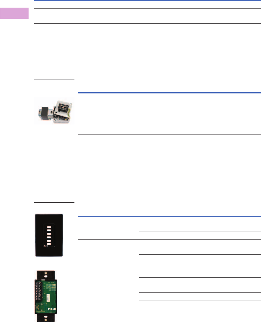
V2-T3-118 Volume 2—Commercial Distribution CA08100003E—April 2014 www.eaton.com
3
3
3
3
3
3
3
3
3
3
3
3
3
3
3
3
3
3
3
3
3
3
3
3
3
3
3
3
3
3
3.6
Panelboards and Lighting Control
Pow-R-Command
Digital Switch I/O Configuration
Digital Switch Network Power Injector
Digital Switch Network
Power Injector (PRCDSNPI) is
used to provide 24 Vac power
on the DSN. A PRCDSNPI
should be installed on the
DSN before every 16th
PRCDS or before the total
length of DSN reaches 500 ft
(whichever comes first).
Digital Switch Network Power Injector
Low Voltage Switch
Pow-R-Command Low
Voltage Switch (PRCLS)
includes momentary dry-
contact pushbuttons used for
inputs into the controller.
PRCLS directly connect to
controller digital and universal
inputs. Each PRCLS can have
a title description using up to
16 characters. Pushbutton
labels can have up to four
characters. Standard font
type is Helvetica regular bold.
Low Voltage Switch 1
Note
1 Consult factory for custom labeling.
Pushbutton Configuration
Analog Input
0–10 Vdc
Digital Input
0–10 Vdc
Analog Output
0–10 Vdc
12 Vdc Output
20 mA Maximum
Two-button ■■■ ■
Four-button ■■■ ■
Six-button ■—■■
Description Catalog Number
Digital Switch Network Power Injector PRCDSNPI
Digital Switch
Network Power
Injector
Color Number of Buttons Catalog Number
Black 2 PRCLS2B
4PRCLS4B
6PRCLS6B
White 2 PRCLS2W
4PRCLS4W
6PRCLS6W
Almond 2 PRCLS2A
4PRCLS4A
6PRCLS6A
Ivory 2 PRCLS2V
4PRCLS4V
6PRCLS6V
Low Voltage Switch
Termination Board

Volume 2—Commercial Distribution CA08100003E—April 2014 www.eaton.com V2-T3-119
3
3
3
3
3
3
3
3
3
3
3
3
3
3
3
3
3
3
3
3
3
3
3
3
3
3
3
3
3
3
3.6
Panelboards and Lighting Control
Pow-R-Command
Switch Wallplates
Fits rocker-style Decorator,
Decora style switches.
Screwless design is available
in black, white, almond and
ivory for 1-, 2- and 3-switch
designs.
Switch Wallplates
Pow-R-Command Switch Override Controller
The Pow-R-Command Switch
Override Controller (PRCSOC)
can be used to connect digital
and analog I/O to Pow-R-
Command systems. This
device is recommended
when controller onboard
digital and analog I/O has
been exceeded or when
there is an advantage to
connecting remote I/O via a
network connection. The
PRCSOC is supplied with the
controller,
termination board
in a NEMA 1
enclosure. Dual
voltage 120/277 Vac power
supply and 32-status LED
output card are optional.
The PRCSOC is connected
to the Pow-R-Command
system via the RS-485
network. Status and
command signals are sent to
the system using Pow-R-
Command peer-to-peer
protocol. The PRCSOC is
configured using Pow-R-
Command Lighting
Optimization Software.
All digital and analog I/O is
connected using #18 AWG
with maximum of 500 ft
length. The PRCSOC features
include:
●Sixty low voltage two-wire
switch inputs for
connecting wall stations,
occupancy sensors and
control relay outputs from
building management
systems
●Eight low voltage two-wire
universal (digital or analog)
inputs. Analog field devices
like light level sensors with
0–5 Vdc outputs can be
connected for dimming
and daylight harvesting
applications
●Three low voltage 0–10
Vdc analog outputs for
controlling fluorescent and
LED light fixtures equipped
dimming circuitry;
maximum of 40 each per
output with optional
dimmer cables
●Sixteen low voltage two-
wire 24 Vdc outputs to
power status LEDs;
optional to add 32 low
voltage two-wire 24 Vdc
outputs to power status
LEDs
●External 15 Vdc power
source for powering
occupancy and light level
sensors and PRC auxiliary
devices
●Connects to Pow-R-
Command RS-485 network
●Communicates to the
system using Pow-R-
Command peer-to-peer
protocol
●Configured by using
Pow-R-Command Lighting
Optimization Software
●Provided in a NEMA 1
enclosure
●Not compatible with
PRC750(E) controllers
Pow-R-Command Switch Override Controller
Color Number of Switches Catalog Number
Black 1 PRCSWP1B
2PRCSWP2B
3PRCSWP3B
White 1 PRCSWP1W
2PRCSWP2W
3PRCSWP3W
Almond 1 PRCSWP1A
2PRCSWP2A
3PRCSWP3A
Ivory 1 PRCSWP1V
2PRCSWP2V
3PRCSWP3V
Switch Wallplates
Description Catalog Number
PRC Switch Override Controller without power supply mounted in NEMA 1 enclosure PRCSOCC
PRC Switch Override Controller w/ 120/277 Vac power supply mounted in a NEMA 1 enclosure PRCSOCEC
PRC Switch Override Controller w/ 120/277 Vac power supply, pilot output card mounted in a
NEMA 1 enclosure
PRCSOCECO
Pow-R-Command
Switch Override
Controller
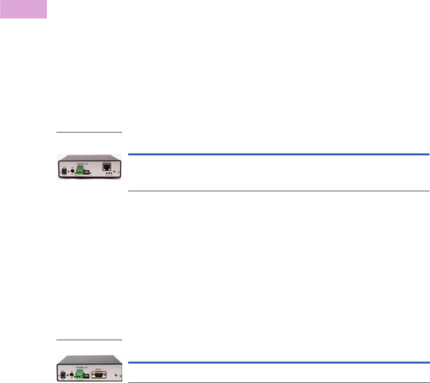
V2-T3-120 Volume 2—Commercial Distribution CA08100003E—April 2014 www.eaton.com
3
3
3
3
3
3
3
3
3
3
3
3
3
3
3
3
3
3
3
3
3
3
3
3
3
3
3
3
3
3
3.6
Panelboards and Lighting Control
Pow-R-Command
Accessories
Ethernet Interface Module
Ethernet Interface Module
(PRCEIM) is used for
connecting a Pow-R-
Command system when
configured in an RS-485
daisy-chain network to a
user’s existing Ethernet
network. The PRCEIM allows
access to the system using
Pow-R-Command software
package over the facility
Ethernet network.
PRCEIM can be used as the
master scheduler and
includes 250 unique
schedules. The PRCEIM can
be programmed to sync
controller time clocks. This
device is connected to the
Ethernet network using
standard CAT5 cable. The
three-pin connector is used to
directly connect to the Pow-
R-Command RS-485
controller network.
The PRCEIM comes in a table
top enclosure and should be
physically located near an
Ethernet hub or repeater, but
the PC can be located
anywhere on the Ethernet
network. The PRCEIM will
communicate at 10Base-T
and must have a fixed IP
address assignment on the
Ethernet network.
Ethernet Interface Module 1
Network Interface Box
Network Interface Box
(PRCNIB) is used for directly
connecting a Pow-R-
Command system when
configured in an RS-485
daisy-chain network
architecture to the user’s
desktop or laptop computer.
PRCNIB can be used as the
master scheduler and
includes 250 unique
schedules. The PRCNIB is
programmed to sync the time
clocks of all controllers
connected to the RS-485
network. The user’s
computer is connected using
the RS-232 communications
connector and the RS-232 to
USB converter cable for
direct connection to a
computer. The Pow-R-
Command controller RS-485
network is connected to the
PRCNIB 3-pin connector. The
PRCNIB comes in a table top
enclosure and should be
mounted within 25 ft of
the computer.
Network Interface Box 1
Note
1 Not compatible with PRC750(E) controllers. Recommended for PRC100, PRC1000(E), PRC1500(E) and
PRC2000(E) controllers.
Description Catalog Number
PRC Ethernet Interface Module mounted in table top enclosure PRCEIM
Ethernet Interface
Module
Description Catalog Number
PRC Network Interface Box mounted in table top enclosure PRCNIB
Network Interface Box

Volume 2—Commercial Distribution CA08100003E—April 2014 www.eaton.com V2-T3-121
3
3
3
3
3
3
3
3
3
3
3
3
3
3
3
3
3
3
3
3
3
3
3
3
3
3
3
3
3
3
3.6
Panelboards and Lighting Control
Pow-R-Command
BACnet Interface Module
Pow-R-Command BACnet
Interface Module (PRCBIM-1)
is designed for simple
BACnet integration without
the need for extensive
BACnet knowledge. The
device maps Pow-R-
Command controller points to
BACnet/IP points of any
RS-485 network connected
Pow-R-Command controller.
The PRCBIM-1 can map up to
50 points. These points
include status and control of
individual controllable circuit
breakers and groups of
controllable circuit breakers.
Input status is also included
in the points map.
Programming the device is
accomplished by using Pow-
R-Command Lighting
Optimization Software
(PRCLOS). The PRCBIM-1
includes two network
connections. The RS-485
connection is used for
connecting the Pow-R-
Command RS-485 network
while the Ethernet 10Base-T
connection is used for
connecting to the facility
Ethernet network. The device
requires a fixed IP address
to be configured before
connecting to the network.
BACnet Interface Module 1
BACnet Shadow Server
Pow-R-Command BACnet
Shadow Server (PRCSS) is
designed for simple BACnet
integration without the need
for extensive BACnet
knowledge. The PRCSS maps
Pow-R-Command controller
points to BACnet/IP points.
Up to 120 devices can be
connected to a system. Each
PRCSS has full access to all
150 points of the directly
connected Pow-R-Command
controller. These points
include status and control of
individual controllable circuit
breakers and groups of
controllable circuit breakers.
Input status is also included
in the points map.
Programming the device is
accomplished by using Pow-
R-Command Lighting
Optimization Software
(PRCLOS). The PRCSS
includes two network
connections. The RS-485
connection is used for
connecting the Pow-R-
Command RS-485 network
while the Ethernet 10Base-T
connection is used for
connecting to the facility
Ethernet network.
The PRCBIM-1 includes two
network connections. The
RS-485 connection is used for
connecting the RS-485
network while the Ethernet
10Base-T connection is used
for connecting to the facility
Ethernet network. The device
requires a fixed IP address
to be configured before
connecting to the network.
Device power is supplied by
controller 12 Vdc external
power source.
BACnet Shadow Server 1
Note
1 Not compatible with PRC750(E) controllers. Recommended for PRC100, PRC1000(E) and PRC1500(E) controllers
RS-485 network.
Description Catalog Number
PRC BACnet Interface Module PRCBIM-1
BACnet Interface
Module
Description Catalog Number
PRC BACnet Shadow Server PRCSS
BACnet Shadow
Server
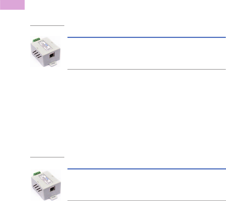
V2-T3-122 Volume 2—Commercial Distribution CA08100003E—April 2014 www.eaton.com
3
3
3
3
3
3
3
3
3
3
3
3
3
3
3
3
3
3
3
3
3
3
3
3
3
3
3
3
3
3
3.6
Panelboards and Lighting Control
Pow-R-Command
Universal Ethernet Interface
The Pow-R-Command
Universal Ethernet Interface
(PRCUEI) is used
in conjunction with the
PRC5000 Advanced Lighting
Controller to connect multiple
RS-485 networks using the
facility’s Ethernet network
via
TCP protocol. The PRC5000
can connect up to 16 Pow-R-
Command RS-485 networks
using a PRCUEI to connect
each network. The PRCUEI
supports up to 120 Pow-R-
Command devices on each
RS-485 network. The device
power is supplied by the
controller 12 Vdc external
power connection.
Universal Ethernet Interface 1
Universal Ethernet Router
Universal Ethernet Router
PRCUER is intended for
facilities where an Ethernet
network is already installed.
The PRCUER extends the
Pow-R-Command controller
network by tunneling Pow-R-
Command controller LAN
control packets over existing
Ethernet network using UDP
Ethernet protocol. PRCUER
devices extend the controller
LAN transparently across
Ethernet segments within
the same subnet, allowing
segments of the controller
network to be physically
separated from each other
within a facility. Programming
the device is accomplished by
using Pow-R-Command
Lighting Optimization
Software (PRCLOS).
The PRCUER includes
two network connections.
The RS-485 connection is
used for connecting the Pow-
R-Command RS-485 network
while the Ethernet 10Base-T
connection is used for
connecting to the facility
Ethernet network.
The device can be configured
for DHCP or be assigned a
static IP address. Device
power is supplied by
controller 12 Vdc external
power source.
Universal Ethernet Router 1
Description Catalog Number
PRC Universal Ethernet Interface PRCUEI
Universal Ethernet
Interface
Description Catalog Number
PRC Universal Ethernet Router PRCUER
Universal Ethernet
Router

Volume 2—Commercial Distribution CA08100003E—April 2014 www.eaton.com V2-T3-123
3
3
3
3
3
3
3
3
3
3
3
3
3
3
3
3
3
3
3
3
3
3
3
3
3
3
3
3
3
3
3.6
Panelboards and Lighting Control
Pow-R-Command
PRC5000 Building Automation Controller
Pow-R-Command 5000
(PRC5000) is a
microprocessor-based
lighting control and energy
management controller. It is
capable of communicating
with other Pow-R-Command
system devices for providing
advanced control strategies
including master schedules
and demand response.
Custom equipment
performance and energy
usage reports can be
configured and automatically
sent to the facility manager
via email notification. These
reports may be used to
measure and verify that
equipment is performing as
designed and delivering
expected energy savings.
The PRC5000 controller is
commonly used to serve
facility custom graphics via
Web pages. Authorized users
can log into the device using
a standard Web browser for
viewing the custom graphics.
System schedule changes
and override controls can be
made at the click of a button.
PRC5000 Building Automation Controller
PRC25 Controller
The PRC25 panelboard is a
flexible and cost-effective
lighting and load control
system that integrates branch
circuit and control in a single
enclosure. The PRC25 stand-
alone panelboard may be
controlled by external time
clocks, photocell, wall switch
or signal from another
building control system.
There is no field programming
and comes from the factory
wired to meet the
specification.
The PRC25 controller has the
ability to accept either four or
six control inputs (MTM-4 and
MTM-6 models). Each control
input is used to control a
discreet group of controllable
circuit breakers. The
controller inputs can be
configured in both maintained
dry or wet contacts.
The PRC25 MTM controller
board is connected to
controllable circuit breakers
using a Group Termination
Board (GTB). Each GTB
consists of nine connectors
distributed across a printed
circuit board for connecting
the controllable circuit
breakers. Each GBT may have
up to seven controllable
circuit breakers connected. A
maximum of three GTBs may
be mounted on each side of
the panelboard. All
controllable breakers
connected to the GTB will be
controlled as a group.
Multiple GTBs can be
connected together using a
factory-supplied jumper to
increase the size of control
groups.
PRC25 Controller
Description Catalog Number
PRC5000 Building Automation Controller PRC5000E
PRC5000 Building Automation Controller with modem PRC5000EM
PRC5000E
Description Catalog Number
PRC25 4-channel controller MTM-4
PRC25 6-channel controller MTM-6
PRC25
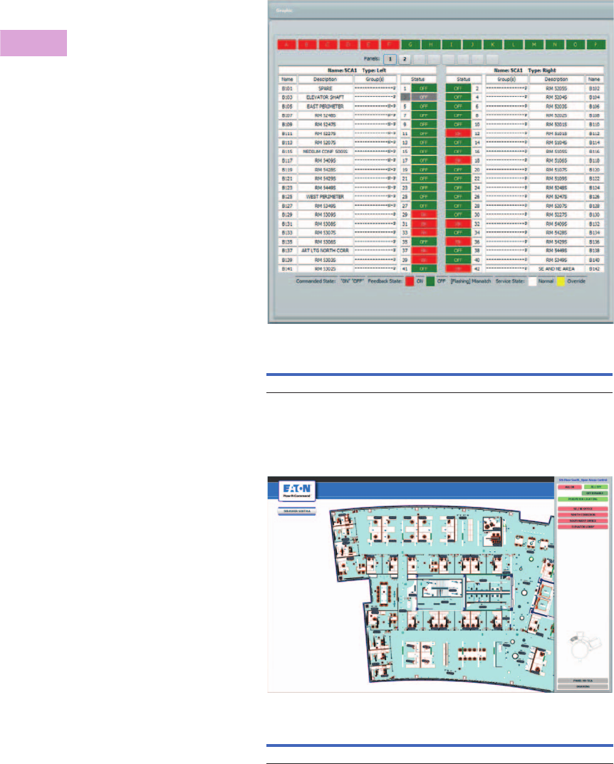
V2-T3-124 Volume 2—Commercial Distribution CA08100003E—April 2014 www.eaton.com
3
3
3
3
3
3
3
3
3
3
3
3
3
3
3
3
3
3
3
3
3
3
3
3
3
3
3
3
3
3
3.6
Panelboards and Lighting Control
Pow-R-Command
Lighting Optimization
Software
Lighting Optimization
Software (PRCLOS) is
recommended for Pow-R-
Command system users. It is
compatible with PRC100,
PRC750(E)1, PRC1000(E),
PC1500(E) and PRC2000(E)
systems. PRCLOS
controllers only through the
front Maintenance port using
a PRCSmartCable. allows
users to set up, program and
monitor their system. This
basic software package is
capable of recognizing and
saving databases for a
single site.
Building Graphics Software
Building Graphics Software
(PRCBGS) is a fully
interactive object oriented
graphics interface for
controlling and monitoring
Pow-R-Command lighting
control and energy
management systems. The
integrator can create and
depict objects such as light
fixtures, switches,
occupancy sensors, light
sensors, floor plans, etc.
PRCBGS provides server
graphic Web pages over local
Ethernet connection to any
computer using a standard
Internet browser. PRCBGS
requires the installation of PC
Central (PRCPCC01/
PRCPCC10).
Lighting Optimization Software 1
Building Graphics Software
Note
1Remote network connection not available. Requires direct connection to controller
Maintenance port. PRC750 connection requires PRCSmartCable. PRC750E connection
requires industry standard patch cable.
Description Catalog Number
PRC Lighting Optimization Software PRCLOS
Description Catalog Number
PRC Building Graphics Software PRCBGS

Volume 2—Commercial Distribution CA08100003E—April 2014 www.eaton.com V2-T3-125
3
3
3
3
3
3
3
3
3
3
3
3
3
3
3
3
3
3
3
3
3
3
3
3
3
3
3
3
3
3
3.6
Panelboards and Lighting Control
Pow-R-Command
PC Central Software
PC Central Software
(PRCPCC) is recommended
for field technicians
responsible for maintaining
Pow-R-Command systems. It
is compatible with PRC100,
PRC750 (E)1, PRC1000(E),
PC1500(E) and PRC2000(E)
systems. PRCPCC allows
users to set up, program and
monitor their system with the
added features of advanced
diagnostics and programming
capabilities. This advanced
software package is capable
of recognizing and saving
databases for single or
multiple sites.
Site Server Software
Pow-R-Command Site Server
(PRCSSS) integrates the PC
Central suite of management
tools with the Internet or
Intranet. The users have real-
time global access to the
Pow-R-Command systems
through the Internet. PRCSSS
allows multiple users access
to historical data, device
status and control, and
graphical display interfaces.
Any computer on the network
with PRCSSS can access real-
time dynamically refreshed
data using a browser
implementing appropriate
Web standards (Netscape
Navigator or Internet
Explorer). Special software
other than the browser is not
required. PC Central is
required to run this
application software.
Desktop Computer
Recommended Minimum Computer Specifications
Although it is difficult to
guarantee compatibility with
all PC-compatible equipment,
the basic installation is
generally compatible with
the following minimum
specifications:
●Microsoft® Windows®
operating system
●1GHz processor or better
●At least 40 MB of unused
RAM
●Hard drive with at least
100 MB of free space plus
50 MB for each site to be
managed
●Ethernet network adapter
●800 x 600 monitor
●CD-ROM drive
Lighting Optimization
Software and PC Central
Software is compatible with
the following operating
systems:
●Windows 98 Second
Edition
●Windows 2000
Professional
●Windows 2000 Server
●Windows 2003 Server
●Windows XP Home Edition
●Windows XP Professional
Edition
●Windows Vista
(all versions)
●Windows 7
Smart Cable Programming Tool
Pow-R-Command Smart Cable
(PRCSmartCable)
is used for
front panelboard
programming PRC100,
PRC750, PRC1000 and
PRC2000 controllers. The
PRCSmartCable connects
the local laptop USB port to
controller maintenance port.
PC Central Software
Site Server Software
Desktop Computer
Smart Cable Programming Tool
Note
1Remote network connection not available. Requires direct connection to controller
maintenance port. PRC750 connection requires PRCSmartCable. PRC750E connection
requires industry standard patch cable.
Description Catalog Number
PC Central Software (single site) PRCPCC01
PC Central Software (10 sites) PRCPCC10
Description Catalog Number
PRC Site Server Software PRCSSS
Description Catalog Number
PRC desktop computer PRCDesktop
PRC Laptop Computer PRCLaptop
Description Catalog Number
PRC smart cable PRCSmartCable
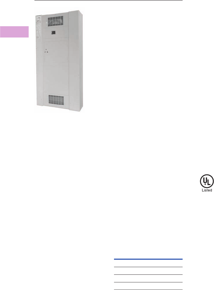
V2-T3-126 Volume 2—Commercial Distribution CA08100003E—April 2014 www.eaton.com
3
3
3
3
3
3
3
3
3
3
3
3
3
3
3
3
3
3
3
3
3
3
3
3
3
3
3
3
3
3
3.7
Panelboards and Lighting Control
Metering Service Sections
Metering Service Section
Contents
Description Page
Metering Service Sections
Catalog Number Selection . . . . . . . . . . . . . . . . V2-T3-127
Product Selection. . . . . . . . . . . . . . . . . . . . . . . V2-T3-127
Technical Data and Specifications . . . . . . . . . . V2-T3-128
Dimensions . . . . . . . . . . . . . . . . . . . . . . . . . . . V2-T3-128
Product Description
●600 Vac maximum
●Three-phase four-wire,
three-phase three-wire,
single-phase three-wire.
●Service entrance panel
combining a main
disconnect with a power
company metering
compartment
●Circuit breaker or fusible
switch disconnect
●400–1200A ratings
●Provision for power
company metering:
●Hinged sealable door
over CT section
●Arranged for bar-type,
200–1200A utility-
furnished CTs
●Barriered CT
compartment
●Factory assembled
●Wallmounted enclosure
Application Description
●For use in areas where the
disconnect and current
transformer combination is
required by utilities
●Suitable for use as Service
Entrance Equipment
●Top or bottom entrance
●Hot or cold sequence
metering
●The current transformer
compartment will
accommodate the following
12-inch (304.8 mm) bar-type
CTs:
Bar-Type CTs
Standards and
Certifications
●UL 67, UL 50
●NEC
ABB
General
Electric Sangamo Astra
CTB JCT-10 R6B TAB, TA
CSF JCM-0 R6BA TCB, AA
CMF JCW-0 R6M AB
CBH JAK-0
Volume 2—Commercial Distribution CA08100003E—April 2014 www.eaton.com V2-T3-127
3
3
3
3
3
3
3
3
3
3
3
3
3
3
3
3
3
3
3
3
3
3
3
3
3
3
3
3
3
3
3.7
Panelboards and Lighting Control
Metering Service Sections
Catalog Number Selection
Panelboard Catalog Number Selection Guide 1
Example: WBMDK24A
WBM = Circuit breaker type, DK = Circuit breaker type from table below, 2 = Single-phase three-wire,
4 = 400A, A = Aluminum bus bar.
Product Selection
Type WBM Circuit Breaker Sections
Notes
1 Refer to Hartford Satellite Plant.
2 For other breaker types, refer to Hartford Satellite Plant.
3 In cold sequence metering only, a 10X or 18X feeder breaker section can be supplied
downstream from the CT compartment. Refer to Hartford Satellite Plant.
4 Complete catalog number according to Catalog the Number Selection Guide—table above.
5 Integral ground fault.
Max.
Ampere
Rating
Interrupting Rating (kA Symmetrical)
Breaker Type 23
Base
Catalog Number 4
240 Vac 480 Vac 600 Vac
400 65 — — DK WBMDK
400 65 35 25 KD WBMKD
400 100 65 35 HKD WBMHKD
400 200 100 50 KDC WBMKDC
400 200 200 — LCL WBMLCL
600 65 35 25 LD WBMLD
600 100 65 35 HLD WBMHLD
600 200 100 50 LDC WBMLDC
800 65 50 25 MDL WBMMDL
800 100 65 35 HMDL WBMHMDL
800 65 50 25 ND WBMND800
800 100 65 35 HND WBMHND800
1200 65 50 25 ND WBMND1200
1200 65 50 25 NDG 5WBMNDG1200
1200 100 65 35 HND WBMHND1200
1200 100 65 35 HNDG 5WBMHNDG1200
Panel Type
WSM = Fusible switch
WBM = Circuit breaker
Ampere Rating
4 = 400A
6 = 600A
8 = 800A
12 = 1200A
Device Type
FDPW = Fusible switch
Circuit breaker = (See table below)
Service and Voltage
2 = Single-phase three-wire
3 = Three-phase three-wire
4 = Three-phase four-wire
Bus Bar Type
A= Aluminum
C= Copper
WBM DK 24A
Metering Service
Section
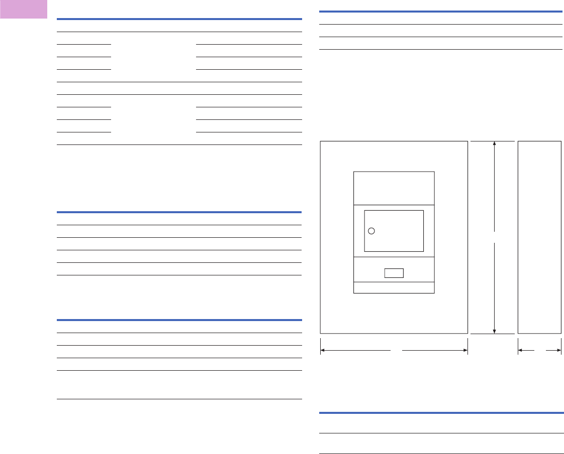
V2-T3-128 Volume 2—Commercial Distribution CA08100003E—April 2014 www.eaton.com
3
3
3
3
3
3
3
3
3
3
3
3
3
3
3
3
3
3
3
3
3
3
3
3
3
3
3
3
3
3
3.7
Panelboards and Lighting Control
Metering Service Sections
WSM Fusible Switch Sections
Modifications
Modifications for WBM Metering Service Sections
Modifications for WSM Metering Service Sections
Ampere
Rating
Interrupting
Rating
(kA Symmetrical)
Fusible
Switch 1
Base
Catalog
Number 2
240 Vac Fusible Devices 3
400 Refer to table on right
(FDPW Switch Ratings, 250 or
600 Vac)
FDPW WSMFDPW
600 FDPW WSMFDPW
800 FDPW WSMFDPW
1200 FDPW WSMFDPW
600 Vac Fusible Devices 3
400 Refer to table on right
(FDPW Switch Ratings, 250 or
600 Vac)
FDPW WSMFDPW
600 FDPW WSMFDPW
800 FDPW WSMFDPW
1200 FDPW WSMFDPW
Description
Copper bus
Circuit breaker shunt trip installed
Circuit breaker undervoltage release installed
Type 3R outdoor enclosure
Provisions for PTs
Description
Copper bus
Shunt trip installed
Type 3R outdoor enclosure
Provisions for PTs
FDPW fusible switch ground fault system
Includes zero sequence current monitor, static sensor, shunt trip
and fused control power transformer
Technical Data and Specifications
FDPW Switch Ratings, 250 or 600 Vac
Dimensions
Approximate Dimensions in Inches (mm)
Note: Not to be used for construction purposes unless approved.
Type 1 Enclosure—Metering Service Section
Type 1 Enclosure
Notes
1Fuses are not included.
2Complete catalog number according to Catalog Number Selection Guide—
Page V2-T3-127.
3Class J Fuse provisions are applicable only to 600V units. When required, use price
and dimensions of 600V units for all voltages 600 and below.
4Class J Fuse provisions are applicable only to 600V units. When required, use price and
dimensions of 600V units for all voltages 600 and below.
Ampere
Rating
Fuse Class
Used 1
Short-Circuit
Ratings (kA Sym.)
400, 600 R 200
400, 600 J 4200
800, 1200 L 200
Panelboard
Type
Ampere
Rating
Enclosure Dimensions Box Catalog
NumberHeight Width Depth
WBM,
Circuit breaker
400–1200 73.50 (1866.9) 36.00 (914.4) 11.31 (287.0) BX3673
WSM,
Fusible
400–1200 90.50 (2286.0) 36.00 (914.4) 11.31 (287.0) BX3690
WD
H
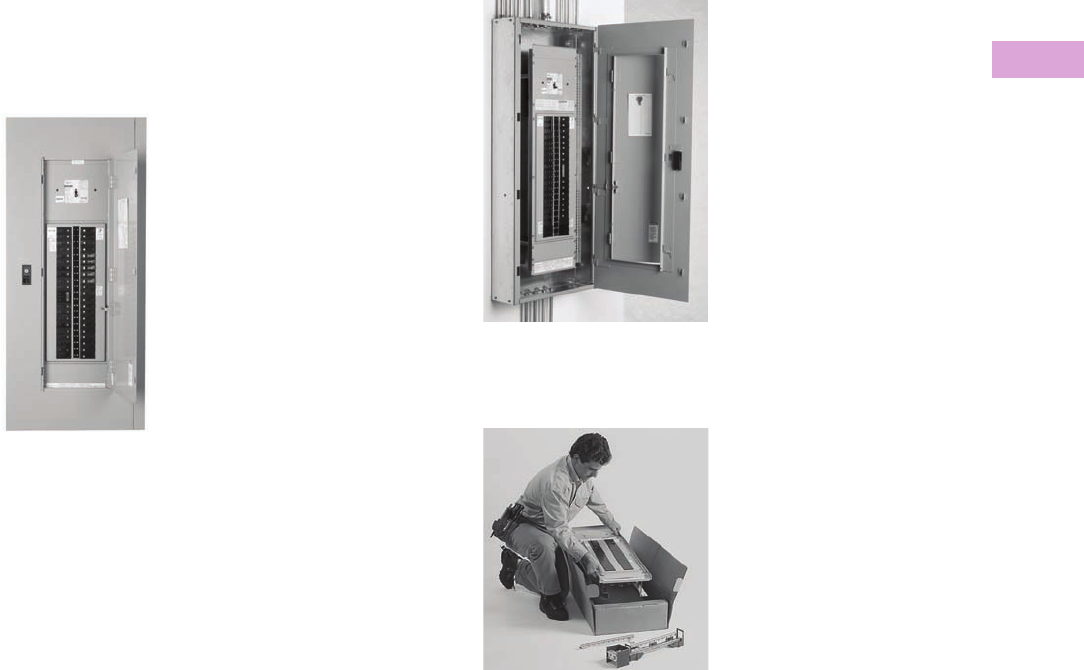
Volume 2—Commercial Distribution CA08100003E—April 2014 www.eaton.com V2-T3-129
3
3
3
3
3
3
3
3
3
3
3
3
3
3
3
3
3
3
3
3
3
3
3
3
3
3
3
3
3
3
3.8
Panelboards and Lighting Control
Pow-R-Stock Plus Program
Pow-R-Stock Plus
Product Description
Offering two options to meet
the demanding schedule
requirements of today's
customers.
Type PRL1a Panelboard
●Factory-assembled
panelboards available from
your local satellite plant in
24 to 72 hours
●Unassembled panelboards
in stock at authorized Pow-
R-Stock Plus distributors
The Product Offering
Pow-R-Stock Plus panels,
available either as factory-
assembled or as
unassembled from distributor
stock, are based on the most
frequently ordered
panelboards, including:
●120/240V, 208Y/120V and
480Y/277V ratings
●100–400A mains
●Single- and three-phase
●Surface and flush mounted
●Aluminum or copper bus
●Type 1 or Type 3R
enclosures
●Service entrance available
●Options for 200% neutrals
and isolated ground bars
●Full menu of branch
breakers available
Factory-Assembled
Panelboard Option
The Pow-R-Stock Plus factory-
assembled
panelboard option
offers key advantages over
programs that offer only
unassembled panelboards.
Reduced Installation Time
Unassembled panelboards
must be assembled at the job
site before the true
installation process can
begin, adding time and labor
cost to the process. Pow-R-
Stock Plus assembled
panelboards are ready to
install the moment they arrive
at the job site.
Reduced On-Site
Material Handling
A typical 42-circuit
unassembled panelboard has
a minimum of 46 parts to
receive and handle, taking up
valuable time at the job site.
A Pow-R-Stock Plus
assembled panelboard is just
one item to receive and
handle (two if the box is
shipped ahead).
Factory Warranty
Field assembly of
unassembled panelboards
adds to contractor warranty
responsibility. Pow-R-Stock
Plus assembled panelboards
carry a full factory warranty.
Simplicity
Order your Pow-R-Stock Plus
Panelboard by description
and it will arrive at the job site
complete. No need to worry
about matching catalog
number kits at the job site or
chasing after miscellaneous
parts and pieces.
Contact your local satellite
plant (see next page for a
listing) for more informa-
tion on the Pow-R-Stock
Plus factory-assembled
panelboard option.
Pow-R-Stock Plus Program Includes
the EZ Trim and EZ Box
Unassembled
Panelboard Option
Pow-R-Line 1a and 2a Panelboards are
Designed to Provide Application
Flexibility with Off-the-Shelf Service
The Pow-R-Stock Plus
unassembled panelboard
interior is designed
specifically for distributor
stock and field assembly.
Its modular design allows
for easy configuration in
the field.
Top or bottom incoming,
main lugs or main breaker...all
with the same Pow-R-Stock
Plus unassembled interior.
Lug and breaker kits provide
greater flexibility with fewer
boxes, interiors and trims
to stock.
Color-Coded Package Labels
The box, interior and trim
packaging are clearly
identified with brightly
colored labels (a different
color for each box size). This
facilitates stocking, filling
orders, and matching
components in the field.
Contact your local Eaton
distributor for more details
on the Pow-R-Stock Plus
unassembled panelboard
option.
Eaton Distributors
Contact your Eaton sales
office or local satellite
manager and arrange to
review the program details
and criteria for qualification
as a Pow-R-Stock Plus
distributor.

V2-T3-130 Volume 2—Commercial Distribution CA08100003E—April 2014 www.eaton.com
3
3
3
3
3
3
3
3
3
3
3
3
3
3
3
3
3
3
3
3
3
3
3
3
3
3
3
3
3
3
3.9
Panelboards and Lighting Control
Customer Manufacturing Solution Centers
Manufacturing Plant Locations
Main Plant
Sumter
845 Corporate Circle
P.O. Box 2258
Sumter, SC 29151
(803) 481-3131
Satellite Plants
Atlanta
7000 Highlands Parkway SE
Suite 103
Smyrna, GA 30082
Fax (770) 433-1863
Phone (678) 309-4260
Baltimore
7451 Coca Cola Drive
Suite C
Hanover, MD 21076
Fax (410) 796-7755
Phone (410) 796-7777
Chicago
220 Windy Point Drive
Glendale Heights, IL 60139
Fax (630) 690-7453
Phone (630) 260-6303
Cleveland
12875 Corporate Drive
Suite E
Parma, OH 44130
Fax (216) 433-0545
Phone (216) 433-0616
Dallas
631 Westport Parkway
Suite 100
Grapevine, TX 76051
Fax (817) 251-6249
Phone (817) 251-6797
Denver
2450 Airport Road
Suite C
Aurora, CO 80011
Fax (303) 366-9993
Phone (303) 366-2080
Hartford
40A International Drive
Windsor, CT 06095
Fax (860) 298-1305
Phone (860) 298-1306
Houston
14825 Northwest Freeway
#100-C
Houston, TX 77040
Fax (713) 744-7531
Phone (713) 744-7530
Los Angeles
11120 Philadelphia Street
Suite A
Mira Loma, CA 91752
Fax (951) 685-3775
Phone (951) 685-5788
New Jersey
96 Stemmers Lane
Westampton, NJ 08060
Fax (609) 835-4777
Phone (609) 835-4230
Orlando
9436 Southridge Park Court
Suite 100
Orlando, FL 32819
Fax (407) 264-9310
Phone (407) 264-9300
Phoenix
560 N. 54th Street
Chandler, AZ 85226
Fax (480) 449-4223
Phone (480) 449-4222
Raleigh
9400 Globe Center Drive
Suite 121
Morrisville, NC 27560
Fax (919) 572-9751
Phone (919) 544-7074
St. Louis
56 Soccer Park Road
Fenton, MO 63026
Fax (636) 717-3505
Phone (636) 717-3500
San Francisco
20923 Cabot Boulevard
Hayward, CA 94545
Fax (510) 784-8980
Phone (510) 784-8981
Seattle
1604 15th Street SW
Suite 114
Auburn, WA 98001
Fax (253) 833-5058
Phone (253) 833-5021
•
•
•
•
•
•
•
•
•
•
•
★
•
•
•
SEATTLE
SAN FRANCISCO
LOS ANGELES
DENVER
DALLAS
HOUSTON
CHICAGO
BALTIMORE
ATLANTA
ST. LOUIS
HARTFORD
SUMTER
CLEVELAND
•
RALEIGH
•
PHOENIX
ORLANDO
NEW JERSEY

Volume 2—Commercial Distribution CA08100003E—April 2014 www.eaton.com V2-T3-131
3
3
3
3
3
3
3
3
3
3
3
3
3
3
3
3
3
3
3
3
3
3
3
3
3
3
3
3
3
3
3.9
Panelboards and Lighting Control
Customer Manufacturing Solution Centers
Customer Manufacturing Solution Centers
A unique concept of
facilities close to customer
locations, assuring fast
delivery of standard- and
custom-assembled
equipment when
it’s needed.
Located at strategic locations
throughout the United States,
these facilities manufacture
and deliver standard or
custom-assembled
panelboards, switchboards
and enclosed circuit
breakers…when and where
you need them. And, when
you have an emergency, they
can have your equipment
ready in hours.
Highly trained and
experienced personnel will
manage your order and
ensure that you receive on-
time delivery of high quality
equipment that meets your
specifications.
Special Configurations
The unique capabilities of
these plants and people can
provide solutions for special
products to meet special
needs.
Typical examples include
special dimensions, retrofit
equipment and panelboard
interiors to fit existing boxes.
Speedy Delivery
●Panelboards: from one to
five days.
●Switchboards: between
five and 10 days.
●Assembled Enclosed Circuit
Breakers: from one to
10 days.
Save Time and Money
No matter your location, you
will save time and money
when ordering from a
CMSC location. For more
information, contact your
Eaton representative or
authorized distributor.

Volume 2—Commercial Distribution CA08100003E—June 2014 www.eaton.com V2-T4-1
4
4
4
4
4
4
4
4
4
4
4
4
4
4
4
4
4
4
4
4
4
4
4
4
4
4
4
4
4
4
Switchboards
Pow-R-Line Group-Mounted
Distribution Switchboard with
Integrated Facilities Switchboard (IFS)
4.1 Group-Mounted Switchboards
Pow-R-Line® Distribution Switchboards
Product Description . . . . . . . . . . . . . . . . . . . . . . . . . . . . . . . . . . . . . . . V2-T4-2
Application Description . . . . . . . . . . . . . . . . . . . . . . . . . . . . . . . . . . . . V2-T4-2
Features, Benefits and Functions . . . . . . . . . . . . . . . . . . . . . . . . . . . . . V2-T4-2
Standards and Certifications . . . . . . . . . . . . . . . . . . . . . . . . . . . . . . . . V2-T4-2
Product Selection . . . . . . . . . . . . . . . . . . . . . . . . . . . . . . . . . . . . . . . . . V2-T4-2
Commercial Metering Switchboards
Product Description . . . . . . . . . . . . . . . . . . . . . . . . . . . . . . . . . . . . . . . V2-T4-3
Application Description . . . . . . . . . . . . . . . . . . . . . . . . . . . . . . . . . . . . V2-T4-3
Features, Benefits and Functions . . . . . . . . . . . . . . . . . . . . . . . . . . . . . V2-T4-4
Standards and Certifications . . . . . . . . . . . . . . . . . . . . . . . . . . . . . . . . V2-T4-5
Product Selection . . . . . . . . . . . . . . . . . . . . . . . . . . . . . . . . . . . . . . . . . V2-T4-5
Technical Data and Specifications . . . . . . . . . . . . . . . . . . . . . . . . . . . . V2-T4-5
4.2 Integrated Facility Switchboards™
Product Description . . . . . . . . . . . . . . . . . . . . . . . . . . . . . . . . . . . . . . . . . . V2-T4-6
Application Description . . . . . . . . . . . . . . . . . . . . . . . . . . . . . . . . . . . . . . . V2-T4-6
Features, Benefits and Functions . . . . . . . . . . . . . . . . . . . . . . . . . . . . . . . V2-T4-7
Standards and Certifications . . . . . . . . . . . . . . . . . . . . . . . . . . . . . . . . . . . V2-T4-7
Product Selection . . . . . . . . . . . . . . . . . . . . . . . . . . . . . . . . . . . . . . . . . . . V2-T4-7
4.3 Pow-R-Line Drawout Molded Case Circuit Breaker Switchboards
Product Description . . . . . . . . . . . . . . . . . . . . . . . . . . . . . . . . . . . . . . . . . . V2-T4-8
Application Description. . . . . . . . . . . . . . . . . . . . . . . . . . . . . . . . . . . . . . . . V2-T4-8
Features, Benefits and Functions . . . . . . . . . . . . . . . . . . . . . . . . . . . . . . . . V2-T4-8
Standards and Certifications . . . . . . . . . . . . . . . . . . . . . . . . . . . . . . . . . . . V2-T4-8
Product Selection . . . . . . . . . . . . . . . . . . . . . . . . . . . . . . . . . . . . . . . . . . . . V2-T4-9
Dimensions . . . . . . . . . . . . . . . . . . . . . . . . . . . . . . . . . . . . . . . . . . . . . . . . V2-T4-10
Options, Accessories and Modifications . . . . . . . . . . . . . . . . . . . . . . . . . . V2-T4-12
4.4 Compartmentalized Switchboards
Pow-R-Line® i Distribution Switchboards
Product Description . . . . . . . . . . . . . . . . . . . . . . . . . . . . . . . . . . . . . . . V2-T4-14
Application Description . . . . . . . . . . . . . . . . . . . . . . . . . . . . . . . . . . . . V2-T4-14
Features, Benefits and Functions . . . . . . . . . . . . . . . . . . . . . . . . . . . . . V2-T4-14
Standards and Certifications . . . . . . . . . . . . . . . . . . . . . . . . . . . . . . . . V2-T4-15
4.5 Instant Service Switchboards
Product Description . . . . . . . . . . . . . . . . . . . . . . . . . . . . . . . . . . . . . . . . . . V2-T4-16
Application Description . . . . . . . . . . . . . . . . . . . . . . . . . . . . . . . . . . . . . . . V2-T4-16
Features, Benefits and Functions . . . . . . . . . . . . . . . . . . . . . . . . . . . . . . . V2-T4-16
Standards and Certifications . . . . . . . . . . . . . . . . . . . . . . . . . . . . . . . . . . . V2-T4-16
Product Selection . . . . . . . . . . . . . . . . . . . . . . . . . . . . . . . . . . . . . . . . . . . V2-T4-17
Accessories . . . . . . . . . . . . . . . . . . . . . . . . . . . . . . . . . . . . . . . . . . . . . . . . V2-T4-19
Technical Data and Specifications . . . . . . . . . . . . . . . . . . . . . . . . . . . . . . . V2-T4-20
Dimensions . . . . . . . . . . . . . . . . . . . . . . . . . . . . . . . . . . . . . . . . . . . . . . . . V2-T4-20
4.6 Roll-Up Generator Termination Box
Product Description . . . . . . . . . . . . . . . . . . . . . . . . . . . . . . . . . . . . . . . . . . V2-T4-21
Features . . . . . . . . . . . . . . . . . . . . . . . . . . . . . . . . . . . . . . . . . . . . . . . . . . . V2-T4-21
Standards and Certifications . . . . . . . . . . . . . . . . . . . . . . . . . . . . . . . . . . . V2-T4-21
Technical Data and Specifications . . . . . . . . . . . . . . . . . . . . . . . . . . . . . . . V2-T4-22
Dimensions . . . . . . . . . . . . . . . . . . . . . . . . . . . . . . . . . . . . . . . . . . . . . . . . V2-T4-35
4.7 Multipoint Meter (MPM)
Overview . . . . . . . . . . . . . . . . . . . . . . . . . . . . . . . . . . . . . . . . . . . . . . . . . . V2-T4-36
Pow-R-Line Multipoint Meter . . . . . . . . . . . . . . . . . . . . . . . . . . . . . . . . . . . V2-T4-37
PRC7500—Tenant Metering. . . . . . . . . . . . . . . . . . . . . . . . . . . . . . . . . . . . V2-T4-38
Learn
Online
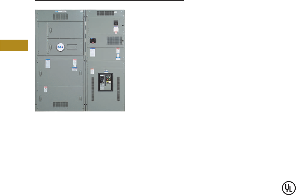
V2-T4-2 Volume 2—Commercial Distribution CA08100003E—June 2014 www.eaton.com
4
4
4
4
4
4
4
4
4
4
4
4
4
4
4
4
4
4
4
4
4
4
4
4
4
4
4
4
4
4
4.1
Switchboards
Group-Mounted Switchboards
Pow-R-Line Group-Mounted Distribution Switchboard
Contents
Description Page
Pow-R-Line Distribution Switchboards
Commercial Metering Switchboards. . . . . . . . . . . V2-T4-3
Pow-R-Line Distribution Switchboards
Product Description
Eaton’s Pow-R-Line
distribution switchboards
combine a space-saving
design with modular
construction and increased
system ratings to provide
economical and dependable
electrical system distribution
and protection.
Application Description
Refer to Eaton’s Consulting
Application Guide.
Features, Benefits
and Functions
●6000A maximum main
bus rating
●600 Vac and below
●600 Vdc and below
●Front or rear accessible
●Type 1 or Type 3R
enclosures
●ANSI-61 gray powder
coat paint finish
●Microprocessor-based
metering and monitoring
devices
●Utility metering provisions
●Surge protective devices
(SPD)
●Ground fault protection
on mains and distribution
devices
●Busway and transformer
connections
●Complete protective device
accessory capability
●65 kAIC bus bracing
standard; optional 100
or 200 kAIC
●Standard tin-plated
aluminum bus; optional
copper- or silver-plated
copper bus
●Standard bus ampacities
based on UL® heat test
ratings. Optional density
rated bus systems are
also available
Main and Individually
Mounted Devices
●Magnum™ SB insulated
case circuit breakers, 800–
5000A, fixed or drawout
●Magnum DS power circuit
breakers, 800–5000A,
fixed or drawout
●Molded case circuit
breakers, 400–2500A,
fixed mounted
●Bolted pressure switches,
800–5000A
●FDPW fusible switches,
400–1200A
Group-Mounted
Distribution Devices
●Molded case circuit
breakers, 15–1200A
●FDPW fusible switches,
30–1200A
Standards and Certifications
●Meets NEMA® Standard
PB-2 and UL 891
●Seismically qualified
Product Selection
For complete application and
pricing information, contact
your local Eaton sales office.
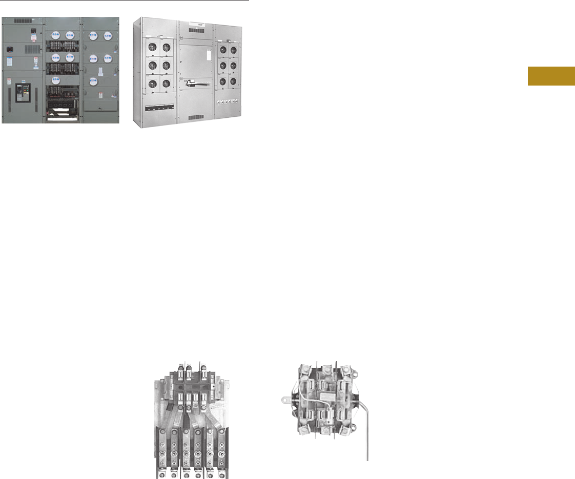
Volume 2—Commercial Distribution CA08100003E—June 2014 www.eaton.com V2-T4-3
4
4
4
4
4
4
4
4
4
4
4
4
4
4
4
4
4
4
4
4
4
4
4
4
4
4
4
4
4
4
4.1
Switchboards
Group-Mounted Switchboards
WWCMS WCMS
Commercial Metering Switchboards
Contents
Description Page
Pow-R-Line Distribution Switchboards . . . . . . . . . V2-T4-2
Commercial Metering Switchboards
Features, Benefits and Functions . . . . . . . . . . . V2-T4-4
Standards and Certifications . . . . . . . . . . . . . . V2-T4-5
Product Selection . . . . . . . . . . . . . . . . . . . . . . . V2-T4-5
Technical Data and Specifications . . . . . . . . . . V2-T4-5
Commercial Metering Switchboards
Product Description
Eaton’s commercial metering
switchboards provide
electrical system distribution
and metering for shopping
centers, office buildings
and other commercial
multimetering applications.
Using standard Pow-R-Line
construction and features,
these switchboards
incorporate metering sections
with tenant feeder circuits
using meter sockets to meet
local utility or customer
requirements.
All meter sockets and
associated feeder devices are
completely factory prewired
and shipped ready for the
installation of the meters.
Application Description
Type WWCMS
For EUSERC serviced areas.
The self-contained meter
sockets include a test
bypass/disconnect block per
EUSERC requirements, and
are arranged, typically, for hot
sequence metering.
Socket and Test Block Assembly
Type WCMS
For other than EUSERC
serviced areas. Self-contained
meter sockets
are provided with manual
lever bypass and can be
arranged for either hot or
cold sequence metering.
Socket with Manual Lever Bypass
Refer to Eaton’s Consulting
Application Guide.

V2-T4-4 Volume 2—Commercial Distribution CA08100003E—June 2014 www.eaton.com
4
4
4
4
4
4
4
4
4
4
4
4
4
4
4
4
4
4
4
4
4
4
4
4
4
4
4
4
4
4
4.1
Switchboards
Group-Mounted Switchboards
Features, Benefits and Functions
Pow-R-Line designates
a family of distribution
switchboards, incorporating
design concepts that fit
the ever-increasing need
for applications on high
short-circuit systems,
while retaining maximum
safety and convenience
throughout the line.
Front Accessible
Front-accessible switchboards
align at the rear, enabling
them to be placed against
a wall (Pow-R-Line front
accessible). If the main
section is deeper than others,
due to physical size of the
main device, the necessary
off-set in line-up will occur in
front, and the main section
will be accessible from the
side as well as from the front.
Standard front accessible
switchboards will align at
the front and rear.
Rear Accessible
Rear-accessible switchboards
align at the front and the rear.
Bus maintenance and cable
entry and exit require rear
access. There are two
types of rear accessible
switchboards. Both types
use the same incoming utility
and/or main structures.
The first type uses group-
mounted feeder devices
with panel construction
(Pow-R-Line rear accessible).
The second type uses
individually compartmentalized
feeder devices with load side
insulated bus bar extensions
(Pow-R-Line i).
Standard Switchboard Height
Standard Pow-R-Line
switchboard height is
90 inches (2286.0 mm).
Group Mounting
Group-mounted circuit
protective devices are an
assembly of units mounted
on a panelboard type base
(panelboard construction).
Units may be molded case
breakers, or FDPW fusible
switches. Circuit protective
devices are accessible from
the front.
A main molded case breaker
or main FDPW fusible switch,
within the sizes listed for
panelboard design, can
be included in the panel-
mounted assembly in lieu
of a separate, individually
mounted unit.
Space Only for Future Devices
Group-Mounted Construction
Where space only for future
circuit protective devices is
required, the proper space
and a blank filler plate will
be supplied. Connections
and mounting hardware are
not included.
Provision for Future Devices
Where provisions for future
circuit protective devices
are required, space for the
device, corresponding vertical
bus, device connectors and
the necessary mounting
hardware will be supplied.
Bus Bar System
Standard bus in the
switchboards is tin-plated
aluminum. Copper and
silver-plated copper are
also available.
Main bus and sub-main
buses meet UL and NEMA
standards for temperature
rise on all Pow-R-Line
switchboards. Special bus
densities are available.
Overcurrent Devices
To properly select and size
overcurrent devices for use in
a switchboard, the allowable
temperature rise must be
taken into account as to its
effect on the tripping
characteristics of the
devices in question.
Accordingly, Article 220
of the NEC® requires
overcurrent devices to be
rated not less than 125% of
the continuous load they are
protecting. To comply with
this, an 80% derating factor
must be used with all
overcurrent devices such
as molded case breakers
and FDPW fusible switches
unless they are tested
and marked as 100%
rated devices.
Short-Circuit Rating
Standard bus and connectors
on all switchboards are rated
for use on systems capable
of producing up to 65,000A
rms symmetrical short-circuit
current at the incoming
terminals.
Increased bus short-circuit
ratings equal to that of
connected switchboard
devices, up to 200,000A rms
symmetrical, are available
in most Pow-R-Line
switchboards when approved
main devices are installed.
Contact Eaton for more
information. UL labeled
switchboard sections are
marked with their applicable
short-circuit rating.
Provision for Busway
Entrance and Exit
Busway connections to
switchboard sections include
cutout and drilling in the
top of the switchboard with
riser connections from the
switchboard device or bus, up
to the point where the bus
duct enters the switchboard.
No connections are furnished
external to the switchboard.
Note: In all transactions
involving busway attached to
switchboards, it is essential that
information regarding orientation
of the busway with respect to the
front of the switchboard be
supplied to the coordinating
assembly plant.
On Pow-R-Line switchboards,
solid bus bar is used to
connect the bus duct to the
individually mounted main
device, main or sub-main
switchboard bus, or vertical
main bus of panel mounted
circuit protective device
panels. Busway fed by group-
mounted branch devices are
cable connected.
Aluminum riser connections
are standard. Copper- or
silver-plated copper is
available as a modification.
Transitions
Transition structures are
required for connecting
switchboards to the
secondary of power center
transformer (dry or fluid
filled), motor control centers,
and for other special
switchboard configurations
such as “L” or “U” shaped
lineups. In some application,
an extra structure complete
with connections is required;
in others, where switchboard
depth and space permit, only
the connection conductors
are required. Refer to factory
for these applications.

Volume 2—Commercial Distribution CA08100003E—June 2014 www.eaton.com V2-T4-5
4
4
4
4
4
4
4
4
4
4
4
4
4
4
4
4
4
4
4
4
4
4
4
4
4
4
4
4
4
4
4.1
Switchboards
Group-Mounted Switchboards
Standards and Certifications
●UL 891
●NEMA PB-2
●Seismically qualified
Product Selection
For complete application and
pricing information, contact
your local Eaton sales office.
Technical Data and Specifications
Service
●120/240V, single-phase,
three-wire
●240/120V, 208Y/120V,
415Y/240V, 480Y/277V or
600Y/347V three-phase,
four-wire
●600 Vdc
Main Bus Rating
●400–4000A
Service Section
●Main circuit breaker,
400–4000A
●Main fusible switch,
400–4000A
●Main lugs only,
400–6000A
Metering Sections
●Tenant main disconnects
and meter sockets (200A
maximum self-contained
metered circuits)
●Hot sequence
metering circuits
●Cold sequence metering
circuits (WCMS only)
●Optional rear barriered
wireways or load side
pull sections for cable
exit requirements
●Sections for metered
circuits larger than 200A
available with 400A
continuous rated self-
contained sockets or
with CT compartment
and transformer rated
socket in combination
with disconnect

V2-T4-6 Volume 2—Commercial Distribution CA08100003E—June 2014 www.eaton.com
4
4
4
4
4
4
4
4
4
4
4
4
4
4
4
4
4
4
4
4
4
4
4
4
4
4
4
4
4
4
4.2
Switchboards
Integrated Facility Switchboards
Integrated Facility Switchboard
Contents
Description Page
Integrated Facility Switchboards
Features, Benefits and Functions . . . . . . . . . . V2-T4-7
Standards and Certifications . . . . . . . . . . . . . . V2-T4-7
Product Selection. . . . . . . . . . . . . . . . . . . . . . . V2-T4-7
An Eaton
Green Solution
Product Description
Eaton’s Integrated Facility
Switchboards use the
modular Pow-R-Line group-
mounted switchboard design
to integrate traditionally
separate electrical distribution
and control equipment into a
single space-saving factory
assembled and connected
package.
The service entrance
equipment can be integrated
with multiple lighting
and appliance branch
panelboards into a compact
front-accessible group-
mounted switchboard. Where
multiple panelboards are
used in the same electrical
room as a conventional
distribution switchboard or
power panelboards, the
integrated design will
significantly reduce
equipment space
requirements, as well as
reduce installation time
and costs.
Other associated equipment
can also be integrated into
the assembly, including
dry-type distribution
transformers, time clock
space, lighting control,
electronic controls, surge
protective devices, metering
and energy monitoring
devices. Depending upon
the application, other user-
defined equipment such as a
subsystem control package
may also be incorporated.
Application Description
Eaton’s Integrated Facility
Switchboards are designed
to meet specific needs for:
●Retail chain stores
●Commercial offices
●High rise buildings
●Correctional facilities
●Agricultural facilities
●Industrial facilities
●Hospitals/health
care facilities
●Educational facilities
Whether the application is a
multi-site prototype or single
application, integrated
switchboards offer time and
space-saving features.
For complete application
description, refer to Eaton’s
Consulting Application Guide.
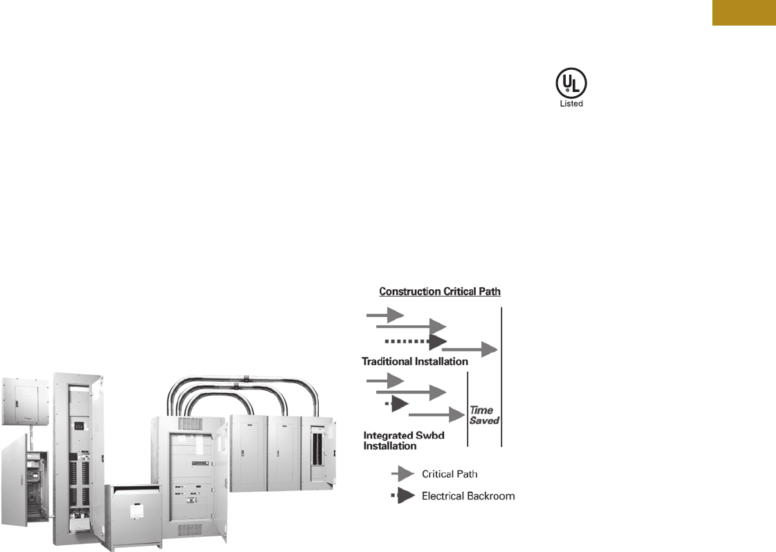
Volume 2—Commercial Distribution CA08100003E—June 2014 www.eaton.com V2-T4-7
4
4
4
4
4
4
4
4
4
4
4
4
4
4
4
4
4
4
4
4
4
4
4
4
4
4
4
4
4
4
4.2
Switchboards
Integrated Facility Switchboards
Features, Benefits and Functions
Front Accessible
Integrated Facility
Switchboards are front
accessible and align at the
rear, enabling them to be
placed against a wall. Most
switchboards align at the
front and the rear. If the main
section is deeper than others,
due to physical size of the
main device, the necessary
off-set in line-up will occur in
front, and the main section
will be accessible from the
side as well as from the front.
Standard Switchboard Height
Switchboard height is
90 inches (2286.0 mm).
A limited offering of
78-inch (1981.2 mm) high
equipment is available.
Consult the factory for
specific applications.
Switchboard Shipping Splits
The sections can be shipped
as specified by the customer
to meet specific requirements.
For retrofit applications,
single-piece switchboard
structures can be shipped to
facilitate movement through
limited access doorways, etc.
Factory Interconnections
Most sub-panels are fed from
the main distribution panel
feeder circuit breakers using
copper cable sized per the
NEC and UL.
Space Savings
The space-saving
switchboard installation
provides additional usable
floor space. For example:
●Retail stores—floor space
for sales
●Offices—additional
storage, cubicle
●Health care—additional
work area
●Retrofits—ability to fit
existing rooms
Traditionally Mounted Equipment
Site Construction Savings
Timely installation of the
electrical system typically is
a key element on the critical
path for any project.
Along with the time to
install the equipment, other
expenses include the time to
handle all of the loose pieces
of equipment arriving on a job
site and ensuring it reaches
the proper trades person.
With Eaton’s Integrated
Facility Switchboards,
one piece of equipment is
typically shipped to a job
site virtually eliminating
these issues.
The equipment may also be
used for temporary power
on job sites, further reducing
construction expenses
and times.
Construction Savings
Standards and
Certifications
●Meets NEMA Standard
PB-2 and UL 891
●Panelboards mounted
inside the sections meet
NEMA PB-1 and UL 67
●Other equipment is
UL listed as applicable
and appropriate
Product Selection
For complete application and
pricing information, contact
your local Eaton sales office.
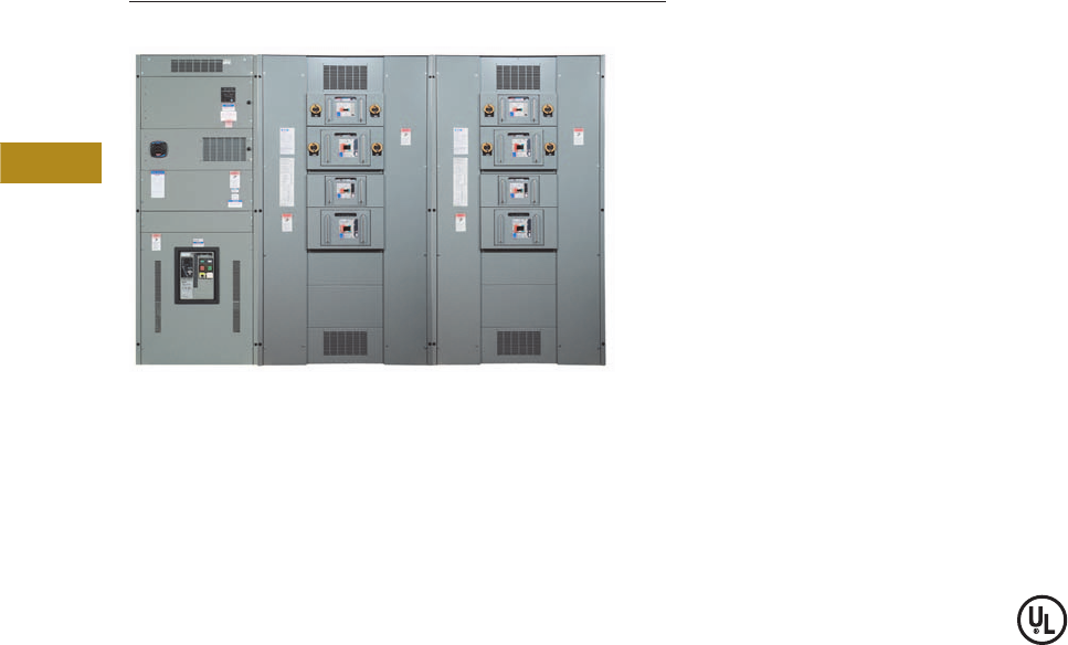
V2-T4-8 Volume 2—Commercial Distribution CA08100003E—June 2014 www.eaton.com
4
4
4
4
4
4
4
4
4
4
4
4
4
4
4
4
4
4
4
4
4
4
4
4
4
4
4
4
4
4
4.3
Switchboards
Pow-R-Line Drawout Molded Case Circuit Breaker Switchboards
Pow-R-Line Drawout Molded Case Circuit Breaker Switchboards
Contents
Description Page
Pow-R-Line Drawout Molded Case Circuit Breaker
Switchboards
Product Selection . . . . . . . . . . . . . . . . . . . . . . . V2-T4-9
Dimensions . . . . . . . . . . . . . . . . . . . . . . . . . . . . V2-T4-10
Options, Accessories and Modifications. . . . . . V2-T4-12
Product Description
●Drawout molded case
circuit breaker switchboard
●Front accessible
●Front connected
●Through-the-door design
drawout mechanism
through 600A
●Insulated case UL 489
breakers up to 1200A
●Visual indication of breaker
status and position
●Large grab handles for
easy removal
●600 Vac maximum
●600A maximum, group-
mounted, drawout molded
case feeder breakers
●Individually mounted
insulated UL 489 breakers
through 1200A
Application Description
●Drawout feeders in UL 891
distribution switchboards
●Rated as Service Entrance
Equipment when
appropriately equipped
●Ideal for:
●Data centers
●Industrial facilities
●Process equipment
manufacturing
●Anywhere that requires
quick change of feeder
devices is needed
Features, Benefits and
Functions
Eaton’s Pow-R-Line Drawout
switchboard design is listed
and labeled to the UL 891
standard. Switchboards may
be rated up to 4000A. Main
breakers are available up to
4000A in both fixed-mounted
and drawout configurations.
Main breakers may be
Magnum DS® power circuit
breakers or Magnum SB
insulated case circuit
breakers in either drawout or
fixed-mounted configurations.
Both are front-accessible
configurations. Fixed-
mounted molded case circuit
breaker mains are available
up through 2500A.
Utility and customer-owned
metering is available.
Customer metering includes
Web-enabled communicating
systems.
Aluminum bus is standard
with copper and silver-plated
copper optional. Other
common options include
surge protective devices
(SPDs), seismically qualified
designs, density rated bus
and many more.
Drawout feeder MCCBs are
available in two-pole and
three-pole offerings from 20A
to 600A in the high-density,
group-mounted design.
Drawout feeders above 600A
through 1200A integrate the
molded case NX drawout
breaker. Drawout breakers
above 1200A through 2000A
use the Magnum SB
insulated case circuit breaker.
All are front accessible and
front connected.
Standards and
Certifications
●UL 891 listed
Instructions
On an interim basis until Bid
Manager™ is updated, please
use the Pow-R-Line C®
switchboard Bid Manager
take-off as the basis for the
following:
●Utility compartments
●Service entrance or non-
service entrance
information
●Volt age
●Bus rating
●Bus material
●Nameplate
●Ground bus material
●Short-circuit current rating
●Top or bottom entrance
●Incoming cable location
●Customer metering
●Surge protective device
●Bus bracing
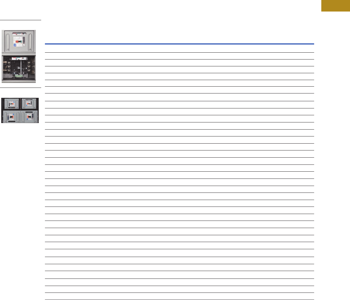
Volume 2—Commercial Distribution CA08100003E—June 2014 www.eaton.com V2-T4-9
4
4
4
4
4
4
4
4
4
4
4
4
4
4
4
4
4
4
4
4
4
4
4
4
4
4
4
4
4
4
4.3
Switchboards
Pow-R-Line Drawout Molded Case Circuit Breaker Switchboards
Product Selection
Select drawout molded case
circuit breaker and UL 489
listed insulated case circuit
breakers from the following
pages.
●Always select front access/
rear aligned
●IFS sections are
permissible but will be
bolt-on devices only
●Use the existing Pow-R-
Line C switchboard take-off
to select main devices
Drawout Branch/Feeder Breakers
Single-Mount Two-Pole and Three-Pole
Interrupting Rating (kA Symmetrical)
Ampere Rating 240 Vac 480 Vac 600 Vac Breaker Type “X” Space
Single-Mount Breakers with Thermal-Magnetic Trip Units
70–250 85 35 18 JGS 7X
70–250 100 65 25 JGH 7X
70–250 200 100 35 JGC 7X
250–600 85 35 18 LGS 9X
250–600 100 65 35 LGH 9X
250–600 200 100 50 LGC 9X
Single-Mount Breakers with Electronic 310+ Trip Units (Three-Pole Only)
20–50853518JGS7X
20–50 100 65 25 JGH 7X
20–50 200 100 35 JGC 7X
40–100 85 35 18 JGS 7X
40–100 100 65 25 JGH 7X
40–100 200 100 35 JGC 7X
80–150 85 35 18 JGS 7X
80–150 100 65 25 JGH 7X
80–150 200 100 35 JGC 7X
100–250 85 35 18 JGS 7X
100–250 100 65 25 JGH 7X
100–250 200 100 35 JGC 7X
100–250 85 35 18 LGS 9X
100–250 100 65 35 LGH 9X
100–250 200 100 50 LGC 9X
200–400 85 35 18 LGS 9X
200–400 100 65 35 LGH 9X
200–400 200 100 50 LGC 9X
250–600 85 35 18 LGS 9X
250–600 100 65 35 LGH 9X
250–600 200 100 50 LGC 9X
Provision for Future (Includes Factory-Installed Base Cassette)
20–250 Any JG family branch/feeder breaker 7X
100–600 Any LG family branch/feeder breaker 9X
Individually Mounted NX Breakers
800856542NX½ Structure
1000 85 65 42 NX ½ Structure
1200 85 65 42 NX ½ Structure
Single Branch/Feeder
Dual Branch/Feeder
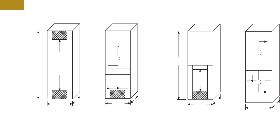
V2-T4-10 Volume 2—Commercial Distribution CA08100003E—June 2014 www.eaton.com
4
4
4
4
4
4
4
4
4
4
4
4
4
4
4
4
4
4
4
4
4
4
4
4
4
4
4
4
4
4
4.3
Switchboards
Pow-R-Line Drawout Molded Case Circuit Breaker Switchboards
Dimensions
Approximate Dimensions in Inches (mm)
Select the appropriate
distribution section(s) for
drawout MCCB feeder
devices from the sections
shown below.
All breakers are front
accessible and front
connected.
Drawout Molded Case Circuit Breaker Feeder Devices
Notes
All four sections widths 36-inch minimum.
See distribution layout Guides Page V2-T4-11 for actual minimum structure width and for feeder device “X” requirements.
1Drawout NX Insulated Case UL 489 breaker. 1200A maximum. Select breaker from Page V2-T4-9.
90.00
(2286.0)
24.00 (609.6)
36, 45
(914.4, 1143.0)
22X
Device
Space
Optional
Customer
Metering
or
Blank
50X
Vertical
Panel
Space
for
Devices
18.00 (457.2)
90.00
(2286.0)
36, 45
(914.4, 1143.0) D
W
Optional GFP
1
1
Optional GFP
1200A
Max.
22X
Dist.
Classis
Feeder
24.00 (609.6)
Min.
36.00
(914.4)
Min.
1
Maximum 2000A
CT Compartment
Combination Section
Top-Mounted Feeder with
Distribution Chassis
Full Distribution Section
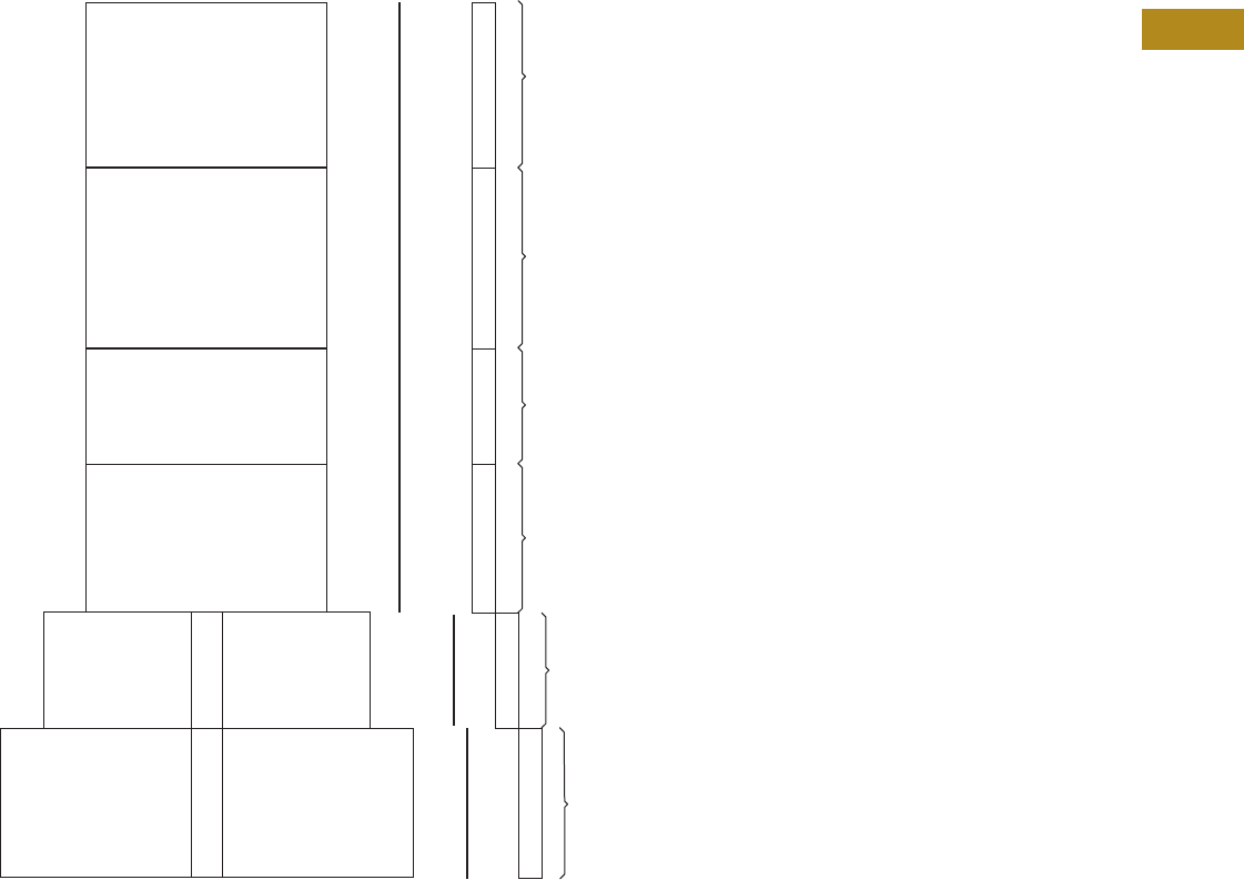
Volume 2—Commercial Distribution CA08100003E—June 2014 www.eaton.com V2-T4-11
4
4
4
4
4
4
4
4
4
4
4
4
4
4
4
4
4
4
4
4
4
4
4
4
4
4
4
4
4
4
4.3
Switchboards
Pow-R-Line Drawout Molded Case Circuit Breaker Switchboards
Layout for Group-Mounted Drawout Molded Case Circuit Breaker Feeder Devices
Instructions
Determine the structure width by the group-mounted drawout MCCB feeder devices below.
The width of the structure is determined by the maximum structure size shown for each device.
Note
1Preferred location of SPD is mounted at the top of the first distribution section.
7X
or
10X
7X
9X
7X
9X
2 or 3P
Single Drawout
Feeder
2 or 3P
Single Drawout
Feeder
2 or 3P
Dual Drawout
Feeder
2 or 3P
Dual Drawout
Feeder
3P
Dual Drawout
Feeder
3P
Dual Drawout
Feeder
JGS, JGH, JGC
250A
Max.
600A
Max.
Surge Protective Device
(includes behind the
deadfront disconnect)
7X through 200 kA
10X 250 kA through 400 kA
JGS, JGH, JGC
LGS, LGH, LGC
250A
Max.
45-Inch (1143.0 mm)
Wide Structure
51-Inch (1295.4 mm)
Wide Structure
36-Inch (914.4 mm) Wide Minimum Structure
600A
Max.
11 X
Customer
Metering Customer Metering
Surge Protective
Device (SPD) 1
LGS, LGH, LGC

V2-T4-12 Volume 2—Commercial Distribution CA08100003E—June 2014 www.eaton.com
4
4
4
4
4
4
4
4
4
4
4
4
4
4
4
4
4
4
4
4
4
4
4
4
4
4
4
4
4
4
4.3
Switchboards
Pow-R-Line Drawout Molded Case Circuit Breaker Switchboards
Options, Accessories and Modifications
1. Ambient Compensating
Breakers
For ambient compensating
breakers (where available) in
lieu of standard breakers, add
10% to panelboard branch
breaker and to main breaker
list prices, when required.
Panels with this option can
not be UL listed.
2. JG and LG Breaker Accessories—Internal (Only One Accessory
Per Position)
Accessories
Notes
1Accessories wired to a pull-apart terminal block. Right position only.
2Accessories wired to a pull-apart terminal block. Left position only.
3Not available when breaker is equipped with ARMS trip unit.
3. Drawout NX Internal
Modification 3
4. Compression Main Lugs
Al/Cu Burndy Range Taking
Type.
Modification 4
5. Copper Lugs/Terminals
Optional copper mechanical
main lugs only and includes
main incoming neutral lug.
Modification 5
Breaker
Type
Device
Mounting Internal Breaker Accessory
JG family Drawout 1Auxiliary switch 1A-1B
JG family Drawout 1Auxiliary switch 2A-2B
JG family Drawout 1Bell alarm
JG family Drawout 1High load alarm w/trip
JG family Drawout 1Ground fault alarm w/trip
JG family Drawout 2Undervoltage release
JG family Drawout 2Zone selective interlock
LG family Drawout 1Auxiliary switch 1A-1B
LG family Drawout 1Auxiliary switch 2A-2B
LG family Drawout 1Bell alarm
LG family Drawout 1High load alarm w/trip
LG family Drawout 1Ground fault alarm w/trip
LG family Drawout 2Undervoltage release 3
LG family Drawout 2Zone selective interlock
Internal NX Breaker Accessories
Shunt trip (specify voltage)
Undervoltage release
Auxiliary switch
Motor operator
Trip indicator
Bell alarm
Shutters
Main Lug
Amperes
PRL4D Lug
Wire Range
800 (3) 500–750 kcmil
1200 (4) #2–600 kcmil
(4) 500–750 kcmil
Main Lug
Amperes
PRL4D Lug
Wire Range
600 (2) 1/0–600 kcmil
800 (2) 1/0–600 kcmil
1200 (3) 1/0–600 kcmil
6. Copper Main Busbars
Optional copper busbars are
available in all ampere ratings.
Modification 6
7. Density Rated Bus
Standard main bus ampere
rating is determined by UL
listed temperature rise
testing. Density rated bus is
defined at 750A per square
inch for aluminum bus and
1000A per square inch for
copper bus. Adder for
aluminum density rated bus is
in addition to the base price.
Adder for copper density
rated bus is in addition to
the base price plus the
appropriate adder for copper
bus. See Modification 7.
Modification 7
8. Electronic Trip Units
Thermal-magnetic trip units
are standard. For electronic
trip units, select appropriate
breaker from the electronic
trip section of Pages
V2-T4-9 and V2-T4-11. See
selection below for electronic
trip units.
Modification 8
Notes
L = Adjustable long time pickup
S = Adjustable short time pickup w/
fixed short time delay
I = Adjustable instantaneous pickup
G = Adjustable ground fault pickup
A = Adjustable ground fault alarm only
(no trip)
ARMS = Arcflash Reduction Maintenance
System
ZSI = Zone selective interlocking
Ampere
Range
Bare Copper
Chassis Bus
Silver-Plated
Copper Bus
800
1200
1600
2000
2500
3000
4000
Ampere Rating
Aluminum—750A per Square Inch
800
1200
1600
2000
2500
3000
4000
Copper—1000A per Square Inch
800
1200
1600
2000
2500
3000
4000
Breaker Frame
Family Trip Unit Type
Drawout Feeder
JGS, JGH, JGC
Digitrip 310+ LS
Digitrip 310+ LSI
Digitrip 310+ LSG
Digitrip 310+ LSIG
LGS, LGH, LGC Digitrip 310+ LS
Digitrip 310+ LSI
Digitrip 310+ LSG
Digitrip 310+ LSIG
Digitrip 310+ LS
with ARMS
Digitrip 310+ LSI
with ARMS
Digitrip 310+ LSG
with ARMS
Digitrip 310+ LSIG
with ARMS
Drawout NX 520 LI
520 LSI
520 LSI with ZSI
520 LSIG
520 LSIG with ZSI
520M LSI
520M LSI with ZSI
520M LSIA
520M LSIA with ZSI
520M LSIG
520M LSIG with ZSI
520M LSI with ARMS
520M LSI with ZSI
and ARMS
520M LSIA with ARMS
520M LSIA with ZSI
and ARMS
520M LSIG with ARMS
520M LSIG with ZSI
and ARMS

Volume 2—Commercial Distribution CA08100003E—June 2014 www.eaton.com V2-T4-13
4
4
4
4
4
4
4
4
4
4
4
4
4
4
4
4
4
4
4
4
4
4
4
4
4
4
4
4
4
4
4.3
Switchboards
Pow-R-Line Drawout Molded Case Circuit Breaker Switchboards
9. Ground Bus
Copper or silver-plated
copper ground bus in lieu of
standard aluminum.
Modification 9
10. Ground Fault Protection
Refer to Modification 8 for
ground fault trip units.
11. Infrared (IR) Viewing
Windows
Infrared viewing windows for
main devices and drawout
single-mounted feeder
devices.
Modification 11
12. Nameplates, Engraved
Field-attached nameplates.
Modification 12
13. Seismically Qualified
For seismically qualified
PRL drawout switchboard,
request seismic labeling on
order.
14. Service Entrance Equipment
Service Entrance labeling as
detailed under the “Service
Entrance Equipment” per UL
and NEC. Only switchboards
meeting these requirements
may be labeled as such. The
requirement or service
entrance labeling must be
noted on the order. Includes
neutral disconnect link and
labeling “Suitable Only For
Use as Service Equipment”
(SUSE).
Bus Material
Size in
Inches (mm)
Copper 0.25 (6.4) x 1.50 (38.1)
0.25 (6.4) x 2.00 (50.8)
Silver-plated
copper
0.25 (6.4) x 1.50 (38.1)
0.25 (6.4) x 2.00 (50.8)
Overcurrent
Device
IR Window
Manufacturer
All fixed mount
mains
Iriss
Hawk (Fluke)
Single drawout
feeder breakers 1
Iriss
Hawk (Fluke)
Description
Mastic back, engraved, black with
white lettering
Mastic back, engraved, colors other
than black
Nameplates, screw attached
15. Surge Protective Devices
(SPD)
Package includes SPD unit
and integral circuit breaker
disconnect (30A) connected
to the chassis bus.
Modification 15
16. Touchup Paint
Modification 16
Note
1Available on only single-mounted
drawout. Not available on dual-mounted
feeder devices.
Surge Current Rating 50 80 100 120 160 200 250 300 400
SPD Package Options—Basic Package
LED monitor, L-N, L-G, L-L
and N-G
■■■■■■■■■
Standard Package
LED monitor, L-N, L-G, L-L and
N-G. EMI/RFI filtering. Audible
alarm with disable switch.
Form C relay contact.
■■■■■■■■■
Premium Package
LED monitor, L-N, L-G, L-L and
N-G. EMI/RFI filtering. Audible
alarm with disable switch.
Form C relay contact. Six-digit
LCD display. Counts surges in
all modes. Nonvolatile memory
(no battery backup). Reset
button designed to prevent
accidental resets.
■■■■■■■■■
Description
12 oz spray can. ANSI-61 light gray indoor
Case lot of 12—12 oz spray can. ANSI-61
light gray indoor
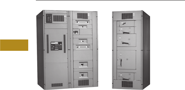
V2-T4-14 Volume 2—Commercial Distribution CA08100003E—June 2014 www.eaton.com
4
4
4
4
4
4
4
4
4
4
4
4
4
4
4
4
4
4
4
4
4
4
4
4
4
4
4
4
4
4
4.4
Switchboards
Compartmentalized Switchboards
Front View—Circuit Breakers Front View—Fusible Units
Compartmentalized Feeder Sections
Contents
Description Page
Compartmentalized Switchboards
Standards and Certifications . . . . . . . . . . . . . . . V2-T4-15
Product Description
Eaton’s Pow-R-Line i
switchboards are engineered
in a new compartmentalized
design for applications where
a greater degree of safety is
required. A wide variety of
configurations is possible,
including utility metering,
customer metering, main
devices, branch devices,
accessories and enclosures.
Application Description
Refer to Eaton’s Consulting
Application Guide.
Features, Benefits and Functions
Significant safety features
include:
●Individual compartments
for branch devices—
glass polyester for circuit
breakers and steel for
fusible switches. These
compartments help
eliminate possible contact
with the main bus and
reduce fault propagation
●Three-section construction
with each section barriered
from the other
●Device section—each
device is mounted in its
own compartment
●Bus bar section—
contains both horizontal
and vertical buses
●Rear cable
compartment—
completely isolated
from the bus bars
●Insulated copper runback.
Power is taken from the
protective device by the
insulated copper runback
through a standard full
height glass polyester
barrier to the rear cable
compartment. This design
virtually eliminates the
possibility of accidental
contact with the main
buses during installation
or maintenance
Main devices are available
from 400–4000A and can
include molded case circuit
breakers, Magnum SB,
Magnum DS circuit breakers,
FDPW fusible switches or
bolted pressure switches.
Main buses are rated up
to 6000A.
Branch circuit breakers range
from 15–1200A frames.
When circuit breakers are
used, higher ratings and
increased series ratings will
be achieved. Branch fusible
switches are available from
100–1200A.
Interrupting ratings up to
200,000A are UL listed and
the bus bar system may be
braced from a standard
65,000A up to a maximum
200,000A.
Integrated Monitoring
Protection and Control
Communications Systems
The capabilities of distribution
and control assemblies
can be expanded by tying
together multiple devices
in electrical distribution
systems. From a central
location (on-site or off-site),
an operator uses a personal
computer (master control
unit) to monitor, control
and communicate with
compatible devices on a
distribution system. These
microprocessor-based
devices, designed and
built by Eaton, perform
monitoring, protection
and control functions.

Volume 2—Commercial Distribution CA08100003E—June 2014 www.eaton.com V2-T4-15
4
4
4
4
4
4
4
4
4
4
4
4
4
4
4
4
4
4
4
4
4
4
4
4
4
4
4
4
4
4
4.4
Switchboards
Compartmentalized Switchboards
Ground Fault Test Panels
Pow-R-Line i switchboards
can accommodate either
integral or zero sequence
types of ground fault
protection. Depending on
the specific application, a
test panel can be mounted
in the circuit breaker
compartment, which may
eliminate the need for an
auxiliary structure.
Fusible Switches
Pow-R-Line i switchboards
have been designed to
accommodate fusible
switches. Safety is provided
by steel compartments that
insulate each horizontally
mounted switch from the
vertical and main buses. As
with switchboards using
circuit breakers, insulated
copper runbacks carry power
into the spacious, glass
polyester barriered rear
cable compartment.
UL Listed Shunt Trip
and Fusible Switches
Shunt trip attachments
for use with ground fault
protection devices can be
installed on 400–1200A Type
FDPW fusible switches. Both
are UL listed when the shunt
trip is factory installed.
High Durability Finish
A baked-on polyester powder
coating system protects
all structural steel parts. It
provides excellent mechanical
strength and resistance to
chalking normally caused
by the sun’s ultraviolet
rays and meets the salt
spray requirements of
ASTM B-117.
Pow-R-Line i
Quality Assurance
Final testing helps ensure
that each Pow-R-Line i
switchboard performs in
accordance with UL standards
and customer specifications.
Each assembly is shipped with
a “Switchboard Verification
Report” that documents
completion of every inspection
and test.
Provisions for the Future
Future expansion provisions
include line side connectors,
load side runbacks, terminals,
and glass polyester
compartments and covers
(for circuit breakers). Space
only for “both circuit breakers
and fusible switches is also
available.
Standards and
Certifications
Pow-R-Line i switchboards
are UL 891 listed and meet all
applicable requirements of
NEMA and NEC. They are
rear accessible and front and
rear aligned. Both indoor
and outdoor enclosures
are available.
●Meets NEMA Standard
PB-2 and UL 891
●Seismically qualified
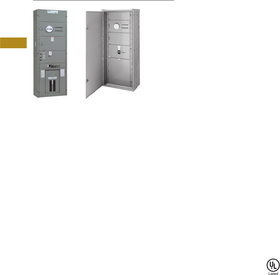
V2-T4-16 Volume 2—Commercial Distribution CA08100003E—June 2014 www.eaton.com
4
4
4
4
4
4
4
4
4
4
4
4
4
4
4
4
4
4
4
4
4
4
4
4
4
4
4
4
4
4
4.5
Switchboards
Instant Service Switchboards
Type 1 Indoor Type 3R Outdoor
Instant Service Switchboards
Contents
Description Page
Instant Service Switchboards
Product Selection. . . . . . . . . . . . . . . . . . . . . . . V2-T4-17
Accessories . . . . . . . . . . . . . . . . . . . . . . . . . . . V2-T4-19
Technical Data and Specifications . . . . . . . . . . V2-T4-20
Dimensions . . . . . . . . . . . . . . . . . . . . . . . . . . . V2-T4-20
Product Description
Eaton’s Instant® Service
Switchboards are designed
as stocked units to provide
fast delivery to match the
needs of the construction
market.
Suitable for use as service
entrance equipment, they
combine utility metering
provisions with a fused main
switch in a single compact
section that can also include a
distribution panel for feeder
and branch circuit breakers.
Application Description
Typical applications for
these versatile switchboards
include small office buildings
and factories, stores,
supermarkets and
shopping centers.
Features, Benefits
and Functions
These switchboards are
available in either indoor
or outdoor enclosures
manufactured of code-gauge
steel with a durable light
gray finish. All units are
completely enclosed with
front, rear and side covers.
Outdoor units include a front
hinged door.
The service section includes:
●Main lugs mounted at the
top (two #4–600 kcmil
per phase) for overhead
feed or for use with an
underground pull section
●A sealable metering and
CT compartment with
bussing for utility bar
type CTs and two 15-inch
(381.0 mm) high meter
compartment doors—one
with provisions for meter
socket and test block, one
blank (meter socket is
ordered separately)
●A 400 or 600A T-Type fused
main switch or 400, 600 or
800A main circuit breaker
with either load lugs (same
as main lugs)
or with connections
to a factory installed
distribution panel
Underground pull sections
are available with lug landing
kits providing studs for
incoming cables per
EUSERC standards and
two #4–600 kcmil lugs per
phase for cable connection
to the service section.
Distribution panels can
be included for 240 Vac
maximum (single-phase
three-wire or three-phase
four-wire), 480Y/277 Vac
(three-phase four-wire) or
480 Vac (three-phase three-
wire). The 240V panels have
provisions for four Type ED
225A frame circuit breakers
and 24 poles of Type BAB
100A frame circuit breakers.
The 480Y/277V panel has
provisions for four Type FD
225A frame circuit breakers
and 24 poles of Type GHB
100A frame circuit breakers.
The bolt-on type circuit
breakers are ordered
separately.
For applications that require
the load circuit conductors to
exit at the top, a loadside
wireway compartment is
available that bolts to the
service section.
Standard switchboards
include two 15.00-inch
(381.0 mm) high meter
compartment doors, one
with meter socket provisions
and one blank. For other
arrangements, accessory
units are available. Check
utility requirements.
Standards and
Certifications
Eaton’s Instant Service
Switchboards are listed by
Underwriters Laboratories
and comply with all applicable
industry standards.
These switchboards meet
EUSERC standards as well
as other local utility codes.
Seismic Qualified
Eaton’s Instant Service
Switchboards are seismically
tested, seismically qualified and
meet or exceed requirements
of the Uniform Building Code®
(UBC), the California Building
Code (CBC) and the
International Building Code
(IBC) for all seismic zones.

Volume 2—Commercial Distribution CA08100003E—June 2014 www.eaton.com V2-T4-17
4
4
4
4
4
4
4
4
4
4
4
4
4
4
4
4
4
4
4
4
4
4
4
4
4
4
4
4
4
4
4.5
Switchboards
Instant Service Switchboards
Product Selection
Main Fused Switch Only
Main Fused Switch with Distribution Panel
Main Breaker Switch Only
Notes
1240V distribution panels have double branch provisions for four Type ED 225A frame circuit breakers and 24 poles of Type BAB 100A frame
circuit breakers.
2480Y/277V distribution panels have double branch provisions for four Type FD 225A frame circuit breakers and 24 poles of Type GHB 100A frame
circuit breakers.
Circuit breakers for distribution panels are ordered separately.
Service
Main
Ampere Rating
Type 1—Indoor
Catalog Number
Type 3R—Outdoor
Catalog Number
240 Vac Maximum
Single-phase
three-wire
400 MSB423 RMSB423
600 MSB623 RMSB623
Three-phase
four-wire
400 MSB424 RMSB424
600 MSB624 RMSB624
480Y/277 Vac
Three-phase
four-wire
400 MSB444 RMSB444
600 MSB644 RMSB644
Service
Main
Ampere Rating
Type 1—Indoor
Catalog Number
Type 3R—Outdoor
Catalog Number
240 Vac Maximum 1
Single-phase
three-wire
400 MSBP423 RMSBP423
600 MSBP623 RMSBP623
Three-phase
four-wire
400 MSBP424 RMSBP424
600 MSBP624 RMSBP624
480Y/277 Vac 2
Three-phase
four-wire
400 MSBP444 RMSBP444
600 MSBP644 RMSBP644
Service
Main
Ampere Rating
Type 1—Indoor
Catalog Number
Type 3R—Outdoor
Catalog Number
240 Vac Maximum 1
Single-phase
three-wire
400 MBB423 RMBB423
600 MBB623 RMBB623
800 MBB823 RMBB823
Three-phase
four-wire
400 MBB424 RMBB424
600 MBB624 RMBB624
800 MBB824 RMBB824
480Y/277 Vac 2
Three-phase
four-wire
400 MBB444 RMBB444
600 MBB644 RMBB644
800 MBB844 RMBB844

V2-T4-18 Volume 2—Commercial Distribution CA08100003E—June 2014 www.eaton.com
4
4
4
4
4
4
4
4
4
4
4
4
4
4
4
4
4
4
4
4
4
4
4
4
4
4
4
4
4
4
4.5
Switchboards
Instant Service Switchboard
Main Breaker Only with Distribution Panel
Underground Pull Sections—Same Depth as Switchboard with Provisions for
Lug Landing Kit
Lug Landing Kits for Underground Pull Sections
Load Side Wireway—12 Inches (304.8 mm) Wide Same Depth as Switchboard
Notes
1240V distribution panels have double branch provisions for four Type ED 225A frame circuit breakers and 24 poles of Type BAB 100A frame
circuit breakers.
2800A distribution panels have double branch provision for six Type FD 225A frame circuit breakers only.
3Suffix-P: four Type FD 225A frame circuit breakers and 24 poles of Type GHB 100A frame circuit breakers.
4Suffix-K: one Type KD OR HKD 400A frame circuit breakers and four Type FD 225A frame circuit breakers.
5480Y/277V distribution panels have double branch provisions for four Type FD 225A frame circuit breakers and 24 poles of Type GHB 100A frame
circuit breakers.
6Check utility requirements—most EUSERC utilities require 30-inch (762.0 mm) width.
7Mounts in 30-inch (762.0 mm) wide section only.
Circuit breakers for distribution panels are ordered separately.
Service
Main
Ampere Rating
Type 1—Indoor
Catalog Number
Type 3R—Outdoor
Catalog Number
240 Vac Maximum
Single-phase
three-wire
400 MBBP423 1RMBBP4231
600 MBBP623 1RMBBP6231
800 MBBP823 2RMBBP823 2
800 MBBP823-P 3RMBBP823-P 3
800 MBBP823-K 4RMBBP823-K 4
Three-phase
four-wire
400 MBBP424 1RMBBP424 1
600 MBBP624 1RMBBP624 1
800 MBBP824 2RMBBP824 2
800 MBBP824-P 3RMBBP824-P 3
800 MBBP824-K 4RMBBP824-K 4
480Y/277 Vac
Three-phase
four-wire
400 MBBP444 5RMBBP444 5
600 MBBP644 5RMBBP644 5
800 MBBP844 2RMBBP844 2
800 MBBP844-K 4RMBBP844-K 4
Section Width
Inches (mm)
Type 1—Indoor
Catalog Number
Type 3R—Outdoor
Catalog Number
24.00 (609.6) 6UG24W RUG24W
30.00 (762.0) UG30W RUG30W
NEMA Type 1 pull section can be installed separate from service section. Add side closer plate, catalog number UGCP.
Maximum
Ampere Rating Service
Catalog
Number
400 Single-phase three-wire LL4003
Three-phase four-wire LL4004
800 Single-phase three-wire LL8003 7
Three-phase four-wire LL8004 7
Type Catalog Number
Type 1—Indoor LSS12W
Type 3R—Outdoor RLSS12W

Volume 2—Commercial Distribution CA08100003E—June 2014 www.eaton.com V2-T4-19
4
4
4
4
4
4
4
4
4
4
4
4
4
4
4
4
4
4
4
4
4
4
4
4
4
4
4
4
4
4
4.5
Switchboards
Instant Service Switchboards
Accessories
Meter Compartment Doors—(Meter Sockets Not Included)
Meter Sockets—For Field Installation
Circuit Breakers for Distribution Panels 240 Vac
Three-Phase Four-Wire Maximum
Circuit Breakers for Distribution Panels 480Y/277 Vac
(Three-Phase Four-Wire)
Special Utility Options—Select for the Following Utilities
Special Bus Options
Notes
1240V distribution panels have double branch provisions for four Type ED 225A frame circuit
breakers and 24 poles of Type BAB 100A frame circuit breakers.
2800A distribution panels have double branch provision for six Type FD 225A frame circuit
breakers only.
3Suffix-P: four Type FD 225A frame circuit breakers and 24 poles of Type GHB 100A frame
circuit breakers.
Height Width Drilling Catalog Number
15.00 (381.0) 32.00 (812.8) Blank MD150
One socket MD151
30.00 (762.0) 32.00 (812.8) Blank MD300
Two sockets MD302
Number of Jaws Catalog Number Number of Jaws Catalog Number
4M4 8M8
5 1M5 13 M13
6 2M6 15 3M15
Ampere
Rating
Single-Pole
120/240 Vac
Catalog
Number
Two-Pole
120/240 Vac
Catalog
Number
Two-Pole
240 Vac
Catalog
Number
Three-Pole
240 Vac
Catalog
Number
15 BAB1015I BAB2015I BAB2015HI BAB3015HI
20 BAB1020I BAB2020I BAB2020HI BAB3030HI
30 BAB1030I BAB2030I BAB2030HI BAB3030HI
40 BAB1040I BAB2040I BAB2040HI BAB3040HI
50 BAB1050I BAB2050I BAB2050HI BAB3050HI
60 BAB1060I BAB2060I BAB2060HI BAB3060HI
70 — BAB2070I BAB2070HI BAB3070HI
90 — BAB2090I BAB2090HI BAB3090HI
100 — BAB2100I BAB2100HI BAB3100HI
100 — — ED2100I ED3100I
125 — — ED2125I ED3135I
150 — — ED2150I ED3150I
175 — — ED2175I ED3175I
200 — — ED2200I ED3200I
225 — — ED2225I ED2225I
300 — — KD2300I KD3300I
350 — — KD2350I KD3350I
400 — — KD2400I KD3400I
Ampere
Rating
Single-Pole
Catalog Number
Two-Pole
Catalog Number
Three-Pole
Catalog Number
15 GHB1015I GHB2015I GHB3015I
20 GHB1020I GHB2020I GHB3030I
30 GHB1030I GHB2030I GHB3030I
40 GHB1040I GHB2040I GHB3040I
50 GHB1050I GHB2050I GHB3050I
60 GHB1060I GHB2060I GHB3060I
70 — GHB2070I GHB3070I
90 — GHB2090I GHB3090I
100 — GHB2100I GHB3100I
100 — FD2100I FD3100I
125 — FD2125I FD3135I
150 — FD2150I FD3150I
175 — FD2175I FD3175I
200 — FD2200I FD3200I
225 — FD2225I FD2225I
300 — HKD2300I HKD3300I
350 — HKD2350I HKD3350I
400 — HKD2400I HKD3400I
Utility Company Catalog Number
City of Anaheim ISTAHEIM
City of Burbank ISTBANK
Maximum Ampere Rating Catalog Number
Density Bus Kit
400 DBK400
600 DBK600
800 DBK800
Copper Bus Kit
400 CUK400
600 CUK600
800 CUK800

V2-T4-20 Volume 2—Commercial Distribution CA08100003E—June 2014 www.eaton.com
4
4
4
4
4
4
4
4
4
4
4
4
4
4
4
4
4
4
4
4
4
4
4
4
4
4
4
4
4
4
4.5
Switchboards
Instant Service Switchboards
Technical Data and Specifications
●120/240 Vac, single-phase three-wire
●208Y/120V or 240/120 Vac, three-phase four-wire
●240 Delta/120 Vac, three-phase four-wire
●480Y/277 Vac, three-phase four-wire
●480 Vac, three-phase three-wire
Interrupting Ratings (Series Rating)
●65,000 rms symmetrical amperes at 240 Vac, using
Types BAB and ED branch circuit breakers
●65,000 rms symmetrical amperes at 480Y/277 Vac,
using Types GHB and FD branch circuit breakers
Dimensions
Approximate Dimensions in Inches (mm)
Instant Service Switchboards
Height Width Depth
Indoor
90.00 (2286.0) 32.00 (812.8) 14.00 (355.6)
Outdoor
90.00 (2286.0) 38.00 (965.2) 26.00 (660.4)

Volume 2—Commercial Distribution CA08100003E—June 2014 www.eaton.com V2-T4-21
4
4
4
4
4
4
4
4
4
4
4
4
4
4
4
4
4
4
4
4
4
4
4
4
4
4
4
4
4
4
4.6
Switchboards
Roll-Up Generator Termination Box
Roll-Up Generator Termination Box
Contents
Description Page
Roll-Up Generator Termination Box
Technical Data and Specifications . . . . . . . . . . V2-T4-22
Dimensions . . . . . . . . . . . . . . . . . . . . . . . . . . . V2-T4-35
Product Description
Eaton’s roll-up generator
termination boxes (RUGTB)
are designed as an
intermediate termination
cabinet between temporary,
portable roll-up generator
and the facility being served.
The RUGTB is designed for
permanent installation and
is secured to a concrete pad
with bolts.
The RUGTB includes
line terminations for the
temporary connection of
the portable generator and
permanent connections
on the load side to the
secondary disconnect in the
facility, which is interlocked
with the main overcurrent
device in a manner that
ensures that only one
(either the service main or
the generator main) can be
energized at any one time.
The conductors and conduits
must be sized and suitable
for carrying the load ratings
marked on the equipment per
the National Electrical Code.
Features
Enclosure
The enclosure is free-
standing with feet on the
bottom, providing access to
the cable connections for
temporary roll-up generator
terminations. The enclosure
is made from code gauge
steel and is suitable for either
outdoor or indoor installation
(Type 3R construction). The
enclosure is powder coat
painted ANSI 61 gray. Each
enclosure houses line and
load phase, neutral and
ground connections. Access
is provided at the bottom of
the enclosure for both the
temporary connections to the
roll-up generator and
permanent connections to
the facility’s generator
overcurrent disconnecting
means. The permanent
connection section at the
bottom of the enclosure
contains a fixed mounting
plate. The temporary
generator connection to the
RUGTB contains a hinged
cover that allows access to
the enclosure for generator
conductors.
The enclosure uses feet
that raise the termination
compartment off finished
grade by 18 inches
(457.2 mm). Enclosure feet
have provisions for anchoring
the RUGTB. Anchor bolts
secure the RUGTB and shall
be encased in a concrete
pad by the installer in a
manner that is suitable as a
permanent base for the unit.
A template for anchor bolt
installation is available from
the manufacturer.
The enclosure contains a
sturdy, lockable, hinged door
for access to the termination
compartment by qualified
personnel as described in
NFPA 70E and the National
Electrical Code. Feeder
conductor entry is provided in
the bottom of the enclosure
for the line side (generator).
A hinged bottom plate is
provided on the line side for
access to line terminations.
The permanent load
connections (feeding to
the facility overcurrent
device) exit the enclosure
from the bottom.
Terminations
All roll-up generator
termination boxes contain
a termination/lug landing
for three phases and neutral
plus ground. Line termination
options include mechanical
lugs, one-hole and two-hole
compression lugs, one-hole
and two-hole compression
lug provisions, and quick
disconnect.
Lug provisions are provided
with bolt configurations as
described in the catalog
data on the following pages.
Where lug provisions are
ordered, lugs are supplied
by others.
Standards and
Certifications
●UL 1773 listed—
termination boxes
●600 Vac maximum
●Amperage ratings: 800,
1200, 1600, 2000 and 2500
●Assembly short-circuit
rating: 25,000A rms
symmetrical
●Marked “Suitable for use
on the line side of service
equipment” per UL 1773

V2-T4-22 Volume 2—Commercial Distribution CA08100003E—June 2014 www.eaton.com
4
4
4
4
4
4
4
4
4
4
4
4
4
4
4
4
4
4
4
4
4
4
4
4
4
4
4
4
4
4
4.6
Switchboards
Roll-Up Generator Termination Box
Technical Data and Specifications
Approximate Dimensions in Inches (mm)
Roll-Up Generator Termination Box with Line and Load Mechanical Box Lugs 1
Roll-Up Generator Termination Box with Line Mechanical Box Lugs; Load Single-Hole Compression Lugs 12
Notes
1Line side mechanical lugs are factory selected and installed.
2Load side Anderson, single-hole compression lugs are factory selected and installed.
Ampere
Rating
Dimensions Mechanical Box Lugs Line
Termination Number, Range and Type
Mechanical Box Lugs Load
Termination Number, Range and Type Catalog NumberHeight Width Depth
800 78.00 (1981.2) 36.00 (914.4) 24.00 (609.6) (3) 4/0–500 kcmil Al/Cu (3) 4/0–500 kcmil Al/Cu GTB08MAMA
(3) 4/0–500 kcmil Al/Cu (2) 3/0–750 kcmil Al/Cu GTB08MAMB
(2) 3/0–750 kcmil Al/Cu (3) 4/0–500 kcmil Al/Cu GTB08MBMA
(2) 3/0–750 kcmil Al/Cu (2) 3/0–750 kcmil Al/Cu GTB08MBMB
1200 78.00 (1981.2) 36.00 (914.4) 24.00 (609.6) (4) 4/0–500 kcmil Al/Cu (4) 4/0–500 kcmil Al/Cu GTB12MCMC
(4) 4/0–500 kcmil Al/Cu (3) 3/0–750 kcmil Al/Cu GTB12MCMD
(3) 3/0–750 kcmil Al/Cu (4) 4/0–500 kcmil Al/Cu GTB12MDMC
(3) 3/0–750 kcmil Al/Cu (3) 3/0–750 kcmil Al/Cu GTB12MDMD
1600 78.00 (1981.2) 36.00 (914.4) 24.00 (609.6) (5) 4/0–500 kcmil Al/Cu (5) 4/0–500 kcmil Al/Cu GTB16MEME
(5) 4/0–500 kcmil Al/Cu (4) 3/0–750 kcmil Al/Cu GTB16MEMF
(4) 3/0–750 kcmil Al/Cu (5) 4/0–500 kcmil Al/Cu GTB16MFME
(4) 3/0–750 kcmil Al/Cu (4) 3/0–750 kcmil Al/Cu GTB16MFMF
2000 78.00 (1981.2) 36.00 (914.4) 24.00 (609.6) (6) 4/0–500 kcmil Al/Cu (6) 4/0–500 kcmil Al/Cu GTB20MGMG
(6) 4/0–500 kcmil Al/Cu (5) 3/0–750 kcmil Al/Cu GTB20MGMH
(5) 3/0–750 kcmil Al/Cu (6) 4/0–500 kcmil Al/Cu GTB20MHMG
(5) 3/0–750 kcmil Al/Cu (5) 3/0–750 kcmil Al/Cu GTB20MHMH
2500 78.00 (1981.2) 36.00 (914.4) 24.00 (609.6) (8) 4/0–500 kcmil Al/Cu (8) 4/0–500 kcmil Al/Cu GTB25MJMJ
(8) 4/0–500 kcmil Al/Cu (7) 3/0–750 kcmil Al/Cu GTB25MJMK
(7) 3/0–750 kcmil Al/Cu (8) 4/0–500 kcmil Al/Cu GTB25MKMJ
(7) 3/0–750 kcmil Al/Cu (7) 3/0–750 kcmil Al/Cu GTB25MJMJ
Ampere
Rating
Dimensions Mechanical Box Lugs Line
Termination Number, Range and Type
Single-Hole Compression Load
Termination Number, Range and Type Catalog NumberHeight Width Depth
800 78.00 (1981.2) 36.00 (914.4) 24.00 (609.6) (3) 4/0–500 kcmil Al/Cu (3) 4/0–500 kcmil Al/Cu GTB08MACA
(3) 4/0–500 kcmil Al/Cu (2) 3/0–750 kcmil Al/Cu GTB08MACB
(2) 3/0–750 kcmil Al/Cu (3) 4/0–500 kcmil Al/Cu GTB08MBCA
(2) 3/0–750 kcmil Al/Cu (2) 3/0–750 kcmil Al/Cu GTB08MBCB
1200 78.00 (1981.2) 36.00 (914.4) 24.00 (609.6) (4) 4/0–500 kcmil Al/Cu (4) 4/0–500 kcmil Al/Cu GTB12MCCC
(4) 4/0–500 kcmil Al/Cu (3) 3/0–750 kcmil Al/Cu GTB12MCCD
(3) 3/0–750 kcmil Al/Cu (4) 4/0–500 kcmil Al/Cu GTB12MDCC
(3) 3/0–750 kcmil Al/Cu (3) 3/0–750 kcmil Al/Cu GTB12MDCD
1600 78.00 (1981.2) 36.00 (914.4) 24.00 (609.6) (5) 4/0–500 kcmil Al/Cu (5) 4/0–500 kcmil Al/Cu GTB16MECE
(5) 4/0–500 kcmil Al/Cu (4) 3/0–750 kcmil Al/Cu GTB16MECF
(4) 3/0–750 kcmil Al/Cu (5) 4/0–500 kcmil Al/Cu GTB16MFCE
(4) 3/0–750 kcmil Al/Cu (4) 3/0–750 kcmil Al/Cu GTB16MFCF
2000 78.00 (1981.2) 36.00 (914.4) 24.00 (609.6) (6) 4/0–500 kcmil Al/Cu (6) 4/0–500 kcmil Al/Cu GTB20MGCG
(6) 4/0–500 kcmil Al/Cu (5) 3/0–750 kcmil Al/Cu GTB20MGCH
(5) 3/0–750 kcmil Al/Cu (6) 4/0–500 kcmil Al/Cu GTB20MHCG
(5) 3/0–750 kcmil Al/Cu (5) 3/0–750 kcmil Al/Cu GTB20MHCH
2500 78.00 (1981.2) 36.00 (914.4) 24.00 (609.6) (8) 4/0–500 kcmil Al/Cu (8) 4/0–500 kcmil Al/Cu GTB25MJCJ
(8) 4/0–500 kcmil Al/Cu (7) 3/0–750 kcmil Al/Cu GTB25MJCK
(7) 3/0–750 kcmil Al/Cu (8) 4/0–500 kcmil Al/Cu GTB25MKCJ
(7) 3/0–750 kcmil Al/Cu (7) 3/0–750 kcmil Al/Cu GTB25MJCJ

Volume 2—Commercial Distribution CA08100003E—June 2014 www.eaton.com V2-T4-23
4
4
4
4
4
4
4
4
4
4
4
4
4
4
4
4
4
4
4
4
4
4
4
4
4
4
4
4
4
4
4.6
Switchboards
Roll-Up Generator Termination Box
Approximate Dimensions in Inches (mm)
Roll-Up Generator Termination Box with Line Mechanical Box Lugs; Load Two-Hole Compression Lugs
Notes
Line side mechanical lugs are factory selected and installed.
Load side factory installed Burndy, two-hole, short barrel compression lugs suitable for copper wire only requires a 45-inch (1143.0 mm) wide enclosure.
Ampere
Rating
Dimensions Mechanical Box Lugs Line
Termination Number, Range and Type
Two-Hole Compression Load
Termination Cu Only Wire Size Catalog NumberHeight Width Depth
800 78.00 (1981.2) 45.00 (1143.0) 24.00 (609.6) (3) 4/0–500 kcmil Al/Cu (3) 350 kcmil Cu only GTB08MACL
(3) 4/0–500 kcmil Al/Cu (3) 400 kcmil Cu only GTB08MBCM
(2) 3/0–750 kcmil Al/Cu (3) 350 kcmil Cu only GTB08MBCL
(2) 3/0–750 kcmil Al/Cu (3) 400 kcmil Cu only GTB08MACL
1200 78.00 (1981.2) 45.00 (1143.0) 24.00 (609.6) (4) 4/0–500 kcmil Al/Cu (4) 500 kcmil Cu only GTB12MCCN
(4) 4/0–500 kcmil Al/Cu (3) 600 kcmil Cu only GTB12MCCP
(4) 4/0–500 kcmil Al/Cu (3) 750 kcmil Cu only GTB12MCCQ
(3) 3/0–750 kcmil Al/Cu (4) 500 kcmil Cu only GTB12MDCN
(3) 3/0–750 kcmil Al/Cu (3) 600 kcmil Cu only GTB12MDCP
(3) 3/0–750 kcmil Al/Cu (3) 750 kcmil Cu only GTB12MDCQ
1600 78.00 (1981.2) 45.00 (1143.0) 24.00 (609.6) (5) 4/0–500 kcmil Al/Cu (5) 500 kcmil Cu only GTB16MECR
(5) 4/0–500 kcmil Al/Cu (4) 600 kcmil Cu only GTB16MECS
(5) 4/0–500 kcmil Al/Cu (4) 750 kcmil Cu only GTB16MECT
(4) 3/0–750 kcmil Al/Cu (5) 500 kcmil Cu only GTB16MFCR
(4) 3/0–750 kcmil Al/Cu (4) 600 kcmil Cu only GTB16MFCS
(4) 3/0–750 kcmil Al/Cu (4) 750 kcmil Cu only GTB16MFCT
2000 78.00 (1981.2) 45.00 (1143.0) 24.00 (609.6) (6) 4/0–500 kcmil Al/Cu (6) 500 kcmil Cu only GTB20MGCU
(6) 4/0–500 kcmil Al/Cu (5) 600 kcmil Cu only GTB20MGCV
(6) 4/0–500 kcmil Al/Cu (5) 750 kcmil Cu only GTB20MGCW
(5) 3/0–750 kcmil Al/Cu (6) 500 kcmil Cu only GTB20MHCU
(5) 3/0–750 kcmil Al/Cu (5) 600 kcmil Cu only GTB20MHCV
(5) 3/0–750 kcmil Al/Cu (5) 750 kcmil Cu only GTB20MHCW
2500 78.00 (1981.2) 45.00 (1143.0) 24.00 (609.6) (8) 4/0–500 kcmil Al/Cu (7) 500 kcmil Cu only GTB25MJCX
(8) 4/0–500 kcmil Al/Cu (6) 600 kcmil Cu only GTB25MJCY
(8) 4/0–500 kcmil Al/Cu (6) 750 kcmil Cu only GTB25MJCZ
(7) 3/0–750 kcmil Al/Cu (7) 500 kcmil Cu only GTB25MKCX
(7) 3/0–750 kcmil Al/Cu (6) 600 kcmil Cu only GTB25MKCY
(7) 3/0–750 kcmil Al/Cu (6) 750 kcmil Cu only GTB25MKCZ

V2-T4-24 Volume 2—Commercial Distribution CA08100003E—June 2014 www.eaton.com
4
4
4
4
4
4
4
4
4
4
4
4
4
4
4
4
4
4
4
4
4
4
4
4
4
4
4
4
4
4
4.6
Switchboards
Roll-Up Generator Termination Box
Approximate Dimensions in Inches (mm)
Roll-Up Generator Termination Box with Line Mechanical Box Lugs; Load Provisions Only, Single-Hole Compression Lugs 12
Roll-Up Generator Termination Box with Line Mechanical Box Lugs; Load Provisions Only, Two-Hole Compression Lugs 134
Notes
1Line side mechanical lugs are factory selected and installed.
2Load side factory installed 3/8-inch bolt provisions for single-hole compression lugs (lugs furnished by others).
3Load side factory installed 1/2-inch bolt provisions on 1-3/4-inch hole centers for two-hole compression lugs (lugs furnished by others).
4Requires 45-inch (1143.0 mm) wide enclosure.
Ampere
Rating
Dimensions Mechanical Box Lugs Line
Termination Number, Range and Type
Single-Hole Compression Load
Provisions Only Number and Range Catalog NumberHeight Width Depth
800 78.00 (1981.2) 36.00 (914.4) 24.00 (609.6) (3) 4/0–500 kcmil Al/Cu (3) Provisions per phase GTB08MAP1
(2) 3/0–750 kcmil Al/Cu (3) Provisions per phase GTB08MBP1
1200 78.00 (1981.2) 36.00 (914.4) 24.00 (609.6) (4) 4/0–500 kcmil Al/Cu (4) Provisions per phase GTB12MCP2
(3) 3/0–750 kcmil Al/Cu (4) Provisions per phase GTB12MDP2
1600 78.00 (1981.2) 36.00 (914.4) 24.00 (609.6) (5) 4/0–500 kcmil Al/Cu (5) Provisions per phase GTB16MEP3
(4) 3/0–750 kcmil Al/Cu (5) Provisions per phase GTB16MFP3
2000 78.00 (1981.2) 36.00 (914.4) 24.00 (609.6) (6) 4/0–500 kcmil Al/Cu (6) Provisions per phase GTB20MGP4
(5) 3/0–750 kcmil Al/Cu (6) Provisions per phase GTB20MHP4
2500 78.00 (1981.2) 36.00 (914.4) 24.00 (609.6) (8) 4/0–500 kcmil Al/Cu (8) Provisions per phase GTB25MJP5
(7) 3/0–750 kcmil Al/Cu (8) Provisions per phase GTB25MKP5
Ampere
Rating
Dimensions Mechanical Box Lugs Line
Termination Number, Range and Type
Two-Hole Compression Load
Provisions Only Number and Range Catalog NumberHeight Width Depth
800 78.00 (1981.2) 45.00 (1143.0) 24.00 (609.6) (3) 4/0–500 kcmil Al/Cu (3) Provisions per phase GTB08MAPA
(2) 3/0–750 kcmil Al/Cu (3) Provisions per phase GTB08MBPA
1200 78.00 (1981.2) 45.00 (1143.0) 24.00 (609.6) (4) 4/0–500 kcmil Al/Cu (4) Provisions per phase GTB12MCPB
(3) 3/0–750 kcmil Al/Cu (4) Provisions per phase GTB12MDPB
1600 78.00 (1981.2) 45.00 (1143.0) 24.00 (609.6) (5) 4/0–500 kcmil Al/Cu (5) Provisions per phase GTB16MEPC
(4) 3/0–750 kcmil Al/Cu (5) Provisions per phase GTB16MFPC
2000 78.00 (1981.2) 45.00 (1143.0) 24.00 (609.6) (6) 4/0–500 kcmil Al/Cu (6) Provisions per phase GTB20MGPD
(5) 3/0–750 kcmil Al/Cu (6) Provisions per phase GTB20MHPD
2500 78.00 (1981.2) 45.00 (1143.0) 24.00 (609.6) (8) 4/0–500 kcmil Al/Cu (8) Provisions per phase GTB25MJPE
(7) 3/0–750 kcmil Al/Cu (8) Provisions per phase GTB25MKPE

Volume 2—Commercial Distribution CA08100003E—June 2014 www.eaton.com V2-T4-25
4
4
4
4
4
4
4
4
4
4
4
4
4
4
4
4
4
4
4
4
4
4
4
4
4
4
4
4
4
4
4.6
Switchboards
Roll-Up Generator Termination Box
Approximate Dimensions in Inches (mm)
Roll-Up Generator Termination Box with Line Single-Hole Compression Lugs and Load Mechanical Box Lugs 12
Roll-Up Generator Termination Box with Line and Load Single-Hole Compression Lugs 3
Notes
1Line side Anderson, single-hole compression lugs are factory selected and installed.
2Load side mechanical lugs are factory selected and installed.
3Line side and load Anderson, single-hole compression lugs are factory selected and installed.
Ampere
Rating
Dimensions Single-Hole Compression Line
Termination Number, Range and Type
Mechanical Box Lugs Load
Termination Number, Range and Type Catalog NumberHeight Width Depth
800 78.00 (1981.2) 36.00 (914.4) 24.00 (609.6) (3) 4/0–500 kcmil Al/Cu (3) 4/0–500 kcmil Al/Cu GTB08CAMA
(3) 4/0–500 kcmil Al/Cu (2) 3/0–750 kcmil Al/Cu GTB08CAMB
(2) 3/0–750 kcmil Al/Cu (3) 4/0–500 kcmil Al/Cu GTB08CBMA
(2) 3/0–750 kcmil Al/Cu (2) 3/0–750 kcmil Al/Cu GTB08CBMB
1200 78.00 (1981.2) 36.00 (914.4) 24.00 (609.6) (4) 4/0–500 kcmil Al/Cu (4) 4/0–500 kcmil Al/Cu GTB12CCMC
(4) 4/0–500 kcmil Al/Cu (3) 3/0–750 kcmil Al/Cu GTB12CCMD
(3) 3/0–750 kcmil Al/Cu (4) 4/0–500 kcmil Al/Cu GTB12CDMC
(3) 3/0–750 kcmil Al/Cu (3) 3/0–750 kcmil Al/Cu GTB12CDMD
1600 78.00 (1981.2) 36.00 (914.4) 24.00 (609.6) (5) 4/0–500 kcmil Al/Cu (5) 4/0–500 kcmil Al/Cu GTB16CEME
(5) 4/0–500 kcmil Al/Cu (4) 3/0–750 kcmil Al/Cu GTB16CEMF
(4) 3/0–750 kcmil Al/Cu (5) 4/0–500 kcmil Al/Cu GTB16CFME
(4) 3/0–750 kcmil Al/Cu (4) 3/0–750 kcmil Al/Cu GTB16CFMF
2000 78.00 (1981.2) 36.00 (914.4) 24.00 (609.6) (6) 4/0–500 kcmil Al/Cu (6) 4/0–500 kcmil Al/Cu GTB20CGMG
(6) 4/0–500 kcmil Al/Cu (5) 3/0–750 kcmil Al/Cu GTB20CGMH
(5) 3/0–750 kcmil Al/Cu (6) 4/0–500 kcmil Al/Cu GTB20CHMG
(5) 3/0–750 kcmil Al/Cu (5) 3/0–750 kcmil Al/Cu GTB20CHMH
2500 78.00 (1981.2) 36.00 (914.4) 24.00 (609.6) (8) 4/0–500 kcmil Al/Cu (8) 4/0–500 kcmil Al/Cu GTB25CJMJ
(8) 4/0–500 kcmil Al/Cu (7) 3/0–750 kcmil Al/Cu GTB25CJMK
(7) 3/0–750 kcmil Al/Cu (8) 4/0–500 kcmil Al/Cu GTB25CKMJ
(7) 3/0–750 kcmil Al/Cu (7) 3/0–750 kcmil Al/Cu GTB25CJMK
Ampere
Rating
Dimensions Single-Hole Compression Line
Termination Number, Range and Type
Single-Hole Compression Load
Termination Number, Range and Type Catalog NumberHeight Width Depth
800 78.00 (1981.2) 36.00 (914.4) 24.00 (609.6) (3) 4/0–500 kcmil Al/Cu (3) 4/0–500 kcmil Al/Cu GTB08CACA
(3) 4/0–500 kcmil Al/Cu (2) 3/0–750 kcmil Al/Cu GTB08CACB
(2) 3/0–750 kcmil Al/Cu (3) 4/0–500 kcmil Al/Cu GTB08CBCA
(2) 3/0–750 kcmil Al/Cu (2) 3/0–750 kcmil Al/Cu GTB08CBCB
1200 78.00 (1981.2) 36.00 (914.4) 24.00 (609.6) (4) 4/0–500 kcmil Al/Cu (4) 4/0–500 kcmil Al/Cu GTB12CCCC
(4) 4/0–500 kcmil Al/Cu (3) 3/0–750 kcmil Al/Cu GTB12CCCD
(3) 3/0–750 kcmil Al/Cu (4) 4/0–500 kcmil Al/Cu GTB12CDCC
(3) 3/0–750 kcmil Al/Cu (3) 3/0–750 kcmil Al/Cu GTB12CDCD
1600 78.00 (1981.2) 36.00 (914.4) 24.00 (609.6) (5) 4/0–500 kcmil Al/Cu (5) 4/0–500 kcmil Al/Cu GTB16CECE
(5) 4/0–500 kcmil Al/Cu (4) 3/0–750 kcmil Al/Cu GTB16CECF
(4) 3/0–750 kcmil Al/Cu (5) 4/0–500 kcmil Al/Cu GTB16CFCE
(4) 3/0–750 kcmil Al/Cu (4) 3/0–750 kcmil Al/Cu GTB16CFCF
2000 78.00 (1981.2) 36.00 (914.4) 24.00 (609.6) (6) 4/0–500 kcmil Al/Cu (6) 4/0–500 kcmil Al/Cu GTB20CGCG
(6) 4/0–500 kcmil Al/Cu (5) 3/0–750 kcmil Al/Cu GTB20CGCH
(5) 3/0–750 kcmil Al/Cu (6) 4/0–500 kcmil Al/Cu GTB20CHCG
(5) 3/0–750 kcmil Al/Cu (5) 3/0–750 kcmil Al/Cu GTB20CHCH
2500 78.00 (1981.2) 36.00 (914.4) 24.00 (609.6) (8) 4/0–500 kcmil Al/Cu (8) 4/0–500 kcmil Al/Cu GTB25CJCJ
(8) 4/0–500 kcmil Al/Cu (7) 3/0–750 kcmil Al/Cu GTB25CJCK
(7) 3/0–750 kcmil Al/Cu (8) 4/0–500 kcmil Al/Cu GTB25CKCJ
(7) 3/0–750 kcmil Al/Cu (7) 3/0–750 kcmil Al/Cu GTB25CJCK

V2-T4-26 Volume 2—Commercial Distribution CA08100003E—June 2014 www.eaton.com
4
4
4
4
4
4
4
4
4
4
4
4
4
4
4
4
4
4
4
4
4
4
4
4
4
4
4
4
4
4
4.6
Switchboards
Roll-Up Generator Termination Box
Approximate Dimensions in Inches (mm)
Roll-Up Generator Termination Box with Line Single-Hole Compression Lugs; Load Two-Hole Compression Lugs 123
Roll-Up Generator Termination Box with Line Single-Hole Compression Lugs; Load Provisions Only, Single-Hole
Compression Lugs 14
Notes
1Line side Anderson, single-hole compression lugs are factory selected and installed.
2Load side factory installed Burndy, two-hole, short barrel compression lugs suitable for copper wire only.
3Requires 45-inch (1143.0 mm) wide enclosure.
4Load side factory installed 3/8-inch bolt provisions for single-hole compression lugs (lugs furnished by others).
Ampere
Rating
Dimensions Single-Hole Compression Line
Termination Number, Range and Type
Two-Hole Compression Load
Termination Cu Only Wire Size Catalog NumberHeight Width Depth
800 78.00 (1981.2) 45.00 (1143.0) 24.00 (609.6) (3) 4/0–500 kcmil Al/Cu (3) 350 kcmil Cu only GTB08CACL
(3) 4/0–500 kcmil Al/Cu (3) 400 kcmil Cu only GTB08CACM
(2) 3/0–750 kcmil Al/Cu (3) 350 kcmil Cu only GTB08CBCL
(2) 3/0–750 kcmil Al/Cu (3) 400 kcmil Cu only GTB08CBCM
1200 78.00 (1981.2) 45.00 (1143.0) 24.00 (609.6) (4) 4/0–500 kcmil Al/Cu (4) 500 kcmil Cu only GTB12CCCN
(4) 4/0–500 kcmil Al/Cu (3) 600 kcmil Cu only GTB12CCCP
(4) 4/0–500 kcmil Al/Cu (3) 750 kcmil Cu only GTB12CCCQ
(3) 3/0–750 kcmil Al/Cu (4) 500 kcmil Cu only GTB12CDCN
(3) 3/0–750 kcmil Al/Cu (3) 600 kcmil Cu only GTB12CDCP
(3) 3/0–750 kcmil Al/Cu (3) 750 kcmil Cu only GTB12CDCQ
1600 78.00 (1981.2) 45.00 (1143.0) 24.00 (609.6) (5) 4/0–500 kcmil Al/Cu (5) 500 kcmil Cu only GTB16CECR
(5) 4/0–500 kcmil Al/Cu (4) 600 kcmil Cu only GTB16CECS
(5) 4/0–500 kcmil Al/Cu (4) 750 kcmil Cu only GTB16CECT
(4) 3/0–750 kcmil Al/Cu (5) 500 kcmil Cu only GTB16CFCR
(4) 3/0–750 kcmil Al/Cu (4) 600 kcmil Cu only GTB16CFCS
(4) 3/0–750 kcmil Al/Cu (4) 750 kcmil Cu only GTB16CFCT
2000 78.00 (1981.2) 45.00 (1143.0) 24.00 (609.6) (6) 4/0–500 kcmil Al/Cu (6) 500 kcmil Cu only GTB20CGCU
(6) 4/0–500 kcmil Al/Cu (5) 600 kcmil Cu only GTB20CGCV
(6) 4/0–500 kcmil Al/Cu (5) 750 kcmil Cu only GTB20CGCW
(5) 3/0–750 kcmil Al/Cu (6) 500 kcmil Cu only GTB20CHCU
(5) 3/0–750 kcmil Al/Cu (5) 600 kcmil Cu only GTB20CHCV
(5) 3/0–750 kcmil Al/Cu (5) 750 kcmil Cu only GTB20CHCW
2500 78.00 (1981.2) 45.00 (1143.0) 24.00 (609.6) (8) 4/0–500 kcmil Al/Cu (7) 500 kcmil Cu only GTB25CJCX
(8) 4/0–500 kcmil Al/Cu (6) 600 kcmil Cu only GTB25CJCY
(8) 4/0–500 kcmil Al/Cu (6) 750 kcmil Cu only GTB25CJCZ
(7) 3/0–750 kcmil Al/Cu (7) 500 kcmil Cu only GTB25CKCX
(7) 3/0–750 kcmil Al/Cu (6) 600 kcmil Cu only GTB25CKCY
(7) 3/0–750 kcmil Al/Cu (6) 750 kcmil Cu only GTB25CKCZ
Ampere
Rating
Dimensions Single-Hole Compression Line
Termination Number, Range and Type
Single-Hole Compression Load
Provisions Only Number and Range Catalog NumberHeight Width Depth
800 78.00 (1981.2) 36.00 (914.4) 24.00 (609.6) (3) 4/0–500 kcmil Al/Cu (3) Provisions per phase GTB08CAP1
(2) 3/0–750 kcmil Al/Cu (3) Provisions per phase GTB08CBP1
1200 78.00 (1981.2) 36.00 (914.4) 24.00 (609.6) (4) 4/0–500 kcmil Al/Cu (4) Provisions per phase GTB12CCP2
(3) 3/0–750 kcmil Al/Cu (4) Provisions per phase GTB12CDP2
1600 78.00 (1981.2) 36.00 (914.4) 24.00 (609.6) (5) 4/0–500 kcmil Al/Cu (5) Provisions per phase GTB16CEP3
(4) 3/0–750 kcmil Al/Cu (5) Provisions per phase GTB16CFP3
2000 78.00 (1981.2) 36.00 (914.4) 24.00 (609.6) (6) 4/0–500 kcmil Al/Cu (6) Provisions per phase GTB20CGP4
(5) 3/0–750 kcmil Al/Cu (6) Provisions per phase GTB20CHP4
2500 78.00 (1981.2) 36.00 (914.4) 24.00 (609.6) (8) 4/0–500 kcmil Al/Cu (8) Provisions per phase GTB25CJP5
(7) 3/0–750 kcmil Al/Cu (8) Provisions per phase GTB25CKP5

Volume 2—Commercial Distribution CA08100003E—June 2014 www.eaton.com V2-T4-27
4
4
4
4
4
4
4
4
4
4
4
4
4
4
4
4
4
4
4
4
4
4
4
4
4
4
4
4
4
4
4.6
Switchboards
Roll-Up Generator Termination Box
Approximate Dimensions in Inches (mm)
Roll-Up Generator Termination Box with Single-Hole Compression Lugs; Load Provisions Only, Two-Hole Compression Lugs) 123
Roll-Up Generator Termination Box with Line Two-Hole Compression Lugs and Load Mechanical Box Lugs 345
Notes
1Line side Anderson, single-hole compression lugs are factory selected and installed.
2Load side factory installed 1/2-inch bolt provisions on 1-3/4-inch hole centers for two-hole compression lugs (lugs furnished by others).
3Requires 45-inch (1143.0 mm) wide enclosure.
4Line side factory installed Burndy, two-hole, short barrel compression lugs suitable for copper wire only.
5Load side mechanical lugs are factory selected and installed.
Ampere
Rating
Dimensions Single-Hole Compression Line
Termination Number, Range and Type
Two-Hole Compression Load
Provisions Only Number and Range Catalog NumberHeight Width Depth
800 78.00 (1981.2) 45.00 (1143.0) 24.00 (609.6) (3) 4/0–500 kcmil Al/Cu (3) Provisions per phase GTB08CAPA
(2) 3/0–750 kcmil Al/Cu (3) Provisions per phase GTB08CBPA
1200 78.00 (1981.2) 45.00 (1143.0) 24.00 (609.6) (4) 4/0–500 kcmil Al/Cu (4) Provisions per phase GTB12CCPB
(3) 3/0–750 kcmil Al/Cu (4) Provisions per phase GTB12CDPB
1600 78.00 (1981.2) 45.00 (1143.0) 24.00 (609.6) (5) 4/0–500 kcmil Al/Cu (5) Provisions per phase GTB16CEPC
(4) 3/0–750 kcmil Al/Cu (5) Provisions per phase GTB16CGPC
2000 78.00 (1981.2) 45.00 (1143.0) 24.00 (609.6) (6) 4/0–500 kcmil Al/Cu (6) Provisions per phase GTB20CGPD
(5) 3/0–750 kcmil Al/Cu (6) Provisions per phase GTB20CHPD
2500 78.00 (1981.2) 45.00 (1143.0) 24.00 (609.6) (8) 4/0–500 kcmil Al/Cu (8) Provisions per phase GTB25CJPE
(7) 3/0–750 kcmil Al/Cu (8) Provisions per phase GTB25CKPE
Ampere
Rating
Dimensions Two-Hole Compression Line
Termination Cu Only Wire Size
Mechanical Box Lugs Load
Termination Number, Range and Type Catalog NumberHeight Width Depth
800 78.00 (1981.2) 45.00 (1143.0) 24.00 (609.6) (3) 350 kcmil Cu only (3) 4/0–500 kcmil Al/Cu GTB08CLMA
(3) 350 kcmil Cu only (2) 3/0–750 kcmil Al/Cu GTB08CLMB
(3) 400 kcmil Cu only (3) 4/0–500 kcmil Al/Cu GTB08CMMA
(3) 400 kcmil Cu only (2) 3/0–750 kcmil Al/Cu GTB08CMMB
1200 78.00 (1981.2) 45.00 (1143.0) 24.00 (609.6) (4) 500 kcmil Cu only (4) 4/0–500 kcmil Al/Cu GTB12CNMC
(4) 500 kcmil Cu only (3) 3/0–750 kcmil Al/Cu GTB12CNMD
(3) 600 kcmil Cu only (4) 4/0–500 kcmil Al/Cu GTB12CPMC
(3) 600 kcmil Cu only (3) 3/0–750 kcmil Al/Cu GTB12CPMD
(3) 750 kcmil Cu only (4) 4/0–500 kcmil Al/Cu GTB12CQMC
(3) 750 kcmil Cu only (3) 3/0–750 kcmil Al/Cu GTB12CQMD
1600 78.00 (1981.2) 45.00 (1143.0) 24.00 (609.6) (5) 500 kcmil Cu only (5) 4/0–500 kcmil Al/Cu GTB16CRME
(5) 500 kcmil Cu only (4) 3/0–750 kcmil Al/Cu GTB16CRMF
(4) 600 kcmil Cu only (5) 4/0–500 kcmil Al/Cu GTB16CSME
(4) 600 kcmil Cu only (4) 3/0–750 kcmil Al/Cu GTB16CSMF
(4) 750 kcmil Cu only (5) 4/0–500 kcmil Al/Cu GTB16CTME
(4) 750 kcmil Cu only (4) 3/0–750 kcmil Al/Cu GTB16CTMF
2000 78.00 (1981.2) 45.00 (1143.0) 24.00 (609.6) (6) 500 kcmil Cu only (6) 4/0–500 kcmil Al/Cu GTB20CUMG
(6) 500 kcmil Cu only (5) 3/0–750 kcmil Al/Cu GTB20CUMH
(5) 600 kcmil Cu only (6) 4/0–500 kcmil Al/Cu GTB20CVMG
(5) 600 kcmil Cu only (5) 3/0–750 kcmil Al/Cu GTB20CVMH
(5) 750 kcmil Cu only (6) 4/0–500 kcmil Al/Cu GTB20CWMG
(5) 750 kcmil Cu only (5) 3/0–750 kcmil Al/Cu GTB20CWMH
2500 78.00 (1981.2) 45.00 (1143.0) 24.00 (609.6) (7) 500 kcmil Cu only (8) 4/0–500 kcmil Al/Cu GTB25CXMJ
(7) 500 kcmil Cu only (7) 3/0–750 kcmil Al/Cu GTB25CXMK
(6) 600 kcmil Cu only (8) 4/0–500 kcmil Al/Cu GTB25CYMJ
(6) 600 kcmil Cu only (7) 3/0–750 kcmil Al/Cu GTB25CYMK
(6) 750 kcmil Cu only (8) 4/0–500 kcmil Al/Cu GTB25CZMJ
(6) 750 kcmil Cu only (7) 3/0–750 kcmil Al/Cu GTB25CZMK

V2-T4-28 Volume 2—Commercial Distribution CA08100003E—June 2014 www.eaton.com
4
4
4
4
4
4
4
4
4
4
4
4
4
4
4
4
4
4
4
4
4
4
4
4
4
4
4
4
4
4
4.6
Switchboards
Roll-Up Generator Termination Box
Approximate Dimensions in Inches (mm)
Roll-Up Generator Termination Box with Line Two-Hole Compression Lugs and Load Single-Hole Compression Lugs
Notes
Line side factory installed Burndy, two-hole, short barrel compression lugs suitable for copper wire only.
Load side Anderson, single-hole compression lugs are factory selected and installed.
Requires 45-inch (1143.0 mm) wide enclosure.
Ampere
Rating
Dimensions Two-Hole Compression Line
Termination Cu Only Wire Size
Single-Hole Compression Load
Termination Number, Range and Type Catalog NumberHeight Width Depth
800 78.00 (1981.2) 45.00 (1143.0) 24.00 (609.6) (3) 350 kcmil Cu only (3) 4/0–500 kcmil Al/Cu GTB08CLCA
(3) 350 kcmil Cu only (2) 3/0–750 kcmil Al/Cu GTB08CLCB
(3) 400 kcmil Cu only (3) 4/0–500 kcmil Al/Cu GTB08CMCA
(3) 400 kcmil Cu only (2) 3/0–750 kcmil Al/Cu GTB08CMCB
1200 78.00 (1981.2) 45.00 (1143.0) 24.00 (609.6) (4) 500 kcmil Cu only (4) 4/0–500 kcmil Al/Cu GTB12CNCC
(4) 500 kcmil Cu only (3) 3/0–750 kcmil Al/Cu GTB12CNCD
(3) 600 kcmil Cu only (4) 4/0–500 kcmil Al/Cu GTB12CPCC
(3) 600 kcmil Cu only (3) 3/0–750 kcmil Al/Cu GTB12CPCD
(3) 750 kcmil Cu only (4) 4/0–500 kcmil Al/Cu GTB12CQCC
(3) 750 kcmil Cu only (3) 3/0–750 kcmil Al/Cu GTB12CQCD
1600 78.00 (1981.2) 45.00 (1143.0) 24.00 (609.6) (5) 500 kcmil Cu only (5) 4/0–500 kcmil Al/Cu GTB16CRCE
(5) 500 kcmil Cu only (4) 3/0–750 kcmil Al/Cu GTB16CRCF
(4) 600 kcmil Cu only (5) 4/0–500 kcmil Al/Cu GTB16CSCE
(4) 600 kcmil Cu only (4) 3/0–750 kcmil Al/Cu GTB16CSCF
(4) 750 kcmil Cu only (5) 4/0–500 kcmil Al/Cu GTB16CTCE
(4) 750 kcmil Cu only (4) 3/0–750 kcmil Al/Cu GTB16CTCF
2000 78.00 (1981.2) 45.00 (1143.0) 24.00 (609.6) (6) 500 kcmil Cu only (6) 4/0–500 kcmil Al/Cu GTB20CUCG
(6) 500 kcmil Cu only (5) 3/0–750 kcmil Al/Cu GTB20CUCH
(5) 600 kcmil Cu only (6) 4/0–500 kcmil Al/Cu GTB20CVCG
(5) 600 kcmil Cu only (5) 3/0–750 kcmil Al/Cu GTB20CVCH
(5) 750 kcmil Cu only (6) 4/0–500 kcmil Al/Cu GTB20CWCG
(5) 750 kcmil Cu only (5) 3/0–750 kcmil Al/Cu GTB20CWCH
2500 78.00 (1981.2) 45.00 (1143.0) 24.00 (609.6) (7) 500 kcmil Cu only (8) 4/0–500 kcmil Al/Cu GTB25CXCJ
(7) 500 kcmil Cu only (7) 3/0–750 kcmil Al/Cu GTB25CXCK
(6) 600 kcmil Cu only (8) 4/0–500 kcmil Al/Cu GTB25CYCJ
(6) 600 kcmil Cu only (7) 3/0–750 kcmil Al/Cu GTB25CYCK
(6) 750 kcmil Cu only (8) 4/0–500 kcmil Al/Cu GTB25CZCJ
(6) 750 kcmil Cu only (7) 3/0–750 kcmil Al/Cu GTB25CZCK

Volume 2—Commercial Distribution CA08100003E—June 2014 www.eaton.com V2-T4-29
4
4
4
4
4
4
4
4
4
4
4
4
4
4
4
4
4
4
4
4
4
4
4
4
4
4
4
4
4
4
4.6
Switchboards
Roll-Up Generator Termination Box
Approximate Dimensions in Inches (mm)
Roll-Up Generator Termination Box with Line Two-Hole Compression Lugs; Load Two-Hole Compression Lugs
Notes
Line and load side factory installed Burndy, two-hole, short barrel compression lugs suitable for copper wire only.
Requires 45-inch (1143.0 mm) wide enclosure.
Ampere
Rating
Dimensions Two-Hole Compression Line
Termination Cu Only Wire Size
Two-Hole Compression Load
Termination Cu Only Wire Size Catalog NumberHeight Width Depth
800 78.00 (1981.2) 45.00 (1143.0) 24.00 (609.6) (3) 350 kcmil Cu only (3) 350 kcmil Cu only GTB08CLCL
(3) 350 kcmil Cu only (3) 400 kcmil Cu only GTB08CLCM
(3) 400 kcmil Cu only (3) 350 kcmil Cu only GTB08CMCL
(3) 400 kcmil Cu only (3) 400 kcmil Cu only GTB08CMCM
1200 78.00 (1981.2) 45.00 (1143.0) 24.00 (609.6) (4) 500 kcmil Cu only (4) 500 kcmil Cu only GTB12CNCN
(4) 500 kcmil Cu only (3) 600 kcmil Cu only GTB12CNCP
(4) 500 kcmil Cu only (3) 750 kcmil Cu only GTB12CNCQ
(3) 600 kcmil Cu only (4) 500 kcmil Cu only GTB12CPCN
(3) 600 kcmil Cu only (3) 600 kcmil Cu only GTB12CPCP
(3) 600 kcmil Cu only (3) 750 kcmil Cu only GTB12CPCQ
(3) 750 kcmil Cu only (4) 500 kcmil Cu only GTB12CQCN
(3) 750 kcmil Cu only (3) 600 kcmil Cu only GTB12CQCP
(3) 750 kcmil Cu only (3) 750 kcmil Cu only GTB12CQCQ
1600 78.00 (1981.2) 45.00 (1143.0) 24.00 (609.6) (5) 500 kcmil Cu only (5) 500 kcmil Cu only GTB16CRCR
(5) 500 kcmil Cu only (4) 600 kcmil Cu only GTB16CRCS
(5) 500 kcmil Cu only (4) 750 kcmil Cu only GTB16CRCT
(4) 600 kcmil Cu only (5) 500 kcmil Cu only GTB16CSCR
(4) 600 kcmil Cu only (4) 600 kcmil Cu only GTB16CSCS
(4) 600 kcmil Cu only (4) 750 kcmil Cu only GTB16CSCT
(4) 750 kcmil Cu only (5) 500 kcmil Cu only GTB16CTCR
(4) 750 kcmil Cu only (4) 600 kcmil Cu only GTB16CTCS
(4) 750 kcmil Cu only (4) 750 kcmil Cu only GTB16CTCT
2000 78.00 (1981.2) 45.00 (1143.0) 24.00 (609.6) (6) 500 kcmil Cu only (6) 500 kcmil Cu only GTB20CUCU
(6) 500 kcmil Cu only (5) 600 kcmil Cu only GTB20CUCV
(6) 500 kcmil Cu only (5) 750 kcmil Cu only GTB20CUCW
(5) 600 kcmil Cu only (6) 500 kcmil Cu only GTB20CVCU
(5) 600 kcmil Cu only (5) 600 kcmil Cu only GTB20CVCU
(5) 600 kcmil Cu only (5) 750 kcmil Cu only GTB20CVCW
(5) 750 kcmil Cu only (6) 500 kcmil Cu only GTB20CWCU
(5) 750 kcmil Cu only (5) 600 kcmil Cu only GTB20CWCV
(5) 750 kcmil Cu only (5) 750 kcmil Cu only GTB20CWCW
2500 78.00 (1981.2) 45.00 (1143.0) 24.00 (609.6) (7) 500 kcmil Cu only (7) 500 kcmil Cu only GTB25CXCX
(7) 500 kcmil Cu only (6) 600 kcmil Cu only GTB25CXCY
(7) 500 kcmil Cu only (6) 750 kcmil Cu only GTB25CXCZ
(6) 600 kcmil Cu only (7) 500 kcmil Cu only GTB25CYCX
(6) 600 kcmil Cu only (6) 600 kcmil Cu only GTB25CYCY
(6) 600 kcmil Cu only (6) 750 kcmil Cu only GTB25CYCZ
(6) 750 kcmil Cu only (7) 500 kcmil Cu only GTB25CZCX
(6) 750 kcmil Cu only (6) 600 kcmil Cu only GTB25CZCY
(6) 750 kcmil Cu only (6) 750 kcmil Cu only GTB25CZCZ

V2-T4-30 Volume 2—Commercial Distribution CA08100003E—June 2014 www.eaton.com
4
4
4
4
4
4
4
4
4
4
4
4
4
4
4
4
4
4
4
4
4
4
4
4
4
4
4
4
4
4
4.6
Switchboards
Roll-Up Generator Termination Box
Approximate Dimensions in Inches (mm)
Roll-Up Generator Termination Box with Line Two-Hole Compression Lugs; Load Provisions Only, Single-Hole
Compression Lugs 123
Roll-Up Generator Termination Box with Two-Hole Compression Lugs; Load Provisions Only, Two-Hole Compression Lugs
Notes
1Line side factory installed Burndy, two-hole, short barrel compression lugs suitable for copper wire only.
2Load side factory installed 3/8-inch bolt provisions for single-hole compression lugs (lugs furnished by others).
3Requires 45-inch (1143.0 mm) wide enclosure.
4Load side factory installed 1/2-inch bolt provisions on 1-3/4-inch hole centers for two-hole compression lugs (lugs furnished by others).
Ampere
Rating
Dimensions Two-Hole Compression Line
Termination Cu Only Wire Size
Single-Hole Compression Load Provisions
Only Number and Range Catalog NumberHeight Width Depth
800 78.00 (1981.2) 45.00 (1143.0) 24.00 (609.6) (3) 350 kcmil Cu only (3) Provisions per phase GTB08CLP1
(3) 400 kcmil Cu only (3) Provisions per phase GTB08CMP1
1200 78.00 (1981.2) 45.00 (1143.0) 24.00 (609.6) (4) 500 kcmil Cu only (4) Provisions per phase GTB12CNP2
(3) 600 kcmil Cu only (4) Provisions per phase GTB12CPP2
(3) 750 kcmil Cu only (4) Provisions per phase GTB12CQP2
2000 78.00 (1981.2) 45.00 (1143.0) 24.00 (609.6) (6) 500 kcmil Cu only (6) Provisions per phase GTB20CUP4
(5) 600 kcmil Cu only (6) Provisions per phase GTB20CVP4
(5) 750 kcmil Cu only (6) Provisions per phase GTB20CWP4
2500 78.00 (1981.2) 45.00 (1143.0) 24.00 (609.6) (7) 500 kcmil Cu only (8) Provisions per phase GTB25CXP5
(6) 600 kcmil Cu only (8) Provisions per phase GTB25CYP6
(6) 750 kcmil Cu only (8) Provisions per phase GTB25CZP6
Ampere
Rating
Dimensions Two-Hole Compression Line
Termination Cu Only Wire Size
Two-Hole Compression Load Provisions
Only Number and Range Catalog NumberHeight Width Depth
800 78.00 (1981.2) 45.00 (1143.0) 24.00 (609.6) (3) 350 kcmil Cu only (3) Provisions per phase GTB08CLPA
(3) 400 kcmil Cu only (3) Provisions per phase GTB08CMPA
1200 78.00 (1981.2) 45.00 (1143.0) 24.00 (609.6) (4) 500 kcmil Cu only (4) Provisions per phase GTB12CNPB
(3) 600 kcmil Cu only (4) Provisions per phase GTB12CPPB
(3) 750 kcmil Cu only (4) Provisions per phase GTB12CQPB
1600 78.00 (1981.2) 45.00 (1143.0) 24.00 (609.6) (5) 500 kcmil Cu only (5) Provisions per phase GTB16CRPC
(4) 600 kcmil Cu only (5) Provisions per phase GTB16CSPC
(4) 750 kcmil Cu only (5) Provisions per phase GTB16CTPC
2000 78.00 (1981.2) 45.00 (1143.0) 24.00 (609.6) (6) 500 kcmil Cu only (6) Provisions per phase GTB20CUPD
(5) 600 kcmil Cu only (6) Provisions per phase GTB20CVPD
(5) 750 kcmil Cu only (6) Provisions per phase GTB20CWPD
2500 78.00 (1981.2) 45.00 (1143.0) 24.00 (609.6) (7) 500 kcmil Cu only (8) Provisions per phase GTB25CXPE
(6) 600 kcmil Cu only (8) Provisions per phase GTB25CYPE
(6) 750 kcmil Cu only (8) Provisions per phase GTB25CZPE

Volume 2—Commercial Distribution CA08100003E—June 2014 www.eaton.com V2-T4-31
4
4
4
4
4
4
4
4
4
4
4
4
4
4
4
4
4
4
4
4
4
4
4
4
4
4
4
4
4
4
4.6
Switchboards
Roll-Up Generator Termination Box
Approximate Dimensions in Inches (mm)
Roll-Up Generator Termination Box with Line Single-Hole Compression Lug Provisions; Load Mechanical Box Lugs 12
Roll-Up Generator Termination Box with Line Single-Hole Compression Lug Provisions; Load Single-Hole
Compression Lugs 13
Notes
1Line side factory installed 3/8-inch bolt provisions for single-hole compression lugs (lugs furnished by others).
2Load side mechanical lugs are factory selected and installed.
3Load side Anderson, single-hole compression lugs are factory selected and installed.
Ampere
Rating
Dimensions Single-Hole Compression Line Provisions
Only Number and Range
Mechanical Box Lugs Load
Termination Number, Range and Type Catalog NumberHeight Width Depth
800 78.00 (1981.2) 36.00 (914.4) 24.00 (609.6) (3) Provisions per phase (3) 4/0–500 kcmil Al/Cu GTB08P1MA
(3) Provisions per phase (2) 3/0–750 kcmil Al/Cu GTB08P1MB
1200 78.00 (1981.2) 36.00 (914.4) 24.00 (609.6) (4) Provisions per phase (4) 4/0–500 kcmil Al/Cu GTB12P2MC
(4) Provisions per phase (3) 3/0–750 kcmil Al/Cu GTB12P2MD
1600 78.00 (1981.2) 36.00 (914.4) 24.00 (609.6) (5) Provisions per phase (5) 4/0–500 kcmil Al/Cu GTB16P3ME
(5) Provisions per phase (4) 3/0–750 kcmil Al/Cu GTB16P3MF
2000 78.00 (1981.2) 36.00 (914.4) 24.00 (609.6) (6) Provisions per phase (6) 4/0–500 kcmil Al/Cu GTB20P4MG
(6) Provisions per phase (5) 3/0–750 kcmil Al/Cu GTB20P4MH
2500 78.00 (1981.2) 36.00 (914.4) 24.00 (609.6) (8) Provisions per phase (8) 4/0–500 kcmil Al/Cu GTB25P5MJ
(8) Provisions per phase (7) 3/0–750 kcmil Al/Cu GTB25P5MK
Ampere
Rating
Dimensions Single-Hole Compression Line Provisions
Only Number and Range
Single-Hole Compression Load Termination
Number, Range and Type Catalog NumberHeight Width Depth
800 78.00 (1981.2) 36.00 (914.4) 24.00 (609.6) (3) Provisions per phase (3) 4/0–500 kcmil Al/Cu GTB08P1CA
(3) Provisions per phase (2) 3/0–750 kcmil Al/Cu GTB08P1CB
1200 78.00 (1981.2) 36.00 (914.4) 24.00 (609.6) (4) Provisions per phase (4) 4/0–500 kcmil Al/Cu GTB12P2CC
(4) Provisions per phase (3) 3/0–750 kcmil Al/Cu GTB12P2CD
1600 78.00 (1981.2) 36.00 (914.4) 24.00 (609.6) (5) Provisions per phase (5) 4/0–500 kcmil Al/Cu GTB16P3CE
(5) Provisions per phase (4) 3/0–750 kcmil Al/Cu GTB16P3CF
2000 78.00 (1981.2) 36.00 (914.4) 24.00 (609.6) (6) Provisions per phase (6) 4/0–500 kcmil Al/Cu GTB20P4CG
(6) Provisions per phase (5) 3/0–750 kcmil Al/Cu GTB20P4CH
2500 78.00 (1981.2) 36.00 (914.4) 24.00 (609.6) (8) Provisions per phase (8) 4/0–500 kcmil Al/Cu GTB25P5CJ
(8) Provisions per phase (7) 3/0–750 kcmil Al/Cu GTB25P5CK

V2-T4-32 Volume 2—Commercial Distribution CA08100003E—June 2014 www.eaton.com
4
4
4
4
4
4
4
4
4
4
4
4
4
4
4
4
4
4
4
4
4
4
4
4
4
4
4
4
4
4
4.6
Switchboards
Roll-Up Generator Termination Box
Approximate Dimensions in Inches (mm)
Roll-Up Generator Termination Box with Line Single-Hole Compression Lug Provisions; Load Two-Hole
Compression Lugs 123
Roll-Up Generator Termination Box with Line Single-Hole Compression Lug Provisions; Load Single-Hole Compression Lugs 4
Notes
1Line side factory installed 3/8-inch bolt provisions for single-hole compression lugs (lugs furnished by others).
2Load side factory installed Burndy, two-hole, short barrel compression lugs suitable for copper wire only.
3Requires 45-inch (1143.0 mm) wide enclosure.
4Line and load side factory installed 3/8-inch bolt provisions for single-hole compression lugs (lugs furnished by others).
Ampere
Rating
Dimensions Single-Hole Compression Line Provisions
Only Number and Range
Two-Hole Compression Load Termination
Cu Only Wire Size Catalog NumberHeight Width Depth
800 78.00 (1981.2) 45.00 (1143.0) 24.00 (609.6) (3) 4/0–500 kcmil (3) 350 kcmil Cu only GTB08P1CL
(3) 4/0–500 kcmil (3) 400 kcmil Cu only GTB08P1CM
1200 78.00 (1981.2) 45.00 (1143.0) 24.00 (609.6) (4) 4/0–500 kcmil (4) 500 kcmil Cu only GTB12P2CN
(4) 4/0–500 kcmil (3) 600 kcmil Cu only GTB12P2CP
(4) 4/0–500 kcmil (3) 750 kcmil Cu only GTB12P2CQ
1600 78.00 (1981.2) 45.00 (1143.0) 24.00 (609.6) (5) 4/0–500 kcmil (5) 500 kcmil Cu only GTB16P3CR
(5) 4/0–500 kcmil (4) 600 kcmil Cu only GTB16P3CS
(5) 4/0–500 kcmil (4) 750 kcmil Cu only GTB16P3CT
2000 78.00 (1981.2) 45.00 (1143.0) 24.00 (609.6) (6) 4/0–500 kcmil (6) 500 kcmil Cu only GTB20P4CU
(6) 4/0–500 kcmil (5) 600 kcmil Cu only GTB20P4CU
(6) 4/0–500 kcmil (5) 750 kcmil Cu only GTB20P4CW
2500 78.00 (1981.2) 45.00 (1143.0) 24.00 (609.6) (8) 4/0–500 kcmil (7) 500 kcmil Cu only GTB25P5CX
(8) 4/0–500 kcmil (6) 600 kcmil Cu only GTB25P5CY
(8) 4/0–500 kcmil (6) 750 kcmil Cu only GTB25P5CZ
Ampere
Rating
Dimensions Single-Hole Compression Line Provisions
Only Number and Range
Single-Hole Compression Load Provisions
Only Number and Range Catalog NumberHeight Width Depth
800 78.00 (1981.2) 36.00 (914.4) 24.00 (609.6) (3) Provisions per phase (3) Provisions per phase GTB08P1P1
1200 78.00 (1981.2) 36.00 (914.4) 24.00 (609.6) (4) Provisions per phase (4) Provisions per phase GTB12P2P2
1600 78.00 (1981.2) 36.00 (914.4) 24.00 (609.6) (5) Provisions per phase (5) Provisions per phase GTB16P3P3
2000 78.00 (1981.2) 36.00 (914.4) 24.00 (609.6) (6) Provisions per phase (6) Provisions per phase GTB20P4P4
2500 78.00 (1981.2) 36.00 (914.4) 24.00 (609.6) (8) Provisions per phase (8) Provisions per phase GTB25P5P5

Volume 2—Commercial Distribution CA08100003E—June 2014 www.eaton.com V2-T4-33
4
4
4
4
4
4
4
4
4
4
4
4
4
4
4
4
4
4
4
4
4
4
4
4
4
4
4
4
4
4
4.6
Switchboards
Roll-Up Generator Termination Box
Approximate Dimensions in Inches (mm)
Roll-Up Generator Termination Box with Line Single-Hole Compression Lug Provisions; Load Provisions Only,
Two-Hole Compression Lugs 123
Roll-Up Generator Termination Box with Line Single-Hole Compression Lug Provisions; Load Mechanical Box Lugs 234
Roll-Up Generator Termination Box with Line Two-Hole Compression Lug Provisions; Load Single-Hole
Compression Lugs 235
Notes
1Line side factory installed 3/8-inch bolt provisions for single-hole compression lugs (lugs furnished by others).
2Load side factory installed 1/2-inch bolt provisions on 1-3/4-inch hole centers for two-hole compression lugs (lugs furnished by others).
3Requires 45-inch (1143.0 mm) wide enclosure.
4Load side mechanical lugs are factory selected and installed.
5Load side Anderson, single-hole compression lugs are factory selected and installed.
Ampere
Rating
Dimensions Single-Hole Compression Line Provisions
Only Number and Range
Two-Hole Compression Load Provisions
Only Number and Range Catalog NumberHeight Width Depth
800 78.00 (1981.2) 45.00 (1143.0) 24.00 (609.6) (3) Provisions per phase (3) Provisions per phase GTB08P1PA
1200 78.00 (1981.2) 45.00 (1143.0) 24.00 (609.6) (4) Provisions per phase (4) Provisions per phase GTB12P2PB
1600 78.00 (1981.2) 45.00 (1143.0) 24.00 (609.6) (5) Provisions per phase (5) Provisions per phase GTB16P3PC
2000 78.00 (1981.2) 45.00 (1143.0) 24.00 (609.6) (6) Provisions per phase (6) Provisions per phase GTB20P4PD
2500 78.00 (1981.2) 45.00 (1143.0) 24.00 (609.6) (8) Provisions per phase (8) Provisions per phase GTB25P5PE
Ampere
Rating
Dimensions Two-Hole Compression Line Provisions
Only Number and Range
Mechanical Box Lugs Load
Termination Number, Range and Type Catalog NumberHeight Width Depth
800 78.00 (1981.2) 45.00 (1143.0) 24.00 (609.6) (3) Provisions per phase (3) 4/0–500 kcmil GTB08PAMA
(3) Provisions per phase (2) 3/0–750 kcmil GTB08PAMB
1200 78.00 (1981.2) 45.00 (1143.0) 24.00 (609.6) (4) Provisions per phase (4) 4/0–500 kcmil GTB12PBMC
(4) Provisions per phase (3) 3/0–750 kcmil GTB12PBMD
1600 78.00 (1981.2) 45.00 (1143.0) 24.00 (609.6) (5) Provisions per phase (5) 4/0–500 kcmil GTB16PCME
(5) Provisions per phase (4) 3/0–750 kcmil GTB16PCMF
2000 78.00 (1981.2) 45.00 (1143.0) 24.00 (609.6) (6) Provisions per phase (6) 4/0–500 kcmil GTB20PDMG
(6) Provisions per phase (5) 3/0–750 kcmil GTB20PDMH
2500 78.00 (1981.2) 45.00 (1143.0) 24.00 (609.6) (8) Provisions per phase (8) 4/0–500 kcmil GTB25PEMJ
(8) Provisions per phase (7) 3/0–750 kcmil GTB25PEMK
Ampere
Rating
Dimensions Two-Hole Compression Line Provisions
Only Number and Range
Single-Hole Compression Load
Termination Number, Range and Type
Catalog
NumberHeight Width Depth
800 78.00 (1981.2) 45.00 (1143.0) 24.00 (609.6) (3) Provisions per phase (3) 4/0–500 kcmil Al/Cu GTB08PACA
(3) Provisions per phase (2) 3/0–750 kcmil Al/Cu GTB08PACB
1200 78.00 (1981.2) 45.00 (1143.0) 24.00 (609.6) (4) Provisions per phase (4) 4/0–500 kcmil Al/Cu GTB12PBCC
(4) Provisions per phase (3) 3/0–750 kcmil Al/Cu GTB12PBCD
1600 78.00 (1981.2) 45.00 (1143.0) 24.00 (609.6) (5) Provisions per phase (5) 4/0–500 kcmil Al/Cu GTB16PCCE
(5) Provisions per phase (4) 3/0–750 kcmil Al/Cu GTB16PCCF
2000 78.00 (1981.2) 45.00 (1143.0) 24.00 (609.6) (6) Provisions per phase (6) 4/0–500 kcmil Al/Cu GTB20PDCG
(6) Provisions per phase (5) 3/0–750 kcmil Al/Cu GTB20PDCH
2500 78.00 (1981.2) 45.00 (1143.0) 24.00 (609.6) (8) Provisions per phase (8) 4/0–500 kcmil Al/Cu GTB25PECJ
(8) Provisions per phase (7) 3/0–750 kcmil Al/Cu GTB25PECK

V2-T4-34 Volume 2—Commercial Distribution CA08100003E—June 2014 www.eaton.com
4
4
4
4
4
4
4
4
4
4
4
4
4
4
4
4
4
4
4
4
4
4
4
4
4
4
4
4
4
4
4.6
Switchboards
Roll-Up Generator Termination Box
Approximate Dimensions in Inches (mm)
Roll-Up Generator Termination Box with Line TWo-Hole Compression Lug Provisions; Load Two-Hole Compression Lugs 123
Roll-Up Generator Termination Box with Line Two-Hole Compression Lug Provisions; Load Single-Hole
Compression Lugs 134
Roll-Up Generator Termination Box with Line Two-Hole Compression Lug Provisions; Load Two-Hole Compression
Lugs Provisions 35
Notes
1Line side factory installed 1/2-inch bolt provisions on 1-3/4-inch hole centers for two-hole compression lugs (lugs furnished by others).
2Load side factory installed Burndy, two-hole, short barrel compression lugs suitable for copper wire only.
3Requires 45-inch (1143.0 mm) wide enclosure.
4Load side factory installed 3/8-inch bolt provisions for 1-hole compression lugs (lugs furnished by others).
5Line and load side factory installed 1/2-inch bolt provisions on 1-3/4-inch hole centers for two-hole compression lugs (lugs furnished by others).
Ampere
Rating
Dimensions Two-Hole Compression Line Provisions
Only Number and Range
Two-Hole Compression Load
Termination Cu Only Wire Size Catalog NumberHeight Width Depth
800 78.00 (1981.2) 45.00 (1143.0) 24.00 (609.6) (3) Provisions per phase (3) 350 kcmil Cu only GTB08PACL
(3) Provisions per phase (3) 400 kcmil Cu only GTB08PACM
1200 78.00 (1981.2) 45.00 (1143.0) 24.00 (609.6) (4) Provisions per phase (4) 500 kcmil Cu only GTB12PBCN
(4) Provisions per phase (3) 600 kcmil Cu only GTB12PBCP
(4) Provisions per phase (3) 750 kcmil Cu only GTB12PBCQ
1600 78.00 (1981.2) 45.00 (1143.0) 24.00 (609.6) (5) Provisions per phase (5) 500 kcmil Cu only GTB16PCCR
(5) Provisions per phase (4) 600 kcmil Cu only GTB16PCCS
(5) Provisions per phase (4) 750 kcmil Cu only GTB16PCCT
2000 78.00 (1981.2) 45.00 (1143.0) 24.00 (609.6) (6) Provisions per phase (6) 500 kcmil Cu only GTB20PDCU
(6) Provisions per phase (5) 600 kcmil Cu only GTB20PDCU
(6) Provisions per phase (5) 750 kcmil Cu only GTB20PDCW
2500 78.00 (1981.2) 45.00 (1143.0) 24.00 (609.6) (8) Provisions per phase (7) 500 kcmil Cu only GTB25PECX
(8) Provisions per phase (6) 600 kcmil Cu only GTB25PECY
(8) Provisions per phase (6) 750 kcmil Cu only GTB25PECZ
Ampere
Rating
Dimensions Two-Hole Compression Line Provisions
Only Number and Range
Single-Hole Compression Load Provisions
Only Number and Range Catalog NumberHeight Width Depth
800 78.00 (1981.2) 45.00 (1143.0) 24.00 (609.6) (3) Provisions per phase (3) Provisions per phase GTB08PAP1
1200 78.00 (1981.2) 45.00 (1143.0) 24.00 (609.6) (4) Provisions per phase (4) Provisions per phase GTB12PBP2
1600 78.00 (1981.2) 45.00 (1143.0) 24.00 (609.6) (5) Provisions per phase (5) Provisions per phase GTB16PCP3
2000 78.00 (1981.2) 45.00 (1143.0) 24.00 (609.6) (6) Provisions per phase (6) Provisions per phase GTB20PDP4
2500 78.00 (1981.2) 45.00 (1143.0) 24.00 (609.6) (8) Provisions per phase (8) Provisions per phase GTB25PEP5
Ampere
Rating
Dimensions Two-Hole Compression Line Provisions
Only Number and Range
Two-Hole Compression Load Provisions
Only Number and Range Catalog NumberHeight Width Depth
800 78.00 (1981.2) 45.00 (1143.0) 24.00 (609.6) (3) Provisions per phase (3) Provisions per phase GTB08PAPA
1200 78.00 (1981.2) 45.00 (1143.0) 24.00 (609.6) (4) Provisions per phase (4) Provisions per phase GTB12PBPB
1600 78.00 (1981.2) 45.00 (1143.0) 24.00 (609.6) (5) Provisions per phase (5) Provisions per phase GTB16PCPC
2000 78.00 (1981.2) 45.00 (1143.0) 24.00 (609.6) (6) Provisions per phase (6) Provisions per phase GTB20PDPD
2500 78.00 (1981.2) 45.00 (1143.0) 24.00 (609.6) (8) Provisions per phase (8) Provisions per phase GTB25PEPE
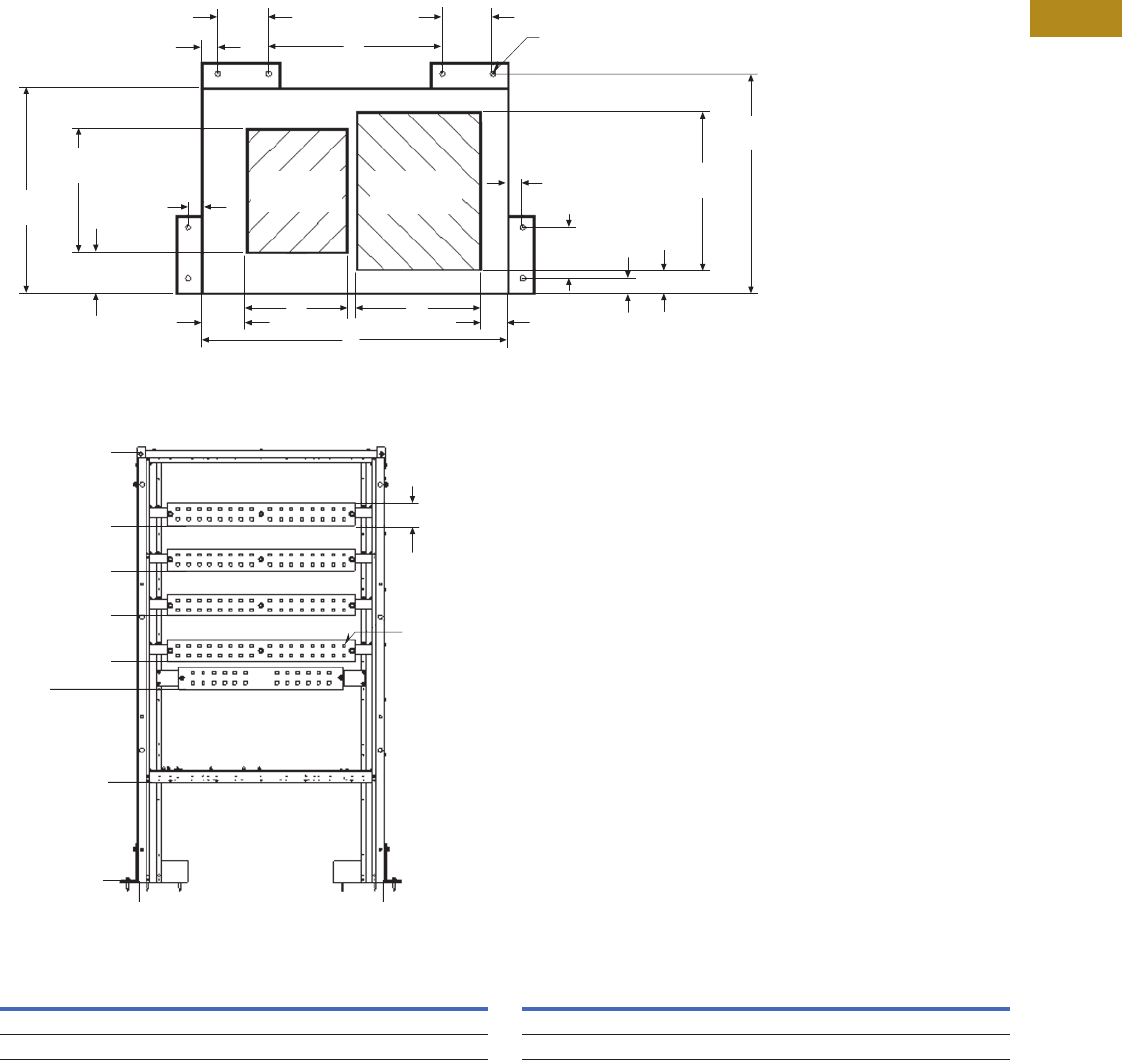
Volume 2—Commercial Distribution CA08100003E—June 2014 www.eaton.com V2-T4-35
4
4
4
4
4
4
4
4
4
4
4
4
4
4
4
4
4
4
4
4
4
4
4
4
4
4
4
4
4
4
4.6
Switchboards
Roll-Up Generator Termination Box
Dimensions
Approximate Dimensions in Inches (mm)
Enclosure
Termination/Lug Landing
Enclosure Dimensions 1Termination/Lug Landing Dimensions
Note
1Conduit landing surface will be 20.00 (508.0) above finished grade.
Front
A
Rear
D
B C
5.25
(133.4)
3.25
(82.6)
1.75
(44.5) (2)
1.75
(44.5) (2)
6.00
(152.4) (2)
1.75
(44.5) (2)
2.75
(69.9)
18.50
(470.0)
25.75
(654.1)
6.00
(152.4)
6.00
(152.4)
Anchor Locations (8)
Use 0.5 (12.7) Diameter
Grade 6 (Min.) Anchor Bolts
That Extend a Minimum of
0.75 (19.1) Above Finished Grade
1.75
(44.5)
4.75
(120.7)
14.50
(368.3)
24.00
(609.6)
Conduit
Area (Load)
Wire/Conduit
Area Line
4.00 (101.6)
(Typical All Phases,
Neutral and Ground)
Punch Pattern on
Bus Varies Based on
Terminal Selection
A0.00
(0.0)
20.00
(508.0)
35.00
(889.0)
40.00
(1016.0)
48.25
(1225.6)
56.50
(1435.1)
64.75
(1644.7)
78.00
(1981.2)
0.00
(0.0)
Structure Width A B C D
36.00 (914.4) 28.00 (711.2) 11.75 (298.5) 14.50 (368.3) 20.50 (520.7)
45.00 (1143.0) 45.00 (1143.0) 18.25 (463.6) 18.00 (457.2) 28.50 (723.9)
Structure Width A
36.00 (914.4) 36.00 (914.4)
45.00 (1143.0) 45.00 (1143.0)
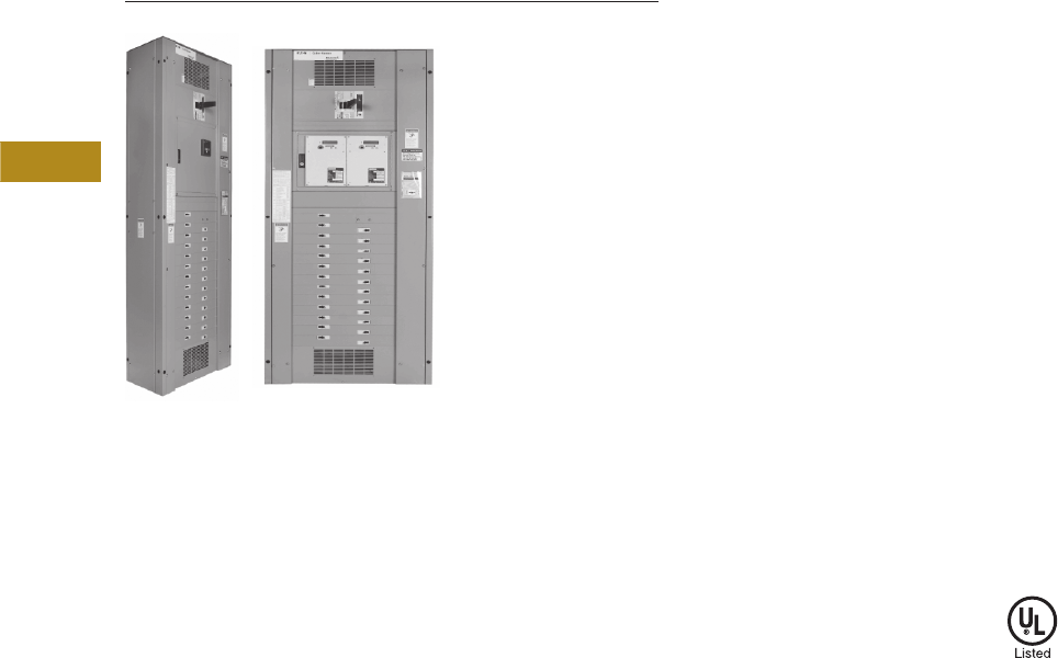
V2-T4-36 Volume 2—Commercial Distribution CA08100003E—June 2014 www.eaton.com
4
4
4
4
4
4
4
4
4
4
4
4
4
4
4
4
4
4
4
4
4
4
4
4
4
4
4
4
4
4
4.7
Switchboards
Multipoint Meter (MPM)
Pow-R-Line Multipoint Meter / PRC7500
Contents
Description Page
Multipoint Meter (MPM)
Overview . . . . . . . . . . . . . . . . . . . . . . . . . . . . . V2-T4-36
Pow-R-Line Multipoint Meter. . . . . . . . . . . . . . V2-T4-37
PRC7500—Tenant Metering . . . . . . . . . . . . . . V2-T4-38
Overview
Allocation of energy
consumption in a residential
or commercial application
is a tremendous task for a
property owner, management
firm or electrical energy
manager. To assist in
allocation or direct billing
of consumed energy,
use Eaton’s Pow-R-Line
Multipoint Meter or
Pow-R-Command™ 7500
(PRC7500) low cost
solutions. The Pow-R-Line
Multipoint Meter / PRC7500
provides a cost-effective
energy tabulation system for
residential or commercial
metering installations. These
installations can include:
●High-rise buildings
●Universities and campuses
●Office buildings
●Apartment and
condominium complexes
●Shopping malls
●Airports
●System commissioning
is required and priced
separately
When there is a need for
accurate information of
consumed energy for monthly
invoicing statements, use
Eaton’s Multipoint Meter
solution. Using the Multipoint
Meter for utility allocation
maximizes revenue by
effectively measuring,
allocating and recovering
utility expenditures. The
Multipoint Meter solution
can interface with a third-party
utility allocation service and
offers the following
advantages:
●Purchase energy at bulk
rates while charging
consumer rates
●Capitalize on naturally
variable tenant loads by
purchasing energy at a
lower coinciding load
●Capture and allocate
common area
maintenance cost
●Promote tenant retention
with accurate and
defensible billing
●Eliminate subsidization
of other tenants
Application Description
Refer to Eaton’s Consulting
Application Guide. For
complete application and
pricing information, contact
your local Eaton sales office.
Features and Benefits
●Factory-wired system
●Saves floor space
●Lower installed cost
●Network compatible
●Tenant sub-billing
Standards and Certifications
●UL listed

Volume 2—Commercial Distribution CA08100003E—June 2014 www.eaton.com V2-T4-37
4
4
4
4
4
4
4
4
4
4
4
4
4
4
4
4
4
4
4
4
4
4
4
4
4
4
4
4
4
4
4.7
Switchboards
Multipoint Meter (MPM)
Pow-R-Line Multipoint Meter
Contents
Description Page
Overview . . . . . . . . . . . . . . . . . . . . . . . . . . . . . . . . V2-T4-36
Pow-R-Line Multipoint Meter
PRC7500—Tenant Metering . . . . . . . . . . . . . . . . . V2-T4-38
Pow-R-Line Multipoint Meter
Product Description
Using Eaton’s Pow-R-Line
Multipoint Meter design,
multiple tenant submetering
has never been easier. The
Pow-R-Line Multipoint Meter
combines the Power Xpert®
Multi-Point Meter and Eaton’s
PRL4, PRLC or Integrated
Facility System™ (IFS™)
to provide a space-saving,
cost-effective energy
tabulation system for
residential or commercial
metering installations.
Application Description
With energy cost on the rise,
it is vital to proactively monitor
and conserve electrical
energy. Documentations of
electrical energy usage can
promote energy conservation
for tenants or business
departments. When the
need for accurate energy
consumption information
for monthly tenant invoicing
arises, use Eaton’s Pow-R-
Line Multipoint Meter
solution.
Using the Multipoint Meter for
utility allocation maximizes
revenue by effectively
measuring, allocating and
recovering utility expenditures.
The Pow-R-Line Multipoint
Meter, using Eaton’s cost-
allocation software or a third-
party billing software, can
generate single-rate or multi-
rate billing.
Features, Benefits and Functions
The Pow-R-Line Multipoint
Meter offers the property
owner or the property
management firm the ability
to:
●Capture and allocate
common area
maintenance cost
●Promote tenant retention
with accurate billing
●Eliminate subsidization
of other tenants
The Pow-R-Line Multipoint
Meter space-saving design
reduces the need for multi-
metering equipment for each
tenant. Additionally, the Pow-
R-Line Multipoint Meter can
monitor loads up to 5000A for
energy billing or cost allocation.
The meter is rated per ANSI
C12.20 for revenue metering
grade accuracy. With built-in
communications capabilities,
the Pow-R-Line Multipoint
Meter can be connected to a
local PC or network. The Pow-
R-Line Multipoint Meter can
connect to a third-party billing
service to provide monthly
energy consumption charges
used by tenants. Additionally,
unit status and communication
activity are provided by a
display on the metering
compartment front panel.
The Pow-R-Line Multipoint
Meter device can measure up
to 60 total poles in any
combination of single-, two- or
three-pole breakers. The
meters and current sensors
are factory mounted with the
current sensors factory wired
to the meter inside the host
structure. The meter monitors
power and energy including
instantaneous (kW), demand
and cumulative (kWh)
measurements for each load.
The meter provides the
following:
●Interval energy data
logging
●Time-of-use energy
registers
●Coincident peak demand
storage
●Schedule remote meter
reading data in non-volatile
memory
●Measure bus voltage
Options
●Energy Portal Module
or Ethernet-based
communications plus
Modbus® TCP and
BACnet/IP
●Pulse input module
for WAGES inputs
●Digital output module
for programmable
alarm functions
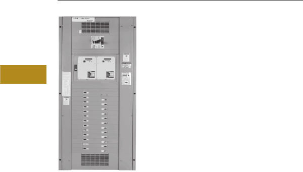
V2-T4-38 Volume 2—Commercial Distribution CA08100003E—June 2014 www.eaton.com
4
4
4
4
4
4
4
4
4
4
4
4
4
4
4
4
4
4
4
4
4
4
4
4
4
4
4
4
4
4
4.7
Switchboards
Multipoint Meter (MPM)
PRC7500—Tenant Submetering
Contents
Description Page
Overview . . . . . . . . . . . . . . . . . . . . . . . . . . . . . . . V2-T4-36
Pow-R-Line Multipoint Meter . . . . . . . . . . . . . . . . V2-T4-37
PRC7500—Tenant Metering
Layout Guide . . . . . . . . . . . . . . . . . . . . . . . . . . V2-T4-39
PRC7500—Tenant Metering
Product Description
Leading property
management companies
around the world are realizing
the time and cost savings of
tenant metering in residential,
commercial and industrial
applications.
Allocating energy
consumption can be a
tremendous task for any
property owner, management
firm or electrical energy
manager. Eaton’s PRC7500
is a solution that combines
Eaton’s IFS switchboards with
Quadlogic® electrical meters
and current transformers for a
cost-effective energy tracking
system perfect for many
applications.
Application Description
Imagine the success of
tenant metering in these
installations:
●Apartments, town homes,
condominium complexes
●Shopping malls
●High-rise office buildings
●Universities and campuses
●Airports
... and more!
Features, Benefits and Functions
Eaton’s reliable IFS is
integrated with Quadlogic’s
Power Line Communications
technology, that transmits
meter data over a building’s
existing power lines. That
means:
●Factory-assembled—
saves time
●No additional wiring
●No meter readers required
This system proves to provide
reliable and accurate data
needed to bill tenants, allocate
energy costs and make smart
energy decisions.
In addition, PRC7500 Tenant
Metering also affords the
following benefits:
●Energy costs allocated
to individual tenants or
departments within
the building
●Allocate common area
electric charges
●Create revenue by
purchasing bulk rate
energy
●Retain happy tenants with
fair and accurate allocation
of energy costs
●Commercial, residential or
industrial applications
●Meters up to 12 (two-pole)
tenants or eight (three-
pole) tenants per meter
●Reliable power line
communications
●Interval data and
time-of-use capability
●Event profiling (power
down, demand resets,
tampers, etc.)
●Load profiling
●Collects data from
water and gas meters
●Easy to install
●Proven accuracy—
ANSI compliant
●Cost-effective—saves
on equipment cost
and installation

Volume 2—Commercial Distribution CA08100003E—June 2014 www.eaton.com V2-T4-39
4
4
4
4
4
4
4
4
4
4
4
4
4
4
4
4
4
4
4
4
4
4
4
4
4
4
4
4
4
4
4.7
Switchboards
Multipoint Meter (MPM)
●Integrated Pow-R-Line
Communications—uses
existing electrical wiring
for communications;
requires no dedicated
hard wires, additional
modules or attachments
for communications
●Flexible data
programming—interval
data down to 5 minutes
allows for flexible load
profiling and time-of-use
billing options
●Accurate—meets ANSI
C12.1 specifications and
stringent requirements of
Measurement Canada
(AE-1148)
●Comprehensive
information—event
reporting with date and
time stamps regarding
power consumption,
demand reset, power-ups
and power-downs, time
changes and tampers
●Liquid crystal display
LCD—provides
consumption readings
for each tenant
●Multi-utility submetering
system—integrates and
stores pulse data from
gas and water meters
●Power quality data—
measures four-quadrant
energy to analyze
power quality
●Data integrity—uses flash
memory for accurate
storage and integrity
without battery reliance
●Installation verification
display—allows on-site
verification of proper
installation
Layout Guide
Refer to Eaton’s Consulting
Application Guide.
The MiniCloset-5 has a display
incorporated into the meter.
A shorting terminal block is
provided to connect between
the MiniCloset-5 and the
current transformers. An
optional component for
collecting data from the
MiniCloset-5 meters is the
Scan Transponder-5 (mounted
separately)—13.50 H x 8.50 W
x 4.50 D in inches (342.9 H x
215.9 W x 114.3 D in mm).

Volume 2—Commercial Distribution CA08100003E—April 2014 www.eaton.com V2-T5-1
5
5
5
5
5
5
5
5
5
5
5
5
5
5
5
5
5
5
5
5
5
5
5
5
5
5
5
5
5
5
Transfer Switches
Transfer Switches
5.1 Transfer Switch Equipment
Product Selection Guide . . . . . . . . . . . . . . . . . . . . . . . . . . . . . . . . . . . V2-T5-2
Product Description. . . . . . . . . . . . . . . . . . . . . . . . . . . . . . . . . . . . . . . V2-T5-5
Application Description . . . . . . . . . . . . . . . . . . . . . . . . . . . . . . . . . . . . V2-T5-5
5.2 Contactor-Based Designs
Automatic Open Transition, 40–1600A . . . . . . . . . . . . . . . . . . . . . . . . V2-T5-8
Automatic Closed Transition, 40–1200A . . . . . . . . . . . . . . . . . . . . . . . V2-T5-13
Bypass Isolation Transfer Switches, 40–1600A, Dual Drawout . . . . . V2-T5-17
Bypass Isolation Transfer Switches, 40–1200A, Fixed Bypass . . . . . . V2-T5-23
5.3 Breaker-Based Designs
Molded Case Switches—Manual Wallmount, 30–1000A . . . . . . . . . . V2-T5-28
Molded Case Switches—Non-Automatic Wallmount, 30–1000A . . . . V2-T5-32
Molded Case Switches—Automatic Wallmount, 30–1000A . . . . . . . . V2-T5-35
Maintenance Bypass Switches—Type MBHE 100–1000A . . . . . . . . . V2-T5-41
5.4 Magnum-Based Designs
Power Case Switch—Floorstanding, 200–5000A . . . . . . . . . . . . . . . . V2-T5-44
Bypass Isolation Transfer Switch, 200–5000A. . . . . . . . . . . . . . . . . . . V2-T5-53
5.5 Automatic Transfer Controllers
Product Selection Guide . . . . . . . . . . . . . . . . . . . . . . . . . . . . . . . . . . . V2-T5-59
ATC-100 Controller . . . . . . . . . . . . . . . . . . . . . . . . . . . . . . . . . . . . . . . V2-T5-63
ATC-300+ Controller . . . . . . . . . . . . . . . . . . . . . . . . . . . . . . . . . . . . . . V2-T5-65
ATC-900 Controller . . . . . . . . . . . . . . . . . . . . . . . . . . . . . . . . . . . . . . . V2-T5-69
ATC-600/800 Controller . . . . . . . . . . . . . . . . . . . . . . . . . . . . . . . . . . . . V2-T5-79
ATC-800 Controller . . . . . . . . . . . . . . . . . . . . . . . . . . . . . . . . . . . . . . . V2-T5-82
Controller Replacement Guide . . . . . . . . . . . . . . . . . . . . . . . . . . . . . . V2-T5-86
5.6 Standard and Optional Features
Standard and Optional Features . . . . . . . . . . . . . . . . . . . . . . . . . . . . . V2-T5-91
5.7 Remote Annunciator Controller
Product Description. . . . . . . . . . . . . . . . . . . . . . . . . . . . . . . . . . . . . . . V2-T5-115
Features . . . . . . . . . . . . . . . . . . . . . . . . . . . . . . . . . . . . . . . . . . . . . . . V2-T5-115
Dimensions . . . . . . . . . . . . . . . . . . . . . . . . . . . . . . . . . . . . . . . . . . . . . V2-T5-117
Wiring Diagram . . . . . . . . . . . . . . . . . . . . . . . . . . . . . . . . . . . . . . . . . . V2-T5-117
5.8 kW Conversions
kW Conversion Chart. . . . . . . . . . . . . . . . . . . . . . . . . . . . . . . . . . . . . . V2-T5-118
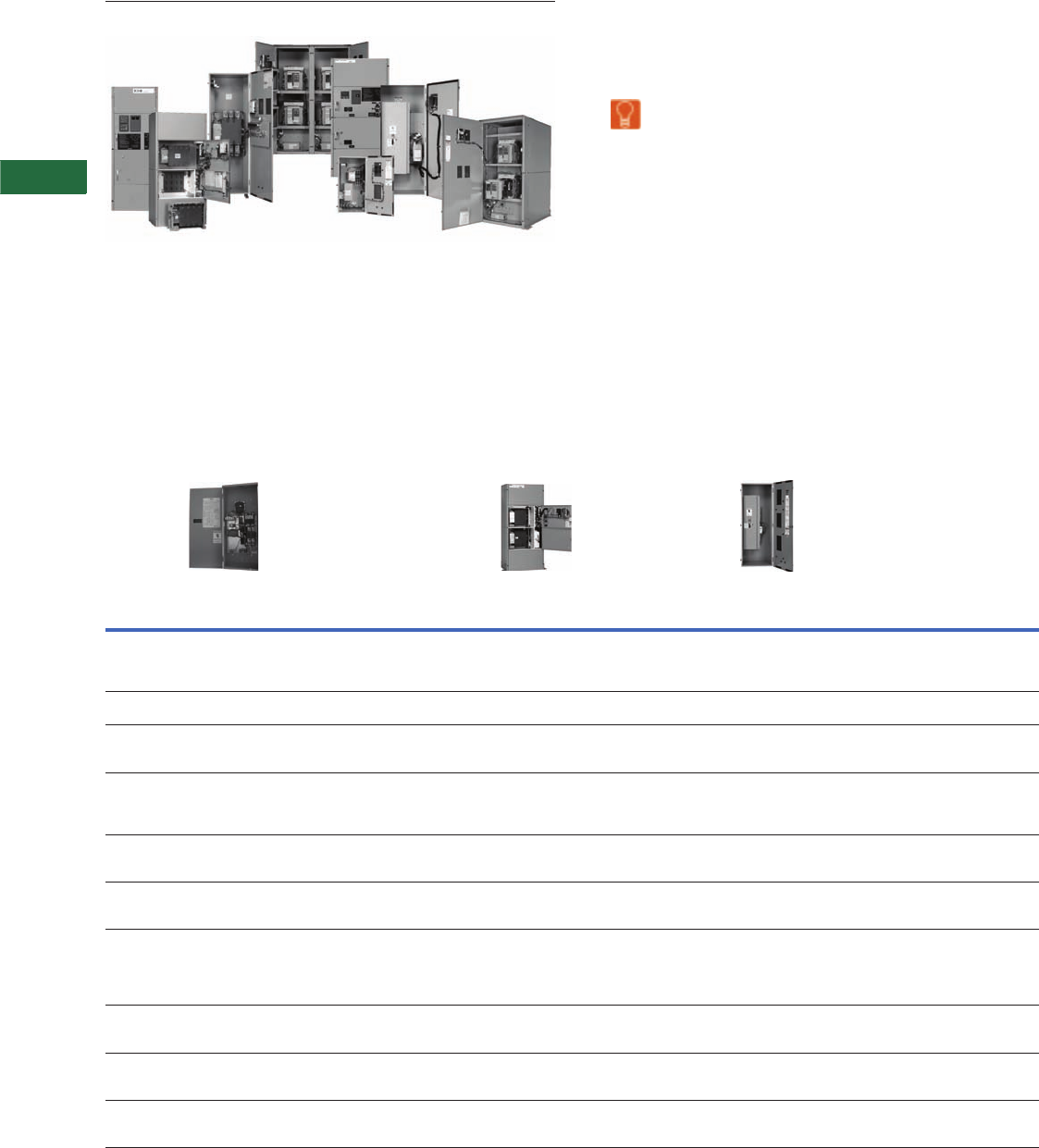
V2-T5-2 Volume 2—Commercial Distribution CA08100003E—April 2014 www.eaton.com
5
5
5
5
5
5
5
5
5
5
5
5
5
5
5
5
5
5
5
5
5
5
5
5
5
5
5
5
5
5
5.1
Transfer Sw itches
Tran s fer Sw itc h Eq uipment
Automatic Transfer Switches
Contents
Description Page
Product Description . . . . . . . . . . . . . . . . . . . . . . . V2-T5-5
Application Description . . . . . . . . . . . . . . . . . . . . . V2-T5-5
Learn
Online
Product Selection Guide
Transfer Switch Product
Note
11600A is dual drawout only.
Key: DO = Drawout
FM = Fixed mounted
MCB = Molded case breaker
MCS = Molded case switch
Catalog
Numbering
System
Automatic Contactor
(600 Vac) (40–1200A)
(480 Vac) (40–1600A)
Bypass Isolation Contactor
(600 Vac) (40–1200A)
(480 Vac) (40–1600A)
Manual Molded Case Switch
(600 Vac) (30–1000A)
Type AT = Automatic
CT = Closed transition
NT = Non-Automatic
Refer to Page V2-T5-8
BI = Bypass isolation open transition
CB = Bypass isolation closed transition
Refer to Page V2-T5-17
MT = Manual
Refer to Page V2-T5-28
Orientation V = Vertical V = Vertical H = Horizontal
V= Vertical
Logic 1 = ATC-100 (up to 400A only)
3 = ATC-300+
9 = ATC-900
3 = ATC-300+
9 = ATC-900
X = No Logic
Frame C = Contactor-based
2 = Two-position open in-phase transition
3 = Three-position delayed transition
5 = Open in-phase with default to delayed transition
C = Contactor-based
3 = Three-position delayed transition
5 = Open in-phase with default to delayed
transition
Molded case device
FD = 30–150A
KD = 150–300A
LD = 400–600A
MD = 600–800A
NB = 800–1000A
Switch X = Fixed mount E = Drawout bypass
X = Fixed mount bypass
Fixed mount
A = FM, N (MCS), E (MCS)
B = FM, N (MCB), E (MCB)
C = FM, N (MCB), E (MCS)
D = FM, N (MCS), E (MCB)
Poles 2 = Two-pole
3 = Three-pole
4 = Four-pole
2 = Two-pole
3 = Three-pole
4 = Four-pole
2 = Two-pole
3 = Three-pole
4 = Four-pole
Amperes 0040 = 40A
0080 = 80A
0100 = 100A
0150 = 150A
0200 = 200A
0225 = 225A
0260 = 260A
0400 = 400A
0600 = 600A
0800 = 800A
1000 = 1000A
1200 = 1200A
1600 = 1600A
0100 = 100A
0150 = 150A
0200 = 200A
0260 = 260A
0400 = 400A
0600 = 600A
0800 = 800A
1000 = 1000A
1200 = 1200A
1600 = 1600A 1
0030 = 30A
0070 = 70A
0100 = 100A
0150 = 150A
0225 = 225A
0300 = 300A
0400 = 400A
0600 = 600A
0800 = 800A
1000 = 1000A
Voltage A = 120V, 60 Hz
B = 208V, 60 Hz
E = 600V, 60 Hz
G = 220V, 50/60 Hz
X = 480V, 60 Hz
H = 380/220, 50/60 Hz
A = 120V, 60 Hz
B = 208V, 60 Hz
E = 600V, 60 Hz
G = 220V, 50/60 Hz
X = 480V, 60 Hz
H = 380/220, 50/60 Hz
E = 600V, 60 Hz
Enclosure K = Open
S = NEMA 1
R = NEMA 3R
D = NEMA 4X
J = NEMA 12
S = NEMA 1
R = NEMA 3R
D = NEMA 4X
K = Open
S = NEMA 1
J = NEMA 12
R = NEMA 3R
D = NEMA 4X
Listing U = UL listed
R = UL recognized
X = No listing
U = UL listed
R = UL recognized
X = No listing
U = UL listed
R = UL recognized
X = No listing
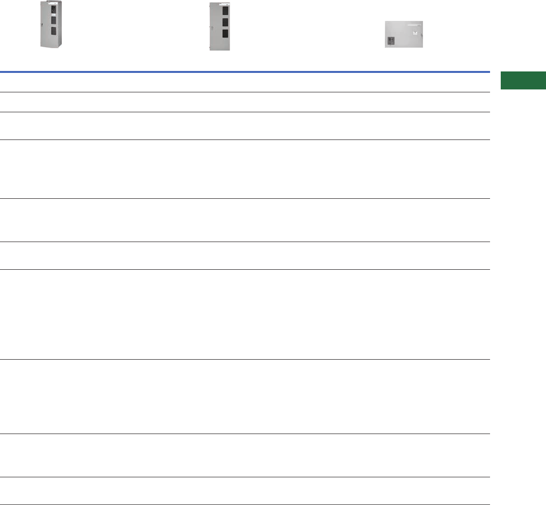
Volume 2—Commercial Distribution CA08100003E—April 2014 www.eaton.com V2-T5-3
5
5
5
5
5
5
5
5
5
5
5
5
5
5
5
5
5
5
5
5
5
5
5
5
5
5
5
5
5
5
5.1
Transfer Switches
Transfer Switch Equipment
Transfer Switch Product Guide, continued
Key: DO = Drawout
FM = Fixed mounted
MCB = Molded case breaker
MCS = Molded case switch
Catalog
Numbering
System
Non-Automatic Molded Case Switch
(600 Vac) (30–1000A)
Automatic (Wallmount) Molded Case Switch
(600 Vac) (30–1000A)
Maintenance Bypass
(480 Vac) (100–1000A)
Type NT = Non-automatic
Refer to Page V2-T5-32
AT = Automatic
Refer to Page V2-T5-35
MB = Maintenance bypass
Refer to Page V2-T5-41
Orientation H = Horizontal
V= Vertical
H = Horizontal
V= Vertical
H = Horizontal
Logic E = Electromechanical 1 = ATC-100
3 = ATC-300+
9 = ATC-900
E = Electromechanical
Frame Molded case device
FD = 30–150A
KD = 150–300A
LD = 400–600A
MD= 600–800A
NB = 800–1000A
Molded case device
FD = 30–200A
KD = 150–300A
LD = 400–600A
MD = 600–800A
NB = 800–1000A
(FD = 200A available on ATH3 only)
Molded case device
FD = 100–150A
KD = 150–300A
LD = 400–600A
MD = 600–800A
NB = 800 –1000A
Switch Fixed mount
A = FM, N (MCS), E (MCS)
B = FM, N (MCB), E (MCB)
C = FM, N (MCB), E (MCS)
D = FM, N (MCS), E (MCB)
Fixed mount
A = FM, N (MCS), E (MCS)
B = FM, N (MCB), E (MCB)
C = FM, N (MCB), E (MCS)
D = FM, N (MCS), E (MCB)
Fixed mount
A = FM, N (MCS), E (MCS)
Poles 2 = Two-pole
3 = Three-pole
4 = Four-pole
2 = Two-pole
3 = Three-pole
4 = Four-pole
2 = Two-pole
3 = Three-pole
4 = Four-pole
Amperes 0030 = 30A
0070 = 70A
0100 = 100A
0150 = 150A
0225 = 225A
0300 = 300A
0400 = 400A
0600 = 600A
0800 = 800A
1000 = 1000A
0030 = 30A
0070 = 70A
0100 = 100A
0150 = 150A
0200 = 200A
0225 = 225A
0300 = 300A
0400 = 400A
0600 = 600A
0800 = 800A
1000 = 1000A
0100 = 100A
0150 = 150A
0225 = 225A
0300 = 300A
0400 = 400A
0600 = 600A
0800 = 800A
1000 = 1000A
Voltage A = 120V, 60 Hz
B = 208V, 60 Hz
E= 600V, 60 Hz
G = 220V, 50/60 Hz
H = 380V, 50 Hz
K = 600V, 50 Hz
O = 415V, 50 Hz
W = 240V, 60 Hz
X = 480V, 60 Hz
B = 208V, 60 Hz
E = 600V, 60 Hz
G = 220V, 50/60 Hz
H = 380V, 50 Hz
K = 600V, 50 Hz
O = 415V, 50 Hz
W = 240V, 60 Hz
X = 480V, 60 Hz
B = 208/120V
W = 240V
W = 240/120V
X = 480V
X = 480/277V
Enclosure K = Open
S = NEMA 1
R = NEMA 3R
J = NEMA 12
D = NEMA 4X
K = Open
S= NEMA 1
J= NEMA 12
R= NEMA 3R
D= NEMA 4X
K = Open
S= NEMA 1
J= NEMA 12
R= NEMA 3R
D= NEMA 4X
Listing U = UL listed
R = UL recognized
X = No listing
U = UL listed
R = UL recognized
X = No listing
U = UL listed
R = UL recognized
X = No listing
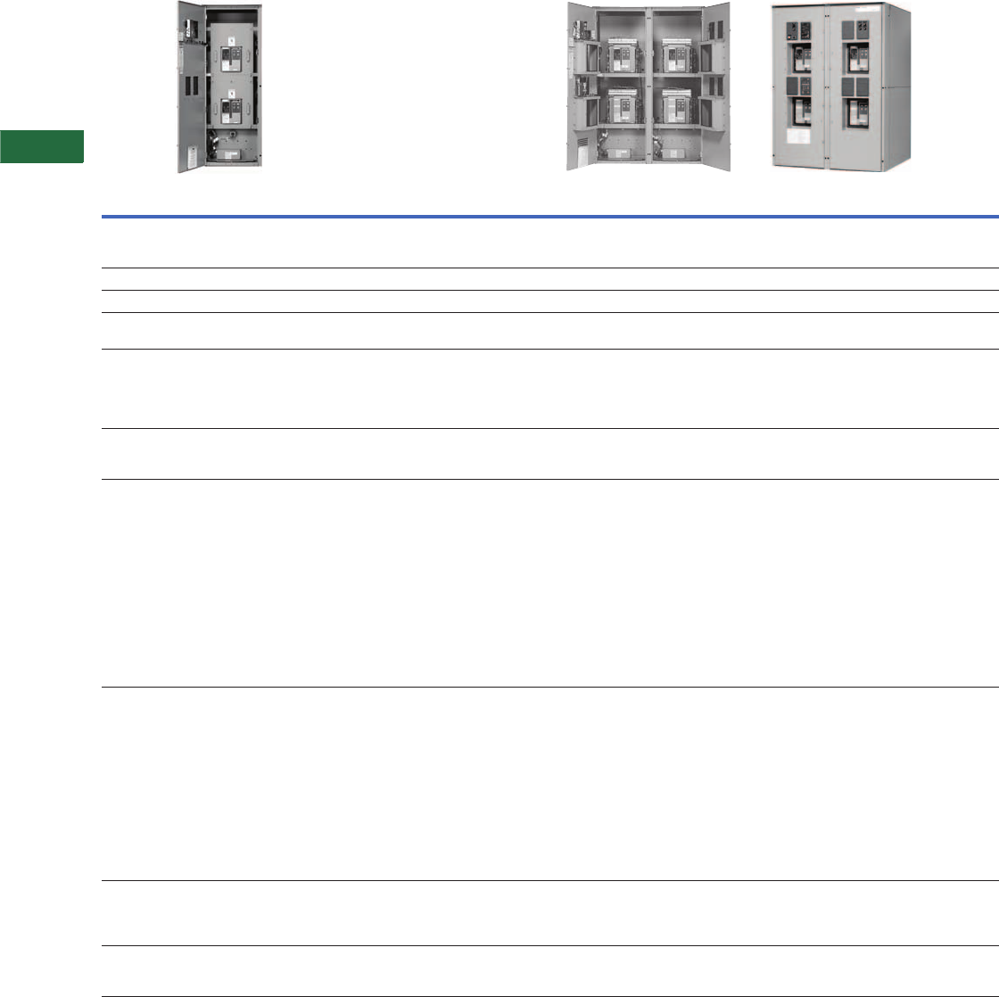
V2-T5-4 Volume 2—Commercial Distribution CA08100003E—April 2014 www.eaton.com
5
5
5
5
5
5
5
5
5
5
5
5
5
5
5
5
5
5
5
5
5
5
5
5
5
5
5
5
5
5
5.1
Transfer Sw itches
Tran s fer Sw itc h Eq uipment
Transfer Switch Product Guide, continued
Note
1Supplied as drawout design only.
Key: DO = Drawout
FM = Fixed mounted
MPB = Magnum power breaker
MPS = Magnum power switch
Catalog
Numbering
System
Automatic (Free Standing)
(600 Vac) (200–5000A)
Bypass Isolation and Closed Transition Bypass Isolation (<100 ms)
(600 Vac) (800–5000A)
Type AT = Automatic
CT = Closed transition
Refer to Pages V2-T5-44–V2-T5-58
BI = Open transition bypass isolation
CB = Closed transition bypass isolation
Refer to Page V2-T5-53
Orientation V = Vertical V = Vertical
Logic 9 = ATC-900 9 = ATC-900
Frame Power case device (Magnum)
MG = 600–5000A
Power case device (Magnum)
MG = 600–5000A
Switch Fixed mount
A = FM,N (MPS), E (MPS)
B = FM, N (MPB), E (MPB)
C = FM, N (MPB), E (MPS)
D = FM, N (MPS), E (MPB)
Drawout mount
E = DO, N (MPS), E (MPS)
F = DO, N (MPB), E (MPB)
G = DO, N (MPB), E (MPS)
H = DO, N (MPS), E (MPB)
Drawout mount
E = DO, N (MPS), E (MPS)
F = DO, N (MPB), E (MPB)
G = DO, N (MPB), E (MPS)
H = DO, N (MPS), E (MPB)
Poles 2 = Two-pole
3 = Three-pole
4 = Four-pole
2 = Two-pole
3 = Three-pole
4 = Four-pole
Amperes 0200 = 200A
0300 = 300A
0400 = 400A
0600 = 600A
0800 = 800A
1000 = 1000A
1200 = 1200A
1600 = 1600A
2000 = 2000A
2500 = 2500A
3000 = 3000A
3200 = 3200A
4000 = 4000A 1
5000 = 5000A 1
0200 = 200A
0300 = 300A
0400 = 400A
0600 = 600A
0800 = 800A
1000 = 1000A
1200 = 1200A
1600 = 1600A
2000 = 2000A
2500 = 2500A
3200 = 3200A
4000 = 4000A
5000 = 5000A
Voltage E = 600V, 60 Hz
E = 600/347, 50 Hz
X = 480/277, 60 Hz
X = 480/240, 60 Hz
X = 480, 60 Hz
O = 415/240, 50 Hz
H = 380/220, 50 Hz
W = 240/120, 60 Hz
W = 240, 60 Hz
G = 220/127, 50 Hz
G = 220, 50 Hz
B = 208/120, 60 Hz
A = 120, Hz
E = 600V, 60 Hz
E = 600/347, 50 Hz
X = 480/277, 60 Hz
X = 480/240, 60 Hz
X = 480, 60 Hz
O = 415/240, 50 Hz
H = 380/220, 50 Hz
W = 240/120, 60 Hz
W = 240, 60 Hz
G = 220/127, 50 Hz
G = 220, 50 Hz
B = 208/120, 60 Hz
A = 120, Hz
Enclosure K = Open (up to 3200A fixed mount only)
S= NEMA 1
R= NEMA 3R
T = NEMA 1 (through the door)
S= NEMA 1
R = NEMA 3R (non-walk-in)
T = NEMA 1 (through the door)
Listing U = UL listed
R = UL recognized
X = No listing
U = UL 1008 listed
X = No listing

Volume 2—Commercial Distribution CA08100003E—April 2014 www.eaton.com V2-T5-5
5
5
5
5
5
5
5
5
5
5
5
5
5
5
5
5
5
5
5
5
5
5
5
5
5
5
5
5
5
5
5.1
Transfer Switches
Trans fer Sw itch Eq uipment
Product Description
Eaton’s automatic transfer
switches are reliable, rugged,
versatile and compact
assemblies for transferring
essential loads and electrical
distribution systems from
one power source to another.
Transfer switches can
be supplied in separate
enclosures for stand-alone
applications or can be
supplied as an integral
component in the following
equipment (see table below).
Product Type
Typical Applications
All Eaton transfer switches
are designed to meet the
requirements set forth by
UL 1008; however, all
transfer switches are not
created equal. You can be
assured of safe and reliable
operation from all types
of transfer switches that
Eaton offers.
Application Description
A transfer switch is a
critical component of any
emergency or standby power
system. When the normal
(preferred) source of power
is lost, a transfer switch
quickly and safely shifts the
load circuit from the normal
source of power to the
emergency (alternate) source
of power. This permits critical
loads to continue running
with minimal or no outage.
After the normal source of
power has been restored,
the retransfer process returns
the load circuit to the normal
power source.
Transfer switches are
available with different
operational modes including:
●Manual
●Non-automatic
●Automatic
●Bypass isolation
●Maintenance bypass
Switch Types
Manual transfer—This type
of transfer is a non-automatic
transfer switch manually
initiated and manually
operated. There is no motor
operator or solenoid to initiate
the transfer. The operator
needs to open the enclosure
door and operate the manual
handle. Manual transfer is
available only on a breaker-
based design. Service
entrance ratings are not
available on manual transfer
breaker-based designs.
Non-automatic transfer—
This type of transfer is
manually initiated, but
electrically operated via the
solenoid in a contactor-based
design and the motor operator
in a breaker-based design.
Automatic transfer—This
type of transfer takes place
automatically per the
programmable settings in
the ATS controller. The ATS
controller senses source
availability and when the
programmed conditions are
met, initiates a command to
start the transfer including
the generator start command
(when transferring from a
utility to a generator source).
An automatic transfer switch
can be configured to perform
a utility-to-utility transfer or a
generator-to-generator
transfer (provided the ATS
controller has this capability).
Bypass isolation transfer
switch—This type of transfer
switch includes an automatic
transfer switch and also
includes the bypass switch
that allows the capability to
transfer the load to the
bypass switch without
interrupting the power.
Description
Section
Reference
Magnum® DS Switchgear Vol. 3, Tab 4
DSII Switchgear Vol. 3, Tab 4
Pow-R-Line® Switchboards Vol. 2, Tab 4
Motor Control Centers Vol. 3, Tab 3
Panelboards Vol. 2, Tab 3
Maintenance bypass
transfer switch—A
maintenance bypass transfer
switch is a manually (manually
initiated and electrically
operated) initiated transfer
switch used for specific
applications for a UPS.
The power switching
operation of transfer switches
may be separated into the
following transition modes:
Transition Types
Open transition—This is a
“break-before-make”
transfer. There is a definite
break in power as the load is
taken off one source and
connected to the other
source.
Open in-phase transition—
This is a “break-before-
make” transfer. There is a
definite break in power as the
load is taken off one source
and connected to the other
source. The ATS controller
allows the transfer only when
the phase difference
between the two sources is
near zero. The two position
transfer switch is closed on
Source 1 or closed on
Source 2.
Open in-phase with default
to time delay neutral—
break-before-make operation
using an in-phase monitor for
source synchronization. If the
in-phase does not initiate a
transfer within a programmable
time delay, then the transfer
will default to a time delay
neutral type of transfer.
Delayed transition—This is a
“break-before-make” or open
transition that also has a
“center off” or neutral
position with a programmable
time delay setting for the
neutral position. The three
position transfer switch is
either closed on Source 1,
closed on Source 2, or in a
center off, neutral position
(not closed on either source).
Delayed transition with
load voltage decay—This is
a delayed transition with the
optional feature to delay in
the neutral position to point
where the load voltage
decays to a programmable
voltage level. When the load
voltage level reaches the
programmable set point, the
transfer from the neutral
position initiates.
Closed transition—This is a
“make-before-break”
transfer. Both sources are
connected to the load for less
than 100ms before the break
occurs. The two power
sources have to be in
synchronism and be good
sources for the transfer to
take place. These
programmable settings for
relative phase angle
difference, frequency and
voltage difference are made
in the ATS controller.
Basic Components
The three basic components
of a transfer switch are:
●Power switching device to
shift the load circuits to and
from the power source
●Transfer logic controller
to monitor the condition
of the power sources
and provide the control
signals to the power
switching device
●Control power source to
supply operational power
to the controller and
switching device

V2-T5-6 Volume 2—Commercial Distribution CA08100003E—April 2014 www.eaton.com
5
5
5
5
5
5
5
5
5
5
5
5
5
5
5
5
5
5
5
5
5
5
5
5
5
5
5
5
5
5
5.1
Transfer Sw itches
Tran s fer Sw itc h Eq uipment
Fully Rated Fourth Pole
(Switched Neutral)
Eaton provides a fully rated
switched neutral or fourth
pole, meaning that the fourth
pole has withstand, interrupt
and closing ratings identical
to the power contacts. The
neutral pole is operated on a
common shaft with the
power contacts, thereby
ensuring simultaneous
opening and closing of the
switched neutral. Eaton’s
fully rated fourth pole
eliminates typical problems
with a three-pole overlapping
neutral:
●Eliminates nuisance
ground trips at the main
due to circulating zero
sequence harmonic
current between sources
●Reduction in ground
current due to isolated
single ground point lowers
arc-flash levels and
reduces generator damage
●Eliminates potential for
faults to propagate across
overlapping neutral; fully
rated fourth pole will
handle as a normal
operation
●Does not generate
voltages that exceed
normal phase voltage
Note: For more detail, reference
Eaton White Paper IA08700002E
UL 1008 Endurance Testing
The importance of specifying a
UL 1008 transfer switch can
be seen in the table below.
When specifying any UL 1008
transfer switch, you can be
assured the switch has met
and passed the following
endurance testing.
UL 1008 Life Expectancy
Transfer switch applications
typically require a plant
exerciser once a week or
once a month. The table
below demonstrates the life
expectancy operating the UL
1008 switch once a week
for the life of the switch.
UL 1008 Endurance Testing
UL 1008 Life Expectancy
ATS Rating
(Amperes)
Rate of Operation
Per Minute
With
Current
Without
Current Total
0–300 1 6000 — 6000
301–400 1 4000 — 4000
401–800 1 2000 1000 3000
801–1600 0.5 1500 1500 3000
1601–4000 0.25 1000 2000 3000
ATS Rating
(Amperes)
Minimum
Operations
Per Year
Life Expectancy
in Years With
Current Applied
Life Expectancy
in Years Without
Current Applied
0–300 52 115 115
301–400 52 76 76
401–800 52 38 57
801–1600 52 28 57
1601–4000 52 19 57
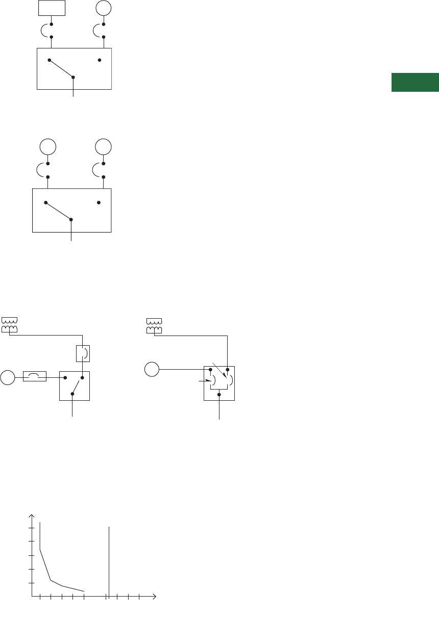
Volume 2—Commercial Distribution CA08100003E—April 2014 www.eaton.com V2-T5-7
5
5
5
5
5
5
5
5
5
5
5
5
5
5
5
5
5
5
5
5
5
5
5
5
5
5
5
5
5
5
5.1
Transfer Switches
Trans fer Sw itch Eq uipment
Utility—Generator
Transfer switches are
traditionally applied between
a utility and a generator set
for emergency and standby
power systems.
Generator—Generator
Transfer switches are
sometimes applied between
two generator sets for
prime power use, often
in remote installations. In
such applications, source
power is periodically
alternated between the
generator sets to equally
share run time.
Service Entrance Rated
Transfer Switches
Modifying the molded
case switch in the transfer
switch by adding trip units
and optional ground fault,
along with adding the service
entrance option eliminates
the need for separate
upstream disconnect devices
and their respective power
interconnections. This means
the automatic transfer switch
(ATS) is installed directly
at the point of service
entrance, saving valuable
space and cost.
Built-In Protection
All Eaton molded case
switches are “self
protected,” such that under
extreme fault conditions,
the switch will open before
destroying itself. This
feature allows Eaton to
offer “Maintenance-Free
Contacts” on the molded
case transfer switch. The
molded case switches have
instantaneous magnetic
trip units installed in each
switch. These trips are not
accessible once installed by
the factory to eliminate field
tapering. The trips are set to
a minimum of 12 to 15 times
the rated current of the
molded case device, well
above any coordination set
points. This means they will
not interfere with the normal
operation of the distribution
system and will only trip if
something is very wrong.
Standard Application Utility—Generator
Standard Application Generator—Generator
Service Entrance Rated Transfer Switches
Built-In Protection
Note
1Magnetic Trip 12 x frame rating.
Service
Disconnect
Utility G
Generator
Breaker
Load
ATS
G
Generator
Breaker
G
Generator
Breaker
Load
ATS
Generator
Breaker
G
Load
Service
Disconnect
ATS
Utility Service
G
Generator
Breaker
Load
ATS
Service
Disconnect
Utility Service
Typical Transfer Switch Installation
Transfer Switch Installation Rated
For Service Entrance
400 FLA x 1.25 = 500 Ampere Breaker
Compare 400 Ampere ATS and 500 Ampere LD Breaker
Time
(Min.)
5
1 2 3 4 5 6 7 8 9 10
Breaker Ok
400 ATS
a
Will Only Trip at
7200 Amperes 100% Rated
Device per UL 1008
Breaker Trips
ATS Ok
ATS Trips
500 Ampere
HLD Breaker
Current x 1000
Misconception: Breaker
Type Switches Susceptible
to Nuisance Tripping.
Example: 400 Ampere ATS With 500 Ampere T/M Breaker
Reality: Upstream Breaker
Will Trip Before ATS MCS
Trips When Overcurrent
is <7200 A
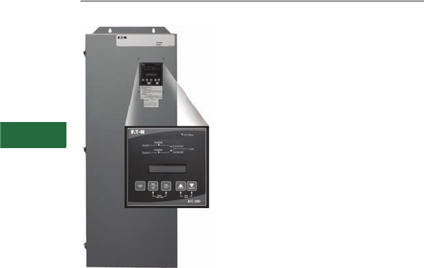
V2-T5-8 Volume 2—Commercial Distribution CA08100003E—April 2014 www.eaton.com
5
5
5
5
5
5
5
5
5
5
5
5
5
5
5
5
5
5
5
5
5
5
5
5
5
5
5
5
5
5
5.2
Transfer Sw itches
Contactor-Based Designs
Contactor-Based ATS with ATC-300+ Controller
Contents
Description Page
Automatic Open Transition, 40–1600A
Features, Benefits and Functions . . . . . . . . . . V2-T5-9
Catalog Number Selection. . . . . . . . . . . . . . . . V2-T5-10
Technical Data and Specifications . . . . . . . . . . V2-T5-10
Dimensions . . . . . . . . . . . . . . . . . . . . . . . . . . . V2-T5-11
Automatic Closed Transition, 40–1200A . . . . . . . . V2-T5-13
Bypass Isolation Transfer Switches, 40–1600A,
Dual Drawout . . . . . . . . . . . . . . . . . . . . . . . . . . . V2-T5-17
Bypass Isolation Transfer Switches, 40–1200A,
Fixed Bypass . . . . . . . . . . . . . . . . . . . . . . . . . . . V2-T5-23
Automatic Open Transition, 40–1600A
Product Description
The automatic open transition
contactor-based transfer
switch is the most basic
design that will provide a
fully functioning automatic
transfer switch.
The power switching
operation of Eaton’s
contactor-based transfer
switches may be separated
into the following key
categories of:
●Open in-phase transition—
break-before-make
operation utilizing an in-
phase monitor for source
synchronization
●Open delayed transition—
break-before-make
operation utilizing a
programmable time delay
(true neutral position)
●Open in-phase with
default to time delay
neutral—break-before-
make operation utilizing an
in-phase monitor for
source synchronization.
If the in-phase does not
initiate a transfer within a
programmable time delay,
then the transfer will
default to a time delay
neutral type of transfer
The open in-phase transition
utilizes a two-position
mechanism and the open
delayed transition utilizes a
three-position mechanism.
The mechanism used to
operate the Eaton electrical
contactor is a momentarily
energized solenoid consisting
of a stationary core and
a moving core that is
magnetically driven by
an electrical coil.
The mechanism can be
electrically and mechanically
operated. The design is
such that the mechanism is
inherently interlocked so the
device cannot be closed on
the Source 1 and Source 2
at the same time under
any circumstances. When
switching from Source 1
to Source 2, or Source 2 to
Source 1, the mechanism
will only allow a break-before-
make operation.
These contactor-based
designs can be applied
with the ATC-100 controller
up to 400A. The ATC-300+
controller can be applied
for applications 40–1600A.
Applications needing
communication capability
require the ATC-300+ with
communication enabled or
the ATC-900 controller.
Application Description
An automatic open transition
transfer switch may be used
for those applications where
emergency backup power is
required, but a momentary
loss of power is acceptable
on the retransfer from
emergency to normal.

Volume 2—Commercial Distribution CA08100003E—April 2014 www.eaton.com V2-T5-9
5
5
5
5
5
5
5
5
5
5
5
5
5
5
5
5
5
5
5
5
5
5
5
5
5
5
5
5
5
5
5.2
Transfer Switches
Contactor-Based Designs
Features, Benefits and Functions
Standard Features
●Auxiliary relay contacts:
●Source 1 present
2NO and 2NC
●Source 2 present
2NO and 2NC
●Switch position
indication contacts:
●Source 1 position
1NO and 1NC
●Source 2 position
1NO and 1NC
●Source 1 and Source 2
sensing:
●Undervoltage/
underfrequency
●Overvoltage/
overfrequency
●Three-phase rotation
protection
●Three-phase voltage
unbalance
●Pretransfer signal contacts
1NO/1NC (with three-
position mechanism)
●Go to emergency
(Source 2)
●Seven field-programmable
time delays
●LCD-based display for
programming, system
diagnostics and Help
message display
●Mimic diagram with source
available and connected
LED indication
●Time-stamped history log
●System TEST pushbutton
●Programmable plant
exerciser—OFF, daily,
7-, 14-, 28-day interval
selectable run time
0–600 minutes no load/
load with fail-safe
●Modbus® RTU via RS-485
Optional Features
●Available surge
suppression device for
power/controller, engine
start circuit, phone and
cable connections
●Space heater with
thermostat
●Eaton IQ and Power Xpert®
series metering
●Stainless steel cover for
controller
●Open in-phase transition,
time delay neutral or in-
phase with a default to
time delay neutral transfer
●ATC-100 and ATC-900
controllers available
●Source 2 inhibit
●Manual retransfer to
normal
●Remote annunciator with
control
●Ethernet communication
(PXG 400 Gateway)
Commercial Design Highlights
●UL 1008 front access
●High withstand and
closing ratings
●Compact design
1600 ATS with ATC-300+ Controller
Typical Contactor-Based ATS 100–400A
200A ATS with ATC-300+ Controller
1200A ATS with ATC-300+ Controller
Manual
Operating
Handle
Crossbar
Neutral
Connections
Voltage
Selection and
Transfor mer
Panel
Normal
Power Source
Power
Panel
Load Lugs
Emergency
Power Source
Logic
Panel
Transfer
Mechanism
V2-T5-10 Volume 2—Commercial Distribution CA08100003E—April 2014 www.eaton.com
5
5
5
5
5
5
5
5
5
5
5
5
5
5
5
5
5
5
5
5
5
5
5
5
5
5
5
5
5
5
5.2
Transfer Sw itches
Contactor-Based Designs
Catalog Number Selection
Automatic Transfer Switch
Technical Data and Specifications
UL 1008 Withstand and Close-On Ratings (kA)
Notes
1For application up to 400A only.
2Up to 480V.
3Specific fuse rating at 480V only.
480V 600V
UL 1008
Ampere Rating Mechanism Any Breaker Specific Breaker Any Breaker Specific Breaker Any Use
40, 80, 100 C2 10,000 30,000 10,000 22,000 100,000 3
150, 200 C2 10,000 30,000 22,000 35,000 100,000
225, 260, 400 C2 30,000 50,000 — — 200,000
40, 80, 100, 150, 200 C3, C5 30,000 50,000 22,000 35,000 200,000
225, 260, 400 C3, C5 30,000 50,000 50,000 65,000 200,000
600, 800, 1000,1200 C3, C5 50,000 65,000 50,000 65,000 200,000
1600 C3, C5 50,000 65,000 — — —
AT C 3 C2 X 3 0400 X S U
Type
AT = Automatic
NT = Non-automatic
Orientation
C = Contactor
Logic
1= ATC-100 1
3= ATC-300+
9= ATC-900
E= Electromechanical
Mechanism
C2 = In-phase only
C3 = Time delay neutral
(TDN) only
C5 = In-phase / TDN transfer
Switch
X = Fix mount
Amperes
0040 = 40A
0080 = 80A
0100 = 100A
0150 = 150A
0200 = 200A
0225 = 225A
0260 = 260A
0400 = 400A
0600 = 600A
0800 = 800A
1000 = 1000A
1200 = 1200A
1600 = 1600A 2
Voltage
A= 120V, 60 Hz
B= 208V, 60 Hz
E= 600V, 60 Hz
G= 220V, 50 Hz
H= 380V, 50 Hz
K= 600V, 50 Hz
M= 230V, 50 Hz
W= 240V, 60 Hz
X= 480V, 60 Hz
Z= 365V, 50 Hz
Enclosure
K= Open
S= NEMA 1
J= NEMA 12
R= NEMA 3R
D= NEMA 4X
Certification
U = UL listed
Number of
Poles
2 = Two-pole
3 = Three-pole
4 = Four-pole
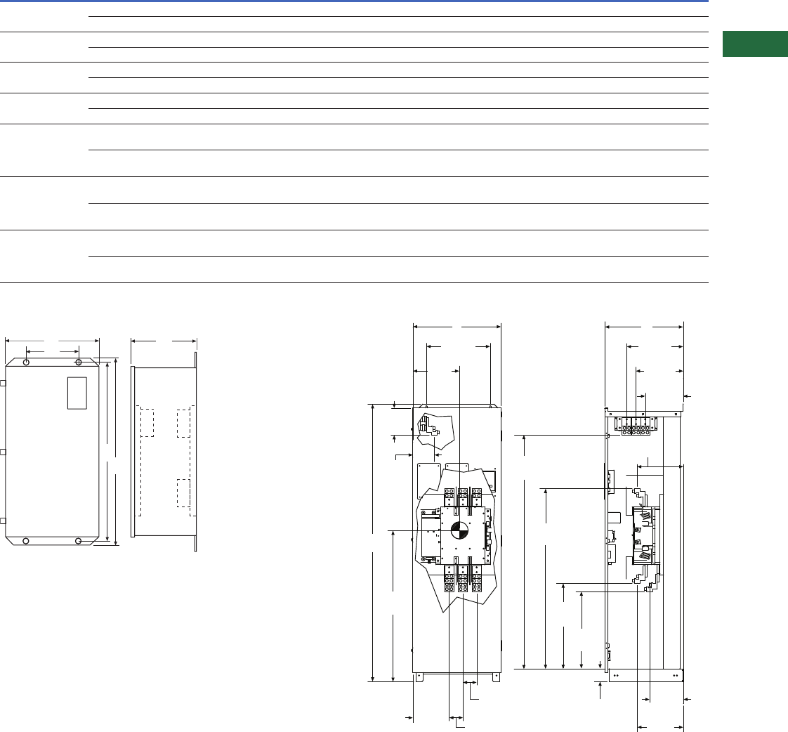
Volume 2—Commercial Distribution CA08100003E—April 2014 www.eaton.com V2-T5-11
5
5
5
5
5
5
5
5
5
5
5
5
5
5
5
5
5
5
5
5
5
5
5
5
5
5
5
5
5
5
5.2
Transfer Switches
Contactor-Based Designs
Dimensions
Approximate Dimensions in Inches (mm)
Contactor-Based Transfer Switch 40–1200A—Dimensions in Inches (mm) and Approximate Shipping Weight in Lbs (kg)
Automatic, Non-Automatic Up to 400A—
Wallmount, N1 or N3R
Notes
1Wallmount.
2Floorstanding and wall-secured—height dimension includes the bottom bracket.
Automatic, Non-Automatic 600–1200A Outline, N1 or N3R
Amperes Enclosure A (Height) B (Width) C (Depth)
Load Side, Normal
and Standby Source
Neutral
Connection Weight
40–100 at 480V 1N1, N12, N3R 38.68 (982.5) 18.31 (465.1) 13.34 (338.8) (1) #14–2/0 (3) #14–1/0 156 (71)
N4X 37.50 (952.5) 17.50 (444.5) 14.34 (364.2) (1) #14–2/0 (3) #14–1/0 156 (71)
40–100 at 600V 1N1, N12, N3R 38.68 (982.5) 18.31 (465.1) 13.34 (338.8) (1) #14–2/0 (3) #14–1/0 164 (74)
N4X 37.50 (952.5) 17.50 (444.5) 14.34 (364.2) (1) #14–2/0 (3) #14–1/0 164 (74)
150–200 at 480V 1N1, N12, N3R 38.68 (982.5) 18.31 (465.1) 13.34 (338.8) (1) #6–250 kcmil (3) 1/0–250 kcmil 164 (74)
N4X 37.50 (952.5) 17.50 (444.5) 14.34 (364.2) (1) #6–250 kcmil (3) 1/0–250 kcmil 164 (74)
150–200 at 600V 1N1, N12, N3R 52.00 (1321.0) 19.81 (503.2) 16.75 (425.5) (1) #6–250 kcmil (3) 1/0–250 kcmil 260 (118)
N4X 52.00 (1321.0) 21.00 (533.4) 16.75 (425.5) (1) #6–250 kcmil (3) 1/0–250 kcmil 260 (118)
225–400 at 480V 1N1, N12, N3R 52.00 (1321.0) 19.81 (503.2) 16.75 (425.5) (2) 3/0–250 kcmil
(1) 3/0–600 kcmil
(6) 250–500 kcmil 260 (118)
N4X 52.00 (1321.0) 21.00 (533.4) 16.75 (425.5) (2) 3/0–250 kcmil
(1) 3/0–600 kcmil
(6) 250–500 kcmil 260 (118)
225–1200 at 600V 2N1, N3R 79.41 (2017.0) 29.19 (741.4) 22.46 (570.5) (4) 1/0–750 kcmil (12) 1/0–750 kcmil 600 (272) three-pole
650 (295) four-pole
N12, N4X 84.75 (2152.7) 29.00 (737.0) three-pole
29.00 (737.0) four-pole
24.26 (616.2) (4) 1/0–750 kcmil (12) 1/0–750 kcmil 700 (318)
750 (340)
600–1200 at 480V 2N1, N3R 79.41 (2017.0) 25.25 (641.4) three-pole
29.19 (741.4) four-pole
22.46 (570.5) (4) 1/0–750 kcmil (12) 1/0–750 kcmil 600 (272) three-pole
650 (295) four-pole
N12, N4X 84.75 (2152.7) 29.00 (737.0) three-pole
29.00 (737.0) four-pole
24.26 (616.2) (4) 1/0–750 kcmil (12) 1/0–750 kcmil 700 (318)
750 (340)
B
G
A
H
C
Front View Side View
Top of
Lugs on
Power Panel
Front View Side View
10.37
(263.4)
3.94
(100.0)
43.23
(1098.1)
13.29
(337.6)
9.60
(43.9)
25.69
(652.5)
28.09
(713.5)
55.12
(1400.0)
3.68
(93.5) 13.13
(333.5)
13.13
(333.5)
18.25
(463.6)
6.11
(155.2)
7.75
(196.8)
68.59
(1742.2)
9.85
(250.2)
12.49
(317.2)
15.13
(384.3)
A
BC
Emergency
LoadNormal
Neutral
C
A
3.94
(100.0)
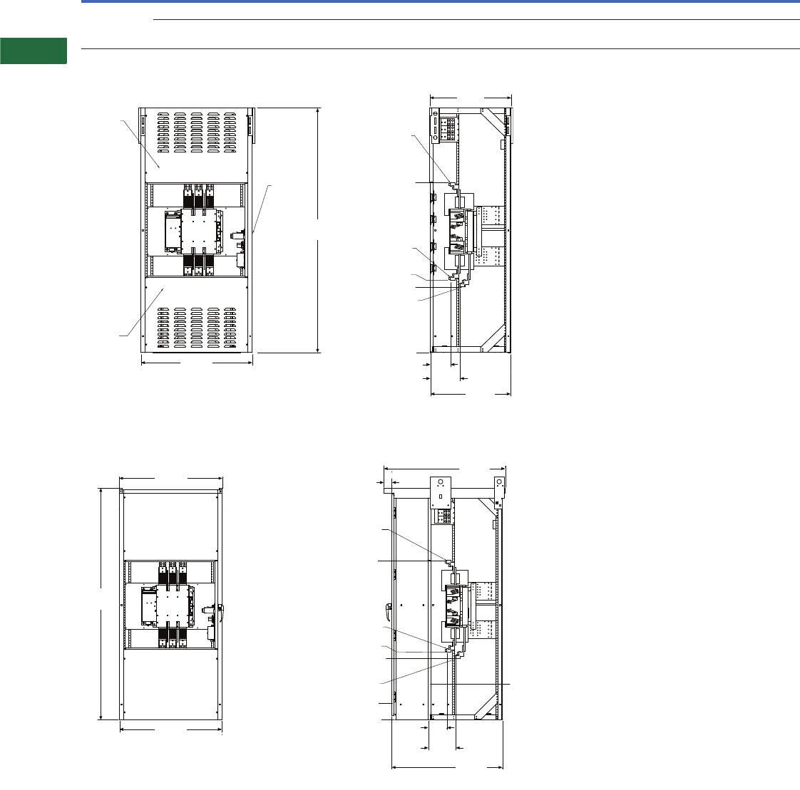
V2-T5-12 Volume 2—Commercial Distribution CA08100003E—April 2014 www.eaton.com
5
5
5
5
5
5
5
5
5
5
5
5
5
5
5
5
5
5
5
5
5
5
5
5
5
5
5
5
5
5
5.2
Transfer Sw itches
Contactor-Based Designs
Approximate Dimensions in Inches (mm)
1600A Transfer Switch
Automatic, Non-Automatic Open Transition NEMA 1 Enclosure 1600A
Automatic, Non-Automatic Open Transition NEMA 3R Enclosure 1600A
Note
1Freestanding.
Ampere
Rating Enclosure
A
(Height)
B
(Width)
C
(Depth)
Load Side, Normal and
Standby Source
Neutral
Connection
Weight
Lbs (kg)
1600A at
480V a
N1 90.00 (2286.0) 40.00 (1016.0) 29.00 (736.6) (4) 1/0–750 kcmil (12) 1/0–750 kcmil 730 (331) three-pole
N3R 90.72 (2304.3) 40.35 (1024.9) 47.59 (1208.8) (4) 1/0–750 kcmil (12) 1/0–750 kcmil 780 (354) three-pole
830 (377) four-pole
90.00
(2286.0)
40.00
(1016.0)
90.00
(2286.0)
28.73
(729.7)
10.72
(272.3)
7.22 (183.4)
0.00
24.13 (612.9)
Load Cable
Connections
Emergency
Power Cable
Connections
26.49 (672.8)
62.51
(1587.8)
Normal
Power Cable
Connections
29.22
(742.2)
Side View
Front View
Removable
Panel
Removable
Panel
Contactor
Compartment
Door
40.00
(1016.0)
Side View
Front View
(with outer door open)
90.69
(2303.5)
40.35
(1024.9)
43.34
(1100.8)
10.72
(272.3)
7.22
(183.4)
0.00
47.59
(1208.8)
3.14
(79.8)
24.13 (612.9)
Outer Door
Inner Removable
Panels and Contactor
Compartment Door
Load Cable
Connections
Emergency
Power Cable
Connections
26.49 (672.8)
62.51
(1587.8)
Normal
Power Cable
Connections
Volume 2—Commercial Distribution CA08100003E—April 2014 www.eaton.com V2-T5-13
5
5
5
5
5
5
5
5
5
5
5
5
5
5
5
5
5
5
5
5
5
5
5
5
5
5
5
5
5
5
5.2
Transfer Switches
Contactor-Based Designs
Contactor-Based ATS with ATC-800 Controller
Contents
Description Page
Automatic Open Transition, 40–1600A . . . . . . . . . V2-T5-8
Automatic Closed Transition, 40–1200A . . . . . . . . V2-T5-13
Features, Benefits and Functions . . . . . . . . . . . V2-T5-14
Catalog Number Selection . . . . . . . . . . . . . . . . V2-T5-15
Technical Data and Specifications . . . . . . . . . . V2-T5-15
Dimensions . . . . . . . . . . . . . . . . . . . . . . . . . . . V2-T5-16
Bypass Isolation Transfer Switches, 40–1600A,
Dual Drawout . . . . . . . . . . . . . . . . . . . . . . . . . . . V2-T5-17
Bypass Isolation Transfer Switches, 40–1200A,
Fixed Bypass. . . . . . . . . . . . . . . . . . . . . . . . . . . . V2-T5-23
Automatic Closed Transition, 40–1200A
Product Description
Eaton’s closed transition
contactor-based automatic
transfer switch is designed to
avoid intentional interruption
of power when both sources
of power are available by
momentarily paralleling
both sources.
The controller is a
comprehensive, multi-
function, microprocessor-
based controller, offering
extensive monitoring, status
reporting and transfer control
operation.
The make-before-break
contact sequence coupled
with Eaton’s ATC-800 or
ATC-900 provides a transfer
switch that is useful in critical
standby power applications
available from 40–1200A.
Application Description
A transfer switch designed
for closed transition has
make-before-break contacts
that require the normal and
alternate sources to be
synchronized. The source
contacts on Eaton’s controller
will parallel for 100 ms or
less. The controller provides
all-phase undervoltage,
underfrequency, and
overvoltage and
overfrequency protection
as a standard. Consult with
the local utility company for
permission and to verify the
protection requirements as
each utility may have
different rules regarding
closed transition applications.
Protective relays may be
available as an option upon
request.
Closed transition controls
The switch accomplishes the
closed transition transfer by
monitoring the voltage and
frequency set point conditions
of both power sources. Once
the set point conditions are
met, the controller will start
the closed transition
synchronization timer (TSCT).
The TSCT is adjustable from
1–60 minutes in duration.
This duration is the time during
which the controller will
monitor the phase angles to
anticipate when they will be
within 8 electrical degrees.
The closed transition scheme
is anticipatory, allowing the
close contacts signal to be
initiated before the sources are
exactly in phase. If the TSCT
times out and the transfer
switch has not reached
synchronization, the transfer
switch will remain connected
to the current power source
and a failure to transfer alarm
will be displayed.
The transfer switch can
also be equipped with an
optional open transition
transfer method for situations
where synchronization is
not possible, but a transfer
is required. One of the
following transition features
can be selected:
●Closed transition only
●Closed transition with
default to load voltage
decay
●Closed transition with
default to time delay
neutral
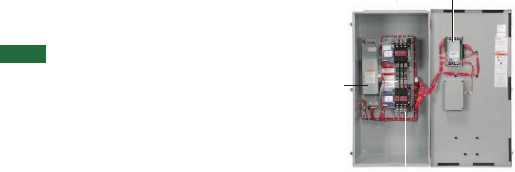
V2-T5-14 Volume 2—Commercial Distribution CA08100003E—April 2014 www.eaton.com
5
5
5
5
5
5
5
5
5
5
5
5
5
5
5
5
5
5
5
5
5
5
5
5
5
5
5
5
5
5
5.2
Transfer Sw itches
Contactor-Based Designs
Features, Benefits and Functions
Standard Features
●Auxiliary relay contacts:
●Source 1 present
1NO and 1NC
●Source 2 present
1NO and 1NC
●Switch position
indication contacts:
●Source 1 position
1NO and 1NC
●Source 2 position
1NO and 1NC
●Source 1 and Source 2
sensing:
●Undervoltage/
underfrequency
●Overvoltage/
overfrequency
●Go to emergency
(Source 2)
●Seven field-programmable
time delays
●LCD-based display for
programming, system
diagnostics and Help
message display
●Mimic diagram with source
available and connected
LED indication
●Time-stamped history log
●System TEST pushbutton
●Programmable plant
exerciser—OFF, daily,
7-day interval selectable
run time 0–600 minutes no
load/load with fail-safe
●Multi-Tap transformer
●Closed transition parallel
limit timer
●IBC/CBC seismic qualified
Optional Features
●Available surge
suppression device for
power/controller, engine
start circuit, phone and
cable connections
●Space heater with
thermostat
●Ammeter—load side
●Power quality metering
●Steel cover for controller
●Closed transition with
default to time delay
neutral or default to load
voltage decay
●Three-phase rotation
protection
●Three-phase voltage
unbalance
●Pretransfer signal contacts
1NO/1NC (with three-
position mechanism)
●ATC-900
Commercial Design Highlights
●UL 1008 front access
●High withstand and
closing ratings
●Compact design
Typical Contactor-Based ATC-900 Controller
Multi-Tap
Tra ns for m er
Normal
Power Source
Load
Lugs
Emergency
Power Source
Controller
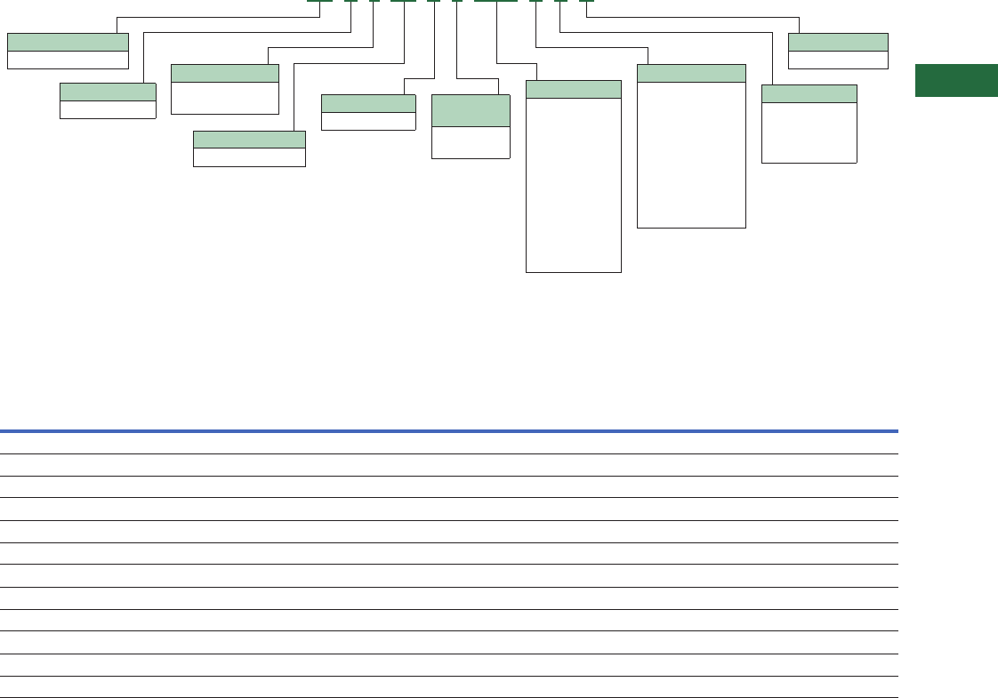
Volume 2—Commercial Distribution CA08100003E—April 2014 www.eaton.com V2-T5-15
5
5
5
5
5
5
5
5
5
5
5
5
5
5
5
5
5
5
5
5
5
5
5
5
5
5
5
5
5
5
5.2
Transfer Switches
Contactor-Based Designs
Catalog Number Selection
Automatic Transfer Switch
Technical Data and Specifications
UL 1008 Withstand and Close-On Ratings (kA)
UL 1008
Ampere
Rating
480V 480V 600V 600V Rating When Used with Upstream Fuse
Any
Breaker
Specific
Breaker
Any
Breaker
Specific
Breaker
Rating
(kA)
Test
Voltage Fuse Type
Maximum Fuse
Amperes
40 10 30 10 22 100 480 RK5 200
80 10 30 10 22 100 480 RK5 200
100 10 30 10 22 100 480 RK5 200
150 10 30 22 35 100 600 RK5 400
200 10 30 22 35 100 600 RK5 400
225 30 50 50 65 200 600 RK5 600
260 30 50 50 65 200 600 RK5 600
400 30 50 50 65 200 600 RK5 600
600 50 65 50 65 200 600 L, R, J, T 1600
800 50 65 50 65 200 600 L, R, J, T 1600
1000 50 65 50 65 200 600 L, R, J, T 1600
1200 50 65 50 65 200 600 L, R, J, T 1600
Type
CT = Closed transition
Orientation
C = Contactor
Logic
8 = ATC-800
9 = ATC-900
Mechanism
C3 = 3-position
Switch
X = Fix mount
Amperes
0040 = 40A
0080 = 80A
0100 = 100A
0150 = 150A
0200 = 200A
0225 = 225A
0260 = 260A
0400 = 400A
0600 = 600A
0800 = 800A
1000 = 1000A
1200 = 1200A
Voltage
A= 120V, 60 Hz
B= 208V, 60 Hz
E= 600V, 60 Hz
G= 220V, 50 Hz
H= 380V, 50 Hz
K= 600V, 50 Hz
M= 230V, 50 Hz
W= 240V, 60 Hz
X= 480V, 60 Hz
Z= 365V, 50 Hz
Enclosure
K= Open
S= NEMA 1
J= NEMA 12
R= NEMA 3R
Certification
U = UL listed
Number of
Poles
3 = Three-pole
4 = Four-pole
CT C 8 C3 X 3 0400 X S U
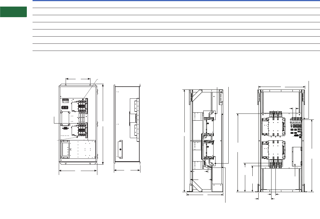
V2-T5-16 Volume 2—Commercial Distribution CA08100003E—April 2014 www.eaton.com
5
5
5
5
5
5
5
5
5
5
5
5
5
5
5
5
5
5
5
5
5
5
5
5
5
5
5
5
5
5
5.2
Transfer Sw itches
Contactor-Based Designs
Dimensions
Approximate Dimensions in Inches (mm)
Contactor-Based Transfer Switch 40–1200A Closed Transition
Automatic Up to 400A Wallmount NEMA 1 and NEMA 3R Automatic 600–1200A—Wallmount NEMA 1 and NEMA 3R
Note
1For NEMA 3R, add 17.00 inches (431.8 mm) to depth.
Ampere Rating
Enclosure Bolt Pattern Standard Terminals
A (Height) B (Width) C (Depth) G (Horizontal) H (Vertical)
Load Side, Normal
and Standby Source
Neutral
Connection
Weight in
Lbs (kg)
40–100 at 480V 52.74 (1339.6) 25.00 (635.0) 17.18 (436.4) 16.00 (406.4) 37.38 (949.5) (1) #14–2/0 (3) #14–2/0 190 (86)
40–100 at 600V 52.74 (1339.6) 25.00 (635.0) 17.18 (436.4) 16.00 (406.4) 37.38 (949.5) (1) #6–250 kcmil (3) #14–1/0 210 (95)
150–200 at 480V 52.74 (1339.6) 25.00 (635.0) 17.18 (436.4) 16.00 (406.4) 37.38 (949.5) (1) #6–250 kcmil (3) 1/0–250 kcmil 210 (95)
150–200 at 600V 171.02 (1803.9) 31.11 (790.2) 14.72 (373.9) 13.00 (330.2) 69.43 (1763.5) (2) 3/0–250 kcmil (6) 250–500 kcmil 800 (363)
225–400 at 480V 71.02 (1803.9) 31.11 (790.2) 14.72 (373.9) 13.00 (330.2) 69.43 (1763.5) (2) 3/0–250 kcmil (6) 250–500 kcmil 420 (191)
225–1200 at 600V 190.00 (2286.0) 46.00 (1168.4) 32.00 (812.8) N/A N/A (4) 1/0–750 Cu/Al (12) 1/0–750 kcmil 800 (363)
600–1200 at 480V 190.00 (2286.0) 46.00 (1168.4) 32.00 (812.8) N/A N/A (4) 1/0–750 Cu/Al (12) 1/0–750 kcmil 800 (363)
G
A
BC
Emergency
Power
Connection
Normal Power
Connections
Load Power
Connection
Front View Side View
(with right side removed)
2.64
(67.1)
TYP
C
A
Front View
Side View
(with left side removed)
15.66
(397.8)
19.19
(487.4)
Load Power
Cable Connections
Emergency
Power Cable
Connections
Normal Power
Cable Connections
Neutral Cable
Connections
B
Transformer
3.94
(100.1)
TYP
11.20
(284.5)
23.00
(584.2)
25.40
(645.2)
68.99
(1752.3) 63.74
(1619.0)
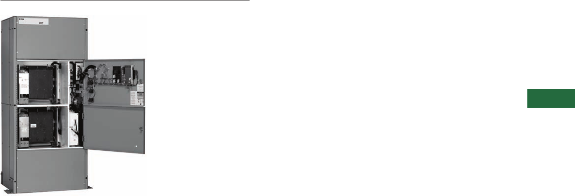
Volume 2—Commercial Distribution CA08100003E—April 2014 www.eaton.com V2-T5-17
5
5
5
5
5
5
5
5
5
5
5
5
5
5
5
5
5
5
5
5
5
5
5
5
5
5
5
5
5
5
5.2
Transfer Switches
Contactor-Based Designs
Bypass Isolation Transfer Switch
Contents
Description Page
Automatic Open Transition, 40–1600A . . . . . . . . . V2-T5-8
Automatic Closed Transition, 40–1200A . . . . . . . . V2-T5-13
Bypass Isolation Transfer Switches, 40–1600A,
Dual Drawout
Standards and Certifications . . . . . . . . . . . . . . V2-T5-19
Catalog Number Selection . . . . . . . . . . . . . . . . V2-T5-19
Technical Data and Specifications . . . . . . . . . . V2-T5-19
Diagram . . . . . . . . . . . . . . . . . . . . . . . . . . . . . . V2-T5-20
Dimensions . . . . . . . . . . . . . . . . . . . . . . . . . . . V2-T5-21
Bypass Isolation Transfer Switches, 40–1200A,
Fixed Bypass . . . . . . . . . . . . . . . . . . . . . . . . . . . V2-T5-23
Bypass Isolation Transfer
Switches, 40–1600A,
Dual Drawout
Product Description
A bypass isolation transfer
switch may be used to
provide emergency power to
life safety and other critical
loads where maintenance
of the main transfer switch,
without interruption of power
to the load, is either desirable
or required.
Application Description
Eaton’s Automatic Transfer
Switch is designed to provide
unmatched performance,
reliability and versatility for
critical standby power
applications. The switches
can be equipped with the
ATC-300+ or ATC-900
controllers to match your
application needs.
A bypass isolation automatic
transfer switch by application
requirements and per UL 1008
requires the main automatic
transfer switch contactor
(ATS) to be a drawout design.
Conventional designs allow
the bypass contactor to be
a fixed-mounted design.
The Eaton premium design
provides a drawout ATS and a
drawout bypass contactor or
a dual drawout design.
Features, Benefits and Functions
Industrial Design Highlights
●Front access is a standard
feature on all ratings
●Entry:
●Top, bottom or both
●Isolated compartments
●Improved safety:
●Isolated compartments
with barriers
●Single motion rack-out
with doors closed
●Ability to test power
switching elements
during drawout process
●Dual ATS capability—
bypass contactor can be
controlled by the ATS
controller in the bypass
mode of operation
●Installation flexibility:
●Field entry/exit locations
can be modified in the
field
●Interchangeable drawout
contactors
●Field-selectable multi-tap
transformer panel permits
operation on a wide range
of system voltages
●Dual drawout
Standard Features
●Drawout cassette design
on both ATS and bypass
●No service interruption in
bypass to the same source
●Source available contacts:
●Source 1 present
2NO and 2NC
●Source 2 present
2NO and 2NC
●Switch position contacts:
●Source 1 position
1NO and 1NC
●Source 2 position
1NO and 1NC
●Source 1 and Source 2
sensing:
●Undervoltage/
underfrequency
●Overvoltage/
overfrequency
●Three-phase rotation
protection
(ATC-300+ only)
●Three-phase voltage
unbalance/loss
(ATC-300+ only)
●Pretransfer signal
contacts 1NO and 1NC
(open transition only)
●Go to Source 2
(EMERGENCY)
●Field-programmable
time delays:
●Time delay engine start:
0–1200 seconds
●Time delay normal
to emergency:
0–1800 seconds
●Time delay emergency
to normal:
0–1800 seconds
●Time delay engine
cooldown:
0–1800 seconds
●Time delay emergency
failure: 0–6 seconds
●LCD-based display for
programming, system
diagnostics and Help
menu display
●Mimic diagram with source
available and connected
LED indication
●Time-stamped history log
●System TEST pushbutton
●Programmable plant
exerciser—OFF, daily,
7-, 14-, 28-day interval
selectable run time
0–600 minutes no load/
load with fail-safe
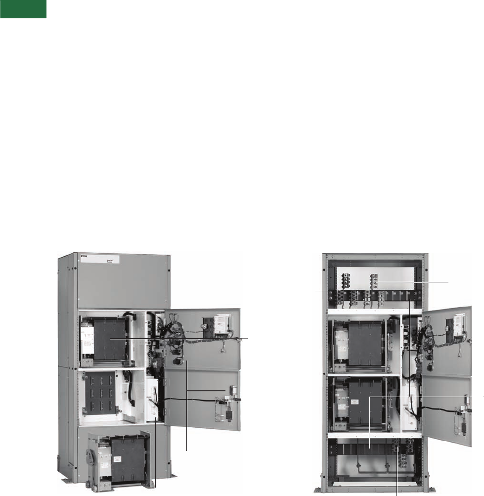
V2-T5-18 Volume 2—Commercial Distribution CA08100003E—April 2014 www.eaton.com
5
5
5
5
5
5
5
5
5
5
5
5
5
5
5
5
5
5
5
5
5
5
5
5
5
5
5
5
5
5
5.2
Transfer Sw itches
Contactor-Based Designs
Optional Features
●Available UL 1448 Third
Edition surge protection
device (SPD)
●Eaton IQ and Power Xpert
multi-function power
quality metering
●Automatic transfer mode
with selectable non-
automatic/automatic
retransfer mode
●Modbus RTU via RS-485
●Remote annunciation with
control
●Open in-phase transition,
time delay neutral or in-
phase with a default to
time delay neutral transfer
●ATC-900 controller
●Includes Modbus RTU
via RS-485
●Includes four
programmable inputs/
outputs
●Includes two plant
exercisers
●Includes LCD color
display with easy
navigation tools to
settings and event logs
●Expandable I/O (up to
20 I/O total)
●Optional integrated load
metering
●Optional EtherNet TCP/
IP communications
Bypass Isolation Switch
Components
Front Access
Front access is a standard
feature. Source 1 (NORMAL)
Source and Load connections
are set up as standard top
entry and Source 2
(EMERGENCY) Source
connections as bottom entry.
These connections are
located in their own separate
compartments. These
connections can be relocated
in the field if necessary.
M u l t i - Ta p Tr a n s f o rm e r
The industry-exclusive multi-
tap system voltage selector
allows the transfer switch to
be applied on most system
voltages by proper insertion
of the selector plug.
Drawout Contactors
The ATS and the bypass
drawout cassette power
contactor designs are
identical and interchangeable.
This standard feature
allows the user the ability
to withdraw, maintain or
swap contactor assemblies,
providing redundancy of ATS
and bypass functions from
one contactor assembly to
the other.
Improved Safety
The unique Eaton design
includes separation
between control and
power components. The
ATS and bypass isolation
contactors are mounted in
separate compartments with
protective barriers between
them. This design prevents
the possibility of contact
with the rear-mounted
power connections to the
contactors. In addition, the
top and bottom entry have
separate compartment doors.
Ease of Maintenance
Transfer to the bypass power
contactor is easily initiated
and controlled via door-
mounted controls. Once
the transfer to the bypass
contactor is complete, the
ATS contactor is easily racked
out with the compartment
door closed.
The ATS contactor may then
be tested in the racked out
position.
Ease of Transfer
The Eaton design allows the
operator to make a quick and
simple transfer from the ATS
power contactor to the
bypass contactor by initiating
the electrically operated
transfer via a two-position
switch. Door-mounted
indicating lights confirm
that a successful transfer
has taken place.
Dual ATS Capability
The controller on conventional
bypass isolation switches only
controls the ATS contactor.
The Eaton design allows the
switch controller to remain
active in both the ATS and
bypass modes, thus providing
control to either contactor.
This ability of the controller
to remain active and control
the bypass isolation contactor
provides “N+1” redundancy
of a second fully functioning
ATS, a feature unique
to Eaton.
Bypass Isolation Switch Components
Drawout
Bypass
Contactor
Separate Doors for ATS
and Bypass
Compartments
Multi-Tap Transformer with
Quick Connect Plug
Drawout ATS Contactor
Completely Removed Source 2 (EMERGENCY)
Connections
Source 1 (NORMAL)
Connections
Load
Connections
Front Access for
Top or Bottom
Entry; Terminals
can be Relocated
in the Field
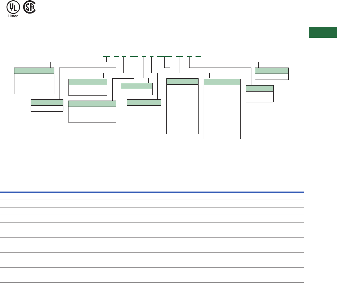
Volume 2—Commercial Distribution CA08100003E—April 2014 www.eaton.com V2-T5-19
5
5
5
5
5
5
5
5
5
5
5
5
5
5
5
5
5
5
5
5
5
5
5
5
5
5
5
5
5
5
5.2
Transfer Switches
Contactor-Based Designs
Standards and Certifications
●UL 1008 listed
●CSA C22.2 No. 178 certified
Catalog Number Selection
Automatic Bypass Isolation Contactor-Based Transfer Switch
Technical Data and Specifications
UL 1008 Withstand and Close-On Ratings (kA)
Note
11600A is dual drawout only and up to 480V.
UL 1008
Ampere
Rating
480V 480V 600V 600V Rating When Used with Upstream Fuse
Any
Breaker
Specific
Breaker
Any
Breaker
Specific
Breaker
Rating
(kA)
Test
Voltage Fuse Type
Maximum Fuse
Amperes
40 10 30 10 22 100 480 RK5 200
80 10 30 10 22 100 480 RK5 200
100 10 30 10 22 100 480 RK5 200
150 10 30 22 35 100 600 RK5 400
200 10 30 22 35 100 600 RK5 400
225 30 50 50 65 200 600 RK5 600
260 30 50 50 65 200 600 RK5 600
400 30 50 50 65 200 600 RK5 600
600 50 65 50 65 200 600 L 1200
800 50 65 50 65 200 600 L 1200
1000 50 65 50 65 200 600 L 1600
1200 50 65 50 65 200 600 L 1600
1600 50 65 — — 200 480 L 1600
Type
BI = Bypass isolation
open transition
CB = Bypass isolation
closed transition
Logic
3= ATC-300+
9= ATC-900
Amperes
0100 = 100A
0150 = 150A
0225 = 225A
0260 = 260A
0400 = 400A
0600 = 600A
0800 = 800A
1000 = 1000A
1200 = 1200A
1600 = 1600A 1
Voltage
B= 208V, 60 Hz
E= 600V, 60 Hz
G= 220V, 50 Hz
H= 380V, 50 Hz
K= 600V, 50 Hz
M= 230V, 50 Hz
N= 401V, 50 Hz
O= 415V, 50 Hz
W= 240V, 60 Hz
X= 480V, 60 Hz
Z= 365V, 50 Hz
Certification
U = UL 1008 listed
Enclosure
S= NEMA 1
R= NEMA 3R
Orientation
C = Contactor
Frame
C3 = Time delay neutral
(TDN) only
C5 = In-phase/TDN transfer
Mounting
E= Drawout
Number of Poles
2 = Two-pole
3 = Three-pole
4 = Four-pole
BI C 3 C3 E 3 1200 W S U
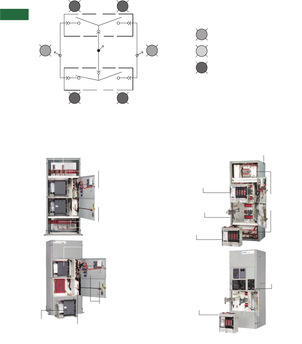
V2-T5-20 Volume 2—Commercial Distribution CA08100003E—April 2014 www.eaton.com
5
5
5
5
5
5
5
5
5
5
5
5
5
5
5
5
5
5
5
5
5
5
5
5
5
5
5
5
5
5
5.2
Transfer Sw itches
Contactor-Based Designs
Diagram
Bypass Isolation
1200A Drawout Bypass 400A Drawout Bypass
Load
Bypass
ATS
(3) (4)
(1) (2)
Source 1
(NORMAL)
Available
Shown as Normal Operation
Source 2
(EMERGENCY)
Available
Bypass
Source 1
(NORMAL)
ATS
Source 1
(NORMAL)
ATS
Source 2
(EMERGENCY)
Bypass
Source 2
(EMERGENCY)
ATS
Locked In
Door Open
ATS Isolated
(Flashing: ATS Removed)
Source 1
(NORMAL)
Connections
Load
Connections
Source 2
(EMERGENCY)
Connections
Front Access for
Top or Bottom
Entry; Terminals
Can be Relocated
in the Field
Separate Doors for
ATS and Bypass
Compartments
Drawout Bypass
Contactor
Multi-Tap Transformer
with Quick Connect Plug
Drawout ATS
Contactor
Completely
Removed
1200A Dual Drawout
Drawout ATS
Contactor
Drawout
Bypass Contactor
Compartment
400A Dual Drawout
Source 1 (NORMAL), Source 2
(EMERGENCY) and Load Connection
Located in Top Compartment Behind
Removable Electrical Panel
Electrical Panels
can be Removed for
Installation for Top
or Bottom Entry
Drawout ATS
Contactor
Completely
Removed
Separate ATS
Compartment
and Door
Drawout Bypass
Contactor
with Separate
Compartment
Door—Shown
Racked Out
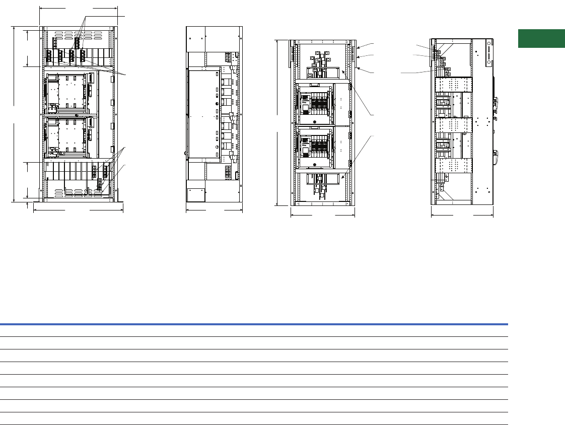
Volume 2—Commercial Distribution CA08100003E—April 2014 www.eaton.com V2-T5-21
5
5
5
5
5
5
5
5
5
5
5
5
5
5
5
5
5
5
5
5
5
5
5
5
5
5
5
5
5
5
5.2
Transfer Switches
Contactor-Based Designs
Dimensions
Approximate Dimensions in Inches (mm)
600–1200A 480V or 225–1200A 600V Dual Drawout Bypass
NEMA 1
Note: Source 1 Normal and Load connections are top and Source 2
is bottom. These connections can be relocated in the field.
100–400A 480V or 100–200A 600V Dual Drawout Bypass
NEMA 1
Contactor-Based Transfer Switch 100–1200A—NEMA 1 Dimensions and Approximate Shipping Weight
Notes
1For seismic applications, it is necessary to use 5–13 UNC Grade or better hex head bolts and washers torqued to 50 ft-lbs.
2NEMA 12 and 4X dimensions are 90.00 inches H x 46.00 inches W x 38.00 inches D (2286.0 mm H x 1168.4 mm W x 965.2 mm D).
NEMA 4X enclosures are 304SS standard with an optional upgrade to 316SS.
3Same number of terminals per phase will be supplied.
4For NEMA 3R dimensions, add 18.29 inches (464.6 mm).
5For NEMA 3R dimensions, add 18.59 inches (472.2 mm).
Load
Connections
Source 1
Normal
Connections
Source 2
Emergency
Connections
Normal
Connections
Bypass
ATS
40.00
(1016.0)
18.50
(470.0)
90.08
(2288.0)
18.50
(470.0)
46.00
(1168.4)
2.00
(50.8)
28.97
(735.8)
CG
Front View Side View
Front View Side View
29.30
(744.2)
30.00
(762.0)
78.07
(1983.0)
Emergency
Power Cable
Connections
Load Cable
Connections
Normal
Power Cable
Connections
Electrical
Panel Not
Shown for
Clarity
Switch Rating
Amperes/Volts 2
Enclosure Seismic 1Standard Terminals
Weight in
Lbs (kg)Height Width Depth
Normal, Emergency
and Load Neutral
Metric Conversion
(mm2) 3
100–200A 480V 478.07 (1983.0) 30.00 (762.0) 29.30 (744.2) (1) #6–350 Cu/Al (3) #6–350 Cu/Al 13–177 mm2 Cu/Al 625 (283.8)
100–200A 600V 478.07 (1983.0) 30.00 (762.0) 29.30 (744.2) (1) #6–350 Cu/Al (3) #6–350 Cu/Al 13–177 mm2 Cu/Al 625 (283.8)
225–400A 480V 478.07 (1983.0) 30.00 (762.0) 29.30 (744.2) (1) 3/0–600 Cu/Al (3) 3/0–600 Cu/Al 85–304 mm2 Cu/Al 625 (283.8)
225–400A 600V 590.00 (2286.0) 40.00 (1016.0) 28.97 (735.8) (2) 3/0–750 Cu/Al (6) 3/0–750 Cu/Al 85–304 mm2 Cu/Al 1750 (794.5)
600A 480V 590.00 (2286.0) 40.00 (1016.0) 28.97 (735.8) (2) 3/0–750 Cu/Al (6) 3/0–750 Cu/Al 85–380 mm2 Cu/Al 1750 (794.5)
600A 600V 590.00 (2286.0) 40.00 (1016.0) 28.97 (735.8) (2) 3/0–750 Cu/Al (6) 3/0–750 Cu/Al 85–380 mm2 Cu/Al 1750 (794.5)
800–1200A 480V 590.00 (2286.0) 40.00 (1016.0) 28.97 (735.8) (4) 3/0–750 Cu/Al (12) 3/0–750 Cu/Al 85–380 mm2 Cu/Al 1850 (839.9)
800–1200A 600V 590.00 (2286.0) 40.00 (1016.0) 28.97 (735.8) (4) 3/0–750 Cu/Al (12) 3/0–750 Cu/Al 85–380 mm2 Cu/Al 1850 (839.9)
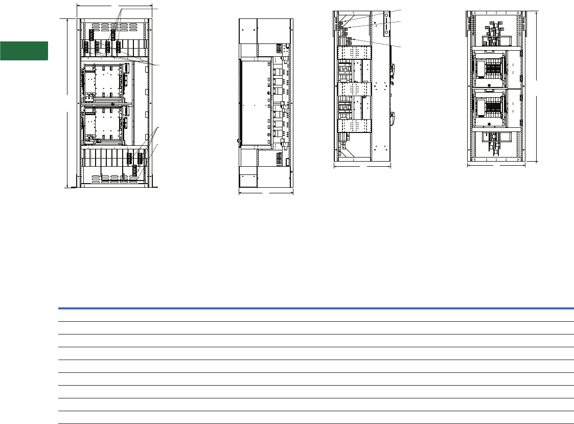
V2-T5-22 Volume 2—Commercial Distribution CA08100003E—April 2014 www.eaton.com
5
5
5
5
5
5
5
5
5
5
5
5
5
5
5
5
5
5
5
5
5
5
5
5
5
5
5
5
5
5
5.2
Transfer Sw itches
Contactor-Based Designs
Approximate Dimensions in Inches (mm)
600–1600A 480V or 225–1200A 600V Dual Drawout Bypass
NEMA 1
Note: Source 1 Normal and Load connections are top and Source 2
is bottom. These connections can be relocated in the field.
100–400A 480V or 100–200A 600V Dual Drawout Bypass
NEMA 1
Contactor-Based Transfer Switch 100–1600A—NEMA 1 Dimensions and Approximate Shipping Weight
Notes
1For seismic applications, it is necessary to use 5–13 UNC Grade or better hex head bolts and washers torqued to 50 ft-lbs.
2NEMA 12 and 4X dimensions are 90.00 inches H x 46.00 inches W x 38.00 inches D (2286.0 mm H x 1168.4 mm W x 965.2 mm D).
NEMA 4X enclosures are 304SS standard with an optional upgrade to 316SS.
3Same number of terminals per phase will be supplied.
4For NEMA 3R dimensions, add 18.29 inches (464.6 mm).
5For NEMA 3R dimensions, add 18.59 inches (472.2 mm).
CG
Load Power
Cable Connections
Normal
Power Cable
Connections
Emergency
Power Cable
Connections
Neutral Cable
Connections
B
A
C
Front View Side View
(With Right Side Removed)
Bypass
ATS
Side View
(With Left Side Removed)
Front View
B
C
A
Emergency Power
Cable Connections
Load Cable
Connections
Normal
Power Cable
Connections
Electrical
Panel Not
Shown for
Clarity
Switch Rating
Amperes/Volts 2
Enclosure Seismic 1Standard Terminals
Weight in
Lbs (kg)Height (A) Width (B) Depth (C)
Normal, Emergency
and Load Neutral
Metric Conversion
(mm2) 3
100–200A 480V 478.07 (1983.0) 30.00 (762.0) 29.30 (744.2) (1) #6–350 Cu/Al (3) #6–350 Cu/Al 13–177 mm2 Cu/Al 625 (283.8)
100–200A 600V 478.07 (1983.0) 30.00 (762.0) 29.30 (744.2) (1) #6–350 Cu/Al (3) #6–350 Cu/Al 13–177 mm2 Cu/Al 625 (283.8)
225–400A 480V 478.07 (1983.0) 30.00 (762.0) 29.30 (744.2) (1) 3/0–600 Cu/Al (3) 3/0–600 Cu/Al 85–304 mm2 Cu/Al 625 (283.8)
225–400A 600V 590.00 (2286.0) 40.00 (1016.0) 28.97 (735.8) (2) 3/0–750 Cu/Al (6) 3/0–750 Cu/Al 85–304 mm2 Cu/Al 1750 (794.5)
600A 480V 590.00 (2286.0) 40.00 (1016.0) 28.97 (735.8) (2) 3/0–750 Cu/Al (6) 3/0–750 Cu/Al 85–380 mm2 Cu/Al 1750 (794.5)
600A 600V 590.00 (2286.0) 40.00 (1016.0) 28.97 (735.8) (2) 3/0–750 Cu/Al (6) 3/0–750 Cu/Al 85–380 mm2 Cu/Al 1750 (794.5)
800–1200A 480V 590.00 (2286.0) 40.00 (1016.0) 28.97 (735.8) (4) 3/0–750 Cu/Al (12) 3/0–750 Cu/Al 85–380 mm2 Cu/Al 1850 (839.9)
800–1200A 600V 590.00 (2286.0) 40.00 (1016.0) 28.97 (735.8) (4) 3/0–750 Cu/Al (12) 3/0–750 Cu/Al 85–380 mm2 Cu/Al 1850 (839.9)
1600A 480V 90.00 (2286.0) 40.00 (1016.0) 40.00 (1016.0) (4) 3/0–750 Cu/Al (12) 3/0–750 Cu/Al 85–380 mm2 Cu/Al 2200 (997.9)
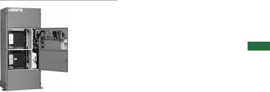
Volume 2—Commercial Distribution CA08100003E—April 2014 www.eaton.com V2-T5-23
5
5
5
5
5
5
5
5
5
5
5
5
5
5
5
5
5
5
5
5
5
5
5
5
5
5
5
5
5
5
5.2
Transfer Switches
Contactor-Based Designs
Bypass Isolation Transfer Switch
Contents
Description Page
Automatic Open Transition, 40–1600A . . . . . . . . . V2-T5-8
Automatic Closed Transition, 40–1200A . . . . . . . . V2-T5-13
Bypass Isolation Transfer Switches, 40–1600A,
Dual Drawout . . . . . . . . . . . . . . . . . . . . . . . . . . . V2-T5-17
Bypass Isolation Transfer Switches, 40–1200A,
Fixed Bypass. . . . . . . . . . . . . . . . . . . . . . . . . . . . V2-T5-23
Catalog Number Selection . . . . . . . . . . . . . . . . V2-T5-25
Technical Data and Specifications . . . . . . . . . . V2-T5-25
Diagram . . . . . . . . . . . . . . . . . . . . . . . . . . . . . . V2-T5-26
Dimensions . . . . . . . . . . . . . . . . . . . . . . . . . . . V2-T5-27
Bypass Isolation Transfer Switches, 40–1200A, Fixed Bypass
Product Description
A bypass isolation transfer
switch may be used to
provide emergency power to
life safety and other critical
loads where maintenance
of the main transfer switch,
without interruption of power
to the load, is either desirable
or required.
Application Description
Eaton’s Automatic Transfer
Switch is designed to provide
unmatched performance,
reliability and versatility for
critical standby power
applications. The switches
can be equipped with the
ATC-300+ or ATC-900
controllers to match your
application needs.
Features
Industrial Design Highlights
●Front access is a standard
feature on all ratings
●Entry:
●Top, bottom or both
●Isolated compartments
●Improved safety:
●Isolated compartments
with barriers
●Single motion rack-out
with doors closed
●Ability to test power
switching elements
during drawout process
●Dual ATS capability—
bypass contactor can be
controlled by the ATS
controller in the bypass
mode of operation
●Installation flexibility:
●Field entry/exit locations
can be modified in the
field
●Interchangeable drawout
contactors
●Field-selectable multi-tap
transformer panel permits
operation on a wide range
of system voltages
●Fixed-mounted bypass,
drawout ATS
Standard Features
●Drawout cassette design
on ATS with fixed-mounted
bypass
●No service interruption in
bypass to the same source
●Source available contacts:
●Source 1 present
2NO and 2NC
●Source 2 present
2NO and 2NC
●Switch position contacts:
●Source 1 position
1NO and 1NC
●Source 2 position
1NO and 1NC
●Source 1 and Source 2
sensing:
●Undervoltage/
underfrequency
●Overvoltage/
overfrequency
●Three-phase rotation
protection
(ATC-300+ only)
●Three-phase voltage
unbalance/loss
(ATC-300+ only)
●Pretransfer signal
contacts 1NO and 1NC
(open transition only)
●Go to Source 2
(EMERGENCY)
●Field-programmable
time delays:
●Time delay engine start:
0–1200 seconds
●Time delay normal
to emergency:
0–1800 seconds
●Time delay emergency
to normal:
0–1800 seconds
●Time delay engine
cooldown:
0–1800 seconds
●Time delay emergency
failure: 0–6 seconds
●LCD-based display for
programming, system
diagnostics and Help
menu display
●Mimic diagram with source
available and connected
LED indication
●Time-stamped history log
●System TEST pushbutton
●Programmable plant
exerciser—OFF, daily,
7-, 14-, 28-day interval
selectable run time
0–600 minutes no load/
load with fail-safe
(ATC-300+ only)
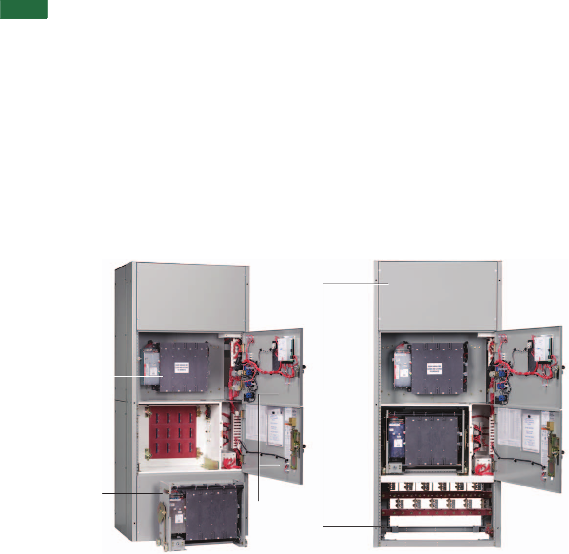
V2-T5-24 Volume 2—Commercial Distribution CA08100003E—April 2014 www.eaton.com
5
5
5
5
5
5
5
5
5
5
5
5
5
5
5
5
5
5
5
5
5
5
5
5
5
5
5
5
5
5
5.2
Transfer Sw itches
Contactor-Based Designs
Optional Features
●Available UL 1448 Third
Edition surge protection
device (SPD)
●Eaton IQ and Power Xpert
multi-function power
quality metering
●Automatic transfer mode
with selectable non-
automatic/automatic
retransfer mode
●Modbus RTU via RS-485
●Remote annunciation with
control
●Open in-phase transition,
time delay neutral or in-
phase with a default to
time delay neutral transfer
●ATC-900 controller
●Includes Modbus RTU
via RS-485
●Includes four
programmable inputs/
outputs
●Includes two plant
exercisers
●Includes LCD color
display with easy
navigation tools to
settings and event logs
●Expandable I/O (up to 20
I/O total)
●Optional integrated load
metering
●Optional EtherNet TCP/
IP communications
Bypass Isolation Switch
Components
Front Access
Front access is a standard
feature. Source 1 (NORMAL),
Source 2 (EMERGENCY) and
Load connections are set up
as bottom entry. These
connections are located in
their own separate
compartments.
M u l t i - Ta p Tr a n s f o rm e r
The industry-exclusive Multi-
Tap system voltage selector
allows the transfer switch to
be applied on most system
voltages by proper insertion
of the selector plug.
Drawout ATS and Fixed-
Mounted Bypass
The ATS is designed as a
drawout with the contactor
mounted in a cassette
with wheels. This allows the
user the ability to withdraw,
maintain, inspect and
re-insert the ATS.
The bypass unit is designed as
a fixed-mounted design in its
own separate compartment.
Improved Safety
The unique Eaton design
includes separation
between control and
power components. The
ATS and bypass isolation
contactors are mounted in
separate compartments with
protective barriers between
them. This design prevents
the possibility of contact
with the rear-mounted
power connections to the
contactors. In addition, the
top and bottom entry have
separate compartment doors.
Ease of Maintenance
Transfer to the bypass power
contactor is easily initiated
and controlled via door-
mounted controls. Once
the transfer to the bypass
contactor is complete, the
ATS contactor is easily racked
out with the compartment
door closed. The ATS
contactor may then be tested
in the isolated position.
Ease of Transfer
The Eaton design allows the
operator to make a quick and
simple transfer from the ATS
power contactor to the
bypass contactor by initiating
the electrically operated
transfer via a two-position
switch. Door-mounted
indicating lights confirm
that a successful transfer
has taken place.
Dual ATS Capability
The controller on conventional
bypass isolation switches only
controls the ATS contactor.
The Eaton design allows the
switch controller to remain
active in both the ATS and
bypass modes, thus providing
control to either contactor.
This ability of the controller
to remain active and control
the bypass isolation contactor
provides “N+1” redundancy
of a second fully functioning
ATS, a feature unique
to Eaton.
Bypass Isolation—Fixed Bypass Components
Fixed-Mounted
Bypass Contactor
Separate Doors for
ATS and Bypass
Compartments
Drawout ATS
Contactor
Completely
Removed
Front Access for
Top or Bottom
Entry
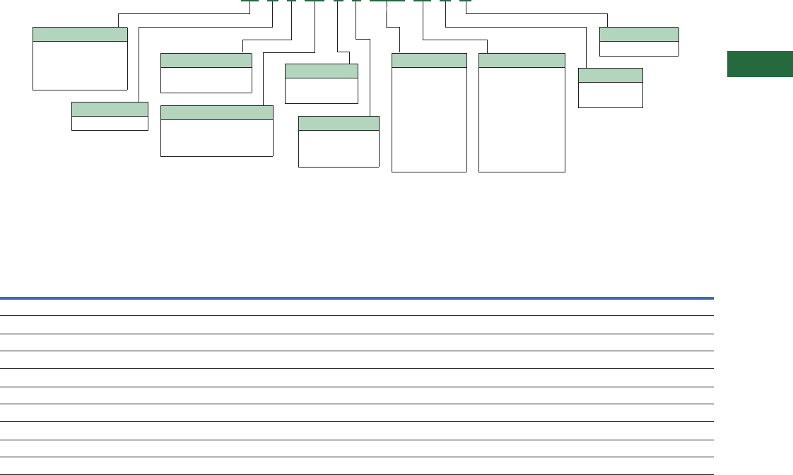
Volume 2—Commercial Distribution CA08100003E—April 2014 www.eaton.com V2-T5-25
5
5
5
5
5
5
5
5
5
5
5
5
5
5
5
5
5
5
5
5
5
5
5
5
5
5
5
5
5
5
5.2
Transfer Switches
Contactor-Based Designs
Catalog Number Selection
Automatic Bypass Isolation Contactor-Based Transfer Switch
Technical Data and Specifications
UL 1008 Withstand and Close-On Ratings (kA)
Note
11600A is available on dual drawout only.
UL 1008
Ampere
Rating 1
480V 480V 600V 600V Rating When Used with Upstream Fuse
Any
Breaker
Specific
Breaker
Any
Breaker
Specific
Breaker
Rating
(kA)
Test
Voltage Fuse Type
Maximum Fuse
Amperes
100 30 50 22 35 100 480 RK5 200
150 30 50 22 35 100 600 RK5 400
200 30 50 22 35 100 600 RK5 400
225 30 50 50 65 200 600 RK5 600
260 30 50 50 65 200 600 RK5 600
400 30 50 50 65 200 600 RK5 600
600 50 65 50 65 200 600 L 1600
800 50 65 50 65 200 600 L 1600
1000 50 65 50 65 200 600 L 1600
1200 50 65 50 65 200 600 L 1600
Type
BI = Bypass isolation
open transition
CB = Bypass isolation
closed transition
Logic
3= ATC-300+
9= ATC-900
Amperes
0100 = 100A
0150 = 150A
0225 = 225A
0260 = 260A
0400 = 400A
0600 = 600A
0800 = 800A
1000 = 1000A
1200 = 1200A
Voltage
B= 208V, 60 Hz
E= 600V, 60 Hz
G= 220V, 50 Hz
H= 380V, 50 Hz
K= 600V, 50 Hz
N= 401V, 50 Hz
O= 415V, 50 Hz
W= 240V, 60 Hz
X= 480V, 60 Hz
Certification
U = UL 1008 listed
Enclosure
S= NEMA 1
R= NEMA 3R
Orientation
C = Contactor
Frame
C3 = Time delay neutral
(TDN) only
C5 = In-phase/TDN transfer
Mounting
X= Fixed-mount
bypass
Number of Poles
2 = Two-pole
3 = Three-pole
4 = Four-pole
BI C 3 C3 E 3 1200 W S U
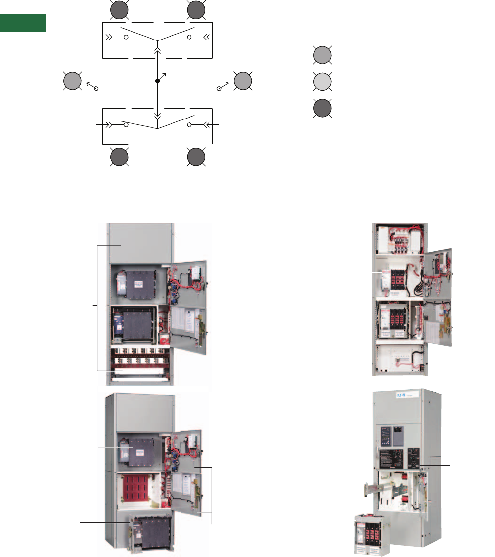
V2-T5-26 Volume 2—Commercial Distribution CA08100003E—April 2014 www.eaton.com
5
5
5
5
5
5
5
5
5
5
5
5
5
5
5
5
5
5
5
5
5
5
5
5
5
5
5
5
5
5
5.2
Transfer Sw itches
Contactor-Based Designs
Diagram
Bypass Isolation
1200A Fixed Bypass 400A Fixed Bypass
Load
Bypass
ATS
(3) (4)
(1) (2)
Source 1
(NORMAL)
Available
Shown as Normal Operation
Source 2
(EMERGENCY)
Available
Bypass
Source 1
(NORMAL)
ATS
Source 1
(NORMAL)
ATS
Source 2
(EMERGENCY)
Bypass
Source 2
(EMERGENCY)
ATS
Locked In
Door Open
ATS Isolated
(Flashing: ATS Removed)
Separate Doors
for ATS and Bypass
Compartments
Fixed-Mounted
Bypass Contactor
Drawout ATS
Contactor Cassette
with Wheels
Completely
Removed
Front Access
for Top or
Bottom Entry
Drawout ATS
Contactor
Drawout ATS
Contactor Rack Out
Fixed-Mounted
Bypass Contactor
Drawout Bypass
Contactor
Compartment
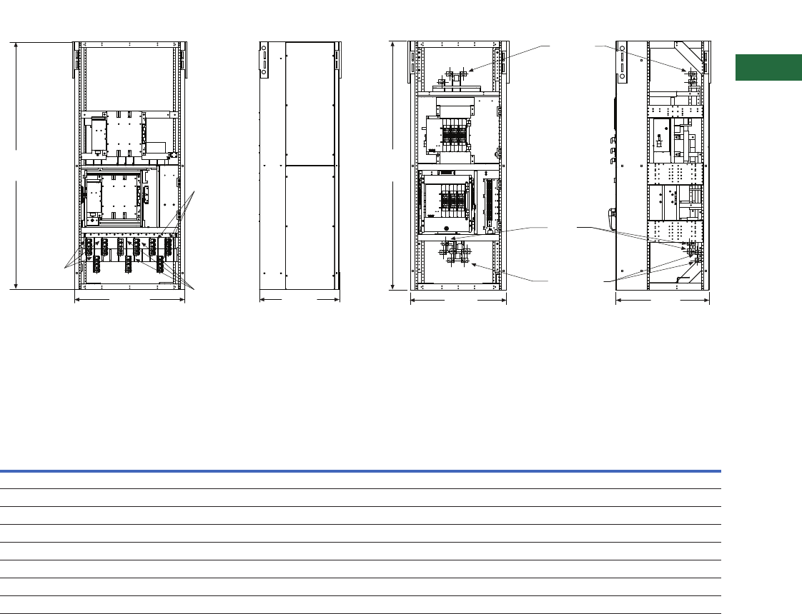
Volume 2—Commercial Distribution CA08100003E—April 2014 www.eaton.com V2-T5-27
5
5
5
5
5
5
5
5
5
5
5
5
5
5
5
5
5
5
5
5
5
5
5
5
5
5
5
5
5
5
5.2
Transfer Switches
Contactor-Based Designs
Dimensions
Approximate Dimensions in Inches (mm)
600−1200A 480V or 225−1200A 600V Fixed Bypass NEMA 1
Note: Source 1 Normal, Source 2 Emergency and Load connections must
be either ALL top or ALL bottom and are NOT field reconfigurable.
100−400A 480V or 100−225A 600V Fixed Bypass NEMA 1
Note: Source 1 Normal, Source 2 Emergency and Load connections are
NOT factory or field reconfigurable. Sufficient wireway and bending space
is available to come in from either top or bottom.
Contactor-Based Transfer Switch 100–1200A—NEMA 1 Dimensions and Approximate Shipping Weight
Notes
1For seismic applications, it is necessary to use 5–13 UNC Grade or better hex head bolts and washers torqued to 50 ft-lbs.
2For NEMA 3R dimensions, add 18.29 inches (464.6 mm).
3For NEMA 3R dimensions, add 18.59 inches (472.2 mm).
Front View Side View
90.00
(2286.0)
40.00
(1016.0)
28.97
(735.8)
Source 1
Normal
Connection Load
Connections
Source 2
Emergency
Connections
Source 1
Normal
Connection
Load
Cable
Connections
Source 2
Emergency
Connections
Top and Bottom
Compartment Electrical
Panel Not Shown for Clarity
29.30
(744.2)
30.00
(762.0)
78.07
(1983.0)
Front View Side View
Switch Rating
Amperes/Volts
Enclosure Seismic 1Standard Terminals
Weight in
Lbs (kg)Height Width Depth
Normal and
Emergency Load Neutral
100–200A 480V 278.07 (1983.0) 30.00 (762.0) 29.30 (744.2) (1) #6–350 Cu/Al (1) #6–350 Cu/Al (3) #6–350 Cu/Al 625 (283.8)
100–200A 600V 278.07 (1983.0) 30.00 (762.0) 29.30 (744.2) (1) #6–350 Cu/Al (1) #6–350 Cu/Al (3) #6–350 Cu/Al 625 (283.8)
225–400A 480V 278.07 (1983.0) 30.00 (762.0) 29.30 (744.2) (1) 3/0–600 Cu/Al (1) 3/0–600 Cu/Al (3) 3/0–600 Cu/Al 625 (283.8)
225–400A 600V 390.00 (2286.0) 40.00 (1016.0) 28.97 (735.8) (2) 3/0–750 Cu/Al (2) 3/0–750 Cu/Al (6) 3/0–750 Cu/Al 1550 (703.7)
600A 480V 390.00 (2286.0) 40.00 (1016.0) 28.97 (735.8) (2) 3/0–750 Cu/Al (2) 3/0–750 Cu/Al (6) 3/0–750 Cu/Al 1550 (703.7)
600A 600V 390.00 (2286.0) 40.00 (1016.0) 28.97 (735.8) (2) 3/0–750 Cu/Al (2) 3/0–750 Cu/Al (6) 3/0–750 Cu/Al 1550 (703.7)
800–1200A 480V 390.00 (2286.0) 40.00 (1016.0) 28.97 (735.8) (4) 3/0–750 Cu/Al (4) 3/0–750 Cu/Al (12) 3/0–750 Cu/Al 1750 (794.5)
800–1200A 600V 390.00 (2286.0) 40.00 (1016.0) 28.97 (735.8) (4) 3/0–750 Cu/Al (4) 3/0–750 Cu/Al (12) 3/0–750 Cu/Al 1750 (794.5)
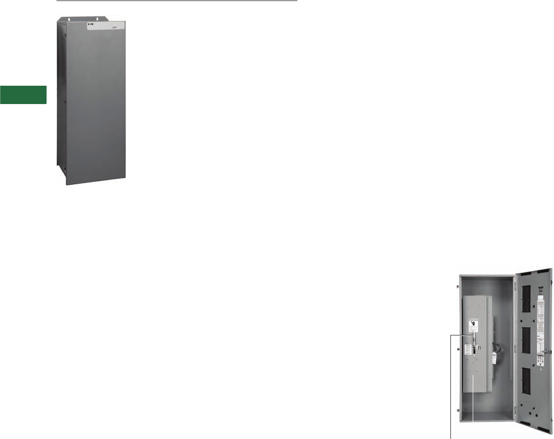
V2-T5-28 Volume 2—Commercial Distribution CA08100003E—April 2014 www.eaton.com
5
5
5
5
5
5
5
5
5
5
5
5
5
5
5
5
5
5
5
5
5
5
5
5
5
5
5
5
5
5
5.3
Transfer Sw itches
Breaker-Based Designs
Manual Wallmount Transfer Switch
Contents
Description Page
Molded Case Switches—Manual
Wallmount, 30–1000A
Standards and Certifications . . . . . . . . . . . . . . V2-T5-29
Catalog Number Selection. . . . . . . . . . . . . . . . V2-T5-29
Technical Data and Specifications . . . . . . . . . . V2-T5-30
Dimensions . . . . . . . . . . . . . . . . . . . . . . . . . . . V2-T5-31
Molded Case Switches—Non-Automatic
Wallmount . . . . . . . . . . . . . . . . . . . . . . . . . . . . . V2-T5-32
Molded Case Switches—Automatic
Wallmount, 30–1000A . . . . . . . . . . . . . . . . . . . . V2-T5-34
Maintenance Bypass Switches—
Type MBHE 100–1000A . . . . . . . . . . . . . . . . . . . V2-T5-41
Molded Case Switches—Manual Wallmount,
30–1000A
Description
Eaton’s wallmount manually
operated transfer switches
are designed for a variety of
standby power applications
for critical loads. In the event
of a primary power source
interruption, the user can
manually transfer the load
circuits to the standby power
source. Once primary power
has been restored, the user
can manually transfer the load
circuits back to the primary
power source.
Application Description
Manual transfer switches
cover applications ranging
from 30 to 1000A through
600 Vac for standard manual
configurations and open
transition.
Manual transfer switches
may be applied for those
application where a manually
initiated and manually
operated transfer is suitable.
The front door of the switch
must be opened to operate
the manual handle. The
design comes standard with a
deadfront design, allowing
safe manual transfer under
load. Should an application
require a service entrance
rating, then a non-automatic
or automatic design needs to
be selected.
Features and Benefits
Features
●Molded case switch power
contact assemblies
●Positive mechanical
interlocking
●Permanently affixed
manual operating handle
Benefits
●High withstand, totally
enclosed for maximum arc
suppression and isolation
during power transfer
●Optional trip units offer
system overcurrent
protection
●Prevents the paralleling of
two sources of power
●Permits safe and
convenient manual transfer
of power
●Requires no control power
Manual Switch with Door Open—
Manually Initiated and
Manually Operated
Note: If a service entrance rating
is required, then a non-automatic
type switch must be selected.
Service entrance ratings are
not available on a manual
transfer switch.
Manual Handle
Deadfront
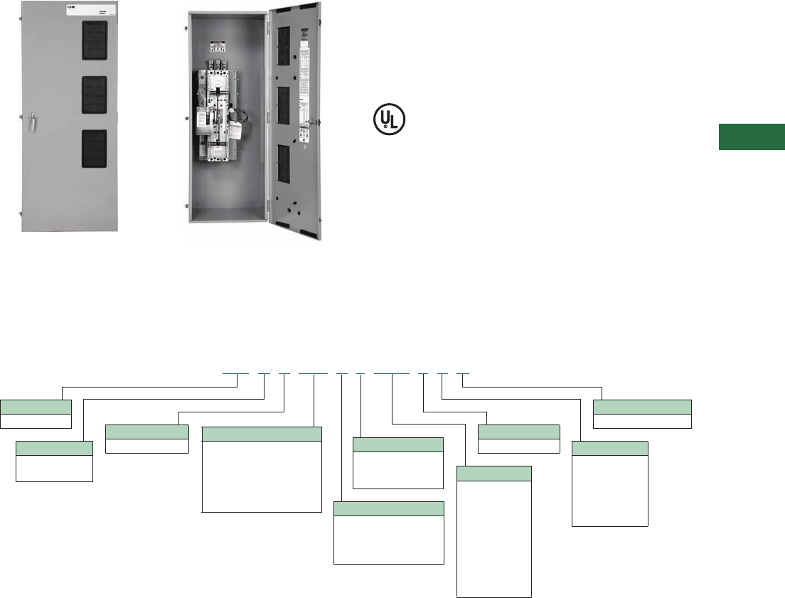
Volume 2—Commercial Distribution CA08100003E—April 2014 www.eaton.com V2-T5-29
5
5
5
5
5
5
5
5
5
5
5
5
5
5
5
5
5
5
5
5
5
5
5
5
5
5
5
5
5
5
5.3
Transfer Switches
Breaker-Based Design
Manual Switch with Door Closed—
Must Open Door to Engage the
Manual Handle
Manual Transfer Switch Shown
Without Deadfront
Standards and Certifications
●Complies with UL 1008
and UL 489 standards
●IBC seismic qualified
●Meets American Bureau of
Shipping (ABS) approval
Catalog Number Selection
Manual Breaker-Based Transfer Switch
Notes
1Horizontal is available only on ratings 150A or less.
Service entrance is not available on a manual design.
MT H X MD C 2 0100 E S U
Type
MT = Manual
Orientation
H = Horizontal 1
V = Vertical
Logic
X = No logic
Mounting (Fixed)
A= FM, N (MCS), E (MCS)
B= FM, N (MCB), E (MCB)
C= FM, N (MCB), E (MCS)
D= FM, N (MCS), E (MCB)
Number of Poles
2 = Two-pole
3 = Three-pole
4 = Four-pole Amperes
0030 =30A
0070 =70A
0100 = 100A
0150 = 150A
0225 = 225A
0300 = 300A
0400 = 400A
0600 = 600A
0800 = 800A
1000 = 1000A
Voltage
E = 600V, 60 Hz Enclosure
K= Open
S= NEMA 1
J= NEMA 12
R= NEMA 3R
L= NEMA 4
D= NEMA 4X
Certification
U = UL 1008 listed
Frame
Molded case device
FD = 30–150A
KD = 150–300A
LD = 400–600A
MD = 600–800A
ND = 800–1000A

V2-T5-30 Volume 2—Commercial Distribution CA08100003E—April 2014 www.eaton.com
5
5
5
5
5
5
5
5
5
5
5
5
5
5
5
5
5
5
5
5
5
5
5
5
5
5
5
5
5
5
5.3
Transfer Sw itches
Breaker-Based Designs
Technical Data and Specifications
Wallmount Transfer Switch Standard Terminal Data for
Power Cable Connections 1
Transfer Switch Ratings—Systems Coordination
Information—Withstand, Closing and Interrupting Ratings 2
Notes
1All terminals suitable for copper or aluminum conductors. For alternate terminal sizes,
contact Eaton.
2For maximum breaker ratings in circuits when the transfer switch is evaluated as a
“Motor Branch Circuit Conductor,” refer to NEC Section 430.25 for sizing.
3Class RK5 fuse with 100 kA rating.
4Four-pole units rated 35 kA.
Switch
Ampere Rating
Breaker
Frame
Line Side (Normal
and Standby Source)
Load
Connection
Neutral
Connection
30–100 HFD (1) #14–1/0 (1) #14–1/0 (3) #14–1/0
150–225 HFD (1) #6–300 (1) #6–300 (3) #4–300
225–300 HKD (1) #3–350 (1) #6–350 (3) #4–350
400 HLD (1) 4/0–600 (2) #1–500 (6) 250–350
600 HLD (1) 3/0–350 (2) #1–500 (6) 250–350
600 HMDL (2) #1–500 (2) #1–500 (12) 4/0–500
600 (four-pole) NB (3) 3/0–400 (3) 3/0–400 (3) 3/0–400
800 HMDL (3) 3/0–400 (3) 3/0–400 (12) 4/0–500
800 HNB (4) 4/0–500 (4) 4/0–500 (12) 4/0–500
1000 HNB (4) 4/0–500 (4) 4/0–500 (12) 4/0–500
Standard UL 1008 3-Cycle—Horizontal and Vertical Industrial
ATS
Ampere
Rating
Any Breaker Rating Ratings When Used With Upstream Fuse (kA)
240V 480V 600V
Maximum
Fuse Rating
Fuse
Type 3600V
30 100 65 25 200 J,T 200
70 100 65 25 200 J,T 200
100 100 65 25 200 J,T 200
150 100 65 25 400 J,T 200
200 100 65 25 400 J,T 200
225 100 65 25 400 J,T 200
300 100 65 25 400 J,T 200
400 100 65 25 600 J,T 200
600 100 65 425 800/1200 J,T 100/200
800 65 50 425 1200/1600 L 100/200
1000 65 50 425 1600 L 200
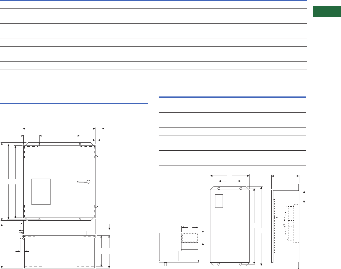
Volume 2—Commercial Distribution CA08100003E—April 2014 www.eaton.com V2-T5-31
5
5
5
5
5
5
5
5
5
5
5
5
5
5
5
5
5
5
5
5
5
5
5
5
5
5
5
5
5
5
5.3
Transfer Switches
Breaker-Based Designs
Dimensions
Approximate Dimensions in Inches (mm)
30–1000A Type MTVX
30–150A Type MTHXFD Manual Power Panel and Transformer Panel
Notes
1Suitable for Cu or Al wire. Consult the factory for other available terminal sizes.
2Alternate line terminals.
Dimensions are approximate and should not be used for construction purposes.
Switch
Type
Enclosure Gutter Space Bolt Pattern
Standard Terminals 1Weight
Lbs (kg)
ABCDEFGH
Height Width Depth Width Depth Bending Horizontal Vertical Line Load Neutral
HKD (150–225A) 48.00 (1219.2) 20.81 (528.6) 16.65 (422.9) 8.00 (203.2) 4.00 (101.6) 10.59 (269.0) 11.00 (279.4) 45.50 (1155.7) (1) #3–350 (1) #6–350 (3) #4–350 305 (138)
HKD (300A) 56.00 (1422.4) 20.81 (528.6) 16.65 (422.0) 8.00 (203.2) 4.00 (101.6) 13.59 (345.2) 11.00 (279.4) 53.50 (1358.9) (1) #3–350 (1) #6–350 (3) #4–350 305 (138)
HLD (400A) 64.00 (1625.6) 25.81 (655.6) 16.65 (422.9) 8.00 (203.2) 4.00 (101.6) 10.54 (267.7) 16.00 (406.4) 61.48 (1561.6) (1) 4/0–600 (2) #1–500 (6) 250–350 425 (193)
HLD (400A) 253.00 (1346.2) 25.81 (655.6) 16.65 (422.9) 8.00 (203.2) 4.00 (101.6) 11.85 (301.0) 16.00 (406.4) 50.48 (1282.2) (2) 3/0–350 (2) #1–500 (6) 250–350 425 (193)
HLD (600A) 64.00 (1625.6) 25.81 (655.6) 16.65 (422.9) 8.00 (203.2) 4.00 (101.6) 10.54 (267.7) 16.00 (406.4) 61.48 (1561.6) (2) 3/0–350 (2) #1–500 (12) 4/0–500 425 (193)
HLD (600A) 264.00 (1625.6) 25.81 (655.6) 16.65 (422.9) 8.00 (203.2) 4.00 (101.6) 10.54 (267.7) 16.00 (406.4) 61.48 (1561.6) (2) 400–500 (2) #1–500 (12) 4/0–500 425 (193)
HMDL (600A) 76.74 (1949.2) 25.81 (655.6) 17.75 (450.8) 8.00 (203.2) 4.00 (101.6) 17.73 (450.3) 16.00 (406.4) 75.15 (1908.8) (2) #1–500 (2) #1–500 (12) 4/0–500 510 (232)
HMDL (800A) 76.74 (1949.2) 25.81 (655.6) 17.75 (450.8) 8.00 (203.2) 4.00 (101.6) 17.73 (450.3) 16.00 (406.4) 75.15 (1908.8) (3) 3/0–400 (3) 3/0–400 (12) 4/0–500 510 (232)
NB (800–1000A) 76.74 (1949.2) 25.81 (655.6) 17.75 (450.8) 8.00 (203.2) 4.00 (101.6) 17.58 (446.5) 16.00 (406.4) 75.15 (1908.8) (4) 4/0–500 (4) 4/0–500 (12) 4/0–500 570 (259)
Dimensions
Weight
Lbs (kg)ABCDEF GH
22.88
(581.2)
13.13
(333.5)
22.74
(577.6)
22.62
(574.5)
24.50
(622.3)
9.78
(248.4)
10.28
(261.1)
32.31
(820.7)
143
(65)
5.00
(127.0)
E C D
A
B
F G
1.75
(44.45)
1.25
(31.75)
H
0.75
(19.1)
Latch
Closed
2.00
(50.8)
Latch
Open
Power Panel Type Height Width Depth
Power Panel
HFD 11.00 (279.4) 17.00 (431.8) 6.81 (173.0)
HKD 24.50 (622.3) 11.88 (301.8) 17.50 (444.5)
HLD 26.00 (660.4) 16.88 (428.8) 17.50 (444.5)
HMDL 36.25 (920.8) 16.88 (428.8) 17.50 (444.5)
NB 36.25 (920.8) 16.88 (428.8) 19.00 (482.6)
Transformer Panel
HFD 22.00 (558.8) 16.50 (419.1) 6.50 (165.1)
HKD, HLD, HMDL and NB 28.63 (727.2) 8.25 (209.6) 5.50 (139.7)
Logic
Panel
D
E
Power
Panel Transformer
Panel
B
G
A
H
C
F
Top of Lugs
on Power Panel
Gutter
Space
Front View Side ViewTop View
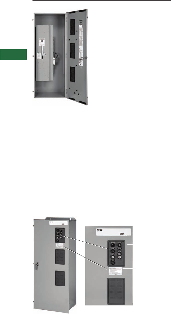
V2-T5-32 Volume 2—Commercial Distribution CA08100003E—April 2014 www.eaton.com
5
5
5
5
5
5
5
5
5
5
5
5
5
5
5
5
5
5
5
5
5
5
5
5
5
5
5
5
5
5
5.3
Transfer Sw itches
Breaker-Based Designs
Non-Automatic Wallmount
Contents
Description Page
Molded Case Switches—Manual
Wallmount, 30–1000A . . . . . . . . . . . . . . . . . . . . V2-T5-28
Molded Case Switches—Non-Automatic
Wallmount
Standards and Certifications . . . . . . . . . . . . . . V2-T5-33
Catalog Number Selection. . . . . . . . . . . . . . . . V2-T5-33
Technical Data and Specifications . . . . . . . . . . V2-T5-33
Dimensions . . . . . . . . . . . . . . . . . . . . . . . . . . . V2-T5-34
Molded Case Switches—Automatic
Wallmount, 30–1000A . . . . . . . . . . . . . . . . . . . . V2-T5-34
Maintenance Bypass Switches—
Type MBHE 100–1000A . . . . . . . . . . . . . . . . . . . V2-T5-41
Molded Case Switches—Non-Automatic Wallmount,
30–1000A
Product Description
Eaton’s wallmount non-
automatic transfer switches
are designed for a variety of
standby power applications
for critical loads.
In the event of a primary
power source interruption,
the user can manually
transfer the load circuits to
the standby power source
through the use of an
external pushbutton. Once
primary power has been
restored, the user can
manually transfer the load
circuits back to the primary
power source through the
use of an external
pushbutton.
Non-Automatic Switch with Doors Closed
Note: Optional service entrance rating shown for this photo.
Device Panel Control
Switch, Service
Entrance Keyed
Switch and
Indication Lights
Service
Entrance
Label (Optional)
Application Description
Non-automatic transfer
switches cover applications
ranging from 30–1000A
through 600 Vac for manual
configurations, open
transition, standard or
service entrance.
Non-automatic transfer
switches are manually
initiated, but electrically
operated designs. Front
door-mounted controls allow
the operator to initiate the
transfer. Overcurrent trips
may be added to the design
for either or both the normal
and emergency source.
Service entrance ratings
are available.
Features and Benefits
Features
●Molded case switch power
contact assemblies
●Positive mechanical and
electrical interlocking
●Permanently affixed
manual operating handle
●Pushbutton operation
Benefits
●High withstand, totally
enclosed for maximum arc
suppression and isolation
during power transfer
●Optional trip units offer
system overcurrent
protection
●Prevents the paralleling of
two sources of power
●Permits safe and
convenient manual transfer
of power under load via
external pushbutton
initiated operation
Non-Automatic Transfer Switch
Device panel shows controls
to initiate the manual transfer
and control indicating lights.
In addition, an optional
service entrance rating may
be specified. Keyed switch is
mounted on the device panel.
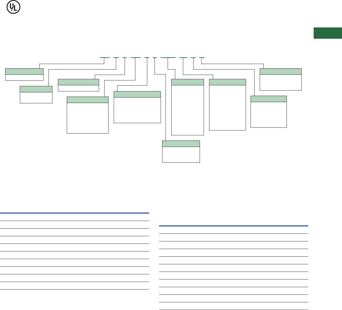
Volume 2—Commercial Distribution CA08100003E—April 2014 www.eaton.com V2-T5-33
5
5
5
5
5
5
5
5
5
5
5
5
5
5
5
5
5
5
5
5
5
5
5
5
5
5
5
5
5
5
5.3
Transfer Switches
Breaker-Based Designs
Standards and Certifications
●Complies with UL 1008 and UL 489 standards
●IBC seismic qualified
Catalog Number Selection
Non-Automatic Breaker-Based Transfer Switch
Technical Data and Specifications
Wallmount Transfer Switch Standard Terminal Data for
Power Cable Connections 1
Transfer Switch Ratings—Systems Coordination
Information—Withstand, Closing and Interrupting Ratings 2
Notes
1All terminals suitable for copper or aluminum conductors. For alternate terminal sizes,
contact Eaton.
2For maximum breaker ratings in circuits when the transfer switch is evaluated as a
“Motor Branch Circuit Conductor,” refer to NEC Section 430.25 for sizing.
3Class RK5 fuse with 100 kA rating.
4Four-pole units rated 35 kA.
Type
NT = Non-automatic
Orientation
H= Horizontal
V=Vertical
Logic
E = Electromechanical
Enclosure
K= Open
S= NEMA 1
R= NEMA 3R
J= NEMA 12
D= NEMA 4X
Certification
U = UL 1008 listed
R = UL recognized
X = No listing
NT H E KD C 2 0100 W S U
Mounting
Fixed
A= FM, N (MCS), E (MCS)
B= FM, N (MCB), E (MCB)
C= FM, N (MCB), E (MCS)
D= FM, N (MCS), E (MCB)
Number of Poles
2 = Two-pole
3 = Three-pole
4 = Four-pole
Frame
Molded case device
FD = 30–150A
KD = 150–300A
LD = 400–600A
MD = 600–800A
ND = 800–1000A
Amperes
0030 = 30A
0070 = 70A
0100 = 100A
0150 = 150A
0225 = 225A
0300 = 300A
0400 = 400A
0600 = 600A
0800 = 800A
1000 = 1000A
Voltage
B= 208V, 60 Hz
E= 600V, 60 Hz
G= 220V, 50/60 Hz
H= 380V, 50 Hz
K= 600V, 50 Hz
O= 415V, 50 Hz
W= 240V, 60 Hz
X= 480V, 60 Hz
Z= 365V, 50 Hz
Switch
Ampere Rating
Breaker
Frame
Line Side (Normal
and Standby Source)
Load
Connection
Neutral
Connection
30–100 HFD (1) #14–1/0 (1) #14–1/0 (3) #14–1/0
150–225 HFD (1) #6–300 (1) #6–300 (3) #4–300
225–300 HKD (1) #3–350 (1) #6–350 (3) #4–350
400 HLD (1) 4/0–600 (2) #1–500 (6) 250–350
600 HLD (1) 3/0–350 (2) #1–500 (6) 250–350
600 HMDL (2) #1–500 (2) #1–500 (12) 4/0–500
600 (four-pole) NB (3) 3/0–400 (3) 3/0–400 (3) 3/0–400
800 HMDL (3) 3/0–400 (3) 3/0–400 (12) 4/0–500
800 HNB (4) 4/0–500 (4) 4/0–500 (12) 4/0–500
1000 HNB (4) 4/0–500 (4) 4/0–500 (12) 4/0–500
Standard UL 1008 Three-Cycle—Horizontal and Vertical Industrial
ATS
Ampere
Rating
Any Breaker Rating Ratings When Used with Upstream Fuse (kA)
240V 480V 600V
Maximum
Fuse Rating
Fuse
Type 3600V
30 100 65 25 200 J, T 200
70 100 65 25 200 J, T 200
100 100 65 25 200 J, T 200
150 100 65 25 400 J, T 200
200 100 65 25 400 J, T 200
225 100 65 25 400 J, T 200
300 100 65 25 400 J, T 200
400 100 65 25 600 J, T 200
600 100 65 425 800/1200 J, T 100/200
800 65 50 425 1200/1600 L 100/200
1000 65 50 425 1600 L 200
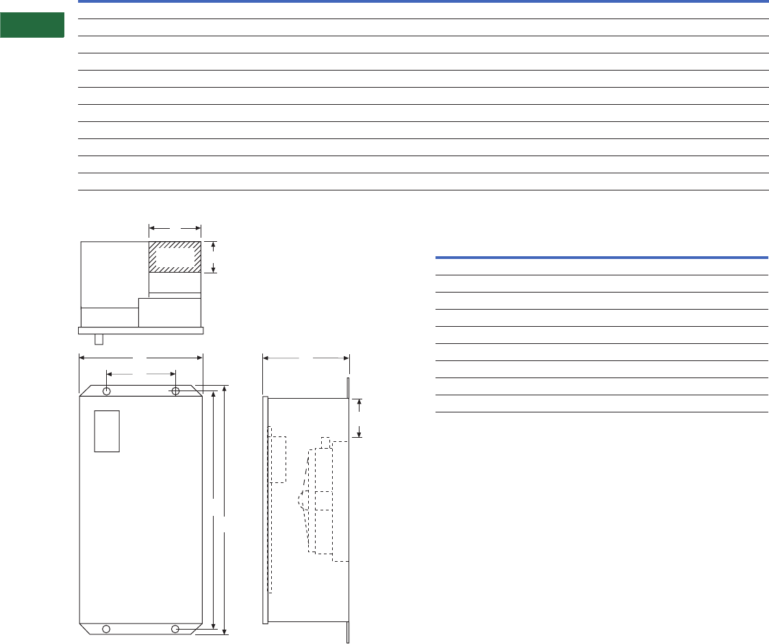
V2-T5-34 Volume 2—Commercial Distribution CA08100003E—April 2014 www.eaton.com
5
5
5
5
5
5
5
5
5
5
5
5
5
5
5
5
5
5
5
5
5
5
5
5
5
5
5
5
5
5
5.3
Transfer Sw itches
Breaker-Based Designs
Dimensions
Approximate Dimensions in Inches (mm)
30–1000A Types NTHE, NTVE
Power Panel and Transformer Panel
Notes
1Suitable for Cu or Al wire. Consult the factory for other available terminal sizes.
2NTHE with multi-tap voltage selection panel.
3Alternate line terminals.
Switch
Type
Enclosure Gutter Space Bolt Pattern
Standard Terminals 1Weight
Lbs (kg)
ABCDEFGH
Height Width Depth Width Depth Bending Horizontal Vertical Line Load Neutral
HFD (30–100A) 247.74 (1213.0) 20.81 (528.6) 15.22 (386.6) 8.00 (203.2) 4.00 (101.6) 6.22 (157.9) 10.75 (273.0) 45.24 (1049.1) (1) #14–1/0 (1) #14–1/0 (3) #14–1/0 232 (105)
HFD (150A) 247.74 (1213.0) 20.81 (528.6) 15.22 (386.6) 8.00 (203.2) 4.00 (101.6) 6.22 (157.9) 10.75 (273.0) 45.24 (1049.1) (1) #6–300 (1) #6–300 (3) #4–300 232 (105)
HKD (150–225A) 48.00 (1219.2) 20.81 (528.6) 16.65 (422.9) 8.00 (203.2) 4.00 (101.6) 10.59 (269.0) 11.00 (279.4) 45.50 (1155.7) (1) #3–350 (1) #6–350 (3) #4–350 305 (138)
HKD (300A) 56.00 (1422.4) 20.81 (528.6) 16.65 (422.9) 8.00 (203.2) 4.00 (101.6) 13.59 (345.2) 11.00 (279.4) 53.50 (1358.9) (1) #3–350 (1) #6–350 (3) #4–350 305 (138)
HLD (400A) 64.00 (1625.6) 25.81 (655.6) 16.65 (422.9) 8.00 (203.2) 4.00 (101.6) 10.54 (267.7) 16.00 (406.4) 61.48 (1561.6) (1) 4/0–600 (2) #1–500 (6) 250–350 425 (193)
HLD (400A) 353.00 (1346.2) 25.81 (655.6) 16.65 (422.9) 8.00 (203.2) 4.00 (101.6) 11.85 (301.0) 16.00 (406.4) 50.48 (1282.2) (2) 3/0–350 (2) #1–500 (6) 250–350 425 (193)
HLD (600A) 64.00 (1625.6) 25.81 (655.6) 16.65 (422.9) 8.00 (203.2) 4.00 (101.6) 10.54 (267.7) 16.00 (406.4) 61.48 (1561.6) (2) 3/0–350 (2) #1–500 (12) 4/0–500 425 (193)
HLD (600A) 364.00 (1625.6) 25.81 (655.6) 16.65 (422.9) 8.00 (203.2) 4.00 (101.6) 10.54 (267.7) 16.00 (406.4) 61.48 (1561.6) (2) 400–500 (2) #1–500 (12) 4/0–500 425 (193)
HMDL (600A) 76.74 (1949.2) 25.81 (655.6) 17.75 (450.8) 8.00 (203.2) 4.00 (101.6) 17.73 (450.3) 16.00 (406.4) 75.15 (1908.8) (2) #1–500 (2) #1–500 (12) 4/0–500 510 (232)
HMDL (800A) 76.74 (1949.2) 25.81 (655.6) 17.75 (450.8) 8.00 (203.2) 4.00 (101.6) 17.73 (450.3) 16.00 (406.4) 75.15 (1908.8) (3) 3/0–400 (3) 3/0–400 (12) 4/0–500 510 (232)
NB (800–1000A) 76.74 (1949.2) 25.81 (655.6) 17.75 (450.8) 8.00 (203.2) 4.00 (101.6) 17.58 (446.5) 16.00 (406.4) 75.15 (1908.8) (4) 4/0–500 (4) 4/0–500 (12) 4/0–500 570 (259)
B
G
A
H
C
F
Top of Lugs
on Power Panel
Transformer
Panel
Logic
Panel
D
E
Power
Panel
Gutter
Space
Front View Side View
Power
Panel Type Height Width Depth
Power Panel
HFD 11.00 (279.4) 17.00 (431.8) 6.81 (173.0)
HKD 24.50 (622.3) 11.88 (301.8) 17.50 (444.5)
HLD 26.00 (660.4) 16.88 (428.8) 17.50 (444.5)
HMDL 36.25 (920.8) 16.88 (428.8) 17.50 (444.5)
NB 36.25 (920.8) 16.88 (428.8) 19.00 (482.6)
Transformer Panel
HFD 22.00 (558.8) 16.50 (419.1) 6.50 (165.1)
HKD, HLD, HMDL and NB 28.63 (727.2) 8.25 (209.6) 5.50 (139.7)
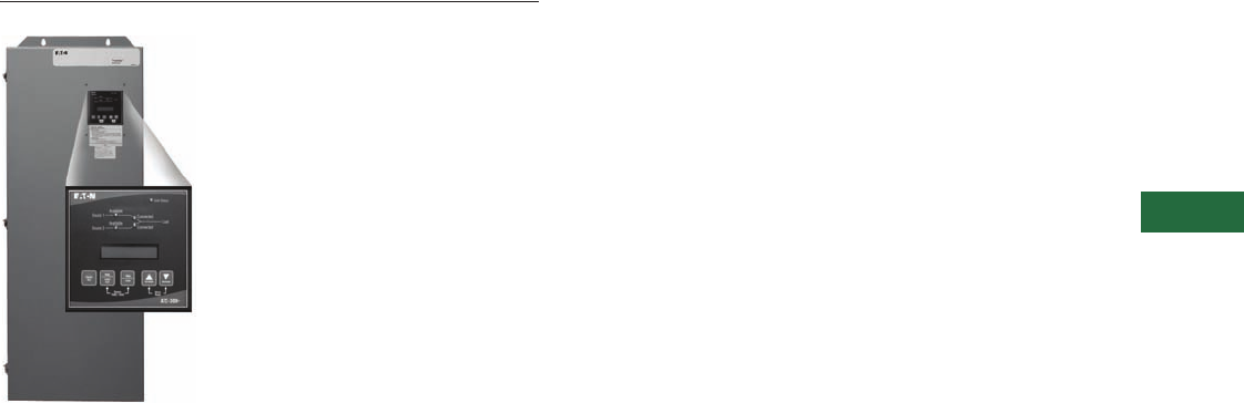
Volume 2—Commercial Distribution CA08100003E—April 2014 www.eaton.com V2-T5-35
5
5
5
5
5
5
5
5
5
5
5
5
5
5
5
5
5
5
5
5
5
5
5
5
5
5
5
5
5
5
5.3
Transfer Switches
Breaker-Based Designs
Automatic Wallmount
Contents
Description Page
Molded Case Switches—Manual
Wallmount, 30–1000A . . . . . . . . . . . . . . . . . . . . V2-T5-28
Molded Case Switches—Non-Automatic
Wallmount. . . . . . . . . . . . . . . . . . . . . . . . . . . . . . V2-T5-32
Molded Case Switches—Automatic
Wallmount, 30–1000A
Standards and Certifications . . . . . . . . . . . . . . V2-T5-38
Catalog Number Selection . . . . . . . . . . . . . . . . V2-T5-38
Technical Data and Specifications . . . . . . . . . . V2-T5-39
Dimensions . . . . . . . . . . . . . . . . . . . . . . . . . . . V2-T5-40
Maintenance Bypass Switches—
Type MBHE 100–1000A . . . . . . . . . . . . . . . . . . . V2-T5-41
Molded Case Switches—Automatic Wallmount,
30–1000A
Product Description
Eaton’s wallmount transfer
switches are designed for a
variety of standby power
applications for critical loads.
They provide flexibility,
reliability and value in a
compact package. In the
event of a primary power
source interruption, a transfer
switch provides an effective
means to transfer the load
circuits to an alternate power
source while reducing the
possibility of injury or
property damage.
Wallmount transfer switches
meet or exceed all industry
standards for endurance,
reliability and performance.
These breaker-based designs
can be applied with the
ATC-100, ATC-300+ or
ATC-900 controllers.
Application Description
Suitable for emergency and
standby systems (all loads).
Industrial Design Highlights
●Double-throw,
mechanically interlocked
transfer mechanism
●High withstand and
closing ratings
●Seismic qualified (BOCA®,
CBC, IBC, UBC)
Standard Features
●Auxiliary relay contacts:
●Source 1 present
2NO and 2NC
●Source 2 present
2NO and 2NC
●Switch position indication
contacts:
●Source 1 position
1NO and 1NC
●Source 2 position
1NO and 1NC
●Source 1 and Source 2
sensing:
●Undervoltage/
underfrequency
●Overvoltage/
overfrequency
●Three-phase rotation
protection
●Three-phase voltage
unbalance/loss
●Pretransfer signal
contacts 1NO/1NC
●Go to emergency
(Source 2)
●Seven field-programmable
time delays
●LCD-based display for
programming, system
diagnostic and Help
message display
●Mimic diagram with source
available and connected
LED indication
●Time-stamped history log
●System TEST pushbutton
●Programmable plant
exerciser—OFF, daily,
7-, 14-, 28-day interval
selectable run time
0–600 minutes no load/
load with fail-safe
●Safe manual operation
under full load with
permanently affixed
operating handle
Optional Features
●Suitable for use as service
equipment in the standard
enclosure size
●Available SPD for power/
controller, engine start
circuit, phone and cable
connections
●Integrated distribution
panels
●
Field-selectable multi-tap
transformer
panel permits
operation on a wide range
of system voltages
●Integral overcurrent
protection
●Not available on contactor
transfer switch
●Space heater with
thermostat
●Ammeter—load side
●Stainless steel cover
for controller
●ATC-100 and ATC-900
controllers available
●Modbus RTU via RS-485
●Source 2 inhibit
●Manual retransfer to
normal
●Remote annunciator with
control
●Ethernet communication
(PXG 400 Gateway)
Features, Benefits and Functions
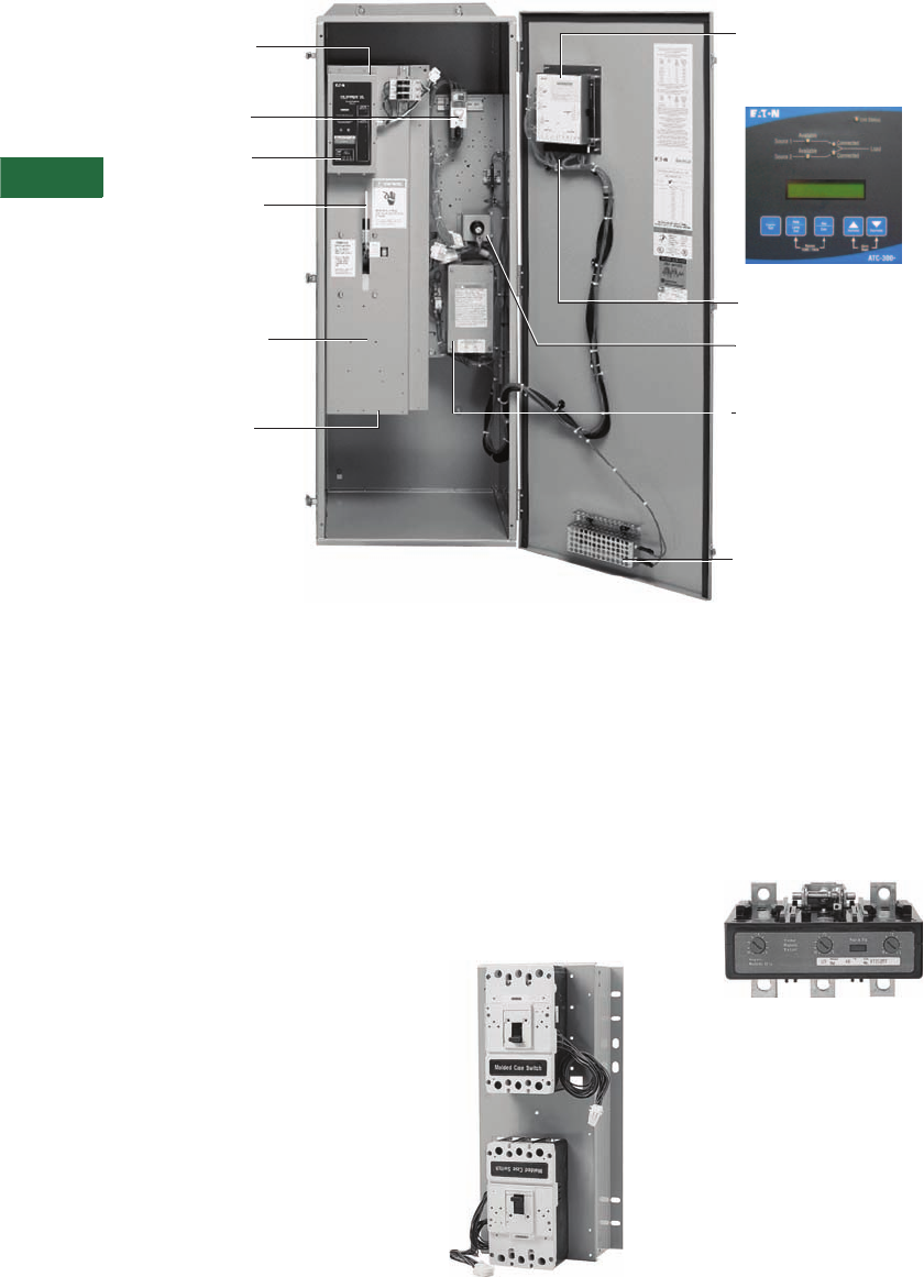
V2-T5-36 Volume 2—Commercial Distribution CA08100003E—April 2014 www.eaton.com
5
5
5
5
5
5
5
5
5
5
5
5
5
5
5
5
5
5
5
5
5
5
5
5
5
5
5
5
5
5
5.3
Transfer Sw itches
Breaker-Based Designs
Basic Components of Automatic Transfer Switches
Eaton’s Superior Design Transfer
Switch Characteristics
Unmatched Performance
and Versatility
Eaton’s family of wallmount
transfer switches offers
unmatched performance,
versatility and value for power
switching applications. At the
heart of these designs is
Eaton’s molded case switch,
designed specifically to meet
UL 1008.
Superior Main
Contact Structure
All Eaton wallmount transfer
switches meet or exceed
the standards set forth in
UL 1008 and UL 489. No
other transfer switch
manufacturer has met the
rigid testing requirements
of this combination of
standards. Completely
enclosed contacts add a
measure of safety and
reliability. It also ensures
the integrity of the contact
assemblies and minimizes
the need for periodic
maintenance of the contacts,
reducing downtime.
Fast, Powerful and
Safe Power Switching
Mechanism
The power panel utilizes a
unidirectional
gear motor
mechanism. The power panel
can be operated manually
under a FULL LOAD.
Molded Case Switch Features
●True four-pole switched
neutral availability
●Totally enclosed contact
assembly
Molded Case Switch
Optional Integral Overcurrent
Protection Capability
For service entrance and
other applications, trip units
can be integrated into the
power switching section.
This eliminates the need
for separate upstream
protective devices, saving
cost and space.
Optional Thermal-Magnetic or
Electronic Trip Units
Source 1 and Load Power
Cable Connections
Power Switching
Panel (With Deadfront
Cover Installed)
Permanently Affixed
Manual Transfer
Handle Provides
Safe Manual Transfer
Under Full Load
Source 2 Power
Cable Connections
Automatic Transfer
Controller (ATC-300+)
■Monitors Power Sources
■Initiates Power Transfers
Service Disconnect Switch
(Keyed) (Service Equipment
Rated Switches Only)
Transfor mer Panel
■Steps Line Power Down
to 120 Vac for Logic and
Electrical Operator
■Available Multi-Tap
Voltage Selec tor
(See Page V2-T5-37 for
additional details)
Space Heater (Optional)
Customer Control
Connections
Surge Suppression
Device (Optional)
Control Service
Disconnect (Service
Equipment Rated
Switches Only)
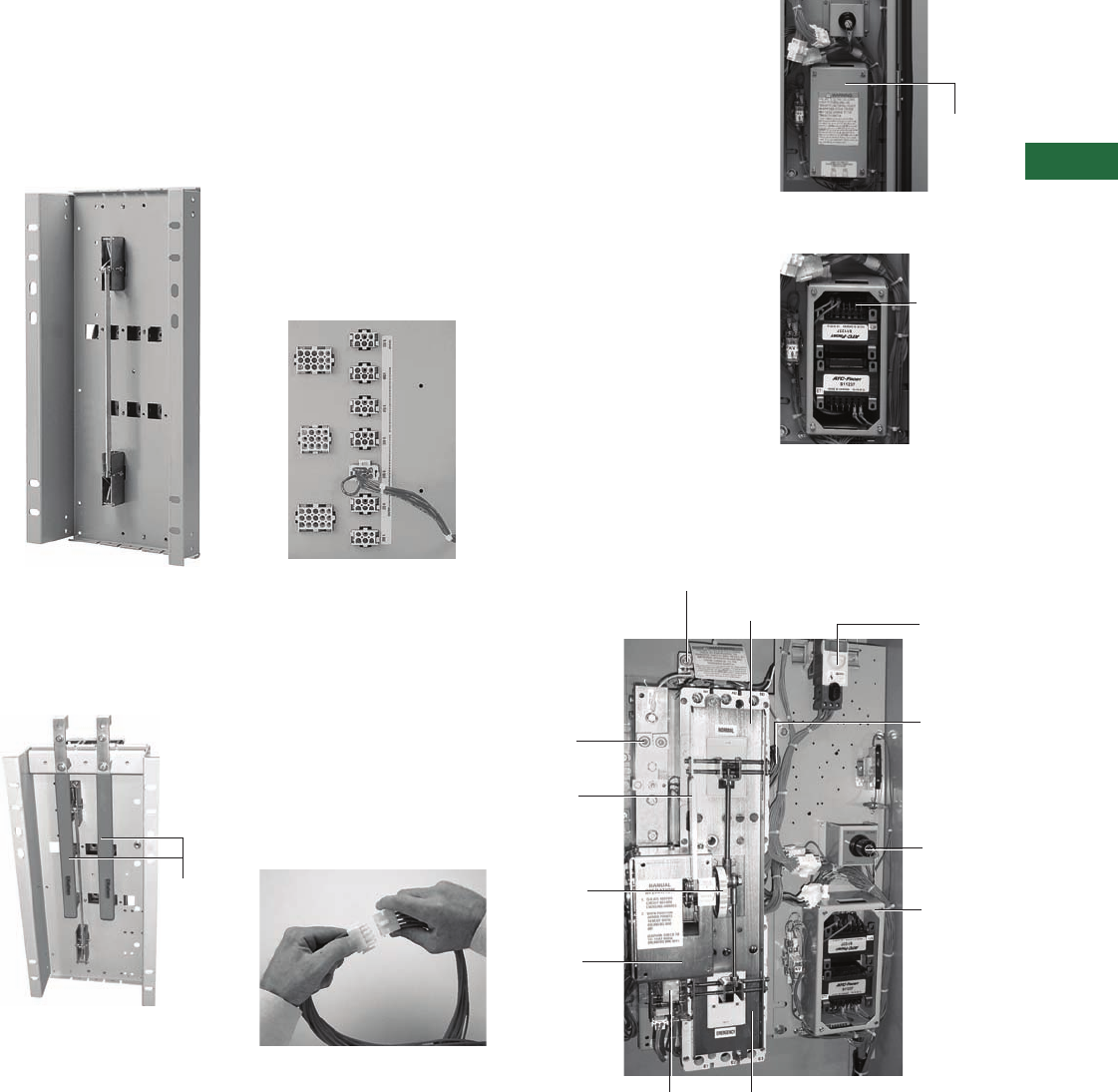
Volume 2—Commercial Distribution CA08100003E—April 2014 www.eaton.com V2-T5-37
5
5
5
5
5
5
5
5
5
5
5
5
5
5
5
5
5
5
5
5
5
5
5
5
5
5
5
5
5
5
5.3
Transfer Switches
Breaker-Based Designs
Mechanical Interlock
Wallmount transfer switches
feature a rear-mounted,
fail-safe mechanical interlock
to prevent paralleling of
sources. This is, in addition
to software interlocking and
the interlocking inherently
provided by the transfer
mechanism.
Triple Interlocks
Load Bus Assembly
The load bus can be oriented
for either top or bottom
access. Top entry is standard.
Load Bus
Multi-Tap Voltage Selector
Eaton’s industry-exclusive
Multi-Tap system voltage
selector allows our transfer
switch to be applied on most
system voltages just by proper
insertion of the selector
plug. Available in two
configurations: Worldwide
Multi-Tap with 600, 480, 415,
380, 240, 220 and 208 Vac,
single- and three-phase,
50 and 60 Hz taps. North
American Multi-Tap with
600, 480, 240, 208 and
120 Vac, single- and three-
phase, 60 Hz taps.
Multi-Tap Voltage Selector
Ease of Maintenance
Keyed quick-disconnect
plugs are provided for
easy and complete isolation
of the control circuitry.
Maintenance can be
performed on the logic
independent from the power
sections and still allow the
user to manually transfer
power under full load
conditions.
Logic Disconnect Plugs
Load
Bus
North American
Voltage Selector
North American multi-tap
transformer comes with 600,
480, 240, 208 and 120 Vac,
single- and three-phase, and
60 Hz
t
aps, which are all field
selectable. Simply remove
the steel cover and move the
appropriate blue flag terminal
to the desired voltage. All
switches are shipped with
the blue flag in the 600V
position.
Transformer Panel Location
Transformer Panel Opened
Typical (225–1000A) Vertical Design Transfer Switch
Equipment
Shown Without the Deadfront
Trans for mer
Panel
Trans for mer
Panel Allows
for Easy Field
Changes to
Voltage
Configurations
Load Lugs
(Top Entry)
Neutral
Connections
Manual
Operating
Handle
Indicator
Wheel
Trans fer
Mechanism
Motor
Brake
Board
Power Panel
Emergency Power
Source Molded
Case Switch
Voltage
Selection
Panel
(Domestic)
Service
Disconnect
Normal
Power
Source
Molded
Case
Switch
Control
Power
Disconnect
Switch
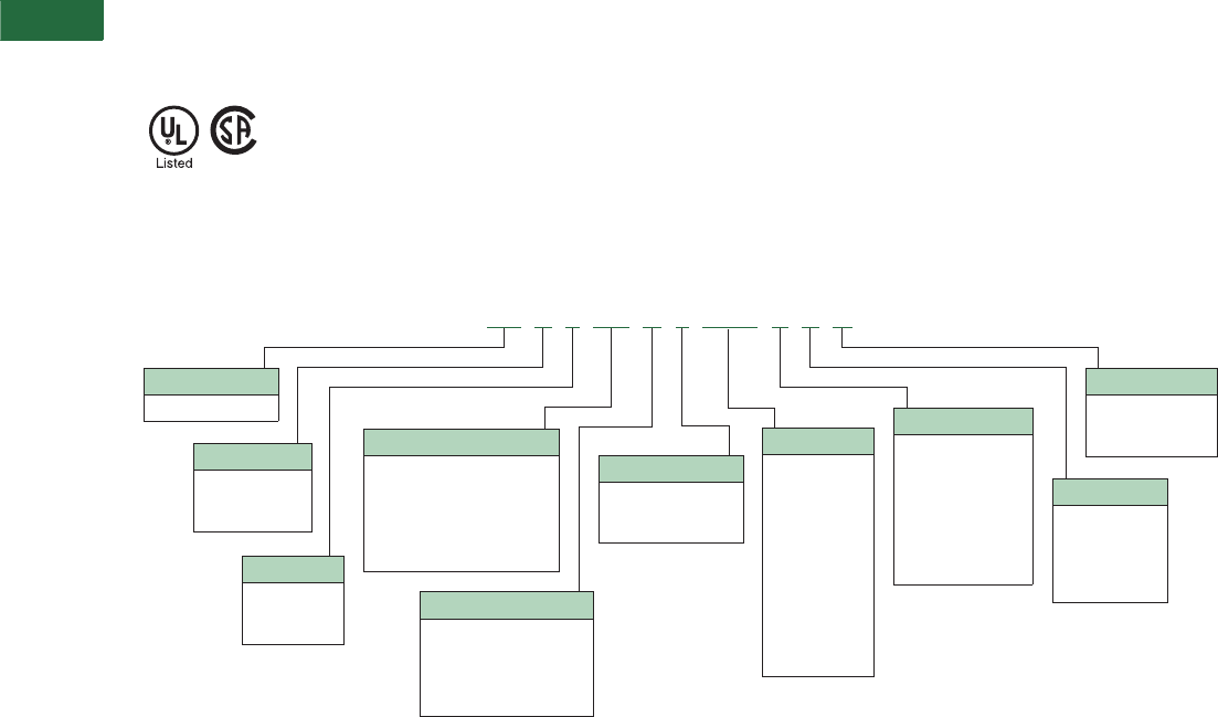
V2-T5-38 Volume 2—Commercial Distribution CA08100003E—April 2014 www.eaton.com
5
5
5
5
5
5
5
5
5
5
5
5
5
5
5
5
5
5
5
5
5
5
5
5
5
5
5
5
5
5
5.3
Transfer Sw itches
Breaker-Based Designs
Standards and Certifications
They are listed under
Underwriters Laboratories UL
1008 Standard for transfer
switch equipment and are
optionally available as suitable
for emergency and standby
systems as defined in NFPA
99 for health care facilities.
●UL 1008 listed
●CSA C22.2 No. 178
certified
Catalog Number Selection
Molded Case Transfer Switch
Notes
1HFD = 200 and 225A, HLD = 600A, HMD = 800A for 240/120 Vac single-phase, three-wire and 208Y/120 Vac three-phase, four-wire systems only.
2Four-pole 600A will use an NB breaker.
3MCB = Molded Case Breaker, MCS = Molded Case Switch.
AT V 3 KD A 3 0400 X S U
Type
AT = Automatic
Orientation
H= Horizontal
V= Vertical
C= Contactor
Logic
1= ATC-100
3= ATC-300+
9= ATC-900
Switch 3
A= S1 (MCS) S2 (MCS)
B= S1 (MCB) S2 (MCB)
C= S1 (MCB) S2 (MCS)
D= S1 (MCS) S2 (MCB)
X= Fix mounted contactor
Number of Poles
2 = Two-pole
3 = Three-pole
4 = Four-pole 2
Enclosure
K= Open
S= NEMA 1
J= NEMA 12
R= NEMA 3R
D= NEMA 4X
Certification
U = UL listed
R = UL recognized
X = No listing
Amperes
0030 = 30A
0070 = 70A
0100 = 100A
0150 = 150A
0200 = 200A
0225 = 225A
0300 = 300A
0320 = 320A
0400 = 400A
0600 = 600A 2
0800 = 800A
1000 = 1000A
Frame Size (Amperes)
Molded case device 1
FD = 30–150
KD = 225–300
LD = 400
MD = 600 (three-pole only)
NB = 800–1000 2
Voltage
B= 208V, 60 Hz
E= 600V, 60 Hz
G= 220V, 50/60 Hz
H= 380V, 50 Hz
K= 600V, 50 Hz
O= 415V, 50 Hz
W= 240V, 60 Hz
X= 480V, 60 Hz

Volume 2—Commercial Distribution CA08100003E—April 2014 www.eaton.com V2-T5-39
5
5
5
5
5
5
5
5
5
5
5
5
5
5
5
5
5
5
5
5
5
5
5
5
5
5
5
5
5
5
5.3
Transfer Switches
Breaker-Based Designs
Technical Data and Specifications
Electrical Ratings
●Molded case and circuit breaker 30–1000A
●Two-, three- or four-pole
●Up to 600 Vac, 50/60 Hz
●NEMA 1, 3R, 4X, 12, open
Molded Case Transfer Switch and Circuit Breaker
UL 1008 Withstand and Close-On Ratings (kA) Wallmount Transfer Switch Standard Terminal Data
for Power Cable Connections 2
Notes
1For 600, 800 and 1000A ratings, four-pole units are rated 35 kA at 480 volts.
2All terminals suitable for copper or aluminum conductors. For alternate terminal sizes,
contact Eaton.
Switch
Ampere
Rating
UL 1008 3-Cycle
Any Breaker Rating
Ratings When Used
with Upstream Fuse
240 Vac 480 Vac 600 Vac
Maximum
Fuse Rating
Fuse
Type 600 Vac
30–100 100 65 25 200 J, T 200
150 100 65 25 400 J, T 200
225 100 65 25 400 J, T 200
300 100 65 25 400 J, T 200
400 100 65 25 600 J, T 200
600 100 65
125 1200 J, T 200
800 65 50
125 1600 L 200
1000 65 50
125 1600 L 200
Switch
Ampere
Rating
Breaker
Frame
Line Side
(Normal and
Standby Source)
Load
Connection
Neutral
Connection
30–100 HFD (1) #14–1/0 (1) #14–1/0 (3) #14–1/0
150–225 HFD (1) #6–300 (1) #6–300 (3) #4–300
150–225 HKD (1) #3–350 (1) #6–350 (3) #4–350
225–300 HKD (1) #3–350 (1) #6–350 (3) #4–350
400 HLD (1) 4/0–600 (2) #1–500 (6) 250–350
600 HLD (1) 3/0–350 (2) #1–500 (6) 250–350
600 HMDL (2) #1–500 (2) #1–500 (12) 4/0–500
600 (four-pole) NB (3) 3/0–400 (3) 3/0–400 (3) 3/0–400
800 HMDL (3) 3/0–400 (3) 3/0–400 (12) 4/0–500
800 HNB (4) 4/0–500 (4) 4/0–500 (12) 4/0–500
1000 HNB (4) 4/0–500 (4) 4/0–500 (12) 4/0–500
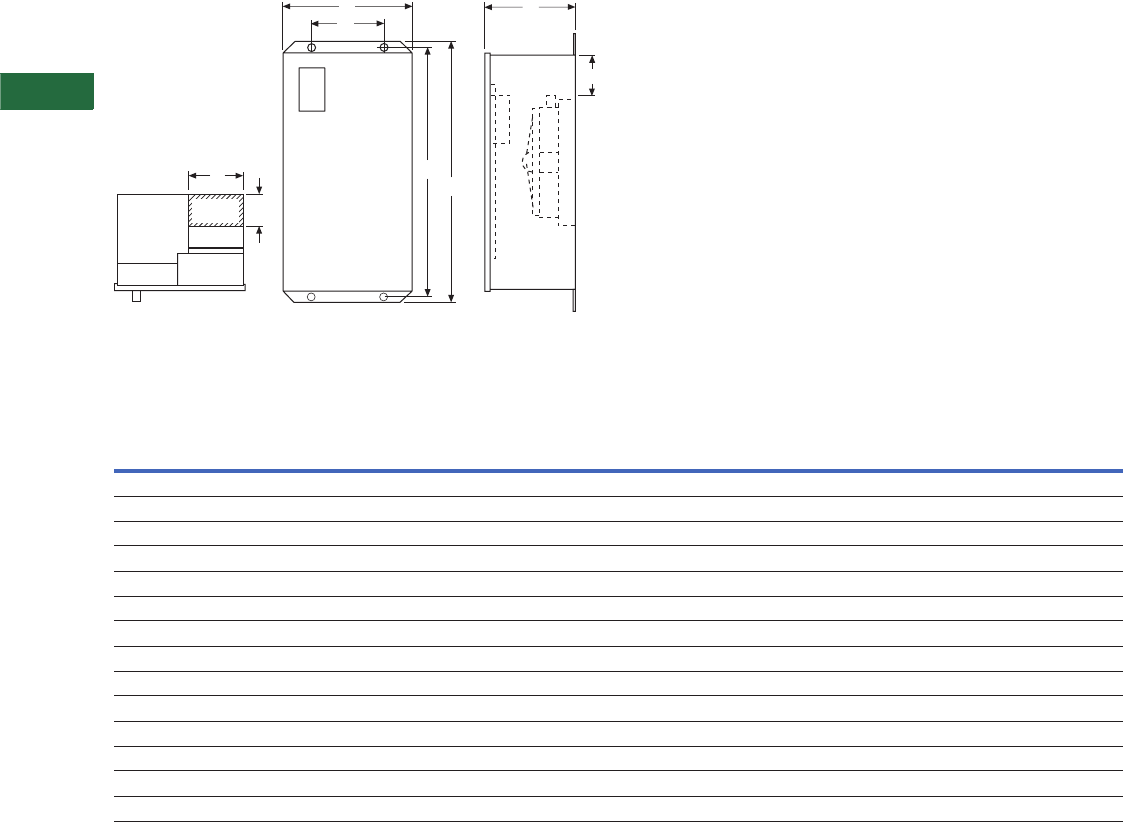
V2-T5-40 Volume 2—Commercial Distribution CA08100003E—April 2014 www.eaton.com
5
5
5
5
5
5
5
5
5
5
5
5
5
5
5
5
5
5
5
5
5
5
5
5
5
5
5
5
5
5
5.3
Transfer Sw itches
Breaker-Based Designs
Dimensions
Approximate Dimensions in Inches (mm)
Dimension Views
Breaker-Based and Molded Case Transfer Switches
Notes
1Suitable with copper only.
2Alternate line terminals.
3With multi-tap voltage selection panel.
Switch
Rating
Amperes
Switch
Type
Enclosure Gutter Space Bolt Pattern Standard Terminals 1
Weight
Lbs (kg)
AB CDEGHLine Side (Normal Load and
Standby Source) Connection
Neutral
ConnectionHeight Width Depth Width Depth Horizontal Vertical
Molded Case
30–100 HFD 247.74 (1213.0) 20.81 (528.6) 15.22 (386.6) 8.00 (203.2) 4.00 (101.6) 10.75 (273.0) 46.44 (1180.0) — — — 232 (105)
150–225 HFD 247.74 (1213.0) 20.81 (528.6) 15.22 (386.6) 8.00 (203.2) 4.00 (101.6) 10.75 (273.0) 46.44 (1180.0) — — — 232 (105)
30–100 HFD 347.74 (1213.0) 20.81 (528.6) 15.22 (386.6) 8.00 (203.2) 4.00 (101.6) 10.75 (273.0) 46.44 (1180.0) — — — 232 (105)
150 HFD 347.74 (1213.0) 20.81 (528.6) 15.22 (386.6) 8.00 (203.2) 4.00 (101.6) 10.75 (273.0) 46.44 (1180.0) — — — 232 (105)
150–225 HFD 235.61 (904.0) 20.06 (509.5) 11.34 (288.0) 8.00 (203.2) 4.00 (101.6) 10.75 (273.0) 34.31 (904.0) — — — 150 (68)
150–225 HKD 56.00 (1422.4) 20.81 (528.6) 16.65 (422.9) 8.00 (203.2) 4.00 (101.6) 11.00 (279.4) 45.50 (1155.7) — — — 305 (134)
300 HKD 53.00 (1346.2) 25.81 (655.6) 16.65 (422.9) 8.00 (203.2) 4.00 (101.6) 16.00 (406.4) 53.50 (1358.9) — — — 295 (134)
400 HLD 64.00 (1625.6) 25.81 (655.6) 16.65 (422.9) 8.00 (203.2) 4.00 (101.6) 16.00 (406.4) 61.48 (1561.6) — — — 425 (193)
400 HLD 253.00 (1346.0) 25.81 (655.6) 16.65 (422.9) 8.00 (203.2) 4.00 (101.6) 16.00 (406.4) 51.50 (1308.0) — — — 425 (193)
600 HLD 64.00 (1625.6) 25.81 (655.6) 16.65 (422.9) 8.00 (203.2) 4.00 (101.6) 16.00 (406.4) 62.50 (1588.0) — — — 475 (214)
600 HMDL 76.74 (1949.2) 25.81 (655.6) 17.75 (450.8) 8.00 (203.2) 4.00 (101.6) 16.00 (406.4) 75.15 (1908.8) — — — 480 (218)
800 HMDL 276.74 (1949.2) 25.81 (655.6) 17.75 (450.8) 8.00 (203.2) 4.00 (101.6) 16.00 (406.4) 75.15 (1908.8) — — — 510 (232)
800–1000 HNB 76.74 (1949.2) 25.81 (655.6) 17.75 (450.8) 8.00 (203.2) 4.00 (101.6) 16.00 (406.4) 75.15 (1908.8) — — — 570 (259)
Logic
Panel
D
E
Power
Panel Transformer
Panel
B
G
A
H
C
F
Top of Lugs
on Power Panel
Gutter
Space
Front View Side ViewTop View
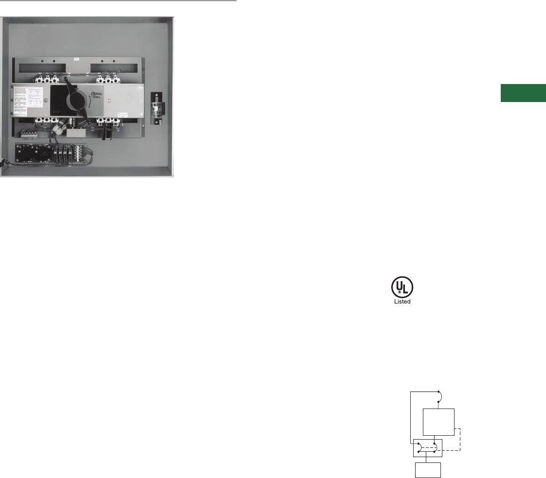
Volume 2—Commercial Distribution CA08100003E—April 2014 www.eaton.com V2-T5-41
5
5
5
5
5
5
5
5
5
5
5
5
5
5
5
5
5
5
5
5
5
5
5
5
5
5
5
5
5
5
5.3
Transfer Switches
Breaker-Based Designs
Type MBHE Maintenance Bypass Switch
Contents
Description Page
Molded Case Switches—Manual
Wallmount, 30–1000A . . . . . . . . . . . . . . . . . . . . V2-T5-28
Molded Case Switches—Non-Automatic
Wallmount. . . . . . . . . . . . . . . . . . . . . . . . . . . . . . V2-T5-32
Molded Case Switches—Automatic
Wallmount, 30–1000A . . . . . . . . . . . . . . . . . . . . V2-T5-35
Maintenance Bypass Switches—
Type MBHE 100–1000A
Catalog Number Selection . . . . . . . . . . . . . . . . V2-T5-42
Technical Data and Specifications . . . . . . . . . . V2-T5-42
Dimensions . . . . . . . . . . . . . . . . . . . . . . . . . . . V2-T5-43
Maintenance Bypass Switches—Type MBHE 100–1000A
Product Description
Eaton’s maintenance bypass
switch is a UL 1008-listed
device that provides a simple
and effective means for
bypassing un-interruptible
power supplies while
maintaining continuity of
power to the critical
computer loads. A
maintenance bypass switch
is a requirement on every
UPS installation in order to
accommodate the
maintenance and testing of
the UPS system.
Features and Benefits
●Make-before-break
electrical operation
●Lockout circuit to be wired
into the UPS bypass
authorization
●Pilot devices to show
UPS position “Normal”
and “Bypassed”
●Pilot device to show
“Lockout” enabled
●Reliable manually initiated
electrical operation
●High interrupting ratings
are standard
●Molded case switch
designs are available
●Solid neutral connections
are standard
●Safe and reliable operation
is ensured due to the
simple and durable
switching design
●Unauthorized bypass is
prevented by the need of
UPS system to send the
bypass authorized signal
●100% current ratings
makes selection to the
UPS kVA ratings easy to
accomplish
●Use of interrupting rating
switches makes the
maintenance bypass
switches adaptable to
systems with high levels
of available fault current
Standards and Certifications
●UL 1008 listing—
File E61639
Diagram
Single Line Diagram
of Maintenance
Bypass Switch
UPS
System
Lockout
Circuit
Computer
Loads
UPS
Input Breaker
Incoming
from Switchboard
Maintenance
Bypass
Switch
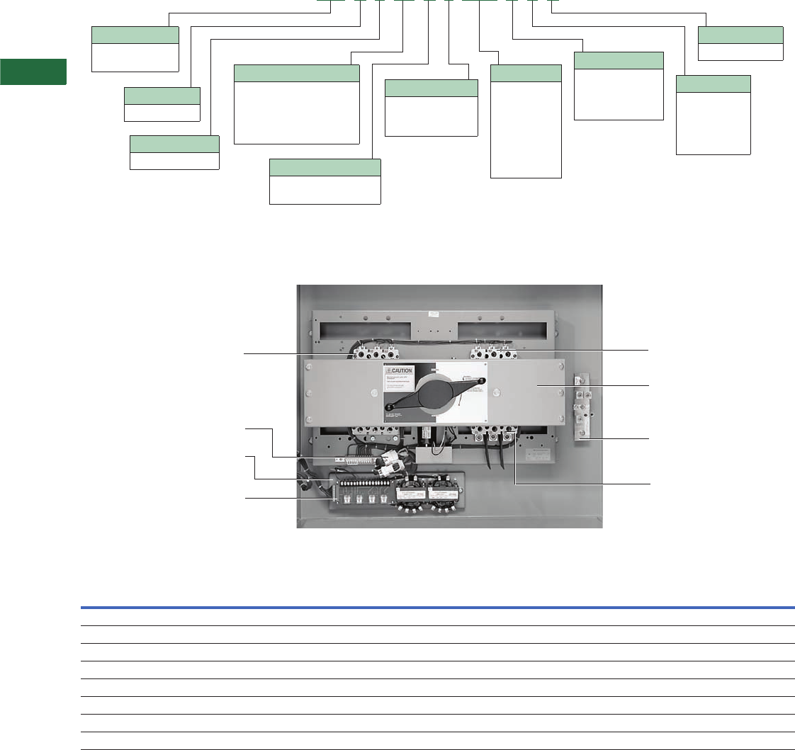
V2-T5-42 Volume 2—Commercial Distribution CA08100003E—April 2014 www.eaton.com
5
5
5
5
5
5
5
5
5
5
5
5
5
5
5
5
5
5
5
5
5
5
5
5
5
5
5
5
5
5
5.3
Transfer Sw itches
Breaker-Based Designs
Catalog Number Selection
Transfer Switch Equipment
Technical Data and Specifications
Maintenance Bypass Switch
Standard Withstand, Closing and Interrupting Ratings 1
Notes
1Tested in accordance with UL 1008.
2For maximum breaker rating in circuits where the transfer switch is evaluated as a “motor branch circuit conductor” refer to the NEC Section 430.25 for sizing.
3Also can use Class RK5 fuse with 100 kA rating.
4Four-pole units rated 35 kA.
To attain the maximum rating shown in the chart, when protected by an upstream breaker, the upstream device must have an equivalent interrupting rating.
Transfer Switch
Ampere Rating
Rating When Used with Upstream Circuit Breaker Rating When Used with Upstream Fuse
Suggested Breaker Rating 2240V 480V Maximum Fuse Rating Fuse Type 480V
100 100 100 65 200 J, T 200
150 150 100 65 400 J, T 200
225 225 100 65 400 J, T 200
300 300 100 65 400 J, T 3200
400 400 65 35 600 J, T 200
600 600 65 50 4800/1200 J, T 100/200
800 800 65 50 41200/1600 L 100/200
1000 1000 65 50 41600 L 200
MB H E FD A 3 0030 A S U
Type
MB = Maintenance
Bypass
Orientation
H = Horizontal
Logic
E = Electromechanical Switch
A = Fix mounted, molded
case switch (MCS) both
Number of Poles
2 = Two-pole
3 = Three-pole
4 = Four-pole
Enclosure
K= Open
S= NEMA 1
J= NEMA 12
R= NEMA 3R
D= NEMA 4X
Certification
U = UL listed
Amperes
0100 = 100A
0150 = 150A
0225 = 225A
0300 = 300A
0400 = 400A
0600 = 600A
0800 = 800A
1000 = 1000A
Frame Size (Amperes)
Molded case
FD = HFD (100A, 150A)
KD = HKD (150A, 225A, 300A)
LD = HLD (400A)
NB = NB (600A, 1000A)
Voltage
A= 120V, 60 Hz
B= 208V, 60 Hz
W= 240V, 60 Hz
X= 480V, 60 Hz
Bypass Power Connections Normal Power Connections
Transfer Mechanism
Solid Neutral Bar
Load Power Connections
Logic Disconnect Plugs
Maintenance Bypass Switch Control Panel
UPS Lockout Circuit Connection
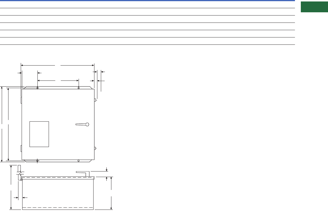
Volume 2—Commercial Distribution CA08100003E—April 2014 www.eaton.com V2-T5-43
5
5
5
5
5
5
5
5
5
5
5
5
5
5
5
5
5
5
5
5
5
5
5
5
5
5
5
5
5
5
5.3
Transfer Switches
Breaker-Based Designs
Dimensions
Approximate Dimensions in Inches (mm)
Manual Transfer and Maintenance Bypass Switches—100–150A Type MTHXFD Manual /100–1000A Type MBHE Maintenance Bypass
Manual and Maintenance Bypass Enclosures
Manual and Maintenance Bypass Switches
Amperes
Dimensions
ABCEGH
100–150 22.88 (581.2) 13.13 (333.5) 22.74 (577.6) 24.50 (622.3) 10.28 (261.1) 32.31 (820.7)
225–300 38.88 (987.6) 29.13 (739.9) 35.74 (907.8) 37.50 (952.5) 17.78 (438.9) 55.81 (1417.6)
400 38.88 (987.6) 29.13 (739.9) 35.74 (907.8) 37.50 (952.5) 17.78 (438.9) 55.81 (1417.6)
600 38.88 (987.6) 29.13 (739.9) 49.74 (1263.4) 51.50 (1308.1) 17.78 (438.9) 55.81 (1417.6)
800 38.88 (987.6) 29.13 (739.9) 49.74 (1263.4) 51.50 (1308.1) 17.78 (438.9) 55.81 (1417.6)
1000 38.88 (987.6) 29.13 (739.9) 59.74 (1517.4) 61.50 (1562.1) 17.78 (438.9) 55.81 (1417.6)
A
B
5.00
(127.0)
E
C
H
1.25
(31.8)
G
1.75
(44.5)
2.00 (50.8)
Latch Open
0.75 (19.05)
Latch Closed
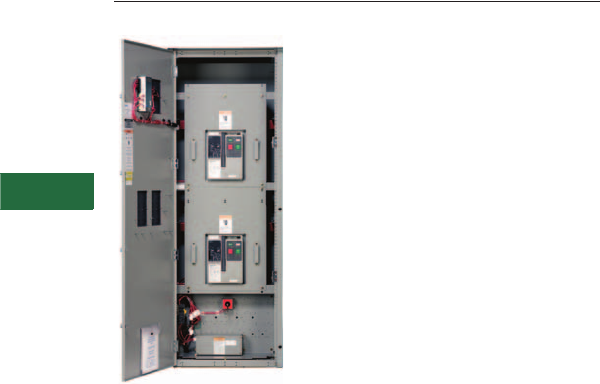
V2-T5-44 Volume 2—Commercial Distribution CA08100003E—April 2014 www.eaton.com
5
5
5
5
5
5
5
5
5
5
5
5
5
5
5
5
5
5
5
5
5
5
5
5
5
5
5
5
5
5
5.4
Transfer Sw itches
Magnum-Based Designs
Floor-Standing Magnum Transfer Switch
Contents
Description Page
Power Case Switch—Floorstanding, 200–5000A
Features, Benefits and Functions . . . . . . . . . . V2-T5-45
Product Selection. . . . . . . . . . . . . . . . . . . . . . . V2-T5-48
Catalog Number Selection. . . . . . . . . . . . . . . . V2-T5-48
Standards and Certifications . . . . . . . . . . . . . . V2-T5-49
Technical Data and Specifications . . . . . . . . . . V2-T5-49
Dimensions . . . . . . . . . . . . . . . . . . . . . . . . . . . V2-T5-50
Bypass Isolation Transfer Switch, 200–5000A . . . V2-T5-53
Power Case Switch—Floorstanding, 200–5000A
Product Description
Eaton’s Magnum transfer
switches are designed for a
variety of standby power
applications for critical and
noncritical loads. They
monitor both Source 1
(Normal) and Source 2
(Emergency) power sources.
In the event of a Source 1
power interruption, these
switches will automatically
transfer the load circuits to
the Source 2 power source.
Once Source 1 power source
has been restored, the
process is automatically
reversed.
Application Description
The Magnum family of
transfer switches covers
applications ranging from 200
to 5000A through 600 Vac.
Some of the applications are:
automatic or non-automatic
configurations, open or
closed transition and standard
or rated suitable for use as
service entrance. They are
designed for applications
where total system
coordination must be
accomplished
while achieving
a high level of Withstand,
Interrupting, and Closing
performance.
Drawout construction is
available for applications,
such as critical life-support
systems, where preventive
maintenance, inspection
and testing must be
accomplished while
maintaining continuity of
power to the load.
Automatic Transfer
Open Transition
Open transition type Magnum
transfer
switches use the
Eaton programmable
ATC-900
microprocessor-based
logic controller.
Automatic Transfer
Closed Transition
Closed transition applications
feature the ATC-900 closed
transition logic controller.
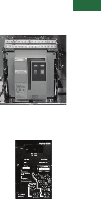
Volume 2—Commercial Distribution CA08100003E—April 2014 www.eaton.com V2-T5-45
5
5
5
5
5
5
5
5
5
5
5
5
5
5
5
5
5
5
5
5
5
5
5
5
5
5
5
5
5
5
5.4
Transfer Switches
Magnum-Based Design
Features, Benefits and Functions
Industrial Design Highlights
●Freestanding enclosure
●High withstand ratings
●100 kA standard
3-cycle rating
●85 kA standard
30-cycle rating
●Dual drawout on ATS
and bypass
●Deadfront
●Safe manual transfer
under load
●Electrically operated
●Magnum stored energy
mechanism
●Quick make / quick
break—switching times
(<3 cycles)
●Multi-tap transformer
●True four-pole switched
neutral
●Mechanically interlocked
●Integral overcurrent trip
option
●Integrated service
entrance rating option
●OSHPD listed
Standard Features
●ATC-900 controller
●
Drawout cassette on ATS
and bypass
●Source available contacts:
●Source 1 available
1NO/1NC
●Source 2 available
1NO/1NC
●Switch position contacts:
●Source 1 position
1NO/1NC
●Source 2 position
1NO/1NC
●Source 1 and Source 2
sensing:
●Undervoltage/
underfrequency
●Overvoltage/
overfrequency
●Field-programmable time
delays
●Time delay engine start
●Time delay normal to
emergency
●Time emergency to
normal
●Time delay engine
cooldown
●Time delay emergency
failure
●LCD color-based display
for programming, system
diagnostics and Help menu
●Mimic diagram with source
available and connected
LED indication
●Four programmable inputs
and outputs
●Standard Modbus 485
●USB port for set point
downloads and event
recording uploads
●Password-protected
access to control functions
and set point programming
●Two automatic plant
exercisers—load or no
load, daily, 7-, 14-,
28-day or calendar date
operation, 0–600 minute
runtime
Optional Features
●Available UL 1449 Third
Edition surge protection
device (SPD)
●Automatic transfer
operation with selectable
(via programming)
nonautomatic or automatic
retransfer with fail-safe
●Space heater with
thermostat
●Digital multi-function
power quality metering
●DC power input for
uninterrupted monitoring
of ATS status
●Integrated load metering
●Expandable I/O (up to
20 I/O total)
●EtherNet TCP/IP
communications
●Integrated service
entrance option
●Optional remote
annunciator
Unmatched Performance
and Versatility
The Eaton family of Magnum
transfer
switches offers
unmatched performance,
versatility and value for
standby power applications.
At the heart of these designs
is the Magnum switch with
the following features:
Superior Main
Contact Structure
All Eaton Magnum Transfer
Switches meet or exceed
the standards set forth in
UL 1008 and UL 489 with
high withstand, totally
enclosed Magnum switches.
No other transfer switch
manufacturer has met the
rigid testing requirements of
this combination of standards.
Completely enclosed contacts
add a measure of safety and
reliability. They also ensure
the integrity of the contact
assemblies and minimize
the need for periodic
maintenance of the contacts,
reducing downtime and
maintenance time.
Fast, Powerful and Safe
Switching Mechanism
The mechanism uses a high
speed less than or equal
to a 3-cycle stored energy
switching mechanism. This
mechanism can be operated
manually under a FULL LOAD.
Ease of Coordination
and Application—
Short-Time Withstand
The use of electronic trips
has allowed performance
curve shaping to facilitate
proper system coordination.
The most significant is the
“short time” rated trip unit.
These trip settings may be
set for what are considered
extremely high currents for
much longer durations than
the three-cycle withstand
test required under UL 1008.
To facilitate improved
coordination, Eaton Magnum
transfer switches have been
tested and are provided with
30-cycle, extended withstand
ratings.
Magnum Power Case Switch
Optional Integral
Overcurrent Protection
Capability
Optional DigitripTM Magnum Trip Unit
Service Entrance
For service entrance and
other applications, Digitrip
solid-state trip units can be
integrated into the power
switching section. This
eliminates the need for
separate upstream protective
devices, saving cost and
space. Available with various
combinations of long, short
time, instantaneous, ground
fault protection and
communication. Overcurrent
trip selection can be made
from the series of Eaton
Digitrip RMS trip units
including the standard
Digitrip 520 or optional 520M,
520MC or 1150.
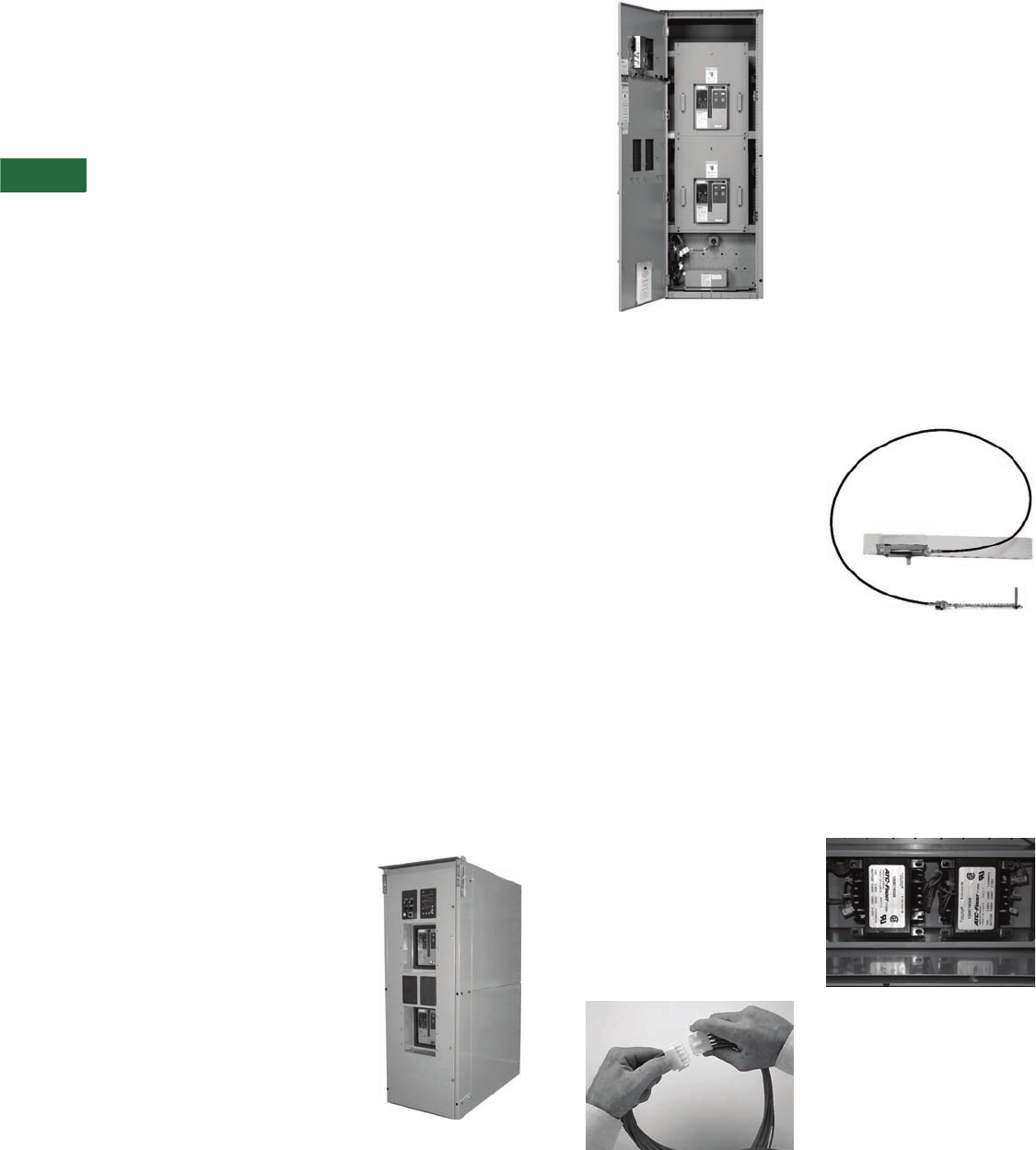
V2-T5-46 Volume 2—Commercial Distribution CA08100003E—April 2014 www.eaton.com
5
5
5
5
5
5
5
5
5
5
5
5
5
5
5
5
5
5
5
5
5
5
5
5
5
5
5
5
5
5
5.4
Transfer Sw itches
Magnum-Based Design
Controller Logic
The ATC-900 Automatic
Transfer Switch Controller
from Eaton is a
comprehensive, multi-
function, microprocessor-
based automatic transfer
switch controller and meter.
It is designed to accurately
monitor power sources and
provide the necessary
intelligence to reliably operate
a transfer switch through a
series of programmed
sensing and timing functions.
The ATC-900 provides an
unmatched degree of
programming flexibility to
address the needs of any
system.
Controller Primary
Functions
The ATC-900 Automatic
Transfer Switch Controller
offers these standard features:
●Monitor normal and
emergency source
voltages and frequencies
●Provide transfer and
re-transfer control signals
●Provide engine/generator
starting and shutdown
signals
●Permit customer
programming of
operational set points
●Display real-time and
historical information
●Permit system testing
●Store customer and
factory-established
parameters in nonvolatile
memory
●Provide faceplate source
status indication
●Provides an LCD-based
display for programming
and status readout
Controller Flexible
Configurations
The ATC-900 controller
includes four programmable
inputs and outputs as a
standard offering. The inputs
and outputs can be assigned
functions from a preset list of
options, either at the factory
or in the field. Additional I/O
can be added at any time by
adding an external I/O
module. Each I/O module
contains four inputs and
outputs, and up to four
modules can be daisy chained
to the ATC-900 controller.
Controller Diagnostics and
Troubleshooting
Eaton’s ATC-900 controller
provides users with data
required to quickly identify
the root cause of a backup
power system failure and
minimize system downtime.
With the DCT module, the
ATC-900 stores 4 seconds of
metered data every 20 msec
for certain events. The data is
captured 2 seconds before
and 2 seconds after the event
(except for a power failure,
which is 4 seconds before).
Oscillographic data for 10
events is stored in the
controller and may be
downloaded over USB or
displayed graphically.
Controller Communications
Every ATC-900 controller
includes a standard Modbus
RTU communications
interface with an option to
upgrade to Modbus TCP/IP.
The ATC-900 is also
compatible with Eaton’s
Power Xpert Gateway for
web-based monitoring,
Modbus TCP/IP, SNMP or
BACnet®/IP. The Power
Xpert Gateway can be used
to consolidate data from up
to 64 devices, including
communications ready
transfer switch controllers,
trip units and meters, as well
as other Eaton devices.
Versions of the Power Xpert
Gateway include email event
notification and data-logging
functionality.
Magnum Fixed Mount
Transfer Switch
2000A, Four-Pole, NEMA 1 Enclosed,
Through-the-Door Design
2000A Three-Pole Fixed Design NEMA
Behind-the-Door Enclosure
Eaton’s drawout Magnum
switch should be considered
for any systems requiring
either greater redundancy,
easier maintainability, or
where true selective
coordination is desired.
Eaton’s drawout Magnum
switch provides the capability
to isolate either of the two
power sources (Source 1 or
Source 2) and its associated
logic while maintaining power
to the load.
Each switching section is
independent and can be
replaced either with a spare
switch, or for less critical
replacement needs, a
replacement unit is available
from the factory.
Ease of Maintenance
Keyed quick-disconnect plugs
are provided for easy and
complete isolation of the
control circuitry.
Maintenance can be
performed on the logic
independent from the power
sections and still allow the
user to manually transfer
power under full load
conditions.
Logic Disconnect Plugs
Deadfronts
The Magnum transfer switch
comes standard with two
deadfront panels mounted
over the Magnum power
case switch or breaker. These
deadfronts provide additional
protection isolation from any
power connections. The
power connections for
Source 1, Source 2 and Load
connections are all in the
back compartment of the
transfer switch.
Interlocking for Open
Transition Applications
The open transition type
Magnum transfer switches
feature both mechanical
(cable) and electrical
interlocking to prevent
paralleling of sources.
Mechanical Cable Interlock
Multi-Tap Voltage Selector
Allows the transfer switch to
be readily applied on most
system voltages worldwide
by connecting to the proper
terminals. Available system
voltages include 120, 208,
220, 230, 240, 380, 401, 415,
480, or 600 Vac, 50 or 60 Hz.
Voltage Selection Terminals
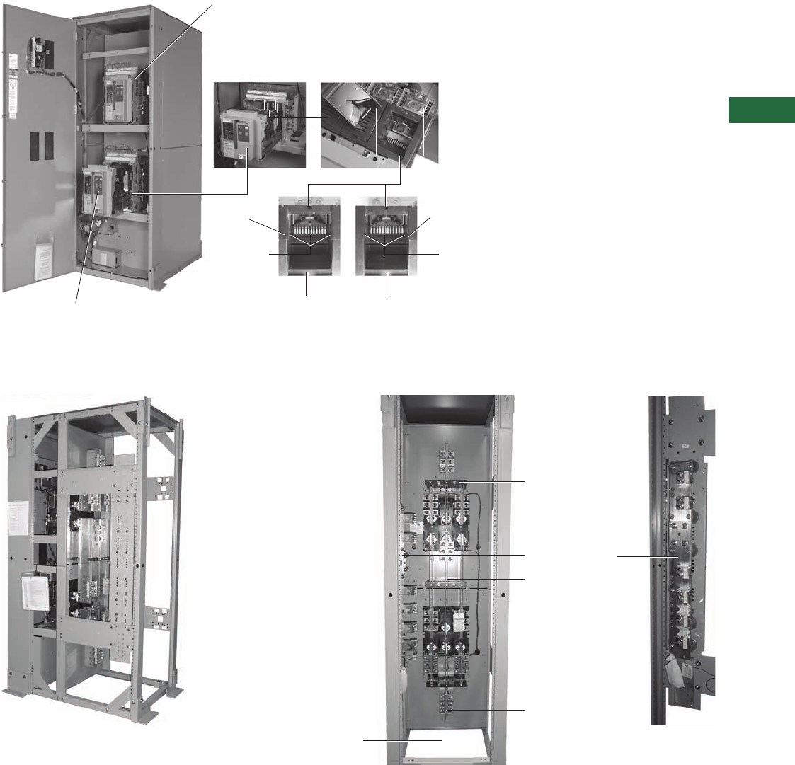
Volume 2—Commercial Distribution CA08100003E—April 2014 www.eaton.com V2-T5-47
5
5
5
5
5
5
5
5
5
5
5
5
5
5
5
5
5
5
5
5
5
5
5
5
5
5
5
5
5
5
5.4
Transfer Switches
Magnum-Based Design
Typical Layout
Basic Switch Components of Magnum Automatic Transfer Switches
Magnum-Based Transfer Switches
Power Panel
Performs Power Transfer Between Source 1 and Source 2
Using Magnum Power Case Switches or Circuit Breakers
Electrical Operator
Pushbutton
Side-to-Side
Ledge
Side-to-Side
Ledge
Contact Wear
Indicator—
Contacts Closed
and in Good
Condition
Contact Wear
Indicator—
Contacts Closed
and Wear
is Indicated
Contact Wear
Inspection
Area (Ledge
Not Visible
Under Contacts)
Contact Wear
Inspection Area
(Ledge Now
Becoming Visible
Under Contacts)
Bottom Entry Area
Side View of Magnum
Side or Rear Access Required
(Half-High Side Panels and Back Panels are Not Shown)
Source 2 Connections
Load Connections
Source 1 Connections
Neutral Connections
Neutral
Assembly
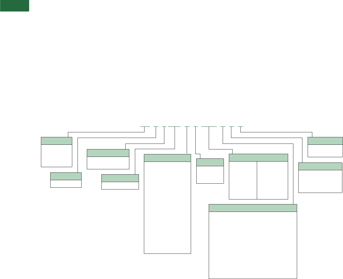
V2-T5-48 Volume 2—Commercial Distribution CA08100003E—April 2014 www.eaton.com
5
5
5
5
5
5
5
5
5
5
5
5
5
5
5
5
5
5
5
5
5
5
5
5
5
5
5
5
5
5
5.4
Transfer Sw itches
Magnum-Based Design
Product Selection
Eaton transfer switch
equipment offers flexibility
and versatility to the system
designer and user. All
switches include the basic
features necessary for
normal operation as standard.
Eaton
also offers an extensive
array of optional
features/
accessories that allows the
user to customize a new
transfer switch to match
the application. Select
the appropriate catalog
number for the application.
Then choose any optional
features/accessories needed
to complete the project
requirements.
Catalog Number:
ATV9MGB33200XRU with
Optional Features 16B and 37B
The example above would
specify the following:
●Automatic transfer switch
●Vertical configuration
●ATC-900 logic
●Magnum DS frame
●Fixed mount
●Three-pole
●3200A
●480V
●NEMA 1 enclosure
●UL listed
●ATC-900 transfer logic
●Integral overcurrent
protection both sources
●Service entrance rated with
ground fault protection if
service entrance rating
was selected
●Seismic qualified
Catalog Number Selection
Using the catalog numbering system provides an overview
of the ten basic style/feature categories that generate the
15-digit catalog number.
Magnum Automatic and Non-Automatic Transfer Switches 200–5000A
Note
1Available on fixed-mounted units up to 3200A.
24000A and 5000A available as drawout configuration only.
Logic
9= ATC-900
E= Electromechanical
Type
AT = Automatic
CT = Closed
transition
NT = Non-auto
Orientation
V = Vertical
Poles
2 = Two-pole
3 = Three-pole
4 = Four-pole
Amperes
0200 = 200A
0300 = 300A
0400 = 400A
0600 = 600A
0800 = 800A
1000 = 1000A
1200 = 1200A
1600 = 1600A
2000 = 2000A
2500 = 2500A
3000 = 3000A
3200 = 3200A
4000 = 4000A 2
5000 = 5000A 2
Enclosure
K = Open 1
S = NEMA 1
R = NEMA 3R
T = Through-door design
Listing
U = UL listed
CSA listed
Frame
MG = Magnum DS
Switch
A= Fixed mount,
power case switch
PCS both
B= Fixed mount,
power case circuit
breaker PCB both
C= Fixed mount,
PCB normal,
PCS emergency
D= Fixed mount,
PCS normal,
PCB emergency
E= Drawout, PCS both
F= Drawout, PCB both
G= Drawout, PCB normal,
PCS emergency
H= Drawout, PCS normal,
PCB emergency
Legend:
PCS = Power Case Switch
PCB = Power Circuit Breaker
Voltage
A= 120V, 60 Hz, three-phase, three-wire
B= 208/120V, 60 Hz, three-phase, four-wire
E= 600V, 60 Hz, three-phase, three-wire
E= 600V, 60 Hz, three-phase, four-wire
G= 220/127V, 50 Hz, three-phase, four-wire
H= 380/220V, 50 Hz, three-phase, four-wire
O= 415/240V, 50 Hz, three-phase, four-wire
W= 240/120V, 60 Hz, single-phase, three-wire
W= 240V, 60 Hz, three-phase, three-wire
W= 240/120V, 60 Hz, three-phase, four-wire hi-leg
X= 480V, 60 Hz, three-phase, three-wire
X= 480/277V, 60 Hz, three-phase, four-wire
X= 480/240V, 50 Hz, single-phase, two-wire
AT V 9 MG B 3 3200 X R U

Volume 2—Commercial Distribution CA08100003E—April 2014 www.eaton.com V2-T5-49
5
5
5
5
5
5
5
5
5
5
5
5
5
5
5
5
5
5
5
5
5
5
5
5
5
5
5
5
5
5
5.4
Transfer Switches
Magnum-Based Designs
Standards and Certifications
Eaton Magnum transfer
switches meet or exceed
all industry standards for
endurance, reliability and
performance. They are
listed under Underwriters
Laboratories UL 1008
Standard for transfer switch
equipment. With certain
options, they also comply
with Source 2 and standby
system requirements as
defined in NFPA 99 for health
care facilities.
●UL 1008—standard for
safety for automatic
transfer switches up to
4000A; 5000A
available as
UL 891 only
●UL 489—standard for
circuit breakers and
molded case switches
●CSA 22.2-178—Canadian
transfer switch standard
●NEC Articles—code
sections 517, 700, 701,
702—applicable switch
equipment
●NFPA 110—Source 2 and
Standby Power Systems
●NFPA 99—health care
facilities
●EGSA 100S—standard for
transfer switches
●NEMA ICS10—Standard
for transfer switch
equipment
●UBC—Uniform Building
Code for Seismic Zone 4
●ISO® 9000—International
Organization for
Standardization
●CBC—California
Building Code
●IBC—International
Building Code
●BOCA—Building Officials
Code Administrators
Technical Data and Specifications
Floor-Standing Magnum
Transfer Switch
●Ambient temperature
range: –40°C to 40°C
(–40°F to 104°F)
●Operating temperature
range: –20°C to 70°C
(–4°F to 158°F)
●Operating humidity:
up to 90%
●Relative humidity
(noncondensing)
Magnum Drawout
Transfer Switch
●200–5000A
●Two-, three-, four-pole
(except 4000A: three-
and four-pole only)
●120–600 Vac
●100,000A withstand/
closing/interrupting
at 480 Vac
●Short-time withstand–
85,000 for 30 cycles
Magnum Fixed-Mount
Transfer Switch
●200–3200A
●Two-, three-, four-pole
(except 3200A: two- and
three-pole only)
●120–600 Vac
●100,000A withstand/
closing/interrupting
at 3 cycle
●Short-time withstand–
85,000 for 30 cycles
Magnum Drawout Transfer
Switches
Automatic and
Non-Automatic
Transfer Switches
Enclosures meet all current
applicable NEMA and UL
standards for conduit entry,
cable bending, gutter space
and shielding of live
components.
NEMA 1 and
NEMA 3R Enclosures
Magnum transfer switches
are supplied with a front door
only. The NEMA 3R are
provided with a door within
a door design.
The Magnum transfer
switch requires rear access.
If placed against a wall, then
a minimum of 3 feet is
needed as well as side
access on at least one of the
sides. Access to cable space
can be via the side, bottom,
top or rear.
Transfer Switch
Withstand Ratings
Systems Coordination
Information—Withstand,
Closing and Interrupting
Ratings
Notes
1Ratings used for coordination with
upstream breakers with short-time
ratings.
2UL 1066 short-time withstand rating.
Transfer
Switch
Ampere
Rating
3-Cycle
Short-Circuit
600V (kA)
30-Cycle 1
Short-Time
600V (kA)
UL 1008
800 100 85
1000 100 85
1200 100 85
1600 100 85
2000 100 85
2500 100 85
3000 100 85
3200 100 85
4000 100 —
UL 891
4000 — 85 2
5000 — 85 2
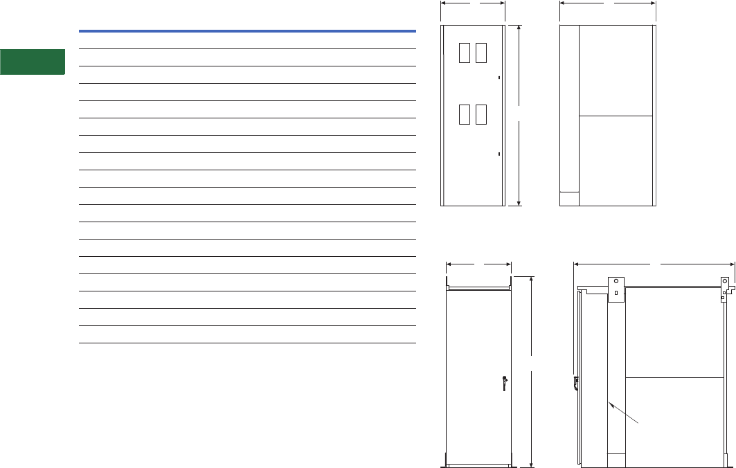
V2-T5-50 Volume 2—Commercial Distribution CA08100003E—April 2014 www.eaton.com
5
5
5
5
5
5
5
5
5
5
5
5
5
5
5
5
5
5
5
5
5
5
5
5
5
5
5
5
5
5
5.4
Transfer Sw itches
Magnum-Based Designs
Dimensions
Approximate Dimensions in Inches (mm)
Magnum Fixed-Mount Transfer Switches
Note
1At 4000 and 5000A, the standard design is drawout. See drawout dimensions.
200–3200A Fixed-Mount NEMA 1
200–3200A Fixed-Mount NEMA 3R
Ampere
Rating
Number
of
Poles
A
Height
B
Width
C
Depth
Shipping
Weight
Lbs (kg)
NEMA 1 Enclosed Fixed-Mount Transfer Switch
200–2000 2 90.00 (2286.0) 32.00 (812.8) 48.00 (1219.2) 1050 (477)
200–2000 3 90.00 (2286.0) 32.00 (812.8) 48.00 (1219.2) 1050 (477)
200–2000 4 90.00 (2286.0) 32.00 (812.8) 48.00 (1219.2) 1250 (568)
2500–3200 2 90.00 (2286.0) 44.00 (1117.6) 48.00 (1219.2) 1900 (863)
2500–3200 3 90.00 (2286.0) 44.00 (1117.6) 48.00 (1219.2) 1900 (863)
2500–3200 4 90.00 (2286.0) 44.00 (1117.6) 48.00 (1219.2) 2000 (910)
4000 1—1111
5000 1—1111
NEMA 3R Enclosed Fixed-Mount Transfer Switch
200–2000 2 90.00 (2286.0) 32.00 (812.8) 63.00 (1600.2) 1600 (726)
200–2000 3 90.00 (2286.0) 32.00 (812.8) 63.00 (1600.2) 1600 (726)
200–2000 4 90.00 (2286.0) 32.00 (812.8) 63.00 (1600.2) 1800 (817)
2500–3200 2 90.00 (2286.0) 44.00 (1117.6) 63.00 (1600.2) 2400 (1090)
2500–3200 3 90.00 (2286.0) 44.00 (1117.6) 63.00 (1600.2) 2400 (1090)
2500–3200 4 90.00 (2286.0) 44.00 (1117.6) 63.00 (1600.2) 2500 (1135)
4000 — 111—
5000 — 111—
A
B C
A
B C
Door Within
a Door Design
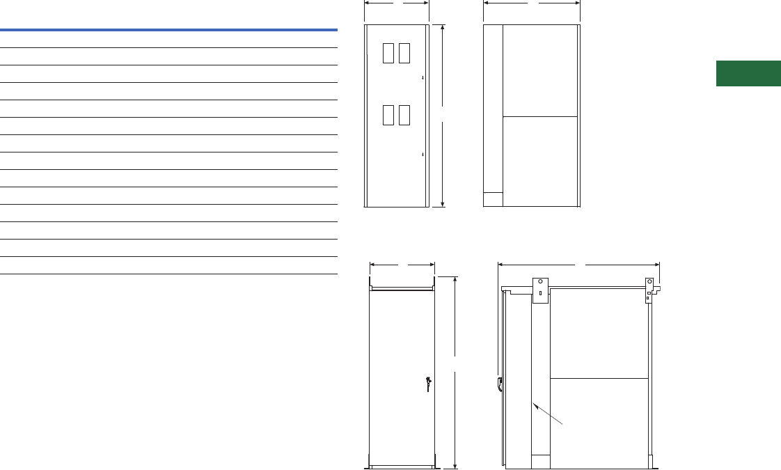
Volume 2—Commercial Distribution CA08100003E—April 2014 www.eaton.com V2-T5-51
5
5
5
5
5
5
5
5
5
5
5
5
5
5
5
5
5
5
5
5
5
5
5
5
5
5
5
5
5
5
5.4
Transfer Switches
Magnum-Based Designs
Approximate Dimensions in Inches (mm)
Magnum Drawout Transfer Switches 200–3200A Drawout NEMA 1
200–3200A Drawout NEMA 3R
Ampere
Rating
Number
of
Poles
A
Height
B
Width
C
Depth
Shipping
Weight
Lbs (kg)
NEMA 1 Enclosed Drawout Transfer Switch
200–2000 2 90.00 (2286.0) 32.00 (812.8) 60.00 (1524.0) 1600 (727)
200–2000 3 90.00 (2286.0) 32.00 (812.8) 60.00 (1524.0) 1600 (727)
200–2000 4 90.00 (2286.0) 32.00 (812.8) 60.00 (1524.0) 1900 (864)
2500–3200 2 90.00 (2286.0) 44.00 (1117.6) 60.00 (1524.0) 2500 (1136)
2500–3200 3 90.00 (2286.0) 44.00 (1117.6) 60.00 (1524.0) 2500 (1136)
2500–3200 4 90.00 (2286.0) 44.00 (1117.6) 60.00 (1524.0) 2800 (1273)
NEMA 3R Enclosed Drawout Transfer Switch
200–2000 2 90.00 (2286.0) 32.00 (812.8) 75.00 (1905.0) 2100 (953)
200–2000 3 90.00 (2286.0) 32.00 (812.8) 75.00 (1905.0) 2100 (953)
200–2000 4 90.00 (2286.0) 32.00 (812.8) 75.00 (1905.0) 2400 (1090)
2500–3200 2 90.00 (2286.0) 44.00 (1117.6) 75.00 (1905.0) 3000 (1362)
2500–3200 3 90.00 (2286.0) 44.00 (1117.6) 75.00 (1905.0) 3000 (1362)
2500–3200 4 90.00 (2286.0) 44.00 (1117.6) 75.00 (1905.0) 3300 (1498)
A
B C
A
B C
Door Within
a Door Design
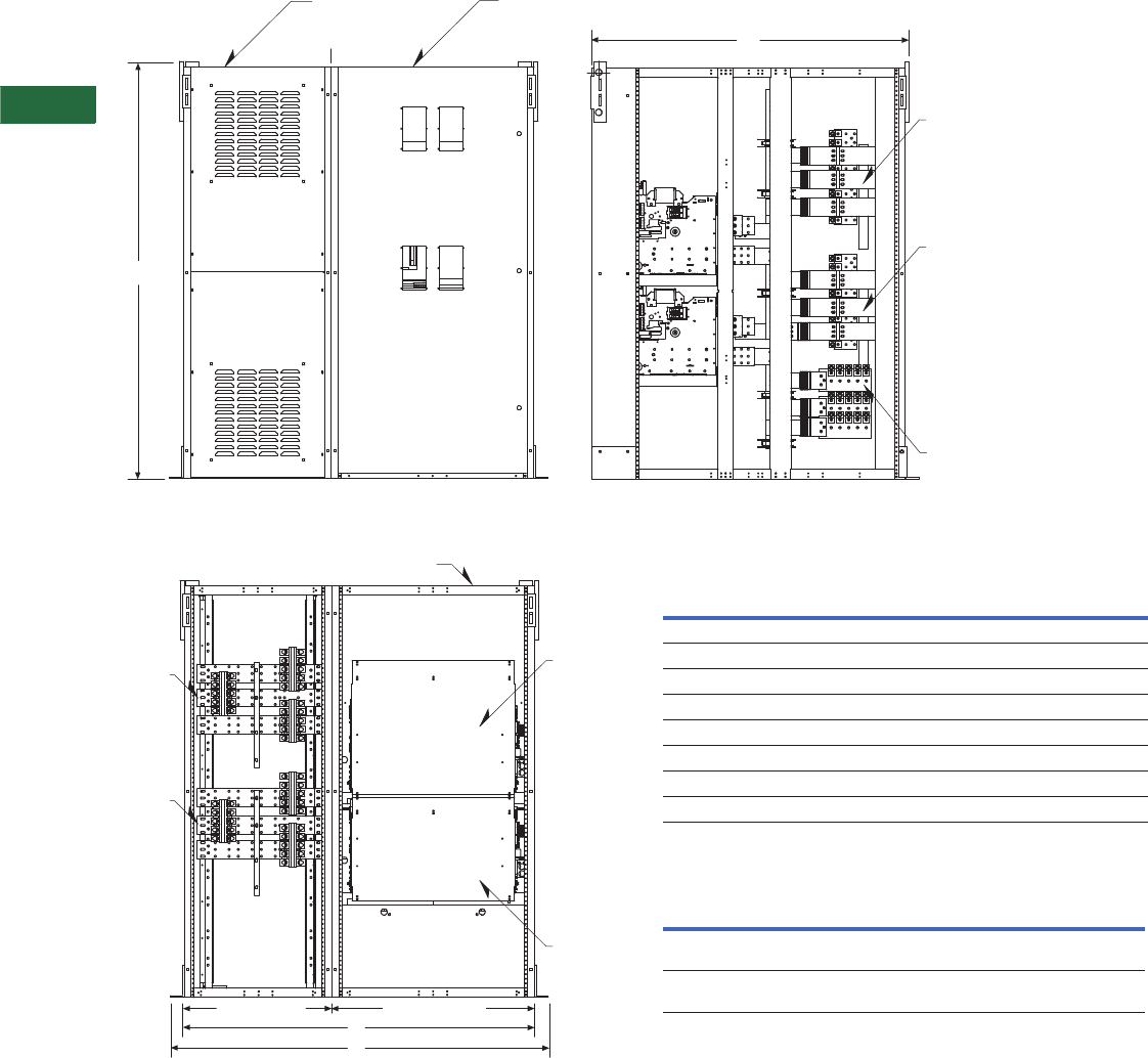
V2-T5-52 Volume 2—Commercial Distribution CA08100003E—April 2014 www.eaton.com
5
5
5
5
5
5
5
5
5
5
5
5
5
5
5
5
5
5
5
5
5
5
5
5
5
5
5
5
5
5
5.4
Transfer Sw itches
Magnum-Based Designs
Approximate Dimensions in Inches (mm)
Magnum 4000–5000A Units
Note: The typical Magnum ATS at 4000 and 5000A ratings will include one cubicle with the Source 1 and Source 2 power case switches or breakers.
A second cubicle called a wireway is required unless bus is used for the connections per Connection Type table above. Cable connections
to the wireway cubicle can be made from the top or bottom. The wireway cubicle will have removable panels on the front, and cable connections
may be made from the top or the bottom. Cable connections to the power case switch or breaker cubicle are made from the back. Consult factory
for dimensions. The wireway width is 32.00 inches (812.8 mm).
Front View With Covers
C
Front View Without Covers
Right Side View
A
Wireway Cubicle ATS Cubicle
Source 1
(Normal)
Source 2
(Emergency)
SP
Emergency Lugs —
Located in Rear of Cubicle
Normal
Lugs
Load
Lugs
Wireway
Cubicle
Source 1
(Normal)
Load
Source 2
B
C
32.00 (812.8) 54.00 (1371.6)
SP = Shipping Split.
Consult factory for dimensions.
Connection Type (4000–5000A Only)
Magnum Drawout Transfer Switches
Notes
1Seismic mounting adds 3.00 inches (76.2 mm) width to each side or additional 6.00 inches
(152.4 mm) to width.
2Consult factory.
Connection Type
WirewayLine Emergency Load
Cable Cable Cable Yes
Bus Cable Cable Yes
Cable Bus Cable Yes
Cable Cable Bus Yes
Bus Bus Cable No
Bus Cable Bus No
Cable Bus Bus No
Bus Bus Bus No
Ampere
Rating
No.
of
Poles
A
Height
B
Width
C 1
Width
D
Depth
Shipping
Weight
Lbs (kg)
4000 3 or 4 90.00
(2286.0)
86.00
(2184.4)
92.00
(2336.8)
68.00
(1727.2)
2
5000 3 or 4 90.00
(2286.0)
86.00
(2184.4)
92.00
(2336.8)
68.00
(1727.2)
2
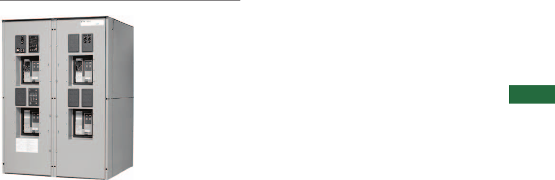
Volume 2—Commercial Distribution CA08100003E—April 2014 www.eaton.com V2-T5-53
5
5
5
5
5
5
5
5
5
5
5
5
5
5
5
5
5
5
5
5
5
5
5
5
5
5
5
5
5
5
5.4
Transfer Switches
Magnum-Based Designs
Bypass Isolation Transfer Switch
Contents
Description Page
Power Case Switch—Floorstanding, 200–5000A . V2-T5-44
Bypass Isolation Transfer Switch, 200–5000A
Standards and Certifications . . . . . . . . . . . . . . V2-T5-54
Catalog Number Selection . . . . . . . . . . . . . . . . V2-T5-55
Product Selection . . . . . . . . . . . . . . . . . . . . . . . V2-T5-55
Technical Data and Specifications . . . . . . . . . . V2-T5-56
Bypass Isolation Transfer Switch, 200–5000A
Product Description
A bypass isolation switch
utilizes loadbreak isolation
and bypass transfer power
contacts. Thus, should
voltage be lost on the line to
which the ATS is connected,
and should a manual bypass
be required to the other line,
this can be accomplished
safely and quickly as
described below. With
contactor designs utilizing
non-loadbreak isolation and
bypass switches, manual
bypass to the other line is
hindered by mechanical or
electrical safety interlocking.
Application Description
The bypass isolation switch
is designed for applications
where maintenance,
inspection and testing
must be performed while
maintaining continuous
power to the load. This is
typically required in critical
life-support systems and
standby power situations
calling for safe system
maintenance with no power
disruptions. Such a design
allows for the quick removal
of the different switching
devices for inspection,
maintenance or replacement.
Features, Benefits and Functions
Eaton’s transfer switch is
a rugged, compact design
utilizing Magnum power
switches or Magnum power
circuit breakers to transfer
essential loads from one
power source to another.
Open transition switching
devices are interlocked to
prevent both switching
devices from being closed at
the same time. The versatile
design, in addition to standard
transfer functions, offers an
optional integral thermal
and short-circuit protection
in either or both switching
devices.
The switching devices
are in a compact vertical
arrangement. The logic
can be easily disconnected
from the switching device
without disturbing critical
connections. The enclosure
is free standing, and by
using the specially supplied
cleats, the switch is seismic
approved (Option 42). The
terminals are mounted in the
rear of the switch, permitting
rear, top, bottom or side
cable or bus bar entrance.
The switching devices have
a high withstand rating. The
high-speed, stored-energy
switching mechanism
guarantees a transfer time
of less than three cycles.
●Reliable microprocessor
logic
●Designed to safely
withstand fault currents
●Eliminates need for
complex interlocks
●Most versatile bypass
isolation transfer switch
available
●Eaton drawout cassette
design
●Overcurrent protection
available
●No loadbreak when
bypassing to the
same source
●Drawout capabilities
on both ATS and
bypass portions
●Compact design
●Ability to test power
switching elements
during drawout process
●Power switching
devices completely
interchangeable between
ATS and bypass portions
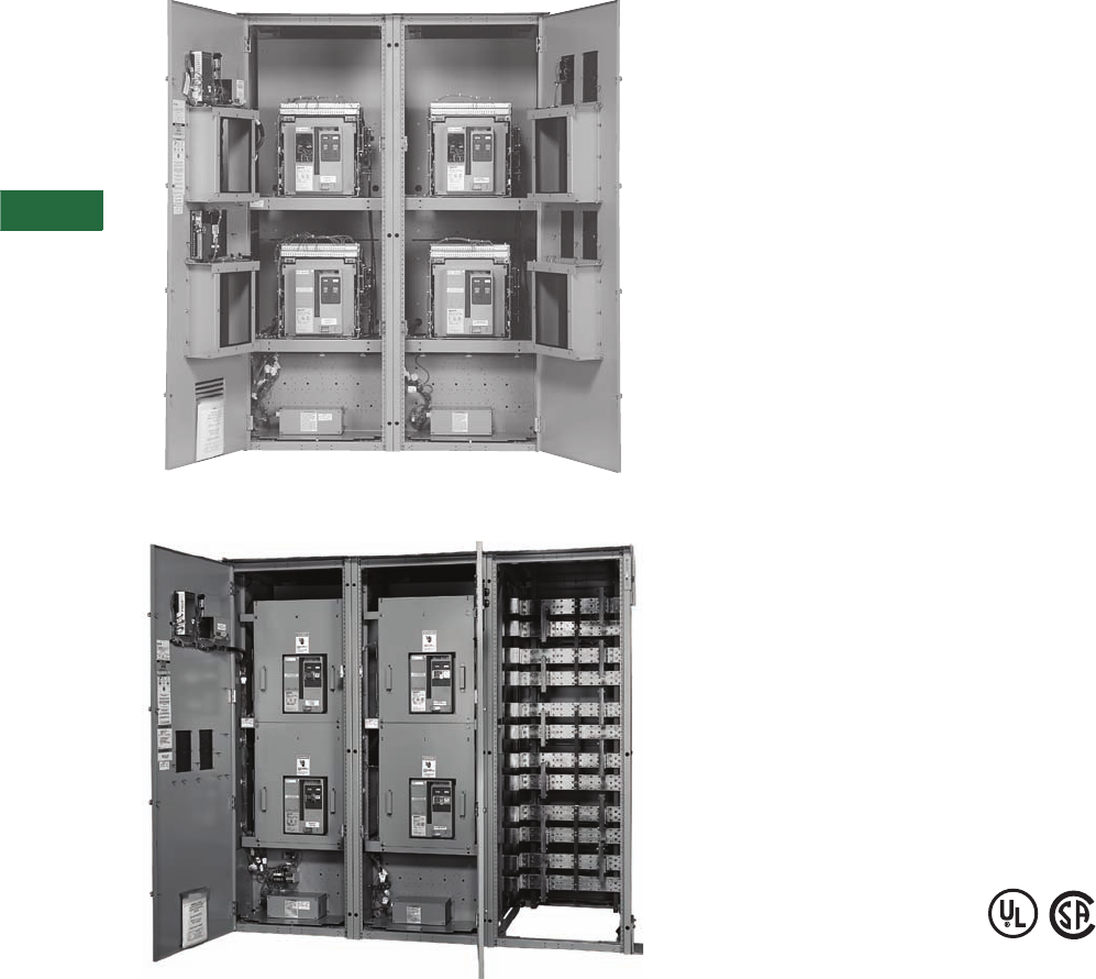
V2-T5-54 Volume 2—Commercial Distribution CA08100003E—April 2014 www.eaton.com
5
5
5
5
5
5
5
5
5
5
5
5
5
5
5
5
5
5
5
5
5
5
5
5
5
5
5
5
5
5
5.4
Transfer Sw itches
Magnum-Based Designs
Magnum Bypass Isolation Front View without the
Deadfront Panels—NEMA 1 Through the Door
Front Access Option 54A is Available on All Magnum Designs
Standards and Certifications
Eaton transfer switch
equipment is listed for
application by UL and CSA.
In addition, Eaton ATSs are
listed in
File E38116 by
Underwriters Laboratories
under Standard UL 1008. This
standard covers requirements
for ATSs intended for use in
ordinary locations to provide
for lighting and power as
follows:
A. In emergency systems,
in accordance with
Articles 517 and 700 in
the National Electrical
Code (NEC), American
National Standards
Institute/National Fire
Protection Association
(ANSI/NFPA) 70 and the
NFPA No. 76A and/or
B. In standby systems, in
accordance with Article
702 of the NEC and/or
C. In legally required standby
systems in accordance
with Article 701 of the
NEC. Eaton ATSs are
available to meet NFPA
110 for emergency and
standby power systems,
and NFPA 99 for health-
care facilities when
ordered with the
appropriate options.
Since Eaton ATSs utilize
specially designed
switches and/or
switching devices as the
main power switching
contacts, these devices
must also be listed under
the additional UL
Standard 1066. UL
utilizes two basic types
of listing programs:
a. Label Service, and
b. Re-examination.
UL 1066 employs a
label service listing
program that requires
an extensive follow-up
testing program for
listed devices.
Standard UL 1008 for
ATSs lists devices
under the re-
examination program
that only requires a
continual physical re-
examination of the
components used in
the product to ensure
consistency with the
originally submitted
device. Follow-up
testing IS NOT
required by UL 1008.
Representative
production samples of
switches and
switching devices
used in Eaton ATSs
are subjected to a
complete test
program identical to
the originally
submitted devices on
an ongoing periodic
basis per UL 1066. The
frequency
of such a re-
submittal can be as
often as every quarter
for a low ampere
device.
Note: IBC seismic qualified.
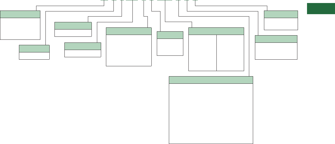
Volume 2—Commercial Distribution CA08100003E—April 2014 www.eaton.com V2-T5-55
5
5
5
5
5
5
5
5
5
5
5
5
5
5
5
5
5
5
5
5
5
5
5
5
5
5
5
5
5
5
5.4
Transfer Switches
Magnum-Based Designs
Catalog Number Selection
Using the catalog numbering system provides an overview
of the ten basic style/feature categories that generate the
15-digit catalog number.
Magnum Bypass, Transfer Switches 200–5000A
Product Selection
Eaton transfer switch
equipment offers flexibility
and versatility to the system
designer and user. All
switches include the basic
features necessary for
normal operation as standard.
Eaton
also offers an extensive
array of optional
features/
accessories that allows the
user to customize a new
transfer switch to match
the application. Select
the appropriate catalog
number for the application.
Then choose any optional
features/accessories needed
to complete the project
requirements.
Catalog Number:
BIV9MGE33200XRU
The example above would
specify the following:
●Bypass isolation
●Vertical configuration
●ATC-900 controller
●Magnum DS frame
●Power case switch normal
and emergency
●Drawout
●Three-pole
●3200A
●480V
●NEMA 3R enclosure
●UL listed
Logic
9= ATC-900
Type
BI = Bypass open
transition
CB = Closed transition/
bypass isolation
Orientation
V = Vertical
Poles
2 = Two-pole
3 = Three-pole
4 = Four-pole
Amperes
0200 = 200A
0300 = 300A
0400 = 400A
0600 = 600A
0800 = 800A
1000 = 1000A
1200 = 1200A
1600 = 1600A
2000 = 2000A
2500 = 2500A
3200 = 3200A
4000 = 4000A
5000 = 5000A
Enclosure
S = NEMA 1
R = NEMA 3R
T = Through-door design
Listing
U = UL listed
CSA listed
Frame
MG = Magnum DS
Switch
E= Drawout, PCS both
F= Drawout, PCB both
G= Drawout, PCB normal,
PCS emergency
H= Drawout, PCS normal,
PCB emergency
Legend:
PCS = Power Case Switch
PCB = Power Circuit Breaker
Voltage
B= 208/120V, 60 Hz, three-phase, four-wire
E= 600V, 60 Hz, three-phase, three-wire
E= 600V, 60 Hz, three-phase, four-wire
G= 220/127V, 50 Hz, three-phase, four-wire
H= 380/220V, 50 Hz, three-phase, four-wire
O= 415/240V, 50 Hz, three-phase, four-wire
W= 240/120V, 60 Hz, single-phase, three-wire
W= 240V, 60 Hz, three-phase, three-wire
W= 240/120V, 60 Hz, three-phase, four-wire hi-leg
X= 480V, 60 Hz, three-phase, three-wire
X= 480/277V, 60 Hz, three-phase, four-wire
X= 480/240V, 50 Hz, single-phase, two-wire
BI V 9 MG E 3 3200 X R U
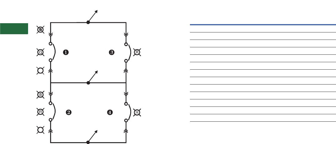
V2-T5-56 Volume 2—Commercial Distribution CA08100003E—April 2014 www.eaton.com
5
5
5
5
5
5
5
5
5
5
5
5
5
5
5
5
5
5
5
5
5
5
5
5
5
5
5
5
5
5
5.4
Transfer Sw itches
Magnum-Based Designs
Technical Data and Specifications
Typical Bypass Isolation Switch Schematic
SOURCE 1
SOURCE 1
SOURCE 1
SOURCE 1
BYPASS
SOURCE 1
SOURCE 1
SOURCE 1
AVAILABLE
SOURCE 2
ISOLATED
ISOLATED
POSITION
SOURCE 2
POSITION
SOURCE 2
AVAILABLE
SOURCE 2 SOURCE 2
SOURCE 2
INCOMING
ATS
BYPASS
BYPASS
ATS
LOAD
SOURCE 2
BYPASS
INCOMING
A
A
Systems Coordination Information—Withstand, Closing and
Interrupting Ratings
Notes
1Ratings used for coordination with upstream breakers with short-time ratings.
2UL 1066 short-time withstand rating.
Transfer
Switch
Ampere
Rating
3-Cycle
Short-Circuit
600V (kA)
30-Cycle 1
Short-Time
600V (kA)
UL 1008
800 100 85
1000 100 85
1200 100 85
1600 100 85
2000 100 85
2500 100 85
3000 100 85
3200 100 85
4000 100 —
UL 891
4000 — 85 2
5000 — 85 2
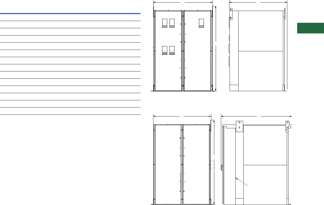
Volume 2—Commercial Distribution CA08100003E—April 2014 www.eaton.com V2-T5-57
5
5
5
5
5
5
5
5
5
5
5
5
5
5
5
5
5
5
5
5
5
5
5
5
5
5
5
5
5
5
5.4
Transfer Switches
Magnum-Based Designs
Approximate Dimensions in Inches (mm)
Magnum Bypass Isolation Drawout Transfer Switches
Note: Add 3.00 inches (76.2 mm) to the height, 6.00 inches (152.4 mm)
to the width and 3.00 inches (76.2 mm) to the depth to all enclosure
dimensions to account for the seismic mounting brackets.
200–3200A Drawout NEMA 1
200–3200A Drawout NEMA 3R
Ampere
Rating
Number
of
Poles
A
Height
B
Width
C
Depth
Shipping
Weight
Lbs (kg)
NEMA 1 Enclosed Drawout Transfer Switch
200–2000 2 90.00 (2286.0) 64.00 (1625.6) 60.00 (1524.0) 3100 (1409)
200–2000 3 90.00 (2286.0) 64.00 (1625.6) 60.00 (1524.0) 3100 (1409)
200–2000 4 90.00 (2286.0) 64.00 (1625.6) 60.00 (1524.0) 3700 (1682)
2500–3200 2 90.00 (2286.0) 64.00 (1625.6) 60.00 (1524.0) 4700 (2136)
2500–3200 3 90.00 (2286.0) 64.00 (1625.6) 60.00 (1524.0) 4700 (2136)
2500–3200 4 90.00 (2286.0) 64.00 (1625.6) 60.00 (1524.0) 5500 (2500)
NEMA 3R Enclosed Drawout Transfer Switch
200–2000 2 90.00 (2286.0) 64.00 (1625.6) 75.00 (1905.0) 4100 (1861)
200–2000 3 90.00 (2286.0) 64.00 (1625.6) 75.00 (1905.0) 4100 (1861)
200–2000 4 90.00 (2286.0) 64.00 (1625.6) 75.00 (1905.0) 4700 (2134)
2500–3200 2 90.00 (2286.0) 64.00 (1625.6) 75.00 (1905.0) 5700 (2588)
2500–3200 3 90.00 (2286.0) 64.00 (1625.6) 75.00 (1905.0) 5700 (2588)
2500–3200 4 90.00 (2286.0) 64.00 (1625.6) 75.00 (1905.0) 6500 (2951)
C
A
B
C
A
B
Door Within
a Door Design
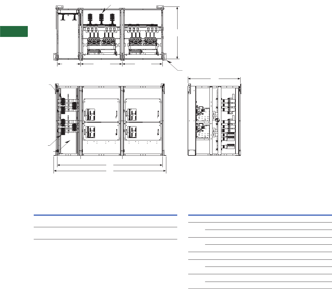
V2-T5-58 Volume 2—Commercial Distribution CA08100003E—April 2014 www.eaton.com
5
5
5
5
5
5
5
5
5
5
5
5
5
5
5
5
5
5
5
5
5
5
5
5
5
5
5
5
5
5
5.4
Transfer Sw itches
Magnum-Based Designs
Approximate Dimensions in Inches (mm)
Magnum 4000–5000A Units—NEMA 1
NEMA 1 Magnum Drawout Transfer Switches Magnum Bypass Isolation Drawout Transfer Switches
Notes
1Seismic mounting adds 3.00 inches (76.2 mm) width to each side or additional 6.00 inches
(152.4 mm) to width.
2Consult factory.
Source 2 Emergency Lugs
Load
Lugs
Source 1
Normal
Lugs
A
54.00
(1371.8)
54.00
(1371.8)
32.00
(872.8)
D
Normal
ATS
Breaker
Normal
Bypass
Breaker
Emergency
ATS
Breaker
Emergency
Bypass
Breaker
Wireway
Cubicle
SP SP
C
B
Note: Seismic mounting
brackets add 3.00 inches (76.2)
width to each side or an
additional 6.00 inches (152.4)
to total width.
Top View
Front View
Right Side View
SP = Shipping Split.
Consult factory for dimensions.
Note: The 4000 and 5000A
bypass isolation ATS will include
two cubicles for the Source 1 and
Source 2 Normal and the Bypass
power case switch.
An additional cubicle called a
wireway is provided for the
Normal and Load connections.
The wireway cubicle will have
removable panels on the front,
and cable connections may
be made from the top or the
bottom. Cable connections for
Emergency are made in the
rear. The wireway width is
32.00 inches (812.8 mm).
Ampere
Rating
Number
of Poles
A
Height
B
Width
C 1
Width
D
Depth
Shipping
Weight
Lbs (kg)
4000 3 or 4 90.00
(2286.0)
137.00
(3479.8)
146.00
(3708.4)
60.00
(1524.0)
2
5000 3 or 4 90.00
(2286.0)
137.00
(3479.8)
146.00
(3708.4)
60.00
(1524.0)
2
Ampere
Rating
Number of
Poles
A
Height
B
Width
C
Depth
Shipping
Weight
Lbs (kg)
NEMA 1 Enclosed Drawout Transfer Switch
4000 2 or 3 90.00 (2286.0) 137.00 (3479.8) 60.00 (1524.0) 6900 (3133)
4 90.00 (2286.0) 137.00 (3479.8) 60.00 (1524.0) 7600 (3450)
5000 2 or 3 90.00 (2286.0) 137.00 (3479.8) 60.00 (1524.0) 7900 (3587)
4 90.00 (2286.0) 137.00 (3479.8) 60.00 (1524.0) 8600 (3904)
NEMA 3R Enclosed Drawout Transfer Switch
4000 2 or 3 90.00 (2286.0) 137.00 (3479.8) 75.00 (1905.0) 7900 (3587)
4 90.00 (2286.0) 137.00 (3479.8) 75.00 (1905.0) 8600 (3904)
5000 2 or 3 90.00 (2286.0) 137.00 (3479.8) 75.00 (1905.0) 8900 (4041)
4 90.00 (2286.0) 137.00 (3479.8) 75.00 (1905.0) 9600 (4358)
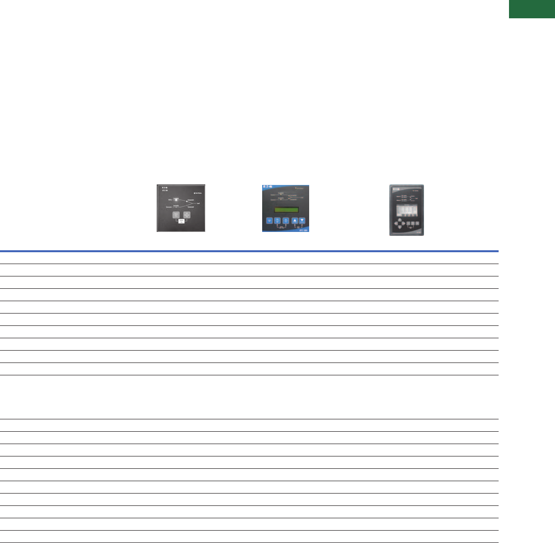
Volume 2—Commercial Distribution CA08100003E—April 2014 www.eaton.com V2-T5-59
5
5
5
5
5
5
5
5
5
5
5
5
5
5
5
5
5
5
5
5
5
5
5
5
5
5
5
5
5
5
5.5
Transfer Switches
Automatic Transfer Controllers
Contents
Description Page
Product Selection Guide
Automatic Transfer Controllers Feature
Selection Chart . . . . . . . . . . . . . . . . . . . . . . . V2-T5-60
ATC-100 Controller . . . . . . . . . . . . . . . . . . . . . . . . V2-T5-63
ATC-300+ Controller . . . . . . . . . . . . . . . . . . . . . . . V2-T5-65
ATC-900 Controller . . . . . . . . . . . . . . . . . . . . . . . . V2-T5-69
ATC-600/800 Controller . . . . . . . . . . . . . . . . . . . . . V2-T5-79
ATC-800 Controller . . . . . . . . . . . . . . . . . . . . . . . . V2-T5-82
Controller Replacement Guide . . . . . . . . . . . . . . . V2-T5-86
Product Selection Guide
Automatic Transfer Controllers Feature Selection Chart
Feature Description ATC-100 ATC-300+ ATC-900
Tr a n s i t i o n
Open transition Standard Standard Standard
Closed transition Not available Not available Standard
Timers
Time delay normal to emergency (TDNE) Standard Standard Standard
Time delay engine start (TDES) Standard Standard Standard
Time delay emergency to normal (TDEN) Standard Standard Standard
Time delay engine cooldown (TDEC) Standard Standard Standard
Time delay emergency fail (TDEF) Standard Standard Standard
Engine/Generator Exerciser
Plant exerciser (PE) with fail-safe Selectable—OFF, 7-, 14-, 28-day
interval fixed run time 15 minutes no
load/load with fail-safe
Selectable—OFF, 7-, 14-, 28-day interval, 0–600
minutes, no load/load with fail-safe
Two independent exerciser modes—OFF,
daily, 7-, 14-, 28-day interval or by
calendar date (up to 12 independent
calendar dates). Test operations include
independent transfer time delays
Source 1 Sensing
All-phase undervoltage and underfrequency protection Standard Standard Standard
All-phase overvoltage and overfrequency protection Standard Standard Standard
Three-phase rotation sensing Not available Standard Standard
Three-phase voltage unbalance Not available Standard Standard
Source 2 Sensing
All-phase undervoltage and underfrequency protection Standard Standard Standard
All-phase overvoltage and overfrequency protection Standard Standard Standard
Three-phase rotation sensing Not available Standard Standard
Three-phase voltage unbalance Not available Standard Standard
V2-T5-60 Volume 2—Commercial Distribution CA08100003E—April 2014 www.eaton.com
5
5
5
5
5
5
5
5
5
5
5
5
5
5
5
5
5
5
5
5
5
5
5
5
5
5
5
5
5
5
5.5
Transfer Sw itches
Automatic Transfer Controllers
Automatic Transfer Controllers Feature Selection Chart, continued
Feature Description ATC-100 ATC-300+ ATC-900
Manual Controls
Test operators Standard Standard Standard
Four-position test selector switch (FPSS) Not available Not available Optional
Time delay bypass pushbutton Not available Standard Standard
Maintenance selector switch (MSS) Not available Optional Optional
Automatic/manual operation selector switch Not available Optional Optional
Automatic/manual retransfer selector switch Not available Not available Optional
Manual retransfer pushbutton Not available Optional Optional
Indications / Status Display
Source 1 connected / Source 2 connected Standard Standard Standard
Source 1 available / Source 2 available Standard Standard Standard
Source 1 tripped / Source 2 tripped Standard Standard Standard
Customer Outputs
Source 1 / Source 2 present contacts Not available Standard—2NO and 2NC Not available
Source 1 available / Source 2 available contacts Not available Not available Standard—1 Form C
Load sequence Not available Not available Configurable—1 Form C
Selective load shed Not available Not available Configurable—1 Form C
Load bank control Not available Not available Configurable—1 Form C
Pre-transfer Not available Standard—1 Form C Configurable—1 Form C
Pre-/post-transfer Not available Not available Configurable—1 Form C
Source 1 connected Not available Not available Configurable—1 Form C
Source 2 connected Not available Not available Configurable—1 Form C
ATS not in automatic Not available Not available Configurable—1 Form C
General alarm Not available Standard Configurable—1 Form C
ATS in test Not available Not available Configurable—1 Form C
Engine test aborted Not available Not available Configurable—1 Form C
Cooldown in process Not available Not available Configurable—1 Form C
Engine start contact status Not available Not available Configurable—1 Form C
Emergency inhibit on Not available Not available Configurable—1 Form C
Switch Position Indication Contact
Source 1 position indication contact Not available Standard—1 Form C Standard—1 Form C
Source 2 position indication contact Not available Standard—1 Form C Standard—1 Form C
Volume 2—Commercial Distribution CA08100003E—April 2014 www.eaton.com V2-T5-61
5
5
5
5
5
5
5
5
5
5
5
5
5
5
5
5
5
5
5
5
5
5
5
5
5
5
5
5
5
5
5.5
Transfer Switches
Automatic Transfer Controllers
Automatic Transfer Controllers Feature Selection Chart, continued
Feature Description ATC-100 ATC-300+ ATC-900
Customer Inputs
Go to emergency (Source 2) Not available Standard Standard—configurable input
Load shed / emergency inhibit Not available Standard Standard—configurable input
Monitor mode Not available Optional Standard—configurable input
Bypass timers Not available Not available Standard—configurable input
Lockout Not available Optional Standard—configurable input
Manual retransfer on/off Not available Programmed Standard—configurable input
Manual retransfer Not available Standard Standard—configurable input
Slave in Not available Not available Standard—configurable input
Remote engine test Not available Not available Standard—configurable input
Preferred source selection Not available Not available Standard—configurable input
Remote load test Not available Not available Standard—configurable input
ATS on bypass Not available Not available Standard—configurable input
Integrated Metering
DCT metering—load side Not available Not available Optional
Communications
Modbus 485 Not available Optional Standard
Modbus TCP/IP Not available Optional Optional
Transfer Mode Open Transition
Delayed—time delay neutral Standard—based on construction Standard—based on construction Standard—based on construction
In-phase monitoring Standard—based on construction Standard—based on construction Standard—based on construction
Load voltage decay Not available Not available Standard—based on construction
Transfer Mode Closed Transition
Closed transition Not available Not available Standard—based on construction
Closed transition/In-phase Not available Not available Standard—based on construction
Closed transition/In-phase/
Time delay neutral
Not available Not available Standard—based on construction
Closed transition/In-phase/
Load voltage delay
Not available Not available Standard—based on construction
Service Entrance Rating
Source 1, Source 2 or both, and with and without
ground fault protection
Not available Optional Optional
Stainless Steel Cover
SS lockable cover for controller Optional Optional
V2-T5-62 Volume 2—Commercial Distribution CA08100003E—April 2014 www.eaton.com
5
5
5
5
5
5
5
5
5
5
5
5
5
5
5
5
5
5
5
5
5
5
5
5
5
5
5
5
5
5
5.5
Transfer Sw itches
Automatic Transfer Controllers
Automatic Transfer Controllers Feature Selection Chart, continued
Feature Description ATC-100 ATC-300+ ATC-900
Programming Selections
Time delay normal to emergency 3 seconds (fixed) 0–1800 seconds 0–9999 seconds
Time delay emergency to normal 5 minutes (fixed) 0–1800 seconds 0–9999 seconds
Time delay engine cooldown 5 minutes (fixed) 0–1800 seconds 0–9999 seconds
Time delay engine start 3 seconds (fixed) 0–120 seconds 0–120 seconds
Time delay neutral Not available 0–120 seconds 0–120 seconds or based on load
voltage decay of 2–30% of nominal
Time delay Source 2 fail Not available 0–6 seconds 0–6 seconds
Time delay voltage unbalance Not available 10–30 seconds 10–30 seconds
Voltage unbalance three-phase Not available 0 or 1 (1 = enabled) Enabled or disabled
Phase reversal three-phase Not available Dropout 5–20%
Pickup (DO –2%) –3%
Dropout 5–20%
Pickup (DO –2%) –3%
In-phase Not available 0 or 1 (1 = enabled)
Load sequencing Not available Not available 0–120 seconds (up to xx devices)
Pre-transfer signal Not available 1–120 seconds 0–120 seconds
Plant exerciser Selectable—OFF, 7-, 14-, 28-day
interval, fixed run time 15 minutes,
no load/load with fail-safe
Selectable—OFF, 7-, 14-, 28-day
interval, 0–600 minutes, no load/
load with fail-safe
Two independent exerciser modes—OFF, daily,
7-, 14-, 28-day interval or by calendar date (up to
12 independent calendar dates). Test operations
include independent transfer time delays
Preferred source selection Not available Not available Source 1, Source 2 or None
Commitment to transfer in TDNE Not available Not available Enabled or disabled
Retransfer mode N/A automatic or manual Not available Optional Enabled or disabled
Auto daylight saving time adjustment Not available Not available Enabled or disabled
System selection Utility/generator Utility/generator or dual utility Utility/generator, dual utility,
dual generator or three source
Voltage Specification
System application voltage Up to 480 Vac Up to 600 Vac Up to 600 Vac
Voltage measurements Source 1 and 2 Source 1 and 2—VAB, VBC and VCA Source 1, 2 and load—VAB, VBC and VCA
Voltage measurement range 120–480 Vac 0–790 Vac rms 0–700 Vac rms
Operating power 95–145 Vac 65–145 Vac 65–160 Vac
24 Vdc (W10%)
Frequency Specifications
Frequency measurements Source 2 Source 1 and 2 Source 1 and 2
Frequency measurement range 50–60 Hz 40–70 Hz 40–70 Hz
Environmental Specifications
Operating temperature range –20 to +70ºC –20 to +70ºC –20 to +70ºC
Storage temperature range –30 to +85ºC –30 to +85ºC –30 to +85ºC
Operating humidity 0 to 95% relative humidity (noncondensing) 0 to 95% relative humidity (noncondensing) 0 to 95% relative humidity (noncondensing)
Operating environment Resistant to ammonia, methane, nitrogen,
hydrogen and hydrocarbons
Resistant to ammonia, methane, nitrogen,
hydrogen and hydrocarbons
Resistant to ammonia, methane, nitrogen,
hydrogen and hydrocarbons
Front Panel Indication
Mimic diagram with LED indication Unit status, Source 1 and 2 available and
connected (five total)
Unit status, Source 1 and 2 available and
connected (five total)
Unit status, Source 1 and 2 available and
connected (seven total)
Main display N/A LCD-based display, 2 lines, 16 characters LCD display, 4.3 inch color TFT (480x272)
Display language N/A English, French and Spanish English, French and Spanish
Communications capable N/A Modbus 485 Modbus 485 or Ethernet TCP/IP
Enclosure compatibility NEMA 1 and 3R NEMA 1, 12, 3R and 4X UV resistant faceplate NEMA 1, 12, 3R and 4X UV resistant faceplate

Volume 2—Commercial Distribution CA08100003E—April 2014 www.eaton.com V2-T5-63
5
5
5
5
5
5
5
5
5
5
5
5
5
5
5
5
5
5
5
5
5
5
5
5
5
5
5
5
5
5
5.5
Transfer Switches
Automatic Transfer Controllers
ATC-100 Controller
Contents
Description Page
Product Selection Guide . . . . . . . . . . . . . . . . . . . . V2-T5-59
ATC-100 Controller
Standards and Certifications . . . . . . . . . . . . . . V2-T5-64
Technical Data and Specifications . . . . . . . . . . V2-T5-64
ATC-300+ Controller . . . . . . . . . . . . . . . . . . . . . . . V2-T5-65
ATC-900 Controller . . . . . . . . . . . . . . . . . . . . . . . . V2-T5-69
ATC-600/800 Controller . . . . . . . . . . . . . . . . . . . . . V2-T5-79
ATC-800 Controller . . . . . . . . . . . . . . . . . . . . . . . . V2-T5-82
Controller Replacement Guide . . . . . . . . . . . . . . . V2-T5-86
ATC-100 Controller
Product Description
The ATC-100 Controller is a
comprehensive, multifunction,
microprocessor-based ATS
controller. It is a compact,
self-contained, panel-
mounted device designed to
replace traditional relay and
solid-state logic panels.
Application Description
The ATC-100 Controller
provides both fixed and
jumper-selectable settings
to allow for a range of
applications. It operates from
all system voltages between
120 and 480 Vac, single-
phase and three-phase, at 50
or 60 Hz. In addition, a period
of no control power operation
is provided. The ATC-100
Controller monitors the
condition of the three-phase
line-to-line voltage and
frequency of both the
utility and generator power
sources. It can also be set
up for single-phase operation.
The ATC-100 controller
provides the necessary
intelligence to ensure that
the transfer switch operates
properly through a series of
sensing and timing functions.
The ATC-100 controller
can be used with both the
breaker-based design and
the contactor-based design
up to 400A single- or three-
phase. See Page V2-T5-64
for ranges and factory
settings.
Features, Benefits and Functions
Standard Features
●Auxiliary relay contacts:
●Source 1 present
2NO and 2NC
●Source 2 present
2NO and 2NC
●Switch position indication
contacts:
●Source 1 position
1NO and 1NC
●Source 2 position
1NO and 1NC
●Source 1 and Source 2
sensing:
●Undervoltage/under
frequency
●Overvoltage/over
frequency
●Controller settings via
jumpers located at the
rear of the unit
●Mimic diagram with source
available and connected
LED indication
●System TEST pushbutton
●Selectable—OFF, daily,
7-, 14-, 28-day interval fixed
run time 15 minutes no
load/load with fail-safe
●Monitor utility and
generator power source
voltages and generator
power source frequency
●Provide undervoltage
protection of the utility and
generator power sources
●Provide underfrequency
and overfrequency
protection of the utility and
generator power source
●Permit easy customer
setup
●Permit system testing
●Provide faceplate source
status indications

V2-T5-64 Volume 2—Commercial Distribution CA08100003E—April 2014 www.eaton.com
5
5
5
5
5
5
5
5
5
5
5
5
5
5
5
5
5
5
5
5
5
5
5
5
5
5
5
5
5
5
5.5
Transfer Sw itches
Automatic Transfer Controllers
Standards and Certifications
●UL listed component
●IEC 61000-4-2, 61000-4-3,
61000-4-4, 61000-4-5,
61000-4-6, 61000-4-11
●CISPR 11, Class B
●FCC Part 15, Class B
Technical Data and Specifications
ATC-100 Controller Specifications
Adjustable Features with Range and Factory Default
Description Specification
Input control voltage 95 to 145 Vac 50/60 Hz
Voltage measurements of Utility VAB Generator VAB
Utility VBC Generator VBC
Utility VCA Generator VCA
Voltage measurement range 0 to 575 Vac rms (50/60 Hz)
Voltage measurement accuracy ±1% of full scale
Frequency measurements of Generator
Frequency measurement range 40 Hz to 70 Hz
Frequency measurement accuracy ±0.3 Hz over the measurement range
Operating temperature range –20° to +70°C (–4° to +158°F)
Storage temperature range –0° to +85°C (–22° to +185°F)
Operating humidity 0 to 95% relative humidity (noncondensing)
Operating environment Resistant to ammonia, methane, nitrogen, hydrogen and hydrocarbons
Generator start relay 5A, 1/6 hp @ 250 Vac
5A at 30 Vdc with a 150W maximum load
K1, K2 relays 10A, 1–3 hp @ 250 Vac
10A @ 30 Vdc
Enclosure compatibility NEMA 1, NEMA 3R and NEMA 12
UV-resistant ATC-100 faceplate
Set Point
Fixed/
Adjustable Description Range
Factory Default
Breakers Contactors
TDES Fixed Time delay engine start 3 seconds 3 seconds 3 seconds
TDNE Jumper-selectable Time delay normal to emergency 2 or 15 seconds 15 seconds 15 seconds
TDEN Fixed Time delay emergency to normal 5 minutes 5 minutes 5 minutes
TDEC Fixed Time delay engine cool-off 1 minute 1 minute 1 minute
NOM FREQ Jumper-selectable Nominal frequency 50 or 60 Hz As ordered As ordered
NOM VOLTS Jumper-selectable Nominal voltage 120, 208, 220, 230, 240, 380, and 480V As ordered As ordered
S1 UV DROP Fixed Utility undervoltage dropout 80% of NOMV 80% of NOMV in volts 80% of NOMV in volts
S2 UV DROP Fixed Generator undervoltage dropout 80% of NOMV 80% of NOMV in volts 80% of NOMV in volts
S1 UV PICK Fixed Utility undervoltage pickup 90% of NOMV 90% of NOMV in volts 90% of NOMV in volts
S2 UV PICK Fixed Generator undervoltage pickup 90% of NOMV 90% of NOMV in volts 90% of NOMV in volts
S2 UF DROP Fixed Utility underfrequency dropout 90% of NOMF 90% of NOMF in hertz 90% of NOMF in hertz
S2 UF PICK Fixed Generator underfrequency pickup 95% of NOMF 95% of NOMF in hertz 95% of NOMF in hertz
S2 OF DROP Jumper-selectable Generator overfrequency dropout Off or 115% of NOMF (contactor) Off 115%
S2 OF PICK Jumper-selectable Generator overfrequency pickup Off or 110% of NOMF Off 110%
Generator test Jumper-selectable Generator test programming 7-, 14- or 28-day 7-day 7-day
Test mode Jumper-selectable Test mode Off, No Load, Load Off Off
TER Fixed Engine run test time 15 minutes 15 minutes 15 minutes
PHASES Jumper-selectable Three-phase or single-phase 1 or 3 As ordered As ordered
TDEF Fixed Time delay emergency fail timer 6 seconds 6 seconds 6 seconds
TDN Jumper-selectable Time delay neutral Disabled (0 seconds) or enabled (2 seconds) Enabled (2 seconds) Enabled (2 seconds)
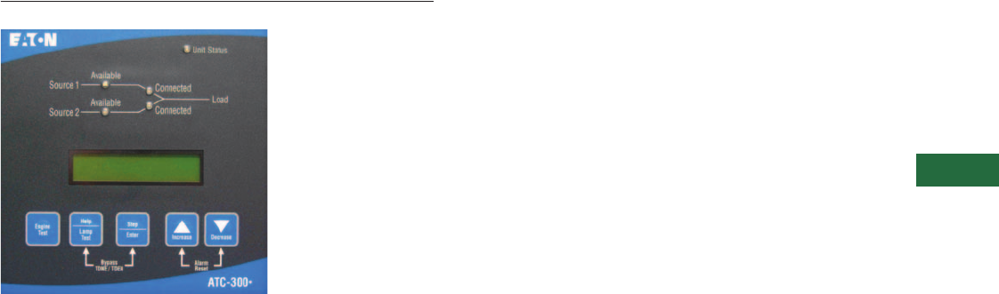
Volume 2—Commercial Distribution CA08100003E—April 2014 www.eaton.com V2-T5-65
5
5
5
5
5
5
5
5
5
5
5
5
5
5
5
5
5
5
5
5
5
5
5
5
5
5
5
5
5
5
5.5
Transfer Switches
Automatic Transfer Controllers
ATC-300+ Controller
Contents
Description Page
Product Selection Guide . . . . . . . . . . . . . . . . . . . . V2-T5-59
ATC-100 Controller . . . . . . . . . . . . . . . . . . . . . . . . V2-T5-63
ATC-300+ Controller
Standards and Certifications . . . . . . . . . . . . . . V2-T5-66
Technical Data and Specifications . . . . . . . . . . V2-T5-66
ATC-900 Controller . . . . . . . . . . . . . . . . . . . . . . . . V2-T5-69
ATC-600/800 Controller . . . . . . . . . . . . . . . . . . . . . V2-T5-79
ATC-800 Controller . . . . . . . . . . . . . . . . . . . . . . . . V2-T5-82
Controller Replacement Guide . . . . . . . . . . . . . . . V2-T5-86
ATC-300+ Controller
Product Description
Transfer switches are equipped
with the high-performance
ATC-300+ digital transfer
controller, receive rock-solid
monitoring, status reporting
and transfer control operation.
Its superior design and robust
construction make the
ATC-300+ the industry
benchmark for critical and
distributed power systems.
Application Description
Eaton’s ATC-300+ Controller-
Based Automatic Transfer
Switch is designed to provide
unmatched performance,
reliability and versatility for
critical standby power
applications.
Features, Benefits and Functions
Standard Features
●Auxiliary relay contacts:
●Source 1 present
2NO and 2NC
●Source 2 present
2NO and 2NC
●Switch position indication
contacts:
●Source 1 position
1NO and 1NC
●Source 2 position
1NO and 1NC
●Source 1 and Source 2
sensing:
●Undervoltage/
underfrequency
●Overvoltage/
overfrequency
●Three-phase rotation
protection
●Three-phase voltage
unbalance
●Pretransfer signal contacts
1NO/1NC
●Go to emergency
(Source 2)
●Seven field-programmable
time delays
●LCD-based display for
programming, system
diagnostic and Help
message display
●Mimic diagram with source
available and connected
LED indication
●Time-stamped history log
●System TEST pushbutton
●Programmable plant
exerciser—OFF, daily,
7-, 14-, 28-day interval
selectable run time
0–600 minutes no load/
load with fail-safe
Optional Features
●Suitable for use as service
equipment in the standard
enclosure size when used
with breaker-based design
transfer switches
●Available UL 1449 3rd
Edition compliant surge
protection devices
●Integrated distribution
panels
●Field-selectable multi-tap
transformer panel permits
operation on a wide range
of system voltages
●Integral overcurrent
protection available when
used with breaker-based
design transfer switches
●Space heater with
thermostat
●Ammeter—load side
●Power quality metering
●Stainless steel cover
for controller
●Manual retransfer from
emergency to normal
●Communication via
Modbus RTU—metering
data, engine test, set point
management system
status
●Load shed/emergency
inhibit
●Remote annunciator
available

V2-T5-66 Volume 2—Commercial Distribution CA08100003E—April 2014 www.eaton.com
5
5
5
5
5
5
5
5
5
5
5
5
5
5
5
5
5
5
5
5
5
5
5
5
5
5
5
5
5
5
5.5
Transfer Sw itches
Automatic Transfer Controllers
Standards and Certifications
●UL listed component
●Meets intent of
UL 991, 1008
●Meets IEC 1000-4-2, 1000-
4-3, 1000-4-4, 1000-4-5,
1000-4-6, 1000-4-11
●Meets CISPR 11, Class A
●Complies with FCC Part 15,
Class A
Technical Data and Specifications
ATC-300+ Controller Specifications
Description Specification
Input control voltage 65 to 145 Vac 50/60 Hz
Voltage measurements of Source 1 VAB Source 2 VAB
Source 1 VBC Source 2 VBC
Source 1 VCA Source 2 VCA
Voltage measurement range 0 to 790 Vac RMS (50/60 Hz)
Voltage measurement accuracy ±1% of full scale
Frequency measurements of Source 1 and Source 2
Frequency measurement range 40 Hz to 70 Hz
Frequency measurement accuracy ±0.3 Hz over the measurement range
Undervoltage dropout range: Breaker/switch style ATS 50 to 97% of the nominal system voltage
Contactor style ATS 78 to 97% of the nominal system voltage
Undervoltage pickup range: Breaker/switch style ATS (Dropout +2%) to 99% of the nominal system voltage
Contactor style ATS (Dropout +2%) to 99% of the nominal system voltage
Overvoltage dropout range: Breaker/switch style ATS 105 to 120% of the nominal system voltage
Contactor style ATS 105 to 110% of the nominal system voltage
Overvoltage pickup range: Breaker/switch style ATS 103% to (dropout –2%) of the nominal system voltage
Contactor style ATS 103% to (dropout –2%) of the nominal system voltage
Underfrequency dropout range: Breaker/switch style ATS 90 to 97% of the nominal system frequency
Contactor style ATS 90 to 97% of the nominal system frequency
Underfrequency pickup range: Breaker/switch style ATS (Dropout +1Hz) to 99% of the nominal system frequency
Contactor style ATS (Dropout +1Hz) to 99% of the nominal system frequency
Overfrequency dropout range: Breaker/switch style ATS 103 to 110% of the nominal system frequency
Contactor style ATS 103 to 105% of the nominal system frequency
Overfrequency pickup range: Breaker/switch style ATS 101% to (dropout –1 Hz) of the nominal system frequency
Contactor style ATS 101% to (dropout –1 Hz) of the nominal system frequency
Operating temperature range –20°C to +70°C (–4°F to +158°F)
Storage temperature range –30°C to +85°C (–22°F to +185°F)
Operating humidity 0 to 95% relative humidity (noncondensing)
Operating environment Resistant to ammonia, methane, nitrogen, hydrogen and hydrocarbons
Generator start relay 5A, 1/6 Hp at 250 Vac
5A at 30 Vdc with a 150W maximum Load
K1, K2, pretransfer, alarm relays 10A, 1–3 hp at 250 Vac
K3, K4 10A at 30 Vdc
Applicable testing UL recognized component
Meets UL 1008
Meets Intent of UL 991
Meets IEC 1000-4-2, 1000-4-3, 1000-4-4, 1000-4-5, 1000-4-6, 1000-4-11
Meets CISPR 11, Class A
Complies with FCC Part 15, Class A
Enclosure compatibility NEMA 1, NEMA 3R and NEMA 12
UV resistant ATC-300+ faceplate
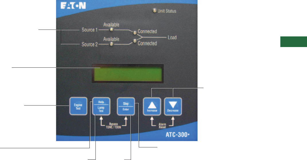
Volume 2—Commercial Distribution CA08100003E—April 2014 www.eaton.com V2-T5-67
5
5
5
5
5
5
5
5
5
5
5
5
5
5
5
5
5
5
5
5
5
5
5
5
5
5
5
5
5
5
5.5
Transfer Switches
Automatic Transfer Controllers
Closed Transition ATC-300+ Front Panel Display and Button Functions
LED Display
Unit will provide LED readout showing
actual metered values for Voltage,
Frequency and Condition (including
Normal, Undervoltage, Overvoltage, etc.)
Source 1, Source 2, and Load
Colored LED lights show status
of both Sources and Load.
Increase/Decrease
A detailed explanation of these buttons
can be found in the Operation section.
Step Button
Shows multiple
variables under each
display select function.
Help
Pressing the Help button in any function
mode will bring up display messages,
explanations and prompts to assist the
operator.
Engine Test Button
Pressing this button twice
initiates an engine test.
Lamp Test Enter

V2-T5-68 Volume 2—Commercial Distribution CA08100003E—April 2014 www.eaton.com
5
5
5
5
5
5
5
5
5
5
5
5
5
5
5
5
5
5
5
5
5
5
5
5
5
5
5
5
5
5
5.5
Transfer Sw itches
Automatic Transfer Controllers
The following set points are programmable if the corresponding feature is programmed.
ATC-300+ Programming Features/Set Points 1
Note
1Complete list of programming selections found in IB01602009E.
Set Point Set Point Units Description Range Factory Default
TDES Minutes: seconds Time delay engine start 0–120 seconds 0:03
TDNE Minutes: seconds Time delay normal to emergency 0–1800 seconds 0:00
TDEN Minutes: seconds Time delay emergency to normal 0–1800 seconds 5:00
TDEC Minutes: seconds Time delay engine cool-off 0–1800 seconds 5:00
TDN Minutes: seconds Time delay neutral 0–120 seconds 0:00
PLANT EXER Days Plant exerciser programming Off, daily, 7-day, 14-day or 28 day Off
TEST MODE — Test Mode 0, 1 or 2 (0 = no load engine test, 1 = load engine test, 2 =disabled) 0
TER Hours: minutes Engine run test time 0–600 min 5:00
TPRE Minutes: seconds Pre-transfer delay timer 0–120 sec 0:00
PHASES — Three-phase or single-phase 1 or 3 As ordered
VOLT UNBAL Volts Voltage unbalanced 0 or 1 (1 = enabled) 1
UNBAL DROP % Percent Percent for unbalanced voltage dropout 5–20% of phase voltage unbalance 20%
UNBAL PICK % Percent Percent for unbalanced voltage pickup Dropout minus (UNBAL DROP % –2) to 3% 10%
UNBAL DELAY Seconds Unbalanced delay timer 10–30 0:20
TDEF Seconds Time delay emergency fail timer 0–6 sec 6
PHASE REV — Phase reversal OFF, ABC or CBA OFF
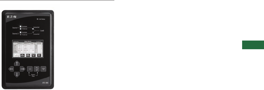
Volume 2—Commercial Distribution CA08100003E—April 2014 www.eaton.com V2-T5-69
5
5
5
5
5
5
5
5
5
5
5
5
5
5
5
5
5
5
5
5
5
5
5
5
5
5
5
5
5
5
5.5
Transfer Switches
Automatic Transfer Controllers
ATC-900 Controller
Contents
Description Page
Product Selection Guide . . . . . . . . . . . . . . . . . . . . V2-T5-59
ATC-100 Controller . . . . . . . . . . . . . . . . . . . . . . . . V2-T5-63
ATC-300+ Controller . . . . . . . . . . . . . . . . . . . . . . . V2-T5-65
ATC-900 Controller
Technical Data and Specifications . . . . . . . . . . V2-T5-78
Dimensions . . . . . . . . . . . . . . . . . . . . . . . . . . . V2-T5-78
ATC-600/800 Controller . . . . . . . . . . . . . . . . . . . . . V2-T5-79
ATC-800 Controller . . . . . . . . . . . . . . . . . . . . . . . . V2-T5-82
Controller Replacement Guide . . . . . . . . . . . . . . . V2-T5-86
ATC-900 Controller
Product Description
Eaton’s ATC-900 brings
intelligence, adaptability, and
enhanced supervisory and
programming capabilities to
Eaton’s complete transfer
switch product offering
including contactor-, breaker-
and Magnum-based transfer
switches. The one standard
model concept offers a
variety of monitoring and
control features, selective
load shedding, remote load
testing, along with event
logging/recording and
Modbus communications.
With configurable monitoring
and control features and add-
on accessory modules, the
ATC-900 provides the
flexibility to meet current
and future system needs.
Application Description
High reliability makes the
ATC-900 ideal for mission-
critical installations in the
health care, water, industrial
and data center industries. An
intelligent control architecture
allows the ATC-900 to
address virtually any system
requirements. Typical
applications include utility-to-
utility, utility-to-generator and
generator-to-generator
transfer pairs, and advanced
programming features
provide for control of three-
source systems. Design
flexibility allows for
operations with open, in-
phase, delayed or closed
transition platforms.
Features, Benefits and Functions
Ease of use is a major benefit
of the ATC-900 controller.
The simple yet powerful user
interface includes many
intuitive operating features.
The color display and LED
indications provide enhanced
operator visibility of transfer
switch status and system
detail. Clear operational focus
was achieved through design
simplicity. Front arrow keys
allow for quick screen
navigation, removal of codes
and abbreviations avoid
potential confusion, and
refined data screens provide
for ease of viewing and edits.
Primary Functions
The ATC-900 Automatic
Transfer Switch Controller
offers these standard
features:
●Monitor normal and
emergency source
voltages and frequencies
●Provide transfer and
retransfer control signals
●Provide engine/generator
start and shutdown signals
●Permit user programming
of operational set points
●Display real-time and
historical information
●Permit system testing
●Store customer and factory
established parameters in
nonvolatile memory
●Provide faceplate source
status indication
●Provide an LCD for
programming and status
readouts
Features and Benefits
●LCD screen for system
status, programming,
system diagnostics, help,
and troubleshooting
●Event logging and
recording, 450 time
stamped events
●0–600V field
programmable system
voltage flexible
configuration with
assignable inputs and
outputs
●Three-source ATS
control—master and slave
controller functionality
●Selective, automatic load
shedding
●Industry standard
communication
protocols—Modbus RTU
and/or Modbus TCP/IP
communications interface
●USB drive for uploading
and downloading of event
data
●USB drive for uploading
and downloading
programmed set points
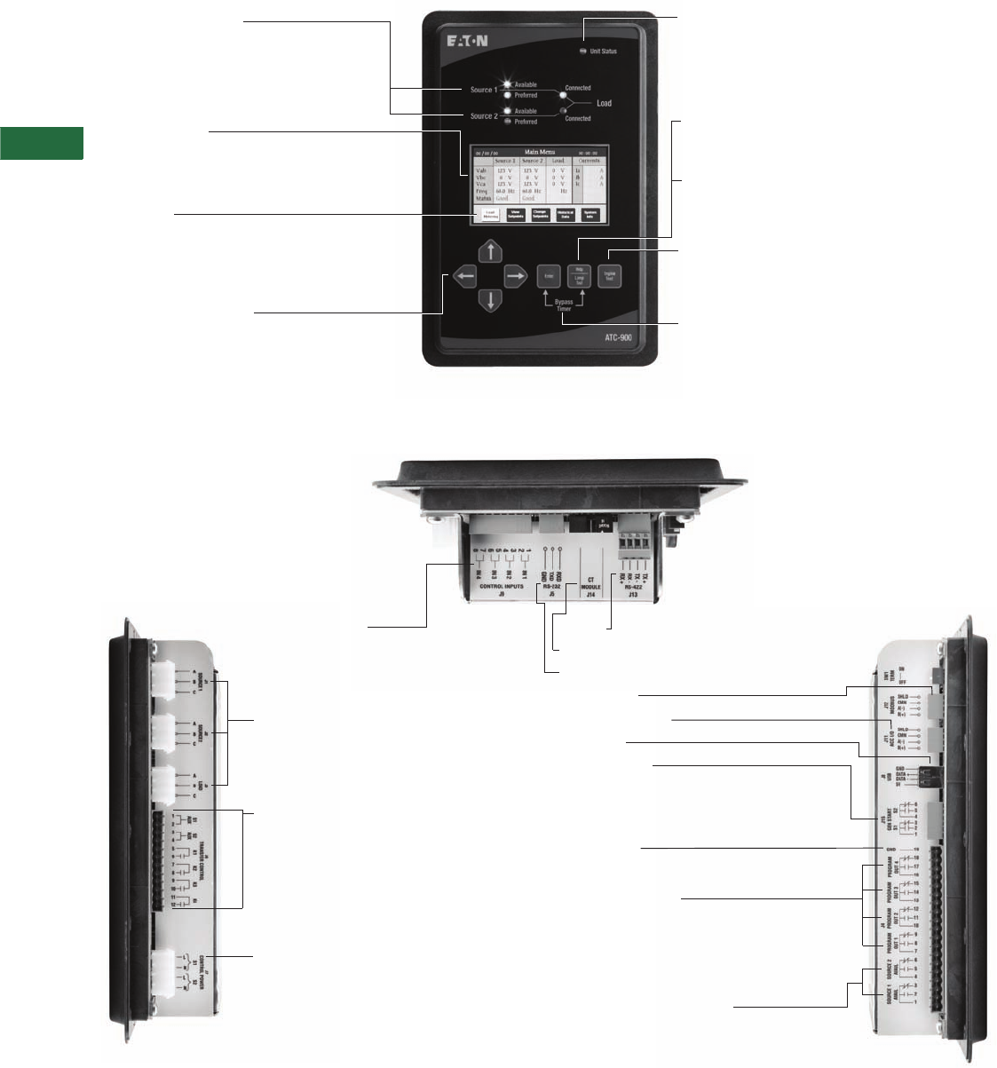
V2-T5-70 Volume 2—Commercial Distribution CA08100003E—April 2014 www.eaton.com
5
5
5
5
5
5
5
5
5
5
5
5
5
5
5
5
5
5
5
5
5
5
5
5
5
5
5
5
5
5
5.5
Transfer Sw itches
Automatic Transfer Controllers
ATC-900 User Interface
ATC-900 Connections
Status Screen
The ATC-900 Main Menu screen provides transfer
switch status at a glance. Source 1, Source 2 and
load-metering data are displayed as well as any
active alarms.
LED Mimic Diagram
Source 1 and Source 2 color-coded LEDs
provide Available and Connected status
indication.
Unit Status Light
This LED blinks green indicating that the ATC-900 is
operating and providing the transfer switch control
function in keeping with programmed set points.
If the LED is not lit or is on continuously,
a problem may be indicated.
Help
Displays controller firmware version and
user tips.
Arrow Key Navigation
Right and Left Arrow Keys are used to navigate
menu options and Up and Down Arrow Keys
are used to select and change set point values.
Display
The ATC-900 eliminates the use of codes and
abbreviations for transfer switch functions. Data
screens are grouped for ease of viewing and edits.
Lamp Test
Pressing the Lamp Test pushbutton lights all LEDs and then
displays ATC-900 controller information.
Engine Test
Performs an engine test using the programmed engine run
and cooldown times. This is a password-protected feature.
Bypass Time Delays
Pressing the Enter and Help pushbuttons simultaneously
reduces the active programmed time delay to zero to
simplify test procedures.
Configurable Inputs
System inputs are “wetted” contacts. System inputs can
be configured to perform a preset list of functions.
(Note: A factory configured input cannot be reconfigured
in the field if the factory provides associated hardware.)
Factory Use Only
The sensing inputs are the connection points for
monitoring Source 1, Source 2, and the Load. Three-
phase systems are connected to Phase A, B and C.
Single-phase systems are connected to points Phase A
and Phase B.
Factory Use Only
■Source 1 and Source 2 auxiliary: These inputs are
connected to the power switching devices position
indication contacts
■K1, K2, K3 and K4: These Form-A output contacts are
utilized to control the power switching mechanism.
They operate in conjunction with the Source 1 and
2 auxiliary inputs
Control Power Inputs (Source 1 and Source 2)
The control power input range is 65–145 Vac, 50/60 Hz,
9–36 Vdc.
RS-422
DCT Module
RS-232 (ATC-900 ECAM)
Modbus 485
Accessory I/O Port
USB Port
Generator start
Form-C contact. This is a latching relay utilized
to initiate startup and shutdown cycles of the engine/
generator set. The GENERATOR START contact is
rated 5 amperes at 250 Vac/30 Vdc.
Earth Ground
Provides a connection point for the common
system ground.
Configurable Outputs
Four Form C dry relay contacts that can be configured to
perform a preset list of functions. Contacts are rated 10
amperes at 250 Vac/30 Vdc. Note: A factory-configured
output cannot be reconfigured in the field if the factory
provides associated hardware)
Source 1 and Source 2 Available
Form C dry relay contacts that indicate
Source 1 and Source 2 availability based on the
programmed voltage and frequency set points.
Contacts are rated 10 amperes at 250 Vac/30 Vdc.

Volume 2—Commercial Distribution CA08100003E—April 2014 www.eaton.com V2-T5-71
5
5
5
5
5
5
5
5
5
5
5
5
5
5
5
5
5
5
5
5
5
5
5
5
5
5
5
5
5
5
5.5
Transfer Switches
Automatic Transfer Controllers
ATC-900 Features
Features ATC-900
Hardware
4.3-inch color TFT LCD display ■
UV-resistant faceplate ■
Mimic diagram and LED status indicators ■
Suitable for application over a wide range of environmental conditions ■
Positive feedback membrane pushbuttons for application in harsh environments ■
Help function for detailed description of displayed message ■
Password protected system test pushbutton ■
Bypass time delay pushbutton ■
Form C engine start contact for Source 1 and Source 2 ■
S1 and S2 available Form C contacts ■
Self-diagnostic and system diagnostic functions with LED indication ■
DC power input Optional
Metering
True rms voltage sensing of Source 1, Source 2 and Load ■
Frequency sensing of Source 1, Source 2 and Load ■
Voltage unbalance and phase rotation sensing ■
Load current sensing Optional
Sampling at 64 samples per cycle Optional
Source 1 voltages (three-phase) ■
Source 2 voltages (three-phase) ■
Load voltages (three-phase) ■
Source 1 frequency ■
Source 2 frequency ■
Load frequency ■
Load currents (three-phase) Optional
Load kW Optional
Load kVAR Optional
Load kVA Optional
PF Optional
Programming
Programmable set points stored in nonvolatile memory ■
System monitoring with historical data storage and display ■
Digital set points for accurate and consistent performance ■
Password-protected access to control functions and set point programming ■
Four programmable control inputs ■
Four programmable control outputs ■
Expandable I/O modules (up to 20 I/O total) Optional
Automatic plant exerciser—two plant exerciser schedules, Off, daily, 7-day, 14-day, 28-day, calendar,
separate TDNE, TDEN, TDEC timers from normal operation, control input provided for remotely initiating an engine test
■
Communications
Modbus RTU ■
Modbus TCP/IP Optional
USB port for set point configuration and event-recording downloads ■
Event History
320 time-stamped events ■
2 seconds of metered data stored before and after a transfer event Optional

V2-T5-72 Volume 2—Commercial Distribution CA08100003E—April 2014 www.eaton.com
5
5
5
5
5
5
5
5
5
5
5
5
5
5
5
5
5
5
5
5
5
5
5
5
5
5
5
5
5
5
5.5
Transfer Sw itches
Automatic Transfer Controllers
ATC-900 Programmable Set Points
The table below lists only controller features; switch features are not listed, as they are defined by switch construction.
Transition settings are specific to the transfer switch construction.
Features and Set Points
Option
Number Description Range
Factory
Default
General Settings
— Set new password 0000–9999 0900
— Selected language English, French or Spanish English
— Nominal frequency 50 or 60 Hz As ordered
— Nominal voltage 110–600V As ordered
— Number of phases 1 or 3 As ordered
— Number of generators 0, 1 or 2 1
— Preferred source Source 1 or Source 2 Source 1
— PT ratio 2:1–500:1 As ordered
— CT ratio 200–5000 —
— Daylight saving time On or Off 1
— Operating mode Stand-alone/master or slave Master
— Phase sequence check ABC, CBA or Off Off
— Commitment to transfer in TDNE Yes or no No
— Manual retransfer Auto, manual or external As ordered
— Modbus address 1–247 1
— Modbus baud rate 0 = 9600, 1, even 9600
1 = 9600, 1, odd —
2 = 9600, 2, none —
3 = 9600, 1, none —
4 = 19,200, 1, even —
5 = 19,200, 1, odd —
6 = 19,200, 2, none —
7 = 19,200, 1, none —
Transition Settings
47 Closed transition
Closed transition On or Off On or Off As ordered
Closed voltage difference 1–5% 2%
Closed frequency difference 0.0–0.3 Hz 0.3
32f/32d Open—in-phase transition
In-phase—On or Off Disable, in-phase default to alarm,
in-phase default to open transition
As ordered
In-phase frequency difference 0.0–3.0 Hz 1.0
— Synchronization timer 1–60 minutes 5
32a/32d Open—delayed transition
Time delay neutral 0–120 seconds 0
Load voltage decay 2–30% of nominal voltage 6%
Time Delays
1a Time delay normal to emergency 0–9999 seconds 0:00
3a Time delay emergency to normal 0–9999 seconds 5:00
35A Time delay pre-transfer 0–120 seconds 0:01
35C Time delay post-transfer 0–120 seconds 0:10
2A Time delay engine 1 start 0–120 seconds 0:03
— Time delay engine 2 start 0–120 seconds 0:03
4A Time delay engine cool-off 0–9999 seconds 5:00
7A Time delay engine fail timer 0–6 seconds 0:06
— Voltage unbalance time delay 10–30 seconds 0:30

Volume 2—Commercial Distribution CA08100003E—April 2014 www.eaton.com V2-T5-73
5
5
5
5
5
5
5
5
5
5
5
5
5
5
5
5
5
5
5
5
5
5
5
5
5
5
5
5
5
5
5.5
Transfer Switches
Automatic Transfer Controllers
Features and Set Points, continued
Option
Number Description Range
Factory
Default
Source Settings
26P Source 1 undervoltage dropout 70–97% of nominal 80%
Source 1 undervoltage pickup (dropout + 2%) to 99% of nominal 90%
5P Source 2 undervoltage dropout 70–97% of nominal 80%
Source 2 undervoltage pickup (dropout + 2%) to 99% of nominal 90%
26K Source 1 overvoltage dropout 105–120% of nominal (0 = disabled) 115%
Source 1 overvoltage pickup 103% of nominal to (dropout –2%) (0 = disabled) 105%
5K Source 2 overvoltage dropout 105–120% of nominal (0 = disabled) 115%
Source 2 overvoltage pickup 103% of nominal to (dropout –2%) (0 = disabled) 105%
26J Source 1 underfrequency dropout 90–97% of nominal (0 = disabled) 94%
Source 1 underfrequency pickup (dropout + 1 Hz) to 99% of nominal (0 = disabled) 96%
5J Source 2 underfrequency dropout 90–97% of nominal (0 = disabled) 94%
Source 2 underfrequency pickup (dropout + 1 Hz) to 99% of nominal (0 = disabled) 96%
26N Source 1 overfrequency dropout 103–110% (0 = disabled) 106%
Source 1 overfrequency pickup 101% to (dropout –1 Hz) (0 = disabled) 104%
5N Source 2 overfrequency dropout 103–110% (0 = disabled) 106%
Source 2 overfrequency pickup 101% to (dropout –1 Hz) (0 = disabled) 104%
26L Source 1 percent for unbalanced
voltage dropout
5–20% of phase-to-phase voltage unbalance
(0 = disabled)
12%
Source 1 percent for unbalanced
voltage pickup
3% to (dropout –2%) (0 = disabled) 10%
5L Source 2 percent for unbalanced
voltage dropout
5–20% of phase-to-phase voltage unbalance
(0 = disabled)
12%
Source 2 percent for unbalanced
voltage pickup
3% to (dropout –2%) (0 = disabled) 10%
Engine Test/Plant Exerciser (PE1 and PE2 are independently programmable)
6B Engine test pushbutton on panel
Test mode No load, load transfer, disabled Load transfer
Engine run test time 0–600 minutes Load transfer
23M PE time delay normal
to emergency
0–9999 seconds 1 minute
PE time delay emergency
to normal
0–9999 seconds 1 minute
PE time delay engine cooldown 0–9999 seconds 5 minutes
PE1/PE2 test mode No load, load transfer, disabled Disabled
PE1/PE2 run time 0–600 minutes 30 minutes
PE1/PE2 schedule Off, daily, 7-day, 14-day, 28-day or calendar date
(up to 12 user-specified dates)
30 minutes
PE1/PE2 calendar date Month: 1–12; Day: 1–31 30 minutes
PE1/PE2 day of week 1 Sunday, 2 Monday, 3 Tuesday, 4 Wednesday,
5 Thursday, 6 Friday or 7 Saturday
30 minutes
PE1/PE2 plant start time HH:MM AM/PM 30 minutes
Accessory I/O
— Accessory I/O modules 0–4 —
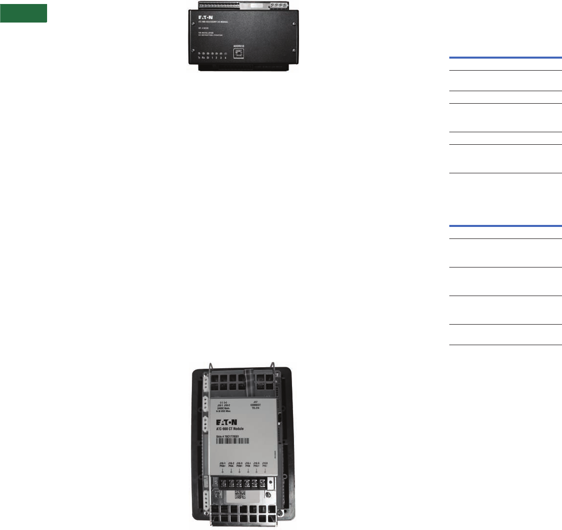
V2-T5-74 Volume 2—Commercial Distribution CA08100003E—April 2014 www.eaton.com
5
5
5
5
5
5
5
5
5
5
5
5
5
5
5
5
5
5
5
5
5
5
5
5
5
5
5
5
5
5
5.5
Transfer Sw itches
Automatic Transfer Controllers
Flexible Configuration
Designed for scalability, the
ATC-900 can be configured
for a wide variety of
applications. A mix-and-match
approach to features allows
the user to build a transfer
switch controller that meets
the precise application needs.
The ATC-900 controller
includes four user
configurable inputs and
outputs. The inputs and
outputs can be assigned
functions from a predefined
list of options either at the
factory or in the field.
●Inputs
●Monitor mode
●Bypass timers
●Lockout
●Manual retransfer
On or Off
●Manual retransfer
●Slave in
●Remote engine test
●Preferred source
selection
●Go to emergency
●Emergency inhibit
●ATS on bypass
●Go to neutral
●Outputs (control)
●Load sequence
●Selective load shed
●Load bank control
●Pre-/post-transfer
●Pre-transfer
●Post-transfer
●User remote control
●Outputs (status/alarms)
●Source 1 available
(standard)
●Source 2 available
(standard)
●Source 1 connected
●Source 2 connected
●ATS not in automatic
●General alarm
●ATS in test
●Engine test aborted
●Cooldown in process
●Engine start contact
status
●Generator 1 start status
●Generator 2 start status
●Emergency inhibit on
●ATS on bypass
Additional I/O can be added at
any time by adding an
external I/O module. Each I/O
module contains four inputs
and outputs and up to four
modules can be daisy chained
to the ATC-900 controller.
I/O Module—The ATC-900 optional I/O
module provides users with four
additional assignable inputs and
outputs. Up to four I/O modules can be
added to an ATC-900 controller
providing a total of 20 inputs
and outputs.
Metering
Optional metering requires
the addition of a DCT module.
The DCT module mounts
directly on the back of the
controller.
The DCT module incorporates
a current transformer
interface to the ATC-900
allowing current to be
metered along with voltage
and frequency. Combined
with the ATC-900, the DCT
module serves as a multi-
function power meter and
provides measurement of the
listed electrical parameters.
Readings are displayed on the
ATC-900 controller display or
can be monitored through
Modbus 485.
DCT Module Attached
Voltage Inputs
(measurement category)
●Range: universal, auto-
ranging up to 416 Vac L–N,
721 Vac L–L
●Supported hookups:
3-element wye or delta
●Input impedance: 2m ohm/
phase
●Burden: 0.0022 VA/phase
at 120V
●Fault withstand: meets
IEEE C37.90.1
Current Inputs
●5A nominal, 10A maximum
●Burden: 0.005 VA per
phase maximum at 11A
●Pickup current: 0.1% of
nominal
●Connections: screw
terminals
●Maximum input wire
gauge: AWG #12/2.5 mm2
●Fault withstand: 100A/10
seconds, 300A/3 seconds,
500A/1 second
Isolation
●All inputs are isolated to
2600 Vac
Measurement Methods
●Voltage, current: true rms
●Power: sampling at 64
samples per cycle on all
channels measured
readings simultaneously
●A/D conversion: 16
simultaneous12 bit analog
to digital converters
Current Voltage Frequency
Metering Data
Power and Energy
Metering Data
Metering Units Accuracy Notes
Current
IA, IB, IC Amps ±1% of
reading
—
Voltage
VAB, VBC,
VCA
Volts ±1% of
reading
Line-
to-line
voltage
Frequency
Frequency Hz ±0.2 Hz of
reading
Range is
20–255
Hz
Power
Metering Units Accuracy Notes
Power kW ±2% of
reading
Approx.
1-second
update
kVA kVA ±2% of
reading
Approx.
1-second
update
kVAR kVAR ±2% of
reading
Approx.
1-second
update
PF (power
factor)
— 0 to ±1.00 —
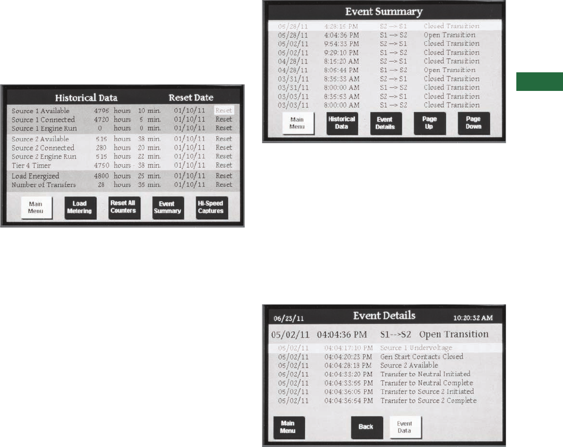
Volume 2—Commercial Distribution CA08100003E—April 2014 www.eaton.com V2-T5-75
5
5
5
5
5
5
5
5
5
5
5
5
5
5
5
5
5
5
5
5
5
5
5
5
5
5
5
5
5
5
5.5
Transfer Switches
Automatic Transfer Controllers
Diagnostics and Troubleshooting
In a mission-critical application, a failure to transfer to the backup
power system requires quick and decisive action. Eaton’s ATC-
900 controller provides users with the data required to quickly
identify the root cause of a backup power system failure and
minimize system downtime. This data allows the user to identify
a specific event and obtain the detailed event information
including a step by step breakdown of the transfer sequence.
Historical Data
Historical Data Display
The historical data display indicates historical and
cumulative counter values as follows:
●Source 1 available
●Source 1 connected
●Source 1 engine run
●Source 2 available
●Source 2 connected
●Source 2 engine run
●Tier IV timer
●Load energized
●Number of transfers
Historical counter resets are date and time-stamped events that
are captured in the event log.
Event Summary
Event Summary Display
The ATC-900 controller stores 100 transfer summaries,
350 transfer details, 100 alarms and 20 time adjustments.
Events include:
●Actions of the transfer sequence
●Alarms
●Changes to the set points
●Changes to the time/date
●Resetting a historical counter
●Engine run test
●Time-stamping resolution of 1 second.
Event Details
Event Details Display
Each transfer event can be exploded to view a step by step,
time stamped, sequence of operation for a transfer event. All
metered values are also logged for each event and can be
viewed on the event data screen. Time stamping resolution
of 0.1 seconds.
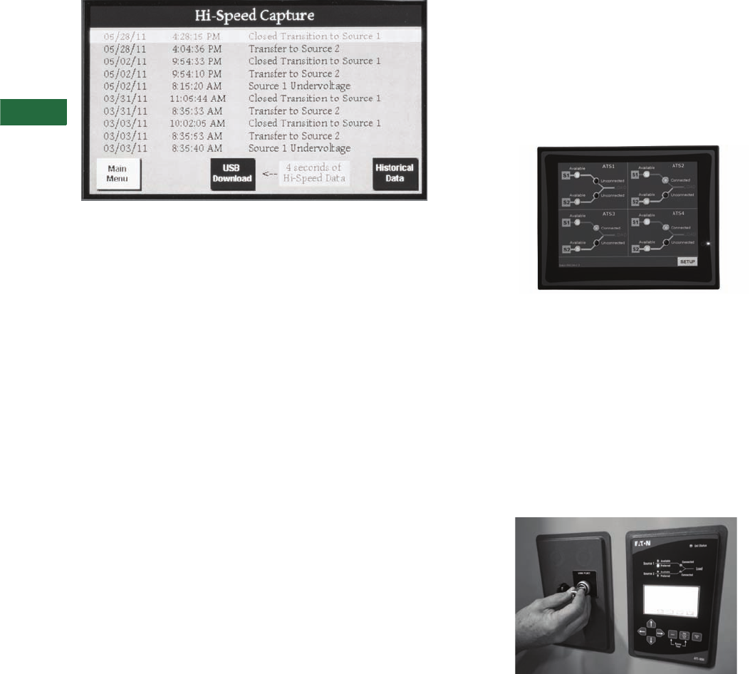
V2-T5-76 Volume 2—Commercial Distribution CA08100003E—April 2014 www.eaton.com
5
5
5
5
5
5
5
5
5
5
5
5
5
5
5
5
5
5
5
5
5
5
5
5
5
5
5
5
5
5
5.5
Transfer Sw itches
Automatic Transfer Controllers
Hi-Speed Capture
High Speed Capture Display, Pre and Post Event
The ATC-900 stores metered data updated on a continuous
20 millisecond basis for specific events. The data is captured
2 seconds before and 2 seconds after the event (except for a
power failure, which is 4 seconds before). Oscillographic data
for 10 events is stored in the controller and may be downloaded
over USB or displayed graphically.
●Events include:
●Source unavailability actions that initiate a transfer sequence
(undervoltage, overvoltage, etc.)
●Successful transfers (at the point of breaker/
contactor closure)
●Unsuccessful transfers (at the point of breaker/contactor
failure to close or open)
Industry Standard Communication Protocol
Every ATC-900 controller includes a standard Modbus RTU
communications interface with an option to upgrade to
Modbus TCP/IP.
The ATC-900 is also compatible with Eaton’s Power Xpert
Gateway for web-based monitoring, Modbus TCP/IP,
SNMP, or BACnet/IP. The Power Xpert Gateway can be
used to consolidate data from up to 64 devices, including
communications ready transfer switch controllers, trip
units and meters, as well as other Eaton devices. Versions
of the Power Xpert Gateway include email event notification
sand data-logging functionality.
HMi Remote Annunciator and Controller
The HMi Remote Annunciator and Controller monitors and
controls up to eight transfer switches on a 7-inch LCD touch
screen. It is compatible with either Modbus RTU or Modbus
TCP/IP protocols. A basic mimic bus for each transfer switch
displays source availability, source connected and preferred
source. Users can drill down to metered source values and
event history for each transfer switch. All control features are
password-protected and include engine test, transfer to
emergency (peak shaving), manual retransfer and bypass
time delays.
HMi Remote Annunciator and Controller
USB Programming Port
Every ATC-900 transfer switch includes a front panel,
NEMA 4X rated USB port for use in configuring set points or
downloading event data to a USB flash drive. To reduce the time
spent on site for commissioning, set points can be configured at
a PC using the ATC-900 configuration software and saved to a
USB flash drive to be uploaded to one or multiple controllers. Set
points are also easily copied from one controller to another.
Downloading event capture data provides the user the ability to
more thoroughly analyze high-speed capture data using a PC, or
data can be emailed to Eaton’s Technical Support Team when
off site troubleshooting support is required.
USB Programming Port
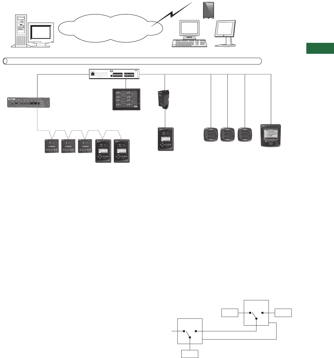
Volume 2—Commercial Distribution CA08100003E—April 2014 www.eaton.com V2-T5-77
5
5
5
5
5
5
5
5
5
5
5
5
5
5
5
5
5
5
5
5
5
5
5
5
5
5
5
5
5
5
5.5
Transfer Switches
Automatic Transfer Controllers
Power Xpert Architecture with ATC-900
Special Applications
Three-Source ATS Control
The ATC-900 Master/Slave controller functionality provides
the user with the ability to use two independent transfer
switches in three-source systems consisting of a utility
and two generator sources. In a three-source system, the
Master ATS controls the engine starting and stopping of
the Slave ATS.
In the event of a Source 1 power failure, the Master ATS
engine start relay closes signaling the Slave ATS to start both
generators. (Note: The Slave ATS requires continuous power
using either the DCT Module for a DC power input or a UPS
input.) The Master ATS handles all transfer time delays between
the utility to generator transfer. If the preferred generator does
not start within the programmed time delay, the Slave ATC-900
will initiate a transfer to the non-preferred generator. If “None
Preferred” is selected, then both generators will start and the
Slave ATS will transfer to the first generator source available.
The ATC-900 will sense the load is connected to a good source
and shut down the second generator.
Load Management
The ATC-900 includes several features to enhance the user’s
ability to manage load while on the alternate source.
●Integrated load metering: provides metering data that allows
the user to monitor energy utilization and manage system
loading
●Selective load shedding: selectively drop non-essential loads
when a user-defined kW level is reached. The
transfer switch remains on generator
●Load shed to neutral (where ATS construction allows):
provides the ability to load shed to a neutral position from
a generator source
●Pre-/post-transfer signals: provides the ability to stop select
loads during the transfer process
●Load bank disable output: disengages a load bank if utility
power is lost during an engine test
Three-Source Transfer Switch Arrangement
Internet
Ethernet
Power Xpert Software Web Terminal
Ethernet Switch
Power Xpert Gateway:
Supports up to 64 Devices
Third-Party
Gateway
HMi Remote Annunciator
and Controller
Power Xpert Meter
ATC-900
ATC-900
IQ250/260
ATC-300+
Utility
Load
Gen 1 Gen 2
Master ATS
Slave ATS
S1 S2
Gen Start (Signal to Start Gen)
S1 S2
S1 S2
Slave
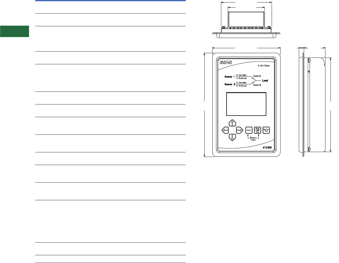
V2-T5-78 Volume 2—Commercial Distribution CA08100003E—April 2014 www.eaton.com
5
5
5
5
5
5
5
5
5
5
5
5
5
5
5
5
5
5
5
5
5
5
5
5
5
5
5
5
5
5
5.5
Transfer Sw itches
Automatic Transfer Controllers
Technical Data and Specifications
Technical Specifications
Dimensions
Approximate Dimensions in Inches (mm)
AT C- 9 0 0
Additional Information
Instruction bulletin: IB01602088E
Web-based demo: www.eaton.com/ats
Parameter Specification
Control
power
120 Vac (50/60 Hz) (operating range 65–160 Vac)
or 24 Vdc (±10%) with DCT module
Power
consumption
18 VA
Environmental
conditions
Operating
temperature
–4 to +158°F (–20 to +70°C)
Operating
humidity
Up to 90% relative humidity (noncondensing)
Enclosure
compatibility
NEMA 12 (standard mounting)
NEMA 4/4X (mounted with gasket between
panel and device faceplate)
NEMA 3R (outdoor)
UV resistant ATC-900 faceplate
System voltage
application
120–600 Vac (50/60 Hz) (single- or three-phase)
Voltage
measurements
Source 1, Source 2 and Load (VAB, VBC, VCA for
three-phase system)
Voltage
measurement
range
0–700 Vac
Voltage
measurement
accuracy
±1% of reading
Frequency
measurements
Source 1 and Source 2
Frequency
measurement
range
40–80 Hz
Frequency
measurement
accuracy
±0.1 Hz
Applicable
testing
UL recognized component
2009 IBC, 2010 CBC and OSHPD certified
in ATS assemblies
Complies with UL 991 environmental tests
Complies with IEC 61000-4-2, 61000-4-3, 61000-4-4,
61000-4-5 and 61000-4-6
Complies with CISPR 11, Class A
Complies with FCC Part 15, Subpart B, Class A
CSA
conformance
C22.2 No. 178-1978 (reaffirmed 1992)
CE mark European standards conformance
Front View Side View
Top View
5.00 (127.0)
3.63 (92.1)
6.72 (170.7)
10.25
(260.4)
0.50
(12.7)
2.10
(53.4)
9.31
(236.5)
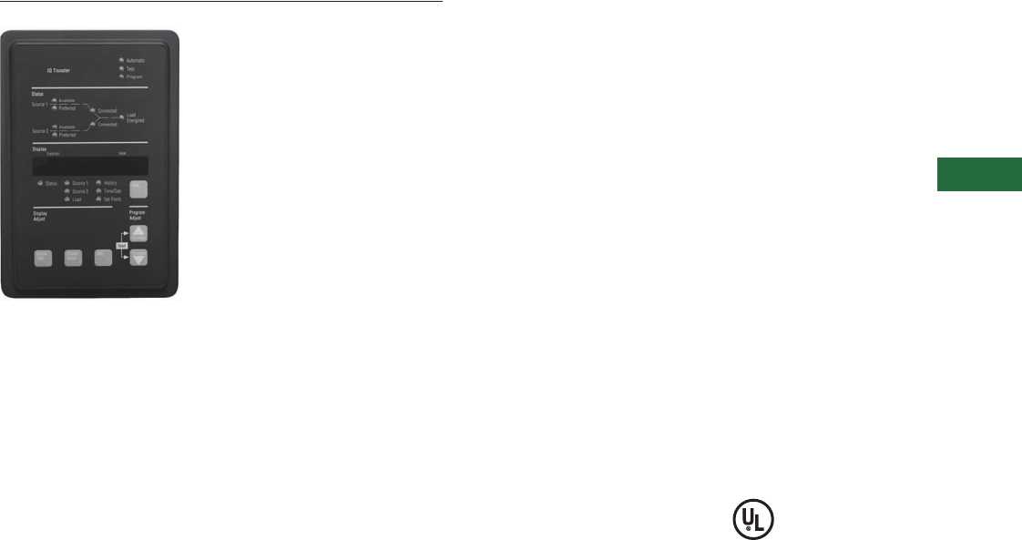
Volume 2—Commercial Distribution CA08100003E—April 2014 www.eaton.com V2-T5-79
5
5
5
5
5
5
5
5
5
5
5
5
5
5
5
5
5
5
5
5
5
5
5
5
5
5
5
5
5
5
5.5
Transfer Switches
Automatic Transfer Controllers
ATC-600/800
Contents
Description Page
Product Selection Guide . . . . . . . . . . . . . . . . . . . . V2-T5-59
ATC-100 Controller . . . . . . . . . . . . . . . . . . . . . . . . V2-T5-63
ATC-300+ Controller . . . . . . . . . . . . . . . . . . . . . . . V2-T5-65
ATC-900 Controller . . . . . . . . . . . . . . . . . . . . . . . . V2-T5-69
ATC-600/800 Controller
Technical Data and Specifications . . . . . . . . . . V2-T5-80
ATC-800 Controller . . . . . . . . . . . . . . . . . . . . . . . . V2-T5-82
Controller Replacement Guide . . . . . . . . . . . . . . . V2-T5-86
ATC-600/800 Controller
Product Description
Eaton’s ATC-600/800 is a
microprocessor-based logic
controller to be used with
transfer switches. This
device is door-mounted
and provides the operator
with an at-a-glance overview
of switch status and
parameters, as well as
key diagnostic data. Real-
time values for volts and
frequency can be viewed
via the front panel LED
display, along with an
indication of the power
source currently in use.
The ATC-600/800 continuously
monitors either single-phase
or three-phase voltages for
Source 1, Source 2 and the
load. When the Source 1
voltage or frequency is
detected to be below the
customer-programmed set
points, transfer to Source 2 is
initiated. When the Source 2
voltage and frequency are
detected to be within the
programmed parameters,
the transfer occurs.
While the load is connected
to Source 2, the ATC-600
continues to monitor
Source 1. As soon as the
Source 1 voltage and
frequency return to within
the programmed limits, and
after a programmed time
delay, a retransfer back to
Source 1 is initiated.
The ATC-600/800 uses
microprocessor-based
technology to provide the
operator with a vast array of
selections. Depending on the
application, the user can
“customize” the ATC-600/
800 to meet the particular
application.
Application Description
The ATC-600/800 controller
can be used in either an open
transition or a closed
transition type of transfer
mode. Historically, the ATC-
600 has been used for open
transition and the ATC-800
controller has been used for
closed transition. In addition,
the ATC-600 controller has
been used on molded case
switch based designs and
Magnum power case switch
open transition based
designs. The ATC-800 has
been used on all closed
transition type designs and
on contactor-based designs
that are either open or closed
transition.
Standards and Certifications
●UL listed component

V2-T5-80 Volume 2—Commercial Distribution CA08100003E—April 2014 www.eaton.com
5
5
5
5
5
5
5
5
5
5
5
5
5
5
5
5
5
5
5
5
5
5
5
5
5
5
5
5
5
5
5.5
Transfer Sw itches
Automatic Transfer Controllers
Technical Data and Specifications
ATC-600/800 Controller Specifications
Note
1Optional features.
Description Specification
Input control power range 65 Vac rms to 160 Vac rms (50/60 Hz)
Voltage measurements of Source 1 VAB
Source 1 VBC
Source 1 VCA
Source 2 VAB
Source 2 VBC
Source 2 VCA
Load VAB
Load VBC
Load VCA
Voltage measurement range 0 to 790 Vac rms (50/60 Hz)
Voltage measurement accuracy ±2% of nominal input voltage
Frequency measurement for Source 1 and Source 2
Frequency measurement range 40 Hz to 80 Hz
Frequency measurement accuracy ±0.1 Hz
Undervoltage sensing Source 1 and Source 2
Undervoltage dropout range 50–90% of nominal voltage
Overvoltage dropout range 1105–120% of nominal voltage
Underfrequency dropout range 190–100% of nominal frequency
Overfrequency dropout range 1100–120% of nominal frequency
Contact Outputs
Two Form A contacts for generator start 5A 250 Vac; 5A 30 Vdc
Four Form A contacts for control functions 10A 250 Vac; 10A 30 Vdc
Three Form C contacts for control functions 10A 250 Vac; 10A 30 Vdc
Communications output over PowerNet (optional) PONI (Product-Operated Network Interface)
Front Panel Indications
Automatic mode Blinking LED indicates automatic operation
Test mode LED illuminated indicating the unit is in the TEST mode
Program mode LED illuminated indicating the unit is in the program mode blinking LED indicates user is viewing set points in program mode
LED lights to indicate Source 1 available (amber), Source 2 available (amber),
Source 1 connected (green), Source 2 connected (red),
Source 1 preferred (red), Source 2 preferred (red), load energized (red)
LED display to indicate History information
Set points
Real-time clock
Operating temperature range Operation: –20°C to +70°C/Storage: –30°C to +85°C

Volume 2—Commercial Distribution CA08100003E—April 2014 www.eaton.com V2-T5-81
5
5
5
5
5
5
5
5
5
5
5
5
5
5
5
5
5
5
5
5
5
5
5
5
5
5
5
5
5
5
5.5
Transfer Switches
Automatic Transfer Controllers
All ATC-600/800 programmable features and associated set point possibilities with any required explanations are presented below.
Remember, only features originally ordered and factory programmed will appear in the display.
Note: Changing the system nominal voltage or frequency set points will automatically change all the pickup and dropout settings to new default values.
ATC-600/800 Programming Features/Set Points 1
Notes
1Complete list of programming selections found in IB ATS-1005.
2Set to order specific value.
Programmable
Feature Display
Factory Default
Display Explanation Set Point Range Value Measure
TDES Time delay engine start timer 0–120 seconds 0:03 Minutes: seconds
TDNE Time delay normal to emergency timer 0–1800 seconds 0:00 Minutes: seconds
TDEN Time delay emergency to normal timer 0–1800 seconds 5:00 Minutes: seconds
TDEC Time delay engine cool down timer 0–1800 seconds 5:00 Minutes: seconds
TDN Time delay neutral timer 0–120 seconds 0:00 Minutes: seconds
PRF SRC Preferred source None
1 = source 1
0 = source 2
1—
EXER Plant exerciser enabled or disabled 0 = disabled
1 = enabled
1—
MANTR Re-transfer mode 0 = automatic
1 = PB return
0—
CTDNE Commitment to transfer in TDNE 0 = not committed
1 = committed
0—
TMODE Engine test with/without load transfer 0 = no load transfer
1 = load transfer
2 = disable test pattern
1—
TPRE Pre-transfer sub-network time delay 1–00 seconds 0:01 Minutes: seconds
PHASE Number of system phases 1 or 3 23—
TSEQ Time delay load sequencing 1–120 seconds 0:10 Minutes: seconds
IPHASE In-phase transition enabled or disabled 1 = enabled
0 = disabled
0—
IPFD In-phase transition frequency difference (Hertz) 0.0–3.0 Hz 1.0 Hertz
SYNC Closed/in-phase transition synchronization timer 1–60 minutes 5 Minutes
TDEF Time delay engine failure 0–60 seconds 6 Seconds
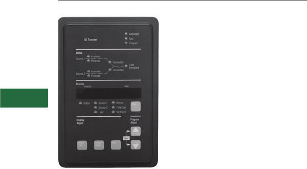
V2-T5-82 Volume 2—Commercial Distribution CA08100003E—April 2014 www.eaton.com
5
5
5
5
5
5
5
5
5
5
5
5
5
5
5
5
5
5
5
5
5
5
5
5
5
5
5
5
5
5
5.5
Transfer Sw itches
Automatic Transfer Controllers
ATC-800
Contents
Description Page
Product Selection Guide . . . . . . . . . . . . . . . . . . . . V2-T5-59
ATC-100 Controller . . . . . . . . . . . . . . . . . . . . . . . . V2-T5-63
ATC-300+ Controller . . . . . . . . . . . . . . . . . . . . . . . V2-T5-65
ATC-900 Controller . . . . . . . . . . . . . . . . . . . . . . . . V2-T5-69
ATC-600/800 Controller. . . . . . . . . . . . . . . . . . . . . V2-T5-79
ATC-800 Controller
Features, Benefits and Functions . . . . . . . . . . V2-T5-83
Controller Replacement Guide . . . . . . . . . . . . . . . V2-T5-86
ATC-800 Controller
Product Description
The ATC-800 is a
programmable,
microprocessor-based
monitoring device designed
for use in Eaton closed
transition transfer switches
and for open transition
contactor-based designs. By
using Eaton’s ATC-800, the
user may avoid intentional
interruption of power when
both sources of power are
available. This make-before-
break mode of operation is
useful during testing of the
engine generator under load
and where a predetermined
transfer to the generator is
desired. Source paralleling
duration is limited to less
than100 msec.
Passive Closed Transition
The closed transition mode
of operation requires that
both power sources be
synchronized in voltage,
frequency and phase angle
within prescribed limits.
Eaton’s ATC-800 uses a
technique that involves
waiting for synchronization
of the two sources without
actively controlling the
generator’s voltage or
frequency. The mode of
operation is anticipatory in that
the switch close command is
initiated before the sources
are exactly in phase. Utilizing
the phase angle and
frequency difference between
the two sources, a calculation
is made to predict when both
sources would be in phase.
The response time of the
switch is then factored in to
determine when the switch
close signal should be given to
ensure optimal closure of the
two sources in phase.
Eaton’s closed transition
ATC-800 must be selected
with one of three feature
sets: 47C, 47D or 47E (47D,
47F, 47G on contactor-based
designs. The difference
between these three feature
sets is the action taken by the
closed transition ATC-800 if it
is determined that the two
sources will not achieve
synchronization. If feature set
47C is selected, failure to
synchronize results in the
switch reverting to an Open
Transition mode of operation
with low voltage decay. If
feature set 47E is selected,
then failure to synchronize
results in the switch reverting
to time delay neutral.
However, if feature set 47D is
selected, failure to synchronize
will result in the ATC-800
refusing to transfer to Source 2
and an alarm signal being
activated. In neither case will
there be a paralleling of
sources if synchronization is
not achieved.
Application Description
●The generator used with
a closed transition transfer
switch must be equipped
with an isynchronous
governor
●When paralleling sources,
fault current contributions
from both sources should
be considered in the
system design
●Closed Transition (make-
before-break) technology
causes paralleling with the
Source 1. It is the user’s
responsibility to comply
with any requirements
regarding protective
relaying. Protective
relaying is not supplied
with the standard transfer
switch, but is available as
an option

Volume 2—Commercial Distribution CA08100003E—April 2014 www.eaton.com V2-T5-83
5
5
5
5
5
5
5
5
5
5
5
5
5
5
5
5
5
5
5
5
5
5
5
5
5
5
5
5
5
5
5.5
Transfer Switches
Automatic Transfer Controllers
Features, Benefits and Functions
Switch Application Section—
Eaton Closed Transition
(ATC-800) Features
The closed transition ATC-
800 is a door-mounted, totally
enclosed device that is
customer accessible from the
transfer switch front panel.
Data access and programming
operations are performed
using the ATC-800 Transfer’s
touch-sensitive function
buttons in conjunction with
an easy-to-read, illuminated,
alphanumeric LED display.
Both the function buttons
and the display window are
part of the device’s front
panel. A built-in Help button
provides user assistance in
the form of message displays.
The ATC-800 is
communications ready
and compatible with all
Eaton IQ devices as well as
the Eaton PowerNet system-
wide supervisory and control
software. This permits
monitoring and control of
several transfer switches,
locally or remotely, from a
single point.
Additional Features
●Source paralleling duration
is limited to 100 msec
or less
●True rms three-phase
voltage sensing on normal,
Source 2 and Load
●Frequency sensing on
normal and Source 2
●Programmable set points
stored in nonvolatile
memory
●PowerNet communication
to personal computer
either on site or remote
●Historical data on most
recent transfers (up to
16 events) viewable at
switch. Unlimited history
storage (remote) available
when used with PowerNet
software
●Wide range of user-
selectable option
combinations
●Load sequencing
●Engine start contacts
●Engine test switch with
user-selectable test mode
and fail-safe
●Alarm contact (multiple
alarm functions available)
●Pretransfer signal
●Heartbeat monitor (flashing
green Automatic light
signifies that the ATC-800
is operating properly)
●Instrumentation:
●Voltmeter
(accuracy ±1%)
●Reads line-to-line
on Sources 1 and 2
and Load
●Frequency meter
(40–80 Hz, accuracy
±0.1 Hz)
●Source available time
(both sources)
●Source connected time
(both sources)
●Source run time
ATC-800 Programming
Button Functions
Three buttons provide easy
access to all commonly used
ATC-800 functions.
When the preferred source is
connected and the ATS is
operating normally, the
automatic indicator light will be
flashing and the display
window will be blank.
Using the Display Select
button, the operator can step
through each of the six
display families:
●Source 1
●Source 2
●Load
●History
●Time/date
●Set points
Note: Stepping through the
various display modes does not
alter preset values or otherwise
affect operation of the ATS.
Once the desired display
family is selected, the user
may press the Step button
to cycle through specific
parameters or metered
values shown in the
display window.
Initial Programming
Factory programming will
load all customer-specified
functions and presets. At the
customer’s request, Eaton
will add, delete or adjust
optional features.
Customer Programming
Customers may reprogram
set points and other
parameters to match
their application, using the
program switch located on
the rear of the unit. Once the
programming mode has been
activated and the program
light is flashing, the user may
access set point settings by
pressing the Display Select
button until the set points
LED is illuminated. Values
for individual set points may
then be altered by pressing the
Increase or Decrease buttons.
Once a parameter has been
reset, the user advances to
the next set point by pressing
the Step button.
While the ATC-800 is in the
program mode, the device
continues to operate in
accordance with the
previously programmed
set points and parameters.
The unit is never offline,
and preset values do not
change until programming
has been completed.
Once reprogramming is
complete, the user may
return the program switch to
the run position. At this point,
all new values are stored in the
ATC-800 non-volatile
memory, and the unit returns
to Automatic mode.
Definitions
Closed transition: Closed
transition is a feature that will
temporarily parallel two live
sources in a make-before-
break scheme when
performing a transfer. The
ATC-800 will close the
switching devices for both
sources,
paralleling both
sources, for a maximum
time
of 100 milliseconds after the
sources are synchronized.
Open transition/in-phase
monitor: In-phase monitor
is a feature that will allow
a transfer between two
sources only when the phase
difference between the two
sources is near zero. This is
an open transition transfer
that prevents inrush currents
from exceeding normal
starting currents in the
case where motor loads
are being transferred.
Open transition/delayed
with load voltage decay:
Load voltage decay transfer is
a feature that, after opening
the switch for the original
source, holds in the neutral
position until the voltage on
the load is less than 30% of
rated voltage. This is an open
transition that
prevents inrush
currents from exceeding
normal starting currents in
the case
where motor loads
are being transferred
.
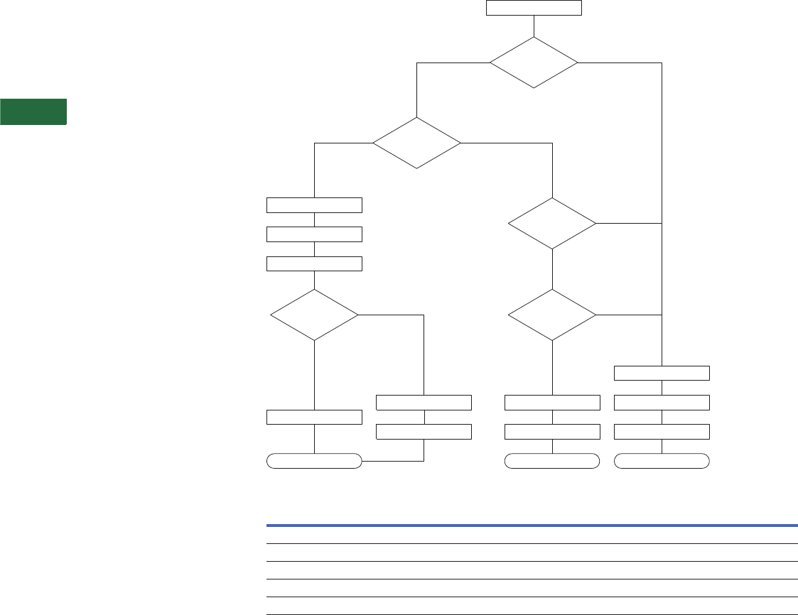
V2-T5-84 Volume 2—Commercial Distribution CA08100003E—April 2014 www.eaton.com
5
5
5
5
5
5
5
5
5
5
5
5
5
5
5
5
5
5
5
5
5
5
5
5
5
5
5
5
5
5
5.5
Transfer Sw itches
Automatic Transfer Controllers
Operation
The ATC-800 operates in
the following modes to meet
most load management
applications:
●Loss of normal power
●Open transition to
alternate source
●Normal power restored
●Closed transition back
to normal source
●Peak shave (remote or
local) closed transition to
and from alternate source
●Test (user selectable)
●Load transfer—closed
transition to and from
alternate source
●No-load transfer—starts
alternate power source
and allows to run
unloaded. No transfer
takes place
Programming and Options
Closed Transition
Operation Modes
Feature Set 47C Closed/In-
Phase/Load Voltage Decay
ATC-800 controllers
equipped with Feature Set
47C execute the following
sequence of operations
upon receipt of a request
for transfer: the controller
waits (for a preselected time
frame) for synchronization
of voltage and frequency. If
achieved, a closed transition
transfer occurs. Failure to
synchronize results in the
controller defaulting to
an in-phase monitor, open
transition mode of operation.
If the two sources fail
to achieve frequency
synchronization within the
user-selectable range, the
controller defaults to an
open transition using
a load voltage decay
delayed transition.
Feature Set 47C Schematic
Closed Transition/In-Phase Standard Features
Standard Features Customer Adjustments
Closed transition frequency difference (Hz) 0.0 to 0.3 Hz
Closed transition voltage difference (V) 1–5%
In-phase transition frequency difference (Hz) 0.0–0.3 Hz
Closed transition synchronization timer 1–60 minutes
In-phase transition synchronization timer 1–60 minutes
Request for Transfer
Alternate
Source
Available?
Sources
Synchronized
<Tmax
Both Sources
Still Available
Sources
Synchronized
<Tmax
Source 1 Open
<100 msec?
Close Source 2
Open Source 1
Detect Source 2 Closed
Good
Open Source 2
Alarm
Open Source 1
Close Source 2
Open Source 1
Load Voltage Decay
Close Source 2
End End End
Yes
Yes
Yes Ye s
Yes
No
No
No
No
No
Open Transition/
In-phase Monitor
Closed
Transition
Open
Transit
Delayed
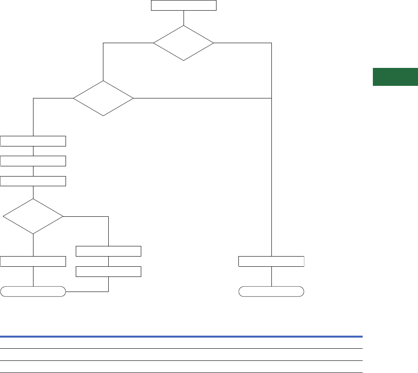
Volume 2—Commercial Distribution CA08100003E—April 2014 www.eaton.com V2-T5-85
5
5
5
5
5
5
5
5
5
5
5
5
5
5
5
5
5
5
5
5
5
5
5
5
5
5
5
5
5
5
5.5
Transfer Switches
Automatic Transfer Controllers
In-Phase Transfer
Feature Set 47D
Closed Only
ATC-800 controllers
equipped with Feature Set
47D only transfer to an
alternate source when both
sources are synchronized.
For synchronization to occur,
both voltage and frequency
differentials must fall within
the user-selectable ranges.
If synchronization does not
occur (within a preselected
amount of time), the
controller will maintain load
connection to the current
power source and initiate
an alarm.
Closed Transition
With Default to In-Phase
Transition With Default
to Time Delay Neutral
Provides a closed transition
transfer as the primary
transfer mode. In the event
Source 1 and Source 2 fail
to synchronize within the
permitted voltage difference,
frequency difference, phase
angle difference and time,
then the controller defaults to
the In-phase transition with
default to time delay neutral
operation as described in
Features 32D and 32A.
Adjustable frequency
difference 0.0–0.3 Hz.
Adjustable voltage difference
1–5% volts. Adjustable
synchronization time
allowance 1–60 minutes.
Feature Set 47D Schematic
Closed Transition Standard Features
Feature Set 47F Closed/
Load Voltage Decay
ATC-800 controllers equipped
with Feature Set 47F will
perform a closed transition
when both sources are
synchronized in frequency,
phase and voltage. Failure to
synchronize will result in an
open transition Time Delay
Load Voltage Decay transfer.
Time Delay Load Voltage
Decay uses the load voltage
measurements to sense back
EMF that is generated when
the transfer switch is in the
Neutral position. It provides
a delay in transfer in either
direction if an unacceptable
level is sensed as established
by a customer programmed
level. The transfer will not
take place until the back EMF
decays below the acceptable
programmed level. This
feature has a separate setting
of enabling or disabling the
operation. If disabled, the
transfer switch will not delay
in the Neutral position and
will transfer between the
sources as fast as possible.
This feature is not available
with the Time Delay Neutral
Optional Feature 32A.
Feature Set 47G Closed/
Time Delay Neutral
ATC-800 controllers equipped
with Feature Set 47F will
perform a closed transition
transfer when both sources
are synchronized in
frequency, phase and
voltage. Failure to
synchronize will result in an
open transition Time Delay
Neutral transfer. Time Delay
Neutral provides a time delay
in the transfer switch neutral
position when both sources
are open. This delay takes
place when the load is
transferred in either direction
to prevent excessive in-rush
currents due to out-of-phase
switching of large motor
loads.
Standard Features Customer Adjustments
Closed transition frequency difference (Hz) 0.0–0.3 Hz
Closed transition voltage difference 1–5%
Closed transition synchronization timer 1–60 minutes
Request for Transfer
Alternate
Source
Available?
Sources
Synchronized
<Tmax
Source 1 Open
<100 msec?
Close Source 2
Open Source 1
Detect Source 2 Closed
Good
Open Source 2
Alarm
Alarm
End End
Yes
Yes
Yes
No
No
No
Closed
Transition
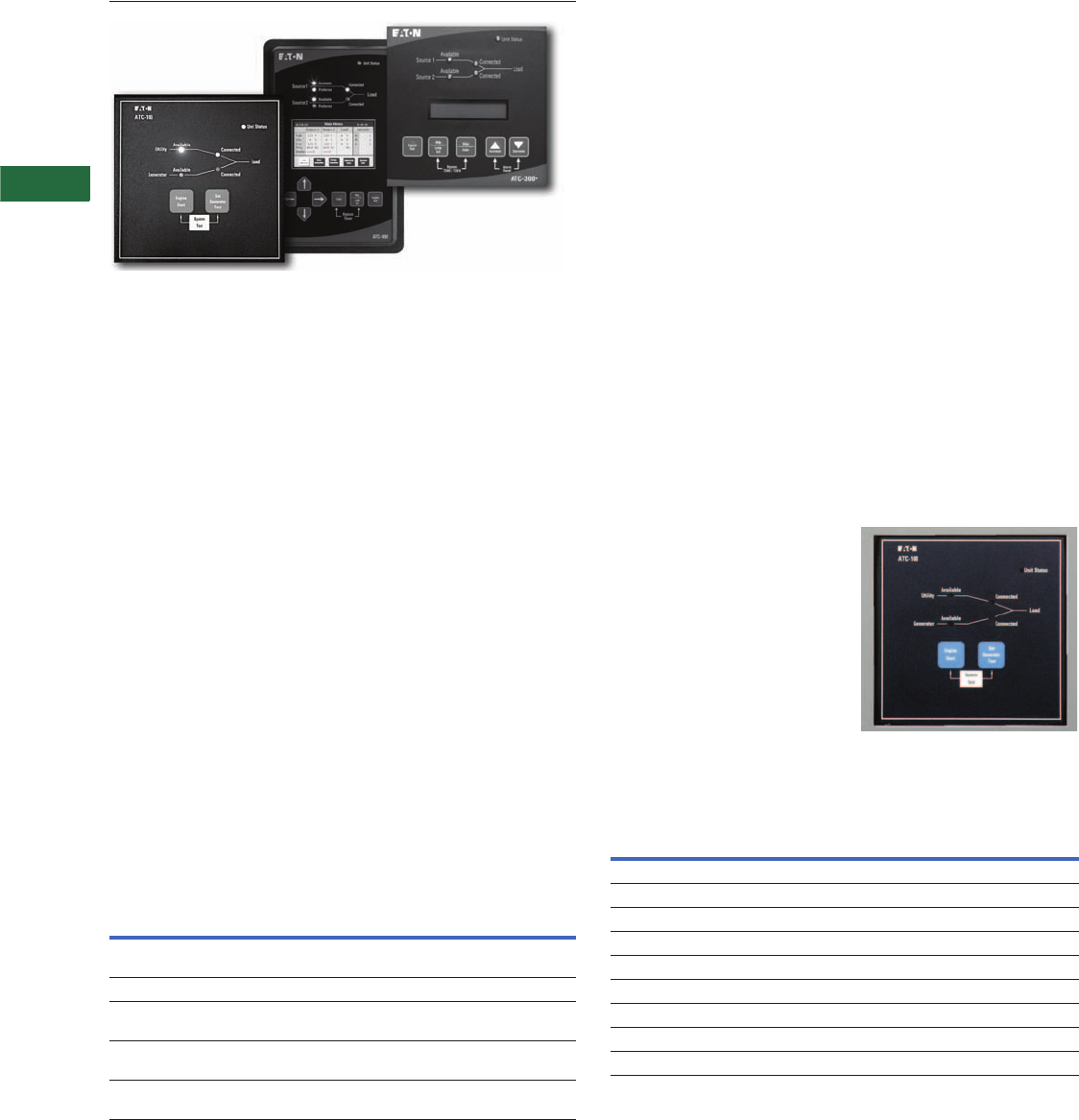
V2-T5-86 Volume 2—Commercial Distribution CA08100003E—April 2014 www.eaton.com
5
5
5
5
5
5
5
5
5
5
5
5
5
5
5
5
5
5
5
5
5
5
5
5
5
5
5
5
5
5
5.5
Transfer Sw itches
Automatic Transfer Controllers
Controller Replacement Guide
Contents
Description Page
Product Selection Guide . . . . . . . . . . . . . . . . . . . . V2-T5-59
ATC-100 Controller . . . . . . . . . . . . . . . . . . . . . . . . V2-T5-63
ATC-300+ Controller . . . . . . . . . . . . . . . . . . . . . . . V2-T5-65
ATC-900 Controller . . . . . . . . . . . . . . . . . . . . . . . . V2-T5-69
ATC-600/800 Controller. . . . . . . . . . . . . . . . . . . . . V2-T5-79
ATC-800 Controller . . . . . . . . . . . . . . . . . . . . . . . . V2-T5-82
Controller Replacement Guide
ATC-100 Controller Replacement Kits . . . . . . . V2-T5-86
ATC-300 Controller Replacement Kits . . . . . . V2-T5-87
ATC-300+ Controller Replacement Kits . . . . . V2-T5-87
ATC-600 and ATC-800 Controller
Replacement Kits . . . . . . . . . . . . . . . . . . . . . V2-T5-88
Feature List . . . . . . . . . . . . . . . . . . . . . . . . V2-T5-89
Feature List Steps. . . . . . . . . . . . . . . . . . . . V2-T5-89
Controller Replacement Guide
Product Description
Automatic Transfer Switch
Controller Replacement
Eaton automatic transfer
switches use several different
controller types. These
automatic transfer controllers
(ATCs) may be ordered as
replacement for current
manufacturer’s existing
automatic transfer switches.
If vintage analog controller or
controller parts are needed,
then a separate renewal part
data list needs to be
referenced. The intent of this
section is to address current
controllers as listed in the
table below.
It is important to note that the
replacement kit style number
does not fully identify all of
the features that may have
been supplied on a specific
application. In some cases,
the replacement kit fully
identifies the features, but
in other cases it does not.
If there is any question
as to what features were
programmed with the
controller, then there are two
ways to verify the correct
feature replacement.
Automatic Transfer Controllers
Controller
Type
Order via Style
Number Only
Order via Replacement Kit
Style Number and Feature List 1
ATC-100 See ATC-100 Replacement Kits
table on the right
ATC-300 Superseded by ATC-300+
ATC-300+ See ATC-300 Replacement Kits,
Page V2-T5-87
ATC-600 See ATC-600/800 Replacement Kits,
Page V2-T5-88
ATC-800 See ATC-600/800 Replacement Kits,
Page V2-T5-88
ATC-100 Controller Replacement Kits
The ATC-100 controller is
primarily used on residential
and light commercial
applications up to 400A.
This controller may be used
with either contactor-based
or molded-case switch
designs. The ATC-100 is only
used on open transition type
transfers. Replacement kits
are ordered by style number
(see table below). ATC-100
ATC-100 Replacement Kits
Note
1Feature list required upon order entry.
Switch
Type
Controller
Type
Replacement
Style Number
Magnum-Based Design
ATC-100 controller is not available — —
Breaker-Based Design
Breaker open transition ATC-100 8160A00G23
Contactor-Based Design
2-position open transition ATC-100 8160A00G24
2-position closed transition — —
3-position open transition — —
3-position closed transition — —
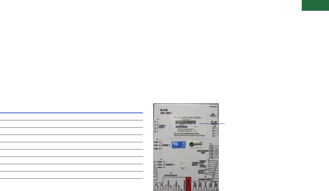
Volume 2—Commercial Distribution CA08100003E—April 2014 www.eaton.com V2-T5-87
5
5
5
5
5
5
5
5
5
5
5
5
5
5
5
5
5
5
5
5
5
5
5
5
5
5
5
5
5
5
5.5
Transfer Switches
Automatic Transfer Controllers
ATC-300 Controller Replacement Kits
The ATC-300 controller has
been in use for many years
and was applied on molded-
case switch units up to
1000A and contactor-based
automatic transfer switches
up to 1200A. In 2012, the
ATC-300 was replaced by the
ATC-300+ controller. An ATC-
300+ replacement kit is used
for replacement of older
ATC-300s. When ordering the
replacement kit, it is very
important to identify that the
existing application is either a
molded-case switch design, a
breaker-based design (has the
lockout feature), or a contactor
2-position or 3-position design.
The ATC-300+ has two
features—Emergency Inhibit
and Manual Retransfer—that
were not available on the
ATC-300. If these features
were not previously supplied
with the ATC-300, then the
end user does not have to use
these additional features. In
addition, the ATC-300+ has
communication
capability for
providing Modbus 485.
The ATC-300 and ATC-300+
have identical size and
mounting dimensions. The
J8 pin is now an 8-pin
connector versus a 4-pin
connector on the older
ATC-300. J8 pins 5–6 and
6–8 are the connections
for Emergency Inhibit and
Manual Retransfer. The
replacement kit includes
the 8-pin connector.
ATC-300 Replacement Kits
Switch
Type
Controller
Type
Replacement
Style Number 1
Magnum-Based Design
ATC-300+ controller is not available — —
Breaker-Based Design
Breaker open transition ATC-300+ 8160A00G100 2
Contactor-Based Design
2-position open transition ATC-300+ 8160A00G104
2-position closed transition — —
3-position open transition ATC-300+ 8160A00G108
3-position closed transition — —
ATC-300+ Controller Replacement Kits
The ATC-300+ controller
was first used in 2012
for molded-case switch,
breaker-based (with lockout
feature) and open transition
contactor-based (2-position
and 3-position) designs. It is
also used as the replacement
kit for older ATC-300
controllers. It is critical to
identify the application that
needs a replacement kit. The
ATC-300+ is NOT used on
closed transition designs.
For breaker-based designs,
the ATC-300+ can be
supplied with or without the
lockout feature. This feature
is typically associated with a
service entrance rated ATS.
Ordering the breaker-based
kit does not assure that the
lockout feature (option 16)
will be supplied. A note
needs to be supplied with
the order entry.
The controllers have
a style number (typically
6D32360Gxx) on the back
of the board. This data can
be used to help identify
the correct controller for
replacement per table below.
If there is trouble identifying
the correct controller type,
pressing the Help button
will provide a scrolling Rev
number, Firmware ID number
and a series of catalog
numbers that an Eaton
factory representative can
use for identification. The
catalog number will be a
series of 1s and 0s.
ATC-300+ Rear View
Notes
1The replacement style number 8160A00Gxx will include the printed circuit board style
number (6D32360Gxx) shown on back of the controller.
2Identify if lockout feature 16 is required.
ATC-300+ PCB Style Number
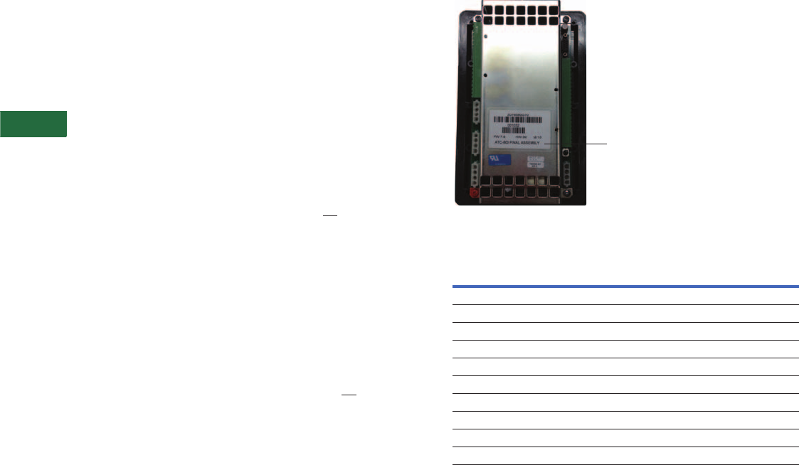
V2-T5-88 Volume 2—Commercial Distribution CA08100003E—April 2014 www.eaton.com
5
5
5
5
5
5
5
5
5
5
5
5
5
5
5
5
5
5
5
5
5
5
5
5
5
5
5
5
5
5
5.5
Transfer Sw itches
Automatic Transfer Controllers
ATC-600 and ATC-800 Controller Replacement Kits
The ATC-600 is used on
molded-case switch and
breaker-based designs up
to 1000A. It is also used on
open transition Magnum
power case switch and
breaker designs up to 5000A.
The ATC-800 has been used
on closed transition Magnum
power case switch and
breaker-based designs up
to 5000A. The ATC-800 is
currently being used on
open and closed transition
contactor-based designs
up to 1200A.
Older automatic transfer
switches may have used
what is referred to as
IQ Controllers. Controller
replacements for those units
can be ordered as ATC-600
for open transition and
ATC-800 for closed transition.
In some cases, both the
ATC-600 and ATC-800
controllers have been
used on medium voltage
transfer switches.
When ordering the
replacement kit, always
provide sufficient notes to
correctly identify the features
supplied with the controller.
This feature set will then
be used to program the
replacement controller.
See the table below for the
replacement kit style numbers
for automatic transfer
switches with ATC-600 or
ATC-800 controllers. Because
each controller was
specifically supplied with the
standard features and any
order-specific optional
features, there is no practical
way to create a replacement
kit style number for each
variation of the features
supplied. Thus, when ordering
the replacement kit
8160A00GXX, the job-specific
controller features must be
specified. Order-specific
features need to be included
with the order entry.
See Feature List Steps
table on Page V2-T5-89 for
identifying the features to be
supplied on the order entry.
On the back of the
ATC-800/600 controllers
is a style number similar
to a 2D7858GXX. This style
number only identifies the
basic control board that is
included in the replacement
kit per the table on this page.
The replacement kit style
number listed on this page
must be used to order the
replacement kit.
ATC-600/800 Replacement Kits
Switch
Type
Controller
Type
Replacement
Style Number
Magnum-Based Design
Magnum open transition ATC-600 8160A00G03
Magnum closed transition ATC-800 8160A00G05
Breaker-Based Design
Breaker open transition ATC-600 8160A00G03
Contactor-Based Design
2-position open transition ATC-800 8160A00G43
2-position closed transition ATC-800 8160A00G43
3-position open transition ATC-800 8160A00G43
3-position closed transition ATC-800 8160A00G43
Board Level Style Number 2D78580Gxx
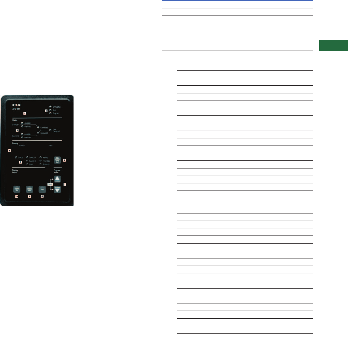
Volume 2—Commercial Distribution CA08100003E—April 2014 www.eaton.com V2-T5-89
5
5
5
5
5
5
5
5
5
5
5
5
5
5
5
5
5
5
5
5
5
5
5
5
5
5
5
5
5
5
5.5
Transfer Switches
Automatic Transfer Controllers
Feature List
The replacement controller
needs to match the features
originally supplied. The easiest
way to supply this list is to
provide the original order
number from the original
shipment. The ATS product
line maintains a database with
the original feature list. The
general order (GO) number is
on the ATS nameplate located
on the inside of the door. In
addition, it is very helpful to
also supply the 15-digit ATS
catalog number that can be
found on the ATS nameplate.
The existing controller also
has a catalog number feature
code that defines what
features are included.
Pressing the Help Lamp
Test button will show this
code on a scrolling display.
If this information is not
supplied on order entry, then
the order will be placed on
manufacturing hold until the
information is supplied.
Feature code example (3f-e3-31-032)
Press Help Lamp Test button to
initiate the Display Screen Readout
Feature List Steps
Notes
1Not replacement order number.
2If ATS is mounted in Eaton motor control center or Eaton switchboard, the ATS order number
must be supplied, not the overall gear General Order number. This ATS order number is
located on the ATS label.
3If the original GO number is not supplied on order entry, then the order will be placed on
manufacturing hold until the feature list is supplied.
Step Action
A.1 Identify replacement style number from table on Page V2-T5-88.
A.2 Identify original general order (GO) number. 12
A.3 Order style number with GO information in the order notes. 3 If the original GO number
is hard to identify or is unavailable, then one of the following steps below can be taken.
B.1 Provide the 9-digit feature code from the ATC-800 or ATC-600 controller. Feature code
is viewable from ATC-600 or ATC-800 readout screen by pressing the Help button.
Controller must be able to be powered up to view this feature code. On older controllers,
the feature code may be 7 or 8 characters. Feature code example (3f-e3-31-032).
C.1 If the above information is not available, then provide a detailed listing of features
to be supplied with the controller. The following questions must be answered.
Switch Type
Molded-case switch
Power case switch, open transition
Power case switch, closed transition
Contactor open transition, 2-position
Contactor open transition, 3-position
Contactor closed transition, 2-position
Contactor closed transition, 2-position
Medium voltage WLI or breaker
Medium voltage open transition
Medium voltage closed transition
Features
5C source 2 O–F monitoring
5E/G source 2 O–V monitoring
Bypass TDEN/TDNE
10 preferred source
16 overcurrent trip
23 plant exerciser
Source 1 O–V monitoring
26D go to emergency
Source 1 U–F monitoring
Source 1 O–F monitoring
29J manual retransfer
32A/B delayed transition
32A TDN time delay neutral
32B time delay load voltage
32C in-phase/TDNLV
32D in-phase/TDN
35 pretransfer signal
36 emergency inhibit
37 service entrance
45 remote sequencing
46 PT ratio
47C closed/in-phase transition
47D closed transition only
47E closed/in-phase/TDN
47F closed/TDNLV

V2-T5-90 Volume 2—Commercial Distribution CA08100003E—April 2014 www.eaton.com
5
5
5
5
5
5
5
5
5
5
5
5
5
5
5
5
5
5
5
5
5
5
5
5
5
5
5
5
5
5
5.6
Transfer Sw itches
Standard and Optional Features
Contents
Description Page
Standard and Optional Features
Contactor-Based—Automatic Transfer Switch
Features . . . . . . . . . . . . . . . . . . . . . . . . . . . . V2-T5-90
Breaker-Based—Automatic Transfer Switch
Features . . . . . . . . . . . . . . . . . . . . . . . . . . . . V2-T5-98
Magnum-Based—Automatic Transfer Switch
Features . . . . . . . . . . . . . . . . . . . . . . . . . . . . V2-T5-102
Feature Description . . . . . . . . . . . . . . . . . . . . . V2-T5-106
Glossary. . . . . . . . . . . . . . . . . . . . . . . . . . . . . . V2-T5-113
Contactor-Based—Automatic Transfer Switch Features
S = Standard, O = Optional, C = Configurable
Feature
Number Description
Open Transition
RLC1 ATC1 ATC3 ATC9 NTCE
C2 C2 C2 C3 C5 C2 C3 C5 C2 C3
Timers
1
1A
1B
Time delay normal to emergency (TDNE) fixed 2 or 15 seconds
Adjustable 0–1800 seconds
Adjustable 0–166 minutes
S
—
—
S
—
—
—
S
—
—
S
—
—
S
—
—
—
S
—
—
S
—
—
S
—
—
—
—
—
—
2
2A
Time delay engine start (TDES) fixed 3 seconds
Adjustable 0–120 seconds
S
—
S
—
—
S
—
S
—
S
—
S
—
S
—
S
—
—
—
—
3
3A
3B
Time delay emergency to normal (TDEN) fixed 5 minutes
Adjustable 0–1800 seconds
Adjustable 0–166 minutes
S
—
—
S
—
—
—
S
—
—
S
—
—
S
—
—
—
S
—
—
S
—
—
S
—
—
—
—
—
—
4
4A
4B
Time delay engine cooldown (TDEC) fixed 5 minutes
Adjustable 0–1800 seconds
Adjustable 0–166 minutes
S
—
—
S
—
—
—
S
—
—
S
—
—
S
—
—
—
S
—
—
S
—
—
S
—
—
—
—
—
—
Emergency (S2) Source Sensing
5H
5J
5K
5L
5L
5N
Phase reversal protection
All phase undervoltage/underfrequency
All phase overvoltage/overfrequency
All phase voltage unbalance and phase loss
All phase voltage unbalance
All phase overfrequency
—
S
—
—
—
—
—
S
—
—
—
—
S
S
S
—
S
—
S
S
S
—
S
—
S
S
S
—
S
—
S
S
S
O
S
S
S
S
S
O
S
S
S
S
S
O
S
S
—
—
—
—
—
—
—
—
—
—
—
—
System or Engine Test
6B
6C
6D
6H
Engine test pushbutton
Remote engine test input
Maintained 2-position test switch
Maintained 4-position test switch
S
—
—
—
S
—
—
—
S
—
—
—
S
—
—
—
S
—
—
—
S
C
O
O
S
C
O
O
S
C
O
O
—
—
—
—
—
—
—
—
7
7A
Time delay emergency fail (TDEF) fixed 6 seconds
Adjustable 0–6 seconds
S
—
S
—
—
S
—
S
—
S
—
S
—
S
—
S
—
—
—
—
Pushbutton Bypass
8C
8D
8E
Bypass TDEN
Bypass TDNE
Bypass TDNE/TDEN (input)
—
—
—
—
—
—
S
S
—
S
S
—
S
S
—
S
S
C
S
S
C
S
S
C
—
—
—
—
—
—
Maintenance Selector Switch
9B Electrical operator isolator switch — — O O O O O O — —

Volume 2—Commercial Distribution CA08100003E—April 2014 www.eaton.com V2-T5-91
5
5
5
5
5
5
5
5
5
5
5
5
5
5
5
5
5
5
5
5
5
5
5
5
5
5
5
5
5
5
5.6
Transfer Switches
Standard and Optional Features
Contactor-Based—Automatic Transfer Switch Features, continued
S = Standard, O = Optional, C = Configurable
Feature
Number Description
Open Transition
RLC1 ATC1 ATC3 ATC9 NTCE
C2 C2 C2 C3 C5 C2 C3 C5 C2 C3
Preferred Source Selector
10A
10C
10B
10D
Preferred source selector (programmed)
Preferred source selector input
Preferred source selector with selector switch
Utility to utility or utility to generator
Generator to generator
—
—
—
—
—
—
—
—
—
—
—
—
—
—
—
—
—
—
—
—
—
—
—
—
—
S
C
O
S
S
S
C
O
S
S
S
C
O
S
S
—
—
—
—
—
—
—
—
—
—
Indicating Lights/LEDs
12C
12D
12G
12H
12L
12M
Normal (S1) source connected
Emergency (S2) source connected
Normal (S1) source available
Emergency (S2) source available
Normal (S1) source tripped (requires feature 16)
Emergency (S2) source tripped (requires feature 16)
S
S
S
S
—
—
S
S
S
S
—
—
S
S
S
S
—
—
S
S
S
S
—
—
S
S
S
S
—
—
S
S
S
S
—
—
S
S
S
S
O
O
S
S
S
S
O
O
S
S
S
S
—
—
S
S
S
S
—
—
Source Available Contacts
14C
14D
14E
14F
14G
14H
Normal (S1) source available 4 Form C
Emergency (S2) source available 4 Form C
Normal (S1) source available 1 Form C
Emergency (S2) source available 1 Form C
Normal (S1) source available 2 Form C
Emergency (S2) source available 2 Form C
—
—
—
—
—
—
—
—
—
—
S
S
O
O
—
—
S
S
O
O
—
—
S
S
O
O
—
—
S
S
O
O
S
S
O
O
O
O
S
S
O
O
O
O
S
S
O
O
O
O
—
—
S
S
O
O
—
—
S
S
Position Contacts
15E
15F
15G
15H
15M
15R
15S
Normal (S1) source position 1 Form C
Emergency (S2) source position 1 Form C
Normal (S1) source position 3 Form C
Emergency (S2) source position 3 Form C
Emergency load shed contacts 4 Form C
(must order as a separate field installed kit) (not in IES)
Normal (S1) source position 1 Form C (relay OUTPUT)
Emergency (S2) source position 1 Form C (relay OUTPUT)
—
—
—
—
O
—
—
S
S
O
O
—
—
—
S
S
O
O
—
—
—
S
S
O
O
—
—
—
S
S
O
O
—
—
—
S
S
O
O
—
C
C
S
S
O
O
—
C
C
S
S
O
O
—
C
C
S
S
O
O
—
—
—
S
S
O
O
—
—
—
Integral Overcurrent Protection
16N
16E
16B
16S
Normal (S1) switch only
Emergency (S2) switch only
Normal (S1) and emergency (S2) switches
Service equipment/overcurrent protection normal (S1) and emergency (S2)
—
—
—
O
—
—
—
—
—
—
—
—
—
—
—
—
—
—
—
—
—
—
—
—
—
—
—
—
—
—
—
—
—
—
—
—
—
—
—
—
Metering
(Specify normal (S1), emergency (S2) or load side for 18A thru E)
18
18A
18B
18D
18E
18O
18P
18Q
18V
18R
18S
18T
18U
Integrated load metering (DCT module)
IQ 250/260
PX4000/6000/8000
IQ 130/140/150
PXM2250/2260/2270
IQ Analyzer normal (S1)
IQ Analyzer emergency (S2)
IQ Analyzer switch selectable (S1) and (S2)
IQ Analyzer load side
DP-4000 normal (S1)
DP-4000 emergency (S2)
DP-4000 switch selectable (S1) and (S2)
DP-4000 load side
—
—
—
—
—
—
—
—
—
—
—
—
—
—
O
—
O
O
—
—
—
—
—
—
—
—
—
O
—
O
O
O
O
O
O
O
O
O
O
—
O
—
O
O
O
O
O
O
O
O
O
O
—
O
—
O
O
O
O
O
O
O
O
O
O
O
O
—
O
O
O
O
O
O
O
O
O
O
O
O
—
O
O
O
O
O
O
O
O
O
O
O
O
—
O
O
O
O
O
O
O
O
O
O
—
O
—
O
O
O
O
O
O
O
O
O
O
—
O
—
O
O
O
O
O
O
O
O
O
O
21A Non-standard terminals — — — — — — — — — —
22
22C
22D
Ground bus
Special ground bar—contact factory
16 conductor ground bus 500 or 750 kcmil
—
—
—
—
—
—
S
—
—
S
—
—
S
—
—
S
—
—
S
—
—
S
—
O
S
—
—
S
—
—
Plant Exerciser
23A
23K
23L
23M
Selectable—disabled/7-, 14-, 28-day interval, fixed 15 minutes
load/no load, with fail-safe
Selectable—disabled 7-, 14-, 28-day interval, 0–600 minutes
load/no load, with fail-safe
24-hour, 7-day, 365-day programmable plant exerciser
Selectable—disabled 7-, 14-, 28-, 365-day interval, 0–600 minutes
load/no load, with fail-safe
S
—
—
—
S
—
—
—
—
S
O
—
—
S
O
—
—
S
O
—
—
—
—
S
—
—
—
S
—
—
—
S
—
—
—
—
—
—
—
—

V2-T5-92 Volume 2—Commercial Distribution CA08100003E—April 2014 www.eaton.com
5
5
5
5
5
5
5
5
5
5
5
5
5
5
5
5
5
5
5
5
5
5
5
5
5
5
5
5
5
5
5.6
Transfer Sw itches
Standard and Optional Features
Contactor-Based—Automatic Transfer Switch Features, continued
S = Standard, O = Optional, C = Configurable
Note
1When these options are selected with the ATC-900 controller, the associated input or output will be factory fixed and cannot be reconfigured by the user.
Feature
Number Description
Open Transition
RLC1 ATC1 ATC3 ATC9 NTCE
C2 C2 C2 C3 C5 C2 C3 C5 C2 C3
Normal (S1) Source Sensing
26D
26E
26H
26J
26K
26L
26L
26M
26P
Go to emergency (S2) input
Go to emergency (S2) input with selector switch 1
Phase reversal protection
All phase undervoltage/underfrequency
All phase overvoltage/overfrequency
All phase voltage unbalance and phase loss
All phase voltage unbalance
Allows operation with generator with utility sensing
(available only through a field installed kit) (not in IES)
All phase undervoltage
—
—
—
—
—
—
—
O
S
—
—
—
—
—
—
—
O
S
S
—
S
S
S
—
S
—
—
S
—
S
S
S
—
S
—
—
S
—
S
S
S
—
S
—
—
C
—
O
S
S
S
O
S
—
C
O
S
S
S
O
S
—
—
C
O
S
S
S
O
S
—
—
—
—
—
—
—
—
—
—
—
—
—
—
—
—
—
—
—
—
Alternative Transfer Modes of Operation
29G
29J
29L
29M
29K
Selector switch for auto or non-auto operation 1
Manual (pushbutton) transfer E to N; automatic N to E 1
Manual retransfer on/off input
Manual retransfer on/off input with selector switch 1
Manual retransfer input
—
—
—
—
—
—
—
—
—
—
O
O
—
—
—
O
O
—
—
—
O
O
—
—
—
O
O
C
O
C
O
O
C
O
C
O
O
C
O
C
—
—
—
—
—
—
—
—
—
—
Open Transfer Operation Modes
32A
32B
32C
32D
32E
32F
32G
Time delay neutral adjustable 0–120 seconds (delayed transition)
Load voltage decay adjustable 2–30% nominal voltage
In-phase transition defaults to load voltage decay
In-phase transition defaults to time delay neutral
Delay transition timer adjustable 3–60 seconds
In-phase transition
Time delay neutral fixed 0 or 2 seconds (delayed transition)
—
—
—
—
—
S
—
—
—
—
—
—
S
—
—
—
—
—
—
S
—
S
—
—
—
—
—
—
—
—
—
S
—
—
—
—
—
—
—
—
S
—
C
C
C
—
—
—
—
C
C
C
—
—
—
—
—
—
—
—
—
—
—
—
—
—
—
—
—
—
Logic Extender Cable (Open Enclosures Only)
34A
34C
34E
34F
48 inches (1219 mm)
96 inches (2438 mm)
144 inches (3658 mm)
100 inches (2540 mm) (fixed mount only)
—
—
—
—
—
O
—
—
—
O
—
—
—
O
—
—
—
O
—
—
—
—
—
—
—
—
—
—
—
—
—
—
—
O
—
—
—
O
—
—
35A
35B
Pre-transfer signal contacts 1 Form C
Pre-/post-transfer signal
—
—
—
—
S
—
S
—
S
—
C
C
C
C
C
C
—
—
—
—
36
36A
Load shed from emergency (S2 inhibit)
Load shed—S2 inhibit with keyed switch (INPUT)
—
—
—
—
—
—
S
—
S
—
C
O
C
O
C
O
—
—
—
—
37 Go to “isolated” position (not SE rated) — — — — — C C C — —
Suitable for Use as Service Equipment Requires 16B, N or S
37A Without ground fault protection — — — — — — — — — —
37B With ground fault protection required at 1000A or more if the electrical service is
a solidly grounded wye system of more than 150V to ground but not exceeding
600V phase to phase
——————————
Stainless Steel Device Covers
38A
38B
SS cover for device plate or SE disconnect
SS cover for controller
—
—
—
O
O
O
O
O
O
O
O
O
O
O
O
O
O
—
O
—
Space Heater with Thermostat
41A
41E
100 watts
375 watts
—
—
O
—
O
—
O
—
O
—
O
—
O
—
O
—
O
—
O
—
42 IBC/CBC seismic qualified S S S S S S S S S S
Load Management Contacts
45A–K
45L
Load sequencing contacts (1)
Selective load shed (assignable to multiple out put contacts)
—
—
—
—
—
—
—
—
—
—
C
C
C
C
—
C
—
—
—
—

Volume 2—Commercial Distribution CA08100003E—April 2014 www.eaton.com V2-T5-93
5
5
5
5
5
5
5
5
5
5
5
5
5
5
5
5
5
5
5
5
5
5
5
5
5
5
5
5
5
5
5.6
Transfer Switches
Standard and Optional Features
Contactor-Based—Automatic Transfer Switch Features, continued
S = Standard, O = Optional, C = Configurable
Notes
1Add feature package B or C (e.g., 51S4B).
B: LED indication and audible alarm, Form C contact, EMI/RFI filtering (standard)
C: B and surge counter with Reset button (standard with surge)
2When these options are selected with the ATC-900 controller, the associated input or output will be factory fixed and cannot be reconfigured by the user.
Feature
Number Description
Open Transition
RLC1 ATC1 ATC3 ATC9 NTCE
C2 C2 C2 C3 C5 C2 C3 C5 C2 C3
Communications
48D
48F
48F
48G
48P
48RAC
48MRAC
48U
PXG400 gateway (includes Modbus)
Modbus—MPONI module (PONI not required with ATC-300+)
Modbus communication—no PONI required
Modbus TCP/IP gateway
Power supply for remote annunciator
Remote annunciator with control (includes Modbus)
Remote annunciator with control multi-switch (includes Modbus)
USB port
—
—
—
—
—
—
—
—
—
—
—
—
—
—
—
—
O
O
S
—
O
O
O
—
O
O
S
—
O
O
O
—
O
O
S
—
O
O
O
—
O
—
S
O
O
O
—
S
O
—
S
O
O
O
—
S
O
—
S
O
O
O
—
S
—
—
—
—
—
—
—
—
—
—
—
—
—
—
—
—
49A
49B
49C
49C
Sensing isolation transformer Magnum
Sensing isolation transformer
Multi-tap voltage transformer (non AG only)
Multi-tap voltage transformer (option only on fixed)
—
—
—
—
—
—
S
—
—
O
S
—
—
O
S
—
—
O
S
—
O
O
S
—
O
O
S
—
O
O
S
—
—
—
S
—
—
—
S
—
TVSS up to 480V (Connected to Normal)
51D1
51F1
50 kA—CVX
100 kA—CVX
—
—
—
—
O
O
O
O
O
O
O
O
O
O
O
O
O
O
O
O
Surge Protection Device with 12 ft Cable (on Normal)
51S1
51S2
51S3
51S4
51S5
51S6
51S7
51S8
51S9
50 kA—SPD 1
80 kA—SPD 1
100 kA—SPD 1
120 kA—SPD 1
160 kA—SPD 1
200 kA—SPD 1
250 kA—SPD 1
300 kA—SPD 1
400 kA—SPD 1
—
—
—
—
—
—
—
—
—
—
—
—
—
—
—
—
—
—
—
—
—
—
—
—
—
—
—
—
—
—
—
—
—
—
—
—
—
—
—
—
—
—
—
—
—
—
—
—
—
—
—
—
—
—
—
—
—
—
—
—
—
—
—
—
—
—
—
—
—
—
—
—
—
—
—
—
—
—
—
—
—
—
—
—
—
—
—
—
—
—
52B
52C
24V generator battery power
24V onboard power supply (charger and batteries)
—
—
—
—
—
—
—
—
—
—
—
—
—
—
—
—
—
—
—
—
54B Upgrade to 316 stainless steel — — O O O O O O O O
60 Control power transformer (240/120V single-phase and 208V only) — O O — — — — — — —
61A
61B
UPS device
UPS 120 Vac terminal block input
—
—
—
—
—
—
—
—
—
—
—
—
—
—
—
—
—
—
—
—
80A Emergency (S2) inhibit contact — — — O O C C C — —
Monitoring Outputs
81A
81B
81C
81D
81E
81F
81G
81GL
81H
General alarm indication contact
ATS not in automatic
ATS in test
Engine test aborted
Cooldown in process
Engine start contact status
Emergency inhibit on
Emergency inhibit on with white indicating light 2
ATS on bypass
—
—
—
—
—
—
—
—
—
—
—
—
—
—
—
—
—
—
—
—
—
—
—
—
—
—
—
—
—
—
—
—
—
—
—
—
—
—
—
—
—
—
—
—
—
C
C
C
C
C
C
C
O
C
C
C
C
C
C
C
C
O
C
C
C
C
C
C
C
C
O
C
—
—
—
—
—
—
—
—
—
—
—
—
—
—
—
—
—
—
Inputs
81J
81K
81L
Lockout
Monitor mode
Remote load test
—
—
—
—
—
—
—
—
—
—
—
—
—
—
—
C
C
C
C
C
C
C
C
C
—
—
—
—
—
—
Three Source ATS Control (Master/Slave)
90A
90B
Master control output
Slave input
—
—
—
—
—
—
—
—
—
—
C
C
C
C
C
C
—
—
—
—

V2-T5-94 Volume 2—Commercial Distribution CA08100003E—April 2014 www.eaton.com
5
5
5
5
5
5
5
5
5
5
5
5
5
5
5
5
5
5
5
5
5
5
5
5
5
5
5
5
5
5
5.6
Transfer Sw itches
Standard and Optional Features
Contactor-Based—Automatic Transfer Switch Features, continued
S = Standard, O = Optional, C = Configurable
Feature
Number Description
Open Transition Closed Transition
BIC3 BIC3 BIC9 BIC9 CBC9 CBC9 CTC9
CDCDCDC3
Timers
1A
1B
Adjustable 0–1800 seconds
Adjustable 0–166 minutes
S
—
S
—
—
S
—
S
—
S
—
S
—
S
2AAdjustable 0–120 seconds SSSSSSS
3A
3B
Adjustable 0–1800 seconds
Adjustable 0–166 minutes
S
—
S
—
—
S
—
S
—
S
—
S
—
S
4A
4B
Adjustable 0–1800 seconds
Adjustable 0–166 minutes
S
—
S
—
—
S
—
S
—
S
—
S
—
S
Emergency (S2) Source Sensing
5H
5J
5K
5L
5L
5N
Phase reversal protection
All phase undervoltage/underfrequency
All phase overvoltage/overfrequency
All phase voltage unbalance and phase loss
All phase voltage unbalance
All phase overfrequency
S
S
S
—
S
—
S
S
S
—
S
—
S
S
S
O
S
S
S
S
S
O
S
S
S
S
S
O
S
S
S
S
S
O
S
S
S
S
S
O
S
S
System or Engine Test
6B
6C
6D
6H
Engine test pushbutton
Remote engine test input
Maintained 2-position test switch
Maintained 4-position test switch
S
—
—
—
S
—
—
—
S
C
O
O
S
C
O
O
S
C
O
O
S
C
O
O
S
C
O
O
7AAdjustable 0–6 seconds SSSSSSS
Pushbutton Bypass
8C
8D
8E
Bypass TDEN
Bypass TDNE
Bypass TDNE/TDEN (input)
S
S
—
S
S
—
S
S
C
S
S
C
S
S
C
S
S
C
S
S
C
Maintenance Selector Switch
9BElectrical operator isolator switch OOOOOOO
Preferred Source Selector
10A
10C
10B
10D
Preferred source selector (programmed)
Preferred source selector input
Preferred source selector with selector switch
Utility to utility or utility to generator
Generator to generator
—
—
—
—
—
—
—
—
—
—
S
C
O
S
S
S
C
O
S
S
S
C
O
S
S
S
C
O
S
S
S
C
O
S
S
Indicating Lights/LEDs
12C
12D
12G
12H
12L
12M
Normal (S1) source connected
Emergency (S2) source connected
Normal (S1) source available
Emergency (S2) source available
Normal (S1) source tripped (requires feature 16)
Emergency (S2) source tripped (requires feature 16)
S
S
S
S
—
—
S
S
S
S
—
—
S
S
S
S
O
O
S
S
S
S
O
O
S
S
S
S
O
O
S
S
S
S
O
O
S
S
S
S
O
O
Source Available Contacts
14C
14D
14E
14F
14G
14H
Normal (S1) source available 4 Form C
Emergency (S2) source available 4 Form C
Normal (S1) source available 1 Form C
Emergency (S2) source available 1 Form C
Normal (S1) source available 2 Form C
Emergency (S2) source available 2 Form C
O
O
—
—
S
S
O
O
—
—
S
S
O
O
S
S
O
O
O
O
S
S
O
O
O
O
S
S
O
O
O
O
S
S
O
O
O
O
S
S
O
O

Volume 2—Commercial Distribution CA08100003E—April 2014 www.eaton.com V2-T5-95
5
5
5
5
5
5
5
5
5
5
5
5
5
5
5
5
5
5
5
5
5
5
5
5
5
5
5
5
5
5
5.6
Transfer Switches
Standard and Optional Features
Contactor-Based—Automatic Transfer Switch Features, continued
S = Standard, O = Optional, C = Configurable
Note
1When these options are selected with the ATC-900 controller, the associated input or output will be factory fixed and cannot be reconfigured by the user.
Feature
Number Description
Open Transition Closed Transition
BIC3 BIC3 BIC9 BIC9 CBC9 CBC9 CTC9
CDCDCDC3
Position Contacts
15E
15F
15G
15H
15R
15S
Normal (S1) source position 1 Form C
Emergency (S2) source position 1 Form C
Normal (S1) source position 3 Form C
Emergency (S2) source position 3 Form C
Normal (S1) source position 1 Form C (relay OUTPUT)
Emergency (S2) source position 1 Form C (relay OUTPUT)
S
S
O
O
—
—
S
S
O
O
—
—
S
S
O
O
C
C
S
S
O
O
C
C
S
S
O
O
C
C
S
S
O
O
C
C
S
S
O
O
C
C
Integral Overcurrent Protection
16N
16E
16B
16S
Normal (S1) switch only
Emergency (S2) switch only
Normal (S1) and emergency (S2) switches
Service equipment/overcurrent protection normal (S1) and emergency (S2)
—
—
—
—
—
—
—
—
—
—
—
—
—
—
—
—
—
—
—
—
—
—
—
—
—
—
—
—
Metering
(Specify normal (S1), emergency (S2) or load side for 18A thru E)
18
18A
18B
18D
18E
Integrated load metering (DCT module)
IQ 250/260
PX4000/6000/8000
IQ 130/140/150
PXM2250/2260/2270
—
O
—
O
O
—
O
O
O
O
O
O
—
O
O
O
O
—
O
O
O
O
—
O
O
O
O
—
O
O
O
O
—
O
O
20A Rear bus connections — — —————
21ANon-standard terminals (optional in IES for centers) ———————
22
22C
22D
Ground bus
Special ground bar—contact factory
16 conductor ground bus 500 or 750 kcmil
S
—
O
S
—
O
—
—
O
—
—
O
—
—
O
—
—
—
—
—
—
Plant Exerciser
23A
23K
23L
23M
Selectable—disabled 7-, 14-, 28-day interval, fixed 15 minutes
load/no load, with fail-safe
Selectable—disabled 7-, 14-, 28-day interval, 0–600 minutes
load/no load, with fail-safe
24-hour, 7-day, 365-day programmable plant exerciser
Selectable—disabled 7-, 14-, 28-, 365-day interval, 0–600 minutes
load/no load, with fail-safe
—
S
O
—
—
S
O
—
—
—
—
S
—
—
—
S
—
—
—
S
—
—
—
S
—
—
—
S
Normal (S1) Source Sensing
26D
26E
26H
26J
26K
26L
26L
Go to emergency (S2) input
Go to emergency (S2) input with selector switch 1
Phase reversal protection
All phase undervoltage/underfrequency
All phase overvoltage/overfrequency
All phase voltage unbalance and phase loss
All phase voltage unbalance
S
—
S
S
S
—
S
S
—
S
S
S
—
S
C
O
S
S
S
O
S
C
O
S
S
S
O
S
C
O
S
S
S
O
S
C
O
S
S
S
O
S
C
O
S
S
S
O
S
Alternative Transfer Modes of Operation
29D
29G
29J
29L
29M
29K
Dual ATS bypass
Selector switch for auto or non-auto operation 1
Manual (pushbutton) transfer E to N; automatic N to E 1
Manual retransfer on/off input
Manual retransfer on/off input with selector switch 1
Manual retransfer input
S
O
O
—
—
—
S
O
O
—
—
—
S
O
O
C
O
C
S
O
O
C
O
C
S
O
O
C
O
C
S
O
O
C
O
C
—
O
O
C
O
C

V2-T5-96 Volume 2—Commercial Distribution CA08100003E—April 2014 www.eaton.com
5
5
5
5
5
5
5
5
5
5
5
5
5
5
5
5
5
5
5
5
5
5
5
5
5
5
5
5
5
5
5.6
Transfer Sw itches
Standard and Optional Features
Contactor-Based—Automatic Transfer Switch Features, continued
S = Standard, O = Optional, C = Configurable
Feature
Number Description
Open Transition Closed Transition
BIC3 BIC3 BIC9 BIC9 CBC9 CBC9 CTC9
CDCDCDC3
Open Transfer Operation Modes
32A
32B
32C
32D
32E
32F
32G
Time delay neutral adjustable 0–120 seconds (delayed transition)
Load voltage decay adjustable 2–30% nominal voltage
In-phase transition defaults to load voltage decay
In-phase transition defaults to time delay neutral
Delay transition timer adjustable 3–60 seconds
In-phase transition
Time delay neutral fixed 0 or 2 seconds (delayed transition)
S
—
—
—
—
—
—
S
—
—
—
—
—
—
C
C
—
—
—
—
—
C
C
—
—
—
—
—
—
—
—
—
—
—
—
—
—
—
—
—
—
—
—
—
—
—
—
—
—
Load Control
35A
35B
Pre-transfer signal contacts 1 Form C
Pre-/post-transfer signal
S
—
S
—
C
C
C
C
C
C
C
C
C
C
36
36A
Load shed from emergency (S2 inhibit)
Load shed—S2 inhibit with keyed switch (INPUT)
S
—
S
—
C
O
C
O
C
O
C
O
C
O
37 Go to “isolated” position (not SE rated) — — C C C C C
Suitable for Use as Service Equipment Requires 16B, N or S
37A
37B
Without ground fault protection
With ground fault protection required at 1000A or more if the
electrical service is a solidly grounded wye system of more than 150V to ground but
not exceeding 600V phase to phase
—
—
—
—
—
—
—
—
—
—
—
—
—
—
Stainless Steel Device Covers
38A
38B
SS cover for device plate or SE disconnect
SS cover for controller
O
O
O
O
O
O
O
O
O
O
O
O
O
O
Space Heater with Thermostat
41A
41E
100 watts
375 watts
O
—
O
—
O
—
O
O
O
—
O
O
O
—
42 IBC/CBC seismic qualified S S S S S S S
Load Management Contacts
45A–K
45L
Load sequencing contacts (1)
Selective load shed (assignable to multiple out put contacts)
—
—
—
—
C
C
C
C
C
C
C
C
C
C
Closed Transition Operational Modes (User Must Specify)
47C
47D
47E
47F
47G
47H
Closed/in-phase transition default to load voltage decay
Closed transition
Closed/in-phase transition default to time delay neutral
Closed transition load voltage decay
Closed transition time delay neutral
Parallel limit timer
—
—
—
—
—
—
—
—
—
—
—
—
—
—
—
—
—
—
—
—
—
—
—
—
—
C
—
C
C
—
—
C
—
C
C
—
—
C
—
C
C
—
Communications
48A
48D
48F
48F
48G
48P
48RAC
48MRAC
48R
48U
INCOM—IPONI module
PXG400 gateway (includes Modbus)
Modbus—MPONI module (PONI not required with ATC-300+)
Modbus communication—no PONI required
Modbus TCP/IP gateway
Power supply for remote annunciator
Remote annunciator with control (includes Modbus)
Remote annunciator with control multi-switch (includes Modbus)
Remote annunciator
USB port
—
O
O
S
O
O
O
—
—
—
—
O
O
S
O
O
O
—
—
—
—
O
—
S
O
O
O
—
S
—
—
O
—
S
O
O
O
—
S
—
—
O
—
S
O
O
O
—
S
—
—
O
—
S
O
O
O
—
S
—
—
O
—
S
O
O
O
—
S
—
49A
49B
49C
49C
Sensing isolation transformer Magnum
Sensing isolation transformer
Multi-tap voltage transformer (non AG only)
Multi-tap voltage transformer (option only on fixed)
—
—
—
S
—
—
—
S
O
O
—
S
O
O
—
S
O
O
—
S
O
O
—
S
O
O
S
—

Volume 2—Commercial Distribution CA08100003E—April 2014 www.eaton.com V2-T5-97
5
5
5
5
5
5
5
5
5
5
5
5
5
5
5
5
5
5
5
5
5
5
5
5
5
5
5
5
5
5
5.6
Transfer Switches
Standard and Optional Features
Contactor-Based—Automatic Transfer Switch Features, continued
S = Standard, O = Optional, C = Configurable
Notes
1Add feature package B or C (e.g., 51S4B).
B: LED indication and audible alarm, Form C contact, EMI/RFI filtering (standard)
C: B and surge counter with Reset button (standard with surge)
2When these options are selected with the ATC-900 controller, the associated input or output will be factory fixed and cannot be reconfigured
by the user.
Feature
Number Description
Open Transition Closed Transition
BIC3 BIC3 BIC9 BIC9 CBC9 CBC9 CTC9
CDCDCDC3
TVSS up to 480V (Connected to Normal)
51D1
51F1
50 kA—CVX
100 kA—CVX
O
O
—
—
O
O
—
—
O
O
—
—
O
O
Surge Protection Device with 12 ft Cable (on Normal)
51S1
51S2
51S3
51S4
51S5
51S6
51S7
51S8
51S9
50 kA—SPD 1
80 kA—SPD 1
100 kA—SPD 1
120 kA—SPD 1
160 kA—SPD 1
200 kA—SPD 1
250 kA—SPD 1
300 kA—SPD 1
400 kA—SPD 1
—
—
—
—
—
—
—
—
—
O
O
O
O
O
O
—
—
—
—
—
—
—
—
—
—
—
—
O
O
O
O
O
O
—
—
—
—
—
—
—
—
—
—
—
—
O
O
O
O
O
O
—
—
—
—
—
—
—
—
—
—
—
—
52B
52C
24V generator battery power
24V onboard power supply (charger and batteries)
—
—
—
—
—
—
—
—
—
—
—
—
—
—
54A
54B
Front access cabinet
Upgrade to 316 stainless steel
—
O
—
O
—
O
—
O
—
O
—
O
—
—
59A
59B
Silver-plated bus
Tin-plated bus
S
O
S
O
—
—
S
—
—
—
S
—
—
—
61A
61B
UPS device
UPS 120 Vac terminal block input
O
S
O
S
—
—
—
—
—
—
—
—
—
—
80A Emergency (S2) inhibit contact S S C C C C C
Monitoring Outputs
81A
81B
81C
81D
81E
81F
81G
81GL
81H
General alarm indication contact
ATS not in automatic
ATS in test
Engine test aborted
Cooldown in process
Engine start contact status
Emergency inhibit on
Emergency inhibit on with white indicating light 2
ATS on bypass
—
—
—
—
—
—
—
—
—
—
—
—
—
—
—
—
—
—
C
C
C
C
C
C
C
O
C
C
C
C
C
C
C
C
O
C
C
C
C
C
C
C
C
O
C
C
C
C
C
C
C
C
O
C
C
C
C
C
C
C
C
O
C
Inputs
81J
81K
81L
Lockout
Monitor mode
Remote load test
—
—
—
—
—
—
C
C
C
C
C
C
C
C
C
C
C
C
C
C
C
Three Source ATS Control (Master/Slave)
90A
90B
Master control output
Slave input
—
—
—
—
C
C
C
C
C
C
C
C
C
C

V2-T5-98 Volume 2—Commercial Distribution CA08100003E—April 2014 www.eaton.com
5
5
5
5
5
5
5
5
5
5
5
5
5
5
5
5
5
5
5
5
5
5
5
5
5
5
5
5
5
5
5.6
Transfer Sw itches
Standard and Optional Features
Breaker-Based—Automatic Transfer Switch Features
S = Standard, O = Optional, C = Configurable
Feature
Number Description
Open Transition Closed Transition
ATH1 ATH3 ATH9 NTHE MTHX MBHE
ATV1 ATV3 ATV9 NTVE MTVX
Timers
1
1A
1B
Time delay normal to emergency (TDNE) fixed 2 or 15 seconds
Adjustable 0–1800 seconds
Adjustable 0–166 minutes
S
—
—
—
S
—
—
—
S
—
—
—
—
—
—
—
—
—
2
2A
Time delay engine start (TDES) fixed 3 seconds
Adjustable 0–120 seconds
S
—
—
S
—
S
—
—
—
—
—
—
3
3A
3B
Time delay emergency to normal (TDEN) fixed 5 minutes
Adjustable 0–1800 seconds
Adjustable 0–166 minutes
S
—
—
S
—
—
—
—
S
—
—
—
—
—
—
—
—
—
4
4A
4B
Time delay engine cooldown (TDEC) fixed 5 minutes
Adjustable 0–1800 seconds
Adjustable 0–166 minutes
S
—
—
—
S
—
—
—
S
—
—
—
—
—
—
—
—
—
Emergency (S2) Source Sensing
5H
5J
5K
5L
5L
5N
Phase reversal protection
All phase undervoltage/underfrequency
All phase overvoltage/overfrequency
All phase voltage unbalance and phase loss
All phase voltage unbalance
All phase overfrequency
—
S
—
—
—
S
S
S
S
—
S
—
S
S
S
O
S
S
—
—
—
—
—
—
—
—
—
—
—
—
—
—
—
—
—
—
System or Engine Test
6B
6C
6D
6H
Engine test pushbutton
Remote engine test input
Maintained 2-position test switch
Maintained 4-position test switch
S
—
—
—
S
—
—
—
S
C
O
O
—
—
—
—
—
—
—
—
—
—
—
—
7
7A
Time delay emergency fail (TDEF) fixed 6 seconds
Adjustable 0–6 seconds
S
—
—
S
—
S
—
—
—
—
—
—
Pushbutton Bypass
8C
8D
8E
Bypass TDEN
Bypass TDNE
Bypass TDNE/TDEN (input)
—
—
—
S
S
—
S
S
C
—
—
—
—
—
—
—
—
—
Maintenance Selector Switch
9B Electrical operator isolator switch — O O — — —
Preferred Source Selector
10A
10C
10B
10D
Preferred source selector (programmed)
Preferred source selector input
Preferred source selector with selector switch
Utility to utility or utility to generator
Generator to generator
—
—
—
—
—
—
—
—
—
—
S
C
O
S
S
—
—
—
—
—
—
—
—
—
—
—
—
—
—
—
Indicating Lights/LEDs
12C
12D
12G
12H
12L
12M
Normal (S1) source connected
Emergency (S2) source connected
Normal (S1) source available
Emergency (S2) source available
Normal (S1) source tripped (requires feature 16)
Emergency (S2) source tripped (requires feature 16)
S
S
S
S
—
—
S
S
S
S
O
O
S
S
S
S
O
O
S
S
S
S
O
O
—
—
—
—
—
—
S
S
—
—
—
—
Source Available Contacts
14C
14D
14E
14F
14G
14H
Normal (S1) source available 4 Form C
Emergency (S2) source available 4 Form C
Normal (S1) source available 1 Form C
Emergency (S2) source available 1 Form C
Normal (S1) source available 2 Form C
Emergency (S2) source available 2 Form C
—
—
—
—
S
S
O
O
—
—
S
S
O
O
S
S
O
O
O
O
—
—
O
O
—
—
—
—
—
—
—
—
—
—
—
—

Volume 2—Commercial Distribution CA08100003E—April 2014 www.eaton.com V2-T5-99
5
5
5
5
5
5
5
5
5
5
5
5
5
5
5
5
5
5
5
5
5
5
5
5
5
5
5
5
5
5
5.6
Transfer Switches
Standard and Optional Features
Breaker-Based—Automatic Transfer Switch Features, continued
S = Standard, O = Optional, C = Configurable
Note
1When these options are selected with the ATC-900 controller, the associated input or output will be factory fixed and cannot be reconfigured by the user.
Feature
Number Description
Open Transition Closed Transition
ATH1 ATH3 ATH9 NTHE MTHX MBHE
ATV1 ATV3 ATV9 NTVE MTVX
Position Contacts
15E
15F
15G
15H
15R
15S
Normal (S1) source position 1 Form C
Emergency (S2) source position 1 Form C
Normal (S1) source position 3 Form C
Emergency (S2) source position 3 Form C
Normal (S1) source position 1 Form C (relay OUTPUT)
Emergency (S2) source position 1 Form C (relay OUTPUT)
S
S
O
O
—
—
S
S
O
O
—
—
S
S
O
O
C
C
—
—
—
—
—
—
—
—
—
—
—
—
—
—
—
—
—
—
Integral Overcurrent Protection
16N
16E
16B
Normal (S1) switch only
Emergency (S2) switch only
Normal (S1) and emergency (S2) switches
—
—
—
O
O
O
O
O
O
O
O
O
O
O
O
—
—
—
Metering
(Specify normal (S1), emergency (S2) or load side for 18A thru E)
18
18A
18B
18D
18E
Integrated load metering (DCT module)
IQ 250/260
PX4000/6000/8000
IQ 130/140/150
PXM2250/2260/2270
—
O
—
O
O
—
O
—
O
O
—
O
—
O
O
—
O
—
O
O
—
—
—
—
—
—
—
—
—
—
20A Rear bus connections — O O O O —
21A Non-standard terminals (optional in IES for centers) O O O O O O
22 Ground bus with provisions to attach to neutral — — O — — —
Plant Exerciser
23A
23K
23L
23M
Selectable—disabled 7-, 14-, 28-day interval, fixed 15 minutes
load/no load, with fail-safe
Selectable—disabled 7-, 14-, 28-day interval, 0–600 minutes
load/no load, with fail-safe
24-hour, 7-day, 365-day programmable plant exerciser
Selectable—disabled 7-, 14-, 28-, 365-day interval, 0–600 minutes
load/no load, with fail-safe
S
—
—
—
—
S
O
—
—
—
—
S
—
—
—
—
—
—
—
—
—
—
—
—
Normal (S1) Source Sensing
26D
26E
26H
26J
26K
26L
26L
26M
26P
Go to emergency (S2) input
Go to emergency (S2) input with selector switch 1
Phase reversal protection
All phase undervoltage/underfrequency
All phase overvoltage/overfrequency
All phase voltage unbalance and phase loss
All phase voltage unbalance
Allows operation with generator with utility sensing
(available only through a field installed kit) (not in IES)
—
—
—
—
—
—
—
O
S
S
—
S
S
S
—
S
—
—
C
O
S
S
S
O
S
—
—
—
—
—
—
—
—
—
—
—
—
—
—
—
—
—
—
—
—
—
—
—
—
—
—
—
—
—
Alternative Transfer Modes of Operation
29G
29J
29L
29M
29K
Selector switch for auto or non-auto operation 1
Manual (pushbutton) transfer E to N; automatic N to E 1
Manual retransfer on/off input
Manual retransfer on/off input with selector switch 1
Manual retransfer input
—
—
—
—
—
O
O
—
—
—
O
O
C
O
C
—
—
—
—
—
—
—
—
—
—
—
—
—
—
—

V2-T5-100 Volume 2—Commercial Distribution CA08100003E—April 2014 www.eaton.com
5
5
5
5
5
5
5
5
5
5
5
5
5
5
5
5
5
5
5
5
5
5
5
5
5
5
5
5
5
5
5.6
Transfer Sw itches
Standard and Optional Features
Breaker-Based—Automatic Transfer Switch Features, continued
S = Standard, O = Optional, C = Configurable
Note
1On dedicated voltage 240V or 208V, multi-tap transformer is not included as standard.
Feature
Number Description
Open Transition Closed Transition
ATH1 ATH3 ATH9 NTHE MTHX MBHE
ATV1 ATV3 ATV9 NTVE MTVX
Open Transfer Operation Modes
32A
32B
32C
32D
32E
32F
32G
Time delay neutral adjustable 0–120 seconds (delayed transition)
Load voltage decay adjustable 2–30% nominal voltage
In-phase transition defaults to load voltage decay
In-phase transition defaults to time delay neutral
Delay transition timer adjustable 3–60 seconds
In-phase transition
Time delay neutral fixed 0 or 2 seconds (delayed transition)
—
—
—
—
—
—
S
S
—
—
—
—
—
—
C
C
—
—
—
—
—
—
—
—
—
S
—
—
—
—
—
—
—
—
—
—
—
—
—
—
—
—
Logic Extender Cable (Open Enclosures Only)
34A
34C
34E
34F
48 inches (1219 mm)
96 inches (2438 mm)
144 inches (3658 mm)
100 inches (2540 mm) (fixed mount only)
—
—
—
—
—
—
—
—
O
O
O
—
O
O
O
—
—
—
—
—
—
—
—
—
35A
35B
Pre-transfer signal contacts 1 Form C
Pre-/post-transfer signal
—
—
S
—
C
C
—
—
—
—
—
—
36
36A
Load shed from emergency (S2 inhibit)
Load shed—S2 inhibit with keyed switch (INPUT)
—
—
O
—
C
O
—
—
—
—
—
—
37 Go to “isolated” position (not SE rated) — — C — — —
Suitable for Use as Service Equipment Requires 16B, N or S
37A
37B
Without ground fault protection
With ground fault protection required at 1000A or more if the
electrical service is a solidly grounded wye system of more than 150V to ground but
not exceeding 600V phase to phase
—
—
O
O
O
O
O
O
—
—
—
—
Stainless Steel Device Covers
38A
38B
SS cover for device plate or SE disconnect
SS cover for controller
—
O
O
O
O
O
O
—
—
—
—
—
Distribution Panel (For 240/120V Only)
39A
39B
39C
225A with (2) 200A feeders
300A with (3) 200A feeders
400A with (4) 200A feeders
—
—
—
O
O
O
—
—
—
—
—
—
—
—
—
—
—
—
Space Heater with Thermostat
41A100 watts OOOO O O
42 IBC/CBC seismic qualified SSSS S S
Load Management Contacts
45A–K
45L
Load sequencing contacts (1)
Selective load shed (assignable to multiple out put contacts)
—
—
—
—
C
C
—
—
—
—
—
—
Communications
48D
48F
48G
48P
48RAC
48MRAC
48U
PXG400 gateway (includes Modbus)
Modbus communication—no PONI required
Modbus TCP/IP gateway
Power supply for remote annunciator
Remote annunciator with control (includes Modbus)
Remote annunciator with control multi-switch (includes Modbus)
USB port
—
—
—
—
—
—
—
O
—
—
O
O
O
—
O
S
O
O
O
—
S
—
—
—
—
—
—
—
—
—
—
—
—
—
—
—
—
—
—
—
—
—
49B
49C
49C
Sensing isolation transformer
Multi-tap voltage transformer 1
Multi-tap voltage transformer (option only on fixed)
—
S
—
O
S
—
O
S
—
—
S
—
—
S
—
—
—
—

Volume 2—Commercial Distribution CA08100003E—April 2014 www.eaton.com V2-T5-101
5
5
5
5
5
5
5
5
5
5
5
5
5
5
5
5
5
5
5
5
5
5
5
5
5
5
5
5
5
5
5.6
Transfer Switches
Standard and Optional Features
Breaker-Based—Automatic Transfer Switch Features, continued
S = Standard, O = Optional, C = Configurable
Notes
1Add feature package B or C (e.g., 51S4B).
B: LED indication and audible alarm, Form C contact, EMI/RFI filtering (standard)
C: B and surge counter with Reset button (standard with surge)
2When these options are selected with the ATC-900 controller, the associated input or output will be factory fixed and cannot be reconfigured by the user.
Feature
Number Description
Open Transition Closed Transition
ATH1 ATH3 ATH9 NTHE MTHX MBHE
ATV1 ATV3 ATV9 NTVE MTVX
TVSS up to 480V (Connected to Normal)
51D1
51F1
50 kA—CVX
100 kA—CVX
—
—
O
O
O
O
O
O
O
O
—
—
Surge Protection Device with 12 ft Cable (on Normal)
51S1
51S2
51S3
51S4
51S5
51S6
51S7
51S8
51S9
50 kA—SPD 1
80 kA—SPD 1
100 kA—SPD 1
120 kA—SPD 1
160 kA—SPD 1
200 kA—SPD 1
250 kA—SPD 1
300 kA—SPD 1
400 kA—SPD 1
—
—
—
—
—
—
—
—
—
—
—
—
—
—
—
—
—
—
—
—
—
—
—
—
—
—
—
—
—
—
—
—
—
—
—
—
—
—
—
—
—
—
—
—
—
—
—
—
—
—
—
—
—
—
52B
52C
24V generator battery power
24V onboard power supply (charger and batteries)
—
—
—
—
—
—
—
—
—
—
—
—
54A
54B
Front access cabinet
Upgrade to 316 stainless steel
—
—
—
O
—
O
—
O
—
O
—
—
55B Source swap (normal—bottom / emergency—top) — — — — — —
60 Control power transformer (240/120V single-phase and 208V only) O O — — — —
61A
61B
UPS device
UPS 120 Vac terminal block input
—
—
—
—
—
—
—
—
—
—
—
—
80A Emergency (S2) inhibit contact — O C — — —
Monitoring Outputs
81A
81B
81C
81D
81E
81F
81G
81GL
81H
General alarm indication contact
ATS not in automatic
ATS in test
Engine test aborted
Cooldown in process
Engine start contact status
Emergency inhibit on
Emergency inhibit on with white indicating light 2
ATS on bypass
—
—
—
—
—
—
—
—
—
—
—
—
—
—
—
—
—
—
C
C
C
C
C
C
C
O
C
—
—
—
—
—
—
—
—
—
—
—
—
—
—
—
—
—
—
—
—
—
—
—
—
—
—
—
Inputs
81J
81K
81L
Lockout
Monitor mode
Remote load test
—
—
—
—
—
—
C
C
C
—
—
—
—
—
—
—
—
—
Three Source ATS Control (Master/Slave)
90A
90B
Master control output
Slave input
—
—
—
—
C
C
—
—
—
—
—
—

V2-T5-102 Volume 2—Commercial Distribution CA08100003E—April 2014 www.eaton.com
5
5
5
5
5
5
5
5
5
5
5
5
5
5
5
5
5
5
5
5
5
5
5
5
5
5
5
5
5
5
5.6
Transfer Sw itches
Standard and Optional Features
Magnum-Based—Automatic Transfer Switch Features
S = Standard, O = Optional, C = Configurable
Feature
Number Description
Open Transition Closed Transition
ATV9 NTVE BIV9 CTV9 CBV9
MG MG MG MG MG
Timers
1B Adjustable 0–166 minutes S — S S S
2A Adjustable 0–120 seconds S — S S S
3A
3B
Adjustable 0–1800 seconds
Adjustable 0–166 minutes
—
S
—
—
—
S
—
S
—
S
4A
4B
Adjustable 0–1800 seconds
Adjustable 0–166 minutes
—
S
—
—
—
S
—
S
—
S
Emergency (S2) Source Sensing
5H
5J
5K
5L
5L
5N
Phase reversal protection
All phase undervoltage/underfrequency
All phase overvoltage/overfrequency
All phase voltage unbalance and phase loss
All phase voltage unbalance
All phase overfrequency
S
S
S
O
S
S
—
—
—
—
—
—
S
S
S
O
S
S
S
S
S
O
S
S
S
S
S
O
S
S
System or Engine Test
6B
6C
6D
6H
Engine test pushbutton
Remote engine test input
Maintained 2-position test switch
Maintained 4-position test switch
S
C
O
O
—
—
—
—
S
C
O
O
S
C
O
O
S
C
O
O
7A Adjustable 0–6 seconds S — S S S
Pushbutton Bypass
8C
8D
8E
Bypass TDEN
Bypass TDNE
Bypass TDNE/TDEN (input)
S
S
C
—
—
—
S
S
C
S
S
C
S
S
C
Maintenance Selector Switch
9B Electrical operator isolator switch O — O O O
Preferred Source Selector
10A
10C
10B
10D
Preferred source selector (programmed)
Preferred source selector input
Preferred source selector with selector switch
Utility to utility or utility to generator
Generator to generator
S
C
O
S
S
—
—
—
S
S
S
C
O
S
S
S
C
O
S
S
S
C
O
S
S
Indicating Lights/LEDs
12C
12D
12G
12H
12L
12M
Normal (S1) source connected
Emergency (S2) source connected
Normal (S1) source available
Emergency (S2) source available
Normal (S1) source tripped (requires feature 16)
Emergency (S2) source tripped (requires feature 16)
S
S
S
S
O
O
S
S
S
S
O
O
S
S
S
S
O
O
S
S
S
S
O
O
S
S
S
S
O
O
Source Available Contacts
14C
14D
14E
14F
14G
14H
Normal (S1) source available 4 Form C
Emergency (S2) source available 4 Form C
Normal (S1) source available 1 Form C
Emergency (S2) source available 1 Form C
Normal (S1) source available 2 Form C
Emergency (S2) source available 2 Form C
O
O
S
S
O
O
O
O
—
—
—
—
O
O
S
S
O
O
O
O
S
S
O
O
O
O
S
S
O
O

Volume 2—Commercial Distribution CA08100003E—April 2014 www.eaton.com V2-T5-103
5
5
5
5
5
5
5
5
5
5
5
5
5
5
5
5
5
5
5
5
5
5
5
5
5
5
5
5
5
5
5.6
Transfer Switches
Standard and Optional Features
Magnum-Based—Automatic Transfer Switch Features, continued
S = Standard, O = Optional, C = Configurable
Note
1When these options are selected with the ATC-900 controller, the associated input or output will be factory fixed and cannot be reconfigured by the user.
Feature
Number Description
Open Transition Closed Transition
ATV9 NTVE BIV9 CTV9 CBV9
MG MG MG MG MG
Position Contacts
15E
15F
15G
15H
15R
15S
Normal (S1) source position 1 Form C
Emergency (S2) source position 1 Form C
Normal (S1) source position 3 Form C
Emergency (S2) source position 3 Form C
Normal (S1) source position 1 Form C (relay OUTPUT)
Emergency (S2) source position 1 Form C (relay OUTPUT)
S
S
O
O
C
C
—
—
—
—
—
—
S
S
O
O
C
C
S
S
O
O
C
C
S
S
O
O
C
C
Integral Overcurrent Protection
16N
16E
16B
Normal (S1) switch only
Emergency (S2) switch only
Normal (S1) and emergency (S2) switches
O
O
O
O
O
O
O
O
O
O
O
O
O
O
O
Metering
(Specify normal (S1), emergency (S2) or load side for 18A thru E)
18
18A
18B
18D
18E
Integrated load metering (DCT module)
IQ 250/260
PX4000/6000/8000
IQ 130/140/150
PXM2250/2260/2270
O
O
—
O
O
—
O
O
O
O
O
O
—
O
O
O
O
—
—
—
O
O
—
—
—
20A Rear bus connections O O O O O
21A Non-standard terminals (optional in IES for centers) O O O O O
22
22A
22B
22C
22D
Ground bus with provisions to attach to neutral
18 conductor ground bus 500 or 750 kcmil
30 conductor ground bus 500 or 750 kcmil
Special ground bar—contact factory
16 conductor ground bus 500 or 750 kcmil
O
S
O
O
—
S
O
O
O
—
O
S
O
O
—
O
S
O
O
—
O
S
O
O
—
Plant Exerciser
23M Selectable—disabled 7-, 14-, 28-, 365-day interval, 0–600 minutes
load/no load, with fail-safe
S—SSS
Normal (S1) Source Sensing
26D
26E
26H
26J
26K
26L
26L
Go to emergency (S2) input
Go to emergency (S2) input with selector switch 1
Phase reversal protection
All phase undervoltage/underfrequency
All phase overvoltage/overfrequency
All phase voltage unbalance and phase loss
All phase voltage unbalance
C
O
S
S
S
O
S
—
—
—
—
—
—
—
C
O
S
S
S
O
S
C
O
S
S
S
O
S
C
O
S
S
S
O
S
Alternative Transfer Modes of Operation
29D
29G
29J
29L
29M
29K
Dual ATS bypass
Selector switch for auto or non-auto operation 1
Manual (pushbutton) transfer E to N; automatic N to E 1
Manual retransfer on/off input
Manual retransfer on/off input with selector switch 1
Manual retransfer input
—
O
O
C
O
C
—
—
—
—
—
—
—
O
O
C
O
C
—
O
O
C
O
C
—
O
O
C
O
C

V2-T5-104 Volume 2—Commercial Distribution CA08100003E—April 2014 www.eaton.com
5
5
5
5
5
5
5
5
5
5
5
5
5
5
5
5
5
5
5
5
5
5
5
5
5
5
5
5
5
5
5.6
Transfer Sw itches
Standard and Optional Features
Magnum-Based—Automatic Transfer Switch Features, continued
S = Standard, O = Optional, C = Configurable
Feature
Number Description
Open Transition Closed Transition
ATV9 NTVE BIV9 CTV9 CBV9
MG MG MG MG MG
Open Transfer Operation Modes
32A
32B
32C
32D
Time delay neutral adjustable 0–120 seconds (delayed transition)
Load voltage decay adjustable 2–30% nominal voltage
In-phase transition defaults to load voltage decay
In-phase transition defaults to time delay neutral
C
C
C
C
—
—
—
—
C
C
C
C
C
C
C
C
C
C
C
C
Logic Extender Cable (Open Enclosures Only)
34F 100 inches (2540 mm) (fixed mount only) O O — — —
35A
35B
Pre-transfer signal contacts 1 Form C
Pre-/post-transfer signal
C
C
—
—
C
C
C
C
C
C
36
36A
Load shed from emergency (S2 inhibit)
Load shed—S2 inhibit with keyed switch (INPUT)
C
O
—
—
C
O
C
O
C
O
37 Go to “isolated” position (not SE rated) C — C C C
Suitable for Use as Service Equipment Requires 16B, N or S
37A
37B
Without ground fault protection
With ground fault protection required at 1000A or more if the
electrical service is a solidly grounded wye system of more than 150V to ground but
not exceeding 600V phase to phase
O
O
O
O
O
O
O
O
O
O
Stainless Steel Device Covers
38A
38B
SS cover for device plate or SE disconnect
SS cover for controller
O
O
O
O
O
O
O
O
O
O
Space Heater with Thermostat
41A
41E
100 watts
375 watts
—
O
—
O
—
O
—
O
—
O
42 IBC/CBC seismic qualified S S S S S
Load Management Contacts
45A–K
45L
Load sequencing contacts (1)
Selective load shed (assignable to multiple out put contacts)
C
C
—
—
C
C
C
C
C
C
Closed Transition Operational Modes (User Must Specify)
47C
47D
47E
47F
47G
47H
Closed/in-phase transition default to load voltage decay
Closed transition
Closed/in-phase transition default to time delay neutral
Closed transition load voltage decay
Closed transition time delay neutral
Parallel limit timer
—
—
—
—
—
—
—
—
—
—
—
—
—
—
—
—
—
—
C
C
C
—
—
S
C
C
C
—
—
S
Communications
48D
48G
48P
48RAC
48MRAC
48U
PXG400 gateway (includes Modbus)
Modbus TCP/IP gateway
Power supply for remote annunciator
Remote annunciator with control (includes Modbus)
Remote annunciator with control multi-switch (includes Modbus)
USB port
O
O
O
O
O
S
—
—
—
—
—
—
O
O
O
O
O
S
O
O
O
O
O
S
O
O
O
O
O
S
49A
49B
49C
Sensing isolation transformer Magnum
Sensing isolation transformer
Multi-tap voltage transformer (non AG only)
O
O
S
—
—
S
O
O
S
O
O
S
O
O
S

Volume 2—Commercial Distribution CA08100003E—April 2014 www.eaton.com V2-T5-105
5
5
5
5
5
5
5
5
5
5
5
5
5
5
5
5
5
5
5
5
5
5
5
5
5
5
5
5
5
5
5.6
Transfer Switches
Standard and Optional Features
Magnum-Based—Automatic Transfer Switch Features, continued
S = Standard, O = Optional, C = Configurable
Notes
1Add feature package B or C (i.e., 51S4B).
B: LED indication + audible alarm, Form C contact, EMI/RFI filtering (standard)
C: B + surge counter with Reset button (standard with surge)
2When these options are selected with the ATC-900 controller, the associated input or output will be factory fixed and cannot be reconfigured by the user.
Feature
Number Description
Open Transition Closed Transition
ATV9 NTVE BIV9 CTV9 CBV9
MG MG MG MG MG
Surge Protection Device with 12 ft Cable (on Normal)
51S1
51S2
51S3
51S4
51S5
51S6
51S7
51S8
51S9
50 kA—SPD 1
80 kA—SPD 1
100 kA—SPD 1
120 kA—SPD 1
160 kA—SPD 1
200 kA—SPD 1
250 kA—SPD 1
300 kA—SPD 1
400 kA—SPD 1
O
O
O
O
O
O
O
O
O
O
O
O
O
O
O
O
O
O
O
O
O
O
O
O
O
O
O
O
O
O
O
O
O
O
O
O
O
O
O
O
O
O
O
O
O
52B
52C
24V generator battery power
24V onboard power supply (charger and batteries)
—
—
—
—
—
—
—
—
—
—
54A
54B
Front access cabinet
Upgrade to 316 stainless steel
O
—
O
—
O
—
O
—
O
—
55BSource swap (normal—bottom/emergency—top) OOOOO
57A
57B
Magnum breaker lift device (1) NEMA 1 only
Magnum breaker lift device bypass (2) NEMA 1 only
O
—
O
—
—
O
—
O
—
O
58A
58B
Shutterless cassette (drawout only)
Shuttered cassette (drawout only)
S
O
S
O
S
O
S
O
S
O
59A
59B
Silver-plated bus
Tin-plated bus
S
O
S
O
S
O
S
O
S
O
61A
61B
UPS device
UPS 120 Vac terminal block input
—
—
O
O
—
—
—
—
—
—
80A Emergency (S2) inhibit contact C — C C C
Monitoring Outputs
81A
81B
81C
81D
81E
81F
81G
81GL
81H
General alarm indication contact
ATS not in automatic
ATS in test
Engine test aborted
Cooldown in process
Engine start contact status
Emergency inhibit on
Emergency inhibit on with white indicating light 2
ATS on bypass
C
C
C
C
C
C
C
O
C
—
—
—
—
—
—
—
—
—
C
C
C
C
C
C
C
O
C
C
C
C
C
C
C
C
O
C
C
C
C
C
C
C
C
O
C
Inputs
81J
81K
81L
Lockout
Monitor mode
Remote load test
C
C
C
—
—
—
C
C
C
C
C
C
C
C
C
Three Source ATS Control (Master/Slave)
90A
90B
Master control output
Slave input
C
C
—
—
C
C
C
C
C
C

V2-T5-106 Volume 2—Commercial Distribution CA08100003E—April 2014 www.eaton.com
5
5
5
5
5
5
5
5
5
5
5
5
5
5
5
5
5
5
5
5
5
5
5
5
5
5
5
5
5
5
5.6
Transfer Sw itches
Standard and Optional Features
Feature Description
Timers
1. Time Delay Normal to
Emergency (TDNE)
Provides a time delay to allow
for the generator to warm up
before transferring the load to
the emergency source.
Timing begins only after the
Emergency Source becomes
available and is deemed good
based on the programmable
voltage and frequency set
points in the controller.
2. Time Delay Engine Start
(TDES)
Provides a time delay before
initiating the generator start
cycle. This is to account for
momentary power outages
or voltage fluctuations of the
normal source. Provides a
Form C contact to the
generator starter circuit.
3. Time Delay Emergency to
Normal (TDEN)
Provides a time delay of the
retransfer operation to permit
stabilization of the normal
source. Timing begins only
after the normal source
becomes available and is
deemed good based on the
programmable voltage and
frequency set points in the
controller. This function is fail-
safe protected.
4. Time Delay Engine Cooldown
(TDEC)
Provides a time delay before
initiating the generator stop
cycle after the retransfer
operation. This allows the
generator to cool down by
running unloaded. Timing
begins on completion of the
retransfer cycle.
Source 2 Sensing
5. Source 2—Monitoring and
Protection
Provides monitoring and
protection based on the
Source 2 voltage and/or
frequency set points. All
Feature 5 monitoring and
protection functions are fail-
safe operations.
5H. Three-Phase Rotation
Protection
Provides three-phase reversal
sensing in order to protect
against transferring
to an out-
of-phase source. The controller
will treat the opposite source
as unavailable if the sources
are out of phase, based on
programmable set points in
the controller.
5J. All-Phase Undervoltage/
Underfrequency Protection
Provides undervoltage/
underfrequency monitoring
and protection based on
programmable set points in
the controller.
5K. All-Phase Overvoltage/
Overfrequency Protection
Provides overvoltage/
overfrequency monitoring
and protection based on
programmable set points in
the controller.
5L. Three-Phase Voltage
Unbalance/Phase Loss
Provides phase loss detection
from blown fuses on the
Source 2 supply circuit.
5M. All Phase Voltage
Phase Loss
Provides phase loss detection
on the Source 2 supply
circuit.
6B. Test Operators
Automatic transfer switches
are provided with a controller
faceplate test pushbutton
that simulates a loss of the
Source 1 as standard. All
programmed time delays
(TDNE, TDEN, etc.) will be
performed as part of the test.
Engine run time of the test is
equal to the plant exerciser
programmed set point. All
tests are fail-safe protected.
6C. Remote Engine Test (INPUT)
Provides an input to initiate a
test to simulate a loss of the
Source 1 as standard. All
programmed time delays
(TDNE, TDEN, etc.) will be
performed as part of the test.
Engine run time of the test is
equal to the plant exerciser
programmed set point. All
tests are fail-safe protected.
The test is initiated via
remote momentary contact
closure.
6H. 4-Position Test Selector
Switch (FPSS)
Provides a door-mounted
4-position, maintained
contact selector switch
marked “Auto,” “Test,”
“Engine Start,” and “Off.”
The FPSS is fail-safe
protected, except for the
“Off Position.” Transfer
switch operation is
determined by the switch
position. Transfer switch
operations are as follows:
“Auto”—Automatic operation
mode.
“Test”—A load test is
performed until the switch is
moved to another position.
“Engine Start”—A no-load
test is performed until the
switch is moved
to another position.
“Off”—The automatic
transfer controller and engine
start contact are disabled. A
white pilot light is provided to
indicate that the FPSS is in
the “Off” position.
7. Time Delay Emergency Fail
(TDEF)
Provides a time delay that
prevents a connected
emergency source from
being declared “unavailable”
based on the customer’s set
points. This is to account for
momentary generator
fluctuations. If the Source
2 remains in a failed state,
then 0.5 seconds after the
TDEF timer expires the
transfer switch will proceed
with the programmed
sequence for retransfer if
Source 1 is available. This
time delay is only implemented
when Source 2 is a generator.
Note: This feature is also enabled
when large loads cause generator
output to drop below customer
set points.
8. Time Delay Bypass
Pushbutton
Provides a momentary
contact pushbutton to bypass
the TDNE (Feature 1) and/or
TDEN (Feature 3) time
delays. The Time Delay
Bypass Pushbutton contact,
when closed, will reduce any
or all of the programmed time
delay to zero. Must be
executed when TDNE or
TDEN timer is displayed on the
controller.
8C. Bypass Time Delay
Emergency to Normal (TDEN)
8D. Bypass Time Delay Normal
to Emergency (TDNE)
8E. Bypass TDNE/TDEN (INPUT)
Provides input to bypass the
TDNE (Feature 1) and/or
TDEN (Feature 2) time
delays. The Time Delay
Bypass Pushbutton contact,
when closed, will reduce any
or all of the programmed time
delay to zero. Must be
executed when TDNE or
TDEN timer is displayed on
the controller. The bypass
time delay feature is initiated
via remote momentary
contact closure.
9B. Maintenance Selector
Switch (MSS)
Provides a 2-position,
maintained contact selector
switch marked “Operate”
and “Disable.” When
the MSS is placed in the
“Disable” position, the
controller logic will be
disconnected from the
transfer motor circuit. The
MSS is placed in the
“Operate” position for
normal automatic operation.

Volume 2—Commercial Distribution CA08100003E—April 2014 www.eaton.com V2-T5-107
5
5
5
5
5
5
5
5
5
5
5
5
5
5
5
5
5
5
5
5
5
5
5
5
5
5
5
5
5
5
5.6
Transfer Switches
Standard and Optional Features
10. Preferred Source Selector
Provides a means to
designate either Source 1 or
Source 2 as the “Preferred”
source. The “Preferred”
source is the source that the
transfer switch will connect
the load to if it is available.
Note: This is a programmable
software feature not an actual
switch.
10A. Preferred Source Selector
(INPUT)
Provides a means to
designate either Source 1 or
Source 2 as the “Preferred”
source using a remote
contact or device panel
mounted contact closure.
The “Preferred” source is
the source that the transfer
switch will connect the load
to if it is available.
10B. Preferred Source Selector
Provides a programmable
source selector for use on
systems comprised of dual
utility or utility and engine/
generator power sources.
10C. Preferred Source Selector
with Selector Switch
Provides a means to
designate either Source 1 or
Source 2 as the “Preferred”
source via device panel
mounted selector switch
control. The “Preferred”
source is the source that the
transfer switch will connect
the load to if it is available.
10D. Preferred Source Selector
Provides a programmable
source selector for use on
systems comprised of dual
engine/generator power
sources. (Dual engine starting
circuits are provided.)
12C. Source 1—Load Connected
Provides a green indication
that indicates the load is
connected to Source 1
when lit.
12D. Source 2—Load Connected
Provides a red indication that
indicates the load is
connected to Source 2
when lit.
12G. Source 1—Present
Provides a white or amber
indication “Depending on the
Controller” that Source 1 has
power; however, this does
not indicate whether
Source 1 is acceptable.
12H. Source 2—Present
Provides an amber indication
that Source 2has power;
however, this does not
indicate whether Source 2
is acceptable.
Overcurrent Trip Indication
Available only with integral
overcurrent protection
(Feature 16) (shown on
automatic transfer controller
display).
12L. Source 1 Trip Indication
The automatic transfer
controller display will read
“Lockout” if the Source 1
circuit breaker is in the
“tripped” position.
12M. Source 2 Trip Indication
The automatic transfer
controller display will read
“Lockout” if the Source
2 circuit breaker is in the
“tripped” position.
14. Relay Auxiliary Contacts
14C. Source 1 Present
Provides 4 Form C relay
auxiliary contacts. The relay is
energized when Source 1 is
present.
14D. Source 2 Present
Provides 4 Form C relay
auxiliary contacts. The relay is
energized when Source 2 is
present.
14E. Source 1 Available
Provides 1 Form C relay
auxiliary contact. The relay is
energized when Source 1 is
available and within the
controller’s programmable
set points.
14F. Source 2 Available
Provides 1 Form C relay
auxiliary contact. The relay is
energized when Source 2 is
available and within the
controller’s programmable
set points.
14G. Source 1 Present
Provides 2 Form C relay
auxiliary contacts. The relay is
energized when Source 1 is
present.
14H. Source 2 Present
Provides 2 Form C relay
auxiliary contacts. The relay is
energized when Source 2 is
present.
15. Switch Position Indication
Contact
Provides a contact that
indicates if the power
switching device is in the
“open” or “closed” position.
15E. Source 1 Position
Indication Contact
Provides 1 Form C contact
that indicates the position of
the Source 1 power switching
device.
15F. Source 2 Position Indication
Contact
Provides 1 Form C contact
that indicates the position of
the Source 2 power
switching device.
15G. Source 1 Position
Indication Contact
Provides 3 Form C contact
that indicates the position of
Source 1 power switching
device.
15H. Source 2 Position
Indication Contact
Provides 3 Form C contact
that indicates the position of
Source 1 power switching
device.
15M. Source 2 Load Shed
Contacts
Provides 4 Form C contacts
to initiate a load circuit
disconnect while on
Source 2. This gives the
user the capability of
selectively choosing not to
run certain loads while on
Source 2.
15R. Normal (S1) Source
Position 1 Form C (Relay
OUTPUT)
Provides 1 Form C relay
contact that indicates the
position of the Source 1
power switching device.
15S. Emergency (S2) Source
Position 1 Form C (Relay
OUTPUT)
Provides 1 Form C relay
contact that indicates the
position of the Source 2
power switching device.
16B. Integral Overcurrent
Protection on Both Power
Source Switching Devices
Provides integral overcurrent
protection on both Source 1
and Source 2 power
switching devices.
16E. Integral Overcurrent
Protection on the Source 2
Power Switching Device
Provides integral overcurrent
protection on the Source
2 power switching device.
16N. Integral Overcurrent
Protection on the Source 1
Power Switching Device
Provides integral overcurrent
protection on the Source 1
power switching device.
16S. External Overcurrent
Protection on the Source 1
Power Switching Device
Provides overcurrent
protection on the Source 1
power switching device.
18. Metering
The ATS controller provides
voltage and frequency
readings. If additional
metering functions are
required, Eaton offers a
series of digital meters that
may be added to the ATS.
The meter type can provide
simple current and voltage
readings or more capable
meters providing Power,
Demand and energy
readings.
Available with an optional
communications interface.
(See Feature 48—
Communications for available
communication modules.)
Feature 18 metering options
include all required external
devices (CTs, etc.) for a fully
functioning metering system.

V2-T5-108 Volume 2—Commercial Distribution CA08100003E—April 2014 www.eaton.com
5
5
5
5
5
5
5
5
5
5
5
5
5
5
5
5
5
5
5
5
5
5
5
5
5
5
5
5
5
5
5.6
Transfer Sw itches
Standard and Optional Features
18J. Integrated Metering
(LOAD Side)
This metering option
incorporates basic load
metering into the ATC-900
using the add-on DCT
module. In addition to the
standard voltage and
frequency metering, the DCT
module adds current, real
power, reactive power,
apparent power, and power
factor. This option also
enables the selective load
shed feature (option 45L).
IQ 130/140/150
IQ 130
This digital meter provides
basic current and voltage per
phase (L-L, L-N) and min./
max. readings (I, V). Optional
communication RS-485,
Modbus RTU.
IQ 140
In addition to basic current
and voltage, will provide
frequency, power measurements
real, reactive and apparent
power, total (W, VAR, VA).
Optional communication
RS-485, Modbus RTU.
IQ 150
In addition to basic current/
voltage/frequency and power
readings, will provide Energy
Real reactive and apparent
(Wh, VAR, Vah). Optional
communication RS-485,
Modbus RTU.
IQ 250/260
IQ 250
This digital meter provides
current per phase and current
demand, voltage (L-L, L-N)
and frequency. Power, energy
and demand readings. Real,
reactive and apparent power
and energy, power factor.
RS-485 communications,
Modbus RTU or ASCII.
Optional I/O slots available.
IQ 260
In addition to all of the
features of the IQ 250, power
quality analysis is available
with THD voltage and current
per phase.
Power Xpert 2000
Provides either a Power Xpert
PXM 2250, PXM 2260 or
PXM 2270 meter.
Power Xpert 4000, 6000, 8000
Provides one of the Power
Xpert Meters with or without
graphic displays.
20A. Rear Bus Provisions
Provides Source 1, Source
2 and Load Circuit rear
accessible bus stabs with
provision for bus bar
connection. Eaton transfer
switches are provided with
either front or rear
(dependent on switch type)
connected solderless screw-
type terminals for power
cable connection as standard.
21A. Optional Power Cable
Connection Terminals
Eaton transfer switches are
provided as standard with
Source 1, Source 2 and load
circuit solderless screw-type
terminals for power cable
connection. Alternate
terminal wire sizes, and
compression lug provisions
may be available dependent on
transfer switch type and
ampere rating.
Plant Exerciser
23A. Plant Exerciser With
Fail-Safe
Provides a means for
automatic testing of the
engine generator set or
standby power system. All
programmed time
delays in
the controller will be performed
during plant exerciser
operations.
Programmable set points for
test intervals are start time,
either disabled, daily, 7, 14
or 28 days.
15-minute fixed engine
test time.
Test may be performed with
or without load transfer. Test
may be manually cancelled
during the operation. This
function is fail-safe protected.
23K. Plant Exerciser With
Fail-Safe
Provides a means for
automatic testing of the
engine generator set or
standby power system. All
programmed time
delays in
the controller will be performed
during plant exerciser
operations.
Programmable set points for
test intervals are start time,
either disabled, daily, 7, 14 or
28 days, engine test time.
Test may be performed with
or without load transfer. Test
may be manually cancelled
during the operation. This
function is fail-safe protected.
23M. Selectable—Disabled,
7, 14, 28 or Day Interval, or
Calendar Date, 0–600 Minutes,
Load/No Load, with Fail-safe
Provides a means for
automatic testing of the
engine generator set or
standby power system. All
programmed time delays in
the controller will be
performed during plant
exerciser operations.
Programmable set points for
test intervals are start time,
engine test time and either
disabled, daily,7, 14 or 28
days or up to 12 specific
calendar dates. Test may be
performed with or without
load transfer. Test may be
manually cancelled during the
operation. This function is fail-
safe protected. This feature
includes independent time
delays for time delay normal
to emergency, time delay
emergency to normal and
time delay for engine
cooldown.
26D. Go to Emergency (Source 2)
Provides the capability for an
external contact closure to
initiate a transfer to the
Source 2 power source. This
includes starting the
generator, performing the
programmed time delays and
the transfer operation.
Retransfer will occur when
the external contact is
opened. This is a fail-safe
function.
26E. Go to Emergency (S2) Input
with Selector Switch
Provides a device panel
mounted selector switch
labeled, “Auto/Go to Source
2”, to initiate a transfer to the
Source 2 power source. This
includes starting the
generator, performing the
programmed time delays and
the transfer operation.
Retransfer will occur when
the external contact is
opened. This is a fail-safe
function.
26M. All Phase Voltage
Phase Loss
Provides phase loss detection
on the Source 1 supply
circuit.
Source 1 Sensing
26. Source 1—Monitoring and
Protection
Provides Source 1 monitoring
and protection functions. If
Source 1 fails, then the
automatic transfer controller
will begin the sequence of
operations necessary to
transfer the load to Source 2.
All Feature 26 monitoring and
protection functions are fail-
safe operations.
26H. Three-Phase Rotation
Protection
Provides three-phase reversal
sensing in order to protect
against transferring
to an out-
of-phase source. The controller
will treat the opposite source
as unavailable if the sources
are out of phase, based on
programmable set points in
the controller.
26J. All-Phase Undervoltage/
Underfrequency Protection
Provides all-phase
undervoltage/underfrequency
monitoring and protection
based on programmable set
points in the controller.
26K. All-Phase Overvoltage/
Overfrequency Protection
Provides all-phase
overvoltage/overfrequency
monitoring and protection
based on programmable set
points in the controller.

Volume 2—Commercial Distribution CA08100003E—April 2014 www.eaton.com V2-T5-109
5
5
5
5
5
5
5
5
5
5
5
5
5
5
5
5
5
5
5
5
5
5
5
5
5
5
5
5
5
5
5.6
Transfer Switches
Standard and Optional Features
26L. Three-Phase Voltage
Unbalance/ Phase Loss
Provides phase loss detection
from blown fuses on the
Source 1.
26M. All Phase Voltage Phase
Loss
Provides phase loss detection
on the Source 1 supply
circuit.
26N. All-Phase Undervoltage
Protection
Provides undervoltage
protection for Source 1
(ATC-100 Controller only).
29. Transfer Operation Modes
Provides standard or optional
transfer modes, mode
selection devices and
operational methods for
transfer switches.
29D. Dual ATS Bypass
Provides automatic transfer
switch control of the bypass
isolation switch.
29G. Automatic/Manual
Operation With Selector Switch
Provides 2-position selector
switch (labeled Auto/manual)
that permits selection of the
automatic or manual transfer.
When in the “Auto” position,
the transfer switch operates
with fully automatic transfer,
retransfer and generator
startup and shutdown
operations. When in the
“Manual” position, manual
operation is required to
initiate the generator startup
or retransfer with generator
shutdown operations.
Note: Transfer switches with
Feature 29 must be labeled as
non-automatic transfer switch
equipment.
29J. Automatic Transfer or
Automatic Transfer With Non-
Automatic Retransfer Operation
Provides a field-selectable
programmable set point that
permits the transfer switch to
operate in one of the following
two transfer modes (A or B):
A. Fully automatic
operation.
B.
Automatic engine/
generator startup
and
automatic transfer
operation from Source 1
to Source 2. Manual
pushbutton operation is
required to initiate the
retransfer operation
and engine/generator
shutdown. The
pushbutton for manual
retransfer operation is
included. This is fail-safe
protected.
29K. Manual Retransfer (INPUT)
Provides an input to remotely
initiate a manual retransfer
from Source 2 to Source 1.
29L. Manual Retransfer On/Off
(INPUT)
Provides an input to remotely
enable or disable the manual
retransfer feature.
29M. Manual Retransfer On/Off
Input with Selector Switch
Provides a device panel
mounted selector switch to
enable or disable the manual
retransfer feature. Selection
of this option automatically
adds option 29J.
32. Delayed Transition Transfer
Modes for Open Transition
Transfer Switches
Provides delayed transition
transfer modes for an open
transition transfer switch.
Often used in systems with
inductive loads, a delayed
transition transfer switch may
prevent or reduce inrush
currents due to out-of-phase
switching of inductive loads.
32A. Time Delay Neutral
Provides a time delay in the
neutral position during the
transfer and retransfer
operations during which both
Source 1 and Source 2 are
disconnected from the load
circuit. This allows inductive
loads time to reach a safe
voltage and eliminate back
EMF. The time delay is
programmable and is the
same for both transfer and
retransfer operations. This
is a passive feature that
requires the consulting
engineer/installer to
determine the settings based
on how the user will operate
the facility. Adjustable 0–120
seconds.
32B. Load Voltage Decay
Provides load voltage
measurement \to sense back
EMF that is generated when
the transfer switch is the
neutral position. It provides a
delay in transfer in either
direction if an unacceptable
level is sensed as established
by a programmed set point.
This is an active feature that
adapts to how the facility is
operating in order to minimize
neutral position wait time, but
ensure safety. Adjustable
2–30% of nominal voltage.
32C. In-Phase Transition With
Default to Load Voltage Decay
Provides in-phase transition,
which is a feature that will
permit a transfer or retransfer
between two available
sources that have a phase
angle difference near zero.
The in-phase transition
feature includes permissible
frequency difference and
synchronization time set
points. In the event Source 1
and Source 2 fail to
synchronize within the
permitted frequency
difference and time, then the
controller defaults to the load
voltage decay operation as
described in Feature 32B.
Adjustable frequency
difference 0.0–3.0 Hz.
Adjustable synchronization
time allowance 1–60
minutes.
32D. In-Phase Transition With
Default to Time Delay Neutral
Provides in-phase transition,
which is a feature that will
permit a transfer or retransfer
only between two available
sources that have a phase
angle difference near zero.
The in-phase transition
feature includes permissible
frequency difference and
synchronization time set
points. In the event Source 1
and Source 2 fail to
synchronize within the
permitted frequency
difference and time, then the
controller defaults to the time
delay neutral operation as
described in Feature 32A.
Adjustable frequency
difference 0.0–3.0 Hz.
Adjustable synchronization
time allowance 1–60
minutes.
32E. Delayed Transition
The transfer and retransfer
operations
during which both
Source 1 and Source 2
are
disconnected from the load
circuit. The time delay is
programmable and the same
for both transfer and retransfer
operation. Adjustable 3–60
seconds.
32F. In-Phase Transition
Provides in-phase transition,
this feature will permit a
transfer or retransfer
between two available
sources that have a phase
angle difference of 8 degrees
or less. The in-phase transition
feature includes permissible
frequency difference and
synchronization time set
points. In the event Source 1
and Source 2 fail to
synchronize within the
permitted frequency
difference and time, the
Alarm relay will energize and
“Failed to Sync” will be
displayed on Line 1 of the
controller. After resetting the
alarm, another in-phase
transition
may be attempted or
a non-synchronized
transfer
may be initiated by failing the
connected source. The
adjustable frequency
difference is 0.0 to 3.0 Hz.
If the synchronization does
not occur within a specified
amount of time, the Alarm
relay will energize and the
failure will be logged into the
transfer history as either
“Sync Fail - Freq” or “Sync
Fail - Phase” depending on
whether the frequency
difference or the phase
difference was excessive.

V2-T5-110 Volume 2—Commercial Distribution CA08100003E—April 2014 www.eaton.com
5
5
5
5
5
5
5
5
5
5
5
5
5
5
5
5
5
5
5
5
5
5
5
5
5
5
5
5
5
5
5.6
Transfer Sw itches
Standard and Optional Features
32G. Time Delay Neutral
This feature provides a time
delay in the neutral position
during the transfer and
retransfer operations during
which both the utility source
and the generator source are
disconnected from the load
circuit. TDN cannot be
implemented on a transfer
switch using a 2-position
contactor.
Jumper selectable at disable
(0 seconds) or enable
(2 seconds).
Logic Extender Cable
34A. 48 Inches (1219 mm)
Provides logic extension
cable with connectors.
34C. 96 Inches (2438 mm)
Provides logic extension
cable with connectors.
34E. 144 Inches (3658 mm)
Provides logic extension
cable with connectors.
34F. 100 Inches (2540 mm)
Provides logic extension only
for open Magnum ATS.
35A. Pre-Transfer Signal with 1
Form C Contact
Provides a signal prior to the
transferring of the load. Will
not transfer until the
programmable delay set point
in the controller is reached. If
both sources are not available,
this option will ignore the time
delay set in the controller.
35C. Pre-/Post-Transfer Signal
(OUTPUT)
Provides a signal prior to the
transferring of the load.
Will not transfer until the
programmable delay set point
in the controller is reached.
If both sources are not
available, this option will
ignore the time delay set in
the controller. The time delay
is programmable for 0–120
seconds pre transfer and
0–120 seconds post transfer.
36. Load Shed From Emergency
Provides the capability for an
external NC contact to initiate
a load circuit disconnection
from the Source 2 power
source. If the load circuit is
connected to Source 2 and
the contact is opened, then a
retransfer to Source 1 is
completed if Source 1 is
available. If Source 1 is not
available, then the transfer
switch will transfer to neutral.
If the load circuit is connected
to Source 1 and the contact is
open, then a transfer Source
2 is prohibited.
36A. Load Shed—S2 Inhibit with
Keyed Switch (INPUT)
Provides a device panel
mounted selector switch to
initiate a load circuit
disconnection from the
Source 2 power source. If the
load circuit is connected to
Source 2 and the selector
switch is switched to the
“S2 Inhibit/Enabled” position,
then a retransfer to Source 1
is completed if Source 1 is
available. If Source 1 is not
available, then the transfer
switch will transfer to neutral.
If the load circuit is connected
to Source 1 and the switch is
in the “S2 Inhibit” position,
then a transfer Source 2 is
prohibited.
37. Go to “Isolated” Position (not
SE Rated) (INPUT)
Provides an input to transfer a
3-position transfer switch
(source 1/off/source 2) to the
off position using a remote
contact closure. When the
signal is removed, the
transfer switch will transfer
back to the available,
preferred source.
37. Service Equipment Rated
Transfer Switch
Provides the label “suitable
for use as service
equipment” and the features
necessary to meet the
requirements for the label.
Includes service disconnect
with visible indication and
neutral assembly with
removable |link. Feature or
must be selected separately.
37A. Service Equipment Rated
Transfer Switch Without Ground
Fault Protection
Provides service equipment
rating for an application that
does not require ground fault
protection.
37B. Service Equipment Rated
Transfer Switch With Ground
Fault Protection
Provides service equipment
rating for an application that
requires ground fault
protection.
38. Steel Cover
Provides protection for a
device panel as option 38a
and protection for the
controller as option 38b.
39. Distribution Panel
The distribution panel feature
uses a panelboard design
with bolt-on circuit breakers
type EHD. Bolt-on breakers
are designed to hold up to the
changes in temperature and
humidity that an industrial
application calls for. (240/120
Vac single-phase systems
only.)
39A. 225A With (2) 200A Feeders
39B. 300A With (3) 200A Feeders
39C. 400A With (4) 200A Feeders
41. Space Heater With
Thermostat
Provides a space heater
and adjustable thermostat.
External control power is
not required. Availability is
dependent on transfer
switch type.
41A. Space Heater With
Thermostat—100 Watt
Provides 100-watt space
heater with an adjustable
thermostat.
41E. Space Heater With
Thermostat—375 Watt
Provides 375-watt space
heater with an adjustable
thermostat.
42. Seismic Qualification
45. Load Sequencing Capability
Provides the capability for
sequential closure of up to 10
addressable relays after a
transfer. Each addressable
relay provides (1) Form C
contact. A single adjustable
time delay between each
of the relay closures is
provided. Operates via a
sub-network. Adjustable
1–120 seconds.
45A. Load Sequencing Contacts
(1) (OUTPUT)
Provides the capability for
sequential contact closure of
up to 10 contacts after a
transfer. A single adjustable
time delay between each
of the relay closures is
provided. Operates using the
configurable output contacts
(Form C). Adjustable 0–120
seconds.
45L. Selective Load Shed
Provides an output contact
that opens to shed a
customer load if the
measured kW value exceeds
the load shed kW set point
value. The load will be picked
up if the load restore set point
is attained.
47. Transfer Modes for Closed
Transition Transfer Switches
Provides available transition
transfer modes for a closed
transition transfer switch.
Closed transition is a “make
before break” transfer and
retransfer scheme that will
parallel (a maximum of 100
ms) Source 1 and Source 2
providing a seamless transfer
when both sources are
available. The closed
transition feature includes
permissible voltage difference
frequency difference and
synchronization time
allowance set points. The
phase angle difference
between the two sources
must be near zero for a
permitted transfer. These
are all programmable set
points in the controller.

Volume 2—Commercial Distribution CA08100003E—April 2014 www.eaton.com V2-T5-111
5
5
5
5
5
5
5
5
5
5
5
5
5
5
5
5
5
5
5
5
5
5
5
5
5
5
5
5
5
5
5.6
Transfer Switches
Standard and Optional Features
47C. Closed Transition With
Default to In-Phase Transition
With Default to Load Voltage
Decay
Provides a closed transition
transfer as the primary
transfer mode. In the event
Source 1 and Source 2 fail to
synchronize within the
permitted voltage difference,
frequency difference, phase
angle difference and time,
then the controller defaults to
the in-phase transition with
default to load voltage decay
operations as described in
Feature 32C and 32B.
Adjustable frequency
difference 0.0–0.3 Hz.
Adjustable voltage difference
1–5%
volts. Adjustable
synchronization
time
allowance 1–60 minutes.
47D. Closed Transition
Provides a closed transition
transfer as the primary
transfer mode. Only under
a fail-safe condition (i.e., loss
of the connected source) will
the controller transfer to the
alternate source using the
load voltage decay operation
as described in Feature 32B.
Adjustable frequency
difference 0.0–0.3 Hz.
Adjustable voltage
difference 1–5% V.
47E. Closed Transition With
Default to In-Phase Transition
With Default toTime Delay
Neutral
Provides a closed transition
transfer as the primary
transfer mode. In the event
Source 1 and Source 2 fail to
synchronize within the
permitted voltage difference,
frequency difference, phase
angle difference and time,
then the controller defaults to
the in-phase transition with
default to time delay neutral
operation as described in
Features 32D and 32A.
Adjustable frequency
difference 0.0–0.3 Hz.
Adjustable voltage
difference 1–5 percent volts.
Adjustable synchronization
time allowance 1–60
minutes.
47F. Closed/Load Voltage Decay
Controllers equipped with
Feature Set 47F will perform
a closed transition when both
sources are synchronized in
frequency, phase and
voltage. Failure to
synchronize will result in an
open transition Time Delay
Load Voltage Decay transfer.
Time Delay Load Voltage
Decay uses the load voltage
measurements to sense back
EMF that is generated when
the transfer switch is in the
Neutral position.
It provides a delay in transfer
in either direction if an
unacceptable level is sensed
as established by a customer
programmed level. The
transfer will not take place
until the back EMF decays
below the acceptable
programmed level. This
feature has a separate setting
of enabling or disabling the
operation. If disabled, the
transfer switch will not delay
in the Neutral position and
will transfer between the
sources as fast as possible.
This feature is not available
with the Time Delay Neutral
Optional Feature 32A.
47G. Closed/Time Delay Neutral
Controllers equipped with
Feature Set 47F will perform
a closed transition transfer
when both sources are
synchronized in frequency,
phase and voltage. Failure to
synchronize will result in an
open transition Time Delay
Neutral transfer. Time Delay
Neutral provides a time delay
in the transfer switch neutral
position when both sources
are open. This delay takes
place when the load is
transferred in either direction
to prevent excessive in-rush
currents due to out-of-phase
switching of large motor
loads.
48. Communication Modules
Provides communications
modules for the transfer
switch controllers.
48D. Ethernet
Communication
(PXG400 Gateway)
Translates Modbus RTU,
QCPort or INCOM to Modbus
TCP. The PXG400 Gateway
includes embedded Web
server monitoring of up to 64
connected devices.
48F. Modbus
Communication (MPONI)
Provides Modbus RTU
protocol via communications
module.
48G. Modbus TCP/IP
Provides a third-party device
for Modbus 485 to Modbus
TCP/IP pass through.
48M1-48M4. I/O Module
Each I/O module provides
four additional user
configurable inputs and
outputs. Up to four additional
I/O modules can be added,
either by the factory or in
the field.
48MRAC. Multi-view Remote
Annunciator with Control
Provides remote monitoring
of source availability, source
position and test status for up
to eight transfer switches
with the ATC-300+ or ATC-
900 controller. Operates
using Modbus protocol.
48RAC. Remote Annunciator
with Control
Provides remote monitoring
and control via a color touch
screen display for the
controllers. Operates using
Modbus protocol (MPONI
required for the ATC-600/
800).
48U. USB Port for Memory Stick
Provides a device panel
mounted USB port for
uploading or downloading
controller set points and for
downloading event history.
49A. Sensing Isolation
Transformer
The sensing isolation
transformer is recommended
for high resistance grounded
systems and for grounded
delta systems. Option 49A is
available for Magnum ATS.
49B. Sensing Isolation
Transformer
The sensing isolation
transformer is recommended
for high resistance grounded
systems and for grounded
delta systems. Option 49B is
available for MCCB and
contactor transfer switches.
49C. Multi-Tap Control Power
Transformer
The multi-tap control power
transformer is used to step-
down voltage to 120 Vac for
the transfer switch control
circuit. Incoming voltage can
be adjusted by moving the
tap on the primary side from
208V, 240V or 480V for 60 Hz
applications or 220V, 380V,
415V, 600V for 50 Hz
applications.
60. Dedicated Voltage Control
Power Transformer
The dedicated voltage control
power transformer can be
selected for 208/240V
systems where an added
buffer is preferred between
the incoming power and the
microprocessor controller’s
control power input.
60C. Power Loss Buffer
Provides ride-through power
for the ELC contained in
automatic transfer switches
with bypass isolation. This
feature does not provide
continuous power for
microprocessor controller.
81B. ATS Not in Automatic
(OUTPUT)
Provides remote indication
that the ATS is not in
automatic mode.
81C. ATS in Test (OUTPUT)
Provides remote indication
that the ATS is currently
running a test. The test could
be initiated by the device
panel engine test pushbutton
or automatically using the
programmed engine
exerciser.

V2-T5-112 Volume 2—Commercial Distribution CA08100003E—April 2014 www.eaton.com
5
5
5
5
5
5
5
5
5
5
5
5
5
5
5
5
5
5
5
5
5
5
5
5
5
5
5
5
5
5
5.6
Transfer Sw itches
Standard and Optional Features
81D. Engine Test Aborted
(OUTPUT)
Provides remote indication
that an engine test has been
aborted. The ATC-900 event
log contains detailed event
information that can help
assess the reason the test
was aborted.
81E. Cooldown in Process
(OUTPUT)
Provides remote indication
that an engine cooldown is in
progress.
81F. Engine Start Contact Status
(OUTPUT)
Provides remote indication
that the engine start contact
is calling for the generator to
start.
81G. LOAD SHED—S2 Inhibit On
(OUTPUT)
Provides remote indication
that the emergency inhibit is
on.
81GL. LOAD SHED—S2 Inhibit
On with White Indicating Light
Provides a 30 mm pilot light
on the transfer switch device
panel to indicate that
S2 Inhibit is on.
81H. ATS on Bypass (OUTPUT)
Provides remote indication
that the bypass switch is
carrying the load.
81J. Lockout
Provides an input to
temporarily disable automatic
control. This feature is used
to indicate a tripped breaker
in a breaker-based transfer
switch. It is treated as an
alarm and the alarm must be
reset to continue automatic
operation.
81K. Monitor Mode
Provides an input to disable
automatic control in the
ATC-900 controller. This
function is used for when
manual operation is required.
The controller continues to
accurately monitor source
status and set points can be
changed; however, no action
will be initiated by the
controller.
81L. Remote Load Test
Provides an input to initiate a
system test using a remote
contact closure. The test will
run based on the programmed
engine test settings in the
controller. The settings
include with or without load,
engine run time, and
independent test time delays.
81M. Terminal Block for
Customer Connections
This feature provides a
common terminal block for all
customer connections.
81N. Load Bank Control
Provides a remote output to
disconnect a load bank if
Source 1 fails while the load
bank is running.
90B. Slave Input (INPUT)
The ATC-900 Master/Slave
controller functionality
provides the user with
the ability to use two
independent transfer
switches in three source
systems consisting of a utility
and two generator sources. In
a three-source system, the
Master ATS controls the
engine starting and stopping
of the Slave ATS. The slave
input receives the engine
start signal from the
Master controller.
Option 51. Surge
Protection Device
Two types of surge protection
devices are used in Eaton
automatic transfer switches.
Both types meet the
requirements for UL 1449 3rd
Edition for surge suppression
devices and are
CE marked. The type CVX is
used on Eaton wallmount
ATS designs and the Eaton
type SPD are used on
floor-standing designs.
CVX
The CVX device features a
Thermally Protected Metal
Oxide Varistor technology
and comes with high intensity
LED phase status indicators.
SPD
The SPD features a Thermally
Protected Metal Oxide
Varistor technology. It comes
with dual-colored protection
status indicators for each
phase and for neutral-ground
protection mode. It comes
with an audible alarm with
silence button and a Form C
contact.
An optional SPD with surge
counter feature package
is available. This provides
six-digit surge counter with
reset button.
51S1B. 50 kA—SPD
standard source 1
51S2B. 80 kA—SPD
standard source 1
51S3B. 100 kA—SPD
standard source 1
51S4B. 120 kA—SPD
standard source 1
51S5B. 160 kA—SPD
standard source 1
51S6B. 200 kA—SPD
standard source 1
51S7B. 250 kA—SPD
standard source 1
51S8B. 300 kA—SPD
standard source 1
51S9B. 400 kA—SPD
standard source 1
51S1C. 50 kA—SPD standard
with surge counter source 1
51S2C. 80 kA—SPD standard
with surge counter source 1
51S3C. 100 kA—SPD
standard with surge counter
source 1
51S4C. 120 kA—SPD
standard with surge counter
source 1
51S5C. 160 kA—SPD
standard with surge counter
source 1
51S6C. 200 kA—SPD
standard with surge counter
source 1
51S7C. 250 kA—SPD
standard with surge counter
source 1
51S8C. 300 kA—SPD
standard with surge counter
source 1
51S9C. 400 kA—SPD
standard with surge counter
source 1
51SC8. Remote display panel
(8 feet standard)
51SC12. Remote display
panel (12 feet)
51SC4. Remote display panel
(4 feet)Front Access
54. Front Access
54A. Front access cabinet
available for all Magnum
products. This option will
add an additional pull section
mounted on the side of the
switch.
59a. Silver-Plated Bus
Silver-plated bus is a standard
feature for all Magnum-based
designs.
59b. Tin-Plated Bus
Tin-plated bus is available as
an option for Magnum-based
designs.

Volume 2—Commercial Distribution CA08100003E—April 2014 www.eaton.com V2-T5-113
5
5
5
5
5
5
5
5
5
5
5
5
5
5
5
5
5
5
5
5
5
5
5
5
5
5
5
5
5
5
5.6
Transfer Switches
Standard and Optional Features
Glossary
With respect to their use in
this document and as they
relate to switch operation, the
following terminology
is defined:
Available—A source is
defined as “available” when
it is within its undervoltage/
overvoltage/underfrequency/
overfrequency (if applicable)
set point ranges for the
nominal voltage and
frequency setting.
Fail-safe—A feature that
prevents disconnection from
the only available source and
will also force a transfer
or retransfer operation to the
only available source.
Retransfer—Retransfer is
defined as a change of the
load connection from the
secondary to primary source.
Source 1—is the primary
source or normal source or
normal power source or
normal. (Except when Source
2 has been designated the
“Preferred Source.”)
Source 2—is the secondary
source or emergency source
or emergency power source
or emergency or standby or
backup source. (Except when
Source 2 has been
designated the “Preferred
Source.”)
Source 1—Failed or fails—
Source 1 is defined as “failed”
when it is outside of its
undervoltage or overvoltage
or underfrequency or
overfrequency (if applicable)
set point ranges for the
nominal voltage and
frequency setting.
Source 2—Failed or fails—
Source 2 is defined as
“failed” when it is outside
of its undervoltage or
overvoltage or under-
frequency or overfrequency
(if applicable) set point ranges
for the nominal voltage and
frequency setting for a time
exceeding 0.5 seconds after
the time delay emergency fail
(TDEF) time delay expires.
Tr a n s f e r —“Transfer” is
defined as a change of the
load connection from the
primary to secondary source
except when specifically
used as “Transfer to
Neutral.”
Transfer to Neutral—
“Transfer to Neutral” is
defined as when the load
circuits are disconnected
from both Source 1 and
Source 2.

V2-T5-114 Volume 2—Commercial Distribution CA08100003E—April 2014 www.eaton.com
5
5
5
5
5
5
5
5
5
5
5
5
5
5
5
5
5
5
5
5
5
5
5
5
5
5
5
5
5
5
5.6
Transfer Sw itches
Standard and Optional Features
Transient Voltage Surge
Suppression
Eaton’s Clipper Power
System —Visor™ series
transient voltage surge
suppression (TVSS)
components can be
integrated into any closed
transition soft load switch.
Surge current ratings 100 kA,
160 kA and 200 kA per phase
provide a range of cost-
effective
facility-wide
protection solutions. Status
indication on each phase is
standard with any TVSS
option. Metering and
communication capabilities
are also available. See
Appendix C for details.
Communications
Optional communication
capability via Communication
Gateway is available, allowing
remote data access, control,
programming, system
interface and dispatch.
System Interface
A system control panel
provides a user-friendly
interface to the closed
transition soft load controller,
allowing operators to easily
monitor the switching
devices position and manually
test
the generator and the
system operations.
Switching Devices
Status Lights
●Source 1 open (green)
●Source 1 closed (red)
●Source 1 trip (amber)
●Source 2 open (green)
●Source 2 closed (red)
●Source 2 trip (amber)
Front Panel Control Switches
and Lights
The combination of the
following pilot devices can be
implemented on the unit:
●AUTO/TEST switch
●SYSTEM TEST switch
●TEST MODE switch
●ALARM SILENCE switch
●
READY FOR OPERATION
lamp (white)
—verifies the
ATC-5000 status
Optional Intergral Overcurrent
Protection Capability
For service entrance
applications, Digitrip
microprocessor-based trip
units can be integrated into
the power switching devices.
This eliminates the need for
the separate upstream
protective device, saving
installation cost and space.
Available with various
combinations of long, short,
instantaneous and ground
fault protection, Digitrips
can communicate with
Eaton’s IMPACC and
PowerNet Power
Management Systems.
Optional On-Board 24 Vdc
Power Supply
On-board 24 Vdc power
supply circuit, consisting of
two 12 Vdc gel-cell UPS type
batteries and battery charger,
is available on the unit to
provide DC control power
to soft load transfer switch
components. Engine battery
can be connected in the
“best battery” circuit as
well, further improving the
system’s reliability.
Optional Components
Description
Service Entrance Rating
16N Overcurrent protection—normal
16E Overcurrent protection—emergency
16B Overcurrent protection—both
37A Service entrance
37B Service entrance with ground fault
Metering
18O IQ Analyzer—normal
18P IQ Analyzer—emergency
18Q IQ Analyzer—N/E selectable
18U IQ Analyzer—load
Plant Exerciser
23J Automatic 24 hours/7 days selectable load/no load
Expanded Controller I/O
25A Additional discrete and analog I/O for Genset control and monitoring
Space Heater and Thermostat
41C 400W heater with thermostat
Surge Protection
51M4B Engine control (24 Vdc) surge device
51NA1 100 kA surge device with AdVisor Source 1
51NS1 100 kA surge device with SuperVisor Source 1
51NN1 100 kA surge device with NetVisor Source 1
51QA1 160 kA surge device with AdVisor Source 1
51QS1 160 kA surge device with SuperVisor Source 1
51QN1 160 kA surge device with NetVisor Source 1
51SA1 200 kA surge device with AdVisor Source 1
51SS1 200 kA surge device with SuperVisor Source 1
51SN1 200 kA surge device with NetVisor Source 1
On-Board 24 Vdc Power Supply
24C Battery charger and gel-cell batteries
Protective Devices
53A Beckwith M-3410A
53B Schweitzer SEL-547
53C Basler BE1-951
53D Beckwith M-3520
53E Schweitzer SEL-351
53F Basler BE1-IPS100
Communication
54B External Communication Gateway
54C Serial Modbus Over Ethernet
Field Startup
56A 2-day startup (includes 1 day for travel)

Volume 2—Commercial Distribution CA08100003E—April 2014 www.eaton.com V2-T5-115
5
5
5
5
5
5
5
5
5
5
5
5
5
5
5
5
5
5
5
5
5
5
5
5
5
5
5
5
5
5
5.7
Transfer Switches
Remote Annunciator Controller
Remote Annunciator Controller
Contents
Description Page
Remote Annunciator Controller. . . . . . . . . . . . . . . V2-T5-115
Dimensions . . . . . . . . . . . . . . . . . . . . . . . . . . . V2-T5-117
Wiring Diagram . . . . . . . . . . . . . . . . . . . . . . . . V2-T5-117
Remote Annunciator Controller
Product Description
Eaton’s HMi remote
annunciator controller series
provides users with the ability
to remotely monitor and
control multiple transfer
switches from one intuitive,
touchscreen user interface.
Remote Monitoring,
Enhanced Safety
Tightening arc-flash
regulations and requirements
for personal protective
equipment are driving more
and more end users toward
the use of remote monitoring
and control devices. Eaton’s
HMi remote annunciator
controller offers a simple and
cost-effective means of
providing transfer switch
monitoring and control.
Designed to meet today’s
most common specifications,
including the City of Chicago
Electrical Code, the HMi
remote annunciator controller
connects to Eaton’s ATC-
300+, 600 or 800 controller
via Modbus® 485 and serves
as an extension of the
transfer switch controller.
One Product,
Multiple Advantages
The HMi remote annunciator
controller has a multi-view
option that allows end users
to monitor and control one
to four transfer switches.
Additional product advantages
include the ability to:
●Initiate a transfer to the
generator for peak shaving
●Perform a remote test
based on programmed
engine exerciser set points
●View and silence
system alarms
●Perform basic
troubleshooting using
the source data and
alarm history screens
Features
●Monitors and controls one
to four transfer switches
●Mimics bus display for
source availability, source
position and preferred
source monitoring
●Audible alarm with alarm
silence option when on
source 2
●Remote control features
include transfer to source 2,
engine test, time delay
bypass and alarm silence
●Date- and time-stamped
alarm history
●6-inch color touch-screen
display
●User-assignable transfer
switch designations
●Compatible with Eaton’s
ATC-300+, ATC-600 and
ATC-800 1 microprocessor
controllers
●Password protection for
all control functions
●Modbus 485
communication
●Flush mounted
Design Highlights
●Uses Eaton’s HMi (human-
machine interface) series
●Display type: 6-inch TFT,
LED backlight
●NEMA® 4X / IP65
●24 Vdc operating voltage
(power supply optional)
●85 dB multi-tone-frequency
alarm buzzer
●Operating temperature
32º to 122ºF (0º to 50ºC)
●Storage temperature
–4º to 140ºF (–20º to 60ºC)
●3V lithium battery backup
(CR2032 x 1)
ATS Individual Unit Screen
●Monitors source availability,
source position indication,
alarm status, ATS in test,
communication status and
ATS in non-automatic mode
for a single transfer switch
●Initiates peak shaving and
engine tests, bypass time
delays 1 and silence
audible alarms
Note
1Requires MPONI communication module
for use with the ATC-600 or ATC-800
controller.
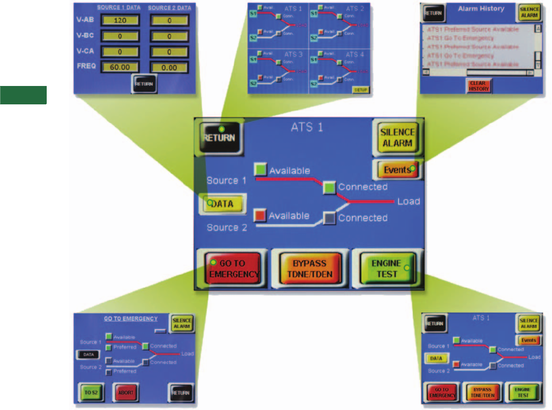
V2-T5-116 Volume 2—Commercial Distribution CA08100003E—April 2014 www.eaton.com
5
5
5
5
5
5
5
5
5
5
5
5
5
5
5
5
5
5
5
5
5
5
5
5
5
5
5
5
5
5
5.7
Transfer Sw itches
Remote Annunciator Controller
ATS Multi-Unit Screen
(ATC-300+ Only)
●Monitors source availability,
source position and alarm
status for up to four
transfer switches
●Password-protected setup
screen for transfer switch
designations
●Access to the ATS
individual unit home screen
Source Data Screen
●Monitors values for
source 1 and source 2
voltage and frequency
Alarm Screen
●Monitors all alarm
messages with the touch
of a button right from the
HMi display. Alarm
messages include:
●Source 2 closed
(audible alarm)
●Overvoltage
●Undervoltage
●Overfrequency
●Plant exerciser
●Engine test
●Remote engine test
●Voltage unbalance 1
●Phase reversal 1
●Go to emergency
●Lockout
●Failed to sync
(phase angle)
●Failed to sync
(frequency difference)
●Engine test or plant
exerciser
●Source 1 error
●Source 2 error
Engine Test Screen
●Provides password
protected control to start
and abort an engine test.
The engine test will run
according to the controller-
programmed set points for
duration and with or
without load
●Provides control to bypass
the source 1 to source 2
and source 2 to source 1
time delays
Go To Emergency Screen
(Peak Shaving)
●Provides password
protected control to force
transfer to source 2
regardless of the condition
of source 1. This feature is
failsafe, meaning the ATS
will automatically return to
source 1 in the event of a
source 2 failure
●Provides control to bypass
the source 1 to source 2
and source 2 to source 1
time delays
Note
1ATC-300+ controller only.
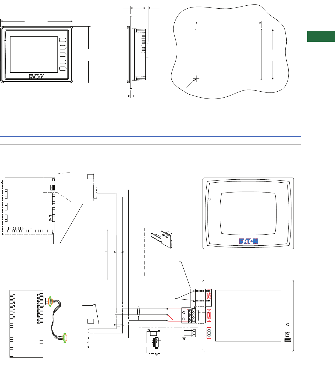
Volume 2—Commercial Distribution CA08100003E—April 2014 www.eaton.com V2-T5-117
5
5
5
5
5
5
5
5
5
5
5
5
5
5
5
5
5
5
5
5
5
5
5
5
5
5
5
5
5
5
5.7
Transfer Switches
Remote Annunciator Controller
Dimensions
Approximate Dimensions in Inches (mm)
Wiring Diagram
Catalog
Number Dimension A Dimension B Dimension C Dimension D
Dimension E
+0.04 (1.0) –0
Dimension F
+0.04 (1.0) –0 Radius R
Panel
Thickness T
HM106CU 7.25 (184.2) 5.67 (144.0) 1.54 (39.1) 0.24 (6.1) 6.67 (169.4) 5.10 (129.5) 0.12 (3.0) 0.06–0.12 (1.5–3.0)
POWER
F3
SYS
F4
F2
F1
7.25 (184.2)
5.67 (144.0)
1.54 (39.1) 0.24 (6.1)
6.67 (169.4)
5.10 (129.5)
Panel Thickness, T
R (4 Places)
Front View Side View Cutout
A
B
CD
E
F
ELC-PS02
LINE
COM
GND
HMI-(+)
HMI-(-)
+
-
GND
POWER
BLUE
WHITE
COM (GND)
COM1 COM2
DC 24V
SLAVE
HOST
SYSTEM
ELC-PSO2-24V
ELC-PSO2-0V
66A8149H01
MOUNT 9 PIN PLUG COM2 AND
CIRCUIT BOARD TO SUPPORT
BRACKET 66A8149H01 PLACE
HOLES OF CIRCUIT BOARD
OVER SCREWS LAYING
FLAT AGAINST FOAM
SECURE ASSEMBLY TO COM1
USING 2 #4 SCREWS.
NOTE: FOLLOW
WIRE DIAGRAM PER
CONTROLLER
MODEL
BLUE
WHITE
COM (GND)
BLUE
WHITE
COM (GND)
1
J2
2
J1
3
2
1
3J7
2
4
3
J4
J3
3
1
1
2
16
19
18
17
13
14
15
12
10
11
3
9
8
7
5
6
4
1
2
J5
7
4
2
1
3
6
5
10
9
12
11
13
8
20
16
17
19
18
15
14
22
21
S1 AUX CLOSE
S2 AUX CLOSE
LOCKOUT
GO TO S2
BYPASS
GO TO NEUTRAL
MANUAL
S2 INHIBIT
SHIELD
INCOM
TDNE/TDEN
RE-TRANSFER
SUBNETWORK
LOAD C PHASE
LOAD B PHASE
LOAD A PHASE
S2 C PHASE
S2 B PHASE
S2 A PHASE
S1 C PHASE
S1 B PHASE
S1 A PHASE
S1 120 Vac
S1 120 Vac
S2 120 Vac
S2 120 Vac
CONTROL
POWER
K1 S2 OPEN
K2 S1 OPEN
K3 S1 CLOSE
K4 S2 CLOSE
S1 AVAILABLE
S2 AVAILABLE
ALARM
EARTH GROUND
S1 GENERATOR
S2 GENERATOR
4
4
4
SW1
1234
B+
A-
COM
SHD
SW1
RS-485
TERMINATION
SW1
RS-485
TERMINATION
SEE NOTE: 1
SEE NOTE: 2
SEE NOTE: 3
SEE NOTE: 5
J10'
J10''
J10'''
J10
#4 SCREW
6" RAC SHOWN
OPTIONAL POWER SUPPLY
ELC-PS02
120 Vac
REMOTE ANNUNCIATOR CONTROL (RAC)
TOUCHSCREEN/DISPLAY
REAR VIEW
6
7
8
9
S
5
4
3
2
1
COM
B+
A-
MPONI
ATC-600/800
J13
CHASSIS
SHIELD
B+ 1-
A- 2-
COM 3-
SHD 4-
J10
RS-485
MODBUS
ATC-300+
SEE NOTE 4
4
3
2
1
J7
3
2
1
J1
3
2
1
J2
1
2
3
4
5
6
7
8
9
10
11
12
13
14
J5
1
2
3
4
5
6
7
8
9
10
J4
ATC-300 +
CONTROLLER
S1 SENSING INPUT
S2 SENSING INPUT
S1 CNTL
PWR INPUT
S2 CNTL
PWR INPUT
S1 INPUT
S2 INPUT
LOCKOUT
INPUT
GO TO S2
MONITOR
MODE
}
}
}
}
}
}
}
}
}
K1
K2
PRE
TRANSFER
ALARM
ENGINE
START
EARTH GND
C
B
A
C
B
A
4
3
2
1
J8
K3
K4
7
6
5
4
J3
3-Out
1-Clk
3
2
1
4-5V
2-In
6-RX
7-TX
5-Gnd
8
7
6
5
MANUAL RE-TRANSFER
S2 INHIBIT
}
}
RS485
TERMINATION
RS-485
MODBUS
GND
ATC-800
J10

V2-T5-118 Volume 2—Commercial Distribution CA08100003E—April 2014 www.eaton.com
5
5
5
5
5
5
5
5
5
5
5
5
5
5
5
5
5
5
5
5
5
5
5
5
5
5
5
5
5
5
5.8
Transfer Sw itches
kW Conversions
kW Conversion Chart
kW to Ampere Conversion Chart
Note
1At 0.8 power factor.
Three-Phase Ampere Table at Common Line-to-Line Voltage
kW 1200V 208V 220V 230V 240V 380V 400V 415V 460V 480V 600V
5.0 18171616159 9 9 8 8 6
7.5 27 26 25 24 23 14 13 13 12 11 9
10.0 36 34 33 31 30 19 18 17 16 15 12
15.0 54 52 49 47 45 28 27 26 24 23 18
20.0 72 69 66 63 60 38 36 35 31 30 24
25.0 90 87 82 78 75 47 45 43 39 38 30
30.0 108 104 98 94 90 57 54 52 47 45 36
40.0 144 139 131 126 120 76 72 70 63 60 48
50.0 180 173 164 157 150 95 90 87 78 75 60
60.0 217 208 197 188 180 114 108 104 94 90 72
75.0 271 260 246 235 226 142 135 130 118 113 90
80.0 289 278 262 251 241 152 144 139 126 120 96
100.0 361 347 328 314 301 190 180 174 157 150 120
125.0 451 434 410 392 376 237 226 217 196 188 150
150.0 541 520 492 471 451 285 271 261 235 226 180
175.0 631 607 574 549 526 332 316 304 275 263 210
200.0 722 694 656 628 601 380 361 348 314 301 241
250.0 902 867 820 784 752 475 451 435 392 376 301
300.0 1083 1041 984 941 902 570 541 522 471 451 361
350.0 1263 1214 1148 1098 1052 665 631 609 549 526 421
400.0 1443 1388 1312 1255 1203 760 722 696 628 601 481
500.0 1804 1735 1640 1569 1504 950 902 870 784 752 601
600.0 2165 2082 1968 1883 1804 1140 1083 1043 941 902 722
700.0 2526 2429 2296 2197 2105 1329 1263 1217 1098 1052 842
800.0 2887 2776 2624 2510 2406 1519 1443 1391 1255 1203 962
900.0 3248 3123 2952 2824 2706 1709 1624 1565 1412 1353 1083
1000.0 3609 3470 3280 3138 3007 1899 1804 1739 1569 1503 1203

Volume 2—Commercial Distribution CA08100003E—April 2014 www.eaton.com V2-T6-1
6
6
6
6
6
6
6
6
6
6
6
6
6
6
6
6
6
6
6
6
6
6
6
6
6
6
6
6
6
6
Low Voltage Busway
Pow-R-Way III Upward Elbow
6.1 Pow-R-Way III
Pow-R-Way III Busway
Product Description . . . . . . . . . . . . . . . . . . . . . . . . . . . . . . . . . . . . V2-T6-2
Features, Benefits and Functions . . . . . . . . . . . . . . . . . . . . . . . . . . V2-T6-12
Standards and Certifications. . . . . . . . . . . . . . . . . . . . . . . . . . . . . . V2-T6-13
Product Support . . . . . . . . . . . . . . . . . . . . . . . . . . . . . . . . . . . . . . . V2-T6-13
Catalog Number Selection . . . . . . . . . . . . . . . . . . . . . . . . . . . . . . . V2-T6-14
Product Selection . . . . . . . . . . . . . . . . . . . . . . . . . . . . . . . . . . . . . . V2-T6-15
Technical Data and Specifications. . . . . . . . . . . . . . . . . . . . . . . . . . V2-T6-20
Dimensions. . . . . . . . . . . . . . . . . . . . . . . . . . . . . . . . . . . . . . . . . . . V2-T6-26
6.2 Pow-R-Way
Pow-R-Way Busway
Product Description . . . . . . . . . . . . . . . . . . . . . . . . . . . . . . . . . . . . V2-T6-32
Standards and Certifications. . . . . . . . . . . . . . . . . . . . . . . . . . . . . . V2-T6-32
Product Selection . . . . . . . . . . . . . . . . . . . . . . . . . . . . . . . . . . . . . . V2-T6-33
Accessories . . . . . . . . . . . . . . . . . . . . . . . . . . . . . . . . . . . . . . . . . . V2-T6-35
Technical Data and Specifications. . . . . . . . . . . . . . . . . . . . . . . . . . V2-T6-35
6.3 100A Busway
100A Busway
Product Description . . . . . . . . . . . . . . . . . . . . . . . . . . . . . . . . . . . . V2-T6-37
Application Description. . . . . . . . . . . . . . . . . . . . . . . . . . . . . . . . . . V2-T6-37
Product Selection . . . . . . . . . . . . . . . . . . . . . . . . . . . . . . . . . . . . . . V2-T6-37
Options and Accessories . . . . . . . . . . . . . . . . . . . . . . . . . . . . . . . . V2-T6-38
Technical Data and Specifications. . . . . . . . . . . . . . . . . . . . . . . . . . V2-T6-39
Learn
Online
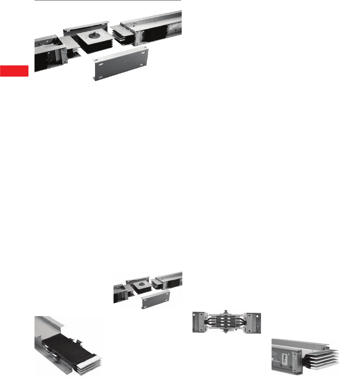
V2-T6-2 Volume 2—Commercial Distribution CA08100003E—April 2014 www.eaton.com
6
6
6
6
6
6
6
6
6
6
6
6
6
6
6
6
6
6
6
6
6
6
6
6
6
6
6
6
6
6
6.1
Low Voltage Busway
Pow-R-Way III
Pow-R-Way III Busway
Contents
Description Page
Pow-R-Way III Busway
Features, Benefits and Functions . . . . . . . . . . V2-T6-12
Standards and Certifications . . . . . . . . . . . . . . V2-T6-13
Product Support . . . . . . . . . . . . . . . . . . . . . . . . V2-T6-13
Catalog Number Selection . . . . . . . . . . . . . . . . V2-T6-14
Product Selection. . . . . . . . . . . . . . . . . . . . . . . V2-T6-15
Technical Data and Specifications . . . . . . . . . . V2-T6-20
Dimensions . . . . . . . . . . . . . . . . . . . . . . . . . . . V2-T6-26
Pow-R-Way III Busway
Product Description
Superior Housing Design
and a True Sandwich Design
Maximize Busway Performance
Eaton’s Pow-R-Way III® is
constructed with a lightweight
and durable, two-piece,
aluminum-extruded housing.
The non-ventilated housing
design excludes potential
points of penetration by
moisture or dust. Busbars for
plug-in applications have full-
sized conductor tabs welded
by a fully automated state-of-
the-art welding process. This
design extends the contact
surfaces outside of the
busway housing and into
the plug-in outlet. The benefits
of the true sandwich design
for both plug-in and feeder
busway include improved
coordination and heat
dissipation, better bracing
and the elimination of the
“chimney effect.”
Cut-Away Section of Plug-In Busway
Epoxy Insulation Provides
Exceptional Performance
The phase and neutral bars
are insulated with Class B,
130°C, epoxy insulation
applied by an automated
fluidized bed process. This
application insulates the
conductors in a precise and
controlled manner to ensure
smooth, continuous, high
quality protection. Following
the epoxy insulation process,
all contact surfaces are
silver-plated to provide
an extremely durable
connection. Tin-plating
is also an option.
Indoor Joint Assembly
Pow-R-Way III Bridge Joint
Reduces Installation Time and
Provides Flexibility for Future
Modifications
Pow-R-Way III joint
connections are made with
the rugged Pow-R-Bridge
joint package. A Pow-R-
Bridge is installed on each
section of busway prior
to shipment. Job site
connections are made quickly
by releasing the bridge joint
bolt, moving the next section
into place, and retightening
the bolt. Torque-indicating,
double-headed bolts with
fall-away instruction tags
are provided to ensure that
proper installation torque is
achieved. The Pow-R-Bridge
provides an adjustment
in section length of up to
±0.5-inch (12.7 mm) at
each joint.
Bridge Joint Assembly
Pow-R-Way III Offers Grounding
and Neutral Options to Meet
Every Customer Preference
and Need
The aluminum housing is
UL listed as a 50% integral
ground path and is provided
as a standard, economical
ground system. A 50%
internal ground bar is also
available. In certain industrial
applications, a ground path
greater than 50% may be
required. Pow-R-Way III can
solve this problem in a cost-
efficient manner through
combining the 50% integral
housing ground with the
50% internal ground. To meet
the growing demand for
grounding isolation,
Pow-R-Way III also offers
a 50% isolated ground
bar. When customers are
concerned about harmonics
and overheating generated
by nonlinear loads, Pow-R-
Way III provides a solution
through a fully rated 200%
capacity neutral bar.
Joint End
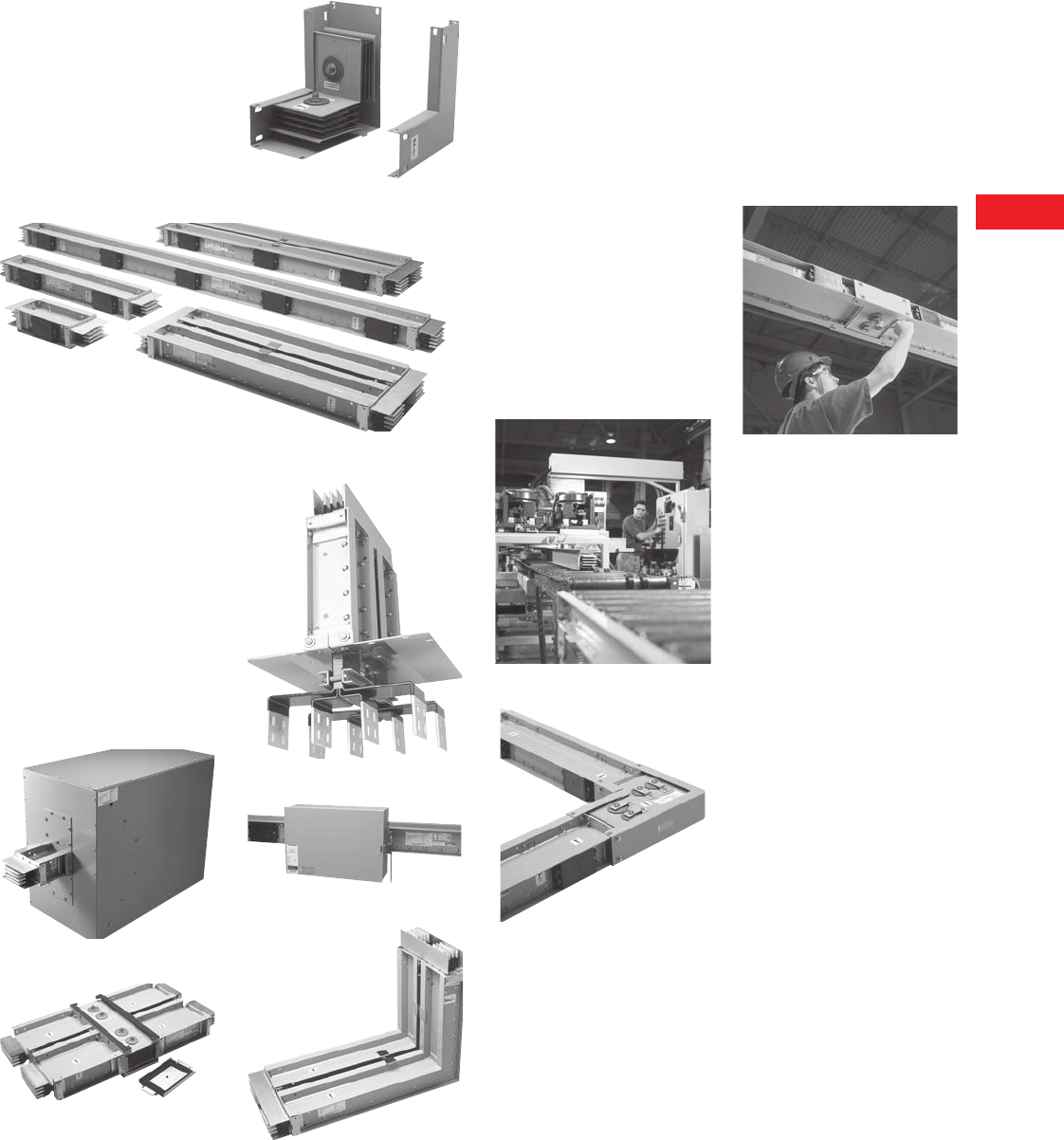
Volume 2—Commercial Distribution CA08100003E—April 2014 www.eaton.com V2-T6-3
6
6
6
6
6
6
6
6
6
6
6
6
6
6
6
6
6
6
6
6
6
6
6
6
6
6
6
6
6
6
6.1
Low Voltage Busway
Pow-R-Way III
A Space-Saving Innovation—
The Corner Joint Elbow
The Pow-R-Way III corner
joint combines the features of
the Pow-R-Bridge with
reduced elbow leg lengths.
Due to its compact design,
the corner joint allows for
layouts that provide optimum
use of space and increases
available plug-in openings.
Upward Corner Joint
Straight Lengths
A Complete Line of Fittings for
Indoor and Outdoor Applications
Pow-R-Way III offers an
extensive range of fittings to
meet every application need.
Flanges, elbows, end cable
tap boxes and end closers are
used in basic busway routing.
For more complex layouts,
combination elbows and
offsets can be used along
with transformer throats,
vault flanges, reducers and
expansion joints.
End Cable Tap Box
Outdoor Joint Assembly
Standard Switchboard Flange
Plug-In Unit
Upward Elbow
Enhanced Bus Plug Design
Facilitates Installation and
Improves Safety
Pow-R-Way III plug-in
protective devices are
available in circuit breaker and
fusible switch designs.
Standard features include:
oversized enclosures,
extended ground and neutral
bars, line side barriers, bus
plug alignment pin, busway
interlock and improved clamp
and guides.
Advanced bus plugs provide
protection, communication
and coordination capabilities
using the
Visor™ Series (SPD),
Energy Sentinel™
, Digitrip™
IQ OPTIM™, Advantage™
motor control components
and receptacle plugs.
Final Busway Assembly
Rearward Corner Joint Assembly
High 6-Cycle Short-Circuit
Ratings Optimize Coordination
Between Busway and Power
Equipment and Meet High
Quality Standards
All ratings of Pow-R-Way III
have been tested to 6-cycle
standards and have achieved
a minimum rating of 85 kA
and a maximum rating of
200 kA rms symmetrical.
Typical Busway Installation
(Torque Indicating Bolt)
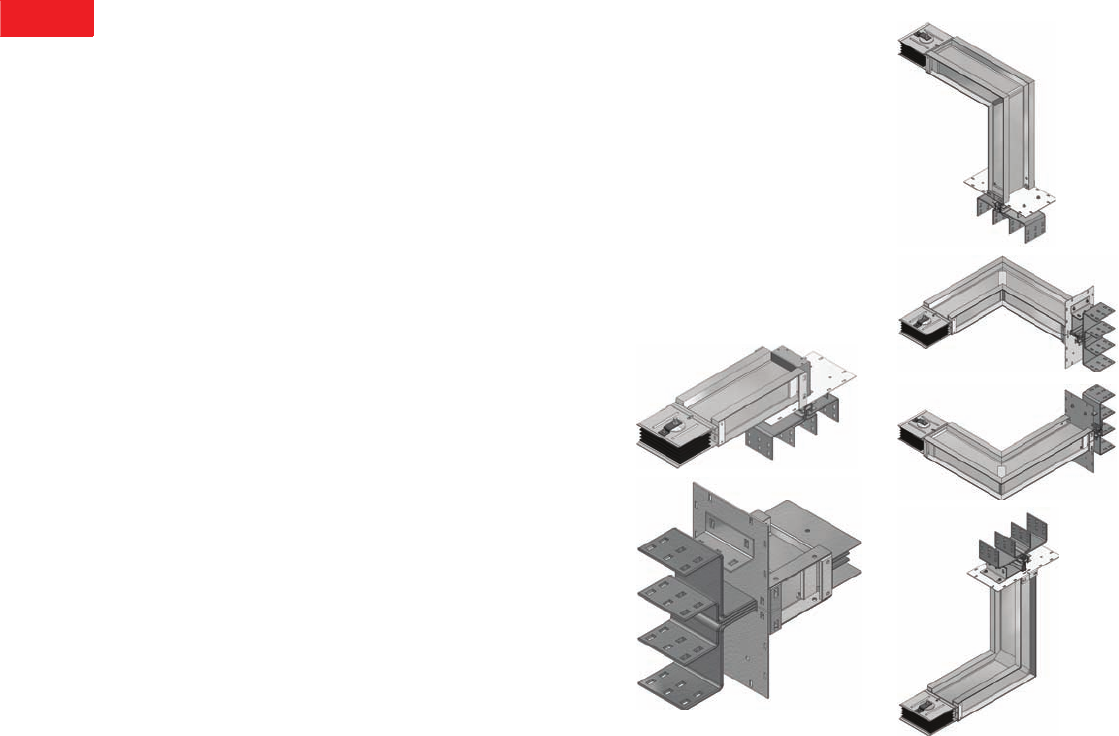
V2-T6-4 Volume 2—Commercial Distribution CA08100003E—April 2014 www.eaton.com
6
6
6
6
6
6
6
6
6
6
6
6
6
6
6
6
6
6
6
6
6
6
6
6
6
6
6
6
6
6
6.1
Low Voltage Busway
Pow-R-Way III
General Information
●Determine the total
footage, all fittings and
accessories for entire
busway run. Price the
total footage by type and
system requirements.
Round footage up to the
nearest foot. Add the
fabrication charge for the
fittings. Add any additional
accessories required for
the total price of the
busway run
●See NEC 364.11 for
Reducer Application
●Fusible reducers are
600V maximum; fuses
are not included
Transformer Connections
●Transformer tap bus
extensions do not include
drilling or lugs
●Transformer throats include
flexible connectors
Commercial Metering
Connections
●For use with 33MM,
37MM and 37SS meter
stack modules; order
separately
●Main breaker units
include circuit breaker
and trip units
●1200A or greater main
devices must be center
fed when installing 800A
residential meter sockets
and 1200A commercial
meter sockets
●Spacer kit 3MMBSK may
be required when stacks
are mounted on right-hand
side in EUSERC areas
●Class T fuse clips only;
fuses not included
●Compatible with indoor
corner elbow accessory
3MMEB12 and 3MMEB16
●In-line metering PTO with
no overcurrent protection
should only be used with
six meter sockets/tenant
main circuit breakers
or less, or applied per
local code
Plug-In
●Straight sections of plug-in
busway are available in
2 ft (0.6m) increments
from 2 ft (0.6m) minimum
to 10 ft (3m) maximum.
Pow-R-Bridge joint
is included
Sprinkler-Proof Plug-In
●For sprinkler-proof plug-in,
multiply the plug-in price by
1.15 and use outdoor
pricing for the feeder
busway
Feeder
●Straight sections of feeder
busway are available
in 1/8-inch (3.2 mm)
increments from 16 inches
(406 mm) minimum to
10 ft (3m) maximum.
Pow-R-Bridge joint is
included. Busway must
carry at least a 50% load
in all outdoor applications
Hangers/Pow-R-Bridge
●The busway price includes
one horizontal hanger per
10 ft (3m) of busway and
one Pow-R-Bridge joint per
connection. All vertical
hangers and any additional
horizontal hangers should
be added to the total price
Ground
●A 50% integral housing
ground is provided as
standard. The housing
ground can be used in
combination with the
internal ground or the
isolated ground to achieve
a 100% ground rating
Standard and Flush Flanges
Flanges provide a direct
connection to low voltage
switchgear, switchboards,
motor control centers and
other apparatus. Cutout
dimensions and drilling
plans are provided with the
customer drawings, and it
is the responsibility of the
switchgear manufacturer
to provide the opening,
flange drillings, connecting
hardware and bus risers
in their equipment. For
proper coordination between
busway and other equipment,
detailed drawings, including
switchgear orientation,
must accompany the order.
A standard flange can be
supplied to the left or right
of a section, as required.
A flush flange is used when
the busway must lay close
to the top of a switchboard.
The edge of the busway is
1.25 of the switchboard.
Elbow Flanges
An elbow flange is a
combination of a standard
elbow and a standard flange
fabricated into a single fitting.
Elbow flanges are typically
used when the minimum
leg lengths for either the
standard elbow or the
standard flange cannot
be maintained.
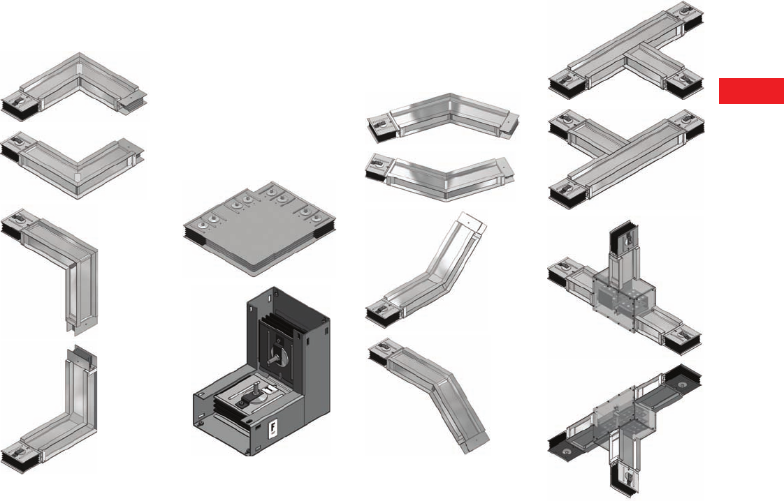
Volume 2—Commercial Distribution CA08100003E—April 2014 www.eaton.com V2-T6-5
6
6
6
6
6
6
6
6
6
6
6
6
6
6
6
6
6
6
6
6
6
6
6
6
6
6
6
6
6
6
6.1
Low Voltage Busway
Pow-R-Way III
Traditional Indoor and
Outdoor Elbows
Elbows are used to make
90° changes in the direction
of busway runs. The four
types that are available are
forward, rearward, upward
and downward.
Corner Joint Elbows
The Pow-R-Way III corner
joint elbow can be installed
in areas where a traditional
90° turn could never have
been accomplished before.
Pow-R-Way III corner
joint elbows can solve any
serious pathway problem
and contribute to successful
layouts with minimal space
requirements. The corner joint
elbow is UL listed for indoor
applications only and
is also certified for seismic
withstand capability to
worst-case, Zone 4 levels.
For Indoor Use Only
Special Angle Elbows
Special angle elbows are
traditional elbows that allow
the direction of the busway
runs to change at angles
greater than 90°. They allow
easy routing through non-
traditional corridors. The
four types offered are
forward, rearward,
upward and downward.
Tees
A tee is a busway fitting
suitable for connection in
three directions.
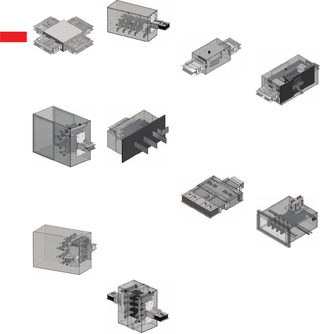
V2-T6-6 Volume 2—Commercial Distribution CA08100003E—April 2014 www.eaton.com
6
6
6
6
6
6
6
6
6
6
6
6
6
6
6
6
6
6
6
6
6
6
6
6
6
6
6
6
6
6
6.1
Low Voltage Busway
Pow-R-Way III
Crosses
A cross is a busway fitting
suitable for connection in four
directions. It is applied when
a bus run must branch off in
three directions, all in the
same plane.
End Cable Tap Box
End cable tap boxes are used
to feed a run of busway with
cable and conduit or where
loads served by busway are
connected without the need
for overcurrent protection.
Center Cable Tap Box
Center cable tap boxes are
used to center feed a run
of busway with cable and
conduit or where loads
served by the busway are
connected without the need
for overcurrent protection.
Weatherheads
Weatherheads are used for
service entrance connections
to busway.
Vault Flanges
Vault flanges are used to
enter a utility vault for
termination to the utility
transformer. Each vault
flange is custom designed
to meet each specific utility
specification. Vault flanges
may look similar to those
shown in figure below.
Expansion Joints
Expansion joints
accommodate the expansion
and contraction of busbars
with respect to the enclosure.
They compensate for the
difference in the coefficient
of expansion of the aluminum
housing and the copper or
aluminum busbars. Expansion
joints must be used wherever
a run of busway crosses an
expansion joint of a building.
They should also be installed
in the center of extremely long
straight runs of busway; one
every 300 ft (91m) for copper
or one every 225 ft (68m) for
aluminum.
Phase Transpositions
Phase transposition fittings
are used in applications
where a phase rotation is
needed due to a change in
phasing from the source
equipment to the load
equipment. Both 90° and
180° rotations are possible.
In each case, all conductors
are rotated.
Non-Protected Reducers
Non-protected reducers are
used to reduce the ampacity
of the busway without
overcurrent devices. Per
NEC Section 364.11, for
industrial applications, no
overcurrent protection is
required where the busway
is reduced in size, provided
the length of the smaller
busway does not extend
more than 50 ft (15.2m)
and has a current rating of
at least one-third of the first
upstream overcurrent device.
Protected Reducers
Protected reducers are used
to reduce the ampacity of
busway using either a circuit
breaker or a fused, non-
automatic circuit breaker
overprotection device. Both
serve as a disconnecting
means. The line side of the
cubicle is connected to the
higher rated busway and
the load side is connected
to the lower (reduced)
rated busway.
Transformer Throat Connections
A transformer throat is used
when making connections
to a liquid-filled substation
transformer. All transformer
throat connections include
flexible connectors between
the transformer low voltage
spades and Pow-R-Way III
busbars. For transformers
with drilled flanges, the
busway will bolt to the
transformer throat instead
of using a sealing ring.
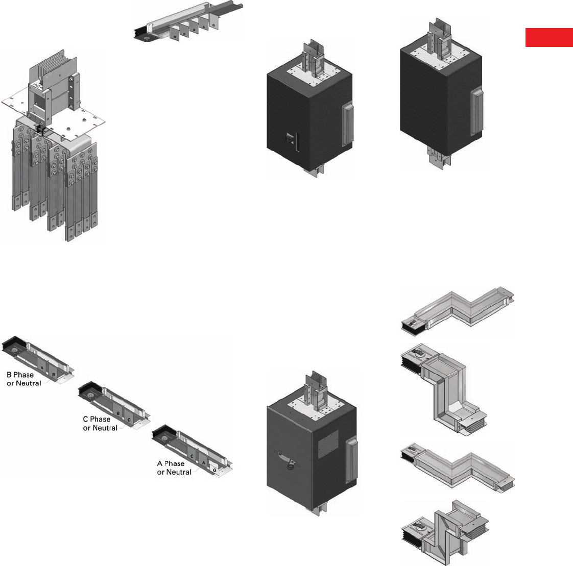
Volume 2—Commercial Distribution CA08100003E—April 2014 www.eaton.com V2-T6-7
6
6
6
6
6
6
6
6
6
6
6
6
6
6
6
6
6
6
6
6
6
6
6
6
6
6
6
6
6
6
6.1
Low Voltage Busway
Pow-R-Way III
Transformer Flange Connections
Transformer flange
connections are used
when making a connection
to a dry-type substation
transformer. Transformer
flange connections include
flexible connectors between
the transformer low
voltage spades and the
Pow-R-Way III flange
busbars.
Single-Phase Transformer Taps
Single-phase transformer
taps arrangements are used
for connections to three
single-phase transformers.
The bus extensions do not
include drilling or lugs.
Three-Phase Transformer Taps
Three-phase transformer
taps are used when making
connections to a three-
phase transformer. The bus
extensions do not include
drilling or lugs.
In-Line Power Takeoff
Main Circuit Breaker PTO
The in-line main circuit
breaker PTO shown in figure
to the left is available with
trip ratings from 300A up to
1200A; using L-, M- and
N-Frame circuit breakers.
This device is indoor rated
and may be sprinkler-proofed
upon request.
Main Fusible Switch PTO
The in-line main fusible
switch PTO shown in figure
to the left is available with
400, 600 and 800A switches;
using Class “T” fuses.
This device is indoor rated
only. The switch handle is
mounted in front, eliminating
interference with the meter
sockets and the need for
spacers between the main
device and the meter stack.
It comes with a hinged door,
giving easy access to the
fuses mounted below the
main switch.
Unprotected PTO
The in-line PTO with no
main device shown in figure
to the left comes with
1200A horizontal cross bus
as standard. This device is
intended for use with six or
fewer meter sockets, or as
local code permits.
Offsets
An offset is used to avoid
obstacles and to conform
to the building’s structure.
It is two elbows fabricated
into a single fitting for use
where space restrictions
prohibit the use of two
standard 90° elbows.
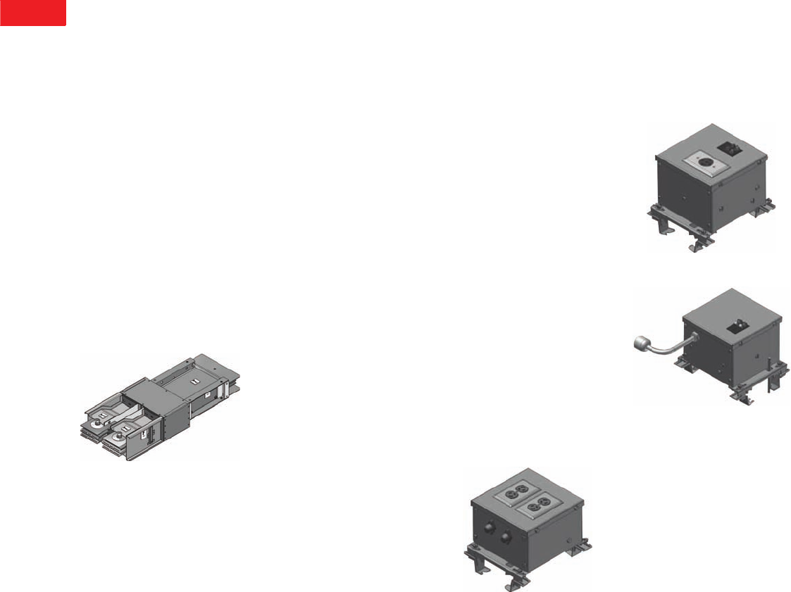
V2-T6-8 Volume 2—Commercial Distribution CA08100003E—April 2014 www.eaton.com
6
6
6
6
6
6
6
6
6
6
6
6
6
6
6
6
6
6
6
6
6
6
6
6
6
6
6
6
6
6
6.1
Low Voltage Busway
Pow-R-Way III
Pow-R-Way III Adapters
A complete line of adapters
are available to enable the
user to add to existing old-line
Westinghouse® or obsolete
Cutler-Hammer® bus runs
with the Pow-R-Way III
design. The specific
Westinghouse product lines
are low impedance busway,
current-limiting busway, Pow-
R-Way and Pow-R-Way II.
The obsolete Cutler-Hammer
designs are CP2, CP3 and
CP4 Safetybus.
The adapters allow the
incorporation of present-
day technologies, available
in Pow-R-Way III plug-in
units, into existing busway
systems. State-of-the-art
features such as energy
monitoring, transient voltage
surge suppression and
coordination/communication
capabilities can all be added
to existing distribution
systems without having to
upgrade and replace entire
runs of busway.
Special adapters to
competitive busway products
are also available. Please
contact the Greenwood
factory for information.
Power Where You Need it!
As a leader in providing quality,
robust, cutting-edge electrical
distribution equipment, Eaton
understands the importance
of providing usable power
access in a variety of
applications. Eaton’s Pow-R-
Way III busway continues to
offer electrical distribution
solutions that are flexible and
without limitations, and are
energy efficient, saving time
and money.
Pow-R-Way III Receptacle
Plug-In Units
Eaton now offers a full line
of receptacle plug-in units
for use on Pow-R-Way III
busway. Pow-R-Way III
receptacle plug-in units come
fully assembled and wired,
reducing installation time.
They are UL listed and offer
a complementary line of
accessories. Eaton’s unique
design makes them the
most flexible receptacle
units in the industry.
Data Centers—Data racks
continue to process more
information at higher speeds
with constantly changing
demands. Pow-R-Way III
receptacle plugs offer the
highest ampere ratings in
the industry. Busway and
receptacle plugs above
the data racks provide faster
installation, faster connectivity,
easier rack changes and
upgrades, and will run cooler
than traditional cable methods.
Retail—As retail
environments change
meeting customer demands,
Pow-R-Way III busway and
receptacle plugs help make
floor layout and display
changes easier. Receptacle
plugs allow for easy power
access, eliminating costly
conduit and cable work.
Schools and Laboratories—
Pow-R-Way III receptacle
plugs offer safe power
access for instrumentation
and other lab equipment at
the point of use.
Machine Shops—
Pow-R-Way III busway and
receptacle plugs offer quick
power connection for shop
equipment and make it easy
to change shop layouts as
demands change.
Light Industrial—
Pow-R-Way III busway
and receptacle plugs help
make manufacturing and
assembly lines more flexible.
Receptacle plugs bring easy
power access for tools and
equipment being used on
the lines.
For application and layout
assistance, and for additional
information, please contact
your local Eaton sales office
or Eaton authorized
distributor.
Fused Duplex Receptacle
Plug-In Unit
These units allow you
to quickly add standard
receptacle power and come
with the following features:
●Two fix-mounted
NEMA 5-20R or L5-20R
duplex receptacles
●Fuse protection for each
duplex receptacle
●120V maximum,
single-phase
Fix-Mounted Duplex Receptacle
Single Receptacle Plug-In Unit
These units are configured
to order based upon the
type and size of receptacle
ordered, and offer the
following features:
●One single or duplex
receptacle. Straight blade
or twist lock, 5–30A
●240V maximum,
single-phase
●Type CH single-pole or
two-pole circuit breaker
protection
●Receptacles can be fix-
mounted or cord-mounted
●Cord lengths are 1–25 feet
in 1-foot increments
Fix-Mounted Single Receptacle
Cord-Mounted Single Receptacle
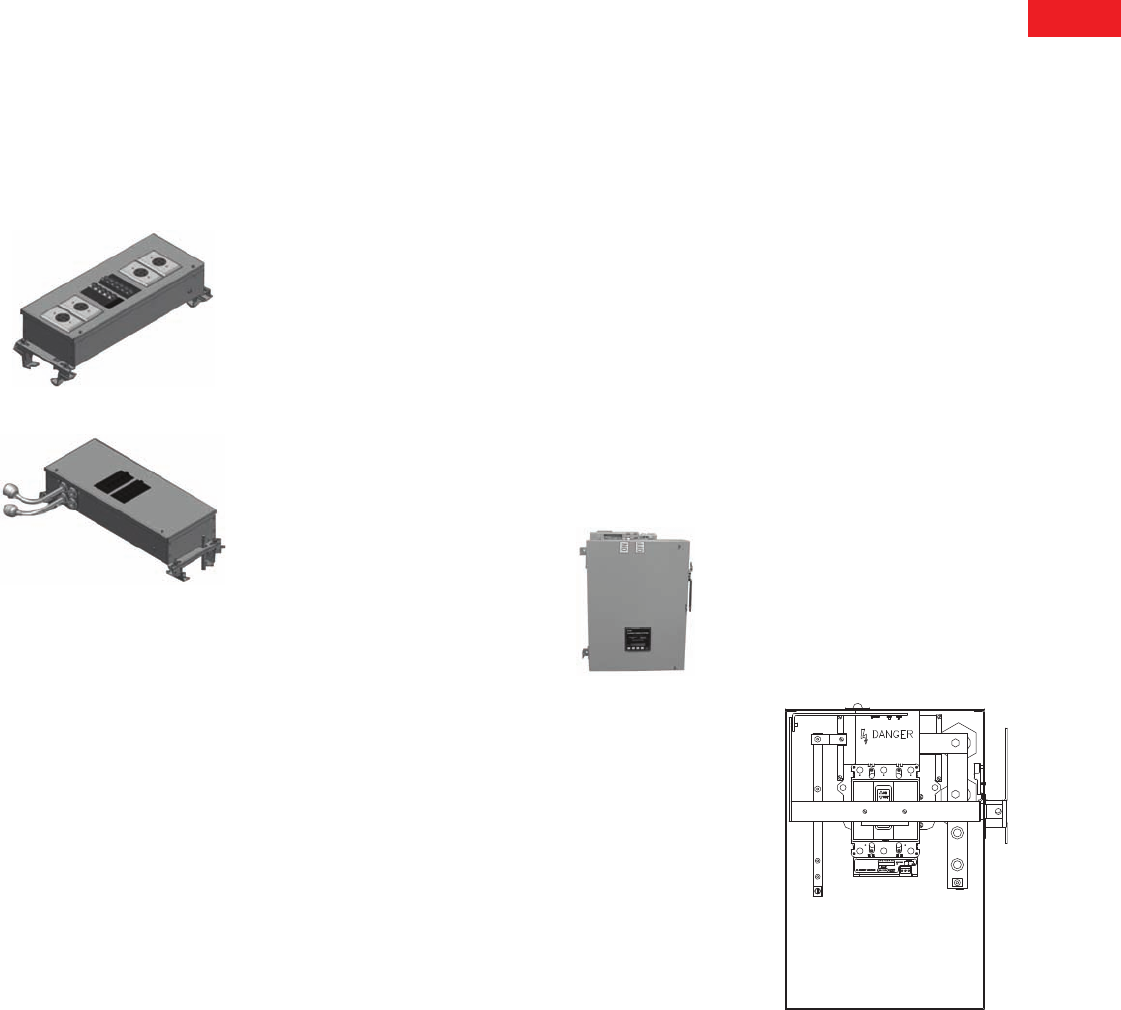
Volume 2—Commercial Distribution CA08100003E—April 2014 www.eaton.com V2-T6-9
6
6
6
6
6
6
6
6
6
6
6
6
6
6
6
6
6
6
6
6
6
6
6
6
6
6
6
6
6
6
6.1
Low Voltage Busway
Pow-R-Way III
Quad Receptacle Plug-In Unit
These units are configured
to order based upon the
quantity, type and size of
receptacles ordered. Any
combination of receptacles
can be ordered and offer the
following features:
●Two to four receptacles.
Any combination and
size of standard NEMA
configured receptacles
●240V maximum,
three-phase
●Type CH single-pole, two-
pole or three-pole circuit
breaker protection
●Receptacles can be fix-
mounted or cord-mounted
●Cord lengths are 1–25 feet
in 1-foot increments
Fix-Mounted Quad Receptacle
Cord-Mounted Quad Receptacle
SPD Plug-In Devices
The Pow-R-Way III plug-in
device product offering
includes a surge protective
device (SPD) that is ideal for
busway fed distribution
systems. A transient voltage
is a random, high-energy,
short duration electrical
anomaly. These high-energy
surges can disrupt, damage
or destroy sensitive
microprocessor-based
equipment. Eaton has
developed the SPD family
of products to ensure that
quality power is supplied
to commercial, industrial,
medical and institutional
facilities.
The SPD not only protects
against externally created
impulse transients such as
lightning, utility capacitor
switching and disturbances
emitted by adjacent facilities,
but it also provides needed
protection against internal
transients. This type of
transient is generated within
a facility’s own distribution
system. Sources of internally
generated or ringwave
transients are imaging,
equipment, variable
frequency drives, lighting
dimmers, arc welders, and
the switching on and off of
electrical distribution
equipment. It is estimated
that more than 80% of surge
disturbances are actually
caused by internal transients.
The SPD also filters repetitive
electrical line noise (EMI/RFI),
which is defined as any
unwanted electrical signal
that produces undesirable
effects in the circuits of
sensitive electronic
equipment or disturbances
that are two times peak
voltage. The suppression
of AC transients is
accomplished through the
use of metal oxide varistors
(MOVs) that provide a low
impedance path to divert
surges away from loads.
Electrical line noise and
ringing transients are
eliminated by adding filtering
capacitors to the suppression
device.
Not all SPD units on the
market have filtering
capabilities. The benefits of
combining SPD and filtering
are reduced MOV stress,
resulting in a longer life cycle,
lower let-through voltage,
better noise attenuation
levels and increased
reliability.
Without protection devices,
electronic-based loads and
microprocessors are not
provided with the noise- and
disturbance-free power that
they require. Because
microprocessors are now
common in those facilities,
specifiers must ensure that
the AC power supply is
properly filtered. Significant
performance advantages are
achieved by integrating SPD
filters into busway systems.
Because the SPD unit is
directly connected to the
busway it is able to minimize
let-through voltage and to
isolate critical loads that are
fed from a protected busway
run. Due to the integrated
design, the SPD bus plug
saves the user-needed wall
space and greatly reduces the
installed project cost. The
SPD bus plug is furnished
with a breaker disconnect.
SPD Bus Plug
IQ Energy Sentinel
Bus Plugs
The IQ Energy Sentinel is a UL
listed microprocessor-based
metering module capable of
communicating energy usage
and demand values over
Eaton’s PowerNet™ power
monitoring network. These
innovative submetering
devices are designed to
mount-directly to Series C®
molded-case breakers
through 400A and are
available for universal
mounting through 2500A.
It offers a centralized
alternative to individually
mounted wattmeters, watt-
hour meters and watt-demand
meters. Key advantages
include unmatched savings
in space, lower installation
costs, and the capability to
communicate data readings in
a variety of ways. IQ Energy
Sentinels with built-in CTs
and communication capability
have the added benefit of
overall system accuracy.
The Energy Sentinel mounts
on the load side of Eaton
F-, J- and K-Frame breakers
within the bus plug enclosure.
The Energy Sentinel is also
available for fusible plug-in
units, which use external CTs
within the plug-in enclosure.
Submetering application
examples for the Energy
Sentinel include energy
monitoring and demand
management, energy cost
analysis/allocation and tenant
or interdepartmental billing.
To accomplish the
communication system,
the customer must provide
a twisted pair communication
cable in 1/2-inch (12.7 mm)
conduit connecting the IQ
Energy Sentinel to an Eaton
Central Energy Display (CED)
or a customer PC to display
and collect the information.
The IQ Energy Sentinel
offers the user full energy
monitoring capability in a
compact, cost-effective
module ideally suited to
busway application.
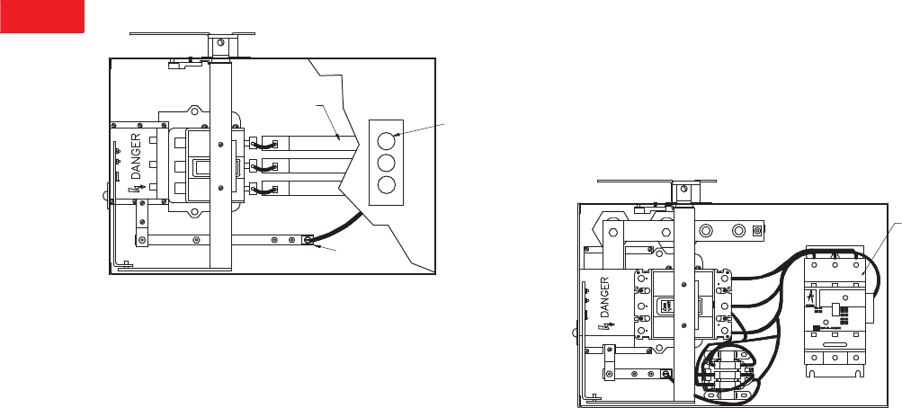
V2-T6-10 Volume 2—Commercial Distribution CA08100003E—April 2014 www.eaton.com
6
6
6
6
6
6
6
6
6
6
6
6
6
6
6
6
6
6
6
6
6
6
6
6
6
6
6
6
6
6
6.1
Low Voltage Busway
Pow-R-Way III
Ground Detector/Neutralizer Bus Plug
In rare cases, busbars in
a busway system pick up
static electricity. In order
to discharge this potential,
a neutralizer and a ground
detector bus plug is available.
The unit has three 18,000 ohm
resistors connected between
the busbars and the ground.
Static electricity is discharged
through these resistors.
A neon lamp is wired in series
with the busbar and part of
the resistor and burns
continuously. If there is a
ground anywhere on the
system of a lower resistance
than the path through the
lamp, the lamp will go out,
indicating that there is a short
in the system.
Cover
(Cutaway)
18,000 Ohm
Resistors (3)
Ground
Indicating
Lamp (3)
Ground
Connection
Combination Starter Bus Plugs
Eaton’s Freedom™ and
Advantage™ motor starters
are included in the Pow-R-
Way III bus plug product
offering. Freedom motor
starters offer state-of-the-art
features that ensure greater
value, flexibility and
performance in the toughest
commercial and industrial
applications.
Advantage motor starters
have features including a
solid-state, heaterless
overload relay with built-in
ground fault protection.
Advantage also features
communication capabilities
and an on-board micro-
processor that controls
the contactor magnet to
eliminate burnout in low
voltage or varying control
circuit conditions.
Plug-in combination starters
or contactors are mounted
in enclosures identical to the
circuit breaker and fusible
switch type bus plugs
including the clamp and
guides, safety interlocks
and guide pin. They are
available from size 0 through
5 with a circuit breaker, motor
circuit protector or fusible
disconnect. Contact Eaton
for specific application and
outline dimensions.
Advantage
Starter
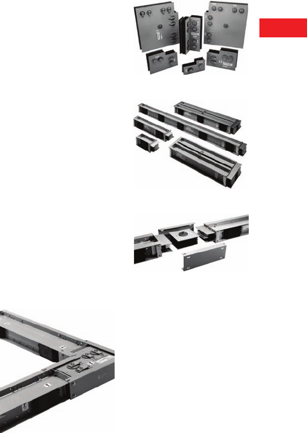
Volume 2—Commercial Distribution CA08100003E—April 2014 www.eaton.com V2-T6-11
6
6
6
6
6
6
6
6
6
6
6
6
6
6
6
6
6
6
6
6
6
6
6
6
6
6
6
6
6
6
6.1
Low Voltage Busway
Pow-R-Way III
Pow-R-Way III Express Bus
Eaton continues to be a
leader in providing service
and product solutions to its
customers. When you need a
complete run of busway fast
to get critical electrical loads
running or meet time-
sensitive deadlines, Express
Bus is the solution.
Product Offering
●Indoor plug-in busway:
●800–2500A copper and
800–2000A aluminum
●Indoor feeder busway:
●800–2500A copper and
800–2000A aluminum
●Corner joints:
●Forward (right)
●Rearward (left)
●Upward
●Downward
●Tap boxes:
●End tap box
●Plug-in tap box
●Bus plugs:
●Fusible
●Circuit breaker
●Accessories:
●End closer
●Wall/floor flange
●Hangers
Program Highlights
Eaton will ship 12 total pieces
of busway in 5 working days
or 24 total pieces in 10
working days after receipt of
released order. Total pieces
are inclusive of end tap boxes
and corner joints.
For pricing, special requests
or needs, please contact your
local Eaton sale office.
Plug-in units and additional
hangers are stocked and
available in the warehouse.
How the Program Works
By using the form provided,
it’s quick and as easy as
1-2-3.
1. Write in the catalog
numbers and quantities
of the pieces needed.
2. Write in and extend the
pricing. Obtain net
multipliers from your
local sales office.
3. Fax in the order sheet
with a copy of your
purchase order.
Once received, your order will
be entered in the system and
shipped within 5 to 10
working days based upon the
number of pieces ordered.
Feeder and plug-in indoor
busway with copper
conductors are available in
10-feet and 6-feet lengths.
They can be used
interchangeably without the
use of special adapters or
special splice plates, provided
they are the same current
and system rating.
Pow-R-Way III is constructed
with a lightweight and
rugged, two-piece all-
aluminum extruded housing,
which is rated as a 50%
ground path.
Copper busbars for plug-in
applications have full-sized
conductor tabs welded to
their side edges to form the
plug-in contact surfaces. Tabs
are the same exact thickness
as the conductors and are
fully rated up to 800A.
Corner Joint Elbows
When it comes to bends
and turns in a bus run, the
Pow-R-Way III corner joint
is the most compact elbow
in the industry. Given the
complexity of today’s
industrial and commercial
distribution systems and the
need to coordinate layouts
with HVAC, plumbing and
lighting requirements,
space quickly becomes
a critical factor.
The Pow-R-Way III corner
joint elbow can be installed
in areas where traditional
90-degree elbows could
never have been
accomplished before.
Due to its compact design,
the corner joint also allows
for layouts that provide
optimum utilization of space.
Critical section length that
would normally be required
for a traditional elbow leg
length can now be dedicated
to maximizing usable plug-in
section length.
The corner joint is as reliable
as traditional elbows. It is
seismic certified and exceeds
the requirements of both the
UBC and CBC (Zone 4). The
corner joint is UL listed for
indoor applications.
Corner Joint Elbows
Fittings and Accessories
End cable tap boxes are
available for all ratings in the
Express Bus program. One
horizontal hanger will be
included for every 10 feet of
busway. Please specify
flatwise or edgewise.
Corner Joint Elbows
Plug-In and Feeder Busway
Pow-R-Bridge Assembly

V2-T6-12 Volume 2—Commercial Distribution CA08100003E—April 2014 www.eaton.com
6
6
6
6
6
6
6
6
6
6
6
6
6
6
6
6
6
6
6
6
6
6
6
6
6
6
6
6
6
6
6.1
Low Voltage Busway
Pow-R-Way III
Features, Benefits and Functions
Pow-R-Way III Offers a Full Line
of Low Voltage Busway to Meet
the Needs of the Global
Marketplace
Eaton has combined the
requirements of NEMA, UL,
CSA and IEC into one design
to present a world-class
product in Pow-R-Way III.
With standard features that
include a two-piece aluminum
housing, finger-safe plug-in
outlets, an integral ground
path and high 6-cycle short-
circuit withstand ratings,
Pow-R-Way III provides a
busway system that can be
used over a broad spectrum
of industrial, commercial and
institutional applications
worldwide.
Product Offering
●Plug-In Busway
225–5000A copper and
225–4000A aluminum
straight sections of plug-in
busway are available in
2 ft (0.6m) incremental
lengths from a 2 ft (0.6m)
minimum to 10 ft (3m)
maximum. Plug-in busway
is also available as
sprinkler proof
●Feeder Busway
225–5000A copper and
225–4000A aluminum
straight sections of
indoor and outdoor feeder
busway available in any
length in 1/8-inch (3.2 mm)
increments from a 16-inch
(406 mm) minimum to a
10-foot (3m) maximum.
A wide range of fittings
are available in indoor
sprinkler-proof, or
outdoor feeder busway
●Plug-In Units
A full family of busway
plug-in units is available.
Standard plug-in units
include fusible or circuit
breaker protection.
Advanced plug-in units
include Visor Series
surge suppression,
communicating IQ Energy
Sentinel and OPTIM circuit
breakers, and Advantage
combination contactors
and starters. A full line
of receptacle plug-in units
are available
Product Features and Benefits
●The all-aluminum two-
piece housing provides
durability and product
integrity
●The lightweight and
compact design results
in easy installation
●The housing combined
with a true sandwich
design in both plug-in
and feeder busway
contributes to improve
coordination and high
short-circuit ratings
●An epoxy insulation
process ensures optimum
conductor and system
protection
●Silver-plated joint and
contact surfaces provide
high-quality connections
●Highly automated
manufacturing processes
result in a superior product
●The Pow-R-Bridge joint
package and torque
indicating bolt gives a
rugged, yet flexible and
easy-to-install connection
●Corner joint elbows
contribute to successful
layouts and minimize space
limitations
●High 6-cycle short-
circuit ratings optimize
coordination between
busway and power
equipment
●This world-class product
design and manufacturing
meets the requirements of
NEMA, CSA, Seismic and
ISO® and IEEE®
●Plug-in busway design and
an enhanced bus plug-in
unit facilitates installation
and improves safety
●Flexible ground and neutral
options provide solutions
for any application problem
●A full family of plug-in
units is available for every
power need
●Advanced bus plugs
provide protection,
communication and
coordination capabilities
Busway Capabilities
●The busway manufacturing
plant in Greenwood, SC,
is able to meet your
emergency or quick ship
requirements with quick
ship lead-times from
3 days to 2 weeks
●Customer approval
drawings can be available
in 2 weeks or less to meet
your project requirements
●Eaton’s final field fit
program ensures accurate
layout and allows for minor
last-minute modifications
during installation
●Advanced system tools
including Bid Manager™
programs provide quick
and accurate product
information
Volume 2—Commercial Distribution CA08100003E—April 2014 www.eaton.com V2-T6-13
6
6
6
6
6
6
6
6
6
6
6
6
6
6
6
6
6
6
6
6
6
6
6
6
6
6
6
6
6
6
6.1
Low Voltage Busway
Pow-R-Way III
Standards and Certifications
●Pow-R-Way III meets the
requirements of NEMA,
UL 857, CSA C22.2 No. 27-
94, IEEE, ANSI, IEC 439-1
and 2, IEC 529 and is
manufactured in an
ISO 9001 certified facility
●Pow-R-Way III meets the
International Building Code
standards and is certified
in the Uniform Building
Code® and the California
Building Code to exceed
Zone 4 requirements
●ANSI, NEMA, IEEE, CSA,
UL 857
●10 kAIC rms symmetrical
●Fused duplex—40A
maximum
●Single—70A maximum
●Quad—125A maximum
Product Support
Busway product and
application support is
available from a professional
team of Eaton employees
that includes field sales
engineers, application
engineers, engineering
service systems and the
greenwood busway product
engineering services.
Additional Programs
Final Field Fit—This program
was established to effectively
manage the dimensional
uncertainties that are often
inherent in bus duct layouts.
This program provides the
assurance of an exact fit the
first time. It allows for bus
duct runs to be released for
manufacture when certain
dimensions are not yet
determined. It also eliminates
the costly delays that can
occur when sections have
to be remade in order to
accommodate last-minute job
site changes in routing. For
program details, please see
publication SA01702001E.
Field Measurements—
For larger and more complex
projects, Eaton will provide
factory assistance with
taking busway layout
measurements. We will
take full accountability of all
measurements and will
ensure an exact fit. Contact
your local Eaton sales office
for pricing and availability.
Additional Information
●Product Brochure:
BR01701001E
●Technical Data:
TD01701001E
●Consulting Application
Guide: CA08104001E
●Electrical Solutions
Catalog: CA08105001E
●ABCs of Planning/
Installation: IM01701002E
●Services and Solutions:
BR01701002E
Pow-R-Way III
●Technical Data:
TD01701001E
●ABCs of Busway:
IM01701002E
●Brochure: BR01701001E
Service and Solutions
●Installation and
Maintenance: IB01701001E
●Selling Policy: 25-000
●Discount Symbol:
CE3-LV Busway
CE4-LV Busway Devices
Bridge Joint Assembly
V2-T6-14 Volume 2—Commercial Distribution CA08100003E—April 2014 www.eaton.com
6
6
6
6
6
6
6
6
6
6
6
6
6
6
6
6
6
6
6
6
6
6
6
6
6
6
6
6
6
6
6.1
Low Voltage Busway
Pow-R-Way III
Catalog Number Selection
Breaker Unit
Fusible Unit
SPD Series Bus Plug
NEMA Receptacle Configuration
Notes
“H” clips are standard for PRW and old line unless specified by adding “R” in catalog number.
Please call Greenwood low voltage busway department for help in assigning a catalog number for a specific application.
Do not leave spaces between characters. Example: P3BFD3100N; ITAP361N.
All plug-in units come fully assembled.
Breaker Frame
(Ex. FD, JDC, KDB) Three-Pole Only
Neutral Option
N= 100% neutral
N2 = 200% neutral (PRWIII only)
ZN = Low Z (old line only)
Ground Option
G= 50% internal
I= Isolated ground (PRWIII only)
Bus Style
P3B = PRWIII
IBP = PRW
BP = Old line
P3B HFD 3 015 G N
Trip Rating
(Ex. 015, 060, 150, 400)
Ground Option
G= 50%
I= Isolated (PRWIII only)
Bus Style
P3F = PRWIII
ITAP = PRW
TAP = Old line Amps
1 = 30
2 = 60
3 = 100
4 = 200
5 = 400
6 = 600
7 = 800
Voltage
6 = 600V
2 = 240V
Neutral Option
N= 100% neutral
N2 = 200% neutral (PRWIII only)
ZN = Low Z (old line only)
P3F 3 6 4 R G N H
Mounting Options for
P3F (30–200A Only)
H= Horizontal
V= Vertical
Three-Pole Only
Fuse Clips
H, J, or R ≤ 600A
T or L for 800A
Fixed—do not change Fixed—do not change
P3BSPD 250 480Y 2 C
Voltage Code
208Y = 208Y/120V (4W + G)
400Y = 400Y/230V (4W + G)
480Y = 480Y/277V (4W + G)
600Y = 600Y/347V (4W + G)
240D = 240 Delta (3W + G)
480D = 240 Delta (3W + G)
600D = 240 Delta (4W + G)
Option Code
1= Basic—Dual-colored LED per phase to indicate protection status of the N-G mode on units
with a neutral wire, single-colored LED to indicate the lack of a neutral wire connection on
systems with a neutral wire.
2 = Standard—Dual-colored LED per phase to indicate protection status of the N-G mode on
units with a neutral wire, single-colored LED to indicate the lack of a neutral wire connection
on systems with a neutral wire, audible alarm with silence button and Form C relay contact.
3 = Standard + Surge Counter—Dual-colored LED per phase to indicate protection status of the
N-G mode on units with a neutral wire, single-colored LED to indicate the lack of a neutral
wire connection on systems with a neutral wire, audible alarm with silence button, Form C
relay contact, EMI/RFI filtering providing up to 50 dB of noise attenuation from 10k Hz to
100M Hz and surge counter with reset button.
Surge Rating
(kA/Phase)
50
80
100
120
160
200
250
300
400
Voltage
1= 125V, two-pole, two-wire
2= 250V, two-pole, two-wire
5= 125V, two-pole, three-wire
6= 250V, two-pole, three-wire
10 = 125/25V, three-pole, three-wire
11 = 250V, three-pole, three-wire
14 = 25/250V, three-pole, four-wire
15 = 250V, three-pole, four-wire
18 = 120/208V, four-pole, four-wire
21 = 120/208V, four-pole, five-wire
Receptacle Type
R = Receptacle
C = Cord receptacle
Blade
Blank = Straight blade
L= Locking blade
Amps
15
20
30
40
50
60
L 5 15 R
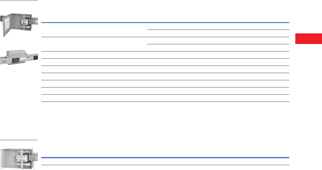
Volume 2—Commercial Distribution CA08100003E—April 2014 www.eaton.com V2-T6-15
6
6
6
6
6
6
6
6
6
6
6
6
6
6
6
6
6
6
6
6
6
6
6
6
6
6
6
6
6
6
6.1
Low Voltage Busway
Pow-R-Way III
Product Selection
Circuit Breaker Plug-In Units
Circuit Breaker Plug-In Units
●Refer to Page V2-T6-25
for breaker data;
for reference only
●The enclosure, circuit
breaker, neutral and
ground are ordered and
shipped assembled
●Housing ground
connection supplied
as standard at no
additional charge
Advanced Circuit Breaker Plug-Ins
●The P3BFD, P3BJD and
P3BKD plug-in units can be
modified to accept breaker
mounted IQ Energy
Sentinels
●T
he IQ Energy Sentinel and
the OPTIM
breaker plug-in
units permit multiple
meters, remote monitoring,
and interconnection with
programmable logic
controllers and building-
management systems.
Applications may range
from revenue metering for
tenant billing to a full-power
management system.
Consult with an Eaton
application engineer or
the busway product line
for assistance
Notes
1 Enclosure not sold separately. Refer to Page V2-T6-14 for assembled bus plug catalog number.
See Page V2-T6-14 for plug assembled style number configuration.
Breaker Frame
Ampere
Rating
Plug-In Enclosure
Catalog Number 1
100% Neutral Stab
Catalog Number
50% Internal
Ground Stab
Catalog Number
50% Isolated
Ground Stab
Catalog Number
200% Neutral Stab
Catalog Number
ED, EDH, EHD, EDC,
FDB, FD, HFD, FDC
10–225 P3BFD P3FDN100 P3FG100 P3FDI100 P3FD2N100
P3FDN225 — P3FDI225 P3FD2N225
JDB, JD, HJD, JDC 70–250 P3BJD P3JDN150 — P3JDI150 P3JD2N150
P3JDN250 P3JDG250 P3JDI250 P3JD2N250
KDB, KD, DK, HKD, KDC 100–400 P3BKD P3KDN400 P3KDG400 P3KDI400 P3KD2N400
LDB, LD, HLD, LDC 300–600 P3BLD P3MDN800 P3MDG800 P3MDI800 —
MDL, HMDL 400–800 P3BMD P3MDN800 P3MDG800 P3MDI800 —
ND, HND, NDC 400–800 P3BND P3NDN800 P3NDG800 P3NDI800 —
FB TRI-PAC 15–100 P3BFBP P3FBPN100 P3FBPG100 P3BFBPI100 —
LA TRI-PAC 75–400 P3BLAP P3LAPN400 P3LAPG400 P3LAPI400 —
NB TRI-PAC 500–800 P3BNBP P3NBPN800 P3NBPG800 P3BNBPI800 —
Horizontal Install
(Front View)
Horizontal Install
(Rear View)
Digitrip
OPTIM
Ampere
Rating
Plug-In Enclosure
Catalog Number
100% Neutral
Catalog Number
50% Internal Ground
Catalog Number
50% Isolated Ground
Catalog Number
L-Frame 70–600 P3BORPL P3BORPLN600 P3BORPLG600 P3BORPLI600
Circuit Breaker Plug
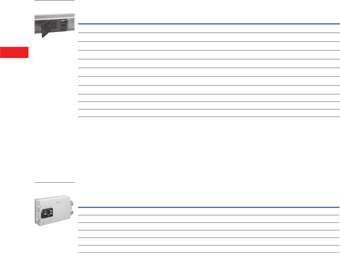
V2-T6-16 Volume 2—Commercial Distribution CA08100003E—April 2014 www.eaton.com
6
6
6
6
6
6
6
6
6
6
6
6
6
6
6
6
6
6
6
6
6
6
6
6
6
6
6
6
6
6
6.1
Low Voltage Busway
Pow-R-Way III
Fusible Plug-In Units
Fusible Plug-In Units
●Fuses are not included
●Mechanical lugs are
provided. If compression
lugs are required, the cable
size must be specified
●Plug-in unit, neutral and
ground are ordered and
shipped assembled
Note: See Page V2-T6-14 for
plug assembled style number
configuration.
●Housing ground connection
supplied as standard at no
additional charge
●R-Fuse clips are supplied
as standard
●If J-Fuse clips are required,
replace “R” in the catalog
number with a “J”
(30–600A, 600V only)
●800A, 600V also available
with L-Fuse clips; replace
“T” in the catalog number
with “L
Special Industry Fusible Plug-In Units
●Fuses are not included
●Housing ground connection
supplied as standard at no
additional charge
●Grounding compression lug
included on 200A and
above. Lugs are ordered
and shipped separately;
fuses are not included
●H-Fuse clips are supplied
as standard
●If J- or R-Fuse clips
are required, order
by description
Notes
1 “H” and “V” do not denote mounting orientation of the bus plug. Horizontal (H) and Vertical (V) refer to the orientation of the bus system that the plug
will be installed on.
2 Neutral and ground kits are not capable of being field installed in these units. Order bus plugs with fully assembled part numbers. See Catalog Number Selection on
Page V2-T6-14 for details.
3 Grounds and neutrals must be factory assembled. Order by description. See Page V2-T6-25.
Ampere
Rating
Three-Wire Plug
600V
Catalog Number 1
Three-Wire Plug
240V
Catalog Number 1
100% Neutral Stab
Catalog Number
50% Internal
Ground Stab
Catalog Number
50% Isolated
Ground Stab
Catalog Number
200% Neutral Stab
Catalog Number
30 (Horizontal) P3F361RGH P3F321RGH 2222
30 (Vertical) P3F361RGV P3F321RGV 2222
60 (Horizontal) P3F362RGH P3F322RGH 2222
60 (Vertical) P3F362RGV P3F322RGV 2222
100 (Horizontal) P3F363RGH P3F323RGH 2222
100 (Vertical) P3F363RGV P3F323RGV 2222
200 (Horizontal) P3F364RGH P3F324RGH 2222
200 (Vertical) P3F364RGV P3F324RGV 2222
400 P3F365R P3F325R P3FN400 P3FG400 P3FI400 —
600 P3F366R P3F326R P3FN600 P3FG800 P3FI800 —
800 P3F367T P3F327T P3FN800 P3FG800 P3FI800 —
Pow-R-Way III
Plug-In Opening
Ampere
Rating
Enclosure
600V
Catalog Number
100% Neutral Stab
Catalog Number
50% Internal
Ground Stab
Catalog Number
50% Isolated
Ground Stab
Catalog Number
Terminal Kit Compression Lugs
Number
Per Phase
Wire
Size
Catalog
Number
30 P3F361H 333
1 1–#12 to #10 CTK30SC
60 P3F362H 333
11–#8 CTK60SC
100 P3F363H 333
11–#4 CTK100SC
200 P3F364H 333
11–2/0 CTK200BSC
400 P3F365H 333
1 1–750 kcmil CTK400SPW
600 P3F366H 333
2 2–500 kcmil CTK600DPM
Pow-R-Way III Plug
(Rear View)

Volume 2—Commercial Distribution CA08100003E—April 2014 www.eaton.com V2-T6-17
6
6
6
6
6
6
6
6
6
6
6
6
6
6
6
6
6
6
6
6
6
6
6
6
6
6
6
6
6
6
6.1
Low Voltage Busway
Pow-R-Way III
Special Plug-In Units
Plug-In Cable Tap Box Units
●Mechanical lugs are
provided. If compression
lugs are required, the cable
size must be specified
Plug-In Combination Starters and Contactors (Non-Reversing, Three-Pole)
Ampere
Rating
Plug-in Cable Tap Box
600V Enclosure
Catalog Number
100% Neutral Stab
Catalog Number
50% Internal Ground Stab
Catalog Number
50% Isolated Ground Stab
Catalog Number
200 P3PTB200 P3PTBN200 P3PTBG200 P3PTBI200
400 P3PTB400 P3PTBN400 P3PTBG400 P3PTBI400
600 P3PTB600 P3PTBN600 P3PTBG600 P3PTBI600
800 P3PTB800 P3PTBN800 P3PTBG800 P3PTBI800
NEMA
Size
Freedom Starter Freedom Contact Advantage Starter Advantage Contact
Fusible Circuit Breaker Fusible Circuit Breaker Fusible Circuit Breaker Fusible Circuit Breaker
0P3FSTR0F P3BSTR0F P3FCON0F P3BCON0F P3FSTR0A P3BSTR0A P3FCON0A P3BCON0A
1P3FSTR1F P3BSTR1F P3FCON1F P3BCON1F P3FSTR1A P3BSTR1A P3FCON1A P3BCON1A
2P3FSTR2F P3BSTR2F P3FCON2F P3BCON2F P3FSTR2A P3BSTR2A P3FCON2A P3BCON2A
3P3FSTR3F P3BSTR3F P3FCON3F P3BCON3F P3FSTR3A P3BSTR3A P3FCON3A P3BCON3A
4P3FSTR4F P3BSTR4F P3FCON4F P3BCON4F P3FSTR4A P3BSTR4A P3FCON4A P3BCON4A

V2-T6-18 Volume 2—Commercial Distribution CA08100003E—April 2014 www.eaton.com
6
6
6
6
6
6
6
6
6
6
6
6
6
6
6
6
6
6
6
6
6
6
6
6
6
6
6
6
6
6
6.1
Low Voltage Busway
Pow-R-Way III
Bolt-On Units
Circuit Breaker Bolt-On Units
●Factory assembled,
refer to Eaton’s busway
for delivery
●Refer to Page V2-T6-25
for breaker data, for
reference only
●Bolt-on units require a
Power Take-off at the
rating of the busway
●Housing ground connection
supplied as standard
Fusible Bolt-On Units
●Factory assembled;
refer to Eaton’s busway
for delivery
●Bolt-on units require a
power take-off at the
rating of the busway
●If neutral and ground
are required, order by
description with bolt-on unit
●Housing ground connection
supplied as standard
Ground Detector Neutralizer Plug (Three-Wire)
Breaker
Frame
Ampere
Rating
Bolt-On Enclosure
Catalog Number
100% Neutral Stab
Catalog Number
50% Internal Ground Stab
Catalog Number
50% Isolated Ground Stab
Catalog Number
EHD, FDB, FD, HFD, FDC 15–225 P3BFDBO P3FDNBO P3FDGBO P3FDIBO
JDB, JD, HJD, JDC 70–250 P3BJDBO P3FJDNBO P3JDGBO P3JDIBO
KDB, KD, HKD, KDC 250–400 P3BKDBO P3KDNBO P3KDGBO P3KDIBO
LDB, LD, HLD, LDC 300–600 P3BLDBO P3LDNBO P3LDGBO P3LDIBO
MDL, HMDL 500–800 P3BMDBO P3MDNBO P3MDGBO P3MDIBO
ND, HND 900–1200 P3BNDBO P3NDNBO P3NDGBO P3NDIBO
Ampere
Rating
Enclosure 600V
Catalog Number
100% Neutral Stab
Catalog Number
50% Internal Ground Stab
Catalog Number
50% Isolated Ground Stab
Catalog Number
30 P3F361BO P3FN100BO P3FG100BO P3FI100BO
60 P3F362BO P3FN100BO P3FG100BO P3FI100BO
100 P3F363BO P3FN100BO P3FG100BO P3FI100BO
200 P3F364BO P3FN250BO P3FG250BO P3FI250BO
400 P3F365BO P3FN400BO P3FG400BO P3FI400BO
600 P3F366BO P3FN600BO P3FG600BO P3FI600BO
800 P3F367BO P3FN800BO P3FG800BO P3FI800BO
1200 P3F369BO P3FN1200BO P3FG1200BO P3FI1200BO
Maximum Voltage Catalog Number
600 P3GND

Volume 2—Commercial Distribution CA08100003E—April 2014 www.eaton.com V2-T6-19
6
6
6
6
6
6
6
6
6
6
6
6
6
6
6
6
6
6
6
6
6
6
6
6
6
6
6
6
6
6
6.1
Low Voltage Busway
Pow-R-Way III
Technical Data and Specifications
Ratings
A. The busway shall
be Eaton’s type
Pow-R-Way III: [three-
phase, three-wire] [three-
phase, three-wire with
50% housing ground
and/or 50% internal
ground] [three-phase,
three-wire with 50%
housing ground and/or
50% isolated ground]
three-phase, four-wire
with 100% neutral]
[three-phase, four-wire
with 100% neutral, 50%
housing and/or 50%
internal ground] [three-
phase, four-wire with
100% neutral, 50%
housing and/or 50%
isolated ground] [three-
phase, four-wire with
200% neutral] [three-
phase, four-wire with
200% neutral, 50%
housing ground, and/or
50% internal ground]
[three-phase, four-wire
with 200% neutral, 50%
housing ground, and/or
50% isolated ground]
with voltage and current
ratings as indicated on
the contract drawings.
B. The busway shall have
a minimum of 6-cycle
short-circuit rating of
85 kA rms symmetrical
for ratings through
800A, 100 kA rms
symmetrical for ratings
through 1350A, 125 kA
rms symmetrical for
ratings through 1600A,
150 kA rms symmetrical
for ratings through
2500A, and 200 kA rms
symmetrical for ratings
through 5000A.
Construction
A. The busway and
associated fittings shall
consist of [aluminum]
[copper] conductors
totally enclosed in a two-
piece extruded aluminum
housing. Outdoor feeder,
indoor feeder and indoor
plug-in busway shall be
interchangeable at the
same rating without the
use of adapters or
special splice plates.
Fittings—such as
elbows, tees, flanges,
etc.—shall be identical
for use with both the
plug-in and feeder types
of busway. The busway
shall be capable of being
mounted flatwise,
edgewise or vertically
without derating. The
busway shall consist of
standard 10 ft (3m)
sections with special
sections and fittings
provided to suit the
installation. Horizontal
runs shall be suitable for
hanging on 10 ft (3m)
maximum centers.
Vertical runs shall be
suitable for mounting on
16 ft (4m) maximum
centers. Provide one
hanger for every 10 ft
(3m) of horizontally
mounted duct. On
vertical runs, provide
one adjustable hanger
per floor.
Bus
A. Busbars shall be
fabricated from high
strength, [57%
conductivity aluminum]
[99% conductivity
copper] and suitably
plated at all electrical
contact surfaces.
B. Busbars shall be
insulated over their
entire length, except at
joints and contact
surfaces, with a UL-
listed insulating material
consisting of epoxy
applied by fluidized bed
process. Tape or heat-
shrink sleeve insulation,
or any other method of
insulation that can allow
air gaps or insulation
breakdown, shall not
be acceptable.
C. The busway shall be
capable of carrying rated
current continuously
without exceeding a
temperature
rise of 55ºC
based on a 40ºC ambient.
Bus Joints
A. Each busway section
shall be furnished
complete with joint
hardware and covers.
The busway joints shall
be a single-bolt, non-
rotating, removable
bridge design. All bridge
joints shall be furnished
with torque-indicating
double-head joint bolts
and Belleville washers.
The bridge joint shall
utilize a captive nut
retainer on the opposite
side of the torque
indicating bolt. The
bridge joint design shall
ensure proper installation
without the use of a
torque wrench, and
provide visual indication
that the joint is properly
torqued. Each busway
joint shall allow for
a minimum length
adjustment of
±0.5 inches (12.7 mm).
De-energization of
busway shall not be
required for safe testing
of joint tightness.
Housing
A. The busway housing shall
be a two-piece design
fabricated from extruded
aluminum. The two-piece
housing shall be bolted
together along the
bottom flange. The
busway enclosure finish
shall be ANSI 61 gray
baked epoxy powder
paint applied by an
electrostatic process.
B. Outdoor feeder busway
housing shall be identical
to indoor feeder busway
housings, and shall be
UL listed for outdoor use.
Plug-In Busway
A. Where required, busway
shall be of the plug-in
type. Plug-in busway
shall be available in
standard 2-, 4-, 6-, 8-
and 10-foot lengths,
with plug-in openings
provided on both sides
of the busway sections
on 2 ft (0.6m) centers.
Plug-in covers shall
prevent dirt and debris
from entering contact
plug-in openings in the
busway. The design shall
allow for 10 hinged cover
outlets per 10 ft (3m) of
plug-in length. Covers
for plug-in openings
shall have a positive
screw close feature
and provisions for the
installation of power
company seals. The
contact surfaces for
bus plug stabs shall be
silver-plated of the same
material, thickness and
rating as the stab bars.
The stabs shall be
welded to the busbars.
A standard housing
ground connection
shall be supplied in each
plug-in opening. Positive
mechanical guides for
plug-in units shall be
provided at each plug-in
opening to facilitate unit
alignment and prevent
improper installation.

V2-T6-20 Volume 2—Commercial Distribution CA08100003E—April 2014 www.eaton.com
6
6
6
6
6
6
6
6
6
6
6
6
6
6
6
6
6
6
6
6
6
6
6
6
6
6
6
6
6
6
6.1
Low Voltage Busway
Pow-R-Way III
B. Where required, plug-in
units of the types and
ratings indicated on the
plans and specifications
shall be supplied.
Plug-in units shall be
mechanically interlocked
with the busway
housing to prevent their
installation or removal
when the switch is in the
ON position. The
enclosure of any plug-in
unit shall make positive
ground connection to the
duct housing before the
stabs make contact with
the busbars. All plug-in
units shall be equipped
with a defeatable
interlock to prevent the
cover from being opened
while the switch is in the
ON position and prevent
accidental closing of the
switch while the cover is
open. The plugs shall be
provided with a means
for padlocking the cover
closed and padlocking
the disconnect device in
the OFF position. The
operating handle and
mechanism shall
remain in control of the
disconnect device at all
times, permitting its easy
operation from the floor
by means of a hookstick
or chain. For safety
reasons, no projections
shall extend into the
busway housing other
than the plug-in stabs.
All plug-in units shall be
interchangeable without
alteration or moderation
of plug-in duct.
C. Fusible-type plugs shall
have a quick-make/quick-
break disconnect switch
and positive pressure
fuse clips.
—OR—
C. Circuit-breaker-type plugs
shall have an interrupting
rating of not less than
symmetrical rms
amperes or be series
rated as otherwise
shown in the contract
document and shall meet
all requirements of UL
Standard 489. It shall be
possible to increase the
interrupting rating of a
breaker plug-in device
having ampere ratings
through 400A up to
100 kAIC at 480 Vac and
200 kAIC at 240 Vac by
changing out the circuit
breaker only and leaving
the enclosure intact. All
breaker plug-in devices
shall be Eaton type
Series C.
Surge Protective Device
A. Provide surge protective
device as specified in
Section 16671.
Short-Circuit Withstand
Ratings—rms Symmetrical
Amperes for Copper Pow-R-
Way III Plug-In and Feeder
Busway
Short-Circuit Withstand
Ratings—rms Symmetrical
Amperes for Aluminum
Pow-R-Way III Plug-In and
Feeder Busway
Ampere
Rating
6-Cycle
Copper
225 85,000
400 85,000
600 85,000
800 85,000
1000 100,000
1200 100,000
1350 100,000
1600 125,000
2000 150,000
2500 150,000
3200 200,000
4000 200,000
5000 200,000
Ampere
Rating
6-Cycle
Aluminum
225 85,000
400 85,000
600 85,000
800 100,000
1000 100,000
1200 125,000
1350 150,000
1600 150,000
2000 150,000
2500 200,000
3200 200,000
4000 200,000
5000 —

Volume 2—Commercial Distribution CA08100003E—April 2014 www.eaton.com V2-T6-21
6
6
6
6
6
6
6
6
6
6
6
6
6
6
6
6
6
6
6
6
6
6
6
6
6
6
6
6
6
6
6.1
Low Voltage Busway
Pow-R-Way III
Pow-R-Way III Plug-In Busway
●225–5000A copper
●225–4000A aluminum
Straight sections of plug-in busway are made only in 24-inch
(609.6 mm) incremental lengths with a maximum length of
10 ft (3m). Page V2-T6-28 depicts the configuration of plug-in
busway and Pow-R-Bridge for the available ampere ratings. See
table below for reference to the proper configuration. Available
in indoor and sprinkler-proof ratings.
Configuration
IEC 60529 IP Ratings
IEC 60529 Degrees of Protection
Pow-R-Way III Feeder Busway
●225–5000A copper
●225–4000A aluminum
Straight sections of feeder busway can be supplied in
any length, at 1/8-inch (3.2 mm) increments, from a
16-inch (406.4 mm) minimum to a 10 ft
(3m) maximum.
Page V2-T6-28
illustrates
the configuration of feeder busway and
Pow-R-Bridge for the available ampere ratings. See table below
for reference to the proper configuration.
Feeder Busway Configuration
Each section will include one factory-installed Pow-R-Bridge
mounted to the left end of the busway (with the “T” to the top,
when viewing the bus from the “F” side). Each Pow-R-Bridge
will have a “T” label, which must always match the “T”
orientation of the busway. Available in indoor, sprinkler-proof
and outdoor ratings. See IEC 60529 IP Ratings table to the left
for details.
Ampere Rating
Configuration
(see Page V2-T6-28)
UL 857 IEC 439
Cu Al Cu
225 225 225 A
400 400 400 A
600 630 630 A
800 800 1000 A
1000 1000 1200 A
1200 1200 1400 A
1350 1350 1550 A
1600 — 1800 A
2000 — 2250 A
—1600—B
2500 2000 3000 B
3200 — 3800 C
4000 2500 4500 C
—3200—D
5000 4000 5800 D
IEC 529
IP Rating Busway Type
IP2X Pow-R-Way
III
plug-in busway; plug-in outlet protects against access
to live parts
IP40 Pow-R-Way
III
indoor plug-in and feeder busway
IP55 Pow-R-Way
III
sprinkler-proof plug-in busway
IP66 Pow-R-Way
III
outdoor feeder busway
IEC 529
IP Rating Description
IP40 Protection against access to hazardous parts with a wire or solid foreign
object 1 mm diameter. No protection against water.
IP55 Protection against access to hazardous parts with a wire and dust shall
not penetrate in quantity to interfere with satisfactory operation or impair
safety. Protects against water jets.
IP66 Protection against access to hazardous parts with a wire and dust shall
not penetrate in quantity to interfere with satisfactory operation or impair
safety. Protects against powerful water jets.
Ampere Rating
Configuration
(see Page V2-T6-28)
UL 857 IEC 439
Cu Al Cu
225 225 225 A
400 400 400 A
600 600 630 A
800 800 1000 A
1000 1000 1200 A
1200 1200 1400 A
1350 1350 1550 A
1600 — 1800 A
2000 — 2250 A
—1600—B
2500 2000 3000 B
3200 — 3800 C
4000 2500 4500 C
—3200—D
5000 4000 5800 D

V2-T6-22 Volume 2—Commercial Distribution CA08100003E—April 2014 www.eaton.com
6
6
6
6
6
6
6
6
6
6
6
6
6
6
6
6
6
6
6
6
6
6
6
6
6
6
6
6
6
6
6.1
Low Voltage Busway
Pow-R-Way III
Circuit Breaker Plug-In Units
Circuit Breakers
100% rated breakers are not available for use in bus plugs.
Contact product line for guidance.
Branch Devices Earth Leakage Ground Fault
Circuit Breakers
(Adjustable pickup from 30 mA to 30A)
Integrally Fused, Current-Limiting Circuit Breaker
Fusible Switch Horsepower Ratings
Ampere
Rating
Interrupting Rating (kA Symmetrical) Breaker
Type240 Vac 480 Vac 600 Vac
15–60 18 14 — EHD
70–100 18 14 — EHD
15–60 18 14 14 FDB
70–100 18 14 14 FDB
110–150 18 14 14 FDB
15–60 65 35 18 FD
70–100 65 35 18 FD
110–150 65 35 18 FD
175–225 65 35 18 FD
15–60 100 65 25 HFD
70–100 100 65 25 HFD
110–150 100 65 25 HFD
175–225 100 65 25 HFD
15–60 200 100 35 FDC
70–100 200 100 35 FDC
110–225 200 100 35 FDC
15–100 200 150 — FCL
100–225 65 — — ED
100–225 100 — — EDH
100–225 200 — — EDC
70–225 65 35 18 JD, JDB
250 65 35 18 JD, JDB
70–225 100 65 25 HJD
250 100 65 25 HJD
70–225 200 100 35 JDC
250 200 100 35 JDC
125–250 200 200 100 LCL
250–400 65 — — DK
100–400 65 35 25 KD, KDB
100–400 100 65 35 HKD
100–400 200 100 65 KDC
200–400 200 200 — LCL
300–600 65 35 25 LD, LDB
300–600 100 65 35 HLD
300–600 200 100 50 LDC
400–800 65 50 25 MDL
400–800 100 65 35 HMDL
400–800 65 50 25 ND
400–800 100 65 35 HND
400–800 200 100 50 NDC
600–1200 65 50 25 ND
600–1200 100 65 35 HND
600–1200 200 100 50 NDC
Ampere
Rating
kAIC (Symmetrical) Breaker
Type480 Vac
35–60 25 ELFD
70–100 25 ELFD
110–150 25 ELFD
35–60 65 ELHFD
70–100 65 ELHFD
110–150 65 ELHFD
35–60 100 ELFDC
70–100 100 ELFDC
110–150 100 ELFDC
100–250 35 ELJD
100–250 65 ELHJD
100–250 100 ELJDC
200–400 35 ELKD
200–400 65 ELHKD
200–400 100 ELKDC
Ampere
Rating
Interrupting Rating (kA Symmetrical) Breaker
Type240 Vac 480 Vac 600 Vac
15–100 200 200 200 FB-P
125–225 200 200 200 LA-P
250–400 200 200 200 LA-P
400–600 200 200 200 NB-P
700–800 200 200 200 NB-P
Ampere
Rating
240V 480V 600V
NEC Std. Max. NEC Std. Max. NEC Std. Max.
30 3 7.55157.520
60 7.5 1515301550
100 15 3025603075
200 25 60 50 125 60 150
400 50 125 100 250 125 350
600 75 200 150 400 200 500
800 100 250 200 500 250 500

Volume 2—Commercial Distribution CA08100003E—April 2014 www.eaton.com V2-T6-23
6
6
6
6
6
6
6
6
6
6
6
6
6
6
6
6
6
6
6
6
6
6
6
6
6
6
6
6
6
6
6.1
Low Voltage Busway
Pow-R-Way III
Dimensions
Approximate Dimensions in Inches (mm)
Busbar and Housing
Three-Wire with No Neutral
Four-Wire with 100% Neutral
Note
1Refer to drawing on Page V2-T6-27.
Ampere Rating Phase Bar Size Bar
Per
Phase
Wire Designation and Housing Size
Figure 1
50% Integral Housing Ground 3WH 50% Internal Ground Bus 3WHG 50% Internal Isolated Ground 3WI
Cu Al Depth Width Width Height Width Height Width Height
225 225 0.25 (6.4) 1.62 (41.1) 1 4.75 (120.7) 4.38 (111.3) 4.75 (120.7) 4.50 (114.3) 4.75 (120.7) 4.55 (115.6) A
400 400 0.25 (6.4) 1.62 (41.1) 1 4.75 (120.7) 4.38 (111.3) 4.75 (120.7) 4.50 (114.3) 4.75 (120.7) 4.55 (115.6) A
600 — 0.25 (6.4) 1.62 (41.1) 1 4.75 (120.7) 4.38 (111.3) 4.75 (120.7) 4.50 (114.3) 4.75 (120.7) 4.55 (115.6) A
800 600 0.25 (6.4) 1.62 (41.1) 1 4.75 (120.7) 4.38 (111.3) 4.75 (120.7) 4.50 (114.3) 4.75 (120.7) 4.55 (115.6) A
1000 — 0.25 (6.4) 2.25 (57.2) 1 5.38 (136.7) 4.38 (111.3) 5.38 (136.7) 4.50 (114.3) 5.38 (136.7) 4.55 (115.6) A
1200 800 0.25 (6.4) 2.75 (70.0) 1 5.88 (149.4) 4.38 (111.3) 5.88 (149.4) 4.50 (114.3) 5.88 (149.4) 4.55 (115.6) A
1350 1000 0.25 (6.4) 3.25 (82.3) 1 6.38 (162.10) 4.38 (111.3) 6.38 (162.1) 4.50 (114.3) 6.38 (162.10) 4.55 (115.6) A
1600 1200 0.25 (6.4) 4.25 (108.0) 1 7.38 (187.5) 4.38 (111.3) 7.38 (187.5) 4.50 (114.3) 7.38 (187.5) 4.55 (115.6) A
2000 1350 0.25 (6.4) 5.50 (139.7) 1 8.64 (219.5) 4.38 (111.3) 8.64 (219.5) 4.50 (114.3) 8.64 (219.5) 4.55 (115.6) A
— 1600 0.25 (6.4) 6.25 (158.8) 1 9.40 (238.8) 4.38 (111.3) 9.40 (238.8) 4.50 (114.3) 9.40 (238.8) 4.55 (115.6) A
2500 2000 0.25 (6.4) 8.00 (203.2) 1 11.17 (283.7) 4.38 (111.3) 11.17 (283.7) 4.50 (114.3) 11.17 (283.7) 4.55 (115.6) A
3200 — 0.25 (6.4) 4.25 (108.0) 2 16.14 (410.0) 4.38 (111.3) 16.14 (410.0) 4.50 (114.3) 16.14 (410.0) 4.55 (115.6) B
4000 2500 0.25 (6.4) 5.50 (139.7) 2 18.64 (473.5) 4.38 (111.3) 18.64 (473.5) 4.50 (114.3) 18.64 (473.5) 4.55 (115.6) B
— 3200 0.25 (6.4) 6.25 (158.8) 2 20.16 (512.0) 4.38 (111.3) 20.16 (512.0) 4.50 (114.3) 20.16 (512.0) 4.55 (115.6) B
5000 4000 0.25 (6.4) 8.00 (203.2) 2 23.70 (602.0) 4.38 (111.3) 23.70 (602.0) 4.50 (114.3) 23.70 (602.0) 4.55 (115.6) B
Ampere Rating
Phase and Neutral
Bar Size Bar
Per
Phase
Wire Designation and Housing Size
Figure 1
50% Integral Housing Ground 4WH 50% Internal Ground 4WHG 50% Internal Isolated Ground 4WI
Cu Al Depth Width Width Height Width Height Width Height
225 225 0.25 (6.4) 1.62 (41.1) 1 4.75 (120.7) 4.38 (111.3) 4.75 (120.7) 4.50 (114.3) 4.75 (120.7) 4.55 (115.6) A
400 400 0.25 (6.4) 1.62 (41.1) 1 4.75 (120.7) 4.38 (111.3) 4.75 (120.7) 4.50 (114.3) 4.75 (120.7) 4.55 (115.6) A
600 — 0.25 (6.4) 1.62 (41.1) 1 4.75 (120.7) 4.38 (111.3) 4.75 (120.7) 4.50 (114.3) 4.75 (120.7) 4.55 (115.6) A
800 600 0.25 (6.4) 1.62 (41.1) 1 4.75 (120.7) 4.38 (111.3) 4.75 (120.7) 4.50 (114.3) 4.75 (120.7) 4.55 (115.6) A
1000 — 0.25 (6.4) 2.25 (57.2) 1 5.38 (111.3) 4.38 (111.3) 5.38 (111.3) 4.50 (114.3) 5.38 (111.3) 4.55 (115.6) A
1200 800 0.25 (6.4) 2.75 (70.0) 1 5.88 (149.4) 4.38 (111.3) 5.88 (149.4) 4.50 (114.3) 5.88 (149.4) 4.55 (115.6) A
1350 1000 0.25 (6.4) 3.25 (82.3) 1 6.38 (162.1) 4.38 (111.3) 6.38 (162.1) 4.50 (114.3) 6.38 (162.1) 4.55 (115.6) A
1600 1200 0.25 (6.4) 4.25 (108.0) 1 7.38 (187.5) 4.38 (111.3) 7.38 (187.5) 4.50 (114.3) 7.38 (187.5) 4.55 (115.6) A
2000 1350 0.25 (6.4) 5.50 (139.7) 1 8.64 (219.5) 4.38 (111.3) 8.64 (219.5) 4.50 (114.3) 8.64 (219.5) 4.55 (115.6) A
— 1600 0.25 (6.4) 6.25 (158.8) 1 9.40 (238.8) 4.38 (111.3) 9.40 (238.8) 4.50 (114.3) 9.40 (238.8) 4.55 (115.6) A
2500 2000 0.25 (6.4) 8.00 (203.2) 1 11.17 (283.7) 4.38 (111.3) 11.17 (283.7) 4.50 (114.3) 11.17 (283.7) 4.55 (115.6) A
3200 — 0.25 (6.4) 4.25 (108.0) 2 16.14 (410.0) 4.38 (111.3) 16.14 (410.0) 4.50 (114.3) 16.14 (410.0) 4.55 (115.6) B
4000 2500 0.25 (6.4) 5.50 (139.7) 2 18.64 (473.5) 4.38 (111.3) 18.64 (473.5) 4.50 (114.3) 18.64 (473.5) 4.55 (115.6) B
— 3200 0.25 (6.4) 6.25 (158.8) 2 20.16 (512.0) 4.38 (111.3) 20.16 (512.0) 4.50 (114.3) 20.16 (512.0) 4.55 (115.6) B
5000 4000 0.25 (6.4) 8.00 (203.2) 2 23.70 (602.0) 4.38 (111.3) 23.70 (602.0) 4.50 (114.3) 23.70 (602.0) 4.55 (115.6) B
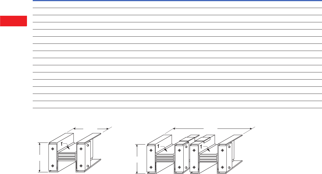
V2-T6-24 Volume 2—Commercial Distribution CA08100003E—April 2014 www.eaton.com
6
6
6
6
6
6
6
6
6
6
6
6
6
6
6
6
6
6
6
6
6
6
6
6
6
6
6
6
6
6
6.1
Low Voltage Busway
Pow-R-Way III
Approximate Dimensions in Inches (mm)
Four-Wire with 200% Neutral
Single and Double Module Cross-Sections
Ampere Rating
Phase Bar Size
Neutral Bar is
0.5 (12.7) x Width Shown Bar
Per
Phase
Wire Designation and Housing Size
Figure
50% Integral Housing Ground 4WNH 50% Internal Ground Bus 4WNG 50% Internal Isolated Ground 4WNI
Cu Al Depth Width Width Height Width Height Width Height
225 225 0.25 (6.4) 1.62 (41.1) 1 4.75 (120.7) 4.92 (125.0) 4.75 (120.7) 5.05 (128.3) 4.75 (120.7) 5.10 (129.5) A
400 400 0.25 (6.4) 1.62 (41.1) 1 4.75 (120.7) 4.92 (125.0) 4.75 (120.7) 5.05 (128.3) 4.75 (120.7) 5.10 (129.5) A
600 — 0.25 (6.4) 1.62 (41.1) 1 4.75 (120.7) 4.92 (125.0) 4.75 (120.7) 5.05 (128.3) 4.75 (120.7) 5.10 (129.5) A
800 600 0.25 (6.4) 1.62 (41.1) 1 4.75 (120.7) 4.92 (125.0) 4.75 (120.7) 5.05 (128.3) 4.75 (120.7) 5.10 (129.5) A
1000 — 0.25 (6.4) 20.25 (57.2) 1 5.38 (136.7) 4.92 (125.0) 5.38 (136.7) 5.05 (128.3) 5.38 (136.7) 5.10 (129.5) A
1200 800 0.25 (6.4) 2.75 (70.0) 1 5.88 (149.4) 4.92 (125.0) 5.88 (149.4) 5.05 (128.3) 5.88 (149.4) 5.10 (129.5) A
1350 1000 0.25 (6.4) 30.25 (82.3) 1 6.38 (162.1) 4.92 (125.0) 6.38 (162.1) 5.05 (128.3) 6.38 (162.1) 5.10 (129.5) A
1600 1200 0.25 (6.4) 40.25 (108.0) 1 7.38 (187.5) 4.92 (125.0) 7.38 (187.5) 5.05 (128.3) 7.38 (187.5) 5.10 (129.5) A
2000 1350 0.25 (6.4) 5.50 (139.7) 1 8.64 (219.5) 4.92 (125.0) 8.64 (219.5) 5.05 (128.3) 8.64 (219.5) 5.10 (129.5) A
— 1600 0.25 (6.4) 60.25 (158.8) 1 9.40 (238.8) 4.92 (125.0) 9.40 (238.8) 5.05 (128.3) 9.40 (238.8) 5.10 (129.5) A
2500 2000 0.25 (6.4) 8.00 (203.2) 1 11.17 (283.7) 4.92 (125.0) 11.17 (283.7) 5.05 (128.3) 11.17 (283.7) 5.10 (129.5) A
3200 — 0.25 (6.4) 40.25 (108.0) 2 16.14 (410.0) 4.92 (125.0) 16.14 (410.0) 5.05 (128.3) 16.14 (410.0) 5.10 (129.5) B
4000 2500 0.25 (6.4) 5.50 (139.7) 2 18.64 (473.5) 4.92 (125.0) 18.64 (473.5) 5.05 (128.3) 18.64 (473.5) 5.10 (129.5) B
— 3200 0.25 (6.4) 60.25 (158.8) 2 20.16 (512.0) 4.92 (125.0) 20.16 (512.0) 5.05 (128.3) 20.16 (512.0) 5.10 (129.5) B
5000 4000 0.25 (6.4) 8.00 (203.2) 2 23.70 (602.0) 4.92 (125.0) 23.70 (602.0) 5.05 (128.3) 23.70 (602.0) 5.10 (129.5) B
225–2000A Aluminum
225–2500A Copper
2500–4000A Aluminum
3200–5000A Copper
Width
Height
Figure A
Figure B
A
B
C
N
A
B
C
N
A
B
C
N
Height
Width
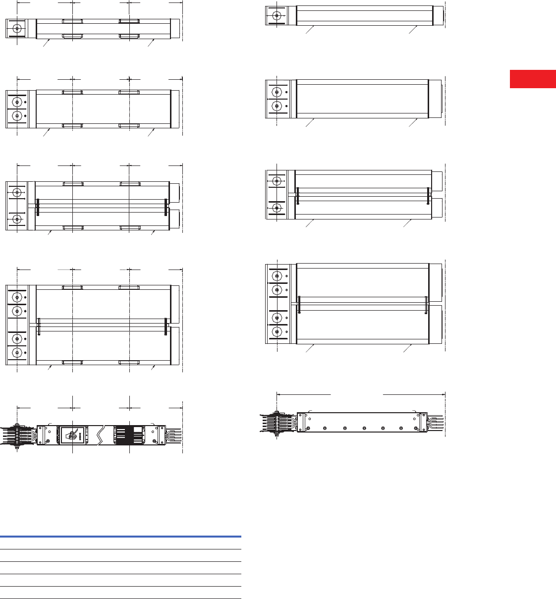
Volume 2—Commercial Distribution CA08100003E—April 2014 www.eaton.com V2-T6-25
6
6
6
6
6
6
6
6
6
6
6
6
6
6
6
6
6
6
6
6
6
6
6
6
6
6
6
6
6
6
6.1
Low Voltage Busway
Pow-R-Way III
Approximate Dimensions in Inches (mm)
Plug-In Busway
The table below illustrates the quantity of plug-in openings per
side that are available per standard section.
Number of Plug-In Openings
Feeder Busway
Duct Length
Number of Plug-In Openings
Front Back
24.00 (609.6) 1 1
48.00 (1219.2) 2 2
72.00 (1828.8) 3 3
96.00 (2438.4) 4 4
120.00 (3048.0) 5 5
12.00
(304.8)
24.00 Spacing
(609.6)
12.00
(304.8)
Conguration A Top View
1 Bar Per Phase
TT
FF
FF
C
LC
L
C
LC
L
TT
12.00
(304.8)
24.00 Spacing
(609.6)
12.00
(304.8)
Conguration B Top View
1 Bar Per Phase
Conguration C Top View
2 Bars Per Phase
Conguration D Top View
2 Bars Per Phase
C
LC
LC
LC
L
12.00
(304.8)
24.00 Spacing
(609.6)
12.00
(304.8)
C
LC
L
C
LC
L
FF
12.00
(304.8)
24.00 Spacing
(609.6)
12.00
(304.8)
12.00
(304.8)
24.00 Spacing
(609.6)
12.00
(304.8)
FF
C
LC
LC
L
C
L
C
LC
L
TT
FF
Front View
TT
TT
16.00 Minimum
(406.4)
Conguration A Top View
1 Bar Per Phase
Conguration B Top View
1 Bar Per Phase
Conguration C Top View
2 Bars Per Phase
Conguration D Top View
2 Bars Per Phase
T
F
C
LC
L
F
T
T
F
C
LC
L
F
T
T
F
C
LC
L
F
T
T
F
C
LC
L
F
T
T
F
C
LC
L
Front View
T
F
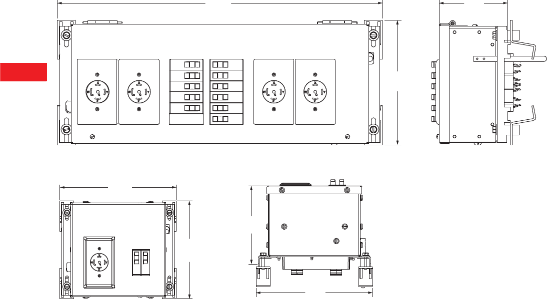
V2-T6-26 Volume 2—Commercial Distribution CA08100003E—April 2014 www.eaton.com
6
6
6
6
6
6
6
6
6
6
6
6
6
6
6
6
6
6
6
6
6
6
6
6
6
6
6
6
6
6
6.1
Low Voltage Busway
Pow-R-Way III
Approximate Dimensions in Inches (mm)
Quad Receptacle Unit
Single Receptacle Unit
22.35
(567.7)
4.70
(119.4)
8.61
(218.7)
10.21
(259.3)
8.61
(218.7)
6.86
(174.2)
10.21
(259.3)
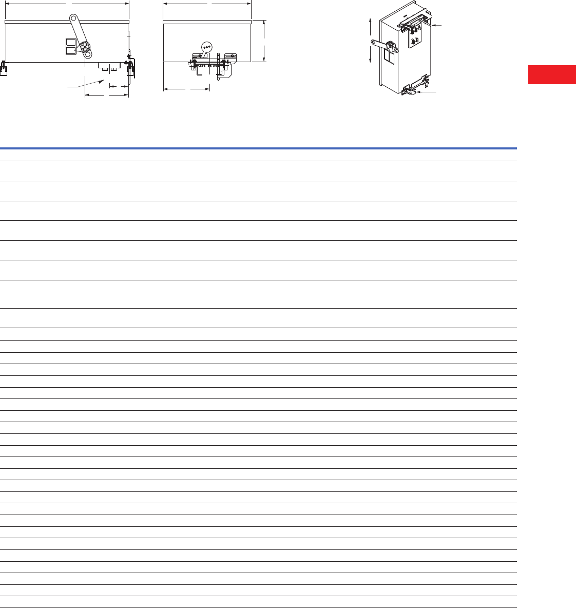
Volume 2—Commercial Distribution CA08100003E—April 2014 www.eaton.com V2-T6-27
6
6
6
6
6
6
6
6
6
6
6
6
6
6
6
6
6
6
6
6
6
6
6
6
6
6
6
6
6
6
6.1
Low Voltage Busway
Pow-R-Way III
Approximate Dimensions in Inches (mm)
Plug-In Units—Physical Data
Bus Plugs
Plug-In Units
Plug-In Unit
Max.
Amperes
Max.
Vac
Dimensions
Mechanical Terminal
Wire Range Per Phase (mm2)
Approx.
Weights
Lbs (kg)ABCDEF
Circuit Breaker Plug-In Units
P3BFD
(E- & F-Frame)
225 600 21.20 (538.5) 12.36 (314.0) 5.43 (138.0) 4.00 (101.6) 6.25 (158.8) 6.06 (153.7) 100A–(1) #14–1/0 (2.5–50)
150A–(1) #4–4/0 (25–95)
25 (11.3)
P3BJD
(J-Frame)
250 600 23.26 (590.8) 12.36 (314.0) 6.97 (177.0) 4.00 (101.6) 10.44 (265.2) 6.06 (153.7) 250A–(1) #14–350 kcmil (25–185)
225A–(1) 3–350 kcmil (35–185)
47 (21.3)
P3BKD
(K-Frame)
400 600 34.41 (874.0) 13.29 (337.6) 7.79 (197.9) 4.00 (101.6) 12.56 (319.0) 6.64 (168.7) 350A–(1) 250–500 kcmil (120–240)
400A–(2) 3/0–250 kcmil (45–120)
53 (24.0)
P3BLD
(L-Frame)
600 600 41.91 (1064.5) 19.65 (499.1) 10.15 (257.8) 4.00 (101.6) 17.38 (441.5) 9.83 (249.7) 400A–(1) 4/0–600 kcmil (120–300)
600A–(2) 400–500 kcmil (185–240)
75 (34.0)
P3BMDL
(MDL-Frame)
800 600 45.89 (1165.6) 19.65 (499.1) 10.15 (257.8) 4.00 (101.6) 17.38 (441.5) 9.83 (249.7) 600A–(2) #1–500 kcmil (50–240)
800A–(2) 500–750 kcmil (300–400)
136 (61.7)
P3BND
(N-Fame)
800 600 45.98 (1167.9) 19.65 (499.1) 10.15 (257.8) 4.00 (101.6) 17.38 (441.5) 9.83 (249.7) 700A–(2) # 1–500 kcmil (50–240)
800A–(3) 3/0–400 kcmil (95–185)
138 (62.6)
P3BLAP
(TRI-PAC)
400 600 45.89 (1165.6) 19.65 (499.1) 10.15 (257.8) 4.00 (101.6) 13.80 (350.5) 9.83 (249.7) 225A–(1) #6–350 kcmil (16–185)
400A–(1) #4–250 kcmil and
(1) 3/0–600 kcmil (25–120 and 95–300)
96 (43.5)
P3BLCL 400 600 41.86 (1063.2) 19.65 (499.1) 10.15 (257.8) 4.00 (101.6) 13.80 (350.5) 9.83 (249.7) (1) #4–250 kcmil (25–120) and
(1) 3/0–600 kcmil (95–300)
88 (39.9)
Fusible Plug-In Units
P3F321RGH 30 240 14.72 (373.9) 13.92 (353.7) 8.46 (214.8) 3.85 (97.7) 7.95 (202.0) 5.66 (143.7) Cu (1) #14–#3 (2.5–35) 32 (14.5)
P3F321RGV 30 240 15.85 (402.5) 14.03 (356.3) 8.46 (214.8) 3.85 (97.7) 6.72 (170.6) 5.66 (143.7) Al (1) #12–#2 (3.2–35) 32 (14.5)
P3F361RGH 30 600 14.72 (373.9) 13.92 (353.7) 8.46 (214.8) 3.85 (97.7) 7.95 (202.0) 5.66 (143.7) Cu (1) #14–#3 (2.5–35) 32 (14.5)
P3F361RGV 30 600 15.85 (402.5) 14.03 (356.3) 8.46 (214.8) 3.85 (97.7) 6.72 (170.6) 5.66 (143.7) Al (1) #12–#2 (3.2–35) 32 (14.5)
P3F322RGH 60 240 14.88 (377.9) 17.92 (455.3) 8.37 (212.5) 3.85 (97.7) 11.95 (303.6) 5.66 (143.7) Cu (1) #14–#3 (2.5–35) 40 (18.1)
P3F322RGV 60 240 19.85 (504.1) 14.16 (359.6) 8.37 (212.5) 3.85 (97.7) 6.84 (173.8) 5.66 (143.7) Al (1) #12–#2 (3.2–35) 40 (18.1)
P3F362RGH 60 600 14.88 (377.9) 17.92 (455.3) 8.37 (212.5) 3.85 (97.7) 11.95 (303.6) 5.66 (143.7) Cu (1) #14–1/0 (2.5–50) 40 (18.1)
P3F362RGV 60 600 19.85 (504.1) 14.16 (359.6) 8.37 (212.5) 3.85 (97.7) 6.84 (173.8) 5.66 (143.7) Al (1) #12–1/0 (3.2–50) 40 (18.1)
P3F323RGH 100 240 14.88 (377.9) 17.92 (455.3) 8.37 (212.5) 3.85 (97.7) 11.95 (303.6) 5.66 (143.7) Cu (1) #14–1/0 (2.5–50) 40 (18.1)
P3F323RGV 100 240 19.85 (504.1) 14.16 (359.6) 8.37 (212.5) 3.85 (97.7) 6.84 (173.8) 5.66 (143.7) Al (1) #12–1/0 (3.2–50) 40 (18.1)
P3F363RGH 100 600 14.88 (377.9) 17.92 (455.3) 8.37 (212.5) 3.85 (97.7) 11.95 (303.6) 5.66 (143.7) Cu (1) #4–250 kcmil (25–120) 40 (18.1)
P3F363RGV 100 600 19.85 (504.1) 14.16 (359.6) 8.37 (212.5) 3.85 (97.7) 6.84 (173.8) 5.66 (143.7) Al (1) #4–250 kcmil (25–120) 40 (18.1)
P3F324RGH 200 240 17.42 (442.5) 21.98 (558.3) 8.52 (216.3) 3.85 (97.7) 15.44 (392.1) 6.80 (172.8) Cu (1) #4–250 kcmil (25–120) 56 (25.4)
P3F324RGV 200 240 23.80 (604.5) 16.64 (422.8) 8.52 (216.3) 3.85 (97.7) 8.26 (209.8) 6.80 (172.8) Al (1) #4–250 kcmil (25–120) 56 (25.4)
P3F364RGH 200 600 17.42 (442.5) 21.98 (558.3) 8.52 (216.3) 3.85 (97.7) 15.44 (392.1) 6.80 (172.8) Cu (1) #4–600 kcmil (25–300) 56 (25.4)
P3F364RGV 200 600 23.80 (604.5) 16.64 (422.8) 8.52 (216.3) 3.85 (97.7) 8.26 (209.8) 6.80 (172.8) Al (1) #4–600 kcmil (25–300) 56 (25.4)
P3F325R 400 240 48.85 (1242.1) 21.22 (539.0) 10.07 (255.8) 4.00 (101.6) 10.69 (271.5) 10.69 (271.5) Cu/Al (1) 250–750 kcmil (127–380) 77 (34.9)
P3F365R 400 600 48.85 (1242.1) 21.22 (539.0) 10.07 (255.8) 4.00 (101.6) 10.69 (271.5) 10.69 (271.5) Cu/Al (1) 250–750 kcmil (127–380) 77 (34.9)
P3F365HR 400 600 23.59 (599.2) 21.22 (539.0) 21.00 (533.4) 4.00 (101.6) 10.69 (271.5) 10.69 (271.5) Cu/Al (2) 3/0–250 kcmil (85–127) 81 (36.7)
P3F326R 600 240 48.90 (1242.1) 26.31 (668.3) 10.59 (270.0) 4.00 (101.6) 13.16 (334.3) 13.16 (334.3) Cu/Al (2) #2–600 kcmil (35–300) 82 (37.1)
P3F366R 600 600 48.90 (1242.1) 26.31 (668.3) 10.59 (270.0) 4.00 (101.6) 13.16 (334.3) 13.16 (334.3) Cu/Al (3) #2–600 kcmil (25–300) 82 (37.1)
P3F327R 800 240 48.90 (1242.1) 26.31 (668.3) 10.59 (270.0) 4.00 (101.6) 13.16 (334.3) 13.16 (334.3) Cu/Al (3) #2–600 kcmil (25–300) 108 (49.0)
P3F367R 800 600 48.90 (1242.1) 26.31 (668.3) 10.59 (270.0) 4.00 (101.6) 13.16 (334.3) 13.16 (334.3) Cu/Al (3) #2–600 kcmil (25–300) 108 (49.0)
Plug-In Opening
and B ©
Handle
Plug-In
Opening
OFF
ON
E
D
A
C
B
F
C
LC
LC
L
Guide Pin
Clamp
and Guide
OFF
ON
OFF
ON
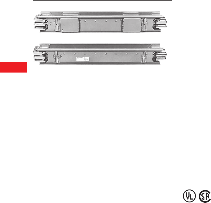
V2-T6-32 Volume 2—Commercial Distribution CA08100003E—April 2014 www.eaton.com
6
6
6
6
6
6
6
6
6
6
6
6
6
6
6
6
6
6
6
6
6
6
6
6
6
6
6
6
6
6
6.2
Low Voltage Busway
Pow-R-Way
Typical Pow-R-Way Plug-In Straight Length
Typical Pow-R-Way Feeder Straight Length
Pow-R-Way Single Bolt per Joint, 600–5000A and Pow-R-Way II
(Single Bolt per Busbar, 225–400A)
Contents
Description Page
Pow-R-Way Busway
Product Selection. . . . . . . . . . . . . . . . . . . . . . . V2-T6-33
Accessories . . . . . . . . . . . . . . . . . . . . . . . . . . . V2-T6-35
Technical Data and Specifications . . . . . . . . . . V2-T6-35
Pow-R-Way Busway
Product Description
Plug-In Busway
●Pow-R-Way II plug-in
busway
225–400A copper
225–400A aluminum
●Pow-R-Way plug-in busway
600–4000A copper
600–4000A aluminum
Straight sections of plug-in
busway are available in 2 ft
(0.6m) incremental lengths
from a 2 ft (0.6m) minimum
to a 10 ft (3m) maximum.
Feeder Busway
●Pow-R-Way II indoor feeder
busway
225–400A copper
225–400A aluminum
●Pow-R-Way indoor or
outdoor feeder busway
600–5000A copper
600–4000A aluminum
Straight sections of
indoor and outdoor feeder
busway are available in
1/8-inch (3.2 mm) increments
from an 1/8-inch (457 mm)
minimum to 10 ft (3m)
maximum.
Plug-In Units
A full family of busway plug-in
units is available. Standard
plug-in units include fusible or
circuit breaker protection.
Standards and Certifications
Pow-R-Way and
Pow-R-Way II busways
meet the requirements
of UL, CSA and NEMA.
Additional Information
Technical Data: AD30-560
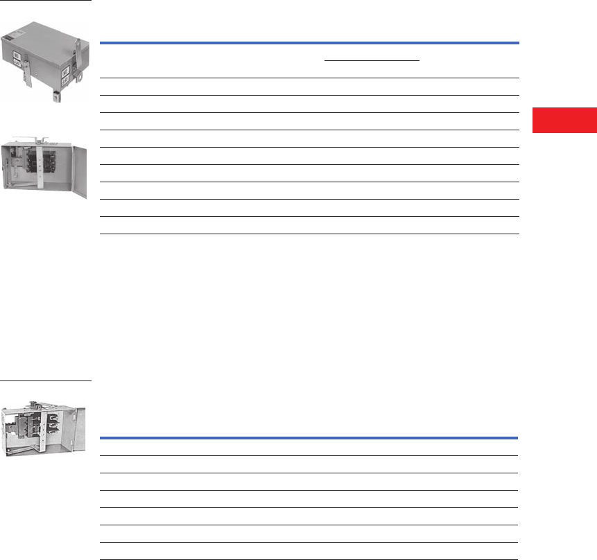
Volume 2—Commercial Distribution CA08100003E—April 2014 www.eaton.com V2-T6-33
6
6
6
6
6
6
6
6
6
6
6
6
6
6
6
6
6
6
6
6
6
6
6
6
6
6
6
6
6
6
6.2
Low Voltage Busway
Pow-R-Way
Product Selection
General Information
●Determine the total
footage, all fittings, and
accessories for entire
busway run. Price the
total footage by type and
system requirements.
Round footage up to the
nearest foot. Add the
fabrication charge for the
fittings. Add any additional
accessories required for
the total price of the
busway run
●When pricing a cable tap
box or a weatherhead,
include the price of 4 ft
(1.2m) of feeder busway to
the fabrication charge
●Cable tap boxes include
1/0 to 600 kcmil lugs. For
additional lugs, larger lugs,
or compression type lugs,
refer to Eaton’s busway
●Additional fittings on
Page V2-T6-39
Plug-In
●Straight sections of plug-in
busway are available in
2 ft (0.6m) increments
from a 2 ft (0.6m)
minimum to a 10 ft (3m)
maximum
Feeder
●Straight sections of feeder
busway are available in
1/8-inch (3.2 mm)
increments from
16 in (406 mm) minimum
to 10 ft (3m) maximum
Hangers
●The busway price includes
one horizontal hanger
per 10 ft (3m) of busway.
All vertical hangers and
any additional horizontal
hangers should be
added to the total price
Circuit Breaker Plug-In Units
Circuit Breaker Plug-In Units
●Refer to Page V2-T6-22
for breaker data; for
reference only
Note: The enclosure, circuit
breaker, neutral and ground are
ordered and shipped
assembled. See Page V2-T6-14
for plug assembled style number
configuration.
●Bolt-on units require a
power take-off at the
rating of the busway
●Also available in bolt-on unit
Fusible Plug-In Units
Fusible Switch Horsepower Ratings
Breaker
Frame
Ampere
Rating
Plug-in Enclosure
Catalog Number
100% Neutral Stab
Catalog Number
50% Internal Ground Stab
Catalog Number
ED, EHD, FDB, FD, HFD,
FDC, EDH, EDC
15–150 IBPFD PWN110 (15–110A) PIGS104
PWN150 (125–250A)
JDB, JD, HJD, JDC 70–250 IBPJD PWN250 (125–250A) PIGS104
KDB, KD, HKD, KDC 100–400 IBPKD PWN400 (150–400A) PIGS104
LDB, LD, HLD, LDC 300–600 IBPLD PWN600 (300–600A) PIGS208
MDL, HMDL 400–800 IBPMD PWN800 (400–800A) PIGS608
FB TRI-PAC®15–100 IBPFBP PWN110 (15–100A) PIGS104
LA TRI-PAC 125–400 IBPLAP PWN400 (125–400A) PIGS104
NB TRI-PAC 500–800 IBPNBP PWN800 (500–800A) PIGS208
FCL Current Limit-R 15–100 IBPFCL PWN110 (15–110A) PIGS104
LCL Current Limit-R 125–400 IBPLCL PWN400 (125–400A) —
Pow-R-Way Bus Plug
(Open View)
Pow-R-Way Bus Plug
Ampere
Rating
240V 480V 600V
NEC
Standard Maximum
NEC
Standard Maximum
NEC
Standard Maximum
3037-1/2515 7-1/220
60 7-1/2 15 15 30 15 50
100 15 30 25 60 30 75
200 25 60 50 125 60 150
400 50 125 100 250 125 350
600 75 200 150 400 200 500
800 100 250 200 500 250 500
Fusible ITAP

V2-T6-34 Volume 2—Commercial Distribution CA08100003E—April 2014 www.eaton.com
6
6
6
6
6
6
6
6
6
6
6
6
6
6
6
6
6
6
6
6
6
6
6
6
6
6
6
6
6
6
6.2
Low Voltage Busway
Pow-R-Way
Fusible Plug-In Units
●Fuses are not included
●Mechanical lugs are
provided. If compression
lugs are required, the size
must be specified
●Plug-in unit, neutral and
ground are ordered and
shipped assembled
Note: See Page V2-T6-14 for
plug assembled style number
configuration.
●H-Fuse clips are supplied
as standard
●Bolt-on units require
a power take-off at the
rating of the busway
●Bolt-on units are available
●If R-Fuse clips are
required, add an “R” to
the end of the catalog
number (30–600A only)
Special Industry Fusible Plug-In Units
●Fuses are not included
●Grounding compression lug
included on 200A and
above. Lugs are ordered
and shipped separately;
fuses are not included
●H-Fuse clips are supplied
as standard
●If J- or R-Fuse clips are
required, order by description
Pow-R-Way Plug-In Cable Tap Box Units
Note
1Grounds and neutrals must be factory assembled. Order by description. See Page V2-T6-10.
Ampere
Rating
Enclosure 600V
Catalog Number
Enclosure 240V
Catalog Number
100% Neutral Stab
Catalog Number
50% Internal
Ground Stab
Catalog Number
Class R Fuse Clips (If Required)
600V
Catalog Number
240V
Catalog Number
30 ITAP361 ITAP321 PWN110 PIGS104 RFK161 RFK121
60 ITAP362 ITAP322 PWN110 PIGS104 RFK262 RFK222
100 ITAP363 ITAP323 PWN110 PIGS104 RFK464 RFK464
200 ITAP364 ITAP324 PWNF250 PIGS208 RFK464 RFK464
400 ITAP365 ITAP325 PWN400 PIGS208 RFK666 RFK666
600 ITAP366 ITAP326 PWN600 PIGS208 RFK666 RFK666
800 ITAP367 ITAP327 PWN800 PIGS208 — —
Ampere
Rating
Enclosure 600V
Catalog Number
100% Neutral Stab
Catalog Number
50% Internal Ground Stab
Catalog Number
Terminal Kit Compression Lugs
Number
Per Phase Wire Size Catalog Number
30 ITAP361H 11 1 1–#12 to #10 CTK30SC
60 ITAP362H 11 1 1–#8 CTK60SC
100 ITAP363H 11 1 1–#4 CTK100SC
200 ITAP364H 11 11–2/0CTK200BSC
400 ITAP365H 11 1 1–750 kcmil CTK400SPW
600 ITAP366H 11 2 2–500 kcmil CTK600DPM
Ampere
Rating
Enclosure 600V
Catalog Number
100% Neutral Stab
Catalog Number
50% Internal Ground Stab
Catalog Number
225 IPTB225 PWN225 PIGS208
400 IPTB400 PWN400 PIGS208
600 IPTB600 PWN600 PIGS208
1000 IPTB1000 PWN1000 PIGS208
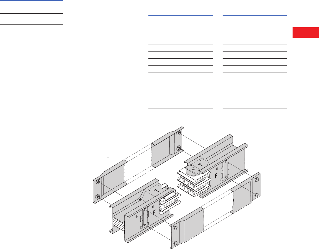
Volume 2—Commercial Distribution CA08100003E—April 2014 www.eaton.com V2-T6-35
6
6
6
6
6
6
6
6
6
6
6
6
6
6
6
6
6
6
6
6
6
6
6
6
6
6
6
6
6
6
6.2
Low Voltage Busway
Pow-R-Way
Accessories
Accessories and
Renewal Parts
Description
Catalog
Number
Indoor joint cover PWIJC
Outdoor joint cover PWOJC
Hookstick kit—
8–14 ft (2.4–4.3m)
HS8-14
Joint puller PWJP
Technical Data and Specifications
The following systems are
available:
●Three-phase, three-wire
●Three-phase, three-wire,
with 50% internal ground
●Three-phase, four-wire
(100% neutral)
●Three-phase, four-wire
(100% neutral) with 50%
internal ground
●All three-wire systems
have a maximum voltage
rating of 600V and all
four-wire systems have
a maximum of 347/600V
Note: The Pow-R-Way bus
housing is NOT suitable for
use as ground.
Short-Circuit Withstand
Ratings—rms Symmetrical
Amperes for Copper
Pow-R-Way Plug-In
and Feeder Busway
Short-Circuit Withstand
Rating—rms Symmetrical
Amperes for Aluminum
Pow-R-Way Plug-In and
Feeder Busway
Typical Pow-R-Way Joint (Single Bolt Construction, One Bar per Phase, See AD 30-560)
Ampere
Rating
3-Cycle
Copper
Plug-In
3-Cycle
Copper
Feeder
225 18,000 18,000
400 25,000 25,000
600 50,000 75,000
800 50,000 75,000
1000 100,000 100,000
1200 100,000 100,000
1350 100,000 100,000
1600 100,000 100,000
2000 100,000 100,000
2500 150,000 150,000
3000 150,000 150,000
4000 200,000 200,000
5000 — 200,000
Ampere
Rating
3-Cycle
Aluminum
Plug-In
3-Cycle
Aluminum
Feeder
225 18,000 18,000
400 25,000 25,000
600 50,000 75,000
800 100,000 100,000
1000 100,000 100,000
1200 100,000 100,000
1350 100,000 100,000
1600 100,000 100,000
2000 100,000 100,000
2500 150,000 150,000
3000 150,000 150,000
4000 200,000 270,000
5000 — —
Joint Cover
16 Inches
(406.4 mm) Long
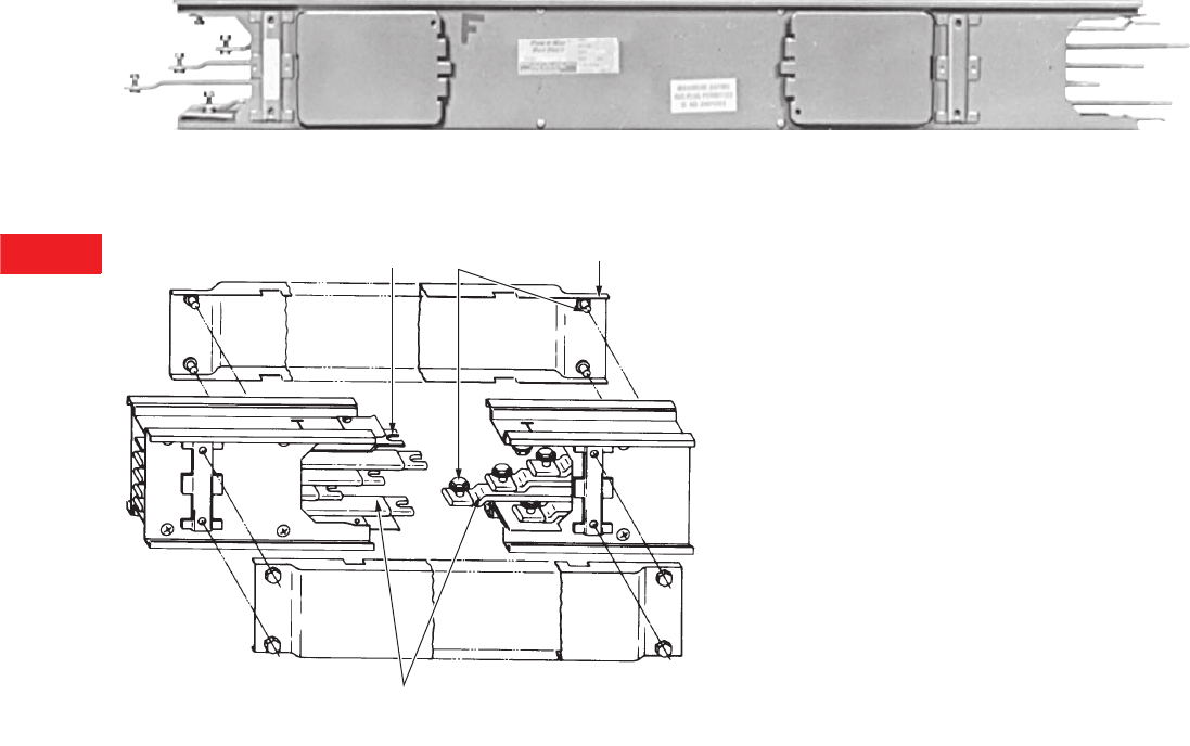
V2-T6-36 Volume 2—Commercial Distribution CA08100003E—April 2014 www.eaton.com
6
6
6
6
6
6
6
6
6
6
6
6
6
6
6
6
6
6
6
6
6
6
6
6
6
6
6
6
6
6
6.2
Low Voltage Busway
Pow-R-Way
Typical Pow-R-Way II Plug-In Straight Length
Ty p i c a l P o w - R - Wa y II Joint (Single Bolt per Busbar, Pow-R-Way II)
Internal Ground
(Optional)
Captive
Hardware
Joint Cover
16 Inches (406.4 mm) Long
Insulated Busbars
FF
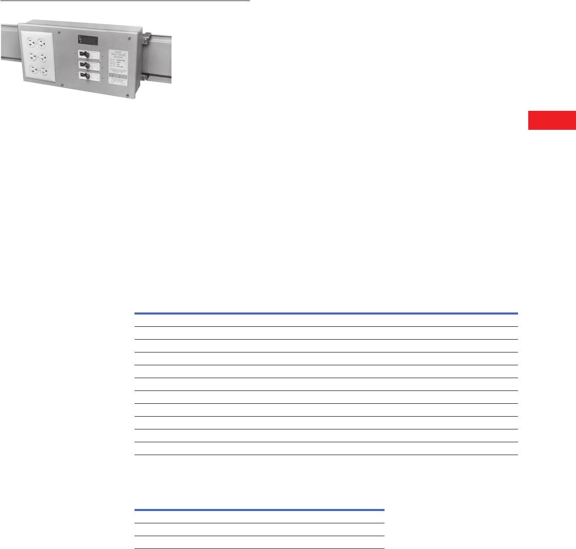
Volume 2—Commercial Distribution CA08100003E—April 2014 www.eaton.com V2-T6-37
6
6
6
6
6
6
6
6
6
6
6
6
6
6
6
6
6
6
6
6
6
6
6
6
6
6
6
6
6
6
6.3
Low Voltage Busway
100A Busway
Bus Plug Receptacle
Contents
Description Page
100A Busway
Options and Accessories . . . . . . . . . . . . . . . . . V2-T6-38
Technical Data and Specifications . . . . . . . . . . V2-T6-39
100A Busway
Product Description
Plug-In Busway
●100A copper
●Straight sections of
plug-in busway
●Three-phase, three-wire;
three-phase, four-wire; and
single-phase, three-wire
applications
Application Description
Eaton 100A busway is
an alternative to cable in
supplying small blocks
of power for the normal
commercial and industrial
power systems. 100A
busway is practical for
small shops, laboratories,
classrooms and light
manufacturing.
Product Selection
Busway
Cable Tap Boxes
Description
Three-Phase, Three-Wire
600V Maximum
Catalog Number
Three-Phase, Four-Wire
FN 277/480V
Catalog Number
Single-Phase, Three-Wire
120/240V
Catalog Number
Copper (Includes 50% Internal Ground Bar)
10 ft (3m) CST13G CST14G CST13NG
5 ft (1.5m) CST135G CST145G CST13N5G
3 ft (0.9m) CST133G CST143G CST13N3G
2 ft (0.6m) CST132G CST142G CST13N2G
1 ft (0.3m) CST131G CST141G CST13N1G
Elbows 10 x 10 in (254.0 x 254.0 mm)
Forward CFE13G CFE14G CFE13NG
Rearward CRE13G CRE14G CRE13NG
Upward CUE13G CUE14G CUE13NG
Downward CDE13G CDE14G CDE13NG
Type
Three- or Four-Wire
Catalog Number
Ground (If Required)
Catalog Number
Plug-in PIB14 PIGS100
End (R or L) EB14 GL100
Center CBIB14G Included
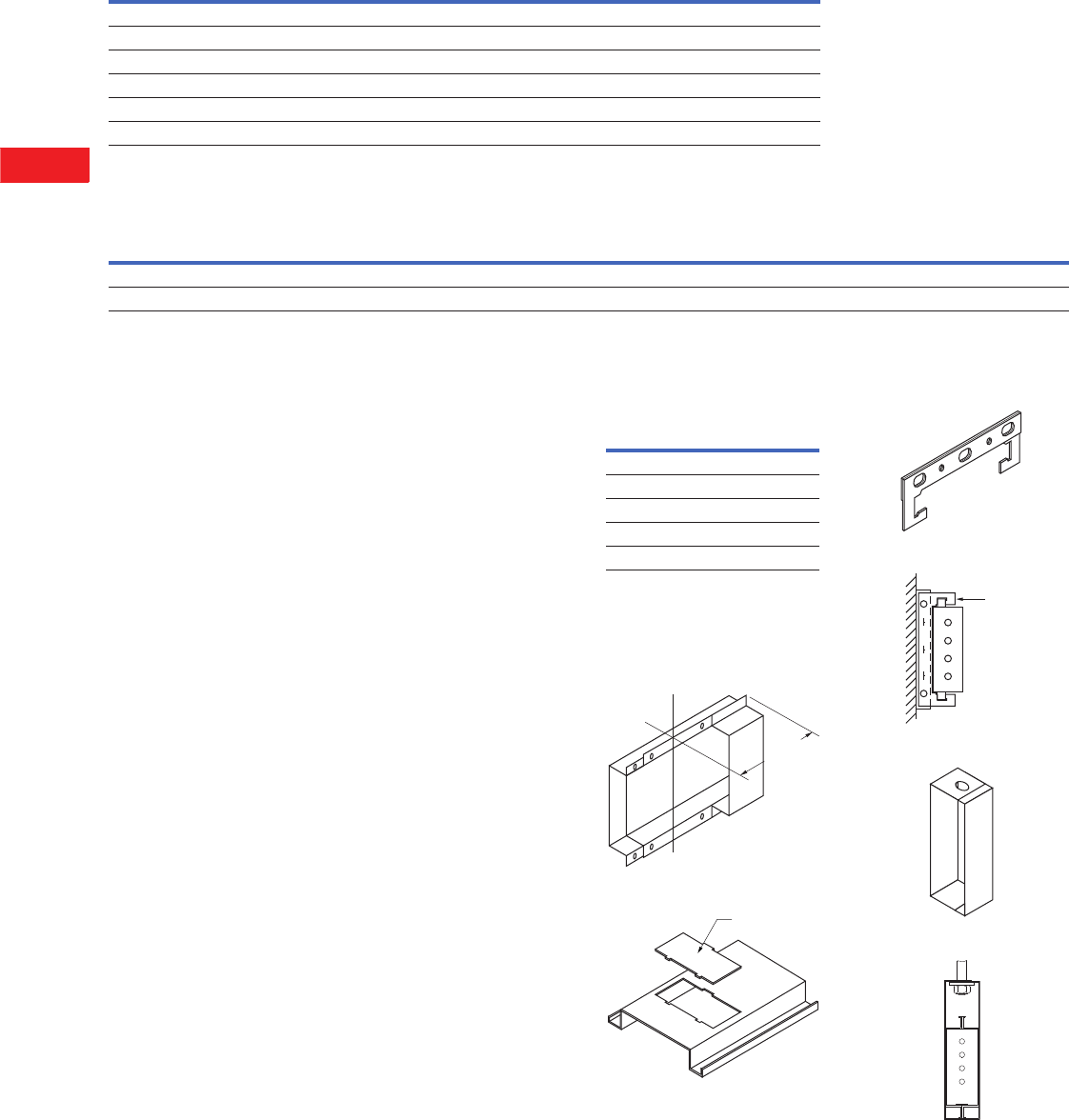
V2-T6-38 Volume 2—Commercial Distribution CA08100003E—April 2014 www.eaton.com
6
6
6
6
6
6
6
6
6
6
6
6
6
6
6
6
6
6
6
6
6
6
6
6
6
6
6
6
6
6
6.3
Low Voltage Busway
10 0 A B u sway
Fusible Plug-In Units
Circuit Breakers for Plug-In Units
Options and Accessories
100A Busway Plug-In Units
Plug-in units for 100A busway
are available with or without
overcurrent protection. All plug-
in units include a neutral stab
and are suitable for three-
phase, three-wire, and three-
phase, four-wire applications.
The PINQP circuit breaker
enclosures and the LCNQP
and LCNFD receptacle
enclosures are all suitable
for single-phase, three-wire
applications. Ground
stabs are available for
field installation.
Fusible Units
Fusible units are available
for 30, 60 and 100A service
for 240 or 600V.
Circuit Breaker Units
If you are using circuit
breaker units, the load must
be distributed evenly among
A, B and C phases. To
accomplish this, distribute
the load evenly among
single-, two- and three-pole
breakers. Available are
QUICKLAG®“HQP” circuit
breaker units for 50A–240V
maximum service, “EHD,
FDB and FD” circuit breakers
for 100A–600V maximum
service.
External Handle
Operating Mechanism
An external operating
mechanism is attached on
top of the breaker switch for
hookstick or chain operation.
This is available for all
circuit breakers.
Receptacle Enclosures
The receptacle enclosures
(loadcenters) include space
for three breaker poles and
provisions for one, two or
three conventional, single-
gang outlets, and blank
covers to fill unused spaces.
Include neutral stab. Do not
include breakers, outlets
or wiring.
The enclosure, circuit breaker
(if required) and ground
are ordered separately
and shipped unassembled.
If the unit is to be factory
assembled, please indicate
on the order, add 15% to
the total price, and allow
additional time for shipment.
For circuit breaker selection,
see Page V2-T6-22.
Accessories
Note
The above items can be used with or without
ground, three-wire or four-wire.
Accessories
End Closers—EC1
Replacement Outlet Cover—OC1
Hangers
“C” Clamp—FH1
Wall Mounted
Edgewise—EH1
Edge Mounted
Voltage
Rating
Ampere
Rating
Fusible Enclosure
Catalog Number
Ground (If Required)
Catalog Number
240 30 FAN321 PIGS100
240 60 FAN322 PIGS100
240 100 FAN323 PIGS100
600 30 FAN361 PIGS100
600 60 FAN362 PIGS100
600 100 FAN363 PIGS100
Breaker
Frame
Ampere
Rating
Circuit Breaker
Enclosure
Catalog Number
Receptacle
Enclosure
Catalog Number
Ground
(If Required)
Catalog Number
External Handle (Required
for Hook-Stick Operation)
Catalog Number
QUICKLAG, HQP 15–50 PINQP LCNQP PIGS100 HMQP
FD, EHD, FDB 15–100 PINFD LCNFD PIGS100 HMFD
Item
Catalog
Number
End closer EC1
Outlet cover OC1
Edgewise hanger EH1
“C” clamp hanger FH1
Slip-on wall flange WF1
C
LJoint
4.00
(101.6)
Outlet Cover
Angle
Iron
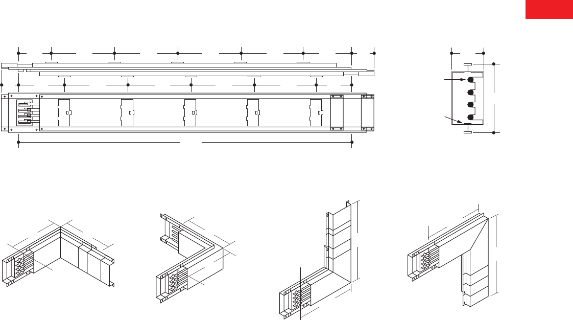
Volume 2—Commercial Distribution CA08100003E—April 2014 www.eaton.com V2-T6-39
6
6
6
6
6
6
6
6
6
6
6
6
6
6
6
6
6
6
6
6
6
6
6
6
6
6
6
6
6
6
6.3
Low Voltage Busway
100A Busway
Technical Data and Specifications
Electrical conductors are
silver-plated round copper
rods. A 50% internal ground
bar is supplied as standard.
Busway with ground will
match existing busway
without ground. The housing
is formed from two channels
of 20-gauge steel riveted
together in a solid assembly
and painted ANSI 6.1.
Conductor joints are made by
means of boltless pressure
clips that require no assembly
or adjustment by the installer.
The busbars are firmly
supported by molded
insulators on the alternate
side of the busway.
100A Busway and Fittings
10"
10"
10"
10"
C
L Joint
C
L Joint
10"
10"
C
L Joint
10"
10"
C
L Joint
FRONT
C
L C
L
120.00
(3048.0)
Joint Joint
50% Internal Ground
Neutral
Busbar Size:
0.281 (7.1) Dia.
26.25
(666.8)
26.25
(666.8)
26.25
(666.8)
26.25
(666.8)
26.25
(666.8)
26.25
(666.8)
26.25
(666.8)
6.00
(152.4)
6.00
(152.4)
3.50
(88.9)
3.50
(88.9)
9.00
(228.6)
26.25
(666.8)
9.00
(228.6)
1.75
(44.4)
5.37
(136.5)
Typical 100A Busway, Straight Length Typical Cross-Section
10.00 (254.0) x 10.00 (254.0) 10.00 (254.0) x 10.00 (254.0) 10.00 (254.0) x 10.00 (254.0) 10.00 (254.0) x 10.00 (254.0)
Forward Elbow Rearward Elbow Upward Elbow Downward Elbow

Volume 2—Commercial Distribution CA08100003E—April 2014 www.eaton.com V2-A1-1
Appendix 1—Eaton Terms & Conditions
Effective Date: November 1, 2008
Eaton Terms & Conditions
Contents
Description Page
Terms and Conditions of Sale. . . . . . . . . . . . . . . . . V2-A1-1
Terms of Payment . . . . . . . . . . . . . . . . . . . . . . . . . V2-A1-2
Freight . . . . . . . . . . . . . . . . . . . . . . . . . . . . . . . . . . V2-A1-3
Warranty . . . . . . . . . . . . . . . . . . . . . . . . . . . . . . . . . V2-A1-3
Selling Policy (Supersedes Selling Policy 25-000, dated February 20, 2006)
Terms and Conditions of Sale
The Terms and Conditions of
Sale set forth herein, and any
supplements which may be
attached hereto, constitute
the full and final expression
of the contract for the sale
of products or services
(hereinafter referred to as
Product(s) or Services by
Eaton Corporation
(hereinafter referred to as
Seller) to the Buyer, and
supersedes all prior
quotations, purchase orders,
correspondence or
communications whether
written or oral between the
Seller and the Buyer.
Notwithstanding any contrary
language in the Buyer’s
purchase order,
correspondence or other
form of acknowledgment,
Buyer shall be bound by
these Terms and Conditions
of Sale when it sends a
purchase order or otherwise
indicates acceptance of this
contract, or when it accepts
delivery from Seller of the
Products or Services.
THE CONTRACT FOR SALE
OF THE PRODUCTS OR
SERVICES IS EXPRESSLY
LIMITED TO THE TERMS
AND CONDITIONS OF SALE
STATED HEREIN. ANY
ADDITIONAL OR DIFFERENT
TERMS PROPOSED BY
BUYER ARE REJECTED
UNLESS EXPRESSLY
AGREED TO IN WRITING BY
SELLER. No contract shall
exist except as herein
provided.
Complete Agreement
No amendment or
modification hereto nor any
statement, representation or
warranty not contained herein
shall be binding on the Seller
unless made in writing by an
authorized representative of
the Seller. Prior dealings,
usage of the trade or a course
of performance shall not be
relevant to determine the
meaning of this contract even
though the accepting or
acquiescing party had
knowledge of the nature
of the performance and
opportunity for objection.
Quotations
Written quotations are valid
for 30 days from its date
unless otherwise stated in
the quotation or terminated
sooner by notice.
Verbal quotations, unless
accepted, expire the same
day they are made.
A complete signed order
must be received by Seller
within 20 calendar days of
notification of award,
otherwise the price and
shipment will be subject to
re-negotiation.
Termination and Cancellation
Any order may be terminated
by the Buyer only by written
notice and upon payment
of reasonable termination
charges, including all costs
plus profit.
Seller shall have the right to
cancel any order at any time
by written notice if Buyer
breaches any of the terms
hereof, becomes the subject
of any proceeding under state
or federal law for the relief
of debtors, or otherwise
becomes insolvent or
bankrupt, generally does not
pay its debts as they become
due or makes an assignment
for the benefit of creditors.
V2-A1-2 Volume 2—Commercial Distribution CA08100003E—April 2014 www.eaton.com
Appendix 1—Eaton Terms & Conditions
Effective Date: November 1, 2008
Prices
All prices are subject to
change without notice. In the
event of a price change, the
effective date of the change
will be the date of the new
price or discount sheet, letter
or telegram. All quotations
made or orders accepted
after the effective date will be
on the new basis. For existing
orders, the price of the
unshipped portion of an order
will be the price in effect at
time of shipment.
Price Policy—Products and
Services
When prices are quoted as
firm for quoted shipment, they
are firm provided the following
conditions are met:
1. The order is released
with complete
engineering details.
2. Shipment of Products are
made, and Services
purchased are provided
within the quoted
lead time.
3. When drawings for
approval are required
for any Products, the
drawings applicable to
those Products must be
returned within 30*
calendar days from the
date of the original
mailing of the drawings
by Seller. The return
drawings must be
released for manufacture
and shipment and must
be marked “APPROVED”
or “APPROVED AS
NOTED.” Drawing
re-submittals which are
required for any other
reason than to correct
Seller errors will not
extend the 30-day period.
* 60 days for orders
through contractors
to allow time for their
review and approval
before and after
transmitting them
to their customers.
If the Buyer initiates or in
any way causes delays
in shipment, provision of
Services or return of approval
drawings beyond the periods
stated above, the price of the
Products or Services will be
increased 1% per month
or fraction thereof up to a
maximum of 18 months from
the date of the Buyer’s order.
For delays resulting in
shipment or provision of
Services beyond 18 months
from the date of the Buyer’s
order, the price must be
renegotiated.
Price Policy—BLS
Refer to Price Policy 25-050.
Minimum Billing
Orders less than $1,000 will
be assessed a shipping and
handling charge of 5% of the
price of the order, with a
minimum charge of $25.00
unless noted differently on
Product discount sheets.
Taxes
The price does not include
any taxes. Buyer shall be
responsible for the payment
of all taxes applicable to, or
arising from the transaction,
the Products, its sale, value,
or use, or any Services
performed in connection
therewith regardless of
the person or entity
actually taxed.
Terms of Payment
Products
Acceptance of all orders is
subject to the Buyer meeting
Seller’s credit requirements.
Terms of payment are subject
to change for failure to meet
such requirements. Seller
reserves the right at any time
to demand full or partial
payment before proceeding
with a contract of sale as a
result of changes in the
financial condition of the
Buyer. Terms of Payment are
either Net 30 days from the
date of invoice of each
shipment or carry a cash
discount based on Product
type. Specific payment terms
for Products are outlined in
the applicable Product
discount schedules.
Services
Terms of payment are net
within 30 days from date of
invoice for orders amounting
to less than $50,000.00.
Terms of payment for orders
exceeding $50,000.00 shall
be made according to the
following:
1. Twenty percent (20%) of
order value with the
purchase order payable
30 days from date of
invoice.
2. Eighty percent (80%) of
order value in equal
monthly payments over
the performance period
payable 30 days from
date of invoice.
Except for work performed (i)
under a firm fixed price basis
or (ii) pursuant to terms of a
previously priced existing
contract between Seller and
Buyer, invoices for work
performed by Seller shall
have added and noted on
each invoice a charge of 3%
(over and above the price of
the work) which is related
to Seller compliance with
present and proposed
environmental, health, and
safety regulations associated
with prescribed requirements
covering hazardous materials
management and employee
training, communications,
personal protective
equipment, documentation
and record keeping
associated therewith.
Adequate Assurances
If, in the judgment of Seller,
the financial condition of the
Buyer, at any time during the
period of the contract, does
not justify the terms of
payment specified, Seller
may require full or partial
payment in advance.
Delayed Payment
If payments are not made in
accordance with these terms,
a service charge will, without
prejudice to the right of Seller
to immediate payment, be
added in an amount equal to
the lower of 1.5% per month
or fraction thereof or the
highest legal rate on the
unpaid balance.
Volume 2—Commercial Distribution CA08100003E—April 2014 www.eaton.com V2-A1-3
Appendix 1—Eaton Terms & Conditions
Effective Date: November 1, 2008
Freight
Freight policy will be listed on
the Product discount sheets,
or at option of Seller one of
the following freight terms
will be quoted.
F.O.B.—P/S—Frt./Ppd. and
Invoiced
Products are sold F.O.B. point
of shipment freight prepaid
and invoiced to the Buyer.
F.O.B.—P/S—Frt./Ppd.
and Allowed
Products sold are delivered
F.O.B. point of shipment,
freight prepaid and included
in the price.
F.O.B. Destination—Frt./Ppd.
and Allowed
At Buyer’s option, Seller will
deliver the Products F.O.B.
destination freight prepaid
and 2% will be added to the
net price.
The term “freight prepaid”
means that freight charges
will be prepaid to the
accessible common carrier
delivery point nearest the
destination for shipments
within the United States and
Puerto Rico unless noted
differently on the Product
discount sheets. For any
other destination contact
Seller’s representative.
Shipment and Routing
Seller shall select the point of
origin of shipment, the
method of transportation, the
type of carrier equipment and
the routing of the shipment.
If the Buyer specifies a
special method of
transportation, type of carrier
equipment, routing, or
delivery requirement, Buyer
shall pay all special freight
and handling charges.
When freight is included in
the price, no allowance will
be made in lieu of
transportation if the Buyer
accepts shipment at factory,
warehouse, or freight station
or otherwise supplies its own
transportation.
Risk of Loss
Risk of loss or damage to the
Products shall pass to Buyer
at the F.O.B. point.
Concealed Damage
Except in the event of F.O.B.
destination shipments, Seller
will not participate in any
settlement of claims for
concealed damage.
When shipment has been
made on an F.O.B. destination
basis, the Buyer must unpack
immediately and, if damage is
discovered must:
1. Not move the Products
from the point of
examination.
2. Retain shipping container
and packing material.
3. Notify the carrier in
writing of any apparent
damage.
4. Notify Seller
representative within
72 hours of delivery.
5. Send Seller a copy of
the carrier’s inspection
report.
Witness Tests/Customer
Inspection
Standard factory tests may be
witnessed by the Buyer
at Seller’s factory for an
additional charge calculated
at the rate of $2,500 per day
(not to exceed eight (8) hours)
per Product type. Buyer may
final inspect Products at the
Seller’s factory for $500 per
day per Product type.
Witness tests will add one (1)
week to the scheduled
shipping date. Seller will
notify Buyer fourteen (14)
calendar days prior to
scheduled witness testing
or inspection. In the event
Buyer is unable to attend, the
Parties shall mutually agree
on a rescheduled date.
However, Seller reserves
the right to deem the witness
tests waived with the right to
ship and invoice Products.
Held Orders
For any order held, delayed
or rescheduled at the request
of the Buyer, Seller may, at
its sole option (1) require
payment to be based on any
reasonable basis, including
but not limited to the contract
price, and any additional
expenses, or cost resulting
from such a delay; (2) store
Products at the sole cost and
risk of loss of the Buyer; and/
or (3) charge to the Buyer
those prices under the
applicable price policy.
Payment for such price,
expenses and costs, in any
such event, shall be due by
Buyer within thirty (30) days
from date of Seller’s invoice.
Any order so held delayed or
rescheduled beyond six (6)
months will be treated as a
Buyer termination.
Drawing Approval
Seller will design the
Products in line with, in
Seller’s judgment, good
commercial practice. If at
drawing approval Buyer
makes changes outside of
the design as covered in their
specifications, Seller will then
be paid reasonable charges
and allowed a commensurate
delay in shipping date based
on the changes made.
Drawing Re-Submittal
When Seller agrees to do so
in its quotation, Seller shall
provide Buyer with the first
set of factory customer
approval drawing(s) at Seller’s
expense. The customer
approval drawing(s) will be
delivered at the quoted
delivery date. If Buyer
requests drawing changes
or additions after the initial
factory customer approval
drawing(s) have been
submitted by Seller, the
Seller, at its option, may
assess Buyer drawing
charges. Factory customer
approval drawing changes
required due to
misinterpretation by Seller
will be at Seller’s expense.
Approval drawings generated
by Bid Manager are excluded
from this provision.
Warranty
Warranty for Products
Seller warrants that the
Products manufactured by
it will conform to Seller’s
applicable specifications and
be free from failure due to
defects in workmanship and
material for one (1) year from
the date of installation of
the Product or eighteen (18)
months from the date of
shipment of the Product,
whichever occurs first.
In the event any Product fails
to comply with the foregoing
warranty Seller will, at its
option, either (a) repair or
replace the defective
Product, or defective part or
component thereof, F.O.B.
Seller’s facility freight
prepaid, or (b) credit Buyer
for the purchase price of the
Product. All warranty claims
shall be made in writing.
Seller requires all non-
conforming Products be
returned at Seller’s expense
for evaluation unless
specifically stated otherwise
in writing by Seller.
This warranty does not
cover failure or damage
due to storage, installation,
operation or maintenance not
in conformance with Seller’s
recommendations and
industry standard practice
or due to accident, misuse,
abuse or negligence. This
warranty does not cover
reimbursement for labor,
gaining access, removal,
installation, temporary power
or any other expenses, which
may be incurred in connection
with repair or replacement.
This warranty does not
apply to equipment not
manufactured by Seller.
Seller limits itself to
extending the same warranty
it receives from the supplier.
V2-A1-4 Volume 2—Commercial Distribution CA08100003E—April 2014 www.eaton.com
Appendix 1—Eaton Terms & Conditions
Effective Date: November 1, 2008
Extended Warranty for Products
If requested by the Buyer and
specifically accepted in
writing by Seller, the
foregoing standard warranty
for Products will be extended
from the date of shipment for
the period and price indicated
below:
●24 months—2% of
Contract Price
●30 months—3% of
Contract Price
●36 months—4% of
Contract Price
Special Warranty (In and Out)
for Products
If requested by the Buyer
and specifically accepted in
writing by Seller, Seller will,
during the warranty period
for Products, at an additional
cost of 2% of the contract
price, be responsible for the
direct cost of:
1. Removing the Product
from the installed
location.
2. Transportation to the
repair facility and return
to the site.
3. Reinstallation on site.
The total liability of Seller for
this Special Warranty for
Products is limited to 50%
of the contract price of the
particular Product being
repaired and excludes
expenses for removing
adjacent apparatus, walls,
piping, structures, temporary
service, etc.
Warranty for Services
Seller warrants that the
Services performed by it
hereunder will be performed
in accordance with generally
accepted professional
standards.
The Services, which do not
so conform, shall be
corrected by Seller upon
notification in writing by the
Buyer within one (1) year
after completion of the
Services.
Unless otherwise agreed to in
writing by Seller, Seller
assumes no responsibility
with respect to the suitability
of the Buyer’s, or its
customer’s, equipment or
with respect to any latent
defects in equipment not
supplied by Seller. This
warranty does not cover
damage to Buyer’s, or its
customer’s, equipment,
components or parts
resulting in whole or in part
from improper maintenance
or operation or from their
deteriorated condition. Buyer
will, at its cost, provide Seller
with unobstructed access
to the defective Services,
as well as adequate free
working space in the
immediate vicinity of the
defective Services and such
facilities and systems,
including, without limitation,
docks, cranes and utility
disconnects and connects,
as may be necessary in order
that Seller may perform its
warranty obligations. The
conducting of any tests shall
be mutually agreed upon and
Seller shall be notified of, and
may be present at, all tests
that may be made.
Warranty for Power Systems
Studies
Seller warrants that any
power systems studies
performed by it will conform
to generally accepted
professional standards. Any
portion of the study, which
does not so conform, shall
be corrected by Seller upon
notification in writing by the
Buyer within six (6) months
after completion of the study.
All warranty work shall be
performed in a single shift
straight time basis Monday
through Friday. In the event
that the study requires
correction of warranty items
on an overtime schedule,
the premium portion of such
overtime shall be for the
Buyer’s account.
Limitation on Warranties for
Products, Services and Power
Systems Studies
THE FOREGOING
WARRANTIES ARE
EXCLUSIVE EXCEPT FOR
WARRANTY OF TITLE.
SELLER DISCLAIMS ALL
OTHER WARRANTIES
INCLUDING ANY IMPLIED
WARRANTIES OF
MERCHANTABILITY
AND FITNESS FOR A
PARTICULAR PURPOSE.
CORRECTION OF NON-
CONFORMITIES IN THE
MANNER AND FOR THE
PERIOD OF TIME PROVIDED
ABOVE SHALL CONSTITUTE
SELLER’S SOLE LIABILITY
AND BUYER’S EXCLUSIVE
REMEDY FOR FAILURE OF
SELLER TO MEET ITS
WARRANTY OBLIGATIONS,
WHETHER CLAIMS OF
THE BUYER ARE BASED
IN CONTRACT, IN TORT
(INCLUDING NEGLIGENCE
OR STRICT LIABILITY), OR
OTHERWISE.
Asbestos
Federal Law requires that
building or facility owners
identify the presence,
location and quantity of
asbestos containing material
(hereinafter “ACM”) at work
sites. Seller is not licensed to
abate ACM. Accordingly, for
any contract which includes
the provision of Services,
prior to (i) commencement of
work at any site under a
specific Purchase Order, (ii) a
change in the work scope of
any Purchase Order, the
Buyer will certify that the
work area associated with the
Seller’s scope of work
includes the handling of Class
II ACM, including but not
limited to generator wedges
and high temperature gaskets
which include asbestos
materials. The Buyer shall, at
its expense, conduct
abatement should the
removal, handling,
modification or reinstallation,
or some or all of them, of said
Class II ACM be likely to
generate airborne asbestos
fibers; and should such
abatement affect the cost
of or time of performance
of the work then Seller shall
be entitled to an equitable
adjustment in the schedule,
price and other pertinent
affected provisions of
the contract.
Compliance with Nuclear
Regulation
Seller’s Products are sold as
commercial grade Products
not intended for application in
facilities or activities licensed
by the United States Nuclear
Regulatory Commission for
atomic purposes. Further
certification will be required
for use of the Products in any
safety-related application in
any nuclear facility licensed
by the U.S. Nuclear
Regulatory Commission.
Volume 2—Commercial Distribution CA08100003E—April 2014 www.eaton.com V2-A1-5
Appendix 1—Eaton Terms & Conditions
Effective Date: November 1, 2008
Returning Products
Authorization and shipping
instructions for the return
of any Products must be
obtained from Seller before
returning the Products.
When return is occasioned
due to Seller error, full credit
including all transportation
charges will be allowed.
Product Notices
Buyer shall provide the user
(including its employees) of
the Products with all Seller
supplied Product notices,
warnings, instructions,
recommendations, and
similar materials.
Force Majeure
Seller shall not be liable for
failure to perform or delay
in performance due to fire,
flood, strike or other labor
difficulty, act of God, act of
any governmental authority or
of the Buyer, riot, embargo,
fuel or energy shortage, car
shortage, wrecks or delays in
transportation, or due to any
other cause beyond Seller’s
reasonable control. In the
event of delay in performance
due to any such cause, the
date of delivery or time for
completion will be extended
by a period of time reasonably
necessary
to overcome the
effect of such delay.
Liquidated Damages
Contracts which include
liquidated damage clauses for
failure to meet shipping or job
completion promises are not
acceptable or binding on
Seller, unless such clauses
are specifically accepted in
writing by an authorized
representative of the Seller at
its headquarters office.
Patent Infringement
Seller will defend or, at its
option, settle any suit or
proceeding brought against
Buyer, or Buyer’s customers,
to the extent it is based upon
a claim that any Product or
part thereof, manufactured by
Seller or its subsidiaries and
furnished hereunder,
infringes any United States
patent, other than a claim of
infringement based upon use
of a Product or part thereof in
a process, provided Seller is
notified in reasonable time
and given authority,
information and assistance
(at Seller’s expense) for the
defense of same. Seller shall
pay all legal and court costs
and expenses and court-
assessed damages awarded
therein against Buyer
resulting from or incident to
such suit or proceeding. In
addition to the foregoing, if at
any time Seller determines
there is a substantial question
of infringement of any United
States patent, and the use of
such Product is or may be
enjoined, Seller may, at its
option and expense: either (a)
procure for Buyer the right to
continue using and selling the
Product; (b) replace the
Product with non-infringing
apparatus; (c) modify the
Product so it becomes non-
infringing; or (d) as a last
resort, remove the Product
and refund the purchase
price, equitably adjusted for
use and obsolescence. In no
case does Seller agree to pay
any recovery based upon its
Buyer’s savings or profit
through use of Seller’s
Products whether the use be
special or ordinary. The
foregoing states the entire
liability of Seller for patent
infringement.
The preceding paragraph
does not apply to any claim of
infringement based upon: (a)
any modification made to a
Product other than by Seller;
(b) any design and/or
specifications of Buyer to
which a Product was
manufactured; or (c) the use
or combination of Product
with other products where
the Product does not itself
infringe. As to the above-
identified claim situations
where the preceding
paragraph does not apply,
Buyer shall defend and hold
Seller harmless in the same
manner and to the extent as
Seller’s obligations described
in the preceding paragraph.
Buyer shall be responsible for
obtaining (at Buyer’s
expense) all license rights
required for Seller to be able
to use software products in
the possession of Buyer
where such use is required in
order to perform any Service
for Buyer.
With respect to a Product or
part thereof not manufactured
by Seller or its subsidiaries,
Seller will attempt to obtain
for Buyer, from the supplier(s),
the patent indemnification
protection normally provided
by the supplier(s) to
customers.
Limitation of Liability
THE REMEDIES OF THE
BUYER SET FORTH IN THIS
CONTRACT ARE EXCLUSIVE
AND ARE ITS SOLE
REMEDIES FOR ANY
FAILURE OF SELLER
TO COMPLY WITH ITS
OBLIGATIONS HEREUNDER.
NOTWITHSTANDING
ANY PROVISION IN THIS
CONTRACT TO THE
CONTRARY, IN NO EVENT
SHALL SELLER BE LIABLE
IN CONTRACT, IN TORT
(INCLUDING NEGLIGENCE
OR STRICT LIABILITY) OR
OTHERWISE FOR DAMAGE
TO PROPERTY OR
EQUIPMENT OTHER THAN
PRODUCTS SOLD
HEREUNDER, LOSS OF
PROFITS OR REVENUE,
LOSS OF USE OF
PRODUCTS, COST OF
CAPITAL, CLAIMS OF
CUSTOMERS OF THE
BUYER OR ANY SPECIAL,
INDIRECT, INCIDENTAL OR
CONSEQUENTIAL
DAMAGES WHATSOEVER,
REGARDLESS OF WHETHER
SUCH POTENTIAL
DAMAGES ARE
FORESEEABLE OR IF
SELLER HAS BEEN ADVISED
OF THE POSSIBILITY OF
SUCH DAMAGES.
THE TOTAL CUMULATIVE
LIABILITY OF SELLER
ARISING FROM OR
RELATED TO THIS
CONTRACT WHETHER
THE CLAIMS ARE BASED
IN CONTRACT, IN TORT
(INCLUDING NEGLIGENCE
OR STRICT LIABILITY) OR
OTHERWISE, SHALL NOT
EXCEED THE PRICE OF THE
PRODUCT OR SERVICES
ON WHICH SUCH LIABILITY
IS BASED.
Volume 2—Commercial Distribution CA08100003E—April 2014 www.eaton.com 1
Appendix 2—Catalog Parent Number Index
A
AC . . . . . . . . . . . . V2-T1-71
ACP . . . . . . . . . . . V2-T1-60
AC1 . . . . . . . . . . . V2-T1-123
AC2 . . . . . . . . . . . V2-T1-123
APJ . . . . . . . . . . . V2-T1-60
B
BAB . . . . . . . . . . . V2-T4-19
BABR. . . . . . . . . . V2-T3-115, V2-T3-116
BX . . . . . . . . . . . . V2-T3-71, V2-T3-74, V2-T3-81, V2-T3-128
B48M . . . . . . . . . V2-T2-64, V2-T2-69
C
CBI . . . . . . . . . . . V2-T6-33
CDE . . . . . . . . . . . V2-T6-33
CFE . . . . . . . . . . . V2-T6-33
CRE . . . . . . . . . . . V2-T6-33
CST . . . . . . . . . . . V2-T6-33
CTK . . . . . . . . . . . V2-T6-16, V2-T6-30
CTXB . . . . . . . . . . V2-T3-35, V2-T3-47
CUE . . . . . . . . . . . V2-T6-33
CUK . . . . . . . . . . . V2-T4-19
C361 . . . . . . . . . . V2-T1-99, V2-T1-100, V2-T1-102
C371 . . . . . . . . . . V2-T1-100
D
DBK . . . . . . . . . . . V2-T4-19
DFD . . . . . . . . . . . V2-T1-106, V2-T1-108, V2-T1-109
DG . . . . . . . . . . . . V2-T1-5
DGD . . . . . . . . . . V2-T1-106, V2-T1-108
DG0 . . . . . . . . . . . V2-T1-14
DG1 . . . . . . . . . . . V2-T1-14
DG2 . . . . . . . . . . . V2-T1-5, V2-T1-14, V2-T1-28, V2-T1-29
DG3 . . . . . . . . . . . V2-T1-5, V2-T1-29
DH . . . . . . . . . . . . V2-T1-6–V2-T1-10, V2-T1-33–V2-T1-41
DH03 . . . . . . . . . . V2-T1-14
DH1 . . . . . . . . . . . V2-T1-14, V2-T1-111
DH16 . . . . . . . . . . V2-T1-68
DH2 . . . . . . . . . . . V2-T1-14, V2-T1-35
DH22 . . . . . . . . . . V2-T1-6, V2-T1-7, V2-T1-33–V2-T1-35, V2-T1-54,
V2-T1-73
DH26 . . . . . . . . . . V2-T1-8–V2-T1-10, V2-T1-36–V2-T1-40, V2-T1-
55, V2-T1-74, V2-T1-77
DH3 . . . . . . . . . . . V2-T1-7, V2-T1-35
DH32 . . . . . . . . . . V2-T1-6, V2-T1-7, V2-T1-18, V2-T1-33–V2-T1-35,
V2-T1-54, V2-T1-57, V2-T1-58, V2-T1-62, V2-T1-
73, V2-T1-77, V2-T1-84, V2-T1-85
DH36 . . . . . . . . . . V2-T1-6–V2-T1-8, V2-T1-9, V2-T1-10, V2-T1-18,
V2-T1-36–V2-T1-40, V2-T1-55, V2-T1-57, V2-T1-
58, V2-T1-60, V2-T1-62, V2-T1-74, V2-T1-75, V2-
T1-77, V2-T1-79, V2-T1-80, V2-T1-84, V2-T1-85
DH42 . . . . . . . . . . V2-T1-6, V2-T1-7, V2-T1-33, V2-T1-34
DH46 . . . . . . . . . . V2-T1-8, V2-T1-9, V2-T1-10, V2-T1-36–V2-T1-40,
V2-T1-75, V2-T1-79
DH66 . . . . . . . . . . V2-T1-10, V2-T1-44
DH8 . . . . . . . . . . . V2-T1-14
DJD . . . . . . . . . . . V2-T1-106, V2-T1-108
DKD . . . . . . . . . . V2-T1-107, V2-T1-109
DP . . . . . . . . . . . V2-T1-5, V2-T1-28
DS . . . . . . . . . . . V2-T1-14, V2-T1-92, V2-T1-100, V2-T1-103
DS0 . . . . . . . . . . V2-T1-15, V2-T1-111
DS1 . . . . . . . . . . V2-T1-14, V2-T1-15, V2-T1-60, V2-T1-111
DS2 . . . . . . . . . . V2-T1-14, V2-T1-15, V2-T1-111
DS3 . . . . . . . . . . V2-T1-14, V2-T1-15, V2-T1-60, V2-T1-64,
V2-T1-111
DS36 . . . . . . . . . V2-T1-64
DS4 . . . . . . . . . . V2-T1-14, V2-T1-15
DS5 . . . . . . . . . . V2-T1-14, V2-T1-15
DS6 . . . . . . . . . . V2-T1-14, V2-T1-60
DS7 . . . . . . . . . . V2-T1-14
DS8 . . . . . . . . . . V2-T1-14, V2-T1-111
DS9 . . . . . . . . . . V2-T1-15, V2-T1-111
DT . . . . . . . . . . . V2-T1-11–V2-T1-12
DT1 . . . . . . . . . . V2-T1-14
DT2 . . . . . . . . . . V2-T1-11, V2-T1-12, V2-T1-14, V2-T1-49
DT22 . . . . . . . . . V2-T1-47, V2-T1-48
DT26 . . . . . . . . . V2-T1-49
DT3 . . . . . . . . . . V2-T1-11–V2-T1-12, V2-T1-49
DT32 . . . . . . . . . V2-T1-48
DT36 . . . . . . . . . V2-T1-49
DT4 . . . . . . . . . . V2-T1-11, V2-T1-12, V2-T1-14
DT46 . . . . . . . . . V2-T1-50
DT6 . . . . . . . . . . V2-T1-12, V2-T1-14
DT66 . . . . . . . . . V2-T1-50
DT8 . . . . . . . . . . V2-T1-14
E
EB . . . . . . . . . . . V2-T6-33
EC . . . . . . . . . . . V2-T6-34
ED . . . . . . . . . . . V2-T4-19
EH . . . . . . . . . . . V2-T6-34
EHD3 . . . . . . . . . V2-T1-106
ER . . . . . . . . . . . V2-T1-123
EXT . . . . . . . . . . V2-T2-191
EZB2 . . . . . . . . . V2-T3-6, V2-T3-29, V2-T3-33, V2-T3-41,
V2-T3-45, V2-T3-61, V2-T3-65
EZTV . . . . . . . . . V2-T3-6
EZT2. . . . . . . . . . V2-T3-6, V2-T3-29, V2-T3-33, V2-T3-41,
V2-T3-45, V2-T3-61, V2-T3-65
F
FAN . . . . . . . . . . V2-T6-34
FD . . . . . . . . . . . V2-T1-106, V2-T4-19
FFD . . . . . . . . . . V2-T1-106, V2-T1-108, V2-T1-109
FH . . . . . . . . . . . V2-T6-34
FJD . . . . . . . . . . V2-T1-106, V2-T1-108
FKD . . . . . . . . . . V2-T1-107, V2-T1-109
G
GHB . . . . . . . . . . V2-T4-19
GHC . . . . . . . . . . V2-T1-106
GHQR . . . . . . . . V2-T3-114, V2-T3-115, V2-T3-116
GL . . . . . . . . . . . V2-T6-33
GTB . . . . . . . . . . V2-T4-22–V2-T4-34
G48M. . . . . . . . . V2-T2-55, V2-T2-59
2 Volume 2—Commercial Distribution CA08100003E—April 2014 www.eaton.com
Appendix 2—Catalog Parent Number Index
H
HKD. . . . . . . . . . . V2-T4-19
HM . . . . . . . . . . . V2-T6-34
HS . . . . . . . . . . . . V2-T6-31
HT20P . . . . . . . . . V2-T2-52, V2-T2-56
H48M . . . . . . . . . V2-T2-53, V2-T2-57
I
IBP. . . . . . . . . . . . V2-T6-29
INK . . . . . . . . . . . V2-T1-111
IPT . . . . . . . . . . . . V2-T6-30
IST . . . . . . . . . . . . V2-T4-19
ITA. . . . . . . . . . . . V2-T6-30
ITAP. . . . . . . . . . . V2-T6-30
J
JDB . . . . . . . . . . . V2-T1-106
JFD . . . . . . . . . . . V2-T1-106, V2-T1-108, V2-T1-109
JGD . . . . . . . . . . . V2-T1-106, V2-T1-108
JJD . . . . . . . . . . . V2-T1-106, V2-T1-108
JKD . . . . . . . . . . . V2-T1-107, V2-T1-109
JLD . . . . . . . . . . . V2-T1-107, V2-T1-109
JLG . . . . . . . . . . . V2-T1-109
JND . . . . . . . . . . . V2-T1-107, V2-T1-109
K
KD . . . . . . . . . . . . V2-T4-19
KDB . . . . . . . . . . . V2-T1-107
L
LCN . . . . . . . . . . . V2-T6-34
LDB . . . . . . . . . . . V2-T1-107
LKS . . . . . . . . . . . V2-T2-192
LL4 . . . . . . . . . . . V2-T4-18
LL8 . . . . . . . . . . . V2-T4-18
LSS . . . . . . . . . . . V2-T4-18
LTC9 . . . . . . . . . . V2-T3-37, V2-T3-49
LTV2 . . . . . . . . . . V2-T3-6, V2-T3-61
LT20 . . . . . . . . . . V2-T3-6, V2-T3-29, V2-T3-33, V2-T3-41, V2-T3-
45, V2-T3-61, V2-T3-65
LY48D . . . . . . . . . V2-T2-137
LY48G . . . . . . . . . V2-T2-137
LY48M. . . . . . . . . V2-T2-137
M
M. . . . . . . . . . . . . V2-T4-19
MBB . . . . . . . . . . V2-T4-17, V2-T4-18
MD . . . . . . . . . . . V2-T2-112–V2-T2-117, V2-T4-19
MDL . . . . . . . . . . V2-T1-107
MSB . . . . . . . . . . V2-T4-17
MV24M . . . . . . . . V2-T2-139
MV24R . . . . . . . . V2-T2-139
MV29M . . . . . . . . V2-T2-138, V2-T2-139
MV29R . . . . . . . . V2-T2-139
MV44M . . . . . . . . V2-T2-140
MV48D . . . . . . . . V2-T2-138
MV48M . . . . . . . . V2-T2-137, V2-T2-138, V2-T2-140, V2-T2-141
MV60M . . . . . . . . V2-T2-141, V2-T2-142
N
ND3 . . . . . . . . . . V2-T1-107
NT20P . . . . . . . . V2-T2-52, V2-T2-56
N48M. . . . . . . . . V2-T2-54, V2-T2-58, V2-T2-65, V2-T2-70
O
OC . . . . . . . . . . . V2-T6-34
P
PIB . . . . . . . . . . . V2-T6-33
PIGS. . . . . . . . . . V2-T6-29, V2-T6-30, V2-T6-33, V2-T6-34
PIN . . . . . . . . . . . V2-T6-34
PRCB . . . . . . . . . V2-T3-121, V2-T3-124
PRCD . . . . . . . . . V2-T3-117, V2-T3-118, V2-T3-125
PRCE . . . . . . . . . V2-T3-120
PRCL . . . . . . . . . V2-T3-118, V2-T3-124, V2-T3-125
PRCN . . . . . . . . . V2-T3-120
PRCPS . . . . . . . . V2-T3-114
PRCS . . . . . . . . . V2-T3-119, V2-T3-121, V2-T3-125
PRCU . . . . . . . . . V2-T3-122, V2-T3-124
PRC10 . . . . . . . . V2-T3-113
PRC75 . . . . . . . . V2-T3-112
PW . . . . . . . . . . . V2-T6-30, V2-T6-31
PWN . . . . . . . . . V2-T6-29, V2-T6-30
P1RB . . . . . . . . . V2-T3-52, V2-T3-57
P1RD . . . . . . . . . V2-T3-57
P1RG . . . . . . . . . V2-T3-57
P1RL . . . . . . . . . V2-T3-52
P1RN . . . . . . . . . V2-T3-57
P2RB . . . . . . . . . V2-T3-53
P2RL . . . . . . . . . V2-T3-53
P3. . . . . . . . . . . . V2-T6-15–V2-T6-18
P3B . . . . . . . . . . V2-T6-15, V2-T6-17, V2-T6-18
P3F. . . . . . . . . . . V2-T6-15–V2-T6-18
P3G . . . . . . . . . . V2-T6-18
P3J. . . . . . . . . . . V2-T6-15, V2-T6-18
P3K . . . . . . . . . . V2-T6-15, V2-T6-18
P3L. . . . . . . . . . . V2-T6-15, V2-T6-18
P3M . . . . . . . . . . V2-T6-15, V2-T6-18
P3N . . . . . . . . . . V2-T6-15, V2-T6-18
P3P . . . . . . . . . . V2-T6-17
P48G . . . . . . . . . V2-T2-121, V2-T2-122
P60G . . . . . . . . . V2-T2-121, V2-T2-122
Q
QS20L . . . . . . . . V2-T2-134
QS20N . . . . . . . . V2-T2-134
R
RFD . . . . . . . . . . V2-T1-106, V2-T1-108, V2-T1-109
RFK . . . . . . . . . . V2-T1-92, V2-T6-30
RGD . . . . . . . . . . V2-T1-106, V2-T1-108
RJD . . . . . . . . . . V2-T1-106, V2-T1-108
RKD . . . . . . . . . . V2-T1-107, V2-T1-109
RL . . . . . . . . . . . V2-T4-18
RLD . . . . . . . . . . V2-T1-107, V2-T1-109
RLG . . . . . . . . . . V2-T1-109
RMB. . . . . . . . . . V2-T4-17, V2-T4-18
Volume 2—Commercial Distribution CA08100003E—April 2014 www.eaton.com 3
Appendix 2—Catalog Parent Number Index
RMS . . . . . . . . . . V2-T4-17
RND. . . . . . . . . . . V2-T1-107, V2-T1-109
RS0 . . . . . . . . . . . V2-T2-192
RS1 . . . . . . . . . . . V2-T2-192
RTA . . . . . . . . . . . V2-T3-54
RTB . . . . . . . . . . . V2-T3-54
RTC . . . . . . . . . . . V2-T3-54
RTD . . . . . . . . . . . V2-T3-54
RTE . . . . . . . . . . . V2-T3-54
RT12M . . . . . . . . V2-T2-135
RT18P . . . . . . . . . V2-T2-136
RT20P . . . . . . . . . V2-T2-135
RT27M . . . . . . . . V2-T2-135
RT29M . . . . . . . . V2-T2-135
RT60M . . . . . . . . V2-T2-136
RUG. . . . . . . . . . . V2-T4-18
S
SC . . . . . . . . . . . . V2-T1-71
SFD . . . . . . . . . . . V2-T1-106, V2-T1-108, V2-T1-109
SGD. . . . . . . . . . . V2-T1-106, V2-T1-108
SJD . . . . . . . . . . . V2-T1-106, V2-T1-108
SKD . . . . . . . . . . . V2-T1-107, V2-T1-109
SLD . . . . . . . . . . . V2-T1-107, V2-T1-109
SLG . . . . . . . . . . . V2-T1-109
SND. . . . . . . . . . . V2-T1-107, V2-T1-109
S10N . . . . . . . . . . V2-T2-94, V2-T2-98, V2-T2-145–V2-T2-165
S12N . . . . . . . . . . V2-T2-98
S20K . . . . . . . . . . V2-T2-95, V2-T2-106
S20L . . . . . . . . . . V2-T2-95, V2-T2-99, V2-T2-106
S20N . . . . . . . . . . V2-T2-95, V2-T2-96, V2-T2-99, V2-T2-106,
V2-T2-145, V2-T2-166–V2-T2-170
S24N . . . . . . . . . . V2-T2-99
S27N . . . . . . . . . . V2-T2-95, V2-T2-99
S29N . . . . . . . . . . V2-T2-94, V2-T2-98
S4P . . . . . . . . . . . V2-T1-123
S40N . . . . . . . . . . V2-T2-96
S48D . . . . . . . . . . V2-T2-97
S48G . . . . . . . . . . V2-T2-97
S48M. . . . . . . . . . V2-T2-97
S54N . . . . . . . . . . V2-T2-96
S60G . . . . . . . . . . V2-T2-97, V2-T2-169, V2-T2-170
S60J . . . . . . . . . . V2-T2-97, V2-T2-169, V2-T2-170
S60M. . . . . . . . . . V2-T2-97
S60N . . . . . . . . . . V2-T2-169, V2-T2-170
T
TS1 . . . . . . . . . . . V2-T1-123
TS3 . . . . . . . . . . . V2-T1-123
T18P . . . . . . . . . . V2-T2-5, V2-T2-7
T20P . . . . . . . . . . V2-T2-4, V2-T2-6, V2-T2-8, V2-T2-10, V2-T2-125,
V2-T2-131, V2-T2-169, V2-T2-170
T27M. . . . . . . . . . V2-T2-5, V2-T2-6, V2-T2-8, V2-T2-10
T27R . . . . . . . . . . V2-T2-5, V2-T2-6, V2-T2-8, V2-T2-10
T29M. . . . . . . . . . V2-T2-4, V2-T2-6, V2-T2-8, V2-T2-10
T29R . . . . . . . . . . V2-T2-4, V2-T2-6, V2-T2-8, V2-T2-10
T42D . . . . . . . . . . V2-T2-175, V2-T2-176
T43P . . . . . . . . . . V2-T2-9, V2-T2-11
T46D . . . . . . . . . V2-T2-175, V2-T2-176
T48M . . . . . . . . . V2-T2-4, V2-T2-6, V2-T2-8
T60M . . . . . . . . . V2-T2-5, V2-T2-7, V2-T2-9, V2-T2-11
T60R . . . . . . . . . V2-T2-9, V2-T2-11
U
UG . . . . . . . . . . . V2-T4-18
UN . . . . . . . . . . . V2-T1-123
V
V24M . . . . . . . . . V2-T2-14, V2-T2-15, V2-T2-25, V2-T2-26,
V2-T2-36, V2-T2-37, V2-T2-44, V2-T2-45
V24R . . . . . . . . . V2-T2-14, V2-T2-15, V2-T2-25, V2-T2-26,
V2-T2-36, V2-T2-37, V2-T2-44, V2-T2-45
V29M . . . . . . . . . V2-T2-12, V2-T2-13, V2-T2-23, V2-T2-24,
V2-T2-34, V2-T2-35, V2-T2-42, V2-T2-43
V29R . . . . . . . . . V2-T2-12, V2-T2-13, V2-T2-23, V2-T2-24,
V2-T2-34, V2-T2-35, V2-T2-42, V2-T2-43
V42D . . . . . . . . . V2-T2-177, V2-T2-179, V2-T2-181, V2-T2-183
V44M . . . . . . . . . V2-T2-16, V2-T2-27, V2-T2-38, V2-T2-46
V46D . . . . . . . . . V2-T2-178, V2-T2-180, V2-T2-182, V2-T2-184
V48M . . . . . . . . . V2-T2-17–V2-T2-19, V2-T2-28–V2-T2-30, V2-T2-
39–V2-T2-41, V2-T2-47–V2-T2-49, V2-T2-63,
V2-T2-68, V2-T2-125, V2-T2-131
V60M . . . . . . . . . V2-T2-20–V2-T2-22, V2-T2-31–V2-T2-33
W
WBM . . . . . . . . . V2-T3-127
WF . . . . . . . . . . . V2-T6-34
WFD. . . . . . . . . . V2-T1-106, V2-T1-108, V2-T1-109
WGD . . . . . . . . . V2-T1-106, V2-T1-108
WJD. . . . . . . . . . V2-T1-106, V2-T1-108
WKD . . . . . . . . . V2-T1-107, V2-T1-109
WLD. . . . . . . . . . V2-T1-107, V2-T1-109
WLG. . . . . . . . . . V2-T1-109
WMB . . . . . . . . . V2-T2-191
WND . . . . . . . . . V2-T1-107, V2-T1-109
WS . . . . . . . . . . . V2-T2-191
WSM . . . . . . . . . V2-T3-128
X
XCTX . . . . . . . . . V2-T3-35, V2-T3-47
XFD . . . . . . . . . . V2-T1-106, V2-T1-108
XJD . . . . . . . . . . V2-T1-106, V2-T1-108
XKD . . . . . . . . . . V2-T1-107, V2-T1-109
XLD . . . . . . . . . . V2-T1-109
XMC. . . . . . . . . . V2-T1-107, V2-T1-109
XND . . . . . . . . . . V2-T1-107, V2-T1-109
XP . . . . . . . . . . . V2-T1-111
X48M . . . . . . . . . V2-T2-73–V2-T2-88
Y
YSC9 . . . . . . . . . V2-T3-37, V2-T3-49
YS2 . . . . . . . . . . V2-T3-6, V2-T3-29, V2-T3-33, V2-T3-41,
V2-T3-45, V2-T3-61, V2-T3-65
Y24G . . . . . . . . . V2-T2-100
Y24M . . . . . . . . . V2-T2-100
Y38G . . . . . . . . . V2-T2-100, V2-T2-101
Y38M . . . . . . . . . V2-T2-100, V2-T2-101
4 Volume 2—Commercial Distribution CA08100003E—April 2014 www.eaton.com
Appendix 2—Catalog Parent Number Index
Y43G . . . . . . . . . . V2-T2-102
Y43M. . . . . . . . . . V2-T2-102
Y44G . . . . . . . . . . V2-T2-102
Y44M. . . . . . . . . . V2-T2-102
Y48D . . . . . . . . . . V2-T2-102–V2-T2-105
Y48G . . . . . . . . . . V2-T2-102–V2-T2-104, V2-T2-105
Y48J . . . . . . . . . . V2-T2-102, V2-T2-103, V2-T2-105
Y48M. . . . . . . . . . V2-T2-102–V2-T2-105
Y60G . . . . . . . . . . V2-T2-105
Y60M. . . . . . . . . . V2-T2-105
Z
Z48G . . . . . . . . . . V2-T2-128
Z48N . . . . . . . . . . V2-T2-128
Numerics
1226. . . . . . . . . . V2-T1-95
177C . . . . . . . . . V2-T1-95
178C . . . . . . . . . V2-T1-14, V2-T1-92
2607. . . . . . . . . . V2-T1-95, V2-T1-96
313C . . . . . . . . . V2-T1-95, V2-T1-96
315C . . . . . . . . . V2-T1-96
371D . . . . . . . . . V2-T1-95, V2-T1-96
503C . . . . . . . . . V2-T1-96
504C . . . . . . . . . V2-T1-96
624B . . . . . . . . . V2-T1-92
657D . . . . . . . . . V2-T1-95, V2-T1-96
673B . . . . . . . . . V2-T1-92
Volume 2—Commercial Distribution CA08100003E—April 2014 www.eaton.com 1
Appendix 3—Alphabetical Product Index
A
Accessories
100A Busway . . . . . . . . . . . . . . . . . . . . . . . . . . . . . . . V2-T6-34
C Clamp Hanger . . . . . . . . . . . . . . . . . . . . . . . . . . . . V2-T6-34
Edgewise Hanger . . . . . . . . . . . . . . . . . . . . . . . . . . . V2-T6-34
End Closer . . . . . . . . . . . . . . . . . . . . . . . . . . . . . . . . V2-T6-34
Outlet Cover . . . . . . . . . . . . . . . . . . . . . . . . . . . . . . . V2-T6-34
Slip-On Wall Flange . . . . . . . . . . . . . . . . . . . . . . . . . V2-T6-34
Instant Service Switchboards
Circuit Breakers . . . . . . . . . . . . . . . . . . . . . . . . . . . . V2-T4-19
Meter Compartment Doors . . . . . . . . . . . . . . . . . . . V2-T4-19
Meter Sockets . . . . . . . . . . . . . . . . . . . . . . . . . . . . . V2-T4-19
Special Options . . . . . . . . . . . . . . . . . . . . . . . . . . . . V2-T4-19
Pow-R-Line C Panelboards . . . . . . . . . . . . . . . . . . . . . V2-T3-57
Box Collar Kits . . . . . . . . . . . . . . . . . . . . . . . . . . . . . V2-T3-57
Branch Breakers—P2R. . . . . . . . . . . . . . . . . . . . . . . V2-T3-57
Branch Circuit Breakers—P1R . . . . . . . . . . . . . . . . . V2-T3-57
Copper Main Bus Adder . . . . . . . . . . . . . . . . . . . . . . V2-T3-57
Copper Terminal Ground Bar . . . . . . . . . . . . . . . . . . V2-T3-57
Depth Adder Kits . . . . . . . . . . . . . . . . . . . . . . . . . . . V2-T3-57
Insulated/Isolated Ground Bus . . . . . . . . . . . . . . . . . V2-T3-57
Neutral Kit. . . . . . . . . . . . . . . . . . . . . . . . . . . . . . . . . V2-T3-57
Pow-R-Way . . . . . . . . . . . . . . . . . . . . . . . . . . . . . . . . . V2-T6-31
Hookstick Kit . . . . . . . . . . . . . . . . . . . . . . . . . . . . . . V2-T6-31
Indoor Joint Cover . . . . . . . . . . . . . . . . . . . . . . . . . . V2-T6-31
Joint Puller . . . . . . . . . . . . . . . . . . . . . . . . . . . . . . . . V2-T6-31
Outdoor Joint Cover . . . . . . . . . . . . . . . . . . . . . . . . . V2-T6-31
Switching Devices, Enclosed Circuit Breakers
Alarm Switch . . . . . . . . . . . . . . . . . . . . . . . . . . . . . V2-T1-110
Auxiliary Switch . . . . . . . . . . . . . . . . . . . . . . . . . . . V2-T1-110
Breather and Drain, Hazardous Enclosures . . . . . . V2-T1-111
Electronic Trip Options . . . . . . . . . . . . . . . . . . . . . . V2-T1-110
Key Interlock Systems . . . . . . . . . . . . . . . . . . . . . . V2-T1-110
Nameplates . . . . . . . . . . . . . . . . . . . . . . . . . . . . . . V2-T1-110
Neutral Assemblies Installed . . . . . . . . . . . . . . . . . V2-T1-110
Neutral Kits, Insulated and Groundable . . . . . . . . . V2-T1-111
Pilot Light On NEMA 1 Enclosure . . . . . . . . . . . . . V2-T1-110
Raintight Hubs . . . . . . . . . . . . . . . . . . . . . . . . . . . . V2-T1-111
Separate Ground Lug Installed . . . . . . . . . . . . . . . . V2-T1-110
Shunt Trip . . . . . . . . . . . . . . . . . . . . . . . . . . . . . . . . V2-T1-110
Special Paint Finish. . . . . . . . . . . . . . . . . . . . . . . . . V2-T1-110
Special RD Modifications and Accessories . . . . . . V2-T1-111
Stainless Steel Flush Covers . . . . . . . . . . . . . . . . . V2-T1-110
Undervoltage Release Mechanism . . . . . . . . . . . . V2-T1-110
Switching Devices, Safety Switches
Auxiliary Contact Kits . . . . . . . . . . . . . . . . . . . . . . . . V2-T1-14
Control Pole Kit. . . . . . . . . . . . . . . . . . . . . . . . . . . . . V2-T1-14
Copper Lug Kits . . . . . . . . . . . . . . . . . . . . . . . . . . . . V2-T1-14
Crimp Lug Pad Kit. . . . . . . . . . . . . . . . . . . . . . . . . . . V2-T1-14
Flex Center Modifications . . . . . . . . . . . . . . . . . . . . V2-T1-16
Fuse Puller Kits. . . . . . . . . . . . . . . . . . . . . . . . . . . . . V2-T1-14
Ground Lug Kits . . . . . . . . . . . . . . . . . . . . . . . . . . . . V2-T1-14
J Fuse Adapter Kits . . . . . . . . . . . . . . . . . . . . . . . . . V2-T1-14
Myers Type Hubs . . . . . . . . . . . . . . . . . . . . . . . . . . . V2-T1-15
Neutral Kits/Ground Kits . . . . . . . . . . . . . . . . . . . . . . V2-T1-14
R Fuse Adapter Kits . . . . . . . . . . . . . . . . . . . . . . . . . V2-T1-14
Switching Neutral Bonding Kits . . . . . . . . . . . . . . . . V2-T1-14
T Fuse Adapter Kits . . . . . . . . . . . . . . . . . . . . . . . . . V2-T1-14
Switching Devices, Safety Switches,
Flange Mounted—Fixed Depth
Electrical Interlocks . . . . . . . . . . . . . . . . . . . . . . . . . V2-T1-103
Switching Devices, Safety Switches,
Flange Mounted—Variable Depth
Interlocks and Connecting Rod . . . . . . . . . . . . . . . . V2-T1-100
Safety Door Hardware . . . . . . . . . . . . . . . . . . . . . . V2-T1-100
Transformers . . . . . . . . . . . . . . . . . . . . . . V2-T2-191–V2-T2-193
Case Parts for Ventilated Units . . . . . . . . . . . . . . . . V2-T2-193
Replacement Parts for Mini–Power Centers . . . . . V2-T2-192
Rodent Screens . . . . . . . . . . . . . . . . . . . . . . . . . . . V2-T2-192
Terminal Extension Kit . . . . . . . . . . . . . . . . . . . . . . V2-T2-191
Terminal Lug Kits . . . . . . . . . . . . . . . . . . . . . . . . . . V2-T2-192
Wall-Mounting Bracket . . . . . . . . . . . . . . . . . . . . . . V2-T2-191
Weathershield Kit . . . . . . . . . . . . . . . . . . . . . . . . . . V2-T2-191
Accessories and Modifications
PRL4D . . . . . . . . . . . . . . . . . . . . . . . . . . . . . . . . . . . . . V2-T3-83
Alarm Switch
Switching Devices, Enclosed Circuit Breakers
Accessories. . . . . . . . . . . . . . . . . . . . . . . . . . . . . . . V2-T1-110
Ambient Compensating Breakers
Pow-R-Line Drawout Molded Case Circuit Breaker
Switchboards . . . . . . . . . . . . . . . . . . . . . . . . . . . . . . V2-T4-12
ATC Controllers, Transfer Switches
ATC-100 Controller . . . . . . . . . . . . . . . . . . . . . . . . . . . V2-T5-63
ATC-300+ Controller . . . . . . . . . . . . . . . . . . . . . . . . . . V2-T5-65
ATC-600/800 Controller . . . . . . . . . . . . . . . . . . . . . . . . V2-T5-79
ATC-800 Controller . . . . . . . . . . . . . . . . . . . . . . . . . . . V2-T5-82
ATC-900 Controller . . . . . . . . . . . . . . . . . . . . . . . . . . . V2-T5-69
ATC-100 Controller
Transfer Switches . . . . . . . . . . . . . . . . . . . . . . . . . . . . V2-T5-63
ATC-300+ Controller
Transfer Switches . . . . . . . . . . . . . . . . . . . . . . . . . . . . V2-T5-65
ATC-600/800 Controller
Transfer Switches . . . . . . . . . . . . . . . . . . . . . . . . . . . . V2-T5-79
ATC-800 Controller
Transfer Switches . . . . . . . . . . . . . . . . . . . . . . . . . . . . V2-T5-82
ATC-900 Controller . . . . . . . . . . . . . . . . . . . . . . . . . . . . . . . V2-T5-69
Transfer Switches . . . . . . . . . . . . . . . . . . . . . . . . . . . . V2-T5-69
Automatic Closed Transition
Contactor-Based Designs
Transfer Switches . . . . . . . . . . . . . . . . . . . . . . . . . . . V2-T5-13
Automatic Open Transition
Contactor-Based Designs
Transfer Switches . . . . . . . . . . . . . . . . . . . . . . . . . . . . V2-T5-8
Automatic Transfer Controllers
Transfer Switches . . . . . . . . . . . . . . . . . . . . V2-T5-59–V2-T5-89
Auxiliary Contact Kits
Switching Devices, Safety Switches
Accessories. . . . . . . . . . . . . . . . . . . . . . . . . . . . . . . . V2-T1-14
Auxiliary Power Heavy-Duty Safety Switch
Safety Switches
Switching Devices . . . . . . . . . . . . . . . . . . . . . . . . . . V2-T1-83
Auxiliary Switch
Switching Devices, Enclosed Circuit Breakers
Accessories. . . . . . . . . . . . . . . . . . . . . . . . . . . . . . . V2-T1-110
2 Volume 2—Commercial Distribution CA08100003E—April 2014 www.eaton.com
Appendix 3—Alphabetical Product Index
B
Box Collar Kits
Pow-R-Line C Panelboards . . . . . . . . . . . . . . . . . . . . . V2-T3-57
Branch Breakers—P2R
Pow-R-Line C Panelboards . . . . . . . . . . . . . . . . . . . . . V2-T3-57
Branch Circuit Breakers—P1R
Pow-R-Line C Panelboards . . . . . . . . . . . . . . . . . . . . . V2-T3-57
Breaker-Based Designs
Transfer Switches
Maintenance Bypass Switches . . . . . . . . . . . . . . . . V2-T5-41
Molded Case Switches—Automatic Wallmount . . . V2-T5-35
Molded Case Switches—Manual Wallmount. . . . . . V2-T5-28
Molded Case Switches—Non-Automatic
Wallmount . . . . . . . . . . . . . . . . . . . . . . . . . . . . . . . V2-T5-32
Breather and Drain, Hazardous Enclosures
Switching Devices, Enclosed Circuit Breakers
Accessories . . . . . . . . . . . . . . . . . . . . . . . . . . . . . . V2-T1-111
Buck-Boost and Low Voltage Lighting Transformers
Distribution Transformers . . . . . . . . . . . . . . . . . . . . . V2-T2-144
Busway Products
100A Busway . . . . . . . . . . . . . . . . . . . . . . . V2-T6-33–V2-T6-35
Low Voltage Busway . . . . . . . . . . . . . . . . . . V2-T6-1–V2-T6-35
Pow-R-Way . . . . . . . . . . . . . . . . . . . . . . . . . V2-T6-28–V2-T6-32
Pow-R-Way III . . . . . . . . . . . . . . . . . . . . . . . . V2-T6-2–V2-T6-27
Bypass Isolation Transfer Switches
Contactor-Based Designs . . . . . . . . . . . . . . . . . . . . . . V2-T5-23
Magnum-Based Designs. . . . . . . . . . . . . . . . . . . . . . . V2-T5-53
C
C Clamp Hanger
100A Busway
Accessories . . . . . . . . . . . . . . . . . . . . . . . . . . . . . . . V2-T6-34
Case Parts for Ventilated Units
Transformers. . . . . . . . . . . . . . . . . . . . . . . . . . . . . . . V2-T2-193
Circuit Breakers
Instant Service Switchboards . . . . . . . . . . . . . . . . . . . V2-T4-19
Class I, Division 2, Groups C and D Transformers
Distribution Transformers . . . . . . . . . . . . . . . . . . . . . V2-T2-127
Commercial Metering Switchboards
Group-Mounted Switchboards . . . . . . . . . . . . . . . . . . . V2-T4-3
Compartmentalized Switchboards . . . . . . . . . . . V2-T4-14–V2-T4-15
Compression Main Lugs
Pow-R-Line Drawout Molded Case Circuit Breaker
Switchboards . . . . . . . . . . . . . . . . . . . . . . . . . . . . . . V2-T4-12
Contactor-Based Designs
Transfer Switches . . . . . . . . . . . . . . . . . . . . . V2-T5-8–V2-T5-27
Automatic Closed Transition . . . . . . . . . . . . . . . . . . V2-T5-13
Automatic Open Transition. . . . . . . . . . . . . . . . . . . . . V2-T5-8
Bypass Isolation . . . . . . . . . . . . . . . . . . . . V2-T5-17, V2-T5-23
Control Pole Kit
Switching Devices, Safety Switches
Accessories . . . . . . . . . . . . . . . . . . . . . . . . . . . . . . . V2-T1-14
Copper Lug Kits
Switching Devices, Safety Switches
Accessories . . . . . . . . . . . . . . . . . . . . . . . . . . . . . . . V2-T1-14
Copper Lugs/Terminals
Pow-R-Line Drawout Molded Case Circuit Breaker
Switchboards . . . . . . . . . . . . . . . . . . . . . . . . . . . . . . V2-T4-12
Copper Main Bus Adder
Pow-R-Line C Panelboards . . . . . . . . . . . . . . . . . . . . . V2-T3-57
Copper Main Busbars
Pow-R-Line Drawout Molded Case Circuit Breaker
Switchboards . . . . . . . . . . . . . . . . . . . . . . . . . . . . . . V2-T4-12
Copper Terminal Ground Bar
Pow-R-Line C Panelboards . . . . . . . . . . . . . . . . . . . . . V2-T3-57
Crimp Lug Pad Kit
Switching Devices, Safety Switches
Accessories. . . . . . . . . . . . . . . . . . . . . . . . . . . . . . . . V2-T1-14
D
Density Rated Bus
Pow-R-Line Drawout Molded Case Circuit Breaker
Switchboards . . . . . . . . . . . . . . . . . . . . . . . . . . . . . . V2-T4-12
Depth Adder Kits
Pow-R-Line C Panelboards . . . . . . . . . . . . . . . . . . . . . V2-T3-57
Distribution Transformers . . . . . . . . . . . . . . . . V2-T2-110–V2-T2-184
Buck-Boost and Low Voltage Lighting
Transformers. . . . . . . . . . . . . . . . . . . . . . . . . . . . . . V2-T2-144
Class I, Division 2, Groups C and D Transformers. . . V2-T2-127
Marine Duty Transformers. . . . . . . . . . . . . . . . . . . . . V2-T2-133
Medium Voltage . . . . . . . . . . . . . . . . . . . . . . . . . . . . V2-T2-173
Mini–Power Centers . . . . . . . . . . . . . . . . . . . . . . . . . V2-T2-119
Motor Drive Isolation Transformers. . . . . . . . . . . . . . V2-T2-111
Open-Type Core and Coil Assembly Transformers . . V2-T2-130
Totally Enclosed Non-Ventilated Transformers . . . . . V2-T2-124
Double-Throw Switches
Safety Switches
Switching Devices . . . . . . . . . . . . . . . . . . . . . . . . . . V2-T1-45
Drawout NX Internal
Pow-R-Line Drawout Molded Case Circuit Breaker
Switchboards . . . . . . . . . . . . . . . . . . . . . . . . . . . . . . V2-T4-12
E
E3 Super Efficient Transformers . . . . . . . . . . . . . . . . . . . . . V2-T2-66
Eaton Terms & Conditions . . . . . . . . . . . . . . . . . . . . . . . . . . . V2-T1-1
Freight . . . . . . . . . . . . . . . . . . . . . . . . . . . . . . . . . . . . . . V2-T1-3
Limitation of Liability . . . . . . . . . . . . . . . . . . . . . . . . . . . V2-T1-5
Terms and Conditions of Sale . . . . . . . . . . . . . . . . . . . . V2-T1-1
Terms of Payment . . . . . . . . . . . . . . . . . . . . . . . . . . . . . V2-T1-2
Warranty . . . . . . . . . . . . . . . . . . . . . . . . . . . . . . . . . . . . V2-T1-3
Edgewise Hanger
100A Busway
Accessories. . . . . . . . . . . . . . . . . . . . . . . . . . . . . . . . V2-T6-34
Electrical Interlocks
Switching Devices, Safety Switches
Accessories. . . . . . . . . . . . . . . . . . . . . . . . . . . . . . . V2-T1-103
Electronic Trip Options
Switching Devices, Enclosed Circuit Breakers
Accessories. . . . . . . . . . . . . . . . . . . . . . . . . . . . . . . V2-T1-110
Volume 2—Commercial Distribution CA08100003E—April 2014 www.eaton.com 3
Appendix 3—Alphabetical Product Index
Electronic Trip Units
Pow-R-Line Drawout Molded Case Circuit Breaker
Switchboards . . . . . . . . . . . . . . . . . . . . . . . . . . . . . . V2-T4-12
Elevator Control Panelboard
Panelboards . . . . . . . . . . . . . . . . . . . . . . . . V2-T3-96, V2-T3-97
Elevator Control Switch
Safety Switches
Switching Devices . . . . . . . . . . . . . . . . . . . . . . . . . . V2-T1-81
Enclosed Circuit Breakers
Switching Devices . . . . . . . . . . . . . . . . . . . . . . . . . . V2-T1-104
Enclosed Rotary Disconnects
Switching Devices . . . . . . . . . . . . . . . . . . . . . . . . . . V2-T1-122
End Closer
100A Busway
Accessories . . . . . . . . . . . . . . . . . . . . . . . . . . . . . . . V2-T6-34
Energy-Efficient Harmonic Mitigating
Transformers . . . . . . . . . . . . . . . . . . . . . . . . . . V2-T2-71–V2-T2-92
EnviroLine—Non-Metallic KRYDON Switch
Safety Switches
Switching Devices . . . . . . . . . . . . . . . . . . . . . . . . . . V2-T1-61
EnviroLine—Receptacle Switches
Safety Switches
Switching Devices . . . . . . . . . . . . . . . . . . . . . . . . . . V2-T1-59
EnviroLine—Stainless Steel Switch
Safety Switches
Switching Devices . . . . . . . . . . . . . . . . . . . . . . . . . . V2-T1-53
EnviroLine—Upper and Lower Window Switches
Safety Switches
Switching Devices . . . . . . . . . . . . . . . . . . . . . . . . . . V2-T1-56
EZ Box and EZ Trim
Panelboards . . . . . . . . . . . . . . . . . . . . . . . . . . V2-T3-4–V2-T3-6
F
Flange Mounted—Fixed Depth
Safety Switches
Switching Devices . . . . . . . . . . . . . . . . . . . . . . . . . V2-T1-102
Flange Mounted—Variable Depth
Safety Switches
Switching Devices . . . . . . . . . . . . . . . . . . . . . . . . . . V2-T1-98
Flex Center Modifications
Switching Devices, Safety Switches
Accessories . . . . . . . . . . . . . . . . . . . . . . . . . . . . . . . V2-T1-16
Fuse Puller Kits
Switching Devices, Safety Switches
Accessories . . . . . . . . . . . . . . . . . . . . . . . . . . . . . . . V2-T1-14
G
General Duty
Safety Switches
Switching Devices . . . . . . . . . . . . . . . . . . . . . . . . . . V2-T1-26
General-Purpose Encapsulated Transformers. . V2-T2-93–V2-T2-109
Ground Bus
Pow-R-Line Drawout Molded Case Circuit Breaker
Switchboards . . . . . . . . . . . . . . . . . . . . . . . . . . . . . . V2-T4-13
Ground Fault Protection
Pow-R-Line Drawout Molded Case Circuit Breaker
Switchboards . . . . . . . . . . . . . . . . . . . . . . . . . . . . . . V2-T4-13
Ground Lug Kits
Switching Devices, Safety Switches
Accessories. . . . . . . . . . . . . . . . . . . . . . . . . . . . . . . . V2-T1-14
Group-Mounted Switchboards. . . . . . . . . . . . . . . . . V2-T4-2–V2-T4-5
Commercial Metering Switchboards . . . . . . . . . . . . . . . V2-T4-3
Pow-R-Line Distribution Switchboards . . . . . . . . . . . . . V2-T4-2
H
Heavy-Duty
Safety Switches
Switching Devices . . . . . . . . . . . . . . . . . . . . . . . . . . V2-T1-31
Heavy-Duty Fusible Safety Switches Accepting Cube Fuses
Safety Switches
Switching Devices . . . . . . . . . . . . . . . . . . . . . . . . . . V2-T1-78
Hookstick Kit
Pow-R-Way
Accessories. . . . . . . . . . . . . . . . . . . . . . . . . . . . . . . . V2-T6-31
I
Indoor Joint Cover
Pow-R-Way
Accessories. . . . . . . . . . . . . . . . . . . . . . . . . . . . . . . . V2-T6-31
Infrared (IR) Viewing Windows
Pow-R-Line Drawout Molded Case Circuit Breaker
Switchboards . . . . . . . . . . . . . . . . . . . . . . . . . . . . . . V2-T4-13
Instant Service Switchboards . . . . . . . . . . . . . . . V2-T4-16–V2-T4-20
Insulated/Isolated Ground Bus
Pow-R-Line C Panelboards . . . . . . . . . . . . . . . . . . . . . V2-T3-57
Integrated Facility Switchboards . . . . . . . . . . . . . . . V2-T4-6–V2-T4-7
Interlocks and Connecting Rod
Switching Devices, Safety Switches
Accessories. . . . . . . . . . . . . . . . . . . . . . . . . . . . . . . V2-T1-100
J
J Fuse Adapter Kits
Switching Devices, Safety Switches
Accessories. . . . . . . . . . . . . . . . . . . . . . . . . . . . . . . . V2-T1-14
JG and LG Breaker Accessories
Pow-R-Line Drawout Molded Case Circuit Breaker
Switchboards . . . . . . . . . . . . . . . . . . . . . . . . . . . . . . V2-T4-12
Joint Puller
Pow-R-Way
Accessories. . . . . . . . . . . . . . . . . . . . . . . . . . . . . . . . V2-T6-31
K
Key Interlock Systems
Switching Devices, Enclosed Circuit Breakers
Accessories. . . . . . . . . . . . . . . . . . . . . . . . . . . . . . . V2-T1-110
K-Factor
NEMA TP-1 Energy-Efficient Transformers . . . . . . . . . V2-T2-51
4 Volume 2—Commercial Distribution CA08100003E—April 2014 www.eaton.com
Appendix 3—Alphabetical Product Index
L
Left-Handed Safety Switch
Safety Switches
Switching Devices . . . . . . . . . . . . . . . . . . . . . . . . . . V2-T1-86
Low Voltage Busway
100A Busway . . . . . . . . . . . . . . . . . . . . . . . V2-T6-33–V2-T6-35
Busway Products . . . . . . . . . . . . . . . . . . . . . V2-T6-1–V2-T6-35
Pow-R-Way . . . . . . . . . . . . . . . . . . . . . . . . . V2-T6-28–V2-T6-32
Pow-R-Way III . . . . . . . . . . . . . . . . . . . . . . . . V2-T6-2–V2-T6-27
M
Magnum-Based Designs
Bypass Isolation Transfer Switches . . . . . . . . . . . . . . V2-T5-53
Power Case Switch—Floor Standing 200–5000A . . . . V2-T5-44
Transfer Switches . . . . . . . . . . . . . . . . . . . . V2-T5-44–V2-T5-58
Maintenance Bypass Switches
Transfer Switches
Breaker-Based Designs . . . . . . . . . . . . . . . . . . . . . . V2-T5-41
Marine Duty Transformer
Distribution Transformers . . . . . . . . . . . . . . . . . . . . . V2-T2-133
Medium Voltage Distribution Transformers . . . . . . . . . . . V2-T2-173
Meter Compartment Doors
Instant Service Switchboards . . . . . . . . . . . . . . . . . . . V2-T4-19
Meter Sockets
Instant Service Switchboards . . . . . . . . . . . . . . . . . . . V2-T4-19
Metering Service Sections
Panelboards. . . . . . . . . . . . . . . . . . . . . . . V2-T3-126–V2-T3-128
Mill-Duty Rated, Heavy-Duty, Fusible, Non-Fusible,
Single-Throw
Safety Switches
Switching Devices . . . . . . . . . . . . . . . . . . . . . . . . . . V2-T1-76
Mini–Power Centers
Distribution Transformers . . . . . . . . . . . . . . . . . . . . . V2-T2-119
Modifications
Panelboards. . . . . . . . . . . . . . . . . . . . . . . . . . . . . . . . . V2-T3-98
PRL5P . . . . . . . . . . . . . . . . . . . . . . . . . . . . . . . . . . . . . V2-T3-92
Molded Case Switches—Automatic Wallmount
Breaker-Based Designs
Transfer Switches . . . . . . . . . . . . . . . . . . . . . . . . . . V2-T5-35
Molded Case Switches—Manual Wallmount
Breaker-Based Designs
Transfer Switches . . . . . . . . . . . . . . . . . . . . . . . . . . V2-T5-28
Molded Case Switches—Non-Automatic Wallmount
Breaker-Based Designs
Transfer Switches . . . . . . . . . . . . . . . . . . . . . . . . . . V2-T5-32
Motor Drive Isolation Transformers
Distribution Transformers . . . . . . . . . . . . . . . . . . . . . V2-T2-111
Multipoint Meter (MPM)
Switchboards . . . . . . . . . . . . . . . . . . . . . . . V2-T4-36–V2-T4-39
Pow-R-Line Multipoint Meter . . . . . . . . . . . . . . . . . . V2-T4-37
Multipoint Submetering
Switchboards
PRC7500—Tenant Metering . . . . . . . . . . . . . . . . . . V2-T4-38
Myers Type Hubs
Switching Devices, Safety Switches
Accessories. . . . . . . . . . . . . . . . . . . . . . . . . . . . . . . . V2-T1-15
N
Nameplates
Switching Devices, Enclosed Circuit Breakers
Accessories. . . . . . . . . . . . . . . . . . . . . . . . . . . . . . . V2-T1-110
Nameplates, Engraved
Pow-R-Line Drawout Molded Case Circuit Breaker
Switchboards . . . . . . . . . . . . . . . . . . . . . . . . . . . . . . V2-T4-13
NEMA 7/9—Hazardous Location Disconnect Switch
Safety Switches
Switching Devices . . . . . . . . . . . . . . . . . . . . . . . . . . V2-T1-63
NEMA Premium Efficient Transformers . . . . . . . . . . . . . . . V2-T2-61
NEMA TP-1 Energy-Efficient Transformers . . . . . . V2-T2-2–V2-T2-60
K-Factor . . . . . . . . . . . . . . . . . . . . . . . . . . . . . . . . . . . . V2-T2-51
Neutral Assemblies Installed
Switching Devices, Enclosed Circuit Breakers
Accessories. . . . . . . . . . . . . . . . . . . . . . . . . . . . . . . V2-T1-110
Neutral Kit
Pow-R-Line C Panelboards . . . . . . . . . . . . . . . . . . . . . V2-T3-57
Neutral Kits, Insulated and Groundable
Switching Devices, Enclosed Circuit Breakers
Accessories. . . . . . . . . . . . . . . . . . . . . . . . . . . . . . . V2-T1-111
Neutral Kits/Ground Kits
Switching Devices, Safety Switches
Accessories. . . . . . . . . . . . . . . . . . . . . . . . . . . . . . . . V2-T1-14
O
Open-Type Core and Coil Assembly Transformers
Distribution Transformers . . . . . . . . . . . . . . . . . . . . . V2-T2-130
Options, Accessories and Modifications
Pow-R-Line Drawout Molded Case Circuit Breaker
Switchboards
Ambient Compensating Breakers . . . . . . . . . . . . . . . V2-T4-12
Compression Main Lugs . . . . . . . . . . . . . . . . . . . . . . V2-T4-12
Copper Lugs/Terminals . . . . . . . . . . . . . . . . . . . . . . . V2-T4-12
Copper Main Busbars . . . . . . . . . . . . . . . . . . . . . . . . V2-T4-12
Density Rated Bus . . . . . . . . . . . . . . . . . . . . . . . . . . V2-T4-12
Drawout NX Internal . . . . . . . . . . . . . . . . . . . . . . . . . V2-T4-12
Electronic Trip Units . . . . . . . . . . . . . . . . . . . . . . . . . V2-T4-12
Ground Bus . . . . . . . . . . . . . . . . . . . . . . . . . . . . . . . . V2-T4-13
Ground Fault Protection . . . . . . . . . . . . . . . . . . . . . . V2-T4-13
Infrared (IR) Viewing Windows . . . . . . . . . . . . . . . . . V2-T4-13
JG and LG Breaker Accessories . . . . . . . . . . . . . . . . V2-T4-12
Nameplates, Engraved . . . . . . . . . . . . . . . . . . . . . . . V2-T4-13
Seismically Qualified . . . . . . . . . . . . . . . . . . . . . . . . . V2-T4-13
Service Entrance Equipment. . . . . . . . . . . . . . . . . . . V2-T4-13
Surge Protective Devices (SPD) . . . . . . . . . . . . . . . . V2-T4-13
Touchup Paint . . . . . . . . . . . . . . . . . . . . . . . . . . . . . . V2-T4-13
Outdoor Joint Cover
Pow-R-Way
Accessories. . . . . . . . . . . . . . . . . . . . . . . . . . . . . . . . V2-T6-31
Outlet Cover
100A Busway
Accessories. . . . . . . . . . . . . . . . . . . . . . . . . . . . . . . . V2-T6-34
Volume 2—Commercial Distribution CA08100003E—April 2014 www.eaton.com 5
Appendix 3—Alphabetical Product Index
P
Panelboards. . . . . . . . . . . . . . . . . . . . . . . . . . . . . V2-T3-1–V2-T3-131
Customer Manufacturing Solution Centers . . . . . . . V2-T3-130
Elevator Control Panelboard . . . . . . . . . . . . V2-T3-96, V2-T3-97
EZ Box and EZ Trim . . . . . . . . . . . . . . . . . . . . V2-T3-4–V2-T3-6
Metering Service Sections . . . . . . . . . . . V2-T3-126–V2-T3-128
Modifications . . . . . . . . . . . . . . . . . . . . . . . . . . . . . . . V2-T3-98
Pow-R-Command . . . . . . . . . . . . . . . . . . V2-T3-107–V2-T3-125
Pow-R-Line C Panelboards . . . . . . . . . . . . . . V2-T3-7–V2-T3-95
Pow-R-Stock Plus Program . . . . . . . . . . . . . . . . . . . . V2-T3-129
Pilot Light On NEMA 1 Enclosure
Switching Devices, Enclosed Circuit Breakers
Accessories . . . . . . . . . . . . . . . . . . . . . . . . . . . . . . V2-T1-110
Power Case Switch—Floor Standing 200–5000A . . . . . . . . V2-T5-44
Pow-R-Command
Panelboards . . . . . . . . . . . . . . . . . . . . . . V2-T3-107–V2-T3-125
Pow-R-Line C Panelboards . . . . . . . . . . . . . . . . . . V2-T3-7–V2-T3-95
Accessories. . . . . . . . . . . . . . . . . . . . . . . . . . . . . . . . . V2-T3-57
Retrofit Panelboard . . . . . . . . . . . . . . . . . . . . . . . . . . . V2-T3-50
Type PRL1a. . . . . . . . . . . . . . . . . . . . . . . . . . . . . . . . . V2-T3-26
Type PRL1aF. . . . . . . . . . . . . . . . . . . . . . . . . . . . . . . . V2-T3-30
Type PRL1a-LX . . . . . . . . . . . . . . . . . . . . . . . . . . . . . . V2-T3-34
Type PRL2a. . . . . . . . . . . . . . . . . . . . . . . . . . . . . . . . . V2-T3-38
Type PRL2aF. . . . . . . . . . . . . . . . . . . . . . . . . . . . . . . . V2-T3-42
Type PRL2a-LX . . . . . . . . . . . . . . . . . . . . . . . . . . . . . . V2-T3-46
Type PRL3a. . . . . . . . . . . . . . . . . . . . . . . . . . . . . . . . . V2-T3-58
Type PRL3E . . . . . . . . . . . . . . . . . . . . . . . . . . . . . . . . V2-T3-62
Type PRL4. . . . . . . . . . . . . . . . . . . . . . . . . . . . . . . . . . V2-T3-66
Type PRL4D . . . . . . . . . . . . . . . . . . . . . . . . . . . . . . . . V2-T3-76
Type PRL5P . . . . . . . . . . . . . . . . . . . . . . . . . . . . . . . . V2-T3-88
Pow-R-Line Distribution Switchboards
Group-Mounted Switchboards . . . . . . . . . . . . . . . . . . . V2-T4-2
Pow-R-Line Drawout Molded Case Circuit Breaker
Switchboards . . . . . . . . . . . . . . . . . . . . . . . . . . . V2-T4-8–V2-T4-13
Pow-R-Line Multipoint Meter
Multipoint Meter (MPM)
Switchboards . . . . . . . . . . . . . . . . . . . . . . . . . . . . . . V2-T4-37
Pow-R-Stock Plus Program
Panelboards . . . . . . . . . . . . . . . . . . . . . . . . . . . . . . . V2-T3-129
Pow-R-Way
Accessories. . . . . . . . . . . . . . . . . . . . . . . . . . . . . . . . . V2-T6-31
Low Voltage Busway . . . . . . . . . . . . . . . . . V2-T6-28–V2-T6-32
Pow-R-Way III
Low Voltage Busway . . . . . . . . . . . . . . . . . . V2-T6-2–V2-T6-27
PRC7500—Tenant Metering
Multipoint Submetering
Switchboards . . . . . . . . . . . . . . . . . . . . . . . . . . . . . . V2-T4-38
Pringle Bolted Pressure Switch
Safety Switches
Switching Devices . . . . . . . . . . . . . . . . . . . . . . . . . . V2-T1-88
PRL4D
Accessories and Modifications . . . . . . . . . . . . . . . . . . V2-T3-83
PRL5P
Modifications . . . . . . . . . . . . . . . . . . . . . . . . . . . . . . . V2-T3-92
Q
Quick Connect Switches
Safety Switches
Switching Devices . . . . . . . . . . . . . . . . . . . . . . . . . . V2-T1-65
R
R Fuse Adapter Kits
Switching Devices, Safety Switches
Accessories. . . . . . . . . . . . . . . . . . . . . . . . . . . . . . . . V2-T1-14
Raintight Hubs
Switching Devices, Enclosed Circuit Breakers
Accessories. . . . . . . . . . . . . . . . . . . . . . . . . . . . . . . V2-T1-111
Remote Annunciator Controller
Transfer Switches . . . . . . . . . . . . . . . . . . V2-T5-115–V2-T5-117
Replacement Parts for Mini–Power Centers
Transformers . . . . . . . . . . . . . . . . . . . . . . . . . . . . . . . V2-T2-192
Retrofit Panelboard
Pow-R-Line C Panelboards . . . . . . . . . . . . . . . . . . . . . V2-T3-50
Rodent Screens
Transformers . . . . . . . . . . . . . . . . . . . . . . . . . . . . . . . V2-T2-192
Roll-Up Generator Termination Box
Switchboards. . . . . . . . . . . . . . . . . . . . . . . . V2-T4-21–V2-T4-35
S
Safety Door Hardware
Switching Devices, Safety Switches
Accessories. . . . . . . . . . . . . . . . . . . . . . . . . . . . . . . V2-T1-100
Safety Switches, Switching Devices
200% Neutral Safety Switches . . . . . . . . . . . . . . . . . . V2-T1-87
316-Grade Stainless Steel Safety Switches . . . . . . . . V2-T1-72
Auxiliary Power Heavy-Duty Safety Switch . . . . . . . . . V2-T1-83
Double-Throw Switches . . . . . . . . . . . . . . . . . . . . . . . V2-T1-45
Elevator Control Switch . . . . . . . . . . . . . . . . . . . . . . . . V2-T1-81
EnviroLine—Non-Metallic KRYDON Switch . . . . . . . . V2-T1-61
EnviroLine—Receptacle Switches. . . . . . . . . . . . . . . . V2-T1-59
EnviroLine—Stainless Steel Switch. . . . . . . . . . . . . . . V2-T1-53
EnviroLine—Upper and Lower Window Switches . . . V2-T1-56
Flange Mounted—Fixed Depth . . . . . . . . . . . . . . . . . V2-T1-102
Flange Mounted—Variable Depth . . . . . . . . . . . . . . . . V2-T1-98
General Duty . . . . . . . . . . . . . . . . . . . . . . . . . . . . . . . . V2-T1-26
Heavy Duty . . . . . . . . . . . . . . . . . . . . . . . . . . . . . . . . . V2-T1-31
Heavy-Duty Fusible Safety Switches Accepting
Cube Fuses . . . . . . . . . . . . . . . . . . . . . . . . . . . . . . . . V2-T1-78
Left-Handed Safety Switch . . . . . . . . . . . . . . . . . . . . . V2-T1-86
Mill-Duty Rated, Heavy-Duty, Fusible, Non-Fusible,
Single-Throw . . . . . . . . . . . . . . . . . . . . . . . . . . . . . . . V2-T1-76
NEMA 7/9—Hazardous Location Disconnect Switch . V2-T1-63
Pringle Bolted Pressure Switch . . . . . . . . . . . . . . . . . . V2-T1-88
Quick Connect Switches . . . . . . . . . . . . . . . . . . . . . . . V2-T1-65
Six-Pole Switches . . . . . . . . . . . . . . . . . . . . . . . . . . . . V2-T1-43
Solar Combiner Box—Source Combiner and
Array Combiner . . . . . . . . . . . . . . . . . . . . . . . . . . . . . V2-T1-69
Solar Disconnect Switch . . . . . . . . . . . . . . . . . . . . . . . V2-T1-67
Type DS, Fusible and Non-Fusible. . . . . . . . . . . . . . . . V2-T1-91
Type Visi-Flex DE-ION . . . . . . . . . . . . . . . . . . . . . . . . . V2-T1-94
6 Volume 2—Commercial Distribution CA08100003E—April 2014 www.eaton.com
Appendix 3—Alphabetical Product Index
Seismically Qualified
Pow-R-Line Drawout Molded Case Circuit Breaker
Switchboards . . . . . . . . . . . . . . . . . . . . . . . . . . . . . . V2-T4-13
Separate Ground Lug Installed
Switching Devices, Enclosed Circuit Breakers
Accessories . . . . . . . . . . . . . . . . . . . . . . . . . . . . . . V2-T1-110
Service Entrance Equipment
Pow-R-Line Drawout Molded Case Circuit Breaker
Switchboards . . . . . . . . . . . . . . . . . . . . . . . . . . . . . . V2-T4-13
Shunt Trip
Switching Devices, Enclosed Circuit Breakers
Accessories . . . . . . . . . . . . . . . . . . . . . . . . . . . . . . V2-T1-110
Six-Pole Switches
Safety Switches
Switching Devices . . . . . . . . . . . . . . . . . . . . . . . . . . V2-T1-43
Slip-On Wall Flange
100A Busway
Accessories . . . . . . . . . . . . . . . . . . . . . . . . . . . . . . . V2-T6-34
Solar Combiner Box—Source Combiner and Array Combiner
Safety Switches
Switching Devices . . . . . . . . . . . . . . . . . . . . . . . . . . V2-T1-69
Solar Disconnect Switch
Safety Switches
Switching Devices . . . . . . . . . . . . . . . . . . . . . . . . . . V2-T1-67
Special Options
Instant Service Switchboards . . . . . . . . . . . . . . . . . . . V2-T4-19
Special Paint Finish
Switching Devices, Enclosed Circuit Breakers
Accessories . . . . . . . . . . . . . . . . . . . . . . . . . . . . . . V2-T1-110
Special RD Modifications and Accessories
Switching Devices, Enclosed Circuit Breakers
Accessories . . . . . . . . . . . . . . . . . . . . . . . . . . . . . . V2-T1-110
Stainless Steel Flush Covers
Switching Devices, Enclosed Circuit Breakers
Accessories . . . . . . . . . . . . . . . . . . . . . . . . . . . . . . V2-T1-110
Standard and Optional Features
Transfer Switches . . . . . . . . . . . . . . . . . . . V2-T5-90–V2-T5-114
Surge Protective Devices (SPD)
Pow-R-Line Drawout Molded Case Circuit Breaker
Switchboards . . . . . . . . . . . . . . . . . . . . . . . . . . . . . . V2-T4-13
Switchboards . . . . . . . . . . . . . . . . . . . . . . . . . . . . V2-T4-1–V2-T4-39
Compartmentalized Switchboards . . . . . . . V2-T4-14–V2-T4-15
Group-Mounted Switchboards . . . . . . . . . . . . V2-T4-2–V2-T4-5
Instant Service Switchboards . . . . . . . . . . . V2-T4-16–V2-T4-20
Integrated Facility Switchboards . . . . . . . . . . . V2-T4-6–V2-T4-7
Multipoint Meter (MPM) . . . . . . . . . . . . . . . V2-T4-36–V2-T4-39
Pow-R-Line Drawout Molded Case Circuit Breaker
Switchboards . . . . . . . . . . . . . . . . . . . . . . . V2-T4-8–V2-T4-13
Roll-Up Generator Termination Box . . . . . . V2-T4-21–V2-T4-35
Switching Devices. . . . . . . . . . . . . . . . . . . . . . . . V2-T1-1–V2-T1-128
Enclosed Circuit Breakers . . . . . . . . . . . . V2-T1-104–V2-T1-121
Enclosed Rotary Disconnects . . . . . . . . . V2-T1-122–V2-T1-128
Safety Switches . . . . . . . . . . . . . . . . . . . . . V2-T1-2–V2-T1-103
Switching Neutral Bonding Kits
Switching Devices, Safety Switches
Accessories . . . . . . . . . . . . . . . . . . . . . . . . . . . . . . . V2-T1-14
T
T Fuse Adapter Kits
Switching Devices, Safety Switches
Accessories. . . . . . . . . . . . . . . . . . . . . . . . . . . . . . . . V2-T1-14
Terminal Extension Kit
Transformers . . . . . . . . . . . . . . . . . . . . . . . . . . . . . . . V2-T2-191
Terminal Lug Kits for Type DT-3
Transformers . . . . . . . . . . . . . . . . . . . . . . . . . . . . . . . V2-T2-192
Totally Enclosed Non-Ventilated Transformers
Distribution Transformers . . . . . . . . . . . . . . . . . . . . . V2-T2-124
Touchup Paint
Pow-R-Line Drawout Molded Case Circuit Breaker
Switchboards . . . . . . . . . . . . . . . . . . . . . . . . . . . . . . V2-T4-13
Transfer Switch Equipment . . . . . . . . . . . . . . . . . . . V2-T5-2–V2-T5-7
Transfer Switches . . . . . . . . . . . . . . . . . . . . . . . . V2-T5-1–V2-T5-118
Automatic Transfer Controllers . . . . . . . . . . V2-T5-59–V2-T5-89
Breaker-Based Designs . . . . . . . . . . . . . . . . . . . . . . . . V2-T5-41
Contactor-Based Designs . . . . . . . . . . . . . . . V2-T5-8–V2-T5-27
Magnum-Based Designs . . . . . . . . . . . . . . . V2-T5-44–V2-T5-58
Remote Annunciator Controller . . . . . . . . V2-T5-115–V2-T5-117
Standard and Optional Features . . . . . . . . V2-T5-90–V2-T5-114
Transformers . . . . . . . . . . . . . . . . . . . . . . . . . . . . V2-T2-1–V2-T2-222
Accessories . . . . . . . . . . . . . . . . . . . . . . . V2-T2-191–V2-T2-193
Distribution Transformers . . . . . . . . . . . . V2-T2-110–V2-T2-184
E3 Super Efficient Transformers . . . . . . . . . . . . . . . . . V2-T2-66
Energy-Efficient Harmonic Mitigating
Transformers. . . . . . . . . . . . . . . . . . . . . . . V2-T2-71–V2-T2-92
General-Purpose Encapsulated
Transformers. . . . . . . . . . . . . . . . . . . . . . V2-T2-93–V2-T2-109
NEMA Premium Efficient Transformers . . . . . . . . . . . V2-T2-61
NEMA TP-1 Energy-Efficient Transformers . . V2-T2-2–V2-T2-60
K-Factor. . . . . . . . . . . . . . . . . . . . . . . . . . . . . . . . . . . V2-T2-51
Type DS, Fusible and Non-Fusible
Safety Switches
Switching Devices . . . . . . . . . . . . . . . . . . . . . . . . . . V2-T1-91
Type PRL1a
Pow-R-Line C Panelboards . . . . . . . . . . . . . . . . . . . . . V2-T3-26
Type PRL1aF
Pow-R-Line C Panelboards . . . . . . . . . . . . . . . . . . . . . V2-T3-30
Type PRL1a-LX
Pow-R-Line C Panelboards . . . . . . . . . . . . . . . . . . . . . V2-T3-34
Type PRL2a
Pow-R-Line C Panelboards . . . . . . . . . . . . . . . . . . . . . V2-T3-38
Type PRL2aF
Pow-R-Line C Panelboards . . . . . . . . . . . . . . . . . . . . . V2-T3-42
Type PRL2a-LX
Pow-R-Line C Panelboards . . . . . . . . . . . . . . . . . . . . . V2-T3-46
Type PRL3a
Pow-R-Line C Panelboards . . . . . . . . . . . . . . . . . . . . . V2-T3-58
Type PRL3E
Pow-R-Line C Panelboards . . . . . . . . . . . . . . . . . . . . . V2-T3-62
Type PRL4
Pow-R-Line C Panelboards . . . . . . . . . . . . . . . . . . . . . V2-T3-66
Type PRL4D
Pow-R-Line C Panelboards . . . . . . . . . . . . . . . . . . . . . V2-T3-76
Volume 2—Commercial Distribution CA08100003E—April 2014 www.eaton.com 7
Appendix 3—Alphabetical Product Index
Type PRL5P
Pow-R-Line C Panelboards . . . . . . . . . . . . . V2-T3-86, V2-T3-88
Type Visi-Flex DE-ION
Safety Switches
Switching Devices . . . . . . . . . . . . . . . . . . . . . . . . . . V2-T1-94
U
Undervoltage Release Mechanism
Switching Devices, Enclosed Circuit Breakers
Accessories . . . . . . . . . . . . . . . . . . . . . . . . . . . . . . V2-T1-110
W
Wall-Mounting Bracket
Transformers. . . . . . . . . . . . . . . . . . . . . . . . . . . . . . . V2-T2-191
Weathershield Kit
Transformers. . . . . . . . . . . . . . . . . . . . . . . . . . . . . . . V2-T2-191
Numerics
100A Busway
Accessories. . . . . . . . . . . . . . . . . . . . . . . . . . . . . . . . . V2-T6-34
Low Voltage Busway . . . . . . . . . . . . . . . . . V2-T6-33–V2-T6-35
200% Neutral Safety Switches
Safety Switches
Switching Devices . . . . . . . . . . . . . . . . . . . . . . . . . . V2-T1-87
316-Grade Stainless Steel Safety Switches
Safety Switches
Switching Devices . . . . . . . . . . . . . . . . . . . . . . . . . . V2-T1-72
