PowerLogic ION7300 Series Installation Guide Directions
2016-10-27
: Pdf 128363-Installationsheet 128363-InstallationSheet B6 unilog
Open the PDF directly: View PDF ![]() .
.
Page Count: 28

70002-0198-08
06/2010
PowerLogic™ ION7300 series
Power and energy meter
Installation guide
70002-0198-08
06/2010
PowerLogic ION7300 Series Installation Guide
© 2010 Schneider Electric. All rights reserved. 3
Danger This symbol indicates the presence of dangerous voltage within and outside the product enclosure
that may constitute a risk of electric shock, serious injury or death to persons if proper precautions
are not followed.
Caution This symbol alerts the user to the presence of hazards that may cause minor or moderate injury to
persons, damage to property or damage to the device itself, if proper precautions are not followed.
Note This symbol directs the user’s attention to important installation, operating and maintenance
instructions.
Installation Considerations
Installation and maintenance of the ION7300 series meter should only be performed by qualified, competent
personnel that have appropriate training and experience with high voltage and current devices. The meter must be
installed in accordance with all local and national electrical codes.
DANGER
Failure to observe the following instructions may result in severe injury or death.
During normal operation of the ION7300 series meter, hazardous voltages are present on its terminal
strips, and throughout the connected potential transformer (PT), current transformer (CT), digital (status)
input, control power and external I/O circuits. PT and CT secondary circuits are capable of generating
lethal voltages and currents with their primary circuit energized. Follow standard safety precautions while
performing any installation or service work (i.e. removing PT fuses, shorting CT secondaries, etc).
The terminal strips on the meter base should not be user-accessible after installation.
Do not use digital output devices for primary protection functions. These include applications where the
devices perform energy limiting functions or provide protection of people from injury. Do not use the
ION7300 series in situations where failure of the devices can cause injury or death, or cause sufficient
energy to be released that can start a fire. The meter can be used for secondary protection functions.
Do not HIPOT/Dielectric test the digital (status) inputs, digital outputs, or communications terminals. Refer
to the label on the ION7300 series meter for the maximum voltage level the device can withstand.
CAUTION
Observe the following instructions, or permanent damage to the meter may occur.
The ION7300 series meter offers a range of hardware options that affect input ratings. The ION7300
series meter’s serial number label lists all equipped options. Applying current levels incompatible with the
current inputs will permanently damage the meter. This document provides installation instructions appli-
cable to each hardware option.
The ION7300 series meter’s chassis ground must be properly connected to the switchgear earth ground
for the noise and surge protection circuitry to function correctly. Failure to do so will void the warranty.
Terminal screw torque: Barrier-type (current, voltage, and relay terminal screws: 1.35 Nm (1.00 ft-lbf)
max. Captured-wire type (digital inputs/outputs, communications, power supply: 0.90 Nm
(0.66 ft.lbf) max.

PowerLogic ION7300 Series Installation Guide
4 © 2010 Schneider Electric. All rights reserved.
FCC Notice
This equipment has been tested and found to comply with the limits for a Class A digital device, pursuant to Part 15
of the FCC Rules. These limits are designed to provide reasonable protection against harmful interference when the
equipment is operated in a commercial environment. This equipment generates, uses, and can radiate radio
frequency energy and, if not installed and used in accordance with the instruction manual, may cause harmful
interference to radio communications. Operation of this equipment in a residential area is likely to cause harmful
interference in which case the user will be required to correct the interference at his own expense.
This Class A digital apparatus complies with Canadian ICES-003.
The Ringer Equivalence Number (REN) for the ION7300 series optional internal modem is 0.6. Connection to the
ION7300 series internal modem should be made via an FCC Part 68 compliant telephone cord (not supplied). The
ION7300 series cannot be used on a public coin phone service or party line services.
Network Compatibility Notice for the Internal Modem
The internal modem in meters equipped with this option is compatible with the telephone systems of most countries
in the world, with the exception of Australia and New Zealand. Use in some countries may require modification of the
internal modem’s initialization strings. If problems using the modem on your phone system occur, please contact
Schneider Electric Technical Support
Standards Compliance
Made by Power Measurement Ltd.
Covered by one or more of the following patents:
U.S. Patent No's 7010438, 7006934, 6990395, 6988182, 6988025, 6983211, 6961641, 6957158,
6944555, 6871150, 6853978, 6825776, 6813571, 6798191, 6798190, 6792364, 6792337, 6751562,
6745138, 6737855, 6694270, 6687627, 6671654, 6671635, 6615147, 6611922, 6611773, 6563697,
6493644, 6397155, 6236949, 6186842, 6185508, 6000034, 5995911, 5828576, 5736847, 5650936,
D505087, D459259, D458863, D443541, D439535, D435471, D432934, D429655, D427533.
N998
DIGITAL
POWER
METER
20SJ

PowerLogic ION7300 Series Installation Guide
© 2010 Schneider Electric. All rights reserved. 5
PowerLogic ION7300 Series Models
Integrated Display Model
Comes with front infrared (IR) port.
TRAN (transducer) Model
The TRAN model has no display. You can connect a Remote Modular Display
unit (RMD) to the TRAN to display measurement values.
RMICAN Model
An integrated display meter that is RMICAN-certified for revenue metering in
Canada. RMICAN meters have different security options available, including
a factory-sealed version.
Available Options
Notes
1Standard = front-panel password protected, no locking or sealing.
2RMANSI = ANSI C12.16 approved; meets ANSI C12.20 class 0.5
accuracy at 25°C (77°F). For 10 A current inputs only.
3Meets IEC 60687 Class 0.5 (for 5 Amps nominal). The OFGEM option is
only available in the United Kingdom.
4Meets Industry Canada Locking Requirements (10 A current inputs only).
5Meets Industry Canada Locking Requirements and Factory Sealed (only for
delivery to Canada).
Option
Form Factor Power Supply COM I/O Security
Model
ION7300
Integ. Display
TRAN
Standard
P24
Standard (one
RS-485 port)
Ethernet
Profibus
Standard (four digital
outputs)
four 0-1mA analog
inputs
four 0-20 mA analog
inputs
four 0-1mA analog
outputs
four 0-20 mA analog
outputs
Standard1
RMANSI2
OFGEM3
ION7300
RMICAN
Integ. Display
only Standard
P24
Standard only
(one RS-485
port)
Same as ION7300 RMICAN
RMICAN
sealed
ION7330
Integ. Display
TRAN
Standard
P24
Standard (two
RS-485 ports)
Ethernet
Modem
Standard (four digital
inputs and four digital
outputs)
Same analog options
as ION7300
Standard
RMANSI
OFGEM
ION7330
RMICAN
Integ. Display
only Standard
P24
Same as
ION7330 Same as ION7330 RMICAN4
RMICAN
sealed5
ION7350
Integ. Display
TRAN
Standard
P24
Same as
ION7330 Same as ION7330 Standard
RMANSI
OFGEM
PowerLogic ION7300 Series Installation Guide
6 © 2010 Schneider Electric. All rights reserved.
Before You Begin
Before installing the meter, familiarize yourself with the steps in this guide and
read the safety precautions presented on the “Installation Considerations”
page.
DANGER
Do not power up the meter until the current and voltage wiring is completed.
Recommended Tools
#1 Phillips screwdriver
Precision flat-head screwdriver
Wire cutters / stripper
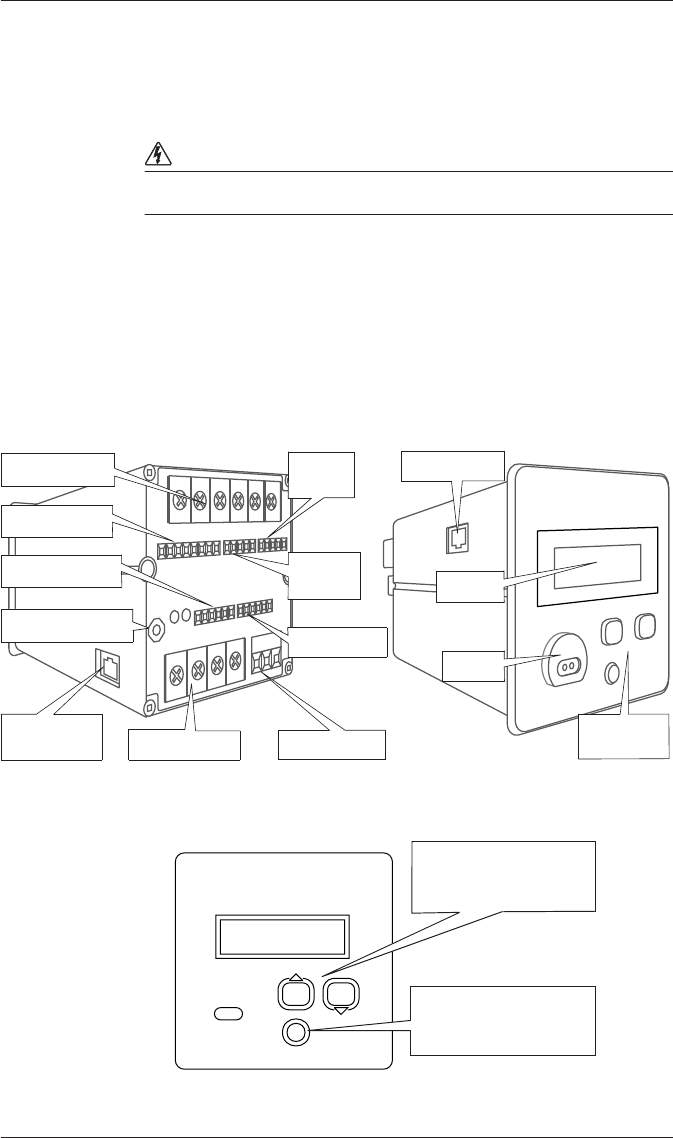
Meter Overview
Using the Buttons
RS-485 Bus
Chassis Ground
Rear of Meter Front of Meter
Current Inputs
Voltage Inputs Power Supply
Ethernet Port
Internal
Modem Port
IR Port
Navigation
Buttons
Analog Inputs
Analog
Outputs
Digital
Inputs
Digital Outputs Display
Use the arrow buttons to
move through menus
and to change values.
Press the round button to
access the Setup menu,
and to make selections.
PowerLogic ION7300 Series Installation Guide
© 2010 Schneider Electric. All rights reserved. 7
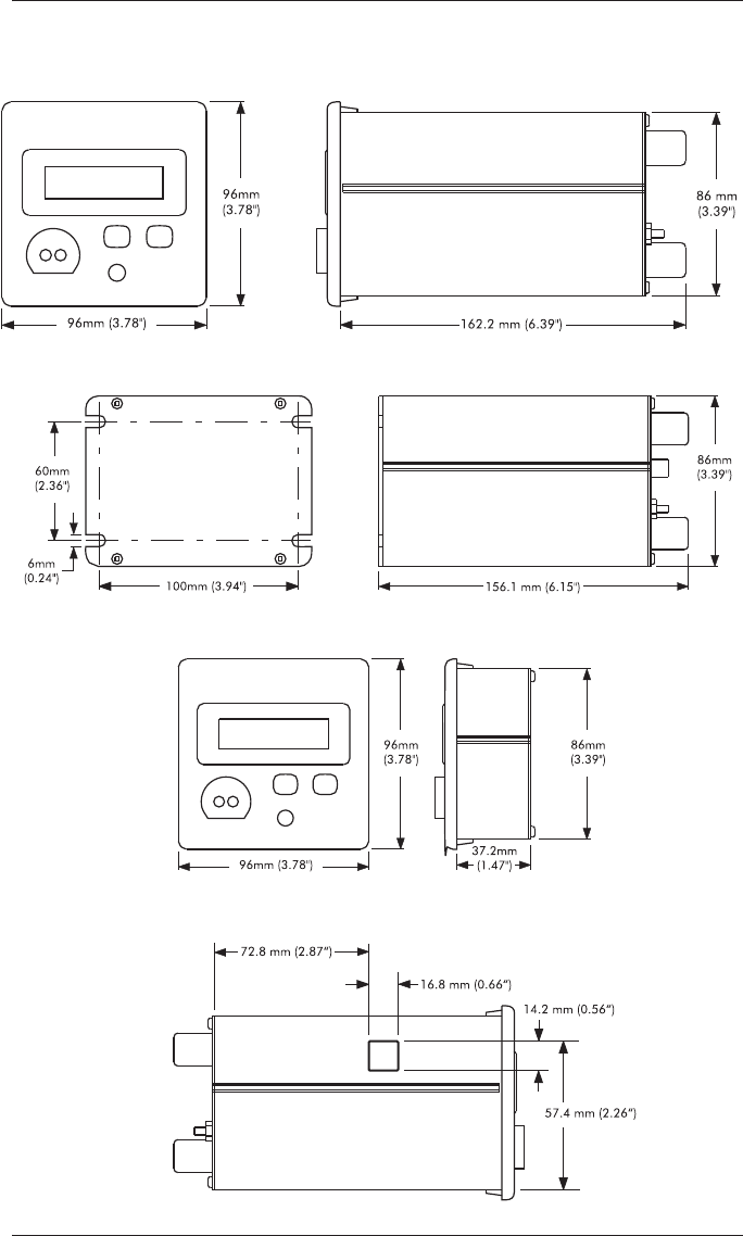
Unit Dimensions
Basic Model Dimensions
TRAN Model Dimensions
RMD Dimensions
Ethernet Port Location (if equipped)

PowerLogic ION7300 Series Installation Guide
8 © 2010 Schneider Electric. All rights reserved.
Internal Modem Port Location (if equipped)
Additional Information
GSKT Option
The GSKT (gasket) option helps to prevent moisture from penetrating air gaps
between your ION7300 series meter and its mounting hole. See the
GSKT
Option Installation Instructions
for more information.
Terminal Cover Option
This option covers the terminal strips on the meter’s base so they are not
accessible after installation. See the
Terminal Cover Option Retrofit
Instructions
for more information.
PowerLogic ION7300 Series Installation Guide
© 2010 Schneider Electric. All rights reserved. 9
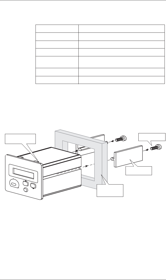
Step 1: Mount the Meter
Once installed, no cleaning of the device is necessary.
Mounting the Basic Model
1. Fit the unit into the cutout [DIN standard 92 X 92 mm or 3.6" X 3.6"]
then slide the supplied slide bars into the grooves on either side of the
unit.
2. Insert the thumbscrews in the back of the meter and tighten them until the
slide bars securely anchor the unit to the cabinet door. Do not overtighten.
Mounting the TRAN Model
The TRAN base unit can be mounted three different ways:
Flush against any flat surface. The unit provides four slots on its mounting
flange for this purpose. It can be mounted in whichever orientation is
most convenient.
Attached to any standard DIN rail (if the TRAN unit was purchased with
the optional DIN rail mount).
Installed in a cutout. To install a TRAN this way, follow directions for
mounting a basic model (see above). Once installed, connect the optional
RMD to the TRAN using the cable provided.
Mounting Location Indoor
Pollution Degree 2
Altitude Less than 2000 m (6561 ft) above sea level
Operating Range See “Power Supply Specifications” on page 21
Display Operating
Temperature Base Unit: -20°C (-4°F) to 60°C (140°F)
Storage Temperature -30°C (-22°F) to +85°C (185°F)
Relative Humidity 0 to 95% non-condensing
Thumbscrews
ION7300 meter
Retainer bars
Switchgear
cabinet door
PowerLogic ION7300 Series Installation Guide
10 © 2010 Schneider Electric. All rights reserved.
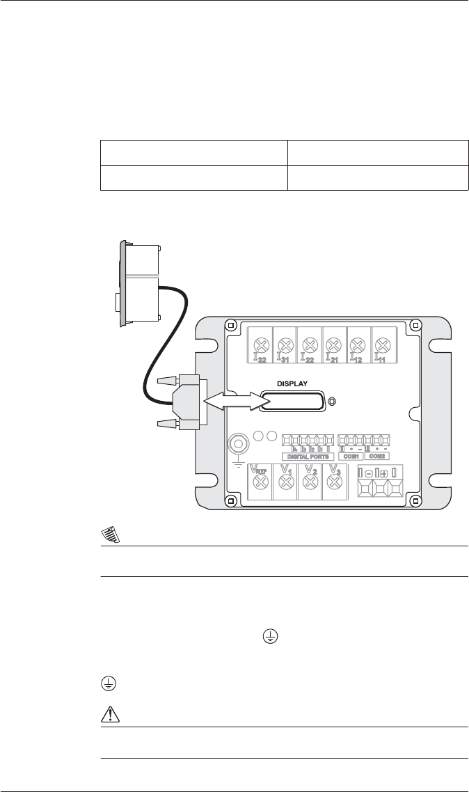
Mounting the RMD (if equipped)
1. Insert the RMD into the panel cutout.
2. Hand-tighten the securing screws on each cable connector.
3. Connect the chassis ground lug on the RMD to the switchgear earth
ground for the noise and surge protection circuitry to function correctly.
Remote Modular Display Connections
Connecting the RMD to the TRAN Unit
NOTE
Only use cable supplied by Schneider Electric to connect the RMD.
Step 2: Wire the Chassis Ground
Wire the meter’s ground terminal to the switchgear earth ground using a
14 AWG (2.1 mm2) or larger wire.
Connect the power supply G (ground) terminal to the same point as the meter
terminal.
CAUTION
Do not use metal door hinges as a ground path.
Connector Type DB25
Wire 1.8 m (6 ft.) cable
TRAN Meter
Remote Display
PowerLogic ION7300 Series Installation Guide
© 2010 Schneider Electric. All rights reserved. 11
Step 3: Wire the Digital and Analog I/O
Digital Output Connections
Typical Form A Application
NOTE
Use only Schneider Electric approved external relays.
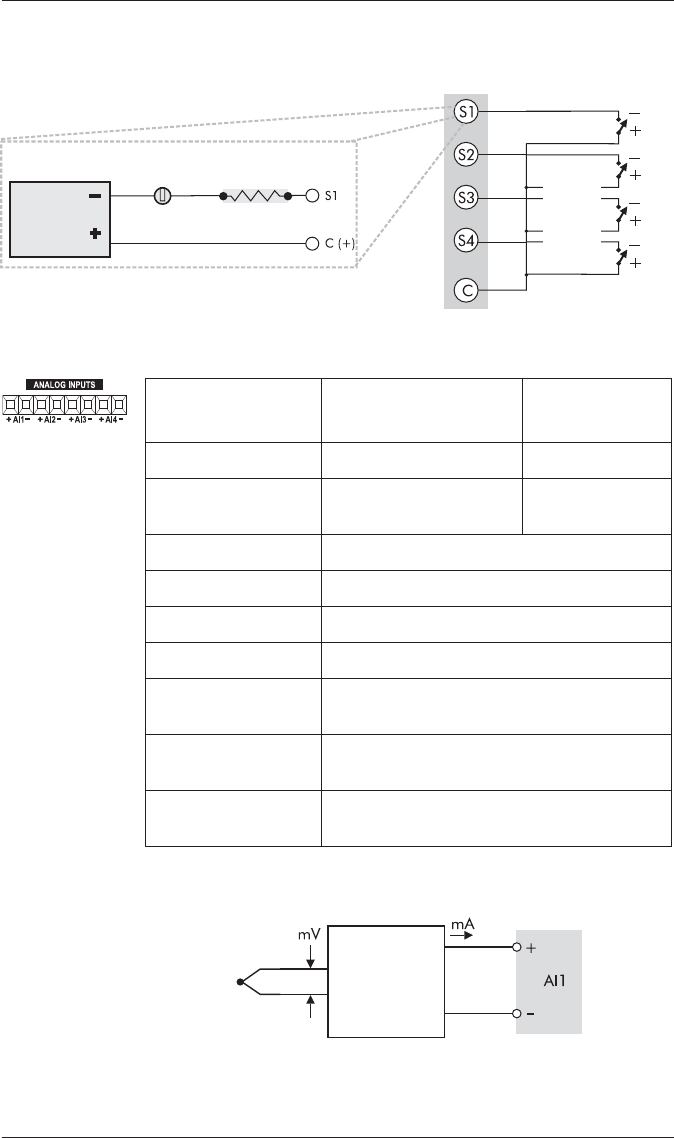
Digital Input Connections (if equipped)
Output Type Form A Solid State
Outputs D1, D2, D3, D4
Wire 28 to 16 AWG (0.1 to 1.3 mm2)
Connector Type Captured wire
Signal Type Continuous or pulse
Max. Load Voltage 30 V
Max. Forward Current 80 mA
Isolation Optical
Digital Outputs V+ (maximum 30 V)
Relays
Internal Circuit
Input Type Self-excited (internal 30 VDC supply)
Inputs S1, S2, S3, S4
Application Dry contact sensing
Wire 28 to 16 AWG (0.1 to 1.3 mm2)
Connector Type Captured wire
Min. Pulse Width 25 milliseconds
Max. Transition Rate 40 transitions per second (20 Hz)
PowerLogic ION7300 Series Installation Guide
12 © 2010 Schneider Electric. All rights reserved.
Typical Digital Input Application
Analog Input Connections (if equipped)
Typical Analog Input Application
30 VDC
Internal
Supply
Optically coupled
solid state relay
Internal Circuit
Digital Inputs External Dry
Contacts
Polarity
for SSR
Contact
shown.
Specification 0-20 mA (scalable to
4-20 mA) Option 0-1 mA Option
Input Impedance 25 :475 :
Maximum Source
Impedance 500 :10 k:
Accuracy ±0.3% of full-scale
Inputs AI1, AI2, AI3, AI4
Connectors Phoenix captured-wire
Update Rate 1 Hz
Channel to Channel
Isolation None
Max. Common Mode
Voltage 30 V
Standards
Compliance IEC 61000-4-4 fast transient test with
capacitive clamp (4 kVp-p@2.5 kHz for 1 min)
Example
application:
temperature
sensing.
Thermocoupler Voltage-to-
Current
Transducer
Meter
PowerLogic ION7300 Series Installation Guide
© 2010 Schneider Electric. All rights reserved. 13
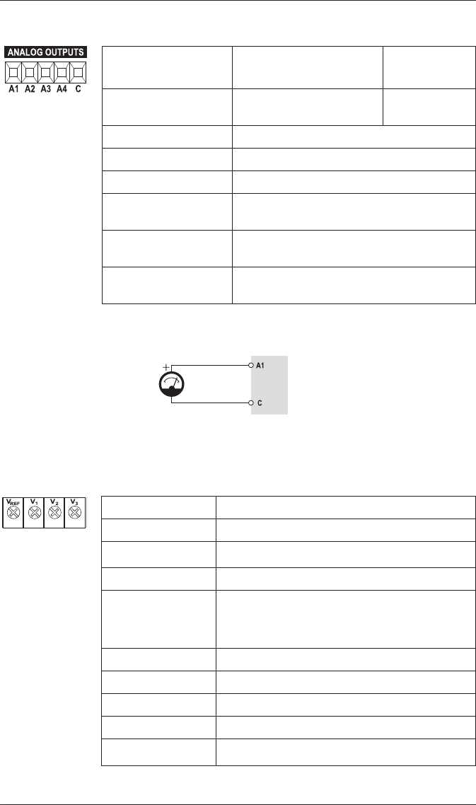
Analog Output Connections (if equipped)
Typical Analog Output Application
Step 4: Wire the Voltage and Current Inputs
Voltage Input Specifications
1Accuracy may be affected if the voltage on V1 falls below 50.
Specification 0-20 mA (scalable to
4-20 mA) Option 0-1 mA Option
Max. Load Drive
Capability 500 :10 k:
Accuracy ±0.3% of full-scale
Outputs A1, A2, A3, A4
Connectors Phoenix captured-wire
Channel to Channel
Isolation None
Max. Common Mode
Voltage 30 V
Standards Compliance IEC 61000-4-4 fast transient test with
capacitive clamp (4 kVp-p@2.5 kHz for 1 min.)
Example application: driving an
analog meter with the DC
current output.
Meter
Analog
Meter
Terminal Type Barrier
Connector Type Ring or split-ring
Wire 14 to 12 AWG (2.1 to 3.3 mm2)
Inputs V1, V2, V3, Vref
Rated Inputs1
50 - 347 L-N (87 - 600 L-L) VAC RMS (3-phase
systems)
50 to 300 L-N (100 to 600 L-L) VAC RMS (single-phase
systems)
Overrange + 25%
Installation Category III (Distribution)
Overload 1500 VAC RMS continuous
Dielectric Withstand 3250 VAC RMS for one second (non-recurring)
Impedance > 2 M:phase (phase-vref)
PowerLogic ION7300 Series Installation Guide
14 © 2010 Schneider Electric. All rights reserved.
Current Input Specifications
Using Current Transformers
The meter is compatible with CTs that have 5 Amp nominal, 10 Amp
full-scale secondaries.
1If the peak anticipated load is considerably less than the rated system
capacity, you can improve accuracy and resolution by selecting a lower
rated CT.
NOTE
Refer to the
ION7300 Series User Guide
for Revenue Metering CT and PT
selection.
Terminal Type Barrier
Connector Type Ring or split-ring
Wire 14 to 12 AWG (2.1 to 3.3 mm2)
Inputs I1, I2, I3
Rated Inputs 10 A RMS (+ 20% maximum, 300 V RMS to
ground)
Installation Category III (Distribution)
Overload 20 A continuous
Dielectric Withstand 500 A for one second (non-recurring)
Burden 0.0625 VA @ 10 Amps
Compliance UL3111-1; and IEC 61010-1, Pollution
Degree 2, Overvoltage Category III
Primary CT Rating Equal to current rating of the power feed
protection device.1
Secondary CT Burden
Capacity > 3 VA
PowerLogic ION7300 Series Installation Guide
© 2010 Schneider Electric. All rights reserved. 15
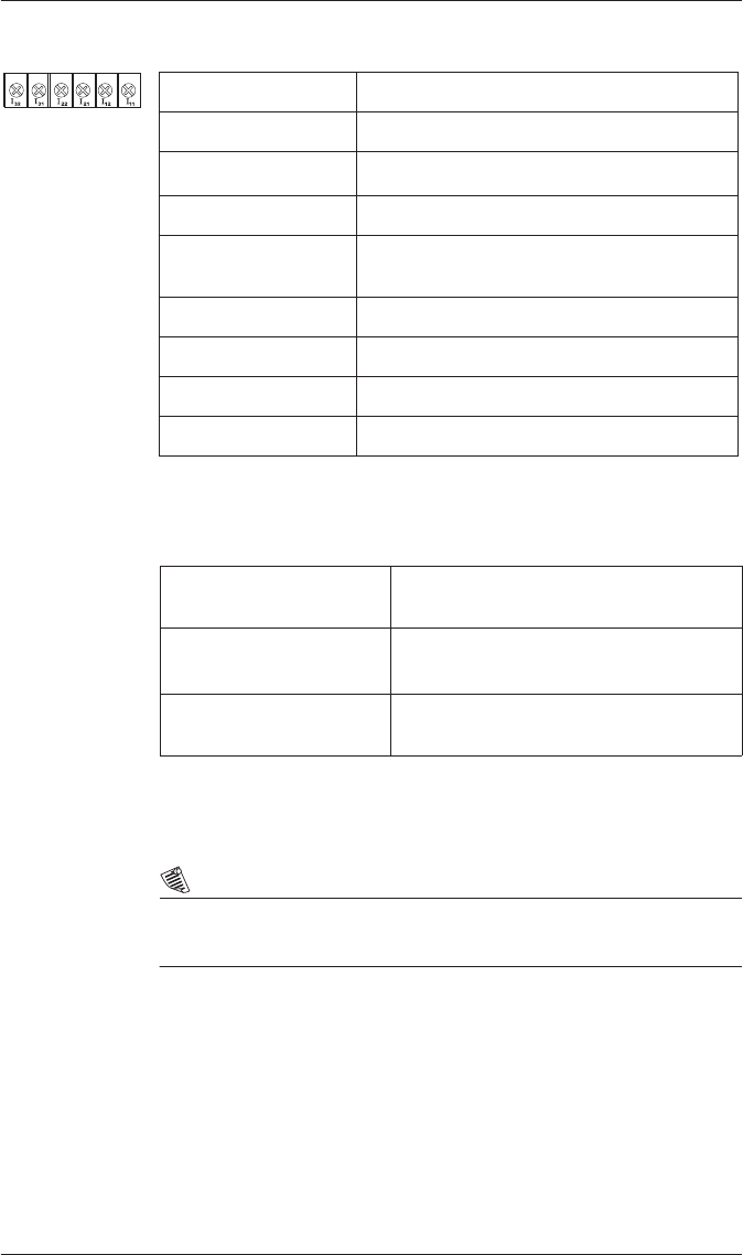
4-Wire Wye, 3-Element, Direct Connection Diagram
347 V L-N or 600 V L-L max.
VOLTS MODE = 4W-WYE
4-Wire Wye, 3-Element, 3 PT Connection Diagram
Use PTs for voltages over 347 L-N or 600 V L-L
VOLTS MODE = 4W-WYE
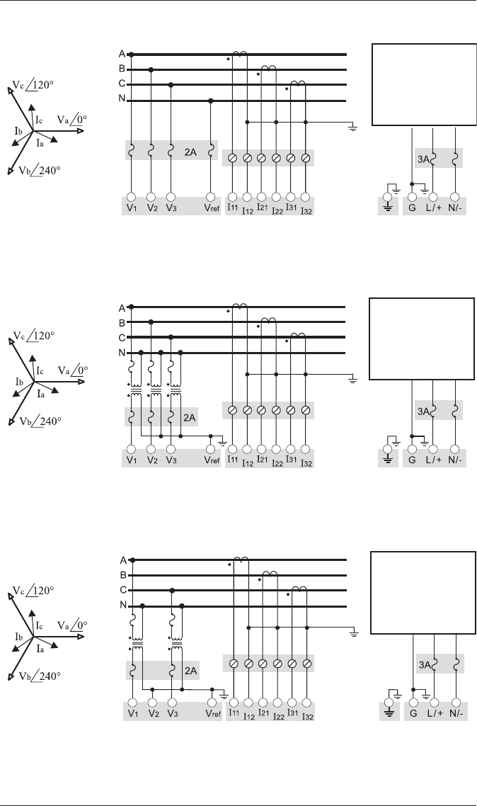
4-Wire Wye, 2½-Element, 2 PT Connection Diagram
Phase B voltage (V2) is derived from phase A and C voltages.
Use PTs for voltages over 347 L-N or 600 V L-L
VOLTS MODE = 3W-WYE
LINE
LOAD
Fuse for N/- terminal
required if its supply
source is ungrounded
Connect G terminal
to ground for AC
power source
PF = 0.9 (25°) Lag
LINE
LOAD
Fuse for N/- terminal
required if its supply
source is ungrounded
Connect G terminal
to ground for AC
power source
PF = 0.9 (25°) Lag
LINE
LOAD
Fuse for N/- terminal
required if its supply
source is ungrounded
Connect G terminal
to ground for AC
power source
PF = 0.9 (25°) Lag
PowerLogic ION7300 Series Installation Guide
16 © 2010 Schneider Electric. All rights reserved.
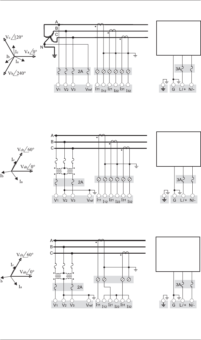
3-Wire Grounded Wye, 3-Element, Direct Connection Diagram
The configuration requires that the transformer secondary star-point is
grounded. The phase-to-ground voltages must be within the meter’s range.
VOLTS MODE = 4W-WYE
3-Wire Delta, 2½-Element, 2 PT & 3 CT Connection Diagram
Use PTs for voltages over 600 V L-L
VOLTS MODE = DELTA
3-Wire Delta, 2-Element, 2 PT & 2 CT Connection Diagram
Use PTs for voltages over 600 V L-L
VOLTS MODE = DELTA
LINE
LOAD
Fuse for N/- terminal
required if its supply
source is ungrounded
Connect G terminal
to ground for AC
power source
PF = 0.9 (25°) Lag
LINE
LOAD
Fuse for N/- terminal
required if its supply
source is ungrounded
Connect G terminal
to ground for AC
power source
PF = 0.9 (25°) Lag
LINE
LOAD
Fuse for N/- terminal
required if its supply
source is ungrounded
Connect G terminal
to ground for AC
power source
PF = 0.9 (25°) Lag
PowerLogic ION7300 Series Installation Guide
© 2010 Schneider Electric. All rights reserved. 17
3-Wire Delta Direct Connection
600 V L-L max.
VOLTS MODE = DIRECT DELTA
Single Phase Connection Diagram
For this configuration ONLY, the 208 V line-to-line voltage inputs can be
used with 240 V line-to-line systems.
VOLTS MODE = SINGLE
Using Potential Transformers
LINE
LOAD
Fuse for N/- terminal
required if its supply
source is ungrounded
Connect G terminal
to ground for AC
power source
PF = 0.9 (25°) Lag
Do not
connect
LINE
LOAD
Fuse for N/- terminal
required if its supply
source is ungrounded
Connect G terminal
to ground for AC
power source
PF = 0.9 (25°) Lag
System Mode Voltage Range Requires PTs
Wye
120 V L-N or 208 V L-L no
277 V L-N or 480 V L-L no
347 V L-N or 600 V L-L no
over 347 V L-N or 600 V L-L yes
Single Phase
120 V L-N or 240 V L-L no
277 V L-N or 554 V L-L no
over 277 V L-N or 554 V L-L yes
Delta up to 600 V L-L no
over 600 V L-L yes
PowerLogic ION7300 Series Installation Guide
18 © 2010 Schneider Electric. All rights reserved.
Step 5: Wire the Communications
RS-485 Specifications (COM1 and COM2)
NOTE
COM2 port is unavailable on ION7300 meters.
RS-485 Connection
Infrared Connection (COM3)
The infrared serial communications port can be used for energy pulsing or
communication with Schneider Electric power monitoring software.
This port is compatible with an ANSI Type II magnetic optical communications
coupler.
Connect the coupler to the port on the front of the meter.
Ethernet Connection (if equipped)
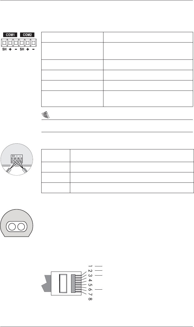
Connect SH at
one end only.
Connector Type Captured wire
Wire Shielded twisted pair RS-485 cable,
22 AWG (0.33 mm2) or larger
Maximum Cable Length 1219 m (4000 ft)
Maximum Devices (per bus) 32
Input Optically isolated
Compliance ANSI/IEEE C37.90-1989 surge withstand
and fast transient tests
Marking Terminal Function
SH RS-485 Shield (electrically connected to chassis ground)
+ RS-485 Data Plus
- RS-485 Data Minus
Pin 1: Transmit Data +
Pin 2: Transmit Data -
Pin 3: Receive Data +
Pin 6: Receive Data -
RJ45
PowerLogic ION7300 Series Installation Guide
© 2010 Schneider Electric. All rights reserved. 19
1The unit ID for Modbus RTU and Modbus/TCP over Ethernet is 100.
NOTE
On ION7330 and ION7350 meters with the Ethernet card, COM2 is
hardwired for EtherGate only, and cannot be used for serial communication.
Ethernet TCP/IP Service Ports
The meter supports a single connection at a time, to one of these three IP
Service Ports: ION (Port 7700), Modbus/TCP (Port 502), or Modbus RTU (Port
7701). At the same time, connections to EtherGate (Port 7802), WebMeter,
and email messaging can be made.
Internal Modem Connection (if equipped)
Wire Type High quality Category 3 or 5 UTP (CAT 5 unshielded twisted pair
recommended) cable
Connector Type RJ45 modular
Type (10 Base-T) IEEE 802.3 10Base-T for 10 Mbps base band CSMA/CD LANs
Data Rate 10 Mbps
Supported Protocols ION, Modbus RTU1, Modbus/TCP1
Isolation Transformer isolated to 1500 VAC RMS
Protocol Port
ION 7700
Modbus RTU 7701
Modbus/TCP 502
EtherGate (COM2) 7802
Pin 3: Ring
Pin 4: Tip
RJ11
PowerLogic ION7300 Series Installation Guide
20 © 2010 Schneider Electric. All rights reserved.
NOTE
On meters with the modem option, the internal modem is hardwired to
COM1, and that communications port is permanently set to ModemGate. If
you want to connect another meter with an internal modem to the ION7300
series, you must connect it in a serial loop using COM2. COM1 cannot be
used, as the two modems (internal modem in the ION7300 series and
internal modem in the serial loop connected meter) conflict during
communication.
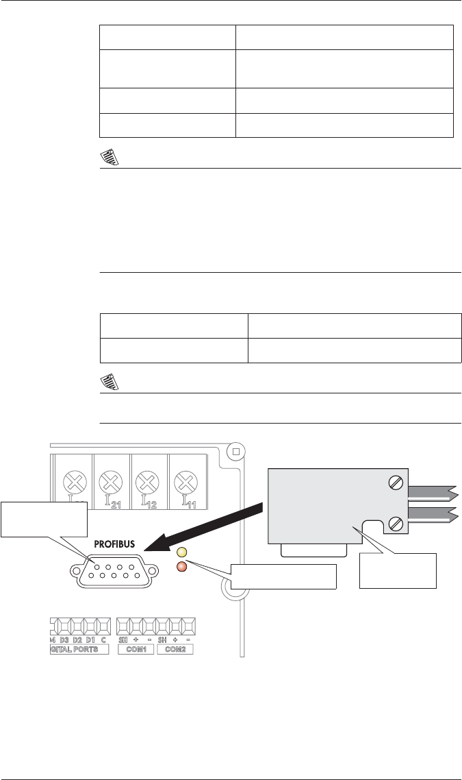
Profibus Connections (if equipped)
NOTE
The Profibus option is only available on ION7300 meters.
Connector Type RJ-11
Wire Type FCC Part 68 compliant telephone cord
(two male RJ-11 ends)
Data Rate 19.2 kbps
Supported Protocols ION, Modbus RTU, Modbus/TCP
Connector Type 9-pin
Data Rate 12 Mbps
LEDs (DE and PWR)
Profibus female
connector
Profibus male
connector
PowerLogic ION7300 Series Installation Guide
© 2010 Schneider Electric. All rights reserved. 21
NOTE
The Profibus Master file (.GSD file) is included on a floppy disk with the meter.
This file must be installed on your Profibus Masters before the meter can
communicate with the Profibus network.
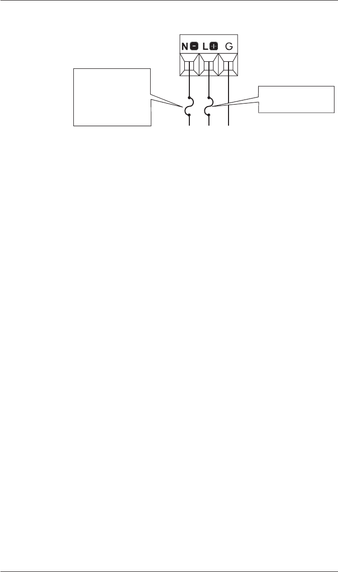
Step 6: Wire the Power Supply
Power Supply Specifications
NOTE
If the meter is used to perform control functions or monitor power quality and
power disruption events, an Uninterruptable Power Supply (UPS) should be
used to ensure constant supply power.
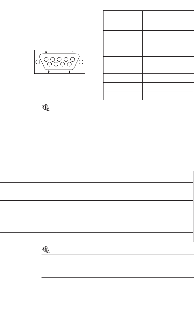
Profibus Female Connector
(located on meter)
)
Pin Number Profibus Function
1N/A
2N/A
3 B-line
4RTS
5Isolated GND
6Isolated Vcc
7N/A
8A-line
9N/A
Specification Standard AC / DC power supply P24 Option
Rated Inputs AC: 95 - 240 VAC r10%
(47 - 440 Hz)
DC: 120 - 310 VDC r10% 20 - 60 VDC r10%
Maximum 0.2 Amp worst case loading
(12 W) at 100 VAC at 25°C (77°F) 0.6 Amp worst case loading (12 W)
Connector Type Captured wire Captured wire
Wire 18 to 14 AWG (0.8 to 2.1 mm2) 18 to 14 AWG (0.8 to 2.1 mm2)
Installation Category II II
PowerLogic ION7300 Series Installation Guide
22 © 2010 Schneider Electric. All rights reserved.
Power Supply Connections
Step 7: Power Up the Meter
Before you apply power to the meter, ensure that ground is securely
connected and that the supply voltage is within the allowed range of the
meter’s power supply. Power up the meter.
Step 8: Set Up the Meter Using the Front Panel
Before the meter can operate and communicate correctly, the meter’s Power
Meter module and Communications modules must be properly configured.
Use the Quick Setup Menu.
Using the Quick Setup Menu
1. Access the menu by pressing the round button twice while the meter is
displaying power system data.
2. Scroll down the Setup menu and highlight QUICK SETUP. Press the
round button to select.
3. Use the arrow buttons to scroll the list of registers until you highlight the
setting you want to change. Press the round button to edit the value of the
register.
4. Change the value of the register using the arrow buttons either by
selecting a new value from a menu, or changing the digits of a number
Press the round button to save the new setting to the register.
5. Once you make a change to any setup register, the meter will prompt you
for a password. Once you have entered the password, confirm the
change of the register by selecting YES when prompted.
3 A IEC Type T slow
blow fuse on L+
3 A IEC Type T slow
blow fuse on N-
if power system
does NOT have
grounded neutral

PowerLogic ION7300 Series Installation Guide
© 2010 Schneider Electric. All rights reserved. 23
Configurable Settings from the Quick Setup Menu
Menu Setting Description Range (Values) Default
Power Meter
Volts Mode The power system’s configuration
– WYE, DELTA, etc.
4W-WYE
DELTA
SINGLE
DEMO
3W-WYE
DIRECT-DELTA
4W-WYE
PT1 (Primary) The Potential Transformer’s
primary winding voltage rating 1 to 999,999,999 347
PT2 (Secondary) The Potential Transformer’s
secondary winding voltage rating 1 to 999,999,999 347
CT1 (Primary) The Current Transformer’s
primary winding current rating 1 to 999,999,999 5
CT2 (Secondary) The Current Transformer’s
secondary winding current rating 1 to 999,999,999 5
V1 Polarity The polarity of the Potential
Transformer on V1 Normal or Inverted Normal
V2 Polarity The polarity of the Potential
Transformer on V2 Normal or Inverted Normal
V3 Polarity The polarity of the Potential
Transformer on V3 Normal or Inverted Normal
I1 Polarity The polarity of the Current
Transformer on I1 Normal or Inverted Normal
I2 Polarity The polarity of the Current
Transformer on I2 Normal or Inverted Normal
I3 Polarity The polarity of the Current
Transformer on I3 Normal or Inverted Normal
Comm 1
COM1 Unit ID Every meter on an RS-485
network must have a unique Unit
ID number 1 to 9999 From serial
number1
COM1 Baud
Rate2The data rate, in bits per second 1200, 2400, 4800, 9600,
19200 9600
COM1 Protocol The communications protocol ION, ModemGate3,
Modbus RTU, DNP 3.00,
Factory ION
Comm 2
COM2 Unit ID Every meter on an RS-485
network must have a unique Unit
ID number 1 to 9999 From serial
number1
COM2 Baud
Rate2The data rate, in bits per second 1200, 2400, 4800, 9600,
19200 9600
COM2 Protocol The communications protocol ION, EtherGate4, Modbus
RTU, DNP 3.00, Factory ION
Infrared Comm
IR1 Unit ID The Unit ID for the Infrared port 1 to 9999 From serial
number1
IR1 Baud Rate The data rate, in bits per second,
for the Infrared port 1200, 2400, 4800, 9600,
19200 9600
IR1 Protocol The communications protocol for
the Infrared port ION, Modbus RTU, DNP
3.00, Factory, Infrared I/O ION

PowerLogic ION7300 Series Installation Guide
24 © 2010 Schneider Electric. All rights reserved.
Notes
1The factory set Unit ID for this port is based on the serial number of the
meter. For example: Serial number: PABC-0009A263-10; Unit ID: 9263.
2All devices connected to the each port must communicate at the same
baud rate as this port.
3ModemGate is available on ION7330 and ION7350 meters with an
internal modem.
4EtherGate is available on ION7330 and ION7350 meters with Ethernet.
5Profibus protocol is an option on ION7300 meters. You can only change
the Profibus address via the front panel, not through software.
6The ANSI C84.1 1989 standard recommends a temporary overvoltage
limit of 106% for Range B voltage levels, and a temporary undervoltage
limit of 88% for load voltages and 92% for the service entrance.
7Sag/Swell is available on ION7350 meters.
8The Nom Volts setup register MUST be set to your primary power system
voltage, or the Sag/Swell feature will not properly function.
Ethernet
ETH1 IP Address The Network IP Address of the
meter - see your Network
Administrator
000.000.000.000 to
999.999.999.999 none
ETH1 Subnet
Mask
Used if subnetting applies to your
network- see your Network
Administrator
000.000.000.000 to
999.999.999.999 none
ETH1 Gateway Used in multiple network
configurations- see your Network
Administrator
000.000.000.000 to
999.999.999.999 none
ETH1 SMTP
Server
Sets the IP Address for the SMTP
Mail Server that is configured to
forward mail from the meter
000.000.000.000 to
999.999.999.999 none
ETH1 SMTP
Connection
Timeout
Sets the minimum time that the
meter waits for a connection to
an SMTP server 0 to 9999 60 seconds
Profibus Comm
CM4 PB
Address5Unique ID for Profibus network. 126
Sag/Swell7
Swell Lim
The limit a monitored voltage
must exceed in order for the
meter to classify it as an
overvoltage condition60 to 9999 106
Sag Lim
The limit a monitored voltage
must fall below in order for the
meter to classify it as an
undervoltage condition60 to 999 88
Nom Volts8The primary power system
voltage (L-L voltage for Delta
systems, and L-N voltage for Wye
systems)
0 to 9,999,999 0
Menu Setting Description Range (Values) Default
PowerLogic ION7300 Series Installation Guide
© 2010 Schneider Electric. All rights reserved. 25
Additional Menus
Clear Functions: allows you to reset cumulative parameters, such as Peak
Demand, Min/Max and Energy.
Adv Meter Setup: access to every ION register in the meter.
Display Setup: allows you to change display settings such as Contrast,
Backlight Timeout and Auto Scroll.
Screen Setup: allows you to change data displayed on the display screens.
Nameplate Info: displays information about the meter options, such as
Serial Number, Battery Life and Meter Firmware Revision.
Security: allows you to modify the meter’s password.
Diagnostics: provides information to assist with meter installation and
troubleshooting.
Navigating Menus
Each menu has a title displayed at the top of the display screen and menu
items displayed below the title.
Editing Registers
For numeric registers, the cursor indicates the number being edited.
For enumerated registers, the current value of the register will be displayed
in the list with an asterix (*) on either side.
Password Security
The password is required when you make a change to a register. The
password is factory set at ‘00000’ (5 zeros).
Button Function
Scrolls up through menu items.
Scrolls down through menu items.
Selects a highlighted item. Select RETURN to go back to
the previous screen.
PowerLogic ION7300 Series Installation Guide
26 © 2010 Schneider Electric. All rights reserved.
NOTE
After you enter the new value by pressing the round button, a verification
screen appears. Select YES to confirm the change or NO to cancel the change
and return to the previous screen.
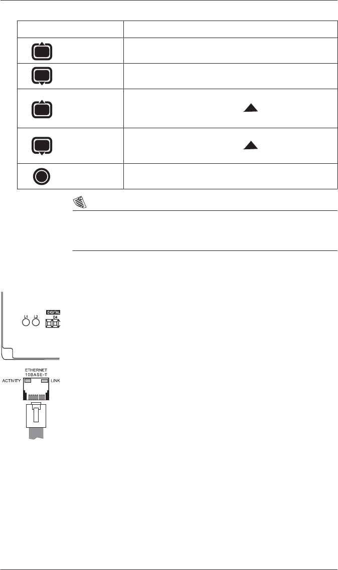
Step 9: Verify Meter Operation
L1 and L2 LEDs are located on the meter backplate.
L1 is factory-configured to pulse once for every 1.8 Wh of energy
measured.
L2 blinks slowly to indicate CPU operation. It blinks rapidly to indicate
communications through one of its serial ports. If the L2 LED does not
blink once the meter is installed, contact Technical Support.
Verifying Ethernet Communications
Two LEDs, Activity and Link, are next to the Ethernet port on the side of the
meter.
LINK remains on while an Ethernet carrier is present; if this LED is off, the
Ethernet connection cannot be established.
ACTIVITY blinks to indicate Ethernet traffic.
Verifying Profibus Communications
Two LEDs are adjacent to the Profibus port on the meter’s backplate.
DE indicates communications between the Profibus Master and the meter
have been established.
PWR is on to show that the meter is powered.
Button Function
Numeric Register: Increases value of register.
Enumerated Register: Moves up in list.
Numeric Register: Decreases value of register.
Enumerated Register: Moves down in list.
Moves the position of the cursor to the right.
Moves the position of the cursor to the left.
Enters the new value.
Press and
hold for 1
second
Press and
hold for 1
second
PowerLogic™ ION7300 series
with WebMeter™
Installation guide
Schneider Electric
2195 Keating Cross Road
Saanichton, BC
Canada V8M 2A5
Tel: 1-250-652-7100
Technical support:
Global-PMC-Tech-support@schneider-electric.com
(00) + 1 250 544 3010
Contact your local Schneider Electric sales
representative for assistance or go to
www.schneider-electric.com
ION, ION Enterprise, Modbus, Power Measurement,
PowerLogic, Schneider Electric, Square D, and WebMeter
are either trademarks or registered trademarks of
Schneider Electric in France, the USA and other countries.
All other trademarks are property of their respective
owners.
Electrical equipment should be installed, operated,
serviced, and maintained only by qualified personnel.
No responsibility is assumed by Schneider Electric for any
consequences arising out of the use of this material.
70002-0198-08
© 2010 Schneider Electric. All rights reserved.
06/2010
