130277 Catalog
1000515360-Catalog 1000515360-Catalog 1000515360-Catalog B4 unilog cesco-content
152495-Catalog 152495-Catalog 152495-Catalog B5 unilog cesco-content
99037-Catalog 99037-Catalog 99037-Catalog 662381 Batch10 unilog cesco-content
62253-Catalog 62253-Catalog 62253-Catalog Batch10 unilog cesco-content
2264-Catalog 2264-Catalog 2264-Catalog 662381 Batch3 unilog cesco-content
2016-07-29
: Pdf 130277-Catalog 130277-Catalog B2 unilog
Open the PDF directly: View PDF ![]() .
.
Page Count: 408 [warning: Documents this large are best viewed by clicking the View PDF Link!]

Easy-wraptm MINITErMs Easy-splIcEtm Easy-Taptm TOrKAlerttm
MINITE
r
M
s
E
asy-spl
asy-spl
I
c
E
tm
E
asy-T
ap
asy-Tapasy-T
tm
TO
r
K
Alert
tm
pOlarIstm Easy-TwIsTtm
PRODUCT
CATALOG
800.321.5847 • USA • www.nsiindustries.com LIT-CE14

Since 1975, NSi’s strength is in the unique products that we bring to the market,
combined with our exceptional ability to provide quality TORK® brand products
manufactured in the company’s Mount Vernon facility. TORK® is NSi Industries largest
brand, covering the categories of Electromechanical and Digital Time Switches,
Signaling and Alert Devices, Pool and Spa Controls, Residential Timers, Photocontrols
and Occupancy Sensors.
For over 90 years, TORK brand recognition and reputation for quality and design make it
the most specified brand in the industry. The TORK brand has a rich history beginning
in the 1920s when the company introduced the first electromechanical time switch to
the marketplace. Currently, TORK’s time switches maintain energy efficiency through
lighting control in such high profile places as the Empire State Building, Washington
DC Parks and Recreation, The Triborough Bridge, The Met Life Building and many
more institutions across the country. As the most specified brand of time switches in the
industry, TORK enjoys the hearty respect of engineers and project planners across all
channels of distribution.
About Us

TABLE OF CONTENTS
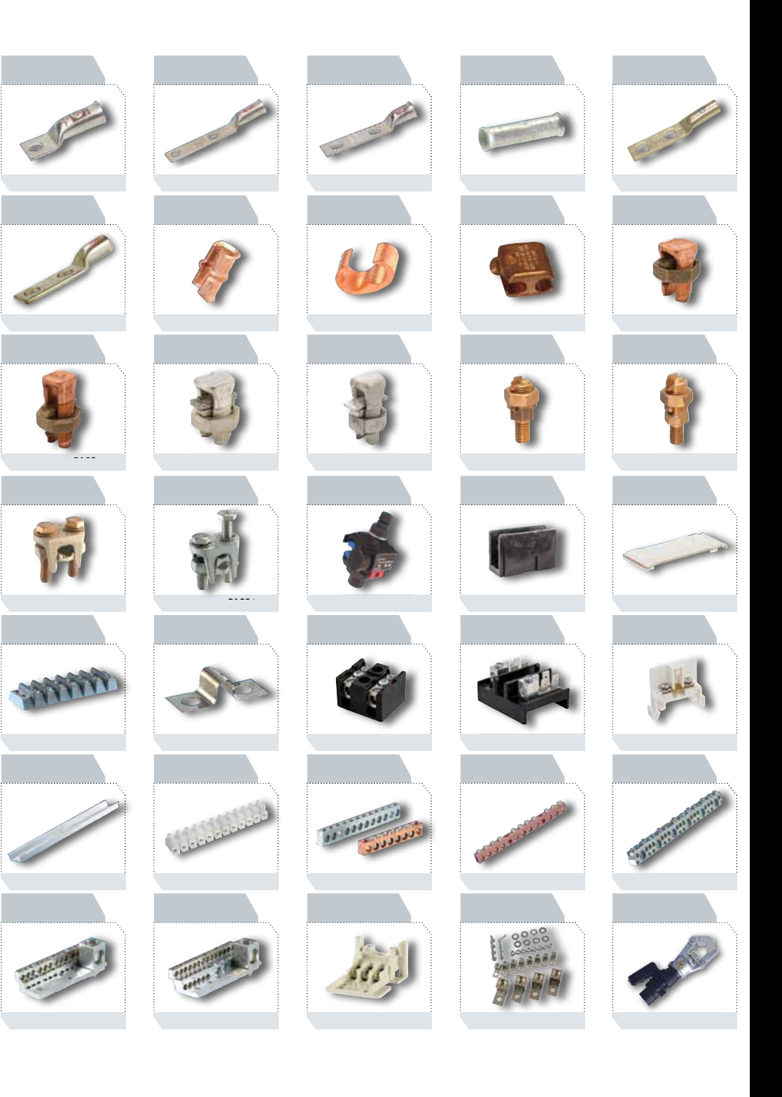
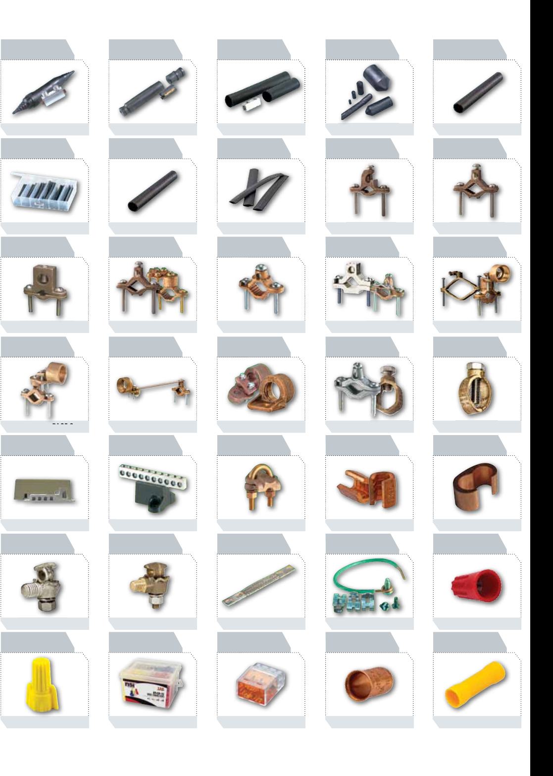
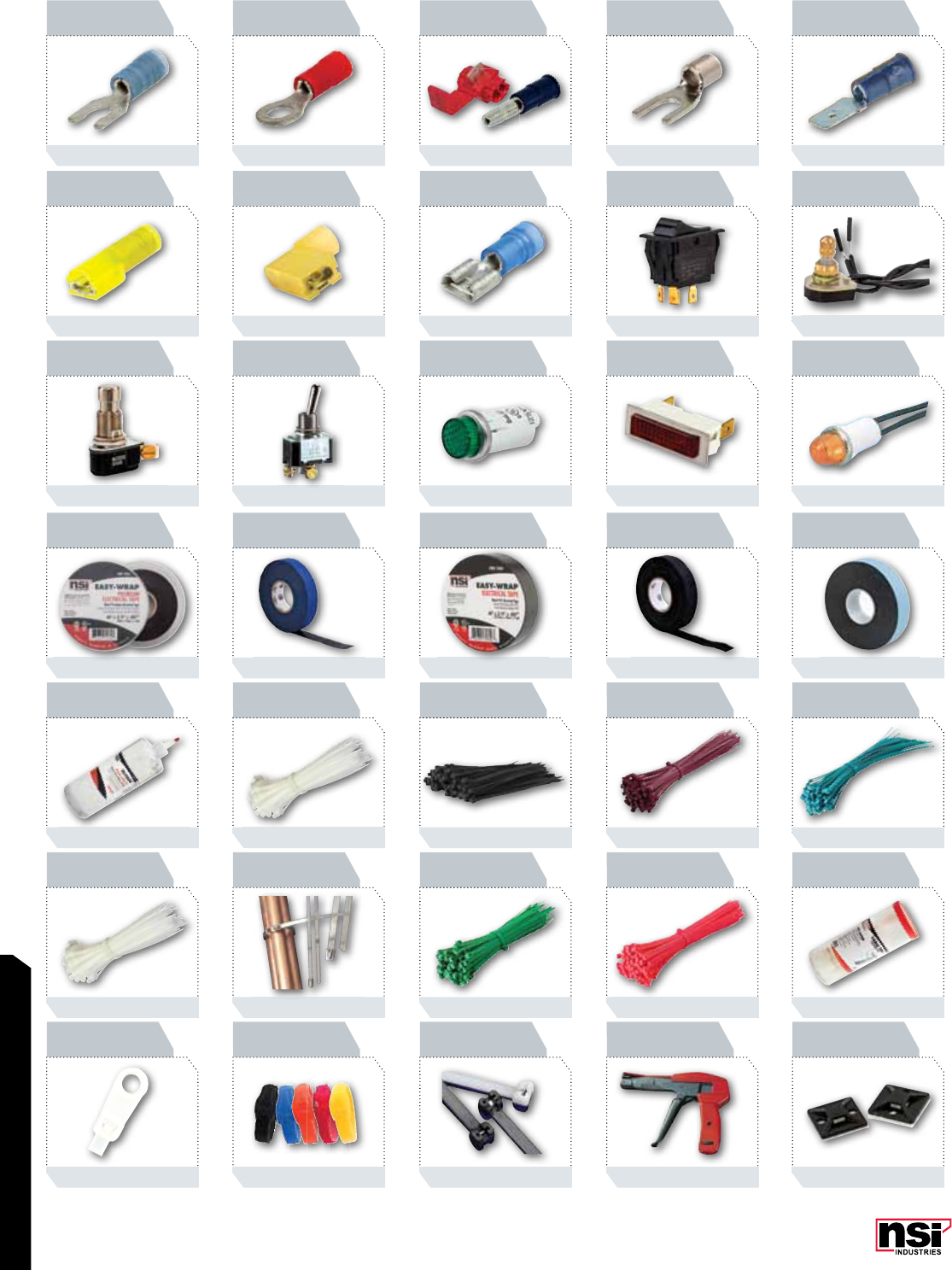
PICTORIAL INDEX ..........................1
CONNECTORS
Aluminum Dual Rated Single & Double Lugs ..............13
Aluminum Dual Rated Panelboard Lugs..................15
Aluminum Dual Rated Stacked Lugs ....................19
Aluminum Dual Rated Splicer & Reducers ................21
Aluminum Dual Rated Turn Prevent Lugs.................23
Aluminum Dual Rated Lay-In & Dual Range Lugs ..........25
Aluminum Dual Rated Tap Connector & Covers ............27
Aluminum Dual Rated Heavy Duty Transformer Lugs........ 29
Aluminum Dual Rated Transformer Lugs .................31
Aluminum Dual Rated Transformer Connectors ............33
Secondary Transformer Connectors ..................... 35
Transformer Stud Connectors.......................... 37
Copper Single Lugs – Cu Extruded & Tubular..............39
Copper Single/Double Solderless Lugs...................41
Copper & Bronze Terminal Lugs .......................43
Aluminum Dual Rated Parallel Groove Clamps.............45
Wedge & Hot-Line Clamps & Service Entrance Connector .....47
Aluminum One Hole Standard Barrel....................49
Aluminum Two Hole Standard Barrel....................51
Dual Rated Aluminum Splice..........................53
Bi-Metallic Pin Terminals.............................55
Dual Rated Pin Terminals ............................57
Dual Rated Wide Range Tap Connectros & Covers ..........59
Dual Rated Meter Socket Lugs......................... 63
Dual Rated Insulated Service Entrance Sleeves ............ 65
Long Barrel One Hole Copper Lugs .....................67
Long Barrel Copper Lugs Two Hole .....................71
Long Barrel Stacking Copper Lugs......................77
Stacking Adapters For Compression Terminals .............78
Short Barrel Copper Lugs One Hole With Peep Hole......... 79
Short Barrel Copper Lugs Two Hole With Peep Hole . . . . . . . . . 83
Copper Splice Short Barrel ...........................85
Copper Splice Long Barrel............................87
For Flexible Copper Cable - One Hole Short Barrel.......... 89
For Flexible Copper Cable - One Hole Long Barrel ..........91
For Flexible Copper Cable - Two Hole Long Barrel ..........93
For Flexible Copper Cable - Two Hole Short Barrel Peep Hole..95
For Flexible Cable - Copper Short Barrel .................97
For Telecommunications - Two Hole Short Barrel ...........99
For Flexible Copper Cable - Two Hole Short Barrel No Peep ..101
C-Taps ......................................... 102
Copper Press-Ons .................................104
Copper Split Bolts 2 Wire ...........................105
Copper Split Bolts 3 Wire ...........................106
Copper Tin Plated Split Bolts . . . . . . . . . . . . . . . . . . . . . . . . . 107
Aluminum Dual Rated Split Bolts...................... 108
Service Post Connectors One-Wire Type .................109
Service Post Connectors Two-Wire Type ................. 110
Two-Bolt Bronze For Copper To Copper .................111
Two-Bolt Bronze For Aluminum, Copper & Steel...........112
Easy-Tap™ IPCS Series - Insulation Piercing Connectors .....113
Connector Bloks™ Single Primary Multiple Secondary
Connector Block Covers.............................115
Connector Bloks™ Multiple Primary Multiple Secondary
Connector Block Covers.............................117
Connector Bloks™ Splice Reducer Primary Secondary
Connector Block Covers ............................119
Terminal Bloks™ Double Row 9/16" Centers 600V ........121
Terminal Bloks™ Hardware Options ...................122
Terminal Bloks™ Splicer & Reducers 75 Amps 600V .......123
Terminal Bloks™ Two Pole 250 Volts...................124
Rail Mounted Modular Terminal Block Hardware Options .... 125
Insulated Terminal Blocks . . . . . . . . . . . . . . . . . . . . . . . . . . . 127
Multiple Connectors Used In Neutral Assemblies And Grounding
Applications .....................................129
TABLE OF CONTENTS

TABLE OF CONTENTS
Copper Neutral Connectors ..........................131
Combination Connectors ............................132
Neutral 225 Amps 600VAC Connectors .................133
Combination Connectors ............................135
Non-Metallic Splice & Tap ...........................137
Transformer Lug Kits – Mechanical Set-Screw Types........139
Tool and Die Charts for Copper & Aluminum Connectors.....141
TOOLS & HARDWARE
Hydraulic Compression Tool..........................153
Crimping Dies....................................154
Hydraulic Die & Battery-Operated Die Type Crimping Tools ..155
U-Type Compression Dies ...........................156
Mechanical Crimpers & Tools, Ratchet Drive Crimpers.......157
Manual & Ratchet-Drive Cable Cutters..................158
Steel Fishtapes & Conduit Benders .................... 159
Precision Wire Strippers & Insulated Miniterm Tool ........ 160
Electrician's Hand Tools.............................161
Electrical Multitesters – Analog & Digital................162
Circuit & Receptacle Testers..........................163
Torque Wrenches, Screwdriver & Accessories ............. 165
Silicon Bronze Bolts, Nuts, Washers, Lockwashers ......... 166
Stainless Steel Bolts, Nuts, Washers, Lockwashers ......... 167
Oxide Inhibitor & Duct Sealing Compound............... 168
POLARIS™
Polaris Grey™ For Fine Stranded Wire .................171
Polaris Grey™ Replacement Sleeves ................... 171
Polaris Blue™ For Direct Burial & Submersible ........... 173
Polaris™ In-Line & Two-Wire ........................177
Polaris™ Splicer/Reducers.......................... 179
Polaris™ Multi-Conductor One Side Wire Entry........... 181
Polaris™ Multi-Conductor Either Side Wire Entry ......... 185
Polaris™ Multi-Cable Blocks Either Side Wire Entry ....... 187
Polaris™ Multi-Cable Stacked Either Side Wire Entry ...... 189
Polaris™ Heavy Duty Either Side Wire Entry ............ 191
Polaris™ Multi-Conductor Blocks With Mounting Holes,
One Side Wire Entry ...............................193
Polaris™ Multi-Conductor Blocks With Mounting Holes,
Either Side Wire Entry..............................195
Submersible Pedestal Connectors......................199
Heavy Duty Unisulated Blocks, Either Side Wire Entry ...... 201
Uninsulated Multi Cable Connectors.................... 203
Polaris™ Custom Designed Connector Blocks............. 207
Polaris™ Installation Instructions.....................209
SPLICING
Easy-Splice Wrap-Around Gel Splice Kits ................213
Easy-Splice Wrap-Around UF Splice Kit..................214
Easy-Splice In-Line Gel Splice Kit With Connector ..........215
Easy-Splice Gel Tap Splice Kit With Connector.............216
Easy-Splice Gel Stub Splice Kit With Connector ........... 217
Easy-Splice H-Tap Splice Covers With Connector ...........218
Easy-Splice Push-On Gel Stub Splice Kits ................219
Easy-Splice Direct Burial Roll-On Splice Sleeve ...........220
Easy-Splice Direct Burial Splice Kit With Rubber Cover ......221
Easy-Splice Self Sealing UF Splice Kit & Hot Melt
Sealant Sleeves ..................................222
Easy-Splice Direct Burial/Submersible Splice Kits
With Heat Shrink ................................. 223
Easy-Splice Heat Shrinkable End Caps . . . . . . . . . . . . . . . . . . 224
Easy-Splice Heavy Wall Heat Shrink For Direct Burial
and Submersible .................................225
Easy-Splice Thin-Wall Heat Shrink Kits.................. 227
Easy-Splice Heavy Wall Heat Shrink ...................228
Easy-Splice Thin-Wall Tubing .........................229
GROUNDING
Heavy Duty Direct Burial With Lay-In Lugs ..............235
Copper & Tin Plated Copper Lay-In Lugs ................236

TABLE OF CONTENTS
Heavy Duty Direct Burial Ground Clamps and Direct
Burial For Rebar.................................. 237
Heavy Duty Direct Burial With Adapters ................238
Bronze Ground Clamps & Heavy Duty Water Pipe Clamps ...240
Aluminum & Bronze Ground Clamps ...................241
Heavy Duty & With 360° Adapters For Rigid Conduit ......242
Rigid Conduit With Flexible Wire Strap .................244
Economy & 360° Swing Type Hubs ....................245
Zinc Die Cast & Standard Duty Silicon Bronze
Ground Clamps...................................246
Heavy Duty Silicon Bronze & Range Taking Rod Clamp .....247
Intersystem Bonding Connectors ......................248
Isolated Ground Bars .............................. 249
Heavy Duty For Parallel, 90° Copper Cable.............. 250
Heavy Duty For Parallel, Two & Three Conductor..........251
Transformer Ground Clamps .........................253
Two-Way Baskets ................................. 254
Flexible Braid Jumper Straps & Ground Strap ............255
Grounding Pigtails (Solid and Stranded) & Grounding Clips ..256
EASY-TWIST™
Easy-Twist™ Standard Twist-On Wire Connectors ..........259
Easy-Twist™ Winged Twist-On Wire Connectors ...........261
Easy-Twist™ Wire Connector Combination Pails ...........263
Push-In Wire Connectors ...........................265
Crimp Sleeve & Nylon Wire Connectors .................267
MINITERMS & SWITCHES
Butt Splices......................................271
Spade Terminals: Locking ...........................273
Spade Terminals Flange & Block ......................275
Spade Terminals .................................. 277
Ring Terminals Vinyl...............................279
Ring Terminals Uninsulated.......................... 281
Ring Terminals Nylon ..............................283
Male & Female Plugs Wire Tap and Pin Terminal,
Male/Female Adapter..............................285
High Temperature Spade, Ring, Piggyback & Disconnect ....287
Male Disconnects: Fully Insulated and Male/Female Adapter . 289
Female Disconnects: Piggyback, Sleeved Barrel &
Fully Insulated ...................................291
Female Flag & Fully Insulated Flag, Two-Way Receptacle ....293
Female Disconnects................................ 295
Rocker Switches ..................................297
Rotary Switches & Miscellaneous......................299
Pushbutton Switches ............................... 301
Toggle Switches: Maintained Contact Single Pole ..........304
Toggle Switches: Maintined Contact Single & Double Pole.... 305
Toggle Switches ..................................307
Round Indicator Lights .............................308
Round & Snap-In Rectangular Indicator Lights............309
Indicator Lights and Emergency Stop Buttons.............310
WIRE MANAGEMENT
Easy-Wrap™ Premium Electrical Tape ..................313
Easy-Wrap™ General Purpose & All-Weather
Corrosion Tape ...................................314
Easy-Wrap™ Rubber Splicing Tape, Harness Wrap &
Duct Tape....................................... 315
Easy-Wrap™ Friction, Electrical Filler and Silicone
Rubber Tape..................................... 316
Easy-Wrap™ High Voltage, Glass Cloth and Rubber
Mastic Tape .....................................317
Slyder™ Wire Lubricant ............................318
Standard (Natural) Cable Ties ........................319
UV & Weather Resistant (Black) Cable Ties .............. 321
Air Handling and Push Mount Cable Ties ...............323
Tefzel, Marker Cable Ties ...........................324
HVAC Standard and Weather Resistant Ties ..............325
TABLE OF CONTENTS
TABLE OF CONTENTS

TABLE OF CONTENTS
Releasable Cable Ties ..............................326
Stainless Steel Ties ................................326
Standard Cable Ties: Color .......................... 327
Standard Cable Ties: Fluorescent ......................329
Cable Ties Canister Packs ...........................331
Natural & Weather Resistant Mountable Ties .............333
Velcro Ties ...................................... 334
Cable Ties With Stainless Steel Barb....................335
Cable Tie Installation Tools ..........................337
Cable Tie Adhesive Mounts ..........................338
Push Mounts..................................... 339
Polyethylene Nail Clips .............................340
Nail-On Plastic Staples For Romex.....................341
Masonry Push Mounts.............................. 342
Adjustable Cable Clamps............................ 342
Standard & Heavy Duty Nylon Cable Clamps.............. 343
Standard Slot Panel Channel..........................345
Narrow Finger, High Density Panel Channel............... 347
Solid Wall Panel Channel and Floor Duct .................349
Cable Marker Plates ................................ 350
Wire Marker Dispensers .............................350
Roll Label Dispenser and Polyester Industrial Tapes .........351
Pocket Pal Marker Books ............................352
Easy Release Wire Marker Cards....................... 353
Voltage Markers...................................354
Self-Adhesive Labels................................ 355
Spiral Wrap ......................................355
Detectable Underground Line & Barricade Tapes ...........356
FIRESTOPTM
FireStop™ Intumescent Caulk ......................... 359
FireStop814™ Residential & Commercial Caulk............ 359
FireBlock136™ Residential Fire Block...................359
FireStop™ Pillows & Putty Pads .......................359
FireStop™ Ratings & UL Systems ...................... 361
LIGHTING
Mini Wallpacks .................................... 371
Compact Wallpacks................................. 372
Medium Wallpacks .................................373
Large & Large Deep Wallpacks . . . . . . . . . . . . . . . . . . . . . . . .374
"The Rocky" Vandal Resistant Wallpacks .................375
Fluorescent & Compact Floodlight ......................377
Low Profile Floodlight............................... 378
Medium & Large Floodlight........................... 379
1000 Watt Floodlight ...............................380
Incandescent Floodlight..............................380
Quartz Floodlight With Lamp..........................381
High Pressure Sodium Ballast Kits With Lamp .............382
Metal Halide Ballast Kits With Lamp ....................383
High Pressure Sodium Ballast Kits Only .................. 384
Metal Halide Ballast Kits Only......................... 385
Twin Head Emergency Light ..........................386
Fixed Optics Emergency Light .........................386
LED & Combo LED Incandescent Exit Light................387
Wet Location Emergency Light.........................388
Heavy Duty Emergency Light .........................389
Emergency Fluorescent Ballast ........................389
Entry Cylinder .................................... 390
5X8 Vandal Resistant Entry Light ......................390
Small & Large Vandal Resistant Light ...................391
Incandescent Loading Dock Lights ......................392
Short-Term Lighting System ..........................393
Accessories .......................................393
Box & Wall Vaportite ...............................393
Fluorescent Undercabinet Lights .......................394
Heavy Duty Ground Stake ...........................394
TORK® ENERGY CODE REFERENCE GUIDE
& RESPONSIBLE ENERGY STATEMENT
Exterior and Interior Lighting Zones ....................397
TABLE OF CONTENTS
TABLE OF CONTENTS

TABLE OF CONTENTS
TORK® PHOTOCONTROLS
Quick Reference Guide & Features .....................401
2100 Series Spec Grade Die Cast Zinc Photocontrol .........403
2110 Series Spec Grade Die Cast Aluminum Photocontrol ....404
2000 Series Fixed Conduit Mount Photocontrol ............405
2001 Series 180° Swivel Conduit Mount Photocontrol ....... 406
2020 Series 180° Swivel Conduit Mount Photocontrol ....... 407
3000 Series Flush Mount Photocontrol...................408
5000M Series Utility Grade Delayed Response w/MOV ......409
5400A Series 6000 Watt Contactors w/Turn-Lock Control.....410
2005A Series Instant Response Turn-Lock Control ..........411
2005B Series Instant Response Turn-Lock Control ..........412
5200 Series Utility Grade Electronic Photocontrol........... 413
5200-UL Series Electronic Photo Control Listed for LED ......414
5737 Series Photo-Timers............................ 415
Photocontrol Turn-Lock Accessories .....................416
TORK® ELECTROMECHANICAL
TIME SWITCHES
Quick Reference Guide & Features .....................419
TU40 Series Universal Multi-Voltage 24-Hr Time Switch ......421
1100 Series 24 Hr Time Switch ........................ 423
7000 Series 24 Hr Time Switch with Skip-a-Day ...........425
7000Z Series SunSet 24 Hr Time Switch with Skip-a-Day.....427
8000 Series Duty Cycle 24 Hr Time Switch ...............429
8000 Series Repeatimg Variable Cycle 24 Hr Time Switch .... 431
WH2B 24 Hr Water Heater Timer ...................... 432
1800 Series Momentary Contact Time Switch..............433
W Series 7 Day Time Switch ..........................435
T900 Series 2 & 3 Circuit Lighting Control Centers .......... 437
TW Series 7 Day Time Switch with Reserve Power .......... 439
TZ Series SunSet Time Switch with Reserve Power .......... 441
TORK® DIGITAL TIME SWITCHES
Quick Reference Guide .............................. 445
DT Series Automatic Voltage Detection 7 Day Time Switch .... 447
DT Series Water Heater Timer ......................... 447
EH20C Water Heater Timer with Summer Load Shed ........ 449
SA300 Series Zip-Set™ Time Switch ....................451
E, E-PB Series 1 or 2 Channel 24 Hr Time Switch........... 453
EW Series 1 or 2 Channel 7 Day Time Switch..............455
EWZ Series SunSet 1 or 2 Channel 7 Day Time Switch .......457
DG100 Series 1 or 2 Channel 365/7 Day Time Switch....... 459
DW Series 1 or 2 Channel 365/7 Day Advance Time Switch...461
DTS Series 1, 2, 4 Channel 365/7 Day Advance Time Switch . . 463
DZS Series 1, 2, 4 Channel 365/7 Day SunSet Time Switch ... 465
DZM Series 365/7 Day SunSet Lighting Control Switch ......467
LC200 Series 2-Zone Lighting Control Switch .............. 469
DGU Series 7 Day Lighting Control Time Switch ............ 471
DGLC Series 7 Day Lighting Control Time Switch ...........471
ELC Series 4, 8, 12 Zone Lighting Control Switch . . . . . . . . . . .473
DLC400BP 4 Zone Lighting Control Switch................ 475
LD Series Lighting Delay Time Switch ...................477
DGS Series Signaling Duty Cycle 24 Hr or 7 Day Time Switch. .479
EJWT & E500T Series Delay, Interval, and Percentage Time
Cycle Time Switches ................................481
PCT Series Panel Mount Cycle Time Switch................483
ACT30MA Series Adjustable Cycle Time Switch .............484
DIN Series 1 or 2 Channel 7 Day Time Switch .............485
SMC Series Momentary Contact Switches . . . . . . . . . . . . . . . . . 487
5401 Series 40 Amp Contactors .......................488
HPS Starter ......................................489
TORK® OCCUPANCY SENSORS
SENSOR TECHNOLOGY & PLACEMENT GUIDE ..............493
WOS, WOS-M, WOS-M2R, WOS-M2T Series ...............494
COS-L, COS-L2T, COS-LU, COS-M Series ..................498
HOS-M Series High Bay PIR Ceiling Mount Occupany Sensors. . 502
CPS-L Series Ceiling Mount Photo Sensor .................503
TRP-24 Series Intelligent Power Pack ...................504
TABLE OF CONTENTS
TABLE OF CONTENTS

TABLE OF CONTENTS
TORK® IN-WALL TIME SWITCHES
Quick Reference Guide .............................. 507
SS700Z and SS721Z SunSet In-Wall Timer................ 509
SS720A .........................................511
SS720Z Series ....................................512
SA170 Series Zip-Set™ In-Wall Timer ................... 513
701A & 711A Series 24 Hr In-Wall Time Switches .......... 514
SS400 Series Digital Auto-Off In-Wall Timers.............. 515
SS Series Auto-Off In-Wall Timer .......................517
D Series Electronic Auto-Off In-Wall Timer ................ 518
A & C Series Springwound Auto-Off In-Wall Timers ......... 519
TORK® PLUG-IN TIMERS
400 Series Indoor Mechanical Plug-In Timers..............523
SA100 Series Indoor Mechanical Plug-In Timers............524
400 & SA100 Series Indoor Digital Plug-In Timers..........525
SA200 & SA500 Series Wireless Remote Controls........... 526
600 & SA200 Series Outdoor Plug-In Mechanical Timers .....527
600 & SA200 Series Outdoor Plug-In Digital Timers......... 528
SA200 Series Outdoor Plug-In Stake Timers............... 529
SA200 Series Outdoor Zip-Set™ Digital Timers ............530
TORKALERT™ SIGNALING DEVICES
Mechanical & Strobe Horns........................... 533
Muti-Tone Electronic Horns ...........................534
Heavy Duty Bells ..................................534
Light Duty and General Purpose Bells & Buzzer,
Chimes & Chime Kits................................535
Watherproof Motor Driven Siren & Manual Fire Alarm....... 536
Telephone Relay................................... 537
Wall Clocks.......................................538
Electric Door Openers . . . . . . . . . . . . . . . . . . . . . . . . . . . . . . .539
Push-Buttons .....................................540
Warning Lights (Industrial) ...........................541
Warning Lights (Vehicular) ...........................542
Power Supply Units and Transformers ................... 543
TorkAlert™ Accessories & Replacement Parts..............544
TorkAlert™ Dimension Drawings....................... 545
TORK® POOL & SPA CONTROLS
PP Panels Series with Time Switches ....................549
P1100 Series Electromechanical .......................551
PEW1100 Series Digital Controls .......................552
1100 Series Swimming Pool Time Switches ...............553
Pool & Spa Junction Boxes ...........................554
DPC201 Series Digital 2-Speed Pump Timer...............555
ENCLOSURES
Electromechanical Mechanisms ........................557
ENCLOSURE DIMENSIONS ............................558
ALPHANUMERIC INDEX .............................. 559
TABLE OF CONTENTS
TABLE OF CONTENTS
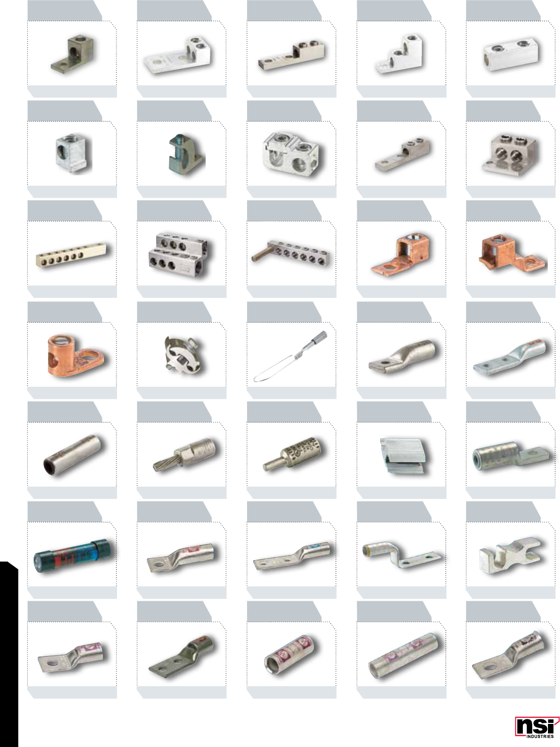
PICTORIAL INDEX
1
T SERIES
TP, BTP SERIES
STL SERIES
TL SERIES
ASC-T SERIES
ISE SERIES
GL SERIES
L SERIES
GLA, BS SERIES
SFTZ SERIES
PAA, PAE SERIES
PT SERIES
L SERIES
GL-N SERIES
L4, LL4, LL2 SERIES
GP, GC SERIES
TS SERIES TC SERIES
W, HLC, EC SERIES
PTS, PTO SERIES
LN SERIES
SC SERIES
T2 SERIES
LL SERIES
AL SERIES
WRD, C SERIES
SL-N SERIES
C SERIES
SR SERIES
T, L SERIES
DE SERIES
AL-N SERIES
CAL SERIES
SA SERIES
GL-B SERIES
PAGE 13
PAGE 23
PAGE 33
PAGE 43
PAGE 53
PAGE 65
PAGE 79
PAGE 15
PAGE 25
PAGE 35
PAGE 45
PAGE 55
PAGE 67
PAGE 83
PAGE 17
PAGE 27
PAGE 37
PAGE 47
PAGE 57
PAGE 71
PAGE 85
PAGE 19
PAGE 29
PAGE 39
PAGE 49
PAGE 59
PAGE 77
PAGE 87
PAGE 21
PAGE 31
PAGE 41
PAGE 51
PAGE 63
PAGE 78
PAGE 89
NSi Industries LLC • USA • 800.321.5847 • www.nsiindustries.com
PICTORIAL INDEX
2
L-B SERIES
GLN-X SERIES
N-SP SERIES
N SERIES- 3 WIRE
TCP SERIES
FQC SERIES
ITB SERIES
L-NB SERIES
CT SERIES
APS SERIES
IPCS SERIES
TBS SERIES
MULTIPLE
CONNECTORS
NEUTRAL
CONNECTORS COMBINATION
CONNECTORS NMS, NMT SERIES
GL-NB SERIES
CTH SERIES
SPM SERIES-1
AS, AM, AL SERIES
TB0 SERIES
CN SERIES
LK SERIES
SC-B SERIES
CSP, CDP SERIES
SPM SERIES-2
AS, AM, AL
SERIES COVERS
DRT, FTB, DRE
DRJ SERIES
CB SERIES
N12ID & N1240
GLN SERIES
N SERIES-2 WIRE
TC SERIES
TB SERIES
DR SERIES
PAGE 91
PAGE 101
PAGE 107PAGE 106
PAGE 112
PAGE 122
PAGE 127
PAGE 135
PAGE 93
PAGE 102
PAGE 108
PAGE 113
PAGE 123
PAGE 129
PAGE 137
PAGE 95
PAGE 103
PAGE 109
PAGE 115
PAGE 124
PAGE 131
PAGE 139
PAGE 97
PAGE 104
PAGE 110
PAGE 117
PAGE 125
PAGE 132
PAGE 153
PAGE 99
PAGE 105
PAGE 111
PAGE 121
PAGE 125
PAGE 133
PAGE 106
PAGE 112

PICTORIAL INDEX
3
KA & KC SERIES FTS, CB, CBS
CBH SERIES
HB, HN, SLW
FW SERIES
SS, SSHN, SSBW
SSSLW, SSFW SERIES
IT, ITO, ITH SERIES
IPLDH SERIES
PL SERIES
ESGTS SERIES
NSI-12, P-750
TL, NH SERIES
ISR SERIES
IPLM SERIES
CUSTOM SERIES
INSTALLATION
ESSLK SERIES
TL SERIES
OX, DS SERIES ITG, ITOG, IPLG
SITG SERIES
IPL SERIES
IPLMD SERIES
WAGS SERIES
ESGHS SERIES
MANUAL
COMPRESSION MANUAL/RATCHET
CABLE CUTTERS
TES SERIES
IPLD SERIES
ISPB, ISPC SERIES
ESUF SERIES
GSS SERIES
TW SERIES
ISW SERIES ITW, IPLW SERIES
IPLDS SERIES
PLH SERIES
ESGS SERIES
ROS SERIES
PAGE 154
PAGE 160
PAGE 167
PAGE 177
PAGE 191
PAGE 203
PAGE 216
PAGE 155
PAGE 161
PAGE 168
PAGE 179
PAGE 193
PAGE 207
PAGE 217
PAGE 162
PAGE 171
PAGE 181
PAGE 195
PAGE 213
PAGE 218
PAGE 158PAGE 157
PAGE 165
PAGE 173
PAGE 185
PAGE 199
PAGE 214
PAGE 219
PAGE 159
PAGE 166
PAGE 175
PAGE 189
PAGE 201
PAGE 215
PAGE 220
NSi Industries LLC • USA • 800.321.5847 • www.nsiindustries.com
PICTORIAL INDEX
4
HSC SERIES
G & G-DB SERIES G-S & G SERIES
(G-79)-(G-90) SERIES GRC SERIES
GBA, GBC SERIES
HTGE SERIES FS, SA SERIES
RSK SERIES SK SERIES
GH, GHM SERIES
UC SERIES
ET-CP SERIES
PG, GGC, GSH
GSC SERIES
PIWC SERIES
SKSS, HMSS SERIES
TWHS SERIES
GCA & G SERIES
GZ, GRC SERIES
CT SERIES CTH SERIES
SB, TOP, C SERIES
GLC SERIES
G SERIES
WC SERIES
WWC SERIES B SERIES
G-S-DB, G-S-BS
SERIES
G-S-DBR, G-BS
SERIES
EG SERIES
GBIAL, GBIAZ SERIES
TGE SERIES
PAGE 221
PAGE 227
PAGE 239PAGE 238
PAGE 244
PAGE 249
PAGE 254
PAGE 263
PAGE 222
PAGE 228
PAGE 240
PAGE 245
PAGE 250
PAGE 255
PAGE 265
PAGE 223
PAGE 229
PAGE 241
PAGE 246
PAGE 102
PAGE 256
PAGE 267
PAGE 224
PAGE 235
PAGE 242
PAGE 247
PAGE 103
PAGE 259
PAGE 271
PAGE 225
PAGE 237
PAGE 243
PAGE 248
PAGE 253
PAGE 261
HWHS SERIES
HHK SERIES
THK SERIES
PAGE 243
PICTORIAL INDEX
5
S SERIES R SERIES HT SERIES M, IM, FTC SERIES
SLYDER
-R, SS SERIES
HVAC DUCT STRAPS
V SERIES
P,IFS, IF SERIES
FULLY INSULATED
EWRT, EWWH
EWDT SERIES EWFT, EWEF
EWSR SERIES EWHR, EWGC
EWMT SERIES
TFZ, -ID SERIES
EWP SERIES
CABLE TIES
-SB SERIES
IFL, SF, DFR SERIES P, IFS, IF SERIES
ROUND
INDICATOR LIGHTS
SNAP-IN
RECTANGULAR LIGHTS EMERGENCY
STOP BUTTONS
UV CABLE TIES
FLUORESCENT TIES
COLORED TIES
TRT, SSCT SERIES
PM, PF, PTC
PT SERIES
-P, -PM SERIES
CTP SERIES
FTH SERIES
ROCKER SWITCHES
PUSHBUTTON
SWITCHES
ROTARY SWITCHES
TOGGLE SWITCHES
PAGE 273
PAGE 291
PAGE 301
PAGE 313
PAGE 318
PAGE 326PAGE 325
PAGE 334
PAGE 279
PAGE 293
PAGE 304
PAGE 314
PAGE 319
PAGE 327
PAGE 335
PAGE 295
PAGE 308
PAGE 315
PAGE 321
PAGE 329
PAGE 337
PAGE 287PAGE 285
PAGE 297
PAGE 309
PAGE 316
PAGE 323
PAGE 331
PAGE 338
PAGE 289
PAGE 299
PAGE 310
PAGE 317
PAGE 324
PAGE 333
-MH SERIES
EWG, EWPP SERIES

NSi Industries LLC • USA • 800.321.5847 • www.nsiindustries.com
PICTORIAL INDEX
6
PNC SERIES
WMC SERIES VM SERIES VL, DSS,
SR SERIES
MPM SERIES
PC, FD SERIES
ADJCC SERIES
MP, WLD SERIES WMB SERIES
ULT, ULTD
BT SERIES
NC, NCH SERIES
RLD, IT-BW SERIES
PC-LS, N SERIES
SM SERIES
PAGE 340
PAGE 349
PAGE 355PAGE 354
PAGE 342
PAGE 350
PAGE 356
PAGE 342
PAGE 351
PAGE 343
PAGE 352
PAGE 345
PAGE 353
PAGE 339
WPM SERIES WP "ROCKY" SERIES
BKS SERIES BKM SERIES
WP SERIES
FS SERIES
FLF, FLC SERIES
EMHD, FBP SERIES
EL, VR SERIES SLUL, SC, RS
VTB, VTW SERIES
WPC SERIES
FLLP SERIES FLM, FL SERIES
EMTW, EMFW
SERIES EXL, EEL, EMWL
EMTW SERIES
UCF SERIESVRS SERIES TA-DOK SERIES
WPL & WPLD SERIES
FLH, PHN SERIES QF SERIES
PAGE 371
PAGE 377
PAGE 383
PAGE 391
PAGE 372
PAGE 378
PAGE 386
PAGE 392
PAGE 373
PAGE 379
PAGE 387
PAGE 393
PAGE 374
PAGE 380 PAGE 381
PAGE 389
PAGE 394
PAGE 359
PAGE 375
PAGE 382
PAGE 390
PAGE 383
PICTORIAL INDEX
7
2100 SERIES
3000 SERIES
5200 SERIES
1100 SERIES
WH2B
TZ SERIES
EW SERIES
2110 SERIES
5000M SERIES
5200-UL SERIES
7000 SERIES
1800 SERIES
DT SERIES
EWZ SERIES
2000 SERIES
5400 SERIES
5737 SERIES
7000Z SERIES
W SERIES
EH20C SERIES
DG100 SERIES
2001 SERIES
2005A SERIES
PHOTOCONTROL
ACCESSORIES
8000 SERIES
T900 SERIES
SA300 SERIES
DW SERIES
2020 SERIES
2005B SERIES
TU40 SERIES
8000 SERIES
TW SERIES
E&E-PB SERIES
DTS SERIES
PAGE 403
PAGE 408
PAGE 413
PAGE 423
PAGE 432
PAGE 441
PAGE 455
PAGE 404
PAGE 409
PAGE 414
PAGE 425
PAGE 433
PAGE 447
PAGE 457
PAGE 405
PAGE 410
PAGE 415
PAGE 427
PAGE 435
PAGE 449
PAGE 459
PAGE 406
PAGE 411
PAGE 416
PAGE 429
PAGE 437
PAGE 451
PAGE 461
PAGE 407
PAGE 412
PAGE 421
PAGE 431
PAGE 439
PAGE 453
PAGE 463
PAGE 427
PAGE 433
PAGE 447
PAGE 449
PAGE 451
PAGE 453
PAGE 455
PAGE 457
PAGE 459
PAGE 461

NSi Industries LLC • USA • 800.321.5847 • www.nsiindustries.com
PICTORIAL INDEX
8
DZS SERIES
DLC400BP SERIES
DIN SERIES
ACT30MA SERIES
WOS-M SERIES
COS-LU SERIES
DZM SERIES
LD SERIES
SMC SERIES
WOS-M2R SERIES
COS-M SERIES
LC200 SERIES
DGS SERIES
5401 SERIES
WOS-M2T SERIES
HOS-M SERIES
DGU/DGLC SERIES
EJWT&E500T SERIES
HPS STARTER
COS-L2T SERIES
CPS-L SERIES
ELC SERIES
PCT15M
WOS SERIES
COS-L SERIES
PAGE 465
PAGE 475
PAGE 485PAGE 484
PAGE 495
PAGE 500
PAGE 509
PAGE 515
PAGE 467
PAGE 477
PAGE 487
PAGE 496
PAGE 501
PAGE 511
PAGE 517
PAGE 469
PAGE 479
PAGE 488
PAGE 497
PAGE 502
PAGE 512
PAGE 518
PAGE 471
PAGE 481
PAGE 489
PAGE 498
PAGE 503
PAGE 513
PAGE 519
PAGE 473
PAGE 483
PAGE 494
PAGE 499
PAGE 504
PAGE 514
PAGE 467
PAGE 475
PAGE 487
PAGE 499
PAGE 501
SS720A SERIES
SS SERIES
SS720Z
D SERIES
SA170 SERIES
A SERIES
701A&711A SERIES
SS700 SERIES
SS403 & SS423
PAGE 509
PAGE 513
TRP-24I SERIES
PICTORIAL INDEX
9
400 SERIES
MECHNICAL
MANUAL
FIRE ALARM
MECHNICAL
HORNS
600&SA200 SERIES
DIGITAL SA200 SERIES
DIGITAL
SA100 SERIES
MECHNICAL
TELEPHONE RELAY
HEAVY DUTY BELLS
4", 6", 10" BELLS
SA100&400 SERIES
DIGITAL
WALL CLOCKS
QUARTZ & ELECTRIC
GENERAL PURPOSE
BELLS AND BUZZERS
SA200&500 SERIES
WIRELESS CONTROLS
ELECTRIC DOOR
OPENERS
MECHANICAL
STROBE HORNS
600&SA200 SERIES
MECHNICAL
PUSH-BUTTONS TRANSFORMERS
MULTI-TONE
ELECTRONIC HORNS
CHIMES &
CHIME KITS
WARNING LIGHTS
INDUSTRIAL UNITS WARNING LIGHTS
VEHICULAR UNITS
P1100 SERIES
MECHANICAL
POOL & SPA
JUNCTION BOXES
POWER SUPPLY
UNITS - 24VDC
P1100 SERIES
DIGITAL
PP PANEL SERIES
SA200 SERIES
WEATHERPROOF
MOTOR DRIVEN SIREN
1100 SERIES
PAGE 523
PAGE 528
PAGE 533
PAGE 536
PAGE 541
PAGE 549
PAGE 554
PAGE 524
PAGE 529
PAGE 534
PAGE 537
PAGE 542
PAGE 551
PAGE 555
PAGE 525
PAGE 530
PAGE 535
PAGE 538
PAGE 543
PAGE 552
PAGE 526
PAGE 533
PAGE 536
PAGE 539
PAGE 543
PAGE 527
PAGE 534
PAGE 535
PAGE 540
PAGE 544
PAGE 553
ACCESSORIES
REPLACEMENT PARTS
PAGE 520
PAGE 528
C SERIES
DPC201 SERIES
PAGE 555

NSi Industries LLC • USA • 800.321.5847 • www.nsiindustries.com
PICTORIAL INDEX
10
NOTES
ConneCtors
13
CONNECTORS
RATINGS
FEATURES
MECHANICAL CONNECTORS
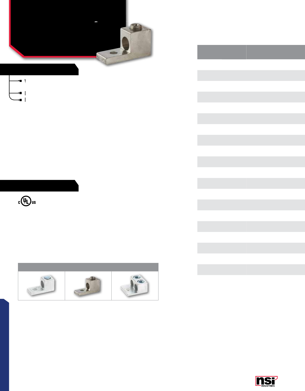
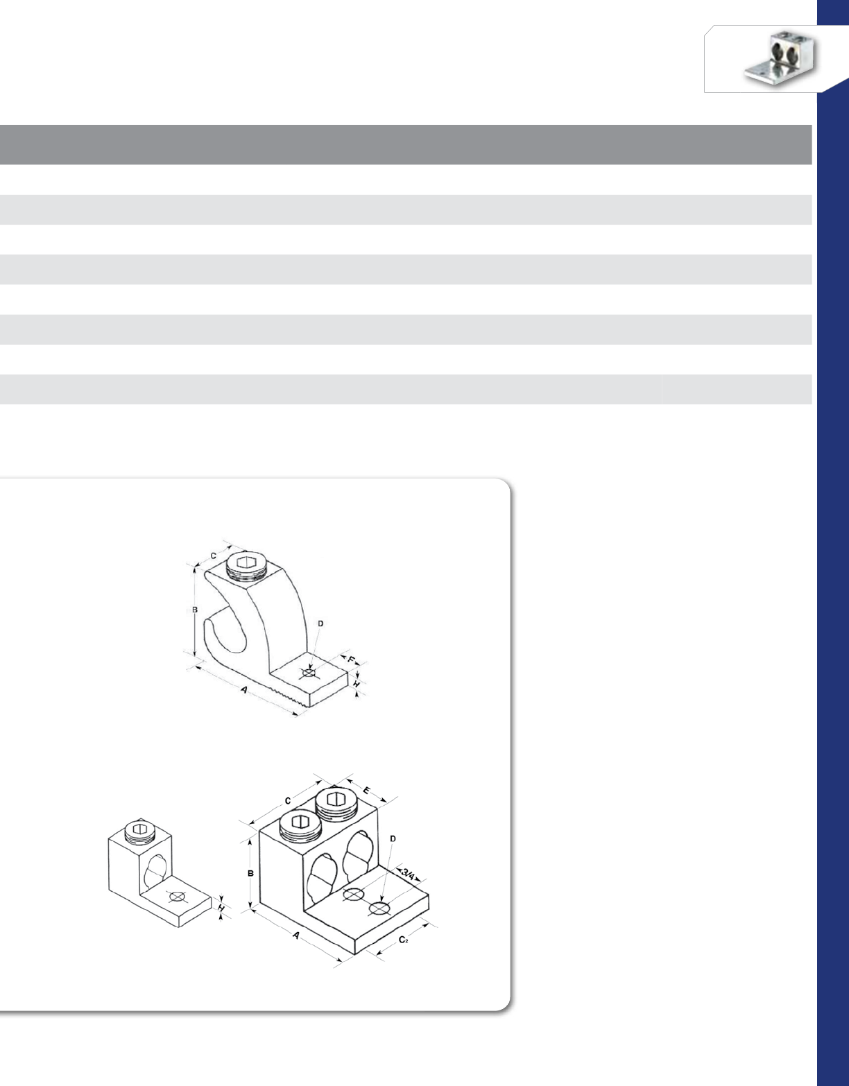
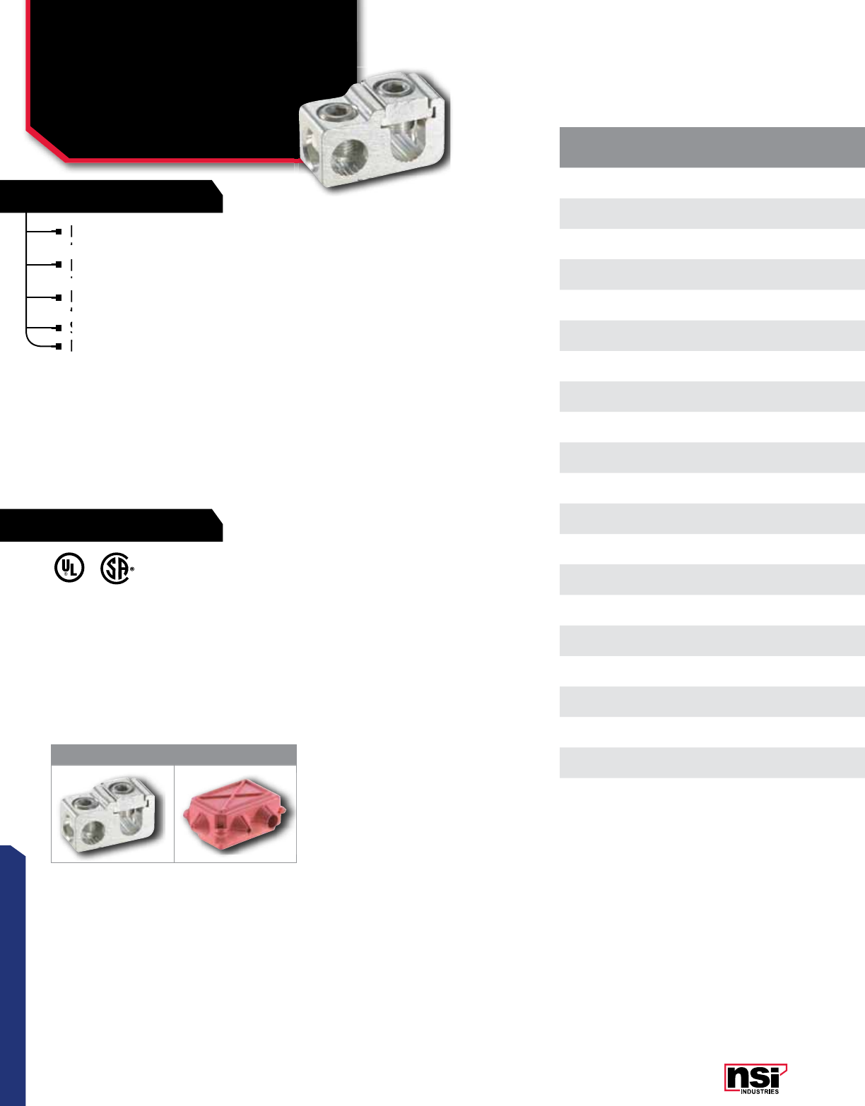
Aluminum Dual Rated
Single & Double Lugs
T SERIES
TEMPERATURE RATING:
90 °C.
VOLTAGE:
600V (2000V max. per UL486B).
UL 486A/B Listed.
Versatile and reusable set screw connectors made
of 6061T-6 aluminum alloy.
Electro-tin plated for low contact resistance.
For use with copper or aluminum conductors.
CAT.
NO.FIG.
NO. WIRE
RANGE MTG. BOLT
SIZE
TORQUE
VALUE
(IN./LBS.)
WRENCH
SIZE MTG. HOLE
DIA.(E) LENGTH
(L) WIDTH
(W) HEIGHT
(H)
TANG
LENGTH
(A)
TANG
LENGTH
(B)
TANG
THICkNESS
(C)
STD.
CTN.
QTY.
6T 16-14 AWG 1/4 45 Slotted 0.265 1.060 0.500 0.500 0.250 0.690 0.100 100
4T 14-14 AWG 1/4 45 Slotted 0.265 1.060 0.375 0.500 0.250 0.690 0.094 100
2T 12-14 AWG 1/4 50 Slotted 0.265 1.160 0.500 0.550 0.310 0.690 0.100 100
0T 21/0-14 AWG 1/4 120 3/16 0.265 1.470 0.630 0.790 0.440 0.850 0.190 50
2-0T 31/0-14 AWG 1/4 120 3/16 0.265 1.470 1.130 0.790 0.440 0.850 0.190 50
2/0T 22/0-14 AWG 1/4 120 3/16 0.265 1.470 0.630 0.790 0.440 0.850 0.190 50
2-2/0T 3(2) 2/0-14 AWG 1/4 120 3/16 0.265 1.470 1.250 0.790 0.440 0.850 0.190 50
3/0T 23/0-6 AWG 1/4 250 3/16 0.265 1.875 0.700 0.890 0.500 0.850 0.145 50
250T 2250 MCM-6 AWG 5/16 330 5/16 0.328 2.000 0.880 1.020 0.470 1.130 0.220 24
2-250T 3(2) 250 MCM-6 AWG 5/16 330 5/16 0.328 2.560 1.630 1.020 0.630 1.690 0.220 10
300T 2300 MCM - 6 AWG 5/16 330 5/16 0.328 2.000 0.880 1.130 0.500 1.000 0.250 24
350T 2350 MCM-6 AWG 3/8 400 5/16 0.406 2.250 0.990 1.130 0.500 1.250 0.250 20
2-350T 3(2) 350 MCM-6 AWG 3/8 400 5/16 0.406 2.880 1.920 1.130 0.630 1.880 0.250 8
500T 2500 MCM - 4 AWG 3/8 550 3/8 0.406 2.750 1.200 1.410 0.630 1.630 0.310 6
600T 2600 MCM-2 AWG 3/8 550 3/8 0.406 3.180 1.380 1.510 0.630 1.930 0.380 6
2-600T 3(2) 600 MCM-2 AWG 1/2 550 3/8 0.531 3.180 2.410 1.510 0.630 1.930 0.380 4
800T 2800-300 MCM 1/2 550 1/2 0.531 3.250 1.440 1.690 0.630 1.880 0.440 6
2-800T 3(2) 800-300 MCM 1/2 550 1/2 0.531 3.250 2.750 1.690 0.880 1.880 0.440 2
1000T 21000-350 MCM 1/2 600 9/16 0.531 3.250 1.690 1.880 0.750 1.750 0.440 6
2-1000T 3(2) 1000-350 MCM 1/2 600 9/16 0.531 3.250 3.190 1.880 0.880 1.750 0.440 2
123
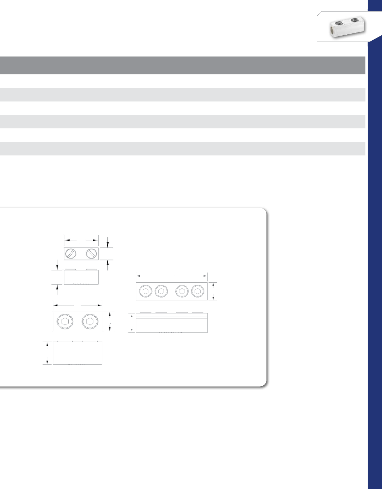
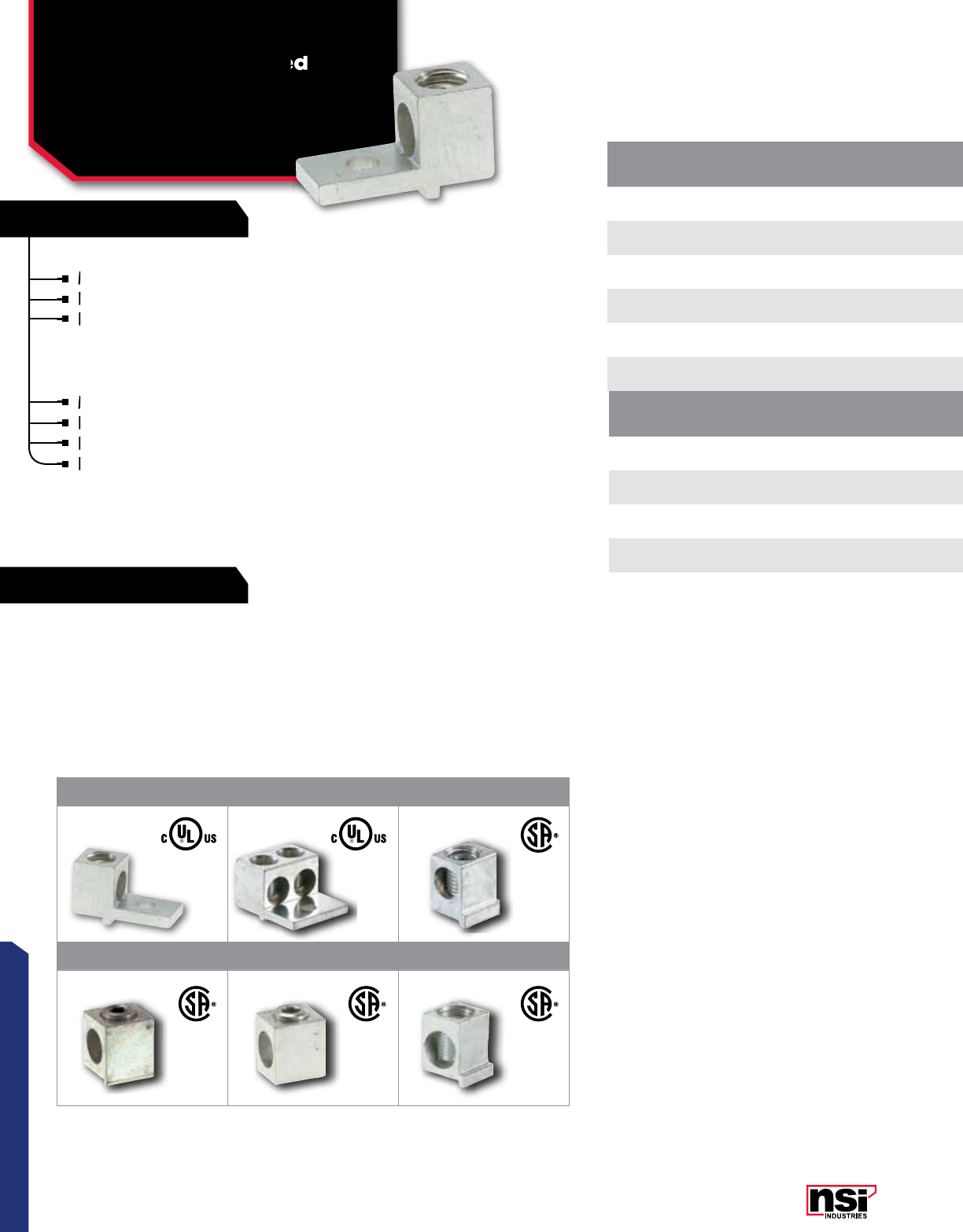
Aluminum Dual Rated
Single & Double Lugs
All dimensional data is listed in inches.
Versatile and reusable set screw connectors made
of 6061T-6 aluminum alloy.
Electro-tin plated for low contact resistance.
For use with copper or aluminum conductors.
For use with copper or aluminum conductors.
For use with copper or aluminum conductors.
LISTED
WIRE CONNECTOR
14
CONNECTORS
NSi Industries LLC • USA • 800.321.5847 • www.nsiindustries.com
CAT.
NO.FIG.
NO. WIRE
RANGE MTG. BOLT
SIZE
TORQUE
VALUE
(IN./LBS.)
WRENCH
SIZE MTG. HOLE
DIA.(E) LENGTH
(L) WIDTH
(W) HEIGHT
(H)
TANG
LENGTH
(A)
TANG
LENGTH
(B)
TANG
THICkNESS
(C)
STD.
CTN.
QTY.
6T 16-14 AWG 1/4 45 Slotted 0.265 1.060 0.500 0.500 0.250 0.690 0.100 100
4T 14-14 AWG 1/4 45 Slotted 0.265 1.060 0.375 0.500 0.250 0.690 0.094 100
2T 12-14 AWG 1/4 50 Slotted 0.265 1.160 0.500 0.550 0.310 0.690 0.100 100
0T 21/0-14 AWG 1/4 120 3/16 0.265 1.470 0.630 0.790 0.440 0.850 0.190 50
2-0T 31/0-14 AWG 1/4 120 3/16 0.265 1.470 1.130 0.790 0.440 0.850 0.190 50
2/0T 22/0-14 AWG 1/4 120 3/16 0.265 1.470 0.630 0.790 0.440 0.850 0.190 50
2-2/0T 3(2) 2/0-14 AWG 1/4 120 3/16 0.265 1.470 1.250 0.790 0.440 0.850 0.190 50
3/0T 23/0-6 AWG 1/4 250 3/16 0.265 1.875 0.700 0.890 0.500 0.850 0.145 50
250T 2250 MCM-6 AWG 5/16 330 5/16 0.328 2.000 0.880 1.020 0.470 1.130 0.220 24
2-250T 3(2) 250 MCM-6 AWG 5/16 330 5/16 0.328 2.560 1.630 1.020 0.630 1.690 0.220 10
300T 2300 MCM - 6 AWG 5/16 330 5/16 0.328 2.000 0.880 1.130 0.500 1.000 0.250 24
350T 2350 MCM-6 AWG 3/8 400 5/16 0.406 2.250 0.990 1.130 0.500 1.250 0.250 20
2-350T 3(2) 350 MCM-6 AWG 3/8 400 5/16 0.406 2.880 1.920 1.130 0.630 1.880 0.250 8
500T 2500 MCM - 4 AWG 3/8 550 3/8 0.406 2.750 1.200 1.410 0.630 1.630 0.310 6
600T 2600 MCM-2 AWG 3/8 550 3/8 0.406 3.180 1.380 1.510 0.630 1.930 0.380 6
2-600T 3(2) 600 MCM-2 AWG 1/2 550 3/8 0.531 3.180 2.410 1.510 0.630 1.930 0.380 4
800T 2800-300 MCM 1/2 550 1/2 0.531 3.250 1.440 1.690 0.630 1.880 0.440 6
2-800T 3(2) 800-300 MCM 1/2 550 1/2 0.531 3.250 2.750 1.690 0.880 1.880 0.440 2
1000T 21000-350 MCM 1/2 600 9/16 0.531 3.250 1.690 1.880 0.750 1.750 0.440 6
2-1000T 3(2) 1000-350 MCM 1/2 600 9/16 0.531 3.250 3.190 1.880 0.880 1.750 0.440 2
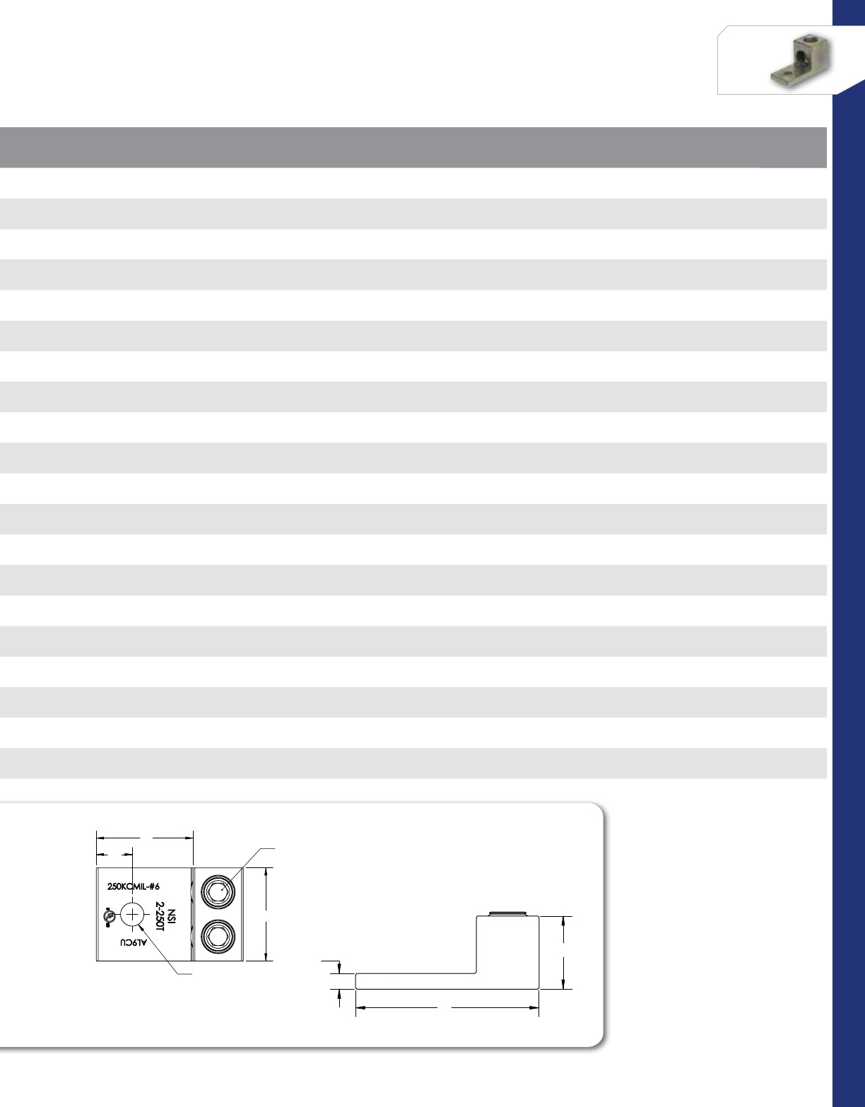
L
H
C
W
A
B
INTERNAL HEX
PRESSURE SCREWS
MOUNT HOLE
2-250T
SHOWN
NOTES:
TIN PLATED 6061-T6511 ALUMINUM ALLOY.
1.
UL LISTED 90° C FOR COPPER AND ALUMINIUM
2.
CONDUCTOR.
CONTACT NSi FOR SALES @ 800.321.5847
PART#
WIRE RANGE
HEX SIZE
L
H
W
A
B
C
MOUNT
HOLE
2-0T
1/0 - 14 AWG
3/16
1.47 .79 1.13 .44 .84 .19
1/4
2-2/0T
2/0 - 14 AWG
3/16
1.47 .79 1.25 .44 .84 .19
1/4
2-250T
250KCMIL - 6 AWG
5/16
2.56 1.02 1.63 .63 1.69 .22
3/8
2-350T
350KCMIL - 6 AWG
5/16
2.88 1.13 1.92 .63 1.88 .25
3/8
2-600T
600KCMIL - 2 AWG
3/8
3.18 1.51 2.41 .63 1.93 .38
1/2
2-800T
800 - 300KCMIL
1/2
3.25 1.69 2.75 .88 1.88 .44
1/2
2-1000T
1000 - 500KCMIL
9/16
3.25 1.88 3.19 .88 1.75 .44
1/2
DWG. NO.
TITLE:
PROPRIETARY AND CONFIDENTIAL
THE INFORMATION CONTAINED IN THIS
DRAWING IS THE SOLE PROPERTY OF
REPRODUCTION IN PART OR AS A WHOLE
WITHOUT THE WRITTEN PERMISSION OF
POLARIS SALES CO. INC. IS PROHIBITED.
2-_T-SERIES
SHEET:
1 OF 1
SCALE:
1:1
DATE
DRAWN BY
SEE NOTE
MATERIAL:
9/17/2012
NAME
NSi
TWO PORT
LUG SERIES
KM
9730 Northcross Center Court, Huntersville, NC 28078
NSi Industries, LLC. Any
L
H
C
W
A
B
INTERNAL HEX
PRESSURE SCREWS
MOUNT HOLE
2-250T
SHOWN
NOTES:
TIN PLATED 6061-T6511 ALUMINUM ALLOY.
1.
UL LISTED 90° C FOR COPPER AND ALUMINIUM
2.
CONDUCTOR.
CONTACT NSi FOR SALES @ 800.321.5847
PART#
WIRE RANGE
HEX SIZE
L
H
W
A
B
C
MOUNT
HOLE
2-0T
1/0 - 14 AWG
3/16
1.47 .79 1.13 .44 .84 .19
1/4
2-2/0T
2/0 - 14 AWG
3/16
1.47 .79 1.25 .44 .84 .19
1/4
2-250T
250KCMIL - 6 AWG
5/16
2.56 1.02 1.63 .63 1.69 .22
3/8
2-350T
350KCMIL - 6 AWG
5/16
2.88 1.13 1.92 .63 1.88 .25
3/8
2-600T
600KCMIL - 2 AWG
3/8
3.18 1.51 2.41 .63 1.93 .38
1/2
2-800T
800 - 300KCMIL
1/2
3.25 1.69 2.75 .88 1.88 .44
1/2
2-1000T
1000 - 500KCMIL
9/16
3.25 1.88 3.19 .88 1.75 .44
1/2
DWG. NO.
TITLE:
PROPRIETARY AND CONFIDENTIAL
THE INFORMATION CONTAINED IN THIS
DRAWING IS THE SOLE PROPERTY OF
REPRODUCTION IN PART OR AS A WHOLE
WITHOUT THE WRITTEN PERMISSION OF
POLARIS SALES CO. INC. IS PROHIBITED.
2-_T-SERIES
SHEET:
1 OF 1
SCALE:
1:1
DATE
DRAWN BY
SEE NOTE
MATERIAL:
9/17/2012
NAME
NSi
TWO PORT
LUG SERIES
KM
9730 Northcross Center Court, Huntersville, NC 28078
NSi Industries, LLC. Any
(unless otherwise noted)
(E)
15
CONNECTORS
RATINGS
FEATURES
MECHANICAL CONNECTORS
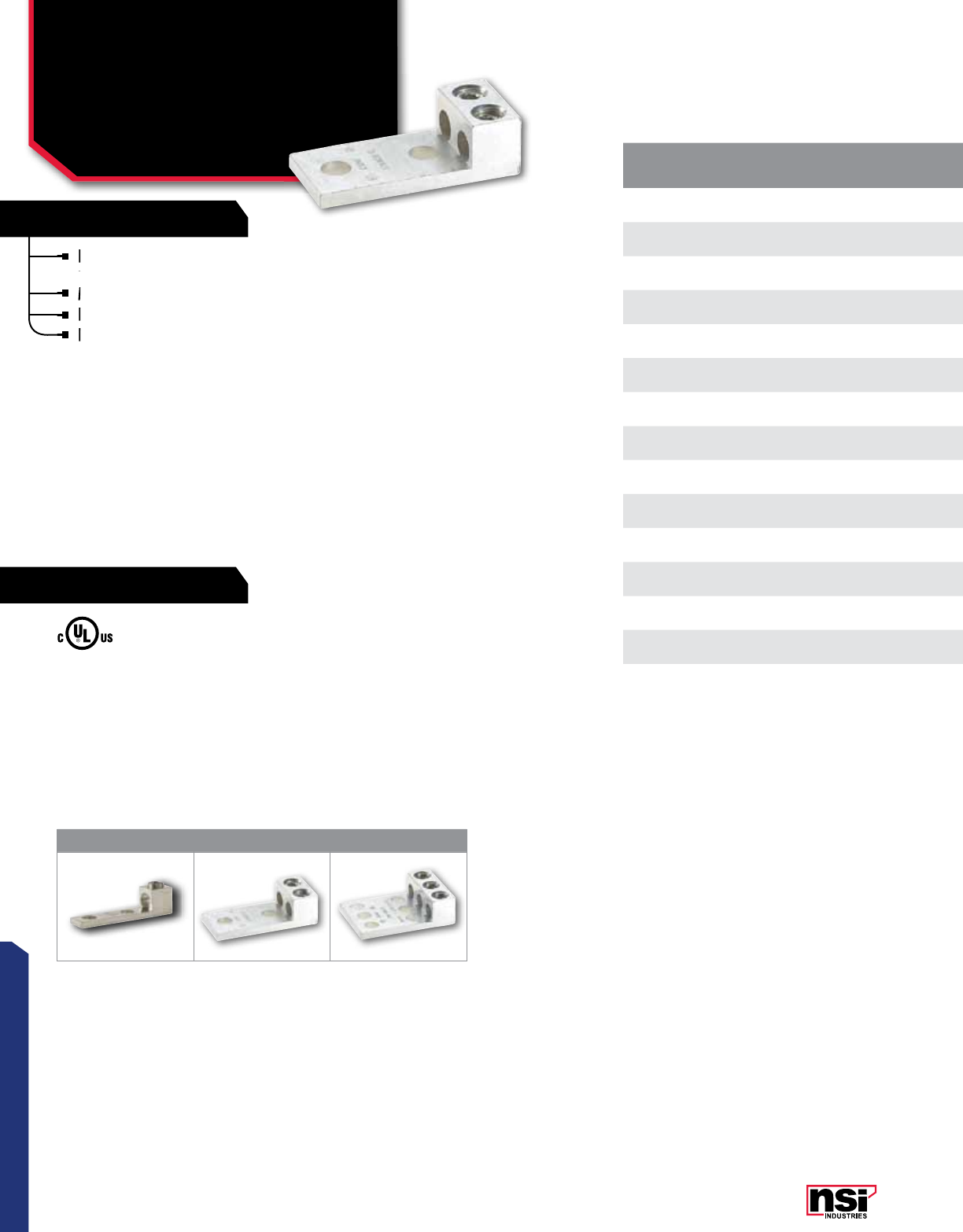
Aluminum Dual Rated
Panelboard Lugs
L SERIES
Panelboard style for multi-conductor with NEMA
mounting hole spacing for turn prevent and secureness.
Made of 6061T-6 aluminum alloy.
Electro-tin plated for low contact resistance.
For use with copper or aluminum conductors.
TEMPERATURE RATING:
90 °C.
VOLTAGE:
600V (2000V max. per UL486B).
UL 486A/B Listed.
CAT.
NO.FIG.
NO. WIRE
RANGE MTG. BOLT
SIZE
TORQUE
VALUE
(IN./LBS.)
WRENCH
SIZE MTG. HOLE
DIA. (E) LENGTH
(L) WIDTH
(W) HEIGHT
(H)
TANG
LENGTH
(A)
TANG
LENGTH
(B)
TANG
THICkNESS
(C)
STD.
CTN.
QTY.
250L2 1250 MCM-6 AWG 1/2 330 5/16 0.560 4.310 0.880 1.380 0.560 3.090 0.310 15
2-250L2 2(2) 250 MCM-6 AWG 1/2 330 5/16 0.560 3.880 1.690 1.020 0.560 3.010 0.220 6
3-250L2/L4 3(3) 250 MCM-6 AWG 1/2 330 5/16 0.560 3.880 2.500 1.020 0.560 3.010 0.220 3
350L2 1350 MCM-6 AWG 1/2 400 5/16 0.560 4.310 0.990 1.380 0.630 3.090 0.310 8
2-350L2 2(2) 350 MCM-6 AWG 1/2 400 5/16 0.560 4.250 1.920 1.130 0.630 3.250 0.250 4
3-350L2/L4 3(3) 350 MCM-6 AWG 1/2 400 5/16 0.560 4.250 2.920 1.130 0.630 3.250 0.250 2
600L2 1600 MCM-2 AWG 1/2 550 3/8 0.560 4.650 1.380 1.510 0.630 3.400 0.380 4
2-600L2 2(2) 600 MCM-2 AWG 1/2 550 3/8 0.560 4.650 2.406 1.510 0.630 3.400 0.380 3
3-600L2/L4 3(3) 600 MCM-2 AWG 1/2 550 3/8 0.560 4.650 3.930 1.510 0.630 3.400 0.380 2
800L2 1800-350 MCM 1/2 550 1/2 0.560 4.750 1.440 1.690 0.630 3.380 0.440 4
2-800L2 2(2) 800-350 MCM 1/2 550 1/2 0.560 4.750 2.750 1.690 0.630 3.380 0.440 2
3-800L2/L4 3(3) 800-350 MCM 1/2 550 1/2 0.560 4.750 4.060 1.690 0.630 3.380 0.440 2
1000L2 11000-500 MCM 1/2 600 9/16 0.560 4.940 1.690 1.880 0.630 3.440 0.440 4
2-1000L2 2(2) 1000-500 MCM 1/2 600 1/2 0.560 4.940 3.190 1.880 0.630 3.440 0.440 2
3-1000L2/L4 3(3) 1000-500 MCM 1/2 600 9/16 0.560 4.940 4.690 1.880 0.630 3.440 0.440 2
123
All dimensional data is listed in inches.
All hole spacing is NEMA Std of 1.750”
Panelboard style for multi-conductor with NEMA
mounting hole spacing for turn prevent and secureness.
Panelboard style for multi-conductor with NEMA
mounting hole spacing for turn prevent and secureness.
Panelboard style for multi-conductor with NEMA
Made of 6061T-6 aluminum alloy.
Electro-tin plated for low contact resistance.
Electro-tin plated for low contact resistance.
Electro-tin plated for low contact resistance.
For use with copper or aluminum conductors.
For use with copper or aluminum conductors.
LISTED
WIRE CONNECTOR
16
CONNECTORS
NSi Industries LLC • USA • 800.321.5847 • www.nsiindustries.com
CAT.
NO.FIG.
NO. WIRE
RANGE MTG. BOLT
SIZE
TORQUE
VALUE
(IN./LBS.)
WRENCH
SIZE MTG. HOLE
DIA. (E) LENGTH
(L) WIDTH
(W) HEIGHT
(H)
TANG
LENGTH
(A)
TANG
LENGTH
(B)
TANG
THICkNESS
(C)
STD.
CTN.
QTY.
250L2 1250 MCM-6 AWG 1/2 330 5/16 0.560 4.310 0.880 1.380 0.560 3.090 0.310 15
2-250L2 2(2) 250 MCM-6 AWG 1/2 330 5/16 0.560 3.880 1.690 1.020 0.560 3.010 0.220 6
3-250L2/L4 3(3) 250 MCM-6 AWG 1/2 330 5/16 0.560 3.880 2.500 1.020 0.560 3.010 0.220 3
350L2 1350 MCM-6 AWG 1/2 400 5/16 0.560 4.310 0.990 1.380 0.630 3.090 0.310 8
2-350L2 2(2) 350 MCM-6 AWG 1/2 400 5/16 0.560 4.250 1.920 1.130 0.630 3.250 0.250 4
3-350L2/L4 3(3) 350 MCM-6 AWG 1/2 400 5/16 0.560 4.250 2.920 1.130 0.630 3.250 0.250 2
600L2 1600 MCM-2 AWG 1/2 550 3/8 0.560 4.650 1.380 1.510 0.630 3.400 0.380 4
2-600L2 2(2) 600 MCM-2 AWG 1/2 550 3/8 0.560 4.650 2.406 1.510 0.630 3.400 0.380 3
3-600L2/L4 3(3) 600 MCM-2 AWG 1/2 550 3/8 0.560 4.650 3.930 1.510 0.630 3.400 0.380 2
800L2 1800-350 MCM 1/2 550 1/2 0.560 4.750 1.440 1.690 0.630 3.380 0.440 4
2-800L2 2(2) 800-350 MCM 1/2 550 1/2 0.560 4.750 2.750 1.690 0.630 3.380 0.440 2
3-800L2/L4 3(3) 800-350 MCM 1/2 550 1/2 0.560 4.750 4.060 1.690 0.630 3.380 0.440 2
1000L2 11000-500 MCM 1/2 600 9/16 0.560 4.940 1.690 1.880 0.630 3.440 0.440 4
2-1000L2 2(2) 1000-500 MCM 1/2 600 1/2 0.560 4.940 3.190 1.880 0.630 3.440 0.440 2
3-1000L2/L4 3(3) 1000-500 MCM 1/2 600 9/16 0.560 4.940 4.690 1.880 0.630 3.440 0.440 2
(E)
17
CONNECTORS
RATINGS
FEATURES
MECHANICAL CONNECTORS
Aluminum Dual Rated
Panelboard Lugs
L4, LL4, LL2 SERIES
Large size set screw connectors with multiple mounting
hole for a secure, turn-prevent connection.
Made of 6061T-6 aluminum alloy.
Tin plated for low contact resistance.
For use with copper or aluminum conductors.
TEMPERATURE RATING:
90 °C.
VOLTAGE:
600V (2000V max. per UL486B).
UL 486A/B Listed.
CAT.
NO.FIG.
NO. WIRE
RANGE MTG. BOLT
SIZE
TORQUE
VALUE
(IN./LBS.)
WRENCH
SIZE MTG. HOLE
DIA. (E) LENGTH
(L) WIDTH
(W) HEIGHT
(H)
END OF CONN.
TO CTR. HOLE
(A)
TANG
LENGTH
(B)
TANG
THICkNESS
(C)
STD.
CTN.
QTY.
4-250L4 1250 MCM-6 AWG 1/2 330 5/16 0.560 3.880 3.300 1.020 0.560 3.010 0.220 3
4-350L4 1350 MCM-6 AWG 1/2 400 5/16 0.560 4.250 3.920 1.130 0.630 3.250 0.250 2
4-600L4 1600 MCM-2 AWG 1/2 550 3/8 0.560 4.650 5.000 1.510 0.630 3.400 0.380 2
600LL2 2600 MCM-2 AWG 1/2 550 3/8 0.560 5.500 1.380 1.510 0.630 3.250 0.380 4
3-600LL4 3600 MCM-2 AWG 1/2 550 3/8 0.560 5.500 3.930 1.510 0.630 3.250 0.380 2
4-600LL4 4600 MCM-2 AWG 1/2 550 3/8 0.560 5.500 5.000 1.510 0.630 3.250 0.380 2
4-800L4 1800-350 MCM 1/2 550 1/2 0.560 4.750 5.380 1.690 0.630 3.380 0.440 2
800LL2 2800-350 MCM 1/2 550 1/2 0.560 5.750 1.440 1.690 0.630 3.440 0.440 4
3-800LL4 3800-350 MCM 1/2 550 1/2 0.560 5.750 4.060 1.690 0.630 3.380 0.440 2
4-800LL4 4800-350 MCM 1/2 550 1/2 0.560 5.750 5.380 1.690 0.630 3.440 0.440 2
4-1000L4 11000-500 MCM 1/2 600 9/16 0.560 4.940 6.190 1.880 0.630 3.440 0.440 2
1000LL2 21000-500 MCM 1/2 600 9/16 0.560 6.190 1.690 1.880 0.630 3.630 0.440 4
3-1000LL4 31000-500 MCM 1/2 600 9/16 0.560 6.190 4.690 1.880 0.630 3.440 0.440 2
4-1000LL4 41000-500 MCM 1/2 600 9/16 0.560 6.180 6.190 1.880 0.630 3.630 0.440 2
1500LL2*21500-1000 MCM 1/2 -9/16 0.560 6.625 2.000 1.975 0.650 3.175 0.750 4
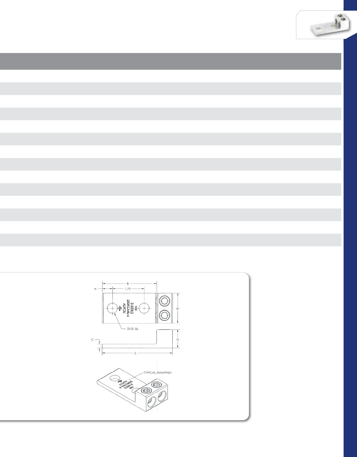
L
C
H
W
A
B
D
1.75
1.75
INTERNAL HEX
PRESSURE SCREWS
MOUNT HOLE
All dimensional data is listed in inches.
All hole spacing is NEMA Std of 1.750”
*1500LL2 is not CSA or UL approved.
1 2
3 4
Large size set screw connectors with multiple mounting
hole for a secure, turn-prevent connection.
Large size set screw connectors with multiple mounting
hole for a secure, turn-prevent connection.
Large size set screw connectors with multiple mounting
Made of 6061T-6 aluminum alloy.
Tin plated for low contact resistance.
Tin plated for low contact resistance.
For use with copper or aluminum conductors.
Tin plated for low contact resistance.
For use with copper or aluminum conductors.
For use with copper or aluminum conductors.
LISTED
WIRE CONNECTOR
E155027

18
CONNECTORS
NSi Industries LLC • USA • 800.321.5847 • www.nsiindustries.com
CAT.
NO.FIG.
NO. WIRE
RANGE MTG. BOLT
SIZE
TORQUE
VALUE
(IN./LBS.)
WRENCH
SIZE MTG. HOLE
DIA. (E) LENGTH
(L) WIDTH
(W) HEIGHT
(H)
END OF CONN.
TO CTR. HOLE
(A)
TANG
LENGTH
(B)
TANG
THICkNESS
(C)
STD.
CTN.
QTY.
4-250L4 1250 MCM-6 AWG 1/2 330 5/16 0.560 3.880 3.300 1.020 0.560 3.010 0.220 3
4-350L4 1350 MCM-6 AWG 1/2 400 5/16 0.560 4.250 3.920 1.130 0.630 3.250 0.250 2
4-600L4 1600 MCM-2 AWG 1/2 550 3/8 0.560 4.650 5.000 1.510 0.630 3.400 0.380 2
600LL2 2600 MCM-2 AWG 1/2 550 3/8 0.560 5.500 1.380 1.510 0.630 3.250 0.380 4
3-600LL4 3600 MCM-2 AWG 1/2 550 3/8 0.560 5.500 3.930 1.510 0.630 3.250 0.380 2
4-600LL4 4600 MCM-2 AWG 1/2 550 3/8 0.560 5.500 5.000 1.510 0.630 3.250 0.380 2
4-800L4 1800-350 MCM 1/2 550 1/2 0.560 4.750 5.380 1.690 0.630 3.380 0.440 2
800LL2 2800-350 MCM 1/2 550 1/2 0.560 5.750 1.440 1.690 0.630 3.440 0.440 4
3-800LL4 3800-350 MCM 1/2 550 1/2 0.560 5.750 4.060 1.690 0.630 3.380 0.440 2
4-800LL4 4800-350 MCM 1/2 550 1/2 0.560 5.750 5.380 1.690 0.630 3.440 0.440 2
4-1000L4 11000-500 MCM 1/2 600 9/16 0.560 4.940 6.190 1.880 0.630 3.440 0.440 2
1000LL2 21000-500 MCM 1/2 600 9/16 0.560 6.190 1.690 1.880 0.630 3.630 0.440 4
3-1000LL4 31000-500 MCM 1/2 600 9/16 0.560 6.190 4.690 1.880 0.630 3.440 0.440 2
4-1000LL4 41000-500 MCM 1/2 600 9/16 0.560 6.180 6.190 1.880 0.630 3.630 0.440 2
1500LL2*21500-1000 MCM 1/2 -9/16 0.560 6.625 2.000 1.975 0.650 3.175 0.750 4
L
H
C
W
1.75
1.75
A
B
D
INTERNAL HEX
PRESSURE SCREWS
MOUNT HOLE
C
H
L
W
1.75
A
B
MOUNT HOLE
INTERNAL HEX
PRESSURE SCREWS
L
H
C
W
1.75
1.75
A
B
D
INTERNAL HEX
PRESSURE SCREWS
MOUNT HOLE
19
CONNECTORS
RATINGS
FEATURES
MECHANICAL CONNECTORS
Aluminum Dual Rated
Stacked Lugs
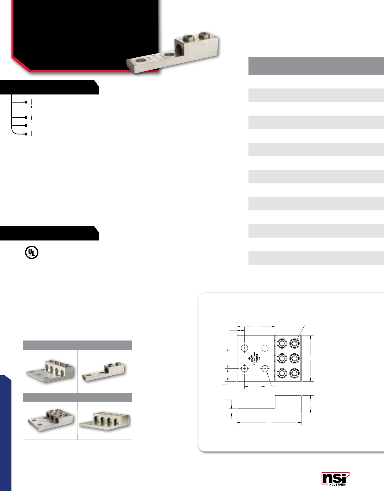
T2 SERIES
Large size set screw connectors with wire holes stacked on
top of each other to minimize the eidth of the connector.
Made of 6061T-6 aluminum alloy.
Tin plated for low contact resistance.
For use with copper or aluminum conductors.
TEMPERATURE RATING:
90 °C.
VOLTAGE:
600V (2000V max. per UL486B).
UL 486A/B Listed.
CAT.
NO.FIG.
NO. WIRE
RANGE MTG. BOLT
SIZE
TORQUE
VALUE
(IN./LBS.)
WRENCH
SIZE MTG. HOLE
DIA. (E) LENGTH
(L) WIDTH
(W) HEIGHT
(H)
END OF CONN.
TO CTR. HOLE
(A)
TANG
LENGTH
(B)
TANG
THICkNESS
(C)
STD.
CTN.
QTY.
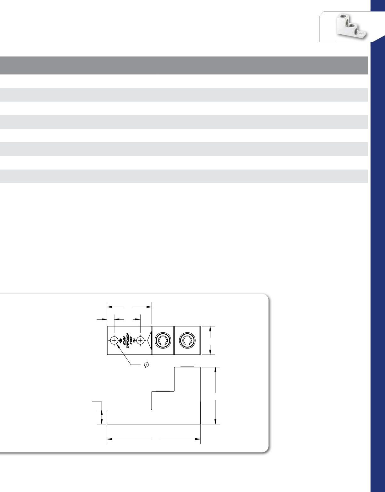
300T-2 1(2) 300 MCM-6 AWG 5/16" 330 5/16 0.330 3.000 1.000 2.000 0.470 1.000 0.310 10
350T-2 2(2) 350 MCM-6 AWG 5/16" 400 5/16 .33 X .43 3.560 1.060 2.000 0.470 1.560 0.250 10
600T-2 2(2) 600 MCM-2 AWG 3/8 550 3/8 0.410 4.910 1.500 3.000 0.380 2.340 0.750 2
600T-3 3(3) 600 MCM-2 AWG 3/8 550 3/8 0.410 4.910 2.500 3.000 0.380 2.340 0.750 2
600T-4 4(4) 600 MCM-2 AWG 3/8 550 3/8 0.410 4.910 2.500 3.000 0.380 2.340 0.750 2
800T-2 2(2) 800-300 MCM 3/8 550 3/8 0.410 4.910 1.500 3.000 0.380 2.340 0.750 2
800T-3 3(3) 800-300 MCM 3/8 550 1/2 0.410 4.910 2.630 3.000 0.380 2.340 0.750 2
800T-4 4(4) 800-300 MCM 3/8 550 1/2 0.410 4.910 2.630 3.000 0.380 2.340 0.750 2
All dimensional data is listed in inches.
All hole spacing is NEMA Std of 1.750”
1 2
3 4
Large size set screw connectors with wire holes stacked on
top of each other to minimize the eidth of the connector.
Large size set screw connectors with wire holes stacked on
top of each other to minimize the eidth of the connector.
Large size set screw connectors with wire holes stacked on
Made of 6061T-6 aluminum alloy.
Tin plated for low contact resistance.
Tin plated for low contact resistance.
For use with copper or aluminum conductors.
Tin plated for low contact resistance.
For use with copper or aluminum conductors.
For use with copper or aluminum conductors.
LISTED
WIRE CONNECTOR
E155027
20
CONNECTORS
NSi Industries LLC • USA • 800.321.5847 • www.nsiindustries.com
CAT.
NO.FIG.
NO. WIRE
RANGE MTG. BOLT
SIZE
TORQUE
VALUE
(IN./LBS.)
WRENCH
SIZE MTG. HOLE
DIA. (E) LENGTH
(L) WIDTH
(W) HEIGHT
(H)
END OF CONN.
TO CTR. HOLE
(A)
TANG
LENGTH
(B)
TANG
THICkNESS
(C)
STD.
CTN.
QTY.
300T-2 1(2) 300 MCM-6 AWG 5/16" 330 5/16 0.330 3.000 1.000 2.000 0.470 1.000 0.310 10
350T-2 2(2) 350 MCM-6 AWG 5/16" 400 5/16 .33 X .43 3.560 1.060 2.000 0.470 1.560 0.250 10
600T-2 2(2) 600 MCM-2 AWG 3/8 550 3/8 0.410 4.910 1.500 3.000 0.380 2.340 0.750 2
600T-3 3(3) 600 MCM-2 AWG 3/8 550 3/8 0.410 4.910 2.500 3.000 0.380 2.340 0.750 2
600T-4 4(4) 600 MCM-2 AWG 3/8 550 3/8 0.410 4.910 2.500 3.000 0.380 2.340 0.750 2
800T-2 2(2) 800-300 MCM 3/8 550 3/8 0.410 4.910 1.500 3.000 0.380 2.340 0.750 2
800T-3 3(3) 800-300 MCM 3/8 550 1/2 0.410 4.910 2.630 3.000 0.380 2.340 0.750 2
800T-4 4(4) 800-300 MCM 3/8 550 1/2 0.410 4.910 2.630 3.000 0.380 2.340 0.750 2
H
L
D
W
A
C
B
E
FIGURE 3
FIGURE 1
(SLOTTED)
FIGURE 4 FIGURE 5
FIGURE 2
21
CONNECTORS
RATINGS
FEATURES
CAT.
NO.FIG.
NO. WIRE
RANGE TORQUE VALUE
(IN./LBS.) WRENCH
SIZE LENGTH
(L) WIDTH
(W) HEIGHT
(H)
STD.
CTN.
QTY.
2SR 12-14 AWG 50 Slotted 1.594 0.443 0.550 50
1/0SR 11/0-14 AWG 120 Slotted 1.500 0.530 0.630 25
4/0SR 14/0-6 AWG 250 5/16 2.310 0.812 1.000 24
250SR 2250 MCM-6 AWG 330 5/16 2.310 0.812 1.000 10
350SR 2350 MCM-6 AWG 400 3/8 4.190 1.130 1.190 8
500SR 2500 MCM-3/0 AWG 550 3/8 5.000 1.380 1.500 3
750SR 2750-250 MCM 550 3/8 6.250 1.630 1.750 3
MECHANICAL CONNECTORS
Aluminum Dual Rated
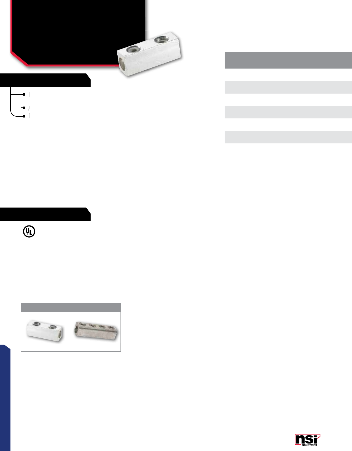
Splicer/Reducers
SR SERIES
For splicing two copper or aluminum wires of
equal or different sizes.
Made of 6061T-6 aluminum alloy.
Electro-tin plated for low contact resistance.
TEMPERATURE RATING:
90 °C.
VOLTAGE:
600V (2000V max. per UL486B).
UL 486A/B Listed.
1 2
All dimensional data is listed in inches.
For splicing two copper or aluminum wires of
equal or different sizes.
For splicing two copper or aluminum wires of
equal or different sizes.
For splicing two copper or aluminum wires of
Made of 6061T-6 aluminum alloy.
Electro-tin plated for low contact resistance.
Electro-tin plated for low contact resistance.
Electro-tin plated for low contact resistance.
LISTED
WIRE CONNECTOR
22
CONNECTORS
NSi Industries LLC • USA • 800.321.5847 • www.nsiindustries.com
CAT.
NO.FIG.
NO. WIRE
RANGE TORQUE VALUE
(IN./LBS.) WRENCH
SIZE LENGTH
(L) WIDTH
(W) HEIGHT
(H)
STD.
CTN.
QTY.
2SR 12-14 AWG 50 Slotted 1.594 0.443 0.550 50
1/0SR 11/0-14 AWG 120 Slotted 1.500 0.530 0.630 25
4/0SR 14/0-6 AWG 250 5/16 2.310 0.812 1.000 24
250SR 2250 MCM-6 AWG 330 5/16 2.310 0.812 1.000 10
350SR 2350 MCM-6 AWG 400 3/8 4.190 1.130 1.190 8
500SR 2500 MCM-3/0 AWG 550 3/8 5.000 1.380 1.500 3
750SR 2750-250 MCM 550 3/8 6.250 1.630 1.750 3
L
L
H
HH
W
W
W
L
L
H
H
H
W
W
W
L
L
HH
H
W
W
W
FIG. 1
FIG. 2
23
CONNECTORS
RATINGS
FEATURES
FEATURES
CAT.
NO.FIG.
NO. WIRE
RANGE LENGTH
(L) WIDTH
(W) HEIGHT
(H)
TANG
LENGTH
(A)
TANG
LENGTH
(B)
TANG
THICkNESS
(C)
TURN PVT.
LENGTH
(D)
TURN PVT.
THICkNESS
(E)
MTG. HOLE TO
TURN PVT.
(F)
HOLE
DIA.
TORQUE
VALUE
(IN./LBS.)
WRENCH
SIZE MTG. BOLT
SIZE
STD.
CTN.
QTY.
2/0TP 12/0-14 AWG 1.470 0.880 1.130 0.470 0.840 0.190 0.090 0.130 0.410 0.280 120 3/16 1/4 50
300TP 1300 MCM-6 AWG 2.000 0.990 1.130 0.380 1.000 0.250 0.090 0.190 0.490 0.440 330 5/16 7/16 24
350TP 1350 MCM-6 AWG 2.250 0.990 1.130 0.500 1.250 0.250 0.090 0.190 0.630 0.340 400 5/16 5/16 20
2-350TP 2(2) 350 MCM-6 AWG 2.250 1.920 1.130 0.500 1.125 0.250 0.090 0.187 0.630 0.406 400 5/8 3/8 8
600TP 1600 MCM-2 AWG 3.180 1.380 1.510 0.880 1.930 0.380 0.090 0.190 0.630 0.530 550 3/8 1/2 6
2-600TP 2(2) 600 MCM-2 AWG 3.180 2.410 1.510 0.880 1.930 0.380 0.130 0.190 0.630 0.530 550 3/8 1/2 4
MECHANICAL CONNECTORS
Aluminum Dual Rated
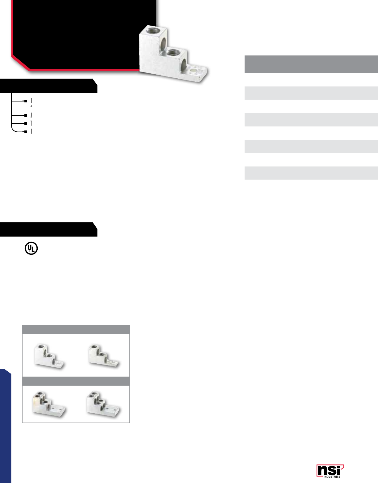
Turn Prevent Lugs
TP, BTP SERIES
DUAL RATED LUGS
Made of 6061T-6 aluminum alloy.
Electro-tin plated for low contact resistance.
For use with copper or aluminum conductors.
ALUMINUM BOX LUGS WITH
TURN-PREVENT
Made of 6061T-6 aluminum alloy.
Electro-tin plated for low contact resistance.
For use with copper or aluminum conductors.
Design includes threaded mounting hole.
TEMPERATURE RATING:
Single/Double TP Lugs: 90 °C.
Box TP Lugs: 75 °C.
VOLTAGE:
600V (2000V max. per UL486B).
UL 486A/B Listed.
123
456
Aluminum Dual Rated
All dimensional data is listed in inches.
CAT.
NO.FIG.
NO. WIRE
RANGE TORQUE VALUE
(IN./LBS.) HEX/WRENCH
SIZE MTG. BOLT
SIZE WIDTH
(A) HEIGHT
(B) LENGTH
(C)
MTG.
HOLE DIA.
(D)
TURN PVT. TO
MTG. HOLE
(X)
STD. CTN.
QTY.
BTP 0 30-10 AWG 120 0.312 # 10 0.660 0.830 0.620 # 10 0.230 25
BTP 300 4300 MCM-6 AWG 325 0.375 1/4 0.970 1.160 0.980 0.250 0.385 40
S300 5300 MCM-6 AWG 325 0.375 1/4 0.880 1.090 0.880 0.250 0.312 25
BTP 350 6350 MCM-6 AWG 375 0.375 1/4 0.880 1.100 0.880 0.250 0.440 48
Made of 6061T-6 aluminum alloy.
Electro-tin plated for low contact resistance.
Electro-tin plated for low contact resistance.
Electro-tin plated for low contact resistance.
For use with copper or aluminum conductors.
For use with copper or aluminum conductors.
For use with copper or aluminum conductors.
Design includes threaded mounting hole.
Electro-tin plated for low contact resistance.
For use with copper or aluminum conductors.
Made of 6061T-6 aluminum alloy.
Electro-tin plated for low contact resistance.
Design includes threaded mounting hole.
Design includes threaded mounting hole.
LISTED
WIRE CONNECTOR LISTED
WIRE CONNECTOR 701642
701642701642701642
24
CONNECTORS
NSi Industries LLC • USA • 800.321.5847 • www.nsiindustries.com
CAT.
NO.FIG.
NO. WIRE
RANGE LENGTH
(L) WIDTH
(W) HEIGHT
(H)
TANG
LENGTH
(A)
TANG
LENGTH
(B)
TANG
THICkNESS
(C)
TURN PVT.
LENGTH
(D)
TURN PVT.
THICkNESS
(E)
MTG. HOLE TO
TURN PVT.
(F)
HOLE
DIA.
TORQUE
VALUE
(IN./LBS.)
WRENCH
SIZE MTG. BOLT
SIZE
STD.
CTN.
QTY.
2/0TP 12/0-14 AWG 1.470 0.880 1.130 0.470 0.840 0.190 0.090 0.130 0.410 0.280 120 3/16 1/4 50
300TP 1300 MCM-6 AWG 2.000 0.990 1.130 0.380 1.000 0.250 0.090 0.190 0.490 0.440 330 5/16 7/16 24
350TP 1350 MCM-6 AWG 2.250 0.990 1.130 0.500 1.250 0.250 0.090 0.190 0.630 0.340 400 5/16 5/16 20
2-350TP 2(2) 350 MCM-6 AWG 2.250 1.920 1.130 0.500 1.125 0.250 0.090 0.187 0.630 0.406 400 5/8 3/8 8
600TP 1600 MCM-2 AWG 3.180 1.380 1.510 0.880 1.930 0.380 0.090 0.190 0.630 0.530 550 3/8 1/2 6
2-600TP 2(2) 600 MCM-2 AWG 3.180 2.410 1.510 0.880 1.930 0.380 0.130 0.190 0.630 0.530 550 3/8 1/2 4
LUG WITH TURN PREVENT
BOX LUGS
FIG. 3
FIG. 4
FIG. 6
FIG. 5
FIG. 3
FIG. 4
FIG. 6
FIG. 5
FIG. 3
FIG. 4
FIG. 6
FIG. 5
FIG. 3
FIG. 4
FIG. 6
FIG. 5
CAT.
NO.FIG.
NO. WIRE
RANGE TORQUE VALUE
(IN./LBS.) HEX/WRENCH
SIZE MTG. BOLT
SIZE WIDTH
(A) HEIGHT
(B) LENGTH
(C)
MTG.
HOLE DIA.
(D)
TURN PVT. TO
MTG. HOLE
(X)
STD. CTN.
QTY.
BTP 0 30-10 AWG 120 0.312 # 10 0.660 0.830 0.620 # 10 0.230 25
BTP 300 4300 MCM-6 AWG 325 0.375 1/4 0.970 1.160 0.980 0.250 0.385 40
S300 5300 MCM-6 AWG 325 0.375 1/4 0.880 1.090 0.880 0.250 0.312 25
BTP 350 6350 MCM-6 AWG 375 0.375 1/4 0.880 1.100 0.880 0.250 0.440 48
25
CONNECTORS
RATINGS
FEATURES
CAT.
NO.FIG.
NO. WIRE
RANGE TORQUE VALUE
(IN./LBS.) HEX/WRENCH
SIZE
MTG.
BOLT
SIZE
LENGTH
(A) HEIGHT
(B) WIDTH
(C) MTG. HOLE DIA.
(D) TANG LENGTH
(F)
TANG
THICkNESS
(H)
STD.
CTN. QTY.
GLA-4 14-14 AWG 45 Slotted 0.187 1.070 0.750 0.380 0.218 0.190 0.150 100
GLA-0 11/0-8 AWG 120 Slotted 0.250 1.500 1.100 0.600 0.272 0.300 0.220 40
GLA-000 13/0-6 AWG 250 0.250 0.375 2.000 1.500 0.800 0.330 0.400 0.300 20
GLA-250 2250 MCM-6 AWG 330 0.250 0.375 2.200 1.700 0.800 0.330 0.400 0.300 20
BS400T2
3(2) 250 MCM-1/0 AWG 500 0.375 0.250 3.812 2.000 2.468 0.281 .325 0.375 4
3(4) 250 MCM-1/0 AWG 500 0.375 0.250 3.812 2.000 2.468 0.281 .325 0.375 4
BS400T
4(1) 600 MCM-4 AWG 500 0.375 0.562 2.810 1.810 1.380 0.625 .725 0.312 6
4(2) 250 MCM-1/0 AWG 500 0.375 0.562 2.810 1.810 1.380 0.625 .725 0.312 6
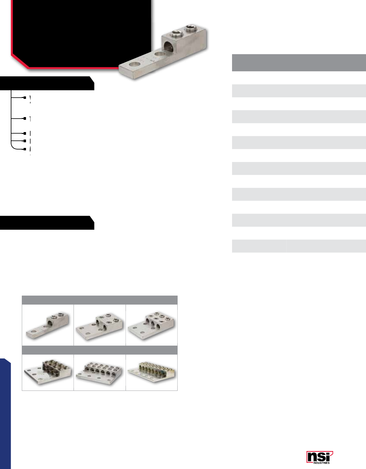
MECHANICAL CONNECTORS
Aluminum Dual Rated
Lay-In & Dual Range Lugs
GLA, BS SERIES
TEMPERATURE RATING:
Dual Rated Lay-In: 90 °C.
Dual Rated Dual Range: 90 °C.
VOLTAGE:
600V (2000V max. per UL486B).
UL 486A/B Listed.
DUAL RATED LAY-IN LUGS
Lay-in connectors offer the ultimate in flexibility.
Excellent for grounding and continuous loop applications.
Made of 6061T-6 aluminum alloy.
Electro-tin plated for low contact resistance.
For use with copper or aluminum conductors.
DUAL RANGE LUGS
Set screw connectors that will accept either
one or two wires.
Made of 6061T-6 aluminum alloy.
Electro-tin plated for low contact resistance.
For use with copper or aluminum conductors.
Lay-In & Dual Range Lugs
1234
®
®®
®
All dimensional data is listed in inches.
Lay-in connectors offer the ultimate in flexibility.
Excellent for grounding and continuous loop applications.
Excellent for grounding and continuous loop applications.
Made of 6061T-6 aluminum alloy.
Electro-tin plated for low contact resistance.
Made of 6061T-6 aluminum alloy.
Electro-tin plated for low contact resistance.
Electro-tin plated for low contact resistance.
For use with copper or aluminum conductors.
For use with copper or aluminum conductors.
Made of 6061T-6 aluminum alloy.
Electro-tin plated for low contact resistance.
For use with copper or aluminum conductors.
Electro-tin plated for low contact resistance.
Set screw connectors that will accept either
one or two wires.
For use with copper or aluminum conductors.
For use with copper or aluminum conductors.
LISTED
WIRE CONNECTOR
LISTED
WIRE CONNECTOR LISTED
WIRE CONNECTOR
701642 701642 701642
26
CONNECTORS
NSi Industries LLC • USA • 800.321.5847 • www.nsiindustries.com
CAT.
NO.FIG.
NO. WIRE
RANGE TORQUE VALUE
(IN./LBS.) HEX/WRENCH
SIZE
MTG.
BOLT
SIZE
LENGTH
(A) HEIGHT
(B) WIDTH
(C) MTG. HOLE DIA.
(D) TANG LENGTH
(F)
TANG
THICkNESS
(H)
STD.
CTN. QTY.
GLA-4 14-14 AWG 45 Slotted 0.187 1.070 0.750 0.380 0.218 0.190 0.150 100
GLA-0 11/0-8 AWG 120 Slotted 0.250 1.500 1.100 0.600 0.272 0.300 0.220 40
GLA-000 13/0-6 AWG 250 0.250 0.375 2.000 1.500 0.800 0.330 0.400 0.300 20
GLA-250 2250 MCM-6 AWG 330 0.250 0.375 2.200 1.700 0.800 0.330 0.400 0.300 20
BS400T2
3(2) 250 MCM-1/0 AWG 500 0.375 0.250 3.812 2.000 2.468 0.281 .325 0.375 4
3(4) 250 MCM-1/0 AWG 500 0.375 0.250 3.812 2.000 2.468 0.281 .325 0.375 4
BS400T
4(1) 600 MCM-4 AWG 500 0.375 0.562 2.810 1.810 1.380 0.625 .725 0.312 6
4(2) 250 MCM-1/0 AWG 500 0.375 0.562 2.810 1.810 1.380 0.625 .725 0.312 6
LAY-IN CONNECTORS
DUAL RANGE LUGS
FIG. 4
FIG. 2
FIG. 3
27
CONNECTORS
RATINGS
FEATURES
CAT.
NO.FIG.
NO. STYLE COLOR
CODE
MAIN (RUN)
WIRE
RANGE
TAP
WIRE
RANGE
TORQUE
VALUE
(IN./LBS.)
HEX/WRENCH
SIZE LENGTH
(L) (IN.) WIDTH
(W) (IN.) HEIGHT
(H) (IN.)
STD.
CTN.
QTY.
GP-2 1Parallel “T” Tap -2-12 STR 4-14 STR 50 Slotted 1.390 0.630 0.880 25
GP-0 1Parallel “T” Tap -1/0-2 AWG 1/0-14 AWG 120 0.187 1.750 0.750 1.000 12
GP-250-0 1Parallel “T” Tap -250 MCM-1/0 AWG 1/0-14 AWG 120
275 0.187, 0.312 2.030 1.060 1.310 12
GP-250 1Parallel “T” Tap -250 MCM-1/0 AWG 250 MCM-6 AWG 275 0.312 2.280 1.060 1.310 12
GP-350 1Parallel “T” Tap -350 MCM-4/0 AWG 350 MCM-6 AWG 275 0.312 2.560 1.250 1.440 6
GP-500 1Parallel “T” Tap -500-350 MCM 500-2 MCM 375 0.375 3.130 1.380 1.750 6
GP-750 1Parallel “T” Tap -750-500 MCM 500-2 MCM 375 0.375 3.380 1.500 2.000 3
GC-2 2Insulated Covers Yellow - - - 2.250 1.370 1.110 1.110 12
GC-0 2Insulated Covers Gray - - - 2.610 2.170 1.260 1.260 6
GC-250 2Insulated Covers Red - - - 3.440 3.180 1.630 1.630 3
GC-350 2Insulated Covers Yellow - - - 3.760 3.290 1.760 1.760 3
GC-500 2Insulated Covers Blue - - - 4.890 3.340 2.120 2.120 3
GC-750 2Insulated Covers Orange - - - 4.550 3.450 2.340 2.340 3
GP-2WC 2Parallel “T” Tap
with Cover Yellow 2-12 STR 4-14 STR 50 Slotted 2.250 1.370 1.110 12
GP-0WC 2Parallel “T” Tap
with Cover Gray 1/0-2 AWG 1/0-14 AWG 120 0.187 2.610 2.170 1.260 10
GP-250-0WC 2Parallel “T” Tap
with Cover Red 250 MCM-1/0 AWG 1/0-14 AWG 120
275 0.187, 0.312 3.440 3.180 1.630 5
GP-250WC 2Parallel “T” Tap
with Cover Red 250 MCM-1/0 AWG 250 MCM-6 AWG 275 0.312 3.440 3.180 1.630 5
GP-350WC 2Parallel “T” Tap
with Cover Yellow 350 MCM-4/0 AWG 350 MCM-6 AWG 275 0.312 3.760 3.290 1.760 6
GP-500WC 2Parallel “T” Tap
with Cover Blue 500-350 MCM 500-2 MCM 375 0.375 4.890 3.340 2.120 2
GP-750WC 2Parallel “T” Tap
with Cover Orange 750-500 MCM 500-2 MCM 375 0.375 4.550 3.450 2.340 2
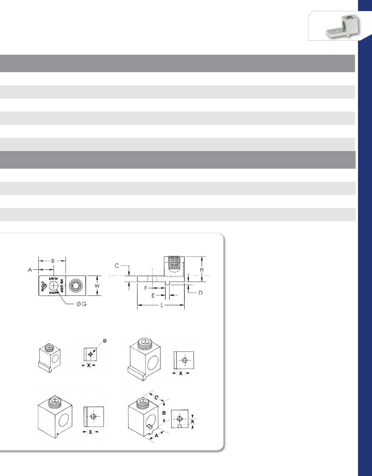
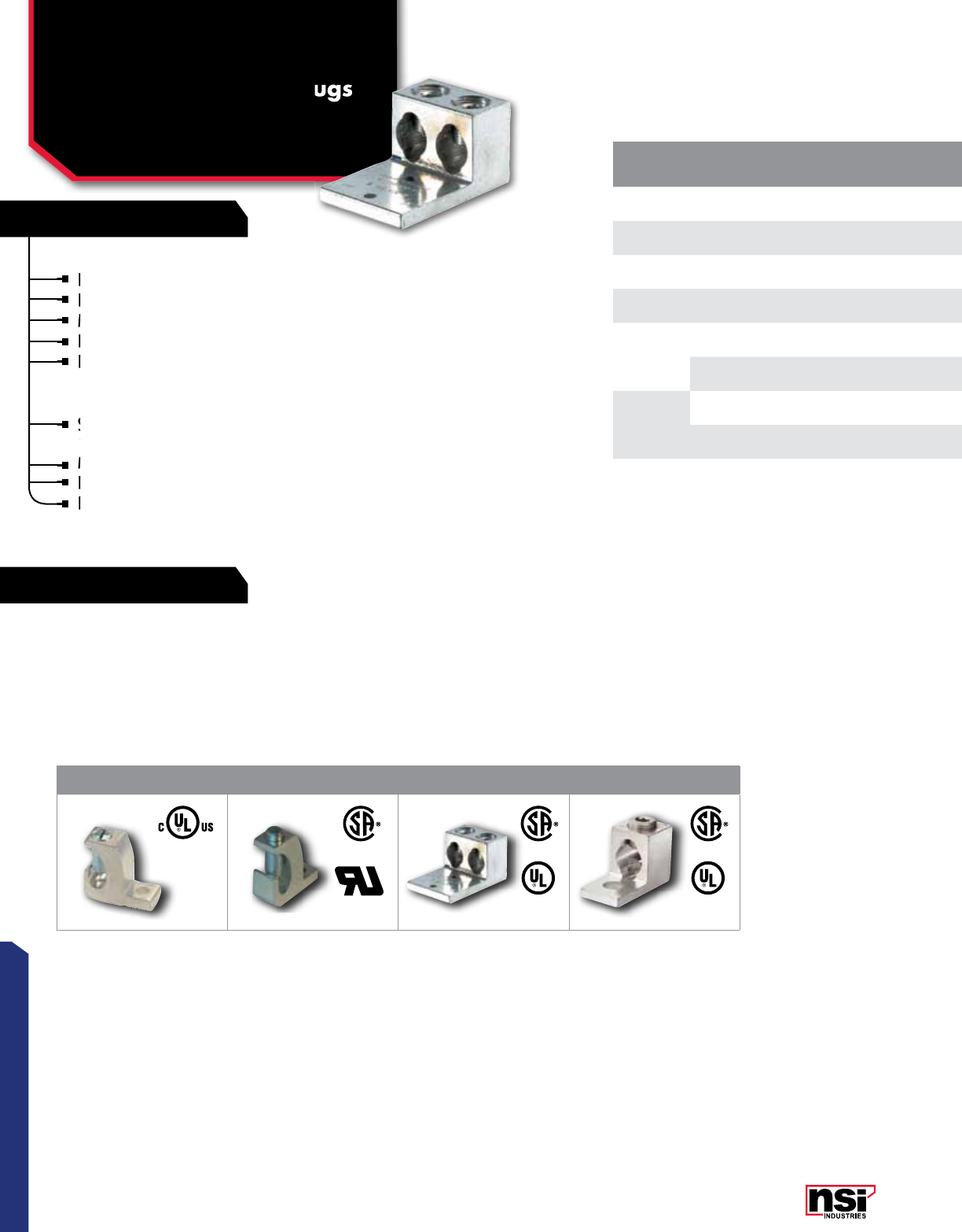
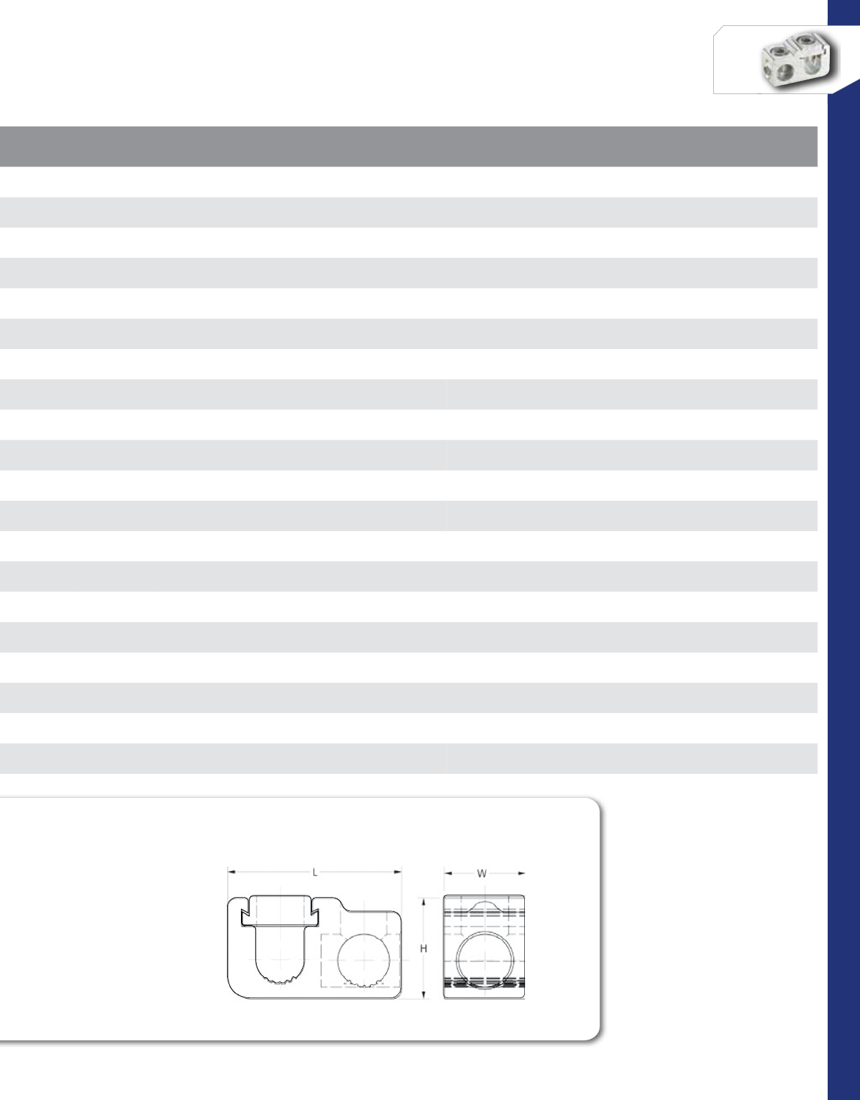
MECHANICAL CONNECTORS
Aluminum Dual Rated
Tap Connector & Covers
PARALLEL/”T” FORMAT
GP, GC SERIES
Excellent for tapping of main conductor due
to lay-in feature.
Perpendicular tap allows for parallel or “T”
tap configuration.
Flexible cover allows for either parallel or “T”
tap wire entry.
Secure snap cover eliminates need for taping.
Electro-tin plated for low contact resistance.
TEMPERATURE RATING:
90 °C.
VOLTAGE:
600V max.
1 2
All dimensional data is listed in inches.
Excellent for tapping of main conductor due
to lay-in feature.
Excellent for tapping of main conductor due
to lay-in feature.
Excellent for tapping of main conductor due
Perpendicular tap allows for parallel or “T”
tap configuration.
Perpendicular tap allows for parallel or “T”
tap configuration.
Perpendicular tap allows for parallel or “T”
Flexible cover allows for either parallel or “T”
tap wire entry.
tap wire entry.
Secure snap cover eliminates need for taping.
tap wire entry.
Secure snap cover eliminates need for taping.
tap wire entry.
Electro-tin plated for low contact resistance.
Electro-tin plated for low contact resistance.
Electro-tin plated for low contact resistance.
LISTED
WIRE CONNECTOR
E155274
701642
28
CONNECTORS
NSi Industries LLC • USA • 800.321.5847 • www.nsiindustries.com
CAT.
NO.FIG.
NO. STYLE COLOR
CODE
MAIN (RUN)
WIRE
RANGE
TAP
WIRE
RANGE
TORQUE
VALUE
(IN./LBS.)
HEX/WRENCH
SIZE LENGTH
(L) (IN.) WIDTH
(W) (IN.) HEIGHT
(H) (IN.)
STD.
CTN.
QTY.
GP-2 1Parallel “T” Tap -2-12 STR 4-14 STR 50 Slotted 1.390 0.630 0.880 25
GP-0 1Parallel “T” Tap -1/0-2 AWG 1/0-14 AWG 120 0.187 1.750 0.750 1.000 12
GP-250-0 1Parallel “T” Tap -250 MCM-1/0 AWG 1/0-14 AWG 120
275 0.187, 0.312 2.030 1.060 1.310 12
GP-250 1Parallel “T” Tap -250 MCM-1/0 AWG 250 MCM-6 AWG 275 0.312 2.280 1.060 1.310 12
GP-350 1Parallel “T” Tap -350 MCM-4/0 AWG 350 MCM-6 AWG 275 0.312 2.560 1.250 1.440 6
GP-500 1Parallel “T” Tap -500-350 MCM 500-2 MCM 375 0.375 3.130 1.380 1.750 6
GP-750 1Parallel “T” Tap -750-500 MCM 500-2 MCM 375 0.375 3.380 1.500 2.000 3
GC-2 2Insulated Covers Yellow - - - 2.250 1.370 1.110 1.110 12
GC-0 2Insulated Covers Gray - - - 2.610 2.170 1.260 1.260 6
GC-250 2Insulated Covers Red - - - 3.440 3.180 1.630 1.630 3
GC-350 2Insulated Covers Yellow - - - 3.760 3.290 1.760 1.760 3
GC-500 2Insulated Covers Blue - - - 4.890 3.340 2.120 2.120 3
GC-750 2Insulated Covers Orange - - - 4.550 3.450 2.340 2.340 3
GP-2WC 2Parallel “T” Tap
with Cover Yellow 2-12 STR 4-14 STR 50 Slotted 2.250 1.370 1.110 12
GP-0WC 2Parallel “T” Tap
with Cover Gray 1/0-2 AWG 1/0-14 AWG 120 0.187 2.610 2.170 1.260 10
GP-250-0WC 2Parallel “T” Tap
with Cover Red 250 MCM-1/0 AWG 1/0-14 AWG 120
275 0.187, 0.312 3.440 3.180 1.630 5
GP-250WC 2Parallel “T” Tap
with Cover Red 250 MCM-1/0 AWG 250 MCM-6 AWG 275 0.312 3.440 3.180 1.630 5
GP-350WC 2Parallel “T” Tap
with Cover Yellow 350 MCM-4/0 AWG 350 MCM-6 AWG 275 0.312 3.760 3.290 1.760 6
GP-500WC 2Parallel “T” Tap
with Cover Blue 500-350 MCM 500-2 MCM 375 0.375 4.890 3.340 2.120 2
GP-750WC 2Parallel “T” Tap
with Cover Orange 750-500 MCM 500-2 MCM 375 0.375 4.550 3.450 2.340 2
PARALLEL OR “T” TAP CONNECTORS
29
CONNECTORS
RATINGS
FEATURES
CAT.
NO.FIG.
NO. WIRE
RANGE NO. OF
CONDUCTORS NO. OF
MTG. HOLES
MTG.
HOLE
DIA.
MTG. HOLE
SPACING WRENCH SIZE BOLT
SIZE LENGTH
(B) (IN.) WIDTH
(A) (IN.) HEIGHT
(H) (IN.)
STD.
CTN.
QTY.
350LL2 1350 MCM-6 AWG 1 2 0.563 1.750 3/8 1/2 5.310 1.130 1.380 1
2-350LL4 2350 MCM-6 AWG 2 4 0.563 1.750 3/8 1/2 5.310 2.000 1.380 1
3-350LL4 3350 MCM-6 AWG 3 4 0.563 1.750 3/8 1/2 5.310 2.940 1.380 1
4-350LL6 4350 MCM-6 AWG 4 6 0.563 1.750 3/8 1/2 5.310 3.870 1.380 1
6-350LL8 5350 MCM-6 AWG 6 8 0.563 1.750 3/8 1/2 5.310 5.750 1.380 1
8-350LL8 6350 MCM-6 AWG 8 8 0.563 1.750 3/8 1/2 5.310 7.620 1.380 1
8-350LL10 6350 MCM-6 AWG 810 0.563 1.750 3/8 1/2 5.310 7.620 1.380 1
2-600LL4 2600 MCM-2 AWG 2 4 0.563 1.750 3/8 1/2 5.875 2.410 1.562 1
4-600LL6 4600 MCM-2 AWG 4 6 0.563 1.750 3/8 1/2 5.875 4.780 1.562 1
6-600LL6 6600 MCM-2 AWG 6 6 0.563 1.750 3/8 1/2 8.750 5.750 1.750 1
2-800LL4 2800-300 MCM 2 4 0.563 1.750 1/2 1/2 6.188 2.737 1.875 1
4-800LL8 4800-300 MCM 4 8 0.563 1.750 1/2 1/2 6.188 5.487 1.875 1
2-1000LL4 2800-300 MCM 2 4 0.563 1.750 1/2 1/2 6.188 2.982 1.875 1
4-1000LL8 41000-500 MCM 4 8 0.563 1.750 1/2 1/2 6.188 5.982 1.875 1
8-1000LL12 61000-500 MCM 812 0.563 1.750 1/2 1/2 6.188 11.982 1.875 1
MECHANICAL CONNECTORS
Aluminum Dual Rated
Heavy Duty Transformer
Lugs
LL SERIES
Meets or exceeds ANSI C119.4 Class A.
TEMPERATURE RATING:
90 °C.
VOLTAGE:
600V max.
Versatile and reusable set screw connectors made
from high strength 6061-T6 aluminum alloy for
superior electrical and mechanical performance.
Two set screws per wire hole ensure an exceptional
connection.
Electro-tin plated for low contact resistance.
For use with copper or aluminum conductors.
Mounting hole spacing is NEMA 1-¾” spacing is
available with the following options: clear plating,
anodized set screws or disc pad screws - contact NSi
Customer Service for ordering details.
123
456
All dimensional data is listed in inches.
Versatile and reusable set screw connectors made
from high strength 6061-T6 aluminum alloy for
For use with copper or aluminum conductors.
Mounting hole spacing is NEMA 1-¾” spacing is
Electro-tin plated for low contact resistance.
For use with copper or aluminum conductors.
Two set screws per wire hole ensure an exceptional
connection.
Mounting hole spacing is NEMA 1-¾” spacing is
available with the following options: clear plating,
Mounting hole spacing is NEMA 1-¾” spacing is
available with the following options: clear plating,
Mounting hole spacing is NEMA 1-¾” spacing is
Mounting hole spacing is NEMA 1-¾” spacing is
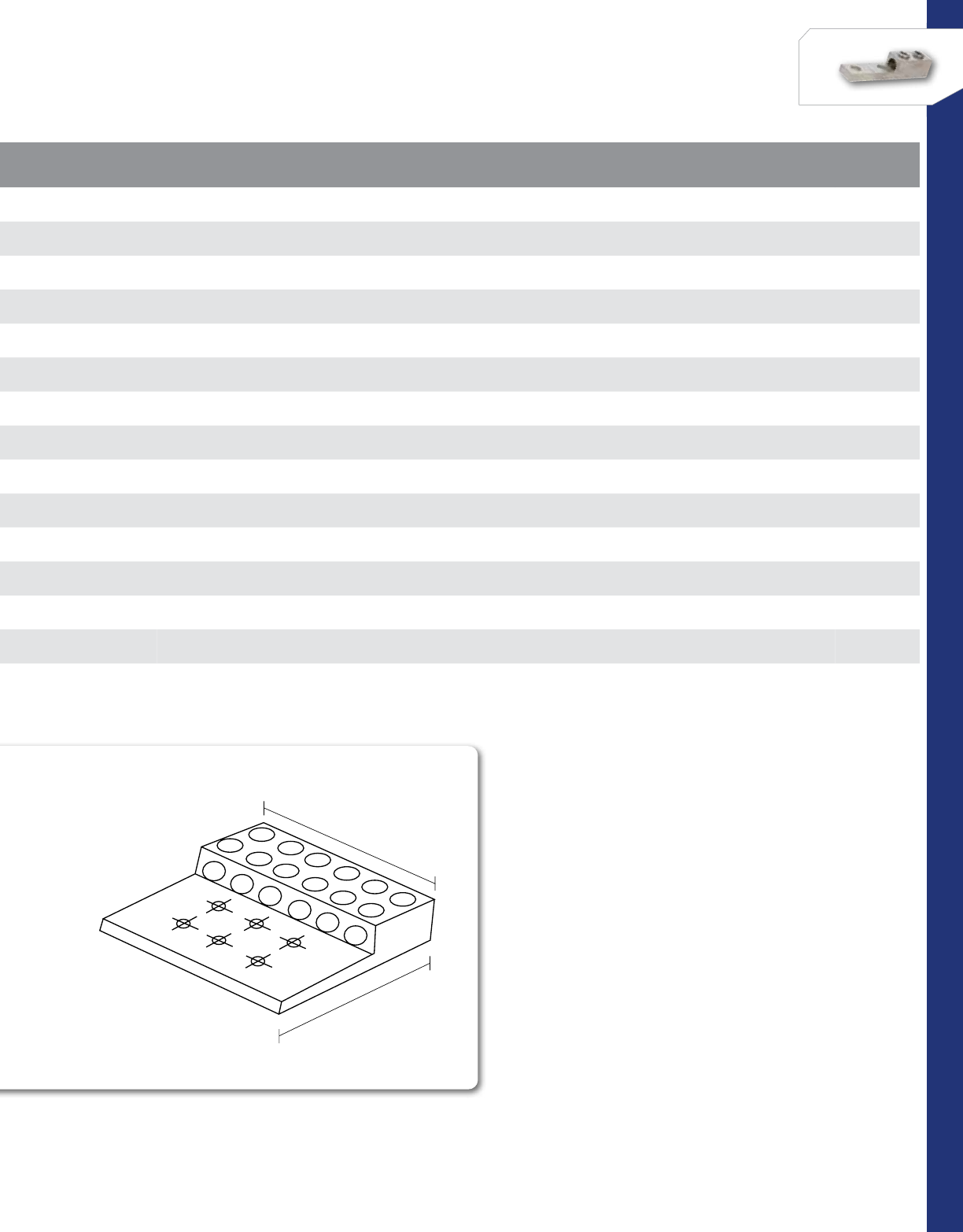
30
CONNECTORS
NSi Industries LLC • USA • 800.321.5847 • www.nsiindustries.com
CAT.
NO.FIG.
NO. WIRE
RANGE NO. OF
CONDUCTORS NO. OF
MTG. HOLES
MTG.
HOLE
DIA.
MTG. HOLE
SPACING WRENCH SIZE BOLT
SIZE LENGTH
(B) (IN.) WIDTH
(A) (IN.) HEIGHT
(H) (IN.)
STD.
CTN.
QTY.
350LL2 1350 MCM-6 AWG 1 2 0.563 1.750 3/8 1/2 5.310 1.130 1.380 1
2-350LL4 2350 MCM-6 AWG 2 4 0.563 1.750 3/8 1/2 5.310 2.000 1.380 1
3-350LL4 3350 MCM-6 AWG 3 4 0.563 1.750 3/8 1/2 5.310 2.940 1.380 1
4-350LL6 4350 MCM-6 AWG 4 6 0.563 1.750 3/8 1/2 5.310 3.870 1.380 1
6-350LL8 5350 MCM-6 AWG 6 8 0.563 1.750 3/8 1/2 5.310 5.750 1.380 1
8-350LL8 6350 MCM-6 AWG 8 8 0.563 1.750 3/8 1/2 5.310 7.620 1.380 1
8-350LL10 6350 MCM-6 AWG 810 0.563 1.750 3/8 1/2 5.310 7.620 1.380 1
2-600LL4 2600 MCM-2 AWG 2 4 0.563 1.750 3/8 1/2 5.875 2.410 1.562 1
4-600LL6 4600 MCM-2 AWG 4 6 0.563 1.750 3/8 1/2 5.875 4.780 1.562 1
6-600LL6 6600 MCM-2 AWG 6 6 0.563 1.750 3/8 1/2 8.750 5.750 1.750 1
2-800LL4 2800-300 MCM 2 4 0.563 1.750 1/2 1/2 6.188 2.737 1.875 1
4-800LL8 4800-300 MCM 4 8 0.563 1.750 1/2 1/2 6.188 5.487 1.875 1
2-1000LL4 2800-300 MCM 2 4 0.563 1.750 1/2 1/2 6.188 2.982 1.875 1
4-1000LL8 41000-500 MCM 4 8 0.563 1.750 1/2 1/2 6.188 5.982 1.875 1
8-1000LL12 61000-500 MCM 812 0.563 1.750 1/2 1/2 6.188 11.982 1.875 1
A
B
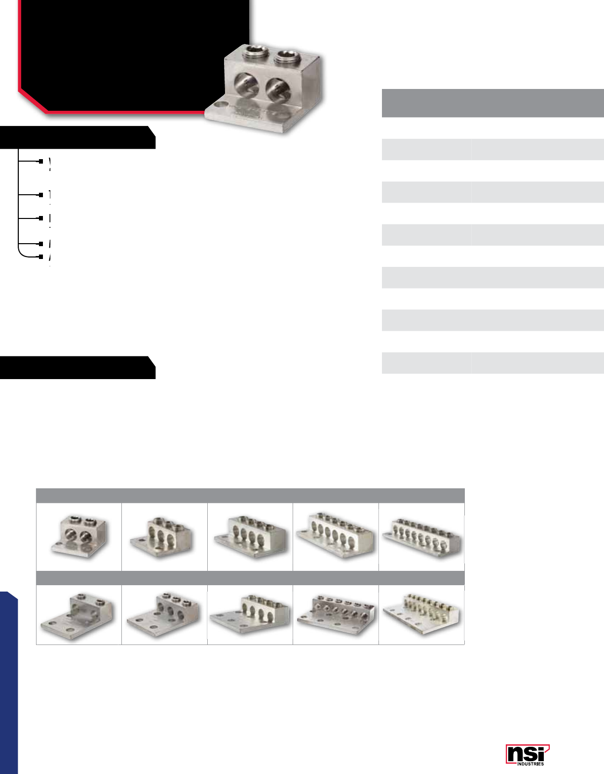
31
CONNECTORS
RATINGS
FEATURES
CAT.
NO.FIG.
NO. WIRE
RANGE NO. OF
CONDUCTORS
NO. OF
MTG.
HOLES
MTG.
HOLE DIA. MTG. HOLE
SPACING WRENCH SIZE MTG. BOLT
SIZE LENGTH
(L) (IN.) WIDTH
(W) (IN.) HEIGHT
(H) (IN.) STD.
PkG. QTY.
2-350T2 1350 MCM-6 AWG 2 2 0.375 1.750 3/8" 5/16" 2.250 1.940 1.250 1
3-350T2 2350 MCM-6 AWG 3 2 0.375 1.750 3/8" 5/16" 2.250 2.840 1.250 1
4-350T3 3350 MCM-6 AWG 4 3 0.375 1.750 3/8" 5/16" 2.250 3.750 1.250 1
6-350T4 4350 MCM-6 AWG 6 4 0.375 1.750 3/8" 5/16" 2.250 4.660 1.250 1
8-350T4 5350 MCM-6 AWG 8 4 0.375 1.750 3/8" 5/16" 2.250 5.560 1.250 1
2-350L4 6350 MCM-6 AWG 2 4 0.563 1.750 3/8" 1/2" 4.310 2.000 1.380 1
3-350L4 7350 MCM-6 AWG 3 4 0.563 1.750 3/8" 1/2" 4.310 2.940 1.380 1
4-350L6 8350 MCM-6 AWG 4 6 0.563 1.750 3/8" 1/2" 4.310 3.870 1.380 1
6-350L8 9350 MCM-6 AWG 6 8 0.563 1.750 3/8" 1/2" 4.310 5.750 1.380 1
8-350L8 10 350 MCM-6 AWG 8 8 0.563 1.750 3/8" 1/2" 4.310 7.620 1.380 1
2-600L4 6600 MCM-2 AWG 2 4 0.563 1.750 3/8" 1/2" 4.500 2.410 1.630 1
4-600L6 8600 MCM-2 AWG 4 6 0.563 1.750 3/8" 1/2" 4.500 4.780 1.630 1
6-600L8 9600 MCM-2 AWG 6 8 0.563 1.750 3/8" 1/2" 4.500 7.160 1.630 1
MECHANICAL CONNECTORS
Aluminum Dual Rated
Transformer Lugs
T, L SERIES
Meets or exceeds ANSI C119.4 Class A .
TEMPERATURE RATING:
90 °C.
VOLTAGE:
600V max.
12345
678910
Versatile and reusable set screw connectors made
from high strength 6061-T6 aluminum alloy for
superior electrical and mechanical performance.
Two set screws per wire hole ensure an
exceptional connection.
Electro-tin plated for low contact resistance.
For use with copper or aluminum conductors.
Mounting hole spacing is is NEMA 1-¾”.
Also available with the following options: clear
plating, anodized set screws or disc pad screws -
contact NSi Customer Service for ordering details.
All dimensional data is listed in inches.
Versatile and reusable set screw connectors made
from high strength 6061-T6 aluminum alloy for
Mounting hole spacing is is NEMA 1-¾”.
Also available with the following options: clear
Electro-tin plated for low contact resistance.
For use with copper or aluminum conductors.
Two set screws per wire hole ensure an
superior electrical and mechanical performance.
Two set screws per wire hole ensure an
superior electrical and mechanical performance.
exceptional connection.
Two set screws per wire hole ensure an
exceptional connection.
Two set screws per wire hole ensure an
Also available with the following options: clear
plating, anodized set screws or disc pad screws -
Also available with the following options: clear
plating, anodized set screws or disc pad screws -
Also available with the following options: clear
Also available with the following options: clear

32
CONNECTORS
NSi Industries LLC • USA • 800.321.5847 • www.nsiindustries.com
SCREW TYPES, TORQUE CHART
CAT.
NO.FIG.
NO. WIRE
RANGE NO. OF
CONDUCTORS
NO. OF
MTG.
HOLES
MTG.
HOLE DIA. MTG. HOLE
SPACING WRENCH SIZE MTG. BOLT
SIZE LENGTH
(L) (IN.) WIDTH
(W) (IN.) HEIGHT
(H) (IN.) STD.
PkG. QTY.
2-350T2 1350 MCM-6 AWG 2 2 0.375 1.750 3/8" 5/16" 2.250 1.940 1.250 1
3-350T2 2350 MCM-6 AWG 3 2 0.375 1.750 3/8" 5/16" 2.250 2.840 1.250 1
4-350T3 3350 MCM-6 AWG 4 3 0.375 1.750 3/8" 5/16" 2.250 3.750 1.250 1
6-350T4 4350 MCM-6 AWG 6 4 0.375 1.750 3/8" 5/16" 2.250 4.660 1.250 1
8-350T4 5350 MCM-6 AWG 8 4 0.375 1.750 3/8" 5/16" 2.250 5.560 1.250 1
2-350L4 6350 MCM-6 AWG 2 4 0.563 1.750 3/8" 1/2" 4.310 2.000 1.380 1
3-350L4 7350 MCM-6 AWG 3 4 0.563 1.750 3/8" 1/2" 4.310 2.940 1.380 1
4-350L6 8350 MCM-6 AWG 4 6 0.563 1.750 3/8" 1/2" 4.310 3.870 1.380 1
6-350L8 9350 MCM-6 AWG 6 8 0.563 1.750 3/8" 1/2" 4.310 5.750 1.380 1
8-350L8 10 350 MCM-6 AWG 8 8 0.563 1.750 3/8" 1/2" 4.310 7.620 1.380 1
2-600L4 6600 MCM-2 AWG 2 4 0.563 1.750 3/8" 1/2" 4.500 2.410 1.630 1
4-600L6 8600 MCM-2 AWG 4 6 0.563 1.750 3/8" 1/2" 4.500 4.780 1.630 1
6-600L8 9600 MCM-2 AWG 6 8 0.563 1.750 3/8" 1/2" 4.500 7.160 1.630 1
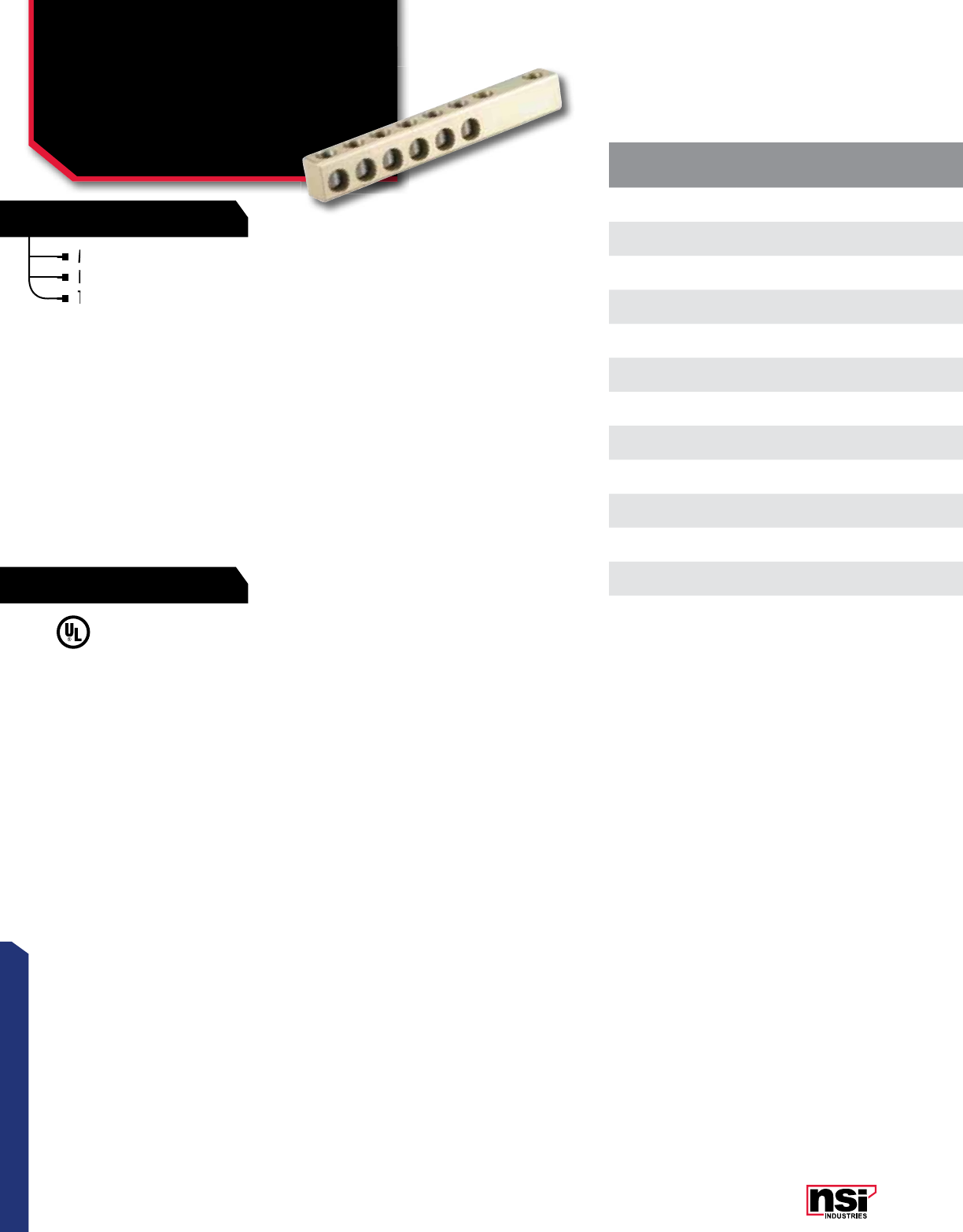
33
CONNECTORS
RATINGS
FEATURES
CAT.
NO.WIRE
RANGE NO. OF
CONDUCTORS MTG. HOLE
DIA. MTG. HOLE
SPACING TORQUE VALUE
(IN./LBS.) MTG. BOLT
SIZE WRENCH SIZE LENGTH
(L) WIDTH
(W) HEIGHT
(H) STD.
CTN. QTY.
STL250-4 250 MCM-6 AWG 40.560 1.750 330 1/2 5/16 6.240 0.875 1.125 6
STL250-6 250 MCM-6 AWG 60.560 1.750 330 1/2 5/16 7.960 0.875 1.125 6
STL250-8 250 MCM-6 AWG 80.560 1.750 330 1/2 5/16 9.680 0.875 1.125 6
STL350-4 350 MCM-6 AWG 40.560 1.750 400 1/2 5/16 6.960 1.000 1.440 6
STL350-6 350 MCM-6 AWG 60.560 1.750 400 1/2 5/16 9.060 1.000 1.440 6
STL350-8 350 MCM-6 AWG 80.560 1.750 400 1/2 5/16 11.160 1.000 1.440 6
STL500-4 500 MCM-4 AWG 40.560 1.750 550 1/2 5/16 7.500 1.130 1.630 6
STL500-6 500 MCM-4 AWG 60.560 1.750 550 1/2 5/16 9.740 1.130 1.630 6
STL500-8 500 MCM-4 AWG 80.560 1.750 550 1/2 5/16 12.030 1.130 1.630 6
STL750-4 750-250 MCM 40.560 1.750 550 1/2 3/8 8.570 1.440 2.000 3
STL750-6 750-250 MCM 60.560 1.750 550 1/2 3/8 11.420 1.440 2.000 3
STL750-8 750-250 MCM 80.560 1.750 550 1/2 3/8 14.280 1.440 2.000 3
MECHANICAL CONNECTORS
Aluminum Dual Rated
Transformer Connectors
2 HOLE NEMA PAD MOUNT
STL SERIES
Made from 6061T-6 aluminum alloy.
Electro-tin plated for low contact resistance.
Two NEMA ½” holes for easy attachment.
VOLTAGE:
600V max.
All dimensional data is listed in inches.
Two NEMA ½” holes for easy attachment.
Electro-tin plated for low contact resistance.
Two NEMA ½” holes for easy attachment.
Two NEMA ½” holes for easy attachment.
Made from 6061T-6 aluminum alloy.
Electro-tin plated for low contact resistance.
Electro-tin plated for low contact resistance.
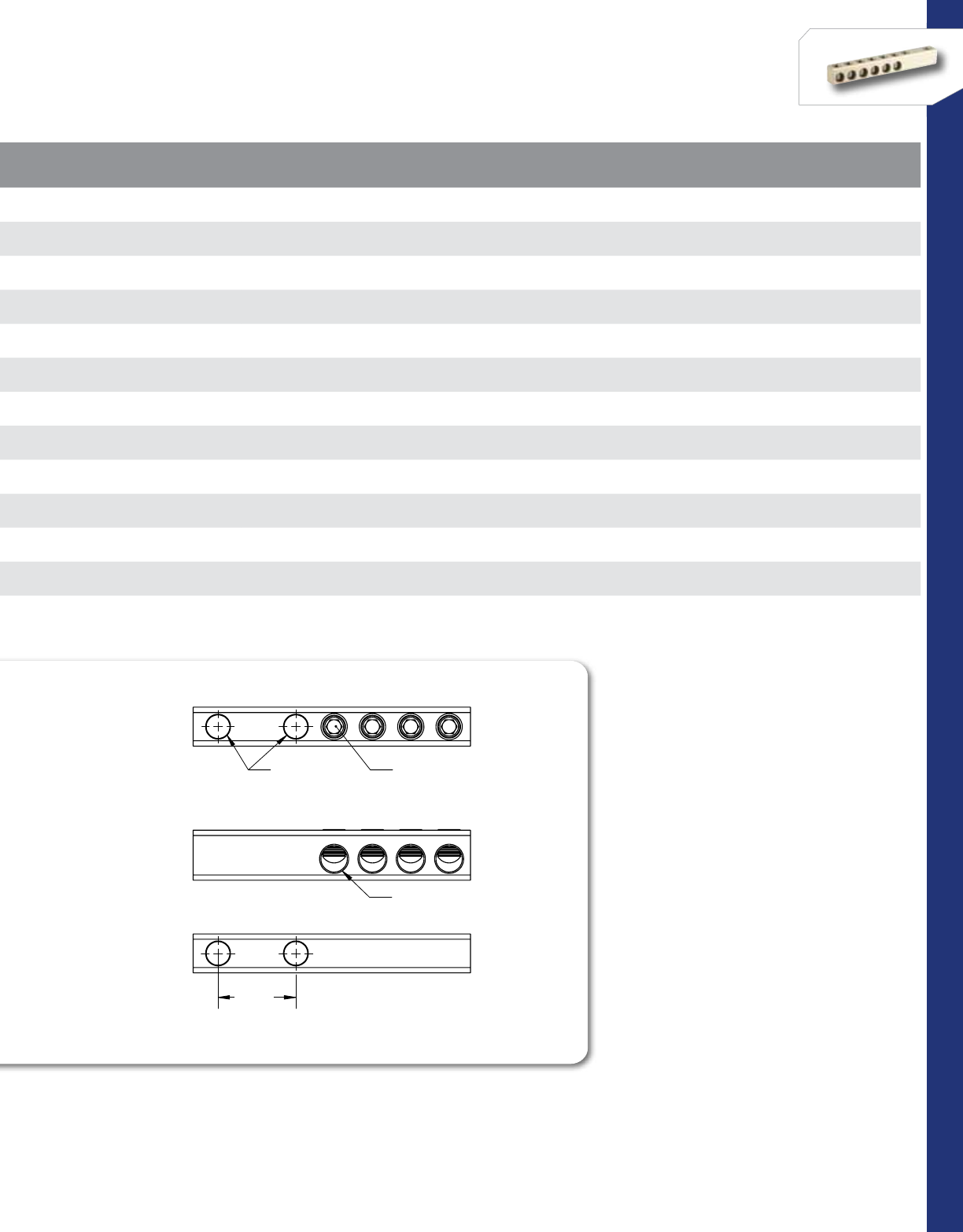
34
CONNECTORS
NSi Industries LLC • USA • 800.321.5847 • www.nsiindustries.com
CAT.
NO.WIRE
RANGE NO. OF
CONDUCTORS MTG. HOLE
DIA. MTG. HOLE
SPACING TORQUE VALUE
(IN./LBS.) MTG. BOLT
SIZE WRENCH SIZE LENGTH
(L) WIDTH
(W) HEIGHT
(H) STD.
CTN. QTY.
STL250-4 250 MCM-6 AWG 40.560 1.750 330 1/2 5/16 6.240 0.875 1.125 6
STL250-6 250 MCM-6 AWG 60.560 1.750 330 1/2 5/16 7.960 0.875 1.125 6
STL250-8 250 MCM-6 AWG 80.560 1.750 330 1/2 5/16 9.680 0.875 1.125 6
STL350-4 350 MCM-6 AWG 40.560 1.750 400 1/2 5/16 6.960 1.000 1.440 6
STL350-6 350 MCM-6 AWG 60.560 1.750 400 1/2 5/16 9.060 1.000 1.440 6
STL350-8 350 MCM-6 AWG 80.560 1.750 400 1/2 5/16 11.160 1.000 1.440 6
STL500-4 500 MCM-4 AWG 40.560 1.750 550 1/2 5/16 7.500 1.130 1.630 6
STL500-6 500 MCM-4 AWG 60.560 1.750 550 1/2 5/16 9.740 1.130 1.630 6
STL500-8 500 MCM-4 AWG 80.560 1.750 550 1/2 5/16 12.030 1.130 1.630 6
STL750-4 750-250 MCM 40.560 1.750 550 1/2 3/8 8.570 1.440 2.000 3
STL750-6 750-250 MCM 60.560 1.750 550 1/2 3/8 11.420 1.440 2.000 3
STL750-8 750-250 MCM 80.560 1.750 550 1/2 3/8 14.280 1.440 2.000 3
CONDUCTOR PORTS
INTERNAL HEX
PRESSURE SCREWS
STUD HOLES
FOR 1/2 BOLT
1.75
STUD SPACING

35
CONNECTORS
RATINGS
FEATURES
CAT.
NO.WIRE
RANGE TYPE NO. OF
CONDUCTORS STUD
SIZE TORQUE VALUE
(IN./LBS.) WRENCH SIZE LENGTH
(L) (IN.) WIDTH
(W) (IN.) HEIGHT
(H) (IN.) STD.
CTN. QTY.
SFTZ350-6 350 MCM-6 AWG Slip Fit 65/8-11, 1-14 400 5/16 5.000 2.250 2.880 1
SFTZ350-8 350 MCM-6 AWG Slip Fit 85/8-11, 1-14 400 5/16 6.000 2.250 2.880 1
SFTZ500-6 500 MCM-6 AWG Slip Fit 65/8-11, 1-14 450 5/16 5.550 2.250 2.880 1
SOTZ350-6 350 MCM-6 AWG Screw On 65/8-11, 1-14 400 5/16 5.000 2.250 2.880 1
SOTZ350-8 350 MCM-6 AWG Screw On 85/8-11, 1-14 400 5/16 6.000 2.250 2.880 1
SOTZ500-6 500 MCM-6 AWG Screw On 65/8-11, 1-14 450 5/16 5.550 2.250 2.880 1
SOTZ500-8 500 MCM-6 AWG Screw On 85/8-11, 1-14 450 5/16 6.680 2.250 2.880 1
MECHANICAL CONNECTORS
Aluminum Dual Rated
Secondary Transformer
Connectors
SFTZ SERIES
Versatile and reusable set screw connectors made from
high strength 6061-T6 aluminum alloy for superior
electrical and mechanical performance.
Electro-tin plated for low contact resistance.
For use on slip-fit or threaded transformers.
For use with copper and aluminum conductors.
Available with street light tap.
Meets or exceeds ANSI C119.4 Class A.
TEMPERATURE RATING:
90 °C.
VOLTAGE:
600V max.
All dimensional data is listed in inches.
Available with street light tap.
Electro-tin plated for low contact resistance.
For use on slip-fit or threaded transformers.
For use on slip-fit or threaded transformers.
For use with copper and aluminum conductors.
Available with street light tap.
Available with street light tap.
For use with copper and aluminum conductors.
Versatile and reusable set screw connectors made from
high strength 6061-T6 aluminum alloy for superior
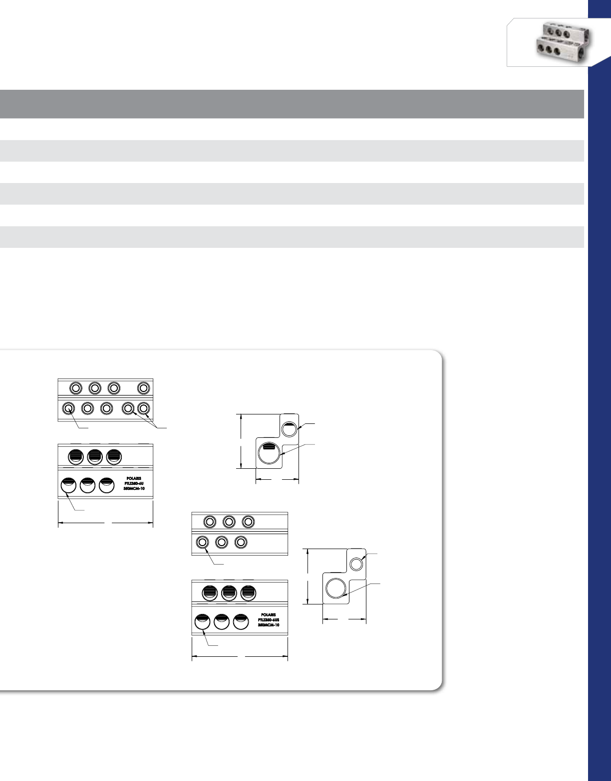
36
CONNECTORS
NSi Industries LLC • USA • 800.321.5847 • www.nsiindustries.com
CAT.
NO.WIRE
RANGE TYPE NO. OF
CONDUCTORS STUD
SIZE TORQUE VALUE
(IN./LBS.) WRENCH SIZE LENGTH
(L) (IN.) WIDTH
(W) (IN.) HEIGHT
(H) (IN.) STD.
CTN. QTY.
SFTZ350-6 350 MCM-6 AWG Slip Fit 65/8-11, 1-14 400 5/16 5.000 2.250 2.880 1
SFTZ350-8 350 MCM-6 AWG Slip Fit 85/8-11, 1-14 400 5/16 6.000 2.250 2.880 1
SFTZ500-6 500 MCM-6 AWG Slip Fit 65/8-11, 1-14 450 5/16 5.550 2.250 2.880 1
SOTZ350-6 350 MCM-6 AWG Screw On 65/8-11, 1-14 400 5/16 5.000 2.250 2.880 1
SOTZ350-8 350 MCM-6 AWG Screw On 85/8-11, 1-14 400 5/16 6.000 2.250 2.880 1
SOTZ500-6 500 MCM-6 AWG Screw On 65/8-11, 1-14 450 5/16 5.550 2.250 2.880 1
SOTZ500-8 500 MCM-6 AWG Screw On 85/8-11, 1-14 450 5/16 6.680 2.250 2.880 1
L
CONDUCTOR PORTS
5/16 INTERNAL HEX
PRESSURE SCREWS
DOUBLE PRESSURE
SCREWS FOR 1-14 STUD
H
W
SLIP FIT FOR
1-14 STUD
SLIP FIT FOR
5/8-11 STUD
L
CONDUCTOR PORTS
5/16 INTERNAL HEX
PRESSURE SCREWS
DOUBLE PRESSURE
SCREWS FOR 1-14 STUD
H
W
SLIP FIT FOR
1-14 STUD
SLIP FIT FOR
5/8-11 STUD
L
CONDUCTOR PORTS
5/16 INTERNAL HEX
PRESSURE SCREWS
W
H
SLIP FIT FOR
5/8-11 STUD
SLIP FIT FOR
1-14 STUD
L
CONDUCTOR PORTS
5/16 INTERNAL HEX
PRESSURE SCREWS
W
H
SLIP FIT FOR
5/8-11 STUD
SLIP FIT FOR
1-14 STUD
SFTZ Series
SOTZ Series
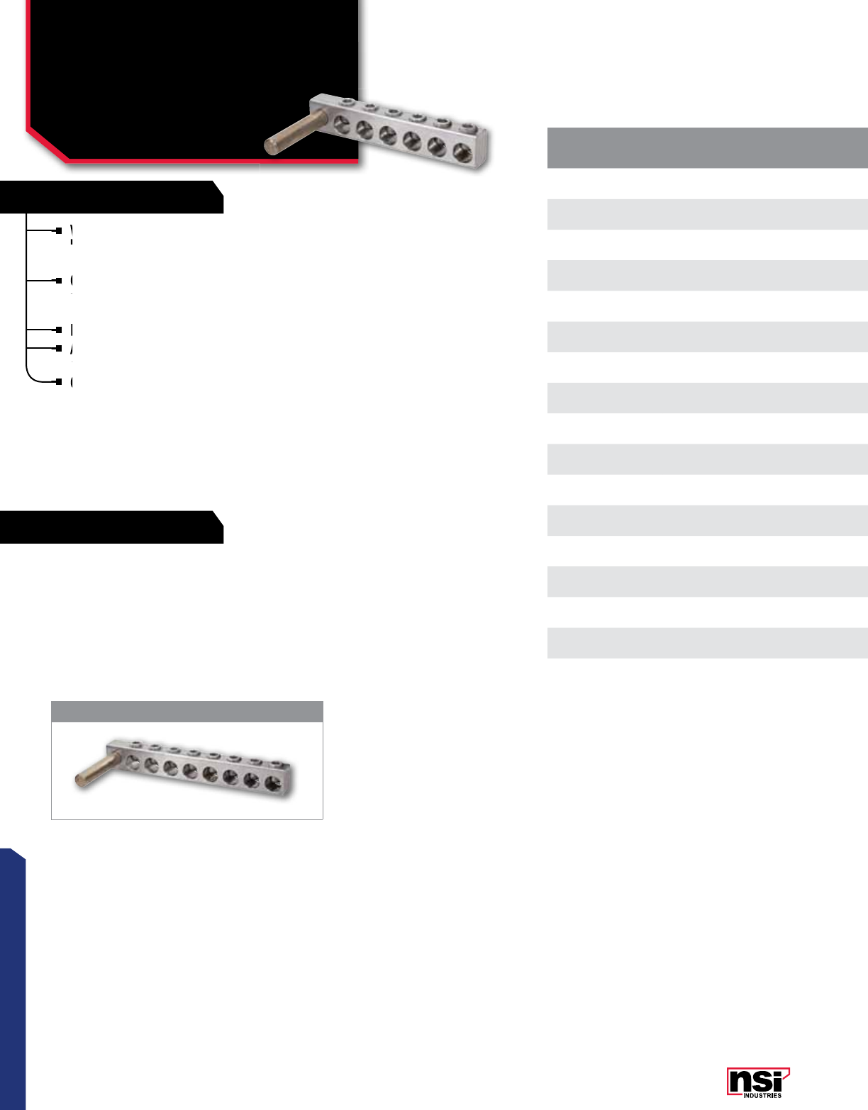
37
CONNECTORS
RATINGS
FEATURES
CAT.
NO.WIRE
RANGE NO. OF
CONDUCTORS COPPER STUD
DIA. STUD
LENGTH TORQUE VALUE
(IN./LBS.) WRENCH SIZE LENGTH
(L) WIDTH
(W) HEIGHT
(H)
STD.
CTN.
QTY.
TS1/0-2 1/0-4 AWG 20.375 3.00 180 5/16 2.030 0.630 0.880 1
TS1/0-4 1/0-4 AWG 40.375 3.00 180 5/16 2.680 0.880 0.880 1
TS250-2 250 MCM-6 AWG 20.500 4.00 360 5/16 2.590 0.880 1.130 1
TS250-3 250 MCM-6 AWG 30.500 4.00 360 5/16 3.460 0.880 1.130 1
TS250-4 250 MCM-6 AWG 40.500 4.00 360 5/16 4.320 0.880 1.130 1
TS250-8 250 MCM-6 AWG 80.500 4.00 360 5/16 7.770 0.880 1.130 1
TS350-2 350 MCM-6 AWG 20.625 4.00 400 5/16 2.950 0.880 1.250 1
TS350-2-12 350 MCM-6 AWG 20.500 4.00 400 5/16 2.950 0.880 1.250 1
TS350-3 350 MCM-6 AWG 30.625 4.00 400 5/16 3.950 0.880 1.250 1
TS350-4 350 MCM-6 AWG 40.625 4.00 400 5/16 4.950 0.880 1.250 1
TS350-6 350 MCM-6 AEG 60.625 4.00 400 5/16 6.950 0.880 1.250 1
TS350-8 350 MCM-6 AWG 80.625 4.00 400 5/16 8.950 0.880 1.250 1
TS500-2 500 MCM-4 AWG 20.750 4.50 450 5/16 4.650 1.130 1.630 1
TS500-3 500 MCM-4 AWG 30.750 4.50 450 5/16 5.790 1.130 1.630 1
TS500-4 500 MCM-4 AWG 40.750 4.50 450 5/16 6.940 1.130 1.630 1
TS750-2 750-250 MCM 20.750 5.50 550 5/16 4.040 1.250 1.750 1
TS750-4 750-250 MCM 40.750 5.50 550 5/16 6.720 1.250 1.750 1
MECHANICAL CONNECTORS
Aluminum Dual Rated
Transformer Stud
Connectors
TS Series
Versatile and reusable set screw connectors made from
high strength 6061-T6 aluminum alloy for superior
electrical and mechanical performance.
Clear plated for low contact resistance; stud is tin
plated copper which provides low contact resistance for
connection to transformer.
For use with copper and aluminum conductors.
Also available with the following options: tin plating,
anodized set screws or disc pad screws.
Contact NSi Customer Service for details.
Meets or exceeds ANSI C119.4 Class A.
TEMPERATURE RATING:
90 °C.
VOLTAGE:
600V max.
All dimensional data is listed in inches.
TS350-8
Contact NSi Customer Service for details.
Clear plated for low contact resistance; stud is tin
plated copper which provides low contact resistance for
Clear plated for low contact resistance; stud is tin
plated copper which provides low contact resistance for
Clear plated for low contact resistance; stud is tin
For use with copper and aluminum conductors.
Also available with the following options: tin plating,
anodized set screws or disc pad screws.
Also available with the following options: tin plating,
anodized set screws or disc pad screws.
Also available with the following options: tin plating,
Also available with the following options: tin plating,
Versatile and reusable set screw connectors made from
high strength 6061-T6 aluminum alloy for superior
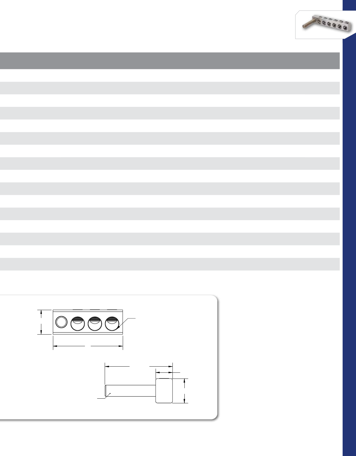
38
CONNECTORS
NSi Industries LLC • USA • 800.321.5847 • www.nsiindustries.com
CAT.
NO.WIRE
RANGE NO. OF
CONDUCTORS COPPER STUD
DIA. STUD
LENGTH TORQUE VALUE
(IN./LBS.) WRENCH SIZE LENGTH
(L) WIDTH
(W) HEIGHT
(H)
STD.
CTN.
QTY.
TS1/0-2 1/0-4 AWG 20.375 3.00 180 5/16 2.030 0.630 0.880 1
TS1/0-4 1/0-4 AWG 40.375 3.00 180 5/16 2.680 0.880 0.880 1
TS250-2 250 MCM-6 AWG 20.500 4.00 360 5/16 2.590 0.880 1.130 1
TS250-3 250 MCM-6 AWG 30.500 4.00 360 5/16 3.460 0.880 1.130 1
TS250-4 250 MCM-6 AWG 40.500 4.00 360 5/16 4.320 0.880 1.130 1
TS250-8 250 MCM-6 AWG 80.500 4.00 360 5/16 7.770 0.880 1.130 1
TS350-2 350 MCM-6 AWG 20.625 4.00 400 5/16 2.950 0.880 1.250 1
TS350-2-12 350 MCM-6 AWG 20.500 4.00 400 5/16 2.950 0.880 1.250 1
TS350-3 350 MCM-6 AWG 30.625 4.00 400 5/16 3.950 0.880 1.250 1
TS350-4 350 MCM-6 AWG 40.625 4.00 400 5/16 4.950 0.880 1.250 1
TS350-6 350 MCM-6 AEG 60.625 4.00 400 5/16 6.950 0.880 1.250 1
TS350-8 350 MCM-6 AWG 80.625 4.00 400 5/16 8.950 0.880 1.250 1
TS500-2 500 MCM-4 AWG 20.750 4.50 450 5/16 4.650 1.130 1.630 1
TS500-3 500 MCM-4 AWG 30.750 4.50 450 5/16 5.790 1.130 1.630 1
TS500-4 500 MCM-4 AWG 40.750 4.50 450 5/16 6.940 1.130 1.630 1
TS750-2 750-250 MCM 20.750 5.50 550 5/16 4.040 1.250 1.750 1
TS750-4 750-250 MCM 40.750 5.50 550 5/16 6.720 1.250 1.750 1
L
H
CONDUCTOR PORT
H
W
W/ PIN
TIN PLATED COPPER STUD
L
H
CONDUCTOR PORT
H
W
W/ PIN
TIN PLATED COPPER STUD
Stud Length
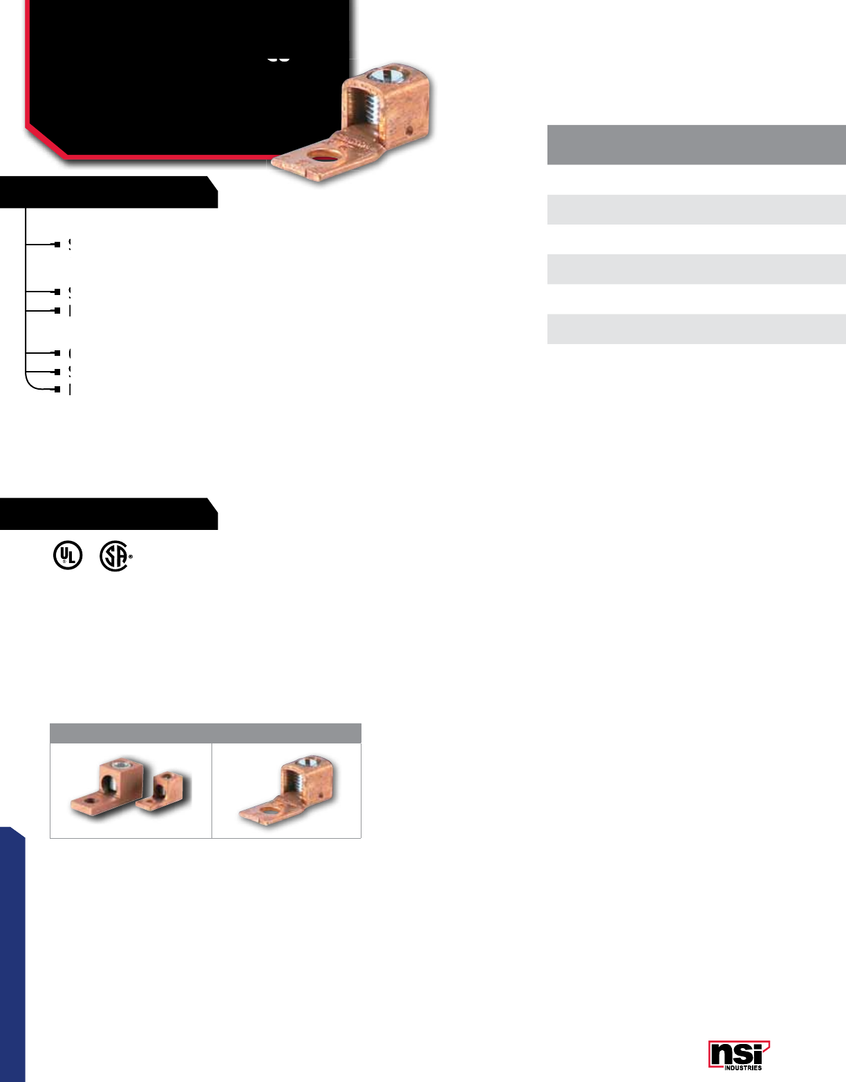
39
CONNECTORS
RATINGS
FEATURES
39
CONNECTORS
CAT.
NO.FIG.
NO. WIRE
RANGE TORQUE
VALUE WRENCH
SIZE MTG. BOLT
SIZE LENGTH
(A) HEIGHT
(B) WIDTH
(C)
MTG. HOLE
DIA.
(D)
DEPTH
(E) TANG LENGTH
(F)
TANG
THICkNESS
(H)
STD.
CTN. QTY.
6TC 16-14 AWG 25 Slotted 3/16 1.020 0.400 0.375 0.193 0.370 0.187 0.115 100
4TC 14-14 AWG 25 Slotted 1/4 1.075 0.440 0.450 0.265 0.328 0.275 0.100 100
2TC 12-14 AWG 30 Slotted 1/4 1.125 0.484 0.458 0.265 0.475 0.325 0.125 100
0TC 11/0-14 AWG 40 Slotted 1/4 1.277 0.680 0.548 0.265 0.600 0.337 0.125 50
4/0TC 14/0-2 AWG 200 5/16" 3/8 1.950 0.950 0.812 0.390 0.875 0.406 0.218 25
6TC-1 26-14 AWG 25 Slotted 3/16 0.995 0.778 0.345 0.203 0.375 0.226 0.610 100
4TC-1 24-14 AWG 45 Slotted 1/4 1.255 1.255 0.453 0.258 0.500 0.500 0.750 100
MECHANICAL CONNECTORS
Copper Single Lugs – Cu
Extruded & Tubular
TC SERIES
TEMPERATURE RATING:
90 °C.
VOLTAGE:
600V (2000V max. per UL486B).
UL 486A/B Listed Wire Connectors.
1 2
COPPER SINGLE LUGS - CU - EXTRUDED STYLES
Solid one-piece copper connector made from extruded
copper for superior mechanical strength and excellent
electrical performance.
Steel screw.
For use with copper wire only.
COPPER SINGLE LUGS - CU - TUBULAR STYLES
Copper connector made from tubular copper.
Steel screw.
For use with copper wire only.
Copper Single Lugs – Cu
All dimensional data is listed in inches.
For use with copper wire only.
LISTED
WIRE CONNECTOR
E155274
701642
Steel screw
For use with copper wire only.
For use with copper wire only.
Steel screw.
For use with copper wire only.
For use with copper wire only.
Copper connector made from tubular copper.
Steel screw.
Solid one-piece copper connector made from extruded
copper for
Solid one-piece copper connector made from extruded
copper for
Solid one-piece copper connector made from extruded
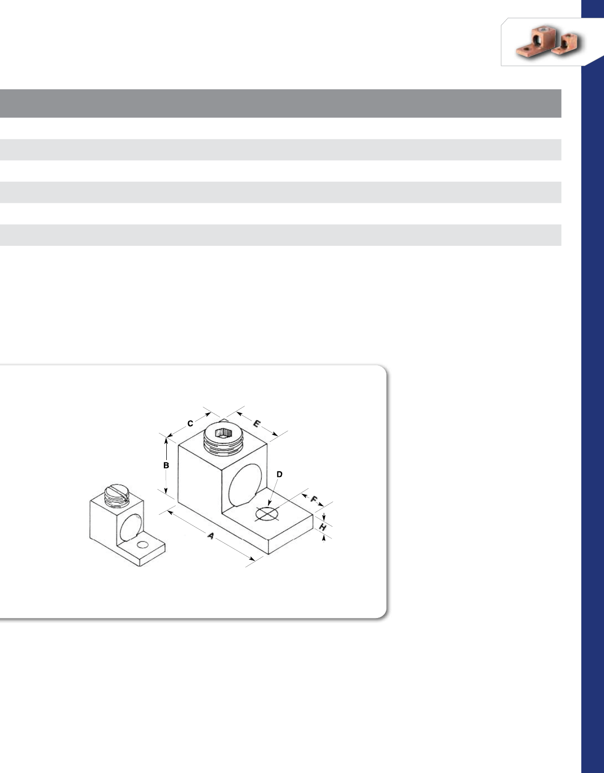
40
CONNECTORS
NSi Industries LLC • USA • 800.321.5847 • www.nsiindustries.com
CAT.
NO.FIG.
NO. WIRE
RANGE TORQUE
VALUE WRENCH
SIZE MTG. BOLT
SIZE LENGTH
(A) HEIGHT
(B) WIDTH
(C)
MTG. HOLE
DIA.
(D)
DEPTH
(E) TANG LENGTH
(F)
TANG
THICkNESS
(H)
STD.
CTN. QTY.
6TC 16-14 AWG 25 Slotted 3/16 1.020 0.400 0.375 0.193 0.370 0.187 0.115 100
4TC 14-14 AWG 25 Slotted 1/4 1.075 0.440 0.450 0.265 0.328 0.275 0.100 100
2TC 12-14 AWG 30 Slotted 1/4 1.125 0.484 0.458 0.265 0.475 0.325 0.125 100
0TC 11/0-14 AWG 40 Slotted 1/4 1.277 0.680 0.548 0.265 0.600 0.337 0.125 50
4/0TC 14/0-2 AWG 200 5/16" 3/8 1.950 0.950 0.812 0.390 0.875 0.406 0.218 25
6TC-1 26-14 AWG 25 Slotted 3/16 0.995 0.778 0.345 0.203 0.375 0.226 0.610 100
4TC-1 24-14 AWG 45 Slotted 1/4 1.255 1.255 0.453 0.258 0.500 0.500 0.750 100
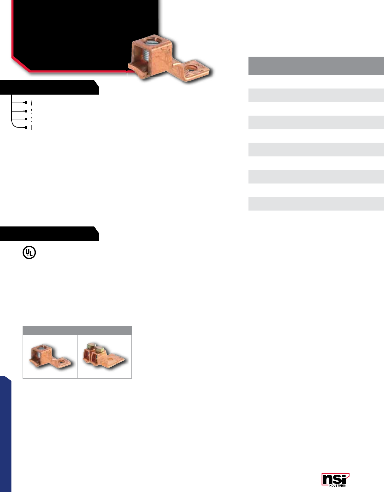
41
CONNECTORS
RATINGS
FEATURES
CAT.
NO.FIG.
NO. WIRE
RANGE MTG. BOLT
SIZE AMP
RATING
TORQUE
VALUE (IN./
(LBS.) WRENCH
SIZE
LENGTH
(L) WIDTH
(W) HEIGHT
(H) TANG LENGTH
(A)
TANG
THICkNESS
(C)
MTG.
HOLE DIA.
(D)
STD.
CTN. QTY.
DE703 110-14 AWG 1/4 25 60 Slotted 1.025 0.315 0.465 0.195 0.069 0.160 100
DE704 16-14 AWG 3/16 35 90 Slotted 1.190 0.380 0.500 0.230 0.070 0.250 100
DE705 12-8 AWG 5/16 70 125 Slotted 1.550 0.500 0.650 0.250 0.090 0.340 100
DE711 14-14 AWG 1/4 70 90 Slotted 1.310 0.500 0.560 0.250 0.080 0.280 50
DE706 11/0-6 AWG 1/4 125 150 Slotted 1.970 0.630 0.880 0.500 0.130 0.280 25
DE713 13/0-4 AWG 3/8 175 200 3/8 2.190 0.750 1.030 0.440 0.130 0.500 18
DE707 14/0-2 AWG 1/2 225 200 7/32 2.380 1.000 1.170 0.470 0.130 0.560 15
D899 24/0-2 AWG 5/8 450 200 5/8 3.200 1.502 1.720 0.915 0.190 0.405 6
DE710 1350 MCM-1/0
AWG 3/4 300 250 3/4 3.025 0.998 2.310 0.450 0.186 0.403 10
DE708 1500 MCM-4/0
AWG 15/16 400 300 15/16 4.320 1.497 2.200 0.840 0.190 0.403 2
DE709 11000-600 MCM 3/8 650 400 3/8 4.360 1.998 2.870 1.080 0.254 0.530 2
MECHANICAL CONNECTORS
Copper Single/Double
Solderless Lugs
DE SERIES
Made of 99.98% pure electrolytic copper.
Steel-plated screws to prevent rusting.
25 to 70 ampere size have slotted head screws.
Larger sizes have hex head screws.
TEMPERATURE RATING:
90 °C.
VOLTAGE:
600V max.
UL 486 Listed.
1 2
All dimensional data is listed in inches.
Larger sizes have hex head screws.
25 to 70 ampere size have slotted head screws.
Larger sizes have hex head screws.
Larger sizes have hex head screws.
Made of 99.98% pure electrolytic copper.
Steel-plated screws to
25 to 70 ampere size have slotted head screws.
Steel-plated screws to
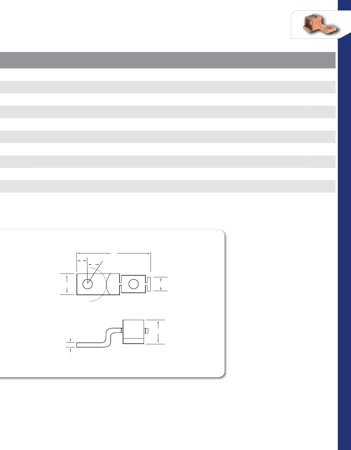
42
CONNECTORS
NSi Industries LLC • USA • 800.321.5847 • www.nsiindustries.com
CAT.
NO.FIG.
NO. WIRE
RANGE MTG. BOLT
SIZE AMP
RATING
TORQUE
VALUE (IN./
(LBS.) WRENCH
SIZE
LENGTH
(L) WIDTH
(W) HEIGHT
(H) TANG LENGTH
(A)
TANG
THICkNESS
(C)
MTG.
HOLE DIA.
(D)
STD.
CTN. QTY.
DE703 110-14 AWG 1/4 25 60 Slotted 1.025 0.315 0.465 0.195 0.069 0.160 100
DE704 16-14 AWG 3/16 35 90 Slotted 1.190 0.380 0.500 0.230 0.070 0.250 100
DE705 12-8 AWG 5/16 70 125 Slotted 1.550 0.500 0.650 0.250 0.090 0.340 100
DE711 14-14 AWG 1/4 70 90 Slotted 1.310 0.500 0.560 0.250 0.080 0.280 50
DE706 11/0-6 AWG 1/4 125 150 Slotted 1.970 0.630 0.880 0.500 0.130 0.280 25
DE713 13/0-4 AWG 3/8 175 200 3/8 2.190 0.750 1.030 0.440 0.130 0.500 18
DE707 14/0-2 AWG 1/2 225 200 7/32 2.380 1.000 1.170 0.470 0.130 0.560 15
D899 24/0-2 AWG 5/8 450 200 5/8 3.200 1.502 1.720 0.915 0.190 0.405 6
DE710 1350 MCM-1/0
AWG 3/4 300 250 3/4 3.025 0.998 2.310 0.450 0.186 0.403 10
DE708 1500 MCM-4/0
AWG 15/16 400 300 15/16 4.320 1.497 2.200 0.840 0.190 0.403 2
DE709 11000-600 MCM 3/8 650 400 3/8 4.360 1.998 2.870 1.080 0.254 0.530 2
D
W
L
E
C
H
A
SOLDERLESS LUGS
D
W
L
E
C
H
A
SOLDERLESS LUGS
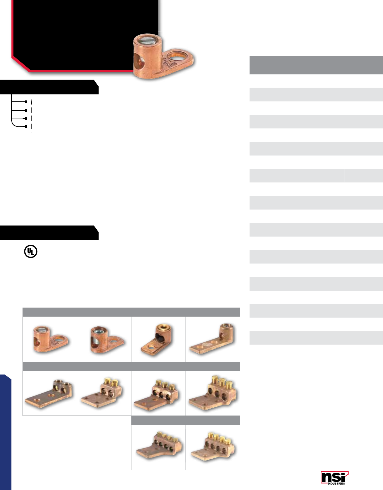
43
CONNECTORS
RATINGS
FEATURES
CAT.
NO.FIG.
NO. MTG. BOLT
SIZE WIRE
RANGE MTG. HOLE
DIA.
TORQUE
VALUE
(IN./LBS.) WRENCH SIZE LENGTH
(L) WIDTH
(W) HEIGHT
(H)
TANG
LENGTH
(A)
TANG
LENGTH
(B)
TANG
THICkNESS
(C)
STD.
CTN. QTY.
TL8 13/16 8 STR-14 SOL 0.200 60 Slotted 0.815 0.390 0.400 0.150 0.467 0.080 100
TL4 11/4 4 STR - 14 SOL 0.278 90 Slotted 1.125 0.537 0.553 0.248 0.617 0.096 100
TL1/0 1A 5/16 1/0 STR - 4 SOL 0.315 150 1/4 1.584 0.723 0.792 0.370 0.866 0.090 50
TL1/0-L2 25/16 1/0 STR - 4 SOL 0.360 150 1/4 2.670 0.775 0.895 0.388 1.908 0.183 40
TL250 1A 3/8 250 MCM - 1/0 STR 0.380 250 1/4 1.950 0.927 1.049 0.416 1.088 0.119 25
TL250-L2 23/8 250 MCM - 1/0 STR 0.403 250 1/4 2.996 1.103 1.025 0.424 1.890 0.246 15
TL250-2L2 31/2 300 MCM - 4/0 STR 0.560 250 1/4 4.473 1.994 1.102 0.713 3.375 0.283 10
TL250-3L2 51/2 300 MCM - 4/0 STR 0.560 250 5/8 4.472 3.058 1.838 0.600 3.255 0.362 4
TL250-4L2 71/2 300 MCM - 4/0 STR 0.560 250 5/8 4.440 4.089 1.783 0.650 3.175 0.394 3
TL500 1B 1/2 500 MCM - 4/0 STR 0.525 300 3/8 2.986 1.375 1.456 0.750 1.640 0.303 10
TL500-L2 21/2 500 - 300 MCM 0.562 300 3/4 4.500 1.375 2.154 0.625 3.000 0.344 6
TL500-2L2 31/2 500 - 300 MCM 0.562 300 3/4 4.500 2.500 2.055 0.625 3.000 0.375 6
TL500-2L4 41/2 500 - 300 MCM 0.562 300 3/4 4.500 3.000 2.055 0.625 3.000 0.375 4
TL500-3L2 51/2 500 - 300 MCM 0.562 300 3/4 4.500 2.500 2.150 0.625 3.000 0.375 3
TL500-3L4 61/2 500 - 300 MCM 0.562 300 3/4 4.500 3.625 2.150 0.625 3.000 0.375 3
TL500-4L2 71/2 500 - 300 MCM 0.562 300 3/4 4.500 4.187 2.150 0.625 3.000 0.375 2
TL500-4L4 81/2 500 - 300 MCM 0.562 300 3/4 4.500 4.187 2.150 0.625 3.000 0.375 2
TL1000 1B 1/2 1000 - 500 MCM 0.557 400 3/8 3.992 1.985 1.945 0.742 2.245 0.356 4
TL1000-L2 21/2 1000 - 750 MCM 0.562 400 7/8 4.875 1.875 2.887 0.625 3.000 0.500 4
TL1000-2L4 41/2 1000 - 750 MCM 0.570 400 7/8 5.045 3.630 2.900 0.620 3.270 0.517 2
TL1000-3L4 61/2 1000 - 750 MCM 0.570 400 7/8 6.045 3.630 2.900 0.620 3.270 0.517 2
11A 1B 2
3 4 5 6
7 8
MECHANICAL CONNECTORS
Copper And Bronze
Terminal Lugs
TL SERIES
Made from high conductivity copper alloy.
Range Taking.
Re-usable.
Fig.2-8 (below) made from high strength
cast bronze.
VOLTAGE:
600V (2000V max. per UL486B).
UL486 Listed Wire Connector.
Fig.2-8 (below) made from high strength
cast bronze.
Fig.2-8 (below) made from high strength
cast bronze.
Fig.2-8 (below) made from high strength
All dimensional data is listed in inches.
LISTED
WIRE CONNECTOR
E155274
Re-usable.
Fig.2-8 (below) made from high strength
Fig.2-8 (below) made from high strength
Made from high conductivity copper alloy.
Range Taking.
Range Taking.
Re-usable.
Re-usable.
Range Taking.

44
CONNECTORS
NSi Industries LLC • USA • 800.321.5847 • www.nsiindustries.com
CAT.
NO.FIG.
NO. MTG. BOLT
SIZE WIRE
RANGE MTG. HOLE
DIA.
TORQUE
VALUE
(IN./LBS.) WRENCH SIZE LENGTH
(L) WIDTH
(W) HEIGHT
(H)
TANG
LENGTH
(A)
TANG
LENGTH
(B)
TANG
THICkNESS
(C)
STD.
CTN. QTY.
TL8 13/16 8 STR-14 SOL 0.200 60 Slotted 0.815 0.390 0.400 0.150 0.467 0.080 100
TL4 11/4 4 STR - 14 SOL 0.278 90 Slotted 1.125 0.537 0.553 0.248 0.617 0.096 100
TL1/0 1A 5/16 1/0 STR - 4 SOL 0.315 150 1/4 1.584 0.723 0.792 0.370 0.866 0.090 50
TL1/0-L2 25/16 1/0 STR - 4 SOL 0.360 150 1/4 2.670 0.775 0.895 0.388 1.908 0.183 40
TL250 1A 3/8 250 MCM - 1/0 STR 0.380 250 1/4 1.950 0.927 1.049 0.416 1.088 0.119 25
TL250-L2 23/8 250 MCM - 1/0 STR 0.403 250 1/4 2.996 1.103 1.025 0.424 1.890 0.246 15
TL250-2L2 31/2 300 MCM - 4/0 STR 0.560 250 1/4 4.473 1.994 1.102 0.713 3.375 0.283 10
TL250-3L2 51/2 300 MCM - 4/0 STR 0.560 250 5/8 4.472 3.058 1.838 0.600 3.255 0.362 4
TL250-4L2 71/2 300 MCM - 4/0 STR 0.560 250 5/8 4.440 4.089 1.783 0.650 3.175 0.394 3
TL500 1B 1/2 500 MCM - 4/0 STR 0.525 300 3/8 2.986 1.375 1.456 0.750 1.640 0.303 10
TL500-L2 21/2 500 - 300 MCM 0.562 300 3/4 4.500 1.375 2.154 0.625 3.000 0.344 6
TL500-2L2 31/2 500 - 300 MCM 0.562 300 3/4 4.500 2.500 2.055 0.625 3.000 0.375 6
TL500-2L4 41/2 500 - 300 MCM 0.562 300 3/4 4.500 3.000 2.055 0.625 3.000 0.375 4
TL500-3L2 51/2 500 - 300 MCM 0.562 300 3/4 4.500 2.500 2.150 0.625 3.000 0.375 3
TL500-3L4 61/2 500 - 300 MCM 0.562 300 3/4 4.500 3.625 2.150 0.625 3.000 0.375 3
TL500-4L2 71/2 500 - 300 MCM 0.562 300 3/4 4.500 4.187 2.150 0.625 3.000 0.375 2
TL500-4L4 81/2 500 - 300 MCM 0.562 300 3/4 4.500 4.187 2.150 0.625 3.000 0.375 2
TL1000 1B 1/2 1000 - 500 MCM 0.557 400 3/8 3.992 1.985 1.945 0.742 2.245 0.356 4
TL1000-L2 21/2 1000 - 750 MCM 0.562 400 7/8 4.875 1.875 2.887 0.625 3.000 0.500 4
TL1000-2L4 41/2 1000 - 750 MCM 0.570 400 7/8 5.045 3.630 2.900 0.620 3.270 0.517 2
TL1000-3L4 61/2 1000 - 750 MCM 0.570 400 7/8 6.045 3.630 2.900 0.620 3.270 0.517 2
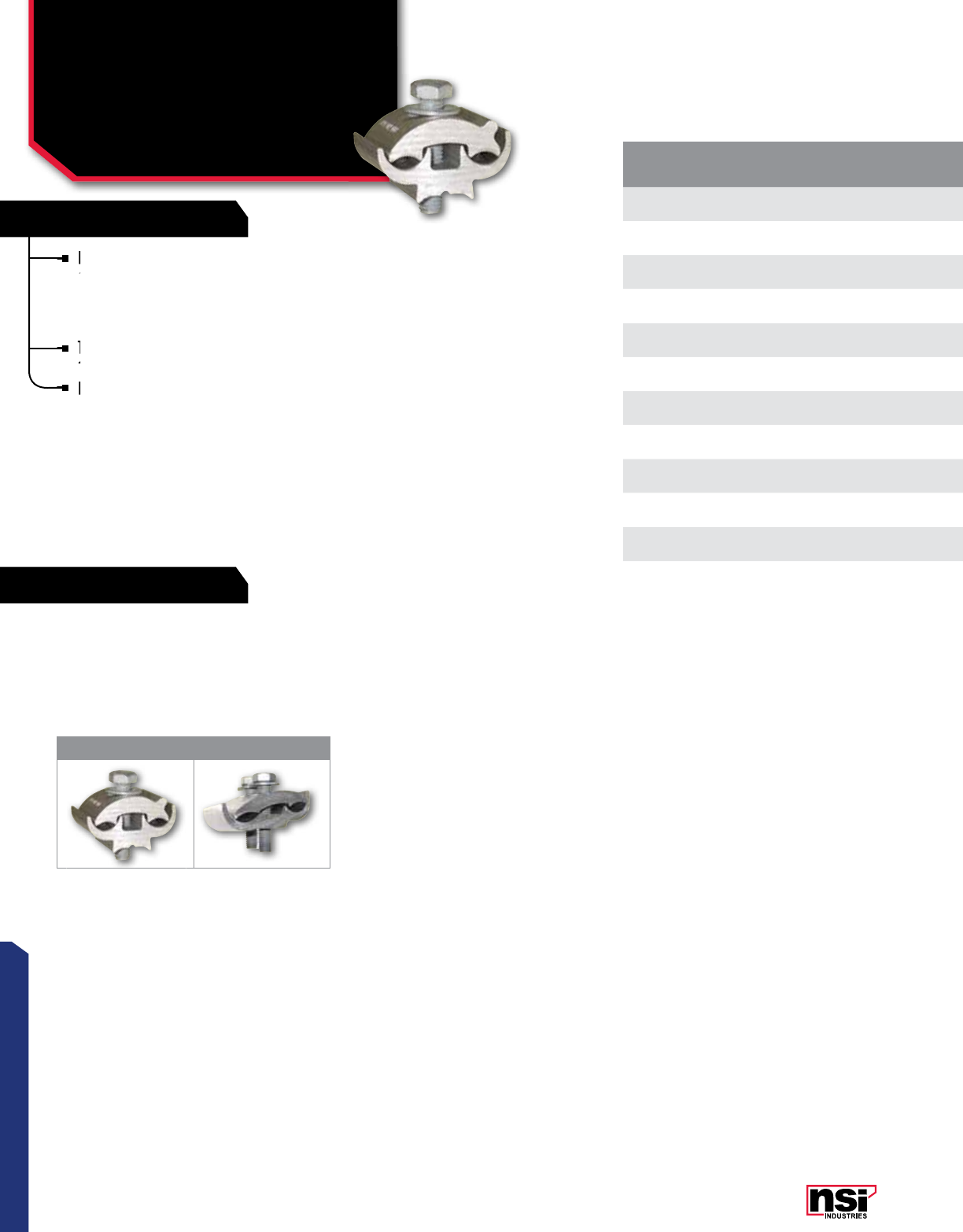
45
CONNECTORS
RATINGS
FEATURES
CAT.
NO.FIG.
NO.
MAIN TAP HEX/WRENCH
SIZE BOLT
HEIGHT WIDTH
(W) LENGTH
(L) STD.
CTN. QTY.
ACSR AL/CU ACSR AL/CU
PAA4 1 1/0-6 1/0 STR-6 SOL 1/0-6 1/0 STR-6 SOL 3/8 1.187 1.500 2.219 25
PAA5 11/0-8 1/0 STR-8 SOL 1/0-8 1/0 STR-8 SOL 3/8 1.496 1.496 1.240 25
PAA6 11/0-8 2/0 STR-8 SOL 1/0-8 2/0 STR-8 SOL 3/8 1.496 1.496 1.240 25
PAA10 1336.4-1/0 400-1/0 SOL 1/0-8 1/0 STR-8 SOL 3/8 2.000 1.750 2.469 12
PAA12 14/0-2 4/0 STR-2 SOL 4/0-2 4/0 STR-2 SOL 1/2 2.000 2.000 2.250 12
PAA29 12-6 2 STR-6 SOL 2-6 2 STR-6 SOL 5/16 1.094 1.375 1.813 25
PAA339 11/0-6 1/0 STR-6 SOL 1/0-6 1/0 STR-6 SOL 3/8 1.250 1.500 1.563 25
PAA49 11/0-6 1/0 STR-6 SOL 1/0-6 1/0 STR-6 SOL 3/8 2.219 1.500 1.187 25
PAA129 14/0-2 4/0 STR-2 SOL 4/0-2 4/0 STR-2OL 1/2 2.250 2.000 2.000 12
PAE2121-9 22/0-6 2/0 STR-6 SOL 2/0-6 2/0 STR-6 SOL 3/8 2.000 1.625 1.375 25
PAE4141-9 24/0-4 4/0 STR-2 SOL 4/0-4 4/0 STR-2 SOL 3/8 2.000 2.000 1.375 12
MECHANICAL CONNECTORS
Aluminum Dual Rated
Parallel Groove Clamps
PAA, PAE SERIES
High strength aluminum extruded alloy fittings
assembled with steel or anodized high strength
aluminum flat washers for heavy duty service
entrance or for use as heavy duty distribution
armor rod clamps.
The serrated grooves provide increased contact.
Supplied pre-filled with oxide inhibitor.
For galvanized steel hardware, add the suffix
-SH to each part number.
TEMPERATURE RATING:
90 °C.
VOLTAGE:
600V max.
1 2
All dimensional data is listed in inches.
High strength aluminum extruded alloy fittings
assembled with steel or anodized high strength
High strength aluminum extruded alloy fittings
assembled with steel or anodized high strength
High strength aluminum extruded alloy fittings
The serrated grooves provide increased contact.
Supplied pre-filled with oxide inhibitor.
For galvanized steel hardware, add the suffix
-SH to each part number.
For galvanized steel hardware, add the suffix
-SH to each part number.
For galvanized steel hardware, add the suffix
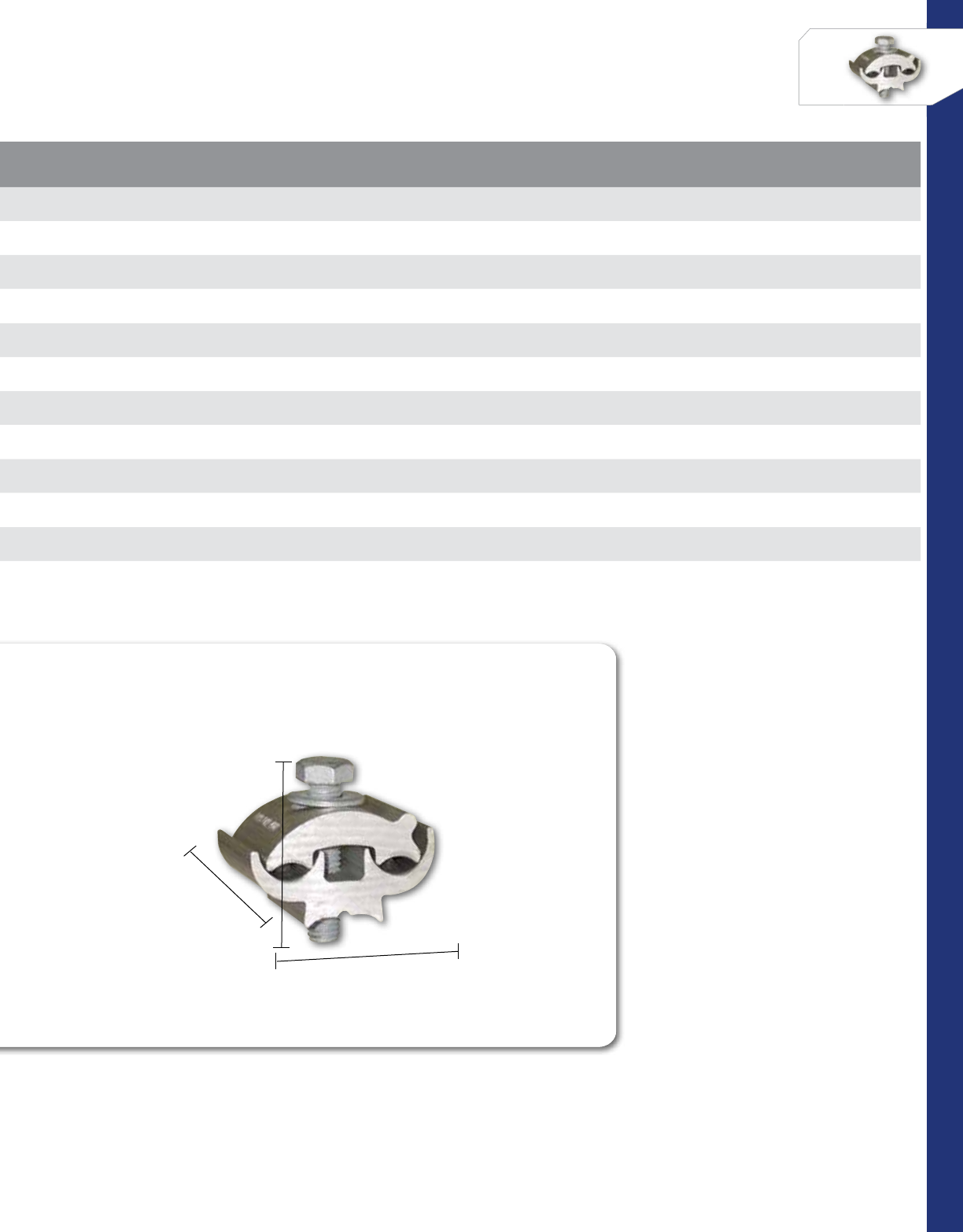
46
CONNECTORS
NSi Industries LLC • USA • 800.321.5847 • www.nsiindustries.com
CAT.
NO.FIG.
NO.
MAIN TAP HEX/WRENCH
SIZE BOLT
HEIGHT WIDTH
(W) LENGTH
(L) STD.
CTN. QTY.
ACSR AL/CU ACSR AL/CU
PAA4 1 1/0-6 1/0 STR-6 SOL 1/0-6 1/0 STR-6 SOL 3/8 1.187 1.500 2.219 25
PAA5 11/0-8 1/0 STR-8 SOL 1/0-8 1/0 STR-8 SOL 3/8 1.496 1.496 1.240 25
PAA6 11/0-8 2/0 STR-8 SOL 1/0-8 2/0 STR-8 SOL 3/8 1.496 1.496 1.240 25
PAA10 1336.4-1/0 400-1/0 SOL 1/0-8 1/0 STR-8 SOL 3/8 2.000 1.750 2.469 12
PAA12 14/0-2 4/0 STR-2 SOL 4/0-2 4/0 STR-2 SOL 1/2 2.000 2.000 2.250 12
PAA29 12-6 2 STR-6 SOL 2-6 2 STR-6 SOL 5/16 1.094 1.375 1.813 25
PAA339 11/0-6 1/0 STR-6 SOL 1/0-6 1/0 STR-6 SOL 3/8 1.250 1.500 1.563 25
PAA49 11/0-6 1/0 STR-6 SOL 1/0-6 1/0 STR-6 SOL 3/8 2.219 1.500 1.187 25
PAA129 14/0-2 4/0 STR-2 SOL 4/0-2 4/0 STR-2OL 1/2 2.250 2.000 2.000 12
PAE2121-9 22/0-6 2/0 STR-6 SOL 2/0-6 2/0 STR-6 SOL 3/8 2.000 1.625 1.375 25
PAE4141-9 24/0-4 4/0 STR-2 SOL 4/0-4 4/0 STR-2 SOL 3/8 2.000 2.000 1.375 12
BOLT HEIGHT
TYPICAL
WIDTH (W)
LENGHT (L)
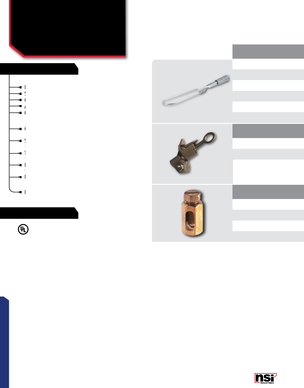
47
CONNECTORSCONNECTORS
MECHANICAL CONNECTORS
Wedge & Hot-Line Clamps,
Service Entrance Connector
W, HLC, EC SERIES
CAT.
NO.
WIRE RANGE LENGTH
(L) WIDTH
(W) STD. CTN.
QTY.
ACSR ALUMINUM AAAC
W62-1 2-6 1 str-6 sol 2-6 12.000 2.375 12
W62-1FC 2-6 1 str-6 sol 2-6 17.500 FLEX 12
W20-1 1/0-4 2/0 str-2 sol 1/0-4 12.500 2.375 8
W20-1FC 1/0-4 2/0 str-2 sol 1/0-4 18.500 FLEX 8
W40-1 4/0-2/0 4/0 str-2/0 sol 4/0-2/0 12.750 2.375 6
W40-1FC 4/0-2/0 4/0 str-2/0 sol 4/0-2/0 18.500 FLEX 6
CAT.
NO.
MAIN TAP LENGTH
(L) WIDTH
(W) HEIGHT
(H)
STD.
CTN.
QTY.
CONDUCTOR
RANGE
WIRE
DIAMETER
CONDUCTOR
RANGE
WIRE
DIAMETER
HLC-2/0 8 sol - 2/0 str .128/.414 8 sol - 2/0 str .128/.414 4.119 2.550 2.120 1
HLC-400 6 sol - 400MCM .162/.745 8 sol - 4/0 str .128/.547 4.716 2.900 1.348 1
ALUMINUM SERVICE WEDGE CLAMPS
For dead-ending self-supporting drop wire.
Saves conductor - drop wire may be cut to exact length.
Can be attached to bare neutral in any point in the span.
Adjustment in drop wire sag are easily made.
Grips ACSR, AAAC or aluminum conductor.
COPPER HOT LINE CLAMPS
Clamping stem is manufactured from high-strength
silicon bronze.
Saddle is made of high-strength copper alloy, ensuring
continued clamping force on the main conductor.
Threads of clamping stem are protected to prevent
damage due to arcing.
Double coil stainless steel washer maintains continuous
pressure on the main conductor.
Retainer pin captivates the saddle for easy installation.
SERVICE ENTRANCE CONNECTOR
Body and screw are of high strength, corrosion resistant
copper allow, 600V.
CAT.
NO.WIRE
RANGE TORQUE VALUE (IN./LBS.) HEX/WRENCH SIZE STD.
CTN. QTY.
EC12 12 str 35 1/4 100
EC6 6 str 45 5/16 100
EC4 4 str 45 3/8 100
EC2 2 str 50 7/8 100
SERVICE ENTRANCE CONNECTOR:
Body and screw are of high-strength,
corrosion-resistant copper alloy.
TEMPERATURE RATING:
90 °C.
VOLTAGE:
600V (2000V max. per UL486B).
UL486A/B Listed Wire Connector.
For dead-ending self-supporting drop wire.
Saves conductor - drop wire may be cut to exact length.
Saves conductor - drop wire may be cut to exact length.
Saves conductor - drop wire may be cut to exact length.
Can be attached to bare neutral in any point in the span.
Can be attached to bare neutral in any point in the span.
Adjustment in drop wire sag are easily made.
Adjustment in drop wire sag are easily made.
Grips ACSR, AAAC or aluminum conductor.
Grips ACSR, AAAC or aluminum conductor.
Double coil stainless steel washer maintains continuous
pressure on the main conductor.
Retainer pin captivates the saddle for easy installation.
Threads of clamping stem are protected to prevent
damage due to arcing.
Threads of clamping stem are protected to prevent
damage due to arcing.
Threads of clamping stem are protected to prevent
Saddle is made of high-strength copper alloy, ensuring
continued clamping force on the main conductor.
Saddle is made of high-strength copper alloy, ensuring
continued clamping force on the main conductor.
Saddle is made of high-strength copper alloy, ensuring
Clamping stem is manufactured from high-strength
silicon bronze.
Clamping stem is manufactured from high-strength
silicon bronze.
Clamping stem is manufactured from high-strength
Body and screw are of high strength, corrosion resistant
copper allow, 600V.
Body and screw are of high strength, corrosion resistant
copper allow, 600V.
Body and screw are of high strength, corrosion resistant
RATINGS
FEATURES

48
NSi Industries LLC • USA • 800.321.5847 • www.nsiindustries.com
CAT.
NO.
WIRE RANGE LENGTH
(L) WIDTH
(W) STD. CTN.
QTY.
ACSR ALUMINUM AAAC
W62-1 2-6 1 str-6 sol 2-6 12.000 2.375 12
W62-1FC 2-6 1 str-6 sol 2-6 17.500 FLEX 12
W20-1 1/0-4 2/0 str-2 sol 1/0-4 12.500 2.375 8
W20-1FC 1/0-4 2/0 str-2 sol 1/0-4 18.500 FLEX 8
W40-1 4/0-2/0 4/0 str-2/0 sol 4/0-2/0 12.750 2.375 6
W40-1FC 4/0-2/0 4/0 str-2/0 sol 4/0-2/0 18.500 FLEX 6
CAT.
NO.
MAIN TAP LENGTH
(L) WIDTH
(W) HEIGHT
(H)
STD.
CTN.
QTY.
CONDUCTOR
RANGE
WIRE
DIAMETER
CONDUCTOR
RANGE
WIRE
DIAMETER
HLC-2/0 8 sol - 2/0 str .128/.414 8 sol - 2/0 str .128/.414 4.119 2.550 2.120 1
HLC-400 6 sol - 400MCM .162/.745 8 sol - 4/0 str .128/.547 4.716 2.900 1.348 1
CAT.
NO.WIRE
RANGE TORQUE VALUE (IN./LBS.) HEX/WRENCH SIZE STD.
CTN. QTY.
EC12 12 str 35 1/4 100
EC6 6 str 45 5/16 100
EC4 4 str 45 3/8 100
EC2 2 str 50 7/8 100
All dimensional data is listed in inches.
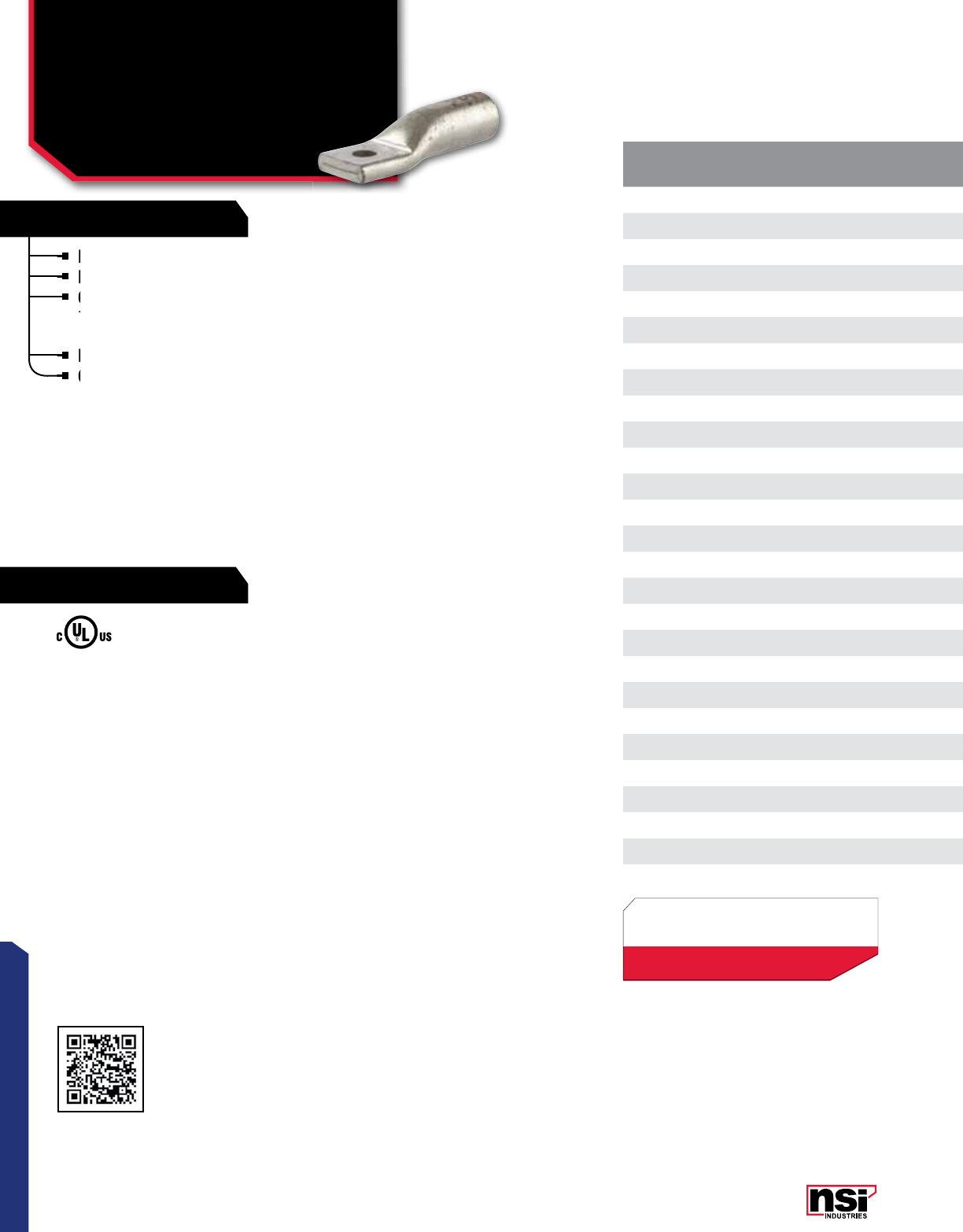
49
CONNECTORS
RATINGS
FEATURES
CAT.
NO. WIRE
RANGE
EXPANDED
WIRE
RANGE*
COLOR
CODE BOLT
SIZE
BARREL
O.D.
BARREL
I.D.
LENGTH
(L)
WIDTH
(W)
TANG LENGTH
(A)
TANG LENGTH
(B)
BARREL
LENGTH (B1)
TANG
THICkNESS (C)
MTG. HOLE
DIA. (D)
STD.
CTN.
QTY.
AL8-14 8 AWG 8 AWG Blue 1/4 0.302 0.182 1.549 0.410 0.231 0.645 0.550 0.114 0.260 24
AL6-14 6 AWG 6-8 AWG Gray 1/4 0.339 0.201 2.008 0.567 0.378 0.878 0.858 0.098 0.248 24
AL4-14 4 AWG 4-6 AWG Green 1/4 0.441 0.252 2.307 0.567 0.378 0.878 1.098 0.189 0.248 24
AL4-38 4 AWG 4-6 AWG Green 3/8 0.441 0.252 2.390 0.650 0.378 0.878 1.098 0.150 0.409 24
AL2-14 2 AWG 2-6 AWG Pink 1/4 0.532 0.311 2.500 0.709 0.378 0.878 1.201 0.217 0.248 24
AL2-38 2 AWG 2-6 AWG Pink 3/8 0.532 0.311 2.500 0.709 0.378 0.878 1.201 0.217 0.409 24
AL1-14 1 AWG 1-6 AWG Gold 1/4 0.532 0.350 2.500 0.728 0.378 0.878 1.201 0.177 0.248 24
AL1/0-38 1/0 AWG 1/0-6 AWG Tan 3/8 0.630 0.390 2.807 0.847 0.500 0.929 1.201 0.240 0.409 24
AL1/0-48 1/0 AWG 1/0-6 AWG Tan 1/2 0.630 0.390 2.807 0.847 0.020 0.929 1.201 0.240 0.508 24
AL2/0-38 2/0 AWG 2/0-4 AWG Olive 3/8 0.689 0.441 2.807 0.937 0.500 1.118 1.299 0.240 0.409 12
AL2/0-48 2/0 AWG 2/0-4 AWG Olive 1/2 0.689 0.441 2.807 0.937 0.500 1.118 1.299 0.240 0.508 12
AL3/0-38 3/0 AWG 3/0-2 AWG Ruby 3/8 0.760 0.480 3.000 1.028 0.500 1.118 1.402 0.280 0.409 12
AL3/0-48 3/0 AWG 3/0-2 AWG Ruby 1/2 0.760 0.480 3.000 1.028 0.500 1.118 1.402 0.280 0.508 12
AL4/0-38 4/0 AWG 4/0-1 AWG White 3/8 0.839 0.551 3.429 1.150 0.559 1.307 1.402 0.287 0.409 12
AL4/0-48 4/0 AWG 4/0-1 AWG White 1/2 0.839 0.551 3.429 1.150 0.559 1.307 1.402 0.287 0.508 12
AL250-48 250 MCM 250 MCM-1/0 AWG Red 1/2 0.921 0.591 3.500 1.260 0.630 1.307 1.500 0.319 0.508 12
AL300-48 300 MCM 300 MCM-2/0 AWG Blue 1/2 1.012 0.650 4.000 1.370 0.630 1.500 1.598 0.347 0.508 6
AL350-48 350 MCM 350MCM-3/0 AWG Brown 1/2 1.118 0.721 4.248 1.520 0.689 1.500 1.902 0.390 0.508 6
AL400-48 400 MCM 400MCM-4/0 AWG Green 1/2 1.189 0.760 4.677 1.606 0.689 1.500 2.299 0.417 0.508 6
AL500-48 500 MCM 500-250 MCM Pink 1/2 1.319 0.839 4.748 1.787 0.748 1.500 2.500 0.469 0.508 6
AL500-58 500 MCM 500-250 MCM Pink 5/8 1.319 0.839 4.748 1.787 0.748 1.500 2.500 0.469 0.669 6
AL600-48 600 MCM 600-250 MCM Black 1/2 1.441 0.921 5.118 1.957 0.748 1.870 2.598 0.508 0.508 3
AL600-58 600 MCM 600-250 MCM Black 5/8 1.441 0.921 5.118 1.957 0.748 1.870 2.598 0.508 0.669 3
AL750-48 750 MCM 750-500 MCM Yellow 1/2 1.598 1.032 6.118 2.189 0.937 2.000 3.201 0.547 0.508 3
AL750-58 750 MCM 750-500 MCM Yellow 5/8 1.598 1.032 6.118 2.189 0.937 2.000 3.201 0.547 0.669 3
AL1000-58 1000 MCM – Brown 5/8 1.833 1.173 6.719 2.500 1.000 2.500 2.562 0.688 0.669 1
COMPRESSION CONNECTORS
Aluminum Dual Rated
One Hole Standard Barrel
AL SERIES
UL486A/B Listed.
UL Listed to 35kV when properly
installed to cable manufacturers
specifications
TEMPERATURE RATING:
90 °C.
CRIMP TOOL:
N1240,N12ID.
VOLTAGE:
600V (2000V Max. per UL486).
Produced from high conductivity aluminum tubing.
Electro-tin plated for corrosion resistance.
Color coded and marked with die index information.
Pre-filled with oxide inhibitor and capped with color
coded cap.
Listed for 35KV maximum when properly installed.
Consult factory for additional hole sizes.
*EXPANDED WIRE RANGE when installed with
NSI N12ID dieless compression tool.
UL Listed with other tools:
FOR TOOL & DIE CRIMPING INFORMATION,
PLEASE SEE TABLE ON PAGE 145
All dimensional data is listed in inches.
Scan QR to view
Tool & Die Charts
Produced from high conductivity aluminum tubing.
Electro-tin plated for corrosion resistance.
Electro-tin plated for corrosion resistance.
Color coded and marked with die index information.
Pre-filled with oxide inhibitor and capped with color
Color coded and marked with die index information.
Listed for 35KV maximum when properly installed.
Consult factory for additional hole sizes.
Consult factory for additional hole sizes.
Consult factory for additional hole sizes.
LISTED
WIRE CONNECTOR
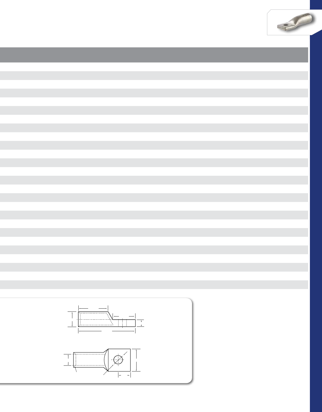
50
CONNECTORS
NSi Industries LLC • USA • 800.321.5847 • www.nsiindustries.com
CAT.
NO. WIRE
RANGE
EXPANDED
WIRE
RANGE*
COLOR
CODE BOLT
SIZE
BARREL
O.D.
BARREL
I.D.
LENGTH
(L)
WIDTH
(W)
TANG LENGTH
(A)
TANG LENGTH
(B)
BARREL
LENGTH (B1)
TANG
THICkNESS (C)
MTG. HOLE
DIA. (D)
STD.
CTN.
QTY.
AL8-14 8 AWG 8 AWG Blue 1/4 0.302 0.182 1.549 0.410 0.231 0.645 0.550 0.114 0.260 24
AL6-14 6 AWG 6-8 AWG Gray 1/4 0.339 0.201 2.008 0.567 0.378 0.878 0.858 0.098 0.248 24
AL4-14 4 AWG 4-6 AWG Green 1/4 0.441 0.252 2.307 0.567 0.378 0.878 1.098 0.189 0.248 24
AL4-38 4 AWG 4-6 AWG Green 3/8 0.441 0.252 2.390 0.650 0.378 0.878 1.098 0.150 0.409 24
AL2-14 2 AWG 2-6 AWG Pink 1/4 0.532 0.311 2.500 0.709 0.378 0.878 1.201 0.217 0.248 24
AL2-38 2 AWG 2-6 AWG Pink 3/8 0.532 0.311 2.500 0.709 0.378 0.878 1.201 0.217 0.409 24
AL1-14 1 AWG 1-6 AWG Gold 1/4 0.532 0.350 2.500 0.728 0.378 0.878 1.201 0.177 0.248 24
AL1/0-38 1/0 AWG 1/0-6 AWG Tan 3/8 0.630 0.390 2.807 0.847 0.500 0.929 1.201 0.240 0.409 24
AL1/0-48 1/0 AWG 1/0-6 AWG Tan 1/2 0.630 0.390 2.807 0.847 0.020 0.929 1.201 0.240 0.508 24
AL2/0-38 2/0 AWG 2/0-4 AWG Olive 3/8 0.689 0.441 2.807 0.937 0.500 1.118 1.299 0.240 0.409 12
AL2/0-48 2/0 AWG 2/0-4 AWG Olive 1/2 0.689 0.441 2.807 0.937 0.500 1.118 1.299 0.240 0.508 12
AL3/0-38 3/0 AWG 3/0-2 AWG Ruby 3/8 0.760 0.480 3.000 1.028 0.500 1.118 1.402 0.280 0.409 12
AL3/0-48 3/0 AWG 3/0-2 AWG Ruby 1/2 0.760 0.480 3.000 1.028 0.500 1.118 1.402 0.280 0.508 12
AL4/0-38 4/0 AWG 4/0-1 AWG White 3/8 0.839 0.551 3.429 1.150 0.559 1.307 1.402 0.287 0.409 12
AL4/0-48 4/0 AWG 4/0-1 AWG White 1/2 0.839 0.551 3.429 1.150 0.559 1.307 1.402 0.287 0.508 12
AL250-48 250 MCM 250 MCM-1/0 AWG Red 1/2 0.921 0.591 3.500 1.260 0.630 1.307 1.500 0.319 0.508 12
AL300-48 300 MCM 300 MCM-2/0 AWG Blue 1/2 1.012 0.650 4.000 1.370 0.630 1.500 1.598 0.347 0.508 6
AL350-48 350 MCM 350MCM-3/0 AWG Brown 1/2 1.118 0.721 4.248 1.520 0.689 1.500 1.902 0.390 0.508 6
AL400-48 400 MCM 400MCM-4/0 AWG Green 1/2 1.189 0.760 4.677 1.606 0.689 1.500 2.299 0.417 0.508 6
AL500-48 500 MCM 500-250 MCM Pink 1/2 1.319 0.839 4.748 1.787 0.748 1.500 2.500 0.469 0.508 6
AL500-58 500 MCM 500-250 MCM Pink 5/8 1.319 0.839 4.748 1.787 0.748 1.500 2.500 0.469 0.669 6
AL600-48 600 MCM 600-250 MCM Black 1/2 1.441 0.921 5.118 1.957 0.748 1.870 2.598 0.508 0.508 3
AL600-58 600 MCM 600-250 MCM Black 5/8 1.441 0.921 5.118 1.957 0.748 1.870 2.598 0.508 0.669 3
AL750-48 750 MCM 750-500 MCM Yellow 1/2 1.598 1.032 6.118 2.189 0.937 2.000 3.201 0.547 0.508 3
AL750-58 750 MCM 750-500 MCM Yellow 5/8 1.598 1.032 6.118 2.189 0.937 2.000 3.201 0.547 0.669 3
AL1000-58 1000 MCM – Brown 5/8 1.833 1.173 6.719 2.500 1.000 2.500 2.562 0.688 0.669 1
B1 ±1.00
COMPRESSION LUGS
ONE HOLE
B ±1.00
L ±1.00
O.D ±0.50
I.D.±0.20 W±1.00
A ±0.50
D±0.20
45°
Deep
Chamfer
C±0.50
D
51
CONNECTORS
RATINGS
FEATURES
COMPRESSION CONNECTORS
ALuminum Dual Rated
Two Hole
Standard Barrel
AL-N SERIES CAT.
NO. WIRE
RANGE EXPANDED WIRE
RANGE* COLOR
CODE BOLT
SIZE O.D. I.D. LENGTH
(L) WIDTH
(W) TANG LENGTH
(A) TANG LENGTH
(B) BARREL
LENGTH (B1)
TANG
THICkNESS
(C)
MTG. HOLE
DIA. (D) MTG. HOLE
SPACING (E)
STD.
CTN.
QTY.
AL1/0N 1/0 AWG 1/0-6 AWG Tan 1/2 0.390 0.630 4.748 0.847 0.630 3.118 1.201 0.240 0.508 1.750 12
AL2/0N 2/0 AWG 2/0-4 AWG Olive 1/2 0.440 0.690 4.799 0.937 0.630 3.118 1.299 0.240 0.508 1.750 12
AL3/0N 3/0 AWG 3/0-2 AWG Ruby 1/2 0.480 0.760 5.000 1.028 0.630 3.118 1.402 0.280 0.508 1.750 12
AL4/0N 4/0 AWG 4/0-1 AWG White 1/2 0.550 0.840 5.248 1.150 0.630 3.118 1.402 0.287 0.508 1.750 12
AL250N 250 MCM 250 MCM-1/0 AWG Red 1/2 0.590 0.920 5.307 1.260 0.630 3.118 1.500 0.319 0.508 1.750 12
AL300N 300 MCM 300 MCM-2/0 AWG Blue 1/2 0.650 1.010 5.500 1.370 0.630 3.118 1.598 0.347 0.508 1.750 6
AL350N 350 MCM 350MCM-3/0 AWG Brown 1/2 0.720 1.120 5.870 1.520 0.630 3.118 1.902 0.390 0.508 1.750 6
AL400N 400 MCM 400MCM-4/0 AWG Green 1/2 0.760 1.190 6.429 1.606 0.630 3.118 2.299 0.417 0.508 1.750 6
AL500N 500 MCM 500-250 MCM Pink 1/2 0.840 1.320 6.500 1.787 0.630 3.118 2.500 0.469 0.508 1.750 6
AL600N 600 MCM 600-250 MCM Black 1/2 0.920 1.440 6.748 1.957 0.630 3.118 2.598 0.508 0.508 1.750 3
AL750N 750 MCM 750-500 MCM Yellow 1/2 1.030 1.600 7.370 2.189 0.630 3.118 3.201 0.547 0.508 1.750 3
AL1000N 1000 MCM – Brown 1/2 1.170 1.831 7.437 2.500 0.750 3.219 2.562 0.687 0.508 1.750 1
UL486A/B Listed.
UL Listed to 35kV when properly.
installed to cable manufacturers
specifications.
TEMPERATURE RATING:
90 °C.
CRIMP TOOL:
N1240,N12ID.
VOLTAGE:
600V (2000V Max. per UL486).
Produced from high conductivity aluminum tubing.
Electro-tin plated for corrosion resistance.
Color coded and marked with die index information.
Pre-filled with oxide inhibitor and capped with color
coded cap.
Listed for 35KV maximum when properly installed.
Consult factory for additional hole sizes.
All dimensional data is listed in inches.
Scan QR to view
Tool & Die Charts
Produced from high conductivity aluminum tubing.
Electro-tin plated for corrosion resistance.
Electro-tin plated for corrosion resistance.
Color coded and marked with die index information.
Color coded and marked with die index information.
Pre-filled with oxide inhibitor and capped with color
coded cap.
Pre-filled with oxide inhibitor and capped with color
coded cap.
Pre-filled with oxide inhibitor and capped with color
Pre-filled with oxide inhibitor and capped with color
Listed for 35KV maximum when properly installed.
Consult factory for additional hole sizes.
Consult factory for additional hole sizes.
Consult factory for additional hole sizes.
LISTED
WIRE CONNECTOR
*EXPANDED WIRE RANGE when installed with
NSI N12ID dieless compression tool.
UL Listed with other tools:
FOR TOOL & DIE CRIMPING INFORMATION,
PLEASE SEE TABLE ON PAGE 145
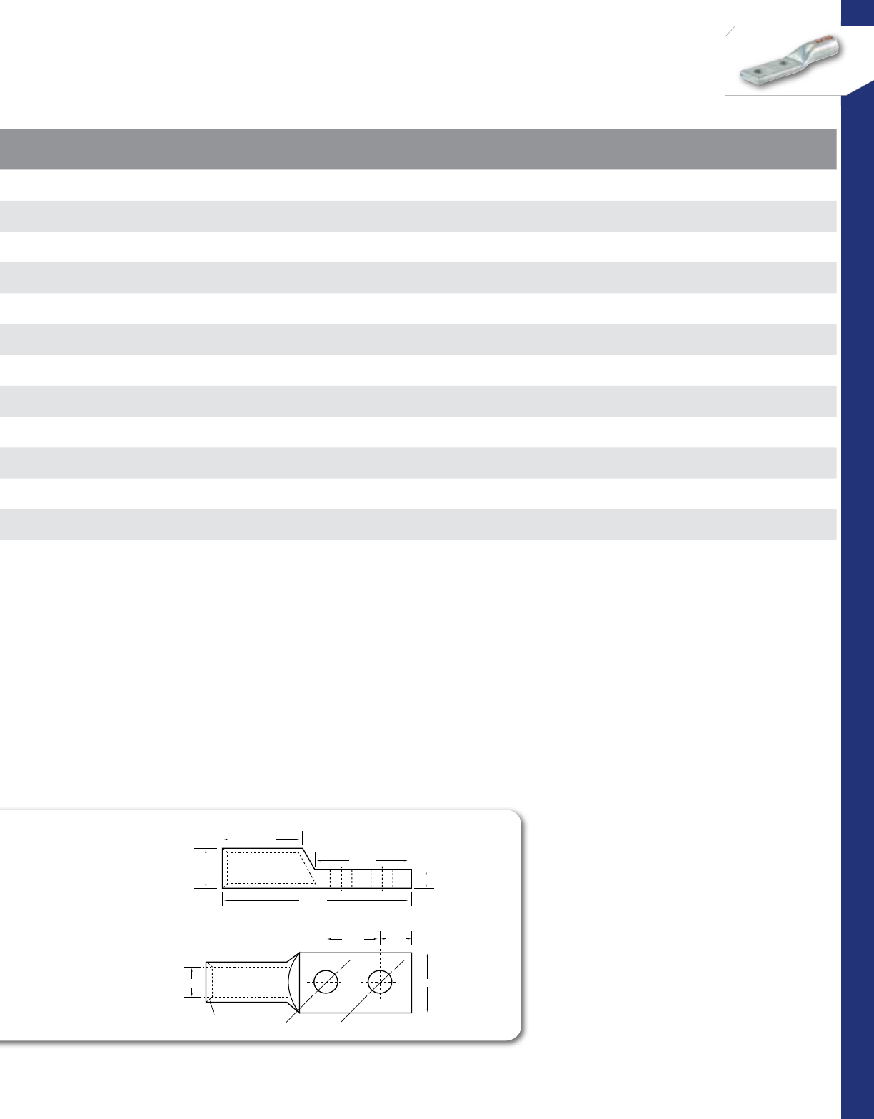
52
CONNECTORS
NSi Industries LLC • USA • 800.321.5847 • www.nsiindustries.com
CAT.
NO. WIRE
RANGE EXPANDED WIRE
RANGE* COLOR
CODE BOLT
SIZE O.D. I.D. LENGTH
(L) WIDTH
(W) TANG LENGTH
(A) TANG LENGTH
(B) BARREL
LENGTH (B1)
TANG
THICkNESS
(C)
MTG. HOLE
DIA. (D) MTG. HOLE
SPACING (E)
STD.
CTN.
QTY.
AL1/0N 1/0 AWG 1/0-6 AWG Tan 1/2 0.390 0.630 4.748 0.847 0.630 3.118 1.201 0.240 0.508 1.750 12
AL2/0N 2/0 AWG 2/0-4 AWG Olive 1/2 0.440 0.690 4.799 0.937 0.630 3.118 1.299 0.240 0.508 1.750 12
AL3/0N 3/0 AWG 3/0-2 AWG Ruby 1/2 0.480 0.760 5.000 1.028 0.630 3.118 1.402 0.280 0.508 1.750 12
AL4/0N 4/0 AWG 4/0-1 AWG White 1/2 0.550 0.840 5.248 1.150 0.630 3.118 1.402 0.287 0.508 1.750 12
AL250N 250 MCM 250 MCM-1/0 AWG Red 1/2 0.590 0.920 5.307 1.260 0.630 3.118 1.500 0.319 0.508 1.750 12
AL300N 300 MCM 300 MCM-2/0 AWG Blue 1/2 0.650 1.010 5.500 1.370 0.630 3.118 1.598 0.347 0.508 1.750 6
AL350N 350 MCM 350MCM-3/0 AWG Brown 1/2 0.720 1.120 5.870 1.520 0.630 3.118 1.902 0.390 0.508 1.750 6
AL400N 400 MCM 400MCM-4/0 AWG Green 1/2 0.760 1.190 6.429 1.606 0.630 3.118 2.299 0.417 0.508 1.750 6
AL500N 500 MCM 500-250 MCM Pink 1/2 0.840 1.320 6.500 1.787 0.630 3.118 2.500 0.469 0.508 1.750 6
AL600N 600 MCM 600-250 MCM Black 1/2 0.920 1.440 6.748 1.957 0.630 3.118 2.598 0.508 0.508 1.750 3
AL750N 750 MCM 750-500 MCM Yellow 1/2 1.030 1.600 7.370 2.189 0.630 3.118 3.201 0.547 0.508 1.750 3
AL1000N 1000 MCM – Brown 1/2 1.170 1.831 7.437 2.500 0.750 3.219 2.562 0.687 0.508 1.750 1
A±0.50
B1±1.00
COMPRESSION LUGS
TWO HOLE
B ±1.00
L ±1.00
O.D.±0.20
I.D.±0.20 W±1.00
E±0.50
D±0.20
45°
Deep
Chamfer
D±0.20
C±0.50
53
CONNECTORS
RATINGS
FEATURES
COMPRESSION CONNECTORS
Dual Rated
Aluminum Splice
ASC-T SERIES
CAT.
NO. WIRE
RANGE EXPANDED WIRE
RANGE* COLOR
CODE O.D. I.D. LENGTH
(L)
STD.
CTN.
QTY.
ASC8T 8 AWG 8 AWG Blue 0.297 0.146 1.750 100
ASC6T 6 AWG 6-8 AWG Gray 0.339 0.197 1.630 24
ASC4T 4 AWG 4-6 AWG Green 0.437 0.248 2.000 24
ASC2T 2 AWG 2-6 AWG Pink 0.528 0.307 2.378 24
ASC1T 1 AWG 1-6 AWG Gold 0.528 0.347 2.378 24
ASC1/0T 1/0 AWG 1/0-6 AWG Tan 0.630 0.390 2.500 24
ASC2/0T 2/0 AWG 2/0-4 AWG Olive 0.689 0.440 2.630 12
ASC3/0T 3/0 AWG 3/0-2 AWG Ruby 0.760 0.480 2.878 12
ASC4/0T 4/0 AWG 4/0-1 AWG White 0.839 0.550 3.130 12
ASC250T 250 MCM 250 MCM-1/0 AWG Red 0.920 0.590 3.248 12
ASC300T 300 MCM 300 MCM-2/0 AWG Blue 1.010 0.650 3.248 6
ASC350T 350 MCM 350MCM-3/0 AWG Brown 1.120 0.720 3.878 6
ASC400T 400 MCM 400MCM-4/0 AWG Green 1.190 0.760 4.878 6
ASC500T 500 MCM 500-250 MCM Pink 1.320 0.840 5.000 6
ASC600T 600 MCM 600-250 MCM Black 1.440 0.920 5.130 6
ASC750T 750 MCM 750-500 MCM Yellow 1.600 1.030 5.378 3
ASC1000T 1000 MCM – Brown 1.844 1.153 5.250 3
UL486A/B Listed.
UL Listed to 35kV when properly.
installed to cable manufacturers
specifications.
TEMPERATURE RATING:
90 °C.
CRIMP TOOL:
N1240,N12ID.
VOLTAGE:
600V (2000V Max. per UL486).
Produced from high conductivity aluminum tubing.
Center stop assures proper cable installation.
Electro-tin plated for corrosion resistance.
Color coded and marked with die index information.
Pre-filled with oxide inhibitor and capped with color
coded cap.
Listed for 35KV maximum when properly installed.
Consult factory for additional hole sizes.
All dimensional data is listed in inches.
Scan QR to view
Tool & Die Charts
Produced from high conductivity aluminum tubing.
Center stop assures proper cable installation.
Electro-tin plated for corrosion resistance.
Color coded and marked with die index information.
Center stop assures proper cable installation.
Electro-tin plated for corrosion resistance.
Center stop assures proper cable installation.
Electro-tin plated for corrosion resistance.
Color coded and marked with die index information.
Pre-filled with oxide inhibitor and capped with color
Color coded and marked with die index information.
coded cap.
Listed for 35KV maximum when properly installed.
Listed for 35KV maximum when properly installed.
Consult factory for additional hole sizes.
Listed for 35KV maximum when properly installed.
Consult factory for additional hole sizes.
Consult factory for additional hole sizes.
LISTED
WIRE CONNECTOR
*EXPANDED WIRE RANGE when installed with
NSI N12ID dieless compression tool.
UL Listed with other tools:
FOR TOOL & DIE CRIMPING INFORMATION,
PLEASE SEE TABLE ON PAGE 145
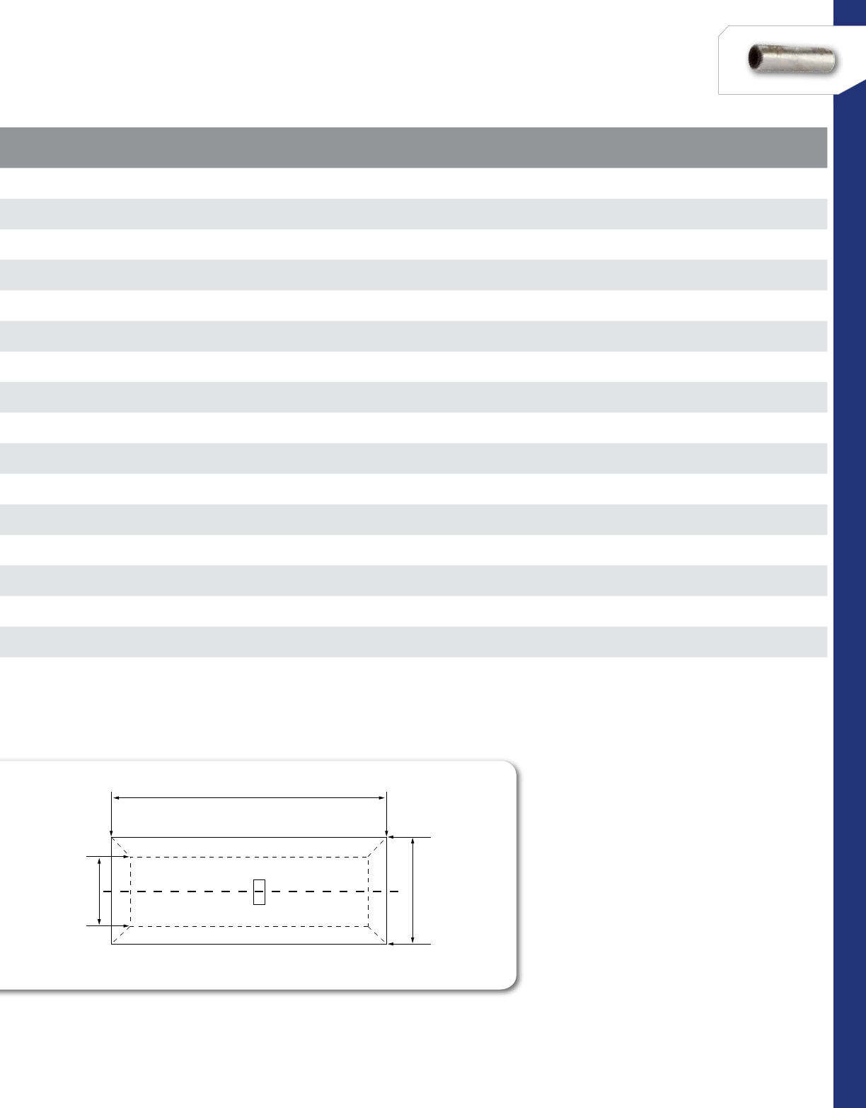
54
CONNECTORS
NSi Industries LLC • USA • 800.321.5847 • www.nsiindustries.com
L
O.D
I.D
CAT.
NO. WIRE
RANGE EXPANDED WIRE
RANGE* COLOR
CODE O.D. I.D. LENGTH
(L)
STD.
CTN.
QTY.
ASC8T 8 AWG 8 AWG Blue 0.297 0.146 1.750 100
ASC6T 6 AWG 6-8 AWG Gray 0.339 0.197 1.630 24
ASC4T 4 AWG 4-6 AWG Green 0.437 0.248 2.000 24
ASC2T 2 AWG 2-6 AWG Pink 0.528 0.307 2.378 24
ASC1T 1 AWG 1-6 AWG Gold 0.528 0.347 2.378 24
ASC1/0T 1/0 AWG 1/0-6 AWG Tan 0.630 0.390 2.500 24
ASC2/0T 2/0 AWG 2/0-4 AWG Olive 0.689 0.440 2.630 12
ASC3/0T 3/0 AWG 3/0-2 AWG Ruby 0.760 0.480 2.878 12
ASC4/0T 4/0 AWG 4/0-1 AWG White 0.839 0.550 3.130 12
ASC250T 250 MCM 250 MCM-1/0 AWG Red 0.920 0.590 3.248 12
ASC300T 300 MCM 300 MCM-2/0 AWG Blue 1.010 0.650 3.248 6
ASC350T 350 MCM 350MCM-3/0 AWG Brown 1.120 0.720 3.878 6
ASC400T 400 MCM 400MCM-4/0 AWG Green 1.190 0.760 4.878 6
ASC500T 500 MCM 500-250 MCM Pink 1.320 0.840 5.000 6
ASC600T 600 MCM 600-250 MCM Black 1.440 0.920 5.130 6
ASC750T 750 MCM 750-500 MCM Yellow 1.600 1.030 5.378 3
ASC1000T 1000 MCM – Brown 1.844 1.153 5.250 3
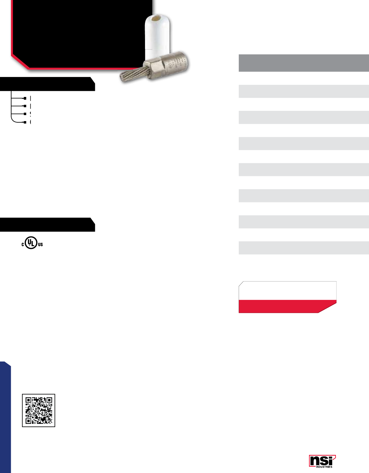
55
CONNECTORS
RATINGS
FEATURES
COMPRESSION CONNECTORS
Bi-Metallic
Pin Terminals
PT SERIES
Designed to facilitate termination of aluminum conductors.
Pin: Starnded copper, tin plated.
Supplied with PVC insulating cover.
Connector bores are coated with oxide inhibitor.
UL 486B Listed.
TEMPERATURE RATING:
90 °C.
RATING:
600V.
CRIMP TOOL:
N1240.
CAT.
NO. WIRE
RANGE COLOR
CODE PIN
SIZE O.D. I.D. PIN
DIA. (A)
LENGTH
(L)
PIN
LENGTH (L1)
BODY
LENGTH (L2)
STD.
CTN.
QTY.
PT6 6 AWG # 8 0.639 0.186 0.144 2.125 0.875 1.250 25
PT4 4 AWG Tan # 6 0.630 0.236 0.188 2.450 0.913 1.540 25
PT2 2 AWG Tan # 4 0.641 0.311 0.228 2.440 0.913 1.527 25
PT1 1 AWG Tan # 3 0.630 0.350 0.279 2.539 1.003 1.530 10
PT1/0 1/0 AWG Tan # 2 0.900 0.366 0.287 3.405 1.259 2.140 10
PT2/0 2/0 AWG White # 1 0.900 0.429 0.322 3.342 1.251 2.090 10
PT3/0 3/0 AWG White 1/0 0.900 0.484 0.362 3.598 1.456 2.140 10
PT4/0 4/0 AWG White 2/0 0.900 0.547 0.405 3.523 1.464 2.050 10
PT250 250 MCM Brown 3/0 1.160 0.653 0.440 3.858 1.551 2.300 10
PT300 300 MCM Brown 4/0 1.160 0.653 0.523 4.086 1.696 2.389 10
PT350 350 MCM Brown 4/0 1.157 0.700 0.496 4.082 1.704 2.377 10
PT400 400 MCM Pink 250 1.330 0.759 0.582 4.362 1.984 2.377 10
PT500 500 MCM Pink 350 1.330 0.759 0.681 4.192 1.842 2.350 10
PT600 600 MCM Yellow 350 1.503 0.921 0.688 4.960 1.897 3.051 3
PT750 750 MCM Yellow 500 1.500 1.015 0.787 5.007 2.003 3.015 3
All dimensional data is listed in inches.
Scan QR to view
Tool & Die Charts
Designed to facilitate termination of aluminum conductors.
Supplied with PVC insulating cover.
Connector bores are coated with oxide inhibitor.
Pin: Starnded copper, tin plated.
Pin: Starnded copper, tin plated.
Supplied with PVC insulating cover.
Connector bores are coated with oxide inhibitor.
Connector bores are coated with oxide inhibitor.
LISTED
WIRE CONNECTOR
*EXPANDED WIRE RANGE when installed with
NSI N12ID dieless compression tool.
UL Listed with other tools:
FOR TOOL & DIE CRIMPING INFORMATION,
PLEASE SEE TABLE ON PAGE 145

56
CONNECTORS
NSi Industries LLC • USA • 800.321.5847 • www.nsiindustries.com
CAT.
NO. WIRE
RANGE COLOR
CODE PIN
SIZE O.D. I.D. PIN
DIA. (A)
LENGTH
(L)
PIN
LENGTH (L1)
BODY
LENGTH (L2)
STD.
CTN.
QTY.
PT6 6 AWG # 8 0.639 0.186 0.144 2.125 0.875 1.250 25
PT4 4 AWG Tan # 6 0.630 0.236 0.188 2.450 0.913 1.540 25
PT2 2 AWG Tan # 4 0.641 0.311 0.228 2.440 0.913 1.527 25
PT1 1 AWG Tan # 3 0.630 0.350 0.279 2.539 1.003 1.530 10
PT1/0 1/0 AWG Tan # 2 0.900 0.366 0.287 3.405 1.259 2.140 10
PT2/0 2/0 AWG White # 1 0.900 0.429 0.322 3.342 1.251 2.090 10
PT3/0 3/0 AWG White 1/0 0.900 0.484 0.362 3.598 1.456 2.140 10
PT4/0 4/0 AWG White 2/0 0.900 0.547 0.405 3.523 1.464 2.050 10
PT250 250 MCM Brown 3/0 1.160 0.653 0.440 3.858 1.551 2.300 10
PT300 300 MCM Brown 4/0 1.160 0.653 0.523 4.086 1.696 2.389 10
PT350 350 MCM Brown 4/0 1.157 0.700 0.496 4.082 1.704 2.377 10
PT400 400 MCM Pink 250 1.330 0.759 0.582 4.362 1.984 2.377 10
PT500 500 MCM Pink 350 1.330 0.759 0.681 4.192 1.842 2.350 10
PT600 600 MCM Yellow 350 1.503 0.921 0.688 4.960 1.897 3.051 3
PT750 750 MCM Yellow 500 1.500 1.015 0.787 5.007 2.003 3.015 3
2.377
Ø1.157
0.787
Ø0.496
1.704
4.082
CD18A-2CR
AL9CU
350 MCM
BROWN DIE
PT-350
NSI
L
R
U
1.354
Ø0.700
IDOD
L1
L
A
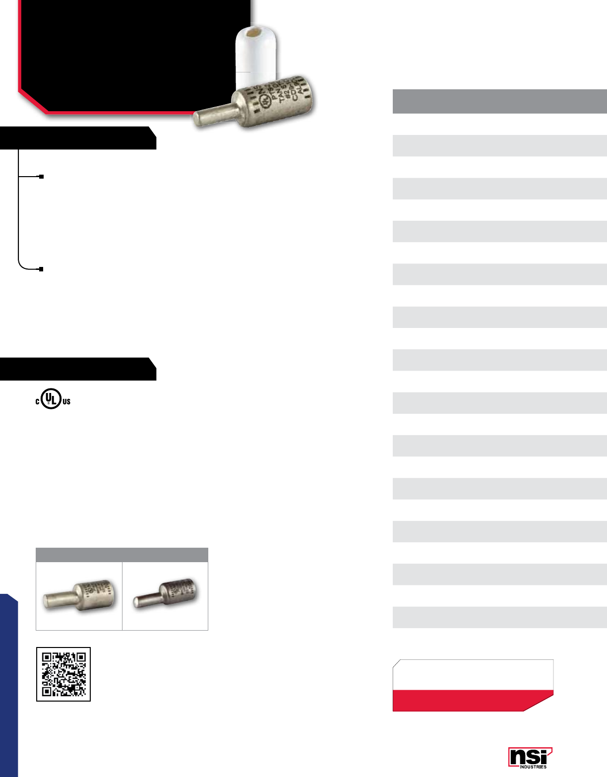
57
CONNECTORS
RATINGS
FEATURES
COMPRESSION CONNECTORS
Dual Rated
Pin Terminals
PTS, PTO SERIES
UL486A/B Listed.
TEMPERATURE RATING:
90 °C.
RATING:
600V.
CRIMP TOOL:
N1240.
CAT.
NO. WIRE
RANGE FIG NO. COLOR
CODE PIN
SIZE O.D. I.D. PIN
DIA. (A) LENGTH
(L) PIN
LENGTH (L1) BODY LENGTH
(L2) STD. CTN.
QTY.
PTS6 6 STR 1Tan 4 0.598 0.220 0.240 1.850 0.681 1.169 25
PTS4 4 STR 1Tan 4 0.598 0.236 0.240 1.850 0.681 1.169 25
PTS2 2 STR 1 Tan 4 0.598 0.299 0.240 1.840 0.680 1.160 25
PTS1 1 STR 1 Tan 3 0.598 0.318 0.250 1.990 0.830 1.160 10
PTS1/0 1/0 STR 1 Tan 2 0.598 0.370 0.290 1.990 0.830 1.160 10
PTS2/0 2/0 STR 1 White 1 0.850 0.429 0.330 2.200 0.830 1.370 10
PTS3/0 3/0 STR 1 White 1/0 0.850 0.476 0.370 2.590 1.220 1.370 10
PTS4/0 4/0 STR 1 White 2/0 0.850 0.535 0.420 2.590 1.220 1.370 10
PTS250 250 MCM 1 Brown 3/0 1.090 0.594 0.460 2.620 1.220 1.400 10
PTS300 300 MCM 1 Brown 4/0 1.090 0.653 0.530 2.730 1.330 1.400 10
PTS350 350 MCM 1 Brown 250 1.090 0.716 0.570 2.730 1.330 1.400 10
PTS400 400 MCM 1 Pink 300 1.310 0.763 0.620 3.070 1.590 1.480 10
PTS500 500 MCM 1 Pink 350 1.310 0.826 0.680 3.070 1.590 1.480 10
PTS600 600 MCM 1 Yellow 400 1.460 0.921 0.720 3.670 1.640 2.030 3
PTS750 750 MCM 1 Yellow 500 1.460 1.027 0.810 3.780 1.750 2.030 3
PTO-2/0 2/0 AWG 2White 1 0.850 0.440 0.330 2.690 1.120 1.570 10
PTO-3/0 3/0 AWG 2White 1/0 0.850 0.500 0.370 2.800 1.250 1.550 10
PTO-4/0 4/0 AWG 2 White 2/0 0.850 0.547 0.420 2.780 1.270 1.510 10
PTO-250 250 MCM 2 Brown 3/0 1.090 0.594 0.460 2.780 1.270 1.510 10
PTO-300 300 MCM 2 Brown 4/0 1.090 0.657 0.530 3.080 1.460 1.620 10
PTO-350 350 MCM 2 Brown 250 1.090 0.704 0.570 3.080 1.460 1.620 10
PTO-400 400 MCM 2 Pink 300 1.310 0.763 0.620 3.380 1.680 1.700 10
PTO-500 500 MCM 2 Pink 350 1.310 0.842 0.680 3.380 1.680 1.700 10
PTO-600 600 MCM 2 Yellow 400 1.460 0.821 0.720 3.990 1.720 2.270 3
PTO-750 750 MCM 2 Yellow 500 1.460 1.031 0.810 4.180 1.720 2.460 3
1 2
SOLID PIN TERMINALS - PTS SERIES
All-aluminum pin terminal designed for termination of both
aluminum and copper conductors. The pin is solid aluminum.
The connector is tin plated to provide low contact resistance
and oxidation protection.Connector is pre-filled with Oxide
Inhibitor and capped with color coded cap indicating color of
die to use. A cover is provided for quick installation.
SOLID PIN TERMINALS - PTO SERIES
All-aluminum pin terminal designed for termination of both
aluminum and copper conductors. In addition to above the
PTO Series provides an offset termination pin. Pin is offset for
use in tight applications while providing ease of installation in
side by side applications. The solid pin is made of aluminum
and is tin-plated and pre- filled with oxide inhibitor. Great for
paralleling cable. A cover is provided for quick insulation.
All dimensional data is listed in inches.
Scan QR to view
Tool & Die Charts
LISTED
WIRE CONNECTOR
ADAPTER
*EXPANDED WIRE RANGE when installed with
NSI N12ID dieless compression tool.
UL Listed with other tools:
FOR TOOL & DIE CRIMPING INFORMATION,
PLEASE SEE TABLE ON PAGE 145
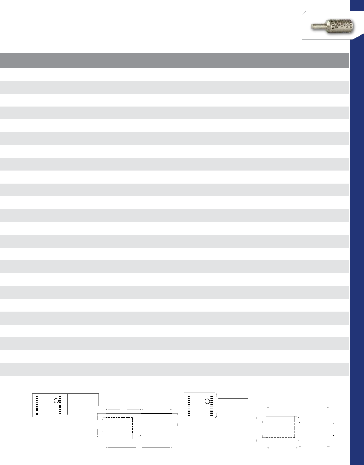
58
CONNECTORS
NSi Industries LLC • USA • 800.321.5847 • www.nsiindustries.com
CAT.
NO. WIRE
RANGE FIG NO. COLOR
CODE PIN
SIZE O.D. I.D. PIN
DIA. (A) LENGTH
(L) PIN
LENGTH (L1) BODY LENGTH
(L2) STD. CTN.
QTY.
PTS6 6 STR 1Tan 4 0.598 0.220 0.240 1.850 0.681 1.169 25
PTS4 4 STR 1Tan 4 0.598 0.236 0.240 1.850 0.681 1.169 25
PTS2 2 STR 1 Tan 4 0.598 0.299 0.240 1.840 0.680 1.160 25
PTS1 1 STR 1 Tan 3 0.598 0.318 0.250 1.990 0.830 1.160 10
PTS1/0 1/0 STR 1 Tan 2 0.598 0.370 0.290 1.990 0.830 1.160 10
PTS2/0 2/0 STR 1 White 1 0.850 0.429 0.330 2.200 0.830 1.370 10
PTS3/0 3/0 STR 1 White 1/0 0.850 0.476 0.370 2.590 1.220 1.370 10
PTS4/0 4/0 STR 1 White 2/0 0.850 0.535 0.420 2.590 1.220 1.370 10
PTS250 250 MCM 1 Brown 3/0 1.090 0.594 0.460 2.620 1.220 1.400 10
PTS300 300 MCM 1 Brown 4/0 1.090 0.653 0.530 2.730 1.330 1.400 10
PTS350 350 MCM 1 Brown 250 1.090 0.716 0.570 2.730 1.330 1.400 10
PTS400 400 MCM 1 Pink 300 1.310 0.763 0.620 3.070 1.590 1.480 10
PTS500 500 MCM 1 Pink 350 1.310 0.826 0.680 3.070 1.590 1.480 10
PTS600 600 MCM 1 Yellow 400 1.460 0.921 0.720 3.670 1.640 2.030 3
PTS750 750 MCM 1 Yellow 500 1.460 1.027 0.810 3.780 1.750 2.030 3
PTO-2/0 2/0 AWG 2White 1 0.850 0.440 0.330 2.690 1.120 1.570 10
PTO-3/0 3/0 AWG 2White 1/0 0.850 0.500 0.370 2.800 1.250 1.550 10
PTO-4/0 4/0 AWG 2 White 2/0 0.850 0.547 0.420 2.780 1.270 1.510 10
PTO-250 250 MCM 2 Brown 3/0 1.090 0.594 0.460 2.780 1.270 1.510 10
PTO-300 300 MCM 2 Brown 4/0 1.090 0.657 0.530 3.080 1.460 1.620 10
PTO-350 350 MCM 2 Brown 250 1.090 0.704 0.570 3.080 1.460 1.620 10
PTO-400 400 MCM 2 Pink 300 1.310 0.763 0.620 3.380 1.680 1.700 10
PTO-500 500 MCM 2 Pink 350 1.310 0.842 0.680 3.380 1.680 1.700 10
PTO-600 600 MCM 2 Yellow 400 1.460 0.821 0.720 3.990 1.720 2.270 3
PTO-750 750 MCM 2 Yellow 500 1.460 1.031 0.810 4.180 1.720 2.460 3
1.620 1.460
Ø1.090
3.090
Ø0.570
Ø0.704
PTO-350
350MCM
NSI
BROWN DIE
CD18A-2CR
AL9CU
L
R
U
1.232
1.620 1.460
Ø1.090
3.090
Ø0.570
Ø0.704
PTO-350
350MCM
NSI
BROWN DIE
CD18A-2CR
AL9CU
L
R
U
1.232
ID
L2
FIGURE 1
L
L1
A
1.330
1.400
Ø1.090
Ø0.570
2.740
PTS-350
350MCM
NSI
BROWN DIE
CD18A-2CR
AL9CU
L
R
U
Ø0.716
1.232
1.330
1.400
Ø1.090
Ø0.570
2.740
PTS-350
350MCM
NSI
BROWN DIE
CD18A-2CR
AL9CU
L
R
U
Ø0.716
1.232
IDOD
FIGURE 2
L2
L
L1
A
OD
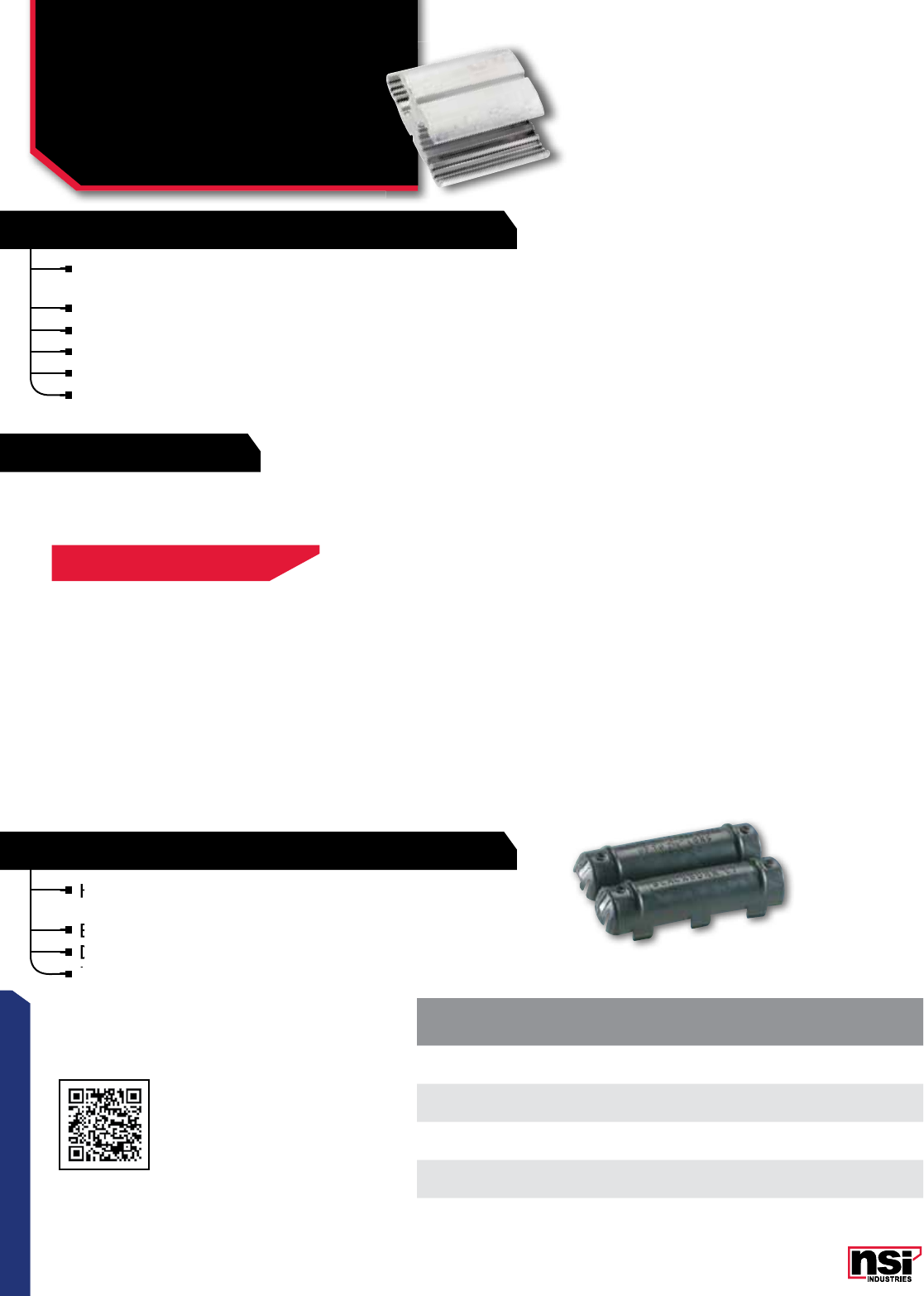
5959
CONNECTORS
RATINGS
59
CONNECTORS
COMPRESSION CONNECTORS
Dual Rated Wide Range
Tap Connectors
and Covers
WRD SERIES
CAT.
NO. CAPACITY
STD.
CTN.
QTY.
C2 All 5/8" OD. Sleeve 2" long or less 12
C5 All "O" die taps 1 3/4" long or less 12
C7 All "D" die taps 2 1/2" long or less 6
C9 All "N" die taps up to 2" long 4
DUAL RATED INSULATING COVERS
Hinged polyurethane cover for easy installation
of WRD series tap connectors.
Eliminates taping.
Drain ports prevent accumulation of moisture.
Ultraviolet stabilized.
Hinged polyurethane cover for easy installation
of WRD series tap connectors.
Hinged polyurethane cover for easy installation
of WRD series tap connectors.
Hinged polyurethane cover for easy installation
Eliminates taping.
Drain ports prevent accumulation of moisture.
Ultraviolet stabilized.
Ultraviolet stabilized.
Drain ports prevent accumulation of moisture.
RATING:
600V.
For combinations of aluminum and aluminum-copper
conductors.
Standard compression tools and dies install in all sizes.
Formable ribs provide broader contact area.
Fold-in tabs provide positive tab interlock as tool closes.
Made from high strength aluminum alloy.
All connectors reversible.
DUAL RATED WIDE RANGE TAP CONNECTORS
Scan QR to view
Tool & Die Charts
FOR TOOL & DIE CRIMPING INFORMATION,
PLEASE SEE TABLE ON PAGE 00
60
NSi Industries LLC • USA • 800.321.5847 • www.nsiindustries.com
CAT.
NO.
STANDARD CONDUCTOR RANGE COMPACT CONDUCTOR STD.
CTN.
QTY.
A GROOVE B GROOVE A GROOVE B GROOVE
ACSR STR SOL ACSR STR SOL ACSR STR ACSR STR
WRD159
-1--1-111125
222222222225
333333333325
444444444425
666666666625
WRD189
- - 3/0 - - 1/0 - - - - 25
- 2/0 2/0 - 1 1 2/0 2/0 1 1 25
1/0 1/0 1/0 2 2 1/0 1/0 2 2 - 25
111333113325
22-444224425
3- -666- -6625
WRD279
- - 4/0 - 3/0 3/0 - - - - 25
- 3/0 3/0 2/0 2/0 2/0 3/0 3/0 3/0 3/0 25
2/0 2/0 2/0 1/0 1/0 - 2/0 2/0 2/0 2/0 25
1/0 4/0 - 1 - - 1/0 1/0 1/0 1/0 25
1---------25
WRD289
- - - - - 1/0 - - - - 25
----11--1125
- - 4/0 2 2 2 3/0 3/0 2 2 25
- 3/0 3/0 3 3 3 2/0 - 3 3 25
2/0 2/0 - 4 4 4 - - 4 4 25
1/0 - - 6 6 6 - - 6 6 25
WRD379
- - - - - 1/0 - - - - 25
----11--1125
- - - 2 2 2 266-18/1 266 2 2 25
4/0 4/0 - 3 3 3 250 250 3 3 25
3/0 - - 4 4 4 4/0 4/0 4 4 25
- - -666- -6625
WRD399
- - - - - 3/0 266-18/1 266 - - 25
- - - 2/0 2/0 2/0 - 250 - 3/0 25
4/0 4/0 - 1/0 1/0 - 4/0 4/0 2/0 2/0 25
3/0 3/0 - 1 - - 3/0 - 1/0 1/0 25
WRD419
- - - - - - 266-18/1 266-18/1 266-18/1 266 25
4/0 4/0 - 4/0 4/0 - - 250 - 250 25
3/0 3/0 - 3/0 3/0 - 4/0 4/0 4/0 4/0 25
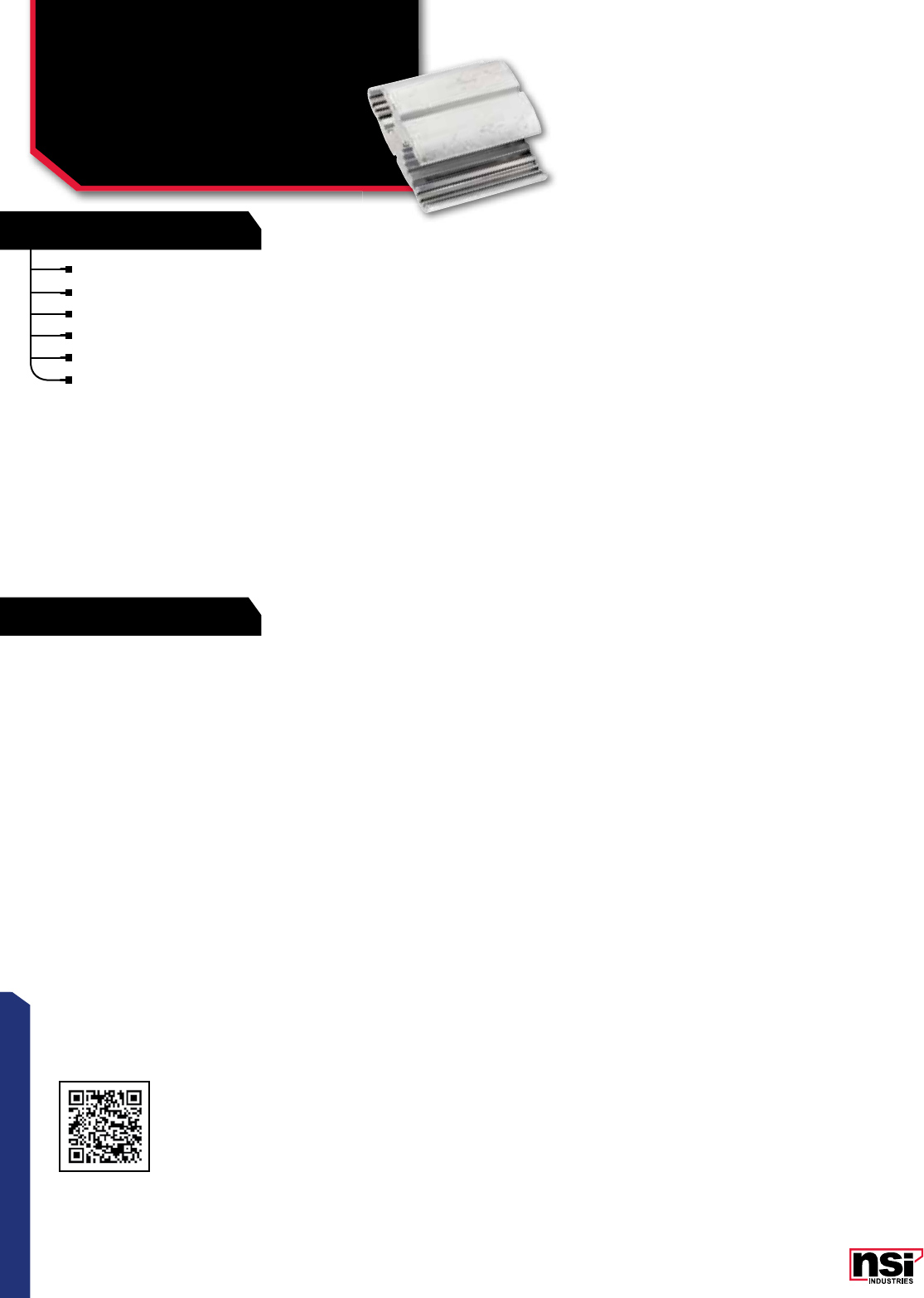
61
CONNECTORS
RATINGS
FEATURES
61
CONNECTORS
COMPRESSION CONNECTORS
Dual Rated Wide Range
Tap Connectors
WRD SERIES CONTINUED
RATING:
600V.
For combinations of aluminum and aluminum-copper conductors.
Standard compression tools and dies install in all sizes.
Formable ribs provide broader contact area.
Fold-in tabs provide positive tab interlock as tool closes.
Made from high strength aluminum alloy.
All connectors reversible.
Scan QR to view
Tool & Die Charts
62
CONNECTORS
NSi Industries LLC • USA • 800.321.5847 • www.nsiindustries.com
CAT.
NO.
STANDARD CONDUCTOR RANGE COMPACT CONDUCTOR STD.
CTN.
QTY.
A GROOVE B GROOVE A GROOVE B GROOVE
ACSR STR SOL ACSR STR SOL ACSR STR ACSR STR
WRD9
--1-88----50
322 - 10 10 - - - - 50
4 3 3 - 12 12 - - - - 50
6 4 4 - 14 14 - - - - 50
6----- ---50
WRD139
- 2/0 - - - - - - - - 25
1/0 1/0 - - - - - - - - 25
111--6----25
222-------25
3 3 - - 10 10 - - - - 25
4---------25
WRD149
--2--2-2-225
-33-33-33325
444444444425
666666666625
WRD179
1/0 1/0 - - - 2 - 2/0 - 2 25
1 1 1 - 3 3 1/0 1/0 - 3 25
22-444114425
3- -666226625
WRD199
1/0 1/0 - - 1 1 - 2/0 1 1 25
111 2 2 2 1/0 1/0 2 2 25
22-33-113-25
3- -44-224-25
WRD219
1/0 1/0 - 1/0 1/0 - - 2/0 - 2/0 25
1 1 - 1 1 - 1/0 1/0 1/0 1/0 25
---2----1-25
WRD259
- 2/0 - - 2/0 - 2/0 2/0 2/0 2/0 25
1/0 1/0 - 1/0 1/0 - 1/0 1/0 1/0 1/0 25
1--1------25
WRD299
- 3/0 - - - 2 3/0 3/0 - 2 25
2/0 2/0 - - 3 3 2/0 - - 3 25
1/0 - - 4 4 4 - - 4 4 25
- - -666- -6625
WRD359
- - - - 1/0 - - - - - 25
4/0 4/0 - 1 1 1 266 266 1/0 1/0 25
3/0 3/0 - 2 2 - - 250 1 1 25
- - - 3 3 - 4/0 4/0 2 2 25
- - - 4 - - 3/0 - - - 25
WRD369
4/0 4/0 - 1/0 1/0 1/0 266 266 1/0 1/0 25
3/0 3/0 - 1 1 1 - 250 1 1 25
2/0 - - 2 2 2 4/0 4/0 2 2 25
- - - 3 3 - 3/0 3/0 3 - 25
---44---4-25
WRD389
- - - - - - 266 266 - - 25
4/0 4/0 - - 3/0 - - 250 3/0 3/0 25
3/0 3/0 - 2/0 2/0 - 4/0 4/0 2/0 - 25
- - - 1/0 - - 3/0 - - - 25
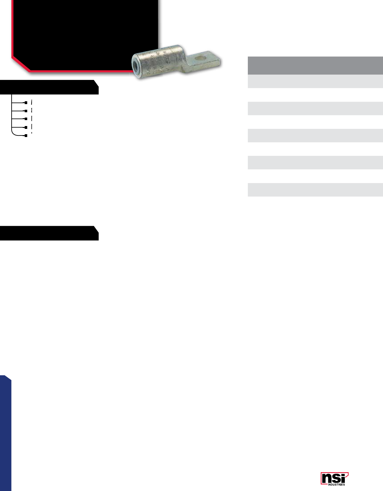
63
CONNECTORS
RATINGS
FEATURES
Made of dead-soft EC grade aluminum.
840 common dies – one die installs on all sizes.
For aluminum or copper conductors.
Pre-filled with oxide inhibitor.
Installing dies (color red): .840, 18, 324, TX, 76,
11A, 249.
Made of dead-soft EC grade aluminum.
840 common dies – one die installs on all sizes.
For aluminum or copper conductors.
Pre-filled with oxide inhibitor
840 common dies – one die installs on all sizes.
For aluminum or copper conductors.
840 common dies – one die installs on all sizes.
For aluminum or copper conductors.
Pre-filled with oxide inhibitor
Installing dies (color red): .840, 18, 324, TX, 76,
Installing dies (color red): .840, 18, 324, TX, 76,
Pre-filled with oxide inhibitor
CAT.
NO.
CONDUCTOR BOLT
SIZE LENGTH
(L) WIDTH
(W) TANG LENGTH
(A)
STD.
CTN.
QTY.
STRANDED SOLID COMPACT
CAL4 4 3 4 3/8 3.250 0.3125 1.3125 12
CAL2 2 1 2 3/8 3.250 0.3125 1.3125 12
CAL1-48 1 1/0 1 1/2 3.250 0.3125 1.3125 12
CAL10 1/0 2/0 1/0 3/8 3.250 0.3125 1.3125 12
CAL10-48 1/0 2/0 1/0 1/2 3.250 0.3125 1.3125 12
CAL20 2/0 3/0 2/0 3/8 3.250 0.3125 1.3125 12
CAL20-48 2/0 3/0 2/0 1/2 3.250 0.3125 1.3125 12
CAL30-48 3/0 4/0 3/0 1/2 3.250 0.3125 1.3125 12
CAL 40 4/0 - 4/0 3/8 3.250 0.3125 1.3125 12
CAL40-48 4/0 - 4/0 1/2 3.250 0.3125 1.3125 12
COMPRESSION CONNECTORS
Dual Rated
Meter Socket Lugs
CAL SERIES
600V
All dimensional data is listed in inches.
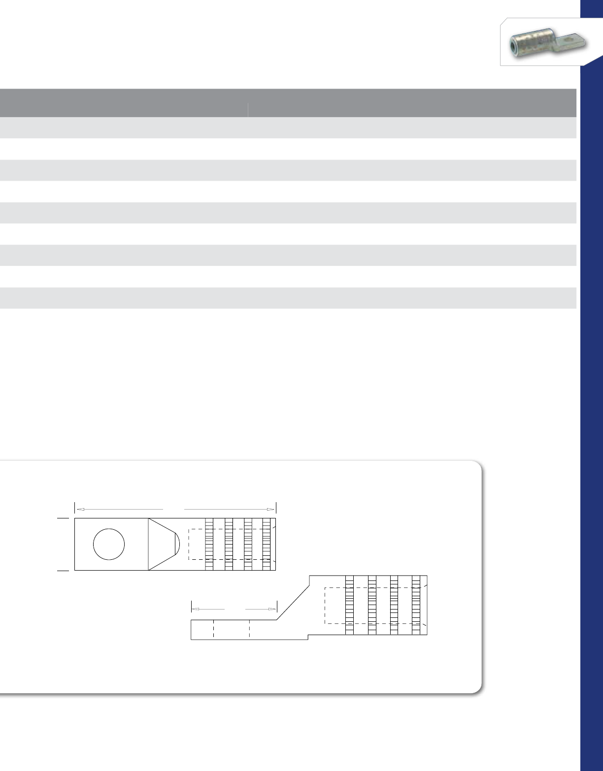
64
CONNECTORS
NSi Industries LLC • USA • 800.321.5847 • www.nsiindustries.com
CAT.
NO.
CONDUCTOR BOLT
SIZE LENGTH
(L) WIDTH
(W) TANG LENGTH
(A)
STD.
CTN.
QTY.
STRANDED SOLID COMPACT
CAL4 4 3 4 3/8 3.250 0.3125 1.3125 12
CAL2 2 1 2 3/8 3.250 0.3125 1.3125 12
CAL1-48 1 1/0 1 1/2 3.250 0.3125 1.3125 12
CAL10 1/0 2/0 1/0 3/8 3.250 0.3125 1.3125 12
CAL10-48 1/0 2/0 1/0 1/2 3.250 0.3125 1.3125 12
CAL20 2/0 3/0 2/0 3/8 3.250 0.3125 1.3125 12
CAL20-48 2/0 3/0 2/0 1/2 3.250 0.3125 1.3125 12
CAL30-48 3/0 4/0 3/0 1/2 3.250 0.3125 1.3125 12
CAL 40 4/0 - 4/0 3/8 3.250 0.3125 1.3125 12
CAL40-48 4/0 - 4/0 1/2 3.250 0.3125 1.3125 12
Max ampacity is based on NEC 310.15, insulation
type, and conductor material. Please consult your
current NEC manual.
1.187
1.187
3.250
.687
W
L
A

65
CONNECTORS
RATINGS
FEATURES
Pre-insulated service entrance compression
sleeves for fast and easy installation with
standard tools and dies.
For combinations of aluminum-aluminum and
aluminum-copper conductors.
Solid center barrier.
Pre-insulated service entrance compression
sleeves for fast and easy installation with
Pre-insulated service entrance compression
sleeves for fast and easy installation with
Pre-insulated service entrance compression
For combinations of aluminum-aluminum and
aluminum-copper conductors.
COMPRESSION CONNECTORS
Dual Rated Insulated
Service Entrance Sleeves
ISE SERIES
Meets or exceeds ANSI C119.4.
RATING:
600V
CAT.
NO. DIE
SIZE
CONDUCTOR RANGE MAIN CONDUCTOR RANGE TAP LENGTH
(L)
STD.
CTN.
QTY.
TOOL ACSR AWG COLOR
CODE ACSR AWG COLOR
CODE
ISE61 5/8 OD581 -8 STR-6 SOL Green -8 STR-6 SOL Green 2.780 50
ISE62 5/8 OD581 66 STR-4 SOL Blue -10 STR-8 SOL Brown 2.780 50
ISE63 5/8 OD581 66 STR-4 SOL Blue -8 STR-6 SOL Green 2.780 50
ISE64 5/8 OD581 66 STR-4 SOL Blue 66 STR-4 SOL Blue 2.780 50
ISE65 5/8 OD581 43-4 STR-2 SOL Orange -10 STR-8 SOL Brown 2.780 50
ISE66 5/8 OD581 43-4 STR-2 SOL Orange -8 STR-6 SOL Green 2.780 50
ISE67 5/8 OD581 43-4 STR-2 SOL Orange 66 STR-4 SOL Blue 2.780 50
ISE68 5/8 OD581 43-4 STR-2 SOL Orange 43-4 STR-2 SOL Orange 2.780 50
ISE71 5/8 OD581 21-2 STR Red 66 STR-4 SOL Blue 2.780 50
ISE72 5/8 OD581 21-2 STR Red 43-4 STR-2 SOL Orange 2.780 50
ISE73 5/8 OD581 21-2 STR Red 21-2 STR Red 2.780 50
ISE76 5/8 OD581 1/0 1/0 Yellow 43-4 STR-2 SOL Orange 2.780 50
ISE77 5/8 OD581 1/0 1/0 Yellow 21-2 STR Red 2.780 50
ISE78 5/8 OD581 1/0 1/0 Yellow -1/0 STR Yellow 2.780 50
ISE135 0.840 OD581+BY377C 1/0 1/0, 2/0 STR* Yellow 21-2 STR Red 5.500 12
ISE136 0.840 OD581+BY377C 1/0 1/0, 2/0 STR* Yellow 1/0 1/0 STR, 2/0 COM Yellow 5.500 12
ISE144 0.840 OD581+BY377C 2/0 2/0, 3/0 STR* Gray 43-4 STR-2 SOL Orange 5.500 12
ISE145 0.840 OD581+BY377C 2/0 2/0, 3/0 STR* Gray 21-2 STR Red 5.500 12
ISE146 0.840 OD581+BY377C 2/0 2/0, 3/0 STR* Gray 1/0 1/0 STR, 2/0 COM Yellow 5.500 12
ISE147 0.840 OD581+BY377C 2/0 2/0, 3/0 STR* Gray 2/0 2/0 STR, 3/0 COM Gray 5.500 12
ISE154 0.840 OD581+BY377C 3/0 3/0, 4/0 STR* Black 43-4 STR, 2 SOL Orange 5.500 12
ISE155 0.840 OD581+BY377C 3/0 3/0, 4/0 STR* Black 21-2 STR Red 5.500 12
ISE156 0.840 OD581+BY377C 3/0 3/0, 4/0 STR* Black 1/0 1/0 STR, 2/0 COM Yellow 5.500 12
ISE158 0.840 OD581+BY377C 3/0 3/0, 4/0 STR* Black 3/0 3/0 STR, 4/0 COM Black 5.500 12
ISE164 0.840 OD581+BY377C 4/0 4/0 STR Pink 43-4 STR-2 SOL Orange 5.500 12
ISE165 0.840 OD581+BY377C 4/0 4/0 STR Pink 21-2 STR Red 5.500 12
ISE167 0.840 OD581+BY377C 4/0 4/0 STR Pink 2/0 2/0 STR, 3/0 COM Gray 5.500 12
ISE168 0.840 OD581+BY377C 4/0 4/0 STR Pink 3/0 3/0 STR, 4/0 COM Black 5.500 12
ISE169 0.840 OD581+BY377C 4/0 4/0 STR Pink 4/0 4/0 STR Pink 5.500 12
*compact
All dimensional data is listed in inches.
L
MAIN
STRIP
LENGTH
ISE SERIES
TAP

66
CONNECTORS
NSi Industries LLC • USA • 800.321.5847 • www.nsiindustries.com
CAT.
NO. DIE
SIZE
CONDUCTOR RANGE MAIN CONDUCTOR RANGE TAP LENGTH
(L)
STD.
CTN.
QTY.
TOOL ACSR AWG COLOR
CODE ACSR AWG COLOR
CODE
ISE61 5/8 OD581 -8 STR-6 SOL Green -8 STR-6 SOL Green 2.780 50
ISE62 5/8 OD581 66 STR-4 SOL Blue -10 STR-8 SOL Brown 2.780 50
ISE63 5/8 OD581 66 STR-4 SOL Blue -8 STR-6 SOL Green 2.780 50
ISE64 5/8 OD581 66 STR-4 SOL Blue 66 STR-4 SOL Blue 2.780 50
ISE65 5/8 OD581 43-4 STR-2 SOL Orange -10 STR-8 SOL Brown 2.780 50
ISE66 5/8 OD581 43-4 STR-2 SOL Orange -8 STR-6 SOL Green 2.780 50
ISE67 5/8 OD581 43-4 STR-2 SOL Orange 66 STR-4 SOL Blue 2.780 50
ISE68 5/8 OD581 43-4 STR-2 SOL Orange 43-4 STR-2 SOL Orange 2.780 50
ISE71 5/8 OD581 21-2 STR Red 66 STR-4 SOL Blue 2.780 50
ISE72 5/8 OD581 21-2 STR Red 43-4 STR-2 SOL Orange 2.780 50
ISE73 5/8 OD581 21-2 STR Red 21-2 STR Red 2.780 50
ISE76 5/8 OD581 1/0 1/0 Yellow 43-4 STR-2 SOL Orange 2.780 50
ISE77 5/8 OD581 1/0 1/0 Yellow 21-2 STR Red 2.780 50
ISE78 5/8 OD581 1/0 1/0 Yellow -1/0 STR Yellow 2.780 50
ISE135 0.840 OD581+BY377C 1/0 1/0, 2/0 STR* Yellow 21-2 STR Red 5.500 12
ISE136 0.840 OD581+BY377C 1/0 1/0, 2/0 STR* Yellow 1/0 1/0 STR, 2/0 COM Yellow 5.500 12
ISE144 0.840 OD581+BY377C 2/0 2/0, 3/0 STR* Gray 43-4 STR-2 SOL Orange 5.500 12
ISE145 0.840 OD581+BY377C 2/0 2/0, 3/0 STR* Gray 21-2 STR Red 5.500 12
ISE146 0.840 OD581+BY377C 2/0 2/0, 3/0 STR* Gray 1/0 1/0 STR, 2/0 COM Yellow 5.500 12
ISE147 0.840 OD581+BY377C 2/0 2/0, 3/0 STR* Gray 2/0 2/0 STR, 3/0 COM Gray 5.500 12
ISE154 0.840 OD581+BY377C 3/0 3/0, 4/0 STR* Black 43-4 STR, 2 SOL Orange 5.500 12
ISE155 0.840 OD581+BY377C 3/0 3/0, 4/0 STR* Black 21-2 STR Red 5.500 12
ISE156 0.840 OD581+BY377C 3/0 3/0, 4/0 STR* Black 1/0 1/0 STR, 2/0 COM Yellow 5.500 12
ISE158 0.840 OD581+BY377C 3/0 3/0, 4/0 STR* Black 3/0 3/0 STR, 4/0 COM Black 5.500 12
ISE164 0.840 OD581+BY377C 4/0 4/0 STR Pink 43-4 STR-2 SOL Orange 5.500 12
ISE165 0.840 OD581+BY377C 4/0 4/0 STR Pink 21-2 STR Red 5.500 12
ISE167 0.840 OD581+BY377C 4/0 4/0 STR Pink 2/0 2/0 STR, 3/0 COM Gray 5.500 12
ISE168 0.840 OD581+BY377C 4/0 4/0 STR Pink 3/0 3/0 STR, 4/0 COM Black 5.500 12
ISE169 0.840 OD581+BY377C 4/0 4/0 STR Pink 4/0 4/0 STR Pink 5.500 12
Max ampacity is based on NEC 310.15, insulation
type, and conductor material. Please consult your
current NEC manual.
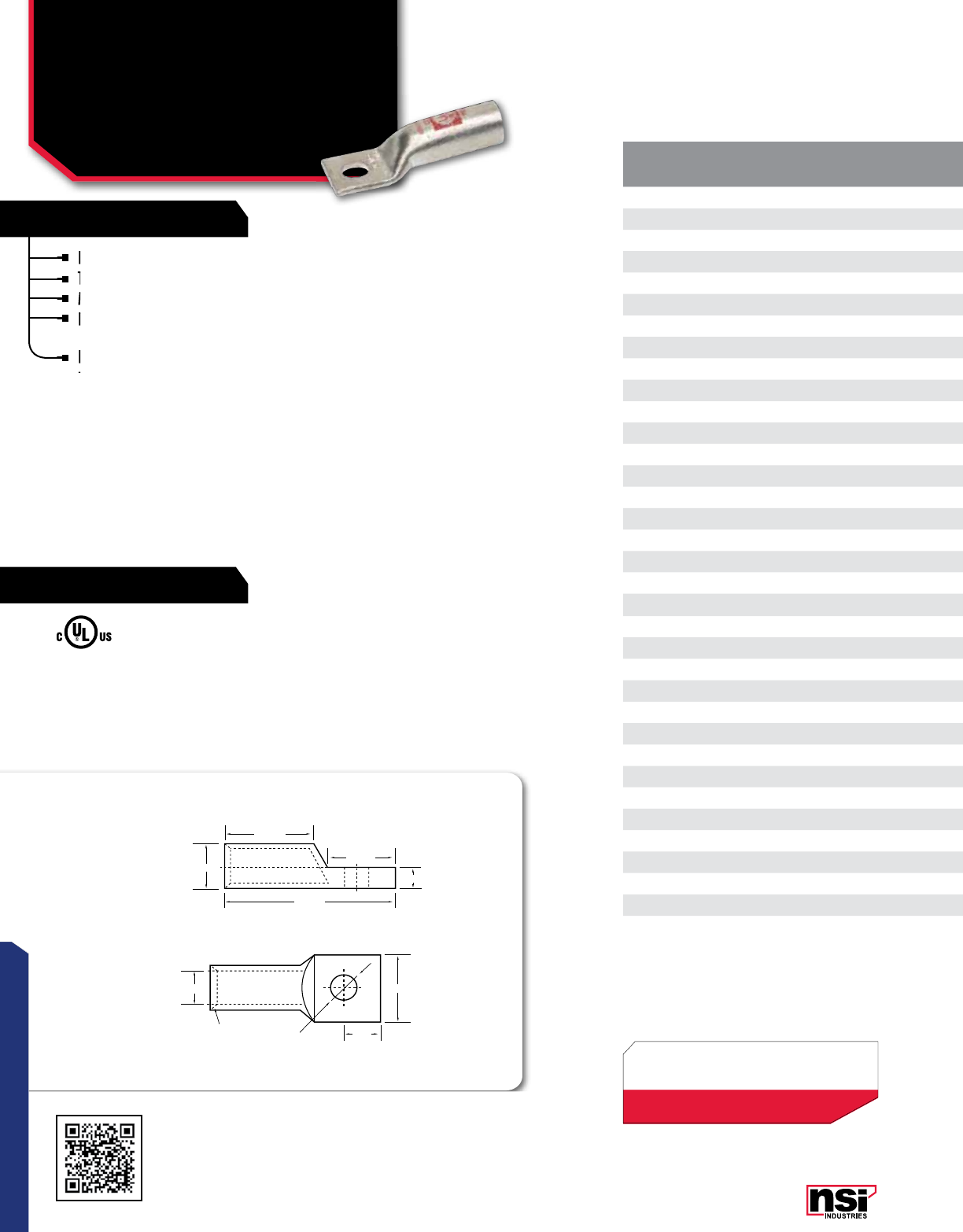
67
CONNECTORS
RATINGS
FEATURES
CAT.
NO. WIRE
RANGE EXPANDED WIRE
RANGE**BOLT
SIZE I.D. O.D. LENGTH
(L) WIDTH
(W) A B B1 C D COLOR STD.
CTN.
QTY.
L810 8 AWG 8 - 10 AWG #10 0.205 0.295 1.520 0.420 0.280 0.590 0.810 0.080 0.210 Red 100
L810P 8 AWG 8 - 10 AWG #10 0.205 0.295 1.520 0.420 0.280 0.590 0.810 0.080 0.210 Red 100
L814 8 AWG 8 - 10 AWG 1/4" 0.205 0.295 1.520 0.420 0.280 0.590 0.810 0.080 0.252 Red 100
L814P 8 AWG 8 - 10 AWG 1/4" 0.205 0.295 1.520 0.420 0.280 0.590 0.810 0.080 0.252 Red 100
L838 8 AWG 8 - 10 AWG 3/8" 0.205 0.295 1.520 0.420 0.280 0.590 0.810 0.080 0.413 Red 100
L838P 8 AWG 8 - 10 AWG 3/8" 0.205 0.295 1.520 0.420 0.280 0.590 0.810 0.080 0.413 Red 100
L610 6 AWG 6 - 8 AWG #10 0.205 0.295 1.770 0.420 0.300 0.640 0.980 0.083 0.210 Blue 100
L614 6 AWG 6 - 8 AWG 1/4" 0.205 0.295 1.772 0.421 0.295 0.669 0.984 0.083 0.252 Blue 100
L614P 6 AWG 6 - 8 AWG 1/4" 0.205 0.295 1.772 0.421 0.295 0.669 0.984 0.083 0.252 Blue 100
L638 6 AWG 6 - 8 AWG 3/8" 0.205 0.295 1.913 0.591 0.370 0.811 0.984 0.083 0.413 Blue 100
L638P 6 AWG 6 - 8 AWG 3/8" 0.205 0.295 1.913 0.591 0.370 0.811 0.984 0.083 0.413 Blue 100
L656 6 AWG 6 - 8 AWG 5/16" 0.205 0.295 1.910 0.590 0.370 0.810 0.980 0.083 0.330 Blue 100
L656P 6 AWG 6 - 8 AWG 5/16" 0.205 0.295 1.910 0.590 0.370 0.810 0.980 0.083 0.330 Blue 100
L410 4 AWG 4 - 6 AWG #10 0.252 0.343 1.770 0.488 0.315 0.669 0.980 0.087 0.210 Gray 100
L414 4 AWG 4 - 6 AWG 1/4" 0.252 0.343 1.772 0.488 0.315 0.669 0.984 0.087 0.252 Gray 100
L414P 4 AWG 4 - 6 AWG 1/4" 0.252 0.343 1.772 0.488 0.315 0.669 0.984 0.087 0.252 Gray 100
L438 4 AWG 4 - 6 AWG 3/8" 0.252 0.343 1.913 0.591 0.370 0.811 0.984 0.087 0.413 Gray 100
L438P 4 AWG 4 - 6 AWG 3/8" 0.252 0.343 1.913 0.591 0.370 0.811 0.984 0.087 0.413 Gray 100
L456 4 AWG 4 - 6 AWG 5/16" 0.252 0.343 1.772 0.488 0.315 0.669 0.984 0.087 0.331 Gray 100
L456P 4 AWG 4 - 6 AWG 5/16" 0.252 0.343 1.772 0.488 0.315 0.669 0.984 0.087 0.331 Gray 100
L314 3 AWG 3 - 6 AWG 1/4" 0.270 0.377 2.344 0.531 0.323 0.828 1.169 0.097 0.277 White 100
L356 3 AWG 3 - 6 AWG 5/16" 0.270 0.377 2.157 0.538 0.346 0.767 1.120 0.091 0.336 White 50
L338 3 AWG 3 - 6 AWG 3/8" 0.270 0.377 2.351 0.550 0.418 0.823 1.188 0.083 0.397 White 50
L214 2 AWG 2 - 6 AWG 1/4" 0.315 0.421 2.071 0.602 0.206 0.811 1.102 0.102 0.252 Brown 50
L214P 2 AWG 2 - 6 AWG 1/4" 0.315 0.421 2.071 0.602 0.206 0.811 1.102 0.102 0.252 Brown 50
L256 2 AWG 2 - 6 AWG 5/16" 0.315 0.421 2.071 0.602 0.370 0.811 1.102 0.102 0.331 Brown 50
L256P 2 AWG 2 - 6 AWG 5/16" 0.315 0.421 2.071 0.602 0.370 0.811 1.102 0.102 0.331 Brown 50
L238 2 AWG 2 - 6 AWG 3/8" 0.315 0.421 2.071 0.602 0.370 0.811 1.102 0.102 0.413 Brown 50
L238P 2 AWG 2 - 6 AWG 3/8" 0.315 0.421 2.071 0.602 0.370 0.811 1.102 0.102 0.413 Brown 50
L156 1 AWG 1 - 6 AWG 5/16" 0.358 0.469 2.110 0.673 0.370 0.811 1.102 0.106 0.331 Green 50
L138 1 AWG 1 - 6 AWG 3/8" 0.358 0.469 2.209 0.673 0.370 0.811 1.102 0.106 0.413 Green 50
L1014 1/0 AWG 1/0 - 6 AWG 1/4" 0.390 0.520 2.210 0.744 0.370 0.811 1.201 0.126 0.210 Pink 50
L1014P 1/0 AWG 1/0 - 6 AWG 1/4" 0.390 0.520 2.210 0.744 0.370 0.811 1.201 0.126 0.210 Pink 50
L1038 1/0 AWG 1/0 - 6 AWG 3/8" 0.390 0.520 2.209 0.744 0.370 0.811 1.201 0.126 0.413 Pink 50
Produced from high conductivity copper tubing.
Tin-plated to provide corrosion low contact resistance.
Marked with die index and color coded.
Listed for 35KV max when properly installed and to cable
manufacturer instructions.
For applications greater than 2000V, consult the cable
manufacturer for voltage stress relief instructions.
NOTE: Part Numbers ending in “P” have a “peep” or sight
inspection hole.
For applications greater than 2000V, consult the cable
manufacturer for voltage stress relief instructions.
For applications greater than 2000V, consult the cable
manufacturer for voltage stress relief instructions.
For applications greater than 2000V, consult the cable
Produced from high conductivity copper tubing.
Tin-plated to provide corrosion low contact resistance.
Listed for 35KV max when properly installed and to cable
manufacturer instructions.
Listed for 35KV max when properly installed and to cable
manufacturer instructions.
Listed for 35KV max when properly installed and to cable
Marked with die index and color coded.
Listed for 35KV max when properly installed and to cable
Tin-plated to provide corrosion low contact resistance.
Tin-plated to provide corrosion low contact resistance.
Marked with die index and color coded.
TEMPERATURE RATING:
90 °C.
* CLASS B OR C BUILDING WIRE CU CABLE
Max ampacity is based on NEC 310.15,
insulation type, and conductor material.
Please consult your current NEC manual.
All dimensional data is listed in inches.
COMPRESSION CONNECTORS
Long Barrel One Hole
Copper Lugs
L SERIES
Scan QR to view
Tool & Die Charts
LISTED
155027
*EXPANDED WIRE RANGE when installed with
NSI N12ID dieless compression tool.
UL Listed with other tools:
FOR TOOL & DIE CRIMPING INFORMATION,
PLEASE SEE TABLE ON PAGE 145
B1 ±1.00
COMPRESSION LUGS
ONE HOLE
B ±1.00
L ±1.00
O.D ±0.50
I.D.±0.20 W±1.00
A ±0.50
D±0.20
45°
Deep
Chamfer
C±0.50
D
68
CONNECTORS
NSi Industries LLC • USA • 800.321.5847 • www.nsiindustries.com
TOOL OPTIONS
CAT. NO. DESCRIPTION PAGE NO.
NSI-12 Hydraulic Die-Type Crimping Tool 00
RDC 1/0 Ratchet-Drive Crimpers 00
M-250 Manual Compression Tool 00
M-500 Manual Compression Tool 00
N1240 Compression Tool 00
N121D Dieless Hydraulic Crimping Tool 00
CAT.
NO. WIRE
RANGE EXPANDED WIRE
RANGE**BOLT
SIZE I.D. O.D. LENGTH
(L) WIDTH
(W) A B B1 C D COLOR STD.
CTN.
QTY.
L810 8 AWG 8 - 10 AWG #10 0.205 0.295 1.520 0.420 0.280 0.590 0.810 0.080 0.210 Red 100
L810P 8 AWG 8 - 10 AWG #10 0.205 0.295 1.520 0.420 0.280 0.590 0.810 0.080 0.210 Red 100
L814 8 AWG 8 - 10 AWG 1/4" 0.205 0.295 1.520 0.420 0.280 0.590 0.810 0.080 0.252 Red 100
L814P 8 AWG 8 - 10 AWG 1/4" 0.205 0.295 1.520 0.420 0.280 0.590 0.810 0.080 0.252 Red 100
L838 8 AWG 8 - 10 AWG 3/8" 0.205 0.295 1.520 0.420 0.280 0.590 0.810 0.080 0.413 Red 100
L838P 8 AWG 8 - 10 AWG 3/8" 0.205 0.295 1.520 0.420 0.280 0.590 0.810 0.080 0.413 Red 100
L610 6 AWG 6 - 8 AWG #10 0.205 0.295 1.770 0.420 0.300 0.640 0.980 0.083 0.210 Blue 100
L614 6 AWG 6 - 8 AWG 1/4" 0.205 0.295 1.772 0.421 0.295 0.669 0.984 0.083 0.252 Blue 100
L614P 6 AWG 6 - 8 AWG 1/4" 0.205 0.295 1.772 0.421 0.295 0.669 0.984 0.083 0.252 Blue 100
L638 6 AWG 6 - 8 AWG 3/8" 0.205 0.295 1.913 0.591 0.370 0.811 0.984 0.083 0.413 Blue 100
L638P 6 AWG 6 - 8 AWG 3/8" 0.205 0.295 1.913 0.591 0.370 0.811 0.984 0.083 0.413 Blue 100
L656 6 AWG 6 - 8 AWG 5/16" 0.205 0.295 1.910 0.590 0.370 0.810 0.980 0.083 0.330 Blue 100
L656P 6 AWG 6 - 8 AWG 5/16" 0.205 0.295 1.910 0.590 0.370 0.810 0.980 0.083 0.330 Blue 100
L410 4 AWG 4 - 6 AWG #10 0.252 0.343 1.770 0.488 0.315 0.669 0.980 0.087 0.210 Gray 100
L414 4 AWG 4 - 6 AWG 1/4" 0.252 0.343 1.772 0.488 0.315 0.669 0.984 0.087 0.252 Gray 100
L414P 4 AWG 4 - 6 AWG 1/4" 0.252 0.343 1.772 0.488 0.315 0.669 0.984 0.087 0.252 Gray 100
L438 4 AWG 4 - 6 AWG 3/8" 0.252 0.343 1.913 0.591 0.370 0.811 0.984 0.087 0.413 Gray 100
L438P 4 AWG 4 - 6 AWG 3/8" 0.252 0.343 1.913 0.591 0.370 0.811 0.984 0.087 0.413 Gray 100
L456 4 AWG 4 - 6 AWG 5/16" 0.252 0.343 1.772 0.488 0.315 0.669 0.984 0.087 0.331 Gray 100
L456P 4 AWG 4 - 6 AWG 5/16" 0.252 0.343 1.772 0.488 0.315 0.669 0.984 0.087 0.331 Gray 100
L314 3 AWG 3 - 6 AWG 1/4" 0.270 0.377 2.344 0.531 0.323 0.828 1.169 0.097 0.277 White 100
L356 3 AWG 3 - 6 AWG 5/16" 0.270 0.377 2.157 0.538 0.346 0.767 1.120 0.091 0.336 White 50
L338 3 AWG 3 - 6 AWG 3/8" 0.270 0.377 2.351 0.550 0.418 0.823 1.188 0.083 0.397 White 50
L214 2 AWG 2 - 6 AWG 1/4" 0.315 0.421 2.071 0.602 0.206 0.811 1.102 0.102 0.252 Brown 50
L214P 2 AWG 2 - 6 AWG 1/4" 0.315 0.421 2.071 0.602 0.206 0.811 1.102 0.102 0.252 Brown 50
L256 2 AWG 2 - 6 AWG 5/16" 0.315 0.421 2.071 0.602 0.370 0.811 1.102 0.102 0.331 Brown 50
L256P 2 AWG 2 - 6 AWG 5/16" 0.315 0.421 2.071 0.602 0.370 0.811 1.102 0.102 0.331 Brown 50
L238 2 AWG 2 - 6 AWG 3/8" 0.315 0.421 2.071 0.602 0.370 0.811 1.102 0.102 0.413 Brown 50
L238P 2 AWG 2 - 6 AWG 3/8" 0.315 0.421 2.071 0.602 0.370 0.811 1.102 0.102 0.413 Brown 50
L156 1 AWG 1 - 6 AWG 5/16" 0.358 0.469 2.110 0.673 0.370 0.811 1.102 0.106 0.331 Green 50
L138 1 AWG 1 - 6 AWG 3/8" 0.358 0.469 2.209 0.673 0.370 0.811 1.102 0.106 0.413 Green 50
L1014 1/0 AWG 1/0 - 6 AWG 1/4" 0.390 0.520 2.210 0.744 0.370 0.811 1.201 0.126 0.210 Pink 50
L1014P 1/0 AWG 1/0 - 6 AWG 1/4" 0.390 0.520 2.210 0.744 0.370 0.811 1.201 0.126 0.210 Pink 50
L1038 1/0 AWG 1/0 - 6 AWG 3/8" 0.390 0.520 2.209 0.744 0.370 0.811 1.201 0.126 0.413 Pink 50
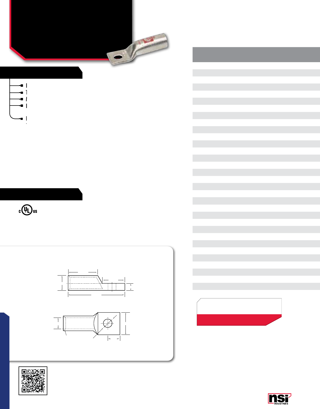
69
CONNECTORS
RATINGS
FEATURES
CAT.
NO. WIRE
RANGE EXPANDED WIRE
RANGE*BOLT
SIZE (IN). I.D. O.D. LENGTH
(L) WIDTH
(W) A B B1 C D COLOR STD.
CTN.
QTY.
L1038P 1/0 AWG 1/0 - 6 AWG 3/8" 0.390 0.520 2.209 0.744 0.370 0.811 1.201 0.126 0.413 Pink 50
L1056 1/0 AWG 1/0 - 6 AWG 5/16" 0.390 0.520 2.210 0.744 0.370 0.811 1.201 0.126 0.330 Pink 50
L1056P 1/0 AWG 1/0 - 6 AWG 5/16" 0.390 0.520 2.210 0.744 0.370 0.811 1.201 0.126 0.330 Pink 50
L1048 1/0 AWG 1/0 - 6 AWG 1/2" 0.390 0.520 2.500 0.744 0.472 1.063 1.201 0.126 0.512 Pink 50
L2014 2/0 AWG 2/0 - 4 AWG 1/4" 0.441 0.563 2.677 0.815 0.472 1.063 1.378 0.118 0.252 Black 25
L2014P 2/0 AWG 2/0 - 4 AWG 1/4" 0.441 0.563 2.677 0.815 0.472 1.063 1.378 0.118 0.252 Black 25
L2038 2/0 AWG 2/0 - 4 AWG 3/8" 0.441 0.563 2.677 0.815 0.472 1.063 1.378 0.118 0.413 Black 25
L2038P 2/0 AWG 2/0 - 4 AWG 3/8" 0.441 0.563 2.677 0.815 0.472 1.063 1.378 0.118 0.413 Black 25
L2048 2/0 AWG 2/0 - 4 AWG 1/2" 0.441 0.563 2.677 0.815 0.472 1.063 1.378 0.118 0.512 Black 25
L2048P 2/0 AWG 2/0 - 4 AWG 1/2" 0.441 0.563 2.677 0.815 0.472 1.063 1.378 0.118 0.512 Black 25
L3014 3/0 AWG 3/0 - 2 AWG 1/4" 0.492 0.622 2.795 0.902 0.472 1.063 1.378 0.126 0.252 Orange 25
L3014P 3/0 AWG 3/0 - 2 AWG 1/4" 0.492 0.622 2.795 0.902 0.472 1.063 1.378 0.126 0.252 Orange 25
L3038 3/0 AWG 3/0 - 2 AWG 3/8" 0.492 0.622 2.795 0.902 0.472 1.063 1.378 0.126 0.413 Orange 25
L3038P 3/0 AWG 3/0 - 2 AWG 3/8" 0.492 0.622 2.795 0.902 0.472 1.063 1.378 0.126 0.413 Orange 25
L3048 3/0 AWG 3/0 - 2 AWG 1/2" 0.492 0.622 2.795 0.902 0.472 1.063 1.378 0.126 0.512 Orange 25
L3048P 3/0 AWG 3/0 - 2 AWG 1/2" 0.492 0.622 2.795 0.902 0.472 1.063 1.378 0.126 0.512 Orange 25
L4014 4/0 AWG 4/0 - 1 AWG 1/4" 0.547 0.689 2.795 1.000 0.520 1.063 1.417 0.134 0.252 Purple 25
L4014P 4/0 AWG 4/0 - 1 AWG 1/4" 0.547 0.689 2.795 1.000 0.520 1.063 1.417 0.134 0.252 Purple 25
L4038 4/0 AWG 4/0 - 1 AWG 3/8" 0.547 0.689 2.795 1.000 0.520 1.063 1.417 0.134 0.413 Purple 25
L4038P 4/0 AWG 4/0 - 1 AWG 3/8" 0.547 0.689 2.795 1.000 0.520 1.063 1.417 0.134 0.413 Purple 25
L4048 4/0 AWG 4/0 - 1 AWG 1/2" 0.547 0.689 2.795 1.000 0.520 1.063 1.417 0.134 0.512 Purple 25
L4048P 4/0 AWG 4/0 - 1 AWG 1/2" 0.547 0.689 2.795 1.000 0.520 1.063 1.417 0.134 0.512 Purple 25
L25048 250 MCM 250 MCM - 1/0 AWG 1/2" 0.594 0.752 3.031 1.091 0.520 1.063 1.614 0.150 0.512 Yellow 25
L30048 300 MCM 300 MCM - 2/0 AWG 1/2" 0.657 0.815 3.386 1.189 0.520 1.063 1.969 0.150 0.512 White 12
L35048 350 MCM 350 MCM - 3/0 AWG 1/2" 0.701 0.874 3.465 1.276 0.520 1.063 1.969 0.165 0.512 Red 12
L40048 400 MCM 400 MCM - 4/0 AWG 1/2" 0.764 0.949 3.858 1.386 0.512 1.378 1.969 0.177 0.512 Blue 6
L50048 500 MCM 500 - 250 MCM 1/2" 0.835 1.063 4.134 1.539 0.512 1.378 2.244 0.217 0.512 Brown 6
L50058 500 MCM 500 - 250 MCM 5/8" 0.835 1.063 4.134 1.539 0.512 1.378 2.244 0.217 0.669 Brown 6
L60058 600 MCM 600 - 250 MCM 5/8" 0.925 1.189 4.252 1.717 0.689 1.457 2.244 0.252 0.669 Green 6
L75048 750 MCM 750 - 500 MCM 1/2" 1.031 1.311 5.157 1.902 0.689 1.850 2.638 0.268 0.512 Black 3
L75058 750 MCM 750 - 500 MCM 5/8" 1.031 1.311 5.157 1.902 0.689 1.850 2.638 0.268 0.669 Black 3
L10058 1000 MCM - 5/8" 1.184 1.494 5.613 2.148 0.866 1.776 2.603 0.328 0.663 White 3
Produced from high conductivity copper tubing.
Tin-plated to provide corrosion low contact resistance.
Marked with die index and color coded.
Listed for 35KV max when properly installed and to cable
manufacturer instructions
For applications greater than 2000V, consult the cable
manufacturer for voltage stress relief instructions.
NOTE: Part Numbers ending in “P” have a “peep” or sight
inspection hole.
For applications greater than 2000V, consult the cable
manufacturer for voltage stress relief instructions.
For applications greater than 2000V, consult the cable
manufacturer for voltage stress relief instructions.
For applications greater than 2000V, consult the cable
Produced from high conductivity copper tubing.
Tin-plated to provide corrosion low contact resistance.
Listed for 35KV max when properly installed and to cable
manufacturer instructions
Listed for 35KV max when properly installed and to cable
manufacturer instructions
Listed for 35KV max when properly installed and to cable
Marked with die index and color coded.
Listed for 35KV max when properly installed and to cable
Tin-plated to provide corrosion low contact resistance.
Tin-plated to provide corrosion low contact resistance.
Marked with die index and color coded.
TEMPERATURE RATING:
90 °C.
All dimensional data is listed in inches.
COMPRESSION CONNECTORS
Long Barrel One Hole
Copper Lugs
L SERIES CONTINUED
Scan QR to view
Tool & Die Charts
LISTED
155027
B1 ±1.00
COMPRESSION LUGS
ONE HOLE
B ±1.00
L ±1.00
O.D ±0.50
I.D.±0.20 W±1.00
A ±0.50
D±0.20
45°
Deep
Chamfer
C±0.50
D
*EXPANDED WIRE RANGE when installed with
NSI N12ID dieless compression tool.
UL Listed with other tools:
FOR TOOL & DIE CRIMPING INFORMATION,
PLEASE SEE TABLE ON PAGE 145

70
CONNECTORS
NSi Industries LLC • USA • 800.321.5847 • www.nsiindustries.com
CAT.
NO. WIRE
RANGE EXPANDED WIRE
RANGE*BOLT
SIZE (IN). I.D. O.D. LENGTH
(L) WIDTH
(W) A B B1 C D COLOR STD.
CTN.
QTY.
L1038P 1/0 AWG 1/0 - 6 AWG 3/8" 0.390 0.520 2.209 0.744 0.370 0.811 1.201 0.126 0.413 Pink 50
L1056 1/0 AWG 1/0 - 6 AWG 5/16" 0.390 0.520 2.210 0.744 0.370 0.811 1.201 0.126 0.330 Pink 50
L1056P 1/0 AWG 1/0 - 6 AWG 5/16" 0.390 0.520 2.210 0.744 0.370 0.811 1.201 0.126 0.330 Pink 50
L1048 1/0 AWG 1/0 - 6 AWG 1/2" 0.390 0.520 2.500 0.744 0.472 1.063 1.201 0.126 0.512 Pink 50
L2014 2/0 AWG 2/0 - 4 AWG 1/4" 0.441 0.563 2.677 0.815 0.472 1.063 1.378 0.118 0.252 Black 25
L2014P 2/0 AWG 2/0 - 4 AWG 1/4" 0.441 0.563 2.677 0.815 0.472 1.063 1.378 0.118 0.252 Black 25
L2038 2/0 AWG 2/0 - 4 AWG 3/8" 0.441 0.563 2.677 0.815 0.472 1.063 1.378 0.118 0.413 Black 25
L2038P 2/0 AWG 2/0 - 4 AWG 3/8" 0.441 0.563 2.677 0.815 0.472 1.063 1.378 0.118 0.413 Black 25
L2048 2/0 AWG 2/0 - 4 AWG 1/2" 0.441 0.563 2.677 0.815 0.472 1.063 1.378 0.118 0.512 Black 25
L2048P 2/0 AWG 2/0 - 4 AWG 1/2" 0.441 0.563 2.677 0.815 0.472 1.063 1.378 0.118 0.512 Black 25
L3014 3/0 AWG 3/0 - 2 AWG 1/4" 0.492 0.622 2.795 0.902 0.472 1.063 1.378 0.126 0.252 Orange 25
L3014P 3/0 AWG 3/0 - 2 AWG 1/4" 0.492 0.622 2.795 0.902 0.472 1.063 1.378 0.126 0.252 Orange 25
L3038 3/0 AWG 3/0 - 2 AWG 3/8" 0.492 0.622 2.795 0.902 0.472 1.063 1.378 0.126 0.413 Orange 25
L3038P 3/0 AWG 3/0 - 2 AWG 3/8" 0.492 0.622 2.795 0.902 0.472 1.063 1.378 0.126 0.413 Orange 25
L3048 3/0 AWG 3/0 - 2 AWG 1/2" 0.492 0.622 2.795 0.902 0.472 1.063 1.378 0.126 0.512 Orange 25
L3048P 3/0 AWG 3/0 - 2 AWG 1/2" 0.492 0.622 2.795 0.902 0.472 1.063 1.378 0.126 0.512 Orange 25
L4014 4/0 AWG 4/0 - 1 AWG 1/4" 0.547 0.689 2.795 1.000 0.520 1.063 1.417 0.134 0.252 Purple 25
L4014P 4/0 AWG 4/0 - 1 AWG 1/4" 0.547 0.689 2.795 1.000 0.520 1.063 1.417 0.134 0.252 Purple 25
L4038 4/0 AWG 4/0 - 1 AWG 3/8" 0.547 0.689 2.795 1.000 0.520 1.063 1.417 0.134 0.413 Purple 25
L4038P 4/0 AWG 4/0 - 1 AWG 3/8" 0.547 0.689 2.795 1.000 0.520 1.063 1.417 0.134 0.413 Purple 25
L4048 4/0 AWG 4/0 - 1 AWG 1/2" 0.547 0.689 2.795 1.000 0.520 1.063 1.417 0.134 0.512 Purple 25
L4048P 4/0 AWG 4/0 - 1 AWG 1/2" 0.547 0.689 2.795 1.000 0.520 1.063 1.417 0.134 0.512 Purple 25
L25048 250 MCM 250 MCM - 1/0 AWG 1/2" 0.594 0.752 3.031 1.091 0.520 1.063 1.614 0.150 0.512 Yellow 25
L30048 300 MCM 300 MCM - 2/0 AWG 1/2" 0.657 0.815 3.386 1.189 0.520 1.063 1.969 0.150 0.512 White 12
L35048 350 MCM 350 MCM - 3/0 AWG 1/2" 0.701 0.874 3.465 1.276 0.520 1.063 1.969 0.165 0.512 Red 12
L40048 400 MCM 400 MCM - 4/0 AWG 1/2" 0.764 0.949 3.858 1.386 0.512 1.378 1.969 0.177 0.512 Blue 6
L50048 500 MCM 500 - 250 MCM 1/2" 0.835 1.063 4.134 1.539 0.512 1.378 2.244 0.217 0.512 Brown 6
L50058 500 MCM 500 - 250 MCM 5/8" 0.835 1.063 4.134 1.539 0.512 1.378 2.244 0.217 0.669 Brown 6
L60058 600 MCM 600 - 250 MCM 5/8" 0.925 1.189 4.252 1.717 0.689 1.457 2.244 0.252 0.669 Green 6
L75048 750 MCM 750 - 500 MCM 1/2" 1.031 1.311 5.157 1.902 0.689 1.850 2.638 0.268 0.512 Black 3
L75058 750 MCM 750 - 500 MCM 5/8" 1.031 1.311 5.157 1.902 0.689 1.850 2.638 0.268 0.669 Black 3
L10058 1000 MCM - 5/8" 1.184 1.494 5.613 2.148 0.866 1.776 2.603 0.328 0.663 White 3
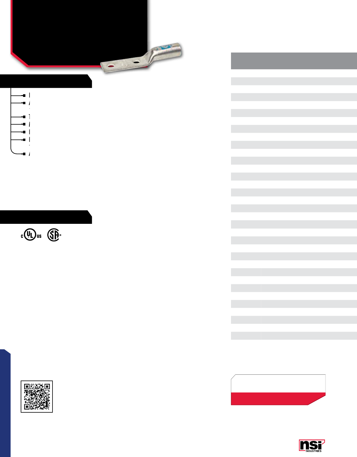
71
CONNECTORS
RATINGS
FEATURES
CAT.
NO. WIRE
RANGE EXPANDED WIRE
RANGE*COLOR BOLT
SIZE I.D. O.D. LENGTH
(L) WIDTH
(W) (IN.)
END OF CONN
TO CTR.
(A)
TANG
LENGTH
(B)
BARREL
LENGTH
(B1)
TANG
THICkNESS
(C)
MTG.
HOLE DIA.
(D)
MTG. HOLE
SPACING
(E)
MAX
AMP
RATING
STD.
CTN.
QTY.
L8N-14 8 AWG 8 - 10 AWG Red 1/4" 0.205 0.295 2.240 0.420 0.280 1.140 0.980 0.080 0.261 1.000 100
L8N-14P 8 AWG 8 - 10 AWG Red 1/4" 0.205 0.295 2.240 0.420 0.280 1.140 0.980 0.080 0.261 1.000 100
L8N-141 8 AWG 8 - 10 AWG Red 1/4" 0.205 0.295 2.240 0.420 0.280 1.140 0.980 0.080 0.261 0.625 100
L8N-141P 8 AWG 8 - 10 AWG Red 1/4" 0.205 0.295 2.240 0.420 0.280 1.140 0.980 0.080 0.261 0.625 100
L8N-142 8 AWG 8 - 10 AWG Red 1/4" 0.205 0.295 2.240 0.420 0.280 1.140 0.980 0.080 0.261 0.750 100
L8N-142P 8 AWG 8 - 10 AWG Red 1/4" 0.205 0.295 2.240 0.420 0.280 1.140 0.980 0.080 0.261 0.750 100
L8N-38 8 AWG 8 - 10 AWG Red 3/8" 0.205 0.295 2.240 0.420 0.280 1.140 0.980 0.080 0.410 1.000 100
L8N-38P 8 AWG 8 - 10 AWG Red 3/8" 0.205 0.295 2.240 0.420 0.280 1.140 0.980 0.080 0.410 1.000 100
L8N-383 8 AWG 8 - 10 AWG Red 3/8" 0.205 0.295 2.240 0.420 0.280 1.140 0.980 0.080 0.410 1.750 100
L8N-383P 8 AWG 8 - 10 AWG Red 3/8" 0.205 0.295 2.240 0.420 0.280 1.140 0.980 0.080 0.410 1.750 100
L8N-563 8 AWG 8 - 10 AWG Blue 5/16" 0.205 0.295 2.240 0.420 0.280 1.140 0.980 0.080 0.312 1.750 100
L8N-563P 8 AWG 8 - 10 AWG Blue 5/16" 0.205 0.295 2.240 0.420 0.280 1.140 0.980 0.080 0.312 1.750 100
L6N-12 6 AWG 6 - 8 AWG Blue 1/4” 0.200 0.300 2.240 0.420 0.280 1.140 0.980 0.080 0.261 0.500 100
L6N-14 6 AWG 6 - 8 AWG Blue 1/4” 0.200 0.300 2.360 0.420 0.280 1.260 0.980 0.080 0.261 0.625 100
L6N-14P 6 AWG 6 - 8 AWG Blue 1/4” 0.200 0.300 2.360 0.420 0.280 1.260 0.980 0.080 0.261 0.625 100
L6N-141 6 AWG 6 - 8 AWG Blue 1/4” 0.200 0.300 2.480 0.420 1.260 1.380 0.980 0.080 0.261 0.625 100
L6N-141P 6 AWG 6 - 8 AWG Blue 1/4” 0.200 0.300 2.480 0.420 1.260 1.380 0.980 0.080 0.261 0.625 100
L6N-142 6 AWG 6 - 8 AWG Blue 1/4” 0.200 0.300 2.480 0.420 0.280 1.380 0.980 0.080 0.261 0.750 100
L6N-142P 6 AWG 6 - 8 AWG Blue 1/4” 0.200 0.300 2.480 0.420 0.280 1.380 0.980 0.080 0.261 0.750 100
L6N-38 6 AWG 6 - 8 AWG Blue 3/8” 0.200 0.300 2.910 0.420 0.380 1.810 0.980 0.080 0.410 1.000 100
L6N-38P 6 AWG 6 - 8 AWG Blue 3/8” 0.200 0.300 2.910 0.420 0.380 1.810 0.980 0.080 0.410 1.000 100
L6N-382 6 AWG 6 - 8 AWG Blue 3/8" 0.200 0.300 4.090 0.870 0.620 2.990 0.980 0.120 0.410 0.750 100
L6N-382P 6 AWG 6 - 8 AWG Blue 3/8" 0.200 0.300 4.090 0.870 0.620 2.990 0.980 0.120 0.410 0.750 100
L6N 6 AWG 6 - 8 AWG Blue 1/2” 0.200 0.300 4.090 0.870 0.620 2.990 0.980 0.120 0.510 1.750 100
L6N-P 6 AWG 6 - 8 AWG Blue 1/2” 0.200 0.300 4.090 0.870 0.620 2.990 0.980 0.120 0.510 1.750 100
L4N-14 4 AWG 4 - 6 AWG Gray 1/4” 0.250 0.340 2.360 0.490 0.280 1.260 0.980 0.090 0.261 0.625 100
L4N-14P 4 AWG 4 - 6 AWG Gray 1/4” 0.250 0.340 2.360 0.490 0.280 1.260 0.980 0.090 0.261 0.625 100
L4N-141P 4 AWG 4 - 6 AWG Gray 1/4" 0.250 0.340 2.950 0.420 0.380 1.810 0.980 0.090 0.261 0.625 100
L4N-142P 4 AWG 4 - 6 AWG Gray 1/4" 0.250 0.340 2.950 0.420 0.380 1.810 0.980 0.090 0.261 0.625 100
L4N-38 4 AWG 4 - 6 AWG Gray 3/8” 0.250 0.340 2.950 0.420 0.380 1.810 0.980 0.090 0.410 1.000 100
L4N-38P 4 AWG 4 - 6 AWG Gray 3/8” 0.250 0.340 2.950 0.420 0.380 1.810 0.980 0.090 0.410 1.000 100
L4N-382 4 AWG 4 - 6 AWG Gray 3/8" 0.250 0.340 4.090 0.870 0.620 2.990 0.980 0.120 0.410 0.750 100
L4N-382P 4 AWG 4 - 6 AWG Gray 3/8" 0.250 0.340 4.090 0.870 0.620 2.990 0.980 0.120 0.410 0.750 100
L4N 4 AWG 4 - 6 AWG Gray 1/2” 0.250 0.340 4.090 0.870 0.620 2.990 0.980 0.120 0.510 1.750 100
Produced from high conductivity copper tubing.
Allows easy inspection of the termination to assure
complete cable insertion.
Tin-plated to provide corrosion and low contact resistance.
Marked with die index and color coded.
Listed for 35KV maximum when properly installed.
For applications greater than 2000V, installed to cable
manufacturer for voltage stress relief instructions.
Additional mounting hole spacing options available on request.
NOTE: Part Numbers ending in “P” have a “peep” or sight
inspection hole.
COMPRESSION CONNECTORS
Long Barrel Copper Lugs
Two Hole
LN SERIES
Additional mounting hole spacing options available on request.
Produced from high conductivity copper tubing.
Allows easy inspection of the termination to assure
Marked with die index and color coded.
Listed for 35KV maximum when properly installed.
Listed for 35KV maximum when properly installed.
For applications greater than 2000V, installed to cable
Listed for 35KV maximum when properly installed.
For applications greater than 2000V, installed to cable
manufacturer for voltage stress relief instructions.
For applications greater than 2000V, installed to cable
manufacturer for voltage stress relief instructions.
For applications greater than 2000V, installed to cable
For applications greater than 2000V, installed to cable
Tin-plated to provide corrosion and low contact resistance.
Marked with die index and color coded.
Allows easy inspection of the termination to assure
complete cable insertion.
Allows easy inspection of the termination to assure
complete cable insertion.
Allows easy inspection of the termination to assure
Allows easy inspection of the termination to assure
TEMPERATURE RATING:
90 °C.
RATING:
600V.
cULus 486A/B Listed.
UL467 Listed on sizes 6 AWG - 3/0 AWG.
Max ampacity is based on NEC 310.15,
insulation type, and conductor material.
Please consult your current NEC manual.
All dimensional data is listed in inches.
Scan QR to view
Tool & Die Charts
LISTED
155027 701642
*EXPANDED WIRE RANGE when installed with
NSI N12ID dieless compression tool.
UL Listed with other tools:
FOR TOOL & DIE CRIMPING INFORMATION,
PLEASE SEE TABLE ON PAGE 145
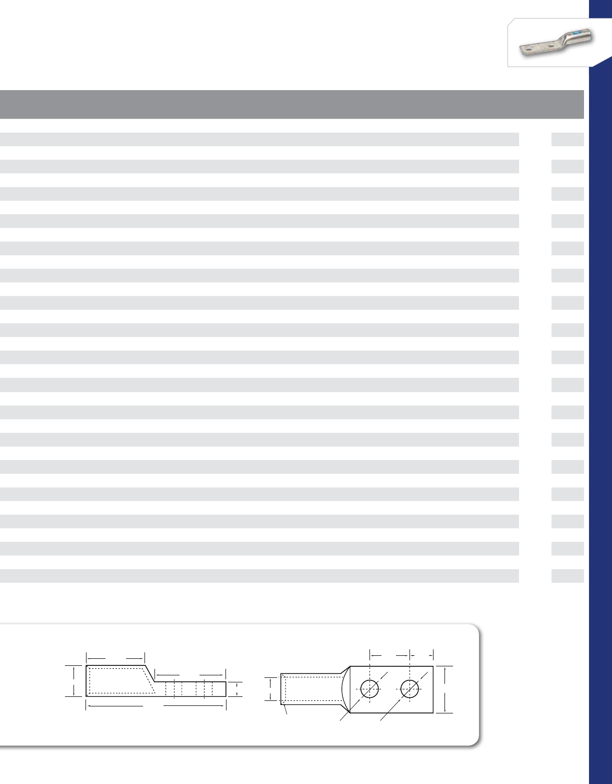
72
CONNECTORS
NSi Industries LLC • USA • 800.321.5847 • www.nsiindustries.com
CAT.
NO. WIRE
RANGE EXPANDED WIRE
RANGE*COLOR BOLT
SIZE I.D. O.D. LENGTH
(L) WIDTH
(W) (IN.)
END OF CONN
TO CTR.
(A)
TANG
LENGTH
(B)
BARREL
LENGTH
(B1)
TANG
THICkNESS
(C)
MTG.
HOLE DIA.
(D)
MTG. HOLE
SPACING
(E)
MAX
AMP
RATING
STD.
CTN.
QTY.
L8N-14 8 AWG 8 - 10 AWG Red 1/4" 0.205 0.295 2.240 0.420 0.280 1.140 0.980 0.080 0.261 1.000 100
L8N-14P 8 AWG 8 - 10 AWG Red 1/4" 0.205 0.295 2.240 0.420 0.280 1.140 0.980 0.080 0.261 1.000 100
L8N-141 8 AWG 8 - 10 AWG Red 1/4" 0.205 0.295 2.240 0.420 0.280 1.140 0.980 0.080 0.261 0.625 100
L8N-141P 8 AWG 8 - 10 AWG Red 1/4" 0.205 0.295 2.240 0.420 0.280 1.140 0.980 0.080 0.261 0.625 100
L8N-142 8 AWG 8 - 10 AWG Red 1/4" 0.205 0.295 2.240 0.420 0.280 1.140 0.980 0.080 0.261 0.750 100
L8N-142P 8 AWG 8 - 10 AWG Red 1/4" 0.205 0.295 2.240 0.420 0.280 1.140 0.980 0.080 0.261 0.750 100
L8N-38 8 AWG 8 - 10 AWG Red 3/8" 0.205 0.295 2.240 0.420 0.280 1.140 0.980 0.080 0.410 1.000 100
L8N-38P 8 AWG 8 - 10 AWG Red 3/8" 0.205 0.295 2.240 0.420 0.280 1.140 0.980 0.080 0.410 1.000 100
L8N-383 8 AWG 8 - 10 AWG Red 3/8" 0.205 0.295 2.240 0.420 0.280 1.140 0.980 0.080 0.410 1.750 100
L8N-383P 8 AWG 8 - 10 AWG Red 3/8" 0.205 0.295 2.240 0.420 0.280 1.140 0.980 0.080 0.410 1.750 100
L8N-563 8 AWG 8 - 10 AWG Blue 5/16" 0.205 0.295 2.240 0.420 0.280 1.140 0.980 0.080 0.312 1.750 100
L8N-563P 8 AWG 8 - 10 AWG Blue 5/16" 0.205 0.295 2.240 0.420 0.280 1.140 0.980 0.080 0.312 1.750 100
L6N-12 6 AWG 6 - 8 AWG Blue 1/4” 0.200 0.300 2.240 0.420 0.280 1.140 0.980 0.080 0.261 0.500 100
L6N-14 6 AWG 6 - 8 AWG Blue 1/4” 0.200 0.300 2.360 0.420 0.280 1.260 0.980 0.080 0.261 0.625 100
L6N-14P 6 AWG 6 - 8 AWG Blue 1/4” 0.200 0.300 2.360 0.420 0.280 1.260 0.980 0.080 0.261 0.625 100
L6N-141 6 AWG 6 - 8 AWG Blue 1/4” 0.200 0.300 2.480 0.420 1.260 1.380 0.980 0.080 0.261 0.625 100
L6N-141P 6 AWG 6 - 8 AWG Blue 1/4” 0.200 0.300 2.480 0.420 1.260 1.380 0.980 0.080 0.261 0.625 100
L6N-142 6 AWG 6 - 8 AWG Blue 1/4” 0.200 0.300 2.480 0.420 0.280 1.380 0.980 0.080 0.261 0.750 100
L6N-142P 6 AWG 6 - 8 AWG Blue 1/4” 0.200 0.300 2.480 0.420 0.280 1.380 0.980 0.080 0.261 0.750 100
L6N-38 6 AWG 6 - 8 AWG Blue 3/8” 0.200 0.300 2.910 0.420 0.380 1.810 0.980 0.080 0.410 1.000 100
L6N-38P 6 AWG 6 - 8 AWG Blue 3/8” 0.200 0.300 2.910 0.420 0.380 1.810 0.980 0.080 0.410 1.000 100
L6N-382 6 AWG 6 - 8 AWG Blue 3/8" 0.200 0.300 4.090 0.870 0.620 2.990 0.980 0.120 0.410 0.750 100
L6N-382P 6 AWG 6 - 8 AWG Blue 3/8" 0.200 0.300 4.090 0.870 0.620 2.990 0.980 0.120 0.410 0.750 100
L6N 6 AWG 6 - 8 AWG Blue 1/2” 0.200 0.300 4.090 0.870 0.620 2.990 0.980 0.120 0.510 1.750 100
L6N-P 6 AWG 6 - 8 AWG Blue 1/2” 0.200 0.300 4.090 0.870 0.620 2.990 0.980 0.120 0.510 1.750 100
L4N-14 4 AWG 4 - 6 AWG Gray 1/4” 0.250 0.340 2.360 0.490 0.280 1.260 0.980 0.090 0.261 0.625 100
L4N-14P 4 AWG 4 - 6 AWG Gray 1/4” 0.250 0.340 2.360 0.490 0.280 1.260 0.980 0.090 0.261 0.625 100
L4N-141P 4 AWG 4 - 6 AWG Gray 1/4" 0.250 0.340 2.950 0.420 0.380 1.810 0.980 0.090 0.261 0.625 100
L4N-142P 4 AWG 4 - 6 AWG Gray 1/4" 0.250 0.340 2.950 0.420 0.380 1.810 0.980 0.090 0.261 0.625 100
L4N-38 4 AWG 4 - 6 AWG Gray 3/8” 0.250 0.340 2.950 0.420 0.380 1.810 0.980 0.090 0.410 1.000 100
L4N-38P 4 AWG 4 - 6 AWG Gray 3/8” 0.250 0.340 2.950 0.420 0.380 1.810 0.980 0.090 0.410 1.000 100
L4N-382 4 AWG 4 - 6 AWG Gray 3/8" 0.250 0.340 4.090 0.870 0.620 2.990 0.980 0.120 0.410 0.750 100
L4N-382P 4 AWG 4 - 6 AWG Gray 3/8" 0.250 0.340 4.090 0.870 0.620 2.990 0.980 0.120 0.410 0.750 100
L4N 4 AWG 4 - 6 AWG Gray 1/2” 0.250 0.340 4.090 0.870 0.620 2.990 0.980 0.120 0.510 1.750 100
COMPRESSION LUGS
TWO HOLE
45° Deep
Chamfer
L
W
A
D
E
B
C
B1
COMPRESSION LUGS
TWO HOLE
45° Deep
Chamfer
L
W
A
D
E
B
C
B1
* CLASS B OR C BUILDING WIRE CU CABLE
Max ampacity is based on NEC 310.15, insulation type, and conductor material. Please consult your current NEC manual.
OD
ID

73
CONNECTORS
RATINGS
FEATURES
COMPRESSION CONNECTORS
Long Barrel Copper Lugs
Two Hole
LN SERIES CONTINUED
TEMPERATURE RATING:
90 °C.
Produced from high conductivity copper tubing.
Allows easy inspection of the termination to assure
complete cable insertion.
Tin-plated to provide corrosion and low contact resistance.
Marked with die index and color coded.
Listed for 35KV maximum when properly installed.
For applications greater than 2000V, installed to cable
manufacturer for voltage stress relief instructions.
Additional mounting hole spacing options available on request.
NOTE: Part Numbers ending in “P” have a “peep” or sight
inspection hole.
Additional mounting hole spacing options available on request.
Produced from high conductivity copper tubing.
Allows easy inspection of the termination to assure
Marked with die index and color coded.
Listed for 35KV maximum when properly installed.
Listed for 35KV maximum when properly installed.
For applications greater than 2000V, installed to cable
manufacturer for voltage stress relief instructions.
For applications greater than 2000V, installed to cable
manufacturer for voltage stress relief instructions.
For applications greater than 2000V, installed to cable
For applications greater than 2000V, installed to cable
Tin-plated to provide corrosion and low contact resistance.
Marked with die index and color coded.
Allows easy inspection of the termination to assure
complete cable insertion.
Allows easy inspection of the termination to assure
complete cable insertion.
Allows easy inspection of the termination to assure
Allows easy inspection of the termination to assure
All dimensional data is listed in inches.
CAT.
NO. WIRE
RANGE EXPANDED WIRE
RANGE*COLOR BOLT
SIZE I.D. O.D. LENGTH
(L) WIDTH
(W) (IN.)
END OF CONN
TO CTR.
(A) (IN.)
TANG
LENGTH
(B) (IN.)
BARREL
LENGTH
(B1) (IN.)
TANG
THICkNESS
(C) (IN.)
MTG.
HOLE DIA.
(D) (IN.)
MTG. HOLE
SPACING
(E) (IN.)
MAX
AMP
RATING
STD.
CTN.
QTY.
L4N-P 4 AWG 4 - 6 AWG Gray 1/2" 0.250 0.340 4.090 0.870 0.620 2.990 0.980 0.120 0.510 1.750 100
L2N-14 2 AWG 2 - 6 AWG Brown 1/4" 0.310 0.420 2.520 0.600 0.280 1.260 1.100 0.100 0.252 1.000 50
L2N-14P 2 AWG 2 - 6 AWG Brown 1/4" 0.310 0.420 2.520 0.600 0.280 1.260 1.100 0.100 0.252 1.000 50
L2N-141 2 AWG 2 - 6 AWG Brown 1/4" 0.310 0.420 2.520 0.600 0.280 1.260 1.100 0.100 0.250 0.625 50
L2N-141P 2 AWG 2 - 6 AWG Brown 1/4" 0.310 0.420 2.520 0.600 0.280 1.260 1.100 0.100 0.250 0.625 50
L2N-142 2 AWG 2 - 6 AWG Brown 1/4" 0.310 0.420 2.640 0.600 0.280 1.380 1.100 0.100 0.250 0.750 50
L2N-38 2 AWG 2 - 6 AWG Brown 3/8" 0.310 0.420 3.070 0.600 0.380 1.810 1.100 0.100 0.410 1.000 50
L2N-38P 2 AWG 2 - 6 AWG Brown 3/8" 0.310 0.420 3.070 0.600 0.380 1.810 1.100 0.100 0.410 1.000 50
L2N-382 2 AWG 2 - 6 AWG Brown 3/8" 0.310 0.420 4.250 0.810 0.620 2.990 1.100 0.100 0.410 0.750 50
L2N-382P 2 AWG 2 - 6 AWG Brown 3/8" 0.310 0.420 4.250 0.810 0.620 2.990 1.100 0.100 0.410 0.750 50
L2N-383 2 AWG 2 - 6 AWG Brown 3/8" 0.310 0.420 4.250 0.810 0.620 2.990 1.100 0.100 0.410 1.750 50
L2N-383P 2 AWG 2 - 6 AWG Brown 3/8" 0.310 0.420 4.250 0.810 0.620 2.990 1.100 0.100 0.410 1.750 50
L2N-56 2 AWG 2 - 6 AWG Brown 5/16" 0.310 0.420 2.870 0.600 0.320 1.610 1.100 0.100 0.330 0.750 50
L2N 2 AWG 2 - 6 AWG Brown 1/2" 0.310 0.420 4.250 0.810 0.620 2.990 1.100 0.100 0.510 1.750 50
L2N-P 2 AWG 2 - 6 AWG Brown 1/2" 0.310 0.420 4.250 0.810 0.620 2.990 1.100 0.100 0.510 1.750 50
L1N-141 1 AWG 1 - 6 AWG Green 1/4" 0.360 0.470 2.560 0.670 0.280 1.260 1.100 0.110 0.250 0.630 50
L1N-38 1 AWG 1 - 6 AWG Green 3/8" 0.360 0.470 3.070 0.670 0.380 1.810 1.100 0.110 0.410 1.000 50
L1N-56 1 AWG 1 - 6 AWG Green 5/16" 0.360 0.470 2.930 0.670 0.320 1.610 1.100 0.110 0.330 0.870 50
L1N 1 AWG 1 - 6 AWG Green 1/2" 0.360 0.470 4.290 0.750 0.620 2.990 1.100 0.100 0.510 1.750 50
L10N-14 1/0 AWG 1/0 - 6 AWG Pink 1/4" 0.390 0.520 3.210 0.740 0.380 1.810 1.200 0.130 0.252 1.000 50
L10N-14P 1/0 AWG 1/0 - 6 AWG Pink 1/4" 0.390 0.520 3.210 0.740 0.380 1.810 1.200 0.130 0.252 1.000 50
L10N-38 1/0 AWG 1/0 - 6 AWG Pink 3/8" 0.390 0.520 3.210 0.740 0.380 1.810 1.200 0.130 0.410 1.000 50
L10N-38P 1/0 AWG 1/0 - 6 AWG Pink 3/8" 0.390 0.520 3.210 0.740 0.380 1.810 1.200 0.130 0.410 1.000 50
L10N-382 1/0 AWG 1/0 - 6 AWG Pink 3/8" 0.390 0.520 4.630 0.740 0.620 2.990 1.200 0.120 0.410 0.750 50
L10N-382P 1/0 AWG 1/0 - 6 AWG Pink 3/8" 0.390 0.520 4.630 0.740 0.620 2.990 1.200 0.120 0.410 0.750 50
L10N-383 1/0 AWG 1/0 - 6 AWG Pink 3/8" 0.390 0.520 4.630 0.740 0.620 2.990 1.200 0.120 0.410 1.750 50
L10N-383P 1/0 AWG 1/0 - 6 AWG Pink 3/8" 0.390 0.520 4.630 0.740 0.620 2.990 1.200 0.120 0.410 1.750 50
L10N 1/0 AWG 1/0 - 6 AWG Pink 1/2" 0.390 0.520 4.630 0.740 0.620 2.990 1.200 0.120 0.510 1.750 50
L10N-P 1/0 AWG 1/0 - 6 AWG Pink 1/2" 0.390 0.520 4.630 0.740 0.620 2.990 1.200 0.120 0.510 1.750 50
L20N-14 2/0 AWG 2/0 - 4 AWG Black 1/4" 0.440 0.560 2.990 0.810 0.280 1.380 1.380 0.120 0.252 0.625 25
L20N-141 2/0 AWG 2/0 - 4 AWG Black 1/4" 0.440 0.560 2.990 0.810 0.280 1.380 1.380 0.120 0.252 0.625 25
L20N-141P 2/0 AWG 2/0 - 4 AWG Black 1/4" 0.440 0.560 2.990 0.810 0.280 1.380 1.380 0.120 0.252 0.750 25
L20N-142 2/0 AWG 2/0 - 4 AWG Black 1/4” 0.440 0.560 2.990 0.810 0.280 1.380 1.380 0.120 0.250 0.750 25
L20N-14P 2/0 AWG 2/0 - 4 AWG Black 1/4" 0.440 0.560 2.990 0.810 0.280 1.380 1.380 0.120 0.252 0.625 25
* CLASS B OR C BUILDING WIRE CU CABLE
Scan QR to view
Tool & Die Charts
LISTED
155027 701642
COMPRESSION LUGS
TWO HOLE
45° Deep
Chamfer
L
W
A
D
E
B
C
B1
*EXPANDED WIRE RANGE when installed with
NSI N12ID dieless compression tool.
UL Listed with other tools:
FOR TOOL & DIE CRIMPING INFORMATION,
PLEASE SEE TABLE ON PAGE 145
ID
OD

74
CONNECTORS
NSi Industries LLC • USA • 800.321.5847 • www.nsiindustries.com
CAT.
NO. WIRE
RANGE EXPANDED WIRE
RANGE*COLOR BOLT
SIZE I.D. O.D. LENGTH
(L) WIDTH
(W) (IN.)
END OF CONN
TO CTR.
(A) (IN.)
TANG
LENGTH
(B) (IN.)
BARREL
LENGTH
(B1) (IN.)
TANG
THICkNESS
(C) (IN.)
MTG.
HOLE DIA.
(D) (IN.)
MTG. HOLE
SPACING
(E) (IN.)
MAX
AMP
RATING
STD.
CTN.
QTY.
L4N-P 4 AWG 4 - 6 AWG Gray 1/2" 0.250 0.340 4.090 0.870 0.620 2.990 0.980 0.120 0.510 1.750 100
L2N-14 2 AWG 2 - 6 AWG Brown 1/4" 0.310 0.420 2.520 0.600 0.280 1.260 1.100 0.100 0.252 1.000 50
L2N-14P 2 AWG 2 - 6 AWG Brown 1/4" 0.310 0.420 2.520 0.600 0.280 1.260 1.100 0.100 0.252 1.000 50
L2N-141 2 AWG 2 - 6 AWG Brown 1/4" 0.310 0.420 2.520 0.600 0.280 1.260 1.100 0.100 0.250 0.625 50
L2N-141P 2 AWG 2 - 6 AWG Brown 1/4" 0.310 0.420 2.520 0.600 0.280 1.260 1.100 0.100 0.250 0.625 50
L2N-142 2 AWG 2 - 6 AWG Brown 1/4" 0.310 0.420 2.640 0.600 0.280 1.380 1.100 0.100 0.250 0.750 50
L2N-38 2 AWG 2 - 6 AWG Brown 3/8" 0.310 0.420 3.070 0.600 0.380 1.810 1.100 0.100 0.410 1.000 50
L2N-38P 2 AWG 2 - 6 AWG Brown 3/8" 0.310 0.420 3.070 0.600 0.380 1.810 1.100 0.100 0.410 1.000 50
L2N-382 2 AWG 2 - 6 AWG Brown 3/8" 0.310 0.420 4.250 0.810 0.620 2.990 1.100 0.100 0.410 0.750 50
L2N-382P 2 AWG 2 - 6 AWG Brown 3/8" 0.310 0.420 4.250 0.810 0.620 2.990 1.100 0.100 0.410 0.750 50
L2N-383 2 AWG 2 - 6 AWG Brown 3/8" 0.310 0.420 4.250 0.810 0.620 2.990 1.100 0.100 0.410 1.750 50
L2N-383P 2 AWG 2 - 6 AWG Brown 3/8" 0.310 0.420 4.250 0.810 0.620 2.990 1.100 0.100 0.410 1.750 50
L2N-56 2 AWG 2 - 6 AWG Brown 5/16" 0.310 0.420 2.870 0.600 0.320 1.610 1.100 0.100 0.330 0.750 50
L2N 2 AWG 2 - 6 AWG Brown 1/2" 0.310 0.420 4.250 0.810 0.620 2.990 1.100 0.100 0.510 1.750 50
L2N-P 2 AWG 2 - 6 AWG Brown 1/2" 0.310 0.420 4.250 0.810 0.620 2.990 1.100 0.100 0.510 1.750 50
L1N-141 1 AWG 1 - 6 AWG Green 1/4" 0.360 0.470 2.560 0.670 0.280 1.260 1.100 0.110 0.250 0.630 50
L1N-38 1 AWG 1 - 6 AWG Green 3/8" 0.360 0.470 3.070 0.670 0.380 1.810 1.100 0.110 0.410 1.000 50
L1N-56 1 AWG 1 - 6 AWG Green 5/16" 0.360 0.470 2.930 0.670 0.320 1.610 1.100 0.110 0.330 0.870 50
L1N 1 AWG 1 - 6 AWG Green 1/2" 0.360 0.470 4.290 0.750 0.620 2.990 1.100 0.100 0.510 1.750 50
L10N-14 1/0 AWG 1/0 - 6 AWG Pink 1/4" 0.390 0.520 3.210 0.740 0.380 1.810 1.200 0.130 0.252 1.000 50
L10N-14P 1/0 AWG 1/0 - 6 AWG Pink 1/4" 0.390 0.520 3.210 0.740 0.380 1.810 1.200 0.130 0.252 1.000 50
L10N-38 1/0 AWG 1/0 - 6 AWG Pink 3/8" 0.390 0.520 3.210 0.740 0.380 1.810 1.200 0.130 0.410 1.000 50
L10N-38P 1/0 AWG 1/0 - 6 AWG Pink 3/8" 0.390 0.520 3.210 0.740 0.380 1.810 1.200 0.130 0.410 1.000 50
L10N-382 1/0 AWG 1/0 - 6 AWG Pink 3/8" 0.390 0.520 4.630 0.740 0.620 2.990 1.200 0.120 0.410 0.750 50
L10N-382P 1/0 AWG 1/0 - 6 AWG Pink 3/8" 0.390 0.520 4.630 0.740 0.620 2.990 1.200 0.120 0.410 0.750 50
L10N-383 1/0 AWG 1/0 - 6 AWG Pink 3/8" 0.390 0.520 4.630 0.740 0.620 2.990 1.200 0.120 0.410 1.750 50
L10N-383P 1/0 AWG 1/0 - 6 AWG Pink 3/8" 0.390 0.520 4.630 0.740 0.620 2.990 1.200 0.120 0.410 1.750 50
L10N 1/0 AWG 1/0 - 6 AWG Pink 1/2" 0.390 0.520 4.630 0.740 0.620 2.990 1.200 0.120 0.510 1.750 50
L10N-P 1/0 AWG 1/0 - 6 AWG Pink 1/2" 0.390 0.520 4.630 0.740 0.620 2.990 1.200 0.120 0.510 1.750 50
L20N-14 2/0 AWG 2/0 - 4 AWG Black 1/4" 0.440 0.560 2.990 0.810 0.280 1.380 1.380 0.120 0.252 0.625 25
L20N-141 2/0 AWG 2/0 - 4 AWG Black 1/4" 0.440 0.560 2.990 0.810 0.280 1.380 1.380 0.120 0.252 0.625 25
L20N-141P 2/0 AWG 2/0 - 4 AWG Black 1/4" 0.440 0.560 2.990 0.810 0.280 1.380 1.380 0.120 0.252 0.750 25
L20N-142 2/0 AWG 2/0 - 4 AWG Black 1/4” 0.440 0.560 2.990 0.810 0.280 1.380 1.380 0.120 0.250 0.750 25
L20N-14P 2/0 AWG 2/0 - 4 AWG Black 1/4" 0.440 0.560 2.990 0.810 0.280 1.380 1.380 0.120 0.252 0.625 25
Max ampacity is based on NEC 310.15, insulation type, and conductor material. Please consult your current NEC manual.

75
CONNECTORS
RATINGS
FEATURES
COMPRESSION CONNECTORS
Long Barrel Copper Lugs
Two Hole
LN SERIES CONTINUED
TEMPERATURE RATING:
90 °C.
Produced from high conductivity copper tubing.
Allows easy inspection of the termination to assure
complete cable insertion.
Tin-plated to provide corrosion and low contact resistance.
Marked with die index and color coded.
Listed for 35KV maximum when properly installed.
For applications greater than 2000V, installed to cable
manufacturer for voltage stress relief instructions.
Additional mounting hole spacing options available on request.
NOTE: Part Numbers ending in “P” have a “peep” or sight
inspection hole.
Additional mounting hole spacing options available on request.
Produced from high conductivity copper tubing.
Marked with die index and color coded.
Listed for 35KV maximum when properly installed.
Listed for 35KV maximum when properly installed.
For applications greater than 2000V, installed to cable
manufacturer for voltage stress relief instructions.
For applications greater than 2000V, installed to cable
manufacturer for voltage stress relief instructions.
For applications greater than 2000V, installed to cable
For applications greater than 2000V, installed to cable
Tin-plated to provide corrosion and low contact resistance.
Marked with die index and color coded.
Allows easy inspection of the termination to assure
complete cable insertion.
Allows easy inspection of the termination to assure
complete cable insertion.
Allows easy inspection of the termination to assure
Allows easy inspection of the termination to assure
All dimensional data is listed in inches.
CAT.
NO. WIRE
RANGE EXPANDED WIRE
RANGE *COLOR BOLT
SIZE I.D. O.D. LENGTH
(L) WIDTH
(W)
END OF CONN
TO CTR.
(A)
TANG
LENGTH
(B)
BARREL
LENGTH
(B1)
TANG
THICkNESS
(C)
MTG.
HOLE DIA.
(D)
MTG. HOLE
SPACING
(E)
MAX
AMP
RATING
STD.
CTN.
QTY.
L20N-38 2/0 AWG 2/0 - 4 AWG Black 3/8" 0.440 0.560 3.430 0.810 0.380 1.810 1.380 0.120 0.410 1.000 25
L20N-38P 2/0 AWG 2/0 - 4 AWG Black 3/8" 0.440 0.560 3.430 0.810 0.380 1.810 1.380 0.120 0.410 1.000 25
L20N-383 2/0 AWG 2/0 - 4 AWG Black 3/8" 0.440 0.560 3.430 0.810 0.380 1.810 1.380 0.120 0.410 1.750 25
L20N-383P 2/0 AWG 2/0 - 4 AWG Black 3/8" 0.440 0.560 3.430 0.810 0.380 1.810 1.380 0.120 0.410 1.750 25
L20N 2/0 AWG 2/0 - 4 AWG Black 1/2" 0.440 0.560 4.610 0.810 0.620 2.990 1.380 0.120 0.510 1.750 25
L20N-P 2/0 AWG 2/0 - 4 AWG Black 1/2" 0.440 0.560 4.610 0.810 0.620 2.990 1.380 0.120 0.510 1.750 25
L30N-141 3/0 AWG 3/0 - 2 AWG Orange 1/4" 0.490 0.620 3.500 0.900 0.380 1.810 1.380 0.130 0.252 0.625 25
L30N-141P 3/0 AWG 3/0 - 2 AWG Orange 1/4" 0.490 0.620 3.500 0.900 0.380 1.810 1.380 0.130 0.252 0.625 25
L30N-38 3/0 AWG 3/0 - 2 AWG Orange 3/8" 0.490 0.620 3.500 0.900 0.380 1.810 1.380 0.130 0.410 1.000 25
L30N-38P 3/0 AWG 3/0 - 2 AWG Orange 3/8" 0.490 0.620 3.500 0.900 0.380 1.810 1.380 0.130 0.410 1.000 25
L30N-56 3/0 AWG 3/0 - 2 AWG Orange 5/16" 0.490 0.620 4.650 0.900 0.620 2.990 1.380 0.130 0.312 1.000 25
L30N-56P 3/0 AWG 3/0 - 2 AWG Orange 5/16" 0.490 0.620 4.650 0.900 0.620 2.990 1.380 0.130 0.312 1.000 25
L30N 3/0 AWG 3/0 - 2 AWG Orange 1/2" 0.490 0.620 4.650 0.900 0.620 2.990 1.380 0.130 0.510 1.750 25
L30N-P 3/0 AWG 3/0 - 2 AWG Orange 1/2" 0.490 0.620 4.650 0.900 0.620 2.990 1.380 0.130 0.510 1.750 25
L40N-141 4/0 AWG 4/0 - 1 AWG Purple 1/4" 0.550 0.690 3.540 1.000 0.380 1.810 1.420 0.130 0.252 0.625 25
L40N-141P 4/0 AWG 4/0 - 1 AWG Purple 1/4" 0.550 0.690 3.540 1.000 0.380 1.810 1.420 0.130 0.252 0.625 25
L40N-142 4/0 AWG 4/0 - 1 AWG Purple 1/4" 0.550 0.690 3.540 1.000 0.380 1.810 1.420 0.130 0.252 0.750 25
L40N-142P 4/0 AWG 4/0 - 1 AWG Purple 1/4" 0.550 0.690 3.540 1.000 0.380 1.810 1.420 0.130 0.252 0.750 25
L40N-38 4/0 AWG 4/0 - 1 AWG Purple 3/8" 0.550 0.690 3.540 1.000 0.380 1.810 1.420 0.130 0.410 1.000 25
L40N-38P 4/0 AWG 4/0 - 1 AWG Purple 3/8" 0.550 0.690 3.540 1.000 0.380 1.810 1.420 0.130 0.410 1.000 25
L40N-383 4/0 AWG 4/0 - 1 AWG Purple 3/8" 0.550 0.690 3.540 1.000 0.380 1.810 1.420 0.130 0.410 1.750 25
L40N-383P 4/0 AWG 4/0 - 1 AWG Purple 3/8" 0.550 0.690 3.540 1.000 0.380 1.810 1.420 0.130 0.410 1.750 25
L40N 4/0 AWG 4/0 - 1 AWG Purple 1/2" 0.550 0.690 4.720 1.000 0.620 2.990 1.420 0.130 0.510 1.750 25
L250N 250 MCM 250 MCM - 1/0 AWG Yellow 1/2" 0.590 0.750 4.960 1.090 0.620 2.990 1.610 0.150 0.510 1.750 25
L250N-38 250 MCM 250 MCM - 1/0 AWG Yellow 3/8" 0.590 0.750 3.780 1.090 0.380 1.810 1.610 0.150 0.410 1.000 25
L300N 300 MCM 300 MCM - 2/0 AWG White 1/2" 0.660 0.810 5.310 1.190 0.620 2.990 1.970 0.150 0.510 1.750 12
L350N 350 MCM 350 MCM - 3/0 AWG Red 1/2" 0.700 0.870 5.390 1.280 0.620 2.990 1.970 0.170 0.510 1.750 12
L350N-38 350 MCM 350 MCM - 3/0 AWG Red 3/8" 0.700 0.870 4.210 1.280 0.380 1.810 1.970 0.170 0.410 1.000 12
L400N 400 MCM 400 MCM - 4/0 AWG Blue 1/2" 0.760 0.950 5.470 1.390 0.620 2.990 1.970 0.180 0.510 1.750 6
L500N 500 MCM 500 - 250 MCM Brown 1/2" 0.840 1.060 5.750 1.540 0.620 2.990 2.240 0.220 0.510 1.750 6
L500N-38 500 MCM 500 - 250 MCM Brown 3/8" 0.840 1.060 4.570 1.540 0.380 1.810 2.240 0.220 0.410 1.000 6
L600N 600 MCM 600 - 250 MCM Green 1/2" 0.930 1.190 5.790 1.720 0.620 2.990 2.240 0.250 0.510 1.750 6
L600N-38 600 MCM 600 - 250 MCM Green 3/8" 0.930 1.190 4.610 1.720 0.380 1.810 2.240 0.250 0.410 1.000 6
L750N 750 MCM 750 - 500 MCM Black 1/2" 1.040 1.310 6.300 1.900 0.620 2.990 2.640 0.270 0.510 1.750 3
L750N-38 750 MCM 750 - 500 MCM Black 3/8" 1.040 1.310 5.120 1.900 0.380 1.810 2.640 0.270 0.410 1.000 3
L1000N 1000 MCM White 1/2" 1.150 1.500 7.125 2.160 0.630 3.060 3.160 0.340 0.510 1.750 3
* CLASS B OR C BUILDING WIRE CU CABLE
FOR TOOL & DIE CRIMPING INFORMATION,
PLEASE SEE TABLE ON PAGE 141
Scan QR to view
Tool & Die Charts
LISTED
155027 701642
COMPRESSION LUGS
TWO HOLE
45° Deep
Chamfer
L
W
A
D
E
B
C
B1
ID
OD

76
CONNECTORS
NSi Industries LLC • USA • 800.321.5847 • www.nsiindustries.com
CAT.
NO. WIRE
RANGE EXPANDED WIRE
RANGE *COLOR BOLT
SIZE I.D. O.D. LENGTH
(L) WIDTH
(W)
END OF CONN
TO CTR.
(A)
TANG
LENGTH
(B)
BARREL
LENGTH
(B1)
TANG
THICkNESS
(C)
MTG.
HOLE DIA.
(D)
MTG. HOLE
SPACING
(E)
MAX
AMP
RATING
STD.
CTN.
QTY.
L20N-38 2/0 AWG 2/0 - 4 AWG Black 3/8" 0.440 0.560 3.430 0.810 0.380 1.810 1.380 0.120 0.410 1.000 25
L20N-38P 2/0 AWG 2/0 - 4 AWG Black 3/8" 0.440 0.560 3.430 0.810 0.380 1.810 1.380 0.120 0.410 1.000 25
L20N-383 2/0 AWG 2/0 - 4 AWG Black 3/8" 0.440 0.560 3.430 0.810 0.380 1.810 1.380 0.120 0.410 1.750 25
L20N-383P 2/0 AWG 2/0 - 4 AWG Black 3/8" 0.440 0.560 3.430 0.810 0.380 1.810 1.380 0.120 0.410 1.750 25
L20N 2/0 AWG 2/0 - 4 AWG Black 1/2" 0.440 0.560 4.610 0.810 0.620 2.990 1.380 0.120 0.510 1.750 25
L20N-P 2/0 AWG 2/0 - 4 AWG Black 1/2" 0.440 0.560 4.610 0.810 0.620 2.990 1.380 0.120 0.510 1.750 25
L30N-141 3/0 AWG 3/0 - 2 AWG Orange 1/4" 0.490 0.620 3.500 0.900 0.380 1.810 1.380 0.130 0.252 0.625 25
L30N-141P 3/0 AWG 3/0 - 2 AWG Orange 1/4" 0.490 0.620 3.500 0.900 0.380 1.810 1.380 0.130 0.252 0.625 25
L30N-38 3/0 AWG 3/0 - 2 AWG Orange 3/8" 0.490 0.620 3.500 0.900 0.380 1.810 1.380 0.130 0.410 1.000 25
L30N-38P 3/0 AWG 3/0 - 2 AWG Orange 3/8" 0.490 0.620 3.500 0.900 0.380 1.810 1.380 0.130 0.410 1.000 25
L30N-56 3/0 AWG 3/0 - 2 AWG Orange 5/16" 0.490 0.620 4.650 0.900 0.620 2.990 1.380 0.130 0.312 1.000 25
L30N-56P 3/0 AWG 3/0 - 2 AWG Orange 5/16" 0.490 0.620 4.650 0.900 0.620 2.990 1.380 0.130 0.312 1.000 25
L30N 3/0 AWG 3/0 - 2 AWG Orange 1/2" 0.490 0.620 4.650 0.900 0.620 2.990 1.380 0.130 0.510 1.750 25
L30N-P 3/0 AWG 3/0 - 2 AWG Orange 1/2" 0.490 0.620 4.650 0.900 0.620 2.990 1.380 0.130 0.510 1.750 25
L40N-141 4/0 AWG 4/0 - 1 AWG Purple 1/4" 0.550 0.690 3.540 1.000 0.380 1.810 1.420 0.130 0.252 0.625 25
L40N-141P 4/0 AWG 4/0 - 1 AWG Purple 1/4" 0.550 0.690 3.540 1.000 0.380 1.810 1.420 0.130 0.252 0.625 25
L40N-142 4/0 AWG 4/0 - 1 AWG Purple 1/4" 0.550 0.690 3.540 1.000 0.380 1.810 1.420 0.130 0.252 0.750 25
L40N-142P 4/0 AWG 4/0 - 1 AWG Purple 1/4" 0.550 0.690 3.540 1.000 0.380 1.810 1.420 0.130 0.252 0.750 25
L40N-38 4/0 AWG 4/0 - 1 AWG Purple 3/8" 0.550 0.690 3.540 1.000 0.380 1.810 1.420 0.130 0.410 1.000 25
L40N-38P 4/0 AWG 4/0 - 1 AWG Purple 3/8" 0.550 0.690 3.540 1.000 0.380 1.810 1.420 0.130 0.410 1.000 25
L40N-383 4/0 AWG 4/0 - 1 AWG Purple 3/8" 0.550 0.690 3.540 1.000 0.380 1.810 1.420 0.130 0.410 1.750 25
L40N-383P 4/0 AWG 4/0 - 1 AWG Purple 3/8" 0.550 0.690 3.540 1.000 0.380 1.810 1.420 0.130 0.410 1.750 25
L40N 4/0 AWG 4/0 - 1 AWG Purple 1/2" 0.550 0.690 4.720 1.000 0.620 2.990 1.420 0.130 0.510 1.750 25
L250N 250 MCM 250 MCM - 1/0 AWG Yellow 1/2" 0.590 0.750 4.960 1.090 0.620 2.990 1.610 0.150 0.510 1.750 25
L250N-38 250 MCM 250 MCM - 1/0 AWG Yellow 3/8" 0.590 0.750 3.780 1.090 0.380 1.810 1.610 0.150 0.410 1.000 25
L300N 300 MCM 300 MCM - 2/0 AWG White 1/2" 0.660 0.810 5.310 1.190 0.620 2.990 1.970 0.150 0.510 1.750 12
L350N 350 MCM 350 MCM - 3/0 AWG Red 1/2" 0.700 0.870 5.390 1.280 0.620 2.990 1.970 0.170 0.510 1.750 12
L350N-38 350 MCM 350 MCM - 3/0 AWG Red 3/8" 0.700 0.870 4.210 1.280 0.380 1.810 1.970 0.170 0.410 1.000 12
L400N 400 MCM 400 MCM - 4/0 AWG Blue 1/2" 0.760 0.950 5.470 1.390 0.620 2.990 1.970 0.180 0.510 1.750 6
L500N 500 MCM 500 - 250 MCM Brown 1/2" 0.840 1.060 5.750 1.540 0.620 2.990 2.240 0.220 0.510 1.750 6
L500N-38 500 MCM 500 - 250 MCM Brown 3/8" 0.840 1.060 4.570 1.540 0.380 1.810 2.240 0.220 0.410 1.000 6
L600N 600 MCM 600 - 250 MCM Green 1/2" 0.930 1.190 5.790 1.720 0.620 2.990 2.240 0.250 0.510 1.750 6
L600N-38 600 MCM 600 - 250 MCM Green 3/8" 0.930 1.190 4.610 1.720 0.380 1.810 2.240 0.250 0.410 1.000 6
L750N 750 MCM 750 - 500 MCM Black 1/2" 1.040 1.310 6.300 1.900 0.620 2.990 2.640 0.270 0.510 1.750 3
L750N-38 750 MCM 750 - 500 MCM Black 3/8" 1.040 1.310 5.120 1.900 0.380 1.810 2.640 0.270 0.410 1.000 3
L1000N 1000 MCM White 1/2" 1.150 1.500 7.125 2.160 0.630 3.060 3.160 0.340 0.510 1.750 3
Max ampacity is based on NEC 310.15, insulation type, and conductor material. Please consult your current NEC manual.
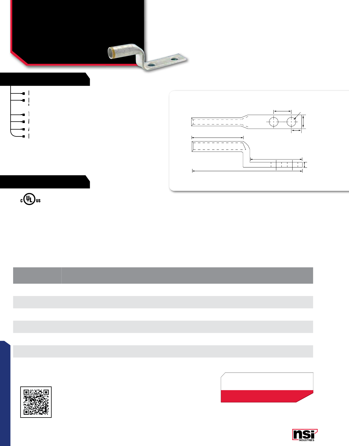
77
CONNECTORS
77
CONNECTORS
Designed for use with the L-N Series.
Produced from high conductivity copper tubing for
heavy duty applications.
Tin-Plated to provide corrosion resistance.
Marked with die index and color coded.
Additional Hole Spacing Options available on request.
For use with LN Series.
COMPRESSION CONNECTORS
Long Barrel Stacking
Copper Lugs
SL-N SERIES
E
C
G
A1
F
A
B
D
CAT.
NO. WIRE
RANGE EXPANDED WIRE
RANGE* COLOR
CODE BOLT
SIZE LENGTH
(A) WIDTH
(B)
END CONN.
TO CTR.
(E)
TANG
LENGTH
(F)
BARREL
LENGTH
(A1)
MTG. HOLE
SPACING
(G)
STD.
CTN.
QTY.
SL40N 4/0 AWG 4/0 - 1 AWG Purple 0.500 5.188 1.500 0.625 3.000 1.625 1.750 25
SL250N 250 MCM 250 MCM - 1/0 AWG Yellow 0.500 5.438 1.125 0.625 3.000 1.688 1.750 25
SL300N 300 MCM 300-2/0 AWG White 0.500 5.580 1.083 0.625 3.000 1.715 1.750 25
SL350N 350 MCM 350 MCM - 3/0 AWG Red 0.500 5.750 1.938 0.625 3.000 1.875 1.750 25
SL500N 500 MCM 500 - 250 MCM Brown 0.500 6.063 1.563 0.625 3.125 2.250 1.750 6
SL600N 600 MCM 600 - 250 MCM Green 0.500 6.750 1.688 0.625 3.125 2.625 1.750 6
SL750N 750 MCM 750 - 500 MCM Black 0.500 6.800 1.758 0.660 2.980 2.957 1.750 3
TEMPERATURE RATING:
90 °C.
RATING:
600V.
* CLASS B OR C BUILDING WIRE CU CABLE
Max ampacity is based on NEC 310.15, insulation
type, and conductor material. Please consult your
current NEC manual.
All dimensional data is listed in inches.
Scan QR to view
Tool & Die Charts
Produced from high conductivity copper tubing for
heavy duty applications.
Produced from high conductivity copper tubing for
heavy duty applications.
Produced from high conductivity copper tubing for
Designed for use with the L-N Series.
Produced from high conductivity copper tubing for
Produced from high conductivity copper tubing for
Tin-Plated to provide corrosion resistance.
Marked with die index and color coded.
Marked with die index and color coded.
Additional Hole Spacing Options available on request.
Marked with die index and color coded.
Additional Hole Spacing Options available on request.
For use with LN Series.
Additional Hole Spacing Options available on request.
For use with LN Series.
For use with LN Series.
RATINGS
FEATURES
*EXPANDED WIRE RANGE when installed with
NSI N12ID dieless compression tool.
UL Listed with other tools:
FOR TOOL & DIE CRIMPING INFORMATION,
PLEASE SEE TABLE ON PAGE 145
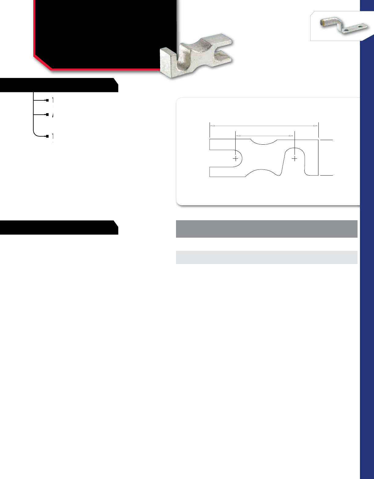
78
RATINGS
FEATURES
CONNECTORS
NSi Industries LLC • USA • 800.321.5847 • www.nsiindustries.com 78
CONNECTORS
COMPRESSION CONNECTORS
Stacking Adapters for
Compression Terminals
SA SERIES
2.875
1.750
W
CAT.
NO. HEIGHT CONNECTOR
SIZE RANGE
STD.
CTN.
QTY.
SA10-400 .875 1/0-400 MCM 10
SA500-1000 1.125 500-1000 MCM 6
RATING:
600V.
Tin-plated pure aluminum for good
conductivity and corrosiion resistance.
Allows for stacking of standard two hole
compression lugs and keeps inventories
to a minimum.
To stack 4-hole NECA drilled terminals,
use two adapters assembled in parallel.
Tin-plated pure aluminum for good
conductivity and corrosiion resistance.
Tin-plated pure aluminum for good
conductivity and corrosiion resistance.
Tin-plated pure aluminum for good
Allows for stacking of standard two hole
compression lugs and keeps inventories
Allows for stacking of standard two hole
compression lugs and keeps inventories
Allows for stacking of standard two hole
To stack 4-hole NECA drilled terminals,
use two adapters assembled in parallel.
To stack 4-hole NECA drilled terminals,
use two adapters assembled in parallel.
To stack 4-hole NECA drilled terminals,
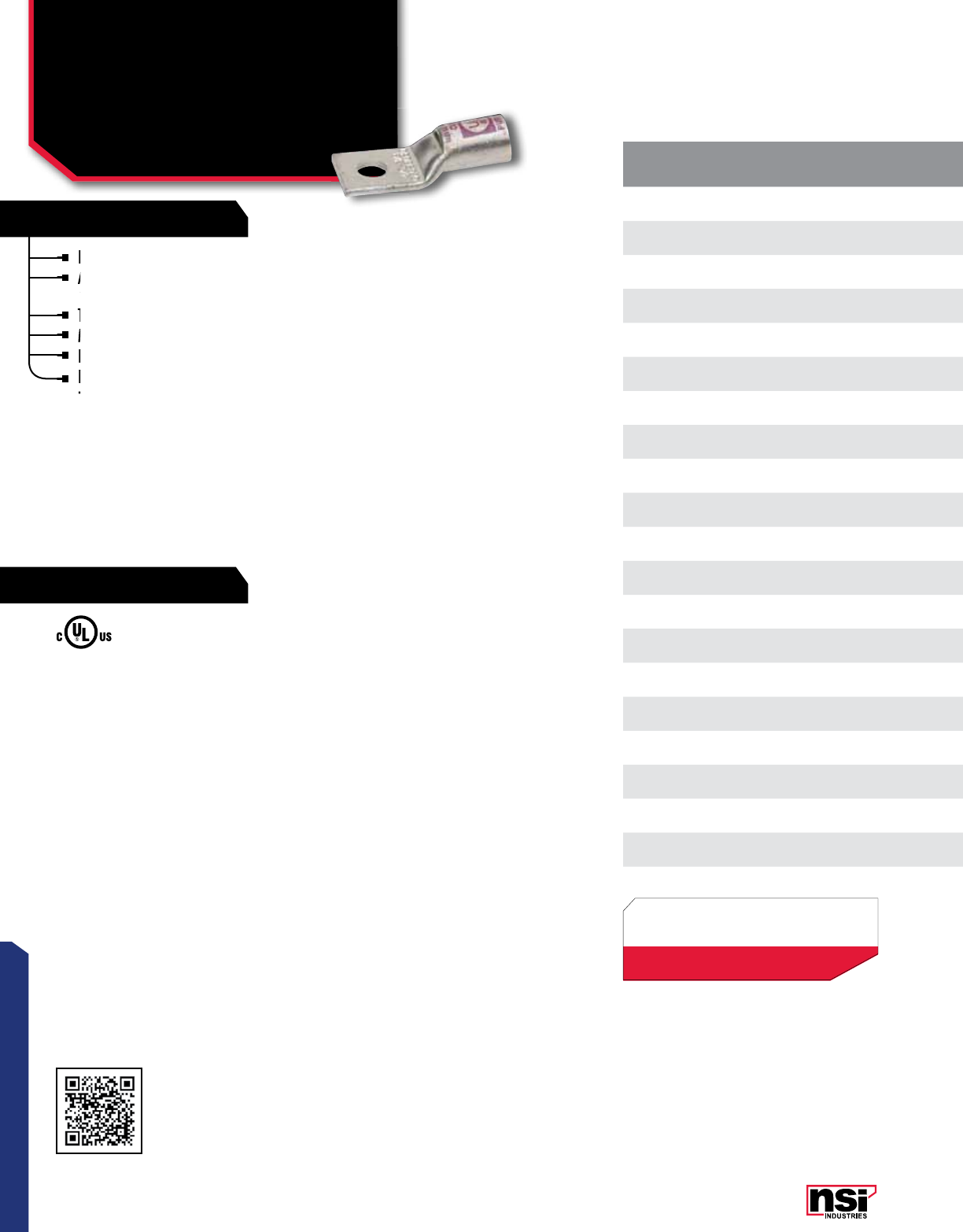
79
CONNECTORS
RATINGS
FEATURES
COMPRESSION CONNECTORS
Short Barrel Copper Lugs
One Hole With Peep Hole
GL SERIES
CAT.
NO. WIRE
RANGE EXPANDED WIRE
RANGE* COLOR
CODE BOLT
SIZE I.D. O.D. LENGTH
(L) WIDTH
(W)
END OF CONN
TO CTR.
(A)
TANG
LENGTH
(B)
BARREL
LENGTH
(B1)
TANG
THICkNESS
(C)
MTG.
HOLE DIA.
(D)
MAX
AMP
RATING
STD.
CTN.
QTY.
GL810 8 AWG 8 AWG Red # 10 0.173 0.272 1.201 0.421 0.276 0.591 0.441 0.079 0.209 100
GL814 8 AWG 8 AWG Red 1/4 0.173 0.272 1.201 0.421 0.276 0.591 0.441 0.079 0.252 100
GL856 8 AWG 8 AWG Red 5/16 0.173 0.272 1.201 0.421 0.276 0.591 0.441 0.079 0.330 100
GL614 6 AWG 6 - 8 AWG Blue 1/4 0.205 0.295 1.496 0.421 0.295 0.669 0.709 0.083 0.252 100
GL656 6 AWG 6 - 8 AWG Blue 5/16 0.205 0.295 1.496 0.488 0.295 0.669 0.709 0.067 0.331 100
GL638 6 AWG 6 - 8 AWG Blue 3/8 0.205 0.295 1.496 0.488 0.295 0.669 0.709 0.067 0.410 100
GL414 4 AWG 4 - 6 AWG Gray 1/4 0.252 0.343 1.496 0.488 0.315 0.669 0.709 0.079 0.252 100
GL456 4 AWG 4 - 6 AWG Gray 5/16 0.252 0.343 1.496 0.488 0.315 0.669 0.709 0.079 0.331 100
GL438 4 AWG 4 - 6 AWG Gray 3/8 0.252 0.343 1.496 0.559 0.315 0.669 0.709 0.079 0.413 100
GL338 3 AWG 3 - 6 AWG White 3/8 0.277 0.372 1.984 0.594 0.375 0.875 0.885 0.086 0.399 50
GL214 2 AWG 2 - 6 AWG Brown 1/4 0.315 0.421 1.795 0.602 0.370 0.811 0.827 0.102 0.252 50
GL256 2 AWG 2 - 6 AWG Brown 5/16 0.315 0.421 1.795 0.602 0.370 0.811 0.827 0.102 0.331 50
GL238 2 AWG 2 - 6 AWG Brown 3/8 0.315 0.421 1.795 0.602 0.370 0.811 0.827 0.102 0.413 50
GL114 1 AWG 1 - 6 AWG Green 1/4 0.358 0.469 1.835 0.673 0.370 0.811 0.827 0.106 0.252 50
GL156 1 AWG 1 - 6 AWG Green 5/16 0.358 0.469 1.835 0.673 0.370 0.811 0.827 0.106 0.331 50
GL138 1 AWG 1 - 6 AWG Green 3/8 0.358 0.469 1.835 0.673 0.394 0.811 0.827 0.106 0.413 50
GL1056 1/0 AWG 1/0 - 6 AWG Pink 5/16 0.390 0.520 1.835 0.744 0.370 0.811 0.827 0.126 0.331 50
GL1038 1/0 AWG 1/0 - 6 AWG Pink 3/8 0.390 0.520 1.835 0.744 0.370 0.811 0.827 0.126 0.413 50
GL1048 1/0 AWG 1/0 - 6 AWG Pink 1/2 0.390 0.520 1.835 0.744 0.370 0.811 0.827 0.126 0.512 50
GL2056 2/0 AWG 2/0 - 4 AWG Black 5/16 0.441 0.563 2.244 0.815 0.472 1.063 0.945 0.118 0.331 25
TEMPERATURE RATING/VOLTAGE:
AL9CU. Rated 600V, 90 °C.
Produced from high conductivity copper tubing.
Allows easy inspection of the termination to assure
complete cable insertion.
Tin-plated to provide corrosion and low contact resistance.
Marked with die index and color coded.
Listed for 35KV maximum when properly installed.
For applications greater than 2000V, installed to cable
manufacturer for voltage stress relief instructions.
For applications greater than 2000V, installed to cable
manufacturer for voltage stress relief instructions.
For applications greater than 2000V, installed to cable
manufacturer for voltage stress relief instructions.
For applications greater than 2000V, installed to cable
Produced from high conductivity copper tubing.
Allows easy inspection of the termination to assure
Marked with die index and color coded.
Listed for 35KV maximum when properly installed.
For applications greater than 2000V, installed to cable
Listed for 35KV maximum when properly installed.
Tin-plated to provide corrosion and low contact resistance.
Marked with die index and color coded.
Allows easy inspection of the termination to assure
complete cable insertion.
Allows easy inspection of the termination to assure
complete cable insertion.
Allows easy inspection of the termination to assure
Allows easy inspection of the termination to assure
All dimensional data is listed in inches.
Scan QR to view
Tool & Die Charts
LISTED
155027
*EXPANDED WIRE RANGE when installed with
NSI N12ID dieless compression tool.
UL Listed with other tools:
FOR TOOL & DIE CRIMPING INFORMATION,
PLEASE SEE TABLE ON PAGE 145
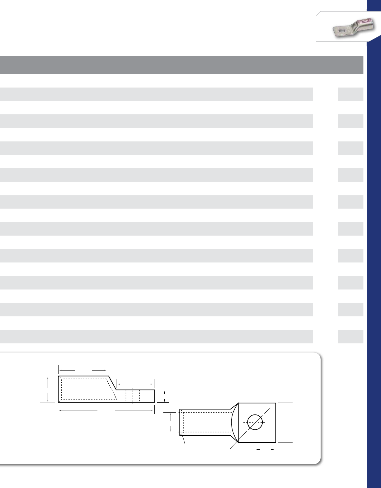
80
CONNECTORS
NSi Industries LLC • USA • 800.321.5847 • www.nsiindustries.com
CAT.
NO. WIRE
RANGE EXPANDED WIRE
RANGE* COLOR
CODE BOLT
SIZE I.D. O.D. LENGTH
(L) WIDTH
(W)
END OF CONN
TO CTR.
(A)
TANG
LENGTH
(B)
BARREL
LENGTH
(B1)
TANG
THICkNESS
(C)
MTG.
HOLE DIA.
(D)
MAX
AMP
RATING
STD.
CTN.
QTY.
GL810 8 AWG 8 AWG Red # 10 0.173 0.272 1.201 0.421 0.276 0.591 0.441 0.079 0.209 100
GL814 8 AWG 8 AWG Red 1/4 0.173 0.272 1.201 0.421 0.276 0.591 0.441 0.079 0.252 100
GL856 8 AWG 8 AWG Red 5/16 0.173 0.272 1.201 0.421 0.276 0.591 0.441 0.079 0.330 100
GL614 6 AWG 6 - 8 AWG Blue 1/4 0.205 0.295 1.496 0.421 0.295 0.669 0.709 0.083 0.252 100
GL656 6 AWG 6 - 8 AWG Blue 5/16 0.205 0.295 1.496 0.488 0.295 0.669 0.709 0.067 0.331 100
GL638 6 AWG 6 - 8 AWG Blue 3/8 0.205 0.295 1.496 0.488 0.295 0.669 0.709 0.067 0.410 100
GL414 4 AWG 4 - 6 AWG Gray 1/4 0.252 0.343 1.496 0.488 0.315 0.669 0.709 0.079 0.252 100
GL456 4 AWG 4 - 6 AWG Gray 5/16 0.252 0.343 1.496 0.488 0.315 0.669 0.709 0.079 0.331 100
GL438 4 AWG 4 - 6 AWG Gray 3/8 0.252 0.343 1.496 0.559 0.315 0.669 0.709 0.079 0.413 100
GL338 3 AWG 3 - 6 AWG White 3/8 0.277 0.372 1.984 0.594 0.375 0.875 0.885 0.086 0.399 50
GL214 2 AWG 2 - 6 AWG Brown 1/4 0.315 0.421 1.795 0.602 0.370 0.811 0.827 0.102 0.252 50
GL256 2 AWG 2 - 6 AWG Brown 5/16 0.315 0.421 1.795 0.602 0.370 0.811 0.827 0.102 0.331 50
GL238 2 AWG 2 - 6 AWG Brown 3/8 0.315 0.421 1.795 0.602 0.370 0.811 0.827 0.102 0.413 50
GL114 1 AWG 1 - 6 AWG Green 1/4 0.358 0.469 1.835 0.673 0.370 0.811 0.827 0.106 0.252 50
GL156 1 AWG 1 - 6 AWG Green 5/16 0.358 0.469 1.835 0.673 0.370 0.811 0.827 0.106 0.331 50
GL138 1 AWG 1 - 6 AWG Green 3/8 0.358 0.469 1.835 0.673 0.394 0.811 0.827 0.106 0.413 50
GL1056 1/0 AWG 1/0 - 6 AWG Pink 5/16 0.390 0.520 1.835 0.744 0.370 0.811 0.827 0.126 0.331 50
GL1038 1/0 AWG 1/0 - 6 AWG Pink 3/8 0.390 0.520 1.835 0.744 0.370 0.811 0.827 0.126 0.413 50
GL1048 1/0 AWG 1/0 - 6 AWG Pink 1/2 0.390 0.520 1.835 0.744 0.370 0.811 0.827 0.126 0.512 50
GL2056 2/0 AWG 2/0 - 4 AWG Black 5/16 0.441 0.563 2.244 0.815 0.472 1.063 0.945 0.118 0.331 25
COMPRESSION LUGS
ONE HOLE
45° Deep
Chamfer
L
W
A
D
B
C
B1
COMPRESSION LUGS
ONE HOLE
45° Deep
Chamfer
L
W
A
D
B
C
B1
Max ampacity is based on NEC 310.15, insulation type, and conductor material. Please consult your current NEC manual.
ID
OD
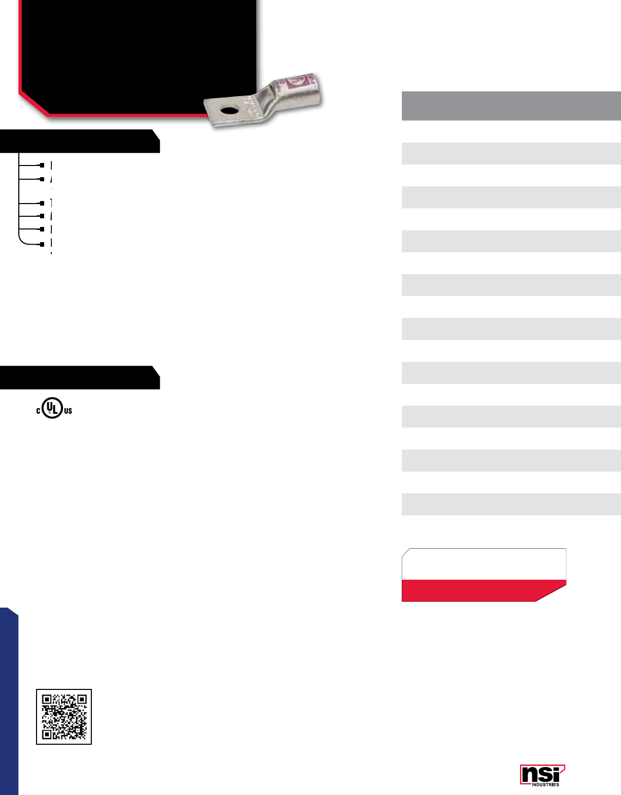
81
CONNECTORS
RATINGS
FEATURES
COMPRESSION CONNECTORS
Short Barrel Copper Lugs
One Hole With Peep Hole
GL SERIES CONTINUED
CAT.
NO. WIRE
RANGE EXPANDED WIRE
RANGE* COLOR
CODE BOLT
SIZE I.D. O.D. LENGTH
(L) WIDTH
(W)
END OF CONN
TO CTR.
(A)
TANG
LENGTH
(B)
BARREL
LENGTH
(B1)
TANG
THICkNESS
(C)
MTG.
HOLE DIA.
(D)
MAX
AMP
RATING
STD.
CTN.
QTY.
GL2038 2/0 AWG 2/0 - 4 AWG Black 3/8 0.441 0.563 2.244 0.815 0.472 1.063 0.945 0.118 0.413 25
GL2048 2/0 AWG 2/0 - 4 AWG Black 1/2 0.441 0.563 2.244 0.815 0.472 1.063 0.945 0.118 0.512 25
GL3038 3/0 AWG 3/0 - 2 AWG Orange 3/8 0.492 0.622 2.362 0.902 0.472 1.063 0.984 0.126 0.413 25
GL3048 3/0 AWG 3/0 - 2 AWG Orange 1/2 0.492 0.622 2.362 0.902 0.472 1.063 0.984 0.126 0.512 25
GL4038 4/0 AWG 4/0 - 1 AWG Purple 3/8 0.547 0.689 2.362 1.000 0.472 1.063 0.984 0.134 0.413 25
GL4048 4/0 AWG 4/0 - 1 AWG Purple 1/2 0.547 0.689 2.362 1.000 0.472 1.063 0.984 0.134 0.512 25
GL25038 250 MCM 250 MCM - 1/0 AWG Yellow 3/8 0.594 0.752 2.480 1.091 0.472 1.063 1.063 0.150 0.413 25
GL25048 250 MCM 250 MCM - 1/0 AWG Yellow 1/2 0.594 0.752 2.480 1.091 0.472 1.063 1.063 0.150 0.512 25
GL30048 300 MCM 300 MCM - 2/0 AWG White 1/2 0.657 0.815 2.480 1.189 0.520 1.063 1.063 0.150 0.512 12
GL35038 350 MCM 350 MCM - 3/0 AWG Red 3/8 0.692 0.875 1.625 1.281 0.395 0.875 1.112 0.173 0.391 12
GL35048 350 MCM 350 MCM - 3/0 AWG Red 1/2 0.701 0.874 2.606 1.276 0.520 1.063 1.102 0.165 0.512 12
GL40048 400 MCM 400 MCM - 4/0 AWG Blue 1/2 0.764 0.949 3.079 1.386 0.520 1.378 1.181 0.177 0.512 6
GL50048 500 MCM 500 - 250 MCM Brown 1/2 0.835 1.063 3.276 1.539 0.520 1.378 1.378 0.217 0.512 6
GL50058 500 MCM 500 - 250 MCM Brown 5/8 0.835 1.063 3.276 1.539 0.520 1.378 1.378 0.217 0.669 6
GL60048 600 MCM 600 - 250 MCM Green 1/2 0.925 1.189 3.504 1.717 0.520 1.457 1.496 0.252 0.512 6
GL60058 600 MCM 600 - 250 MCM Green 5/8 0.925 1.189 3.504 1.717 0.689 1.457 1.496 0.252 0.669 6
GL75048 750 MCM 750 - 500 MCM Black 1/2 1.022 1.295 3.866 1.760 0.685 1.550 1.743 0.277 0.541 3
GL75058 750 MCM 750 - 500 MCM Black 5/8 1.031 1.311 4.370 1.902 0.689 1.850 1.850 0.268 0.669 3
GL10058 1000 MCM White 5/8 1.158 1.491 4.085 2.151 0.730 1.675 1.789 0.327 0.669 3
TEMPERATURE RATING/VOLTAGE:
AL9CU. Rated 600V, 90 °C.
Produced from high conductivity copper tubing.
Allows easy inspection of the termination to assure
complete cable insertion.
Tin-plated to provide corrosion and low contact resistance.
Marked with die index and color coded.
Listed for 35KV maximum when properly installed.
For applications greater than 2000V, installed to cable
manufacturer for voltage stress relief instructions.
For applications greater than 2000V, installed to cable
manufacturer for voltage stress relief instructions.
For applications greater than 2000V, installed to cable
manufacturer for voltage stress relief instructions.
For applications greater than 2000V, installed to cable
Produced from high conductivity copper tubing.
Allows easy inspection of the termination to assure
Marked with die index and color coded.
Listed for 35KV maximum when properly installed.
For applications greater than 2000V, installed to cable
Listed for 35KV maximum when properly installed.
Tin-plated to provide corrosion and low contact resistance.
Marked with die index and color coded.
Allows easy inspection of the termination to assure
complete cable insertion.
Allows easy inspection of the termination to assure
complete cable insertion.
Allows easy inspection of the termination to assure
Allows easy inspection of the termination to assure
All dimensional data is listed in inches.
Scan QR to view
Tool & Die Charts
LISTED
155027
*EXPANDED WIRE RANGE when installed with
NSI N12ID dieless compression tool.
UL Listed with other tools:
FOR TOOL & DIE CRIMPING INFORMATION,
PLEASE SEE TABLE ON PAGE 145

82
CONNECTORS
NSi Industries LLC • USA • 800.321.5847 • www.nsiindustries.com
CAT.
NO. WIRE
RANGE EXPANDED WIRE
RANGE* COLOR
CODE BOLT
SIZE I.D. O.D. LENGTH
(L) WIDTH
(W)
END OF CONN
TO CTR.
(A)
TANG
LENGTH
(B)
BARREL
LENGTH
(B1)
TANG
THICkNESS
(C)
MTG.
HOLE DIA.
(D)
MAX
AMP
RATING
STD.
CTN.
QTY.
GL2038 2/0 AWG 2/0 - 4 AWG Black 3/8 0.441 0.563 2.244 0.815 0.472 1.063 0.945 0.118 0.413 25
GL2048 2/0 AWG 2/0 - 4 AWG Black 1/2 0.441 0.563 2.244 0.815 0.472 1.063 0.945 0.118 0.512 25
GL3038 3/0 AWG 3/0 - 2 AWG Orange 3/8 0.492 0.622 2.362 0.902 0.472 1.063 0.984 0.126 0.413 25
GL3048 3/0 AWG 3/0 - 2 AWG Orange 1/2 0.492 0.622 2.362 0.902 0.472 1.063 0.984 0.126 0.512 25
GL4038 4/0 AWG 4/0 - 1 AWG Purple 3/8 0.547 0.689 2.362 1.000 0.472 1.063 0.984 0.134 0.413 25
GL4048 4/0 AWG 4/0 - 1 AWG Purple 1/2 0.547 0.689 2.362 1.000 0.472 1.063 0.984 0.134 0.512 25
GL25038 250 MCM 250 MCM - 1/0 AWG Yellow 3/8 0.594 0.752 2.480 1.091 0.472 1.063 1.063 0.150 0.413 25
GL25048 250 MCM 250 MCM - 1/0 AWG Yellow 1/2 0.594 0.752 2.480 1.091 0.472 1.063 1.063 0.150 0.512 25
GL30048 300 MCM 300 MCM - 2/0 AWG White 1/2 0.657 0.815 2.480 1.189 0.520 1.063 1.063 0.150 0.512 12
GL35038 350 MCM 350 MCM - 3/0 AWG Red 3/8 0.692 0.875 1.625 1.281 0.395 0.875 1.112 0.173 0.391 12
GL35048 350 MCM 350 MCM - 3/0 AWG Red 1/2 0.701 0.874 2.606 1.276 0.520 1.063 1.102 0.165 0.512 12
GL40048 400 MCM 400 MCM - 4/0 AWG Blue 1/2 0.764 0.949 3.079 1.386 0.520 1.378 1.181 0.177 0.512 6
GL50048 500 MCM 500 - 250 MCM Brown 1/2 0.835 1.063 3.276 1.539 0.520 1.378 1.378 0.217 0.512 6
GL50058 500 MCM 500 - 250 MCM Brown 5/8 0.835 1.063 3.276 1.539 0.520 1.378 1.378 0.217 0.669 6
GL60048 600 MCM 600 - 250 MCM Green 1/2 0.925 1.189 3.504 1.717 0.520 1.457 1.496 0.252 0.512 6
GL60058 600 MCM 600 - 250 MCM Green 5/8 0.925 1.189 3.504 1.717 0.689 1.457 1.496 0.252 0.669 6
GL75048 750 MCM 750 - 500 MCM Black 1/2 1.022 1.295 3.866 1.760 0.685 1.550 1.743 0.277 0.541 3
GL75058 750 MCM 750 - 500 MCM Black 5/8 1.031 1.311 4.370 1.902 0.689 1.850 1.850 0.268 0.669 3
GL10058 1000 MCM White 5/8 1.158 1.491 4.085 2.151 0.730 1.675 1.789 0.327 0.669 3
Max ampacity is based on NEC 310.15, insulation type, and conductor material. Please consult your current NEC manual.
COMPRESSION LUGS
ONE HOLE
45° Deep
Chamfer
L
W
A
D
B
C
B1
COMPRESSION LUGS
ONE HOLE
45° Deep
Chamfer
L
W
A
D
B
C
B1
OD
ID

83
CONNECTORS
RATINGS
FEATURES
COMPRESSION CONNECTORS
Short Barrel Copper Lugs
Two Hole With Peep
GL-N SERIES
CAT.
NO. WIRE
RANGE EXPANDED WIRE
RANGE* COLOR
CODE BOLT
SIZE I.D. O.D. LENGTH
(L) WIDTH
(W)
END OF CONN
TO CTR.
(A)
TANG
LENGTH
(B)
BARREL
LENGTH
(B1)
TANG
THICkNESS
(C)
MTG.
HOLE DIA.
(D)
MTG. HOLE
SPACING
(E)
MAX
AMP
RATING
STD.
CTN.
QTY.
GL6N-141 6 AWG 6 - 8 AWG Blue 1/4 0.205 0.295 2.087 0.421 0.280 1.260 0.709 0.083 0.252 0.625 100
GL6N-141X 6 AWG 6 - 8 AWG Blue 1/4 0.205 0.295 2.087 0.421 0.280 1.260 0.709 0.083 0.252 0.625 100
GL6N-143 6 AWG 6 - 8 AWG Blue 1/4 0.205 0.295 2.638 0.421 0.280 1.811 0.709 0.083 0.252 1.000 100
GL6N-38 6 AWG 6 - 8 AWG Blue 3/8 0.205 0.295 2.638 0.488 0.382 1.811 0.709 0.087 0.413 1.000 100
GL4N-141 4 AWG 4 - 6 AWG Gray 1/4 0.252 0.343 2.087 0.488 0.280 1.260 0.709 0.087 0.252 0.625 100
GL4N-38 4 AWG 4 - 6 AWG Gray 3/8 0.252 0.343 2.677 0.488 0.382 1.811 0.748 0.087 0.413 1.000 100
GL2N-141 2 AWG 2 - 6 AWG Brown 1/4 0.315 0.421 2.283 0.602 0.280 1.260 0.827 0.102 0.252 0.625 50
GL2N-141X 2 AWG 2 - 6 AWG Brown 1/4 0.315 0.421 2.283 0.602 0.280 1.260 0.827 0.102 0.252 0.625 50
GL2N-142 2 AWG 2 - 6 AWG Brown 1/4 0.315 0.421 2.362 0.602 0.280 1.378 0.827 0.102 0.252 0.750 50
GL2N-143 2 AWG 2 - 6 AWG Brown 1/4 0.315 0.421 2.795 0.602 0.280 1.811 0.827 0.102 0.252 1.000 50
GL2N-38 2 AWG 2 - 6 AWG Brown 3/8 0.315 0.421 2.835 0.602 0.280 1.811 0.827 0.102 0.413 1.000 50
GL2N-38X 2 AWG 2 - 6 AWG Brown 3/8 0.315 0.421 2.835 0.602 0.280 1.811 0.827 0.102 0.413 1.000 50
GL1N-38 1 AWG 1 - 6 AWG Green 3/8 0.350 0.463 3.024 0.672 0.345 1.842 0.955 0.106 0.404 1.000 50
GL10N-38 1/0 AWG 1/0 - 6 AWG Pink 3/8 0.390 0.520 2.835 0.744 0.382 1.811 0.827 0.126 0.413 1.000 50
GL10N-38X 1/0 AWG 1/0 - 6 AWG Pink 3/8 0.390 0.520 2.835 0.744 0.382 1.811 0.827 0.126 0.413 1.000 50
GL20N 2/0 AWG 2/0 - 4 AWG Black 1/2 0.441 0.563 4.173 0.815 0.618 2.992 0.945 0.118 0.512 1.750 25
GL20N-38 2/0 AWG 2/0 - 4 AWG Black 3/8 0.441 0.563 2.992 0.815 0.382 1.811 0.945 0.118 0.413 1.000 25
GL30N 3/0 AWG 3/0 - 2 AWG Orange 1/2 0.492 0.622 4.291 0.902 0.618 2.992 0.984 0.126 0.512 1.750 25
GL30N-38 3/0 AWG 3/0 - 2 AWG Orange 3/8 0.492 0.622 3.110 0.902 0.382 1.811 0.984 0.126 0.413 1.000 25
GL40N 4/0 AWG 4/0 - 1 AWG Purple 1/2 0.547 0.689 4.291 1.000 0.618 2.992 0.984 0.134 0.512 1.750 25
GL40N-38 4/0 AWG 4/0 - 1 AWG Purple 3/8 0.547 0.689 3.110 1.000 0.382 1.811 0.984 0.134 0.413 1.000 25
GL250N 250 MCM 250 MCM - 1/0 AWG Yellow 1/2 0.594 0.752 4.409 1.091 0.618 2.992 1.063 0.150 0.512 1.750 25
GL250N-38 250 MCM 250 MCM - 1/0 AWG Yellow 3/8 0.594 0.752 3.228 1.091 0.382 1.811 1.063 0.150 0.413 1.000 25
GL350N 350 MCM 350 MCM - 3/0 AWG Red 1/2 0.701 0.874 4.528 1.276 0.618 2.992 1.102 0.165 0.512 1.750 12
GL350N-38 350 MCM 350 MCM - 3/0 AWG Red 3/8 0.701 0.874 3.346 1.276 0.382 1.811 1.102 0.165 0.413 1.000 12
GL400N 400 MCM 400 MCM - 4/0 AWG Blue 1/2 0.764 0.949 4.685 1.386 0.618 2.992 1.181 0.177 0.512 1.750 6
GL500N 500 MCM 500 - 250 MCM Brown 1/2 0.839 1.063 4.882 1.539 0.618 2.992 1.378 0.217 0.512 1.750 6
GL500N-38 500 MCM 500 - 250 MCM Brown 3/8 0.839 1.063 3.701 1.539 0.382 1.811 1.378 0.217 0.413 1.000 6
GL600N 600 MCM 600 - 250 MCM Green 1/2 0.925 1.189 5.039 1.717 0.618 2.992 1.496 0.252 0.512 1.750 6
GL750N 750 MCM 750 - 500 MCM Black 1/2 1.043 1.311 5.512 1.902 0.618 2.992 1.850 0.268 0.512 1.750 3
GL1000N 1000 MCM White 1/2 1.173 1.492 5.870 2.158 0.620 3.436 1.910 0.331 0.544 1.750 1
TEMPERATURE RATING/VOLTAGE:
AL9CU. Rated 600V, 90 °C.
Produced from high conductivity copper tubing.
Allows easy inspection of the termination to assure
complete cable insertion.
Tin-plated to provide corrosion and low contact resistance.
Marked with die index and color coded.
Listed for 35KV maximum when properly installed.
For applications greater than 2000V, installed to cable
manufacturer for voltage stress relief instructions.
Note: Part numbers ending in “X” have no peep hole.
For applications greater than 2000V, installed to cable
manufacturer for voltage stress relief instructions.
For applications greater than 2000V, installed to cable
manufacturer for voltage stress relief instructions.
For applications greater than 2000V, installed to cable
Produced from high conductivity copper tubing.
Allows easy inspection of the termination to assure
Marked with die index and color coded.
Listed for 35KV maximum when properly installed.
For applications greater than 2000V, installed to cable
Listed for 35KV maximum when properly installed.
Tin-plated to provide corrosion and low contact resistance.
Marked with die index and color coded.
Allows easy inspection of the termination to assure
complete cable insertion.
Allows easy inspection of the termination to assure
complete cable insertion.
Allows easy inspection of the termination to assure
Allows easy inspection of the termination to assure
All dimensional data is listed in inches.
COMPRESSION LUGS
TWO HOLE
45° Deep
Chamfer
L
W
A
D
E
B
C
B1
Scan QR to view
Tool & Die Charts
LISTED
155027
*EXPANDED WIRE RANGE when installed with
NSI N12ID dieless compression tool.
UL Listed with other tools:
FOR TOOL & DIE CRIMPING INFORMATION,
PLEASE SEE TABLE ON PAGE 145
OD
ID

84
CONNECTORS
NSi Industries LLC • USA • 800.321.5847 • www.nsiindustries.com
CAT.
NO. WIRE
RANGE EXPANDED WIRE
RANGE* COLOR
CODE BOLT
SIZE I.D. O.D. LENGTH
(L) WIDTH
(W)
END OF CONN
TO CTR.
(A)
TANG
LENGTH
(B)
BARREL
LENGTH
(B1)
TANG
THICkNESS
(C)
MTG.
HOLE DIA.
(D)
MTG. HOLE
SPACING
(E)
MAX
AMP
RATING
STD.
CTN.
QTY.
GL6N-141 6 AWG 6 - 8 AWG Blue 1/4 0.205 0.295 2.087 0.421 0.280 1.260 0.709 0.083 0.252 0.625 100
GL6N-141X 6 AWG 6 - 8 AWG Blue 1/4 0.205 0.295 2.087 0.421 0.280 1.260 0.709 0.083 0.252 0.625 100
GL6N-143 6 AWG 6 - 8 AWG Blue 1/4 0.205 0.295 2.638 0.421 0.280 1.811 0.709 0.083 0.252 1.000 100
GL6N-38 6 AWG 6 - 8 AWG Blue 3/8 0.205 0.295 2.638 0.488 0.382 1.811 0.709 0.087 0.413 1.000 100
GL4N-141 4 AWG 4 - 6 AWG Gray 1/4 0.252 0.343 2.087 0.488 0.280 1.260 0.709 0.087 0.252 0.625 100
GL4N-38 4 AWG 4 - 6 AWG Gray 3/8 0.252 0.343 2.677 0.488 0.382 1.811 0.748 0.087 0.413 1.000 100
GL2N-141 2 AWG 2 - 6 AWG Brown 1/4 0.315 0.421 2.283 0.602 0.280 1.260 0.827 0.102 0.252 0.625 50
GL2N-141X 2 AWG 2 - 6 AWG Brown 1/4 0.315 0.421 2.283 0.602 0.280 1.260 0.827 0.102 0.252 0.625 50
GL2N-142 2 AWG 2 - 6 AWG Brown 1/4 0.315 0.421 2.362 0.602 0.280 1.378 0.827 0.102 0.252 0.750 50
GL2N-143 2 AWG 2 - 6 AWG Brown 1/4 0.315 0.421 2.795 0.602 0.280 1.811 0.827 0.102 0.252 1.000 50
GL2N-38 2 AWG 2 - 6 AWG Brown 3/8 0.315 0.421 2.835 0.602 0.280 1.811 0.827 0.102 0.413 1.000 50
GL2N-38X 2 AWG 2 - 6 AWG Brown 3/8 0.315 0.421 2.835 0.602 0.280 1.811 0.827 0.102 0.413 1.000 50
GL1N-38 1 AWG 1 - 6 AWG Green 3/8 0.350 0.463 3.024 0.672 0.345 1.842 0.955 0.106 0.404 1.000 50
GL10N-38 1/0 AWG 1/0 - 6 AWG Pink 3/8 0.390 0.520 2.835 0.744 0.382 1.811 0.827 0.126 0.413 1.000 50
GL10N-38X 1/0 AWG 1/0 - 6 AWG Pink 3/8 0.390 0.520 2.835 0.744 0.382 1.811 0.827 0.126 0.413 1.000 50
GL20N 2/0 AWG 2/0 - 4 AWG Black 1/2 0.441 0.563 4.173 0.815 0.618 2.992 0.945 0.118 0.512 1.750 25
GL20N-38 2/0 AWG 2/0 - 4 AWG Black 3/8 0.441 0.563 2.992 0.815 0.382 1.811 0.945 0.118 0.413 1.000 25
GL30N 3/0 AWG 3/0 - 2 AWG Orange 1/2 0.492 0.622 4.291 0.902 0.618 2.992 0.984 0.126 0.512 1.750 25
GL30N-38 3/0 AWG 3/0 - 2 AWG Orange 3/8 0.492 0.622 3.110 0.902 0.382 1.811 0.984 0.126 0.413 1.000 25
GL40N 4/0 AWG 4/0 - 1 AWG Purple 1/2 0.547 0.689 4.291 1.000 0.618 2.992 0.984 0.134 0.512 1.750 25
GL40N-38 4/0 AWG 4/0 - 1 AWG Purple 3/8 0.547 0.689 3.110 1.000 0.382 1.811 0.984 0.134 0.413 1.000 25
GL250N 250 MCM 250 MCM - 1/0 AWG Yellow 1/2 0.594 0.752 4.409 1.091 0.618 2.992 1.063 0.150 0.512 1.750 25
GL250N-38 250 MCM 250 MCM - 1/0 AWG Yellow 3/8 0.594 0.752 3.228 1.091 0.382 1.811 1.063 0.150 0.413 1.000 25
GL350N 350 MCM 350 MCM - 3/0 AWG Red 1/2 0.701 0.874 4.528 1.276 0.618 2.992 1.102 0.165 0.512 1.750 12
GL350N-38 350 MCM 350 MCM - 3/0 AWG Red 3/8 0.701 0.874 3.346 1.276 0.382 1.811 1.102 0.165 0.413 1.000 12
GL400N 400 MCM 400 MCM - 4/0 AWG Blue 1/2 0.764 0.949 4.685 1.386 0.618 2.992 1.181 0.177 0.512 1.750 6
GL500N 500 MCM 500 - 250 MCM Brown 1/2 0.839 1.063 4.882 1.539 0.618 2.992 1.378 0.217 0.512 1.750 6
GL500N-38 500 MCM 500 - 250 MCM Brown 3/8 0.839 1.063 3.701 1.539 0.382 1.811 1.378 0.217 0.413 1.000 6
GL600N 600 MCM 600 - 250 MCM Green 1/2 0.925 1.189 5.039 1.717 0.618 2.992 1.496 0.252 0.512 1.750 6
GL750N 750 MCM 750 - 500 MCM Black 1/2 1.043 1.311 5.512 1.902 0.618 2.992 1.850 0.268 0.512 1.750 3
GL1000N 1000 MCM White 1/2 1.173 1.492 5.870 2.158 0.620 3.436 1.910 0.331 0.544 1.750 1
Max ampacity is based on NEC 310.15, insulation type, and conductor material. Please consult your current NEC manual.
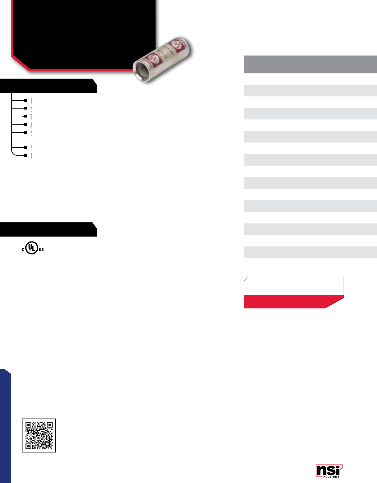
85
CONNECTORS
RATINGS
FEATURES
Produced from high conductivity copper tubing.
Serrations indicate proper crimp locations.
Tin-plated to provide corrosion resistance.
Marked with die index and color code.
Suitable for use at voltages up to 35KV provided
connector is properly taped.
5KV is the maximum voltage in all bare splices.
For applications greater than 2000V, consult the cable
manufacturer for voltage stress relief instructions.
COMPRESSION CONNECTORS
Copper Splice
Short Barrel
SC SERIES
For applications greater than 2000V, consult the cable
manufacturer for voltage stress relief instructions.
For applications greater than 2000V, consult the cable
manufacturer for voltage stress relief instructions.
For applications greater than 2000V, consult the cable
Produced from high conductivity copper tubing.
Marked with die index and color code.
Suitable for use at voltages up to 35KV provided
connector is properly taped.
Suitable for use at voltages up to 35KV provided
connector is properly taped.
Suitable for use at voltages up to 35KV provided
Suitable for use at voltages up to 35KV provided
5KV is the maximum voltage in all bare splices.
For applications greater than 2000V, consult the cable
For applications greater than 2000V, consult the cable
Serrations indicate proper crimp locations.
Serrations indicate proper crimp locations.
Tin-plated to provide corrosion resistance.
Serrations indicate proper crimp locations.
Tin-plated to provide corrosion resistance.
CAT.
NO. WIRE
RANGE EXPANDED WIRE
RANGE* COLOR
CODE I.D. O.D. LENGTH
(L)
STD.
CTN.
QTY.
SC-8 8 AWG 8 AWG Red 0.173 0.272 0.902 100
SC-6 6 AWG 6 - 8 AWG Blue 0.205 0.295 1.000 100
SC-4 4 AWG 4 - 6 AWG Gray 0.252 0.343 1.000 100
SC-3 3 AWG 3 - 6 AWG White 0.282 0.378 1.883 50
SC-2 2 AWG 2 - 6 AWG Brown 0.315 0.421 1.252 50
SC-1 1 AWG 1 - 6 AWG Green 0.358 0.469 1.799 50
SC-1/0 1/0 AWG 1/0 - 6 AWG Pink 0.390 0.520 1.598 50
SC-2/0 2/0 AWG 2/0 - 4 AWG Black 0.441 0.563 1.752 25
SC-3/0 3/0 AWG 3/0 - 2 AWG Orange 0.492 0.622 1.752 25
SC-4/0 4/0 AWG 4/0 - 1 AWG Purple 0.547 0.689 1.902 25
SC-250 250 MCM 250 MCM - 1/0 AWG Yellow 0.594 0.752 2.000 25
SC-300 300 MCM 300 MCM - 2/0 AWG White 0.657 0.815 2.098 12
SC-350 350 MCM 350 MCM - 3/0 AWG Red 0.701 0.874 2.098 12
SC-400 400 MCM 400 MCM - 4/0 AWG Blue 0.764 0.949 2.299 6
SC-500 500 MCM 500 - 250 MCM Brown 0.835 1.063 2.500 6
SC-600 600 MCM 600 - 250 MCM Green 1.189 1.189 2.500 6
SC-750 750 MCM 750-500 MCM Black 1.031 1.311 3.201 3
TEMPERATURE RATING/VOLTAGE:
AL9CU. Rated 600V, 90 °C.
All dimensional data is listed in inches.
Scan QR to view
Tool & Die Charts
LISTED
155027
*EXPANDED WIRE RANGE when installed with
NSI N12ID dieless compression tool.
UL Listed with other tools:
FOR TOOL & DIE CRIMPING INFORMATION,
PLEASE SEE TABLE ON PAGE 145

86
CONNECTORS
NSi Industries LLC • USA • 800.321.5847 • www.nsiindustries.com
CAT.
NO. WIRE
RANGE EXPANDED WIRE
RANGE* COLOR
CODE I.D. O.D. LENGTH
(L)
STD.
CTN.
QTY.
SC-8 8 AWG 8 AWG Red 0.173 0.272 0.902 100
SC-6 6 AWG 6 - 8 AWG Blue 0.205 0.295 1.000 100
SC-4 4 AWG 4 - 6 AWG Gray 0.252 0.343 1.000 100
SC-3 3 AWG 3 - 6 AWG White 0.282 0.378 1.883 50
SC-2 2 AWG 2 - 6 AWG Brown 0.315 0.421 1.252 50
SC-1 1 AWG 1 - 6 AWG Green 0.358 0.469 1.799 50
SC-1/0 1/0 AWG 1/0 - 6 AWG Pink 0.390 0.520 1.598 50
SC-2/0 2/0 AWG 2/0 - 4 AWG Black 0.441 0.563 1.752 25
SC-3/0 3/0 AWG 3/0 - 2 AWG Orange 0.492 0.622 1.752 25
SC-4/0 4/0 AWG 4/0 - 1 AWG Purple 0.547 0.689 1.902 25
SC-250 250 MCM 250 MCM - 1/0 AWG Yellow 0.594 0.752 2.000 25
SC-300 300 MCM 300 MCM - 2/0 AWG White 0.657 0.815 2.098 12
SC-350 350 MCM 350 MCM - 3/0 AWG Red 0.701 0.874 2.098 12
SC-400 400 MCM 400 MCM - 4/0 AWG Blue 0.764 0.949 2.299 6
SC-500 500 MCM 500 - 250 MCM Brown 0.835 1.063 2.500 6
SC-600 600 MCM 600 - 250 MCM Green 1.189 1.189 2.500 6
SC-750 750 MCM 750-500 MCM Black 1.031 1.311 3.201 3
L
O.D
I.D

87
CONNECTORS
RATINGS
FEATURES
COMPRESSION CONNECTORS
Copper Splice
Long Barrel
C SERIES
TEMPERATURE RATING:
90 °C.
CAT.
NO. WIRE
RANGE EXPANDED WIRE
RANGE* COLOR CODE
INDEX I.D. O.D. LENGTH
(L) (IN.)
STD.
CTN.
QTY.
C-8 8 AWG 8 AWG Red 0.173 0.272 1.752 100
C-6 6 AWG 6 - 8 AWG Blue 0.205 0.295 1.752 100
C-4 4 AWG 4 - 6 AWG Gray 0.252 0.343 1.752 100
C-3 3 AWG 3 - 6 AWG White 0.282 0.378 2.381 50
C-2 2 AWG 2 - 6 AWG Brown 0.315 0.421 1.902 50
C-1 1 AWG 1 - 6 AWG Green 0.358 0.469 2.201 50
C-1/0 1/0 AWG 1/0 - 6 AWG Pink 0.390 0.520 2.201 50
C-2/0 2/0 AWG 2/0 - 4 AWG Black 0.441 0.563 2.252 25
C-3/0 3/0 AWG 3/0 - 2 AWG Orange 0.492 0.622 2.252 25
C-4/0 4/0 AWG 4/0 - 1 AWG Purple 0.547 0.689 2.752 25
C-250 250 MCM 250 MCM - 1/0 AWG Yellow 0.594 0.752 3.252 25
C-300 300 MCM 300 MCM - 2/0 AWG White 0.657 0.815 3.504 12
C-350 350 MCM 350 MCM - 3/0 AWG Red 0.701 0.874 3.752 12
C-400 400 MCM 400 MCM - 4/0 AWG Blue 0.764 0.949 3.752 6
C-500 500 MCM 500 - 250 MCM Brown 0.835 1.063 4.252 6
C-600 600 MCM 600 - 250 MCM Green 1.189 1.189 4.500 6
C-750 750 MCM 750-500 MCM Black 1.031 1.311 4.752 3
Produced from high conductivity copper tubing.
Serrations indicate proper crimp locations.
Tin-plated to provide corrosion resistance.
Marked with die index and color code.
Suitable for use at voltages up to 35KV provided
connector is properly taped.
5KV is the maximum voltage in all bare splices.
For applications greater than 2000V, consult the cable
manufacturer for voltage stress relief instructions.
For applications greater than 2000V, consult the cable
manufacturer for voltage stress relief instructions.
For applications greater than 2000V, consult the cable
manufacturer for voltage stress relief instructions.
For applications greater than 2000V, consult the cable
Produced from high conductivity copper tubing.
Marked with die index and color code.
Suitable for use at voltages up to 35KV provided
Suitable for use at voltages up to 35KV provided
connector is properly taped.
Suitable for use at voltages up to 35KV provided
connector is properly taped.
Suitable for use at voltages up to 35KV provided
Suitable for use at voltages up to 35KV provided
5KV is the maximum voltage in all bare splices.
For applications greater than 2000V, consult the cable
For applications greater than 2000V, consult the cable
Serrations indicate proper crimp locations.
Serrations indicate proper crimp locations.
Tin-plated to provide corrosion resistance.
Marked with die index and color code.
Tin-plated to provide corrosion resistance.
All dimensional data is listed in inches.
Scan QR to view
Tool & Die Charts
LISTED
155027
*EXPANDED WIRE RANGE when installed with
NSI N12ID dieless compression tool.
UL Listed with other tools:
FOR TOOL & DIE CRIMPING INFORMATION,
PLEASE SEE TABLE ON PAGE 145
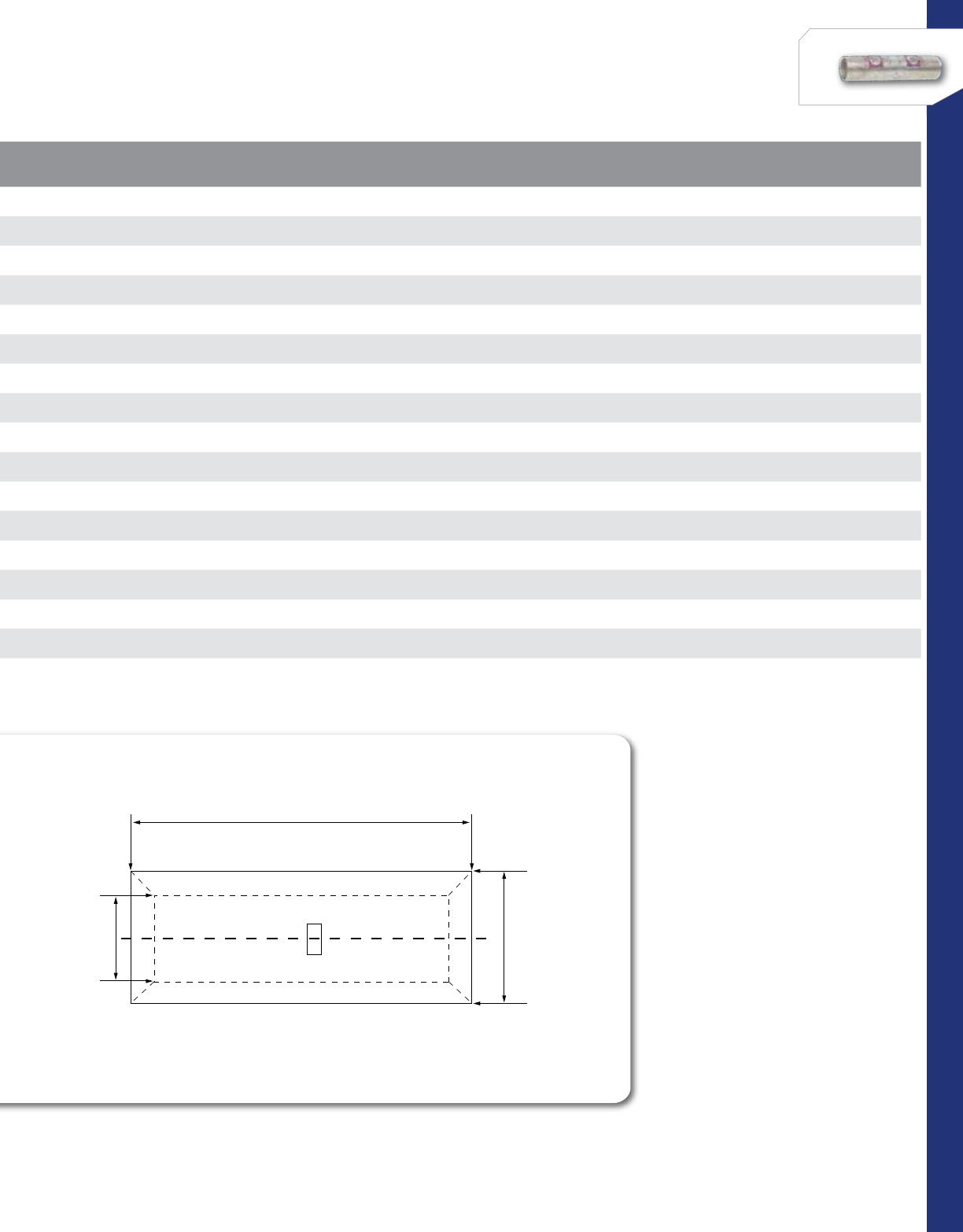
88
CONNECTORS
NSi Industries LLC • USA • 800.321.5847 • www.nsiindustries.com
CAT.
NO. WIRE
RANGE EXPANDED WIRE
RANGE* COLOR CODE
INDEX I.D. O.D. LENGTH
(L) (IN.)
STD.
CTN.
QTY.
C-8 8 AWG 8 AWG Red 0.173 0.272 1.752 100
C-6 6 AWG 6 - 8 AWG Blue 0.205 0.295 1.752 100
C-4 4 AWG 4 - 6 AWG Gray 0.252 0.343 1.752 100
C-3 3 AWG 3 - 6 AWG White 0.282 0.378 2.381 50
C-2 2 AWG 2 - 6 AWG Brown 0.315 0.421 1.902 50
C-1 1 AWG 1 - 6 AWG Green 0.358 0.469 2.201 50
C-1/0 1/0 AWG 1/0 - 6 AWG Pink 0.390 0.520 2.201 50
C-2/0 2/0 AWG 2/0 - 4 AWG Black 0.441 0.563 2.252 25
C-3/0 3/0 AWG 3/0 - 2 AWG Orange 0.492 0.622 2.252 25
C-4/0 4/0 AWG 4/0 - 1 AWG Purple 0.547 0.689 2.752 25
C-250 250 MCM 250 MCM - 1/0 AWG Yellow 0.594 0.752 3.252 25
C-300 300 MCM 300 MCM - 2/0 AWG White 0.657 0.815 3.504 12
C-350 350 MCM 350 MCM - 3/0 AWG Red 0.701 0.874 3.752 12
C-400 400 MCM 400 MCM - 4/0 AWG Blue 0.764 0.949 3.752 6
C-500 500 MCM 500 - 250 MCM Brown 0.835 1.063 4.252 6
C-600 600 MCM 600 - 250 MCM Green 1.189 1.189 4.500 6
C-750 750 MCM 750-500 MCM Black 1.031 1.311 4.752 3
L
O.D
I.D
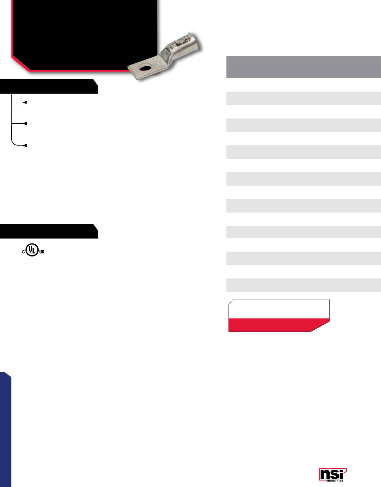
89
CONNECTORS
RATINGS
FEATURES
COMPRESSION CONNECTORS
For Flexible Copper Cable –
One Hole Short Barrel
(Peep Hole)
GL-B SERIES
TEMPERATURE RATING:
90 °C.
600V.
for copper cables only.
CAT.
NO. WIRE
RANGE EXPANDED
WIRE RANGE* COLOR
CODE
CABLE SIZE BOLT
SIZE I.D. O.D. LENGTH
(L) WIDTH
(W)
COMM ASTM
CLASS H WELDING
CLASS M DIESEL
LOCOMOTIVE
GL256B 2 AWG 2 - 6 AWG Brown 244(125) 5/16 0.315 0.421 1.800 0.600
GL156B 1 AWG 1 - 6 AWG Green 122(150) 5/16 0.358 0.469 1.830 0.670
GL1056B 1/0 AWG 1/0 - 6 AWG Pink 1/0 11(225) 5/16 0.390 0.520 1.830 0.740
GL2038B 2/0 AWG 2/0 - 4 AWG Black 2/0 1/0 1/0 1/0 (275) 3/8 0.441 0.563 2.240 0.810
GL3038B 3/0 AWG 3/0 - 2 AWG Orange 3/0 2/0 -2/0 (325) 3/8 0.492 0.622 2.360 0.900
GL3048B 3/0 AWG 3/0 - 2 AWG Orange 3/0 2/0 -2/0 (325) 1/2 0.492 0.622 2.360 0.900
GL4048B 4/0 AWG 4/0 - 1 AWG Purple 4/0 3/0 2/0 3/0 (450) 1/2 0.547 0.689 2.360 1.000
GL25038B 250 MCM 250 MCM - 1/0 AWG Yellow 250 -3/0 4/0 (550) 3/8 0.594 0.752 2.480 1.090
GL25048B 250 MCM 250 MCM - 1/0 AWG Yellow 250 -3/0 4/0 (550) 1/2 0.594 0.752 2.480 1.090
GL30048B 300 MCM 300 MCM - 2/0 AWG White 300 4/0 4/0 262.6 1/2 0.657 0.815 2.490 1.190
GL35058B 350 MCM 350 MCM - 3/0 AWG Red 350 250 250 313.1 5/8 0.692 0.875 2.910 1.280
GL50058B 400 MCM 400 MCM - 4/0 AWG Brown 500 350 300 373.3 5/8 0.835 1.063 3.280 1.540
GL60058B 500 MCM 500 - 250 MCM Green 600 400 350 444.4 5/8 0.925 1.189 3.500 1.720
GL70058B 600 MCM 600 - 250 MCM Pink 700 500 400 535.3 5/8 1.031 1.311
GL75058B 750 MCM 750-500 MCM Black 750 600 500 -5/8 1.031 1.311 4.370 1.950
GL10058B 1000 MCM 1000-500 MCM White 1000 800 700 777.7 5/8 1.158 1.491 4.769 2.170
Connector end has a gentle, continuous flare to ensure
ease of cable insertion of flexible and extra-flexible
cables such as locomotive, welding, mining cable and more.
The flared end also reduces pressure on the cable strands
after installation and protects them from chafing and
breakage as a result of cable movement.
Tin- plated for corrosion resistance.
All dimensional data is listed in inches.
LISTED
155027
*EXPANDED WIRE RANGE when installed with
NSI N12ID dieless compression tool.
UL Listed with other tools:
FOR TOOL & DIE CRIMPING INFORMATION,
PLEASE SEE TABLE ON PAGE 145
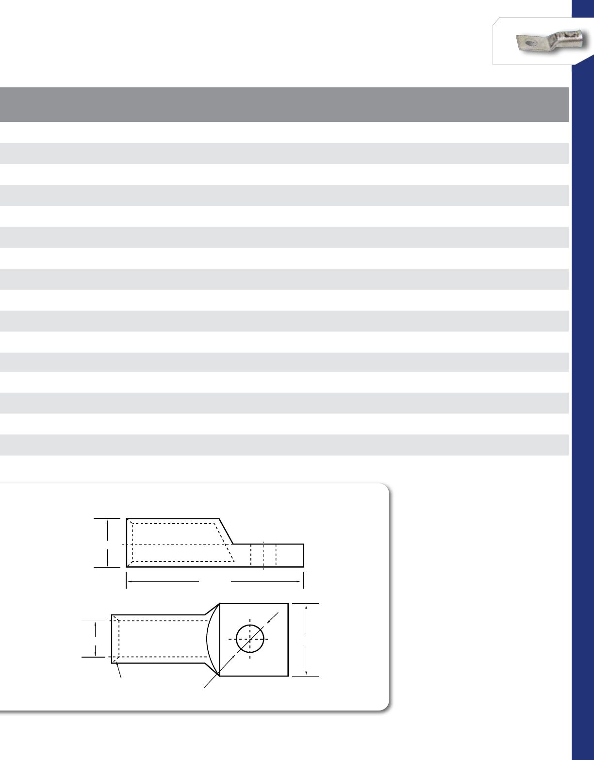
90
CONNECTORS
NSi Industries LLC • USA • 800.321.5847 • www.nsiindustries.com
CAT.
NO. WIRE
RANGE EXPANDED
WIRE RANGE* COLOR
CODE
CABLE SIZE BOLT
SIZE I.D. O.D. LENGTH
(L) WIDTH
(W)
COMM ASTM
CLASS H WELDING
CLASS M DIESEL
LOCOMOTIVE
GL256B 2 AWG 2 - 6 AWG Brown 244(125) 5/16 0.315 0.421 1.800 0.600
GL156B 1 AWG 1 - 6 AWG Green 122(150) 5/16 0.358 0.469 1.830 0.670
GL1056B 1/0 AWG 1/0 - 6 AWG Pink 1/0 11(225) 5/16 0.390 0.520 1.830 0.740
GL2038B 2/0 AWG 2/0 - 4 AWG Black 2/0 1/0 1/0 1/0 (275) 3/8 0.441 0.563 2.240 0.810
GL3038B 3/0 AWG 3/0 - 2 AWG Orange 3/0 2/0 -2/0 (325) 3/8 0.492 0.622 2.360 0.900
GL3048B 3/0 AWG 3/0 - 2 AWG Orange 3/0 2/0 -2/0 (325) 1/2 0.492 0.622 2.360 0.900
GL4048B 4/0 AWG 4/0 - 1 AWG Purple 4/0 3/0 2/0 3/0 (450) 1/2 0.547 0.689 2.360 1.000
GL25038B 250 MCM 250 MCM - 1/0 AWG Yellow 250 -3/0 4/0 (550) 3/8 0.594 0.752 2.480 1.090
GL25048B 250 MCM 250 MCM - 1/0 AWG Yellow 250 -3/0 4/0 (550) 1/2 0.594 0.752 2.480 1.090
GL30048B 300 MCM 300 MCM - 2/0 AWG White 300 4/0 4/0 262.6 1/2 0.657 0.815 2.490 1.190
GL35058B 350 MCM 350 MCM - 3/0 AWG Red 350 250 250 313.1 5/8 0.692 0.875 2.910 1.280
GL50058B 400 MCM 400 MCM - 4/0 AWG Brown 500 350 300 373.3 5/8 0.835 1.063 3.280 1.540
GL60058B 500 MCM 500 - 250 MCM Green 600 400 350 444.4 5/8 0.925 1.189 3.500 1.720
GL70058B 600 MCM 600 - 250 MCM Pink 700 500 400 535.3 5/8 1.031 1.311
GL75058B 750 MCM 750-500 MCM Black 750 600 500 -5/8 1.031 1.311 4.370 1.950
GL10058B 1000 MCM 1000-500 MCM White 1000 800 700 777.7 5/8 1.158 1.491 4.769 2.170
B1 ±1.00
COMPRESSION LUGS
ONE HOLE
B ±1.00
L ±1.00
O.D ±0.50
I.D.±0.20 W±1.00
A ±0.50
D±0.20
45° Deep
Chamfer
C±0.50
B1 ±1.00
COMPRESSION LUGS
ONE HOLE
B ±1.00
L ±1.00
O.D ±0.50
I.D.±0.20 W±1.00
A ±0.50
D±0.20
45° Deep
Chamfer
C±0.50
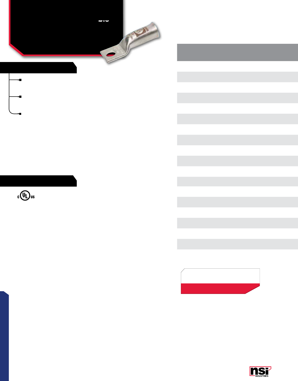
91
CONNECTORS
RATINGS
FEATURES
COMPRESSION CONNECTORS
For Flexible Copper Cable –
One Hole Long Barrel
L-B SERIES
Connector end has a gentle, continuous flare to ensure
ease of cable insertion of flexible and extra-flexible
cables such as locomotive, welding, mining cable and more.
The flared end also reduces pressure on the cable strands
after installation and protects them from chafing and
breakage as a result of cable movement.
Tin- plated for corrosion resistance.
For Flexible Copper Cable –
TEMPERATURE RATING:
90 °C.
600V.
for copper cables only.
CAT.
NO. WIRE
RANGE EXPANDED
WIRE RANGE* COLOR
CODE
CABLE SIZE LENGTH
(L) BOLT
SIZE WIDTH
(W) I.D. O.D.
COMM ASTM
CLASS H WELDING
CLASS M DIESEL
LOCOMOTIVE
L638B 6 AWG 6-8 AWG Blue 688(61) 1.910 3/8 0.590 0.205 0.295
L438B 4 AWG 4 - 6 AWG Grey 466(105) 1.910 3/8 0.590 0.252 0.343
L256B 2 AWG 2 - 6 AWG Brown 244(125) 2.070 5/16 0.600 0.315 0.421
L238B 2 AWG 2 - 6 AWG Brown 244(125) 2.070 3/8 0.600 0.315 0.421
L156B 1 AWG 1 - 6 AWG Green 122(150) 2.110 5/16 0.670 0.358 0.469
L1056B 1/0 AWG 1/0 - 6 AWG Pink 1/0 1 1 (225) 2.210 5/16 0.740 0.390 0.520
L2038B 2/0 AWG 2/0 - 4 AWG Black 2/0 1/0 1/0 1/0 (275) 2.680 3/8 0.810 0.441 0.563
L3038B 3/0 AWG 3/0 - 2 AWG Orange 3/0 2/0 -2/0 (325) 2.800 3/8 0.900 0.492 0.622
L3048B 3/0 AWG 3/0 - 2 AWG Orange 3/0 2/0 -2/0 (325) 2.800 1/2 1.000 0.492 0.622
L4048B 4/0 AWG 4/0 - 1 AWG Purple 4/0 3/0 2/0 3/0 (450) 2.800 1/2 1.000 0.547 0.689
L25038B 250 MCM 250 MCM - 1/0 AWG Yellow 250 -3/0 4/0 (550) 3.030 3/8 1.090 0.594 0.752
L25048B 250 MCM 250 MCM - 1/0 AWG Yellow 250 -3/0 4/0 (550) 3.030 1/2 1.090 0.594 1.752
L30048B 300 MCM 300 MCM - 2/0 AWG White 300 4/0 4/0 262.6 3.390 1/2 1.190 0.651 1.815
L35058B 350 MCM 350 MCM - 3/0 AWG Red 350 250 250 313.1 3.460 5/8 1.280 0.701 0.874
L50058B 500 MCM 500 - 250 MCM Brown 500 350 300 373.3 4.130 5/8 1.540 0.835 1.063
L60058B 600 MCM 600 - 250 MCM Green 600 400 350 444.4 4.256 5/8 1.720 0.925 1.189
L70048B 700 MCM 700-500 MCM -700 500 400 535.3 4.922 1/2 1.690 0.975 1.241
L70058B 700 MCM 700-500 MCM -700 500 400 535.3 5.094 5/8 1.702 0.962 1.241
L75058B 750 MCM 750-500 MCM Black 750 600 500 -5.160 5/8 1.900 1.031 1.311
All dimensional data is listed in inches.
LISTED
155027
*EXPANDED WIRE RANGE when installed with
NSI N12ID dieless compression tool.
UL Listed with other tools:
FOR TOOL & DIE CRIMPING INFORMATION,
PLEASE SEE TABLE ON PAGE 145
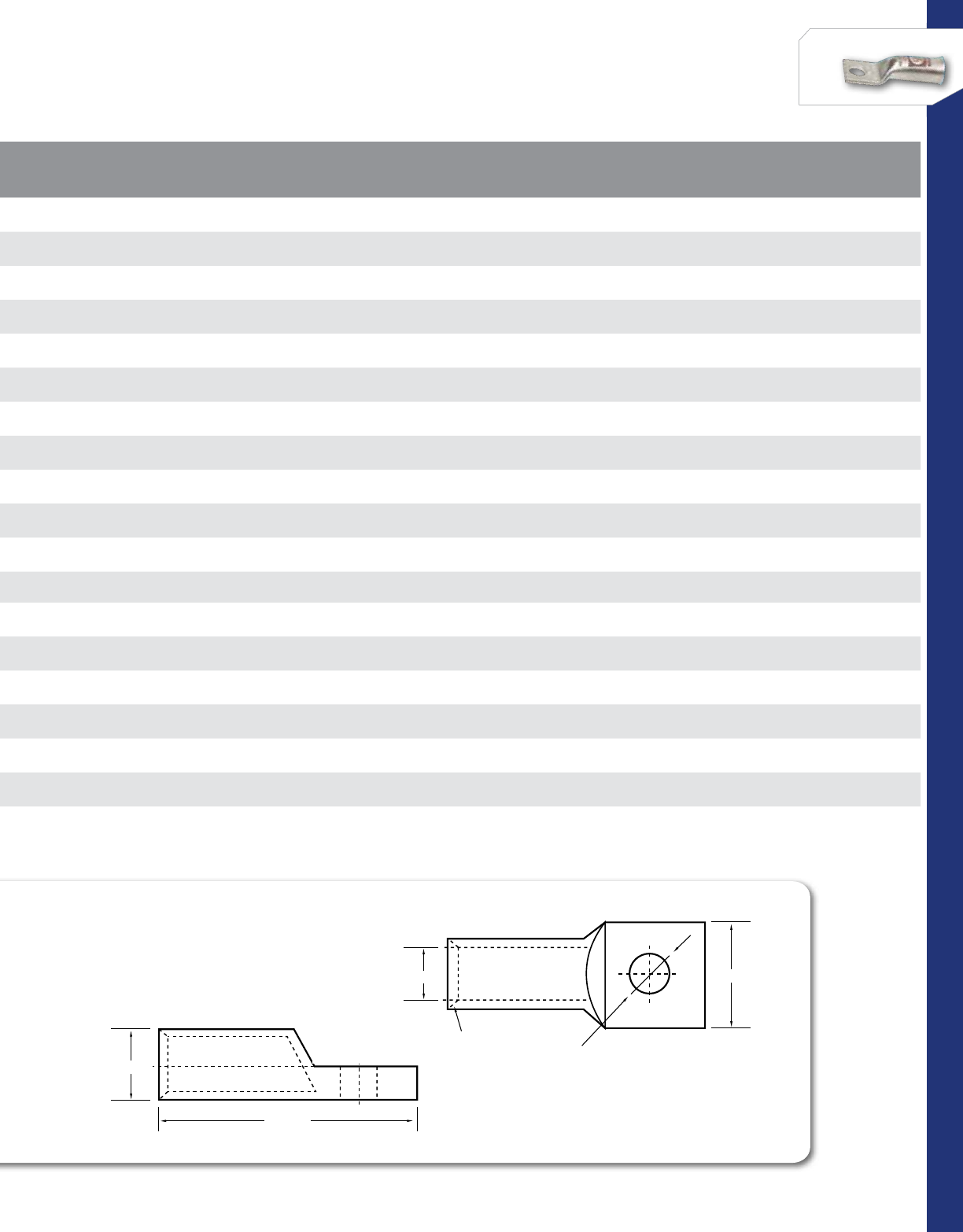
92
CONNECTORS
NSi Industries LLC • USA • 800.321.5847 • www.nsiindustries.com
B1 ±1.00
COMPRESSION LUGS
ONE HOLE
B ±1.00
L ±1.00
O.D ±0.50
I.D.±0.20 W±1.00
A ±0.50
D±0.20
45° Deep
Chamfer
C±0.50
B1 ±1.00
COMPRESSION LUGS
ONE HOLE
B ±1.00
L ±1.00
O.D ±0.50
I.D.±0.20 W±1.00
A ±0.50
D±0.20
45° Deep
Chamfer
C±0.50
CAT.
NO. WIRE
RANGE EXPANDED
WIRE RANGE* COLOR
CODE
CABLE SIZE LENGTH
(L) BOLT
SIZE WIDTH
(W) I.D. O.D.
COMM ASTM
CLASS H WELDING
CLASS M DIESEL
LOCOMOTIVE
L638B 6 AWG 6-8 AWG Blue 688(61) 1.910 3/8 0.590 0.205 0.295
L438B 4 AWG 4 - 6 AWG Grey 466(105) 1.910 3/8 0.590 0.252 0.343
L256B 2 AWG 2 - 6 AWG Brown 244(125) 2.070 5/16 0.600 0.315 0.421
L238B 2 AWG 2 - 6 AWG Brown 244(125) 2.070 3/8 0.600 0.315 0.421
L156B 1 AWG 1 - 6 AWG Green 122(150) 2.110 5/16 0.670 0.358 0.469
L1056B 1/0 AWG 1/0 - 6 AWG Pink 1/0 1 1 (225) 2.210 5/16 0.740 0.390 0.520
L2038B 2/0 AWG 2/0 - 4 AWG Black 2/0 1/0 1/0 1/0 (275) 2.680 3/8 0.810 0.441 0.563
L3038B 3/0 AWG 3/0 - 2 AWG Orange 3/0 2/0 -2/0 (325) 2.800 3/8 0.900 0.492 0.622
L3048B 3/0 AWG 3/0 - 2 AWG Orange 3/0 2/0 -2/0 (325) 2.800 1/2 1.000 0.492 0.622
L4048B 4/0 AWG 4/0 - 1 AWG Purple 4/0 3/0 2/0 3/0 (450) 2.800 1/2 1.000 0.547 0.689
L25038B 250 MCM 250 MCM - 1/0 AWG Yellow 250 -3/0 4/0 (550) 3.030 3/8 1.090 0.594 0.752
L25048B 250 MCM 250 MCM - 1/0 AWG Yellow 250 -3/0 4/0 (550) 3.030 1/2 1.090 0.594 1.752
L30048B 300 MCM 300 MCM - 2/0 AWG White 300 4/0 4/0 262.6 3.390 1/2 1.190 0.651 1.815
L35058B 350 MCM 350 MCM - 3/0 AWG Red 350 250 250 313.1 3.460 5/8 1.280 0.701 0.874
L50058B 500 MCM 500 - 250 MCM Brown 500 350 300 373.3 4.130 5/8 1.540 0.835 1.063
L60058B 600 MCM 600 - 250 MCM Green 600 400 350 444.4 4.256 5/8 1.720 0.925 1.189
L70048B 700 MCM 700-500 MCM -700 500 400 535.3 4.922 1/2 1.690 0.975 1.241
L70058B 700 MCM 700-500 MCM -700 500 400 535.3 5.094 5/8 1.702 0.962 1.241
L75058B 750 MCM 750-500 MCM Black 750 600 500 -5.160 5/8 1.900 1.031 1.311
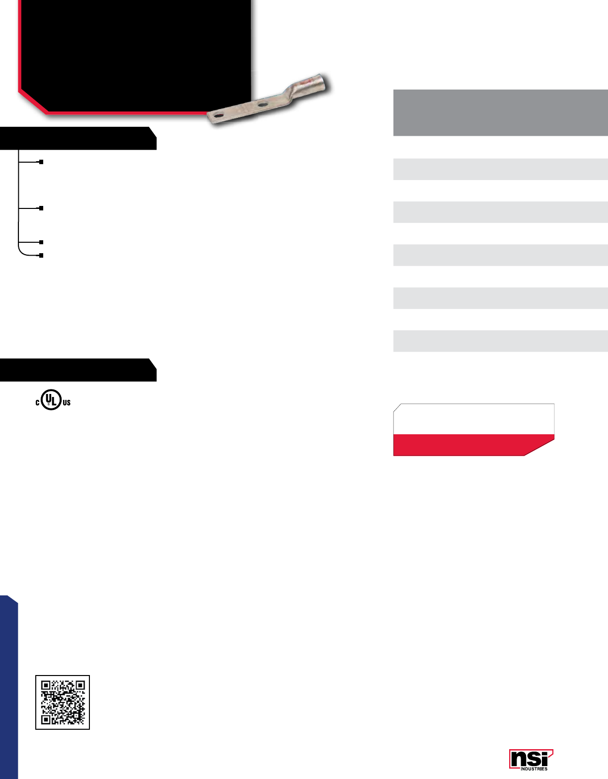
93
CONNECTORS
RATINGS
FEATURES
COMPRESSION CONNECTORS
For Flexible Copper Cable –
Two Hole Long Barrel
L-NB SERIES
† Mounting hole spacing is 1”
CAT.
NO. WIRE
RANGE EXPANDED
WIRE RANGE* COLOR
CODE LENGTH
(L) BOLT
SIZE WIDTH
(W) I.D. O.D. COMM CABLE SIZE DIESEL
LOCOMOTIVE
STD.
CTN.
QTY.
ASTM
CLASS H CLASS M
WELDING
L30NB 3/0 3/0 - 2 AWG Orange 4.650 1/2 0.900 0.490 0.620 3/0 2/0 –2/0 (325) 12
L40NB 4/0 4/0 - 1 Purple 4.720 1/2 1.000 0.550 0.690 4/0 3/0 2/0 3/0 (450) 12
L250NB 250 250 - 1/0 Yellow 4.960 1/2 1.090 0.590 0.750 250 –3/0 4/0 (550) 12
L300NB 300 300 - 2/0 White 5.310 1/2 1.190 0.660 0.810 300 4/0 4/0 262.6 6
L350NB-38† 350 350 - 3/0 Red 4.210 3/8 1.280 0.700 0.870 350 250 250 313.1 6
L350NB 350 350 - 3/0 Red 5.390 1/2 1.280 0.700 0.870 350 250 250 313.1 6
L500NB 500 500 - 250 Brown 5.750 1/2 1.540 0.840 1.060 500 350 300 373.3 3
L600NB 600 600 - 250 Green 5.790 1/2 1.720 0.930 1.190 600 400 350 444.4 3
L700NB 700 700 - 500 –6.250 1/2 1.844 0.980 1.230 700 500 400 535.3 3
L750NB 750 750 - 500 Black 6.300 1/2 1.900 1.030 1.310 750 600 500 –3
L100NB 1000 1000 - 750 White 7.125 1/2 2.160 1.150 1.500 1000 800 700 777.7 3
Connector end has a gentle, continuous flare to
ensure ease of cable insertion of flexible and extra-
flexible cables such as locomotive, welding, mining
cable and more.
The flared end also reduces pressure on the cable
strands after installation and protects them from
chafing and breakage as a result of cable movement.
Tin- plated for corrosion resistance.
NEMA spaced mounting holes (1¾”). (E Dimension)
All dimensional data is listed in inches.
TEMPERATURE RATING:
90 °C.
Rated 600V for copper cables only.
Scan QR to view
Tool & Die Charts
*EXPANDED WIRE RANGE when installed with
NSI N12ID dieless compression tool.
UL Listed with other tools:
FOR TOOL & DIE CRIMPING INFORMATION,
PLEASE SEE TABLE ON PAGE 145
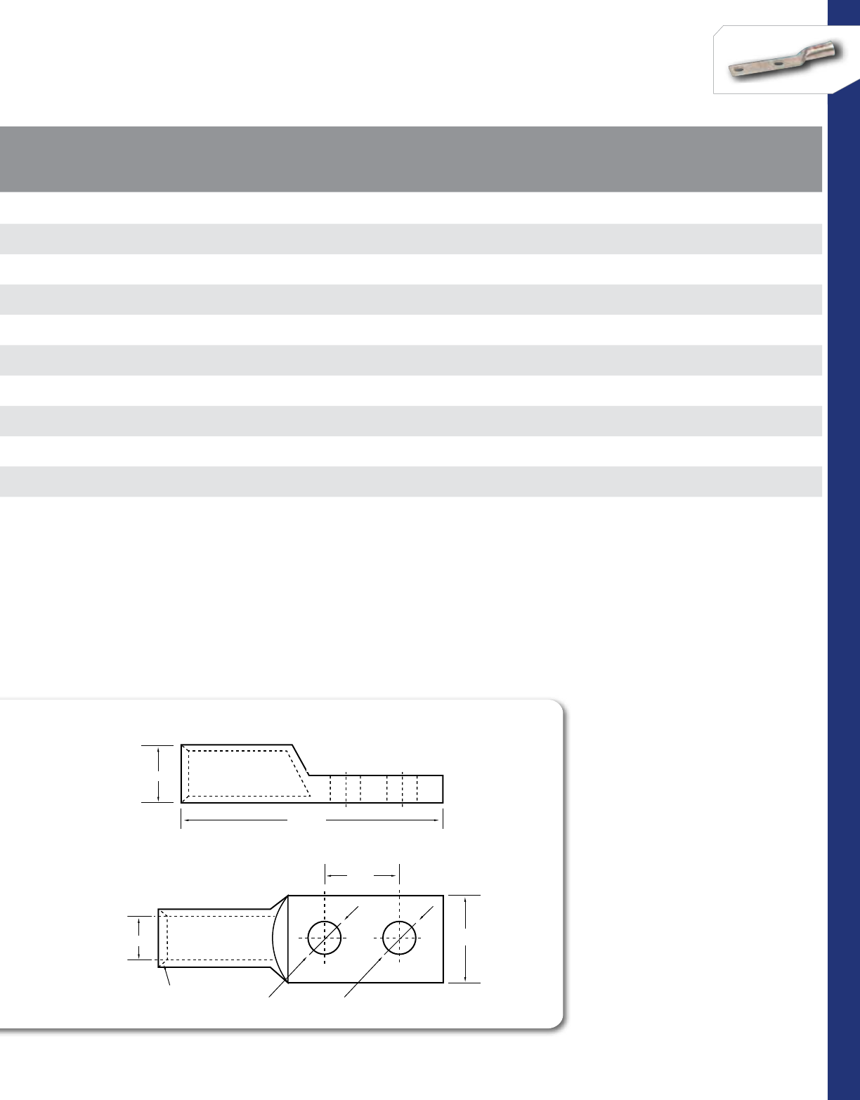
94
CONNECTORS
NSi Industries LLC • USA • 800.321.5847 • www.nsiindustries.com
CAT.
NO. WIRE
RANGE EXPANDED
WIRE RANGE* COLOR
CODE LENGTH
(L) BOLT
SIZE WIDTH
(W) I.D. O.D. COMM CABLE SIZE DIESEL
LOCOMOTIVE
STD.
CTN.
QTY.
ASTM
CLASS H CLASS M
WELDING
L30NB 3/0 3/0 - 2 AWG Orange 4.650 1/2 0.900 0.490 0.620 3/0 2/0 –2/0 (325) 12
L40NB 4/0 4/0 - 1 Purple 4.720 1/2 1.000 0.550 0.690 4/0 3/0 2/0 3/0 (450) 12
L250NB 250 250 - 1/0 Yellow 4.960 1/2 1.090 0.590 0.750 250 –3/0 4/0 (550) 12
L300NB 300 300 - 2/0 White 5.310 1/2 1.190 0.660 0.810 300 4/0 4/0 262.6 6
L350NB-38† 350 350 - 3/0 Red 4.210 3/8 1.280 0.700 0.870 350 250 250 313.1 6
L350NB 350 350 - 3/0 Red 5.390 1/2 1.280 0.700 0.870 350 250 250 313.1 6
L500NB 500 500 - 250 Brown 5.750 1/2 1.540 0.840 1.060 500 350 300 373.3 3
L600NB 600 600 - 250 Green 5.790 1/2 1.720 0.930 1.190 600 400 350 444.4 3
L700NB 700 700 - 500 –6.250 1/2 1.844 0.980 1.230 700 500 400 535.3 3
L750NB 750 750 - 500 Black 6.300 1/2 1.900 1.030 1.310 750 600 500 –3
L100NB 1000 1000 - 750 White 7.125 1/2 2.160 1.150 1.500 1000 800 700 777.7 3
COMPRESSION LUGS
TWO HOLE
45° Deep
Chamfer
L
W
A
D
E
B
C
B1
OD
ID
95
CONNECTORS
RATINGS
FEATURES
COMPRESSION CONNECTORS
For Flexible Copper Cable –
Two Hole Short Barrel
(Peep Hole)
GL-NB SERIES
CAT.
NO. WIRE
RANGE EXPANDED
WIRE RANGE* COLOR
CODE BOLT
SIZE I.D. O.D. COMM CABLE SIZE DIESEL
LOCOMOTIVE
STD.
CTN.
QTY.
LENGTH
(L) WIDTH
(W)
ASTM
CLASS H CLASS M
WELDING
GL30NB 3/0 3/0 - 2 Orange 1/2 0.492 0.622 3/0 2/0 –2/0 (325) 12 4.291 0.902
GL250NB 250 250 - 1/0 Yellow 1/2 0.590 0.752 250 –3/0 4/0 (550) 12 4.409 1.090
GL300NB 300 300 - 2/0 White 1/2 0.660 0.810 300 4/0 4/0 262.6 64.528 1.276
GL350NB 350 350 - 3/0 Red 1/2 0.700 0.870 350 250 250 313.1 64.528 1.276
GL500NB 500 500 - 250 Brown 1/2 0.840 1.060 500 350 300 373.3 34.882 1.540
GL600NB 600 600 - 250 Green 1/2 0.925 1.190 600 400 350 444.4 35.039 1.717
GL700NBX† 700 700 - 500 –1/2 0.983 1.230 700 500 400 535.3 35.512 1.844
GL750NB 750 750 - 500 Black 1/2 1.040 1.310 750 600 500 –35.512 1.900
GL100NB 1000 -White 1/2 1.173 1.492 1000 800 700 777.7 35.870 2.158
† Supplied without peephole
Connector end has a gentle, continuous flare to ensure
ease of cable insertion of flexible and extra-flexible
cables such as locomotive, welding, mining cable and more.
The flared end also reduces pressure on the cable strands
after installation and protects them from chafing and
breakage as a result of cable movement.
Tin- plated for corrosion resistance.
NEMA spaced mounting holes (1¾”). (E Dimension)
All dimensional data is listed in inches.
TEMPERATURE RATING:
90 °C.
Rated 600V for copper cables only.
Scan QR to view
Tool & Die Charts
*EXPANDED WIRE RANGE when installed with
NSI N12ID dieless compression tool.
UL Listed with other tools:
FOR TOOL & DIE CRIMPING INFORMATION,
PLEASE SEE TABLE ON PAGE 145
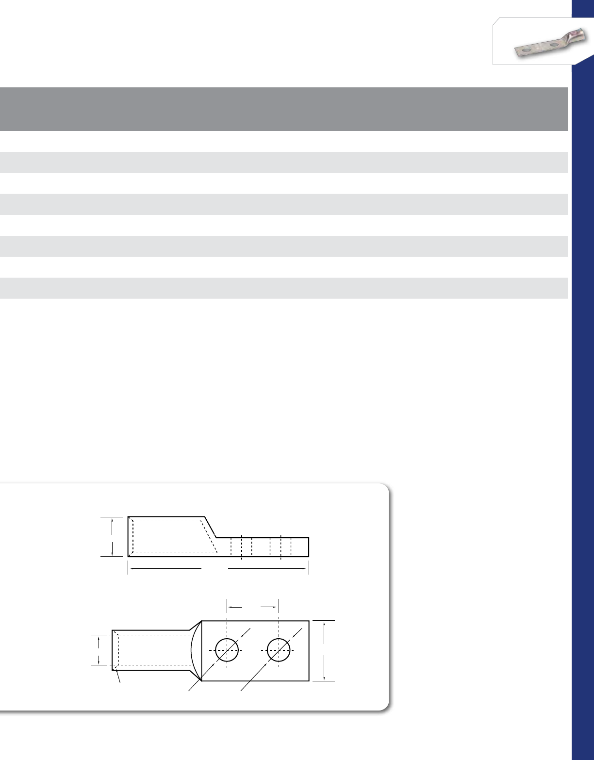
96
CONNECTORS
NSi Industries LLC • USA • 800.321.5847 • www.nsiindustries.com
CAT.
NO. WIRE
RANGE EXPANDED
WIRE RANGE* COLOR
CODE BOLT
SIZE I.D. O.D. COMM CABLE SIZE DIESEL
LOCOMOTIVE
STD.
CTN.
QTY.
LENGTH
(L) WIDTH
(W)
ASTM
CLASS H CLASS M
WELDING
GL30NB 3/0 3/0 - 2 Orange 1/2 0.492 0.622 3/0 2/0 –2/0 (325) 12 4.291 0.902
GL250NB 250 250 - 1/0 Yellow 1/2 0.590 0.752 250 –3/0 4/0 (550) 12 4.409 1.090
GL300NB 300 300 - 2/0 White 1/2 0.660 0.810 300 4/0 4/0 262.6 64.528 1.276
GL350NB 350 350 - 3/0 Red 1/2 0.700 0.870 350 250 250 313.1 64.528 1.276
GL500NB 500 500 - 250 Brown 1/2 0.840 1.060 500 350 300 373.3 34.882 1.540
GL600NB 600 600 - 250 Green 1/2 0.925 1.190 600 400 350 444.4 35.039 1.717
GL700NBX† 700 700 - 500 –1/2 0.983 1.230 700 500 400 535.3 35.512 1.844
GL750NB 750 750 - 500 Black 1/2 1.040 1.310 750 600 500 –35.512 1.900
GL100NB 1000 -White 1/2 1.173 1.492 1000 800 700 777.7 35.870 2.158
COMPRESSION LUGS
TWO HOLE
45° Deep
Chamfer
L
W
A
D
E
B
C
B1
OD
ID
97
CONNECTORS
RATINGS
FEATURES
Splice has flared openings at both ends to ensure ease
of cable insertion of flexible and extra-flexible cables
such as locomotive, welding, mining cable and more.
Positive center stop.
Tin-plated for corrosion resistance.
COMPRESSION CONNECTORS
For Flexible Cable –
Copper Short Barrel
SC-B SERIES
CAT.
NO. WIRE
RANGE EXPANDED
WIRE RANGE* COLOR
CODE LENGTH
(L) I.D. O.D. COMM CABLE SIZE DIESEL
LOCOMOTIVE
STD.
CTN.
QTY.
ASTM
CLASS H CLASS M
WELDING
SC-1/0B 1/0 AWG 1/0 - 6 AWG Pink 1.598 0.520 0.520 1/0 1 1 (225) 25
SC-2/0B 2/0 AWG 2/0 - 4 AWG Black 1.752 0.560 0.563 2/0 1/0 1/0 1/0 (275) 25
SC-3/0B 3/0 AWG 3/0 - 2 AWG Orange 1.752 0.620 0.622 3/0 2/0 –2/0 (325) 25
SC-4/0B 4/0 AWG 4/0 - 1 AWG Purple 1.902 0.690 0.689 4/0 3/0 2/0 3/0 (450) 25
SC-250B 250 MCM 250 MCM - 1/0 AWG Yellow 2.000 0.750 0.752 250 –3/0 4/0 (550) 25
SC-300B 300 MCM 300 MCM - 2/0 AWG White 2.098 0.810 0.815 300 4/0 4/0 262.6 12
SC-350B 350 MCM 350 MCM - 3/0 AWG Red 2.098 0.870 0.874 350 250 250 313.1 12
All dimensional data is listed in inches.
TEMPERATURE RATING:
90 °C.
Rated 600V for copper cables only.
Scan QR to view
Tool & Die Charts
Splice has flared openings at both ends to ensure ease
of cable insertion of flexible and extra-flexible cables
Splice has flared openings at both ends to ensure ease
of cable insertion of flexible and extra-flexible cables
Splice has flared openings at both ends to ensure ease
Positive center stop.
Tin-plated for corrosion resistance.
Tin-plated for corrosion resistance.
Tin-plated for corrosion resistance.
*EXPANDED WIRE RANGE when installed with
NSI N12ID dieless compression tool.
UL Listed with other tools:
FOR TOOL & DIE CRIMPING INFORMATION,
PLEASE SEE TABLE ON PAGE 145
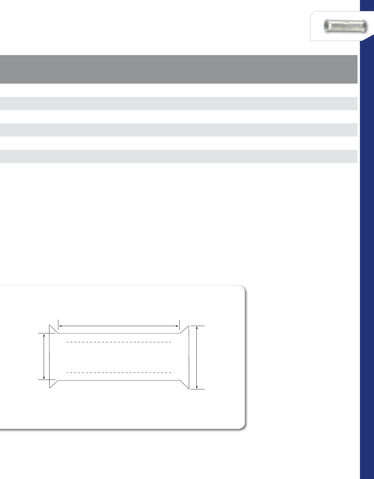
98
CONNECTORS
NSi Industries LLC • USA • 800.321.5847 • www.nsiindustries.com
CAT.
NO. WIRE
RANGE EXPANDED
WIRE RANGE* COLOR
CODE LENGTH
(L) I.D. O.D. COMM CABLE SIZE DIESEL
LOCOMOTIVE
STD.
CTN.
QTY.
ASTM
CLASS H CLASS M
WELDING
SC-1/0B 1/0 AWG 1/0 - 6 AWG Pink 1.598 0.520 0.520 1/0 1 1 (225) 25
SC-2/0B 2/0 AWG 2/0 - 4 AWG Black 1.752 0.560 0.563 2/0 1/0 1/0 1/0 (275) 25
SC-3/0B 3/0 AWG 3/0 - 2 AWG Orange 1.752 0.620 0.622 3/0 2/0 –2/0 (325) 25
SC-4/0B 4/0 AWG 4/0 - 1 AWG Purple 1.902 0.690 0.689 4/0 3/0 2/0 3/0 (450) 25
SC-250B 250 MCM 250 MCM - 1/0 AWG Yellow 2.000 0.750 0.752 250 –3/0 4/0 (550) 25
SC-300B 300 MCM 300 MCM - 2/0 AWG White 2.098 0.810 0.815 300 4/0 4/0 262.6 12
SC-350B 350 MCM 350 MCM - 3/0 AWG Red 2.098 0.870 0.874 350 250 250 313.1 12
L
O.D
I.D

99
CONNECTORS
RATINGS
FEATURES
These connectors are the same as the GL-N Series
– Short Barrel Copper Compression Lugs (with Peep
Hole) except that the mounting hole sizes and spac-
ings are common to the telecommunications industry.
Produced from high conductivity copper tubing, they
are tin-plated to provide corrosion resistance. Also,
they are marked with die index and color coded.
Listed for 35 KV maximum when properly installed.
For bolt hole sizes not listed, please contact NSi.
COMPRESSION CONNECTORS
For Telecommunications –
Two Hole Short Barrel
(Peep Hole)
GLN SERIES CAT.
NO. WIRE
SIZE EXPANDED WIRE
RANGE* COLOR
CODE BOLT
SIZE HOLE
SPACING (E) LENGTH
(L) WIDTH
(W) TANG
THICkNESS (C)
STD.
CTN.
QTY.
GL6N-141 6 AWG 6 - 8 AWG Blue 1/4 0.625 2.560 0.450 0.080 100
GL6N-143 6 AWG 6 - 8 AWG Blue 1/4 1.000 2.660 0.450 0.080 100
GL6N-38 6 AWG 6 - 8 AWG Blue 3/8 1.000 2.830 0.580 0.080 100
GL4N-141 4 AWG 4 - 6 AWG Gray 1/4 0.625 2.340 0.500 0.090 100
GL4N-143 4 AWG 4 - 6 AWG Gray 1/4 1.000 2.710 0.500 0.090 100
GL4N-38 4 AWG 4 - 6 AWG Gray 3/8 1.000 2.930 0.580 0.090 100
GL2N-141 2 AWG 2 - 6 AWG Brown 1/4 0.625 2.460 0.610 0.110 50
GL2N-142 2 AWG 2 - 6 AWG Brown 1/4 0.750 2.580 0.610 0.110 50
GL2N-143 2 AWG 2 - 6 AWG Brown 1/4 1.000 2.830 0.610 0.110 50
GL2N-38 2 AWG 2 - 6 AWG Brown 3/8 1.000 3.050 0.610 0.110 50
GL10N-38 1/0 AWG 1/0 - 6 AWG Pink 3/8 1.000 3.140 0.750 0.120 50
GL20N-38 2/0 AWG 2/0 - 4 AWG Black 3/8 1.000 3.240 0.830 0.120 25
GL20N 2/0 AWG 2/0 - 4 AWG Black 1/2 1.750 4.170 0.830 0.120 25
GL30N-38 3/0 AWG 3/0 - 2 AWG Orange 3/8 1.000 3.360 0.910 0.130 25
GL30N 3/0 AWG 3/0 - 2 AWG Orange 1/2 1.750 4.280 0.910 0.130 25
GL40N-38 4/0 AWG 4/0 - 1 AWG Purple 3/8 1.000 3.410 1.020 0.140 25
GL40N 4/0 AWG 4/0 - 1 AWG Purple 1/2 1.750 4.280 1.020 0.140 25
GL250N-38 250 AWG 250 MCM - 1/0 AWG Yellow 3/8 1.000 3.530 1.110 0.160 25
GL250N 250 AWG 250 MCM - 1/0 AWG Yellow 1/2 1.750 4.410 1.110 0.160 25
GL350N-38 350 AWG 350 MCM - 3/0 AWG Red 3/8 1.000 3.700 1.290 .180 12
GL350N 350 AWG 350 MCM - 3/0 AWG Red 1/2 1.750 4.530 1.290 0.180 12
GL500N-38 500 AWG 500 - 250 MCM Brown 3/8 1.000 4.080 1.520 0.230 6
GL500N 500 AWG 500 - 250 MCM Brown 1/2 1.750 4.880 1.520 0.230 6
Scan QR to view
Tool & Die Charts
These connectors are the same as the GL-N Series
– Short Barrel Copper Compression Lugs (with Peep
Produced from high conductivity copper tubing, they
are tin-plated to provide
Produced from high conductivity copper tubing, they
are tin-plated to provide
Produced from high conductivity copper tubing, they
Listed for 35 KV maximum when properly installed.
For bolt hole sizes not listed, please contact NSi.
Listed for 35 KV maximum when properly installed.
For bolt hole sizes not listed, please contact NSi.
Listed for 35 KV maximum when properly installed.
COMPRESSION LUGS
TWO HOLE
45° Deep
Chamfer
L
W
A
D
E
B
C
B1
*EXPANDED WIRE RANGE when installed with
NSI N12ID dieless compression tool.
UL Listed with other tools:
FOR TOOL & DIE CRIMPING INFORMATION,
PLEASE SEE TABLE ON PAGE 145

100
CONNECTORS
NSi Industries LLC • USA • 800.321.5847 • www.nsiindustries.com
CAT.
NO. WIRE
SIZE EXPANDED WIRE
RANGE* COLOR
CODE BOLT
SIZE HOLE
SPACING (E) LENGTH
(L) WIDTH
(W) TANG
THICkNESS (C)
STD.
CTN.
QTY.
GL6N-141 6 AWG 6 - 8 AWG Blue 1/4 0.625 2.560 0.450 0.080 100
GL6N-143 6 AWG 6 - 8 AWG Blue 1/4 1.000 2.660 0.450 0.080 100
GL6N-38 6 AWG 6 - 8 AWG Blue 3/8 1.000 2.830 0.580 0.080 100
GL4N-141 4 AWG 4 - 6 AWG Gray 1/4 0.625 2.340 0.500 0.090 100
GL4N-143 4 AWG 4 - 6 AWG Gray 1/4 1.000 2.710 0.500 0.090 100
GL4N-38 4 AWG 4 - 6 AWG Gray 3/8 1.000 2.930 0.580 0.090 100
GL2N-141 2 AWG 2 - 6 AWG Brown 1/4 0.625 2.460 0.610 0.110 50
GL2N-142 2 AWG 2 - 6 AWG Brown 1/4 0.750 2.580 0.610 0.110 50
GL2N-143 2 AWG 2 - 6 AWG Brown 1/4 1.000 2.830 0.610 0.110 50
GL2N-38 2 AWG 2 - 6 AWG Brown 3/8 1.000 3.050 0.610 0.110 50
GL10N-38 1/0 AWG 1/0 - 6 AWG Pink 3/8 1.000 3.140 0.750 0.120 50
GL20N-38 2/0 AWG 2/0 - 4 AWG Black 3/8 1.000 3.240 0.830 0.120 25
GL20N 2/0 AWG 2/0 - 4 AWG Black 1/2 1.750 4.170 0.830 0.120 25
GL30N-38 3/0 AWG 3/0 - 2 AWG Orange 3/8 1.000 3.360 0.910 0.130 25
GL30N 3/0 AWG 3/0 - 2 AWG Orange 1/2 1.750 4.280 0.910 0.130 25
GL40N-38 4/0 AWG 4/0 - 1 AWG Purple 3/8 1.000 3.410 1.020 0.140 25
GL40N 4/0 AWG 4/0 - 1 AWG Purple 1/2 1.750 4.280 1.020 0.140 25
GL250N-38 250 AWG 250 MCM - 1/0 AWG Yellow 3/8 1.000 3.530 1.110 0.160 25
GL250N 250 AWG 250 MCM - 1/0 AWG Yellow 1/2 1.750 4.410 1.110 0.160 25
GL350N-38 350 AWG 350 MCM - 3/0 AWG Red 3/8 1.000 3.700 1.290 .180 12
GL350N 350 AWG 350 MCM - 3/0 AWG Red 1/2 1.750 4.530 1.290 0.180 12
GL500N-38 500 AWG 500 - 250 MCM Brown 3/8 1.000 4.080 1.520 0.230 6
GL500N 500 AWG 500 - 250 MCM Brown 1/2 1.750 4.880 1.520 0.230 6
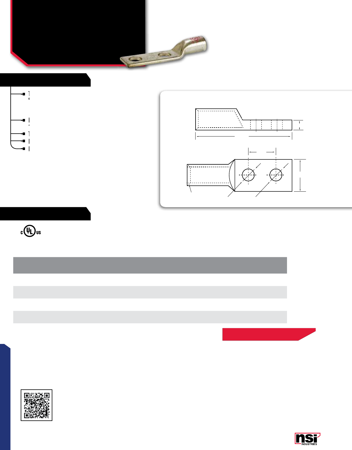
101
RATINGS
FEATURES
CONNECTORS
These connectors are the same as the GL-N
Series – Short Barrel Copper Compression Lugs
(with Peep Hole) except that they are provided
without the peephole.
Produced from high conductivity copper tubing,
they are tin-plated to provide corrosion resistance.
They are marked with die index and color coded.
Listed for 35 KV maximum when properly installed.
For bolt hole sizes not listed, please contact NSi.
COMPRESSION CONNECTORS
For Flexible Copper Cable -
Two Hole Short Barrel
(No Peep Hole)
GLN-X SERIES
CAT.
NO. WIRE
SIZE BOLT
SIZE HOLE
SPACING (E) COLOR
CODE LENGTH
(L) WIDTH
(W) TANG
THICkNESS (C)
STD.
CTN.
QTY.
GL6N-141X 61/4 0.625 Blue 2.560 0.450 0.080 100
GL2N-141X 21/4 0.625 Brown 2.460 0.610 0.110 50
GL2N-38X 23/8 1.000 Brown 3.050 0.610 0.110 50
GL10N-38X 1/0 3/8 1.000 Pink 3.140 0.750 0.120 50
COMPRESSION LUGS
TWO HOLE
45° Deep
Chamfer
L
W
A
D
E
B
C
B1
COMPRESSION LUGS
TWO HOLE
45° Deep
Chamfer
L
W
A
D
E
B
C
B1
FOR TOOL & DIE CRIMPING INFORMATION,
PLEASE SEE TABLE ON PAGE 141
Scan QR to view
Tool & Die Charts
These connectors are the same as the GL-N
Series – Short Barrel Copper Compression Lugs
They are marked with die index and color coded.
Produced from high conductivity copper tubing,
they are tin-plated to provide corrosion resistance.
Produced from high conductivity copper tubing,
they are tin-plated to provide corrosion resistance.
Produced from high conductivity copper tubing,
Listed for 35 KV maximum when properly installed.
For bolt hole sizes not listed, please contact NSi.
Listed for 35 KV maximum when properly installed.
For bolt hole sizes not listed, please contact NSi.
For bolt hole sizes not listed, please contact NSi.
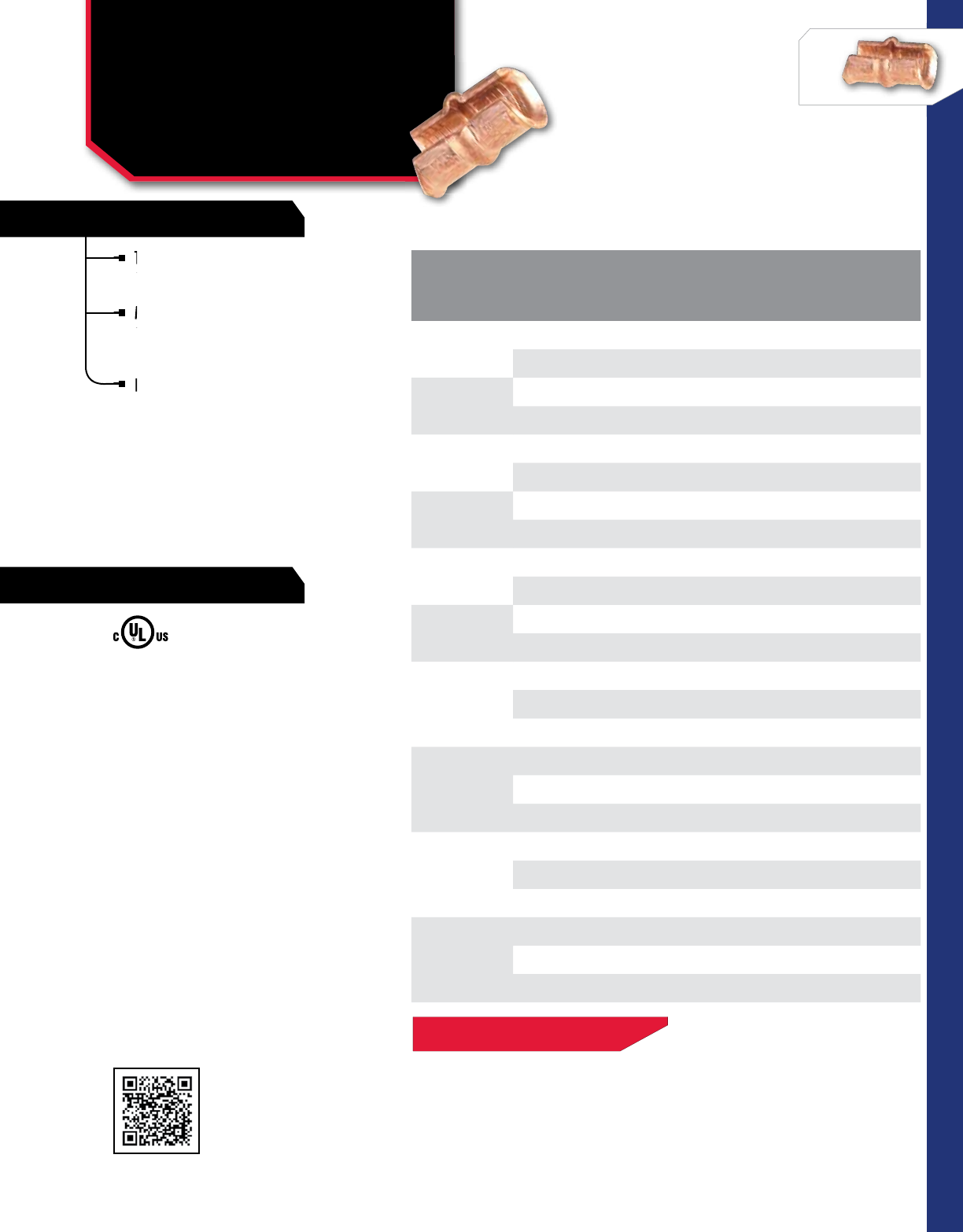
102
RATINGS
FEATURES
CONNECTORS
NSi Industries LLC • USA • 800.321.5847 • www.nsiindustries.com
These taps ensure positive, all-around
compression with low resistance and
high pull-out values.
Made of high conductivity copper, they
satisfy the requirements of NEC250-
81 and 250-91 for connecting to the
grounding electrode system.
Rated for 600V applications.
COMPRESSION CONNECTORS
C-Taps
CT SERIES
CAT.
NO.
WIRE SIZE COLOR
CODE
STD.
CTN.
QTY.
MAIN BRANCH
CT-101 14 16 Red 100
12 14
CT-102 10 10 Blue 100
812
CT-103 610-12 Gray 100
88-10
CT-104 4 or 5 8-10-12 Brown 100
66-8
CT-105 36-8-10-12 Green 100
4 or 5 6-5
CT-106 3 5 Pink 100
4 4
CT-107
1 – Black 50
24-5
33-4
CT-108
1/0 4Orange 50
13-4
22-3
CT-109
2/0 3-4 Purple 50
1/0 2-3
-1-2
CT-110
3/0 2-3-4 Yellow 25
2/0 1-2
1/0 1/0-1
Scan QR to view
Tool & Die Charts
FOR TOOL & DIE CRIMPING INFORMATION,
PLEASE SEE TABLE ON PAGE 143
Made of high conductivity copper, they
satisfy the requirements of NEC250-
Made of high conductivity copper, they
satisfy the requirements of NEC250-
Made of high conductivity copper, they
These taps ensure positive, all-around
compression with low resistance and
These taps ensure positive, all-around
compression with low resistance and
These taps ensure positive, all-around
Rated for 600V applications.
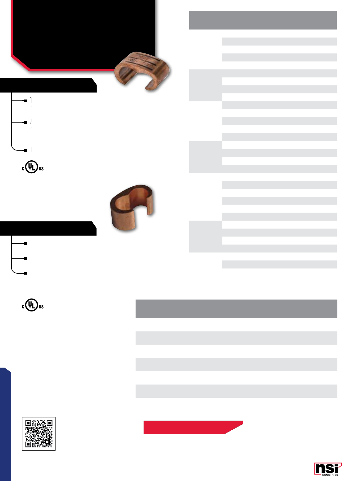
103
COPPER “C” TAPS
FEATURES
CONNECTORS
These taps ensure positive, all-around
compression with low resistance and
high pull-out values.
Made of high conductivity copper, they
satisfy the requirements of NEC250-
81 and 250-91 for connecting to the
grounding electrode system.
Rated for 600V applications.
COMPRESSION CONNECTORS
C-Taps
CTH SERIES
CAT.
NO.
WIRE SIZE COLOR
CODE
STD.
CTN.
QTY.
MAIN BRANCH
CTH-111
11Blue 25
1/0 1/0-2
2/0 2/0-4
3/0 1/0-6
4/0 1-8
CTH-112
2/0 2/0-1 Brown 25
3/0 3/0-3
4/0 4/0-4
250 1/0-8
CTH-113
2/0 2/0-1 Pink 12
3/0 3/0-2
4/0 4/0-4
250 3/0-6
300 2/0-8
CTH-114
4/0 4/0-2/0 Black 6
250 250-1
300 4/0-4
350 3/0-6
CTH-115
250 250 Yellow 6
300 300-3/0
350 350-1/0
400 300-2
450 250-4
500 250-6
CTH-116
350 350-4/0 White 3
400 400-2/0
450 450-1
500 500-2
CTH-117 750-500 4/0-6 -3
750 750-4/0
CAT.
NO.
CONDUCTOR RANGE STRIP
LENGTH
STD.
CTN.
QTY.
RUN TAP
CTH-46 6 SOL - 4 STR 6 SOL - 6 STR 3/4 25
CTH-44 6 SOL - 4 STR 4 SOL - 4 STR 3/4 25
CTH-24 2 SOL - 2 STR 8 SOL - 4 STR 7/8 10
CTH-22 2 SOL - 2 STR 2 SOL - 2 STR 7/8 25
CTH-2020 1/0 STR - 2/0 STR 1/0 STR - 2/0 STR 11/16 3
CTH-4020 3/0 STR - 4/0 STR 1/0 STR - 2/0 STR 13/16 3
CTH-4040 3/0 STR - 4/0 STR 3/0 STR - 4/0 STR 13/16 3
FOR TOOL & DIE CRIMPING INFORMATION,
PLEASE SEE TABLE ON PAGE 143
Scan QR to view
Tool & Die Charts
These taps ensure positive, all-around
compression with low resistance and
These taps ensure positive, all-around
compression with low resistance and
These taps ensure positive, all-around
Made of high conductivity copper, they
satisfy the requirements of NEC250-
Made of high conductivity copper, they
satisfy the requirements of NEC250-
Made of high conductivity copper, they
Rated for 600V applications.
All dimensional data is listed in inches.
Range-taking compression connectors made from high
conductivity copper alloy.
Ideal for making tap or parallel copper connections from
8 SOL to 4/0 STR conductors.
Provides consistent reliability with heavy wall construction
that prevents relaxation of the joint after installation.
Installation time is reduced because of its “C” shape.
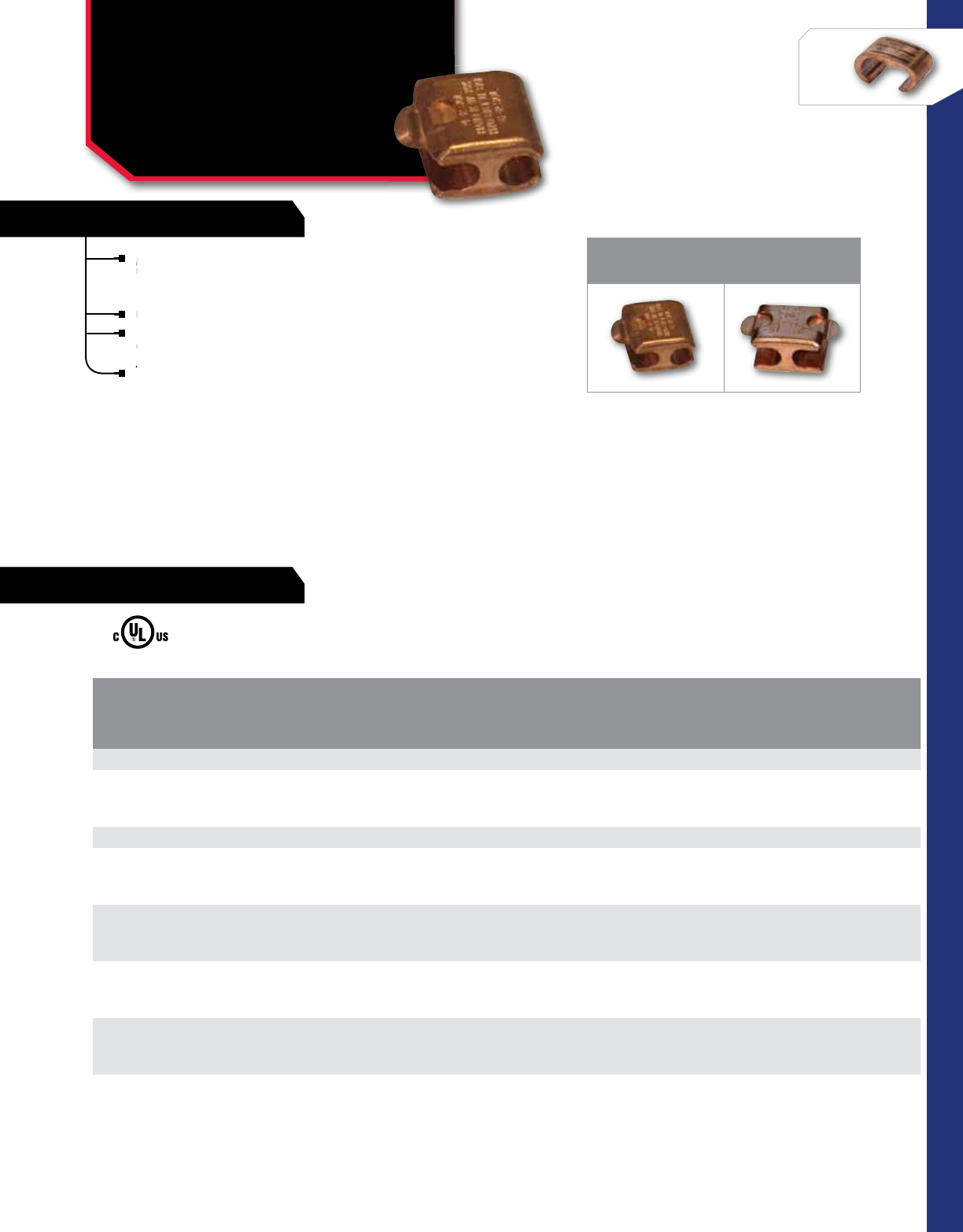
RATINGS
FEATURES
NSi Industries LLC • USA • 800.321.5847 • www.nsiindustries.com 104
CONNECTORS
Made of high conductivity copper-metal
barrier separates conductor thereby
eliminating strand cutting.
Generous chamfer protects cable.
For compressing, use one crimp with
hydraulic tools.
Three crimps with mechanical tools.
COMPRESSION CONNECTORS
Copper Press-Ons
CSP, CDP SERIES
1 2
SINGLE TAB CSP DOUBLE TAP CDP
CAT.
NO.SIDE A WIRE DIA.
RANGE (IN)SIDE B WIRE DIA.
RANGE (IN)
DIE SETS FOR HYDRAULIC TOOLS STD.
PkG.
QTY.WH-1, W-2 Y-35* PRESS. SET
SINGLE TAB PRESS-ON
CSP-301 6 SOL, 6 STR, 4 SOL 0.162/0.204 8 SOL, 8 STR, 6 SOL,
6 STR, 4 SOL 0.128/0.204 B-K-T U-BG or U 243 41
DOUBLE TAB PRESS-ON
CDP-399-8 6 SOL, 6 STR, 4 SOL 0.162/0.204 8 SOL, 6 STR, 4 SOL 0.128/0.204 B or B-K-T U-BG or U 243 41
CDP-304-8 2 STR, 1 STR, 1/0 STR 0.292/0.375 6 SOL, 4 SOL, 4 STR, 2 SOL,
2 STR, 1 STR, 1/0 STR 0.162/0.258 O O 41
CDP-303-8 2 STR, 1 STR, 1/0 STR 0.292/0.375 6 SOL, 4 SOL, 4 STR, 2 SOL,
2 STR, 1 STR, 1/0 STR 0.292/0.375 O O 41
CDP-308-8 2/0 STR, 4/0 STR 0.419/0.528 2 STR, 1 STR, 1/0 STR,
2/0 STR, 4/0 STR 0.292/0.375 D D3 4 1
CDP-307-8 2/0 STR, 4/0 STR 0.419/0.528 2 STR, 1 STR, 1/0 STR,
2/0 STR, 4/0 STR 0.419/0.528 D D3 4 1
Made of high conductivity copper-metal
barrier separates conductor thereby
Made of high conductivity copper-metal
barrier separates conductor thereby
Made of high conductivity copper-metal
Generous chamfer protects cable.
hydraulic tools.
Three crimps with mechanical tools.
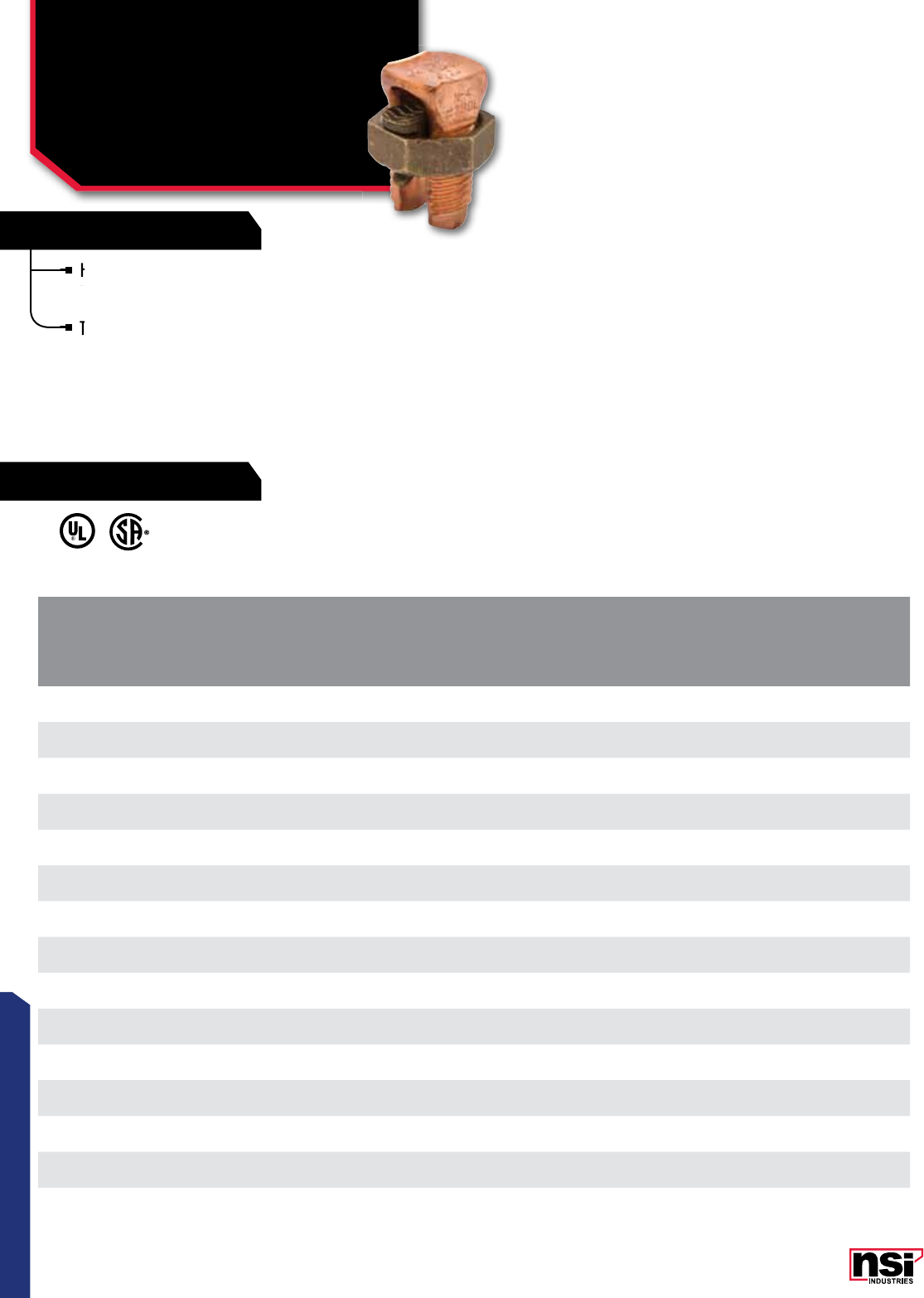
105
CONNECTORS
High-strength solderless service connector
made of high-copper alloy for copper and
copperweld wires.
Type for two maximum wire sizes.
SPLIT BOLT CONNECTORS
Copper Split Bolts
2 Wire
N SERIES
CAT.
NO.
COPPER CONDUCTOR MAXIMUM CONDUCTOR
COPPERWELD WIRE DIA.
RANGE
IN.
REC.
TORQUE
(IN. LB.)
STD.
CTN.
QTY.
RANGE OF EQUAL
MAIN & TAP MIN. TAP WITH
ONE MAX. MAIN STR TYPE A
MIN. MAX.
N-10 16 STR 10 STR 16 STR – – 0.057 – 0.116 80 100
N-8 16 STR 8 STR 16 STR – – 0.057 – 0.145 80 100
N-6 10 SOL 6 SOL 16 SOL – – 0.102 – 0.162 165 100
N-4 8 SOL 4 SOL 16 SOL 3 NO.12 8A 0.128 – 0.204 165 75
N-3 6 SOL 2 SOL 16 SOL 3 NO. 9 5A 0.162 – 0.258 275 50
N-2 6 SOL 2 STR 14 STR 3 NO. 7 3A 0.162 – 0.292 275 40
N-1/0 4 SOL 1/0 STR 14 SOL 3 NO. 6 2A 0.204 – 0.375 385 20
N-2/0 2 SOL 2/0 STR 14 STR 3 NO. 5 –0.258 – 0.418 385 15
N-3/0 2 SOL 3/0 STR 12 SOL 7 NO. 7 –0.258 – 0.470 500 10
N-250 1/0 SOL 250 MCM 10 SOL 7 NO. 5 –0.325 – 0.575 650 6
N-350 4/0 STR 350 MCM 8 SOL 19 NO. 7 –0.528 – 0.682 650 4
N-500 250 MCM 500 MCM 8 SOL 19 NO. 6 –0.575 – 0.815 825 3
N-750 350 MCM 750 MCM 8 SOL 19 NO. 5 –0.682 – 0.999 1000 2
N-1000 500 MCM 1000 MCM 8 SOL – – 0.815 – 1.153 1100 2
High-strength solderless service connector
made of high-copper alloy for copper and
High-strength solderless service connector
made of high-copper alloy for copper and
High-strength solderless service connector
Type for two maximum wire sizes.
RATINGS
FEATURES

106
CONNECTORS
NSi Industries LLC • USA • 800.321.5847 • www.nsiindustries.com
CONNECTORS
SPLIT BOLT CONNECTORS
Copper Split Bolts
3 Wire
N SERIES
CAT.
NO. MAXIMUM
WIRE SIZE MIN. TAP WITH
MAX. RUN
STD.
CTN.
QTY.
N-8L 8 str 14 str 100
N-6L 6 str 12 str 100
N-4L 4 str 12 str 75
N-3L 3 str 10 str 40
N-2L 2 str 10 str 30
RATINGS
FEATURES
High-strength solderless service connector
madeof high-copper alloy for copper and
copperweld wires.
Type for three maximum wire sizes.
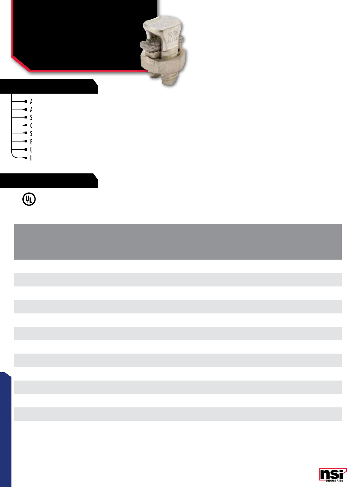
107
CONNECTORS
107
CONNECTORS
Aluminum to copper.
Aluminum to aluminum.
Steel to aluminum.
Copper to copper.
Steel to copper.
Electro-tinned body.
UL listed for copper and copperweld wires only.
Includes nut, spacer and pressure pad.
SPLIT BOLT CONNECTORS
Copper Tin Plated
Split Bolts
N-SP SERIES
CAT.
NO.
CONDUCTOR ACSR REC.
TORQUE
(IN. LB.)
STD.
CTN.
QTY.
RANGE OF EQUAL
MAIN & TAP MIN. TAP WITH
ONE MAX. MAIN
RANGE OF MAIN OR TAP WIRE DIA.
RANGE
IN.
MIN.MAX.
MIN. MAX.
N-6SP 14 STR 8 STR 14 STR – 8 0.073 - 0.146 165 100
N-4SP 10 STR 6 STR 10 SOL – 6 0.116 – 0.184 165 75
N-3SP 8 SOL 3 STR 8 SOL 6 4 0.128 – 0.258 275 50
N-2SP 8 SOL 2 STR 8 SOL 6 2 0.128 – 0.316 275 40
N-1/0SP 6 SOL 1/0 STR 10 SOL 6 1 0.162 – 0.375 385 20
N-2/0SP 6 STR 2/0 STR 10 SOL 61/0 0.184 – 0.419 385 15
N-3/0SP 4 STR 3/0 STR 6 SOL 62/0 0.198 – 0.470 500 10
N-250SP 4 STR 250 MCM 4 STR 44/0 0.232 – 0.575 650 6
N-350SP 3/0 STR 350 MCM 1 SOL 2/0 350 –650 4
N-500SP 3/0 STR 500 MCM 1/0 STR 2/0 477 18/1 –825 3
N-750SP 250 MCM 750 MCM 2/0 STR 4/0 666.6 –1000 2
N-1000SP 250 MCM 1000 MCM 4/0 STR 300 900 –1100 2
Aluminum to copper.
Aluminum to aluminum.
Aluminum to aluminum.
Steel to aluminum.
Steel to aluminum.
Copper to copper.
Copper to copper.
Steel to copper.
Steel to copper.
Electro-tinned
Electro-tinned
UL listed for copper and copperweld wires only.
Includes nut, spacer and pressure pad.
UL listed for copper and copperweld wires only.
Includes nut, spacer and pressure pad.
Includes nut, spacer and pressure pad.
RATINGS
FEATURES
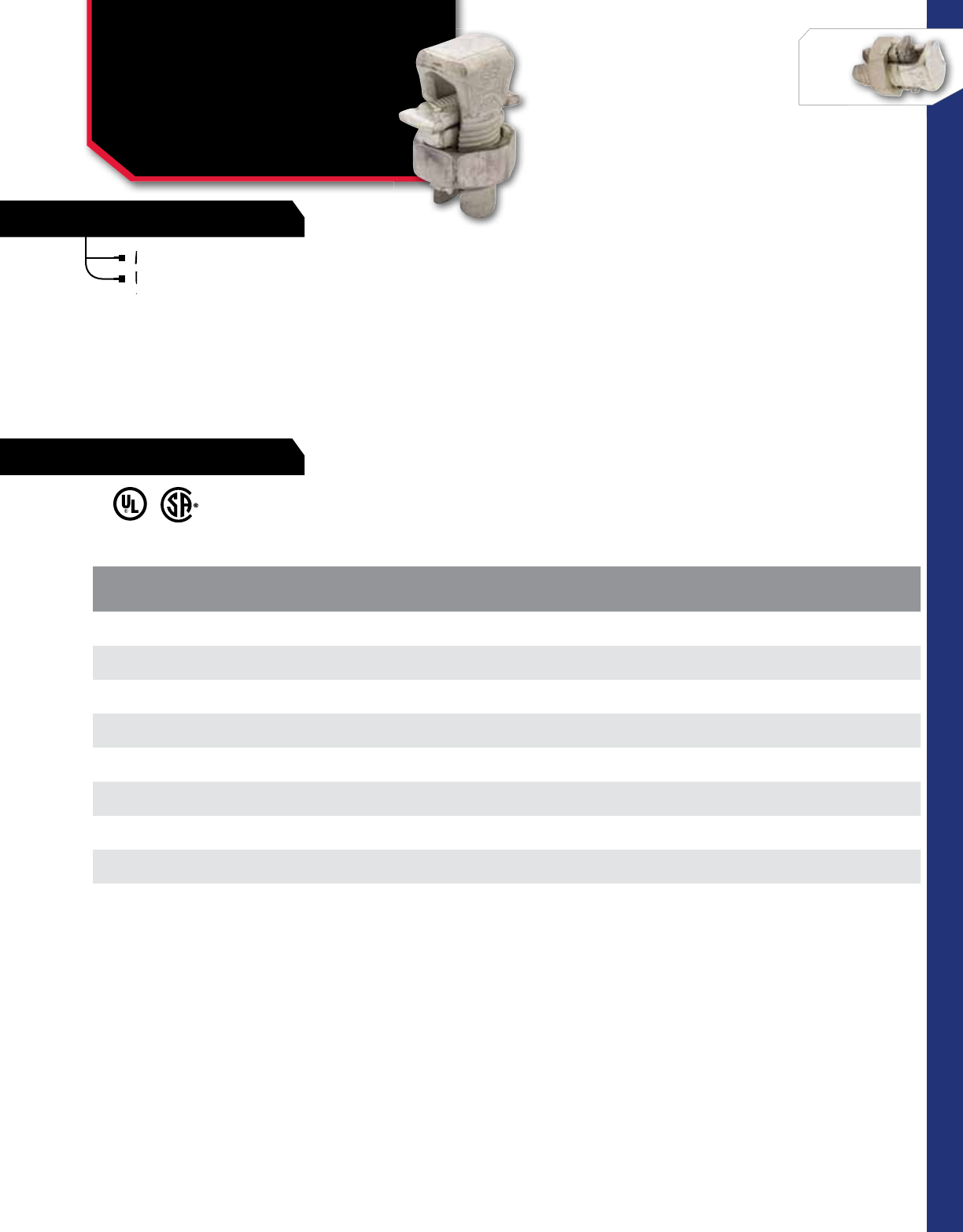
108
CONNECTORS
NSi Industries LLC • USA • 800.321.5847 • www.nsiindustries.com
FEATURES
108
CONNECTORS
Made from tin-plated aluminum.
UL-486B listed for aluminum and copper
conductor combinations.
SPLIT BOLT CONNECTORS
Aluminum Dual Rated
Split Bolts
APS SERIES
CAT.
NO.
RANGE OF EQUAL
MAIN AND TAP
(COPPER AND ALUMINUM)
WIRE DIAMETER
RANGE
(INCHES)
RECOMMENDED
TORQUE
(IN. LB.)
STD.
CTN.
QTY.
APS06 10 sol. – 6 str 0.101 – 0.184 165 100
APS04 10 sol. – 4 str 0.101 – 0.232 165 75
APS02 8 str. – 2 str 0.146 – 0.292 275 40
APS11 8 sol. – 1/0 str 0.162 – 0.375 385 20
APS21 2 sol. – 2/0 str 0.257 – 0.418 390 15
APS41 6 str. – 4/0 str 0.368 – 0.575 650 6
APS350* 2/0 str. – 350 MCM 0.414 – 0.681 650 3
APS500 3/0 str. – 500 MCM 0.464 – 0.814 825 2
* Not CSA Approved
RATINGS
FEATURES
Made from tin-plated aluminum.
UL-486B listed for aluminum and copper
UL-486B listed for aluminum and copper
conductor combinations.
UL-486B listed for aluminum and copper
conductor combinations.
UL-486B listed for aluminum and copper
UL-486B listed for aluminum and copper

109
RATINGS
FEATURES
CONNECTORS
109
CONNECTORS
CONNECTORS
Service Post Connectors
One-Wire Type
SPM SERIES
Made from high copper content hard-drawn rod;
used for connecting one or two conductors.
Lay-in feature makes them excellent for continuous
loop grounding and bonding.
Used to ground to bar or plate.
Suitable for direct burial in earth or concrete.
CAT.
NO. CONDUCTOR
RANGE STUD
SIZE HEX
NUT
STD.
CTN.
QTY.
SPM-1L 12 sol - 8 str 0.250 X 20-1 0.375 X 24 25
SPM-2L 8 sol - 7 str 0.250 x 20-1 0.437 x 20 25
SPM-3L 10 sol - 4 str 0.312 x 18-1 0.500 x 20 25
SPM-4L 6 sol - 3 str 0.375 x 16 – 1.125 0.562 x 18 12
SPM-5L 4 str - 2 str 0.375 x 16 – 1.125 0.625 x 18 12
SPM-6L 6 sol - 1/0 str 0.500 x 13 – 1.250 0.750 x 16 12
SPM-7L 1 sol - 2/0 str 0.500 x 13 – 1.250 0.875 x 14 6
SPM-9L 3/0 sol - 4/0 str 0.625 x 11 – 1.500 1.125 X 11 3
Lay-in feature makes them excellent for continuous
loop grounding and bonding.
Lay-in feature makes them excellent for continuous
loop grounding and bonding.
Lay-in feature makes them excellent for continuous
Made from high copper content hard-drawn rod;
used for connecting one or two conductors.
Made from high copper content hard-drawn rod;
used for connecting one or two conductors.
Made from high copper content hard-drawn rod;
Used to ground to bar or plate.
Suitable for direct burial in earth or concrete.
Suitable for direct burial in earth or concrete.
Suitable for direct burial in earth or concrete.
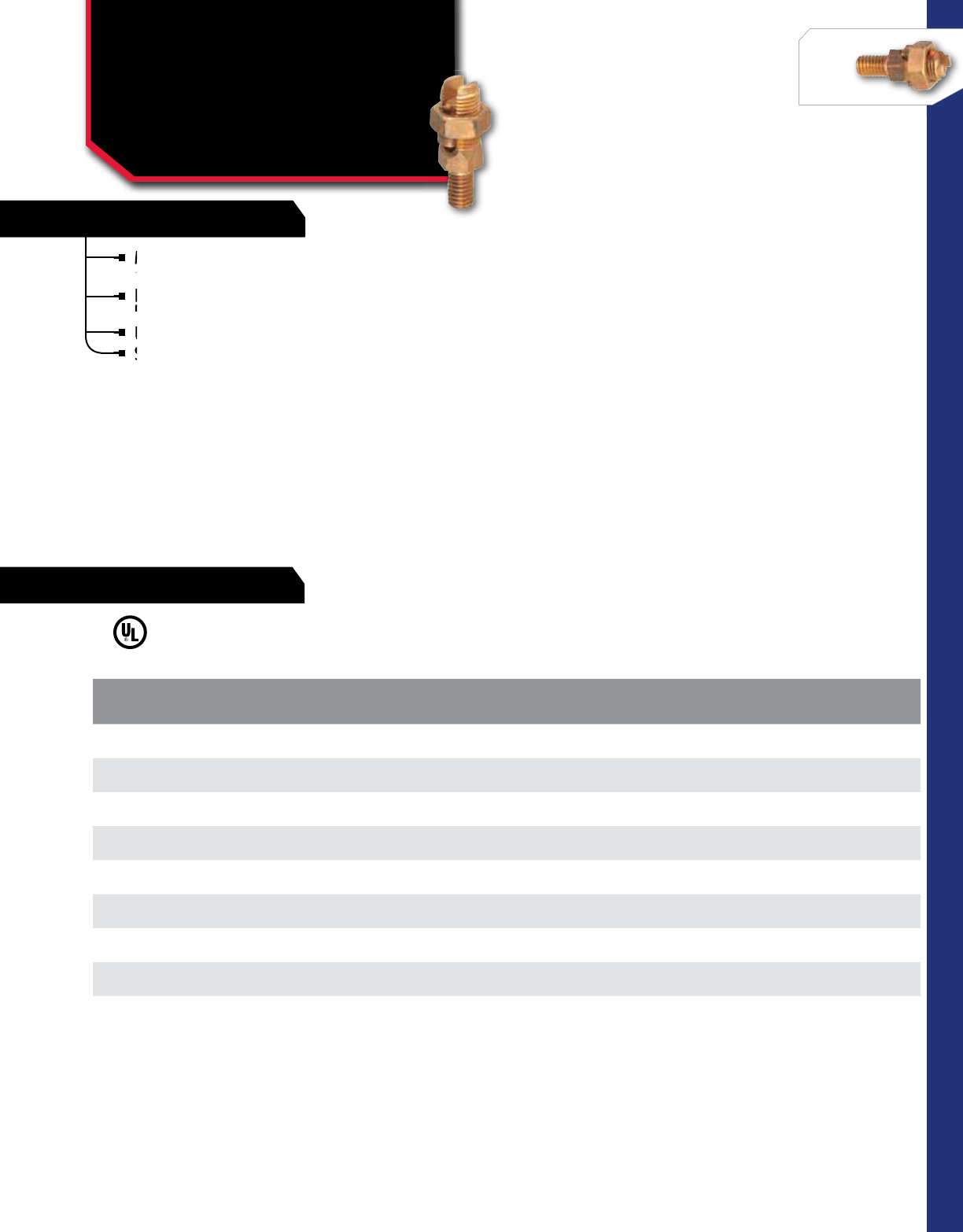
110
RATINGS
FEATURES
CONNECTORS
NSi Industries LLC • USA • 800.321.5847 • www.nsiindustries.com
FEATURES
110
CONNECTORS
CONNECTORS
Service Post Connectors
Two-Wire Type
SPM SERIES
Made from high copper content hard-drawn rod;
used for connecting one or two conductors.
Lay-in feature makes them excellent for continuous
loop grounding and bonding.
Used to ground to bar or plate.
Suitable for direct burial in earth or concrete.
CAT.
NO. CONDUCTOR
RANGE STUD
SIZE HEX
NUT
STD.
CTN.
QTY.
SPM-21L 12 sol - 8 str 0.250 x 20 – 1 0.375 x 24 25
SPM-22L 10 sol - 7 str 0.250 x 20 – 1 0.437 x 20 25
SPM-23L 8 sol - 5 str 0.312 x 18 – 1 0.500 x 20 25
SPM-24L 6 sol - 3 str 0.375 x 16 – 1.125 0.562 x 18 12
SPM-25L 10 sol - 2 str 0.375 x 16 – 1.125 0.625 x 18 12
SPM-26L 4 sol - 1/0 str 0.500 x 13 – 1.250 0.750 x 16 12
SPM-27L 2 sol - 2 str 0.500 x 13 – 1.250 0.875 x 14 6
SPM-29L 1 sol - 4/0 str 0.625 x 11 – 1.500 1.125 X 11 3
Lay-in feature makes them excellent for continuous
loop grounding and bonding.
Lay-in feature makes them excellent for continuous
loop grounding and bonding.
Lay-in feature makes them excellent for continuous
Made from high copper content hard-drawn rod;
used for connecting one or two conductors.
Made from high copper content hard-drawn rod;
used for connecting one or two conductors.
Made from high copper content hard-drawn rod;
Used to ground to bar or plate.
Suitable for direct burial in earth or concrete.
Suitable for direct burial in earth or concrete.
Suitable for direct burial in earth or concrete.
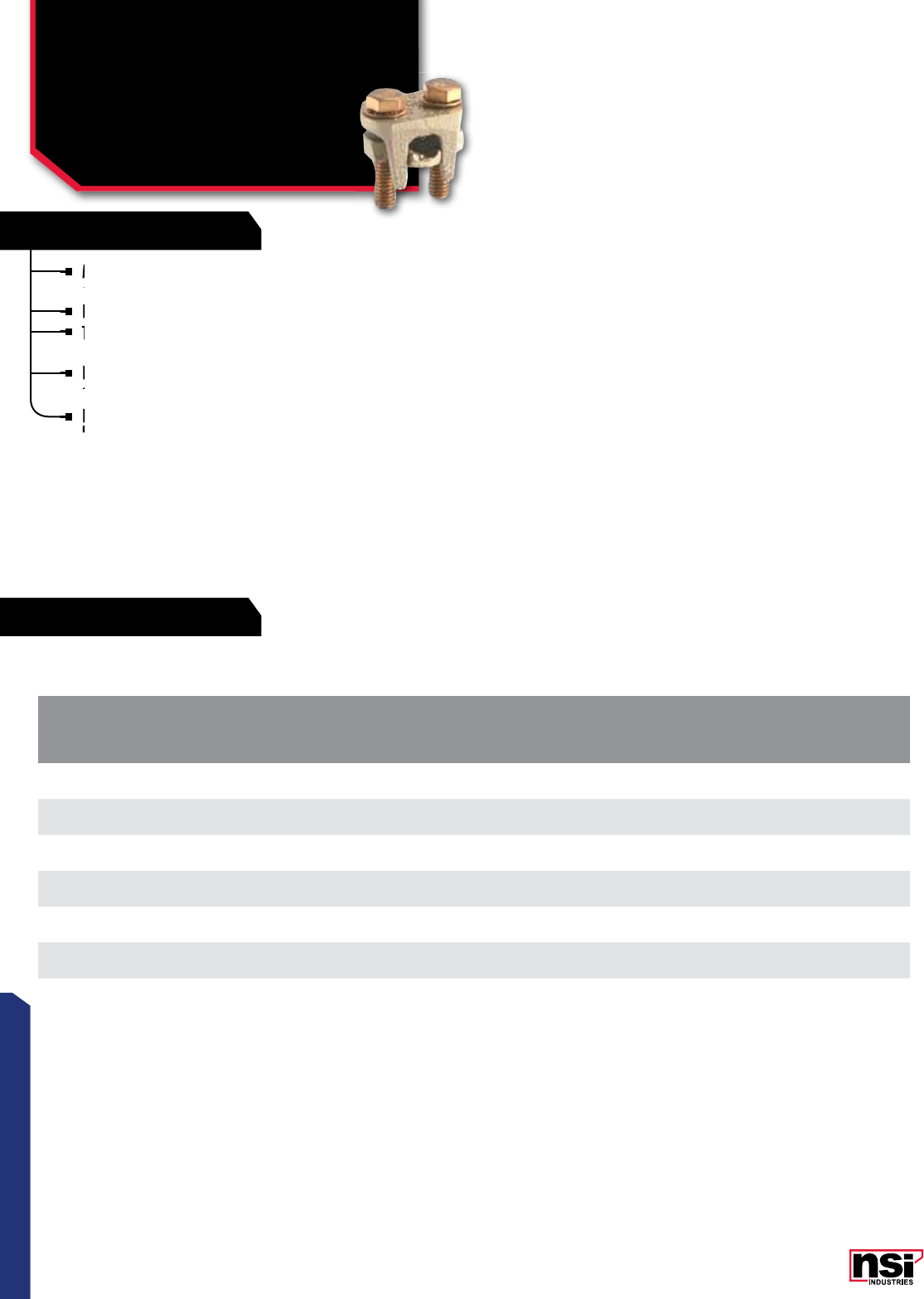
111
CONNECTORS
RATINGS
FEATURES
111
CONNECTORS
TAP CONNECTORS
Two-Bolt Bronze
For Copper To Copper
TC SERIES
CAT.
NO.
MAIN WIRE RANGE TAP WIRE RANGE STD.
CTN.
QTY.
MAX.MIN.MAX.MIN.
TC 1/0 1/0 str 2 sol 1/0 str 6 sol 10
TC 2/0 2/0 str 1 sol 2/0 str 6 sol 10
TC 4/0 4/0 str 2/0 str 4/0 str 6 sol 6
TC 350 350 MCM 4/0 str 350 MCM 4 sol 5
TC 500 500 MCM 350 MCM 500 MCM 4 sol 5
TC 800 800 MCM 600 MCM 800 MCM 2 sol 3
TC 1000 1000 MCM 750 MCM 1000 MCM 2 sol 2
Made from high strength Bronze Castings-assurance
against stress corrosion and season cracking.
Designed for heavy-duty service connections.
The cap swivels to permit quick and easy installation
of conductors.
Retaining rubber washer eliminates loose parts.
Silicon Bronze Hardware.
Flat back permits use as bus tap when used with
longer bolts.
The cap swivels to permit quick and easy installation
of conductors.
The cap swivels to permit quick and easy installation
of conductors.
The cap swivels to permit quick and easy installation
Designed for heavy-duty service connections.
The cap swivels to permit quick and easy installation
Made from high strength Bronze Castings-assurance
against stress corrosion and season cracking.
Made from high strength Bronze Castings-assurance
against stress corrosion and season cracking.
Made from high strength Bronze Castings-assurance
Retaining rubber washer eliminates loose parts.
Silicon Bronze Hardware.
Flat back permits use as bus tap when used with
longer bolts.
Flat back permits use as bus tap when used with
longer bolts.
Flat back permits use as bus tap when used with
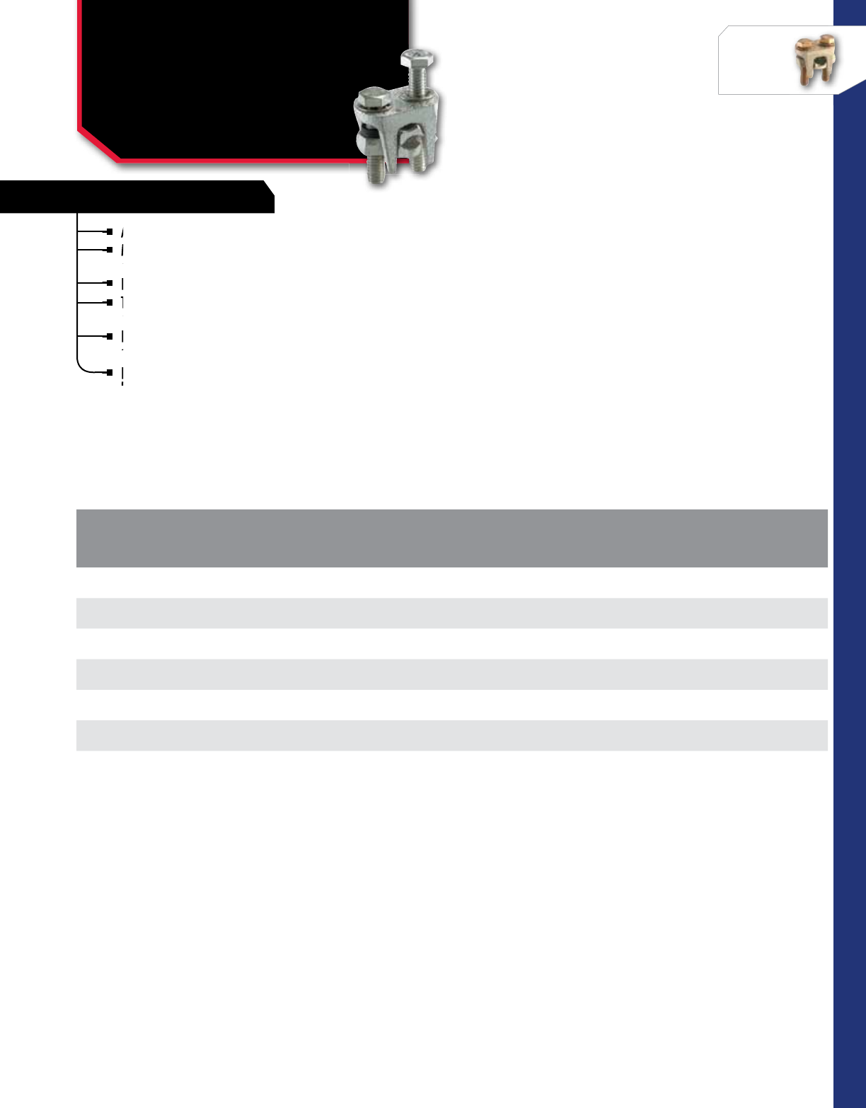
112
CONNECTORS
NSi Industries LLC • USA • 800.321.5847 • www.nsiindustries.com
FEATURES
112
CONNECTORS
TAP CONNECTORS
Two-Bolt Bronze
For Aluminum, Copper
and Steel
TCP SERIES
All parts are tin plated.
Made from High Strength Bronze castings with high
conductivity spacer bar.
Designed for heavy-duty service connections.
The cap swivels to permit quick and easy installation
of conductors.
Retaining rubber washer eliminates loose parts.
Silicon Bronze Hardware.
Flat back permits use as bus tap when used with
longer bolts.
CAT.
NO.
MAIN WIRE RANGE TAP WIRE RANGE STD.
CTN.
QTY.
MAX.MIN.MAX.MIN.
TCP 1/0 1/0 str 2 sol 1/0 str 6 sol 10
TCP 2/0 2/0 str 1 sol 2/0 str 6 sol 10
TCP 4/0 4/0 str 2/0 str 4/0 str 6 sol 6
TCP 350 350 MCM 4/0 str 350 MCM 4 sol 5
TCP 500 500 MCM 350 MCM 500 MCM 4 sol 5
TCP 800 800 MCM 600 MCM 800 MCM 2 sol 3
TCP 1000 1000 MCM 750 MCM 1000 MCM 2 sol 2
Designed for heavy-duty service connections.
Made from High Strength Bronze castings with high
conductivity spacer bar.
Made from High Strength Bronze castings with high
conductivity spacer bar.
Made from High Strength Bronze castings with high
All parts are tin plated.
Made from High Strength Bronze castings with high
The cap swivels to permit quick and easy installation
of conductors.
The cap swivels to permit quick and easy installation
of conductors.
The cap swivels to permit quick and easy installation
The cap swivels to permit quick and easy installation
Retaining rubber washer eliminates loose parts.
Silicon Bronze Hardware.
Flat back permits use as bus tap when used with
longer bolts.
Flat back permits use as bus tap when used with
longer bolts.
Flat back permits use as bus tap when used with
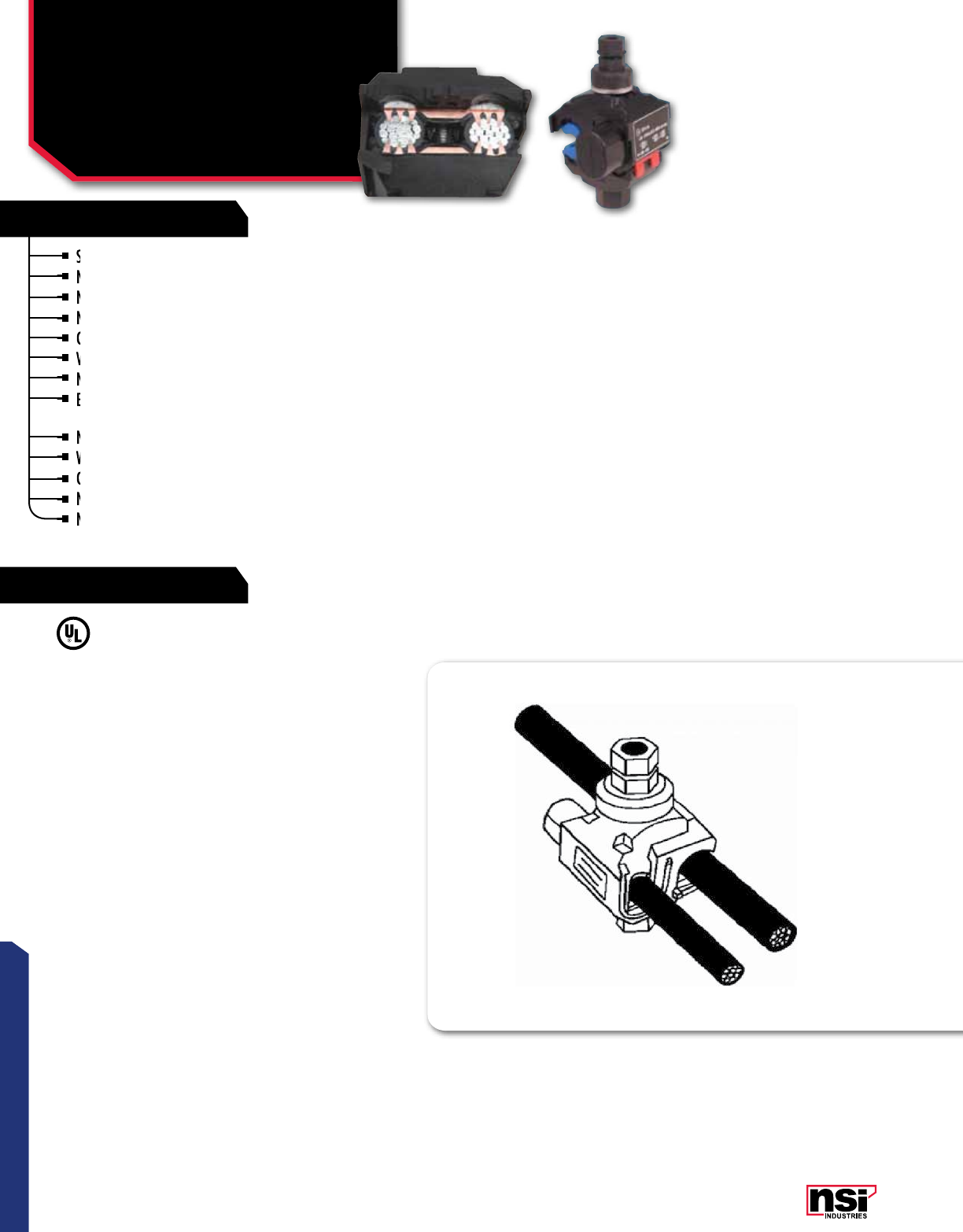
113
CONNECTORS
RATINGS
FEATURES
113
CONNECTORS
EASY-TAP™
IPCS Series – Insulation
Piercing Connectors
IPCS SERIES
Safe to use.
No need to strip wire and totally insulated.
No tape or cover needed.
No contact at any point with a live part.
Can be installed on energized conductors.
Versatile and reliable.
No spacer required between connections.
Exclusive “turbo spacer” keeps tap side open
while main conductor is being tightened.
No need for a third hand to install.
Watertight and corrosion-free.
Connection sealed by a rubber grommet.
No migration of water.
No contamination between main and tap.
UL486B listed.
Meets ANSI C119.4 requirements.
TEMPERATURE RATING:
90 °C.
VOLTAGE:
600V.
Connectors handle a large wire range of
#14 awg to 750MCM.
Double shear-head bolts ensure perfect
connection every time Hot spots eliminated.
Can be used as a splice or a tap.
Easy to install and no special tools required.
For copper-to-copper, copper-to-aluminum and
aluminum-to-aluminum applications.
Suitable for solid and/or stranded wires.
4 sizes are approved for use with bare wire
(from 4/0 to #10) - these connectors come
with a blue insert which re-creates the insulation
and avoids any damage to the conductor.
No contact at any point with a live part.
No tape or cover needed.
No contact at any point with a live part.
No need to strip wire and totally insulated.
No tape or cover needed.
Safe to use.
No need to strip wire and totally insulated.
Can be installed on energized conductors.
Can be installed on energized conductors.
Versatile and reliable.
Versatile and reliable.
No spacer required between connections.
No spacer required between connections.
Exclusive “turbo spacer” keeps tap side open
while main conductor is being tightened.
Exclusive “turbo spacer” keeps tap side open
while main conductor is being tightened.
Exclusive “turbo spacer” keeps tap side open
Exclusive “turbo spacer” keeps tap side open
No need for a third hand to install.
Watertight and corrosion-free.
Connection sealed by a rubber grommet.
Watertight and corrosion-free.
Connection sealed by a rubber grommet.
No migration of water.
Connection sealed by a rubber grommet.
No migration of water.
No contamination between main and tap.
No migration of water.
No contamination between main and tap.
No contamination between main and tap.

114
CONNECTORS
NSi Industries LLC • USA • 800.321.5847 • www.nsiindustries.com 114
CONNECTORS
CAT.
NO.
CONDUCTOR RANGE CURRENT RATING DIMENSIONS (IN)
NO. OF
BOLTS
STD.
PACk
QTY.
STD.
CTN.
QTY.
MAIN AWG TAP AWG CU AMP AL AMP HEIGHT WIDTH LENGTH
IPCS2001* 2/0 – 4 10 – 14 55 40 3.000 1.800 2.200 116
IPCS7501* 750 – 3/0 10 – 14 55 40 3.700 2.400 2.600 116
IPCS1002 1/0 – 8 2 – 10 190 150 3.100 1.800 2.200 116
IPCS1010 1/0 – 8 1/0 – 8 190 150 3.100 1.800 2.200 116
IPCS4002* 4/0 – 3 2 – 10 190 150 3.100 1.800 2.200 116
IPCS4020 4/0 – 2 2/0 – 6 300 235 3.300 2.200 2.600 114
IPCS4040 4/0 – 2 4/0 – 4 405 315 3.300 2.400 3.500 114
IPCS2540** 250 – 1 4/0 – 4 405 315 3.500 2.200 2.600 114
IPCS3535** 350 – 1/0 350 – 1/0 570 445 4.500 3.000 3.900 212
IPCS5040** 500 – 2/0 4/0 – 4 405 315 4.500 3.000 3.900 212
IPCS5035** 500 – 4/0 350 – 1/0 570 445 4.500 3.000 3.900 212
IPCS7550** 750 – 250 500 – 250 700 545 4.700 3.300 4.300 212
*Cannot be used with bare wire or as a splice
**Cannot be used with bare wire
All sizes can be installed on energized main conductor,
however, the tap must not be under load.
Not recommended for use with extra-flexible cables.
Not approved for submersible applications.

115
CONNECTORS
Each block can stand alone or combine with other blocks to form a
multi-block set.
Add as many holes as you need, in any configuration you want!
There are no end pieces or connector pieces to fool around with.
The connector body is made from high-strength, high-conductivity
aluminum alloy and is mounted in a high-strength glass-filled
polyester base.
Default SCCR Rating 10,000 Amps.
CONNECTOR BLOkS™
Single Primary
Multiple Secondary
Connector Blocks
AS, AM, AL SERIES
See-through clear acrylic covers permit visual inspection.
Snaps easily into place.
Just three sizes fit all styles and configurations of Connector-Bloks*.
CONNECTOR BLOK COVERS
SINGLE PRIMARY, MULTIPLE SECONDARY
Each block can stand alone or combine with other blocks to form a
multi-block set.
Add as many holes as you need, in any configuration you want!
There are no end pieces or connector pieces to fool around with.
There are no end pieces or connector pieces to fool around with.
See-through clear acrylic covers permit visual inspection.
Snaps easily into place.
The connector body is made from high-strength, high-conductivity
aluminum alloy and is mounted in a high-strength glass-filled
The connector body is made from high-strength, high-conductivity
aluminum alloy and is mounted in a high-strength glass-filled
The connector body is made from high-strength, high-conductivity
The connector body is made from high-strength, high-conductivity
Snaps easily into place.
Just three sizes fit all styles and configurations of Connector-Bloks*.
Snaps easily into place.
Default SCCR Rating 10,000 Amps.
Just three sizes fit all styles and configurations of Connector-Bloks*.
Just three sizes fit all styles and configurations of Connector-Bloks*.
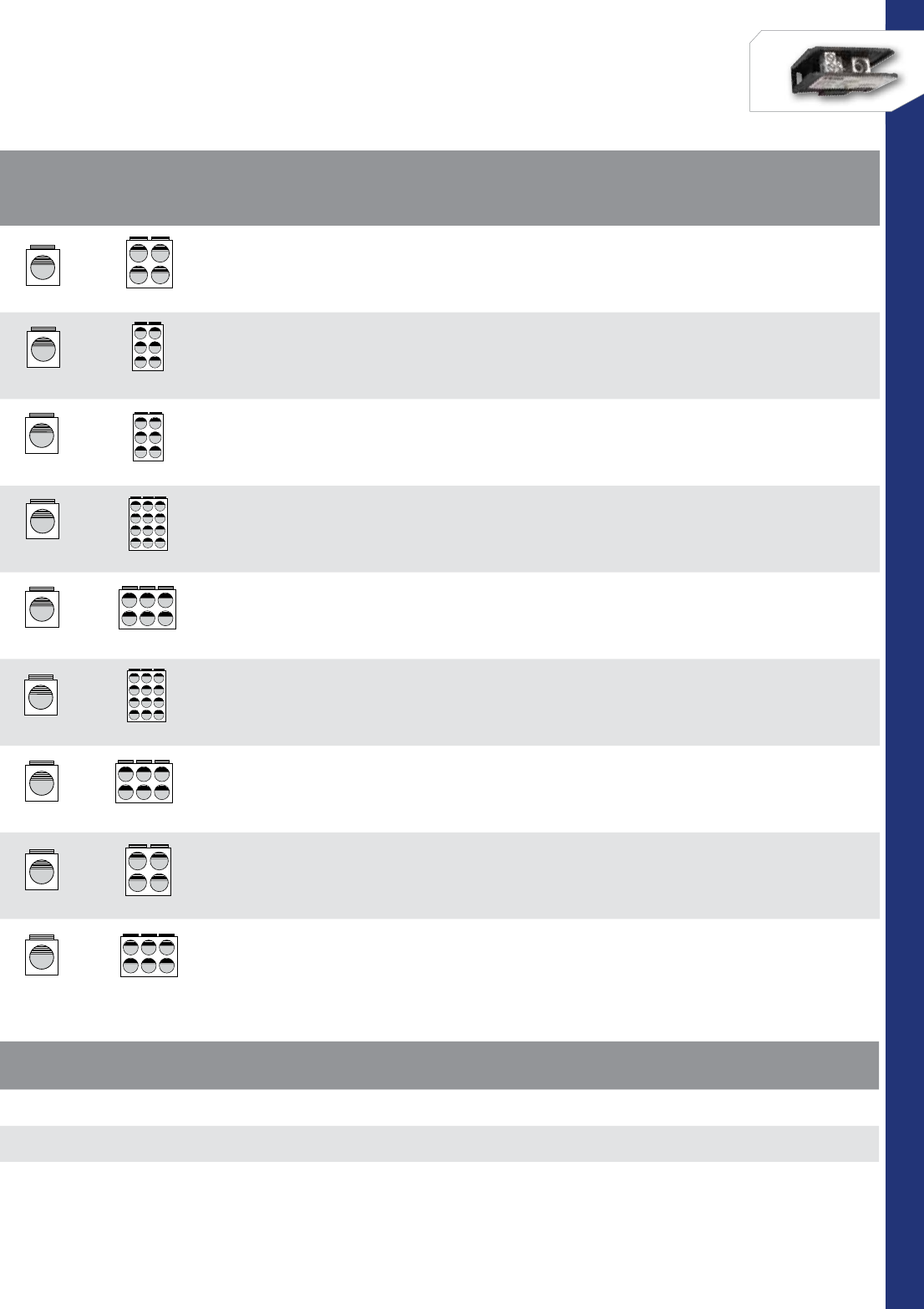
116
CONNECTORS
NSi Industries LLC • USA • 800.321.5847 • www.nsiindustries.com
CONFIGURATION CAT.
NO. AMPS PER
POLE LENGTH HEIGHT WIDTH STD.
PkG.
QTY.
STD.
CTN.
QTY.
LINE SIDE LOAD SIDE
2/0-14 AWG 4-14 AWG
AS-K1-H4 175 2.900 2.340 1.040 1 3
2/0-14 AWG 4-14 AWG
AS-K1-H6 175 2.900 2.340 1.040 1 3
350MCM-6 AWG 4-14 AWG
AM-P1-H6 310 4.000 2.620 1.710 1 3
350MCM-6 AWG 4-14 AWG
AM-P1-H12 310 4.000 2.620 1.710 1 3
350MCM-6 AWG 2/0-14 AWG
AL-P1-K6 310 5.500 3.250 2.900 1 3
500MCM-4 AWG 4-14 AWG
AM-R1-H12 380 4.000 2.620 1.710 1 3
500MCM-4 AWG 2/0-14 AWG
AL-R1-K6 380 5.500 3.250 2.900 1 3
500MCM-4 AWG 4/0-6 AWG
AL-R1-M4 380 5.500 3.250 2.900 1 3
1000-250 MCM 2/0-14 AWG
AL-V1-K6 545 5.500 3.250 2.900 1 1
*Not suitable for use with Catalog No. AS-K2-H6. AS-K2-K2 and AS-K1-H6.
CAT.
NO. FOR USE WITH CONNECTOR BLOCkS
SERIES WITH PREFIX STD. CN.
QTY.
CS AS* 12
CM AM 9
CL AL 6
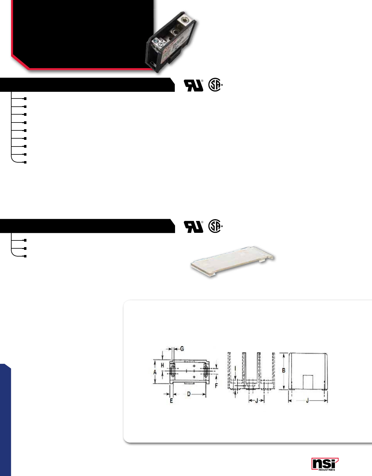
117
CONNECTORS
CONNECTOR BLOkS™
Multiple Primary
Multiple Secondary
Connector Blocks
AS, AM, AL SERIES
CONNECTOR BLOK COVERS
SINGLE PRIMARY, MULTIPLE SECONDARY
Compact.
Versatile.
90 °C.
600V.
Durable.
High-impact bases.
One-piece connectors .
No assembly on job site.
Default SCCR Rating 10,000 Amps.
See-through clear acrylic covers permit visual inspection.
Snaps easily into place.
Just three sizes fit all styles and configurations of Connector-Bloks*.

118
CONNECTORS
NSi Industries LLC • USA • 800.321.5847 • www.nsiindustries.com
CONFIGURATION CAT.
NO. AMPS PER
POLE LENGTH HEIGHT WIDTH STD.
PkG.
QTY.
STD.
CTN.
QTY.
LINE SIDE LOAD SIDE
2/0-14 AWG 4-14 AWG
AS-K2-H6 350 2.900 2.340 1.040 1 3
2/0-14 AWG 4-14 AWG
AM-K2-H6 350 4.000 2.620 1.710 1 3
2/0-14 AWG 4-14 AWG
AM-K2-H12 350 4.000 2.620 1.710 1 3
2/0-14 AWG 2-14 AWG
AM-K2-I6 350 4.000 2.620 1.710 1 3
350MCM-6 AWG 4-14 AWG
AL-P2-H12 620 5.500 3.250 2.900 1 3
350MCM-6 AWG 2/0-14 AWG
AL-P2-K6 620 5.500 3.250 2.900 1 3
500MCM-4 AWG 4-14 AWG
AL-R2-H12 760 5.500 3.250 2.900 1 3
500MCM-4 AWG 2/0-14 AWG
AL-R2-K6 760 5.500 3.250 2.900 1 3
500MCM-4 AWG 4/0-6 AWG
AL-R2-M4 760 5.500 3.250 2.900 1 3
*Not suitable for use with Catalog No. AS-K2-H6. AS-K2-K2 and AS-K1-H6.
CAT.
NO. FOR USE WITH CONNECTOR BLOCkS
SERIES WITH PREFIX
STD.
CTN.
QTY.
CS AS* 12
CM AM 9
CL AL 6

119
CONNECTORS
CONNECTOR BLOkS™
Splice Reducer
Primary Secondary
Connector Blocks
AS, AM, AL SERIES
CONNECTOR BLOK COVERS
SINGLE PRIMARY, MULTIPLE SECONDARY
Compact.
Versatile.
90 °C.
600V.
Durable.
High-impact bases.
One-piece connectors .
No assembly on job site.
Default SCCR Rating 10,000 Amps.
See-through clear acrylic covers permit visual inspection.
Snaps easily into place.
Just three sizes fit all styles and configurations of Connector-Bloks*.
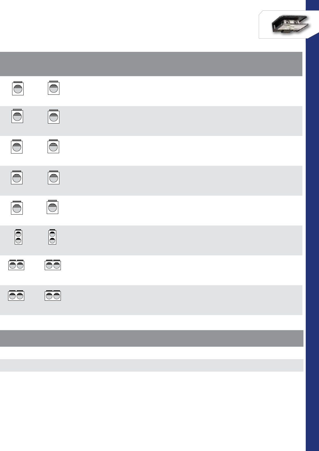
120
CONNECTORS
NSi Industries LLC • USA • 800.321.5847 • www.nsiindustries.com
CONFIGURATION CAT.
NO. AMPS PER
POLE LENGTH HEIGHT WIDTH STD.
PkG.
QTY.
STD.
CTN.
QTY.
LINE SIDE LOAD SIDE
2-14 AWG 2-14 AWG
AS-I1-I1 115 2.900 2.340 1.040 1 3
2/0-14 AWG 2/0-14 AWG
AS-K1-K1 175 2.900 2.340 1.040 1 3
250MCM-6 AWG 250MCM-6 AWG
AM-N1-N1 310 4.000 2.620 1.710 1 3
350MCM-6 AWG 350MCM-6 AWG
AM-P1-P1 350 4.000 2.620 1.710 1 3
500MCM-4 AWG 500MCM-4 AWG
AM-R1-R1 380 4.000 2.620 1.710 1 3
2/0-14 AWG 2/0-14 AWG
AS-K2-K2 350 2.900 2.340 1.040 1 3
350MCM-6 AWG 350MCM-6 AWG
AL-P2-P2 620 5.500 3.250 2.900 1 3
500MCM-4 AWG 500MCM-4 AWG
AL-R2-R2 760 5.500 3.250 2.900 1 3
*Not suitable for use with Catalog No. AS-K2-H6. AS-K2-K2 and AS-K1-H6.
CAT.
NO. FOR USE WITH CONNECTOR BLOCkS
SERIES WITH PREFIX
STD.
CTN.
QTY.
CS AS* 12
CM AM 9
CL AL 6
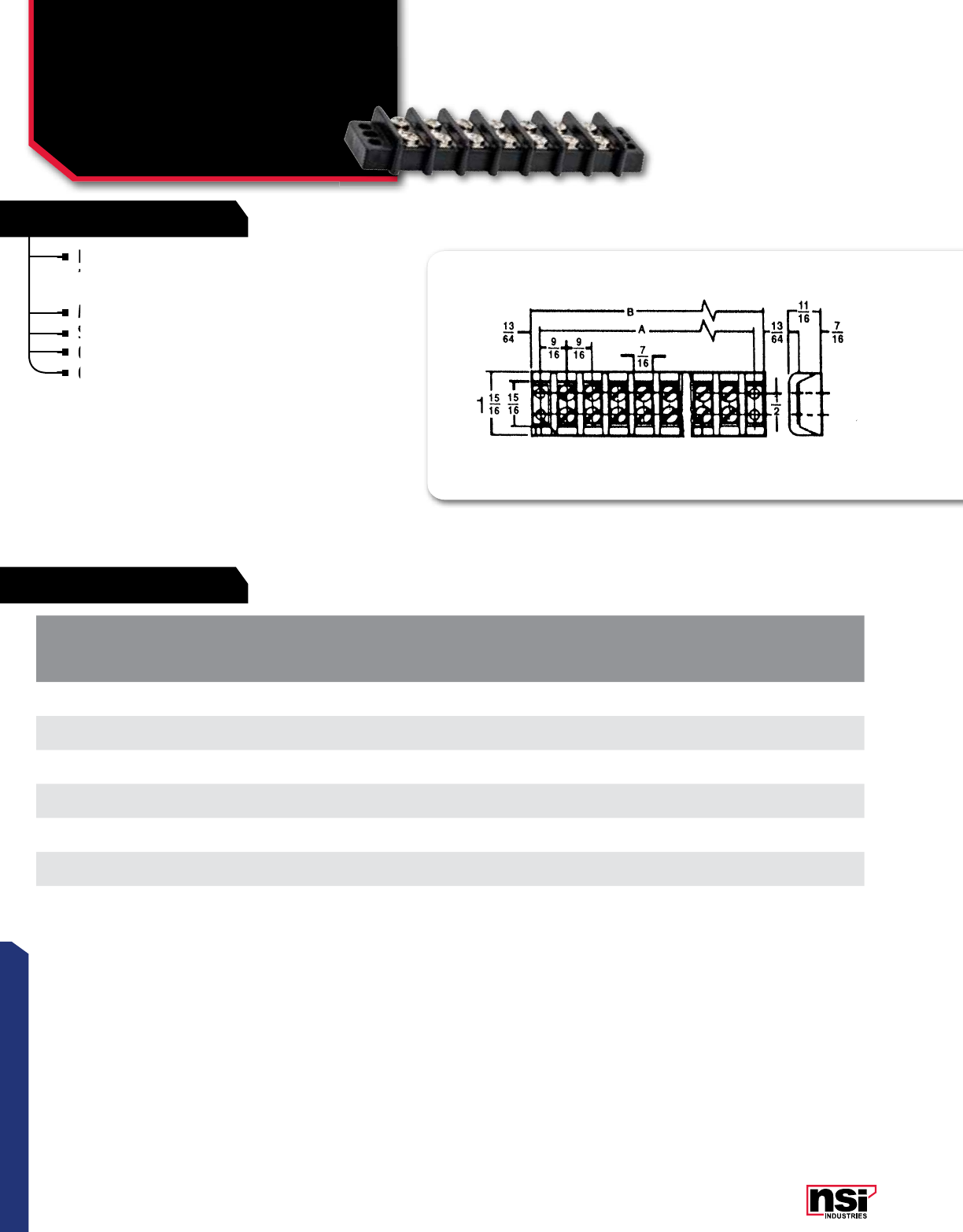
121
RATINGS
FEATURES
CONNECTORS
Heavy duty construction with corrosion-resistant
terminal plates ensures dependable, easy-access
multiple termination block.
Made from strong, glass-filled polyester.
Screws are #8 stud size.
Other sizes and styles available.
Contact NSi for price and availability.
TEMPERATURE RATING:
208 °C.
VOLTAGE:
30AMP.
600V Max.
TERMINAL BLOkS™
Double Row
9/16” Centers, 600V
TB SERIES
CAT.
NO. NUMBER
OF CIRCUITS
DIMENSIONS STD.
CTN.
QTY.
A B
TB3096-2 21.688 2.109 10
TB3096-4 42.812 3.250 10
TB3096-6 63.938 4.375 6
TB3096-8 85.062 5.500 4
TB3096-10 10 6.203 6.625 4
TB3096-12 12 7.328 7.750 3
TB3096-14 14 8.453 8.875 3
Screws are #8 stud size.
Made from strong, glass-filled polyester.
Screws are #8 stud size.
Screws are #8 stud size.
Heavy duty construction with corrosion-resistant
terminal plates ensures dependable, easy-access
Heavy duty construction with corrosion-resistant
terminal plates ensures dependable, easy-access
Heavy duty construction with corrosion-resistant
Other sizes and styles available.
Contact NSi for price and availability.
Other sizes and styles available.
Contact NSi for price and availability.
Contact NSi for price and availability.
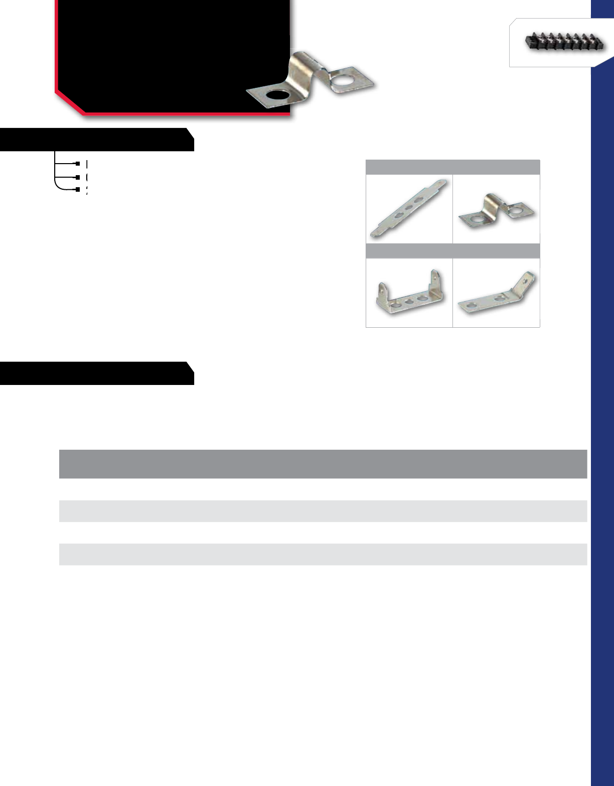
122
RATINGS
FEATURES
CONNECTORS
NSi Industries LLC • USA • 800.321.5847 • www.nsiindustries.com
Nickel plated.
0.250 x 0.30 tab size.
22-14AWG wire size.
1 2
3 4
CAT.
NO. FIGURE
NO. DESCRIPTION STD.
CTN.
QTY.
FQC-00 1quick disconnect – 0° flat 10
FQC-45 4quick disconnect – 45° bend 10
FQC-90 3quick disconnect – 90° bend 10
J-30 230 AMP jumper 10
TERMINAL BLOkS™
Hardware Options
FQC SERIES
Nickel plated.
0.250 x 0.30 tab size.
22-14AWG wire size.
0.250 x 0.30 tab size.
22-14AWG wire size.
22-14AWG wire size.
VOLTAGE:
30AMP.
600V Max.
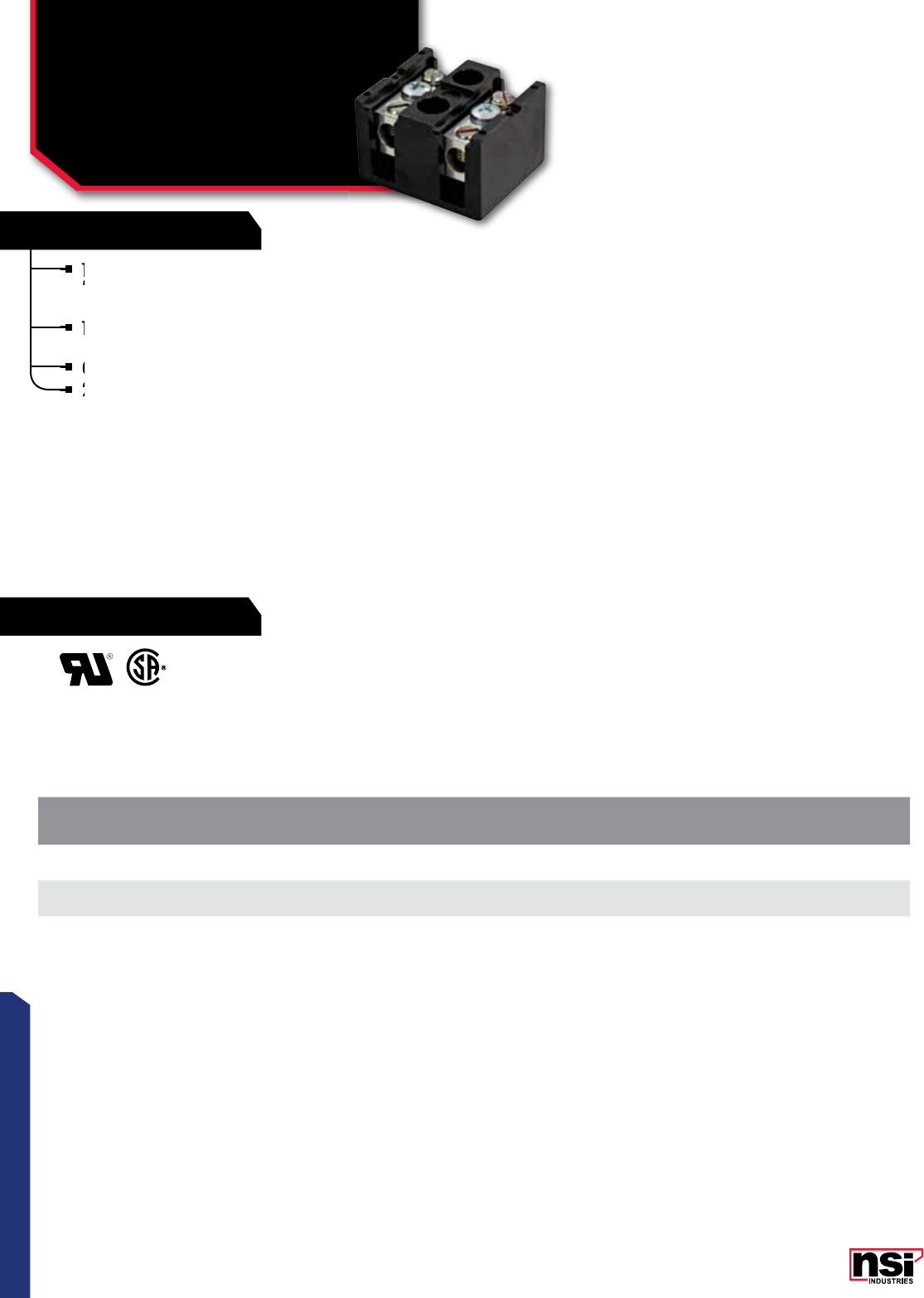
123
RATINGS
FEATURES
CONNECTORS
TERMINAL BLOkS™
Splicer/Reducers
75 Amps 600V
TBS SERIES
CAT.
NO. NO. OF
POLES WIRE
RANGE LENGTH HEIGHT WIDTH CTN.
QTY.
TBS2-2 22-14 AWG CU or AL 1.750 1.250 1.500 6
TBS2-3 32-14 AWG CU or AL 2.380 1.250 1.500 6
Terminal Bloks™ Power Terminal Blocks are made
from high-conductivity bodies and will accept either
copper or aluminum conductors on the line side.
The bases are manufactured from high-strength
phenolic compound.
Contact NSi for price and availability.
2-14 AWG.
The bases are manufactured from high-strength
phenolic compound.
The bases are manufactured from high-strength
phenolic compound.
The bases are manufactured from high-strength
Terminal Bloks
from high-conductivity bodies and will accept either
Contact NSi for price and availability.
2-14 AWG.
2-14 AWG.
2-14 AWG.
TEMPERATURE RATING:
150 °C.
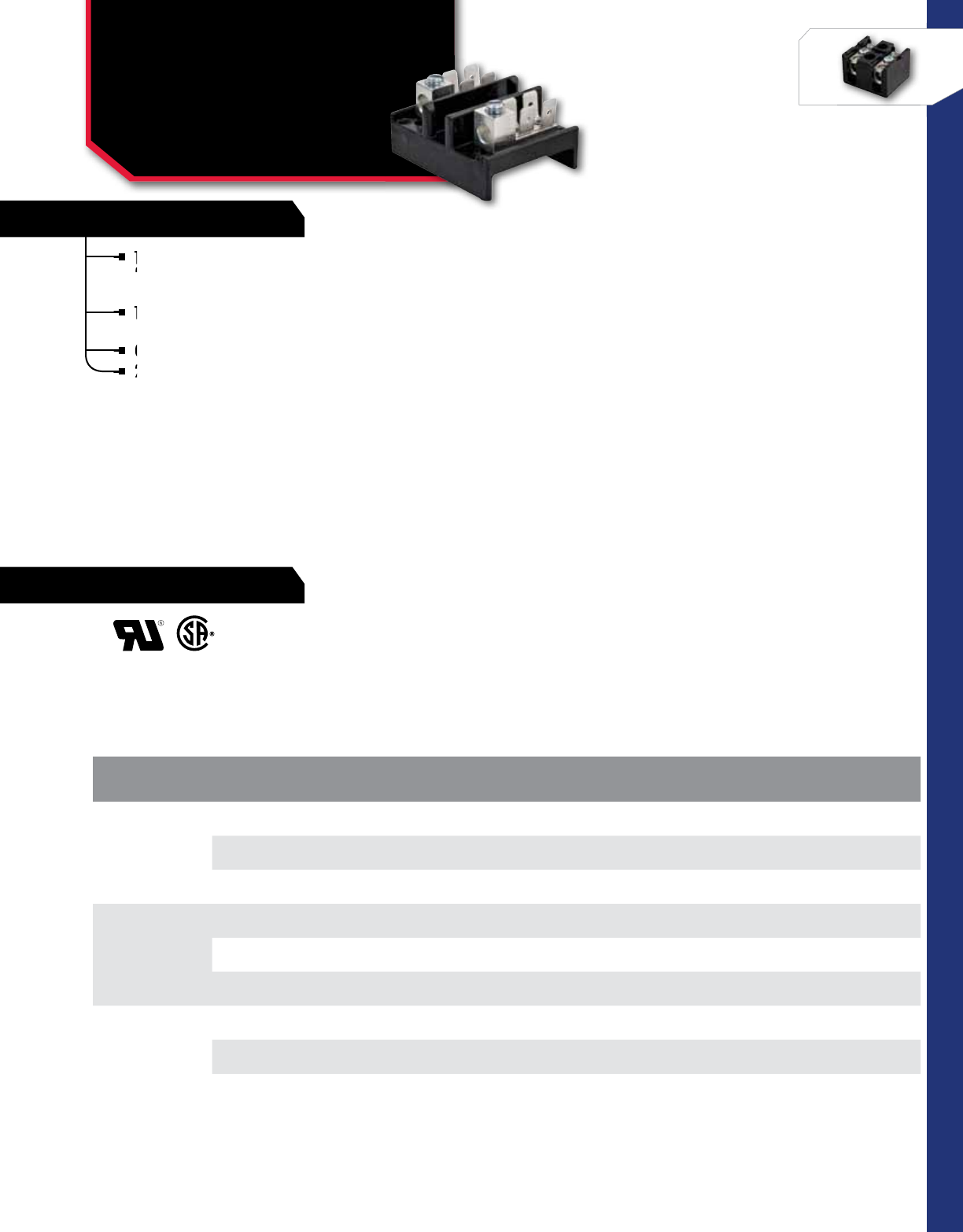
124
RATINGS
FEATURES
CONNECTORS
NSi Industries LLC • USA • 800.321.5847 • www.nsiindustries.com
CAT.
NO. LINE *
CONNECTION LOAD *
CONNECTION LENGTH HEIGHT WIDTH STD.
CTN.
QTY.
TB4-4T2
4-14 AWG 0.250 x 0.032 2.050 0.970 1.630 10
50 AMPS 4 quick-connect tabs
CU OR AL
TB2-4T2
2-14 AWG 0.250 x 0.032 2.050 1.090 1.630 10
75 AMPS 4 quick-connect tabs
CU OR AL
TB0-4T2
1/0-14 AWG 0.250 x 0.032 2.050 1.150 1.630 10
120 AMPS 4 quick-connect tabs
CU OR AL
*Connections per pole.
TERMINAL BLOkS™
Two Pole,
250 Volts
TB SERIES
Terminal Bloks™ Power Terminal Blocks are made
from high-conductivity bodies and will accept either
copper or aluminum conductors on the line side.
The bases are manufactured from high-strength
phenolic compound.
Contact NSi for price and availability.
2-14 AWG.
The bases are manufactured from high-strength
phenolic compound.
The bases are manufactured from high-strength
phenolic compound.
The bases are manufactured from high-strength
Terminal Bloks
from high-conductivity bodies and will accept either
Contact NSi for price and availability.
2-14 AWG.
2-14 AWG.
2-14 AWG.
TEMPERATURE RATING:
150 °C.
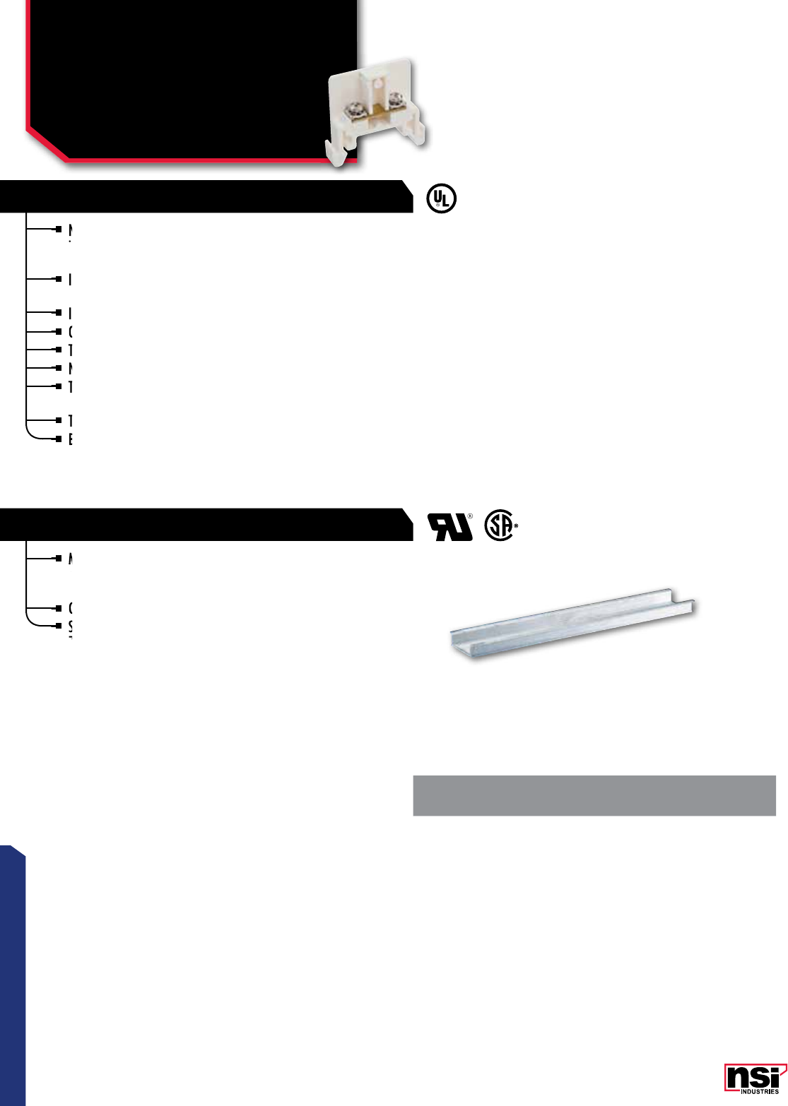
125
CONNECTORS
NSi Din Rail Mounted Terminal Blocks are a cost-effective and
intelligent solution to connecting and terminating a wide variety of
sizes and styles of wiring in a neat and professional manner.
Individual blocks can easily be inserted or removed without disturbing
adjacent blocks.
Insertion is made simply by snapping the block in place by hand.
Only a screwdriver is needed for removal.
The mounting rail is simply fastened by screws to the mounting surface.
No special brackets or hardware are needed.
The design of all component pieces is such that they may be mixed in
an assembly.
The blocks form their own barriers.
Blocks include integral mounting feet with screw slot for direct panel
mounting, if desired.
TERMINAL BLOkS™
Rail Mounted Modular
Terminal Block-
Hardware Options
DRT, FTB, DRE, DRJ SERIES
TERMINAL BLOCKS-HARDWARE OPTIONS
RAIL MOUNTED MODULAR
Made from 35 mm unplated 6061-T6 Aluminum alloy providing for a
strong, lightweight rail for mounting sockets, terminal blocks or other
electro-mechanical devices.
Comes supplied with oval holes 1.1 cm, approximately x 0.4 cm apart.
Standard 10 mm height allows for ease of installation vs. traditional
7.5 mm height.
CAT.
NO. HEIGHT LENGTH STD.
CTN.
QTY
DR3910 10 mm 39.3” 10
Individual blocks can easily be inserted or removed without disturbing
adjacent blocks.
Individual blocks can easily be inserted or removed without disturbing
adjacent blocks.
Individual blocks can easily be inserted or removed without disturbing
NSi Din Rail Mounted Terminal Blocks are a cost-effective and
intelligent solution to connecting and terminating a wide variety of
Insertion is made simply by snapping the block in place by hand.
The blocks form their own barriers.
Blocks include integral mounting feet with screw slot for direct panel
The design of all component pieces is such that they may be mixed in
an assembly.
The design of all component pieces is such that they may be mixed in
an assembly.
The design of all component pieces is such that they may be mixed in
Comes supplied with oval holes 1.1 cm, approximately x 0.4 cm apart.
Standard 10 mm height allows for ease of installation vs. traditional
Made from 35 mm unplated 6061-T6 Aluminum alloy
strong, lightweight rail for mounting sockets, terminal blocks or other
Made from 35 mm unplated 6061-T6 Aluminum alloy
strong, lightweight rail for mounting sockets, terminal blocks or other
Made from 35 mm unplated 6061-T6 Aluminum alloy
No special brackets or hardware are needed.
The design of all component pieces is such that they may be mixed in
The mounting rail is simply fastened by screws to the mounting surface.
No special brackets or hardware are needed.
Only a screwdriver is needed for removal.
Only a screwdriver is needed for removal.
The mounting rail is simply fastened by screws to the mounting surface.
Blocks include integral mounting feet with screw slot for direct panel
mounting, if desired.
Blocks include integral mounting feet with screw slot for direct panel
mounting, if desired.
Blocks include integral mounting feet with screw slot for direct panel
Blocks include integral mounting feet with screw slot for direct panel
Standard 10 mm height allows for ease of installation vs. traditional
7.5 mm height.
Standard 10 mm height allows for ease of installation vs. traditional
7.5 mm height.
Standard 10 mm height allows for ease of installation vs. traditional
Standard 10 mm height allows for ease of installation vs. traditional
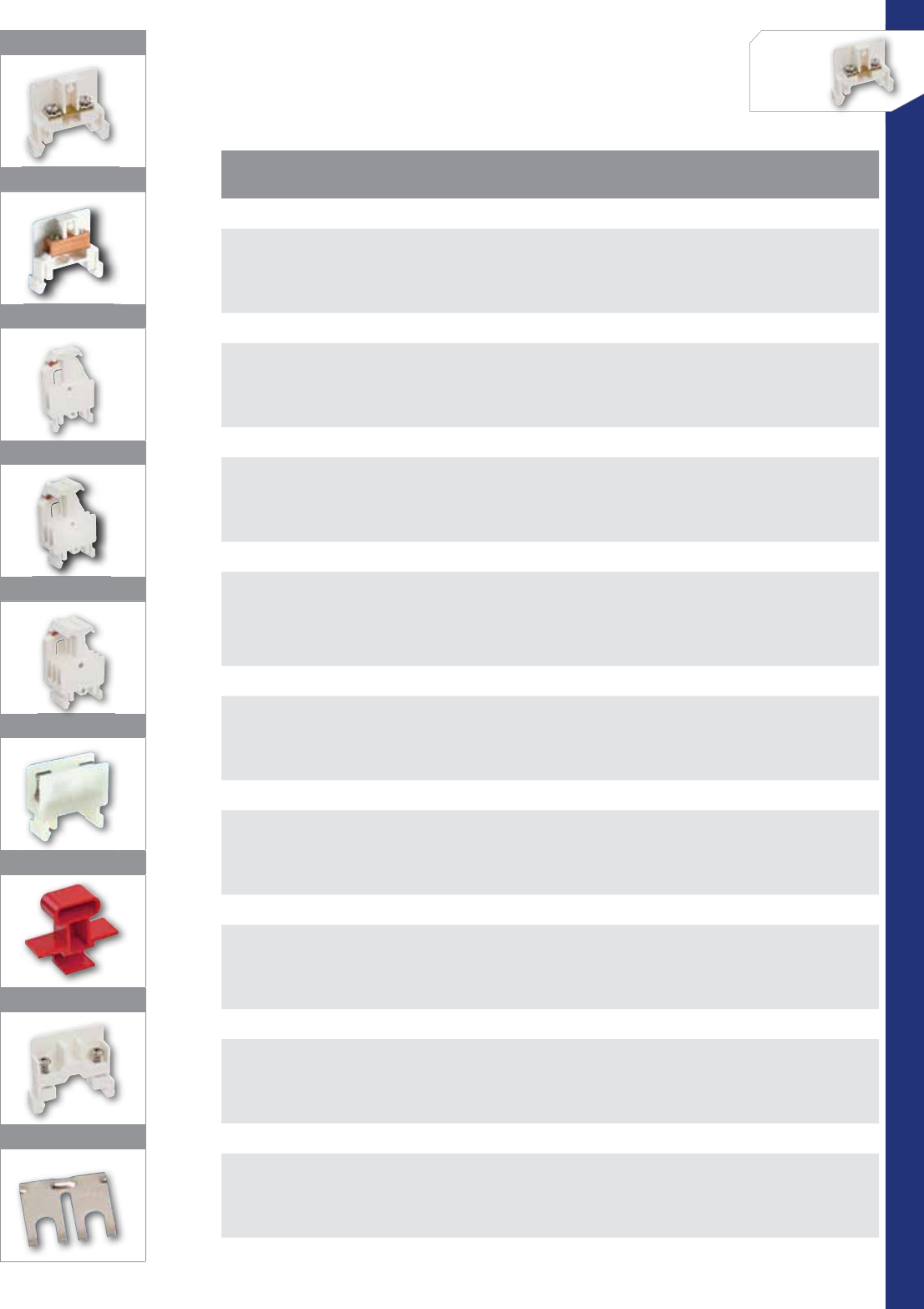
126
CONNECTORS
NSi Industries LLC • USA • 800.321.5847 • www.nsiindustries.com
CATALOG
NO. FIG.
NO. DESCRIPTION STD.
CTN.
QTY.
25 AMP TERMINAL BLOCk
DRTB25F 1
Will accept #22 to two #12 wires per terminal and include captive
wire clamps for use with stranded or solid wire or ring terminals.
Flat top marking with either pen or stick-on labels. Rated 25 Amps,
600 Volts.
50
50 AMP TERMINAL BLOCk
DRTB50 2
The DRTB50 block uses a box type connector to accept up to a #8 str.
Requires only 3/8” per point, allowing 32 points per foot. Provides 3/8”
square marking area. Rated 50 Amps, 600 Volts, 94V-O Rated housing.
25
SINGLE POLE DISCONNECT
DRDTB-1 3
The DRD Series of Disconnect Blocks may be used in a single-pole
function or linked together with other disconnects to form multiple
pole assemblies. Rated 15 Amps per pole. Accepts #22 to two #12
wires per terminal.
10
2 POLE DISCONNECT
DRDTB-2 4
Two single-pole disconnects with an interlocked handle
so that operation on any pole operates all poles. This unique assembly
makes it possible to interlock the isolation of different control panel
functions without using expensive relays or cam switches.
6
3 POLE DISCONNECT
DRDTB-3 5Three single-pole disconnects with an interlocked handle. Also available
up to 6 poles. Contact NSi for price and delivery. 3
DRFTB FUSE BLOCk
DRFTB 6
The DRFTB Fuse Block accepts 13/32” dia. by 11/2” long cartridge fuses
through 25 Amps, 600 Volts. The fusible block requires 3/4” rail taking
exactly two standard terminal blocks.
10
FUSE PULLER
FTBFP 7The FTBFB is supplied red as standard. 25
END BARRIER
DREB 8
Each assembly of blocks requires only an end barrier on each end of the
assembly. It acts as both the end barrier for the block
and retains the blocks on the rail.
50
JUMPER
DRJS2 9Jumper strap from one point to another on 25 Amp terminal block. 100
1
2
3
4
5
6
7
8
9
6
6
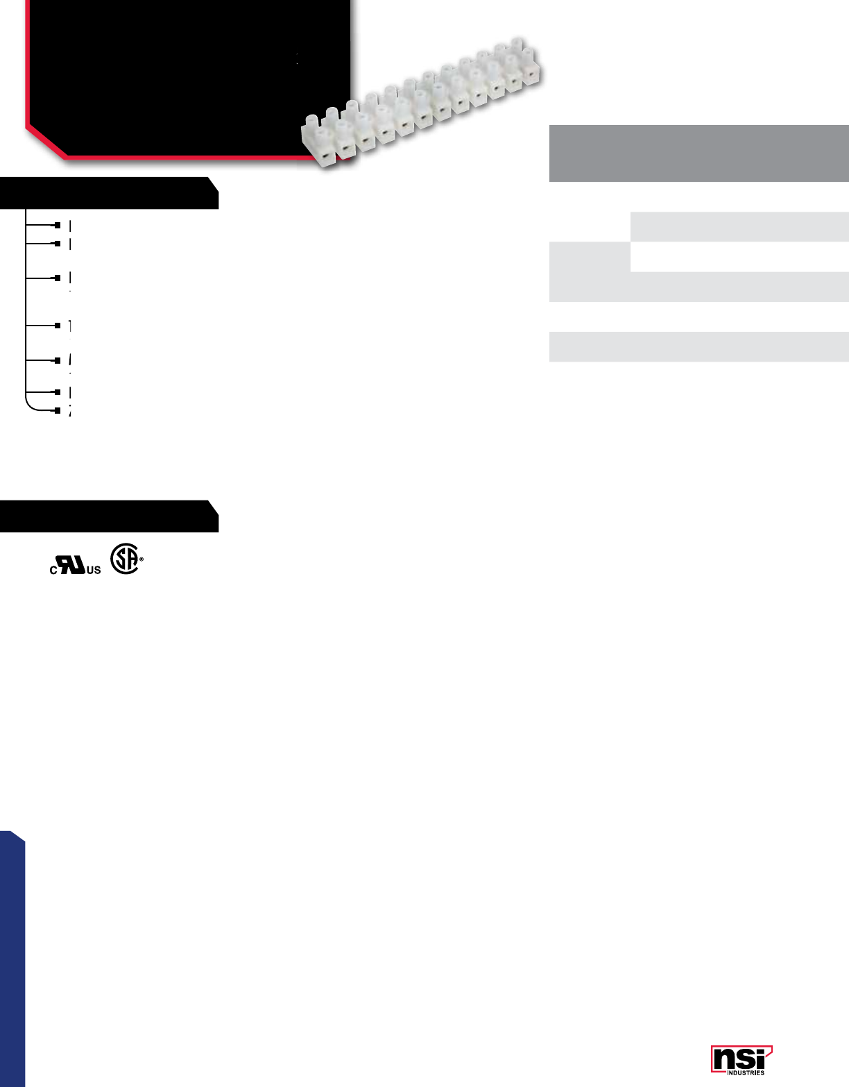
127
CONNECTORS
RATINGS
FEATURES
Nylon 66 housing ensures ‘touchproof’ safety.
Recessed screws and tubular contacts provide
additional safety and help prevent short circuits.
Integrated stainless steel spring wire protectors
prevent twisting and breaking of stranded wires
during installation.
Tubular contacts connect stripped solid or stranded
un-terminated wire directly to each contact.
Modular design allows for connector to be cut into
smaller sections or stacked end-to-end.
Brass metal alloy, nickel plated terminal insert.
Zinc plated, yellow chromed screws.
TERMINAL BLOkS™
Insulated Terminal Block
ITB SERIES
CAT.
NO. NO. OF
CIRCUTS RATINGS AMPS WIRE
RANGE
DIMENSIONS STD.
CTN.
QTY.
A B C D E F
ITB20-12
12 RU 20 22-12 3.787 0.669 0.570 0.315 0.114 0.110 50
CSA 10 20-18
ITB30-12
12 RU 30 22-10 4.626 0.795 0.670 0.394 0.142 0.134 50
CSA 20 18-14
ITB35-12 12 CRU 35 22-10 5.540 0.937 0.748 0.472 0.154 0.154 40
ITB50-12 12 CRU 50 20-8 6.220 1.008 0.992 0.531 0.173 0.189 25
Insulated Terminal Block
Integrated stainless steel spring wire protectors
prevent twisting and breaking of stranded wires
Integrated stainless steel spring wire protectors
prevent twisting and breaking of stranded wires
Integrated stainless steel spring wire protectors
Nylon 66 housing ensures ‘touchproof’ safety.
Recessed screws and tubular contacts provide
additional safety and help prevent short circuits.
Recessed screws and tubular contacts provide
additional safety and help prevent short circuits.
Recessed screws and tubular contacts provide
Recessed screws and tubular contacts provide
Brass metal alloy, nickel plated terminal insert.
Zinc plated, yellow chromed screws.
Modular design allows for connector to be cut into
smaller sections or stacked end-to-end.
Modular design allows for connector to be cut into
smaller sections or stacked end-to-end.
Modular design allows for connector to be cut into
Tubular contacts connect stripped solid or stranded
un-terminated wire directly to each contact.
Tubular contacts connect stripped solid or stranded
un-terminated wire directly to each contact.
Tubular contacts connect stripped solid or stranded
Zinc plated, yellow chromed screws.
Zinc plated, yellow chromed screws.
Rated UL 94V-2.
TEMPERATURE RATING:
110 °C.
VOLTAGE:
300V.
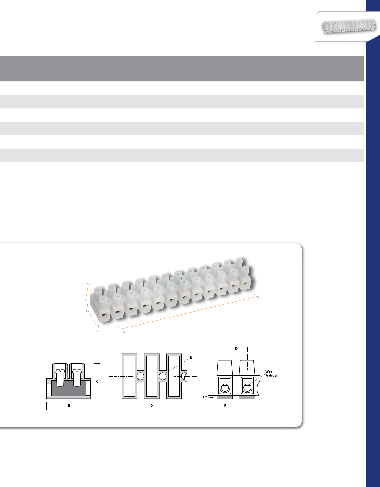
128
CONNECTORS
NSi Industries LLC • USA • 800.321.5847 • www.nsiindustries.com
A
B
C
CAT.
NO. NO. OF
CIRCUTS RATINGS AMPS WIRE
RANGE
DIMENSIONS STD.
CTN.
QTY.
A B C D E F
ITB20-12
12 RU 20 22-12 3.787 0.669 0.570 0.315 0.114 0.110 50
CSA 10 20-18
ITB30-12
12 RU 30 22-10 4.626 0.795 0.670 0.394 0.142 0.134 50
CSA 20 18-14
ITB35-12 12 CRU 35 22-10 5.540 0.937 0.748 0.472 0.154 0.154 40
ITB50-12 12 CRU 50 20-8 6.220 1.008 0.992 0.531 0.173 0.189 25
DIMENSIONS
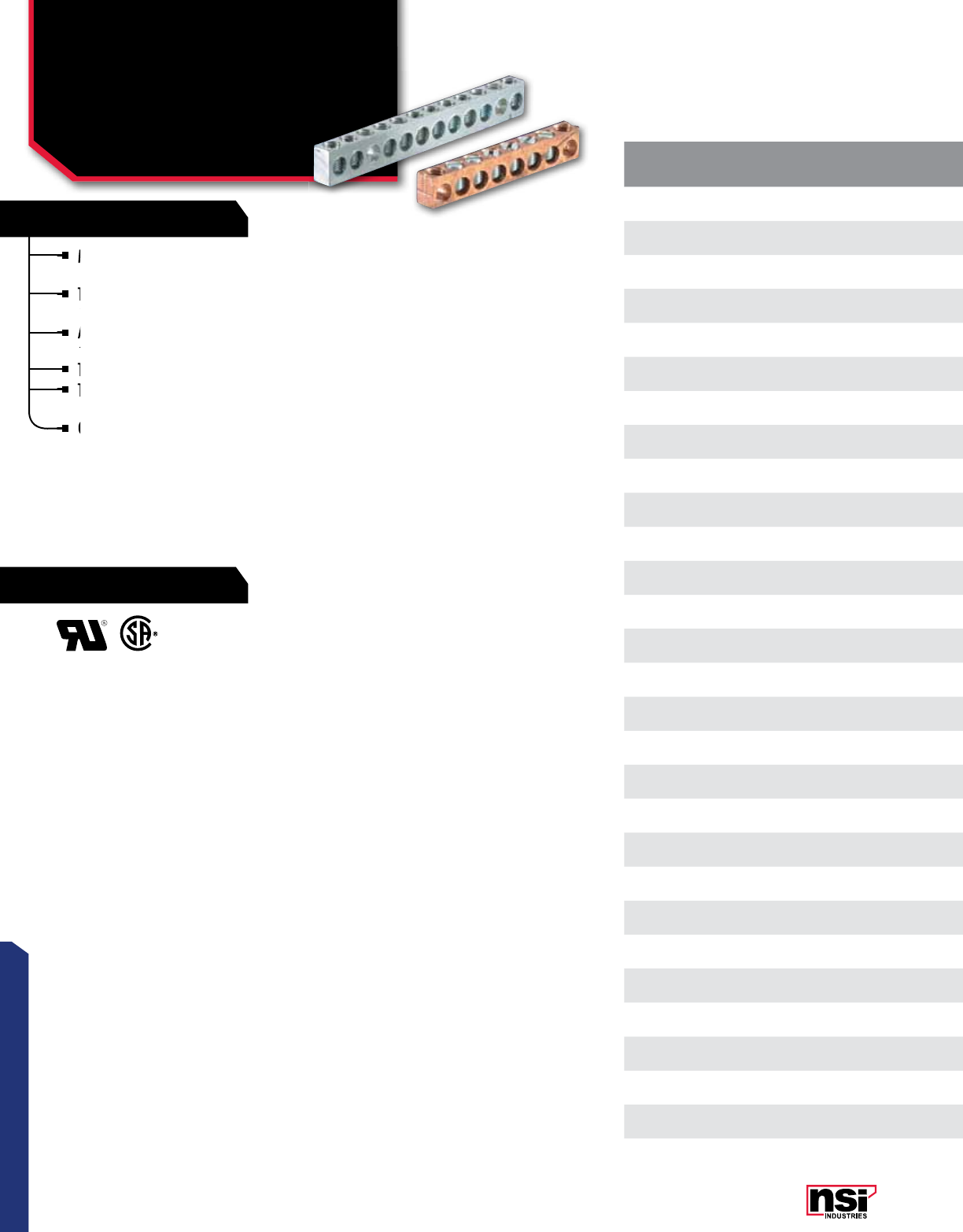
129
RATINGS
FEATURES
CONNECTORS
Multiple connectors are made from either copper or aluminum bar
and can be used in a variety of neutral and grounding applications.
The aluminum connectors are tin plated for low contact resistance
and are suitable for use with copper or aluminum conductors.
Aluminum connectors are dual rated for use with aluminum and
copper cables.
The copper connectors are suitable for use with copper wire only.
The 4-14 awg multiple connectors can be custom made in any
number of wire holes up to 190 holes.
Contact NSi for price and delivery information.
MULTIPLE CONNECTORS
Used In Neutral Assemblies
And Grounding
Applications
CAT.
NO. MATERIAL WIRE
RANGE NO. OF
CIRCUTS TOTAL NO.
OF HOLES LENGTH HEIGHT WIDTH HOLE
SPACING MTNG. HOLE
POSITION
STD.
CTN.
QTY.
4-14 (32) Aluminum 4-14 2 3 0.950 0.440 0.310 0.312 2100
4-14 (53) Aluminum 4-14 4 5 1.570 0.440 0.310 0.312 3100
4-14 (63) Aluminum 4-14 5 6 1.880 0.440 0.310 0.312 3100
4-14 (74) Aluminum 4-14 6 7 2.250 0.440 0.310 0.312 4100
4-14 (614) Aluminum 4-14 4 6 1.880 0.440 0.310 0.312 1 & 4 100
4-14 (717) Aluminum 4-14 5 7 2.250 0.440 0.310 0.312 1 & 7 100
4-14 (726) Aluminum 4-14 5 7 2.250 0.440 0.310 0.312 2 & 6 100
4-14 (847) Aluminum 4-14 6 8 2.560 0.440 0.310 0.312 4 & 7 100
4-14 (937) Aluminum 4-14 7 9 2.870 0.440 0.310 0.312 3 & 7 100
4-14
(11111) Aluminum 4-14 911 3.500 0.440 0.310 0.312 1 & 11 50
4-14
(12112) Aluminum 4-14 10 12 3.810 0.440 0.310 0.312 1 & 12 50
4-14
(14114) Aluminum 4-14 12 14 4.430 0.440 0.310 0.312 1 & 14 50
4-14
(17117) Aluminum 4-14 15 17 5.370 0.440 0.310 0.312 1 & 17 50
4-14
(22122) Aluminum 4-14 20 22 6.930 0.440 0.310 0.312 1 & 22 50
4-14 (190)* Aluminum 4-14 190 190 60.000 0.440 0.310 0.312 –10
2-14
(12311)** Aluminum 2-14 10 12 4.120 0.500 0.380 0.340 3 & 11 50
2/0-14
(32)** Aluminum 2/0-14 2 3 1.750 0.750 0.560 0.601 2 25
2/0-14
(524)** Aluminum 2/0-14 3 5 2.950 0.750 0.560 0.601 2 & 4 25
2/0-14
(818)** Aluminum 2/0-14 6 8 4.750 0.750 0.560 0.601 1 & 8 25
4C-14 (616) Copper 4-14 4 6 1.940 0.440 0.310 0.312 1 & 6 100
4C-14 (717) Copper 4-14 5 7 2.250 0.440 0.310 0.312 1 & 7 100
4C-14 (818) Copper 4-14 6 8 2.56 0.440 0.310 0.312 1 & 8 100
4C-14
(14114) Copper 4-14 12 14 4.430 0.440 0.310 0.312 1 & 14 50
4C-14
(15313) Copper 4-14 13 15 4.740 0.440 0.310 0.312 3 & 13 50
4C-14
(15611) Copper 4-14 13 15 4.740 0.440 0.310 0.312 6 & 11 50
4C-190* Copper 4-14 190 190 60.000 0.440 0.310 0.312 –10
2C-14 (515) Copper 2-14 3 5 2.000 0.500 0.380 0.397 1 & 5 50
2C-14 (827) Copper 2-14 6 8 3.250 0.500 0.380 0.397 2 & 7 50
Aluminum connectors are dual rated for use with aluminum and
copper cables.
Multiple connectors are made from either copper or aluminum bar
and can be used in a variety of neutral and grounding applications.
Multiple connectors are made from either copper or aluminum bar
and can be used in a variety of neutral and grounding applications.
Multiple connectors are made from either copper or aluminum bar
The aluminum connectors are tin plated for low contact resistance
and are suitable for use with copper or
The aluminum connectors are tin plated for low contact resistance
and are suitable for use with copper or
The aluminum connectors are tin plated for low contact resistance
The 4-14
number of wire holes up to 190 holes.
The copper connectors are suitable for use with copper wire only.
The 4-14
Contact NSi for price and delivery information.

130
CONNECTORS
NSi Industries LLC • USA • 800.321.5847 • www.nsiindustries.com
CAT.
NO. MATERIAL WIRE
RANGE NO. OF
CIRCUTS TOTAL NO.
OF HOLES LENGTH HEIGHT WIDTH HOLE
SPACING MTNG. HOLE
POSITION
STD.
CTN.
QTY.
4-14 (32) Aluminum 4-14 2 3 0.950 0.440 0.310 0.312 2100
4-14 (53) Aluminum 4-14 4 5 1.570 0.440 0.310 0.312 3100
4-14 (63) Aluminum 4-14 5 6 1.880 0.440 0.310 0.312 3100
4-14 (74) Aluminum 4-14 6 7 2.250 0.440 0.310 0.312 4100
4-14 (614) Aluminum 4-14 4 6 1.880 0.440 0.310 0.312 1 & 4 100
4-14 (717) Aluminum 4-14 5 7 2.250 0.440 0.310 0.312 1 & 7 100
4-14 (726) Aluminum 4-14 5 7 2.250 0.440 0.310 0.312 2 & 6 100
4-14 (847) Aluminum 4-14 6 8 2.560 0.440 0.310 0.312 4 & 7 100
4-14 (937) Aluminum 4-14 7 9 2.870 0.440 0.310 0.312 3 & 7 100
4-14
(11111) Aluminum 4-14 911 3.500 0.440 0.310 0.312 1 & 11 50
4-14
(12112) Aluminum 4-14 10 12 3.810 0.440 0.310 0.312 1 & 12 50
4-14
(14114) Aluminum 4-14 12 14 4.430 0.440 0.310 0.312 1 & 14 50
4-14
(17117) Aluminum 4-14 15 17 5.370 0.440 0.310 0.312 1 & 17 50
4-14
(22122) Aluminum 4-14 20 22 6.930 0.440 0.310 0.312 1 & 22 50
4-14 (190)* Aluminum 4-14 190 190 60.000 0.440 0.310 0.312 –10
2-14
(12311)** Aluminum 2-14 10 12 4.120 0.500 0.380 0.340 3 & 11 50
2/0-14
(32)** Aluminum 2/0-14 2 3 1.750 0.750 0.560 0.601 2 25
2/0-14
(524)** Aluminum 2/0-14 3 5 2.950 0.750 0.560 0.601 2 & 4 25
2/0-14
(818)** Aluminum 2/0-14 6 8 4.750 0.750 0.560 0.601 1 & 8 25
4C-14 (616) Copper 4-14 4 6 1.940 0.440 0.310 0.312 1 & 6 100
4C-14 (717) Copper 4-14 5 7 2.250 0.440 0.310 0.312 1 & 7 100
4C-14 (818) Copper 4-14 6 8 2.56 0.440 0.310 0.312 1 & 8 100
4C-14
(14114) Copper 4-14 12 14 4.430 0.440 0.310 0.312 1 & 14 50
4C-14
(15313) Copper 4-14 13 15 4.740 0.440 0.310 0.312 3 & 13 50
4C-14
(15611) Copper 4-14 13 15 4.740 0.440 0.310 0.312 6 & 11 50
4C-190* Copper 4-14 190 190 60.000 0.440 0.310 0.312 –10
2C-14 (515) Copper 2-14 3 5 2.000 0.500 0.380 0.397 1 & 5 50
2C-14 (827) Copper 2-14 6 8 3.250 0.500 0.380 0.397 2 & 7 50
*Supplied with screws unassembled.
**Not UL Rated.
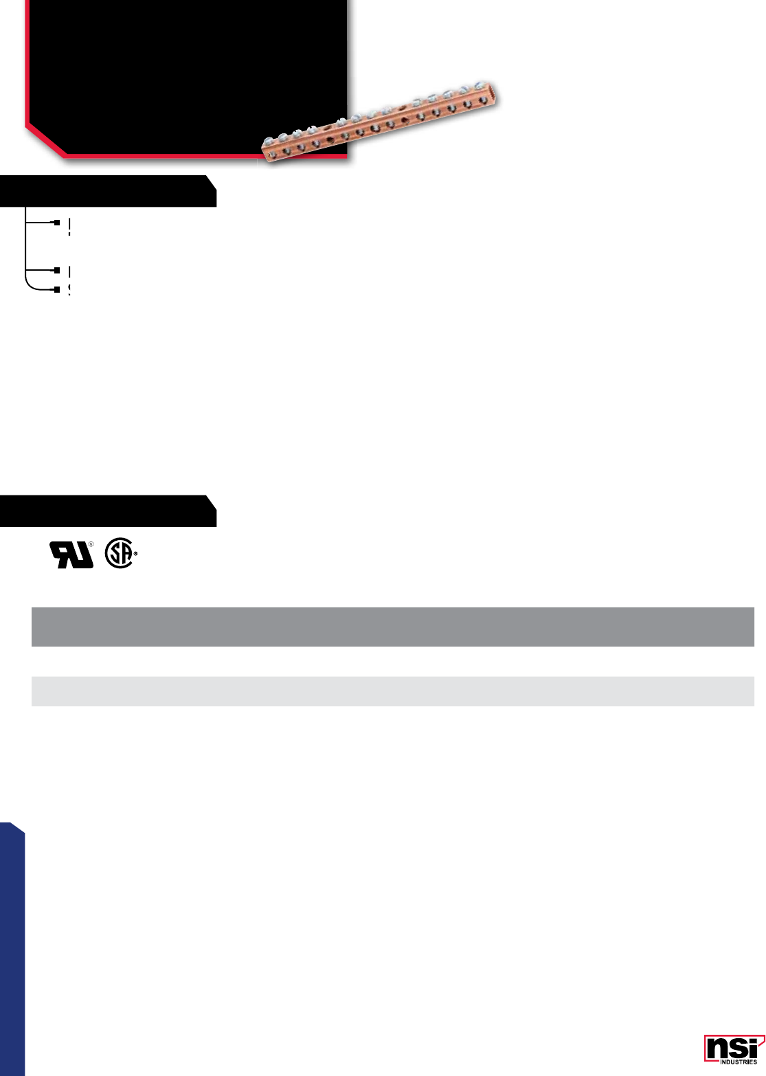
131
RATINGS
FEATURES
CONNECTORS
NSi copper neutral connectors are manufactured from
high strength pure electrolytic copper tube to ensure both
maximum strength and conductivity.
Plain copper finish.
Suitable for use with copper conductors only.
MULTIPLE CONNECTORS
Copper Neutral
Connectors
CN SERIES
CAT.
NO. LINE
NO. LINE
RANGE NO. OF
CIRCUTS CIRCUT
RANGE MTG.
HOLES LENGTH HEIGHT WIDTH STD.
CTN.
QTY.
CN70-10-1 14-14 86-14 2 x .20 4.370 0.750 0.340 100
CN70-14-1 14-14 12 6-14 2 x .20 5.940 0.750 0.340 100
Plain copper finish.
Suitable for use with copper conductors only.
NSi copper neutral connectors are manufactured from
high strength pure electrolytic copper tube to ensure both
NSi copper neutral connectors are manufactured from
high strength pure electrolytic copper tube to ensure both
NSi copper neutral connectors are manufactured from
Suitable for use with copper conductors only.
Suitable for use with copper conductors only.
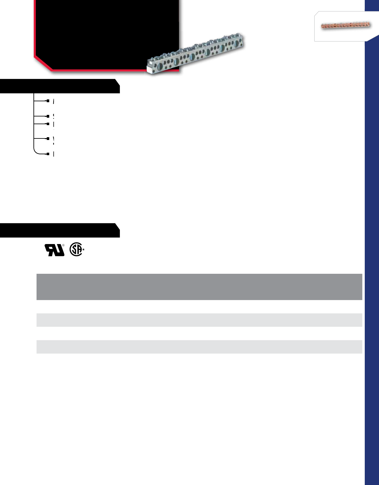
132
RATINGS
FEATURES
CONNECTORS
NSi Industries LLC • USA • 800.321.5847 • www.nsiindustries.com
CAT.
NO.
NUMBER OF CIRCUTS LENGTH STD.
CTN.
QTY.
1/0-14 AWG 6-14 AWG
CB-11 3 8 3.500 25
CB-19 514 5.810 25
CB-23 617 7.000 25
CB-120 30 90 36.000 10
MULTIPLE CONNECTORS
Combination
Connectors
CB SERIES
Multiple combination connectors are made from aluminum
and are tin-plated for low contact resistance.
Suitable for use with both copper and aluminum conductors.
Each connector contains a combination of 1/0-14 awg and
6-14 awg wire holes.
Very economical and compact due to innovative design and
hole spacing.
Dual rated for use with aluminum and copper cables.
Suitable for use with both copper and aluminum conductors.
Multiple combination connectors are made from aluminum
and are tin-plated for low contact resistance.
Multiple combination connectors are made from aluminum
and are tin-plated for low contact resistance.
Multiple combination connectors are made from aluminum
Very economical and compact due to innovative design and
hole spacing.
Very economical and compact due to innovative design and
hole spacing.
Very economical and compact due to innovative design and
Each connector
6-14
Each connector
Dual rated for use with aluminum and
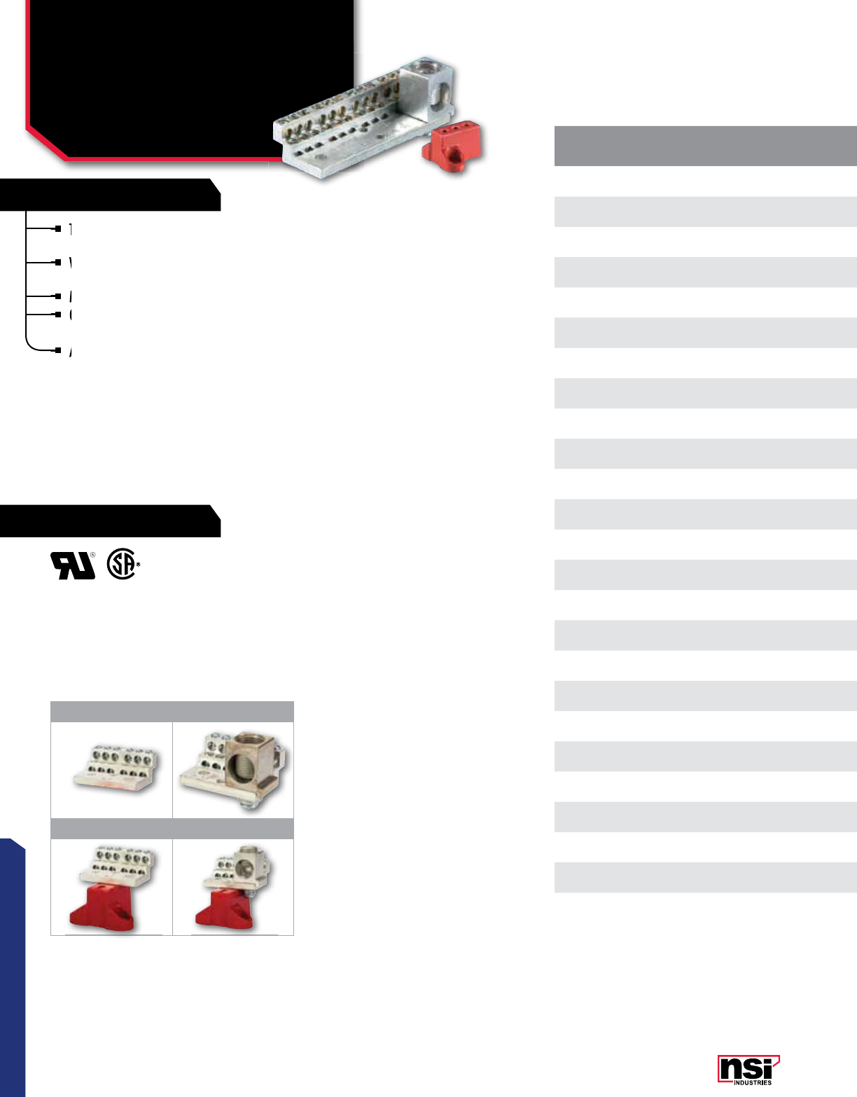
133
CONNECTORS
RATINGS
FEATURES
These stacked neutral assemblies offer the ultimate in compact
design and performance.
Wire holes are stacked to minimize width. One-piece
construction provides superior mechanical performance.
Made from high-strength 6061T-6 aluminum alloy.
Options include a 350 mcm main lug and a high-strength,
glass-filled polyester mounting base for isolated – mounting.
Available in 12 to 42 wire holes (4-14 awg).
NEUTRAL CONNECTORS
Neutral 225A
600 VAC
1 2
3 4
CATALOG
NO. FIGURE
NO. NO. OF 4-14
AWG CIRCUTS MAIN
LUG SIZE MOUNTING
BASE LENGTH HEIGHT WIDTH STD.
CTN.
QTY.
1012 112 none no 2.068 0.875 1.500 1
1012M 212 350-6 no 2.193 1.375 1.500 1
1012B 312 none yes 2.068 2.250 2.250 1
1012MB 412 350-6 yes 2.193 2.750 2.250 1
1018 118 none no 3.132 0.875 1.500 1
1018M 218 350-6 no 3.257 1.375 1.500 1
1018B 318 none yes 3.132 2.250 2.250 1
1018MB 418 350-6 yes 3.257 2.750 2.250 1
1024 124 none no 4.196 0.875 1.500 1
1024M 224 350-6 no 4.321 1.375 1.500 1
1024B 324 none yes 4.196 2.250 2.250 1
1024MB 424 350-6 yes 4.321 2.750 2.250 1
1030 130 none no 5.260 0.875 1.500 1
1030M 230 350-6 no 5.385 1.375 1.500 1
1030B 330 none yes 5.260 2.250 2.250 1
1030MB 430 350-6 yes 5.385 2.750 2.250 1
1036 136 none no 6.324 0.875 1.500 1
1036M 236 350-6 no 6.449 1.375 1.500 1
1036B 336 none yes 6.324 2.250 2.250 1
1036MB 436 350-6 yes 6.449 2.750 2.250 1
1042 142 none no 7.388 0.875 1.500 1
1042M 242 350-6 no 7.513 1.375 1.500 1
1042B 342 none yes 7.388 2.250 2.250 1
1042MB 442 350-6 yes 7.513 2.750 2.250 1
Options include a 350
glass-filled polyester mounting base for isolated –
Wire holes are stacked to minimize width. One-piece
construction provides superior mechanical performance.
Wire holes are stacked to minimize width. One-piece
construction provides superior mechanical performance.
Wire holes are stacked to minimize width. One-piece
Made from
Options include a 350
These stacked neutral assemblies offer the
design and performance.
Available in 12 to 42 wire holes (4-14

134
CONNECTORS
NSi Industries LLC • USA • 800.321.5847 • www.nsiindustries.com
CATALOG
NO. FIGURE
NO. NO. OF 4-14
AWG CIRCUTS MAIN
LUG SIZE MOUNTING
BASE LENGTH HEIGHT WIDTH STD.
CTN.
QTY.
1012 112 none no 2.068 0.875 1.500 1
1012M 212 350-6 no 2.193 1.375 1.500 1
1012B 312 none yes 2.068 2.250 2.250 1
1012MB 412 350-6 yes 2.193 2.750 2.250 1
1018 118 none no 3.132 0.875 1.500 1
1018M 218 350-6 no 3.257 1.375 1.500 1
1018B 318 none yes 3.132 2.250 2.250 1
1018MB 418 350-6 yes 3.257 2.750 2.250 1
1024 124 none no 4.196 0.875 1.500 1
1024M 224 350-6 no 4.321 1.375 1.500 1
1024B 324 none yes 4.196 2.250 2.250 1
1024MB 424 350-6 yes 4.321 2.750 2.250 1
1030 130 none no 5.260 0.875 1.500 1
1030M 230 350-6 no 5.385 1.375 1.500 1
1030B 330 none yes 5.260 2.250 2.250 1
1030MB 430 350-6 yes 5.385 2.750 2.250 1
1036 136 none no 6.324 0.875 1.500 1
1036M 236 350-6 no 6.449 1.375 1.500 1
1036B 336 none yes 6.324 2.250 2.250 1
1036MB 436 350-6 yes 6.449 2.750 2.250 1
1042 142 none no 7.388 0.875 1.500 1
1042M 242 350-6 no 7.513 1.375 1.500 1
1042B 342 none yes 7.388 2.250 2.250 1
1042MB 442 350-6 yes 7.513 2.750 2.250 1
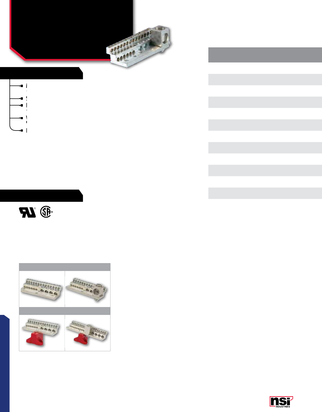
135
CONNECTORS
RATINGS
FEATURES
Multiple combination connectors are made from aluminum
and are tin-plated for low contact resistance.
Suitable for use with both copper and aluminum conductors.
Each connector contains a combination of 1/0-14 AWG and
6-14 AWG wire holes.
Very economical and compact due to innovative design and
hole spacing.
Dual rated for use with aluminum and copper cables.
MULTIPLE CONNECTORS
Combination Connectors
CAT.
NO. FIG. NO. OF 4-14
AWG CIRCUTS
NO. OF
1/0-14 AWG
CIRCUTS
MAIN LUG
SIZE MOUNTING
BASE LENGTH HEIGHT WIDTH STD.
CTN.
QTY.
2024 120 4None No 4.332 1.025 1.687 1
2024M 220 4350-6 No 4.457 1.525 1.687 1
2024MB 420 4350-6 Yes 4.457 2.900 2.437 1
2030 126 4None No 5.244 1.025 1.687 1
2030M 226 4350-6 No 5.369 1.525 1.687 1
2030B 326 4None Yes 5.244 2.400 2.437 1
2030MB 426 4350-6 Yes 5.369 2.900 2.437 1
2036 132 4None No 6.156 1.025 1.687 1
2036M 232 4350-6 No 6.281 1.525 1.687 1
2036MB 432 4350-6 Yes 6.281 2.900 2.437 1
2042M 238 4350-6 No 7.193 1.525 1.687 1
2042MB 438 4350-6 Yes 7.193 2.900 2.437 1
1 2
3 4
Very economical and compact due to innovative design and
hole spacing.
Very economical and compact due to innovative design and
hole spacing.
Very economical and compact due to innovative design and
Suitable for use with both copper and aluminum conductors.
Each connector
Each connector
6-14
Each connector
Multiple combination connectors are made from aluminum
and are tin-plated for low contact resistance.
Multiple combination connectors are made from aluminum
and are tin-plated for low contact resistance.
Multiple combination connectors are made from aluminum
Dual rated for use with aluminum and

136
CONNECTORS
NSi Industries LLC • USA • 800.321.5847 • www.nsiindustries.com
CAT.
NO. FIG. NO. OF 4-14
AWG CIRCUTS
NO. OF
1/0-14 AWG
CIRCUTS
MAIN LUG
SIZE MOUNTING
BASE LENGTH HEIGHT WIDTH STD.
CTN.
QTY.
2024 120 4None No 4.332 1.025 1.687 1
2024M 220 4350-6 No 4.457 1.525 1.687 1
2024MB 420 4350-6 Yes 4.457 2.900 2.437 1
2030 126 4None No 5.244 1.025 1.687 1
2030M 226 4350-6 No 5.369 1.525 1.687 1
2030B 326 4None Yes 5.244 2.400 2.437 1
2030MB 426 4350-6 Yes 5.369 2.900 2.437 1
2036 132 4None No 6.156 1.025 1.687 1
2036M 232 4350-6 No 6.281 1.525 1.687 1
2036MB 432 4350-6 Yes 6.281 2.900 2.437 1
2042M 238 4350-6 No 7.193 1.525 1.687 1
2042MB 438 4350-6 Yes 7.193 2.900 2.437 1
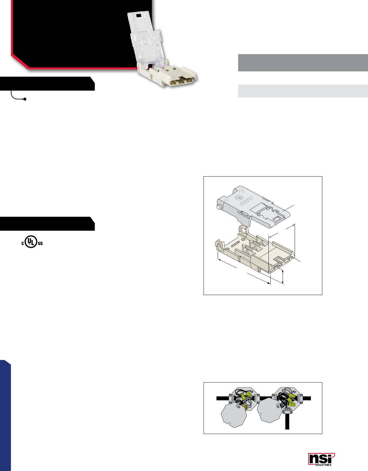
137
CONNECTORS
RATINGS
FEATURES
For splicing 12 or 14 awg solid conductor, 2-conductor
cable with ground. Hinged cover makes termination
fast and easy. The NMS-2 kit includes everything
required to make a two conductor splice.
FIG. 1
NMS -2 (SPLICE)
CONVENTIONAL
TAPPING METHOD
SPLICES AND TAPS
Non-Metallic Splice
& Tap
NMS, NMT SERIES
BLACK
GREEN
WHITE
BLACK
GREEN
WHITE
AMP
58.0
(2.28)
29.6
(1.16)
13.7
(0.54)
Housing
Hinged
Cover
CATALOG
NO. WIRE RANGE kIT DESCRIPTION STD.
CTN.
QTY.
NMS-2 12 – 14 AWG SPLICE FOR 2-CONDUCTOR CABLE WITH GROUND 25
NMS-3 12 – 14 AWG SPLICE FOR 3-CONDUCTOR CABLE WITH GROUND 25
NMT-2 12 – 14 AWG SPLICE AND TAP KIT FOR 2-CONDUCTOR CABLE 12
The NSi NM Splice & Tap method provides a fast and reliable way to connect 12 and 14
AWG circuits using non-metallic (NM) cable. It eliminates the need for junction boxes,
covers, fittings, connectors – and is approved for use in a variety of applications including:
residential branch circuits, manufactured housing and pre-fabricated building structures.
When adding new circuits in residential applications, NM connectors eliminate both the
need to cut into the existing wiring and the extra junction boxes and associated hardware
required for the tap connection.
In factory installations within pre-fabricated structures, the NM connectors eliminate
costly time- consuming on-site wiring. As individual modules are joined, splices and taps are
simply snapped together easily by assembly crews with no special training or tools.
Termination is easy. Split the cable, remove the sheathing and cut the splice conductors
to length (if necessary). With the tap, individual conductors do not need to be stripped, only
exposed. Clear cover installation is done with slip-joint pliers. The installation displacement
contacts eliminate the need to strip individual conductors. Simply plug the connectors
together and the installation is complete.
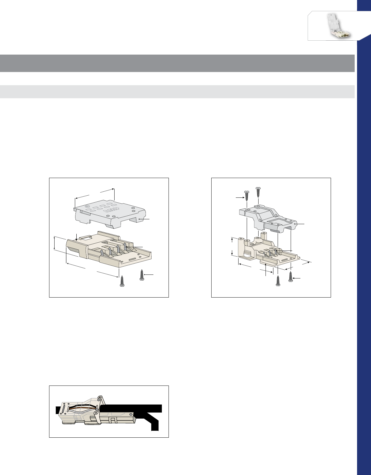
138
CONNECTORS
NSi Industries LLC • USA • 800.321.5847 • www.nsiindustries.com
For splicing 12 or 14 awg solid conductor, 3-conductor
cable with ground. The NMS-3 kit includes everything
required to make a three conductor splice.
For tapping into 12 or 14 awg solid conductor 2-conductor
cable with ground. The NMT-2 kit includes everything
required to complete a two conductor tap.
FIG. 2
NMS - 3 (SPLICE)
NSI NM SPLICE & TAP
METHOD
FIG. 3
NMT - 2 (TAP)
WHITE
GREEN
BLACK
RED
WHITE
GREEN
BLACK
RED
AMP
36.6
(1.44)
13.2
(.52)
54.9
(2.16)
Housing
Screws
Contacts
Clear
Cover
24.4
(.96)
36.9
(1.53)
54.9
(2.16)
Housing Screws
Screws
Contacts
Clear
Cover
CATALOG
NO. WIRE RANGE kIT DESCRIPTION STD.
CTN.
QTY.
NMS-2 12 – 14 AWG SPLICE FOR 2-CONDUCTOR CABLE WITH GROUND 25
NMS-3 12 – 14 AWG SPLICE FOR 3-CONDUCTOR CABLE WITH GROUND 25
NMT-2 12 – 14 AWG SPLICE AND TAP KIT FOR 2-CONDUCTOR CABLE 12
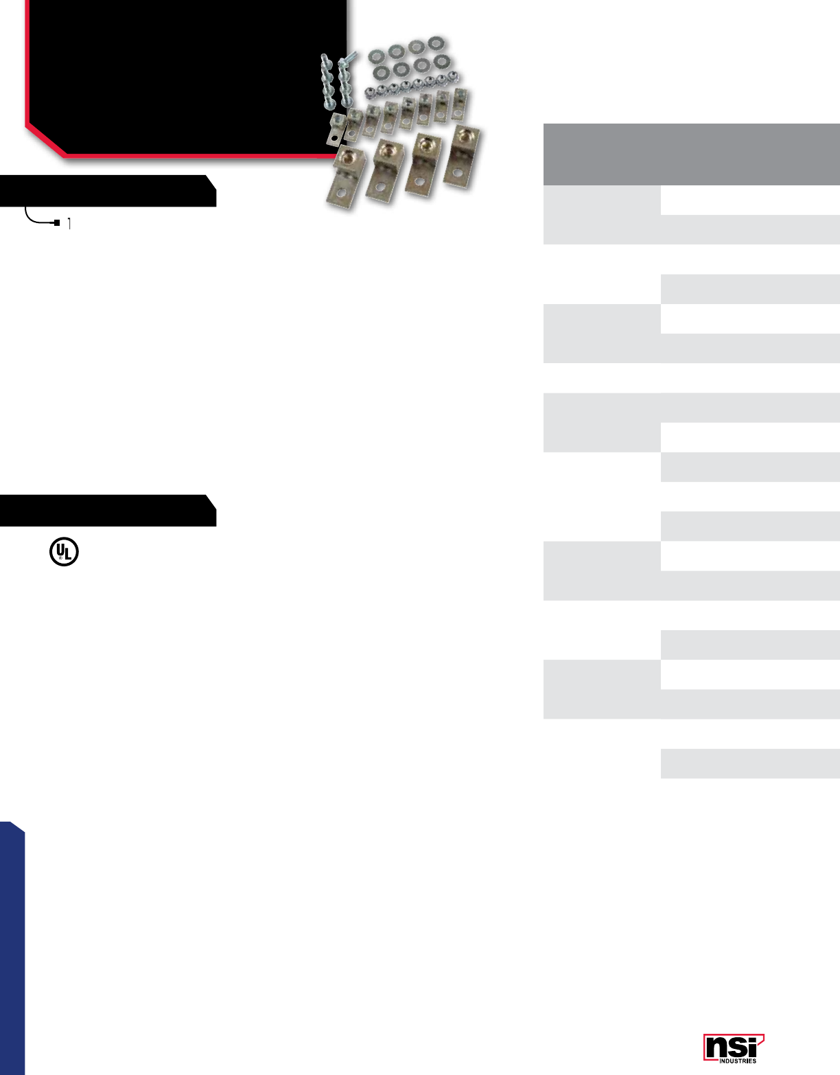
139
CONNECTORS
RATINGS
FEATURES
Terminal lugs are dual rated for use with both
copper and aluminum cables.
CONNECTOR ACCESSORIES
Transformer Lug Kits
Mechanical Set-Screw
Types
Lk SERIES
CAT.
NO.
TRANSFORMER
kVA SIZE
TERMINAL LUGS INCLUDED HARDWARE INCLUDED STD.
CTN.
QTY.
QTY.LUG TYPE WIRE RANGE QTY.BOLT SIZE
LK-1
15-37-1/2 1ø 82T 2-14 81/4-20X3/4 1
15-45-3ø 4250T 250 MCM-6 81/4-20X3/4 1
LK-2
50-75 1ø 12 250T 250 MCM-6 81
/4-20 x 3/4 1
75-112-1/2 3ø 12 250T 250 MCM-6 81
/4-20 x 1 3/4 1
LK-3 100-167 1ø 3250T 250 MCM-6 31
/4-20 x 3/4 1
150-300 3ø 22 600T 600 MCM-2 16 3/8-16 x 2 1
LK-4 500 3ø 29 600T 600 MCM-2 18 3/8-16 x 2 1
LK-5
15-25 1ø 7OT 1/0-14 71
/4-20 x 1 1/2 1
15-37 1/2 3ø 7OT 1/0-14 71
/4-20 x 1 1/2 1
LK-6
37 1/2-50 1ø 7250T 250 MCM-6 75/16-16 x 1 1/2 1
45-75 3ø 6350T 350 MCM-6 75/16-16 x 1 1/2 1
3OT 1/0-14 31
/4-20 x 1 1
LK-7
225 3ø 62-350T 350 MCM-6 61/2-13 x 2 1
6350T 350 MCM-6 13 3/8-16 x 1 1/2 1
LK-8 225 3ø 3500T 500 MCM-4 73/8-16 x 2 1
42-600T 600 MCM-2 73/8-16 x 2 1
LK-9
300 3ø 32-350T 350 MCM-6 71/2-13 x 2 1
12 500T 500 MCM-4 41/2-13 x 2 1/2 1
LK-10 400-500 3ø 16 800T 800-300 MCM 11 1/2-13 x 2 1/2 1
32-600T 600 MCM-2 11 1/2-13 x 2 1/2 1
Terminal lugs are dual rated for use with both
copper and aluminum cables.

140
CONNECTORS
NSi Industries LLC • USA • 800.321.5847 • www.nsiindustries.com
CAT.
NO.
TRANSFORMER
kVA SIZE
TERMINAL LUGS INCLUDED HARDWARE INCLUDED STD.
CTN.
QTY.
QTY.LUG TYPE WIRE RANGE QTY.BOLT SIZE
LK-1
15-37-1/2 1ø 82T 2-14 81/4-20X3/4 1
15-45-3ø 4250T 250 MCM-6 81/4-20X3/4 1
LK-2
50-75 1ø 12 250T 250 MCM-6 81
/4-20 x 3/4 1
75-112-1/2 3ø 12 250T 250 MCM-6 81
/4-20 x 1 3/4 1
LK-3 100-167 1ø 3250T 250 MCM-6 31
/4-20 x 3/4 1
150-300 3ø 22 600T 600 MCM-2 16 3/8-16 x 2 1
LK-4 500 3ø 29 600T 600 MCM-2 18 3/8-16 x 2 1
LK-5
15-25 1ø 7OT 1/0-14 71
/4-20 x 1 1/2 1
15-37 1/2 3ø 7OT 1/0-14 71
/4-20 x 1 1/2 1
LK-6
37 1/2-50 1ø 7250T 250 MCM-6 75/16-16 x 1 1/2 1
45-75 3ø 6350T 350 MCM-6 75/16-16 x 1 1/2 1
3OT 1/0-14 31
/4-20 x 1 1
LK-7
225 3ø 62-350T 350 MCM-6 61/2-13 x 2 1
6350T 350 MCM-6 13 3/8-16 x 1 1/2 1
LK-8 225 3ø 3500T 500 MCM-4 73/8-16 x 2 1
42-600T 600 MCM-2 73/8-16 x 2 1
LK-9
300 3ø 32-350T 350 MCM-6 71/2-13 x 2 1
12 500T 500 MCM-4 41/2-13 x 2 1/2 1
LK-10 400-500 3ø 16 800T 800-300 MCM 11 1/2-13 x 2 1/2 1
32-600T 600 MCM-2 11 1/2-13 x 2 1/2 1
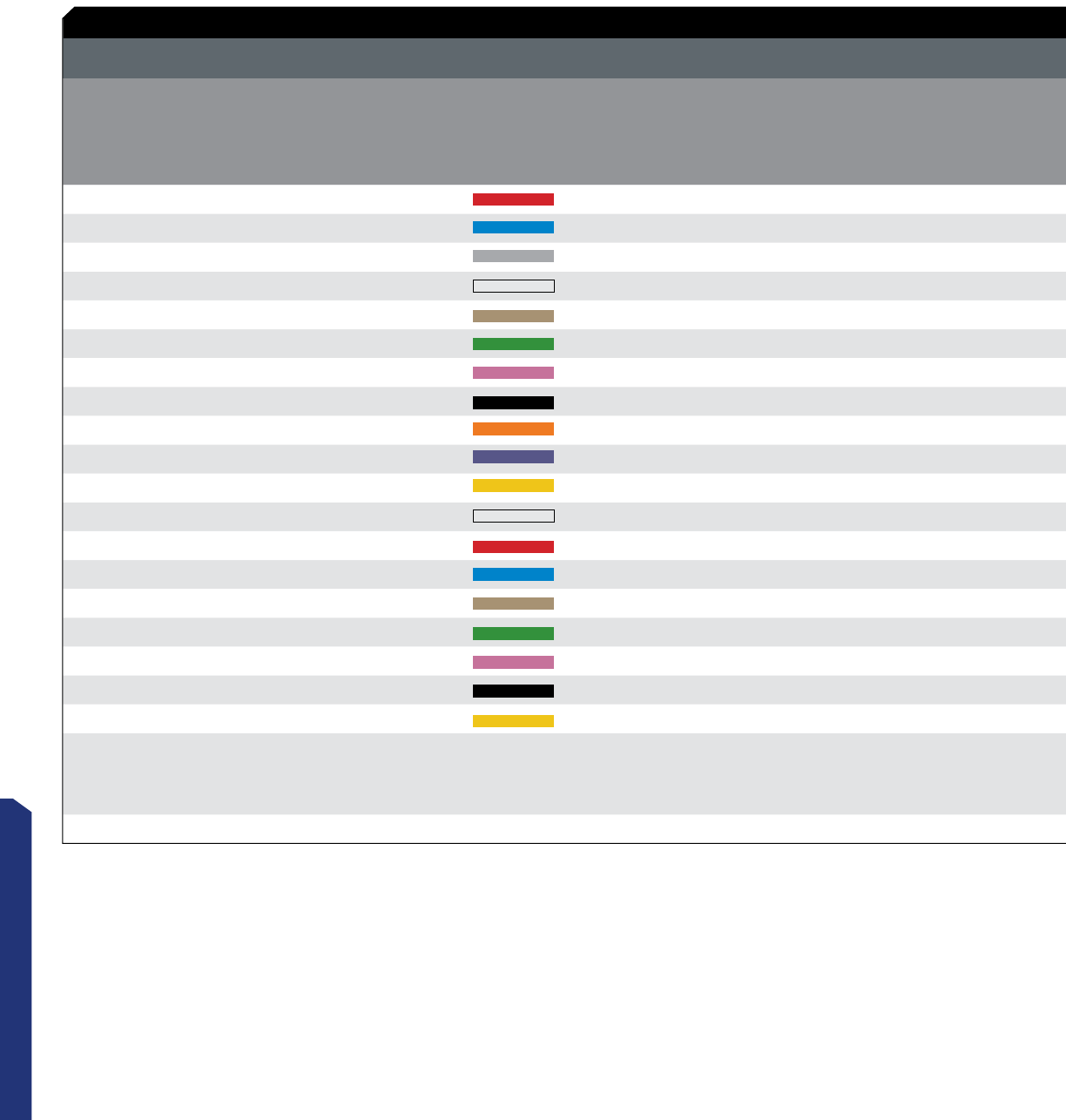
141
TOOL AND DIE CHARTS
COPPER COMPRESSION CONNECTOR TOOL AND DIE CHART
CONNECTOR SERIES: L, LN, LNB, GL, GLN, GLNB, SLN, C, SC, SCB
COPPER
CLASS B /C
CONDUCTOR
SIZE
COPPER
CLASS GHIkM
FLEX CONDUCTOR
SIZE W/ LB, LNB,
GLB, GLNB AND SCB
SERIES ONLY
COPPER
CLASS DL O
CONDUCTOR S IZE
W/ LB, LNB, GLB,
GLNB AND SCB
SERIES ONLY
MIN. # OF
CRIMPS
REQUIRED
COPPER
COLOR
CODE
NSI
DIE NSI/GREENLEE
DIE ILSCO
DIE BURNDY
DIE T&B DIE HUSkIE
DIE
COPPER
CLASS B /C
EXPANDED WIRE
RANGE WHEN
INSTALLED WI TH
NSI N12ID
MIN. # OF
CRIMPS
REQUIRED
8 AWG - - 1 - KC12-8 ILD-1, ILD-21 U8CRT 15520 - 8 AWG 1
6 AWG - - 1 CD2 KC12-6 ILD-2, ILD-24 U5CRT 15522 HT41AT 6-8 AWG 1
4 AWG - - 1 CD3 KC12-4 ILD-3, ILD-29 U4CRT 15527-CK HT41AU 4-6 AWG 1
3 AWG #4 FLEX - 1 - KC12-3 ILD-29 U3CRT - HT41AV 3-6 AWG 1
2 AWG - - 1 CD4 KC12-2 ILD-4, ILD-33 U2CRT 15528 HT41AW 2-6 AWG 1
1 AWG #2 FLEX - 1 CD5 KC12-1 ILD-4, ILD-37 U1CRT-1 15513-CK HT41AX 1-6 AWG 1
1/0 AWG #1 FLEX - 2 CD6 KC12-1/0 ILD-5, ILD-42 U25RT 15508 HT41AY 1/0-6 AWG 2
2/0 AWG 1/0 FLEX - 2 CD7 KC12-2/0 ILD-6, ILD-45 U26RT 15526 HT41AZ 2/0-4 AWG 2
3/0 AWG 2/0 FLEX - 2 CD10 KC12-3/0 ILD-9, ILD-50 U27RT 15530 HT41BA 3/0-2 AWG 2
4/0 AWG 3/0 FLEX - 2 CD12 KC12-4/0 ILD-10, ILD-54 U28RT 15511 HT41BC 4/0-1 AWG 2
250 MCM 4/0 FLEX - 2 CD14 KC12-250 ILD-11, ILD-62 U29RT 15510-CK HT41BE 250 MCM-1/0 AWG 2
300 MCM 250 FLEX - 2 CD15 KC12-300 ILD-12, ILD-66 U30RT 15534 HT41BF 300 MCM-2/0 AWG 2
350 MCM 250 FLEX 262.2 2 CD16A KC12-350 ILD-13, ILD-71 U31RT 15514-CK HT41BJ 350 MCM-3/0 AWG 2
400 MCM 300 FLEX 313.1 2 CD17 KC12-400 ILD-14, ILD-76 U32RT 15512 HT41BK 400 MCM-4/0 AWG 2
500 MCM 350 FLEX 373.7 2 CD18 KC12-500 ILD-15, ILD-87 U34RT 15506 HT41BL 500 MCM-250 MCM 2
600 MCM 400 FLEX 444.4 2 CD19 KC12-600 ILD-16, ILD-94 U36RT 15536-CK HT41BM 600 MCM-250 MCM 2
700 MCM 500 FLEX 535.3 2 CD20 KC12-700 ILD-16A, ILD-99 U38RT 15505 HT41BM 700 MCM-350 MCM 2
750 MCM 600 FLEX 646.6 2 CD21 KC12-750 ILD-17, ILD-106 U39RT 15515-CK HT41BP 750 MCM-500 MCM 2
1000 MCM 750 FLEX 777.7 2 CD23 - ILD-18*, ILD-125 P44RT 15603* HT61BU* - 2
- - - - LISTED
TOOLS
N1240
NSI-12
P-750 HK1240 ILC-12
ILC-12H
ILC-15 Y-35 TBM-15
TBM-14M EP51OC
N12ID
M-250
M-500
RDC-1/0
N12ID
M-250
M-500
RDC-1/0
* REQUIRES 15 TON TOOL
RED
BROWN
ORANGE
RED
BLUE
GREEN
PURPLE
BLUE
PINK
GREY
PINK
YELLOW
BROWN
BLACK
WHITE
WHITE
BLACK
GREEN
YELLOW
COMPRESSION CONNECTORS
Tool and Die Charts
For Connector Series: L, LN, LNB, GL, GLN, GLNB, SLN, C, SC, SCB
COPPER CONNECTORS
142
NSi Industries LLC • USA • 800.321.5847 • www.nsiindustries.com
COPPER COMPRESSION CONNECTOR TOOL AND DIE CHART
CONNECTOR SERIES: L, LN, LNB, GL, GLN, GLNB, SLN, C, SC, SCB
COPPER
CLASS B /C
CONDUCTOR
SIZE
COPPER
CLASS GHIkM
FLEX CONDUCTOR
SIZE W/ LB, LNB,
GLB, GLNB AND SCB
SERIES ONLY
COPPER
CLASS DL O
CONDUCTOR S IZE
W/ LB, LNB, GLB,
GLNB AND SCB
SERIES ONLY
MIN. # OF
CRIMPS
REQUIRED
COPPER
COLOR
CODE
NSI
DIE NSI/GREENLEE
DIE ILSCO
DIE BURNDY
DIE T&B DIE HUSkIE
DIE
COPPER
CLASS B /C
EXPANDED WIRE
RANGE WHEN
INSTALLED WI TH
NSI N12ID
MIN. # OF
CRIMPS
REQUIRED
8 AWG - - 1 - KC12-8 ILD-1, ILD-21 U8CRT 15520 - 8 AWG 1
6 AWG - - 1 CD2 KC12-6 ILD-2, ILD-24 U5CRT 15522 HT41AT 6-8 AWG 1
4 AWG - - 1 CD3 KC12-4 ILD-3, ILD-29 U4CRT 15527-CK HT41AU 4-6 AWG 1
3 AWG #4 FLEX - 1 - KC12-3 ILD-29 U3CRT - HT41AV 3-6 AWG 1
2 AWG - - 1 CD4 KC12-2 ILD-4, ILD-33 U2CRT 15528 HT41AW 2-6 AWG 1
1 AWG #2 FLEX - 1 CD5 KC12-1 ILD-4, ILD-37 U1CRT-1 15513-CK HT41AX 1-6 AWG 1
1/0 AWG #1 FLEX - 2 CD6 KC12-1/0 ILD-5, ILD-42 U25RT 15508 HT41AY 1/0-6 AWG 2
2/0 AWG 1/0 FLEX - 2 CD7 KC12-2/0 ILD-6, ILD-45 U26RT 15526 HT41AZ 2/0-4 AWG 2
3/0 AWG 2/0 FLEX - 2 CD10 KC12-3/0 ILD-9, ILD-50 U27RT 15530 HT41BA 3/0-2 AWG 2
4/0 AWG 3/0 FLEX - 2 CD12 KC12-4/0 ILD-10, ILD-54 U28RT 15511 HT41BC 4/0-1 AWG 2
250 MCM 4/0 FLEX - 2 CD14 KC12-250 ILD-11, ILD-62 U29RT 15510-CK HT41BE 250 MCM-1/0 AWG 2
300 MCM 250 FLEX - 2 CD15 KC12-300 ILD-12, ILD-66 U30RT 15534 HT41BF 300 MCM-2/0 AWG 2
350 MCM 250 FLEX 262.2 2 CD16A KC12-350 ILD-13, ILD-71 U31RT 15514-CK HT41BJ 350 MCM-3/0 AWG 2
400 MCM 300 FLEX 313.1 2 CD17 KC12-400 ILD-14, ILD-76 U32RT 15512 HT41BK 400 MCM-4/0 AWG 2
500 MCM 350 FLEX 373.7 2 CD18 KC12-500 ILD-15, ILD-87 U34RT 15506 HT41BL 500 MCM-250 MCM 2
600 MCM 400 FLEX 444.4 2 CD19 KC12-600 ILD-16, ILD-94 U36RT 15536-CK HT41BM 600 MCM-250 MCM 2
700 MCM 500 FLEX 535.3 2 CD20 KC12-700 ILD-16A, ILD-99 U38RT 15505 HT41BM 700 MCM-350 MCM 2
750 MCM 600 FLEX 646.6 2 CD21 KC12-750 ILD-17, ILD-106 U39RT 15515-CK HT41BP 750 MCM-500 MCM 2
1000 MCM 750 FLEX 777.7 2 CD23 - ILD-18*, ILD-125 P44RT 15603* HT61BU* - 2
- - - - LISTED
TOOLS
N1240
NSI-12
P-750 HK1240 ILC-12
ILC-12H
ILC-15 Y-35 TBM-15
TBM-14M EP51OC
N12ID
M-250
M-500
RDC-1/0
N12ID
M-250
M-500
RDC-1/0
* REQUIRES 15 TON TOOL
142
TOOL AND DIE CHARTS (COPPER)
Dieless NSi N12ID
143
TOOL AND DIE CHARTS
COPPER COMPRESSION CONNECTOR TOOL AND DIE CHART
CONNECTOR SERIES: CT, CTH
COPPER
CLASS B/C
CONDUCTOR
SIZE
MAIN / RUN
WIRE RANGE TAP / BRANCH
WIRE RANGE
MIN. # OF
CRIMPS
REQUIRED
COPPER
COLOR
CODE
NSI
DIE NSI
TOOL
CT-101 12 SOL-12 STR 14 SOL-12 STR 1
CT-102 10 STR
8 STR 10 STR
12 STR 1
CT-103 6 STR
8 STR 10-12 STR
8-10 STR 1
CT-104 4 STR
6 STR 8-12 STR
6-8 STR 1
CT-105 4 STR
4-5 STR 6-12 STR
6-5 STR 1
CT-106 4 STR
4 STR 4 STR
4 STR 1
CT-107 1 STR
2 STR
4 STR
4 STR
4 STR
4 STR 1
CT-108 1/0 STR
1 STR
2 STR
4 STR
4 STR
2 STR 1
CT-109 2/0 STR
1/0 STR
1/0 STR
4 STR
2 STR
1-2 STR 2
CT-110 3/0 STR
2/0 STR
1/0 STR
4 STR
4 STR
4 STR 2
CTH-111
1 STR
1/0 STR
2/0 STR
3/0-4/0 STR
4/0 STR
1 STR
1/0-2 STR
2/0-4 STR
1/0-6 STR
1.8 STR
2
CTH-112
2/0 STR
3/0 STR
4/0 STR
250 STR
2/0-1 STR
3/0-2 STR
4/0-4 STR
1/0-8 STR
2
CTH-113
2/0 STR
3/0 STR
4/0 STR
250 STR
300 STR
2/0-1 STR
3/0-2 STR
4/0-4 STR
3/0-6 STR
2/0-8 STR
2
CTH-114
4/0 STR
250 STR
300 STR
350 STR
4/0-2/0 STR
250-1 STR
4/0-4 STR
3/0-6 STR
2
CTH-115
250 STR
300 STR
350 STR
400 STR
450 STR
500 STR
250 STR
300-3/0 STR
350-1/0 STR
300-2 STR
250-4 STR
250-6 STR
2
CTH-116
350 STR
400 STR
450 STR
500 STR
350-4/0 STR
400-2/0 STR
450-1 STR
500-2 STR
2
BARE 8
BARE 4
BARE 4
BARE 2
INS 2
INS 2
BG
KC12-2/0
KC12-4/0
KC12-250
KC12-250
KC12-400
KC12-400
KC12-500
KC12-750
KC12-750
M-250
RDC-1/0
RDC-1/0
RDC-1/0
RDC-1/0
RDC-1/0
OD-59
N1240
N1240
N1240
N1240
N1240
N1240
N1240
N1240
N1240
RED
LIGHT BLUE
GREY
BROWN
GREEN
PINK
BLACK
ORANGE
PURPLE
YELLOW
BLUE
BROWN
PINK
BLACK
YELLOW
WHITE
COMPRESSION CONNECTORS
Tool and Die Charts
For Connector Series: CT, CTH
COPPER CONNECTORS

144
NSi Industries LLC • USA • 800.321.5847 • www.nsiindustries.com
COPPER COMPRESSION CONNECTOR TOOL AND DIE CHART
CONNECTOR SERIES: CT, CTH
COPPER
CLASS B/C
CONDUCTOR SIZE
MAIN / RUN
WIRE RANGE TAP / BRANCH
WIRE RANGE
MIN. # OF
CRIMPS
REQUIRED
COPPER
COLOR
CODE
NSI
DIE NSI
TOOL
CTH-117 750-500 STR
750 STR 4/0-6 STR
750-4/0 STR 4 - - T&B TBM-15
CTH-46 4 STR 6 STR 1 - - N1240
CTH-44 6 STR
4 STR
4 STR
4 STR 1 - - N1240
CTH-24 2 SOL
2 STR 8 SOL
4 STR 1 - C OD581
CTH-22 2 SOL
2 STR 2 SOL
2 STR 1 - C OD581
CTH-2020 1/0 STR
2/0 STR 1/0 STR
2/0 STR 1 - 0 OD581
CTH-4020 3/0 STR
4/0 STR 1/0 STR
2/0 STR 1 - D3 OD581
CTH-4040 3/0 STR
4/0 STR 3/0 STR
4/0 STR 1 - D3 OD581
T&B 15603
KC12-1/0
KC12-1/0
TOOL AND DIE CHARTS (COPPER)

145
TOOL AND DIE CHARTS
ALUMINUM COMPRESSION CONNECTOR TOOL AND DIE CHART
CONNECTOR SERIES: AL, ALN, ASCT
ALUMINUM
CLASS B /C
CONDUCTOR
SIZE
MIN. # OF
CRIMPS
REQUIRED
ALUMINUM
COLOR
CODE
NSI
DIE NSI/GREENLEE
DIE ILSCO
DIE BURNDY
DIE T&B DIE HUSkIE
DIE
COPPER
CLASS B /C
EXPANDED WIRE
RANGE WHEN
INSTALLED WI TH
NSI N12ID
MIN. # OF
CRIMPS
REQUIRED
8 AWG 1 CD2 KA12-8 ILD-2 U8CABT 15522 HT41GL 8 AWG 1
6 AWG 1 CD3 KA12-6 ILD-3 U6CABT 15527-CK HT41GE 6-8 AWG 1
4 AWG 1 CD5A KA12-4 ILD-4 U4CABT 15313-CK HT41GM 4-6 AWG 1
2 AWG 1 CD6A KA12-2 ILD-7 U2CABT 15508 HT41GF 2-6 AWG 1
1 AWG 1 - KA12-1 ILD-7 U1CABT 15526 - 1-6 AWG 1
1/0 AWG 2 CD9 KA12-1/0 ILD-8 U25ART 15530 HT41EX 1/0-6 AWG 2
2/0 AWG 2 CD11 KA12-2/0 ILD-10 U26ART 15511 HT41EY 2/0-4 AWG 2
3/0 AWG 2 CD13 KA12-3/0 ILD-10 U27ART 15532-CK HT41GW 3/0-2 AWG 2
4/0 AWG 2 CD15A KA12-4/0 ILD-12 U28ART 15534 HT41EZ 4/0-1 AWG 2
250 MCM 2 CD16A KA12-250 ILD-13 U29ART 15514-CK HT41FW 250 MCM-1/0 AWG 2
300 MCM 2 CD17A KA12-300 ILD-14 U30ART 15512 HT41GZ 300 MCM-2/0 AWG 2
350 MCM 2 CD18A KA12-350 ILD-14 U31ART 15506 HT41FA 350 MCM-3/0 AWG 2
400 MCM 2 CD19A KA12-400 ILD-16 U32ART 15536-CK HT41HH 400 MCM-4/0 AWG 2
500 MCM 2 CD20 KA12-500 ILD-16A U34ART 15505 HT41FB 500 MCM-250 MCM 2
600 MCM 2 CD21A KA12-600 ILD-17 U36ART - HT41HG 600 MCM-250 MCM 2
750 MCM 2 CD22 KA12-750 ILD-18 U39ART-2 15504 HT41LJ 750 MCM-500 MCM 2
1000 MCM 2 - - ILD-P302* P44ART* 15602 - - 2
- - LISTED
TOOLS
N1240
NSI-12
P-750 HK1240 ILC-12
ILC-12H
ILC-15 Y-35 TBM-15
TBM-14M EP51OC
N12ID
M-250
M-500
RDC-1/0
N12ID
M-250
M-500
RDC-1/0
* REQUIRES 15 TON TOOL
BLUE
GREY
GREEN
PINK
YELLOW
TAN
OLIVE
RUBY
WHITE
RED
BLUE
BROWN
GREEN
PINK
BLACK
RED
BROWN
COMPRESSION CONNECTORS
Tool and Die Charts
For Connector Series: AL, ALN, ASCT
ALUMINUM CONNECTORS
146
NSi Industries LLC • USA • 800.321.5847 • www.nsiindustries.com
ALUMINUM COMPRESSION CONNECTOR TOOL AND DIE CHART
CONNECTOR SERIES: AL, ALN, ASCT
ALUMINUM
CLASS B /C
CONDUCTOR
SIZE
MIN. # OF
CRIMPS
REQUIRED
ALUMINUM
COLOR
CODE
NSI
DIE NSI/GREENLEE
DIE ILSCO
DIE BURNDY
DIE T&B DIE HUSkIE
DIE
COPPER
CLASS B /C
EXPANDED WIRE
RANGE WHEN
INSTALLED WI TH
NSI N12ID
MIN. # OF
CRIMPS
REQUIRED
8 AWG 1 CD2 KA12-8 ILD-2 U8CABT 15522 HT41GL 8 AWG 1
6 AWG 1 CD3 KA12-6 ILD-3 U6CABT 15527-CK HT41GE 6-8 AWG 1
4 AWG 1 CD5A KA12-4 ILD-4 U4CABT 15313-CK HT41GM 4-6 AWG 1
2 AWG 1 CD6A KA12-2 ILD-7 U2CABT 15508 HT41GF 2-6 AWG 1
1 AWG 1 - KA12-1 ILD-7 U1CABT 15526 - 1-6 AWG 1
1/0 AWG 2 CD9 KA12-1/0 ILD-8 U25ART 15530 HT41EX 1/0-6 AWG 2
2/0 AWG 2 CD11 KA12-2/0 ILD-10 U26ART 15511 HT41EY 2/0-4 AWG 2
3/0 AWG 2 CD13 KA12-3/0 ILD-10 U27ART 15532-CK HT41GW 3/0-2 AWG 2
4/0 AWG 2 CD15A KA12-4/0 ILD-12 U28ART 15534 HT41EZ 4/0-1 AWG 2
250 MCM 2 CD16A KA12-250 ILD-13 U29ART 15514-CK HT41FW 250 MCM-1/0 AWG 2
300 MCM 2 CD17A KA12-300 ILD-14 U30ART 15512 HT41GZ 300 MCM-2/0 AWG 2
350 MCM 2 CD18A KA12-350 ILD-14 U31ART 15506 HT41FA 350 MCM-3/0 AWG 2
400 MCM 2 CD19A KA12-400 ILD-16 U32ART 15536-CK HT41HH 400 MCM-4/0 AWG 2
500 MCM 2 CD20 KA12-500 ILD-16A U34ART 15505 HT41FB 500 MCM-250 MCM 2
600 MCM 2 CD21A KA12-600 ILD-17 U36ART - HT41HG 600 MCM-250 MCM 2
750 MCM 2 CD22 KA12-750 ILD-18 U39ART-2 15504 HT41LJ 750 MCM-500 MCM 2
1000 MCM 2 - - ILD-P302* P44ART* 15602 - - 2
- - LISTED
TOOLS
N1240
NSI-12
P-750 HK1240 ILC-12
ILC-12H
ILC-15 Y-35 TBM-15
TBM-14M EP51OC
N12ID
M-250
M-500
RDC-1/0
N12ID
M-250
M-500
RDC-1/0
* REQUIRES 15 TON TOOL
Dieless NSi N12ID
TOOL AND DIE CHARTS (ALUMINUM)

147
TOOL AND DIE CHARTS
COMPRESSION CONNECTORS
Tool and Die Charts
For Connector Series: PT, PTO, PTS
ALUMINUM CONNECTORS
ALUMINUM COMPRESSION CONNECTOR TOOL AND DIE CHART
CONNECTOR SERIES: PT, PTO, PTS
ALUMINUM
CONDUCTOR
ONLY
PT SERIES
ALUMINUM
CONDUCTOR
ONLY
PT SERIES
ALUMINUM OR
COPPER CO NDUCTOR
PTS & PTO SERIES
ALUMINUM OR
COPPER CLASS B/C
CONDUCTOR
SIZE
PTS & PTO
SERIES
PIN
SIZE
MIN. # OF
CRIMPS
REQUIRED
COPPER
COLOR
CODE
NSI
DIE NSI/GREENLEE
DIE ILSCO
DIE BURNDY
DIE T&B DIE HUSkIE
DIE
--PTS6 6 AWG 4 AWG 1 CD9 KA12-1/0 ILD-8 U25ART 15530 HT41EX
PT6 6 AWG -- 8 AWG 1 - BG 52 - - - - -
--PTS4 4 AWG 4 AWG 1 CD9 KA12-1/0 ILD-8 U25ART 15530 HT41EX
PT4 4 AWG -- 6 AWG 1 - BG 52 - - - - -
--PTS2 2 AWG 4 AWG 1 CD9 KA12-1/0 ILD-8 U25ART 15530 HT41EX
PT2 2 AWG -- 4 AWG 1 - BG 52 - - - - -
--PTS1 1 AWG 3 AWG 1 CD9 KA12-1/0 ILD-8 U25ART 15530 HT41EX
PT1 1 AWG -- 3 AWG 1 - BG 52 - - - - -
--PTS1/0 1/0 AWG 2 AWG 2 CD9 KA12-1/0 ILD-8 U25ART 15530 HT41EX
PT1/0 1/0 AWG -- 2 AWG 2 CD16A KC12-350 ILD-13, ILD-71 U31RT 15514-CK HT41BJ
--PTS2/0 PTO2/0 2/0 AWG 1 AWG 2 CD15A KA12-4/0 ILD-12 U28ART 15534 HT41EZ
PT2/0 2/0 AWG -- 1 AWG 2 CD16A KC12-350 ILD-13, ILD-71 U31RT 15514-CK HT41BJ
--PTS3/0 PTO3/0 3/0 AWG 1/0 AWG 2 CD15A KA12-4/0 ILD-12 U28ART 15534 HT41EZ
PT3/0 3/0 AWG -- 1/0 AWG 2 CD16A KC12-350 ILD-13, ILD-71 U31RT 15514-CK HT41BJ
--PTS4/0 PTO4/0 4/0 AWG 2/0 AWG 2 CD15A KA12-4/0 ILD-12 U28ART 15534 HT41EZ
PT4/0 4/0 AWG -- 2/0 AWG 2 CD16A KC12-350 ILD-13, ILD-71 U31RT 15514-CK HT41BJ
--PTS250 PTO250 250 MCM 3/0 AWG 2 CD18A KA12-350 ILD-14 U31ART 15506 HT41FA
PT250 250 MCM -- 3/0 AWG 2 CD18A KA12-350 ILD-14 U31ART 15506 HT41FA
--PTS300 PTO300 300 MCM 4/0 AWG 2 CD18A KA12-350 ILD-14 U31ART 15506 HT41FA
PT300 300 MCM -- 4/0 AWG 2 CD18A KA12-350 ILD-14 U31ART 15506 HT41FA
--PTS350 PTO350 350 MCM 250 MCM 2 CD18A KA12-350 ILD-14 U31ART 15506 HT41FA
PT350 350 MCM -- 4/0 AWG 2 CD18A KA12-350 ILD-14 U31ART 15506 HT41FA
--PTS400 PTO400 400 MCM 300 MCM 2 CD20 KA12-500 ILD-16A U34ART 15505 HT41FB
PT400 400 MCM -- 250 MCM 2 CD20 KA12-500 ILD-16A U34ART 15505 HT41FB
--PTS500 PTO500 500 MCM 350 MCM 2 CD20 KA12-500 ILD-16A U34ART 15505 HT41FB
PT500 500 MCM -- 350 MCM 2 CD20 KA12-500 ILD-16A U34ART 15505 HT41FB
--PTS600 PTO600 600 MCM 400 MCM 2 CD23 - ILD-18*, ILD-125 P44RT 15603* HT61BU*
PT600 600 MCM -- 350 MCM 2 CD23 - ILD-18*, ILD-125 P44RT 15603* HT61BU*
--PTS750 PTO750 750 MCM 500 MCM 2 CD23 - ILD-18*, ILD-125 P44RT 15603* HT61BU*
PT750 750 MCM -- 500 MCM 2 CD23 - ILD-18*, ILD-125 P44RT 15603* HT61BU*
---- - - LISTED
TOOLS
N1240
NSI-12
P-750 HK1240 ILC-12
ILC-12H
ILC-15 Y-35 TBM-15
TBM-14M EP51OC
* REQUIRES 15 TON TOOL
PINK
PINK
PINK
PINK
YELLOW
YELLOW
YELLOW
YELLOW
TAN
TAN
TAN
TAN
TAN
WHITE
WHITE
WHITE
RED
RED
RED
RED
BROWN
BROWN
BROWN
BROWN
BROWN
BROWN

148
NSi Industries LLC • USA • 800.321.5847 • www.nsiindustries.com
ALUMINUM COMPRESSION CONNECTOR TOOL AND DIE CHART
CONNECTOR SERIES: PT, PTO, PTS
ALUMINUM
CONDUCTOR
ONLY
PT SERIES
ALUMINUM
CONDUCTOR
ONLY
PT SERIES
ALUMINUM OR
COPPER CO NDUCTOR
PTS & PTO SERIES
ALUMINUM OR
COPPER CLASS B/C
CONDUCTOR
SIZE
PTS & PTO
SERIES
PIN
SIZE
MIN. # OF
CRIMPS
REQUIRED
COPPER
COLOR
CODE
NSI
DIE NSI/GREENLEE
DIE ILSCO
DIE BURNDY
DIE T&B DIE HUSkIE
DIE
--PTS6 6 AWG 4 AWG 1 CD9 KA12-1/0 ILD-8 U25ART 15530 HT41EX
PT6 6 AWG -- 8 AWG 1 - BG 52 - - - - -
--PTS4 4 AWG 4 AWG 1 CD9 KA12-1/0 ILD-8 U25ART 15530 HT41EX
PT4 4 AWG -- 6 AWG 1 - BG 52 - - - - -
--PTS2 2 AWG 4 AWG 1 CD9 KA12-1/0 ILD-8 U25ART 15530 HT41EX
PT2 2 AWG -- 4 AWG 1 - BG 52 - - - - -
--PTS1 1 AWG 3 AWG 1 CD9 KA12-1/0 ILD-8 U25ART 15530 HT41EX
PT1 1 AWG -- 3 AWG 1 - BG 52 - - - - -
--PTS1/0 1/0 AWG 2 AWG 2 CD9 KA12-1/0 ILD-8 U25ART 15530 HT41EX
PT1/0 1/0 AWG -- 2 AWG 2 CD16A KC12-350 ILD-13, ILD-71 U31RT 15514-CK HT41BJ
--PTS2/0 PTO2/0 2/0 AWG 1 AWG 2 CD15A KA12-4/0 ILD-12 U28ART 15534 HT41EZ
PT2/0 2/0 AWG -- 1 AWG 2 CD16A KC12-350 ILD-13, ILD-71 U31RT 15514-CK HT41BJ
--PTS3/0 PTO3/0 3/0 AWG 1/0 AWG 2 CD15A KA12-4/0 ILD-12 U28ART 15534 HT41EZ
PT3/0 3/0 AWG -- 1/0 AWG 2 CD16A KC12-350 ILD-13, ILD-71 U31RT 15514-CK HT41BJ
--PTS4/0 PTO4/0 4/0 AWG 2/0 AWG 2 CD15A KA12-4/0 ILD-12 U28ART 15534 HT41EZ
PT4/0 4/0 AWG -- 2/0 AWG 2 CD16A KC12-350 ILD-13, ILD-71 U31RT 15514-CK HT41BJ
--PTS250 PTO250 250 MCM 3/0 AWG 2 CD18A KA12-350 ILD-14 U31ART 15506 HT41FA
PT250 250 MCM -- 3/0 AWG 2 CD18A KA12-350 ILD-14 U31ART 15506 HT41FA
--PTS300 PTO300 300 MCM 4/0 AWG 2 CD18A KA12-350 ILD-14 U31ART 15506 HT41FA
PT300 300 MCM -- 4/0 AWG 2 CD18A KA12-350 ILD-14 U31ART 15506 HT41FA
--PTS350 PTO350 350 MCM 250 MCM 2 CD18A KA12-350 ILD-14 U31ART 15506 HT41FA
PT350 350 MCM -- 4/0 AWG 2 CD18A KA12-350 ILD-14 U31ART 15506 HT41FA
--PTS400 PTO400 400 MCM 300 MCM 2 CD20 KA12-500 ILD-16A U34ART 15505 HT41FB
PT400 400 MCM -- 250 MCM 2 CD20 KA12-500 ILD-16A U34ART 15505 HT41FB
--PTS500 PTO500 500 MCM 350 MCM 2 CD20 KA12-500 ILD-16A U34ART 15505 HT41FB
PT500 500 MCM -- 350 MCM 2 CD20 KA12-500 ILD-16A U34ART 15505 HT41FB
--PTS600 PTO600 600 MCM 400 MCM 2 CD23 - ILD-18*, ILD-125 P44RT 15603* HT61BU*
PT600 600 MCM -- 350 MCM 2 CD23 - ILD-18*, ILD-125 P44RT 15603* HT61BU*
--PTS750 PTO750 750 MCM 500 MCM 2 CD23 - ILD-18*, ILD-125 P44RT 15603* HT61BU*
PT750 750 MCM -- 500 MCM 2 CD23 - ILD-18*, ILD-125 P44RT 15603* HT61BU*
---- - - LISTED
TOOLS
N1240
NSI-12
P-750 HK1240 ILC-12
ILC-12H
ILC-15 Y-35 TBM-15
TBM-14M EP51OC
* REQUIRES 15 TON TOOL
TOOL AND DIE CHARTS (ALUMINUM)

149
TOOL AND DIE CHARTS
COMPRESSION CONNECTORS
Aluminum Connectors
Connector Series: WRD (H-Taps)
TOOL AND DIE CHARTS
ALUMINUM COMPRESSION CONNECTOR TOOL AND DIE CHART
CONNECTOR SERIES: WRD (H-Taps)
PART
NUMBER DIE # OF INDENTS W/
MECHANICAL TOOL # OF INDENTS W/
HYDRAULIC TOOL
WRD9 5/8 BG 3 -
WRD 139 O 4 2
WRD 149 O 5 2
WRD 159 O 4 2
WRD 179 O 5 2
WRD 189 O 5 2
WRD 199 O 5 2
WRD 219 D 5 2
WRD 259 D 5 2
WRD 279 D 5 2
WRD 289 D 5 2
WRD 299 D 4 2
WRD 359 D 4 2
WRD 369 D 5 2
WRD 379 D 5 2
WRD 389 D 6 2
WRD 399 D 7 3
WRD 419 D 7 3

150
NSi Industries LLC • USA • 800.321.5847 • www.nsiindustries.com
TOOL AND DIE CHARTS (ALUMINUM)

Tools & Hardware
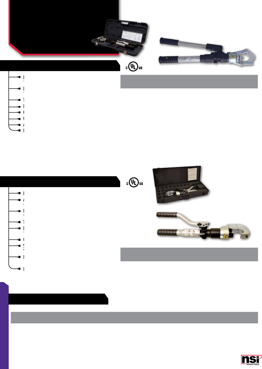
153
TOOLS & HARDWARE
Dieless indent style crimping head does not require
interchangeable crimping dies.
Flip-open Crimping head rotates 350 degrees to get
into tight locations.
Two-speed pump provides rapid crimping cycle time.
Lightweight and strong fiberglass handles.
Comes with a molded carrying case.
Copper - 4 AWG - 1000 kcmil (MCM).
Aluminum - 6 AWG - 1000 kcmil (MCM).
UL and cUL Listed*.
*UL and cUL classified with Anderson®, Blackburn®, Burndy®, ILSCO®, Panduit®, Thomas & Betts®, Penn-Union®, Tyco® color coded connectors.
The products listed above are registered trademarks of Anderson®, Blackburn®, Burndy®, ILSCO®, Panduit®Thomas & Betts®, Penn-Union® and Tyco®.
N1240 with 1.65 in (42 mm) opening.
Accepts KC12, KA12 and KD12 crimping dies as
well as industry "U" style dies.
New head design results in lower weight and
improved durability - tested to 50,000 crimp cycles.
Two-speed pump to reduce cycle time.
Ram automatically retracts when crimp cycle
is compelte.
Crimping heads rotate 350 degrees.
Smaller and lighter than most competitive tools.
Includes carrying case.
N1240 - 8 AWG to 750 kcmil copper and aluminum
color-coded lugs and splices.
UL and cUL Listed*.
CAT.
NO. DESCRIPTION LENGTH
(IN) WEIGHT
(LBS)
STD.
CTN.
QTY.
N12ID Dieless Hydraulic Crimping Tool 26 15 1
CAT.
NO. DESCRIPTION CRIMPING
FORCE (IN) LENGTH
(IN) WEIGHT
(LBS)
STD.
CTN.
QTY.
N1240 12 Ton hydraulic Crimping
Tool, 1.65 in. opening. 24,000 21-1/2 12.2 1
Flip-open Crimping head rotates 350 degrees to get
into tight locations.
Flip-open Crimping head rotates 350 degrees to get
into tight locations.
Flip-open Crimping head rotates 350 degrees to get
Dieless indent style crimping head does not require
interchangeable crimping dies.
Dieless indent style crimping head does not require
interchangeable crimping dies.
Dieless indent style crimping head does not require
Two-speed pump provides rapid crimping cycle time.
Lightweight and strong fiberglass handles.
Comes with a molded carrying case.
Copper - 4 AWG - 1000 kcmil (MCM).
Copper - 4 AWG - 1000 kcmil (MCM).
Aluminum - 6 AWG - 1000 kcmil (MCM).
Copper - 4 AWG - 1000 kcmil (MCM).
Aluminum - 6 AWG - 1000 kcmil (MCM).
Aluminum - 6 AWG - 1000 kcmil (MCM).
Lightweight and strong fiberglass handles.
Comes with a molded carrying case.
Comes with a molded carrying case.
UL and cUL Listed*.
UL and cUL Listed*.
New head design results in lower weight and
improved durability - tested to 50,000 crimp cycles.
New head design results in lower weight and
improved durability - tested to 50,000 crimp cycles.
New head design results in lower weight and
Accepts KC12, KA12 and KD12 crimping dies as
well as industry "U" style dies.
Accepts KC12, KA12 and KD12 crimping dies as
well as industry "U" style dies.
Accepts KC12, KA12 and KD12 crimping dies as
N1240 with 1.65 in (42 mm) opening.
Accepts KC12, KA12 and KD12 crimping dies as
Accepts KC12, KA12 and KD12 crimping dies as
Two-speed pump to reduce cycle time.
Ram automatically retracts when crimp cycle
is compelte.
Ram automatically retracts when crimp cycle
is compelte.
Ram automatically retracts when crimp cycle
Ram automatically retracts when crimp cycle
Crimping heads rotate 350 degrees.
Smaller and lighter than most competitive tools.
Includes carrying case.
Smaller and lighter than most competitive tools.
Includes carrying case.
Smaller and lighter than most competitive tools.
Smaller and lighter than most competitive tools.
N1240 - 8 AWG to 750 kcmil copper and aluminum
color-coded lugs and splices.
UL and cUL Listed*.
TOOLS
Hydraulic Compression
Tools
NSI GREENLEE BURNDY THOMAS & BETTS ILSCO HUSKIE PANDUIT BLACKBURN PENN-UNION
N1240 KC12, KD12, U-Style U15500 Series ILD HT41 CD-920 B, H T
DIELESS HYDRAULIC CRIMPING TOOL
12 TON HYDRAULIC CRIMPING TOOL
CROSS REFERENCE GUIDE
154
NSi Industries LLC • USA • 800.321.5847 • www.nsiindustries.com
154
TOOLS & HARDWARE
*UL and cUL classified with Anderson®, Blackburn®, Burndy®, ILSCO®, Panduit®, Thomas & Betts®, Penn-Union®, Tyco® color coded connectors.
The products listed above are registered trademarks of Anderson®, Blackburn®, Burndy®, ILSCO®, Panduit®Thomas & Betts®, Penn-Union® and Tyco®.
CAT.
NO. DESCRIPTION STD.
CTN.
QTY.
D1082 Crimping Die Carrying Case, 15 Pairs 1
CRIMPING DIE CARRYING CASE
CAT.
NO. DESCRIPTION ALUMINUM
COLOR
CODE
CAT.
NO. DESCRIPTION COPPER
COLOR
CODE
STD.
CTN.
QTY.
KA12-8* 8 AWG, Aluminum KC12-8* 8 AWG, Copper Red 1
KA12-6* 6 AWG, Aluminum KC12-6* 6 AWG, Copper 1
KA12-4* 4 AWG, Aluminum KC12-4* 4 AWG, Copper 1
KA12-2* 2 AWG, Aluminum KC12-2* 2 AWG, Copper 1
KA12-1* 1 AWG, Aluminum KC12-1* 1 AWG, Copper 1
KA12-1/0* 1/0 AWG, Aluminum KC12-1/0* 1/0 AWG, Copper 1
KA12-2/0* 2/0 AWG, Aluminum KC12-2/0* 2/0 AWG, Copper 1
KA12-3/0* 3/0 AWG, Aluminum KC12-3/0* 3/0 AWG, Copper 1
KA12-4/0* 4/0 AWG, Aluminum KC12-4/0* 4/0 AWG, Copper 1
KA12-250* 250 MCM, Aluminum KC12-250* 250 MCM, Copper 1
KA12-300* 300 MCM, Aluminum KC12-300* 300 MCM, Copper 1
KA12-350* 350 MCM, Aluminum KC12-350* 350 MCM, Copper 1
KA12-400* 400 MCM, Aluminum KC12-400* 400 MCM, Copper 1
KA12-500* 500 MCM, Aluminum KC12-500* 500 MCM, Copper 1
KA12-600* 600 MCM, Aluminum KC12-600* 600 MCM, Copper 1
KA12-750* 750 MCM, Aluminum KC12-750* 750 MCM, Copper 1
TOOLS
Crimping Dies
KA & KC SERIES
RED
BLUE
GREEN
BLUE
PINK
GREY
PINK
YELLOW
BROWN
BLACK
WHITE
GREEN
GOLD
TAN
RUBY
OLIVE
RED
BROWN
ORANGE
RED
BLUE
GREEN
PURPLE
BLUE
GREY
PINK
YELLOW
BROWN
BLACK
WHITE
BLACK
GREEN

155
TOOLS & HARDWARE
12-Ton Compression Tool for U-Type Dies.
Delivers 12 tons of hydraulic force.
1/2” jaw opening for large conductors and taps.
Automatic two-speed pump action for rapid ram
advancement.
Fast ram release with twist of handle.
180° head rotation.
Accepts all standard U-type dies.
CAT.
NO.
WIRE RANGE AL-CU LENGTH
(IN)
MAX. MIN.
NSI-12 750 MCM 8 STR 23
CAT.
NO.
WIRE RANGE AL-CU LENGTH
(IN)
MAX. MIN.
P-750 750 MCM 8 STR 16.5
Automatic two-speed pump action for rapid ram
advancement.
Automatic two-speed pump action for rapid ram
advancement.
Automatic two-speed pump action for rapid ram
Automatic two-speed pump action for rapid ram
Accepts all standard U-type dies.
Accepts all standard U-type dies.
Accepts all standard U-type dies.
TOOLS
Hydraulic Die &
Battery-Operated
Die Type Crimping
HYDRAULIC DIES
POWER 750
14.6 tons, 1.65” jaw opening for U-type dies.
Powerful 14.4 Volt battery crimper.
High power Ni-Cad battery.
Head rotates through 180°.
Reinforced molded nylon body.
Pressure release button.
Switch protected against accidental operation.
Battery condition display.
Balanced tool and sculptured body for greater control.
Ergonomically designed center grip handle.
10,000 PSI rated operating pressure.
Includes steel carrying case, shoulder strap,
spare battery and battery charger.
Accepts all standard U-type dies.
Includes steel carrying case, shoulder strap,
spare battery and battery charger.
Includes steel carrying case, shoulder strap,
spare battery and battery charger.
Includes steel carrying case, shoulder strap,
spare battery and battery charger.
Accepts all standard U-type dies.
spare battery and battery charger.
Accepts all standard U-type dies.
spare battery and battery charger.
spare battery and battery charger.
High power Ni-Cad battery.
Head rotates through 180°.
Head rotates through 180°.
Reinforced molded nylon body.
Head rotates through 180°.
Reinforced molded nylon body.
Pressure release button.
Reinforced molded nylon body.
Pressure release button.
Switch protected against accidental operation.
Battery condition display.
Battery condition display.
Balanced tool and sculptured body for greater control.
Balanced tool and sculptured body for greater control.
Ergonomically designed center grip handle.
Balanced tool and sculptured body for greater control.
Ergonomically designed center grip handle.
10,000
Includes steel carrying case, shoulder strap,
Powerful 14.4 Volt battery crimper.
High power Ni-Cad battery.
14.6 tons, 1.65” jaw opening for U-type dies.
Powerful 14.4 Volt battery crimper.
Accepts all standard U-type dies.
Accepts all standard U-type dies.
156
NSi Industries LLC • USA • 800.321.5847 • www.nsiindustries.com
156
TOOLS & HARDWARE
CAT.
NO. DIE INDEX
NO.
NSI
TOOL DIE
INDEX
T&B
TOOL DIE
INDEX
ILSCO
TOOL DIE
INDEX
HUSKIE
TOOL DIE
INDEX
BURNDY
TOOL DIE
INDEX
ALUMINUM
COLOR
CODE
COPPER LUGS
AND SPLICES
WIRE SIZE
ALUM. LUGS
AND SPLICES
BI-METALLIC
PIN
TERMINALS
CD2 7/374 AT 24 ILD-2 AT 7 6 8 –
CD3 8/346 AU 29 ILD-3 AU 8 4 6 –
CD4 10 AW 33 ILD-4 AW 10 2 – –
CD5A 375 GM 3 ILD-4 GM 375 1 4 –
CD6A 348 GF 42H ILD-5 GF 348 1/0 2 –
CD7 13 AZ 45 ILD-6 AZ 13 2/0 – –
CD9 296 EX 50 ILD-8 EX 296 – 1/0 –
CD10 14 BA 50 ILD-9 BA 14 3/0 – 6, 4, 2, 1
CD11 297 EY 54H – EY 297 – 2/0 –
CD12 15 BC 54H ILD-10 BC 15 4/0 – –
CD13 467 GW 60 – GW 467 – 3/0 –
CD14 16 BE 62 ILD-11 BE 16 250 MCM – –
CD15 17 BF 66 ILD-12 BF 17 300 MCM – –
CD15A 298 EZ 66 ILD-12 EZ 298 300 MCM 4/0 –
CD16 18 BJ 71H ILD-13 BJ 18 350 MCM – –
CD16A 324 FW 71H ILD-13 FW 324 350 MCM 250 MCM 1/0, 2/0, 3/0, 4/0
CD17 19 BK 76 ILD-14 BK 19 400 MCM – –
CD17A 470 BK 76 ILD-14 BK 470 400 MCM 300 MCM –
CD18 20 BL 87H ILD-15 BL 20 500 MCM – –
CD18A 299 FA 87H – FA 299 500 MCM 350 MCM 250, 300, 350, MCM
CD19 22 HH 94H ILD-16 HH 472 600 MCM – –
CD19A 472 BM 94H ILD-16 BM 22 600 MCM 400 MCM –
CD20 300 FB 99H ILD-16A FB 300 – 500 MCM 400, 500 MCM
CD21 24 BP 106H ILD-17 BP 24 750 MCM – –
CD21A 743 BP 106H ILD-17 BP 473 750 MCM 600 MCM –
CD23 936 LJ 115H – LJ 936 – 750 MCM 600, 750 MCM
TOOLS
U-Type Compression Dies
BLUE
GREY
GREEN
PINK
TAN
OLIVE
RUBY
WHITE
WHITE
BLUE
BLUE
BROWN
GREEN
GREEN
PINK
BLACK
BLACK
BLACK
RED
RED
BROWNBROWN
BROWN
PURPLE
YELLOW
YELLOW
ORANGE

157
TOOLS & HARDWARE
FEATURES FEATURES
1. MECHANICAL SINGLE-INDENT
LUG CRIMPERS
Manually operated single-indent compressor tool
Wire Range: CU-250 MCM to 8 AWG and AL-4/0
AWG to 8 AWG.
Requires no dies.
2. MECHANICAL SINGLE-INDENT
LUG CRIMPERS
Extendable handle design provides increased
leverage and allows you to crimp connectors up
to 500 MCM.
Requires no dies.
3. MECHANICAL TOOL
With 5/8” nose die
For copper and aluminum.
4. MECHANICAL TOOL
With 5/8” nose die.
For copper and aluminum.
5. RACHET-DRIVE CRIMPERS
For non-insulated terminals from 6 to 1/0 AWG
and insulated terminals from 22 to 8 AWG.
Rugged, compact and lightweight.
Requires minimum effort due to ratchet action,
ensuring an excellent crimp every time.
CAT.
NO. FIG.
NO. DESCRIPTION
M-250 1 Mechanical Crimper Up To 250 MCM
M-500 2Mechanical Crimper Up To 500 MCM
OD581 3Mechanical Crimper For WR Series/H-tap Connectors
With Fibreglass Handles & 5/8” Nose Die. Output: 4.5 Tons.
OD59 4Mechanical Crimper For Wr Series/H-Tap Connectors
Fiberglass Handles And ‘O’ And ‘D’ Nose Dies. Output: 4.5 Tons.
RDC 1/0 5Ratchet Drive Crimper – 6-1/0 AWG Uninsulated,
22-8 AWG Insulated
123
4 5
TOOLS
Mechanical Crimpers &
Tools, Ratchet Drive
Crimpers
INSERT DIES FOR OD581 AND OD59
CAT.
NO. DESCRIPTION
OJB ‘O’ die for OD581
DBL ‘D’ die for OD581
BY31 5/8-1 (index 165) for OD581
BY37C 840 red for OD581
U-BG U-BG die for OD59
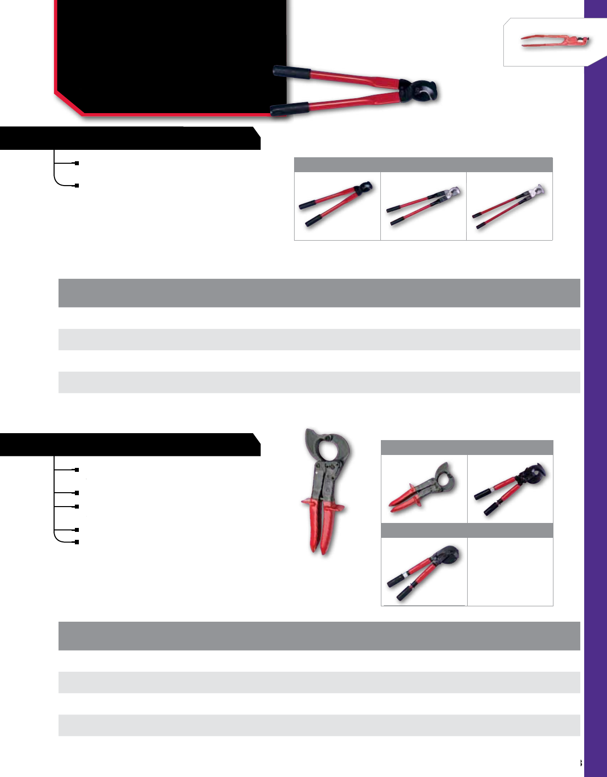
158
NSi Industries LLC • USA • 800.321.5847 • www.nsiindustries.com
158
TOOLS & HARDWARE
FEATURES
Fine quality tools crafted for cutting ease,
minimum cable distortion and long life.
Rugged, compact and lightweight.
High quality steel blades offer excellent cutting-
edge performance.
Handles are made from fiberglass.
Replacement blades and handles available.
CAT.
NO. FIG.
NO. CABLE
CAPACITY FOR USE
WITH MAX.
INSUL. DIA. LENGTH
(IN)
CCM-350 1 350 MCM Copper & Aluminum 1.25 16
CCM-500 2500 MCM Copper & Aluminum 1.25 21
CCM-1000 31000 MCM Copper & Aluminum 1.90 32
CCM-500RB Replacement Blades For CCM-500
CAT.
NO. FIG.
NO. CABLE
CAPACITY FOR USE
WITH MAX.
INSUL. DIA. LENGTH
(IN)
CCR-600 4350 MCM Copper & Aluminum 1.20 10
CCR-750 5500 MCM Copper & Aluminum 1.40 20
CCR-1000 61000 MCM Copper & Aluminum 2.38 20
CCR-750 RB Replacement Blades For CCR-750
minimum cable distortion and long life.
edge performance.
Rugged, lightweight manual cable cutters available
in three sizes to handle all sizes of cable.
Replacement blades are available for CCM-500 and
CCM-1000.
123
4 5
6
TOOLS
Manual & Ratchet-Drive
Cable Cutters
FOR COPPERS AND ALUMINUM CABLES
RATCHET-DRIVE CABLE CUTTERS
MANUAL CABLE CUTTERS
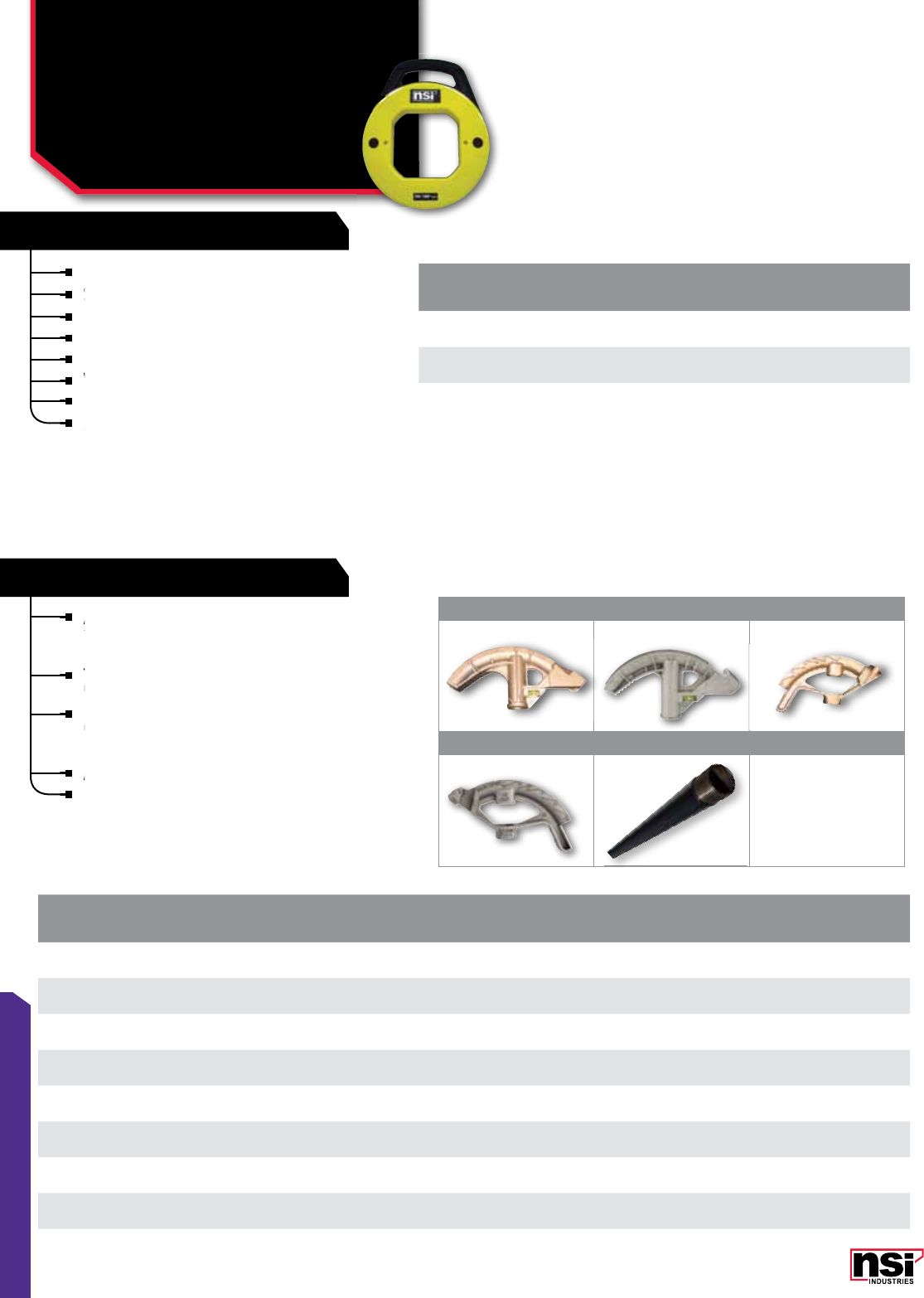
FEATURES
159
TOOLS & HARDWARE
123
4 5
Extremely flexible and durable flat spring steel.
Stiffer construction is excellent for long runs.
Looped end for attaching wires.
Heavy-duty housing withstands rough conditions.
High visibility yellow makes fish tape easy to locate.
Viewing holes to show remaining tape.
Handle slides through base to reel tape easily.
500 Lbs. maximum tape strength.
CAT.
NO. DESCRIPTION LENGTH
(FT) END TYPE
FTS50 1
/8” Steel Fishtape c/w handle 50 Formed hook
FTS120 1
/8” Steel Fishtape c/w handle 120 Formed hook
FTS200 1
/8” Steel Fishtape c/w handle 200 Formed hook
TOOLS
Steel Fishtapes &
Conduit Benders
FTS , CB, CBS, CBH SERIES
Viewing holes to show remaining tape.
Viewing holes to show remaining tape.
Viewing holes to show remaining tape.
Stiffer construction is excellent for long runs.
Stiffer construction is excellent for long runs.
Stiffer construction is excellent for long runs.
500 Lbs. maximum tape strength.
500 Lbs. maximum tape strength.
All NSi conduit benders have cast in-angle
indicators with raised bending points of reference
to aid the installer.
The bodies are aluminum die cast which are
lightweight yet strong enough for everyday use.
Handles are tough steel construction and have a
black powder coat finish that is textured for better
gripping; flared handle corrects overbends.
Aluminum Die Cast Bender with Steel Handle.
Handles are made of steel.
CAT.
NO. FIG.
NO. DESCRIPTION TYPE HANDLE
SIZE HANDLE
LENGTH
STD.
CTN.
QTY.
CB100 1For 1” EMT or 3/4” Rigid, 8 Degree Inside Radius Aluminum Die Cast –– 12
CB75 2For 3/4” EMT or 1/2” Rigid, 6 Degree Inside Radius Aluminum Die Cast –– 12
CB50 3For 1/2” EMT, 5 Degree Inside Radius Aluminum Die Cast –– 12
CB50WH 4For 1/2” EMT, 5 Degree Inside Radius Aluminum Die Cast With Handles 3/4 x 38 – 12
CB75WH 4For 3/4” EMT or 1/2” Rigid, 6 Degree Inside Radius Aluminum Die Cast With Handles 3/4 x 38 – 12
CB100WH 4For 1” EMT or 3/4” Rigid, 8 Degree Inside Radius Aluminum Die Cast With Handles 1” x 44 – 12
CBH75 53/4” Diameter, for use with CB50 and CB75 Handles only 3/4 38 12
CBH100 51” Diameter, for use with CB100 Handles only 1 44 12
The bodies are aluminum die cast which are
lightweight yet strong enough for everyday use.
black powder coat finish that is textured for better
Aluminum Die Cast Bender with Steel Handle.
All NSi conduit benders have cast in-angle
indicators with raised bending points of reference
All NSi conduit benders have cast in-angle
indicators with raised bending points of reference
All NSi conduit benders have cast in-angle
STEEL FISHTAPES
CONDUIT BENDERS
All dimensional data is listed in inches.
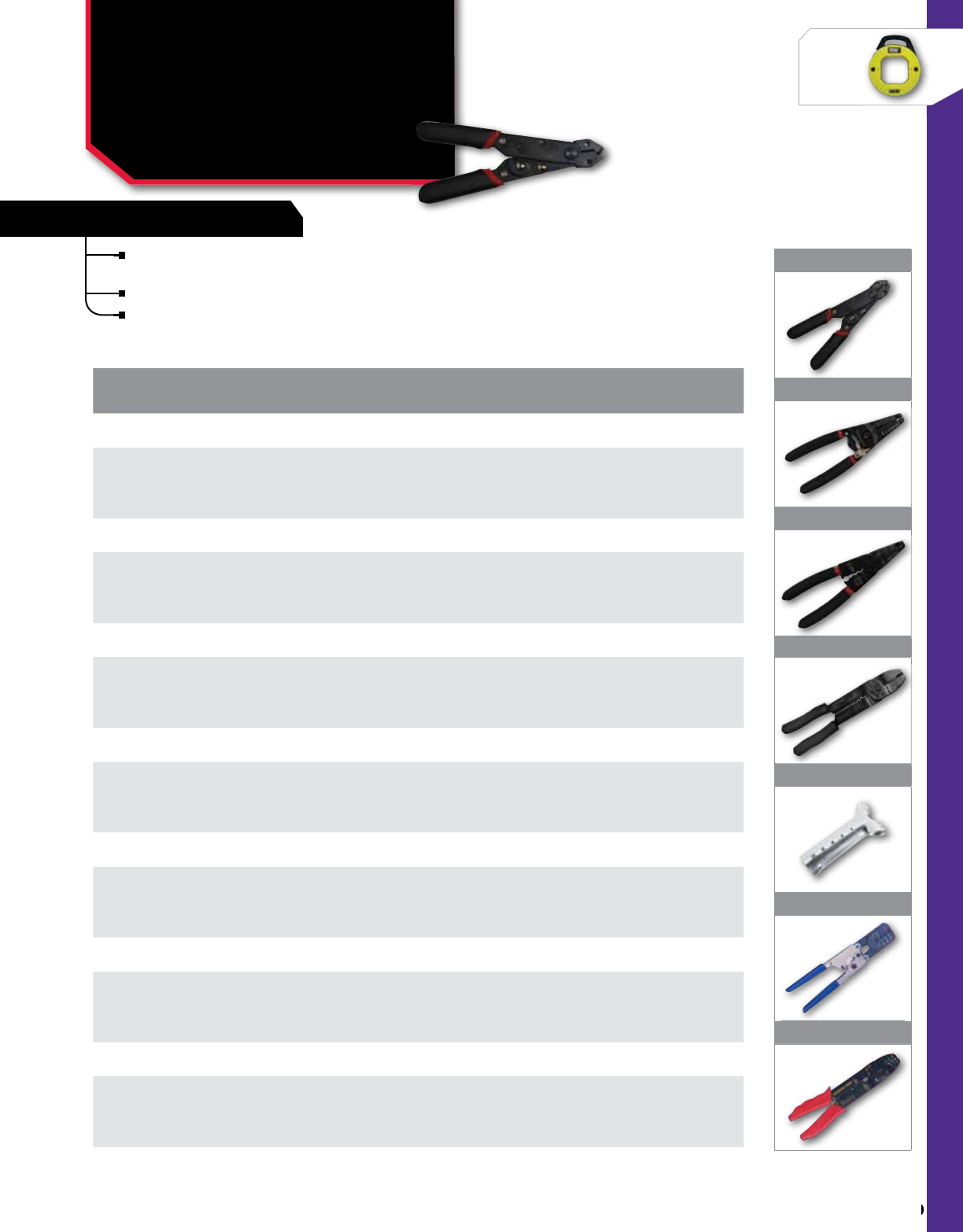
160
NSi Industries LLC • USA • 800.321.5847 • www.nsiindustries.com
160
TOOLS & HARDWARE
FEATURES
1
2
3
4
5
6
7
TOOLS
Precision Wire
Strippers & Insulated
Miniterm Tool
TL, NH SERIES
Finest heat treated spring steel construction
with precision-ground cutting edges.
Double-Insulated cushioned handles.
Strip solid or stranded copper or aluminum wires.
CAT.
NO. FIG.
NO. DESCRIPTION STD.
CTN.
QTY.
ADJUSTABLE 10-24 AWG 5” WIRE STRIPPER
TL-ADJ5 1
Adjustment wheel sets wire stripper for 8 wire gauge sizes from 10 to 24 AWG.
Wire cutter (CU/AL). Wire looper. Heat treated spring steel.
Cushioned double insulated handle
1
10-20 AWG 6” WIRE STRIPPER
TL-WS6 2
Six precision-cut wire stripping holes: 10, 12, 14, 16, 18, 20 AWG.
Pliers nose. Wire cutter (CU/AL). Wire looper. Spring and lock.
Heat treated spring steel. Cushioned double insulated handle.
1
10-20 AWG 8 1/2” 6-FUNCTION ELECTRICIAN’S TOOL
TL-6-1 3
Six precision-cut wire stripping holes: 10, 12, 14, 16, 18, 20 AWG.
Pliers nose. Wire cutter (CU/AL). Wire looper. Insulated and non-insulated
crimping stations. Bolt cutter and re-threader. Spring and lock.
Heat-treated spring steel. Cushioned double insulated handle
1
10-22 AWG 9 1/2” 5-FUNCTION ELECTRICIAN’S TOOL
TL-5-1 4
Seven wire stripping holes: 10, 12, 14, 16, 18, 20, 22 AWG.
Wire cutter nose (CU/AL). Insulated and non-insulated crimping stations.
Bolt cutter and re-threader. Heat-treated hardened steel.
Cushioned double insulated handle.
1
CABLE JACKET RIPPER 4”
TL-RCR 5Slits NM jackets on Romex TM cables to allow stripping of internal wires.
Wire gauge holes. 1
INSULATED MINITERM TOOL
NH-1 6
A rachet-action crimping tool for quality crimping of insulated terminals and connectors,
including rings, spades, male plugs, female receptacles and disconnects in 22/18, 16/14
and 12/10 awg wire sizes. 1
UNINSULATED MINITERM TOOL
NH-2 7An economical combination tool for cutting, stripping and crimping
non-insulated terminals in 22/18, 16/14 and 12/10 awg wire sizes. 1
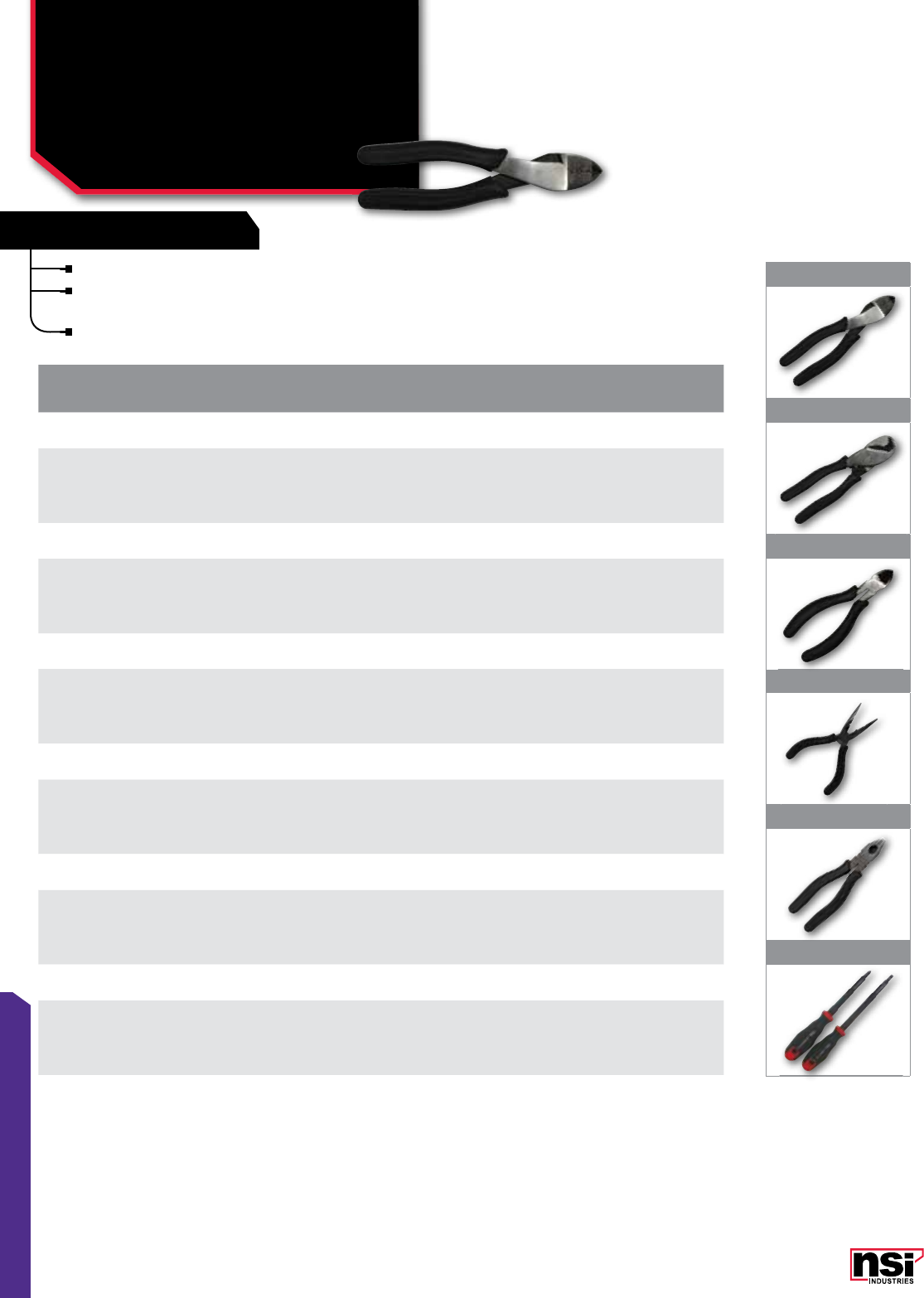
161
TOOLS & HARDWARE
FEATURES FEATURES
1
2
3
4
5
6
TOOLS
Electrician's Hand Tools
TL SERIES
The essential hand tools for electrical work.
Heat-treated forged steel construction with precision
ground edges for cutting copper and aluminum.
Double-insulated cushioned handles.
CAT.
NO. FIG.
NO. DESCRIPTION STD.
CTN.
QTY.
DIAGONAL CUTTING PLIERS 6 1/2”
TL-DC 1Designed and shaped for wire cutting in tight places. Wire cutter nose (CU/AL).
Heat-treated drop-forged steel. Cushioned insulated handles. 1
CABLE CUTTER 8”
TL-CCIH 2Designed for high-leverage cutting of cable to 2/0 (CU/AL).
Heat-treated drop-forged steel. Cushioned insulated handles. 1
LONG REACH CUTTER/CRIMPER 8”
TL-CRP 3
Long reach design for wire cutting and crimping in tight places.
Wire cutter nose (CU/AL). Heat-treated drop-forged steel.
Cushioned insulated handles.
1
LONG NOSE PLIERS/STRIPPER/CRIMPER 6 1/2”
TL-LNP 4
For long reach twisting and positioning wires in tight places. Wire cutter (CU/AL).
Non-insulated crimping stations. Heat-treated drop-forged steel.
Cushioned insulated handles.
1
LINEMAN’S PLIERS 7 1/2”
TL-LP 5
Designed for high leverage pulling and twisting wires and cables.
Threaded wire-gripping nose. Wire cutter (CU/AL). Heat-treated drop-forged steel.
Cushioned insulated handle.
1
ELECTRICIAN’S 1000V SCREWDRIVERS
TL-ISS 6
Fully insulated (1000 Volt) screwdriver set. Comfort grip handles and fully insulated
shafts for full shock protection (1) #2 Phillips head (1) 3/16” slotted tip. Hang holes.
Heat treated drop forged steel.
1
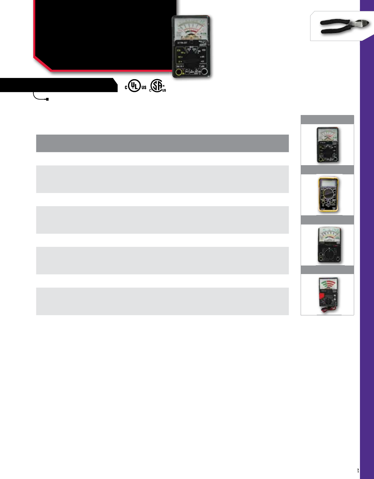
162
NSi Industries LLC • USA • 800.321.5847 • www.nsiindustries.com
162
TOOLS & HARDWARE
FEATURES
1
2
3
4
TOOLS
Electrical Multitesters -
Analog & Digital
TES SERIES
Precision hand-held analog and digital meter
for measuring voltage, amperage, continuity,
resistance, battery and decibel strenght.
CAT.
NO. FIG.
NO. DESCRIPTION STD.
CTN.
QTY.
ANALOG MULTITESTER 5-FUNCTION 12 RANGE
TES-MT12 1
Measures AC/DC voltage to 300 Volts. DC amperage to 250 mA.
Decibels from -20 to 56dB. 1.5 and 9V Batteries Continuity. Fuse protection.
Insulated test leads. Requires (2) AAA batteries.
1
ANALOG MULTITESTER 7-FUNCTION 19 RANGE
TES-MT19 2
Tests AC/DC voltage to check 10 Meg. Decibels from -8 to +62dB 1.5 and 9V batteries.
Continuity with audible buzzer Fuse protection. Insulated test leads.
Requires (2) AA batteries.
1
ANALOG BATTERY TESTER
TES-MTBTL 3
Tests AA; AAA; C; D; C; button cells; Ni-Cad; 3V lithium; 22.5V photo and
lantern cells; 6V lantern; 12V, 15V photo cells. Insulated test leads.
Exclusive button cell test compartment.
1
DIGITAL MULTITESTER 6-FUNCTION 20 RANGE
TES-DT18 4DC current to 200 mA. 1.5 and 9V batteries. Continuity (audible buzzer)
Fuse protection. Insulated test leads. Requires 9V battery. 1
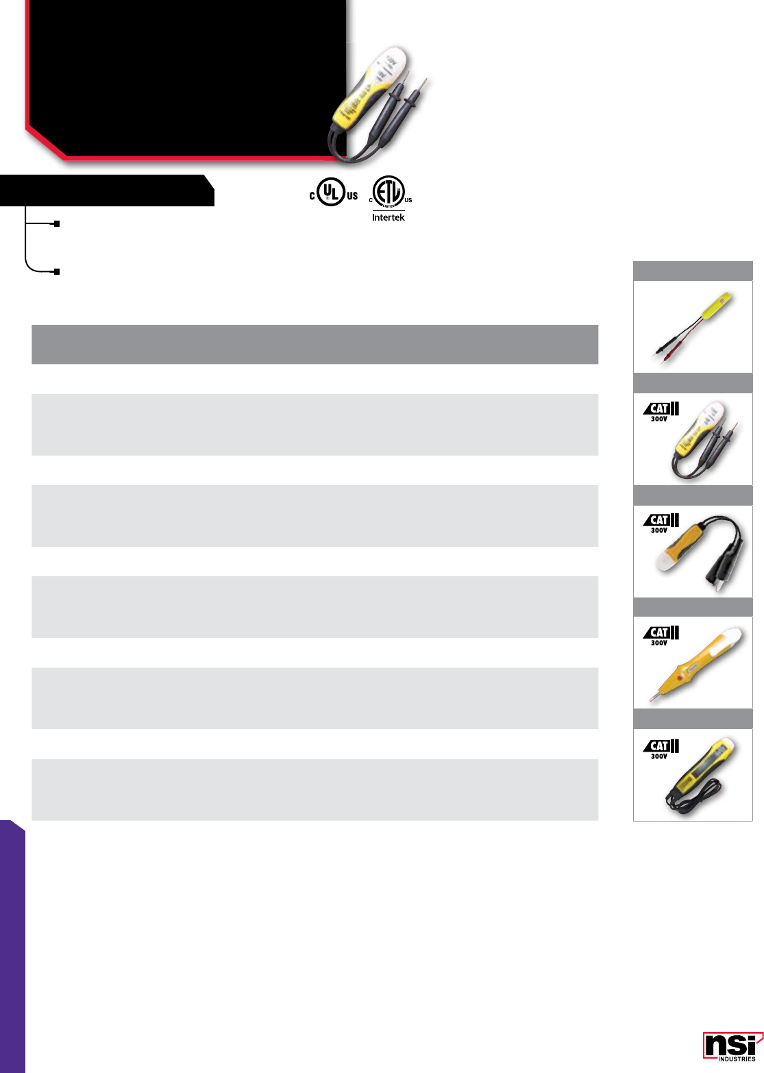
163
TOOLS & HARDWARE
FEATURES FEATURES
TESTERS
Circuit/Receptacle Testers
TES SERIES
1
2
3
4
5
Hand-held probe testers for measuring household
voltage presence and level, low voltage presence,
continuity and polarity.
AC/DC home, commercial, automotive and
marine voltages.
CAT.
NO. FIG.
NO. DESCRIPTION STD.
CTN.
QTY.
80-250 VAC TWIN PROBE VOLTAGE TESTER
TES-111 1Neon light indicates presence of AC voltage from 80-250 VAC.
Double insulated housing and test leads. Pocket clip. 1
120 OR 240 VAC VOLTAGE TESTER
TES-2 2Dual neon light indicates presence of AC voltage of either 120 or 240 VAC.
Double insulated housing and test leads. Pocket clip. 1
5-50 VAC/DC VOLTAGE TESTER
TES-LVT 3
Neon light indicates presence of low voltage from 5 to 50 VAC or DC.
Double insulated housing and fully insulated test leads with alligator clips.
Pocket clip.
1
CONTINUITY/VOLTAGE SCREWDRIVER TESTER
TES-CT 4
Neon light indicates presence of AC voltage from 12-300 VAC. Neon light also
indicates circuit continuity. Double insulated housing. Handy screwdriver / voltage probe.
Pocket clip. (2) LR-44 batteries included
1
120-480 VAC/DC HEAVY-DUTY VOLTAGE TESTER
TES-SOL 5
Solenoid spring activated gauge measures voltage levels from 120 to 480 VAC.
Double insulated housing and heavy gauge 48” test leads with housing storage. Lighted
polarity indication.
1
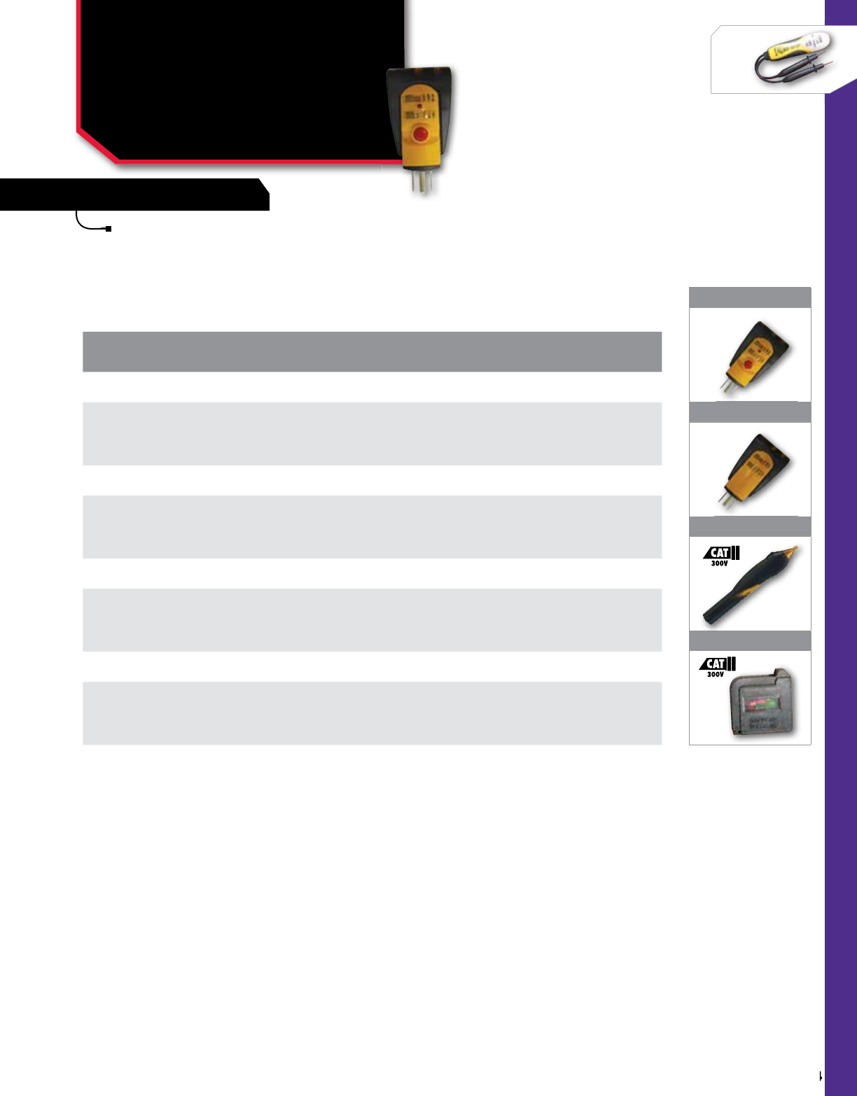
164
NSi Industries LLC • USA • 800.321.5847 • www.nsiindustries.com
164
TOOLS & HARDWARE
FEATURES
TESTERS
Circuit/Receptacle Testers
TES SERIES CONT'D
1
2
3
4
Hand-held probe testers for measuring household
voltage presence without contacting conductors,
analyzing circuit wiring and GFCI integrity and
quick baterry testing.
CAT.
NO. FIG.
NO. DESCRIPTION STD.
CTN.
QTY.
GFCI ELECTRICAL JUNCTION BOX WIRING ANALYZER
TES-131 1
Plug in tester shows presence of correct wiring of electrical junction boxes.
Also shows presence of up to 6 junction box wiring errors.
Includes push-button GFCI integrity test. Neon bulb indication.
1
ELECTRICAL JUNCTION BOX WIRING ANALYZER
TES-122 2Plug in tester shows presence of correct wiring of electrical junction boxes.
Also shows presence of up to 6 junction box wiring errors. Neon bulb indication. 1
90-200 VAC NON-CONTACT VOLTAGE TESTER
TES-NC 3
Detects household voltages from 90 to 200 VAC without touching conductors.
(2) AAA batteries are included. AAA battery test feature included. Double insulated.
Pocket clip.
1
POCKET BATTERY TESTER
TES-BT 4Checks strength of AA, AAA, C, D, N, 9V and 1.5V Button Cell Batteries.
Flip up contact arm fits battery poles. 1
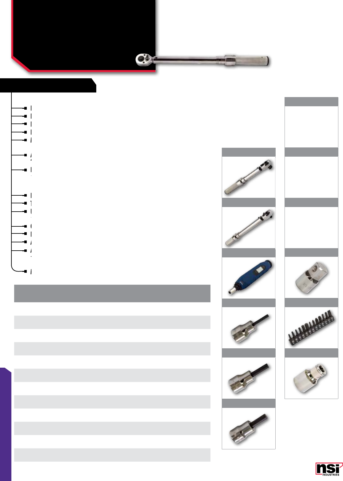
165
TOOLS & HARDWARE
FEATURES FEATURES
TORQUE WRENCHES
Dual scale, calibrated dual direction.
Positive lock with spring laoded pull down lock ring.
Fast, accurate and easy to set.
Easy-to-read laser marked scales.
Most feature quick release buttons which provide good
socket retention as well as easy socket removal.
Accuracy:3% CW, 4% CCW of indicated value, CW, from
20% to 100% of full scale.
Individually serialized with matching certificate of
calibration traceable to N.I.S.T.
TORQUE SCREWDRIVERS
Positive locking pull down adjustment knob.
Trilobular comfort grip.
Universal 1/4 in hex bit holder with strong
rare earth magnet.
Cam-over torque limiting clutch and slip resistant finsih.
Easy-to-read windown scale and light weight.
Automatic lock in CCW direction for disassembly.
Accuracy: 6% of indicated value, CW fro 20% to 100%
of full scale.Individually serialized with matching
certificate of calibration traceable to N.I.S.T.
Meets or exceeds ASME B107.14-2004
Dual
Positive lock with spring laoded pull down lock ring.
Positive lock with spring laoded pull down lock ring.
Fast, accurate and easy to set.
Fast, accurate and easy to set.
Easy-to-read laser marked scales.
Easy-to-read laser marked scales.
Most feature quick release buttons which provide good
socket retention as well as easy socket removal.
Most feature quick release buttons which provide good
socket retention as well as easy socket removal.
Most feature quick release buttons which provide good
Most feature quick release buttons which provide good
Accuracy:3% CW, 4% CCW of indicated value, CW, from
20% to 100% of full scale.
Accuracy:3% CW, 4% CCW of indicated value, CW, from
20% to 100% of full scale.
Accuracy:3% CW, 4% CCW of indicated value, CW, from
Individually serialized with matching certificate of
calibration traceable to N.I.S.T.
Individually serialized with matching certificate of
calibration traceable to N.I.S.T.
Individually serialized with matching certificate of
Positive locking pull down adjustment knob.
Trilobular comfort grip.
Trilobular comfort grip.
Universal 1/4 in hex bit holder with strong
rare earth magnet.
Universal 1/4 in hex bit holder with strong
rare earth magnet.
Universal 1/4 in hex bit holder with strong
Universal 1/4 in hex bit holder with strong
Cam-over torque limiting clutch and slip resistant finsih.
Easy-to-read windown scale and light weight.
Easy-to-read windown scale and light weight.
Automatic lock in CCW direction for disassembly.
Accuracy: 6% of indicated value, CW fro 20% to 100%
Automatic lock in CCW direction for disassembly.
Accuracy: 6% of indicated value, CW fro 20% to 100%
of full scale.Individually serialized with matching
Accuracy: 6% of indicated value, CW fro 20% to 100%
of full scale.Individually serialized with matching
Accuracy: 6% of indicated value, CW fro 20% to 100%
Accuracy: 6% of indicated value, CW fro 20% to 100%
Meets or exceeds ASME B107.14-2004
TOOLS
Torque Wrenches,
Screwdriver &
Accessories
TW SERIES
CAT.
NO. FIG.
NO. DESCRIPTION STD.
CTN.
QTY.
TW20-2150 1Torque Wrench. Click Type. 20-150 In Lbs.
3/8" Drive Dual Scale. 1
TW100-250 2Torque Wrench. Click Type. 100-750 In Lbs.
3/8" Drive Dual Scale. 1
TW5-40 3Torque Screwdriver. Micro Adjustable. 5-40 In Lbs.
1/4" Drive Single Scale. 1
TWHB 3818 4Hex Bit 3/8" Socket. 1/8" Hex. 1
TWHB 38316 5Hex Bit 3/8" Socket. 3/16" Hex. 1
TWHB 3814 6Hex Bit 3/8" Socket. 1/4" Hex. 1
TWHB 38516 7Hex Bit 3/8" Socket. 5/16" Hex. 1
TWHB 3838 8Hex Bit 3/8" Socket. 3/8" Hex. 1
TWHB 1212 9Hex Bit 1/2" Socket. 1/2" Hex. 1
TWHB 3812 10 Drive Adaptor. 3/8" Female To 1/2" Male
(Needed For Sa16a, Sa18a And Sa20a) 1
TWBS 14 11 13 Piece 1/4" Drive Insert Bit Set. 1
TWSB 12 Holder For 1/4" Hex Screwdriver Bit. 3/8" Drive. 1
7
8
9
10
11
12
1
2
3
4
5
6
Image Not
Available
Image Not
Available
Image Not
Available
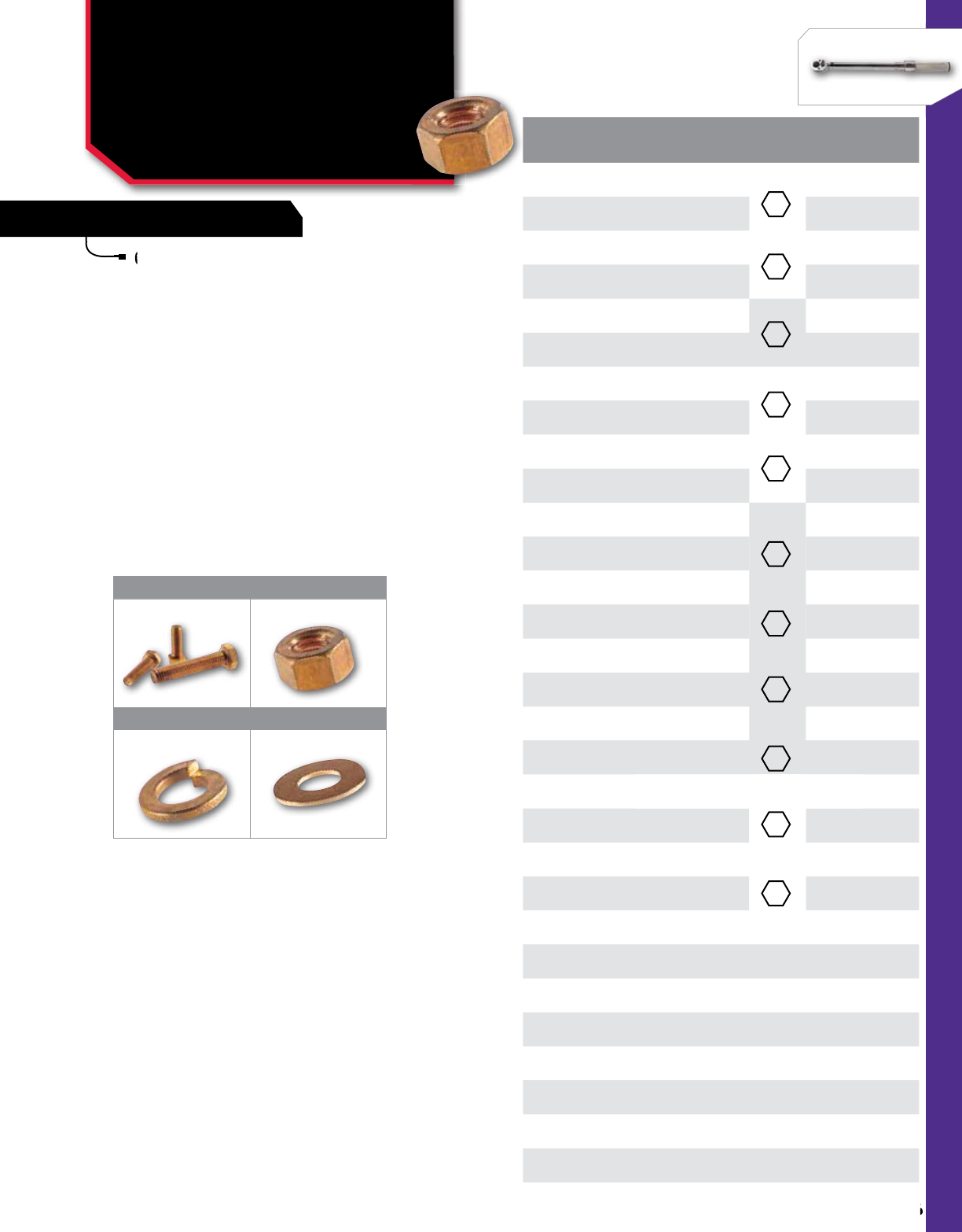
166
NSi Industries LLC • USA • 800.321.5847 • www.nsiindustries.com
166
TOOLS & HARDWARE
FEATURES
Corrosion resistance and physical strength
combine to provide reliability.
CAT.
NO. FIG.
NO. BOLT
SIZE
HEX/
WRENCH
SIZE
SCREW
SHAPE LENGTH
(IN)
STD.
CTN.
QTY.
HB403 1 1/4" 1/4" 3/4" 25
HB404 1 1/4" 1/4" 1" 25
HB405 1 1/4" 1/4" 1 1/4" 25
HB406 1 1/4" 1/4" 1 1/2" 25
HB505 1 5/16" 5/16" 1 1/4" 25
HB507 1 5/16" 5/16" 2" 25
HB604 1 3/8" 3/8" 1" 25
HB605 1 3/8" 3/8" 1 1/4" 25
HB606 1 3/8" 3/8" 1 1/2" 25
HB607 1 3/8" 3/8" 2" 25
HB804 1 1/2" 1/2" 1" 25
HB805 1 1/2" 1/2" 1 1/4" 25
HB806 1 1/2" 1/2" 1 1/2" 25
HB807 1 1/2" 1/2" 2" 25
HB808 1 1/2" 1/2" 2 1/4" 25
HB809 1 1/2" 1/2" 2 1/2" 25
HB811 1 1/2" 1/2" 3" 25
HB812 1 1/2" 1/2" 3 1/2" 25
HN-4 2 1/4" 1/4" –25
HN-5 2 5/16" 5/16" –25
HN-6 2 3/8" 3/8" –25
HN-8 2 1/2" 1/2" –25
SLW-4 3 1/4" –––
25
SLW-5 3 5/16" –––
25
SLW-6 3 3/8" –––
25
SLW-8 3 1" –––
25
FW-4 4 1/4" –––
25
FW-5 4 5/16" –––
25
FW-6 4 3/8" –––
25
FW-8 4 1" –––
25
Corrosion
combine to provide reliability.
1 2
3 4
HARDWARE
Silicon Bronze Bolts,
Hex Nuts, Flat Washers
& Split Lockwashers
HB, HN, SLW, FW SERIES
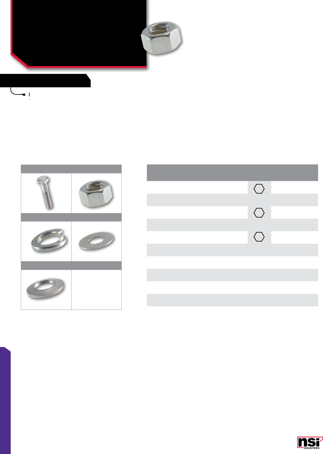
167
TOOLS & HARDWARE
FEATURES FEATURES
Corrosion resistance and physical strength combine
to provide reliability.
Corrosion resistance and physical strength combine
to provide reliability.
Corrosion resistance and physical strength combine
to provide reliability.
Corrosion resistance and physical strength combine
1 2
3 4
5
CAT.
NO.
FIG.
NO. BOLT
SIZE
HEX/
WRENCH
SIZE
SCREW
SHAPE LENGTH
(IN)
STD.
CTN.
QTY.
SS66 1 3/8" 3/8" 2 1/4" 25
SS34 1 1/2" 1/2" 1 3/4" 25
SS37 1 1/2" 1/2" 2 1/2" 25
SSHN-6 2 3/8" 3/8" – 25
SSHN-8 2 1/2" 1/2" – 25
SSBW-6 3 3/8" – – – 25
SSSLW-8 3 1" – – – 25
SSFW-6 4 3/8" – – – 25
SSFW-8 4 1" – – – 25
SSBW-8 5 1" – – – 25
HARDWARE
Stainless Steel Bolts,
Hex Nuts, Flat Washers
& Split Lockwashers
SS, SSHN, SSBW, SSSLW, SSFW, SSBW SERIES
168
NSi Industries LLC • USA • 800.321.5847 • www.nsiindustries.com
168
TOOLS & HARDWARE
FEATURES
Universal Oxide Inhibitor for aluminum and/or
copper terminations.
Remains stable over a wide tempera ture range.
Supplied in clear, easy-squeeze bottles or tubes.
Universal
copper terminations.
Remains stable over a wide
Supplied in clear, easy-squeeze bottles or tubes.
Supplied in clear, easy-squeeze bottles or tubes.
Supplied in clear, easy-squeeze bottles or tubes.
INHIBITORS
Oxide Inhibitor &
Duct Sealing Compound
OX, DS SERIES
CAT.
NO. FIG.
NO. DESCRIPTION SIZE
(OZ)
STD.
CTN.
QTY.
OX-8 1Oxide Inhibitor. Squeeze Bottle. 8 oz. 12
OX-4 2Oxide Inhibitor. Squeeze Bottle. 4 oz. 12
OX-1 3Oxide Inhibitor. Squeeze Tube. 3/4 oz. 100
123
1 2
CAT.
NO. FIG.
NO. DESCRIPTION STD.
CTN.
QTY.
DS184 1Duct Seal – 1 Lb. Pkg. 50
DS185 2Duct Seal – 5 Lbs. Pkg. 10
Intended for sealing around electrical service entries,
junction boxes and other devices where weather-
proofing is critical.
Will stay soft and pliable for several years and has
an excellent shelf life.
Will not damage wire covers, glass, wood, painted
surfaces, plastics or other materials it may contact.
It is chemically inert, inhibiting no chemical activity
and is nontoxic.
Contains no asbestos or mineral fibers and no
mineral oil which can shorten the effective life of
the product.
Remains pliable through a wide range of
temperatures and will adhere to most clean
dry surfaces.
Contains no asbestos or
mineral oil which can shorten the effective life of
Will
an excellent shelf life.
Will not damage wire covers, glass, wood, painted
surfaces, plastics or other materials it may contact.
Will not damage wire covers, glass, wood, painted
surfaces, plastics or other materials it may contact.
Will not damage wire covers, glass, wood, painted
It is chemically inert, inhibiting no chemical activity
and is nontoxic.
It is chemically inert, inhibiting no chemical activity
and is nontoxic.
It is chemically inert, inhibiting no chemical activity
Intended for sealing around electrical service entries,
junction boxes and other devices where weather-
Intended for sealing around electrical service entries,
junction boxes and other devices where weather-
Intended for sealing around electrical service entries,
Remains pliable through a wide range of
temperatures and will adhere to most clean
Remains pliable through a wide range of
temperatures and will adhere to most clean
Remains pliable through a wide range of
OXIDE INHIBITOR
DUCT SEALING COMPOUND


PolarisTM
Polaris
TM
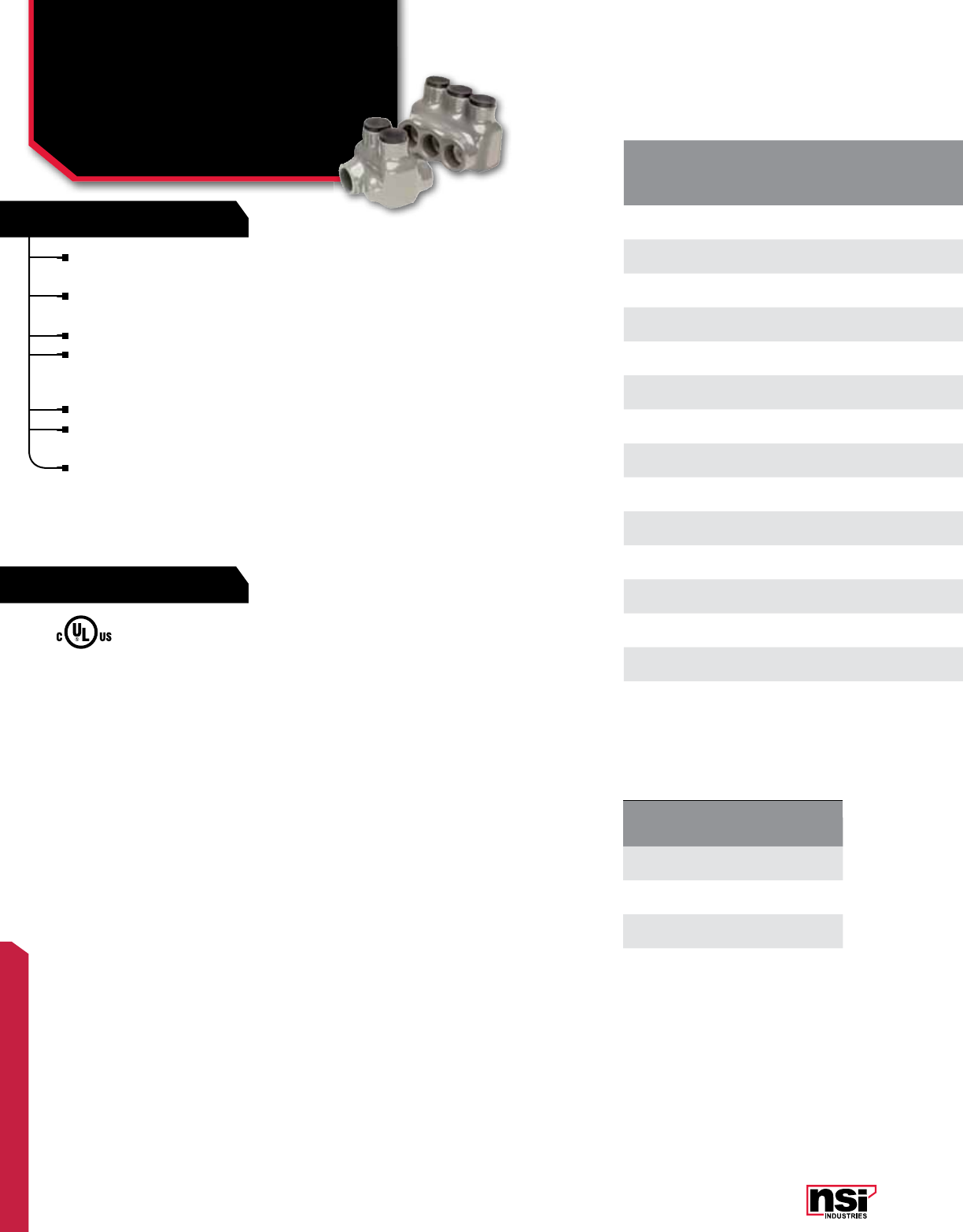
171
POLARIS™
FEATURES
RATINGS
CAT.
NO. NO. OF
PORTS
WIRE RANGE (BY CLASSIFICATION) LENGTH
(L) WIDTH
(W) HEIGTH
(H)
TORQUE
VALUE
(IN./LBS.)
HEX
SIZE
STD.
CTN.
QTY.
CLASS B, C, D CLASS K, M, I
ITG-6 26-14 AWG 6-14 AWG 1.130 1.240 1.370 45 1/8 12
ITOG-6 26-14 AWG 6-14 AWG 1.130 1.270 1.370 45 1/8 12
IPLG6-3 36-14 AWG 6-14 AWG 1.550 1.240 1.370 45 1/8 12
IPLG6-4 46-14 AWG 6-14 AWG 1.980 1.240 1.370 45 1/8 6
IPLG6-6 66-14 AWG 6-14 AWG 2.820 1.240 1.370 45 1/8 6
ITG-1 21-10 AWG 2-10 AWG 1.600 1.550 1.750 150 3/16 6
ITOG-1 21-10 AWG 2-10 AWG 1.600 1.630 1.750 150 3/16 6
IPLG1-3 31-10 AWG 2-10 AWG 1.550 1.240 1.370 150 3/16 6
IPLG1-4 41-10 AWG 2-10 AWG 1.980 1.240 1.370 150 3/16 6
IPLG1-6 61-10 AWG 2-10 AWG 2.820 1.240 1.370 150 3/16 6
ITG-3/0 23/0-4 AWG 2/0-2 AWG 1.850 1.600 1.810 250 3/16 6
ITOG-3/0 23/0-4 AWG 2/0-2 AWG 1.850 1.630 1.810 250 3/16 6
IPLG3/0-3 33/0-4 AWG 2/0-2 AWG 2.250 1.600 1.750 250 3/16 6
IPLG3/0-4 43/0-4 AWG 2/0-2 AWG 2.900 1.600 1.750 250 3/16 6
IPLG3/0-6 63/0-4 AWG 2/0-2 AWG 4.200 1.600 1.750 250 3/16 4
Safe: Insulated with high dielectric strength plastisol
for tough mechanical protection.
Factory applied insulation provides consistent quality
and protection.
Abrasion and chemical resistant.
Fast: Eliminates the need for cover and taping –
supplied with removable access plugs over the hex
screws to protect against contami nation.
Easy: Three sizes cover 14 to 3/0 AWG.
Reusable: ideal for cabletrays, troughs, wire-ways,
raceways, ducts and motor junction boxes.
For Copper Wire Only
POLARIS GREY™ REPLACEMENT SLEEVES
CAT.
NO. STD. CTN.
QTY.
SITG-6 10
SITG-1 10
SITG-3/0 10
POLARIS GREY™ INSULATED CONNECTORS
For Fine Stranded Wire
& Replacement Sleeves
ITG, ITOG, IPLG, SITG SERIES
For display bags with a mounting hole for hanging, add
the suffix “-B” to the part number when ordering.
All dimensional data is listed in inches.
UL Listed 486A Wire Connector.
TEMPERATURE RATING/VOLTAGE:
ALCU9. Cold temperature rated to -45˚C,
rated 600V, 90˚C.
WIRE TYPE:
Can be used with virtually any kind of copper conductor,
but is specifically designed for use with fine-stranded,
flexible and extra-flexible copper conductors. This includes
DLO cable and motor lead wire - excellent for use in motor
connect/disconnect applications.
ASSEMBLY INSTRUCTIONS:
See page 209 for detailed information for assembly,
mounting and installation.

172
NSi Industries LLC • USA • 800.321.5847 • www.nsiindustries.com
172
POLARIS™
CAT.
NO. NO. OF
PORTS
WIRE RANGE (BY CLASSIFICATION) LENGTH
(L) WIDTH
(W) HEIGTH
(H)
TORQUE
VALUE
(IN./LBS.)
HEX
SIZE
STD.
CTN.
QTY.
CLASS B, C, D CLASS K, M, I
ITG-6 26-14 AWG 6-14 AWG 1.130 1.240 1.370 45 1/8 12
ITOG-6 26-14 AWG 6-14 AWG 1.130 1.270 1.370 45 1/8 12
IPLG6-3 36-14 AWG 6-14 AWG 1.550 1.240 1.370 45 1/8 12
IPLG6-4 46-14 AWG 6-14 AWG 1.980 1.240 1.370 45 1/8 6
IPLG6-6 66-14 AWG 6-14 AWG 2.820 1.240 1.370 45 1/8 6
ITG-1 21-10 AWG 2-10 AWG 1.600 1.550 1.750 150 3/16 6
ITOG-1 21-10 AWG 2-10 AWG 1.600 1.630 1.750 150 3/16 6
IPLG1-3 31-10 AWG 2-10 AWG 1.550 1.240 1.370 150 3/16 6
IPLG1-4 41-10 AWG 2-10 AWG 1.980 1.240 1.370 150 3/16 6
IPLG1-6 61-10 AWG 2-10 AWG 2.820 1.240 1.370 150 3/16 6
ITG-3/0 23/0-4 AWG 2/0-2 AWG 1.850 1.600 1.810 250 3/16 6
ITOG-3/0 23/0-4 AWG 2/0-2 AWG 1.850 1.630 1.810 250 3/16 6
IPLG3/0-3 33/0-4 AWG 2/0-2 AWG 2.250 1.600 1.750 250 3/16 6
IPLG3/0-4 43/0-4 AWG 2/0-2 AWG 2.900 1.600 1.750 250 3/16 6
IPLG3/0-6 63/0-4 AWG 2/0-2 AWG 4.200 1.600 1.750 250 3/16 4
Protect those fine-stranded
wires with Polaris Grey™.
Here’s our secret: Polaris Grey™ comes with an
integral sleeve which protects the fine strands and
helps the conductor maintain its shape during the
tightening process. The sleeve eliminates breakage
of the strands and reduces stress on the conductor
and therefore the potential for hot-spots. Replacement
sleeves can be purchased separately.
Specially designed for connecting and terminating
fine-stranded, flexible copper conductors. Polaris
Grey™ combines the reliability and safety of a
compression connection with the ease, affordability
and flexibility
of a mechanical connection.
Motor replacement is now really easy. Simply strip
the cable, insert it into Polaris Grey™, tighten the
hex head screw, replace the cap.
W
H
L
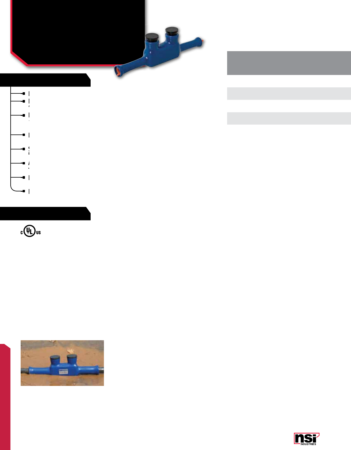
173
POLARIS™
FEATURES
RATINGS
For connecting two wires in-line.
For direct burial and submersible applications
(UL486D).
Insulated with specially formulated high-strength
dielectric plastisol and molded for precise fit for a
direct burial connection.
Requires no taping, compounds, heat shrink or
cutting-to-size in the field.
Supplied with removable access plugs over the
hex screws.
Abrasion and chemical resistant. UV rated.
Will not support combustion.
Dual-Rated suitable for use with aluminum and/or
copper conductors.
Reusable.
CAT.
NO.
WIRE RANGE
URD/USE
THHN/XHHW*
INSULATION LENGTH
(L) WIDTH
(W) HEIGHT
(H)
TORQUE
VALUE
(IN./LBS.)
HEX
SIZE STRIP
LENGTH
STD.
CTN.
QTY.
MIN. DIA. MAX. DIA.
ISW-4 4-6 AWG 0.244 0.412 6.375 0.813 1.500 45 Slotted 13/16 1
ISW-1 1-2 AWG 0.352 0.582 6.830 0.880 1.680 150 3/16 27/32 1
ISW-3/0 3/0-1/0 AWG 0.462 0.720 7.625 1.625 2.625 250 1/4 7/8 1
ISW-250 250-4/0 AWG 0.618 0.895 7.563 1.188 2.125 360 5/16 1-1/8 1
POLARIS BLUE™ INSULATED CONNECTORS
For Direct Burial &
Submersible
ISW SERIES All dimensional data is listed in inches.
For connecting two wires in-line.
For direct burial and submersible applications
(UL486D).
For direct burial and submersible applications
Insulated with specially
dielectric plastisol and molded for precise fit for a
Insulated with specially
dielectric plastisol and molded for precise fit for a
Insulated with specially
Requires
cutting-to-size in the field.
Requires
cutting-to-size in the field.
Requires
Supplied with removable access plugs over the
hex screws.
Supplied with removable access plugs over the
hex screws.
Supplied with removable access plugs over the
Abrasion and chemical resistant. UV rated.
Will not support combustion.
Dual-Rated suitable for use with aluminum and/or
copper conductors.
Reusable.
UL Listed 486D Wire Connector.
TEMPERATURE RATING/VOLTAGE:
AL9CU. Cold temperature rated to -45˚C,
rated 600V, 90˚C.
WIRE TYPE:
Suitable for use with aluminum and/or copper conductors.
Approved for use with all conductors with insulation
suitable for wet and/or damp locations. Not recommended
for use with extra flexible cable (see Polaris Grey™ Series
page 171).
INSTALLATION INSTRUCTIONS:
See page 209 for detailed installation information.
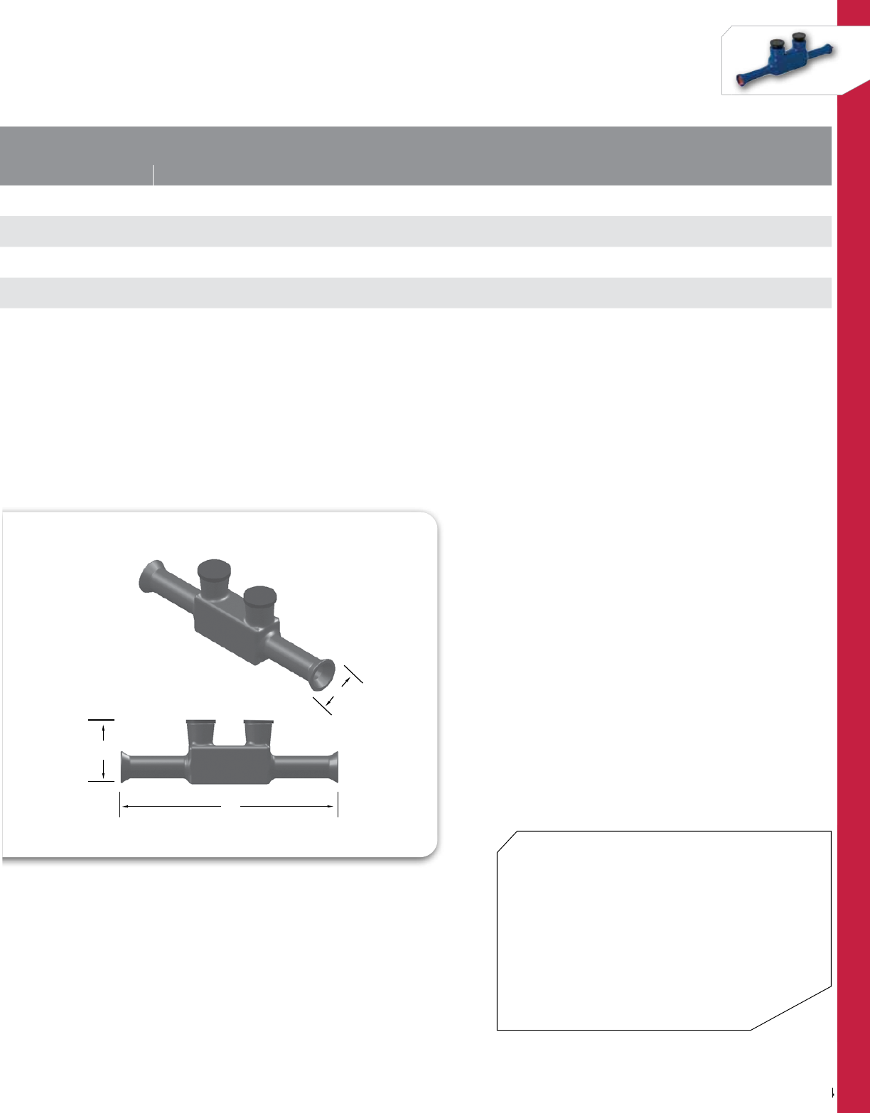
174
NSi Industries LLC • USA • 800.321.5847 • www.nsiindustries.com
174
POLARIS™
* Not suitable for direct burial with THHN/XHHW wire. For use in enclosures only.
A properly installed connector will have no more than one conductor per port.
CAT.
NO.
WIRE RANGE
URD/USE
THHN/XHHW*
INSULATION LENGTH
(L) WIDTH
(W) HEIGHT
(H)
TORQUE
VALUE
(IN./LBS.)
HEX
SIZE STRIP
LENGTH
STD.
CTN.
QTY.
MIN. DIA. MAX. DIA.
ISW-4 4-6 AWG 0.244 0.412 6.375 0.813 1.500 45 Slotted 13/16 1
ISW-1 1-2 AWG 0.352 0.582 6.830 0.880 1.680 150 3/16 27/32 1
ISW-3/0 3/0-1/0 AWG 0.462 0.720 7.625 1.625 2.625 250 1/4 7/8 1
ISW-250 250-4/0 AWG 0.618 0.895 7.563 1.188 2.125 360 5/16 1-1/8 1
L
H
W
Polaris™ Blue custom connectors
Let us help you custom engineer and fabricate a
UL Listed direct burial and submersible insulated
connector for your next project. Choose any
combination and quantity of our standard Polaris
Blue and we’ll build a connector to meet your exact
requirements. Wire entry can even be from either
side of the connector, based on your specific project
needs. UL486D for direct burial or below ground
use and submersible applications.
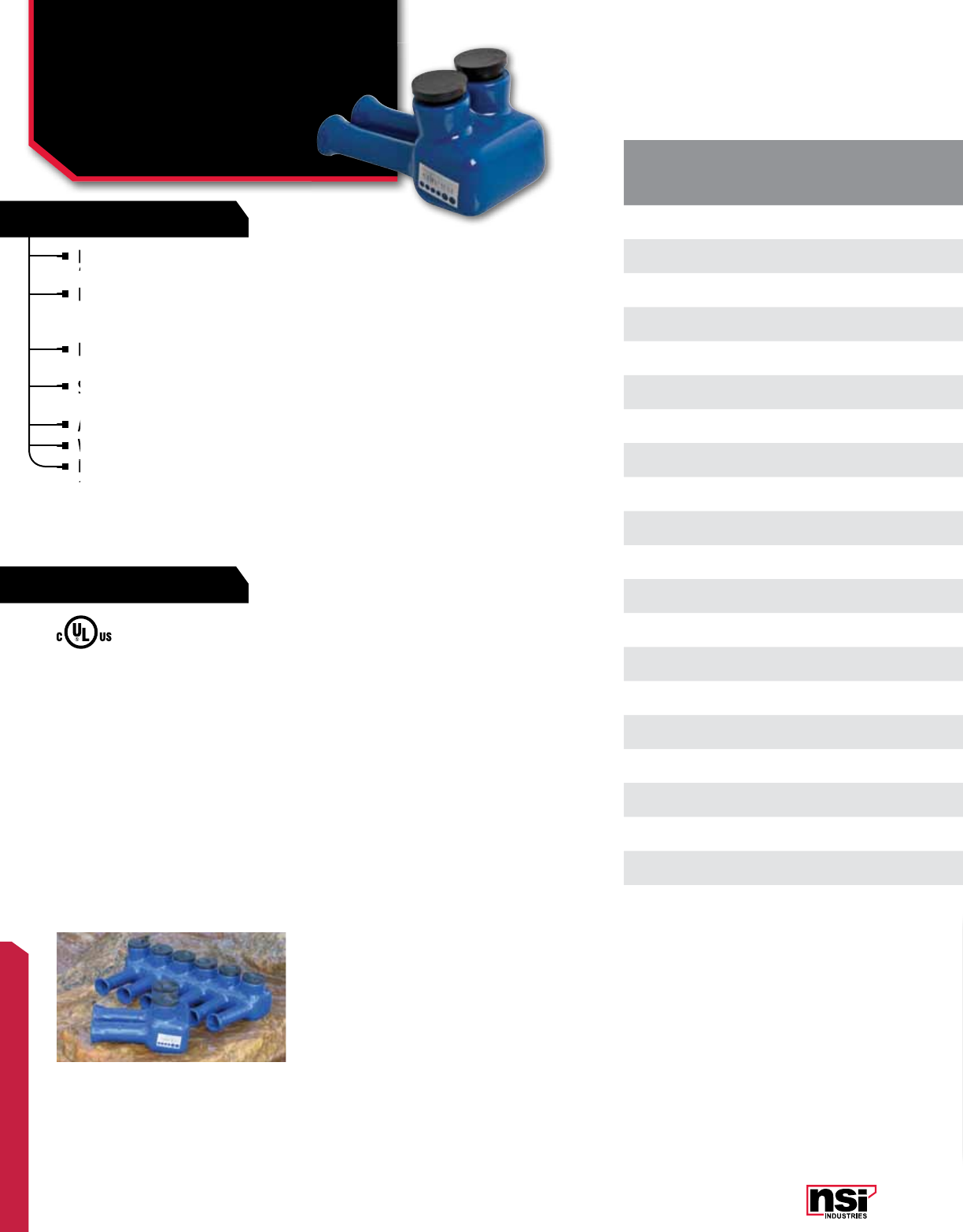
175
POLARIS™
FEATURES
RATINGS
For connecting multiple wires and are UL Listed
(UL486D) for direct burial and submersible applications.
Insulated with specially formulated high-strength
dielectric plastisol and molded for precise fit for a
direct burial connection.
Requires no taping, compounds, heat shrink or
cutting-to-size in the field.
Supplied with removable access plugs over the hex
screws and pre-filled oxide inhibitor.
Abrasion and chemical resistant. UV resistant.
Will not support combustion.
Dual-Rated suitable for use with aluminum and/or
copper conductors.
CAT.
NO. NO. OF
PORTS
WIRE RANGE
URD/USE
THHN/ XHHW*
INSULATION HEX
SIZE LENGTH
(L) WIDTH
(W) HEIGHT
(H)
TORQUE
VALUE
(IN./LBS.)
STRIP
LENGTH
STD.
CTN.
QTY.
MIN. DIA. MAX. DIA.
ITW-4 24-6 AWG 0.244 0.412 Slotted 1.680 3.260 1.460 45 3/16 1
IPLW4-3 34-6 AWG 0.244 0.412 Slotted 2.640 3.260 1.460 45 3/16 1
IPLW4-4 44-6 AWG 0.244 0.412 Slotted 3.610 3.260 1.460 45 3/16 1
IPLW4-5 54-6 AWG 0.244 0.412 Slotted 4.570 3.260 1.460 45 3/16 1
IPLW4-6 64-6 AWG 0.244 0.412 Slotted 5.540 3.260 1.460 45 3/16 1
ITW-1 21-2 AWG 0.352 0.582 3/16 1.880 3.550 1.820 150 27/32 1
IPLW1-3 31-2 AWG 0.352 0.582 3/16 2.800 3.550 1.820 150 27/32 1
IPLW1-4 41-2 AWG 0.352 0.582 3/16 3.730 3.550 1.820 150 27/32 1
IPLW1-5 51-2 AWG 0.352 0.582 3/16 4.650 3.550 1.820 150 27/32 1
IPLW1-6 61-2 AWG 0.352 0.582 3/16 5.580 3.550 1.820 150 27/32 1
ITW-3/0 23/0-1/0 AWG 0.462 0.720 1/4 2.270 3.710 1.990 250 7/8 1
IPLW3/0-3 33/0-1/0 AWG 0.462 0.720 1/4 3.470 3.710 1.990 250 7/8 1
IPLW3/0-4 43/0-1/0 AWG 0.462 0.720 1/4 4.670 3.710 1.990 250 7/8 1
IPLW3/0-5 53/0-1/0 AWG 0.462 0.720 1/4 5.870 3.710 1.990 250 7/8 1
IPLW3/0-6 63/0-1/0 AWG 0.462 0.720 1/4 7.070 3.710 1.990 250 7/8 1
ITW-250 2250-4/0 AWG 0.618 0.895 5/16 2.510 3.940 2.290 360 1-1/8 1
IPLW250-3 3250-4/0 AWG 0.618 0.895 5/16 3.810 3.940 2.290 360 1-1/8 1
IPLW250-4 4250-4/0 AWG 0.618 0.895 5/16 5.110 3.940 2.290 360 1-1/8 1
IPLW250-5 5250-4/0 AWG 0.618 0.895 5/16 6.410 3.940 2.290 360 1-1/8 1
IPLW250-6 6250-4/0 AWG 0.618 0.895 5/16 7.710 3.940 2.290 360 1-1/8 1
POLARIS BLUE™ INSULATED CONNECTORS
Direct Burial &
Submersible
ITW, IPLW SERIES
UL Listed 486D Wire Connector.
TEMPERATURE RATING/VOLTAGE:
AL9CU. Cold temperature rated to -45˚C,
rated 600V, 90˚C.
WIRE TYPE:
Suitable for use with aluminum and/or copper conductors.
Approved for use with all conductors with insulation
suitable for wet and/or damp locations. Not recommended
for use with extra flexible cable (see Polaris Grey™ Series
page 171).
INSTALLATION INSTRUCTIONS:
See page 209 for detailed installation information.
All dimensional data is listed in inches.
For connecting multiple wires and are UL Listed
(UL486D) for direct burial and submersible applications.
For connecting multiple wires and are UL Listed
(UL486D) for direct burial and submersible applications.
For connecting multiple wires and are UL Listed
Insulated with specially
dielectric plastisol and molded for precise fit for a
Insulated with specially
dielectric plastisol and molded for precise fit for a
Insulated with specially
Requires
cutting-to-size in the field.
Requires
cutting-to-size in the field.
Requires
Supplied with removable access plugs over the hex
screws and pre-filled oxide inhibitor.
Supplied with removable access plugs over the hex
screws and pre-filled oxide inhibitor.
Supplied with removable access plugs over the hex
Abrasion and chemical resistant. UV resistant.
Will not support combustion.
Dual-Rated suitable for use with aluminum and/or
Will not support combustion.
Dual-Rated suitable for use with aluminum and/or
copper conductors.
Dual-Rated suitable for use with aluminum and/or

176
NSi Industries LLC • USA • 800.321.5847 • www.nsiindustries.com
176
POLARIS™
CAT.
NO. NO. OF
PORTS
WIRE RANGE
URD/USE
THHN/ XHHW*
INSULATION HEX
SIZE LENGTH
(L) WIDTH
(W) HEIGHT
(H)
TORQUE
VALUE
(IN./LBS.)
STRIP
LENGTH
STD.
CTN.
QTY.
MIN. DIA. MAX. DIA.
ITW-4 24-6 AWG 0.244 0.412 Slotted 1.680 3.260 1.460 45 3/16 1
IPLW4-3 34-6 AWG 0.244 0.412 Slotted 2.640 3.260 1.460 45 3/16 1
IPLW4-4 44-6 AWG 0.244 0.412 Slotted 3.610 3.260 1.460 45 3/16 1
IPLW4-5 54-6 AWG 0.244 0.412 Slotted 4.570 3.260 1.460 45 3/16 1
IPLW4-6 64-6 AWG 0.244 0.412 Slotted 5.540 3.260 1.460 45 3/16 1
ITW-1 21-2 AWG 0.352 0.582 3/16 1.880 3.550 1.820 150 27/32 1
IPLW1-3 31-2 AWG 0.352 0.582 3/16 2.800 3.550 1.820 150 27/32 1
IPLW1-4 41-2 AWG 0.352 0.582 3/16 3.730 3.550 1.820 150 27/32 1
IPLW1-5 51-2 AWG 0.352 0.582 3/16 4.650 3.550 1.820 150 27/32 1
IPLW1-6 61-2 AWG 0.352 0.582 3/16 5.580 3.550 1.820 150 27/32 1
ITW-3/0 23/0-1/0 AWG 0.462 0.720 1/4 2.270 3.710 1.990 250 7/8 1
IPLW3/0-3 33/0-1/0 AWG 0.462 0.720 1/4 3.470 3.710 1.990 250 7/8 1
IPLW3/0-4 43/0-1/0 AWG 0.462 0.720 1/4 4.670 3.710 1.990 250 7/8 1
IPLW3/0-5 53/0-1/0 AWG 0.462 0.720 1/4 5.870 3.710 1.990 250 7/8 1
IPLW3/0-6 63/0-1/0 AWG 0.462 0.720 1/4 7.070 3.710 1.990 250 7/8 1
ITW-250 2250-4/0 AWG 0.618 0.895 5/16 2.510 3.940 2.290 360 1-1/8 1
IPLW250-3 3250-4/0 AWG 0.618 0.895 5/16 3.810 3.940 2.290 360 1-1/8 1
IPLW250-4 4250-4/0 AWG 0.618 0.895 5/16 5.110 3.940 2.290 360 1-1/8 1
IPLW250-5 5250-4/0 AWG 0.618 0.895 5/16 6.410 3.940 2.290 360 1-1/8 1
IPLW250-6 6250-4/0 AWG 0.618 0.895 5/16 7.710 3.940 2.290 360 1-1/8 1
W
H
L
Polaris™ Blue custom connectors
Let us help you custom engineer and fabricate a
UL Listed direct burial and submersible insulated
connector for your next project. Choose any
combination and quantity of our standard Polaris
Blue and we’ll build a connector to meet your exact
requirements. Wire entry can even be from either
side of the connector, based on your specific project
needs. UL486D for direct burial or below ground
use and submersible applications.
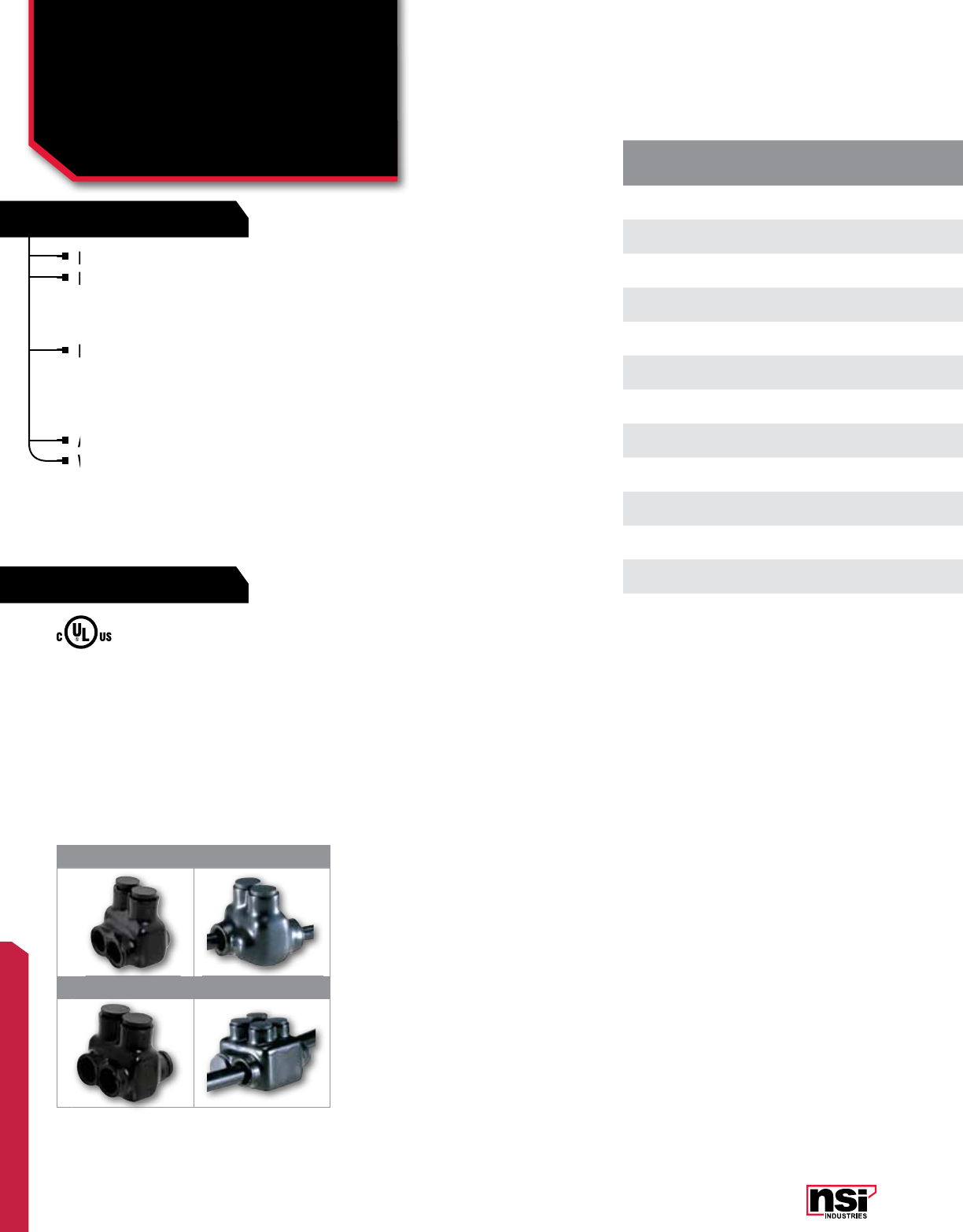
177
POLARIS™
FEATURES
RATINGS
* IT-600 is AL7CU and 75C
** IT-750 is not UL listed.
Insul-Tap connectors, suitable for connecting two wires.
For sizes 3/0 AWG and smaller, available in two styles
– with wires being connected from the same side
of the connector (Figure 1) or opposite sides of the
connector (Figure 2).
For sizes 250 MCM and larger, provided with open
wire entry ports on both sides of the connector (Figure
3), which allows for access from either side. This style
is supplied with removable access plugs to close the
entry port not being utilized.
Abrasion and chemical resistant. UV resistant.
Will not support combustion.
UL Listed 486B Wire Connector.
TEMPERATURE RATING/VOLTAGE:
AL9CU. Cold temperature rated to -45˚C,
rated 600V, 90˚C.
WIRE TYPE:
Dual rated for use with copper and/or aluminum cables.
Not recommended for fine-stranded, flexible wire (see
Polaris Grey™ Series page 171).
Insul-Tap connectors, suitable for connecting two wires.
For sizes 3/0 AWG and smaller, available in two styles
– with wires being
For sizes 3/0 AWG and smaller, available in two styles
– with wires being
For sizes 3/0 AWG and smaller, available in two styles
For sizes 3/0 AWG and smaller, available in two styles
For sizes 250 MCM and larger, provided with open
wire entry ports on both sides of the connector (Figure
For sizes 250 MCM and larger, provided with open
wire entry ports on both sides of the connector (Figure
For sizes 250 MCM and larger, provided with open
Abrasion and chemical resistant. UV resistant.
Will not support combustion.
Will not support combustion.
CAT.
NO. FIG.
NO. WIRE RANGE NO. OF
PORTS LENGTH
(L) WIDTH
(W) HEIGHT
(H)
TORQUE
VALUE
(IN./LBS.)
HEX/WRENCH
SIZE
STD.
CTN.
QTY.
IT-4 14-14 AWG 2 1.120 1.180 1.380 35 Slotted 12
ITO-4 24-14 AWG 2 1.120 1.250 1.380 35 Slotted 12
IT-4A 14-14 AWG 2 1.120 1.180 1.380 35 Slotted 12
IT-1/0 11/0-14 AWG 2 1.620 1.620 1.750 180 3/16 6
ITO-1/0 21/0-14 AWG 2 1.620 1.750 1.750 180 3/16 6
IT-3/0 13/0-6 AWG 2 1.840 1.750 1.870 250 1/4 6
ITO-3/0 23/0-6 AWG 2 1.840 1.870 1.870 250 1/4 6
IT-250 3250 MCM-6 AWG 2 2.120 2.250 2.250 360 5/16 6
IT-350 3350 MCM-6 AWG 2 2.470 2.500 2.440 400 5/16 4
IT-500 3500 MCM-4 AWG 2 2.810 2.870 2.940 450 5/16 4
IT-600* 3600 MCM-6 AWG 2 2.340 2.940 3.050 550 5/16 4
IT-750** 3750-250 MCM 2 3.480 3.500 3.500 550 3/8 2
ITH-750 4750-250 MCM 2 3.480 4.500 3.500 550 5/16 2
1 2
3 4
POLARIS™ INSULATED CONNECTORS
Dual Rated Two-Wire
IT, ITO, ITH SERIES
All dimensional data is listed in inches.
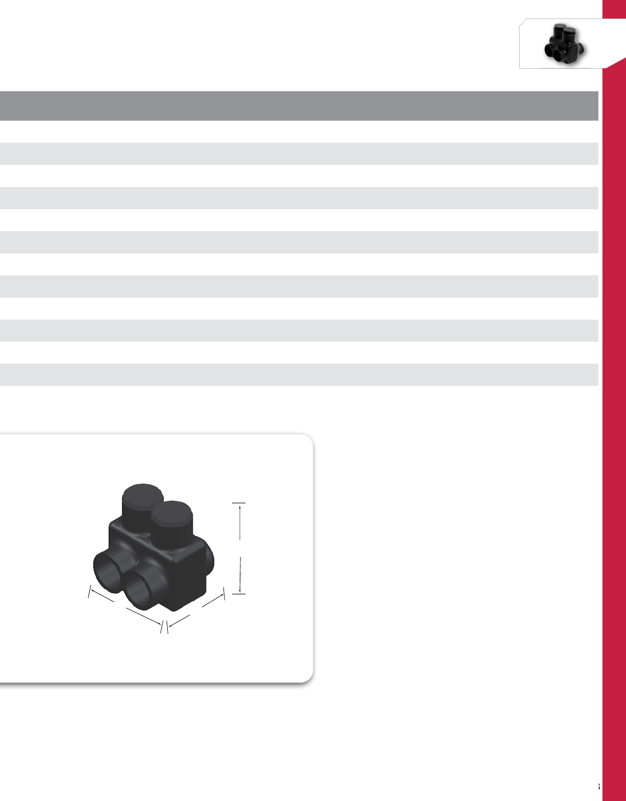
178
NSi Industries LLC • USA • 800.321.5847 • www.nsiindustries.com
178
POLARIS™
W
L
H
CAT.
NO. FIG.
NO. WIRE RANGE NO. OF
PORTS LENGTH
(L) WIDTH
(W) HEIGHT
(H)
TORQUE
VALUE
(IN./LBS.)
HEX/WRENCH
SIZE
STD.
CTN.
QTY.
IT-4 14-14 AWG 2 1.120 1.180 1.380 35 Slotted 12
ITO-4 24-14 AWG 2 1.120 1.250 1.380 35 Slotted 12
IT-4A 14-14 AWG 2 1.120 1.180 1.380 35 Slotted 12
IT-1/0 11/0-14 AWG 2 1.620 1.620 1.750 180 3/16 6
ITO-1/0 21/0-14 AWG 2 1.620 1.750 1.750 180 3/16 6
IT-3/0 13/0-6 AWG 2 1.840 1.750 1.870 250 1/4 6
ITO-3/0 23/0-6 AWG 2 1.840 1.870 1.870 250 1/4 6
IT-250 3250 MCM-6 AWG 2 2.120 2.250 2.250 360 5/16 6
IT-350 3350 MCM-6 AWG 2 2.470 2.500 2.440 400 5/16 4
IT-500 3500 MCM-4 AWG 2 2.810 2.870 2.940 450 5/16 4
IT-600* 3600 MCM-6 AWG 2 2.340 2.940 3.050 550 5/16 4
IT-750** 3750-250 MCM 2 3.480 3.500 3.500 550 3/8 2
ITH-750 4750-250 MCM 2 3.480 4.500 3.500 550 5/16 2
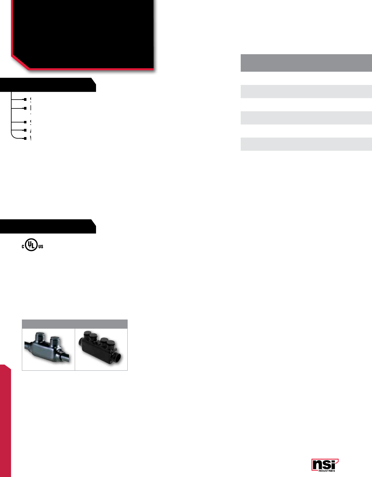
179
POLARIS™
FEATURES
RATINGS
Suitable for connecting two wires in-line.
Insulated with high dielectric strength plastisol and
molded for precise fit.
Supplied with removable access plugs over the hex screw.
Abrasion and chemical resistant. UV resistant.
Will not support combustion.
CAT.
NO. FIG.
NO. WIRE
RANGE NO. OF
PORTS LENGTH
(L) WIDTH
(W) HEIGHT
(H)
TORQUE
VALUE
(IN./LBS.)
HEX/WRENCH
SIZE
STD.
CTN.
QTY.
ISR-1/0 11/0-14 AWG 2 3.250 0.900 1.480 180 3/16 4
ISR-250 1250 MCM-6 AWG 2 4.000 1.190 1.900 360 5/16 4
ISR-350 1350 MCM-6 AWG 2 4.470 1.320 2.200 400 5/16 2
ISR-500 1500 MCM-4 AWG 2 4.620 1.620 3.000 450 5/16 2
ISR-600* 1600 MCM-6 AWG 2 5.830 1.570 3.050 550 5/16 2
ISRH-750 2750-250 MCM 2 7.250 1.750 3.250 550 5/16 2
UL Listed 486B Wire Connector.
TEMPERATURE RATING/VOLTAGE:
Cold temperature rated to -45˚C, rated 600V, 90˚C.
WIRE TYPE:
Dual rated for use with copper and/or aluminum cables.
Not recommended for use with extra-flexible cables (see
Polaris Grey™ Series page 171).
Suitable for connecting two wires in-line.
Insulated with high dielectric strength plastisol and
Insulated with high dielectric strength plastisol and
molded for precise fit.
Insulated with high dielectric strength plastisol and
molded for precise fit.
Insulated with high dielectric strength plastisol and
Insulated with high dielectric strength plastisol and
Supplied with removable access plugs over the hex screw.
Abrasion and chemical resistant. UV resistant.
Abrasion and chemical resistant. UV resistant.
Will not
Will not
*600 Series are AL7CU and 75˚C
1 2
POLARIS™ INSULATED CONNECTORS
Dual Rated
Splicer/Reducers
ISR SERIES All dimensional data is listed in inches.
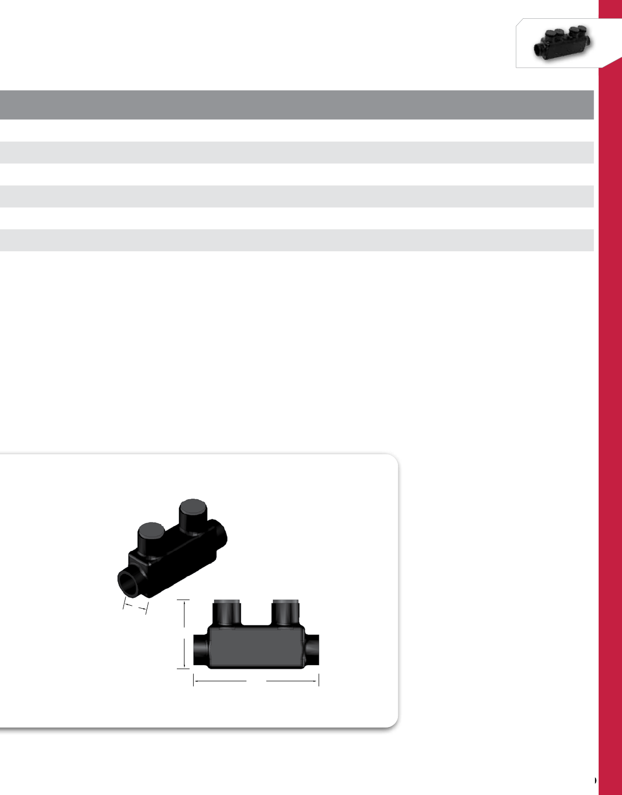
180
NSi Industries LLC • USA • 800.321.5847 • www.nsiindustries.com
180
POLARIS™
CAT.
NO. FIG.
NO. WIRE
RANGE NO. OF
PORTS LENGTH
(L) WIDTH
(W) HEIGHT
(H)
TORQUE
VALUE
(IN./LBS.)
HEX/WRENCH
SIZE
STD.
CTN.
QTY.
ISR-1/0 11/0-14 AWG 2 3.250 0.900 1.480 180 3/16 4
ISR-250 1250 MCM-6 AWG 2 4.000 1.190 1.900 360 5/16 4
ISR-350 1350 MCM-6 AWG 2 4.470 1.320 2.200 400 5/16 2
ISR-500 1500 MCM-4 AWG 2 4.620 1.620 3.000 450 5/16 2
ISR-600* 1600 MCM-6 AWG 2 5.830 1.570 3.050 550 5/16 2
ISRH-750 2750-250 MCM 2 7.250 1.750 3.250 550 5/16 2
L
H
W
L
H
W

181
POLARIS™
FEATURES
RATINGS
Wire entry ports on one side only.
Eliminates the need for cover and taping.
Insulated with high-dielectric strength plastisol.
Molded for precise fit and supplied with removable
access plugs over the hex screws.
Abrasion and chemical resistant. UV resistant.
Will not support combustion.
CAT.
NO. NO. OF
PORTS WIRE
RANGE LENGTH
(L) WIDTH
(W) HEIGHT
(H)
TORQUE
VALUE
(IN./LBS.)
HEX/WRENCH
SIZE
STD.
CTN.
QTY.
IPL4-3 34-14 AWG 1.550 1.188 1.375 45 Slotted 12
IPL4-3A 34-14 AWG 1.550 1.188 1.375 45 Allan 12
IPL4-4 44-14 AWG 1.970 1.188 1.375 45 Slotted 6
IPL4-4A 44-14 AWG 1.970 1.188 1.375 45 Allan 6
IPL4-5 54-14 AWG 2.390 1.188 1.375 45 Slotted 6
IPL4-6 64-14 AWG 2.810 1.188 1.375 45 Slotted 6
IPL4-8 84-14 AWG 3.660 1.188 1.375 45 Slotted 4
IPL4-8A 84-14 AWG 3.660 1.188 1.375 45 Slotted 4
IPL4-10 10 4-14 AWG 4.500 1.188 1.375 45 Slotted 4
IPL4-12 12 4-14 AWG 5.100 1.188 1.375 45 Slotted 2
IPL4-14 14 4-14 AWG 6.180 1.188 1.375 180 3/16 12
IPL1/0-3 31/0-14 AWG 2.240 1.500 1.688 180 3/16 6
IPL1/0-4 41/0-14 AWG 2.890 1.500 1.688 180 3/16 6
IPL1/0-5 51/0-14 AWG 3.540 1.500 1.688 180 3/16 6
IPL1/0-6 61/0-14 AWG 4.190 1.500 1.688 180 3/16 4
IPL1/0-8 81/0-14 AWG 5.490 1.500 1.688 180 3/16 4
IPL1/0-10 10 1/0-14 AWG 6.820 1.500 1.688 180 3/16 3
IPL1/0-12 12 1/0-14 AWG 8.120 1.500 1.688 180 3/16 2
IPL1/0-14 14 1/0-14 AWG 9.420 1.500 1.688 250 5/16 6
IPL3/0-3 33/0-6 AWG 2.630 1.600 1.800 250 5/16 6
IPL3/0-4 43/0-6 AWG 3.410 1.600 1.800 250 5/16 4
IPL3/0-5 53/0-6 AWG 4.190 1.600 1.800 250 5/16 4
IPL3/0-6 63/0-6 AWG 4.970 1.600 1.800 250 5/16 3
IPL3/0-8 83/0-6 AWG 6.530 1.600 1.800 250 5/16 3
UL Listed 486B Wire Connector.
TEMPERATURE RATING/VOLTAGE:
AL9CU. Cold temperature rated to -45˚C,
rated 600V, 90˚C.
WIRE TYPE:
Dual rated for use with copper and/or
aluminum cables. Not recommended for
fine-stranded, flexible wire.
Wire entry ports on one side only.
Eliminates the need for cover and taping.
Eliminates the need for cover and taping.
Insulated with high-dielectric strength plastisol.
Insulated with high-dielectric strength plastisol.
Molded for precise fit and supplied with removable
access plugs over the hex screws.
Molded for precise fit and supplied with removable
access plugs over the hex screws.
Molded for precise fit and supplied with removable
Molded for precise fit and supplied with removable
Abrasion and chemical resistant. UV resistant.
Will not support combustion.
Will not support combustion.
POLARIS™ INSULATED CONNECTORS
Multi-Conductor Connector
One Side Wire Entry
IPL SERIES All dimensional data is listed in inches.
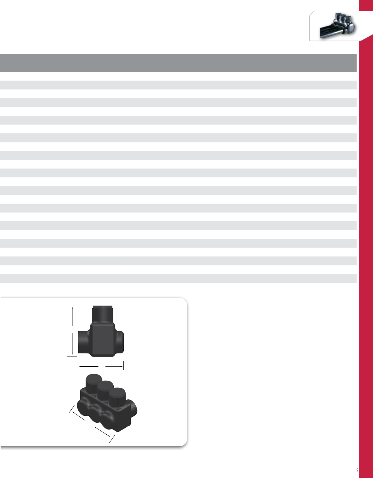
182
NSi Industries LLC • USA • 800.321.5847 • www.nsiindustries.com
182
POLARIS™
CAT.
NO. NO. OF
PORTS WIRE
RANGE LENGTH
(L) WIDTH
(W) HEIGHT
(H)
TORQUE
VALUE
(IN./LBS.)
HEX/WRENCH
SIZE
STD.
CTN.
QTY.
IPL4-3 34-14 AWG 1.550 1.188 1.375 45 Slotted 12
IPL4-3A 34-14 AWG 1.550 1.188 1.375 45 Allan 12
IPL4-4 44-14 AWG 1.970 1.188 1.375 45 Slotted 6
IPL4-4A 44-14 AWG 1.970 1.188 1.375 45 Allan 6
IPL4-5 54-14 AWG 2.390 1.188 1.375 45 Slotted 6
IPL4-6 64-14 AWG 2.810 1.188 1.375 45 Slotted 6
IPL4-8 84-14 AWG 3.660 1.188 1.375 45 Slotted 4
IPL4-8A 84-14 AWG 3.660 1.188 1.375 45 Slotted 4
IPL4-10 10 4-14 AWG 4.500 1.188 1.375 45 Slotted 4
IPL4-12 12 4-14 AWG 5.100 1.188 1.375 45 Slotted 2
IPL4-14 14 4-14 AWG 6.180 1.188 1.375 180 3/16 12
IPL1/0-3 31/0-14 AWG 2.240 1.500 1.688 180 3/16 6
IPL1/0-4 41/0-14 AWG 2.890 1.500 1.688 180 3/16 6
IPL1/0-5 51/0-14 AWG 3.540 1.500 1.688 180 3/16 6
IPL1/0-6 61/0-14 AWG 4.190 1.500 1.688 180 3/16 4
IPL1/0-8 81/0-14 AWG 5.490 1.500 1.688 180 3/16 4
IPL1/0-10 10 1/0-14 AWG 6.820 1.500 1.688 180 3/16 3
IPL1/0-12 12 1/0-14 AWG 8.120 1.500 1.688 180 3/16 2
IPL1/0-14 14 1/0-14 AWG 9.420 1.500 1.688 250 5/16 6
IPL3/0-3 33/0-6 AWG 2.630 1.600 1.800 250 5/16 6
IPL3/0-4 43/0-6 AWG 3.410 1.600 1.800 250 5/16 4
IPL3/0-5 53/0-6 AWG 4.190 1.600 1.800 250 5/16 4
IPL3/0-6 63/0-6 AWG 4.970 1.600 1.800 250 5/16 3
IPL3/0-8 83/0-6 AWG 6.530 1.600 1.800 250 5/16 3
L
W
H
L
W
H
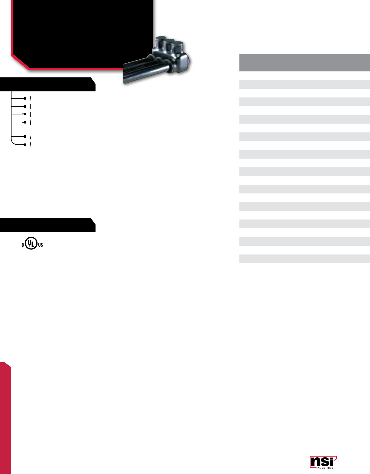
183
POLARIS™
FEATURES
RATINGS
CAT.
NO. NO. OF
PORTS WIRE
RANGE LENGTH
(L) WIDTH
(W) HEIGHT
(H)
TORQUE
VALUE
(IN./LBS.)
HEX/WRENCH
SIZE
STD.
CTN.
QTY.
IPL250-3 3250 MCM-6 AWG 2.930 2.030 2.180 360 5/16 6
IPL250-4 4250 MCM-6 AWG 3.800 2.030 2.180 360 5/16 4
IPL250-5 5250 MCM-6 AWG 4.660 2.030 2.180 360 5/16 4
IPL250-6 6250 MCM-6 AWG 5.220 2.030 2.180 360 5/16 3
IPL250-8 8250 MCM-6 AWG 7.240 2.030 2.180 400 5/16 4
IPL350-3 3350 MCM-6 AWG 3.470 2.130 2.460 400 5/16 3
IPL350-4 4350 MCM-6 AWG 4.540 2.130 2.460 400 5/16 3
IPL350-5 5350 MCM-6 AWG 5.570 2.130 2.460 400 5/16 2
IPL350-6 6350 MCM-6 AWG 6.620 2.130 2.460 400 5/16 2
IPL350-8 8350 MCM-6 AWG 8.720 2.130 2.460 450 5/16 3
IPL500-3 3500 MCM-4 AWG 3.960 2.500 2.940 450 5/16 3
IPL500-4 4500 MCM-4 AWG 5.110 2.500 2.940 450 5/16 2
IPL500-5 5500 MCM-4 AWG 6.250 2.500 2.940 450 5/16 2
IPL500-6 6500 MCM-4 AWG 7.400 2.500 2.940 450 5/16 2
IPL500-7 7500 MCM-4 AWG 8.590 2.500 2.940 450 5/16 2
IPL500-8 8500 MCM-4 AWG 9.690 2.500 2.940 550 5/16 3
IPL600-3* 3600 MCM-6 AWG 4.470 2.710 3.020 550 5/16 2
IPL600-4* 4600 MCM-6 AWG 5.770 2.710 3.020 550 5/16 2
IPL600-6* 6600 MCM-6 AWG 8.370 2.710 3.020 550 3/8 3
IPL750-3** 3750-250 MCM 4.950 3.090 3.490 550 3/8 2
IPL750-4** 4750-250 MCM 6.380 3.090 3.490 550 3/8 1
IPL750-5** 5750-250 MCM 7.800 3.090 3.490 550 3/8 1
IPL750-6** 6750-250 MCM 9.230 3.090 3.490 550 3/8 1
UL Listed 486B Wire Connector.
TEMPERATURE RATING/VOLTAGE:
AL9CU. Cold temperature rated to -45˚C,
rated 600V, 90˚C.
WIRE TYPE:
Dual rated for use with copper and/or
aluminum cables. Not recommended for
fine-stranded, flexible wire.
*AL7CU rated.
**Not UL listed.
POLARIS™ INSULATED CONNECTORS
Multi-Conductor Connector
One Side Wire Entry
IPL SERIES CONT'D All dimensional data is listed in inches.
Wire entry ports on one side only.
Eliminates the need for cover and taping.
Insulated with high-dielectric strength plastisol.
Molded for precise fit and supplied with removable
access plugs over the hex screws.
Abrasion and chemical resistant. UV resistant.
Will not support combustion.
Wire entry ports on one side only.
Eliminates the need for cover and taping.
Eliminates the need for cover and taping.
Insulated with high-dielectric strength plastisol.
Insulated with high-dielectric strength plastisol.
Molded for precise fit and supplied with removable
access plugs over the hex screws.
Molded for precise fit and supplied with removable
access plugs over the hex screws.
Molded for precise fit and supplied with removable
Molded for precise fit and supplied with removable
Abrasion and chemical resistant. UV resistant.
Will not support combustion.
Will not support combustion.

184
NSi Industries LLC • USA • 800.321.5847 • www.nsiindustries.com
184
POLARIS™
CAT.
NO. NO. OF
PORTS WIRE
RANGE LENGTH
(L) WIDTH
(W) HEIGHT
(H)
TORQUE
VALUE
(IN./LBS.)
HEX/WRENCH
SIZE
STD.
CTN.
QTY.
IPL250-3 3250 MCM-6 AWG 2.930 2.030 2.180 360 5/16 6
IPL250-4 4250 MCM-6 AWG 3.800 2.030 2.180 360 5/16 4
IPL250-5 5250 MCM-6 AWG 4.660 2.030 2.180 360 5/16 4
IPL250-6 6250 MCM-6 AWG 5.220 2.030 2.180 360 5/16 3
IPL250-8 8250 MCM-6 AWG 7.240 2.030 2.180 400 5/16 4
IPL350-3 3350 MCM-6 AWG 3.470 2.130 2.460 400 5/16 3
IPL350-4 4350 MCM-6 AWG 4.540 2.130 2.460 400 5/16 3
IPL350-5 5350 MCM-6 AWG 5.570 2.130 2.460 400 5/16 2
IPL350-6 6350 MCM-6 AWG 6.620 2.130 2.460 400 5/16 2
IPL350-8 8350 MCM-6 AWG 8.720 2.130 2.460 450 5/16 3
IPL500-3 3500 MCM-4 AWG 3.960 2.500 2.940 450 5/16 3
IPL500-4 4500 MCM-4 AWG 5.110 2.500 2.940 450 5/16 2
IPL500-5 5500 MCM-4 AWG 6.250 2.500 2.940 450 5/16 2
IPL500-6 6500 MCM-4 AWG 7.400 2.500 2.940 450 5/16 2
IPL500-7 7500 MCM-4 AWG 8.590 2.500 2.940 450 5/16 2
IPL500-8 8500 MCM-4 AWG 9.690 2.500 2.940 550 5/16 3
IPL600-3* 3600 MCM-6 AWG 4.470 2.710 3.020 550 5/16 2
IPL600-4* 4600 MCM-6 AWG 5.770 2.710 3.020 550 5/16 2
IPL600-6* 6600 MCM-6 AWG 8.370 2.710 3.020 550 3/8 3
IPL750-3** 3750-250 MCM 4.950 3.090 3.490 550 3/8 2
IPL750-4** 4750-250 MCM 6.380 3.090 3.490 550 3/8 1
IPL750-5** 5750-250 MCM 7.800 3.090 3.490 550 3/8 1
IPL750-6** 6750-250 MCM 9.230 3.090 3.490 550 3/8 1
L
W
H
L
W
H
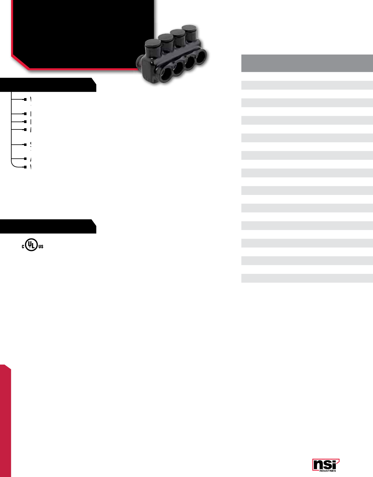
185
POLARIS™
FEATURES
RATINGS
Wire entry ports on both sides of the connector
allow for access from either side.
Eliminates the need for cover and taping.
Insulated with high-dielectric strength plastisol.
Molded for precise fit and supplied with removable
access plugs over the hex screws.
Supplied with removable plugs to close the entry port
not being utilized.
Abrasion and chemical resistant. UV resistant.
Will not support combustion.
CAT.
NO. NO. OF
PORTS WIRE
RANGE LENGTH
(L) WIDTH
(W) HEIGHT
(H)
TORQUE
VALUE
(IN./LBS.)
HEX/WRENCH
SIZE
STD.
CTN.
QTY.
IPLD3/0-3 33/0-6 AWG 2.630 1.830 1.790 250 1/4 6
IPLD3/0-4 43/0-6 AWG 3.410 1.830 1.790 250 1/4 6
IPLD3/0-5 53/0-6 AWG 4.190 1.830 1.790 250 1/4 4
IPLD3/0-6 63/0-6 AWG 4.970 1.830 1.790 250 1/4 4
IPLD3/0-7 73/0-6 AWG 5.750 1.830 1.790 250 1/4 3
IPLD3/0-8 83/0-6 AWG 6.530 1.830 1.790 250 1/4 3
IPLD3/0-10 10 3/0-6 AWG 8.090 1.830 1.790 250 1/4 2
IPLD3/0-12 12 3/0-6 AWG 11.210 1.830 1.790 250 1/4 2
IPLD250-3 3250 MCM-6 AWG 2.930 2.280 2.180 360 5/16 6
IPLD250-4 4250 MCM-6 AWG 3.800 2.280 2.180 360 5/16 6
IPLD250-5 5250 MCM-6 AWG 4.660 2.280 2.180 360 5/16 4
IPLD250-6 6250 MCM-6 AWG 5.520 2.280 2.180 360 5/16 4
IPLD250-7 7250 MCM-6 AWG 6.380 2.280 2.180 360 5/16 3
IPLD250-8 8250 MCM-6 AWG 7.240 2.280 2.180 360 5/16 3
IPLD250-10 10 250 MCM-6 AWG 8.970 2.280 2.180 360 5/16 2
IPLD250-12 12 250 MCM-6 AWG 10.740 2.280 2.180 360 5/16 2
IPLD350-3 3350 MCM-6 AWG 3.520 2.410 2.610 400 5/16 3
IPLD350-4 4350 MCM-6 AWG 4.570 2.410 2.610 400 5/16 3
IPLD350-5 5350 MCM-6 AWG 5.620 2.410 2.610 400 5/16 3
IPLD350-6 6350 MCM-6 AWG 6.670 2.410 2.610 400 5/16 3
IPLD350-7 7350 MCM-6 AWG 7.720 2.410 2.610 400 5/16 2
IPLD350-8 8350 MCM-6 AWG 8.770 2.410 2.610 400 5/16 2
IPLD350-9 9350 MCM-6 AWG 9.820 2.410 2.610 400 5/16 2
IPLD350-10 10 350 MCM-6 AWG 10.870 2.410 2.610 400 5/16 2
IPLD350-12 12 350 MCM-6 AWG 12.970 2.410 2.610 400 5/16 1
UL Listed 486B Wire Connector.
TEMPERATURE RATING/VOLTAGE:
AL9CU. Cold temperature rated to -45˚C,
rated 600V, 90˚C.
WIRE TYPE:
Dual rated for use with copper and/or
aluminum cables. Not recommended for
fine-stranded, flexible wire.
Wire entry ports on both sides of the connector
allow for access from either side.
Wire entry ports on both sides of the connector
allow for access from either side.
Wire entry ports on both sides of the connector
Insulated with high-dielectric strength plastisol.
Eliminates the need for cover and taping.
Insulated with high-dielectric strength plastisol.
Molded for precise fit and supplied with removable
access plugs over the hex screws.
Molded for precise fit and supplied with removable
access plugs over the hex screws.
Molded for precise fit and supplied with removable
Molded for precise fit and supplied with removable
Supplied with removable plugs to close the entry port
not being utilized.
Supplied with removable plugs to close the entry port
not being utilized.
Supplied with removable plugs to close the entry port
Abrasion and chemical resistant. UV resistant.
Will not support combustion.
Will not support combustion.
POLARIS™ INSULATED CONNECTORS
Multi-Conductor Connector
Either Side Wire Entry
IPLD SERIES All dimensional data is listed in inches.
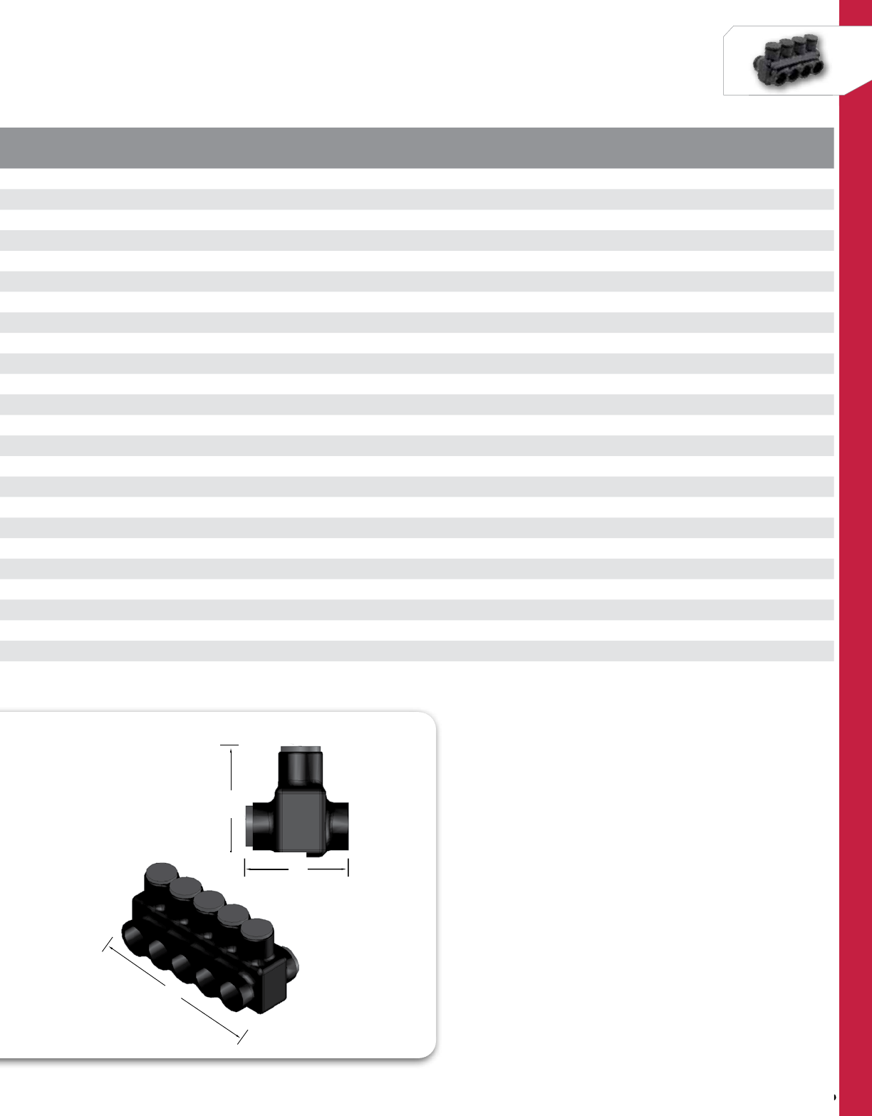
186
NSi Industries LLC • USA • 800.321.5847 • www.nsiindustries.com
186
POLARIS™
CAT.
NO. NO. OF
PORTS WIRE
RANGE LENGTH
(L) WIDTH
(W) HEIGHT
(H)
TORQUE
VALUE
(IN./LBS.)
HEX/WRENCH
SIZE
STD.
CTN.
QTY.
IPLD3/0-3 33/0-6 AWG 2.630 1.830 1.790 250 1/4 6
IPLD3/0-4 43/0-6 AWG 3.410 1.830 1.790 250 1/4 6
IPLD3/0-5 53/0-6 AWG 4.190 1.830 1.790 250 1/4 4
IPLD3/0-6 63/0-6 AWG 4.970 1.830 1.790 250 1/4 4
IPLD3/0-7 73/0-6 AWG 5.750 1.830 1.790 250 1/4 3
IPLD3/0-8 83/0-6 AWG 6.530 1.830 1.790 250 1/4 3
IPLD3/0-10 10 3/0-6 AWG 8.090 1.830 1.790 250 1/4 2
IPLD3/0-12 12 3/0-6 AWG 11.210 1.830 1.790 250 1/4 2
IPLD250-3 3250 MCM-6 AWG 2.930 2.280 2.180 360 5/16 6
IPLD250-4 4250 MCM-6 AWG 3.800 2.280 2.180 360 5/16 6
IPLD250-5 5250 MCM-6 AWG 4.660 2.280 2.180 360 5/16 4
IPLD250-6 6250 MCM-6 AWG 5.520 2.280 2.180 360 5/16 4
IPLD250-7 7250 MCM-6 AWG 6.380 2.280 2.180 360 5/16 3
IPLD250-8 8250 MCM-6 AWG 7.240 2.280 2.180 360 5/16 3
IPLD250-10 10 250 MCM-6 AWG 8.970 2.280 2.180 360 5/16 2
IPLD250-12 12 250 MCM-6 AWG 10.740 2.280 2.180 360 5/16 2
IPLD350-3 3350 MCM-6 AWG 3.520 2.410 2.610 400 5/16 3
IPLD350-4 4350 MCM-6 AWG 4.570 2.410 2.610 400 5/16 3
IPLD350-5 5350 MCM-6 AWG 5.620 2.410 2.610 400 5/16 3
IPLD350-6 6350 MCM-6 AWG 6.670 2.410 2.610 400 5/16 3
IPLD350-7 7350 MCM-6 AWG 7.720 2.410 2.610 400 5/16 2
IPLD350-8 8350 MCM-6 AWG 8.770 2.410 2.610 400 5/16 2
IPLD350-9 9350 MCM-6 AWG 9.820 2.410 2.610 400 5/16 2
IPLD350-10 10 350 MCM-6 AWG 10.870 2.410 2.610 400 5/16 2
IPLD350-12 12 350 MCM-6 AWG 12.970 2.410 2.610 400 5/16 1
W
H
L
W
H
L
W

187
POLARIS™
FEATURES
RATINGS
CAT.
NO. NO. OF
PORTS WIRE
RANGE LENGTH
(L) WIDTH
(W) HEIGHT
(H)
TORQUE
VALUE
(IN./LBS.)
HEX/WRENCH
SIZE
STD.
CTN.
QTY.
IPLD500-3 3500 MCM-4 AWG 4.010 2.830 2.910 450 5/16 3
IPLD500-4 4500 MCM-4 AWG 5.240 2.830 2.910 450 5/16 3
IPLD500-5 5500 MCM-4 AWG 6.380 2.830 2.910 450 5/16 2
IPLD500-6 6500 MCM-4 AWG 7.520 2.830 2.910 450 5/16 2
IPLD500-7 7500 MCM-4 AWG 8.670 2.830 2.910 450 5/16 2
IPLD500-8 8500 MCM-4 AWG 9.820 2.830 2.910 450 5/16 2
IPLD500-9 9500 MCM-4 AWG 10.880 2.830 2.910 450 5/16 2
IPLD500-10 10 500 MCM-4 AWG 12.110 2.960 3.030 450 5/16 1
IPLD500-12 12 500 MCM-4 AWG 14.400 2.960 3.030 450 5/16 1
IPLD600-3†† 3600 MCM-6 AWG 4.550 2.960 3.030 450 5/16 3
IPLD600-4†† 4600 MCM-6 AWG 5.850 2.960 3.030 450 5/16 3
IPLD600-5†† 5600 MCM-6 AWG 7.150 2.960 3.030 450 5/16 2
IPLD600-6†† 6600 MCM-6 AWG 8.450 2.960 3.030 550 5/16 2
IPLD600-7†† 7600 MCM-6 AWG 9.750 2.960 3.030 550 5/16 2
IPLD600-8†† 8600 MCM-6 AWG 11.050 2.960 3.030 550 5/16 2
IPLD600-9†† 9600 MCM-6 AWG 12.390 2.960 3.030 550 5/16 1
IPLD600-10†† 10 600 MCM-6 AWG 13.650 3.410 3.420 550 5/16 1
IPLD600-12†† 12 600 MCM-6 AWG 16.250 3.410 3.420 550 5/16 1
IPLD750-3* 3750-250 MCM 4.950 3.410 3.420 550 3/8 3
IPLD750-4* 4750-250 MCM 6.380 3.410 3.420 550 3/8 2
IPLD750-5* 5750-250 MCM 7.800 3.410 3.420 550 3/8 1
IPLD750-6* 6750-250 MCM 9.230 3.410 3.420 550 3/8 1
IPLD750-7* 7750-250 MCM 10.650 3.410 3.420 550 3/8 1
IPLD750-8* 8750-250 MCM 12.080 3.410 3.420 550 3/8 1
IPLD750-9* 9750-250 MCM 13.690 3.410 3.420 550 3/8 1
IPLD750-10* 10 750-250 MCM 14.930 3.410 3.420 550 3/8 1
IPLD750-12* 12 750-250 MCM 17.780 3.410 3.420 550 3/8 1
†† AL7CU rated, 75˚C.
*Not UL listed.
Wire entry ports on both sides of the connector
allow for access from either side.
Eliminates the need for cover and taping.
Insulated with high-dielectric strength plastisol.
Molded for precise fit and supplied with removable
access plugs over the hex screws.
Supplied with removable plugs to close the entry port
not being utilized.
Abrasion and chemical resistant. UV resistant.
Will not support combustion.
UL Listed 486B Wire Connector.
TEMPERATURE RATING/VOLTAGE:
AL9CU. Cold temperature rated to -45˚C,
rated 600V, 90˚C.
WIRE TYPE:
Dual rated for use with copper and/or
aluminum cables. Not recommended for
fine-stranded, flexible wire.
Insulated with high-dielectric strength plastisol.
Molded for precise fit and supplied with removable
Eliminates the need for cover and taping.
Insulated with high-dielectric strength plastisol.
Insulated with high-dielectric strength plastisol.
Wire entry ports on both sides of the connector
allow for access from either side.
Wire entry ports on both sides of the connector
allow for access from either side.
Wire entry ports on both sides of the connector
Molded for precise fit and supplied with removable
access plugs over the hex screws.
Molded for precise fit and supplied with removable
access plugs over the hex screws.
Molded for precise fit and supplied with removable
Molded for precise fit and supplied with removable
Supplied with removable plugs to close the entry port
not being utilized.
Supplied with removable plugs to close the entry port
not being utilized.
Supplied with removable plugs to close the entry port
Abrasion and chemical resistant. UV resistant.
Will not support combustion.
Will not support combustion.
Will not support combustion.
POLARIS™ INSULATED CONNECTORS
Multi-Cable Blocks
Either Side Wire Entry
IPLD SERIES All dimensional data is listed in inches.
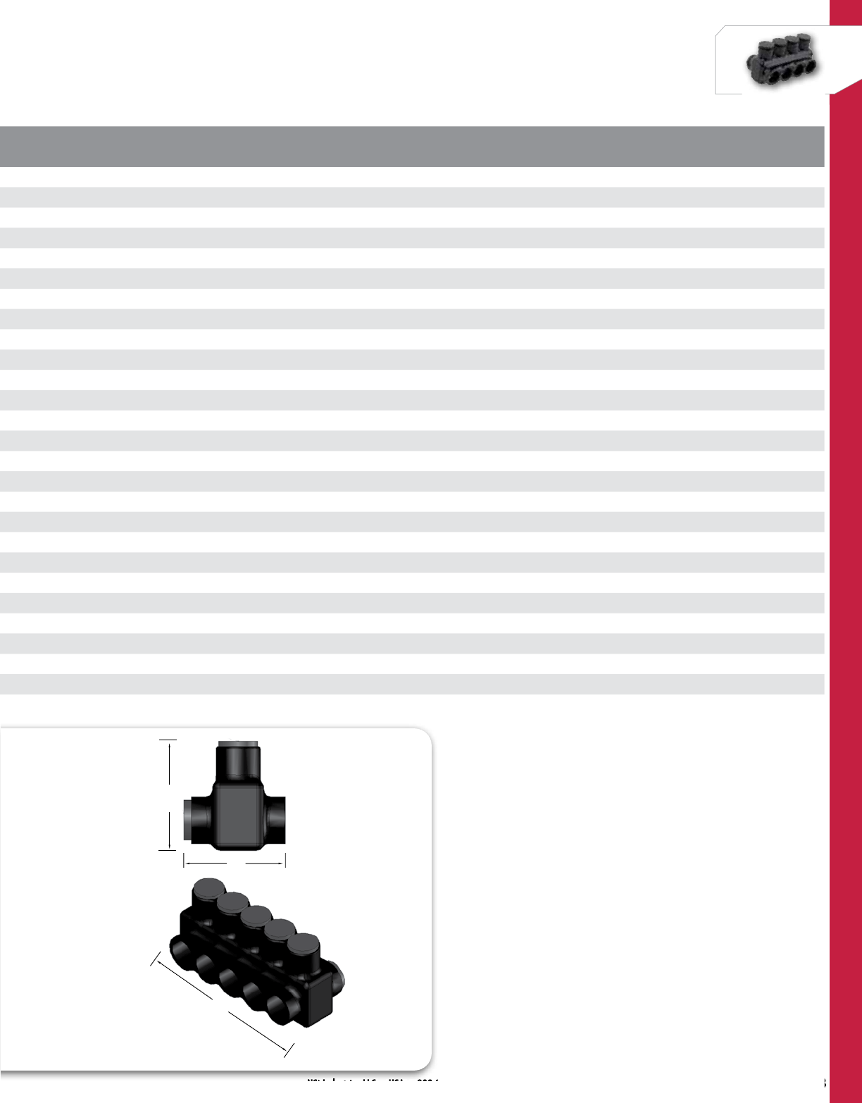
188
NSi Industries LLC • USA • 800.321.5847 • www.nsiindustries.com
188
POLARIS™
CAT.
NO. NO. OF
PORTS WIRE
RANGE LENGTH
(L) WIDTH
(W) HEIGHT
(H)
TORQUE
VALUE
(IN./LBS.)
HEX/WRENCH
SIZE
STD.
CTN.
QTY.
IPLD500-3 3500 MCM-4 AWG 4.010 2.830 2.910 450 5/16 3
IPLD500-4 4500 MCM-4 AWG 5.240 2.830 2.910 450 5/16 3
IPLD500-5 5500 MCM-4 AWG 6.380 2.830 2.910 450 5/16 2
IPLD500-6 6500 MCM-4 AWG 7.520 2.830 2.910 450 5/16 2
IPLD500-7 7500 MCM-4 AWG 8.670 2.830 2.910 450 5/16 2
IPLD500-8 8500 MCM-4 AWG 9.820 2.830 2.910 450 5/16 2
IPLD500-9 9500 MCM-4 AWG 10.880 2.830 2.910 450 5/16 2
IPLD500-10 10 500 MCM-4 AWG 12.110 2.960 3.030 450 5/16 1
IPLD500-12 12 500 MCM-4 AWG 14.400 2.960 3.030 450 5/16 1
IPLD600-3†† 3600 MCM-6 AWG 4.550 2.960 3.030 450 5/16 3
IPLD600-4†† 4600 MCM-6 AWG 5.850 2.960 3.030 450 5/16 3
IPLD600-5†† 5600 MCM-6 AWG 7.150 2.960 3.030 450 5/16 2
IPLD600-6†† 6600 MCM-6 AWG 8.450 2.960 3.030 550 5/16 2
IPLD600-7†† 7600 MCM-6 AWG 9.750 2.960 3.030 550 5/16 2
IPLD600-8†† 8600 MCM-6 AWG 11.050 2.960 3.030 550 5/16 2
IPLD600-9†† 9600 MCM-6 AWG 12.390 2.960 3.030 550 5/16 1
IPLD600-10†† 10 600 MCM-6 AWG 13.650 3.410 3.420 550 5/16 1
IPLD600-12†† 12 600 MCM-6 AWG 16.250 3.410 3.420 550 5/16 1
IPLD750-3* 3750-250 MCM 4.950 3.410 3.420 550 3/8 3
IPLD750-4* 4750-250 MCM 6.380 3.410 3.420 550 3/8 2
IPLD750-5* 5750-250 MCM 7.800 3.410 3.420 550 3/8 1
IPLD750-6* 6750-250 MCM 9.230 3.410 3.420 550 3/8 1
IPLD750-7* 7750-250 MCM 10.650 3.410 3.420 550 3/8 1
IPLD750-8* 8750-250 MCM 12.080 3.410 3.420 550 3/8 1
IPLD750-9* 9750-250 MCM 13.690 3.410 3.420 550 3/8 1
IPLD750-10* 10 750-250 MCM 14.930 3.410 3.420 550 3/8 1
IPLD750-12* 12 750-250 MCM 17.780 3.410 3.420 550 3/8 1
NSi Industries LLC
USA
• 800.321.5847
W
H
L
W
H
L
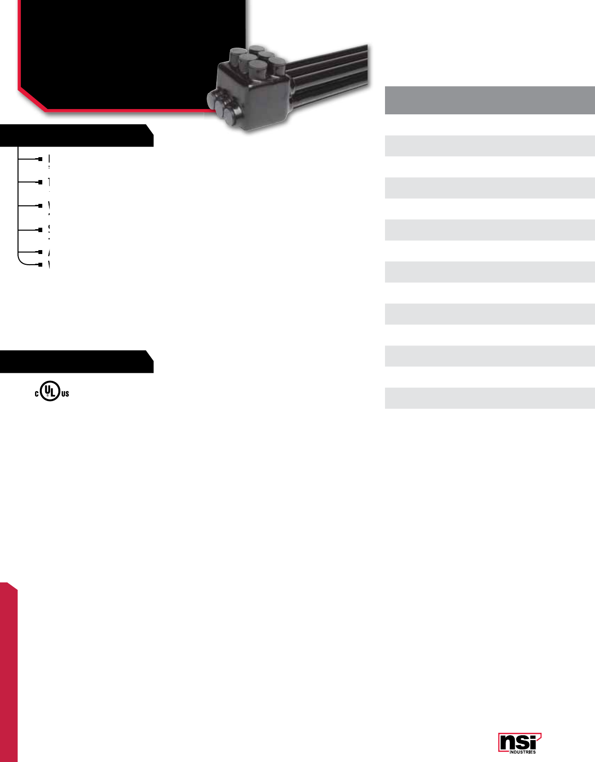
189
POLARIS™
FEATURES
RATINGS
CAT.
NO. NO. OF
PORTS WIRE
RANGE LENGTH
(L) WIDTH
(W) HEIGHT
(H)
TORQUE
VALUE
(IN./LBS.)
HEX
SIZE
STD.
CTN.
QTY.
IPLDS350-4 4350 MCM-6 AWG 2.550 3.910 3.520 400 5/16 1
IPLDS350-6 6350 MCM-6 AWG 3.600 3.910 3.520 400 5/16 1
IPLDS350-8 8350 MCM-6 AWG 4.650 3.910 3.520 400 5/16 1
IPLDS350-10 10 350 MCM-6 AWG 5.700 3.910 3.520 400 5/16 1
IPLDS350-12 12 350 MCM-6 AWG 6.750 3.910 3.520 400 5/16 1
IPLDS500-4 4500 MCM-4 AWG 2.940 4.710 4.280 450 5/16 1
IPLDS500-6 6500 MCM-4 AWG 4.080 4.710 4.280 450 5/16 1
IPLDS500-8 8500 MCM-4 AWG 5.230 4.710 4.280 450 5/16 1
IPLDS500-10 10 500 MCM-4 AWG 6.380 4.710 4.280 450 5/16 1
IPLDS500-12 12 500 MCM-4 AWG 7.520 4.710 4.280 450 5/16 1
IPLDS750-6 6750-250 MCM 4.950 4.970 4.920 550 3/8 1
IPLDS750-8 8750-250 MCM 6.380 4.970 4.920 550 3/8 1
IPLDS750-10 10 750-250 MCM 7.800 4.970 4.920 550 3/8 1
IPLDS750-12 12 750-250 MCM 9.230 4.970 4.920 550 3/8 1
Exceptional for use with large wire sizes, especially
in tight-fitting spaces, small wire ways and panels.
The wire holes on the bottom row allow for entry from
either side of the connector for even greater versatility.
Wire entry holes are stacked on top of each other for
the ultimate in compact design.
Supplied with removable plugs to close the entry port
not being utilized.
Abrasion and chemical resistant. UV resistant.
Will not support combustion.
UL Listed 486B Wire Connector.
TEMPERATURE RATING/VOLTAGE:
Cold temperature rated to -45˚C, rated 600V, 90˚C.
WIRE TYPE:
Dual rated for use with copper and/or aluminum
cables. Not recommended for fine-stranded,
flexible wire.
Exceptional for use with large wire sizes, especially
in tight-fitting spaces, small wire ways and panels.
Exceptional for use with large wire sizes, especially
in tight-fitting spaces, small wire ways and panels.
Exceptional for use with large wire sizes, especially
Wire entry holes are stacked on top of each other for
the ultimate in compact design.
Wire entry holes are stacked on top of each other for
the ultimate in compact design.
Wire entry holes are stacked on top of each other for
The wire holes on the
either side of the connector for even greater
Supplied with removable plugs to close the entry port
not being utilized.
Supplied with removable plugs to close the entry port
not being utilized.
Supplied with removable plugs to close the entry port
Abrasion and chemical resistant. UV resistant.
Will not support combustion.
Will not support combustion.
* 750 MCM not UL Listed.
POLARIS™ INSULATED CONNECTORS
Multi-Cable Stacked
Either Side Wire Entry
IPLDS SERIES All dimensional data is listed in inches.
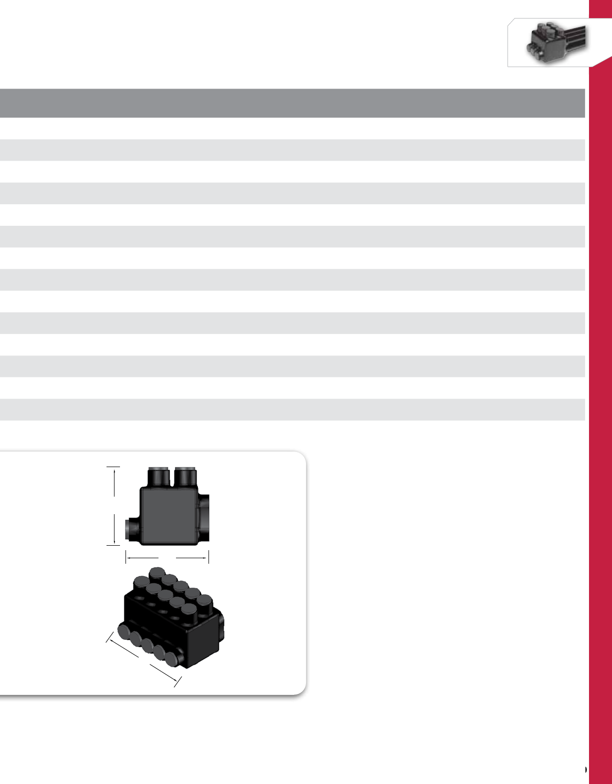
190
NSi Industries LLC • USA • 800.321.5847 • www.nsiindustries.com
190
POLARIS™
CAT.
NO. NO. OF
PORTS WIRE
RANGE LENGTH
(L) WIDTH
(W) HEIGHT
(H)
TORQUE
VALUE
(IN./LBS.)
HEX
SIZE
STD.
CTN.
QTY.
IPLDS350-4 4350 MCM-6 AWG 2.550 3.910 3.520 400 5/16 1
IPLDS350-6 6350 MCM-6 AWG 3.600 3.910 3.520 400 5/16 1
IPLDS350-8 8350 MCM-6 AWG 4.650 3.910 3.520 400 5/16 1
IPLDS350-10 10 350 MCM-6 AWG 5.700 3.910 3.520 400 5/16 1
IPLDS350-12 12 350 MCM-6 AWG 6.750 3.910 3.520 400 5/16 1
IPLDS500-4 4500 MCM-4 AWG 2.940 4.710 4.280 450 5/16 1
IPLDS500-6 6500 MCM-4 AWG 4.080 4.710 4.280 450 5/16 1
IPLDS500-8 8500 MCM-4 AWG 5.230 4.710 4.280 450 5/16 1
IPLDS500-10 10 500 MCM-4 AWG 6.380 4.710 4.280 450 5/16 1
IPLDS500-12 12 500 MCM-4 AWG 7.520 4.710 4.280 450 5/16 1
IPLDS750-6 6750-250 MCM 4.950 4.970 4.920 550 3/8 1
IPLDS750-8 8750-250 MCM 6.380 4.970 4.920 550 3/8 1
IPLDS750-10 10 750-250 MCM 7.800 4.970 4.920 550 3/8 1
IPLDS750-12 12 750-250 MCM 9.230 4.970 4.920 550 3/8 1
W
H
L
W
H
L

191
POLARIS™
FEATURES
RATINGS
Connector block is double the size of the standard IPLD
Series connector with two pressure screws provided for
each cable to ensure the best connection possible.
Designed, built and tested to handle even the most
demanding applications from 250 MCM to 750 MCM.
Insulated with high-dielectric strength plastisol molded
for a precise fit.
Supplied with removable access plugs to allow for cable
entry from either side of the connector.
Eliminates the need for cover and taping.
Abrasion and chemical resistant. UV resistant.
Will not support combustion.
CAT.
NO. NO. OF
PORTS WIRE
RANGE LENGTH
(L) WIDTH
(W) HEIGHT
(H)
TORQUE
VALUE
(IN./LBS.)
HEX/WRENCH
SIZE
STD.
CTN.
QTY.
IPLDH750-3 3750 - 250 MCM 4.950 4.460 3.300 550 5/16 2
IPLDH750-4 4750 - 250 MCM 6.380 4.460 3.300 550 5/16 2
IPLDH750-5 5750 - 250 MCM 7.800 4.460 3.300 550 5/16 1
IPLDH750-6 6750 - 250 MCM 9.230 4.460 3.300 550 5/16 1
IPLDH750-8 8750 - 250 MCM 12.080 4.460 3.300 550 5/16 1
IPLDH750-10 10 750 - 250 MCM 14.600 4.460 3.300 550 5/16 1
UL Listed 486B Wire Connector.
TEMPERATURE RATING/VOLTAGE:
AL9CU. Cold temperature rated to -45˚C,
rated 600V, 90˚C.
WIRE TYPE:
Dual rated for use with copper and/or
aluminum cables. Not recommended for
fine-stranded, flexible wire.
Connector block is double the size of the standard IPLD
Series connector with two pressure screws provided for
Insulated with high-dielectric strength plastisol molded
for a precise fit.
Insulated with high-dielectric strength plastisol molded
for a precise fit.
Insulated with high-dielectric strength plastisol molded
Designed, built and tested to handle even the most
demanding applications from 250 MCM to 750 MCM.
Designed, built and tested to handle even the most
demanding applications from 250 MCM to 750 MCM.
Designed, built and tested to handle even the most
Supplied with removable access plugs to allow for cable
entry from either side of the connector.
Supplied with removable access plugs to allow for cable
entry from either side of the connector.
Supplied with removable access plugs to allow for cable
Eliminates the need for cover and taping.
Abrasion and chemical resistant. UV resistant.
Will not support combustion.
Abrasion and chemical resistant. UV resistant.
Will not support combustion.
Will not support combustion.
POLARIS™ INSULATED CONNECTORS
Heavy Duty Connectors
Either Side Wire Entry
IPLDH SERIES All dimensional data is listed in inches.
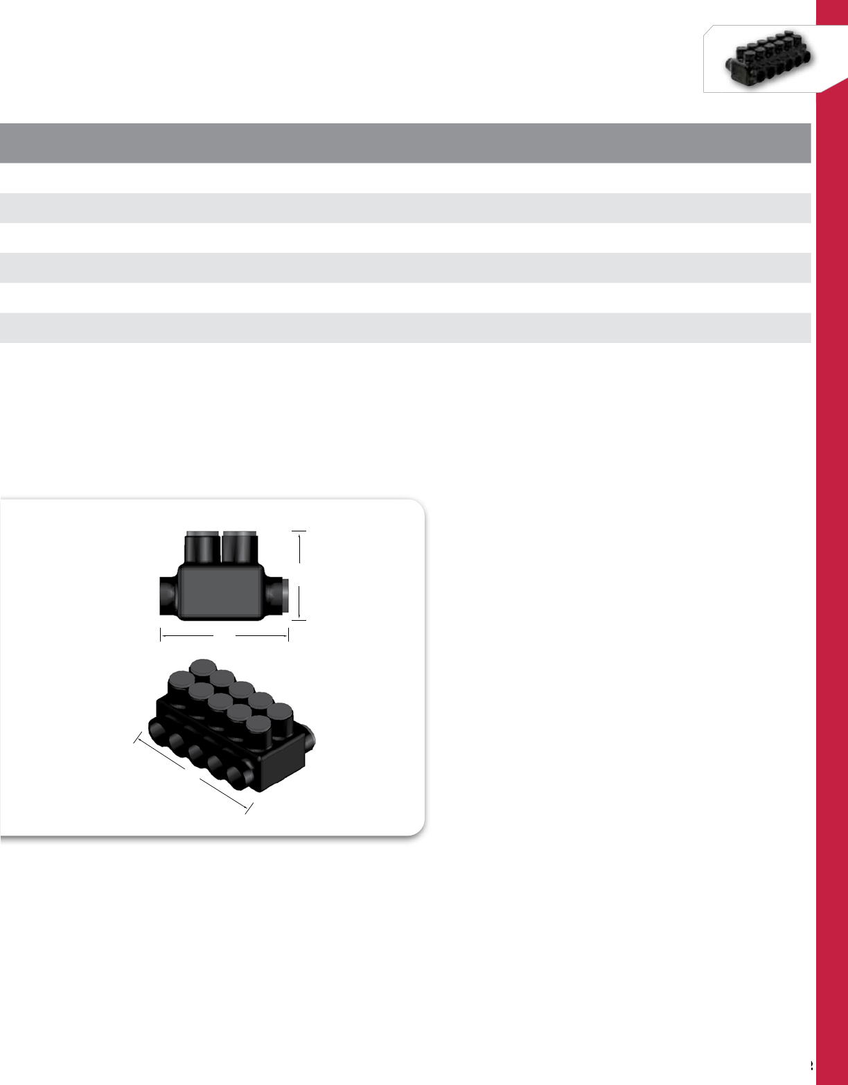
192
NSi Industries LLC • USA • 800.321.5847 • www.nsiindustries.com
192
POLARIS™
CAT.
NO. NO. OF
PORTS WIRE
RANGE LENGTH
(L) WIDTH
(W) HEIGHT
(H)
TORQUE
VALUE
(IN./LBS.)
HEX/WRENCH
SIZE
STD.
CTN.
QTY.
IPLDH750-3 3750 - 250 MCM 4.950 4.460 3.300 550 5/16 2
IPLDH750-4 4750 - 250 MCM 6.380 4.460 3.300 550 5/16 2
IPLDH750-5 5750 - 250 MCM 7.800 4.460 3.300 550 5/16 1
IPLDH750-6 6750 - 250 MCM 9.230 4.460 3.300 550 5/16 1
IPLDH750-8 8750 - 250 MCM 12.080 4.460 3.300 550 5/16 1
IPLDH750-10 10 750 - 250 MCM 14.600 4.460 3.300 550 5/16 1
W
H
L
W
H
L
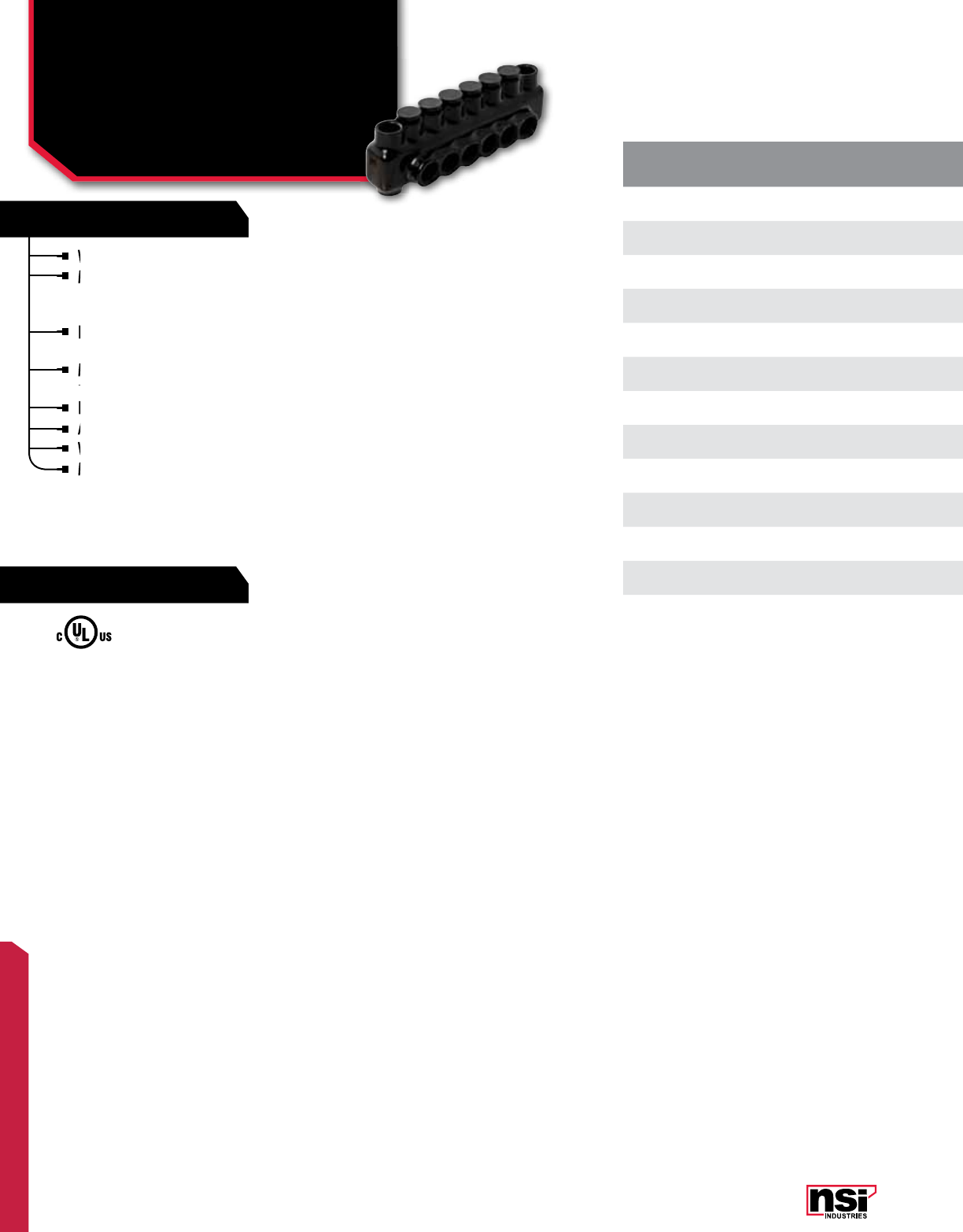
193
POLARIS™
FEATURES
RATINGS
CAT.
NO. NO. OF
PORTS WIRE
RANGE LENGTH
(L) WIDTH
(W) HEIGHT
(H)
TORQUE
VALUE
(IN./LBS.)
HEX
SIZE
STD.
CTN.
QTY.
IPLM4-3 34-14 AWG 2.750 1.240 1.390 45 Slotted 6
IPLM4-4 44-14 AWG 3.180 1.240 1.390 45 Slotted 6
IPLM4-5 54-14 AWG 3.600 1.240 1.390 45 Slotted 4
IPLM4-6 64-14 AWG 4.020 1.240 1.390 45 Slotted 4
IPLM4-7 74-14 AWG 4.190 1.240 1.390 45 Slotted 4
IPLM4-10 10 4-14 AWG 5.710 1.240 1.390 45 Slotted 3
IPLM1/0-3 31/0-14 AWG 3.460 1.550 1.820 180 3/16 6
IPLM1/0-4 41/0-14 AWG 4.110 1.550 1.820 180 3/16 6
IPLM1/0-5 51/0-14 AWG 4.760 1.550 1.820 180 3/16 4
IPLM1/0-6 61/0-14 AWG 5.410 1.550 1.820 180 3/16 4
IPLM1/0-8 81/0-14 AWG 6.710 1.550 1.820 180 3/16 4
IPLM1/0-9 91/0-14 AWG 7.520 1.550 1.820 180 3/16 3
IPLM1/0-10 10 1/0-14 AWG 8.010 1.550 1.820 180 3/16 3
Wire entry ports on one side only.
Mounting holes at each end of the connector
allow for direct isolated mounting to the trough,
panel or wireway.
IPLM Series connectors are insulated with high-
dielectric strength plastisol.
Molded for precise fit and supplied with
removable access plugs over the hex screws.
Eliminates the need for cover and taping.
Abrasion and chemical resistant. UV resistant.
Will not support combustion.
Mounting holes will accept a 1/4” bolt.
UL Listed 486B Wire Connector.
TEMPERATURE RATING/VOLTAGE:
Cold temperature rated to -45˚C, rated 600V, 90˚C.
WIRE TYPE:
Dual rated for use with copper and/or aluminum cables.
Not recommended for fine-stranded, flexible wire.
Wire entry ports on one side only.
IPLM Series connectors are insulated with high-
dielectric strength plastisol.
IPLM Series connectors are insulated with high-
dielectric strength plastisol.
IPLM Series connectors are insulated with high-
Mounting holes at each end of the connector
allow for direct isolated mounting to the trough,
Mounting holes at each end of the connector
allow for direct isolated mounting to the trough,
Mounting holes at each end of the connector
Mounting holes at each end of the connector
Molded for precise fit and supplied with
removable access plugs over the hex screws.
Molded for precise fit and supplied with
removable access plugs over the hex screws.
Molded for precise fit and supplied with
Abrasion and chemical resistant. UV resistant.
Will
Will
Eliminates the need for cover and taping.
Abrasion and chemical resistant. UV resistant.
Abrasion and chemical resistant. UV resistant.
Mounting holes will accept a 1/4” bolt.
Mounting holes will accept a 1/4” bolt.
POLARIS™ INSULATED CONNECTORS
Multi-Connector Bloks
With Mounting Holes,
One Side Wire Entry
IPLM SERIES All dimensional data is listed in inches.
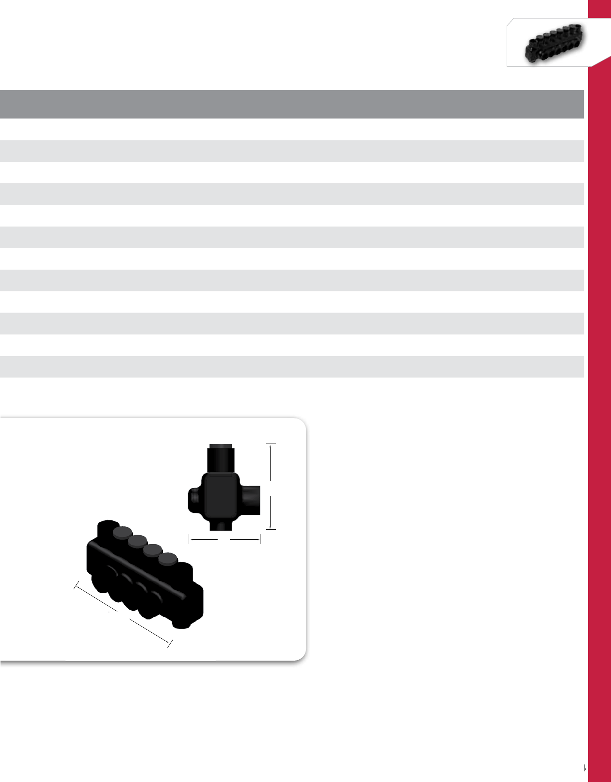
194
NSi Industries LLC • USA • 800.321.5847 • www.nsiindustries.com
194
POLARIS™
CAT.
NO. NO. OF
PORTS WIRE
RANGE LENGTH
(L) WIDTH
(W) HEIGHT
(H)
TORQUE
VALUE
(IN./LBS.)
HEX
SIZE
STD.
CTN.
QTY.
IPLM4-3 34-14 AWG 2.750 1.240 1.390 45 Slotted 6
IPLM4-4 44-14 AWG 3.180 1.240 1.390 45 Slotted 6
IPLM4-5 54-14 AWG 3.600 1.240 1.390 45 Slotted 4
IPLM4-6 64-14 AWG 4.020 1.240 1.390 45 Slotted 4
IPLM4-7 74-14 AWG 4.190 1.240 1.390 45 Slotted 4
IPLM4-10 10 4-14 AWG 5.710 1.240 1.390 45 Slotted 3
IPLM1/0-3 31/0-14 AWG 3.460 1.550 1.820 180 3/16 6
IPLM1/0-4 41/0-14 AWG 4.110 1.550 1.820 180 3/16 6
IPLM1/0-5 51/0-14 AWG 4.760 1.550 1.820 180 3/16 4
IPLM1/0-6 61/0-14 AWG 5.410 1.550 1.820 180 3/16 4
IPLM1/0-8 81/0-14 AWG 6.710 1.550 1.820 180 3/16 4
IPLM1/0-9 91/0-14 AWG 7.520 1.550 1.820 180 3/16 3
IPLM1/0-10 10 1/0-14 AWG 8.010 1.550 1.820 180 3/16 3
W
H
L
W
H
L

195
POLARIS™
FEATURES
RATINGS
Wire entry ports on both sides of the connector
allow for access from either side.
Supplied with removable access plugs to close the
entry port not being used.
The mounting holes at each end of the connector
allow for direct isolated mounting to the trough,
panel or wireway.
Insulated with high-dielectric strength plastisol.
Molded for precise fit and supplied with removable
access plugs over the hex screws.
Eliminates the need for cover and taping.
Abrasion and chemical resistant. UV resistant.
Will not support combustion.
CAT.
NO. NO. OF
PORTS WIRE
RANGE LENGTH
(L) WIDTH
(W) HEIGHT
(H)
TORQUE
VALUE
(IN./LBS.)
HEX
SIZE
STD.
CTN.
QTY.
IPLMD3/0-3 33/0-6 AWG 3.870 1.830 1.910 250 1/4 3
IPLMD3/0-4 43/0-6 AWG 4.650 1.830 1.910 250 1/4 3
IPLMD3/0-5 53/0-6 AWG 5.430 1.830 1.910 250 1/4 2
IPLMD3/0-6 63/0-6 AWG 6.210 1.830 1.910 250 1/4 2
IPLMD3/0-7 73/0-6 AWG 6.990 1.830 1.910 250 1/4 2
IPLMD3/0-8 83/0-6 AWG 7.770 1.830 1.910 250 1/4 2
IPLMD3/0-9 93/0-6 AWG 8.600 1.830 1.910 250 1/4 2
IPLMD3/0-10 10 3/0-6 AWG 9.330 1.830 1.910 250 1/4 2
IPLMD250-3 3250 MCM-6 AWG 4.420 2.280 2.370 360 5/16 2
IPLMD250-4 4250 MCM-6 AWG 5.280 2.280 2.370 360 5/16 2
IPLMD250-5 5250 MCM-6 AWG 6.140 2.280 2.370 360 5/16 2
IPLMD250-6 6250 MCM-6 AWG 7.010 2.280 2.370 360 5/16 2
IPLMD250-7 7250 MCM-6 AWG 7.820 2.280 2.370 360 5/16 2
IPLMD250-8 8250 MCM-6 AWG 8.730 2.280 2.370 360 5/16 2
IPLMD250-10 10 250 MCM-6 AWG 10.400 2.280 2.370 360 5/16 2
IPLMD250-12 12 250 MCM-6 AWG 12.130 2.280 2.370 360 5/16 1
IPLMD350-3 3350 MCM-6 AWG 5.120 2.410 2.770 400 5/16 2
IPLMD350-4 4350 MCM-6 AWG 6.170 2.410 2.770 400 5/16 2
IPLMD350-5 5350 MCM-6 AWG 7.220 2.410 2.770 400 5/16 2
IPLMD350-6 6350 MCM-6 AWG 8.270 2.410 2.770 400 5/16 2
IPLMD350-7 7350 MCM-6 AWG 9.320 2.410 2.770 400 5/16 2
IPLMD350-8 8350 MCM-6 AWG 10.370 2.410 2.770 400 5/16 2
IPLMD350-10 10 350 MCM-6 AWG 12.470 2.410 2.770 400 5/16 2
IPLMD350-12 12 350 MCM-6 AWG 14.570 2.410 2.770 400 5/16 1
UL Listed 486B Wire Connector.
TEMPERATURE RATING/VOLTAGE:
AL9CU. Cold temperature rated to -45˚C,
rated 600V, 90˚C.
WIRE TYPE:
Dual rated for use with copper and/or
aluminum cables. Not recommended for
fine-stranded, flexible wire.
MOUNTING:
Mounting holes will accept a 1/4” bolt for
3/0 AWG and a 5/16” bolt for 250 MCM
and 350 MCM.
Wire entry ports on both sides of the connector
allow for access from either side.
Wire entry ports on both sides of the connector
allow for access from either side.
Wire entry ports on both sides of the connector
The mounting holes at each end of the connector
allow for direct
The mounting holes at each end of the connector
allow for direct
The mounting holes at each end of the connector
Insulated with high-dielectric strength plastisol.
Molded for precise fit and supplied with removable
Supplied with removable access plugs to close the
entry port not being used.
Supplied with removable access plugs to close the
entry port not being used.
Supplied with removable access plugs to close the
Eliminates the need for cover and
Abrasion
Abrasion
Abrasion
Will
Will
POLARIS™ INSULATED CONNECTORS
Multi-Conductor With
Mounting Holes,
Either Side Wire Entry
IPLMD SERIES All dimensional data is listed in inches.
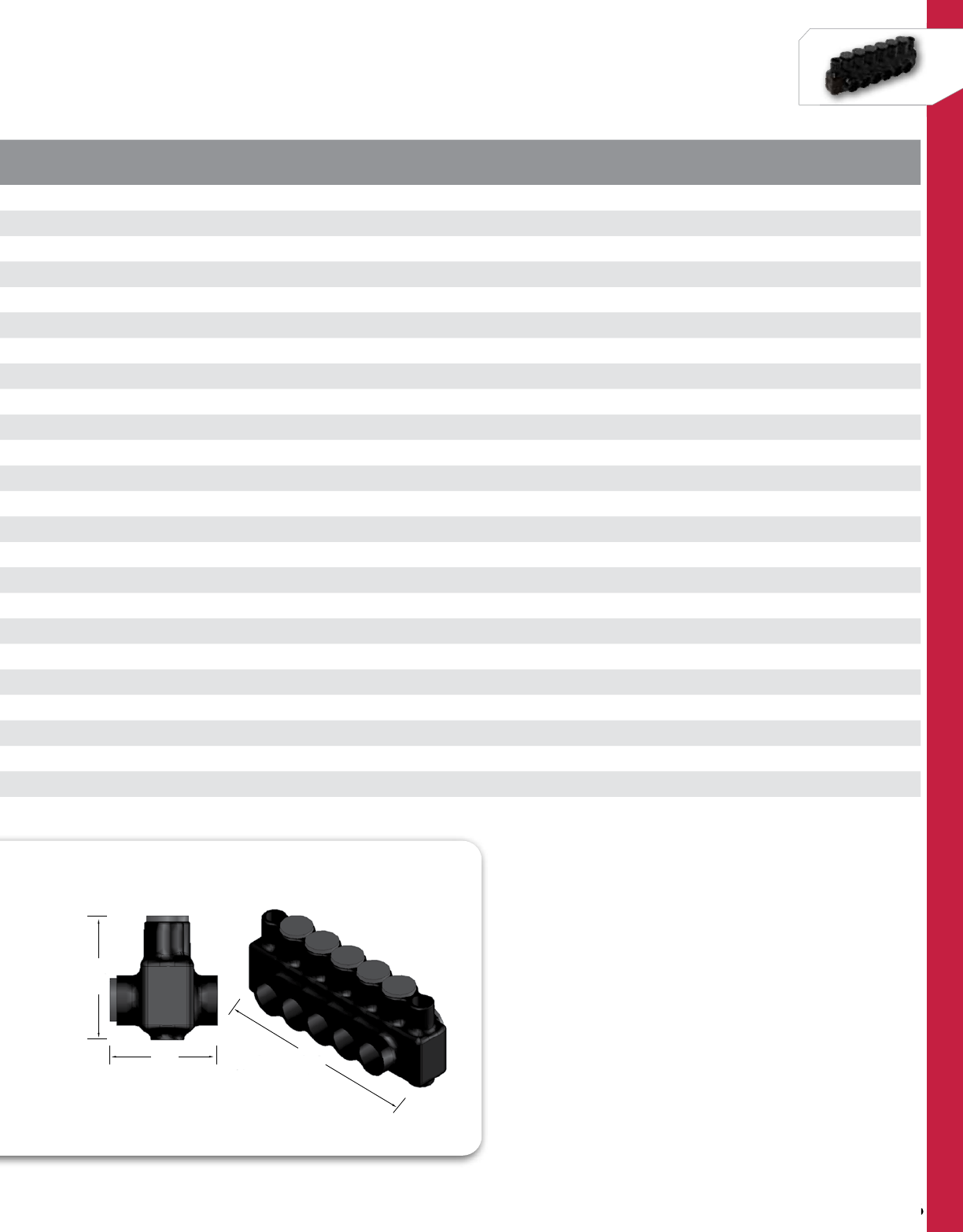
196
NSi Industries LLC • USA • 800.321.5847 • www.nsiindustries.com
196
POLARIS™
CAT.
NO. NO. OF
PORTS WIRE
RANGE LENGTH
(L) WIDTH
(W) HEIGHT
(H)
TORQUE
VALUE
(IN./LBS.)
HEX
SIZE
STD.
CTN.
QTY.
IPLMD3/0-3 33/0-6 AWG 3.870 1.830 1.910 250 1/4 3
IPLMD3/0-4 43/0-6 AWG 4.650 1.830 1.910 250 1/4 3
IPLMD3/0-5 53/0-6 AWG 5.430 1.830 1.910 250 1/4 2
IPLMD3/0-6 63/0-6 AWG 6.210 1.830 1.910 250 1/4 2
IPLMD3/0-7 73/0-6 AWG 6.990 1.830 1.910 250 1/4 2
IPLMD3/0-8 83/0-6 AWG 7.770 1.830 1.910 250 1/4 2
IPLMD3/0-9 93/0-6 AWG 8.600 1.830 1.910 250 1/4 2
IPLMD3/0-10 10 3/0-6 AWG 9.330 1.830 1.910 250 1/4 2
IPLMD250-3 3250 MCM-6 AWG 4.420 2.280 2.370 360 5/16 2
IPLMD250-4 4250 MCM-6 AWG 5.280 2.280 2.370 360 5/16 2
IPLMD250-5 5250 MCM-6 AWG 6.140 2.280 2.370 360 5/16 2
IPLMD250-6 6250 MCM-6 AWG 7.010 2.280 2.370 360 5/16 2
IPLMD250-7 7250 MCM-6 AWG 7.820 2.280 2.370 360 5/16 2
IPLMD250-8 8250 MCM-6 AWG 8.730 2.280 2.370 360 5/16 2
IPLMD250-10 10 250 MCM-6 AWG 10.400 2.280 2.370 360 5/16 2
IPLMD250-12 12 250 MCM-6 AWG 12.130 2.280 2.370 360 5/16 1
IPLMD350-3 3350 MCM-6 AWG 5.120 2.410 2.770 400 5/16 2
IPLMD350-4 4350 MCM-6 AWG 6.170 2.410 2.770 400 5/16 2
IPLMD350-5 5350 MCM-6 AWG 7.220 2.410 2.770 400 5/16 2
IPLMD350-6 6350 MCM-6 AWG 8.270 2.410 2.770 400 5/16 2
IPLMD350-7 7350 MCM-6 AWG 9.320 2.410 2.770 400 5/16 2
IPLMD350-8 8350 MCM-6 AWG 10.370 2.410 2.770 400 5/16 2
IPLMD350-10 10 350 MCM-6 AWG 12.470 2.410 2.770 400 5/16 2
IPLMD350-12 12 350 MCM-6 AWG 14.570 2.410 2.770 400 5/16 1
W
H
L
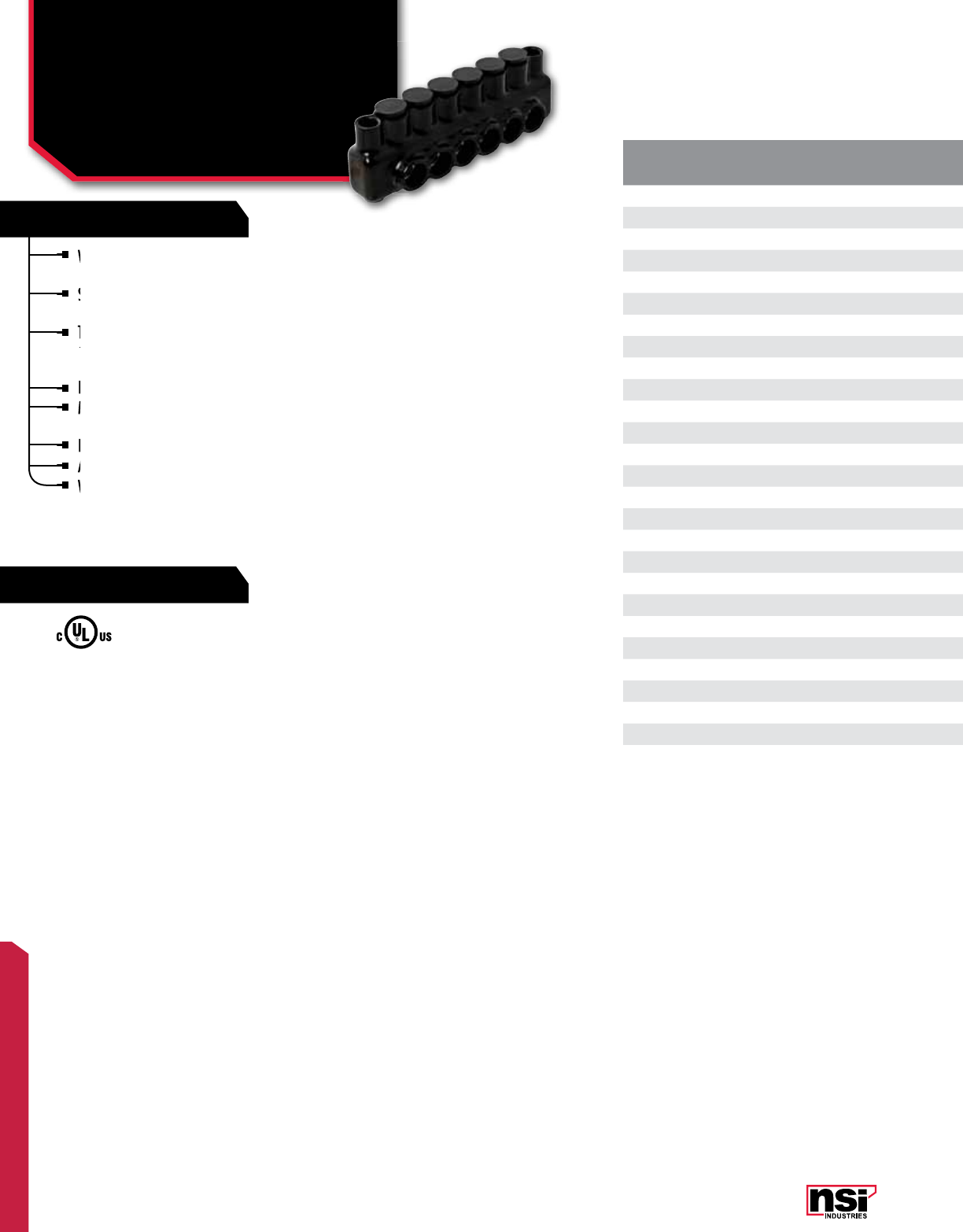
197
POLARIS™
FEATURES
RATINGS
CAT.
NO. NO. OF
PORTS WIRE
RANGE LENGTH
(L) WIDTH
(W) HEIGHT
(H)
TORQUE
VALUE
(IN./LBS.)
HEX
SIZE
STD.
CTN.
QTY.
IPLMD500-3 3500 MCM-4 AWG 5.510 2.810 3.030 450 5/16 2
IPLMD500-4 4500 MCM-4 AWG 6.650 2.810 3.030 450 5/16 2
IPLMD500-5 5500 MCM-4 AWG 7.800 2.810 3.030 450 5/16 2
IPLMD500-6 6500 MCM-4 AWG 8.940 2.810 3.030 450 5/16 2
IPLMD500-7 7500 MCM-4 AWG 9.710 2.810 3.030 450 5/16 2
IPLMD500-8 8500 MCM-4 AWG 11.230 2.810 3.030 450 5/16 2
IPLMD500-9 9500 MCM-4 AWG 12.480 2.810 3.030 450 5/16 2
IPLMD500-10 10 500 MCM-4 AWG 13.520 2.810 3.030 450 5/16 1
IPLMD500-12 3500 MCM-4 AWG 15.440 2.810 3.030 550 5/16 1
IPLMD600-3 3600 MCM-6 AWG 5.880 2.960 3.150 550 5/16 1
IPLDM600-4 4600 MCM-6 AWG 7.180 2.960 3.150 550 5/16
IPLMD600-5** 4600 MCM-6 AWG 8.480 2.960 3.150 550 5/16 1
IPLMD600-6** 5600 MCM-6 AWG 9.780 2.960 3.150 550 5/16 1
IPLMD600-8** 8600 MCM-6 AWG 10.700 2.960 3.150 550 5/16 1
IPLMD600-9** 9600 MCM-6 AWG 13.610 2.960 3.150 550 5/16 1
IPLMD600-10** 10 600 MCM-6 AWG 14.980 2.960 3.150 550 5/16 1
IPLMD600-12** 12 600 MCM-6 AWG 17.200 2.960 3.150 550 5/16 1
IPLMD750-3* 3750-250 MCM 6.320 3.410 3.540 550 5/16 1
IPLMD750-4* 4750-250 MCM 7.750 3.410 3.540 550 5/16 1
IPLMD750-5* 5750-250 MCM 9.180 3.410 3.540 550 5/16 1
IPLMD750-6* 6750-250 MCM 10.600 3.410 3.540 550 5/16 1
IPLMD750-7* 7750-250 MCM 11.650 3.410 3.540 550 5/16 1
IPLMD750-8* 8750-250 MCM 13.450 3.410 3.540 550 5/16 1
IPLMD750-9* 9750-250 MCM 15.050 3.410 3.540 550 5/16 1
IPLMD750-10* 10 750-250 MCM 16.300 3.410 3.540 550 5/16 1
IPLMD750-12* 12 750-250 MCM 18.780 3.410 3.540 550 5/16 1
*750 MCM not UL listed
**600 Series are ALC7U and 75°C
POLARIS™ INSULATED CONNECTORS
Multi-Conductor With
Mounting Holes,
Either Side Wire Entry
IPLMD SERIES CONT'D
Wire entry ports on both sides of the connector
allow for access from either side.
Supplied with removable access plugs to close the
entry port not being used.
The mounting holes at each end of the connector
allow for direct isolated mounting to the trough,
panel or wireway.
Insulated with high-dielectric strength plastisol.
Molded for precise fit and supplied with
removable access plugs over the hex screws.
Eliminates the need for cover and taping.
Abrasion and chemical resistant. UV resistant.
Will not support combustion.
UL Listed 486B Wire Connector.
TEMPERATURE RATING/VOLTAGE:
AL9CU. Cold temperature rated to -45˚C,
rated 600V, 90˚C.
WIRE TYPE:
Dual rated for use with copper and/or
aluminum cables. Not recommended for
fine-stranded, flexible wire.
MOUNTING:
Mounting holes will accept a 1/4” bolt for
3/0 AWG and a 5/16” bolt for 250 MCM
and 350 MCM.
Wire entry ports on both sides of the connector
allow for access from either side.
Wire entry ports on both sides of the connector
allow for access from either side.
Wire entry ports on both sides of the connector
Insulated with high-dielectric strength plastisol.
The mounting holes at each end of the connector
allow for direct
The mounting holes at each end of the connector
allow for direct
The mounting holes at each end of the connector
Molded for precise fit and supplied with
removable access plugs over the hex screws.
Molded for precise fit and supplied with
removable access plugs over the hex screws.
Molded for precise fit and supplied with
Molded for precise fit and supplied with
Supplied with removable access plugs to close the
entry port not being used.
Supplied with removable access plugs to close the
entry port not being used.
Supplied with removable access plugs to close the
Eliminates the need for cover and
Abrasion
Abrasion
Will not support combustion.
Will not support combustion.
All dimensional data is listed in inches.
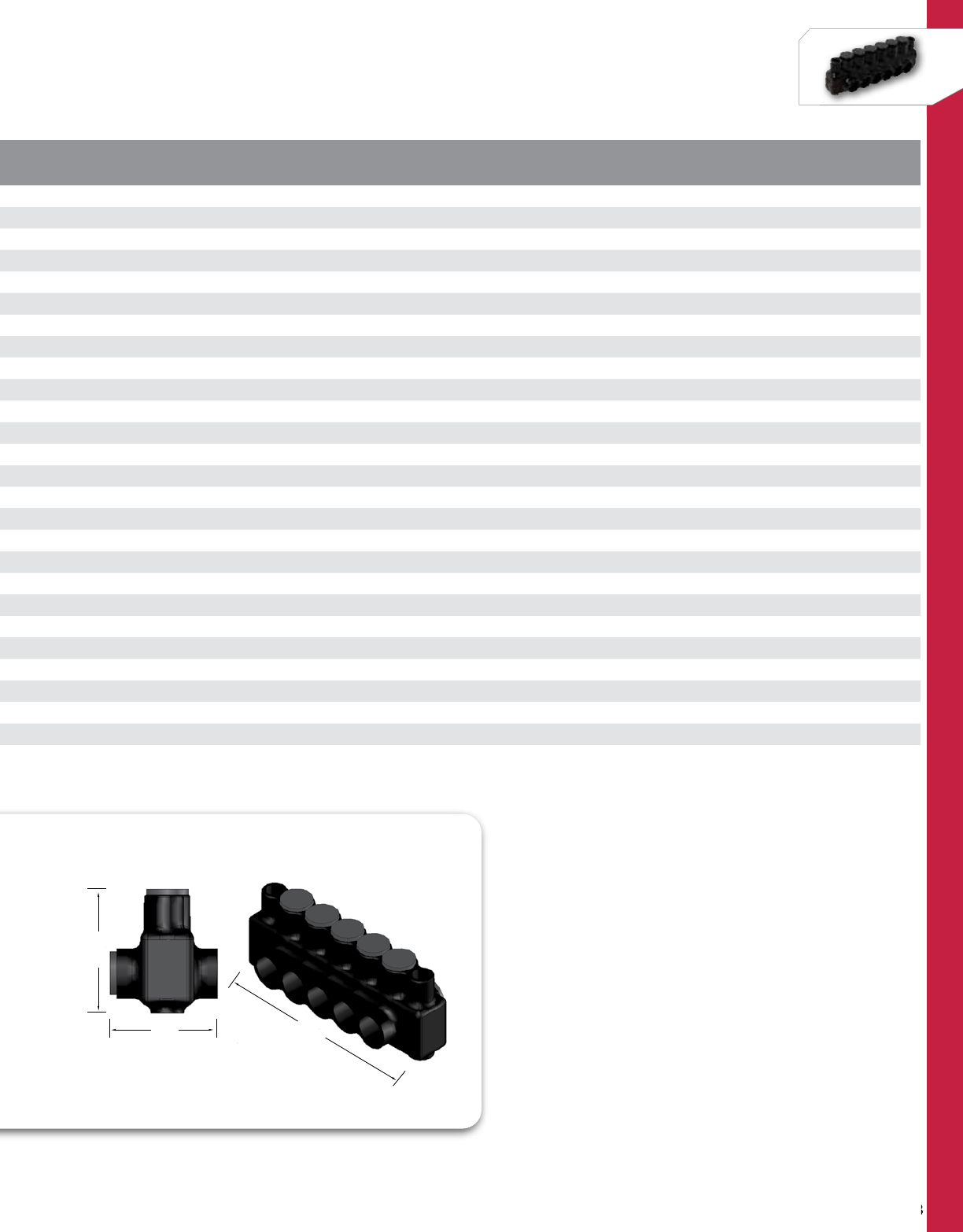
198
NSi Industries LLC • USA • 800.321.5847 • www.nsiindustries.com
198
POLARIS™
CAT.
NO. NO. OF
PORTS WIRE
RANGE LENGTH
(L) WIDTH
(W) HEIGHT
(H)
TORQUE
VALUE
(IN./LBS.)
HEX
SIZE
STD.
CTN.
QTY.
IPLMD500-3 3500 MCM-4 AWG 5.510 2.810 3.030 450 5/16 2
IPLMD500-4 4500 MCM-4 AWG 6.650 2.810 3.030 450 5/16 2
IPLMD500-5 5500 MCM-4 AWG 7.800 2.810 3.030 450 5/16 2
IPLMD500-6 6500 MCM-4 AWG 8.940 2.810 3.030 450 5/16 2
IPLMD500-7 7500 MCM-4 AWG 9.710 2.810 3.030 450 5/16 2
IPLMD500-8 8500 MCM-4 AWG 11.230 2.810 3.030 450 5/16 2
IPLMD500-9 9500 MCM-4 AWG 12.480 2.810 3.030 450 5/16 2
IPLMD500-10 10 500 MCM-4 AWG 13.520 2.810 3.030 450 5/16 1
IPLMD500-12 3500 MCM-4 AWG 15.440 2.810 3.030 550 5/16 1
IPLMD600-3 3600 MCM-6 AWG 5.880 2.960 3.150 550 5/16 1
IPLDM600-4 4600 MCM-6 AWG 7.180 2.960 3.150 550 5/16
IPLMD600-5** 4600 MCM-6 AWG 8.480 2.960 3.150 550 5/16 1
IPLMD600-6** 5600 MCM-6 AWG 9.780 2.960 3.150 550 5/16 1
IPLMD600-8** 8600 MCM-6 AWG 10.700 2.960 3.150 550 5/16 1
IPLMD600-9** 9600 MCM-6 AWG 13.610 2.960 3.150 550 5/16 1
IPLMD600-10** 10 600 MCM-6 AWG 14.980 2.960 3.150 550 5/16 1
IPLMD600-12** 12 600 MCM-6 AWG 17.200 2.960 3.150 550 5/16 1
IPLMD750-3* 3750-250 MCM 6.320 3.410 3.540 550 5/16 1
IPLMD750-4* 4750-250 MCM 7.750 3.410 3.540 550 5/16 1
IPLMD750-5* 5750-250 MCM 9.180 3.410 3.540 550 5/16 1
IPLMD750-6* 6750-250 MCM 10.600 3.410 3.540 550 5/16 1
IPLMD750-7* 7750-250 MCM 11.650 3.410 3.540 550 5/16 1
IPLMD750-8* 8750-250 MCM 13.450 3.410 3.540 550 5/16 1
IPLMD750-9* 9750-250 MCM 15.050 3.410 3.540 550 5/16 1
IPLMD750-10* 10 750-250 MCM 16.300 3.410 3.540 550 5/16 1
IPLMD750-12* 12 750-250 MCM 18.780 3.410 3.540 550 5/16 1
W
H
L
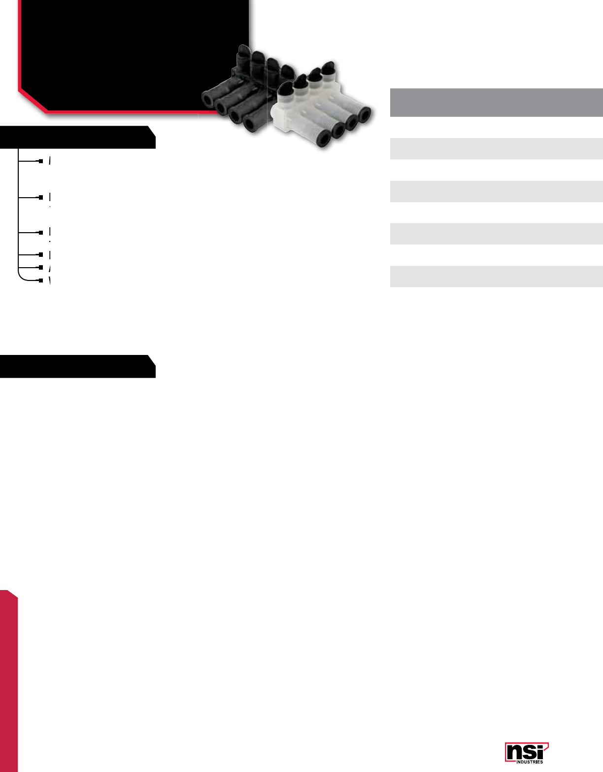
199
POLARIS™
FEATURES
RATINGS
Manufactured from high strength 6061-T6
aluminum alloy, providing premium electrical
and mechanical performance.
Radial tipped set screws reduce conductor strand
damage, and the range taking design allows for many
sizes and types of conductors – all in one connector.
Encapsulated in rubber with a nominal thickness of 125
mils. and high dielectric strength.
ISPC connectors (clear) allow for an easier installation.
Abrasion and chemical resistant. UV resistant.
Will not support combustion.
CAT.
NO. NO. OF
PORTS COLOR WIRE RANGE LENGHT
(L) WIDTH
(W) HEIGHT
(H)
TORQUE
VALUE
(IN./LBS.)
HEX
SIZE
STD.
CTN.
QTY.
ISPB350-3 3 Black 350 MCM-12 AWG 3.610 4.190 3.060 360 5/16 1
ISPB350-4 4 Black 350 MCM-12 AWG 4.800 4.190 3.060 360 5/16 1
ISPB350-6 6 Black 350 MCM-12 AWG 7.180 4.190 3.060 360 5/16 1
ISPC350-3 3 Clear 350 MCM-12 AWG 3.610 4.190 3.060 360 5/16 1
ISPC350-4 4 Clear 350 MCM-12 AWG 4.800 4.190 3.060 360 5/16 1
ISPC350-6 6 Clear 350 MCM-12 AWG 7.180 4.190 3.060 360 5/16 1
ISPB600-3 3 Black 600 MCM-12 AWG 4.870 5.460 3.130 550 5/16 1
ISPB600-4 4 Black 600 MCM-12 AWG 6.560 5.460 3.130 550 5/16 1
ISPB600-6 6 Black 600 MCM-12 AWG 9.940 5.460 3.130 550 5/16 1
Meets or exceeds ANSI C119.4 Class A specifications
TEMPERATURE RATING/VOLTAGE:
AL9CU. Cold temperature rated to -45˚C,
rated 600V, 90˚C.
WIRE TYPE:
For use with copper and/or aluminum cables.
INSTALLATION INSTRUCTIONS:
See page 209 for detailed installation information.
Manufactured from high strength 6061-T6
aluminum
Encapsulated in rubber with a nominal thickness of
mils. and high dielectric strength.
Encapsulated in rubber with a nominal thickness of
mils. and high dielectric strength.
Encapsulated in rubber with a nominal thickness of
Radial tipped set screws reduce conductor strand
damage, and the range taking design allows for many
Radial tipped set screws reduce conductor strand
damage, and the range taking design allows for many
Radial tipped set screws reduce conductor strand
Abrasion and chemical resistant. UV resistant.
ISPC connectors (clear) allow for an easier installation.
Abrasion and chemical resistant. UV resistant.
Will not support combustion.
Will not support combustion.
POLARIS™
Submersible Pedestal
Connectors
ISPB, ISPC SERIES All dimensional data is listed in inches.
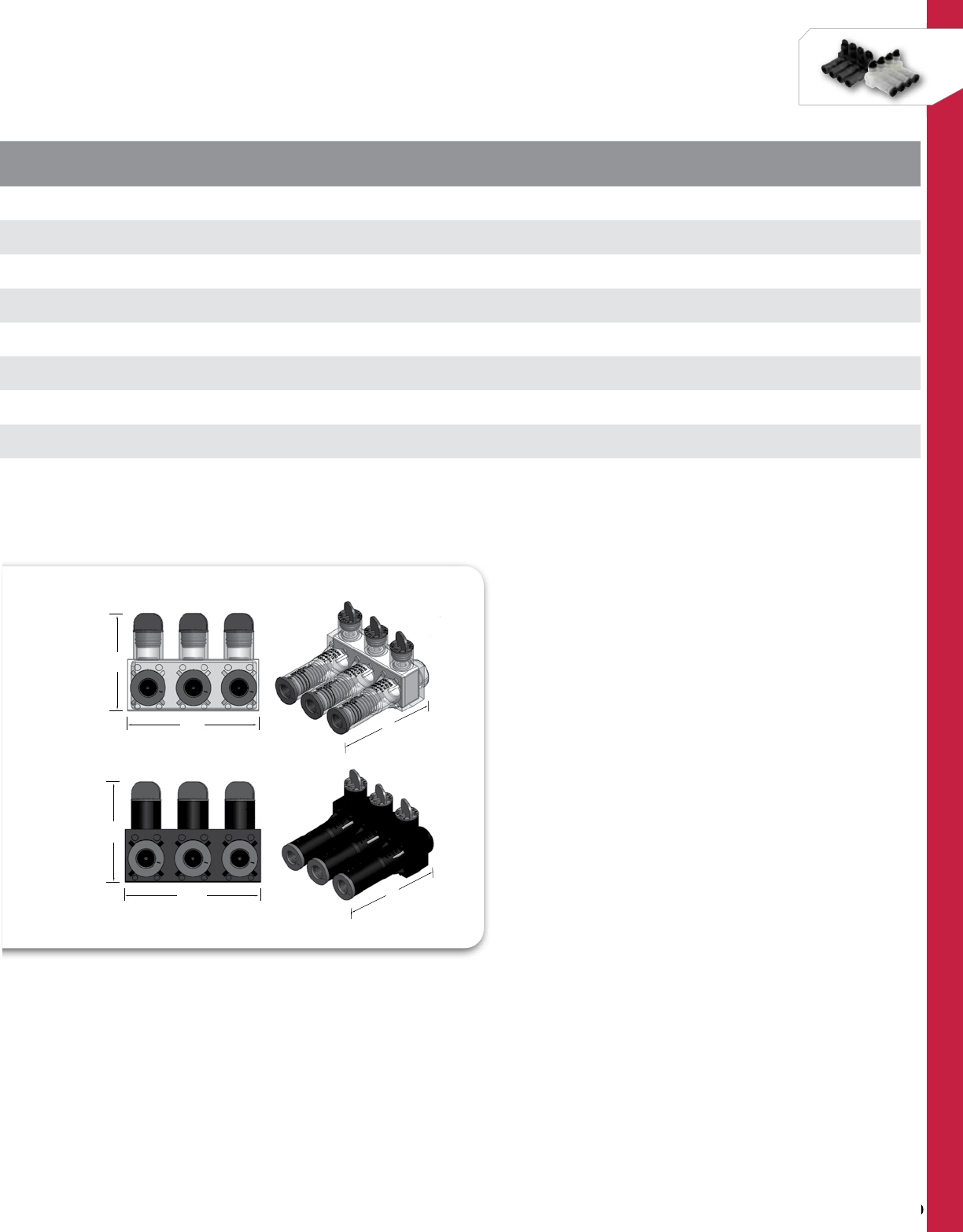
200
NSi Industries LLC • USA • 800.321.5847 • www.nsiindustries.com
200
POLARIS™
CAT.
NO. NO. OF
PORTS COLOR WIRE RANGE LENGHT
(L) WIDTH
(W) HEIGHT
(H)
TORQUE
VALUE
(IN./LBS.)
HEX
SIZE
STD.
CTN.
QTY.
ISPB350-3 3 Black 350 MCM-12 AWG 3.610 4.190 3.060 360 5/16 1
ISPB350-4 4 Black 350 MCM-12 AWG 4.800 4.190 3.060 360 5/16 1
ISPB350-6 6 Black 350 MCM-12 AWG 7.180 4.190 3.060 360 5/16 1
ISPC350-3 3 Clear 350 MCM-12 AWG 3.610 4.190 3.060 360 5/16 1
ISPC350-4 4 Clear 350 MCM-12 AWG 4.800 4.190 3.060 360 5/16 1
ISPC350-6 6 Clear 350 MCM-12 AWG 7.180 4.190 3.060 360 5/16 1
ISPB600-3 3 Black 600 MCM-12 AWG 4.870 5.460 3.130 550 5/16 1
ISPB600-4 4 Black 600 MCM-12 AWG 6.560 5.460 3.130 550 5/16 1
ISPB600-6 6 Black 600 MCM-12 AWG 9.940 5.460 3.130 550 5/16 1
L
H
W
W
H
L
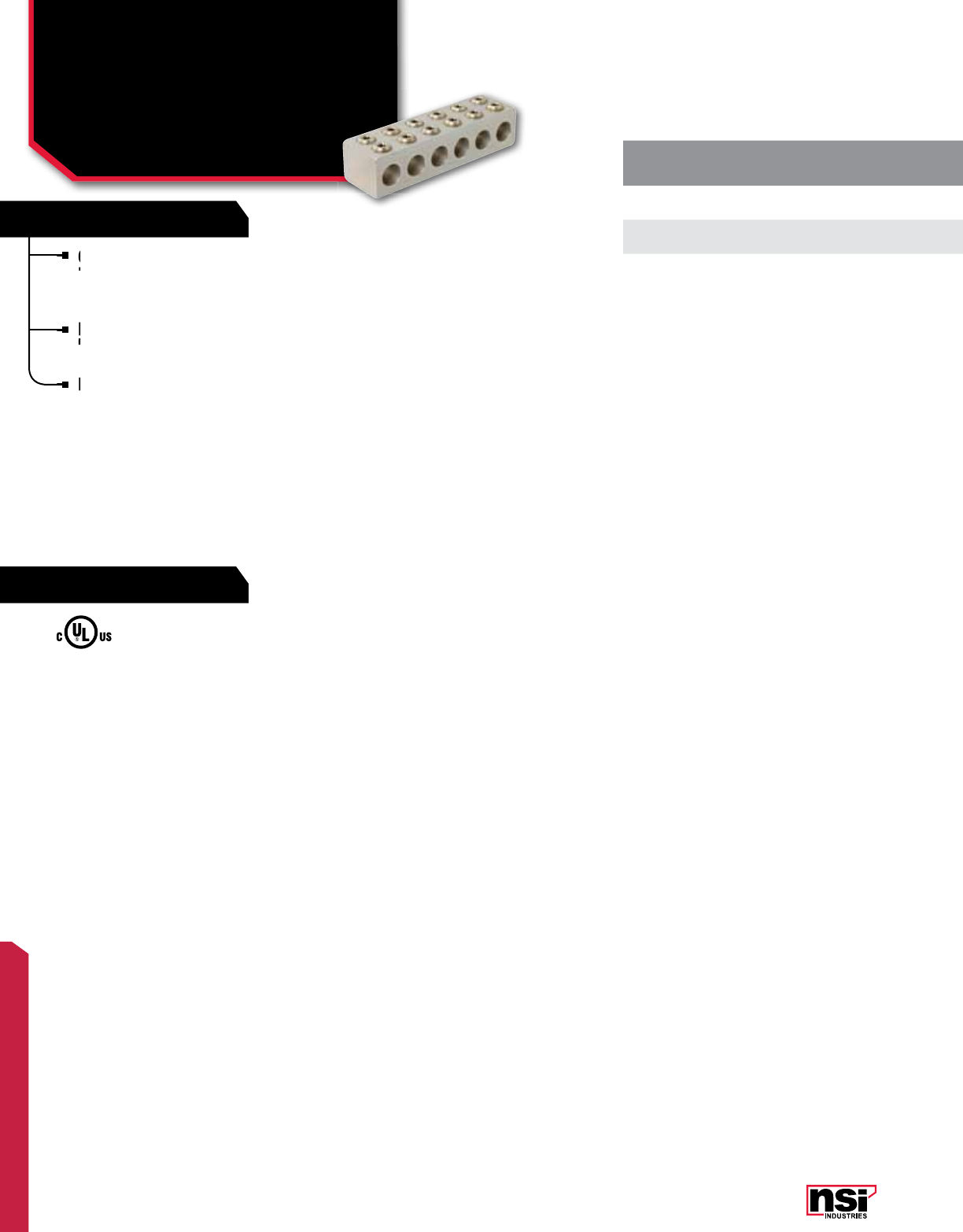
201
POLARIS™
FEATURES
RATINGS
Connector block is double the size of the standard
PL Series connector and there are also two pressure
screws provided for each cable to ensure the best
connection possible.
Heavy duty PLH Series connectors are designed, to
handle the most demanding applications from 250
MCM to 750 MCM.
Plated for cor rosion resistance.
CAT.
NO. NO. OF
PORTS WIRE
RANGE LENGTH
(L) WIDTH
(W) HEIGHT
(H)
TORQUE
VALUE
(IN./LBS.)
HEX
SIZE
STD.
CTN.
QTY.
PLH750-6 6750-250 MCM 8.850 2.500 2.000 550 5/16 1
PLH750-10 10 750-250 MCM 14.550 2.500 2.000 550 5/16 1
UL Listed 486B Wire Connector.
TEMPERATURE RATING/VOLTAGE:
AL9CU. Rated 600V, 90˚C.
WIRE TYPE:
Dual rated for use with copper and/or
aluminum cables. Not recommended for
fine-stranded, flexible wire.
Connector block is double the size of the standard
PL Series connector and there are also two pressure
Heavy duty PLH Series connectors are designed, to
handle the most demanding applications from 250
Heavy duty PLH Series connectors are designed, to
handle the most demanding applications from 250
Heavy duty PLH Series connectors are designed, to
Plated for cor
POLARIS™
Heavy Duty Uninsulated
Either Side Wire Entry
PLH SERIES All dimensional data is listed in inches.
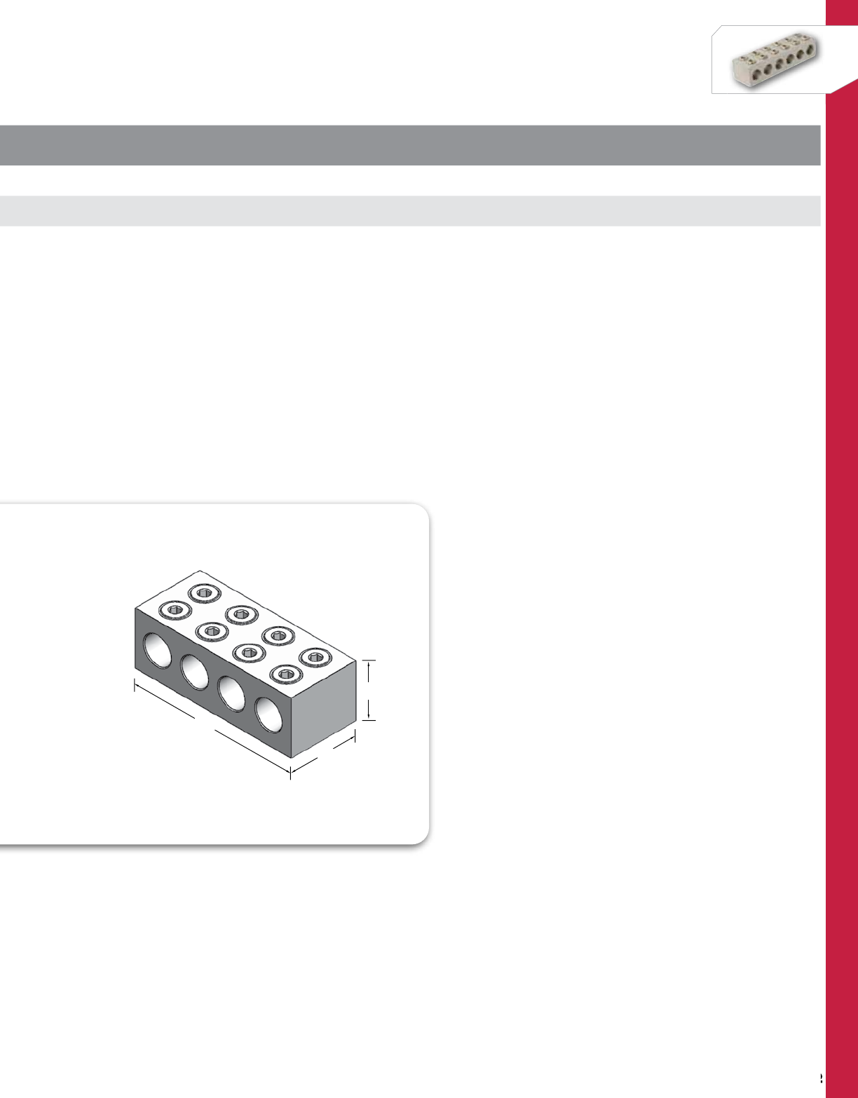
202
NSi Industries LLC • USA • 800.321.5847 • www.nsiindustries.com
202
POLARIS™
H
L
W
CAT.
NO. NO. OF
PORTS WIRE
RANGE LENGTH
(L) WIDTH
(W) HEIGHT
(H)
TORQUE
VALUE
(IN./LBS.)
HEX
SIZE
STD.
CTN.
QTY.
PLH750-6 6750-250 MCM 8.850 2.500 2.000 550 5/16 1
PLH750-10 10 750-250 MCM 14.550 2.500 2.000 550 5/16 1
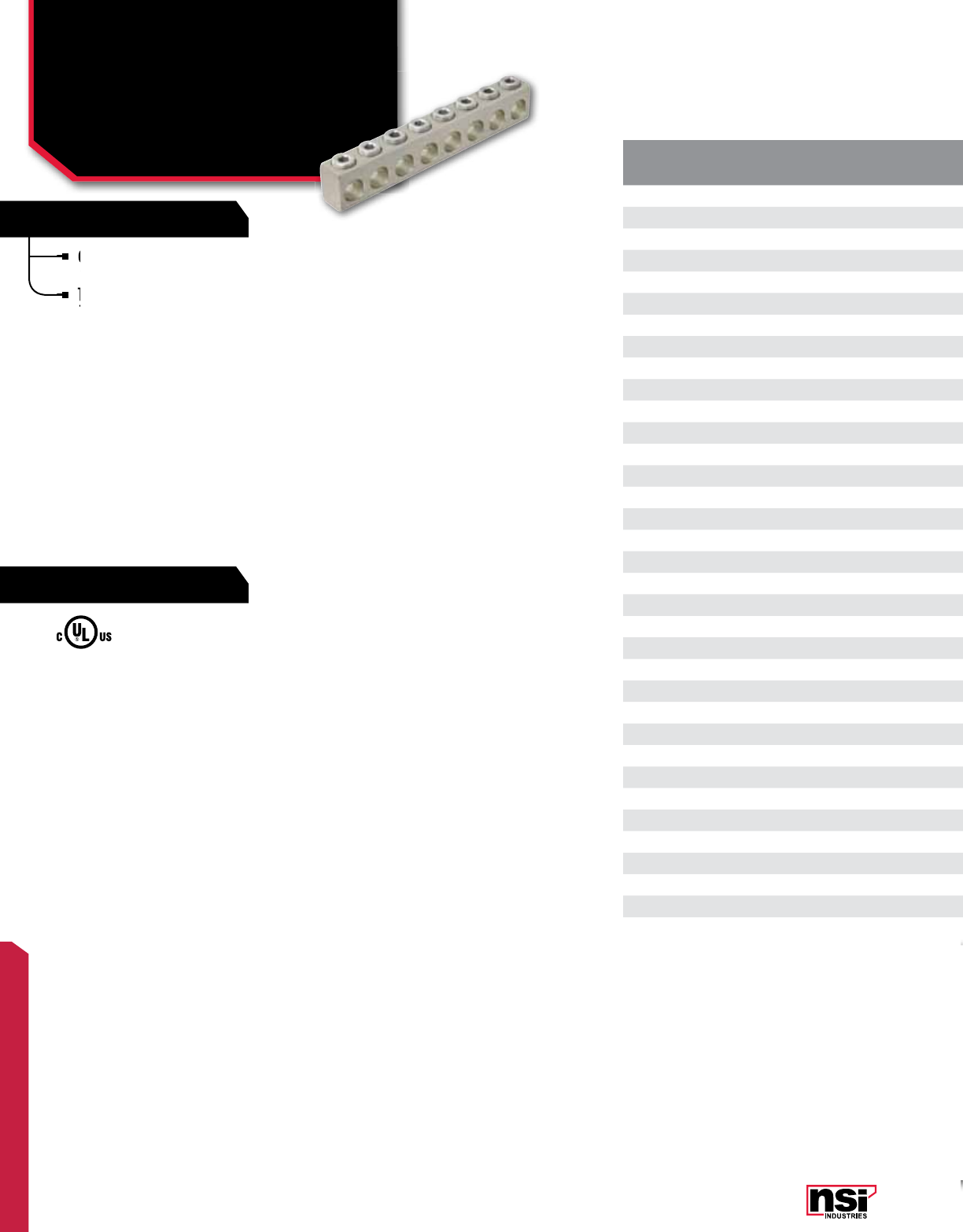
203
POLARIS™
FEATURES
RATINGS
CAT.
NO. NO. OF
PORTS WIRE
RANGE LENGTH
(L) WIDTH
(W) HEIGHT
(H)
TORQUE
VALUE
(IN./LBS.)
HEX
SIZE
STD.
CTN.
QTY.
PL4-2 24-14 AWG 0.880 0.500 0.630 45 Slotted 12
PL4-3 34-14 AWG 1.300 0.500 0.630 45 Slotted 12
PL4-4 44-14 AWG 1.730 0.500 0.630 45 Slotted 12
PL4-5 54-14 AWG 2.150 0.500 0.630 45 Slotted 6
PL4-6 64-14 AWG 2.570 0.500 0.630 45 Slotted 6
PL4-8 84-14 AWG 3.410 0.500 0.630 45 Slotted 6
PL4-10 10 4-14 AWG 4.260 0.500 0.630 45 Slotted 4
PL4-14 14 4-14 AWG 5.960 0.500 0.630 45 Slotted 2
PL1/0-2 21/0-14 AWG 1.350 0.630 0.880 180 3/16 12
PL1/0-3 31/0-14 AWG 2.000 0.630 0.880 180 3/16 12
PL1/0-4 41/0-14 AWG 2.650 0.630 0.880 180 3/16 12
PL1/0-5 51/0-14 AWG 3.300 0.630 0.880 180 3/16 6
PL1/0-6 61/0-14 AWG 3.950 0.630 0.880 180 3/16 6
PL1/0-7 71/0-14 AWG 4.610 0.630 0.880 180 3/16 6
PL1/0-8 81/0-14 AWG 5.250 0.630 0.880 180 3/16 6
PL1/0-10 10 1/0-14 AWG 6.550 0.630 0.880 180 3/16 4
PL1/0-14 14 1/0-14 AWG 9.150 0.630 0.880 180 3/16 2
PL3/0-3 33/0-6 AWG 2.380 0.690 0.940 250 1/4 6
PL3/0-4 43/0-6 AWG 3.160 0.690 0.940 250 1/4 6
PL3/0-5 53/0-6 AWG 3.940 0.690 0.940 250 1/4 6
PL3/0-6 63/0-6 AWG 4.720 0.690 0.940 250 1/4 6
PL3/0-7 73/0-6 AWG 5.490 0.690 0.940 250 1/4 6
PL3/0-8 83/0-6 AWG 6.280 0.690 0.940 250 1/4 6
PL3/0-9 93/0-6 AWG 7.050 0.690 0.940 250 1/4 4
PL3/0-10 10 3/0-6 AWG 7.840 0.690 0.940 250 1/4 4
PL3/0-12 12 3/0-6 AWG 9.400 0.690 0.940 250 1/4 3
PL3/0-14 14 3/0-6 AWG 10.960 0.690 0.940 250 1/4 2
PL250-2 2250 MCM-6 AWG 1.820 0.880 1.130 360 5/16 6
PL250-3 3250 MCM-6 AWG 2.680 0.880 1.130 360 5/16 6
PL250-4 4250 MCM-6 AWG 3.550 0.880 1.130 360 5/16 6
PL250-5 5250 MCM-6 AWG 4.410 0.880 1.130 360 5/16 6
PL250-6 6250 MCM-6 AWG 5.270 0.880 1.130 360 5/16 6
PL250-7 7250 MCM-6 AWG 6.140 0.880 1.130 360 5/16 6
PL250-8 8250 MCM-6 AWG 6.990 0.880 1.130 360 5/16 6
Connectors are made from 6061-T6 aluminum
alloy and are plated for corrosion resistance.
They are stocked in one hole increments, up to
14 holes and are suitable for use on wire from
#4 AWG to 750 MCM.
UL Listed 486B Wire Connector.
TEMPERATURE RATING/VOLTAGE:
AL9CU. Rated 600V, 90˚C.
WIRE TYPE:
Dual rated for use with copper and/or
aluminum cables. Not recommended for
fine-stranded, flexible wire.
Connectors are made from 6061-T6 aluminum
alloy and are plated for corrosion resistance.
They are stocked in one hole increments, up to
14 holes and are suitable for use on wire from
They are stocked in one hole increments, up to
14 holes and are suitable for use on wire from
They are stocked in one hole increments, up to
POLARIS™
Uninsulated Multi-Cable
Connectors
PL SERIES All dimensional data is listed in inches.
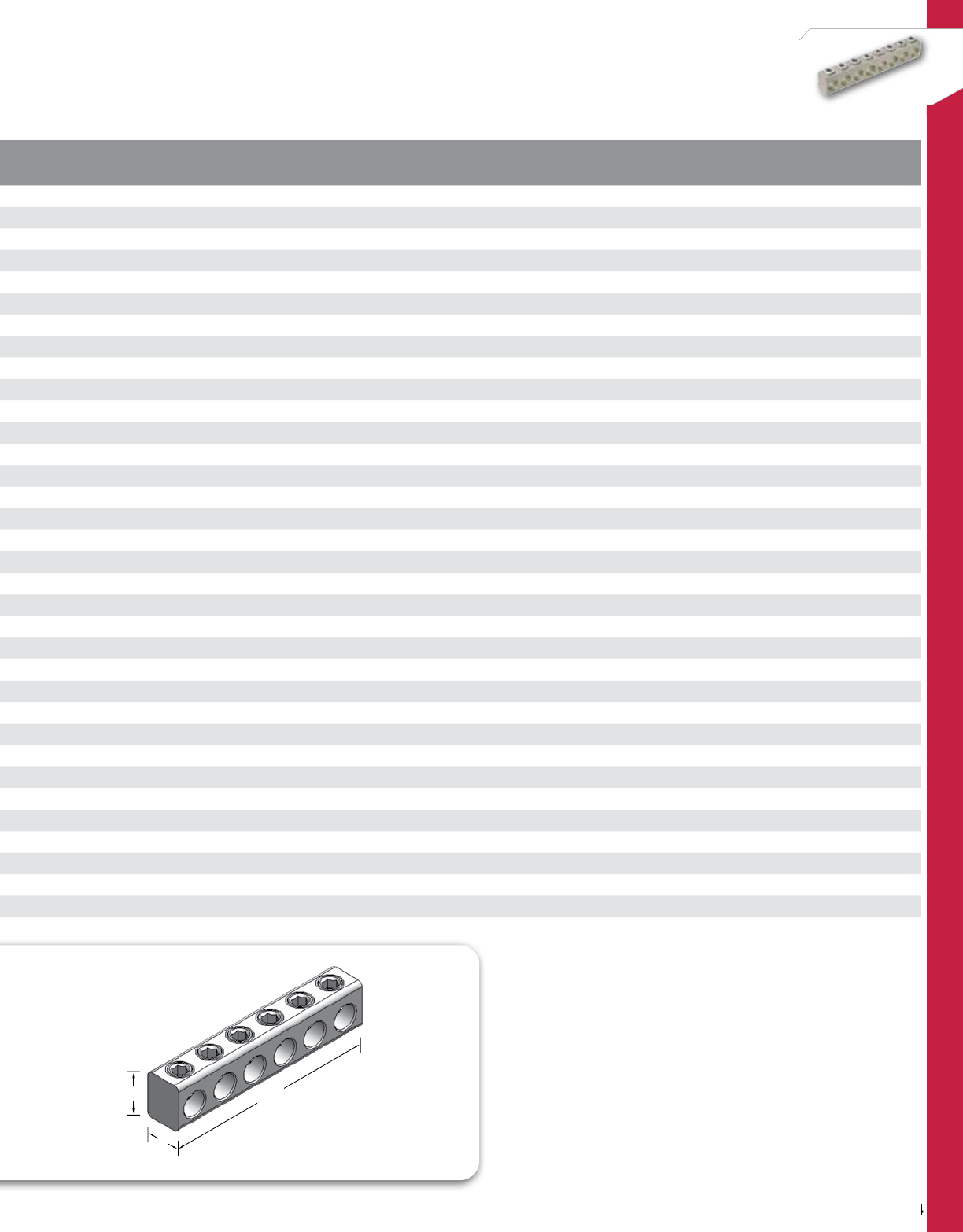
204
NSi Industries LLC • USA • 800.321.5847 • www.nsiindustries.com
204
POLARIS™
CAT.
NO. NO. OF
PORTS WIRE
RANGE LENGTH
(L) WIDTH
(W) HEIGHT
(H)
TORQUE
VALUE
(IN./LBS.)
HEX
SIZE
STD.
CTN.
QTY.
PL4-2 24-14 AWG 0.880 0.500 0.630 45 Slotted 12
PL4-3 34-14 AWG 1.300 0.500 0.630 45 Slotted 12
PL4-4 44-14 AWG 1.730 0.500 0.630 45 Slotted 12
PL4-5 54-14 AWG 2.150 0.500 0.630 45 Slotted 6
PL4-6 64-14 AWG 2.570 0.500 0.630 45 Slotted 6
PL4-8 84-14 AWG 3.410 0.500 0.630 45 Slotted 6
PL4-10 10 4-14 AWG 4.260 0.500 0.630 45 Slotted 4
PL4-14 14 4-14 AWG 5.960 0.500 0.630 45 Slotted 2
PL1/0-2 21/0-14 AWG 1.350 0.630 0.880 180 3/16 12
PL1/0-3 31/0-14 AWG 2.000 0.630 0.880 180 3/16 12
PL1/0-4 41/0-14 AWG 2.650 0.630 0.880 180 3/16 12
PL1/0-5 51/0-14 AWG 3.300 0.630 0.880 180 3/16 6
PL1/0-6 61/0-14 AWG 3.950 0.630 0.880 180 3/16 6
PL1/0-7 71/0-14 AWG 4.610 0.630 0.880 180 3/16 6
PL1/0-8 81/0-14 AWG 5.250 0.630 0.880 180 3/16 6
PL1/0-10 10 1/0-14 AWG 6.550 0.630 0.880 180 3/16 4
PL1/0-14 14 1/0-14 AWG 9.150 0.630 0.880 180 3/16 2
PL3/0-3 33/0-6 AWG 2.380 0.690 0.940 250 1/4 6
PL3/0-4 43/0-6 AWG 3.160 0.690 0.940 250 1/4 6
PL3/0-5 53/0-6 AWG 3.940 0.690 0.940 250 1/4 6
PL3/0-6 63/0-6 AWG 4.720 0.690 0.940 250 1/4 6
PL3/0-7 73/0-6 AWG 5.490 0.690 0.940 250 1/4 6
PL3/0-8 83/0-6 AWG 6.280 0.690 0.940 250 1/4 6
PL3/0-9 93/0-6 AWG 7.050 0.690 0.940 250 1/4 4
PL3/0-10 10 3/0-6 AWG 7.840 0.690 0.940 250 1/4 4
PL3/0-12 12 3/0-6 AWG 9.400 0.690 0.940 250 1/4 3
PL3/0-14 14 3/0-6 AWG 10.960 0.690 0.940 250 1/4 2
PL250-2 2250 MCM-6 AWG 1.820 0.880 1.130 360 5/16 6
PL250-3 3250 MCM-6 AWG 2.680 0.880 1.130 360 5/16 6
PL250-4 4250 MCM-6 AWG 3.550 0.880 1.130 360 5/16 6
PL250-5 5250 MCM-6 AWG 4.410 0.880 1.130 360 5/16 6
PL250-6 6250 MCM-6 AWG 5.270 0.880 1.130 360 5/16 6
PL250-7 7250 MCM-6 AWG 6.140 0.880 1.130 360 5/16 6
PL250-8 8250 MCM-6 AWG 6.990 0.880 1.130 360 5/16 6
W
HL
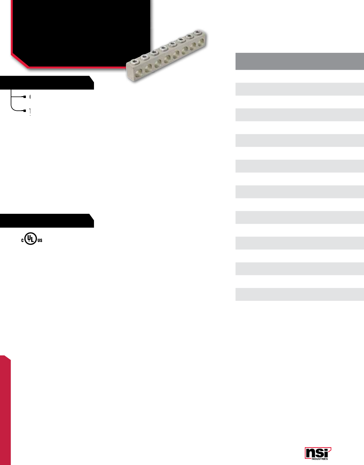
205
POLARIS™
FEATURES
RATINGS
CAT.
NO. NO. OF
PORTS WIRE
RANGE LENGTH
(L) WIDTH
(W) HEIGHT
(H)
TORQUE
VALUE
(IN./LBS.)
HEX
SIZE
STD.
CTN.
QTY.
PL250-9 9250 MCM-6 AWG 7.860 0.880 1.130 360 IN/LBS 5/16 4
PL250-10 10 250 MCM-6 AWG 8.720 0.880 1.130 360 IN/LBS 5/16 4
PL250-11 11 250 MCM-6 AWG 9.580 0.880 1.130 360 IN/LBS 5/16 3
PL250-12 12 250 MCM-6 AWG 10.450 0.880 1.130 360 IN/LBS 5/16 3
PL350-3 3350 MCM-6 AWG 3.220 1.000 1.440 400 IN/LBS 5/16 6
PL350-4 4350 MCM-6 AWG 4.270 1.000 1.440 400 IN/LBS 5/16 6
PL350-6 6350 MCM-6 AWG 6.370 1.000 1.440 400 IN/LBS 5/16 6
PL350-8 8350 MCM-6 AWG 8.470 1.000 1.440 400 IN/LBS 5/16 4
PL350-10 10 350 MCM-6 AWG 10.570 1.000 1.440 400 IN/LBS 5/16 2
PL500-4 4500 MCM-4 AWG 4.860 1.130 1.630 450 IN/LBS 5/16 4
PL500-6 6500 MCM-4 AWG 7.145 1.130 1.630 450 IN/LBS 5/16 3
PL500-7 7500 MCM-4 AWG 8.280 1.130 1.630 450 IN/LBS 5/16 3
PL500-8 8500 MCM-4 AWG 9.440 1.130 1.630 450 IN/LBS 5/16 3
PL500-9 9500 MCM-4 AWG 10.570 1.130 1.630 450 IN/LBS 5/16 2
PL500-10 10 500 MCM-4 AWG 11.730 1.130 1.630 450 IN/LBS 5/16 2
PL750-3 3750-250 MCM 4.570 1.440 2.000 550 IN/LBS 3/8 3
PL750-4 4750-250 MCM 6.000 1.440 2.000 550 IN/LBS 3/8 3
PL750-6 6750-250 MCM 8.850 1.440 2.000 550 IN/LBS 3/8 2
PL750-8 8750-250 MCM 11.700 1.440 2.000 550 IN/LBS 3/8 1
Connectors are made from 6061-T6 aluminum
alloy and are plated for corrosion resistance.
They are stocked in one hole increments, up to
14 holes and are suitable for use on wire from
#4 AWG to 750 MCM.
UL Listed 486B Wire Connector.
TEMPERATURE RATING/VOLTAGE:
AL9CU. Rated 600V, 90˚C.
WIRE TYPE:
Dual rated for use with copper and/or
aluminum cables. Not recommended for
fine-stranded, flexible wire.
Connectors are made from 6061-T6 aluminum
alloy and are plated for corrosion resistance.
They are stocked in one hole increments, up to
14 holes and are suitable for use on wire from
They are stocked in one hole increments, up to
14 holes and are suitable for use on wire from
They are stocked in one hole increments, up to
POLARIS™
Uninsulated Multi-Cable
Connectors
PL SERIES CONT'D All dimensional data is listed in inches.
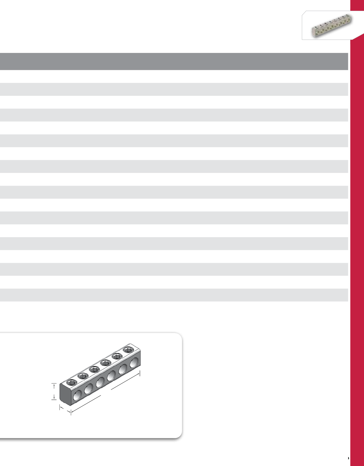
206
NSi Industries LLC • USA • 800.321.5847 • www.nsiindustries.com
206
POLARIS™
CAT.
NO. NO. OF
PORTS WIRE
RANGE LENGTH
(L) WIDTH
(W) HEIGHT
(H)
TORQUE
VALUE
(IN./LBS.)
HEX
SIZE
STD.
CTN.
QTY.
PL250-9 9250 MCM-6 AWG 7.860 0.880 1.130 360 IN/LBS 5/16 4
PL250-10 10 250 MCM-6 AWG 8.720 0.880 1.130 360 IN/LBS 5/16 4
PL250-11 11 250 MCM-6 AWG 9.580 0.880 1.130 360 IN/LBS 5/16 3
PL250-12 12 250 MCM-6 AWG 10.450 0.880 1.130 360 IN/LBS 5/16 3
PL350-3 3350 MCM-6 AWG 3.220 1.000 1.440 400 IN/LBS 5/16 6
PL350-4 4350 MCM-6 AWG 4.270 1.000 1.440 400 IN/LBS 5/16 6
PL350-6 6350 MCM-6 AWG 6.370 1.000 1.440 400 IN/LBS 5/16 6
PL350-8 8350 MCM-6 AWG 8.470 1.000 1.440 400 IN/LBS 5/16 4
PL350-10 10 350 MCM-6 AWG 10.570 1.000 1.440 400 IN/LBS 5/16 2
PL500-4 4500 MCM-4 AWG 4.860 1.130 1.630 450 IN/LBS 5/16 4
PL500-6 6500 MCM-4 AWG 7.145 1.130 1.630 450 IN/LBS 5/16 3
PL500-7 7500 MCM-4 AWG 8.280 1.130 1.630 450 IN/LBS 5/16 3
PL500-8 8500 MCM-4 AWG 9.440 1.130 1.630 450 IN/LBS 5/16 3
PL500-9 9500 MCM-4 AWG 10.570 1.130 1.630 450 IN/LBS 5/16 2
PL500-10 10 500 MCM-4 AWG 11.730 1.130 1.630 450 IN/LBS 5/16 2
PL750-3 3750-250 MCM 4.570 1.440 2.000 550 IN/LBS 3/8 3
PL750-4 4750-250 MCM 6.000 1.440 2.000 550 IN/LBS 3/8 3
PL750-6 6750-250 MCM 8.850 1.440 2.000 550 IN/LBS 3/8 2
PL750-8 8750-250 MCM 11.700 1.440 2.000 550 IN/LBS 3/8 1
W
HL
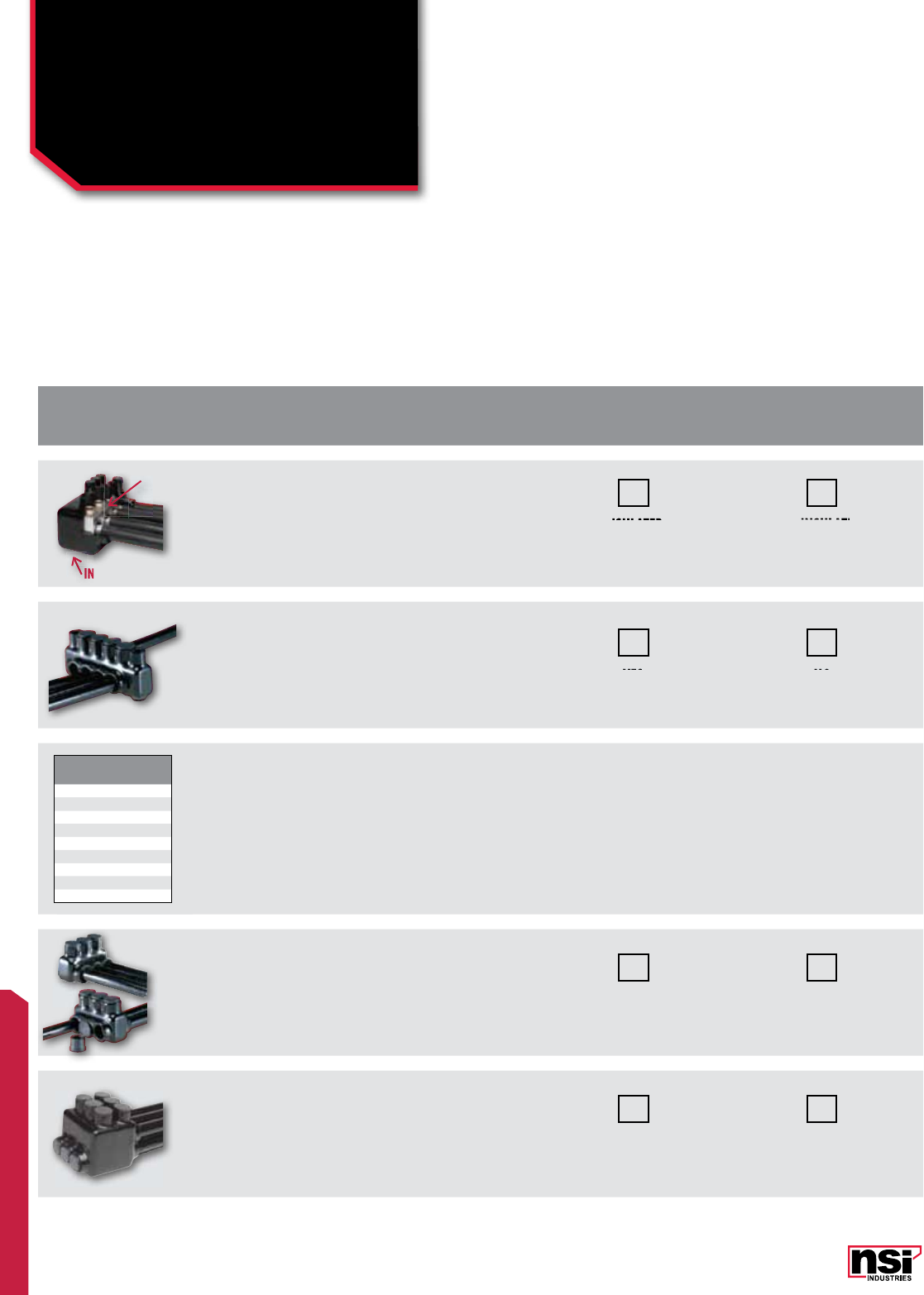
FEATURES
RATINGS
207
POLARIS™
BUILD THE CATALOG NUMBER
Create a custom catalog number, follow the checklist and build your catalog number as you go. Call our sales staff at 800-321-5847 with any questions.
Insulated/
Uninsulated
Blocks are covered with a unique plastisol
insulation but you are able to have
uninsulated.
INSULATED
BLOCK USE
"i"
UNINSULATED
BLOCK USE
"u"
Mounting
Mounting holes are provided in each end
of the connector block and are isolated
from the block with insulated sleeves. YES
ADD
"M"
NO
LEAVE BLANK
Ports /
Wire Size
Ports: How many ports will you need?
___(space for #1)
Wire Size: Choose the letter indicating
your wire size from the chart to the
left:___
Single Wire Size:
A. 4 ports 500-4MCM = 4F
Add to the part number: 4F
Multiple:
A. 4 ports 500-4MCM = 4F
B. 6 ports 1/0-14 = 6B
C. 2 ports 2250MCM = 2D
Add to the part number: 4F6B2D
Same/
Opposite Side
Cable can enter either side of the
connector block, based on your
requirements. This eliminates having
to bend the secondary cable around
the connector.
YES
ADD
"O"
NO
LEAVE BLANK
Stacked
Wire entry holes on top of the other,
allowing the block to be shorter, in length
and is ideal for use in small wireways or
panels.
YES
ADD
"S"
NO
LEAVE BLANK
UNINSULA
TED
UNINSULATEDUNINSULA
INSULATED
NO
YES
UNINSULATED
INSULATED
INSULATED
INSULATED
INSULATED
INSULATED
WIRE
RANGE
LETTER
DESIGNATION
4-14 A
1/0-14 B
3/0-6 C
250-6 D
350-6 E
500-4 F
600 J
750-250 G
1000-500 H
Let us custom engineer and fabricate a UL Listed insulated
block system for your next project. Each connector is made
with exact hole size and number for the cable runs being
used. You may choose to order a customized version of our IPL
Series or add one or more of the options listed below.
The combinations we can create and produce are almost
unlimited. Connector size can be up to 22” long also available
without insulation. We custom design a computer program
from your specifications; our engineering and production data
and machine your unique connector.
POLARIS™
Custom Designed
Connector Blocks
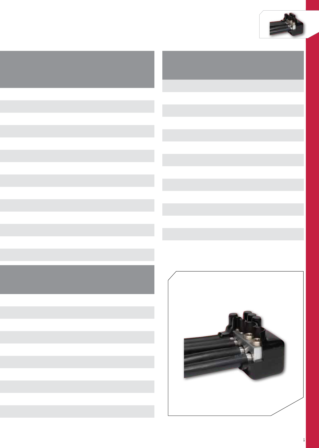
208
NSi Industries LLC • USA • 800.321.5847 • www.nsiindustries.com
208
POLARIS™
POLARIS™
ACCESSORIES
CATALOG
NO. UPC
CODE DESCRIPTION CONNECTION
SIZE
STD.
CNT.
QTY.
SP-4 95201 Set screw covers 4 AWG 15
SP-1/0 95202 Set screw covers 1/0 AWG 15
SP-3/0 95203 Set screw covers 3/0 AWG 15
SP-250 95204 Set screw covers 250 MCM 12
SP-350 95205 Set screw covers 350 MCM 10
SP-500 95206 Set screw covers 500 MCM 8
SP-600 78940 Set screw covers 600 MCM 6
SP-750 95207 Set screw covers 750 MCM 6
CP-3/0 95210 Cable port plugs 3/0 AWG 15
CP-250 95211 Cable port plugs 250 MCM 10
CP-350 95212 Cable port plugs 350 MCM 8
CP-500 95213 Cable port plugs 500 MCM 6
CP-600 78943 Cable port plugs 600 MCM 4
CP-750 95214 Cable port plugs 750 MCM 4
STRIP CHART FOR STANDARD CONNECTORS
CONNECTOR
SIZE STRIP
LENGTH BOLT DIA.
FOR MOUNTING
750 H 3.250 5/16
ISRH 750 2.312 5/16
750 MCM 2.000 5/16
600 MCM 1.625 5/16
500 MCM 1.625 5/16
350 MCM 1.375 5/16
250 MCM 1.250 5/16
ISR 250 1.125 5/16
3/0 AWG 1.000 1/4
1/0 AWG 0.875 1/4
4 AWG 0.689 3/16
TORQUE CHART (IN./LBS.)
CONNECTOR SIZE
WIRE
SIZE 1000 750 600 500 350 250 3/0 1/0 #4
800-
1000 550
750-600 550 550 550
500 450 450 450 450
400 425 425 425
350 400 400 400 400
250 360 360 360 360 360
4/0 250 250 250 250
3/0 250 250 250 250 250
2/0 180 180 180 180 180
1/0 180 180 180 180 180 180
#3-#1 150 150 150 150 150 150
#4-#6 110 110 110 110 110 110 45
#8 75 40
#10-#14 35 35
HOW TO BUILD A CUSTOM POLARIS™ CONNECTOR
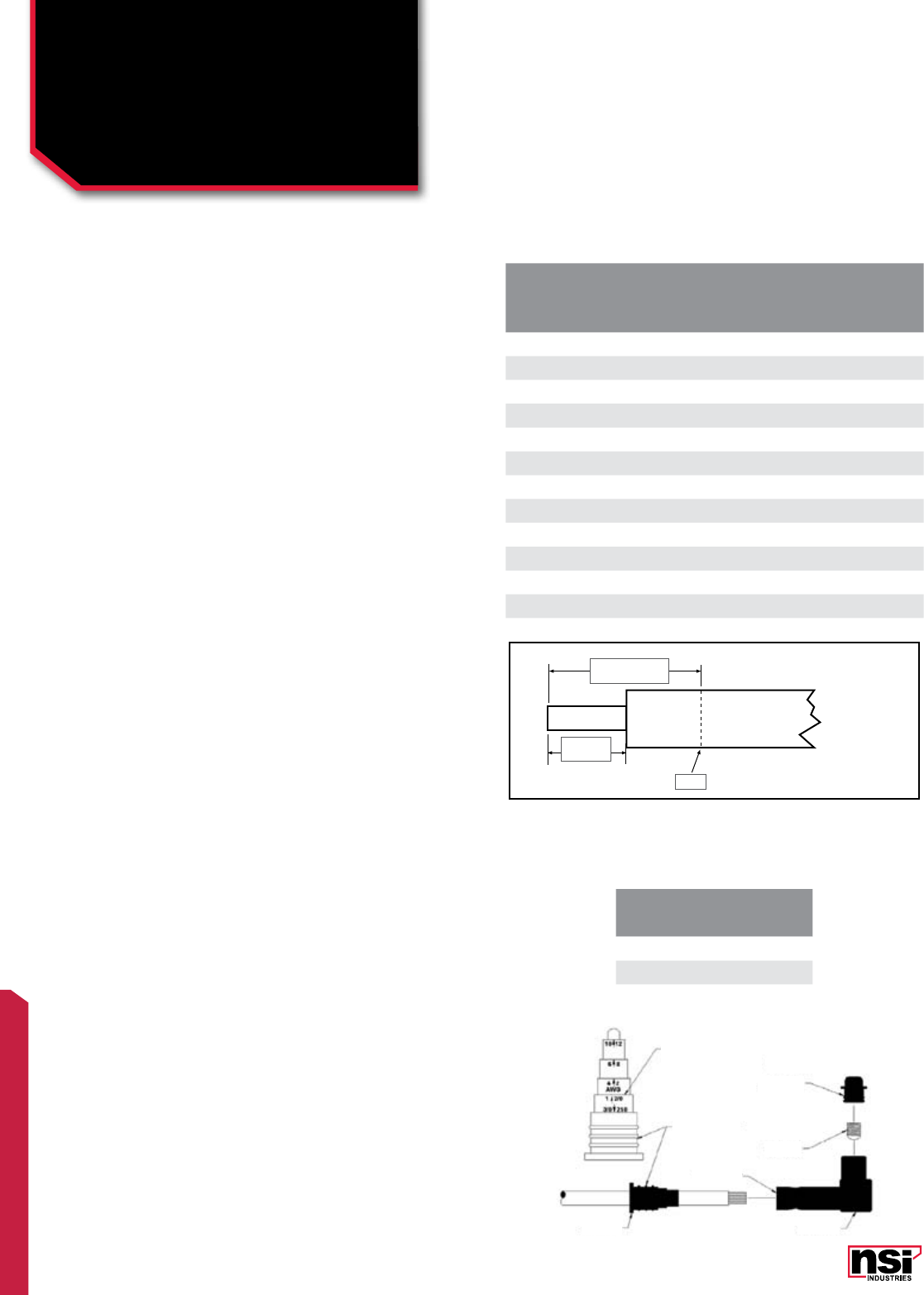
FEATURES
RATINGS
209
POLARIS™
1. Refer to the installation chart on the other side for; overall
distances, strip lengths, and tightening torque values.
2. Conductor must have insulation acceptable for direct burial.
3. Wipe off any foreign material (dirt, water, oil, etc.) on insulation
of conductor to be spliced.
4. Mark the conductor insulation with the proper overall distance
for the connector model number being used.
5. Mark the conductor insulation with the proper strip length for the
connector model number being used.
6. Remove the conductor insulation up to the marked strip length,
be sure not to “score” or “nick” the conductor.
7. Using the oxide inhibitor provided, lubricate the conductor
insulation by lightly coating the exposed conductor and insulation
up to the marked overall distance.
*****NOTE: Step 7 is optional, but will make installation quick
and easy.*****
8. Back off pressure screws enough to allow the stripped conductor
to enter the connector block.
9. Insert the conductor into the connector, slide the connector over
the conductor until the end of the connector insulation is within
1/8” of the overall mark on the conductor insulation.
10. Tighten the pressure screws to the proper torque value for the
connector model number being used.
11. Insert the caps to cover the pressure screws. Press caps firmly
into place.
12. Do not alter the connector to the connector insulation in
any manner!
13. Use only the pre-installed oxide inhibitor.
14. Caps are not a sealing mechanism in the wire entry ports, all
wire entry ports must have a properly sized conductor installed.
The UL Listing is for stranded wire only, AL-CU 600V maximum.
The connector and insulation are rated for 90° C.
The connectors are intended for Submersible/Direct Burial/Below Grade Applications
mark
A
overall distance
B
strip distance
CABLE/Conductor
PART
NO. WIRE
RANGE (A)
OVERALL
DISTANCE
(IN.)
(B)
STRIP
LENGTH
(IN.)
TIGHTENING
TORQUE
(IN./LBS.)
ITW 250 250mcm- 4/0 AWG 3 9/16 1 1/8 360
IPLW 250- 250mcm- 4/0 AWG 3 9/16 1 1/8 360
ISW 250 250mcm- 4/0 AWG 3 9/16 1 1/8 360
ITW 3/0- 3/0 AWG-2/0 AWG-1/0 AWG 3 5/16 15/16 250
IPLW 3/0- 3/0 AWG-2/0 AWG-1/0 AWG 3 5/16 15/16 250
ISW 3/0 3/0 AWG-2/0 AWG-1/0 AWG 3 5/16 15/16 250
ITW 1 #1 AWG - #2 AWG 3 1/4 15/16 150
IPLW 1- #1 AWG - #2 AWG 3 1/4 15/16 150
ISW 1 #1 AWG - #2 AWG 3 1/4 15/16 150
ITW 4 #4 AWG - #6 AWG 3 3/4 45
IPLW 4- #4 AWG - #6 AWG 3 3/4 45
ISW 4 #4 AWG - #6 AWG 3 1/16 13/16 45
INSTALLATION INSTRUCTIONS ISPB & ISPC
SUBMERSIBLE CONNECTORS
CABLE OUTLET
CUT SLEEVE TO APPROPRIATE SIZE.
EXAMPLE: FOR 2/0 CONDUCTOR
CUT HERE.
SET SCREW
ACCESS PLUG
CONDUCTOR SLEEVE
SET SCREW
CONNECTOR
SLEEVE END
CONDUCTOR
RANGE INCH-POUNDS
#12 - #6 135
#4 - 3/0 210
4/0 - 350 360
1. Remove cable insulation 1-1/8" from end of conductor
(insulation strip length imprinted on conductor port).
2. Wire brush bare conductor.
3. Remove conductor sleeve from connector.
4. Select and cutoff the correct step end at tip of arrow on
the sleeve. Make sure to cut sleeve straight across the end
of step. Discard sleeve for 300 and 350 MCM.
5. Reinsert the conductor sleeve (rocket) if required.
6. Remove set screw access plug and loosen set screw to
allow cable insertion.
7. Insert conductor into the cable outlet or rocket until
conductor hits the back of the connector and tighten set
screw to the recommended torque (table 1).
8. Replace set screw access plug.
POLARIS™
Installation Instructions
POLARIS BLUE™ SUBMERSIBLE & DIRECT BURIAL CONNECTORS

210
NSi Industries LLC • USA • 800.321.5847 • www.nsiindustries.com
210
POLARIS™
ASSEMBLY OF POLARIS GREY™ CONNECTORS
Wire insulation must be stripped in accordance with the Standard Connector Strip Length Chart below. The wire
insulation on a properly installed connector must be inside the conductor port no less than 3/8 inch. Pressure screws
MUST be secured at the torque value given on the Torque Charts corresponding to the connector, wire size and
classification shown on the reverse side. The UL listing is for stranded wire only, CU 600 Volts maximum for building
wiring and 1000 volts maximum for signs or luminaries. The connector and insulation temperature rating is 90˚C.
STRIP LENGTH CHART
CONNECTOR SIZE STRIP LENGTH (IN)
3/0 1
#1 7/8
#6 11/16
TORQUE CHART FOR POLARIS GREY™ CONNECTORS IN INCH POUNDS
BUILDING WIRE CLASS B, C, D WIRE SIZE AWG
CONNECTOR 3/0 2/0 1/0 #1 #2 #3 #4 #6 #8 #10 #12 #14
3/0 250 180 180 120 120 120 110
#1 150 150 150 110 110 75 45
#6 45 45 45 45 45
FLEXIBLE WIRE CLASS K, M, I WIRE SIZE AWG
CONNECTOR 3/0 2/0 1/0 #1 #2 #3 #4 #6 #8 #10 #12 #14
3/0 180 180 120 120
#1 150 150 110 110 75 45
#6 45 45 45 45 45
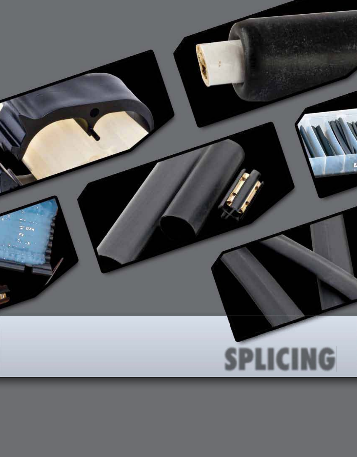
Splicing

213
SPLICING
FEATURES
RATINGS CAT.
NO. CONDUCTOR
SIZE GENERAL USE
DIA. LENGTH SLEEVE
LENGTH
MAX.
CONDUCTOR
OPENING
STD.
CTN.
QTY.
WAGS-4/0-4 4/0-14 AWG 0.15-0.70 (4-18) 4.00 (100) 1.00 (25) 3
WAGS-4/0-6 4/0-14 AWG 0.15-0.70 (4-18) 6.00 (150) 3.00 (75) 3
WAGS-4/0-8 4/0-14 AWG 0.15-0.70 (4-18) 8.00 (200) 5.00 (125) 3
WAGS-4/0-10 4/0-14 AWG 0.15-0.70 (4-18) 10.00 (250) 7.00 (175) 3
WAGS-500-8 500 MCM-6 AWG 0.30-1.30 (10-33) 8.00 (200) 4.00 (100) 3
WAGS-500-10 500 MCM-6 AWG 0.30-1.30 (10-33) 10.00 (250) 6.00 (150) 3
WAGS-750-10 750-250 MCM 0.80-1.50 (20-38) 10.00 (250) 4.00 (100) 3
Wrap-around gel splice closure sleeves quickly
insulate and seal buried electrical connections
rated up to 1,000 volts.
Engineered to handle direct burial and manhole
applications, these splice enclosure sleeves are
equally well suited for insulation and jacket repair.
Simply wrap and snap the sleeve on any cable in
the use range.
The sealant gel in the sleeve seals on contact.
The splice closure sleeve can be applied on all
common compression connectors and low voltage
cables, as well as in-line mechanical connectors.
EASY-SPLICE™
Wrap-Around
Gel Splice Kits
WAGS SERIES
rated up to 1,000 volts.
Engineered to handle direct burial and manhole
applications, these splice enclosure sleeves are
Engineered to handle direct burial and manhole
applications, these splice enclosure sleeves are
Engineered to handle direct burial and manhole
equally well suited for insulation and jacket repair.
Simply wrap and snap the sleeve on any cable in
the
The sealant gel in the sleeve seals on contact.
Wrap-around gel splice closure sleeves quickly
insulate and seal buried electrical connections
Wrap-around gel splice closure sleeves quickly
insulate and seal buried electrical connections
Wrap-around gel splice closure sleeves quickly
The sealant gel in the sleeve seals on contact.
The splice closure sleeve can be applied on all
The splice closure sleeve can be applied on all
common compression connectors and low voltage
The splice closure sleeve can be applied on all
The sealant gel in the sleeve seals on contact.
APPLICATION:
Qualified to ANSI C119.1-1986 for
underground splicing.
RATING:
Insulate and seal buried electrical
connections rated up to 1,000 volts.
A minimum seal length is required on
each side of the connector opening or
jacket damage.
Use these guidelines for minimum
seal distance:
WAGS-4/0 series: 1.50” each side
WAGS-500 series: 2.00” each side
WAGS-750 series: 3.00” each side
All dimensional data is listed in inches.
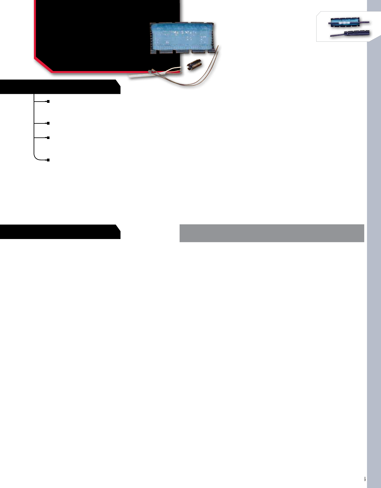
SPLICING
214
NSi Industries LLC • USA • 800.321.5847 • www.nsiindustries.com
214
SPLICING
SPLICING
SPLICING
FEATURES
RATINGS
EASY-SPLICE™
Wrap-Around
UF Splice Kit
ESUF SERIES
CAT.
NO. WIRE
RANGE LENGTH
(L)
STD.
CTN.
QTY.
ESUF 14/2 To 8/3 With Ground 8.000 3
Wrap-around UF splice kit provides a quick and
convenient method of splicing underground feeder
(UF) cable.
Convenient wrap-around design and fast installation.
No heating or waiting for compounds to cure.
The unique sealing gel entirely encapsulates the
splice, completely sealing out moisture and other
contaminants.
Kit includes connector and closure.
RATING:
The splice kit is rated for 600V applications.
All dimensional data is listed in inches.

215
SPLICING
FEATURES
RATINGS
In-line gel splice kit provides a sealed splice for
underground, buried and overhead applications.
Closure offers a fast and simple method for
splicing, insulating and environmentally sealing
low voltage cable splices.
Simply install the connector on a copper or
aluminum cable, place it in the closure, and
snap closed.
The splice kit is watertight for use in all locations.
Sealing and corrosion protection provided by
sealant gel.
CAT.
NO. WIRE
RANGE LENGTH
(L) WIDTH
(W) HEIGHT
(H)
STD.
CTN.
QTY.
ESGS-4/0 #2 – 4/0 AWG 4.229 1.973 1.097 3
low voltage cable splices.
Simply install the connector on a copper or
In-line gel splice kit provides a sealed splice for
underground, buried and overhead applications.
In-line gel splice kit provides a sealed splice for
underground, buried and overhead applications.
In-line gel splice kit provides a sealed splice for
underground, buried and overhead applications.
Closure offers a fast and simple method for
splicing, insulating and environmentally sealing
Closure offers a fast and simple method for
splicing, insulating and environmentally sealing
Closure offers a fast and simple method for
snap closed.
The splice kit is watertight for use in all locations.
snap closed.
The splice kit is watertight for use in all locations.
snap closed.
TEMPERATURE RATING:
-40 °C to 90 °C (-40 °F to 194 °F), 1000V.
APPLICATION:
Qualified to ANSI C119.1-1986 for
underground splicing. Insulate and seal buried
electrical connections rated up to 1,000 volts.
EASY-SPLICE™
In-Line Gel Splice Kit
With Connector
ESGS SERIES
All dimensional data is listed in inches.
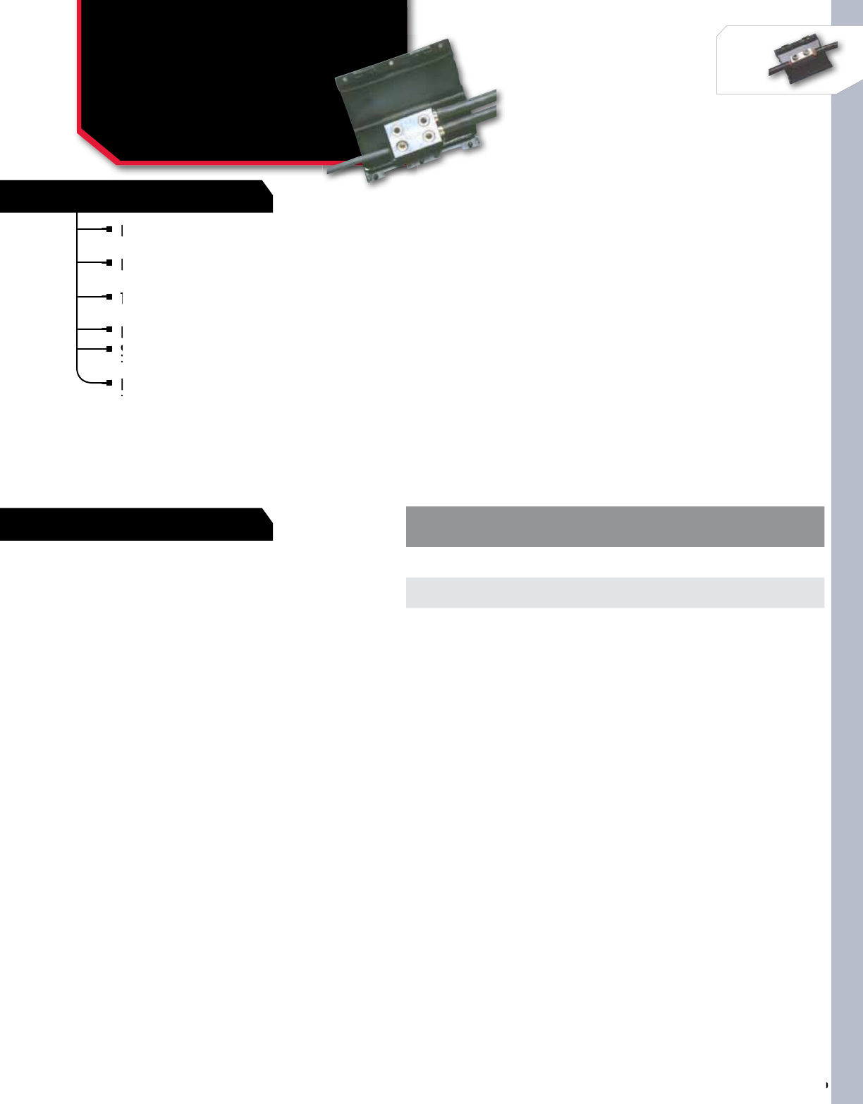
SPLICING
216
NSi Industries LLC • USA • 800.321.5847 • www.nsiindustries.com
216
SPLICING
SPLICING
SPLICING
FEATURES
RATINGS
Fast and simple method for connecting, insulating, and
environmentally sealing low-voltage splices.
Designed for underground and overhead environments
and is useful for street lighting applications.
The kit’s dual-rated mechanical connector splices a wide
range of cables, including copper and aluminum.
Four port design allows maximum inventory flexibility.
Sealant gel protects the connection from moisture
ingress, corrosion and pollution.
Hinged splice closure can be installed over the connector
in seconds by simply snapping the cover shut.
CAT.
NO. WIRE RANGE LENGTH
(L) WIDTH
(W) HEIGHT
(H)
STD.
CTN.
QTY.
ESGTS-2 #14 – #2 AWG 2.750 1.625 1.063 3
ESGTS-2/0 #14 – 2/0 AWG 4.250 2.000 1.188 3
Sealant gel protects the connection from moisture
ingress, corrosion and pollution.
Sealant gel protects the connection from moisture
ingress, corrosion and pollution.
Sealant gel protects the connection from moisture
range of cables, including
Four port design allows maximum inventory flexibility.
The kit’s dual-rated mechanical connector splices a
range of cables, including
The kit’s dual-rated mechanical connector splices a
range of cables, including
The kit’s dual-rated mechanical connector splices a
environmentally sealing low-voltage splices.
Designed for underground and overhead environments
and is useful for street lighting applications.
Designed for underground and overhead environments
and is useful for street lighting applications.
Designed for underground and overhead environments
Fast and simple method for connecting, insulating, and
environmentally sealing low-voltage splices.
Fast and simple method for connecting, insulating, and
environmentally sealing low-voltage splices.
Fast and simple method for connecting, insulating, and
Hinged splice closure can be installed over the connector
in seconds by simply snapping the cover shut.
Hinged splice closure can be installed over the connector
in seconds by simply snapping the cover shut.
Hinged splice closure can be installed over the connector
TEMPERATURE RATING:
-40 °C to 90 °C.
APPLICATION:
Qualified to ANSI C119.1-1986 for
underground splicing.
EASY-SPLICE™
Gel Tap Splice Kit
With Connector
ESGTS SERIES
All dimensional data is listed in inches.

217
SPLICING
FEATURES
RATINGS
Perfect for street light connections.
Accepts wires from #14 to 2/0 AWG (feeder cable).
Use the single port that accepts #14 to #6 AWG to
power the light.
Specially formulated material provides excellent
abrasion resistance, insulation value and UV
resistance.
The cap is clear to allow visual inspection of
connector positioning during installation and
connector performance during service life.
Corrosion protection is provided by the sealant gel.
CAT.
NO
WIRE RANGE LENGTH
(L) WIDTH
(W) HEIGHT
(H)
TORQUE VALUE STD.
CTN.
QTY.
HOLE A HOLE B HOLE A HOLE B
ESSLK-2/0 14-2/0 AWG 6-14 AWG 2.760 1.660 1.185 120-180IN/
Lbs
120-150IN/
Lbs 3
TESTING TEST CONDITIONS
Chemical Resistance Astm D543, Sulfuric Acid, Sodium Hydroxide, Transformer And Motor Oil
Ozone Resistance Astm D1149, 120 Hours @ 40˚C, 50Pphm
Accelerated Aging Astm D2671
Uv Resistance Astm G154, Uvb, 4,000 Hours On/Off Cycle
Abrasion Resistance 2040 Gm Wt., 4,000 Cycles, 5% Max Thickness Loss
Accepts wires from #14 to 2/0 AWG (feeder
Use the single port that accepts #14 to #6 AWG to
Accepts wires from #14 to 2/0 AWG (feeder
Use the single port that accepts #14 to #6 AWG to
Accepts wires from #14 to 2/0 AWG (feeder
Specially formulated material provides
abrasion resistance, insulation value and UV
Specially formulated material provides
abrasion resistance, insulation value and UV
Specially formulated material provides
The cap is clear to allow visual inspection of
connector positioning during installation and
The cap is clear to allow visual inspection of
connector positioning during installation and
The cap is clear to allow visual inspection of
Perfect for street light connections.
Perfect for street light connections.
Corrosion protection is provided by the
TEMPERATURE RATING:
-40 °C to 90 °C.
APPLICATION:
Gel stub splice kit insulates, seals
and protects stub splice connections
up to 1,000 volts.
INSTALLATION:
To install, simply push the cover
down over the connection and snap
the clamp closed.
Kit includes a UL listed connector for
use with copper and/or aluminum
conductors, a gel filled cap and a
cap clamp.
EASY-SPLICE™
Gel Stub Splice Kit
With Connector
ESSLK SERIES
All dimensional data is listed in inches.
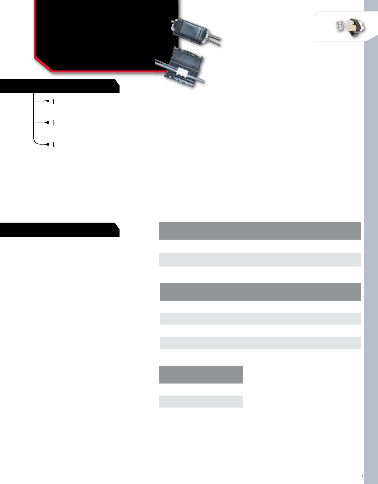
SPLICING
218
NSi Industries LLC • USA • 800.321.5847 • www.nsiindustries.com
218
SPLICING
SPLICING
SPLICING
FEATURES
RATINGS
ESGHS-0 APPROVED CONNECTORS
Blackburn WR139 Burndy YH0-1 Homac 0B22 NSi WRD139 T&B 63110
Blackburn WR159 Burndy YH0-2 Homac 0B44 NSi WRD159 UTILCO HT1
Blackburn WR179 Burndy YH0 100 Homac 0B102 NSi WRD179 UTILCO HT2
Blackburn WR199 Burndy YH0 125 Homac 0B103 NSi WRD199
Burndy YH0 150
ESGHS-BG APPROVED CONNECTORS
Blackburn WR9 NSi WR9
Burndy YPC2A8U T&B 63105
Homac UB214
CAT.
NO.
WIRE RANGE LENGTH
(L) WIDTH
(W) HEIGHT
(H)
STD.
CTN.
QTY.
MAIN TAP
ESGHS-BG 6-2 AWG 14-8 AWG 2.700 1.583 1.055 3
ESGHS-O 2-2/0 AWG 14-6 AWG 4.230 1.988 1.083 3
ESGHS-N 350 MCM 4/0 AWG 6.000 3.240 2.110 3
Low-voltage H-frame closure insulates and
seals low-voltage cable-taps and and splices
made with H-frame compression connectors.
The closure utilizes sealing gel material to
seal and protect the connection from moisture
ingress, corrosion and pollution.
H tap gel splice covers do not include connector.
made with H-frame compression
The closure utilizes sealing gel
seal and protect the connection from moisture
The closure utilizes sealing gel
seal and protect the connection from moisture
The closure utilizes sealing gel
Low-voltage H-frame closure insulates and
seals low-voltage cable-taps and and splices
Low-voltage H-frame closure insulates and
seals low-voltage cable-taps and and splices
Low-voltage H-frame closure insulates and
H tap gel splice covers do
TEMPERATURE RATING:
-40 °C to 90 °C.
1000V, UV resistant.
Qualified to ANSI C119.1-1986 for
underground splicing.
APPLICATION:
The low-voltage H-frame closure is ideal for
both underground and overhead applications
and is especially useful for street lighting
applications.
INSTALLATION:
To install, simply place the connection on
the closure and press the closure together.
EASY-SPLICE™
H-Tap Gel Splice Covers
With Connector
ESGHS SERIES
All dimensional data is listed in inches.
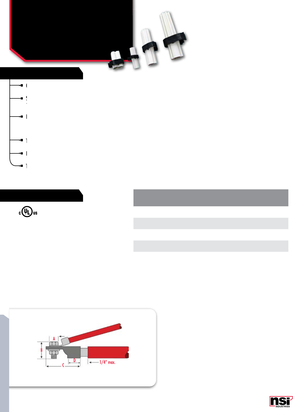
219
SPLICING
FEATURES
RATINGS
Quickly and conveniently insulate, seal, and
protect stub splice connections up to 1,000 volts.
Specially formulated material provides excellent
abrasion resistance, insulation value, and UV
resistance.
Each cap size is designed to fit a wide range of
cable sizes, the expandable design keeps the
cap as small as possible allowing it to expand
only as much as needed to fit.
The GSS-10 kit is designed for three phases in
one cap.
It includes one gel filled cap, one cap clamp,
and one phase separator.
The remaining kits include three of each – one
per phase.
CAT.
NO. WIRE
RANGE
MAX. BOLT DIMENSION MAX. LUG DIMENSION STD.
CTN.
QTY.
WIDTH
(A) LENGTH
(B) TOTAL LENGTH
(C) BARREL LENGTH
(D)
GSS-10 16-10 AWG 0.375 0.500 1.000 0.500 5
GSS-2 8-2 AWG 0.625 1.000 2.000 1.000 5
GSS-4/0 2-4/0 AWG 0.850 1.300 3.000 1.500 5
GSS-500 250-500 MCM 1.100 1.850 5.000 2.000 5
TEMPERATURE RATING:
105 °C.
APPLICATION:
Insulate, seal, and protect stub splice connections up to
1,000 volts. The robust yet compact design is engineered
to handle the harsh environment of motor and many
other connection applications (including street lights).
INSTALLATION:
GSS connector kits provide the fastest installation. Simply
slide the cover down over the connection and snap the
clamp closed. Sealant gel is already in the cap.
Quickly and conveniently insulate, seal, and
protect stub splice connections up to 1,000 volts.
Quickly and conveniently insulate, seal, and
protect stub splice connections up to 1,000 volts.
Quickly and conveniently insulate, seal, and
Specially formulated material provides excellent
abrasion resistance, insulation value, and UV
Specially formulated material provides excellent
abrasion resistance, insulation value, and UV
Specially formulated material provides excellent
Each cap size is designed to fit a wide range of
cable sizes, the expandable design keeps the
Each cap size is designed to fit a wide range of
cable sizes, the expandable design keeps the
Each cap size is designed to fit a wide range of
only as much as needed to fit.
The GSS-10 kit is designed for three phases in
It includes one gel filled cap, one cap clamp,
and one phase separator.
It includes one gel filled cap, one cap clamp,
and one phase separator.
It includes one gel filled cap, one cap clamp,
The remaining kits include three of each – one
per phase.
The remaining kits include three of each – one
per phase.
The remaining kits include three of each – one
EASY-SPLICE™
Push-On Gel Stub
Splice Kits
GSS SERIES
All dimensional data is listed in inches.
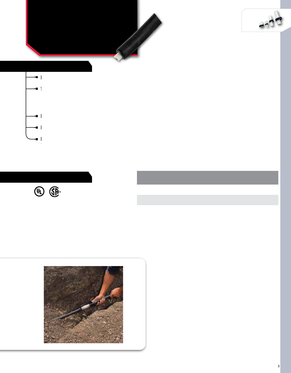
SPLICING
220
NSi Industries LLC • USA • 800.321.5847 • www.nsiindustries.com
220
SPLICING
SPLICING
SPLICING
FEATURES
RATINGS
Easy “roll-on” way to insulate and seal
cable connections up to 1,000 volts.
The gripping force of the EPDM elastomer
combines with high performance sealant to
form a water resistant, UV resistant insulating
sleeve appropriate for direct burial application
over in-line compression connectors.
Ideal for use where gas or electric heating
devices are not approved.
RUS accepted for use as a secondary tap or
splice cover.
Each kit includes one Easy-Splice sleeve and
sealant strips.
CAT.
NO. WIRE
RANGE CABLE
O.D. SLEEVE
LENGTH MAX. CONNECTOR
LENGTH
STD.
CTN.
QTY.
ROS-2/0 8-2/0 AWG 0.22-0.68 8.00 5.00 5
ROS-250 1/0 AWG-250 MCM 0.50-0.90 9.50 4.50 5
ROS-600 250-600 MCM 0.70-1.20 12.00 7.00 5
RATING:
Qualified to ANSI C119.1-1986. CSA certified to C22.2
No. 198.2. UL 486D listed, suitable for direct burial.
APPLICATION:
For use on standard poly or elastomeric- insulated cables.
Insulates and seals in-line compression connectors or
terminal lugs. Cable can be energized immediately.
Easy “roll-on” way to insulate and seal
cable connections up to 1,000 volts.
Easy “roll-on” way to insulate and seal
cable connections up to 1,000 volts.
Easy “roll-on” way to insulate and seal
The gripping force of the EPDM elastomer
combines with high performance sealant to
The gripping force of the EPDM elastomer
combines with high performance sealant to
The gripping force of the EPDM elastomer
Ideal for use where gas or electric heating
devices are not approved.
Ideal for use where gas or electric heating
devices are not approved.
Ideal for use where gas or electric heating
RUS accepted for use as a secondary tap or
splice cover.
RUS accepted for use as a secondary tap or
splice cover.
RUS accepted for use as a secondary tap or
Each kit includes one Easy-Splice sleeve and
sealant strips.
Each kit includes one Easy-Splice sleeve and
sealant strips.
Each kit includes one Easy-Splice sleeve and
EASY-SPLICE™
Direct Burial Roll-On
Splice Sleeve
ROS SERIES
US
All dimensional data is listed in inches.
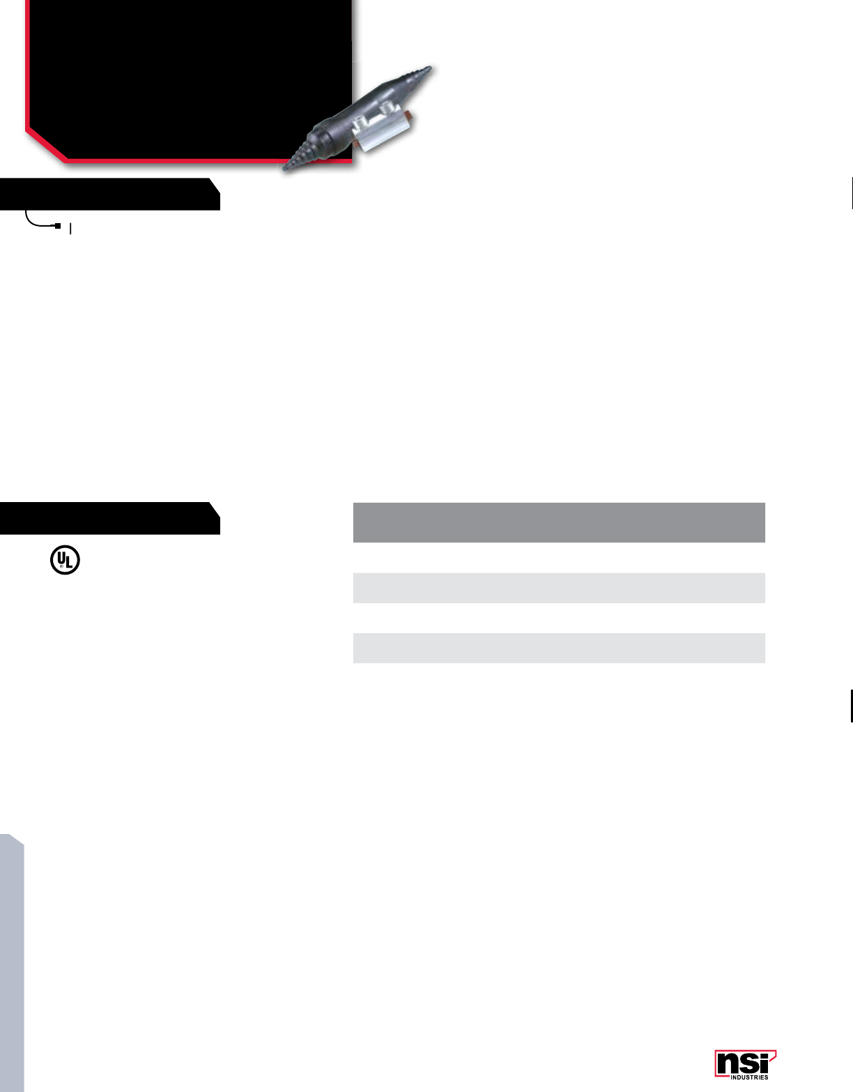
221
SPLICING
FEATURES
RATINGS
Dual-rated for use with copper and aluminum
cable, these kits consist of an in-line mechanical
set screw connector pre-filled with oxide inhibitor,
and an EPDM rubber insulating cover to ensure a
watertight seal.
CAT.
NO. WIRE
RANGE CONNECTOR
LENGTH
STD.
CTN.
QTY.
RSK-2/0 #14 – 2/0 AWG 1.880 12
RSK-350 #6 AWG – 350 MCM 3.000 6
RSK-500 2/0 AWG – 500 MCM 3.190 6
RSK-750 250 MCM – 750 MCM 6.250 3
Dual-rated for use with copper and aluminum
cable, these kits consist of an in-line mechanical
Dual-rated for use with copper and aluminum
cable, these kits consist of an in-line mechanical
Dual-rated for use with copper and aluminum
RATING:
600V.
APPLICATION:
street lights, motor connection, irrigation
systems, HVAC, outdoor lighting, and over
wire nuts for a secure seal.
EASY-SPLICE™
Direct Burial Splice Kit
With Rubber Cover
RSK SERIES
All dimensional data is listed in inches.
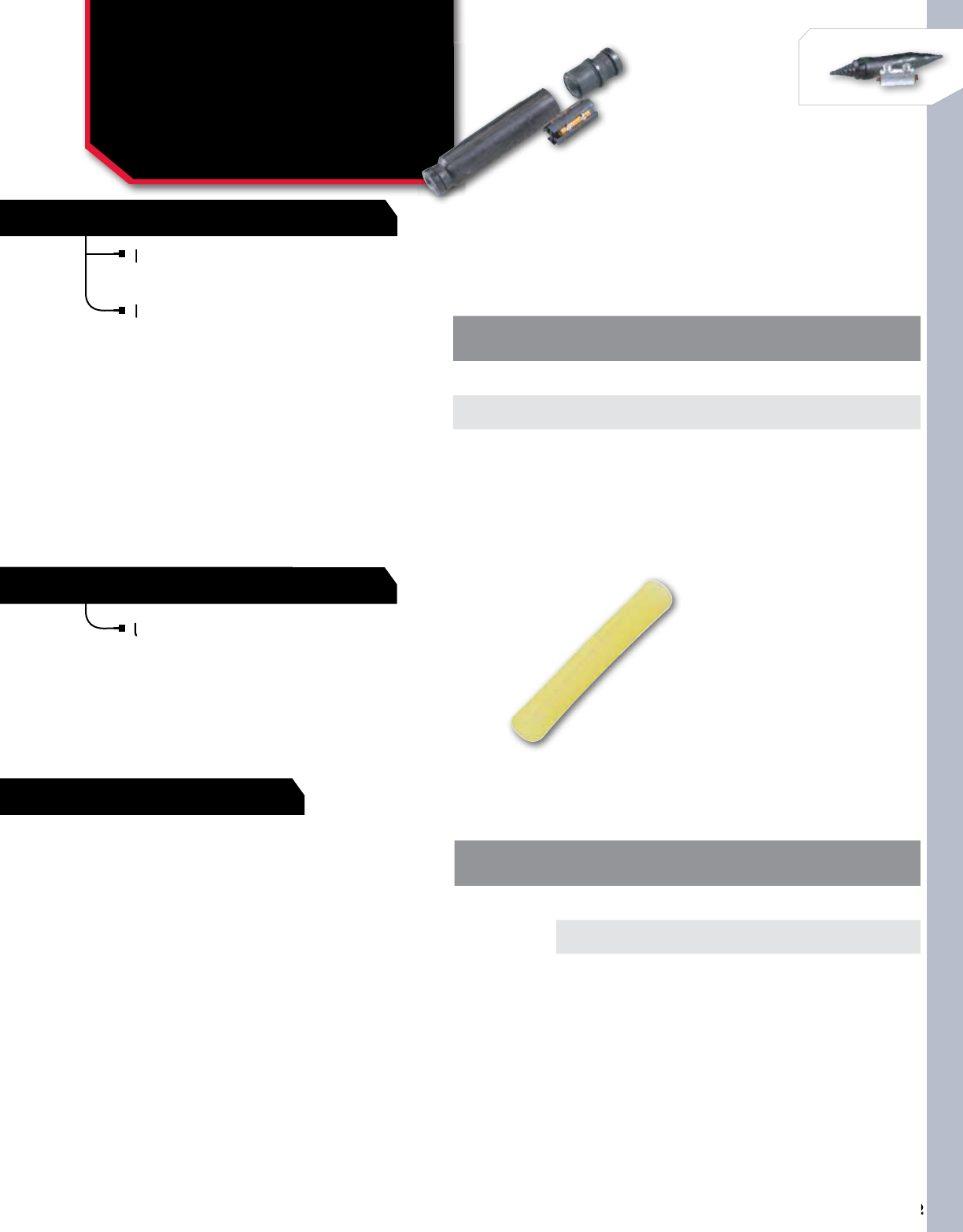
SPLICING
222
NSi Industries LLC • USA • 800.321.5847 • www.nsiindustries.com
222
SPLICING
SPLICING
SPLICING
NO. OF
CONDUCTORS CAT.
NO. WIRE
RANGE CONNECTOR
LENGTH
STD.
CTN.
QTY.
2SKSS-2 14/2-10/2 9.500 12
3SKSS-3 14/3-10/3 9.500 12
Fully waterproof, submersible and re-enterable
splice, through the use of uniquely designed
interference fit covers.
Kit comes complete with a connector, silicone
and cover AWG UF cable.
Fully waterproof, submersible and re-enterable
splice, through the use of uniquely designed
Fully waterproof, submersible and re-enterable
splice, through the use of uniquely designed
Fully waterproof, submersible and re-enterable
Kit comes complete with a connector, silicone
and cover AWG UF cable.
Kit comes complete with a connector, silicone
and cover AWG UF cable.
Kit comes complete with a connector, silicone
EASY-SPLICE™
Self Sealing UF Splice Kit
and Hot Melt Sealant
Sleeves
SKSS & HMSS Series
All dimensional data is listed in inches.
SELF SEALING UF SPLICE KIT
HOT MELT SEALANT SLEEVES
Used to provide a cable block in multi-conductor cables.
Used to provide a cable block in multi-conductor cables.
INSTALLATION:
Use a minimum of one sleeve for every
two cable conductors. Install HWHS or
CRS product over HMSS sealant sleeves
to melt sealant sleeves and provide
cable block.
CAT.
NO. LENGTH INSIDE
DIA. NO. OF
SLEEVES/CONDUCTOR
STD.
CTN.
QTY.
HMSS-4-40
1.75 0.160 #24 – #20 AWG: Use 1 Sleeve/
2 Conductors 100
1.75 0.160 #14 – #12 AWG: Use 1 Sleeve/
Conductor 100
All dimensional data is listed in inches.
RATINGS
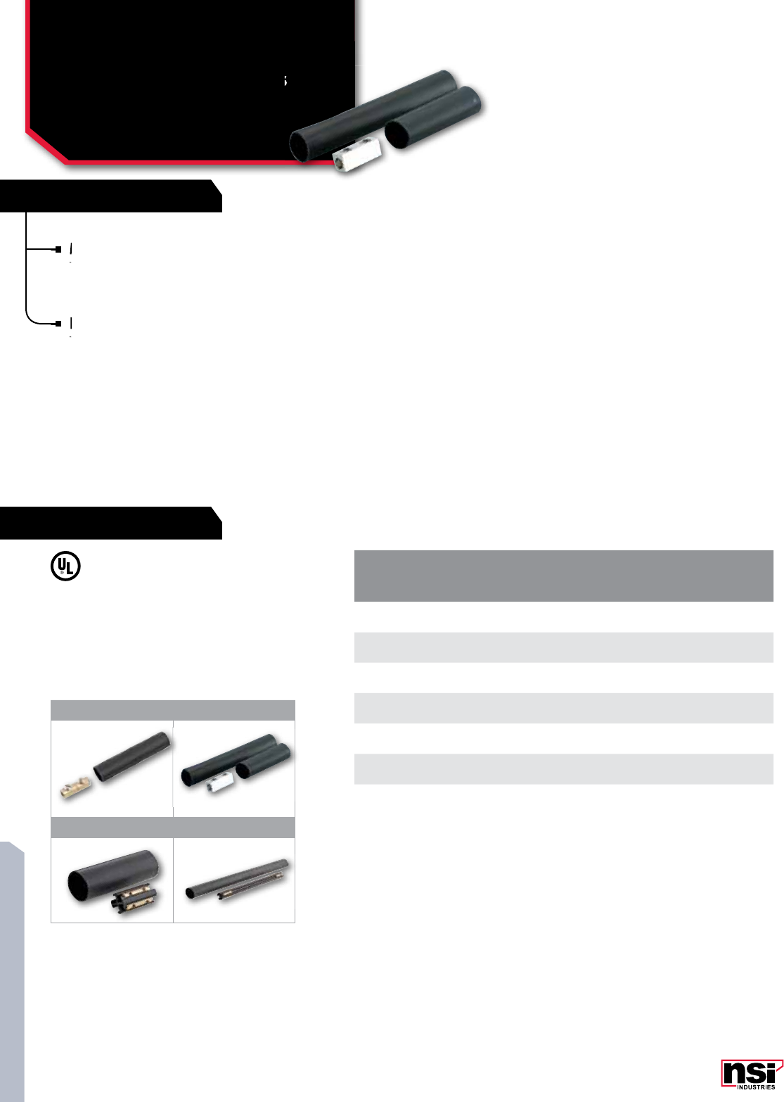
223
SPLICING
FEATURES
RATINGS
CAT.
NO. FIG.
NO. RANGE STD.
CTN.
QTY.
SKCB-8 1#14 to #8 AWG 24
SKCB-2 1#8 to #2 AWG 24
SKAB-2 2#8 to #2 AWG 24
SKAB-0 2#6 to 1/0 AWG 24
SKAB-250 21/0 AWG to 250 MCM 12
SKDB 314/3 to 8/3 24
SKUF 414/3 Without Ground To
8/3 With Ground 12
1. COPPER BUTT SPLICE KITS
Mechanical copper butt splice and a heavy
wall heat shrink tubing to create a fully
insulated splice for copper conductors only.
3. UF CABLE SPLICE KIT
For simplified splicing of UF cable designed
with heavy wall heat shrink with sealant.
This kit will accommodate 14/3 through
8/3 with ground UF cable and create a
direct burial splice. Contains one four-
position connector.
2. DUAL RATED BUTT SPLICE KITS
Mechanical dual rated splice and matched heavy wall heat
shrink tubing to create an insulated splice for copper and/
or aluminum cables.
4. UF STRETCHER KIT
Eliminates the need for using two connectors and a short
piece of cable when repairing damaged UF cable. Includes
one 11.5” connector that will accommodate 14/3 without
GRD minimum and 8/3 with GRD maximum. 600 Volt,
105°C. Utilizes heavy wall shrink with sealant for a quick
and reliable repair.
Mechanical copper butt splice and a heavy
wall heat shrink tubing to create a fully
Mechanical copper butt splice and a heavy
wall heat shrink tubing to create a fully
Mechanical copper butt splice and a heavy
For simplified splicing of UF cable designed
with heavy wall heat shrink with sealant.
For simplified splicing of UF cable designed
with heavy wall heat shrink with sealant.
For simplified splicing of UF cable designed
TEMPERATURE RATING:
105 °C.
600V Max.
1 2
3 4
EASY-SPLICE™
Direct Burial/
Submersible Splice Kits
With Heat Shrink
SK SERIES
All dimensional data is listed in inches.
Submersible Splice Kits
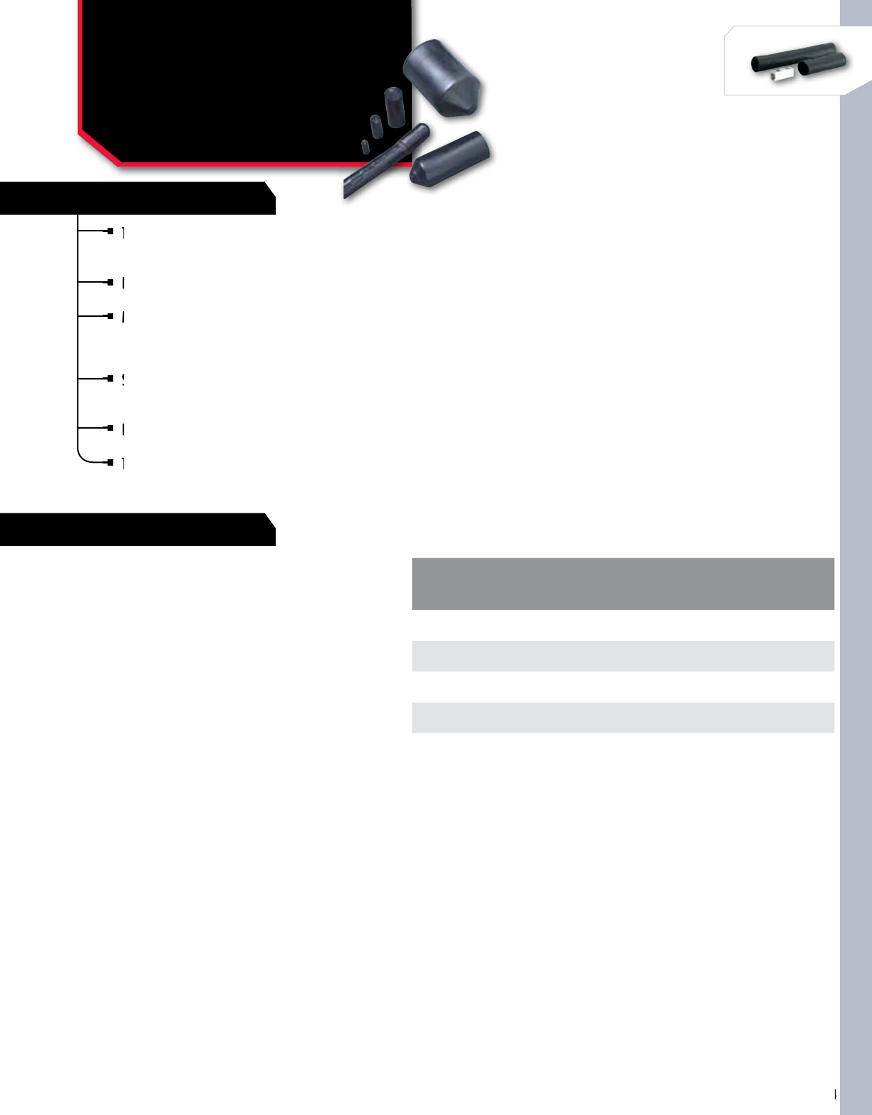
SPLICING
224
NSi Industries LLC • USA • 800.321.5847 • www.nsiindustries.com
224
SPLICING
SPLICING
SPLICING
FEATURES
RATINGS
These caps replace greases, tapes, epoxy, encapsulation,
or dips. In most sizes, installation may be accomplished in
less than one minute.
Heat-shrinkable end caps provide for efficient and positive
cable end sealing.
Made of thermally stabilized polyolefin, the interior
of the HSC is coated with a meltable sealant to assure
a watertight seal, complete insulation, abrasion and
corrosion resistance.
Seals may be affected over lead, steel, aluminum,
copper and all standard plastic and elastomeric insulating
materials and conduit.
HSC end sealing caps can be used as a live seal for cables
carrying up to 1,000V.
They can also be used as end seals for storing and pulling
de-energized cable.
CAT.
NO. CONDUCTOR
SIZE
GENERAL USE RANGE STD.
CTN.
QTY.
MAX. MIN.
HSC-70 6-3/0 AWG 0.700 0.300 10
HSC-125 4/0 AWG-750 MCM 1.250 0.650 10
HSC-195 750-1500 MCM 1.950 1.050 10
HSC-450 – 4.500 2.950 2
These caps replace greases, tapes, epoxy, encapsulation,
or dips. In most sizes, installation may be accomplished in
These caps replace greases, tapes, epoxy, encapsulation,
or dips. In most sizes, installation may be accomplished in
These caps replace greases, tapes, epoxy, encapsulation,
Made of
of the HSC is coated with a meltable sealant to assure
Heat-shrinkable end caps provide for efficient and positive
cable end sealing.
Heat-shrinkable end caps provide for efficient and positive
cable end sealing.
Heat-shrinkable end caps provide for efficient and positive
Seals may be affected over lead, steel, aluminum,
copper and all standard plastic and elastomeric insulating
Seals may be affected over lead, steel, aluminum,
copper and all standard plastic and elastomeric insulating
Seals may be affected over lead, steel, aluminum,
HSC end sealing caps can be used as a live seal for cables
carrying up to 1,000V.
They can also be used as end seals for storing and pulling
de-energized cable.
They can also be used as end seals for storing and pulling
de-energized cable.
They can also be used as end seals for storing and pulling
EASY-SPLICE™
Heat Shrinkable
End Caps
HSC SERIES
HSC end sealing caps are qualified
to ANSI C119.
1-1986 and rated to ICEA electrical
withstand test for 1,000 volts.
All dimensional data is listed in inches.
225
SPLICING
FEATURES
RATINGS
CAT.
NO. SEALABLE WIRE
RANGE LENGTH GENERAL USE RANGE MAX. CONNECTOR
O.D. MIN. SEAL LENGTH
PER SIDE
STD.
CTN.
QTY.
RECOVERED EXPANDED
HWHS14-6-6 14-6 AWG 6 0.130 0.390 0.290 1.500 3
HWHS14-6-12 14-6 AWG 12 0.130 0.390 0.290 1.500 3
HWHS14-6-48 14-6 AWG 48 0.130 0.390 0.290 1.500 3
HWHS8-2-6 8-2 AWG 6 0.170 0.550 0.410 2.000 3
HWHS8-2-12 8-2 AWG 12 0.170 0.550 0.410 2.000 3
HWHS8-2-48 8-2 AWG 48 0.170 0.550 0.410 2.000 3
HWHS6-40-4 6-4/0 AWG 4 0.250 0.860 0.690 2.000 3
HWHS6-40-6 6-4/0 AWG 6 0.250 0.860 0.690 2.000 3
HWHS6-40-9 6-4/0 AWG 9 0.250 0.860 0.690 2.000 3
HWHS6-40-12 6-4/0 AWG 12 0.250 0.860 0.690 2.000 3
HWHS6-40-48 6-4/0 AWG 48 0.250 0.860 0.690 2.000 3
HWHS2-500-4 2 AWG - 500 MCM 4 0.350 1.220 1.060 2.000 3
HWHS2-500-6 2 AWG - 500 MCM 6 0.350 1.220 1.060 2.000 3
HWHS2-500-8 2 AWG - 500 MCM 8 0.350 1.220 1.060 2.000 3
HWHS2-500-9 2 AWG - 500 MCM 9 0.350 1.220 1.060 2.000 3
HWHS2-500-12 2 AWG - 500 MCM 12 0.350 1.220 1.060 2.000 3
HWHS2-500-48 2 AWG - 500 MCM 48 0.350 1.220 1.060 2.000 3
HWHS20-750-6 2/0 AWG - 750 MCM 6 0.510 1.730 1.300 2.000 3
HWHS20-750-9 2/0 AWG - 750 MCM 9 0.510 1.730 1.300 2.000 3
HWHS20-750-12 2/0 AWG - 750 MCM 12 0.510 1.730 1.300 2.000 3
HWHS20-750-48 2/0 AWG - 750 MCM 48 0.510 1.730 1.300 2.000 3
HWHS250-1000-6 250-1000 MCM 6 0.700 1.960 1.500 2.000 3
HWHS250-1000-9 250-1000 MCM 9 0.700 1.960 1.500 2.000 3
HWHS250-1000-12 250-1000 MCM 12 0.700 1.960 1.500 2.000 3
HWHS250-1000-48 250-1000 MCM 48 0.700 1.960 1.500 2.000 3
HWHS500-1500-9 500-1500 MCM 9 0.860 2.480 1.840 2.500 3
HWHS500-1500-12 500-1500 MCM 12 0.860 2.480 1.840 2.500 3
HWHS500-1500-48 500-1500 MCM 48 0.860 2.480 1.840 2.500 3
HWHS800-2000-12 800-2000 MCM 12 1.290 3.930 - 2.500 3
HWHS800-2000-48 800-2000 MCM 48 1.290 3.930 - 2.500 3
HWHS1500-2500-12 1500-2500 MCM 12 1.490 4.640 - 2.500 3
HWHS1500-2500-48 1500-2500 MCM 48 1.490 4.640 - 2.500 3
Made of specially formulated polyolefin irradiated and
thermally stabilized to give the material “elastic memory”.
When a proper amount of heat is directly applied to the shrink sleeve,
it will permanently shrink to its original unexpanded diameter tightly
cover and “mold” itself into irregular shapes
The interior of the sleeve is coated with an adhesive that assures a
watertight seal after shrinking
For use on standard poly- or elastomeric-insulated/jacketed cables or
lead-jacketed cables, which may include aluminum or steel armoring.
RUS accepted for use as a secondary tap or splice cover. May be used
for jacket repair on cables up to 35 kV
Heavy wall heat shrink is also available without sealant. Medium
wall heat shrink and flame retardant heavy wall heat shrink also
available, with or without sealant (not UL Listed)
Made of specially formulated polyolefin irradiated and
thermally stabilized to give the material “elastic memory”.
Made of specially formulated polyolefin irradiated and
thermally stabilized to give the material “elastic memory”.
Made of specially formulated polyolefin irradiated and
thermally stabilized to give the material “elastic memory”.
When a proper amount of heat is directly applied to the shrink sleeve,
it will permanently shrink to its original unexpanded diameter tightly
When a proper amount of heat is directly applied to the shrink sleeve,
it will permanently shrink to its original unexpanded diameter tightly
When a proper amount of heat is directly applied to the shrink sleeve,
cover and “mold” itself into irregular shapes
The interior of the sleeve is coated with an adhesive that assures a
watertight seal after shrinking
watertight seal after shrinking
For use on standard poly- or elastomeric-insulated/jacketed cables or
watertight seal after shrinking
For use on standard poly- or elastomeric-insulated/jacketed cables or
watertight seal after shrinking
lead-jacketed cables, which may include aluminum or steel armoring.
For use on standard poly- or elastomeric-insulated/jacketed cables or
lead-jacketed cables, which may include aluminum or steel armoring.
For use on standard poly- or elastomeric-insulated/jacketed cables or
RUS accepted for use as a
for jacket repair on cables up to 35 kV
RUS accepted for use as a
for jacket repair on cables up to 35 kV
RUS accepted for use as a
Heavy wall heat shrink is also available without sealant. Medium
wall heat shrink and
EASY-SPLICE™
Heavy Wall Heat Shrink
For Direct Burial And
Submersible
HWHS SERIES
US
All dimensional data is listed in inches.
UL 486D Listed
CSA C22.2
TEMPERATURE RATING:
121-135 °C, 1000V.
APPLICATION:
Qualified to ANSI C119.1-1986 for
underground splicing. Insulate and seal
buried electrical connections rated up to
1,000 volts.
CONNECTORS UP TO 6 INCHES:
Recomended cut length = Connector length
+ 4 inches.
CONNECTORS OVER 6 INCHES:
Recomended cut length = Connector length
+ 5 inches.

226
NSi Industries LLC • USA • 800.321.5847 • www.nsiindustries.com
SPLICING
226
SPLICING
SPLICING
SPLICING
CAT.
NO. SEALABLE WIRE
RANGE LENGTH GENERAL USE RANGE MAX. CONNECTOR
O.D. MIN. SEAL LENGTH
PER SIDE
STD.
CTN.
QTY.
RECOVERED EXPANDED
HWHS14-6-6 14-6 AWG 6 0.130 0.390 0.290 1.500 3
HWHS14-6-12 14-6 AWG 12 0.130 0.390 0.290 1.500 3
HWHS14-6-48 14-6 AWG 48 0.130 0.390 0.290 1.500 3
HWHS8-2-6 8-2 AWG 6 0.170 0.550 0.410 2.000 3
HWHS8-2-12 8-2 AWG 12 0.170 0.550 0.410 2.000 3
HWHS8-2-48 8-2 AWG 48 0.170 0.550 0.410 2.000 3
HWHS6-40-4 6-4/0 AWG 4 0.250 0.860 0.690 2.000 3
HWHS6-40-6 6-4/0 AWG 6 0.250 0.860 0.690 2.000 3
HWHS6-40-9 6-4/0 AWG 9 0.250 0.860 0.690 2.000 3
HWHS6-40-12 6-4/0 AWG 12 0.250 0.860 0.690 2.000 3
HWHS6-40-48 6-4/0 AWG 48 0.250 0.860 0.690 2.000 3
HWHS2-500-4 2 AWG - 500 MCM 4 0.350 1.220 1.060 2.000 3
HWHS2-500-6 2 AWG - 500 MCM 6 0.350 1.220 1.060 2.000 3
HWHS2-500-8 2 AWG - 500 MCM 8 0.350 1.220 1.060 2.000 3
HWHS2-500-9 2 AWG - 500 MCM 9 0.350 1.220 1.060 2.000 3
HWHS2-500-12 2 AWG - 500 MCM 12 0.350 1.220 1.060 2.000 3
HWHS2-500-48 2 AWG - 500 MCM 48 0.350 1.220 1.060 2.000 3
HWHS20-750-6 2/0 AWG - 750 MCM 6 0.510 1.730 1.300 2.000 3
HWHS20-750-9 2/0 AWG - 750 MCM 9 0.510 1.730 1.300 2.000 3
HWHS20-750-12 2/0 AWG - 750 MCM 12 0.510 1.730 1.300 2.000 3
HWHS20-750-48 2/0 AWG - 750 MCM 48 0.510 1.730 1.300 2.000 3
HWHS250-1000-6 250-1000 MCM 6 0.700 1.960 1.500 2.000 3
HWHS250-1000-9 250-1000 MCM 9 0.700 1.960 1.500 2.000 3
HWHS250-1000-12 250-1000 MCM 12 0.700 1.960 1.500 2.000 3
HWHS250-1000-48 250-1000 MCM 48 0.700 1.960 1.500 2.000 3
HWHS500-1500-9 500-1500 MCM 9 0.860 2.480 1.840 2.500 3
HWHS500-1500-12 500-1500 MCM 12 0.860 2.480 1.840 2.500 3
HWHS500-1500-48 500-1500 MCM 48 0.860 2.480 1.840 2.500 3
HWHS800-2000-12 800-2000 MCM 12 1.290 3.930 - 2.500 3
HWHS800-2000-48 800-2000 MCM 48 1.290 3.930 - 2.500 3
HWHS1500-2500-12 1500-2500 MCM 12 1.490 4.640 - 2.500 3
HWHS1500-2500-48 1500-2500 MCM 48 1.490 4.640 - 2.500 3

227
SPLICING
FEATURES
Kits have been carefully constructed to include the most
common sizes and types in their category.
Cases are made of extremely durable polypropylene and
have heat sealed hinges.
Kits provide the ultimate in organization and convenience.
Clearly labeled on the inside lid for easy recognition.
Convenient size for easy carrying and easy storing.
KIT CAT.
NO.
KIT CONTENTS LENGTH STD.
CTN.
QTY.
CAT. NO. QTY.
THK
TWHS-125-6 25
6
1
TWHS-187-6 25 1
TWHS-250-6 20 1
TWHS-375-6 12 1
TWHS-500-6 71
TWHS-750-6 51
Kits have been carefully constructed to include the most
common sizes and types in their category.
Kits have been carefully constructed to include the most
common sizes and types in their category.
Kits have been carefully constructed to include the most
Cases are made of extremely durable polypropylene and
have heat sealed hinges.
Cases are made of extremely durable polypropylene and
have heat sealed hinges.
Cases are made of extremely durable polypropylene and
Kits provide the ultimate in organization and convenience.
Clearly labeled on the inside lid for easy recognition.
Clearly labeled on the inside lid for easy recognition.
Convenient size for easy carrying and easy storing.
Clearly labeled on the inside lid for easy recognition.
Convenient size for easy carrying and easy storing.
Convenient size for easy carrying and easy storing.
EASY-SPLICE™
Thin-Wall Heat
Shrink Kits
TWHS SERIES
All dimensional data is listed in inches.
SPLICING
228
NSi Industries LLC • USA • 800.321.5847 • www.nsiindustries.com
228
SPLICING
SPLICING
SPLICING
FEATURES
RATINGS
Kits have been carefully constructed to include the four
most common sizes of heavy wall heat shrink 6" lengths.
Sealant included.
Kits have been carefully constructed to include the four
Sealant included.
EASY-SPLICE™
Heavy Wall Heat
Shrink kits
HHK SERIES
US
KIT CAT.
NO. CAT.
NO. SEALABLE WIRE
RANGE LENGTH GENERAL USE RANGE MAX.
CONNECTOR
O.D.
MIN. SEAL
LENGTH
PER SIDE
STD.
CTN.
QTY.
RECOVERED EXPANDED
HHK
HWHS 8-2-6 8-2 AWG 6 0.170 0.550 0.410 2.000 9
HWHS 6-40-6 6-4/0 AWG 6 0.250 0.860 0.690 2.000 3
HWHS 2-500-6 2 AWG - 500 MCM 6 0.350 1.220 1.060 2.000 3
HWHS 20-750-6 2/0 AWG - 750 MCM 6 0.510 1.730 1.300 2.000 3
All dimensional data is listed in inches.

229
SPLICING
FEATURES
RATINGS
Flexible flame-retardant, thin wall, general
purpose heat-shrinkable polyolefin tubing has
a 2:1 shrink ratio.
Used for electrical insulation, wire harness
bundling, wire jacket marking and color
coding, it also splices and makes functional
terminations.
Standard packaging is either 6” lengths in
blister boxes, or in economical 25’ spools.
Available in black.
Black, white and colored thin wall tubing meet
MIL-DTL-23053/5, Class 1.
Clear meets MIL-DTL-23053/5, Class 2 and is
not flame retardant.
Flexible flame-retardant, thin wall, general
purpose heat-shrinkable polyolefin tubing has
Flexible flame-retardant, thin wall, general
purpose heat-shrinkable polyolefin tubing has
Flexible flame-retardant, thin wall, general
CAT.
NO. EXPANDED
I.D. RECOVERED
I.D. NOMIINAL RECOVERED
WALL THICKNESS LENGTH
(IN/FT)
STD.
CTN.
QTY.
TWHS-046-6 0.046 0.230 0.016 6" 15
TWHS-046-48 0.046 0.230 0.016 48" 1
TWHS-063-6 0.063 0.031 0.017 6" 15
TWHS-063-48 0.063 0.031 0.017 48" 1
TWHS-063-25B 0.063 0.031 0.017 25' Spool 1
TWHS-093-6 0.093 0.046 0.020 6" 15
TWHS-093-48 0.093 0.046 0.020 48" 1
TWHS-093-25B 0.093 0.046 0.020 25' Spool 1
TWHS-125-6 0.125 0.062 0.020 6" 15
TWHS-125-48 0.125 0.062 0.020 48" 1
TWHS-125-25B 0.125 0.062 0.020 25' Spool 1
TWHS-187-6 0.187 0.093 0.020 6" 12
TWHS-187-48 0.187 0.093 0.020 48" 1
TWHS-187-25B 0.187 0.093 0.020 25' Spool 1
TWHS-187 0.187 0.093 0.020 1,000' Spool 1
TWHS-250-6 0.250 0.125 0.025 6" 10
TWHS-250-48 0.250 0.125 0.025 48" 1
TWHS-250-25B 0.250 0.125 0.025 25' Spool 1
TWHS-250 0.250 0.125 0.025 500' Spool 1
UL Recognized to Standard 224.
TEMPERATURE RATING:
125 °C.
600V Max.
Used for electrical insulation, wire harness
bundling, wire jacket marking and color
Used for electrical insulation, wire harness
bundling, wire jacket marking and color
Used for electrical insulation, wire harness
Black, white and colored thin wall tubing meet
MIL-DTL-23053/5, Class 1.
Black, white and colored thin wall tubing meet
MIL-DTL-23053/5, Class 1.
Black, white and colored thin wall tubing meet
Standard packaging is either 6” lengths in
blister boxes, or in economical 25’ spools.
Standard packaging is either 6” lengths in
blister boxes, or in economical 25’ spools.
Standard packaging is either 6” lengths in
Clear meets MIL-DTL-23053/5, Class 2 and is
not flame retardant.
Clear meets MIL-DTL-23053/5, Class 2 and is
not flame retardant.
Clear meets MIL-DTL-23053/5, Class 2 and is
EASY-SPLICE™
Thin-Wall Tubing
TWHS SERIES

230
NSi Industries LLC • USA • 800.321.5847 • www.nsiindustries.com
SPLICING
230
SPLICING
SPLICING
SPLICING
CAT.
NO. EXPANDED
I.D. RECOVERED
I.D. NOMIINAL RECOVERED
WALL THICKNESS LENGTH
(IN/FT)
STD.
CTN.
QTY.
TWHS-046-6 0.046 0.230 0.016 6" 15
TWHS-046-48 0.046 0.230 0.016 48" 1
TWHS-063-6 0.063 0.031 0.017 6" 15
TWHS-063-48 0.063 0.031 0.017 48" 1
TWHS-063-25B 0.063 0.031 0.017 25' Spool 1
TWHS-093-6 0.093 0.046 0.020 6" 15
TWHS-093-48 0.093 0.046 0.020 48" 1
TWHS-093-25B 0.093 0.046 0.020 25' Spool 1
TWHS-125-6 0.125 0.062 0.020 6" 15
TWHS-125-48 0.125 0.062 0.020 48" 1
TWHS-125-25B 0.125 0.062 0.020 25' Spool 1
TWHS-187-6 0.187 0.093 0.020 6" 12
TWHS-187-48 0.187 0.093 0.020 48" 1
TWHS-187-25B 0.187 0.093 0.020 25' Spool 1
TWHS-187 0.187 0.093 0.020 1,000' Spool 1
TWHS-250-6 0.250 0.125 0.025 6" 10
TWHS-250-48 0.250 0.125 0.025 48" 1
TWHS-250-25B 0.250 0.125 0.025 25' Spool 1
TWHS-250 0.250 0.125 0.025 500' Spool 1

231
SPLICING
FEATURES
RATINGS
EASY-SPLICE™
Thin-Wall Tubing
TWHS SERIES CONT'D
Flexible flame-retardant, thin wall, general
purpose heat-shrinkable polyolefin tubing has
a 2:1 shrink ratio.
Used for electrical insulation, wire harness
bundling, wire jacket marking and color
coding, it also splices and makes functional
terminations.
Standard packaging is either 6” lengths in
blister boxes, or in economical 25’ spools.
Available in black.
Black, white and colored thin wall tubing meet
MIL-DTL-23053/5, Class 1.
Clear meets MIL-DTL-23053/5, Class 2 and is
not flame retardant.
UL Recognized to Standard 224.
TEMPERATURE RATING:
125 °C.
600V Max.
Used for electrical insulation, wire harness
bundling, wire jacket marking and color
Used for electrical insulation, wire harness
bundling, wire jacket marking and color
Used for electrical insulation, wire harness
Flexible flame-retardant, thin wall, general
purpose heat-shrinkable polyolefin tubing has
Flexible flame-retardant, thin wall, general
purpose heat-shrinkable polyolefin tubing has
Flexible flame-retardant, thin wall, general
Black, white and colored thin wall tubing meet
MIL-DTL-23053/5, Class 1.
Black, white and colored thin wall tubing meet
MIL-DTL-23053/5, Class 1.
Black, white and colored thin wall tubing meet
Standard packaging is either 6” lengths in
blister boxes, or in economical 25’ spools.
Standard packaging is either 6” lengths in
blister boxes, or in economical 25’ spools.
Standard packaging is either 6” lengths in
Clear meets MIL-DTL-23053/5, Class 2 and is
not flame retardant.
Clear meets MIL-DTL-23053/5, Class 2 and is
not flame retardant.
Clear meets MIL-DTL-23053/5, Class 2 and is
CAT.
NO. EXPANDED
I.D. RECOVERED
I.D. NOMIINAL RECOVERED
WALL THICKNESS LENGTH
(IN/FT)
STD.
CTN.
QTY.
TWHS-312-6 0.312 0.156 0.025 6" 10
TWHS-312-48 0.312 0.156 0.025 48" 1
TWHS-312 0.312 0.156 0.025 200' Spool 1
TWHS-375-6 0.375 0.187 0.025 6" 9
TWHS-375-48 0.375 0.187 0.025 48" 1
TWHS-375-25B 0.375 0.187 0.025 25' Spool 1
TWHS-375 0.375 0.187 0.025 200' Spool 1
TWHS-500-6 0.500 0.250 0.025 6" 8
TWHS-500-48 0.500 0.250 0.025 48" 1
TWHS-500-25B 0.500 0.250 0.025 25' Spool 1
TWHS-500 0.500 0.250 0.025 200' Spool 1
TWHS-750-6 0.750 0.375 0.030 6' 6
TWHS-750-48 0.750 0.375 0.030 48' 1
TWHS-750-25B 0.750 0.375 0.030 25' Spool 1
TWHS-750-25B 0.750 0.375 0.030 25' Spool 1
TWHS-750 0.750 0.375 0.030 100' Spool 1
TWHS-1000-6 1.000 0.500 0.035 6" 4
TWHS-1000-48 1.000 0.500 0.035 48" 1
TWHS-1000-25B 1.000 0.500 0.035 25' Spool 1
TWHS-1000 1.000 0.500 0.035 100' Spool 1
TWHS-1500-48 1.500 0.750 0.040 48" 1
TWHS-1500-25B 1.500 0.750 0.040 25' Spool 1
TWHS-2000-48 2.000 1.000 0.045 48" 1
TWHS-2000-25B 2.000 1.000 0.045 25' Spool 1

232
NSi Industries LLC • USA • 800.321.5847 • www.nsiindustries.com
SPLICING
232
SPLICING
SPLICING
SPLICING
CAT.
NO. EXPANDED
I.D. RECOVERED
I.D. NOMIINAL RECOVERED
WALL THICKNESS LENGTH
(IN/FT)
STD.
CTN.
QTY.
TWHS-312-6 0.312 0.156 0.025 6" 10
TWHS-312-48 0.312 0.156 0.025 48" 1
TWHS-312 0.312 0.156 0.025 200' Spool 1
TWHS-375-6 0.375 0.187 0.025 6" 9
TWHS-375-48 0.375 0.187 0.025 48" 1
TWHS-375-25B 0.375 0.187 0.025 25' Spool 1
TWHS-375 0.375 0.187 0.025 200' Spool 1
TWHS-500-6 0.500 0.250 0.025 6" 8
TWHS-500-48 0.500 0.250 0.025 48" 1
TWHS-500-25B 0.500 0.250 0.025 25' Spool 1
TWHS-500 0.500 0.250 0.025 200' Spool 1
TWHS-750-6 0.750 0.375 0.030 6' 6
TWHS-750-48 0.750 0.375 0.030 48' 1
TWHS-750-25B 0.750 0.375 0.030 25' Spool 1
TWHS-750-25B 0.750 0.375 0.030 25' Spool 1
TWHS-750 0.750 0.375 0.030 100' Spool 1
TWHS-1000-6 1.000 0.500 0.035 6" 4
TWHS-1000-48 1.000 0.500 0.035 48" 1
TWHS-1000-25B 1.000 0.500 0.035 25' Spool 1
TWHS-1000 1.000 0.500 0.035 100' Spool 1
TWHS-1500-48 1.500 0.750 0.040 48" 1
TWHS-1500-25B 1.500 0.750 0.040 25' Spool 1
TWHS-2000-48 2.000 1.000 0.045 48" 1
TWHS-2000-25B 2.000 1.000 0.045 25' Spool 1
GroundinG
Groundin
G
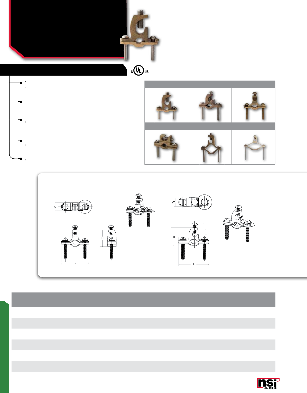
235
GROUNDING
GROUND CLAMPS
Heavy Duty Direct Burial
with Lay-in Lugs
GLC SERIES
CAT.
NO. FIG.
NO. PIPE SIZE
(IPS) GROUND
WIRE RANGE REBAR SIZE GROUND ROD
SIZE LENGTH
(L) WIDTH
(W) HEIGHT
(H)
STD.
CTN.
QTY.
GLC-140DB 1 1/2-1 8 STR-4/0 STR 3/8-1 1/2-1 2.551 0.784 2.132 10
GLC-12 DB 2 1/2-1 #10-2 STR 3/8-1 1/2-1 2.281 0.714 1.382 25
GLC-12 RDB 3 1/2-1 #10-2 STR 3/8-1 1/2-1 2.283 0.670 1.385 25
GLC-12 HDB 4 1/2-1 #10-2 STR 3/8-1 1/2-1 2.362 0.708 1.200 25
GLC-240DB 51 1/4-2 #8-4/0 STR - - 3.319 0.693 3.190 6
GLC-440DB 62 1/2-4 #8-4/0 STR - - 5.688 0.823 3.743 3
The ultimate ground clamp for large ground wires.
This incredible ground clamp can handle just about
any size ground wire and just about any application.
Lay-in feature provides for the ultimate in flexibility.
Convenient and pre-assembled screws are 304
stainless steel.
Available with silicon bronze screws by adding suffix
of SB.
APPLICATION:
UL Listed for direct burial in earth and concrete, it can
be used with rebar, copper water pipe, copper tubing
and ground rods up to 1 inch in diameter.
cULus Listed 467 Grounding and Bonding.
GLC-12 RDB GLC-12 DB
HEAVY DUTY DIRECT BURIAL W/LAY-IN
123
456
All dimensional data is listed in inches.
The ultimate ground clamp for large ground wires.
This incredible ground clamp can handle just about
Available with silicon bronze screws by adding suffix
of SB.
Available with silicon bronze screws by adding suffix
of SB.
Available with silicon bronze screws by adding suffix
Convenient and pre-assembled screws are 304
be used with rebar, copper water pipe, copper tubing
cULus Listed 467 Grounding and Bonding.
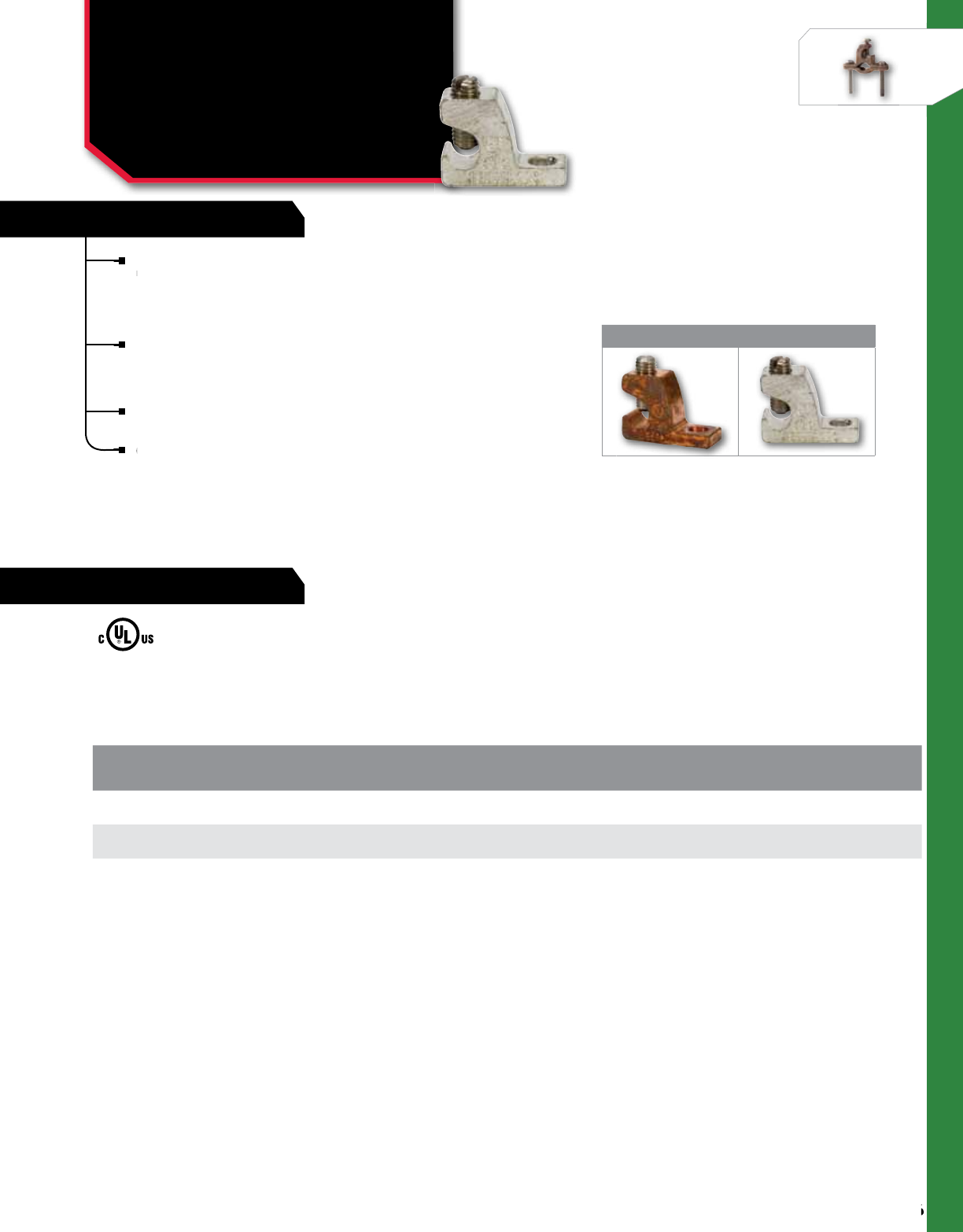
FEATURES
236
NSi Industries LLC • USA • 800.321.5847 • www.nsiindustries.com
236
GROUNDING
RATINGS
Lay-in lugs are used for grounding or in continuous loop
bonding and are available in several variations, depending
on the application.
GLC-4
Has a copper body with a steel screw and is used for
general grounding applications with copper wire.
GLC-4 DB/GLC-4 DBP
Have copper bodies with stainless steel screws and are UL
Listed for direct burial in earth or concrete with copper wire.
cULus Listed 467 Grounding and Bonding.
CAT.
NO. FIG.
NO. MATERIAL WIRE
RANGE USE LENGTH
(L) WIDTH
(W) HEIGHT
(H)
STD.
CTN.
QTY.
GLC-4 1copper with steel screws 4 -14 AWG general use for CU wire only 1.312 0.396 0.908 100
GLC-4 DB 1copper with stainless steel screws 4 -14 AWG direct burial for CU wire only 1.312 0.396 0.908 100
GLC-4 DBP 2tin-plated copper with stainless steel screws 4 -14 AWG direct burial for CU wire only 1.312 0.396 0.908 100
1 2
GROUND CLAMPS
Copper & Tin Plated Copper
Lay-in Lugs
GLC SERIES
LISTED
All dimensional data is listed in inches.
bonding and are available in several variations, depending
general grounding applications with copper wire.
cULus Listed 467 Grounding and Bonding.
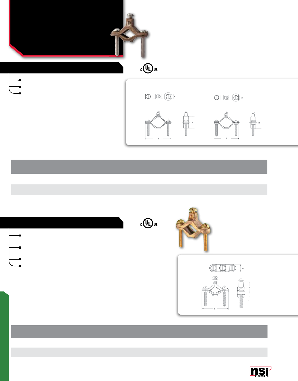
237
GROUNDING
G-2-S-BS
G-1-S-DB G-2-S-DB
UL Listed for direct burial in earth or concrete.
Screws are 304 stainless steel.
cULus Listed 467 Grounding and Bonding.
CAT.
NO. PIPE SIZE
(IPS) GROUND WIRE
BOLT SIZE GROUND CLAMP
BOLT SIZE GROUND
WIRE RANGE LENGTH
(L) WIDTH
(W) HEIGHT
(H)
STD.
CTN.
QTY.
G-1-SDB* 1/2-1 1/4"-20 x 1/2" 1/4"-20 x 1.50" 10 SOL – 2 STR 2.280 0.650 1.400 20
G-2-SDB* 1 1/4-2 1/4"-20 x 1/2" 5/16"-18 x 2" 10 SOL – 2 STR 3.600 0.750 1.690 10
HEAVY DUTY DIRECT BURIAL
Used to connect bare copper wire to copper water pipe,
ground rods and rebar for bonding.
Assembled with copper alloy screws and UL Listed for
direct burial in earth and concrete.
Can accommodate ground wires up to 2 AWG.
cULus Listed 467 Grounding and Bonding.
CAT.
NO. PIPE SIZE
(IPS) REBAR SIZE GROUND
WIRE RANGE GROUND WIRE
BOLT SIZE GROUND CLAMP
BOLT SIZE LENGTH
(L) WIDTH
(W) HEIGHT
(H)
STD.
CTN.
QTY.
G-2-S BS 11/4-2 3/8 - 1 10 SOL-2 STR 1/4-20 x 1/2" 5/16-18 x 2" 3.600 0.750 1.690 10
G-4-S BS 2 1/2-4 3/8 - 1 10 SOL-2 STR 1/4-20 x 1/2" 3/8-16 x 4" 6.350 0.970 3.750 6
DIRECT BURIAL FOR REBAR
GROUND CLAMPS
Heavy Duty Direct Burial
Ground Clamps,
Direct Burial for Rebar
G-S-DB, G-S-BS SERIES
*Available with silicon bronze screws by adding suffix of -SB.
All dimensional data is listed in inches.
All dimensional data is listed in inches.
Assembled with copper alloy screws and UL Listed for
Screws are 304 stainless steel.
Screws are 304 stainless steel.
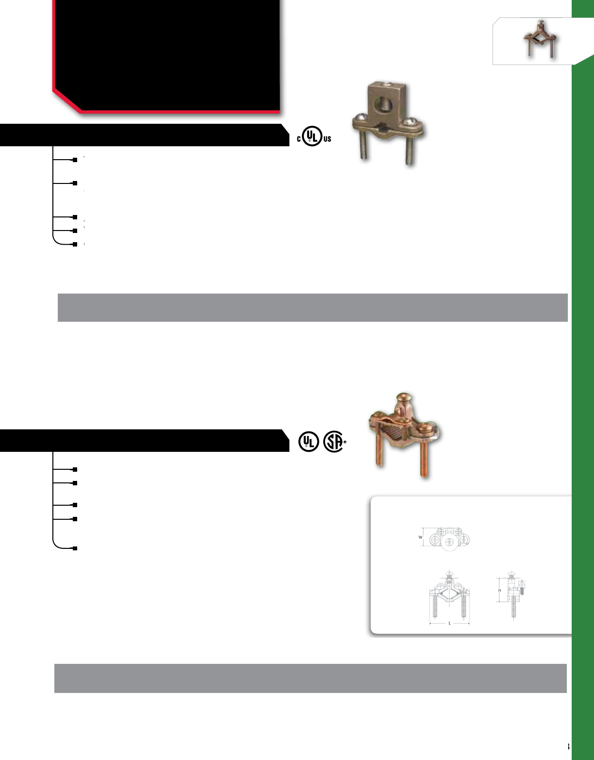
238
NSi Industries LLC • USA • 800.321.5847 • www.nsiindustries.com
238
GROUNDING
This incredible ground clamp can handle just about any size
ground wire and just about any application.
UL Listed for direct burial in earth and concrete, it can
be used with rebar, copper water pipe, copper tubing and
ground rods up to 1 inch in diameter.
Assembled with tough, 304 stainless steel screws.
Will accommodate ground wires from 8 AWG to 4/0 AWG.
cULus Listed 467 Grounding and Bonding.
This incredible ground clamp can handle just about any size
ground wire and just about any application.
This incredible ground clamp can handle just about any size
ground wire and just about any application.
This incredible ground clamp can handle just about any size
be used with rebar, copper water pipe, copper tubing and
Assembled with tough, 304 stainless steel screws.
Will accommodate ground wires from 8 AWG to 4/0 AWG.
Will accommodate ground wires from 8 AWG to 4/0 AWG.
cULus Listed 467 Grounding and Bonding.
Will accommodate ground wires from 8 AWG to 4/0 AWG.
cULus Listed 467 Grounding and Bonding.
cULus Listed 467 Grounding and Bonding.
EXTRA HEAVY DUTY DIRECT BURIAL
CAT.
NO. PIPE SIZE
(IPS) GROUND
WIRE RANGE REBAR SIZE GROUND ROD
SIZE LENGTH
(L) WIDTH
(W) HEIGHT
(H)
STD.
CTN.
QTY.
G-140DB 18 STR-4/0 STR 3/8-1 1/2-1 2.362 0.669 1.761 10
GROUND CLAMPS
Heavy Duty Direct Burial
& with Adapters
G & G-DB SERIES
For connecting wire to copper water pipe for grounding.
Special pressure bar grips cable armor to lessen chances of
grounding conductor being pulled out.
Assembled with silicon bronze screws.
UL Listed 467 Grounding and Bonding.
APPLICATION:
UL Listed for direct burial in earth or concrete.
DIRECT BURIAL WITH WIRE ADAPTERS
G-20-DB
CAT.
NO. PIPE SIZE
(IPS) GROUND
WIRE RANGE GROUND WIRE
BOLT SIZE GROUND CLAMP
BOLT SIZE LENGTH
(L) WIDTH
(W) HEIGHT
(H)
STD.
CTN.
QTY.
G-20DB 1/2 - 1 4,6,8 STR 1/4 - 20 x 1/2 1/4 - 20 x 1 1/2 2.250 1.000 1.350 20
All dimensional data is listed in inches.
All dimensional data is listed in inches.
*Available with silicon bronze screws by adding suffix of -SB.
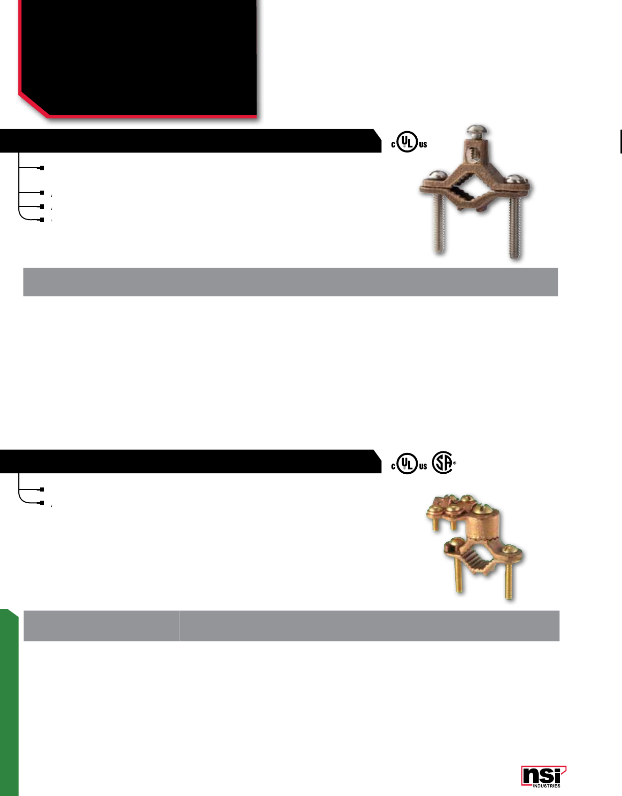
239
GROUNDING
CAT.
NO. GROUND
WIRE RANGE PIPE SIZE LENGTH
(L) WIDTH
(W) HEIGHT
(H)
STD.
CTN.
QTY.
G-3-BS 8-4/0 STR 1/2-1 2.320 0.748 1.437 20
Bronze clamps for copper water pipes with bronze adapters.
Assembled with brass screws.
HD GROUND CLAMP WITH ADAPTER AND BRASS SCREWS
CAT.
NO. GROUND
WIRE RANGE PIPE SIZE
(IPS)REBAR SIZE GROUND ROD
SIZE LENGTH
(L) WIDTH
(W) HEIGHT
(H)
STD.
CTN.
QTY.
G-1-SDBR 10 SOL - 2 STR 1/2-1 3/8 - 1 3/8-1 2.280 0.650 1.400 20
Bronze ground clamp for bonding bare copper wire to
copper water pipe.
Assembled 304 stainless steel screws.
Available with silicon bronze screws by adding suffix -SB.
cULus Listed 467 Grounding and Bonding.
HEAVY DUTY BRONZE GROUND CLAMP
copper water pipe.
Available with silicon bronze screws by adding suffix -SB.
cULus Listed 467 Grounding and Bonding.
Assembled 304 stainless steel screws.
Available with silicon bronze screws by adding suffix -SB.
Available with silicon bronze screws by adding suffix -SB.
cULus Listed 467 Grounding and Bonding.
cULus Listed 467 Grounding and Bonding.
Assembled with brass screws.
Assembled with brass screws.
GROUND CLAMPS
Heavy Duty Direct Burial
& with Adapters
G-S-DBR & G-BS SERIES
All dimensional data is listed in inches.
All dimensional data is listed in inches.
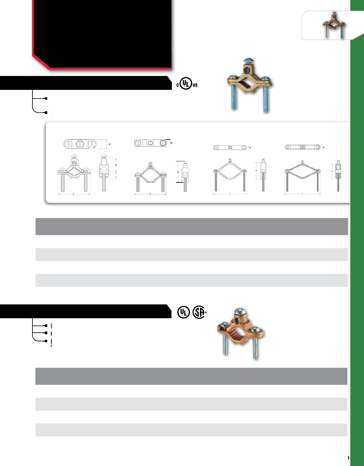
240
NSi Industries LLC • USA • 800.321.5847 • www.nsiindustries.com
240
GROUNDING
CAT.
NO. PIPE SIZE
(IPS) GROUND
WIRE RANGE LENGTH
(L) WIDTH
(W) HEIGHT
(H)
STD.
CTN.
QTY.
G-1 1/2-1 10 SOL-2 STR 2.200 0.748 1.437 25
G-2 1 1/4-2 10 SOL-2 STR 3.500 0.847 2.180 15
G-12 2 1/2-4 10 SOL-2 STR 6.250 0.943 3.674 6
G-13 4 1/2-6 10 SOL-2 STR 7.916 0.933 4.165 4
Bronze water pipe clamps with serrated head.
Cast bronze body with plated steel screws.
Designed for use alone or with heavy duty
bronze adapters.
HEAVY DUTY WATER PIPE CLAMPS
Bronze water pipe clamps with serrated head.
Cast bronze body with plated steel screws.
Bronze water pipe clamps with serrated head.
Cast bronze body with plated steel screws.
Designed for use alone or with heavy duty
bronze adapters.
Designed for use alone or with heavy duty
bronze adapters.
Designed for use alone or with heavy duty
Designed for use alone or with heavy duty
*Also cULus listed.
CAT.
NO. PIPE SIZE
(IPS) GROUND
WIRE RANGE LENGTH
(L) WIDTH
(W) HEIGHT
(H)
STD.
CTN.
QTY.
G-1-S* 1/2-1 10 SOL– 2 STR 2.280 0.650 1.400 20
G-2-S* 1 1/4-2 10 SOL– 2 STR 3.600 0.750 1.690 10
G-4-S 2 1/2-4 10 SOL– 2 STR 6.350 0.970 3.750 6
G-6-S 4 1/2-6 10 SOL– 2 STR 8.300 1.250 4.000 3
Bronze ground clamp for bonding bare copper wire to
water pipe or for use as a water meter shunt.
Zinc plated steel screws.
BRONZE GROUND CLAMPS
G-1-S G-2-S G-4-S G-6-S
GROUND CLAMPS
Bronze Ground Clamps &
Heavy Duty Water
Pipe Clamps
G-S & G SERIES
All dimensional data is listed in inches.
All dimensional data is listed in inches.
water pipe or for use as a water meter shunt.
Zinc plated steel screws.
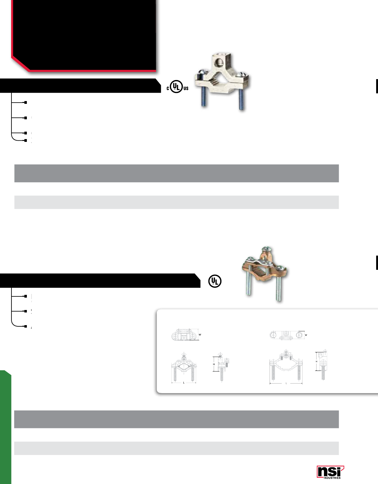
241
GROUNDING
Dual-rated ground clamp that grounds aluminum or
copper to water pipe, galvanized pipe or steel conduit.
Constructed from high-strength, extruded aluminum
alloy and are plated to provide low-contact resistance.
cULus Listed 467 Grounding and Bonding.
Zinc plated steel screws.
CAT.
NO. PIPE SIZE
(IPS) GROUND
WIRE RANGE LENGTH
(L) WIDTH
(W) HEIGHT
(H)
STD.
CTN.
QTY.
GCA-1 1/2-1 1/0-14 AWG 2.260 0.685 1.670 25
GCA-2 1 1/4-2 250 MCM-6 AWG 3.760 0.828 2.930 10
GCA-4 2 1/2-4 250 MCM-6 AWG 6.125 0.996 4.630 3
copper to water pipe, galvanized pipe or steel conduit.
cULus Listed 467 Grounding and Bonding.
Zinc plated steel screws.
Constructed from high-strength, extruded aluminum
alloy and are plated to
Constructed from high-strength, extruded aluminum
alloy and are plated to
Constructed from high-strength, extruded aluminum
Zinc plated steel screws.
Zinc plated steel screws.
ALUMINUM GROUND CLAMPS
GROUND CLAMPS
Aluminum & Bronze
Ground Clamps
GCA & G SERIES
G-20 G-66
CAT.
NO. PIPE SIZE
(IPS) GROUND WIRE
BOLT SIZE GROUND CLAMP
BOLT SIZE GROUND
WIRE RANGE LENGTH
(L) WIDTH
(W) HEIGHT
(H)
STD.
CTN.
QTY.
G-20 1/2-1 1/4 - 20 x 1/2 1/4 - 20 x 1 1/2 4,6,8 STR 2.250 1.000 1.350 20
G-66 1 1/4-2 1/4 - 20 x 1/2 5/16 -18 x 2 4,6,8 STR 3.580 0.850 2.040 10
For connecting unarmored wire to water pipe
for grounding.
Special pressure bar grips cable to lessen chances
of grounding conductor being pulled out.
Assembled with zinc-plated steel screws.
BRONZE GROUND CLAMP WITH WIRE ADAPTERS
LISTED
All dimensional data is listed in inches.
All dimensional data is listed in inches.
Special pressure bar grips cable to lessen chances
of grounding conductor being pulled out.
Special pressure bar grips cable to lessen chances
of grounding conductor being pulled out.
Special pressure bar grips cable to lessen chances
For connecting unarmored wire to water pipe
for grounding.
For connecting unarmored wire to water pipe
for grounding.
For connecting unarmored wire to water pipe
Assembled with zinc-plated steel screws.
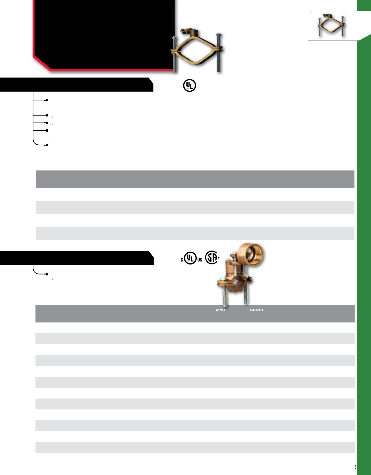
242
NSi Industries LLC • USA • 800.321.5847 • www.nsiindustries.com
242
GROUNDING
Heavy duty bronze adapters have serrations that match
the serrations on the ground clamp, assuring positive lock.
All adapters fit all clamps for the ultimate in flexibility.
Assembled with Zinc plated steel hardware.
Used to connect grounding conductor to rigid conduit on
water pipe.
UL Listed 467 Grounding and Bonding.
Used to connect grounding conductor to rigid conduit on
water pipe.
CAT.
NO. PIPE SIZE
(IPS) GROUND
WIRE RANGE LENGTH
(L) WIDTH
(W) HEIGHT
(H)
STD.
CTN.
QTY.
G-3 1/2-1 8-4/0 STR 2.320 0.748 1.437 20
G-4 1 1/4-2 8-4/0 STR 3.528 0.850 2.706 10
G-15 2 1/2-4 8-4/0 STR 6.125 0.964 3.962 6
G-16 4 1/2-6 8-4/0 STR 7.916 0.933 4.565 3
CAT.
NO. CONDUIT HUB
SIZE PIPE SIZE
(IPS) GROUND
WIRE RANGE LENGTH
(L) WIDTH
(W) HEIGHT
(H)
STD.
CTN.
QTY.
G-5 1/2 1/2 - 1 10 SOL – 2/0 STR 2.200 0.748 2.437 15
G-6 1/2 11/4 - 2 10 SOL – 2/0 STR 3.667 0.791 3.195 10
G-18 1/2 2 1/2 - 4 10 SOL – 2/0 STR 6.125 0.961 4.812 6
G-19 1/2 4 1/2 - 6 10 SOL – 2/0 STR 8.125 1.263 4.740 3
G-7 3/4 1/2 - 1 10 SOL – 3/0 STR 2.200 0.748 1.437 15
G-8 3/4 1 1/4 - 2 10 SOL – 3/0 STR 3.616 0.791 3.298 8
G-21 3/4 2 1/2 - 4 10 SOL – 3/0 STR 6.125 0.961 4.943 6
G-22 3/4 4 1/2 - 6 10 SOL – 3/0 STR 8.227 1.244 5.050 3
G-9 1 1/2 - 1 10 SOL – 3/0 STR 2.315 0.747 3.159 12
G-10 1 1 1/4 - 2 10 SOL – 3/0 STR 3.616 0.816 3.561 8
G-24 1 2 1/2 - 4 10 SOL – 3/0 STR 6.125 0.940 5.191 6
G-25 1 4 1/2 - 6 10 SOL – 3/0 STR 8.225 1.260 5.245 3
HEAVY DUTY BRONZE
FOR RIGID CONDUIT
GROUND CLAMPS
Heavy Duty & with 360°
Adapters for Rigid Conduit
G SERIES
water pipe.
LISTED
All dimensional data is listed in inches.
All dimensional data is listed in inches.
LENGTH
WIDTH
water pipe.
Assembled with Zinc plated steel hardware.
All adapters
Assembled with Zinc plated steel hardware.
the serrations on the ground clamp, assuring
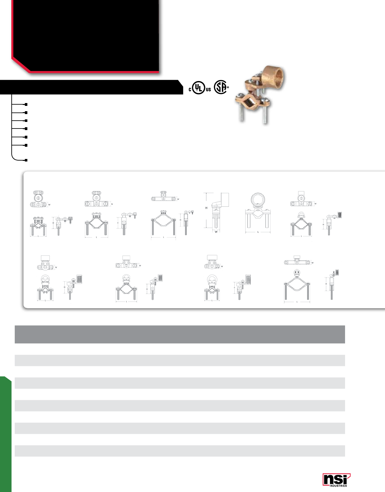
243
GROUNDING
GROUND CLAMPS
Heavy Duty with 360°
Adapters for Rigid Conduit
EG SERIES
CAT.
NO. CONDUIT HUB
SIZE PIPE SIZE (IPS) GROUND
WIRE RANGE LENGTH
(L) WIDTH
(W) HEIGHT
(H)
STD.
CTN.
QTY.
EG-3 1/2 1/2 - 1 10 SOL – 2/0 STR 2.200 0.585 2.300 20
EG-4 1/2 1
1/4 - 2 10 SOL – 2/0 STR 3.588 0.737 3.117 10
EG-15 1/2 2
1/2 - 4 10 SOL – 2/0 STR 6.125 0.972 4.834 6
EG-5 1/2 1/2 - 1 10 SOL – 2/0 STR 2.208 0.597 2.210 15
EG-6 1/2 1 1/4 - 2 10 SOL – 2/0 STR 3.631 0.725 2.696 10
EG-7 3/4 1/2 - 1 10 SOL – 2/0 STR 2.298 0.663 2.470 15
EG-8 3/4 1 1/4 - 2 10 SOL – 2/0 STR 3.576 0.789 3.841 8
EG-9 1 1/2 - 1 10 SOL – 3/0 STR 2.280 0.650 1.900 12
EG-10 1 1 1/4 - 2 10 SOL – 3/0 STR 3.587 0.792 4.029 8
EG-24 1 2 1/2 - 4 10 SOL – 3/0 STR 6.125 0.962 5.158 6
EG-5 EG-6
EG-7 EG-8 EG-9 EG-24
Bronze water pipe clamps with bronze adapters.
Excellent quality yet economical.
All adapters are interchangeable.
Assembled with zinc-plated steel screws.
Hub swings 360° for easy alignment.
Used to connect rigid conduct and ground conductor
to water pipe.
UL Listed 467 Grounding and Bonding.
WITH 360° ADAPTERS FOR RIGID CONDUIT
EG-3 EG-4 EG-15
All dimensional data is listed in inches.
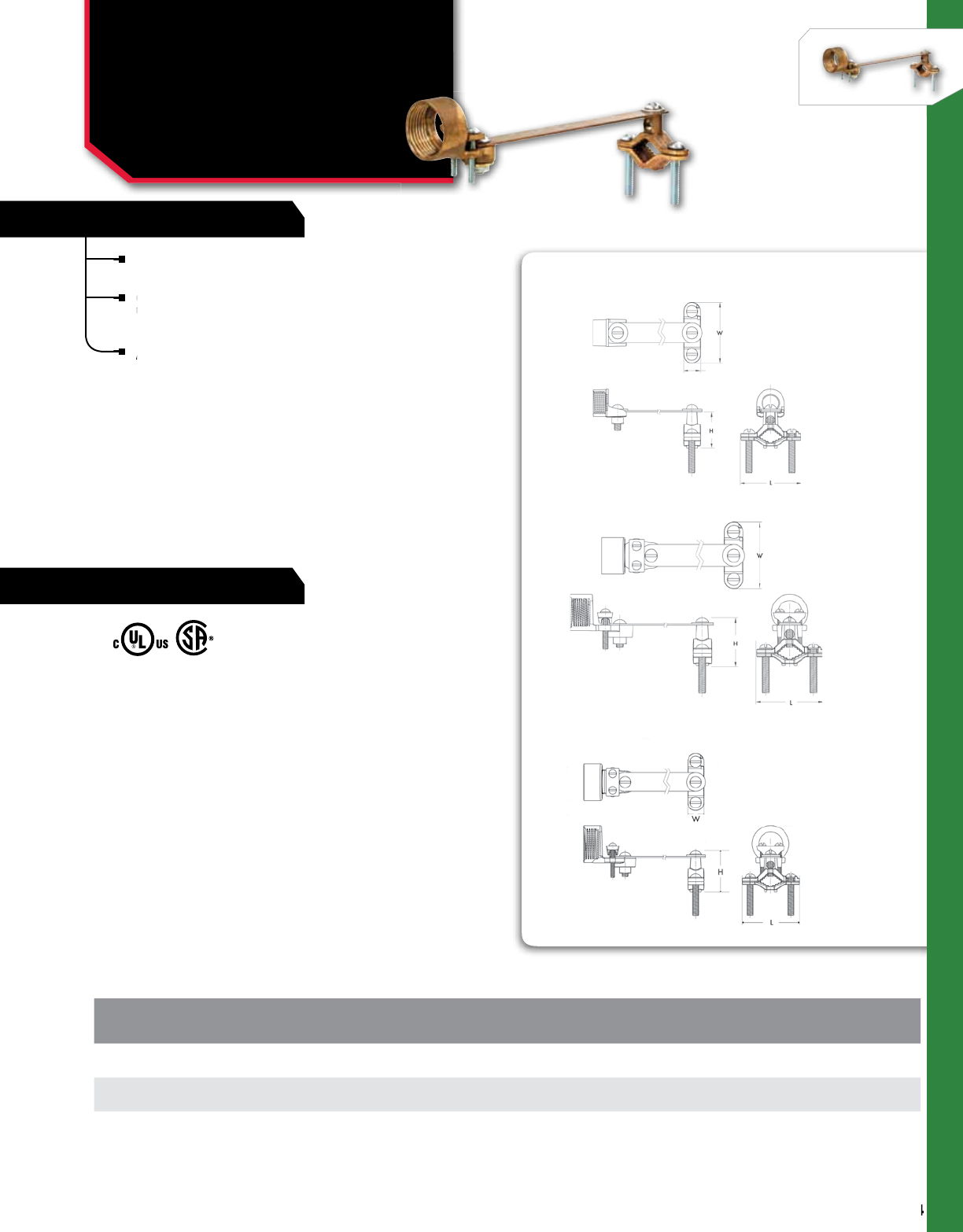
FEATURES
244
NSi Industries LLC • USA • 800.321.5847 • www.nsiindustries.com
244
GROUNDING
RATINGS
For connecting the grounding conductor in rigid
conduit to water pipe.
Copper strap allows flexibility during grounding and
helps protect the conduit system from the results of
vibrations in the water system.
Assembled with zinc-plated steel screws.
CAT.
NO. CONDUIT
HUB SIZE PIPE SIZE
(IPS) GROUND
WIRE RANGE
STD.
CTN.
QTY.
G-90 1/2 1/2 - 1 10 SOL – 2/0 STR 15
G-79 3/4 1/2 - 1 10 SOL – 2/0 STR 12
G-83 11/2 - 1 10 SOL – 3/0 STR 12
Copper strap allows flexibility during grounding
helps protect the conduit system from the results of
Copper strap allows flexibility during grounding
helps protect the conduit system from the results of
Copper strap allows flexibility during grounding
conduit to water pipe.
Assembled with zinc-plated steel screws.
GROUND CLAMPS
Rigid Conduit
w/Flexible Wire Strap
G SERIES
All dimensional data is listed in inches.
G-90
G-79
G-83

245
GROUNDING
Threaded hub cast of high-strength, highly conductive bronze.
Used with ground clamp to ground conductor To water pipe.
CAT.
NO. CONDUIT HUB
SIZE GROUND
WIRE RANGE
STD.
CTN.
QTY.
GH-50 1/2 10 SOL – 4 STR 50
GH-75 3/4 10 SOL – 2/0 STR 25
GH-100 110 SOL – 3/0 STR 15
Threaded hub cast of high-strength, highly
conductive bronze.
Used with ground cLamp with serrated hub to
ground conductor to water pipe.
Allows entry from any direction.
Zinc plated steel screws.
CAT.
NO. CONDUIT
HUB SIZE GROUND WIRE
RANGE
STD.
CTN.
QTY.
GHM-50 1/2 10 SOL – 2/0 STR 50
GHM-75 3/4 10 SOL – 2/0 STR 75
GHM-100 110 SOL – 3/0 STR 15
Threaded hub cast of high-strength, highly conductive bronze.
ECONOMY 360° HUB FOR GROUND CLAMPS
360˚ SWING TYPE
Threaded hub cast of high-strength, highly
conductive bronze.
Threaded hub cast of high-strength, highly
conductive bronze.
Threaded hub cast of high-strength, highly
ground conductor to water pipe.
Allows entry from any direction.
Zinc plated steel screws.
Zinc plated steel screws.
GROUND CLAMPS
Economy and
360˚ Swing Type Hubs
GH, GHM SERIES
All dimensional data is listed in inches.
All dimensional data is listed in inches.
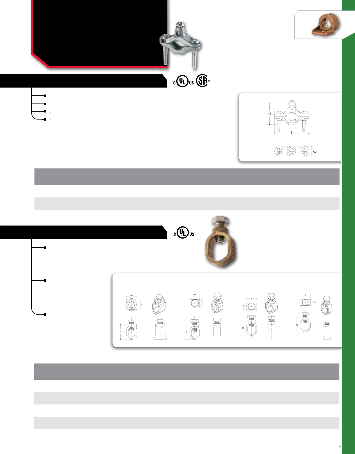
246
NSi Industries LLC • USA • 800.321.5847 • www.nsiindustries.com
246
GROUNDING
GROUND CLAMPS
Zinc Die Cast and
Standard Duty Silicon
Bronze Ground Clamp
GZ, GRC SERIES
Ground rod clamps
are made from silicon
bronze with 304
stainless steel screws
for maximum strenght.
All standard duty and
heavy duty ground
clamps are UL Listed
for direct burial in
earth or concrete.
cULus Listed 467
Grounding and Bonding.
CAT.
NO. GROUND ROD
SIZE REBAR SIZE GROUND WIRE
MAxIMUM
STD.
CTN.
QTY.
GRC 38*(**) 3/8 - 10 SOL – 4 STR 50
GRC 50** 1/2 3/8 10 SOL – 2 STR 25
GRC 58** 5/8 1/2 10 SOL – 1/0 STR 25
GRC 34** 3/4 5/8 10 SOL – 1 STR 20
*Not UL Listed/ **Available with silicon bronze screws by adding suffix of -SB.
STANDARD DUTY SILICON BRONZE
GRC-50 GRC-34GRC-58GRC-38
Die cast from high-strength zinc alloy.
Used to connect bare copper wire for grounding.
Zinc plated steel screws.
GZB-1 is brass plated.
CAT.
NO. CONDUIT
SIZE GROUND
WIRE RANGE
STD.
CTN.
QTY.
GZ-1 1/2 - 1 2 - 10 20
GZB-1* 1/2 - 1 2 - 10 20
ZINC DIE-CAST GROUND CLAMPS
Zinc plated steel screws.
GZB-1 is brass plated.
Zinc plated steel screws.
GZB-1 is brass plated.
GZB-1 is brass plated.
*Not UL Listed.
GZ-1
All dimensional data is listed in inches.
All dimensional data is listed in inches.
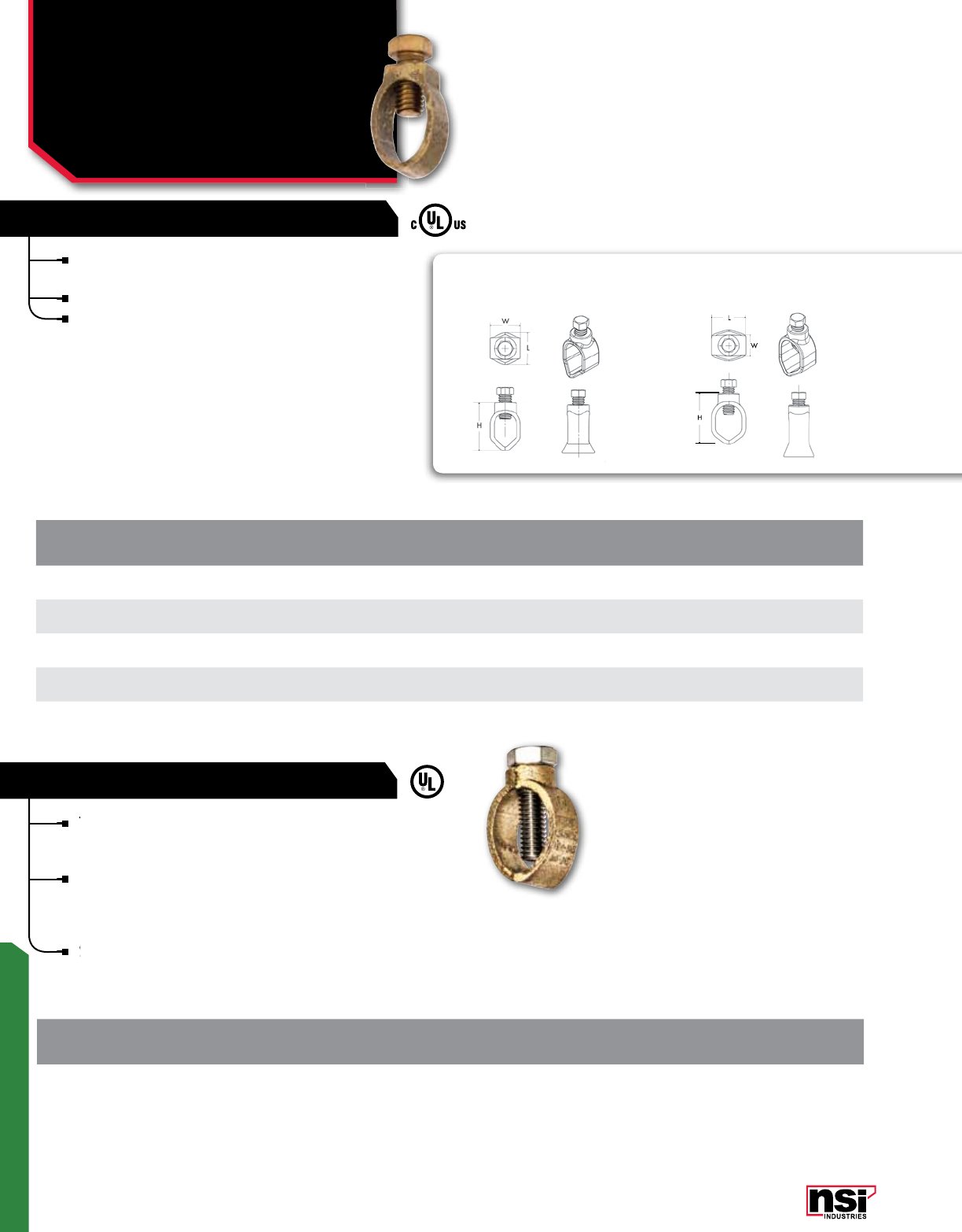
247
GROUNDING
This heavy duty ground rod clamp replaces all existing
ground rod clamps, eliminating the need to stock several
different sizes and types.
UL listed for direct burial in earth and concrete, heavy
duty construction enables it to handle large ground wires
up to 1/0 AWG – much larger than a standard ground
rod clamp.
Suitable for 3/8”, 1/2”, 5/8”, 3/4” ground rods.
CAT.
NO. GROUND WIRE
RANGE GROUND ROD
SIZE REBAR SIZE SCREW
MATERIAL
STD.
CTN.
QTY.
GRC-3834* 10 SOL – 1/0 STR 3/8, 1/2, 5/8, 3/4 3/8, 1/2, 5/8 silicon bronze 25
RANGE TAKING ROD CLAMP
This heavy duty ground rod clamp replaces all existing
ground rod clamps, eliminating the need to stock several
This heavy duty ground rod clamp replaces all existing
ground rod clamps, eliminating the need to stock several
This heavy duty ground rod clamp replaces all existing
duty construction enables it to handle large ground wires
Suitable for 3/8”, 1/2”, 5/8”, 3/4” ground rods.
Ground rod clamps are made from silicon bronze for
maximum strength.
A silicon bronze screw furnishes maximum clamping force.
All standard duty and heavy duty ground clamps are UL
Listed for direct burial in earth or concrete.
CAT.
NO. GROUND ROD
SIZE GROUND WIRE
MAxIMUM
STD.
CTN.
QTY.
GRC-50H* 1/2 10 SOL – 2 STR 25
GRC-58H* 5/8 10 SOL – 1/0 STR 20
GRC-34H* 3/4 8 SOL – 1/0 STR 20
GRC-100H* 18 SOL – 4/0 STR 10
HEAVY DUTY SILICON BRONZE
GRC-58H GRC-34H
GROUND CLAMPS
Heavy Duty Silicon
Bronze & Range Taking
Rod Clamp
GRC SERIES
*Available with silicon bronze screws by adding suffix of -SB.
*Available with silicon bronze screws by adding suffix of -SB.
All dimensional data is listed in inches.
All dimensional data is listed in inches.
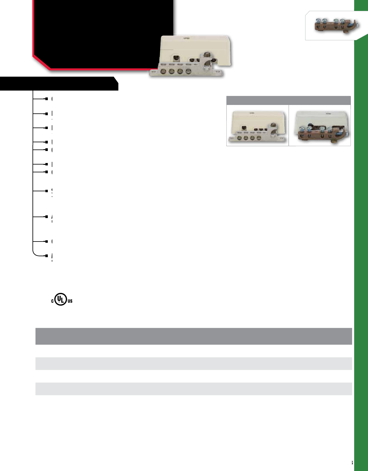
248
NSi Industries LLC • USA • 800.321.5847 • www.nsiindustries.com
248
GROUNDING
GROUNDING CONNECTORS
Intersystem Bonding
Connectors
GBIAL, GBIBZ SERIES
CAT.
NO.
FIG.
NO. MATERIAL DESCRIPTION WIRE
RANGE NO. OF
CIRCUITS
STD.
CTN.
QTY.
GBIAL 126-4414-WC 1 Aluminum With cover (1) 2-6, (4) 4-14 4 1
GBIAL 126-4414 1 Aluminum Cover not included (1) 2-6, (4) 4-14 4 1
GBIBZ 126-4414-WC 2 Bronze With cover (1) 2-6, (4) 4-14 4 1
GBIBZ 126-4414 2 Bronze Cover not included (1) 2-6, (4) 4-14 4 1
Convenient lay-in feature for main grounding
conductor, accommodates #2 to #6 AWG.
Lay-In feature eliminates the need to cut or splice to
main electrode.
Lay-In feature eliminates disassembling ground to
rod connection.
UL Listed 467 Grounding.
Optional UV Resistant paintable cover for more
desirable appearance.
For indoor and outdoor use.
Compact size measures 1.4”H x 1.19”W x 3.93”L.
GBIAL:
Supplied with stainless steel screws to prevent corrosion.
Dual rated for copper or aluminum conductor.
GBIBZ
Assembled with Zinc plated steel screws.
Rated for copper conductor only.
APPLICATIONS
Connector for intersystem bonding of power and
communication (phone, cable, and satellite) grounding systems.
Meets or exceeds requirements set forth in NEC2008 250.94
Bonding of other systems facilitates a fast and simple
connection to ground conductor below the meter.
Connector for intersystem bonding of power and
communication (phone, cable, and satellite) grounding systems.
Connector for intersystem bonding of power and
communication (phone, cable, and satellite) grounding systems.
Connector for intersystem bonding of power and
Assembled with Zinc plated steel screws.
Rated for copper conductor only.
Assembled with Zinc plated steel screws.
Rated for copper conductor only.
Assembled with Zinc plated steel screws.
Supplied with stainless steel screws to prevent corrosion.
Dual rated for copper or aluminum conductor.
Compact size measures 1.4”H x 1.19”W x 3.93”L.
For indoor and outdoor use.
Compact size measures 1.4”H x 1.19”W x 3.93”L.
Optional UV Resistant paintable cover for more
desirable appearance.
Optional UV Resistant paintable cover for more
desirable appearance.
Optional UV Resistant paintable cover for more
UL Listed 467 Grounding.
Optional UV Resistant paintable cover for more
Lay-In feature eliminates disassembling ground to
rod connection.
Lay-In feature eliminates disassembling ground to
rod connection.
Lay-In feature eliminates disassembling ground to
Lay-In feature eliminates the need to cut or splice to
main electrode.
Lay-In feature eliminates the need to cut or splice to
main electrode.
Lay-In feature eliminates the need to cut or splice to
Convenient lay-in feature for main grounding
conductor, accommodates #2 to #6 AWG.
Convenient lay-in feature for main grounding
conductor, accommodates #2 to #6 AWG.
Convenient lay-in feature for main grounding
Meets or exceeds requirements set forth in NEC2008 250.94
Bonding of other systems facilitates a fast and simple
Meets or exceeds requirements set forth in NEC2008 250.94
Bonding of other systems facilitates a fast and simple
Meets or exceeds requirements set forth in NEC2008 250.94
All dimensional data is listed in inches.
1 2
GBIAL GBIBZ
FEATURES

249
GROUNDING
FEATURES
GROUNDING CONNECTORS
Isolated Ground Bars
GBA, GBC SERIES
Made from either high-strength aluminum alloy 6061-T6
or high- conductivity copper as indicated below.
The base is made from high-strength glass-filled polyester.
Aluminum connectors are dual-rated for use with
aluminum or copper cables.
CAT.
NO.
FIG.
NO. MATERIAL WIRE
RANGE NO. OF
CIRCUITS LENGTH HEIGHT WIDTH STD.
CTN.
QTY.
GBA2-7 1 Aluminum AL/CU 2 - 14 7 2.88 2.31 1.88 3
GBC2-7 2 Copper CU 2 - 14 7 2.88 2.31 1.75 3
GBA2-10 1 Aluminum AL/CU 2 - 14 10 4.07 2.31 1.88 3
GBC2-10 2 Copper CU 2 - 14 10 4.07 2.31 1.75 3
GBA2-14 1 Aluminum AL/CU 2- 14 14 5.56 2.31 1.88 2
GBC2-14 2 Copper CU 2 - 14 14 5.56 2.31 1.75 2
GBA2-20 1 Aluminum AL/CU 2- 14 20 8.04 2.31 1.88 2
GBC2-20 2 Copper CU 2 - 14 20 8.04 2.31 1.75 2
GBA20-7 1 Aluminum AL/CU 2/0 - 14 7 4.61 2.31 2.13 3
GBA20-10 1 Aluminum AL/CU 2/0 - 14 10 6.41 2.31 2.13 3
GBA20-14 1 Aluminum CL/CU 2/0 - 14 14 8.81 2.31 2.13 2
1 2
Made from either high-strength aluminum alloy 6061-T6
or high-
Made from either high-strength aluminum alloy 6061-T6
or high-
Made from either high-strength aluminum alloy 6061-T6
The base is made from
Aluminum connectors are dual-rated for use with
Aluminum connectors are dual-rated for use with
aluminum or copper cables.
Aluminum connectors are dual-rated for use with
Aluminum and copper Copper only
All dimensional data is listed in inches.
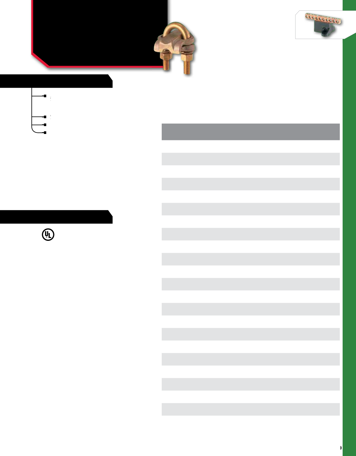
250
NSi Industries LLC • USA • 800.321.5847 • www.nsiindustries.com
250
GROUNDING
FEATURES
RATINGS
Made of high-copper-content alloy for grounding to
½” – 1” ground rods and ground pipes from
¼” - 3½” in parallel or 90° position.
Suitable for direct burial in earth and concrete.
Nuts and lockwashers are silicon bronze.
For use with single wire CAT.
NO. ROD SIZE PIPE SIZE CABLE
RANGE
STD.
CTN.
QTY.
UC-101 1/2 1/4 2/0 - 4 12
UC-102* 1/2 1/4 250-2/0 12
UC-103 5/8 - 3/4 3/8 4 - 8 12
UC-104 5/8 - 3/4 3/8 2/0 - 4 12
UC-105 5/8 - 3/4 3/8 250 - 2/0 12
UC-108 7/8 - 1 1/2 - 3/4 2/0 - 4 12
UC-109 7/8 - 1 1/2 - 3/4 250 - 2/0 12
UC-110* 7/8 - 1 1/2 - 3/4 300-500 12
UC-114 – 1 2/0 - 4 6
UC-115 – 1 250 - 2/0 12
UC-120 – 1 1/4 2/0 - 4 12
UC-121 – 1 1/4 250 - 2/0 12
UC-126 – 1 1/2 2/0 - 4 12
UC-127 – 1 1/2 250 - 2/0 12
UC-132 – 2 2/0 - 4 12
UC-133 – 2 250 - 2/0 6
UC-137 – 2 1/2 2/0 - 4 6
UC-138 – 2 1/2 250 - 2/0 6
UC-142 – 3 2/0 - 4 6
UC-143 – 3 250 - 2/0 6
UC-147 – 3 1/2 2/0 - 4 3
UC-148* – 3 1/2 250 - 2/0 3
*Not UL Listed
Made
½” – 1” ground rods and ground pipes from
Suitable for direct burial in earth and concrete.
GROUNDING CONNECTORS
Heavy Duty for Parallel,
90° Copper Cable
UC SERIES
All dimensional data is listed in inches.
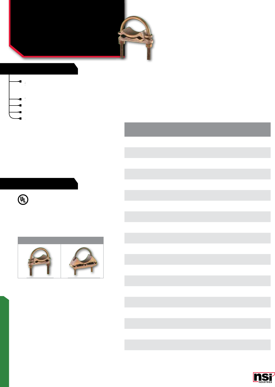
FEATURES
RATINGS
251
GROUNDING
1 2
Made of high-copper-content alloy for grounding to
½” – 1” ground rods and ground pipes from
¼” - 3½” in parallel or 90° position.
Suitable for direct burial in earth and concrete.
Nuts and lockwashers are silicon bronze.
200 Series for use with two wire
300 Series for use with three wire
CAT.
NO. FIG.
NO. PIPE SIZE CABLE
RANGE
STD.
CTN.
QTY.
UC-214 1 1 2/0 - 4 6
UC-215 1 1 250 - 2/0 6
UC-220 1 1 1/4 2/0 - 4 6
UC-221 1 1 1/4 250 - 2/0 6
UC-226 1 1 1/2 2/0 - 4 6
UC-227 1 1 1/2 250 - 2/0 6
UC-232 1 2 2/0 - 4 6
UC-233 1 2 250 - 2/0 3
UC-237 1 2 1/2 2/0 - 4 3
UC-238 1 2 1/2 250 - 2/0 3
UC-242 1 3 2/0 - 4 3
UC-243 1 3 250 - 2/0 3
UC-315 2 1 250 - 2/0 6
UC-320 2 1 1/4 2/0 - 4 6
UC-326 2 1 1/2 2/0 - 4 6
UC-327 2 1 1/2 250 - 2/0 6
UC-332 2 2 2/0 - 4 6
UC-333 2 2 250 - 2/0 3
UC-338 2 2 1/2 250 - 2/0 3
UC-342 2 3 2/0 - 4 3
UC-343 2 3 250 - 2/0 3
Made of high-copper-content alloy for grounding to
½” – 1” ground rods and ground pipes from
Made of high-copper-content alloy for grounding to
½” – 1” ground rods and ground pipes from
Made of high-copper-content alloy for grounding to
Suitable for direct burial in earth and concrete.
200 Series for use with two wire
200 Series for use with two wire
200 Series for use with two wire
300 Series for use with three wire
300 Series for use with three wire
GROUNDING CONNECTORS
Heavy Duty for Parallel,
Two & Three Conductor
UC SERIES
All dimensional data is listed in inches.
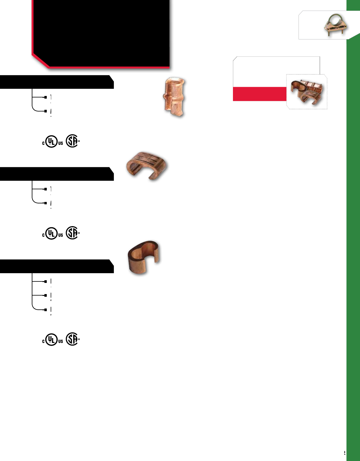
CT SERIES
CTH SERIES
CTH SERIES
252
NSi Industries LLC • USA • 800.321.5847 • www.nsiindustries.com
252
GROUNDING
These taps ensure positive, all-around compression
with low resistance and high pull-out values.
Made of high conductivity copper, they satisfy
the requirements of NEC250-81 and 250-91 for
connecting to the grounding electrode system.
These taps ensure positive, all-around compression
with low resistance and high pull-out values.
Made of high conductivity copper, they satisfy
the requirements of NEC250-81 and 250-91 for
connecting to the grounding electrode system.
Range-taking compression connectors made from high
conductivity copper alloy.
Ideal for making tap or parallel copper connections from
8 SOL to 4/0 STR conductors.
Provides consistent reliability with heavy wall construction
that prevents relaxation of the joint after installation.
Installation time is reduced because of its “C” shape.
These taps ensure positive, all-around compression
with low resistance and high pull-out values.
These taps ensure positive, all-around compression
with low resistance and high pull-out values.
These taps ensure positive, all-around compression
These taps ensure positive, all-around compression
with low resistance and high pull-out values.
These taps ensure positive, all-around compression
with low resistance and high pull-out values.
These taps ensure positive, all-around compression
Range-taking compression connectors made from high
conductivity copper alloy.
Range-taking compression connectors made from high
conductivity copper alloy.
Range-taking compression connectors made from high
Ideal for making tap or parallel copper connections from
8 SOL to 4/0 STR conductors.
Ideal for making tap or parallel copper connections from
8 SOL to 4/0 STR conductors.
Ideal for making tap or parallel copper connections from
Made of high conductivity copper, they satisfy
the requirements of NEC250-81 and 250-91 for
Made of high conductivity copper, they satisfy
the requirements of NEC250-81 and 250-91 for
Made of high conductivity copper, they satisfy
Made of high conductivity copper, they satisfy
the requirements of NEC250-81 and 250-91 for
Made of high conductivity copper, they satisfy
the requirements of NEC250-81 and 250-91 for
Made of high conductivity copper, they satisfy
Provides consistent reliability with heavy wall construction
that prevents relaxation of the joint after installation.
Provides consistent reliability with heavy wall construction
that prevents relaxation of the joint after installation.
Provides consistent reliability with heavy wall construction
GROUNDING CONNECTORS
"C" Taps
C-TAPS ORDER INFO
Find them in the
Connectors Section
PAGES 102-103
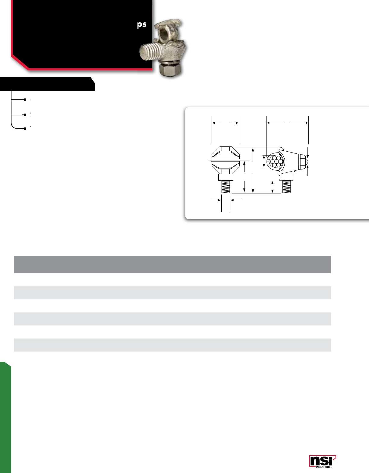
253
GROUNDING
FEATURES
Cast from high conductivity, high strength copper
alloy with cast high strength bronze eyebolts.
Stainless steel nuts and lockwashers are standard
on all clamps.
The TGE may be tightened by using a wrench on
the body.
CAT.
NO.
COPPER
CONDUCTOR
RANGE (A)
FINISH
WIRE DIA. STUD SIZE
(D)
LENGTH
(L) WIDTH
(W) HEIGHT
(H)
STD.
CTN.
QTY.
TGE-1 10 SOL - 1 STR Plain .102/.332 1/2 - 13 1.450 0.932 1.701 50
TGE-2/0 8 SOL -2/0 STR Plain .128/.419 1/2 - 13 1.782 1.225 2.208 15
TGE-250 6 SOL - 250MCM Plain .162/.575 1/2 - 13 2.760 1.863 2.569 10
TGE-1TN 10 SOL - 1 STR Tin Plated .102/.332 1/2 - 13 1.450 0.932 1.701 50
TGE-2/0TN 8 SOL -2/0 STR Tin Plated .128/.419 1/2 - 13 1.782 1.225 2.208 15
TGE-250TN 6 SOL - 250MCM Tin Plated .162/.575 1/2 - 13 2.760 1.863 2.569 10
W
H
G
L
D
J
P
A
Stainless steel nuts and lockwashers are standard
on all clamps.
Cast from high conductivity, high strength copper
alloy with cast high strength bronze eyebolts.
Cast from high conductivity, high strength copper
alloy with cast high strength bronze eyebolts.
Cast from high conductivity, high strength copper
The TGE may be tightened by using a wrench on
the body.
The TGE may be tightened by using a wrench on
the body.
The TGE may be tightened by using a wrench on
GROUNDING CONNECTORS
Transformer Ground Clamps
TGE SERIES
ound Clamps
All dimensional data is listed in inches.
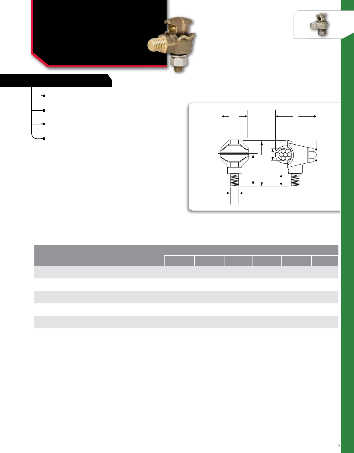
254
NSi Industries LLC • USA • 800.321.5847 • www.nsiindustries.com
254
GROUNDING
FEATURES
GROUNDING CONNECTORS
Two-Way Baskets
HTGE SERIES
Cast from high conductivity, high strength copper
alloy with cast high strength bronze eyebolts.
Stainless steel nuts and lockwashers are standard
on all clamps.
The HTGE provides a hex or square shoulder for
wrench tightening.
The flat surface also acts as a seal to the tank.
CAT.
NO.
COPPER
CONDUCTOR
RANGE (A)
FINISH
WIRE DIA. STUD
SIZE (D)
APPROx DIMENSIONS
G
IN MM H
IN MM j
(EYEBOLT) IN L
IN MM P
IN MM W
IN MM
HTGE-1 10 SOL - 1 STR Plain .102/.332 1/2 - 13 1 - 3/16 30 1- 3/4 44 3/8 -16 1-
31/32 50 7⁄16 11 1- 1/8 28
HTGE-2/0 8 SOL -2/0 STR Plain .128/.419 1/2 - 13 1 - 5/16 33 1-
15/16 49 3/8-16 2 51 7⁄16 11 1- 1/4 32
HTGE-250 6 SOL - 250MCM Plain .162/.575 1/2 - 13 1 - 3/16 30 2- 1/8 54 1/2 -13 2- 5/8 67 15⁄32 12 1- 7/8 48
HTGE-2/0TN 8 SOL -2/0 STR Tin Plated .128/.419 1/2 - 13 1 - 5/16 33 1-
15/16 49 3/8 -16 2 51 7⁄16 11 1- 1/4 32
HTGE-250TN 6 SOL - 250MCM Tin Plated .162/.575 1/2 - 13 1 - 3/16 30 2- 1/8 54 1/2 -13 2- 5/8 67 15⁄32 12 1- 7/8 48
W
H
G
L
D
J
P
A
All dimensional data is listed in inches.

255
GROUNDING
4
Recommended for motion due to expansion,
contraction, vibration and operational movement
of current carrying members.
Manufactured from flat, extra-flexible tinned braid, they
are available in a wide variety of sizes and amperages.
The ferrules are made from pure electrolytic copper and
are tin-plated.
Standard mounting holes are 9/16” NEMA spaded holes.
CAT
NO. LENGTH AMPERE RATING
INDOORS OUTDOORS APPROx.
CIRCULAR MILS THICKNESS WIDTH
(2 HOLE PAD ONLY)
STD.
CTN.
QTY.
FS1-19-8N 12 190 225 77,000 1/4 11/16 1
FS1-19-8N-18 18 190 225 77,000 1/4 11/16 1
FS1-19-8N-24 24 190 225 77,000 1/4 11/16 1
FS1-33-8N 12 330 400 154,500 1/4 1 1/2 1
FS1-33-8N-18 18 330 400 154,500 1/4 1 1/2 1
FS1-33-8N-24 24 330 400 154,000 1/4 1 1/2 1
FS1-36-8N 12 360 430 231,500 1/4 13/16 1
FS2-60-8N 12 600 720 463,000 7/16 13/16 1
The ferrules are made from pure electrolytic copper and
are tin-plated.
The ferrules are made from pure electrolytic copper and
are tin-plated.
The ferrules are made from pure electrolytic copper and
Manufactured from flat, extra-flexible tinned braid, they
are available in a wide variety of sizes and amperages.
Manufactured from flat, extra-flexible tinned braid, they
are available in a wide variety of sizes and amperages.
Manufactured from flat, extra-flexible tinned braid, they
contraction, vibration and operational movement
Standard mounting holes are
FLEXIBLE BRAID JUMPER STRAPS
GROUNDING CONNECTORS
Flexible Braid Jumper
Straps & Ground Strap
FS, SA SERIES
Woven of high conductivity, annealed, tinned copper wire,
this braided ground strap provides maximum flexibility and
ease of handling when installing ground or shield continuity.
This braid is used for shield and lead-sheath grounding and
is easily soldered to lead, copper and tinned metals.
It is also used for continuing the fault-carrying capacity of
the cable shield as a jumper braid.
CAT.
NO. WIDTH
(IN) LENGTH
(FT) EQUIvALENT
AWG SIZE
STD.
CTN.
QTY.
SA 382B 3/8 25 9 AWG 1
SA 382C 3/8 100 9 AWG 1
SA 582B 1/2 25 6 AWG 1
SA 582C 1/2 100 6 AWG 1
This braid is used for shield and lead-sheath grounding and
is easily soldered to lead, copper and tinned metals.
This braid is used for shield and lead-sheath grounding and
is easily soldered to lead, copper and tinned metals.
This braid is used for shield and lead-sheath grounding and
Woven of high conductivity, annealed, tinned copper wire,
this braided ground strap provides maximum flexibility and
Woven of high conductivity, annealed, tinned copper wire,
this braided ground strap provides maximum flexibility and
Woven of high conductivity, annealed, tinned copper wire,
the cable shield as a jumper braid.
FLEXIBLE GROUND STRAP
All dimensional data is listed in inches.
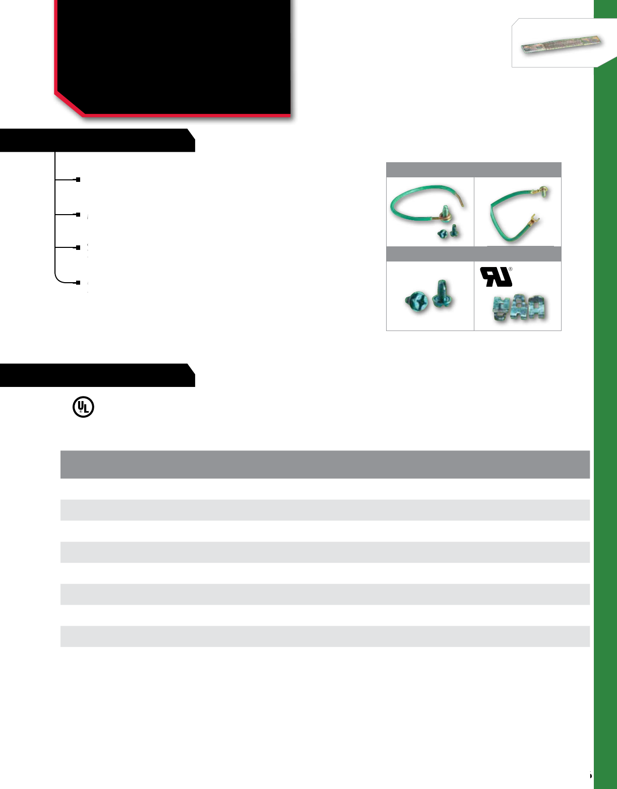
FEATURES
256
NSi Industries LLC • USA • 800.321.5847 • www.nsiindustries.com
256
GROUNDING
RATINGS
1 2
3 4
SOLID PIGTAILS WITH SCREWS
Pigtails are insulated conductors supplied with an
attached ground screw on one end and the insulation
stripped back one inch on the other end.
Meets NEC requirements.
STRANDED WITH RING & SPADE
Supplied with a spade terminal on one end and a
ring terminal with a captive green-dyed screw on
the other end.
65 strand #12 AWG and 41 strand #14 AWG for
maximum flexibility.
CAT.
NO.
FIG.
NO. DESCRIPTION STD.
CTN.
QTY.
PG14C 16.5 Inch 14 AWG Solid With Combo Screw - Green 50
PG12C 16.5 Inch 12 AWG Solid With Combo Screw - Green 50
PG12C-8 1 8 Inch 12 AWG Solid Wtih Combo Screw - Green 50
PG14SC 28 Inch 14 AWG (41W) Stranded With Combo Slotted Screw 50
PG12SC 28 Inch 12 AWG (65W) Stranded With Combo Slotted Screw 50
GSH 3Hex Head Green Grounding Screw 100
GSC 3Combo Slotted Hex Screw 100
GGC-1000 4Green Grounding Clips 100
attached ground screw on one end and the insulation
Meets NEC requirements.
Supplied with a spade terminal on one end and a
ring terminal with a captive green-dyed screw on
Supplied with a spade terminal on one end and a
ring terminal with a captive green-dyed screw on
Supplied with a spade terminal on one end and a
65 strand #12 AWG and 41 strand #14 AWG for
maximum flexibility.
GROUNDING CONNECTORS
Grounding Pigtails
(for solid & stranded wire)
and Grounding Clips
PG, GGC, GSH, GSC SERIES
All dimensional data is listed in inches.
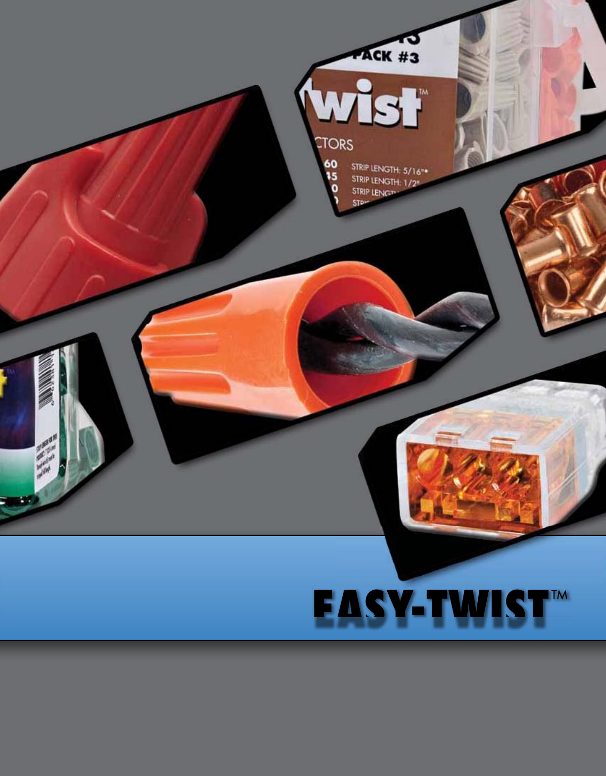
Easy-TwisTTM
Easy-Twis
T
TM
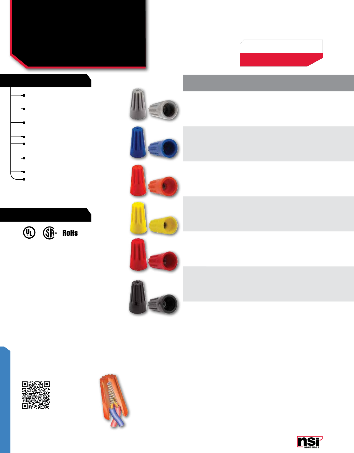
259
EASY-TWIST™
FEATURES
RATINGS
Scan QR code for mobile access
to wire combinations.
EASY-TWIST™
Standard Twist-On
Wire Connectors
WC SERIES
UL 486C Listed Wire Connector.
TEMPERATURE RATING:
105 °C (221 °F),
150 °C (302 °F) High Temp.
VOLTAGE:
1,000V max. in fixtures and signs.
WIRE TYPE:
For Copper wire only.
INSTALLATION:
Socket installation tools are included in each
bag of Easy-Twist™ Connectors (Cat.No. with "-B"
suffix). Made to fit any pneumatic or electrical
tool with a ¼" chuck or drive socket.
Flame retardant UL 94V-2 thermoplastic shell
provides excellent electrical insulation.
Fixed, precise square wire spring provides
secure gripping of conductors.
Deep skirt entry provides protection from
flashover and shorts.
Sure-grip ribs improve gripping comfort.
Compact design ensures proper installation,
especially in tight spaces.
Threaded funnel entry guides the wires into
the connector easily.
Pre-twisting of wires is not necessary.
Zinc-plated springs for low contact resistance.
COLOR/
TYPE WIRE
RANGE MAX
VOLTAGE
WIRE RANGE CARTON SMALL
JAR LARGE
JAR BAG BULK DRUM
MIN. MAX.
Grey 22-14 AWG 300V 2 #22 AWG 1 #14
w/ 1 #20 AWG
WC-G-C
(100) (10x100)
WC-G-SJ
(300) (50x300) –WC-B-B
(1000) (26x1000)
WC-G
(25000) –
Blue 22-14 AWG 300V 2 #22 AWG 3 #16 AWG WC-B-C
(100) (10x100)
WC-B-SJ
(300) (50x300) –WC-G-B
(1000) (18x1000)
WC-B
(10000) –
Orange 22-14 AWG 600V 1 #18
w/ 1 #20 AWG 4 #16
w/ 1 #20 AWG
WC-O-C
(100) (10x100)
WC-O-CJ
(100) (50x100)
WC-O-J
(700) (12x700)
WC-O-B
(500) (16x500)
WC-O
(10000)
WC-O-D
(50000)
Yellow 22-10 AWG 600V 3 #20 AWG 1 #10
w/ 2 #14
w/ 1 #16 AWG
WC-Y-C
(100) (10x100)
WC-Y-CJ
(100) (50x100)
WC-Y-J
(500) (12x500)
WC-Y-B
(500) (12x500)
WC-Y
(10000)
WC-Y-D
(35000)
Red 22-8 AWG 600V 3 #18 AWG 3 #10 AWG WC-R-C
(100) (10x100)
WC-R-SJ
(100) (20x100)
WC-R-J
(350) (12x350)
WC-R-B
(500) (8x500)
WC-R
(5000)
WC-R-D
(25000)
High
Temp 1 22-18 AWG 300V 1 #18 Str
w/ 1 #22 Str 2 #18 Str –––WC-HB1-B
(1000) (26x1000)
WC-HB1
(10000) –
High
Temp 3 22-14 AWG 600V 1 #16 w/1 #22 1 #14 w/ 1 #16
w/ 1 #18 –––WC-HB3-B
(500) (16x500)
WC-HB3
(10000) –
LISTED
WIRE CONNECTOR
E155027
231168
Example: (100) (10X100) =
100 in standard package,
1000 in standard carton.

260
NSi Industries LLC • USA • 800.321.5847 • www.nsiindustries.com
260
EASY-TWIST™
COLOR/
TYPE WIRE
RANGE MAX
VOLTAGE
WIRE RANGE CARTON SMALL
JAR LARGE
JAR BAG BULK DRUM
MIN. MAX.
Grey 22-14 AWG 300V 2 #22 AWG 1 #14
w/ 1 #20 AWG
WC-G-C
(100) (10x100)
WC-G-SJ
(300) (50x300) –WC-B-B
(1000) (26x1000)
WC-G
(25000) –
Blue 22-14 AWG 300V 2 #22 AWG 3 #16 AWG WC-B-C
(100) (10x100)
WC-B-SJ
(300) (50x300) –WC-G-B
(1000) (18x1000)
WC-B
(10000) –
Orange 22-14 AWG 600V 1 #18
w/ 1 #20 AWG 4 #16
w/ 1 #20 AWG
WC-O-C
(100) (10x100)
WC-O-CJ
(100) (50x100)
WC-O-J
(700) (12x700)
WC-O-B
(500) (16x500)
WC-O
(10000)
WC-O-D
(50000)
Yellow 22-10 AWG 600V 3 #20 AWG 1 #10
w/ 2 #14
w/ 1 #16 AWG
WC-Y-C
(100) (10x100)
WC-Y-CJ
(100) (50x100)
WC-Y-J
(500) (12x500)
WC-Y-B
(500) (12x500)
WC-Y
(10000)
WC-Y-D
(35000)
Red 22-8 AWG 600V 3 #18 AWG 3 #10 AWG WC-R-C
(100) (10x100)
WC-R-SJ
(100) (20x100)
WC-R-J
(350) (12x350)
WC-R-B
(500) (8x500)
WC-R
(5000)
WC-R-D
(25000)
High
Temp 1 22-18 AWG 300V 1 #18 Str
w/ 1 #22 Str 2 #18 Str –––WC-HB1-B
(1000) (26x1000)
WC-HB1
(10000) –
High
Temp 3 22-14 AWG 600V 1 #16 w/1 #22 1 #14 w/ 1 #16
w/ 1 #18 –––WC-HB3-B
(500) (16x500)
WC-HB3
(10000) –
COLOR MAX. SPRING
WIDTH
(A)
MAX. SKIRT
ENTRY
(B)
MAX.
WIDTH
(C)
MAX. SKIRT
DEPTH
(D)
LENGTH/
HEIGHT
(E)
Grey 0.150 0.256 0.339 0.217 0.598
Blue 0.161 0.280 0.390 0.217 0.697
Orange 0.197 0.382 0.500 0.268 0.866
Yellow 0.236 0.433 0.551 0.268 0.969
Red 0.339 0.516 0.642 0.406 1.043
High Temp 1 0.150 0.256 0.339 0.228 0.598
High Temp 3 0.197 0.382 0.500 0.307 0.866
All Dimenional Data is listed in inches.
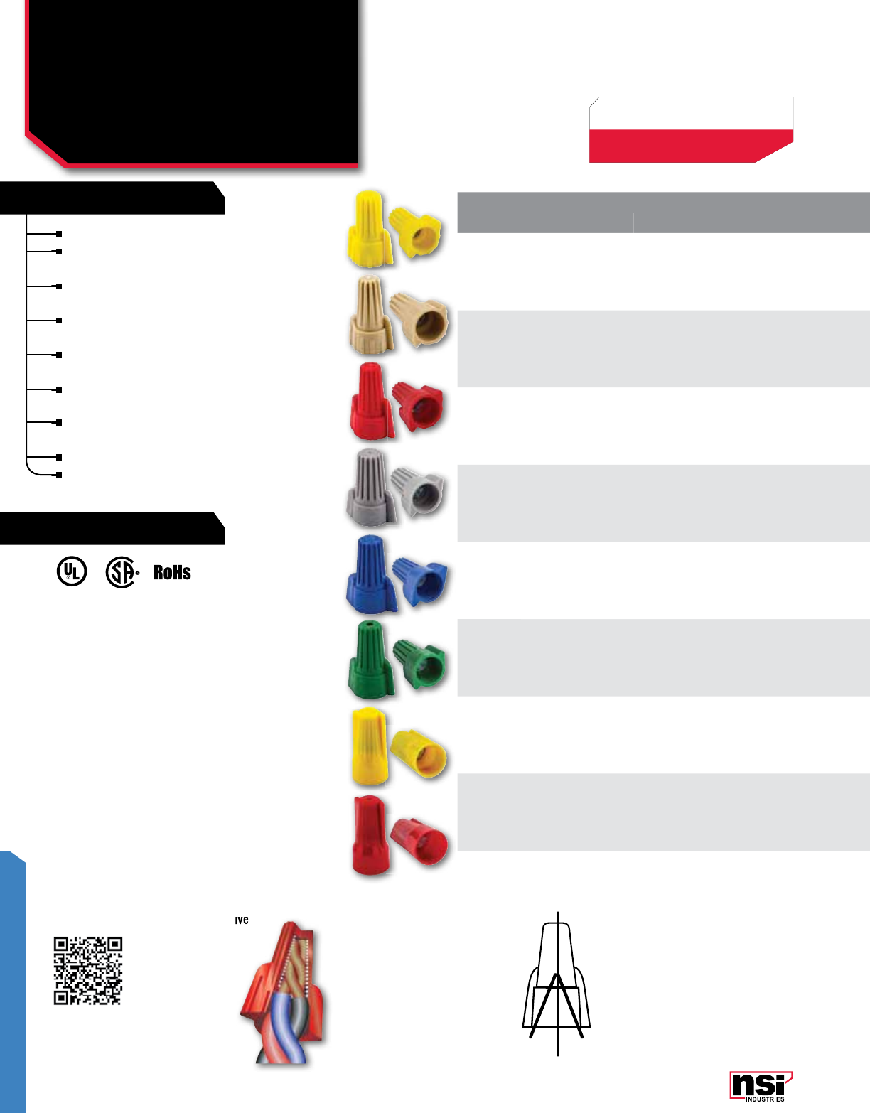
261
EASY-TWIST™
FEATURES
RATINGS
ORDERING INFO
UL 486C Listed Wire Connector.
WWC-GR is UL 467 Listed Grounding
and Bonding.
TEMPERATURE RATING:
105 °C (221 °F).
VOLTAGE:
600V max., 1,000V max. in fixtures
and signs.
WIRE TYPE:
For Copper wire only.
INSTALLATION:
Socket installation tools are included in each
bag of Easy-Twist™ Connectors (Cat.No.
with "-B" suffix). Made to fit any pneumatic
or electrical tool with a ¼" chuck or drive
socket.
WINGED GREEN
GROUNDING CONNECTOR:
X System grounding wire
Y System grounding wire
Z “Through” wire between device
and box ground
Note: If “through” wire is a jump-
er, be sure wire extends below
skirt 6” min.
or electrical tool with a ¼" chuck or drive
X
in
Z
To Box
Y
out
Z
To Device
EASY-TWIST™
Winged Twist-On
Wire Connectors
WWC SERIES
COLOR/
TYPE WIRE
RANGE MAX
VOLTAGE
WIRE RANGE CARTON SMALL
JAR LARGE
JAR BAG BULK DRUM
MIN. MAX.
Yellow 18 - 10 AWG 600V 2 #18 AWG 3 #12 AWG WWC-Y-C
(100) (10X100)
WWC-Y-CJ
(100) (50x100)
WWC-Y-J
(550) (12x550)
WWC-Y-B
(500) (13x500)
WWC-Y
(5000)
WWC-Y-D
(35000)
Tan 22-8 AWG 600V 3 #22 AWG 4 #12 AWG WWC-T-C
(100) (10x100)
WWC-T-CJ
(100) (50x100)
WWC-T-J
(450) (12x450)
WWC-T-B
(500) (12x500)
WWC-T
(5000)
WWC-T-D
(30000)
Red 18-8 AWG 600V 3 #16 AWG 5 #12 AWG WWC-R-C
(100) (10x100)
WWC-R-SJ
(100) (20x100)
WWC-R-J
(300) (12x300)
WWC-R-B
(500) (7x500)
WWC-R
(5000)
WWC-R-D
(20000)
Grey 18 - 8 AWG 600V 3 #14
w/1 #18 AWG 3 #10 AWG WWC-G-C
(50) (10x50)
WWC-G-SJ
(50) (32x50) –WWC-G-B
(250) (11x250)
WWC-G
(5000)
WWC-G-D
(20000)
Blue 14 - 6 AWG 600V 2 #10
w/ 1 #12 AWG
1 #8
w/ 3 #10 AWG
WWC-B-C
(50) (10x50)
WWC-B-SJ
(50) (20x50)
WWC-B-J (125)
(12x125)
WWC-B-B
(100) (16x100)
WWC-B
(2500)
WWC-B-D
(9500)
Green GND 14-10 AWG 600V 2 #14 5 #12 WWC-GR-C
(100) (10x100)
WWC-GR-SJ
(100) (20x100)
WWC-GR-J
(350) (12x350)
WWC-GR-B
(500) (9x500)
WWC-GR
(25000)
WWC-GR-D
(25000)
Yellow N1 22 - 10 AWG 600V 4 #22 AWG 3 #12 AWG WWC-N1-C
(100) (10X100)
WWC-N1-CJ
(100) (50x100)
WWC-N1-J
(600) (12x600)
WWC-N1-B
(500) (13x500)
WWC-N1
(10000)
WWC-N1-D
(45000)
Red N2 22 - 6 AWG 600V 3 #20 AWG 1 #8
w/ 3#12 AWG
WWC-N2-C
(100) (10X100)
WWC-N2-SJ
(100) (20x100)
WWC-N2-J
(400) (12x400)
WWC-N2-B
(500) (9x500)
WWC-N2
(10000)
WWC-N2-D
(25000)
Deep surface ridges provide better grip.
Ergonomic, swept-back wing design provides
handling comfort and increased torque ability.
Flame retardant UL 94V-2 thermoplastic shell
provides excellent electrical insulation.
Fixed, precise square wire spring provides
secure gripping of conductors.
Deep skirt entry provides protection from
flashover and shorts.
Compact design ensures proper installation,
especially in tight spaces.
Threaded funnel entry guides the wires into
the connector easily.
Pre-twisting of wires is not necessary.
Zinc-plated springs for low contact resistance.
LISTED
WIRE CONNECTOR
E155027
231168
Example: (100) (10X100) =
100 in standard package,
1000 in standard carton.
Scan QR code for mobile access
to wire combinations.
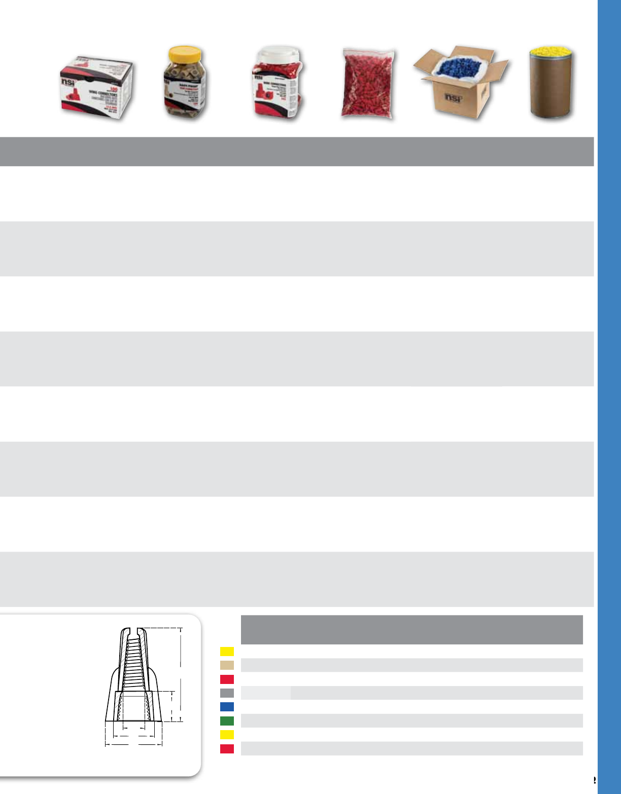
262
NSi Industries LLC • USA • 800.321.5847 • www.nsiindustries.com
262
EASY-TWIST™
A
D
E
B
C
COLOR MAX. SPRING
WIDTH
(A)
MAX. SKIRT
ENTRY
(B)
MAX.
WIDTH
(C)
MAX. SKIRT
DEPTH
(D)
LENGTH/
HEIGHT
(E)
Yellow 0.252 0.386 0.717 0.354 1.016
Tan 0.283 0.457 0.720 0.362 1.142
Red 0.354 0.512 0.906 0.378 1.252
Grey 0.394 0.587 1.004 0.394 1.311
Blue 0.472 0.701 1.260 0.512 1.575
Green 0.327 0.476 0.795 0.370 1.134
N-type Yellow 0.287 0.429 0.492 0.417 0.992
N-Type Red 0.358 0.520 0.583 0.453 1.161
COLOR/
TYPE WIRE
RANGE MAX
VOLTAGE
WIRE RANGE CARTON SMALL
JAR LARGE
JAR BAG BULK DRUM
MIN. MAX.
Yellow 18 - 10 AWG 600V 2 #18 AWG 3 #12 AWG WWC-Y-C
(100) (10X100)
WWC-Y-CJ
(100) (50x100)
WWC-Y-J
(550) (12x550)
WWC-Y-B
(500) (13x500)
WWC-Y
(5000)
WWC-Y-D
(35000)
Tan 22-8 AWG 600V 3 #22 AWG 4 #12 AWG WWC-T-C
(100) (10x100)
WWC-T-CJ
(100) (50x100)
WWC-T-J
(450) (12x450)
WWC-T-B
(500) (12x500)
WWC-T
(5000)
WWC-T-D
(30000)
Red 18-8 AWG 600V 3 #16 AWG 5 #12 AWG WWC-R-C
(100) (10x100)
WWC-R-SJ
(100) (20x100)
WWC-R-J
(300) (12x300)
WWC-R-B
(500) (7x500)
WWC-R
(5000)
WWC-R-D
(20000)
Grey 18 - 8 AWG 600V 3 #14
w/1 #18 AWG 3 #10 AWG WWC-G-C
(50) (10x50)
WWC-G-SJ
(50) (32x50) –WWC-G-B
(250) (11x250)
WWC-G
(5000)
WWC-G-D
(20000)
Blue 14 - 6 AWG 600V 2 #10
w/ 1 #12 AWG
1 #8
w/ 3 #10 AWG
WWC-B-C
(50) (10x50)
WWC-B-SJ
(50) (20x50)
WWC-B-J (125)
(12x125)
WWC-B-B
(100) (16x100)
WWC-B
(2500)
WWC-B-D
(9500)
Green GND 14-10 AWG 600V 2 #14 5 #12 WWC-GR-C
(100) (10x100)
WWC-GR-SJ
(100) (20x100)
WWC-GR-J
(350) (12x350)
WWC-GR-B
(500) (9x500)
WWC-GR
(25000)
WWC-GR-D
(25000)
Yellow N1 22 - 10 AWG 600V 4 #22 AWG 3 #12 AWG WWC-N1-C
(100) (10X100)
WWC-N1-CJ
(100) (50x100)
WWC-N1-J
(600) (12x600)
WWC-N1-B
(500) (13x500)
WWC-N1
(10000)
WWC-N1-D
(45000)
Red N2 22 - 6 AWG 600V 3 #20 AWG 1 #8
w/ 3#12 AWG
WWC-N2-C
(100) (10X100)
WWC-N2-SJ
(100) (20x100)
WWC-N2-J
(400) (12x400)
WWC-N2-B
(500) (9x500)
WWC-N2
(10000)
WWC-N2-D
(25000)
All Dimenional Data is listed in inches.
Shown: WWC-GR
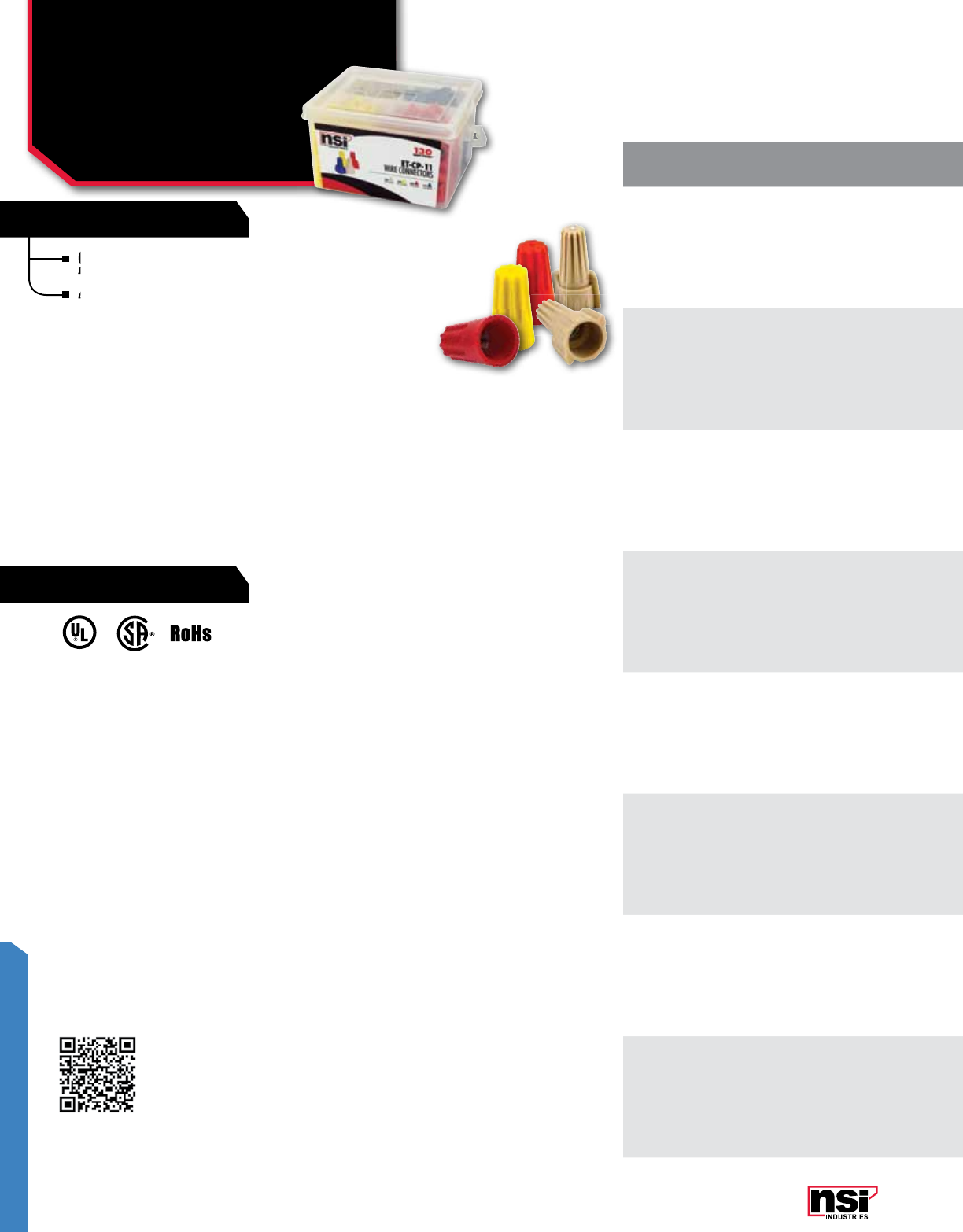
263
EASY-TWIST™
FEATURES
RATINGS
UL 486C Listed Wire Connector.
TEMPERATURE RATING:
105 °C (221 °F).
VOLTAGE:
1,000V max. in fixtures and signs.
WIRE TYPE:
For copper wire only.
Compact, easy to carry pail, also convenient
for use on maintenance cart.
4-pack pail includes the most common Easy-Twist™ connectors.
Compact, easy to carry pail, also convenient
for use on maintenance cart.
Compact, easy to carry pail, also convenient
for use on maintenance cart.
Compact, easy to carry pail, also convenient
4-pack pail includes the most common Easy-Twist
EASY-TWIST™
Wire Connector
Combination Pails
WC & WWC SERIES
LISTED
WIRE CONNECTOR
E155027
231168
CAT.
NO.PAIL
CONTENTS COLOR WIRE
RANGE QTY. PER
PAIL
STD.
CTN.
QTY.
ET-CP-1
WWC-T Tan 22-8 AWG 70
12
WWC-Y Yellow 18-10 AWG 80
WWC-R Red 18-8 AWG 45
WWC-B Blue 14-6 AWG 20
ET-CP-2
WC-O Orange 22-14 AWG 100
12
WC-Y Yellow 22-10 AWG 75
WC-R Red 22-10 AWG 50
WWC-T Tan 22-8 AWG 70
ET-CP-3
WC-O Orange 22-14 AWG 100
12
WWC-T Tan 22-8 AWG 70
WWC-Y Yellow 18-10 AWG 80
WWC-R Red 18-8 AWG 45
ET-CP-11
WWC-T Tan 22-8 AWG 40
16
WWC-Y Yellow 18-10 AWG 50
WWC-R Red 18-8 AWG 30
WWC-B Blue 14-6 AWG 10
ET-CP-12
WC-O Orange 22-14 AWG 65
16
WC-Y Yellow 22-10 AWG 45
WC-R Red 22-10 AWG 30
WWC-T Tan 22-8 AWG 40
ET-CP-13
WC-O Orange 22-14 AWG 60
16
WWC-T Tan 22-8 AWG 45
WWC-Y Yellow 18-10 AWG 50
WWC-R Red 18-8 AWG 30
ET-CP-14
WC-O Orange 22-14 AWG 65
16
WC-Y Yellow 22-10 AWG 45
WC-R Red 22-10 AWG 30
WC-B Blue 22-14 AWG 100
ET-CP-15
WC-G Gray 22-14 AWG 120
16
WC-B Blue 22-14 AWG 100
WC-O Orange 22-14 AWG 65
WC-Y Yellow 22-10 AWG 45
Scan QR code for mobile access
to wire combinations.

264
NSi Industries LLC • USA • 800.321.5847 • www.nsiindustries.com
264
EASY-TWIST™
CAT.
NO.PAIL
CONTENTS COLOR WIRE
RANGE QTY. PER
PAIL
STD.
CTN.
QTY.
ET-CP-1
WWC-T Tan 22-8 AWG 70
12
WWC-Y Yellow 18-10 AWG 80
WWC-R Red 18-8 AWG 45
WWC-B Blue 14-6 AWG 20
ET-CP-2
WC-O Orange 22-14 AWG 100
12
WC-Y Yellow 22-10 AWG 75
WC-R Red 22-10 AWG 50
WWC-T Tan 22-8 AWG 70
ET-CP-3
WC-O Orange 22-14 AWG 100
12
WWC-T Tan 22-8 AWG 70
WWC-Y Yellow 18-10 AWG 80
WWC-R Red 18-8 AWG 45
ET-CP-11
WWC-T Tan 22-8 AWG 40
16
WWC-Y Yellow 18-10 AWG 50
WWC-R Red 18-8 AWG 30
WWC-B Blue 14-6 AWG 10
ET-CP-12
WC-O Orange 22-14 AWG 65
16
WC-Y Yellow 22-10 AWG 45
WC-R Red 22-10 AWG 30
WWC-T Tan 22-8 AWG 40
ET-CP-13
WC-O Orange 22-14 AWG 60
16
WWC-T Tan 22-8 AWG 45
WWC-Y Yellow 18-10 AWG 50
WWC-R Red 18-8 AWG 30
ET-CP-14
WC-O Orange 22-14 AWG 65
16
WC-Y Yellow 22-10 AWG 45
WC-R Red 22-10 AWG 30
WC-B Blue 22-14 AWG 100
ET-CP-15
WC-G Gray 22-14 AWG 120
16
WC-B Blue 22-14 AWG 100
WC-O Orange 22-14 AWG 65
WC-Y Yellow 22-10 AWG 45
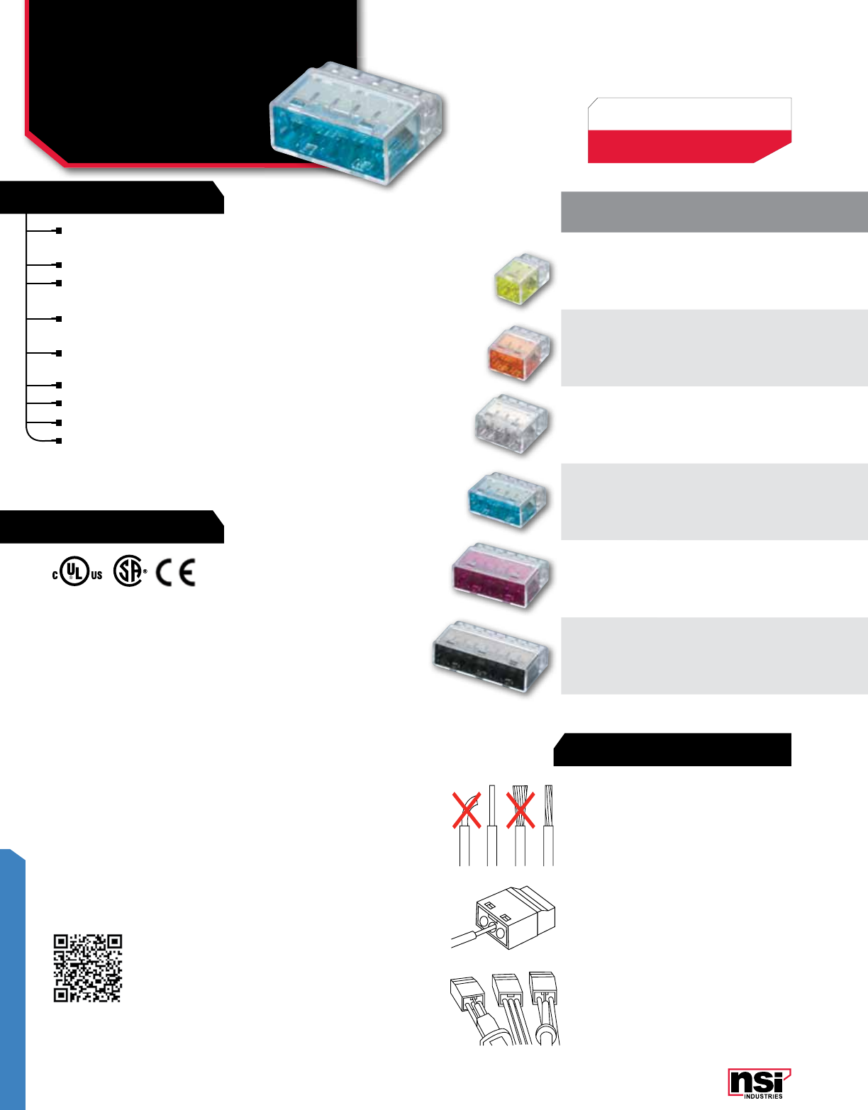
265
EASY-TWIST™
FEATURES
RATINGS
COLOR/
TYPE NO. OF
PORTS WIRE
RANGE MAX
VOLTAGE
WIRE RANGE CARTON BAG
MIN. MAX.
Yellow 222-12 AWG 600V 2 #22 AWG 2 #12 AWG PIWC -2-C
(100) (10x100)
PIWC-2-B
(500) (14x500)
Orange 322-12 AWG 600V 2 #22 AWG 3 #12 AWG PIWC -3-C
(100) (10x100)
PIWC-3-B
(500) (11x500)
Clear 422-12 AWG 600V 2 #22 AWG 4 #12 AWG PIWC -4-C
(75) (10x75)
PIWC-2-B
(400) (11x400)
Blue 522-12 AWG 600V 2 #22 AWG 5 #12 AWG PIWC -5-C
(50) (10x50)
PIWC-5-B
(300) (12x300)
Purple 622-12 AWG 600V 2 #22 AWG 6 #12 AWG PIWC -6-C
(50) (10x50)
PIWC-6-B
(250) (12x250)
Grey 822-12 AWG 600V 2 #22 AWG 8 #12 AWG PIWC -8-C
(40) (10x40)
PIWC-8-B
(200) (12x200)
UL 486C Listed Wire Connector.
TEMPERATURE RATING:
-40 °F to 221 °F (-30 °C to 105 °C).
VOLTAGE:
600V max., 1,000V max. in fixtures
and signs.
Fast, safe and reliable installation saves time
and money.
No twisting or taping of conductors required.
Just strip the wire, insert the connector and you
are done.
One wire per opening ensures loose connections
are eliminated.
Made of strong, UL 94V-2 flame retardant
polycarbonate.
Integrated test port enables continuity testing.
Color coded for easy identification.
Compact design perfect for tight spaces.
Copper, tin-plated; Stainless steel spring; Steel
frame, zinc-plated.
1. Turn off power. Strip wire approximately
0.45 inches (11mm).
2. Push the stripped conductor into the port of
connector fully. No twisting or taping.
3. Use a voltage meter to test your connection
via the port on connector.
EASY-TWIST™
Push-In
Wire Connectors
PIWC SERIES
INSTALLATION
231168
LISTED
WIRE CONNECTOR
E155027
Example: (100) (10X100) =
100 in standard package,
1000 in standard carton.
Scan QR code for mobile access
to wire combinations.

266
NSi Industries LLC • USA • 800.321.5847 • www.nsiindustries.com
266
EASY-TWIST™
COLOR/
TYPE NO. OF
PORTS WIRE
RANGE MAX
VOLTAGE
WIRE RANGE CARTON BAG
MIN. MAX.
Yellow 222-12 AWG 600V 2 #22 AWG 2 #12 AWG PIWC -2-C
(100) (10x100)
PIWC-2-B
(500) (14x500)
Orange 322-12 AWG 600V 2 #22 AWG 3 #12 AWG PIWC -3-C
(100) (10x100)
PIWC-3-B
(500) (11x500)
Clear 422-12 AWG 600V 2 #22 AWG 4 #12 AWG PIWC -4-C
(75) (10x75)
PIWC-2-B
(400) (11x400)
Blue 522-12 AWG 600V 2 #22 AWG 5 #12 AWG PIWC -5-C
(50) (10x50)
PIWC-5-B
(300) (12x300)
Purple 622-12 AWG 600V 2 #22 AWG 6 #12 AWG PIWC -6-C
(50) (10x50)
PIWC-6-B
(250) (12x250)
Grey 822-12 AWG 600V 2 #22 AWG 8 #12 AWG PIWC -8-C
(40) (10x40)
PIWC-8-B
(200) (12x200)
All Dimenional Data is listed in inches.
COLOR DEPTH
(A) WIDTH
(B)
FRONT
HEIGHT
(C)
REAR
HEIGHT
(D)
CASE
THICKNESS
(E)
Yellow 0.748 0.463 0.411 0.343 0.035
Orange 0.748 0.626 0.411 0.343 0.035
Clear 0.748 0.789 0.411 0.343 0.035
Blue 0.748 0.953 0.411 0.343 0.035
Purple 0.748 1.116 0.411 0.343 0.035
Black 0.748 1.443 0.411 0.343 0.035
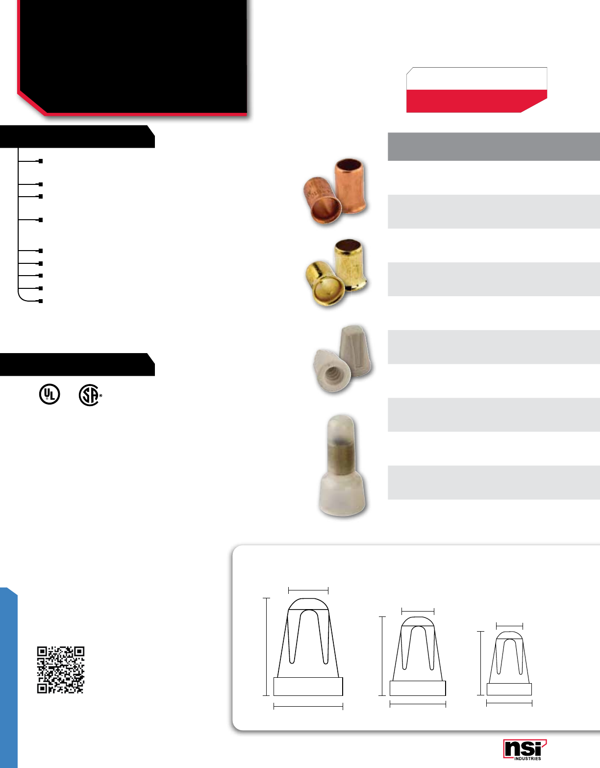
267
EASY-TWIST™
FEATURES
RATINGS
Copper Crimp Sleeves: Designed for easy installation and provide
an exceptional connection.
Closed End Connectors: Made from nylon 6/6 (Polyimide 66).
Steel Crimp Sleeves: Economical, brass-plated steel provides an
excellent low resistance connection.
UL 94V-2 self extinguishing, closed end style.
CERAMICS
Made of high quality ceramics.
Have excellent electrical and heat resistant properties.
Maximum working temperature of 1,000 °F.
For applications above 200 °F.
Uses include appliances, high powered lighting fixtures, ceiling
fans, heaters, plastic extrusion/injection molding barrels and
similar high temperature applications.
Part # SB is UL Listed
Part # C-N and C-N-B are
UL and CSA Listed
TEMPERATURE RATING:
C-N Series 105 °C (221 °F)
TOP Series 93.3333 °C (200 °F)
EASY-TWIST™
Crimp Sleeve & Nylon
Wire Connectors
SB, TOP & C-N SERIES
COLOR/
TYPE WIRE
RANGE MAX
VOLTAGE BLISTER PACK CARTON BAG
Copper Crimp Sleeve 18-10 AWG –SB1810
(100) (10x100) –SB1810-B
(1000) (10x1000)
Copper Crimp Sleeve 18-8 AWG –SB1808
(50) (10x50)) –SB1808-B
(500) (10x500)
Steel Crimp Sleeve 18-10 AWG –SB1810S
(100) (10x100) –SB1810S-B
(1000) (10x1000)
Steel Crimp Sleeve 18-8 AWG –SB1808S
(50) (10x50) –SB1808S-B
(500) (10x500)
Ceramic, White 22-14 AWG –TOP-S-D
(15) (15x25)
TOP-S-CD
(100) (10x100) –
Ceramic, White 22-10 AWG –TOP-M-D
(15) (15x25)
TOP-M-CD
(100) (10x100) –
Ceramic, White 18-8 AWG –TOP-L-D
(15) (15x25)
TOP-L-CD
(100) (10x100) –
Nylon, Clear 22-18 AWG 300V –C22-N
(100) (18x100)
C22-N-B
(1000) (30x1000)
Nylon, Clear 22-14 AWG 300V –C16-N
(100) (12x100)
C16-N-B
(1000) (20x1000)
Nylon, Clear 22-10 AWG 300V –C12-N
(50) (12x50)
C12-N-B
(1000) (10x1000)
Nylon, Clear 16-10 AWG 300V –C8-N
(40) (12x40)
C8-N-B
(500) (12x500)
LISTED
WIRE CONNECTOR 231168
Example: (100) (10X100) =
100 in standard package,
1000 in standard carton.
Scan QR code for mobile access
to wire combinations.
0.410
0.715
1.025
0.315
0.567
0.784
0.215
0.375
0.665
TOP-L TOP-M TOP-S

268
NSi Industries LLC • USA • 800.321.5847 • www.nsiindustries.com
268
EASY-TWIST™
CAT.
NO.I.D.
(A)
MAX. SKIRT
ENTRY
(B)
MAX.
WIDTH
(C)
MAX. SKIRT
DEPTH
(D)
LENGTH/
HEIGHT
(E)
SB1810 0.204 0.295 0.240 n/a 0.374
SB1808 0.263 0.364 0.307 n/a 0.610
C22-N 0.102 0.244 0.307 0.236 0.709
C16-N 0.118 0.311 0.374 0.276 0.787
C12-N 0.173 0.413 0.492 0.378 1.004
C8-N* 0.209 0.488 0.563 0.472 1.091
COLOR/
TYPE WIRE
RANGE MAX
VOLTAGE BLISTER PACK CARTON BAG
Copper Crimp Sleeve 18-10 AWG –SB1810
(100) (10x100) –SB1810-B
(1000) (10x1000)
Copper Crimp Sleeve 18-8 AWG –SB1808
(50) (10x50)) –SB1808-B
(500) (10x500)
Steel Crimp Sleeve 18-10 AWG –SB1810S
(100) (10x100) –SB1810S-B
(1000) (10x1000)
Steel Crimp Sleeve 18-8 AWG –SB1808S
(50) (10x50) –SB1808S-B
(500) (10x500)
Ceramic, White 22-14 AWG –TOP-S-D
(15) (15x25)
TOP-S-CD
(100) (10x100) –
Ceramic, White 22-10 AWG –TOP-M-D
(15) (15x25)
TOP-M-CD
(100) (10x100) –
Ceramic, White 18-8 AWG –TOP-L-D
(15) (15x25)
TOP-L-CD
(100) (10x100) –
Nylon, Clear 22-18 AWG 300V –C22-N
(100) (18x100)
C22-N-B
(1000) (30x1000)
Nylon, Clear 22-14 AWG 300V –C16-N
(100) (12x100)
C16-N-B
(1000) (20x1000)
Nylon, Clear 22-10 AWG 300V –C12-N
(50) (12x50)
C12-N-B
(1000) (10x1000)
Nylon, Clear 16-10 AWG 300V –C8-N
(40) (12x40)
C8-N-B
(500) (12x500)
All Dimenional Data is listed in inches.


MiniterMs & switches
Miniter
M
s &
s
witches
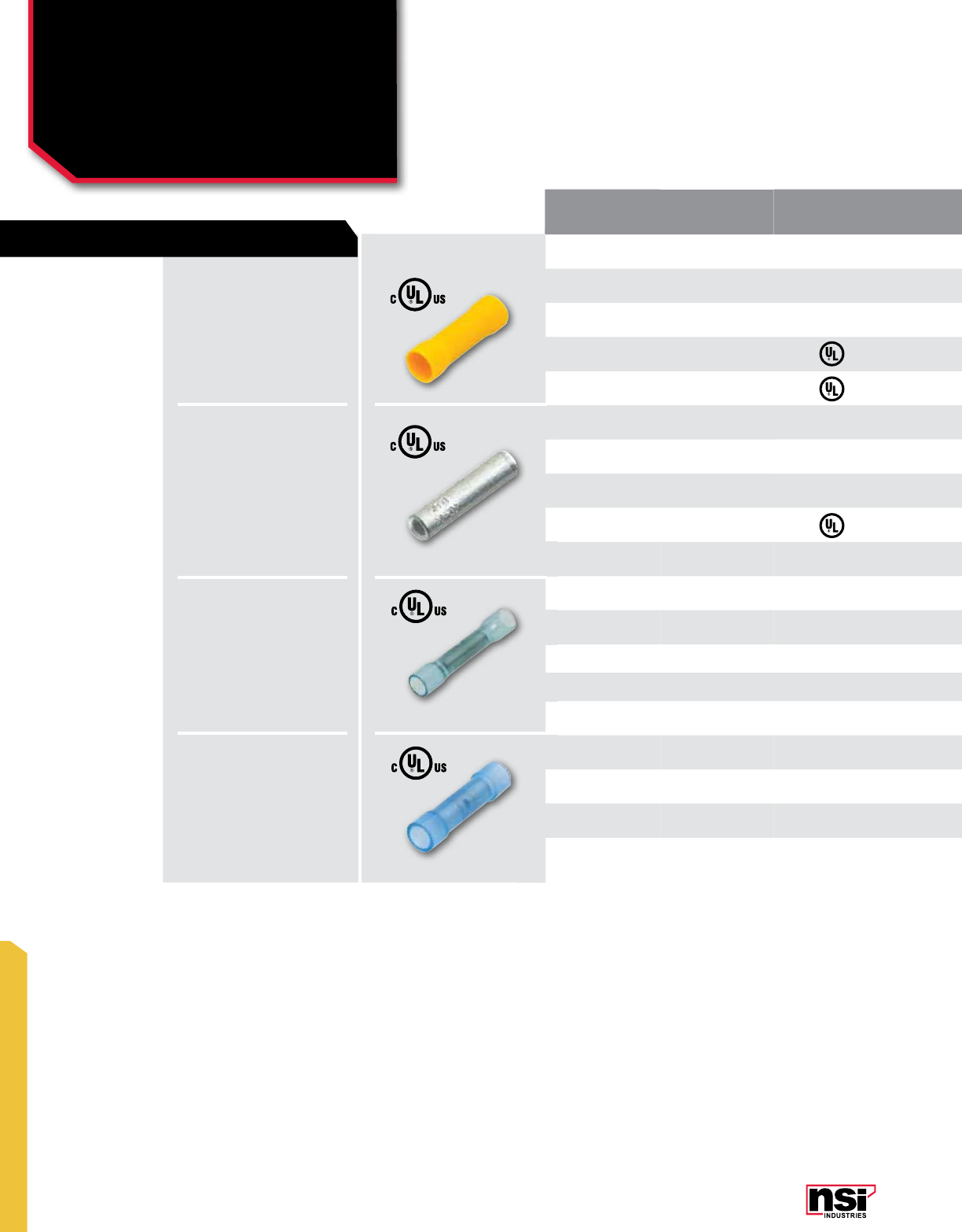
271
MINITERMS
INSULATION
TYPE WIRE
RANGE CERTIfICATION
vARIANCE LENGTH
(IN) CAT. NO. QTY CAT. NO. QTY CAT. NO. QTY CAT. NO. QTY
Vinyl 22-18 1.024 B22-V-S 25 B22-V-P 70 B22-V 100 B22-V-BULK 1000
Vinyl 16-14 1.024 B16-V-S 20 B16-V-P 50 B16-V 100 B16-V-BULK 1000
Vinyl 12-10 1.024 B12-V-S 15 B12-V-P 30 B12-V 50 B12-V-BULK 500
Vinyl 8 1.398 – – B8-V-P 10 B8-V 50 B8-V-BULK 250
Vinyl 6 1.855 – – – – B6-V 50 B6-V-BULK 100
Un-insulated - Bare 22-18 0.472 – – – – B22 100 B22-BULK 1000
Un-insulated - Bare 16-14 0.591 – – – – B16 100 B16-BULK 1000
Un-insulated - Bare 12-10 0.591 – – – – B12 50 B12-BULK 1000
Un-insulated - Bare 8 0.827 – – – – B8 50 B8-BULK 1000
0.945 – – – – SB22 25 SB22-BULK 500
Polyolefin HS 22-18 1.457 – – – – SB16 25 SB16-BULK 500
Polyolefin HS 16-14 1.614 – – – – SB12 50 SB12-BULK 500
Polyolefin HS 12-10
1.024 – – – – B22-N 100 B22-N-BULK 1000
Nylon 22-18 1.024 – – – – B16-N 100 B16-N-BULK 1000
Nylon 16-14 1.063 – – – – B12-N 50 B12-N-BULK 500
Nylon 12-10
MINITERMS
Butt Splices
B SERIES
FEATURES
VINYL:
Stripped wires are inserted from
each end and "butt" in the center.
A crimp at each end secures the
connection.
Electro tin plated copper,
vinyl (PVC) 300V, 75 °C.
POLYOLEFIN HS:
Stripped wires are inserted from
each end and "butt" in the center.
A crimp at each end secures the
connection.
Electro tin plated copper, Heat
shrink, 600V, 105 °C, Shrink temp
150 °C.
NYLON:
Stripped wires are inserted from
each end and "butt" in the center.
A crimp at each end secures the
connection.
Electro tin plated copper, Nylon,
600V, 105 °C.
UN-INSULATED:
Stripped wires are inserted from
each end and "butt" in the center.
A crimp at each end secures the
connection.
Electro tin plated copper,
600V, 105 °C.

272
NSi Industries LLC • USA • 800.321.5847 • www.nsiindustries.com
272
MINITERMS
“S” PACKS PRO PACKS STD PACKS BULK PACKS
INSULATION
TYPE WIRE
RANGE CERTIfICATION
vARIANCE LENGTH
(IN) CAT. NO. QTY CAT. NO. QTY CAT. NO. QTY CAT. NO. QTY
Vinyl 22-18 1.024 B22-V-S 25 B22-V-P 70 B22-V 100 B22-V-BULK 1000
Vinyl 16-14 1.024 B16-V-S 20 B16-V-P 50 B16-V 100 B16-V-BULK 1000
Vinyl 12-10 1.024 B12-V-S 15 B12-V-P 30 B12-V 50 B12-V-BULK 500
Vinyl 8 1.398 – – B8-V-P 10 B8-V 50 B8-V-BULK 250
Vinyl 6 1.855 – – – – B6-V 50 B6-V-BULK 100
Un-insulated - Bare 22-18 0.472 – – – – B22 100 B22-BULK 1000
Un-insulated - Bare 16-14 0.591 – – – – B16 100 B16-BULK 1000
Un-insulated - Bare 12-10 0.591 – – – – B12 50 B12-BULK 1000
Un-insulated - Bare 8 0.827 – – – – B8 50 B8-BULK 1000
0.945 – – – – SB22 25 SB22-BULK 500
Polyolefin HS 22-18 1.457 – – – – SB16 25 SB16-BULK 500
Polyolefin HS 16-14 1.614 – – – – SB12 50 SB12-BULK 500
Polyolefin HS 12-10
1.024 – – – – B22-N 100 B22-N-BULK 1000
Nylon 22-18 1.024 – – – – B16-N 100 B16-N-BULK 1000
Nylon 16-14 1.063 – – – – B12-N 50 B12-N-BULK 500
Nylon 12-10
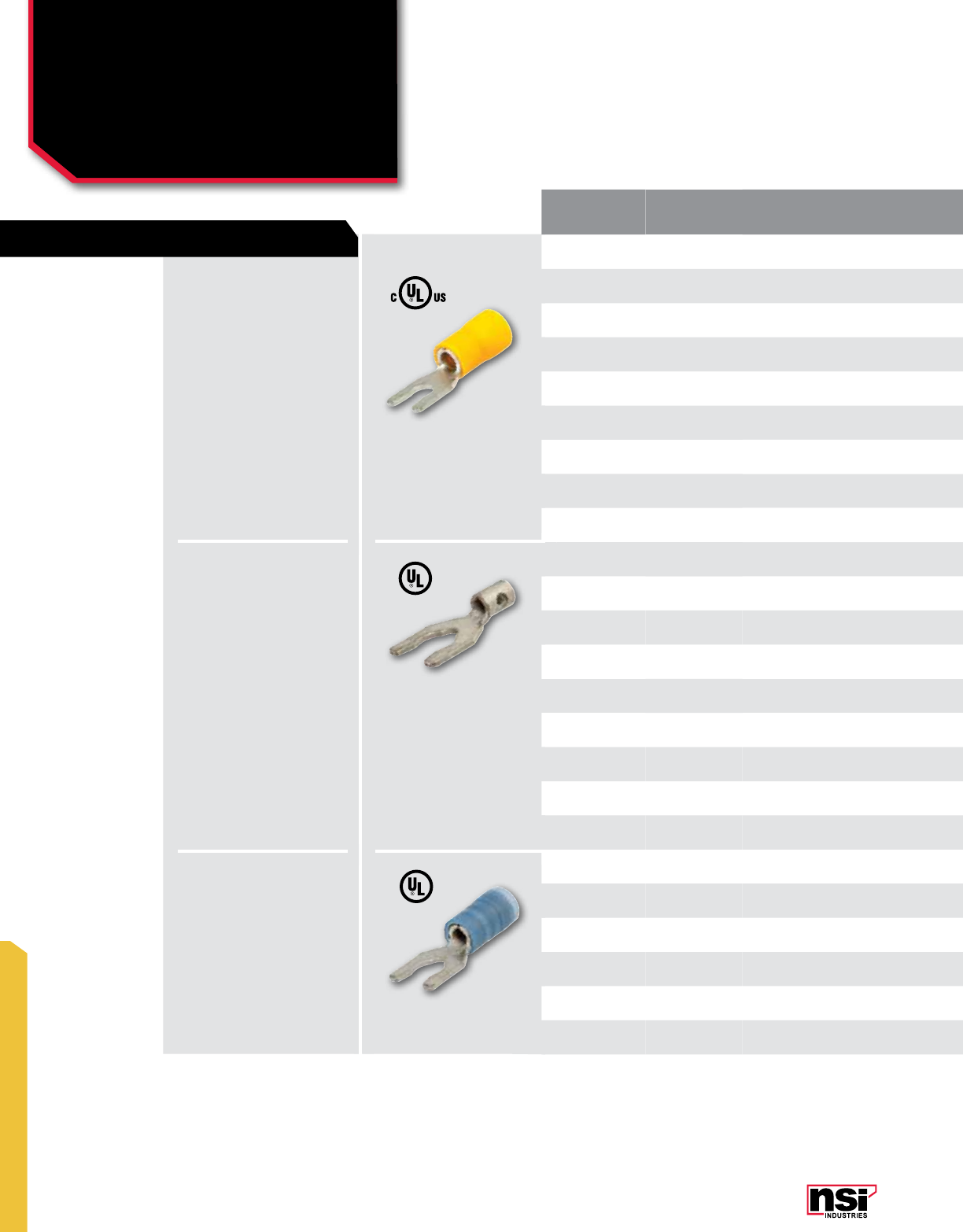
273
MINITERMS
MINITERMS
Spade Terminals:
Locking
S SERIES
INSULATION
TYPE WIRE
RANGE STUD
SIZE LENGTH
(IN) WIDTH
(IN) CAT. NO. QTY CAT. NO. QTY CAT. NO. QTY
Vinyl 22-18 #10 0.827 0.315 ––S22-10V-L 100 S22-10V-L-BULK 1000
Vinyl 22-18 #6 0.827 0.228 ––S22-6V-L 100 S22-6V-L-BULK 1000
Vinyl 22-18 #8 0.827 0.315 ––S22-8V-L 100 S22-8V-L-BULK 1000
Vinyl 16-14 #10 0.866 0.335 S16-10V-L-P 85 S16-10V-L 100 S16-10V-L-BULK 1000
Vinyl 16-14 #6 0.827 0.228 – – S16-6V-L 100 S16-6V-L-BULK 1000
Vinyl 16-14 #8 0.827 0.283 S16-8V-L-P 85 S16-8V-L 50 S16-8V-L-BULK 1000
Vinyl 12-10 #10 0.992 0.374 – – S12-10V-L 50 S12-10V-L-BULK 500
Vinyl 12-10 #6 0.992 0.335 – – S12-6V-L 50 S12-6V-L-BULK 500
Vinyl 12-10 #8 0.992 0.335 – – S12-8V-L 50 S12-8V-L-BULK 500
Un-insulated 22-18 #10 0.694 0.340 – – S22-10-L 100 S22-10-L-BULK 1000
Un-insulated 22-18 #6 0.585 0.260 – – S22-6-L 100 S22-6-L-BULK 1000
Un-insulated 22-18 #8 0.646 0.261 – – S22-8-L 100 S22-8-L-BULK 1000
Un-insulated 16-14 #10 0.694 0.340 – – S16-10-L 100 S16-10-L-BULK 1000
Un-insulated 16-14 #6 0.585 0.260 – – S16-6-L 100 S16-6-L-BULK 1000
Un-insulated 16-14 #8 0.646 0.320 – – S16-8-L 100 S16-8-L-BULK 1000
Un-insulated 12-10 #10 0.773 0.340 – – S12-10-L 50 S12-10-L-BULK 1000
Un-insulated 12-10 #6 0.664 0.260 – – S12-6-L 50 S12-6-L-BULK 1000
Un-insulated 12-10 #8 0.646 0.261 – – S12-8-L 50 S12-8-L-BULK 1000
Nylon 22-18 #8 0.866 0.315 – – S22-8N-L 100 S22-8N-L-BULK 1000
Nylon 16-14 #10 0.906 0.335 – – S16-10N-L 100 S16-10N-L-BULK 1000
Nylon 16-14 #6 0.866 0.328 – – S16-6N-L 100 S16-6N-L-BULK 1000
Nylon 16-14 #8 0.866 0.283 – – S16-8N-L 100 S16-8N-L-BULK 1000
Nylon 12-10 #10 1.012 0.374 – – S12-10N-L 50 S12-10N-L-BULK 1000
Nylon 12-10 #8 1.012 0.335 – – S12-8N-L 50 S12-8N-L-BULK 1000
VINYL:
Tongue snaps around the
screw & terminal is locked
into place until the mounting
screw can be tightened down.
Electro tin plated copper,
vinyl (PVC) 300V, 75 °C.
NYLON:
Tongue snaps around the
screw & terminal is locked
into place until the mounting
screw can be tightened down.
Electro tin plated copper,
easy-entry Nylon, 600V,
105 °C.
UN-INSULATED:
Tongue snaps around the
screw & terminal is locked
into place until the mounting
screw can be tightened down.
Electro tin plated copper,
600V, 105 °C.
FEATURES

274
NSi Industries LLC • USA • 800.321.5847 • www.nsiindustries.com
274
MINITERMS
PRO PACKS STD PACKS BULK PACKS
INSULATION
TYPE WIRE
RANGE STUD
SIZE LENGTH
(IN) WIDTH
(IN) CAT. NO. QTY CAT. NO. QTY CAT. NO. QTY
Vinyl 22-18 #10 0.827 0.315 ––S22-10V-L 100 S22-10V-L-BULK 1000
Vinyl 22-18 #6 0.827 0.228 ––S22-6V-L 100 S22-6V-L-BULK 1000
Vinyl 22-18 #8 0.827 0.315 ––S22-8V-L 100 S22-8V-L-BULK 1000
Vinyl 16-14 #10 0.866 0.335 S16-10V-L-P 85 S16-10V-L 100 S16-10V-L-BULK 1000
Vinyl 16-14 #6 0.827 0.228 – – S16-6V-L 100 S16-6V-L-BULK 1000
Vinyl 16-14 #8 0.827 0.283 S16-8V-L-P 85 S16-8V-L 50 S16-8V-L-BULK 1000
Vinyl 12-10 #10 0.992 0.374 – – S12-10V-L 50 S12-10V-L-BULK 500
Vinyl 12-10 #6 0.992 0.335 – – S12-6V-L 50 S12-6V-L-BULK 500
Vinyl 12-10 #8 0.992 0.335 – – S12-8V-L 50 S12-8V-L-BULK 500
Un-insulated 22-18 #10 0.694 0.340 – – S22-10-L 100 S22-10-L-BULK 1000
Un-insulated 22-18 #6 0.585 0.260 – – S22-6-L 100 S22-6-L-BULK 1000
Un-insulated 22-18 #8 0.646 0.261 – – S22-8-L 100 S22-8-L-BULK 1000
Un-insulated 16-14 #10 0.694 0.340 – – S16-10-L 100 S16-10-L-BULK 1000
Un-insulated 16-14 #6 0.585 0.260 – – S16-6-L 100 S16-6-L-BULK 1000
Un-insulated 16-14 #8 0.646 0.320 – – S16-8-L 100 S16-8-L-BULK 1000
Un-insulated 12-10 #10 0.773 0.340 – – S12-10-L 50 S12-10-L-BULK 1000
Un-insulated 12-10 #6 0.664 0.260 – – S12-6-L 50 S12-6-L-BULK 1000
Un-insulated 12-10 #8 0.646 0.261 – – S12-8-L 50 S12-8-L-BULK 1000
Nylon 22-18 #8 0.866 0.315 – – S22-8N-L 100 S22-8N-L-BULK 1000
Nylon 16-14 #10 0.906 0.335 – – S16-10N-L 100 S16-10N-L-BULK 1000
Nylon 16-14 #6 0.866 0.328 – – S16-6N-L 100 S16-6N-L-BULK 1000
Nylon 16-14 #8 0.866 0.283 – – S16-8N-L 100 S16-8N-L-BULK 1000
Nylon 12-10 #10 1.012 0.374 – – S12-10N-L 50 S12-10N-L-BULK 1000
Nylon 12-10 #8 1.012 0.335 – – S12-8N-L 50 S12-8N-L-BULK 1000
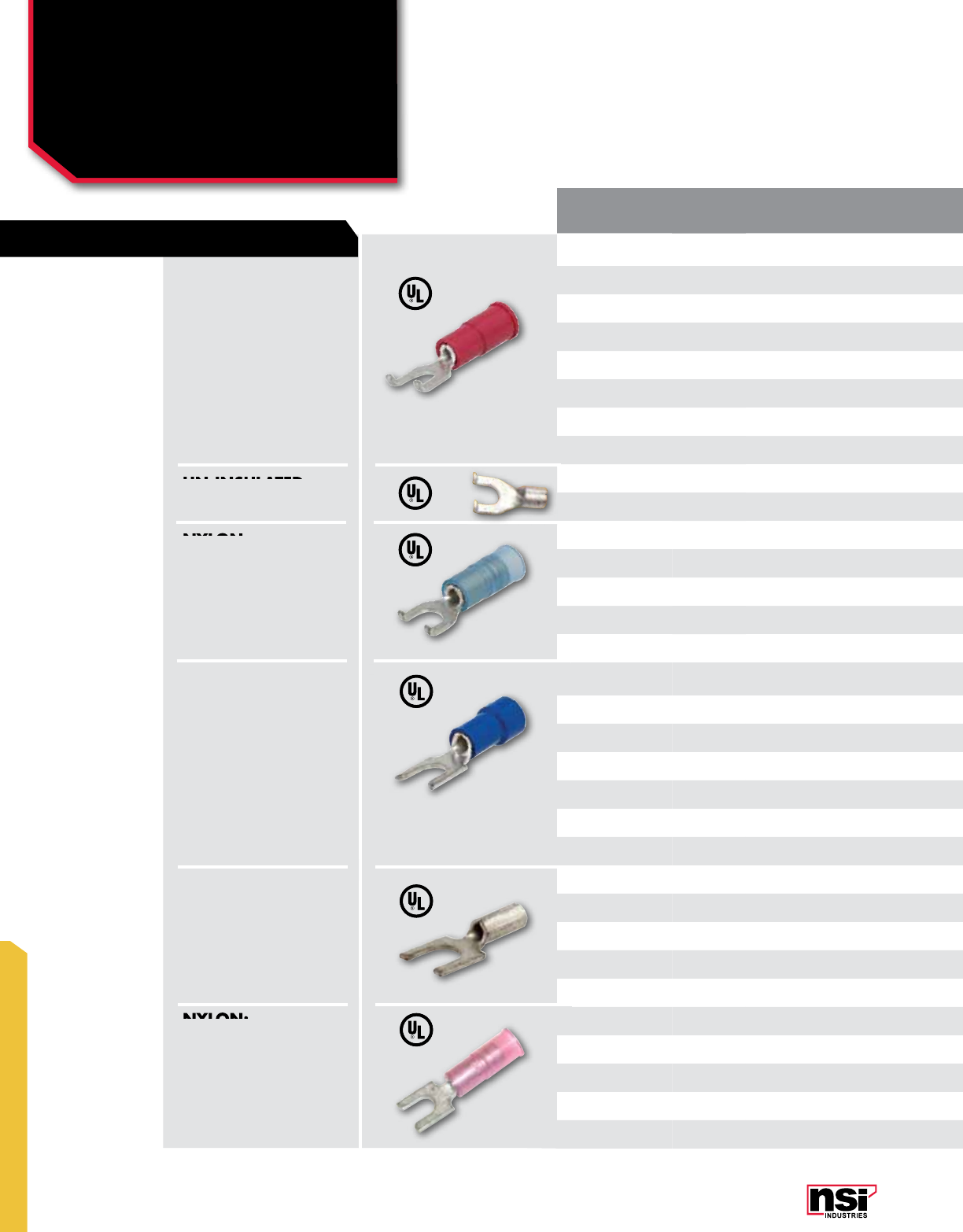
275
MINITERMS
MINITERMS
Spade Terminals
Flange & Block
S SERIES
INSULATION
TYPE WIRE
RANGE STUD
SIZE CERTIfICATION
vARIANCE LENGTH (IN) WIDTH (IN) CAT. NO. QTY CAT. NO. QTY CAT. NO. QTY
Vinyl 22-18 #6 0.836 0.301 ––S22-6V-F 100 S22-6V-F-BULK 1000
Vinyl 22-18 #8 0.836 0.301 ––S22-8V-F 100 S22-8V-F-BULK 1000
Vinyl 16-14 #10 0.850 0.301 ––S16-10V-F 100 S16-10V-F-BULK 1000
Vinyl 16-14 #6 0.850 0.301 – – S16-6V-F 100 S16-6V-F-BULK 1000
Vinyl 16-14 #8 0.850 0.301 – – S16-8V-F 100 S16-8V-F-BULK 1000
Vinyl 12-10 #10 1.075 0.320 – – S12-10V-F 50 S12-10V-F-BULK 1000
Vinyl 12-10 #8 1.075 0.320 – – S12-8V-F 50 S12-8V-F-BULK 1000
Un-insulated 16-14 #10 0.635 0.300 – – S16-10-F 100 S16-10-F-BULK 1000
Un-insulated 16-14 #6 0.570 0.301 – – S16-6-F 100 S16-6-F-BULK 1000
Nylon 22-18 #6 0.885 0.294 – – S22-6N-F 100 S22-6N-F-BULK 1000
Nylon 16-14 #10 0.910 0.293 – – S16-10N-F 100 S16-10N-F-BULK 1000
Nylon 16-14 #6 0.910 0.293 – – S16-6N-F 100 S16-6N-F-BULK 1000
Nylon 16-14 #8 0.908 0.294 – – S16-8N-F 100 S16-8N-F-BULK 1000
Nylon 12-10 #10 0.770 0.385 – – S12-10N-F 50 S12-10N-F-BULK 1000
Vinyl 22-18 #10 0.831 0.297 – – S22-10V-B 100 S22-10V-B-BULK 1000
Vinyl 22-18 #6 0.560 0.301 – – S22-6V-B 100 S22-6V-B-BULK 1000
Vinyl 22-18 #8 0.822 0.296 – – S22-8V-B 100 S22-8V-B-BULK 1000
Vinyl 16-14 #10 S16-10V-B 100
Vinyl 16-14 #6 0.828 0.251 – – S16-6V-B 100 S16-6V-B-BULK 1000
Vinyl 16-14 #8 0.781 0.295 – – S16-8V-B 100 S16-8V-B-BULK 1000
Un-insulated 22-18 #6 0.560 0.255 – – S22-6-B 100 S22-6-B-BULK 1000
Un-insulated 22-18 #8 0.560 0.301 – – S22-8-B 100 S22-8-B-BULK 1000
Un-insulated 16-14 #10 NON-UL 0.560 0.301 – – S16-10-B 100 S16-10-B-BULK 1000
Un-insulated 16-14 #6 NON-UL 0.736 0.332 – – S16-6-B 100 S16-6-B-BULK 1000
Un-insulated 16-14 #8 NON-UL 0.736 0.329 – – S16-8-B 100 S16-8-B-BULK 1000
Nylon 22-18 #10 0.904 0.293 – – S22-10N-B 100 S22-10N-B-BULK 1000
Nylon 22-18 #6 0.904 0.297 – – S22-6N-B 100 S22-6N-B-BULK 1000
Nylon 16-14 #10 NON-UL 0.556 0.305 – – S16-10N-B 100 S16-10N-B-BULK 1000
Nylon 16-14 #6 0.940 0.245 – – S16-6N-B 100 S16-6N-B-BULK 1000
Nylon 16-14 #8 0.940 0.295 – – S16-8N-B 100 S16-8N-B-BULK 1000
fLANGE SPADES
BLOCK SPADES
FLANGE SPADES
VINYL:
Turned up edges give this spade
more safety and reliability. Flanges
give a location and locking action
that aid in installation.
Electro tin plated copper, vinyl
(PVC) 300V, 75 °C.
BLOCK SPADES
VINYL:
Similar tongue style to a spade, block
spades have longer, flatter sides
designed for use in terminal blocks.
Electro tin plated copper with brazed
seam, Vinyl (PVC), 300V, 75 °C.
NYLON:
Turned up edges give this spade
more safety and reliability. Flanges
give a location and locking action
that aid in installation.
Electro tin plated copper, easy-entry
Nylon, 600V, 105 °C.
NYLON:
Similar tongue style to a spade,
block spades have longer, flatter
sides designed for use in terminal
blocks.
Electro tin plated copper with brazed
seam, easy-entry Nylon, 600V,
105 °C.
UN-INSULATED:
Electro tin plated copper, 600V, 105 °C.
UN-INSULATED:
Similar tongue style to a spade, block
spades have longer, flatter sides
designed for use in terminal blocks.
Electro tin plated copper with brazed
seam, 600V, 105 °C.
FEATURES
UN-INSULATED:
NYLON:
NYLON:

276
NSi Industries LLC • USA • 800.321.5847 • www.nsiindustries.com
276
MINITERMS
PRO PACKS STD PACKS BULK PACKS
INSULATION
TYPE WIRE
RANGE STUD
SIZE CERTIfICATION
vARIANCE LENGTH (IN) WIDTH (IN) CAT. NO. QTY CAT. NO. QTY CAT. NO. QTY
Vinyl 22-18 #6 0.836 0.301 ––S22-6V-F 100 S22-6V-F-BULK 1000
Vinyl 22-18 #8 0.836 0.301 ––S22-8V-F 100 S22-8V-F-BULK 1000
Vinyl 16-14 #10 0.850 0.301 ––S16-10V-F 100 S16-10V-F-BULK 1000
Vinyl 16-14 #6 0.850 0.301 – – S16-6V-F 100 S16-6V-F-BULK 1000
Vinyl 16-14 #8 0.850 0.301 – – S16-8V-F 100 S16-8V-F-BULK 1000
Vinyl 12-10 #10 1.075 0.320 – – S12-10V-F 50 S12-10V-F-BULK 1000
Vinyl 12-10 #8 1.075 0.320 – – S12-8V-F 50 S12-8V-F-BULK 1000
Un-insulated 16-14 #10 0.635 0.300 – – S16-10-F 100 S16-10-F-BULK 1000
Un-insulated 16-14 #6 0.570 0.301 – – S16-6-F 100 S16-6-F-BULK 1000
Nylon 22-18 #6 0.885 0.294 – – S22-6N-F 100 S22-6N-F-BULK 1000
Nylon 16-14 #10 0.910 0.293 – – S16-10N-F 100 S16-10N-F-BULK 1000
Nylon 16-14 #6 0.910 0.293 – – S16-6N-F 100 S16-6N-F-BULK 1000
Nylon 16-14 #8 0.908 0.294 – – S16-8N-F 100 S16-8N-F-BULK 1000
Nylon 12-10 #10 0.770 0.385 – – S12-10N-F 50 S12-10N-F-BULK 1000
Vinyl 22-18 #10 0.831 0.297 – – S22-10V-B 100 S22-10V-B-BULK 1000
Vinyl 22-18 #6 0.560 0.301 – – S22-6V-B 100 S22-6V-B-BULK 1000
Vinyl 22-18 #8 0.822 0.296 – – S22-8V-B 100 S22-8V-B-BULK 1000
Vinyl 16-14 #10 S16-10V-B 100
Vinyl 16-14 #6 0.828 0.251 – – S16-6V-B 100 S16-6V-B-BULK 1000
Vinyl 16-14 #8 0.781 0.295 – – S16-8V-B 100 S16-8V-B-BULK 1000
Un-insulated 22-18 #6 0.560 0.255 – – S22-6-B 100 S22-6-B-BULK 1000
Un-insulated 22-18 #8 0.560 0.301 – – S22-8-B 100 S22-8-B-BULK 1000
Un-insulated 16-14 #10 NON-UL 0.560 0.301 – – S16-10-B 100 S16-10-B-BULK 1000
Un-insulated 16-14 #6 NON-UL 0.736 0.332 – – S16-6-B 100 S16-6-B-BULK 1000
Un-insulated 16-14 #8 NON-UL 0.736 0.329 – – S16-8-B 100 S16-8-B-BULK 1000
Nylon 22-18 #10 0.904 0.293 – – S22-10N-B 100 S22-10N-B-BULK 1000
Nylon 22-18 #6 0.904 0.297 – – S22-6N-B 100 S22-6N-B-BULK 1000
Nylon 16-14 #10 NON-UL 0.556 0.305 – – S16-10N-B 100 S16-10N-B-BULK 1000
Nylon 16-14 #6 0.940 0.245 – – S16-6N-B 100 S16-6N-B-BULK 1000
Nylon 16-14 #8 0.940 0.295 – – S16-8N-B 100 S16-8N-B-BULK 1000
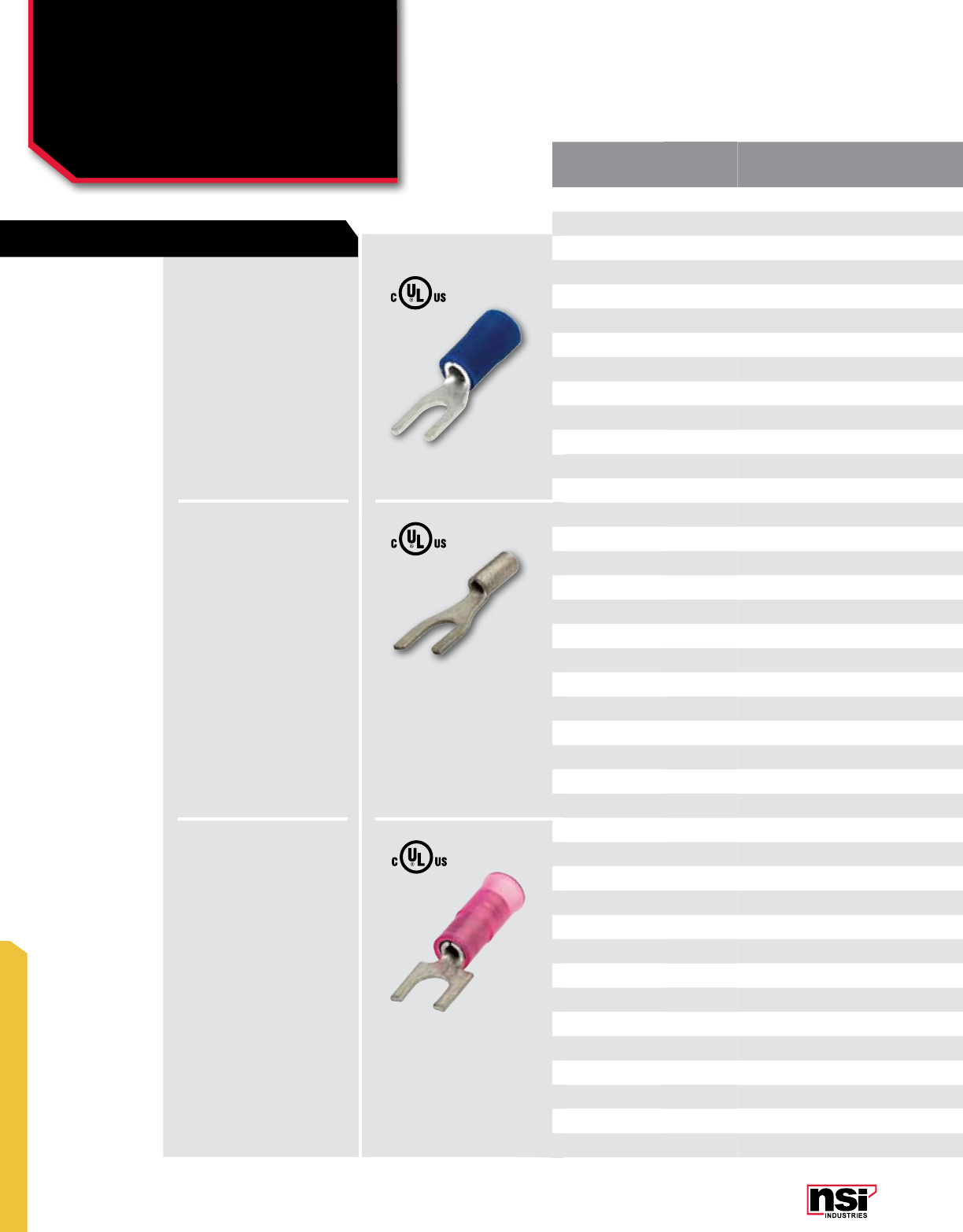
277
MINITERMS
MINITERMS
Spade Terminals
S SERIES
INSULATION
TYPE WIRE
RANGE STUD
SIZE CERTIfICATION
vARIANCE L
(IN) W
(IN) CAT. NO. QTY CAT. NO. QTY CAT. NO. QTY CAT. NO. QTY
Vinyl 22-18 1/4 1.070 0.472 – – – – S22-14V 100 S22-14V-BULK 1000
Vinyl 22-18 #10 0.826 0.374 S22-10V-S 25 S22-10V-P 100 S22-10V 100 S22-10V-BULK 1000
Vinyl 22-18 #4 UL 0.817 0.251 – – – – S22-4V 100 S22-4V-BULK 1000
Vinyl 22-18 #6 0.826 0.228 S22-6V-S 25 S22-6V-P 100 S22-6V 100 S22-6V-BULK 1000
Vinyl 22-18 #8 0.826 0.283 S22-8V-S 25 S22-8V-P 100 S22-8V 100 S22-8V-BULK 1000
Vinyl 16-14 1/4 0.812 0.543 – – – – S16-14V 100 S16-14V-BULK 1000
Vinyl 16-14 #10 0.966 0.362 S16-10V-S 20 S16-10V-P 85 S16-10V 100 S16-10V-BULK 1000
Vinyl 16-14 #6 0.966 0.388 S16-6V-S 20 S16-6V-P 85 S16-6V 100 S16-6V-BULK 1000
Vinyl 16-14 #8 1.103 0.388 S16-8V-S 20 S16-8V-P 85 S16-8V 100 S16-8V-BULK 1000
Vinyl 12-10 1/4 1.103 0.375 S12-14V-S 12 S12-14V-P 40 S12-14V 50 S12-14V-BULK 500
Vinyl 12-10 #10 1.103 0.375 S12-10V-S 15 S12-10V-P 50 S12-10V 50 S12-10V-BULK 500
Vinyl 12-10 #6 1.103 0.375 S12-6V-S 15 S12-6V-P 50 S12-6V 50 S12-6V-BULK 500
Vinyl 12-10 #8 0.690 0.316 S12-8V-S 15 S12-8V-P 50 S12-8V 50 S12-8V-BULK 500
Un-insulated 22-18 #10 UL 0.623 0.251 – – – – S22-10 100 S22-10-BULK 1000
Un-insulated 22-18 #4 UL 0.629 0.228 – – – – S22-4 100 S22-4-BULK 1000
Un-insulated 22-18 #6 0.778 0.316 – – – – S22-6 100 S22-6-BULK 1000
Un-insulated 22-18 #8 UL 0.770 0.388 – – – – S22-8 100 S22-8-BULK 1000
Un-insulated 16-14 #10 0.638 0.245 – – S16-10-P 100 S16-10 100 S16-10-BULK 1000
Un-insulated 16-14 #6 0.635 0.295 – – – – S16-6 100 S16-6-BULK 1000
Un-insulated 16-14 #8 UL 1.000 0.492 – – S16-8-P 100 S16-8 100 S16-8-BULK 1000
Un-insulated 12-10 1/4 NON-UL 0.812 0.375 – – – – S12-14 50 S12-14-BULK 1000
Un-insulated 12-10 #10 0.812 0.375 – – – – S12-10 50 S12-10-BULK 1000
Un-insulated 12-10 #6 UL 0.812 0.375 – – – – S12-6 50 S12-6-BULK 1000
Un-insulated 12-10 #8 0.953 0.471 – – – – S12-8 50 S12-8-BULK 1000
Un-insulated 8 1/4 NON-UL 0.956 0.471 – – – – S8-14 50 S8-14-BULK 100
Un-insulated 8 #10 NON-UL 1.033 0.322 – – – – S8-10 50 S8-10-BULK 100
Nylon 22-18 #10 UL 0.727 0.187 – – – – S22-10N 100 S22-10N-BULK 1000
Nylon 22-18 #4 UL 1.031 0.319 – – – – S22-4N 100 S22-4N-BULK 1000
Nylon 22-18 #6 UL 0.898 0.286 – – – – S22-6N 100 S22-6N-BULK 1000
Nylon 22-18 #8 UL 1.022 0.472 – – – – S22-8N 100 S22-8N-BULK 1000
Nylon 16-14 1/4 NON-UL 0.898 0.338 – – – – S16-14N 100 S16-14N-BULK 1000
Nylon 16-14 #10 0.855 0.255 – – – – S16-10N 100 S16-10N-BULK 1000
Nylon 16-14 #6 0.855 0.286 – – – – S16-6N 100 S16-6N-BULK 1000
Nylon 16-14 #8 1.221 0.476 – – – – S16-8N 100 S16-8N-BULK 1000
Nylon 12-10 1/4 1.024 0.375 – – – – S12-14N 50 S12-14N-BULK 500
Nylon 12-10 #10 1.000 0.336 – – – – S12-10N 50 S12-10N-BULK 500
Nylon 12-10 #6 1.000 0.375 – – – – S12-6N 50 S12-6N-BULK 500
Nylon 12-10 #8 1.256 0.474 – – – – S12-8N 50 S12-8N-BULK 500
Nylon 8 1/4 NON-UL 1.256 0.474 – – – – S8-14N 50 S8-14N-BULK 500
Nylon 8 #10 NON-UL 1.256 0.474 – – – – S8-10N 50 S8-10N-BULK 500
VINYL:
Open tongue end for rapid
insertion on the mounting
screw. Typically used on
free-standing studs.
Electro tin plated copper,
vinyl (PVC) 300V, 75 °C.
NYLON:
Open tongue end for rapid
insertion on the mounting
screw. Typically used on
free-standing studs.
Electro tin plated copper,
easy-entry Nylon, 600V,
105 °C.
UN-INSULATED:
Open tongue end for rapid
insertion on the mounting
screw. Typically used on
free-standing studs.
Electro tin plated copper,
600V, 105 °C.
FEATURES

278
NSi Industries LLC • USA • 800.321.5847 • www.nsiindustries.com
278
MINITERMS
“S” PACKS PRO PACKS STD PACKS BULK PACKS
INSULATION
TYPE WIRE
RANGE STUD
SIZE CERTIfICATION
vARIANCE L
(IN) W
(IN) CAT. NO. QTY CAT. NO. QTY CAT. NO. QTY CAT. NO. QTY
Vinyl 22-18 1/4 1.070 0.472 – – – – S22-14V 100 S22-14V-BULK 1000
Vinyl 22-18 #10 0.826 0.374 S22-10V-S 25 S22-10V-P 100 S22-10V 100 S22-10V-BULK 1000
Vinyl 22-18 #4 UL 0.817 0.251 – – – – S22-4V 100 S22-4V-BULK 1000
Vinyl 22-18 #6 0.826 0.228 S22-6V-S 25 S22-6V-P 100 S22-6V 100 S22-6V-BULK 1000
Vinyl 22-18 #8 0.826 0.283 S22-8V-S 25 S22-8V-P 100 S22-8V 100 S22-8V-BULK 1000
Vinyl 16-14 1/4 0.812 0.543 – – – – S16-14V 100 S16-14V-BULK 1000
Vinyl 16-14 #10 0.966 0.362 S16-10V-S 20 S16-10V-P 85 S16-10V 100 S16-10V-BULK 1000
Vinyl 16-14 #6 0.966 0.388 S16-6V-S 20 S16-6V-P 85 S16-6V 100 S16-6V-BULK 1000
Vinyl 16-14 #8 1.103 0.388 S16-8V-S 20 S16-8V-P 85 S16-8V 100 S16-8V-BULK 1000
Vinyl 12-10 1/4 1.103 0.375 S12-14V-S 12 S12-14V-P 40 S12-14V 50 S12-14V-BULK 500
Vinyl 12-10 #10 1.103 0.375 S12-10V-S 15 S12-10V-P 50 S12-10V 50 S12-10V-BULK 500
Vinyl 12-10 #6 1.103 0.375 S12-6V-S 15 S12-6V-P 50 S12-6V 50 S12-6V-BULK 500
Vinyl 12-10 #8 0.690 0.316 S12-8V-S 15 S12-8V-P 50 S12-8V 50 S12-8V-BULK 500
Un-insulated 22-18 #10 UL 0.623 0.251 – – – – S22-10 100 S22-10-BULK 1000
Un-insulated 22-18 #4 UL 0.629 0.228 – – – – S22-4 100 S22-4-BULK 1000
Un-insulated 22-18 #6 0.778 0.316 – – – – S22-6 100 S22-6-BULK 1000
Un-insulated 22-18 #8 UL 0.770 0.388 – – – – S22-8 100 S22-8-BULK 1000
Un-insulated 16-14 #10 0.638 0.245 – – S16-10-P 100 S16-10 100 S16-10-BULK 1000
Un-insulated 16-14 #6 0.635 0.295 – – – – S16-6 100 S16-6-BULK 1000
Un-insulated 16-14 #8 UL 1.000 0.492 – – S16-8-P 100 S16-8 100 S16-8-BULK 1000
Un-insulated 12-10 1/4 NON-UL 0.812 0.375 – – – – S12-14 50 S12-14-BULK 1000
Un-insulated 12-10 #10 0.812 0.375 – – – – S12-10 50 S12-10-BULK 1000
Un-insulated 12-10 #6 UL 0.812 0.375 – – – – S12-6 50 S12-6-BULK 1000
Un-insulated 12-10 #8 0.953 0.471 – – – – S12-8 50 S12-8-BULK 1000
Un-insulated 8 1/4 NON-UL 0.956 0.471 – – – – S8-14 50 S8-14-BULK 100
Un-insulated 8 #10 NON-UL 1.033 0.322 – – – – S8-10 50 S8-10-BULK 100
Nylon 22-18 #10 UL 0.727 0.187 – – – – S22-10N 100 S22-10N-BULK 1000
Nylon 22-18 #4 UL 1.031 0.319 – – – – S22-4N 100 S22-4N-BULK 1000
Nylon 22-18 #6 UL 0.898 0.286 – – – – S22-6N 100 S22-6N-BULK 1000
Nylon 22-18 #8 UL 1.022 0.472 – – – – S22-8N 100 S22-8N-BULK 1000
Nylon 16-14 1/4 NON-UL 0.898 0.338 – – – – S16-14N 100 S16-14N-BULK 1000
Nylon 16-14 #10 0.855 0.255 – – – – S16-10N 100 S16-10N-BULK 1000
Nylon 16-14 #6 0.855 0.286 – – – – S16-6N 100 S16-6N-BULK 1000
Nylon 16-14 #8 1.221 0.476 – – – – S16-8N 100 S16-8N-BULK 1000
Nylon 12-10 1/4 1.024 0.375 – – – – S12-14N 50 S12-14N-BULK 500
Nylon 12-10 #10 1.000 0.336 – – – – S12-10N 50 S12-10N-BULK 500
Nylon 12-10 #6 1.000 0.375 – – – – S12-6N 50 S12-6N-BULK 500
Nylon 12-10 #8 1.256 0.474 – – – – S12-8N 50 S12-8N-BULK 500
Nylon 8 1/4 NON-UL 1.256 0.474 – – – – S8-14N 50 S8-14N-BULK 500
Nylon 8 #10 NON-UL 1.256 0.474 – – – – S8-10N 50 S8-10N-BULK 500
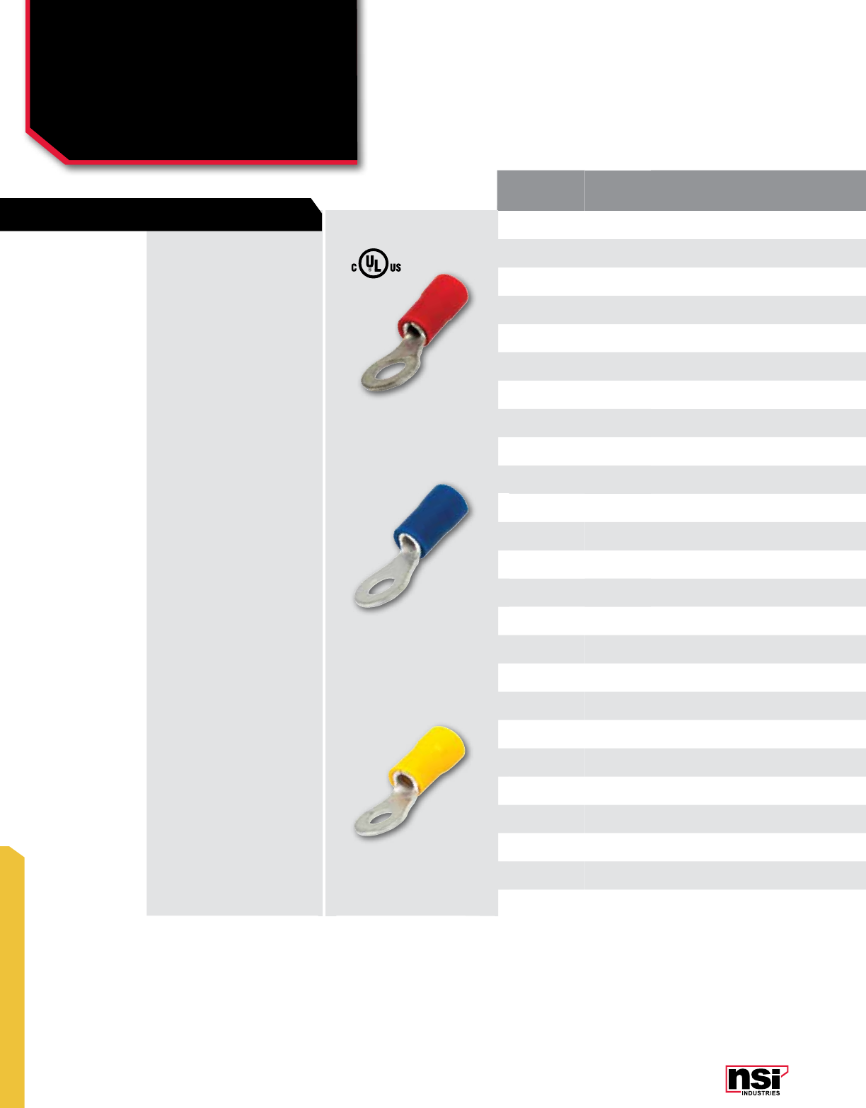
279
MINITERMS
MINITERMS
Ring Terminals
Vinyl
R SERIES
INSULATION
TYPE WIRE
RANGE STUD
SIZE CERTIfICATION
vARIANCE L
(IN) W
(IN) CAT. NO. QTY CAT. NO. QTY CAT. NO. QTY CAT. NO. QTY
Vinyl 22-18 1/4 1.055 0.456 – --- – – R22-14V 100 R22-14V-BULK 1000
Vinyl 22-18 5/16 UL 1.085 0.464 – --- – – R22-56V 100 R22-56V-BULK 1000
Vinyl 22-18 3/8 UL 1.306 0.534 – --- – – R22-38V 100 R22-38V-BULK 1000
Vinyl 22-18 #10 0.826 0.314 R22-10V-S 25 R22-10V-P 100 R22-10V 100 R22-10V-BULK 1000
Vinyl 22-18 #6 0.826 0.314 R22-6V-S 25 – – R22-6V 100 R22-6V-BULK 1000
Vinyl 22-18 #8 0.826 0.314 R22-8V-S 25 – – R22-8V 100 R22-8V-BULK 1000
Vinyl 16-14 1/4 1.062 0.472 – --- R16-14V-P 70 R16-14V 100 R16-14V-BULK 1000
Vinyl 16-14 5/16 1.062 0.472 – --- – – R16-56V 100 R16-56V-BULK 1000
Vinyl 16-14 3/8 1.208 0.535 – --- – – R16-38V 100 R16-38V-BULK 1000
Vinyl 16-14 1/2 NON-UL 1.348 0.745 – --- – – R16-50V 100 R16-50V-BULK 1000
Vinyl 16-14 #10 0.866 0.334 R16-10V-S 25 R16-10V-P 90 R16-10V 100 R16-10V-BULK 1000
Vinyl 16-14 #6 0.767 0.259 R16-6V-S 25 R16-6V-P 90 R16-6V 100 R16-6V-BULK 1000
Vinyl 16-14 #8 0.866 0.334 R16-8V-S 25 R16-8V-P 90 R16-8V 100 R16-8V-BULK 1000
Vinyl 12-10 1/4 1.141 0.472 R12-14V-S 20 R12-14V-P 50 R12-14V 50 R12-14V-BULK 500
Vinyl 12-10 5/16 1.326 0.59 – --- – – R12-56V 50 R12-56V-BULK 500
Vinyl 12-10 3/8 1.326 0.59 R12-38V-S 10 – – R12-38V 50 R12-38V-BULK 500
Vinyl 12-10 1/2 1.499 0.755 – --- – – R12-50V 50 R12-50V-BULK 500
Vinyl 12-10 #10 1.003 0.374 R12-10V-S 10 R12-10V-P 50 R12-10V 50 R12-10V-BULK 500
Vinyl 12-10 #6 1.003 0.374 – --- – – R12-6V 50 R12-6V-BULK 500
Vinyl 12-10 #8 1.003 0.374 R12-8V-S 15 R12-8V-P 50 R12-8V 50 R12-8V-BULK 500
Vinyl 8 1/4 UL 1.27 0.374 – --- – – R8-14V 50 R8-14V-BULK 250
Vinyl 8 5/16 UL 1.31 0.328 – --- – – R8-56V 50 R8-56V-BULK 250
Vinyl 8 3/8 UL 1.43 0.583 – --- – – R8-38V 50 R8-38V-BULK 250
Vinyl 8 1/2 UL 1.73 0.81 – --- – – R8-50V 50 R8-50V-BULK 250
Vinyl 8 #10 UL 1.27 0.374 – --- – – R8-10V 50 R8-10V-BULK 250
VINYL:
Basic tongue type ring
terminal. Safe and reliable
connections, because it
cannot be disconnected
unless the screw is
completely removed.
Electro tin plated copper with
brazed seam, vinyl (PVC)
300V, 75 °C.
FEATURES

280
NSi Industries LLC • USA • 800.321.5847 • www.nsiindustries.com
280
MINITERMS
“S” PACKS PRO PACKS STD PACKS BULK PACKS
INSULATION
TYPE WIRE
RANGE STUD
SIZE CERTIfICATION
vARIANCE L
(IN) W
(IN) CAT. NO. QTY CAT. NO. QTY CAT. NO. QTY CAT. NO. QTY
Vinyl 22-18 1/4 1.055 0.456 – --- – – R22-14V 100 R22-14V-BULK 1000
Vinyl 22-18 5/16 UL 1.085 0.464 – --- – – R22-56V 100 R22-56V-BULK 1000
Vinyl 22-18 3/8 UL 1.306 0.534 – --- – – R22-38V 100 R22-38V-BULK 1000
Vinyl 22-18 #10 0.826 0.314 R22-10V-S 25 R22-10V-P 100 R22-10V 100 R22-10V-BULK 1000
Vinyl 22-18 #6 0.826 0.314 R22-6V-S 25 – – R22-6V 100 R22-6V-BULK 1000
Vinyl 22-18 #8 0.826 0.314 R22-8V-S 25 – – R22-8V 100 R22-8V-BULK 1000
Vinyl 16-14 1/4 1.062 0.472 – --- R16-14V-P 70 R16-14V 100 R16-14V-BULK 1000
Vinyl 16-14 5/16 1.062 0.472 – --- – – R16-56V 100 R16-56V-BULK 1000
Vinyl 16-14 3/8 1.208 0.535 – --- – – R16-38V 100 R16-38V-BULK 1000
Vinyl 16-14 1/2 NON-UL 1.348 0.745 – --- – – R16-50V 100 R16-50V-BULK 1000
Vinyl 16-14 #10 0.866 0.334 R16-10V-S 25 R16-10V-P 90 R16-10V 100 R16-10V-BULK 1000
Vinyl 16-14 #6 0.767 0.259 R16-6V-S 25 R16-6V-P 90 R16-6V 100 R16-6V-BULK 1000
Vinyl 16-14 #8 0.866 0.334 R16-8V-S 25 R16-8V-P 90 R16-8V 100 R16-8V-BULK 1000
Vinyl 12-10 1/4 1.141 0.472 R12-14V-S 20 R12-14V-P 50 R12-14V 50 R12-14V-BULK 500
Vinyl 12-10 5/16 1.326 0.59 – --- – – R12-56V 50 R12-56V-BULK 500
Vinyl 12-10 3/8 1.326 0.59 R12-38V-S 10 – – R12-38V 50 R12-38V-BULK 500
Vinyl 12-10 1/2 1.499 0.755 – --- – – R12-50V 50 R12-50V-BULK 500
Vinyl 12-10 #10 1.003 0.374 R12-10V-S 10 R12-10V-P 50 R12-10V 50 R12-10V-BULK 500
Vinyl 12-10 #6 1.003 0.374 – --- – – R12-6V 50 R12-6V-BULK 500
Vinyl 12-10 #8 1.003 0.374 R12-8V-S 15 R12-8V-P 50 R12-8V 50 R12-8V-BULK 500
Vinyl 8 1/4 UL 1.27 0.374 – --- – – R8-14V 50 R8-14V-BULK 250
Vinyl 8 5/16 UL 1.31 0.328 – --- – – R8-56V 50 R8-56V-BULK 250
Vinyl 8 3/8 UL 1.43 0.583 – --- – – R8-38V 50 R8-38V-BULK 250
Vinyl 8 1/2 UL 1.73 0.81 – --- – – R8-50V 50 R8-50V-BULK 250
Vinyl 8 #10 UL 1.27 0.374 – --- – – R8-10V 50 R8-10V-BULK 250
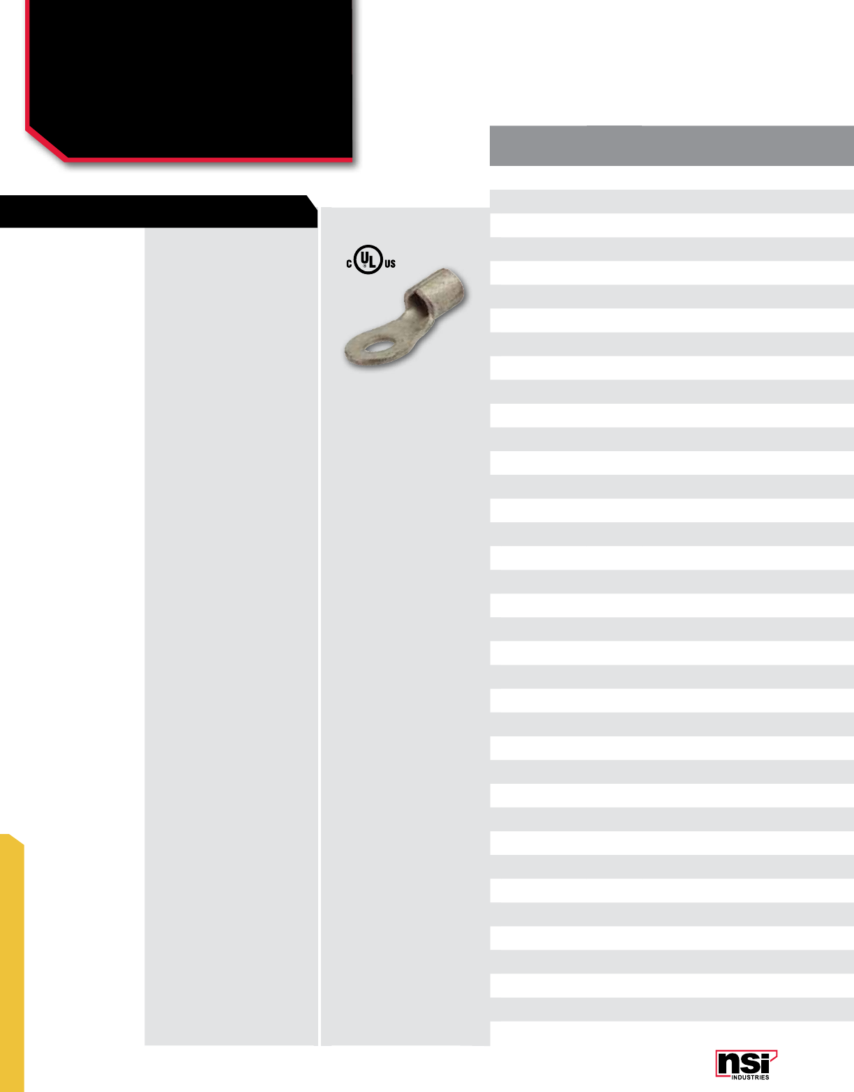
281
MINITERMS
MINITERMS
Ring Terminals
Uninsulated
R SERIES
INSULATION
TYPE WIRE
RANGE STUD
SIZE CERTIfICATION
vARIANCE LENGTH
(IN) WIDTH
(IN) CAT. NO. QTY CAT. NO. QTY CAT. NO. QTY
Un-insulated 22-18 1/4 UL 0.894 0.255 – – R22-14 100 R22-14-BULK 1000
Un-insulated 22-18 5/16 UL 0.893 0.323 – – R22-56 100 R22-56-BULK 1000
Un-insulated 22-18 3/8 UL 1.097 0.38 – – R22-38 100 R22-38-BULK 1000
Un-insulated 22-18 #10 0.629 0.314 – – R22-10 100 R22-10-BULK 1000
Un-insulated 22-18 #6 UL 0.702 0.312 – – R22-6 100 R22-6-BULK 1000
Un-insulated 22-18 #8 0.629 0.314 – – R22-8 100 R22-8-BULK 1000
Un-insulated 16-14 1/4 0.866 0.472 – – R16-14 100 R16-14-BULK 1000
Un-insulated 16-14 5/16 UL 0.892 0.472 – – R16-56 100 R16-56-BULK 1000
Un-insulated 16-14 3/8 1.011 0.535 – – R16-38 100 R16-38-BULK 1000
Un-insulated 16-14 1/2 NON-UL 1.123 0.748 – --- R16-50 100 R16-50-BULK 1000
Un-insulated 16-14 #10 0.669 0.334 R16-10-P 125 R16-10 100 R16-10-BULK 1000
Un-insulated 16-14 #6 UL 0.704 0.313 – – R16-6 100 R16-6-BULK 1000
Un-insulated 16-14 #8 0.669 0.334 R16-8-P 125 R16-8 100 R16-8-BULK 1000
Un-insulated #6 1/4 UL 1.253 0.634 – – R6-14 50 R6-14-BULK 500
Un-insulated #6 5/16 UL 1.243 0.635 – – R6-56 50 R6-56-BULK 500
Un-insulated #6 3/8 UL 1.239 0.635 – – R6-38 50 R6-38-BULK 500
Un-insulated #6 1/2 UL 1.434 0.827 – – R6-50 50 R6-50-BULK 500
Un-insulated #6 #10 UL 1.18 0.485 – – R6-10 50 R6-10-BULK 500
Un-insulated #4 1/4 UL 1.245 0.469 – – R4-14 25 R4-14-BULK 500
Un-insulated #4 5/16 UL 1.25 0.476 – – R4-56 25 R4-56-BULK 500
Un-insulated #4 3/8 UL 1.34 0.665 – – R4-38 25 R4-38-BULK 500
Un-insulated #4 1/2 UL 1.327 0.665 – – R4-50 25 R4-50-BULK 500
Un-insulated #2 1/4 UL 1.563 0.636 – – R2-14 25 R2-14-BULK 500
Un-insulated #2 5/16 UL 1.673 0.868 – – R2-56 25 R2-56-BULK 500
Un-insulated #2 3/8 UL 1.563 0.635 – – R2-38 25 R2-38-BULK 500
Un-insulated #2 1/2 UL 1.677 0.868 – – R2-50 25 R2-50-BULK 500
Un-insulated 12-10 1/4 0.885 0.472 – – R12-14 50 R12-14-BULK 1000
Un-insulated 12-10 5/16 1.07 0.59 – – R12-56 50 R12-56-BULK 500
Un-insulated 12-10 3/8 1.07 0.59 – – R12-38 50 R12-38-BULK 500
Un-insulated 12-10 1/2 NON-UL 1.284 0.755 – – R12-50 50 R12-50-BULK 500
Un-insulated 12-10 #10 0.74 0.372 R12-10-P 80 R12-10 50 R12-10-BULK 1000
Un-insulated 12-10 #6 UL 0.766 0.374 – – R12-6 50 R12-6-BULK 500
Un-insulated 12-10 #8 UL 0.766 0.376 – – R12-8 50 R12-8-BULK 500
Un-insulated 8 1/4 UL 0.956 0.457 – – R8-14 50 R8-14-BULK 500
Un-insulated 8 5/16 UL 0.952 0.471 – – R8-56 50 R8-56-BULK 500
Un-insulated 8 3/8 UL 1.083 0.59 – – R8-38 50 R8-38-BULK 500
Un-insulated 8 #10 UL 0.955 0.47 – – R8-10 50 R8-10-BULK 500
UN-INSULATED:
Basic tongue type ring
terminal. Safe and reliable
connections, because it
cannot be disconnected
unless the screw is
completely removed.
Electro tin plated copper with
brazed seam, 600V, 105 °C.
FEATURES

282
NSi Industries LLC • USA • 800.321.5847 • www.nsiindustries.com
282
MINITERMS
PRO PACKS STD PACKS BULK PACKS
INSULATION
TYPE WIRE
RANGE STUD
SIZE CERTIfICATION
vARIANCE LENGTH
(IN) WIDTH
(IN) CAT. NO. QTY CAT. NO. QTY CAT. NO. QTY
Un-insulated 22-18 1/4 UL 0.894 0.255 – – R22-14 100 R22-14-BULK 1000
Un-insulated 22-18 5/16 UL 0.893 0.323 – – R22-56 100 R22-56-BULK 1000
Un-insulated 22-18 3/8 UL 1.097 0.38 – – R22-38 100 R22-38-BULK 1000
Un-insulated 22-18 #10 0.629 0.314 – – R22-10 100 R22-10-BULK 1000
Un-insulated 22-18 #6 UL 0.702 0.312 – – R22-6 100 R22-6-BULK 1000
Un-insulated 22-18 #8 0.629 0.314 – – R22-8 100 R22-8-BULK 1000
Un-insulated 16-14 1/4 0.866 0.472 – – R16-14 100 R16-14-BULK 1000
Un-insulated 16-14 5/16 UL 0.892 0.472 – – R16-56 100 R16-56-BULK 1000
Un-insulated 16-14 3/8 1.011 0.535 – – R16-38 100 R16-38-BULK 1000
Un-insulated 16-14 1/2 NON-UL 1.123 0.748 – --- R16-50 100 R16-50-BULK 1000
Un-insulated 16-14 #10 0.669 0.334 R16-10-P 125 R16-10 100 R16-10-BULK 1000
Un-insulated 16-14 #6 UL 0.704 0.313 – – R16-6 100 R16-6-BULK 1000
Un-insulated 16-14 #8 0.669 0.334 R16-8-P 125 R16-8 100 R16-8-BULK 1000
Un-insulated #6 1/4 UL 1.253 0.634 – – R6-14 50 R6-14-BULK 500
Un-insulated #6 5/16 UL 1.243 0.635 – – R6-56 50 R6-56-BULK 500
Un-insulated #6 3/8 UL 1.239 0.635 – – R6-38 50 R6-38-BULK 500
Un-insulated #6 1/2 UL 1.434 0.827 – – R6-50 50 R6-50-BULK 500
Un-insulated #6 #10 UL 1.18 0.485 – – R6-10 50 R6-10-BULK 500
Un-insulated #4 1/4 UL 1.245 0.469 – – R4-14 25 R4-14-BULK 500
Un-insulated #4 5/16 UL 1.25 0.476 – – R4-56 25 R4-56-BULK 500
Un-insulated #4 3/8 UL 1.34 0.665 – – R4-38 25 R4-38-BULK 500
Un-insulated #4 1/2 UL 1.327 0.665 – – R4-50 25 R4-50-BULK 500
Un-insulated #2 1/4 UL 1.563 0.636 – – R2-14 25 R2-14-BULK 500
Un-insulated #2 5/16 UL 1.673 0.868 – – R2-56 25 R2-56-BULK 500
Un-insulated #2 3/8 UL 1.563 0.635 – – R2-38 25 R2-38-BULK 500
Un-insulated #2 1/2 UL 1.677 0.868 – – R2-50 25 R2-50-BULK 500
Un-insulated 12-10 1/4 0.885 0.472 – – R12-14 50 R12-14-BULK 1000
Un-insulated 12-10 5/16 1.07 0.59 – – R12-56 50 R12-56-BULK 500
Un-insulated 12-10 3/8 1.07 0.59 – – R12-38 50 R12-38-BULK 500
Un-insulated 12-10 1/2 NON-UL 1.284 0.755 – – R12-50 50 R12-50-BULK 500
Un-insulated 12-10 #10 0.74 0.372 R12-10-P 80 R12-10 50 R12-10-BULK 1000
Un-insulated 12-10 #6 UL 0.766 0.374 – – R12-6 50 R12-6-BULK 500
Un-insulated 12-10 #8 UL 0.766 0.376 – – R12-8 50 R12-8-BULK 500
Un-insulated 8 1/4 UL 0.956 0.457 – – R8-14 50 R8-14-BULK 500
Un-insulated 8 5/16 UL 0.952 0.471 – – R8-56 50 R8-56-BULK 500
Un-insulated 8 3/8 UL 1.083 0.59 – – R8-38 50 R8-38-BULK 500
Un-insulated 8 #10 UL 0.955 0.47 – – R8-10 50 R8-10-BULK 500
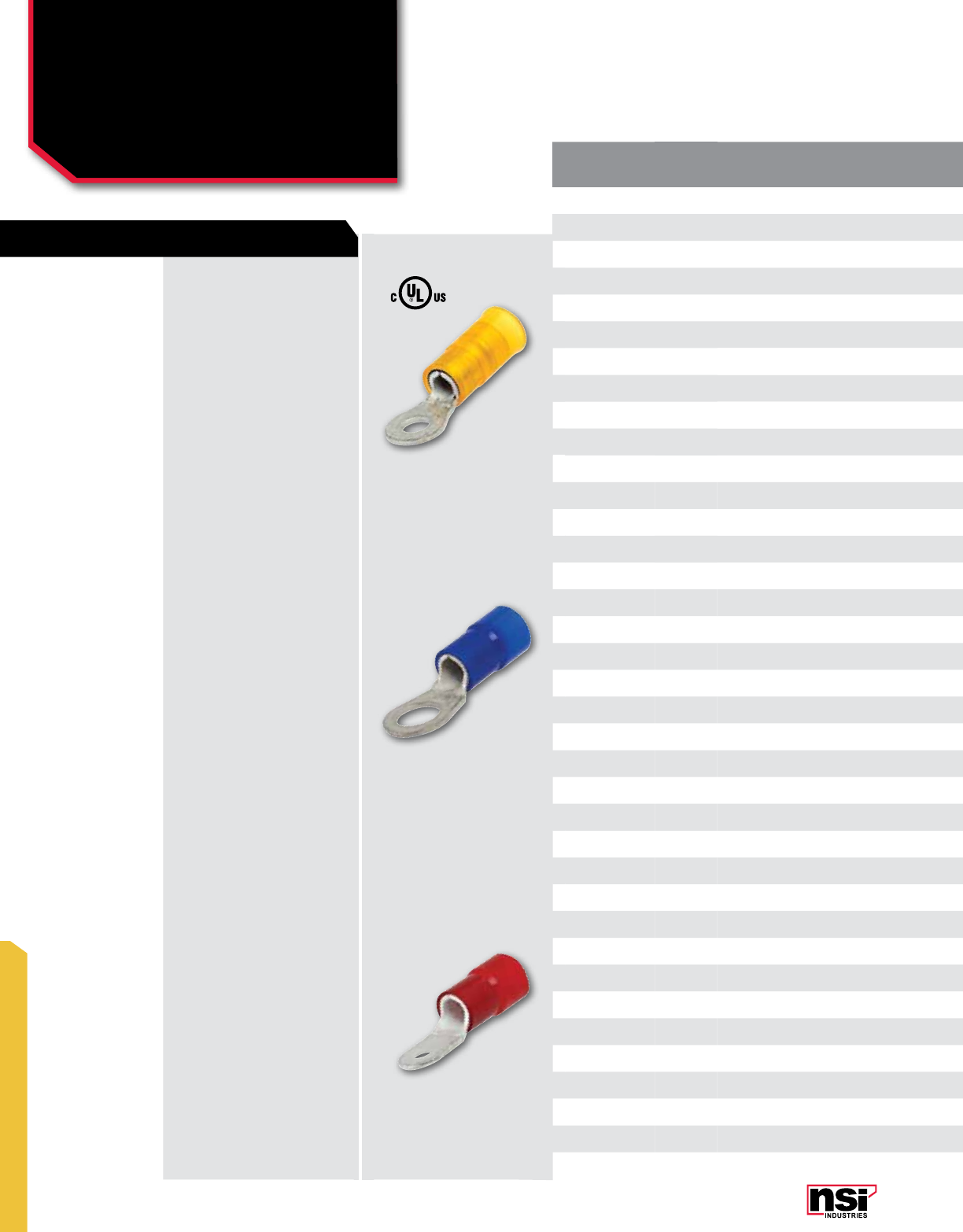
283
MINITERMS
MINITERMS
Ring Terminals
Nylon
R SERIES
INSULATION
TYPE WIRE
RANGE STUD
SIZE CERTIfICATION
vARIANCE LENGTH
(IN) WIDTH
(IN) CAT. NO. QTY CAT. NO. QTY CAT. NO. QTY
Nylon 22-18 1/4 UL 1.094 0.456 --- --- R22-14N 100 R22-14N-BULK 1000
Nylon 22-18 5/16 UL 1.094 0.456 --- --- R22-56N 100 R22-56N-BULK 1000
Nylon 22-18 3/8 UL 1.248 0.535 --- --- R22-38N 100 R22-38N-BULK 1000
Nylon 22-18 #10 UL 0.866 0.314 --- --- R22-10N 100 R22-10N-BULK 1000
Nylon 22-18 #4 UL 0.953 0.264 --- --- R22-4N 100 R22-4N-BULK 1000
Nylon 22-18 #6 0.866 0.314 --- --- R22-6N 100 R22-6N-BULK 1000
Nylon 22-18 #8 UL 0.866 0.314 --- --- R22-8N 100 R22-8N-BULK 1000
Nylon 16-14 1/4 UL 1.102 0.472 --- --- R16-14N 100 R16-14N-BULK 1000
Nylon 16-14 5/16 UL 0.807 0.529 --- --- R16-56N 100 R16-56N-BULK 1000
Nylon 16-14 3/8 UL 1.248 0.535 --- --- R16-38N 100 R16-38N-BULK 1000
Nylon 16-14 1/2 NON-UL 1.44 0.755 --- --- R16-50N 100 R16-50N-BULK 1000
Nylon 16-14 #10 0.905 0.334 --- --- R16-10N 100 R16-10N-BULK 1000
Nylon 16-14 #6 UL 0.995 0.31 --- --- R16-6N 100 R16-6N-BULK 1000
Nylon 16-14 #8 0.905 0.334 --- --- R16-8N 100 R16-8N-BULK 1000
Nylon #6 1/4 UL 1.355 0.48 --- --- R6-14N 50 R6-14N-BULK 250
Nylon #6 5/16 UL 1.355 0.64 --- --- R6-56N 50 R6-56N-BULK 250
Nylon #6 3/8 UL 1.355 0.64 --- --- R6-38N 50 R6-38N-BULK 250
Nylon #6 1/2 NON-UL 1.447 0.832 --- --- R6-50N 50 R6-50N-BULK 250
Nylon #4 1/4 UL 1.85 0.475 --- --- R4-14N 25 R4-14N-BULK 100
Nylon #4 5/16 UL 1.85 0.475 --- --- R4-56N 25 R4-56N-BULK 100
Nylon #4 3/8 UL 1.95 0.668 --- --- R4-38N 25 R4-38N-BULK 100
Nylon #4 1/2 UL 1.95 0.668 --- --- R4-50N 25 R4-50N-BULK 100
Nylon #2 1/4 UL 1.821 0.645 --- --- R2-14N 25 R2-14N-BULK 100
Nylon #2 5/16 UL 1.821 0.645 --- --- R2-56N 25 R2-56N-BULK 100
Nylon #2 3/8 UL 1.821 0.645 --- --- R2-38N 25 R2-38N-BULK 100
Nylon #2 1/2 NON-UL 2.202 0.863 --- --- R2-50N 25 R2-50N-BULK 100
Nylon 12-10 1/4 1.161 0.472 --- --- R12-14N 50 R12-14N-BULK 500
Nylon 12-10 5/16 UL 1.346 0.59 --- --- R12-56N 50 R12-56N-BULK 500
Nylon 12-10 3/8 UL 1.346 0.59 --- --- R12-38N 50 R12-38N-BULK 500
Nylon 12-10 1/2 NON-UL 1.519 0.755 --- --- R12-50N 50 R12-50N-BULK 500
Nylon 12-10 #10 1.023 0.374 --- --- R12-10N 50 R12-10N-BULK 500
Nylon 12-10 #6 UL 1.023 0.374 --- --- R12-6N 50 R12-6N-BULK 500
Nylon 12-10 #8 UL 1.023 0.374 --- --- R12-8N 50 R12-8N-BULK 500
Nylon 8 1/4 UL 1.39 0.468 --- --- R8-14N 50 R8-14N-BULK 250
Nylon 8 5/16 UL 1.39 0.468 --- --- R8-56N 50 R8-56N-BULK 250
Nylon 8 3/8 UL 1.51 0.588 --- --- R8-38N 50 R8-38N-BULK 250
Nylon 8 #10 UL 1.39 0.468 --- --- R8-10N 50 R8-10N-BULK 500
NYLON:
Basic tongue type ring
terminal. Safe and reliable
connections, because it
cannot be disconnected
unless the screw is
completely removed.
Electro tin plated copper with
brazed seam, easy-entry
Nylon, 600V, 105 °C.
FEATURES

284
NSi Industries LLC • USA • 800.321.5847 • www.nsiindustries.com
284
MINITERMS
PRO PACKS STD PACKS BULK PACKS
INSULATION
TYPE WIRE
RANGE STUD
SIZE CERTIfICATION
vARIANCE LENGTH
(IN) WIDTH
(IN) CAT. NO. QTY CAT. NO. QTY CAT. NO. QTY
Nylon 22-18 1/4 UL 1.094 0.456 --- --- R22-14N 100 R22-14N-BULK 1000
Nylon 22-18 5/16 UL 1.094 0.456 --- --- R22-56N 100 R22-56N-BULK 1000
Nylon 22-18 3/8 UL 1.248 0.535 --- --- R22-38N 100 R22-38N-BULK 1000
Nylon 22-18 #10 UL 0.866 0.314 --- --- R22-10N 100 R22-10N-BULK 1000
Nylon 22-18 #4 UL 0.953 0.264 --- --- R22-4N 100 R22-4N-BULK 1000
Nylon 22-18 #6 0.866 0.314 --- --- R22-6N 100 R22-6N-BULK 1000
Nylon 22-18 #8 UL 0.866 0.314 --- --- R22-8N 100 R22-8N-BULK 1000
Nylon 16-14 1/4 UL 1.102 0.472 --- --- R16-14N 100 R16-14N-BULK 1000
Nylon 16-14 5/16 UL 0.807 0.529 --- --- R16-56N 100 R16-56N-BULK 1000
Nylon 16-14 3/8 UL 1.248 0.535 --- --- R16-38N 100 R16-38N-BULK 1000
Nylon 16-14 1/2 NON-UL 1.44 0.755 --- --- R16-50N 100 R16-50N-BULK 1000
Nylon 16-14 #10 0.905 0.334 --- --- R16-10N 100 R16-10N-BULK 1000
Nylon 16-14 #6 UL 0.995 0.31 --- --- R16-6N 100 R16-6N-BULK 1000
Nylon 16-14 #8 0.905 0.334 --- --- R16-8N 100 R16-8N-BULK 1000
Nylon #6 1/4 UL 1.355 0.48 --- --- R6-14N 50 R6-14N-BULK 250
Nylon #6 5/16 UL 1.355 0.64 --- --- R6-56N 50 R6-56N-BULK 250
Nylon #6 3/8 UL 1.355 0.64 --- --- R6-38N 50 R6-38N-BULK 250
Nylon #6 1/2 NON-UL 1.447 0.832 --- --- R6-50N 50 R6-50N-BULK 250
Nylon #4 1/4 UL 1.85 0.475 --- --- R4-14N 25 R4-14N-BULK 100
Nylon #4 5/16 UL 1.85 0.475 --- --- R4-56N 25 R4-56N-BULK 100
Nylon #4 3/8 UL 1.95 0.668 --- --- R4-38N 25 R4-38N-BULK 100
Nylon #4 1/2 UL 1.95 0.668 --- --- R4-50N 25 R4-50N-BULK 100
Nylon #2 1/4 UL 1.821 0.645 --- --- R2-14N 25 R2-14N-BULK 100
Nylon #2 5/16 UL 1.821 0.645 --- --- R2-56N 25 R2-56N-BULK 100
Nylon #2 3/8 UL 1.821 0.645 --- --- R2-38N 25 R2-38N-BULK 100
Nylon #2 1/2 NON-UL 2.202 0.863 --- --- R2-50N 25 R2-50N-BULK 100
Nylon 12-10 1/4 1.161 0.472 --- --- R12-14N 50 R12-14N-BULK 500
Nylon 12-10 5/16 UL 1.346 0.59 --- --- R12-56N 50 R12-56N-BULK 500
Nylon 12-10 3/8 UL 1.346 0.59 --- --- R12-38N 50 R12-38N-BULK 500
Nylon 12-10 1/2 NON-UL 1.519 0.755 --- --- R12-50N 50 R12-50N-BULK 500
Nylon 12-10 #10 1.023 0.374 --- --- R12-10N 50 R12-10N-BULK 500
Nylon 12-10 #6 UL 1.023 0.374 --- --- R12-6N 50 R12-6N-BULK 500
Nylon 12-10 #8 UL 1.023 0.374 --- --- R12-8N 50 R12-8N-BULK 500
Nylon 8 1/4 UL 1.39 0.468 --- --- R8-14N 50 R8-14N-BULK 250
Nylon 8 5/16 UL 1.39 0.468 --- --- R8-56N 50 R8-56N-BULK 250
Nylon 8 3/8 UL 1.51 0.588 --- --- R8-38N 50 R8-38N-BULK 250
Nylon 8 #10 UL 1.39 0.468 --- --- R8-10N 50 R8-10N-BULK 500
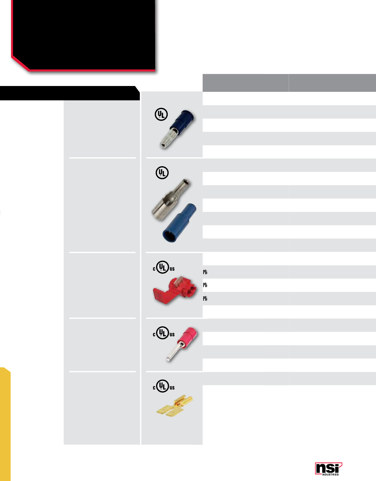
285
MINITERMS
MINITERMS
Male & Female Plugs
Plier Tap and Pin Terminal,
Male/Female Adapter
PM, Pf, PTC, PT SERIES
STYLE INSULATION
TYPE WIRE
RANGE STUD
SIZE CERTIfICATION
vARIANCE L
(IN) W
(IN) CAT. NO. QTY CAT. NO. QTY CAT. NO. QTY CAT. NO. QTY
Plugs Male Un-insulated 22-18 0.157 NON-UL 0.630 0.145 – --- --- --- PM22-157 100 PM22-157-BULK 1000
Plugs Male Un-insulated 16-14 0.157 NON-UL 0.630 0.136 – --- --- --- PM16-157 100 PM16-157-BULK 1000
Plugs Male Nylon 22-18 0.157 UL 0.890 0.145 – --- --- --- PM22-157N 100 PM22-157N-BULK 1000
Plugs Male Nylon 16-14 0.157 UL 0.890 0.145 – --- --- --- PM16-157N 100 PM16-157N-BULK 1000
Plugs Female Un-insulated 22-18 0.157 NON-UL 0.680 0.194 – --- --- --- PF22-157 100 PF22-157-BULK 1000
Plugs Female Un-insulated 16-14 0.157 NON-UL 0.680 0.185 – --- --- --- PF16-157 100 PF16-157-BULK 1000
Plugs Female Nylon 22-18 0.157 UL 1.000 0.128 – --- --- --- PF22-157N 100 PF22-157N-BULK 1000
Plugs Female Nylon 22-18 0.157 NON-UL 1.234 0.309 – --- --- --- PFS22-157N 100 PFS22-157N-BULK 1000
Plugs Female Nylon 16-14 0.157 UL 1.000 0.150 – --- --- --- PF16-157N 100 PF16-157N-BULK 1000
Plugs Female Nylon 16-14 0.157 NON-UL 1.233 0.339 – --- --- --- PFS16-157N 100 PFS16-157N-BULK 1000
Plugs Female Nylon 16-14 0.197 NON-UL 1.233 0.339 – --- --- --- PFS16-197N 100 PFS16-197N-BULK 1000
Plier Tap Connector Vinyl 22-18 n/a 0.790 0.550 – --- --- --- PTC22-18 100 PTC22-18-BULK 500
Plier Tap Connector Vinyl 16-14 n/a 0.790 0.550 – --- --- --- PTC16-14 100 PTC16-14-BULK 500
Plier Tap Connector Vinyl 12-10 n/a 0.800 0.740 – --- --- --- PTC12-10 50 PTC12-10-BULK 250
Pin Terminal Vinyl 22-18 n/a 0.930 0.078 – --- --- --- PT-22V 100 PT-22V-BULK 1000
Pin Terminal Vinyl 16-14 n/a 0.930 0.078 – --- --- --- PT-16V 100 PT-16V-BULK 1000
Pin Terminal Vinyl 12-10 n/a 1.120 0.107 – --- --- --- PT-12V 50 PT-12V-BULK 500
Male Female
Adapter Un-insulated n/a 0.250 0.825 0.564 – – --- --- 250-3-Z 100 250-3-Z-BULK 1000
Male Female
Adapter Un-insulated n/a 0.250 0.825 0.564 DMT250-3-S 15 DMT250-3-P 60 DMT250-3 100 DMT250-3-BULK 1000
Plier Tap Connector
Plier Tap Connector
Plier Tap Connector
UN-INSULATED/
NYLON:
Electro tin plated copper, vinyl
(PVC) 600V, 75 °C.
VINYL:
Similar tongue style to a spade, block
spades have longer, flatter sides
designed for use in terminal blocks.
Electro tin plated copper with brazed
seam, Vinyl (PVC), 600V, 75 °C
UN-INSULATED/
NYLON:
Turned up edges give this spade
more safety and reliability. Flanges
give a location and locking action
that aid in installation.
Electro tin plated copper, easy-entry
Nylon, 600V, 105 °C.
UN-INSULATED:
Similar tongue style to a spade,
block spades have longer, flatter
sides designed for use in terminal
blocks.
Electro tin plated copper with brazed
seam, easy-entry Nylon, 600V,
105 °C.
VINYL:
Similar tongue style to a spade, block
spades have longer, flatter sides
designed for use in terminal blocks.
Electro tin plated copper with brazed
seam, 600V, 105 °C.
FEATURES

286
NSi Industries LLC • USA • 800.321.5847 • www.nsiindustries.com
286
MINITERMS
“S” PACKS PRO PACKS STD PACKS BULK PACKS
STYLE INSULATION
TYPE WIRE
RANGE STUD
SIZE CERTIfICATION
vARIANCE L
(IN) W
(IN) CAT. NO. QTY CAT. NO. QTY CAT. NO. QTY CAT. NO. QTY
Plugs Male Un-insulated 22-18 0.157 NON-UL 0.630 0.145 – --- --- --- PM22-157 100 PM22-157-BULK 1000
Plugs Male Un-insulated 16-14 0.157 NON-UL 0.630 0.136 – --- --- --- PM16-157 100 PM16-157-BULK 1000
Plugs Male Nylon 22-18 0.157 UL 0.890 0.145 – --- --- --- PM22-157N 100 PM22-157N-BULK 1000
Plugs Male Nylon 16-14 0.157 UL 0.890 0.145 – --- --- --- PM16-157N 100 PM16-157N-BULK 1000
Plugs Female Un-insulated 22-18 0.157 NON-UL 0.680 0.194 – --- --- --- PF22-157 100 PF22-157-BULK 1000
Plugs Female Un-insulated 16-14 0.157 NON-UL 0.680 0.185 – --- --- --- PF16-157 100 PF16-157-BULK 1000
Plugs Female Nylon 22-18 0.157 UL 1.000 0.128 – --- --- --- PF22-157N 100 PF22-157N-BULK 1000
Plugs Female Nylon 22-18 0.157 NON-UL 1.234 0.309 – --- --- --- PFS22-157N 100 PFS22-157N-BULK 1000
Plugs Female Nylon 16-14 0.157 UL 1.000 0.150 – --- --- --- PF16-157N 100 PF16-157N-BULK 1000
Plugs Female Nylon 16-14 0.157 NON-UL 1.233 0.339 – --- --- --- PFS16-157N 100 PFS16-157N-BULK 1000
Plugs Female Nylon 16-14 0.197 NON-UL 1.233 0.339 – --- --- --- PFS16-197N 100 PFS16-197N-BULK 1000
Plier Tap Connector Vinyl 22-18 n/a 0.790 0.550 – --- --- --- PTC22-18 100 PTC22-18-BULK 500
Plier Tap Connector Vinyl 16-14 n/a 0.790 0.550 – --- --- --- PTC16-14 100 PTC16-14-BULK 500
Plier Tap Connector Vinyl 12-10 n/a 0.800 0.740 – --- --- --- PTC12-10 50 PTC12-10-BULK 250
Pin Terminal Vinyl 22-18 n/a 0.930 0.078 – --- --- --- PT-22V 100 PT-22V-BULK 1000
Pin Terminal Vinyl 16-14 n/a 0.930 0.078 – --- --- --- PT-16V 100 PT-16V-BULK 1000
Pin Terminal Vinyl 12-10 n/a 1.120 0.107 – --- --- --- PT-12V 50 PT-12V-BULK 500
Male Female
Adapter Un-insulated n/a 0.250 0.825 0.564 – – --- --- 250-3-Z 100 250-3-Z-BULK 1000
Male Female
Adapter Un-insulated n/a 0.250 0.825 0.564 DMT250-3-S 15 DMT250-3-P 60 DMT250-3 100 DMT250-3-BULK 1000

287
MINITERMS
MINITERMS
High Temperature
Spade, Ring, Piggyback
& Disconnect
HT SERIES
STYLE INSULATION
TYPE WIRE
RANGE STUD
SIZE CERTIfICATION
vARIANCE L
(IN) W
(IN) CAT. NO. QTY CAT. NO. QTY CAT. NO. QTY CAT. NO. QTY
Spade Un-insulated 12-10 #10 0.499 0.384 HTS12-10-S 15 – – – --- HTS12-10-BULK 1000
Ring Un-insulated 22-18 #10 UL 0.443 0.325 – – – – HTR22-10 100 HTR22-10-BULK 1000
Ring Un-insulated 22-18 #6 NON-UL 0.443 0.270 – – – – HTR22-6 100 HTR22-6-BULK 1000
Ring Un-insulated 22-18 #8 UL 0.411 0.270 – – – – HTR22-8 100 HTR22-8-BULK 1000
Ring Un-insulated 16-14 #10 UL 0.450 0.384 – – HTR16-10-P 100 HTR16-10 100 HTR16-10-BULK 1000
Ring Un-insulated 16-14 #6 UL 0.470 0.345 – – – – HTR16-6 100 HTR16-6-BULK 1000
Ring Un-insulated 16-14 #8 UL 0.444 0.390 – – – – HTR16-8 100 HTR16-8-BULK 1000
Ring Un-insulated 12-10 1/4 NON-UL 0.616 0.482 – – – – HTR12-14 50 HTR12-14-BULK 1000
Ring Un-insulated 12-10 #10 UL 0.530 0.384 – – HTR12-10-P 60 HTR12-10 50 HTR12-10-BULK 1000
Ring Un-insulated 12-10 #8 NON-UL 0.530 0.384 – – – – HTR12-8 50 HTR12-8-BULK 1000
Piggyback Un-insulated 16-14 0.250 0.625 0.291 – – – – HTP16-250-3 --- HTP16-250-3-BULK 1000
Disconnect Male Un-insulated 12-10 0.250 0.685 0.250 – – – – HTM12-250-3 50 HTM12-250-3-BULK 1000
Disconnect Female Flag Un-insulated 16-14 0.250 0.506 0.312 – – HTSF16-250-3-P 60 HTSF16-250-3 60 HTSF16-250-3-BULK 1000
Disconnect Female Flag Un-insulated 12-10 0.250 0.587 0.294 – – HTSF12-250-3-P 50 HTSF12-250-3 50 HTSF12-250-3-BULK 1000
Disconnect Female Un-insulated 16-14 0.250 0.500 0.250 HTF16-250-3-S 15 HTF16-250-3-P 60 HTF16-250-3 50 HTF16-250-3-BULK 1000
Disconnect Female Un-insulated 12-10 0.250 0.690 0.304 HTF12-250-3-S 15 – --- HTF12-250-3-BULK 500
Disconnect Female Un-insulated 8 0.250 0.715 0.304 – – HTF8-250-3-P –HTF8-250-3 25 HTF8-250-3-BULK 1000
Disconnect Female Flag
Disconnect Female Flag
UN-INSULATED:
Electro tin plated copper, vinyl
(PVC) 600V, 75 °C.
UN-INSULATED:
Similar tongue style to a spade, block
spades have longer, flatter side
UN-INSULATED:
Turned up edges give this spade
more safety and reliability.
UN-INSULATED:
Similar tongue style to a spade,
block spades have longer, flatter
sides designed for use in terminal
blocks.
Electro tin plated copper with brazed
seam, easy-entry Nylon, 600V,
105 °C.
UN-INSULATED:
Electro tin plated copper,
600V, 105 °C.
UN-INSULATED:
Similar tongue style to a spade, block
spades have longer, flatter sides
designed for use in terminal blocks.
FEATURES
Disconnect Female Flag

288
NSi Industries LLC • USA • 800.321.5847 • www.nsiindustries.com
288
MINITERMS
22-18 (100)
16-14 (100)
12-10 (50)
8 (50)
6 (50)
4 (25)
2 (25)
22-18 (100)
16-14 (100)
12-10 (50)
8 (50)
6 (50)
4 (25)
2 (25)
22-18 (1000)
16-14 (1000)
12-10 (500)
8 (500)
6 (500)
4 (250)
2 (250)
22-18 (100)
8 (50)
22-18 (100)
8 (50)
8 (50)
8 (50)
6 (50)
4 (25)
22-18 (1000)
16-14 (1000)
12-10 (500)
8 (500)
6 (500)
4 (250)
2 (250)
8 (50)
“S” PACKS PRO PACKS STD PACKS BULK PACKS
STYLE INSULATION
TYPE WIRE
RANGE STUD
SIZE CERTIfICATION
vARIANCE L
(IN) W
(IN) CAT. NO. QTY CAT. NO. QTY CAT. NO. QTY CAT. NO. QTY
Spade Un-insulated 12-10 #10 0.499 0.384 HTS12-10-S 15 – – – --- HTS12-10-BULK 1000
Ring Un-insulated 22-18 #10 UL 0.443 0.325 – – – – HTR22-10 100 HTR22-10-BULK 1000
Ring Un-insulated 22-18 #6 NON-UL 0.443 0.270 – – – – HTR22-6 100 HTR22-6-BULK 1000
Ring Un-insulated 22-18 #8 UL 0.411 0.270 – – – – HTR22-8 100 HTR22-8-BULK 1000
Ring Un-insulated 16-14 #10 UL 0.450 0.384 – – HTR16-10-P 100 HTR16-10 100 HTR16-10-BULK 1000
Ring Un-insulated 16-14 #6 UL 0.470 0.345 – – – – HTR16-6 100 HTR16-6-BULK 1000
Ring Un-insulated 16-14 #8 UL 0.444 0.390 – – – – HTR16-8 100 HTR16-8-BULK 1000
Ring Un-insulated 12-10 1/4 NON-UL 0.616 0.482 – – – – HTR12-14 50 HTR12-14-BULK 1000
Ring Un-insulated 12-10 #10 UL 0.530 0.384 – – HTR12-10-P 60 HTR12-10 50 HTR12-10-BULK 1000
Ring Un-insulated 12-10 #8 NON-UL 0.530 0.384 – – – – HTR12-8 50 HTR12-8-BULK 1000
Piggyback Un-insulated 16-14 0.250 0.625 0.291 – – – – HTP16-250-3 --- HTP16-250-3-BULK 1000
Disconnect Male Un-insulated 12-10 0.250 0.685 0.250 – – – – HTM12-250-3 50 HTM12-250-3-BULK 1000
Disconnect Female Flag Un-insulated 16-14 0.250 0.506 0.312 – – HTSF16-250-3-P 60 HTSF16-250-3 60 HTSF16-250-3-BULK 1000
Disconnect Female Flag Un-insulated 12-10 0.250 0.587 0.294 – – HTSF12-250-3-P 50 HTSF12-250-3 50 HTSF12-250-3-BULK 1000
Disconnect Female Un-insulated 16-14 0.250 0.500 0.250 HTF16-250-3-S 15 HTF16-250-3-P 60 HTF16-250-3 50 HTF16-250-3-BULK 1000
Disconnect Female Un-insulated 12-10 0.250 0.690 0.304 HTF12-250-3-S 15 – --- HTF12-250-3-BULK 500
Disconnect Female Un-insulated 8 0.250 0.715 0.304 – – HTF8-250-3-P –HTF8-250-3 25 HTF8-250-3-BULK 1000
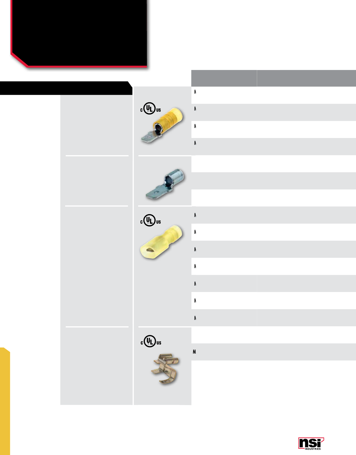
289
MINITERMS
MINITERMS
Male Disconnects:
Fully Insulated & Male/
Female Adapter
M, IM, fCT SERIES
STYLE INSULATION
TYPE WIRE
RANGE STUD
SIZE CERTIfICATION
vARIANCE L
(IN) W
(IN) CAT. NO. QTY CAT. NO. QTY CAT. NO. QTY CAT. NO. QTY
Male Fully Insulated
Barrel Vinyl 22-18 0.250 0.834 0.249 M22-250-3V-S 30 – – M22-250-3V 100 M22-250-3V-BULK 1000
Male Fully Insulated
Barrel Vinyl 16-14 0.187 0.755 0.188 – – – – M16-187-2V 100 M16-187-2V-BULK 1000
Male Fully Insulated
Barrel Vinyl 16-14 0.250 0.834 0.249 M16-250-3V-S 30 M16-250-3V-P 100 M16-250-3V 100 M16-250-3V-BULK 1000
Male Fully Insulated
Barrel Vinyl 12-10 0.250 0.933 0.249 M12-250-3V-S 25 M12-250-3V-P 50 M12-250-3V 50 M12-250-3V-BULK 500
Un-Insulated
Male Barrel Un-insulated 16-14 0.187 NON-UL 0.630 0.240 – – – – M16-187-2 100 M16-187-2-BULK 1000
Un-Insulated
Male Barrel Un-insulated 16-14 0.250 NON-UL 0.630 0.240 – – – – M16-250-3 100 M16-250-3-BULK 1000
Un-Insulated
Male Barrel Un-insulated 12-10 0.250 NON-UL 0.765 0.250 – – – – M12-250-3 50 M12-250-3-BULK 1000
Male Fully Insulated Nylon 22-18 0.250 0.925 0.249 – – – – IM22-250-3N 100 IM22-250-3N-
BULK 1000
Male Fully Insulated Nylon 22-18 0.250 UL 0.904 0.249 – – – – M22-250-3N 100 M22-250-3N-
BULK 1000
Male Fully Insulated Nylon 16-14 0.187 0.795 0.188 – – – – M16-187-2N 100 M16-187-2N-
BULK 1000
Male Fully Insulated Nylon 16-14 0.250 0.925 0.249 IM16-250-3N-S 20 IM16-250-3N-P 30 IM16-250-3N 50 IM16-250-3N-
BULK 1000
Male Fully Insulated Nylon 16-14 0.250 0.874 0.249 – – – – M16-250-3N 100 M16-250-3N-
BULK 1000
Male Fully Insulated Nylon 12-10 0.250 1.062 0.249 – – – – IM12-250-3N 50 IM12-250-3N-
BULK 500
Male Fully Insulated Nylon 12-10 0.250 UL 1.061 0.249 – – – – M12-250-3N 50 M12-250-3N-
BULK 500
Male/Female Adapter Un-insulated 12-10 0.250 0.529 0.549 FCT12-250-3-S 10 – – FCT12-250-3 50 FCT12-250-3-BULK 1000
Male Fully Insulated
Male Fully Insulated
Male Fully Insulated
Male Fully Insulated
Male Fully Insulated
Male Fully Insulated
Male Fully Insulated
Male Fully Insulated
Male Fully Insulated
Male Fully Insulated
Male Fully Insulated
Male/Female Adapter
VINYL:
Electro tin plated, vinyl (PVC)
300V, 75 °C.
UN-INSULATED-
BARE:
Turned up edges give this
spade more safety and
reliability.
600V, 105 °C.
NYLON:
Turned up edges give this
spade more safety and
reliability.
300V, 105 °C.
UN-INSULATED:
Electro tin plated copper,
600V, 105 °C.
FEATURES

290
NSi Industries LLC • USA • 800.321.5847 • www.nsiindustries.com
290
MINITERMS
“S” PACKS PRO PACKS STD PACKS BULK PACKS
STYLE INSULATION
TYPE WIRE
RANGE STUD
SIZE CERTIfICATION
vARIANCE L
(IN) W
(IN) CAT. NO. QTY CAT. NO. QTY CAT. NO. QTY CAT. NO. QTY
Male Fully Insulated
Barrel Vinyl 22-18 0.250 0.834 0.249 M22-250-3V-S 30 – – M22-250-3V 100 M22-250-3V-BULK 1000
Male Fully Insulated
Barrel Vinyl 16-14 0.187 0.755 0.188 – – – – M16-187-2V 100 M16-187-2V-BULK 1000
Male Fully Insulated
Barrel Vinyl 16-14 0.250 0.834 0.249 M16-250-3V-S 30 M16-250-3V-P 100 M16-250-3V 100 M16-250-3V-BULK 1000
Male Fully Insulated
Barrel Vinyl 12-10 0.250 0.933 0.249 M12-250-3V-S 25 M12-250-3V-P 50 M12-250-3V 50 M12-250-3V-BULK 500
Un-Insulated
Male Barrel Un-insulated 16-14 0.187 NON-UL 0.630 0.240 – – – – M16-187-2 100 M16-187-2-BULK 1000
Un-Insulated
Male Barrel Un-insulated 16-14 0.250 NON-UL 0.630 0.240 – – – – M16-250-3 100 M16-250-3-BULK 1000
Un-Insulated
Male Barrel Un-insulated 12-10 0.250 NON-UL 0.765 0.250 – – – – M12-250-3 50 M12-250-3-BULK 1000
Male Fully Insulated Nylon 22-18 0.250 0.925 0.249 – – – – IM22-250-3N 100 IM22-250-3N-
BULK 1000
Male Fully Insulated Nylon 22-18 0.250 UL 0.904 0.249 – – – – M22-250-3N 100 M22-250-3N-
BULK 1000
Male Fully Insulated Nylon 16-14 0.187 0.795 0.188 – – – – M16-187-2N 100 M16-187-2N-
BULK 1000
Male Fully Insulated Nylon 16-14 0.250 0.925 0.249 IM16-250-3N-S 20 IM16-250-3N-P 30 IM16-250-3N 50 IM16-250-3N-
BULK 1000
Male Fully Insulated Nylon 16-14 0.250 0.874 0.249 – – – – M16-250-3N 100 M16-250-3N-
BULK 1000
Male Fully Insulated Nylon 12-10 0.250 1.062 0.249 – – – – IM12-250-3N 50 IM12-250-3N-
BULK 500
Male Fully Insulated Nylon 12-10 0.250 UL 1.061 0.249 – – – – M12-250-3N 50 M12-250-3N-
BULK 500
Male/Female Adapter Un-insulated 12-10 0.250 0.529 0.549 FCT12-250-3-S 10 – – FCT12-250-3 50 FCT12-250-3-BULK 1000
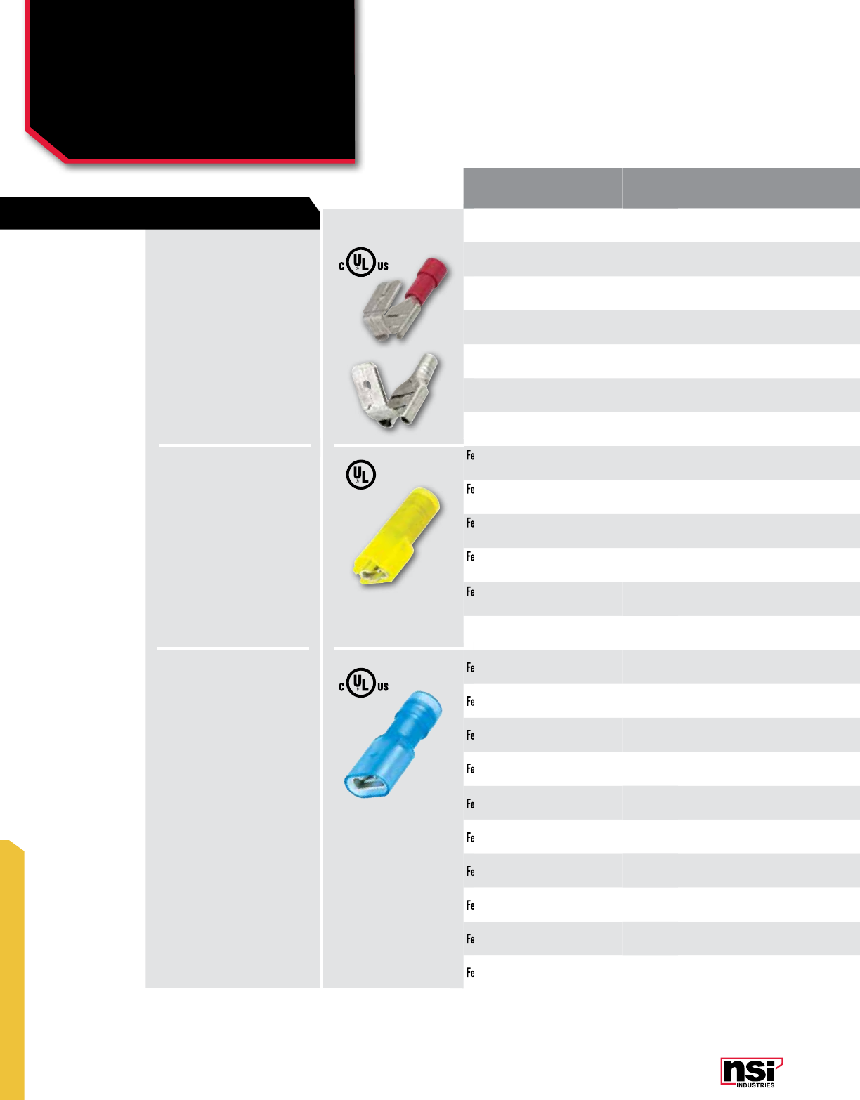
291
MINITERMS
MINITERMS
Female Disconnects:
Piggyback, Sleeved Barrel
& Fully Insulated
P, I fS, If SERIES
STYLE INSULATION
TYPE WIRE
RANGE STUD
SIZE CERTIfICATION
vARIANCE L
(IN) W
(IN) CAT. NO. QTY CAT. NO. QTY CAT. NO. QTY CAT. NO. QTY
Female Piggyback Vinyl 22-18 0.250 0.826 0.259 – – – – P22-250-3V 100 P22-250-3V-BULK 1000
Female Piggyback Vinyl 16-14 0.250 0.826 0.259 P16-250-3V-S 15 P16-250-3V-P 40 P16-250-3V 100 P16-250-3V-BULK 1000
Female Piggyback Vinyl 12-10 0.250 UL 1.010 0.250 – – – – P12-250-3V 50 P12-250-3V-BULK 500
Female Piggyback Un-insulated 16-14 0.250 0.677 0.295 – --- – --- P16-250-3 100 P16-250-3-BULK 1000
Female Piggyback Nylon 22-18 0.250 0.866 0.259 – – --- P22-250-3N 100 P22-250-3N-BULK 1000
Female Piggyback Nylon 16-14 0.250 0.866 0.259 – – – – P16-250-3N 100 P16-250-3N-BULK 1000
Female Fully Insulated
Sleeved Barrel Nylon 22-18 0.110 0.800 0.230 – – – – IFS22-110-2N 100 IFS22-110-2N-
BULK 1000
Female Fully Insulated
Sleeved Barrel Nylon 22-18 0.110 0.800 0.230 – – – – IFS22-110-3N 100 IFS22-110-3N-
BULK 1000
Female Fully Insulated
Sleeved Barrel Nylon 22-18 0.250 0.890 0.380 – – – – IFS22-250-3N 100 IFS22-250-3N-
BULK 1000
Female Fully Insulated
Sleeved Barrel Nylon 16-14 0.250 0.890 0.380 – – – – IFS16-250-3N 100 IFS16-250-3N-
BULK 1000
Female Fully Insulated
Sleeved Barrel Nylon 12-10 0.250 1.040 0.380 – – – – IFS12-250-3N 50 IFS12-250-3N-
BULK 500
Female Fully Insulated Nylon 22-18 0.110 UL 0.800 0.230 – – – – IF22-110-2N 100 IF22-110-2N-BULK 1000
Female Fully Insulated Nylon 22-18 0.110 UL 0.800 0.230 – – – – IF22-110-3N 100 IF22-110-3N-BULK 1000
Female Fully Insulated Nylon 22-18 0.187 UL 0.780 0.320 – – – – IF22-187-2N 100 IF22-187-2N-BULK 1000
Female Fully Insulated Nylon 22-18 0.187 UL 0.780 0.320 – – – – IF22-187-3N 100 IF22-187-3N-BULK 1000
Female Fully Insulated Nylon 22-18 0.250 0.866 0.259 – – – – IF22-250-3N 100 IF22-250-3N-BULK 1000
Female Fully Insulated Nylon 16-14 0.187 0.780 0.320 – – – – IF16-187-2N 100 IF16-187-2N-BULK 1000
Female Fully Insulated Nylon 16-14 0.187 UL 0.780 0.320 – – – – IF16-187-3N 100 IF16-187-3N-BULK 1000
Female Fully Insulated Nylon 16-14 0.250 0.866 0.259 IF16-250-3N-S 12 IF16-250-3N-P 50 IF16-250-3N 100 IF16-250-3N-BULK 1000
Female Fully Insulated Nylon 16-14 0.250 NON-UL 0.955 0.395 IF16-250-3N-IG-S 10 – – IF16-250-3N-IG 100 IF16-250-3N-IG-
BULK 1000
Female Fully Insulated Nylon 12-10 0.250 0.964 0.259 IF12-250-3N-S 12 IF12-250-3N-P 30 IF12-250-3N 50 IF12-250-3N-BULK 500
Female Fully Insulated
Female Fully Insulated
Female Fully Insulated
Female Fully Insulated
Female Fully Insulated
Female Fully Insulated
Female Fully Insulated
Female Fully Insulated
Female Fully Insulated
Female Fully Insulated
Female Fully Insulated
Female Fully Insulated
Female Fully Insulated
Female Fully Insulated
Female Fully Insulated
VINYL/
UN-INSULATED/
NYLON:
Electro tin plated copper,
600V, 105 °C.
NYLON:
Turned up edges give this
spade more safety and
reliability.
600V, 105 °C.
NYLON:
Electro tin plated copper,
600V, 105 °C.
FEATURES
Female Fully Insulated

292
NSi Industries LLC • USA • 800.321.5847 • www.nsiindustries.com
292
MINITERMS
“S” PACKS PRO PACKS STD PACKS BULK PACKS
STYLE INSULATION
TYPE WIRE
RANGE STUD
SIZE CERTIfICATION
vARIANCE L
(IN) W
(IN) CAT. NO. QTY CAT. NO. QTY CAT. NO. QTY CAT. NO. QTY
Female Piggyback Vinyl 22-18 0.250 0.826 0.259 – – – – P22-250-3V 100 P22-250-3V-BULK 1000
Female Piggyback Vinyl 16-14 0.250 0.826 0.259 P16-250-3V-S 15 P16-250-3V-P 40 P16-250-3V 100 P16-250-3V-BULK 1000
Female Piggyback Vinyl 12-10 0.250 UL 1.010 0.250 – – – – P12-250-3V 50 P12-250-3V-BULK 500
Female Piggyback Un-insulated 16-14 0.250 0.677 0.295 – --- – --- P16-250-3 100 P16-250-3-BULK 1000
Female Piggyback Nylon 22-18 0.250 0.866 0.259 – – --- P22-250-3N 100 P22-250-3N-BULK 1000
Female Piggyback Nylon 16-14 0.250 0.866 0.259 – – – – P16-250-3N 100 P16-250-3N-BULK 1000
Female Fully Insulated
Sleeved Barrel Nylon 22-18 0.110 0.800 0.230 – – – – IFS22-110-2N 100 IFS22-110-2N-
BULK 1000
Female Fully Insulated
Sleeved Barrel Nylon 22-18 0.110 0.800 0.230 – – – – IFS22-110-3N 100 IFS22-110-3N-
BULK 1000
Female Fully Insulated
Sleeved Barrel Nylon 22-18 0.250 0.890 0.380 – – – – IFS22-250-3N 100 IFS22-250-3N-
BULK 1000
Female Fully Insulated
Sleeved Barrel Nylon 16-14 0.250 0.890 0.380 – – – – IFS16-250-3N 100 IFS16-250-3N-
BULK 1000
Female Fully Insulated
Sleeved Barrel Nylon 12-10 0.250 1.040 0.380 – – – – IFS12-250-3N 50 IFS12-250-3N-
BULK 500
Female Fully Insulated Nylon 22-18 0.110 UL 0.800 0.230 – – – – IF22-110-2N 100 IF22-110-2N-BULK 1000
Female Fully Insulated Nylon 22-18 0.110 UL 0.800 0.230 – – – – IF22-110-3N 100 IF22-110-3N-BULK 1000
Female Fully Insulated Nylon 22-18 0.187 UL 0.780 0.320 – – – – IF22-187-2N 100 IF22-187-2N-BULK 1000
Female Fully Insulated Nylon 22-18 0.187 UL 0.780 0.320 – – – – IF22-187-3N 100 IF22-187-3N-BULK 1000
Female Fully Insulated Nylon 22-18 0.250 0.866 0.259 – – – – IF22-250-3N 100 IF22-250-3N-BULK 1000
Female Fully Insulated Nylon 16-14 0.187 0.780 0.320 – – – – IF16-187-2N 100 IF16-187-2N-BULK 1000
Female Fully Insulated Nylon 16-14 0.187 UL 0.780 0.320 – – – – IF16-187-3N 100 IF16-187-3N-BULK 1000
Female Fully Insulated Nylon 16-14 0.250 0.866 0.259 IF16-250-3N-S 12 IF16-250-3N-P 50 IF16-250-3N 100 IF16-250-3N-BULK 1000
Female Fully Insulated Nylon 16-14 0.250 NON-UL 0.955 0.395 IF16-250-3N-IG-S 10 – – IF16-250-3N-IG 100 IF16-250-3N-IG-
BULK 1000
Female Fully Insulated Nylon 12-10 0.250 0.964 0.259 IF12-250-3N-S 12 IF12-250-3N-P 30 IF12-250-3N 50 IF12-250-3N-BULK 500
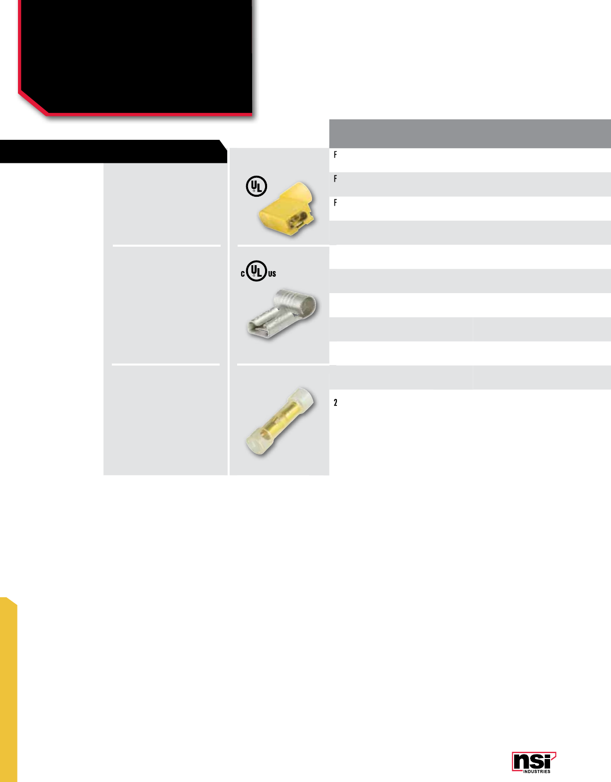
293
MINITERMS
MINITERMS
Female Flag & Fully
Insulated Flag, Two-Way
Receptacle
IfL, Sf, DfR SERIES
STYLE INSULATION
TYPE WIRE
RANGE STUD
SIZE CERTIfICATION
vARIANCE L
(IN) W
(IN) CAT. NO. QTY CAT. NO. QTY CAT. NO. QTY CAT. NO. QTY
Female Flag Fully
Insulated Nylon 22-18 0.250 0.630 0.236 – – – – IFL22-250-3N 100 IFL22-250-3N-
BULK 1000
Female Flag Fully
Insulated Nylon 16-14 0.250 0.630 0.390 – – – – IFL16-250-3N 100 IFL16-250-3N-
BULK 1000
Female Flag Fully
Insulated Nylon 12-10 0.250 0.667 0.311 IFL12-250-3N-S 12 IFL12-250-3N-P 30 IFL12-250-3N 50 IFL12-250-3N-
BULK 500
Female Flag Un-insulated 22-18 0.250 UL 0.539 0.312 – – – – SF22-250-3 100 SF22-250-3-BULK 1000
Female Flag Un-insulated 16-14 0.187 UL 0.539 0.312 – --- SF16-187-2-P –SF16-187-2 100 SF16-187-2-BULK 1000
Female Flag Un-insulated 16-14 0.250 0.539 0.312 SF16-250-3-S 20 – – SF16-250-3 100 SF16-250-3-BULK 1000
Female Flag Un-insulated 12-10 0.250 0.582 0.259 SF12-250-3-S 15 – – SF12-250-3 50 SF12-250-3-BULK 1000
Female Flag Un-insulated 12-10 0.250 NON-UL 0.570 0.320 – – – – SF12-250-3-SP 50 SF12-250-3-SP-
BULK 1000
2 Way Receptacle Nylon n/a 0.157 – – – – – DFR-157N 100 DFR-157N-BULK 1000
Female Flag Fully
Female Flag Fully
Female Flag Fully
2 Way Receptacle
NYLON:
Electro tin plated copper,
600V, 105 °C.
NYLON:
Turned up edges give this
spade more safety and
reliability.
600V, 105 °C.
UN-INSULATED:
Electro tin plated copper,
600V, 105 °C.
FEATURES

294
NSi Industries LLC • USA • 800.321.5847 • www.nsiindustries.com
294
MINITERMS
“S” PACKS PRO PACKS STD PACKS BULK PACKS
STYLE INSULATION
TYPE WIRE
RANGE STUD
SIZE CERTIfICATION
vARIANCE L
(IN) W
(IN) CAT. NO. QTY CAT. NO. QTY CAT. NO. QTY CAT. NO. QTY
Female Flag Fully
Insulated Nylon 22-18 0.250 0.630 0.236 – – – – IFL22-250-3N 100 IFL22-250-3N-
BULK 1000
Female Flag Fully
Insulated Nylon 16-14 0.250 0.630 0.390 – – – – IFL16-250-3N 100 IFL16-250-3N-
BULK 1000
Female Flag Fully
Insulated Nylon 12-10 0.250 0.667 0.311 IFL12-250-3N-S 12 IFL12-250-3N-P 30 IFL12-250-3N 50 IFL12-250-3N-
BULK 500
Female Flag Un-insulated 22-18 0.250 UL 0.539 0.312 – – – – SF22-250-3 100 SF22-250-3-BULK 1000
Female Flag Un-insulated 16-14 0.187 UL 0.539 0.312 – --- SF16-187-2-P –SF16-187-2 100 SF16-187-2-BULK 1000
Female Flag Un-insulated 16-14 0.250 0.539 0.312 SF16-250-3-S 20 – – SF16-250-3 100 SF16-250-3-BULK 1000
Female Flag Un-insulated 12-10 0.250 0.582 0.259 SF12-250-3-S 15 – – SF12-250-3 50 SF12-250-3-BULK 1000
Female Flag Un-insulated 12-10 0.250 NON-UL 0.570 0.320 – – – – SF12-250-3-SP 50 SF12-250-3-SP-
BULK 1000
2 Way Receptacle Nylon n/a 0.157 – – – – – DFR-157N 100 DFR-157N-BULK 1000
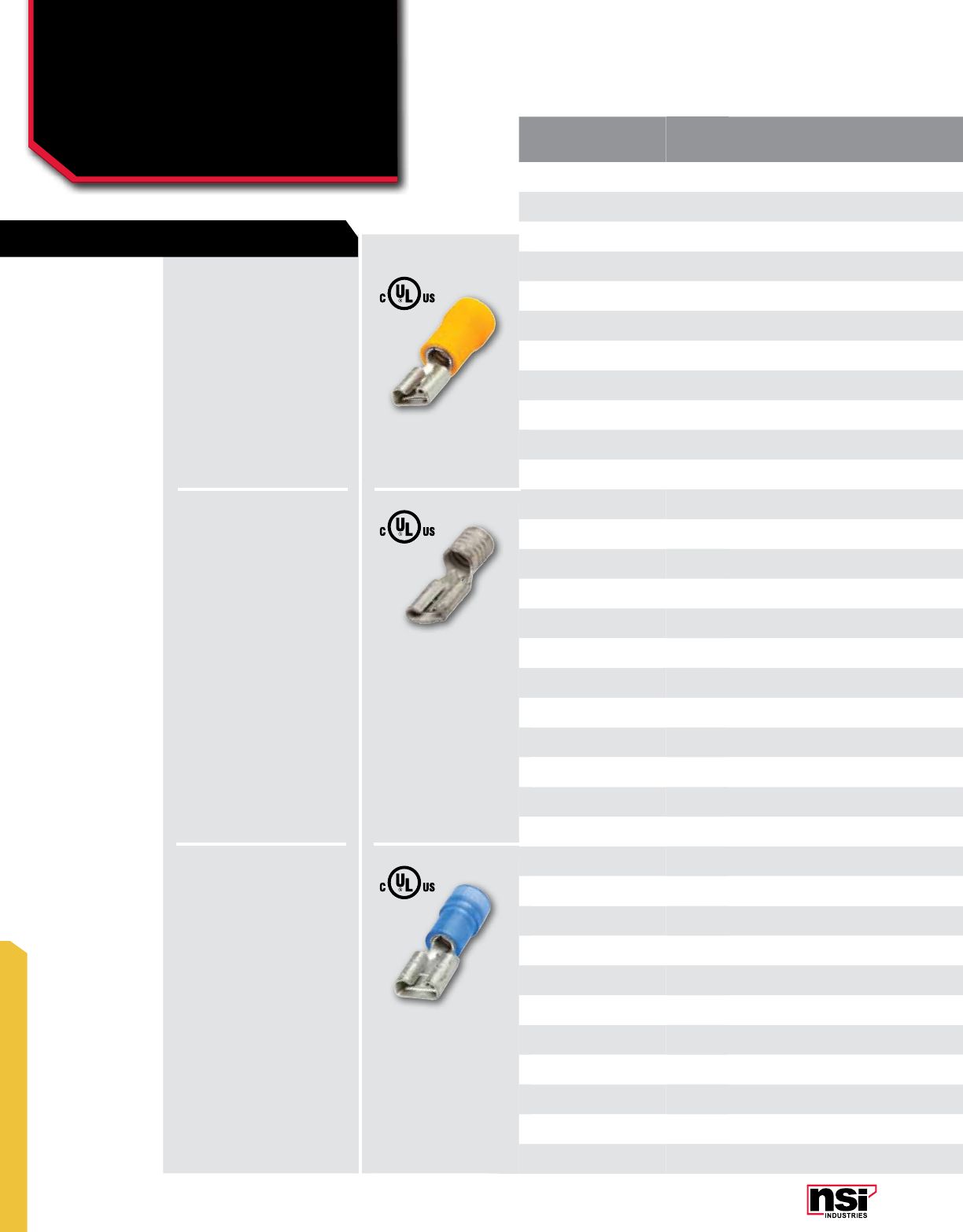
295
MINITERMS
MINITERMS
Female Disconnects
f SERIES
STYLE INSULATION
TYPE WIRE
RANGE STUD
SIZE CERTIfICATION
vARIANCE L
(IN) W
(IN) CAT. NO. QTY CAT. NO. QTY CAT. NO. QTY CAT. NO. QTY
Female Vinyl 22-18 0.110 0.728 0.125 – – – – F22-110-2V 100 F22-110-2V-BULK 1000
Female Vinyl 22-18 0.110 UL 0.789 0.170 – – – – F22-110-3V 100 F22-110-3V-BULK 1000
Female Vinyl 22-18 0.187 0.748 0.196 – – – – F22-187-2V 100 F22-187-2V-BULK 1000
Female Vinyl 22-18 0.187 UL 0.789 0.250 – – – – F22-187-3V 100 F22-187-3V-BULK 1000
Female Vinyl 22-18 0.250 0.826 0.259 F22-250-3V-S 25 F22-250-3V-P 80 F22-250-3V 100 F22-250-3V-BULK 1000
Female Vinyl 16-14 0.110 UL 0.789 0.170 – – – – F16-110-2V 100 F16-110-2V-BULK 1000
Female Vinyl 16-14 0.110 UL 0.789 0.170 – – – – F16-110-3V 100 F16-110-3V-BULK 1000
Female Vinyl 16-14 0.187 0.748 0.196 F16-187-2V-S 25 – – F16-187-2V 100 F16-187-2V-BULK 1000
Female Vinyl 16-14 0.187 0.748 0.196 – – – – F16-187-3V 100 F16-187-3V-BULK 1000
Female Vinyl 16-14 0.250 0.826 0.259 F16-250-3V-S 25 F16-250-3V-P 70 F16-250-3V 100 F16-250-3V-BULK 1000
Female Vinyl 12-10 0.250 0.925 0.259 F12-250-3V-S F12-250-3V-P 50 F12-250-3V 50 F12-250-3V-BULK 500
Female Un-insulated 22-18 0.110 UL 0.550 0.150 – – – – F22-110-2 100 F22-110-2-BULK 1000
Female Un-insulated 22-18 0.110 UL 0.554 0.150 – – – – F22-110-3 100 F22-110-3-BULK 1000
Female Un-insulated 22-18 0.187 UL 0.565 0.233 – – – – F22-187-2 100 F22-187-2-BULK 1000
Female Un-insulated 22-18 0.187 UL 0.565 0.233 – – – – F22-187-3 100 F22-187-3-BULK 1000
Female Un-insulated 22-18 0.250 0.629 0.259 – – F22-250-3-P 100 F22-250-3 100 F22-250-3-BULK 1000
Female Un-insulated 16-14 0.110 UL 0.557 0.149 – – – – F16-110-2 100 F16-110-2-BULK 1000
Female Un-insulated 16-14 0.110 0.531 0.125 – – – – F16-110-3 100 F16-110-3-BULK 1000
Female Un-insulated 16-14 0.187 UL 0.556 0.233 – – – – F16-187-2 100 F16-187-2-BULK 1000
Female Un-insulated 16-14 0.187 UL 0.559 0.233 – – – – F16-187-3 100 F16-187-3-BULK 1000
Female Un-insulated 16-14 0.250 0.629 0.259 – – F16-250-3-P 125 F16-250-3 100 F16-250-3-BULK 1000
Female Un-insulated 12-10 0.250 0.669 0.259 – – – – F12-250-3 50 F12-250-3-BULK 500
Female Un-insulated 8 0.250 NON-UL 0.665 0.320 – – – – F8-250-3 50 F8-250-3-BULK 1000
Female Nylon 22-18 0.110 NON-UL 0.789 0.163 – – – – F22-110-2N 100 F22-110-2N-BULK 1000
Female Nylon 22-18 0.110 UL 0.789 0.210 – – – – F22-110-3N 100 F22-110-3N-BULK 1000
Female Nylon 22-18 0.187 UL 0.789 0.125 – – – – F22-187-2N 100 F22-187-2N-BULK 1000
Female Nylon 22-18 0.187 UL 0.789 0.125 – – – – F22-187-3N 100 F22-187-3N-BULK 1000
Female Nylon 22-18 0.250 0.866 0.259 – – – – F22-250-3N 100 F22-250-3N-BULK 1000
Female Nylon 16-14 0.110 UL 0.789 0.163 – – – – F16-110-2N 100 F16-110-2N-BULK 1000
Female Nylon 16-14 0.110 UL 0.789 0.163 – – – – F16-110-3N 100 F16-110-3N-BULK 1000
Female Nylon 16-14 0.187 UL 0.789 0.238 – – – – F16-187-2N 100 F16-187-2N-BULK 1000
Female Nylon 16-14 0.187 0.787 0.196 – – – – F16-187-3N 100 F16-187-3N-BULK 1000
Female Nylon 16-14 0.250 0.866 0.259 – – – – F16-250-3N 100 F16-250-3N-BULK 1000
Female Nylon 12-10 0.250 0.944 0.259 – – – – F12-250-3N 50 F12-250-3N-BULK 500
VINYL:
Electro tin plated copper,
600V, 105 °C.
NYLON:
Turned up edges give this
spade more safety and
reliability.
600V, 105 °C.
UN-INSULATED-
BARE:
Electro tin plated copper,
600V, 105 °C.
FEATURES

296
NSi Industries LLC • USA • 800.321.5847 • www.nsiindustries.com
296
MINITERMS
“S” PACKS PRO PACKS STD PACKS BULK PACKS
STYLE INSULATION
TYPE WIRE
RANGE STUD
SIZE CERTIfICATION
vARIANCE L
(IN) W
(IN) CAT. NO. QTY CAT. NO. QTY CAT. NO. QTY CAT. NO. QTY
Female Vinyl 22-18 0.110 0.728 0.125 – – – – F22-110-2V 100 F22-110-2V-BULK 1000
Female Vinyl 22-18 0.110 UL 0.789 0.170 – – – – F22-110-3V 100 F22-110-3V-BULK 1000
Female Vinyl 22-18 0.187 0.748 0.196 – – – – F22-187-2V 100 F22-187-2V-BULK 1000
Female Vinyl 22-18 0.187 UL 0.789 0.250 – – – – F22-187-3V 100 F22-187-3V-BULK 1000
Female Vinyl 22-18 0.250 0.826 0.259 F22-250-3V-S 25 F22-250-3V-P 80 F22-250-3V 100 F22-250-3V-BULK 1000
Female Vinyl 16-14 0.110 UL 0.789 0.170 – – – – F16-110-2V 100 F16-110-2V-BULK 1000
Female Vinyl 16-14 0.110 UL 0.789 0.170 – – – – F16-110-3V 100 F16-110-3V-BULK 1000
Female Vinyl 16-14 0.187 0.748 0.196 F16-187-2V-S 25 – – F16-187-2V 100 F16-187-2V-BULK 1000
Female Vinyl 16-14 0.187 0.748 0.196 – – – – F16-187-3V 100 F16-187-3V-BULK 1000
Female Vinyl 16-14 0.250 0.826 0.259 F16-250-3V-S 25 F16-250-3V-P 70 F16-250-3V 100 F16-250-3V-BULK 1000
Female Vinyl 12-10 0.250 0.925 0.259 F12-250-3V-S F12-250-3V-P 50 F12-250-3V 50 F12-250-3V-BULK 500
Female Un-insulated 22-18 0.110 UL 0.550 0.150 – – – – F22-110-2 100 F22-110-2-BULK 1000
Female Un-insulated 22-18 0.110 UL 0.554 0.150 – – – – F22-110-3 100 F22-110-3-BULK 1000
Female Un-insulated 22-18 0.187 UL 0.565 0.233 – – – – F22-187-2 100 F22-187-2-BULK 1000
Female Un-insulated 22-18 0.187 UL 0.565 0.233 – – – – F22-187-3 100 F22-187-3-BULK 1000
Female Un-insulated 22-18 0.250 0.629 0.259 – – F22-250-3-P 100 F22-250-3 100 F22-250-3-BULK 1000
Female Un-insulated 16-14 0.110 UL 0.557 0.149 – – – – F16-110-2 100 F16-110-2-BULK 1000
Female Un-insulated 16-14 0.110 0.531 0.125 – – – – F16-110-3 100 F16-110-3-BULK 1000
Female Un-insulated 16-14 0.187 UL 0.556 0.233 – – – – F16-187-2 100 F16-187-2-BULK 1000
Female Un-insulated 16-14 0.187 UL 0.559 0.233 – – – – F16-187-3 100 F16-187-3-BULK 1000
Female Un-insulated 16-14 0.250 0.629 0.259 – – F16-250-3-P 125 F16-250-3 100 F16-250-3-BULK 1000
Female Un-insulated 12-10 0.250 0.669 0.259 – – – – F12-250-3 50 F12-250-3-BULK 500
Female Un-insulated 8 0.250 NON-UL 0.665 0.320 – – – – F8-250-3 50 F8-250-3-BULK 1000
Female Nylon 22-18 0.110 NON-UL 0.789 0.163 – – – – F22-110-2N 100 F22-110-2N-BULK 1000
Female Nylon 22-18 0.110 UL 0.789 0.210 – – – – F22-110-3N 100 F22-110-3N-BULK 1000
Female Nylon 22-18 0.187 UL 0.789 0.125 – – – – F22-187-2N 100 F22-187-2N-BULK 1000
Female Nylon 22-18 0.187 UL 0.789 0.125 – – – – F22-187-3N 100 F22-187-3N-BULK 1000
Female Nylon 22-18 0.250 0.866 0.259 – – – – F22-250-3N 100 F22-250-3N-BULK 1000
Female Nylon 16-14 0.110 UL 0.789 0.163 – – – – F16-110-2N 100 F16-110-2N-BULK 1000
Female Nylon 16-14 0.110 UL 0.789 0.163 – – – – F16-110-3N 100 F16-110-3N-BULK 1000
Female Nylon 16-14 0.187 UL 0.789 0.238 – – – – F16-187-2N 100 F16-187-2N-BULK 1000
Female Nylon 16-14 0.187 0.787 0.196 – – – – F16-187-3N 100 F16-187-3N-BULK 1000
Female Nylon 16-14 0.250 0.866 0.259 – – – – F16-250-3N 100 F16-250-3N-BULK 1000
Female Nylon 12-10 0.250 0.944 0.259 – – – – F12-250-3N 50 F12-250-3N-BULK 500
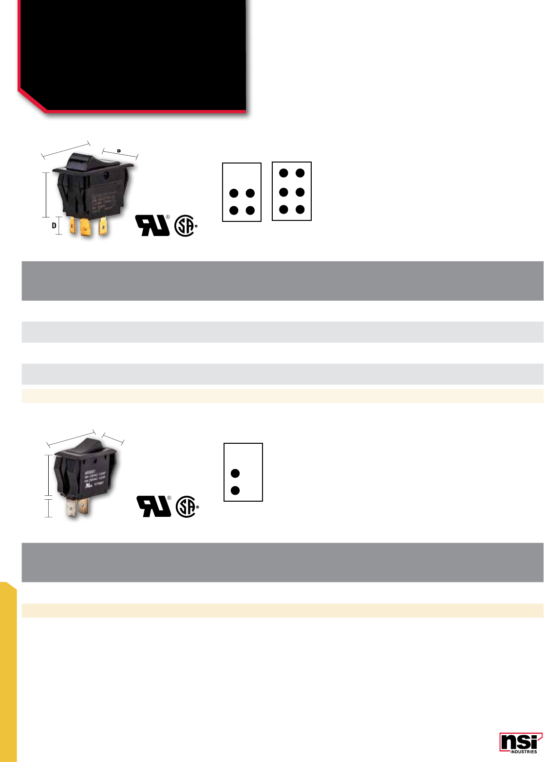
297
SWITCHES
CAT.
NO. CIRCUT
fUNC. POLES &
THROWS
RATINGS vOLTAGE LAMP
COLOR ACTR.
CONTACT CONN.
TYPE
STD.
CTN.
QTY.
AMPS
125vAC AMPS
250vAC HP
125-250vAC
77140RQ ON-OFF SPST 15 10 – Non-Lighted Black Maintained 0.250
Quikconnect 5
Dimensions (IN)
A: 1.250 B: 0.625 C: 0.828 D: 0.406
Dimensions (IN) A: 1.348 B: 0.750 C: 0.762 D: 0.422
CAT.
NO. CIRCUT
fUNC. POLES &
THROWS
RATINGS vOLTAGE LAMP
COLOR ACTR.
CONTACT CONN.
TYPE
STD.
CTN.
QTY.
AMPS
125vAC AMPS
250vAC HP
125-250vAC
77010RQ ON-OFF DPST 20 10 1 1/2 @125,2 @ 250 Non-Lighted Black Maintained 0.250 Quikconnect 5
77040RQ ON-ON DPDT 20 10 1 1/2 @125,2 @ 250 Non-Lighted Black Maintained 0.250 Quikconnect 5
77060RQ ON-OFF-ON DPDT 20 10 1 1/2 @125,2 @ 250 Non-Lighted Black Maintained 0.250 Quikconnect 5
77130RQ ON-OFF-ON DPDT 15 10 3/4 Non-Lighted Black Momentary 0.250 Quikconnect 5
AB
C
D
B
D
S.P.S.T
D.P.S.T D.P.D.T
SWITCHES
Rocker Switches
AB
C
D
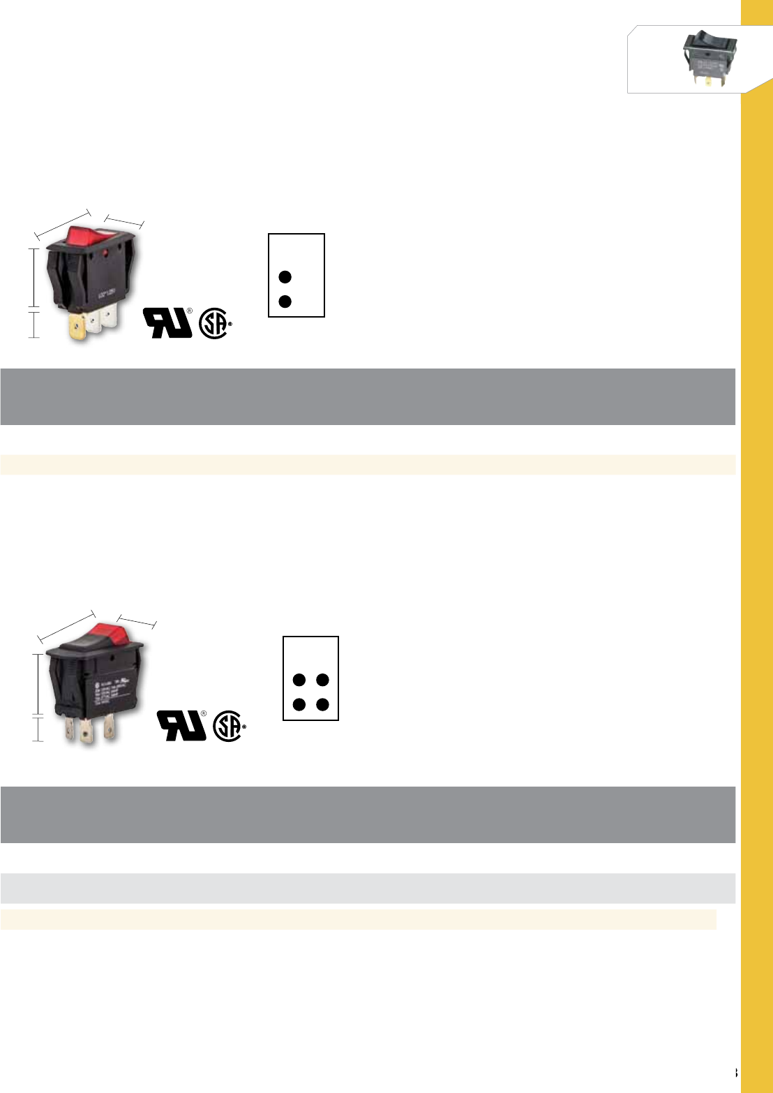
298
NSi Industries LLC • USA • 800.321.5847 • www.nsiindustries.com
SWITCHES
298
SWITCHES
CAT.
NO. CIRCUT
fUNC. POLES &
THROWS
RATINGS vOLTAGE LAMP
COLOR ACTR.
CONTACT CONN.
TYPE
STD.
CTN.
QTY.
AMPS
125vAC AMPS
250vAC HP
125-250vAC
77150RQ ON-OFF SPST 15 7.5 – – Red Maintained 0.250 Quikconnect 5
Dimensions (IN)
A: 1.348 B: 0.750 C: 0.762 D: 0.422
Dimensions (IN)
A: 0.426 B: 1.088 C: 0.709 D: 0.345
CAT.
NO. CIRCUT
fUNC. POLES &
THROWS
RATINGS vOLTAGE LAMP
COLOR ACTR.
CONTACT CONN.
TYPE CTN.
QTY.
AMPS
125vAC AMPS
250vAC H.P
125-250vAC
77030RQ ON-OFF DPST 15 10 3/4 @ 250 125V Incand. Red – Maintained 0.250 Quikconnect 5
77020RQ ON-OFF DPST 15 10 3/4 @ 250 125V Neon Amber – Maintained 0.250 Quikconnect 5
S.P.S.T
D.P.S.T
AB
C
D
AB
C
D
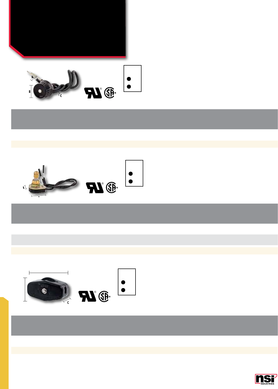
299
SWITCHES
CAT.
NO. CIRCUT
fUNC. POLES &
THROWS
RATINGS vOLTAGE LAMP
COLOR ACTR.
CONTACT CONN.
TYPE
STD.
CTN.
QTY.
AMPS
125vAC AMPS
250vAC HP
125-250vAC
77300RW ON-OFF SPST 3 1 Non-Lighted Rotary Canopy – Maintained Wire Leads 5
CAT.
NO. CIRCUT
fUNC. POLES &
THROWS
RATINGS vOLTAGE LAMP
COLOR ACTR.
CONTACT CONN.
TYPE
STD.
CTN.
QTY.
AMPS
125vAC AMPS
250vAC HP
125-250vAC
77340RW ON-OFF SPST 6 3 Non-Lighted Rotary Canopy – Maintained Wire Leads 5
77320RW OFF-ON-ON-ON SPST 3 1 Non-Lighted Rotary Canopy – Maintained Wire Leads 5
CAT.
NO. CIRCUT
fUNC. POLES &
THROWS
RATINGS vOLTAGE LAMP
COLOR ACTR.
CONTACT CONN.
TYPE
STD.
CTN.
QTY.
AMPS
125vAC AMPS
250vAC HP
125-250vAC
79100MS ON-OFF SPST 6 3 –––
Feed Through
Switch Screws 5
B
A
B
C
Dimensions (IN)
A: 0.718 B: 0.600 C: 0.265
Dimensions (IN)
A: 1.000 B: 0.844
Dimensions (IN)
A: 0.844 B: 0.594 C: 1.375
S.P.S.T
S.P.S.T
S.P.S.T
SWITCHES
Rotary Switches &
Miscellaneous
B
B
C
C
A
A
A
A
A
A
B
C
A
C
C
C
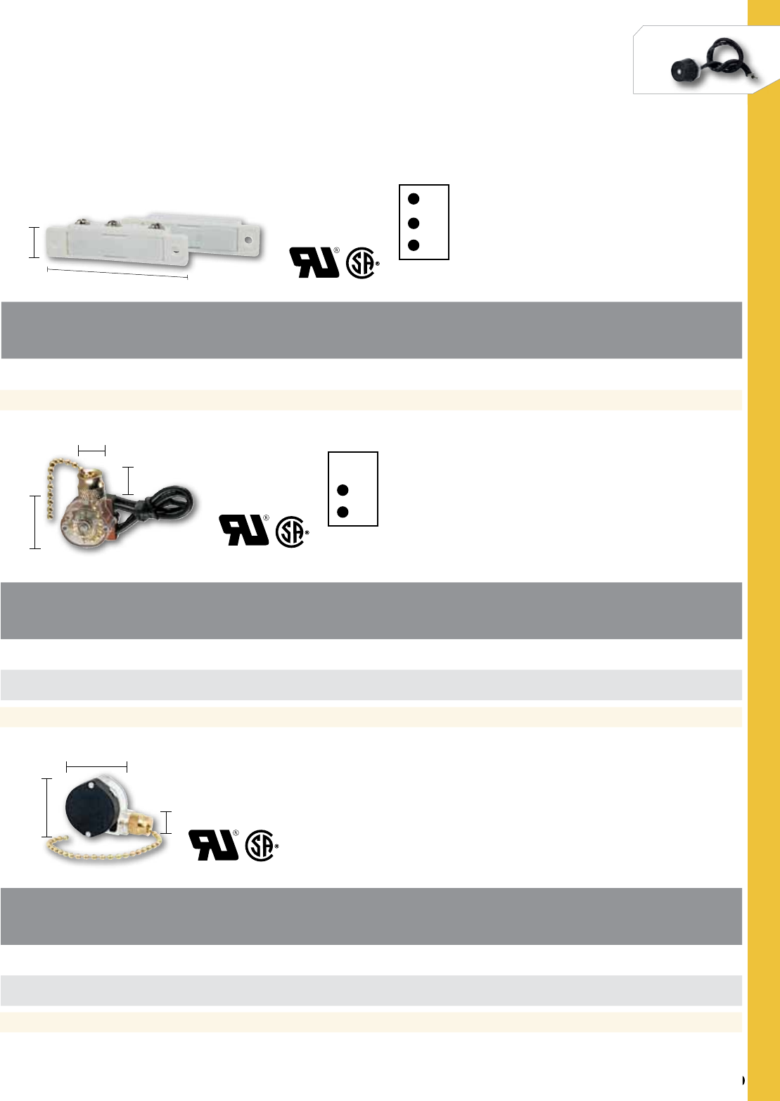
300
NSi Industries LLC • USA • 800.321.5847 • www.nsiindustries.com
SWITCHES
300
SWITCHES
CAT.
NO. CIRCUT
fUNC. POLES &
THROWS
RATINGS vOLTAGE LAMP
COLOR ACTR.
CONTACT CONN.
TYPE
STD.
CTN.
QTY.
AMPS
125vAC AMPS
250vAC HP
125-250vAC
79200MS N.C. & N.O. SPDT 5 – – – – Magnetic Feed
Switch Screws 5
A
B
Dimensions (IN)
A: 2.500 B: 0.531
Dimensions (IN)
A: 1.250 B: 0.781 C: 0.594
Dimensions (IN)
A: 1.250 B: 1.125 C: 0.742
CAT.
NO. CIRCUT
fUNC. POLES &
THROWS
RATINGS ACTUATOR
STYLE ACTUATOR
MATERIAL CONTACT CONN.
TYPE
STD.
CTN.
QTY.
AMPS
125vAC AMPS
250vAC HP
125-250vAC
75101CW ON-OFF SPST 6 3 – Chain W/Cord Brass – Wire Leads 5
75102CW ON-OFF SPST 6 3 – Chain W/Cord Nickel – Wire Leads 5
CAT.
NO. CIRCUT
fUNC. POLES &
THROWS
RATINGS ACTUATOR
STYLE ACTUATOR
MATERIAL CONTACT CONN.
TYPE
STD.
CTN.
QTY.
AMPS
125vAC AMPS
250vAC HP
125-250vAC
75110CW Way/2 Circuit SP3T 6 3 – Chain W/Cord Brass – Wire Leads 5
75111CQ OFF-ON-ON-ON SP3T 6 3 – Chain W/Cord Brass – Push In 5
S.P.S.T
S.P.D.T
A
B
C
A
B
C
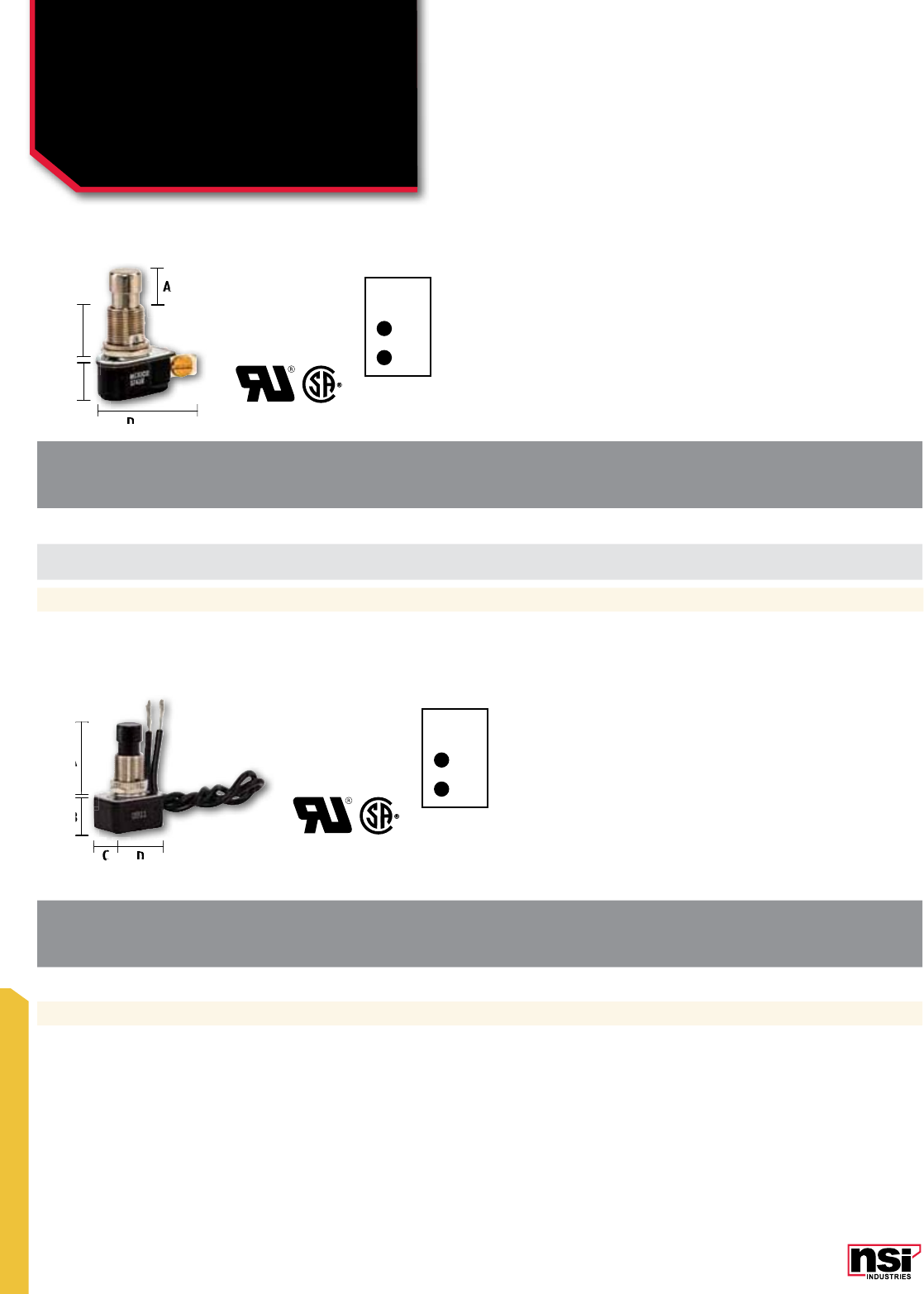
301
SWITCHES
CAT.
NO. CIRCUT
fUNC. POLES &
THROWS
RATINGS ACTUATOR
STYLE ACTUATOR
MATERIAL CONTACT CONN.
TYPE
STD.
CTN.
QTY.
AMPS
125vAC AMPS
250vAC HP
125-250vAC
76050PS PUSH-ON, PUSH-OFF SPST 6* 3* – Pushbutton Brass/Nickel Maintained Screws 5
76040PW PUSH ON, PUSH OFF SPST 6 3 1/3 @125 Pushbutton Brass/Nickel Maintained Wire Leads 5
CAT.
NO. CIRCUT
fUNC. POLES &
THROWS
RATINGS ACTUATOR
STYLE ACTUATOR
MATERIAL CONTACT CONN.
TYPE
STD.
CTN.
QTY.
AMPS
125vAC AMPS
250vAC HP
125-250vAC
76010PW PUSH ON, PUSH OFF SPST 10 5 1/4 @125 Pushbutton Nylon Maintained Wire Leads 5
A
B
C
D
Dimensions (IN)
A: 0.437 B: 0.562 C: 0.542 D: 1.183
Dimensions (IN)
A: 1.003 B: 0.612 C: 0.550 D: 0.993
S.P.S.T
S.P.S.T
SWITCHES
Pushbutton Switches
A
A
D
A
B
CD
A
B
D
C
C
C

302
NSi Industries LLC • USA • 800.321.5847 • www.nsiindustries.com
SWITCHES
302
SWITCHES
CAT.
NO. CIRCUT
fUNC. POLES &
THROWS
RATINGS ACTUATOR
STYLE ACTUATOR
MATERIAL CONTACT CONN.
TYPE
STD.
CTN.
QTY.
AMPS
125vAC AMPS
250vAC HP
125-250vAC
76055PS ON-OFF SPST 6 3 – Pushbutton Brass Maintained Wire Leads 1
76056PS ON-OFF SPST 6 3 – Pushbutton Nickel Maintained Wire Leads 1
76090PW ON-OFF SPST 6 3 – Push Canopy Brass Maintained Wire Leads 5
76100PW ON-OFF SPST 6 3 – Push Canopy Bickel Maintained Wire Leads 5
CAT.
NO. CIRCUT
fUNC. POLES &
THROWS
RATINGS ACTUATOR
STYLE ACTUATOR
MATERIAL CONTACT CONN.
TYPE
STD.
CTN.
QTY.
AMPS
125vAC AMPS
250vAC HP
125-250vAC
76060PS PUSH ON, PUSH OFF SPST 15 10 – Pushbutton Brass/Nickel Maintained Screws 5
Dimensions (IN)
A: 0.283 B: 0.562 C: 0.982 D: 1.125
Dimensions (IN)
A: 0.968 B: 0.313 C:0.858
S.P.S.T
S.P.S.T
S.P.S.T
CAT.
NO. CIRCUT
fUNC. POLES &
THROWS
RATINGS ACTUATOR
STYLE ACTUATOR
MATERIAL CONTACT CONN.
TYPE
STD.
CTN.
QTY.
AMPS
125vAC AMPS
250vAC HP
125-250vAC
76020PS OFF-ON SPST N.O. 3/4 1/4 – Pushbutton Nylon Momentary Screws 5
76030PS ON-OFF SPST N.C. 3/4 1/4 – Pushbutton Nylon Momentary Screws 5
Dimensions (IN)
A: 0.460 B: 1.070 C: 0.650 D: 1.950
A
B
A
A
C
B
B
D
D
C
C
D
C
D
A
B
A
C
B
A
A
A
A
A
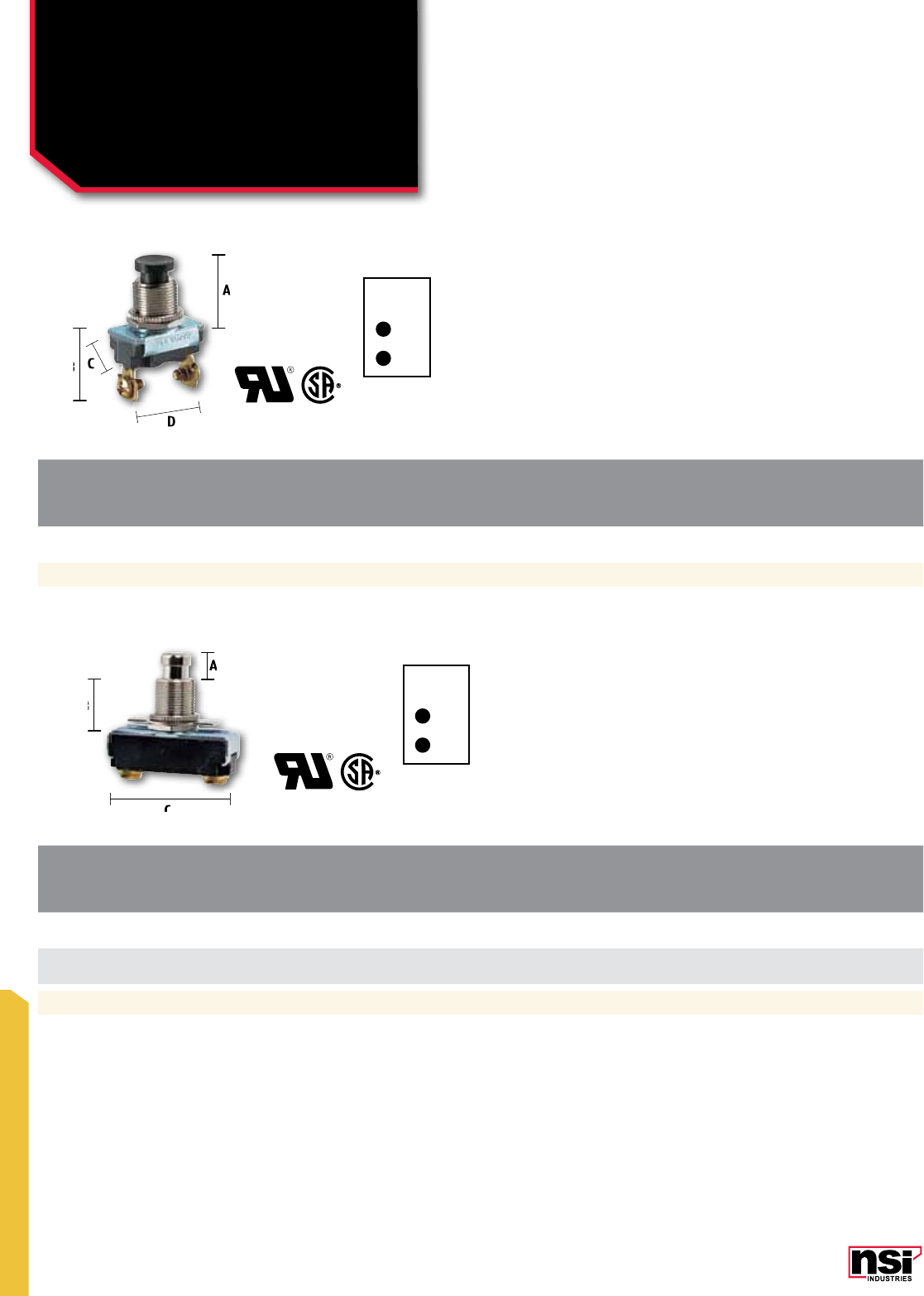
303
SWITCHES
CAT.
NO. CIRCUT
fUNC. POLES &
THROWS
RATINGS ACTUATOR
STYLE ACTUATOR
MATERIAL CONTACT CONN.
TYPE
STD.
CTN.
QTY.
AMPS
125vAC AMPS
250vAC HP
125-250vAC
76065PS OFF-ON SPST N.O. 3 – – Pushbutton Plastic Momentary Screws 5
CAT.
NO. CIRCUT
fUNC. POLES &
THROWS
RATINGS ACTUATOR
STYLE ACTUATOR
MATERIAL CONTACT CONN.
TYPE
STD.
CTN.
QTY.
AMPS
125vAC AMPS
250vAC HP
125-250vAC
76070PS OFF-ON SPST N.O. 15 10 – Pushbutton Brass/Nickel Momentary Screws 5
76080PS ON-OFF SPST N.C. 15 10 – Pushbutton Brass/Nickel Momentary Screws 5
Dimensions (IN)
A: .689 B: 1.406 C: .563 D: .875
Dimensions (IN)
A: .576 B: .562 C: 1.382
SWITCHES
Pushbutton Switches
S.P.S.T
S.P.S.T
A
BC
D
A
B
C
C
D
A
B
C
A
A
B
C
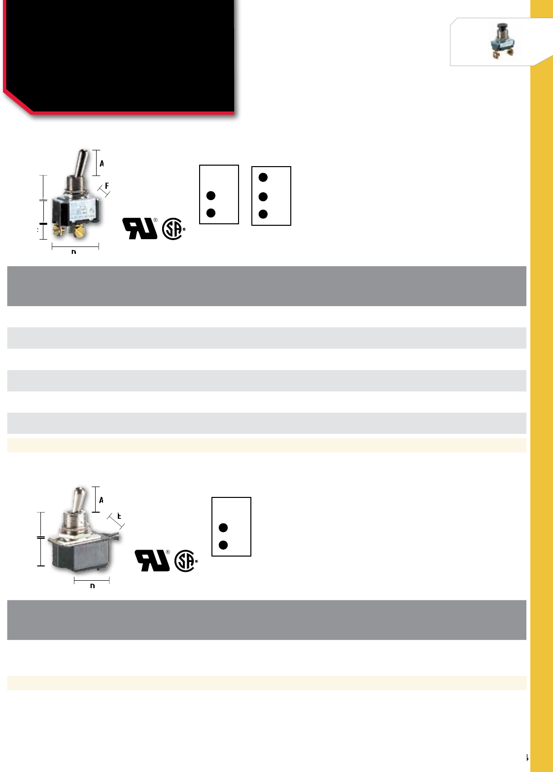
304
NSi Industries LLC • USA • 800.321.5847 • www.nsiindustries.com
304
SWITCHES
Dimensions (IN)
A: .687 B: .465 C: .670 D: .348 E: 1.134 F: .634 THREAD: 15/32-32UNS-2A KEYWAY: .072 X .038 DP
Dimensions (IN)
A: .500 B: .469 C: .685 D: 1.093 E: 1.856 THREAD: 15/32-32 STANDARD 6" WIRE LEADS
CAT.
NO. CIRCUT
fUNCTIONS POLES &
THROWS
RATINGS ACTUATOR
STYLE ACTUATOR
MATERIAL CONN.
TYPE
STD.
CTN.
QTY.
AMPS
125vAC AMPS
250vAC H.P
125-250vAC
78110TS OFF-ON SPST 6 3 – Bat Brass/Nickel Screws 5
78120TQ OFF-ON SPST 20 10 3/4 Bat Brass/Nickel 0.250 Quikconnect 5
78210TS OFF-ON SPST 20 10 3/4 Bat Brass/Nickel Screws 5
78200TS ON-ON SPDT 20 10 3/4 Bat Brass/Nickel Screws 5
78160TS ON-OFF-ON SPDT 20 10 3/4 Bat Brass/Nickel Screws 5
78070TQ ON-OFF-ON SPDT 20 10 3/4 Bat Brass/Nickel 0.250 Quikconnect 5
S.P.D.T
*Amperage and voltage are also valid for D.C. Rating
CAT.
NO. CIRCUT
fUNCTIONS POLES &
THROWS
RATINGS ACTUATOR
STYLE ACTUATOR
MATERIAL CONN.
TYPE
STD.
CTN.
QTY.
AMPS
125vAC AMPS
250vAC H.P
125-250vAC
78150TW ON-OFF SPST 10* 4* – Bat Brass/Nickel Wire Leads 5
SWITCHES
Toggle Switches:
Maintained Contact
Single Pole
S.P.S.T
S.P.S.T
A
B
C
F
D
E
A
F
F
F
F
E
E
D
A
B
C
E
D
A
E
E
E
D

305
SWITCHES
CAT.
NO. CIRCUT
fUNCTIONS POLES &
THROWS
RATINGS ACTUATOR
STYLE ACTUATOR
MATERIAL CONN.
TYPE
STD.
CTN.
QTY.
AMPS
125vAC AMPS
250vAC H.P
125-250vAC
78065TS ON-OFF SPST 6 3 – Bat Nickel Screws 5
78040TQ ON-OFF SPST 15* 10* 3/4 Flat Poly. (Red)** 0.250 Quikconnect 5
Dimensions (IN)
A: 0.715 B: 0.379 C: 0.865 D: 0.750
E: 0.422 THREAD: 15/32-32UNS-2A KEYWAY: 0.072 X 0.038 DP
Dimensions (IN)
A: 0.687 B: 0.465 C: 0.778 D: 0.750
E: 1.308 F: 0.422 THREAD: 15/32-32UNS-2A KEYWAY: 0.072 X 0.038
CAT.
NO. CIRCUT
fUNCTIONS POLES &
THROWS
RATINGS ACTUATOR
STYLE ACTUATOR
MATERIAL CONN.
TYPE
STD.
CTN.
QTY.
AMPS
125vAC AMPS
250vAC H.P
125-250vAC
78220TS ON-OFF DPST 20 10 3/4 Bat Brass/Nickel Screws 5
78130TQ ON-OFF DPST 20 10 3/4 Bat Brass/Nickel 0.250 Quikconnect 5
78090TQ ON-ON DPDT 15 10 – Bat Brass/Nickel 0.250 Quikconnect 5
78270TS ON-ON DPDT 20 10 1½@125.2@250 Bat Brass/Nickel Screws 5
78230TS ON-OFF-ON DPDT 10 20 1 1/2 Bat Brass/Nickel Screws 5
78240TS OFF-ON DPST 15 10 3/4 Bat Brass/Nickel Screws 5
78250TS ON-OFF-ON DPDT 15 10 3/4 Bat Brass/Nickel Screws 5
78260TS ON-OFF-ON DPDT 15 10 3/4 Bat Brass/Nickel Screws 5
D.P.S.T D.P.D.T
SWITCHES
Toggle Switches:
Maintained Contact
Single & Double Pole
*Amperage and voltage are also valid for D.C. Rating /**Lighted toggle /Poly. = Polycarbonate
S.P.S.T
A
BD
C
E
F
A
B
B
B
D
D
C
F
F
E
A
B
C
D
E
A
B
B
B
D
D
D
D
E
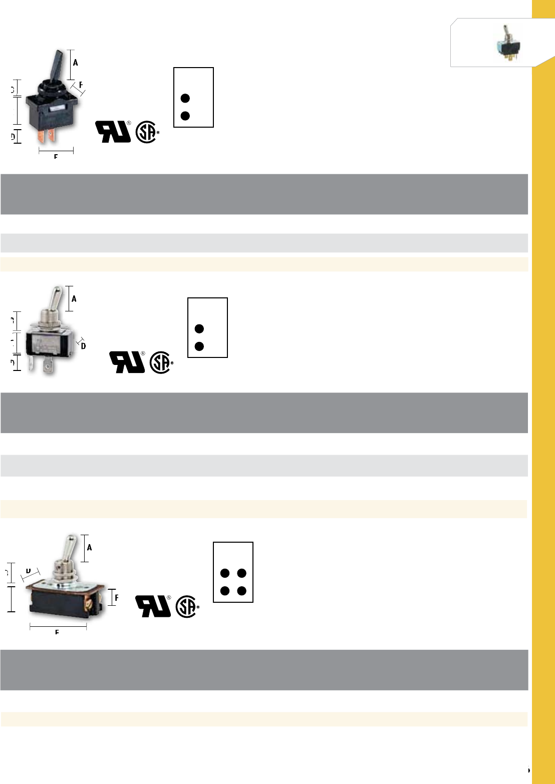
306
NSi Industries LLC • USA • 800.321.5847 • www.nsiindustries.com
SWITCHES
306
SWITCHES
CAT.
NO. CIRCUT
fUNCTIONS POLES &
THROWS
RATINGS ACTUATOR
STYLE ACTUATOR
MATERIAL CONN.
TYPE
STD.
CTN.
QTY.
AMPS
125vAC AMPS
250vAC H.P
125-250vAC
78280TS ON-OFF SPST 16* 8* 1 Bat Brass/Nickel Screws 5
78015TS ON-OFF SPST 20 10 – Flat Nylon Screws 5
Dimensions (IN)
A: 0.687 B: 0.280 C: 0.687 D: 0.375
E: 1.000 F: 0.588 KEYWAY: 0.072 X 0.038
Dimensions (IN)
A: 0.687 B: 0.465 C: 0.585 D: 0.522
E: 0.312 THREAD: 15/32-32UNS-2A KEYWAY: 0.072 X 0.038
Dimensions (IN)
A: 0.687 B: 0.465 C: 0.765 D: 0.836
E: 1.750 F: 1.764 THREAD: 15/32-32UNS-2A KEYWAY: 0.072 X 0.038
CAT.
NO. CIRCUT
fUNCTIONS POLES &
THROWS
RATINGS ACTUATOR
STYLE ACTUATOR
MATERIAL CONN.
TYPE
STD.
CTN.
QTY.
AMPS
125vAC AMPS
250vAC H.P
125-250vAC
78050TQ ON-OFF SPST 20 10 3/4 Bat Brass/Nickel 0.250 Quikconnect 5
78130TS ON-OFF SPST 6 3 – Ball Brass/Nickel Screws 5
78150TS ON-OFF SPST 20 10 3/4 Spade Brass/Nickel Screws 5
D.P.S.T
CAT.
NO. CIRCUT
fUNCTIONS POLES &
THROWS
RATINGS ACTUATOR
STYLE ACTUATOR
MATERIAL CONN.
TYPE
STD.
CTN.
QTY.
AMPS
125vAC AMPS
250vAC H.P
125-250vAC
78290TS ON-OFF DPST 16* 8* 1 Bat Brass/Nickel Screws 5
S.P.S.T
S.P.S.T
A
BF
C
E
D
A
B
B
B
B
B
F
F
F
F
F
F
F
C
D
D
D
D
D
E
A
B
D
C
D
A
B
B
B
D
D
C
D
C
C
D
D
D
D
D
A
BD
C
E
F
A
B
B
B
D
D
F
F
E

307
SWITCHES
CAT.
NO. CIRCUT
fUNCTIONS POLES &
THROWS
RATINGS ACTUATOR
STYLE ACTUATOR
MATERIAL CONN.
TYPE
STD.
CTN.
QTY.
AMPS
125vAC AMPS
250vAC H.P
125-250vAC
78300TS ON-OFF DPST 20* 10* 1 1/2 Bat Brass/Nickel Screws 5
CAT.
NO. CIRCUT
fUNCTIONS POLES &
THROWS
RATINGS ACTUATOR
STYLE ACTUATOR
MATERIAL CONN.
TYPE
STD.
CTN.
QTY.
AMPS
125vAC AMPS
250vAC H.P
125-250vAC
78310TS ON-OFF 3PST 15 10 3/4 @ 250 Bat Brass/Nickel Screws 5
78315TS ON-OFF-ON 3PDT 15 10 3/4 @ 250 Bat Brass/Nickel Screws 5
CAT.
NO. CIRCUT
fUNCTIONS
STD.
CTN.
QTY.
79300MS Toggle Switch Boots 2
79300MSR Toggle Switch Boots 2
Dimensions (IN)
A: 0.687 B: 0.465 C: 0.895 D: 1.000
E: 2.093
Dimensions (IN)
A: 0.688 B: 0.469 C: 0.965 D: 0.300
THREAD: 15/32
Dimensions (IN)
A: 0.950 B: 0.812
SWITCHES
Toggle Switches
3 P.D.T3 P.S.T
D.P.S.T
A
A
B
C
D
B
D
E
C
A
A
A
A
A
A
B
B
B
B
D
D
D
D
D
B
D
D
D
E
A
B
A
B
B
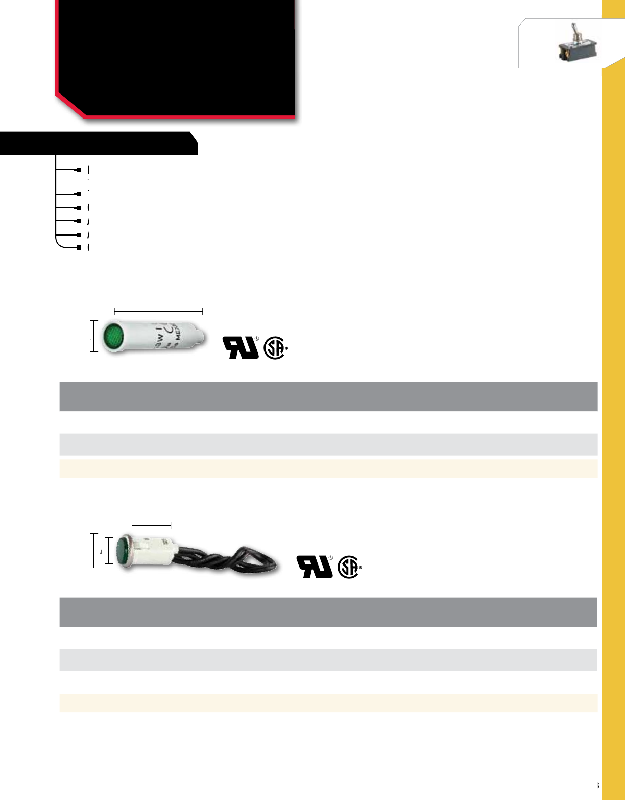
308
NSi Industries LLC • USA • 800.321.5847 • www.nsiindustries.com
308
SWITCHES
Dimensions (IN)
A: 0.130 B: 1.430 MOUNTING HOLE: 0.312 PANEL THICKNESS: 0.030 MIN.
Dimensions (IN)
A: 0.210 B: 0.100 C: 0.910 MOUNTING HOLE: 0.312 PANEL THICKNESS: 0.030 MIN.
High quality indicator lights made of nylon with –
polycarbonate lens material and neon lamps.
125-volt rated.
Connection with 6 inch wire leads.
Available in many other styles and finishes.
Also available with incandescent lamps.
Contact NSi for price and delivery.
FEATURES
High quality indicator lights made of nylon with –
polycarbonate lens material and neon lamps.
High quality indicator lights made of nylon with –
polycarbonate lens material and neon lamps.
High quality indicator lights made of nylon with –
125-volt rated.
Connection with 6 inch wire leads.
Connection with 6 inch wire leads.
Connection with 6 inch wire leads.
Also available with incandescent lamps.
Contact NSi for price and delivery.
Available in many other styles and finishes.
Also available with incandescent lamps.
Available in many other styles and finishes.
Also available with incandescent lamps.
Contact NSi for price and delivery.
Contact NSi for price and delivery.
CAT.
NO. PANEL
CUTOUT PANEL
THICKNESS LENS
STYLE LENS
COLOR LENS
TYPE BEZEL
COLOR TYPE
Of fIT
MTNG.
HOLE
DIA.
STD.
CTN.
QTY.
79710LW 0.312 0.030 Min. Flush Green Diamond White Press 0.312 5
79720LW 0.312 0.030 Min. Flush Red Diamond White Press 0.312 5
CAT.
NO. PANEL
CUTOUT PANEL
THICKNESS LENS
STYLE LENS
COLOR LENS
TYPE BEZEL
COLOR TYPE
Of fIT
MTNG.
HOLE
DIA.
STD.
CTN.
QTY.
79740LW 0.500 0.030 - .093 0.09 Cyl Green Diamond Stainless Press 0.500 5
79750LW 0.500 0.030 - .093 0.09 Cyl Red Diamond Chrome Press 0.500 5
79755LW 0.500 0.030 - .093 0.09 Cyl Amber Diamond Stainless Press 0.500 5
SWITCHES
Round Indicator Lights
WITH NON-REPLACEABLE LAMPS
A
AC
B
B
A
A
A
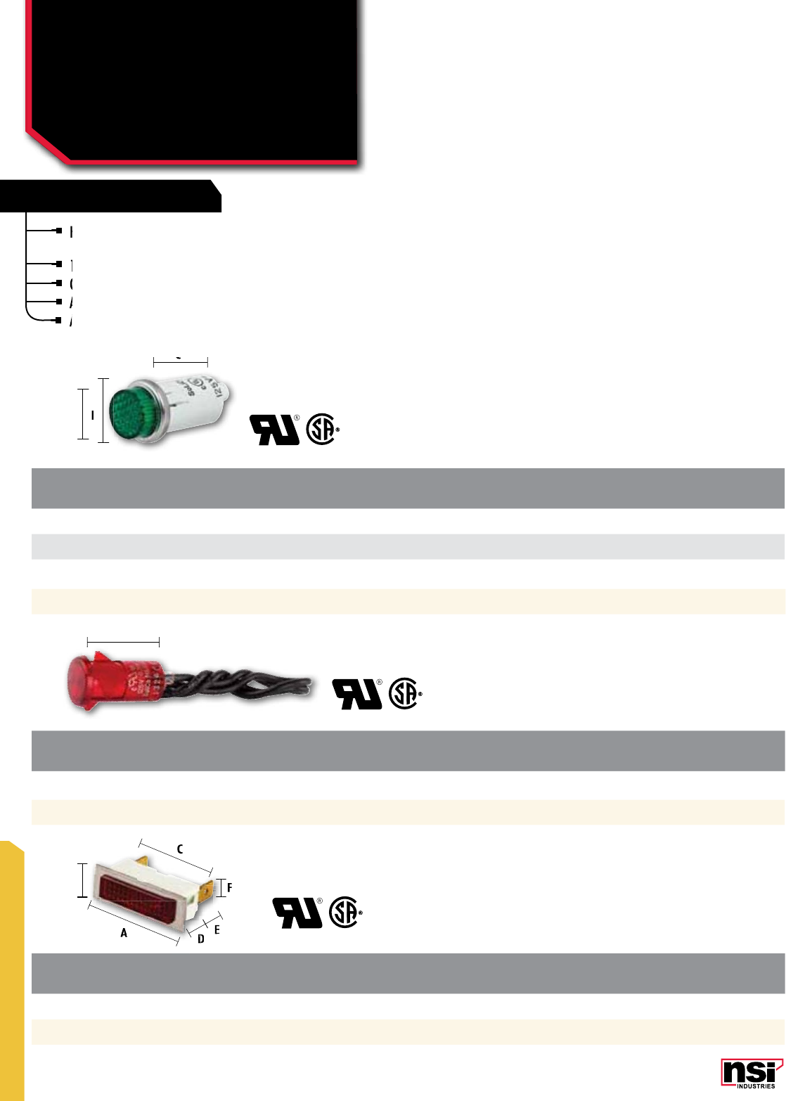
SWITCHES
309
CAT.
NO. PANEL
CUTOUT PANEL
THICKNESS LENS
COLOR LENS
TYPE BEZEL
COvER CONN.
TYPE LAMP
COLOR
79505LQ 0.375 x 1.28 0.03 - .10 Red Diamond Stainless 0.250 Quikconnect 5
CAT.
NO. PANEL
CUTOUT PANEL
THICKNESS LENS
STYLE LENS
COLOR LENS
TYPE BEZEL
COLOR TYPE
Of fIT
MTNG.
HOLE
DIA.
STD.
CTN.
QTY.
79770LW 0.500 0.030 - 0.093 0.25 Cyl Green Diamond Stainless Press 0.500 5
79780LW 0.500 0.030 - 0.093 0.25 Cyl Red Diamond Stainless Press 0.500 5
79785LW 0.500 0.030 - 0.093 0.25 Cyl Amber Diamond Stainless Press 0.500 5
CAT.
NO. PANEL
CUTOUT PANEL
THICKNESS LENS
STYLE LENS
COLOR LENS
TYPE BEZEL
COLOR TYPE
Of fIT
MTNG.
HOLE
DIA.
STD.
CTN.
QTY.
79800LW 0.500 0.040 - 0.110 Semi-Dome Red Rings None Snap In 0.500 5
Dimensions (IN) A: 0.210 B: 0.100 C: 0.910 MOUNTING HOLE: 0.500 PANEL THICKNESS: 0.030 - 0.093
Dimensions (IN)
A: 1.130
MOUNTING HOLE: 0.500 PANEL THICKNESS: 0.040 - 0.110
Dimensions (IN) A: 1.080 B: 0.290 C: 1.380 D: 0.460 E: 0.500 F: 0.370 G: 0.120
High quality indicator lights made of nylon with
polycarbonate lens material and neon lamps.
125-volt rated.
Connection with 6 inch wire leads (Round Indicator lights).
Available in many other styles and finishes.
Also available with incandescent lamps.
FEATURES
High quality indicator lights made of nylon with
polycarbonate lens material and neon lamps.
High quality indicator lights made of nylon with
polycarbonate lens material and neon lamps.
High quality indicator lights made of nylon with
125-volt rated.
Connection with 6 inch wire leads (Round Indicator lights).
Connection with 6 inch wire leads (Round Indicator lights).
Available in many other styles and finishes.
Also available with incandescent lamps.
Available in many other styles and finishes.
Also available with incandescent lamps.
Also available with incandescent lamps.
SWITCHES
Round & Snap-In
Rectangular Indicator
Lights
A
C
A
A
B
C
F
DE
B
B
C
A
C
C
E
E
E
E
E
E
E
E
D
D
D
D
D
D
D
D
D
F
F
F
F
F
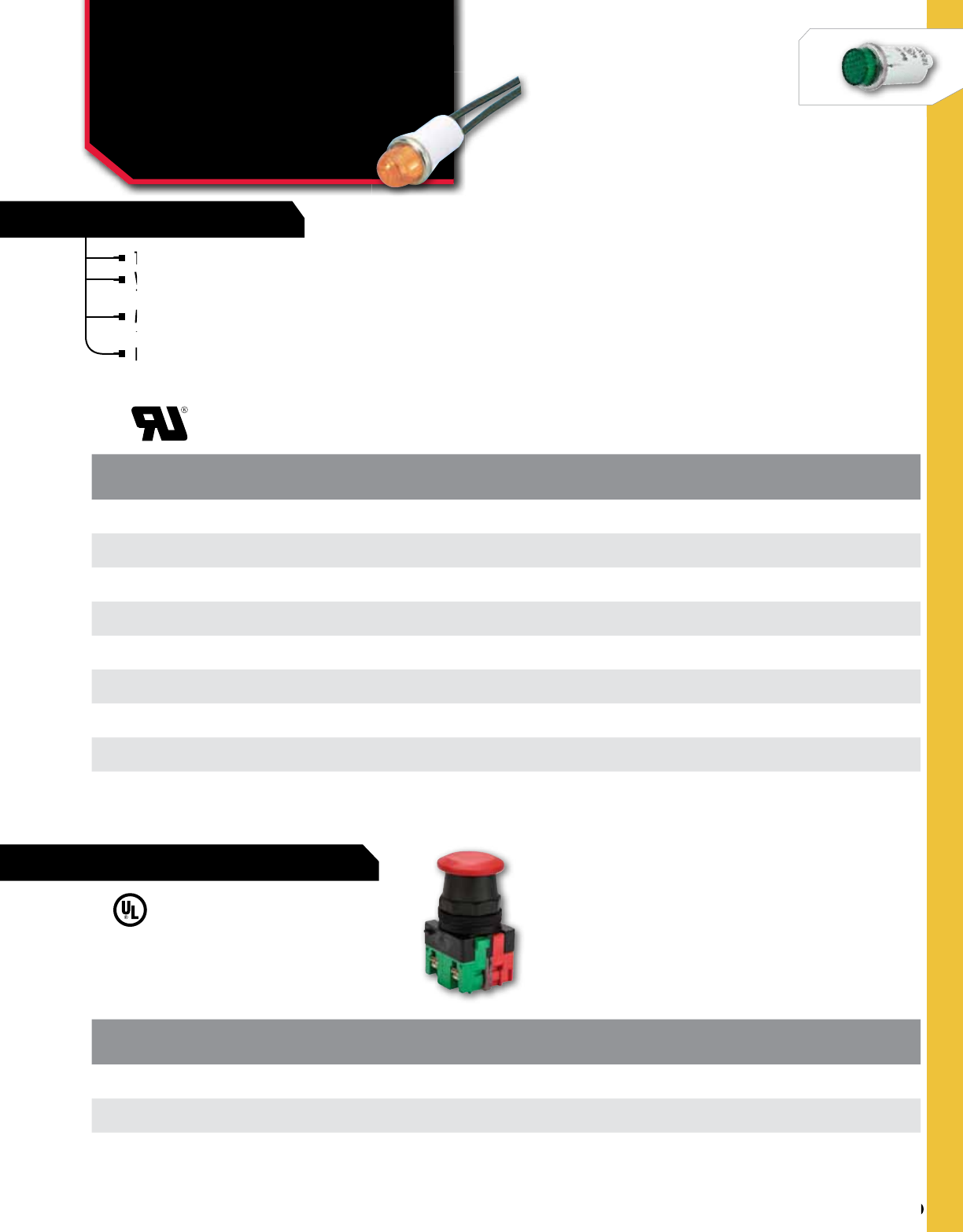
310
NSi Industries LLC • USA • 800.321.5847 • www.nsiindustries.com
SPLICING
310
SWITCHES
SPLICING
SPLICING
CAT.
NO. COLOR LENS
MATERIAL vOLTAGE BULB
TYPE BAG
QTY.
STD.
CTN.
QTY.
79900LW Red Polycarbonate 28V Incandescent 1 12
79901LW Green Polycarbonate 28V Incandescent 1 12
79902LW Amber Polycarbonate 28V Incandescent 1 12
79910LW Red Nylon 105-125VAC Neon 1 12
79911LW Green Polycarbonate 105-125VAC Neon 1 12
79912LW Amber Nylon 105-125VAC Neon 1 12
79920LW Red Polycarbonate 208-250 VAC Neon 1 12
79921LW Green Polycarbonate 208-250 VAC Neon 1 12
79922LW Amber Polycarbonate 208-250 VAC Neon 1 12
Terminals are tin-plated brass.
Wire leads are 22 AWG, 4.4-4.8" long,
1/2" stripped.
Mounting will snap-fit into 0.500-0.505"
diameter hole in 0.020-0.100" thick panels.
Dome style.
FEATURES
Terminals are tin-plated brass
Wire leads are 22 AWG, 4.4-4.8" long,
Wire leads are 22 AWG, 4.4-4.8" long,
1/2" stripped.
Wire leads are 22 AWG, 4.4-4.8" long,
1/2" stripped.
Wire leads are 22 AWG, 4.4-4.8" long,
Wire leads are 22 AWG, 4.4-4.8" long,
Mounting will snap-fit into 0.500-0.505"
diameter hole in 0.020-0.100" thick panels.
Mounting will snap-fit into 0.500-0.505"
diameter hole in 0.020-0.100" thick panels.
Mounting will snap-fit into 0.500-0.505"
Dome style.
SWITCHES
Indicator LightS &
Emergency Stop
Buttons
CAT.
NO. NAED
NO. LENS
COLOR
STD.
CTN.
QTY.
ESB2-INC-R 32132 Red 6
ESB2-INOINC-R 32136 Red 6
EMERGENCY STOP BUTTON

Wire ManageMent

WIRE MANAGEMENT
313
CAT.
no. CoLoR LEnGTH
(FT.) WIDTH
(In.) THICKnESS
(In.)
STD.
CTn.
QTY.
EWP 7066 Black 66 0.75 0.007 10
EWP 7066-1 Brown 66 0.75 0.007 10
EWP 7066-2 Red 66 0.75 0.007 10
EWP 7066-3 Orange 66 0.75 0.007 10
EWP 7066-4 Yellow 66 0.75 0.007 10
EWP 7066-5 Green 66 0.75 0.007 10
EWP 7066-6 Blue 66 0.75 0.007 10
EWP 7066-7 Purple 66 0.75 0.007 10
EWP 7066-8 Grey 66 0.75 0.007 10
EWP 7066-9 White 66 0.75 0.007 10
CAT.
no. CoLoR LEnGTH
(FT.) WIDTH
(In.) THICKnESS
(In.)
STD.
CTn.
QTY.
EWP 8566 Black 66 0.75 0.0085 10
EASY-WRAP™ PREMIUM 085
EASY-WRAP™ PREMIUM 070
EASY-WRAP™
Premium Electrical Tape
EWP SERIES
7 mil., all-weather, premium grade, pressure
sensitive vinyl electrical tape.
Cold and sunlight resistant.
Flame retardant.
Suitable for use in all kinds of electrical and
mechanical applications.
Provides exceptional flexibility and performance
over a wide range of temperatures.
Available in standard black and nine assorted
colors for easy identification or color coding.
TEMPERATURE RATInG:
Suitable for use at no more than 600V
and not more than 80 °C (176 °F).
CSA temperature range: -18 °C to 105 °C
(-0.4 °F to 221 °F).
Flame retardant.
Suitable for use in all kinds of electrical and
Cold and sunlight resistant.
Flame retardant.
7 mil., all-weather, premium grade, pressure
sensitive vinyl electrical tape.
7 mil., all-weather, premium grade, pressure
sensitive vinyl electrical tape.
7 mil., all-weather, premium grade, pressure
Suitable for use in all kinds of electrical and
mechanical applications.
Suitable for use in all kinds of electrical and
Provides exceptional flexibility and performance
over a wide range of temperatures.
Provides exceptional flexibility and performance
over a wide range of temperatures.
Provides exceptional flexibility and performance
Available in standard black and nine assorted
colors for easy identification or color coding.
8.5 mil., all-weather, premium grade,
pressure sensitive vinyl electrical tape.
Cold and sunlight resistant.
Flame retardant.
Suitable for use in all kinds of electrical
and mechanical applications.
Provides exceptional flexibility and
performance over a wide range
of temperatures.
Available in standard black only.
TEMPERATURE RATInG:
Suitable for use at no more than 600V and not
more than 80 °C (176 °F).
CSA temperature range: -18 °C to 105 °C
(-0.4 °F to 221 °F).
Meets MIL-I-24391C, HH-I-595C and ASTM D-3005.
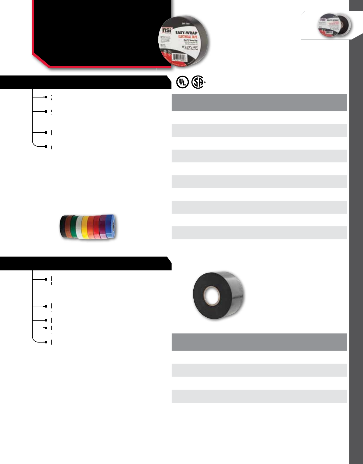
WIRE MANAGEMENT
NSi Industries LLC • USA • 800.321.5847 • www.nsiindustries.com 314
CAT.
no. CoLoR LEnGTH
(FT.) WIDTH
(In.) THICKnESS
(In.)
STD.
CTn.
QTY.
EWG 7060 Black 60 0.75 0.007 10
EWG 7060-1 Brown 60 0.75 0.007 10
EWG 7060-2 Red 60 0.75 0.007 10
EWG 7060-3 Orange 60 0.75 0.007 10
EWG 7060-4 Yellow 60 0.75 0.007 10
EWG 7060-5 Green 60 0.75 0.007 10
EWG 7060-6 Blue 60 0.75 0.007 10
EWG 7060-7 Purple 60 0.75 0.007 10
EWG 7060-8 Grey 60 0.75 0.007 10
EWG 7060-9 White 60 0.75 0.007 10
EASY-WRAP™ GENERAL PURPOSE
CAT.
no. CoLoR LEnGTH
(FT.) WIDTH
(In.) THICKnESS
(In.)
STD.
CTn.
QTY.
EWPP 102100P Black 100 2 0.01 1
EWPP 102100 Black 100 2 0.01 1
EWPP 104100 Black 100 2 0.01 1
EWPP 202100 Black 100 2 0.02 1
EWPP 202100P Black 100 2 0.02 1
*Suffix "P" denotes printed tapes.
ALL-WEATHER CORROSION (PIPE WRAP)
EASY-WRAP™
General Purpose & All-
Weather Corrosion Tape
EWG, EWPP SERIES
7 mil., economy-grade, sunlight resistant, pressure
sensitive vinyl electrical tape.
Suitable for use in all kinds of electrical and
mechanical applications such as cable insulation,
wire bundling, and reinforcing.
Extremely flexible with good adhesion and
conformability.
Available in standard black and nine assorted
colors for easy identification or color coding.
TEMPERATURE RATInG:
Suitable for use at no more than 600V and not more
than 80 °C (176 °F).
CSA temperature range: -7 °C to 80 °C
(19.4 °F to 176 °F).
7 mil., economy-grade, sunlight resistant, pressure
sensitive vinyl electrical tape.
7 mil., economy-grade, sunlight resistant, pressure
sensitive vinyl electrical tape.
7 mil., economy-grade, sunlight resistant, pressure
Suitable for use in all kinds of electrical and
mechanical applications such as cable insulation,
Extremely flexible with good adhesion and
conformability.
Extremely flexible with good adhesion and
conformability.
Extremely flexible with good adhesion and
Available in standard black and nine assorted
colors for easy identification or color coding.
Heavy duty PVC tape, manufactured with a
high quality adhesive and are designed to
protect pipe surfaces from corrosion, abrasion
and electrolytic action.
Indoors or outdoors, above or below ground to
protect pipes, conduits, joints and fittings.
Pliable and easy to apply.
Outstanding protection against water, sunlight,
acids, alkalis, corrosive salts and sewage.
Excellent UV resistant.
TEMPERATURE RATInG:
Temperature rated to 80 °C (176 °F).
Pliable and easy to apply.
Heavy duty PVC tape, manufactured with a
high quality adhesive and are designed to
Heavy duty PVC tape, manufactured with a
high quality adhesive and are designed to
Heavy duty PVC tape, manufactured with a
Indoors or outdoors, above or below ground to
protect pipes, conduits, joints and fittings.
Indoors or outdoors, above or below ground to
protect pipes, conduits, joints and fittings.
Indoors or outdoors, above or below ground to
Outstanding protection against water, sunlight,
acids, alkalis, corrosive salts and sewage.
Outstanding protection against water, sunlight,
acids, alkalis, corrosive salts and sewage.
Outstanding protection against water, sunlight,
Outstanding protection against water, sunlight,
Excellent UV resistant.

WIRE MANAGEMENT
315
EASY-WRAP™ RUBBER SPLICING
EASY-WRAP™ WIRE HARNESS WRAP
CAT.
no. CoLoR LEnGTH
(FT.) WIDTH
(In.) THICKnESS
(In.)
STD.
CTn.
QTY.
EWRT 3022-.75 Black 22 0.750 0.030 1
EWRT 3022-1.5 Black 22 1.500 0.030 1
EWRT 3022-2 Black 22 2.000 0.030 1
CAT.
no. CoLoR LEnGTH
(FT.) WIDTH
(In.) THICKnESS
(In.)
STD.
CTn.
QTY.
EWWH 5060 Black 60 0.750 0.005 1
CAT.
no. CoLoR TEnSILE
(In/LbS.) LEnGTH
(YD.) WIDTH
(In.) THICKnESS
(mm.)
STD.
CTn.
QTY.
EWDT-8 Silver 18 55 2.000 18 1
DUCT TAPE
EASY-WRAP™
Rubber Splicing, Harness
Wrap, & Duct Tape
EWRT, EWWH, EWDT SERIES
EASY-WRAP™ RUBBER SPLICING
High quality unvulcanized rubber that will
bond quickly to itself to form a solid mass
of watertight protection.
Self-fusing with liner.
Can be used as primary insulation for electrical
wires and cable splices up to 600 volts.
Conforms to irregular shapes and is flexible to
withstand expansion and contraction.
Highly resistant to salt water, steam, oils, detergents
and other chemicals.
TEMPERATURE RATInG:
Dielectric strength 490 Volts per mil.
Meets HH-I-553C Grade B and ASTM D-119; UL 510
listing #2C58.
of watertight protection.
Self-fusing with liner.
High quality unvulcanized rubber that will
bond quickly to itself to form a solid mass
High quality unvulcanized rubber that will
bond quickly to itself to form a solid mass
High quality unvulcanized rubber that will
Can be used as primary insulation for electrical
wires and cable splices up to 600 volts.
Can be used as primary insulation for electrical
wires and cable splices up to 600 volts.
Can be used as primary insulation for electrical
Can be used as primary insulation for electrical
Conforms
withstand expansion and contraction.
Highly resistant to salt water, steam, oils, detergents
and other chemicals.
Highly resistant to salt water, steam, oils, detergents
and other chemicals.
Highly resistant to salt water, steam, oils, detergents
A 5 mil PVC film, coated with a rubber adhesive
for high elongation and exceptional adherence.
Excellent conformability to the wiring harness.
Matte finish.
A 5 mil PVC film, coated with a rubber adhesive
for high elongation and exceptional adherence.
A 5 mil PVC film, coated with a rubber adhesive
for high elongation and exceptional adherence.
A 5 mil PVC film, coated with a rubber adhesive
Excellent conformability to the wiring harness.
Matte finish.
Excellent conformability to the wiring harness.
Matte finish.
Excellent conformability to the wiring harness.
Superior cloth duct tapes, designed to meet
all industry demands and applications.
Uniform MD/CD tear properties.
Superior cloth duct tapes, designed to meet
all industry demands and applications.
Superior cloth duct tapes, designed to meet
all industry demands and applications.
Superior cloth duct tapes, designed to meet
Uniform MD/CD tear properties.
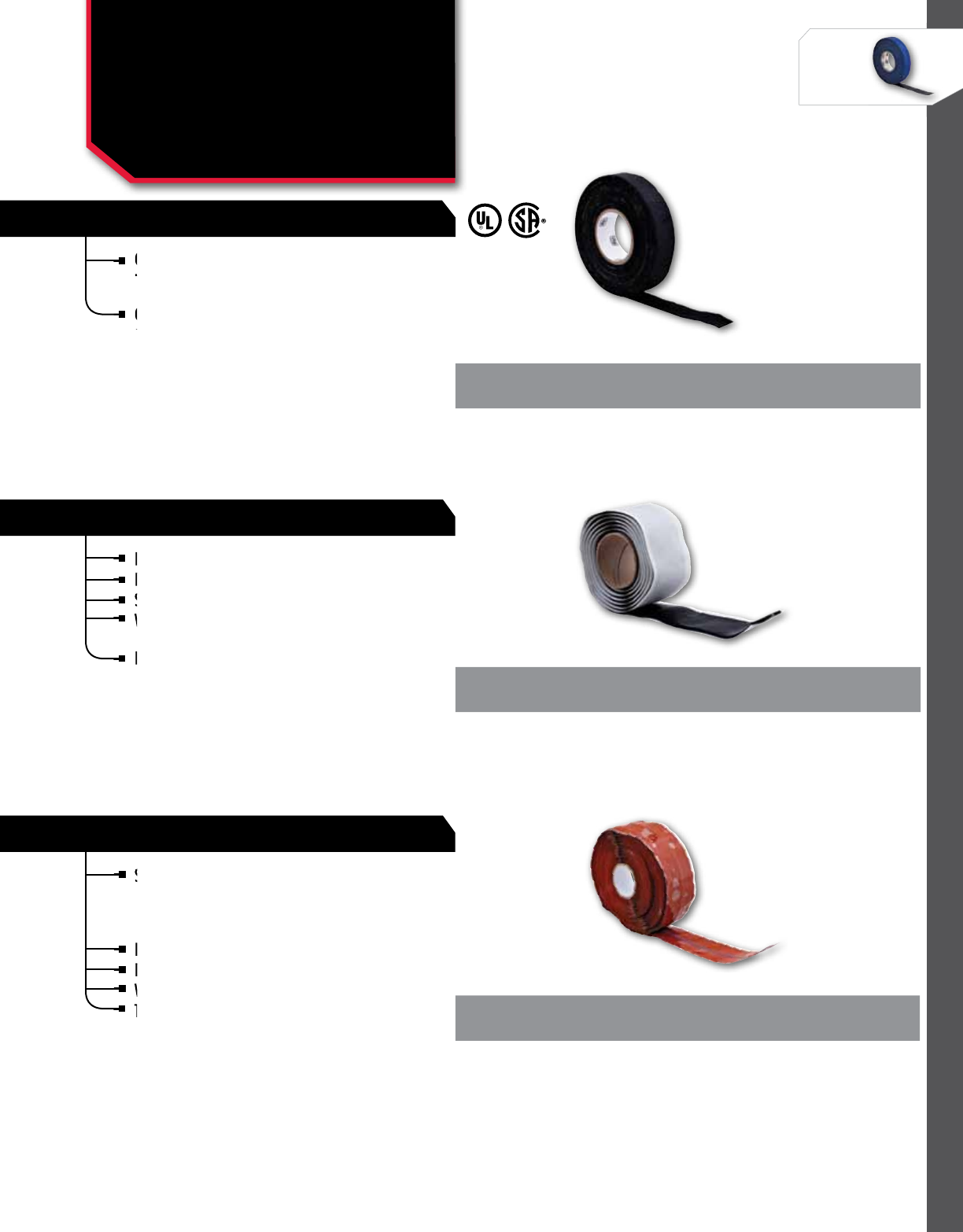
WIRE MANAGEMENT
NSi Industries LLC • USA • 800.321.5847 • www.nsiindustries.com 316
CAT.
no. CoLoR LEnGTH
(FT.) WIDTH
(In.) THICKnESS
(In.)
STD.
CTn.
QTY.
EWFT 157560 Black 60 0.750 0.015 1
FRICTION TAPE
CAT.
no. CoLoR LEnGTH
(FT.) WIDTH
(In.) THICKnESS
(In.)
STD.
CTn.
QTY.
EWEF 12155 Black 5 1.500 0.125 1
EASY-WRAP™ ELECTRICAL FILLER TAPE
SILICONE RUBBER TAPE - 69 KV
CAT.
no. LEnGTH
(FT.) WIDTH
(In.) THICKnESS
(In.)
STD.
CTn.
QTY.
EWSR 121030 30 1.000 0.120 1
EASY-WRAP™
Friction, Electrical Filler &
Silicone Rubber Tape
EWFT, EWEF, EWSR SERIES
Cloth construction offers good mechanical
protection against abrasion and penetration of
cable, splices and wire.
Coated on both sides with a rubber adhesive for
good adhesion to all types of surfaces.
Cloth construction offers good mechanical
protection against abrasion and penetration of
Cloth construction offers good mechanical
protection against abrasion and penetration of
Cloth construction offers good mechanical
Coated on both sides with a rubber adhesive for
good adhesion to all types of surfaces.
Butyl based insulation is 1/8” thick for build-up.
Easy to mold around irregular shapes.
Self-amalgamates into solid flexible mass.
Will not corrode copper or aluminum and highly
resistant to moisture.
Rated for applications up to 5 KV.
Easy to mold around irregular shapes.
Self-amalgamates into solid flexible mass.
Butyl based insulation is 1/8” thick for build-up.
Easy to mold around irregular shapes.
Easy to mold around irregular shapes.
Self-amalgamates into solid flexible mass.
Self-amalgamates into solid flexible mass.
Will not corrode copper or aluminum and highly
resistant to moisture.
Will not corrode copper or aluminum and highly
Rated for applications up to 5 KV.
Self-bonding silicone rubber tape adheres to itself when
wrapped under tension and fuses to form a homogeneous
mass within 24 hours at room temperature or four hours
at 176.6 °C (350 °F).
No adhesive required; tape leaves no residue.
Excellent dialectric properties.
Waterproof and chemical resistant.
Triangular configuration.
APPLICATIonS:
For use on applications up to 69 KV.
Meets MIL-A-A-59163.
TEMPERATURE RATInG:
-53.8 °C to 204.4 (-65 °F to 400 °F).
Self-bonding silicone rubber tape adheres to itself when
wrapped under tension and fuses to form a homogeneous
Self-bonding silicone rubber tape adheres to itself when
wrapped under tension and fuses to form a homogeneous
Self-bonding silicone rubber tape adheres to itself when
Waterproof and chemical resistant.
Triangular configuration.
Excellent dialectric properties.
Waterproof and chemical resistant.
No adhesive required; tape leaves no residue.
Excellent dialectric properties.
Triangular configuration.
Triangular configuration.
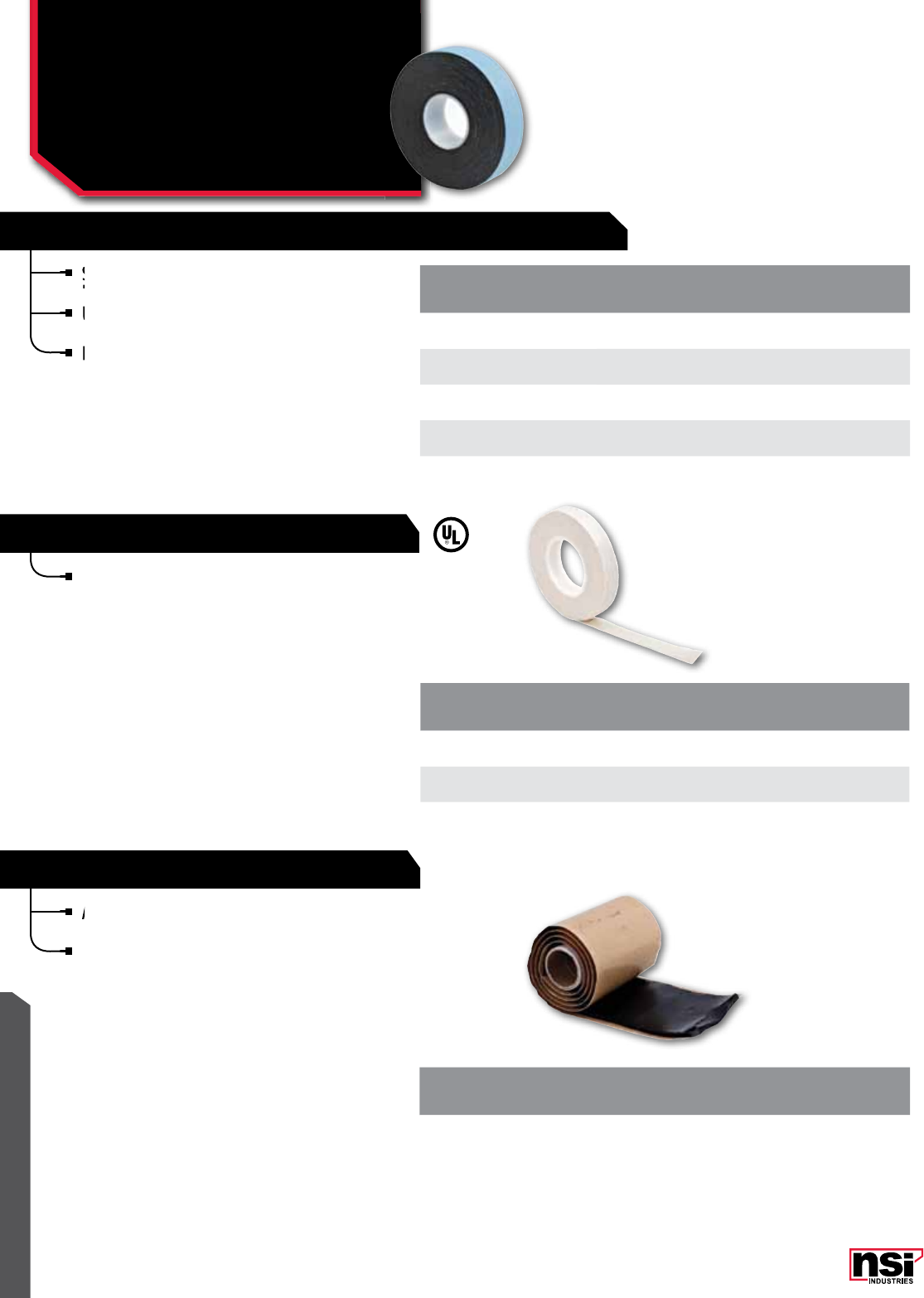
317
WIRE MANAGEMENT
CAT.
no. LEnGTH
(FT.) WIDTH
(In.) THICKnESS
(In.)
STD.
CTn.
QTY.
EWHR 307530-L 30 0.750 0.030 1
EWHR 3010030-L 30 1.000 0.030 1
EWHR 3015030-L 30 1.500 0.030 1
EWHR 3020030-L 30 2.000 0.030 1
HIGH VOLTAGE RUBBER TAPE - 69 KV WITH WHITE LINER
GLASS CLOTH RUBBER ADHESIVE
CAT.
no. LEnGTH
(FT.) WIDTH
(In.) THICKnESS
(In.)
STD.
CTn.
QTY.
EWGC75066 66 0.500 0.007 1
EWGC77566 66 0.750 0.007 1
LINED RUBBER MASTIC TAPE
CAT.
no. LEnGTH
(FT.) WIDTH
(In.) THICKnESS
(In.)
STD.
CTn.
QTY.
EWMT 1252524 2 2.500 0.125 1
EASY-WRAP™
High Voltage, Glass Cloth
& Rubber Mastic Tape
EWHR, EWGC, EWMT SERIES
Self bonding, highly conformable 30 mil
EPR rubber, with liner.
Use as primary electrical insulation for a
pplications through 69 KV.
Flame Retardant, IEEE Standard 17-1974 ANSI.
TEMPERATURE RATInG:
Rated for 90 °C (194 °F) continuous operating
temperature. Intermittent to 130 °C (266 °F).
Will not crack at -40 °C (-40 °F).
Use as primary electrical insulation for a
pplications through 69 KV.
Use as primary electrical insulation for a
pplications through 69 KV.
Use as primary electrical insulation for a
Self bonding, highly conformable 30 mil
EPR rubber, with liner.
Self bonding, highly conformable 30 mil
EPR rubber, with liner.
Self bonding, highly conformable 30 mil
Flame Retardant, IEEE Standard 17-1974 ANSI.
Provides heat stabilized insulation for applications
where resistance to high temperature and high
mechanical strength are required, such as motor
leads, hot spots, switches and controls.
TEMPERATURE RATInG:
Insulation Class: 130 °C (266 °F).
Dialectric strength: 3,300 Volts.
MIL-I-15126F (type GFT).
A self-fusing conformable electrical insulating and
sealing tape.
EPR rubber with a strong stable mastic adhesive
for busbar and splice connections.
TEMPERATURE RATInG:
130 °C (266 °F).
A self-fusing conformable electrical insulating and
sealing tape.
A self-fusing conformable electrical insulating and
sealing tape.
A self-fusing conformable electrical insulating and
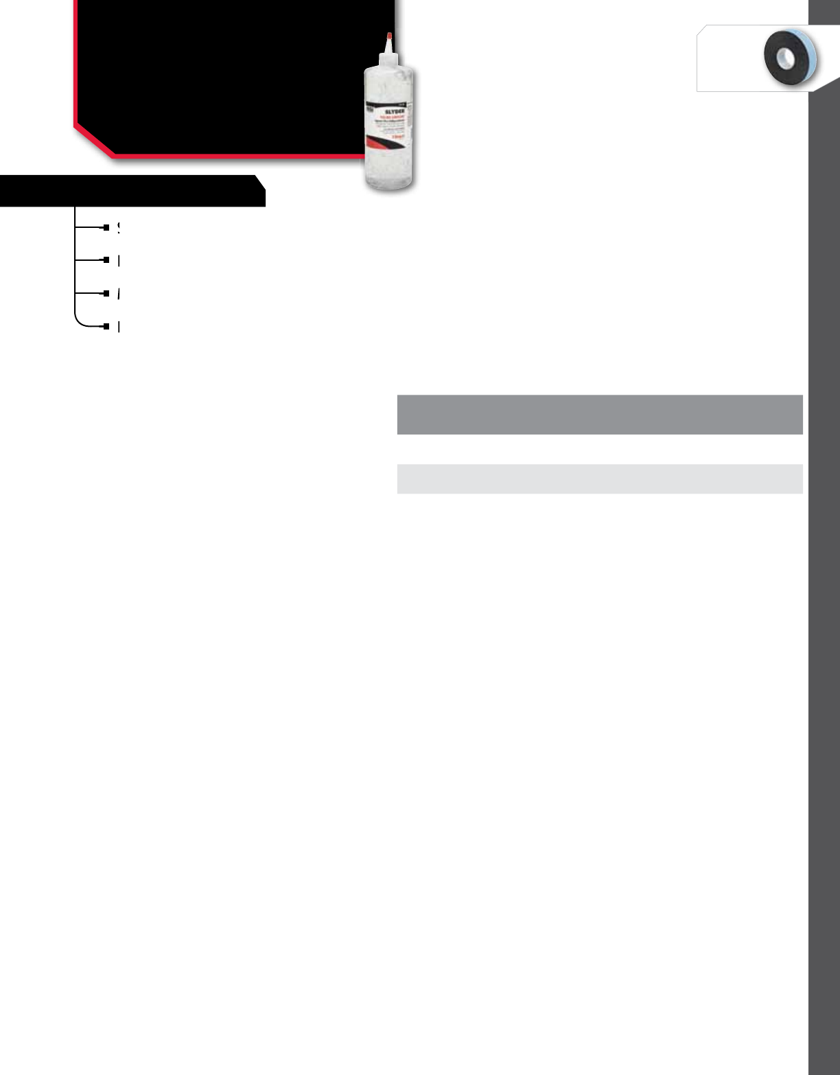
318
WIRE MANAGEMENT
NSi Industries LLC • USA • 800.321.5847 • www.nsiindustries.com
FEATURES
Superior gel lubricant that reduces surface tension
on cable to the lowest level.
Excellent adherence to cable ensures maximum
performance and easier pulls.
Maintains its lubricity even after drying and has
excellent re-wetting characteristics.
Non-toxic and non-flame propagating and can be
used as part of a fire retardant installation. Does
not contain any aromatic or petroleum derivative.
Maintains its
excellent re-wetting characteristics.
Excellent adherence to cable ensures maximum
performance and easier pulls.
Superior gel lubricant that reduces
on cable to the lowest level.
Superior gel lubricant that reduces
on cable to the lowest level.
Superior gel lubricant that reduces
SLYDER™ LUbRICAnT
Slyder™ Wire Lubricant
Non-toxic and non-flame propagating and can be
used as part of a fire retardant installation. Does
Non-toxic and non-flame propagating and can be
used as part of a fire retardant installation. Does
Non-toxic and non-flame propagating and can be
CAT.
no. DESCRIPTIon
STD.
CTn.
QTY.
SWL-1Q 1 Quart 12
SWL-1G 1 Gallon 4
SWL-5G 5 Gallons 1
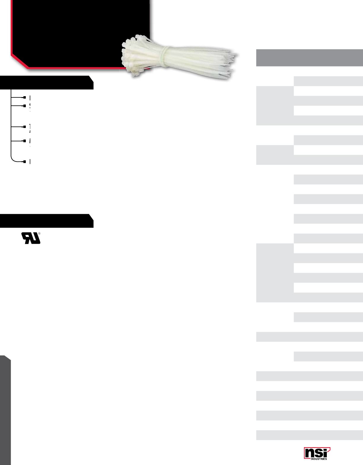
319
RATINGS
FEATURES
WIRE MANAGEMENT
Designed for quick and easy use.
Strong and flexible, they can be wrapped around
a bundle quickly and the tail easily inserted into a
self-locking head.
The smaller standard size ties have bent tails to
facilitate insertion by user.
Made of high-strength Nylon 66 that resists
abrasion and chemicals such as common oils,
greases, solvents, dilute acids and alkalines.
Fungus-resistant, self-extinguishing and have
excellent dielectric properties.
MAX. WIRE/
CAbLE SIZE
(L)
CAT.
no. MAX bUnDLE
DIAMETER TEnSILE
STREnGHT LEnGTH
(In.) WIDTH
(In.)
STD.
PKG.
QTY.
STD.
CTn.
QTY.
4" 418 0.800 18 Lbs.. 4.000 0.095 100 5,000
418X 0.800 18 Lbs... 4.000 0.095 1000 5,000
5"
518 1.430 18 Lbs.. 6.000 0.095 100 5,000
518X 1.375 18 Lbs.. 5.500 0.100 1000 5,000
540 1.300 40 Lbs.. 5.500 0.140 100 3,000
540X 1.300 40 Lbs.. 5.000 0.140 1000 3,000
6" 650 1.320 50 Lbs.. 6.250 0.181 100 3,000
650X 1.320 50 Lbs.. 6.300 0.181 1000 3,000
7" 750 1.810 50 Lbs.. 7.500 0.189 100 3,000
750X 1.810 50 Lbs.. 7.500 0.189 1000 3,000
8"
818 2.060 18 Lbs.. 8.000 0.095 100 3,000
818X 2.060 18 Lbs.. 8.000 0.095 1000 3,000
840 2.060 40 Lbs.. 8.000 0.140 100 3,000
840X 2.060 40 Lbs.. 8.000 0.140 1000 3,000
850 1.940 50 Lbs.. 8.000 0.189 100 3,000
850X 1.940 50 Lbs.. 8.000 0.189 1000 3,000
8120 2.000 120 Lbs.. 8.000 0.300 100 2,000
8120X 2.000 120 Lbs.. 8.000 0.300 1000 2,000
11"
1140 3.300 40 Lbs.. 11.500 0.140 100 2,000
1140X 3.300 40 Lbs.. 11.500 0.140 1000 2,000
1150 2.940 50 Lbs.. 11.100 0.189 100 2,000
1150X 2.940 50 Lbs.. 11.100 0.189 1000 2,000
11120 3.000 120 Lbs.. 11.500 0.300 100 2,000
11120X 3.000 120 Lbs.. 11.500 0.300 1000 2,000
14"
1450 4.070 50 Lbs.. 14.100 0.189 100 3,000
1450X 4.070 50 Lbs.. 14.100 0.189 1000 3,000
14120 4.070 120 Lbs.. 14.250 0.300 100 2,000
15" 15250 4.375 250 Lbs.. 15.000 0.500 50 500
18"
1850 5.070 50 Lbs.. 18.000 0.189 100 2,000
18175 5.250 175 Lbs.. 17.750 0.315 50 500
18250 5.500 250 Lbs.. 18.870 0.500 50 500
22" 22250 6.875 250 Lbs. 22.87 0.500 50 500
24" 24175 7.140 175 Lbs.. 24.000 0.345 50 500
28" 28250 8.875 250 Lbs. 28.75 0.500 50 500
30" 30175 9.250 175 Lbs.. 30.000 0.354 50 500
36" 36175 11.000 175 Lbs.. 36.000 0.350 50 500
48" 48175 15.000 175 Lbs.. 48.000 0.354 50 500
60" 60175 18.250 175 Lbs.. 59.000 0.354 50 500
TEMPERATURE RATInG:
Designed for continuous use from -40 °C to 85 °C
(-40 °F to 185 °F) and will withstand temperatures
up to 149 °C (300.2 °F). 94V-2 flammability rating.
Strong and flexible, they can be wrapped around
a bundle quickly and the tail easily inserted into a
Strong and flexible, they can be wrapped around
a bundle quickly and the tail easily inserted into a
Strong and flexible, they can be wrapped around
Designed for quick and easy use.
Strong and flexible, they can be wrapped around
Strong and flexible, they can be wrapped around
The smaller standard size ties have bent tails to
facilitate insertion by user.
Made of high-strength Nylon 66 that resists
abrasion and chemicals such as common oils,
Made of high-strength Nylon 66 that resists
abrasion and chemicals such as common oils,
Made of high-strength Nylon 66 that resists
Fungus-resistant, self-extinguishing and have
excellent dielectric properties.
Fungus-resistant, self-extinguishing and have
excellent dielectric properties.
Fungus-resistant, self-extinguishing and have
CAbLE TIES
Standard (Natural)
Cable Ties

320
WIRE MANAGEMENT
NSi Industries LLC • USA • 800.321.5847 • www.nsiindustries.com
MAX. WIRE/
CAbLE SIZE
(L)
CAT.
no. MAX bUnDLE
DIAMETER TEnSILE
STREnGHT LEnGTH
(In.) WIDTH
(In.)
STD.
PKG.
QTY.
STD.
CTn.
QTY.
4" 418 0.800 18 Lbs.. 4.000 0.095 100 5,000
418X 0.800 18 Lbs... 4.000 0.095 1000 5,000
5"
518 1.430 18 Lbs.. 6.000 0.095 100 5,000
518X 1.375 18 Lbs.. 5.500 0.100 1000 5,000
540 1.300 40 Lbs.. 5.500 0.140 100 3,000
540X 1.300 40 Lbs.. 5.000 0.140 1000 3,000
6" 650 1.320 50 Lbs.. 6.250 0.181 100 3,000
650X 1.320 50 Lbs.. 6.300 0.181 1000 3,000
7" 750 1.810 50 Lbs.. 7.500 0.189 100 3,000
750X 1.810 50 Lbs.. 7.500 0.189 1000 3,000
8"
818 2.060 18 Lbs.. 8.000 0.095 100 3,000
818X 2.060 18 Lbs.. 8.000 0.095 1000 3,000
840 2.060 40 Lbs.. 8.000 0.140 100 3,000
840X 2.060 40 Lbs.. 8.000 0.140 1000 3,000
850 1.940 50 Lbs.. 8.000 0.189 100 3,000
850X 1.940 50 Lbs.. 8.000 0.189 1000 3,000
8120 2.000 120 Lbs.. 8.000 0.300 100 2,000
8120X 2.000 120 Lbs.. 8.000 0.300 1000 2,000
11"
1140 3.300 40 Lbs.. 11.500 0.140 100 2,000
1140X 3.300 40 Lbs.. 11.500 0.140 1000 2,000
1150 2.940 50 Lbs.. 11.100 0.189 100 2,000
1150X 2.940 50 Lbs.. 11.100 0.189 1000 2,000
11120 3.000 120 Lbs.. 11.500 0.300 100 2,000
11120X 3.000 120 Lbs.. 11.500 0.300 1000 2,000
14"
1450 4.070 50 Lbs.. 14.100 0.189 100 3,000
1450X 4.070 50 Lbs.. 14.100 0.189 1000 3,000
14120 4.070 120 Lbs.. 14.250 0.300 100 2,000
15" 15250 4.375 250 Lbs.. 15.000 0.500 50 500
18"
1850 5.070 50 Lbs.. 18.000 0.189 100 2,000
18175 5.250 175 Lbs.. 17.750 0.315 50 500
18250 5.500 250 Lbs.. 18.870 0.500 50 500
22" 22250 6.875 250 Lbs. 22.87 0.500 50 500
24" 24175 7.140 175 Lbs.. 24.000 0.345 50 500
28" 28250 8.875 250 Lbs. 28.75 0.500 50 500
30" 30175 9.250 175 Lbs.. 30.000 0.354 50 500
36" 36175 11.000 175 Lbs.. 36.000 0.350 50 500
48" 48175 15.000 175 Lbs.. 48.000 0.354 50 500
60" 60175 18.250 175 Lbs.. 59.000 0.354 50 500
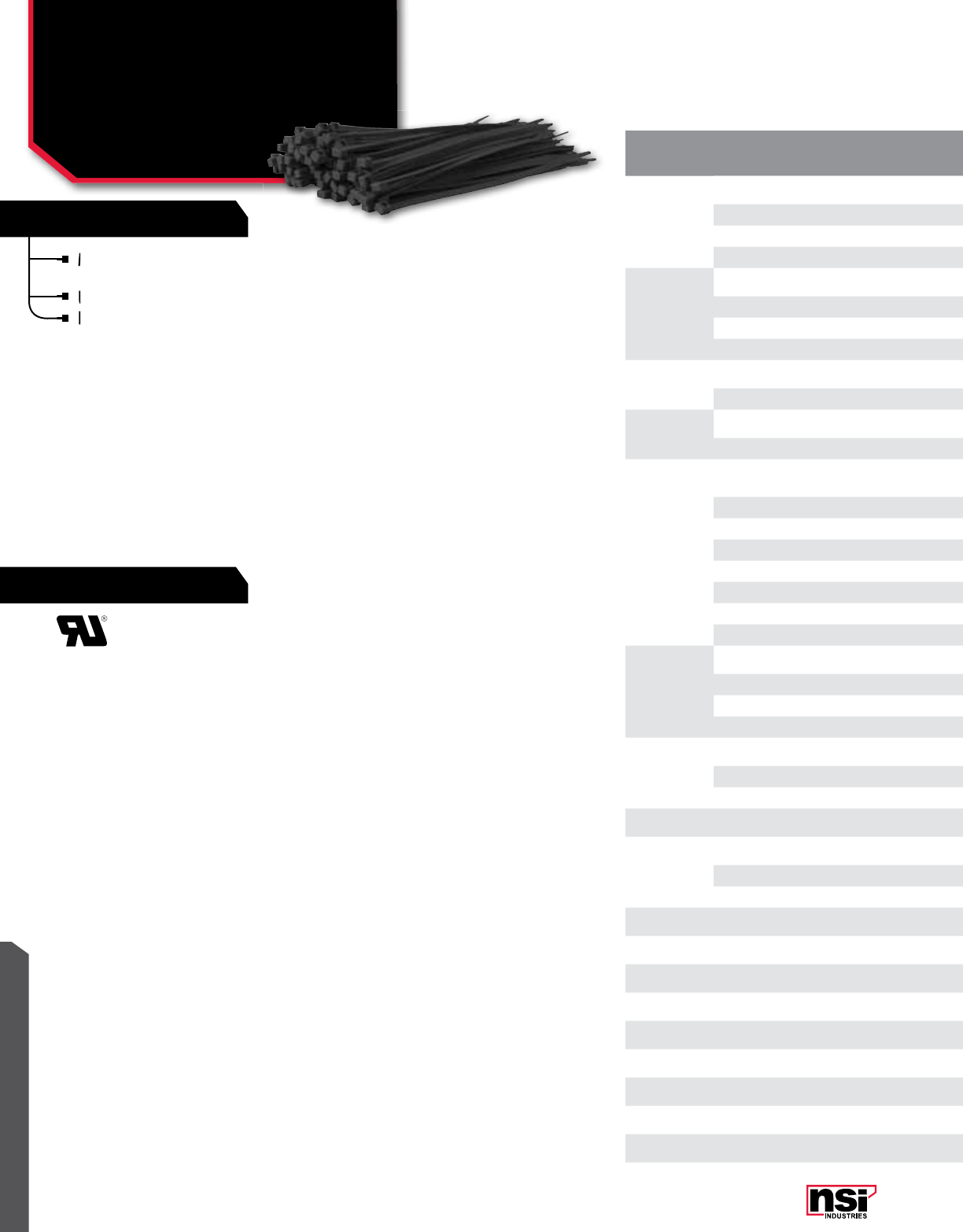
321
RATINGS
FEATURES
WIRE MANAGEMENT
Made from weather resistant Nylon 66 for
applications exposed to outside elements.
UV resistant.
Black only.
MAX. WIRE/
CAbLE SIZE
(L)
CAT.
no. MAX bUnDLE
DIAMETER TEnSILE
STREnGHT LEnGTH
(In.) WIDTH
(In.)
STD.
PKG.
QTY.
STD.
CTn.
QTY.
4"
4180 0.800 18 Lbs 4.000 0.095 100 5,000
4180X 0.800 18 Lbs 4.000 0.095 1000 5,000
4500 1.430 50 Lbs 6.000 0.095 100 5,000
4500X 1.375 50 Lbs 5.500 0.100 1000 5,000
5"
5180 1.300 18 Lbs 5.500 0.140 100 3,000
5180X 1.300 18 Lbs 5.000 0.140 1000 3,000
5400 1.320 40 Lbs 6.250 0.181 100 3,000
5400X 1.320 40 Lbs 6.300 0.181 1000 3,000
6" 6500 1.810 40 Lbs 7.500 0.189 100 3,000
6500X 1.810 50 Lbs 7.500 0.189 1000 3,000
7" 7500 2.060 50 Lbs 8.000 0.095 100 3,000
7500X 2.060 50 Lbs 8.000 0.095 1000 3,000
8"
8180 2.060 18 Lbs 8.000 0.140 100 3,000
8180X 2.060 18 Lbs 8.000 0.140 1000 3,000
8400 1.940 40 Lbs 8.000 0.189 100 3,000
8400X 1.940 40 Lbs 8.000 0.189 1000 3,000
8500 2.000 50 Lbs 8.000 0.300 100 2,000
8500X 2.000 50 Lbs 8.000 0.300 1000 2,000
81200 3.300 120 Lbs 11.500 0.140 100 2,000
81200X 3.300 120 Lbs 11.500 0.140 1000 2,000
11"
11400 2.940 40 Lbs 11.100 0.189 100 2,000
11500 2.940 50 Lbs 11.100 0.189 1000 2,000
11500X 3.000 50 Lbs 11.500 0.300 100 2,000
111200 3.000 120 Lbs 11.500 0.300 1000 2,000
14"
14500 4.070 50 Lbs 14.100 0.189 100 3,000
14500X 4.070 50 Lbs 14.100 0.189 1000 3,000
141200 4.070 120 Lbs 14.250 0.300 100 2,000
15" 152500 4.375 250 Lbs 15.000 0.500 50 500
18"
18500 5.070 50 Lbs 18.000 0.189 100 2,000
181750 5.250 175 Lbs 17.750 0.315 50 500
182500 5.500 250 Lbs 18.870 0.500 50 500
22" 222500 6.875 250 Lbs. 22.87 0.500 50 500
24" 241750 7.140 175 Lbs 24.000 0.345 50 500
28" 282500 8.875 250 Lbs. 28.75 0.500 50 500
30" 301750 9.250 175 Lbs 30.000 0.354 50 500
34' 342500 10.5 250 Lbs. 34.68 0.500 50 500
36" 361750 11.000 175 Lbs 36.000 0.350 50 500
40" 402500 12.5 250 Lbs. 40.5 0.500 50 500
48" 481750 15.000 175 Lbs 48.000 0.354 50 500
60" 601750 18.250 175 Lbs 59.000 0.354 50 500
TEMPERATURE RATInG:
Designed for continuous use from -40 °C to 85 °C
(-40 °F to 185 °F) and will withstand temperatures
up to 149 °C (300.2 °F).
94V-2 flammability rating.
Made from weather resistant Nylon 66 for
applications exposed to outside elements.
Made from weather resistant Nylon 66 for
applications exposed to outside elements.
Made from weather resistant Nylon 66 for
UV resistant.
Black only.
Black only.
Black only.
CAbLE TIES
UV & Weather Resistant
(Black) Cable Ties

322
WIRE MANAGEMENT
NSi Industries LLC • USA • 800.321.5847 • www.nsiindustries.com
MAX. WIRE/
CAbLE SIZE
(L)
CAT.
no. MAX bUnDLE
DIAMETER TEnSILE
STREnGHT LEnGTH
(In.) WIDTH
(In.)
STD.
PKG.
QTY.
STD.
CTn.
QTY.
4"
4180 0.800 18 Lbs 4.000 0.095 100 5,000
4180X 0.800 18 Lbs 4.000 0.095 1000 5,000
4500 1.430 50 Lbs 6.000 0.095 100 5,000
4500X 1.375 50 Lbs 5.500 0.100 1000 5,000
5"
5180 1.300 18 Lbs 5.500 0.140 100 3,000
5180X 1.300 18 Lbs 5.000 0.140 1000 3,000
5400 1.320 40 Lbs 6.250 0.181 100 3,000
5400X 1.320 40 Lbs 6.300 0.181 1000 3,000
6" 6500 1.810 40 Lbs 7.500 0.189 100 3,000
6500X 1.810 50 Lbs 7.500 0.189 1000 3,000
7" 7500 2.060 50 Lbs 8.000 0.095 100 3,000
7500X 2.060 50 Lbs 8.000 0.095 1000 3,000
8"
8180 2.060 18 Lbs 8.000 0.140 100 3,000
8180X 2.060 18 Lbs 8.000 0.140 1000 3,000
8400 1.940 40 Lbs 8.000 0.189 100 3,000
8400X 1.940 40 Lbs 8.000 0.189 1000 3,000
8500 2.000 50 Lbs 8.000 0.300 100 2,000
8500X 2.000 50 Lbs 8.000 0.300 1000 2,000
81200 3.300 120 Lbs 11.500 0.140 100 2,000
81200X 3.300 120 Lbs 11.500 0.140 1000 2,000
11"
11400 2.940 40 Lbs 11.100 0.189 100 2,000
11500 2.940 50 Lbs 11.100 0.189 1000 2,000
11500X 3.000 50 Lbs 11.500 0.300 100 2,000
111200 3.000 120 Lbs 11.500 0.300 1000 2,000
14"
14500 4.070 50 Lbs 14.100 0.189 100 3,000
14500X 4.070 50 Lbs 14.100 0.189 1000 3,000
141200 4.070 120 Lbs 14.250 0.300 100 2,000
15" 152500 4.375 250 Lbs 15.000 0.500 50 500
18"
18500 5.070 50 Lbs 18.000 0.189 100 2,000
181750 5.250 175 Lbs 17.750 0.315 50 500
182500 5.500 250 Lbs 18.870 0.500 50 500
22" 222500 6.875 250 Lbs. 22.87 0.500 50 500
24" 241750 7.140 175 Lbs 24.000 0.345 50 500
28" 282500 8.875 250 Lbs. 28.75 0.500 50 500
30" 301750 9.250 175 Lbs 30.000 0.354 50 500
34' 342500 10.5 250 Lbs. 34.68 0.500 50 500
36" 361750 11.000 175 Lbs 36.000 0.350 50 500
40" 402500 12.5 250 Lbs. 40.5 0.500 50 500
48" 481750 15.000 175 Lbs 48.000 0.354 50 500
60" 601750 18.250 175 Lbs 59.000 0.354 50 500
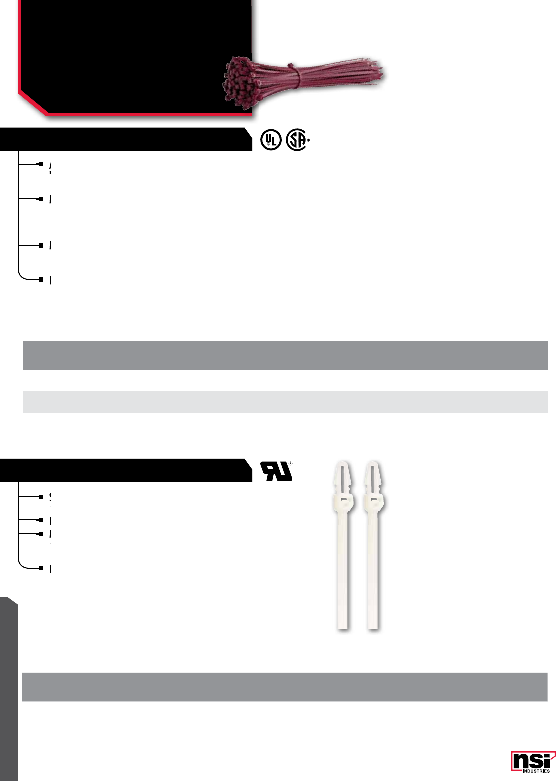
WIRE MANAGEMENT
323
AIR HANDLING CABLE TIES
PUSH MOUNT CABLE TIES
Air handling ties are approved for indoor use in air
handling spaces other than plenums and ducts per
NFPA-1993.
Meets UL 1565 test standards. MIL spec. 3367-1, -7,
-2. NEC Sec. 300-22 (C) & (D), Rules 12-010 (3),
(4), and (5) and 12-020 of the Canadian Electrical
code, Part 1.
Made of high strength nylon, these ties are self-
extinguishing and resist abrasions and chemicals such
as oil, greases, solvents, dilute acids and alkalies.
Burgundy in color for easy identification.
TEMPERATURE RATInG:
Maximum operating temperature 85 °C (185 °F).
MAX.
WIRE/
CAbLE SIZE
CAT.
no. MAX.
bUnDLE DIA. MIn. TEnSILE
STREnGTH LEnGTH
(In.) WIDTH
(In.)
STD.
PKG.
QTY.
STD.
CTn.
QTY.
7" 750-P 1.750 50 Lbs. 7.500 0.180 100 5,000
11" 1150-P 3.000 50 Lbs. 11.100 0.180 100 5,000
14" 1450-P 4.000 50 Lbs. 14.200 0.180 100 5,000
Made of high strength nylon, these ties are self-
extinguishing and resist abrasions and
Made of high strength nylon, these ties are self-
extinguishing and resist abrasions and
Made of high strength nylon, these ties are self-
Meets UL 1565 test standards. MIL spec. 3367-1, -7,
-2. NEC Sec. 300-22 (C) & (D), Rules 12-010 (3),
Meets UL 1565 test standards. MIL spec. 3367-1, -7,
-2. NEC Sec. 300-22 (C) & (D), Rules 12-010 (3),
Meets UL 1565 test standards. MIL spec. 3367-1, -7,
Air handling ties are approved for indoor use in air
handling spaces other than plenums and ducts per
Air handling ties are approved for indoor use in air
handling spaces other than plenums and ducts per
Air handling ties are approved for indoor use in air
Secure a cable tie to a back panel quickly and easily,
eliminating the possibility of adhesive mount failure.
Drill the mounting hole and insert.
Made of high-strength Nylon 66 that resists abrasion
and chemicals such as common oils, greases, solvents,
dilute acids and alkalines.
Fungus-resistant, self-extinguishing and excellent
dielectric properties.
TEMPERATURE RATInG:
-40 °C to 85 °C (-40 °F to 185 °F) and will
withstand temperatures up to 149 °C (300.2 °F).
94V-2 flammability rating.
MAX.
WIRE/
CAbLE SIZE
CAT.
no. MAX.
bUnDLE DIA. MIn. TEnSILE
STREnGTH
MTG. HoLE
SIZE REQ.
(In.)
LEnGTH
(In.) WIDTH
(In.)
STD.
PKG.
QTY.
STD.
CTn.
QTY.
6" 640-PM 1.59 40 Lbs. 3/16 6.125 0.139 100 1,000
Made of high-strength Nylon 66 that resists abrasion
and chemicals such as common oils, greases, solvents,
Made of high-strength Nylon 66 that resists abrasion
and chemicals such as common oils, greases, solvents,
Made of high-strength Nylon 66 that resists abrasion
Drill the mounting hole and insert.
Made of high-strength Nylon 66 that resists abrasion
Secure a cable tie to a back panel quickly and easily,
eliminating the possibility of adhesive mount failure.
Secure a cable tie to a back panel quickly and easily,
eliminating the possibility of adhesive mount failure.
Secure a cable tie to a back panel quickly and easily,
CAbLE TIES
Air Handling and Push
Mount Cable Ties
-P, -PM SERIES
Burgundy in color for easy identification.
Fungus-resistant, self-extinguishing and excellent
dielectric properties.
Fungus-resistant, self-extinguishing and excellent
dielectric properties.
Fungus-resistant, self-extinguishing and excellent

WIRE MANAGEMENT
NSi Industries LLC • USA • 800.321.5847 • www.nsiindustries.com 324
Suitable for extreme environments.
Rated for air handling spaces and chemical, weather
and radiation resistant.
Ideal for high temperature applications, up to 150 °C
(302 °F) continuous operating temperature.
UL 94V-0 approved.
Aqua blue in color.
TEMPERATURE RATInG:
18.3 °C to 150 °C (65 °F to 302 °F).
Melting point 271.1 °C (520 °F).
MAX. WIRE/CAbLE
SIZE CAT.
no. MAX.
bUnDLE DIA. MIn. TEnSILE
STREnGTH LEnGTH
(In.) WIDTH
(In.)
STD.
PKG.
QTY.
STD.
CTn.
QTY.
8" TFZ850 1.750 50 Lbs. 7.500 0.190 100 1,000
11" TFZ1150 3.000 50 Lbs. 11.500 0.190 100 1,000
UL 94V-0 approved.
Ideal for high temperature applications, up to 150
(
Rated for air handling spaces and chemical,
and radiation resistant.
Rated for air handling spaces and chemical,
and radiation resistant.
Rated for air handling spaces and chemical,
Suitable for extreme environments.
Rated for air handling spaces and chemical,
Rated for air handling spaces and chemical,
TEFZEL CABLE TIES
MARKER TIES
Manufactured from natural colored Nylon 66,
with an identification area provided as detailed
below (see STYLE).
Horizontal (fig. 1)
Flag (fig. 2)
Vertical (fig. 3)
MAX.
WIRE/
CAbLE SIZE
CAT.
no. STYLE MAX.
bUnDLE
DIA.
TEnSILE
STREnGHT LEnGTH
(In.) WIDTH
(In.)
STD.
PKG.
QTY.
STD.
CTn.
QTY.
4"
418-ID Vertical 0.75 18 Lbs. 4.000 0.100 100 1,000
418F-ID Flag 0.75 18 Lbs. 4.000 0.100 100 1,000
418H-ID Horizontal 0.75 18 Lbs. 4.000 0.100 100 1,000
7" 750-ID Vertical 2 50 Lbs. 7.800 0.183 100 1,000
8" 818H-ID Horizontal 2 18 Lbs. 8.000 0.100 100 1,000
CAbLE TIES
Tefzel, Marker Cable Ties
TFZ, -ID SERIES
Manufactured from natural colored Nylon 66,
with an identification area provided as detailed
Manufactured from natural colored Nylon 66,
with an identification area provided as detailed
Manufactured from natural colored Nylon 66,
Aqua blue in color.
UL 94V-0 approved.
below (see STYLE).
TRUE PLEnUM RATInG
Air handling ties approved for indoor use in air handling
spaces and plenums and ducts per NFPA-1993.
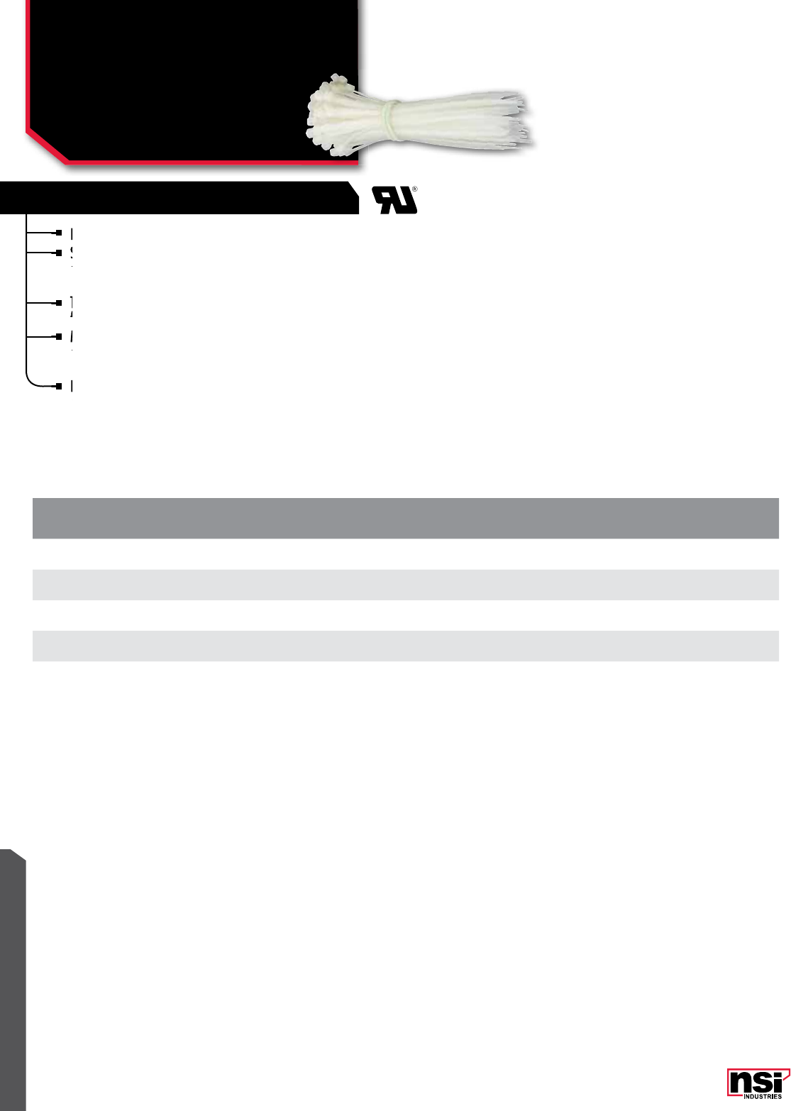
325
WIRE MANAGEMENT
CAT.
no. LEnGTH WIDTH CoLoR MAX.
bUnDLE DIA. MIn. TEnSILE
STREnGTH
STD.
PKG.
QTY.
STD.
CTn.
QTY.
36175 36 0.354 Natural 10.625 175 Lbs. 50 500
361750 36 0.354 Black 10.625 175 Lbs. 50 500
48175 48 0.354 Natural 15.000 175 Lbs. 50 500
481750 48 0.354 Black 15.000 175 Lbs. 50 500
HVAC UL181B FOR FLEXIBLE DUCT
CAbLE TIES
HVAC Standard &
Weather Resistant Ties
Designed for quick and easy use.
Strong and flexible, they can be wrapped around
a bundle quickly and the tail easily inserted into a
self-locking head.
The smaller standard size ties have bent tails to
facilitate insertion by user.
Made of high-strength Nylon 66 that resists
abrasion and chemicals such as common oils,
greases, solvents, dilute acids and alkalines.
Fungus-resistant, self-extinguishing and have
excellent dielectric properties.
Strong and flexible, they can be wrapped around
a bundle quickly and the tail easily inserted into a
Strong and flexible, they can be wrapped around
a bundle quickly and the tail easily inserted into a
Strong and flexible, they can be wrapped around
Designed for quick and easy use.
Strong and flexible, they can be wrapped around
Strong and flexible, they can be wrapped around
The smaller standard size ties have bent tails to
facilitate insertion by user.
Made of high-strength Nylon 66 that resists
abrasion and chemicals such as common oils,
Made of high-strength Nylon 66 that resists
abrasion and chemicals such as common oils,
Made of high-strength Nylon 66 that resists
Fungus-resistant, self-extinguishing and have
excellent dielectric properties.
Fungus-resistant, self-extinguishing and have
excellent dielectric properties.
Fungus-resistant, self-extinguishing and have

326
WIRE MANAGEMENT
NSi Industries LLC • USA • 800.321.5847 • www.nsiindustries.com
RELEASABLE
STAINLESS STEEL CABLE TIES
Releasable ties are manufactured from either
natural Nylon 66 or Weather Resistant Nylon 66,
these ties can be easily released and re-used.
TEMPERATURE RATInG:
-40 °C to 85 °C (-40 °F to 185 °F).
MAX. WIRE/CAbLE
SIZE CAT.
no. MAX.
bUnDLE DIA. MIn. TEnSILE
STREnGTH LEnGTH
(In.) WIDTH
(In.)
STD.
PKG.
QTY.
STD.
CTn.
QTY.
8" 850-R 2.000 50 Lbs. 8.00 0.210 100 1,000
Made of Grade 304 stainless steel and are ideally
suited for hazardous environments.
Roller-ball design that is self locking, fast and easy
to install.
Smooth edges will not damage wires.
Installation by hand or with a tool.
Available with a non-toxic, halogen-free polyester
coating in a wide choice of colors.
Available in Grade 316, for applications that require
extremely high corrosion resistance. To order 316SS
material, add suffix "-316" to part number.
TEMPERATURE RATInG:
-80 °C to 538 °C (-62.2 °F to 281.1 °F).
MAX.
WIRE/
CAbLE SIZE
CAT.
no. MAX.
bUnDLE DIA. MIn. TEnSILE
STREnGTH LEnGTH
(In.) WIDTH
(In.)
STD.
PKG.
QTY.
STD.
CTn.
QTY.
8" SS8100 1.970 100 Lbs. 8.000 0.181 100 500
14"
SS14100 3.940 100 Lbs. 14.000 0.181 100 500
SS14250 3.940 250 Lbs. 14.000 0.311 100 500
20"
SS20100 5.900 100 Lbs. 20.5 0.181 100 500
SS20250 5.900 250 Lbs. 20.5 0.311 100 500
26" SS26250 7.870 250 Lbs. 26.5 0.311 100 500
Available with a non-toxic, halogen-free polyester
coating in a wide choice of colors.
Available with a non-toxic, halogen-free polyester
coating in a wide choice of colors.
Available with a non-toxic, halogen-free polyester
Installation by hand or with a tool.
Available with a non-toxic, halogen-free polyester
Available with a non-toxic, halogen-free polyester
Smooth edges will not damage wires.
Installation by hand or with a tool.
Roller-ball design that is self locking, fast and easy
to install.
Roller-ball design that is self locking, fast and easy
to install.
Roller-ball design that is self locking, fast and easy
Made of Grade 304 stainless steel and are ideally
suited for hazardous environments.
Made of Grade 304 stainless steel and are ideally
suited for hazardous environments.
Made of Grade 304 stainless steel and are ideally
CAbLE TIES
Releasable &
Stainless Steel Ties
-R, SS SERIES
Available in Grade 316, for applications that require
extremely high corrosion resistance. To order 316SS
Available in Grade 316, for applications that require
extremely high corrosion resistance. To order 316SS
Available in Grade 316, for applications that require
Releasable ties are manufactured from either
natural Nylon 66 or Weather Resistant Nylon 66,
TRUE PLEnUM RATInG
Air handling ties approved for indoor use in air handling
spaces and plenums and ducts per NFPA-1993.
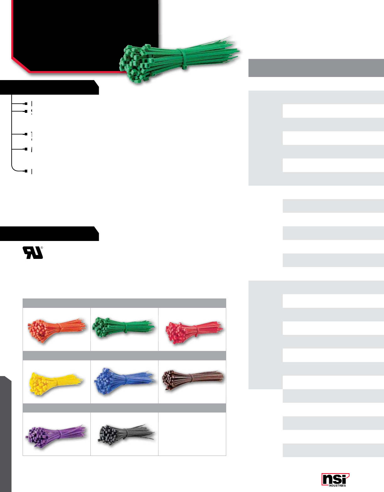
327
RATINGS
FEATURES
WIRE MANAGEMENT
MAX. WIRE/
CAbLE SIZE
(L)
CAT.
no. CoLoR MAX bUnDLE
DIAMETER TEnSILE
STREnGHT LEnGTH
(In.) WIDTH
(In.)
STD.
PKG.
QTY.
STD.
CTn.
QTY.
4" 418-4 Yellow 0.800 18 Lbs. 4.000 0.095 100 5,000
5"
530-1 Brown 1.300 30 Lbs. 5.600 0.140 100 5,000
530-2 Red 1.300 30 Lbs. 5.000 0.140 100 5,000
530-3 Orange 1.300 30 Lbs. 5.000 0.140 100 5,000
530-4 Yellow 1.250 30 Lbs. 5.600 0.130 100 5,000
530-5 Green 1.300 30 Lbs. 5.000 0.140 100 5,000
530-6 Blue 1.300 30 Lbs. 5.000 0.140 100 5,000
530-8 Gray 1.300 30 Lbs. 5.600 0.140 100 5,000
7"
750-2 Red 1.810 50 Lbs. 8.000 0.189 100 3,000
750-3 Orange 1.810 50 Lbs. 7.500 0.189 100 3,000
750-4 Yellow 1.810 50 Lbs. 8.000 0.189 100 3,000
750-5 Green 1.810 50 Lbs. 8.000 0.189 100 3,000
750-6 Blue 1.810 50 Lbs. 8.000 0.189 100 3,000
750-7 Purple 1.810 50 Lbs. 8.000 0.189 100 3,000
750-8 Gray 1.810 50 Lbs. 8.000 0.189 100 3,000
8"
840-1 Brown 2.060 40 Lbs. 8.500 0.140 100 3,000
840-2 Red 2.060 40 Lbs. 8.000 0.140 100 3,000
840-3 Orange 2.060 40 Lbs. 8.000 0.140 100 3,000
840-4 Yellow 2.060 40 Lbs. 8.500 0.140 100 3,000
840-5 Green 2.060 40 Lbs. 8.500 0.140 100 3,000
840-6 Blue 2.060 40 Lbs. 8.000 0.140 100 3,000
840-7 Purple 2.060 40 Lbs. 8.500 0.140 100 3,000
840-8 Gray 2.060 40 Lbs. 8.500 0.140 100 3,000
11" 1150-2 Red 3.000 50 Lbs. 11.100 0.187 100 2,000
14"
1450-2 Red 4.000 50 Lbs. 14.100 0.187 100 2,000
1450-3 Orange 4.000 50 Lbs. 14.100 0.187 100 2,000
1450-4 Yellow 4.070 50 Lbs. 14.000 0.189 100 2,000
1450-5 Green 4.000 50 Lbs. 14.100 0.187 100 2,000
Designed for quick and easy use.
Strong and flexible, they can be wrapped around
a bundle quickly and the tail easily inserted into a
self-locking head.
The smaller standard size ties have bent tails to
facilitate insertion by user.
Made of high-strength Nylon 66 that resists
abrasion and chemicals such as common oils,
greases, solvents, dilute acids and alkalines.
Fungus-resistant, self-extinguishing and have
excellent dielectric properties.
Strong and flexible, they can be wrapped around
a bundle quickly and the tail easily inserted into a
Strong and flexible, they can be wrapped around
a bundle quickly and the tail easily inserted into a
Strong and flexible, they can be wrapped around
Designed for quick and easy use.
Strong and flexible, they can be wrapped around
The smaller standard size ties have bent tails to
facilitate insertion by user.
Made of high-strength Nylon 66 that resists
abrasion and chemicals such as common oils,
Made of high-strength Nylon 66 that resists
abrasion and chemicals such as common oils,
Made of high-strength Nylon 66 that resists
Fungus-resistant, self-extinguishing and have
excellent dielectric properties.
Fungus-resistant, self-extinguishing and have
excellent dielectric properties.
Fungus-resistant, self-extinguishing and have
CAbLE TIES
Standard Cable Ties:
Color
ORANGE (-3) GREEN (-5) RED (-2)
YELLOW (-4) BLUE (-6) BROWN (-1)
PURPLE (-7) GRAY (-8)

328
WIRE MANAGEMENT
NSi Industries LLC • USA • 800.321.5847 • www.nsiindustries.com
MAX. WIRE/
CAbLE SIZE
(L)
CAT.
no. CoLoR MAX bUnDLE
DIAMETER TEnSILE
STREnGHT LEnGTH
(In.) WIDTH
(In.)
STD.
PKG.
QTY.
STD.
CTn.
QTY.
4" 418-4 Yellow 0.800 18 Lbs. 4.000 0.095 100 5,000
5"
530-1 Brown 1.300 30 Lbs. 5.600 0.140 100 5,000
530-2 Red 1.300 30 Lbs. 5.000 0.140 100 5,000
530-3 Orange 1.300 30 Lbs. 5.000 0.140 100 5,000
530-4 Yellow 1.250 30 Lbs. 5.600 0.130 100 5,000
530-5 Green 1.300 30 Lbs. 5.000 0.140 100 5,000
530-6 Blue 1.300 30 Lbs. 5.000 0.140 100 5,000
530-8 Gray 1.300 30 Lbs. 5.600 0.140 100 5,000
7"
750-2 Red 1.810 50 Lbs. 8.000 0.189 100 3,000
750-3 Orange 1.810 50 Lbs. 7.500 0.189 100 3,000
750-4 Yellow 1.810 50 Lbs. 8.000 0.189 100 3,000
750-5 Green 1.810 50 Lbs. 8.000 0.189 100 3,000
750-6 Blue 1.810 50 Lbs. 8.000 0.189 100 3,000
750-7 Purple 1.810 50 Lbs. 8.000 0.189 100 3,000
750-8 Gray 1.810 50 Lbs. 8.000 0.189 100 3,000
8"
840-1 Brown 2.060 40 Lbs. 8.500 0.140 100 3,000
840-2 Red 2.060 40 Lbs. 8.000 0.140 100 3,000
840-3 Orange 2.060 40 Lbs. 8.000 0.140 100 3,000
840-4 Yellow 2.060 40 Lbs. 8.500 0.140 100 3,000
840-5 Green 2.060 40 Lbs. 8.500 0.140 100 3,000
840-6 Blue 2.060 40 Lbs. 8.000 0.140 100 3,000
840-7 Purple 2.060 40 Lbs. 8.500 0.140 100 3,000
840-8 Gray 2.060 40 Lbs. 8.500 0.140 100 3,000
11" 1150-2 Red 3.000 50 Lbs. 11.100 0.187 100 2,000
14"
1450-2 Red 4.000 50 Lbs. 14.100 0.187 100 2,000
1450-3 Orange 4.000 50 Lbs. 14.100 0.187 100 2,000
1450-4 Yellow 4.070 50 Lbs. 14.000 0.189 100 2,000
1450-5 Green 4.000 50 Lbs. 14.100 0.187 100 2,000
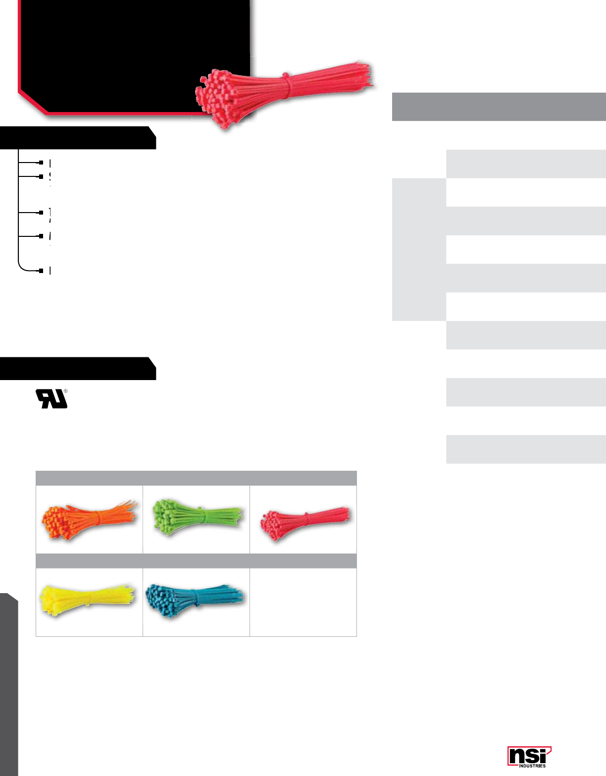
329
RATINGS
FEATURES
WIRE MANAGEMENT
MAX. WIRE/
CAbLE SIZE CAT.
no. CoLoR
(FLoURESCEnT) MAX bUnDLE
DIAMETER TEnSILE
STREnGHT LEnGTH
(In.) WIDTH
(In.)
STD.
PKG.
QTY.
STD.
CTn.
QTY.
7"
750-16 Orange 1.750 50 Lbs. 7.500 0.187 100 3,000
750-18 Green 1.810 50 Lbs. 7.500 0.189 100 3,000
8"
840-11 Pink 2.000 40 Lbs. 8.500 0.130 100 3,000
840-16 Orange 2.000 40 Lbs. 8.500 0.130 100 3,000
840-17 Yellow 2.060 40 Lbs. 8.000 0.140 100 3,000
840-18 Green 2.000 40 Lbs. 8.500 0.130 100 3,000
840-20 Blue 2.000 40 Lbs. 8.500 0.130 100 3,000
11"
1150-11 Pink 3.000 50 Lbs. 11.100 0.187 100 2,000
1150-16 Orange 3.000 50 Lbs. 11.100 0.187 100 2,000
1150-17 Yellow 3.000 50 Lbs. 11.100 0.187 100 2,000
1150-18 Green 3.000 50 Lbs. 11.100 0.187 100 2,000
1150-20 Blue 3.000 50 Lbs. 11.100 0.187 100 2,000
Designed for quick and easy use.
Strong and flexible, they can be wrapped around
a bundle quickly and the tail easily inserted into a
self-locking head.
The smaller standard size ties have bent tails to
facilitate insertion by user.
Made of high-strength Nylon 66 that resists
abrasion and chemicals such as common oils,
greases, solvents, dilute acids and alkalines.
Fungus-resistant, self-extinguishing and have
excellent dielectric properties.
Strong and flexible, they can be wrapped around
a bundle quickly and the tail easily inserted into a
Strong and flexible, they can be wrapped around
a bundle quickly and the tail easily inserted into a
Strong and flexible, they can be wrapped around
Designed for quick and easy use.
Strong and flexible, they can be wrapped around
Strong and flexible, they can be wrapped around
The smaller standard size ties have bent tails to
facilitate insertion by user.
Made of high-strength Nylon 66 that resists
abrasion and chemicals such as common oils,
Made of high-strength Nylon 66 that resists
abrasion and chemicals such as common oils,
Made of high-strength Nylon 66 that resists
Fungus-resistant, self-extinguishing and have
excellent dielectric properties.
Fungus-resistant, self-extinguishing and have
excellent dielectric properties.
Fungus-resistant, self-extinguishing and have
CAbLE TIES
Standard Cable Ties:
Fluorescent
ORANGE (-16) GREEN (-18) PINK (-11)
YELLOW (17) BLUE (-20)

330
WIRE MANAGEMENT
NSi Industries LLC • USA • 800.321.5847 • www.nsiindustries.com
MAX. WIRE/
CAbLE SIZE CAT.
no. CoLoR
(FLoURESCEnT) MAX bUnDLE
DIAMETER TEnSILE
STREnGHT LEnGTH
(In.) WIDTH
(In.)
STD.
PKG.
QTY.
STD.
CTn.
QTY.
7"
750-16 Orange 1.750 50 Lbs. 7.500 0.187 100 3,000
750-18 Green 1.810 50 Lbs. 7.500 0.189 100 3,000
8"
840-11 Pink 2.000 40 Lbs. 8.500 0.130 100 3,000
840-16 Orange 2.000 40 Lbs. 8.500 0.130 100 3,000
840-17 Yellow 2.060 40 Lbs. 8.000 0.140 100 3,000
840-18 Green 2.000 40 Lbs. 8.500 0.130 100 3,000
840-20 Blue 2.000 40 Lbs. 8.500 0.130 100 3,000
11"
1150-11 Pink 3.000 50 Lbs. 11.100 0.187 100 2,000
1150-16 Orange 3.000 50 Lbs. 11.100 0.187 100 2,000
1150-17 Yellow 3.000 50 Lbs. 11.100 0.187 100 2,000
1150-18 Green 3.000 50 Lbs. 11.100 0.187 100 2,000
1150-20 Blue 3.000 50 Lbs. 11.100 0.187 100 2,000
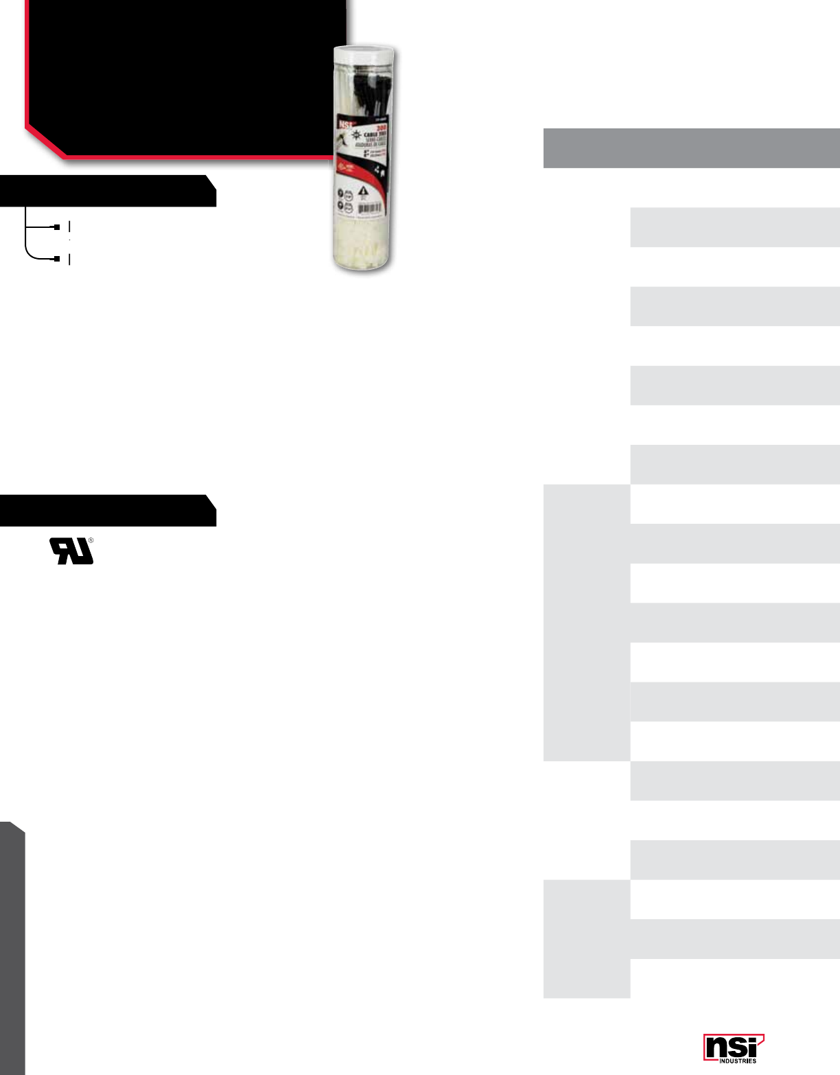
331
RATINGS
FEATURES
WIRE MANAGEMENT
Four sizes of canister packs include popular
assortments of standard and colored cable ties.
Provided in an air-tight canister to prevent
drying, extending life.
CAT.
no. ConTEnTS QTY. CoLoR bUnDLE
DIAL MAX bUnDLE
DIAMETER TEnSILE
STREnGHT LEnGTH
(In.) WIDTH
(In.)
STD.
PKG.
QTY.
STD.
CTn.
QTY.
CTP-300
418 100 Natural 7/ 8 0.875 18 Lbs.. 4.000 0.100 1 12
418-2 25 Red 7/ 8 0.875 18 Lbs. 4.000 0.100 1 12
418-4 25 Yellow 7/ 8 0.875 18 Lbs. 4.000 0.100 1 12
418-5 25 Green 7/ 8 0.875 18 Lbs. 4.000 0.100 1 12
418-6 25 Blue 7/ 8 0.875 18 Lbs. 4.000 0.100 1 12
840 50 Natural 2 1/8 2.125 40 Lbs. 8.000 0.140 1 12
840-2 25 Red 2 1/8 2.125 40 Lbs. 8.000 0.140 1 12
840-6 25 Blue 2 1/8 2.125 40 Lbs. 8.000 0.140 1 12
CTP-650
418 200 Natural 7/ 8 0.875 18 Lbs. 4.000 0.100 1 12
418-2 25 Red 7/ 8 0.875 18 Lbs. 4.000 0.100 1 12
418-4 25 Yellow 7/ 8 0.875 18 Lbs. 4.000 0.100 1 12
418-5 25 Green 7/ 8 0.875 18 Lbs. 4.000 0.100 1 12
418-6 25 Blue 7/ 8 0.875 18 Lbs. 4.000 0.100 1 12
840 300 Natural 2 1/8 2.125 40 Lbs. 8.000 0.140 1 12
1150 50 Natural 3 1/8 3.125 50 Lbs. 11.000 0.187 1 12
CTP-650N
418 300 Natural 7/ 8 0.875 18 Lbs. 4.000 0.100 1 12
840 300 Natural 2 1/8 2.125 40 Lbs. 8.000 0.140 1 12
1150 50 Natural 3 1/8 3.125 50 Lbs. 11.000 0.187 1 12
CTP-650B
4180 300 UV Black 7/ 8 0.875 18 Lbs. 4.000 0.100 1 12
8400 300 UV Black 2 1/8 2.125 40 Lbs. 8.000 0.140 1 12
11500 50 UV Black 3 1/8 3.125 50 Lbs. 11.000 0.187 1 12
Four sizes of canister packs include popular
assortments of standard and colored cable ties.
Four sizes of canister packs include popular
assortments of standard and colored cable ties.
Four sizes of canister packs include popular
CAbLE TIES
Cable Tie Canister Packs
CTP SERIES
Provided in an air-tight canister to prevent
drying, extending life.
Provided in an air-tight canister to prevent
drying, extending life.
Provided in an air-tight canister to prevent

332
WIRE MANAGEMENT
NSi Industries LLC • USA • 800.321.5847 • www.nsiindustries.com
CAT.
no. ConTEnTS QTY. CoLoR bUnDLE
DIAL MAX bUnDLE
DIAMETER TEnSILE
STREnGHT LEnGTH
(In.) WIDTH
(In.)
STD.
PKG.
QTY.
STD.
CTn.
QTY.
CTP-300
418 100 Natural 7/ 8 0.875 18 Lbs.. 4.000 0.100 1 12
418-2 25 Red 7/ 8 0.875 18 Lbs. 4.000 0.100 1 12
418-4 25 Yellow 7/ 8 0.875 18 Lbs. 4.000 0.100 1 12
418-5 25 Green 7/ 8 0.875 18 Lbs. 4.000 0.100 1 12
418-6 25 Blue 7/ 8 0.875 18 Lbs. 4.000 0.100 1 12
840 50 Natural 2 1/8 2.125 40 Lbs. 8.000 0.140 1 12
840-2 25 Red 2 1/8 2.125 40 Lbs. 8.000 0.140 1 12
840-6 25 Blue 2 1/8 2.125 40 Lbs. 8.000 0.140 1 12
CTP-650
418 200 Natural 7/ 8 0.875 18 Lbs. 4.000 0.100 1 12
418-2 25 Red 7/ 8 0.875 18 Lbs. 4.000 0.100 1 12
418-4 25 Yellow 7/ 8 0.875 18 Lbs. 4.000 0.100 1 12
418-5 25 Green 7/ 8 0.875 18 Lbs. 4.000 0.100 1 12
418-6 25 Blue 7/ 8 0.875 18 Lbs. 4.000 0.100 1 12
840 300 Natural 2 1/8 2.125 40 Lbs. 8.000 0.140 1 12
1150 50 Natural 3 1/8 3.125 50 Lbs. 11.000 0.187 1 12
CTP-650N
418 300 Natural 7/ 8 0.875 18 Lbs. 4.000 0.100 1 12
840 300 Natural 2 1/8 2.125 40 Lbs. 8.000 0.140 1 12
1150 50 Natural 3 1/8 3.125 50 Lbs. 11.000 0.187 1 12
CTP-650B
4180 300 UV Black 7/ 8 0.875 18 Lbs. 4.000 0.100 1 12
8400 300 UV Black 2 1/8 2.125 40 Lbs. 8.000 0.140 1 12
11500 50 UV Black 3 1/8 3.125 50 Lbs. 11.000 0.187 1 12

333
WIRE MANAGEMENT
RATINGS
FEATURES
Standard mountable cable ties are manufactured
from natural Nylon 66 and come complete with a
mounting hole.
Black weather mountable cable ties are also screw
mounted, are manufactured from Weather Resistant
Nylon 66 and suitable for outdoor use.
MAX.
WIRE/
CAbLE SIZE
CAT.
no. CoLoR MAX
bUnDLE
DIAMETER
TEnSILE
STREnGHT LEnGTH
(In.) WIDTH
(In.)
STD.
PKG.
QTY.
STD.
CTn.
QTY.
5" 530MH Natural 1.500 30 Lbs. 6.000 0.145 100 1,000
7" 750MH Natural 2.250 50 Lbs. 8.000 0.165 100 1,000
11" 1150MH Natural 3.250 50 Lbs. 11.750 0.188 100 1,000
14"
1450MH Natural 4.000 50 Lbs. 14.500 0.188 100 500
14120MH Natural 4.750 120 Lbs. 15.500 0.310 100 500
5" 5300MH UV Black 1.500 30 Lbs. 6.000 0.145 100 1,000
7" 7500MH UV Black 2.000 50 Lbs. 8.000 0.165 100 1,000
11" 11500MH UV Black 3.250 50 Lbs. 11.750 0.188 100 1,000
14"
14500MH UV Black 4.000 50 Lbs. 14.500 0.188 100 500
141200MH UV Black 4.750 120 Lbs. 15.500 0.310 100 500
Standard mountable cable ties are manufactured
from natural Nylon 66 and come complete with a
TEMPERATURE RATInG:
Designed for continuous use from
-40 °C to 85 °C (-40 °F to 185 °F)
94V-2 flammability rating.
CAbLE TIES
Natural & Weather
Resistant Mountable Ties
-MH SERIES
Black weather mountable cable ties are also screw
mounted, are manufactured from Weather Resistant
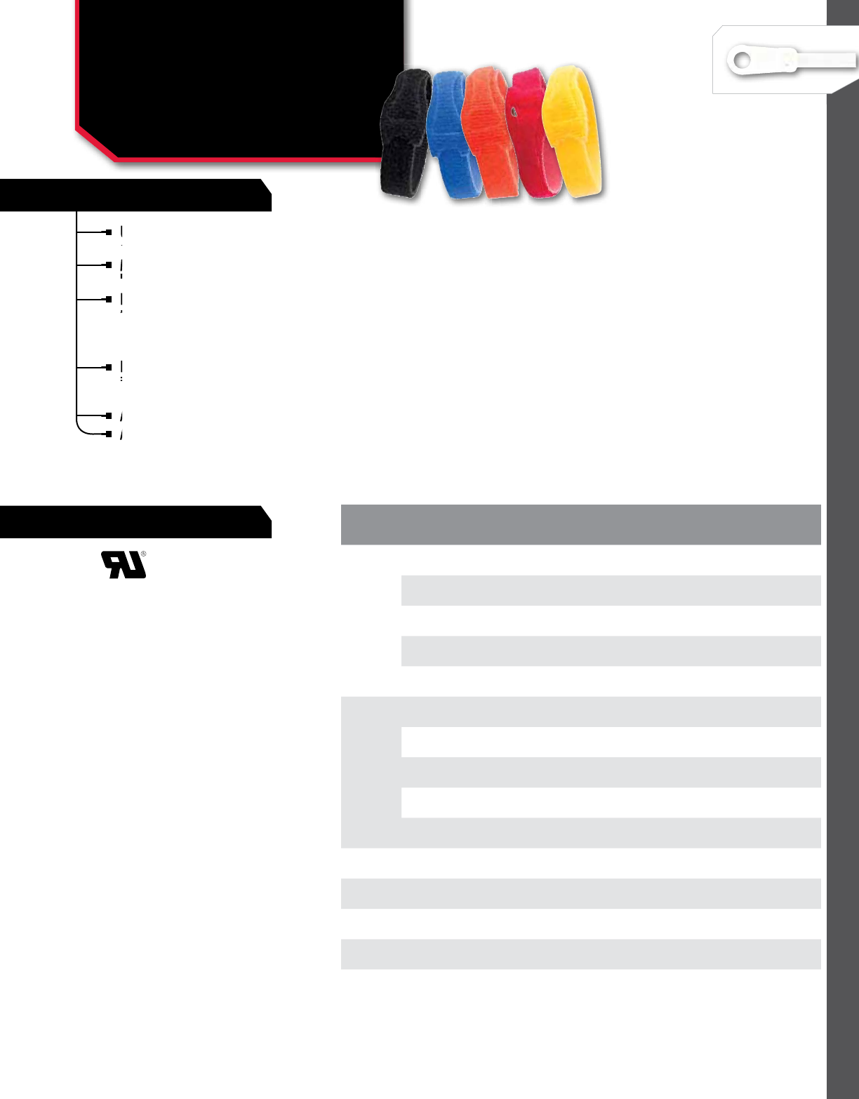
334
WIRE MANAGEMENT
NSi Industries LLC • USA • 800.321.5847 • www.nsiindustries.com
RATINGS
FEATURES
*Note: Rolls of Velcro tape can be cut to desired length.
Unique back-to-back fastening system: a self-gripping,
double-sided strap that is easy to use and cost effective.
Molded high performance polyethylene hook fastener
laminated on to a non-woven polyester loop.
Low peel strength allows for easy entry or removal by
the user yet the average shear strength is 3.0 PSI, which
increases substantially with each circular rotation.
Will not over-cinch delicate cable and fiber optics.
For use with cord and cable management, wire harnesses,
inventory control, fibre optics, packaging, in-plant
maintenance, etc.
Allow for a minimum 2” overlap when installing.
Available in five colors.
MAX.
WIRE/
CAbLE SIZE
CAT.
no. CoLoR MAX. bUnDLE
DIAMETER LEnGTH
(In.) WIDTH
(In.)
STD.
PKG.
QTY.
STD.
CTn.
QTY.
8"
V850 Black 1.750 8" 0.500 25 1
V850-2 Red 1.750 8" 0.500 25 1
V850-3 Orange 1.750 8" 0.500 25 1
V850-4 Yellow 1.750 8" 0.500 25 1
V850-6 Blue 1.750 8" 0.500 25 1
12"
V1250 Black 3.000 12" 0.500 20 1
V1250-2 Red 3.000 12" 0.500 20 1
V1250-4 Yellow 3.000 12" 0.500 20 1
V1250-6 Blue 3.000 12" 0.500 20 1
80" V875 Black Perforated
Every 8" 80" 0.75 10 1
10' V1275 Black Perforated
Every 12" 10' 0.75 10 1
15' V180 Black - 15' 0.75 10 1
75' V900 Black - 75' 0.75 3 1
600' V7200 Black - 600' 0.75 1 1
Allow for a minimum 2” overlap when installing.
For use with cord and cable management, wire harnesses,
inventory control, fibre optics, packaging, in-plant
For use with cord and cable management, wire harnesses,
inventory control, fibre optics, packaging, in-plant
For use with cord and cable management, wire harnesses,
Low peel strength allows for easy entry or removal by
the user yet the average shear strength is 3.0 PSI, which
Low peel strength allows for easy entry or removal by
the user yet the average shear strength is 3.0 PSI, which
Low peel strength allows for easy entry or removal by
Molded high performance polyethylene hook fastener
laminated on to a non-woven polyester loop.
Molded high performance polyethylene hook fastener
laminated on to a non-woven polyester loop.
Molded high performance polyethylene hook fastener
Unique back-to-back fastening system: a self-gripping,
double-sided strap that is easy to use and cost effective.
Unique back-to-back fastening system: a self-gripping,
double-sided strap that is easy to use and cost effective.
Unique back-to-back fastening system: a self-gripping,
CAbLE TIES
Velcro Ties
V SERIES
Available in five colors.
Available in five colors.
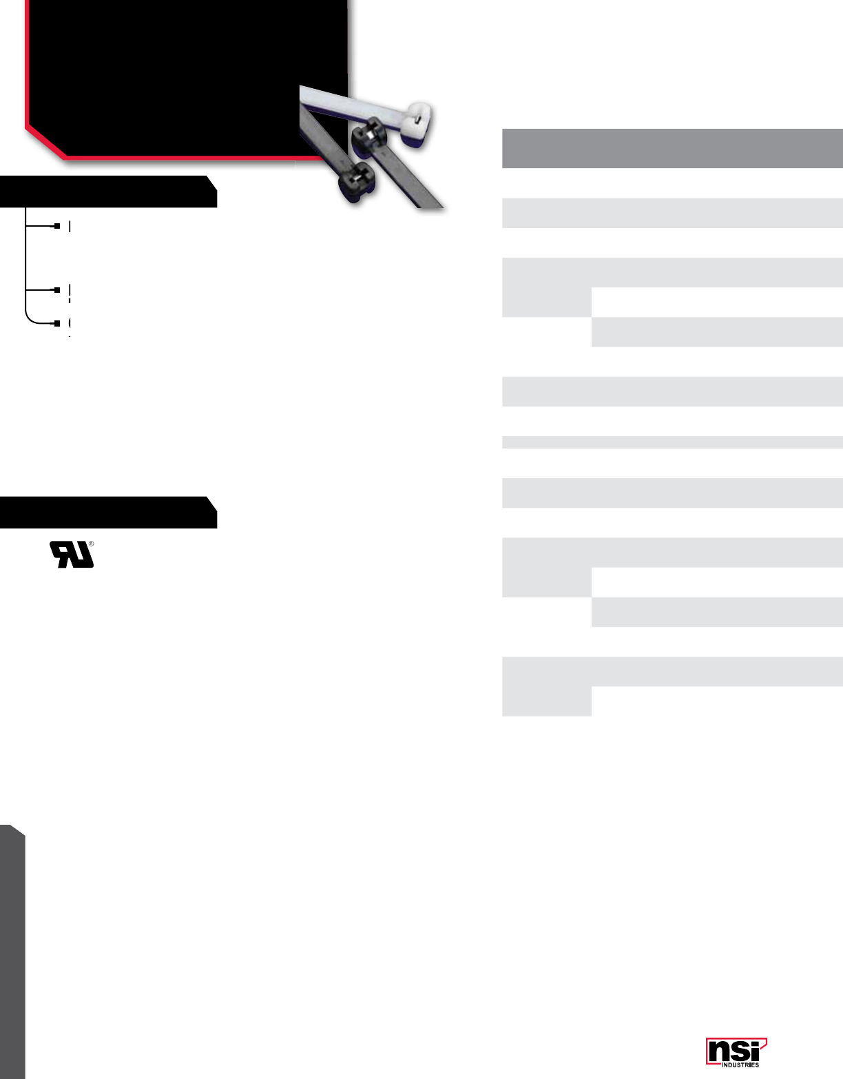
335
RATINGS
FEATURES
WIRE MANAGEMENT
Natural and UV resistant black, nylon cable ties have
stainless steel barb; barb is at 45° pitch with 60°
cutting angle, setting strap to desired position to suit
all diameters in range.
Flexible and resistant at low temperatures and
humidity-free environments.
Cold and fastening resistances are higher than
normal cable tie tolerances.
MAX.
WIRE/
CAbLE SIZE
CAT.
no. CoLoR MAX.
bUnDLE DIA. MIn. TEnSILE
STREnGTH LEnGTH
(In.) WIDTH
(In.)
STD.
PKG.
QTY.
4" 418-SB Natural 0.944 18 Lbs. 4.000 0.100 100
5" 540-SB Natural 1.417 40 Lbs. 5.500 0.137 100
7" 750-SB Natural 2.007 50 Lbs. 7.322 0.177 100
8"
818-SB Natural 2.165 18 Lbs. 7.874 0.100 100
840-SB Natural 2.165 40 Lbs. 7.874 0.137 100
11"
1140-SB Natural 3.149 40 Lbs. 11.023 0.137 100
1150-SB Natural 3.149 50 Lbs. 11.023 0.177 100
14" 1450-SB Natural 3.976 50 Lbs. 14.173 0.177 100
14" 14120-SB Natural 3.976 120 Lbs. 14.173 0.295 50
4" 4180-SB UV Black 0.944 18 Lbs. 4.000 0.100 100
5" 5400-SB UV Black 1.417 40 Lbs. 5.500 0.137 100
7" 7500-SB UV Black 2.007 50 Lbs. 7.322 0.177 100
8"
8180-SB UV Black 2.165 18 Lbs. 7.874 0.100 100
8400-SB UV Black 2.165 40 Lbs. 7.874 0.137 100
11"
11400-SB UV Black 3.149 40 Lbs. 11.023 0.137 100
11500-SB UV Black 3.149 50 Lbs. 11.023 0.177 100
14"
14500-SB UV Black 3.976 50 Lbs. 14.173 0.177 100
141200-SB UV Black 3.976 120 Lbs. 14.173 0.295 50
Flexible and resistant at low temperatures and
humidity-free environments.
Flexible and resistant at low temperatures and
humidity-free environments.
Flexible and resistant at low temperatures and
Natural and UV resistant black, nylon cable ties have
stainless steel barb; barb is at 45° pitch with 60°
Natural and UV resistant black, nylon cable ties have
stainless steel barb; barb is at 45° pitch with 60°
Natural and UV resistant black, nylon cable ties have
Cold and fastening resistances are higher than
normal cable tie tolerances.
Cold and fastening resistances are higher than
normal cable tie tolerances.
Cold and fastening resistances are higher than
CAbLE TIES
Cable Ties with Stainless
Steel Barb
-Sb SERIES

336
WIRE MANAGEMENT
NSi Industries LLC • USA • 800.321.5847 • www.nsiindustries.com
MAX.
WIRE/
CAbLE SIZE
CAT.
no. CoLoR MAX.
bUnDLE DIA. MIn. TEnSILE
STREnGTH LEnGTH
(In.) WIDTH
(In.)
STD.
PKG.
QTY.
4" 418-SB Natural 0.944 18 Lbs. 4.000 0.100 100
5" 540-SB Natural 1.417 40 Lbs. 5.500 0.137 100
7" 750-SB Natural 2.007 50 Lbs. 7.322 0.177 100
8"
818-SB Natural 2.165 18 Lbs. 7.874 0.100 100
840-SB Natural 2.165 40 Lbs. 7.874 0.137 100
11"
1140-SB Natural 3.149 40 Lbs. 11.023 0.137 100
1150-SB Natural 3.149 50 Lbs. 11.023 0.177 100
14" 1450-SB Natural 3.976 50 Lbs. 14.173 0.177 100
14" 14120-SB Natural 3.976 120 Lbs. 14.173 0.295 50
4" 4180-SB UV Black 0.944 18 Lbs. 4.000 0.100 100
5" 5400-SB UV Black 1.417 40 Lbs. 5.500 0.137 100
7" 7500-SB UV Black 2.007 50 Lbs. 7.322 0.177 100
8"
8180-SB UV Black 2.165 18 Lbs. 7.874 0.100 100
8400-SB UV Black 2.165 40 Lbs. 7.874 0.137 100
11"
11400-SB UV Black 3.149 40 Lbs. 11.023 0.137 100
11500-SB UV Black 3.149 50 Lbs. 11.023 0.177 100
14"
14500-SB UV Black 3.976 50 Lbs. 14.173 0.177 100
141200-SB UV Black 3.976 120 Lbs. 14.173 0.295 50
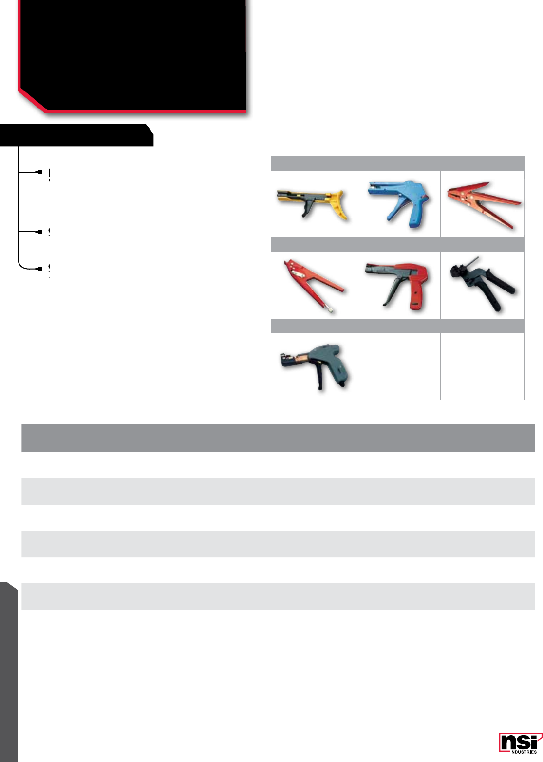
337
FEATURES
WIRE MANAGEMENT
TRT
Ergonomic, durable cable tie tools suitable
for tensile strengths from 18lb through 250lb
extra heavy lashing ties.
SSCT
Stainless Steel manual tools are ergonomic,
durable cable tie tools suitable for 100lb and
250lb tensile strength stainless steel ties.
SSCT-5 has preset tension adjustment control,
allowing for uniform tension setting and
automatic cutting on each bundle.
CAT.
no. FIG.
no. TooL DUTY APPLICATIon MIn. TEnSILE
STREnGTH
STD.
CTn.
QTY.
TRT-100 1Light weight, plastic Miniature, intermediate and standard duty cable ties 18-50 Lbs. 1
TRT-200 2Sturdy, metal Miniature, intermediate, and standard duty cable ties 18-50 Lbs. 1
TRT-300 3Heavy Duty, all-metal Miniature up to Heavy Duty cable ties 18-175 Lbs. 1
TRT-400 4Extra Heavy Duty, all-metal Miniature up to extra Heavy Duty cable ties 18-250 Lbs. 1
TRT-500 5Deluxe cable tie tool Miniature up to Standard Duty cable ties 18-50 Lbs. 1
SSCT-3 6Stainless Steel cable tie tool 100lb and 250lb Stainless Steel cable ties 100-250 Lbs. 1
SSCT-5 7Stainless Steel cable tie tool 100lb and 250lb Stainless Steel cable ties 100-250 Lbs. 1
Ergonomic, durable cable tie tools suitable
for tensile strengths from 18lb through 250lb
Ergonomic, durable cable tie tools suitable
for tensile strengths from 18lb through 250lb
Ergonomic, durable cable tie tools suitable
Stainless Steel manual tools are ergonomic,
durable cable tie tools suitable for 100lb and
Stainless Steel manual tools are ergonomic,
durable cable tie tools suitable for 100lb and
Stainless Steel manual tools are ergonomic,
123
456
7
CAbLE TIES
Cable Tie Installation Tools
TRT, SSCT SERIES
SSCT-5 has preset tension adjustment control,
allowing for uniform tension setting and
SSCT-5 has preset tension adjustment control,
allowing for uniform tension setting and
SSCT-5 has preset tension adjustment control,

338
WIRE MANAGEMENT
NSi Industries LLC • USA • 800.321.5847 • www.nsiindustries.com
FEATURES
Mounts are used to route and fasten cable-tied
bundles to flat surfaces.
Cable ties may be inserted from any of four
directions, eliminating orientation time.
The top of the mount has a cradle design which
allows the bundle to fit snugly and a mounting
hole for additional support, where required.
TEMPERATURE RATInG:
-80 °C to 538 °C (-112 °F to 1000.4 °F).
L
WH
CAT.
no. FIG.
no. CoLoR SLoT
WIDTH LEnGTH
(In.) WIDTH
(In.) HEIGHT
FTH5A 1Natural 0.140 0.750 0.750 0.140
FTH5A-B 1Black 0.140 0.750 0.750 0.140
FTH7A 2Natural 0.203 1.000 1.000 0.160
FTH7A-B 2Black 0.203 1.000 1.000 0.160
FTH15A 3Natural 0.394 1.500 1.500 0.300
FTH15A-B 3Black 0.394 1.500 1.500 0.300
FTH20A 4Natural 0.500 2.000 2.000 0.500
FTH20A-B 4Black 0.500 2.000 2.000 0.500
Cable ties may be inserted from any of four
directions, eliminating orientation time.
Cable ties may be inserted from any of four
directions, eliminating orientation time.
Cable ties may be inserted from any of four
Mounts are used to route and fasten
bundles
1 2
3 4
CAbLE TIE MoUnTS
Cable Tie Adhesive Mounts
FTH SERIES
The top of the mount has a cradle design which
allows the bundle to fit snugly and a mounting
The top of the mount has a cradle design which
allows the bundle to fit snugly and a mounting
The top of the mount has a cradle design which
W
H
H
H
L

339
RATINGS
FEATURES
WIRE MANAGEMENT
Manufactured using UL approved Nylon 66, 94V-2.
Saddle design provides maximum stability to wire bundles.
L
screw
size
slot
width W
H
L
screw
size
slot
width
W
H
SM-O, OL SM-1, 2, 3
TEMPERATURE RATInG:
-80 °C to 538 °C (-112 °F to 1000.4 °F).
CAT.
no. FIG.
no. CoLoR SCREW
SIZE SLoT
WIDTH LEnGTH
(In.) WIDTH
(In.) HEIGHT
(In.)
STD.
PKG.
QTY.
STD.
CTn.
QTY.
SM-0 1 Natural 0.133 0.200 0.750 0.370 0.200 100 1,000
SM-0L 1 Natural 0.204 0.200 0.750 0.370 0.200 100 1,000
SM-1 2 Natural 0.120 0.280 0.590 0.390 0.280 100 1,000
SM-2 2 Natural 0.130 0.160 0.500 0.280 0.230 100 1,000
SM-3 2 Natural 0.236 0.350 0.900 0.630 0.350 100 1,000
SM-1-B 2 Black 0.120 0.280 0.590 0.390 0.280 100 1,000
SM-2-B 2 Black 0.130 0.160 0.500 0.280 0.230 100 1,000
SM-3-B 2 Black 0.236 0.350 0.900 0.630 0.350 100 1,000
Manufactured using UL approved Nylon 66, 94V-2.
1 2
CAbLE TIE MoUnTS
Push Mounts
SM SERIES
Saddle design provides maximum stability to wire bundles.
Saddle design provides maximum stability to wire bundles.
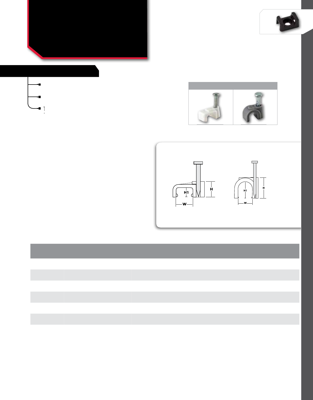
340
WIRE MANAGEMENT
NSi Industries LLC • USA • 800.321.5847 • www.nsiindustries.com
FEATURES
Made from impact resistant, non-corrosive
polyethylene.
Supplied with corrosion resistant, hardened steel nails
already inserted for ease-of-use.
The smooth polyethylene surface prevents damage to
the insulation.
CAT.
no. FIGURE
no. CoLoR WIDTH HEIGHT
(In.) HEIGHT 1
(In.)
STD.
PKG.
QTY.
STD.
CTn.
QTY.
PNC-217W 1 White 0.217 0.216 0.122 100 1,000
PNC-335W 1 White 0.335 0.315 0.205 100 1,000
PNC-157G 2 Grey 0.157 0.260 0.165 100 1,000
PNC-197G 2 Grey 0.197 0.299 0.206 100 1,000
PNC-236G 2 Grey 0.236 0.354 0.260 100 1,000
PNC-315G 2 Grey 0.315 0.453 0.339 100 1,000
PNC-391G 2 Grey 0.391 0.528 0.413 100 1,000
1 2
CAbLE TIE MoUnTS
Polyethylene Nail Clips
PnC SERIES
The smooth polyethylene surface prevents damage to
the insulation.
The smooth polyethylene surface prevents damage to
the insulation.
The smooth polyethylene surface prevents damage to
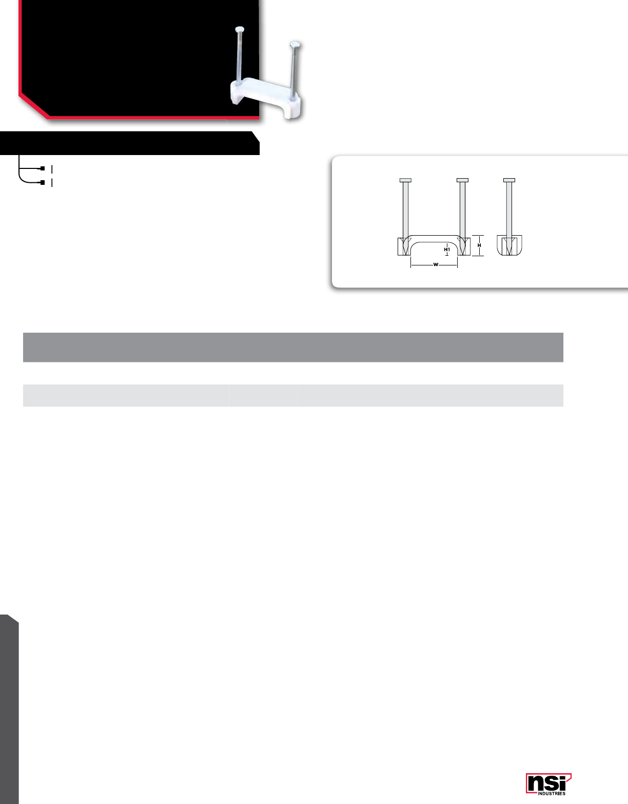
341
WIRE MANAGEMENT
PNC-492W is suitable for use with 14/2, 14/3 or 12/2.
PNC-736W is suitable for use with 12/3, 10/2 or 10/3.
PNC-492W is suitable for use with 14/2, 14/3 or 12/2.
PLASTIC STAPLES FOR ROMEX
CAT.
no. FIG.
no. CoLoR WIDTH HEIGHT
(In.) HEIGHT 1
(In.)
STD.
PKG.
QTY.
STD.
CTn.
QTY.
PNC-492W 3 White 0.492 0.315 0.209 500 5,000
PNC-736W 3 White 0.736 0.315 0.209 500 5,000
PNC-736W is suitable for use with 12/3, 10/2 or 10/3.
PNC-736W is suitable for use with 12/3, 10/2 or 10/3.
CAbLE TIES
Nail-On Plastic Staples
for Romex
PnC SERIES
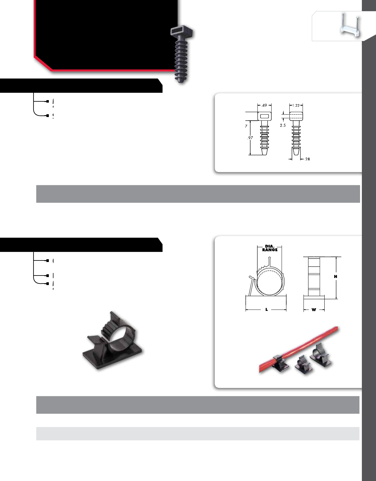
342
WIRE MANAGEMENT
NSi Industries LLC • USA • 800.321.5847 • www.nsiindustries.com
Manufactured using UL approved Nylon 66,
94V-2. Installs in masonry surfaces.
Simply pre-drill a mounting hole, hammer the push
mount in, then feed a cable tie through the head.
MPM-1
CAT.
no. CAbLE TIE WIDTH
ACCEPTAbLE THREAD
LEnGTH oVERALL
WIDTH THREAD
WIDTH HEAD SIZE
L X W STD.
PKG.
STD.
CTn.
QTY.
MPM-1 0.39 0.97 1.22 0.28 0.49 x 0.47 100 500
Manufactured using UL approved Nylon 66,
94V-2. Installs in masonry surfaces.
Manufactured using UL approved Nylon 66,
94V-2. Installs in masonry surfaces.
Manufactured using UL approved Nylon 66,
MASONARY PUSH MOUNTS
ADJUSTABLE CABLE CLAMPS
Clamps are adjustable to accommodate various
sizes of cables.
Easy to install and open for unlimited usage.
Manufactured using UL approved Nylon 66,
94V-2 and have an adhesive tape backing.
CAT.
no. DIA.
RAnGE LEnGTH
(In.) WIDTH
(In.) HEIGHT
(In.)
STD.
PKG.
QTY.
STD.
CTn.
QTY.
ADJCC-1 0.31 to 0.40 1.000 0.750 0.870 100 1,000
ADJCC-3 0.50 to 0.60 1.500 0.750 1.250 100 1,000
ADJCC-5 0.87 to 1.00 1.650 1.000 1.750 100 1,000
Clamps are adjustable to accommodate various
sizes of cables.
Clamps are adjustable to accommodate various
sizes of cables.
Clamps are adjustable to accommodate various
Easy to install and open for unlimited usage.
Simply pre-drill a mounting hole, hammer the push
mount in, then feed a cable tie through the head.
Simply pre-drill a mounting hole, hammer the push
mount in, then feed a cable tie through the head.
Simply pre-drill a mounting hole, hammer the push
Manufactured using UL approved Nylon 66,
94V-2 and have an adhesive tape backing.
Manufactured using UL approved Nylon 66,
94V-2 and have an adhesive tape backing.
Manufactured using UL approved Nylon 66,
Manufactured using UL approved Nylon 66,
CAbLE TIE MoUnTS
Masonry Push Mounts &
Adjustable Cable Clamps
MPM, ADJCC SERIES

343
FEATURES
WIRE MANAGEMENT
STANDARD DUTY
Standard duty clamps are similar to heavy duty
nylon cable clamps, except narrower in width.
Made from Nylon 66. 94 V-2 rated.
Complete with 0.180” mounting hole.
HEAVY DUTY
Made from Nylon 66. 94V-2 rated.
Designed with wide arc to hold cables, tubes, etc.
Fully radiused interior edges to protect cable insulation.
Non-conductive, non-corrosive, resistant to fuels,
lubricants and most chemicals.
0.180” mounting hole.
CAT.
no. DIAMETER CoLoR LEnGHT
(In.) WIDTH
(In.)
STD.
PKG.
QTY.
STD.
CTn.
QTY.
STANDARD DUTY
NC-125
0.125
Natural 0.780 0.378 100 1,200
NC-125-0 Black 0.780 0.378 100 1,200
NC-187
0.187
Natural 0.780 0.378 100 1,200
NC-187-0 Black 0.780 0.378 100 1,200
NC-250
0.250
Natural 0.790 0.394 100 1,200
NC-250-0 Black 0.790 0.394 100 1,200
NC-312
0.312
Natural 0.860 0.394 100 1,200
NC-312-0 Black 0.860 0.394 100 1,200
NC-375
0.375
Natural 0.940 0.375 100 1,200
NC-375-0 Black 0.940 0.375 100 1,200
NC-500
0.500
Natural 1.220 0.375 100 1,200
NC-500-0 Black 1.220 0.375 100 1,200
HEAVY DUTY
NCH-250
0.250
Natural 0.790 0.500 100 1,200
NCH-250-0 Black 0.790 0.500 100 1,200
NCH-312
0.312
Natural 0.860 0.500 100 1,200
NCH-312-0 Black 0.860 0.500 100 1,200
NCH-375
0.375
Natural 0.940 0.472 100 1,200
NCH-375-0 Black 0.940 0.472 100 1,200
NCH-437 0.437 Natural 1.080 0.500 100 1,200
NCH-500
0.500
Natural 1.220 0.472 100 1,200
NCH-500-0 Black 1.220 0.472 100 1,200
NCH-562 0.562 Natural 1.280 0.500 100 1,200
NCH-625 0.625 Natural 1.350 0.472 100 1,200
NCH-750 0.750 Natural 1.380 0.472 100 1,200
NCH-1000 1.000 Natural 1.690 0.472 100 1,200
Standard duty clamps are similar to heavy duty
nylon cable clamps, except narrower in width.
Standard duty clamps are similar to heavy duty
nylon cable clamps, except narrower in width.
Standard duty clamps are similar to heavy duty
Non-conductive, non-corrosive, resistant to fuels,
lubricants and most chemicals.
Non-conductive, non-corrosive, resistant to fuels,
lubricants and most chemicals.
Non-conductive, non-corrosive, resistant to fuels,
Fully radiused interior edges to protect cable
Non-conductive, non-corrosive, resistant to fuels,
Designed with wide arc to hold cables, tubes, etc.
Fully radiused interior edges to protect cable
Made from Nylon 66. 94V-2 rated.
Designed with wide arc to hold cables, tubes, etc.
Complete with 0.180” mounting hole.
Made from Nylon 66. 94 V-2 rated.
Complete with 0.180” mounting hole.
CAbLE TIE CLAMPS
Standard & Heavy Duty
Nylon Cable Clamps
nC, nCH SERIES
0.180”

344
WIRE MANAGEMENT
NSi Industries LLC • USA • 800.321.5847 • www.nsiindustries.com
CAT.
no. DIAMETER CoLoR LEnGHT
(In.) WIDTH
(In.)
STD.
PKG.
QTY.
STD.
CTn.
QTY.
STANDARD DUTY
NC-125
0.125
Natural 0.780 0.378 100 1,200
NC-125-0 Black 0.780 0.378 100 1,200
NC-187
0.187
Natural 0.780 0.378 100 1,200
NC-187-0 Black 0.780 0.378 100 1,200
NC-250
0.250
Natural 0.790 0.394 100 1,200
NC-250-0 Black 0.790 0.394 100 1,200
NC-312
0.312
Natural 0.860 0.394 100 1,200
NC-312-0 Black 0.860 0.394 100 1,200
NC-375
0.375
Natural 0.940 0.375 100 1,200
NC-375-0 Black 0.940 0.375 100 1,200
NC-500
0.500
Natural 1.220 0.375 100 1,200
NC-500-0 Black 1.220 0.375 100 1,200
HEAVY DUTY
NCH-250
0.250
Natural 0.790 0.500 100 1,200
NCH-250-0 Black 0.790 0.500 100 1,200
NCH-312
0.312
Natural 0.860 0.500 100 1,200
NCH-312-0 Black 0.860 0.500 100 1,200
NCH-375
0.375
Natural 0.940 0.472 100 1,200
NCH-375-0 Black 0.940 0.472 100 1,200
NCH-437 0.437 Natural 1.080 0.500 100 1,200
NCH-500
0.500
Natural 1.220 0.472 100 1,200
NCH-500-0 Black 1.220 0.472 100 1,200
NCH-562 0.562 Natural 1.280 0.500 100 1,200
NCH-625 0.625 Natural 1.350 0.472 100 1,200
NCH-750 0.750 Natural 1.380 0.472 100 1,200
NCH-1000 1.000 Natural 1.690 0.472 100 1,200
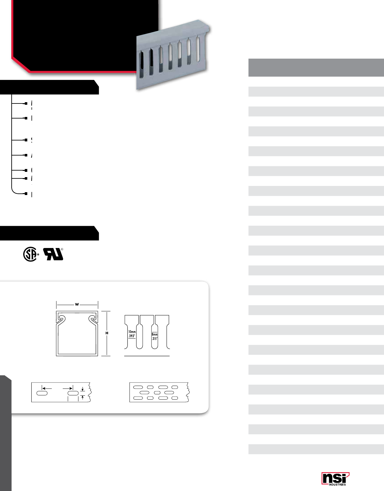
345
RATINGS
FEATURES
WIRE MANAGEMENT
WIRE MANAGEMENT
Made from high-impact, self-extinguishing, warp-proof
PVC for routing wires.
Restricted slot opening is designed to retain wires and
allow for breakout when required. Individual wires are
easily traced and removed when necessary.
Scored sidewalls allow for easy break-off of panel
channel sections.
All sizes are supplied with mounting holes and non-slip,
snap-on and off covers.
Optional adhesive backing is available.
Maximum service temperature: 85 °C (185 °F), Tested
to UL File up to 50 °C (122 °F). 94V-O Rated.
For other sizes, please contact NSi.
100 mm
15 mm
5 mm
CAT.
no. noMInAL
SIZE CoLoR LEnTH
(FT.)
STD.
PKG.
QTY.
STD.
CTn.
QTY.
PC1010-LS 1 x 1 Grey 6' 6' 72'
PC1010-LS-W 1 x 1 White 6' 6' 72'
PC1015-LS 1 x 1 1/2 Grey 6' 6' 72'
PC1015-LS-W 1 x 1 1/2 White 6' 6' 72'
PC1020-LS 1 x 2 Grey 6' 6' 72'
PC1020-LS-W 1 x 2 White 6' 6' 72'
PC1030-LS 1 x 3 Grey 6' 6' 72'
PC1030-LS-W 1 x 3 White 6' 6' 72'
PC1040-LS 1 x 4 Grey 6' 6' 72'
PC1040-LS-W 1 x 4 White 6' 6' 72'
PC1515-LS 1 1/2 x 1 1/2 Grey 6' 6' 72'
PC1515-LS-W 1 1/2 x 1 1/2 White 6' 6' 72'
PC1520-LS 1 1/2 x 2 Grey 6' 6' 72'
PC1520-LS-W 1 1/2 x 2 White 6' 6' 72'
PC1530-LS 1 1/2 x 3 Grey 6' 6' 72'
PC1530-LS-W 1 1/2 x 3 White 6' 6' 72'
PC1540-LS-W 1 1/2 x 4 White 6' 6' 72'
PC2010-LS 2 x 1 Grey 6' 6' 72'
PC2010-LS-W 2 x 1 White 6' 6' 72'
PC2020-LS 2 x 2 Grey 6' 6' 72'
PC2020-LS-W 2 x 2 White 6' 6' 72'
PC2030-LS 2 x 3 Grey 6' 6' 72'
PC2030-LS-W 2 x 3 White 6' 6' 72'
PC2040-LS 2 x 4 Grey 6' 6' 72'
PC2040-LS-W 2 x 4 White 6' 6' 72'
PC3020-LS 3 x 2 Grey 6' 6' 72'
PC3020-LS-W 3 x 2 White 6' 6' 72'
PC3030-LS 3 x 3 Grey 6' 6' 72'
PC3030-LS-W 3 x 3 White 6' 6' 72'
PC3040-LS 3 x 4 Grey 6' 6' 72'
PC3040-LS-W 3 x 4 White 6' 6' 72'
PC4020-LS 4 x 2 Grey 6' 6' 72'
PC4030-LS 4 x 3 Grey 6' 6' 72'
PC4030-LS-W 4 x 3 White 6' 6' 72'
PC4040-LS 4 x 4 Grey 6' 6' 72'
PC4040-LS-W 4 x 4 White 6' 6' 72'
PC6040-LS 6 x 4 Grey 6' 6' 72'
PC6040-LS-W 6 x 4 White 6' 6' 72'
Finger width = 10 mm, slot width = 8 mm.
Mounting holes:
For widths up to 2.5” For widths over 2.5”
Scored sidewalls allow for easy break-off of panel
channel sections.
Scored sidewalls allow for easy break-off of panel
channel sections.
Scored sidewalls allow for easy break-off of panel
All sizes are supplied with mounting holes and non-slip,
snap-on and off covers.
All sizes are supplied with mounting holes and non-slip,
snap-on and off covers.
All sizes are supplied with mounting holes and non-slip,
Optional adhesive backing is available.
Maximum service temperature: 85 °C (185 °F), Tested
to UL File up to 50 °C (122 °F). 94V-O Rated.
Maximum service temperature: 85 °C (185 °F), Tested
Made from high-impact, self-extinguishing, warp-proof
PVC for routing wires.
Made from high-impact, self-extinguishing, warp-proof
PVC for routing wires.
Made from high-impact, self-extinguishing, warp-proof
Restricted slot opening is designed to retain wires and
allow for breakout when required. Individual wires are
Restricted slot opening is designed to retain wires and
allow for breakout when required. Individual wires are
Restricted slot opening is designed to retain wires and
PAnEL CHAnnEL
Standard Slot
Panel Channel
PC--LS SERIES
to UL File up to 50 °C (122 °F). 94V-O Rated.
For other sizes, please contact NSi.
WIRE MANAGEMENT

346
WIRE MANAGEMENT
NSi Industries LLC • USA • 800.321.5847 • www.nsiindustries.com
CAT.
no. noMInAL
SIZE CoLoR LEnTH
(FT.)
STD.
PKG.
QTY.
STD.
CTn.
QTY.
PC1010-LS 1 x 1 Grey 6' 6' 72'
PC1010-LS-W 1 x 1 White 6' 6' 72'
PC1015-LS 1 x 1 1/2 Grey 6' 6' 72'
PC1015-LS-W 1 x 1 1/2 White 6' 6' 72'
PC1020-LS 1 x 2 Grey 6' 6' 72'
PC1020-LS-W 1 x 2 White 6' 6' 72'
PC1030-LS 1 x 3 Grey 6' 6' 72'
PC1030-LS-W 1 x 3 White 6' 6' 72'
PC1040-LS 1 x 4 Grey 6' 6' 72'
PC1040-LS-W 1 x 4 White 6' 6' 72'
PC1515-LS 1 1/2 x 1 1/2 Grey 6' 6' 72'
PC1515-LS-W 1 1/2 x 1 1/2 White 6' 6' 72'
PC1520-LS 1 1/2 x 2 Grey 6' 6' 72'
PC1520-LS-W 1 1/2 x 2 White 6' 6' 72'
PC1530-LS 1 1/2 x 3 Grey 6' 6' 72'
PC1530-LS-W 1 1/2 x 3 White 6' 6' 72'
PC1540-LS-W 1 1/2 x 4 White 6' 6' 72'
PC2010-LS 2 x 1 Grey 6' 6' 72'
PC2010-LS-W 2 x 1 White 6' 6' 72'
PC2020-LS 2 x 2 Grey 6' 6' 72'
PC2020-LS-W 2 x 2 White 6' 6' 72'
PC2030-LS 2 x 3 Grey 6' 6' 72'
PC2030-LS-W 2 x 3 White 6' 6' 72'
PC2040-LS 2 x 4 Grey 6' 6' 72'
PC2040-LS-W 2 x 4 White 6' 6' 72'
PC3020-LS 3 x 2 Grey 6' 6' 72'
PC3020-LS-W 3 x 2 White 6' 6' 72'
PC3030-LS 3 x 3 Grey 6' 6' 72'
PC3030-LS-W 3 x 3 White 6' 6' 72'
PC3040-LS 3 x 4 Grey 6' 6' 72'
PC3040-LS-W 3 x 4 White 6' 6' 72'
PC4020-LS 4 x 2 Grey 6' 6' 72'
PC4030-LS 4 x 3 Grey 6' 6' 72'
PC4030-LS-W 4 x 3 White 6' 6' 72'
PC4040-LS 4 x 4 Grey 6' 6' 72'
PC4040-LS-W 4 x 4 White 6' 6' 72'
PC6040-LS 6 x 4 Grey 6' 6' 72'
PC6040-LS-W 6 x 4 White 6' 6' 72'
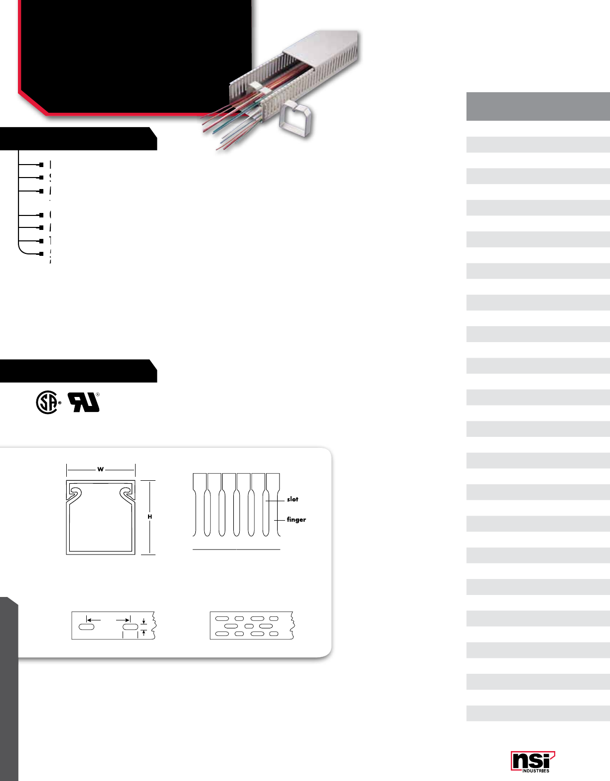
347
RATINGS
FEATURES
WIRE MANAGEMENT
Narrower finger width is 6mm
Slot width is 4mm.
Made from high-impact, self-extinguishing,
warp-proof PVC.
Optional adhesive backing is available.
Maximum service temperature: 85 °C (185 °F).
Tested to UL File up to 50 °C (122 °F). 94V-O rated.
5mm slot width is available in both white and grey
for 1020, 2020, 2030, 2040
CAT.
no. noMInAL
SIZE CoLoR LEnTH
(FT.)
STD.
PKG.
QTY.
STD.
CTn.
QTY.
PC.75.75-LSN 3/4 x 3/4 Grey 6' 6' 72'
PC1010-LSN 1 x 1 Grey 6' 6' 72'
PC1010-LSN-W 1 x 1 White 6' 6' 72'
PC1015-LSN 1 x 1 1/2 Grey 6' 6' 72'
PC1015-LSN-W 1 x 1 1/2 White 6' 6' 72'
PC10175-LSN 1 x 1 3/4 Grey 6' 6' 72'
PC10175-LSN-W 1 x 1 3/4 White 6' 6' 72'
PC1020-LSN 1 x 2 Grey 6' 6' 72'
PC1020-LSN-W 1 x 2 White 6' 6' 72'
PC10250-LSN 1 x 2 1/2 Grey 6' 6' 72'
PC1030-LSN 1 x 3 Grey 6' 6' 72'
PC1030-LSN-W 1 x 3 White 6' 6' 72'
PC1515-LSN 1 1/2 x 1 1/2 Grey 6' 6' 72'
PC1515-LSN-W 1 1/2 x 1 1/2 White 6' 6' 72'
PC1520-LSN 1 1/2 x 2 Grey 6' 6' 72'
PC1520-LSN-W 1 1/2 x 2 White 6' 6' 72'
PC1530-LSN 1 1/2 x 3 Grey 6' 6' 72'
PC1530-LSN-W 1 1/2 x 3 White 6' 6' 72'
PC1540-LSN 1 1/2 x 4 Grey 6' 6' 72'
PC1540-LSN-W 1 1/2 x 4 White 6' 6' 72'
PC175175-LSN 1 3/4 x 1 3/4 Grey 6' 6' 72'
PC2015-LSN-W 2 x 1 1/2 White 6' 6' 72'
PC2020-LSN 2 x 2 Grey 6' 6' 72'
PC2020-LSN-W 2 x 2 White 6' 6' 72'
PC2030-LSN 2 x 3 Grey 6' 6' 72'
PC2030-LSN-W 2 x 3 White 6' 6' 72'
PC2040-LSN 2 x 4 Grey 6' 6' 72'
PC2040-LSN-W 2 x 4 White 6' 6' 72'
PC3020-LSN 3 x 2 Grey 6' 6' 72'
PC3020-LSN-W 3 x 2 White 6' 6' 72'
PC3030-LSN 3 x 3 Grey 6' 6' 72'
PC3030-LSN-W 3 x 3 White 6' 6' 72'
PC3040-LSN 3 x 4 Grey 6' 6' 72'
PC3040-LSN-W 3 x 4 White 6' 6' 72'
PC4020-LSN-W 4 x 2 White 6' 6' 72'
PC4030-LSN 4 x 3 Grey 6' 6' 72'
PC4030-LSN-W 4 x 3 White 6' 6' 72'
PC4040-LSN 4 x 4 Grey 6' 6' 72'
PC4040-LSN-W 4 x 4 White 6' 6' 72'
Narrower finger width is 6mm
Slot width is 4mm.
Made from high-impact, self-extinguishing,
Slot width is 4mm.
Made from high-impact, self-extinguishing,
warp-proof PVC.
Made from high-impact, self-extinguishing,
warp-proof PVC.
Made from high-impact, self-extinguishing,
Made from high-impact, self-extinguishing,
Optional adhesive backing is available.
Maximum service temperature: 85 °C (185 °F).
Tested to UL File up to 50 °C (122 °F). 94V-O rated.
Maximum service temperature: 85 °C (185 °F).
Tested to UL File up to 50 °C (122 °F). 94V-O rated.
5mm slot width is available in both white and grey
Tested to UL File up to 50 °C (122 °F). 94V-O rated.
PAnEL CHAnnEL
Narrow Finger, High Density
Panel Channel
PC--LSn SERIES
5mm slot width is available in both white and grey
for 1020, 2020, 2030, 2040
5mm slot width is available in both white and grey
for 1020, 2020, 2030, 2040
5mm slot width is available in both white and grey
5mm slot width is available in both white and grey
WIRE MANAGEMENT
WIRE MANAGEMENT
100 mm
15 mm
5 mm
Mounting holes:
For widths up to 2.5” For widths over 2.5”

348
WIRE MANAGEMENT
NSi Industries LLC • USA • 800.321.5847 • www.nsiindustries.com
CAT.
no. noMInAL
SIZE CoLoR LEnTH
(FT.)
STD.
PKG.
QTY.
STD.
CTn.
QTY.
PC.75.75-LSN 3/4 x 3/4 Grey 6' 6' 72'
PC1010-LSN 1 x 1 Grey 6' 6' 72'
PC1010-LSN-W 1 x 1 White 6' 6' 72'
PC1015-LSN 1 x 1 1/2 Grey 6' 6' 72'
PC1015-LSN-W 1 x 1 1/2 White 6' 6' 72'
PC10175-LSN 1 x 1 3/4 Grey 6' 6' 72'
PC10175-LSN-W 1 x 1 3/4 White 6' 6' 72'
PC1020-LSN 1 x 2 Grey 6' 6' 72'
PC1020-LSN-W 1 x 2 White 6' 6' 72'
PC10250-LSN 1 x 2 1/2 Grey 6' 6' 72'
PC1030-LSN 1 x 3 Grey 6' 6' 72'
PC1030-LSN-W 1 x 3 White 6' 6' 72'
PC1515-LSN 1 1/2 x 1 1/2 Grey 6' 6' 72'
PC1515-LSN-W 1 1/2 x 1 1/2 White 6' 6' 72'
PC1520-LSN 1 1/2 x 2 Grey 6' 6' 72'
PC1520-LSN-W 1 1/2 x 2 White 6' 6' 72'
PC1530-LSN 1 1/2 x 3 Grey 6' 6' 72'
PC1530-LSN-W 1 1/2 x 3 White 6' 6' 72'
PC1540-LSN 1 1/2 x 4 Grey 6' 6' 72'
PC1540-LSN-W 1 1/2 x 4 White 6' 6' 72'
PC175175-LSN 1 3/4 x 1 3/4 Grey 6' 6' 72'
PC2015-LSN-W 2 x 1 1/2 White 6' 6' 72'
PC2020-LSN 2 x 2 Grey 6' 6' 72'
PC2020-LSN-W 2 x 2 White 6' 6' 72'
PC2030-LSN 2 x 3 Grey 6' 6' 72'
PC2030-LSN-W 2 x 3 White 6' 6' 72'
PC2040-LSN 2 x 4 Grey 6' 6' 72'
PC2040-LSN-W 2 x 4 White 6' 6' 72'
PC3020-LSN 3 x 2 Grey 6' 6' 72'
PC3020-LSN-W 3 x 2 White 6' 6' 72'
PC3030-LSN 3 x 3 Grey 6' 6' 72'
PC3030-LSN-W 3 x 3 White 6' 6' 72'
PC3040-LSN 3 x 4 Grey 6' 6' 72'
PC3040-LSN-W 3 x 4 White 6' 6' 72'
PC4020-LSN-W 4 x 2 White 6' 6' 72'
PC4030-LSN 4 x 3 Grey 6' 6' 72'
PC4030-LSN-W 4 x 3 White 6' 6' 72'
PC4040-LSN 4 x 4 Grey 6' 6' 72'
PC4040-LSN-W 4 x 4 White 6' 6' 72'
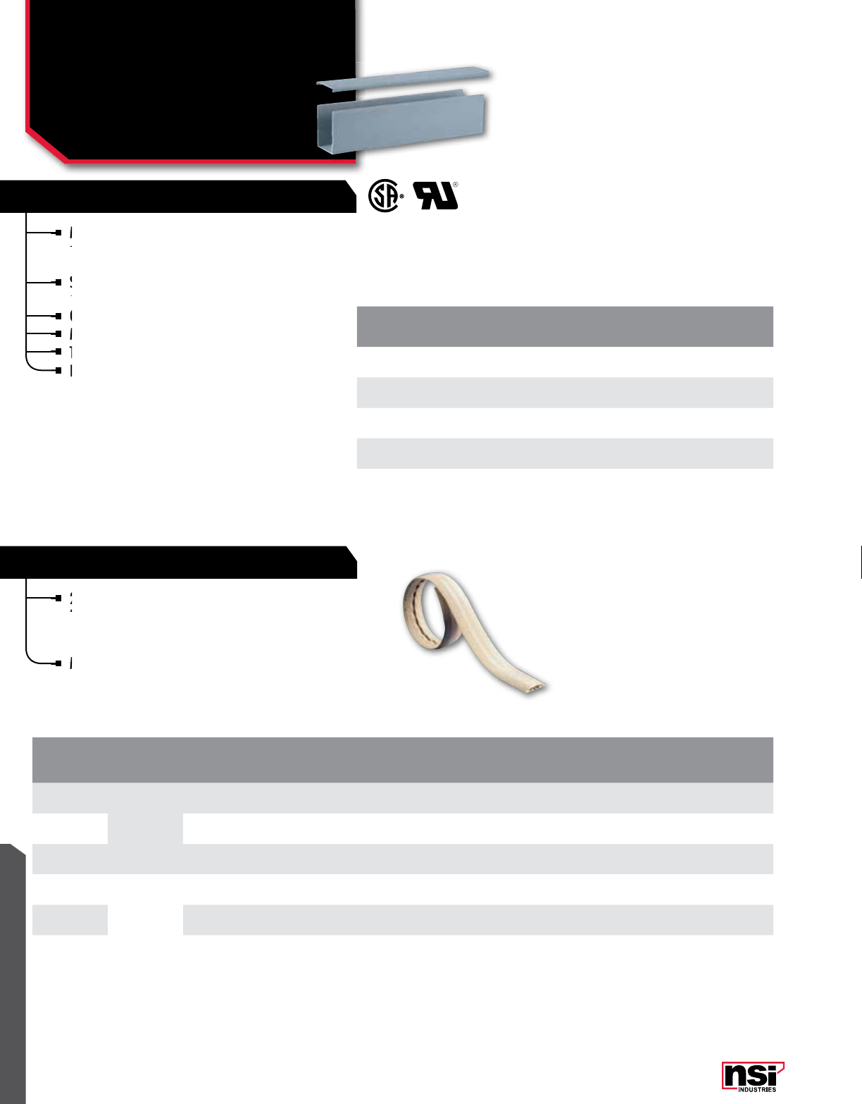
349
WIRE MANAGEMENT
Made from high-impact, self-extinguishing, warp-
proof PVC for routing wires where wire extraction is
not necessary.
Supplied complete with mounting holes and non-slip,
snap-on and off covers.
Optional adhesive backing is available.
Maximum service temperature: 85 °C (185 °F).
Tested to UL File up to 50 °C (122 °F). 94V-O Rated.
For other sizes, please contact NSi.
2.5" and 4" wide floor duct for use as safe
temporary enclosure of electrical cords, data
communications cables and other objects that
present a trip hazard.
Manufactured using soft PVC.
CAT.
no. CoLoR noMInAL
SIZE (In) LEnGTH
(FT.)
STD.
PKG.
QTY.
STD.
CTn.
QTY.
PC2020 Grey 2 x 2 6' 6' 72'
PC2030 Grey 2 x 3 6' 6' 72'
PC3030 Grey 3 x 3 6' 6' 72'
PC4030 Grey 4 x 3 6' 6' 72'
PC4040 Grey 4 x 4 6' 6' 72'
CAT.
no. noMInAL
SIZE (In.) CoLoR LEnGTH
(FT.)
WIDTH (In) HEIGHT (In) STD.
PKG.
QTY.
STD.
CTn.
QTY.
ID oD ID oD
FD250W
2.5"
Off White 6' 0.750 2.600 0.430 0.600 6' 18'
FD250B Brown 6' 0.750 2.600 0.430 0.600 6' 18'
FD250K Black 6' 0.750 2.600 0.430 0.600 6' 18'
FD400W
4"
Off White 6' 1.160 4.000 0.610 0.910 6' 18'
FD400B Brown 6' 1.160 4.000 0.610 0.910 6' 18'
FD400K Black 6' 1.160 4.000 0.610 0.910 6' 18'
Made from high-impact, self-extinguishing, warp-
proof PVC for routing wires where wire extraction is
Made from high-impact, self-extinguishing, warp-
proof PVC for routing wires where wire extraction is
Made from high-impact, self-extinguishing, warp-
Supplied complete with mounting holes and non-slip,
snap-on and off covers.
Supplied complete with mounting holes and non-slip,
snap-on and off covers.
Supplied complete with mounting holes and non-slip,
Optional adhesive backing is available.
Maximum service temperature: 85 °C (185
Maximum service temperature: 85 °C (185
Tested to UL File up to 50 °C (122
Tested to UL File up to 50 °C (122
2.5" and 4" wide floor duct for use as safe
temporary enclosure of electrical cords, data
SOLID WALL PANEL CHANNEL
FLOOR DUCT
PAnEL CHAnnEL
Solid Wall Panel Chanel,
Floor Duct
PC, FD SERIES
For other sizes, please contact NSi.
For other sizes, please contact NSi.
Manufactured using soft PVC.
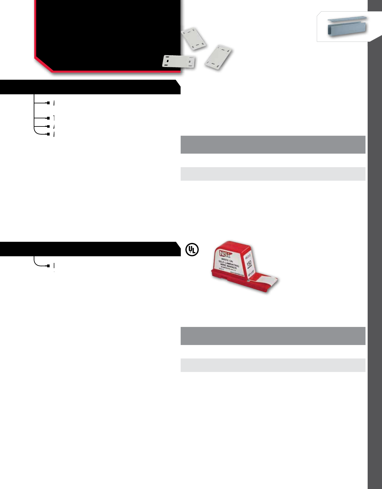
350
WIRE MANAGEMENT
NSi Industries LLC • USA • 800.321.5847 • www.nsiindustries.com
Mark-Pro™ cable marker plates provide reliable
method of identification of larger cables and bundles.
They can be installed using standard nylon tie wraps.
A fine tip permanent marker is recommended.
Manufactured using natural colored nylon.
Permanent markers are recommended for writing
on these vinyl self laminating labels, backed with
an acrylic adhesive.
TEMPERATURE RATInG:
-40 °C to 121.1 °C (-40 °F to 250 °F).
UL 969.
CAT.
no. LEnGTH
(In.) WIDTH
(In.)
STD.
PKG.
QTY.
STD.
CTn.
QTY.
MP-2 1.58 0.790 100 1000
MP-3 2.36 1.000 100 1000
CAT.
no. WHITE-on
AREA LEnGHT
(In.) WIDTH
(In.)
STD.
CTn.
QTY.
WLD-1 0.75 x 0.31 0.75 1.250 1
WLD-2 0.75 x 0.50 0.75 1.880 1
WLD-3 0.75 x 0.75 0.75 3.000 1
They can be installed using standard nylon tie wraps.
A fine tip permanent marker is recommended.
Mark-Pro™ cable marker plates provide reliable
method of identification of larger cables and bundles.
Mark-Pro™ cable marker plates provide reliable
method of identification of larger cables and bundles.
Mark-Pro™ cable marker plates provide reliable
A fine tip permanent marker is recommended.
A fine tip permanent marker is recommended.
CABLE MARKER PLATES
WIRE MARKER DISPENSERS
WIRE MARKInG / ID
Cable Marker Plates &
Wire Marker Dispensers
MP, WLD SERIES
Manufactured using natural
Manufactured using natural
Permanent markers are recommended for writing
on these vinyl self laminating labels, backed with
Permanent markers are recommended for writing
on these vinyl self laminating labels, backed with
Permanent markers are recommended for writing
351
WIRE MANAGEMENT
ROLL LABEL DISPENSER
POLYESTER INDUSTRIAL TAPES
Reusable, refillable, compact and convenient,
roll label dispensers provide 760 1 1/4” markers
per dispenser.
Made of tough tyvek material with an excellent
acrylic adhesive and a silicone release liner.
TEMPERATURE RATInG:
-40 °C to 121.1 °C (-40 °F to 250 °F).
UL 969.
CAT.
no. LAbEL LEGEnD
STD.
PKG.
QTY.
STD.
CTn.
QTY.
RLD-1 0 - 9 1 1
RLD-4 0-9 1 1
A high performance label stock.
2 mil pressure sensitive polyester and thermal transfer
resin ribbon in a cartridge.
Up to seven year exterior life.
Chemical, water, UV and abrasion resistant.
TEMPERATURE RATInG:
-40 °C to 121.1 °C (-40 °F to 250 °F).
CAT.
no. SIZE DESCRIPTIon LEnGHT
(FT.) WIDTH
(In.)
STD.
PKG.
QTY.
STD.
CTn.
QTY.
IT3/4-BW 3/4" Black on White 26' 0.750 1 1
IT1-BW 1" Black on White 26' 1.000 1 1
Reusable, refillable, compact and convenient,
roll label dispensers provide 760 1 1/4” markers
Reusable, refillable, compact and convenient,
roll label dispensers provide 760 1 1/4” markers
Reusable, refillable, compact and convenient,
A high performance label stock.
2 mil pressure sensitive polyester and
resin ribbon in a cartridge.
2 mil pressure sensitive polyester and
resin ribbon in a cartridge.
2 mil pressure sensitive polyester and
2 mil pressure sensitive polyester and
Up to seven year exterior life.
WIRE MARKInG / ID
Roll Label Dispenser &
Industrial Tapes
RLD, IT-bW SERIES
Made of tough tyvek material with an excellent
acrylic adhesive and a silicone release liner.
Made of tough tyvek material with an excellent
acrylic adhesive and a silicone release liner.
Made of tough tyvek material with an excellent
Chemical, water, UV and abrasion resistant.
Chemical, water, UV and abrasion resistant.

WIRE MANAGEMENT
NSi Industries LLC • USA • 800.321.5847 • www.nsiindustries.com 352
Convenient NSi wire marker books made with vinyl
impregnated cloth.
A strong adhesive ensures the marking will last.
Printed with black legends on a white background.
Each book contains 450 wire markers.
TEMPERATURE RATInG:
-40 °C to 121.1 °C (-40 °F to
250 °F).
CAT.
no. LEGEnD MARKERS
PER booK
STD.
CTn.
QTY.
WMB-1 0-9 45 12
WMB-2 A-Z, 0-15 +,-,/ 10 12
WMB-3 0-45 10 12
WMB-4 1,2,3 150 Each 12
WMB-5 A,B,C 150 Each 12
WMB-6 T1,T2,T3 150 Each 12
WMB-7 L1,L2,L3 150 Each 12
WMB-8
1-15
16-90
A-Z,+,-,/,0
6 Each
4 Each
2 Each
12
WMB-9
1,2,3
A,B,C
L1,L2,L3
T1,T2,T3
45 Each
45 Each
30 Each
30 Each
12
WMB-10 10 Nema Colors 45 Each 12
WMB-11 1-30 15 Each 12
WMB-12
A-Z
Blank
+
-
15 Each
45 Each
8 Each
7 Each
12
WMB-13
+,-,AC,DC
POS,NEG,GND
NEUT
Spare,Blank
45 Each
33 Each
27 Each
21 Each
12
WMB-14
0-9
L1,L2,L3
T1,T2,T3
45 Each
15 Each
15 Each
12
WMB-15 46-90 10 Each 12
WMB-20 1 X 6 Blank
(1 x 1 Write on Area) 30 Each 12
WMB-21 1 x 3 Blank
(1x0.75 Write on Area) 60 Each 12
Convenient NSi wire marker books made with vinyl
impregnated cloth.
Convenient NSi wire marker books made with vinyl
impregnated cloth.
Convenient NSi wire marker books made with vinyl
A strong adhesive ensures the marking will last.
Printed with black legends on a white background.
Printed with black legends on a white background.
WIRE MARKInG / ID
Pocket Pal Marker Books
WMb SERIES
Each book contains 450 wire markers.
Each book contains 450 wire markers.
RATINGS
FEATURES

353
FEATURES
WIRE MANAGEMENT
NSi wire marker cards are made from vinyl
impregnated cloth with pressure sensitive adhesive.
Each marker is 1 1/2” long and is mounted on easy
release dispenser cards for quick, easy identification.
Standard Carton Quantity of 25.
NSi wire marker cards are made from vinyl
impregnated cloth with pressure sensitive adhesive.
NSi wire marker cards are made from vinyl
impregnated cloth with pressure sensitive adhesive.
NSi wire marker cards are made from vinyl
Each marker is 1 1/2” long and is mounted on
release
Each marker is 1 1/2” long and is mounted on
release
Each marker is 1 1/2” long and is mounted on
CATALoG
no SYMboL CATALoG
no SYMboL
WMC-0 0WMC-35 35
WMC-1 1WMC-36 36
WMC-2 2WMC-37 37
WMC-3 3WMC-38 38
WMC-4 4WMC-39 39
WMC-5 5WMC-40 40
WMC-6 6WMC-41 41
WMC-7 7WMC-42 42
WMC-8 8WMC-43 43
WMC-9 9WMC-44 44
WMC-10 10 WMC-45 45
WMC-11 11 WMC-46 46
WMC-12 12 WMC-73 73
WMC-13 13 WMC-81 81
WMC-14 14 WMC-34-66 34-66
WMC-15 15 WMC-67-99 67-99
WMC-16 16 WMC-100-124 100-124
WMC-17 17 WMC-- --
WMC-18 18 WMC-A A
WMC-19 19 WMC-B B
WMC-20 20 WMC-C C
WMC-21 21 WMC-D D
WMC-22 22 WMC-E E
WMC-23 23 WMC-F F
WMC-24 24 WMC-G G
WMC-25 25 WMC-H H
WMC-26 26 WMC-I I
WMC-27 27 WMC-N N
WMC-28 28 WMC-S S
WMC-29 29 WMC-W W
WMC-30 30 WMC-X X
WMC-31 21 WMC-Y Y
WMC-32 32 WMC-Z Z
WMC-33 33 WMC-A-Z A-Z
WMC-34 34 WMC-1-25A Asst. Pack
WIRE MARKInG / ID
Easy Release
Wire Marker Cards
WMC SERIES
Standard Carton Quantity of 25.
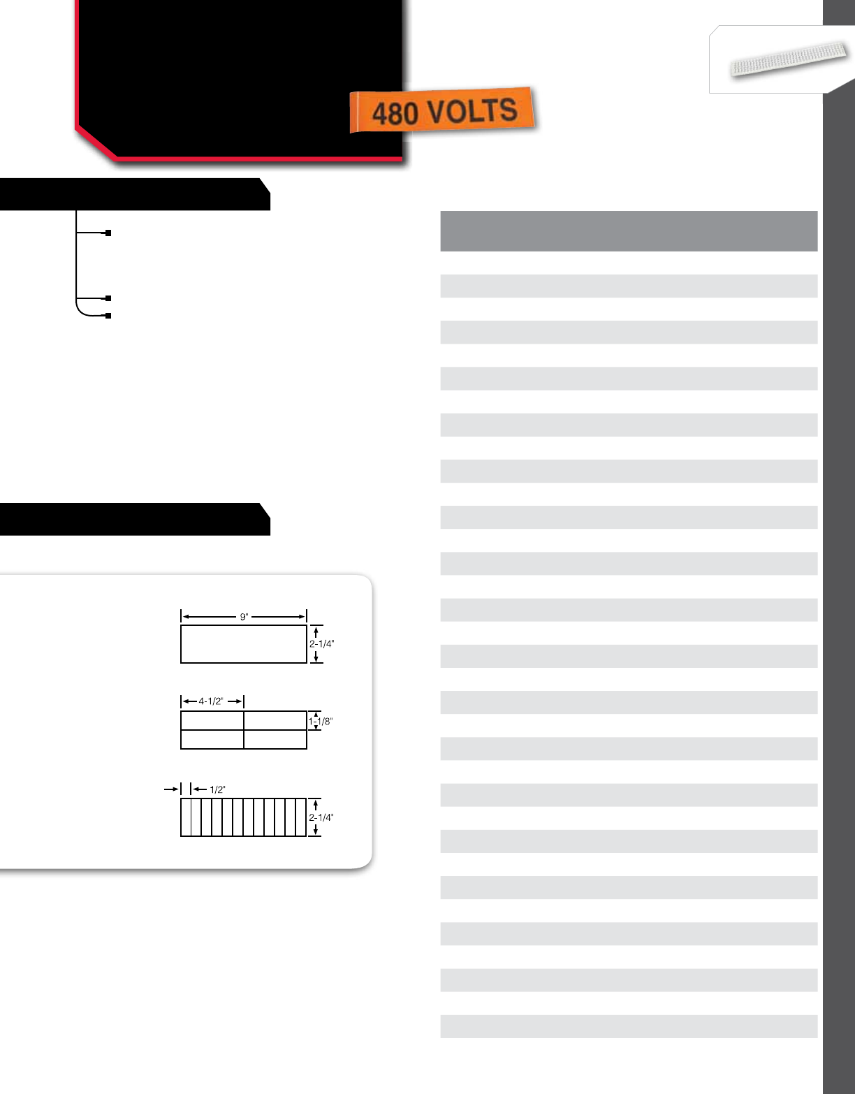
354
WIRE MANAGEMENT
NSi Industries LLC • USA • 800.321.5847 • www.nsiindustries.com
FEATURES
Pressure-sensitive vinyl markers for marking
power lines, conduit bus, fuse boxes, switches
and other electrical equipment, stocked in
three convenient sizes.
Standard Carton Quantity of 25.
Black lettering on orange background.
Style A
Style B
Style C
CAT.
no. SYMboL CAT.
no. SYMboL
VM-A-3 120 Volts VM-B-32 Three Phase
VM-A-4 208 Volts VM-B-35 120V to 208V
VM-A-5 220 Volts VM-B-36 120V to 240V
VM-A-7 240 Volts VM-B-37 277V to 480V
VM-A-9 277 Volts VM-B-48 Danger High Voltage
VM-A-11 440 Volts VM-B-49 24 Volts
VM-A-12 460 Volts VM-C-1 110 Volts
VM-A-13 480 Volts VM-C-3 120 Volts
VM-A-15 600 Volts VM-C-4 208 Volts
VM-A-18 2400 Volts VM-C-5 220 Volts
VM-A-19 4160 Volts VM-C-7 240 Volts
VM-A-20 4800 Volts VM-C-9 277 Volts
VM-A-25 12470 Volts VM-C-11 440 Volts
VM-A-27 13200 Volts VM-C-12 460 Volts
VM-A-28 13800 Volts VM-C-13 480 Volts
VM-A-30 Single Phase VM-C-15 600 Volts
VM-A-32 Three Phase VM-C-19 4160 Volts
VM-A-35 120V to 208V VM-C-20 4800 Volts
VM-A-36 120V to 240V VM-C-25 12470 Volts
VM-A-37 277V to 480V VM-C-30 Single Phase
VM-A-48 Danger High Voltage VM-C-32 Three Phase
VM-A-49 24 Volts VM-C-35 120V to 208V
VM-B-1 110 Volts VM-C-36 120V to 240V
VM-B-3 120 Volts VM-C-37 277V to 480V
VM-B-4 208 Volts VM-C-48 Danger High Voltage
VM-B-5 220 Volts VM-C-49 24 Volts
VM-B-7 240 Volts
VM-B-9 277 Volts
VM-B-13 480 Volts
VM-B-15 600 Volts
VM-B-23 7200 Volts
VM-B-27 13200 Volts
VM-B-28 13800 Volts
VM-B-30 Single Phase
STYLES
WIRE MARKInG / ID
Voltage Markers
VM SERIES
355
FEATURES
WIRE MANAGEMENT
SPIRAL WRAP
CAT.
no. LEGEnD SIZE
(In.)
STD.
CTn.
QTY.
VL-4 Remove All Doubt. Lock it Out. 2 1/4 x 4 1/2 25
VL-7 Warning Potential Arc-Flash Hazards Exist
While Working on this Energized Equipment 2 1/4 x 4 1/2 25
DSS-5 High Voltage 10 x 14 25
DSS-6 High Voltage Keep Out 10 x 14 25
Self-adhesive labels are sub-surface printed
polyester labels.
Rigid signs are available in either polycar-
bonate or polyester material.
CAUTIon
In Accordance with OSHA Standard 1910.147, All
Equipment, Machines and Processes Shall Be Locked
Out Prior to Servicing. Lockout Procedures are Posted
in the Main Operating Area and/or by the Main
Energy Source of Each Machine. If You Have any
Questions About the Lockout Procedures, Please See
Your Supervisor or the Safety Director. This Standard
Will Be Strictly Enforced.
Self-adhesive labels are sub-surface printed
polyester labels.
Self-adhesive labels are sub-surface printed
polyester labels.
Self-adhesive labels are sub-surface printed
Rigid signs are available in either polycar
bonate or
Rigid signs are available in either polycar
bonate or
Rigid signs are available in either polycar
LoCKoUT / TAGoUT
Self-Adhesive Labels and
Spiral Wrap
VL, DSS, SR SERIES
Permits flexible routing of cable harnesses while
forming a neat, protective bundle.
Twists on easily and allows lead-outs at any point.
PoLYETHYLEnE
For general indoor use with good resistance to
ordinary solvents and abrasion.
UV PoLYETHYLEnE
Ultraviolet resistance for general outdoor use with
good resistance to ordinary solvents and abrasion.
nYLon
For use in wider temperature ranges with high resistance
to abrasion and good solvent resistance.
CAT.
no. CoLoR MATERIAL o.D. I.D. bUnDLE
RAnGE LEnGTH
(FT.)
STD.
CTn.
QTY.
SRPE-250 Natural Polyethylene 0.236 0.157 0.157 - 1.97 100 1
SRPE-375 Natural Polyethylene 0.393 0.295 0.295 - 2.36 100 1
SRPE-500 Natural Polyethylene 0.472 0.354 0.354 - 2.56 100 1
SRPE-2500 Black UV Polyethylene 0.236 0.157 0.157 - 1.97 100 1
SRPE-3750 Black UV Polyethylene 0.393 0.295 0.295 - 2.36 100 1
SRPE-5000 Black UV Polyethylene 0.472 0.354 0.354 - 2.56 100 1
SRNY-375 Natural Nylon 0.375 0.312 0.312 - 3.00 100 1
Ultraviolet resistance for general outdoor use with
good resistance to ordinary solvents and abrasion.
Ultraviolet resistance for general outdoor use with
good resistance to ordinary solvents and abrasion.
Ultraviolet resistance for general outdoor use with
For general indoor use with good resistance to
ordinary solvents and abrasion.
For general indoor use with good resistance to
ordinary solvents and abrasion.
For general indoor use with good resistance to
Permits flexible routing of cable harnesses while
forming a neat, protective bundle.
Permits flexible routing of cable harnesses while
forming a neat, protective bundle.
Permits flexible routing of cable harnesses while
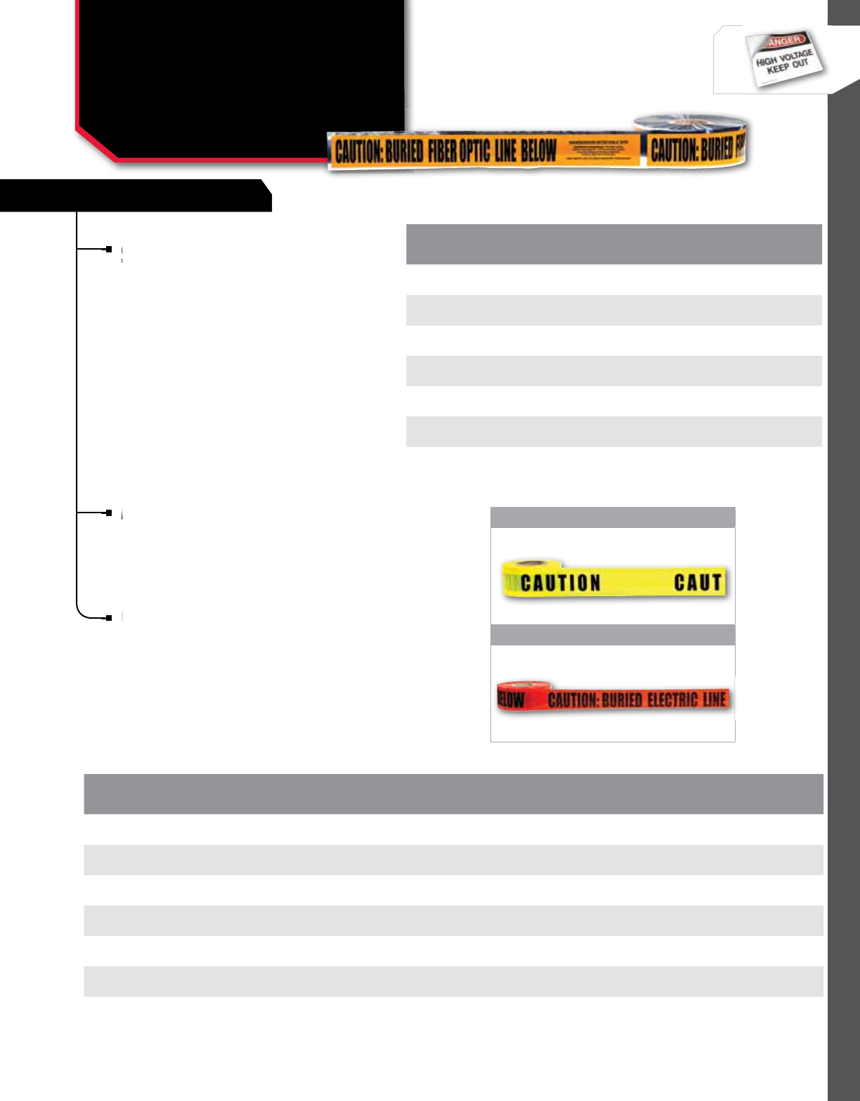
356
WIRE MANAGEMENT
NSi Industries LLC • USA • 800.321.5847 • www.nsiindustries.com
FEATURES
356
DETECTAbLE UnDERGRoUnD LInE TAPE
Consists of a minumum 5 mil overall thickness with no
less than a 35 gauge solid aluminum foil core, which
allows for easy detection. Specially formulated to resist
degradation by elements normally encountered in soil.
All printing is encased to avoid ink rub-off with
environmentally safe ink. Custom lengends are
available, contact NSi for details.
bARRICADE TAPE
Made of long lasting, non-adhesive polyethylene for
exceptional quality, durability and performance.
Used above ground to mark off hazards. Supplied in
1,000 ft. rolls.
UnDERGRoUnD LInE TAPE
Underground tapes are impervious to alkalines, acids
and other soil components for the protection, location
and identification of underground utility installations.
Consists of a 4 mil overall thickness, inert 100 percent
virgin low-density polyethylene plastic film formulated
for underground use and environmentally safe ink.
Custom legends are available. Contact NSi for details.
1
2
CAT.
no. FIG.
no. CoLoR LEGEnD USE LEnGTH
(FT.) WIDTH
(In.)
STD.
CTn.
QTY.
BT-305 1 Yellow Caution Above ground 1000 3 8
BT-308 1 Yellow Caution Do Not Enter Above ground 1000 3 8
ULT-326 2 Yellow CautionBuried Electric Line Below Underground 1000 3 8
ULT-327 2 Red CautionBuried Electric Line Below Underground 1000 3 8
ULT-626 2 Yellow CautionBuried Electric Line Below Underground 1000 6 4
ULT-627 2 Red CautionBuried Electric Line Below Underground 1000 6 4
CAT.
no. CoLoR LEGEnD LEnGTH
(FT.) WIDTH
(In.)
STD.
CTn.
QTY.
ULTD-327 Red Caution Buried Electric
Line Below 1000 38
ULTD-342 Orange Caution Buried Fiber
Optic Line Below 1000 38
ULTD-343 Yellow Caution Buried
Communication Line Below 1000 38
ULTD-626 Yellow Caution Buried Electric
Line Below 1000 64
ULTD-627 Red Caution Buried Electric
Line Below 1000 64
ULTD-636 Orange Caution Buried Telephone
Line Below 1000 64
ULTD-643 Yellow Caution Buried
Communication Line Below 1000 64
LoCKoUT / TAGoUT
Detectable Underground
Line and Barricade Tapes
ULT, ULTD, bT SERIES
Underground tapes are impervious to alkalines, acids
and other soil components for the protection, location
Underground tapes are impervious to alkalines, acids
and other soil components for the protection, location
Underground tapes are impervious to alkalines, acids
Consists
less than a 35 gauge solid aluminum foil core, which
Made of long lasting, non-adhesive polyethylene for
exceptional quality, durability and performance.
Made of long lasting, non-adhesive polyethylene for
exceptional quality, durability and performance.
Made of long lasting, non-adhesive polyethylene for

FEATURES
RATINGS

FirestopTM
Firestop
TM

359
FIRESTOP™
FEATURES
RATINGS
FireStop™ Intumescent Caulk is water-based, single component elastomeric sealant
intended for use as a firestop system component. It forms an economical yet
durable, flexible and watertight bond with most construction materials. It is applied
independently for “caulk and walk” systems or over mineral wool or backer rod to
seal the openings where building services such as pipes and cables penetrate fire
rated assemblies. Will not crack or crumble as the physical properties remain stable
over time. It tools easily and cleans up with water. May be applied by caulking gun
or trowel. ASTM–E 814 and UL 1479.
Insert FireStop™ in front of intumescent caulk.
Change to Fireblock814™ Residential and Commercial.
Fireblock136™ Residential.
Change to FireStop™ Pillows.
Change to Fire Rated Puddy pads.
CAT.
NO. FIG.
NO. DESCRIPTION WEIGHT
(OZ) LENGTH
(IN) WIDTH
(IN) HEIGHT
(IN)
STD.
CTN.
QTY.
FSIC-10 1FireStop™ Intumescent Caulk 10 – – – 12
FS-814 2FireStop814™Residential and
Commercial 10 – – – 12
FS-136 3FireBlok136™ Residential Fire Block 10 – – – 12
FSP 4Firestop Pillows – 8.000 4.000 2.000 25
FSPP-1 5Fire Rated Putty Pad – 6.000 7.000 – 20
FSPP-2 5Fire Rated Putty Stick Pad – 7.000 7.000 – 20
1
2
3
4 5
Change to
Fireblock136
Change to
Change to Fireblock814
Fireblock136
Insert
Change to Fireblock814
FIRESTOP™
Residential & Commercial
Caulk, Pillows &
Putty Pads
FS SERIES
Change to Fire Rated Puddy pads.
Change to Fire Rated Puddy pads.
FireStopTM INTUMESCENT CAULK

360
NSi Industries LLC • USA • 800.321.5847 • www.nsiindustries.com
360
FIRESTOP™
FireBlock136™ Fire-blocking caulk is a single component, non-combustible material for residential applications. Colored
red for easy inspection, FireBlock136 creates an effective barrier against flames, smoke, and toxic gasses and has superior
adhesion and gunnability. FireBlock136 is for use in annular spaces around wires, pipes, ducts, vents and other penetrating
items at ceiling and floor openings; and room to room in wood and steel frame constructions. It restores the integrity
of fireblocks in one and two family construction. Exceeds ASTM-E136 standards for fireblocking residential requirements
prescribed by all major-model building codes, and also meets or exceeds requirements of UBC, BOCA, SBC, IRC, NYS and MA
codes. Meets UL 1479/ ASTM-E136 standards.
FireStop814™ Fire stopping caulk is a single component, non-combustible, non-intumescent material for residential and
commercial applications. Colored red for easy inspection, FireStop814 creates an effective barrier against flames, smoke, and
toxic gasses and has superior adhesion and gunnability. FireStop814 is for use in annular spaces around wires and pipes, in
one- and two-hour fire rated assemblies. It restores the integrity of firestops in residential and commercial construction. Meets
UL 1479/ ASTM-E814 standards.
FireStop™ Pillows are a single step firestop system component. Intended for wall and/or floor openings through fire
separations where temporary or permanent firestops are required. They are ideal where cable retrofitting is frequent and
anticipated. Quick and clean single product installation. Self-supporting – no wire lath or mesh is required. They are to be
packed tightly into the voids between penetrating items and the perimeter of the opening. During a fire, the intumescent
component within each pillow dramatically expands to seal the opening from fire, thereby maintaining the integrity of
the fire separation. FireStop Pillows consist of an intumescent layer sandwiched between non-combustible insulation, all
enclosed in a hermetically sealed polyethylene shell. No sealant or putty is required. Easy to install, easy to remove – a
quick and clean single product installation. ASTM E 814 and UL 1479.
NSi Fire Rated Putty is a moldable non-curing, one-component fire rated material for through penetration fire stop systems.
In the event of a fire, Putty will expand when exposed to fire, forming an insulating char, which prevents the spread of
flames, smoke, gas and water through penetration openings. Installation is easy as there are no additives, there is no
mixing and no curing time is required. The putty is applied by hand and adheres to all common building surfaces. Putty can
be installed in confined or occupied spaces since there are no volatile solvents or asbestos fillers.
NSi Putty systems are rated up to 3 hours in accordance with ASTM E 814, UL 1479 and ULC/CAN4-S115-M standards. NSi
Fire Rated Putty is available in sticks or pads. Moldable Putty Pads are available in two sizes, 6” x 7” x 1/8” or 7” x 7” x
1/8”, and are classified as a wall opening protective material. Use them to protect metal electrical cabinets, outlet boxes
and mechanical cabinets. STC Rating 49.
FireStop814TM CAULK
FireBlok136TM CAULK
FireStop8136TM PILLOWS
FIRE RATED PUTTY PADS

361
FIRESTOP™
MAX.PEN.
DIA. RATING
(HR.) MAX.
OPENING FLOOR OR
WALL SYSTEM
NSI FIRESTOP
REQUIRED
PRODUCT(S)
APPLICATION
THICKNESS SYSTEM
NO. PAGE
NO.
6 in. conduit &
EMT or smaller 20 in to 7/8 in.
annulus
Floor - concrete (2 1
/2 in.
min.), Wall - concrete,
concrete block
or precast units
NSi FireStop
Intumescent Caulk
Min. 1
/4 in. thick within
annulus flush with top of floor
or both surfaces of wall
C-AJ-1511 212
6 in. conduit &
EMT or smaller 20 in. to
1
/2 in. annulus Wall – gypsum board NSi FireStop
Intumescent Caulk
Min. 11
/4 in. thick within
annulus flush with both
surfaces of wall
W-L-1349 212
6 in. conduit &
EMT or smaller 11
/4 in. to
1
/2 in. annulus Wall – gypsum board NSi FireStop
Intumescent Caulk
Min. 5/8 in. thick within
annulus flush with both
surfaces of wall
W-L-1351 213
3 in. conduit &
EMT or smaller 20 in. to
13/4 in. annulus Wall – gypsum board NSi FireStop
Intumescent Caulk
Min. 11
/4 in. thick
within annulus
flush with both surfaces of wall
W-L-1348 214
4 in. conduit &
EMT or smaller 1
0 in. to 1
/2 in.
annulus Floor – lumber
Ceiling – gypsum board
NSi FireStop
Intumescent Caulk
Min. 3
/4 in. thick within
annulus on top of floor Min. 5/8
in. thick within annulus on
bottom surface of ceiling
F-C-1128 214
TYPE OF
PENETRATION RATING
(HR.) MAX.
OPENING FLOOR OR
WALL SYSTEM NSI FIRESTOP
REQUIRED PRODUCT(S) APPLICATION
THICKNESS SYSTEM
NO. PAGE
NO.
Coaxial, fiber
optic & 24 AWG 3288 sq. in. Floor – concrete,
Wall - concrete or concrete block NSi FireStop Pillows
Installed with 8 in. dimension projecting
through floor or wall & centered
within opening
C-AJ-4073 215
Coaxial, fiber
optic, 24 AWG
& data cable
3288 sq. in.
Floor – concrete,
Wall – concrete or
concrete block
NSi FireStop Pillows
Installed with 8 in. dimension projecting
through floor or wall & centered
within opening
C-AJ-4074 216
Cables 1 0 in. to. 1
/4 in
annulus
Floor – lumber
Ceiling – gypsum board
NSi FireStop
Intumescent Caulk
Min. 11
/4 in. thick within annulus on top of
floor Min. 1
/2 in. thick within annulus on
bottom surface of ceiling
F-C-3084 216
MAX.PEN.
DIA. RATING
(HR.) MAX.
OPENING FLOOR OR
WALL SYSTEM NSI FIRESTOP
REQUIRED PRODUCT(S) APPLICATION
THICKNESS SYSTEM
NO. PAGE
NO.
2, PVC, CPVC,
ABS & Rigid
conduit or
smaller
11
/4 in. Floor – lumber
Ceiling - gypsum board
NSi FireStop
Intumescent Caulk
Min. 3
/4 in. thick within annulus on top of
floor. Min. 5/8 in. thick within annulus on bot-
tom surface of ceiling
F-C-2297 215
CONDUIT AND EMT
CABLE LARGER OPENINGS
NON-METALLIC CONDUIT
FIRESTOP™
Ratings & UL Systems
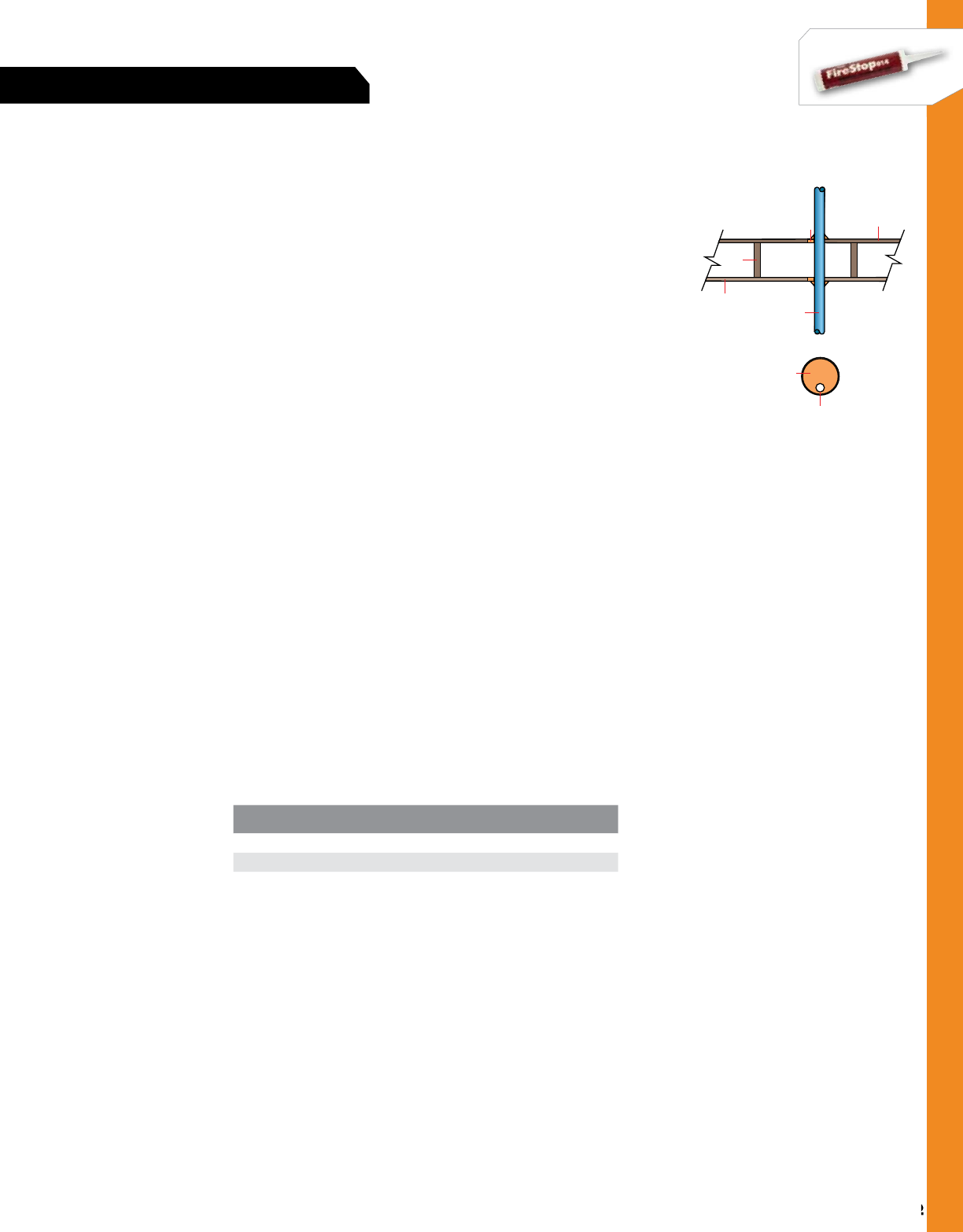
362
NSi Industries LLC • USA • 800.321.5847 • www.nsiindustries.com
362
FIRESTOP™
3
2
2
1a
3
1d
1b
F Rating – 1 hr., T Ratings – 3
/4 hr. and 1 hr. (See Item 2)
1. Floor-Ceiling Assembly – The fire-rated wood joist floor-ceiling assembly shall be con-
structed of the materials and in the manner specified in Design No. L512, L513 or L514 in
the UL Fire Resistance Directory and shall include the following construction features:
a) Flooring System – Lumber or minimum 1
/2 in. plywood subfloor with lumber or minimum
3
/4 in. plywood finish floor or Floor-Topping Mixture as specified in the individual floor-
ceiling design. Maximum diameter of floor opening is 5
/8 in.
b) Wood Joists – Nom. 2 x 10 in. lumber joists, spaced 16 in. oc. with nom. 1 x 3 in. lum-
ber bridging and with ends firestopped
c) Furring Channels (not shown) – Resilient galv. steel furring installed perpendicular to
wood joist between wallboard and wood joist and spaced maximum 24 in. oc.
d) Wallboard, Gypsum – Nom. 4 ft. wide x 5
/8 in. thick as specified in the individual floor-
ceiling design. Wallboard attached to wood joists or furring channels as specified in the
individual floor-ceiling design. Maximum diameter of ceiling opening is 5
/8 in.
2. Cables – One cable to be installed either eccentrically or concentrically in opening with
annular space between the cable and periphery of opening of min. 0 in. (point contact) to
maximum 14 in. Cable to be rigidly supported on both sides of floor-ceiling assembly. The
following types of cables may be used:
a) Maximum 3/C (with ground) No. 12 AWG (or smaller) with polyvinyl chloride (PVC)
insulation and jacket
b) Maximum 3/C (with ground) No. 14 AWG (or smaller) with PVC jacketed aluminium or
steel clad, Type RW90
c) Type RG6U coaxial cable with fluorinated ethylene propylene insulation and jacket
d) Maximum 2/C (with ground) No. 14 AWG (or smaller), type NM90, with nylon jacket
e) Maximum 8/C No. 24 AWG (or smaller), type CMR MPR, with polyvinyl chloride (PVC)
insulation and jacket.
The T Rating of the firestop system is dependent upon the type of cable used, as tabulated
below:
3. Fill, void or cavity material – NSi FireStop Intumescent Caulk. On top of assembly, a
minimum 11
/4 in. thickness of fill material applied within the annulus on top surface of floor.
On bottom assembly, a minimum 1
/2 in. thickness of fill material applied within annulus on
bottom surface of ceiling. Additional fill material to be installed such that a minimum 1
/2 in.
thick crown is formed around the through penetrant on both sides of floor-ceiling assembly.
CABLE TYPE T-RATING (HR.)
a, b, c and e 1
d3
/4
UL SYSTEM NO. F-C-3084
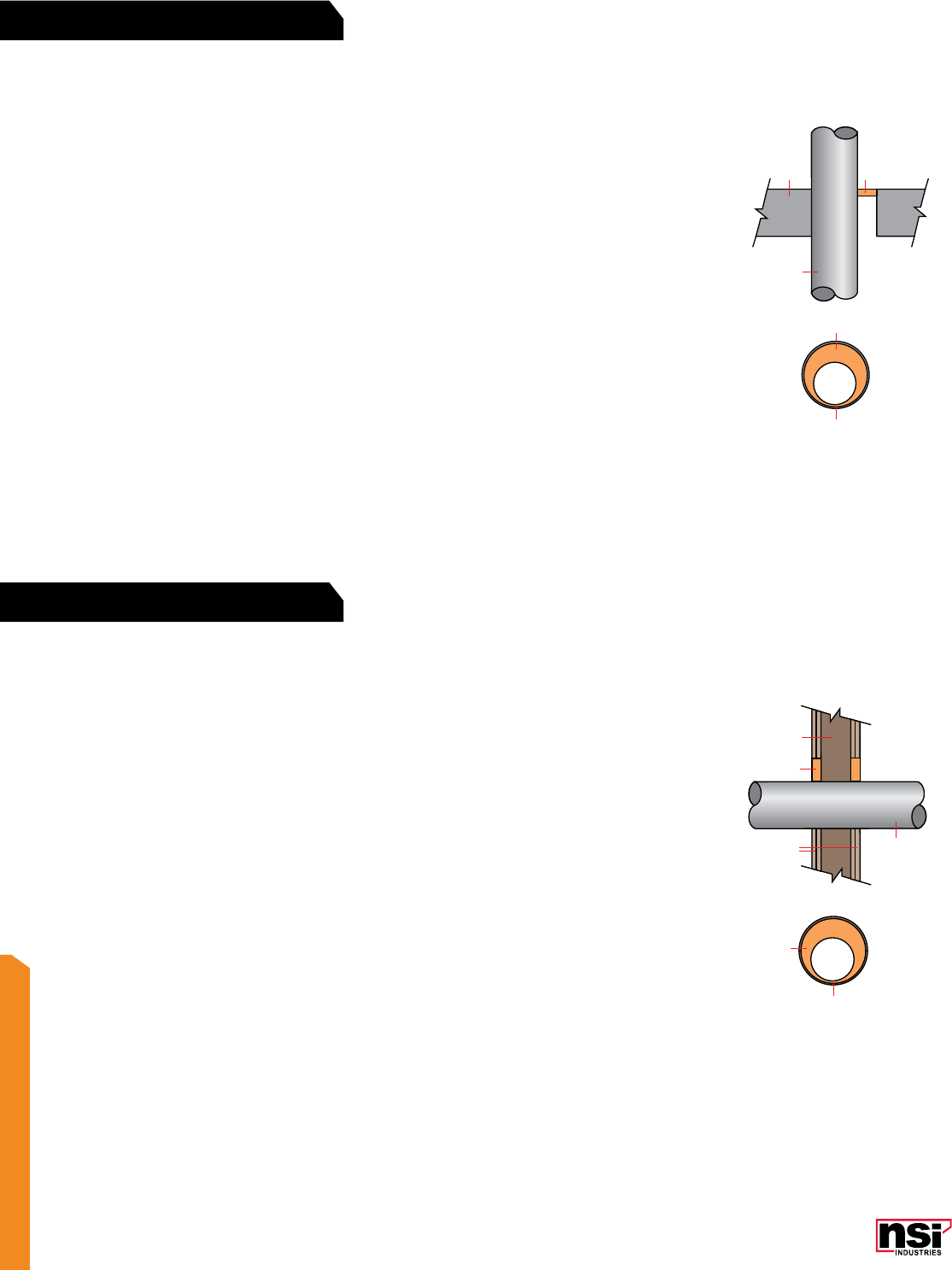
363
FIRESTOP
3
2
2
1b
1a
3
3
2
2
13
F Rating – 2 hr., T Rating – 0 hr.
1. Floor or wall assembly – Minimum 21
/2 in. thick reinforced lightweight or normal weight (100-150 pcf) concrete
floor. Floor may also be constructed of any minimum 6 in. thick UL Classified hollow-core precast concrete units. Wall may
also be constructed of any UL Classified concrete blocks. Maximum diameter of opening is 24 7
/8 in. Maximum diameter
of opening in floors constructed of hollow-core is 7 in. See Concrete Blocks (CAZT) or Precast Concrete Units (CFTV)
category in the Fire Resistance Directory for names of manufacturers.
2. Through Penetrant – One metallic pipe, conduit or tubing to be installed within the firestop system. Pipe, conduit or
tubing to be rigidly supported on both sides of floor or wall assembly. The annular space between the pipe or conduit and
the periphery of opening shall be a minimum of 0 in. (point contact) to a maximum of 7
/8 in. The following types and
sizes of metallic pipes, conduits or tubing may be used:
a) Steel pipe – Nom. 24 in. diameter (or smaller) Schedule 10 (or heavier) steel pipe
b) Iron pipe – Nom. 24 in. diameter (or smaller) cast or ductile iron pipe
c) Conduit – Nom. 6 in. diameter (or smaller) steel electrical metallic tubing or steel conduit
d) Copper pipe or tubing – Nom. 6 in. diameter (or smaller) Type L (or heavier) copper tubing.
3. Fill, void or cavity material – NSi FireStop Intumescent Caulk. Minimum 1
/2 in. thickness of caulk applied within the
annulus, flush with top surface of floor or with both surfaces of wall. In floors constructed of hollow-core precast concrete
units, fill material installed symmetrically on both sides of floor. Additional material installed to form a minimum 1
/4 in.
crown bead at the point contact location between the pipe and periphery of the opening. For vertical installations, sealant
to be applied symmetrically on both sides of wall.
F Rating – 2 hr., T Rating – 0 hr.
1. Wall Assembly – The fire-rated gypsum wallboard/stud wall assembly shall be constructed of the materials and in the
manner described in the individual U300 or U400 Series Wall or Partition Design in the UL Fire Resistance Directory and shall
include the following construction features:
a) Studs – Wall framing may consist of either wood studs or steel channel studs. Wood studs to consist of nom. 2 x 4 in.
lumber spaced 16 in. oc. Steel studs to be minimum 35
/8 in. wide and spaced maximum 24 in. oc. When steel studs are
used and the diameter of openings exceeds the width of stud cavity, the opening shall be framed on all sides using lengths
of steel stud installed between vertical studs and screw-attached to the studs at each end. The framed opening in the wall
shall be 4 to 6 in. wider and 4 to 6 in. higher than the diameter of the penetrating item such that, when the penetrating
item is installed in the opening, a 2 to 3 in. clearance is present between the penetrating item and the framing on all four
sides.
b) Wallboard, Gypsum – 5
/8 in. thick, 4 ft. wide with square or tapered edges. The gypsum wall board type, thickness,
number of layers, fastener type and sheet orientation shall be as specified in the individual U300 or U400 Series Design in
the UL Fire Resistance Directory. Maximum diameter of opening is 65
/8 in.
2. Through Penetrant – One metallic pipe, conduit or tubing to be installed either concentrically or eccentrically within the
firestop system. The annular space between pipes, conduits or tubing and the periphery of opening shall be a minimum of 0 in.
(point contact) to a maximum of 1
/2 in. Pipe, tubing or conduit to be rigidly supported on both sides of wall assembly.
The following types and sizes of metallic pipes, tubing or conduits may be used:
a) Steel pipe – Nom. 24 in. diameter (or smaller) Schedule 5 (or heavier) steel pipe
b) Iron pipe – Nom. 24 in. diameter (or smaller) cast or ductile iron pipe
c) Conduit – Nom. 6 in. diameter (or smaller) steel electrical metallic tubing or steel conduit
d) Copper Tubing – Nom. 6 in. diameter (or smaller) Type L (or heavier) copper tubing
e) Copper Pipe – Nom. 6 in. diameter (or smaller) Regular (or heavier) copper pipe.
3. Fill, void or cavity material – Sealant – NSi FireStop Intumescent Caulk. Minimum 11
/4 in. thickness of fill material
applied within the annulus, flush with both surfaces of wall. At the point contact location between through penetrant and
gypsum wall board, a minimum 1
/2 in. diameter bead of fill material shall be applied at the gypsum wallboard/through
penetrant interface on both surfaces of wall.
UL SYSTEM NO. C-AJ-1511
UL SYSTEM NO. W-L-1349
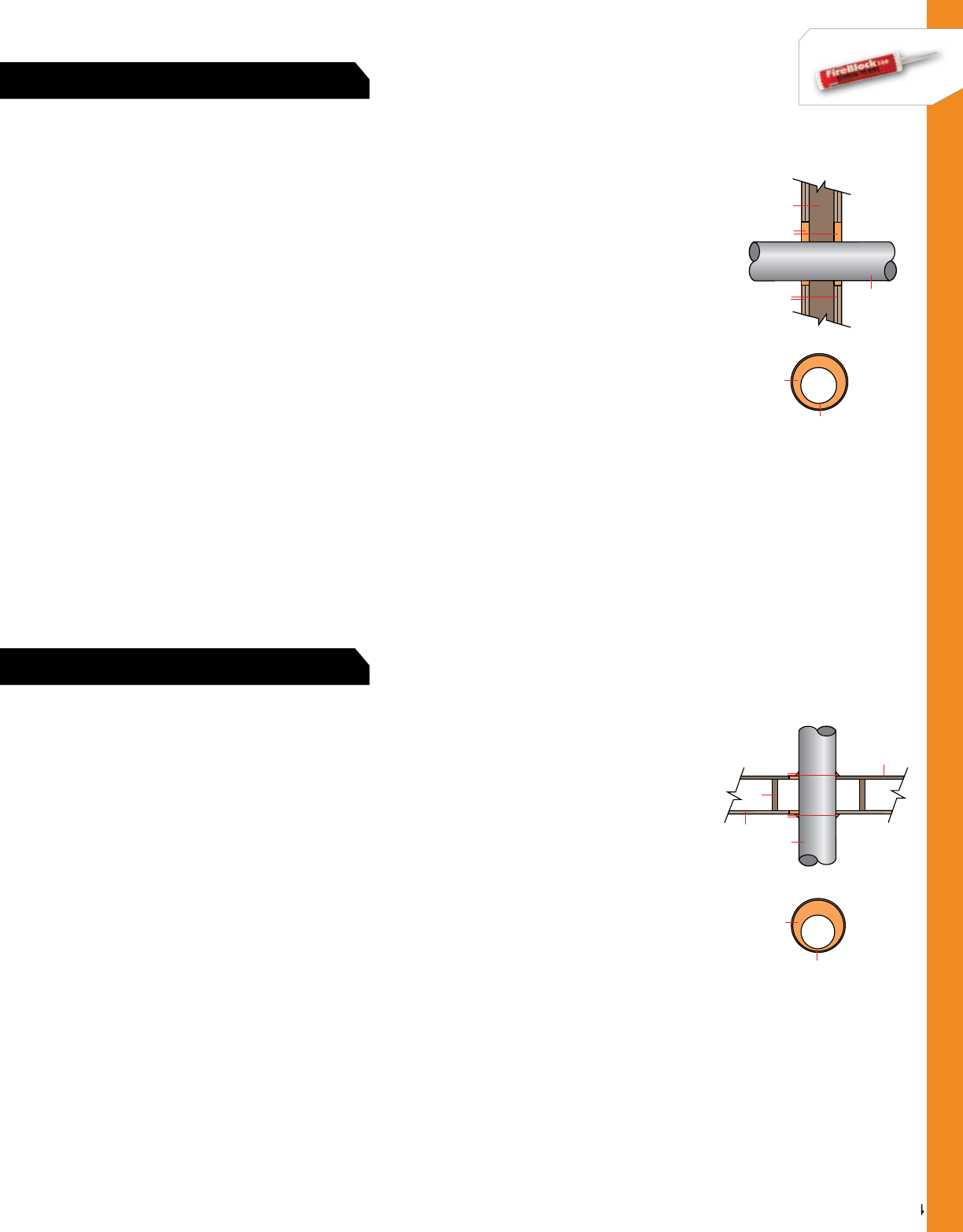
364
NSi Industries LLC • USA • 800.321.5847 • www.nsiindustries.com
364
FIRESTOP™
F Rating – 1 hr., T Rating – 0 hr.
1. Wall Assembly – The 1 hr. fire-rated gypsum wallboard/stud wall assembly shall be constructed of the materials and in the
manner described in the individual U300 or U400 Series Wall or Partition Design in the UL Fire Resistance Directory and shall
include the following construction features:
a) Studs – Wall framing may consist of either wood studs or steel channel studs. Wood studs to consist of nom. 2 x 4 in. lumber
spaced 16 in. oc. Steel studs to be minimum 3 5
/8 in. wide and spaced maximum 24 in. oc. When steel studs are used and the
diameter of openings exceeds the width of stud cavity, the opening shall be framed on all sides using lengths of steel stud
installed between vertical studs and screw-attached to the studs at each end. The framed opening in the wall shall be 4 to 6 in.
wider and 4 to 6 in. higher than the diameter of the penetrating item such that, when the penetrating item is installed in the
opening, a 2 to 3 in. clearance is present between the penetrating item and the framing on all four sides
b) Wallboard, Gypsum – 5
/8 in. thick, 4 ft. wide with square or tapered edges. The gypsum wall board type, thickness, number
of layers, fastener type and sheet orientation shall be as specified in the individual U300 or U400 Series Design in the UL Fire
Resistance Directory. Maximum diameter of opening is 243
/4 in. for steel stud walls. Maximum diameter opening is 141
/2 in.
for wood stud walls.
2. Through Penetrant – One metallic pipe, conduit or tubing to be installed either concentrically or eccentrically within the firestop
system. The annular space between pipes, conduits or tubing and the periphery of opening shall be a minimum of 1
/4 in. to a
maximum
of 1
/2 in. Pipe, tubing or conduit to be rigidly supported on both sides of wall assembly. The following types and sizes of metallic
pipes, tubing or conduits may be used:
a) Steel pipe – Nom. 24 in. diameter (or smaller) Schedule 5 (or heavier) steel pipe
b) Iron pipe – Nom. 24 in. diameter (or smaller) cast or ductile iron pipe
c) Conduit – Nom. 6 in. diameter (or smaller) steel electrical metallic tubing or steel conduit
d) Copper Tubing – Nom. 6 in. diameter (or smaller) Type L (or heavier) copper tubing
e) Copper Pipe – Nom. 6 in. diameter (or smaller) Regular (or heavier) copper pipe.
3. Fill, void or cavity material – Sealant – NSi FireStop Intumescent Caulk. Minimum 5
/8 in. thickness of fill material applied
within the annulus, flush with both surfaces of wall.
3
2
2
1b
1a
3
3
2
2
1a
3
1c
1b
3
F Rating – 1 hr., T Rating – 0 hr.
1. Floor-Ceiling Assembly – The 1 hr. fire-rated solid or trussed lumber joist floor-ceiling assembly shall be constructed of the
materials and in the manner specified in the individual L500 Series Floor-Ceiling Designs in the UL Fire Resistance Directory and
shall include the following construction features:
a) Flooring System – Lumber or plywood subfloor with finish floor of lumber, plywood or Floor-Topping Mixture as specified in
the individual floor-ceiling design. Maximum diameter of floor opening is 5 in.
b) Wood Joists – Nom. 10 in. deep (or deeper) lumber, steel or combination lumber and steel joists, trusses or Structural Wood
Members with bridging as required and with ends firestopped
c) Wallboard, Gypsum – Nom. 4 ft. wide x 5
/8 in. thick as specified in the individual floor-ceiling design. Wallboard nailed to
wood joists.
2. Through Penetrant – One metallic pipe, conduit or tubing to be installed either concentrically or eccentrically within the firestop
system. The annular space between pipe, conduit or tubing and the periphery of opening shall be a minimum of 0 in. (point con-
tact) to a maximum of 1
/2 in. Pipe, tubing or conduit to be rigidly supported on both sides of wall assembly. The following types
and sizes of metallic pipes, tubing or conduits may be used:
a) Steel pipe – Nom. 4 in. diameter (or smaller) Schedule 10 (or heavier) steel pipe
b) Iron pipe – Nom. 4 in. diameter (or smaller) cast or ductile iron pipe
c) Conduit – Nom. 4 in. diameter (or smaller) steel electrical metallic tubing or steel conduit
d) Copper Tubing – Nom. 4 in. diameter (or smaller) Type L (or heavier) copper tubing
e) Copper Pipe – Nom. 4 in. diameter (or smaller) Regular (or heavier) copper pipe.
3. Fill, void or cavity material – NSi FireStop Intumescent Caulk. Minimum 3/4 in. thickness of fill material applied within the
annulus on top surface of floor. Minimum 5
/8 in. thickness of fill material applied within annulus on bottom surface of ceiling.
Additional fill material to be installed such that a minimum 1
/2 in. thick crown is formed around the through penetrant on top
surface of floor-ceiling assembly.
UL SYSTEM NO. W-L-1351
UL SYSTEM NO. W-L-1128
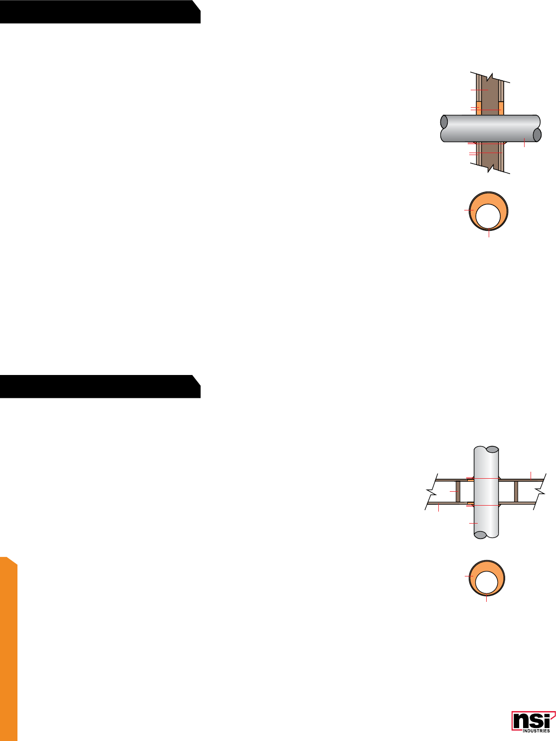
365
FIRESTOP
F Rating – 2 hr., T Rating – 0 hr.
1. Wall Assembly – The 2 hr. fire-rated gypsum wallboard/stud wall assembly shall be constructed of the materials and in the
manner described in the individual U300 or U400 Series Wall or Partition Design in the UL Fire Resistance Directory and shall
include the following construction features:
a) Studs – Wall framing may consist of either wood studs or steel channel studs. Wood studs to consist of nom. 2 x 4 in. lumber
spaced 16 in. oc. with nom. 2 x 4 in. lumber end plates and cross braces. Steel studs to be minimum 3 5
/8 in. wide and spaced
maximum 24 in. oc. When steel studs are used and the diameter of openings exceeds the width of stud cavity, the opening
shall be framed on all sides using lengths of steel stud installed between vertical studs and screw-attached to the studs at each
end. The framed opening in the wall shall be 4 to 6 in. wider and 4 to 6 in. higher than the diameter of the penetrating item,
such that when the penetrating item is installed in the opening, a 2 to 3 in. clearance is present between the penetrating item
and the framing on all four sides
b) Wallboard, Gypsum – 5
/8 in. thick, 4 ft. wide with square or tapered edges. The gypsum wall board type, thickness, number
of layers, fastener type and sheet orientation shall be as specified in the individual U300 or U400 Series Design in the UL Fire
Resistance Directory. Maximum diameter of opening is 5 in.
2. Through Penetrant – One metallic pipe, conduit or tubing to be installed either concentrically or eccentrically within the firestop
system. The annular space between pipes, conduits or tubing and the periphery of opening shall be a minimum of 0 in. (point
contact) to a maximum of 13
/4 in. Pipe, tubing or conduit to be rigidly supported on both sides of wall assembly. The following
types and sizes of metallic pipes, tubing or conduits may be used:
a) Steel pipe – Nom. 3 in. diameter (or smaller) Schedule 5 (or heavier) steel pipe
b) Conduit – Nom. 3 in. diameter (or smaller) steel electrical metallic tubing or galv. steel conduit
c) Copper Tubing – Nom. 3 in. diameter (or smaller) Type L (or heavier) copper tubing
d) Copper Pipe – Nom. 3 in. diameter (or smaller) Regular (or heavier) copper pipe.
3. Fill, void or cavity material – Sealant – NSi FireStop Intumescent Caulk. Minimum 11
/4 in. thickness of fill material applied
within the annulus, flush with both surfaces of wall. At the point contact location between through penetrant and gypsum wall
board, a minimum 3
/8 in. diameter bead of fill material shall be applied at the gypsum wallboard/through penetrant interface on
both surfaces of wall.
3
2
2
1b
1a
3
3
F Rating – 1 hr., T Rating – 0 hr.
1. Floor-Ceiling Assembly – The fire-rated wood joist floor-ceiling assembly shall be constructed of the materials and in
the manner specified in the individual L505, L511, or L536 Designs in the UL Fire Resistance Directory and shall include the
following construction features:
a) Flooring System – Lumber or plywood subfloor with finish floor of lumber, plywood or Floor-Topping Mixture as specified in
the individual floor-ceiling design. Maximum diameter of opening is 2.875 in.
b) Wood Joists – Nom. 2 x 10 in. lumber joists spaced 16 in. oc. with nom. 1 x 3 in. lumber bridging and with ends firestopped
c) Wallboard, Gypsum – Nom. 4 ft. wide x 5
/8 in. thick as specified in the individual floor-ceiling design. Maximum diameter
of ceiling opening is 2.875 in.
2. Through Penetrant – One nonmetallic pipe or conduit to be installed approximately midway between wood joists and
centered within the firestop system. Diameter of openings hole-sawed through flooring system and one layer through gypsum
wallboard ceiling to be nom. 1
/2 in. larger than the outside diameter of through penetrant. Pipe or conduit to be rigidly
supported on both sides of floor-ceiling assembly. The following types and sizes of nonmetallic pipes or conduits may be used:
a) Polyvinyl Chloride (PVC) Pipe – Nom. 2 in. diameter (or smaller) Schedule 40 cellular or solid core PVC pipe for use in
closed (process or supply) or vented (drain, waste, or vent) piping systems
b) Acrylonitrile Butadiene Styrene (ABS) Pipe – Nom. 2 in. diameter (or smaller) Schedule 40 cellular or solid core ABS pipe
for use in closed (process or supply) or vented (drain, waste, or vent) piping systems
c) Chlorinated Polyvinyl Chloride (CPVC) Pipe – Nom. 2 in. diameter (or smaller) SDR 17 CPVC pipe for use in closed (process
or supply) or vented (drain, waste, or vent) piping systems
d) Rigid Nonmetallic Conduit – Nom. 2 in. diameter (or smaller) Schedule 40 PVC conduit installed in accordance with Article
347 of the National Electrical Code (NFPA No. 70).
3. Fill, void or cavity material – NSi FireStop Intumescent Caulk. Minimum 3
/4 in. thickness of fill material applied within the
annulus on top surface of floor. Minimum 5/8 in. thickness of fill material applied within annulus on bottom surface of ceiling or
top plate of chase wall assembly. Additional fill material to be installed such that a minimum 1
/8 in. thick crown is formed around
the through penetrant on top surface of floor-ceiling assembly.
3
2
2
1a
3
1c
1b
3
UL SYSTEM NO. W-L-1348
UL SYSTEM NO. F-C-2297

366
NSi Industries LLC • USA • 800.321.5847 • www.nsiindustries.com
366
FIRESTOP™
4
2
3
3
1
2
4
1
F Rating – 3 hr., T Rating – 11
/2 hr.
1. Floor or wall assembly – Minimum 5 in. thick reinforced normal weight concrete. Wall may also be constructed of any UL
Classified concrete blocks. Maximum area of opening is 288 sq. in. with a maximum dimension of 24 in. See Concrete Blocks (CAZT)
category in the Fire Resistance Directory for names of manufacturers.
2. Cable Tray – Maximum 12 in. wide by maximum 35
/8 in. deep (maximum 3 in. deep loading depth) trough type cable tray with
channel-shaped side rails formed of No. 18 MSG (0.048 in.) thick galvanized steel and with 4 in. wide by No. 18 MSG (0.048 in.)
thick ventilated type rungs spaced 10 in. oc. Maximum one cable tray to be installed either concentrically or eccentrically within the
firestop
system. The annular space between the cable tray and the periphery of opening shall be a minimum of 11
/2 in. to a maximum of 7
in. Cable tray to be rigidly supported on both sides of floor or wall assembly.
3. Cables – Maximum four individual cable bundles, each containing a maximum seven cables, to be installed within cable tray.
Maximum diameter of individual cable bundles shall be 2 in. Cable bundles to be spaced a minimum 11
/2 in. to a maximum 3 in. oc.
Any combination of the following types and sizes of cables may be used:
a) Maximum 3 pair No. 24 AWG (or smaller) copper conductor cables with polyvinyl chloride (PVC) insulation and jacket
b) Maximum 2 fiber 62.5/125 uM fiber optic cable with PVC insulation and jacket
c) Maximum RG/U (or smaller) coaxial copper conductor cable with fluorinated ethylene insulation and jacket materials.
4. Fill, Void or Cavity Materials – NSi FireStop Pillows. Maximum 8 in. long x 4 in. wide x 2 in. deep thick pillow-like material.
Pillows shall be tightly packed into opening to fill the annular space between cables and periphery of opening and between cable tray
and periphery of opening. Pillows installed with 8 in. dimension projecting through floor or wall and centered within the opening.
(For Horizontal or Vertical Separations)
F Rating – 3 hr., T Rating – 0 hr.
1. Floor or wall assembly – Minimum 41
/2 in. thick reinforced lightweight (100 pcf) concrete. Maximum size of opening is 288 sq.
in. with maximum dimension of 24 in. Wall may also be constructed of any UL Classified concrete blocks. See Concrete Blocks (CAZT)
category in the Fire Resistance Directory for names of manufacturers.
2. Cable Tray – Maximum 12 in. wide by maximum 35
/8 in. deep (maximum 3 in. deep loading depth) trough type cable tray with
channel-shaped side rails formed of No. 18 MSG (0.048 in.) thick galvanized steel and with 4 in. wide by No. 18 MSG (0.048 in.) thick
ventilated type rungs spaced 10 in. oc. Maximum one cable tray to be installed either concentrically or eccentrically within the firestop
system. The annular space between the cable tray and the periphery of opening shall be a minimum of 11
/2 in. to a maximum of 7 in.
Cable tray to be rigidly supported on both sides of floor or wall assembly.
3. Cables – Aggregate cross-sectional area of cables in cable tray to be 25% of the cross-sectional area of the cable tray based on a
maximum 3 in. cable loading within the cable tray. Any combination of the following types and sizes of cables may be used:
a) Maximum 287 lengths of cables, each with 3 pair No. 24 AWG Type D telephone cables with PVC insulation and jacket
b) Maximum 24 lengths of double stranded fiber optic cables, 1/8 in. diameter with PVC insulation and jacket
c) Maximum 12 lengths of coaxial cable, 1/4 in. diameter, 22 AWG solid copper conductor with polyethylene insulation and PVC jacket
d) Maximum 12 lengths of data cable, Alcatel 380100, E107890, 24 AWG CMR, with PVC jacket.
4. Fill, Void or Cavity Materials – NSi FireStop Pillows. Maximum 8 in. long x 4 in. wide x 2 in. deep thick pillow-like material.
Pillows shall be tightly packed into opening to fill the annular space between cables and periphery of opening and between cable tray
and periphery of opening. Pillows installed with 8 in. dimension projecting through floor or wall and centered within the opening.
4
2
3
3
1
2
4
1
UL SYSTEM NO. C-A-4073
UL SYSTEM NO. C-AJ-4074
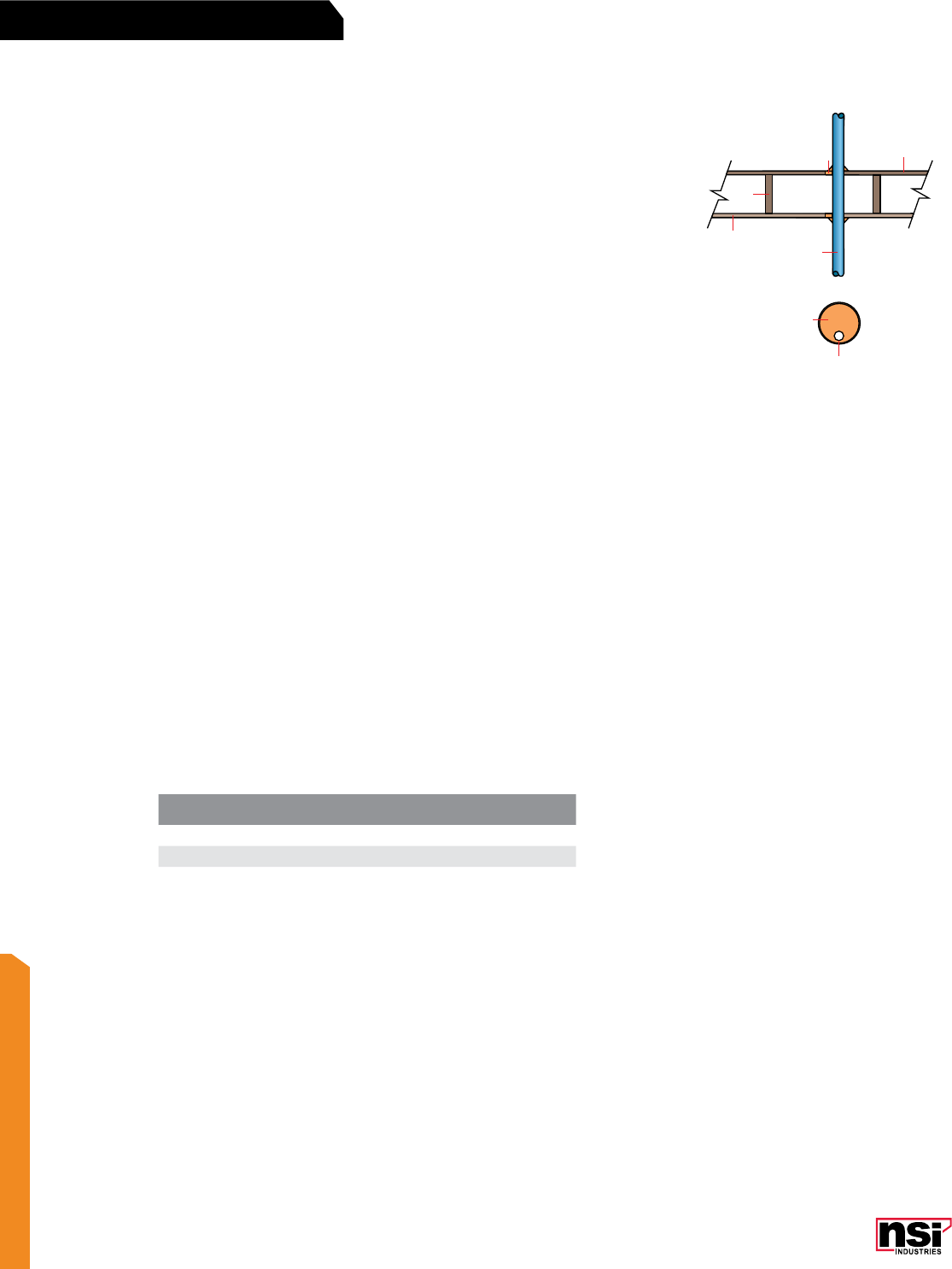
367
FIRESTOP
3
2
2
1a
3
1d
1b
F Rating – 1 hr., T Ratings – 3
/4 hr. and 1 hr. (See Item 2)
1. Floor-Ceiling Assembly – The fire-rated wood joist floor-ceiling assembly shall be con-
structed of the materials and in the manner specified in Design No. L512, L513 or L514 in
the UL Fire Resistance Directory and shall include the following construction features:
a) Flooring System – Lumber or minimum 1
/2 in. plywood subfloor with lumber or minimum
3
/4 in. plywood finish floor or Floor-Topping Mixture as specified in the individual floor-
ceiling design. Maximum diameter of floor opening is 5
/8 in.
b) Wood Joists – Nom. 2 x 10 in. lumber joists, spaced 16 in. oc. with nom. 1 x 3 in. lum-
ber bridging and with ends firestopped
c) Furring Channels (not shown) – Resilient galv. steel furring installed perpendicular to
wood joist between wallboard and wood joist and spaced maximum 24 in. oc.
d) Wallboard, Gypsum – Nom. 4 ft. wide x 5
/8 in. thick as specified in the individual floor-
ceiling design. Wallboard attached to wood joists or furring channels as specified in the
individual floor-ceiling design. Maximum diameter of ceiling opening is 5
/8 in.
2. Cables – One cable to be installed either eccentrically or concentrically in opening with
annular space between the cable and periphery of opening of min. 0 in. (point contact) to
maximum 14 in. Cable to be rigidly supported on both sides of floor-ceiling assembly. The
following types of cables may be used:
a) Maximum 3/C (with ground) No. 12 AWG (or smaller) with polyvinyl chloride (PVC)
insulation and jacket
b) Maximum 3/C (with ground) No. 14 AWG (or smaller) with PVC jacketed aluminium or
steel clad, Type RW90
c) Type RG6U coaxial cable with fluorinated ethylene propylene insulation and jacket
d) Maximum 2/C (with ground) No. 14 AWG (or smaller), type NM90, with nylon jacket
e) Maximum 8/C No. 24 AWG (or smaller), type CMR MPR, with polyvinyl chloride (PVC)
insulation and jacket.
The T Rating of the firestop system is dependent upon the type of cable used, as tabulate below:
3. Fill, void or cavity material – NSi FireStop Intumescent Caulk. On top of assembly, a
minimum 11
/4 in. thickness of fill material applied within the annulus on top surface of floor.
On bottom assembly, a minimum 1
/2 in. thickness of fill material applied within annulus on
bottom surface of ceiling. Additional fill material to be installed such that a minimum 1
/2 in.
thick crown is formed around the through penetrant on both sides of floor-ceiling assembly.
CABLE TYPE T-RATING (HR.)
a, b, c and e 1
d3
/4
UL SYSTEM NO. F-C-3084

368
NSi Industries LLC • USA • 800.321.5847 • www.nsiindustries.com
368
FIRESTOP™
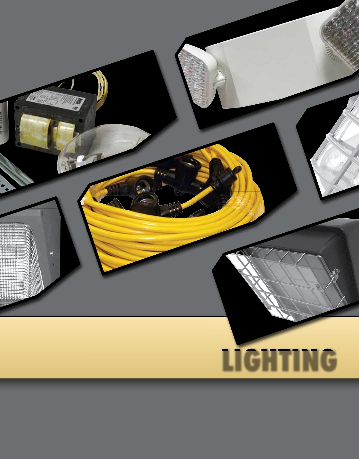
LIGHTING
LIGHTING

371
HID/OUTDOOR
FEATURES
RATINGS
1 2
CAT.
NO. FIG.
NO. DESCRIPTION VOLTAGE HEIGHT WIDTH DEPTH BALLAST LAMPBASE
WP42FL* 142 Watt Fluorescent 120/277VAC 11 6.9 5.2 Electronic PLC –
WP26FLPC* 126 Watt Fluorescent with
Photocontrol 120/277VAC 11 6.9 5.2 Electronic PLC –
WP70S 170 Watt Sodium 120VAC 11 6.9 5.2 R-NPF ED17 Medium
WP70SPC 170 Watt Sodium With
Photocontrol 120VAC 11 6.9 5.2 R-NPF ED17 Medium
WPGC100MHQ 2Die Cast 100 Watt Metal Halide 120/208/240/277VAC 12 7.3 5.3 QUAD HX-NPF ED17 Medium
For small area fixtures: Doorways, loading docks,
commercial, institutional, industrial areas.
Mini wallpacks are available with a one-piece polycarbonate
housing and lens (1) or with a die-cast housing and
borosilicate glass lens (2).
Excellent for security and perimeter lighting and commercial
and industrial applications.
Polycarbonate version available with built-in photocontrol.
Die cast version can be field installed with photocontrol.
UL Listed for wet location use.
Lamp included.
LIGHTING
Mini Wallpacks
WP SERIES
*
All dimensional data is listed in inches.
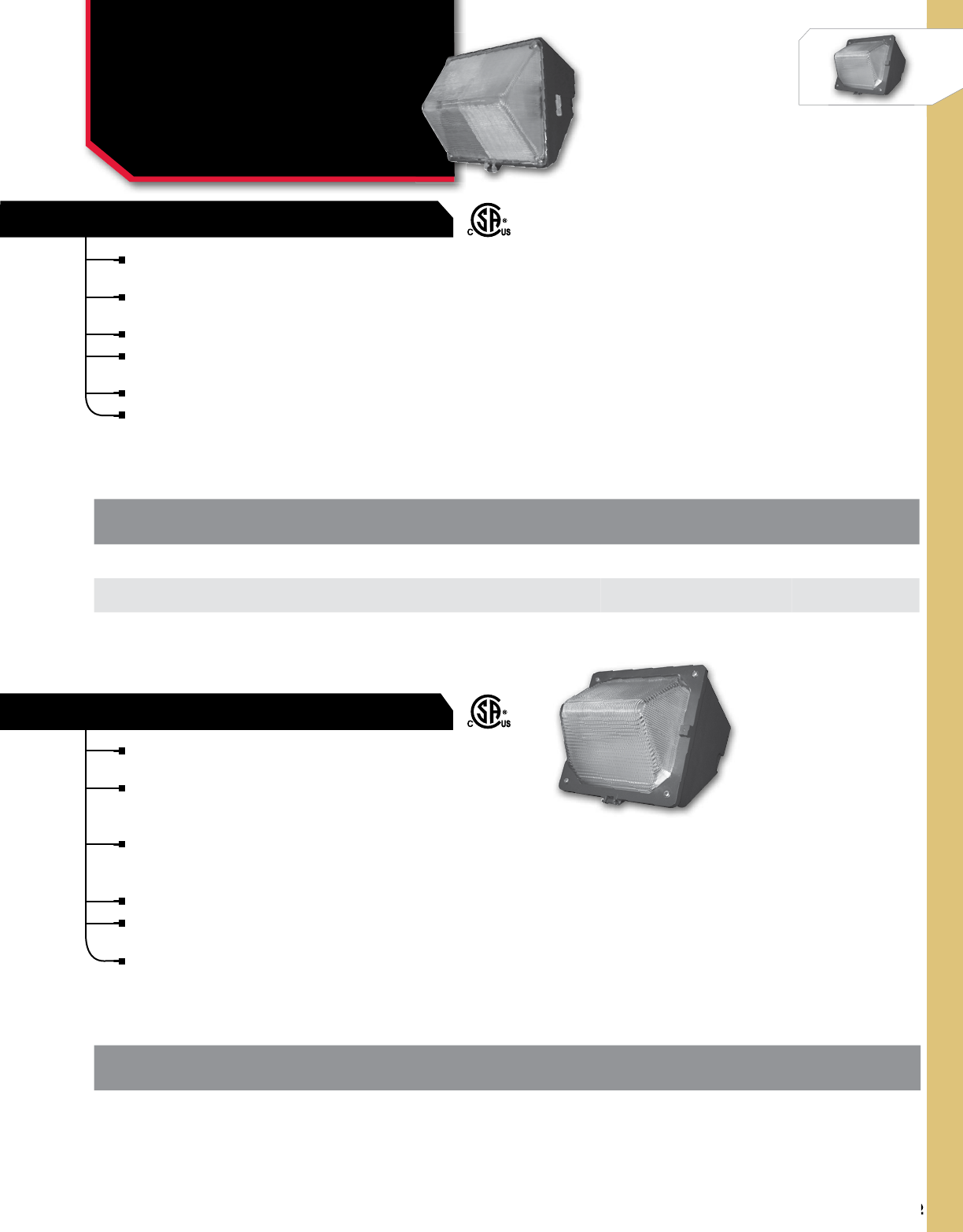
372
NSi Industries LLC • USA • 800.321.5847 • www.nsiindustries.com
372
HID/OUTDOOR
For small area fixtures: Doorways, loading docks,
commercial, institutional, industrial areas.
Compact wallpacks have a die cast housing with powder-
coat finish and prismatic polycarbonate lens with gasket.
Porcelain medium base socket assembly.
One piece semi-specular asymmetric anodized
aluminum reflector.
UL Listed for wet location use.
Lamp included.
For small area fixtures: Doorways, loading docks,
commercial, institutional, industrial areas.
Compact wallpacks have a die cast housing with
powdercoat finish and prismatic borosilicate glass
lens with gasket.
Porcelain medium base socket assembly.
One piece semi-specular asymmetric anodized
aluminum reflector.
UL Listed for wet location use.
Excellent for security and perimeter lighting and
commercial and industrial applications.
Lamp included.
LIGHTING
Compact Wallpacks
WPC SERIES
COMPACT WALLPACK - DIE CAST
COMPACT WALLPACK
CAT.
NO. DESCRIPTION VOLTAGEBALLASTHEIGHT WIDTH DEPTH LAMPBASE
WPC100MHQ Compact Wallpack
100 Watt Metal Halide Glass Lens 120/208/240/277VAC QUAD HX-HPF 9.5 8.5 7.5 ED17 Medium
CAT.
NO. DESCRIPTION VOLTAGEBALLASTHEIGHT WIDTH DEPTH LAMPBASE
WPC70MHQ 70 Watt Metal Halide Polycarbonate Lens 120/208/240/277VAC QUAD HX-NPF 9.5 8.5 7 ED17 Medium
WPC100S 100 Watt Sodium Polycarbonate Lens 120VAC R-NPF 9.5 8.5 7 ED17 Medium
All dimensional data is listed in inches.
All dimensional data is listed in inches.
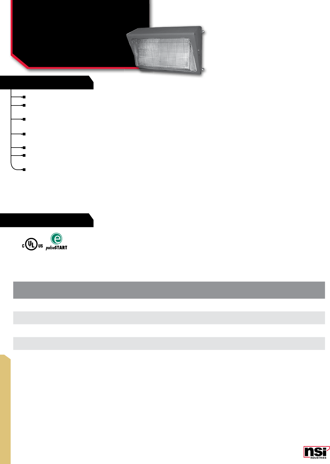
373
HID/OUTDOOR
FEATURES
RATINGS
CAT.
NO. DESCRIPTION VOLTAGEBALLASTHEIGHT WIDTH DEPTH LAMPBASE
WPM100MHQ 100 Watt Metal Halide 120/208/240/277VAC QUAD HX-HPF 914.25 7.1 ED17 Medium
WPM150SQ 150 Watt Sodium 120/208/240/277VAC QUAD HX-HPF 914.25 7.1 ED17 Medium
WPM150S 150 Watt Sodium 120VAC R-NPF 914.25 7.1 ED17 Medium
WPM150MHQP* 150 Watt Metal Halide
Pulse Start 120/208/240/277VAC QUAD PULSE 914.25 7.1 ED17 Medium
LIGHTING
Medium Wallpacks
WPM SERIES
For warehouse, perimeter lighting, security, and retail.
Die cast housing and lens frame with powdercoat finish and
a porcelain medium base socket assembly.
Front frame is hinged with one piece stippled aluminum
reflector.
Heat and shock resistant borosilicate glass lens, silicone
gasketing.
Listed for wet location use.
Excellent for security and perimeter lighting and commercial
and industrial applications.
Lamp included.
*
All dimensional data is listed in inches.

374
NSi Industries LLC • USA • 800.321.5847 • www.nsiindustries.com
374
HID/OUTDOOR
WALLPACK - LARGE DEEP
WALLPACK – LARGE
CAT.
NO. DESCRIPTION VOLTAGEBALLASTHEIGHT WIDTH DEPTH LAMPBASE
WPLD400SQ 400 Watt Sodium 120/208/240/277VAC QUAD CWA 918.2 12.8 ED18 Mogul
WPLD250SQ 250 Watt Sodium 120/208/240/277VAC QUAD CWA 918.2 12.8 ED18 Mogul
WPLD320MHQP* 320 Watt Metal
Halide Pulse Start 120/208/240/277VAC QUAD PULSE 918.2 12.8 ED37 Mogul
WPLD250MHQP* 250 Watt Metal
Halide Pulse Start 120/208/240/277VAC QUAD PULSE 918.2 12.8 ED28 Mogul
CAT.
NO. DESCRIPTION VOLTAGEBALLASTHEIGHT WIDTH DEPTH LAMPBASE
WPL250SQ 250 Watt Sodium 120/208/240/277VAC QUAD CWA 918.2 9.4 ED18 Mogul
WPL250MHQP* 250 Watt Metal
Halide Pulse Start 120/208/240/277VAC QUAD PULSE 918.2 9.4 ED28 Mogul
LIGHTING
Large & Large Deep
Wallpacks
WPL & WPLD SERIES
For warehouse, perimeter, security and retail lighting.
Large wallpacks have a die cast housing with
powdercoat finish and a porcelain mogul base socket
assembly.
One piece stippled aluminum reflector.
Heat and shock resistant borosilicate glass lens,
silicone gasketing.
Listed for wet location use.
Excellent for security and perimeter lighting, tunnels
and commercial and industrial applications.
Lamp included.
For warehouse, perimeter, security and retail lighting.
Large Deep wallpacks have a die cast housing with
powdercoat finish and a porcelain 4KV mogul socket
assembly.
Specular aluminum reflector. Heat and shock resistant
borosilicate glass lens, silicone gasketing.
Listed for wet location use.
Excellent for security and perimeter lighting, tunnels
and commercial and industrial applications.
Large Deep wallpacks have an extra deep housing for
better cooling and longer lasting Lamp included.
*
*
All dimensional data is listed in inches.
All dimensional data is listed in inches.
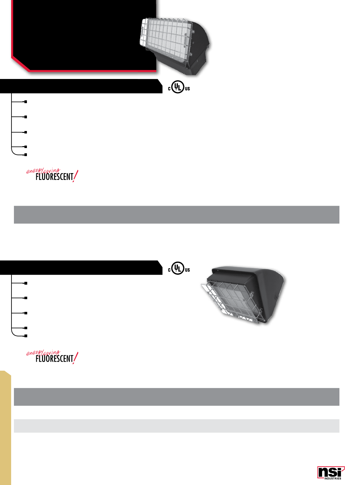
375
HID/OUTDOOR
"THE ROCKY" LARGE WALLPACK
CAT.
NO. DESCRIPTION VOLTAGE BALLASTHEIGHT WIDTH DEPTH LAMP BASE
WPCRKY100MHQ Compact Vandal Resistant Wallpack
100 Watt Metal Halide Quad HX-HPF 8.86 8.74 7.48 ED17 Medium
WPCRKY70S Compact Vandal Resistant Wallpack
70 Watt Sodium 120VAC R-NPF 8.86 8.74 7.48 ED17 Medium
WPCRKY42FL* Compact Vandal Resistant Wallpack
42 Watt Fluorescent 120/277VAC Electronic 8.86 8.74 7.48 CFL42W 3U GX24q
CAT.
NO. DESCRIPTION VOLTAGE BALLASTHEIGHT WIDTH DEPTH LAMP BASE
WPLRKY320MHQP* Large Vandal Resistant Wallpack 320 Watt Metal
Halide with Pulse Start Quad CWA 9.84 17 14.4 ED28 MOG
"THE ROCKY" COMPACT WALLPACK
For warehouse, parking lots, schools, correctional
facilities, and high potential abuse areas.
Includes wire guard and polycarbonate shield for total
protection.
Aluminum die cast housing, tempered glass lens, corrosion
resistant hardware and silicone gasketing.
Listed for wet location use.
Lamp included.
For warehouse, parking lots, schools, correctional
facilities and high potential abuse areas.
Includes wire guard and polycarbonate shield for total
protection.
Aluminum die cast housing, tempered glass lens,
corrosion resistant hardware and silicone gasketing.
Listed for wet location use.
Lamp included.
LIGHTING
Vandal Resistant
Wallpacks
WP "THE ROCKY" SERIES
*
*
All dimensional data is listed in inches.
All dimensional data is listed in inches.
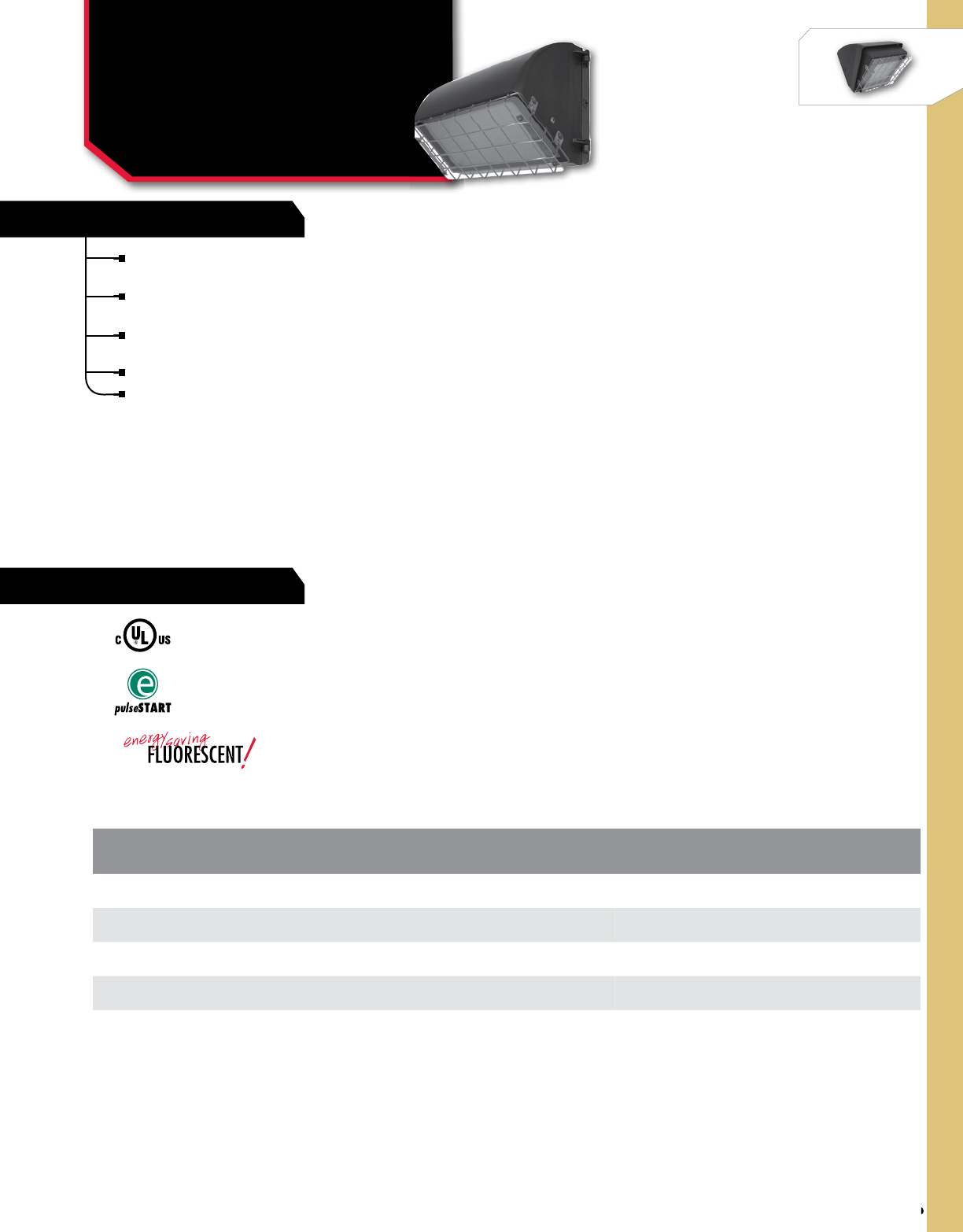
376
NSi Industries LLC • USA • 800.321.5847 • www.nsiindustries.com
376
HID/OUTDOOR
**
For warehouse, parking lots, schools, correctional facilities
and high potential abuse areas.
Includes wire guard and polycarbonate shield for total
protection.
Aluminum die cast housing, tempered glass lens, corrosion
resistant hardware and silicone gasketing.
Listed for wet location use.
Lamp included.
LIGHTING
Medium Vandal
Resistant Wallpacks
WP "THE ROCKY" SERIES
*
FEATURES
RATINGS
CAT.
NO. DESCRIPTION VOLTAGE BALLASTHEIGHT WIDTH DEPTH LAMP BASE
WPMRKY84FL* 84 Watt Fluorescent 120/277VAC Electronic 9.06 14.17 8.46 2 x CFL42W 3U GX24q
WPMRKY84FL-BBU* 84 Watt Fluorescent with
90 min. Battery Backup 120/277VAC Electronic 9.06 14.17 8.46 2 x CFL42W 3U GX24q
WPMRKY150SQ 150 Watt High Pressure Sodium Quad HX-HPF 9.06 14.17 8.46 ED23.5 MOG
WPMRKY150MHQP** 150 Watt Metal Halide
w/ Pulse Start Quad CWA 9.06 14.17 8.46 ED28 MOG
All dimensional data is listed in inches.
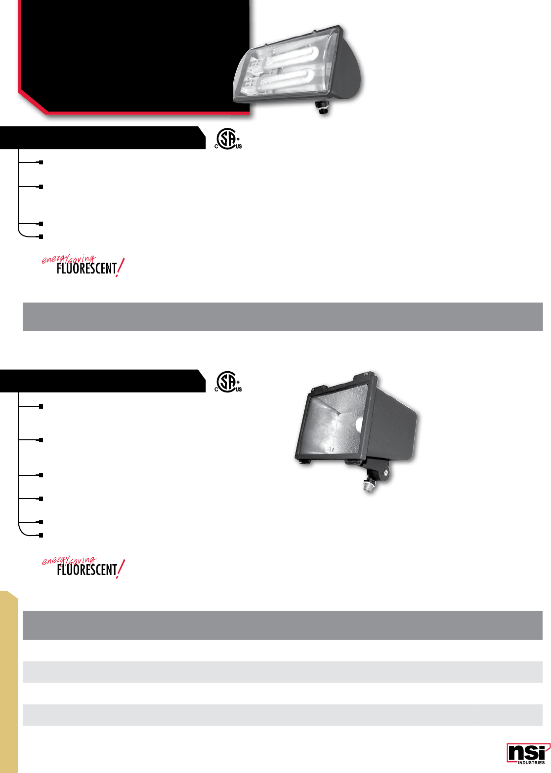
377
HID/OUTDOOR
CAT.
NO. DESCRIPTION VOLTAGE BALLASTHEIGHT WIDTH DEPTH LAMP BASE
FLC70MHQ Compact Flood 70 Watt Metal Halide 120/208/240/277VAC QUAD HX-HPF 7.5 97 ED17 Medium
FLC70SQ Compact Flood 70 Watt Sodium 120/208/240/277VAC QUAD HX-HPF 7.5 97 ED17 Medium
FLC150SQ Compact Flood 150 Watt Sodium 120/208/240/277VAC QUAD HX-HPF 7.5 97 ED17 Medium
FLC42FL* Compact Flood 42 Watt Fluorescent 120VAC ELECTRONIC 7.5 97 PLC Medium
CAT.
NO. DESCRIPTION VOLTAGE BALLASTHEIGHT WIDTH DEPTH LAMP
FLF26NM* Fluorescent Flood 26 Watt Non-metallic 120VAC ELECTRONIC 4.75 9.25 4.6 PLC
LIGHTING
Fluorescent & Compact
Floodlight
FLF & FLC SERIES
For landscape, facade, security, pathway and sign lighting.
NSi’s non-metallic Fluorescent Floodlight features twin
13 Watt fluorescent lamps, fully silicone gasketed lens
and frame.
Mounts with fully adjustable 1⁄2” NPT threaded knuckle.
Listed for wet locations.
Lamp included.
Compact designs are ideal for security, sign, accent
and perimeter, landscape, general floodlighting and
facade lighting.
Our Compact Floodlight has a die cast housing and lens
frame with powdercoat finish and a one piece high impact
tempered lens, ½” NPT knuckle assembly.
The reflector is stippled for glare reduction and controlled
beam distribution.
Hinged lens assembly has silicone gasket to seal out dust
and moisture.
Listed for wet location use.
Lamp included.
COMPACT FLOOD
FLUORESCENT FLOOD
*
*
All dimensional data is listed in inches.
All dimensional data is listed in inches.
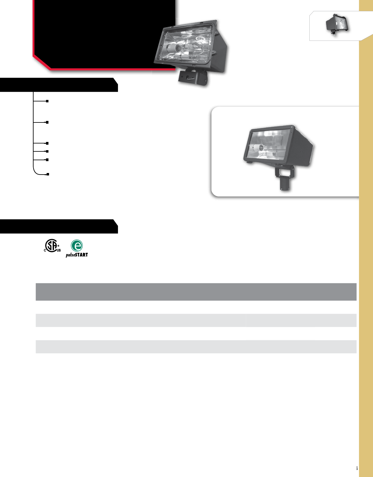
378
NSi Industries LLC • USA • 800.321.5847 • www.nsiindustries.com
378
HID/OUTDOOR
SHOWN MOUNTED ON FLPTM
CAT.
NO. DESCRIPTION VOLTAGE BALLASTHEIGHT WIDTH DEPTH LAMP BASE
FLLP150MHQP* 150 Watt Metal Halide Pulse Start 120/208/240/277VAC QUAD PULSE 10.25 16.25 10.75 ED28 Mogul
FLLP250MHQP* 250 Watt Metal Halide Pulse Start 120/208/240/277VAC QUAD PULSE 10.25 16.25 10.75 ED28 Mogul
FLLP320MHQP* 320 Watt Metal Halide Pulse Start 120/208/240/277VAC QUAD PULSE 10.25 16.25 10.75 ED37 Mogul
FLPTM Pole Tenon Mount for FLLP Series
LIGHTING
Low Profile Floodlight
FLLP SERIES
For large area perimeter and security lighting: Industrial,
storage yards, parking areas, auto dealerships, landscape
and recreational areas.
Our Low-Profile floodlight has a die cast housing with
powdercoat finish and comes with three piece anodized
aluminum reflector, supplying wide beam distribution.
High impact tempered lens.
Listed for wet location use.
Can be mounted for landscape/facade lighting; Pole
tenon mount available.
Lamp included.
*
FEATURES
RATINGS
All dimensional data is listed in inches.
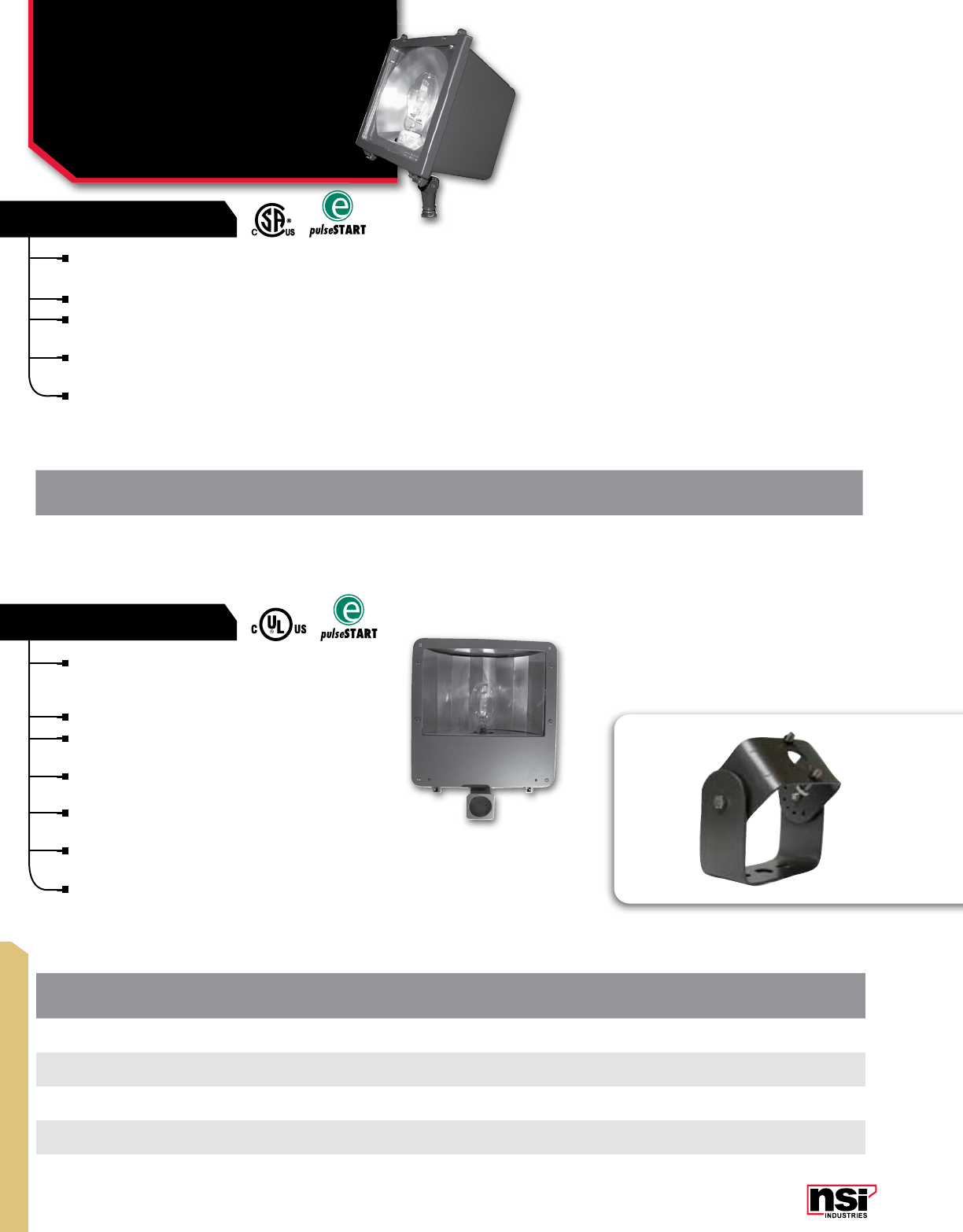
379
HID/OUTDOOR
CAT
NO. DESCRIPTION VOLTAGE BALLASTHEIGHT WIDTH DEPTH LAMP BASE
FL400SQ 400 Watt Sodium 120/208/240/277VAC QUAD CWA 17 16.5 7.2 ED18 Mogul
FL320MHQP* 320 Watt Metal Halide
Pulse Start 120/208/240/277VAC QUAD PULSE 17 16.5 7.2 ED28 Mogul
FL250MHQP* 250 Watt Metal Halide
Pulse Start 120/208/240/277VAC QUAD PULSE 17 16.5 7.2 ED28 Mogul
FLBR Bracket Mount for FL Series 250, 320 and 400 Watt Floods
CAT.
NO. DESCRIPTION VOLTAGE BALLASTHEIGHT WIDTH DEPTH LAMP BASE
FLM70MHQ 70 Watt Metal Halide 120/208/240/277VAC QUAD CWA 10.25 97.25 ED17 Medium
MEDIUM FLOOD
LARGE FLOOD
LIGHTING
Medium And Large
Floodlight
FLM & FL SERIES
*
*
For large area perimeter and security lighting:
Industrial, storage yards, parking areas, auto
dealerships, landscape and recreational areas.
16” 400, 320 and 250 Watt Floodlights.
Heavy duty die cast aluminum housing and durable
bronze powdercoat finish.
Extra heavy duty slipfitter included (bracket mount
is available).
Fixture has silicone gasketing, stainless steel hardware
and a tempered glass lens.
Front lens assembly is fully hinged for easy relamping
and maintenance.
Lamp included.
For compact designs: security, accent and perimeter lighting.
Ideal for landscape, general floodlighting, signs and facade lighting.
Die cast housing and hinged top frame with textured bronze finish.
The aluminum hydroformed reflector is rotatable and is adjustable
for horizontal or vertical lamp positions.
Fixture has adjustable ½” NPT threaded knuckle with angle
indicators to assist in correct aiming.
Lamp included.
FLBR
All dimensional data is listed in inches.
All dimensional data is listed in inches.
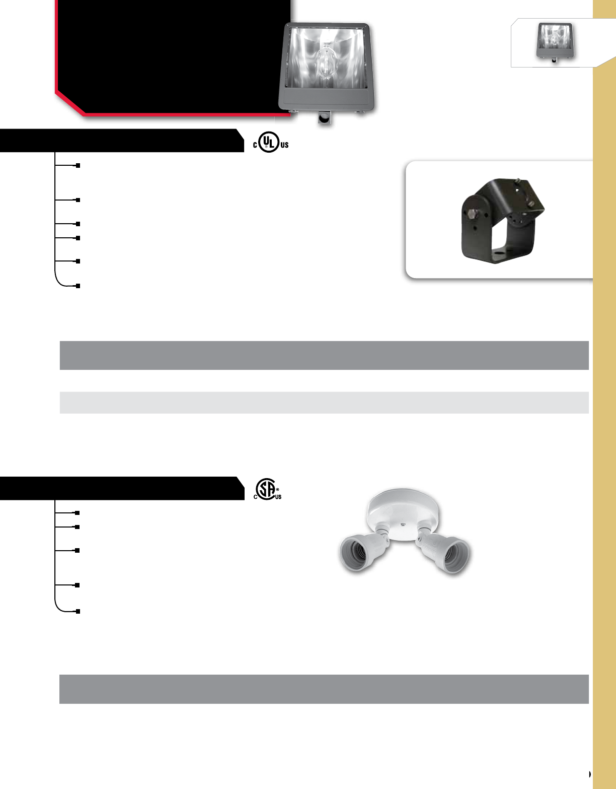
380
NSi Industries LLC • USA • 800.321.5847 • www.nsiindustries.com
380
HID/OUTDOOR
CAT.
NO. DESCRIPTION VOLTAGE BALLASTHEIGHT WIDTH DEPTH LAMP BASE
FLH1000MHQ 1000 Watt Flood Metal Halide 120/208/240/277VAC QUAD CWA 29 23.75 10.25 ED37 Mogul
FLH1000SQ 1000 Watt Flood Sodium 120/208/240/277VAC QUAD CWA 29 23.75 10.25 ED25 Mogul
FLHBR Bracket Mount For 1000 Watt Flood - FLH Series
CAT.
NO. DESCRIPTION DIAMETER
(BACKPLATE) LAMP
TYPE
PHNM300 300 Watt Nonmetallic Twin Par Holder 5.25 PAR 38
INCANDESCENT FLOOD
1000 WATT FLOOD
LIGHTING
1000 Watt And
Incandescent Floodlight
FLH & PHN SERIES
Incandescent: General purpose floodlighting
Quartz: Accent, security, landscape, facades, signs and
general purpose floodlighting.
The Non-metallic Par Holder features an oversized
backplate designed specially to cover gaps where cutouts
for boxes are too big.
The extra deep backplate also fits over a flush-mounted
pancake box to provide a good fit and appearance.
Both par holders swivel side to side and up and down
and can be securely locked.
For large area perimeter and security lighting: Industrial,
storage yards, parking areas, auto dealerships, landscape and
recreational areas.
23” 1000 Watt Floodlights have heavy duty die cast aluminum
housing and durable bronze powdercoat finish.
Extra heavy duty slipfitter included (bracket mount is available).
Fixture has silicone gasketing, stainless steel hardware and a
tempered glass lens.
Front lens assembly is fully hinged for easy relamping
and maintenance.
Lamp included.
FLHBR
All dimensional data is listed in inches.
All dimensional data is listed in inches.
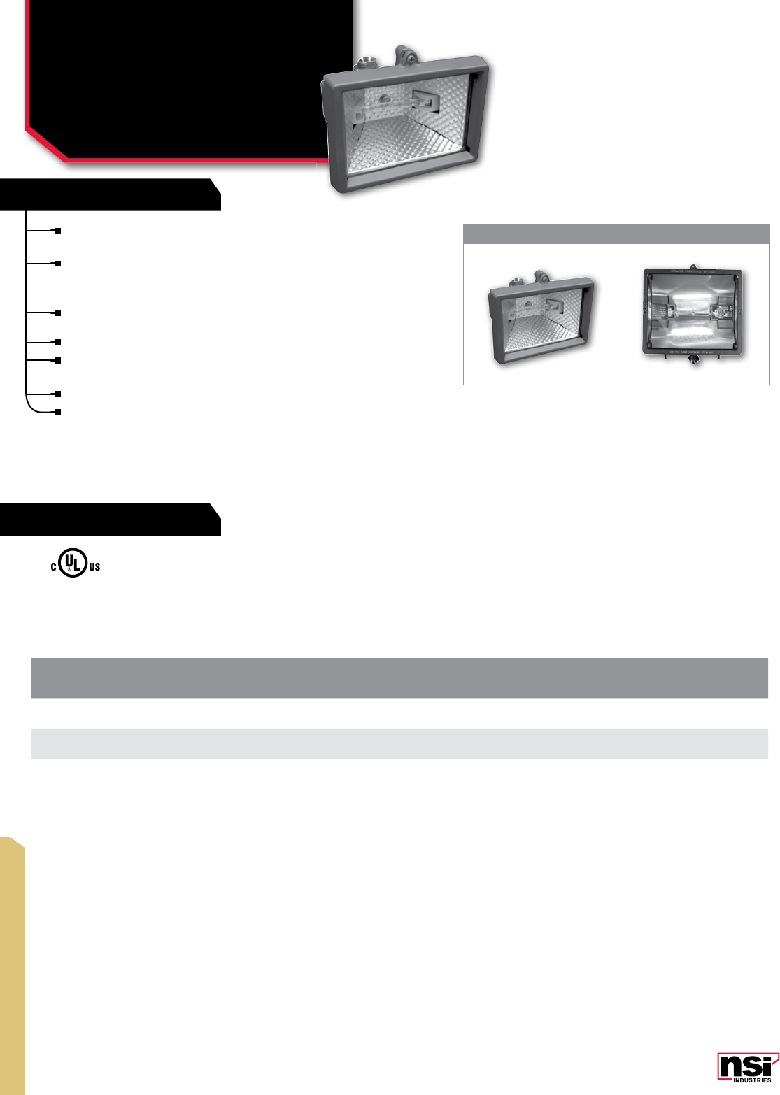
381
WORKLIGHT
FEATURES
RATINGS
CAT.
NO. FIG.
NO. DESCRIPTION VOLTAGE HEIGHT WIDTH EXTENSION
QF150B 1150 Watt Quartz Flood Bronze With Lamp 120VAC 3.5 3.3 3.9
QF300-500B 2Quartz Flood Bronze With 300/500 Watt Lamps 120VAC 5.75 5.75 4.6
1 2
For accent, security, landscape, facades, signs and
general purpose floodlighting.
Solid one piece die cast aluminum construction, high
impact resistant tempered glass lens, aluminum
reflector and corrosion resistant hardware.
Silicone rubber gasketing is included to prevent leakage
from outside.
UL and CUL listed for wet location use.
150 Watt is perfect for lighting small outdoor areas; the
others are excellent for general purpose floodlighting.
Mounts with ½” NPT knuckle.
Lamps included.
LIGHTING
Quartz Floodlight
with Lamp
QF SERIES
All dimensional data is listed in inches.

WORKLIGHT
NSi Industries LLC • USA • 800.321.5847 • www.nsiindustries.com 382
FEATURES
RATINGS
CAT.
NO. DESCRIPTION VOLTAGELAMP
BKS70RL-MED 70 Watt HPS Reactor 120VAC Medium
BKS50QL-MED 50 Watt HPS Quad 120/208 /240/277V Medium
BKS70QL-MED 70 Watt HPS Quad 120/208/240/277V Medium
BKS100QL-MED 100 Watt HPS Quad 120/208/240/277V Medium
BKS150QL-MED 150 Watt HPS Quad 120/208/240/277V Medium
BKS250QL-M 250 Watt HPS Quad 120/208/240/277V Mogul
BKS400QL-M 400 Watt HPS Quad 120/208/240/277V Mogul
BKS1000QL-M 1000 Watt HPS Quad 120/208/240/277V Mogul
BKS1000480L-M 1000 Watt HPS 480VAC Mogul
LIGHTING
High Pressure Sodium
Ballast Kits with Lamp
BKS SERIES
Kit includes: Cap, ignitor, brackets with Medium
or Mogul lamp.
Kit includes: Cap, ignitor, brackets with Medium
or Mogul lamp.
Kit includes: Cap, ignitor, brackets with Medium
or Mogul lamp.
Kit includes: Cap, ignitor, brackets with Medium

383
WORKLIGHT
FEATURES
RATINGS
CAT.
NO. DESCRIPTION VOLTAGELAMP
BKM50QL-MED 50 Watt Metal Halide Quad 120/208/240/277V Medium
BKM70QL-MED 70 Watt Metal Halide Quad 120/208/240/277V Medium
BKM100QL-MED 100 Watt Metal Halide Quad 120/208/240/277V Medium
BKM175QL-MED 175 Watt Metal Halide Quad 120/208/240/277V Medium
BKM175QL-M 175 Watt Metal Halide Quad 120/208/240/277V Medium
BKM250QL-M 250 Watt Metal Halide Quad 120/208/240/277V Medium
BKM400QL-M 400 Watt Metal Halide Quad 120/208/240/277V Mogul
BKM400480L-M 400 Watt Metal Halide 480VAC Mogul
BKM1000QL-M 1000 Watt Metal Halide 120/208/240/277V Mogul
BKM1000480L-M 1000 Watt Metal Halide 480VAC Mogul
BKM320QPL-M* 320 Watt Metal Halide Pulse Quad 120/208/240/277V Mogul
Kit includes: Cap, ignitor, brackets with Medium
or Mogul lamp.
*
LIGHTING
Metal Halide Ballast Kits
with Lamp
BKM SERIES

WORKLIGHT
NSi Industries LLC • USA • 800.321.5847 • www.nsiindustries.com 384
FEATURES
RATINGS
Kit includes: Cap, ignitor, and brackets.
CAT.
NO. DESCRIPTION VOLTAGE
BKS70R 70 Watt HPS Reactor – Cap, Ignitor & Brackets 120V
BKS100R 100 Watt HPS Reactor – Cap, Ignitor & Brackets 120V
BKS50Q 50 Watt HPS Quad – Cap, Ignitor & Brackets 120/208/240/277V
BKS70Q 70 Watt HPS Quad – Cap, Ignitor & Brackets 120/208/240/277V
BKS100Q 100 Watt HPS Quad – Cap, Ignitor & Brackets 120/208/240/277V
BKS150Q 150 Watt HPS Quad – Cap, Ignitor & Brackets 120/208/240/277V
BKS250Q 250 Watt HPS Quad – Cap, Ignitor & Brackets 120/208/240/277V
BKS400Q 400 Watt HPS Quad – Cap, Ignitor & Brackets 120/208/240/277V
BKS1000Q 1000 Watt HPS Quad – Cap, Ignitor & Brackets 120/208/240/277V
LIGHTING
High Pressure Sodium
Ballast Kits Only
BKS SERIES

385
EMERGENCY/EXIT
FEATURES
RATINGS
CAT.
NO. DESCRIPTION VOLTAGE
BKM50Q 50 Watt Metal Halide Quad – Cap, Ignitor & Brackets 120/208/240/277V
BKM70Q 70 Watt Metal Halide Quad – Cap, Ignitor & Brackets 120/208/240/277V
BKM100120 100 Watt Metal Halide – Cap, Ignitor & Brackets 120V
BKM100Q 100 Watt Metal Halide Quad – Cap, Ignitor & Brackets 120/208/240/277V
BKM175Q 175 Watt Metal Halide Quad – Cap & Brackets 120/208/240/277V
BKM250Q 250 Watt Metal Halide Quad – Cap & Brackets 120/208/240/277V
BKM400Q 400 Watt Metal Halide Quad – Cap & Brackets 120/208/240/277V
BKM400480 400 Watt Metal Halide – Cap & Brackets 480V
BKM1000Q 1000 Watt Metal Halide Quad – Cap & Brackets 120/208/240/277V
BKM1000480 1000 Watt Metal Halide – Cap & Brackets 480V
BKM150QP* 150 Watt Metal Halide Pulse Quad – Cap, Ignitor & Brackets 120/208/240/277V
BKM250QP* 250 Watt Metal Halide Pulse Quad – Cap, Ignitor & Brackets 120/208/240/277V
BKM320QP* 320 Watt Metal Halide Pulse Quad – Cap, Ignitor & Brackets 120/208/240/277V
Kit includes: Cap, ignitor, and brackets.
LIGHTING
Metal Halide Ballast
Kits Only
BKM SERIES
*
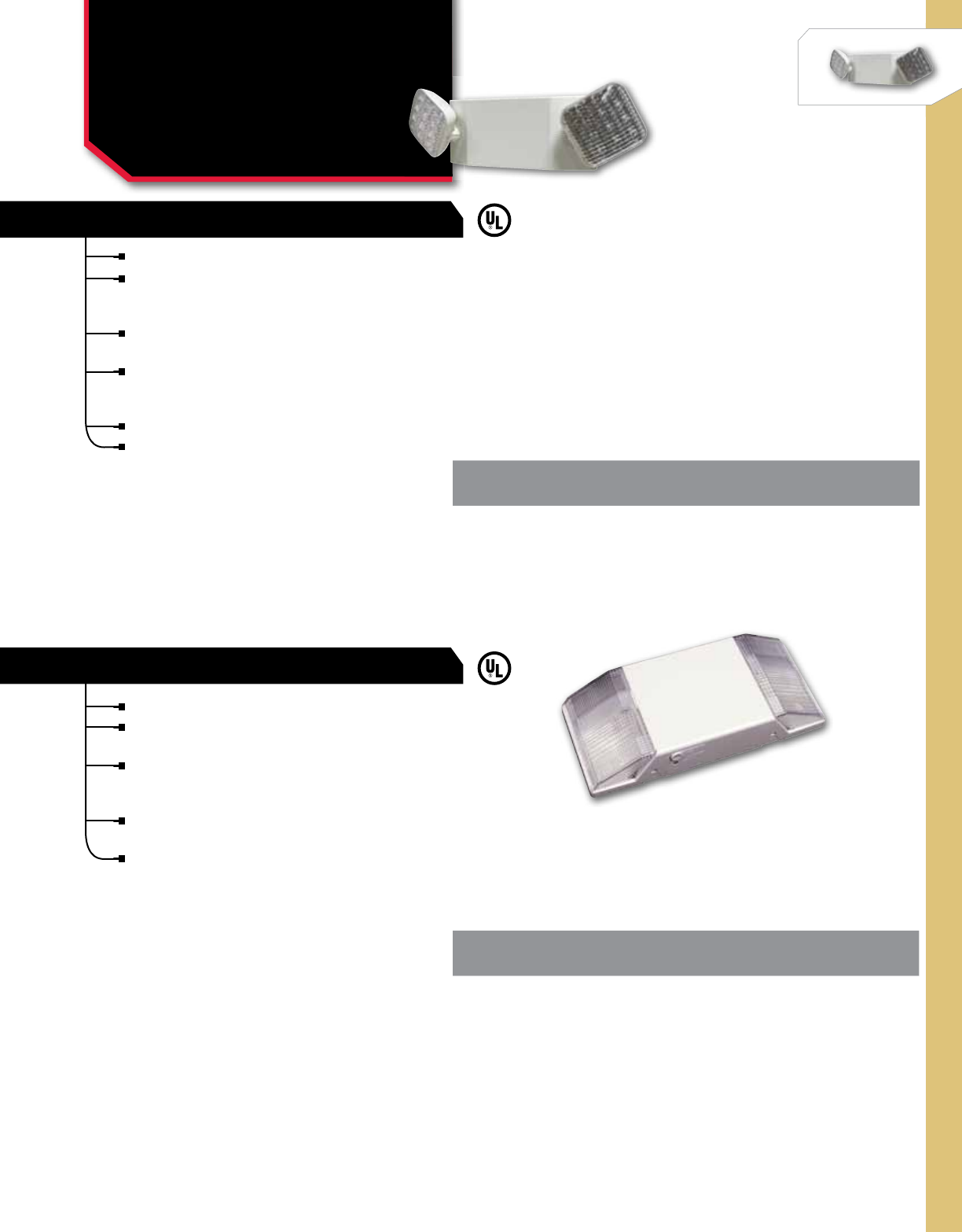
EMERGENCY/EXIT
NSi Industries LLC • USA • 800.321.5847 • www.nsiindustries.com 386
CAT.
NO. UPC
CODE BATTERY HOUSING LAMP
EMTW-LED 05281 6 Volt White 2 x 5.4 Watt
CAT.
NO. BATTERYHOUSING LAMP
EMFW 6 Volt White 2 x 5.4 Watt
TWIN HEAD EMERGENCY LIGHT
FIXED OPTICS EMERGENCY LIGHT
LIGHTING
Twin Head & Fixed Optics
Emergency Light
EMTW & EMFW SERIES
For commercial, industrial, institutional and retail lighting.
Unit gives a low profile appearance with automatic LVD
(low voltage disconnect) and universal transformer for
120 or 277VAC.
Universal mounting plate with quick connect for labor
saving installation.
Injection-molded V-O flame retardant high-impact
thermoplastic housing and a 6 volt sealed lead acid
maintenance free battery with 90 minute operation.
Environmentally-coated solid state charger.
Listed for damp location use.
For commercial, industrial, institutional and retail lighting.
Fully automatic operation with automatic LVD (low voltage
disconnect) and universal transformer for 120 or 277VAC.
Injection-molded V-O flame retardant high-impact
thermoplastic housing and a 6 volt premium grade, sealed
lead acid, maintenance free battery with 90 minute operation.
Compact, low profile design in pleasing neutral finish with
environmentally-coated solid state charger.
Listed for damp location use.
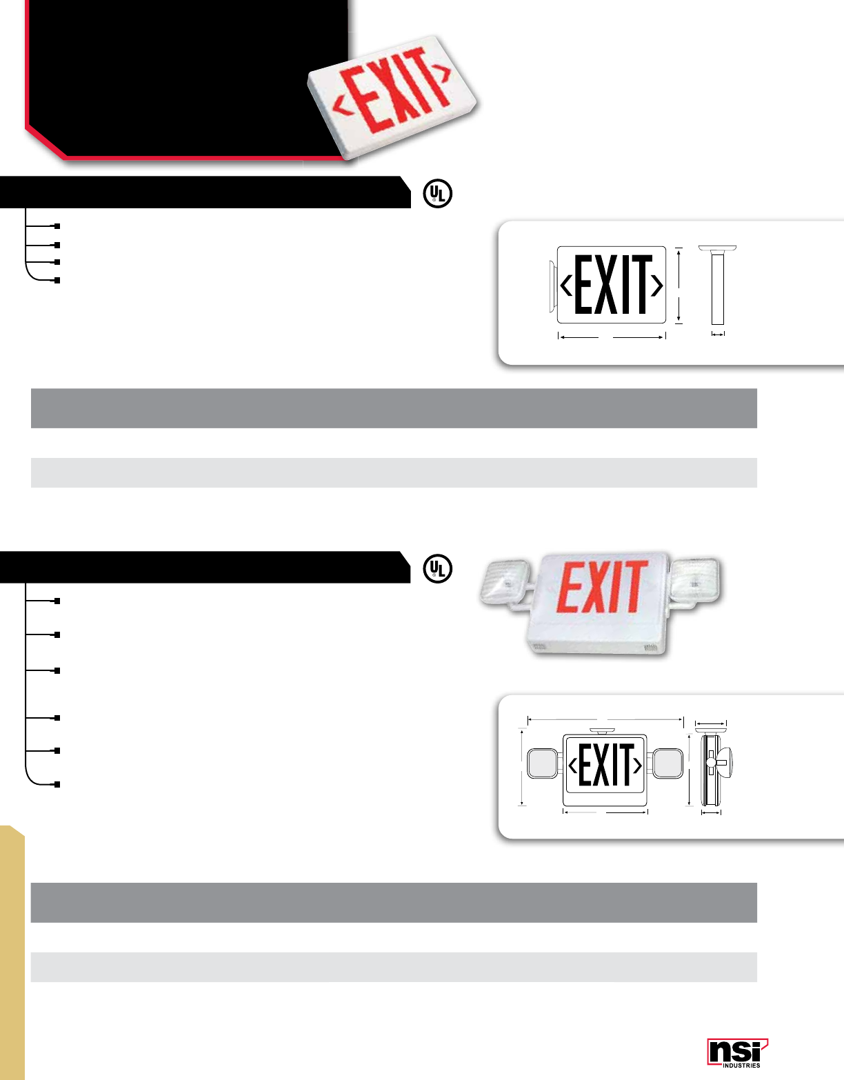
387
EMERGENCY/EXIT
LED EXIT LIGHT
COMBO LED/INCANDESCENT EXIT LIGHT
CAT.
NO. NO. OF
FACES TYPE LETTERING HOUSING
EXLRW 2AC Red White
EXLBURW-SL 290 Min. Slimline Battery Backup Red White
EXLBUGW 290 Min. Battery Backup Green White
CAT.
NO.NO. OF
FACES LETTERING HOUSING REMOTE
EEL2RW-LED 2Red White No
EEL2RWRM-LED 2 Red White Yes
EEL2GW 2Green White No
For commercial, industrial, institutional and retail lighting.
Fully automatic operation at 120 or 277VAC with 25+ years LED lamp life.
LED exit lights have a universal mounting canopy for side or top installation.
Injection-molded V-O flame retardant high-impact thermoplastic housing
with a low profile design and excellent energy savings.
For commercial, industrial, institutional and retail lighting.
Excellent energy savings and the LED lamp life of 25+ years.
Automatic LVD (low voltage disconnect) and universal
transformer for 120 or 277VAC.
Injection-molded V-O flame retardant high-impact thermoplastic
housing and a 6 volt pure lead maintenance free battery with
90 minute operation.
Two fully adjustable glare free lighting heads in a compact,
modern design.
Self-diagnostic and remote capable options are available for
this fixture, call for special quote.
Universal mounting canopy for ceiling installation.
12”
7.5”
1.5”
22”
13”
10”
11”
5“
2 “
/
34
LIGHTING
LED Exit & Combo LED
Incandescent Exit Light
EXL & EEL SERIES
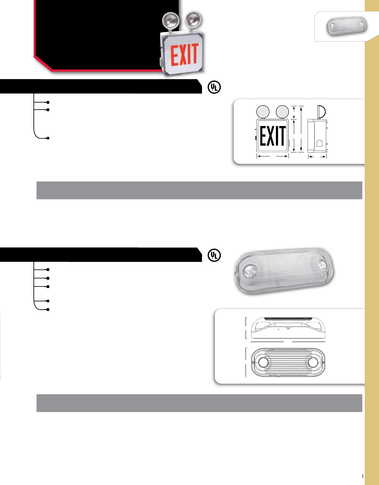
388
NSi Industries LLC • USA • 800.321.5847 • www.nsiindustries.com
388
EMERGENCY/EXIT
CAT.
NO. DESCRIPTION BATTERY
TYPE BATTERYHEIGHT WIDTH DEPTH LAMP
EMTWMR16WL Wet Location Twin Head
Mr16 Emergency Light-Gray
Sealed Lead Acid
90 Minute Operation 6V 5.7 14.9 4.2 2 x 7 Watt MR-16 Halogen
WET LOCATION LED EXIT LIGHT, 2-HEAD UNIT
WET LOCATION LED EXIT LIGHT
CAT.
NO.TYPE LETTERING HOUSING BATTERY
EMWL26RW 2-Head Emergency Light Red White 6V
LIGHTING
Wet Location
Emergency Light
EMWL & EMTW SERIES
For commercial, industrial, institutional and retail lighting.
ABS, corrosion resistant UV stabilized enclosures meet NFPA,
NEC, OSHA, NEC and local and state codes, making these
energy-saving wet location LED exit lights great for corrosive
or damaging environments.
Universal 120/277VAC operation with removable directional
indicators and an 25+ year light source life expectancy.
For commercial, industrial, institutional and retail lighting.
Dual 120/277VAC operation.
Sealed lead acid, rechargeable, maintenance-free battery and
high-impact housing.
Push-to-test switch and automatic, low-voltage disconnect (LVD).
Completely self-contained and UL listed for wet locations.
12”
12” 6 ”
7
/
8
6”
18”
14.9"
5.7"
4.2"
All dimensional data is listed in inches.
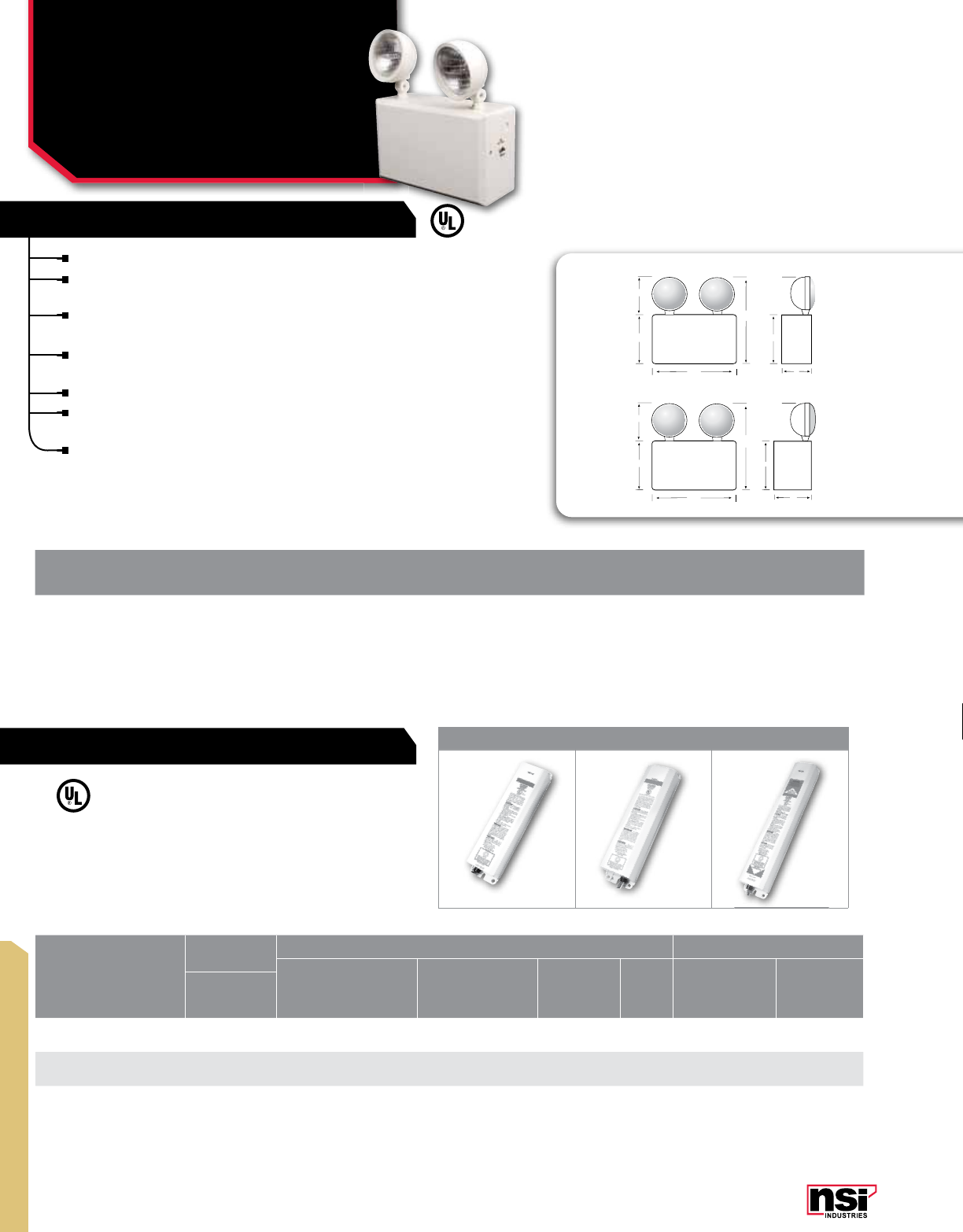
389
EMERGENCY/EXIT
LIGHTING
Heavy Duty Emergency
Light & Emergency
Fluorescent Ballast
EMHD & FBP SERIES
CAT.
NO. WATTAGE
CAPACITY BATTERYVOLTAGE LAMP
EMHD506 50 Watt 6 Volts 120/277VAC 13
*The ballast may not fit in a typical T5 fixture and needs to be remotely mounted. All ballast are standard with dual 120/277V input. Damp location listed (0 °C to 50 °C).
CAT.
NO.FIG. LUMENS
DIMENSIONSLINEAR LAMPS COMPACT FLUORESCENT LAMPS
2'4' Rapid, Instant, or Energy
Savings, T8-T12, HO, VHO
2'-8' Rapid, Instant, or
Energy Savings, Circline
T8-T12, HO, VHO
8W-28W
- T5*
54W -
T5HO
17W-40W 4-pin
compact 40W-55W 4-pin
compact
HLW
FBP100 1500 1.5" 9.4" 2.4" 1 1 1
FBP60 2700 1.5" 9.4" 2.4" 1 or 2 1 1 1 or 2 1
FBP50 31400 1.5" 13.3" 2.4" 1 or 2 1 1 or 2 1 or 2 1 or 2 1
HEAVY DUTY EMERGENCY LIGHT
EMERGENCY FLUORESCENT BALLAST
For commercial, industrial, institutional and retail lighting.
Automatic LVD (low voltage disconnect) and universal transformer
for 120 or 277 VAC.
This heavy duty light comes standard with two fully adjustable
glare-free lighting heads and side and top conduit KOs.
6 volt premium grade, sealed lead acid, maintenance free batteries
included with 10 year life expectancy.
Remote capability and easy installation.
6 volt units offer 7.2 watt lamps standard and 12 volt units offer 9
watt lamps standard.
UL listed for damp location use.
123
12.5”
8”
14”
3”
6”
8”
6V
12.5 ”
8”
14”
5”
6”
8”
12V
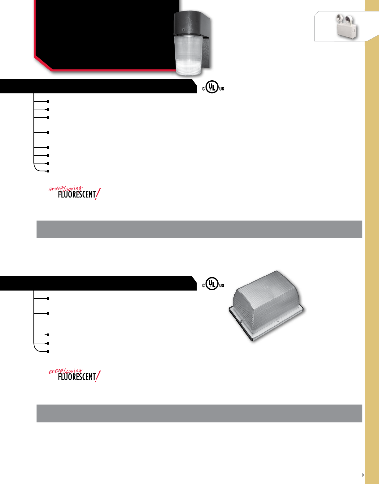
390
NSi Industries LLC • USA • 800.321.5847 • www.nsiindustries.com
390
VANDAL/CANOPY
CAT.
NO.DESCRIPTION VOLTAGE BALLAST HEIGHT WIDTH DEPTH LAMP
VRM13FL* Mini VR 5x8 13 Watt
Fluorescent (Clear Lens) 120VAC Electronic 5.5 7.75 4.25 PLC
CAT.
NO.DESCRIPTION VOLTAGE BALLAST HEIGHT WIDTH DEPTH LAMP
EL26FL* Entry Cylinder
26 Watt Fluorescent 120 VAC Electronic 957PLC
LIGHTING
Entry Cylinder &
5x8 Vandal Resistant
EL & VRM SERIES
ENTRY CYLINDERS
VANDAL RESISTANT 5X8 ENTRY LIGHT
For loading docks, security lighting and entrance doorway lighting.
EL Series Entry Cylinder in sodium or fluorescent.
Features impact and corrosion resistant polycarbonate housing and
polycarbonate lens.
The lens is engineered to diffuse the light to properly light
entryways without glare.
Lens locks in place with an allen set screw to resist tampering.
26W 4100K fluorescent lamp.
Listed for wet locations.
Lamp included.
For residential multi-family, commercial, institutional entry
and small area fixtures.
Available in fluorescent with clear polycarbonate lens.
Includes steel pan, gasket and hardware, socket and
bracket.
Can be ceiling/canopy or wall mounted.
Listed for wet locations.
Lamp Included
*
*
All dimensional data is listed in inches.
All dimensional data is listed in inches.

391
VANDAL/CANOPY
CAT.
NO. DESCRIPTION VOLTS BALLAST HEIGHT WIDTH DEPTH LAMPBASE
VRS100MHQ Large Vandal Resistant 12x12 Square
100 Watt Metal Halide 120/208/240/277VAC QUAD HX-HPF 12.4 12.3 8.6 ED17 Medium
CAT.
NO. DESCRIPTION VOLTS BALLAST HEIGHT WIDTH DEPTH LAMPBASE
VRS70MHQ Small Vandal Resistant 8x8 Square
70 Watt Metal Halide 120/208/240/277VAC QUAD HX-HPF 16.63 16.13 7 ED17 Medium
SMALL VANDAL RESISTANT
LIGHTING
Small & Large Vandal
Resistant Light
VRS SERIES
For large area perimeter and security lighting:
Industrial, storage yards, parking areas, auto
dealerships, landscape and recreational areas.
Heavy duty die cast aluminum housing and
hinged top frame, ½” coin plugs for conduit &
photocell, textured architectural bronze powder
finish over a chromate conversion coating.
Aluminum smooth reflector with tempered flat
clear glass lens.
2-piece swivel bracket, adjustable slipfitter
for mounting.
Listed for wet locations.
Lamp included.
For canopy, parking garages and loading dock lighting.
Die cast housing, chromate conversion coating and
textured bronze finish and corrosion resistant stainless
steel hardware.
Polycarbonate lens, silicone gasketing and medium
socket with white reflector.
1/2” coin plugs are provided for surface wiring.
Listed for wet locations.
Lamp included.
LARGE VANDAL RESISTANT
All dimensional data is listed in inches.
All dimensional data is listed in inches.
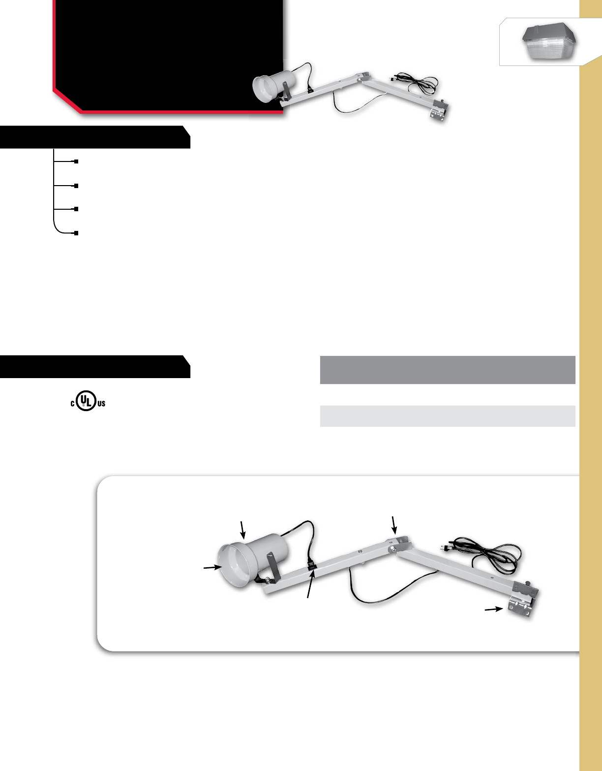
WORKLIGHT
NSi Industries LLC • USA • 800.321.5847 • www.nsiindustries.com 392
FEATURES
RATINGS CAT.
NO DESCRIPTION COLOR
TA-DOK 40VA 115VAC Extends 40 Inches Yellow
TA-DOK 60VA 115VAC Extends 60 Inches Yellow
LIGHTING
Incandescent Loading
Dock Lights
TA-DOK SERIES
Adjustable pivot friction which maintains
intended positions.
1 1/2” square, 14 gauge steel arm
resists damage from impact.
36”, 3 conductor #18SJT cord with wall
plug is included.
Lamp not included.
KNUCLE JOINT CONSTRUCTION
Horizontal and Vertical Positions
PAR38 OR R40 BULB
Up to 300 Watts (Bulb Not Included)
YELLOW FINISH
Powder Coat Paint
PORCELAIN SOCKET
PLUG SOCKET STEEL MOUNTING BRACKET
2 Pc. Heavy Duty
#18SJT 3 CONDUCTOR
Cord With Wall Plug
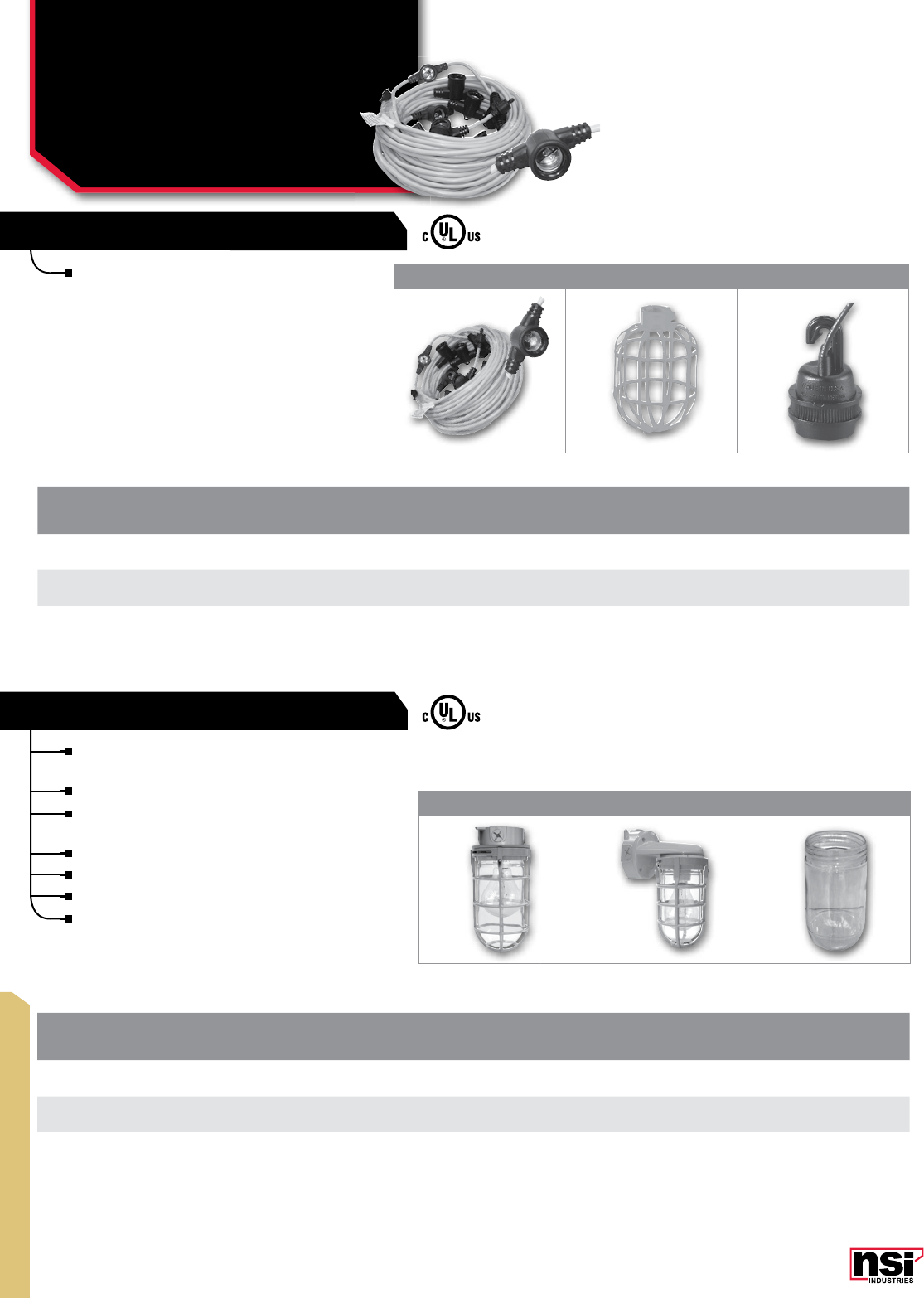
393
WORKLIGHT
123
CAT.
NO FIG.
NO. DESCRIPTION STD.
CTN.
QTY.
SLUL100* 1100 Ft. With Molded Sockets In 10 Ft. Intervals. 150 Watts. Osha And Nec Compliant. High Visibility Yellow. 1
SC200 2Standard Cage 24
RS200 3Rotatable Socket 200 Watt 24
LIGHTING
Short-term Lighting
Systems, Accessories &
Box & Wall Vaportite
SLUL, SC, RS, VTB, VTW SERIES
*UL Listed.
SHORT-TERM LIGHTING SYSTEMS
123
CAT.
NO. FIG.
NO. DESCRIPTION HEIGHT WIDTH LAMP
VTB15012 1Box 150 Watt ½" Vaportite 94.125 Incandescent
VTW15012 2Wall 150 Watt ½ Vaportite 10 7.13 Incandescent
CG150 3Clear Glass Globe for 150 Series
Vaportite Fixtures –––
BOX AND WALL VAPORTITE
For well or pit lighting, indicators on docks,
industrial and commercial lighting.
Heavy duty die cast aluminum housing.
One piece locking die cast aluminum guard
with grey polyester powder coat finish.
Screw in tempered glass globe.
Listed for wet location use.
½” NPT knockouts.
Lamp not included.
All dimensional data is listed in inches.
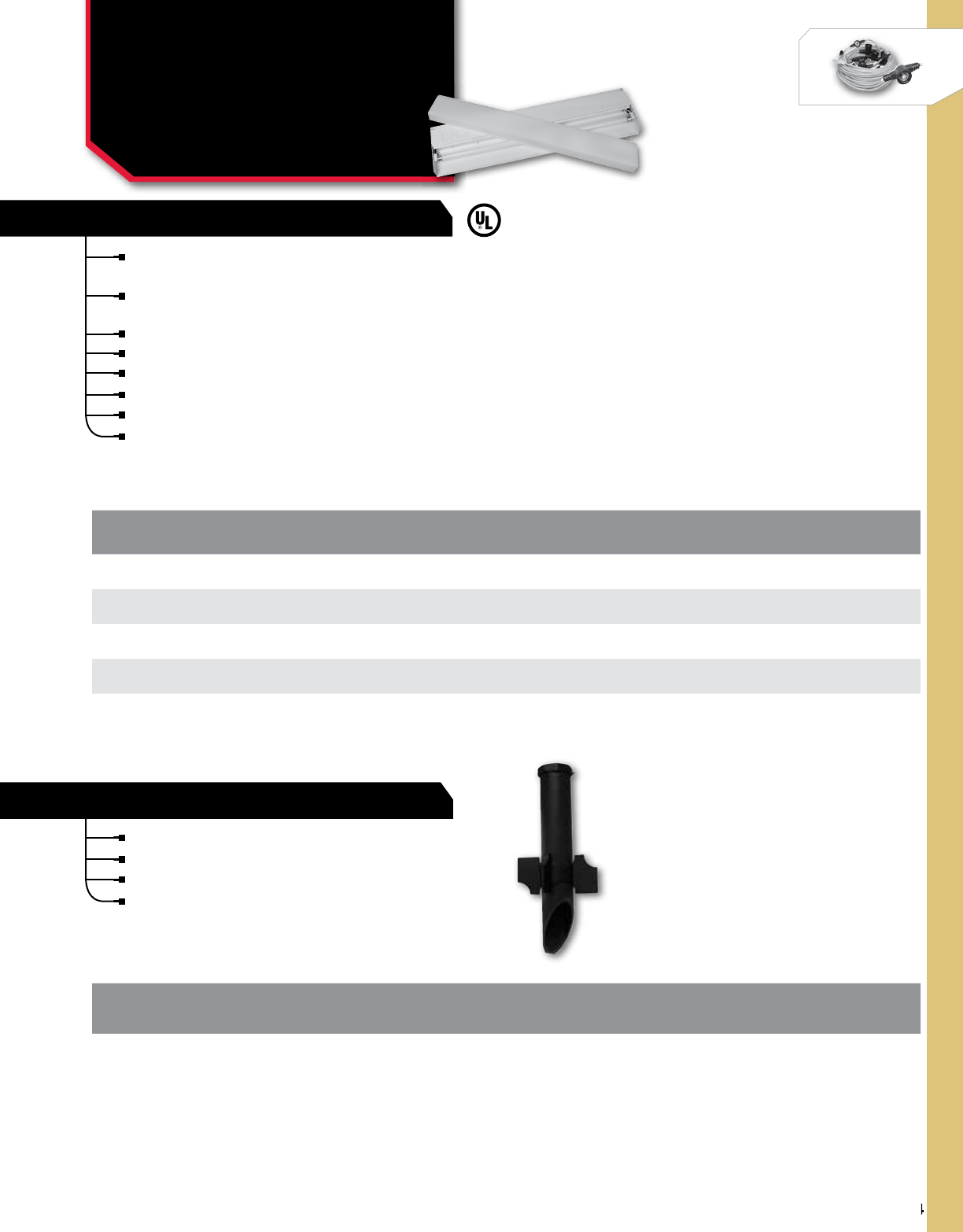
394
NSi Industries LLC • USA • 800.321.5847 • www.nsiindustries.com
394
WORKLIGHT
CAT.
NO. DESCRIPTION VOLTS LENGTH WIDTH DEPTH
UCF128WT5 8 Watt T-5 Electronic Ballast, with Lamp 110-125 12 5 1
UCF2113WT5 13 Watt T-5 Electronic Ballast, with Lamp 110-125 21 5 1
UCF2416WT5 16 Watt T-5 Electronic Ballast, with Lamp 110-125 24 5 1
UCF3321WT5 21 Watt T-5 Electronic Ballast, with Lamp 110-125 33 5 1
UCF4226WT5 26 Watt T-5 Electronic Ballast, with Lamp 110-125 42 5 1
LIGHTING
Fluorescent Undercabinet
& Heavy Duty Ground
Stake
UCF SERIES
FLUORESCENT UNDERCABINET
HEAVY DUTY GROUND STAKE
For fluorescent undercabinet lighting is constructed of
heavy duty steel with white powdercoat finish.
UV inhibited acrylic diffuser with linear prism which snaps
in for easy maintenance.
T-5 4100K lamp included.
Flourescent is great for energy savings.
Ultra thin, 1" thick.
K.O.s on top, side and back.
Includes rocker switch.
Lamp Included.
Adjustable stabilizer and built in wiring compartment.
Durable molded plastic with die cast fitting for 1⁄2” NPT threads.
Two 1⁄2” coin plugs for enclosed wiring.
Two 1⁄2” coin plugs outside for surface and through-wiring.
CAT.
NO. DESCRIPTION HEIGHT WIDTH DEPTH
GST Non-metallic Heavy Duty Ground Stake 19 93.5
All dimensional data is listed in inches.
All dimensional data is listed in inches.

ALPHANUMERIC INDEX
ALPHANUMERIC INDEX
559
0T – 1000T ...........................13
0TC – 6TC-1........................... 39
1012 – 1042 ........................133
1101 . . . . . . . . . . . . . . . . . . . . . . . . . . .423, 553
1101-7 .............................423
1101BM-IAP......................423, 553
1101B-P ............................423
1101D ..............................553
1101FM-M ...........................553
1101FM-N ...........................553
1101-NC ............................423
1101-O .............................423
1102B ..............................423
1103 . . . . . . . . . . . . . . . . . . . . . . . . . . . . . . .423
1103B-P ............................423
1103M..............................423
1103-NC ............................423
1103-O .............................423
1104 . . . . . . . . . . . . . . . . . . . . . . . . . . .423, 553
1104BM-IAP......................423, 553
1104BM-MB..........................423
1104B-O ........................423, 553
1104B-P ........................423, 553
1104D ..............................553
1104DF .............................553
1104FM-M ...........................553
1104FM-N ...........................553
1104-NC ............................423
1847A . . . . . . . . . . . . . . . . . . . . . . . . . .433–434
1847AL .........................433–434
1847AW.........................433–434
1847AWL........................433–434
1847AZ .........................433–434
1847AZL ........................433–434
1848A . . . . . . . . . . . . . . . . . . . . . . . . . .433–434
2/0–14.............................129
2/0TP – 2-600TP.......................23
2-14 – 4-14..........................129
2-210T≠2-1000T .......................13
2-350L4 – 8-350L8 ..................... 31
2-350T2 – 8-350T4 .....................31
2C-14, 4C-14 .........................129
2SR – 750SR ..........................21
200-3-2.............................285
250L2 – 600L2 ........................15
2000 . . . . . . . . . . . . . . . . . . . . . . . . . . . . . . .405
2000-2 .............................405
2001 . . . . . . . . . . . . . . . . . . . . . . . . . . . . . . .406
2002 . . . . . . . . . . . . . . . . . . . . . . . . . . . . . . .406
2005A . . . . . . . . . . . . . . . . . . . . . . . . . . . . . .411
2005B ..............................412
2006 . . . . . . . . . . . . . . . . . . . . . . . . . . . . . . .406
2007A . . . . . . . . . . . . . . . . . . . . . . . . . . . . . .411
2007B ..............................412
2008B ..............................412
2018 . . . . . . . . . . . . . . . . . . . . . . . . . . . . . . .406
2021 . . . . . . . . . . . . . . . . . . . . . . . . . . . . . . .407
2022 . . . . . . . . . . . . . . . . . . . . . . . . . . . . . . .407
2024 – 2042.........................135
2101 . . . . . . . . . . . . . . . . . . . . . . . . . . . . . . .403
2104 . . . . . . . . . . . . . . . . . . . . . . . . . . . . . . .403
2107 . . . . . . . . . . . . . . . . . . . . . . . . . . . . . . .403
2115 . . . . . . . . . . . . . . . . . . . . . . . . . . . . . . .404
2116 . . . . . . . . . . . . . . . . . . . . . . . . . . . . . . .404
2117 . . . . . . . . . . . . . . . . . . . . . . . . . . . . . . .404
2223 . . . . . . . . . . . . . . . . . . . . . . . . . . . . . . .416
2224 . . . . . . . . . . . . . . . . . . . . . . . . . . . . . . .416
2421 . . . . . . . . . . . . . . . . . . . . . . . . . . . . . . .416
300T-2 – 800T-4 .......................19
350LL2 – 8-1000LL12 ..................29
36175 – 481750......................325
3000 . . . . . . . . . . . . . . . . . . . . . . . . . . . . . . .408
3002 . . . . . . . . . . . . . . . . . . . . . . . . . . . . . . .408
3006 . . . . . . . . . . . . . . . . . . . . . . . . . . . . . . .408
3010 . . . . . . . . . . . . . . . . . . . . . . . . . . . . . . .408
4-250L4 – 4-1000L4 ...................17
401A . . . . . . . . . . . . . . . . . . . . . . . . . . . . . . .523
402A . . . . . . . . . . . . . . . . . . . . . . . . . . . . . . .523
403A . . . . . . . . . . . . . . . . . . . . . . . . . . . . . . .523
405A . . . . . . . . . . . . . . . . . . . . . . . . . . . . . . .523
418 – 60175.....................319–320
418-4 – 1450-5...................327–328
418-ID – 818H-ID . . . . . . . . . . . . . . . . . . . . .324
418-SB – 14120-SB ...................335
418X – 14500X...................319–320
455D ...............................525
457Z ...............................525
4180 – 601750.......................321
530MH – 141200MH...................333
5001M..............................409
5004M..............................409
5007M..............................409
5008M..............................409
5021M..............................409
5024M..............................409
5026M..............................409
5231 . . . . . . . . . . . . . . . . . . . . . . . . . . . . . . .413
5237 . . . . . . . . . . . . . . . . . . . . . . . . . . . . . . .413
5237-UL ............................414
5401A . . . . . . . . . . . . . . . . . . . . . . . . . . . . . .488
5403A . . . . . . . . . . . . . . . . . . . . . . . . . . . . . .410
5404A . . . . . . . . . . . . . . . . . . . . . . . . . . . . . .410
5404-3A ............................410
5441A . . . . . . . . . . . . . . . . . . . . . . . . . . . . . .488
5500 . . . . . . . . . . . . . . . . . . . . . . . . . . . . . . .416
5500-OC ............................416
5737TM .............................415
5737TZ .............................415
601A . . . . . . . . . . . . . . . . . . . . . . . . . . . . . . .527
602A . . . . . . . . . . . . . . . . . . . . . . . . . . . . . . .527
611D ...............................528
621D ...............................528
631D ...............................528
640-PM .............................323
652A . . . . . . . . . . . . . . . . . . . . . . . . . . . . . . .527
652B ...............................527
654A . . . . . . . . . . . . . . . . . . . . . . . . . . . . . . .528
701A . . . . . . . . . . . . . . . . . . . . . . . . . . . . . . .514
701AA ..............................520
705-16 – 1150-20 ....................314
711A . . . . . . . . . . . . . . . . . . . . . . . . . . . . . . .514
750P – 1450P........................323
7100 . . . . . . . . . . . . . . . . . . . . . . . . . . .425–426
7102 . . . . . . . . . . . . . . . . . . . . . . . . . . .425–426
7120 . . . . . . . . . . . . . . . . . . . . . . . . . . .425–426
7120L ..........................425–426
7120Z ..........................425–427
7120ZL .........................425–427
7122 . . . . . . . . . . . . . . . . . . . . . . . . . . .425–426
7122ZL .........................425–427
7200L ..........................425–426
7200-O .........................425–426
7200 . . . . . . . . . . . . . . . . . . . . . . . . . . .425–426
7200Z ..........................427–428
7200ZL .........................427–428
7202 . . . . . . . . . . . . . . . . . . . . . . . . . . .425–426
7202L ..........................425–426
7202-O .........................425–426
7202Z ..........................427–428
7202ZL .........................427–428
7220 . . . . . . . . . . . . . . . . . . . . . . . . . . .425–426
7220L ..........................425–426
7222 . . . . . . . . . . . . . . . . . . . . . . . . . . .425–426
7222L ..........................425–426
ITEM PAGE ITEM PAGE ITEM PAGE

NSi Industries LLC • USA • 800.321.5847 • www.nsiindustries.com
ALPHANUMERIC INDEX
560
7300 . . . . . . . . . . . . . . . . . . . . . . . . . . .425–426
7300L ..........................425–426
7300Z ..........................427–428
7300ZL .........................427–428
7302 . . . . . . . . . . . . . . . . . . . . . . . . . . .425–426
7302L ..........................425–426
7302Z ..........................427–428
7302ZL .........................427–428
73866 . . . . . . . . . . . . . . . . . . . . . . . . . . . . . .416
75(000)CW, CQ .......................300
76(000)PS .......................301–303
76(000)PW ......................301–302
77(000)RQ ......................297–298
77(000)RW ..........................299
78(000)TQ.......................304–306
78(000)TS . . . . . . . . . . . . . . . . . . . . . . .304–307
78(000)TW ..........................304
79(000)LW.......................308–310
79(000)LQ...........................309
79(000)MS ..................299–300, 307
79(000)MSR .........................307
850-R ..............................326
8001 . . . . . . . . . . . . . . . . . . . . . . . . . . . . . . .429
8001-LC/WB .........................429
8001-N .............................429
8001-NC ............................429
8001-O .............................429
8001U ..............................429
8001U-N ............................429
8001U-O ............................429
8004 . . . . . . . . . . . . . . . . . . . . . . . . . . . . . . .429
8007 . . . . . . . . . . . . . . . . . . . . . . . . . . . . . . .429
8007L ..............................429
8007-O .............................429
8007U ..............................429
8007U-O ............................429
8007V ..............................429
8007VL .............................429
8008 . . . . . . . . . . . . . . . . . . . . . . . . . . . . . . .429
8008L ..............................429
8061 . . . . . . . . . . . . . . . . . . . . . . . . . . . . . . .431
8121 . . . . . . . . . . . . . . . . . . . . . . . . . . . . . . .431
8301 . . . . . . . . . . . . . . . . . . . . . . . . . . . . . . .431
8601 . . . . . . . . . . . . . . . . . . . . . . . . . . . . . . .431
90058-1 ............................489
A502H ..............................519
A502HHW ...........................519
A502HW ............................519
A506H ..............................519
A506HHW ...........................519
A506HW ............................519
A512H ..............................519
A512HH.............................519
A512HHW ...........................519
A512HW ............................519
A515M..............................519
A515MA.............................519
A515MH ............................519
A515MHW ...........................519
A515MW ............................519
A530M..............................519
A530MA.............................519
A530MH ............................519
A530MHW ...........................519
A530MW ............................519
A560M..............................519
A560MH ............................519
A560MHW ...........................519
A560MW ............................519
ACT30MA ............................484
ADJCC ..............................342
AL ..................................49
AL (C.Blok), AM, AS ................115-120
AL-N ................................51
APS ................................108
ASC .................................53
B . . . . . . . . . . . . . . . . . . . . . . . . . . . . . . . . . .271
BKM............................383, 385
BKS ............................382, 384
BS400T, T2............................25
BT .................................356
BTP .................................23
BY .................................157
C ..................................267
C-8 – C-750...........................87
C2 – C9 ..............................59
C412H ..............................520
C460M..............................520
C502H ..............................520
C506H ..............................520
C512H ..............................520
C512HH............................. 520
C515M..............................520
C530M..............................520
C560M..............................520
C560MH.............................520
CAL ................................. 63
CB-11 – CB-120.......................132
CB .................................159
CBH ................................159
CCM ................................158
CCR ................................158
CD ................................156
CDP ...............................104
CG . . . . . . . . . . . . . . . . . . . . . . . . . . . . . . . . .393
CN ................................131
COS-ADP ....................498–501, 503
COS-L...............................499
COS-L2T .............................498
COS-LU..............................500
COS-M ..............................501
CPS-L ...............................503
CSP ................................104
CT .................................102
CTH ................................103
CTP ................................ 331
D1060LA ............................518
D1060M.............................518
D1060MW ...........................518
D1082 ..............................154
D212H..............................518
D212HA.............................518
D212HW ............................518
DBL ................................157
DE ..................................41
DFR ...............................293
DG100A.........................459–460
DG100A-Y .......................459–460
DG180A.........................479–480
DG200A.........................459–460
DG280A.........................479–480
DG280A-24 ......................479–480
DGLC100A-NC ....................471–472
DGLC200A-NC ....................471–472
DGM100A .......................459–460
DGM100A-Y......................459–460
DGS100A ........................479–480
DGS100A-12 .....................479–480
DGS100A-24 .....................479–480
DGU100A-Y ......................471–472
DGUM100A ......................471–472
DGUM100A-Y.....................471–472
DIN100B ........................485–486
DIN200B ........................485–486
ITEM PAGE ITEM PAGE ITEM PAGE

ALPHANUMERIC INDEX
ALPHANUMERIC INDEX
561
DLC400BP .......................475–476
DMT................................285
DPC201 .........................555–556
DRD, DRE, DRF, DRJ, DRT ...............126
DS . . . . . . . . . . . . . . . . . . . . . . . . . . . . . . . . .168
DSS ................................355
DTS100B ........................463–464
DTS200B ........................463–464
DTS400B ........................463–464
DTU40 ..........................447–448
DTWH40 ........................447–448
DW200B ........................461–462
DW200B-O.......................461–462
DWZ100B .......................461–462
DZM200BP.......................467–468
DZM200BP-O.....................467–468
DZS100BP .......................465–466
DZS100BP-O .....................465–466
DZS200BP .......................465–466
DZS200BP-12 ....................465–466
DZS200BP-24 ....................465–466
DZS200BP-O .....................465–466
DZS400BP .......................465–466
DZS400BP-O .....................465–466
E101B ..........................453–454
E101PB .........................453–454
E103B ..........................453–454
E120B ..........................453–454
E201B ..........................453–454
E500T ..........................481–482
E501T ..........................481–482
E502T ..........................481–482
EC ..................................47
EEL.................................387
EG .................................243
EH20C ..............................449
EJWT ...........................481–482
EL .................................390
ELC712 .........................473–474
ELC74 ..........................473–474
ELC78 ..........................473–474
EMFW...........................386, 392
EMHD...............................389
EMFW...............................386
EMTW...........................386, 388
EMWL...............................388
EPC-A...............................471
EPC-LC ..............................473
ESB2 ...............................310
ESGHS ..............................218
ESGS ...............................215
ESGTS...............................216
ESSLK...............................217
ESUF ...............................214
ET-CP ...........................263–264
EW101B.........................455–456
EW101B-Y .......................455–456
EW103B.........................455–456
EW103B-C .......................455–456
EW103B-Y .......................455–456
EW120B.........................455–456
EW120B-C .......................455–456
EW120B-Y .......................455–456
EW201B.........................455–456
EW201B-Y .......................455–456
EWDT .............................. 315
EWEF ...............................316
EWFT ...............................316
EWG................................314
EWGC...............................317
EWHR...............................317
EWMT...............................317
EWP................................313
EWPP ..............................314
EWRT ..............................315
EWSR ..............................316
EWWH ..............................315
EWZ101.........................457–458
EWZ101-MB......................457–458
EWZ103.........................457–458
EWZ103-MB......................457–458
EWZ120.........................457–458
EWZ120-MB......................457–458
EWZ201.........................457–458
EWZ201-MB......................457–458
EXL ................................387
F ..................................295
FBP ................................389
FCT ................................289
FD .................................349
FL .................................379
FLBR ...............................379
FLHBR ..............................380
FLC ................................377
FLF.................................377
FLH ................................380
FLLP................................378
FLM . . . . . . . . . . . . . . . . . . . . . . . . . . . . . . . .379
FLPTM ..............................378
FQC ................................122
FS .................................255
FS-136..............................359
FS-814..............................359
FSIC ...............................359
FSP ................................359
FSPP ...............................359
FTBFP...............................125
FTH ................................338
FTS ................................159
FW ................................166
G-(1)-S-BS ..........................237
G-(1)-S-DB...........................237
G-(1)-S-DBR..........................239
G-1 – G-66 ......................240-242
G-140DB ............................238
G-1-S – G-6-S ........................240
G-20DB .............................238
G-3-BS .............................239
G-79 – G-90 .........................244
GBA ...............................249
GBC ................................249
GBIAL, GBIBZ.........................248
GC .................................27
GCA ...............................241
GGC ...............................256
GH ................................245
GHM ...............................245
GL ...............................79-82
GLA ................................. 25
GL-B ................................89
GLC ............................235–236
GLN .................................99
GL-N ................................83
GL-NB ...............................95
GLN-X ..............................101
GP ................................. 27
GRC ...........................246–247
GSC, GSH ...........................256
GSS ................................219
GST ................................394
GZ .................................246
GZB ...............................246
HB ................................166
HHK................................228
ITEM PAGE ITEM PAGE ITEM PAGE

NSi Industries LLC • USA • 800.321.5847 • www.nsiindustries.com
ALPHANUMERIC INDEX
562
HLC ................................. 47
HMSS...............................222
HN ................................166
HOS-M ..............................502
HPS30 ..............................489
HSC ................................224
HTF ................................287
HTGE ...............................254
HTM................................288
HTP ................................288
HTR ................................287
HTS, HTSF............................287
HWHS ..............................225
IF .............................291–292
IFL.................................293
IFS ............................291–292
IM .................................289
IPCS............................113–114
IPL ............................181-184
IPLD............................185-188
IPLDH ..............................191
IPLDS...............................189
IPLG................................171
IPLM ...............................193
IPLMD ..........................195-198
IPLW ...............................175
ISE .................................65
ISPB................................199
ISPC................................199
ISR ................................179
ISW ................................173
IT .................................177
ITB ................................127
IT-BW...............................351
ITG . . . . . . . . . . . . . . . . . . . . . . . . . . . . . . . .171
ITH.................................177
ITO.................................177
ITOG ...............................171
ITW ................................175
J ..................................122
JBP57510 ........................... 554
JBP75175 ........................... 554
KA .................................154
KC .................................154
L, L-P.............................67-70
L-B..................................91
LC200 ..........................469–470
LC200M .........................469–470
LCS115M ........................473, 504
LDS ............................477–478
LDS-A...........................477–478
LDSH ...........................477–478
LDSH-A .........................477–478
LK .................................139
LN, LN-P...........................71–76
L-NB ................................ 93
LT . . . . . . . . . . . . . . . . . . . . . . . . . . . . . . . . . .35
M .................................289
M-250, M-500 .......................157
MP ................................350
MPM ...............................342
N .............................105–106
N12ID, N1240 ........................153
NC ................................343
NCH................................343
NH-1, NH-2 ..........................160
NMS, NMT ........................... 137
NSi-12 .............................155
N-SP ...............................107
OD ................................157
OJB ................................157
OX ................................168
P ..................................291
P-750 ..............................153
P1101-2M ...........................551
P1101FM-M ..........................551
P1101-M ............................551
P1104FM-M ..........................551
P1104-M ............................551
P47 ................................553
PAA .................................45
PAE .................................45
PC-LC, PC-LSW ....................345–349
PCT15M . . . . . . . . . . . . . . . . . . . . . . . . . . . . .483
PEW101-M...........................552
PEW104-M...........................552
PF .................................285
PF1101FM-M .........................551
PF1101-M ...........................551
PF1104FM-M .........................551
PF1104-M ...........................551
PFEW101-M ..........................551
PFEW104-M ..........................552
PFP1102-M ..........................551
PFP1103-M ..........................551
PFP2 ...............................551
PFP3 ...............................551
PFPEW1102-M ........................552
PFPEW1103-M ........................552
PFPT................................551
PFS ................................288
PG ................................ 256
PHMN ..............................380
PIWC ...............................265
PL .............................203–206
PLH ................................201
PM ................................285
PNC ...........................340–341
Polaris Custom ........................207
Polaris Installation .....................209
PP-100R.........................549–550
PP-125R.........................549–550
PP-125R-P4 ......................549–550
PP-125R-P4-100X .................549–550
PP-125R-P4-300X .................549–550
PT ..................................55
PT-12V – PT-22V ......................285
PTC ................................ 285
PTO .................................57
PTS .................................57
QF . . . . . . . . . . . . . . . . . . . . . . . . . . . . . . . . .381
R .............................279–284
RDC 1/0 ............................157
RLD ................................351
ROS ...............................220
RS200 ..............................393
RSK ................................221
S ..............................273–278
S300 ................................23
SA 382 – SA 582 ......................255
SA011 ..............................524
SA100 ..............................524
SA10-400, SA500-1000 . . . . . . . . . . . . . . . . . .78
SA105 ..............................524
SA110 ..............................524
SA130 ..............................525
SA134 ..............................525
SA170 ..............................513
SA204 ..............................528
SA205 ..............................527
SA210 ..............................530
SA215 ..............................529
SA220 ..............................530
SA230 ..............................526
ITEM PAGE ITEM PAGE ITEM PAGE

ALPHANUMERIC INDEX
ALPHANUMERIC INDEX
563
SA300 ..........................451–452
SA306 ..........................451–452
SA400 ..........................451–452
SA500 ..............................526
SB .........................267–268, 271
SC .................................393
SC ..................................85
SC-B.................................97
SF .................................293
SFTZ................................. 35
SITG................................171
SKAB, SKCB, SKDB ..................... 223
SKSS ...............................222
SKUF ...............................223
SL-N.................................77
SLUL ...............................393
SLW ...............................166
SM ................................339
SMC3D..............................487
SOTZ ................................35
SPM ............................109–110
SR .................................360
SRNY ..............................355
SRPE ...............................355
SS13B ..............................517
SS13F ..............................517
SS20 ...............................517
SS20F ..............................517
SS34 – SS66 .........................167
SS403 ..........................515–516
SS410 ..........................515–516
SS423 ..........................515–516
SS700Z .........................509–510
SS700ZA ........................509–510
SS720A .............................511
SS720AA ............................511
SS720Z .............................512
SS721Z .........................509–510
SS721ZA ........................509–510
SS8100 – SS26250 ....................326
SSBW ..............................167
SSCT................................337
SSFW ..............................167
SSHN ..............................167
SSSLW .............................. 167
STL . . . . . . . . . . . . . . . . . . . . . . . . . . . . . . . . .33
SWL ...............................318
T920L ..........................437–438
T920L-E .........................437–438
T920L-O.........................437–438
T930L ..........................437–438
T930L-E .........................437–438
T930L-O.........................437–438
TA09 ...............................539
TA1245Y-50 ..........................543
TA1245Y-75 ..........................543
TA131DAN5 . . . . . . . . . . . . . . . . . . . . . . . . . .542
TA131DAU1 . . . . . . . . . . . . . . . . . . . . . . . . . .542
TA131DRN5 . . . . . . . . . . . . . . . . . . . . . . . . . .542
TA131DRU1 . . . . . . . . . . . . . . . . . . . . . . . . . .542
TA152 ..............................539
TA154 ..............................539
TA1786B ............................540
TA1786CB ...........................540
TA1880 B............................538
TA1880 G............................ 538
TA1882 B............................538
TA1882 G............................ 538
TA1886 B............................538
TA1886 G............................ 538
TA1887 B............................538
TA1887 BK........................... 538
TA1887 G............................ 538
TA215LB ............................540
TA236 ..............................539
TA270A .............................536
TA315-1N5...........................536
TA340-10G5..........................534
TA340-4G5...........................534
TA340-4N5...........................534
TA340-6G5...........................534
TA340-6N5...........................535
TA434-10N5..........................534
TA434-4N5...........................534
TA434-6N5...........................534
TA44 ...............................539
TA45 ...............................539
TA46 ...............................539
TA47AN5 ............................541
TA47AR5 ............................541
TA47RN5 ............................541
TA502 ..............................539
TA502SW . . . . . . . . . . . . . . . . . . . . . . . . . . . .544
TA52AN5 ............................541
TA52BN5 ............................541
TA52RN5 ............................541
TA53AF1 ............................542
TA53AG1 ............................542
TA54AE1 ............................542
TA54RE1 ............................542
TA5508H-G1 .........................533
TA590 ..............................543
TA591 ..............................543
TA592 ..............................543
TA598 ..............................543
TA599 ..............................543
TA60 ...............................539
TA600 ..............................540
TA601 ..............................540
TA602 ..............................540
TA603 ..............................540
TA603L..............................540
TA606 ..............................543
TA61 ...............................539
TA62 ...............................539
TA620 ..............................540
TA620B .............................540
TA620L..............................540
TA620LB ............................540
TA631 ..............................540
TA631L..............................540
TA635 ..............................540
TA640 ..............................543
TA656B .............................540
TA666BK ............................540
TA67W ..............................539
TA725 ..............................535
TA740 ..............................535
TA744 ..............................535
TA874-N5............................533
TA874-N5R........................... 533
TA875-1G1...........................534
TA875-G1............................533
TA876-N5............................533
TA879 ..............................542
TA880-N5............................533
TA93-2AN5...........................541
TA93-2BN5........................... 541
TA93-2CN5...........................541
TA93-2RN5........................... 541
TA94AN5 ............................541
TA94BN5 ............................541
TA94RN5 ............................541
TA-ADA..............................544
ITEM PAGE ITEM PAGE ITEM PAGE

NSi Industries LLC • USA • 800.321.5847 • www.nsiindustries.com
ALPHANUMERIC INDEX
564
TA-ADR..............................544
TA-B-8332 ...........................537
TA-BBSF .............................544
TAC212WL ...........................535
TAC212WS ...........................535
TA-D5B..............................544
TA-D6A..............................544
TA-D7A..............................544
TA-D7C..............................544
TA-D7R..............................544
TA-D8R..............................544
TA-DOK .............................392
TA-L10 ..............................544
TA-L10-1 ............................544
TA-L6-2 .............................544
TA-L8 ...............................544
TA-MTS.............................. 534
TA-SFPF .............................544
TA-SFPFR ............................544
TA-WBBF ............................544
TB .................................121
TB0 – TB4 ...........................124
TBS ................................123
TC .................................111
TCP ................................ 112
TES ............................162-164
TFZ ................................324
TGE ................................253
THK ................................227
TL ..................................43
TL-5-1, TL-6-1 ........................160
TL-ADJ5 .............................160
TL-CCIH .............................161
TL-CRP ..............................161
TL-DC...............................161
TL-ISS...............................161
TL-LP, TL-LNP .........................161
TL-RCR ..............................160
TL-WS6..............................160
Tool and Die Charts.................141-149
TOP ................................267
TRP-24I .....................498–500, 504
TRP-24B ........................503–504
TRT ................................337
TS ..................................37
TU40 ...............................421
TU40-Y..............................421
TW-220L ........................439–440
TW-220L-E .......................439–440
TW-222L ........................439–440
TW-300L ........................439–440
TW-302L ........................439–440
TWBS ...............................165
TWHB...............................165
TWHS...........................229–232
TWSB ...............................165
TZ-220L .........................441–442
TZ-220L-O .......................441–442
TZ-222L .........................441–442
TZ-300L .........................441–442
TZ-300L-O .......................441–442
TZ-302L .........................441–442
U-BG ...............................157
UC ............................250–251
UCF ................................394
ULT, ULTD............................ 356
USB-MMP............................467
V ..........................465, 467, 475
V850–V7200 .........................334
VL .................................355
VM ................................354
VRM................................390
VRS ................................391
VTB ................................393
VTW ................................393
W .................................. 47
W100...........................435–436
W120...........................435–436
W200...........................435–436
W202...........................435–436
W220...........................435–436
W220L..........................435–436
W222...........................435–436
W222L..........................435–436
W300...........................435–436
W300L..........................435–436
W300-O.........................435–436
W302...........................435–436
W302L..........................435–436
W400B..........................435–436
W400BL.........................435–436
W402B..........................435–436
WAGS............................... 213
WAHS...........................225, 231
WC ............................259–260
WC-HB1, HB3.....................259–260
WH2B ..............................432
WLD................................350
WMB ...............................352
WMC ...............................353
WOS-M..............................495
WOS-M2R............................ 496
WOS-MN ............................495
WOS-MN2R ..........................496
WOS-MN2T...........................497
WOS-SN .............................494
WP.................................371
WPC................................ 372
WPGC...............................371
WPL................................374
WPLD...............................374
WPCRKY.............................375
WPLRKY.............................375
WPMRKY ............................376
WPM ...............................373
WRD .............................59-62
WWC, WWC-GR, WWC-N1, WWC-N2.....261–262
ITEM PAGE ITEM PAGE ITEM PAGE
