01_SPMC_intro_AGG 132933 Catalog
2014-10-23
: Pdf 132933-Catalog 132933-Catalog Batch9 unilog
Open the PDF directly: View PDF ![]() .
.
Page Count: 288 [warning: Documents this large are best viewed by clicking the View PDF Link!]

System pro M compact®
Protection and comfort systems
for residential and small commercial
installations

1
System pro M compact® | 2CSC 400 031 D0202 /I
5
3
2
6
4
System pro M compact®
ABB system for your home and your business
Introduction
Protection
Command and alerts
Comfort
Energy efficiency
Consumer units and junction boxes

1
System pro M compact® | 2CSC 400 031 D0202 1/1
Clearly the best 1/2
Technology that works and lives with you 1/4
Applications and solutions
Smart protection for lasting comfort 1/6
Expertise that lets you think big 1/8
Protecting and valorising your business 1/10
Greater comfort, full protection 1/12
An offering designed to meet present and future needs 1/14
Efficiency, protection, comfort: measuring a system’s value 1/16
Application examples 1/22
Introduction
1
1/2 2CSC 400 031 D0202 | System pro M compact®
Clearly the best
Thanks to its extensive expertise ABB offers the best solutions and most effective
products for business and residential applications. A comprehensive fully integrated
range of high reliability, easy to install products.
By definition, the home is where you find maximum comfort
and protection.
Comfort and protection are closely linked. They are
linked to factors such as personal safety, energy savings,
environmental sustainability, economic advantage.
Nowadays, new buildings are based on higher building
standards and regulations: state-of-the-art materials and
products are designed, installed and operated to ensure
once unimaginable levels of well-being and safety. Within
this rapid evolution, plants - whether electric, thermo-
hydraulic, data transmission or any other kind - are the nerves
and intelligence of all buildings. They allow us to manage
1
System pro M compact® | 2CSC 400 031 D0202 1/3
and optimise our use of energy, climate, sound, alarms,
communications and to synchronise any device - electric,
electronic, mechanical, hydraulic - based on time of day, use
conditions and user expectations.
Through its System pro M compact® range, ABB makes a
full product range available to residential and commercial
building plant designers and installers. Reliable, easy to use,
based on advanced technology these products were born
of the research and know how of one of the world’s greatest
industrial leaders.
Today ABB offers all the products, systems and services
needed to guarantee maximum domestic comfort and
protection, in any environment or context.
The System pro M compact® range includes devices and
equipment used to reliably manage utilities: these solutions
enable you to optimise, integrate and make safety, protection
and comfort systems inside and outside your home more
efficient, from kitchen to bathroom, lounge to bedroom,
garage to garden. Range integration and modularity are two
of the basic concepts of ABB’s System pro M compact® . All
System pro M compact® products are versatile and can easily
be completed and enriched by other solutions chosen from
the vast ABB solution portfolio.
Devices installed in the control panel or switchboard are
flanked by System pro M compact® range control and
automation solutions based on the most modern aesthetic
and design concepts, but also provided with analogical and
digital functions and bus or wireless communications.
1
1/4 2CSC 400 031 D0202 | System pro M compact®
Technology that works and lives with you
The endless personalization and integration possibilities of ABB business and
residential solutions allow you to tailor systems to your exact requirements,
combining protection, safety, comfort and savings for home and work.
Protection
Protecting means safeguarding users, environments
and equipment against risks and damage linked to bad use
conditions or breakdown.
Surge, overloads, short circuits or earth leakage currents
are danger situations which, with no adequate control, can
damage the plant and lead to bad accidents like fulmination,
fire, flooding or explosion.
Miniature circuit breakers (MCBs), residual current devices
(RCDs) and the other protection products in System pro
M compact® catalogue allow you to make installations and
equipment safer, offering users the certainty that their plants
always satisfy parameters established by the most binding
international standards.
Safety
Making one’s personal, domestic environment safe and
inviolable has always been one of our most important needs.
ABB offers a number of safety solutions guaranteeing control
over the surrounding environment to avoid intrusion and
dangerous situations.
Its ample catalogue includes integrated anti-intrusion, video
control, video entry-phones and building automation systems.
Reliable, flexible and affordable, these products come in both
the bus and wireless versions and allow you to control and
interact with your environment, locally or from a distance, by
mobile phone or through internet.
These systems are flanked by effective controls and modular
alarms on DIN Rails, installable in any ABB switchboard or
small control panel.
1
System pro M compact® | 2CSC 400 031 D0202 1/5
Comfort
A person normally spends most of his/her time at home and it
is there that the user expects greater comfort and well-being.
Modern technologies have all the necessary features to
make home welcoming, highly functional and advantageous
economically.
ABB’s System pro M compact® products make the different
plant components functionally adaptable to the user’s
wellness needs. These products actively and dynamically
regulate climate and lighting, but also irrigation and the many
other functions needed to obtain those high comfort levels
and an intelligent use of energy.
Savings
The increased cost of energy and growing sensitivity over the
environment have stimulated the user to pay greater attention
to energy and its efficiency.
Even at home, those small daily gestures -like using
the cheapest tariff brackets appropriately - can have a
fundamental impact on both your home budget and a more
rational use of our planet’s resources.
The ABB System pro M compact® catalogue offers several
products with innovative functions, with efficiency and energy
savings as their main target.
1
1/6 2CSC 400 031 D0202 | System pro M compact®
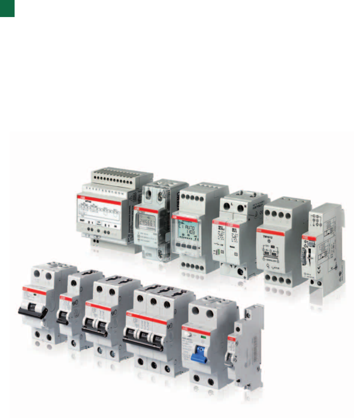
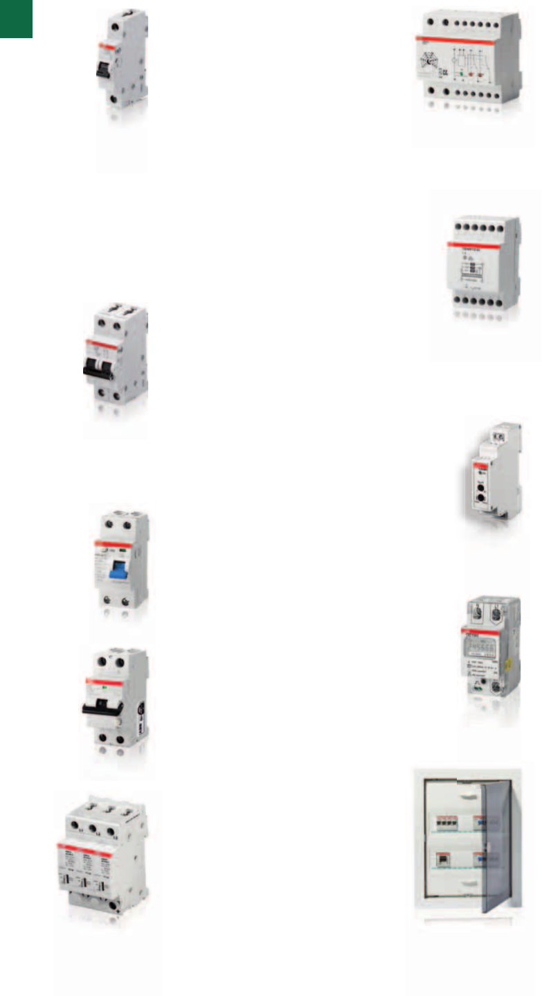
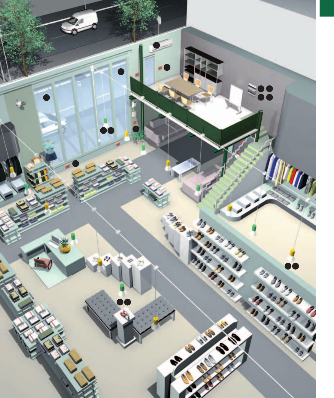
Smart protection for lasting comfort
Applications for an apartment
1. Protection of the stove and other
kitchen equipment
There are many situations, in which
a short-circuit can occur, e.g. bad
insulation of kitchen equipment
and connection to water. Without
suitable cable protection, not only
the connection cable of the kitchen
equipment would become charred,
but also the cable installed in the wall
behind the socket outlet. In worst case
also hazard for human beings exists.
ABB MCBs protect you and your
installation in the best way – easy and
safe installation is possible.
5. Surge protection
Compact and easy to install, the DIN
Rail OVR Type 2 range gives high
overvoltage protection to your sensible
equipment and to your apartment.
2. Separately protection of media and
TV circuits
In newer installations, TV and media
circuits are protected separately. Due
to the electronics used in this kind of
loads they could inject harmonics into
the system and maybe it interferes
with other electrical equipment. MCBs
provide the best protection in cases of
overload and short-circuit.
6. Prevention of overloads
Load management device LSS1/2
prevents overtaking a preset power
consumption threshold. Two embedded
relays 16A disconnect non prioritary
loads for some minutes in case of
overload, then will switch them on
again automatically. Current threshold is
programmable between 5A and 90A.
3. Main residual current protection.
In order to ensure safety and continuity
of service, ABB offers selective type
RCCB F200 S solution to perform
selectivity with the RCDs protecting
terminal circuits.
4. Protection of the bathroom circuit.
Thanks to the availability of 10mA
DS201 RCBOs, it’s possible to ensure
maximum safety also in critical rooms
like the bathroom where the earth
leakage effects on the human body are
more dangerous due to the presence of
water.
7. Safety for auxiliary circuits
Door entry and bathroom safety
pushbuttons should always be supplied
in SELV (safety extra low voltage) for
safety reasons. TS transformers supply
these auxiliary circuits; in case of short
circuit TS are made to disconnect
automatically the secondary winding
and restore their feature automatically
as soon as fault is repaired.
8. Bioarchitecture made real
E235 mains disconnection switch
ensures no electricity in wiring
accessories and electric devices on
bedroom circuits when sleeping. Of
course as soon as user switches on a
load, electricity immediately flows again
to supply it.
9. Object metering
Heating and ventilation pumps are
obvious candidates for object metering
in the home. Also electronic equipments
such as washing machines and
dishwashers are possible objects to
measure.
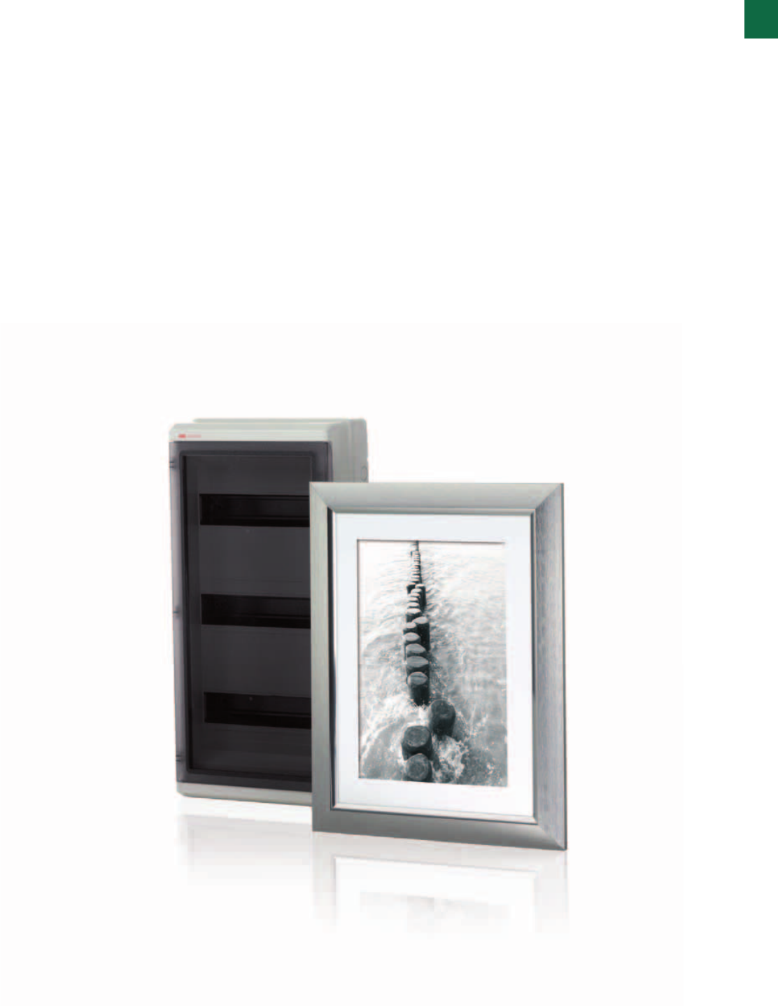
10. UK500 – Heart of your home
In order to fulfill not only technical, but
also aesthetic requirements, the UK500
combines technology and design,
while offering the highest possible
quality down to the smallest detail.
The UK500 is an aesthetic consumer
unit which harmoniously fits in its living
environment.
1
1
1
1
1
7
7
2
5
3
10
9
8
6
4
4
1
System pro M compact® | 2CSC 400 031 D0202 1/7
1
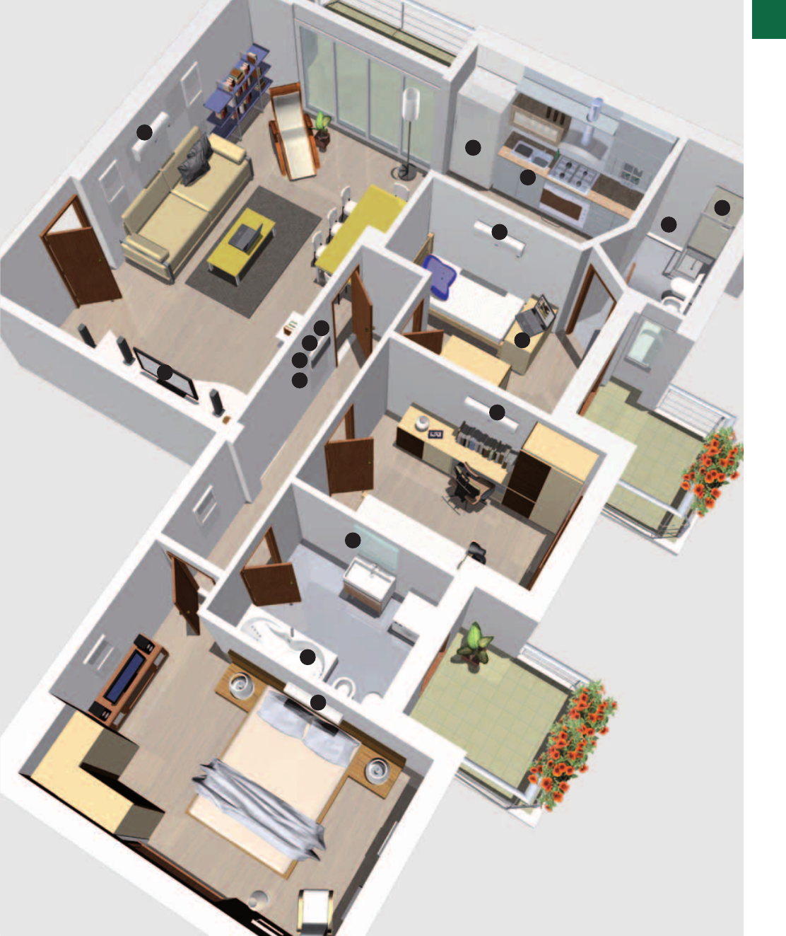
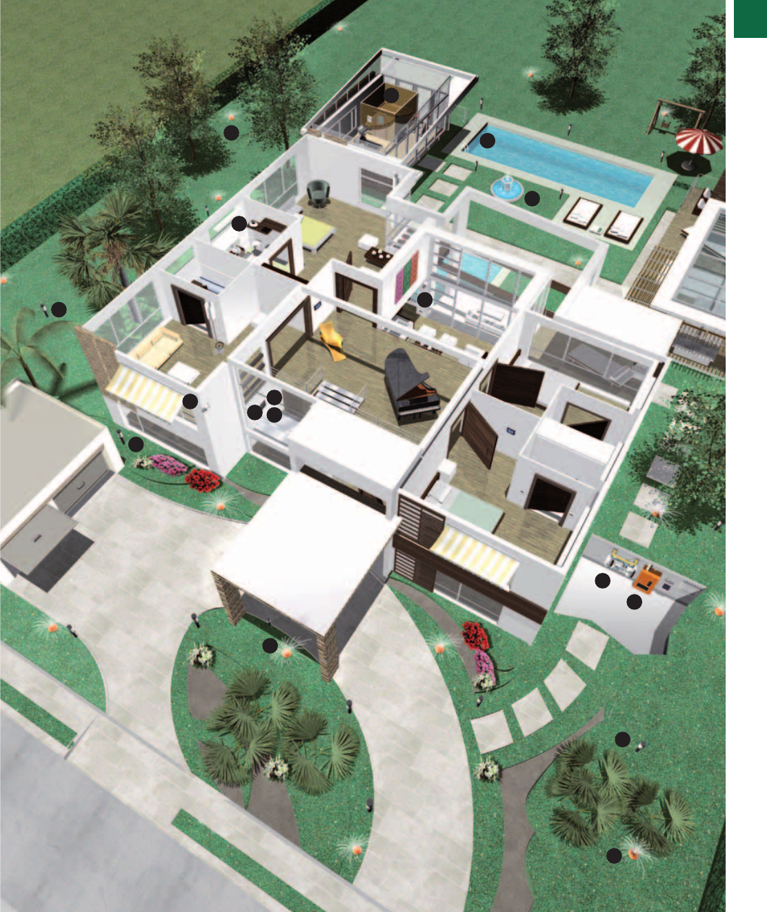
1/8 2CSC 400 031 D0202 | System pro M compact®
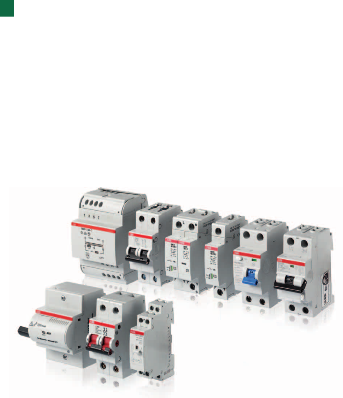
Expertise that lets you think big
Residential applications
6. Surge protection
The modular autoprotected OVR PLUS
range define a new standards in surge
protection.Compact, the integrated
backup protection with MCB allows a very
easy installation for a better protection of
your equipment. The complete OVR range
is the solution to bring your house a full
and safe surge protection.
7. Staircase lighting
E232 staircase light switches allow to
switch on staircase lights only when
needed, as user pushes a button. This
way users can avoid energy waste,
while ensuring full light availability when
walking on stairways. E232 can be
forced permanently on for staircase
cleaning and maintenance purposes.
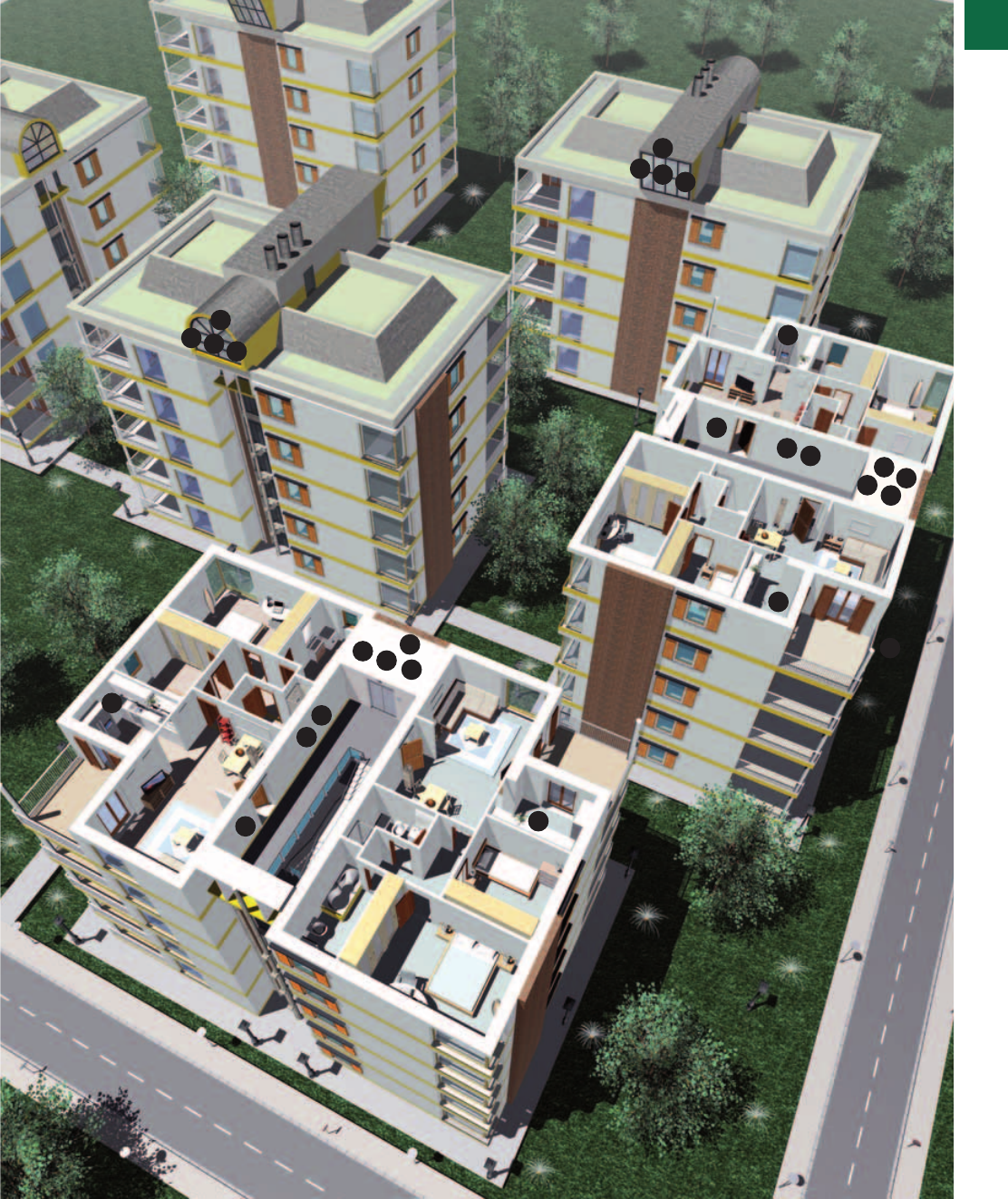
8. Joint residential sourcing
Unlike applications where a separate
billing meter is installed in every
apartment or residence for individual
billing, joint residential sourcing involves
having one central ‘billing’ meter. The
housing association, condominium
or equivalent then acts as a single
electricity subscriber and redistributes
its costs amongst its members
according to their actual consumption
measured by a meter in each apartment.
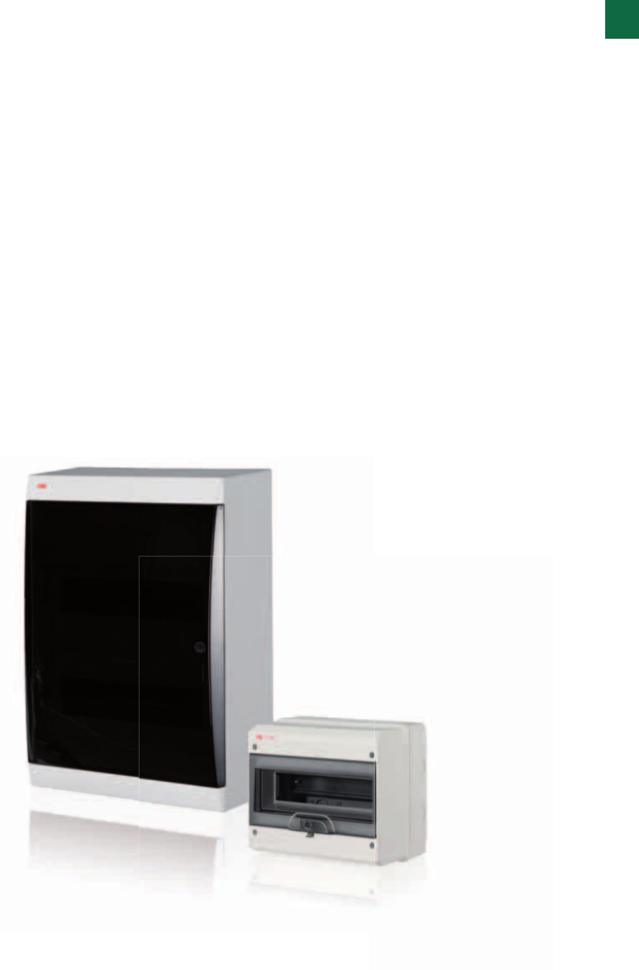
9. An attractive enclosure that can be
discreetly integrated into your interior
The Unibox consumer units are
distinguished by an advanced and elegant
design. They integrate themselves easily
in whichever decoration solution; for the
door, it is possible to choose between
the transparent smoked version and the
opaque white version. Functionality of the
Unibox Series and its safety of installation
and safety of use guarantee high quality
of construction characteristics.
3. Residual current protection in the
common areas.
The F200 RCCB range offers the
solution for the protection against
insulation fault of any kind of common
circuits like the staircase, outside and
garage lights, porter’s lodge, automated
gate and all the common sockets.
5. Gate management
Thanks to ATT GSM module, all
housemasters can open building gate
with their mobile by just dialing a number.
ATT recognises authorized users avoiding
the use of hundreds of expensive and
unsafe gate remote controls.
1. Common lighting circuits
protection
In newer installations, lighting circuits
are always protected separately from
socket outlet circuits. Therefore, it is
almost impossible for a danger to occur
in lighting circuits in the home sector
today, as the permanently connected
consumers (lights and lamps) only
permit their load-dependent current.
However, cable protection must be
provided to prevent overloading of the
cable by short-circuits.
ABB MCBs protect you and your
installation in the best way – easy and
safe installation is possible.
2. Common socket outlet protection
There is a limit to the current carrying
capacity for all cables! It’s not important
whether the short-circuit is caused by a
defect common appliance or whether a
nail pounded into the wall hits the cable.
In addition, similar consequences can
result when too many appliances are
connected to a circuit at the same time
(e.g. several fan heaters) to one and the
same circuit via a multiple socket-outlet
(overload protection). MCBs provide
the best protection in cases of overload
and short-circuit. For sure, you can also
disconnect your circuits with MCBs if
you need to make maintenance work.
4. Protection of the refrigerator
With the new RCBO DS201 APR,
specifically designed against nuisance
tripping, you can achieve a dedicated
protection for the line of the refrigerator
preventing goods decay due the lack of
supply.
1
1
2
2
7
7
4
4
4
4
6
9
6
9
8
8
6
9
8
3
3
3
6
9
8
3
5
1
System pro M compact® | 2CSC 400 031 D0202 1/9
1
1/10 2CSC 400 031 D0202 | System pro M compact®
Protecting and valorising your business
Commercial applications
4. Mains disconnection
E200 switch disconnector is installed
upstream whole electric distribution system
ensuring both isolation and safety of
maintenance and selectivity in case of fault.
5. Lighting control
Latching relays E250 match performance
and energy efficiency in one device. Since
coil is energized on switching only, average
energy use is as low as one hundredth in
comparison with a contactor. Moreover
E250 latching relays are specifically made
to control a high number of lighting devices,
regardless their kind and rated power.
6. Circuit command in less space
Thanks to E210 half-modules commands
and indicator lights, command section of
switchboard can be reduced in size up
to 50% keeping same functionalities and
performances. E210 range foresees on-off
switches, control switches, pushbuttons,
all available in versions with embedded
coloured indicator LED.
7. Window automation
By installing TW twilight swicthes and D
line digital timers, shop window and sign
are fully automated. Lights will switch on
only when dark and during shop opening
times, preserving energy and providing
comfort to shop owner.
8. Consumption monitoring
EQ meters A43 is the perfect solution
for measuring energy consumption
in commercial buildings: thanks to its
features, like for instance the tariff handling
function you can efficiently monitor and
account cost distribution. Thanks to the
available options for communication,
Modbus, M-Bus and KNX, you are able
to read and control your consumption in a
very efficient way.
9. Practical, versatile, intelligent and still
looking good
ABB offers with the 18-module Alpha
Series attractive electrical installation
that can be discreetly integrated into its
surroundings like office, hotel rooms or
commercial buildings, but also in domestic
applications. The attractive but discreet
design of Alpha consumer units makes it
highly suitable for their living environment
and they no longer need to be hidden.
1. Socket outlet protection
There is a limit to the current carrying
capacity for all cables! It’s not important
whether the defect household appliance
is a cleaning machine or some other
appliance. Or whether the short-circuit is
caused by a nail pounded into the wall that
exactly hits the cable. In addition, similar
consequences can result when too many
appliances are connected to a circuit at
the same time to one and the same circuit
via a multiple socket-outlet. This is not
referred to as short-circuit protection, but
instead as overload protection.
2. Lighting circuit protection
In newer installations, lighting circuits are
always protected separately from socket
outlet circuits. Therefore, it is almost
impossible for a danger to occur in lighting
circuits in the home sector today, as
the permanently connected consumers
(lights and lamps) only permit their load-
dependent current.
However, cable protection must be
provided to prevent overloading of the
cable by short-circuits. Without suitable
cable protection the cable installed in the
wall behind the light becomes charred and
maybe needs to be replaced.
3. Residual current protection in shops
With F200 range of RCCBs ABB offers
different solutions for commercial
applications like the APR type, robust
devices with high resistance against
unwanted tripping (that can be caused
by in-rush currents due to the switch
on of many ballasts or many electronic
appliances connected to the network) and
100A selective type, that can be used as
main RCD of the switchboard.
1
1
1
2
2
2
7
7
4
69
8
3
5
5
5
1
System pro M compact® | 2CSC 400 031 D0202 1/11
1
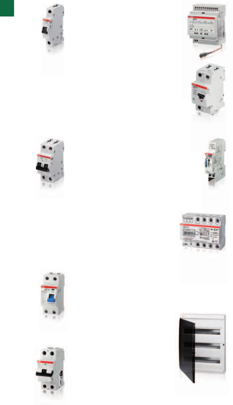
1/12 2CSC 400 031 D0202 | System pro M compact®
Greater comfort, full protection
Applications for the detached house
1. Protection of the entry phone
line and other telecommunication
systems
In this kind of application normally
different voltage level and/or different
frequencies are used. To ensure the
correct working of these circuits, cable
protection must be provided to prevent
overloading of the cable. There is a limit
to the current carrying capacity for all
cables! ABB MCBs protect you and your
installation in the best way – easy and
safe installation is possible.
Make your choice.
5. Automation of basic functions
Time switch D2 with two changeover
contacts controls external two zones
watering system. Another digital time
switch D2 controls some internal ligh
circuits, enabling housemaster to
simulate people presence even when
nobody is in, thanks to random program.
2. Protection of security systems, bell
circuits or electrical shutters
To ensure the correct working of these
auxiliary circuits with maybe different
voltage-level cable protection must
be provided to prevent overloading
of the cable by short-circuits or even
an overload e.g. due to obstruction
of the shutter. Without suitable cable
protection the cable installed in the wall
behind the loads becomes charred and
maybe needs to be replaced or even the
devices get damaged.
6. External lighting only when needed
With twilight switch TW external lighting
switches on automatically when getting
dark, thanks to external light detection
sensor. Threshold can be programmed
on a wide lux range ensuring both
optimal lighting and energy efficiency.
3. Sauna and swimming pool residual
current protection.
To ensure continuity of service and avoid
nuisance tripping due to the natural earth
leakage currents that are common in a
wet environment, it’s a best practice to
protect individually the sauna and the
swimming pool circuits with a dedicated
DS201 RCBO for each line.
7. Safety of outdoor circuits
Care should always taken on outdoor
lighting. Especially when close to
pools or fountains, a safety extra low
voltage transformer TS-C can supply
continuously low voltage lighting devices
preventing risks of indirect contacts.
4. Mains disconnection
E200 switch disconnector is installed
upstream whole electric distribution
system ensuring and it is suitable for
commanding loads.
8. Burner and venting control
ESB and EN contactors provide efficient
load control, for single and three phase
loads up to 63 A of rated current. Thanks
to their endurance and high switching
capacity ESB and EN are ideal in
automation of frequently operating loads.
9. Object metering
Heating and ventilation pumps are
obvious candidates for object metering
in the home, and these can be joined
by appliances such as electronic
equipment, washing machines,
dishwashers as well as sauna. And
don’t forget outdoors.
Garden terrace heaters space and
lighting plus the pond pump are all
significant ‘energy thieves’. The actual
consumption is easy to measure
with EQ meters. EQ meters A-series
measures in two directions, so it is
suitable for a residential PV application.
10. One complete solution for your
home
Electrical enclosures for the residential
applications coordinate between all
technical elements that make up the
interior essential in today’s homes.
The AT & U compact distribution boards
from ABB response this trend about
an ever increasing offer of products for
home installations. ABB offers with AT
& U cabinets one complete solution for
all electrical installation requirements in
your home.
6
6
6
5
5
5
3
3
7
8
8
9
1
4
10
1
2
1
System pro M compact® | 2CSC 400 031 D0202 1/13

1
1/14 2CSC 400 031 D0202 | System pro M compact®
An offering designed to meet present and future needs
The measure of an offering’s worth is its completeness and integration. ABB offers
solutions that meet and anticipate all the needs of contemporary life: from video
entry phones and video surveillance to home automation and charger systems for
electric vehicles.
1. Home series
The ABB residential series are the best available
on the wiring accessories market. The materials,
shapes and colours of plates and controls can
be matched, with umpteen combinations, adding
value to environments based on your taste,
fantasy and needs.
Aesthetics must not sacrifice safety and comfort.
The series have a complete energy and alarm
functions line, from control devices to plugs, from
safety and comfort devices to alarm units, from
protectors to detectors, from limit switches to
special systems, from domotic bus solutions to
installation components.
The series are all integrated with ABB products
portfolio, ensuring modular architecture that is
always expandable.
3. Home automation and security systems
ABB home automation systems turn a house
plant into an intelligent system, adaptable to the
wellness, safety, protection and saving needs of
whoever lives in it.
ABB domotic line modularity can be adapted
to any type of building, giving us full, integrated
management of safety and comfort functions.
From anti-intrusion control to managing lighting,
to operating loads for greater energy efficiency,
ABB domotic systems on bus are easy to install,
program and use, with decided modular features
guaranteeing the plant can grow based on a
customer’s evolving needs.
2. Entry phone/ Video entry phones
ABB systems offer solutions which enable you
to implement entry phone and video entry phone
systems for single homes and large residential
complexes really easily.
Integrating any internal or external architectural
style, these products offer users the most
advanced functions and are available in analogical,
digital and even wireless versions.
4. Comfort control, security system and radio
video surveillance
Available in wired or wireless versions, both
analogical and fully digital, ABB solutions allow
users to create an inviolable, customised safety
barrier between the house and its outside area.
Signalling effective danger or discomfort situations,
they guarantee users full control over the
perimeter.
Reliable and technologically advanced, the
ABB burglar alarm and video entry phone lines
are modular and integrated with a modern,
valuable design meaning they can be used in any
architectural context.
1
System pro M compact® | 2CSC 400 031 D0202 1/15
5. Components for solar PV plants
ABB has developed a complete range of
photovoltaic application products. They satisfy
any plant need, from photovoltaic fields to micro
domestic installations. Switches, isolators,
dischargers, trackers but also measuring and
control parts, control panels, distribution units...
everything needed to integrate, monitor and
protect the energy generated by house panels, in a
safe, protected way.
6. Charger systems for electric vehicles
Electric vehicles are the new mobility frontier.
E-mobility challenges are not just in
the ability to generate energy but also in the
possibility to integrate different sources, to
accumulate excess production and dislocate safe,
reliable charge points accessible for everyone,
even in the home environment.
For really personal, sustainable mobility ABB
offers a rich catalogue of electric vehicle charging
products , from turnkey solutions to single
components.
8. Switchboards protecting and isolating
photovoltaic plants
ABB offers the best solutions to protect, isolate
and cut off photovoltaic sources.
In particular, string combiners - consolidating DC
energy produced by the different strings making
them available for inverters – allow to protect
against overcurrents, lightnings and surges.
7. External lightning protection with the OPR
range
The ABB OPR range makes the construction of
a lightning protection system very easy to install.
Designed to conduct the lightning current from
the external rod to the earthing system, it will keep
your home safe and protected against any
damage. When you have external protection, you
must add a surge protection device (OVR range)
to protect your electrical installation and sensitive
equipment.
9. Selective device downstream from the meter
The S700 series products are selective main
circuit breakers for DIN rail enabling you to protect
electric installations from surges. They boast
total selectivity towards MCBs downstream and
considerable selectivity towards protection devices
upstream. As they have been designed for the IV
overvoltage category and integrate the isolation
function they can be used in any distribution or
control cabinet.
At the meter
OVR surge
protection
(SPD)
Residual current
circuit breaker
(RCCB)
Lights
Sockets
Fridge
Burglar alarm
Main switch
1
1/16 2CSC 400 031 D0202 | System pro M compact®
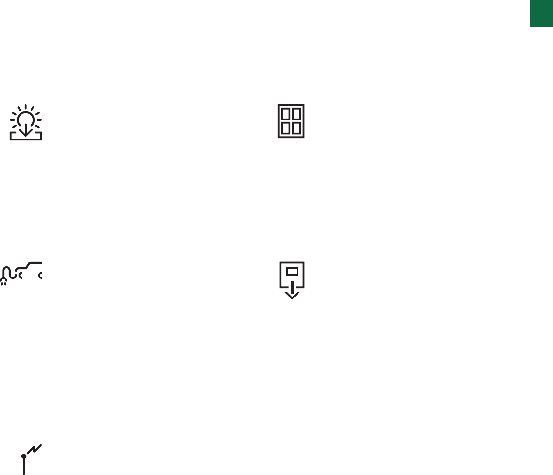
Efficiency, protection, comfort:
measuring a system’s value
Small flat
In a small apartment plant simplicity and relative
extension allows you to keep load subdivision to a
minimum.
OVR surge
protection
(SPD)
Lights
Sockets
Fridge
Burglar alarm
Main switch
At the meter 1
System pro M compact® | 2CSC 400 031 D0202 1/17
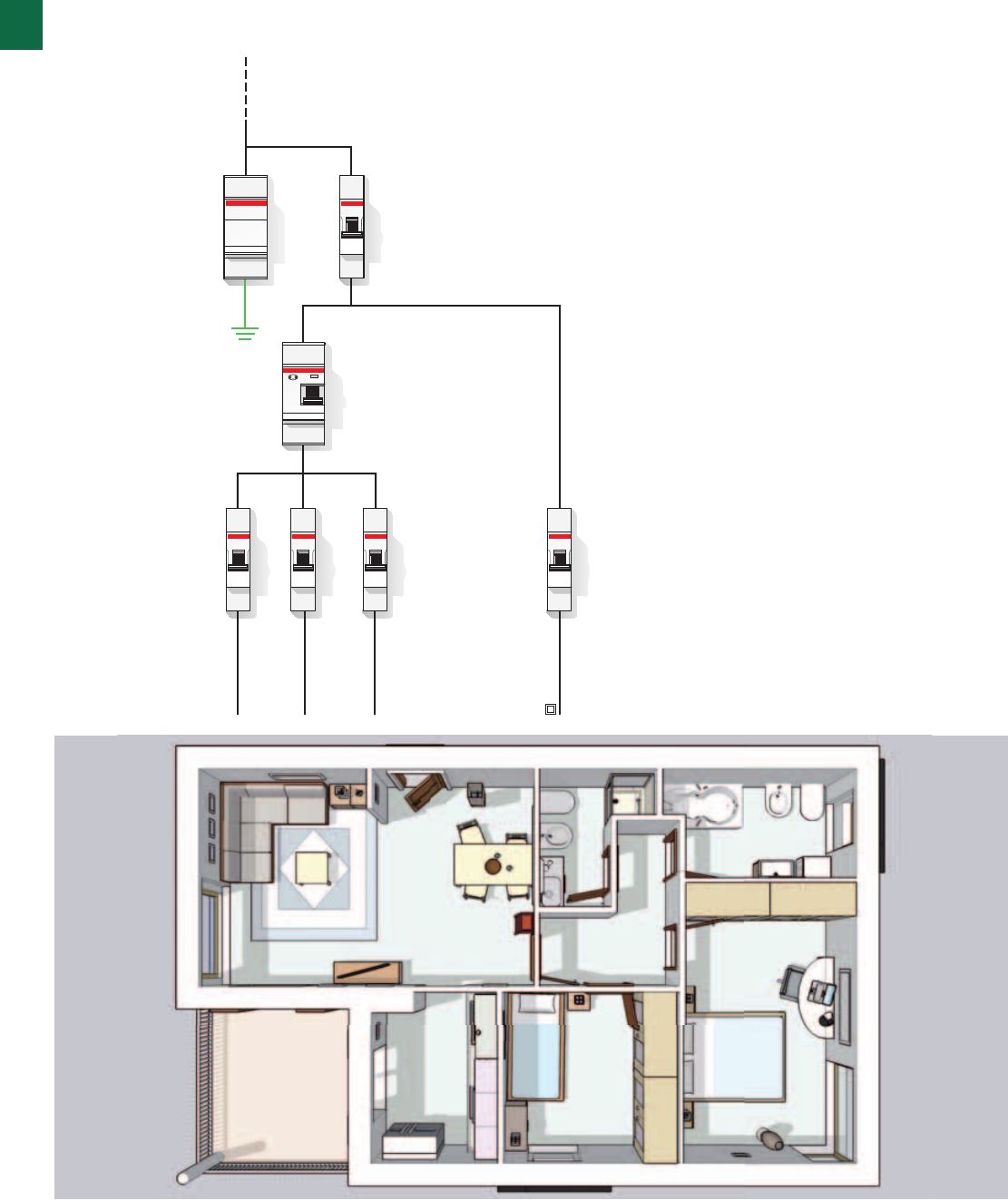
Small flat
For a minimum amount of selectivity you can give
to each circuit a differential protection.
At the meter
OVR surge
protection
(SPD)
Living area
lighting
Fridge
Bedroom area
lighting
Kitchen
sockets
Boiler
Other sockets
Burglar alarm
Main switch
Residual current
circuit breaker
(RCCB)
Residual current
circuit breaker
(RCCB)
1
1/18 2CSC 400 031 D0202 | System pro M compact®
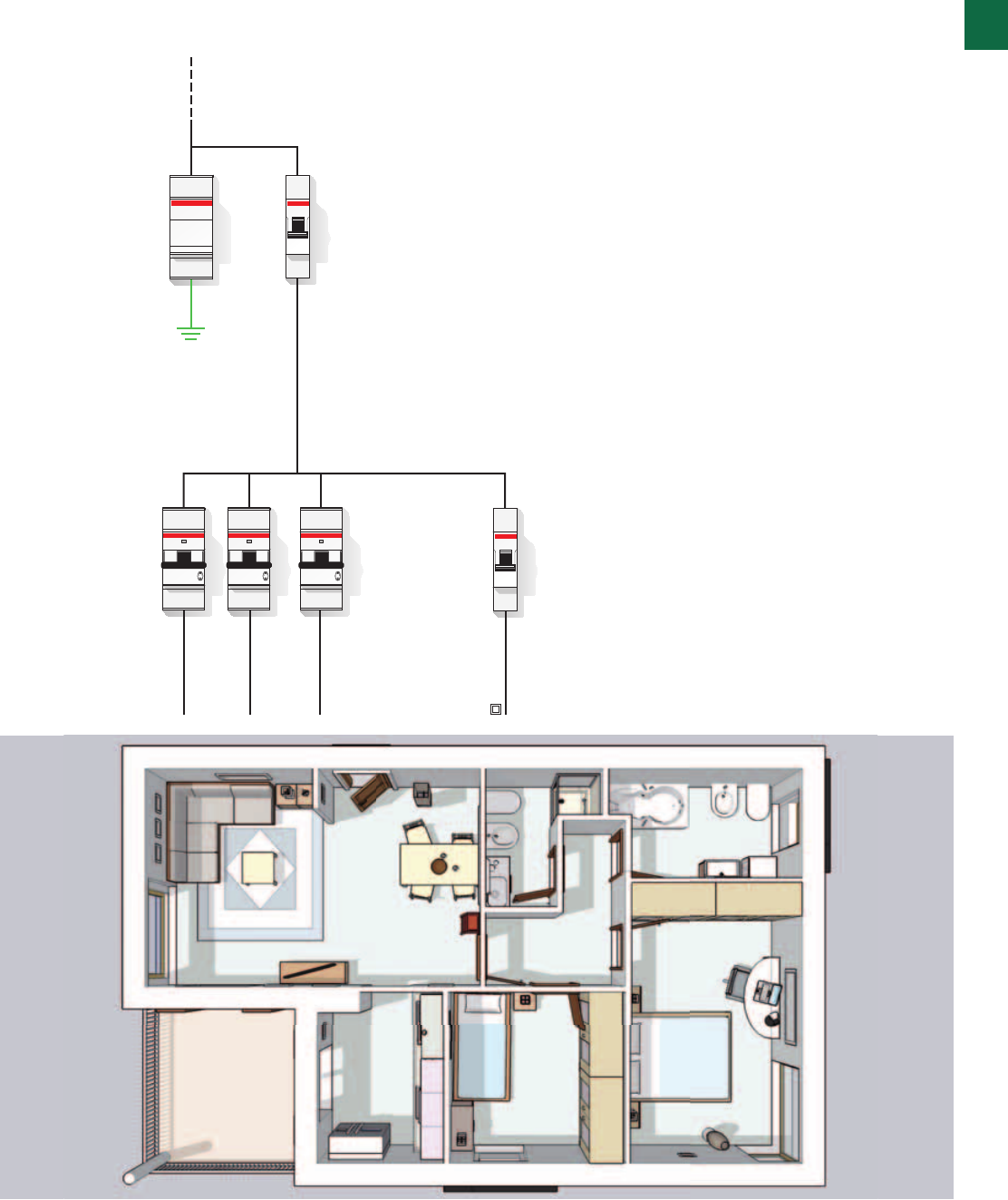
Efficiency, protection, comfort:
measuring a system’s value
Medium flat
In a medium sized apartment the right subdivision
of circuits allows easier plant management and
makes searching for any breakdowns simpler.
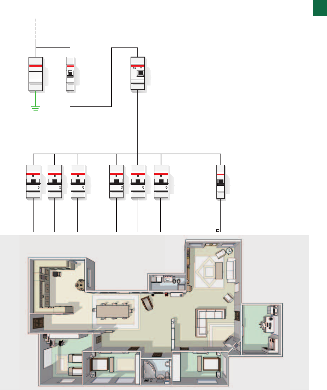
At the meter
OVR surge
protection
(SPD)
Living area
lighting
Fridge
Bedroom area
lighting
Kitchen
sockets
Boiler
Other sockets
Burglar alarm
Main switch
Selective
residual current
circuit breaker
(RCCB)
1
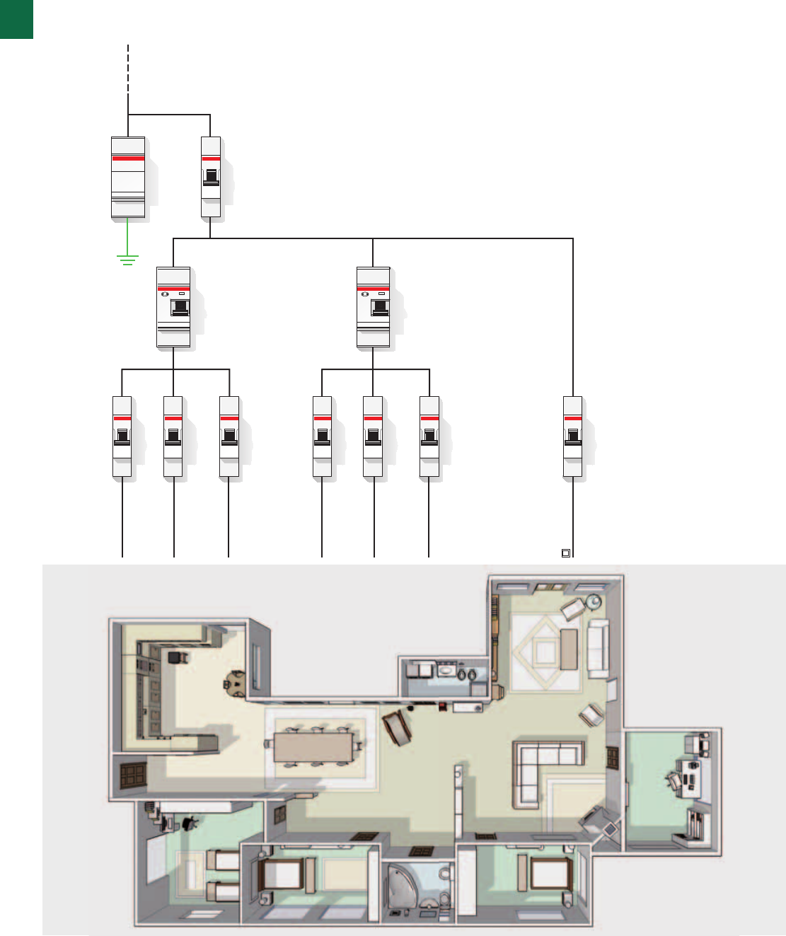
System pro M compact® | 2CSC 400 031 D0202 1/19
Medium flat
The certainty that you can just disconnect the fault
affected circuit is only possible with differential
protection on each single circuit.
At the meter
OVR surge
protection
(SPD)
Living area
lighting
Ground floor
sockets
Boiler
Basement
sockets
Bedroom area
lighting
First floor
sockets
Washing
machine
Garden
Garage lights
Kitchen
sockets
Air conditioner
Driveway gate
Fridge
Burglar alarm
Entry phone
TV switchboard
Main switch
Residual current
circuit breaker
(RCCB)
Residual current
circuit breaker
(RCCB)
Residual current
circuit breaker
(RCCB)
Residual current
circuit breaker
(RCCB)
1
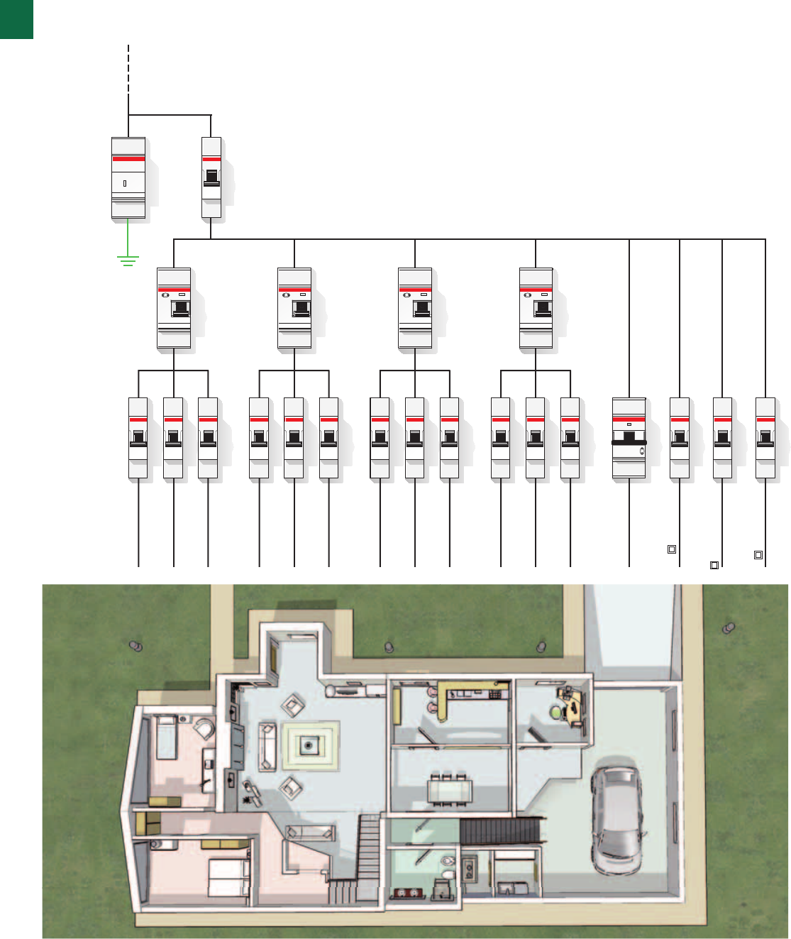
1/20 2CSC 400 031 D0202 | System pro M compact®
Efficiency, protection, comfort:
measuring a system’s value
Detached house
In a detached house the right subdivision
of circuits allows easier plant management
and makes searching for any breakdowns simpler.
At the meter
OVR surge
protection
(SPD)
Living area
lighting
Ground floor
sockets
Boiler
Basement
sockets
Bedroom area
lighting
First floor
sockets
Washing
machine
Garden
Garage lights
Kitchen
sockets
Air conditioner
Driveway gate
Fridge
Burglar alarm
Entry phone
TV switchboard
Main switch
Selective
residual current
circuit breaker
(RCCB)
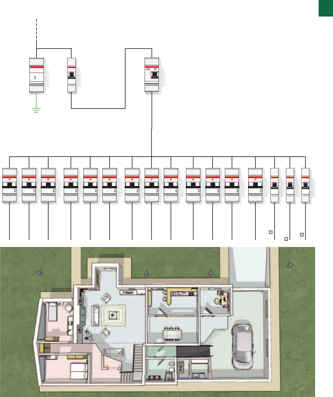
1
System pro M compact® | 2CSC 400 031 D0202 1/21
Detached house
Full plant selectivity allows all circuits not affected
by a breakdown to carry on working guaranteeing
full efficiency for the rest of the plant,
avoiding unpleasant disservices.
MDB
Network System
TT and TNS 4 wires configuration
1
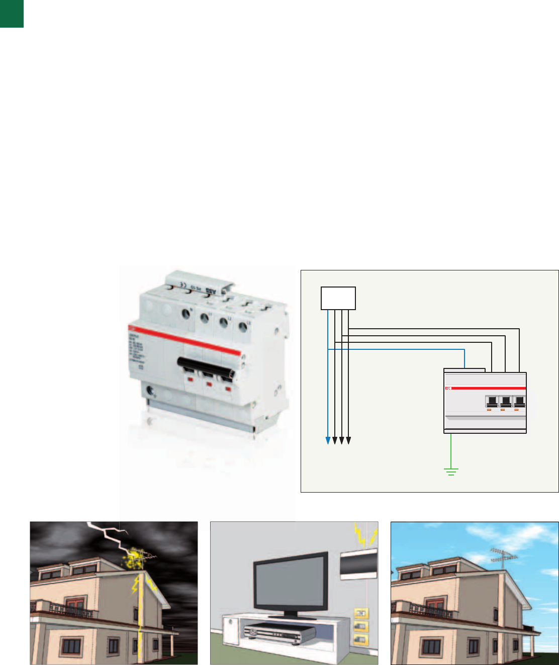
1/22 2CSC 400 031 D0202 | System pro M compact®
Application examples
OVR PLUS N3
Autoprotected surge arrester
Operating principle
The OVR PLUS N3 autoprotected surge arrester enable to
protect your equipment and installations without worrying
about coordination rules with a specific backup protection.
Application environments
The OVR PLUS N3 surge arresters are recommended in 4
wires networks where a a fully coordinated surge arrester
backup protection is required for an easy installation.
Example of installation
One of the possible applications is to mount the OVR Plus N3
in the main distribution board of an electric installation. Fully
coordinated with the integrated backup protection it will fully
protect a small shop against surges.
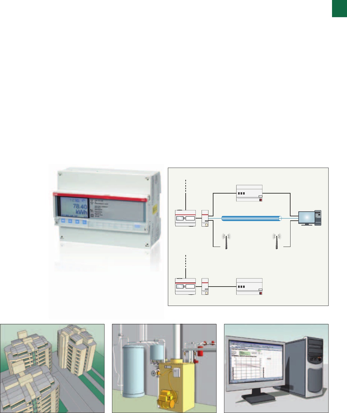
At meter
At meter
EQ meters
EQ meters
SCA
SCA EIB unit
M-Bus Master
Local LAN
GSM/GPRS Network
AMR/BMS/
EMS system
Ethernet
1
System pro M compact® | 2CSC 400 031 D0202 1/23
Application examples
EQ meters A-series
Electronic energy meter
Operating principle
EQ meters A-series are available for both single phase and
three phase networks. They allow active energy or combined
(active and reactive) energy to be measured.
EQ meters A-series measures in two directions, both import
and export of energy. The meters are prepared for external
communication via their built-in communication interface or
via a serial communication adapter (SCA).
Application environments
The EQ meters A-series meters offers an ideal solution in
measuring applications for electrical energy produced in a
photovoltaic installation.
Example of installation
EQ meters A-series can be easily integrated into measured
data collection systems via serial communication adapters.
The devices are approved to the Measuring Instruments
Directive (MID) European Directive 2004/22/EC.
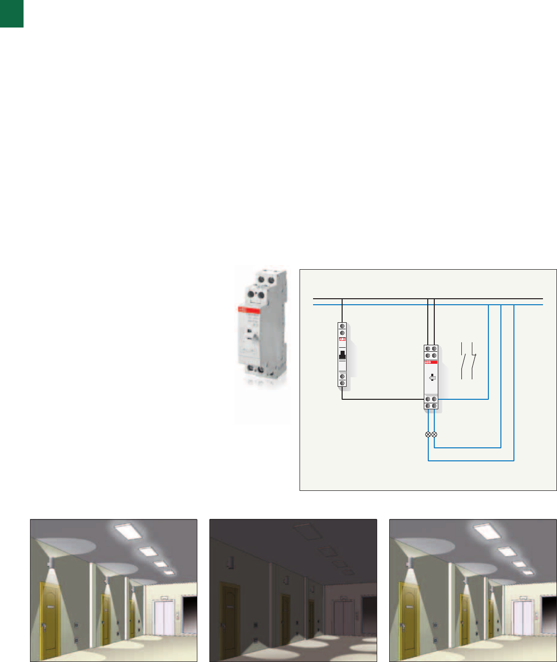
4
3
2
1
E211 4
A1
3
2
A2
1
Ceiling lights Corridor lamps
E259
1
1/24 2CSC 400 031 D0202 | System pro M compact®
Operating principle
The E 259 installation relays are 16 A contactors specifically
engineered for residential and commercial applications and
are available in a wide range of contact layouts and coil
voltages.
Application environments
The E 259 installation relays are particularly indicated in
residential and commercial buildings for lighting control.
Example of installation
The E 259 16-11 installation relay can be installed with a NO
and a NC contact inside the lighting system of the common
areas of a building. The first control sent through a switch to
the command circuit of the relay will turn off the ceiling lights
and turn on the corridor lamps, while the second command
returns to the previous state.
Application examples
E 259 installation relays
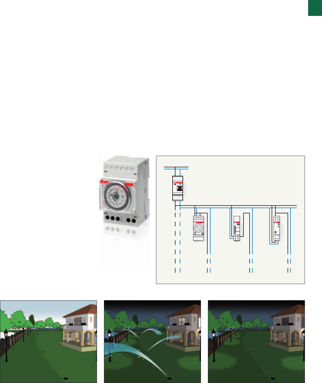
Garden
Watering
Path lighting
Outdoor lights
1
System pro M compact® | 2CSC 400 031 D0202 1/25
Operating principle
The AT electro-mechanical time switches enable to control
the circuit opening/closing according to a daily or weekly
program or to manually set permanent ON/OFF operation.
Application environments
The AT electro-mechanical time switches are particularly
indicated in any environment and situation where it is
necessary to program system load operation according to
a daily or weekly frequency (shop lighting system, public
buildings, heating systems, irrigation systems, etc.).
Example of installation
The AT3-7R electromechanical time switch can be assembled
inside the power supply circuit of the garden. In this case
the device programming enables the daily activation of the
irrigation system at a preset time.
Application examples
AT electro-mechanical time switches
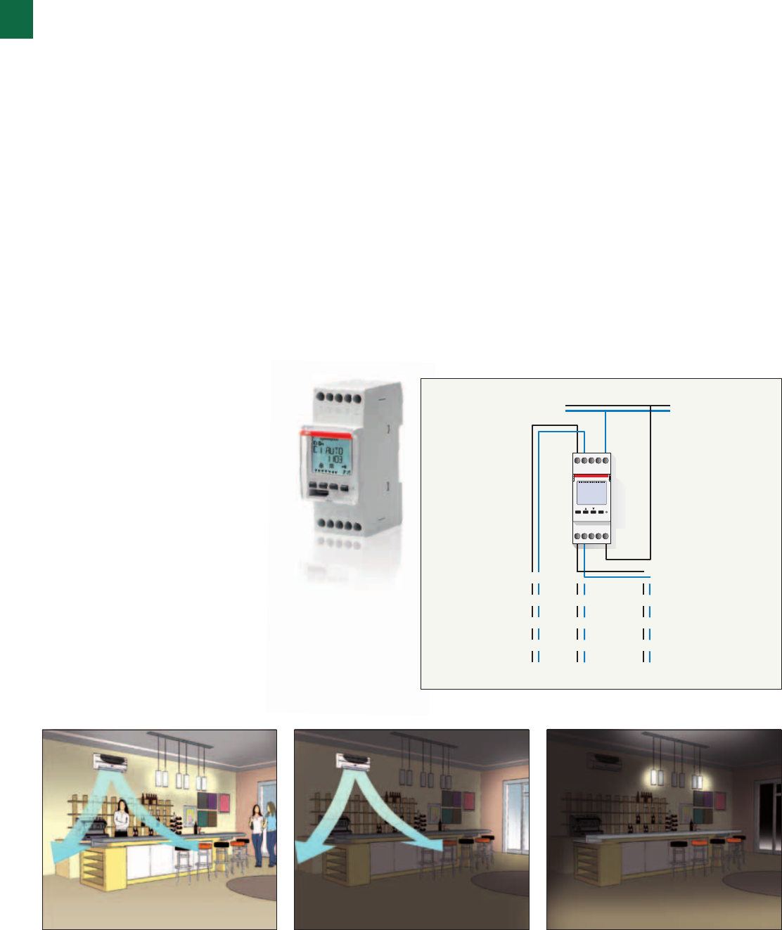
Heating
Lighting
Lighting
1
1/26 2CSC 400 031 D0202 | System pro M compact®
Operating principle
The D2 two-channel digital time switches enable to open
and close circuits according to a daily or weekly program,
controlling single loads or group of loads even when they
require different time controls with a common time reference.
Application environments
The D2 two-channel digital time switches are particularly
indicated in environments and situations requiring the
management of multiple loads according to a time program
flexible enough to include or exclude their application based
on the day of the week (offices, schools, public areas, etc.).
Example of installation
In this example, the digital time switch D2 allows the
operation of heating as well as lighting systems of a small
office; during weekend the device only controls the heating
system (programmed on one of the two channels), while on
the resto f the week the lighting system is also switched on
(through a program on the second channel).
Application examples
D Line digital time switches
Push-buttons
Lighting load
1
System pro M compact® | 2CSC 400 031 D0202 1/27
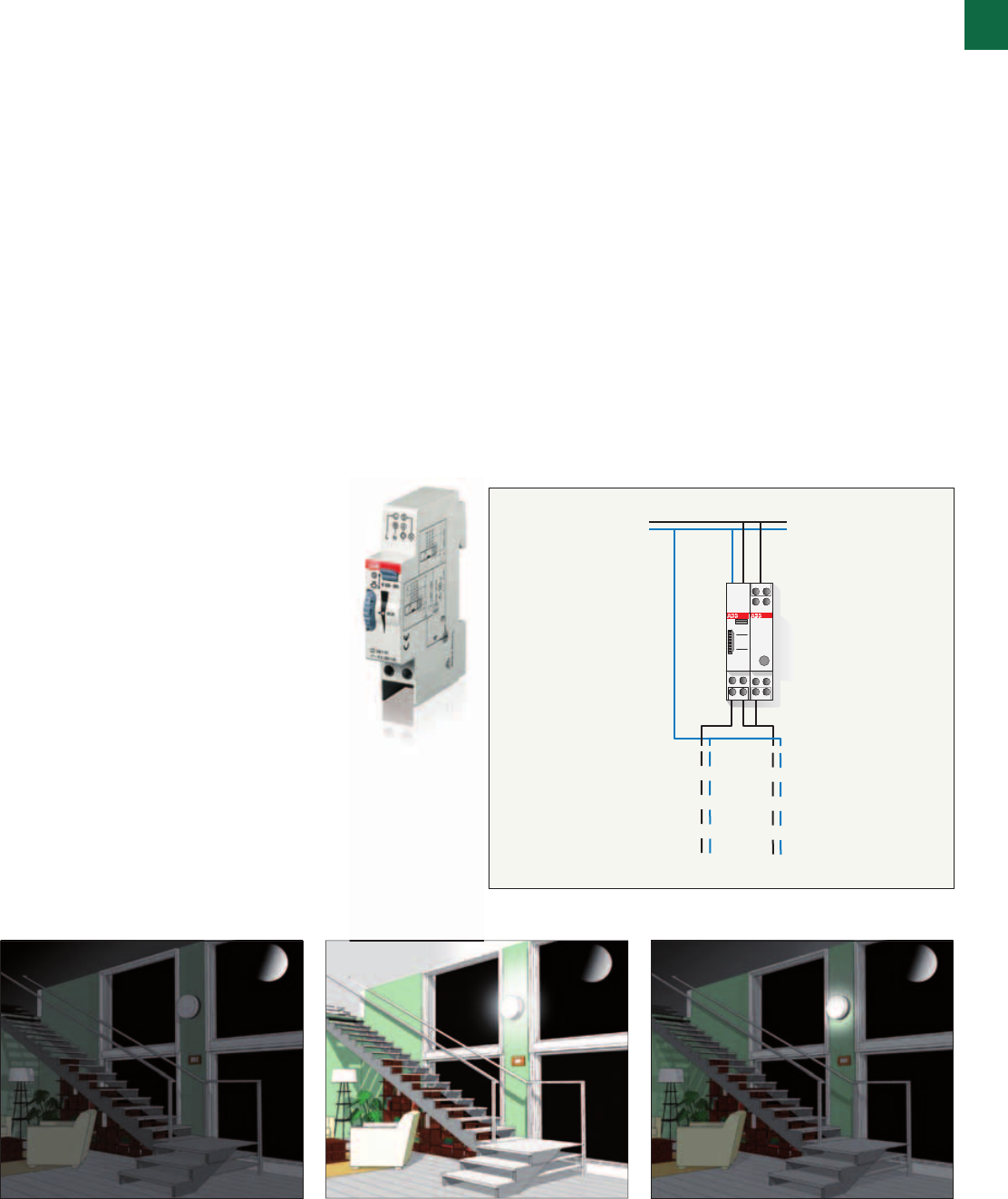
Operating principle
Activated by a pulse command of a push-button, the E 232
staircase switch turns on the plant’s light for a T1 time that
can be protracted, with a 50% dimming of the light intensity,
by means of the parallel wiring of a HLM half-light module.
Application environments
Installation of E 232 staircase switch, coupled with the HLM
half-light module, can be ideal wherever timing of the lighting
is requested (staircase and pathways of public places, cellars,
garage, etc.).
Example of installation
One of possible applications of the E 232 staircase switch,
coupled to a HLM half-light module, in the staircase lighting
plant of a multistory building. Pushing the push-button, the
timer of the E 232 switch turns on the lights for a settable T1
time. At the end of T1 time, the HLM half-light module dims
the light by a 50% for a T2 time in the while is possible turn
on again the full lighting.
Application examples
E 232 staircase relays
1
1/28 2CSC 400 031 D0202 | System pro M compact®
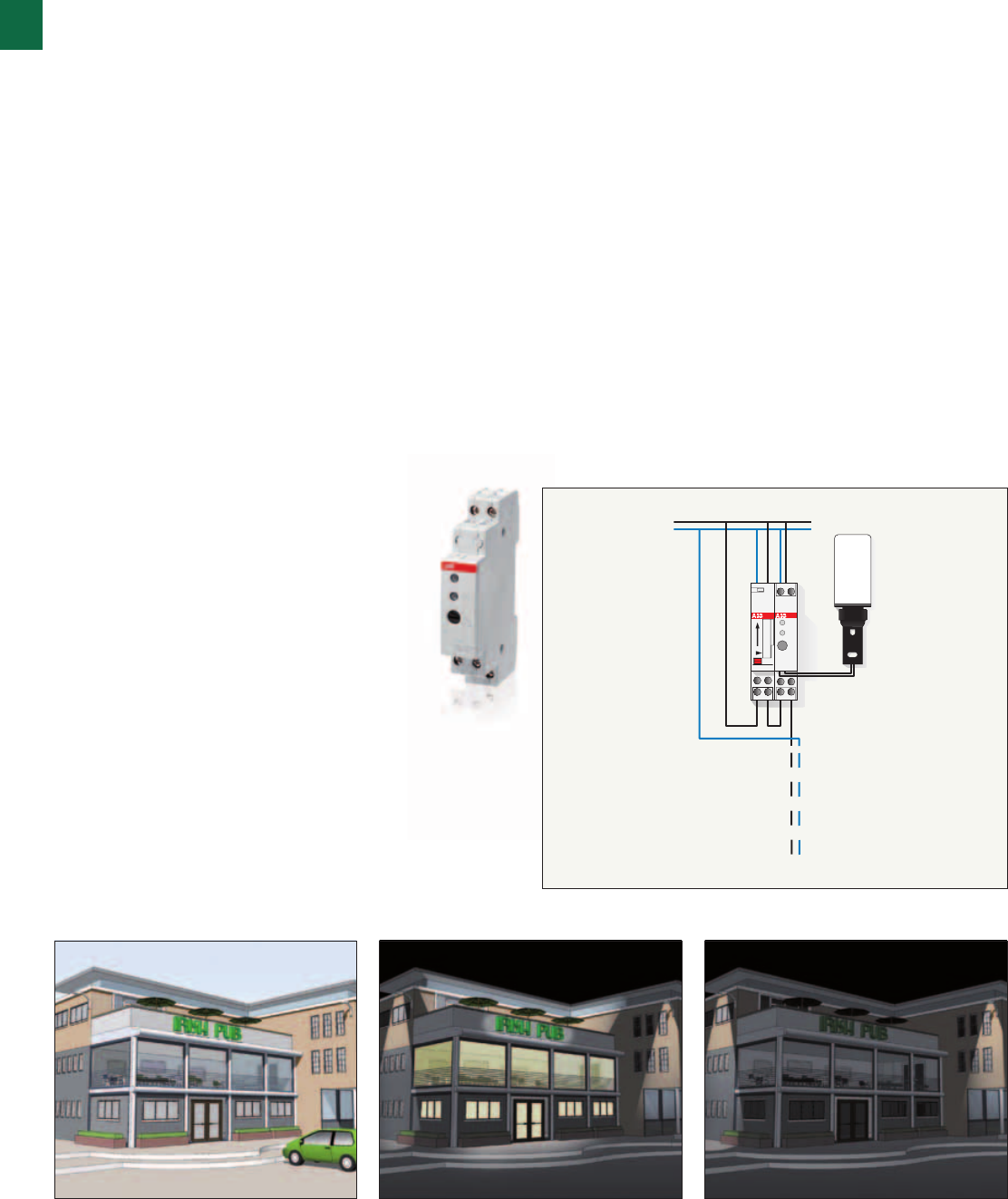
Application examples
TW1
Operating principle
The diagram is an example of a TW1 twilight device installed
in a mall lighting system. When outdoor light drops under a
certain level (for example, in the evening store closing hours),
the device turns on window and sign lights. Lights can be
turned off during the night to rationalise consumption thanks
to the AT1 timer switch.
Application environments
The installation of a TW1 twilight switch with AT
electromechanical timer switch is especially suited for
environments and situations in which energy consumption
rationalisation is required (stores, office and public walkways,
car parks, parks, etc.).
Example of installation
As shown in the diagrams, one of the possible applications
consists in the installation of a TW1 twilight switch in a mall
lighting system. When outdoor light drops under a certain
level (for example, in the evening store closing hours), the
twilight switch turns on window and sign lights. Lights can
be turned of during the night thanks to the AT1 timer switch
which keeps the circuit open until the next morning. When
outdoor lighting returns over the limit, the twilight relay returns
to the open position.
Lighting
1
System pro M compact® | 2CSC 400 031 D0202 1/29
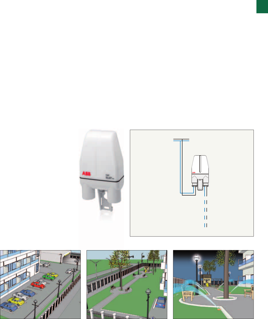
Application examples
TWP twilight switches for pole mounting
Operating principle
The TWP pole mounting switch equipped with an integrated
photo-sensor preset at 10 Lux is the ideal solution for
controlling external lighting systems. They are supplied with
water-proof cable glands, user instructions printed on the
back of the product and a pull-out sensor that allows fast,
safe and error-proof maintenance operations.
Application environments
The pole mounting TWP twilight switch installation can be
ideal to light command in private parking areas thanks to its
capability of installation in pole, lamppost, etc.
Example of installation
One of the possible applications concern the installation of
a pole mounting TWP twilight switch in lighting plant. When
daylight dims below a set level (e.g. during twilight) the switch
turns on the lighting devices, assuring the requested lighting.
At dawn, when the light raise above the set threshold, the
relays of TWP returns in open position.
1 3 5 7
2 4 6 8
Lighting
1
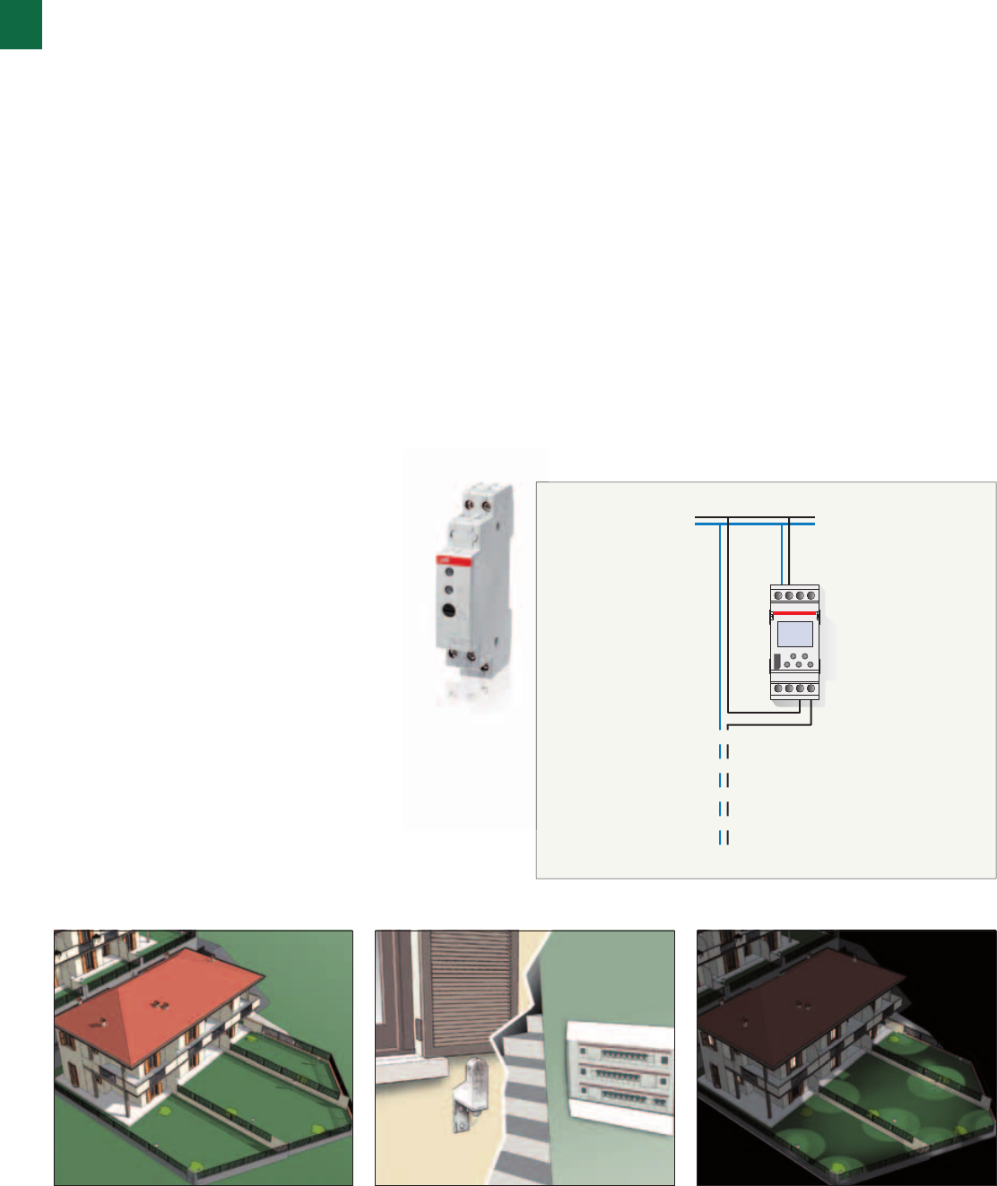
1/30 2CSC 400 031 D0202 | System pro M compact®
Application examples
TWA twilight switches
Operating principle
Installation of a twilight astronomical switch in a system is
particularly useful in places and situations where light sources
or other environmental conditions may cause changes in the
Lux level. In these cases, TWA-1 and TWA-2 enable control of
the lighting system depending on the time when the sun rises
and sets, based on the geographic location where they are
installed.
Application environments
The TWA-1 and TWA-2 twilight astronomical switches
are particularly suitable for use in applications where
the operation of a twilight switch with external sensor is
potentially subject to alteration or damage from external
agents (e.g. smog, overexposure to light, vandalism etc.).
Example of installation
One cause of reductions in the level of ambient light is
atmospheric smog. Particle deposits on the external sensor
of a traditional twilight switch can over time compromise its
operation, preventing the activation of the lighting systems
controlled. As illustrated in the diagrams, it is possible to
counter this type of problem by installing a TWA twilight
astronomical switch, which controls the lighting based on the
ambient light level calculated from the preset longitude and
latitude parameters.
Heating system lock
Thermostat switch-on
Earth fault
Air conditioner switch-on
1
System pro M compact® | 2CSC 400 031 D0202 1/31
Application examples
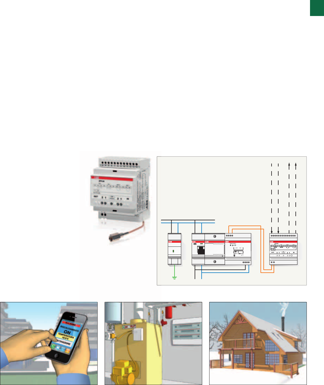
ATT-22 GSM modules
Operating principle
ATT-22 module is a GSM terminal with 2 outputs and 2 inputs
for transmitting commands and alarms via SMS message, free
phone call ring, fax or e-mail. Configuration is accomplished
by means of SMS messages, or using the ATT-Tool software
with ATT-22 connected to a PC.
Application environments
The ATT-22 module is especially suited for residential
and services-sector installations in which loads need to
be remotely monitored or controlled. ATT-22E version is
equipped with a pre-wired external antenna, indispensable
when the module is installed in places that do not guarantee
adequate GSM coverage.
Example of installation
The figures illustrate an example application in which ATT-22
module is installed in the control panel of a second home in
the mountains.
With a cell phone call ring to ATT-22, it is possible to switch
on the boiler just before arriving at the house, or to keep it
continually in operation. In the event of a problem with the
boiler, ATT-22 sends a notification SMS.
230 V AC
Main circuit
breaker
RAL
Lights
Dedicated
socket
Shunt trip
(230 V AC)
in case of
circuit-
breaker
tripping
1
1/32 2CSC 400 031 D0202 | System pro M compact®
Application examples
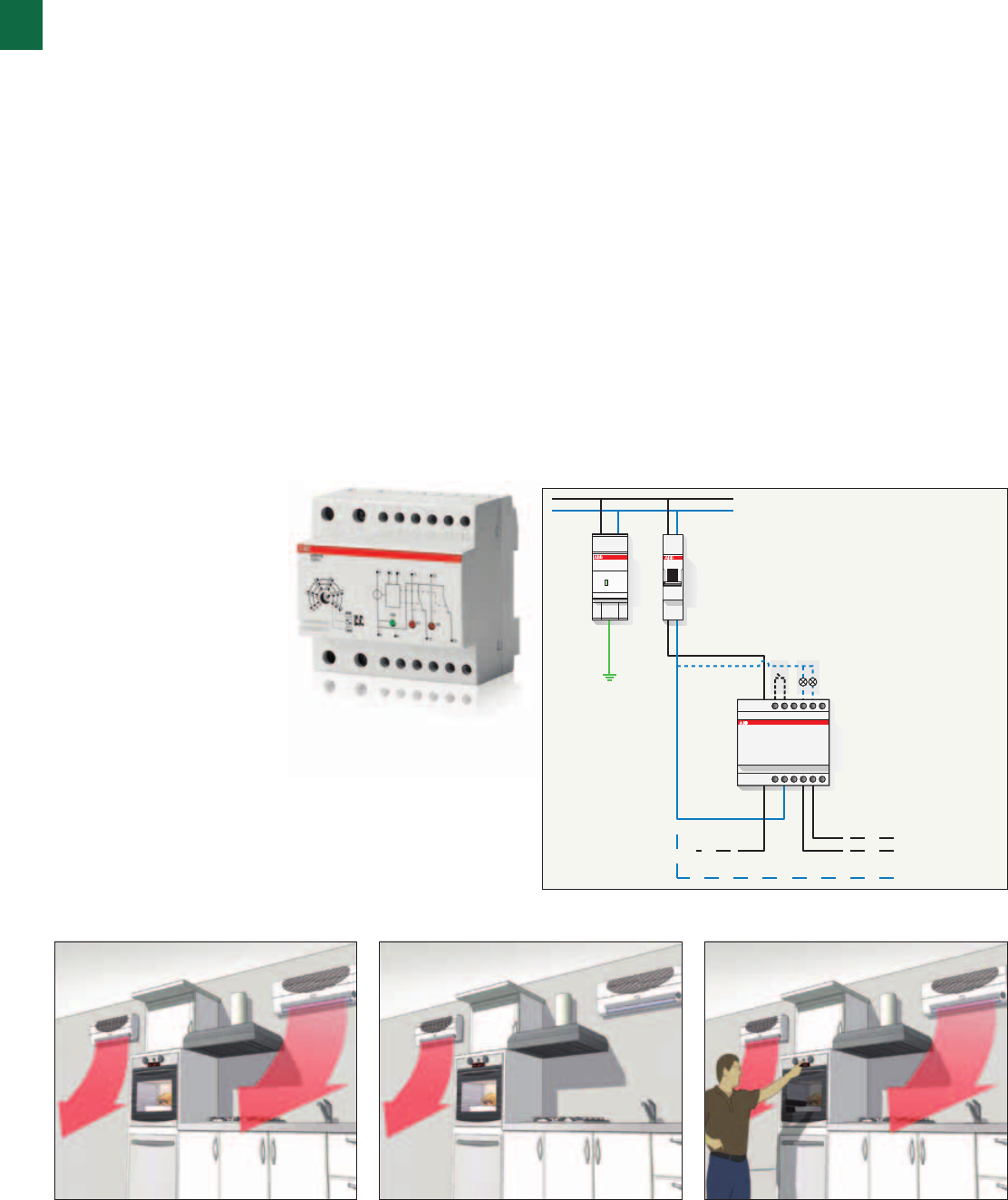
RAL overload alarms
Operating principle
The RAL overload alarms constantly compare the maximum
preset power consumption value to effective system power
consumption. Approaching allowed threshold, they signal to
disconnect one of the loads through acoustic alarm avoiding
the main circuit breaker tripping. Connecting the undervoltage
release to the appropriate contact, the RAL overload alarms
provide an acoustic alarm and simultaneously opens the
circuit-breaker protecting one or more not primary loads.
Application environments
The installation of the RAL overload alarms is suitable for
any environment and situation in order to avoid power
consumption which could trip the limiting circuit breaker of
the system.
Example of installation
As shown in the diagrams, one of the possible applications
is the installation of the RAL overload alarms in the domestic
system where the electric oven and washing machine
are simultaneously switched on increasing the power
consumption. When the power consumption approaches the
preset threshold values, an acoustic alarm is activated and
the washing machine switches off automatically through an
undervoltage release.
LOCKED
BLOCCATO
F2C - ARH
230V~
OFF
OFF
ON
Connection to the load
1
System pro M compact® | 2CSC 400 031 D0202 1/33
Application examples
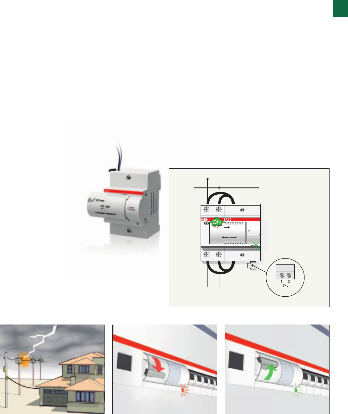
F2C-ARH
Operating principle
The GreenLight F2C-ARH automatically recloses the
associated residual current device (2 poles RCCBs up to 63A
- 30 mA or 100mA, depending on F2C-ARH version), after
first checking that there isn’t an insulation fault on the circuit
protected by the RCCB.
Application environments
The GreenLight F2C-ARH is suitable for installation in any
TT and TN distribution system and it has been designed to
always maintain continuity of service in case of nuisance
trippings caused by storms or electrical disturbances,
restoring current to all connected utilities after verifying the
correct state of the system.
Example of installation
An ideal application of auto-reclosing device F2C-ARH is
related to home distribution systems.
This is particularly useful to preserve the critical loads - for
example to avoid alarm system wrong intervention, irrigation
stops or defrost of the freezer - during holidays or when the
home is not manned, even for short periods.
Possible
remote
signalling
Possible
CNP1 and
CNP2 forced
switch-off
Prevention of meter tripping
and automatic reset of loads
LSS1/2
load management switch
Non-priority loads:
Air conditioner, kitchen, other socket outlets
Priority loads:
Burglar alarm,
refrigerator, lights
Bathroom, household appliances
1
1/34 2CSC 400 031 D0202 | System pro M compact®
Application examples
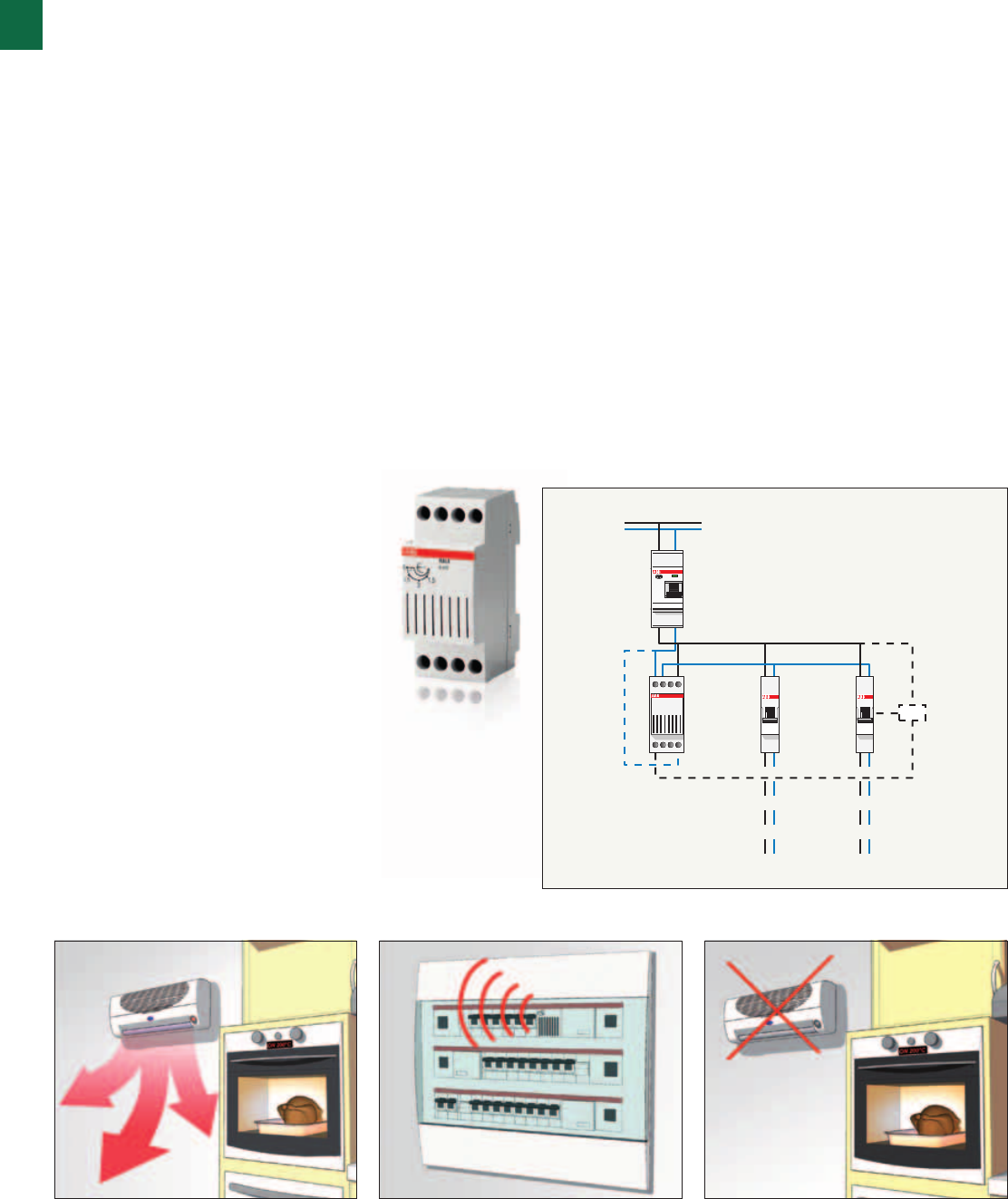
LSS
Operating principle
LSS1/2 load shedding switches are used in case of exceeding
of consumption threshold allowed in the system by switching
off in sequence one or two loads, if necessary. At preset
intervals and until current consumption is not below the
reference level, the switch tries to reset the disconnected
loads.
Application environments
The installation of the LSS1/2 load shedding switches
is suitable for any environment and situation where it is
necessary to control electric energy consumption within
consumption limits allowed in the system.
Example of installation
As shown in the diagrams, one of the possible applications
is the installation of the LSS1/2 load shedding switches in
a printing office system, where the conditioning switch-on
causes the exceeding of the energy consumption threshold
defined with the supplying company by contract. The LSS1/2
load shedding switch preserves printing machines operation
by switching off one or two primary loads automatically (i.e.
night conditioning and lighting), where ON red leds indicate
temporary OFF. After a preset interval, the switch checks that
current consumption values fall within the limits again trying to
reset the previously disconnected loads.
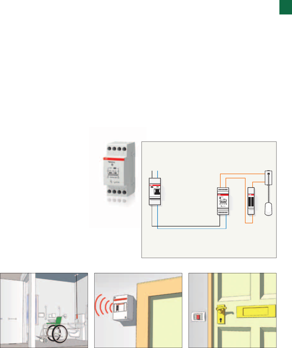
SELV line bathroom
pull cord switch
and outer bell
Transformer for
bells 15VA 12V
TM15/12
Bathrooms
1
System pro M compact® | 2CSC 400 031 D0202 1/35
Application examples
TM, SM
Operating principle
A residual current circuit breaker with Idn equal to 10 mA
installed on the bathroom circuits ensures better protection
against indirect contacts. The residual current circuit breaker
may be installed directly on the control board.
Application environments and example of installation
The SELV circuit guarantees safe power supply where the risk
of accident is higher, such as near the bathtub.

1
1/36 2CSC 400 031 D0202 | System pro M compact®

System pro M compact® | 2CSC 400 031 D0202 2/1
2
Introduction 2/2
Miniature circuit-breakers 2/5
Residual current devices 2/29
Surge protective devices 2/55
Other protection devices 2/63
Busbars and end caps 2/77
Protection

2/2 2CSC 400 031 D0202 | System pro M compact®
2
Constant attention
Protection, selectivity and savings: ABB’s mission for your hom
Protecting the electrical system is an essential step to ensure safety and comfort to
its users, as well as the correct economical and functional operation of the devices
it supplies.
System pro M compact® | 2CSC 400 031 D0202 2/3
2
Protection aims at minimizing risks for people and devices
due to abnormal conditions or faults that impair the electrical
parameters of the installation and of the loads.
In this context, an adequate coordination between the various
protection devices (normally located on the sections of the
system or on specific components) and an appropriate degree
of selectivity enable to provide total safety of the installation.
For the system to operate properly, protection has to allow
quick identification and exclusion of the area affected by the
problem, without hasty, inappropriate or untimely actions that
may compromise the power supply to the unaffected areas.
In case of tripping of a protection device, the maintenance
personnel should have clear and essential information rapidly
available in order to restore the service as quickly as possible.
A protection system must also provide adequate flexibility and
include reserve mechanisms, in case of malfunctioning of the
main protection unit.
For a good compromise between reliability, simplicity and
convenience, a protection system must be able to identify
how and where the fault occurred, differentiating between
abnormal but tolerable situations and actual situations. It is
imperative to act as quickly as possible to minimize risks and
damage (destruction, accelerated aging, etc.), safeguarding
the continuity and stability of power supply.
Along with their quality, ease of installation the modular
products for DIN rail proposed by the ABB System pro M
compact® catalogue combine features that enable to reconcile
two seemingly conflicting needs: accurate identification of the
fault and effectiveness of action.
Although a marked selectivity of protective devices is
rarely required by the applicable regulations and may seem
unwarranted, designing a selective system means choosing
a much more efficient, cost-effective solution, suited to the
needs of the users and perfectly made, beyond the simple
regulatory aspect.

2

System pro M compact® | 2CSC 400 031 D0202 2/5
2
S 200
Plus of range 2/6
Technical features table 2/8
Ordering information 2/12
Technical details 2/19
Overall dimensions 2/25
Miniature circuit-breakers
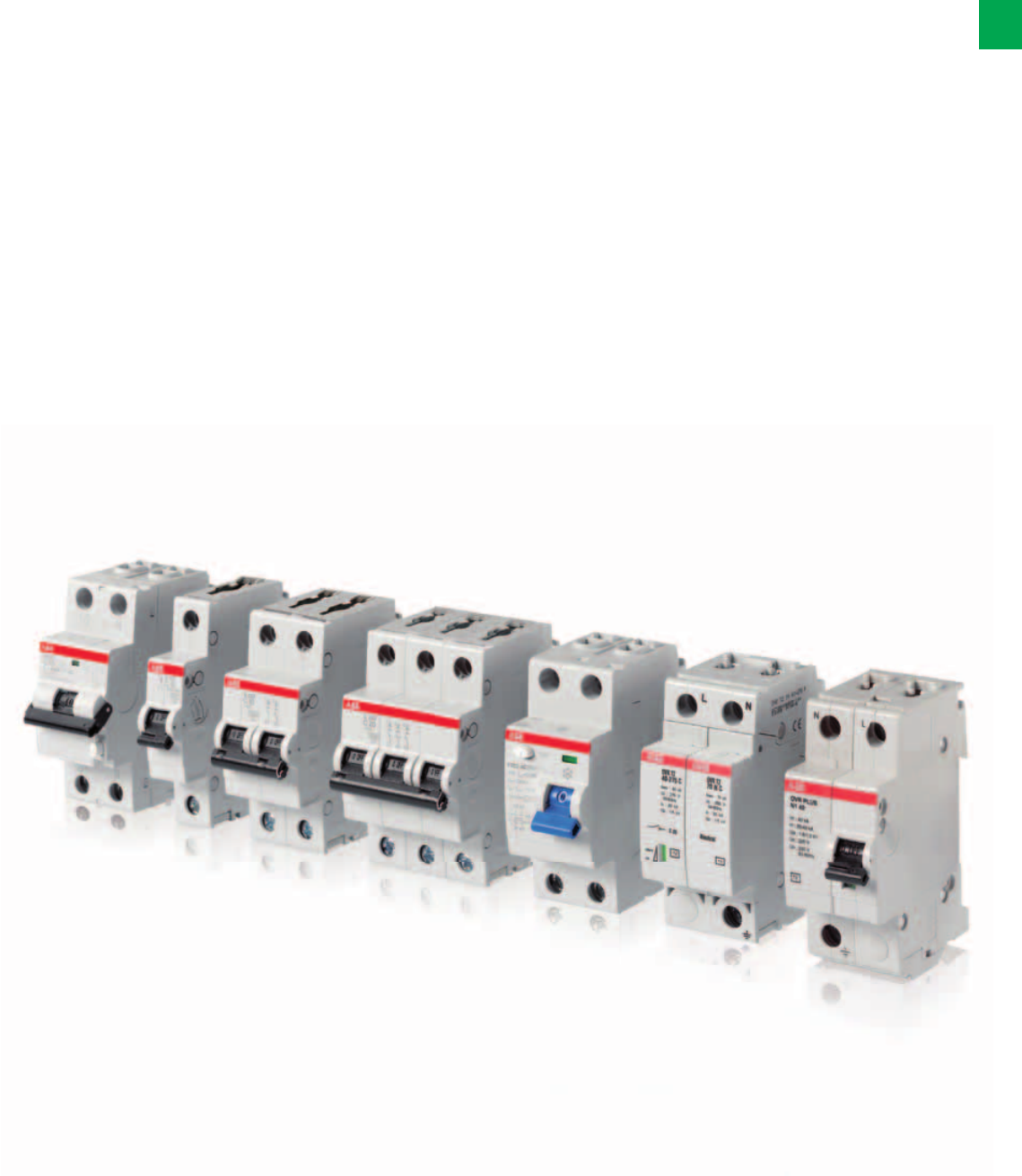
2/6 2CSC 400 031 D0202 | System pro M compact®
2
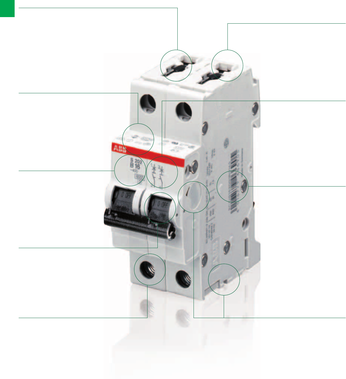
MCB S 200. The details make the difference
A range designed to ensure efficiency and protection
Safe your time –
all important data
available right
away
Easy product
name, easy
identification, easy
life
Twin terminal for
separate feeding
of busbar and
conductor
Captive screws:
don’t loose what’s
important for you
IP20 - finger safety
Easy identification
of the product and
highly resistant
laser marking
Quick identification
thanks to laser
printed EAN
marking
Whatever your
application need
is – applicable with
a wide range of
accessories
Contact position
indication
System pro M compact® | 2CSC 400 031 D0202 2/7
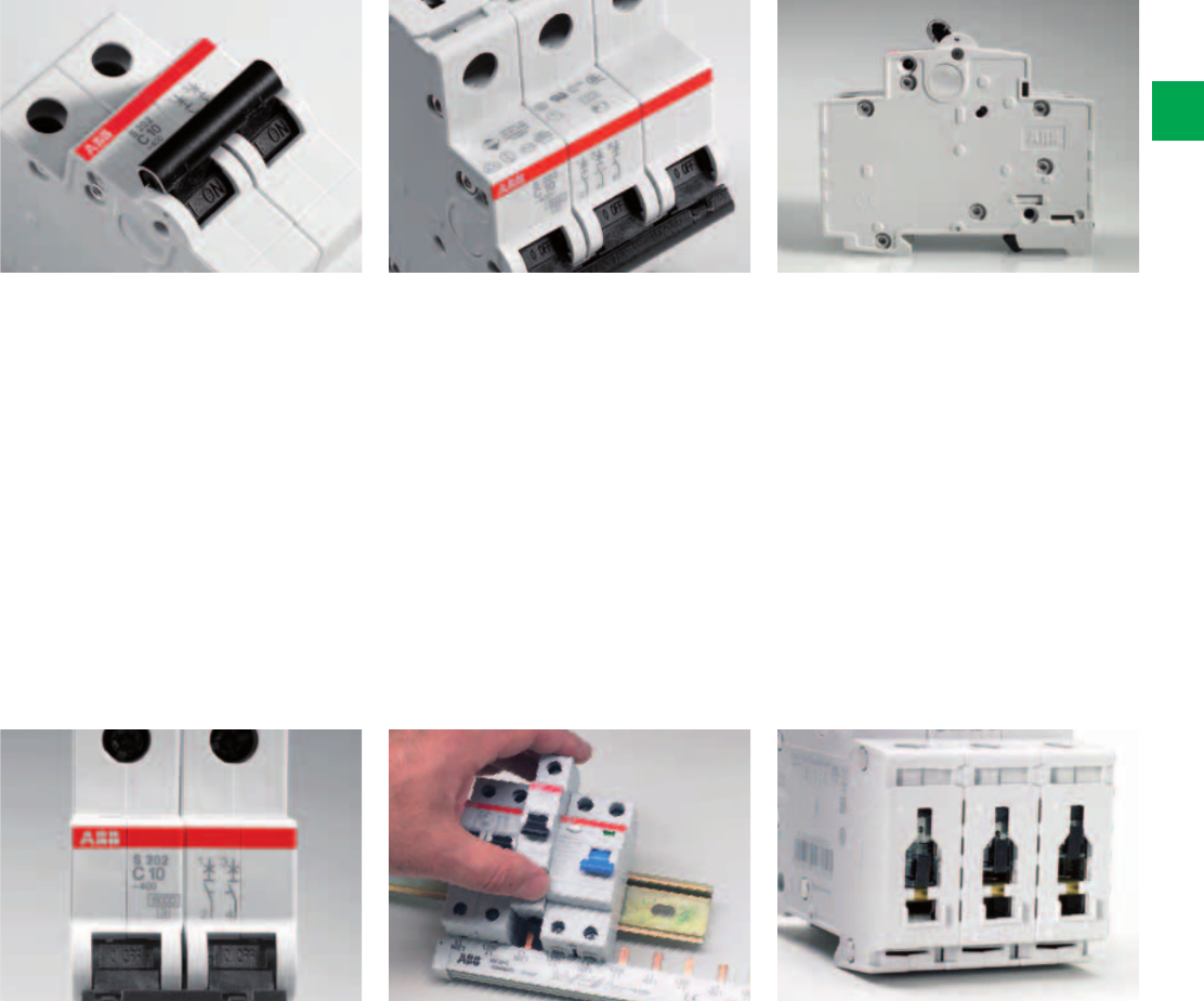
2
Contact position indication
All System pro M compact® MCBs are
suited with a contact position indication
(CPI) on the toggle. You can easily
identify, if the MCB is in the ON or the
OFF position – easy and safe
maintenance work is possible.
Laser printing
All printings of the S 200 and S 200 M
MCBs, like the approvals on the dome
and the product identification, are
printed by a laser. The laser printing
ensures a friction, scratch and solvent
resistant marking on the MCBs.
Easy identification of the products in
case of maintenance or replacements
due to safe laser printing.
Approvals printed on the dome
S 200 and S 200 M MCBs comply to
IEC/EN 60898 and IEC/EN 60947 and
carry all relevant approval marks for
each market and segment they are
destined to. The certification markings
are also printed on the dome of the
MCB. Thus make it possible to see the
markings also in the mounted position.
For control and acceptance
procedure – certification marks
visible on fitted devices on the dome.
Removal of the devices
Special quick fastening for an easy
removal of the devices from the
assembly pressing upwards, both
for MCBs S 200/S 200 M and RCCBs F
200.
Housing material
By using the state-of-the-art housing
material, ABB is taking care of the
environment. With the latest generation
of thermoplastics it’s possible to recycle
the MCBs – especially the thermoplastic
housing-material can be re-used. By
using the latest generation of
thermoplastics the material stability of
all System pro M compact® MCBs is
improved. S200 and S200M are 100%
free of halogens – no environmental
pollution.
IP 20 - finder safe terminals
The System pro M compact® MCB’s are
equiped with 35 mm² + 10 mm² cylinder
lift twin terminals, a well proven and
reliable technology - designed for
sopisticated industrial use.
The cross wiring can easily be done by
inserting the System pro M compact®
busbars into the rear terminal part and
then the incoming wires into the front
part of the terminal.

2/8 2CSC 400 031 D0202 | System pro M compact®
2
Technical features table for miniature circuit-breakers
S 200 Series
General Data
Standards
Poles
Tripping characteristics
Rated current InA
Rated frequency f Hz
Rated insulation voltage Ui acc. to IEC/EN 60664-1 V
Overvoltage category
Pollution degree
Data acc. to IEC/EN 60898-1
Rated operational voltage UnV
Max. power frequency recovery voltage (Umax) V
Min. operating voltage V
Rated short-circuit capacity Icn kA
Energy limiting class (B, C up to 40 A)
Rated impulse withstand voltage Uimp. (1.2/50μs) kV
Dielectric test voltage kV
Reference temperature for tripping characteristics °C
Electrical endurance ops.
Data acc. to IEC/EN 60947-2
Rated operational voltage UnV
Max. power frequency recovery voltage (Umax) V
Min. operating voltage V
Rated ultimate short-circuit breaking capacity Icu kA
Rated service short-circuit breaking capacity Ics kA
Rated impulse withstand voltage Uimp. (1.2/50μs) kV
Dielectric test voltage kV
Reference temperature for tripping characteristics °C
Electrical endurance ops.
Data acc. to UL / CSA
Rated voltage V
Rated interrupting capacity acc. to UL 1077 kA
Application
Reference temperature for tripping characteristics °C
Electrical endurance ops.
2CSC400031F0001
2CSC400031F0001
System pro M compact® | 2CSC 400 031 D0202 2/9
2
S 200 S 200 M
IEC/EN 60898-1, IEC/EN 60947-2
UL 1077, CSA 22.2 No. 235
IEC/EN 60898-1, IEC/EN 60947-2
-
1P, 2P, 3P, 4P, 1P+N, 3P+N
B, C
6…40 A
50 / 60 Hz
250 V AC (phase to groud), 500 V AC (phase to phase)
III
3
1P: 230/400 V AC; 1P+N: 230 V AC ; 2...4P: 400 V AC; 3P+N: 400 V AC
1P: 253 V AC; 1P+N: 253 V AC; 2P: 440 V AC; 3...4P: 440 V AC; 3P+N: 440 V AC; 1P: 72 V DC; 2P: 125 V DC
12 V AC - 12 V DC
6 kA 10 k A
3
4 kV (test voltage 6.2kV at sea level, 5kV at 2,000m)
2 kV (50 / 60Hz, 1 min.)
B, C: 30°C
In < 32A: 20,000 ops (AC), In ≥ 32A: 10,000 ops. (AC); 1,000 ops. (DC); 1 cycle (2s - ON, 13s - OFF, In ≤ 32A), 1 cycle (2s - ON, 28s - OFF, In > 32A)
1P: 230 V AC; 1P+N: 230 V AC; 2...4P: 400 V AC; 3P+N: 400 V AC
1P: 253 V AC; 1P+N: 253 V AC; 2P: 440 V AC; 3...4P: 440 V AC; 3P+N: 440 V AC; 1P: 72 V DC; 2P: 125 V DC
12 V AC - 12 V DC
10 k A ≤ 40 A: 15 kA
50, 63 A: 10 kA
7.5 k A ≤ 40 A: 11.2 kA
50, 63 A: 7.5 kA
4 kV (test voltage 6.2kV at sea level, 5kV at 2,000m)
2 kV (50 / 60Hz, 1 min.)
B, C: 55°C
In < 32A: 20,000 ops (AC), In ≥ 32A: 10,000 ops. (AC); 1,000 ops. (DC); 1 cycle (2s - ON, 13s - OFF, In ≤ 32A), 1 cycle (2s - ON, 28s - OFF, In > 32A)
480Y / 277 V AC -
6 kA -
Suppl. prot. for general use. Application Codes: TC2, OL0, SC: U1 -
B, C: 30°C -
6,000 ops (AC), 6,000 ops. (DC); 1 cycle (1s - ON, 9s - OFF)

2/10 2CSC 400 031 D0202 | System pro M compact®
2
Technical features table for miniature circuit-breakers
S 200 Series
Mechanical Data
Housing
Toggle
Contact position indication
Protection degree acc. to EN 60529
Mechanical endurance ops.
Shock resistance acc. to IEC/EN 60068-2-27
Vibration resistance acc. to IEC/EN 60068-2-6
Environmental conditions (damp heat cyclic) acc. to IEC/EN 60068-2-30 °C/RH
Ambient temperature °C
Storage temperature °C
Installation
Terminal
Cross-section of conductors (top / bottom) mm²
AWG
Cross-section of busbars (top / bottom) mm²
AWG
Torque Nm
in-Ibs.
Screwdriver
Mounting
Mounting position
Supply
Dimensions and weight
Mounting dimensions acc. to DIN 43880
Pole dimensions (H x D x W) mm
Pole weight g
Combination with aux. elements
Auxiliary contact
Signal contact
Shunt trip
Undervoltage release
Motor Operating Device
2CSC400031F0001
2CSC400031F0001
System pro M compact® | 2CSC 400 031 D0202 2/11
2
S 200 S 200 M
Insulation group I, RAL 7035
Insulation group II, black, sealable
Marking on toggle (I ON / 0 OFF)
IP20*, IP40 in enclosure with cover
20,000 ops.
30 g - 3 shocks - 11 ms
5g - 20 cycles at 5…150…5 Hz with load 0.8 In
28 cycles with 55°C/90-96% and 25°C/95-100%
-25 … +55°C
-40 … +70°C
Failsafe bi-directional cylinder-lift terminal
25 mm2 / 25 mm2
18 - 4 AWG -
10 mm2 / 10 mm2
18 - 8 AWG -
2.8 Nm
25 in-Ibs. -
No. 2 Pozidrive
On DIN rail 35 mm acc. to EN 60715 by fast clip
any
optional
Mounting dimension 1
88 x 69 x 17.5 mm
ca. 125 g
Yes
Yes
Yes
Yes
Yes
2CSC400031F0002
2CSC400031F00032CSC400031F0003
2CSC400031F0004
S201-B
S201-B…NA
S202-B
S203-B
2/12 2CSC 400 031 D0202 | System pro M compact®
2
Ordering Information
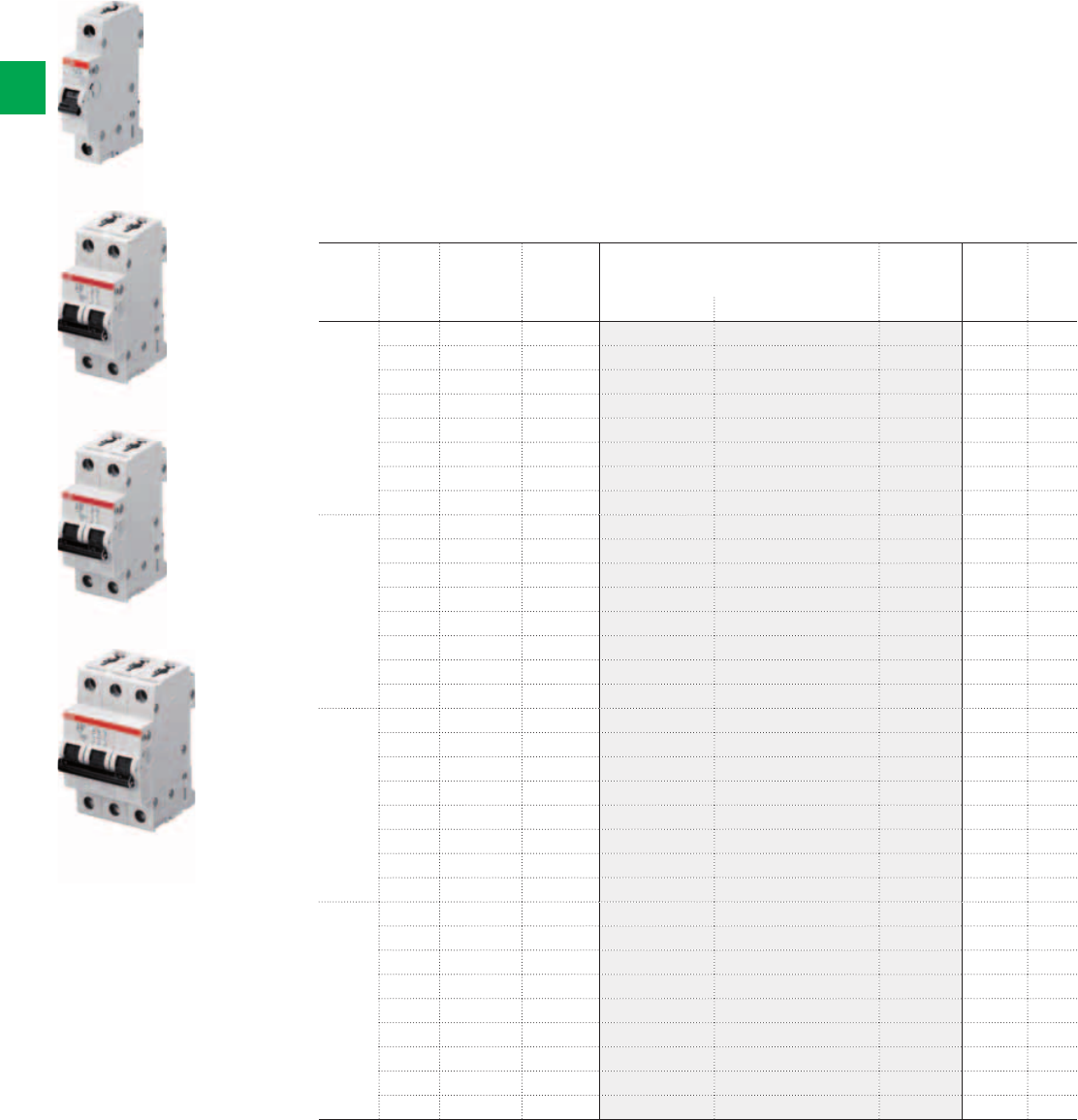
MCB S 200 Series - B characteristic
The S 200 miniature circuit breaker is perfectly suitable for protecting lighting and power
socket circuits that can be frequently found in residential areas. ABB used its years of
experience with miniature circuit breaker to create this product by combining the optimum
features for residential use alone.
The System pro M compact® range is versatile to provide the customer with the perfect
solution for residential overcurrent protection. It is available in tripping characteristics B and
C type; with breaking capacities between 6 and 10 kA. As usual for ABB miniature circuit
breaker, S200 is available from one to four poles and additional in one & three pole plus
Neutral. The rated currents are available from 0,5A up to 63A.
N. of
poles
Rated
current
N° module Bbn
4016779
Order details Weight
1 piece
Pack
unit
In A [17,5 mm] EAN Type code Order code Price Kg
1 6 1 464901 S201-B 6 2CDS251001R0065 0,125 10
10 1 463805 S201-B 10 2CDS251001R0105 0,125 10
13 1 465007 S201-B 13 2CDS251001R0135 0,125 10
16 1 463904 S201-B 16 2CDS251001R0165 0,125 10
20 1 465106 S201-B 20 2CDS251001R0205 0,125 10
25 1 465205 S201-B 25 2CDS251001R0255 0,125 10
32 1 465304 S201-B 32 2CDS251001R0325 0,125 10
40 1 465403 S201-B 40 2CDS251001R0405 0,125 10
1+N 6 2 531580 S201-B 6 NA 2CDS251103R0065 0,250 5
10 2 531597 S201-B 10 NA 2CDS251103R0105 0,250 5
13 2 531603 S201-B 13 NA 2CDS251103R0135 0,250 5
16 2 531610 S201-B 16 NA 2CDS251103R0165 0,250 5
20 2 531627 S201-B 20 NA 2CDS251103R0205 0,250 5
25 2 531634 S201-B 25 NA 2CDS251103R0255 0,250 5
32 2 531641 S201-B 32 NA 2CDS251103R0325 0,250 5
40 2 531658 S201-B 40 NA 2CDS251103R0405 0,250 5
2 6 2 466400 S202-B 6 2CDS252001R0065 0,250 5
10 2 466608 S202-B 10 2CDS252001R0105 0,257 5
13 2 466707 S202-B 13 2CDS252001R0135 0,257 5
16 2 466905 S202-B 16 2CDS252001R0165 0,260 5
20 2 467001 S202-B 20 2CDS252001R0205 0,270 5
25 2 467100 S202-B 25 2CDS252001R0255 0,250 5
32 2 467209 S202-B 32 2CDS252001R0325 0,250 5
40 2 467407 S202-B 40 2CDS252001R0405 0,250 5
3 6 3 467506 S203-B 6 2CDS253001R0064 0,375 1
8 3 467605 S203-B 8 2CDS253001R0084 0,375 1
10 3 467803 S203-B 10 2CDS253001R0104 0,375 1
13 3 467902 S203-B 13 2CDS253001R0134 0,375 1
16 3 468008 S203-B 16 2CDS253001R0164 0,375 1
20 3 468107 S203-B 20 2CDS253001R0204 0,375 1
25 3 468206 S203-B 25 2CDS253001R0254 0,375 1
32 3 468305 S203-B 32 2CDS253001R0324 0,375 1
40 3 468404 S203-B 40 2CDS253001R0404 0,375 1
2CSC400031F0005
S203-B…NA
S204-B
2CSC400031F0005
System pro M compact® | 2CSC 400 031 D0202 2/13
2
N. of
poles
Rated
current
N° module Bbn
4016779
Order details Weight
1 piece
Pack
unit
In A [17,5 mm] EAN Type code Order code Price Kg
3+N 6 4 532280 S203-B 6 NA 2CDS253103R0065 0,500 1
10 4 532297 S203-B 10 NA 2CDS253103R0105 0,500 1
13 4 532303 S203-B 13 NA 2CDS253103R0135 0,500 1
16 4 532310 S203-B 16 NA 2CDS253103R0165 0,500 1
20 4 532327 S203-B 20 NA 2CDS253103R0205 0,500 1
25 4 532334 S203-B 25 NA 2CDS253103R0255 0,500 1
32 4 532341 S203-B 32 NA 2CDS253103R0325 0,500 1
40 4 532358 S203-B 40 NA 2CDS253103R0405 0,500 1
4 6 4 528955 S204-B 6 2CDS254001R0065 0,500 1
10 4 528962 S204-B 10 2CDS254001R0105 0,500 1
13 4 528979 S204-B 13 2CDS253403R0135 0,500 1
16 4 528986 S204-B 16 2CDS254001R0165 0,500 1
20 4 528993 S204-B 20 2CDS254001R0205 0,500 1
25 4 529006 S204-B 25 2CDS254001R0255 0,500 1
32 4 529013 S204-B 32 2CDS254001R0325 0,500 1
40 4 529020 S204-B 40 2CDS254001R0405 0,500 1
2CSC400031F0002
2CSC400031F00032CSC400031F0003
2CSC400031F0004
S201-C
S201-C…NA
S202-C
S203-C
2/14 2CSC 400 031 D0202 | System pro M compact®
2
Ordering Information
MCB S 200 Series - C characteristic
N. of
poles
Rated
current
N° module Bbn
4016779
Order details Weight
1 piece
Pack
unit
In A [17,5 mm] EAN Type code Order code Price Kg
1 6 1 464000 S201-C 6 2CDS251001R0064 0,125 10
8 1 464109 S201-C 8 2CDS251001R0084 0,125 10
10 1 464208 S201-C 10 2CDS251001R0104 0,125 10
13 1 464307 S201-C 13 2CDS251001R0134 0,125 10
16 1 464406 S201-C 16 2CDS251001R0164 0,125 10
20 1 464505 S201-C 20 2CDS251001R0204 0,125 10
25 1 464604 S201-C 25 2CDS251001R0254 0,125 10
32 1 464703 S201-C 32 2CDS251001R0324 0,125 10
40 1 464802 S201-C 40 2CDS251001R0404 0,125 10
1+N 6 2 531733 S201-C 6 NA 2CDS251103R0064 0,250 5
8 2 531740 S201-C 8 NA 2CDS251103R0084 0,250 5
10 2 531757 S201-C 10 NA 2CDS251103R0104 0,250 5
13 2 531764 S201-C 13 NA 2CDS251103R0134 0,250 5
16 2 531771 S201-C 16 NA 2CDS251103R0164 0,250 5
20 2 531788 S201-C 20 NA 2CDS251103R0204 0,250 5
25 2 531795 S201-C 25 NA 2CDS251103R0254 0,250 5
32 2 531801 S201-C 32 NA 2CDS251103R0324 0,250 5
40 2 531818 S201-C 40 NA 2CDS251103R0404 0,250 5
2 6 2 465502 S202-C 6 2CDS252001R0064 0,250 5
8 2 465601 S202-C 8 2CDS252001R0084 0,246 5
10 2 465700 S202-C 10 2CDS252001R0104 0,250 5
13 2 465809 S202-C 13 2CDS252001R0134 0,257 5
16 2 465908 S202-C 16 2CDS252001R0164 0,250 5
20 2 466004 S202-C 20 2CDS252001R0204 0,250 5
25 2 466103 S202-C 25 2CDS252001R0254 0,250 5
32 2 466202 S202-C 32 2CDS252001R0324 0,250 5
40 2 466301 S202-C 40 2CDS252001R0404 0,250 5
3 6 3 467506 S203-C 6 2CDS253001R0064 0,375 1
8 3 467605 S203-C 8 2CDS253001R0084 0,375 1
10 3 467803 S203-C 10 2CDS253001R0104 0,375 1
13 3 467902 S203-C 13 2CDS253001R0134 0,375 1
16 3 468008 S203-C 16 2CDS253001R0164 0,375 1
20 3 468107 S203-C 20 2CDS253001R0204 0,375 1
25 3 468206 S203-C 25 2CDS253001R0254 0,375 1
32 3 468305 S203-C 32 2CDS253001R0324 0,375 1
40 3 468404 S203-C 40 2CDS253001R0404 0,375 1
2CSC400031F0005
S203-C…NA
S204-C
2CSC400031F0005
System pro M compact® | 2CSC 400 031 D0202 2/15
2
N. of
poles
Rated
current
N° module Bbn
4016779
Order details Weight
1 piece
Pack
unit
In A [17,5 mm] EAN Type code Order code Price Kg
3+N 6 4 532433 S203-C 6 NA 2CDS253103R0064 0,500 1
8 4 532440 S203-C 8 NA 2CDS253103R0084 0,500 1
10 4 532457 S203-C 10 NA 2CDS253103R0104 0,500 1
13 4 532464 S203-C 13 NA 2CDS253103R0134 0,500 1
16 4 532471 S203-C 16 NA 2CDS253103R0164 0,500 1
20 4 532488 S203-C 20 NA 2CDS253103R0204 0,500 1
25 4 532495 S203-C 25 NA 2CDS253103R0254 0,500 1
32 4 532501 S203-C 32 NA 2CDS253103R0324 0,500 1
40 4 532518 S203-C 40 NA 2CDS253103R0404 0,500 1
4 6 4 529174 S204-C 6 2CDS254001R0064 0,500 1
8 4 529181 S204-C 8 2CDS254001R0084 0,500 1
10 4 529198 S204-C 10 2CDS254001R0104 0,500 1
13 4 529204 S204-C 13 2CDS254001R0134 0,500 1
16 4 529211 S204-C 16 2CDS254001R0164 0,500 1
20 4 529228 S204-C 20 2CDS254001R0204 0,500 1
25 4 529235 S204-C 25 2CDS254001R0254 0,500 1
32 4 529242 S204-C 32 2CDS254001R0324 0,500 1
40 4 529259 S204-C 40 2CDS254001R0404 0,500 1

Ordering Information
MCB S 200 M Series - C characteristic
2CSC400031F0002
2CSC400031F00032CSC400031F0003
2CSC400031F0004
S201 M-C
S201 M-C…NA
S202 M-C
S203 M-C
2/16 2CSC 400 031 D0202 | System pro M compact®
2
N. of
poles
Rated
current
N° module Bbn
4016779
Order details Weight
1 piece
Pack
unit
In A [17,5 mm] EAN Type code Order code Price Kg
1 6 1 549967 S 201 M-C 6 2CDS271001R0064 0,125 10
8 1 549974 S 201 M-C 8 2CDS271001R0084 0,125 10
10 1 549981 S 201 M-C 10 2CDS271001R0104 0,125 10
13 1 549998 S 201 M-C 13 2CDS271001R0134 0,125 10
16 1 550000 S 201 M-C 16 2CDS271001R0164 0,125 10
20 1 550017 S 201 M-C 20 2CDS271001R0204 0,125 10
25 1 550024 S 201 M-C 25 2CDS271001R0254 0,125 10
32 1 550031 S 201 M-C 32 2CDS271001R0324 0,125 10
40 1 550048 S 201 M-C 40 2CDS271001R0404 0,125 10
1+N 6 2 550116 S 201 M-C 6 NA 2CDS271103R0064 0,250 5
8 2 550123 S 201 M-C 8 NA 2CDS271103R0084 0,250 5
10 2 550130 S 201 M-C 10 NA 2CDS271103R0104 0,250 5
13 2 550147 S 201 M-C 13 NA 2CDS271103R0134 0,250 5
16 2 550154 S 201 M-C 16 NA 2CDS271103R0164 0,250 5
20 2 550161 S 201 M-C 20 NA 2CDS271103R0204 0,250 5
25 2 550178 S 201 M-C 25 NA 2CDS271103R0254 0,250 5
32 2 550185 S 201 M-C 32 NA 2CDS271103R0324 0,250 5
40 2 550192 S 201 M-C 40 NA 2CDS271103R0404 0,250 5
2 6 2 550260 S 202 M-C 6 2CDS272001R0064 0,250 5
8 2 550277 S 202 M-C8 2CDS272001R0084 0,250 5
10 2 550284 S 202 M-C 10 2CDS272001R0104 0,250 5
13 2 550291 S 202 M-C 13 2CDS272001R0134 0,250 5
16 2 550307 S 202 M-C 16 2CDS272001R0164 0,250 5
20 2 550314 S 202 M-C 20 2CDS272001R0204 0,250 5
25 2 550321 S 202 M-C 25 2CDS272001R0254 0,250 5
32 2 550338 S 202 M-C 32 2CDS272001R0324 0,250 5
40 2 550345 S 202 M-C 40 2CDS272001R0404 0,250 5
3 6 3 550413 S 203 M-C 6 2CDS273001R0064 0,375 1
8 3 550420 S 203 M-C 6 2CDS273001R0084 0,375 1
10 3 550437 S 203 M-C 10 2CDS273001R0104 0,375 1
13 3 550444 S 203 M-C 13 2CDS273001R0134 0,375 1
16 3 550451 S 203 M-C 16 2CDS273001R0164 0,375 1
20 3 550468 S 203 M-C 20 2CDS273001R0204 0,375 1
25 3 550475 S 203 M-C 25 2CDS273001R0254 0,375 1
32 3 550482 S 203 M-C 32 2CDS273001R0324 0,375 1
40 3 550499 S 203 M-C 40 2CDS273001R0404 0,375 1

2CSC400031F0005
S203 M-C…NA
S204 M-C
2CSC400031F0005
System pro M compact® | 2CSC 400 031 D0202 2/17
2
N. of
poles
Rated
current
N° module Bbn
4016779
Order details Weight
1 piece
Pack
unit
In A [17,5 mm] EAN Type code Order code Price Kg
3+N 6 4 550567 S 203 M-C 6 NA 2CDS273103R0064 0,500 1
8 4 550574 S 203 M-C 8 NA 2CDS273103R0084 0,500 1
10 4 550581 S 203 M-C 10 NA 2CDS273103R0104 0,500 1
13 4 550598 S 203 M-C 13 NA 2CDS273103R0134 0,500 1
16 4 550604 S 203 M-C 16 NA 2CDS273103R0164 0,500 1
20 4 550611 S 203 M-C 20 NA 2CDS273103R0204 0,500 1
25 4 550628 S 203 M-C 25 NA 2CDS273103R0254 0,500 1
32 4 550635 S 203 M-C 32 NA 2CDS273103R0324 0,500 1
40 4 550642 S 203 M-C 40 NA 2CDS273103R0404 0,500 1
4 6 4 550710 S 204 M-C 6 2CDS274001R0064 0,500 1
8 4 550727 S 204 M-C 8 2CDS274001R0084 0,500 1
10 4 550734 S 204 M-C 10 2CDS274001R0104 0,500 1
13 4 550741 S 204 M-C 13 2CDS274001R0134 0,500 1
16 4 550758 S 204 M-C 16 2CDS274001R0164 0,500 1
20 4 550765 S 204 M-C 20 2CDS274001R0204 0,500 1
25 4 550772 S 204 M-C 25 2CDS274001R0254 0,500 1
32 4 550789 S 204 M-C 32 2CDS274001R0324 0,500 1
40 4 550796 S 204 M-C 40 2CDS274001R0404 0,500 1
2CSC400031F0002
2CSC400031F0003
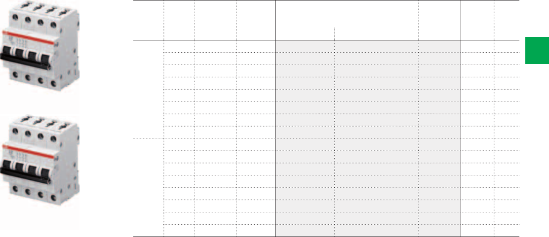
2CSC400031F0004
S201 M-B
S202 M-B
S203 M-B
S204 M-B
2CSC400031F0005
2/18 2CSC 400 031 D0202 | System pro M compact®
2
Ordering Information
MCB S 200 M Series - B characteristic
N. of
poles
Rated
current
N° module Bbn
4016779
Order details Weight
1 piece
Pack
unit
In A [17,5 mm] EAN Type code Order code Price Kg
1 6 1 549424 S 201 M-B 6 2CDS271001R0065 0,125 10
10 1 549431 S 201 M-B 10 2CDS271001R0105 0,125 10
13 1 549448 S 201 M-B 13 2CDS271001R0135 0,125 10
16 1 549455 S 201 M-B 16 2CDS271001R0165 0,125 10
20 1 549462 S 201 M-B 20 2CDS271001R0205 0,125 10
25 1 549479 S 201 M-B 25 2CDS271001R0255 0,125 10
32 1 549486 S 201 M-B 32 2CDS271001R0325 0,125 10
40 1 549493 S 201 M-B 40 2CDS271001R0405 0,125 10
2 6 2 549585 S 202 M-B 6 2CDS272001R0065 0,250 5
10 2 549592 S 202 M-B 10 2CDS272001R0105 0,250 5
13 2 549608 S 202 M-B 13 2CDS272001R0135 0,250 5
16 2 549615 S 202 M-B 16 2CDS272001R0165 0,250 5
20 2 549622 S 202 M-B 20 2CDS272001R0205 0,250 5
25 2 549639 S 202 M-B 25 2CDS272001R0255 0,250 5
32 2 549646 S 202 M-B 32 2CDS272001R0325 0,250 5
40 2 549653 S 202 M-B 40 2CDS272001R0405 0,250 5
3 6 3 549660 S 203 M-B 6 2CDS273001R0065 0,375 1
10 3 549677 S 203 M-B 10 2CDS273001R0105 0,375 1
13 3 549684 S 203 M-B 13 2CDS273001R0135 0,375 1
16 3 549691 S 203 M-B 16 2CDS273001R0165 0,375 1
20 3 549707 S 203 M-B 20 2CDS273001R0205 0,375 1
25 3 549714 S 203 M-B 25 2CDS273001R0255 0,375 1
32 3 549721 S 203 M-B 32 2CDS273001R0325 0,375 1
40 3 549738 S 203 M-B 40 2CDS273001R0405 0,375 1
4 6 4 549820 S 204 M-B 6 2CDS274001R0065 0,500 1
10 4 549837 S 204 M-B 10 2CDS274001R0105 0,500 1
13 4 549844 S 204 M-B 13 2CDS274001R0135 0,500 1
16 4 549851 S 204 M-B 16 2CDS274001R0165 0,500 1
20 4 549868 S 204 M-B 20 2CDS274001R0205 0,500 1
25 4 549875 S 204 M-B 25 2CDS274001R0255 0,500 1
32 4 549882 S 204 M-B 32 2CDS274001R0325 0,500 1
40 4 549899 S 204 M-B 40 2CDS274001R0405 0,500 1
System pro M compact® | 2CSC 400 031 D0202 2/19
2
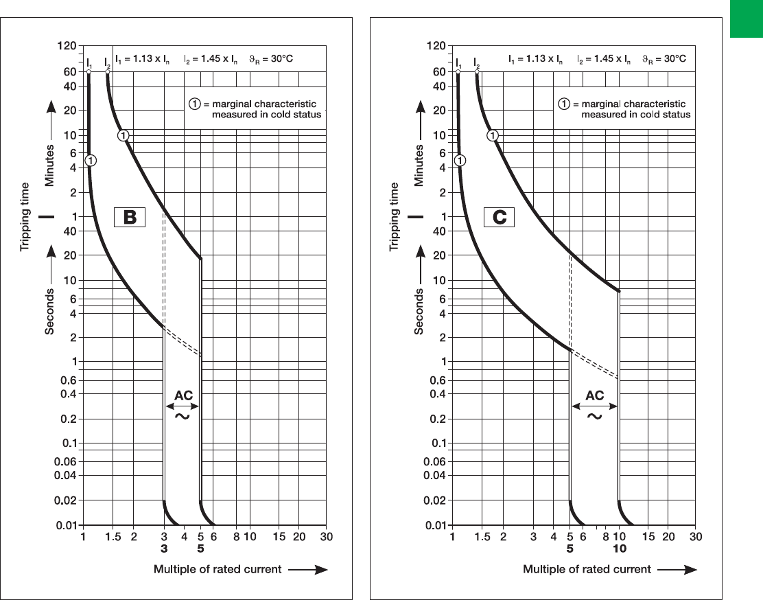
Technical details
Tripping diagrams
B characteristic C characteristic
acc. to IEC/EN 60898-1
In = 6 ... 40 A
S200 / S200 M
acc. to IEC/EN 60898-1
In = 6 ... 40 A
S 200 / S 200 M

2/20 2CSC 400 031 D0202 | System pro M compact®
2
Internal resistances and power losses of the Miniature Circuit-Breakers
Tripping characteristics
Rated current Device series B, C
In Am ΩW
6
8
10
55
15
13.3
2.0
1.0
1.3
13
16
20
13.3
7.0
6.25
2.3
1.8
2.5
25
32
40
5.0
3.6
3.0
3.2
3.7
4.8
Technical details
Internal resistances per pole in m Ω
Power losses per pole in W
Internal resistances are subject to application-specific and environment-specific
conditions and are therefore to be considered as typical values.
acc. to Tripping
characterisitic
Thermal trips 1Electromagnetic trips 2
Test currents: Tripping-time Test currents: Tripping-time
conventional
non-tripping
current
I1
conventional
tripping
current
I2
hold current
surges of
trip
at least at
IEC/EN 60898-1
B 1.13 · In1.45 · In
> 1 h
< 1 h 33 · In5 · In
0.1 s … 45 s ≤ 32 A / 0.1 s … 90 s ≥ 32 A
< 0,1 s
C 1.13 · In1.45 · In
> 1 h
< 1 h 35 · In10 · In
0.1 s … 15 s ≤ 32 A / 0.1 s … 30 s ≥ 32 A
< 0,1 s
1) Influence of ambient temperature see below.
2) The tripping for the electromagnetic trip are valid for AC 50...60 Hz. For other frequencies see table below.
3) From warm operating condition (After I1>1 h resp. 2 h).
Influence of frequency on electromagnetic trips
AC DC
100 Hz 200 Hz 400 Hz
Factor approx. 1.1 1.2 1.5 1.5
The stated tripping values of the electromagnetic trips are
valid for a frequency of 50… 60 Hz. In case of frequencies
deviating from 50… 60 Hz as well as direct current the
tripping values are changed by the factor mentioned below.
The tripping values of the thermal trips are independent
of the frequency.
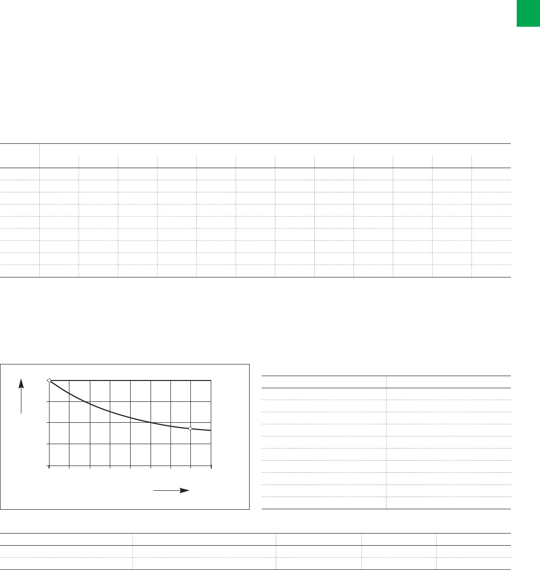
System pro M compact® | 2CSC 400 031 D0202 2/21
2
Derating of load capability of MCBs
Max. operating current depending on the ambient temperature of a circuit-breaker in load circuit of characteristics type B and C.
B and C Ambient temperature T (°C)
In (A)-40-30-20-100 10203040506070
6.0 8.0 7.7 7.5 7.2 6.9 6.6 6.3 6.0 5.7 5.3 4.9 4.5
8.0 10.7 10.3 10.0 9.6 9.2 8.8 8.4 8.0 7.5 7.1 6.5 6.0
10.0 13.3 12.9 12.5 12.0 11.5 11.1 10.5 10.0 9.4 8.8 8.2 7.5
13.0 17.3 16.8 16.2 15.6 15.0 14.4 13.7 13.0 12.3 11.5 10.6 9.7
16.0 21.3 20.7 20.0 19.2 18.5 17.7 16.9 16.0 15.1 14.1 13.1 11.9
20.0 26.7 25.8 24.9 24.0 23.1 22.1 21.1 20.0 18.9 17.6 16.3 14.9
25.0 33.3 32.3 31.2 30.0 28.9 27.6 26.4 25.0 23.6 22.0 20.4 18.6
32.0 42.7 41.3 39.9 38.5 37.0 35.4 33.7 32.0 30.2 28.2 26.1 23.9
40.0 53.3 51.6 49.9 48.1 46.2 44.2 42.2 40.0 37.7 35.3 32.7 29.8
Influence of adjacent devices S200
Correction factor Fm
No. of adjacent devices Fm
11
20.95
30.9
40.86
50.82
60.795
70.78
80.77
90.76
>9 0.76
Example: S 202 C 16 with T=40 °C
Type of use Values to use Formula Calculation Result
Continuous load In (amb. t°) -see tables-, 0.9 In (amb. t°)x0.9 15.1x0.9 In=16 A
Continuous load with 8 adj. devices In (amb. t°) -see tables-, 0.9, Fm (0.77) In (amb. t°) x0.9x0.77 15.1x0.9x0.77 In=12.23 A
Fm Factor
Number of devices
123456789
0.6
0.7
0.8
0.9
1.0
Influence of ambient temperature
The thermal trips are calibrated for an ambient temerpature 30 °C for B- and C-characteristic.
In the case of temperatures deviating from these values the tripp values:
- are reduced in case of higher temperatures;
- are increased in case of lower temperatures.
The electronic tripping is not dependent on temperature
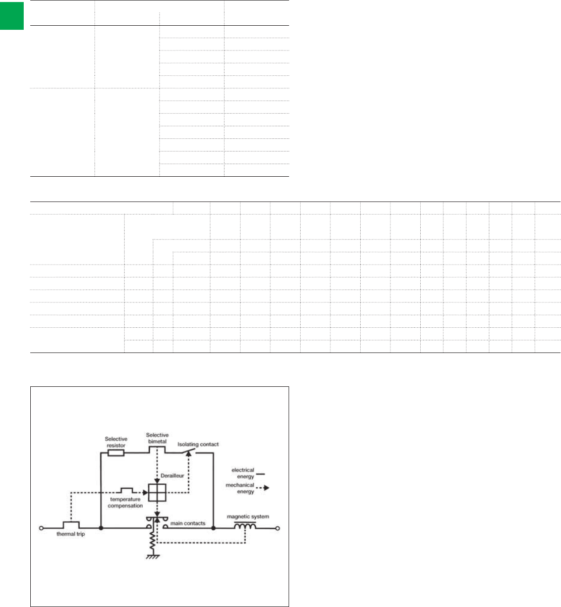
2/22 2CSC 400 031 D0202 | System pro M compact®
2
Technical details
Coordination tables
Fuse gG, gL - MCB S 200, S 200 M
240 V Supply s. Fuse gG, gL
Load s. Characteristic In [A]
S200, S200 M B 6 63
10...20 100
25...32 100
40 125
50...63 160
S200, S200 M C 3...4 20
640
863
10...20 100
25...32 100
40 125
50...63 160
MCB - MCB @ 240 V
Supply s. S200 S200M S200P S200P S280 S290 S800S 25gL 40gL 50gL 63gL 80gL 100gL
Load s. Char. B-C B-C B-C B-C B-C C-D B-C-
D-K
Icu
[kA]
20 25 40 25 20 25 50
In[A]
0,5…63 0,5…63 0,5…25 32…63 80…100 80…125 10…125
SN201 L/DS201 L B,C 6 2...40 20 25 40 25 15 15 50 35 25 20 15 10 10
SN201/DS201/DS202C B,C,D 10 2...40 20 25 40 25 15 15 50 35 25 20 15 10 10
SN201 M/DS201 M/ DS202C M B,C 10 2...40 20 25 40 25 15 15 50 35 25 20 15 10 10
S200 B,C,K,Z 20 0,5…63 25 40 25 50
S200 M B,C,D 25 0,5…63 40 50
S200 P B,C 40 0,5…25 50
D,K,Z 25 32…63 50
Functional diagram of selective main circuit breakers S 700
Back-up protection
Selective main circuit breakers of the S 700 series are
capable of switching off short-circuit currents of up to 25 kA
automatically in networks with a rated voltage of 230/400 V.
Back-up protection is necessary only when the prospective
short-circuit current may exceed 25 kA prosp. at the
installation point. Further information on back-up protection
on request.
Short circuit discrimination
When ABB miniature circuit-breaker are used in combination
with the S 700, higher short-circuit currents can be
disconnected than are indicated as permissible rated
switching capacity of device. Considering the values given in
the table, the S 700 operates selectively with respect to the
combination with the final device. If other mcbs are used
selectivity for 6 kA and 10 kA devices is available up to the
rated switching capacity of the final device.
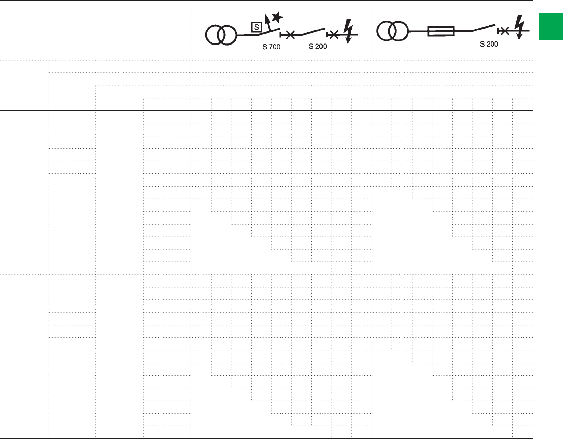
System pro M compact® | 2CSC 400 031 D0202 2/23
2
Short circuit selectivity
MCBs
Load side Supply side S 700 fuse
Char. E/K gG
Icu [kA] 25
In [A] 162025354050638010016202535506380100
S 200 C 6 m 2 >15 >15 >15 >15 >15 >15 >15 >15 >15 1 1.2 4 >15 >15 >15 >15 >15
3 10101010101010880.30.71.24.66666
4 10101010101010880.30.60.92.86666
B, C 6 101010101010108 8 0.20.50.82 3.35.56 6
C 8 10 10 10 10 10 10 10 8 8 0.2 0.4 0.7 1.7 2.8 4.5 6 6
B, C 10 101010101010108 8 0.20.40.71.52.53.55 6
13 10*1010101010108 8 0.71.52.53.55 6
16 10*10101010108 8 1.32 2.94.16
20 10*101010108 8 1.82.63.55
25 10*1010108 8 1.82.63.55
32 10*10108 8 2.23 4
40 10* 10 8 8 2.5 4
50/63 8* 8 3.5
S 200 M C 6 m 2 >15 >15 >15 >15 >15 >15 >15 >15 >15 1 1.2 4 >15 >15 >15 >15 >15
3 1515151515151510100.30.71.24.610101010
4 1515151515151510100.30.60.92.810101010
B, C 6 1515151515151510100.20.50.81.73.17 1010
C 8 15 15 15 15 15 15 15 10 10 0.2 0.4 0.7 1.4 2.3 3.4 4.8 7.5
B, C 10 1515151515151510100.20.40.71.42.33.44.87.5
13 15*1515151515151010 0.71.42.33.44.87.5
16 15*15151515151010 1.32 2.94.26
20 15*151515151010 1.92.73.85.6
25 15*1515151010 1.92.63.65.4
32 15*15151010 2.43.24.2
40 15* 15 10 10 3.2 4.2
50/63 10* 10 3.8
* Limited overload selectivity

2/24 2CSC 400 031 D0202 | System pro M compact®
2
Technical details
Maximum permissible earth-fault loop impedance ZS at U0 = 230 V~
Impedance Zs at U0 = 230 V AC1 to ensure compliance with the operation conditions pursuant to IEC 60364-4.
Operating time < 0.4 s; at 400 V~ < 0.2 s and at > 400 V~ < 0.1 s
The instantaneous release of the MCB ensures an operating time of ≤ 0.1 s (TN system).
Determined according to DIN VDE 0100-520 sheet 2:2002-11(source impedance = 300 mΩ, c = 0.95 and conductor
temperature 70 °C = factor 0.8). The internal resistance of the MCB is already included.
S 200 and S 200 M
Rated B C
current In A max. Zsmax. Zs
ΩΩ
67.7 3.8
8– 2.8
10 4.6 2.2
13 3.5 1.7
16 2.9 1.4
20 2.3 1.2
25 1.8 0.9
32 1.4 0.7
40 1.1 0.6
1) U0 = rated voltage against earthed conductor; for U0 = 240 V~ is ZS · 1.04; for U0 = 127 V~ is ZS · 0.55
Take into account the voltage drop:
e.g. in the case of a 1.5 mm2 conductor, protected by a B 16 circuit-breaker, the maximum cable length is 82 m. If the voltage
drop is below 3%, this would result in a maximum cable length (2-strand) of 17 m. For more details on this topic, get your own
copy of the technical information leaflet “Maximum cable lengths”.
Maximum cable length in case of different voltages and cross sections on request.
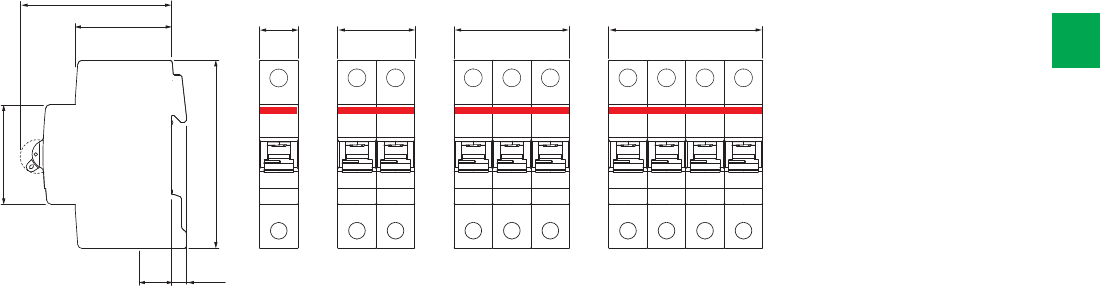
69
44
17.5 6.8
17.5
1 module 2 modules 3 modules 4 modules
35 52.5 70.5
45
85
System pro M compact® | 2CSC 400 031 D0202 2/25
2
Overall dimensions
S 200, S 200 M

2

System pro M compact® | 2CSC 400 031 D0202 2/27
2
F 200
Plus of range 2/28
Technical features table 2/30
Ordering information 2/32
Technical details 2/37
DS201 and DS202C
Plus of range 2/38
Technical features table 2/40
Ordering information DS201 series 2/42
Ordering information DS202C series 2/49
Technical details 2/50
Overall dimensions 2/54
Residual current devices
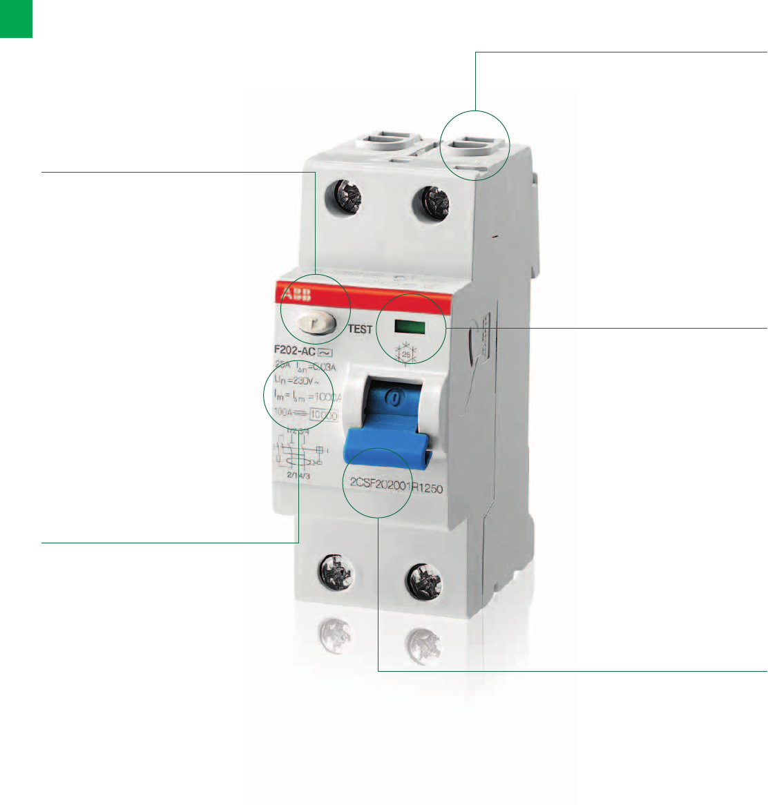
2/28 2CSC 400 031 D0202 | System pro M compact®
2
RCCB F 200. The details make the difference
A range designed to ensure efficiency and protection
Laser-marked
order code on
the front to make
easier future
orders.
Contact position
indicator (CPI):
to always know
the status of
the contacts
(red: closed
contacts; green:
open contacts)
independently on
the toggle position
Information on the
device are laser
printed to make
them clearly visible
and long lasting.
Bi-directional
cylindrical
terminals ensure
higher safety of
wiring operations,
making them
easier.
Test pushbutton to
verify the correct
functioning of the
device.
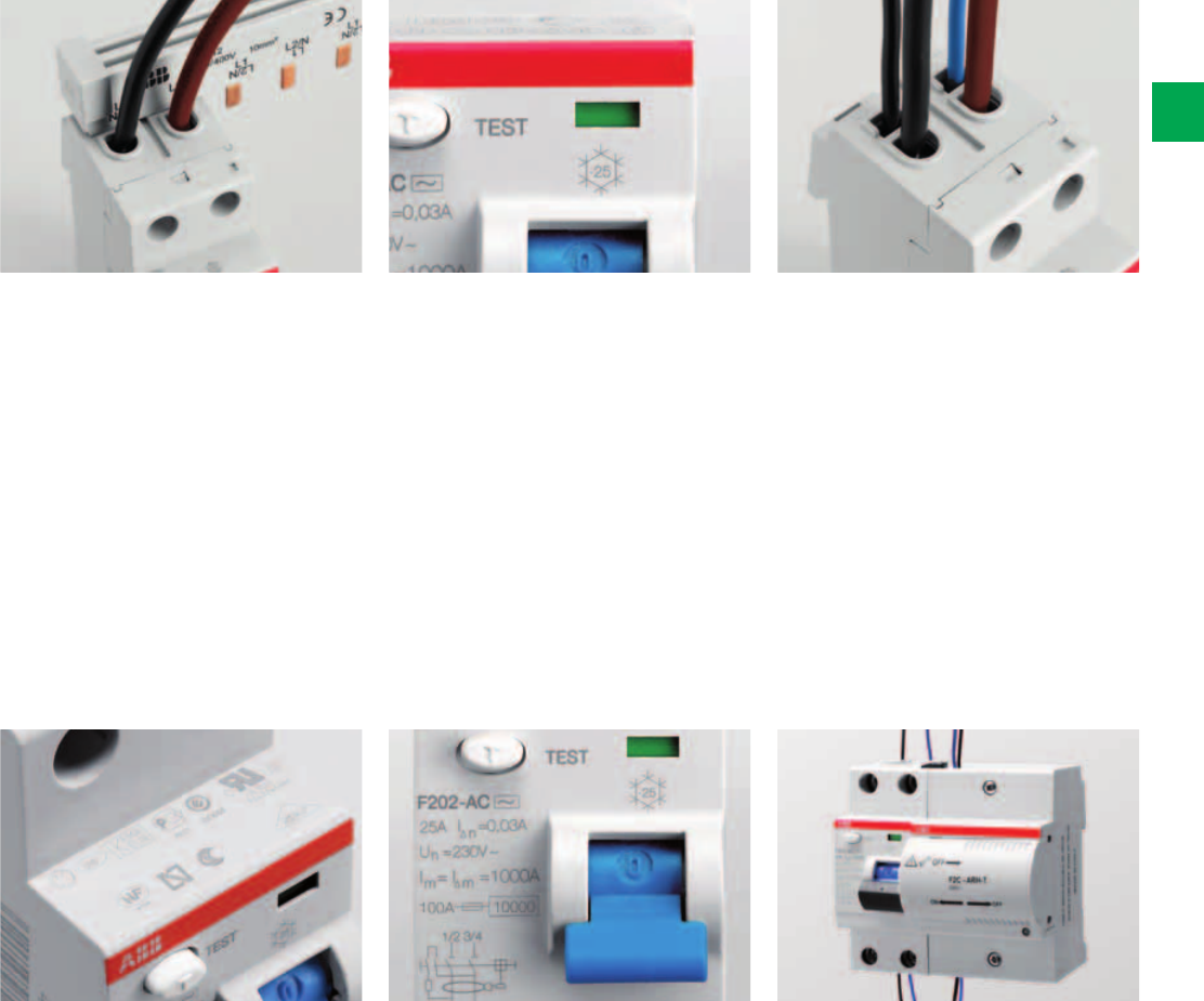
System pro M compact® | 2CSC 400 031 D0202 2/29
2
Two terminals are available, the fore one
for cables up to 25 mm2, the back one
for cables up to 10 mm2 or for busbars.
All the safety ensured by the
international marks: approvals’ marking
in a visible area, even if RCDs is
installed and with the panel-door
closed.
RCCBs F200 can be used in ambient
conditions where the temperature of the
surrounding atmosphere has values
between -25°C (snowflake laser printed
on the front of the device) and +55°C.
High performances:
- rated breaking capacity and rated
residual breaking capacity laser
printed on the device:
Im=IΔm= 1000 A
- coordination with a 100 A rated
current SCPD (short-circuit protective
device) = 10000 A.
The availability of two terminals offers
different connection solutions thanks to
the possibility to connect two
indipendent cables in the same device:
the second terminal can be used for an
auxiliary circuit or for the supply of
devices with small section cables
without connecting them together with
the main circuit.
The F 202 can be coupled with the
autoreclosing unit F2C-ARH in order to
ensure continuity of service for the
whole installation of your home avoiding
lack of supply.

2/30 2CSC 400 031 D0202 | System pro M compact®
2
Technical features table for residual current circuit breakers
(RCCBs)
F 200 Series
Standards
Electrical features
Type (wave form of the earth leakage sensed)
Poles
Rated current InA
Rated sensitivity IΔn mA
Rated voltage UeV
Insulation voltage UiV
Max. operating voltage of circuit test V
Min. operating voltage of circuit test V
Rated frequency Hz
Rated conditional short-circuit current Inc=IΔc kA
Rated residual breaking capacity IΔm=ImkA
Rated impulse withstand voltage (1.2/50) Uimp kV
Dielectric test voltage at ind. freq. for 1 min. kV
Surge current resistance (wave 8/20) A
Mechanical features
Toggle
Contact position indicator (CPI)
Electrical life
Mechanical life
Protection degree housing
terminals
Tropicalization
acc. to IEC/EN 60068-2
humid heat °C/RH
constant climatic conditions °C/RH
variable climatic conditions °C/RH
Ambient temperature (with daily average ≤ +35 °C) °C
Storage temperature °C
Installation
Terminal type
Terminal size top/bottom for cable mm2
Terminal size top/bottom for busbar mm2
Tightening torque N*m
Tool
Mounting
Connection
Dimensions and weight
Dimensions (H x D x W) 2P mm
4P mm
Weight 2P g
4P g
Combination with auxiliary elements
Combinable with: F2C-ARH autoreclosing unit

2CSC400031F0006
2CSC400031F0006
2CSC400031F0006
System pro M compact® | 2CSC 400 031 D0202 2/31
2
F 200 F 200 APR F 200 S
IEC/EN 61008
AC A A A
2P, 4P 2P, 4P 2P, 4P
16, 25, 40, 63 25, 40, 63 40, 63,100
10, 30, 100, 300 30 300
230/400 - 240/415
500
254
110
50..60
10 (with a SCPD-fuse gG 100A )
1
4
2.5
250 3000 5000
BLUE sealable in ON-OFF position
yes
10.000
20.000
IP4X
IP2X
28 cycles with 55/95…100
23/83 - 40/93 - 55/20
25/95 - 40/95
-25..+55
-40…+70
failsafe bi-directional cylinder-lift terminal at top and bottom
(shock protected)
25/25
10/10
2.8
Nr. 2 Pozidriv
on DIN rail EN 60715 (35 mm) by means of fast clip device
from top and bottom
85 x 69 x 35
85 x 69 x 70
200
350
yes (the 2 poles version 30mA and 100mA) yes (the 2 poles version 30mA and 100mA) no
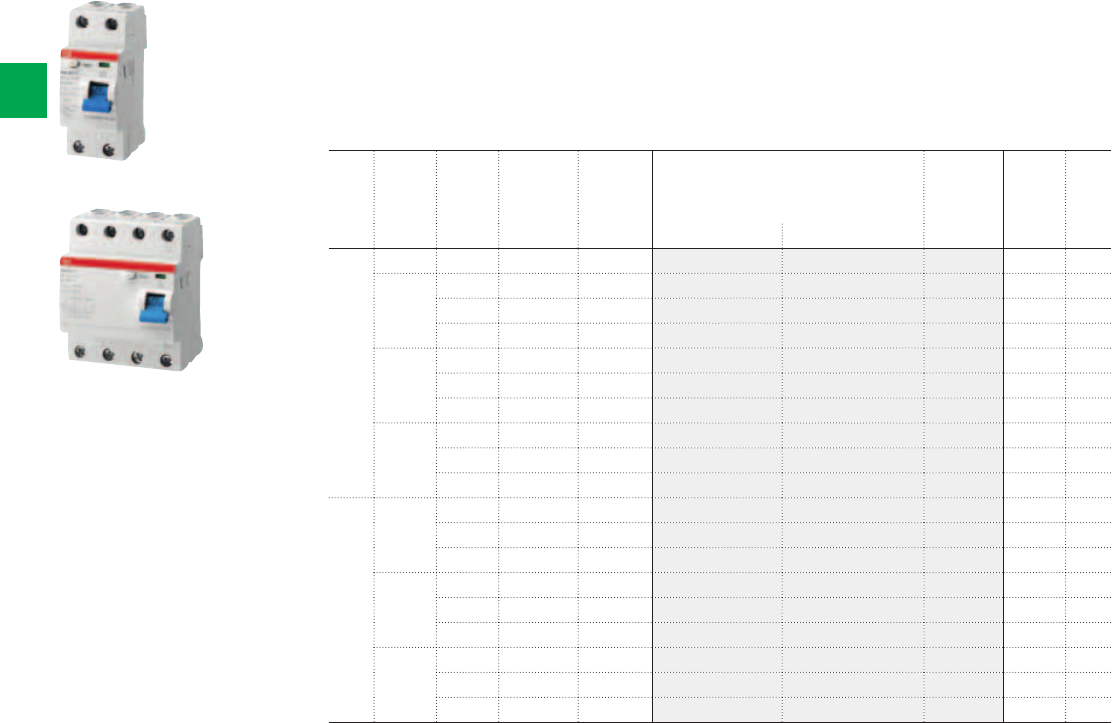
2CSC400031F0006
2CSC400031F0007
F202 AC
F204 AC
2/32 2CSC 400 031 D0202 | System pro M compact®
2
N. of
poles
Rated
residual
current
Rated
current
N° module Bbn
8012542
Order details Weight
1 piece
Pack
unit
IΔn mA In A [17,5 mm] EAN Type code Order code Price Kg
2 10 16 2 779902 F202 AC-16/0.01 2CSF202001R0160 0,225 1/6
30 25 2 780007 F202 AC-25/0.03 2CSF202001R1250 0,225 1/6
40 2 780106 F202 AC-40/0.03 2CSF202001R1400 0,225 1/6
63 2 780205 F202 AC-63/0.03 2CSF202001R1630 0,225 1/6
100 25 2 780304 F202 AC-25/0.1 2CSF202001R2250 0,225 1/6
40 2 780403 F202 AC-40/0.1 2CSF202001R2400 0,225 1/6
63 2 780502 F202 AC-63/0.1 2CSF202001R2630 0,225 1/6
300 25 2 780601 F202 AC-25/0.3 2CSF202001R3250 0,225 1/6
40 2 780700 F202 AC-40/0.3 2CSF202001R3400 0,225 1/6
63 2 780809 F202 AC-63/0.3 2CSF202001R3630 0,225 1/6
4 30 25 4 781202 F204 AC-25/0.03 2CSF204001R1250 0,375 1/3
40 4 781301 F204 AC-40/0.03 2CSF204001R1400 0,375 1/3
63 4 781400 F204 AC-63/0.03 2CSF204001R1630 0,375 1/3
100 25 4 781509 F204 AC-25/0.1 2CSF204001R2250 0,375 1/3
40 4 781608 F204 AC-40/0.1 2CSF204001R2400 0,375 1/3
63 4 781707 F204 AC-63/0.1 2CSF204001R2630 0,375 1/3
300 25 4 781806 F204 AC-25/0.3 2CSF204001R3250 0,375 1/3
40 4 781905 F204 AC-40/0.3 2CSF204001R3400 0,375 1/3
63 4 782001 F204 AC-63/0.3 2CSF204001R3630 0,375 1/3
Function: protection against the effects of sinusoidal alternating earth fault currents;
protection against indirect contacts and additional protection against direct (with IΔn=30 mA)
contacts.
Standard: IEC/ EN 61008
Marking: according to EN 61008
Ordering Information
F 200 - AC type
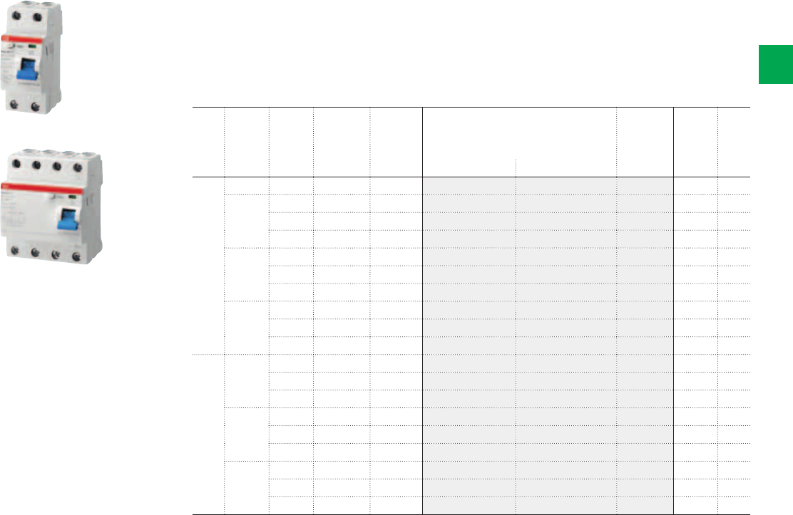
2CSC400031F0006
2CSC400031F0007
F202 AC
F204 AC
System pro M compact® | 2CSC 400 031 D0202 2/33
2
N. of
poles
Rated
residual
current
Rated
current
N° module Bbn
8012542
Order details Weight
1 piece
Pack
unit
IΔn mA In A [17,5 mm] EAN Type code Order code Price Kg
2 10 16 2 814603 F202 AC-16/0.01 2CSF202005R0160 0,225 1/6
30 25 2 814702 F202 AC-25/0.03 2CSF202005R1250 0,225 1/6
40 2 814801 F202 AC-40/0.03 2CSF202005R1400 0,225 1/6
63 2 814900 F202 AC-63/0.03 2CSF202005R1630 0,225 1/6
100 25 2 815006 F202 AC-25/0.1 2CSF202005R2250 0,225 1/6
40 2 815105 F202 AC-40/0.1 2CSF202005R2400 0,225 1/6
63 2 815204 F202 AC-63/0.1 2CSF202005R2630 0,225 1/6
300 25 2 815303 F202 AC-25/0.3 2CSF202005R3250 0,225 1/6
40 2 815402 F202 AC-40/0.3 2CSF202005R3400 0,225 1/6
63 2 815501 F202 AC-63/0.3 2CSF202005R3630 0,225 1/6
4 30 25 4 817109 F204 AC-25/0.03 2CSF204005R1250 0,375 1/3
40 4 817208 F204 AC-40/0.03 2CSF204005R1400 0,375 1/3
63 4 817307 F204 AC-63/0.03 2CSF204005R1630 0,375 1/3
100 25 4 817406 F204 AC-25/0.1 2CSF204005R2250 0,375 1/3
40 4 817505 F204 AC-40/0.1 2CSF204005R2400 0,375 1/3
63 4 817604 F204 AC-63/0.1 2CSF204005R2630 0,375 1/3
300 25 4 817703 F204 AC-25/0.3 2CSF204005R3250 0,375 1/3
40 4 817802 F204 AC-40/0.3 2CSF204005R3400 0,375 1/3
63 4 817901 F204 AC-63/0.3 2CSF204005R3630 0,375 1/3
Function: protection against the effects of sinusoidal alternating earth fault currents;
protection against indirect contacts and additional protection against direct (with IΔn=30 mA)
contacts.
Standard: IEC/ EN 61008
Marking: according to IEC 61008
Ordering Information
F 200 - AC type (for overseas markets)
2CSC400031F0008
2CSC400031F0009
F202 A
F204 A
2/34 2CSC 400 031 D0202 | System pro M compact®
2
N. of
poles
Rated
residual
current
Rated
current
N° module Bbn
8012542
Order details Weight
1 piece
Pack
unit
IΔn mA In A [17,5 mm] EAN Type code Order code Price Kg
2 10 16 2 782407 F202 A-16/0.01 2CSF202101R0160 0,225 1/6
30 25 2 782506 F202 A-25/0.03 2CSF202101R1250 0,225 1/6
40 2 782605 F202 A-40/0.03 2CSF202101R1400 0,225 1/6
63 2 782704 F202 A-63/0.03 2CSF202101R1630 0,225 1/6
100 25 2 786900 F202 A-25/0.1 2CSF202101R2250 0,225 1/6
40 2 787006 F202 A-40/0.1 2CSF202101R2400 0,225 1/6
63 2 787105 F202 A-63/0.1 2CSF202101R2630 0,225 1/6
300 25 2 782803 F202 A-25/0.3 2CSF202101R3250 0,225 1/6
40 2 782902 F202 A-40/0.3 2CSF202101R3400 0,225 1/6
63 2 783008 F202 A-63/0.3 2CSF202101R3630 0,225 1/6
4 30 25 4 783404 F204 A-25/0.03 2CSF204101R1250 0,375 1/3
40 4 783503 F204 A-40/0.03 2CSF204101R1400 0,375 1/3
63 4 783602 F204 A-63/0.03 2CSF204101R1630 0,375 1/3
100 25 4 787204 F204 A-25/0.1 2CSF204101R2250 0,375 1/3
40 4 787303 F204 A-40/0.1 2CSF204101R2400 0,375 1/3
63 4 787402 F204 A-63/0.1 2CSF204101R2630 0,375 1/3
300 25 4 783701 F204 A-25/0.3 2CSF204101R3250 0,375 1/3
40 4 783800 F204 A-40/0.3 2CSF204101R3400 0,375 1/3
63 4 783909 F204 A-63/0.3 2CSF204101R3630 0,375 1/3
Function: protection against the effects of sinusoidal alternating and direct pulsating earth
fault currents; protection against indirect contacts and additional protection against direct
(with IΔn=30 mA) contacts.
Standard: IEC/ EN 61008
Marking: according to EN 61008
Ordering Information
F 200 - A type
2CSC400031F0006
2CSC400031F0007
F202 AC...AP-R
F204 AC...AP-R
System pro M compact® | 2CSC 400 031 D0202 2/35
2
N. of
poles
Rated
residual
current
Rated
current
N° module Bbn
8012542
Order details Weight
1 piece
Pack
unit
IΔn mA In A [17,5 mm] EAN Type code Order code Price Kg
2 30 25 2 785101 F202 A-25/0.03 AP-R 2CSF202401R1250 0,225 1/6
40 2 785200 F202 A-40/0.03 AP-R 2CSF202401R1400 0,225 1/6
63 2 785309 F202 A-63/0.03 AP-R 2CSF202401R1630 0,225 1/6
4 30 25 4 785408 F204 A-25/0.03 AP-R 2CSF204401R1250 0,375 1/3
40 4 785507 F204 A-40/0.03 AP-R 2CSF204401R1400 0,375 1/3
63 4 785606 F204 A-63/0.03 AP-R 2CSF204401R1630 0,375 1/3
Function: protection against the effects of sinusoidal alternating and direct pulsating earth
fault currents, providing the best compromise between safety and continuity of service
thanks to the resistance against unwanted trippings; protection against indirect contacts and
additional protection against direct (with IΔn=30 mA) contacts.
Standard: IEC/ EN 61008
Marking: according to IEC 61008
Ordering Information
F 200 APR - A type
2CSC400031F0008
2CSC400031F0009
F202 AC S
F204 AC S
2/36 2CSC 400 031 D0202 | System pro M compact®
2
N. of
poles
Rated
residual
current
Rated
current
N° module Bbn
8012542
Order details Weight
1 piece
Pack
unit
IΔn mA In A [17,5 mm] EAN Type code Order code Price Kg
2 300 40 2 784302 F202 A S-40/0.3 2CSF202201R3400 0,225 1/6
63 2 784401 F202 A S-63/0.3 2CSF202201R3630 0,225 1/6
100 2 916109 F202 A S-100/0.3 2CSF202201R3900 0,225 1/6
4 300 40 4 784708 F204 A S-40/0.3 2CSF204201R3400 0,375 1/3
63 4 784807 F204 A S-63/0.3 2CSF204201R3630 0,375 1/3
100 4 919100 F204 A S-100/0.3 2CSF204201R3900 0,375 1/3
Function: protection against the effects of sinusoidal alternating and direct pulsating earth
fault currents with an intentional tripping delay, which permits to realize the selectivity with
downstream instantaneous devices; protection against indirect contacts.
Standard: IEC/ EN 61008
Marking: according to IEC 61008
Ordering Information
F 200 S - A type

System pro M compact® | 2CSC 400 031 D0202 2/37
2
Technical details
Coordination tables
F202
Single-phases 230-240 V circuit
25 A 40 A 63 A 100 A
S201 Na 6 6 - -
S201M Na 10 10 - -
S202 20 20 20 -
S202M252525-
Fuse 25 gG100---
Fuse 40 gG 60 60 - -
Fuse 63 gG 20 20 20 -
Fuse 100 gG 10 10 10 10
Coordination tables between Short Circuit Protection Devices (SCPD) and F 200 RCCBs
If you are using an RCCB you must verify that the Short Circuit Protection Device (SCPD) protects it from the effects of high
current that arise under short-circuit conditions. The IEC/EN 61008 provides some tests to verify the behaviour of RCCB in
short-circuit conditions. The tables below provide the maximum withstanding short-circuit current expressed in eff. kA for which
the RCCBs are protected thanks to the coordination with the SCPD installed upstream or downstream. The tests are performed
with SCPD with a rated current (thermal protection) less than or equal to the rated current of the associated RCCB.
F204
Three-phases circuits with neutral (y/Δ) 230-240 V/400-415 V*
25 A 40 A 63 A 100 A
S201/S201Na*66- -
S201M/S201MNa* 10 10 - -
S202* 202020-
S202M* 25 25 25 -
Fuse 25 gG100---
Fuse 40 gG 60 60 - -
Fuse 63 gG 20 20 20 -
Fuse 100 gG 10 10 10 10
* The switches are considered between phase and neutral (230/240V)
Power loss
Rated current Power loss W
In [A] [W]
2P 4P
25 1.0 1.3
40 2.4 3.2
63 3.2 4.4
100 15.2 44.4
F204
Three-phases circuits with neutral (y/Δ) 230-240 V/400-415 V
25 A 40 A 63 A 100 A
S203/S204666-
S203M/S204M101010-
Fuse 25 gG50---
Fuse 40 gG 30 30 - -
Fuse 63 gG 20 20 20 -
Fuse 100 gG 10 10 10 10
F204
Three-phases circuits with neutral (y/Δ) 133-138V/230-240V
25 A 40 A 63 A 100 A
S201M2020- -
S203/S204202020-
S203M/S204M252525-
Fuse 25 gG100---
Fuse 40 gG 60 60 - -
Fuse 63 gG 20 20 20 -
Fuse 100 gG 10 10 10 10
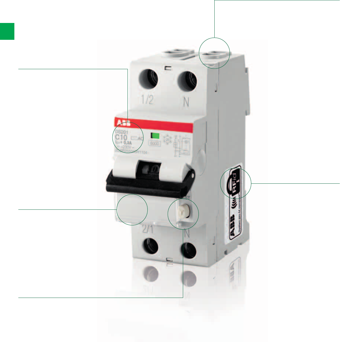
2/38 2CSC 400 031 D0202 | System pro M compact®
2
RCBO DS201 and DS202C. The details make the difference
A range designed to ensure efficiency and protection
Test pushbutton to
verify the correct
functioning of the
device
Label carrier to
identify the line
the RCBO is
protecting.
Bi-directional
cylindrical
terminals ensure
higher safety of
wiring operations,
making them
easier.
Information on the
device are laser
printed to ensure
readability over
time.
Each RCBO of the
DS201-DS202C
range is equipped
with an RFid
tag containing
a unique serial
number assigned
to ABB according
to the standard
ISO/IEC FCD
15693-3 in order
to authenticate the
product.
System pro M compact® | 2CSC 400 031 D0202 2/39
2
Any earth fault can be immediately
identified through the blue indicator,
that signals the differential tripping and
which cannot be activated in case of
manual operation on the toggle. This
prevents any misinterpretations of the
device and system status.
All the devices of the DS201 and
DS202C series have been tested in
a wide range of temperatures: from
-25 °C (as indicated by the snowflake
marked on the front side) up to +55°C.
Product description and EAN code laser
printed on the lateral side of the device
for an easier stock management.
Contact position indicator (CPI): to
always know the status of the contacts
(red: closed contacts; green: open
contacts).
Label carrier for clear and reliable
identification.
With the practical label carrier fitted in
the new circuit breakers you can give
maximum visibility to the information
relating to the protected loads.
The terminals available on DS201-
DS202C make easier the supply
operation in parallel with busbars as
they are composed by two different
seats, a front seat for 25 mm2 cables
and a back seat for 10 mm2 busbars.
All the quality ensured by the main
international marks is clearly visible
on the device even if installed in the
switchboard.

2/40 2CSC 400 031 D0202 | System pro M compact®
2
Technical features table for RCBOs
DS201and DS202C Series
Standards
Electrical features
Type (wave form of the earth leakage sensed)
Poles
Rated current InA
Rated sensitivity IΔn mA
Rated voltage UeV
Insulation voltage UiV
Max. operating voltage of circuit test V
Min. operating voltage of circuit test V
Rated frequency Hz
Rated breaking capacity acc. to IEC/EN 61009 ultimate Icn A
Rated residual breaking capacity IΔm kA
Rated impulse withstand voltage (1.2/50) Uimp kV
Dielectric test voltage at ind. freq. for 1 min. kV
Thermomagnetic release characteristic B: 3 In ≤ Im ≤ 5 In
C: 5 In ≤ Im ≤ 10 In
Surge current resistance (wave 8/20) A
Mechanical features
Toggle
Flag indicators
Electrical life
Mechanical life
Protection degree housing
terminals
Tropicalization
acc. to IEC/EN 60068-2
constant climatic conditions °C/RH
variable climatic conditions °C/RH
Reference temperature for setting of thermal element °C
Ambient temperature (with daily average ≤ +35 °C) °C
Storage temperature °C
Installation
Terminal type
Terminal size top/bottom for cables mm2
Terminal size top/bottom for busbar mm2
Tightening torque top/bottom N*m
Mounting
Connection
Dimensions and weight
Dimensions (H x D x W) mm
Weight g
Combination with auxiliary elements
Combinable with: auxiliary contact
signal contact/auxiliary switch
shunt trip
undervoltage release
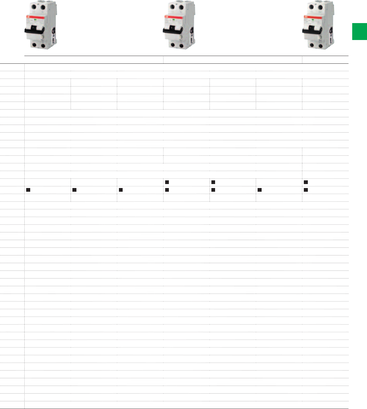
2CSC400030F0046
2CSC400030F0047
2CSC400030F0048
System pro M compact® | 2CSC 400 031 D0202 2/41
2
DS201 L DS201 DS202C
IEC / EN 61009
AC A APR AC A APR A
1P+N 1P+N 1P+N 1P+N 1P+N 1P+N 2P
6…32 6…32 6…32 6…40 2…40 6…40 6…32
30 10, 30, 300 30 30,100 10, 30, 100, 300 30 30
230-240
500
254
110
50…60
4500 6000 6000
4.5 6 6
4 4
2.5 2.5
250 250 3000 250 250 3000 250
black sealable in ON-OFF position
differential trip indicator (blue); contact position indicator (green/red)
10000
20000
IP4X
IP2X
23/83 - 40/93 - 55/20
25/95 - 40/95
30
-25…+55
-40…+70
failsafe bi-directional cylinder-lift terminal at top and bottom (shock protected)
25/25
10/10
2.8
on DIN rail EN 60715 (35 mm) by means of fast clip device
from top and bottom
85x69x35
239
yes
yes
yes
yes
DS201 L - AC
2CSC400030F0046
2/42 2CSC 400 031 D0202 | System pro M compact®
2
Ordering Information
DS201 L - AC type
Function: protection of end user single-phase circuits against overload and short-circuit
currents; protection against the effects of sinusoidal alternating earth fault currents; protection
against indirect contact and additional protection against direct contact (IΔn=30 mA).
Standard: IEC/ EN 61009
Icn = 4500 A
C characteristic
N. of
poles
Rated
residual
current
Rated
current
N° module Bbn
8012542
Order details Weight
1 piece
Pack
unit
IΔn mA In A [17,5 mm] EAN Type code Order code Price Kg
1+N 30 6 2 171201 DS201 L C6 AC30 2CSR245040R1064 0.275 5
10 2 171300 DS201 L C10 AC30 2CSR245040R1104 0.275 5
16 2 171409 DS201 L C16 AC30 2CSR245040R1164 0.275 5
20 2 171508 DS201 L C20 AC30 2CSR245040R1204 0.275 5
25 2 171607 DS201 L C25 AC30 2CSR245040R1254 0.275 5
32 2 171706 DS201 L C32 AC30 2CSR245040R1324 0.275 5
DS201 L - A
2CSC400030F0049
System pro M compact® | 2CSC 400 031 D0202 2/43
2
Ordering Information
DS201 L - A type
Function: protection of end user single-phase circuits against overload and short-circuit
currents; protection against the effects of sinusoidal alternating and direct pulsating earth
fault currents; protection against indirect contact and additional protection against direct
contact (IΔn=30 mA).
Standard: IEC/ EN 61009
Icn = 4500 A
C characteristic
N. of
poles
Rated
residual
current
Rated
current
N° module Bbn
8012542
Order details Weight
1 piece
Pack
unit
IΔn mA In A [17,5 mm] EAN Type code Order code Price Kg
1+N 10 6 2 163404 DS201 L C6 A10 2CSR245140R0064 0.275 5
10 2 171003 DS201 L C10 A10 2CSR245140R0104 0.275 5
16 2 171102 DS201 L C16 A10 2CSR245140R0164 0.275 5
30 6 2 172406 DS201 L C6 A30 2CSR245140R1064 0.275 5
10 2 172505 DS201 L C10 A30 2CSR245140R1104 0.275 5
16 2 172604 DS201 L C16 A30 2CSR245140R1164 0.275 5
20 2 172703 DS201 L C20 A30 2CSR245140R1204 0.275 5
25 2 173809 DS201 L C25 A30 2CSR245140R1254 0.275 5
32 2 173908 DS201 L C32 A30 2CSR245140R1324 0.275 5
300 6 2 174004 DS201 L C6 A300 2CSR245140R3064 0.275 5
10 2 174103 DS201 L C10 A300 2CSR245140R3104 0.275 5
16 2 174202 DS201 L C16 A300 2CSR245140R3164 0.275 5
20 2 174301 DS201 L C20 A300 2CSR245140R3204 0.275 5
25 2 174707 DS201 L C25 A300 2CSR245140R3254 0.275 5
32 2 174806 DS201 L C32 A300 2CSR245140R3324 0.275 5
DS201 L - APR
2CSC400030F0050
2/44 2CSC 400 031 D0202 | System pro M compact®
2
Ordering Information
DS201 L - APR type
Function: protection against the effects of sinusoidal alternating and direct pulsating earth fault
currents, providing an optimal trade-off between safety and continuity of service, thanks to the
resistance to unwanted tripping; protection against indirect contact and additional protection
against direct (IΔn=30mA) contact; protection and isolation of resistive and inductive loads.
Standard: IEC/ EN 61009
Icn = 4500 A
C characteristic
N. of
poles
Rated
residual
current
Rated
current
N° module Bbn
8012542
Order details Weight
1 piece
Pack
unit
IΔn mA In A [17,5 mm] EAN Type code Order code Price Kg
1+N 30 6 2 174905 DS201 L C6 APR30 2CSR245440R1064 0.275 5
10 2 175001 DS201 L C10 APR30 2CSR245440R1104 0.275 5
16 2 175100 DS201 L C16 APR30 2CSR245440R1164 0.275 5
20 2 175209 DS201 L C20 APR30 2CSR245440R1204 0.275 5
25 2 175605 DS201 L C25 APR30 2CSR245440R1254 0.275 5
32 2 175704 DS201 L C32 APR30 2CSR245440R1324 0.275 5
DS201 B - AC
DS201 C - AC
2CSC400030F00512CSC400030F0047
System pro M compact® | 2CSC 400 031 D0202 2/45
2
Ordering Information
DS201 - AC type
Function: protection of end user single-phase circuits against overload and short-circuit
currents; protection against the effects of sinusoidal alternating earth fault currents; protection
against indirect contact and additional protection against direct contact (IΔn=30 mA).
Standard: IEC/ EN 61009
Icn = 6000 A
B characteristic
N. of
poles
Rated
residual
current
Rated
current
N° module Bbn
8012542
Order details Weight
1 piece
Pack
unit
IΔn mA In A [17,5 mm] EAN Type code Order code Price Kg
1+N 30 6 2 279709 DS201 B6 AC30 2CSR255040R1065 0.275 5
10 2 280309 DS201 B10 AC30 2CSR255040R1105 0.275 5
13 2 285205 DS201 B13 AC30 2CSR255040R1135 0.275 5
16 2 285304 DS201 B16 AC30 2CSR255040R1165 0.275 5
20 2 285403 DS201 B20 AC30 2CSR255040R1205 0.275 5
25 2 285502 DS201 B25 AC30 2CSR255040R1255 0.275 5
32 2 285601 DS201 B32 AC30 2CSR255040R1325 0.275 5
40 2 285700 DS201 B40 AC30 2CSR255040R1405 0.275 5
100 6 2 285809 DS201 B6 AC100 2CSR255040R2065 0.275 5
10 2 285908 DS201 B10 AC100 2CSR255040R2105 0.275 5
13 2 286004 DS201 B13 AC100 2CSR255040R2135 0.275 5
16 2 286103 DS201 B16 AC100 2CSR255040R2165 0.275 5
20 2 286202 DS201 B20 AC100 2CSR255040R2205 0.275 5
25 2 286301 DS201 B25 AC100 2CSR255040R2255 0.275 5
32 2 286400 DS201 B32 AC100 2CSR255040R2325 0.275 5
40 2 286509 DS201 B40 AC100 2CSR255040R2405 0.275 5
C characteristic
1+N 30 6 2 294504 DS201 C6 AC30 2CSR255040R1064 0.275 5
10 2 294603 DS201 C10 AC30 2CSR255040R1104 0.275 5
13 2 294702 DS201 C13 AC30 2CSR255040R1134 0.275 5
16 2 294801 DS201 C16 AC30 2CSR255040R1164 0.275 5
20 2 294900 DS201 C20 AC30 2CSR255040R1204 0.275 5
25 2 295006 DS201 C25 AC30 2CSR255040R1254 0.275 5
32 2 296003 DS201 C32 AC30 2CSR255040R1324 0.275 5
40 2 296102 DS201 C40 AC30 2CSR255040R1404 0.275 5
100 6 2 296201 DS201 C6 AC100 2CSR255040R2064 0.275 5
10 2 296409 DS201 C10 AC100 2CSR255040R2104 0.275 5
13 2 370802 DS201 C13 AC100 2CSR255040R2134 0.275 5
16 2 370901 DS201 C16 AC100 2CSR255040R2164 0.275 5
20 2 371601 DS201 C20 AC100 2CSR255040R2204 0.275 5
25 2 371700 DS201 C25 AC100 2CSR255040R2254 0.275 5
32 2 371809 DS201 C32 AC100 2CSR255040R2324 0.275 5
40 2 498100 DS201 C40 AC100 2CSR255040R2404 0.275 5
DS201 B - A
2CSC400030F0052
2/46 2CSC 400 031 D0202 | System pro M compact®
2
Ordering Information
DS201 - A type
Function: protection of end user single-phase circuits against overload and short-circuit
currents; protection against the effects of sinusoidal alternating and direct pulsating earth fault
currents; protection against indirect contact and additional protection against direct contact
(IΔn=30 mA).
Standard: IEC/ EN 61009
Icn = 6000 A
B characteristic
N. of
poles
Rated
residual
current
Rated
current
N° module Bbn
8012542
Order details Weight
1 piece
Pack
unit
IΔn mA In A [17,5 mm] EAN Type code Order code Price Kg
1+N 10 10 2 995708 DS201 B10 A10 2CSR255140R0105 0.275 5
13 2 995807 DS201 B13 A10 2CSR255140R0135 0.275 5
16 2 995906 DS201 B16 A10 2CSR255140R0165 0.275 5
30 6 2 638506 DS201 B6 A30 2CSR255140R1065 0.275 5
10 2 647805 DS201 B10 A30 2CSR255140R1105 0.275 5
13 2 655503 DS201 B13 A30 2CSR255140R1135 0.275 5
16 2 655602 DS201 B16 A30 2CSR255140R1165 0.275 5
20 2 655701 DS201 B20 A30 2CSR255140R1205 0.275 5
25 2 766902 DS201 B25 A30 2CSR255140R1255 0.275 5
32 2 814504 DS201 B32 A30 2CSR255140R1325 0.275 5
40 2 910602 DS201 B40 A30 2CSR255140R1405 0.275 5
100 6 2 990307 DS201 B6 A100 2CSR255140R2065 0.275 5
10 2 990406 DS201 B10 A100 2CSR255140R2105 0.275 5
13 2 990505 DS201 B13 A100 2CSR255140R2135 0.275 5
16 2 990604 DS201 B16 A100 2CSR255140R2165 0.275 5
20 2 990703 DS201 B20 A100 2CSR255140R2205 0.275 5
25 2 990802 DS201 B25 A100 2CSR255140R2255 0.275 5
32 2 990901 DS201 B32 A100 2CSR255140R2325 0.275 5
40 2 991007 DS201 B40 A100 2CSR255140R2405 0.275 5
300 6 2 991908 DS201 B6 A300 2CSR255140R3065 0.275 5
10 2 992004 DS201 B10 A300 2CSR255140R3105 0.275 5
13 2 992103 DS201 B13 A300 2CSR255140R3135 0.275 5
16 2 992202 DS201 B16 A300 2CSR255140R3165 0.275 5
20 2 992301 DS201 B20 A300 2CSR255140R3205 0.275 5
25 2 992400 DS201 B25 A300 2CSR255140R3255 0.275 5
32 2 992509 DS201 B32 A300 2CSR255140R3325 0.275 5
40 2 992608 DS201 B40 A300 2CSR255140R3405 0.275 5
DS201 C - A
2CSC400030F0053
System pro M compact® | 2CSC 400 031 D0202 2/47
2
Ordering Information
DS201 - A type
C characteristic
N. of
poles
Rated
residual
current
Rated
current
N° module Bbn
8012542
Order details Weight
1 piece
Pack
unit
IΔn mA In A [17,5 mm] EAN Type code Order code Price Kg
1+N 10 10 2 996002 DS201 C10 A10 2CSR255140R0104 0.275 5
13 2 996101 DS201 C13 A10 2CSR255140R0134 0.275 5
16 2 996200 DS201 C16 A10 2CSR255140R0164 0.275 5
30 2 2 123958 DS201 C2 A30 2CSR255140R1024 0.275 5
4 2 942306 DS201 C4 A30 2CSR255140R1044 0.275 5
6 2 942405 DS201 C6 A30 2CSR255140R1064 0.275 5
8 2 124054 DS201 C8 A30 2CSR255140R1084 0.275 5
10 2 952503 DS201 C10 A30 2CSR255140R1104 0.275 5
13 2 976004 DS201 C13 A30 2CSR255140R1134 0.275 5
16 2 976103 DS201 C16 A30 2CSR255140R1164 0.275 5
20 2 976202 DS201 C20 A30 2CSR255140R1204 0.275 5
25 2 976301 DS201 C25 A30 2CSR255140R1254 0.275 5
32 2 990109 DS201 C32 A30 2CSR255140R1324 0.275 5
40 2 990208 DS201 C40 A30 2CSR255140R1404 0.275 5
100 6 2 991106 DS201 C6 A100 2CSR255140R2064 0.275 5
10 2 991205 DS201 C10 A100 2CSR255140R2104 0.275 5
13 2 991304 DS201 C13 A100 2CSR255140R2134 0.275 5
16 2 991403 DS201 C16 A100 2CSR255140R2164 0.275 5
20 2 991502 DS201 C20 A100 2CSR255140R2204 0.275 5
25 2 991601 DS201 C25 A100 2CSR255140R2254 0.275 5
32 2 991700 DS201 C32 A100 2CSR255140R2324 0.275 5
40 2 991809 DS201 C40 A100 2CSR255140R2404 0.275 5
300 6 2 992707 DS201 C6 A300 2CSR255140R3064 0.275 5
8 2 124351 DS201 C8 A300 2CSR255140R3084 0.275 5
10 2 992806 DS201 C10 A300 2CSR255140R3104 0.275 5
13 2 992905 DS201 C13 A300 2CSR255140R3134 0.275 5
16 2 993001 DS201 C16 A300 2CSR255140R3164 0.275 5
20 2 993100 DS201 C20 A300 2CSR255140R3204 0.275 5
25 2 993209 DS201 C25 A300 2CSR255140R3254 0.275 5
32 2 993308 DS201 C32 A300 2CSR255140R3324 0.275 5
40 2 993407 DS201 C40 A300 2CSR255140R3404 0.275 5
DS201 C - APR
2CSC400030F0054
2/48 2CSC 400 031 D0202 | System pro M compact®
2
Ordering Information
DS201 - APR type
Function: protection of end user single-phase circuits against overload and short-circuit
currents; protection against the effects of sinusoidal alternating and direct pulsating earth fault
currents, providing an optimal trade-off between safety and continuity of service thanks to the
resistance to unwanted tripping; protection against indirect contact and additional protection
against direct (IΔn=30 mA) contact; protection and isolation of resistive and inductive loads.
Standard: IEC/ EN 61009
Icn = 6000 A
C characteristic
N. of
poles
Rated
residual
current
Rated
current
N° module Bbn
8012542
Order details Weight
1 piece
Pack
unit
IΔn mA In A [17,5 mm] EAN Type code Order code Price Kg
1+N 30 6 2 997306 DS201 C6 APR30 2CSR255440R1064 0.275 5
10 2 997405 DS201 C10 APR30 2CSR255440R1104 0.275 5
13 2 997504 DS201 C13 APR30 2CSR255440R1134 0.275 5
16 2 997603 DS201 C16 APR30 2CSR255440R1164 0.275 5
20 2 997702 DS201 C20 APR30 2CSR255440R1204 0.275 5
25 2 997801 DS201 C25 APR30 2CSR255440R1254 0.275 5
32 2 997900 DS201 C32 APR30 2CSR255440R1324 0.275 5
40 2 998006 DS201 C40 APR30 2CSR255440R1404 0.275 5
DS202 B - A
DS202 C - A
2CSC400030F00552CSC400030F0056
System pro M compact® | 2CSC 400 031 D0202 2/49
2
Ordering Information
DS202C - A type
Function: protection of end user two-phase circuits against overload and short-circuit
currents; protection against the effects of sinusoidal alternating and direct pulsating earth fault
currents; protection against indirect contact and additional protection against direct contact
(IΔn=30 mA).
Standard: IEC/ EN 61009
Icn = 6000 A
B characteristic
N. of
poles
Rated
residual
current
Rated
current
N° module Bbn
8012542
Order details Weight
1 piece
Pack
unit
IΔn mA In A [17,5 mm] EAN Type code Order code Price Kg
230 6 2 132257 DS202C B6 A30 2CSR252140R1065 0.275 5
10 2 132356 DS202C B10 A30 2CSR252140R1105 0.275 5
13 2 132455 DS202C B13 A30 2CSR252140R1135 0.275 5
16 2 132554 DS202C B16 A30 2CSR252140R1165 0.275 5
20 2 132653 DS202C B20 A30 2CSR252140R1205 0.275 5
25 2 132752 DS202C B25 A30 2CSR252140R1255 0.275 5
32 2 132851 DS202C B32 A30 2CSR252140R1325 0.275 5
C characteristic
230 6 2 122357 DS202C C6 A30 2CSR252140R1064 0.275 5
10 2 122456 DS202C C10 A30 2CSR252140R1104 0.275 5
13 2 122555 DS202C C13 A30 2CSR252140R1134 0.275 5
16 2 122654 DS202C C16 A30 2CSR252140R1164 0.275 5
20 2 122753 DS202C C20 A30 2CSR252140R1204 0.275 5
25 2 122852 DS202C C25 A30 2CSR252140R1254 0.275 5
32 2 122951 DS202C C32 A30 2CSR252140R1324 0.275 5
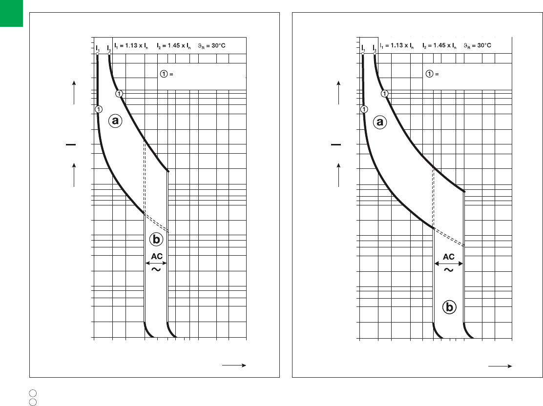
IEC-EN61009
Seconds
Multiples of rated current
Minutes
Tripping curve
from cold state
120
60
40
20
10
6
4
2
1
40
20
10
6
4
2
1
0.6
0.4
0.2
0.1
0.06
0.04
0.02
0.01
1 1.5 2 3 4 5 6 8 10 15 20 30
3 5
4 7
IEC-EN61009
Seconds
Multiples of rated current
Minutes
Tripping curve
from cold state
120
60
40
20
10
6
4
2
1
40
20
10
6
4
2
1
0.6
0.4
0.2
0.1
0.06
0.04
0.02
0.01
1 1.5 2 3 4 5 6 8 10 15 20 30
5 10
7 15
2/50 2CSC 400 031 D0202 | System pro M compact®
2
Technical details
DS201 and DS202C Series
Tripping diagrams
a thermal trip
b electromagnetic trip
B characteristic C characteristic
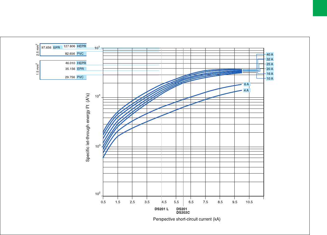
System pro M compact® | 2CSC 400 031 D0202 2/51
2
Limitation of specific let-through energy I2t
The I2t curves give the values of the specific let-through energy expressed in A2s (A=amps; s=seconds) in relation to the
perspective short-circuit current (Irms) in kA.
DS201 L - DS201 - DS202C
230 V let-through energy
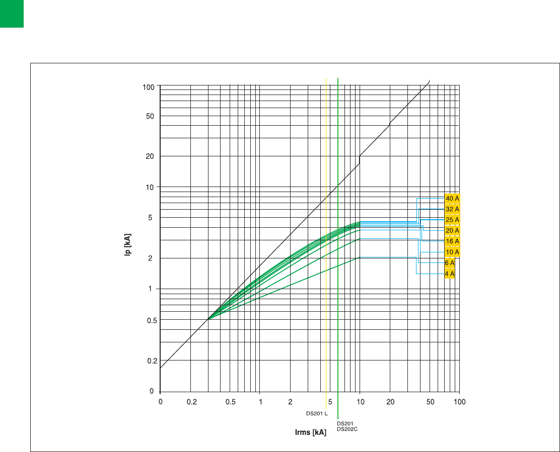
2/52 2CSC 400 031 D0202 | System pro M compact®
2
Peak current Ip
The Ip curves give the values of the peak current, expressed in kA, in relation to the perspective symmetrical short-circuit
current (kA).
DS201 L - DS201 - DS202C
230 V
Technical details
DS201 and DS202C Series

System pro M compact® | 2CSC 400 031 D0202 2/53
2
Power loss and internal resistance
DS201
Rated
current
In [A]
Power
loss
[W]
Internal
resistance
[mΩ]
2 1.6 411
4 2.5 155
6 4.4 123.4
8 1.5 23.1
10 2.3 23.1
13 2.2 13.3
16 3.4 13.3
20 4.4 11.1
25 3.9 6.2
32 5.9 5.8
40 8.6 5.4
DS202C
Rated
current
In [A]
Power
loss
[W]
Internal
resistance
[mΩ]
6 8.1 224.8
10 4.1 40.6
13 3.5 21
16 5.4 21
20 6.6 16.6
25 5.5 8.8
32 8.2 8
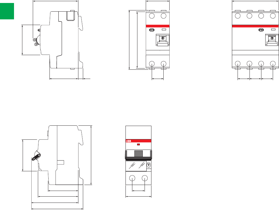
45
85
43 17.5
3558
67
73
69 35
17.5 17.5 17.5 17.5
70
6.844
45
88
85
2/54 2CSC 400 031 D0202 | System pro M compact®
2
Overall dimensions
DS201 - DS202C
FH202 - F202 FH204 - F204

System pro M compact® | 2CSC 400 031 D0202 2/55
2
OVR
Plus of range 2/56
Technical features table 2/58
Ordering information 2/60
Overall dimensions 2/62
Surge protective devices
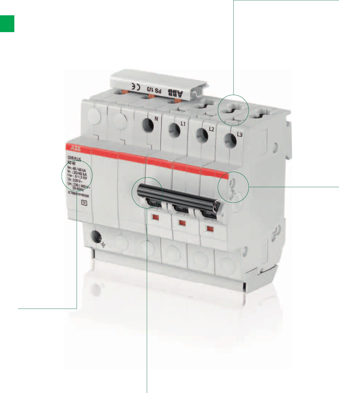
2/56 2CSC 400 031 D0202 | System pro M compact®
2
OVR Plus and T2 range. The details make the difference
A complete range for your surge protection
Standard pro M
terminals design
for a better
coordination with
the complete ABB
System pro M
compact®
modular range.
The MCB toggle indicates
the statu of the OVR PLUS
N3.
Toggle on: OVR PLUS N3 is active
Toggle off: You can switch on again.
The OVR PLUS N3 has protected your
installation and is astill active
Toggle off: You cannot switch on again.
You have to change the OVR PLUS N3.
Clear information
on the front of the
product indicating
the technical
characteristics of
the OVR PLUS N3.
Possibility
to add and
auxiliary
contact by
installing
the
standard
ABB option
S2C-H6R.
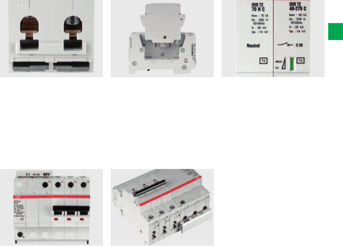
System pro M compact® | 2CSC 400 031 D0202 2/57
2
The end-of-service-life indicator of the
surge protective device signals the
status of the device. A mechanical
indicator turns from green to red when
the SPD reaches the end of its service
life.
The bidirectional cylindrical terminal
block of the OVR T2 and Plus range
allows a complete coordination with
the ABB range with considerable time
savings in wiring operations. All the
devices allow connection through
busbars, both from above and from
below.
The toggle of the miniature circuit
breaker indicates the status of the OVR
Plus range.
If the toggle is on, the surge protection
is active.
If the toggle is off and can be switched
on again, the device has protected your
equipment.
If the toggle is off and cannot be
swicthed on. The device must be
changed.
The pluggable feature of ABB surge
arresters facilitates maintenance. Should
one or more worn cartridges need to
be replaced, the electrical circuit does
not have to be isolated nor do the wires
have to be removed.
The configuration allows to use the OVR
Plus range on TT and TNS network in
Phase + Neutral and 3 Phases + Neutral
with a high surge capacity up to 40kA
Imax.
2CSC400031F0017
2/58 2CSC 400 031 D0202 | System pro M compact®
2
Technical features table surge arresters
OVR and OVR PLUS Series
OVR T1+2 xx 7 s P
Technology MOVs
Electrical features
Standard EN 61643-11, IEC 61643-1
Type / test class T1-T2 / I-II
Poles - / 1N / 3L / 4L
Types of networks TNC-TNS-TT
Type of current VAC
Nominal voltage Un (L-N/L-L) V 230/400
Max. cont. operating voltage Uc V 275
Impulse current Iimp (10/350) per pole kA 7
Maximum discharge current Imax (8/20) per pole kA 70
Nominal discharge current In (8/20) per pole kA 7
Voltage protection level Up (L-N / N-PE / L-PE) kV 0,9
Residual voltage Ures at 3kA (L-N / N-PE) kV 0,8
Follow current interrupting rating Ifi kA na
TOV (Temporary overvoltage) withstand Ut (L-N: 5s./N-PE: 200ms) V 334
Continuous operating current Ic mA <1
Short-circuit withstand capability kA 50
Disconnector gG -gL fuse A ≤ 50
curve C circuit breaker A ≤ 50
Pluggable cartridge Yes
Integrated thermal disconnector Yes
State indicator Yes
TS auxiliary contact No
Mechanical features
Stocking temperature °C -40 to +80
Operating temperature -40 to +70
Degree of protection IP 20
Fire resistance according to UL 94 V0
Installation
Wire range (L, N)
solid wire mm² 2.5 …25
stranded wire mm² 2.5 …16
Stripping length (L, N) mm 12,5
Tightening torque (L, N) Nm 2,8
Technical features of the integrated auxiliary contact (TS)
Electrical features
Contact complement -
Min. load -
Max. load -
Installation
Connection cross-section mm² -
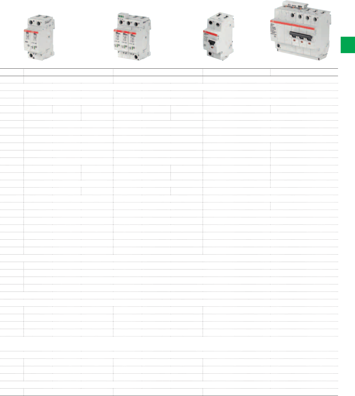
2CSC400031F0018
2CSC400031F0019
2CSC400031F0012
2CSC400031F0015
System pro M compact® | 2CSC 400 031 D0202 2/59
2
OVR T2 xx xx 275 P OVR T2 xx xx 440 P OVR Plus N1 40 OVR Plus N3 XX
MOVs MOVs MOVs
EN 61643-11, IEC 61643-1 EN 61643-11, IEC 61643-1 EN 61643-11, IEC 61643-1
T2 / II T2 / II T2 / II
- 3L / 4L 1N / 3N - 3L / 4L 1N / 3N N1 N3
TNC-TNS TNS-TT IT-TNC-TNS TNS-TT TT-TNS
AC AC AC
230/400 400/400 230/400
275 440 320
----
15 / 40 15 / 40 40 15 / 40
5 / 20 5 / 20 20 5 / 20
- / - / 1.0 -/ -/ 1.4 1.4 / 1.4 / 1.5 - / - / 1.0 -/ -/ 1.9 1.9 / 1.4 / 1.9 1.6 / - / 1.8 1.3 / 1.3 / 1.3 2.0 / 1.5 / 2.0
- / - / 0.9 0.9 / 0.9 / 0.9 - / - / 1.3 1.3 / 1.2 / 1.3 1.0 / - / 1.0 1.1 / 1.1 / 1.1
na na na na
334 / - 334 / 1200 440 / - 440 / 1200 334 / 1200
<1 <1 <1
50 50 15 10 / 15
≤ 50 ≤ 50 Integrated MCB disconnector
≤ 50 ≤ 50 Integrated MCB disconnector
Yes Yes No
Yes Yes Yes
Yes Yes Yes (MCB)
Option Option S2C-H6R
-40 to +80
-40 to +70
IP 20
V0
2.5 …25 2.5 …25 2.5 … 25
2.5 …16 2.5 …16 2.5 … 16
12,5 12,5 11
2.8 2.8 2.8
1 NO - 1 NC 1 NO - 1 NC -
12 VDC - 10mA 12 VDC - 10mA -
250 VAC - 1A 250 VAC - 1A -
1.5 1.5 -
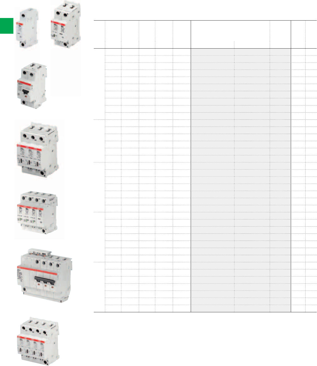
2CSC400031F0012
2CSC400031F0013
2CSC400031F0014
2CSC400031F0015
2CSC400031F0016
OVR T2 OVR T2 1N
OVR PLUS N1
OVR T2 3L
OVR T2 3N
OVR PLUS N3
OVR T2 4L
2CSC400031F0010
2CSC400031F0011
2/60 2CSC 400 031 D0202 | System pro M compact®
2
Surge Protective Devices, Type 1+2 and Type 2, to protect sensible equipment and the
installation against direct and indirect surges.
N. of
poles
Nom.
voltage
Un
Impulse
current
limp
Max.
disch.
current
Imax
N°
module
Bbn
3660308
Order details Weight
1 piece
Pack
unit
V kA 17,5 mm EAN Type code Order code Price Kg
1 230 2 15 0.12 512840 OVR T2 15 275 P 2CTB803851R2400 1 1
230 2 40 0.12 512833 OVR T2 40 275 P 2CTB803851R2300 1 1
230 2 40 0.12 512826 OVR T2 40 275 s P 2CTB803851R2000 1 1
230 2 40 0.14 514363 OVR T2 40 275 P TS 2CTB803851R1700 1 1
230 2 40 0.15 512802 OVR T2 40 275 s P TS 2CTB803851R1400 1 1
400 2 15 0.12 512772 OVR T2 15 440 P 2CTB803851R1100 1 1
400 2 40 0.12 512789 OVR T2 40 440 P 2CTB803851R1200 1 1
400 2 40 0.12 512765 OVR T2 40 440 P s P 2CTB803851R0800 1 1
400 2 40 0.14 514370 OVR T2 40 440 P TS 2CTB803851R0500 1 1
400 2 40 0.15 512741 OVR T2 40 440 s P TS 2CTB803851R0200 1 1
1+N 230 2 15 0.22 513106 OVR T2 1N 15 275 P 2CTB803952R1200 1 1
230 2 40 0.22 513250 OVR T2 1N 40 275 P 2CTB803952R1100 1 1
230 2 40 0.27 513090 OVR T2 1N 40 275 s P 2CTB803952R0800 1 1
230 2 40 0.27 514387 OVR T2 1N 40 275 P TS 2CTB803952R0500 1 1
230 2 40 0.27 513076 OVR T2 1N 40 275 s P TS 2CTB803952R0200 1 1
230 2 40 0.26 517005 OVR PLUS N1 40 2CTB803701R0400 1 1
3 230 2 15 0.35 512987 OVR T2 3L 15 275 P 2CTB803853R3400 1 1
230 2 40 0.35 513366 OVR T2 3L 40 275 P 2CTB803853R2400 1 1
230 2 40 0.40 512963 OVR T2 3L 40 275 s P 2CTB803853R2200 1 1
230 2 40 0.35 514400 OVR T2 3L 40 275 P TS 2CTB803853R2500 1 1
230 2 40 0.40 512970 OVR T2 3L 40 275 s P TS 2CTB803853R2300 1 1
400 2 40 0.35 516879 OVR T2 3L 40 440 P 2CTB803953R2600 1 1
400 2 40 4.35 516886 OVR T2 3L 40 440 P TS 2CTB803853R2700 1 1
3+N 230 2 15 0.45 513151 OVR T2 3N 15 275 P 2CTB803953R1200 1 1
230 2 40 0.45 513267 OVR T2 3N 40 275 P 2CTB803953R1100 1 1
230 2 40 0.45 513144 OVR T2 3N 40 275 s P 2CTB803953R0800 1 1
230 2 40 0.45 514394 OVR T2 3N 40 275 P TS 2CTB803953R0500 1 1
230 2 40 0.50 513120 OVR T2 3N 40 275 s P TS 2CTB803953R0200 1 1
230 2 15 0.79 517081 OVR PLUS N3 15 2CTB803701R0400 1 1
230 2 40 0.79 517074 OVR PLUS N3 40 2CTB803701R0300 1 1
4 230 2 15 0.45 513038 OVR T2 4L 15 275 P 2CTB803853R6000 1 1
230 2 40 0.45 513274 OVR T2 4L 40 275 P 2CTB803853R5600 1 1
230 2 40 0.50 513021 OVR T2 4L 40 275 s P 2CTB803853R5400 1 1
230 2 40 0.45 514417 OVR T2 4L 40 275 P TS 2CTB803853R5200 1 1
230 2 40 0.50 513014 OVR T2 4L 40 275 s P TS 2CTB803853R5000 1 1
400 2 40 0.45 516916 OVR T2 4L 40 440 P 2CTB803853R5100 1 1
400 2 40 0.45 516923 OVR T2 4L 40 440 P TS 2CTB803853R5300 1 1
Ordering Information
OVR and OVR PLUS Series - Type 1+2 and Type 2
2CSC400031F0017
OVR T1+2
System pro M compact® | 2CSC 400 031 D0202 2/61
2
N. of
poles
Nom.
voltage
Un
Impulse
current
limp
Max.
disch.
current
Imax
N°
module
Bbn
3660308
Order details Weight
1 piece
Pack
unit
V kA 17,5 mm EAN Type code Order code Price Kg
1,
1N,
3,
3N,
4
230 1+2 7 0.12 513403 OVR T1+2 7 275 s P 2CTB815101R3900 1 1
230 1+2 7 0.27 515728 OVRT1+2 1N 7 275 s P 2CTB815102R1000 1 1
230 1+2 7 0.50 515735 OVR T1+2 3N 7 275 s P 2CTB815502R1000 1 1
230 1+2 7 0.40 513410 OVR T1+2 3L 275 s P 2CTB815101R4000 1 1
230 1+2 7 0.50 513427 OVR T1+2 4L 275 s P 2CTB815101R4100 1 1
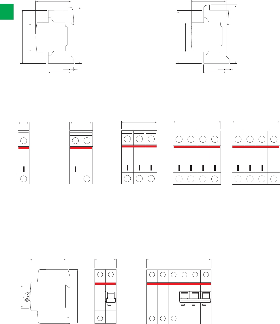
58
43.5 7
85
93
45
58
43.5 7
85
94.4
45
4 poles (4P+0) 3 poles (3P+N)1-pole 2-poles (1P+N) 3-poles
68 36 105.6
70 70
OVR T1+2 4L 7
OVR T2 4L 15
OVR T2 4L 40
OVR T1+2 3N 7
OVR T2 3N 15
OVR T2 3N 40
OVR T1+2 7
OVR T2 15
OVR T2 40
OVR Plus N1 40 OVR Plus N3 15
OVR Plus N3 40
OVR T2 1N 15
OVR T2 1N 40
OVR T1+2 3L 7
OVR T2 3L 15
OVR T2 3L 40
17.5 35 52.5
45
91
2/62 2CSC 400 031 D0202 | System pro M compact®
22
Overall dimensions
OVR T2
OVR Plus
OVR T2 with TS

System pro M compact® | 2CSC 400 031 D0202 2/63
2
Ordering information
E 90 2/64
TM 2/65
TS 2/66
TS C 2/67
TSM and TSR 2/68
Technical details 2/69
Overall dimensions 2/74
Other protection devices
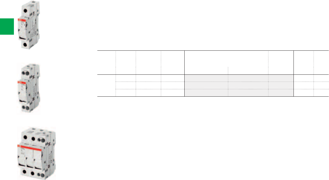
E 91/32
E 91HN/32
E 93HN/32
2CSC400030F0057
2CSC400030F0058
2CSC400030F0059
2/64 2CSC 400 031 D0202 | System pro M compact®
2
Ordering Information
E 90 fuseholders for 10.3x38 mm fuses
E 90h fuseholders are suitable for protection against overloads and short circuits. Available
in a single module 1P+N version and in a three-module 3P+N version, they are designed for
use with gG and aM cylindrical fuse links. The body is made from self-extinguishing material
resistant to high temperatures, while the contact clips are in silver-plated copper.
E 90h fuseholders can be sealed or padlocked to assure operator safety during maintenance.
Versions with blown fuse indicator allow to check whether the fuse is still working correctly or not.
N. of
poles
Rated
current
N° module Bbn
8012542
Order details Weight
1 piece
Pack
unit
In A [17,5 mm] EAN Type code Order code Price Kg
1 32 1 009238 E 91/32 2CSM200923R1801 0.061 6
1+N 32 1 009139 E 91HN/32 2CSM200913R1801 0.070 6
3+N 32 3 047438 E 93HN/32 2CSM204743R1801 0.192 2
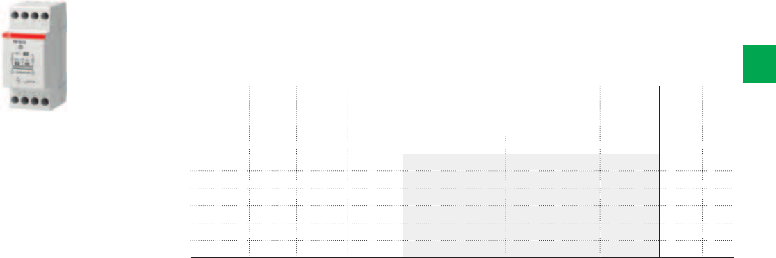
TM15/12
2CSC400030F0060
System pro M compact® | 2CSC 400 031 D0202 2/65
2
Ordering Information
TM fail safe bell transformers
These transformers, with safety extremely-low voltage secondary (SELV), are suitable for loads
that require a discontinuous supply, and in particular doorbells and chimes.
Fail safe operation and excellent safety are assured thanks to the perfect isolation and
separation between the primary and secondary circuits.
Maxim.
rated power
(disc.)
Second.
voltage
rating
N°
module
Bbn
8012542
Order details Weight
1 piece
Pack
unit
VA V AC [17,5 mm] EAN Type code Order code Price Kg
10 4-8-12 2 367109 TM10/12 2CSM101021R0801 0.300 6
10 12-24 2 367208 TM10/24 2CSM101041R0801 0.300 6
15 4-8-12 2 367307 TM15/12 2CSM151021R0801 0.300 6
15 12-24 2 367406 TM15/24 2CSM151041R0801 0.300 6
30 4-8-12 3 367505 TM30/12 2CSM301021R0801 0.450 4
30 12-24 3 367604 TM30/24 2CSM301041R0801 0.450 4
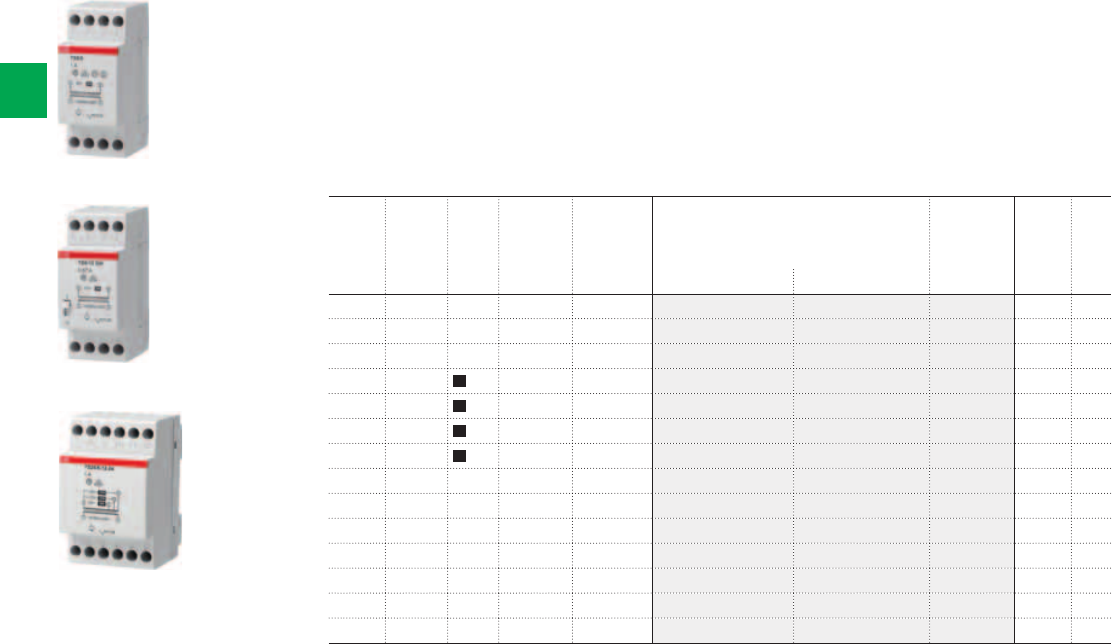
TS8/8
TS8/12 SW
TS24/8-12-24
2CSC400030F0061
2CSC400030F0062
2CSC400030F0063
2/66 2CSC 400 031 D0202 | System pro M compact®
2
Ordering Information
TS non-inherently short-circuit proof bell transformers
These transformers, with safety extremely-low voltage secondary (SELV), are suitable for driving
loads that call for a discontinuous supply, and in particular doorbells and chimes. In addition to
perfect isolation and separation between the primary and secondary circuits, the TS transformers
have a thermal protection device integrated into the secondary that makes them resistant to
short circuit currents (non-inherently short-circuit proof).
In addition, the TS8/SW series is equipped with a switch for controlling loads connected to the
secondary.
Maxim.
rated
power
(disc.)
Second.
voltage
rating
Switch
0-1
N°
module
Bbn
8012542
Order details Weight
1 piece
Pack
unit
VA V AC [17,5 mm] EAN Type code Order code Price Kg
8 8 2 368007 TS8/8 2CSM081301R0811 0.355 6
8 12 2 368106 TS8/12 2CSM081401R0811 0.355 6
8 24 2 368205 TS8/24 2CSM081501R0811 0.355 6
8 8 2 368304 TS8/8SW 2CSM081302R0811 0.277 6
8 12 2 368403 TS8/12SW 2CSM081402R0811 0.277 6
8 4-6-8 2 368601 TS8/4-6-8SW 2CSM081012R0811 0.280 6
8 4-8-12 2 368700 TS8/4-8-12SW 2CSM081022R0811 0.280 6
16 8 2 368809 TS16/8 2CSM161301R0811 0.355 6
16 12 2 368908 TS16/12 2CSM161401R0811 0.355 6
16 24 2 369004 TS16/24 2CSM161501R0811 0.330 6
16 4-6-8 2 369103 TS16/4-6-8 2CSM161011R0811 0.330 6
16 4-8-12 2 369202 TS16/4-8-12 2CSM161021R0811 0.330 6
24 4-8-12 3 369301 TS24/4-8-12 2CSM241021R0811 0.465 4
24 8-12-24 3 369400 TS24/8-12-24 2CSM241031R0811 0.465 4
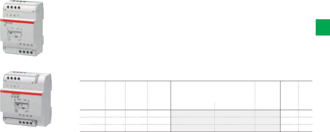
TS25/12-24 C
TS63/12-24 C
2CSC400030F0064
2CSC400030F0065
System pro M compact® | 2CSC 400 031 D0202 2/67
2
Ordering Information
TS-C safety isolating transformers for general use
These transformers are non-inherently short-circuit proof. In fact they are equipped with
a thermal protective device which automatically restores the power when the transformer
is sufficiently cooled down. So even during an overload or a short-circuit they maintain their
temperature below the specified limits and they continue functioning after the fault’s removal.
They are ideal for supplying permanent power to meters, auxiliary electronic devices
(e.g. measurement, video-entry phone systems, BUS communication) and circuits with
safety extremely-low voltage (SELV) for bathrooms and showers, lighting, fountains,
electro-medical devices and suchlike.
One important feature of these new devices is that they take up very little space in the
4-module size for the 25 and 40VA versions and the 5-module size for the 63VA version.
Rated
power
(cont.)
Second.
rated
voltage
N°
module
Bbn
8012542
Order details Weight
1 piece
Pack
unit
VA V [17,5 mm] EAN Type code Order code Price Kg
25 12-24 4 928508 TS25/12-24 C 2CSM251043R0811 0.920 1
40 12-24 4 928607 TS40/12-24 C 2CSM401043R0811 1.000 1
63 12-24 5 928706 TS63/12-24 C 2CSM631043R0811 1.150 1
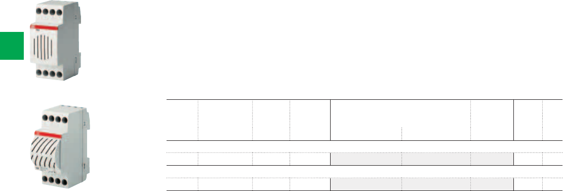
TSM
TSR
2CSC400030F0066
2CSC400030F0067
2/68 2CSC 400 031 D0202 | System pro M compact®
2
Ordering Information
Bells and buzzers
The range of bells and buzzers includes modular versions for discontinuous use SM1, RM1,
TSM and TSR, suitable for acoustic signalling in residential and commercial sectors, and
versions for continuous use SM2 and RM2, which are able to operate continuously for up to
12 hours while maintaining the quality and level of the sound. RM2 and SM2 are dedicated to
specific applications such as acoustic signalling in the industry, alarms notification, supervision
and intensive use (schools, factories etc...). TSM and TSR versions also include a transformer:
the input is 230V a.c. and the bell is supplied in 12 or 24 V.
Rated
voltage
Use N°
module
Bbn
8012542 Order details
Weight
1 piece
Pack
unit
V AC [17,5 mm] EAN Type code Order code Price Kg
TSM modular electronic bell (two-tones) + transformer included
230 Discontinuous 2 007005 TSM 2CSM100000R0841 0.300 6
TSR bell + buzzer + transformer included
230 Discontinuous 2 369608 TSR 2CSM100000R0831 0.300 1

System pro M compact® | 2CSC 400 031 D0202 2/69
2
Technical details
E 90/32 E 90hN/32
Fuse mm 10 x 38
Current type AC / DC
Rated frequency Hz = / 50-60
Rated current A 32
Max power dissipation W 3
Tightening torque Nm PZ2 2-2.5 PZ2 0.8-1.2
Terminal cross section mm225 16
Protection degree IP20
Can be padlocked (open) Q
Can be sealed (closed) Q
IEC 60947-3
Rated operating voltage V 400 -
Utilization category AC-22B -
Markings IMQ, NF -
Alternate current characteristics according to IEC 60947 - 3
Rated operating voltage V 690 -
Utilization category AC-22B -
Direct current characteristics according to IEC 60947 - 3
Rated operating voltage V 690 -
Utilization category DC-20B* -
IEC 60269-1
Rated AC voltage V 690
Rated DC voltage V 690
IEC 60269-2
Fuse system F
Rated AC voltage V 690
Rated DC voltage V 440
Breaking capacity kA 200 (AC) – 100 (DC)
IEC 60269-3
Fuse system B
Rated AC voltage V 400
Markings - IMQ
IEC 60269-4
Fuse system F
Rated AC voltage V 690
Rated DC voltage V 690
UL 4248
Mark - cURus
E 90
1P+N 3P+N
Electrical symbols
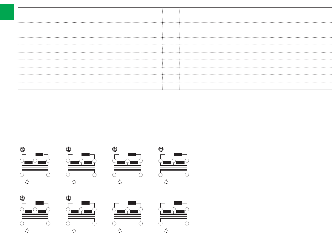
Wiring diagrams and marking information
T40/24
811
2 5
24 V~
~ 50 Hz 230 V
10
40 VA
12 V~
20 VA
12 V~
20 VA
t 40 ¯
C/B
a
T40/12
811
2 5
12 V~
~ 50 Hz 230 V
10
40 VA
8 V~
27 VA
4 V~
13 VA
t 40 ¯
C/B
a
T30/12
811
2 5
12 V~
~ 50 Hz 230 V
10
30 VA
8 V~
20 VA
4 V~
10 VA
t 40 ¯
C/B
a
T30/24
811
2 5
24 V~
~ 50 Hz 230 V
10
30 VA
12 V~
15 VA
12 V~
15 VA
t 40 ¯
C/B
a
T15/24
5 8
1 4
24 V~
~ 50 Hz 230 V
7
15 VA
12 V~
7,5 VA
12 V~
7,5 VA
t 40 ¯
C/B
a
T15/12
5 8
1 4
12 V~
~ 50 Hz 230 V
7
15 VA
8 V~
10 VA
4 V~
5VA
t 40 ¯
C/B
a
T10/12
5 8
1 4
12 V~
~ 50 Hz 230 V
7
10 VA
8 V~
6,66 VA
4 V~
3,33 VA
t 40 ¯
C/B
a
T10/24
5 8
1 4
24 V~
~ 50 Hz 230 V
7
10 VA
12 V~
5VA
12 V~
5VA
t 40 ¯
C/B
a
2/70 2CSC 400 031 D0202 | System pro M compact®
2
Technical details
TM
TM
Rated primary voltage Un V 230 a.c.
Rated secondary voltage Un V 4, 8, 12, 24
Rated frequency Hz 50/60
Rated power (discontinuous) VA 10, 15, 30, 40
Power loss W 1…4
Modules No. 2 (TM10,TM15), 3 (TM30,TM40)
Cable section (Ø min/max) mm21.5 / 10
Tightening torque Nm 1
Protection degree IP 20
Reference standards IEC/EN 61558-2-8
Approvals GOST, IMQ (TM10, TM15, TM30)
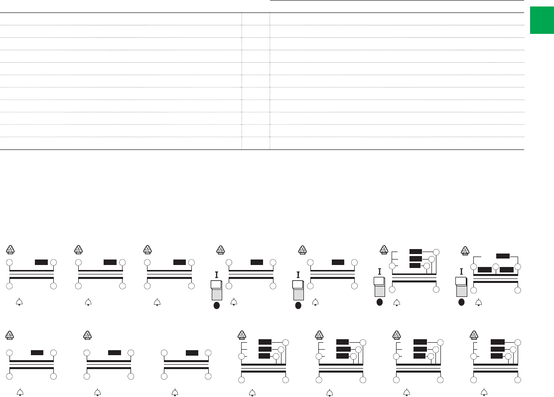
Wiring diagrams and marking information
TS16/4-8-12
5
8
1 4
~ 50 Hz 230 V
7
6
12 V~16 VA
8 V~
10,6 VA
4 V~
5,3 VA
t 40 ¯
C/B
a
TS8/4-6-8 SW
5
8
1 4
~ 50 Hz 230 V
7
6
8 V~ 8 VA
6 V~ 6VA
4 V~ 4VA
t 40 ¯
C/B
a
TS16/4-6-8
5
8
1 4
~ 50 Hz 230 V
7
6
8 V~16 VA
6 V~12 VA
4 V~ 8VA
t 40 ¯
C/B
a
TS8/4-8-12 SW
5 8
4 4
12 V~
~ 50 Hz 230 V
7
8VA
8 V~
5,3 VA
4 V~
2,7 VA
t 40 ¯
C/B
a
TS16/24
5 8
1 4
~ 50 Hz 230 V
24 V~16 VA
t 40 ¯
C/B
a
TS24/4-8-12
8
11
2 5
~ 50 Hz 230 V
10
12 V~ 24 VA
8 V~ 16 VA
4 V~ 8VA
t 40 ¯
C/B
a
TS16/12
5 8
1 4
~ 50 Hz 230 V
12 V~16 VA
t 40 ¯
C/B
a
TS16/8
5 8
1 4
~ 50 Hz 230 V
8 V~ 16 VA
t 40 ¯
C/B
a
TS24/8-12-24
8
11
2 5
~ 50 Hz 230 V
10
24 V~ 24 VA
12 V~ 12 VA
8 V~ 8VA
t 40 ¯
C/B
a
TS8/8 SW
5 8
1 4
~ 50 Hz 230 V
8 V~ 8VA
t 40 ¯
C/B
a
TS8/12 SW
5 8
1 4
~ 50 Hz 230 V
12 V~ 8VA
t 40 ¯
C/B
a
TS8/8
5 8
1 4
~ 8 V
~ 50 Hz 230 V
t 40 ¯
C/B
a
8 VA
TS8/12
5 8
1 4
~ 12 V
~ 50 Hz 230 V
t 40 ¯
C/B
a
8VA 8VA
TS8/24
5 8
1 4
~ 24 V
~ 50 Hz 230 V
t 40 ¯
C/B
a
System pro M compact® | 2CSC 400 031 D0202 2/71
2
Technical details
TS
TS
Rated primary voltage Un V 230 a.c.
Rated secondary voltage Un V 4, 8, 12, 24
Rated frequency Hz 50/60
Rated power (discontinuous) VA 10, 15, 30, 40
Power loss W 1…4
Modules No. 2 (TM10,TM15), 3 (TM30,TM40)
Cable section (Ø min/max) mm21.5 / 10
Tightening torque Nm 1
Protection degree IP 20
Reference standards IEC/EN 61558-2-8
Approvals VDE, GOST
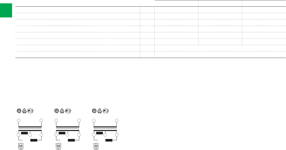
TS25/12-24 C
3 7
10 14
~ 50 Hz 230 V
12
24 V~ 25 VA
12 V~
25 VA
t 40 ¯C
a
TS40/12-24 C
3 7
10 14
~ 50 Hz 230 V
12
24 V~ 40 VA
12 V~
40 VA
t 40 ¯C
a
TS63/12-24 C
3 7
10 14
~ 50 Hz 230 V
12
24 V~ 63 VA
12 V~
63 VA
t 40 ¯C
a
2/72 2CSC 400 031 D0202 | System pro M compact®
2
Wiring diagrams and marking information
Technical details
TS C
TS 25 C TS 40 C TS 63 C
Primary rated voltage Un V 230 AC 230 AC 230 AC
Secondary rated voltage Un V 12 - 24 V AC 12 - 24 V AC 12 - 24 V AC
Rated frequency Hz 50/60 50/60 50/60
Rated power (continuous use) VA 25 40 63
Power loss W 5 10 16,7
Modules No. 4 4 5
Standards IEC/EN 61558-2-6
Approvals IMQ, VDE, GOST
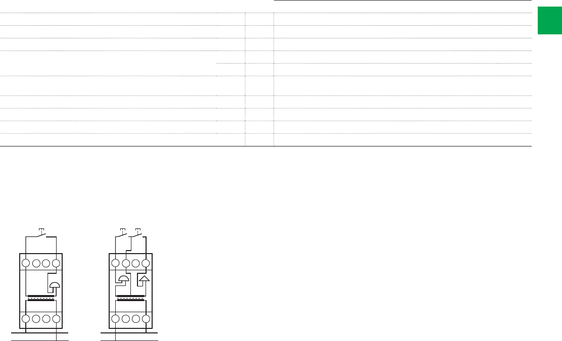
5678
TSM
1234
230V
N
L
5678
TSR
1234
230V
N
L
24V 24V
System pro M compact® | 2CSC 400 031 D0202 2/73
2
Wiring diagrams and marking information
Technical details
TSM, TSR
TSM, TSR
Rated Voltage Un V AC 230
Rated frequency Hz 50
Power consumption VA 5,5
Sound level at 1 meter SM: dB 80
RM: dB 70
Max permanent working time TSM: 1 min
TSR: 5 min
Max cable cross-section mm210
Mounting position vertical only
Protection degree IP20-IP40, switchboard mounting
Modules No. 2
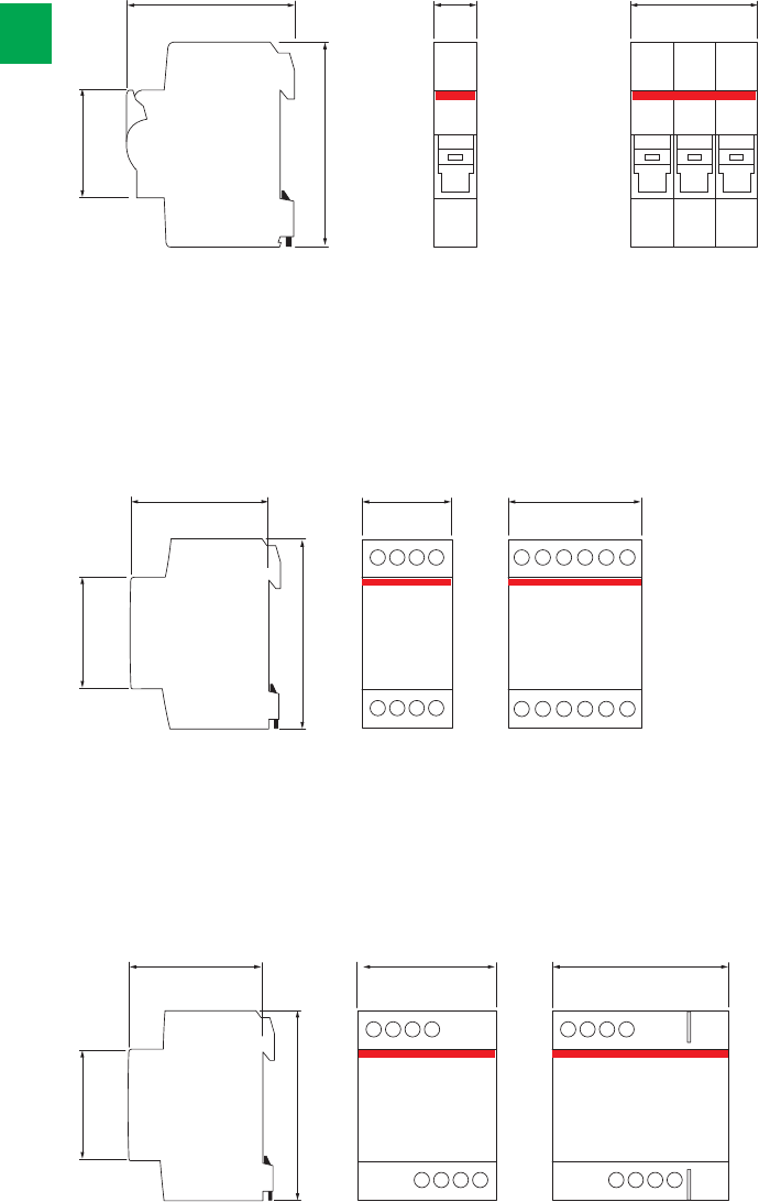
TM10...TM15
2 modules
TM30
3 modules
45
85
58 35 52.5
45
100
58 70 87.5
TS25, TS40
4 modules
TS63
5 modules
1 module
1P, 1P+N (E 91h)
3 modules
3P+N (E 93h)
45
85
64 17.5 52.5
2/74 2CSC 400 031 D0202 | System pro M compact®
2
Overall dimensions
E 90 fuse disconnectors and E 90h fuse holders
TM/TS bell transformers
TS-C safety isolating transformers for general use
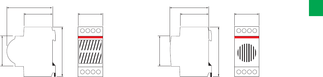
45
85
TSR
68
44 35
45
85
TSM
58
44 35
System pro M compact® | 2CSC 400 031 D0202 2/75
2
Bells and buzzers

2

System pro M compact® | 2CSC 400 031 D0202 2/77
2
Ordering information 2/78
Busbars and end caps
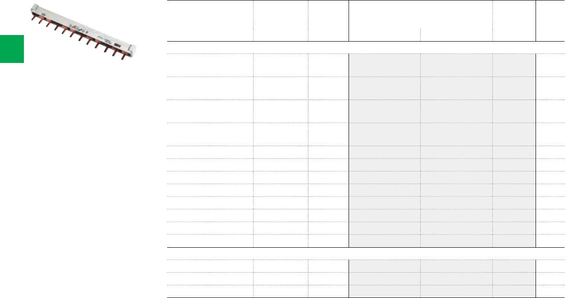
PSH3/12
2CSC400030F0068
2/78 2CSC 400 031 D0202 | System pro M compact®
2
Ordering Information
Phase sequence End cap Bbn
4016779
Order details Pack
unit
EAN Type code Order code Price
Busbar
L1-L1-… incl. 463102 PS1/6
(not to be cut)
2CDL210001R1006 60
L1-L1-… incl. 463201 PS1/9
(not to be cut)
2CDL210001R1009 30
L1-L1-… incl. 463300 PS1/12
(not to be cut)
2CDL210001R1012 30
L1-L2-L3-L1-… incl. 463607 PS3/12
(not to be cut)
2CDL231001R1012 30
L1-L1-… PS-END 0 514668 PS1/60 2CDL210001R1060 20
L1-L2-L1-… incl. 556521 PS2/12 2CDL220001R1012 50
L1-L2-L1-… PS-END 556552 PS2/58 2CDL220001R1058 10
L1-L2-L3-L1-… incl. 576116 PS3/12 2CDL230001R1012 50
L1-L2-L3-L1-… PS-END 514699 PS3/60 2CDL230001R1060 10
L1-L2-L3-N-L1-… incl. 656054 PS4/12 2CDL240101R1012 30
L1-L2-L3-N-L1-… PS-END 1 656085 PS4/60 2CDL240101R1060 10
L1-N-L2-N-L3-N-… PS-END 1 656146 PS4/58N 2CDL240101R1058 10
End cap
- - 652261 PS-END 0 2CDL200001R0004 50
- - 514729 PS-END 2CDL200001R0001 50
- - 570114 PS-END 1 2CDL200001R0002 50

3
System pro M compact® | 2CSC 400 031 D0202 3/1
Introduction 3/2
Ordering information
E 210 switches 3/4
E 210 pushbuttons with and without LEDs 3/6
E 210 indicator Lights with LEDs 3/7
E 200 switches 3/8
E 250 latching relays 3/10
E 260 electronic latching relays 3/12
FLR flush mounting latching relays 3/14
E 259 installation relays 3/15
SM/RM bells and buzzers 3/16
ESB installation contactors 3/17
EN series contactors 3/19
EH04... auxiliary contact block 3/21
Overall dimensions 3/22
Command and alerts
3
3/2 2CSC 400 031 D0202 | System pro M compact®
Simplicity of control makes life easier
Command and alert devices
Using modular DIN-rail mounted devices (MDRC) such as on-off switches,
pushbuttons, indicator lights, disconnectors, relays, contactors, bells and buzzers
makes it possible to switch and control electric loads from a central location.
Thanks to signalling, operating states can be recognized easily and user always has
the complete control of the situation.
The range is completed by a complete range of accessories and auxiliary elements
such as auxiliary contact blocks, sealing cover and distance pieces
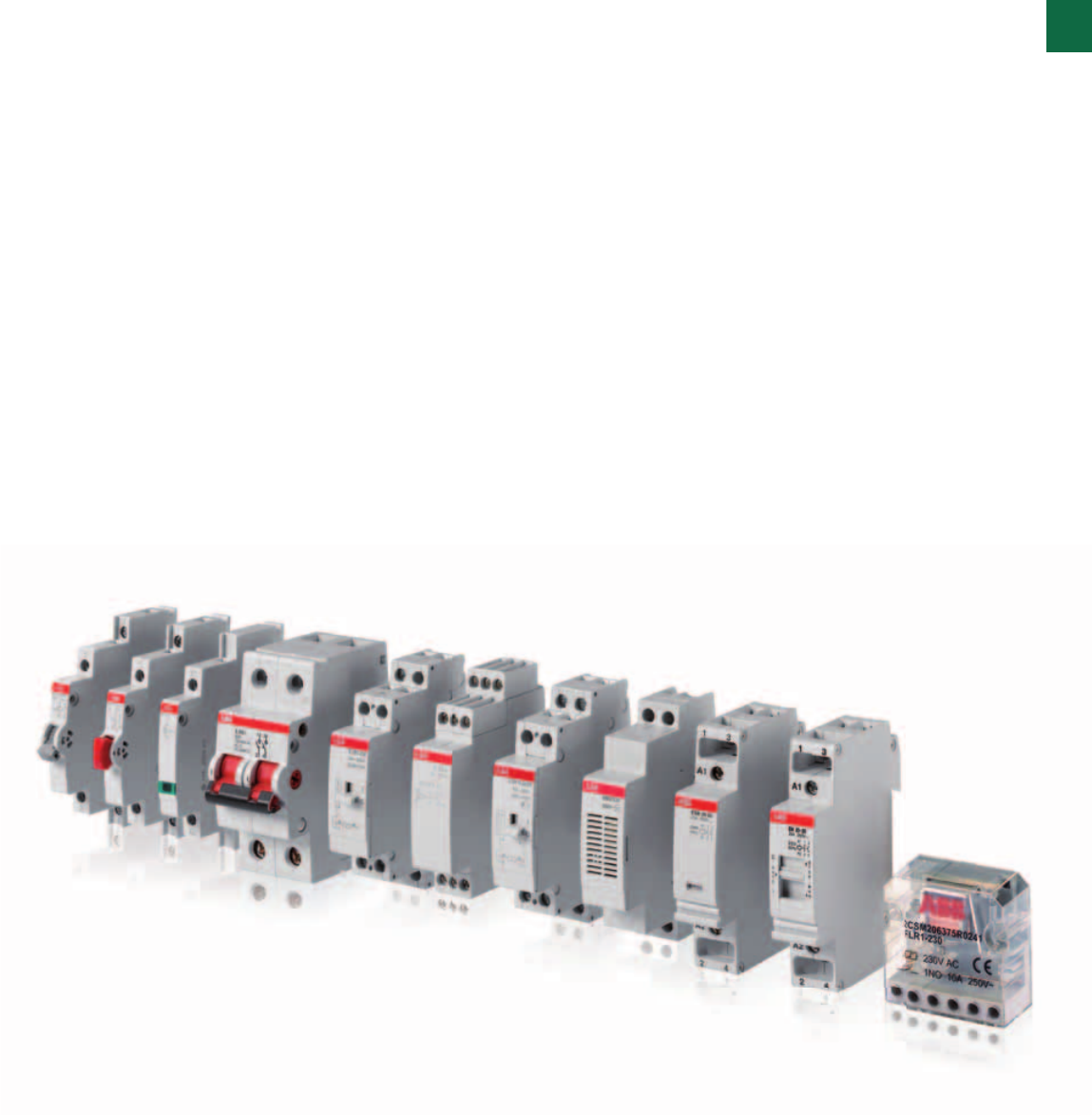
3
System pro M compact® | 2CSC 400 031 D0202 3/3
ABB offers a complete range of modular DIN-rail mounted
devices (MDRC) that makes it possible to switch and
control electric loads from a central location. Thanks to the
new narrow width of only 9 mm (0.5 modular width) place
is saved in the distribution board. Integration of modular
installation devices in the distribution boards affords the
additional advantage of intelligible signalling of electric loads
operating states. Easy operation or interpretation of devices is
ensured by the clearly recognizable switching position (toggle
lever) and/or a status display by means of an LED light.
Depending on the system requirements, further signalling or
control functionality for reliable operation can be used in the
subdistribution board in the form of pushbuttons or indicator
lights. Switch are available for different functions: on-off,
change over, group control.
Commands can be coupled with electro-magnetic and
electronic latching relays which allow contact switching
for each impulse sent using single or parallel pushbutton.
Ideal for load controlling from different positions, they are
available in various versions according to pick-up voltage,
contact position, installation options. They also allow manual
operation on the product and contact position indicator (visual
on the product).
Also important in command portfolio of product is the range
of bells and buzzers, which includes modular versions for
discontinuous use SM1 and RM1, suitable for acoustic
signalling in residential and commercial sectors.
Finally ESB and EN series of contactors, suitable for loads to
be automatically controller through high number of operations.
Contactors are used mainly in buildings for switching and
controlling lighting, heating, ventilation and pumps. The ESB
24, 40, 63 contactors are used for the control of loads up to
24, 40, 63 A. Due to their DC solenoid actuator, the ESB 24
can be connected to AC or DC voltages.The EN contactors
have a built-in toggle switch to select between three function
modes: Off position, automatic run (normal contactor
function), manual override with a return to Auto the next time
the coil is energized.
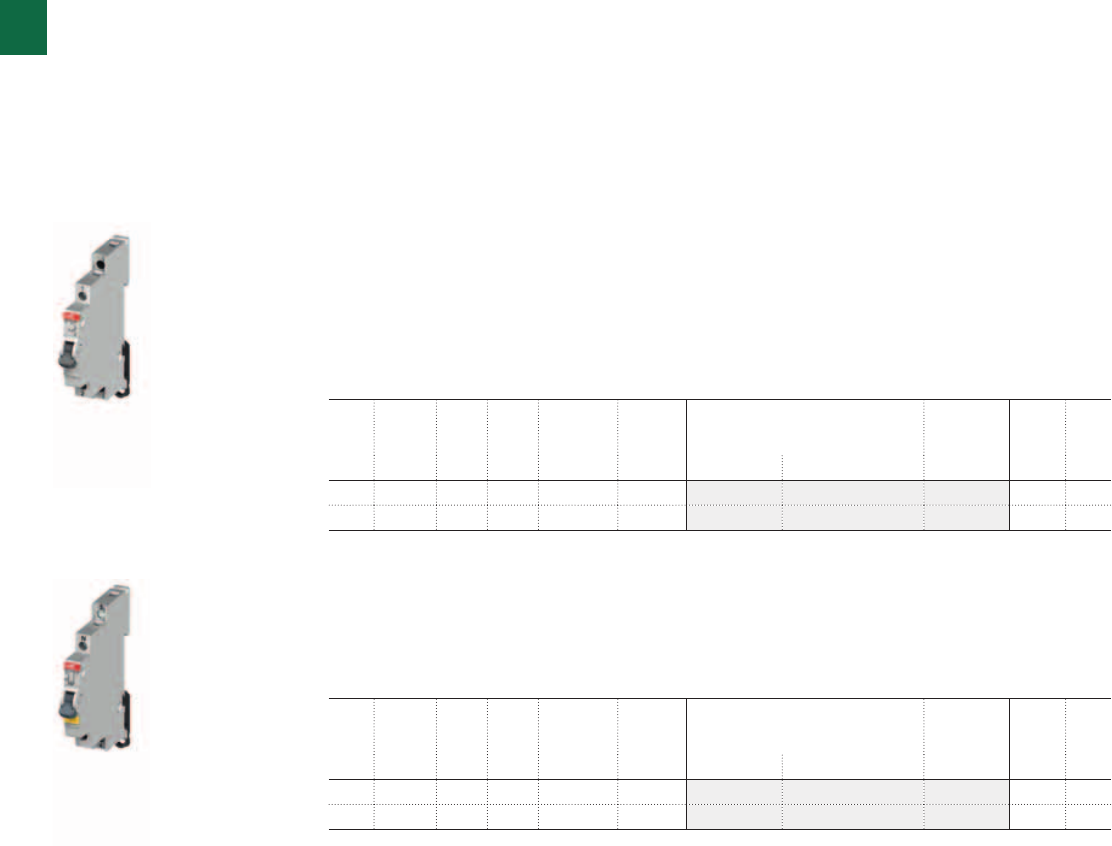
2CSC400030F01012CSC400030F0102
E211
E211X
3
3/4 2CSC 400 031 D0202 | System pro M compact®
Ordering Information
E 210 switches
These devices are specifically made for commanding loads and signalling electrical conditions
in any low-voltage switchboard. They are available in half module or 1 module, depending on
the contact-layout. The devices with indicator lights are equipped with a LED, which grants an
optimal illumination with very low consumption.
The functions of these devices are particularly switching, pushing and signalling electrical
conditions in any installations (low-voltage area)
General new features
- Space-saving through 9mm modules
- All terminals equipped with Pozidrive 1 screws
- Safe connection due to cage-clamp
- LED with bright colours and available in three different voltage ranges
- Different lens and button colours
- Compliance to international standards
E 211-... ON-OFF switches
For example, such devices are used to switch indicators or other electrical components (like
fan’s, air-conditions, e.g.). The new On-Off switches distinguish themselves through simple
handling, easy mounting and optimal functionality.
Rated current = 16A
E 211X-... ON-OFF switches with yellow LED for contact indication
Rated current = 16A
LED voltage 115-250 V AC
LED colour yellow
Cont. Rated
voltage
Power
loss
Width N° module Bbn
7612270
Order details Weight
1 piece
Pack
unit
V AC W mm [17.5 mm] EAN Type code Order code Price Kg
1 NO 250 0.32 9 0.5 938575 E211-16-10 2CCA703000R0001 0.035 10
2 NO 230/400 0.82 9 0.5 938582 E211-16-20 2CCA703005R0001 0.045 10
Cont. Rated
voltage
Power
loss
Width N° module Bbn
7612270
Order details Weight
1 piece
Pack
unit
V AC W mm [17.5 mm] EAN Type code Order code Price Kg
1 NO 250 0.50 9 0.5 938872 E211X-16-10 2CCA703100R0001 0.040 10
2 NO 230/400 1.00 18 0.5 938889 E211X-16-20 2CCA703110R0001 0.050 10
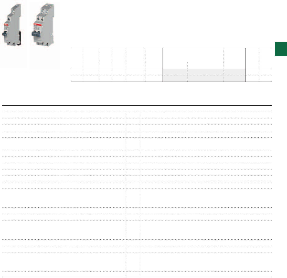
2CSC400030F0103
2CSC400030F0104
E214-16-101 E214-16-202 3
System pro M compact® | 2CSC 400 031 D0202 3/5
Cont. Rated
voltage
Power
loss
Width N° module Bbn
7612270
Order details Weight
1 piece
Pack
unit
V AC W mm [17.5 mm] EAN Type code Order code Price Kg
1 CO 250 0.32 9 0.5 938735 E214-16-101 2CCA703025R0001 0.032 10
2 CO 250 0.82 18 1.0 938742 E214-16-202 2CCA703030R0001 0.064 10
E 214-... Group switches (I-0-II, manual-OFF-automatic)
The new Group switches can be used to control the main installation of an emergency supply.
Such devices distinguish themselves through simple handling, easy mounting and optimal
functionality.
Rated current = 16A
Technical details
Switching capacity according to EN 60669-1
Isolating properties according to EN 60669-2-4; IEC/EN 60947-3
Utilization category AC-22A; DC-22A acc. IEC/EN60947-3
Short-circuit withstand capacity [kA] 3
Rated voltage Un[V] 250/400 in accordance with EN
240 in accordance UL 508
Lowest operat. voltage 24 V; 25 mA
Rated current In[A] 16, 25, 32
LED current [mA] 5
Rated frequency [Hz] 50/60
Modules [No] 0.5 or 1
Sealable in ON and OFF position
Climatic resistance according to IEC 60068-2-2 (Dry heat)
IEC 60068-2-30 (Damp heat)
IEC 60068-2-1 (Cold)
Ambient temperature [°C/°F] -25°C/-13°F to +55°C/+131°F
Storage temperature [°C] -40°C to +70°C
Connection capacity [mm2] rom 1x1 mm2 to 1x6 mm2 or 2x2.5 mm2 massive;
lexible up 1x0.75 mm2 to 2x1.5 mm2 with connector
leve or pin-endconnector
Tightening torque [Nm] 1.2 - 1.5
Positive opening according to EN 60204-1
Standards DIN EN 60669-1 *VDE 0632-1
DIN EN 60669-2-4 *VDE 0632-2-4
UL 508
Approvals VDE, UL, GOST, CCC
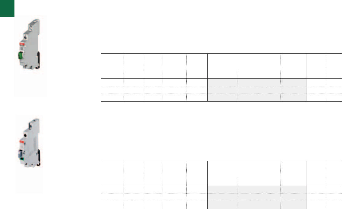
2CSC400030F01052CSC400030F0106
E215
E217
3
3/6 2CSC 400 031 D0202 | System pro M compact®
Ordering Information
E 210 pushbuttons with and without LEDs
The new products are available in 9 mm widths (= 0.5 modules).
The devices can be used in distribution boards and are all distinguished by their simple
handling, ease of mounting and optimal functionality. The pushbuttons are used for remote
control in all kinds of electrical installation (e.g. public, industrial). The range offers three
different voltages.
(Ranges: 12-48 V AC/DC; 115-250 V AC and 110-220 V DC).
E 215-... Pushbuttons
Rated current = 16A
Contacts: 1NO+1NC
Rated voltage: 250 V AC
E 217-... Luminous Pushbuttons (3 different LED colours)
Rated current = 16A
Contacts: 1NO
Rated voltage: 250 V AC
LED Voltage range = 115-250 V AC
Power
loss
Button
colour
Width N° module Bbn
7612270
Order details Weight
1 piece
Pack
unit
W mm [17.5 mm] EAN Type code Order code Price Kg
0.50 grey 9 0.5 938810 E215-16-11B 2CCA703150R0001 0.042 10
0.50 red 9 0.5 938827 E215-16-11C 2CCA703151R0001 0.042 10
0.50 green 9 0.5 938834 E215-16-11D 2CCA703152R0001 0.042 10
Power
loss
LED
colour
Width N° module Bbn
7612270
Order details Weight
1 piece
Pack
unit
W mm [17.5 mm] EAN Type code Order code Price Kg
1.10 white 9 0.5 938988 E217-16-10B 2CCA703160R0001 0.050 10
1.10 red 9 0.5 938995 E217-16-10C 2CCA703161R0001 0.050 10
1.10 green 9 0.5 939008 E217-16-10D 2CCA703162R0001 0.050 10
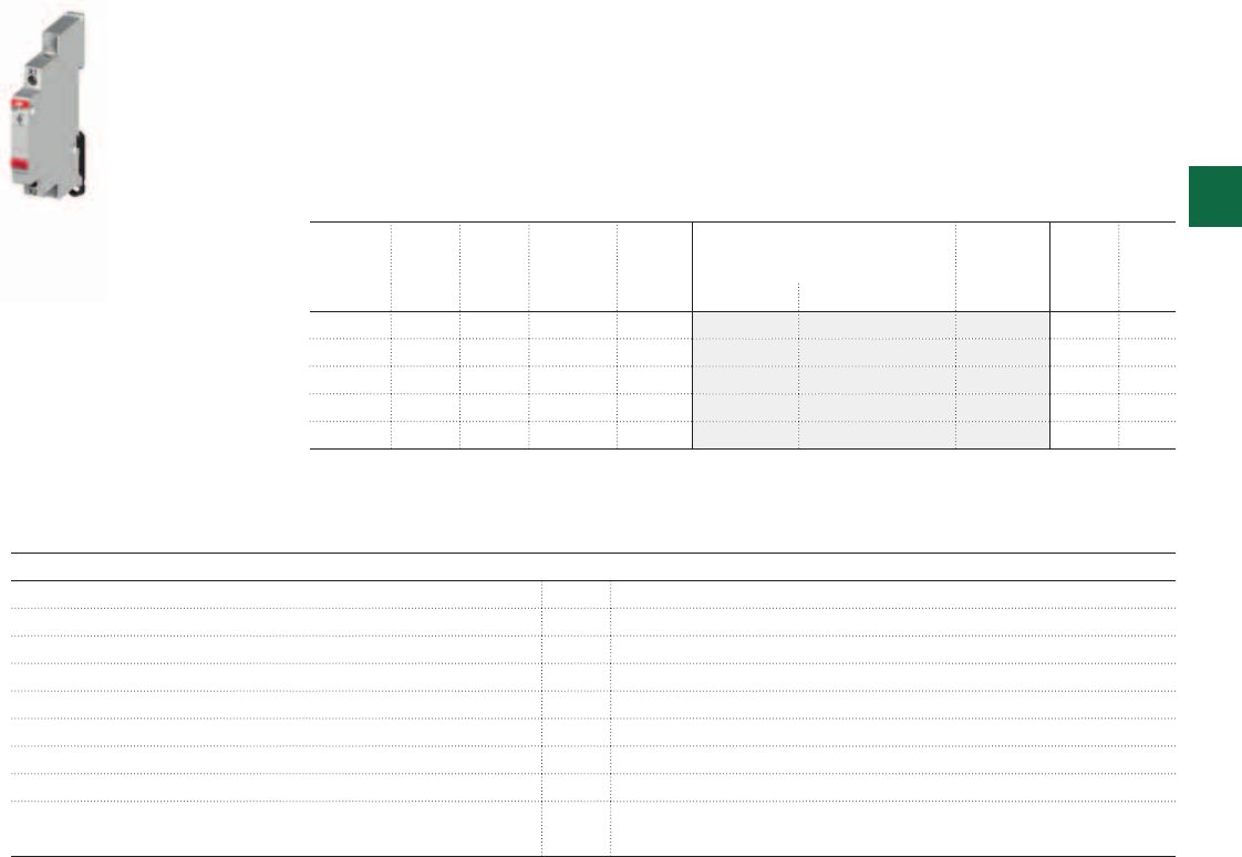
2CSC400030F0107
E219
3
System pro M compact® | 2CSC 400 031 D0202 3/7
Pushbuttons and Indicator lights
Rated Voltage Un[V] 250/400
Lowest operat. voltage 24 V; 25 mA
Rated current In[A] 16
LED current [mA] 5
Rated frequency [Hz] 50/60
Modules [No] 0.5
Tightening torque [Nm] 1.2 - 1.5
Standards EN 60669-1; EN 62094-1; UL 508
Approvals Pushbuttons: VDE, UL, GOST, CCC
Indicator lights: VDE, UL, GOST*
*CCC approval for these Indicator lights not required
Ordering Information
E 210 indicator Lights with LEDs
The new products are available in 9 mm width (= 0.5 modules) and can be used for indicating
any operational condition such as signalling loss of a phase.
The range offers three different voltages.
(Ranges: 12-48 V AC/DC; 115-250 V AC and 110-220 V DC).
Rated current = 16A
LED Voltage range = 115-250 V AC
Power
loss
LED
colour
Width N° module Bbn
7612270
Order details Weight
1 piece
Pack
unit
W mm [17.5 mm] EAN Type code Order code Price Kg
0.47 white 9 0.5 939282 E219-B 2CCA703400R0001 0.040 10
0.47 red 9 0.5 939299 E219-C 2CCA703401R0001 0.040 10
0.47 green 9 0.5 939305 E219-D 2CCA703402R0001 0.040 10
0.47 yellow 9 0.5 939312 E219-E 2CCA703403R0001 0.040 10
0.47 blue 9 0.5 939329 E219-G 2CCA703404R0001 0.040 10
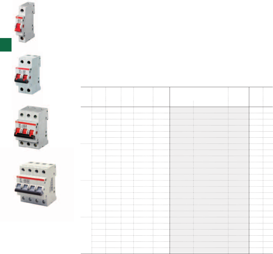
2CSC400030F0108
2CSC400030F0109
2CSC400030F0110
E201
E202
E203
E204
3
3/8 2CSC 400 031 D0202 | System pro M compact®
Ordering Information
E 200 switches
Isolator for panel installation onto DIN rail acc. to DIN EN 60715
Mounting depth: 70mm
Mounting width: per pole = 17.5mm = 1module
Colour: grey, RAL 7035
Colour of switch lever: red RAL 3000 (r); grey RAL 7000 (g)
Special features
- Fast removal without dismantling of the busbar
- Captive screws with recessed/slotted head, Pozidriv size 2
- Add-on of up to 3 auxiliary contact S2C-H6R possible
- Integrated lay-on edge for labeling system ILS
- Locking device as accessories for unauthorized ON/OFF
- Approval: VDE, CCC, KEMA
N. of
poles
Rated
current
Rated
voltage
Power
loss
N° module Bbn
4016779
Order details Weight
1 piece
Pack
unit
A V AC W [17.5 mm] EAN Type code Order code Price Kg
1 16 230 0.15 1 645621 E201/16r 2CDE281001R0016 0.095 10
25 230 0.30 1 645645 E201/25r 2CDE281001R0025 0.095 10
32 230 0.50 1 645669 E201/32r 2CDE281001R0032 0.095 10
40 230 0.70 1 645683 E201/40r 2CDE281001R0040 0.095 10
45 230 0.90 1 645706 E201/45r 2CDE281001R0045 0.095 10
63 230 1.65 1 645720 E201/63r 2CDE281001R0063 0.095 10
2 16 400 0.30 2 645805 E202/16r 2CDE282001R0016 0.190 5
25 400 0.60 2 645829 E202/25r 2CDE282001R0025 0.190 5
32 400 0.95 2 645843 E202/32r 2CDE282001R0032 0.190 5
40 400 1.40 2 645867 E202/40r 2CDE282001R0040 0.190 5
45 400 1.80 2 645881 E202/45r 2CDE282001R0045 0.190 5
63 400 3.30 2 645904 E202/63r 2CDE282001R0063 0.190 5
3 16 400 0.45 3 645980 E203/16r 2CDE283001R0016 0.290 3
25 400 0.90 3 646000 E203/25r 2CDE283001R0025 0.290 3
32 400 1.40 3 646024 E203/32r 2CDE283001R0032 0.290 3
40 400 2.10 3 646048 E203/40r 2CDE283001R0040 0.290 3
45 400 2.65 3 646062 E203/45r 2CDE283001R0045 0.290 3
63 400 4.90 3 646086 E203/63r 2CDE283001R0063 0.290 3
4 16 400 0.60 4 646161 E204/16r 2CDE284001R0016 0.390 2
25 400 1.20 4 646185 E204/25r 2CDE284001R0025 0.390 2
32 400 1.90 4 646208 E204/32r 2CDE284001R0032 0.390 2
40 400 2.80 4 646222 E204/40r 2CDE284001R0040 0.390 2
45 400 3.50 4 646246 E204/45r 2CDE284001R0045 0.390 2
63 400 6.55 4 646260 E204/63r 2CDE284001R0063 0.390 2
2CSC400030F0111

3
System pro M compact® | 2CSC 400 031 D0202 3/9
E 200
Switching capacity 1.25 x In; 1.1 x Un; cosϕ = 0.3 acc. to DIN VDE 0632
16...100 A : AC-22A / 125 A : AC-23A acc. to VDE 0660 part 107,
DIN EN 60947-3 resp. IEC 947-3, DC21-B for applications up to 60 V DC
Protection fuse NH00 gL-gG ≤ rated current E 200
Positive opening acc. to DIN VDE 0113
Suitable for isolation acc. to DIN EN 60947-3
Short-circuit withstand capacity 16...100 A : 25 kAeff in series with NH 00 ≤ 100 A gL-gG;
125 A : 6 kAeff in series with NH 00 125 A gL-gG and S 2.. ≤63 A
Rated voltage 230/400 V AC; 50/60 Hz
Surge withstand capability Uimp 4 kV acc. to EN 60947-1
Ambient temperature -25 °C to +55 °C
Storage temperature -40 °C to +70 °C
Climatic resistance constant climate 23/83, 40/93, 55/20 [°C/RH]
alternating climate 25/95 - 40/93 [°C/RH]
Mounting position optional
Degree of protection IP10, IP40 in panelboard
Mechanical endurance 20000 switching cycles
Electrical endurance 1000 switching cycles
Min. voltage 12 V AC/DC at 0.1 VA
Min. contact loading 24 V/4 mA
Wire range 2.5 to 50 mm2
Busbars cross section ≥ 16 mm2
Torque 2.5 Nm
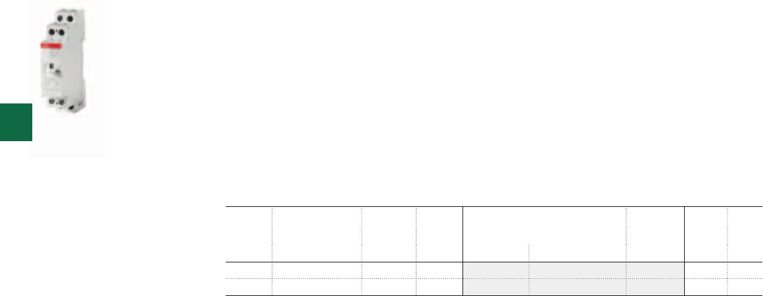
2CSC400030F0112
E251
3
3/10 2CSC 400 031 D0202 | System pro M compact®
Ordering Information
E 250 latching relays
Allow switching of the contacts in response to each pulse sent to the coil via the normally
open pushbuttons. Their high performance in the single or multi-point control of lamps make
them an ideal solution for lighting circuits. The manual control lever also gives an indication of
the contact position.
The relays come in versions with different coil voltages and contact configurations. The main
modules, available in one-and two-contact versions, can be combined with two-pole power
contact modules to obtain three-contact and four-contact devices. They can also be provided
with auxiliary signal contacts.
E 250, 16 A
Contacts Coil voltage N° module Bbn
8012542
Order details Weight
1 piece
Pack
unit
[17.5 mm] EAN Type code Order code Price Kg
1 NO 230 V AC/ 115 V DC 1 530305 E251-230 2CSM111000R0201 0.114 12
2 NO 230 V AC/ 115 V DC 1 530800 E252-230 2CSM112000R0201 0.116 12

3
System pro M compact® | 2CSC 400 031 D0202 3/11
E 251 / E 252 / E 256
Technical details
Rated current In [A] 16 32
Rated voltage Un [V] 250 (1-2 contacts)
400 (3-4 contacts)
250 (1-2 contacts)
400 (3-4 contacts)
Rated frequency [Hz] 50/60 (1) 50/60 (1)
Contacts main module NO 1 - 2 1 - 2
change-over 1 - 2 1 - 2
NO+NC 1 + 1 1 + 1
additional
power contacts
NO 2 2
change-over 2 -
NO+NC 1+1 -
Width
(no. of DIN modules)
main module [mod.] 1 1
with additional power contacts [mod.] 2 2
Control coil characteristics supply voltage: DC/AC ratio (2) 0,5 : 1 0,5 : 1
tolerance on supply voltage ±10% ±10%
power consumption AC holding (3) [VA] 11 11,5
pick-up [VA] 14,5 16,5
power consumption DC [W] 7,5 8
Pulse durations minimum pulse duration (at Un) [s] 0,05 0,05
minimum pulse duration (90% Un) [s] 0,1 0,1
minimum interval between two pulses [s] 0,15 0,15
maximum number of pulses per minute 250 250
Lifetime in number
of operations (4)
electrical (in AC-1 at full load) 4 x 1053 x 105
mechanical 2 x 1062 x 106
Load characteristics maximum load in AC-1 per phase [A] 20 32
minimum load per phase (under 5 V) [W] 2 2
short circuit protection fuse (gL) [A] 20 32
Maximum no. of lamps (103
operations/h)
incandescent and halogen [W] 3000 4000
fluorescent, corrected power factor
(cosϕ = 0,9)
series [VA] 4000 4000
parallel [VA] 2500 3200
fluorescent, uncorrected power factor
(cosϕ = 0,5)
[VA] 1800 2200
Maximum number
of buttons
non illuminated unlimited unlimited
illuminated 3 wires unlimited unlimited
General characteristics DIN rail mount yes yes
hooking on bistable DIN rail yes yes
two position knob yes yes
contact position indication yes yes
label-holder yes yes
cage terminals yes yes
captive screws yes yes
sealable terminals yes yes
cable section (o min./max.) [mm2] 1,5/10 (2P: 6) 1,5/10 (2P: 6)
min./max. operating temperature [°C] -20...+45 -20...+46
(1) All latching relays can also be used at 60Hz. In this case and escluding E255, you can use maximum one auxiliary contact E250H but it is not possible to use power contacts E250CM.
(2) Supply voltage: all devices operate in both a.c. and d.c., with the specified voltage ratios, except for the 115 V a.c. version that operates at 48 V d.c..
(3) The relays can withstand the “button stuck” condition. When the application calls for the relays to be permanently supplied, spacers must be used on either side, making sure that the duty cycle allows the device
to cool down to ambient temperature.
(4) 1 cycle = 2 operations per pole (closing + opening)
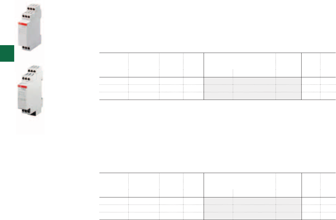
2CSC400030F0113
2CSC400030F0114
E262
E262C
3
3/12 2CSC 400 031 D0202 | System pro M compact®
Ordering Information
E 260 electronic latching relays
The electronic version of latching relays guarantees maximum reliability, life, and noiseless
operation. The E 260 C version also allows centralized reset function (ON/OFF).
Latching relays with control electronics
Coil voltage UC = 230 V AC
Latching relays with control electronics for central ON/OFF switch
The central commands have always priority and reliably switch on/off any given number of
devices connected in parallel, irrespective of their previous switching position. Local control
inputs are blocked when a central command is received. Same potential at central / local
control input.
Coil voltage UC = 230 V AC
* Values in brackets indicate power loss when permanently excitated, rated voltage and rated contact loading.
Contacts Power
loss
N° module Bbn
4016779
Order details Weight
1 piece
Pack
unit
W* [17.5 mm] EAN Type code Order code Price Kg
1 NO 1.5 (2.0) 1 575966 E261-230 2CDE141000R0301 0.085 1
2 NO 1.7 (3.6) 1 575973 E262-230 2CDE142000R0301 0.096 1
1 NO+1 NC 1.7 (3.6) 1 575980 E266-230 2CDE144000R0301 0.096 1
Contacts Power
loss
N° module Bbn
4016779
Order details Weight
1 piece
Pack
unit
W* [17.5 mm] EAN Type code Order code Price Kg
1 NO 1.5 (2.0) 1 576024 E261C-230 2CDE141000R0311 0.085 1
2 NO 1.7 (3.0) 1 576031 E262C-230 2CDE142000R0311 0.096 1
1 NO+1 NC 1.7 (3.0) 1 576048 E266C-230 2CDE144000R0311 0.096 1

3
System pro M compact® | 2CSC 400 031 D0202 3/13
E 260/E 260 C E 261 SRV-230
Technical details
Rated load at 250 V AC 8 A 16 A
Incandescent lamp load 1000 W 1600 W
Fluorescent lamp load in twin-lamp circuit 1000 W 1000 W
Fluorescent lamp load shunt compensated 350 W (1) 500 W
Fluorescent lamp load inductive or capacitive 500 W 1000 W
Electronic ballast Ion m 70 A/10 ms (2) Ion m 70 A/10 ms (2)
Inductive load, cosϕ = 0.6/230 V ~ 5 A 5 A
Contact rating at DC 100 W 100 W
Minimum contact rating 4 V AC/10 mA 4 V AC/10 mA
Contact gap/contact material 0.5 mm/Ag Sn020.5 mm/Ag Sn02
Service life mecha--nical switchover at 103/h > 107> 107
Service life at rated load cosϕ = 1 and 103/h > 105> 105
Service life with filament lamps at 103/h 800 W > 105 , 1000 W > 0.8x1051000 W > 105
Service life at rated load cosϕ = 0.6 and 103/h > 104> 104
Max. switching rate 103/h 103/h
Bounce time 3 ms
Connection capacity 2 x 1.5 mm2 with connector sleeve
2 x 2.5 mm2 without connector sleeve
Tightening torque 0.5 … 0.8 Nm 0.5 … 0.8 Nm
ON duration at rated voltage 100 % 100 %
Coil voltage range 0.9 to 1.1 Un0.9 to 1.1 Un
Minimum command time/interval between commands 50/1000 ms 50 ms
Ambient temperature -20 °C / -4 °F to 50 °C / 122 °F -20 °C / - 4 °F to 50 °C / 122 °F
Control current when controlled locally 230 V AC 115 mA, after 10s 8 mA -± 20 %
24 V UC 140 mA, after 10s 80 mA ± 20 %
Control current when controlled centrally 230 V AC 8 mA, after 10s 3 mA -± 20 %
24 V UC 17 mA ± 20 %
Max. parallel capacity of individual control wire at 230 V ~ 0.7 μF (ca. 2000 m)
Max. parallel capacity of central control wire at 230 V ~ 0.2 μF (ca. 700 m)
Max. glow lamp current – parallel to 230 V control buttons 10 mA 10 mA
Max. induced voltage at 230 V control inputs 0.2 Un120 V
Latching relays for lamp installations on request.
(1) E 260 C can not be used with fluorescent lamp load shunt compensated.
(2) In the case of electronic control gear, take into account a 40-fold inrush current.
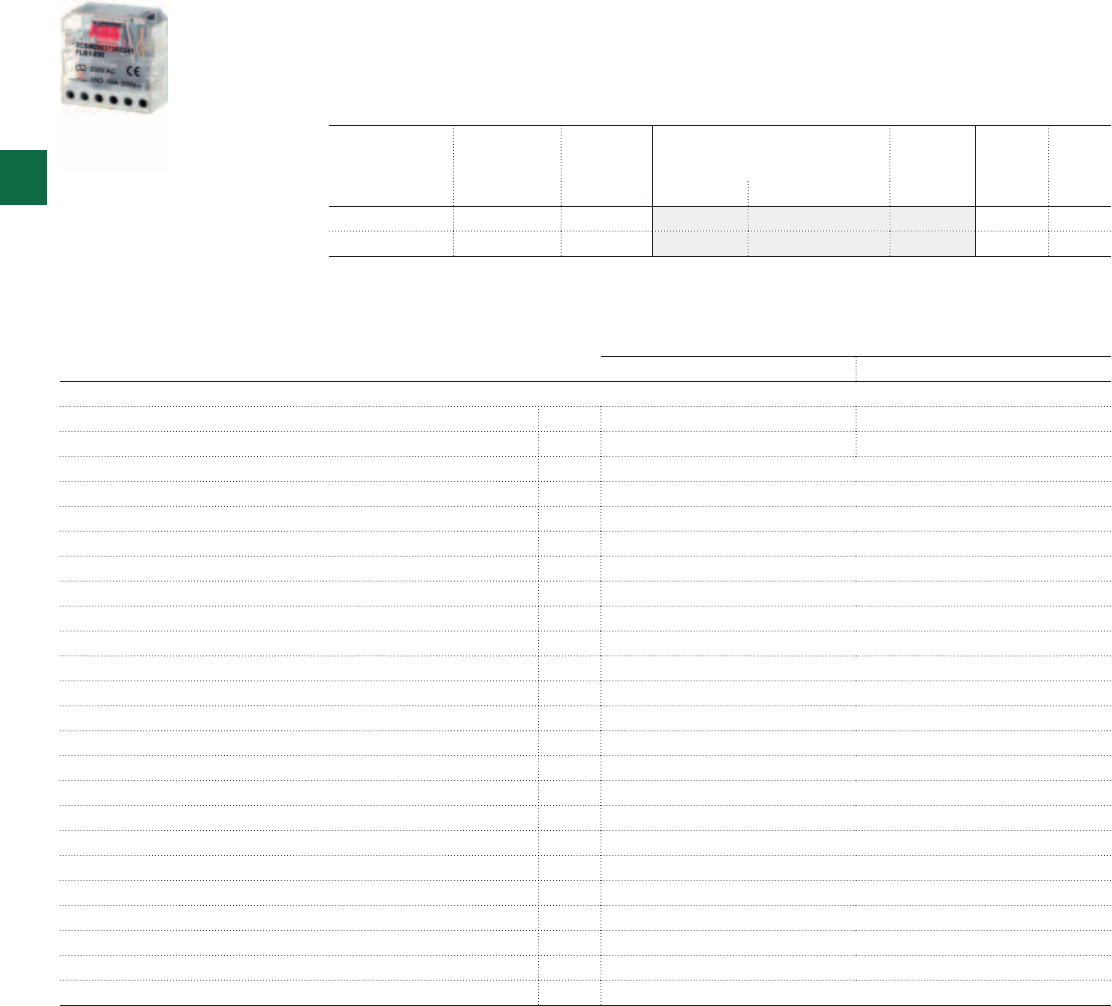
2CSC400030F0115
FLR
3
3/14 2CSC 400 031 D0202 | System pro M compact®
Speed and ease of assembly, along with their compact size, make the FLR flush mounting
latching relays suitable for installation inside flush mount or junction boxes. They are ideal
for implementing multipoint command of lighting systems in residential and commercial
installations, so as to simplify and reduce the cost of wiring.
FLR1 FLR5
Technical details
Contact type 1NO 2NO
Number of sequences [No.] 2 4
Rated voltage [V] 12 / 230 AC
Rated load 10 A / 250 V AC
Max. Peak current [A] 15
Max. switching power [VA] 2500
Max. switching voltage [V] 250 AC
Incandescent lamp load [W] 805
Fluorescent lamp load [W] 345
Frequency [Hz] 50-60
Type of operation sequential - mechanical
Protection degree IP20
Max. number of electrical operations [No.] 100000
Max. number of mechanical operations [No.] 300000
Insulation resistance [MΩ] 100 (500 V DC)
Dielectric strength (contacts) [V] 2000 AC
Dielectric strength (coil) [V] 3500 AC
Power dissipation [VA] 4.5
Operating temperature [°C] -25…+55
Max. Cable section at terminals [mm²] 1...2.5
Terminals screw
Installation type wall/flush mounting
Dimensions (LxWxH) [mm] 45 x 22 x 45
Standards EN 60669-1; EN 60669-2-1
Contacts N° module Bbn
8012542
Order details Weight
1 piece
Pack
unit
[17.5 mm] EAN Type code Order code Price Kg
1 - 063759 FLR1-230 2CSM206375R0241 0.060 20
2 - 063957 FLR5-230 2CSM206395R0241 0.060 20
Ordering Information
FLR flush mounting latching relays
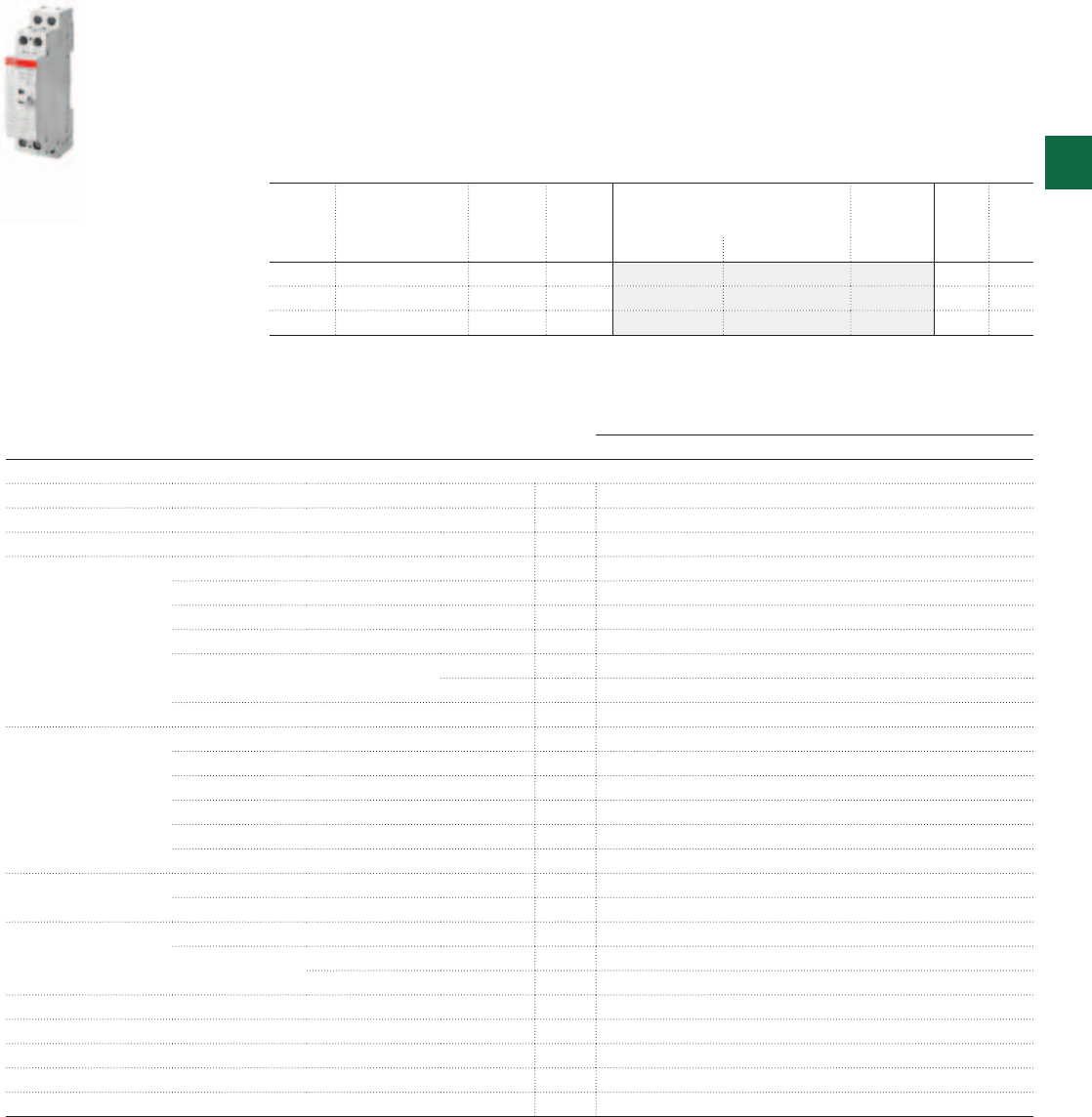
2CSC400030F0116
E259 3
System pro M compact® | 2CSC 400 031 D0202 3/15
Ordering Information
E 259 installation relays
E 259 Installation relays are 16 A contactors specifically engineered for residential and
commercial applications. Their high performance in the control of lamps makes them ideal for
lighting circuit applications.
The front control lever indicates the position of the contacts and allows the relay to be
commanded, for example for local testing of the circuit.
In installations that require several E 259 relays side by side, it is advisable to use E 259 DIS
half-module width spacer elements every second relay for heat dissipation.
E 259
Technical details
Rated voltage Un [V] 250
Rated frequency [Hz] 50
Rated current in AC1/AC-7a [A] 16
Control coil characteristics AC power supply voltage [V] 8, 12, 24, 48, 115, 230
DC power supply voltage [V] 6, 12, 24, 48, 115
DC/AC ratio (1) 0.5 : 1
operation limits ±10%
power consumption AC pick-up [VA] 3.4
holding [VA] 1.8
power consumption DC [W] 2.1
Load characteristics per
phase
maximum load AC-1 [kW] 3
maximum load AC-5b [kW] 1.8
maximum load AC-7b [kW] 0.9
maximum load AC-3 (400V) [kW] -
maximum load (under 5V) [W] 2
short circuit fuse protection [gL] [A] 20
Lifetime in number
of operations
electrical (in AC-1 at full load) [No.] 3 x 10⁵
mechanical [No.] 2 x 10⁶
Max.lamp power Incandescent and halogen (40-200W) [W] 1800
Fluorescent Parallel p.f. correction (cosϕ=0.9) [VA] 500
p.f. uncorrected (cosϕ=0.5) [VA] 900
Width (number of DIN modules) [No.] 1
Cable cross section (Ø min/max) [mm2] 1.5 / 10
Maximum torque on terminals [Nm] 1
Min./Max. ambient T ° at installation point [°C] -20 … +45
Standard IEC EN 60947-4-1, IEC EN 61095
(1) Control coil voltage: all the products work both in AC and DC (with the specified ratio) except the 115 V AC version that works at 48 DC
Contacts Coil voltage N° module Bbn
8012542
Order details Weight
1 piece
Pack
unit
[17.5 mm] EAN Type code Order code Price Kg
1 NO 230 V AC / 115 V DC 1 735939 E259 16-10/230 2CSM273593R0401 0.100 12
2 NO 230 V AC / 115 V DC 1 736233 E259 16-20/230 2CSM273623R0401 0.100 12
1 NO+1NC 230 V AC / 115 V DC 1 736530 E259 16-11/230 2CSM273653R0401 0.100 12
2CSC400030F0117
SM1
3
3/16 2CSC 400 031 D0202 | System pro M compact®
Ordering Information
SM/RM bells and buzzers
The range of bells and buzzers includes modular versions for discontinuous use SM1, RM1,
TSM and TSR, suitable for acoustic signalling in residential and commercial sectors, and
versions for continuous use SM2 and RM2, which are able to operate continuously for up to
12 hours while maintaining the quality and level of the sound. RM2 and SM2 are dedicated to
specific applications such as acoustic signalling in the industry, alarms notification, supervision
and intensive use (schools, factories etc...). TSM and TSR versions also include a transformer:
the input is 230V a.c. and the bell is supplied in 12 or 24 V.
SM1-12, RM1-12 SM1-230, RM1-230
Technical details
Rated Voltage Un[V AC] 8-12 230
Rated frequency [Hz] 50 50
Power consumption [VA] 2,5-6,5 4,5
Sound level at 1 meter SM: [dB] 82 82
RM: [dB] 80 80
Max permanent working time 15 min 15 min
Max cable cross-section [mm2]10 10
Mounting position vertical only
Protection degree IP20-IP40, switchboard mounting
Modules [No.] 1 1
Rated
voltage
Use N° module Bbn
8012542
Order details Weight
1 piece
Pack
unit
V AC [17.5 mm] EAN Type code Order code Price Kg
SM electro-mechanical modular bells
8/12 Discontinuous 1 886204 SM1-12 2CSM111000R0821 0.076 12
230 Discontinuous 1 886303 SM1-230 2CSM131000R0821 0.076 12
RM electro-mechanical modular buzzers
8/12 Discontinuous 1 886419 RM1-12 2CSM211000R0821 0.076 12
230 Discontinuous 1 886518 RM1-230 2CSM231000R0821 0.076 12
2CSC400030F0118
2CSC400030F0119
2CSC400030F0120
ESB 20-20
ESB 24-40
ESB 63-40
3
System pro M compact® | 2CSC 400 031 D0202 3/17
Ordering Information
ESB installation contactors
Application: the ESB contactors are used mainly in buildings for switching and controlling
lighting, heating, ventilation and pumps. They are part of the complete range of Din rail
products and can be integrated easily in dedicated panels.
ESB20 are AC coil operated.
The ESB 24, 40, 63 contactors are used for the control of loads up to 24, 40, 63 A.
Due to their DC solenoid actuator, the ESB 24 can be connected to AC or DC voltages.
This provides the following benefits:
Hum-free operating system, no vibration, silent in operation, low power consumption,
integrated high overvoltage protection 5 kV. You can choose between a various N.O. and N.C.
contacts combination.
Main accessories for ESB 24, 40, 63: auxiliary contact blocks EH04.
Main
poles
Control coil voltage N° module Bbn
3471520
Order details Weight
1 piece
Pack
unit
50 Hz 60 Hz [17.5 mm] EAN Type code Order code Price Kg
ESB 20
2 NO 230 V 264 V 1 263263 ESB 20-20 GHE 321 1102 R0006 0.140 10
2 NC 230 V 264 V 1 263867 ESB 20-02 GHE 321 1202 R0006 0.140 10
1 NO
1 NC
230 V 264 V 1 263560 ESB 20-11 GHE 321 1302 R0006 0.140 10
Main
poles
Control coil voltage N° module Bbn
4013614
Order details Weight
1 piece
Pack
unit
40...450 Hz DC [17.5 mm] EAN Type code Order code Price Kg
ESB 24
2 NO 230...240 V 230...240 V 2 146756 ESB 24-20 GHE 329 1402 R0006 0.280 5
4 NO 230...240 V 230...240 V 2 084454 ESB 24-40 GHE 329 1102 R0006 0.280 5
4 NC 230...240 V 230...240 V 2 084546 ESB 24-04 GHE 329 1202 R0006 0.280 5
ESB 40
4 NO 230...240 V 230...240 V 3 084867 ESB 40-40 GHE 349 1102 R0006 0.400 3
ESB 63
4 NO 230...240 V 230...240 V 3 084973 ESB 63-40 GHE 369 1102 R0006 0.420 3

3
3/18 2CSC 400 031 D0202 | System pro M compact®
ESB20
(AC operated)
ESB24
(AC/DC operated)
ESB40
(AC/DC operated)
ESB63
(AC/DC operated)
Technical details
Main Pole - Utilization Characteristics according to IEC
Rated operational voltage Ue max. V 250 400
Rated frequency limits Hz 50/60 40...450
Utilization category AC-1 / AC-7a
for air temperature close to contactor < 55 °C (NO) A 20 24 40 63
Max. rated operational current Ie AC-1 / AC-7a (NC) A 20 24 30 30
Rated operational power AC-1
230 V - 1 phase kW 4 5.3 8.8 13.8
400 V - 3 phases kW - 16 26 41
Utilization category AC-3 / AC-7b for air temperature close to contactor < 55 °C
Max. rated operational current Ie AC-3/AC-7b
230 V - 1 phase A 9 9 22 30
400 V - 3 phases A - 9 22 30
Rated operational power AC-3
230 V - 1 phase kW 1.1 2.2 5.5 8
400 V - 3 phases kW - 4 11 15
Rated making capacity AC-3 10 x Ie / AC-3
Rated breaking capacity AC-3 8 x Ie / AC-3
Short-circuit protection for contactors gG type fuse A 20 35 63 80
Rated short-time withstand current Icw
at 40 °C ambient temp., in free air, from a cold state 10 s
A72 176 240
Heat dissipation per pole Ie / AC-1/AC-7a W 1 1.5 3 6
Max. electrical switching frequency
- for AC-1 / AC-7a cycles/h 300
- for AC-3 / AC-7b cycles/h 600
Electrical durability
- for AC-1 / AC-7a cycles 150000 150000 150000 150000
- for AC-3 / AC-7b cycles 150000 500000 170000 240000
Mechanical durability
- millions of operating cycles 1.000.000
Magnet System Characteristics
Coil operating limits acc. to IEC 60947-4-1 0.85 ... 1.1 x Uc (at θ m 55 °C)
Drop-out voltage in % of Ucapprox. 20 ... 75 % approx. 20 ... 70 %
Frequency range Hz 50/60 40 ... 450
Coil consumption
Average pull-in value VA / W 8 / 5 4 / 4 5 / 5 65 / 65
Average holding value VA / W 3.2 / 1.2 4 / 4 5 / 5 4.2 / 4.2
Connecting Characteristics
Connecting capacity (min. ... max.)
Main pole terminals
Rigid 1 x mm² 1.5 ... 10 - 1.5 ... 25 -
2 x mm² 1.5 ... 4 - 1.5 ... 10 -
Degree of protection
acc. to IEC 60947-1 / EN 60947-1 and IEC 60529 / EN 60529
Protection against direct contact in acc. with EN 50274
All terminals IP20 - IP20 -
Ordering Information
ESB installation contactors
2CSC400030F0121
2CSC400030F0122
2CSC400030F0123
EN 20-20
EN 24-40
EN 40-40
3
System pro M compact® | 2CSC 400 031 D0202 3/19
Ordering Information
EN series contactors
Application: the EN contactors are used mainly in buildings for switching and controlling
lighting, heating, ventilation and pumps. They are part of the complete range of Din rail
products and can be integrated easily in dedicated panels.
Description: EN contactors have a built-in toggle switch to select between three function
modes: Off position, automatic run (normal contactor function), manual override with a return
to Auto the next time the coil is energized.
This offers many advantages as: You can make functionnal test before installation start-up.
It can be used for maintenance operation, to change lamps and test it. It provides higher
safety and drop out as you can switch the application manually.
The toggle switch is also used for household application like water heating where double tariff
of kWh is used.
Main
poles
Control coil voltage N° module Bbn
3471520
Order details Weight
1 piece
Pack
unit
50 Hz 60 Hz [17.5 mm] EAN Type code Order code Price Kg
EN 20
2 NO 230 V 264 V 1 265069 EN 20-20 GHE 322 1101 R0006 0.140 10
Main
poles
Control coil voltage N° module Bbn
4013614
Order details Weight
1 piece
Pack
unit
40...450 Hz DC [17.5 mm] EAN Type code Order code Price Kg
EN 24
4 NO 230...240 V 230...240 V 2 133688 EN 24-40 GHE 326 1101 R0006 0.240 5
3 NO 230...240 V 230...240 V 2 134319 EN 24-30 GHE 326 1501 R0006 0.230 5
EN 40
2 NO 230...240 V 230...240 V 3 129582 EN 40-20 GHE 342 1401 R0006 0.400 3
3 NO 230...240 V 230...240 V 3 212338 EN 40-30 GHE 342 1501 R0006 0.400 3
4 NO 230...240 V 230...240 V 3 133701 EN 40-40 GHE 342 1101 R0006 0.410 3

3
3/20 2CSC 400 031 D0202 | System pro M compact®
Ordering Information
EN series contactors
EN20
(AC operated)
EN24
(AC/DC operated)
EN40
(AC/DC operated)
Technical details
Main Pole - Utilization Characteristics according to IEC
Rated operational voltage Ue max. V 250 400
Rated frequency limits Hz 50/60 40...450
Utilization category AC-1 / AC-7a
for air temperature close to contactor < 55 °C (NO) A 20 24 40
Max. rated operational current Ie AC-1 / AC-7a (NC) A 20 24 30
Rated operational power AC-1
230 V - 1 phase kW 4 5.3 8.8
400 V - 3 phases kW - 16 26
Utilization category AC-3 / AC-7b for air temperature close to contactor < 55 °C
Max. rated operational current Ie AC-3/AC-7b
230 V - 1 phase A 9 9 22
400 V - 3 phases A - 9 22
Rated operational power AC-3
230 V - 1 phase kW 1.1 2.2 5.5
400 V - 3 phases kW - 4 11
Rated making capacity AC-3 10 x Ie / AC-3
Rated breaking capacity AC-3 8 x Ie / AC-3
Short-circuit protection for contactors gG type fuse A 20 35 63
Rated short-time withstand current Icw
at 40 °C ambient temp., in free air, from a cold state 10 s
A72 176
Heat dissipation per pole Ie / AC-1/AC-7a W 1 1.5 3
Max. electrical switching frequency
- for AC-1 / AC-7a cycles/h 300
- for AC-3 / AC-7b cycles/h 600
Electrical durability
- for AC-1 / AC-7a cycles 150000 150000 150000
- for AC-3 / AC-7b cycles 150000 500000 170000
Mechanical durability
- millions of operating cycles 1.000.000
2CSC400030F0124
EH 04 3
System pro M compact® | 2CSC 400 031 D0202 3/21
Ordering Information
EH04... auxiliary contact block
ESB20
(AC operated)
ESB24
(AC/DC operated)
ESB40
(AC/DC operated)
ESB63
(AC/DC operated)
Technical details
Rated operational voltage Ue max. V - 500
Conventional free air thermal current Ith θ < 40 °C A- 6
Rated frequency limits Hz - 50/60
Rated operational current Ie / AC-15 acc. to IEC 60947-5-1
240 V 50/60 Hz A - 4
415 V 50/60 Hz A - 3
500 V 50/60 Hz A - 2
Making capacity acc. to IEC 60947-5-1 - 11 x Ie AC-15
Breaking capacity acc. to IEC 60947-5-1 - 11 x Ie AC-15
Short-circuit protection gl type fuse A - 10
Minimum switching capacity with failure rate acc. to IEC 60947-5-4 V/mA - 17 / 5
Heat dissipation per pole at 6 A W - 0.1
Contactor
Type
Contact
blocks
N° module Bbn
3471520
Order details Weight
1 piece
Pack
unit
[17.5 mm] EAN Type code Order code Price Kg
ESB/EN 24, 40, 63 2 - 0.5 084768 EH 04-20 GHE 340 1321 R0001 0.004 10
1 1 0.5 084768 EH 04-11 GHE 340 1321 R0002 0.004 10
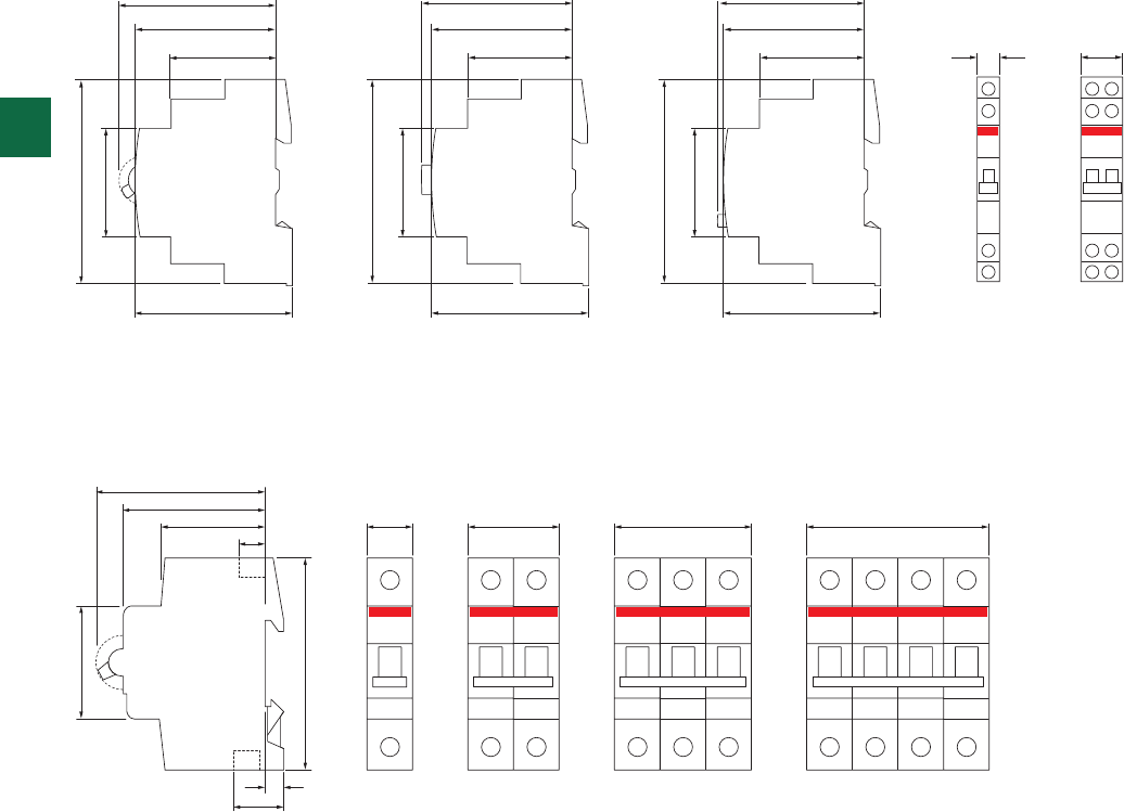
45
85
70
58
44 17.5 35 52.5 70
11
11
6.8 1 module 2 modules 3 modules 4 modules
0.5 module 1 module
67.9 67.5 59.5
58 58 58
64.7 64.7 64.7
43.5 43.5 43.5 9 18
85
85
85
45
45
45
3
3/22 2CSC 400 031 D0202 | System pro M compact®
Overall dimensions
E 210 - Switches, pushbuttons and indicator lights
E 200
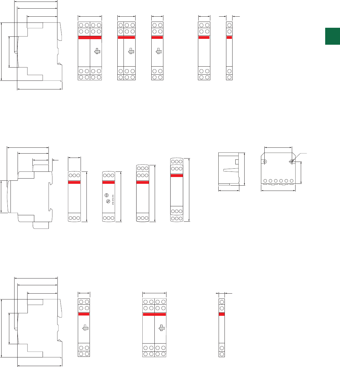
58
43.4 17.5
5
45
70
70
80
89
E 261
E 261 C
E 261 SRV E 262
E 266
E 262 C
E 266 C
39.8
Ø 3.5
4523
47
30
2 modules
E 259 16-10, E 259 16-20,
E 259 16-11, E 259 16-19,
E 259 16-29,
E 259 16-30, E 259 16-40,
E 259 16-39, E 259 16-49
E 250-H
1 module 1/2 module
62
58
65
43.5 17.8 35.6 8.9
85
45
2 modules
E 257-C003
E 257-C30
1,5 modules
E 257-C20
E 257-C002
1 module
E 251, E 252,
E 256, E 256.1
E 256.2, E 257-C10
1 module
E 250 CM
E 250 CP
E 250 GM
1/2 module
E 257-CM
E 250-H
62
58
65
43.5 35.6 26.7 17.8 17.8 8.9
85
45
3
System pro M compact® | 2CSC 400 031 D0202 3/23
E 250
E 260 FLR
E 259
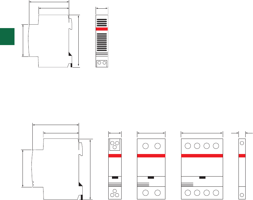
1 module
58
44 17.5
45
85
1 module 2 modules 3 modules
ESB 20 ESB 24 ESB 40 - ESB 63 ESB 0458
44 17.5 35 54 9
45
85
3
3/24 2CSC 400 031 D0202 | System pro M compact®
SM, RM
ESB/EN contactors
Overall dimensions

System pro M compact® | 2CSC 400 031 D0202 4/1
4
Introduction 4/2
Plus of range 4/4
Ordering information
F2C-ARH and F2C-ARH-T 4/6
E 450 4/7
AT T 4/8
RAL 4/10
LSS1/2 4/11
E 235 4/12
Socket outlets 4/13
LEE 230 4/14
Overall dimensions 4/15
Comfort
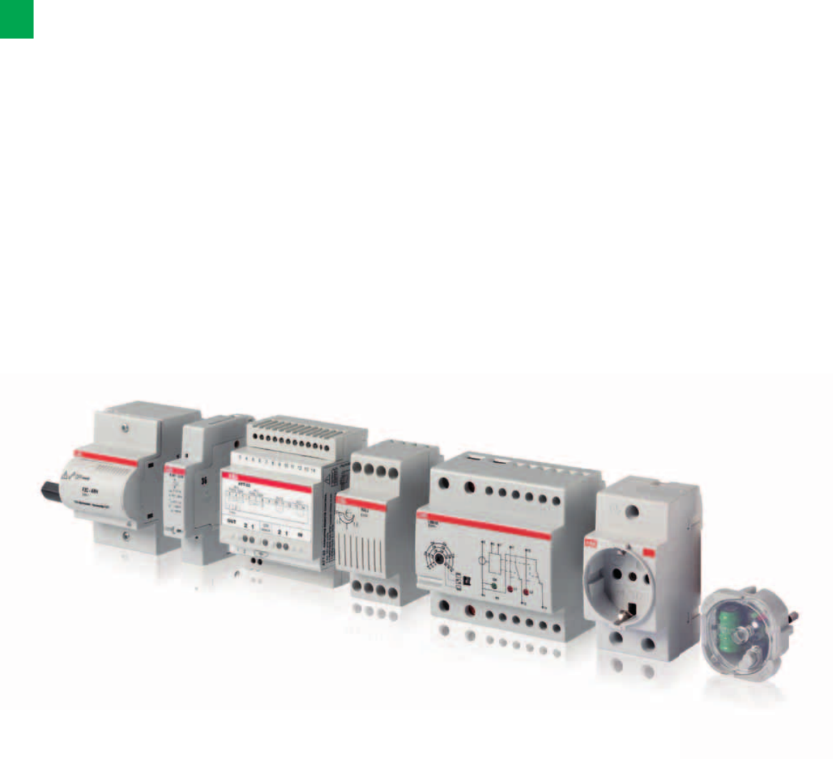
4/2 2CSC 400 031 D0202 | System pro M compact®
4
Comfortable living, easy to manage
ABB solutions for home comfort
The basic idea behind a modern electrical installation is to adapt the system to the
users’ needs and not vice versa, providing simple operation, safety and energy
efficiency. ABB products have all the necessary features to control homes through a
flexible networking of solutions that make life easy.
Electronic components have always been used to improve the
performance, increase comfort and save energy.
Even in domestic installations, loads must be protected and
monitored to guarantee their correct behaviour in critical
conditions. This is a fundamental aspect for the comfort of
users. The ABB’s portfolio of products devoted to improve the
comfort is very complete.
The F2C-ARH-T autoreclosing unit for domestic and similar
application periodically performs the auto test and
reclosure of the associated residual current device (2-pole
RCCBs up to 63 A - 30 mA / 100 mA), only after having
checked that there are no effective faults in the system
protected by the RCCB.
The ATT modules are GSM telephone actuators for remotely
controlling electrical loads over the mobile phone network,
which answer the installation requirements of a variety of
application settings. Instructions and alarms can be sent via
SMS message, free phone call ring, fax or e-mail according to
need. Configuration can be accomplished by SMS messages
or using the ATT-Tool software.

System pro M compact® | 2CSC 400 031 D0202 4/3
4
Modular devices in the load management devices category
react automatically to variations of parameters and other
events in the system to allow installation optimization. The
priority switch is used in wiring systems where existing lead
cross sections or the size of the power supply service box.
The E 450 priority switches in particular disconnects the long-
term load as long as the short-term consumer is switched on.
Installed downstream of the main circuit-breaker, LSS1/2 load
shedding switch compares the actual power consumption
of the system to a preset maximum permitted value, and
prevents tripping of the main circuit-breaker by sequentially
switching off a maximum of two non-prioritary loads (NPL1
and NPL2) when the preset threshold is exceeded. A green
LED indicates the presence of the supply voltage, and two
red LEDs indicate the load OFF conditions. At preset time
intervals, the device automatically attempts to reconnect the
previously disabled loads.
E 235 mains disconnection relays – Bioswitch - constant
exposure of electrical interference fields originating from live
conductors - as is the case e.g. in bedrooms – which may
impair the well-being of people.
LEE 230 extractable power failure signalling lamp is an
automatic electronic lamp that can be installed in any modular
socket or wiring accessory socket conforming to the German
VDE Schuko standard, to the Italian standard P11 10A, or to
the 10/16 A Italian dual standard. The device functions both
as a power failure signalling lamp and as a lighting device, to
be used for example during maintenance activities or when
seeking faults in the panel.
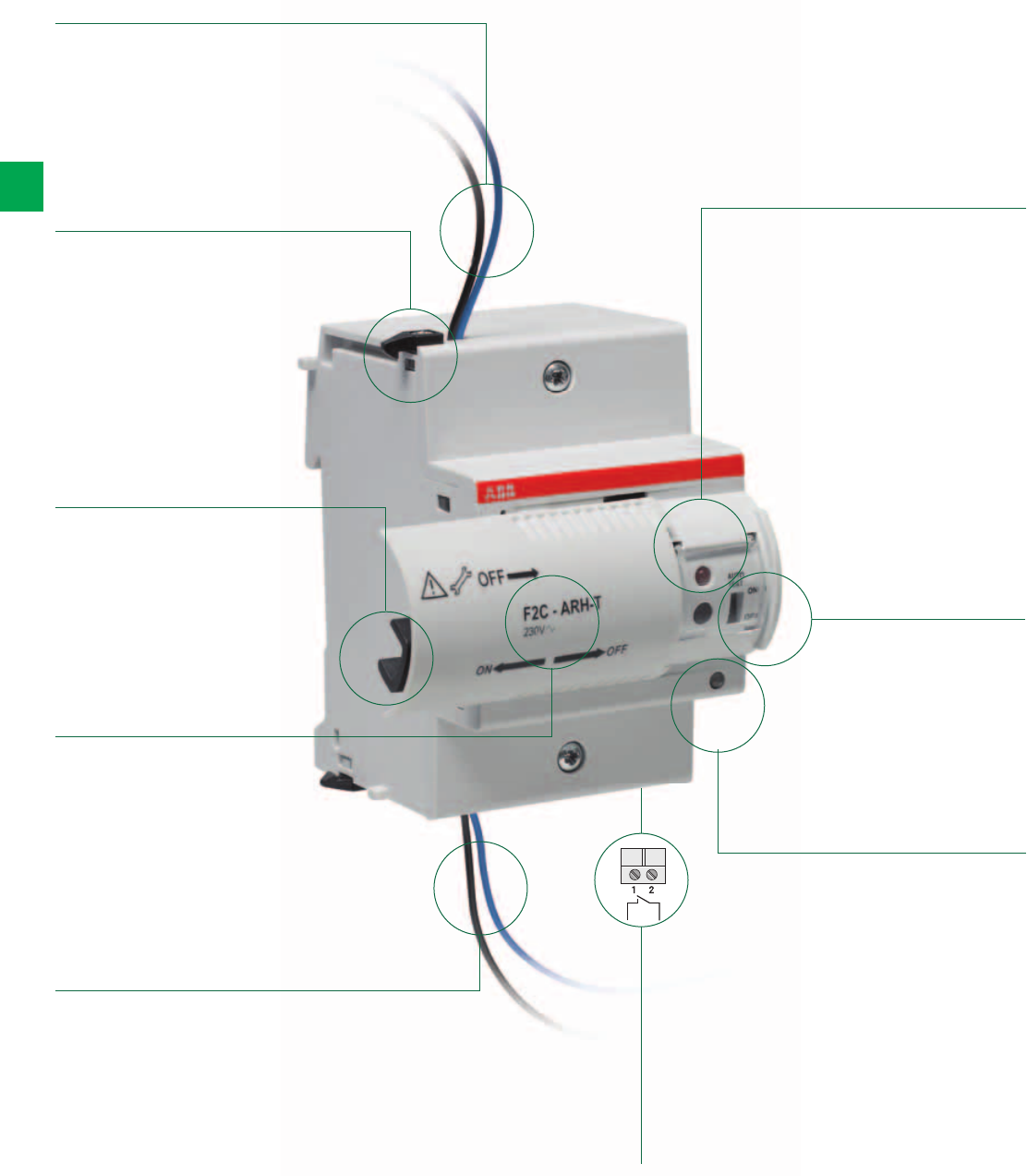
4/4 2CSC 400 031 D0202 | System pro M compact®
4
F2C-ARH and F2C-ARH-T
The details make the difference
The characteristics and assets of an efficient and reliable product
Withdrawable
terminals to
connect the
auxiliary signalling
contact
Slide that
activates/
de-activates the
automatic resetting
function
Supply cables of
the device
Wiring cables
of the device
Autotest
programming key
(only on
F2C-ARH-T)
Plastic prong to
couple Greenlight
to the residual
current
circuit-breaker
Coupler that
connects to the
operating lever
of the RCCB
Selector switch
for activating the
RCCB’s automatic
test function (only
on F2C-ARH-T)
Indicator LED
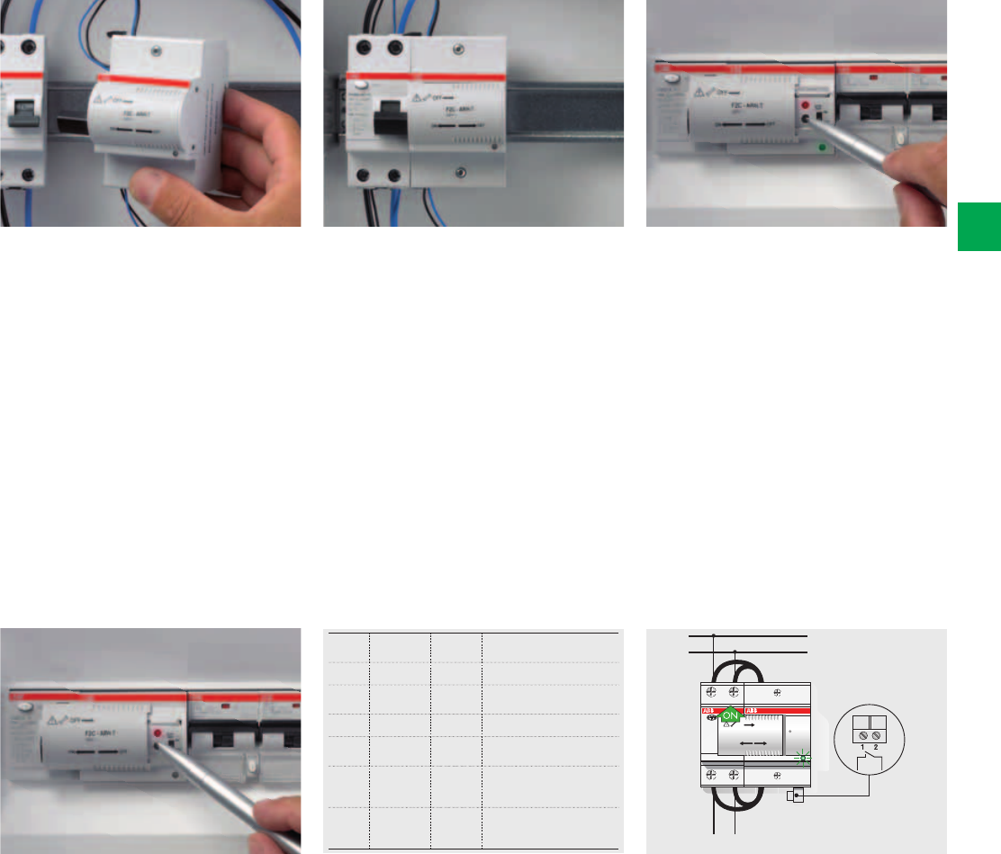
LOCKED
BLOCCATO
F2C - ARH
230V~
OFF
OFF
ON
Colour State Auxiliary
contact
Meaning
None Off Open Greenlight not powered
Green Flashing Open Greenlight powered and
auto-reclosing not activated
Green Fixed Open Auto-reclosing activated
Red Flashing Open Inspection of the installation
after the RCCB has tripped
Red Fixed Closed Greenlight has blocked
owing to a permanent fault
in the line
Orange
(only on
F2C-ARH-T)
Fixed Open The RCCB automatic test
has given a negative result:
call an electrician.
System pro M compact® | 2CSC 400 031 D0202 4/5
4
Wiring
Greenlight auto-reclosing units are
supplied already wired and ready to
be installed and connected. You only
need a screwdriver to turn the hooks
that fasten it to the circuit-breaker and
to tighten the terminals. The four wires
of the Greenlight device are specially
designed to be simply and reliably
connected to the rear terminals of
FH202 30 mA / 100 mA residual current
circuit-breaker.
Delay time (only on F2C-ARH-T)
A simple programming system allows
you to delay the time at which the test
is performed in relation to the time when
the autotest system was activated. A
five, ten and fifteen hour delay can be
obtained by releasing and pressing
the programming key once, twice or
three times when the red LED light has
become fixed after having been pressed
the first time.
Set-up
Just a few minutes for the assembly,
connection and programming
procedures: Greenlight can be activated
within an exceptionally short time. The
operations are so simple that there
is absolutely no room for error and
the first autotest (available on F2C-
ARHT), already included in the start-up
procedure, allows you to immediately
make sure that the system is working in
an efficient and reliable way.
LED light
The multicolored LED on the front of
the Greenlight device informs the user
at a glance when the system is in the
normal condition: if the reclosing system
is activated, if the system is being tested
because the residual current circuit-
breaker has tripped, if the device is in
the blocked status owing to a permanent
fault in the installation and, lastly, if the
residual current circuit-breaker has not
passed the automatic test (only F2C-
ARH-T) and maintenance work by an
electrician is required in order to inspect.
Autotest programming
(only on F2C-ARH-T)
Once Greenlight with autotest has been
assembled and connected, just power it,
close the residual current circuit-breaker
and move the slide towards the left to
free the programming button. The red
LED alongside the programming button
will flash to indicate that the autotest
needs to be programmed. Keep pressed
the programming button for three
seconds. The red LED light will become
fixed and the device will perform the first
test. The test will be repeated, at the
same time of day, every six months.
Signalling contacts
A signalling contact allows the device
to signal faults by remote control.
For example, in combination with a
telephone actuator (ATT-22) it can
transmit information to a mobile phone
to warn the user that the residual
current circuit-breaker has tripped and
that Greenlight has failed its reclosing
because it has detected a fault in the
installation.
Connection to the load
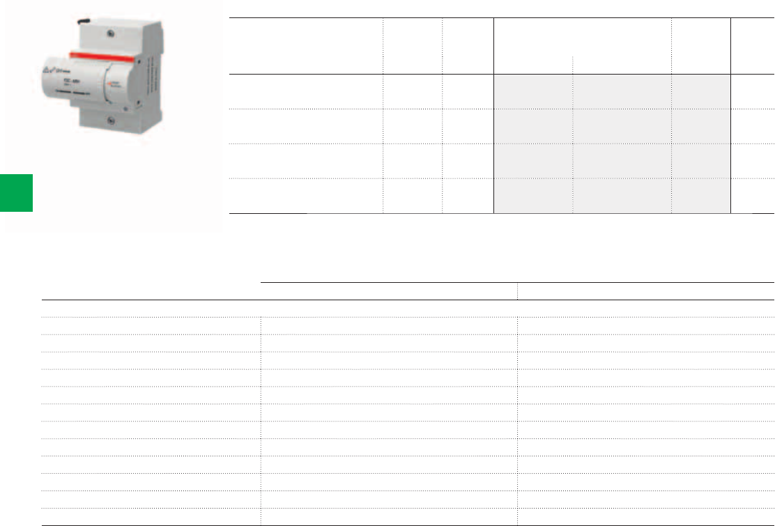
2CSC400030F0125
F2C-ARH
4/6 2CSC 400 031 D0202 | System pro M compact®
4
Ordering Information
F2C-ARH, F2C-ARH-T
F2C-ARH, F2C-ARH100 F2C-ARH-T, F2C-ARH-T100
Technical details
Power supply 230 V a.c. (-15% / +10%) 230 V a.c. (-15% / +10%)
Number of automatic reclosing attempts 1 1
Reset time for counter of automatic reclosing attempts 12 sec 12 sec
Power consumption during operation (t<0.5s) 20VA max (t<0.5s) 20VA max
Power consumption when idle 0.4W max 0.4W max
Number of operations ≤ 10,000 ≤ 10,000
Operating temperature -25 ... + 55 °C -25 ... + 55 °C
Signalling contact cable section ≤ 2.5 mm2≤ 2.5 mm2
Type of RCCB compatible FH202-F202 30mA/100 mA (depending on version), up to 63A FH202-F202 30mA /100 mA (depending on version), up to 63A
Locked state signalling contact (terminals 1-2) 1NO (change-over) 1NO (change-over)
Rated current of locked state contact 3A (250 V a.c.) 3A (250 V a.c.)
Autotest of the residual current circuit-breaker NO YES
Description N° module Bbn
8012542
Order details Weight
1 piece
[17.5 mm] EAN Type code Order code Price Kg
Auto-reclosing device
for 30 mA 2P RCCBs
3 732433 F2C-ARH 2CSF200992R0005 0.200
Auto-reclosing device
for 100 mA 2P RCCBs
3 658535 F2C-ARH100 2CSF200990R0005 0.200
Auto-reclosing device with automatic
test for 30 mA 2P RCCBs
3 733232 F2C-ARH-T 2CSF200991R0005 0.200
Auto-reclosing device with automatic
test for 100 mA 2P RCCBs
3 593836 F2C-ARH-T100 2CSF200989R0005 0.200
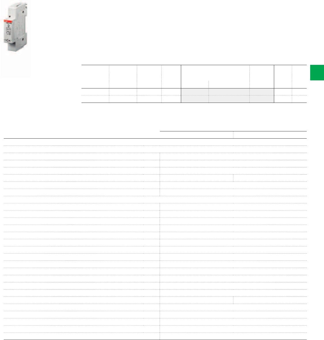
2CSC400030F0126
E 451-5,7A
System pro M compact® | 2CSC 400 031 D0202 4/7
4
Ordering Information
E 450 priority switches
The priority switch is used in wiring systems where existing lead cross sections or the size of
the power supply service box do not allow for simultaneous operation of two powerful loads
(e.g. storage heating and flow-type heater).
The priority switch disconnects the long-term load (storage heating) for as long as the short-
term consumer (flow-type heater) is switched on.
The coil of the priority switch is connected in series to the short-term load. When this load
is switched on, the NC contact of the priority switch disconnects e.g. the heating system
contactor.
E 451-5.7 E 452-5.7
Technical details
Operating coil
Range of rated current 6.7 … 39 A
equivalent to 1.5 … 9 kW at 230 V, 4.6 … 27 kW at 230/400 V
Threshold current 3.1 … 5.3 A
OFF delay (max.) 0 main half waves 2 main half waves
Max. continuous current 43 A
Therm. continuous capacity at 40 °C/104 °F 5 W
Contact assembly
Control contact 1 NC contact
Rated contact current at 250 V 1 A
Contact material solid silver
Max. switching voltage 400 V
Max. switching capacity 230 VA
Max. switched current 1 A
Max. inrush current peak 5 A
Electr. service life > 105 operations
Mechanical service life ca. 2 x 10⁶ operations
Max. electrical switching rate ca. 1800 operations/hour
ON duration 100 %
Ambient temperature – 20 °C/– 4 °F to + 40 °C/104 °F
Response time 10 … 20 ms
Release time 5 … 20 ms ≥ 20 ms
Test voltage contact/coil 2.5 kV
Clearance and creepage distance C/250 V AC cording to IEC 669-1-23
Degree of protection IP 40
Protection against electric shock according to DIN VDE 0106 Part 100 (BGV A2)
Terminal contact series coil up to 16 mm2, control contact up to 2.5 mm2
Rated
current
range
Power
loss
N° module Bbn
4016779
Order details Weight
1 piece
Pack
unit
W [17.5 mm] EAN Type code Order code Price Kg
6,7 ... 39 A 2.4 1 415903 E 451 - 5.7 A 2CDE160000R0901 0.1 10
6.7 ... 39 A 2.4 1 209502 E 452 - 5.7 A 2CDE160010R0901 0.1 10
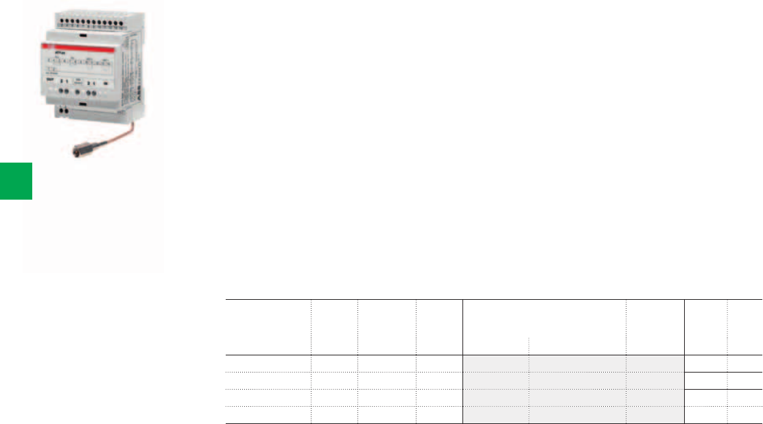
2CSC400030F0127
ATT-22
4/8 2CSC 400 031 D0202 | System pro M compact®
4
Ordering Information
ATT GSM modules
The ATT modules are GSM telephone actuators for remotely controlling electrical loads
over the mobile phone network, which answer the installation requirements of a variety of
application settings.
In particular, the ATT-22 version consists of a control module with 2 outputs and 2 inputs for
residential, services-sector and industrial installations, while the ATT-81 alarm module, with 8
inputs and one output, is suitable for status and alarm monitoring in industrial and services-
sector installations.
Instructions and alarms can be sent via SMS message, free phone call ring, fax or e-mail
according to need. Configuration can be accomplished by SMS messages or using the
ATT-Tool software.
All the ATT modules are supplied with backup lithium battery, ATT-Tool programming software
and PC connecting cable. In addition, the ATT-22E and ATT-81E models are equipped with a
pre-wired external antenna – essential if the module is installed in locations that do not assure
adequate GSM coverage, such as cellars, enclosed metal structures, etc.
The modules can be supplied with an ABB type TS 25/12-24 C modular transformer and are
compatible with the GSM SIM cards of all mobile telephone operators.
Inputs Outputs N° module Bbn
8012542
Order details Weight
1 piece
Pack
unit
[17.5 mm] EAN Type code Order code Price Kg
2 analog or digital 2 NO 4 944904 ATT-22 2CSM322000R1371 0.200 1
8 digital 1 NO 4 945000 ATT-81 2CSM381000R1371 0.200 1
2 analog or digital 2 NO 4 083450 ATT-22E 2CSM208345R1371 0.200 1
8 digital 1 NO 4 083559 ATT-81E 2CSM208355R1371 0.200 1

System pro M compact® | 2CSC 400 031 D0202 4/9
4
ATT-22
Technical details
GSM module Dual band EGSM900 and GSM1800 for data, sms, fax and voice applications.
Full Type Approved conforming to ETSI GSM Phase 2+
Output power Class 4 (2 W@900 MHz )
Class 1 (1 W@1800 MHz )
Commands sent by SMS, call rings, DTMF tones, GPRS connection
Incoming alarms SMS, call rings, e-mail, fax
Inputs digital self-powered max. 20 V DC, 2 mA
analog (only ATT-22) input voltage 0...10 V
input impedance < 10 Kohm / 100 nF
sampling rate 90 Ksps
Outputs relay NO 4 A 250 V AC - max 2500 VA
minimum load 100 mA, 12 V
GSM indicator LED OFF device not supplied
STEADY ON device under power not connected to mobile network, SIM pin code missing or incorrect
SLOW BLINK device under power, connected to mobile network
FAST BLINK communication in progress
Power supply [V] 12 ±10% AC/DC
Power consumption when transmitting [W] 2.5
in stand-by [W] 0.4
Terminal section 2.5 mm2
Temperature ambient [°C] -20...55
storage [°C] -30...85
Relative humidity ambient 5...95% non condensing
storage 5...95% only external condensation
Modules 4
Protection degree IP40
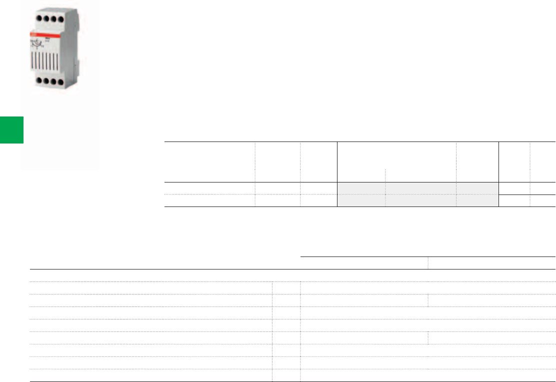
2CSC400030F0128
RAL6
4/10 2CSC 400 031 D0202 | System pro M compact®
4
Ordering Information
RAL overload relays
Installed downstream of the main circuit-breaker in a single-phase system, they constantly
compare the actual power consumption to the preset threshold. An acoustic alarm alerts that
some appliances must be switched off to avoid tripping the main circuit-breaker whenever the
preset threshold is exceeded. The device calibration is 3 kW.
RAL built in relay output contact allows the following functions to be implemented:
a) remote signalling (acoustic or lighting)
b) opening a divisional circuit-breaker to disable a non essential electrical appliance.
Function b) allows one or more appliances to be automatically switched off in order to keep
the power consumption within the preset limit and avoid unwanted tripping of the current-
limiting device installed outside the home (e.g. in the basement). RAL must be reset manually.
RAL3 RAL6
Technical details
Rated voltage Un[V] AC 230
Rated current In[A] 18.3 27.5
Rated contact capacity In[A] 12 cosϕ=1; 4 cosϕ=0.8
Rated frequency [Hz] 50
Adjustment ranges [A] 0...18.3 0…27.5
Power consumption [W] 10
Modules [No.] 2
Intervention delay instantaneous
Adjustable
range
N° module Bbn
8012542
Order details Weight
1 piece
Pack
unit
kW [17.5 mm] EAN Type code Order code Price Kg
0/3 2 400509 RAL 3 2CSM111200R1301 0.200 6
0/6 2 400608 RAL 6 2CSM121200R1301 0.200 6
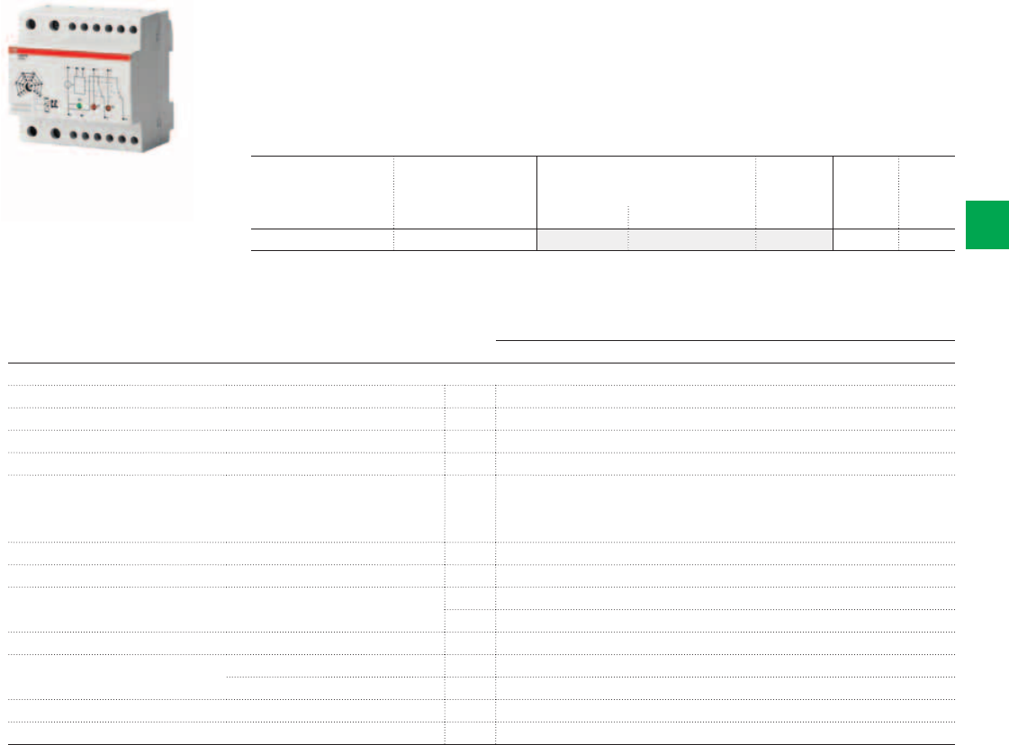
2CSC400030F0129
LSS1/2
System pro M compact® | 2CSC 400 031 D0202 4/11
4
Ordering Information
LSS1/2 load shedding switch
Installed downstream of the main circuit-breaker, it compares the actual power consumption
of the system to a preset maximum permitted value, and prevents tripping of the main circuit-
breaker by sequentially switching off a maximum of two non-prioritary loads (NPL1 and NPL2)
when the preset threshold is exceeded. A green LED indicates the presence of the supply
voltage, and two red LEDs indicate the load OFF conditions. At preset time intervals, the
device automatically attempts to reconnect the previously disabled loads.
LSS1/2
Technical details
Rated voltage Un[V] a.c. 230
Rated capacity In[A] 90
Rated contact capacity In NPL1 and NPL2 [A] 16 each (terminals 12 and 14)
Rated frequency [Hz] 50/60
Regulating thresholds [A] 5...30
10...60
15...90
Load reinsertion delay 5-7 min. (NPL1); 4-5, 50 min. (NPL2)
Load disinsertion delay about 2 sec.
Indicators 1 green LED = supply voltage available
2 red LEDs = loads switched off
Load OFF remote signalling [A] 1 (terminals 11 and 13)
Terminals Primary load 35 mm2
Non prioritary loads 10 mm2
Power consumption [W] 5
Modules [No.] 5
N° module Bbn
8012542
Order details Weight
1 piece
Pack
unit
[17.5 mm] EAN Type code Order code Price Kg
5 274407 LSS1/2 2CSM112500R1311 0.400 1
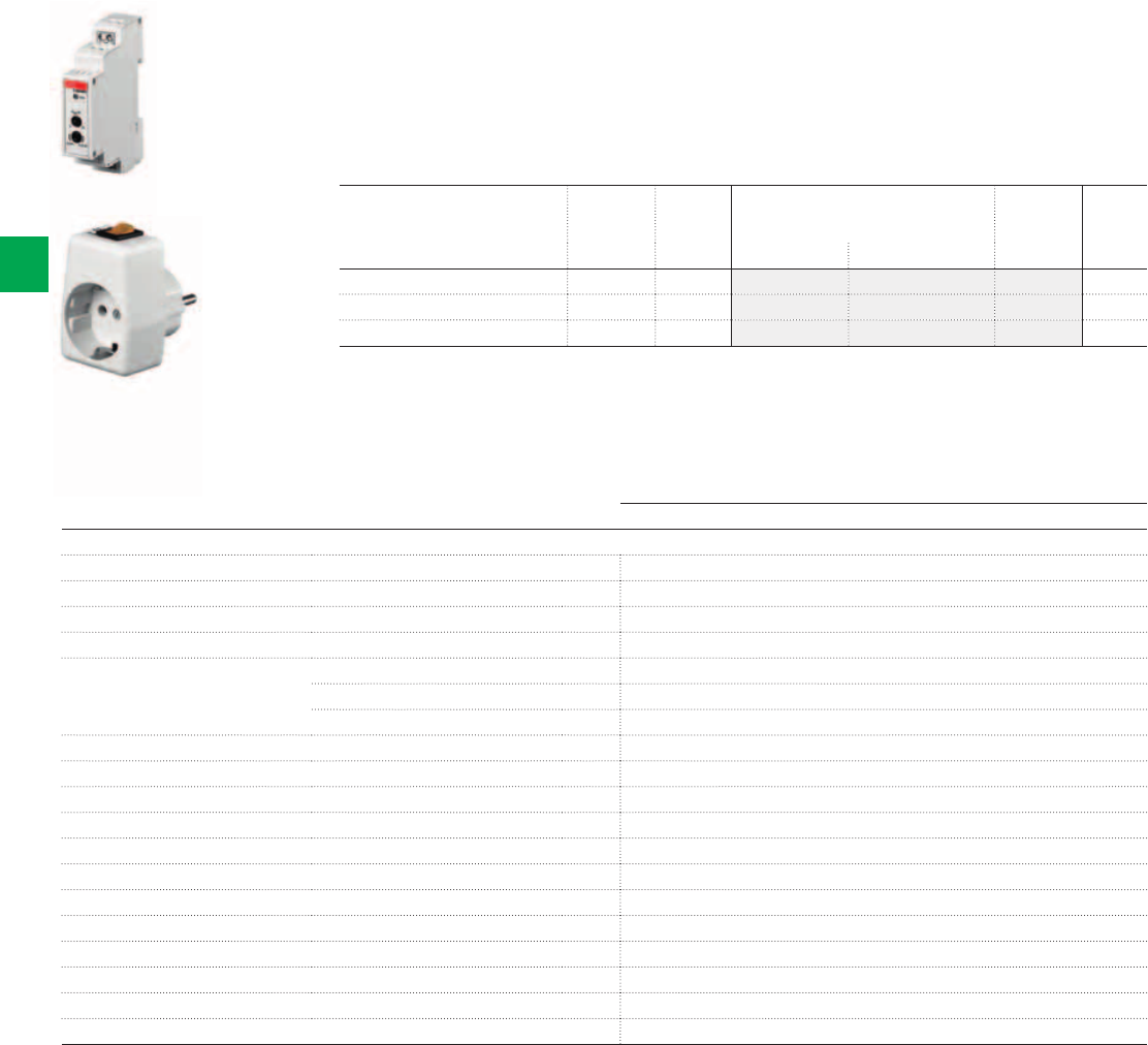
2CSC400030F0130
2CSC400030F0131
E 235-NFS
E 235-GLA
4/12 2CSC 400 031 D0202 | System pro M compact®
4
Ordering Information
E 235 mains disconnection relays - Bioswitch
Constant exposure of electrical interference fields originating from live conductors - as is the
case e.g. in bedrooms - may impair the well-being of people, experts say.
With the extra base load adapter E235-GLA, the mains disconnection relays can be switched
on manually.
For the permanent installation of loads that switch on independently of the supply voltage,
such as fluorescent lamps, a E235-GLE PTC base load element is available.
E 235
Technical details
Short circuit rupturing capacity 16 A/230 V AC
Rated frequency 50/60 Hz
Range of control voltage 0.9 to 1.1 Un
Load of filament lamps 2300 W
Fluorescent lamp load: twin lamp circuit 100 W
shunt compensated 56 W
electronic ballast max. 36 W, dependent on manufacturer
Induce load 6 A cosϕ = 0.6
Max. switching capacity (cosϕ 0.5) 3500 VA
Intrinsic consumption ca. 1 W
Control voltage 5 V AC
Adjustable making capacity 2 - 15 VA
Breaking capacity 0.66 x making capacity
ON delay 50 ms
OFF delay ca. 3 sec.
Contact assembly 1 NO contact
Service life at rated load > 100000 switching cycles
Ambient temperature - 10 °C/14 °F to +45 °C/113 °F
Connection capacity (clamping terminal) max 2.5 mm2
Description N° module Bbn
4016779
Order details Weight
1 piece
[17.5 mm] EAN Type code Order code Price Kg
mains disconnection relay 1 571821 E 235-NFS 2CDE110000R1701 0.065
base load element 1 571814 E 235-GLE 2CDE100500R1711 0.001
base load adapter 1 571869 E 235-GLA 2CDE100510R1711 0.070
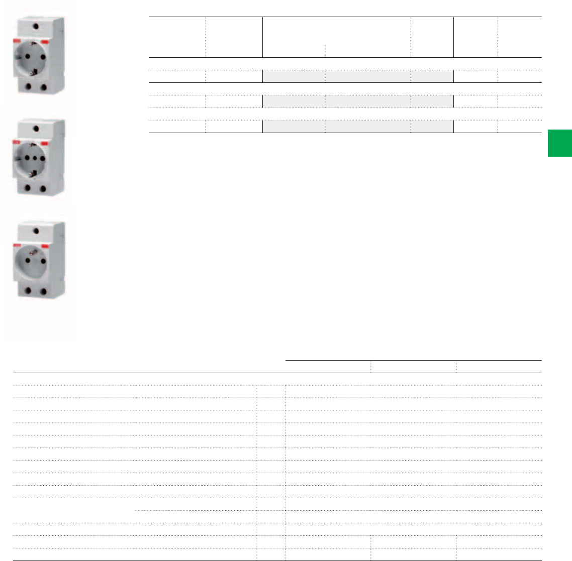
2CSC400030F0132
2CSC400030F01332CSC400030F0134
M1175
M1173
M1174
System pro M compact® | 2CSC 400 031 D0202 4/13
4
Ordering Information
Socket Outlets
M1175 M1174 M1173
Technical details
Rated voltage Un[V] 250 AC
Rated current In[A] 16 (M1170, M1173, M1174, M1175),
Rated frequency [Hz] 50/60
Power loss [W] 0,6
Modules [No.] 2.5
Safety shutters yes, on entire range
Terminal type positive safety
Cable section (ø min./max.) [mm2] 2.5 / 16
Tightening torque [Nm] 1.2
Temperature storage [°C] -40 … +70
operating [°C] -25 … +35
Protection degree IP20
Reference standards DIN VDE 0620-1 NF C 61 303 CEI 23-50
Approvals VDE, GOST LCIE, CEBEC, GOST IMQ, GOST
N° module Bbn
8012542
Order details Weight
1 piece
Pack
unit
[17.5 mm] EAN Type code Order code Price Kg
German Shuko standard modular sockets
2.5 027850 M1175 2CSM210000R0721 0.120 4
Italian P30 standard modular sockets
2.5 004103 M1173 2CSM110000R0701 0.120 4
French standard modular sockets
2.5 006602 M1174 2CSM110000R0711 0.120 4
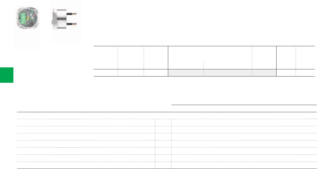
2CSC400030F0135
2CSC400030F1135
LEE 230
4/14 2CSC 400 031 D0202 | System pro M compact®
4
Ordering Information
LEE 230 extractable power failure signalling lamp
The LEE 230 lamp is an automatic electronic lamp that can be installed in any modular socket
or wiring accessory socket conforming to the German VDE Schuko standard (e.g. ABB M1173
or M1175), to the Italian standard P11 10A, or to the 10/16 A italian dual standard.
The device functions both as a power failure signalling lamp and as a lighting device, to be
used for example during maintenance activities or when seeking faults in the panel.
LEE 230
Technical details
2P 10 A plug distance between pins 19 mm, pin ø 4 mm
Supply [V] 230 AC, 50-60 Hz
Recharge time [h] 24
Endurance [h] 3
Lighting level [mcd] 3000
Operating temperature [°C] 0…+45
Min. life cycle 5 years (battery)
Additional technical features
LEE-230 lamp automatically switches on when the voltage fails; the built-in rechargeable battery guarantees the supply.
It is particularly useful thanks to its construction and functional characteristics:
- it can be extracted from the socket and used as a torch with ON-OFF button on its frontal side
- when necessary it can work with standard sockets
- it can be moved when it is needed
- it has a long operation endurance, up to three hours
- it is ready to use, it does not require installation
- with a screw (ø 3.5 mm, L 16 mm) it is possible to fix it preventing the extraction from the M1173 ABB sockets with central
hole
- the projecting part of the Schuko profile is very small (8 mm).
The two LEDs placed on the frontal side of the lamp indicate its operation condition:
- the red LED indicates the recharge activity and that, in the case of a network voltage back-out, the lamp will remain off
- the green LED indicates the recharge activity and that, in the case of a network voltage black-out, the lamp will switch on
(it will automatically switch off when the voltage returns).
By pushing the frontal pushbutton it is possible to change the status; if you do not use the lamp for a prolonged time it is
suggested to set the first condition in order to preserve the battery life.
Pack N° module Bbn
8012542
Order details Weight
1 piece
Pack
unit
[17.5 mm] EAN Type code Order code Price Kg
Blister - 507406 LEE 230 2CSM111000R1361 0.100 1
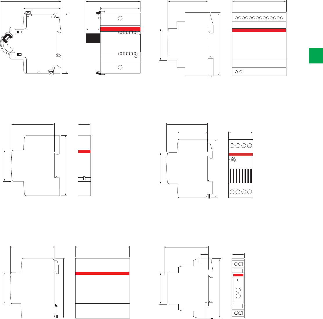
80.5 70.05
53
19.05
50.3
85
58 71
45
90
60 17.5
45
85
1
2
3
58
44 35
45
85
2 modules
58 87.5
45
85
5 modules
58
17.512
45
85
System pro M compact® | 2CSC 400 031 D0202 4/15
4
Overall dimensions
F2C-ARH, F2C-ARH-T ATT
E 450 RAL
LSS1/2 E 235
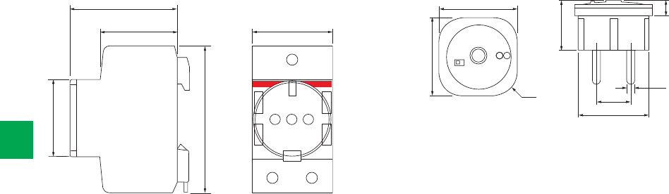
42.5
Ø 38
19
Ø 4
R1
42.5
27
8.5
60
44 44
2.5 modules
45
85
4/16 2CSC 400 031 D0202 | System pro M compact®
4
Overall dimensions
M1175, M1174, M1173 sockets LEE 230

System pro M compact® | 2CSC 400 031 D0202 5/1
5
Introduction 5/2
Plus of range 5/4
Technical features 5/6
Ordering information
EQ meters C11 5/8
EQ meters A41 5/9
ODIN 5/10
EQ meters A43 5/11
Communication adapters 5/12
AT electro-mechanical time switches 5/14
D Line digital time switches 5/15
E 232 staircase lighting time-delay switches 5/16
TW modular twilight switches 5/18
TWP pole mounting twilight switch 5/19
TWA twilight astronomical switches 5/20
E 233 electro-mechanical hour counters 5/21
VLMD, AMTD digital instruments with alarm relay 5/22
Overall dimensions 5/23
Energy efficiency
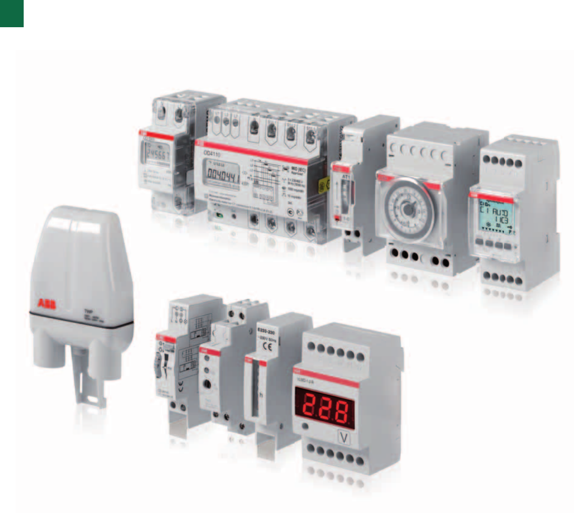
5/2 2CSC 400 031 D0202 | System pro M compact®
5
Energy savings, safety gains
ABB for energy efficiency
ABB is a leading producer of low-voltage devices for commercial and residential
building sector. Its complete offering that can help to achieve significant reduction
of energy budget through an accurate monitoring and control of every parameter
of the building: heating temperature, lighting, energy consumption of electric
appliances can be adapted to actual needs, with a substantial saving potential
without compromising comfort, safety or quality of life.
System pro M compact® | 2CSC 400 031 D0202 5/3
5
Commercial and residential buildings account for a big part
of global end-user energy demand. ABB systems that can
help to achieve savings through an accurate monitoring
and control of electric loads such HVAC systems, lighting
installations and appliances.
The modular DIN rail electricity meters of ABB’s portfolio offer
a wide range of programmable functions useful to measure
electricity consumption and reduce energy costs. The line
of DIN-mounted electricity meters and the wide range of
communication adapters offer an ideal solution for every
application.
Control loads operations in a system improves functionality
and optimize power consumption. Programming the control of
electric appliances according to the needs of each application
obtains measurable advantages in terms of comfort and
reduction of power wastage.
The range of ABB’s modular analogue and digital time
switches includes several functions that guarantee the
opening and closing of electrical circuits according to a
scheduled program. AT analogue time-switches are available
in both daily and weekly versions, with 16 A contact which
can be operated according to a timing program. Some
versions are equipped with a built-in battery, generally
charged by the network voltage, which enables them to
maintain the timing function even in case of lengthy power
supply failures.
DT digital time switches ABB are equipped with a permanent
EEPROM memory to ensure that the scheduled timing is
followed and the date and hour settings are maintained even
in case of power down. The range, used for both daily and
weekly programming, includes single/double channel versions
with a change-over contact and a switching capacity of 16
or 10 A. Some time switches can be combined with DT-DCF
antenna for automatic synchronization with Frankfurt official
time. New features include a holiday mode that allows forcing
of the ON-OFF output for a certain period, a random mode
used to simulate event presence, and a waiver mode to carry
out waivers remotely or locally.
Rationalization of the light consumption is very important.
To command the lighting in stairs of buildings, ABB offers
the time-delay switch E 232. The switch includes an electro-
mechanical timer with a synchronous motor drive to ensure
high operational safety in whatever mounting position. The
time range is adjustable in increments of 15 seconds from
1 to seven minutes. Devices include an integrated warning
feature (warning by blinking) according to DIN 18015-2 as well
as a 60 minute long-time function.
For lamps control, ABB’s TW modular twilight switches allow
to switch on and off lighting devices according to a scheduled
level of ambient light. They are used in combination with
a sensor to detect if the ambient light is higher or lower
than the set level. TW2/10K, equipped with three different
types of adjustment range (2:100, 2:1000, 2:10000), fits the
daylight applications where Lux values are very high. This
range addresses all applications, for example shop windows,
parking areas and so on.
Hour counters – as E 233 series – offer a very important
function for energy budget improvement. They are used to
record operating times as well as to determine idle times
and off times of electric loads in commercial or domestic
installations, with an immediate feedback on energy
consumption.
In terms of energy quality, modular digital instruments of
VLMD and AMTD series measure voltage, current and
frequency. The range is composed by a voltmeter for a.c./d.c.
voltage monitoring, ammeter for a.c./d.c. currents, and
frequency meter. Ammeters measure in indirect insertion
thanks to measuring accessories, like current transformer for
a.c. and shunt for d.c. The full scale is programmable by the
user.
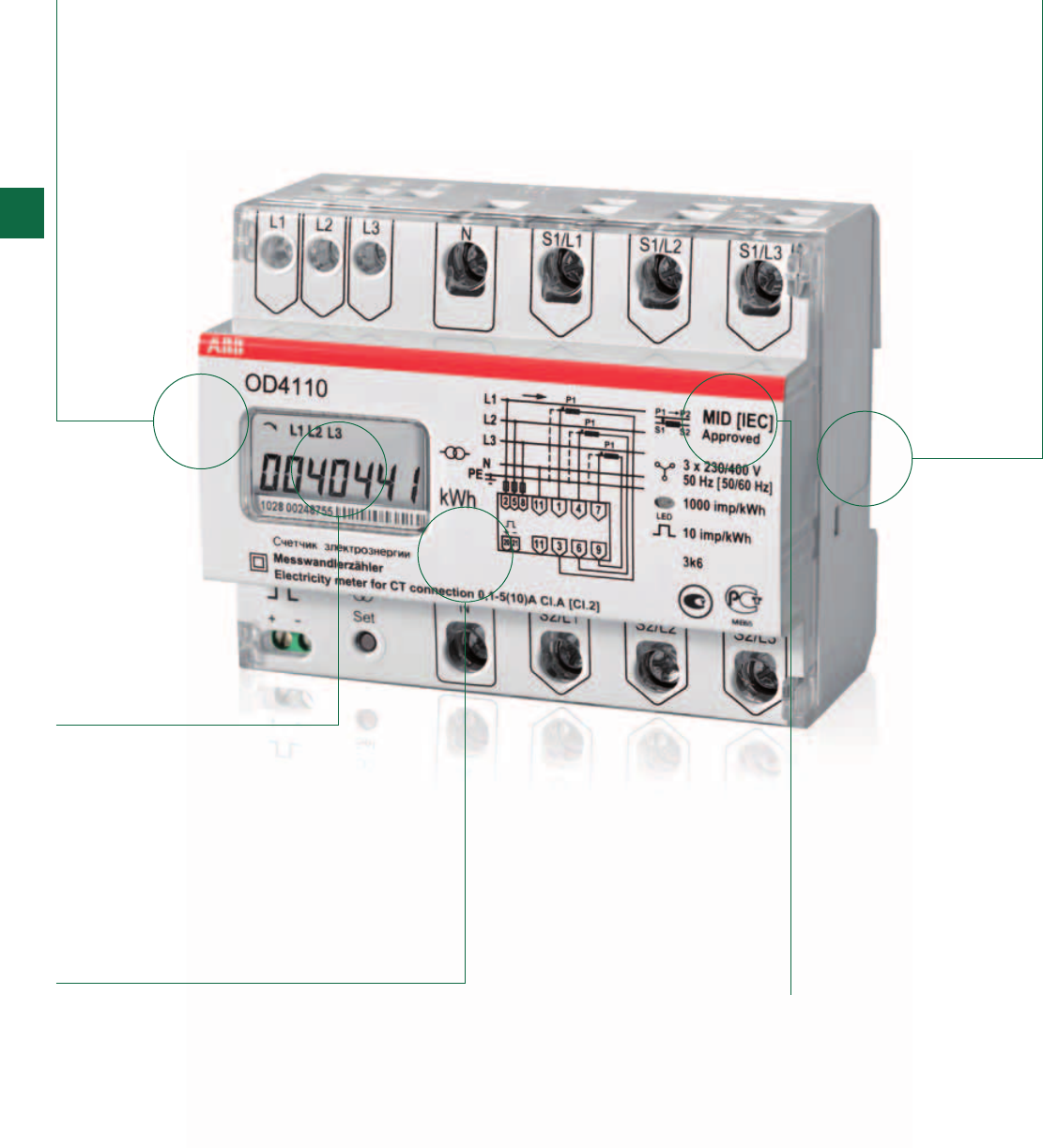
5/4 2CSC 400 031 D0202 | System pro M compact®
5
Electricity meters
The details make the difference
MID approved
“annex B and D”
LCD display
Infrared port for
communication
between
communications
adapter and meter
Wide temperature
range
DIN rail mounted
and pro M design
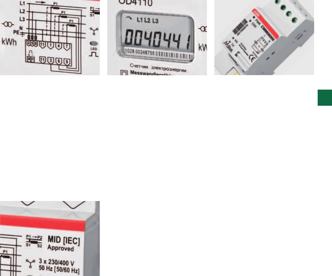
System pro M compact® | 2CSC 400 031 D0202 5/5
5
The DIN rail mounted electricity meters
are available in two product families:
ODINsingle and EQ meters C11
and A41 for single phase metering
and EQ meters A43 three phase
metering. The meters are available in
several configurations to suite many
applications.
EQ meters A-series have a pixel-
oriented display that shows the values
clearly and is easy to navigate through
the menu. Due to compact desigen of
the meters, only 1 to 7 modules, space
will be saved at installation. The meters
have a temperature range from -40 °C
to +70 °C (storage +85 °C).
MID – Measuring Instrument Directive
- means common testing rules based
on IEC standards for all EU and EES
countries.
You find a label certifying that the ABB
electricity meter is tested and approved
according to MID directive.
The EQ meters A-series, ODINsingle
and ODIN meters offer flexible solutions
for communication with in-built
communcation, standard pulse output
and/or infrared (IR) port. The IR port
can be connected to any of the Serial
Communication Adapters (SCA)
avavilable. Due to open protocols and
the possibility to add a SCA later the
installation is flexible and adaptable to
any future communication needs.The
Serial Communication Adapter (SCA)
enables serial data communication
between the electricity meter and an
Automatic Meter Reading system (AMR).
5/6 2CSC 400 031 D0202 | System pro M compact®
5
Technical features table for electricity meters
EQ meters and ODIN
C11 ODINsingle
Technical Data
Single phase Yes Yes
Three phase 3 wire (TPE) N/A N/A
Three phase 4 wire (TPE+N) N/A N/A
Accuracy class MID [IEC] B [1] B [1]
Internal clock N/A N/A
Voltage 230 VAC 230 V
Frequency 50/60 Hz 50/60 Hz
Active energy Yes Yes
Reactive energy N/A N/A
Tariffs 1 1
Pulse output Yes Yes
Built-in communication N/A IR
Width, DIN modules 1 2
Direct connected Yes Yes
Imin 0,25 A 0,25 A
Iref 5 A 5 A
Imax 40 A 65 A
Ist < 20 mA 20 mA
Power consumption Current circuits 0,02 W 0,004 VA, 0,004 W
Power consumption voltage circuits < 0,8 VA, 0,2 W 1,0 VA, 1,0 W
Transformer connected*) N/A N/A
Imin N/A N/A
InN/A N/A
Imax N/A N/A
Ist N/A N/A
Max transformer ratio N/A N/A
Power consumption Current circuits N/A N/A
Power consumption voltage circuits N/A N/A
Tariff control N/A N/A
Instrumentation values Yes N/A
I/O N/A N/A
Previous values N/A N/A
Max Demand N/A N/A
Load profiles N/A N/A
Harmonics N/A N/A
*) For ABB current/voltage transformers range, please see System pro M compact® catalogue 2CSC400002D0209
2CSC400030F0136
2CSC400030F0140
System pro M compact® | 2CSC 400 031 D0202 5/7
5
A41 ODIN A43
Yes N/A Yes
N/A N/A Yes
N/A Yes Yes
B [1] A [2] B [1]
Yes N/A Yes
57,7 - 288 VAC 230/400 3x57,7-288/100-500 VAC
50/60 Hz 50/60 Hz 50/60 Hz
Yes Yes Yes
Yes N/A Yes
41 4
Yes Yes Yes
IR, Modbus, M-bus IR IR, Modbus, M-bus
46 7
Yes Yes Yes
0,25 A 0,25 A 0,25 A
5 A 5 A 5 A
80 A 65 A 80 A
< 20 mA 25 mA < 20 mA
0,007 VA, 0,007 W 0,004 VA, 0,004 W per phase 0,007 VA, 0,007 W
0,8 VA, 0,8 W 0,9 VA, 0,9 W per phase 0,8 VA, 0,8 W
N/A CT N/A
N/A 0,1 A N/A
N/A 5 A N/A
N/A 10 A N/A
N/A 15 mA N/A
N/A 900/5 N/A
N/A 0,004 VA, 0,004 W per phase N/A
N/A 0,9 VA, 0,9 W per phase N/A
I/O, internal clock, communication N/A I/O, internal clock, communication
Yes N/A Yes
2 fixed inputs, 2 fixed outputs N/A 2 fixed inputs, 2 fixed outputs
Day, week, month N/A Day, week, month
1,…, 1440 min interval N/A 1,…, 1440 min interval
1,…, 1440 min interval N/A 1,…, 1440 min interval
N/A N/A N/A
2CSC400030F0141
2CSC400030F0138
2CSC400030F0143

2CSC400030F0140
C11
5/8 2CSC 400 031 D0202 | System pro M compact®
5
Ordering Information
EQ meters C11
The C11 is a very compact single phase meter for direct connected applications up to 40 A.
The small size and the DIN rail mounting makes it suitable for installation in distribution boards
and small standard enclosures. The power consumption of the meter is very low, less than
0.8 VA (0.2 W).
Main characteristics include:
- Single phase metering
- Active energy, accuracy class B (Cl. 1)
- Direct metering up to 40 A
- LCD display
- Pulse output or alarm
- IEC and MID type approval
EQ meters C11 has an LCD with large digits on a vertical line and small digits on a horizontal
line below. Due to the compact design of the meter, only 1 module, space will be saved at
installation. The meter has a wide temperature range which makes it possible to install the
meter in many locations, - 25°C - +70°C (storage - 25°C - +80°C).
Navigating the meter is easily done via the push-button below the display. The C11 meters
support reading of instrument values. A number of electrical properties can be read:
- Power factor
- Active power
- Current
- Voltage
C11 has one output that could be used as pulse output or as an alarm output.
The C11 is tested and approved according to different standards. These
standards cover technical aspects of the meter such as climate conditions, electromagnetic
compatibility (EMC), electrical requirements, mechanical requirements and accuracy.
N° module Bbn
7392696
Order details Weight
1 piece
Pack
unit
[17.5 mm] EAN Type code Order code Price Kg
1 705509 C11 110-300 2CMA170550R1000 0.070 1
2CSC400030F0141
A41
System pro M compact® | 2CSC 400 031 D0202 5/9
5
Ordering Information
EQ meters A41
EQ meters A41 is an advanced single phase electricity meter for active energy. It is designed
for installation on a DIN rail in distribution boards and small enclosures. Key product features
are internal clock for tariff handling and direct metering up to 80 A.
Main specifications are:
- Single phase measuring
- Active energy, accuracy class B (Cl. 1)
- Measure import/export energy
- Direct metering up to 80A
- Pixel-oriented display
- In-built M-bus or Modbus, pulse output and IR for SCA
- Internal clock for up to 4 tariffs and monthly values
- Memory back-up (EEprom)
- IEC and MID approval
This active energy, single phase meter for direct metering up to 80 A is equipe with a pixel-
oriented display which allows for showing values clearly together with instrumentation values
and a easy navigated manu system. The meter has a compact design, only 4 modules
(72 mm) that saves space in the installation. In the case of a power failure, the meter is
equipped with a “Super Cap” power backup capacitor that will run the clock for 48 hours
at +20˚ C. A red LED (Light Emitting Diode) on the front flashes proportionally to the energy
consumed. The operating temperature range is from –40 to +70º C (storage +80º C).
EQ meters A41 has 4 ways to communicate depending on type
- In-built M-bus or Modbus (RS485)
- IR interface for serial communcation (together with the serial communication adapter)
- Pulse output
- Front display
It is possible to choose information shown on the display and change the settings in the meter
using the push buttons. The push button used for changing settings can be sealed. The EQ
meters A41 includes up to 4 tariffs options which can be changed by inputs, communication
or internal clock. All EQ meters A41 are tested and approved according to different standards.
These standards covers all technical aspects of the meter such as climate conditions,
electromagnetic compatibility (EMC), electrical requirements, mechanical requirements as well
as accuracy.
N° module Bbn
7392696
Order details Weight
1 piece
Pack
unit
[17.5 mm] EAN Type code Order code Price Kg
4 705059 A41 412-100 2CMA170505R1000 0.230 1
4 705066 A41 413-100 2CMA170506R1000 0.230 1
2CSC400030F0142
OD4165
OD1065
2CSC400030F0136
5/10 2CSC 400 031 D0202 | System pro M compact®
5
Ordering Information
ODIN and ODINsingle
Basic 3-phase ODIN Meter is an electricity meter in a compact format designed to measure
active energy and for mounting on a DIN rail. It is suitable for use in distribution boards and
standard cabinets.
ODIN meter is an active energy, 3-phase meter for up to 65A or transformer connected up to
10 A secondary.
The LCD display (Liquid Crystal Display) has 7 digits, 6 mm high and reports information such
as phase, load or transformer ratio.
The compact design, only 6 modules, saves space in the installation.
Selection of the transformer ratio is easily achieved by using the push button on the front.
The programming / push button can be sealed.
N° module Bbn
7392696
Order details Weight
1 piece
Pack
unit
[17.5 mm] EAN Type code Order code Price Kg
6 310246 OD4165 2CMA131024R1000 0.420 1
6 310253 OD4110 2CMA131025R1000 0.450 1
ODINsingle is a compact, single phase electricity meter for direct connection up to 65 A. The
small size and the DIN rail mounting makes it suitable for installation in distribution boards and
small standard enclosures.
Main characteristics include:
- Single phase measuring
- Active energy, accuracy class B (Cl. 1)
- Direct metering up to 65A
- LCD display, Pulse output and IR for SCA
- IEC and MID approval
N° module Bbn
7392696
Order details Weight
1 piece
Pack
unit
[17.5 mm] EAN Type code Order code Price Kg
2 310406 OD1065 2CMA131040R1000 0.100 1
2 310413 OD1310 2CMA131041R1000 0.100 1
ODIN and ODINsingle has three ways to communicate:
- Front backlit LCD display
- IR interface for serial communication (together with a Serial Communication Adapter)
- Pulse output.
The ODIN and ODINsingle types are tested and approved according to different standards.
These
standards cover technical aspects of the meter such as climate conditions, electromagnetic
compatibility (EMC), electrical requirements, mechanical requirements and accuracy.
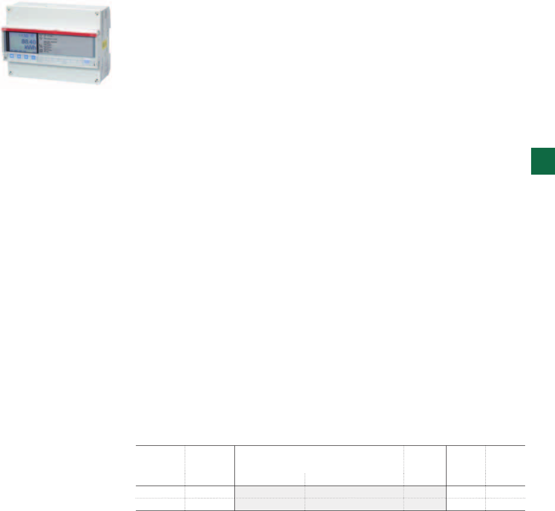
2CSC400030F0143
A43
System pro M compact® | 2CSC 400 031 D0202 5/11
5
Ordering Information
EQ meters A43
The EQ meters A43 is an advanced four quadrant meter for installation in three phase
networks. The meter is mounted on a DIN rail and is suitable for installation in distribution
boards and small enclosures such as consumer units. The meter measures (active and
reactive) energy. The product supports a wide voltage range and a wide temperature range
which makes it suitable for installation in many applications.
EQ meters A43 has a in-built clock function for controlling tariffs, save monthly values, and
demand functionality. It is also used to log events with a time stamp for easy learn what
have happend and when. All values can easily be read on the large pixel-oriented display
together with the eady navigated menu system. The meter has a LED on the front that flashes
proportionally to the measured energy. The energy consumption of the meter is very low, only
0.8 VA.
Data from EQ meters A43 is collected via pulse output or serial communication. The pulse
output is a polarity independent solid state relay that generates pulses proportionally to the
measured energy. EQ meters A43 can be equipped with a built-in communication interface for
M-bus or Modbus (RS485). All EQ meters A43 come with an infrared port for communication
with an external Serial Communication Adapter (SCA). There are SCAs for M-Bus, RS-232,
Ethernet and GSM/GPRS.
The EQ meters A43 can handle up to 4 tariffs which could be controlled via internal clock, via
communication or through inputs.
Through the instrumentation functionality of EQ meters A43 can be read electrical properties
such as active power, apparent power, reactive power, current, voltage, frequency, power
factor, active quadrant, and much more.
EQ meters A43 supports four fixed I/O’s, two inputs and two outputs. Outputs can be used for
controlling external apparatus like a contactor or an alarm (max 100 mA). Inputs can be used
for counting pulses from e.g. a water meter, or for reading status from external devices.
The configuration of EQ meters A43 is very simple. Using the push bottons you can configure
transformer ratio, pulse frequency, M-Bus address and baud rate when applicable.
The settings button is under a sealable cover. When sealed, meter values can still be read but
no configuration is possible. EQ meters is type approved according to IEC and it is both type
approved and verified according to MID. MID is the Measuring Instruments Directive
2004/22/EC from the European Commission. MID type approval and verification is mandatory
for meters in billing applications within EU and EEA.
The type approval is according to standards that covers all relevant technical aspects of
the meter. These include climate conditions, electromagnetic compatibility (EMC), electrical
requirements, mechanical requirements and accuracy.
N° module Bbn
7392696
Order details Weight
1 piece
Pack
unit
[17.5 mm] EAN Type code Order code Price Kg
7 705288 A43 412-100 2CMA17528R1000 0.440 1
7 705295 A43 413-100 2CMA170529R100 0.440 1
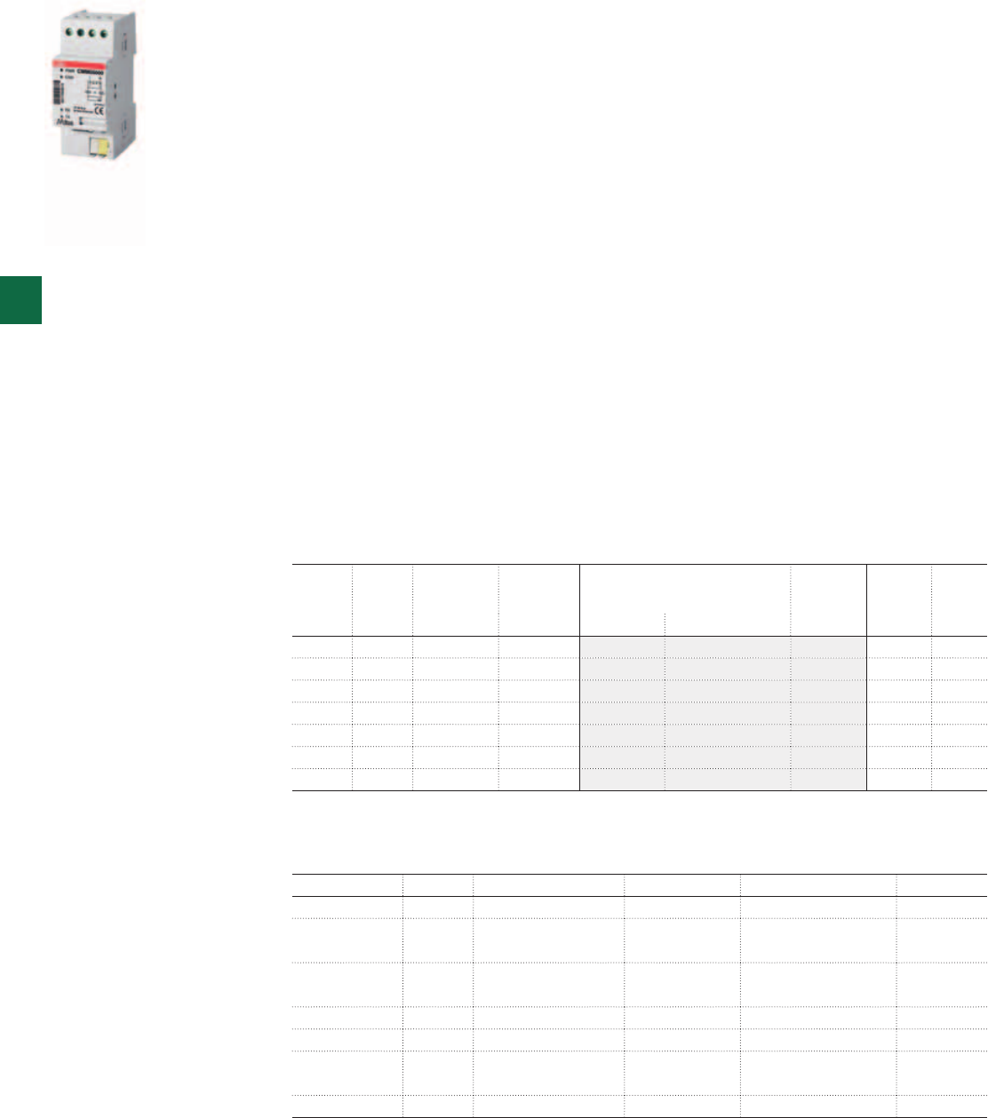
2CSC400030F0144
CMM05000
5/12 2CSC 400 031 D0202 | System pro M compact®
5
Technical details
Media Protocol Voltage Connection Additional function SCA
Ethernet, IR M-Bus 100-240 V RJ-45 Web server CEM 05100
GSM/GPRS, IR M-Bus 100-240 V SMA Short Message Service
(SMS)
CGM 05000
IR, IR, M-Bus TP M-Bus 100-240 V Bus connection
terminal
M-Bus Master extension for
32 slaves
CMM 05000
RS-232, IR M-Bus Powered from RS-232 Screw terminal N/A CRM 04000
M-Bus TP, IR M-Bus Powered from bus Screw terminal N/A CTM 04000
KNX bus, IR KNX Powered from bus Bus connection
terminal
N/A ZS/S 1.1
MODBUS - - - - CSO 05000
Ordering Information
Communication adapters
The Serial Communication Adapter (SCA) enables serial data communication between the
electricity meter and an Automatic Meter Reading system (AMR). These compact size,
2 DIN-modules complements ABB DIN-rail mounted electricity meters, wich have an optical
interface for remote reading of measured data and identity, using the M-Bus protocol. A
SCA converts the optical signals to different chosen media (Twisted pair, etc.) and protocols
(MODBUS, M-Bus, TCP/IP, etc.). The SCA is designed for DIN-rail mounting. The optical
interface on the left side of ABB meter must face the optical interface on the right side of
the SCA . It is important that the electricity meter and the adapter are installed close to each
other. They are available in different versions. The SCA Two-wire M-bus can be ordered for
two-wire an-Bus usage. To connect the M-Bus loop, terminals 1-2 or 3-4 can be used. The
loop continues on the other two free terminals. The M-Bus two-wire connection is polarity
insensitive. The two-wire connection is mainly used when several M-Bus slaves are to be
connected into an M-Bus loop. The Adapter is powered directly by the M-Bus and does not
require an additional power source. The M-Bus adapter consumes 3 mA i.e. two standard
M-Bus loads. The RS232 M-Bus connection is used when connecting an M-Bus slave directly
to a Master (e.g. PC/modem). The SCA Ethernet M-bus adapter is used for communication
over Ethernet networks. It has two main functions. One is supporting remote reading using
M-Bus over UDP or TCP. It is used by AMR systems. The other function is a built in web
server. The Ethernet adapter is powered by 100 – 240 VAC (-20/+15%) between terminal 1
and 4. To connect to an Ethernet network a RJ-45 connector is used. The SCA GSM/GPRS
M-bus communication adapter is a quard band GSM/GPRS device, which enables AMR with
GSM or GPRS over GSM 850/900 and GSM 1800/2900 networks. Furthermore the ABB GSM/
GPRS communication adapter support remote configuration using Short Message Service
(SMS). The adapter is powered with 100-240 VAC (-15/+10%).
Voltage IR port
output
N° module Bbn
7392696
Order details Weight
1 piece
Pack
unit
V [17.5 mm] EAN Type code Order code Price Kg
100-240 Yes 2 371216 CEM 05100 2CMA137121R1000 - 1
100-240 Yes 2 371049 CGM 05000 2CMA137104R1000 0.105 1
100-240 Yes 2 371209 CMM 05000 2CMA137120R1000 0.070 1
- Yes 2 370912 CRM 04000 2CMA137091R1000 0.072 1
100-240 - 2 371247 CSO 05000 2CMA137124R1000 0.102 1
- Yes 2 370905 CTM 04000 2CMA137090R1000 0.073 1
- Yes 2 - ZS/S 1.1 2CDG110083R0011 0.067 1
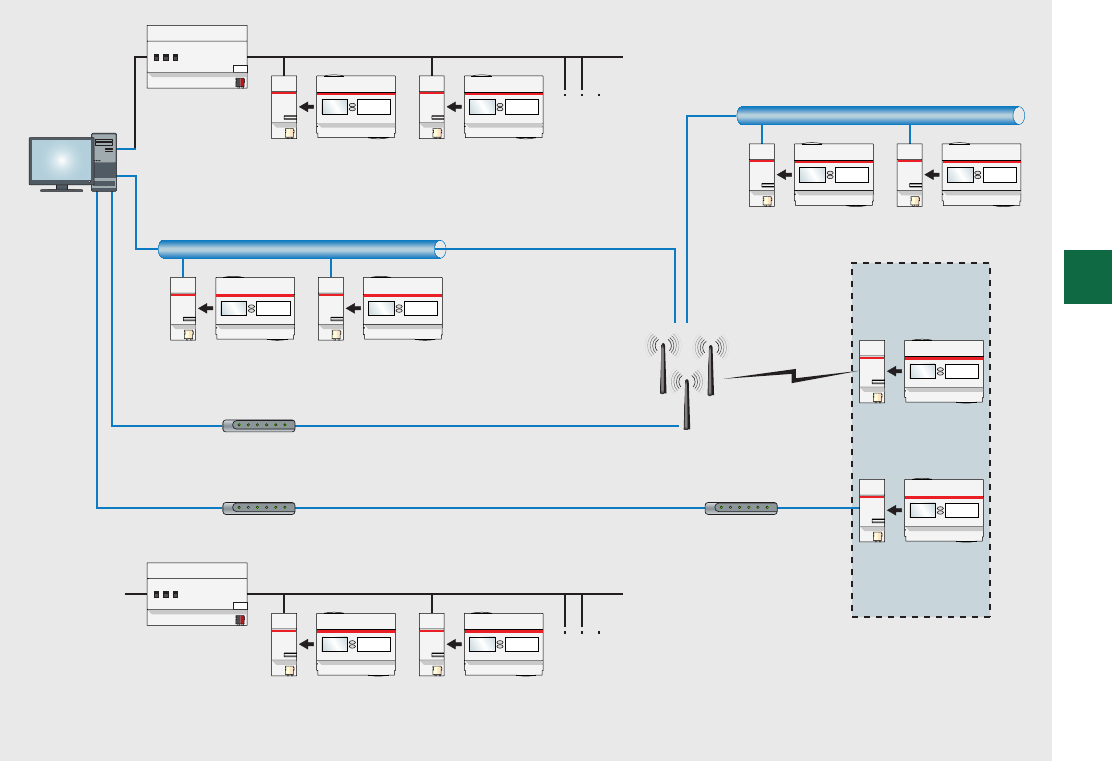
Short Distance Communication
Local LAN
External LAN
Internet
WWW
GSM/GPRS Network
Service Provider
SCA for
Standalone
Application
Electricity Meter
with SCA GSM/
GPRS Adapter
Electricity Meter
with SCA RS-232
Adapter
GSM Modem
PSTN Modem
EIB unit
PSTN Modem
Ethernet
Ethernet
M-Bus Master
AMR/BMS/EMS
System
Electricity Meter
with SCA M-Bus
Adapter
Electricity Meter
with SCA Ethernet
Adapter
Electricity Meter
with SCA KNX
Adapter
Electricity Meter
with SCA Ethernet
Adapter
Electricity Meter
with SCA KNX
Adapter
Electricity Meter
with SCA M-Bus
Adapter
System pro M compact® | 2CSC 400 031 D0202 5/13
5
Communication network
Abbreviations:
AMR Automatic Meter Reading
BMS Building Management Stystem
EMS Energy Management System
GPRS General Packet Radio System
GSM Global System for Mobile Communication
LAN Local Area Network
PSTN Public Switched Telephone Network
SCA Serial Communication Adapter
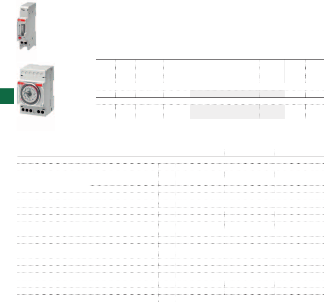
2CSC400030F0145
2CSC400030F0146
AT1
AT3
5/14 2CSC 400 031 D0202 | System pro M compact®
5
Ordering Information
AT electro-mechanical time switches
They control circuit opening and closing according to the scheduled program. Available
both on daily and weekly version and equipped with a 16A contact, they can be set on
the scheduled program or on the permanent ON function (ON-OFF only for three modules
versions). The AT1-R, AT3-R and AT3-7R versions are equipped with a built-in battery,
generally charged by the network voltage, which allows the devices to maintain the set time
also in case of long (up to 200h) power supply failures. The products fit applications such as
lighting systems, heating, irrigation systems and so forth.
AT1-R AT3-R AT3-7R
Technical details
Rated supply voltage [V] 230 AC + 10%
Contact type 1NO 1CO 1CO
Switching capacity resistive load [A] 16
inductive load [A] 4 3 3
Rated frequency [Hz] 50-60
Time base quartz
Minimum switching time [min] 15 15 120
Max number of commands per cycle 96 96 84
Running reserve [h] 200 200 200
Accurary ± 1sec / 24h
Power consumption [VA] 0.5
Max. switching power [W] 4000
Terminal size for cable [mm²] 4
Terminals loss-proof screw
Mounting on DIN rail
Operating temperature [°C] -10….+55
Storage temperature [°C] -10...+55 -10….+55 -10….+55
Modules 133
Reference standards EN 60730-1; EN 60730-2-7
Running
reserve
Version N° module Bbn
8012542
Order details Weight
1 piece
Pack
unit
[17.5 mm] EAN Type code Order code Price Kg
Contact 1NO
200h daily 1 042150 AT1-R 2CSM204215R0601 0.095 1
Contact 1CO
200h daily 3 042358 AT3-R 2CSM204235R0601 0.180 1
200h weekly 3 042457 AT3-7R 2CSM204245R0601 0.180 1
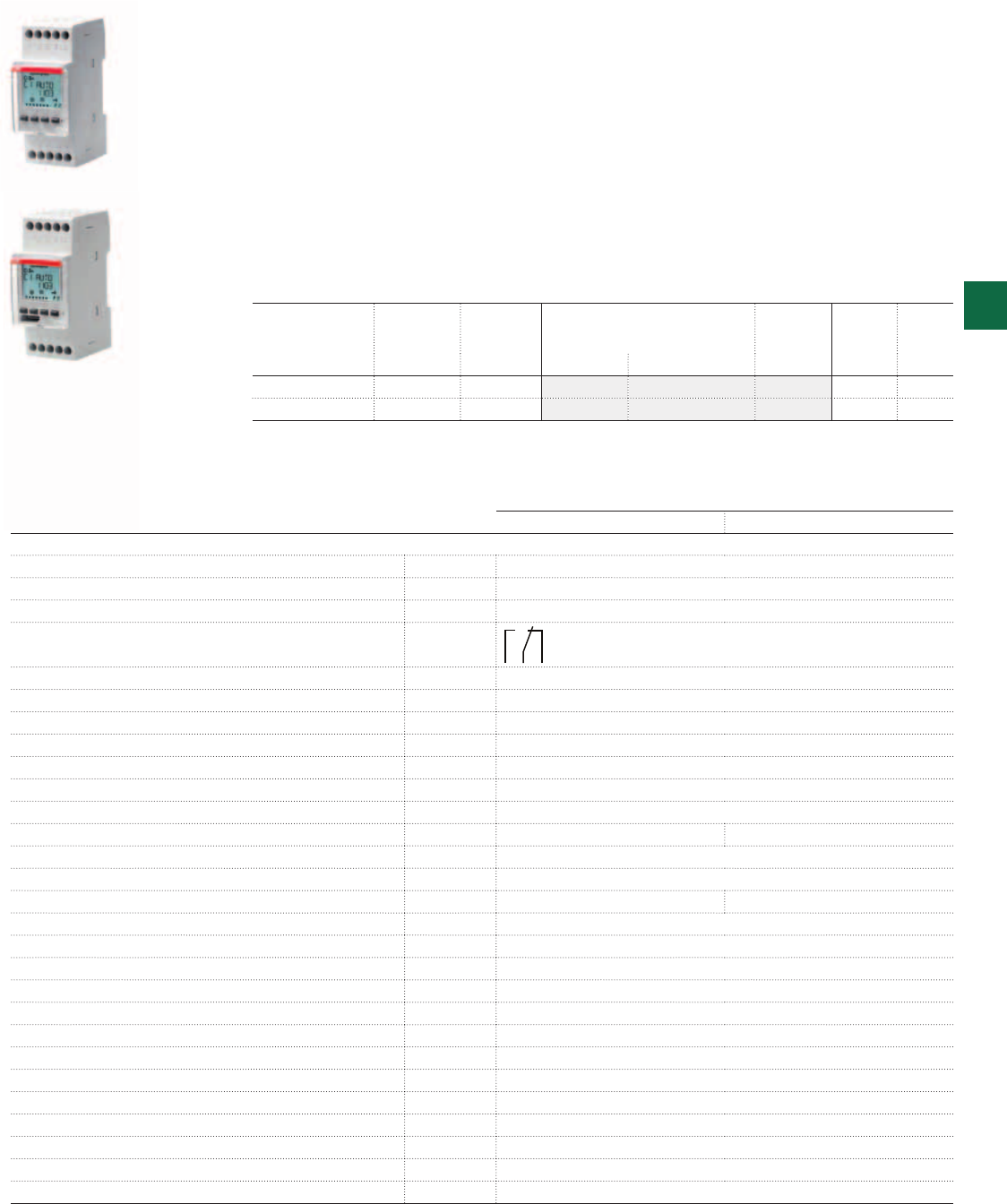
2CSC400030F0148 2CSC400030F0147
D1
D2
System pro M compact® | 2CSC 400 031 D0202 5/15
5
Ordering Information
D Line digital time switches
The unique design, with white backlit LCD display, and extreme ease of use with two lines of
text menu and only four buttons, make D LINE ideal to automate the installation functions.
Thanks to the innovative management of time vacation, the D Line digital time switches
allow the exclusion of the normal weekly program in one or more periods of several years or
between two different years.
The range includes 1 and 2 channel versions, equipped with large capacity internal battery
to maintain operation without power supply and permanent memory EEPROM, to avoid the
risk of program loss and to maintain the date and time settings in the event of power failure,
irrespective of its duration.
The D Line is particularly useful in environments and situations where user management is
required with a time schedule flexible enough to predict or exclude activities according to time
and day of week or month.
D1 D2
Technical details
Rated voltage [V] 230 AC ± 10%
Rated pulsating voltage [kV] 4
Contact type Contact relay in free exchange from potential
250 V contact capacity
Ohm loads [A] 16 16
Inductive loads [A] 10 2
Rated frequency [Hz] 50-60
Time base quartz
Minimum switching [sec.] 1
Max programs per cycle [No.] 64 (can be coupled in day blocks)
Load reserve [years] 6 from the first start-up (lithium battery)
External input [No.] 1 2
Activity suspension From 1 day to 12 months
Operating precision sec./ day ± 0.5
Max. dissipated power [VA] 6.5 7.8
Max. switch power [VA] 3500
Incandescent LP power [W] 3000
Non-rephased fluorescent tube LP power [W] 1100
Fluorescent tube LP power rephased in parallel [W] 900
Fluorescent tube LP power with electronic reactor [W] 7 ÷ 23 (max. 23 lamp.)
Fluorescent tube LP power rephased in series [W] 1100
Protection grade [IP] 20
Max. terminal section [mm²] 6
Terminals In positive safety with captive screw
Installation type DIN rail
Operating temperature [°C] -5 … +55
Storage temperature [°C] -10 … +65
Modules [No.] 2
Channels no. N° module Bbn
8012542
Order details Weight
1 piece
Pack
unit
[17.5 mm] EAN Type code Order code Price Kg
1 2 587637 D1 2CSM258763R0621 0.140 1
2 2 563136 D2 2CSM256313R0621 0.140 1
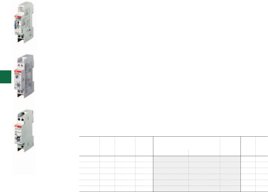
2CSC400030F0150
2CSC400030F0151 2CSC400030F0149
E232-230
E232E-8/230N
E232-HLM
5/16 2CSC 400 031 D0202 | System pro M compact®
5
Ordering Information
E 232 staircase lighting time-delay switches
Staircase lighting time-delay switches are usually operated by pushbuttons, often fitted with a
glow lamp. Switches are designed for a glow lamp current of up to 150 mA and thus perfectly
suitable for installations in multi-storey buildings.
The E 232-230 staircase lighting time-delay switch includes an electro-mechanical timer with a
synchronous motor drive to ensure high operational safety in whatever mounting position. The
time range is adjustable in increments of 15 seconds from 1 to seven minutes. Resettable after
30 seconds.
E 232E–230N and E 232E-8/230N devices feature electronic time delays. A high switching
capacity, 150 mA glow lamp current parallel to the pushbuttons, steplessly adjustable time
range from 0.5 to 20 min, as well as low switching noise make these devices so special.
Devices of the E 232E-230 Multi 10 and E 232E-8/230 Multi 10 series are multi-functional
products with 10 functions to choose from that can be adjusted from the front. Through an
electronically controlled connection of the load at voltage zero, a very high switching capacity
of 3,600 W (load of filament lamp) is reached.
The devices include an integrated warning feature (warning by blinking) according to DIN
18015-2 as well as a 60 minute long-time function.
The E 232E-8/230N and E 232E-8/230 Multi 10 staircase lighting time-delay switches offer an
additional metallically separated control input for 8…240 V AC/DC.
The electronic E 232-HLM half-light module is a supplementary device for staircase lighting
time-delay switches for semi-light control according to DIN 18015-2. The module switches
filament lamps and 230 V halogen lamps up to 2,300 W in the warning phase to an output
voltage that is reduced by 50%. Adjustable time range from 20 – 60 seconds.
Time
range
Power
loss
N° module Bbn
4016779
Order details Weight
1 piece
Pack
unit
W [17.5 mm] EAN Type code Order code Price Kg
1…7 min. 1 V A 1 548243 E232 230 2CDE110000R0501 0.081 10
20…60 sec. 6 V A 1 548281 E232-HLM 2CDE150000R0521 0.075 10
20 min 6 V A 1 654166 E232 E-230N 2CDE110003R0511 0.095 10
20 min 6 V A 1 654173 E232 E-8/230N 2CDE010003R0511 0.100 10
20 min 6 V A 1 654180 E232 E-230 Multi 10 2CDE110013R0511 0.100 10
20 min 6 V A 1 654197 E232 E-8/230 Multi 10 2CDE010013R0511 0.095 10

System pro M compact® | 2CSC 400 031 D0202 5/17
5
E 232-230 E 232E-230N E 232E-8/230N E 232E-230
Multi 10
E 232E-8/230
Multi 10
E 232E-HLM
Technical details
Time range (stepless) 1 – 7 min.
in 15 sec. increments
0.5 – 20 min.
stepless
20 – 60 sec.
stepless
Control voltage 230 V AC QQQQQ
Universal voltage in addition - - 8 … 240 V AC/DC - 8…240 V AC/DC -
Glow lamp load 50 mA 150 mA -
3/4 conductor operated switches automatically -
Resettable QQQQQ
Steady-light switch QQQQQ
Advance warning acc. DIN 18015-2 QQ Q
Long-time range of 60 min. QQ
Multi-functional device (10 functions) QQ
Rated voltage 230 V AC 230 ... 240 V AC
50Hz 50 / 60 Hz
Control voltage range 0.9 ... 1.1 Un 0.85 ... 1.1 Un 0.9 ... 1.1 Un
Power loss 1 VA 6 VA
Rated switching capacity 16 A, 230 V AC 10 A, 230 V AC
Filament lamp load 2,300 W 3,600 W 2,300 W
Halogen lamp load 2,300 W 3,600 W 2,300 W
Fluorescent lamps series compensated / uncor-
rected
2,300 VA 3,600 VA * not permitted
Fluorescent lamps inductive or capacitive 2,300 VA 3,600 VA * not permitted
Fluorescent lamps shunt compensated 1,300 VA (70 μF) 400 VA (42 μF) 1,200 VA (120 μF) * not permitted
Electronic controlgear 9x7 W, 6x11 W 9x7 W, 7x11 W 34x7 W, 27x11 W not permitted
5x15 W, 5x20 W 7x20 W, 7x23 W 24x15 W, 22x23 W -
Inductive load (cos ϕ = 0.6/230 V AC) 2,300 not permitted
Contact material AgSnO2
Contact gap ≥ 3 mm < 3 mm ≥ 3 mm
Mech. serviceable life > 106> 107
Serviceable life at rated load, cos ϕ =1 > 105> 2x10⁵> 105
Serviceable life at rated load, cos ϕ =0.6 > 104> 4x10⁴> 104
Terminal capacity 10.7 mm² 13 mm² 13.6 mm²
Max. conductor capacity 6 mm² 4 mm² 6 mm²
ON duration Resettable after 30
sec.
100 %
Ambient temperature – 10 °C to + 50 °C – 25 °C to + 50 °C – 10 °C to + 50 °C
Housing and insulation material heat resistant, self-extinguishing thermoplast
Control current at 230 V AC 4.5 mA 26 mA 26 mA (min. 8 mA at 8 V AC) -
Minimum command duration 10 ms 20 ms 20 ms / 50 ms
for multi voltage input
-
* no disconnection advance warning possible for this application.
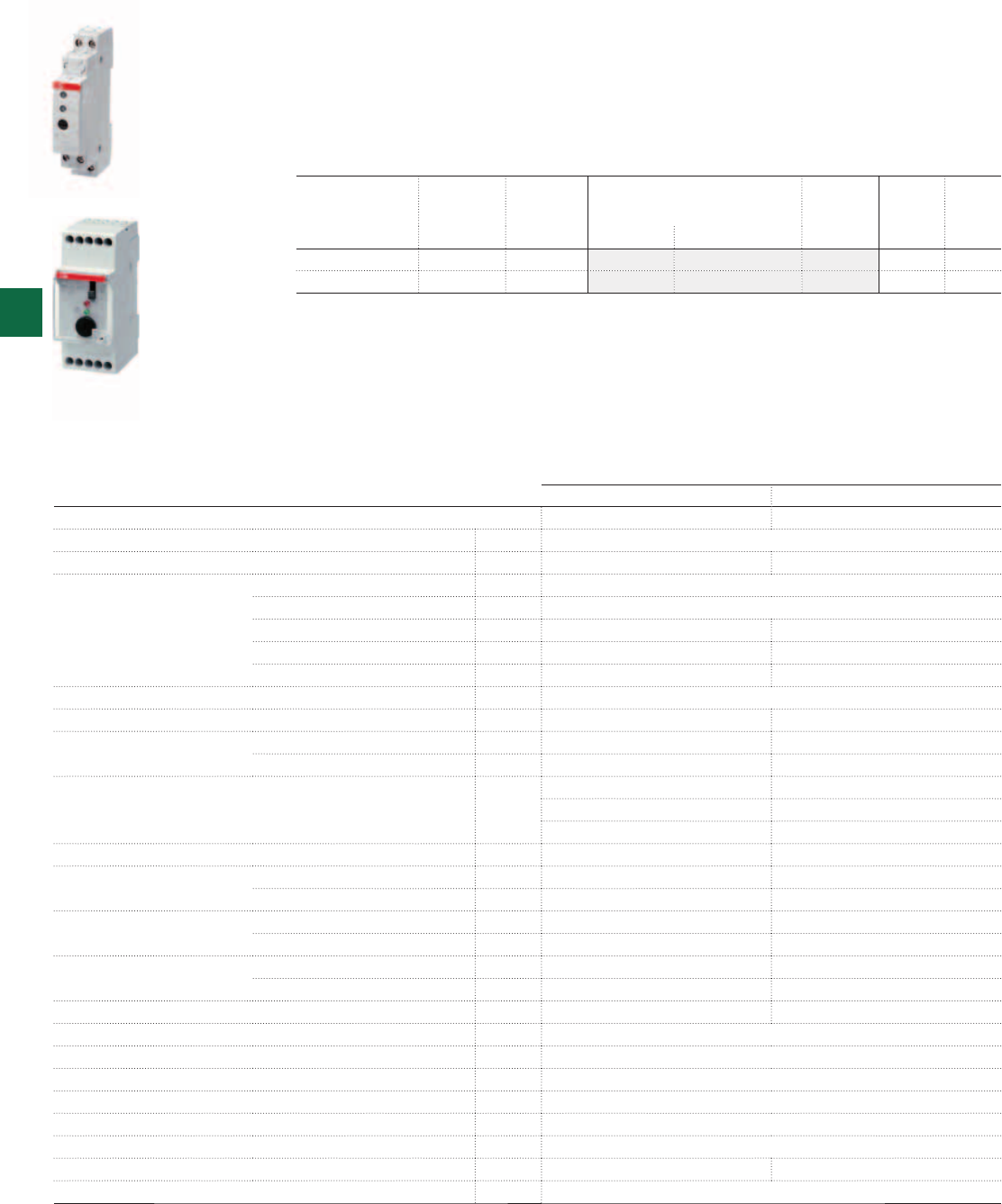
2CSC400030F0153
2CSC400030F0152
TW1
TW2/10K
5/18 2CSC 400 031 D0202 | System pro M compact®
5
Ordering Information
TW modular twilight switches
They allow to switch on and switch off lighting devices according to a scheduled level of the
ambient light. They are used in combination with a sensor to detect if the ambient light is
higher or lower than the set level. TW2/10K, equipped with three different types of adjustment
range (2:100, 2:1000, 2:10000), fits well the daylight applications where the Lux value is very
high. This range, thanks to its features, fits all applications where the rationalization of the
energy consumption is required.
TW1 TW2/10K
Technical details
Rated supply voltage [V] 230 AC
Contact type 1NO 1CO
Switching capacity resistive load [A] 16
inductive load cosϕ 0.6 [A] 3
incandescent lamps cosϕ 1 max 960 W max 1080 W
fluorescent lamps cosϕ 0.8 max 720 W max 720 W
fluorescent - duo./electronic lamps cosϕ 0.9 max 200 W max 200 W
Rated frequency [Hz] 50-60
Programs ON-OFF - -
Switching delay ON [s] 8 ±10% 8 ±10%
OFF [s] 38 ±10% 38 ±10%
Brightness range [lx] 2:100
2:100 2:1,000
2:10,000
Accuracy --
Protection degree twilight switch IP20 IP20
sensor IP65 IP65
Operating temperature twilight switch [°C] 0…+55 0…+55
sensor [°C] -30...+65 -30...+65
Storage temperature twilight switch -10...+65 -10...+65
sensor -40...+75 -40...+75
Power consumption 4.5 2.5
Max. commutable power 3500
Terminal size for cable 2.5
Terminals loss-proof screw
Mounting on DIN rail
Switching status indication/brightness range red Led / green Led
Max wiring length 100
Modules 12
Reference standards EN 60669-1; EN 60669-2-1
Brightness
range
N° module Bbn
8012542
Order details Weight
1 piece
Pack
unit
Ix [17.5 mm] EAN Type code Order code Price Kg
2 : 100 1 041351 TW1 2CSM204135R1341 0.107 1
2 : 10.000 2 041450 TW2/10K 2CSM204145R1341 0.215 1
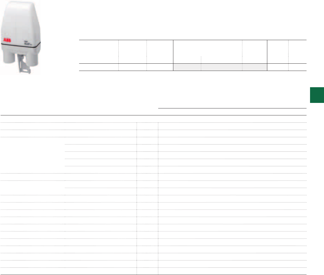
2CSC400030F0154
TWP
System pro M compact® | 2CSC 400 031 D0202 5/19
5
Ordering Information
TWP pole mounting twilight switch
The TWP pole twilight switch, equipped internally with a preset sensor of 10 Lux, is the ideal
solution for the management of external light systems such as the public ones. The sensor
is extractable from the base and allows an easy and efficient maintenance without needing
further wiring.
TWP
Technical details
Rated supply voltage [V] 230 AC
Contact type 1NO polarized
Switching capacity resistive load [A] 16
inductive load cosϕ 0.6 [A] 3
incandescent lamps cosϕ 1 max 960 W
fluorescent lamps cosϕ 0.8 max 720 W
fluorescent - duo./electronic lamps cosϕ 0.9 max 200 W
Rated frequency [Hz] 50-60
Switching delay ON [s] 25 ± 10%
OFF [s] 25 ± 10%
Brightness range [lx] 2:200
Protection degree IP65
Operating temperature [°C] -30…+60
Storage temperature [°C] -30…+65
Power consumption [VA] 7.5
Max. commutable power [W] 3500
Terminal size for cable [mm²] 2.5
Terminals screw
Mounting pole
Switching status indication/ brightness range - / red Led
Reference standards EN 60669-1; EN 60669-2-1
Brightness
range
N° module Bbn
8012542
Order details Weight
1 piece
Pack
unit
Ix [17.5 mm] EAN Type code Order code Price Kg
2 : 200 - 041658 TWP 2CSM204165R1341 0.155 1
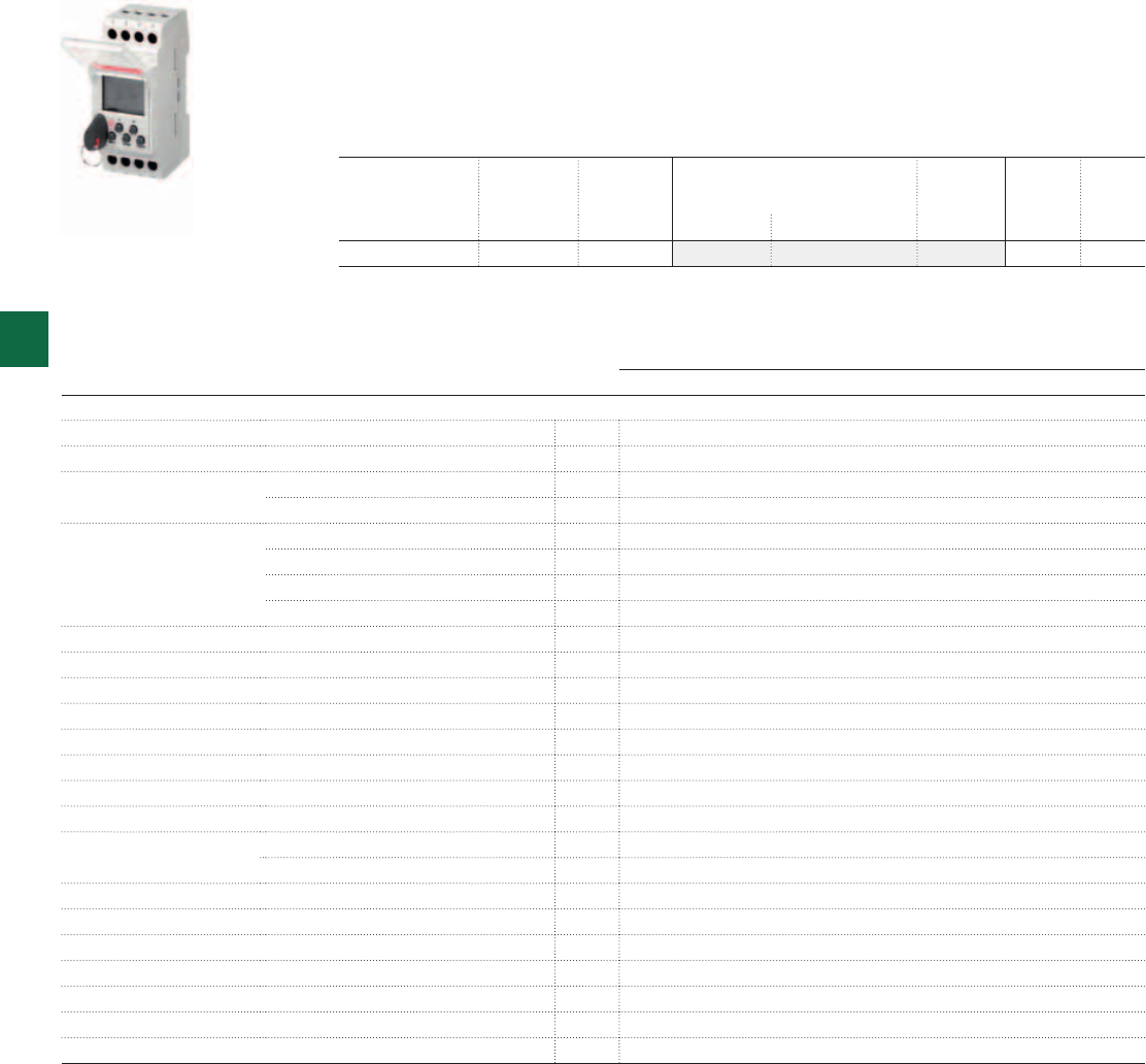
2CSC400030F0155
TWA-1
5/20 2CSC 400 031 D0202 | System pro M compact®
5
They allow to control automatically the light systems according to the hour when the sun
rises and sets. The programming is made defining the longitude and latitude parameters
of the geographical area where the switch is mounted. Thanks to its features the TWA
fits applications, particularly when the external sensor is subjected to strong external
inconveniences like in area with high level of pollution or in area exposed to vandalic acts.
Ordering Information
TWA twilight astronomical switches
TWA-1
Technical details
Rated supply voltage [V] 230 AC ± 15%
Contact type 1CO
Switching capacity resistive load [A] 16
inductive load cosϕ 0.6 [A] 10
Max. number of lamps incandescent and halogen fluorescent [W] 2300
compensated (max. 45μF) [W] 400
non-compensated, series compensated [W] 1000
compact fluorescent [W] 500
Rated frequency [Hz] 50-60
Time base quartz
Minimum time between two steps [min] 1
Program steps 56
Power reserve [years] 5
Accuracy ± 1,5sec / 24h
Astronomical time accuracy [min] ± 10
Power consumption [VA] 6
Terminal size for cable flexible [mm²] 1 to 6
rigid [mm²] 1.5 to 10
Terminals loss-proof screw
Mounting on DIN rail
Operating temperature [°C] -10…+55
Storage temperature [°C] -20…+60
Protection degree IP20
Modules 2
Reference standards NFC 15 100; IEC 60 634-1
Contacts N° module Bbn
8012542
Order details Weight
1 piece
Pack
unit
[17.5 mm] EAN Type code Order code Price Kg
1 CO 2 043652 TWA-1 2CSM204365R1341 0.160 1
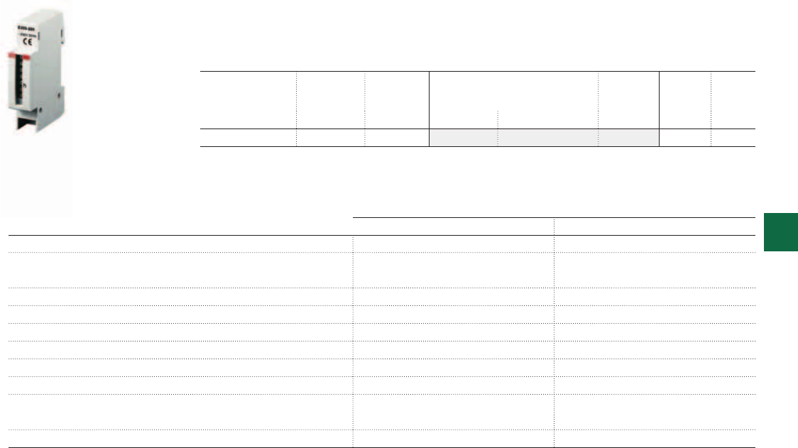
2CSC400030F0156
E233-230
System pro M compact® | 2CSC 400 031 D0202 5/21
5
Ordering Information
E 233 electro-mechanical hour counters
Hour counters are used to record operating times as well as to determine idle times and off
times of electrical loads in domestic installations.
No reset functionality.
AC equipment DC equipment
Technical details
Rated voltage 50 Hz: 24 V, 230 V
60 Hz: 24 V, 120 V, 240 V*
DC 12 V ... 48 V
Voltage tolerance ±15 % ±10 %
Power consumption 1.5 VA ca. 20 mW (at 12 V DC)
Ambient temperature –15 °C/5 °F... +50 °C/122 °F –10 °C/14 °F ... +50 °C/122 °F
Counting capacity 99.999 h 99.999 h
Precision class 0.01 h 0.1 h
Operation display fast running LED blinking
Protection against electric shock according to DIN VDE 0106
Part 100 (BGV A2)
according to DIN VDE 0106
Part 100 (BGV A2)
Terminal size up to 10 mm2up to 10 mm2
* UL approval
Rated
voltage
N° module Bbn
4012233
Order details Weight
1 piece
Pack
unit
[17.5 mm] EAN Type code Order code Price Kg
AC 230 V/50 Hz 1 630004 E233-230 2CDE100000R1601 0.050 10
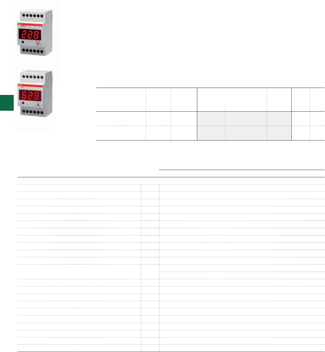
2CSC400030F0158 2CSC400030F0157
VLMD-1-2
AMTD-1
5/22 2CSC 400 031 D0202 | System pro M compact®
5
Ordering Information
VLMD, AMTD digital instruments with alarm relay
The range comprises one voltmeter and one ammeter that display and monitor a value,
tripping a relay contact and signalling the alarm condition if it over- or undershoots a
programmable threshold. The alarm threshold as either a minimum or a maximum limit, the
peak maximum and minimum values measured are stored in the non volatile instrument
memory.
The contact type is NO, so that the contact is open when the instrument is powered off, but it
is possible to obtain positive safety operation via a software setting which determines whether
the alarm condition is with an open or closed contact.
The instrument with relay can be used as either a minum or maximum relay, but not for both
functions simultaneously
VLMD, AMTD
Technical details
Power supply [V] 230 V AC
Rated frequency [Hz] 50÷60
Ammeter full scale value [A] 5, 20, 25, 40, 60, 100, 150, 200, 250, 400, 600
Voltmeter full scale value [V] 300, 500
Frequency meter range [Hz] 35...400
Tripping delay [s] 1, 5, 10, 20, 30
Hysteresis [%] 5, 10, 20, 30 set threshold
Output pins 3-4
Output relay NO
Rated voltage relay [V] 230 V AC
Rated current relay [A] AC1 16, AC15 3
Relay configuration NO relay closes in alarm status
NC relay opens in alarm status, positive safety
Overload [In/Vn] 1, 2
Accuracy class [%] ±0,5 full scale ±1digit at 25 °C
Max. signal input value for ammeters 5 A AC
Display 3 digit LED display
Operating temperature [°C] -10…+55
Storage temperature [°C] -40...+70
Protection degree IP20
Power consumption [VA] 4
Modules 3
Overall dimensions front panel devices [mm] 36x72x61.5 (51.5 depth inside the switchboard)
Version N° module Bbn
8012542
Order details Weight
1 piece
Pack
unit
[17.5 mm] EAN Type code Order code Price Kg
AC/DC digital voltmeter
with alarm relay
3 746935 VLMD-1-2-R 2CSM274693R1011 0.300 1
AC digital ammeter
with alarm relay
3 747734 AMTD-1-R 2CSM274773R1011 0.300 1
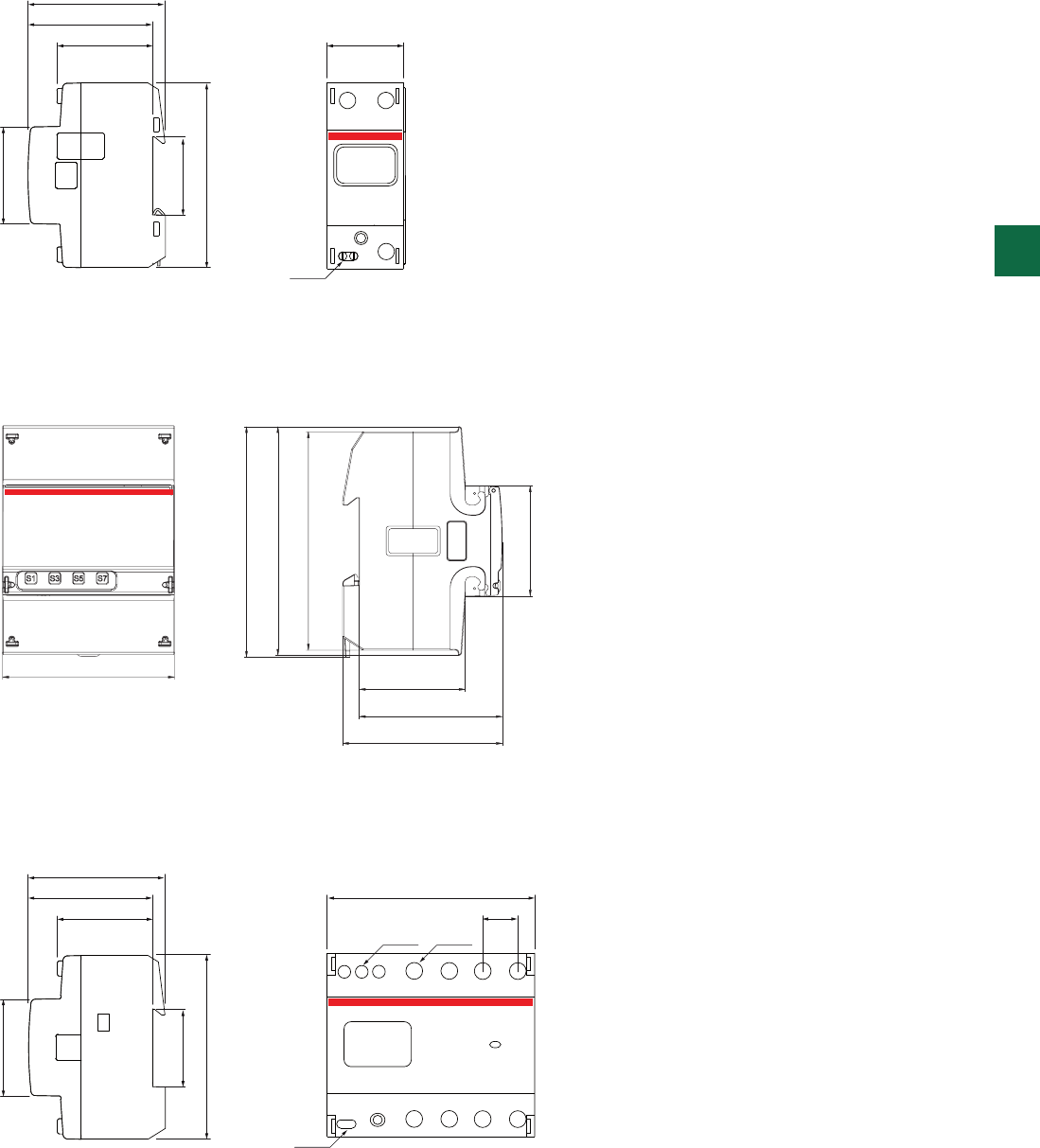
L1
NL1
63.4
57.4
44 35.8
Ø 4.4
45
35.8
85
63.4
57.4
44
105
17.5
Ø 4.4
Ø 5.3 Ø 7.4
45
35.8
85
System pro M compact® | 2CSC 400 031 D0202 5/23
5
Overall dimensions
ODINsingle
EQ meters A41
ODIN
70
89
93
45
97
43
58
65
63.4
58
44 36
45
35.8
90
97
123
89
93
43
45
58
65
5/24 2CSC 400 031 D0202 | System pro M compact®
5
Communication adapters
EQ meters A43
Overall dimensions
60
43.8 35
45
90
246 1012
13
24
60
44 17.8
AT1-R
54
AT3-R
AT3-7R
45
88.5
E 232-230
59
44 17.5
45
88
E 232 E - E 232 HLM
58
44 17.5
45
90
System pro M compact® | 2CSC 400 031 D0202 5/25
5
AT D Line
E 232
1
LN
3
57
TW1
60 17.5
45
90
135LN
246810
TW2/10K
60 35
45
90
24 6 8
13 5 7
TWA-1
60
43.8 35.8
45
85
TWP
72 37.5
147
58 17.5
45
85
A
58 52.5
45
85
3 modules
5/26 2CSC 400 031 D0202 | System pro M compact®
5
Overall dimensions
TW
E 233 VLMD, AMTD

System pro M compact® | 2CSC 400 031 D0202 6/1
6
Introduction 6/2
UK500 Flush-mounting Series
Plus of range 6/4
N/PE Quick-terminals 6/6
Ordering information 6/8
Unibox Wall-mounting Series
Plus of range 6/20
Ordering information 6/22
Alpha
Plus of range 6/26
Ordering information 6/28
AT/U Series
Plus of range 6/30
N/PE Quick-terminals 6/32
Compact distribution boards 6/34
Ordering information 6/36
IP65 Europa Series
Plus of range 6/52
Ordering information 6/54
IP40 Wall-mounting covers
Plus of range 6/60
Ordering information 6/62
IP44, IP55 and IP65 Junction boxes
Plus of range 6/64
Ordering information 6/66
CJ8/16 Cable joint
Plus of range 6/74
Ordering information 6/75
Technical details 6/78
Overall dimensions 6/89
Consumer units and junction boxes
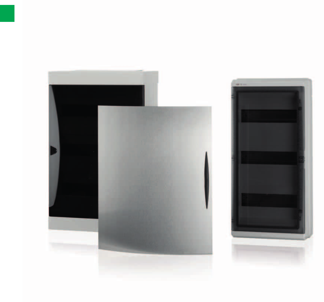
6/2 2CSC 400 031 D0202 | System pro M compact®
6
Freedom of choice, the best solution for any need
ABB Consumer units and Junction boxes
There has been a trend towards an ever increasing offer of products for residential
installation. Technology is increasingly present in the domestic environment,
and technological components are required to seamlessly integrate into the
structure. ABB offers a wide range of consumer units for the installation of modular
components to meet the requirements for domestic applications. The portfolio
enables to implement any type of application for electrical distribution in residential
and non-residential environments according to highest safety conditions and
international regulations. The modularity of the products allows significant savings
during installation.
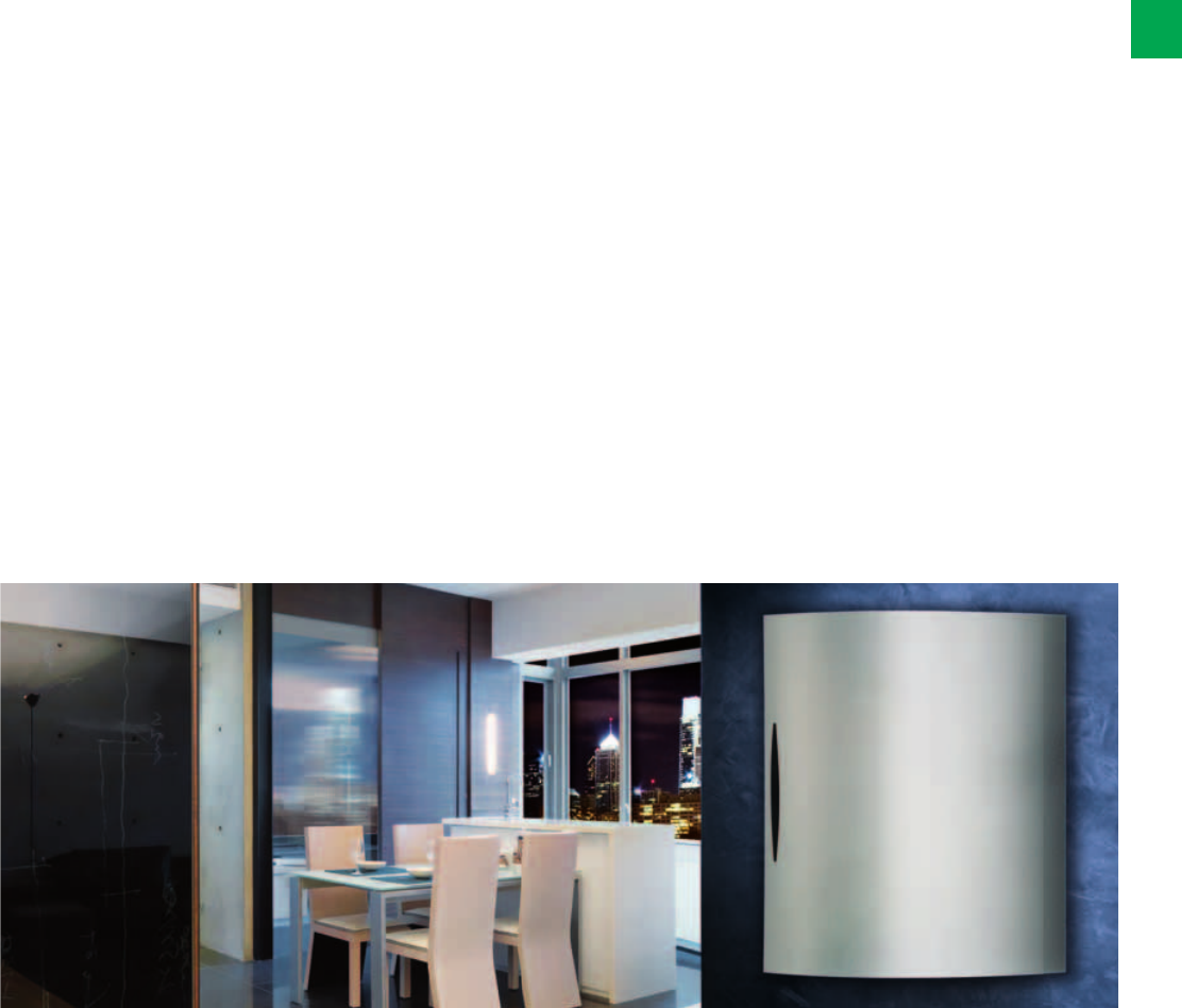
System pro M compact® | 2CSC 400 031 D0202 6/3
6
Installation products for the residential application must
respond to a series of specific requirements. Within the wide
range of the ABB portfolio you can choose the electrical
installation that fulfills the technical requirements and still
looks good.
The UK500 Series sets a new aesthetical standard. The
flush-mounting consumer unit offers a range of different
designs which covers all customer’s needs of elegance. The
UK500 Series is an ideal combination of engineering and
design, offering quick and flexible installation. The wall box is
non-warp, non-breakable and non-flammable. It offers a large
wiring space. The installation process is simple, quick and
well thought-out. Various types of doors adapt all furnishing
styles, from classic to modern as well as for multi-media
applications.
The Unibox Series is distinguished by an advanced and
elegant design which complements easy installation and
user-friendliness. These IP40 wall-mounting consumer
units perfectly fit into any architectural style. The range
accommodates configurations from 8 to 54 modules which
can be easily wired extracting the frame. Resistance to
chemical agents, atmospheric agents, UV rays and shocks
is guaranteed. Its wide set of accessories completes the
functions of these units.
The range of IP40 wall-mounting covers also offers 2,4 and
6 module housings for electrical devices.
ABB offers with the Alpha Series enhanced features for your
comfort. The Alpha Series with 18 modules per row comes
with a smoky brown door which can be opened wide (210°),
to allow easy access to the protective and control devices, if
required. The wall-mounting Alpha enclosure is not only easy
and quick to assemble, but also its timeless design ensures
that it also fits harmoniously in any environment, for residential
as well as for tertiary applications.
Whether for high-end residential or for tertiary sectors,
the range of the AT/U Series offers a solution for every
application. Specially designed accessories and spare parts
guarantee that the AT/U Series will be a flexible and reliable
partner for various applications – for flush-mounting as
well as for wall-mounting or for hollow-wall-mounting. ABB
provides with the AT/U compact distribution boards one
complete solution for all electrical installation requirements
in your home and makes the work easier for the electrical
contractor.
The high level of reliability of the various models of watertight
boxes of ABB, perfectly meets the need for watertight
enclosures which guarantee complete protection in any
situation where watertight consumer units and wall-mounted
junction boxes are required. In industrial and tertiary, as well
as in residential outdoor applications (heating rooms, garages,
cellars, etc.) ABB’s watertight boxes fulfill any requirements
of robustness, reliability and ease of installation. The IP65
Europa watertight consumer units are available in RAL 9016
white and in RAL 7035 grey and can be equipped with blind
and transparent doors. Designed for the use of the UNIFIX SL
fast wiring system, IP65 Europa switchboards can be fitted
with modular terminal boards.
To further enhance the existing range of IP44 and IP55
watertight boxes, ABB has expanded the portfolio by the
IP65 junction boxes. The new range of IP65 boxes (with
smooth sides) are now in halogen free thermoplastic material.
ABB’s range of consumer units and junction boxes present
a safe use even under the most difficult environmental
conditions: In particular the unique design of ABB’s cable
joint CJ8/16 eliminates the need for foam seals. Cables can
be connected outside the casing and offers ample space for
both joining and derivation.
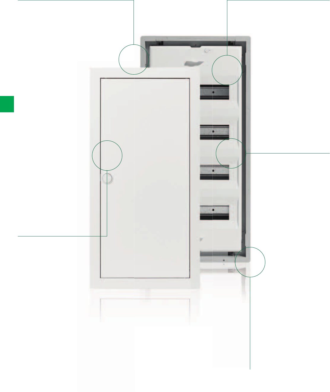
6/4 2CSC 400 031 D0202 | System pro M compact®
6
UK500 Flush-mounting Series
The details make the difference
UK500 series can
be used for
flush- mounting,
hollow-wall or as
a wall-mounting
version, as well
as for partially-
recessed mounting
Design doors,
picture frame,
stainless steel,
transparent and
differently coloured
doors available as
an accessory
Cover with
sealable 90°
quick-action
locking screws
Time-saving
installation thanks
to intelligent
plug-in technology
in the form of the
N/PE quick busbar
Wall box made of
torsionally-rigid,
non-breakable,
flame-resistant,
low-halogen plastic
with cable entry
slides
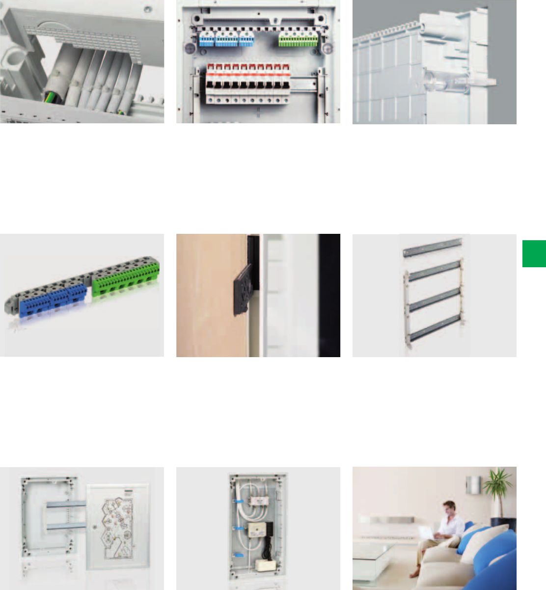
System pro M compact® | 2CSC 400 031 D0202 6/5
6
Removable cable inlet allows easy
insertion of incoming and outgoing
cables and uses a quick, single-hand-
operated push and-stay design. Both
cable inlets can be screwed tight when
installation is complete.
Time-saving installation thanks to
intelligent plug-in technology. The N/PE
Quick busbars are of the plug-in variety.
If required, the N-RCD terminal can also
be attached to the DIN rail and will not
twist. There are also versions available
with screw-type terminals.
The “tech line” control panel of the
UK500 Series offers that extra bit more.
The monitoring and operation such as
the control of lighting systems is taken
care of by the control panel in a way
that’s both easy-to view and decorative.
The control panel can be finished by
the user or supplied already wired and
printed by the factory.
Multifunctional wall grips: Can be used
as a spacer when mounting consumer
units side by side or to adjust the
mounting depth by two more levels.
The rapid development of information
technologies means that ever more
media and communication devices
are to be found in homes. In the new
multimedia enclosure you have all
your media applications at a glance
with the central assembly of media
and communications technology in
distribution cabinets.
The removable device support can
be snapped in and is installed quickly
without tools. Here too, a variety of
common installation techniques have
been catered for – the device support
can also be fixed in position using
screws.
Functional yet elegant – a perfect example
of how easy it can be to combine these
two essential features. Beautiful and
perfectly formed – the design doors for
the UK500 Series are an embodiment of
the design principle based on reducing
things right down to the essentials. You
would never believe that these high-quality
design doors conceal a technical product.
The non-warp, non-breakable and non-
flammable wall box offers large wiring
space. The strain-relief comb for neat
cabling is an integral part of the wall
box. there are ample further pre-formed
cable entry points on the sides and
back of the wall box.
All UK500 Series are suitable for hollow-
wall installation. Upgrading is incredibly
quick and simple – just as easy as the
hollow wall installation itself. You just need
the UZ90P4 hollow wall set for UK500. No
screws, yet nothing can slip. Fastening it
is as easy as fastening cable ties.
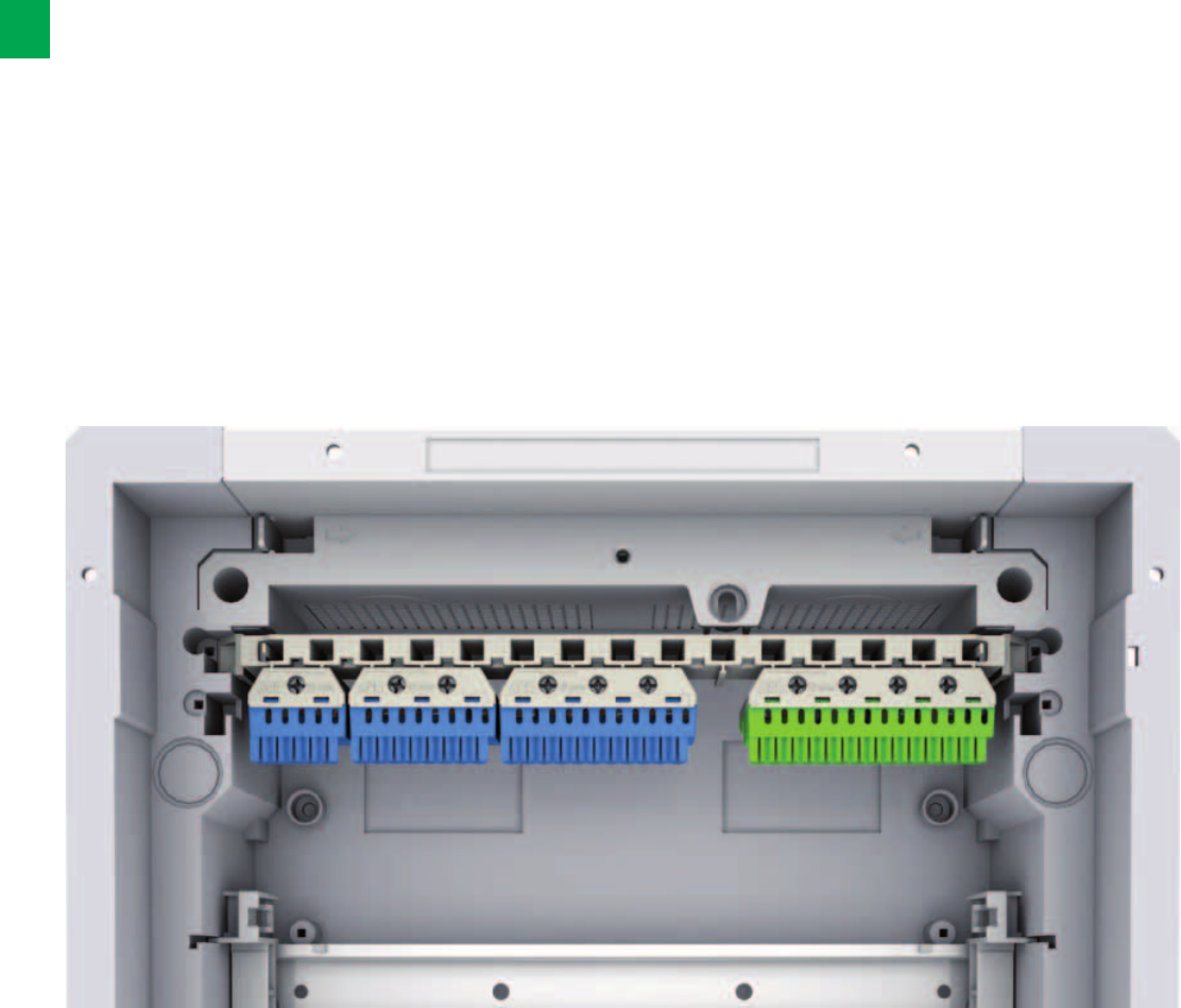
6/6 2CSC 400 031 D0202 | System pro M compact®
6
N/PE Quick-terminals
Standardised, future-oriented and flexible
The new N/PE Quick-terminals from STRIEBEL & JOHN
are designed for the things to come. Conforming to the
current standard DIN VDE 0100 Part 410 and extremely
flexible in terms of expandability, these N/PE Quick-
terminals are unmatched for safe, efficient and future-
oriented conductor connections.
Product benefits
– Compliance with DIN VDE 0100 Part 410 (protection
against electric shock)
– Flexible terminal system for several N power circuits:
Screw connections: 2.5 to 25mm²; spring terminals:
1.5 to 4mm².
– Optimal when using several residual current circuit breaker
(RCDs)
– Combination of several Quick-terminals on one common
quick carrier
– Ease of expansion using connecting bridges
– Precise assignment of the terminal blocks
(clear colour coding: N = blue, PE = yellow-green)
– Easy labelling of the terminals (DIN VDE 0603 Part 1) using
pre-printed, self-adhesive number strips
– Wide range of applications:
can be used in the UK500 and A300 consumer unit series,
in all compact distribution boards, and with all meter cabi-
nets, wall-mounting and floor-standing cabinets
– The new terminal system replaces the N/PE Quick-busbars
that were previously in use
As an electrician you no longer have to compromise.
The new N/PE Quick-terminals from STRIEBEL & JOHN can
simplify your work: Just choose the right terminal blocks and
plug them in! The resulting installation is tidy and flexible. The
colour coding ensures that you will find your way even with
expansions.

System pro M compact® | 2CSC 400 031 D0202 6/7
6
N/PE Quick-terminals
The complete range of products
Clean and tidy work
Anyone would like their distribution board so tidy:
all Quick-terminals are mounted next to each other on one
carrier with standardised colour coding.
Configure based on your needs
The modularity of the new series and the extensive range of
products allow customising the new products to the needs
based on real-world use. Various Quick-terminals can be
combined on one quick carrier as necessary.
Flexible by design
You need a larger N terminal?
No problem. You can connect individual Quick-terminals with
connecting bridges and remain in compliance with the
technical requirements of IEC 60364-4-41 and DIN VDE 0100
Part 410 in an economic way.
The high flexibility of the new series is a crucial advantage
here and in other solutions. The ability to combine terminal
blocks with different numbers of terminals offers numerous
possibilities.
N Quick-terminals PE Quick-terminals
1 x 25mm2 + 5 x 1.5 - 4mm21 x 25mm2 + 5 x 1.5 - 4mm2
2 x 25mm2 + 8 x 1.5 - 4mm22 x 25mm2 + 8 x 1.5 - 4mm2
3 x 25mm2 + 11 x 1.5 - 4mm23 x 25mm2 + 11 x 1.5 - 4mm2
4 x 25mm2 + 14 x 1.5 - 4mm24 x 25mm2 + 14 x 1.5 - 4mm2
5 x 25mm2 + 17 x 1.5 - 4mm25 x 25mm2 + 17 x 1.5 - 4mm2
6 x 25mm2 + 20 x 1.5 - 4mm26 x 25mm2 + 20 x 1.5 - 4mm2
0 x 25mm2 + 5 x 1.5 - 4mm2
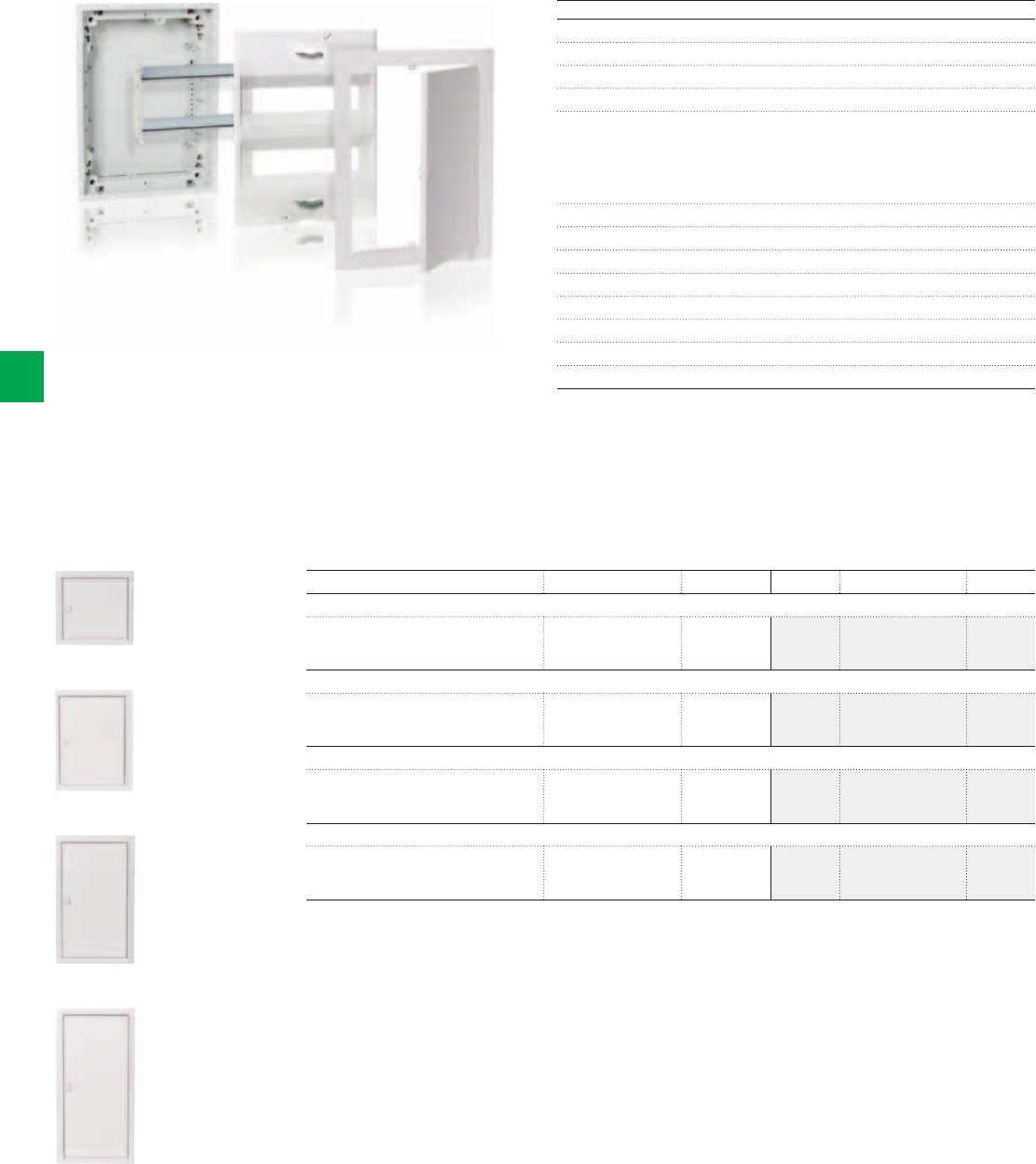
2CSC400030F0600
UK512N2
2CSC400030F0601
UK524N3
2CSC400030F0602
UK536N3
2CSC400030F0603
UK548N3
6/8 2CSC 400 031 D0202 | System pro M compact®
6
Complete version UK500N with trim frame and doors
With the new N/PE Quick-terminals
Flush-mounted consumer units – UK500N, IP30 - , ;
*
In up to 63 A
Consumer unit DIN VDE 0603-1, DIN 43871
Available in 1 up to 4 row versions as flush-mounted consumer units
Upgradeable for hollow-wall mounting using UZ90P4
Wall box:
- Non-warp, break-proof, non-flammable, low-halogen plastic
- With cable strain relief comb
- With detachable cable inlets
Wall grips
Removable device support
With the new N/PE Quick-terminals
Cover with 90° quick-action screws, lead-sealable
45mm slots for 12 devices, expandable to 14
Labelling system
Trim frame and sheet steel door, adjustable for uneven surface
Colour: White, RAL 9016
* In connection with UZ90P4
Article H x W x D in mm SU Type Ord. no. Price
Flush-mounted consumer units, 1-row
Niche dimensions
Wall cut out dimensions for
hollow-wall mounting
335 x 350 x 95
308 x 327 x 88
12 (13) UK512N2 2CPX031281R9999
Flush-mounted consumer units, 2-row
Niche dimensions
Wall cut out dimensions for
hollow-wall mounting
460 x 350 x 95
433 x 327 x 88
24 (28) UK524N3 2CPX031282R9999
Flush-mounted consumer units, 3-row
Niche dimensions
Wall cut out dimensions for
hollow-wall mounting
585 x 350 x 95
558 x 327 x 88
36 (41) UK536N3 2CPX031283R9999
Flush-mounted consumer units, 4-row
Niche dimensions
Wall cut out dimensions for
hollow-wall mounting
710 x 350 x 95
683 x 327 x 88
48 (56) UK548N3 2CPX031284R9999
> Dimensions and technical details, see page 6/78 and 6/89
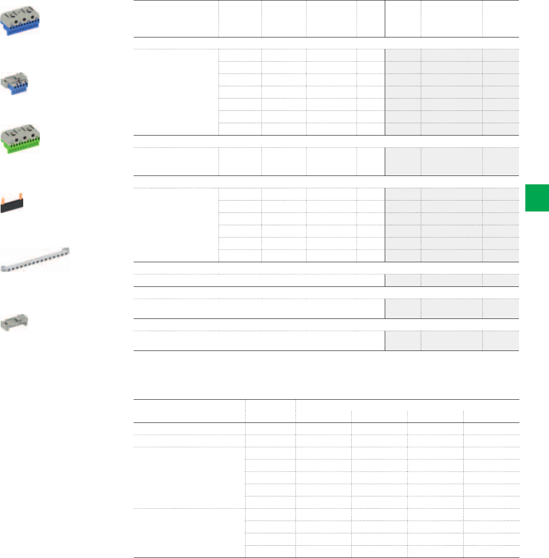
2CSC400030F0604
2CSC400030F0605
2CSC400030F0606
2CSC400030F0607
2CSC400030F0608
2CSC400030F0609
ZK113B
ZK50BT
ZK113G
ZK10P10
ZK11
ZK15
System pro M compact® | 2CSC 400 031 D0202 6/9
6
N/PE Quick-terminals
Accessories / Equipment in the UK500N
Article Type
Equipment with new N/PE Quick-terminals*
UK512N2 UK524N3 UK536N3 UK548N3
Quick carrier for UK500N ZK11 1 pc. 1 pc. 1 pc. 1 pc.
Adapter for ZK50B ZK15 1 pc. 1 pc.
N Quick-terminal ZK50B 1 pc. 1 pc. 1 pc.
ZK51B 1 pc.
ZK82B 1 pc. 2 pcs. 1 pc.
ZK113B 2 pcs.
ZK144B 1 pc.
PE Quick-terminal ZK113G 1 pc.
ZK144G 1 pc.
ZK175G 1 pc.
ZK206G 1 pc.
* Included in the scope of delivery
Article Number of
terminals
1.5 - 4mm2
Number of
terminals
2.5 - 25 mm2
External
dimensions
H x W x D
in mm
Pcs. Type Ord. no. Price
N Quick-terminals
For quick carriers 5 0 23 x 32 x 21 1 ZK50B 2CPX062750R9999
5 1 32 x 32 x 31 1 ZK51B 2CPX062751R9999
8 2 32 x 49 x 31 1 ZK82B 2CPX062752R9999
11 3 32 x 65 x 31 1 ZK113B 2CPX062753R9999
14 4 32 x 82 x 31 1 ZK144B 2CPX062754R9999
17 5 32 x 98 x 31 1 ZK175B 2CPX062755R9999
20 6 32 x 115 x 31 1 ZK206B 2CPX062756R9999
N Quick-terminal with adapter ZK15
For lateral assembly to the
UK5… , A3…or for fastening
to the DIN rail
5 0 28 x 39 x 25 1 ZK50BT 2CPX062745R9999
PE Quick-terminals
For quick carriers 5 1 32 x 32 x 31 1 ZK51G 2CPX062757R9999
8 2 32 x 49 x 31 1 ZK82G 2CPX062758R9999
11 3 32 x 65 x 31 1 ZK113G 2CPX062759R9999
14 4 32 x 82 x 31 1 ZK144G 2CPX062760R9999
17 5 32 x 98 x 31 1 ZK175G 2CPX062761R9999
20 6 32 x 115 x 31 1 ZK206G 2CPX062762R9999
Connecting bridges
For Quick-terminals 10 ZK10P10 2CPX062763R9999
Quick carriers
For consumer units UK5...
Usable width for Quick-terminals 247 mm
1 ZK11 2CPX064980R9999
Adapter for ZK50B
Engaging the ZK50B N Quick-terminal in the adapter ZK15, leads to ZK50BT to
be laterally fastened UK5… , A3 or to the DIN rail
1 ZK15 2CPX064984R9999
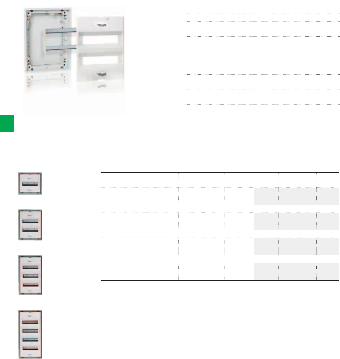
2CSC400030F0610
2CSC400030F06112CSC400030F06122CSC400030F0613
UK512BN
UK524BN
UK536BN
UK548BN
6/10 2CSC 400 031 D0202 | System pro M compact®
6
Basic version UK500BN without trim frame and doors
With the new N/PE Quick-terminals
Flush-mounted consumer units – UK500BN, IP30 - , ;
*
In up to 63 A
Consumer unit DIN VDE 0603-1, DIN 43871
Available in 1 up to 4 row versions as flush-mounted consumer units
Upgradeable for hollow-wall mounting using UZ90P4
Wall box:
- Non-warp, break-proof, non-flammable, low-halogen plastic
- With cable strain relief comb
- With detachable cable inlets
Wall grips
Removable device support
With the new N/PE Quick-terminals
Cover with 90° quick-action screws, lead-sealable
45mm slots for 12 devices, expandable to 14
Labelling system
* In connection with UZ90P4
Article H x W x D in mm SU Type Ord. no. Price
Flush-mounted consumer units, 1-row
Niche dimensions
Wall cut out dimensions for
hollow-wall mounting
335 x 350 x 95
308 x 327 x 88
12 (14*) UK512BN2 2CPX031285R9999
Flush-mounted consumer units, 2-row
Niche dimensions
Wall cut out dimensions for
hollow-wall mounting
460 x 350 x 95
433 x 327 x 88
24 (28) UK524BN3 2CPX031286R9999
Flush-mounted consumer units, 3-row
Niche dimensions
Wall cut out dimensions for
hollow-wall mounting
585 x 350 x 95
558 x 327 x 88
36 (42*) UK536BN3 2CPX031287R9999
Flush-mounted consumer units, 4-row
Niche dimensions
Wall cut out dimensions for
hollow-wall mounting
710 x 350 x 95
683 x 327 x 88
48 (56) UK548BN3 2CPX031288R9999
* In connection with a standard door, "vision line" or "color line" with TIP-in closure there will be one space unit less.
> Dimensions and technical details, see page 6/8
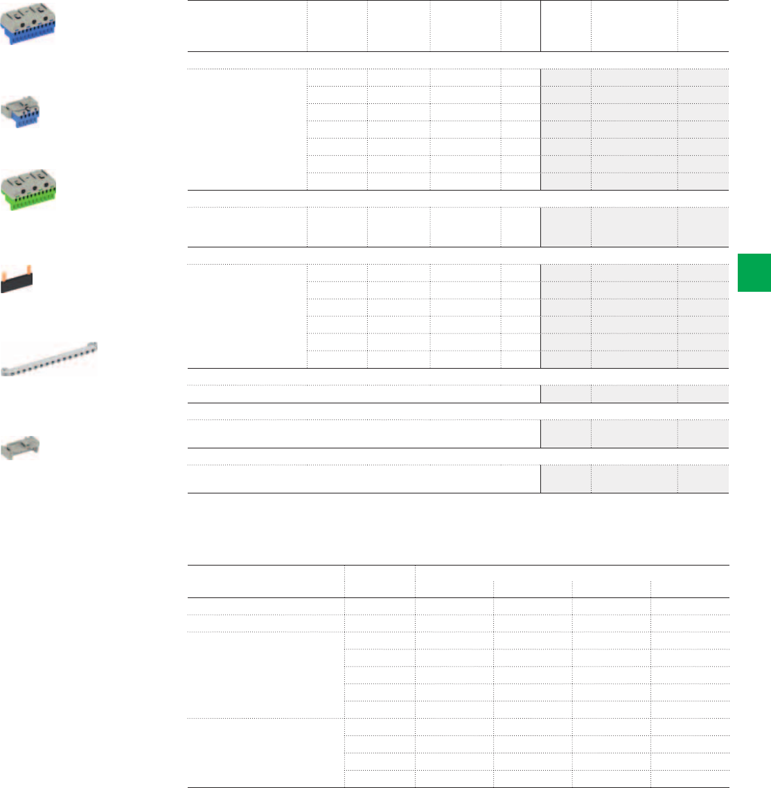
ZK113B
ZK50BT
ZK113G
ZK10P10
ZK11
ZK15
2CSC400030F0604
2CSC400030F0605
2CSC400030F0606
2CSC400030F0607
2CSC400030F0608
2CSC400030F0609
System pro M compact® | 2CSC 400 031 D0202 6/11
6
N/PE Quick-terminals
Accessories / Equipment with UK500BN
Article Number of
terminals
1.5 - 4mm2
Number of
terminals
2.5 - 25 mm2
External
dimensions
H x W x D
in mm
Pcs. Type Ord. no. Price
N Quick-terminals
For quick carriers 5 0 23 x 32 x 21 1 ZK50B 2CPX062750R9999
5 1 32 x 32 x 31 1 ZK51B 2CPX062751R9999
8 2 32 x 49 x 31 1 ZK82B 2CPX062752R9999
11 3 32 x 65 x 31 1 ZK113B 2CPX062753R9999
14 4 32 x 82 x 31 1 ZK144B 2CPX062754R9999
17 5 32 x 98 x 31 1 ZK175B 2CPX062755R9999
20 6 32 x 115 x 31 1 ZK206B 2CPX062756R9999
N Quick-terminal with adapter ZK15
For lateral assembly to the
UK5… , A3…or for fastening
to the DIN rail
5 0 28 x 39 x 25 1 ZK50BT 2CPX062745R9999
PE Quick-terminals
For quick carriers 5 1 32 x 32 x 31 1 ZK51G 2CPX062757R9999
8 2 32 x 49 x 31 1 ZK82G 2CPX062758R9999
11 3 32 x 65 x 31 1 ZK113G 2CPX062759R9999
14 4 32 x 82 x 31 1 ZK144G 2CPX062760R9999
17 5 32 x 98 x 31 1 ZK175G 2CPX062761R9999
20 6 32 x 115 x 31 1 ZK206G 2CPX062762R9999
Connecting bridges
For Quick-terminals 10 ZK10P10 2CPX062763R9999
Quick carriers
For consumer units UK5...
Usable width for Quick-terminals 247 mm
1 ZK11 2CPX064980R9999
Adapter for ZK50B
Engaging the ZK50B N Quick-terminal in the adapter ZK15, leads to ZK50BT to
be laterally fastened UK5… , A3 or to the DIN rail
1 ZK15 2CPX064984R9999
Article Type
Equipment with new N/PE Quick-terminals*
UK512BN2 UK524BN3 UK536BN3 UK548BN3
Quick carrier for UK500BN ZK11 1 pc. 1 pc. 1 pc. 1 pc.
Adapter for ZK50B ZK15 1 pc. 1 pc.
N Quick-terminal ZK50B 1 pc. 1 pc. 1 pc.
ZK51B 1 pc.
ZK82B 1 pc. 2 pcs. 1 pc.
ZK113B 2 pcs.
ZK144B 1 pc.
PE Quick-terminal ZK113G 1 pc.
ZK144G 1 pc.
ZK175G 1 pc.
ZK206G 1 pc.
* Included in the scope of delivery

UK510E
UK520E
UK530E
UK540E
2CSC400030F0600
2CSC400030F0601
2CSC400030F0602
2CSC400030F0603
6/12 2CSC 400 031 D0202 | System pro M compact®
6
Article H x W x D in mm SU Type Ord. no. Price
Flush-mounted consumer units, 1-row
Niche dimensions for flush-mounting
Wall cut out dimensions for
hallow wall mounting
335 x 350 x 95
308 x 327 x 88
12 (13)
With screwable N/PE terminals
and sheet steel door
UK510E 2CPX077600R9999
With screwable N/PE terminals
and transparent door
UK510ETT 2CPX031017R9999
Without N/PE terminals
With sheet steel door
UK510KE 2CPX031001R9999
With screwable N/PE terminals
With sheet steel door
and cable inlet for tubes
UK510SN 2CPX030819R9999
Flush-mounted consumer units, 2-row
Niche dimensions for flush-mounting
Wall cut out dimensions for
hallow wall mounting
460 x 350 x 95
433 X 327 x 88
24 (28)
With screwable N/PE terminals
and sheet steel door
UK520E 2CPX077601R9999
With screwable N/PE terminals
and transparent door
UK520ETT 2CPX031018R9999
Without N/PE terminals
With sheet steel door
UK520KE 2CPX031002R9999
With screwable N/PE terminals
With sheet steel door
and cable inlet for tubes
UK520SN 2CPX030820R9999
Flush-mounted consumer units, 3-row
Niche dimensions for flush-mounting
Wall cut out dimensions for
hallow wall mounting
585 x 350 x 95
558 X 327 x 88
36 (41)
With screwable N/PE terminals
and sheet steel door
UK530E 2CPX077602R9999
With screwable N/PE terminals
and transparent door
UK530ETT 2CPX031019R9999
Without N/PE terminals
With sheet steel door
UK530KE 2CPX031003R9999
With screwable N/PE terminals
With sheet steel door
and cable inlet for tubes
UK530SN 2CPX030821R9999
Flush-mounted consumer units, 4-row
Niche dimensions for flush-mounting
Wall cut out dimensions for
hallow wall mounting
710 x 350 x 95
683 X 327 x 88
48 (56)
With screwable N/PE terminals
and sheet steel door
UK540E 2CPX077603R9999
With screwable N/PE terminals
and transparent door
UK540ETT 2CPX031020R9999
Without N/PE terminals
With sheet steel door
UK540KE 2CPX031004R9999
With screwable N/PE terminals
With sheet steel door
and cable inlet for tubes
UK540SN 2CPX030822R9999
> Dimensions and technical details, see page 6/8
Complete version UK500 with trim frame and doors
With screwable N/PE terminals
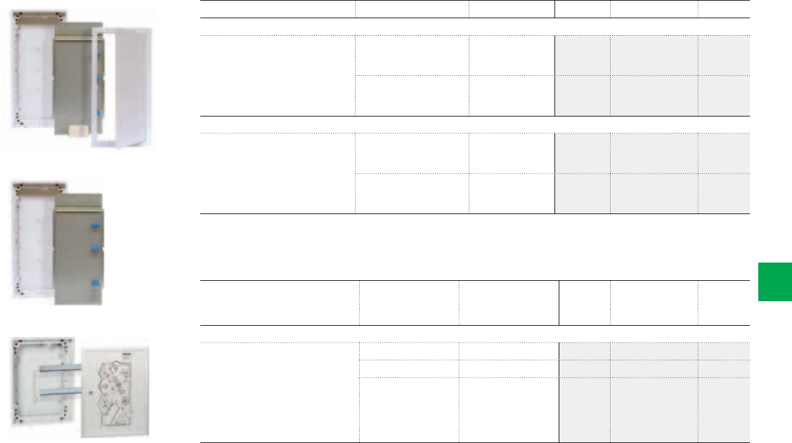
UK530MV
UZM530MV
FPT520
2CSC400030F0614
2CSC400030F0615
2CSC400030F0616
System pro M compact® | 2CSC 400 031 D0202 6/13
6
Multimedia enclosures with and without trim frame and doors
Consumer units with control panel FPT500
Article Internal dimensions
of the control panel
External dimensions
of the control panel
Type Ord. no. Price
H x W in mm H x W x D in mm
Consumer units with control panel
Wall box with device support, removable
DIN rails; aluminium control panel
unprinted and unwired;
the control panel can be finished by
the user or supplied already wired and
printed by the factory; control panels
must only be mounted in vertical
direction; door hinged right
282 x 293 362 x 374 x 22 FPT510 2CPX030825R9999
403 x 293 487 x 374 x 22 FPT520 2CPX030826R9999
528 x 293 612 x 374 x 22 FPT530 2CPX030827R9999
> Dimensions and technical details, see page 6/8
> Useable space of the control panel, see page 6/90
Article Remark H x W x D in mm Type Ord. no. Price
Flush-mounted multimedia enclosures with doors
Wall box with perforated sheet steel
mounting plate, wire holders,
DIN rail, wall grips, double socket with
euro-plug insert, trim frame
and door with ventilation holes
Niche dimensions
Wall cut out dimensions
Mounting plate dimensions
585 x 350 x 95
558 x 327 x 88
447 x 277 x 1.5
UK530MV 2CPX030839R9999
Niche dimensions
Wall cut out dimensions
Mounting plate dimensions
710 x 350 x 95
638 x 327 x 88
572 x 277 x 1.5
UK540MV 2CPX030840R9999
Flush-mounted multimedia enclosures without doors
with perforated sheet steel mounting
plate, wire holders,
DIN rail and wall grips
Niche dimensions
Wall cut out dimensions
Mounting plate dimensions
585 x 350 x 95
558 x 327 x 88
447 x 277 x 1.5
UZM530MV 2CPX030985R9999
Niche dimensions
Wall cut out dimensions
Mounting plate dimensions
710 x 350 x 95
683 x 327 x 88
572 x 277 x 1.5
UM540MV 2CPX030986R9999
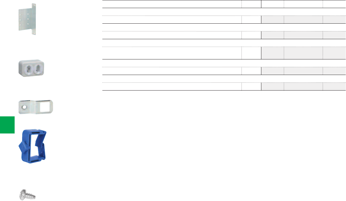
ZX29
ZE225
ED57P10
ED44P10
ZX287P10
2CSC400030F0617
2CSC400030F0618
2CSC400030F0619
2CSC400030F0620
2CSC400030F0621
6/14 2CSC 400 031 D0202 | System pro M compact®
6
Article Pcs. Type Ord. no. Price
Cross member
For double socket 1 ZX29 2CPX061178R9999
Double socket with euro-plug insert
For supplying 230V power to power supplies 1 ZE225 2CPX061177R9999
Adapter
To fasten the ED44P10 wire holder to the perforated
sheet steel mounting plate
10 ED57P10 2CPX061179R9999
Wire holder
28.5mm 10 ED44P10 2CPX062335R9999
Screws M4 x14 thread rolling
For the perforated sheet steel mounting plate 10 ZX287P10 2CPX061180R9999
Multimedia enclosures
Accessories
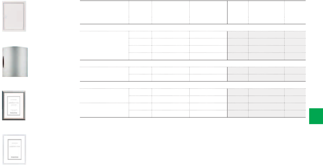
BL5
BL528D
BL521D
BL527D
2CSC400030F0622
2CSC400030F0623
2CSC400030F0624
2CSC400030F0625
System pro M compact® | 2CSC 400 031 D0202 6/15
6
Article To be used
with...
Internal
dimensions of the
trim cover
External
dimensions of the
trim cover
Type Ord. no. Price
H x W x D in mm H x W x D in mm
Trim frame with door (complete version)
Colour: white, RAL 9016
Sheet steel, powder coated
UK51... 282 x 297 x 33 352 x 367 x 9 BL510 2CPX030853R9999
UK52... 407 x 297 x 33 477 x 367 x 9 BL520 2CPX030854R9999
UK53... 532 x 297 x 33 602 x 367 x 9 BL530 2CPX030855R9999
UK54... 657 x 297 x 33 727 x 367 x 9 BL540 2CPX030856R9999
art line
Brushed stainless steel UK52... 407 x 297 x 33 490 x 407 x 39 BL528D 2CPX030918R9999
UK53... 532 x 297 x 33 615 x 407 x 39 BL538D 2CPX030919R9999
addition line
Picture frame door
Brushed aluminium
UK52... 407 x 297 x 27 487 x 378 x 26 BL521D 2CPX030858R9999
UK53... 532 x 297 x 27 612 x 378 x 26 BL531D 2CPX030859R9999
Picture frame door
Colour: white, RAL 9016
UK52... 407 x 297 x 27 487 x 374 x 22 BL527D 2CPX030897R9999
UK53... 532 x 297 x 27 612 x 374 x 22 BL537D 2CPX030898R9999
> Dimensions and technical details, see page 6/14
> Dimensions picture frame doors, see page 6/14
Doors for UK500
Door selection
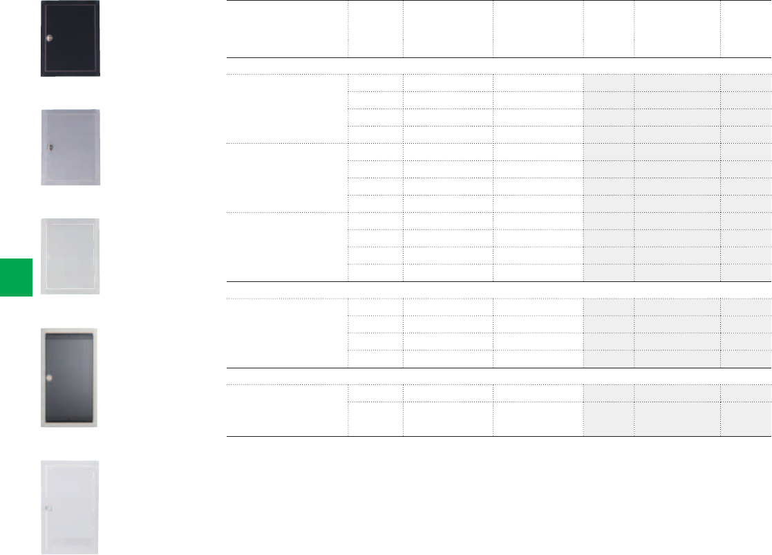
2CSC400030F0629
BL510K
2CSC400030F0626
BL516C
2CSC400030F0627
2CSC400030F0628
BL518C
2CSC400030F0630
BL530L
BL517C
6/16 2CSC 400 031 D0202 | System pro M compact®
6
Article To be used
with...
Internal
dimensions of
the trim cover
External
dimensions of
the trim cover
Type Ord. no. Price
H x W x D in mm H x W x D in mm
color line
Trim frame with door
Colour: anthracite RAL 7016
UK51... 282 x 297 x 33 352 x 367 x 9 BL516C 2CPX031251R9999
UK52... 407 x 297 x 33 477 x 367 x 9 BL526C 2CPX031252R9999
UK53... 532 x 297 x 33 602 x 367 x 9 BL536C 2CPX031253R9999
UK54... 657 x 297 x 33 727 x 367 x 9 BL546C 2CPX031254R9999
Trim frame with door
Colour: silver RAL 9006
UK51... 282 x 297 x 33 352 x 367 x 9 BL517C 2CPX031255R9999
UK52... 407 x 297 x 33 477 x 367 x 9 BL527C 2CPX031256R9999
UK53... 532 x 297 x 33 602 x 367 x 9 BL537C 2CPX031257R9999
UK54... 657 x 297 x 33 727 x 367 x 9 BL547C 2CPX031258R9999
Trim frame with door
Colour: light grey RAL 7035
UK51... 282 x 297 x 33 352 x 367 x 9 BL518C 2CPX031259R9999
UK52... 407 x 297 x 33 477 x 367 x 9 BL528C 2CPX031260R9999
UK53... 532 x 297 x 33 602 x 367 x 9 BL538C 2CPX031261R9999
UK54... 657 x 297 x 33 727 x 367 x 9 BL548C 2CPX031262R9999
vision line
Transparent door UK51... 282 x 297 x 33 352 x 367 x 9 BL510K 2CPX030835R9999
UK52... 407 x 297 x 33 477 x 367 x 9 BL520K 2CPX030836R9999
UK53... 532 x 297 x 33 602 x 367 x 9 BL530K 2CPX030837R9999
UK54... 657 x 297 x 33 727 x 367 x 9 BL540K 2CPX030838R9999
media line
Trim frame and door with
ventilation holes
Colour: white, RAL 9016
Sheet steel, powder-coated
UZM530MV 532 x 297 x 33 602 x 367 x 9 BL530L 2CPX030990R9999
UZM540MV 657 x 297 x 33 727 x 367 x 9 BL540L 2CPX030991R9999
Dimensions and technical details, see page 1/28
Doors for UK500
Door selection
UZ7
UZM5
UZ4P2
UZ530G
UZ510A
UZ90P4
AP5
ZK502
ZK505
ZK506
ZK507
ZA120
2CSC400030F0631
2CSC400030F0632
2CSC400030F0633
2CSC400030F0634
2CSC400030F0635
2CSC400030F0636
2CSC400030F0637
2CSC400030F06382CSC400030F0639
2CSC400030F0639
2CSC400030F0640
2CSC400030F0641
System pro M compact® | 2CSC 400 031 D0202 6/17
6
Article Pcs Type Ord. no. Price
Door hinge set
UK500
1UZ7 2CPX030917R9999
Wall box with wall grips
To be used with UK51... 1 UZM510 2CPX030805R9999
To be used with UK52... 1 UZM520 2CPX030806R9999
To be used with UK53... 1 UZM530 2CPX030807R9999
To be used with UK54... 1 UZM540 2CPX030808R9999
Wall grips
To fix the wall box in two mounting depths 4 UZ4P2 2CPX062447R9999
DIN rail with device support
To be used with UK51... 1 UZ510G 2CPX030841R9999
To be used with UK52... 1 UZ520G 2CPX030842R9999
To be used with UK53... 1 UZ530G 2CPX030843R9999
To be used with UK54... 1 UZ540G 2CPX030844R9999
Cover with 90° quick-action screws
To be used with UK51... 1 UZ510A 2CPX030845R9999
To be used with UK52... 1 UZ520A 2CPX030846R9999
To be used with UK53... 1 UZ530A 2CPX030847R9999
To be used with UK54... 1 UZ540A 2CPX030848R9999
Hollow-wall mounting set
To modify the flush-mounting consumer unit into a hollow-wall consumer unit UK500
(type label and 20 cable ties included) wall thickness
min. 8mm, max. 35mm
1UZ90P4 2CPX062563R9999
On wall mounting set
For wall mounting or partially recessed installation
To be used with UK51... 1 AP510 2CPX030849R9999
To be used with UK52... 1 AP520 2CPX030850R9999
To be used with UK53... 1 AP530 2CPX030851R9999
To be used with UK54... 1 AP540 2CPX030852R9999
NP/E terminals
3 x 16 mm2 + 14 x 4 mm2, Cu screwable (each) 1 ZK502 2CPX030887R9999
N terminals
5 x 16 mm2 + 19 x 10 mm2, Cu screwable 1 ZK505 2CPX030890R9999
NP terminals
5 x 16 mm2 + 19 x 10 mm2, Cu screwable 1 ZK506 2CPX030891R9999
N-RCD-busbar
3 x 16mm2 + 2 x 10mm2 Cu pluggable 1 ZK507 2CPX030892R9999
Touch-up applicator
Colour RAL 9016, 12ml 1 ZA120 2CPX039043R9999
Consumer units UK500
Accessories
UZ3
ZA89P20
UZ510M
UZ530L
UZ2
UZ1
ZA3P5
UZ5
UZ52
UZ84
2CSC400030F0642
2CSC400030F0643
2CSC400030F0644
2CSC400030F0645
2CSC400030F0646
2CSC400030F0647
2CSC400030F0648
2CSC400030F0649
2CSC400030F0650
2CSC400030F0651
6/18 2CSC 400 031 D0202 | System pro M compact®
6
Article Pcs. Type Ord. no. Price
Labelling system
Self-adhesive, for identifying circuits, 17.5mm 1 UZ3 2CPX030882R9999
Screws
20 pcs. for fixing DIN rails and mounting plates 1 ZA89P20 2CPX062376R9999
Mounting plate, sheet steel, galvanised
H x W in mm
130 x 255 to be used with UK510S 1 UZ510M 2CPX030872R9999
255 x 255 to be used with UK520S 1 UZ520M 2CPX030873R9999
380 x 255 to be used with UK530S 1 UZ530M 2CPX030874R9999
505 x 255 UK540S 1 UZ540M 2CPX030875R9999
Perforated mounting plate for multimedia enclosures
H x W in mm
447 x 227 UZM530MV 1 UZ530L 2CPX030992R9999
572 x 227 to be used with UZM540MV 1 UZ540L 2CPX030993R9999
TIP-in-closure
Colour: white 1 UZ2 2CPX030885R9999
Closure with lock
With 2 keys 1 UZ1 2CPX030870R9999
Slot cover, 5 pcs.
Colour: white, RAL 9016 5 ZA3P5 2CPX062385R9999
Cable inlet for wall box
Top or bottom, 1 to 4 rows 1 UZ5 2CPX030871R9999
Vertical partition
1-row 1 UZ51 2CPX030878R9999
2-row 1 UZ52 2CPX030879R9999
3-row 1 UZ53 2CPX030880R9999
4-row 1 UZ54 2CPX030881R9999
Horizontal partition
1 UZ84 2CPX030877R9999
Consumer units UK500
Accessories

System pro M compact® | 2CSC 400 031 D0202 6/19
6
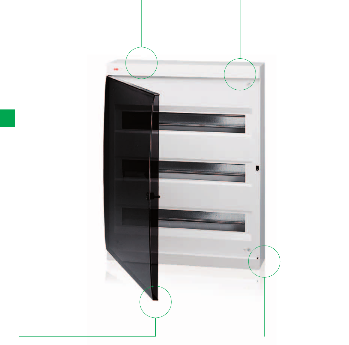
6/20 2CSC 400 031 D0202 | System pro M compact®
6
Unibox Wall-mounting Series
The details make the difference
Available
dimensions from 8
up to 54 modules
The cover is
fitted using rapid
pitch screws in
insulating thermo-
plastic that can
be lead-sealed if
necessary
Elegant attractive
line following the
latest trends in
design (patented
model)
Extractable and
inclinable frame,
snap fixing
onto the base;
components and
accessories are
easy to assembly
by snapping on,
without the need
for screws
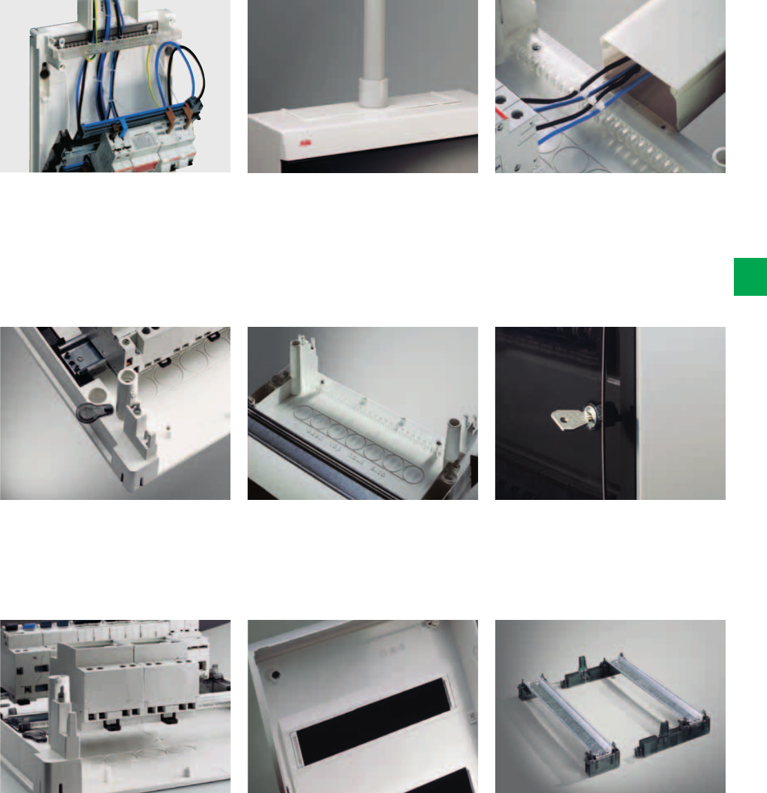
System pro M compact® | 2CSC 400 031 D0202 6/21
6
A characteristic of consumer units in the
UNIBOX Series is the frame, which
can be kept in an angled position thanks
to practical wires, making it easier to
work on the connection cables.
The special caps used to cover the
holes for attaching to the wall ensure
that the consumer unit is double
insulated.
Thanks to plenty of room under the DIN
rail it is possible to install the cables
tidily and rationalise their paths.
Complete with accessories for tidy
wiring and for clamping of incoming and
outgoing cables
The knockouts in the cover give maximum
flexibility in trunking branch connections.
The knockout cut halfway down the
module on both sides makes it possible
to fit an extra module corresponding to
each row of circuit breakers.
Equipped with spring door closure
employing the push-pull system,
prepared for the fitting of a lock
The modular, snap-on frame is
easy to extract and is therefore ideal for
bench cabling.
The consumer unit is designed
with a flange so that it can be used for
branch connection using a conduit. The
knockouts make it possible to make
branch connections with conduits with a
maximum diameter of 40 mm.
The practical holding system
secures the incoming and outgoing
cables to a special comb accessory,
which not only keeps the cables tidy
but also protects the devices’ terminals
from any direct mechanical contact.
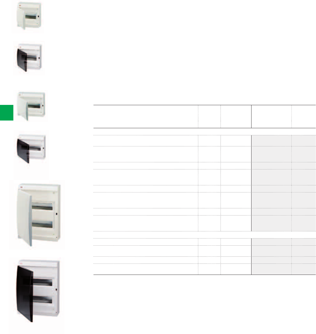
2CSC400030F0159
2CSC400030F0161
2CSC400030F0162
2CSC400030F0163
2CSC400030F0160
Unibox 1-row with opaque door
Unibox 1-row with opaque door
Unibox 1-row with transparent,
smoky door
Unibox 2-row opaque door
Unibox 2-row transparent,
smoky door
Unibox 1-row with transparent,
smoky door
6/22 2CSC 400 031 D0202 | System pro M compact®
6
Ordering Information
Unibox Wall-mounting Series
- Unibox wall-mounting series for residential applications (houses, flats).
- Rated current In = 125A; Protection degree IP40; Protection class II (double insulated);
Shock resistance 10 Joules (IK level 09).
- In thermoplastic, self-extinguishing and resistant to abnormal heat and fire up to 650°C
(glow wire flammability index) in compliance with IEC 60695-2-11 Standard.
- Installation temperature from -25°C to +60°C; resistant to heat: ball thermopressure up to
+85°C in compliance with EN 60695-10-2 Standard.
- Unibox consumer units are manufactured in compliance with CEI 23-49 (1996) + V1 + V2,
CB certificate IEC 60670-24 Standards.
- IP40 Unibox Series wall-mounting consumer units obtained the IMQ mark of approval IMQ.
- Unibox consumer units are supplied complete with: module covers; protective film for door;
cable-clip accessory; rigid flange for branch connections with conduits; 1 self-adhesive
indicator strip per row; 1 plate for CEI 23-51 certification; instruction sheet; 4 protection
caps.
Description N° module Dimensions
HxWxD
[18 mm] [mm] Order code Price
1-row ,
Unibox, wall-mounting, RAL 9016, with opaque door 8 215x220x105 12238
Unibox, wall-mounting, RAL 9016, with opaque door,
with terminal bars (n°1 12531 + n°1 12532)
8 215x220x105 M12238000U
Unibox, wall-mounting, RAL 9016, with transparent, smoky door 8 215x220x105 12258
Unibox, wall-mounting, RAL 9016, with transparent, smoky door,
with terminal bars (n°1 12531 + n°1 12532)
8 215x220x105 M12258000U
Unibox, wall-mounting, RAL 9016, with opaque door 12 295x245x115 12242
Unibox, wall-mounting, RAL 9016, with opaque door,
with terminal bars (n°2 12535)
12 295x245x115 M12242000A
Unibox, wall-mounting, RAL 9016, with transparent, smoky door 12 295x245x115 12262
Unibox, wall-mounting, RAL 9016, with transparent,
smoky door, with terminal bars (n°2 12535)
12 295x245x115 M12262000A
2-row ,
Unibox, wall-mounting, RAL 9016, with opaque door 24 295x390x115 12244
Unibox, wall-mounting, RAL 9016, with opaque door,
with terminal bars (n°2 12531 + n°2 12533)
24 295x390x115 M12244000U
Unibox, wall-mounting, RAL 9016, with transparent, smoky door 24 295x390x115 12264
Unibox, wall-mounting, RAL 9016, with transparent,
smoky door, with terminal bars (n°2 12531 + n°2 12533)
24 295x390x115 M12264000U
2CSC400030F0164
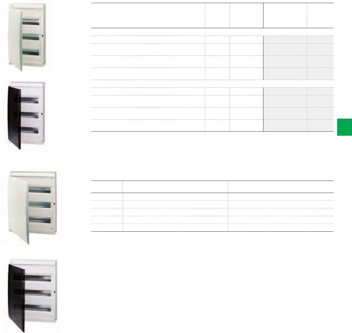
2CSC400030F0165
2CSC400030F0166
Unibox with opaque door
Unibox with transparent,
smoky door
2CSC400030F0167
2CSC400030F0168
Unibox with opaque door
Unibox with transparent,
smoky door
System pro M compact® | 2CSC 400 031 D0202 6/23
6
Description N° module Dimensions
HxWxD
[18 mm] [mm] Order code Price
3-row ,
Unibox, wall-mounting, RAL 9016, with opaque door 36 295x515x115 12246
Unibox, wall-mounting, RAL 9016, with opaque door,
with terminal bars (n°2 12531 + n°2 12534)
36 295x515x115 M12246000U
Unibox, wall-mounting, RAL 9016, with transparent,
smoky door
36 295x515x115 12266
Unibox, wall-mounting, RAL 9016, with transparent,
smoky door, with terminal bars (n°2 12531 + n°2 12534)
36 295x515x115 M12266000U
3-row ,
Unibox, wall-mounting, RAL 9016, with opaque door 54 405x515x115 12247
Unibox, wall-mounting, RAL 9016, with opaque door,
with terminal bars (n°2 12535)
54 405x515x115 M12247000U
Unibox, wall-mounting, RAL 9016, with transparent,
smoky door
54 405x515x115 12267
Unibox, wall-mounting, RAL 9016, with transparent,
smoky door, with terminal bars (n°2 12535)
54 405x515x115 M12267000U
No
modules
N
(holes x mm²)
PE
(holes x mm²)
8 (10 x 16) + (3 x 25) (5 x 16)
12 (10 x 16) + (3 x 25) (10 x 16) + (3 x 25)
24 (16 x 16) + (3 x 25) + (5 x 16) (16 x 16) + (3 x 25) + (5 x 16)
36 (15 x 16) + (6 x 25) + (5 x 16) (15 x 16) + (6 x 25) + (5 x 16)
54 (19 x 16) + (6 x 25) (19 x 16) + (6 x 25)
Terminal bars configuration
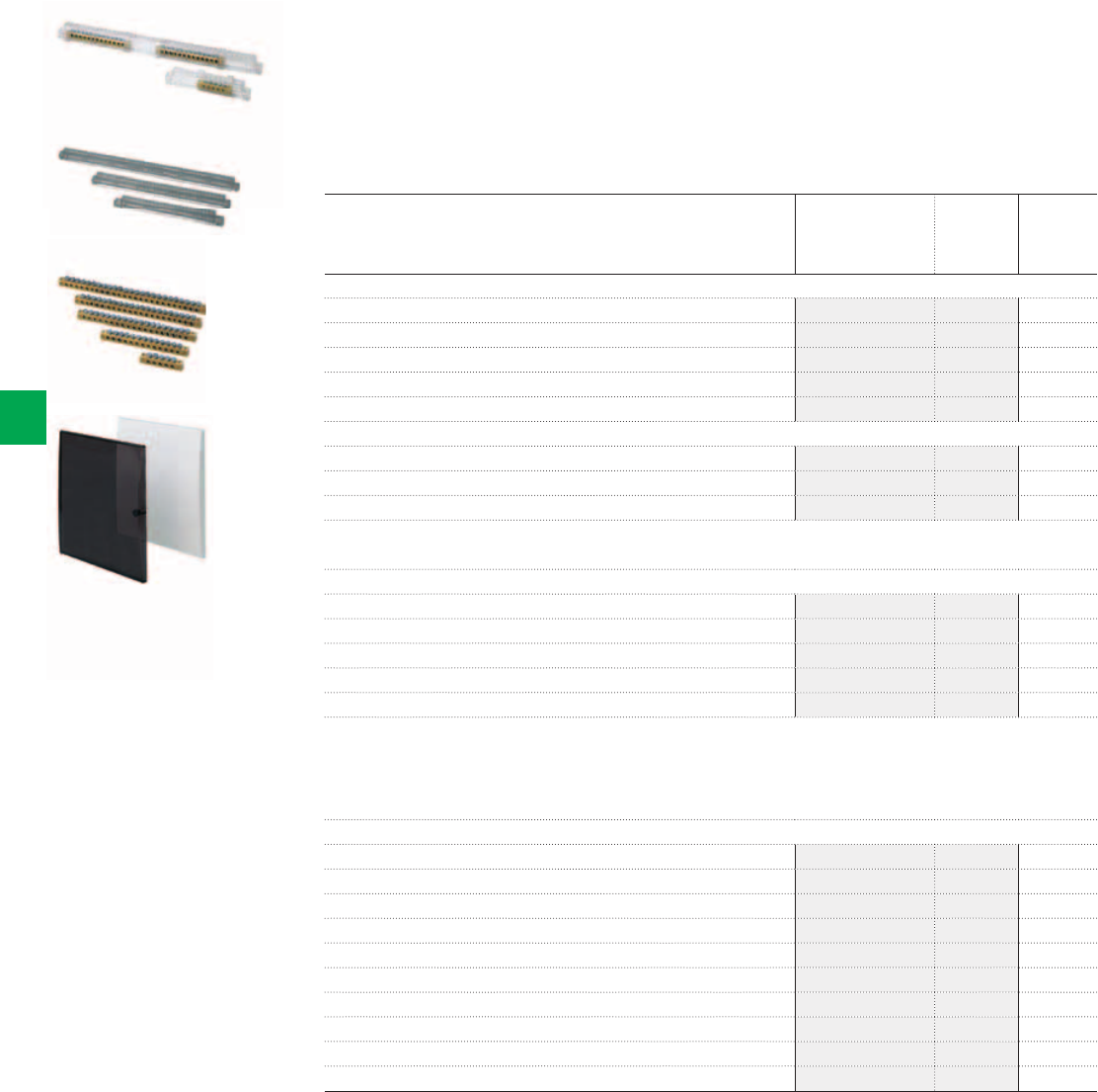
2CSC400030F0169
2CSC400030F0170
2CSC400030F0171
2CSC400030F0172
Terminal blocks
Terminal holders
Terminal bars
Spare doors
6/24 2CSC 400 031 D0202 | System pro M compact®
6
Ordering Information
Unibox Wall-mounting Series
Accessories
Terminal blocks
The complete terminal blocks are composed of a combination of terminal holders and terminal
bars as indicated in the description, with the terminal bars already mounted on terminal
holders. Configuration of the complete terminal block is standard. For different requirements
(customized terminal block), the terminal holders and bars must be procured separately in the
versions indicated in the table.
Description Box/Pack
No items
Order code Price
Terminal blocks
For 8 modules – composed of 12540x1 + 12531x1 + 12532x1 12492 10/40
For 12 modules – composed of 12541x1 + 12532x2 12495 10/40
For 24 modules – composed of 12541x2 + 12531x2 + 12533x2 12504 10/40
For 36 modules – composed of 12541x2 + 12531x2 + 12534x2 12505 10/40
For 54 modules – composed of 12542x2 + 12535x2 12501 5/20
Terminal holders
For 8 modules – for Unibox 12238 and 12258 12540 12/144
For 12 modules per row – for Unibox 12262, 12244, 12264, 12246 and 12266 12541 12/144
For 18 modules per row – for Unibox 12247 and 12267 12542 12/108
The terminal block is completed by combining the necessary terminal bars to the terminal holders, taking care to keep the terminal bars separated from each
other.
Terminal bars
5 holes x Ø 4.5 12531 20/240
10 holes Ø 4.5 mm and 3 holes Ø 5.6 mm² 12532 20/240
16 holes Ø 4.5 mm and 3 holes Ø 5.6 mm² 12533 20/240
15 holes Ø 4.5 mm and 6 holes Ø 5.6 mm² 12534 20/240
19 holes Ø 4.5 mm and 6 holes Ø 5.6 mm² 12535 20/240
The terminal bars can be installed on any kind of terminal holder; they are snapped onto these with 2 clips per bar, through two holes made at the ends of the
bar itself.
Terminal holders and terminal bars are supplied separately. In this way, by inserting one or two terminal bars into the terminal holder you can create the best
terminal for your requirements, with the advantage of obtaining a terminal block that is cheap as well as personalized, due to the fact that you only need to use
material that is really necessary. Some standard configurations are illustrated in the table. All the possible configurations that can be created for each type of
consumer unit are given in the technical details.
Spare doors
Opaque door, RAL 9016 white, for Unibox 12238 and M12238000U 12511 1/25
Opaque door, RAL 9016 white, for Unibox 12242 and M12242000A 15212 1/15
Opaque door, RAL 9016 white, for Unibox 12244 and M12244000U 12513 1/10
Opaque door, RAL 9016 white, for Unibox 12246 and M12246000U 12514 1/5
Opaque door, RAL 9016 white, for Unibox 12247 and M12247000U 12515 1/5
Transparent, smoky door for Unibox 12258 and M12258000U 12521 1/25
Transparent, smoky door for Unibox 12262 and M12262000A 12522 1/15
Transparent, smoky door for Unibox 12264 and M12264000U 12523 1/10
Transparent, smoky door for Unibox 12266 and M12266000U 12524 1/5
Transparent, smoky door for Unibox 12267 and M12267000U 12525 1/5
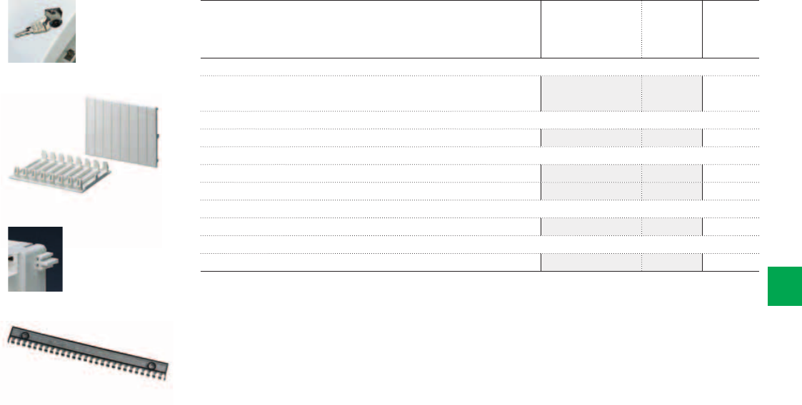
2CSC400030F0173
2CSC400030F0174
2CSC400030F0175
2CSC400030F0176
Door accessories
Closure
Coupling element
Spare doors
System pro M compact® | 2CSC 400 031 D0202 6/25
6
Description Box/Pack
No items
Order code Price
Door accessories
The mechanism for push-pull code No 12526 (in packs of 5 items) should be always
ordered with each door.
12526 1/1
Closure
Lock with Key for Unibox 12 530 20/300
Cover strips
RAL 9016 wgite, module cover strips for 1 module 1SL2857A00 50/1500
RAL 9016 wgite, module cover strips for 4 modules 1SL2859A00 25/300
Coupling element
Unibox coupling element 12556 10/100
Spare doors
Cable-clip com for Unibox Series 12550 1/30
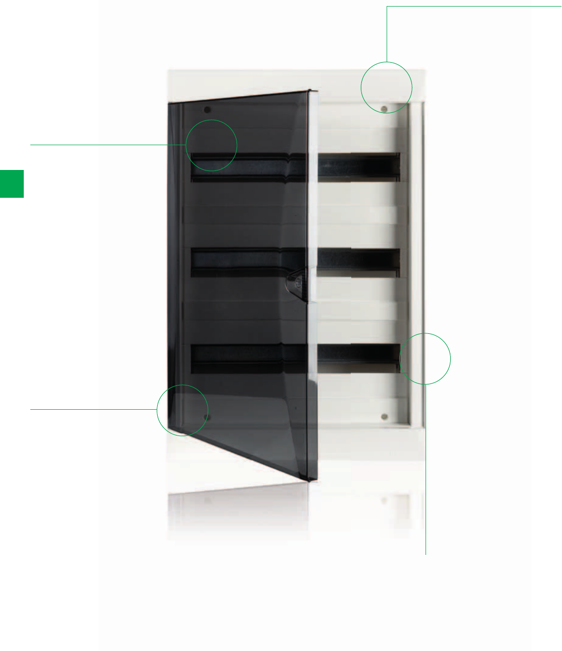
6/26 2CSC 400 031 D0202 | System pro M compact®
6
Alpha Series
The details make the difference
Takes trunking up
to 260x65mm;
Feed wire (25mm²)
can be easily
inserted
Removable frames
(complete frame
and individual
DIN-rails)
Flexible frame
allows mounting
on uneven
surfaces
IP40 Wall-
mounting
consumer unit;
18 modules
(17,5-18mm) per
row; DIN-rail row
spacing: 150mm
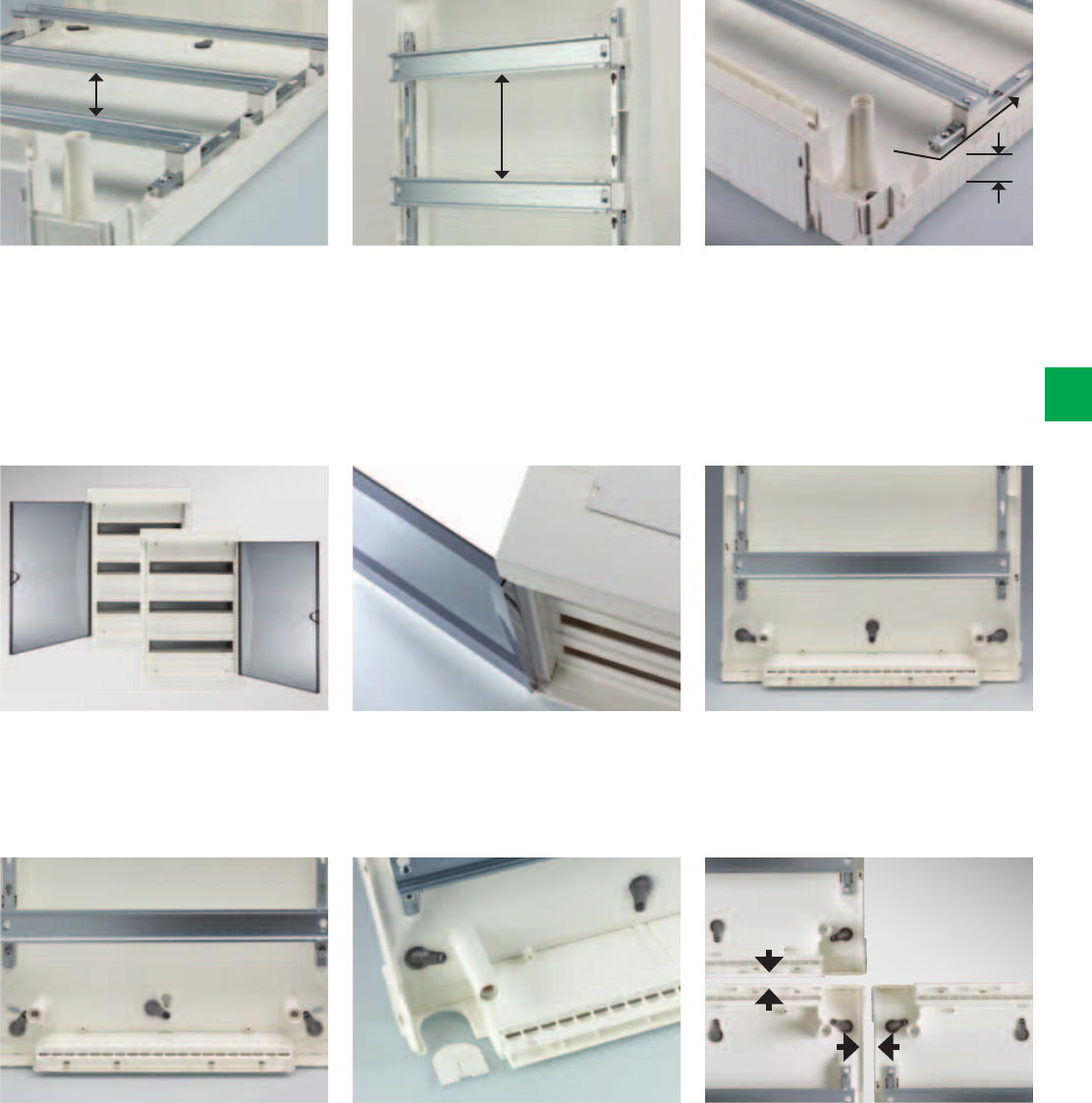
150 mm
26 mm
wires
40 mm
System pro M compact® | 2CSC 400 031 D0202 6/27
6
Plenty of wiring space in the Alpha
Series: the distance between the DIN-
rail and the back plate is 40mm.
Reversible door: left or right opening by
flipping of cover. Lock can be inserted
in door.
Sliding screw covers to ensure
protection class II (double insulated).
Door can be opened up onto the wall
(210°).
Possibility for inserting cable gland M25
on all four corners.
Easy alignment thanks to slotted holes.
Alpha enclosures can be interconnected
horizontally and vertically.
Flexible and easy wiring: Removable
complete DIN-rail frame to facilitate
cabling and wiring. The DIN-rails can be
also taken out individually. The distance
of 150 mm between each DIN-rail allows
more space for wiring.
Easiness and flexibility: low sides of the
Alpha consumer units for easy access;
wires can be led around the frame.
Flexible frame allows mounting on
uneven surfaces.
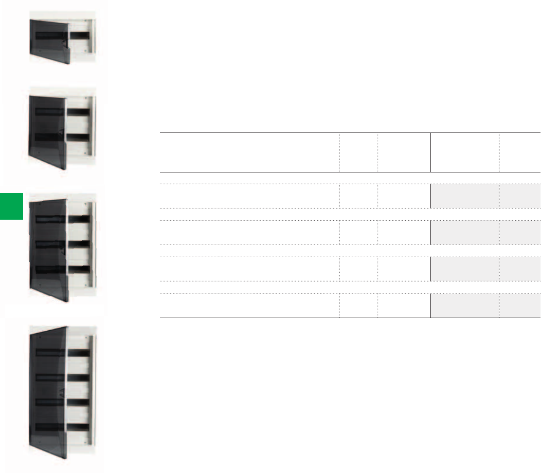
2CSC400030F01772CSC400030F0178
2CSC400030F0179
2CSC400030F0180
1-row
2-row
3-row
4-row
6/28 2CSC 400 031 D0202 | System pro M compact®
6
Ordering Information
Alpha Series
- Rated current In = 100A; Protection degree IP41; Protection class II (double insulated); Shock
resistance 2 Joules (IK level 07)
- In thermoplastic, self-extinguishing and resistant to abnormal heat and fire up to 750°C
(GWT)
- Installation temperature from -5°C ÷ +40°C
- Row Distance: 150mm
- Alpha Series are manufactured in compliance with IEC 60439 Standard
- Alpha consumer units are supplied complete with: Cover strip 13 modules; labelling sheet;
labelling pictogrammes; PE terminal bars
Description N° module Dimensions
HxWxD
[18 mm] [mm] Order code Price
1-row ,
Alpha, wall-mounting, RAL 9010 white, with smoky brown
door, with PE terminal bar 9 x 10 + 8 x 16 mm²
18 307x390x152 1SPE007711F0001
2-row ,
Alpha, wall-mounting, RAL 9010 white, with smoky brown
door, with PE terminal bar 9 x 10 + 8 x 16 mm²
36 457x390x152 1SPE007711F0002
3-row ,
Alpha, wall-mounting, RAL 9010 white, with smoky brown
door, with PE terminal bar 13 x 10 + 12 x 16 mm²
54 607x390x152 1SPE007711F0003
4-row ,
Alpha, wall-mounting, RAL 9010 white, with smoky brown
door, with PE terminal bar 13 x 10 + 12 x 16 mm²
72 757x390x152 1SPE007711F0004
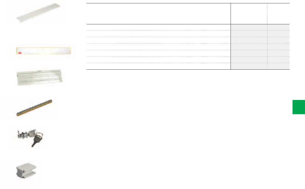
2CSC400030F0181
2CSC400030F0182
2CSC400030F0183
2CSC400030F0184
2CSC400030F0185
2CSC400030F0186
Cover strip
Circuit identification label
Cable insert
PE terminal bar
Lock with unique key code
Coupler
System pro M compact® | 2CSC 400 031 D0202 6/29
6
Ordering Information
Alpha Series - Accessories
Description
Order code Price
Cover strip 18 modules, RAL 9010 white 1SPE007711F0007
Circuit identification label 1SPE007711F0008
Cable insert 1SPE007711F0009
PE terminal bar 13x10+12x16 mm² 1SPE007711F0010
Lock with random key code 1SPE007710F0420
Lock with unique key code 134 1SPE007710F0425
Coupler (for horizontal & vertical coupling) 1SPE007710F0710
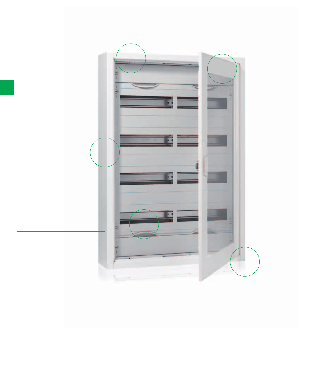
6/30 2CSC 400 031 D0202 | System pro M compact®
6
AT/U Series
The details make the difference
Wide range:
with metal or
transparent door;
Range from 36 up
to 240 modules
(18 mm)
Integrated cable
strain-relief,
spacious wall
mounting
Compact
distribution boards
AT/U series: for
wall-mounting,
flush-mounting
and hollow-wall
mounting (in
connection with
ZKV200P4)
The installed
distribution panels
can be removed for
equipping and wiring
Doors are
assembled and
disassembled
without tools, and
the door hinges
can be adjusted
steplessly
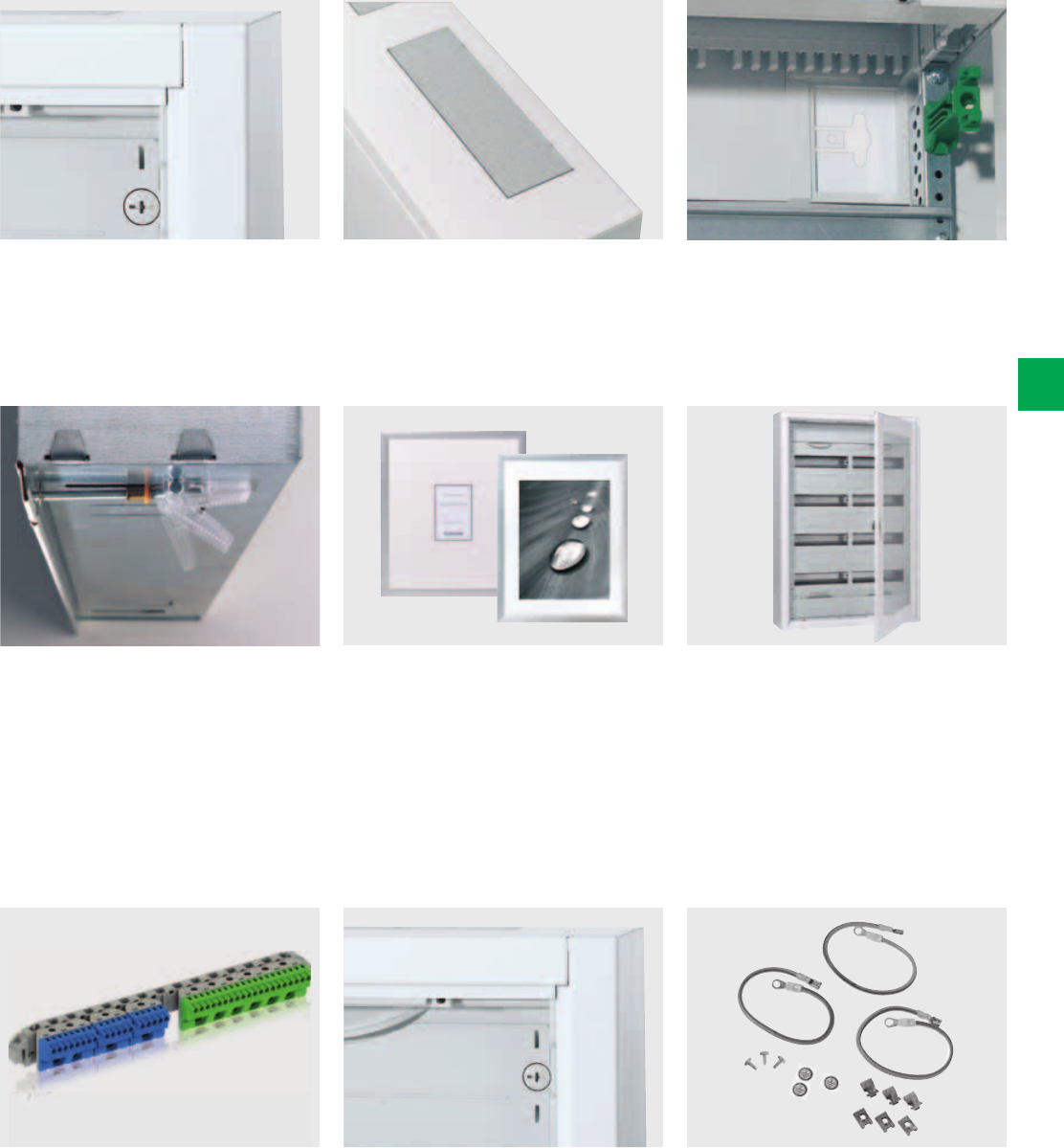
System pro M compact® | 2CSC 400 031 D0202 6/31
6
With its slightly inclined sides, the bright
white cabinet and the attractive locking
system, the compact distribution boards
sets new standards in design.
All flush-mounting compact distribution
boards can be installed in the hollow
wall in just a few steps using the hollow
wall set (accessory). No longer two
separate cabinets need to be kept on
stock - you only need one cabinet for
two applications.
AT and U series allows with its user-
friendly snap-in type N/PE quick
busbars considerable time-saving.
An alternative picture frame door is
available for the U flush-mounting version.
Control panels for commercial and
industrial buildings are also available: they
can be supplied to be finished and wired
by the user, or can be printed and wired
according to the user’s requirements
already in the factory.
Fast assembly of the sealable covers
using 90° press and turn closures,
which fit into all modular cabinets.
Easy any flexible: AT and U Series offers
a wide range for almost all applications:
wall-mounting, flush-mounting, with
metal, transparent or design door, with
mounting plates or with DIN-rails and
many more. And all with one single
order number.
Prepared for all requirements: An
earthing set for conversion to protection
class I (earthed) is available as an
accessory for AT and for U Series.
All AT wall-mounting compact
distribution boards are equipped with
one integrated flush fitting membrane
flange per panel width on top.
A further standard feature per panel
width is the cable strain-relief at the top
and the bottom, which considerably
simplifies the installation for every wall-
mounting and flush-mounting type.
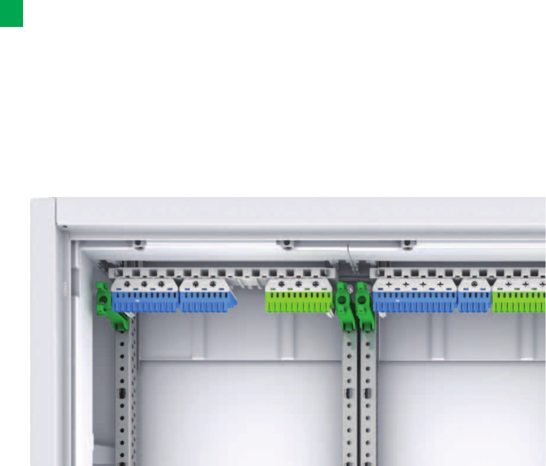
6/32 2CSC 400 031 D0202 | System pro M compact®
6
N/PE Quick-terminals
standardised, future-oriented and flexible
The new N/PE Quick-terminals from STRIEBEL & JOHN
are designed for the things to come. Conforming to the
current standard DIN VDE 0100 Part 410 and extremely
flexible in terms of expandability, these N/PE Quick-
terminals are unmatched for safe, efficient and future-
oriented conductor connections.
Product benefits
– Compliance with DIN VDE 0100 Part 410 (protection
against electric shock)
– Flexible terminal system for several N power circuits:
Screw connections: 2.5 to 25mm²; spring terminals:
1.5 to 4mm².
– Optimal when using several residual current circuit breaker
(RCDs)
– Combination of several Quick-terminals on one common
quick carrier
– Ease of expansion using connecting bridges
– Precise assignment of the terminal blocks
(clear colour coding: N = blue, PE = yellow-green)
– Easy labelling of the terminals (DIN VDE 0603 Part 1) using
pre-printed, self-adhesive number strips
– Wide range of applications:
can be used in the UK500 and A300 consumer unit series,
in all compact distribution boards, and with all meter cabi-
nets, wall-mounting and floor-standing cabinets
– The new terminal system replaces the N/PE Quick-busbars
that were previously in use
As an electrician you no longer have to compromise.
The new N/PE Quick-terminals from STRIEBEL & JOHN can
simplify your work: Just choose the right terminal blocks and
plug them in! The resulting installation is tidy and flexible. The
colour coding ensures that you will find your way even with
expansions.
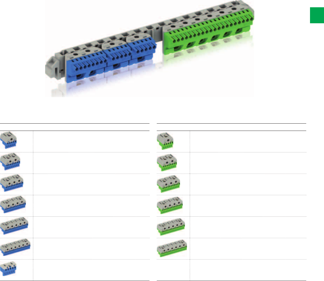
System pro M compact® | 2CSC 400 031 D0202 6/33
6
N/PE Quick-terminals
The complete range of products
Clean and tidy work
Anyone would like their distribution board so tidy:
all Quick-terminals are mounted next to each other on one
carrier with standardised colour coding.
Configure based on your needs
The modularity of the new series and the extensive range of
products allow customising the new products to the needs
based on real-world use. Various Quick-terminals can be
combined on one quick carrier as necessary.
Flexible by design
You need a larger N terminal?
No problem. You can connect individual Quick-terminals with
connecting bridges and remain in compliance with the
technical requirements of IEC 60364-4-41 and DIN VDE 0100
Part 410 in an economic way.
The high flexibility of the new series is a crucial advantage
here and in other solutions. The ability to combine terminal
blocks with different numbers of terminals offers numerous
possibilities.
N Quick-terminals PE Quick-terminals
1 x 25mm2 + 5 x 1.5 - 4mm21 x 25mm2 + 5 x 1.5 - 4mm2
2 x 25mm2 + 8 x 1.5 - 4mm22 x 25mm2 + 8 x 1.5 - 4mm2
3 x 25mm2 + 11 x 1.5 - 4mm23 x 25mm2 + 11 x 1.5 - 4mm2
4 x 25mm2 + 14 x 1.5 - 4mm24 x 25mm2 + 14 x 1.5 - 4mm2
5 x 25mm2 + 17 x 1.5 - 4mm25 x 25mm2 + 17 x 1.5 - 4mm2
6 x 25mm2 + 20 x 1.5 - 4mm26 x 25mm2 + 20 x 1.5 - 4mm2
0 x 25mm2 + 5 x 1.5 - 4mm2

2CSC400030F0190
Panels and doors
6/34 2CSC 400 031 D0202 | System pro M compact®
6
Compact distribution boards
With panels and doors
Compact distribution boards with panels and doors
125mm or 150mm DIN rail spacing
In up to 125A
DIN EN 60439-1 (VDE 0660-500)
Degree of protection IP43 (AT)
Degree of protection IP31 (U)
Protection class II, double insulated
Protection class I, earthed in connection with an earthing set (accessory)
The installed distribution board panels can be removed for equipping and wiring
The covers of U and AT compact distribution boards are made of polystyrene
Panels for DIN rail devices come with N/PE quick terminals
125mm or 150mm DIN rail spacing
Enclosures and doors made of sheet steel, 1mm
Colour: white, RAL 9016
3 or more panels wide: double-wing doors
With new N/PE Quick-terminals for panels for rail mounting devices
Without N/PE Quick-terminals for panels with wiring space or mounting plates
Panels for terminals have DIN rails assembled insulated (without N/PE Quick terminals) (K)
Panels with mounting plate (without N/PE Quick-terminal) (M)
Hollow-wall-mounting set for flush-mounting versions (accessory)
With cable strain relief
With one membrane flange per panel width on top (AT)
With labelling system
Trim frame adjusted for uneven surfaces (U)
Cable entry covers (accessory)
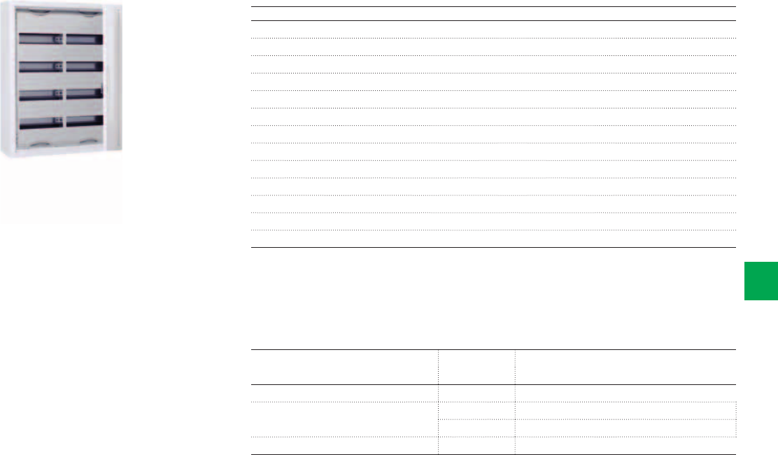
2CSC400030F0191
The new N/PE Quick-terminals
System pro M compact® | 2CSC 400 031 D0202 6/35
6
Compact distribution boards
The new N/PE Quick-terminals
Article Type
Equipment with new N/PE Quick-terminals
Compact distribution boards*
N/PE quick carriers ZK13 1 pc.
N Quick terminal ZK82B 1 pc.
ZK113B 1 pc.
PE Quick-terminal ZK175G 1 pc.
*Included in the scope of delivery for distribution board panels for rail mounting devices
Compact distribution boards, IP43 (AT), IP31(U) - , .
* ;
*1
In up to 125 A
DIN EN 60439-1 (VDE 0660-500)
The installed distribution board panels can be removed for equipping and wiring
125mm or 150mm DIN rail spacing
Enclosures and doors made of sheet steel, 1mm
Colour: white, RAL 9016
3 or more panels wide: Double-wing doors
With new N/PE Quick-terminals for panels for rail mounting devices
Without N/PE Quick-terminals for panels with wiring space or mounting plates
With cable strain relief
With one membrane flange per panel width on top (AT)
With labelling system
Trim frame adjusted for uneven surfaces (U)
* In connection with earthing set
*1 In connection with a hollow-wall set ZKV200P4
2CSC400030F0604
2CSC400030F0605
2CSC400030F0606
2CSC400030F0607
2CSC400030F0608
2CSC400030F0609
ZK113B
ZK50BT
ZK113G
ZK10P10
ZK13
ZK15
6/36 2CSC 400 031 D0202 | System pro M compact®
6
N/PE Quick-terminals
Accessories
Article Number of
terminals
1.5 - 4mm2
Number of
terminals
2.5 - 25 mm2
External
dimensions
H x W x D
in mm
Pcs. Type Ord. no. Price
N Quick-terminals
For quick carriers 5 0 23 x 32 x 21 1 ZK50B 2CPX062750R9999
5 1 32 x 32 x 31 1 ZK51B 2CPX062751R9999
8 2 32 x 49 x 31 1 ZK82B 2CPX062752R9999
11 3 32 x 65 x 31 1 ZK113B 2CPX062753R9999
14 4 32 x 82 x 31 1 ZK144B 2CPX062754R9999
17 5 32 x 98 x 31 1 ZK175B 2CPX062755R9999
20 6 32 x 115 x 31 1 ZK206B 2CPX062756R9999
N Quick-terminal with adapter ZK15
For lateral assembly to the
UK5… , A3…or for fastening
to the DIN rail
5 0 28 x 39 x 25 1 ZK50BT 2CPX062745R9999
PE Quick-terminals
For quick carriers 5 1 32 x 32 x 31 1 ZK51G 2CPX062757R9999
8 2 32 x 49 x 31 1 ZK82G 2CPX062758R9999
11 3 32 x 65 x 31 1 ZK113G 2CPX062759R9999
14 4 32 x 82 x 31 1 ZK144G 2CPX062760R9999
17 5 32 x 98 x 31 1 ZK175G 2CPX062761R9999
20 6 32 x 115 x 31 1 ZK206G 2CPX062762R9999
Connecting bridges
For Quick-terminals 10 ZK10P10 2CPX062763R9999
Quick carriers
For consumer units AT/U
Usable width for Quick-terminals 214 mm
1 ZK13 2CPX064982R9999
Adapter for ZK50B
Engaging the ZK50B N Quick-terminal in the adapter ZK15, leads to ZK50BT to
be laterally fastened UK5… , A3 or to the DIN rail
1 ZK15 2CPX064984R9999
AT31
AT42
AT42/2
AT53
AT54E
2CSC400030F0300
2CSC400030F0301
2CSC400030F0302
2CSC400030F0303
2CSC400030F0304
System pro M compact® | 2CSC 400 031 D0202 6/37
6
AT wall-mounting distribution boards
With panels and sheet steel doors
PW GU SU
External dimensions
Type Ord. no. PriceH x W x D in mm
For rail mounting devices, 125mm DIN rail spacing, with membran flanges
1 3 36 524 x 324 x 140 AT31 2CPX030099R9999
4 48 674 x 324 x 140 AT41 2CPX030121R9999
5 60 824 x 324 x 140 AT51 2CPX030124R9999
6 72 974 x 324 x 140 AT61 2CPX030130R9999
2 2 48 374 x 574 x 140 AT22E 2CPX071740R9999
4 96 674 x 574 x 140 AT42 2CPX030122R9999
5 120 824 x 574 x 140 AT52 2CPX030125R9999
6 144 974 x 574 x 140 AT62 2CPX030131R9999
7 168 1124 x 574 x 140 AT72 2CPX030134R9999
2 (1/1) 3 72 524 x 574 x 140 AT32 2CPX030120R9999
4 96 674 x 574 x 140 AT42/2 2CPX030138R9999
5 120 824 x 574 x 140 AT52/2 2CPX030139R9999
3 (2/1) 4 144 674 x 824 x 140 AT43 2CPX030123R9999
5 180 824 x 824 x 140 AT53 2CPX030127R9999
6 216 974 x 824 x 140 AT63E 2CPX071751R9999
4 (2/2) 5 240 824 x 1074 x 140 AT54E 2CPX071748R9999
> For cable entry cover accessories, see page 2/16
AT41R3
AT42R3
AT53R4
AT54R4
AT41R3IE
AT42R3IE
AT53R4IE
AT54R4IE
2CSC400030F0305
2CSC400030F0306
2CSC400030F0307
2CSC400030F0308
2CSC400030F0309
2CSC400030F0310
2CSC400030F0311
2CSC400030F0312
6/38 2CSC 400 031 D0202 | System pro M compact®
6
AT wall-mounting distribution boards
With panels and sheet steel doors
PW GU SU
External dimensions
Type Ord. no. PriceH x W x D in mm
For rail mounting devices, 150 mm DIN rail spacing, with membran flanges
13 36 674 x 324 x 140 AT41R3 2CPX071681R9999
4 48 824 x 324 x 140 AT51R4 2CPX071684R9999
5 60 974 x 324 x 140 AT61R5 2CPX071688R9999
22 48 524 x 574 x 140 AT32R2 2CPX071680R9999
3 72 674 x 574 x 140 AT42R3 2CPX071682R9999
4 96 824 x 574 x 140 AT52R4 2CPX071685R9999
5 120 974 x 574 x 140 AT62R5 2CPX071689R9999
6 144 1124 x 574 x 140 AT72R6 2CPX071691R9999
3 (2/1) 3 108 674 x 824 x 140 AT43R3 2CPX071683R9999
4 144 824 x 824 x 140 AT53R4 2CPX071686R9999
5 180 974 x 824 x 140 AT63R5 2CPX071690R9999
6 216 1124 x 824 x 140 AT73R6 2CPX071692R9999
4 (2/2) 4 192 824 x 1074 x 140 AT54R4 2CPX071687R9999
For rail mounting devices, 150 mm DIN rail spacing, with sheet steel flange
13 36 674 x 324 x 140 AT41R3IE 2CPX071681R9999
4 48 824 x 324 x 140 AT51R4IE 2CPX071684R9999
5 60 974 x 324 x 140 AT61R5 2CPX071688R9999
22 48 524 x 574 x 140 AT32R2IE 2CPX071680R9999
3 72 674 x 574 x 140 AT42R3IE 2CPX071682R9999
4 96 824 x 574 x 140 AT52R4IE 2CPX071685R9999
5 120 974 x 574 x 140 AT62R5IE 2CPX071689R9999
6 144 1124 x 574 x 140 AT72R6IE 2CPX071691R9999
3 (2/1) 3 108 674 x 824 x 140 AT43R3IE 2CPX071683R9999
4 144 824 x 824 x 140 AT53R4IE 2CPX071686R9999
5 180 974 x 824 x 140 AT63R5IE 2CPX071690R9999
6 216 1124 x 824 x 140 AT73R6IE 2CPX071692R9999
4 (2/2) 4 192 824 x 1074 x 140 AT54R4IE 2CPX071687R9999
> For cable entry cover accessories, see page 2/16
2CSC400030F0313
2CSC400030F0314
2CSC400030F0315
2CSC400030F0316
2CSC400030F0317
2CSC400030F03182CSC400030F03192CSC400030F0320
AT52K
AT53K
AT64K
M
AT42M
M
AT53M
AT32EP
AT42EP
AT52EP
System pro M compact® | 2CSC 400 031 D0202 6/39
6
PW GU SU
External dimensions
Type Ord. no. PriceH x W x D in mm
For rail mounting devices and terminals, DIN rail spacing 125mm
2 5 120 824 x 574 x 140 AT52K 2CPX030126R9999
6 144 974 x 574 x 140 AT62K 2CPX030132R9999
7 168 1124 x 574 x 140 AT72K 2CPX030135R9999
3 (2/1) 5 180 824 x 824 x 140 AT53K 2CPX030128R9999
6 216 974 x 824 x 140 AT63K 2CPX030133R9999
7 252 1124 x 824 x 140 AT73K 2CPX030136R9999
4 (2/2) 5 240 824 x 1074 x 140 AT54K 2CPX030129R9999
6 288 974 x 1074 x 140 AT64K 2CPX030137R9999
For rail mounting devices and mounting plates, DIN rail spacing 125 mm
2 (1/1) 4 96 674 x 574 x 140 AT42M 2CPX030148R9999
3 (2/1) 5 180 824 x 824 x 140 AT53M 2CPX030149R9999
For rail mounting devices and meter plates, DIN rail spacing 125 mm
2 (1/1) 3 72 524 x 574 x 140 AT32EP 2CPX071760R9999
2 (1/1) 4 96 674 x 574 x 140 AT42EP 2CPX071761R9999
2 (1/1) 5 120 824 x 574 x 140 AT52EP 2CPX071762R9999
> For cable entry cover accessories, see page 2/16
AT41TE
AT32TE
AT52TE
AT41TR3
AT52TR4
AT63TR5
AT54TR4
2CSC400030F0321
2CSC400030F0322
2CSC400030F0323
2CSC400030F0324
2CSC400030F0325
2CSC400030F0326
2CSC400030F0327
6/40 2CSC 400 031 D0202 | System pro M compact®
6
PW GU SU
External dimensions
Type Ord. no. PriceH x W x D in mm
For rail mounting devices, 125mm DIN rail spacing
14 48 674 x 324 x 140 AT41TE 2CPX071585R9999
5 60 824 x 324 x 140 AT51TE 2CPX071587R9999
6 72 974 x 324 x 140 AT61TE 2CPX071589R9999
2 (1/1) 3 72 524 x 574 x 140 AT32TE 2CPX071584R9999
24 96 674 x 574 x 140 AT42TE 2CPX071586R9999
5 120 824 x 574 x 140 AT52TE 2CPX071588R9999
6 144 974 x 574 x 140 AT62TE 2CPX071590R9999
For rail mounting devices, 150 mm DIN rail spacing
13 36 674 x 324 x 140 AT41TR3 2CPX071695R9999
4 48 824 x 324 x 140 AT51TR4 2CPX071698R9999
5 60 974 x 324 x 140 AT61TR5 2CPX071702R9999
22 48 524 x 574 x 140 AT32TR2 2CPX071694R9999
3 72 674 x 574 x 140 AT42TR3 2CPX071696R9999
4 96 824 x 574 x 140 AT52TR4 2CPX071699R9999
5 120 974 x 574 x 140 AT62TR5 2CPX071703R9999
6 144 1124 x 574 x 140 AT72TR6 2CPX071705R9999
3 (2/1) 3 108 674 x 824 x 140 AT43TR3 2CPX071697R9999
4 144 824 x 824 x 140 AT53TR4 2CPX071700R9999
5 180 974 x 824 x 140 AT63TR5 2CPX071704R9999
6 216 1124 x 824 x 140 AT73TR6 2CPX071706R9999
4 (2/2) 4 192 82 x 1074 x 140 AT54TR4 2CPX071701R9999
> For cable entry cover accessories, see page 2/16
AT wall-mounting distribution boards
With panels and transparent doors
2CSC400030F0328
2CSC400030F0329
2CSC400030F0330
2CSC400030F0331
KB19
KB219
KBS9
KBW1
System pro M compact® | 2CSC 400 031 D0202 6/41
6
AT wall-mounting distribution boards
Accessories cable entry covers
Article Type Ord. no. Price
Cable entry covers
With end plates and mounting brackets
colour RAL 9016, adjusted to the colour of the cabinets
Panel width 1, width = 300 mm KB19 2CPX044049R9999
Panel width 2, width = 550 mm KB29 2CPX044050R9999
Panel width 3, width = 800 mm KB39 2CPX044051R9999
Panel width 4, width = 1050 mm KB49 2CPX044052R9999
Profile
Colour RAL 9016, width 2000 mm KB219 2CPX044055R9999
End plate left/right
Colour RAL 9016 KBS9 2CPX044057R9999
Mounting brackets KBW1 2CPX044058R9999
2CSC400030F0332
2CSC400030F0333
2CSC400030F0334
2CSC400030F0335
2CSC400030F0336
2CSC400030F0337
2CSC400030F0338
2CSC400030F0339
2CSC400030F0340
U41
U52
U42/2
U53
U54E
U41R3
U42R3
U53R4
U54R4
6/42 2CSC 400 031 D0202 | System pro M compact®
6
U flush-mounting compact distribution boards
With panels and sheet steel doors
PW GU SU
Wall cut out dimensions Trim frame dimensions
Type Ord. no. PriceH x W x D in mm H x W x D in mm
For rail mounting devices, 125mm DIN rail spacing
14 48 684 x 310 x 120 694 x 354 x 27 U41 2CPX030101R9999
5 60 834 x 310 x 120 844 x 354 x 27 U51 2CPX030104R9999
6 72 984 x 310 x 120 994 x 354 x 27 U61 2CPX030110R9999
24 96 684 x 560 x 120 694 x 604 x 27 U42 2CPX030102R9999
5 120 834 x 560 x 120 844 x 604 x 27 U52 2CPX030105R9999
6 144 984 x 560 x 120 994 x 604 x 27 U62 2CPX030111R9999
7 168 1134 x 560 x 120 1144 x 604 x 27 U72 2CPX030114R9999
2 (1/1) 3 72 534 x 560 x 120 544 x 604 x 27 U32 2CPX030100R9999
4 96 684 x 560 x 120 694 x 604 x 27 U42/2 2CPX030118R9999
5 120 834 x 560 x 120 844 x 604 x 27 U52/2 2CPX030119R9999
3 (2/1) 4 144 684 x 810 x 120 694 x 854 x 27 U43 2CPX030103R9999
5 180 834 x 810 x 120 844 x 854 x 27 U53 2CPX030107R9999
6 216 984 x 810 x 120 994 x 854 x 27 U63E 2CPX071787R9999
4 (2/2) 5 240 834 x 1060 x 120 844 x 1104 x 27 U54E 2CPX071784R9999
For rail mounting devices, 150 mm DIN rail spacing
13 36 684 x 310 x 120 694 x 354 x 27 U41R3 2CPX071708R9999
4 48 834 x 310 x 120 844 x 354 x 27 U51R4 2CPX071711R9999
5 60 984 x 310 x 120 994 x 354 x 27 U61R5 2CPX071715R9999
22 48 534 x 560 x 120 544 x 604 x 27 U32R2 2CPX071707R9999
3 72 684 x 560 x 120 694 x 604 x 27 U42R3 2CPX071709R9999
4 96 834 x 560 x 120 844 x 604 x 27 U52R4 2CPX071712R9999
5 120 984 x 560 x 120 994 x 604 x 27 U62R5 2CPX071716R9999
6 144 1134 x 560 x 120 1144 x 604 x 27 U72R6 2CPX071718R9999
3 (2/1) 3 108 684 x 810 x 120 694 x 854 x 27 U43R3 2CPX071710R9999
4 144 834 x 810 x 120 844 x 854 x 27 U53R4 2CPX071713R9999
5 180 984 x 810 x 120 994 x 854 x 27 U63R5 2CPX071717R9999
6 216 1134 x 810 x 120 1144 x 854 x 27 U73R6 2CPX071719R9999
4 (2/2) 4 192 834 x 1060 x 120 844 x 1104 x 27 U54R4 2CPX071714R9999
U52K
U53K
U54K
M
U42M
M
U53M
U51EP
U32EP
U42EP
U52EP
2CSC400030F0341
2CSC400030F0342
2CSC400030F0343
2CSC400030F0344
2CSC400030F0345
2CSC400030F0346
2CSC400030F03472CSC400030F0348
2CSC400030F0349
System pro M compact® | 2CSC 400 031 D0202 6/43
6
U flush-mounting compact distribution boards
With panels and sheet steel doors
PW GU SU
Wall cut out dimensions Trim frame dimensions
Type Ord. no. PriceH x W x D in mm H x W x D in mm
For rail mounting devices and terminals, DIN rail spacing 125mm
2 5 120 834 x 560 x 120 844 x 604 x 27 U52K 2CPX030106R9999
6 144 984 x 560 x 120 994 x 604 x 27 U62K 2CPX030112R9999
7 168 1134 x 560 x 120 1144 x 604 x 27 U72K 2CPX030115R9999
3 (2/1) 5 180 834 x 810 x 120 844 x 854 x 27 U53K 2CPX030108R9999
6 216 984 x 810 x 120 994 x 854 x 27 U63K 2CPX030113R9999
7 252 1134 x 810 x 120 1144 x 854 x 27 U73K 2CPX030116R9999
4 (2/2) 5 240 834 x 1060 x 120 844 x 1104 x 27 U54K 2CPX030109R9999
6 288 984 x 1060 x 120 994 x 1104 x 27 U64K 2CPX030117R9999
For rail mounting devices and mounting plates, 125mm DIN rail spacing
2 (1/1) 4 96 684 x 560 x 120 694 x 604 x 27 U42M 2CPX030146R9999
3 (2/1) 5 180 834 x 810 x 120 844 x 854 x 27 U53M 2CPX030147R9999
For rail mounting devices and meter plates, DIN rail spacing 125 mm
1 5 60 834 x 310 x 120 844 x 354 x 27 U51EP 2CPX071564R9999
2 (1/1) 3 72 534 x 560 x 120 544 x 604 x 27 U32EP 2CPX071560R9999
2 (1/1) 4 96 684 x 560 x 120 694 x 604 x 27 U42EP 2CPX071561R9999
2 (1/1) 5 120 834 x 560 x 120 844 x 604 x 27 U52EP 2CPX071562R9999
2CSC400030F0350
2CSC400030F0351
2CSC400030F0352
2CSC400030F0353
2CSC400030F0354
2CSC400030F0355
2CSC400030F0356
U41TE
U32TE
U42TE
U41TR3
U42TR3
AT53TR4
U54TR4
6/44 2CSC 400 031 D0202 | System pro M compact®
6
PW GU SU
Wall cut out dimensions Trim frame dimensions
Type Ord. no. PriceH x W x D in mm H x W x D in mm
For rail mounting devices, 125mm DIN rail spacing
14 48 684 x 310 x 120 694 x 354 x 27 U41TE 2CPX071592R9999
5 60 834 x 310 x 120 844 x 354 x 27 U51TE 2CPX071594R9999
6 72 984 x 310 x 120 994 x 354 x 27 U61TE 2CPX071596R9999
2 (1/1) 3 72 534 x 560 x 120 544 x 604 x 27 U32TE 2CPX071591R9999
24 96 684 x 560 x 120 694 x 604 x 27 U42TE 2CPX071593R9999
5 120 834 x 560 x 120 844 x 604 x 27 U52TE 2CPX071595R9999
6 144 984 x 560 x 120 994 x 604 x 27 U62TE 2CPX071597R9999
For rail mounting devices, 150 mm DIN rail spacing
13 36 684 x 310 x 120 694 x 354 x 27 U41TR3 2CPX071722R9999
4 48 834 x 310 x 120 844 x 354 x 27 U51TR4 2CPX071725R9999
5 60 984 x 310 x 120 994 x 354 x 27 U61TR5 2CPX071729R9999
22 48 534 x 560 x 120 544 x 604 x 27 U32TR2 2CPX071721R9999
3 72 684 x 560 x 120 694 x 604 x 27 U42TR3 2CPX071723R9999
4 96 834 x 560 x 120 844 x 604 x 27 U52TR4 2CPX071726R9999
5 120 984 x 560 x 120 994 x 604 x 27 U62TR5 2CPX071730R9999
6 144 1134 x 560 x 120 1144 x 604 x 27 U72TR6 2CPX071733R9999
3 (2/1) 3 108 684 x 810 x 120 694 x 854 x 27 U43TR3 2CPX071724R9999
4 144 834 x 810 x 120 844 x 854 x 27 U53TR4 2CPX071727R9999
5 180 984 x 810 x 120 994 x 854 x 27 U63TR5 2CPX071731R9999
6 216 1134 x 810 x 120 1144 x 854 x 27 U73TR6 2CPX071734R9999
4 (2/2) 4 192 834 x 1060 x 120 844 x 1104 x 27 U54TR4 2CPX071728R9999
U flush-mounting compact distribution boards
With panels and transparent doors
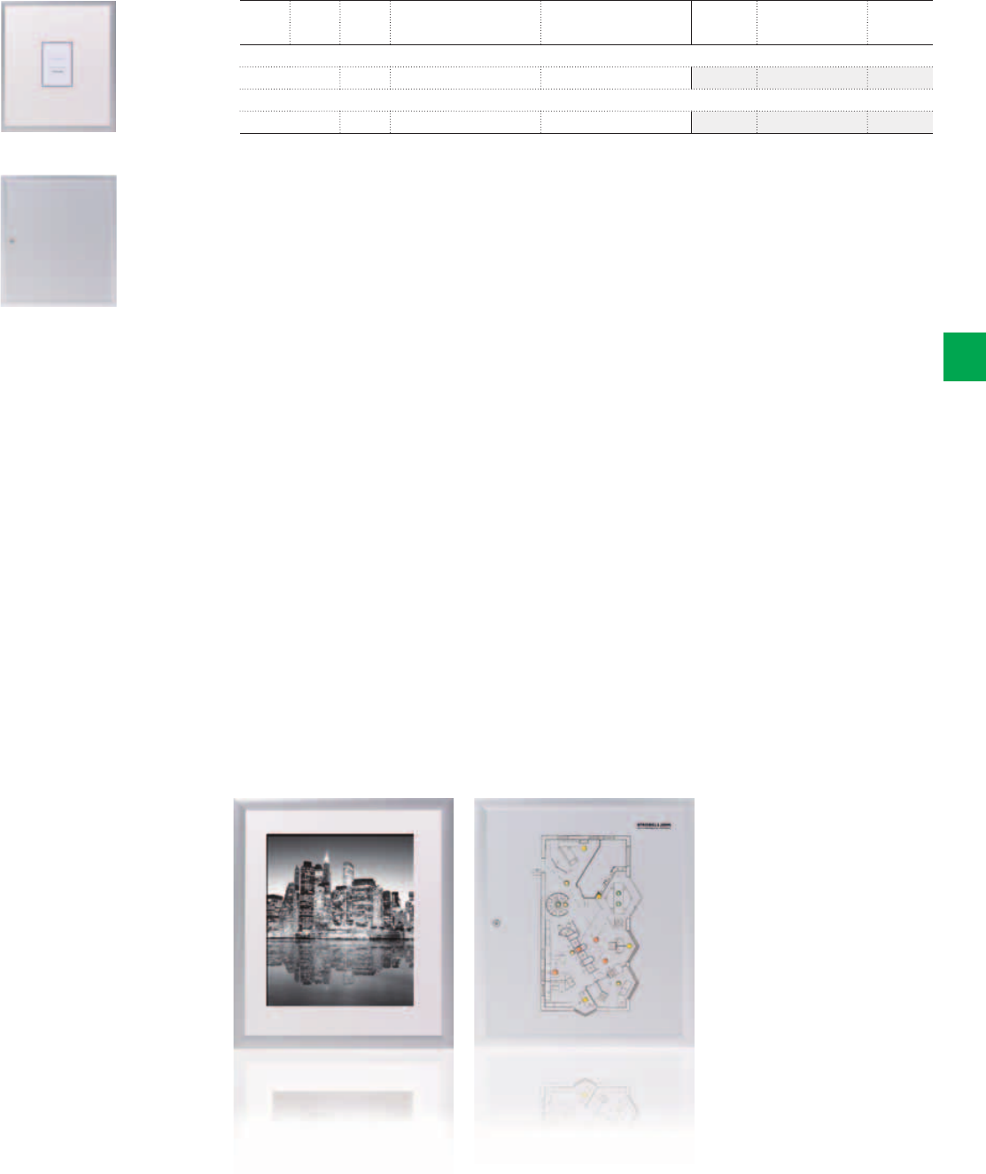
2CSC400030F0357
2CSC400030F0358
U42D
U42FPT
Example control panel
with layout and control lights
(delivery unprinted/not wired)
Example picture frame door with
decoration picture
(delivery without picture)
System pro M compact® | 2CSC 400 031 D0202 6/45
6
PW GU SU
Wall cut out dimensions Trim frame dimensions
Type Ord. no. PriceH x W x D in mm H x W x D in mm
With picture frame door, aluminium anodised, DIN rail spacing 125mm
2 4 96 684 x 560 x 120 716 x 625 x 25 U42D 2CPX038152R9999
With control panel, unprinted and not wired, distribution board panel without cover and N/PE rail
2 4 96 684 x 560 x 120 716 x 625 x 25 U42FPT 2CPX038151R9999
U flush-mounting compact distribution boards
With panels and picture frame doors
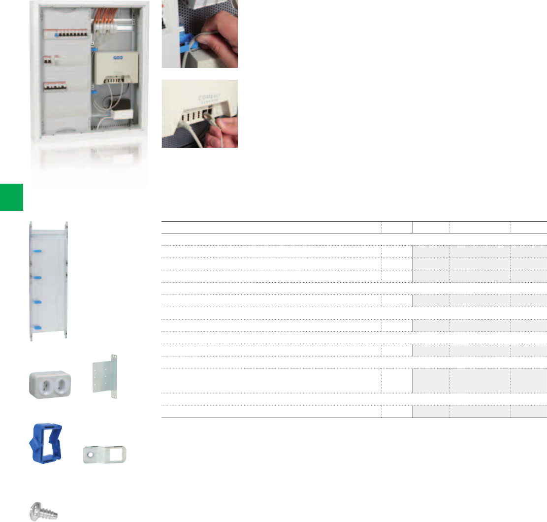
2CSC400030F0359
2CSC400030F0360
2CSC400030F0362
2CSC400030F0363
2CSC400030F0364
2CSC400030F0361
ZE225 ZX29
ED44P10 ED57P10
ZX287P10
6/46 2CSC 400 031 D0202 | System pro M compact®
6
Ordering Information
AT/U Series - Accessories
- Media panels with perforated sheet steel mounting plate without cover
- With fitted DIN rail
- Wire holders supplied
- Quick mounting of devices without drilling
Article Pcs. Type Ord. no. Price
Media panel with perforated sheet steel mounting plate
Overall height 4 GU 1 1MM0A 2CPX030987R9999
Overall height 5 GU 1 1MM1A 2CPX030988R9999
Overall height 6 GU 1 1MM2A 2CPX030989R9999
Double socket with Euro plug insert
For supplying 230V power to power supplies 1 ZE225 2CPX061177R9999
Mounting cross member
For double socket (ZE225) 1 ZX29 2CPX061178R9999
Wire holder
28.5mm 10 ED44P10 2CPX062335R9999
Adapter
For assembling ED44P10 wire holders
on the perforated sheet steel mounting plate
10 ED57P10 2CPX061179R9999
Screws
M4 x 14 thread rolling for the perforated sheet steel mounting plate 10 ZX287P10 2CPX061180R9999
ZB113
ZB111
ZX456
ZX440
ZH800
ZH220
ZH130 ZH132
ZH134 ZH137
2CSC400030F0365
2CSC400030F0366
2CSC400030F0367
2CSC400030F0367
2CSC400030F0369
2CSC400030F0370
2CSC400030F03712CSC400030F0373
2CSC400030F03722CSC400030F0374
System pro M compact® | 2CSC 400 031 D0202 6/47
6
Article Pcs. Type Ord. no. Price
Standard closure
Included in the scope of delivery 1 ZB113 2CPX038478R9999
Closure with lock
With 2 keys 1 ZB111 2CPX038479R9999
Espagnolette closure
In combination with standard closure ZB113* (earthing partl)
or closure with lock ZB111
Overall height 4 GU 1 ZX456 2CPX039586R9999
Overall height 5 GU 1 ZX457 2CPX039587R9999
Overall height 6 GU 1 ZX458 2CPX039588R9999
Overall height 7 GU 1 ZX459 2CPX039589R9999
Espagnolette closure
In combination with ZH203, ZH220, ZH221, ZH222, ZH227, ZH228
Overall height 4 GU 1 ZX440 2CPX039570R9999
Overall height 5 GU 1 ZX441 2CPX039571R9999
Overall height 6 GU 1 ZX442 2CPX039572R9999
Overall height 7 GU 1 ZX443 2CPX039573R9999
Installation set*
Of different closure systems in
combination with ZH220/ZH221/ZH222
1 ZH800 2CPX038544R9999
Latch plate
Double bit operating pin, 3mm standard and 5mm
(ZH800 must be ordered separately)
1 ZH220 2CPX045700R9999
For triangular or square operating pins and for Daimler-Benz insert
(ZH800 must be ordered separately)
1 ZH221 2CPX045701R9999
For T-handle or latch handle (ZH800 must be ordered separately) 1 ZH222 2CPX045702R9999
Operating pin
Double-bit 3 mm 1 ZH130 2CPX060490R9999
Double-bit 5mm 1 ZH131 2CPX060491R9999
Triangular 7mm 1 ZH132 2CPX060492R9999
Triangular 8 mm 1 ZH133 2CPX060493R9999
Square 6 mm 1 ZH134 2CPX060494R9999
Square 7mm 1 ZH135 2CPX060495R9999
Square 8 mm 1 ZH136 2CPX060496R9999
Daimler-Benz insert 1 ZH137 2CPX060497R9999
* Leave not less than 2 SU for DIN rail devices behind the closure
ZH157
ZH91
ZH138 ZH139
ZH140 ZH141
ZH228
ZH227
ZH203
ZH142
2CSC400030F0375
2CSC400030F0376
2CSC400030F03772CSC400030F0379
2CSC400030F0381
2CSC400030F0382
2CSC400030F0383
2CSC400030F0384
2CSC400030F0380 2CSC400030F0378
6/48 2CSC 400 031 D0202 | System pro M compact®
6
Compact distribution boards
Accessories
Article Pcs. Type Ord. no. Price
Operating keys
Triangular 7mm 1 ZH157 2CPX060657R9999
Triangular 8 mm 1 ZH158 2CPX060658R9999
Double-bit 3 mm 1 ZH160 2CPX060660R9999
Double-bit 5mm 1 ZH161 2CPX060661R9999
Square 6 mm 1 ZH162 2CPX060662R9999
Square 7mm 1 ZH163 2CPX060663R9999
Square 8 mm 1 ZH164 2CPX060664R9999
Daimler-Benz insert 1 ZH165 2CPX060665R9999
Universal key
Double bit 3 and 5mm
Triangular 8mm
Square 6 and 8mm
1 ZH91 2CPX066091R9999
T-handle*
Without lock 1 ZH138 2CPX060498R9999
With lock 1 ZH139 2CPX060498R9999
Latch handle*
Without lock 1 ZH140 2CPX060500R9999
With lock 1 ZH141 2CPX060501R9999
Swivel handle with lead sealable cap*
For semi-cylinder 40mm (30/10) 1 ZH228 2CPX045709R9999
Swivel handle with lead sealable cap*
With cabinet handle Berlin 1 ZH227 2CPX045708R9999
Swivel handle with lead sealable cap*
With closure E0 12 1 ZH203 2CPX045707R9999
Dummy insert
Instead of a semi-cylinder for the swivel handle ZH228 1 ZH142 2CPX060502R9999
* Leave not less than 2 SU for DIN rail devices behind the closure
ZKV200P4
ZE11 ZE12
ZB43
ZB40
ZB101
ZX69
ZA1P5
ZA6 ZA5
ZX139LR
2CSC400030F0385
2CSC400030F0386
2CSC400030F0388
2CSC400030F0389
2CSC400030F0390
2CSC400030F0391
2CSC400030F0392
2CSC400030F0393
2CSC400030F0394
2CSC400030F0395
2CSC400030F0387
System pro M compact® | 2CSC 400 031 D0202 6/49
6
rice Article Pcs. Type Ord. no. Price
Hollow-wall-mounting set
For retrofitting flush-mounted distribution boards
Wall thickness: min. 14mm, max. 58mm
1 ZB19 2CPX038187R9999
Earthing set for wall-mounting compact distribution boards
For conversion into protection class 1 1 ZE11 2CPX038143R9999
Earthing set for flush-mounting compact distribution boards
For conversion into protection class 1 1 ZE12 2CPX038144R9999
Membrane flange
For inserting the cable from below 1 ZB43 2CPX038183R9999
Nipple Flange 1 ZB40 2CPX038195R9999
Closing Flange 1 ZB101 2CPX038181R9999
Flange for conduits (bottom) 1 ZB107E 2CPX071211R9999
Flange for conduits (top) 1 ZB108E 2CPX071212R9999
Vertical partitions
Between distribution board panels, not arc-resistant
Overall height 3 GU 1 ZX69 2CPX039069R9999
Overall height 4 GU 1 ZX70 2CPX039070R9999
Overall height 5 GU 1 ZX71 2CPX039071R9999
Overall height 6 GU 1 ZX72 2CPX039072R9999
Overall height 7 GU 1 ZX73 2CPX039073R9999
Slot cover
Colour RAL 7035
For 12 space units, break-off type
5 ZA1P5 2CPX062384R9999
50 ZA1P50 2CPX062378R9999
Document holder DINA4
Self-adhesive with transparent sleeve 1 ZA6 2CPX038227R9999
10 ZA6P10 2CPX062380R9999
Self-adhesive with transparent sleeve and reinforced back 10 ZA61P10 2CPX062375R9999
Document holder DINA4
Self-adhesive 1 ZA13 2CPX038233R9999
10 ZA13P10 2CPX062381R9999
Document holder DINA5
Self-adhesive 1 ZA5 2CPX038228R9999
10 ZA5P10 2CPX062382R9999
Door hinge (plastic) 2 ZX139LR 2CPX039139R9999
ZX464
ZX374
ZH411 ZH412
ZH425 ZH428
ZX371
ZK90P2
ZX21
ZB32P20
2CSC400030F0396
2CSC400030F0397
2CSC400030F0398
2CSC400030F0399
2CSC400030F0400
2CSC400030F0401
2CSC400030F0402
2CSC400030F0403
2CSC400030F0404
2CSC400030F0364
6/50 2CSC 400 031 D0202 | System pro M compact®
6
Compact distribution boards
Accessories
Article Pcs. Type Ord. no. Price
Door bolt for double-wing doors
For cabinets with three or more panel widths 1 ZX464 2CPX039596R9999
Cross member
For fuse switch disconnectors size 00, 1 panel wide 1 ZX374 2CPX068079R9999
Fuse switch disconnector
Size 00 160A (without trim cover)
With M8 screw connection 1 ZH411 2CPX062947R9999
With clip terminal up to 50 mm21 ZH412 2CPX062948R9999
Trim cover
For fuse switch disconnector size 00
Single trim cover 1 ZH425 2CPX062952R9999
Double trim cover 1 ZH426 2CPX062953R9999
Blank cover 1 ZH428 2CPX062955R9999
DIN rail for terminals
35 x 7.5 mm
For recessed mounting in conjunction with mounting bracket ZX372P2
and insulator ZK90P2
1 panel wide 1 ZX371 2CPX068076R9999
2 panels wide 1 ZX389 2CPX068190R9999
Insulator for DIN rails
35 x 7.5mm including fastening material 2 ZK90P2 2CPX062426R9999
DIN rail
35 x 7.5mm
1 panel wide 1 ZX21 2CPX039021R9999
2 panels wide 1 ZX22 2CPX039022R9999
Fastening screws for DIN rails
Slotted/hexalobular socket pan head thread rolling screw T25 – 20 ZB32P20 2CPX062651R9999
Slotted/hexalobular socket pan head thread rolling screw T25 – 500 ZB32P500 2CPX062652R9999
ED137P4
ED50P12
ZKV201
ZK300
ZX518
ZX400
ZB19
ZA122 ZA20 ZA120
2CSC400030F0406
2CSC400030F0407
2CSC400030F0408
2CSC400030F0409
2CSC400030F0410
2CSC400030F0411
2CSC400030F0412
2CSC400030F0413
2CSC400030F0414
2CSC400030F0415
System pro M compact® | 2CSC 400 031 D0202 6/51
6
Article Pcs. Type Ord. no. Price
Cover holder 45 mm high
For fastening on the EDF profile
For DIN rails 35 x 7.5mm, use only these cover holders
4 ED137P4 2CPX062600R9999
40 ED137P40 2CPX062601R9999
Press-and-turn fixing
To cover distribution board panels 12 ED50P12 2CPX062337R9999
Labelling system
Self-adhesive, for AT and U distribution boards 1 ZKV201 2CPX038148R9999
Busbar system for N/PE
Cu 12 x 5mm, max. connection 95mm2
1 panel wide 1 ZK300 2CPX038551R9999
2 panels wide 1 ZK301 2CPX038552R9999
N/PE busbar holder
For copper busbars 12 x 5mm, 20 x 5mm, 30 x 5mm 1 ZX518 2CPX067805R9999
10 ZX518P10 2CPX062551R9999
Copper busbars
12 x 5mm = 250A
1m long ZX400 2CPX061400R9999
2 m long ZX401 2CPX061401R9999
3 m long ZX402 2CPX061402R9999
4 m long ZX350 2CPX061350R9999
Cover profile
For copper busbars 12 x 5 and 12 x 10mm, length 1m
To clip on busbars
ZB19 2CPX038187R9999
Cleaner
For distribution board panel covers
Spray dispenser, 500 ml
1 ZA122 2CPX038293R9999
Spray paint can
Colour RAL 9016, 150 ml 1 ZA20 2CPX038229R9999
Touch-up applicator
Colour RAL 9016, 12ml 1 ZA120 2CPX039043R9999
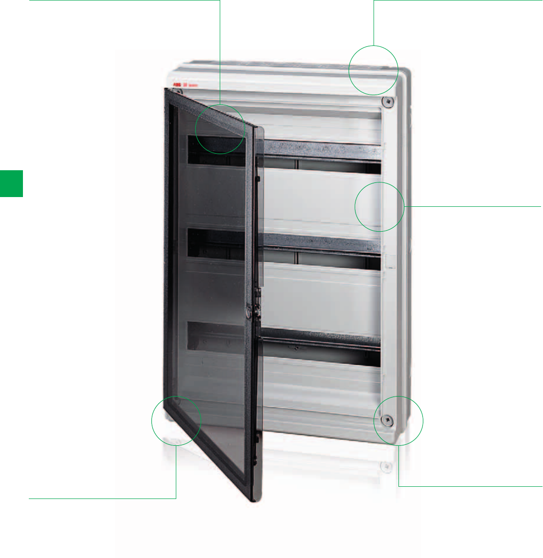
6/52 2CSC 400 031 D0202 | System pro M compact®
6
IP65 Europa Series
The details make the difference
The snap-on,
extractable DIN rail
frame simplifies
and speeds up
bench cabling
operations.
Available in two
versions: with
opaque door and
with transparent,
smoky door;
Range from 4 up
to 54 modules.
Versions with
sealable spring
closure and with
key lock.
Designed to use
the UNIFIX L rapid
cabling system
Cover with special
hinges: possibility
to attach cover on
the door (on the
right or the left);
door plus cover
with 140° opening
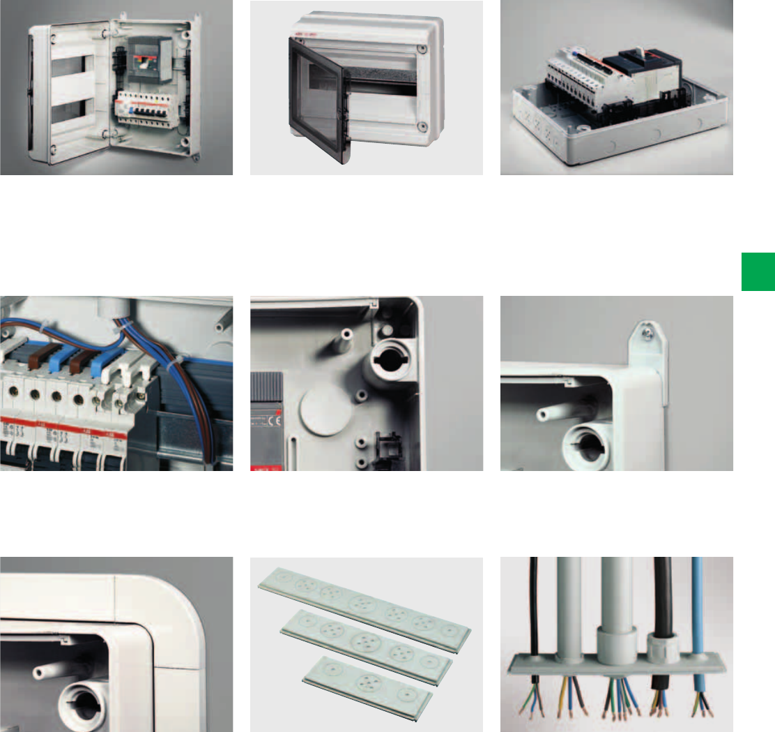
System pro M compact® | 2CSC 400 031 D0202 6/53
6
Perfectly symmetrical consumer units
with the possibility of attaching the door
hinge onto the front (by means of the
special articulated screws supplied) on
the right or left with 140° opening.
Europa IP65 with 8 modules and more
have been designed to use the UNIFIX L
rapid cabling system.
The frame that can be fitted onto
the consumer unit makes semi-flush
mounting possible, guaranteeing an
attractive finish.
When fixing the unit to the wall from
the inside, the special hole caps ensure
double insulation is maintained.
The two-component flange for direct
wiring with conduits and cables: thanks
to the two-component technology
(molding of two materials at the same
time) the flange obtains rigid plastic
and softer plastic (rubber) and a rubber
coating.
Using the brackets it is easy to fix the
Europa IP65 consumer unit in any
environment.
The elastic properties of the rubber of
the two-component flange ensure the
complete tightness to the plastic of the
conduit or of the cable case. By using
a simple screwdriver and a scissor you
get the wiring by saving considerable
time (no drill). Various ways of wiring
are possible: directly with the conduit
or directly with the cable or with cable/
conduit gland (traditional).
Europa IP65 models with 8 modules
and more fitted with one rigid and one
bi-material flange to facilitate input of
conduits and cables.
Extractable DIN-rail frame to facilitate
bench cabling. It can also be dismantled
(and snapped on to reassemble it) to
make it easier and faster to cable the
individual wires
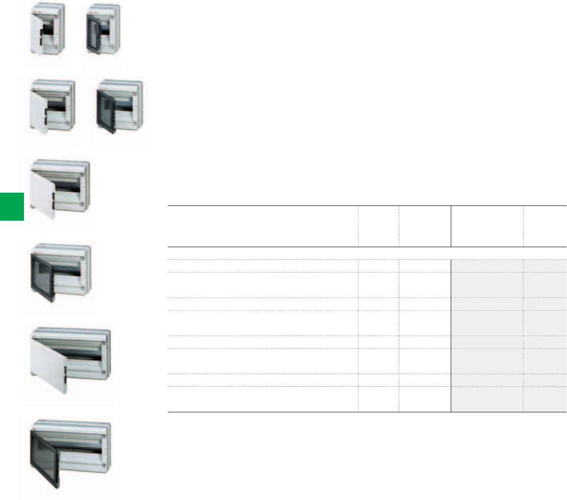
2CSC400030F0200
2CSC400030F0202
2CSC400030F0204
2CSC400030F0205
2CSC400030F0206
2CSC400030F0207
2CSC400030F0203
2CSC400030F0201
IP65 Europa
IP65 Europa
IP65 Europa
IP65 Europa
IP65 Europa
IP65 Europa
IP65 Europa
IP65 Europa
6/54 2CSC 400 031 D0202 | System pro M compact®
6
- IP65 Europa watertight series for outdoor applications, heating rooms, garages, farms,
cellars, photovoltaic installations, etc.
- Rated current In = 125A; Protection degree IP65; Protection class II (double insulated); Shock
resistance 6 Joules (IK level 08)
- In thermoplastic material, self-extinguishing and resistant to abnormal heat and fire up to
650°C (glow wire flammability index) in compliance with IEC 60695-2-11 Standard
- Installation temperature from -25°C to +60°C; resistant to heat: ball thermopressure up to
+85°C in compliance with EN 60695-10-2 Standard
- Rated isolation voltage: 1000 V AC; 1500 V DC
- Consumer units manufactured in compliance with CEI 23-49 (1996) + V1 + V2, CB certificate
IEC 60670-24 Standards
- IP65 Europa Series wall-mounting consumer units obtained the IMQ mark of approval
- IP65 Europa consumer units are supplied complete with: module covers; 4 screw-cover caps
to guarantee proection class II; accessories for attaching the hinges to the front;
1 self-adhesive indicator strip per row; 1 plate for CEI 23-51 certification, instruction sheet
Ordering Information
IP65 Europa Series
Description N° module Dimensions
HxWxD
[18 mm] [mm] Order code Price
1-row ,
IP65 Europa, wall-mounting, RAL 7035 grey, with opaque door 4 140x220x140 12724
IP65 Europa, wall-mounting, RAL 7035 grey, with transparent,
smoky door
4 140x220x140 12744
IP65 Europa, wall-mounting, RAL 7035 grey, with opaque door 8 205x220x140 12728
IP65 Europa, wall-mounting, RAL 7035 grey, with transparent,
smoky door
8205x220x14012748
IP65 Europa, wall-mounting, RAL 7035 grey, with opaque door 12 275x220x140 12732
IP65 Europa, wall-mounting, RAL 7035 grey, with transparent,
smoky door
12 275x220x140 12752
IP65 Europa, wall-mounting, RAL 7035 grey, with opaque door 18 380x220x140 12733
IP65 Europa, wall-mounting, RAL 7035 grey, with transparent,
smoky door
18 380x220x140 12753
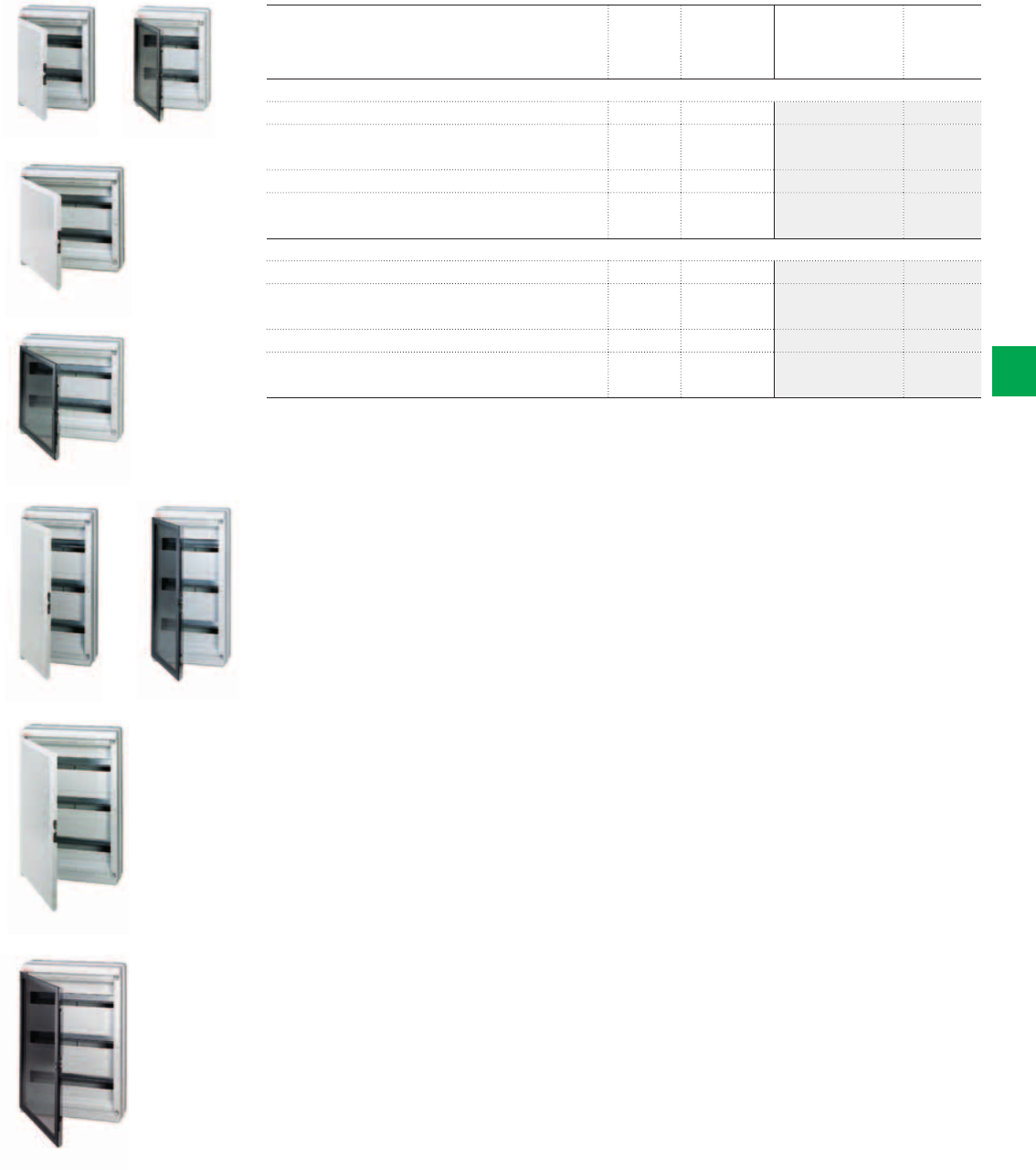
2CSC400030F0208
2CSC400030F0210
2CSC400030F0211
2CSC400030F0212
2CSC400030F0214
2CSC400030F0215
2CSC400030F0213
2CSC400030F0209
IP65 Europa
IP65 Europa
IP65 Europa
IP65 Europa
IP65 Europa
IP65 Europa
IP65 Europa
IP65 Europa
System pro M compact® | 2CSC 400 031 D0202 6/55
6
Description N° module Dimensions
HxWxD
[18 mm] [mm] Order code Price
2-row ,
IP65 Europa, wall-mounting, RAL 7035 grey, with opaque door 24 275x370x140 12734
IP65 Europa, wall-mounting, RAL 7035 grey, with transparent,
smoky door
24 275x370x140 12754
IP65 Europa, wall-mounting, RAL 7035 grey, with opaque door 36 380x370x140 12735
IP65 Europa, wall-mounting, RAL 7035 grey, with transparent,
smoky door
36 380x370x140 12755
3-row ,
IP65 Europa, wall-mounting, RAL 7035 grey, with opaque door 36 275x570x140 12736
IP65 Europa, wall-mounting, RAL 7035 grey, with transparent,
smoky door
36 275x570x140 12756
IP65 Europa, wall-mounting, RAL 7035 grey, with opaque door 54 380x570x140 12738
IP65 Europa, wall-mounting, RAL 7035 grey, with transparent,
smoky door
54 380x570x140 12758
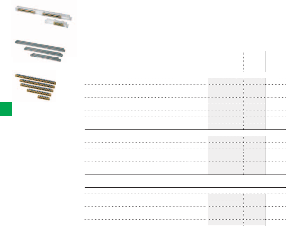
2CSC400030F0216
2CSC400030F0217
2CSC400030F0218
Terminal blocks
Terminal holders
Terminal bars
6/56 2CSC 400 031 D0202 | System pro M compact®
6
Ordering Information
IP65 Europa Series - Accessories
Terminal blocks
The complete terminal blocks are composed of a combination of terminal holders and terminal
bars as indicated in the description, with the terminal bars already mounted on terminal
holders. Configuration of the complete terminal block is standard. For different requirements
(customized terminal block), the terminal holders and bars must be procured separately in the
versions indicated in the table.
Description Box/Pack
No items
Order code Price
Terminal blocks
For 4 modules – composed of 12538x2 + 12531x2 12490 10/60
For 8 modules – composed of 12539x2 + 12531x2 12491 10/60
For 12 modules – composed of 12540x1 + 12531x1 + 12532x1 12492 10/40
For 18 modules – composed of 12543x1 + 12531x1 + 12535x1 12498 10/40
For 24 modules – composed of 12540x2 + 12533x2 12494 10/40
For 36 modules (3 rows) – composed of 12540x2 + 12534x2 12493 10/40
For 36 modules (2 rows) – composed of 12543x2 + 12534x2 12507 10/40
For 54 modules – composed of 12543x2 + 12535x2 12497 10/40
Terminal holders
For 4 modules – for IP65 Europa 12724 and 12744 12538 12/360
For 8 modules – for IP65 Europa 12728 and 12748 12539 12/360
For 12 modules per row – for IP65 Europa 12732, 12752, 12734, 12754, 12736
and 12756
12540 12/144
For 18 modules per row – for IP65 Europa 12733, 12753, 12735, 12755, 12738
and 12758
12543 12/108
The terminal block is completed by combining the necessary terminal bars to the terminal holders, taking care to keep the terminal bars separated from each
other.
Terminal bars
5 holes x Ø 4.5 12531 20/240
10 holes Ø 4.5 mm and 3 holes Ø 5.6 mm² 12532 20/240
16 holes Ø 4.5 mm and 3 holes Ø 5.6 mm² 12533 20/240
15 holes Ø 4.5 mm and 6 holes Ø 5.6 mm² 12534 20/240
19 holes Ø 4.5 mm and 6 holes Ø 5.6 mm² 12535 20/240
The terminal block is completed by combining the necessary terminal bars to the terminal holders, taking care to keep the terminal bars separate from each
other.
Terminal holders and terminal bars are supplied separately. In this way, by inserting one or two terminal bars into the terminal holder you can create the best
terminal for your requirements, with the advantage of obtaining a terminal block that is cheap as well as personalised, due to the fact that you only need to use
material that is really necessary. Some standard configurations are illustrated in the table. All the possible configurations that can be created for each type of
consumer unit are given in the technical details.
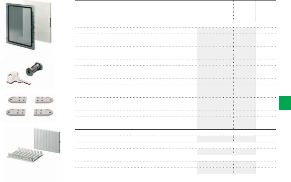
2CSC400030F0219
2CSC400030F0220
2CSC400030F0221
2CSC400030F0222
Spare doors
Closure
Plastic wall brackets
Cover strips
System pro M compact® | 2CSC 400 031 D0202 6/57
6
Description Box/Pack
No items
Order code Price
Spare doors
Opaque Door, RAL 7035 grey, for IP65 Europa 12724 and 12744 12568 1/8
Opaque Door, RAL 7035 grey, for IP65 Europa 12728 and 12748 12569 1/10
Opaque Door, RAL 7035 grey, for IP65 Europa 12732 and 12752 12570 1/8
Opaque Door, RAL 7035 grey, for IP65 Europa 12734 and 12754 12571 1/5
Opaque Door, RAL 7035 grey, for IP65 Europa 12736 and 12756 12572 1/10
Opaque Door, RAL 7035 grey, for IP65 Europa 12738 and 12758 12573 1/8
Opaque Door, RAL 7035 grey, for IP65 Europa 12733 and 12753 12584 1/20
Opaque Door, RAL 7035 grey, for IP65 Europa 12735 and 12755 12585 1/8
Transparent, smoky door for IP65 Europa 12724 and 12744 12578 1/8
Transparent, smoky door for IP65 Europa 12728 and 12748 12579 1/10
Transparent, smoky door for IP65 Europa 12732 and 12752 12580 1/8
Transparent, smoky door for IP65 Europa 12734 and 12754 12581 1/5
Transparent, smoky door for IP65 Europa 12736 and 12756 12582 1/10
Transparent, smoky door for IP65 Europa 12738 and 12758 12583 1/8
Transparent, smoky door for IP65 Europa 12733 and 12753 12586 1/20
Transparent, smoky door for IP65 Europa 12735 and 12755 12587 1/8
Closure
Lock with Key for IP65 Europa 12866 10/300
Plastic wall brackets
Wall fixing brackets in insulating material (4 pieces) 12858 20/240
Cover strips
RAL 7035 grey module cover strips for 1 module 12861 50/1500
RAL 7035 grey module cover strips for 4 modules 12863 25/300
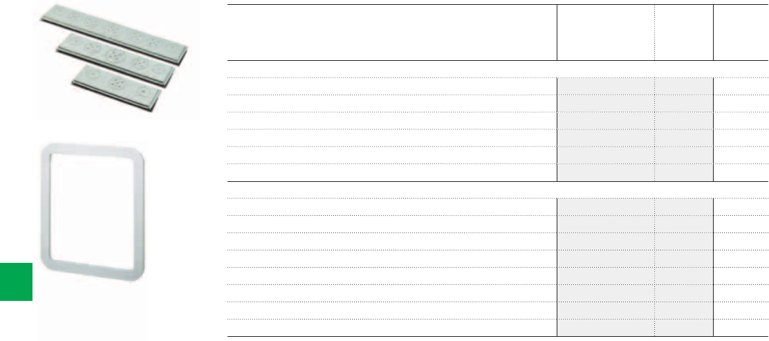
2CSC400030F0223
2CSC400030F0224
Spare Flanges
Semi-flush-mounting frame
6/58 2CSC 400 031 D0202 | System pro M compact®
6
Ordering Information
IP65 Europa Series - Accessories
Description Box/Pack
No items
Order code Price
Spare Flanges
Flange for 8 modules, bi-material for boxes width 205 mm 12600 30/120
Flange for 12, 24, 36 (12x3 rows) modules, bi-material for boxes width 275 mm 12601 20/80
Flange for 18, 36 (18x2 rows), 54 modules, bi-material for boxes width 385 mm 12602 20/80
Rigid flange, for 8 modules per row 1SL0550A00 30/120
Rigid flange, for 12 modules per row 1SL0551A00 20/80
Rigid flange, for 18 modules per row 1SL0552A00 20/80
Semi-flush-mounting frame
Semi-flush-mounting frame box 140 x 220 for IP65 Europa 12724 and 12744 12590 5/20
Semi-flush-mounting frame box 205 x 220 for IP65 Europa 12728 and 12748 12591 5/20
Semi-flush-mounting frame box 275 x 220 for IP65 Europa 12732 and 12752 12592 5/20
Semi-flush-mounting frame box 275 x 370 for IP65 Europa 12734 and 12754 12593 5/20
Semi-flush-mounting frame box 275 x 570 for IP65 Europa 12736 and 12756 12594 5/5
Semi-flush-mounting frame box 380 x 570 for IP65 Europa 12738 and 12758 12595 5/5
Semi-flush-mounting frame box 380 x 220 for IP65 Europa 12733 and 12753 12596 5/5
Semi-flush-mounting frame box 380 x 370 for IP65 Europa 12735 and 12755 12597 5/5
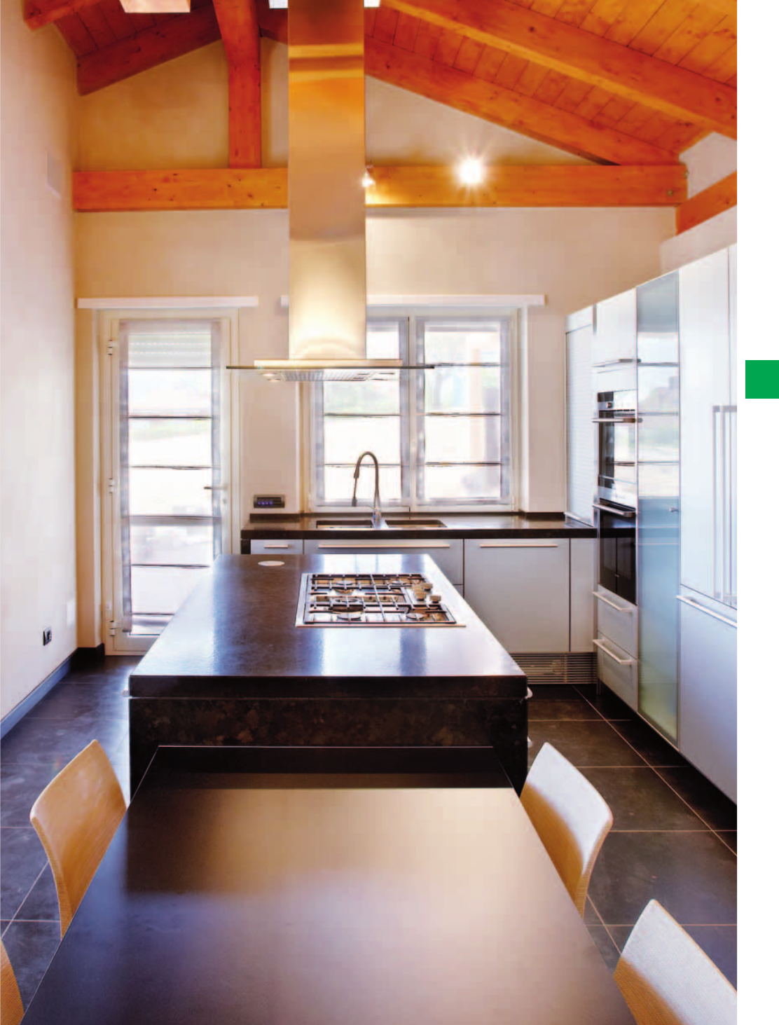
System pro M compact® | 2CSC 400 031 D0202 6/59
6
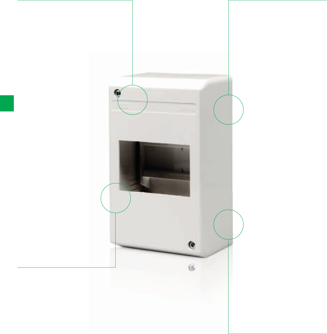
6/60 2CSC 400 031 D0202 | System pro M compact®
6
IP40 Wall-mounting covers
The details make the difference
Supplied with
module covers and
instruction sheet
Colors, white RAL
9016 and grey
RAL 7035
Rated maximum
current 63A,
installation
temperature from
-25°C to +60°C
In thermoplastic,
self-extinguishing
and resistant to
abnormal heat and
fire up to 650°C
(glow wire test) in
compliance with
IEC 60695-2-11
Standard
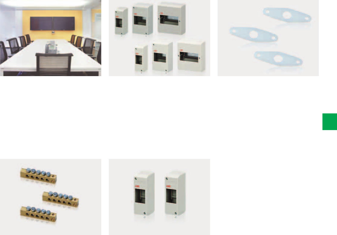
System pro M compact® | 2CSC 400 031 D0202 6/61
6
The wall covers are mainly for residential
and commercial (shops, office buildings,
etc.) applications.
The terminal bar can be fixed to covers
by using the supplied screws.
The wall cover with 2 modules can be
sealed very easy (with frame of 1/2
modules).
The IP40 Wall covers are available
in white, RAL 9016 and in grey, RAL
7035. Both ranges are without door and
available with 2, 4 and 6 modules.
The screw lead sealing (code 12860)
can also be used for the range of IP40
wall covers.
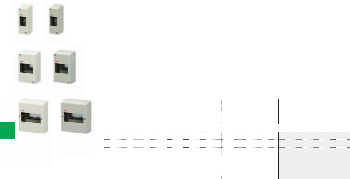
2CSC400030F0225
2CSC400030F0227
2CSC400030F0229
2CSC400030F0230
2CSC400030F0228
2CSC400030F0226
IP40
IP40
IP40 IP40
IP40
IP40
6/62 2CSC 400 031 D0202 | System pro M compact®
6
Ordering Information
IP40 Wall-mounting covers
- IP40 Wall-mounting covers for residential and commercial applications (houses, shops, office
buildlings, etc.)
- Rated current In = 125A; Protection degree IP 40; Protection class II (double insulated);
Shock resistance 6 Joules (IK level 08)
- In thermoplastic material, self-extinguishing and resistant to abnormal heat and fire up to
650°C (glow wire flammability index) in compliance with IEC 60695-2-11 Standard
- Installation temperature from -25°C to +60°C; resistant to heat: ball thermopressure up to
+85°C in compliance with EN 60695-10-2 Standard
- IP40 Wall-mounting covers are produced in compliance with CEI 23-49 (1996) + V1 + V2,
CB certificate IEC 60670-24 Standards
- IP40 Wall-mounting covers obtained the IMQ mark of approval IMQ mark
Description N° module Dimensions
HxWxD
[18 mm] [mm] Order code Price
1-row ,
IP40 Wall-mounting cover, RAL 9016 white 2 50x140x65 1SL2402A00
IP40 Wall-mounting cover, RAL 7035 grey 2 50x140x65 12422
IP40 Wall-mounting cover, RAL 9016 white 4 95x160x65 1SL2404A00
IP40 Wall-mounting cover, RAL 7035 grey 4 95x160x65 12424
IP40 Wall-mounting cover, RAL 9016 white 6 140x160x65 1SL2406A00
IP40 Wall-mounting cover, RAL 7035 grey 6 140x160x65 12426
2CSC400030F0231
2CSC400030F0232
2CSC400030F0233
Terminal bars
Screw lead sealing accessory
Cover strips
System pro M compact® | 2CSC 400 031 D0202 6/63
6
Ordering Information
IP40 Wall-mounting covers - Accessories
Description Box/Pack
No items
Order code Price
Terminal bars
Terminal bar - 2 holes x Ø 4.5 mm and 3 holes x Ø 5.6 mm for IP40 Wall-mounting
covers type 1SL2402A00, 12422, 1SL2404A00, 12424, 1SL2406A00, 12426
12502 25/ 750
The terminal bar can be fixed to covers using the supplied screws.
Screw lead sealing accessory
Lead coating accessory 12860 50/1500
Cover strips
RAL 9016 white module cover strips for 1 module 1SL2857A00 50/1500
RAL 9016 white module cover strips for 4 modules 1SL2859A00 25/300
RAL 7035 grey module cover strips for 1 module 12861 50/1500
RAL 7035 grey module cover strips for 4 modules 12863 25/300
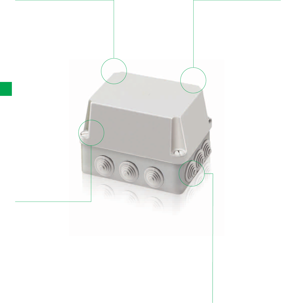
6/64 2CSC 400 031 D0202 | System pro M compact®
6
IP44, IP55 and IP65 Junction boxes
The details make the difference
Boxes with
protection degree
IP55 and IP65
are composed
of a patented lid
produced in a
single pressing
phase together
with its seal
Three lid types
available: press-
on, with steel
screws and with
plastic screws with
a ¼ turn closing
High resistance to
heat and chemical
and atmospheric
agents
Installation
temperature from
-25°C to +60°C
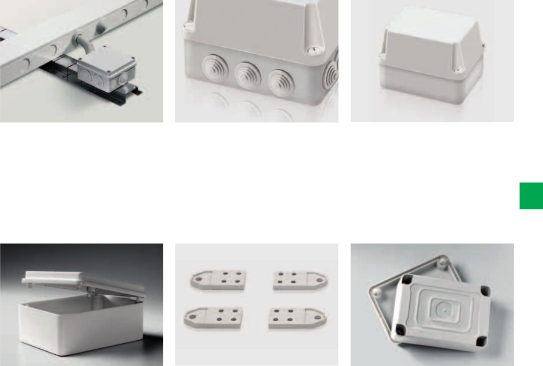
System pro M compact® | 2CSC 400 031 D0202 6/65
6
A wide range for all needs.
There are IP44 for press-on lid boxes
with cable glands, IP55 for screw-on lid
boxes with cable glands and IP65 for
screw-on lid box with smooth sides.
Now new: All IP65 junction boxes (with
smooth sides) are manufactured in
halogen free thermoplastic material.
Wall-mounting is also possible. All
junction boxes measuring 160x135,
220x170 and 310x240 mm can be
mounted on the wall with brackets
(accessory; code 12858).
All IP44, IP55 and IP65 junction boxes
are also available in thermoplastic
material, self-extinguishing in
compliance with UL 94 V2 Standard and
resistant to abnormal heat and fire up to
960°C GWT.
Some versions of the IP44 and IP55
junction boxes are already equipped
with cable glands.
Boxes with protection degree IP55 and
IP65 are composed
of a patented lid produced in a single
pressing phase together
with its seal.
2CSC400030F0234
2CSC400030F0235
2CSC400030F0236
IP44 boxes
IP44 boxes
IP55
6/66 2CSC 400 031 D0202 | System pro M compact®
6
- IP44, IP55 and IP65 Junction boxes for swimming pool control equipment, washing car
centers, garages, building services, automatic garden lighting and watering, traffic signs,
photovoltaic installations.
- Protection degree: IP44 for press-on lid boxes with cable glands, IP55 for screw-on lid boxes
with cable glands, IP65 for screw-on lid box with smooth sides
- Shock resistant: IK07 for IP44 boxes, IK08 for IP55 and IP65 boxes
- IP44 and IP55 boxes with press-on lids in thermoplastic material, self-extinguishing in
compliance with UL 94 HB Standard and resistant to abnormal heat and fire up to 650°C
(glow wire flammability index) in compliance with IEC 60695-2-11 Standard
- IP65 boxes with screw-on lids in halogen free thermoplastic material, self-extinguishing in
compliance with UL 94 HB Standard and resistant to abnormal heat and fire up to 650°C
(glow wire flammability index) in compliance with IEC 60695- 2-11 Standard
- Installation temperature from -25°C to +60°C; Resistant to heat: ball thermopressure up to
+85°C for IP44, IP55 and IP65 junction boxes
- Boxes with protection degree IP55 and IP65 are composed of a patented lid produced in a
single pressing phase together with its seal
- All junction boxes made in compliance with IEC 60670-1 and IEC 60670-22 Standards
- IP44 and IP55 junction boxes in thermoplastic material obtained the IMQ mark of approval
- All the boxes are RoHS compliance
All IP44, IP55 and IP65 junction boxes are also available in thermoplastic material,
self-extinguishing in compliance with UL 94 V2 Standard and resistant to abnormal heat
and fire up to 960°C (glow wire flammability index) in compliance with IEC 60695-2-11
Standard.
Ordering Information
IP44, IP55 and IP65 Junction boxes
Description Dimensions
HxWxD
Box/Pack
No items
[mm] Order code Price
IP44 boxes - GWT 650°C
With cable glands and press-on lid
IP44-Snap-on cover - GWT 650°C Ø 60 - H 35 800 240/240
IP44-Snap-on cover - GWT 650°C Ø 80 - H 40 802 144/144
IP44-Snap-on cover - GWT 650°C 65x65x32 808 168/168
IP44-Snap-on cover - GWT 650°C 80x80x40 810 100/100
IP55 waterproof boxes with plastic 1/4 turn screws - GWT 650°C
With cable glands and low screw-on lid RAL 7035
IP55-Cable glands-low lid-1/4TS GWT 650°C 100x100x50 1SL0816A00 1/54
IP55-Cable glands-low lid-1/4TS GWT 650°C 105x70x50 1SL0820A00 1/70
IP55-Cable glands-low lid-1/4TS GWT 650°C 100x100x80 1SL0821A00 1/40
IP55-Cable glands-low lid-1/4TS GWT 650°C 153x110x66 1SL0822A00 1/32
IP55-Cable glands-low lid-1/4TS GWT 650°C* 160x135x77 1SL0824A00 1/18
IP55-Cable glands-low lid-1/4TS GWT 650°C* 220x170x80 1SL0826A00 1/12
IP55-Cable glands-low lid-1/4TS GWT 650°C* 310x240x110 1SL0828A00 1/6
* Can be wall-mounted using wall brackets code 12858.
2CSC400030F0237
2CSC400030F0238
2CSC400030F0239
2CSC400030F0240
2CSC400030F0241
IP65
IP65
IP55
IP65
IP65
System pro M compact® | 2CSC 400 031 D0202 6/67
6
Description Dimensions
HxWxD
Box/Pack
No items
[mm] Order code Price
IP65 waterproof boxes with plastic 1/4 turn screws - GWT 650°C halogen free
With smooth sides and low screw-on lid RAL 7035
IP65-Smooth-low lid-1/4TS GWT 650°C halogen free 100x100x50 1SL0846A00 1/60
IP65-Smooth-low lid-1/4TS GWT 650°C halogen free 105x70x50 1SL0850A00 1/100
IP65-Smooth-low lid-1/4TS GWT 650°C halogen free 100x100x80 1SL0851A00 1/40
IP65-Smooth-low lid-1/4TS GWT 650°C halogen free 153x110x66 1SL0852A00 1/32
IP65-Smooth-low lid-1/4TS GWT 650°C halogen free* 160x137x77 1SL0854A00 1/24
IP65-Smooth-low lid-1/4TS GWT 650°C halogen free* 220x170x80 1SL0856A00 1/12
IP65-Smooth-low lid-1/4TS GWT 650°C halogen free* 310x240x110 1SL0858A00 1/6
With smooth sides and transparent low screw-on lid
IP65-Smooth-low transparent lid-1/4TS GWT 650°C
halogen free
153x110x66 1SL0872A00 1/34
IP65-Smooth-low transparent lid-1/4TS GWT 650°C
halogen free*
160x135x77 1SL0874A00 1/24
IP65-Smooth-low transparent lid-1/4TS GWT 650°C
halogen free*
220x170x80 1SL0876A00 1/12
IP65-Smooth-low transparent lid-1/4TS GWT 650°C
halogen free*
310x240x110 1SL0878A00 1/6
IP55 waterproof boxes with steel screws - GWT 650°C
With cable glands and high screw-on lid RAL 7035
IP55- Cable glands-low lid - GWT 650°C 100x100x50 00816 1/54
IP55- Cable glands-low lid - GWT 650°C 105x70x50 00820 1/70
IP55- Cable glands-low lid - GWT 650°C 100x100x80 00821 1/40
IP55- Cable glands-low lid - GWT 650°C 153x110x66 00822 1/32
IP65 waterproof boxes with steel screws - GWT 650°C halogen free
With smooth sides and high screw-on lid RAL 7035
IP65- Smooth W.-low lid - GWT 650°C halogen free 100x100x50 00846 1/60
IP65- Smooth W.-low lid - GWT 650°C halogen free 105x70x50 00850 1/100
IP65- Smooth W.-low lid - GWT 650°C halogen free 100x100x80 00851 1/40
IP65- Smooth W.-low lid - GWT 650°C halogen free 153x110x66 00852 1/34
With Smooth sides and transparent high screw-on lid
IP65- Smooth W.-transparent. low lid-153X110X66 GWT
650°C halogen free
151x110x66 00872 1/34
* Can be wall-mounted using wall brackets code 12858.
2CSC400030F0242
2CSC400030F0243
2CSC400030F0244
IP55
IP65
IP65
6/68 2CSC 400 031 D0202 | System pro M compact®
6
Ordering Information
IP44, IP55 and IP65 Junction boxes
Description Dimensions
HxWxD
Box/Pack
No items
[mm] Order code Price
IP55 waterproof boxes with plastic 1/4 turn screws - GWT 650°C
With Cable glands and high screw-on lid RAL 7035
IP55-Cable glands-high lid -1/4TS GWT 650°C 160x135x150 1SL0830A00 1/16
IP55-Cable glands-high lid -1/4TS GWT 650°C 220x170x150 1SL0832A00 1/8
IP55-Cable glands-high lid -1/4TS GWT 650°C 310x240x160 1SL0834A00 1/4
IP65 waterproof boxes with plastic 1/4 turn screws - GWT 650°C halogen free
With Smooth sides and high screw-on lid RAL 7035
IP65-Smooth-high lid -1/4TS GWT 650°C halogen free 160x135x150 1SL0860A00 1/16
IP65-Smooth-high lid -1/4TS GWT 650°C halogen free 220x170x150 1SL0862A00 1/8
IP65-Smooth-high lid -1/4 TS GWT 650°C halogen free 310x240x160 1SL0864A00 1/4
With Smooth sides and transparent high screw-on lid
IP65-Smooth-high transparent lid -1/4TS GWT 650°C
halogen free*
160x135x150 1SL0880A00 1/16
IP65-Smooth-high transparent lid -1/4TS GWT 650°C
halogen free*
220x170x150 1SL0882A00 1/8
IP65-Smooth-high transparent lid -1/4TS GWT 650°C
halogen free*
310x240x160 1SL0884A00 1/4
* Can be wall-mounted using wall brackets code 12858.
2CSC400030F0245
2CSC400030F0246
IP44
IP44
2CSC400030F0247
2CSC400030F0248
2CSC400030F0249
IP55
IP65
IP65
System pro M compact® | 2CSC 400 031 D0202 6/69
6
Ordering Information
IP 44, IP 55 and IP 65 junction boxes in thermoplastic material
Description Dimensions
HxWxD
Box/Pack
No items
[mm] Order code Price
IP 44 boxes - GWT 960 °C
With cable glands and press-on lid Ø 60 - H 35 1SL0900A00 240/240
Ø 80 - H 40 1SL0901A00 144/144
65x65x32 1SL0902A00 168/168
80x80x40 1SL0903A00 100/100
IP 55 waterproof boxes with plastic 1/4 turn screws - GWT 960 °C
With cable glands and low screw-on lid RAL 7035 100x100x50 1SL0916A00 1/54
105x70x50 1SL0920A00 1/70
100x100x80 1SL0921A00 1/40
153x110x66 1SL0922A00 1/32
160x135x77 1SL0924A00(*)1/18
220x170x80 1SL0926A00(*)1/12
310x240x110 1SL0928A00(*)1/6
IP 65 waterproof boxes with plastic 1/4 turn screws - GWT 960 °C
With smooth sides and low screw-on lid RAL 7035 100x100x50 1SL0946A00 1/60
105x70x50 1SL0950A00 1/100
100x100x80 1SL0951A00 1/40
153x110x66 1SL0952A00 1/32
160x137x77 1SL0954A00(*)1/24
220x170x80 1SL0956A00(*)1/12
310x240x110 1SL0958A00(*)1/6
With smooth sides and transparent low screw-on lid 153x110x66 1SL0972A00 1/34
160x135x77 1SL0974A00(*)1/24
220x170x80 1SL0976A00(*)1/12
310x240x110 1SL0978A00(*)1/6
(*) Can be wall-mounted using wall brackets code 12 858.
2CSC400030F0250
2CSC400030F0251
2CSC400030F0252
2CSC400030F0254
2CSC400030F0255
IP55
IP65
IP65
IP55
IP65
IP65
6/70 2CSC 400 031 D0202 | System pro M compact®
6
Ordering Information
IP 44, IP 55 and IP 65 junction boxes in thermoplastic material
Description Dimensions
HxWxD
Box/Pack
No items
[mm] Order code Price
IP 55 waterproof boxes with steel screws - GWT 960 °C
With cable glands and high screw-on lid RAL 7035 100x100x50 1SL0904A00 1/54
105x70x50 1SL0905A00 1/70
100x100x80 1SL0906A00 1/40
153x110x66 1SL0907A00 1/32
IP 65 waterproof boxes with steel screws - GWT 960 °C
With smooth sides and high screw-on lid RAL 7035 100x100x50 1SL0908A00 1/60
105x70x50 1SL0909A00 1/100
100x100x80 1SL0910A00 1/40
153x110x66 1SL0911A00 1/34
With smooth sides and transparent high screw-on lid 151x110x66 1SL0912A00 1/34
IP 55 waterproof boxes with plastic 1/4 turn screws - GWT 960 °C
With cable glands and high screw-on lid RAL 7035 160x135x150 1SL0930A00 1/16
220x170x150 1SL0932A00 1/8
310x240x160 1SL0934A00 1/4
IP 65 waterproof boxes with plastic 1/4 turn screws - GWT 960 °C
With smooth sides and high screw-on lid RAL 7035 160x135x150 1SL0960A00 1/16
220x170x150 1SL0962A00 1/8
310x240x160 1SL0964A00 1/4
With smooth sides and transparent high screw-on lid 160x135x150 1SL0980A00(*)1/16
220x170x150 1SL0982A00(*)1/8
310x240x160 1SL0984A00(*)1/4
2CSC400030F0253
(*) Can be wall-mounted using wall brackets code 12 858.
2CSC400030F0256
PG pitch
PG pitch
metric pitch
metric pitch
2CSC400030F0257
2CSC400030F0258
2CSC400030F0259
System pro M compact® | 2CSC 400 031 D0202 6/71
6
Pitch Torque
values
For cables diameter Cable gland Nut x cable gland Cable
clamp
Box/pack
Nuts x
cable
Box/pack
Pg N x m Min (mm) Max (mm) Order code Price Order code Price No Items No Items
9 3.75 6.5 8.5 00931 00941 100/500 100/3000
11 3.75 8 10 00932 00942 100/500 100/3000
13.5 3.75 8 11 00933 00943 50/500 50/1500
16 5 11 14 00934 00944 50/300 50/1500
21 7.5 14.5 18 00935 00945 50/300 50/1500
29 7.5 19 26 00936 00946 25/150 50/600
36 7.5 30 34 00937 00947 25/75 25/300
42 7.5 30 38 00938 00948 15/60 25/300
In compliance with CEI EN 50262 Standard.
Pitch Torque
values
Cables diameter Cable gland Nut Box/pack Cable
clamp
Box/pack
Pg N x m Min (mm) Max (mm) Order code Price Order code Price No Items No Items
12 x 1.5 2.7 3.5 7 00951 00961 100/1200 100/3000
16 x 1.5 5 5.5 10 00952 00962 100/500 100/3000
20 x 1.5 7 7 13 00953 00963 100/500 50/1500
25 x 1.5 7.5 10 17 00954 00964 50/250 50/1500
32 x 1.5 8 12 21 00955 00965 25/150 50/500
40 x 1.5 8 19 28 00956 * 00966 25/75 25/300
50 x 1.5 10 27 35 00957 * 00967 15/60 25/300
63 x 1.5 10 34 45 00958 * 00968 10/40 20/100
In compliance with CEI EN 50262 Standard.
* Cable clamps and M40, M50 and M63 nuts are available on request.
Ordering Information
IP44, IP55 and IP65 Junction boxes
Accessories
Cable glands and nuts - PG pitch
Cable glands and nuts - metric pitch
Technical characteristics of metric cable clamps:
- Protection degree IP68
- Material: polyamide 6.6, self-extinguishing material
according to UL94 V2 Standard and resistant to abnormal
heat and to fire up to 750°C (glow wire test) according to
IEC 60695-2-11 Standard
- Operational temperature: from -20°C up to +120°C (short
period of time)
- Colour: RAL 7035 grey;
- Neoprene seal;
- Thread pitch: 1.5 mm; Thread angle: 60°
- Tightening with a plate crown on the whole diameter of
cable (excluded the possibility to damage the cable itself)
- Possibility to recover the cable clamp without compromising
its efficiency.
Technical characteristics nuts of with metric pitch collar
- Material: polyamide 6.6, self-extinguishing material
according to UL94 V2 Standard and resistant to abnormal
heat and to fire up to 750°C (glow wire test) according to
IEC 60695-2-11 Standard
- Operational temperature: from -20°C up to +120°C
(continuous) from -20°C up to +120°C (short period of time)
- Colour: RAL 7035 grey
- Thread pitch: 1.5 mm; Thread angle: 60°.
Metal base plates
Cable Clamps
Condiut clamps
Unions
2CSC400030F02602CSC400030F0261
2CSC400030F02622CSC400030F0263
6/72 2CSC 400 031 D0202 | System pro M compact®
6
Ordering Information
IP44, IP55 and IP65 Junction boxes
Accessories
Description Box/Pack
No items
Order code Price
Metal base plates
Metal base plate for boxes with dimensions 160x135x77 1/10 00900
Metal base plate for boxes with dimensions 220x170x80 1/5 00902
Metal base plate for boxes with dimensions 310x240x110 1/5 00904
All metal base plates listed above are equipped with fixing screws type 3.5x9.5.
Cable Clamps - Protection Degree: IP55
Cable clamp for conduit Ø 20 mm 100/1500 00908
Cable clamp for conduit Ø 25 mm 100/1000 00910
Cable clamp for conduit Ø 32 mm 50/400 00912
Condiut clamps - Box Connector - Protection Degree: IP67
Conduit clamp Ø 16 mm 00430 500/500
Conduit clamp Ø 20 mm 00431 300/300
Conduit clamp Ø 25 mm 00432 150/150
Conduit clamp Ø 32 mm 00433 100/100
Conduit clamp Ø 40 mm 00434 50/50
Conduit clamp Ø 50 mm 00435 50/50
Unions - Protection Degree: IP55
Union connector PG 16 IP55 Ø 23 mm 13874 10/500
Union connector PG 21 IP55 Ø 28,5 mm 13875 100/400
Union connector PG 29 IP55 Ø 37 mm 13876 100/200
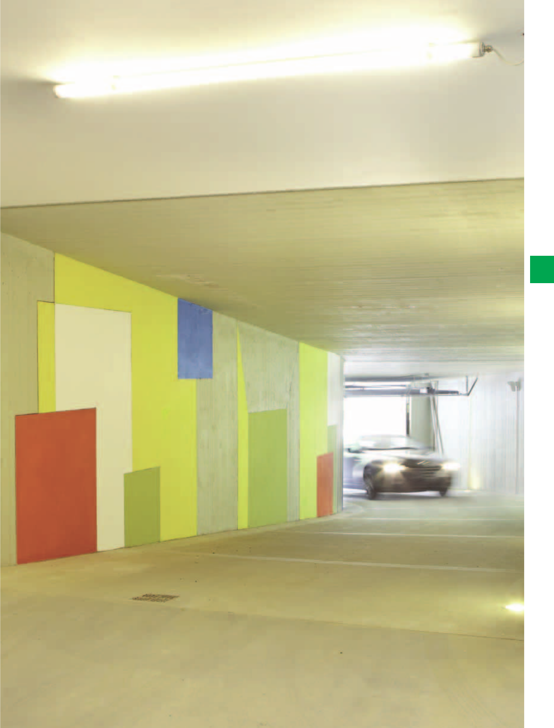
System pro M compact® | 2CSC 400 031 D0202 6/73
6
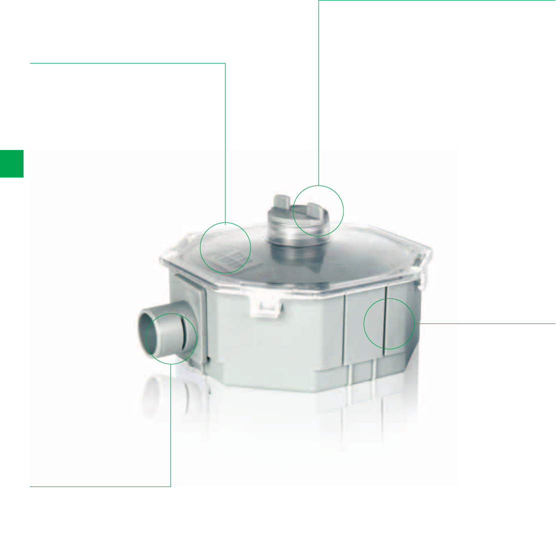
6/74 2CSC 400 031 D0202 | System pro M compact®
6
CJ8/16 Cable joint
The details make the difference
Suitable for cable
thicknesses
from 8 mm
up to 14.5 mm
Transparent lid
allows visual
inspection
After closing the
screw-type cap
on top, the cable
joint can be put
into the ground
immediately, it no
longer needs to be
kept level until the
resin has hardened
Cut-outs on all
four sides to use
a feedthrough,
T- or X-branched
sleeve

System pro M compact® | 2CSC 400 031 D0202 6/75
6
Cable with a diameter of 8 to 14.5 mm
can be cut and prepared for use in the
cable joint.The inserts can easiliy slide
over the cable.
The assembly can slide into the box and
the inserts will assure that the resin will
not leak out during the hardening
process.
The resin is supplied as 2 split
component s resin and activator. The
resin and activator need to be mixed
until a homogenous colour is reached.
(without need to touch material).
There is more than enough space inside
the box for all the connections.
The resin can be poured into the box
(funnel included).
The clear lid allows for visual inspection.
After closing of the screw type lid the
box needs no longer to be level and
there is no need to wait untill the resin
has completely hardened before putting
the joint back into the ground. (saves
time).
The electrical connections can be made
outside the box.
The required number of entries can be
made by removing the cutouts with a
set of pliers.
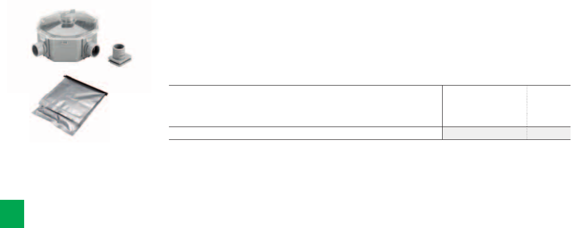
Cable Joint Kit
2CSC400030F0264
6/76 2CSC 400 031 D0202 | System pro M compact®
6
Ordering Information
CJ8/16 Cable joint
Unique design, eliminates the need for foam seals. Cables can be connected outside the
casing. Ample space for both joining and derivation. Transparent lid allows for visual
inspection.
Comes complete with resin, gloves, sand-linen, three inserts and instruction manual.
The universal underground jointing solution for professionals and do-it-yourself alike.
Description
Order code Price
Cable Joint Kit: universal connection; universal T- or X- split; for cables 8-14,5 mm 1SPA007189F0101

System pro M compact® | 2CSC 400 031 D0202 6/77
6

6/78 2CSC 400 031 D0202 | System pro M compact®
6
Technical details
UK500 Series
Code UK512N2 UK524N3 UK536N3 UK548N3
UK510E UK520E UK530E UK540E
UK510ETT UK520ETT UK530ETT UK540ETT
UK512BN2 UK524BN3 UK536BN3 UK548BN3
Number of Modules 12 24 36 48
Colour RAL 9016 white RAL 9016 white RAL 9016 white RAL 9016 white
Without door YES YES YES YES
With opaque door YES YES YES YES
With transparent door YES YES YES YES
Double Insulation YES YES YES YES
Resistance to Heat GWT 850° GWT 850° GWT 850° GWT 850°
Type of Material Thermo-plastic, Sheet steel Thermo-plastic, Sheet steel Thermo-plastic, Sheet steel Thermo-plastic, Sheet steel
Shock Resistance 2 Joule (IK 07) 2 Joule (IK 07) 2 Joule (IK 07) 2 Joule (IK 07)
Installation Temperature -5°C ÷ +40°C -5°C ÷ +40°C -5°C ÷ +40°C -5°C ÷ +40°C
Protection degree IP 30 IP 30 IP 30 IP 30
Max Dissipation Power 13W 15W 19W 21W
Cable Holding System by hollow wall
mounting
YES YES YES YES
Designed for Input push and stay design push and stay design push and stay design push and stay design
Extractable Frame YES YES YES YES
Power loss
DIN 43871 by over temperature ΔT
Type Power loss (W)
ΔT 20K ΔT 25K ΔT 30K
UK512N2, UK510E, UK510ETT, UK512BN2 10,0 13,0 16,0
UK524N3, UK520E, UK520ETT, UK524BN3 11,5 15,0 19,0
UK536N3, UK530E, UK530ETT, UK536BN3 14,5 19,0 24,0
UK548N3, UK540E, UK540ETT, UK548BN3 16,5 21,5 27,0
UK500 IP30 Flush-mounting consumer units with and without door

System pro M compact® | 2CSC 400 031 D0202 6/79
6
Wall-mounting consumer units IP40 Unibox Series with door
Code 12 238 12 242 12 244 12 246 12 247
12 258 12 262 12 264 12 266 12 267
Number of modules 8 + 1 12 + 1 24 + 2 36 + 3 54 + 3
Colour RAL 9016 white RAL 9016 white RAL 9016 white RAL 9016 white RAL 9016 white
With transparent door yes yes yes yes yes
With opaque door yes yes yes yes yes
Double insulation yes yes yes yes yes
Resistance to heat GWT 650°C GWT 650°C GWT 650°C GWT 650°C GWT 650°C
Type of material Thermo-plastic Thermo-plastic Thermo-plastic Thermo-plastic Thermo-plastic
Shock resistance 10 Joule (IK 09) 10 Joule (IK 09) 10 Joule (IK 09) 10 Joule (IK 09) 10 Joule (IK 09)
Installation temperature -25°C ÷ +60°C -25°C ÷ +60°C -25°C ÷ +60°C -25°C ÷ +60°C -25°C ÷ +60°C
Resistance to heat up to +85 °C up to +85 °C up to +85 °C up to +85 °C up to +85 °C
Protection degree IP40 IP40 IP40 IP40 IP40
Max dissipation power* 20 W 30 W 40 W 45 W 54 W
Cable holding system yes yes yes yes yes
Designed for input Conduits Ø 25÷32 mm Conduits Ø 25÷32 mm Conduits Ø 25÷32 mm Conduits Ø 25÷32 mm Conduits Ø 25÷32 mm
Trunkings
up to 200X60 mm
Trunkings
up to 200X60 mm
Trunkings
up to 200X60 mm
Trunkings
up to 200X60 mm
Trunkings
up to 200X60 mm
Extractable frame - - yes yes yes
* Data concerning dissipative power have been obtained by following the instructions in CEI 23-49 Standard, with a temperature difference of Dt = 30 °C.
Reaction to chemical agents *
Cold water
Hot water
Sulphuric acid 40%
Hydrochloric acid 35%
Acetic acid 10%
Benzole
Gasoline
Acetone
Ethyl alccohol
Ammonia liquid
Dichloromethane
Diesel oil-naphta
Mineral oils and grases
Food oils and grases
Perchloroethylene
Trichloroethylene
Ethylether
Ozone
Toluene
Methanol
Spirits
Milk
Fruit juices
Fluoride hydrocarbons
Lye-washes
Cleansings
Water solution
IP40 Unibox SSzzSzzzzzSz
resistant S partially resistant z not resistant
* Indications concerning the resistance of the products to chemical agents must be considered as an indication only, and refer to standard conditions (40 °C, integral product).
Technical details
Unibox Series

6/80 2CSC 400 031 D0202 | System pro M compact®
6
Technical details
Unibox Series
Possible configurations of terminal holders – terminal bars for consumer units
For consumer units
Number of modules
Terminal holder
Code
Terminal bars
Code x q.ty
8 12 540 12 531 x 1
12 540 12 531 x 2
12 540 12 531 x 1 with 12 532 x 1
12 540 12 532 x 1
12 540 12 533 x 1
12 540 12 534 x 1
12, 24, 36
(12 mod. x 2 rows)
12 541 12 531 x 1
12 541 12 531 x 2
12 541 12 531 x 1 with 12 532 x 1
12 541 12 531 x 1 with 12 533 x 1
12 541 12 531 x 1 with 12 534 x 1
12 541 12 531 x 1 with 12 535 x 1
12 541 12 532 x 1
12 541 12 532 x 2
12 541 12 533 x 1
12 541 12 534 x 1
12 541 12 535 x 1
18, 54 12 542 12 531 x 1
12 542 12 531 x 2
12 542 12 531 x 1 with 12 532 x 1
12 542 12 531 x 1 with 12 533 x 1
12 542 12 531 x 1 with 12 534 x 1
12 542 12 531 x 1 with 12 535 x 1
12 542 12 532 x 1
12 542 12 532 x 2
12 542 12 532x1 with 12 533x1
12 542 12 532x1 with 12 534x1
12 542 12 533x1
12 542 12 534x1
12 542 12 535x1

System pro M compact® | 2CSC 400 031 D0202 6/81
6
Technical details
Alpha Series
Alpha IP40 Wall-mounting consumer Units with door
Alpha, 1 row Alpha, 2 row Alpha, 3 row Alpha, 4 row
Number of modules 18 36 54 72
Colour RAL 9010 white RAL 9010 white RAL 9010 white RAL 9010 white
With smokey door YES YES YES YES
Double insulation YES YES YES YES
Resistance to heat GWT 750° GWT 750° GWT 750° GWT 750°
Type of material Thermo-plastic Thermo-plastic Thermo-plastic Thermo-plastic
Shock resistance IK 07 IK 07 IK 07 IK 07
Installation temperature -5°C ÷ +40°C -5°C ÷ +40°C -5°C ÷ +40°C -5°C ÷ +40°C
Protection degree IP 41 IP 41 IP 41 IP 41
Designed for input trunking trunking trunking trunking
Extractable frame YES YES YES YES

6/82 2CSC 400 031 D0202 | System pro M compact®
6
Technical details
AT Series
Code AT31 AT22E AT51 AT32 AT42
AT41 AT51TE AT32TE AT42/2
AT41TE AT61
AT42M AT61TE
AT41TE
Number of Modules 36 48 60 72 96
Colour RAL 9016 white RAL 9016 white RAL 9016 white RAL 9016 white RAL 9016 white
Without door NO NO NO NO NO
With metal door YES YES YES YES YES
With transparent door YES YES YES YES YES
Double Insulation YES YES YES YES YES
Resistance to Heat 750°C 750°C 750°C 750°C 750°C
Type of Material Thermo-plastic,
Sheet steel
Thermo-plastic,
Sheet steel
Thermo-plastic,
Sheet steel
Thermo-plastic,
Sheet steel
Thermo-plastic,
Sheet steel
Shock Resistance 10 Joule (IK 09) 10 Joule (IK 09) 5 Joule (IK 08) 5 Joule (IK 08) 5 Joule (IK 08)
Installation Temperature -5°C ÷ +40°C -5°C ÷ +40°C -5°C ÷ +40°C -5°C ÷ +40°C -5°C ÷ +40°C
Protection degree IP43 IP43 IP43 IP43 IP43
Max Dissipation Power 38 W 48 W 60 W 68 W 73 W
Cable Holding System NO NO NO NO NO
Designed for Input Membrane flange Membrane flange Membrane flange Membrane flange Membrane flange
Wall-mounting Compact Distribution Board IP43 AT Series with door
AT compact distribution board with doors
Type Weight in kg Power loss in W
AT22E 9,7 47
AT31 7,5 38
AT32 12,5 60
AT32R2 12 60
AT32TE 12 60
AT32TR2 11,5 60
AT41 9,5 48
AT41R3 10 48
AT41TE 9 48
AT41TR3 9 48
AT42 15 73
AT42/2 15,5 73
AT42M 17,5 73
AT42R3 15 73
AT42TE 13 73
Type Weight in kg Power loss in W
AT42TR3 13,5 73
AT43 21,5 96
AT43R3 21,5 96
AT43TR3 18 96
AT51 11,5 58
AT51R4 11,5 58
AT51TE 11,5 58
AT51TR4 11 58
AT52 17 85
AT52/2 18 85
AT52K 17,5 85
AT52R4 18 85
AT52TE 18 85
AT52TR4 16 85
AT53 25 120

System pro M compact® | 2CSC 400 031 D0202 6/83
6
AT52 AT43 AT72 AT53 AT63E AT54E
AT52/2 AT62
AT52TE AT62TE
AT53M
120 144 168 180 216 240
RAL 9016 white RAL 9016 white RAL 9016 white RAL 9016 white RAL 9016 white RAL 9016 white
NO NO NO NO NO NO
YES YES YES YES YES YES
YES YES YES YES YES YES
YES YES YES YES YES YES
750°C 750°C 750°C 750°C 750°C 750°C
Thermo-plastic,
Sheet steel
Thermo-plastic,
Sheet steel
Thermo-plastic,
Sheet steel
Thermo-plastic,
Sheet steel
Thermo-plastic,
Sheet steel
Thermo-plastic,
Sheet steel
5 Joule (IK 08) 5 Joule (IK 08) 5 Joule (IK 08) 5 Joule (IK 08) 5 Joule (IK 08) 5 Joule (IK 08)
-5°C ÷ +40°C -5°C ÷ +40°C -5°C ÷ +40°C -5°C ÷ +40°C -5°C ÷ +40°C -5°C ÷ +40°C
IP43 IP43 IP43 IP43 IP43 IP43
85 W 96 W 111 W 120 W 130W 140 W
NO NO NO NO NO NO
Membrane flange Membrane flange Membrane flange Membrane flange Membrane flange Membrane flange
Type Weight in kg Power loss in W
AT53K 25 120
AT53M 28 120
AT53R4 25,5 120
AT53TR4 21,5 120
AT54E 32 140
AT54K 31 140
AT54R4 32,5 140
AT54TR4 26,5 140
AT61 13,5 68
AT61R5 13,5 68
AT61TE 11,5 68
AT61TR5 12 68
AT62 21 100
AT62K 20,5 100
AT62R5 20 100
Type Weight in kg Power loss in W
AT62TE 20 100
AT62TR5 20 100
AT63E 29,5 130
AT63K 29 130
AT63R5 29 130
AT63TR5 24 13
AT64K 36 176
AT 72 23,5 111
AT 72K 23,5 111
AT 72R6 23,5 111
AT 72TR6 20 111
AT73K 33,5 153
AT73R6 34 153
AT73TR6 30,5 153
> Maße in mm

6/84 2CSC 400 031 D0202 | System pro M compact®
6
Type Weight in kg Power loss in W
U42TR3 14 60
U43 22,5 80
U43R3 23 80
U43TR3 19,5 80
U51 12,5 43
U51R4 12 43
U51TE 12 43
U51TR4 10,5 43
U52 18,5 69
U52/2 19 69
U52K 18,5 69
U52R4 18 69
U52TE 16 69
U52TR4 16 69
U53 26,5 93
Technical details
U Series
Code U41 U51 U32 U42D U42
U41TE U51TE U32TE U42FPT U42/2
U42M U61 U42TE
U61TE
Number of Modules 48 60 72 96 96
Colour RAL 9016 white RAL 9016 white RAL 9016 white RAL 9016 white RAL 9016 white
Without door NO NO NO NO NO
with metal door YES YES YES YES YES
With transparent door YES YES YES YES YES
Double Insulation YES YES YES YES YES
Resistance to Heat 850°C 850°C 850°C 850°C 850°C
Type of Material Thermo-plastic,
Sheet steel
Thermo-plastic,
Sheet steel
Thermo-plastic,
Sheet steel
Thermo-plastic,
Sheet steel
Thermo-plastic,
Sheet steel
Shock Resistance 10 Joule (IK 09) 10 Joule (IK 09) 5 Joule (IK 08) 5 Joule (IK 08) 5 Joule (IK 08)
Installation Temperature -5°C ÷ +40°C -5°C ÷ +40°C -5°C ÷ +40°C -5°C ÷ +40°C -5°C ÷ +40°C
Protection degree IP31 IP31 IP31 IP31 IP31
Max Dissipation Power 47 W 43 W 50 W 60 W 60 W
Cable Holding System by
hollow wall mounting
YES YES YES YES YES
Designed for Input Nipple flange Nipple flange Nipple flange Nipple flange Nipple flange
Extractable Frame YES YES YES YES YES
Flush-mounting Compact Distribution Board IP30 U Series with door
U compact distribution board with doors
Type Weight in kg Power loss in W
U32 13,5 50
U32R2 13 50
U32TE 12,5 50
U32TR2 11 50
U41 10,5 36
U41R3 10,5 36
U41TE 9 36
U41TR3 9,5 36
U42 15,5 60
U42/2 16,5 60
U42D 16,5 60
U42FPT 17 60
U42M 18,5 60
U42R3 16 60
U42TE 14 60

System pro M compact® | 2CSC 400 031 D0202 6/85
6
Type Weight in kg Power loss in W
U53K 26 93
U53M 29 93
U53R4 26,5 93
U53TR4 22 93
U54E 33 120
U54K 32,5 120
U54R4 33,5 120
U61 14,5 50
U61R5 14,5 50
U61TE 12,5 50
U61TR5 12,5 50
U62 22 80
U62K 22 80
U62R5 22 80
U62TE 19 80
U52 U43 U72 U53 U63E U54E
U52/2 U62
U52TE U62TE
U53M
120 144 168 180 216 240
RAL 9016 white RAL 9016 white RAL 9016 white RAL 9016 white RAL 9016 white RAL 9016 white
NO NO NO NO NO NO
YES YES YES YES YES YES
YES YES YES YES YES YES
YES YES YES YES YES YES
850°C 850°C 850°C 850°C 850°C 850°C
Thermo-plastic,
Sheet steel
Thermo-plastic,
Sheet steel
Thermo-plastic,
Sheet steel
Thermo-plastic,
Sheet steel
Thermo-plastic,
Sheet steel
Thermo-plastic,
Sheet steel
5 Joule (IK 08) 5 Joule (IK 08) 5 Joule (IK 08) 5 Joule (IK 08) 5 Joule (IK 08) 5 Joule (IK 08)
-5°C ÷ +40°C -5°C ÷ +40°C -5°C ÷ +40°C -5°C ÷ +40°C -5°C ÷ +40°C -5°C ÷ +40°C
IP31 IP31 IP31 IP31 IP31 IP31
69 W 80 W 89 W 93 W 110 W 120 W
YES YES YES YES YES YES
Nipple flange Nipple flange Nipple flange Nipple flange Nipple flange Nipple flange
YES YES YES YES YES YES
Type Weight in kg Power loss in W
U62TR5 19 80
U63E 31 110
U63K 30,5 110
U63R5 31,5 110
U63TR5 26 110
U64K 38 137
U72 25 89
U72K 25 89
U72R6 26 89
U72TR6 21,5 89
U73K 35 125
U73R6 35,5 125
U73TR6 28,5 125
> Maße in mm

6/86 2CSC 400 031 D0202 | System pro M compact®
6
Technical details
IP65 Europa Series
Code 12 724
12 744
12 728
12 748
12 732
12 752
12 733
12 753
12 734
12 754
12 735
12 755
12 736
12 756
12 738
12 758
Number of modules 4 8 12 18 24 36 54
Colour RAL 7035 grey RAL 7035 grey RAL 7035 grey RAL 7035 grey RAL 7035 grey RAL 7035 grey RAL 7035 grey
With transparent door yes yes yes yes yes yes yes
With opaque door yes yes yes yes yes yes yes
Double insulation yes yes yes yes yes yes yes
Resistance to heat GWT 650°C GWT 650°C GWT 650°C GWT 650°C GWT 650°C GWT 650°C GWT 650°C
Type of material Thermo-plastic Thermo-plastic Thermo-plastic Thermo-plastic Thermo-plastic Thermo-plastic Thermo-plastic
Shock resistance 6 Joule (IK 08) 6 Joule (IK 08) 6 Joule (IK 08) 6 Joule (IK 08) 6 Joule (IK 08) 6 Joule (IK 08) 6 Joule (IK 08
Installation temperature 25°C ÷ +60°C 25°C ÷ +60°C 25°C ÷ +60°C 25°C ÷ +60°C 25°C ÷ +60°C 25°C ÷ +60°C 25°C ÷ +60°C
Resistance to heat up to +85°C up to +85°C up to +85°C up to +85°C up to +85°C up to +85°C up to +85°C
Protection degree IP65 IP65 IP65 IP65 IP65 IP65 IP65
Max dissipation power* 15W 20W 30W 32W 34W 45W 56 W
Flange for direct branch - Cond. and trunk
Ø 5÷35 mm
Cond. and trunk
Ø 5÷35 mm
Cond. and trunk
Ø 5÷35 mm
Cond. and trunk
Ø 5÷35 mm
Cond. and trunk
Ø 5÷35 mm
Cond. and trunk
Ø 5÷35 mm
Extractable mouled-case yes yes yes yes yes yes yes
Designed for mouled-case
circuit breakers
yes yes yes yes yes yes yes
Designed for rapid cabling - Unifix L Unifix L Unifix L Unifix L Unifix L Unifix L
* Data concerning dissipative power have been obtained by following the instructions in CEI 23-49 Standard, with a temperature difference of Dt = 30°C.
Wall-mounting consumer units IP65 Europa Series
Reaction to chemical agents *
Cold water
Hot water
Sulphuric acid 40%
Hydrochloric acid 35%
Acetic acid 10%
Benzole
Gasoline
Acetone
Ethyl alccohol
Ammonia liquid
Dichloromethane
Diesel oil-naphta
Mineral oils and grases
Food oils and grases
Perchloroethylene
Trichloroethylene
Ethylether
Ozone
Toluene
Methanol
Spirits
Milk
Fruit juices
Fluoride hydrocarbons
Lye-washes
Cleansings
Water solution
IP65 Europa Series wall-mounting consumer
units SSzzSzzzzzSz
resistant S partially resistant z not resistant
* Indications concerning the resistance of the products to chemical agents must be considered as an indication only, and refer to standard conditions (40°C, integral product).

System pro M compact® | 2CSC 400 031 D0202 6/87
6
Possible configurations of terminal holders – terminal bars for consumer units
For IP65 Europa consumer units
Number of modules
Terminal holder
Code
Terminal bars
Code x q.ty
4 12 538 12 531 x 1
8 12 539 12 531 x 1
12, 24, 36
(12 mod. x 2 rows)
12 540 12 531 x 1
12 540 12 531 x 2
12 540 12 531 x 1 with 12 532 x 1
12 540 12 532 x 1
12 540 12 533 x 1
12 540 12 534 x 1
18, 36 (12 mod. x 2 rows), 54 12 543 12 531 x 1
12 543 12 531 x 2
12 543 12 531 x 1 with 12 532 x 1
12 543 12 531 x 1 with 12 533 x 1
12 543 12 531 x 1 with 12 534 x 1
12 543 12 531 x 1 with 12 535 x 1
12 543 12 532 x 1
12 543 12 532 x 2
12 543 12 532 x 1 with 12 533 x 1
12 543 12 532 x 1 with 12 534 x 1
12 543 12 532 x 1 with 12 535 x 1
12 543 12 533 x 1
12 543 12 533 x 2
12 543 12 533 x 1 with 12 534 x 1
12 543 12 534 x 1
12 543 12 534 x 2
12 543 12 535 x 1

6/88 2CSC 400 031 D0202 | System pro M compact®
6
Technical details
IP40 wall mounting covers
Code M12422000
1SL2402A00
M12424000
1SL2404A00
M12426000
1SL2406A00
Number of modules 2 4 6
Colour RAL 9016 white / RAL 7035 grey RAL 9016 white / RAL 7035 grey RAL 9016 white / RAL 7035 grey
Double insulation NO NO NO
Resistance to heat GWT 650°C GWT 650°C GWT 650°C
Type of material Thermo-plastic Thermo-plastic Thermo-plastic
Shock resistance 6 Joule (IK 08) 6 Joule (IK 08) 6 Joule (IK 08)
Installation temperature -25°C ÷ +80°C -25°C ÷ +80°C -25°C ÷ +80°C
Resistance to heat up to +85°C up to +85°C up to +85°C
Protection degree IP40 IP40 IP40
Cable holding system YES YES YES
Designed for input - - -
Extractable frame - - -
IP40 wall mounting covers
Reaction to chemical agents *
Cold water
Hot water
Sulphuric acid 40%
Hydrochloric acid 35%
Acetic acid 10%
Benzole
Gasoline
Acetone
Ethyl alccohol
Ammonia liquid
Dichloromethane
Diesel oil-naphta
Mineral oils and grases
Food oils and grases
Perchloroethylene
Trichloroethylene
Ethylether
Ozone
Toluene
Methanol
Spirits
Milk
Fruit juices
Fluoride hydrocarbons
Lye-washes
Cleansings
Water solution
IP40 wall-mounting covers SSzzSzzzzzSz
resistant S partially resistant z not resistant
* Indications concerning the resistance of the products to chemical agents must be considered as an indication only, and refer to standard conditions (40 °C, integral product).
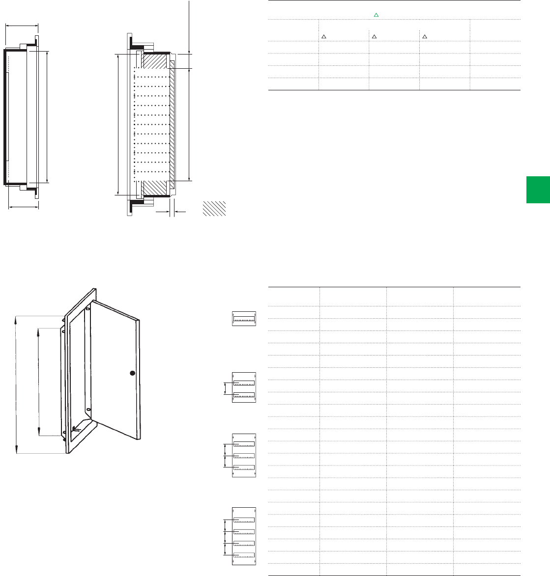
11,5
12 space units
270
1.5 space units
space for wiring
mounting plates
89
78
H
125125125125 125125
internal dimension
external dimension
System pro M compact® | 2CSC 400 031 D0202 6/89
6
Overall dimensions
UK500 Series
Wall box
Trim frame
Type Int. dimensions
(H x W mm)
Ext. dimensions
(H x W mm)
Weight
in kg
BL510 282 x 297 352 x 367 1.5
BL516C 282 x 297 352 x 367 1.5
BL517C 282 x 297 352 x 367 1.5
BL517C 282 x 297 352 x 367 1.5
BL510K 282 x 297 352 x 367 1.5
BL520 407 x 297 477 x 367 1.9
BL526C 407 x 297 477 x 367 1.9
BL527C 407 x 297 477 x 367 1.9
BL528C 407 x 297 477 x 367 1.9
BL520K 407 x 297 477 x 367 1.9
BL530 532 x 297 602 x 367 2.3
BL536C 532 x 297 602 x 367 2.3
BL537C 532 x 297 602 x 367 2.3
BL538C 532 x 297 602 x 367 2.3
BL530K 532 x 297 602 x 367 2.3
BL530L 532 x 297 602 x 367 2.3
BL540 657 x 297 727 x 367 2.7
BL546C 657 x 297 727 x 367 2.7
BL547C 657 x 297 727 x 367 2.7
BL548C 657 x 297 727 x 367 2.7
BL540K 657 x 297 727 x 367 2.7
BL540L 657 x 297 727 x 367 2.7
Power loss and height
DIN 43871 with over temperature T
Type Power loss (W) Height
T 20K T25K T30K in mm
UK51... 10.0 13.0 16.0 250
UK52... 11.5 15.0 19.0 375
UK53... 14.5 19.0 24.0 500
UK54... 16.5 21.5 27.0 625
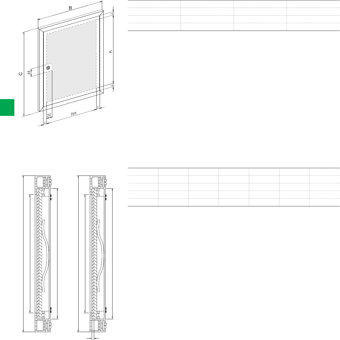
E
C
A
F
D
B
2,5 mm
glass thickness
Side view Top view
Useable space
6/90 2CSC 400 031 D0202 | System pro M compact®
6
Control panel
Picture frame door
TypeABC
FPT510 278 374 362
FPT520 403 374 487
FPT530 528 374 612
TypeABCDEF
BL521D 417 308 402 293 487 378
BL531D 542 308 526 293 612 378
BL527D 456 343 441 328 487 374
BL537D 581 343 566 328 612 374
Overall dimensions
UK500 Series
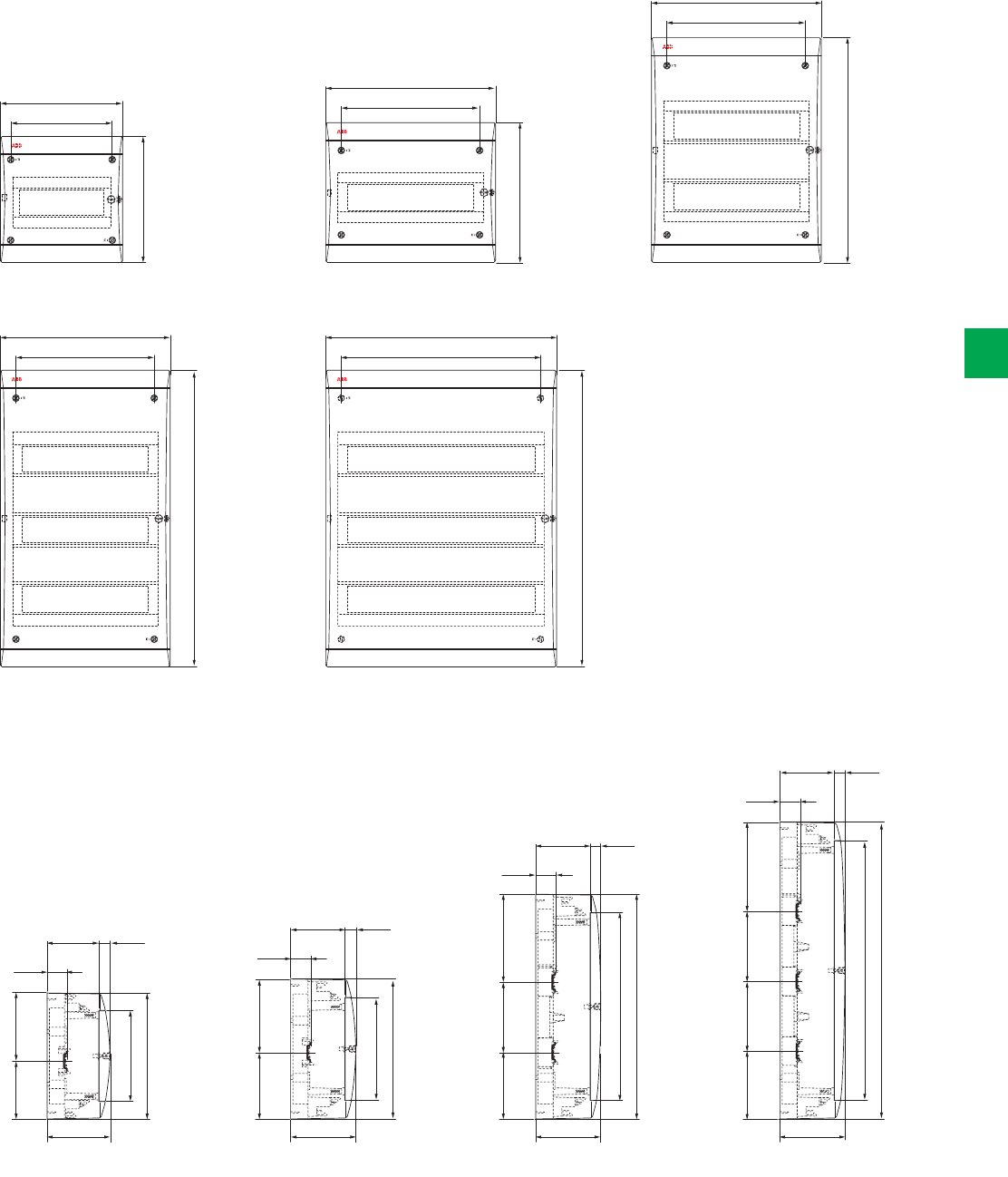
8 modules
36 modules
12 modules
54 modules
295
234
390
295
234
245
215
174
220
24 modules
295 403
234 342
515
515
8 modules 12 modules 24 modules 36-54 modules
95
95
85
115115
22
22
20
31
31
25
117
177
177 177
177
125 148
95
115
22
31
117 125 125 148
515
450
390
245
220
325
180
155
System pro M compact® | 2CSC 400 031 D0202 6/91
6
Overall dimensions
Unibox Series
Side view
Front view
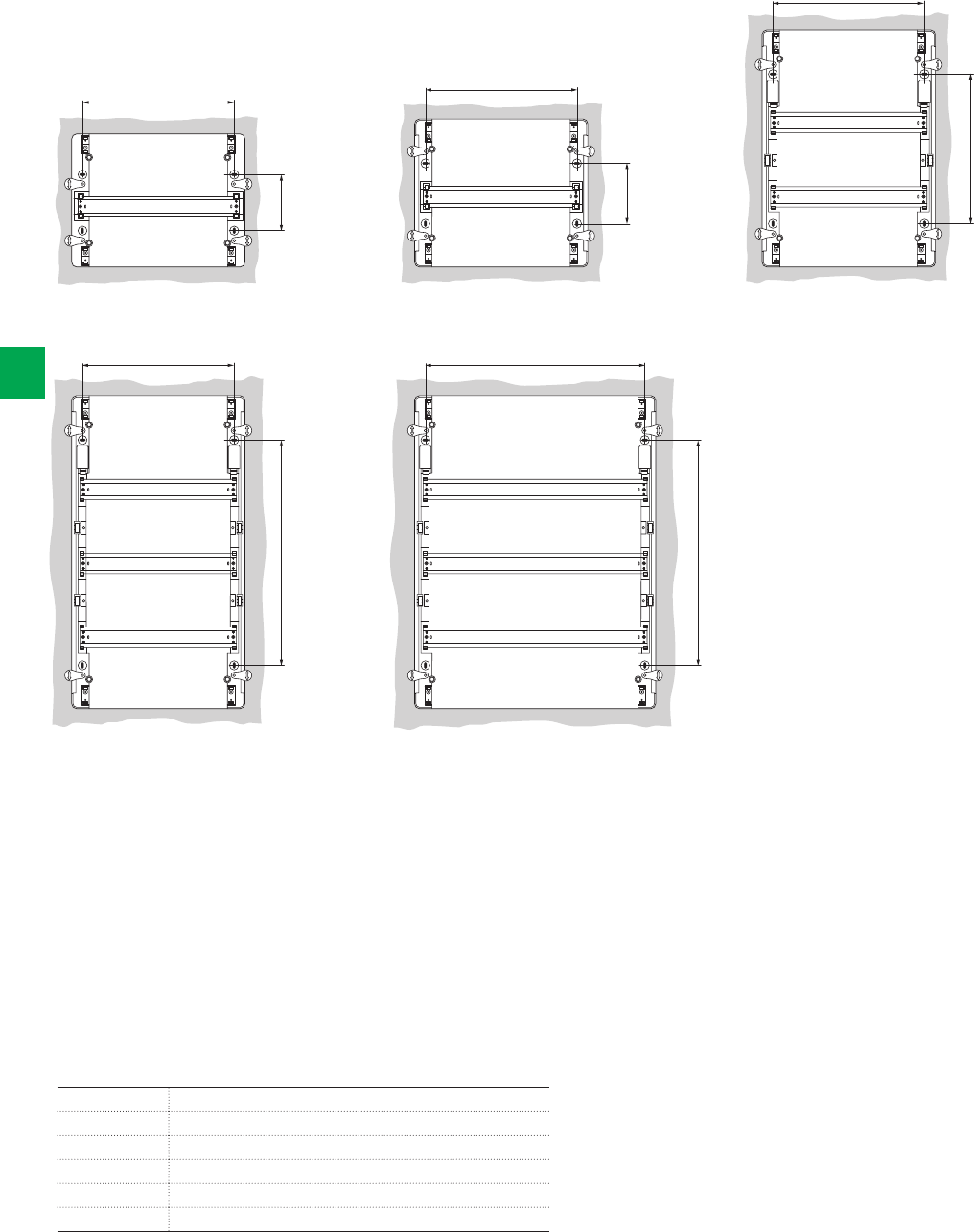
8 modules
36 modules
12 modules
54 modules
24 modules
257
257
187
257
240
94
87365
365
365
6/92 2CSC 400 031 D0202 | System pro M compact®
6
Drilling sheets
Modules Code
8 modules 12 238 – 12 258 – M12238000U - M12258000U
12 modules 12 242 – 12 262 – M12242000A - M12262000A
24 modules 12 244 – 12 264 – M12244000U - M12264000U
36 modules 12 246 – 12 266 – M12246000U - M12266000U
54 modules 12 247 – 12 267 – M12247000U - M12267000U
Overall dimensions
Unibox Series
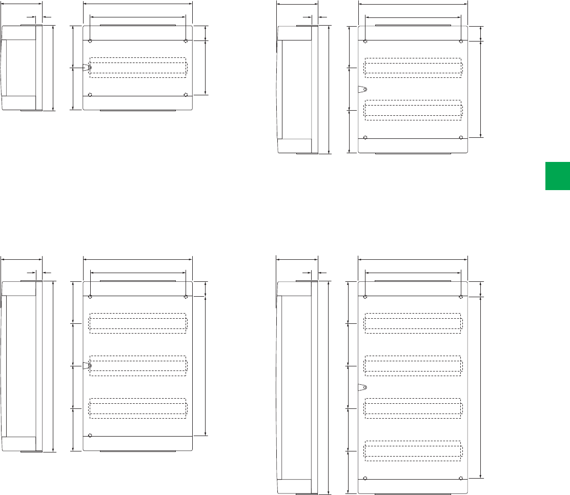
149 390
34025
307
54
150
192
150
152 390
34025
607
54
150150
492
150150
153 390
34025
757
54
150150
642
150150150
151 390
34025
457
54
150
342
150150
System pro M compact® | 2CSC 400 031 D0202 6/93
6
Overall dimensions
Alpha Series
1 row
3 rows
2 rows
4 rows
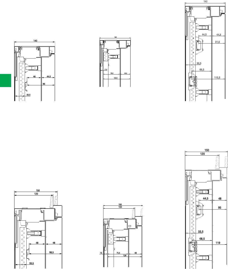
140
115,5
68,5
33,5
44,5
91,5
44.5
Panel for terminals
Panel for terminals
Panel with mounting plate
Panel with mounting plate
Compact distribution board panel
Compact distribution board panel
140
140
140
48
33.5
44.5
95 75.5
122,5
44.5
11.5
44.5
91.5
115.5
150
120
75.5 48
126
13
150
120
48
33.5
48
98.5
150
120
44.5
33.5
68.5
48
95
119
44.5
33.5
68.5
6/94 2CSC 400 031 D0202 | System pro M compact®
6
Flush-mounting with door, U series
Wall-mounting with door, AT series
Overall dimensions
AT/U Series
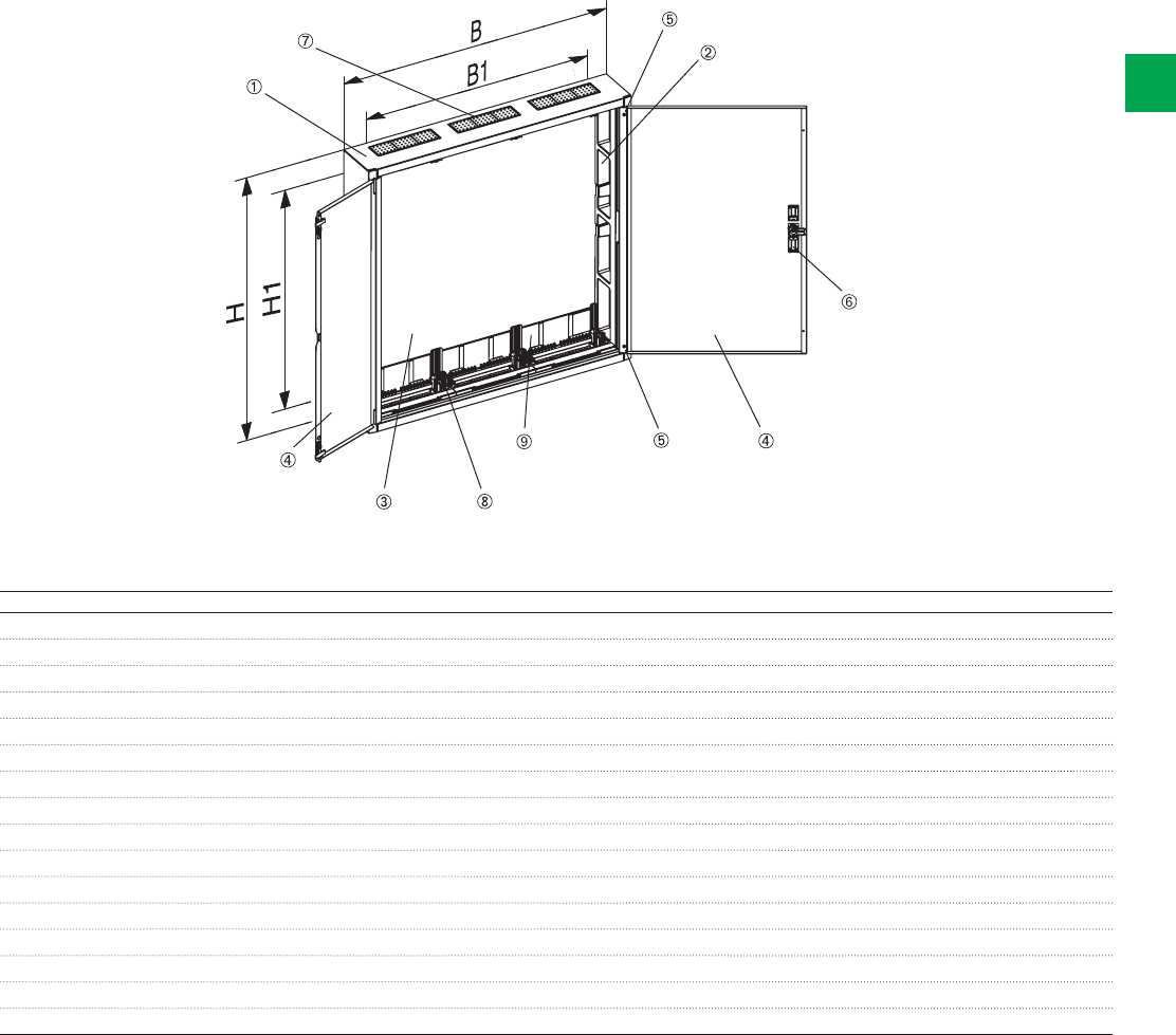
wall fastening
wall fastening
System pro M compact® | 2CSC 400 031 D0202 6/95
6
Compact distribution boards
Technical information
1. The cabinet is made of sheet steel (1mm) and is powder-
coated (RAL 9016). Its extraordinary stability is achieved
by the profiled cabinet frame. Problem-free surface
mounting is therefore also possible.
2. The protective insulation is guaranteed by an inserted
plastic profile.
3. An additional plastic rear wall is inserted in order to
maintain the protective insulation.
4. The door provides great stability thanks to its special
shape in the hinge area and on the closing side.
5. The door can be readjusted with the special hinge.
6. The standard lock offers not only a new design but
also secure closure, both as "standard" and as
"security design".
7. The flange openings on top are closed ex-factory
with the membrane flange.
8. The cabinet provides an optimum connection space
thanks to the individual panel holders.
9. Prepunched knockouts are provided for inserting
cables from the rear.
Type H W H1 W1
AT22E 374 574 235 417
AT31 524 324 385 167
AT32, AT32TE, AT32R2, AT32TR2 524 574 385 417
AT41, AT41TE, AT41R3, AT41TR3 674 324 535 167
AT42, AT42TE, AT42M, AT42/2, AT42R3, AT42TR3 674 574 535 417
AT43, AT43R3, AT43TR3 674 824 535 667
AT51, AT51TE, AT51R4, AT51TR4 824 324 685 167
AT52, AT52TE, AT52K, AT52/2, AT52R4, AT52TR4 824 574 685 417
AT53, AT53M,AT53K, AT53R4, AT53TR4 824 824 685 667
AT54K, AK54E, AT54R4 824 1074 685 917
AT61, AT61TE, AT61R5, AT61TR5 974 324 835 167
AT62, AT62TE, AT62K, AT62R5, AT62TR5 974 574 835 417
AT63E, AT63K, AT63R5, AT63TR5 974 824 835 667
AT64K 974 1074 835 917
AT72, AT72K, AT72R6, AT72TR6 1124 574 985 417
AT73K, AT73R6, AT73TR6 1124 824 985 667
Dimensions in mm
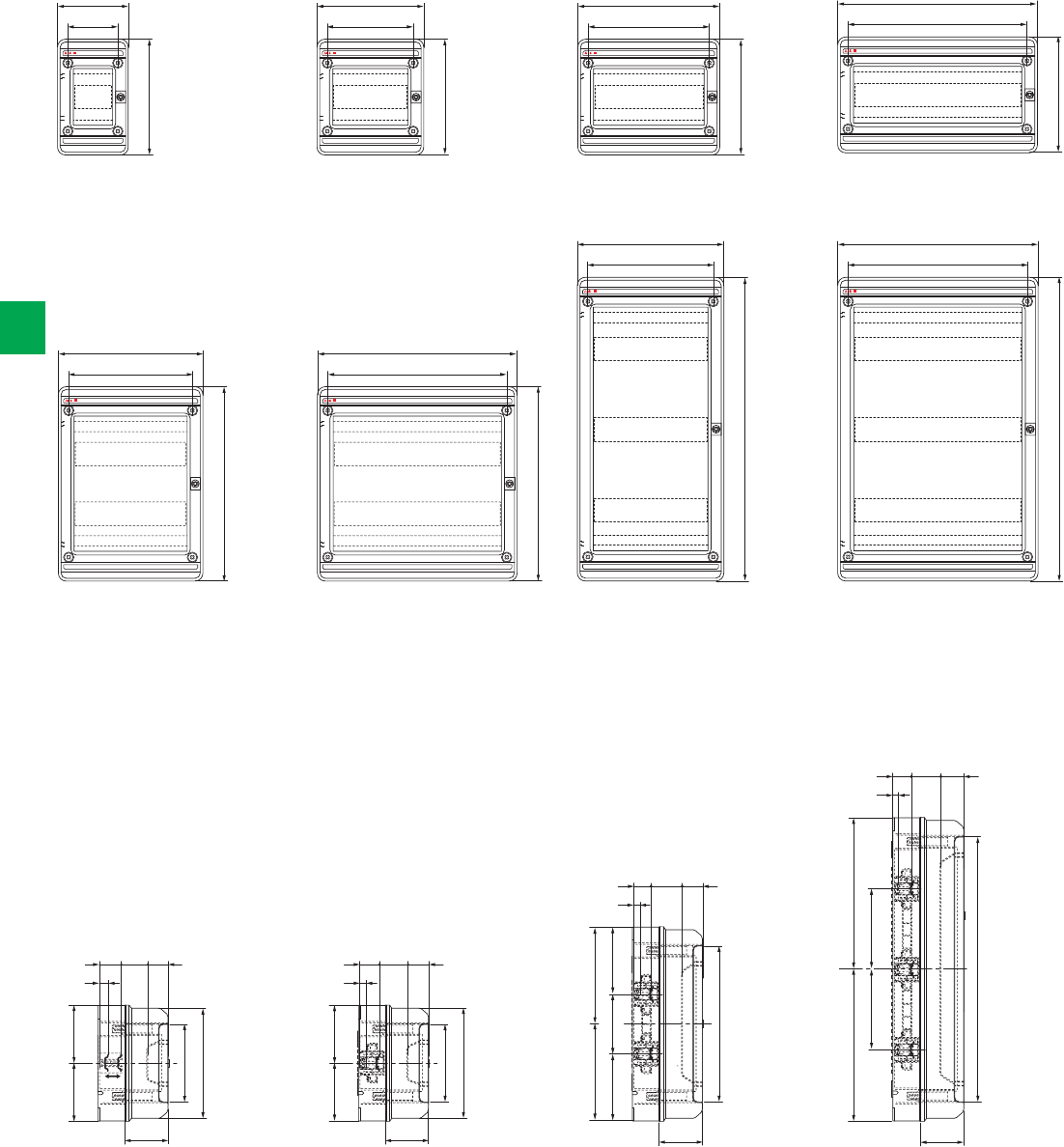
4-8-12 modules 18 modules 24 modules 36-54 modules
IP65IP65
IP65IP65
4 modules
24 modules
8 modules
36 modules
12 modules
36 modules
18 modules
54 modules
IP65 IP65 IP65 IP65
137 204 274 379
90 165 235 340
220
220
220
220
274 379
274 379
235 340
235 340
370
370
570
570
210
160
105 105
16
46 50
81.5
44
210
310
502
160
105
185
281 281
122.5 125
150 150
122.5
105
185
16
16
16
46
46
46
50
50
50
81.5 81.5 81.5
44
44
44
6/96 2CSC 400 031 D0202 | System pro M compact®
6
Overall dimensions
IP65 Europa Series
Front view
Side view
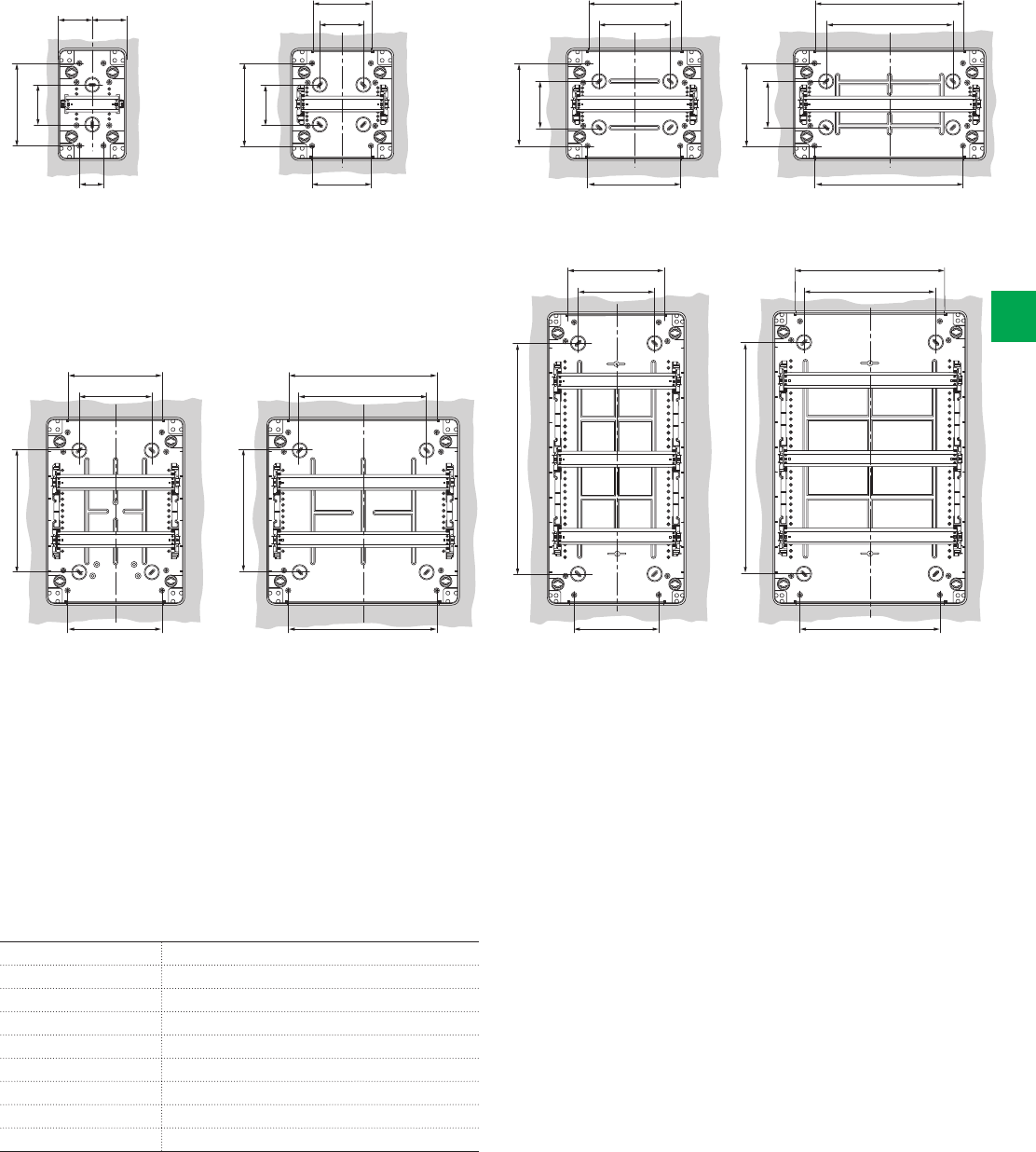
12 modules
90
170
210
164
184
18 modules
90
170
285
269
289
8 modules
90
170
140
94
160
4 modules
170
90
68 68
68
24 modules
240
210
164
184
36 modules
240
284
269
289
36 modules
440
210
164
184
54 modules
440
285
269
289
System pro M compact® | 2CSC 400 031 D0202 6/97
6
Modules Code
4 modules 12 724 – 12 744
8 modules 12 728 – 12 748
12 modules 12 732 – 12 752
18 modules 12 733 – 12 753
24 modules 12 734 – 12 754
36 modules (18x2) 12 735 – 12 755
36 modules (12x3) 12 736 – 12 756
54 modules 12 738 – 12 758
Drilling sheets
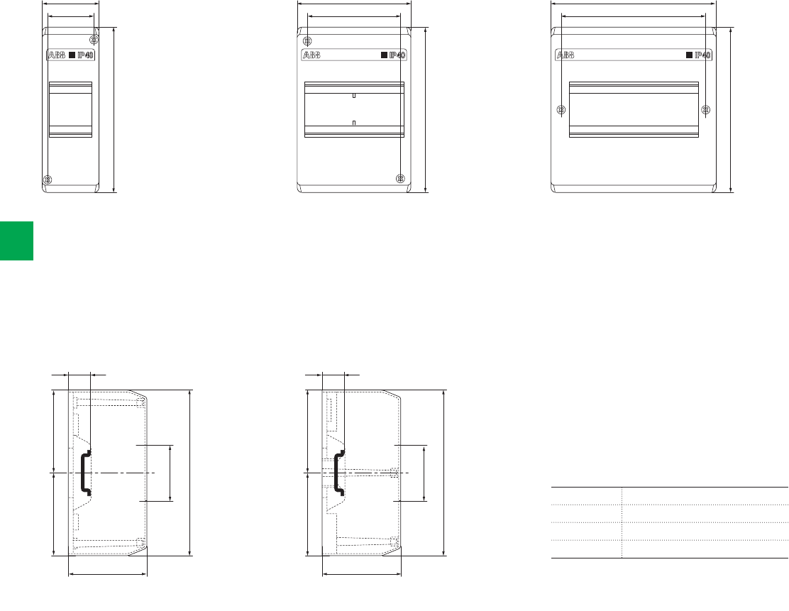
2 modules
2 modules
4 modules
4-6 modules
6 modules
50 96 139
35 74 121
140
160
160
140
160
46
46
=
=
=
=
17.5 17.5
65 65
6/98 2CSC 400 031 D0202 | System pro M compact®
6
Overall dimensions
IP40 Wall-mounting covers
Front view
Side view
Modules Code
2 modules 1SL2402A00 – 12 422
4 modules 1SL2404A00 – 12 424
6 modules 1SL2406A00 – 12 426
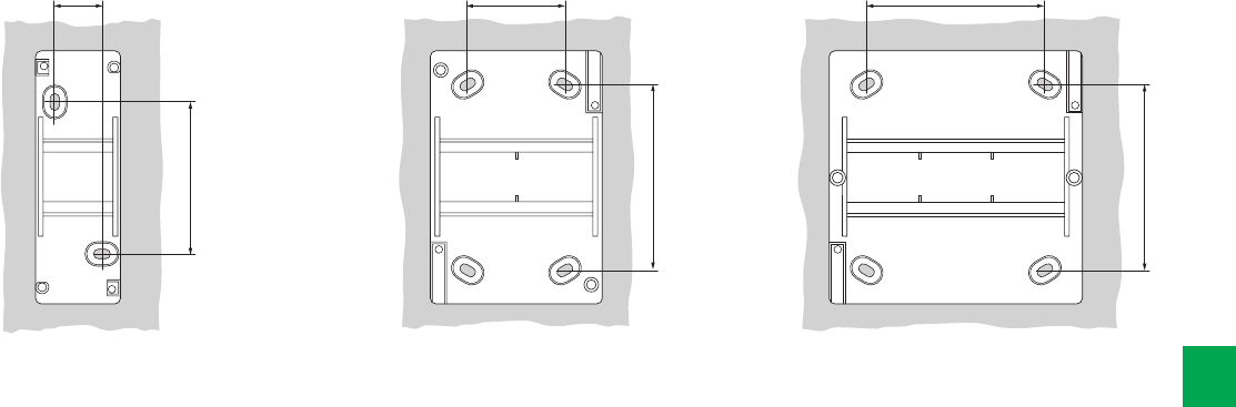
2 modules 4 modules 6 modules
25
80
44
118
94
125
System pro M compact® | 2CSC 400 031 D0202 6/99
6
Drilling sheets

00 800
1SL0900A00
00 820
00 850
1SL0820A00
1SL0850A00
1SL0905A00
1SL0909A00
1SL0920A00
1SL0950A00
1SL0824A00
1SL0830A00
1SL0854A00
1SL0860A00
1SL0874A00
1SL0880A00
1SL0924A00
1SL0930A00
1SL0954A00
1SL0960A00
1SL0974A00
1SL0980A00
00 802
1SL0901A00
00 816
00 821
00 846
00 851
1SL0816A00
1SL0821A00
1SL0846A00
1SL0851A00
1SL0904A00
1SL0906A00
1SL0908A00
1SL0910A00
1SL0916A00
1SL0921A00
1SL0946A00
1SL0951A00
1SL0826A00
1SL0832A00
1SL0856A00
1SL0862A00
1SL0876A00
1SL0884A00
1SL0926A00
1SL0932A00
1SL0956A00
1SL0962A00
1SL0976A00
1SL0984A00
00 808
1SL0902A00
00 822
00 852
00 872
1SL0822A00
1SL0852A00
1SL0872A00
1SL0907A00
1SL0911A00
1SL0912A00
1SL0922A00
1SL0972A00
1SL0985A00
1SL0828A00
1SL0834A00
1SL0858A00
1SL0864A00
1SL0878A00
1SL0884A00
1SL0928A00
1SL0934A00
1SL0958A00
1SL0964A00
1SL0978A00
1SL0984A00
00 810
1SL0903A00
76
130
130 179
114
113 162
96
95 142
94 87
101
75 88
Ø 71 Ø 89
87
75
101
88
97
130
133
79
113
120
61
95
99
162
203
275
145
181
251
125.5
155
226
187
253
345
170
231
323
150.5
205
149 149
6/100 2CSC 400 031 D0202 | System pro M compact®
6
Overall dimensions
IP44, IP55 and IP65 junction boxes
Front view
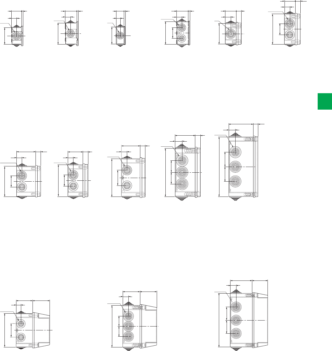
00 800
1SL0900A00
1SL0830A00
1SL0860A00
1SL0880A00
1SL0930A00
1SL0960A00
1SL0980A00
00 802
1SL0901A00
1SL0832A00
1SL0862A00
1SL0882A00
1SL0932A00
1SL0962A00
1SL0982A00
00 808
1SL0902A00
1SL0834A00
1SL0864A00
1SL0884A00
1SL0934A00
1SL0964A00
1SL0984A00
00 810
1SL0903A00
00 820
00 850
1SL0820A00
1SL0850A00
1SL0905A00
1SL0909A00
1SL0920A00
1SL0950A00
00 816
00 846
1SL0816A00
1SL0846A00
1SL0904A00
1SL0908A00
1SL0916A00
1SL0921A00
1SL0946A00
37 42 45 40
40
4266 617
17
6
18 18 20 20
20
18
Ø 23 Ø 23 Ø 32 Ø 32
Ø 32
Ø 23
56
74
75
75
108
42
40
66
1SL0824A00
1SL0854A00
1SL0874A00
1SL0924A00
1SL0954A00
1SL0974A00
1SL0826A00
1SL0856A00
1SL0876A00
1SL0926A00
1SL0956A00
1SL0976A00
1SL0828A00
1SL0858A00
1SL0878A00
1SL0928A00
1SL0958A00
1SL0978A00
00 822
00 852
00 872
1SL0822A00
1SL0852A00
1SL0872A00
1SL0907A00
1SL0911A00
1SL0912A00
1SL0922A00
1SL0952A00
1SL0972A00
00 821
00 851
1SL0821A00
1SL0851A00
1SL0906A00
1SL0910A00
1SL0921A00
1SL0951A00
70
66
72
100
56
70
72
100
17
90
88
70
17
17
17
17
23
21
27
27
21
21
27
27
Ø 28
Ø 28
Ø 37
Ø 37
Ø 28
Ø 28
Ø 37
Ø 37
108140
175
245
115
140
175
245
40
55
45
60
45
60
42
55
55
60 60
55
System pro M compact® | 2CSC 400 031 D0202 6/101
6
Side view
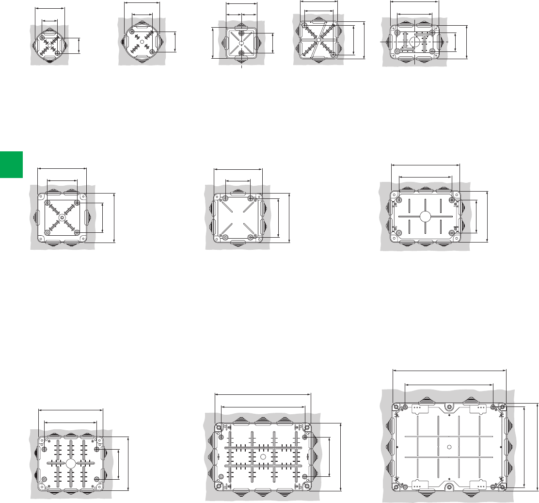
00 800
00 581
1SL0900A00
1SL0910A00
00 802
1SL0901A00
00 808
1SL0902A00
00 810
1SL0903A00
00 820
00 850
1SL0820A00
1SL0850A00
1SL0905A00
1SL0909A00
1SL0920A00
1SL0950A00
00 816
00 846
1SL0816A00
1SL0846A00
1SL0904A00
1SL0908A00
1SL0916A00
1SL0946A00
00 822
00 852
00 872
1SL0822A00
1SL0852A00
1SL0872A00
1SL0907A00
1SL0911A00
1SL0912A00
1SL0922A00
1SL0952A00
1SL0972A00
00 821
00 851
1SL0821A00
1SL0851A00
1SL0906A00
1SL0910A00
1SL0921A00
1SL0951A00
1SL0830A00
1SL0824A00
1SL0874A00
1SL0854A00
1SL0860A00
1SL0880A00
1SL0924A00
1SL0930A00
1SL0954A00
1SL0960A00
1SL0974A00
1SL0980A00
1SL0826A00
1SL0832A00
1SL0876A00
1SL0856A00
1SL0862A00
1SL0884A00
1SL0926A00
1SL0932A00
1SL0956A00
1SL0962A00
1SL0976A00
1SL0984A00
1SL0828A00
1SL0834A00
1SL0878A00
1SL0858A00
1SL0864A00
1SL0884A00
1SL0928A00
1SL0934A00
1SL0958A00
1SL0964A00
1SL0978A00
1SL0984A00
Ø 66 Ø 83 82 110
108
165
224
224
108 108
68
30 44 62 75
73.5
126
186
186
55 55
==
30
44
62
41
73.5
70
106
106
85
85
82
75
108
140
175
175
108
108
37
68
6/102 2CSC 400 031 D0202 | System pro M compact®
6
Overall dimensions
IP44, IP55 and IP65 junction boxes
Drilling sheets and internal dimensions

Contacts
www.abb.com
2CSC400031D0201 - 01/2012
The data and illustrations are not binding. We reserve
the right to modify the contents of this document on
the basis of technical development of the products,
without prior notice.
Copyright 2012 ABB. All right reserved.
System pro M compact® Protection and comfort systems for residential and small commercial installations
