Unknown 136641 Catalog
2014-11-11
: Pdf 136641-Catalog 136641-Catalog Batch12 unilog
Open the PDF directly: View PDF ![]() .
.
Page Count: 64
Wire Termination
A
Wire Connectors
www.idealindustries.com 1-800-435-0705 for Customer Service
A-2
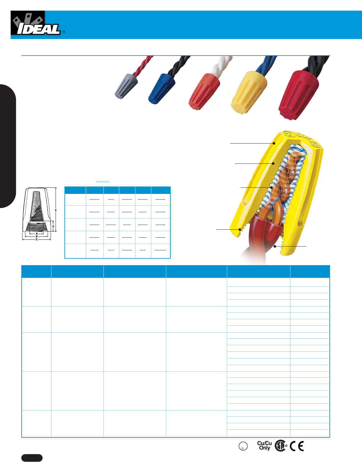
Wire-Nut®Wire Connectors
Wire Combination Wire Combination
Model Color Range Range (mm) Quantity Cat. No.
300V 300V Box of 100 30-071
71B®Gray 22 to 16 AWG ,34mm2to 1,5mm2Carton of 1,000 30-171
Min. 2 #22 – Max. 2 #16 Min. 2-,34mm2Max. 3-1,5mm2Keg of 25,000 (loose pack) 30-271
Barrel of 150,000 30-871
300V 300V Box of 100 30-072
72B®Blue 22 to 14 AWG ,34mm2to 2,5mm2Carton of 1,000 30-172
Min. 2 #22 – Max. 3 #16 Min. 2-,34mm2Max. 3-1,5mm2Keg of 10,000 (loose pack) 30-272
Barrel of 85,000 30-872
Box of 100 30-073
600V* 600V* Jar of 300 30-073J
73B®Orange 22 to 14 AWG ,34mm2to 2,5mm2Carton of 1,000 30-173
Min. 1 #18 & 1 #20 Min. 1-,75mm2w/1-,50mm2Keg of 10,000 (20 bags, 500 ea.) 30-273
Max. 4 #16 & 1 #20 Max. 4-1,5mm2w/1-,50mm2Keg of 10,000 (loose pack) 30-673
Barrel of 50,000 30-873
Box of 100 30-074
600V* 600V* Jar of 175 30-074J
74B®Yellow 18 to 12 AWG ,75mm2to 4,0mm2Carton of 1,000 30-174
Min. 2 #18 Min. 2-,75mm2Keg of 5,000 (10 bags, 500 ea.) 30-274
Max. 4 #14 & 1 #18 Max. 4-2,5mm2w/1-,75mm2Keg of 10,000 (loose pack) 30-674
Barrel of 35,000 30-874
600V* 600V* Box of 100 30-076
18 to 10 AWG ,75mm2to 6,0mm2Carton of 1,000 30-176
76B®Red Min. 2 #14 Min. 2-2,5mm2Keg of 5,000 (20 bags, 250 ea.) 30-276
Max. 2 #10 & 2 #12 Max. 2-6,0mm2w/2-4,0mm2Barrel of 15,000 30-876
*1,000V maximum in fixtures and signs
Tough, durable
thermoplastic shell
Positive-grip
design
Long, fully seated
square-wire spring
Threaded
entry
Deep skirt,
wide throat
U
L
R
L
I
S
T
E
D
-
W
I
R
E
C
O
N
N
CUS
EN 60-998-2-4
Model A B C D E
71B®11/64 1/4 21/64 11/64 37/64
4.5 6.5 8 4.5 15
72B®11/64 5/16 25/64 3/16 45/64
4.5 8 10 5 18
73B®11/64 11/32 7/16 11/32 55/64
4.5 9 11 9 22
74B®17/64 7/16 35/64 5/16 61/64
711148 24
76B®9/32 1/2 19/32 3/8 1-1/16
713151027
Dimensions Inches
mm
( )
■
Five color-coded models cover a full
range of wire sizes from 22 - 8 AWG
■
Fixed, square-wire spring creates its
own threads — maintains a secure
positive grip that will not relax over
time
■
No pre-twisting required — positive grip
design provides fast, easy installation
■
Deep, wide skirt helps protect against flash-over and turned-back strands
for maximum dielectric protection
■
Reusable for easy circuit changes and additions
■
Tough, UL94V-2 flame-retardant shell rated at 105oC (221oF)
■
UL Listed to 486C and CSA certified to C22.2 #188; comply with Federal
Specification W-S-610E
■
Classified in accordance with IEC Publications 998-2 and 998-2-4
Wire Connectors
1-800-435-0705 for Customer Service www.idealindustries.com A-3
Wire Termination
Wire Combination Wire Combination
Model Color Range Range (mm) Quantity Cat. No.
300V 300V
22 to 16 AWG ,34mm2to 1,5mm2Carton of 1,000 30-151
71B®Black Min. 2 #22 Str Min. 2-,34mm2
Keg of 25,000 (loose pack) 30-251
Max. 2 #16 Max. 2-1,5mm2
300V 300V
22 to 14 AWG ,34mm2to 2,5mm2Carton of 1,000 30-152
72B®Black Min. 2 #22 Min. 2-,34mm2
Keg of 10,000 (loose pack) 30-252
Max. 3 #16 Max. 3-1,5mm2
600V* 600V*
22 to 14 AWG ,34mm2to 2,5mm2Carton of 1,000 30-153
73B®Black Min. 1 #18 w/1 #20 Min. 1-,75mm2w/1-,50mm2
Keg of 10,000 (loose pack) 30-253
Max. 4 #16 & 1 #20 Max. 4-1,5mm2w/1-,50mm2
600V* 600V* Box of 100 30-059
22 to 12 AWG ,34mm2to 4,0mm2Carton of 1,000 30-159
59B™ Black Min. 2 #20 Min. 2-,5mm2
Keg of 5,000 (loose pack) 30-259
Max. 3 #14 Max. 3-2,5mm2
*1,000V maximum in fixtures and signs
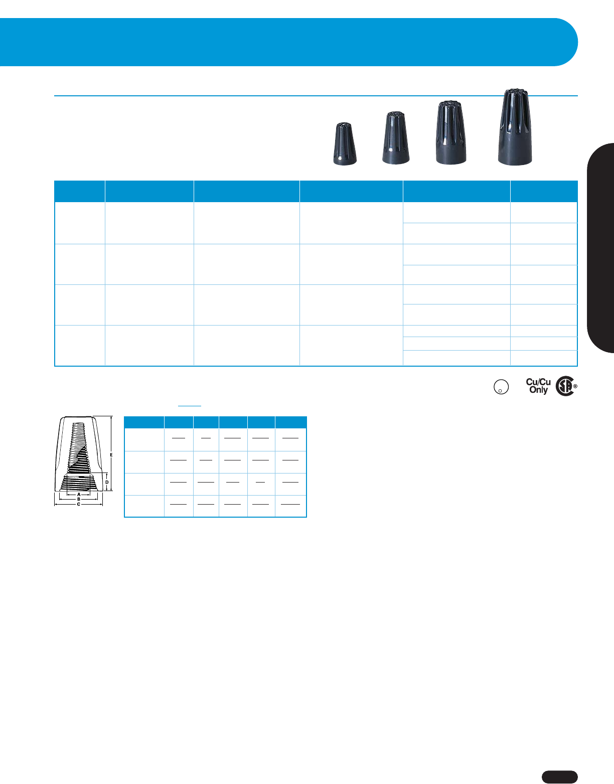
High Temperature Wire-Nut®Wire Connectors
All of the Wire-Nut®Wire Connector features plus:
■
Black, thermoplastic shell specially designed to withstand the
extreme heat build-up commonly found in high-wattage light
fixtures and signs. UL Listed to 150°C (302°F)
■
Four models to cover wire ranges from 22 through 12 AWG
Dimensions Inches
mm
( )
U
L
R
L
I
S
T
E
D
-
W
I
R
E
C
O
N
N
CUS
Model A B C D E
71B®5/32 1/4 21/64 13/64 37/64
Black 4 6.5 8 5 15
72B®13/64 5/16 25/64 15/64 45/64
Black 5 8 10 6 18
73B®13/64 23/64 7/16 3/8 55/64
Black 5 9 11 9.5 22
59BTM 13/64 13/32 31/64 37/64 1-1/16
Black 5 10 12 14.5 27
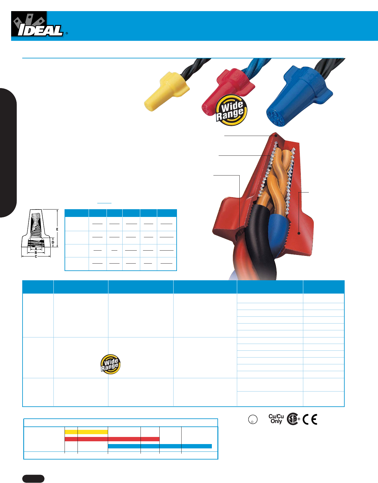
Wing-Nut®Wire Connectors
■
Three color-coded models cover a full range of wire sizes
from 18 through 6 AWG
■
Specially designed contoured wings provide a
secure grip for extra leverage on maximum wire
combinations
■
Live-action spring expands to accept wire shape
and size with no pre-twisting required
■
Square-wire spring threads directly onto conductors
for fast, secure connections
■
Deep skirt helps protect against flash-over and turned-back
strands for maximum dielectric protection
■
Easily removed for repeat usage on same size or larger wire
combinations
■
Tough, UL 94V-2 flame-retardant shell rated at 105°C (221°F)
■
UL Listed to 486C and CSA Certified to C22.2 #188; comply
with Federal Specification W-S-610E
■
Classified in accordance with IEC Publications 998-2 and
998-2-4
Tough, durable
thermoplastic shell
Live-action,
square-wire spring
Deep skirt,
wide throat
Comfortable
contoured wings
Wire Connectors
www.idealindustries.com 1-800-435-0705 for Customer Service
A-4
U
L
R
L
I
S
T
E
D
-
W
I
R
E
C
O
N
N
CUS
EN 60-998-2-4
Wire Combination Wire Combination
Model Color Range Range (mm) Quantity Cat. No.
Box of 100 30-451
600V* 600V* Jar of 225 30-451J
451®Yellow 18 thru 10 AWG ,75mm2to 6,0mm2Jar of 500 30-651J
Min. 2 #18 Min. 2-,75mm2Carton of 1,000 30-551
Max. 3 #12 Max. 3-4,0mm2Keg of 5,000 (10 bags, 500 ea.) 30-651
Barrel of 35,000 30-851
Box of 100 30-452
600V* 600V* Jar of 300 30-452J
452®Red 18 thru 8 AWG ,75mm2to 10,0mm2Jar of 500 30-652J
Min. 2 #18 Min. 2-,75mm2Carton of 1,000 30-552
Max. 4 #10 Max. 4-6,0mm2Keg of 5,000 (10 bags, 500 ea.) 30-652
Barrel of 25,000 30-852
600V* 600V*
454®Blue 14 thru 6 AWG 2,5mm2to 16,0mm2Box of 50 30-454
Min. 3 #12 Min. 3-4,0mm2
Keg of 2,500 (25 bags, 100 ea.) 30-654
Max. 1 #6 & 2 #8 Max. 2-16,0mm2w/1-4,0mm2
*1,000V maximum in fixtures and signs
Model A B C D E
451®15/64 11/32 11/16 5/16 1-1/64
6918826
452®21/64 15/32 15/16 5/16 1-15/64
8.5 12 24 8 31.5
454®7/16 5/8 1-3/16 13/32 1-15/32
11 16 30 10.5 37.5
92®21/64 13/32 29/32 9/32 1-5/32
8.5 10.5 23 10 30
Dimensions Inches
mm
( )
Min
2 #18
Min
2 #18
Min
3 #12
Max
3 #12
Max
4 #10 Max
1 #6 & 2 #8
451 Yellow
452 Red
454 Blue
Wire Combinations
Model
2 #18 2 #14 3 #12 5 #12 4 #10 5 #10
Wire Connectors
1-800-435-0705 for Customer Service www.idealindustries.com A-5
Wire Termination
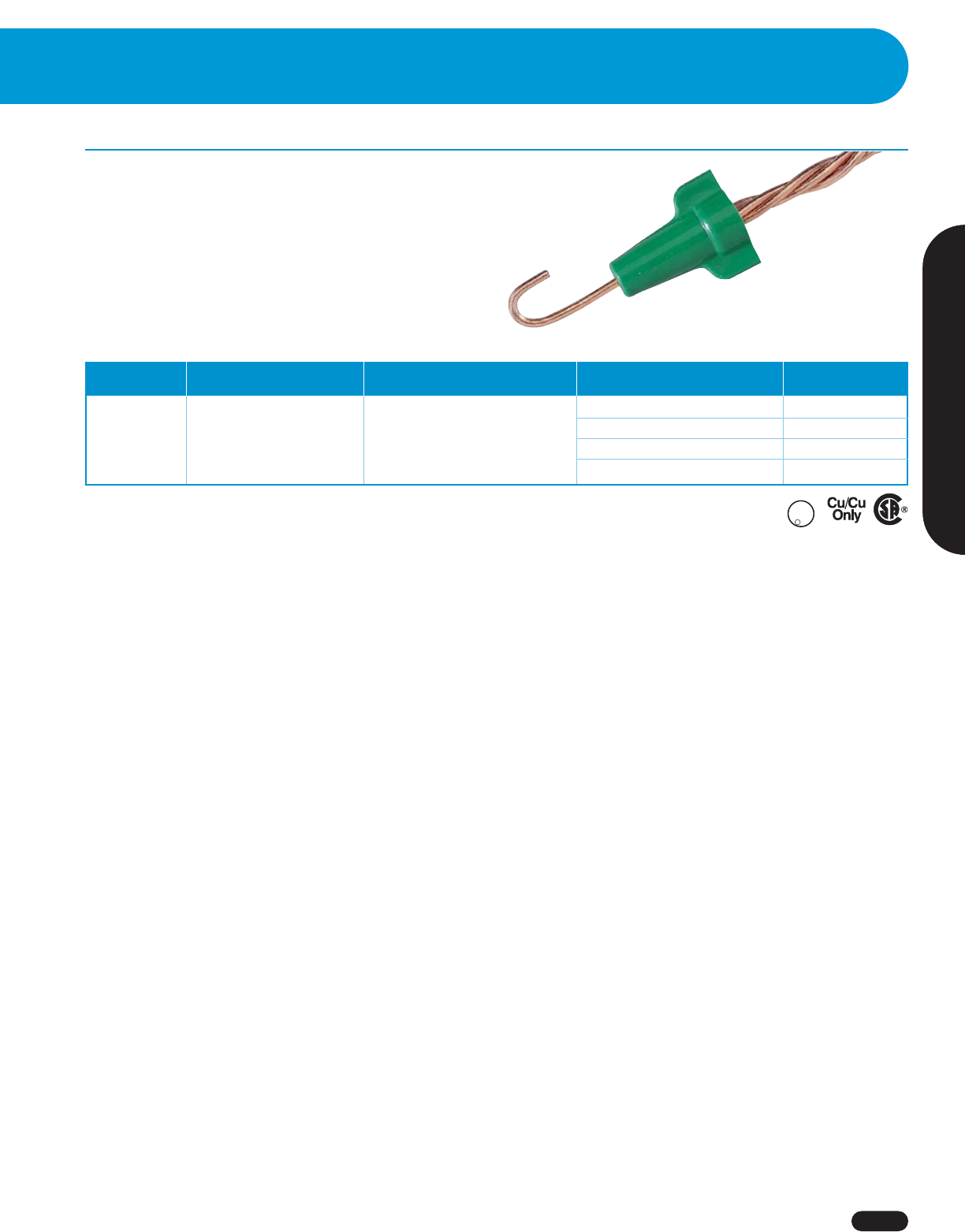
Greenie®Grounding Connector
■
Designed for making ground connections and bonding
non-metallic sheathed cable
■
Contoured wings for maximum leverage
■
Live-action, square-wire spring provides superior
grounding connections
■
Tough, UL 94V-2 flame-retardant shell
■
UL Listed to 467 and CSA Certified to C22.2 #188; complies
with Federal Specification W-S-610E
Wire Combination Wire Combination
Model Range Range (mm) Quantity Cat. No.
Box of 100 30-092
Jar of 150 30-092J
Carton of 1,000 30-192
Keg of 5,000 (10 bags, 500 ea.) 30-292
Greenie®Grounding Connector fully meets the intent of the
N.E.C. and specifically aids in compliance with the following:
ARTICLE 250: GROUNDING
250-146 Connecting Receptacle
Grounding Terminal to Box
250-148 Continuity and Attachment of
Equipment Grounding
Conductors to Boxes
(B) Grounding continuity
(D) Nonmetallic boxes
U
L
G
N
D
C
O
N
.
N
L
I
S
T
E
-
D
R
92®
14 thru 10 AWG
Min. 2 #14
Max. 3 #12 & 1 #14
2,5mm2to 6,0mm2
Min. 2-2,5mm2
Max. 3-4,0mm2w/1-2,5mm2
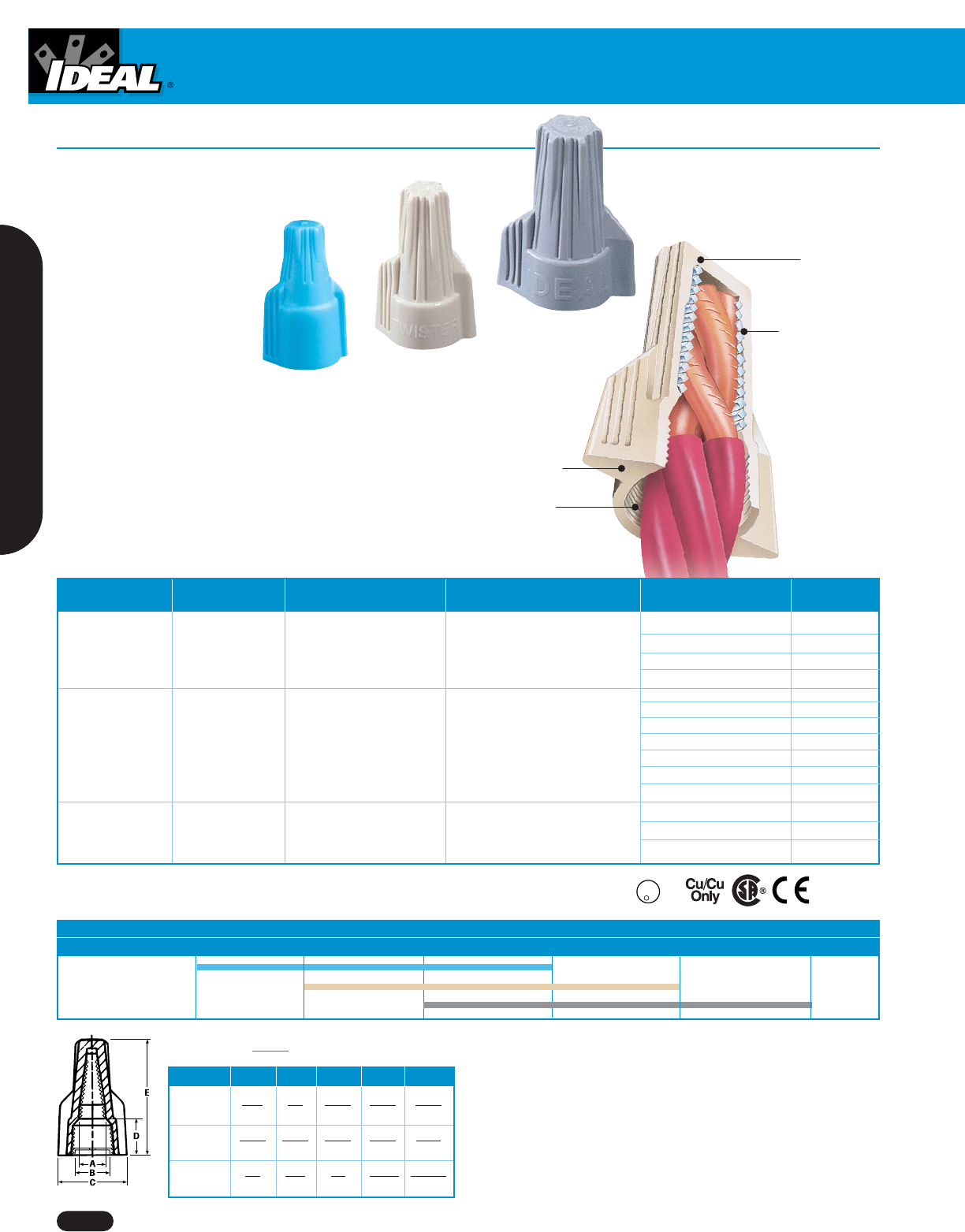
Twister®Wire Connectors
Wire Connectors
www.idealindustries.com 1-800-435-0705 for Customer Service
A-6
■
Exceptional wire-range capacity — three models
handle wire combinations from as small as
22 AWG to as large as 6 AWG
■
Ribbed cap provides a secure
grip and fast fingertip starts
■
Swept wings offer extra leverage
and less effort for large wire
combinations
■
Hexagonal shape
accommodates standard
nutdriver for tool installation
■
Live-action, square-wire spring
locks onto wire for safe,
secure connections
■
Deep skirt helps protect against flash-over and turned-back
strands for maximum dielectric protection
■
Tough, UL 94V-2 flame-retardant shell rated at 105°C (221°F)
■
UL Listed to 486C and CSA Certified to C22.2 #188; comply with
Federal Specification W-S-610E
■
Classified in accordance with IEC Publications 998-2 and 998-2-4
Tough, durable
thermoplastic
shell
Live-action,
square-wire
spring
Deep,
threaded
skirt entry
Wire Combination Wire Combination
Model Color Range Range (mm) Quantity Cat. No.
600V* 600V* Box of 100 30-340
340®Lt. Blue 22 thru 10 AWG ,34mm2to 4,0mm2Bag of 500 30-640
Min. 2 #22 Min. 2-,34mm2Jar of 500 30-640J
Max. 3 #12 Max. 3-4,0mm2
Barrel of 35,000 30-840
Box of 50 30-141
Box of 100 30-341
341®Tan Jar of 400 30-441J
Jar of 750 30-341J
Carton of 1,000 30-541
Keg of 5,000 (10 bags, 500 ea.) 30-641
Barrel of 25,000 30-841
Box of 25 30-142
342®Gray Box of 50 30-342
Keg of 2,500 (10 bags, 250 ea.) 30-642
*1,000V maximum in fixtures and signs
Compact
swept wings
Model A B C D E
340®5/16 3/8 39/64 27/64 63/64
Lt. Blue 7.8 9.5 15.2 10.6 24.9
341®17/64 29/64 23/32 23/64 1-1/8
Tan 7 11.5 18 9 28.5
342®3/8 9/16 1.0 13/32 1-19/64
Gray 9.5 20 25.5 10.5 33
Combination 2#22 3#22 3#14 3 #12 3#10 2#12 w/2#8
Cir Mil Area 1,280 (.65mm2) 1,920 (.97mm2) 12,330 (6.24mm2) 19,590 (9.93mm2) 31,140 (15.78mm2) 46,080 (23mm2)
340®
341®
342®
U
L
R
L
I
S
T
E
D
-
W
I
R
E
C
O
N
N
CUS
EN 60-998-2-4
600V*
22 thru 8 AWG
Min. 3 #22
Max. 3 #10
600V*
,34mm2to 10,0mm2
Min. 3-,34mm2
Max. 3-6,0mm2
600V*
18 thru 8 AWG
Min. 3 #14
Max. 2 #8 w/2 #12
600V*
,75mm2to 10,0mm2
Min. 3-2,5mm2
Max. 2-10,0mm2w/2-4,0mm2
Dimensions Inches
mm
( )
Wire Connectors
1-800-435-0705 for Customer Service www.idealindustries.com A-7
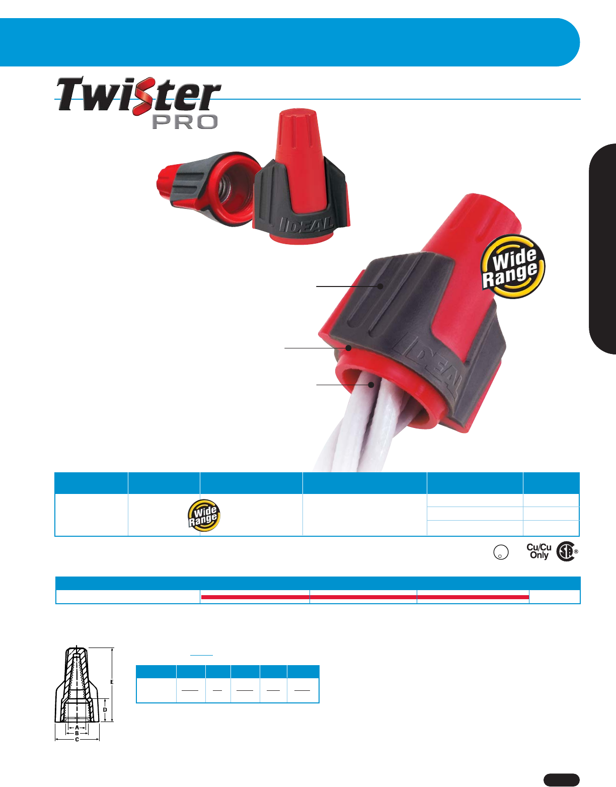
Model A B C D E
344 11/32 1/2 15/16 7/16 1-1/4
Red/Gray 8.8 12.7 23.5 10.7 31.8
Dimensions Inches
mm
( )
Combination Min. 2 #18 4 #14 5 #12 Max. 4 #10
344®
Wire Termination
Wire Connector
■
SureGrip™ overmolding
provides better
grip for improved
leverage and
more torque
■
Comfortable swept
wings designed to
help reduce hand
fatigue
■
Expanding square-wire
spring provides a secure
connection every time
■
Better grip and more leverage
for faster connections with
less effort
Molded vertical
grooves provide
maximum grip
Patented swept-
wing SureGrip™
design
Exceptional wire range
and capacity
- Min. 2 #18
- Max. 4 #10
Wire Combination Wire Combination
Model Color Range Range (mm) Quantity Cat. No.
600V* 600V* Tube of 25 30-144J
22 to 8 AWG ,34mm2to 10,0mm2Jar of 250 30-244J
344 Red/Gray Min. 2 #18 Min. 2-,75mm2
Jar of 500 30-644J
Max. 4 #10 Max. 4-6,0mm2
*1,000V maximum in fixtures and signs
U
L
R
L
I
S
T
E
D
-
W
I
R
E
C
O
N
N
CUS
®
Wire Connectors
www.idealindustries.com 1-800-435-0705 for Customer Service
A-8
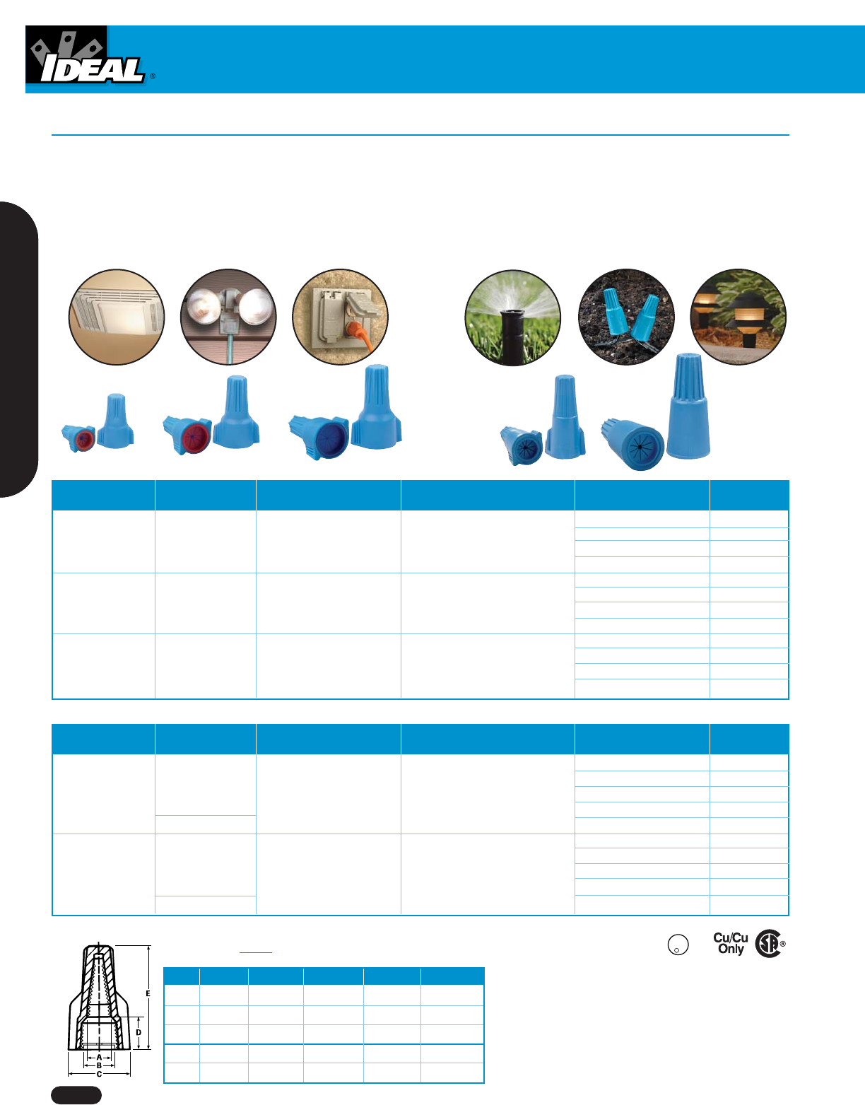
■
Silicone-based sealant protects against moisture
and corrosion
■
UL Listed to 486D for use in damp/wet locations
or direct burial
■
Easy to apply, pre-filled twist-on wire connectors
■
Handles wire sizes from #20 to #6 copper conductors
WeatherProof™ and UnderGround™ Wire Connectors
WeatherProof™ — suitable for interior and exterior electrical
connections exposed to rain or damp conditions.
Wire Combination Wire Combination
Model Color Range Range (mm) Quantity Cat. No.
600V* 600V* Card of 6 30-061
22 to 14 AWG ,34mm2to 4,0mm2Card of 25 30-161
61 Blue/Orange Min. 2 #20 Min. 2-,5mm2Box of 100 30-261
Max. 2 #14 Max. 2-2,5mm2Box of 1,000 30-361
600V* 600V* Card of 5 30-062
18 to 8 AWG ,75mm2to 10,0mm2Card of 20 30-162
62 Blue/Red Min. 2 #18 Min. 2-,75mm2Box of 100 30-262
Max. 3 #10 Max. 3-6,0mm2Box of 1,000 30-362
600V* 600V* Card of 3 30-063
16 to 6 AWG 1,5mm2to 16,0mm2Card of 15 30-163
63 Blue/Dr. Blue Min. 3 #14 Min. 3-2,5mm2Box of 100 30-263
Max. 2 #8 & 1 #10 Max. 2-10,0mm2w/1-6,0mm2Box of 1,000 (yellow) 30-363
U
L
R
L
I
S
T
E
D
-
W
I
R
E
C
O
N
N
CUS
WARNING:
1. One time use only. Do not reuse.
2. Wiring must comply with all applicable electrical codes.
3. For use on copper wire only. Do not use on aluminum wire.
4. Not for use in continuous submersion applications.
Model A B C D E
61 3/16 (4,8) 5/16 (7,9) 21/32 (16,7) 13/32 (10,3) 29/32 (23,0)
62 9/32 (7,1) 1/2 (12,7) 15/16 (23,8) 19/32 (15,1) 1-11/32 (34,1)
63 3/8 (9,5) 19/32 (15,1) 1-1/16 (27,0) 23/32 (18,3) 1-19/32(40,5)
60 9/32 (7,1) 17/32 (13,5) 41/64 (16,2) 55/64 (22,0) 1-21/32 (42,0)
64 9/32 (7,1) 19/32 (15,1) 29/32 (23,0) 1-1/8 (28,6) 2-1/32 (51,6)
Dimensions Inches
mm
( )
Wire Combination Wire Combination
Model Color Range Range (mm) Quantity Cat. No.
600V* 600V* Card of 2 30-060
20 to 10 AWG ,5mm2to 6,0mm2Card of 10 30-760
60 Blue/Blue Min. 2 #20 Min. 2-,5mm2Box of 100 30-260
Max. 1 #10 & 2 #12 Max. 1-6,0mm2w/2-4,0mm2Box of 1,000 30-360
Yellow Box of 1,000 (yellow) 30-360Y
600V* 600V* Card of 2 30-064
18 to 8 AWG ,75mm to 10,0mm2Card of 10 30-764
64 Blue/Dk. Blue Min. 2 #18 Min. 2-,75mm2Box of 50 30-264
Max. 3 #10 Max. 3-6,0mm2Box of 1,000 30-364
Yellow Box of 25 (yellow) 30-164Y
*1,000V maximum in fixtures and signs
WeatherProof™ Wire Connectors
UnderGround™ Wire Connectors
UnderGround™ — suitable for use in a wide variety of
direct burial and wet location electrical connections.
Wire Connectors
1-800-435-0705 for Customer Service www.idealindustries.com A-9
Wire Termination
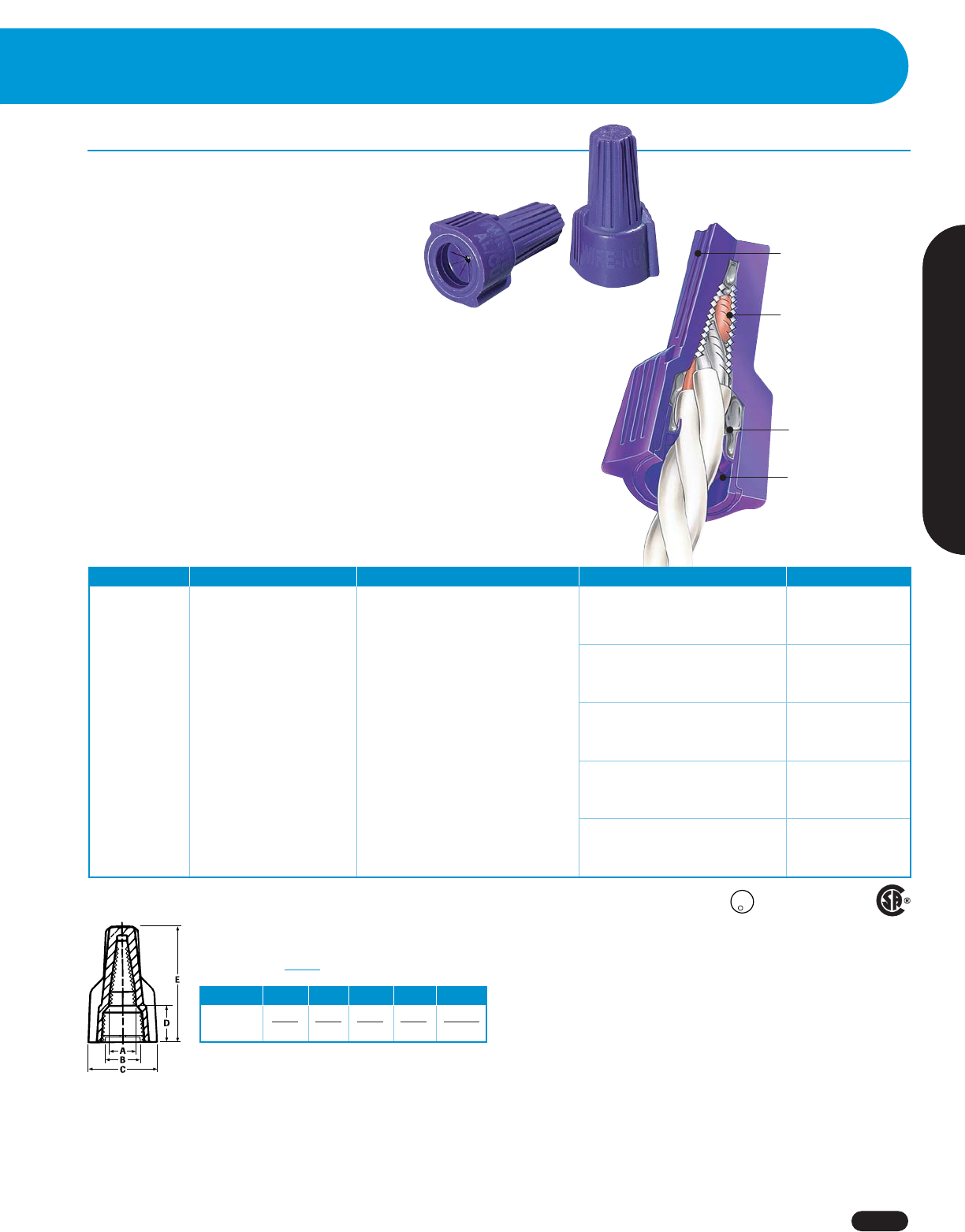
Twister®AI/Cu Wire Connector
■
Only aluminum-to-copper twist-on connector specifically
designed to guarantee a secure connection while
preventing aluminum corrosion
■
Specially formulated corrosion- resistant
compound cuts and penetrates corrosion
build-up on aluminum conductors for increased
conductivity and cooler connections
■
Compact, one-piece design features ribbed cap, swept
wings and hexagonal head for easy installation by hand
or with standard nutdriver
■
Live-action, square-wire spring expands and contracts with
aluminum wire
■
Deep skirt provides maximum dielectric strength
■
Tough, UL 94V-2 flame-retardant shell rated at 105°C (221°F)
■
Complies with N.E.C. Section #110-14(b) for aluminum-to-copper
connections; UL Listed to 486C and CSA Certified to C22.2 #188;
complies with Federal Specification
W-S-610E
■
UL Listed to 467 for grounding and bonding
Ribbed cap for hand
or nutdriver
installation
Live-action,
square-wire
spring expands
and contracts
with aluminum wire
Entry cap retains
corrosion-resistant
compound
Compound cuts
corrosion build-up
on aluminum
conductors
WARNING:
1. One time use only. Do not reuse connector.
2. Do not use on aluminum to aluminum wire combinations.
3. Wiring must comply with all applicable electrical codes.
4. Contact IDEAL for complete wire combination listing.
Model A B C D E
65 17/64 13/32 13/16 35/64 1-11/32
7 10.5 21 14 34
Dimensions Inches
mm
Model Color Wire Combinations Quantity Cat. No.
1 #10 Al solid w/1 or 2 #10 Cu solid
1 #10 Al w/1 or 2 #12 Cu Card of 2 30-065
2 #10 Al solid w/1 #12 Cu
1 #10 Al w/1 or 2 #14 Cu
2 #10 Al solid w/1 #14 Cu
2 #12 Al solid w/1 #10 Cu Card of 10 30-765
1 #12 Al solid w/1 or 2 #10 Cu
1 #12 Al stranded w/1 or 2 #10 Cu solid
1 #12 Al w/1 or 2 #12 Cu
65 Purple 2 #12 Al solid w/1 #12 Cu Card of 25 30-165
1 #12 Al w/1 or 2 #14 Cu
2 #12 Al solid w/1 #14 Cu
1 #10 Al w/1 or 2 #18 Cu
2 #10 Al solid w/1 #18 Cu Box of 100 30-265
1 #12 Al w/1 or 2 #16 Cu
2 #12 Al solid w/1 #16 Cu
1 #10 Al w/1 or 2 #16 Cu
2 #10 Al solid w/1 #16 Cu Carton of 1,000 30-365
1 #12 Al w/1 or 2 #18 Cu
2 #12 Al solid w/1 #18 Cu
600V maximum building wire; 1,000V signs or lighting fixtures Wire Connector
also listed as
grounding equipment
U
L
R
L
I
S
T
E
D
-
W
I
R
E
C
O
N
N
CUS
( )
Wire Connectors
www.idealindustries.com 1-800-435-0705 for Customer Service
A-10
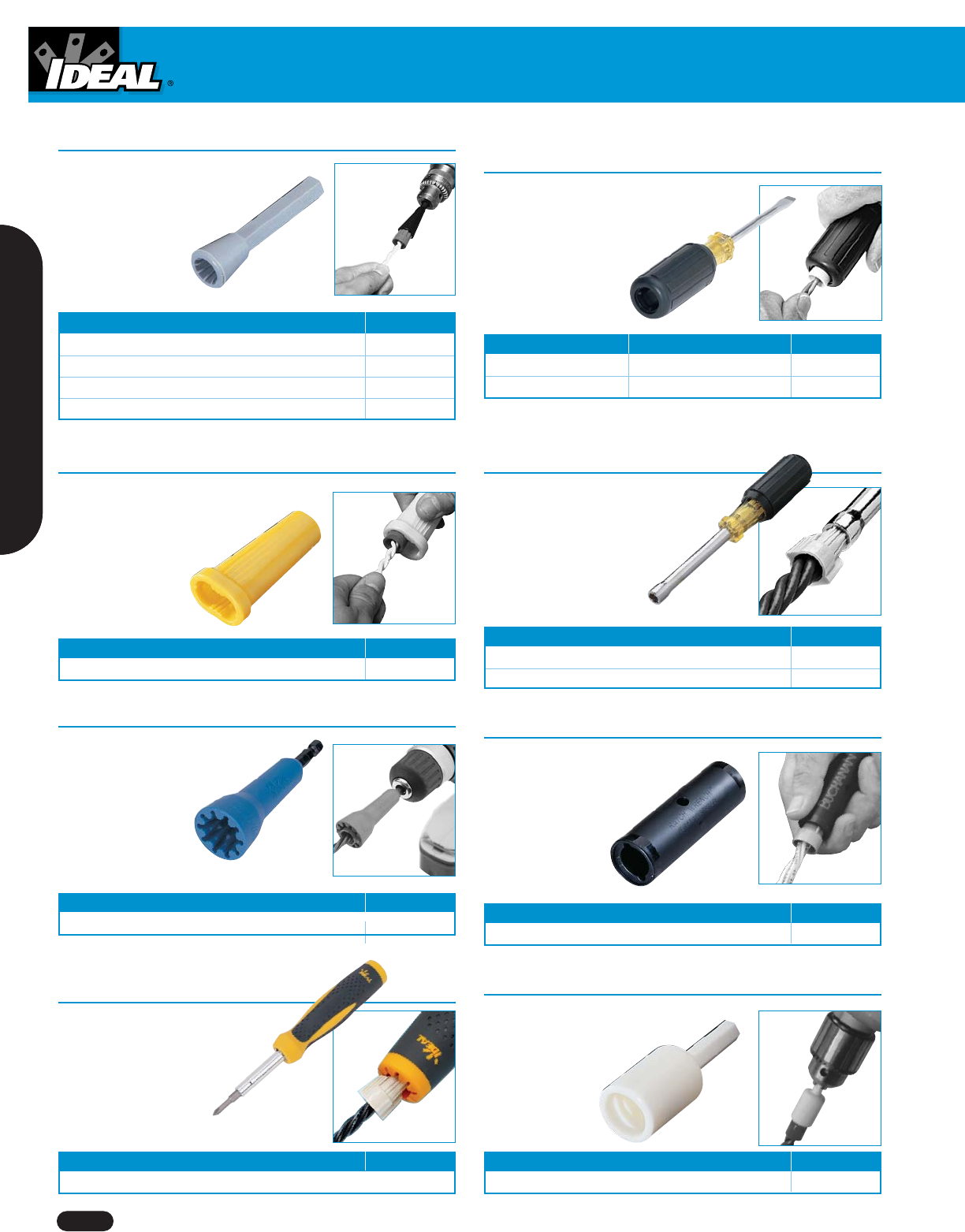
Wire-Nut®Wire Connector Sockets
■
Speeds installation of Wire-Nut®
Wire Connectors
■
Fit any pneumatic or
electric tool
with a 1/4 in.
chuck or
drive socket
For Connector Model Cat. No.
71B®, 71B®Black, 72B®& 72B®Black 30-903
73B®& 73B®Black 30-904
59B™ 30-905
74B®, 76B®& 59B™ 30-906
Wire-Nut®Wire Connector Wrench
■
Speeds installation of Wire-Nut®
Wire Connectors
■
Excellent leverage
helps reduce fatigue
For Connector Model Cat. No.
73B®, 74B®& 76B®H-632
Wire-Nut®Wire Connector
Wrench/Screwdriver Combo
■
Speeds installation of Wire-Nut®
Wire Connectors
■
Slotted-tip screwdriver
with convenient
connector-wrench
socket in end of
insulated handle
■
Speeds installation of Twister®
Wire Connectors
■
Nickel/chrome plated to
resist rust and corrosion
■
Cushioned rubber grip
For Connector Model Cat. No.
341®35-292
342®35-295
Nutmaster®Nutdrivers
Spin-Twist®Wire Connector Socket
For Connector Model Cat. No.
Wire-Nut®, Wing-Nut®, Twister®, B-CAP®and WingTwist™ 30-902
Twist-a-Nut™
7-in-1 Screwdriver
■
Facilitate installation of
connectors
■
Universal Wire-Nut®
Wrench in handle
■
Accepts most twist-on
connectors
Description Cat. No.
7-in-1 Twist-a-Nut™ 35-908
Ratch Wrench
■
Speeds installation of
B-CAP®Wire Connectors
■
Either end accepts 1/4-in.
drive for tight-spot
wire splicing
For Connector Model Cat. No.
B1, B2 & B4 BR-5
High-Speed Wire Connector Chuck
■
Cordless screwdriver adapter
for installing B-CAP®
Wire Connectors
For Connector Model Cat. No.
B1, B2 & B4 HSC-1
For Connector Model Type Cat. No.
74B®& 76B®Mechanic – 1/4 in. x 4 in. 30-331
74B®& 76B®Electrician – 3/16 in. x 6 in. 30-333
■
Speeds installation of IDEAL
and BUCHANAN Wire
Connectors
■
For use with electric
corded or cordless
drill drivers
■
1/4 in. chuck fits
most drills or drive sockets
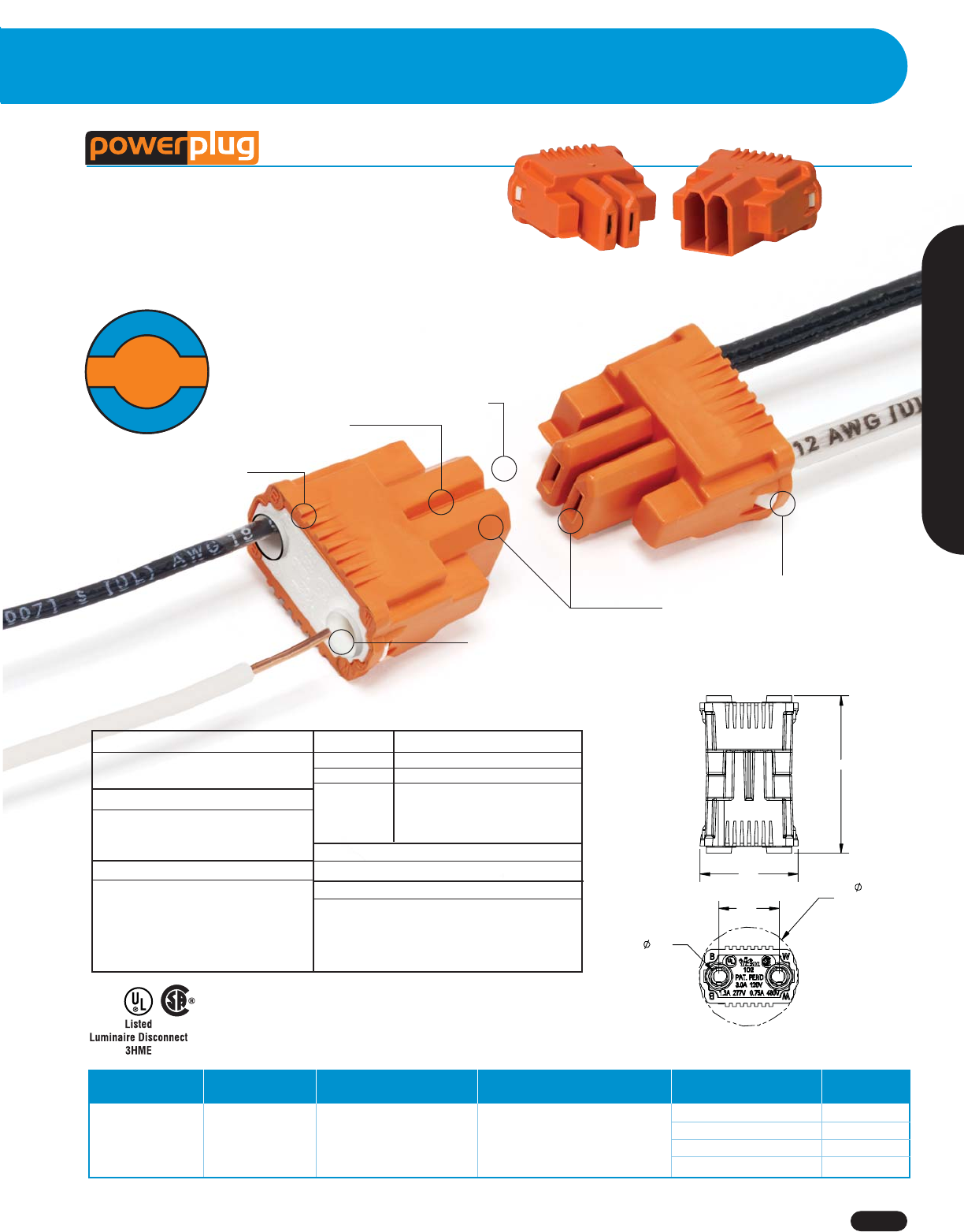
Patented IDEAL push-in
technology quickly
locks wires in place
Pieces pull apart
safely and easily
Thumb ridges provide
superior grip
Fits through 1/2”
knockout
3/8” strip length
indicator
Both halves pass UL 2459 &
CSA 182.3 finger probe
requirements
Wire Connectors
1-800-435-0705 for Customer Service www.idealindustries.com A-11
Wire Termination
Luminaire Disconnect
■
The first push-in disconnect to meet the new NEC and CEC code
changes for non-residential fluorescent luminaires
■
Perfect for OEM or retrofit lighting applications
■
Meets UL and CSA finger-probe safety requirements
■
Allows safe disconnect of hot and neutral ballast wiring
Wire Combination Wire Combination
Model Color Range Range (mm) Quantity Cat. No.
Card of 25 30-372
Jar of 75 30-382J
102 Orange Jar of 150 30-352J
Box of 1,000 30-102
*1,000V maximum in fixtures and signs
™
600V*
18 thru 12 AWG
600V*
,75mm2to 24,0mm2
Materials
Housings: Nylon
Contacts: Copper Alloy
Ratings
Temperature: 105°C (221°F)
Flammability: UL 94V-0
Current Interruption: 10 Cycles
Max. Current Rating
120V 3 Amps
277V 1.3 Amps
347V 1 Amps
480V 0.75 Amps
600V 0.60 Amps
Patents Pending
Wire Range
Solid 12 AWG – 18 AWG
Stranded 12 AWG – 14 AWG (19 strand or less)
Stranded 12 AWG (19 strand or less)
(Tin-Bonded) 14 AWG (19 strand or less)
16 AWG (26 strand or less)
18 AWG (16 strand or less)
Agency Approvals
UL 2459 CSA 182.3 RoHS Compliant
Physical
Strip Length: 3/8” ± 1/16”
Number of Circuits: 2 (3 circuit coming soon)
Color: Orange and White
Mating/Unmating Force: 3-8 Pounds
F
o
r
L
u
m
i
n
a
i
r
e
L
i
g
h
t
i
n
g
o
n
l
y
3 Amp
Max.
3 Amp
Max.
.82
HOLE
CLEARANCE
.137
.50
1.30
.81
Wire Connectors
www.idealindustries.com 1-800-435-0705 for Customer Service
A-12
Length Width Height
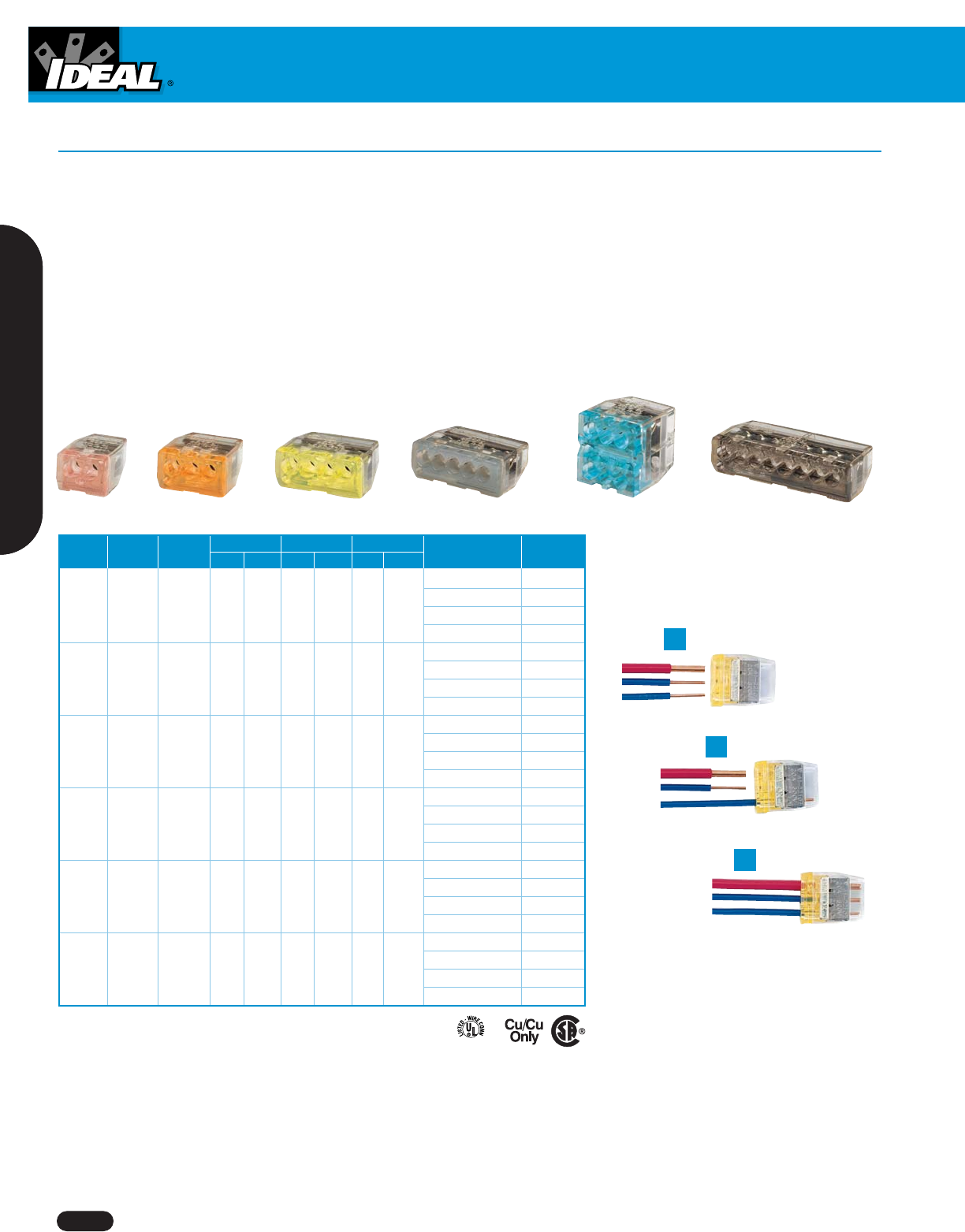
Model Color Ports In. mm In. mm In. mm Quantity Cat. No.
Box of 100 30-084
Jar of 300 30-084J
84 Red 2 .355 9.02 .434 11.02 .729 18.52 Box of 1,000 30-184
Box of 5,000 30-684
Box of 100 30-085
Jar of 250 30-085J
85 Orange 3 .355 9.02 .591 15.01 .729 18.52 Box of 1,000 30-185
Box of 5,000 30-685
Box of 100 30-086
Jar of 200 30-086J
86 Yellow 4 .355 9.02 .748 18.99 .729 18.52 Box of 1,000 30-186
Box of 4,000 30-686
Box of 50 30-087
Jar of 150 30-087J
87 Gray 5 .355 9.02 .907 23.03 .729 18.52 Box of 1,000 30-187
Box of 5,000 30-687
Box of 50 30-088
Jar of 100 30-088J
88 Blue 6 Stacked .607 15.42 .603 15.32 .729 18.52 Box of 1,000 30-188
Box of 5,000 30-688
Box of 50 30-090
Jar of 100 30-090J
90 Black 8 .355 9.02 1.38 35.03 .717 18.21 Box of 1,000 30-190
Box of 2,000 30-690
COPPER TO COPPER ONLY. Do not use on aluminum.
Temperature rating: 105°C (221°F) maximum
600V maximum building wire, 1000V maximum signs or lighting fixtures
CUS
In-Sure™ Push-In Wire Connectors
■
No-twist connection reduces repetitive motion fatigue
■
Low insertion force for fast and easy connections
■
Compact size makes installation easy
■
Clear shell gives visual verification of connection
■
UL Listed to 486C and CSA Certified to C22.2 #188
■
UL 467 Listed for grounding and bonding applications
■
Accepts the following copper wire sizes
- Solid
#20 - #12 solid
- Stranded
#16 - #14 (19 strand or less)
#18 (7 strand or less)
- Stranded (Tin Bonded)
#14 - #12 (19 strand or less)
#16 (26 strand or less)
#18 (16 strand or less)
1.
Strip
2.
Push
3.
Connect
Installation as easy
as 1-2-3...
Wire Connectors
Wire Termination
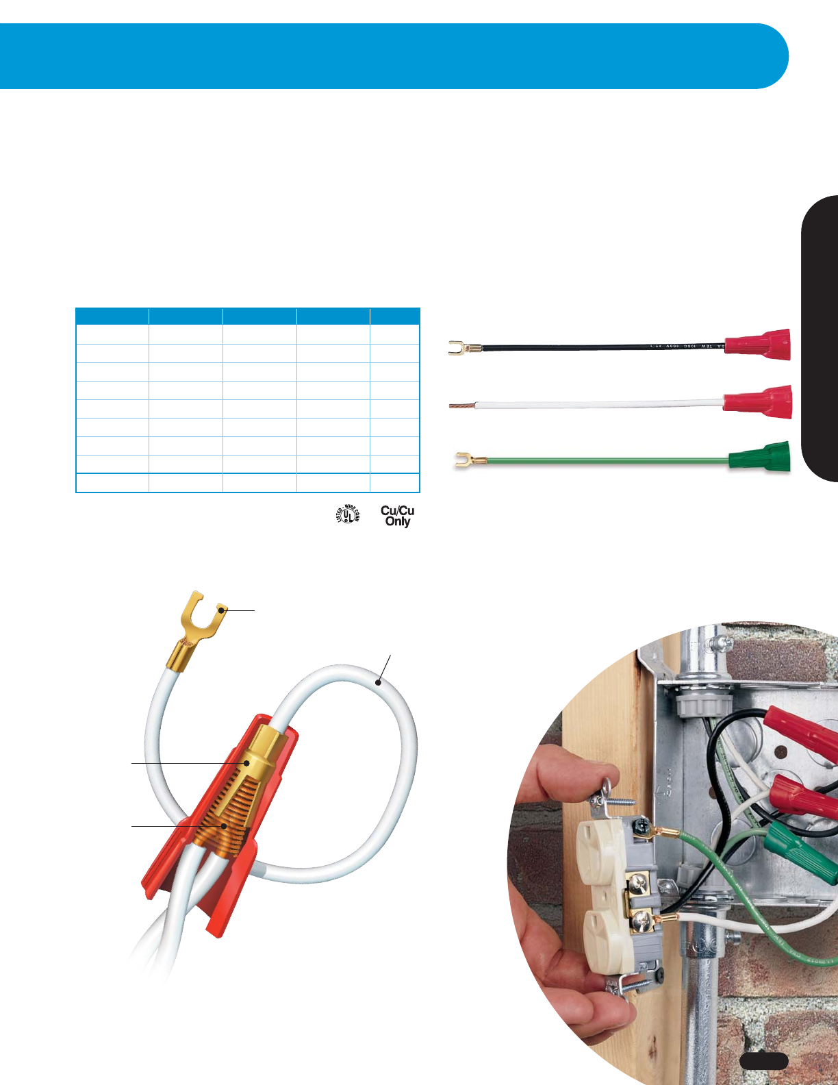
Term-a-Nut®Pigtail Wire Connectors
Shell Color Wire Color Terminal End Quantity Cat. No.
Red White #10 fork 25 30-3170
Red White #10 fork 10 30-3370
Red Black #10 fork 25 30-3171
Red Black #10 fork 10 30-3371
Red White Stripped end 25 30-3172
Red Black Stripped end 25 30-3173
Green Green #10 fork 25 30-3180
Green Green #10 fork 10 30-3380
MultiPak* White/Black/Green #10 fork 9 30-3181
*Includes 3 red shells w/white wire, 3 red shells w/black wire,
and 3 green shells w/green wire.
■
Ultra-flexible 6-in. lead allows for easy positioning in outlet box — reduces stress on device, wires and connection
■
Wide range of wire combinations – #18 through #12 solid or stranded conductors
■
Brass adapter for strong, conductive transition from spring to lead wire
■
Brass-alloy terminals with locking tabs for fast, efficient device connection
■
UL 486A and UL 486C Listed and tested to CSA standard C22.2 #65 and C22.2 #188
■
Wire Range: Red/Green Shell – Min. 2 #18 w/1 #14, Max. 4 #12
Brass-alloy
terminal with
locking tabs
Brass
adapter
Phosphor-
bronze spring
Ultra-
flexible
lead
CUS
1-800-435-0705 for Customer Service www.idealindustries.com A-13
Wire Connectors
www.idealindustries.com 1-800-435-0705 for Customer Service
A-14
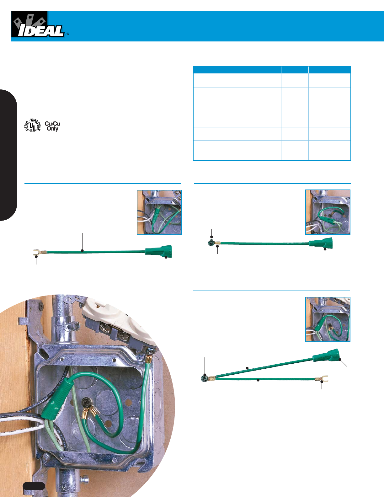
Term-a-Nut®Grounding Connectors Quantity Cat. No. Fig.
Term-a-Nut®Grounding Connector, 12 AWG
stranded, 6 in. tail w/#10 fork Bag of 10 30-3380 A
Term-a-Nut®Grounding Connector, 12 AWG
stranded, 6 in. tail w/#10 fork Bag of 25 30-3180 A
Term-a-Nut®Grounding Connector, 12 AWG
stranded, 6 in. tail w/#10 fork Box of 100 30-3280 A
Term-a-Nut®Grounding Connector, 12 AWG
stranded, 6 in. tail w/#10 fork Box of 250 30-3680 A
Term-a-Nut®Grounding Connector, 12 AWG
stranded w/#10 ring & ground screw Bag of 25 30-3182 B
Term-a-Nut®Grounding Connector, 12 AWG
stranded w/#10 ring & ground screw and 6 in. Bag of 10 30-3386 C
jumper w/#10 fork
Grounding Connectors
■
Term-a-Nut®grounding connectors address specific
requirements for grounding to steel outlet boxes
and wiring multiple devices
■
UL Listed to UL486C and UL467 (grounding and
bonding)
Term-a-Nut®Grounding Connector
Term-a-Nut®Grounding Connector
Connects grounding conductors to a
device’s grounding screw, connects
grounding conductors to the mounting box
and bonds the device to the box.
Bonds the box to the grounding
conductors.
Fig. C
Fig. B
Combo hex head
Stranded bonding jumper
Ultra-flexible lead wire
Heavy-duty brass terminal
Heavy-duty
brass terminal
Thread-forming
grounding screw
Twist-on wire
connector
Twist-on wire
connector
Term-a-Nut®Grounding Connector
Connects multiple grounding conductors to
a device.
Fig. A
Ultra-flexible
lead wire
Heavy-duty
brass terminal
Twist-on wire
connector
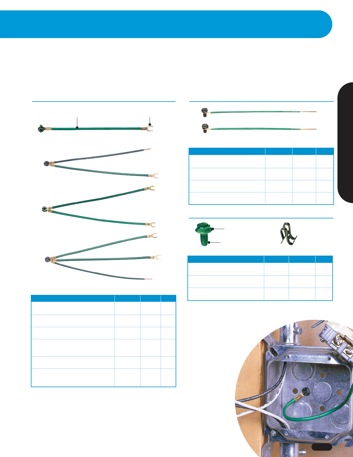
Fig. D
Stranded Wire Grounding Tails Quantity Cat. No. Fig.
14 AWG stranded 7-3/4 in. tail w/#10 fork &
10 ring and ground screw Bag of 25 30-3183 A
12 AWG stranded, 7-3/4 in. tail w/#10 fork &
10 ring and ground screw Bag of 25 30-3184 B
12 AWG stranded, 7-3/4 in. tail w/#10 fork &
10 ring and ground screw Bundle of 100 30-3284 B
12 AWG stranded, 2-wire tail joined w/#10 ring
and ground screw, one stripped-end tail and one Bag of 25 30-3287 C
10 fork tail
12 AWG stranded, 2-wire tail joined w/#10 ring
and ground screw and two #10 fork tails Bag of 25 30-3288 D
12 AWG stranded, 3-wire tail joined w/#10 ring
and ground screw, one stripped-end tail and two Bag of 25 30-3289 E
10 fork tails
Grounding Tails - Stranded Wire
Fig. A - #14 AWG
Fig. B - #12 AWG
Fig. C
Fig. E
Ultra-flexible
lead wire
Heavy-duty
brass terminal
1-800-435-0705 for Customer Service www.idealindustries.com A-15
Wire Termination
Wire Connectors
Solid Wire Grounding Tails Quantity Cat. No. Fig.
14 AWG solid, 8 in. tail w/loop & ground
screw and stripped end Box of 50 30-3390 A
12 AWG solid, 8 in. tail w/loop & ground
screw and stripped end Box of 50 30-3392 B
12 AWG solid, 8 in. tail w/loop & ground
screw and stripped end Bundle of 50 30-3496 B
12 AWG solid, 10 in. tail w/loop & ground
screw and stripped end Bundle of 50 30-3394 C
Miscellaneous Grounding Products Quantity Cat. No. Fig.
Ground Screw, thread-forming, combination
hex, Phillips, slotted and Robertson-tip Pack of 50 30-3194 A
Ground Screw, thread-forming, combination
hex, Phillips, slotted and Robertson-tip Bag of 100 30-3294 A
Grounding clip – accepts 10, 12 or Pack of 100 30-3395 B
14 AWG wire
Grounding Accessories
■
Solid and stranded pigtail lead wires are convenient for stranded device grounding applications
■
Grounding screws offer a unique thread-forming feature, plus combination hex, Phillips, slotted and Robertson tip
Grounding Tails - Solid Wire
Grounding Accessories
Fig. B - 8 in. length
Fig. C - 10 in. length
Fig. A
Fig. A Fig. B
Combo hex head
Thread-forming
grounding screw
Wire Connectors
www.idealindustries.com 1-800-435-0705 for Customer Service
A-16
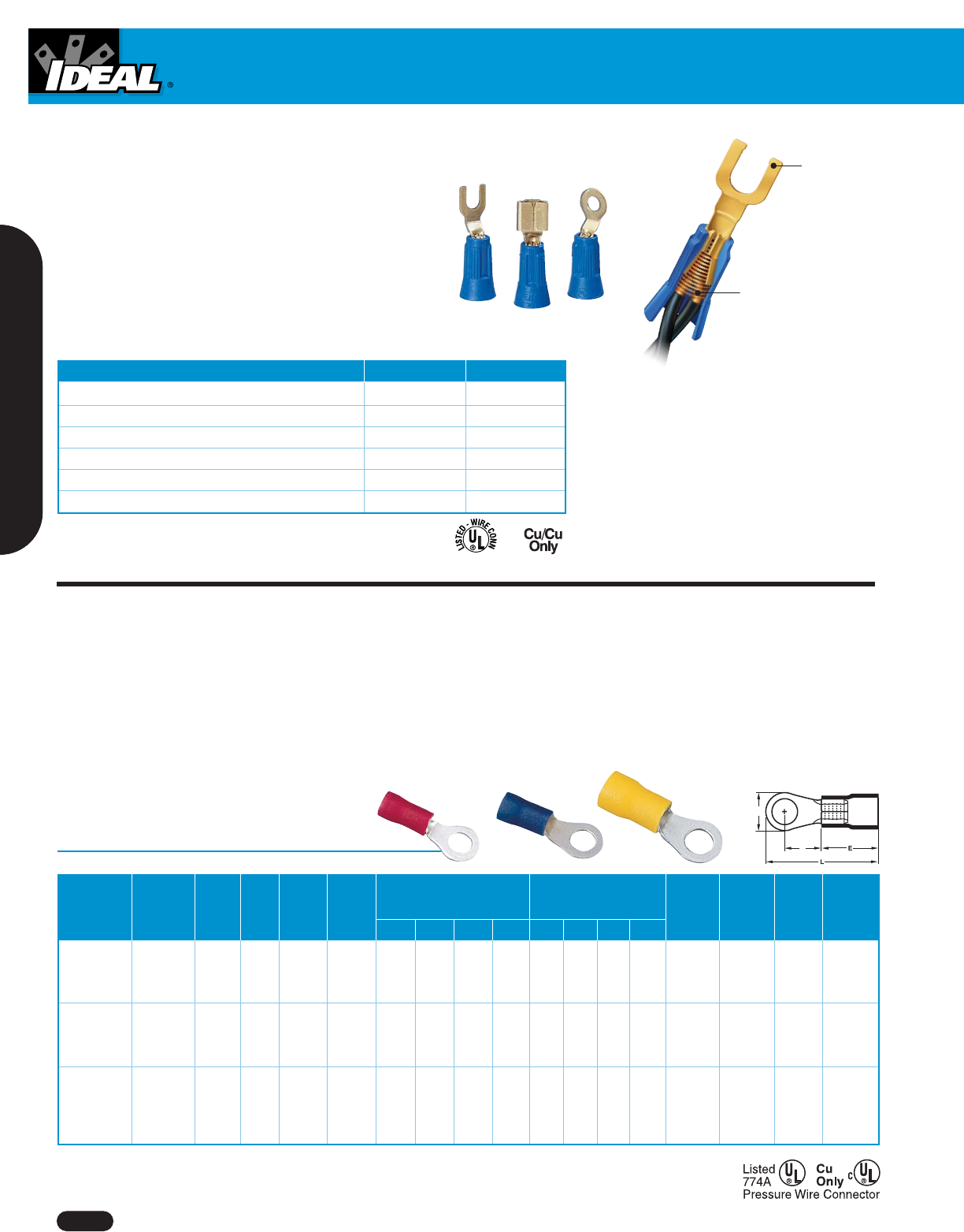
Term-a-Nut®Terminal Wire Connectors
■
No tools required – installs quickly without crimping – easily
removed for quick changes
■
Use with single or multiple wires – solid and/or stranded
22 to 12 AWG
■
Highly conductive brass terminal and phosphor-bronze spring
for maximum conductivity and smooth performance
■
Tough, UL 94V-2 flame-retardant shell rated at 105°C (221°F)
■
UL 486A and UL 486C Listed and tested to CSA C22.2 #65
and C22.2 #188
High-quality
brass terminal
with locking tabs
Phosphor-bronze
spring
Terminal Configurations Qty./Clamshell Cat. No.
#10 fork 25 30-3004
#8 fork 25 30-3014
.250 in. disconnect 25 30-3006
#10 ring 25 30-3012
#8 ring 25 30-3010
Assortment 40/kit* 30-3901
*Kit contains 8 each: 30-3004, 30-3014, 30-3006, 30-3012 and 30-3010.
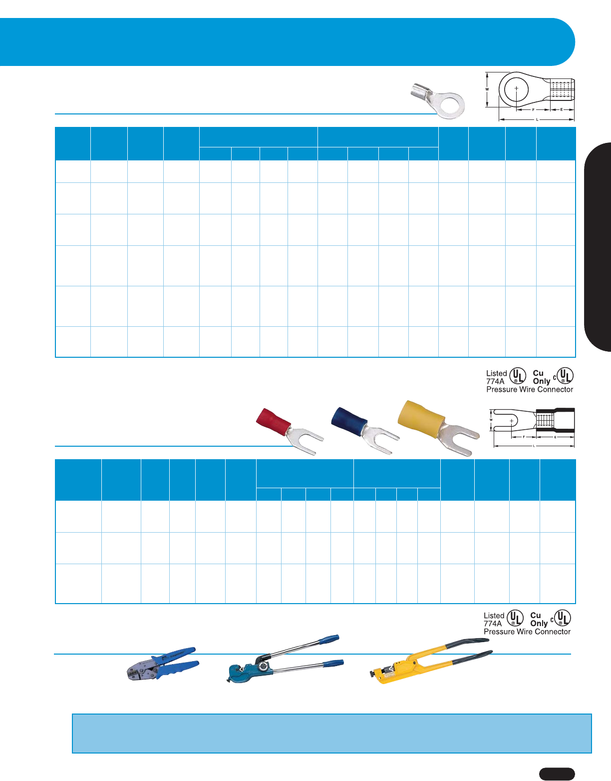
Vinyl Insulated Ring Terminals
Max. Max.
Wire Wire Stud Stud Wire Wire Dimensions Dimensions
Range Range Size Size Ins. Dia. Ins. Dia. (Inches) (mm) Ctn. Cat. Ctn. Cat.
(AWG) (mm2) (Inches) (mm) (Inches) (mm) LW EFLWEF Qty. No. Qty. No.
6 3.7 .764 .260 .394 .248 19.4 6.6 10.0 6.3 25 83-2121 ——
22 – 18 0.5 – 1.0 8 4.3 .157 4.0 .819 .315 .394 .276 20.8 8.0 10.0 7.0 25 83-2131 ——
10 5.3 .819 .315 .394 .276 20.8 8.0 10.0 7.0 25 83-2141 ——
1/4 6.4 1.055 .457 .394 .433 26.8 11.6 10.0 11.0 25 83-2151 ——
6 3.7 .764 .260 .394 .248 19.4 6.6 10.0 6.3 25 83-2221 ——
16 – 14 1.5 – 2.5 8 4.3 .177 4.5 .858 .335 .394 .307 21.8 8.5 10.0 7.8 25 83-2231 ——
10 5.3 .858 .374 .394 .287 21.8 9.5 10.0 7.3 25 83-2241 1,000 84-2241
1/4 6.4 1.055 .472 .394 .433 26.8 12.0 10.0 11.0 25 83-2251 ——
8 4.3 1.047 .374 .512 .358 26.6 9.5 13.0 9.1 25 83-2331 ——
10 5.3 1.047 .374 .512 .358 26.6 9.5 13.0 9.1 25 83-2341 1,000 84-2341
12 – 10 4.0 – 6.0 1/4 6.4 .248 6.3 1.167 .472 .512 .413 29.5 12.0 13.0 10.5 25 83-2351 ——
5/16 8.4 1.339 .591 .512 .531 34.0 15.0 13.0 13.5 25 83-2361 ——
3/8 10.5 1.339 .591 .512 .531 34.0 15.0 13.0 13.5 25 83-2371 ——
75° C/600 Volts max.
F
W
■
Butted seam-construction prevents splitting under maximum
pressure
■
Internal barrel serrations grip wires tightly to resist pull-out and
reduce electrical resistance
■
Tin-plated brass construction for corrosion resistance
■
Shouldered barrel insulation quickly positions terminal for
proper crimping
■
Expanded insulation entry accomodates a wide variety of
insulation diameters and provides additional insulation support
■
Color-coded insulation and wire range stamped on terminal for
easy identification
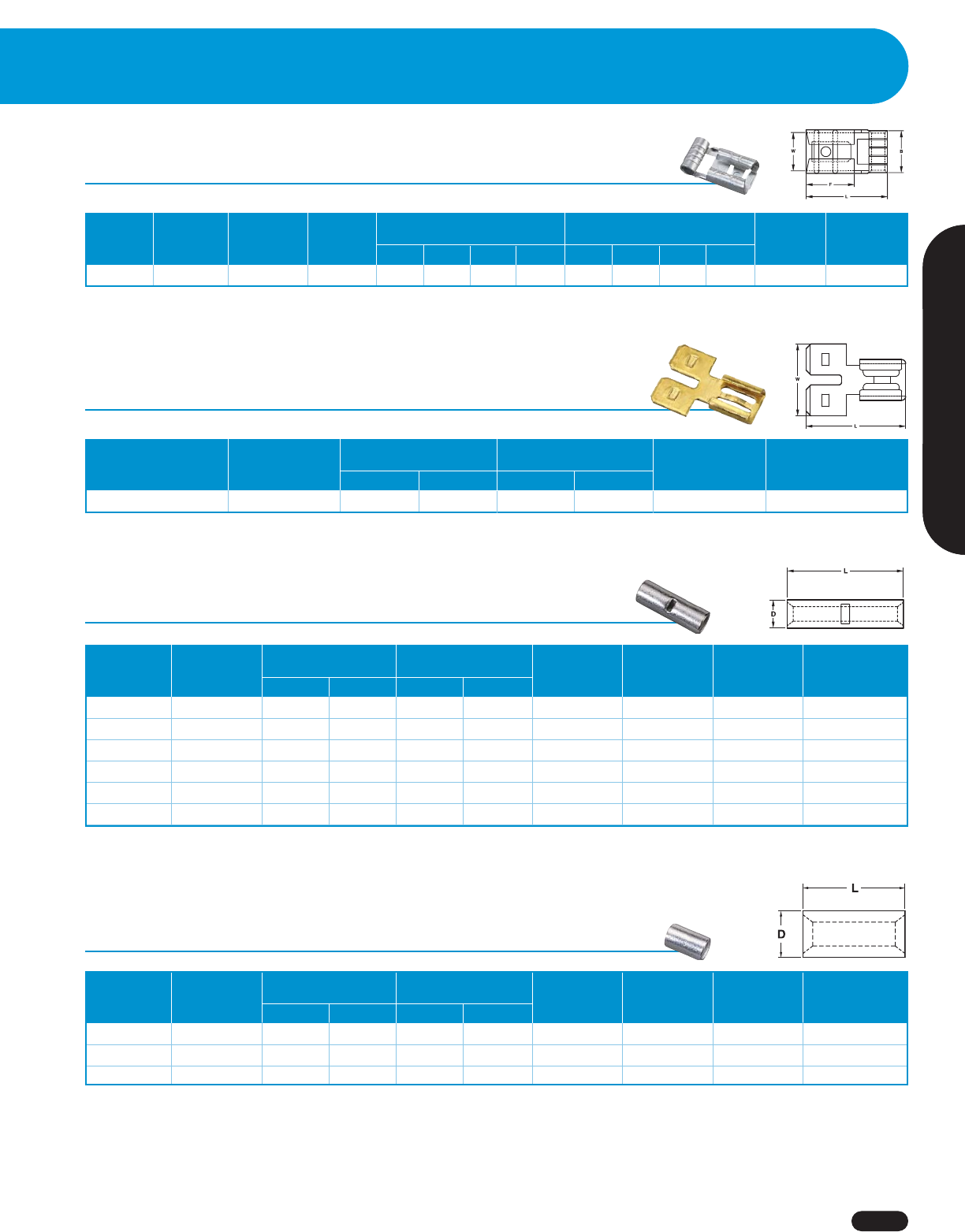
Crimp Terminals-Rings, Forks, Disconnects and Splices
CUS
Crimp Terminals
1-800-435-0705 for Customer Service www.idealindustries.com A-17
Wire Termination
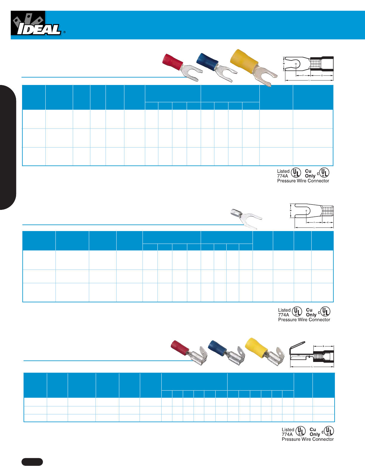
Vinyl Insulated Spade Terminals
Max. Max.
Wire Wire Stud Stud Wire Wire Dimensions Dimensions
Range Range Size Size Ins. Dia. Ins. Dia. (Inches) (mm) Ctn. Cat. Ctn. Cat.
(AWG) (mm2) (Inches) (mm) (Inches) (mm) L W E F L W E F Qty. No. Qty. No.
6 3.7 .827 .252 .394 .256 21.0 6.4 10.0 6.5 25 83-7111 1,000 84-7111
22 – 18 0.5 – 1.0 8 4.3 .157 4.0 .827 .283 .394 .256 21.0 7.2 10.0 6.5 25 83-7121 ——
10 5.3 .827 .374 .394 .256 21.0 9.5 10.0 6.5 25 83-7131 ——
6 3.7 .827 .236 .394 .256 21.0 6.0 10.0 6.5 25 83-7151 ——
16 – 14 1.5 – 2.5 8 4.3 .177 4.5 .827 .283 .394 .256 21.0 7.2 10.0 6.5 25 83-7161 1,000 84-7161
10 5.3 .827 .366 .394 .256 21.0 9.3 10.0 6.5 25 83-7171 1,000 84-7171
6 3.7 1.004 .327 .512 .276 25.5 8.3 13.0 7.0 25 83-7201 ——
8 4.3 1.004 .283 .512 .357 25.5 9.0 13.0 7.0 25 83-7211 ——
12 – 10 4.0 – 6.0 10 5.3 .248 6.3 1.004 .283 .512 .354 25.5 9.0 13.0 7.0 25 83-7221 500 84-7221
1/4 6.4 1.240 .472 .512 .472 31.5 12.0 13.0 12.0 25 83-7231 ——
75° C/600 Volts max.
Insulated and Non-Insulated Terminals, Splices and Disconnects (#22 - #10 AWG) are UL Listed when used with IDEAL Crimp Tool #30-518 (Replacement Die #30-519).
Non-Insulated Ring Terminals (#8 - #4 AWG) are UL Listed when used with IDEAL Crimp Tool #83-005 or 88-843.
Non-Insulated Disconnects, Splices and Vinyl Insulated Parallel Splices (#22 - #10 AWG) are not UL Listed; recommended IDEAL Crimp Tool #30-518.
Non-Insulated Splices (#8 - #4 AWG) are not UL Listed, recommended IDEAL Crimp Tool #83-005 or #88-843.
#30-518 Tool w/die
#30-519 Replacement die
#83-005 #88-843
Non-Insulated Ring Terminals
Crimp Tools
Wire Wire Stud Stud Dimensions Dimensions
Range Range Size Size (Inches)* (mm)** Ctn. Cat. Ctn. Cat.
(AWG) (mm2) (Inches) (mm) LWE FLWEF
Qty. No. Qty. No.
8 4.3 .622 .315 .189 .276 15.8 8,0 4.8 7.0 25 83-0131 ——
22 – 18 0.5 – 1.0 10 5.3 .622 .315 .189 .276 15.8 8.0 4.8 7.0 25 83-0141 ——
6 3.7 .567 .260 .189 .248 14.4 6.6 4.8 6.3 25 83-0221 ——
16 – 14 1.5 – 2.5 8 4.3 .661 .335 .189 .307 16.8 8.5 4.8 7.8 25 83-0231 ——
10 5.3 .661 .374 .189 .287 16.8 9.5 4.8 7.3 25 83-0241 1,000 84-0241
8 4.3 .772 .374 .236 .358 19.6 9.5 6.0 9.1 25 83-0331 ——
12 – 10 4.0 – 6.0 10 5.3 .772 .374 .236 .358 19.6 9.5 6.0 9.1 25 83-0341 1,000 84-0341
1/4 6.4 .886 .472 .236 .413 22.5 12.0 6.0 10.5 25 83-0351 ——
10 5.3 .937 .472 .337 .366 23.8 12.0 8.5 9.3 25 83-0421 ——
1/4 6.4 .937 .472 .337 .366 23.8 12.0 8.5 9.3 25 83-0431 ——
8 8.0 5/16 8.4 1.161 .591 .337 .543 29.8 15.0 8.5 13.8 25 83-0441 ——
3/8 10.5 1.161 .591 .337 .543 29.8 15.0 8.5 13.8 25 83-0451 ——
10 5.3 1.173 .472 .413 .524 29.8 12.0 10.5 13.3 20 83-0511 ——
1/4 6.4 1.173 .472 .413 .524 29.8 12.0 10.5 13.3 20 83-0521 ——
6 14.0 5/16 8.4 1.280 .630 .413 .559 32.5 16.0 10.5 14.2 20 83-0531 ——
3/8 10.5 1.280 .630 .413 .559 32.5 16.0 10.5 14.2 20 83-0541 ——
1/4 6.4 1.319 .650 .472 .531 33.5 16.5 12.0 13.5 20 83-0611 ——
4 22.0 5/16 8.4 1.319 .650 .472 .531 33.5 16.5 12.0 13.5 20 83-0621 ——
3/8 10.5 1.319 .650 .472 .531 33.5 16.5 12.0 13.5 20 83-0631 ——
105°C/600 Volts max.
*Plus or minus .020 in.
**Plus or minus .50 in.
Crimp Terminals
www.idealindustries.com 1-800-435-0705 for Customer Service
A-18
Vinyl Insulated Snap Spade Terminals
Max. Max.
Wire Wire Stud Stud Wire Wire Dimensions Dimensions
Range Wire Range Size Size Ins. Dia. Ins. Dia. (Inches) (mm) Ctn.
(AWG) (mm2) (Inches) (mm) (Inches) (mm) LWEF LWE F Qty. Cat. No.
6 3.7 .827 .252 .394 .256 21.0 6.4 10.0 6.5 25 83-7011
22 – 18 0.5 – 1.0 8 4.3 .134 4.0 .827 .283 .394 .256 21.0 7.2 10.0 6.5 25 83-7021
10 5.3 .827 .319 .394 .256 21.0 8.1 10.0 6.5 25 83-7031
6 3.7 .827 .236 .394 .256 21.0 6.0 10.0 6.5 25 83-7051
16 – 14 1.5 – 2.5 8 4.3 .161 4.5 .827 .319 .394 .256 21.0 8.1 10.0 6.5 25 83-7061
10 5.3 .827 .319 .394 .256 21.0 8.1 10.0 6.5 25 83-7071
8 4.3 .992 .327 .512 .276 25.2 8.3 13.0 7.0 25 83-7081
12 – 10 4.0 – 6.0 10 5.3 .248 6.3 .992 .354 .512 .276 25.2 9.0 13.0 7.0 25 83-7091
1/4 6.4 1.240 .472 .512 .472 31.5 12.0 13.0 12.0 25 83-7101
75° C/600 Volts max.
Non-Insulated Spade Terminals
Dimensions Dimensions
Wire Range Wire Range Stud Size Stud Size (Inches) (mm) Ctn. Cat. Ctn. Cat.
(AWG) (mm2) (Inches) (mm) L W E F L W E F Qty. No. Qty. No.
6 3.7 .630 .252 .189 .256 16.0 6.4 4.8 6.5 25 83-6111
22 – 18 0.5 - 1.0 8 4.3 .630 .283 .189 .256 16.0 7.2 4.8 6.5 25 83-6121 ——
10 5.3 .630 .319 .189 .256 16.0 8.1 4.8 6.5 25 83-6131 ——
16 – 14 1.5 – 2.5 8 4.3 .630 .283 .189 .256 16.0 7.2 4.8 6.5 25 83-6161 ——
10 5.3 .630 .366 .189 .256 16.0 9.3 4.8 6.5 25 83-6171 1,000 84-6171
8 4.3 .728 .354 .236 .276 18.5 9.0 6.0 7.0 25 83-6211 ——
12 – 10 4.0 – 6.0 10 5.3 .728 .354 .236 .276 18.5 9.0 6.0 7.0 25 83-6221 ——
1/4 6.4 .965 .472 .236 .472 24.5 12.0 6.0 12.0 25 83-6231 ——
105° C/600 Volts max.
Max. Max.
Wire Wire Tab Tab Wire Wire Dimensions Dimensions
Range Range Size Size Ins. Dia. Ins. Dia. (Inches) (mm) Ctn. Cat.
(AWG) (mm2) (Inches) (mm) (Inches) (mm) L B W F W1 F1 L B W F W1 F1 Qty. No.
22 – 18 0.5 – 1.0 .250 x .032 6.35 x 0.8 .150 3.8 .886 .413 .260 .315 .250 .323 22.5 10.5 6.6 8.0 6.35 8.2 25 83-9611
16 – 14 1.5 – 2.5 .250 x .032 6.35 x 0.8 .185 4.7 .886 .413 .260 .315 .250 .323 22.5 10.5 6.6 8.0 6.35 8.2 25 83-9621
12 – 10 4.0 – 6.0 .250 x .032 6.35 x 0.8 .244 6.2 .945 .512 .260 .315 .250 .323 22.5 13.0 6.6 8.0 6.35 8.2 25 83-9631
75° C/300 Volts max.
Vinyl Insulated Multi-Stack Disconnects
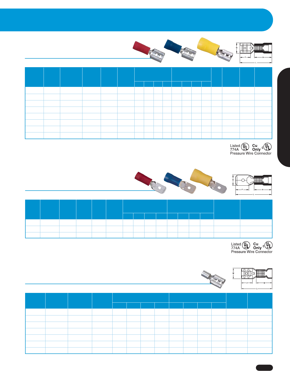
Crimp Terminals/Disconnects
1-800-435-0705 for Customer Service www.idealindustries.com A-19
Wire Termination
Max. Max.
Wire Wire Tab Tab Wire Wire Dimensions Dimensions
Range Range Size Size Ins. Dia. Ins. Dia. (Inches) (mm) Ctn. Cat. Ctn. Cat.
(AWG) (mm2) (Inches) (mm) (Inches) (mm) L B W F L B W L Qty. No. Qty. No.
22 – 18 0.5 – 1.0 .110 x .020 2.8 x 0.5 .150 3.8 .728 .413 .126 .256 18.5 10.5 3.2 6.5 25 83-9511 ——
16 – 14 1.5 – 2.5 .110 x .020 2.8 x 0.5 .185 4.7 .748 .413 .126 .256 19.0 10.5 3.2 6.5 25 83-9521 ——
22 – 18 0.5 – 1.0 .187 x .020 4.75 x 0.5 .150 3.8 .764 .413 .197 .252 19.4 10.5 5.0 6.4 25 83-9541 ——
16 – 14 1.5 – 2.5 .187 x .020 4.75 x 0.5 .185 4.7 .764 .413 .197 .252 19.4 10.5 5.0 6.4 25 83-9551 ——
22 – 18 0.5 – 1.0 .250 x .032 6.35 x 0.8 .150 3.8 .819 .413 .260 .287 20.8 10.5 6.6 7.3 25 83-9571 ——
16 – 14 1.5 – 2.5 .250 x .032 6.35 x 0.8 .185 4.7 .819 .413 .260 .287 20.8 10.5 6.6 7.3 25 83-9581 500 84-9581
14 – 12 2.5 – 4.0 .250 x .032 6.35 x 0.8 .244 6.2 .917 .512 .260 .287 23.3 13.0 6.6 7.3 25 83-9591 ——
12 – 10 4.0 – 6.0 .250 x .032 6.35 x 0.8 .244 6.2 .917 .512 .260 .287 23.3 13.0 6.6 7.3 25 83-9601 ——
75° C/300 Volts max.
Vinyl Insulated Female Disconnects
Vinyl Insulated Male Disconnects
Max. Max.
Wire Wire Wire Wire Dimensions Dimensions
Range Wire Range Tab Size Tab Size Ins. Dia. Ins. Dia. (Inches) (mm) Ctn.
(AWG) (mm2) (Inches) (mm) (Inches) (mm) L B W F L B W F Qty. Cat. No.
22 – 18 0.5 – 1.0 .250 x .032 6.35 x 0.8 .150 3.8 .858 .413 .250 .303 21.8 10.5 6.35 7.7 25 83-9971
16 – 14 1.5 – 2.5 .250 x .032 6.35 x 0.8 .185 4.7 .858 .413 .250 .303 21.8 10.5 6.35 7.7 25 83-9981
12 – 10 4.0 – 6.0 .250 x .032 6.35 x 0.8 .244 6.2 .945 .512 .250 .303 24.0 13.0 6.35 7.7 25 83-9991
75° C/300 Volts max.
Non-Insulated Female Disconnects
Wire Wire Tab Tab Dimensions Dimensions
Range Range Size Size (Inches) (mm)
(AWG) (mm2) (Inches) (mm) L B W F L B W F Ctn. Qty. Cat. No.
22 – 18 0.5 – 1.0 .110 x .020 2.8 x 0.5 .630 .189 .126 .256 16.0 4.8 3.2 6.5 25 83-9411
16 – 14 1.5 – 2.5 .110 x .020 2.8 x 0.5 .630 .189 .126 .256 16.0 4.8 3.2 6.5 25 83-9421
22 – 18 0.5 – 1.25 .187 x .020 4.75 x 0.5 .630 .189 .197 .252 16.0 4.8 5.0 6.4 25 83-9441
16 – 14 1.5 – 2.5 .187 x .020 4.75 x 0.5 .630 .189 .197 .252 16.0 4.8 5.0 6.4 25 83-9451
22 – 18 0.5 – 1.25 .250 x .032 6.35 x 0.8 .630 .189 .260 .287 16.0 4.8 6.6 7.3 25 83-9471
16 – 14 1.5 – 2.5 .250 x .032 6.35 x 0.8 .630 .189 .260 .287 16.0 4.8 6.6 7.3 25 83-9481
12 – 10 4.0 – 6.0 .250 x .032 6.35 x 0.8 .728 .236 .260 .287 18.5 6.0 6.6 7.3 25 83-9501
105° C/300 Volts max.
Disconnects
www.idealindustries.com 1-800-435-0705 for Customer Service
A-20
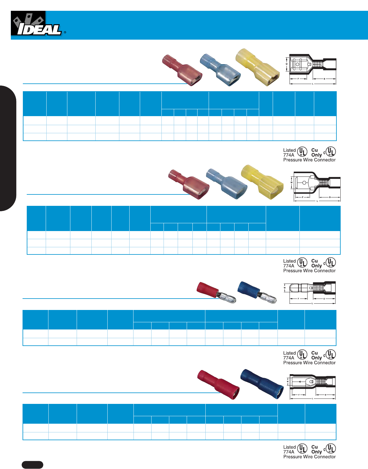
Max. Max.
Wire Wire Tab Tab Wire Wire Dimensions Dimensions
Range Range Size Size Ins. Dia. Ins. Dia. (Inches) (mm) Ctn. Cat. Ctn. Cat.
(AWG) (mm2) (Inches) (mm) (Inches) (mm) L B W F L B W L Qty. No. Qty. No.
22 – 18 0.5 – 1.0 .250 x .032 6.35 x 0.8 .150 3.8 .866 .433 .260 .287 22.0 11.0 6.6 7.3 25 83-9771 ——
16 – 14 1.5 – 2.5 .250 x .032 6.35 x 0.8 .185 4.7 .866 .433 .260 .287 22.0 11.0 6.6 7.3 25 83-9781 1,000 84-9781
12 – 10 4.0 – 6.0 .250 x .032 6.35 x 0.8 .244 6.2 .945 .512 .260 .287 24.0 13.0 6.6 7.3 25 83-9791 500 84-9791
105° C/300 Volts max.
Nylon Fully-Insulated Female Disconnects
Nylon Fully-Insulated Male Disconnects
Max. Max.
Wire Wire Wire Wire Dimensions Dimensions
Range Wire Range Tab Size Tab Size Ins. Dia. Ins. Dia. (Inches) (mm) Ctn.
(AWG) (mm2) (Inches) (mm) (Inches) (mm) L B W F L B W F Qty. Cat. No.
22 – 18 0.5 – 1.0 .250 x .032 6.35 x 0.8 .150 3.8 .906 .433 .250 .303 23.0 11.0 6.35 7.7 25 83-9911
16 – 14 1.5 – 2.5 .250 x .032 6.35 x 0.8 .185 4.7 .945 .433 .250 .303 24.0 11.0 6.35 7.7 25 83-9921
12 – 10 4.0 – 6.0 .250 x .032 6.35 x 0.8 .244 6.2 .984 .512 .250 .303 25.0 13.0 6.35 7.7 25 83-9931
105° C/300 Volts max.
Vinyl Fully-Insulated Receptacle Disconnects
Wire Wire Max. Wire Max. Wire Dimensions Dimensions
Range Range Ins. Dia. Ins. Dia. (Inches) (mm)
(AWG) (mm2) (Inches) (mm) L B W F L B W F Ctn. Qty. Cat. No.
22 – 18 0.5 – 1.0 .150 3.8 .917 .413 .153 .287 23.3 10.5 3.9 7.3 25 83-8101
16 – 14 1.5 – 2.5 .185 4.7 .917 .413 .153 .287 23.3 10.5 3.9 7.3 25 83-8111
75° C/300 Volts max.
Vinyl Insulated Bullet Disconnects
Wire Wire Max. Wire Max. Wire Dimensions Dimensions
Range Range Ins. Dia. Ins. Dia. (Inches) (mm)
(AWG) (mm2) (Inches) (mm) L B W F L B W F Ctn. Qty. Cat. No.
22 – 18 0.5 – 1.0 .150 3.8 .846 .413 .157 .335 21.5 10.5 4.0 8.5 25 83-8001
16 – 14 1.5 – 2.5 .185 4.7 .846 .413 .157 .335 21.5 10.5 4.0 8.5 25 83-8011
75° C/300 Volts max.
Non-Insulated Flag Female Disconnect
Wire Wire Tab Tab Dimensions Dimensions
Range Range Size Size (Inches) (mm)
(AWG) (mm2) (Inches) (mm) L B W F L B W F Ctn. Qty. Cat. No.
16 – 14 1.5 – 2.5 .250 x .032 6.35 x 0.8 .551 .291 .260 299 14.0 7.4 6.6 7.6 25 83-9401
105° C/300 Volts max.
Disconnect Adapter – Male to Female (2-1)
Dimensions Dimensions
Tab Size Tab Size (Inches) (mm)
(Inches) (mm2) L W L W Ctn. Qty. Cat. No.
.250 x .032 6.35 x 0.8 .551 .260 14.0 6.6 25 83-9801
105° C/300 Volts max.
Non-Insulated Butt Splices
Wire Dimensions Dimensions
Range Wire Range (Inches) (mm)
(AWG) (mm2)LDL D
Ctn. Qty. Cat. No. Ctn. Qty. Cat. No.
22 – 18 0.5 – 1.0 .591 .130 15.0 3.3 25 83-9001 ——
16 – 14 1.5 – 2.5 .591 .154 15.0 3.9 25 83-9011 ——
12 – 10 4.0 – 6.0 .591 .213 15.0 5.4 25 83-9021 500 84-9021
8 8.0 .827 .276 21.0 7.0 25 83-9031 250 84-9031
6 14.0 1.024 .350 26.0 8.9 20 83-9041 ——
4 22.0 1.142 .445 29.0 11.3 20 83-9051 ——
105° C/600 Volts max.
Non-Insulated Parallel Splices
Wire Dimensions Dimensions
Range Wire Range (Inches) (mm)
(AWG) (mm2)LDL D
Ctn. Qty. Cat. No. Ctn. Qty. Cat. No.
22 – 18 0.5 – 1.0 .315 .130 8.0 3.3 25 83-9071 ——
16 – 14 1.5 – 2.5 .315 .154 8.0 3.9 25 83-9081 1,000 84-9081
12 – 10 4.0 – 6.0 .335 .213 8.5 5.4 25 83-9091 ——
105° C/600 Volts max.
Disconnects
1-800-435-0705 for Customer Service www.idealindustries.com A-21
Wire Termination
Disconnects
www.idealindustries.com 1-800-435-0705 for Customer Service
A-22
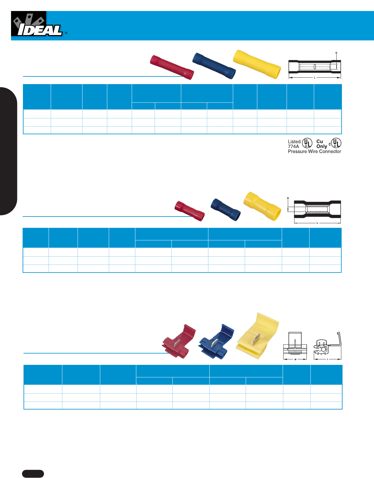
Tap Splice Connectors
Wire Wire Dimensions Dimensions
Range Range (Inches) (mm)
(AWG) (mm2) Color L W L W Ctn. Qty. Cat. No.
22 – 18 0.5 – 1.0 Red 1.063 .787 27.0 20.0 25 83-3261
16 – 14 1.5 – 2.5 Blue 1.063 .787 27.0 20.0 25 83-3271
12 – 10 4.0 – 6.0 Yellow 1.358 .807 34.5 20.5 25 83-3281
105°C/ 600 Volts max.
Vinyl Insulated Parallel Splices
Wire Wire Max. Wire Max. Wire Dimensions Dimensions
Range Range Ins. Dia. Ins. Dia. (Inches) (mm)
(AWG) (mm2) (Inches) (mm) L W L W Ctn. Qty. Cat. No.
22 – 18 0.5 – 1.0 .157 4.0 .512 .067 13.0 1.7 25 83-9351
16 – 14 1.5 – 2.5 .177 4.5 .512 .091 13.0 2.3 25 83-9361
12 – 10 4.0 – 6.0 .248 6.3 .591 .134 15.0 3.4 25 83-9371
75°C/ 600 Volts max.
Vinyl Insulated Butt Splices
Max. Max.
Wire Wire Ins. Wire Ins. Dimensions Dimensions
Range Wire Range Dia. Dia. (Inches) (mm)
(AWG) (mm2) (Inches) (Inches) LD L D
Ctn. Qty. Cat. No. Ctn. Qty. Cat. No.
22 – 18 0.5 – 1.25 .157 4.0 .986 .067 24.6 1.7 25 83-9281 1,000 84-9281
16 – 14 1.5 – 2.5 .177 4.5 .986 .091 24.6 2.3 25 83-9291 1,000 84-9291
12 – 10 4.0 – 6.0 .248 6.3 1.043 .134 26.5 3.4 25 83-9301 500 84-9301
75° C/600 Volts max.
1-800-435-0705 for Customer Service www.idealindustries.com A-23
Wire Termination
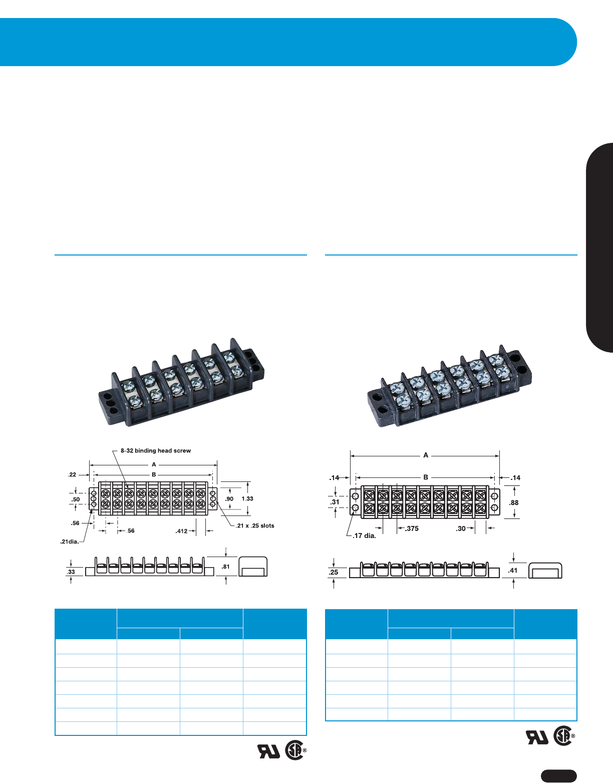
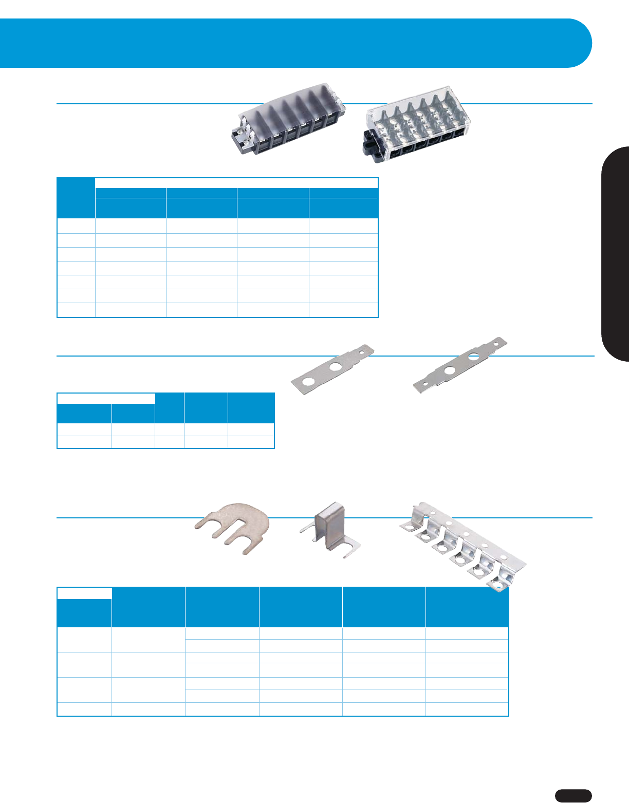
Terminal Strips
Terminal Strips
■
Heavy-duty, corrosion-resistant screws, surface
plates and optional hardware
■
Accessory hardware provides a variety of
termination options
■
Available cover helps prevent contact with live terminals
■
.562 in. (14.28mm) center spacing
■
Accepts wire sizes from 22 through 10 AWG Cu
■
#8-32 philslot, zinc-plated steel terminal screws
(Recommended torque: 16 in. - lb.)
89-200 Series Terminal Strips
30A/600V* UL/CSA
■
.375 in. (9.52mm) center spacing
■
Accepts wire sizes from 22 through 14 AWG Cu
■
#6-32 philslot, zinc-plated steel terminal screws
(Recommended torque: 9 in. - lb.)
89-300 Series Terminal Strips
15A/250V** UL, 15A/150V** CSA
Dimensions
No. of (Inches)
Poles A B Cat. No.
2 1.40 1.12 89-302
4 2.16 1.88 89-304
6 2.90 2.62 89-306
8 3.66 3.38 89-308
10 4.40 4.12 89-310
12 5.16 4.88 89-312
**Max. electrical rating 15A/125V when used with
optional quick-connects.
■
Rugged polyester thermoplastic base
(UL Rated 94V-O)
■
Operating temperature rated from 130°C (260°F) to
-40°C (-40°F)
■
UL Recognized (E62622) and CSA Certified (LR15364)
Dimensions
No. of (Inches)
Poles A B Cat. No.
2 2.13 1.69 89-202
3 2.69 2.25 89-203
4 3.25 2.81 89-204
6 4.37 3.94 89-206
8 5.50 5.06 89-208
10 6.62 6.19 89-210
12 7.75 7.31 89-212
*Max. electrical rating 30A/250V when used
with optional quick-connects.
Terminal Strips
www.idealindustries.com 1-800-435-0705 for Customer Service
A-24
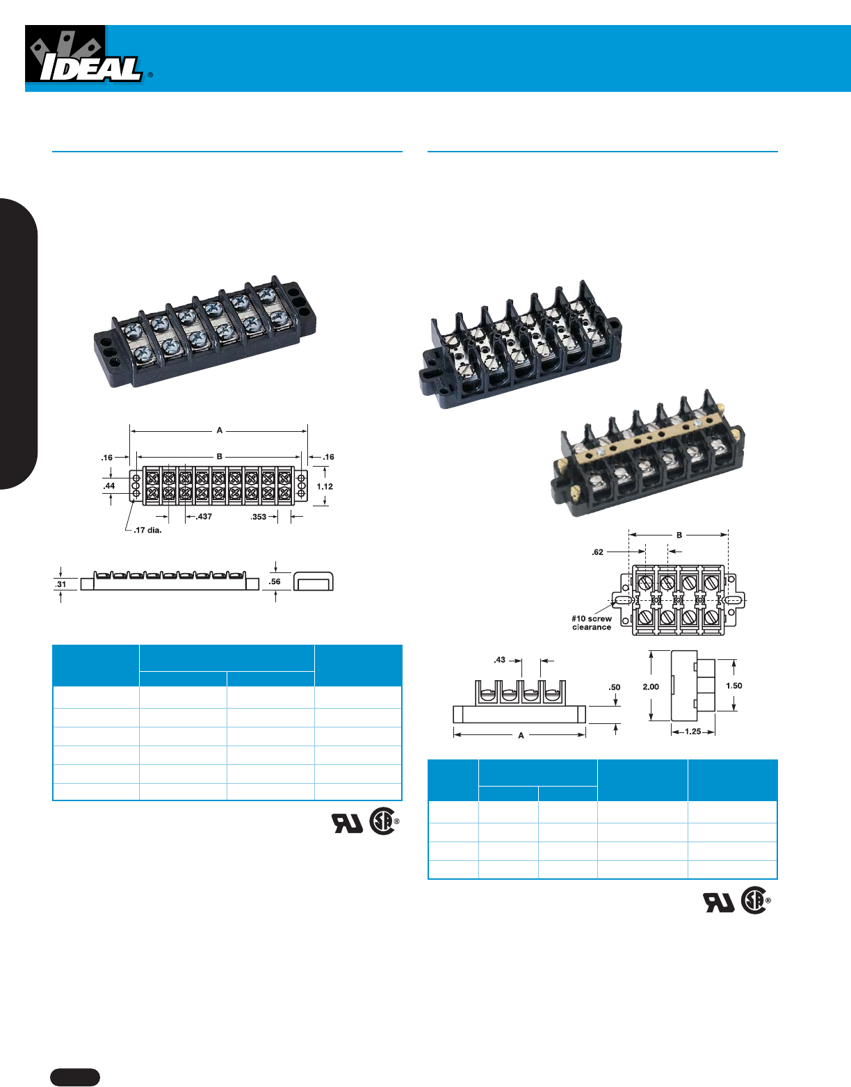
■
.437 in. (11.10mm) center spacing
■
Accepts wire sizes from 22 through 12 AWG Cu
■
#6-32 philslot, zinc-plated steel terminal screws
(Recommended torque: 9 in. - lb.)
89-400 Series Terminal Strips
20A/250V UL/CSA
■
Available in standard or shorting-block style
■
.625 in. (15.88mm) center spacing
■
Accepts wire sizes from 22 through 6 AWG Cu
■
#10-32 slotted, nickel plated brass terminal screws
(Recommended torque: 20 in. - lb.)
89-500 Series Terminal Strips
60A/600V* UL/CSA
Dimensions
No. of (Inches)Standard Block Shorting Block
Poles A B Cat. No. Cat. No.
4 3.75 2.87 89-504 89-505
6 5.00 4.12 89-506 89-507
8 6.25 5.37 89-508 89-509
12 8.75 7.87 89-512 89-513
*Max. electrical rating 60A/600V achieved only when used
with #6 AWG copper wire crimped to ring terminal.
Dimensions
No. of (Inches)
Poles A B Cat. No.
2 1.63 1.31 89-402
4 2.51 2.18 89-404
6 3.38 3.06 89-406
8 4.25 3.93 89-408
10 5.13 4.81 89-410
12 6.00 5.68 89-412
Standard Block
Shorting Block
Covers
1-800-435-0705 for Customer Service www.idealindustries.com A-25
Wire Termination
For Use With
Terminal Strip Tab Size Flat - None Flat - Flat
Series (Inches) Qty Cat. No. Cat. No.
89-300 .187 x .020 10 pcs. 89-314 89-317
89-200 & 89-400 .250 x .031 10 pcs. 89-414 89-417
For Use With Terminal Strip Series
89-200 89-300 89-400 89-500
No. of Clear Clear Clear Clear
Circuits Cat. No. Cat. No. Cat. No. Cat. No.
289-233 89-334 89-434 —
389-234 ———
489-235 89-335 89-435 89-514
689-236 89-336 89-436 89-516
889-237 89-337 89-437 89-518
10 89-238 89-338 89-438 —
12 89-239 89-339 89-439 89-520
Quick Connects
Jumpers
Flat - None
Flat Slip-on
Flat - Flat
Flat 12-Circuit
Covers
For Use With
Flat Over Barrier Flat
Terminal Strip Center Spacing Slip-on Slip-on 12-Circuit
Series (Inches)Qty. Cat. No. Cat. No. Cat. No.
89-200 .562 10 pcs. 89-229 89-224 —
100 pcs. 89-230 ——
89-300 .375 10 pcs. 89-323 89-324 —
100 pcs. 89-330 ——
89-400 .437 10 pcs. 89-423 89-424 —
100 pcs. 89-430 ——
89-500 .625 2 pcs. — — 89-525
■
Helps prevent contact with live terminals
■
Allows fast, flexible circuit changes
■
Provides easy connection of
multiple circuits
Over Barrier
Slip-on
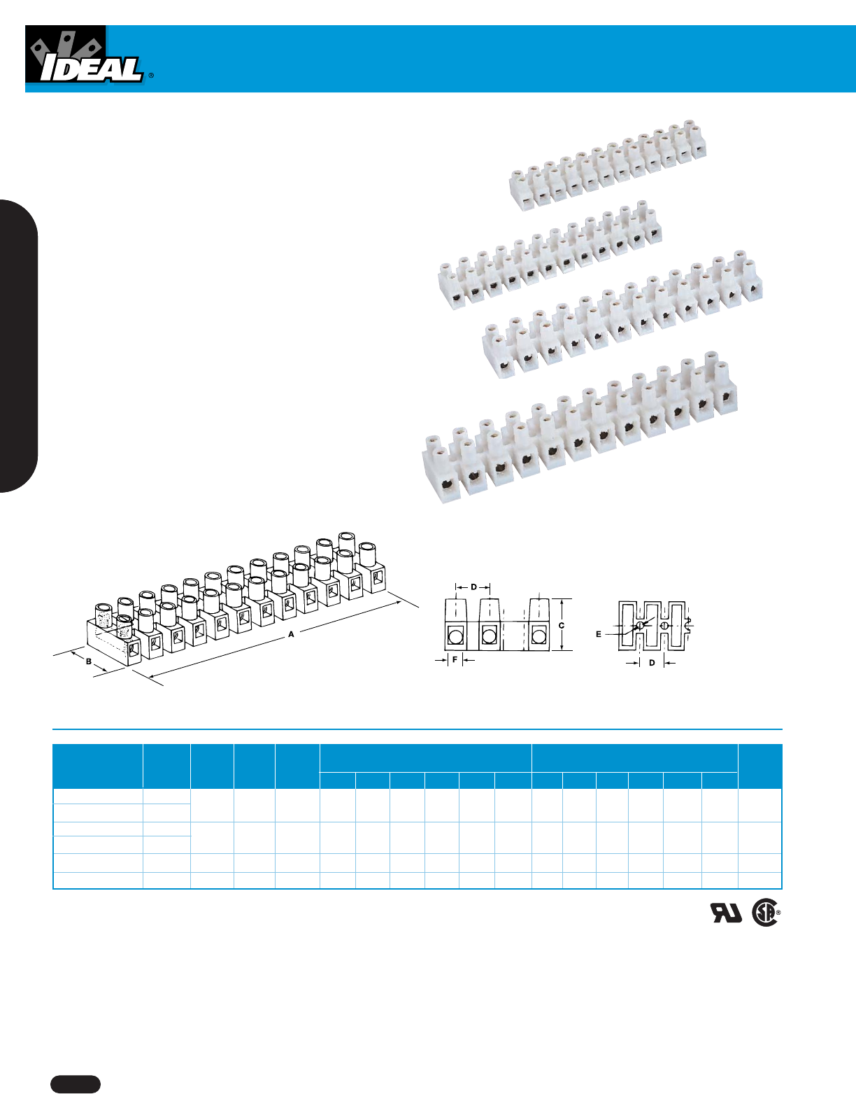
Barrier Strips
www.idealindustries.com 1-800-435-0705 for Customer Service
A-26
Barrier Strips
Wire Dimensions Dimensions
Electrical Range No. of Torque Model (Inches)(
mm)
Ratings (AWG) Circuits in.-lb. No. A B C D E F* A B C D E F** Cat. No.
20A/600V UL 22 - 12 12 3.5 PA8DS 3.787 0.669 0.570 0.315 0.114 0.110 96.2 17.0 14.5 8.0 2.9 2.8 89-608
10A/400V CSA 20 - 18
30A/600V UL 22 - 10 12 4.4 PA10DS 4.626 0.795 0.670 0.394 0.142 0.134 117.0 20.2 17.0 10.0 3.6 3.4 89-610
20A/400V CSA 18 - 14
35A/600V UL/CUL 22 - 10 12 7.0 PA12DS 5.540 0.937 0.748 0.472 0.154 0.154 140.7 23.8 19.0 12.0 3.9 3.9 89-612
50A/600V UL/CUL 20 - 8 12 12.0 PA14DS 6.220 1.008 0.992 0.531 0.173 0.189 158.0 25.6 25.2 13.5 4.4 4.8 89-614
*Plus or minus .004 in.
**Plus or minus 0.1mm
Barrier Strips
■
Recessed screws and tubular contacts provide
added safety and help prevent short circuits
■
Tubular contacts connect stripped, un-terminated
solid or stranded wire directly to each contact
■
Integrated wire protectors prevent twisting and
breakage of stranded wire during connection
■
Modular 12-circuit design can be cut into smaller
sections, or stacked end-to-end
■
Rugged nylon construction, UL 94V2
■
Operating temperature rated to 105°C (221°F)
Wire Connectors
1-800-435-0705 for Customer Service www.idealindustries.com A-27
Wire Termination
Wire Combination
Model Range Quantity Cat. No.
600V Box of 100 30-410
410 18 thru 10 AWG Carton of 1,000 30-510
Min. 1 #14 & 1 #18
Max. 2 #10 & 2 #14 Keg of 10,000 30-610
600V Box of 40 30-401
411 18 thru 8 AWG Box of 50 30-411
Min. 3 #12
Max. 4 #10 Carton of 1,000 30-511
600V Box of 20 30-402
412 18 thru 4 AWG Box of 50 30-412
Min. 1 #14 & 1 #16
Max. 2 #8 & 1 #6 Carton of 1,000 30-512
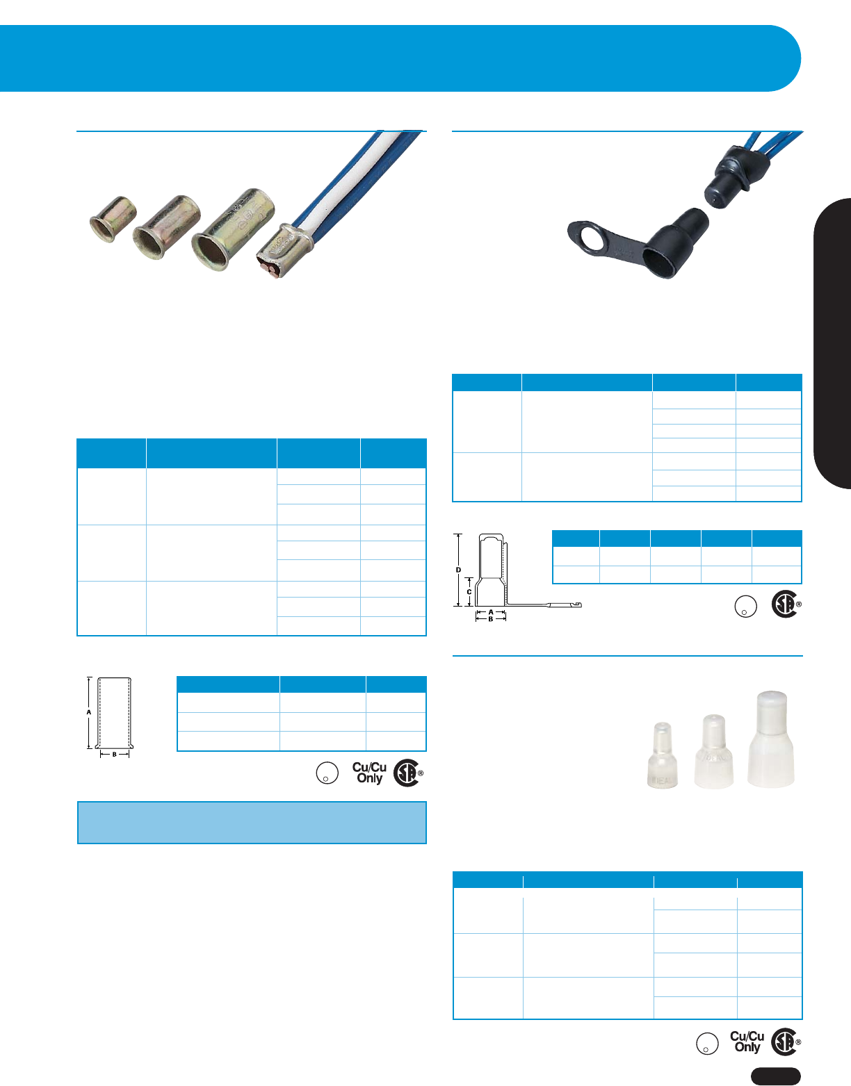
Crimp Connectors
■
Designed for making fast, permanent, pressure-type connections
■
Long, zinc-plated steel sleeves maximize contact area
with conductors
■
Will not vibrate loose when securely crimped
■
Steel crimp connectors are UL Listed to 486C and CSA Certified
to C22.2 #188; comply with Federal Specification W-S-610E.
Wrap-Cap®Insulators
■
Provide high dielectric and physical
protection for UL Listed, non-insulated
pressure-type wire connectors
■
Cap and loop design eliminates
need for tape
■
Unique design
completely covers
splice — insulates
both around and
between wires
■
Reusable and easy to install
■
UL Listed and CSA Certified for 600V maximum building wiring
(1,000V maximum for fixtures and signs); temperature rated at
75°C (167°F) maximum
Model Description Quantity Cat. No.
Box of 20 30-405
415 Insulator for Model Box of 100 30-415
410 sleeves Carton of 1,000 30-515
Keg of 10,000 30-615
Box of 10 30-407
417 Insulator for Model 411 Box of 50 30-417
& 412 sleeves Carton of 1,000 30-517
Model A B C D
415 1/2 5/8 23/32 1-13/64
417 11/16 3/4 3/4 1-25/32
Dimensions (Inches)
Model A B
410 Steel 3/8 13/64
411 Steel 5/8 1/4
412 Steel 51/64 19/64
Dimensions (Inches)
Steel Crimp Connectors
U
L
R
L
I
S
T
E
D
-
W
I
R
E
C
O
N
N
IDEAL hand tools U.L. listed for Model 410, 411, 412.
Crimps: 30-420, 30-425, 30-429, 30-430.
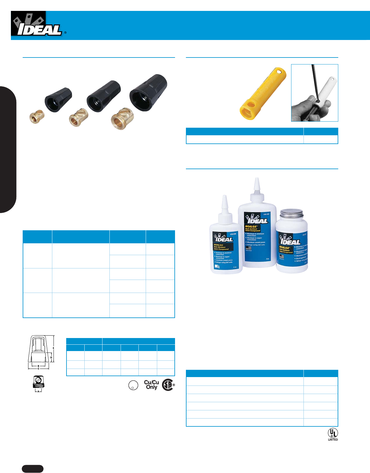
Model Wire Combination Range Quantity Cat. No.
600V* 1,000 30-245
48 Min. 2 #22
Max. 1 #14 w/2 #18 10,000 30-645
600V* 1,000 30-249
49 Min. 1 #22 w/1 #18
Max. 1 #12 w/1 #16 10,000 30-649
600V* 1,000 30-148
NC-8 Min. 4 #w16
Max. 1 #12 w/4 #14 5,000 30-648
*1,000V maximum in fixtures and signs
Pre-Insulated Crimp Connectors
■
Three models cover a wide range
of wire combinations from 22 AWG
stranded through 8 AWG stranded
■
Compact design fits easily
into tight locations
■
Flared skirt protects against
turned–back strands
■
Beveled opening eases
wire entry
■
UL Listed and CSA Certified for 600V maximum building wiring
(1,000V maximum for fixtures and signs); temperature rated at
105°C (221°F) maximum
U
L
R
L
I
S
T
E
D
-
W
I
R
E
C
O
N
N
U
L
R
L
I
S
T
E
D
-
W
I
R
E
C
O
N
N
www.idealindustries.com 1-800-435-0705 for Customer Service
A-28
Wire Connectors
Set-Screw Wire Connectors
■
Eliminates need for restripping wire each time connection is disturbed
■
Solid brass sleeves in three sizes handle 18 through 12 AWG wires
■
Set-screw easily and securely applies maximum compression to
conductors to ensure a vibration-resistant splice
■
Permits fast visual inspection of splice
■
Tough, flame-retardant shell rated at 150°C (302°F)
■
UL Listed to 486C and CSA Certified to C22.2 #188 ; comply with
Federal Specification W-S-610E
Wire Combination
Model Range Quantity Cat. No.
300V Box of 100 30-210
10 22 thru 16 AWG
Min. 1 #20 w/1 #22
Max. 2 #14 w/1 #16 Carton of 1,000 30-310
600V Box of 100 30-211
11 22 thru 14 AWG
Min. 1 #14 w/1 #20
Max. 3 #14 w/2 #18 Carton of 1,000 30-311
600V Box of 100 30-222
22 20 thru 10 AWG
Min. 1 #16 w/3 #18
Max. 2 #10 w/1 #12 Carton of 1,000 30-322
Insert Shell
Model A B C D E
10 1/8 5/16 1/2 19/64 45/64
11 3/16 3/8 33/64 13/32 63/64
22 1/4 1/2 11/16 13/32 1-1/64
Dimensions (Inches)
Set-Screw Holder
For Connector Models Cat. No.
11 & 22 K-2422
Noalox®Anti-Oxidant
■
Anti-oxidant and anti-seizing compound improves efficiency
and service life of aluminum electrical applications
■
Suspended zinc particles penetrate and cut aluminum oxide
■
Provides additional inner-strand and inner-conductor current
paths for improved conductivity and cooler connections
■
Carrier material excludes air to prevent further oxidation
■
For use with all types of pressure-type wire connectors
including screw-on, tap, service entrance and split-bolt
■
Reduces galling and seizing on aluminum conduit joints —
promotes good ground continuity
Description Cat. No.
1/2-oz. Tube 30-024
4-oz. Squeeze bottle 30-026
8-oz. Squeeze bottle 30-030
8-oz. Brush cap 30-031
1-gal. Bucket 30-032
5-gal. Bucket 30-040
U
L
R
L
I
S
T
E
D
-
W
I
R
E
C
O
N
N
■
Convenient tool for holding and
tightening set-screw connectors
■
Accepts IDEAL
Models 11 and 22
set-screw connectors
1-800-435-0705 for Customer Service www.idealindustries.com A-29
1-800-435-0705 for Customer Service www.idealindustries.com
Wire Termination
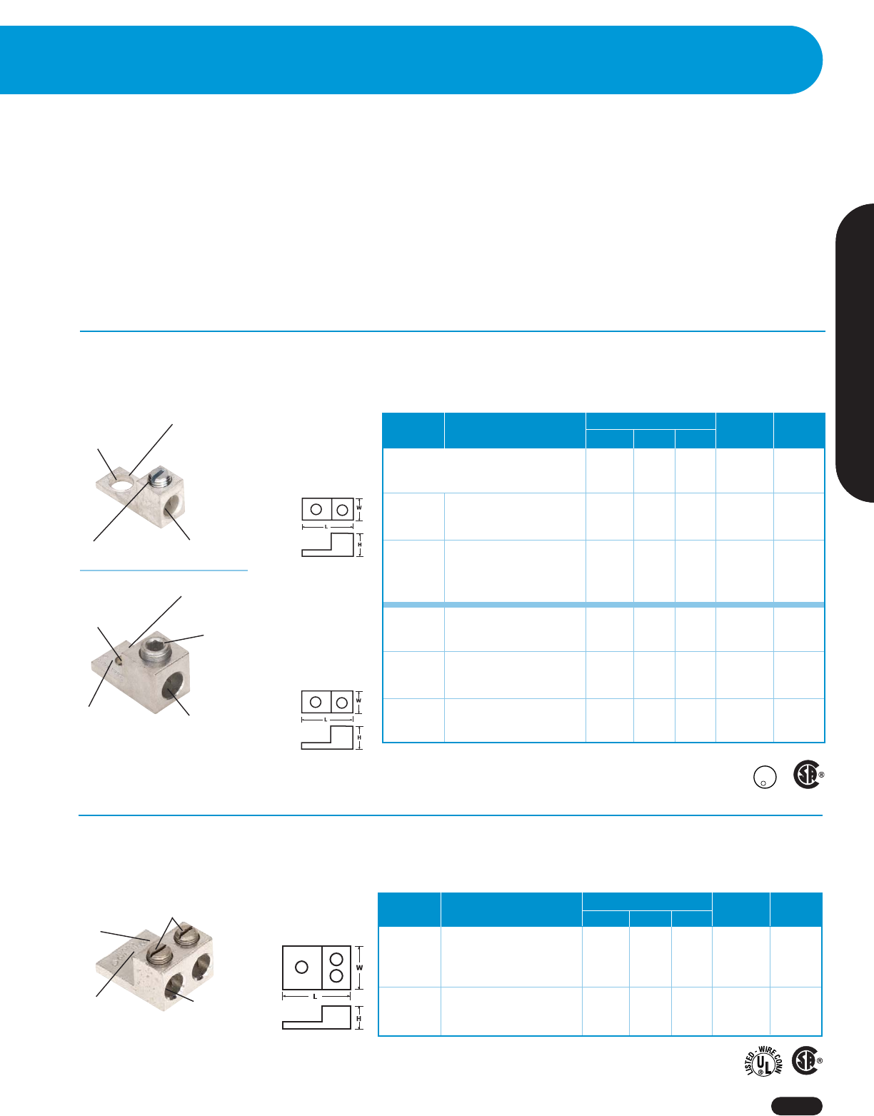
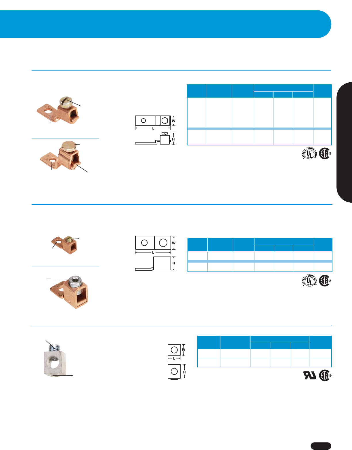
Mechanical Lugs
Dual-Rated (Al/Cu) Single-Barrel Connectors
Tang and
mounting hole
Slotted screw
Wire range and
stud size
identification
Chamfered
wire entry
Tang and
mounting hole Hex socket
screw
Wire range
and stud size
identification
Chamfered
wire entry
Functional wire stop
■
Chamfered entry for faster, more reliable connections
■
Uniform plating resists corrosion, reduces contact
resistance and provides maximum conductivity
■
UL Listed at 600V — acceptable for use through 2,000V
Powr-Connect™ Mechanical Lugs
■
Can be used through 8,000V if installed in
accordance with National Electric Code Section
310-6 (UL Green Book)
■
UL Listed to 486B for dual-rated connectors —
UL Listed to 486A for copper connectors
■
Meets ANSI C119.4 requirements
■
Electro tin-plated, high-strength aluminum alloy construction
■
UL Listed to 486B (AL9CU)
Wire Dimensions (Inches) Stud Cat.
Model Range L W H Size (In.) No.
LA-50-1 6 – 14 AWG 1-1/16 3/8 1/2 1/4 87-002
Narrow type – special mounting requirements
LA-2 2 – 14 AWG 1-5/32 1/2 9/16 1/4 87-005
LA-1/0 1/0 – 14 AWG 1-15/32 5/8 25/32 1/4 87-007
LA-1/0* 1/0 – 14 AWG 1-15/32 5/8 25/32 3/8 87-008
LA-2/0 2/0 – 14 AWG 1-15/32 5/8 25/32 1/4 87-009
LA-2/0* 2/0 – 14 AWG 1-15/32 5/8 23/32 3/5 87-010
LA-250 250 KCMIL – 6 AWG 2 1 1-1/8 5/16 87-011
LA-250* 250 KCMIL – 6 AWG 2 1 1-1/8 3/8 87-012
LA-350 350 KCMIL – 6 AWG 2-1/4 1-1/8 1-1/4 3/8 87-015
LA-350* 350 KCMIL – 6 AWG 2-1/4 1-1/8 1-1/4 1/2 87-016
LA-500 500 KCMIL – 4 AWG 2-13/16 1-1/4 1-9/16 3/8 87-017
LA-500* 500 KCMIL – 4 AWG 2-13/16 1-1/2 1-9/16 1/2 87-018
*Larger mounting hole
U
L
R
L
I
S
T
E
D
-
W
I
R
E
C
O
N
N
C
Two hex
socket screws
Dual-Rated (Al/Cu) Two-Barrel Connectors
■
Electro tin-plated, high-strength aluminum alloy construction
■
UL 486B Listed AL9CU
Chamfered
wire entry
Tang
and mounting
hole
Wire range
and stud size
identification
Wire Dimensions (Inches) Stud Cat.
Model Range LWH
Size (In.) No.
L2A1-1/0 1/0 – 14 AWG (2) 1-15/32 1-1/8 25/32 1/4 87-040
L2A1-2/0 2/0 – 14 AWG (2) 1-15/32 1-1/4 25/32 1/4 87-042
L2A1-250 250 KCMIL – 6 AWG (2) 2-9/16 1-5/8 1-3/16 3/8 87-044
L2A1-350 350 KCMIL – 6 AWG (2) 2-7/8 1-15/16 1-1/4 1/2 87-046
L2A1-600 600 KCMIL – 2 AWG (2) 3-3/16 2-13/32 1-9/16 1/2 87-048
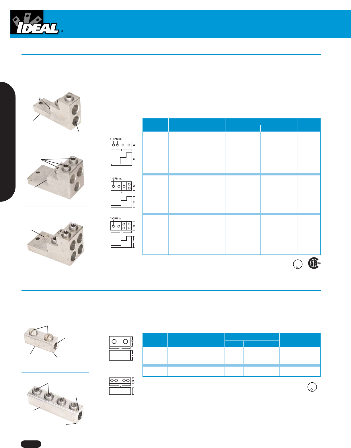
Mechanical Lugs
www.idealindustries.com 1-800-435-0705 for Customer Service
A-30
Wire Dimensions (Inches) Stud Cat.
Model Range LW H
Size (In.) No.
SR-2* 2 – 14 AWG 1-3/8 1/2 9/16 5/8 87-143
SR-1/0* 1/0 – 14 AWG 1-29/32 3/4 3/4 7/8 87-144
SR-250 250 KCMIL – 6 AWG 3-15/16 1 1-1/8 1-15/16 87-145
Dual-Rated (Al/Cu) Panel-Board Connectors
■
Electro tin-plated, high-strength aluminum alloy construction
■
UL Listed to 486B (AL9CU)
Tang and two
mounting holes
Flat
bottom ensures
good mounting
contact
Wire range
and stud size
identification
Chamfered
wire entry
Hex socket
screws
Wire
stop
*Slotted screws
Rounded bottom
facilitates tapping
Solid center
barrier
Chamfered
wire entry
Slotted screws
Solid center
barrier
Chamfered
wire entry
Hex socket screws
Rounded bottom
facilitates tapping
Dual-Rated (Al/Cu) Splicer Reducers
■
Electro tin-plated, high-strength aluminum alloy construction
■
UL Listed to 486B (AL9CU)
Wire Dimensions (Inches) Stud Cat.
Model Range L W H Size (In.) No.
PV2-600 600 KCMIL – 2 AWG 4-29/32 1-1/2 3 3/8 87-126
PV2-750 750 KCMIL – 1/0 AWG 4-29/32 1-9/16 3 3/8 87-129
PV3-600 600 KCMIL – 2 AWG 4-29/32 2-1/2 3 3/8 87-132
PV3-750 750 KCMIL – 1/0 AWG 4-29/32 2-27/32 3 3/8 87-135
PV4-600 600 KCMIL – 2 AWG 4-29/32 2-1/2 3 3/8 87-138
PV4-750 750 KCMIL – 3/0 AWG 4-29/32 2-27/32 3 3/8 87-141
U
L
R
L
I
S
T
E
D
-
W
I
R
E
C
O
N
N
C
U
L
R
L
I
S
T
E
D
-
W
I
R
E
C
O
N
N
C
Mechanical Lugs
1-800-435-0705 for Customer Service www.idealindustries.com A-31
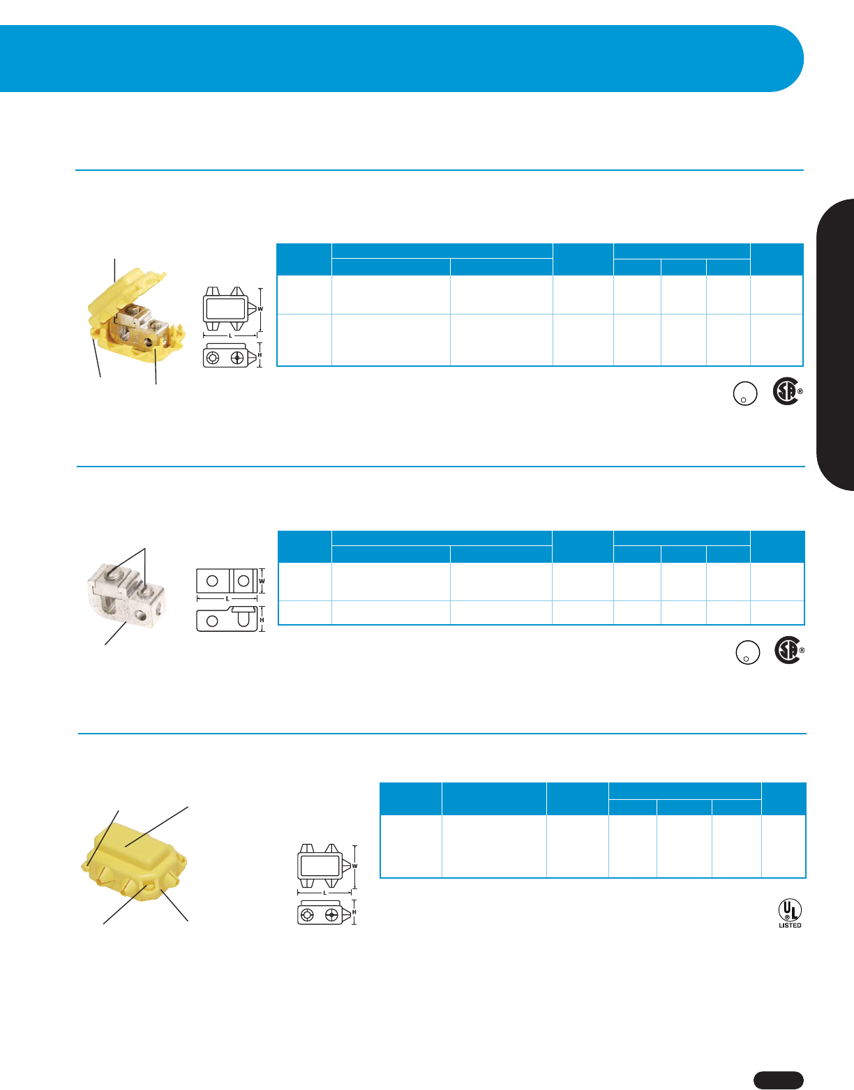
Wire Termination
Flexible
hinge Self-locking
design
Dual-Rated (Al/Cu) Parallel-Tap Connectors with Covers
■
Electro tin-plated, high-strength aluminum alloy construction
■
UL Listed to 486B (AL9CU) — 105°C, 600V max.
Wire Range Strip Dimensions (Inches) Cat.
Model Main Tap Length (In.) L W H No.
GP-2C 2 – 12 AWG 4 – 14 AWG 5/8 2-7/32 1-29/32 1-7/64 87-180
GP-1/0C 1/0 – 2 AWG 1/0 – 14 AWG 3/4 2-5/8 2-5/32 1-1/4 87-182
GP-250C 250 KCMIL – 1/0 AWG 250 KCMIL – 6 AWG 1-1/16 3-7/16 2-7/8 1-5/8 87-186
GP-350C 350 KCMIL – 4/0 AWG 350 KCMIL – 6 AWG 1-1/4 3-3/4 3-3/16 1-3/4 87-190
GP-500C 500 – 350 KCMIL 500 KCMIL – 2 AWG 1-3/8 4-3/8 3-5/16 2-3/32 87-194
Powr-Connect™ Tap Connectors
Insulating cover reduces
installation cost
U
L
R
L
I
S
T
E
D
-
W
I
R
E
C
O
N
N
C
Slotted
screws
Serrated barrel
bottom for positive
terminations
Dual-Rated (Al/Cu) Parallel-Tap Connectors without Covers
■
Electro tin-plated, high-strength aluminum alloy construction
■
UL Listed to 486B (AL9CU)
Wire Range Strip Dimensions (Inches) Cat.
Model Main Tap Length (In.) L W H No.
GP-2 2 – 12 AWG 4 – 14 AWG 5/8 1-25/64 5/8 7/8 87-150
GP-1/0 1/0 – 2 AWG 1/0 – 14 AWG 3/4 1-3/4 3/4 1 87-152
GP-250 250 KCMIL – 1/0 AWG 250 KCMIL – 6 AWG 1-1/16 2-9/32 1-1/16 1-5/16 87-156
U
L
R
L
I
S
T
E
D
-
W
I
R
E
C
O
N
N
C
Self-locking
design
■
600V maximum
■
105°C maximum temperature
Thermoplastic
elastomer material
Range
identification
with color code
Flexible hinge
Insulating Covers for Parallel-Tap Connectors
For Use Dimensions (Inches) Cat.
Model With: Color LWH
No.
GIC-2 87-150 Yellow 2-7/32 1-29/32 1-7/64 87-370
GIC-1/0 87-152 Gray 2-5/8 2-5/32 1-1/4 87-372
GIC-250 87-150 Red 3-7/16 2-7/8 1-5/8 87-374
Rod Wire Dimensions (Inches) Cat.
Model Dia. (In.) Range HWL No.
WB58 5/8 1/0 – 8 2-1/8 7/8 1 87-958
Heavy-Duty Clamps
Pipe Wire Dimensions (Inches) Cat.
Model Size (In.) Range HWL No.
J 1/2 – 1 2 – 10 2-3/4 2-3/8 3/4 87-563
J2 1-1/4 – 2 2 – 10 3-3/4 3-5/8 7/8 87-564
High-Strength Ground Clamps
Mechanical Lugs
www.idealindustries.com 1-800-435-0705 for Customer Service
A-32
■
Designed to maintain proper contact and alignment between
ground and wire rod
■
Brass or plated screws for corrosion resistance
■
High-strength copper alloy construction
Powr-Connect™ Grounding Connectors
Flexible plastisol
insulating cover
Chamfered
wire entry Aluminum screws
■
High-strength copper alloy
construction (nut, bolt and
body)
■
UL 486A Listed
■
UL 486A Listed (Lug only)
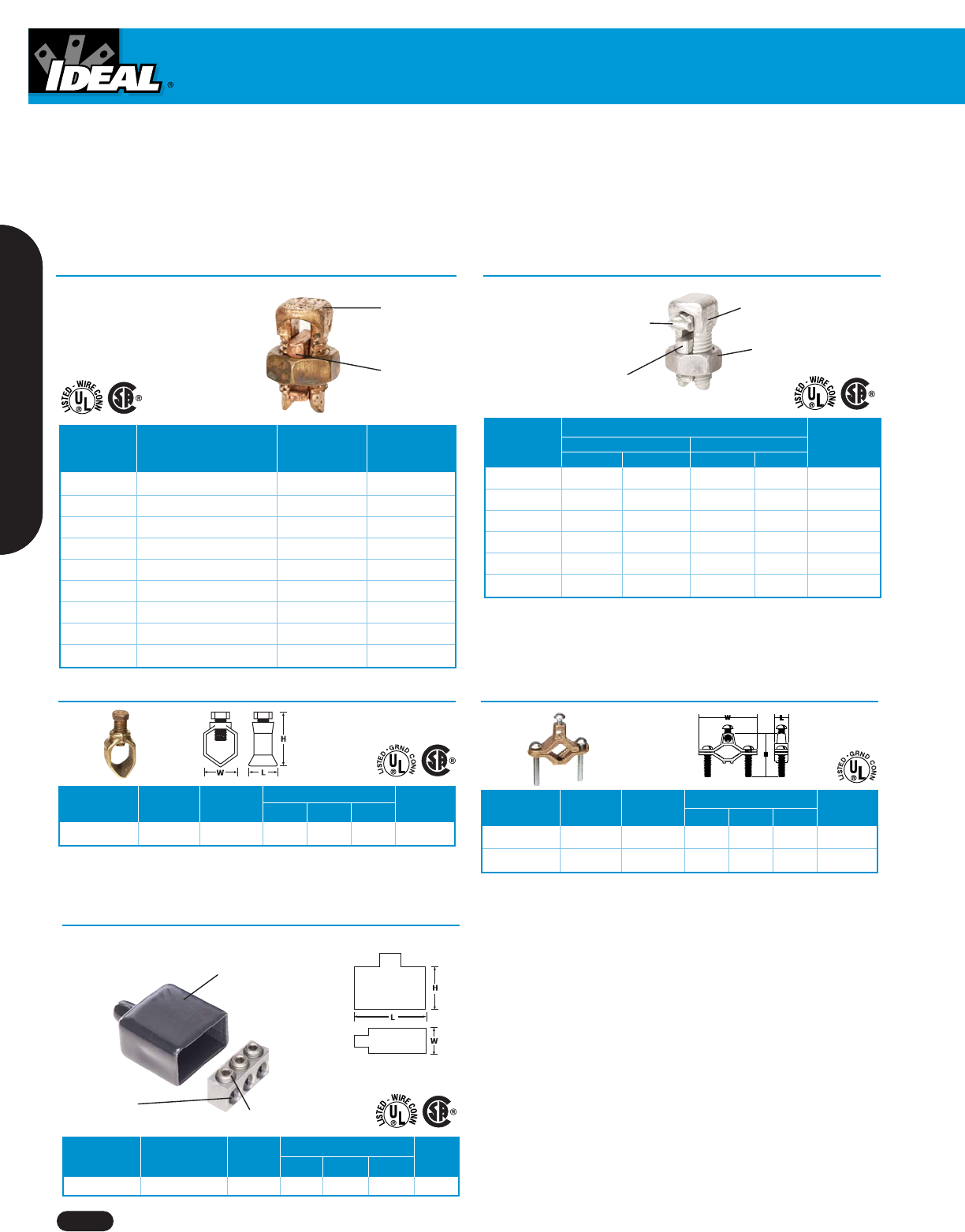
Type K Split Bolts for Copper Connections
Dual-Rated (Al/Cu) Street-Light
Connector Kit with Cover
Wire No. of Dimensions (Inches) Cat.
Model Range Cond. L W H No.
SLK-1/0 1/0 – 14 AWG 3 2 1-3/16 2-3/16 88-100
■
UL 486B Listed AL9CU
Wire Range
Run Tap
Model Max. Min. Max. Min. Cat. No.
AS-6 6 str. 10 sol. 6 str. 10 sol. 87-681
AS-4 4 str. 8 sol. 4 str. 10 sol. 87-682
AS-2 2 str. 6 sol. 2 str. 8 str. 87-683
AS-1/0 1/0 str. 2 compact 1/0 str. 8 sol. 87-685
AS-2/0 2/0 str. 2 compact 2/0 str. 8 str. 87-686
AS-4/0 4/0 str. 2 compact 4/0 str. 6 str. 87-687
Dual-Rated (Al/Cu) Type AS Split Bolts
Spacer provides serration
to retard corrosion
Aluminum, tin-plated
to inhibit oxide formation
Anti-galling
threaded components
"Tooth" configuration
provides low contact
resistance
Wire range
Bottom pad
attached to
nut and guide
assembly
Range for Min. Tap
Equal Run with Max.
Model & Tap Run Cat. No.
K-10 10 str. – 12 str. 16 str. 87-650
K-8 8 str. – 10 str. 14 str. 87-651
K-6 6 sol. – 8 str. 14 str. 87-652
K-4 4 sol. – 8 str. 14 str. 87-653
K-3 2 sol. – 6 str. 14 str 87-654
K-2 2 str. – 6 str. 14 str. 87-655
K-1/0 1/0 str. – 4 str. 14 str. 87-656
K-2/0 2/0 str. – 2 str. 14 str. 87-657
K-3/0 3/0 str. – 1 str. 8 sol. 87-658
Mechanical Lugs
1-800-435-0705 for Customer Service www.idealindustries.com A-33
Wire Termination
Dual-Rated (AI/Cu) Collar Connectors
10-32 tapped mounting hole
with 0.229 in. square boss
for bottom mounting to
electrical devices or bus bars
Wire Dimensions (Inches) Cat.
Model Range LWHNo.
CA-60** 2 – 14 AWG 9/16 15/32 15/32 87-583
CA-110* 1/0 – 14 AWG 19/32 17/32 5/8 87-585
*Successfully tested to AL9CU
**Successfully tested to AL7CU
Slotted wire
screw
Single-Hole Solderless Lugs for Copper Conductors
■
Electrolytic copper construction
■
UL 486A Listed
Wire Stud Dimensions (Inches) Cat.
Model Range Size (In.) L W H No.
FT-65 6 – 14 AWG 3/16 1 3/8 3/4 87-736
FT-90 1/0 – 14 AWG 1/4 1-17/64 5/8 1 87-738
Wire range
and stud size
identification
Floating
offset tang
Slotted
screw
Hex head
bolt
Barrel collar
ensures positive contact
Tang
staked to
collar
Hex
socket
screw
Single-Hole Solderless Lugs for Copper Conductors (Offset)
■
Electrolytic copper construction
■
UL 486A listed
Powr-ConnectTM Mechanical Solderless Lugs
Slotted
screw
Wire Stud Dimensions (Inches) Cat.
Model Range Size (In.) L W H No.
CF-25* 10 – 14 AWG #8 1 5/16 3/8 87-700
CF-35 6 – 14 AWG 3/16 1-3/32 3/8 3/4 87-701
CF-70 4 – 14 AWG 1/4 1-5/16 1/2 13/16 87-702
CF-90 2 – 8 AWG 1/4 1-15/32 1/2 1 87-703
CF-125 1/0 – 2 AWG 1/4 1-13/16 5/8 1-11/32 87-704
CF-225 4/0 – 2 AWG 5/16 2-5/8 1 1-13/16 87-706
*Not CSA Certified

Notes
www.idealindustries.com 1-800-435-0705 for Customer Service
A-34
Notes:
_________________________________________________________________________________________________________________________________
_________________________________________________________________________________________________________________________________
_________________________________________________________________________________________________________________________________
_________________________________________________________________________________________________________________________________
_________________________________________________________________________________________________________________________________
_________________________________________________________________________________________________________________________________
_________________________________________________________________________________________________________________________________
_________________________________________________________________________________________________________________________________
_________________________________________________________________________________________________________________________________
_________________________________________________________________________________________________________________________________
_________________________________________________________________________________________________________________________________
_________________________________________________________________________________________________________________________________
_________________________________________________________________________________________________________________________________
_________________________________________________________________________________________________________________________________
_________________________________________________________________________________________________________________________________
_________________________________________________________________________________________________________________________________
_________________________________________________________________________________________________________________________________
_________________________________________________________________________________________________________________________________
_________________________________________________________________________________________________________________________________
_________________________________________________________________________________________________________________________________
_________________________________________________________________________________________________________________________________
_________________________________________________________________________________________________________________________________
_________________________________________________________________________________________________________________________________
_________________________________________________________________________________________________________________________________
_________________________________________________________________________________________________________________________________
_________________________________________________________________________________________________________________________________
_________________________________________________________________________________________________________________________________
_________________________________________________________________________________________________________________________________
_________________________________________________________________________________________________________________________________
_________________________________________________________________________________________________________________________________
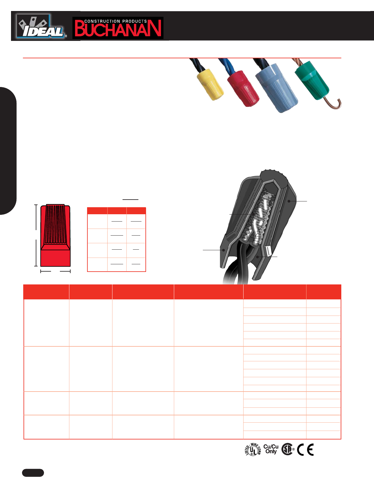
Our wedge-edge expanding
spring is specially designed for faster
pull-up and quick connections.
It also accommodates a wide
range of wire gauges.
The B2 B-CAP®Wire Connector is
the universal connector that
accepts the widest range of wire
combinations. Plus, the Classic
Fin™ ergonomic design fits easily
in tight electrical boxes.
(2) #18 stranded
(1) #14 solid
(1) #18 stranded
(2) #14 solid
(1) #14 solid
(2) #12 stranded
(2) #10 stranded
(3) #12 solid
(2) #14 solid
(5) #12 solid
The Buchanan C-24 Crimp Tool
has an iron-clad reputation that’s
up to every job, every time.
A patented four-way crimp ensures
reliable connections, while the
spring-loaded, cam-actuated design
fits a wide range of connectors.
The comprehensive line of
Buchanan sectional
terminal blocks offers a
wide range of block
configurations, mounting
options and contact styles
accommodating wire sizes
from 30 AWG to 250 MCM.
Twist-on Wire Connectors
A-35
Wire Termination
Twist-on Wire Connectors
www.idealindustries.com 1-800-435-0705 for Customer Service
A-36
■
Three color-coded models cover a full range of wire
sizes from 22 AWG through 6 AWG
■
Classic FinTM design provides secure grip for extra
leverage on maximum wire combinations
■
Live-action spring expands to accept wire shape and size – no
pre-twisting required
■
Square-wire spring threads directly onto conductors for fast,
secure connections
■
Deep skirt protects against flash-over and turned-back strands
for maximum dielectric protection
■
Easily removed for repeat usage on same size or
larger wire combinations
■
Tough, UL 94V-2 flame-retardant shell rated at 105oC (221oF)
■
Green-B®designed for making ground connections and
bonding non-metallic sheathed cable
■
UL 486C Listed (Green-B®UL 467 Listed) and CSA 22.2 #188
Certified; comply with Federal Specification -S-610E
*1,000V maximum in fixtures and signs
Wire Combination Wire Combination
Model Color Range (Inches) Range (mm) Quantity / Package Cat. No.
100 / Box B1-1
250 / Jar B1-250JR
500 / Jar B1-500JR
2,500 / Bucket (5 bags, 500 ea.) B1-25
10,000 / Keg (20 bags, 500 ea.) B1-B
Barrel of 25,000 B1-SK
100 / Box B2-1
350 / Jar B2-350JR
500 / Jar B2-500JR
2,500 / Bucket (5 bags, 500 ea.) B2-25
10,000 / Keg (20 bags, 500 ea.) B2-B
Barrel of 25,000 B2-SK
50 / Box B4-1
1,000 / Bucket (4 bags, 250 ea.) B4-25
2,500 / Keg (10 bags, 250 ea.) B4-B
14 to 10 AWG 2,5mm2to 6,0mm250 / Box BGR-1
Min. 2 #14 Min. 2-2,5mm22,500 / Bucket (10 bags, 250 ea.) BGR-25
Max. 5 #12 Max. 5-4,0mm25,000 / Keg (20 bags, 250 ea.) BGR-B
EN 60-998-2-4
Contoured Classic
Fin™
Live-action, square-
wire spring
Tough, durable
thermoplastic
shell Deep skirt, wide
throat
()
mm
A
B
Model A B
31/32 15/32
24.5 12
1-5/32 9/16
29.5 14
1-1/2 3/4
38 19
1-5/32 9/16
29.5 14
Dimensions Inches
B1
B2
B4
BGR
B1
B2
B4
BGR
Yellow
600V*
22 to 10 AWG
Min. 2 #18
Max. 3 #12
600V*
,34mm2to 6,0mm2
Min. 2-,75mm2
Max. 3-4,0mm2
600V*
22 to 8 AWG
Min. 2 #18
Max. 5 #12
600V*
,34mm2to 10,0mm2
Min. 2-,75mm2
Max. 5-4,0mm2
600V*
14 to 6 AWG
Min. 2 #12
Max. 2 #6
600V*
2,5mm2to 16,0mm2
Min. 2-4,0mm2
Max. 2-16,0mm2
Red
Blue-Gray
Green
B-CAP®Wire Connectors
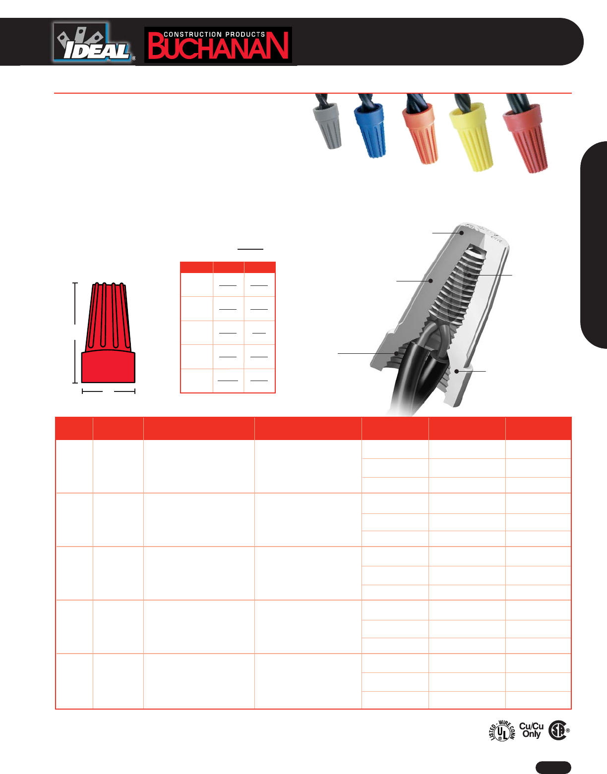
Fixed square-
wire spring
Positive grip
design
Flame-retardant,
thermoplastic shell
Threaded entry
Deep skirt, wide
throat
■
Five color-coded models cover common construction wire
ranges
■
Ribbed cap provides positive grip for fast, easy installation
■
Fixed, square-wire spring threads itself creating a secure
pressure grip
■
Deep, wide-throated skirt protects against flash-over and
turned-back strands for maximum dielectric protection
■
Tough, UL 94V-2 flame-retardant shell rated at 105oC (221oF)
■
UL 486C Listed and CSA 22.2 #188 Certified
A
B
Model A B
37/64 21/64
15 8
45/64 25/64
18 10
55/64 7/16
22 11
61/64 35/64
24 14
1-1/16 21/32
27 17
()
mm
Dimensions Inches
WT1
WT2
WT3
WT4
WT6
*1,000V maximum in fixtures and signs
**Includes 5 each of WT1, WT2, WT3, WT4 and WT6 WireTwist™ Wire Connectors
Twist-on Wire Connectors
1-800-435-0705 for Customer Service www.idealindustries.com A-37
Wire Termination
WireTwist™ Wire Connectors
Wire Combination Wire Combination BUCHANAN IDEAL
Model Color Range (Inches) Range (mm) Quantity / Package Cat. No. Cat. No.
300V 300V
22 to 14 AWG ,34mm2to 2,5mm2
100 / Box WT1-1 30-WT1C
WT1 Gray Min. 3 #22 Min. 3-,34mm2500 / Bag WT1-B 30-WT1B
Max. 2 #16 Max. 2-1,5mm2
50,000 / Barrel — 30-891
300V 300V
22 to 14 AWG ,34mm2to 2,5mm2
100 / Box WT2-1 30-WT2C
WT2 Blue Min. 3 #20 Min. 3-,50mm2500 / Bag WT2-B 30-WT2B
Max. 3 #16 Max. 3-1,5mm2
50,000 / Barrel — 30-892
600V* 600V*
22 to 14 AWG ,34mm2to 2,5mm2
100 / Box WT3-1 30-WT3C
WT3 Orange Min. 2 #18 Min. 2-,75mm2500 / Bag WT3-B 30-WT3B
Max. 2 #14 Max. 2-2,5mm2
50,000 / Barrel — 30-893
600V* 600V*
22 to 10 AWG ,75mm2to 6,0mm2
100 / Box WT4-1 30-WT4C
WT4 Yellow Min. 3 #20 Min. 3-,50mm2500 / Bag WT4-B 30-WT4B
Max. 2 #12 Max. 2-4,0mm2
30,000 / Barrel — 30-894
600V* 600V*
20 to 8 AWG ,50mm2to 10,0mm2
100 / Box WT6-1 30-WT6C
WT6 Red Min. 2 #14 Min. 2-2,5mm2250 / Bag WT6-B 30-WT6B
Max. 4 #12 Max. 4-4,0mm2
20,000 / Barrel — 30-896
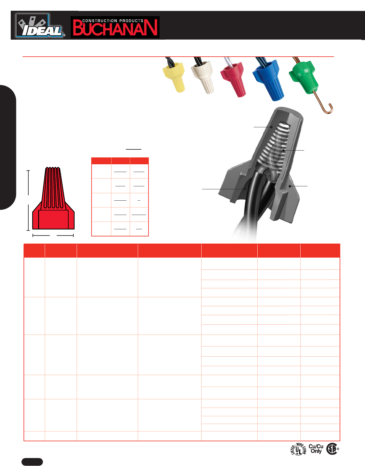
Twist-on WIre Connectors
www.idealindustries.com 1-800-435-0705 for Customer Service
A-38
■
Four color-coded models cover common construction
wire ranges; green model designed for ground connections
■
Unique contoured wing design acts as built-in wrench
providing maximum torque with minimum effort
■
Fixed, square-wire spring threads itself creating secure pressure
grip
■
Deep, wide-throated skirt protects against flash-over and turned-
back strands for maximum dielectric protection
■
Tough, UL 94V-2 flame retardant shell rated at 105°C (221°F)
■
UL 486C Listed (WGR UL 467 Listed) and CSA C22.2
#188 Certified
Fixed square-
wire spring
Tough,
flame-retardant shell
Built-in
contoured wings
Deep, wide
skirt
A
B
Model A B
1-1/32 23/32
26 18
1-1/4 29/32
32 23
1-5/16 1
33 25
1-9/16 1-15/64
40 31
1-5/32 7/8
29.5 22
Wire Combination Wire Combination BUCHANAN IDEAL
Model Color Range (Inches) Range (mm) Quantity / Package Cat. No. Cat. No.
600V* 600V* 100 / Box WT51-1 30-WT51C
WT51 Yellow 18 to 10 AWG ,75mm2to 6,0mm2
500 / Bag WT51-B 30-WT51B
Min. 2 #18 Min. 2-,75mm2
500 / Jar WT51-500JR 30-WT51J
Max. 3 #12 Max. 3-4,0mm2
25,000 / Barrel WT51-SK 30-886
600V* 600V*
100 / Box WT41-1 30-WT41C
WT41 Tan 22 to 10 AWG ,34mm2to 6,0mm2500 / Bag WT41-B 30-WT41B
Min. 2 #20 Min. 2-0,5mm2500 / Jar WT41-500JR 30-WT41J
Max. 3 #10 Solid Max. 3-6,0mm2
25,000 / Barrel WT41-SK 30-885
600V* 600V*
18 to 10 AWG ,75mm2to 6,0mm2
100 / Box WT52-1 30-WT52C
WT52 Red Min. 2 #14 Min. 2-2,5mm2
500 / Bag WT52-B 30-WT52B
Max. 5 #12 Max. 5-4,0mm2500 / Jar WT52-500JR 30-WT52J
25,000 / Barrel WT52-SK 30-887
600V* 600V*
14 to 6 AWG 2,5mm2to 16,0mm250 / Box WT54-1 30-WT54C
WT54 Blue Min. 3 #12 Min. 3-4,0mm2
100 / Bag WT54-B 30-WT54B
Max. 2 #6 Max. 2-16,0mm2
14 to 10 AWG 2,5mm2to 6,0mm2
50 / Box WGR-1 30-WGRC
WGR Green Min. 2 #14 Min. 2-2,5mm2250 / Bag WGR-B 30-WGRB
Max. 5 #12 Max. 5-4,0mm2500 / Jar WGR-500JR 30-WGRJ
25,000 / Barrel WGR-SK 30-890
WT5 Assortment** See WT51 & WT52 above See WT51 & WT52 above (75 Yellow, 75 Red)/Jar WT5152JR —
()
mm
Dimensions Inches
WT51
WT52
WT53
WT54
WGR
*1,000V maximum in fixtures and signs
**Includes 75 each of WT51 and WT52 WingTwist™ Wire Connectors
WingTwist™ Wire Connectors
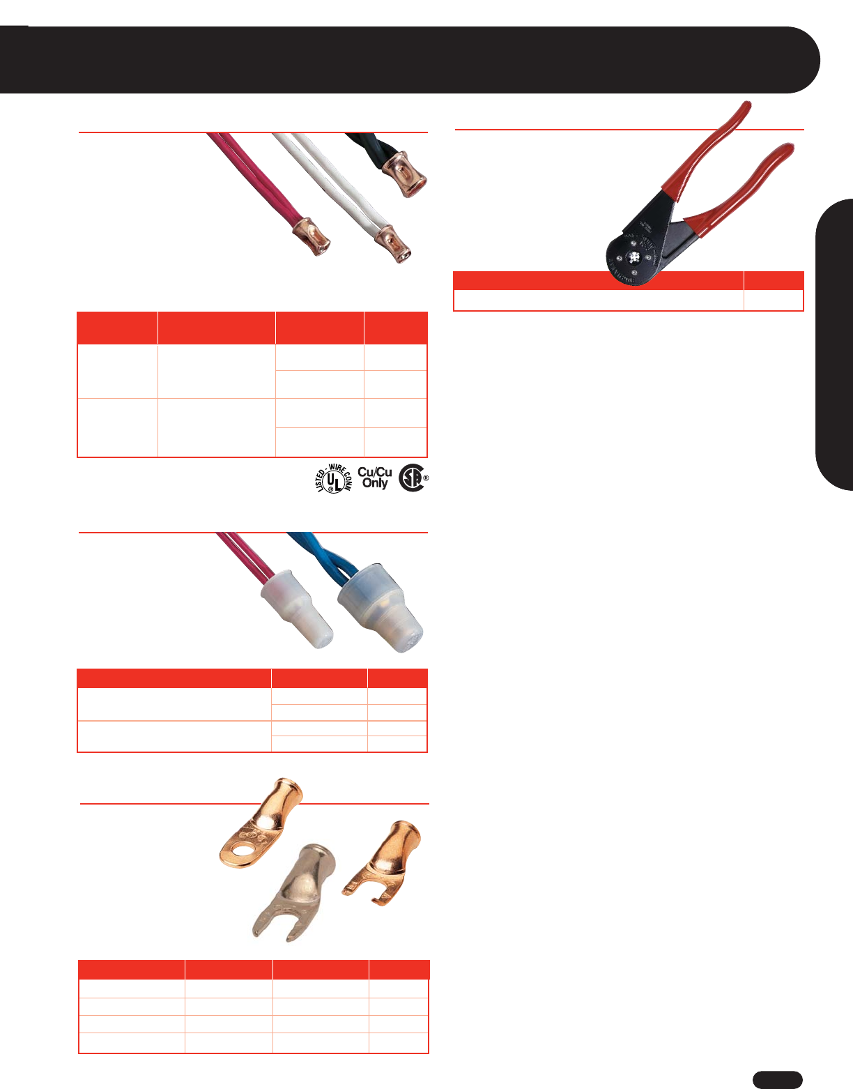
Connectors/Crimp Tool
1-800-435-0705 for Customer Service www.idealindustries.com A-39
Splice Cap Insulators
■
Designed for making
fast, permanent, pressure-
type connections
■
Solid copper sleeves require
less crimping pressure
■
Resist corrosion in harsh environments
■
Tin-plated steel sleeves also available
■
UL 486C Listed and CSA C22.2 #188 Certified; comply with
Federal Specification W-S-61D
■
Convenient, safe and
fast installation
■
Snap-on nylon construction
■
Rated at 105°C (221°F) –
600V (1,000V maximum in fixtures
and signs)
Four-Way Crimp Tool
■
Patented design ensures even
compression and reliable
connectors
■
Spring-loaded, cam-actuated
plungers
■
Fingertip adjustment for
different connector sizes
*1,000V maximum in fixtures and signs
For Connector Model Quantity / Package Cat. No.
2006S & 2008S 100 / Box 2007
1,000 / Bag 2007B
2011S 50 / Box 2014
500 / Bag 2014B
Description Cat. No.
Four-Way Crimp Tool C-24
Wire Combination
Description Range (Inches) Quantity / Package Cat. No.
600V*
Copper Crimp 18 to 10 AWG 100 / Box 2006S
Connector Min. 2 #18 1,000 / Bag 2006SB
Max. 4 #12
600V*
Copper Crimp 14 to 4 AWG 50 / Box 2011S
Connector Min. 2 #10 500 / Bag 2011SB
Max. 2 #6
Termend®Lugs
■
Convenient, safe and
fast installation
■
One size fits 16 AWG
through 8 AWG solid or
stranded wire
■
Available in ring, spade
and locking spade
Wire Termination
Splice Cap Crimp Connectors
Tongue Type Stud Size Quantity / Package Cat. No.
Ring 10 50 / Box 16-8-10
Ring 1/4 50 / Box 16-8-1/4
Spade 10 50 / Box 16-8-10S
Locking Spade 10 50 / Box 16-8-10L
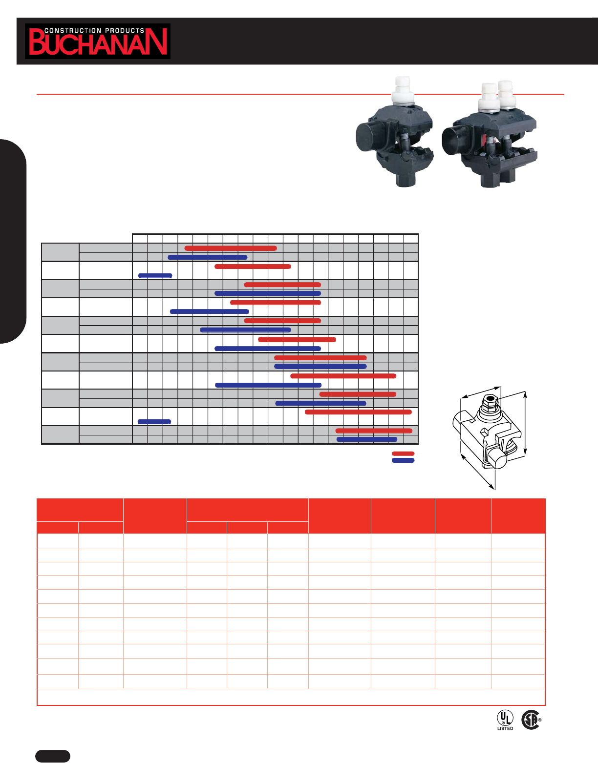
www.idealindustries.com 1-800-435-0705 for Customer Service
A-40
Tap Connectors
■
Eliminates split bolts and tape
■
Easy two-minute installation requires only box/socket wrench
■
Installs on energized systems eliminating costly power shutdowns
■
Self-sealing, grease-filled end-cap ensures safe, weather-tight connection
■
Unique turbo spacer keeps connector wide open for quick and easy installation
■
Torque-regulating nut breaks off when proper tension is reached
■
Full-line is 600V dual-rated,194˚F (90˚C)
A
B
C
Conductor
Range Voltage Dimensions (Inches) Socket Torque No. of
Run Tap Rating A B C Size (Inches) (In. Lbs.) Bolts Cat. No.
1/0-8 2-101600V 3.1 1.8 2.2 1/2 80 1 BTC1/0-10
2/0-4 10-142600V 3.1 1.8 2.2 1/2 80 1 BTC2/0-14
4/0-2 4/0-4 600V 4.4 2.4 3.2 1/2 160 1 BTC4/0-4
4/0-3 2-103600V 3.1 1.8 2.2 1/2 125 1 BTC4/0-10
4/0-2 2/0-6 600V 3.5 2.2 2.5 1/2 160 1 BTC4/0-6
250-1 4/0-4 600V 3.5 2.2 2.5 1/2 160 1 BTC250-4
350-1/0 350-1/0 600V 4.5 3 3.9 5/8 330 2 BTC350-1/0
500-2/0 4/0-4 600V 4.5 3 3.9 5/8 330 2 BTC500-4
500-4/0 350-1/0 600V 4.5 3 3.9 5/8 330 2 BTC500-1/0
750-3/0 10-144600V 3.7 2.5 2.2 1/2 80 1 BTC500-14
750-250 500-250 600V 4.7 3.4 4.75 5/8 330 2 BTC750-250
Assortment* BTCA-2
* Includes BTC 1/0-10, BTC 2/0-14, BTC 4/0-2, BTC 4/0-10, BTC 4/0-6, BTC 250-4, BTC 350-1/0, BTC 500-4 & BTC 500-1/0
1Tap #2 - #10 Cu solid/stranded; #2 - #10 Al stranded 3Tap #2 - #10 Cu solid/stranded; #2 - #8 Al stranded
2Tap #10 - #14 Cu solid/stranded; #10 - #14 Al stranded 4Tap #10 - #14 Cu solid/stranded; #10 - #12 Al stranded
B-Tap® Wire Range Chart
B-TAP®Insulation-Piercing Tap Connectors
Wire Size
Cat. No. 14 12 10 8643211/02/03/04/0250300350400500750
Main: 1/0 - 8
Tap: 2 - 10
Main: 2/0 - 4
Tap: 10 - 14
Main: 4/0 - 2
Tap: 4/0 - 4
Main: 4/0 - 3
Tap: 2 - 10
Main: 4/0 - 2
Tap: 2/0 - 6
Main: 250 - 1
Tap: 4/0 - 4
Main: 350 - 1/0
Tap: 350 - 1/0
Main: 500 - 2/0
Tap: 4/0 - 4
Main: 500 - 4/0
Tap: 350 - 1/0
Main: 750 - 3/0
Tap: 10 - 14
Main: 750 - 250
Tap: 500 - 250
Main
Tap
BTC500-1/0
BTC500-14
BTC750-250
BTC4/0-6
BTC250-4
BTC350-1/0
BTC500-4
BTC1/0-10
BTC2/0-14
BTC4/0-4
BTC4/0-10
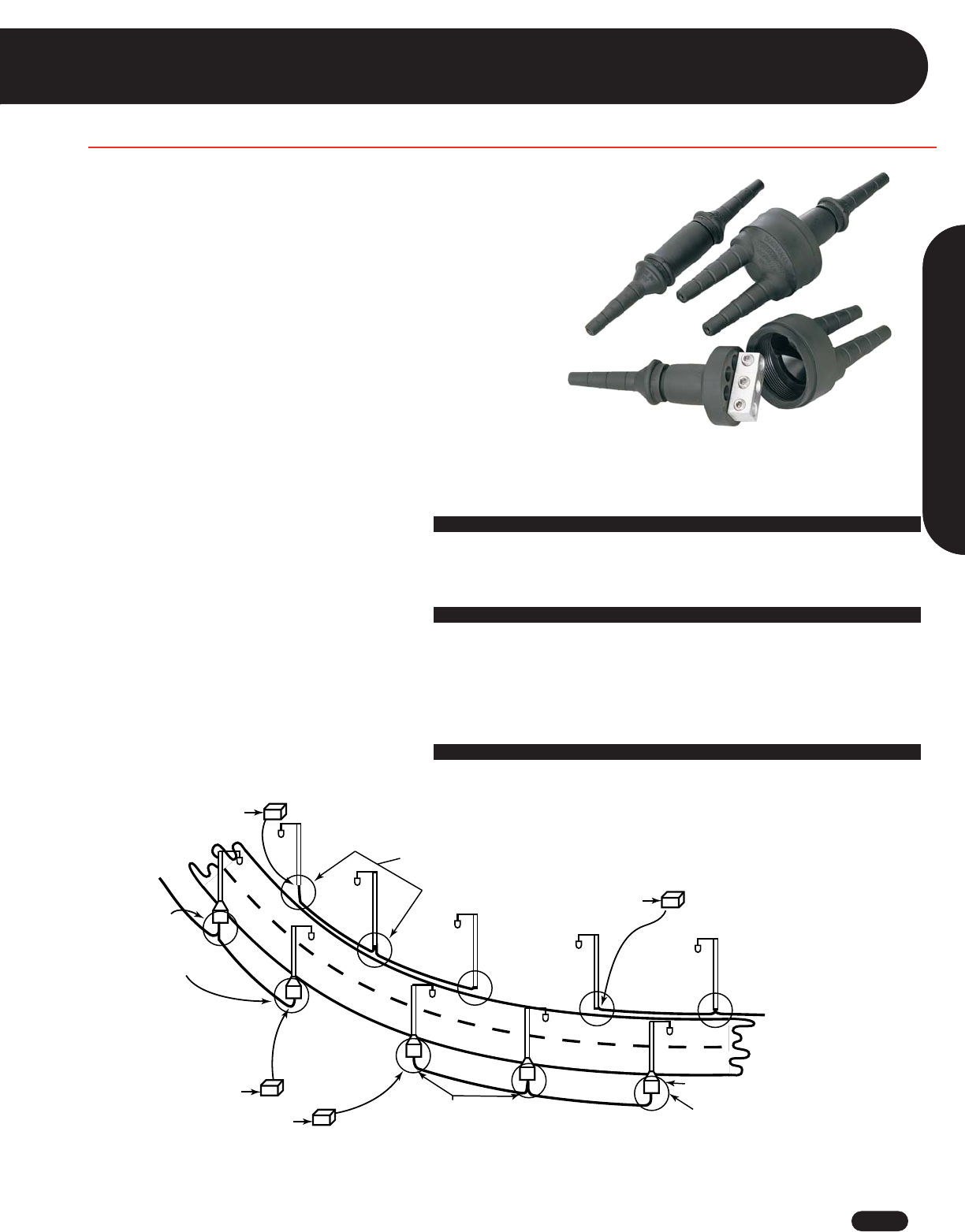
1-800-435-0705 for Customer Service www.idealindustries.com A-41
Streetlight Kits
Wire Termination
Waterproof Breakaway Steetlight Connector & Splice Insulating Kits
Transformer
Transformer
82 or 82S for Phase (fuse)
and
83 or 83S for Neutral (common)
Two 82 or 82S for
Phase (fuse)
or
D65 for Phases (fuse)
and two 84 or 84S
for Taps
End of run
65 Kit for Phase (fuse) and
20 Kit for Neutral (common)
or D65PN Kit
Two 65 or one
D65 to fuse
Tap unnecessary
Two 65 or one D65
to Fuse (Phases)
84 or 84S for Taps
D65PN for Phase
and Neutral
84 or 84S for Tap
Phase
to Phase
Transformer Phase
to Neutral
Phase to Phase
Transformer Phase
to Neutral
End of Run
■
Safe and easy installation in five minutes or less
■
No special equipment necessary – requires only a knife, wire stripper and crimp
tool
■
Unique wire entry port, cut-off design accommodates industry’s widest range of
insulation diameters
■
Fewer parts than competitive brands for better waterproof protection
■
Built-in break-away design eliminates de-energization of complete circuits
■
Safely separates upon impact without breaking wires – eliminates potential
danger and electrical shock (breakaway models)
■
Unique 2-in-1 one-piece crimp barrel accommodates industry’s widest range
of conductors (breakaway models)
■
Spring-loaded contacts compensate for thermal expansion to maintain integrity
of waterproof connection (breakaway models)
For Poles with Transformer Bases, Standard Bases and Junction Boxes
Configurations Comments
• D65 dual in-line for phases and two 84 or 84S kits for taps Recommended
• Two 82 or 82S Y-Tap Kits for phases and taps Cost-effective
• Two BTS4 B-CAP®Twist & Seal Wire Connectors Non-breakaway, small gauge (8 AWG and above).
See Wire Connector section.
Configurations Comments
• D65PN dual in-line for phase and neutral and Recommended configuration
Two 84 or 84S kits for tap
• One 82 or 82S Y-Tap Kit for phase and tap and Cost-effective
one 83 or 83S Y-Tap Kit for neutral and tap
• Two BTS4 B-CAP® Twist and Seal Wire Connectors Non-breakaway, small gauge (8 AWG and above).
See Wire Connector section.
For Lights Mounted to Utility Poles, etc...
• Two B-Tap® Insulation Piercing Connectors for Recommended configuration, see B-Tap®
phase and/or tap (for insulated conductors only) Insulation Piercing Connectors in this catalog.
Underground Feed Phase to Neutral
Underground Feed Phase to Phase
Application
Guide
Examples of Several
Kit Configurations
Overhead Feed
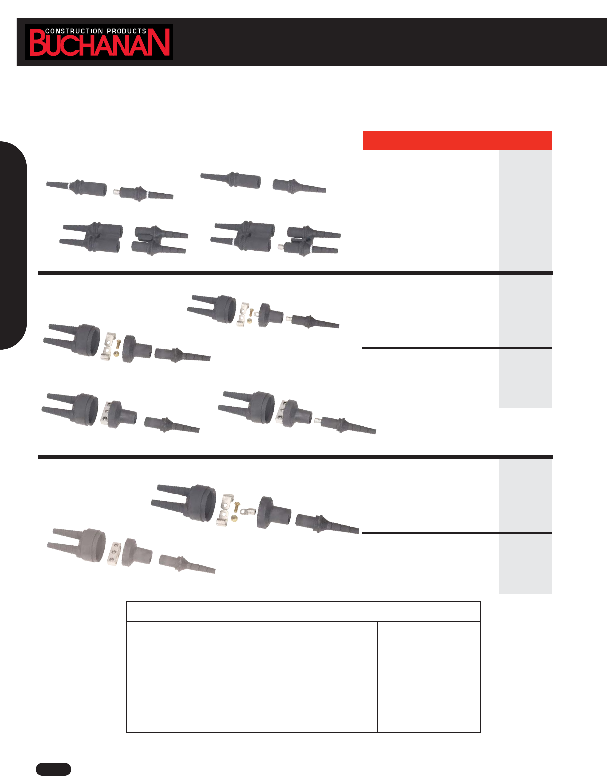
www.idealindustries.com 1-800-435-0705 for Customer Service
A-42
Streetlight Kits
Breakaway In-Line Kits
Application Electrical Ordering Code
Rating
Crimp Splice 150 Amp 84 –
Tap & Run 600 Volt
Set Screw Splice 70 Amp 84S –
Tap & Run 600 Volt
Application Electrical Ordering Code
Rating
In-Line Neutral 30 Amp 20 –
Non-Fused Breakaway 600 Volt
In-Line Phase 1/10-30 Amp 65 –
Fused Breakaway 600 Volt
Dual In-Line Phase 1/10-30 Amp D65 –
Fused Breakaway 600 Volt
Dual In-Line Phase & 1/10-30 Amp Phase D65PN –
Neutral Fused 30 Amp Neutral
Breakaway 600 Volt
Application Electrical Ordering Code
Rating
Crimped Phase 1/10-30 Amp 82 –
Fused Tap & Run 600 Volt
Crimp Neutral 125 Amp Line 83 –
Non-Fused Tap & Run 30 Amp Load
600 Volt
Set Screw Phase 1/10-30 Amp 82S –
Fused Tap & Run 600 Volt
Set Screw Neutral 70 Amp Line 83S –
Non-Fused Tap & Run 30 Amp Load
600 Volt
Breakaway Y-Tap Kits
Y-Splice Kits
MODEL
Ordering Information
Use the following chart and table to determine the correct part number by choosing model, line side, and
load side ordering codes from the shaded columns. See example below, right (Page A-45).
82TM Kit
83TM Kit
82STM Kit 83STM Kit
84TM Kit
84STM Kit
65TM Kit
D65TM Kit D65PNTM Kit
20TM Kit
Excerpts of the 1996 NEC Tables 5 & 5A
Dimensions of Insulated Conductors and Fixture Wires
Approx. Diameter in Inches for Insulation Types: Approx. Diameter in Inches for
Size RHH, THHW THHN XHH
Compact AL with Insulation Types:
(AWG) RH RHW-2,RHW TW THW,THW-2 THWN,THWN-2 XHHW,XHHW-2 THW,THHW THHN XHHW
14
12
10
8
6
4
3
2
1
1/0
0.163
0.182
0.236
0.326
0.364
0.412
0.440
0.472
0.582
0.622
0.193
0.212
0.236
0.326
0.364
0.412
0.440
0.472
0.582
0.622
0.133
0.152
0.176
0.236
0.304
0.352
0.380
0.412
0.492
0.532
0.163
0.182
0.206
0.266
0.304
0.352
0.380
0.412
0.492
0.532
0.111
0.130
0.164
0.216
0.254
0.324
0.352
0.384
0.446
0.486
0.133
0.152
0.176
0.236
0.274
0.322
0.350
0.382
0.442
0.482
–
–
–
0.255
0.290
0.335
–
0.390
0.465
0.500
–
–
–
–
0.240
0.305
–
0.360
0.415
0.450
–
–
–
0.224
0.260
0.305
–
0.360
0.415
0.450
National Electric Code
®,Copyright © 1996, National Fire Protection Association, Quincy MA 02269
Line side
Double Ridge
Line side
housing (receptacle)
Line side
housing (receptacle)
Line side
housing (receptacle)
Line side
housing (receptacle)
Line side
housing (receptacle) Y Insert
Assembly
Y Insert
Assembly
Y Insert
Assembly
Pin
Line side
housing (receptacle)
Crimp-on
flag
terminals
Crimp-on
flag
terminals
Crimp-on
ring
terminals
Crimp-on
flag
terminals
Nut
and
Bolt
Nut
and
Bolt
Nut
and
Bolt
Line side
insert Load side
housing
(Plug)
Load side
housing
(Plug)
Load side
housing
(Plug)
Load side
housing
(Plug)
Load side
housing
(Plug)
Line Side Insert
Terminal
Block
Line side
insert Load side
housing
(Plug)
Line side
Double Ridge
Line side
Double Ridge
Line side
Double Ridge
Fuse
(not included)
White Band
White Band
Pin Contact
Load side
Single Ridge
Load side
Single Ridge
Load side
Single Ridge
Fuse
(not included)
Fuse
(not included)
Load side
Single Ridge
White Band
(Neutral Side) White Band (Neutral Side)
Metal Pin
Contact
1-800-435-0705 for Customer Service www.idealindustries.com A-43
Streetlight Kits
Wire Termination
Insulation Stranded* Ordering
Diameter Range Conductor Type Code
(Inches) Size (AWG) (
CHOOSE 1)
12-6 Copper Crimp U –
12-6 Aluminum Crimp UA –
.120-.430
4 or 2 Copper Crimp LC –
4 or 2 Aluminum Crimp LA –
Insulation Ordering Stranded* Ordering
Diameter Range Code Conductor Type Code
(Inches) (
CHOOSE 1)
Size (AWG) (
CHOOSE 1)
10 Copper Crimp 6 –
.155-.430 ADB 8 Copper Crimp 4 –
6 Copper Crimp 3 –
4 Copper Crimp 2 –
.420-.785 EAFB 2 Copper Crimp 1 –
1 Copper Crimp 0 –
1/0 Copper Crimp 10 –
.155-.430 ADB 10 1 –
81 –
6 Terminal Block 1 –
4 with Set Screws 1 –
2 Copper or Alum. 1 –
.420-.785 EAFB 1 Conductors 10 –
1/0 10 –
LINE SIDE LOAD SIDE
Insulation Equivalent Conductor Size Ordering
Diameter Range Conductor Size (AWG) Type Code
(Inches) (See Table) (
CHOOSE 1)
10 Copper Crimp 6
8 Copper Crimp 4
.120 -.430 1 6 Copper Crimp 3
4 Copper Crimp 2
2 Copper Crimp 1
1 Copper Crimp 0
Terminal Block
Copper or
.120 -.430 1 10-2 Aluminum N/A
Conductors
NOTE:
Fused kits require a 13/32” x 1 1/2” fuse. DO NOT USE GLASS OR INDICATING TYPES.
Waterproof or direct burial wire is recommended. THHN is NOT recommended.
*For solid wire: 14-4 AWG, use codes U, UA, C, or A. 2 AWG, use codes LC or LA.
Example:
A Y-Tap Kit with set screws for a 2 AWG phase line side conductor with a
diameter of .472" and a 10 AWG copper load side conductor is ordered as
an 82S-EAFB1-C.
Insulation Equivalent Stranded* Ordering
Diameter Range Conductor Conductor Type Code
(Inches) (See Table) Size (AWG) (
CHOOSE 1)
12-6 Copper Crimp U
12-6 Aluminum Crimp UA
.120-.430 1
4 or 2 Copper Crimp LC
4 or 2 Aluminum Crimp LA
NOTE: It is not necessary to use the load side ordering code if it is the same
as the line side code, i.e., a 65U-U is ordered as a 65U.
Insulation Equivalent Stranded* Ordering
Diameter Range Conductor Conductor Type Code
(Inches) (See Table) Size (AWG) (
CHOOSE 1)
12-6 Copper Crimp C
.120 -.430 1 12-6 Aluminum Crimp A
4 or 2 Copper Crimp LC
12-6 Copper Crimp C
12-6 Aluminum Crimp A
.120 -.430 1
4 or 2 Copper Crimp LC
4 or 2 Aluminum Crimp LA
Insulation Ordering Stranded* Ordering
Diameter Range Code Conductor Type Code
(Inches) (
CHOOSE 1)
Size (AWG) (
CHOOSE 1)
10 Copper Crimp 6 –
.155-.430 ADB 8 Copper Crimp 4 –
6 Copper Crimp 3 –
4 Copper Crimp 2 –
.420-.785 EAFB 2 Copper Crimp 1 –
1 Copper Crimp 0 –
1/0 Copper Crimp 10 –
.155-.430 ADB 10 1 –
81 –
6 Terminal Block 1 –
4 with Set Screws 1 –
2 Copper or Alum. 1 –
.420-.785 EAFB 1 Conductors 10 –
1/0 10 –
LR32565
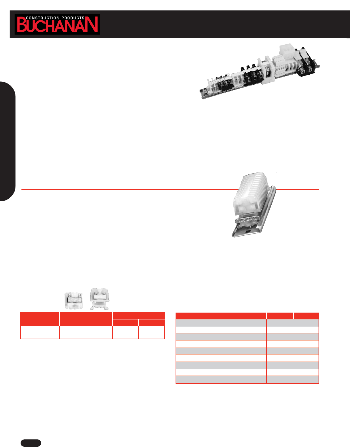
www.idealindustries.com 1-800-435-0705 for Customer Service
A-44
Terminal Blocks
Terminal Blocks
BUCHANAN CONSTRUCTION PRODUCTS, INC. offers the industry’s most
comprehensive and accommodating line of terminal blocks. BUCHANAN
terminal blocks make wiring jobs simpler and allow easy ready hook-up of
wires from different components or areas throughout a structure.
■
Wide range of configurations to solve virtually any wiring need
■
Wide wire ranges — 30 AWG to 250 KCMIL (MCM)
■
Easy installation — connect and disconnect quickly making
them perfect for maintenance and troubleshooting applications
■
Versatile, accommodating sectional design
■
Three housing options to meet your specific applications —
nylon, phenolic and polyester
■
Wide selection of contact types
■
Full line of accessories for easy customization
WIRE RANGE: Solid or Stranded
Tubular Clamp
1 #12 AWG, 1 #14 AWG, 1 to 3 #16 AWG, 1 to 5 #18 AWG, 1 to 6 #20 AWG,
1 to 7 #22 AWG
100 Series - Miniature (High Density)
Terminal Block Specifications
These miniature terminal blocks fit on a much smaller channel to save valuable panel space or
can be surface mounted directly to the panel. Miniature blocks accept wire as large as 12 AWG.
■No wire crimping required – clamp contacts hold wire from 30 AWG to 12 AWG better
than crimp-on terminals
■Saves installation time and cost – tubular clamp contacts supplied with captive screws
backed out
■Nylon housing for rugged applications
■Positive stop prevents wire from being inserted too far and prevents screw from being tightened on insulation; easy access contact provides
safe, reliable and cost-effective connection
■Quick installation and change – additional sections may be added or removed without removing channel mounting screw
■Matte-finish area for marking directly on block
Catalog Number - End Section
100 Series 125 115 130 120
Mounting Style Direct Mount Channel Mount Direct Mount Channel Mount
(Flat Base) (Dovetail Base) (Flat Base) (Dovetail Base)
100 Series 125 115
Housing Material Nylon
Maximum Service Temperature 125°C (257°F)
Flammability UL94V2
Wire Strip Length (in.) 5/16
Torque (lbs.) 6-9
UL Rating 28A @ 300V
Wire Range (AWG) Solid & Stranded 30-12
Pitch (in.) 0.25
Terminals per foot 48
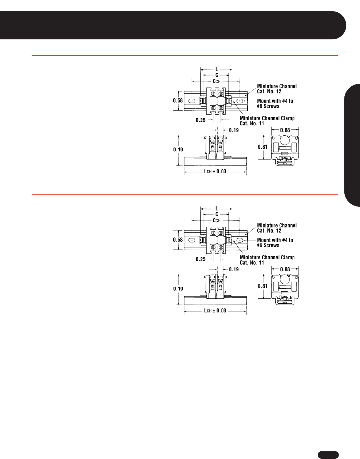
1-800-435-0705 for Customer Service www.idealindustries.com A-45
Terminal Blocks
Wire Termination
Miniature - Single Tier HIGH DENSITY
Flat Base
C = .29 + (.25 X N)
L = .51 + (.25 X N)
On Miniature #12 Channel:
CCH = 1.00 + (.25 XA)
LCH = 1.35 + (.25 X A)
A = N when N is even
A = N + 1 when N is odd
N = Number of Miniature Sections
Dovetail Base
C = .35 + (.25 X N)
L = .50 + (.25 X N)
On Standard #60 Channel:
CCH = 2.00 + (.25 XA)
LCH = 2.75 + (.25 X A)
N = Number of Single Tier Sections
On Miniature #12 Channel:
CCH = 1.00 + (.25 XA)
LCH = 1.35 + (.25 X A)
A = N when N is even
A = N + 1 when N is odd
N = Number of Miniature Sections
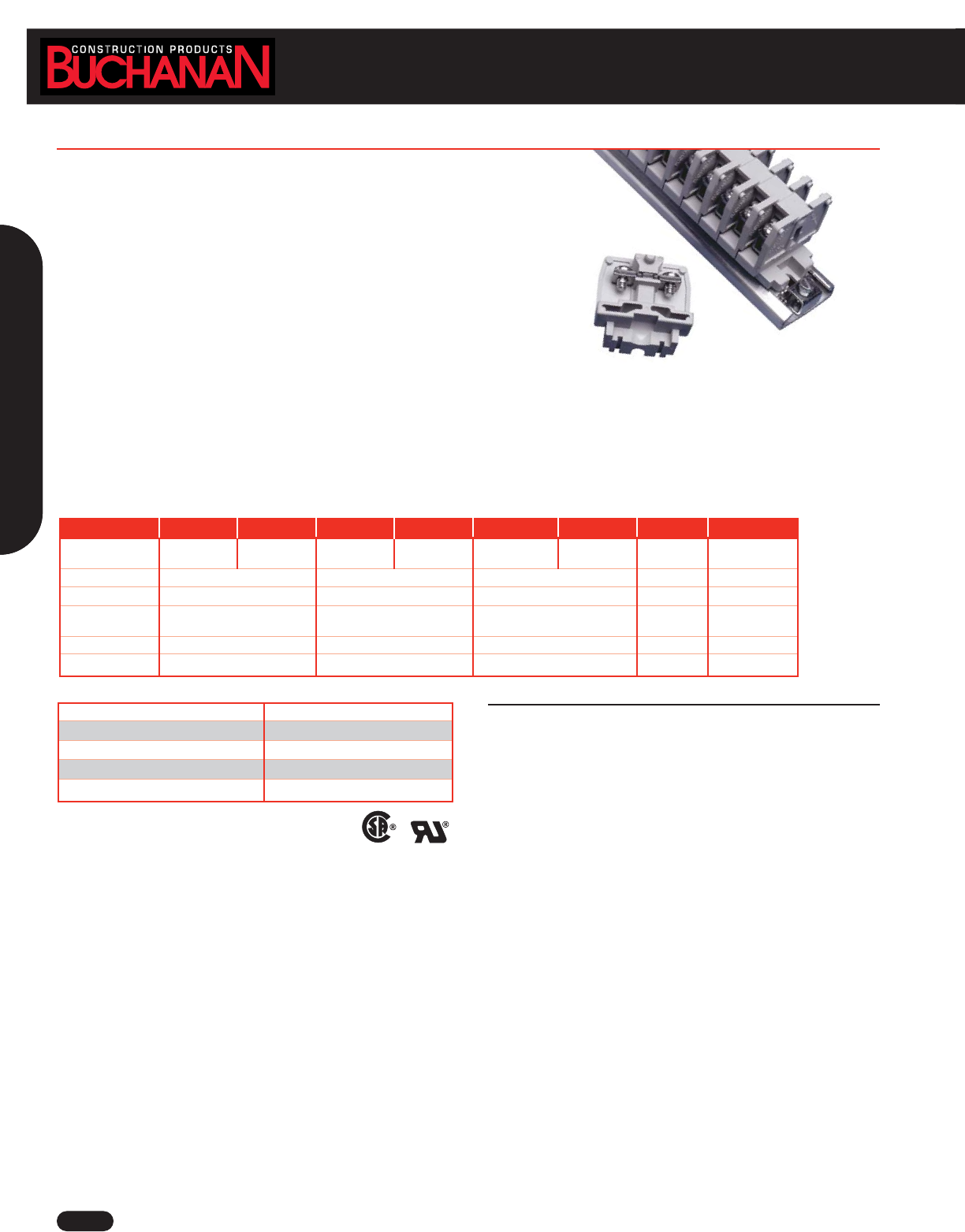
Terminal Blocks
www.idealindustries.com 1-800-435-0705 for Customer Service
A-46
This family of polyester blocks is ideal for high temperature applications.
The rugged material withstands temperatures up to 302°F (150°C)
■Three contact styles cover broad wire range — accept single wire or
combinations from 22 AWG to 8 AWG solid or stranded
■Rated at 15A to 50A per circuit
■Flat base models mount directly to surfaces; dovetail base models
mount on stranded channel
■Only one end section needed per block assembly
■Readily identifiable circuits - write directly on matte surface of block
■Sections snap-fit with Heavy Duty, Intermediate Heavy Duty and Fuse blocks
Specifications
Center-to-Center Spacing: .375 in.
Voltage Rating: 600 Volt max., Current: 50 Amp max.
Ampacity: #8 - #22 AWG
WIRE RANGE: Solid or Stranded
Strap Screw
1 #22 to 1 #14 AWG
Tubular Screw
1 #8 AWG, 1 #10 AWG, 1 to 3 #12 AWG, 1 to 4 #14 AWG, 1 to 4 #16 AWG,
1 to 5 #18 AWG, 1 to 10 #22 AWG
Tubular Clamp
1 #10 AWG, 1 or 2 #12 AWG, 1 to 3 #14 AWG, 1 to 4 #16 AWG, 1 to 5 #18 AWG,
1 to 10 #22 AWG
LR25557 E63810
Catalog Number 921 0921 924 0924 925 0925 930 0930
Mounting Style Direct Mount Channel Mount Direct Mount Channel Mount Direct Mount Channel Mount End Section End Section
(Flat Base) (Dovetail Base) (Flat Base) (Dovetail Base) (Flat Base) (Dovetail Base) (Direct Mount) (Channel Mount)
Ampacity 15A 50A 30A — —
Contact Type Strap Screw Tubular Screw Tubular Clamp — —
Screw Type 6-32 10-32 10-32 ——
Combo Head Combo Head Combo Head
Screw Torque 12 in./lbs. 8 in./lbs. 8 in./lbs. — —
Wire Range (AWG) #14 to #22 #8 to #22 #10 to #22 — —
Housing Material Polyester (gray)
Contact Material Copper Alloy, Zinc Plated
Screw Material Steel, Zinc Plated
Maximum Service Temperature 150°C (302°F)
Flammability UL94V-0 Rated
900 Series Medium Duty
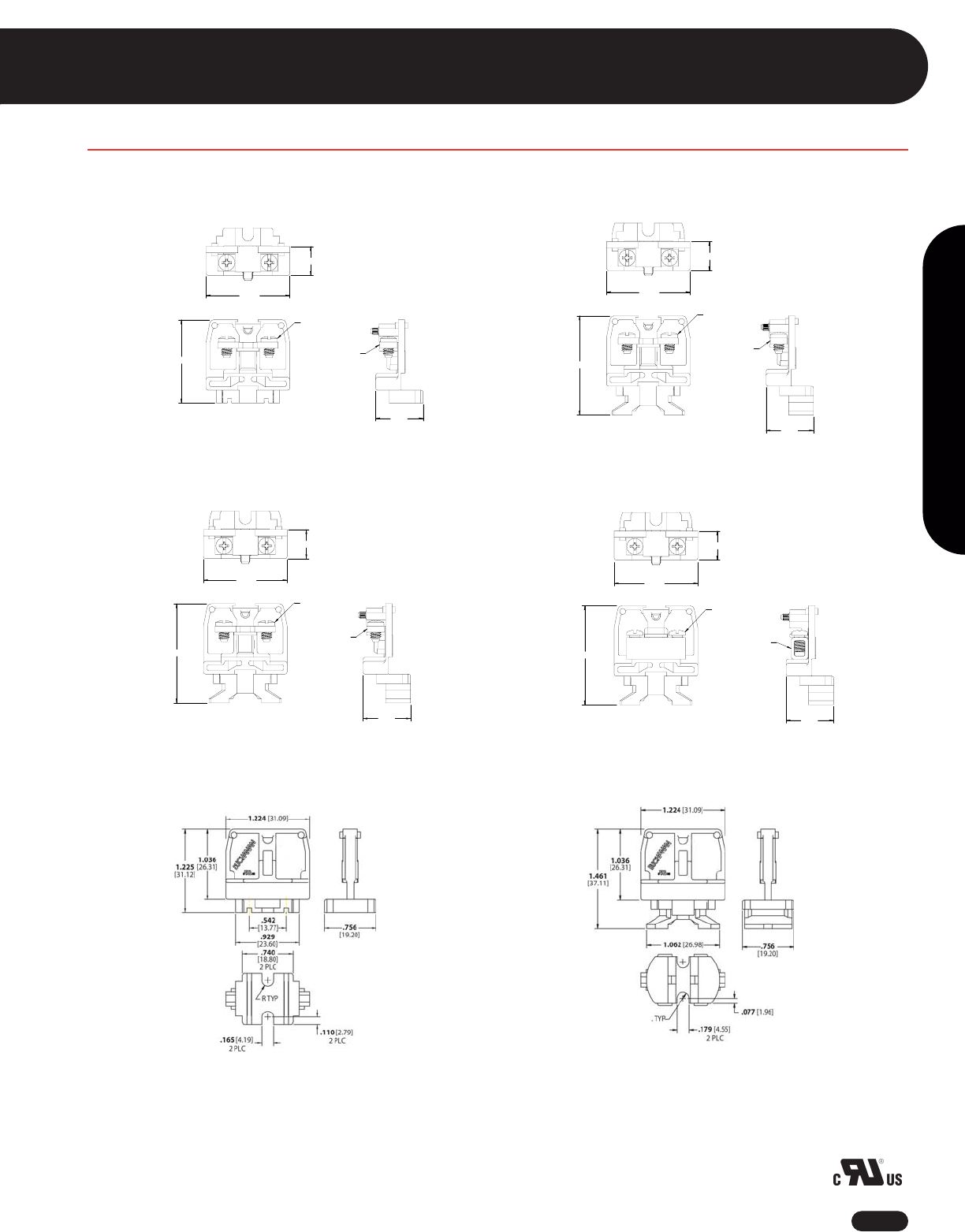
Terminal Blocks
1-800-435-0705 for Customer Service www.idealindustries.com A-47
Wire Termination
900 Series
End Section
Direct Mount (Flat Base)
Strap Screw
Direct Mount (Flat Base)
6-32 SCREW
QTY: 2
CONTACT STRAP
.427 [10.85]
1.231
[31.27]
1.225 [31.12]
.700
[17.78]
6-32 SCREW
QTY: 2
CONTACT STRAP
1.468 [37.29]
.700
[17.78]
.427 [10.85]
1.231
[31.27]
Tubular Screw/Tubular Clamp
Direct Mount (Flat Base)
Channel Mount (Dovetail Base)
Channel Mount (Dovetail Base)
Channel Mount (Dovetail Base)
6-32 SCREW
QTY: 2
CONTACT STRAP
1.468 [37.29]
.700
[17.78]
.427 [10.85]
1.231
[31.27]
10-32 SCREW
QTY: 2
TUBULAR CONTACT
1.461 [37.11]
1.231
[31.27]
.427 [10.85]
.700
[17.78]
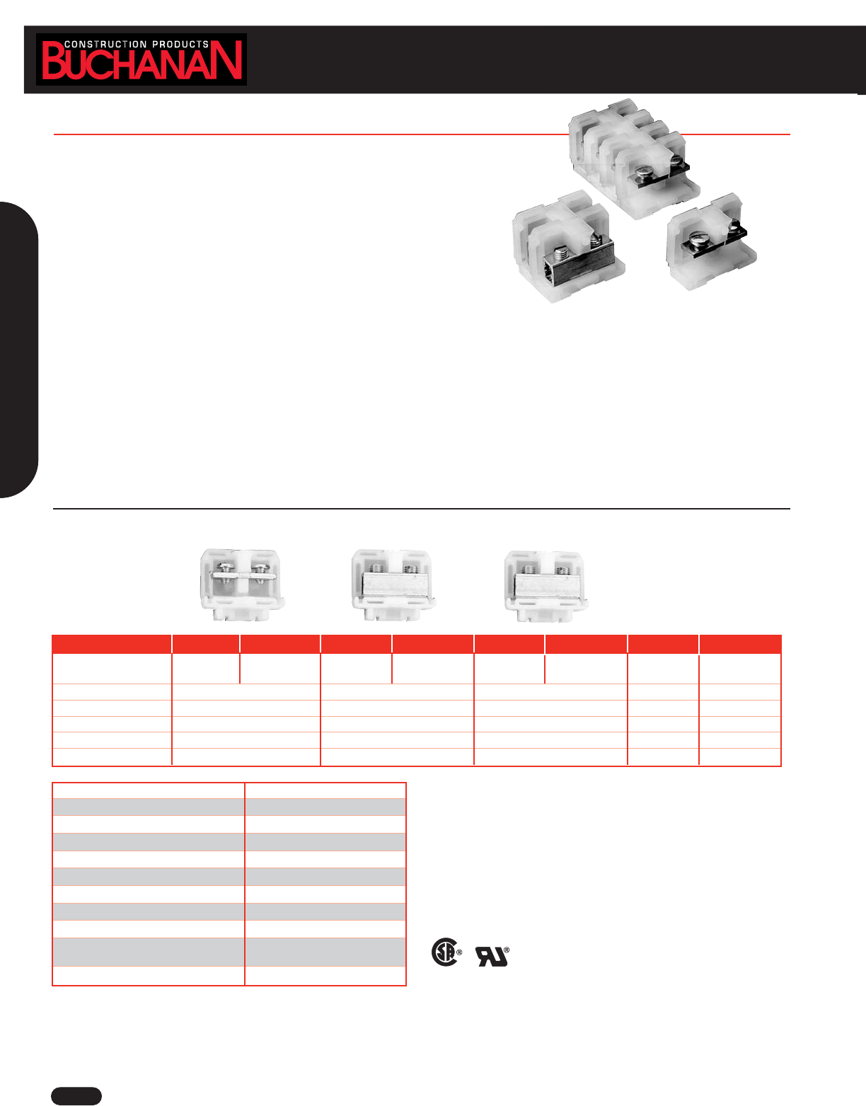
Terminal Blocks
www.idealindustries.com 1-800-435-0705 for Customer Service
A-48
200 Series - Nylon HEAVY DUTY
This compact design, heavy-duty line accepts single wire or combinations up to
4 AWG, solid or stranded,; 600V UL and NEMA rating.
■138 circuits per 6 foot length
■Three contact styles conservatively rated from 35A to 85A per circuit
■Two-way flat-base models surface mount directly to the panel or snap-on
miniature channel; dovetail base models mount on standard channel
■Only one end section needed per block assembly
■Readily identifiable circuits – mark directly on painted surface of block sections or
use removable marking tape
■Nylon housing for more rugged applications
■Sections snap-fit with Phenolic Heavy Duty, Intermediate Heavy Duty and Fuse blocks
Specifications
Center-to-Center Spacing: .50 in. CL: 24 circuits per foot.
Voltage Rating: Blocks meet 600V creepage and clearance requirements of NEMA, UL and CSA for general industrial control equipment and
panelboards. Withstand voltages greatly in excess of IEEE switchgear standards for 750V.
Ampacity: For a single 4 AWG wire, the maximum amperage recommended is 85A.
WIRE RANGE: Solid or Stranded
Strap Screw
1 #22 to 1 #10 AWG
Tubular Screw
1 #4 AWG, 1 #6 AWG, 1 or 2 #8 AWG, 1 to 4 #10 AWG, 1 to 5 #12 AWG, 1 to 6 #14 AWG,
1 to 6 #16 AWG, 1 to 8 #18 AWG
Tubular Clamp
1 #6 AWG, 1 or 2 #8 AWG, 1 to 3 #10 AWG, 1 to 4 #12 AWG, 1 to 4 #14 AWG, 1 to 6 #16
AWG, 1 to 8 #18 AWG
LR25557 E63810
Housing Material Nylon, Type 6/6 unfilled
Contact Material Copper / Copper Alloy
Screw Material Steel Plated
Maximum Service Temperature 125°C (257°F)
Breakdown Voltage AC, 60Hz 7000V
Dielectric Strength (RH40% at sea level) 470-385 V/mil thickness (per ASTM D149)
UL High Voltage Arc Testing (in./min.) 0.1 - .35
Water Absorption (24 hrs. % weight gain) 1.5%
Flammability 94V-2 (per UL94)
Chemical Resistance Resistant to aromatic hydrocarbons,
strong alkalies
Radiation Resistance (ergs g-1 C) 8 x 10⁷
Catalog Number 241 0241 242 0242 243 0243 250 0250
Mounting Style Direct Mount Channel Mount Direct Mount Channel Mount Direct Mount Channel Mount End-Section End-Section
(Flat Base) (Dovetail Base) (Flat Base) (Dovetail Base) (Flat Base) (Dovetail Base) (Direct Mount) (Channel Mount)
Ampacity 35A 85A 65A — —
Contact Type Strap Screw Tubular Screw Tubular Clamp — —
Screw Type 10-32 Slotted Binding Head 1/4-28 Slotted Headless 1/4-28 Slotted Headless — —
Wire Range (AWG) #22 to #10 #18 to #4 #18 to #6 — —
Wire Strip Length — 1/2 in. 1/2 in. — —
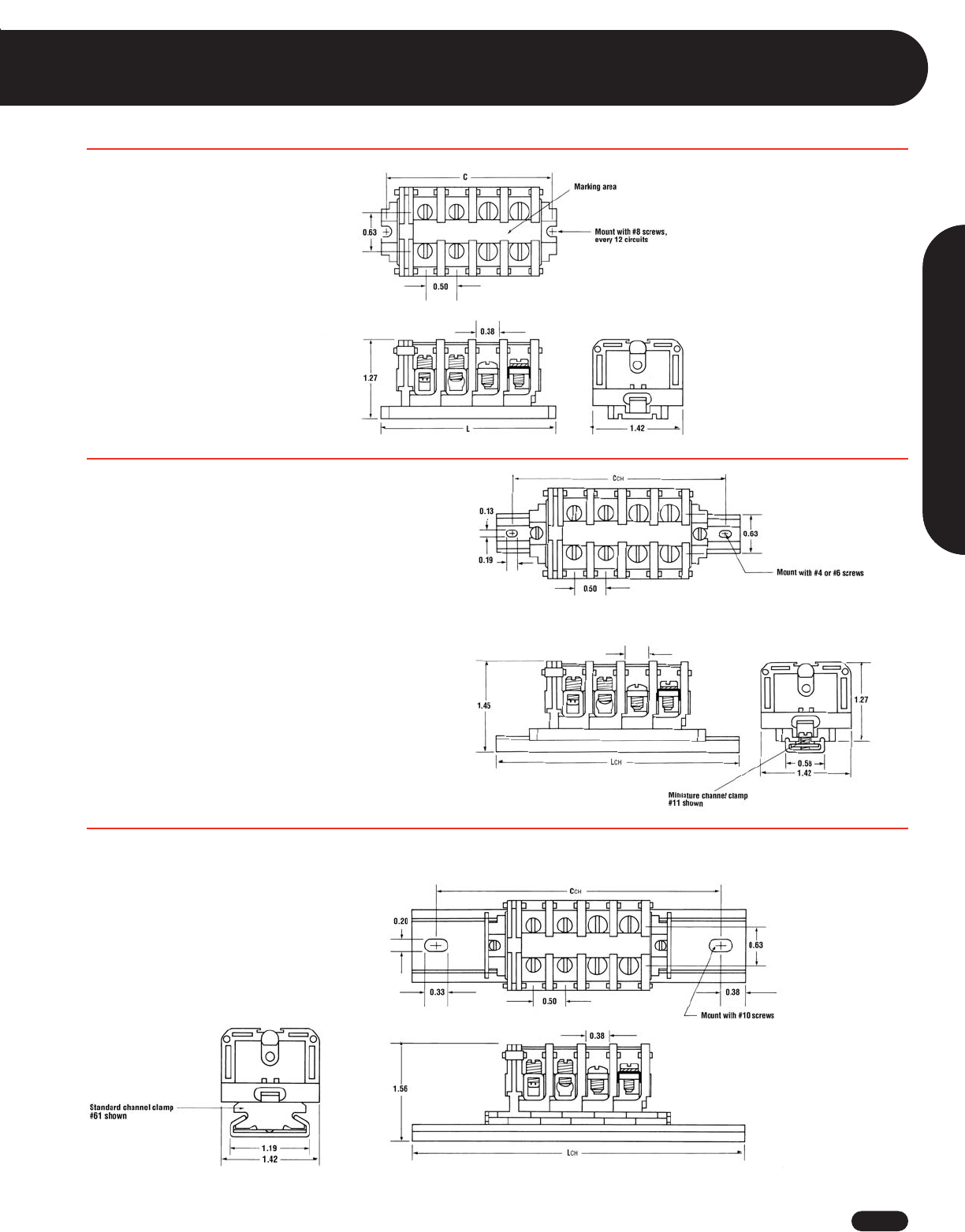
1-800-435-0705 for Customer Service www.idealindustries.com A-49
Wire Termination
Terminal Blocks
200 Series - Nylon HEAVY DUTY
Flat Base (Direct Mount)
C = .56 + (.50 X N)
L = .78 + (.50 X N)
N = Number of circuits
Flat Base Mounted on #12 Miniature Channel
LCH = 1.85 + (.50 X N)
CCH = 1.50 + (.50 X N)
N = Number of Circuits
Dovetail Base Mounted on Standard #60 Channel
LCH = .3.03 + (.50 X N)
CCH = 2.28 + (.50 X N)
N = Number of circuits
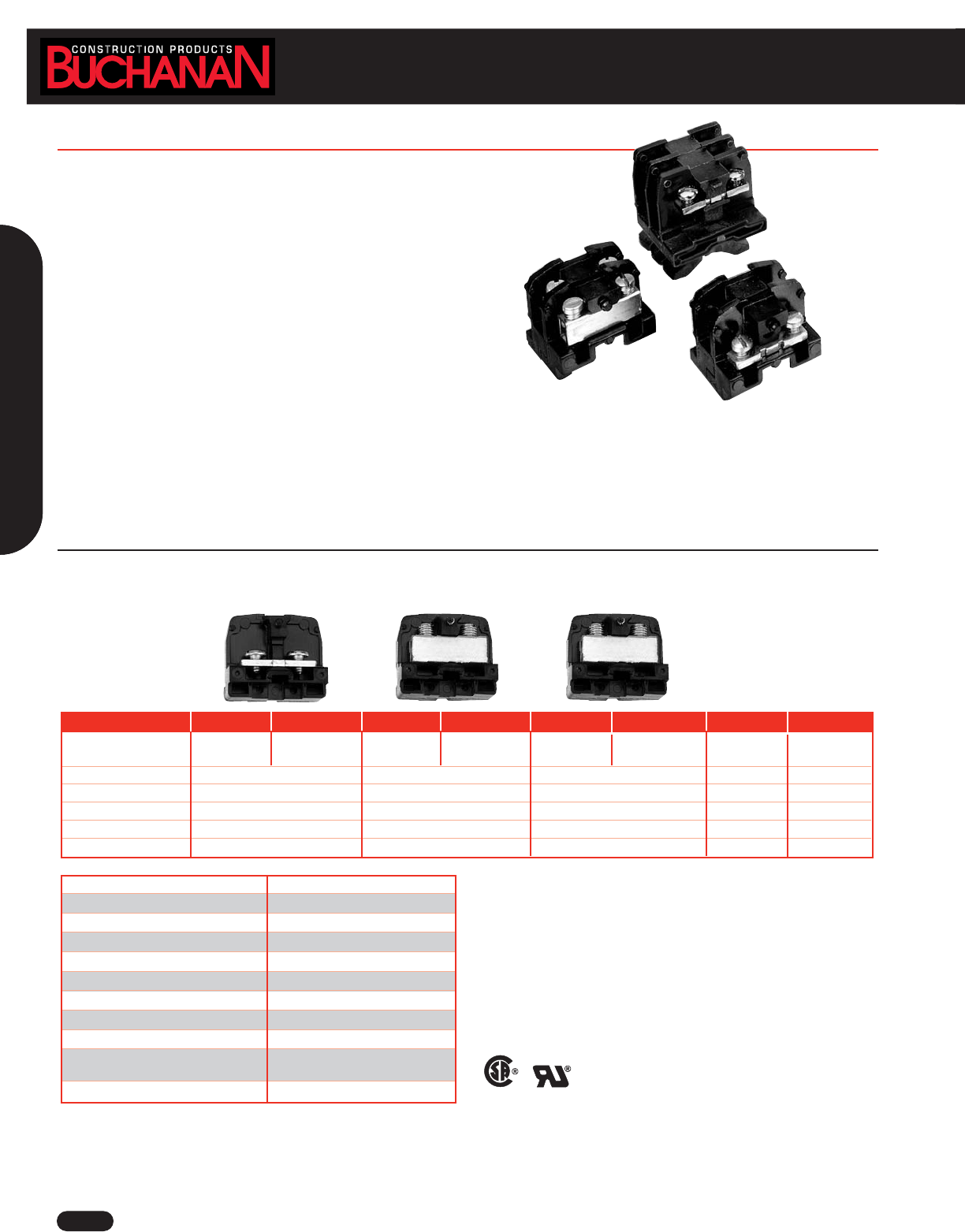
www.idealindustries.com 1-800-435-0705 for Customer Service
A-50
Terminal Blocks
200 Series - Phenolic HEAVY DUTY
The family of phenolic heavy duty blocks is ideal for high temperature, high current
applications. The rugged material withstands temperatures up to 302°F (150°C).
■Sturdy block accepts single wire or combinations up to 4 AWG solid or stranded
■122 circuits per 6 foot length
■Three contact styles conservatively rated to 35A to 85A
■Only one end section needed per block assembly
■Readily identifiable circuits – mark directly on painted marking surface or
use removable marking strip
■Sections snap-fit with Nylon Heavy Duty, Intermediate Heavy Duty
and Fuse Blocks
Specifications
Center-to-Center Spacing: .56 in. CL: 20 circuits per foot.
Voltage Rating: Blocks meet 600V creepage and clearance requirements of NEMA, UL and CSA for general industrial control equipment and
panelboards. Withstand voltages greatly in excess of IEEE switchgear standards for 750V.
Ampacity: For a single 4 AWG wire, the maximum amperage recommended is 85A.
WIRE RANGE: Solid or Stranded
Strap Screw
1 #18 to 1 #8 AWG
Tubular Screw
1 #4 AWG, 1 #6 AWG, 1 or 2 #8 AWG, 1 to 4 #10 AWG, 1 to 5 #12 AWG, 1 to 6 #14 AWG,
1 or 6 #16 AWG, 1 to 8 #18 AWG
Tubular Clamp
1 #6 AWG, 1 or 2 #8 AWG, 1 to 3 #10 AWG, 1 to 4 #12 AWG, 1 to 4 #14 AWG, 1 to 6 #16
AWG, 1 to 8 #18 AWG
LR25557 E63810
Housing Material Phenolic, Filled, Flame retardant
Contact Material Copper / Copper Alloy
Screw Material Steel Plated
Maximum Service Temperature 150°C (302°F)
Breakdown Voltage AC, 60Hz 7000V
Dielectric Strength (RH40% at sea level) 300V/mil thickness (per ASTM D149)
UL High Voltage Arc Testing (in./min.) .49 - .59
Water Absorption (24 hrs. % weight gain) 45% (per ASTM D570)
Flammability 94V-1 (per UL94)
Chemical Resistance Resistant to acids, alkalies, aliphatic
hydrocarbons and ketones (per ASTM D5343)
Radiation Resistance (ergs g-1 C) 2.7 x 10⁸min.
Catalog Number 221 0221 222 0222 223 0223 230 0230
Mounting Style Direct Mount Channel Mount Direct Mount Channel Mount Direct Mount Channel Mount End-Section End-Section
(Flat Base) (Dovetail Base) (Flat Base) (Dovetail Base) (Flat Base) (Dovetail Base) (Direct Mount) (Channel Mount)
Ampacity 35A 85A 65A — —
Contact Type Strap Screw Tubular Screw Tubular Clamp — —
Screw Type 10-32 Slotted Binding Head 1/4-28 Slotted Headless 1/4-28 Slotted Headless — —
Wire Range (AWG) #22 to #10 #18 to #4 #18 to #6 — —
Wire Strip Length — 1/2 in. 1/2 in. — —
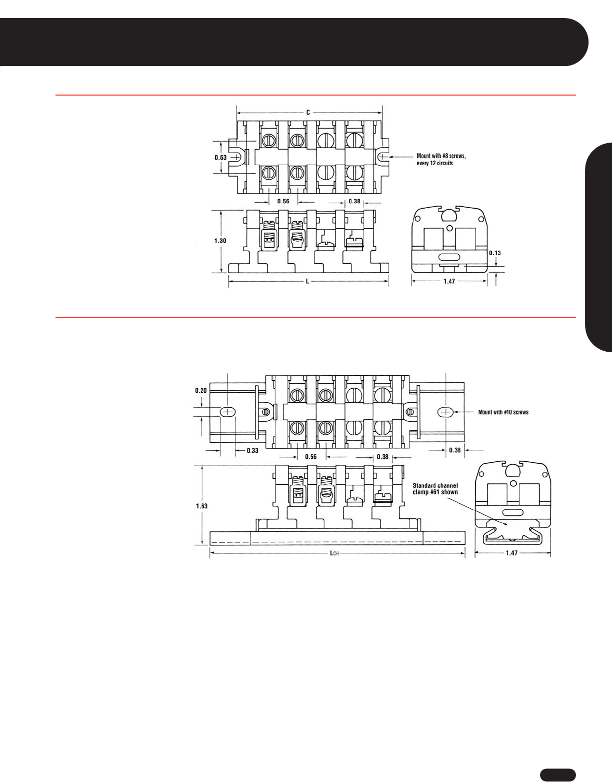
1-800-435-0705 for Customer Service www.idealindustries.com A-51
Terminal Blocks
Wire Termination
200 Series - Phenolic HEAVY DUTY
Flat Base (Direct Mount)
C = .59 + (.57 X N)
L = .81 + (.57 X N)
N = Number of circuits
Dovetail Base Mounted on Standard #60 Channel
CCH = 2.31 + (.57 X N)
LCH = 3.06 + (.57 X N)
N = Number of circuits
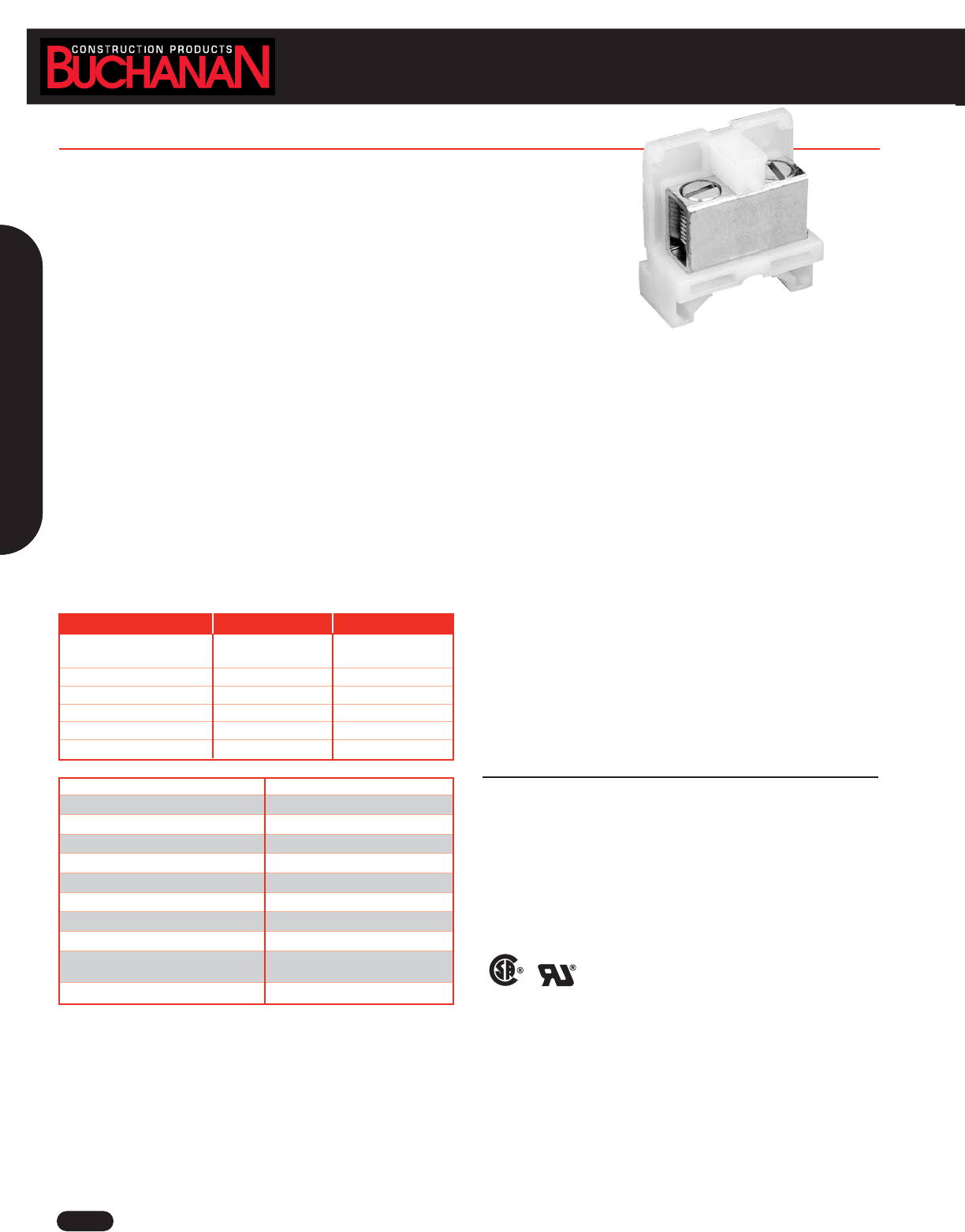
www.idealindustries.com 1-800-435-0705 for Customer Service
A-52
Terminal Blocks
Nylon INTERMEDIATE HEAVY DUTY
The 800 Series line of 600V blocks is conservatively rated up to 150A for a
single 1/0 AWG copper wire.
■Exceptionally compact block accepts single wire or combinations up to 1/0 AWG
■92 circuits per 6 foot length
■Tubular screw contact style accepts AWG sizes from 12 to 1/0, solid or stranded
■Two-way mounting base fits standard channel or mounts directly to flat surfaces
■Only one end section needed per block assembly
■Readily identifiable circuits – write directly on painted marking surface or use removable vinyl
marking strip
■Nylon housing for rugged applications, 7/16 -20 slotted headless screws
■Snap-fit with Heavy-Duty Nylon and Phenolic and Fuse Blocks
Specifications
Center-to-Center Spacing: .75 in. CL: 16 circuits per foot.
Voltage Rating: Blocks meet 600V creepage and clearance requirements of NEMA, UL and CSA standards for general industrial control
equipment and panelboards. Withstand voltages greatly in excess of IEEE switchgear standards for 750V.
Ampacity: For a single 1/0 AWG copper wire, the maximum amperage recommended is 150A.
Housing Material Nylon, Type 6/6 Unfilled
Contact Material Copper
Screw Material Steel, Zinc-Plated
Maximum Service Temperature 125°C (257°F)
Breakdown Voltage AC, 60Hz 8800V
Dielectric Strength (RH40% at sea level) 470-385V/mil thickness (per ASTM D149)
UL High Voltage Arc Testing (in./min.) .01 - .35
Water Absorption (24 hrs. % weight gain) 1.5%
Flammability 94V-2
Chemical Resistance Resistant to aromatic hydrocarbons,
strong alkalies
Radiation Resistance (ergs g-1 C) 8 x 10⁷
Catalog Number 824 830
Mounting Style Two-Way End Section
Mounting Base
Ampacity 150A —
Contact Type Tubular Screw —
Screw Type 7/16-20 Slotted Headless —
Wire Range (AWG) 12 to 1/0 —
Wire Strip Length 11/16 in. —
WIRE RANGE: Solid or Stranded
Tubular Screw
1 #1/0 AWG, 1 #1 AWG, 1 #2 AWG, 1 or 2 #4 AWG, 1 to 3 #6 AWG, , 2, 3 or 5 #8 AWG,
1 to 6 #10 AWG, 1 to 7 #12 AWG
LR25557 E63810
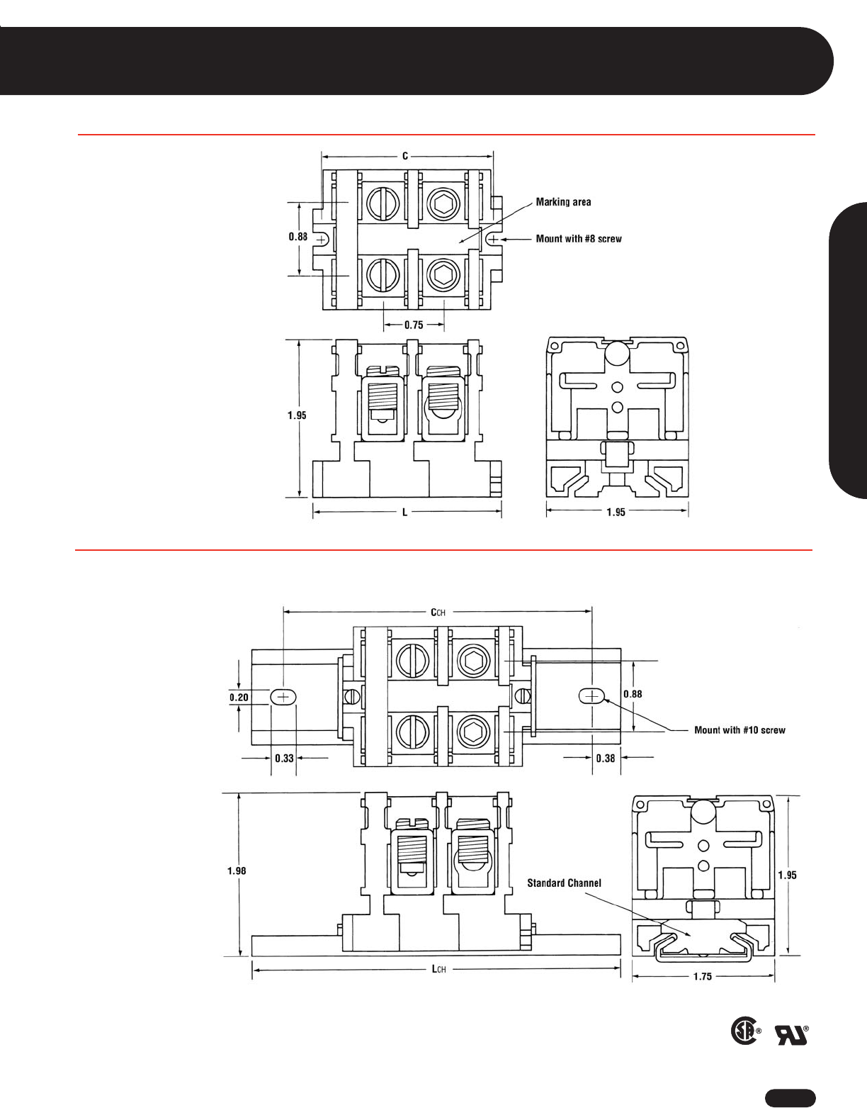
1-800-435-0705 for Customer Service www.idealindustries.com A-53
Terminal Blocks
Wire Termination
Flat Base (Direct Mount)
C = .59 + (.75 X N)
L = .81 + (.75 X N)
N = Number of circuits
Phenolic HEAVY DUTY
Dovetail Base Mounted on Standard #60 Channel
CCH = 2.31 + (.75 X N)
LCH = 3.06 + (.75 X N)
N = Number of circuits
LR25557 E63810
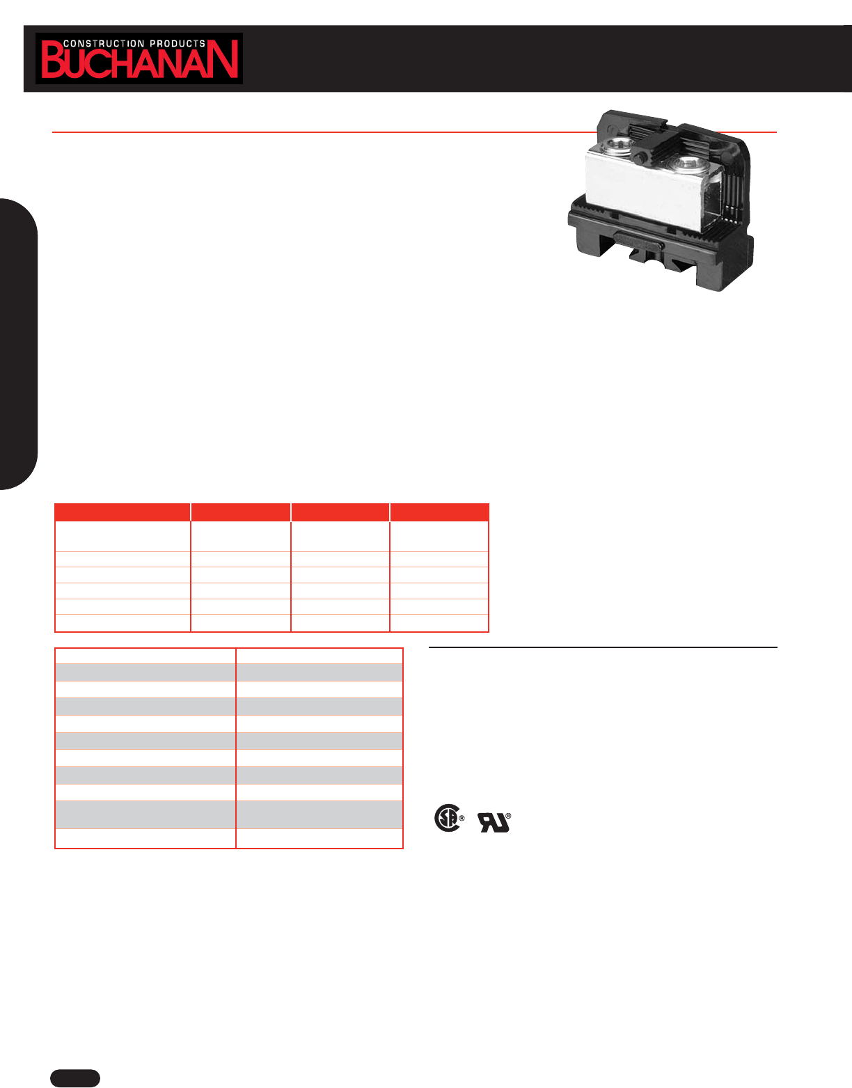
Fuse & Switch
www.idealindustries.com 1-800-435-0705 for Customer Service
A-54
Phenolic ULTRA HEAVY DUTY - 250 KCMIL (MCM)
This Ultra Heavy Duty line is rated up to 255 amps with a single 250 MCM conductor.
■Compact block accepts wire sizes up to 2/0 or 250 KCMIL (MCM)
■57 circuits per 6 foot length
■Tubular screw contact style for maximum electrical rating
■Block mounts directly on flat surface or standard channel
■Only one end section needed per block assembly
■Readily identifiable circuits – write directly on painted marking area or use removable vinyl
marking strip
■Hex socket screws allow maximum torque when using large wire sizes
■High current capacity snap-fit sectional blocks do not snap-fit with other block styles
Specifications
Center-to-Center Spacing: 1.19 in. CL: 9 circuits per foot.
Voltage Rating: Blocks meet 600V creepage and clearance requirements of NEMA, UL and CSA for general industrial control equipment and
panelboards. Withstand voltages greatly in excess of IEEE switchgear standards for 750V.
Ampacity: For a single 250 KCMIL wire, the maximum amperage recommended is 255A.
Housing Material Phenolic, Filled, Flame retardant
Contact Material Copper
Screw Material Steel Plated
Maximum Service Temperature 150°C (302°F)
Breakdown Voltage AC, 60Hz 10000V
Dielectric Strength (RH40% at sea level) 300V/mil thickness (per ASTM D149)
UL High Voltage Arc Testing (in./min.) .49 - .58
Water Absorption (24 hrs. % weight gain) 0.45% (per ASTM D570)
Flammability 94V-1 (per UL94)
Chemical Resistance Resistant to acids, alkalies and aliphatic,
hydrocarbons and ketones (per ASTM D543)
Radiation Resistance (ergs g-1 C) 2.7 x 10⁸min.
Catalog Number 426 427 430
Mounting Style Two-Way Two-Way End-Section
Mounting Base Mounting Base
Ampacity 175A 255A —
Contact Type Tubular Screw Tubular Screw —
Screw Type 1/2-30 Hex Socket 3/4-16 Hex Socket —
Wire Range (AWG) #12-2/0 #6-250 KCMIL/MCM —
Wire Strip Length 1 in. 1 in. —
LR25557 E63810
WIRE RANGE: Solid or Stranded
Tubular Screw
1 #2/0 AWG, 1 #1/0 AWG, 1 #1 AWG, 1 or 2 #2 AWG, 1 to 3 #4 AWG, 1 to 3 #6 AWG,
1 to 4 #8 AWG, 1 to 6 #10 AWG, 2 to 8 #12 AWG
Tubular Screw
1 #250 KCMIL, 1 $4/0 AWG, 1 #3/0 AWG, 1 or 2 #2/0 AWG, 1 or 2 #1/0 AWG,
1 or 2 #1 AWG, 1 to 3 #2 AWG, 1 to 4 #4 AWG, 1 to 5 #6 AWG
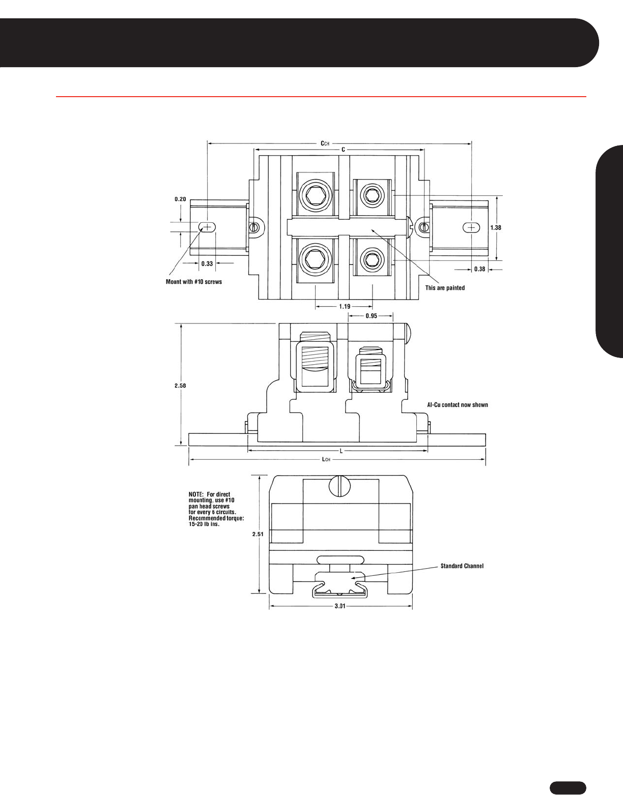
1-800-435-0705 for Customer Service www.idealindustries.com A-55
Wire Termination
Terminal Blocks
Flat Base Mounted on Standard #60 Channel
C = 1.19 + (1.19 X N)
L = 1.40 + (1.19 X N)
CCH = 2.90 + (2.90 X N)
LCH = 3.65 + (3.65 X N)
N = Number of circuits
Phenolic HEAVY DUTY
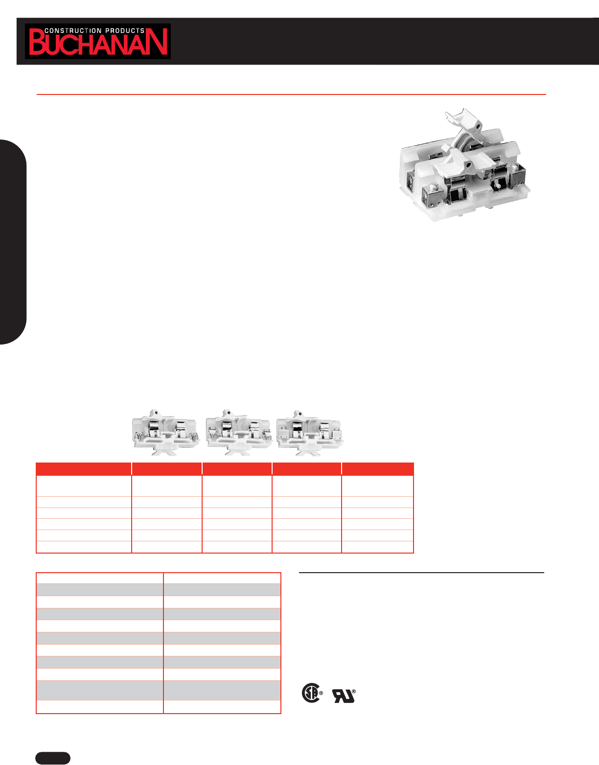
www.idealindustries.com 1-800-435-0705 for Customer Service
A-56
Terminal Blocks
■Provide in-line circuit protection for any circuit or group of circuits
■Three contact styles for terminated or unterminated wire are conservatively rated to 30A
■Remove, check and replace fuses safely and quickly
■Switch-action fuse blocks open circuits before fuse can be removed or installed
■Good circuit density when mounted adjacently – 91 circuits per 6 foot length
■Nylon housing for more rugged applications
■Dovetail base mounts on standard channel; can also be mounted on flat surfaces
■Only one end section needed per block assembly
■Open or close several circuits simultaneously – holes in puller handles allow use of nylon “ganging” rods
■Readily identifiable circuits – mark directly on white, matte-surface puller assembly, marking tab on block or use removable marking tape
■Sections snap-fit with Heavy Duty and Intermediate Heavy Duty Blocks
Specifications
Center-to-Center Spacing: .75 in. CL: 16 circuits per foot.
Voltage Rating: Blocks meet 600V creepage and clearance requirements of NEMA, UL and CSA for general industrial control equipment and
panelboards. Withstand voltages greatly in excess of IEEE switchgear standards for 750V.
Ampacity: Fuse blocks, 30A
Fuse Size: Any 13/32 in. x 1-1/2 in. ferrule-type cartridge fuse up to 30A, indicating, which meets Mil. Spec. F-15160 is recommended.
Housing Material Nylon
Contact Material Aluminum Alloy
Screw Material Steel Plated
Maximum Service Temperature 125°C (257°F)
Breakdown Voltage AC, 60Hz 7400V
Dielectric Strength (RH40% at sea level) 470-385V/mil thickness (per ASTM D149)
UL High Voltage Arc Testing (in./min.) .01 - .35
Water Absorption (24 hrs. % weight gain) 1.5% (per ASTM D570)
Flammability 94V-2 (per UL94)
Chemical Resistance Resistance to aromatic hydrocarbons,
strong alkalies
Radiation Resistance (ergs g-1 C) 8 x 10⁷
Catalog Number 0311 0318 0312 0380
Mounting Style Channel Mount Channel Mount Channel Mount End-Section
(Dovetail Base) (Dovetail Base) (Dovetail Base)
Ampacity 30A 30A 30A —
Contact Type Strap Screw Strap Clamp Tubular Screw —
Screw Type 10-32 Binding Head 8-32 Pan Head w/Clamp 1/4-28 Set Screw —
Wire Range (AWG) #22 to #8 #18 to #8 #18 - #8 —
Wire Strip Length — 1/2 in. 1/2 in. —
WIRE RANGE: Solid or Stranded
Tubular Screw
1 #1/0 AWG, 1 #1 AWG, 1 #2 AWG, 1 or 2 #4 AWG, 1 to 3 #6 AWG, , 2, 3 or 5 #8 AWG,
1 to 6 #10 AWG, 1 to 7 #12 AWG
LR25557 E63810
Nylon Fuse Blocks
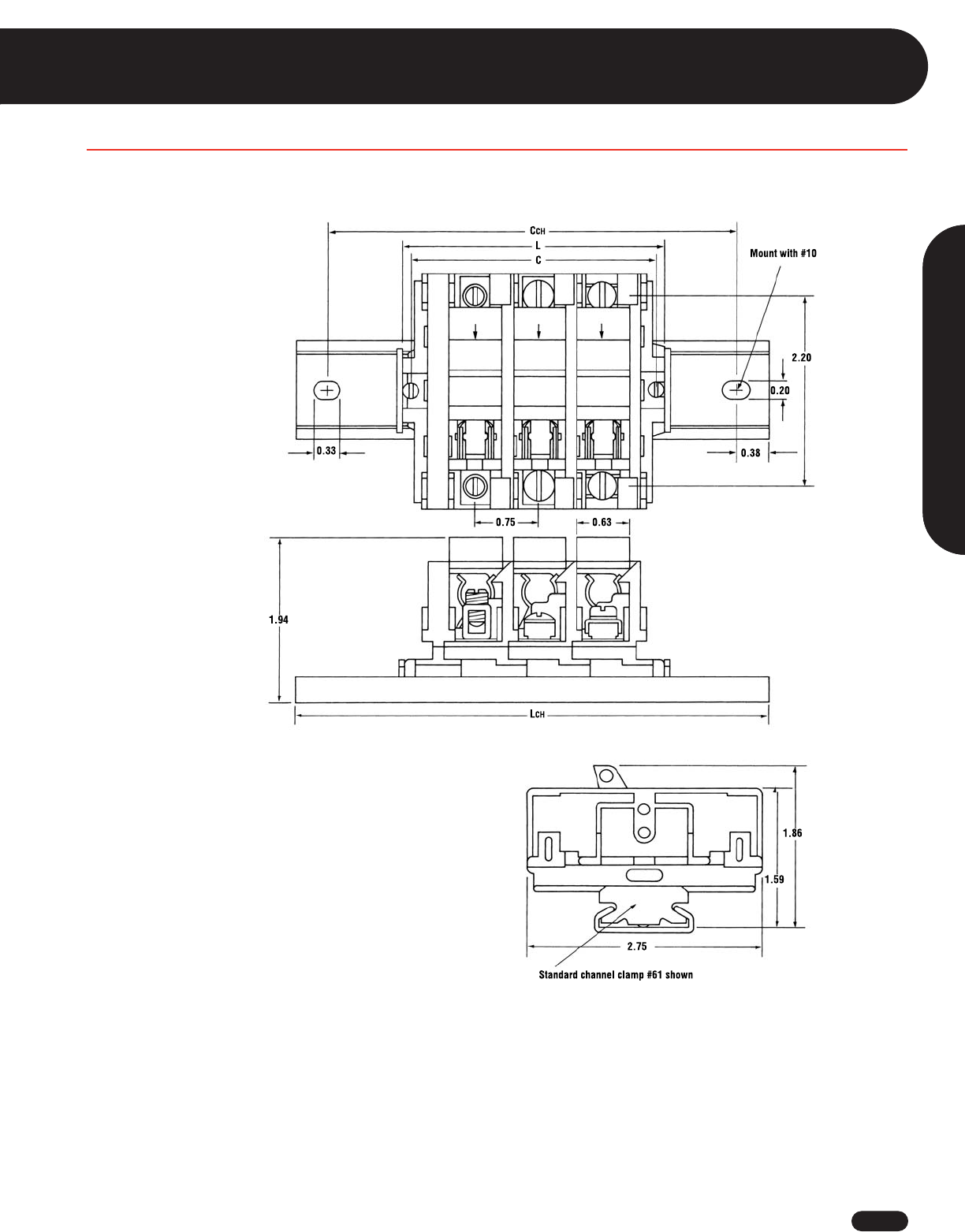
1-800-435-0705 for Customer Service www.idealindustries.com A-57
Terminal Blocks
Nylon Fuse Blocks
Dovetail Base Mounted on Standard #60 Channel (may also be mounted direct)
C = .56 + (.75 X N)
L = .78 + (.75 X N)
CCH = 2.28 + (.75 X N)
LCH = 3.03 + (.75 X N)
N = Number of circuits
Wire Termination
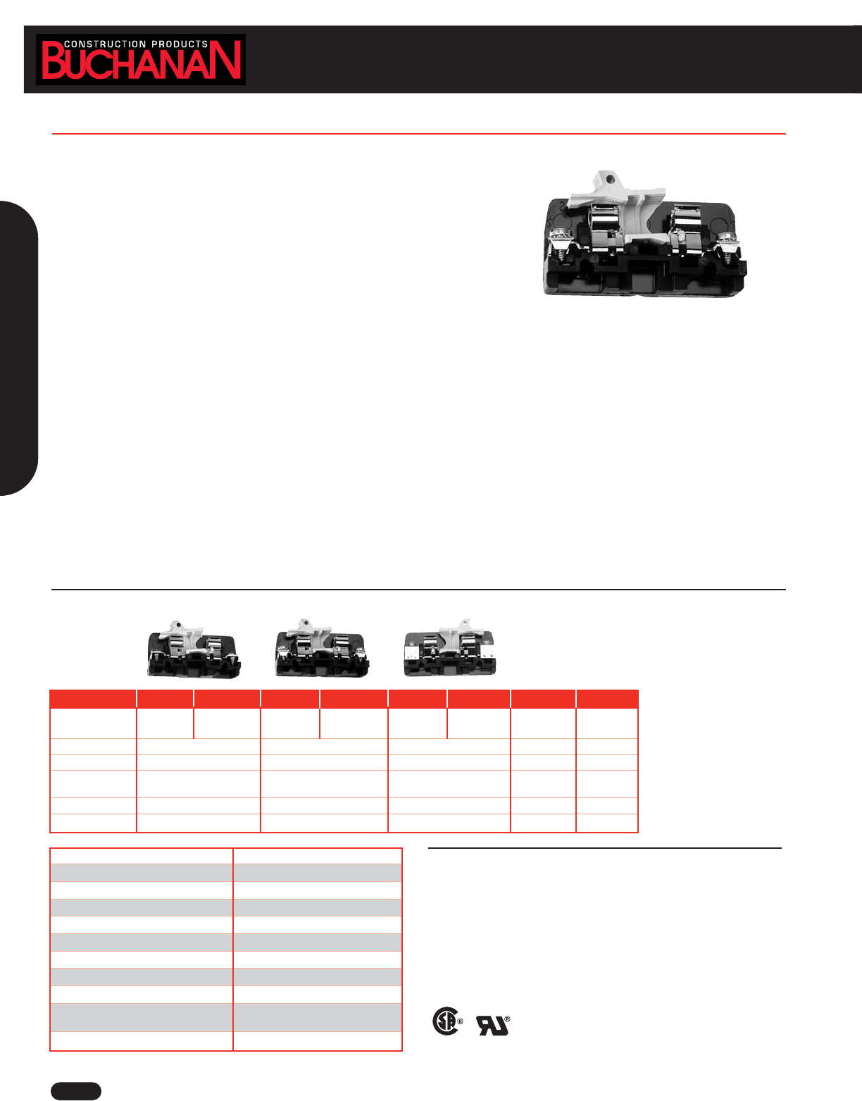
www.idealindustries.com 1-800-435-0705 for Customer Service
A-58
Terminal Blocks
Housing Material Phenolic, Filled, Flame retardant
Contact Material Copper alloy
Screw Material Steel Plated
Maximum Service Temperature 150°C (302°F)
Breakdown Voltage AC, 60Hz 8400V
Dielectric Strength (RH40% at sea level) 300V/mil thickness (per ASTM D149)
UL High Voltage Arc Testing (in./min.) .49 - .58
Water Absorption (24 hrs. % weight gain) 0.45% (per ASTM D570)
Flammability 94V-1 (per UL94)
Chemical Resistance Resistance to acids, alkalies and aliphatic
hydrocarbons and ketones (per ASTM D543)
Radiation Resistance (ergs g-1 C) 2.7 x 10⁷min.
Catalog Number 351 0351 358 0358 352 0352 330 0330
Mounting Style Direct Mount Channel Mount Direct Mount Channel Mount Direct Mount Channel Mount End-Section End-Section
(Flat Base) (Dovetail Base) (Flat Base) (Dovetail Base) (Flat Base) (Dovetail Base) (Direct Mount) (ChannelMount)
Ampacity 30A 30A 30A — —
Contact Type Strap Screw Strap Clamp Tubular Screw — —
Screw Type 10-32 8-32 Pan 1/4-28 ——
Binding Head Head w/Clamp Set Screw
Wire Range (AWG) #22 to #8 #18 to #8 #18 - #8 — —
Wire Strip Length — 1/2 in. 1/2 in. — —
LR25557 E63810
Phenolic Fuse Blocks
Specifications
Center-to-Center Spacing: .75 in. CL: 16 circuits per foot.
Voltage Rating: Blocks meet 600V creepage and clearance requirements of NEMA, UL and CSA for general industrial control equipment and
panelboards. Withstand voltages greatly in excess of IEEE switchgear standards for 750V.
Ampacity: Fuse blocks, 30A
Fuse Size: Any 13/32 in. x 1-1/2 in. ferrule-type cartridge fuse up to 30A, indicating or non-indicating, which meets MIL. Spec. F-15160 is
recommended.
WIRE RANGE: Solid or Stranded
Tubular Screw, Cat. No. 362 and 0362
1 #4 AWG, 1 #6 AWG, 1 or 2 #8 AWG, 1 to 4 #10 AWG, 1 to 5 #12 AWG, 1 to 6 #14
AWG, 1 to 6 #16 AWG, 1 to 8 #18 AWG
■Provide in-line circuit protection for any circuit or group of circuits
■Three contact styles for terminated or unterminated wire are conservatively rated to 30A
■Remove, check and replace fuses safely and quickly – switch-action fuse blocks open
circuits before fuse can be removed or installed
■Good circuit density when mounted adjacently – 91 circuits per 6 foot length
■Use in high temperature applications – phenolic housing withstands temperatures
up to 302°F (150°C)
■Flat base models for surface mounting, dovetail base models for standard channel
■Only one end section needed per block assembly
■Open or close several circuits simultaneously – holes in puller handles allow use of nylon “ganging” rods
■Readily identifiable circuits – mark directly on white, matte-surface puller assembly, marking tab on block or use removable marking tape
■Sections snap-fit with Heavy Duty and Intermediate Heavy Duty Blocks
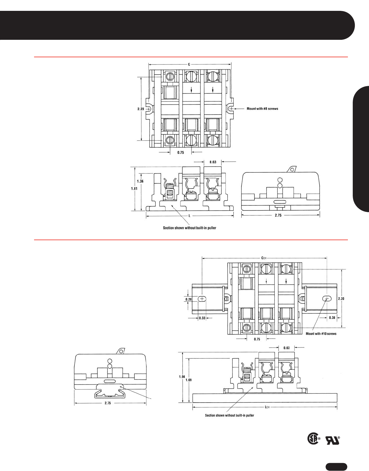
1-800-435-0705 for Customer Service www.idealindustries.com A-59
Terminal Blocks
LR25557 E63810
Phenolic Fuse Blocks
Flat Base (Direct Mount)
C = .59 + (.75 X N)
L = .81 + (.75 X N)
N = Number of circuits
Dovetail Base Mounted on Standard #60 Channel
CCH = 2.31+ (.76 X N)
LCH = 3.06 + (.76 X N)
N = Number of circuits
Wire Termination
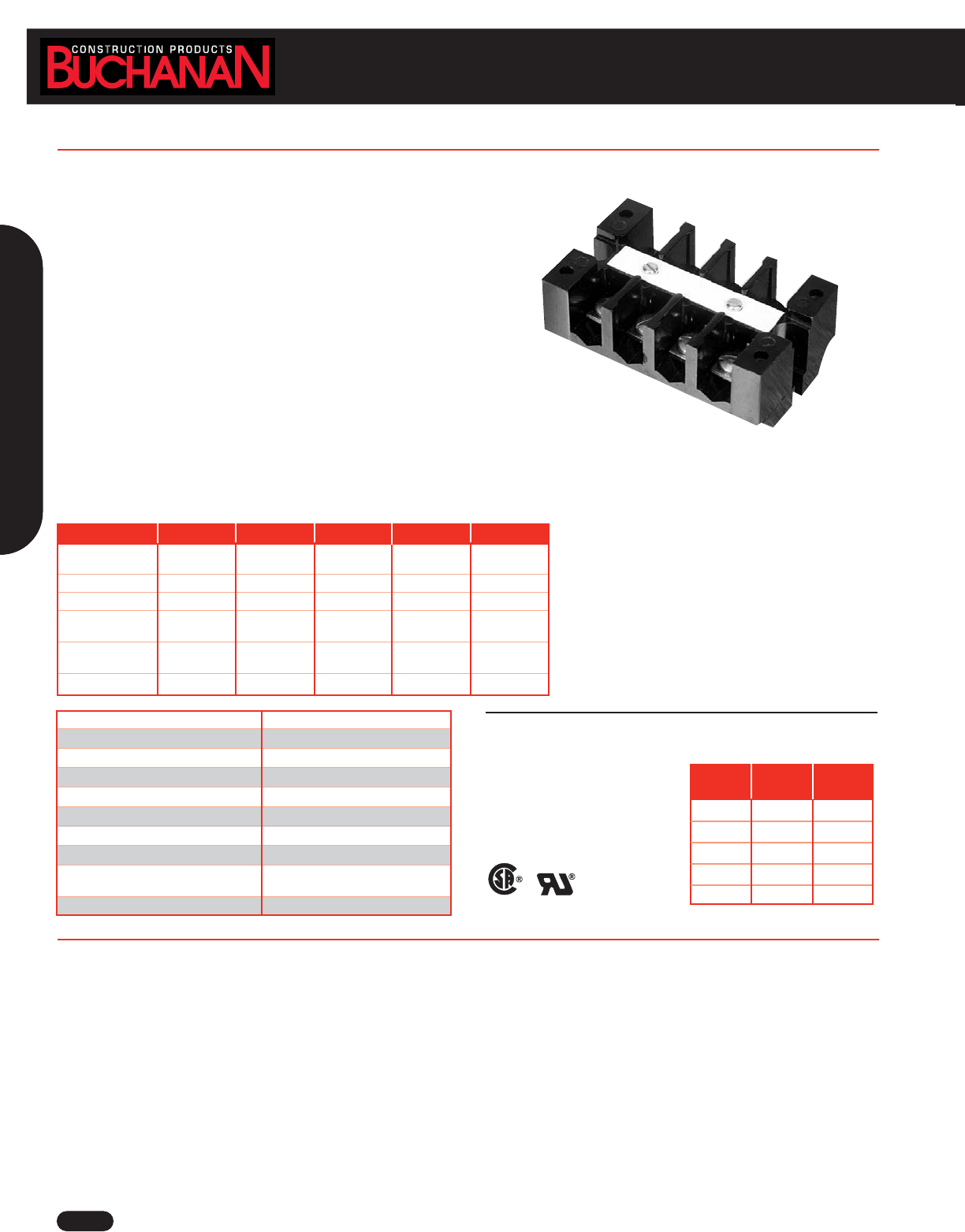
Terminal Blocks
Wire Termination
A-60
Phenolic One Piece
Traditional standard in the heavy industrial, rail transport, utility and traffic control industries. The rugged, one-piece construction finds wide
application in dirty and fibration-prone environments.
■Two, four, six, eight and twelve circuit models
■Strap screw contacts accept wire 8 AWG and smaller and are rated to 50 Amps
■Dovetail base mounts on standard size channel
■Pilot point screws with strap screw contacts speed installation time
■Easily identifiable circuits with use of plain white marking strip
■No assembly required - each block is a single, easily installed unit
Specifications
Center-to-Center Spacing: .63 in. CL
Voltage Rating: Blocks meet 600V creepage and clearance requirements of NEMA, UL and CSA for general industrial control equipment and
panelboards. Withstand voltages greatly in excess of IEEE switchgear standards for 750V.
Ampacity: For a single 8 AWG wire, the maximum amperage recommended is 50A.
WIRE RANGE: Solid or Stranded
Strap Screw
1 #18 AWG through 1 #8 AWG
LR25557 E63810
Catalog Number B102 B104 B106 B108 B112
Mounting Style Two-Way Two-Way Two-Way Two-Way Two-Way Mount
Mounting Base Mounting Base Mounting Base Mounting Base Mounting Base
Number of Circuits 246812
Ampacity 50A 50A 50A 50A 50A
Contact Type Strap Screw Strap Screw Strap Screw Strap Screw Strap Screw
(Steel) (Steel) (Steel) (Steel) (Steel)
Screw Type 10-32 10-32 10-32 10-32 10-32
Binding Head Binding Head Binding Head Binding Head Binding Head
Wire Range (AWG) #18 to #8 #18 to #8 #18 to #8 #18 to #8 #18 to #8
Housing Material Phenolic, Filled, Flame retardant
Contact Material Copper / Copper Alloy
Screw Material Steel Plated
Maximum Service Temperature 150°C (302°F)
Dielectric Strength (RH40% at sea level) 300V/mil thickness (per ASTM D149)
UL High Voltage Arc Testing (in./min.) .49 - .58
Water Absorption (24 hrs. % weight gain) 0.45% (per ASTM D570)
Flammability 94V-1 (per UL94)
Chemical Resistance Resistance to acids, alkalies and aliphatic
hydrocarbons and ketones (per ASTM D543)
Radiation Resistance (ergs g-1 C) 2.7 x 10⁷min.
No. of
Circuits CL
2 1.63 2.0
4 2.88 3.25
6 4.13 4.50
8 5.38 5.75
12 7.88 8.25
Dimensions
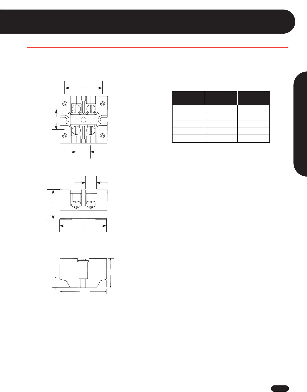
Terminal Blocks
1-800-435-0705 for Customer Service www.idealindustries.com A-61
Phenolic One Piece
Dovetail Base Mounted on Standard #60 Channel
Strap Screw (Steel)
No. of
Circuits C L
2 1.63 2.0
4 2.88 3.25
6 4.13 4.50
8 5.38 5.75
12 7.88 8.25
C
0.63
0.91
L
0.41
1.25
0.38
2.00
1.25
Wire Termination
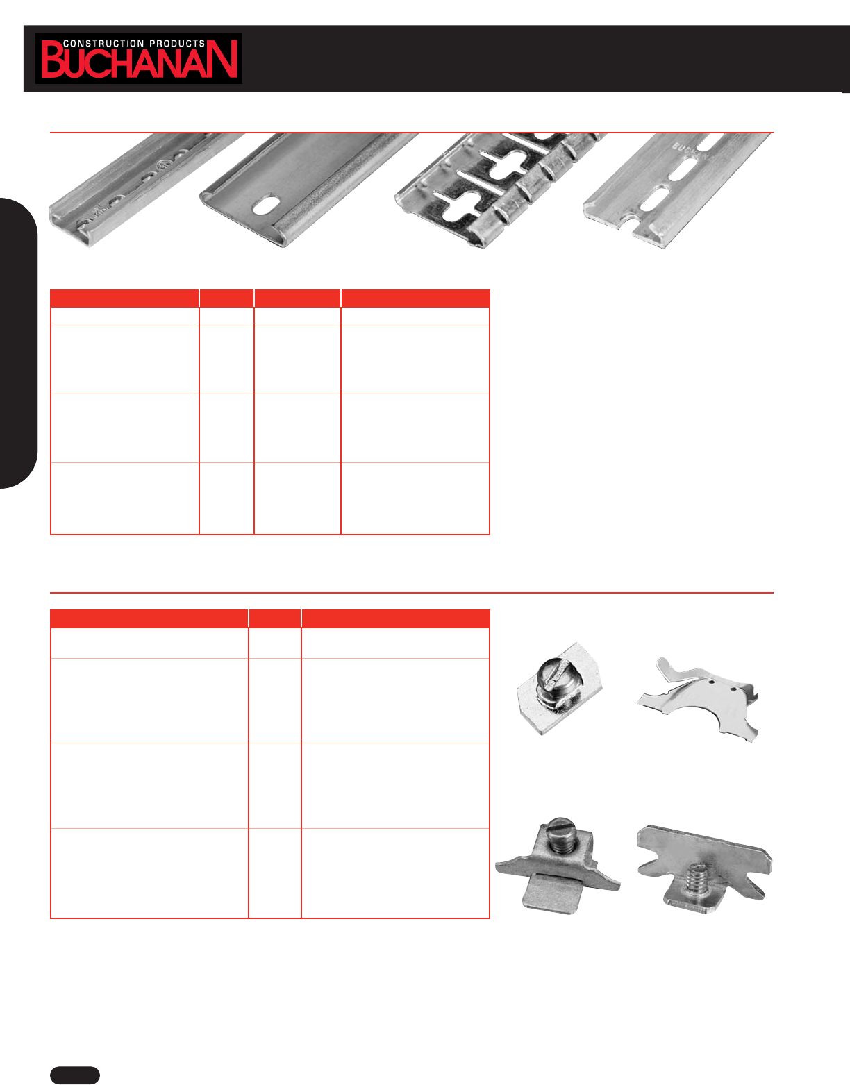
Universal Clamp Screw Clalmp
www.idealindustries.com 1-800-435-0705 for Customer Service
A-62
Accessories
Mounting Channels
Mounting Channels Length Cat. No. For use with:
Miniature Channel 3 ft. 12 Heavy Duty (200 Series)
Steel Channel 6 ft. 60 Medium Duty (900 Series)
3 ft. 63 Heavy Duty (200 Series)
Intermediate Heavy Duty (800 Series)
Ultra Heavy Duty (400 Series)
Fuse Blocks (300 Series)
Steel Channel (Breakaway) 3 ft. 60B36 Medium Duty (900 Series)
Heavy Duty (200 Series)
Intermediate Heavy Duty (800 Series)
Ultra Heavy Duty (400 Series)
Fuse Blocks (300 Series)
Aluminum Channel (Pre-punched) 6 ft. 64 Medium Duty (900 Series)
3 ft. 67 Heavy Duty (200 Series)
Intermediate Heavy Duty (800 Series)
Ultra Heavy Duty (400 Series)
Fuse Blocks (300 Series)
Channel Clamps Cat. No. For use with:
Miniature Clamp 11 High Density Miniature (100 Series)
Heavy Duty (200 Series)
Snap-in Clamp 62 High Density Miniature (100 Series)
Medium Duty (900 Series)
Heavy Duty (200 Series)
Intermediate Heavy Duty (800 Series)
Ultra Heavy Duty (400 Series)
Fuse Blocks (300 Series)
Universal Clamp 68 High Density Miniature (100 Series)
Medium Duty (900 Series)
Heavy Duty (200 Series)
Intermediate Heavy Duty (800 Series)
Ultra Heavy Duty (400 Series)
Fuse Blocks (300 Series)
Universal Clamp 61 High Density Miniature (100 Series)
Medium Duty (900 Series)
Heavy Duty (200 Series)
Intermediate Heavy Duty (800 Series)
Ultra Heavy Duty (400 Series)
Fuse Blocks (300 Series)
Miniature Channel Steel Channel Steel Channel (Breakaway) Aluminum Channel (Pre-punched)
Miniature Clamp Snap-in Clamp
Channel Clamps
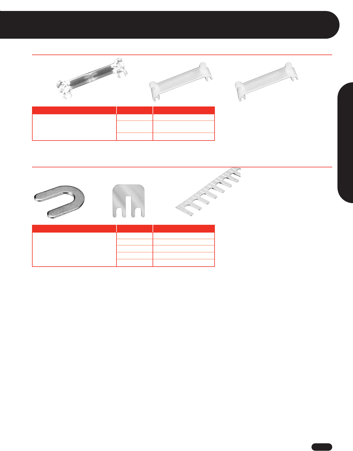
1-800-435-0705 for Customer Service www.idealindustries.com A-63
Accessories
Wire Termination
Description Cat. No. Available for:
Terminal Block 13 High Density Miniature (100 Series)
23 Heavy Duty (200 Series)
Heavy Duty-Phenolic (200 Series)
71 Medium Duty (900 Series)
#23 #71#13
Jumpers
Cat. No. Available for:
Jumpers for Tubular Contacts 41 Heavy Duty-Phenolic (200 Series)
42 Heavy Duty (200 Series)
43 Heavy Duty-Phenolic (200 Series)
70 Medium Duty (900 Series)
73 Medium Duty (900 Series)
Jumper for Tubular Contacts Jumper for Strap Screw Snap-apart Jumper
Covers

www.idealindustries.com 1-800-435-0705 for Customer Service
A-64
Notes
Notes:
_________________________________________________________________________________________________________________________________
_________________________________________________________________________________________________________________________________
_________________________________________________________________________________________________________________________________
_________________________________________________________________________________________________________________________________
_________________________________________________________________________________________________________________________________
_________________________________________________________________________________________________________________________________
_________________________________________________________________________________________________________________________________
_________________________________________________________________________________________________________________________________
_________________________________________________________________________________________________________________________________
_________________________________________________________________________________________________________________________________
_________________________________________________________________________________________________________________________________
_________________________________________________________________________________________________________________________________
_________________________________________________________________________________________________________________________________
_________________________________________________________________________________________________________________________________
_________________________________________________________________________________________________________________________________
_________________________________________________________________________________________________________________________________
_________________________________________________________________________________________________________________________________
_________________________________________________________________________________________________________________________________
_________________________________________________________________________________________________________________________________
_________________________________________________________________________________________________________________________________
_________________________________________________________________________________________________________________________________
_________________________________________________________________________________________________________________________________
_________________________________________________________________________________________________________________________________
_________________________________________________________________________________________________________________________________
_________________________________________________________________________________________________________________________________
_________________________________________________________________________________________________________________________________
_________________________________________________________________________________________________________________________________
_________________________________________________________________________________________________________________________________
_________________________________________________________________________________________________________________________________
_________________________________________________________________________________________________________________________________
