Product Detail Manual
33605-Attachment 33605-Attachment 33605-Attachment 051712 Batch4 unilog cesco-content
627743-Catalog 627743-Catalog 627743-Catalog 051712 Batch4 unilog cesco-content
108989-Catalog 108989-Catalog 108989-Catalog 051712 Batch5 unilog cesco-content
104088-Catalog 104088-Catalog 104088-Catalog 051712 Batch6 unilog cesco-content
120235-Catalog 120235-Catalog 120235-Catalog 051712 Batch7 unilog cesco-content
2014-10-17
: Pdf 137251-Attachment 137251-Attachment Batch10 unilog
Open the PDF directly: View PDF ![]() .
.
Page Count: 240 [warning: Documents this large are best viewed by clicking the View PDF Link!]
- Table of Contents
- Electrical – Power Fuses
- Electronic – PC Board and Small Dimension Fuses
- Fuseblocks and Holders
- Disconnect Switches
- High Speed Fuses
- Medium Voltage Fuses and Fuse Links
- Telecommunications Protection
- British, European, & Canadian Standard Industrial Fuses
- Fuse Accessories, Displays, Kits, Etc.
- Fuse Technology
- Glossary of Terms
- Index
Circuit Protection Solutions
Bussmann®
B
U
S
S
M
A
N
N
Finger-Safe
Test Points
•
30-Amp Fuses
Plug Into 60-Amp
Fuseholders
Fuseholder
Mounted by 35mm
DIN Rail or by
Standard Hardware
Finger-Safe Fuse,
Fuseholder, and
Wire Ports (IP-20)
Class J Time-
Delay Electrical
Performance
Wire Ports Can
Accept Dual Wires
Smaller Footprint
Than Class J and
Class CC
Dovetail Fuseholder
Design for Ganging 30-
Amp and 60-Amp Poles
Permanent “Open-
Fuse” Indication
•
•
•
•
•
•
•
•
©2003, Cooper Bussmann, Inc. • St. Louis, MO 63178 • 636-394-2877
www.bussmann.com
www.cubefuse.com
REORDER #1007 6-03-40M
CUBEFuse™
The World’s First
“Finger-Safe” Industrial Fuse.
3814-16891-01 VHG DATE 01-04-02 #0615 BLACK CYAN MAGENTA YELLOW
The Power to Protect.
™
Bussmann®
This catalog is intended to present product data and provide technical information that will
help the end user with design application. Bussmann reserves the right, without notice,
to change design or construction of any products and to discontinue or limit distribution
of any products. Bussmann also reserves the right to change or update, without notice,
any technical information contained in this catalog. Once a product has been selected, it
should be tested by the user in all possible applications.
©2003 Cooper Bussmann
Printed in the U.S.A.
COOPER BUSSMANN • P.O. BOX 14460 • ST. LOUIS, MO 63178-4460 • (636) 394-2877
World Wide Web: www.bussmann.com
The Power to Protect.
Bussmann
®
HEADQUARTERS
Cooper Bussmann
P. O. Box 14460
St. Louis, Missouri 63178-4460, USA
Telephone: 636 394 2877
Fax: 800 544 2570
International: 636 527 1413
Email: fusebox@buss.com
COOPER BUSSMANN CHICAGO
175 Hansen Court
Wood Dale, IL 60191
Telephone: 630 422 2400
Fax: 630 422 2500
EUROPEAN HEADQUARTERS
Cooper (UK) Ltd.
Bussmann Division
Burton-on-the-Wolds
Leicestershire LE12 5th, England
Telephone: 44 1509 882737
Fax: 44 1509 882786
Email: info@bussmann.co.uk
BUSSMANN ASIA-PACIFIC
1 Jalan Kilang Timor
#06-01 Pacific Tech Centre
Singapore 159303
Republic of Singapore
Telephone: 65 278 6151
Fax: 65 278 3151
Email: bussmann@bussasiapac.com.sg
BUSSMANN AUSTRALIA
205-209 Woodpark Road
PO Box 2577
Smithfield NSW 2164
Australia
Telephone: 61 2 8787 2700
Fax: 61 2 9609 2342
BUSSMANN BRASIL
Bussmann do Brasil Ltda.
Rodovia Santos Dumont, Km 23
Cruz das Almas
Itu - Sao Paulo- 13 300-000
Brasil
Telephone: 55 11 4024 8400
Fax: 55 11 4024 8424
BUSSMANN DENMARK
5 Literbuen
DK-2740 Skovlunde
Copenhagen, Denmark
Telephone: 45 4485 0900
Fax: 45 4485 0901
Email: bussmann@bussmann.dk
BUSSMANN INDIA
EVR Street, Sedarapet
Pondicherry - 605 111
India
Telephone: 91 413 678203
or 91 984 678204
Fax: 91 413-677010
BUSSMANN MEXICO
Arrow-Hart, S.A. de C.V.
Poniente 148, No. 933
02300 Mexico, D.F. Mexico
Telephone: 52 5 587 0211
Fax: 52 5 567 4049
COOPER ELECTRONIC TECHNOLOGIES, INC.
3601 Quantum Blvd.
Boynton Beach, Fl 33426
Tel: 561 752 5000
Fax: 561 742 1178
ENBRAY CONTACTORS
Cooper Bussmann (UK) Limited
Salterbeck Trading Estate
Workington, Cumbria
CA14 5TD
United Kingdom
Tel : +44 0 1946 839000
Fax : +44 0 1946 833000
REORDER #1007 6-03-40M
World’s leading supplier of fuses and fusible protection
systems, Bussmann continues its 89-year history of blazing new
trails of innovative technologies. Maker of the industry’s first
truly global product line, each item is backed by an efficient
worldwide network of distribution, customer service and
technical support. Bussmann products include the most
extensive circuit protection solutions approved for use in
a variety of major standards: UL, CSA, IEC. . . Not to
mention both European (DIN, British Standard) and
North American styled fuses for a wide range of
applications: industrial motor protection, power
conversion, medium voltage, power distribution,
telecommunications network equipment, electronics,
and automotive. Manufacturing operations in the U.S.,
Denmark, and the United Kingdom have earned ISO
9000 certification. Bussmann customers are assured
of only the utmost quality across every product line.
Knowledgeable. Responsive. Customer focused.
Bussmann continues to set the standard for circuit
protection solutions around the world.
™
1 Electrical – Power Fuses 1
2 Electronic – PC Board and Small Dimension Fuses 29
3 Fuseblocks and Holders 41
4 Disconnect Switches 99
5 High Speed Fuses 123
6 Medium Voltage Fuses and Fuse Links 157
7 Telecommunications Protection 175
8 British, European, & Canadian Standard Industrial Fuses 189
9 Fuse Accessories, Displays, Kits, Etc. 202
10 Fuse Technology 210
Glossary of Terms 231
Index 233
Bussmann®
i
Section Guide
Bussmann
Information Fax ~
636.527.1450
Page
Now you can get current information about Bussmann products at anytime,
using BIF (Bussmann Information FAX) or visit us on the World Wide Web.
BIF is a simple to use automated fax response system. All you need is a touch-
tone telephone and a fax machine to get complete product specifications when
you want it. Data sheet numbers are located throughout this catalog. To get a
detailed data sheet on the product of your choice, simply dial 636-527-1450
and request the document number listed. In a matter of minutes a data sheet
will be faxed to you. It’s that simple.
Data sheets can also be downloaded from the Internet. The Bussmann web site
is continuously updated with our newest products and latest data on circuit pro-
tection solutions. Visit us often at http://www.bussmann.com
©2003 Cooper Bussmann Printed in U.S.A.
Bussmann
Worldwide Web ~
http://www.bussmann.com

Bussmann®
ii
Table of Contents
Disconnect Switches
Disconnects . . . . . . . . . . . . . . . . . . . . . . . . . . . . . . . . . . .99
Fusible . . . . . . . . . . . . . . . . . . . . . . . . . . . . .99-105, 121
Non-Fusible . . . . . . . . . . . . . . . . . . . . . . . . . . . .106-112
Fusible, Enclosed . . . . . . . . . . . . . . . . . . . . . . . .113-116
Non Fusible, Enclosed . . . . . . . . . . . . . . . . . . . .117-120
Power Modules . . . . . . . . . . . . . . . . . . . . . . . . . . . . .122
High Speed Fuses
North American Style . . . . . . . . . . . . . . . . . . . . . . . .123-130
European Style Square Body . . . . . . . . . . . . . . . . . .131-147
British Standard BS88 . . . . . . . . . . . . . . . . . . . . . . .148-150
Ferrule Style . . . . . . . . . . . . . . . . . . . . . . . . . . . . . .151-158
Medium Voltage Fuses
BBU Boric Acid Fuse . . . . . . . . . . . . . . . . . . . . . . . .157-158
R-Rated Fuses (Motor Circuit Protection) . . . . . . . . .161-164
E-Rated Fuses (Transformers Protection) . .159-160, 165-168
DIN Dimensions . . . . . . . . . . . . . . . . . . . . . . . . . . . . . . .169
Potential Transformer Fuses . . . . . . . . . . . . . . . . . . . . . .170
Medium Volt, Fast Acting . . . . . . . . . . . . . . . . . . . . . . . .171
BS2692-1 Fuses . . . . . . . . . . . . . . . . . . . . . . . . . . . . . .172
Fuse Links . . . . . . . . . . . . . . . . . . . . . . . . . . . . . . . . . . .173
Telecommunications
Fused Disconnect Switch . . . . . . . . . . . . . . . . . . . .175-181
Telpower Fuses . . . . . . . . . . . . . . . . . . . . . . . . . . . .182-184
Indicating Fuses & Holders . . . . . . . . . . . . . . . . . . . .185-186
Specialty Fuses . . . . . . . . . . . . . . . . . . . . . . . . . . . .187-188
British, European, & Canadian
Standard Industrial Fuses
CSA Type P and D Fuses . . . . . . . . . . . . . . . . . . . . . . . .190
HRC Industrial Fuses . . . . . . . . . . . . . . . . . . . . . . . .191-195
BS88 Low Voltage Industrial Fuses . . . . . . . . . . . . . .196-197
DIN Style Type D and Neozed Fuses . . . . . . . . . . . . . . . .198
HRC Fuseholders . . . . . . . . . . . . . . . . . . . . . . . . . . . . . .199
NH Fuse System . . . . . . . . . . . . . . . . . . . . . . . . . .200-201
Fuse Accessories, Displays,
Kits, Etc.
Accessories . . . . . . . . . . . . . . . . . . . . . . . . . . . . . . .202-204
Display Racks and Service Kits . . . . . . . . . . . . . . . .205-209
Fuse Technology
Fuseology . . . . . . . . . . . . . . . . . . . . . . . . . . . . . . . .210-215
Fuse Diagnostic Chart . . . . . . . . . . . . . . . . . . . . . . .216-218
Time-Current & Current Limitation Curves . . . . . . . . .219-230
Glossary of Terms . . . . . . . . . . . . . . . . . . . . . . . . . .231-232
Index . . . . . . . . . . . . . . . . . . . . . . . . . . . . . . . . .233-234
Electrical - Power Fuses
General Data (Selection Guide, Dimensional Data) . . . . . . .1-3
Cubefuse (TCF & TCFH) . . . . . . . . . . . . . . . . . . . . . . . . .4-5
Class L Fuses (KRP-C_SP, KTU, KLU) . . . . . . . . . . . . . . .6-8
Class RK1 Fuses
(LPN-RK_SP, LPS-RK_SP, KTN-R, KTS-R) . . . . . .9-11, 15
Class RK5 Fuses (FRN-R, FRS-R, DLN-R, DLS-R) . . . .12-14
One-Time Fuses (NON, NOS) . . . . . . . . . . . . . . . . . . . . . .16
Class J Fuses (LPJ_SP, JKS) . . . . . . . . . . . . . . . . . . . .17-18
Class T Fuses (JJN, JJS) . . . . . . . . . . . . . . . . . . . . . . . . .19
Class G Fuses (SC) . . . . . . . . . . . . . . . . . . . . . . . . . . . . .20
Class CC Fuses (LP-CC, FNQ-R, KTK-R) . . . . . . . . . . .21-22
Supplementary Fuses (Midget fuses ⁄‹Ω£™∑ diameter) . . . .23-25
Plug Fuses . . . . . . . . . . . . . . . . . . . . . . . . . . . . . . . . .26-27
Cable Limiters and Welder Limiters . . . . . . . . . . . . . . . . . .28
Electronic Fuses
PC Board and Small Dimension
5mm x 15mm Fuses . . . . . . . . . . . . . . . . . . . . . . . . . . . . .29
5mm x 20mm Fuses . . . . . . . . . . . . . . . . . . . . . . . . . .30-31
⁄Ω¢∑ Diameter Fuses . . . . . . . . . . . . . . . . . . . . . . . . . . .32-36
Pin Indicating Type Fuses . . . . . . . . . . . . . . . . . . . . . . .37-38
Actuators and Limiters . . . . . . . . . . . . . . . . . . . . . . . . . . .38
In-Line Fuses/Fuseholders . . . . . . . . . . . . . . . . . . . . . . . .39
Blade-Type Fuses . . . . . . . . . . . . . . . . . . . . . . . . . . . . . . .40
Fuseblocks, Holders and Terminal
Blocks
Overcurrent Protection Modules . . . . . . . . . . . . . . . . . .41-45
Fuse Covers . . . . . . . . . . . . . . . . . . . . . . . . . .46 Fuseblocks
Class H, K, and R . . . . . . . . . . . . . . . . . . . . . . .47-52, 63
Class J . . . . . . . . . . . . . . . . . . . . . . . . . . . . . . .53-55, 63
Semiconductor . . . . . . . . . . . . . . . . . . . . . . . . . . . . . .56
Class J (Touch Safe) . . . . . . . . . . . . . . . . . . . . . . . .57-58
Class T . . . . . . . . . . . . . . . . . . . . . . . . . . . . . . . . .59-62
Class CC, G and Type M . . . . . . . . . . . . . . . . . . . . . . .64
for ⁄Ω¢∑ and ⁄‹Ω£™∑ Diameter Fuses . . . . . . . . .66, 83-84, 86
for 5mm Diameter Fuses . . . . . . . . . . . . . . . . . . . . . . .85
Modular Fuseblocks and Fuseholders . . . . . . . . . . . . .65, 67
Box Cover Units for Plug Fuses . . . . . . . . . . . . . . . . . . . . .68
PC Board Mount Fuseholders . . . . . . . . . . . . . . . . . . .69-70
Panel Mount Fuseholders . . . . . . . . . . . . . . . . .71-75, 78-79
In-Line Fuseholders . . . . . . . . . . . . . . . . . . . . .76-77, 80-82
PC Board Fuseclips . . . . . . . . . . . . . . . . . . . . . . . . . . .87-88
Terminal Blocks . . . . . . . . . . . . . . . . . . . . . . . . . . . . . .89-93
Rail Mount Fuseholders . . . . . . . . . . . . . . . . . . . . . . . . . .94
Power Distribution Blocks . . . . . . . . . . . . . . . . . . . . . .95-97

Buss Fuse Selection Chart (600 Volts or Less)
Circuit Load Ampere Fuse Symbol Voltage Interrupting Remarks
Rating Type Rating (a-c) Class Rating Page
(KA)
Conventional Dimensions—Class RK1, RK5 (0-600A), L (601-6000A)
All type loads 0-600A LOW-PEAK®LPN-RK_SP 250V RK1†† 300 All-purpose fuses. 9-11
(optimum (dual-element, LPS-RK_SP 600V Unequaled for combined
overcurrent time-delay) short-circuit and
protection). 601 to LOW-PEAK®KRP-C_SP 600V L 300 overload protection. 6-7
6000A (time-delay) (Specification grade product)
Motors, welder, 0 FUSETRON®FRN-R 250V RK5†† 200 Moderate degree of 12
transformers, to (dual-element, FRS-R 600V current limitation. Time-delay 13
capacitor banks 600A time-delay) passes surge currents.
(circuits with heavy 0 DURA-LAGTM DLN-R 250V RK5 200 14
inrush currents). to (dual-element, DLS-R 600V
600A time-delay)
601 to LIMITRON®KLU 600V L 200 All-purpose fuse. Time- 8
Main, 4000A (time-delay) delay passes surge-currents.
Feeder Non-motor loads KTN-R 250V RK1†† 200 Same short-circuit protection 15
and (circuits with no 0 KTS-R 600V as LOW-PEAK fuses but
Branch heavy inrush to must be sized larger for
currents). 600A LIMITRON®circuits with surge-currents;
LIMITRON fuses
_____
(fast-acting) i.e., up to 300%.
particularly suited for 601 to KTU 600V L 200 A fast acting, high 8
circuit breaker 6000A performance fuse.
protection.
Reduced Dimensions For Installation in Restricted Space—Class J(0-600A), T(0-1200A), CC(0-30A), G(0-60A)
All type loads LOW-PEAK®LPJ_SP 600V J 300 All-purpose fuses. 17
(optimum (dual-element Unequaled for combined
overcurrent time-delay) short-circuit and overload
protection). 0protection. (Specification
__________ to grade product)
Non-motor loads 600A LIMITRON®JKS 600V J 200 Very similar to KTS-R 18
(circuits with no (quick acting) LIMITRON, but smaller.
heavy inrush 0 to T-TRONTM JJN 300V T 200 The space saver (⁄Ω£ the size 19
currents). 1200A JJS 600V of KTN-R/KTS-R).
Motor loads 0 to 30A LOW-PEAK®LP-CC 600V CC 200 Rejection feature 21
(circuits with (time-delay)
heavy in-rush
currents.)
Non-motor loads 0 to 30A LIMITRON®KTK-R 600V CC 200 Very compact (⁄‹Ω£™∑ ≈ 1⁄Ω™∑); 22
(circuits with no (fast-acting) rejection feature.
heavy in-rush
Branch currents.)
Control transformer 0 to 30A TRON®FNQ-R 600V CC 200 Excellent for control 22
circuits and lighting (time-delay) transformer protection.
ballasts; etc.
General purpose; 1 to 20A SC SC 600V G 100 Current limiting; 20
i.e., lighting ⁄‹Ω£™∑ dia. ≈varying
panel boards. 25 to 60A 480V lengths per amp rating.
Miscellaneous 0 to ONE-TIME NON 250V H or K5†10 Forerunners of 16
600A NOS 600V the modern
Plug fuses can 0 FUSTAT®S125V S 10 Base threads of Type S 26
be used for to (dual-element, differ with amp ratings.
branch circuits 30A time-delay) T and W have Edison base.
and small FUSETRON®T125V ** 10 T & S fuses recommended
component (dual-element, for motor circuits. W not 26
protection. time-delay) recommended for circuits
Buss Type W W125V ** 10 with motor loads.
** UL Listed as Edison Base Plug Fuse.
†Some ampere ratings are available as UL Class K5 with a 50,000A interrupting rating.
†† RK1 and RK5 fuses fit standard switches, fuseblocks and holders; however, the rejection feature of class R switches and fuseblocks designed specifically for rejection type fuses
(RK1 and RK5) prevent the insertion of the non-rejection fuses (K1, K5, and H).
Bussmann®
1
General Data — Selection Chart
200,000A or 300,000A Interrupting Rating (rms symmetrical)
Current Limiting
10,000–50,000 AIC
General
Purpose
(non-
current
limiting
fuses)
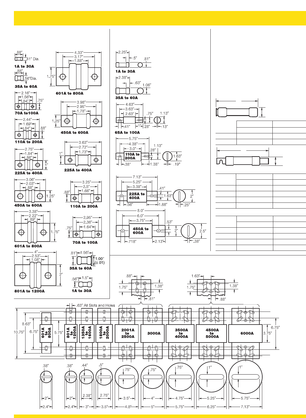
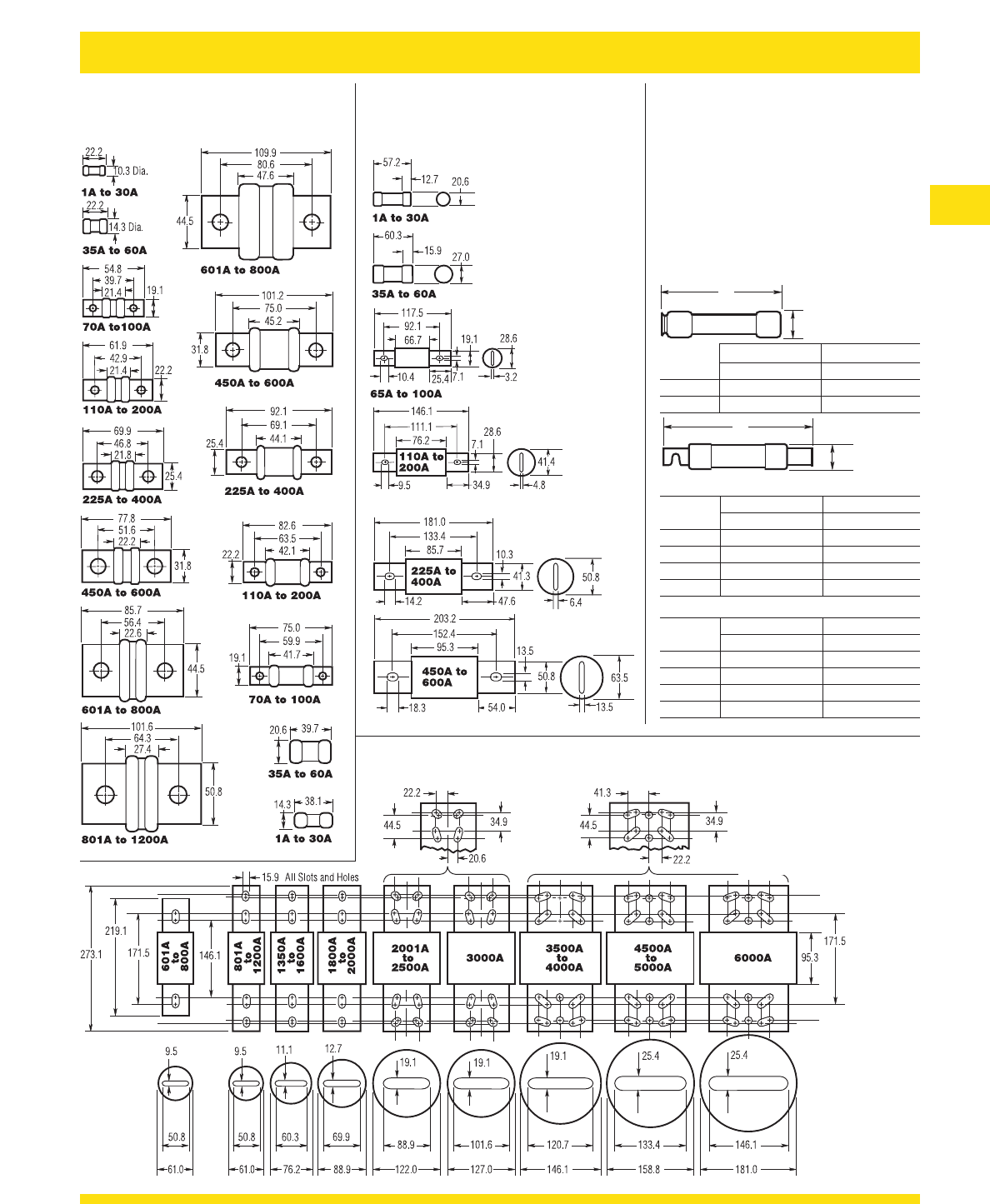
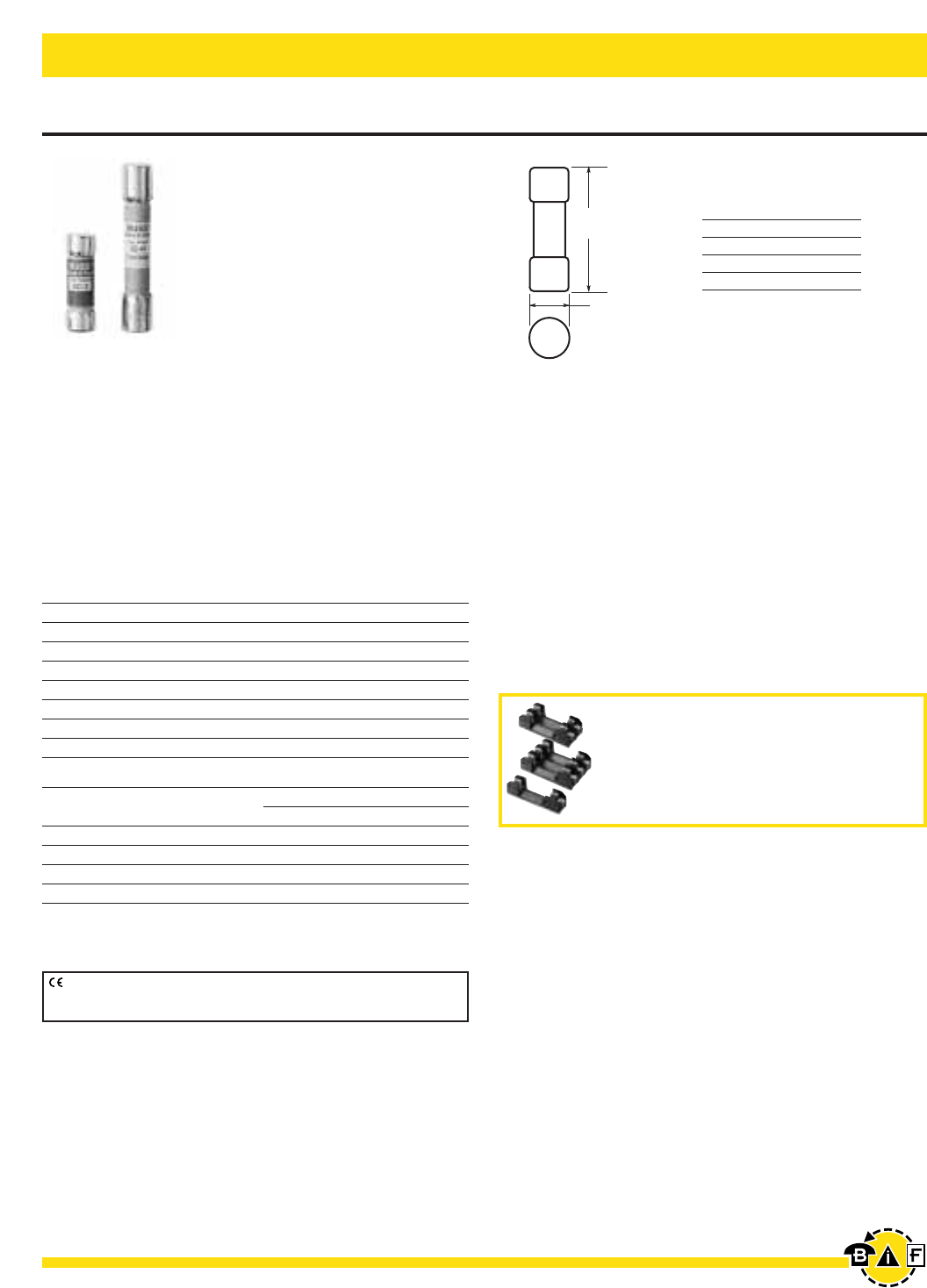
General Data – Dimensions (Inches) Bussmann®
2
A
B
CLASS T
T- Tr o n ™ Fuses
JJN (300V) JJS (600V)
CLASS J
Low-Peak®& Limitron®Fuses
LPJ & JKS (600V)
CLASS L Low-Peak®& Limitron®Fuses
KRP-C, KTU, & KLU (601 - 6000A) (600V)
NOTE: KRP-CL (150A to 600A) fuses
have same dimensions as 601A to
800A case size. KTU (200A to 600A)
have same dimensions, except tube
3∑lgth. ≈2∑dia.; terminal 1fi/•∑ width
≈ 1⁄/¢∑ thick.
CLASS RK5 & RK1
Fusetron®, Low-Peak®&
Limitron®Fuses (250V & 600V)
FRN-R & FRS-R; LPN-RK &
LPS-RK; KTN-R & KTS-R
Basic dimensions are same as Class H (for-
merly NEC) ONE-TIME (NON & NOS) and
SUPERLAG Renewable RES & REN fuses.
NOTE: These fuses can be used to replace
existing Class H, RK1 and RK5 fuses relating
to dimensional compatibility.
250V 600V
Ampere A B A B
⁄Ω¡º-30 2∑.56∑5∑.81∑
35-60 3∑.81∑5.5∑1.06∑
Fusetron & Limitron
250V 600V
Ampere A B A B
70-100 5.88∑1.06∑7.88∑1.34∑
110-200 7.13∑1.56∑9.63∑1.84∑
225-400 8.63∑2.06∑11.63∑2.59∑
450-600 10.38∑2.59∑13.38∑3.13∑
Low-Peak
250V 600V
Ampere A B A B
70-100 5.88∑ 1.16∑ 7.88∑ 1.16∑
110-200 7.13∑1.66∑9.63∑1.66∑
225-400 8.63∑2.38∑11.63∑2.38∑
450-600 10.38∑2.88∑13.38∑2.88∑
A
B
Bussmann®
General Data – Dimensions (Millimeters)
3
A
B
CLASS T
T- Tr o n ™ Fuses
JJN (300V) JJS (600V)
CLASS J
Low-Peak®& Limitron®Fuses
LPJ & JKS (600V)
CLASS L Low-Peak®& Limitron®Fuses
KRP-C, KTU, & KLU (601 - 6000A) (600V)
NOTE: KRP-CL (150A to 600A) fuses
have same dimensions as 601A to
800A case size. KTU (200A to 600A)
have same dimensions, except tube
76.2mm lgth. x 50.8mm dia.; terminal
41,3mm width x 31.8mm thick.
CLASS RK5 & RK1
Fusetron®, Low-Peak®&
Limitron®Fuses (250V & 600V)
FRN-R & FRS-R; LPN-RK &
LPS-RK; KTN-R & KTS-R
Basic dimensions are same as Class H (for-
merly NEC) ONE-TIME (NON & NOS) and
SUPERLAG Renewable RES & REN fuses.
NOTE: These fuses can be used to replace
existing Class H, RK1 and RK5 fuses relating
to dimensional compatibility.
250V 600V
Ampere A B A B
⁄Ω¡º-30 50.8 14.3 127.0 20.6
35-60 76.2 20.6 139.7 27.0
Fusetron & Limitron
250V 600V
Ampere A B A B
70-100 149.2 26.9 200.0 34.0
110-200 181.0 39.6 244.5 46.7
225-400 219.1 52.3 295.3 65.8
450-600 263.5 65.8 339.7 79.5
Low-Peak
250V 600V
Ampere A B A B
70-100 149.2 29.5 200.0 29.5
110-200 181.0 42.2 244.5 42.2
225-400 219.1 60.5 295.3 60.5
450-600 263.5 73.2 339.7 73.2
A
B
Bussmann®
4For complete specification data, call Bussmann Information Fax ~ 636.527.1450
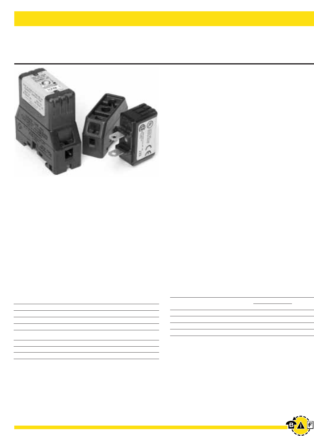
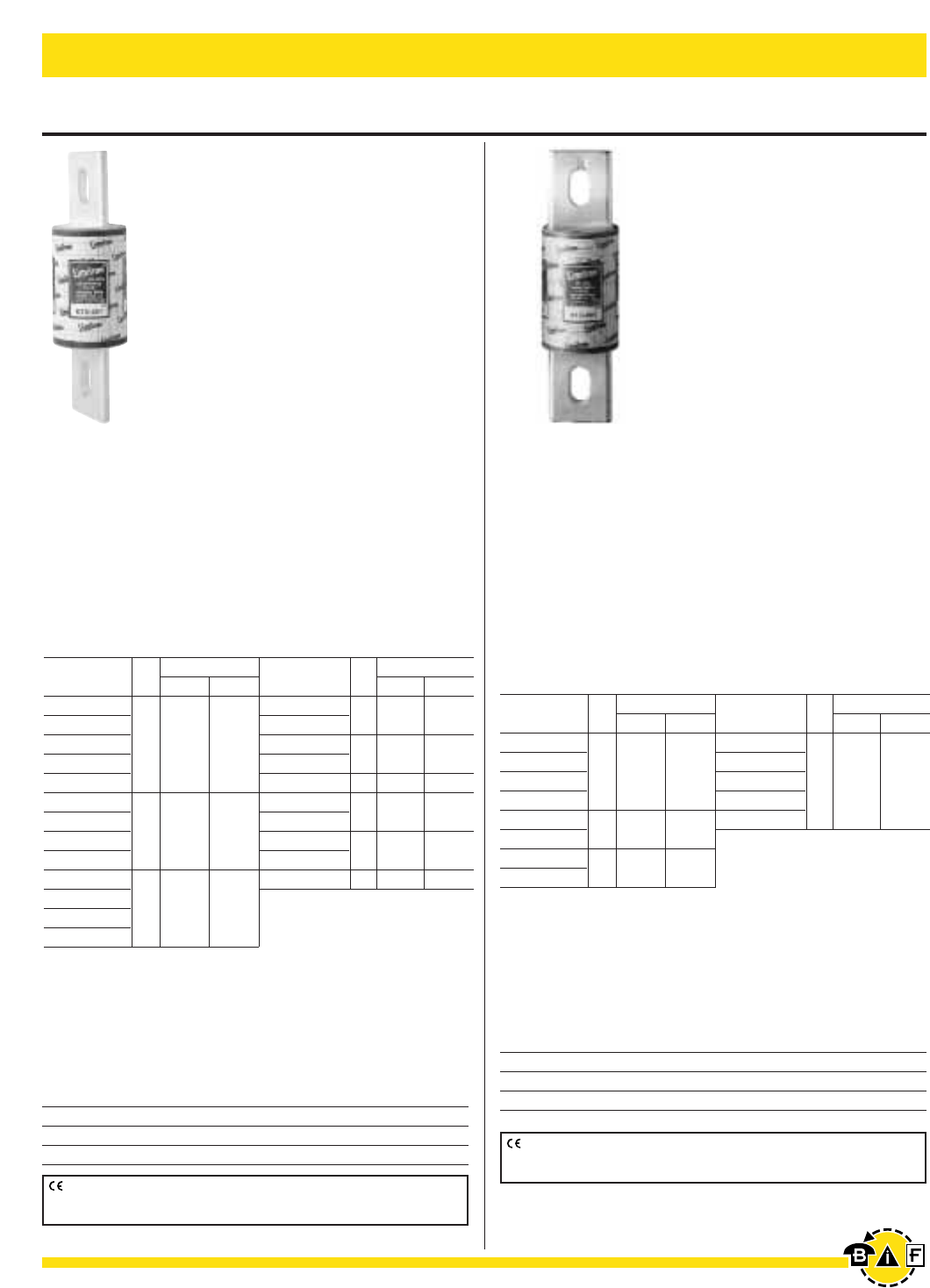
CUBEFUSE™ and Fuseholder TCF & TCFH
Finger-Safe Dual-Element Time-Delay Fuses
Indicating – 600 Volts or Less 1-60 Amps
Electrical - Power Fuses
Data Sheet: 9000
Catalog Symbol: TCF (Fuse) & TCFH (Holder)
Dual-Element, Time-Delay Fuse: 10 Seconds
Minimum Operating Time at 500% Rated Current
Ampere Rating: 1 to 60A
Voltage Rating: 600Vac (or less)
DC Voltage Rating: 300 Vdc (or less), 100,000AIR
Interrupting Rating: 300,000A RMS Symmetrical (UL)
200,000A RMS Symmetrical (CSA)
Agency Information:
UL Listed Special Purpose Fuse (UL 248-8) (1-60A)
CSA Certified Fuse (CSA-22.2 No. 106) (1-60A)
UL Listed Special Purpose Fuseholder
CSA Certified Fuseholder (C22.2 Nos. 39 & 65)
Other Electrical Certifications:
CE compliance for the European Union Low Voltage
Directive (50-1000Vac, 75-1500Vdc)
Catalog Numbers
TCF1 TCF3 TCF6 TCF10
TCF15 TCF17-1/2 TCF20 TCF25
TCF30 TCF35 TCF40 TCF45
TCF50 TCF60
CUBEFuse™ Fuseholder Catalog Data
Amps Poles Wire * Dual Wire * Part Number
30 1 14 AWG to 8 AWG CU 14 AWG CU TCFH30
60 1 14 AWG to 4 AWG CU 10 AWG to 6 AWG CU TCFH60
* 75ºC (MIN) CU Wire Only
• The world’s first finger safe industrial fuse system.
• True dual-element fuse construction with a minimum of 10
seconds time-delay at 500% of rating.
• Long time-delay minimizes nuisance circuit openings due
to temporary overloads and transient surges.
• Meets UL Class J Time-Delay electrical performance re-
quirements.
• High interruption rating to safely interrupt faults up to
300,000 amperes.
• Faster response to damaging faults reduces destructive
thermal and magnetic forces.
• Permanent open fuse indication.
• Designed to be an internationally accepted and specified
world class product.
• Smallest footprint of any power class fuse including Class
J, CC, T and RK.
• Meets requirements of IEC 60529 for IP-20 finger safe rat-
ing.
• No venting of arc or molten metal and gases during open-
ing.
• Robust cycling and inrush current withstand.
• Low let through currents under fault conditions.
• Provides TYPE 2 “no damage” protection for IEC motors
starters when properly sized.
• Low watt loss reduces power consumption and lowers
operating temperature.
• Conventional Class J fuse case sizes and ampere ratings.
• Dovetail fuseholder design for ganging multiple fuse poles.
• 30 and 60 Amp fuseholders can be ganged together.
• 30 Amp fuses can be plugged into the 60A holder without a
reducer.
• 35mm DIN rail and chassis mounting features.
• Fuseholder wire ports rated for dual wires.
Carton Quantity and Weight
Ampere Carton. Weight Per Carton
Rating Qty Lbs. Kg.
TCF1-30 12 1.39 .518
TCFH1-30 12 2.42 .902
TCF35-60 12 1.42 .530
TCFH35-60 12 2.57 .958
Time-Current and Current Limitation Curves on page 219.
Bussmann®
5
For complete specification data, call Bussmann Information Fax ~ 636.527.1450
Electrical - Power Fuses
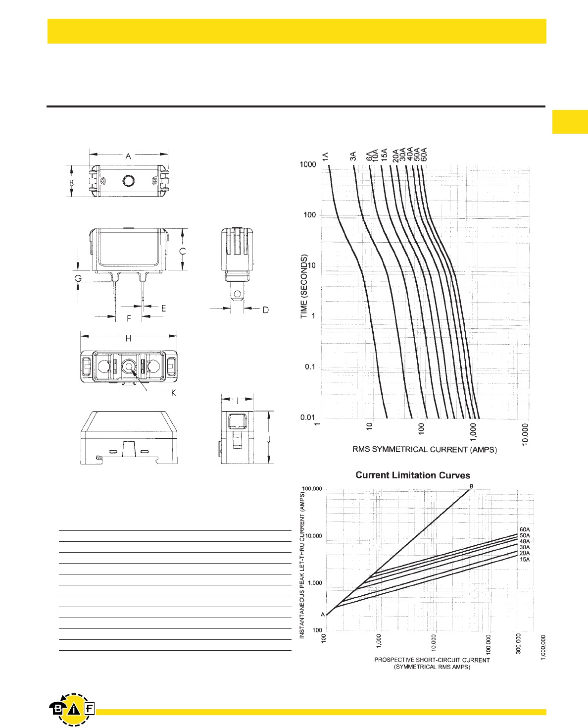
CUBEFUSE™ and Fuseholder TCF & TCFH
Finger-Safe Dual-Element Time-Delay Fuses
Indicating – 600 Volts or Less 1-60 Amps
Dimensional Data For TCF and TCFH
Dimension 30A in [mm] 60A in [mm]
A 1.88 [47.75] 2.13 [54.10]
B .75 [19.05] 1.00 [25.40]
C 1.00 [25.40] 1.13 [28.58]
D .31 [7.94] .44 [11.11]
E .04 [1.02] .04 [1.02]
F .63 [15.88] .63 [15.88]
G .27 [6.86] .38 [9.65]
H 2.30 [58.42] 2.60 [66.04]
I .76 [19.30] 1.03 [26.16]
J 1.27 [32.18] 1.53 [38.86]
K .15 [3.81] .17 [4.32]
Time-Current Characteristic Curves–Average Melt
Bussmann®
6For complete specification data, call Bussmann Information Fax ~ 636.527.1450
Electrical - Power Fuses
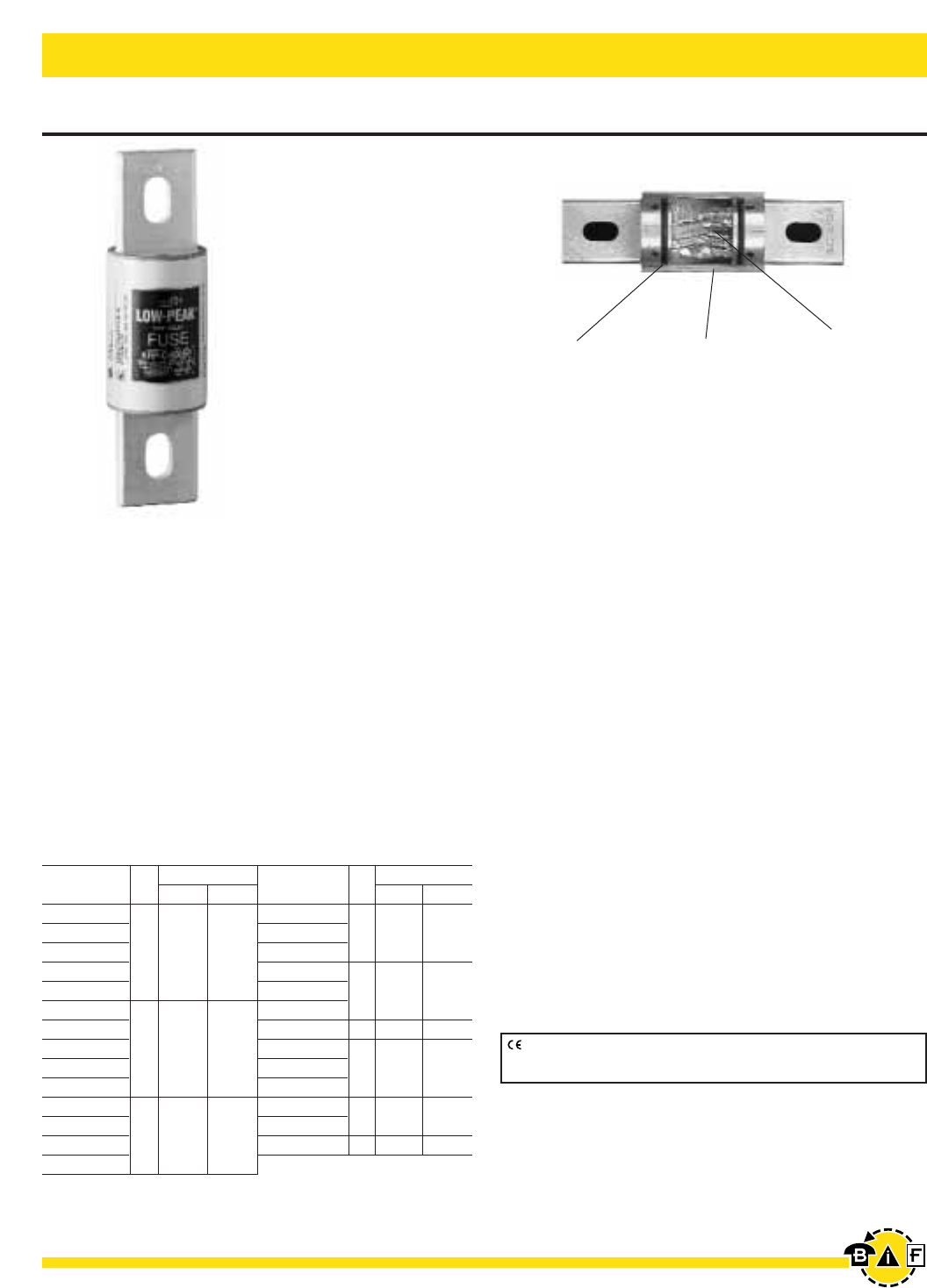
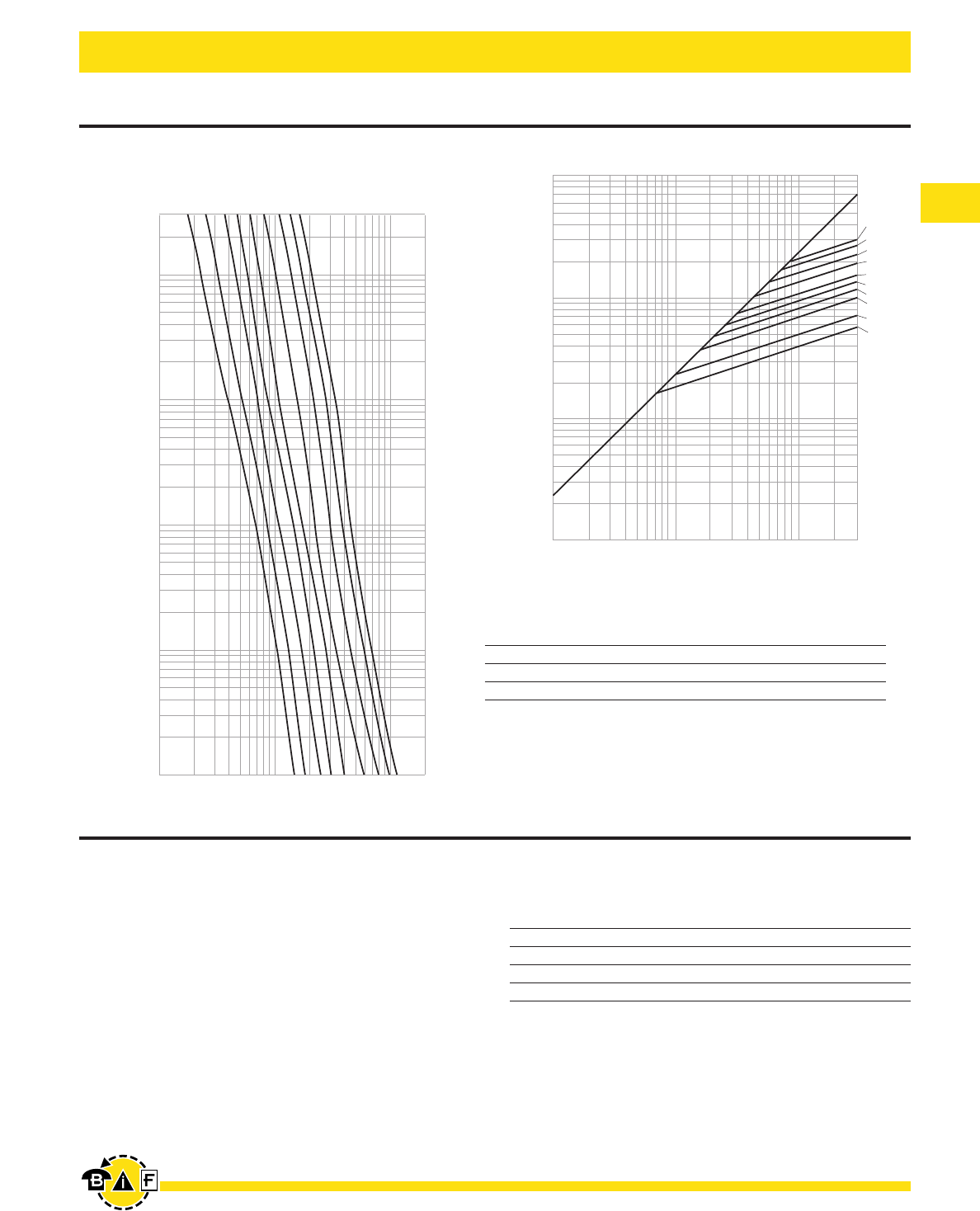
KRP-C_SP
Time-Delay – 4 seconds (minimum) at 500% rated current
Ampere Ratings: 601-6000A†
Voltage Rating: 600Vac (or less), 300Vdc for 601-2000A.
Interrupting Rating: ac: 300,000A RMS Sym.
dc: 100,000A
Agency Information:
UL Listed-Special Purpose (meets all performance
requirements of UL Standard 248-10 for Class L fuses),
Guide JFHR, File E56412
CSA Certified (200,000 AIR), Class 1422-02, File 53787,
Class L per CSA C22.2, No. 248.10
Dimensions: See pages 2-3 for Class L dimensional data.
•All-purpose silver linked fuse for both overload and short-
circuit protection for high capacity systems (mains and large
feeders).
•Time-delay (minimum of four seconds at five times amp rating)
for close sizing.
•Current limiting action of the fuse generally affords consider-
able reduction in bus bracing.
•Interrupting rating of 300,000 amperes complies with
NEC Sections 110-9 and 230-65 for today’s large capacity
systems.
•O-ring seals maximize pressure build-up during current limiting
action and ensure filler retention.
•High grade silica-sand filler; accelerates response of fuse to
short-circuits by having quenching effect upon the fuse arc.
•99.9% pure silver fuselinks. The high conductivity of silver
gives low watt loss and low operating temperature at normal
current levels; minimizes total clearing I2t fault energy let-thru.
•Selective coordination (blackout prevention)
•Glass melamine tube.
•Silver plated end bells.
•Reducers not necessary.
Ordering Information
Catalog Ctn. Weight**
Number Qty. Lbs. Kg.
KRP-C-601SP
KRP-C-650SP
KRP-C-700SP 1 3.75 1.7
KRP-C-750SP
KRP-C-800SP
KRP-C-801SP
KRP-C-900SP
KRP-C-1000SP 1 4.5 2.041
KRP-C-1100SP
KRP-C-1200SP
KRP-C-1350SP
KRP-C-1400SP
KRP-C-1500SP 1 6.50 2.948
KRP-C-1600SP
Catalog Ctn. Weight**
Number Qty. Lbs. Kg.
KRP-C-1800SP
KRP-C-1900SP 1 8.5 3.85
KRP-C-2000SP
KRP-C-2001SP
KRP-C-2400SP 1 17.25 7.824
KRP-C-2500SP
KRP-C-3000SP 1 18.25 8.278
KRP-C-3500SP
KRP-C-3800SP 1 23.50 10.659
KRP-C-4000SP
KRP-C-4500SP 1 29 13.154
KRP-C-5000SP
KRP-C-6000SP 1 36 16.329
Special purpose rating of 300,000 AIR.
**Weight per carton.
†Use KRP-CL for current ratings below 601A.
O-RING SEALS
Formation of arc gas within fuse
body suppresses arcing; lowers
arcing I2t energy. O-ring seals
maximize pressure build-up during
current limiting action. Also volume
of sand is critical. Slight loss can
adversely impact on current limit-
ing action. O-ring seals insure filler
retention. They compensate to a
degree for switchgear misalign-
ment, and expansion and con-
traction of mounting surfaces
with change in load to no-load
conditions.
SAND FILLER
High grade silica-sand filler.
Accelerates response of fuse to
short-circuits by having quenching
effect upon the fuse arc.
Substantially contributes to current
limiting action.
99.9% PURE SILVER
FUSELINKS
Embody “silver-sand” design.
99.9% pure silver links; silica-
sand filler. The high conductivity of
silver gives low watt loss and low
operating temperature at normal
current levels; minimizes total
clearing I2t fault energy let-thru…
state-of-art fuse design. High
degree of current limitation holds
down fault currents and levels of
destructive energy. (Although other
link materials can provide current
limitation, they do not equal that
of silver.)
Low-Peak®Time-Delay, Class L Fuses
Data Sheet: 1008 and 1009
CE logo denotes compliance with European Union Low Voltage Directive
(50-1000Vac, 75-1500Vdc). Refer to Data Sheet: 8002 or contact
Bussmann Application Engineering at 636-527-1270 for more information.
Bussmann®
7
For complete specification data, call Bussmann Information Fax ~ 636.527.1450
Electrical - Power Fuses
Data Sheet: 1016
1000,000
10,000
1,000
10,000
300,000
INSTANTANEOUS PEAK LET-THRU CURRENT IN AMPS
100,000
100,000
6,000A
5,000A
4,000A
3,000A
2,500A
2,000A
1,600A
1,200A
800A
601A
A
AMPERE
RATING
B
1,000
300
100
10
1
.1
.01
1,000
10,000
100,000
200,000
TIME IN SECONDS
800A
1200A
1600A
2000A
2500A
3000A
4000A
5000A
6000A
AMPERE
RATING
KRP-CL
Current Limiting, Time-Delay
Construction: Glass Melamine Tube
Ampere Ratings: 150-600A.
Voltage Rating: 600Vac (or less)
These fuses have the same performance characteristics as
KRP-C fuses. They are used in applications where there is a
need for Class L dimension fuses with 150-600A ratings.
KRP-CL fuses have the same dimensions as
800A Class L fuses.
Dimensions: See pages 2-3 for Class L dimensional data.
Ordering Information
Catalog Number (Symbol & Amps)
KRP-CL-150 KRP-CL-300 KRP-CL-500
KRP-CL-200 KRP-CL-350 KRP-CL-600
KRP-CL-225 KRP-CL-400
KRP-CL-250 KRP-CL-450
Weight of each is 3.75 lbs.
CURRENT IN
AMPERES
Current Limitation Curves—KRP-CTime-Current Characteristic Curves—Average Melt
KRP-C
Recommended Fuseblocks for Class L: (601–1200A)
Catalog Number Poles
51215 1
51235 3
Use KRP-CL for current ratings below 601A.
PROSPECTIVE SHORT CIRCUIT CURRENT
SYMMETRICAL RMS AMPERES
Bussmann®
8For complete specification data, call Bussmann Information Fax ~ 636.527.1450
Electrical - Power Fuses
Data Sheet: 1010 Data Sheet: 1013
KLU
Time-Delay – 5 seconds (minimum) at 500%
rated current
Bolt Mount
Ampere Ratings: 601-4000A.
Voltage Rating: 600Vac (or less)
Interrupting Rating: 200,000A RMS Sym.
Agency Information: Std. 248-10, Class L
UL Listed, Guide JDDZ, File E4273
CSA Certified, CSA Class 1422-02, File 53787
Dimensions: See pages 2-3 for Class L dimensional data.
Ordering Information
Catalog Ctn. Weight**
Number Qty. Lbs. Kg.
KLU-601
KLU-650
KLU-700 1 3.75 1.70
KLU-800
KLU-1000 1 4.25 1.93
KLU-1200
KLU-1500 1 6.00 2.72
KLU-1600
Catalog Ctn. Weight**
Number Qty. Lbs. Kg.
KLU-1800
KLU-2000
KLU-2500 1 8.50 3.86
KLU-3000
KLU-4000
**Weight per carton.
•KLU Limitron® general purpose copper link fuses.
•Current limiting—provides component short-circuit
protection.
•Fuse reducers not necessary.
•See KRP-CL for current ratings below 601A
Recommended Fuseblocks: (601–1200A)
Catalog Number Poles
51215 1
51235 3
Limitron® Class L Fuses
KTU
Fast Acting, Bolt Mount
Ampere Ratings: 601-6000A.
Voltage Rating: 600Vac (or less)
Interrupting Rating: 200,000 RMS Sym.
Agency Information: Std. 248-10, Class L
UL Listed, Guide JDDZ, File E4273
CSA Certified, Class 1422-02, File 53787
Dimensions: See pages 2-3 for Class L dimensional data.
Ordering Information
Catalog Ctn. Weight**
Number Qty. Lbs. Kg.
KTU-601
KTU-650
KTU-700 1 3.75 1.70
KTU-750
KTU-800
KTU-801
KTU-900
KTU-1100 1 4.25 1.927
KTU-1200
KTU-1350
KTU-1400
KTU-1500 1 6 2.721
KTU-1600
Catalog Ctn. Weight**
Number Qty. Lbs. Kg.
KTU-1800
KTU-2000 1 8.5 3.855
KTU-2400
KTU-2500 1 17 7.711
KTU-3000 1 17.25 7.824
KTU-3001
KTU-4000 1 24 10.886
KTU-4500 1 31 14.061
KTU-5000
KTU-6000 1 34 15.422
**Weight per carton.
Recommended Fuseblocks for Class L: (601–1200A)
Catalog Number Poles
51215 1
51235 3
•For protection of circuit breakers with lower interrupting
ratings and non-inductive loads such as lighting and
heating circuits.
•99.9% pure silver-links.
•Reducers not necessary.
CE logo denotes compliance with European Union Low Voltage Directive
(50-1000Vac, 75-1500Vdc). Refer to Data Sheet: 8002 or contact
Bussmann Application Engineering at 636-527-1270 for more information.
CE logo denotes compliance with European Union Low Voltage Directive
(50-1000Vac, 75-1500Vdc). Refer to Data Sheet: 8002 or contact
Bussmann Application Engineering at 636-527-1270 for more information.
Bussmann®
9
For complete specification data, call Bussmann Information Fax ~ 636.527.1450
Electrical - Power Fuses
Data Sheet: (LPN-RK) 1003 (0-60) & 1004 (70-600) Data Sheet: (LPS-RK) 1001 (0-60) & 1002 (70-600)
Low-Peak®Dual-Element, Time-Delay, Class RK1 Fuses
LPN-RK_SP (250V)
LPS-RK_SP (600V)
Dual-Element, Time-Delay – 10 seconds (minimum) at
500% rated current (8 seconds for 0-30A sizes)
Ampere Ratings: ⁄Ω¡º-600A.
Voltage Rating: LPN-RK: 250Vac (or less),
125Vdc (⁄Ω¡º-60A); 250Vdc (70-600 A)
LPS-RK: 600Vac (or less), 300Vdc
Current Limiting RK1 Fuse
Interrupting Rating:
ac: 300,000A RMS Sym.
dc: 100,000A
Agency Information:
UL Listed – Special Purpose**, Guide JFHR, File E56412
CSA Certified (200,000 AIR), Class RK1 per CSA C22.2,
No. 248.12, Class 1422-02, File 53787
Dimensions: See pages 2-3 for Class RK1 dimensional data.
Catalog Numbers (250Vac/125Vdc)
LPN-RK-⁄Ω¡ºSP LPN-RK-3⁄Ω™SP LPN-RK-60SP
LPN-RK-⁄fiΩ¡ººSP LPN-RK-4SP LPN-RK-70SP
LPN-RK-¤Ω¡ºSP LPN-RK-4⁄Ω™SP LPN-RK-80SP
LPN-RK-‹Ω¡ºSP LPN-RK-5SP LPN-RK-90SP
LPN-RK-›Ω¡ºSP LPN-RK-5flΩ¡ºSP LPN-RK-100SP
LPN-RK-⁄Ω™SP LPN-RK-6SP LPN-RK-110SP
LPN-RK-flΩ¡ºSP LPN-RK-6⁄Ω¢SP LPN-RK-125SP
LPN-RK-°Ω¡ºSP LPN-RK-8SP LPN-RK-150SP
LPN-RK-1SP LPN-RK-9SP LPN-RK-175SP
LPN-RK-1⁄Ω•SP LPN-RK-10SP LPN-RK-200SP
LPN-RK-1⁄Ω¢SP LPN-RK-12SP LPN-RK-225SP
LPN-RK-1›Ω¡ºSP LPN-RK-15SP LPN-RK-250SP
LPN-RK-1flΩ¡ºSP LPN-RK-17⁄Ω™SP LPN-RK-300SP
LPN-RK-1°Ω¡ºSP LPN-RK-20SP LPN-RK-350SP
LPN-RK-2SP LPN-RK-25SP LPN-RK-400SP
LPN-RK-2⁄Ω¢SP LPN-RK-30SP LPN-RK-450SP
LPN-RK-2⁄Ω™SP LPN-RK-35SP LPN-RK-500SP
LPN-RK-2°Ω¡ºSP LPN-RK-40SP LPN-RK-600SP
LPN-RK-3SP LPN-RK-45SP
LPN-RK-3¤Ω¡ºSP LPN-RK-50SP
**Meets all performance requirements of UL Standard 248-12 for Class RK1 fuses.
0-60A fuses available with Nickel plate option. (Ex: LPSRK30SPNP)
70-600A fuses available with Tin plate option. (Ex: LPS-RK-100SP-TP)
•Current limitation for maximum short-circuit protection.
High speed of response is highly sensitive to fault currents, but
insensitive to starting current and transient surges.
•Provides long time-delay for temporary motor start-up.
•Time-delay permits 125% FLA sizing for back-up, motor running
protection.
Catalog Numbers (600Vac/300Vdc)
LPS-RK-⁄Ω¡ºSP LPS-RK-2⁄Ω™SP LPS-RK-12SP LPS-RK-110SP
LPS-RK-¤Ω¡ºSP LPS-RK-2°Ω¡ºSP LPS-RK-15SP LPS-RK-125SP
LPS-RK-‹Ω¡ºSP LPS-RK-3SP LPS-RK-17⁄Ω™SP LPS-RK-150SP
LPS-RK-›Ω¡ºSP LPS-RK-3¤Ω¡ºSP LPS-RK-20SP LPS-RK-175SP
LPS-RK-⁄Ω™SP LPS-RK-3⁄Ω™SP LPS-RK-25SP LPS-RK-200SP
LPS-RK-flꭧSP LPS-RK-4SP LPS-RK-30SP LPS-RK-225SP
LPS-RK-°Ω¡ºSP LPS-RK-4⁄Ω™SP LPS-RK-35SP LPS-RK-250SP
LPS-RK-1SP LPS-RK-5SP LPS-RK-40SP LPS-RK-300SP
LPS-RK-1⁄Ω•SP LPS-RK-5flΩ¡ºSP LPS-RK-45SP LPS-RK-350SP
LPS-RK-1⁄Ω¢SP LPS-RK-6SP LPS-RK-50SP LPS-RK-400SP
LPS-RK-1›Ω¡ºSP LPS-RK-6⁄Ω¢SP LPS-RK-60SP LPS-RK-450SP
LPS-RK-1⁄Ω™SP LPS-RK-7SP LPS-RK-70SP LPS-RK-500SP
LPS-RK-1flꭧSP LPS-RK-8SP LPS-RK-80SP LPS-RK-600SP
LPS-RK-1°Ω¡ºSP LPS-RK-9SP LPS-RK-90SP
LPS-RK-2⁄Ω¢SP LPS-RK-10SP LPS-RK-100SP
**Meets all performance requirements of UL Standard 248-12 for Class RK1 fuses.
Carton Quantity and Weight
LPN-RK (250Vac) LPS-RK (600Vac)
Ampere Carton Weight* Carton Weight*
Ratings Qty. Lbs. Kg Qty. Lbs. Kg
0-30 10 0.5 0.227 10 1.6 0.725
35-60 10 1.2 0.544 10 2.6 1.178
70-100 5 1.5 0.680 5 4.0 1.814
110-200 1 0.69 0.313 1 2.0 0.906
225-400 1 1.75 0.793 1 4.6 2.086
450-600 1 3.25 1.474 1 5.6 2.540
*Weight per carton.
CE logo denotes compliance with European Union Low Voltage Directive
(50-1000Vac, 75-1500Vdc). Refer to Data Sheet: 8002 or contact
Bussmann Application Engineering at 636-527-1270 for more information.
Bussmann®
10 For complete specification data, call Bussmann Information Fax ~ 636.527.1450
Electrical - Power Fuses
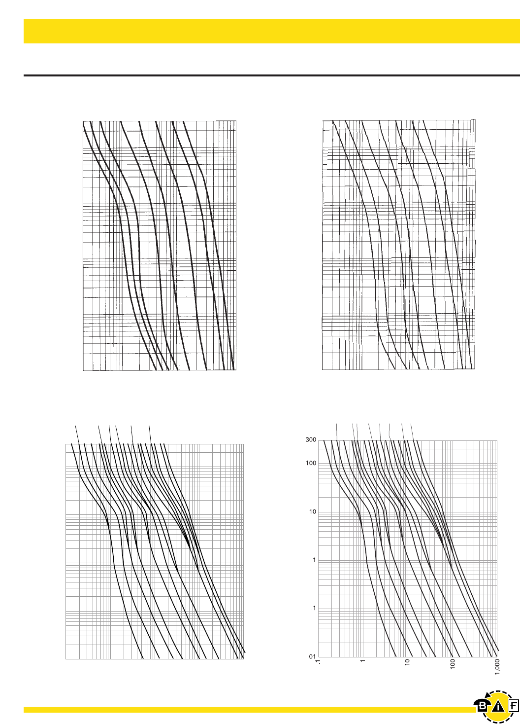
Data Sheet: (LPS-RK) 1001 (0-60) & 1002 (70-600)Data Sheet: (LPN-RK) 1003 (0-60) & 1004 (70-600)
1
2
4
5
8
10
12
AMPERE RATING
300
100
10
1
.1
.01
.1
1
10
100
1,000
TIME IN SECONDS
RMS SYMMETRICAL CURRENT IN AMPERES
1/10 15/100
2/10
3/10
4/10 1/2
6/10 8/10
11/4
16/10
21/2
32/10
61/4
1/10
15/100
2/10
4/10
6/10
16/10
8/10
1
2
4
5
8
12
10
11/4
21/232/10
61/4
1/2
3/10
Time-Current Characteristic Curves—Average Melt
LPN-RK
250V LPS-RK
600V
TIME IN SECONDS
TIME IN SECONDS
TIME IN SECONDS
CURRENT IN AMPERES
CURRENT IN AMPERES
CURRENT IN AMPERES
CURRENT IN AMPERES
AMPERE
RATING
AMPERE
RATING
AMPERE
RATING
Low-Peak®Dual-Element, Time-Delay, Class RK1 Fuses
300
100
10
1
.1
.01
300
100
10
1
.1
.01
20
100
1,000
10,000
20
100
1,000
10,000
15 20 30 60 100 200 400 600 20 30 60 100 200 400 600
Bussmann®
11
For complete specification data, call Bussmann Information Fax ~ 636.527.1450
Electrical - Power Fuses
Low-Peak®Dual-Element, Time-Delay, Class RK1 Fuses
Data Sheet: (LPN-RK) 1003 (0-60) & 1004 (70-600) Data Sheet: (LPS-RK) 1001 (0-60) & 1002 (70-600)
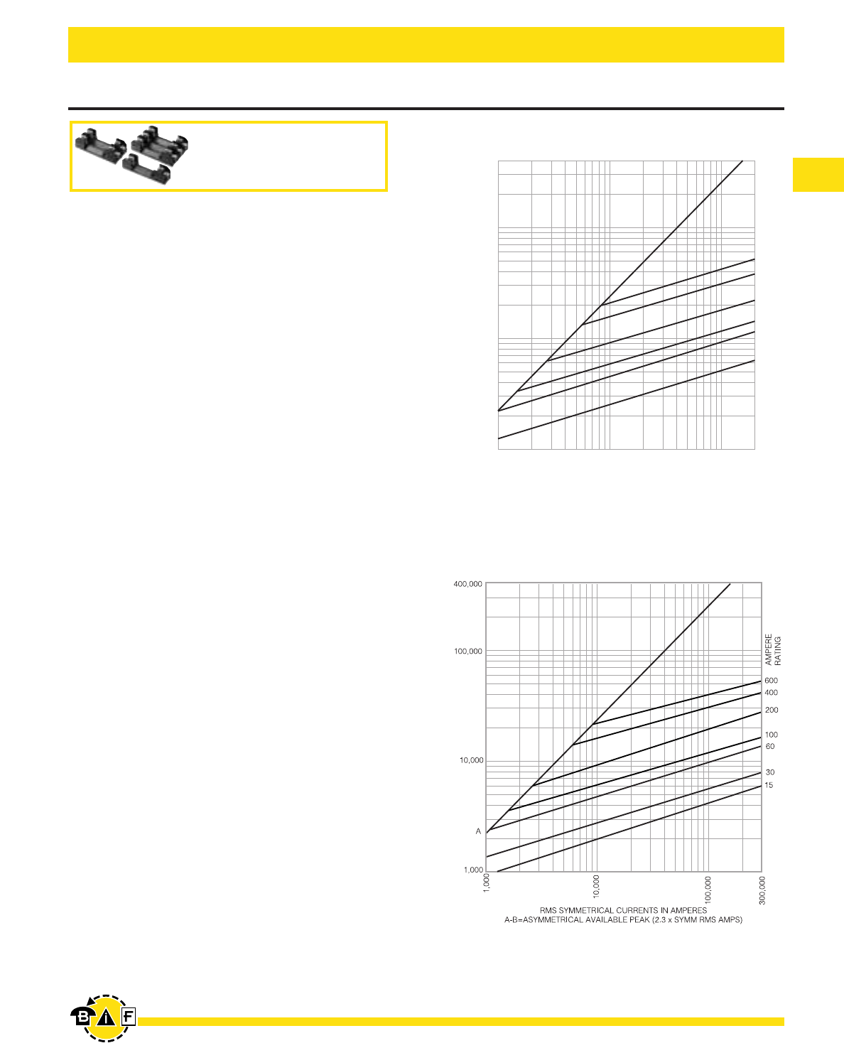
A
B
600
400
200
100
AMPERE
RATING
400,000
100,000
10,000
1,000
1,000
10,000
100,000
200,000
RMS SYMMETRICAL CURRENTS IN AMPERES
A–B=ASYMMETRICAL AVAILABLE PEAK (2.3 X SYMM RMS AMPS)
INSTANTANEOUS PEAK LET-THRU CURRENT IN AMPS
60
30
B
INSTANTANEOUS PEAK LET-THRU CURRENT IN AMPS
Current Limitation Curves—LPN-RK (250V)
Current Limitation Curves—LPS-RK (600V)
Recommended fuseblocks for
Class R 250 & 600V fuses
See pages 47-52
Bussmann®
12 For complete specification data, call Bussmann Information Fax ~ 636.527.1450
Electrical - Power Fuses
Data Sheet: 1019 (0-60), 1020 (70-600)
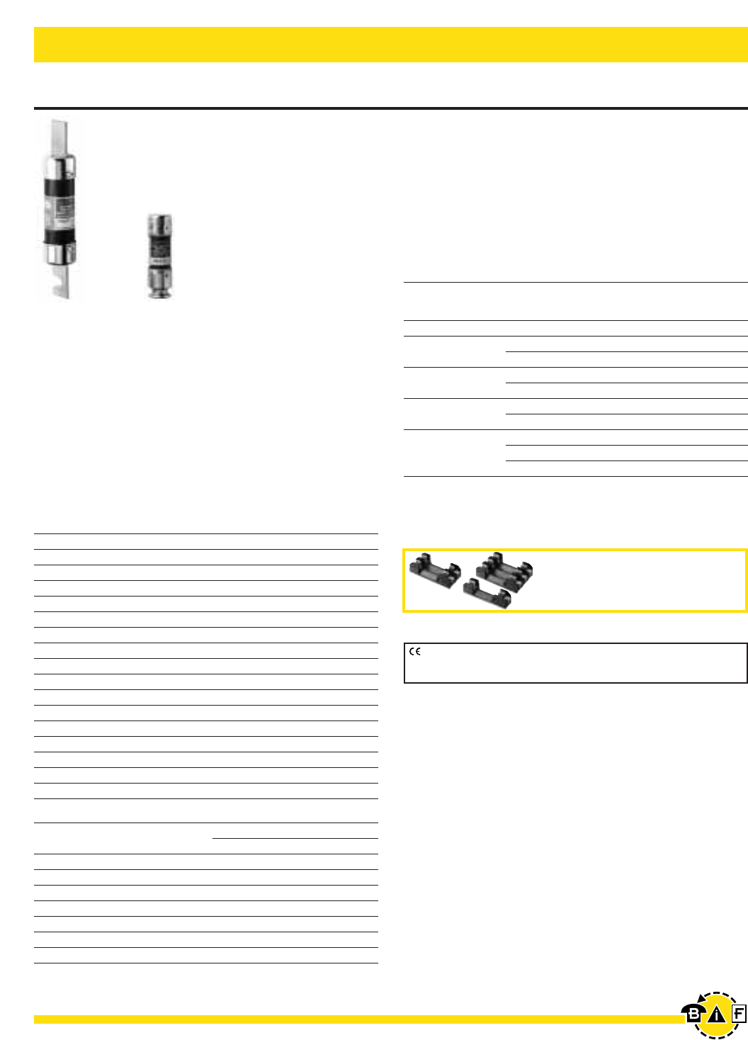
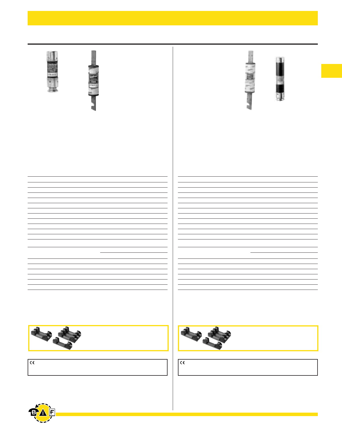
Fusetron®Dual-Element, Time-Delay, Class RK5 Fuses
FRN-R (250V)
Dual-Element, Time-Delay – 10 seconds (minimum) at
500% rated current
Ampere Ratings: ⁄Ω¡º-600A.
Voltage Rating: 250Vac (or less), 125Vdc (⁄Ω¡º-200A)
250Vdc (201-600A)
Current Limiting RK5 Fuse
Interrupting Rating: 200,000A RMS Sym.
20,000A dc
Agency Information: Std. 248-12, Class RK5
UL Listed, Guide JDDZ, File E4273
CSA Certified, Class 1422-01, File 53787
Dimensions: See pages 2-3 for Class RK5 dimensional data.
Catalog Numbers (250Vac/125Vdc)
FRN-R-⁄Ω¡º FRN-R-2 FRN-R-10 FRN-R-100
FRN-R-⁄Ω• FRN-R-2⁄Ω¢ FRN-R-12 FRN-R-110
FRN-R-⁄fiΩ¡ºº FRN-R-2⁄Ω™ FRN-R-15 FRN-R-125
FRN-R-¤Ω¡º FRN-R-2°Ω¡º FRN-R-17⁄Ω™ FRN-R-150
FRN-R-⁄Ω¢ FRN-R-3 FRN-R-20 FRN-R-175
FRN-R-‹Ω¡º FRN-R-3¤Ω¡º FRN-R-25 FRN-R-200
FRN-R-›Ω¡º FRN-R-3⁄Ω™ FRN-R-30 FRN-R-225
FRN-R-⁄Ω™ FRN-R-4 FRN-R-35 FRN-R-250
FRN-R-flΩ¡º FRN-R-4⁄Ω™ FRN-R-40 FRN-R-300
FRN-R-°Ω¡º FRN-R-5 FRN-R-45 FRN-R-350
FRN-R-1 FRN-R-5flꭧ FRN-R-50 FRN-R-400
FRN-R-1⁄Ω• FRN-R-6 FRN-R-60 FRN-R-450
FRN-R-1⁄Ω¢ FRN-R-6⁄Ω¢ FRN-R-70 FRN-R-500
FRN-R-1›Ω¡º FRN-R-7 FRN-R-75 FRN-R-600
FRN-R-1⁄Ω™ FRN-R-7⁄Ω™ FRN-R-80
FRN-R-1flꭧ FRN-R-8 FRN-R-85
FRN-R-1°Ω¡º FRN-R-9 FRN-R-90
Carton Quantity and Weight
Ampere Carton Weight*
Ratings Qty. Lbs. Kg.
0-15 10 0.40 0.181
17.5-30 10 .50 0.227
35-60 10 1.00 0.453
70-100 5 1.5 0.680
101-200 1 0.77 0.349
201-400 1 1.52 0.689
401-600 1 2.94 1.334
*Weight per carton.
•Provides motor overload, ground fault and short-circuit
protection when sized properly.
•Helps protect motors against burnout from overloads when
sized properly.
•Helps protect motors against burnout from single phasing
on three phase systems when sized properly.
•Simplifies and improves blackout prevention (selective
coordination) when sized properly.
Fuse Reducers For Class R Fuses
Desired Catalog Number
Equipment Fuse (Case) (Pairs)
Fuse Clips Size 250V
60A 30A No. 263-R
100A 30A No. 213-R
60A No. 216-R
200A 60A No. 226-R
100A No. 2621-R
100A No. 2641-R
400A 200A No. 242-R
100A No. 2661-R
600A 200A No. 2662-R
400A No. 2664-R*
*Single reducer only (pair not required).
Time-Current and Current Limitation Curves located on
page 223.
CE logo denotes compliance with European Union Low Voltage Directive
(50-1000Vac, 75-1500Vdc). Refer to Data Sheet: 8002 or contact
Bussmann Application Engineering at 636-527-1270 for more information.
Recommended fuseblocks for
Class R 250V fuses
See pages 47-49
Bussmann®
13
For complete specification data, call Bussmann Information Fax ~ 636.527.1450
Electrical - Power Fuses
Data Sheet: 1017 (0-60), 1018 (70-600)
Fusetron®Dual-Element, Time-Delay, Class RK5 Fuses
FRS-R (600V)
Dual-Element, Time-Delay – 10 seconds (minimum) at
500% rated current
Ampere Ratings: ⁄Ω¡º-600A.
Voltage Rating: 600Vac (or less), 300Vdc
Current Limiting RK5 Fuse
Interrupting Rating: 200,000A RMS Sym.
(20,000A @ 300Vdc)
Agency Information: Std. 248-12, Class RK5
UL Listed, Guide JDDZ, File E4273
CSA Certified, Class 1422-02, File 53787
Dimensions: See pages 2-3 for Class RK5 dimensional data.
Catalog Numbers (600Vac/ 300Vdc)
FRS-R-⁄Ω¡º FRS-R-2 FRS-R-10 FRS-R-110
FRS-R-⁄Ω• FRS-R-2⁄Ω¢ FRS-R-12 FRS-R-125
FRS-R-⁄fiΩ¡ºº FRS-R-2⁄Ω™ FRS-R-15 FRS-R-150
FRS-R-¤Ω¡º FRS-R-2°Ω¡º FRS-R-17⁄Ω™ FRS-R-175
FRS-R-⁄Ω¢ FRS-R-3 FRS-R-20 FRS-R-200
FRS-R-‹Ω¡º FRS-R-3¤Ω¡º FRS-R-25 FRS-R-225
FRS-R-›Ω¡º FRS-R-3⁄Ω™ FRS-R-30 FRS-R-250
FRS-R-⁄Ω™ FRS-R-4 FRS-R-35 FRS-R-275
FRS-R-flΩ¡º FRS-R-4⁄Ω™ FRS-R-40 FRS-R-300
FRS-R-°Ω¡º FRS-R-5 FRS-R-45 FRS-R-325
FRS-R-1 FRS-R-5flꭧ FRS-R-50 FRS-R-350
FRS-R-1⁄Ω• FRS-R-6 FRS-R-60 FRS-R-400
FRS-R-1⁄Ω¢ FRS-R-6⁄Ω¢ FRS-R-70 FRS-R-450
FRS-R-1›Ω¡º FRS-R-7 FRS-R-75 FRS-R-500
FRS-R-1⁄Ω™ FRS-R-7⁄Ω™ FRS-R-80 FRS-R-600
FRS-R-1flꭧ FRS-R-8 FRS-R-90
FRS-R-1°Ω¡º FRS-R-9 FRS-R-100
Carton Quantity and Weight
Ampere Carton Weight*
Ratings Qty. Lbs. Kg.
0-15 10 0.40 0.181
17.5-30 10 0.50 0.227
35-60 10 3.10 1.406
65-100 1 0.54 0.245
101-200 1 1.22 0.544
201-400 1 3.00 1.359
401-600 1 5.00 2.268
*Weight per carton.
Fuse Reducers For Class R Fuses
Desired Catalog Number
Equipment Fuse (Case) (Pairs)
Fuse Clips Size 600V
60A 30A No. 663-R
100A 30A No. 216-R
60A No. 616-R
200A 60A No. 626-R
100A No. 2621-R
400A 100A No. 2641-R
200A No. 642-R
100A No. 2661-R
600A 200A No. 2662-R
400A No. 2664-R*
*Single reducer only (pair not required).
Time-Current and Current Limitation Curves located on
page 224.
CE logo denotes compliance with European Union Low Voltage Directive
(50-1000Vac, 75-1500Vdc). Refer to Data Sheet #8002 or contact
Bussmann Application Engineering at 636-527-1270 for more information.
Recommended fuseblocks for
Class R 600V fuses
See pages 50-52
Bussmann®
14 For complete specification data, call Bussmann Information Fax ~ 636.527.1450
Electrical - Power Fuses
Data Sheet: 1021 (0-600) Data Sheet: 1022 (0-600)
Dura-Lag™Dual-Element, Time-Delay, Class RK5 Fuses
DLN-R (250V)
Dual-Element, Time-Delay – 10 seconds (minimum) at
500% rated current
Ampere Ratings: 1-600A
Voltage Rating: 250Vac (or less), 125Vdc
Current Limiting RK5 Fuses
Interrupting Rating: 200,000A RMS Sym.
(20,000A @125Vdc)
Agency Information: Std. 248-12, Class RK5
UL Listed, Guide JDDZ, File E4273
CSA C22.2, No. 106-HRCI-R, File 53787
Dimensions: See pages 2-3 for Class RK5 dimensional data.
Catalog Numbers (250Vac/125Vdc)
DLN-R-1 DLN-R-15 DLN-R-100
DLN-R-2 DLN-R-20 DLN-R-125
DLN-R-2⁄Ω™ DLN-R-25 DLN-R-150
DLN-R-3 DLN-R-30 DLN-R-175
DLN-R-3¤Ω¡º DLN-R-35 DLN-R-200
DLN-R-4 DLN-R-40 DLN-R-225
DLN-R-5 DLN-R-45 DLN-R-250
DLN-R-6 DLN-R-50 DLN-R-300
DLN-R-6⁄Ω¢ DLN-R-60 DLN-R-400
DLN-R-8 DLN-R-70 DLN-R-600
DLN-R-10 DLN-R-80
DLN-R-12 DLN-R-90
Carton Quantity and Weight
Ampere Carton Weight*
Ratings Qty. Lbs. Kg.
⁄Ω¡º-30 10 0.56 0.252
35-60 10 1.38 0.621
70-100 5 1.56 0.702
110-200 1 0.90 0.405
225-400 1 1.80 0.810
450-600 1 3.30 1.485
*Weight per carton.
DLS-R (600V)
Dual-Element, Time-Delay – 10 seconds (minimum) at
500% rated current
Ampere Ratings: 1-600A
Voltage Rating: 600Vac (or less), 300Vdc
Current Limiting RK5 Fuses
Interrupting Rating: 200,000A RMS Sym.,
(20,000A @ 300Vdc)
Agency Information: Std. 248-12, Class RK5
UL Listed, Guide JDDZ, File E4273
CSA C22.2, No. 106-HRCI-R
Dimensions: See pages 2-3 for Class RK5 dimensional data.
Catalog Numbers (600Vac/300Vdc)
DLS-R-1 DLS-R-12 DLS-R-100
DLS-R-1flꭧ DLS-R-15 DLS-R-110
DLS-R-2 DLS-R-17⁄Ω™ DLS-R-125
DLS-R-2⁄Ω™ DLS-R-20 DLS-R-150
DLS-R-3 DLS-R-25 DLS-R-175
DLS-R-3⁄Ω™ DLS-R-30 DLS-R-200
DLS-R-4 DLS-R-35 DLS-R-225
DLS-R-5 DLS-R-40 DLS-R-250
DLS-R-6 DLS-R-45 DLS-R-300
DLS-R-6⁄Ω¢ DLS-R-50 DLS-R-350
DLS-R-7 DLS-R-60 DLS-R-400
DLS-R-8 DLS-R-70 DLS-R-500
DLS-R-9 DLS-R-80 DLS-R-600
DLS-R-10 DLS-R-90
Carton Quantity and Weight
Ampere Carton Weight*
Ratings Qty. Lbs. Kg.
⁄Ω¡º-30 10 1.62 0.729
35-60 10 3.00 1.35
70-100 5 3.00 1.35
110-200 1 1.41 0.635
225-400 1 3.13 1.409
450-600 1 5.28 2.376
*Weight per carton.
CE logo denotes compliance with European Union Low Voltage Directive
(50-1000Vac, 75-1500Vdc). Refer to Data Sheet: 8002 or contact
Bussmann Application Engineering at 636-527-1270 for more information.
CE logo denotes compliance with European Union Low Voltage Directive
(50-1000Vac, 75-1500Vdc). Refer to Data Sheet: 8002 or contact
Bussmann Application Engineering at 636-527-1270 for more information.
Recommended fuseblocks for
Class R 250V fuses
See pages 47-49
Recommended fuseblocks for
Class R 600V fuses
See pages 50-52
Bussmann®
15
For complete specification data, call Bussmann Information Fax ~ 636.527.1450
Electrical - Power Fuses
KTS-R (600V)
Fast Acting
Ampere Ratings: 1-600A
Voltage Rating: 600Vac (or less).
Current Limiting RK1 Fuse (curves on page 206)
Interrupting Rating: 200,000A RMS Sym.
Agency Information: Std. 248-12, Class RK1
UL Listed, Guide JDDZ, File E54273
CSA Certified, Class 1422-02, File 53787
Dimensions: See pages 2-3 for Class RK1 dimensional data.
Catalog Numbers (600Vac)
KTS-R-1 KTS-R-30 KTS-R-125
KTS-R-2 KTS-R-35 KTS-R-150
KTS-R-3 KTS-R-40 KTS-R-175
KTS-R-4 KTS-R-45 KTS-R-200
KTS-R-5 KTS-R-50 KTS-R-225
KTS-R-6 KTS-R-60 KTS-R-250
KTS-R-8 KTS-R-70 KTS-R-300
KTS-R-10 KTS-R-75 KTS-R-350
KTS-R-12 KTS-R-80 KTS-R-400
KTS-R-15 KTS-R-90 KTS-R-450
KTS-R-20 KTS-R-100 KTS-R-500
KTS-R-25 KTS-R-110 KTS-R-600
Carton Quantity and Weight
Ampere Carton Weight*
Ratings Qty. Lbs. Kg.
1-30 10 1.45 0.657
40-60 10 2.63 1.262
70-100 1 0.5 0.226
110-200 1 1.4 0.634
225-400 1 2.75 1.246
450-600 1 4.25 1.925
*Weight per carton.
Data Sheet: 1043 (0-600) Data Sheet: 1044 (0-600)
Limitron®Fast Acting, Class RK1 Fuses
KTN-R (250V)
Fast Acting
Ampere Ratings: 1-600A
Voltage Rating: 250Vac (or less).
Current Limiting RK1 Fuse (curves on page 205)
Interrupting Rating: 200,000A RMS Sym.
Agency Information: Std. 248-12, Class RK1
UL Listed, Guide JDDZ, File E54273
CSA Certified, Class 1422-02, File 53787
Dimensions: See pages 2-3 for Class RK1 dimensional data.
Catalog Numbers (250Vac)
KTN-R-1 KTN-R-30 KTN-R-125
KTN-R-2 KTN-R-35 KTN-R-150
KTN-R-3 KTN-R-40 KTN-R-175
KTN-R-4 KTN-R-45 KTN-R-200
KTN-R-5 KTN-R-50 KTN-R-225
KTN-R-6 KTN-R-60 KTN-R-250
KTN-R-8 KTN-R-70 KTN-R-300
KTN-R-10 KTN-R-75 KTN-R-350
KTN-R-12 KTN-R-80 KTN-R-400
KTN-R-15 KTN-R-90 KTN-R-450
KTN-R-20 KTN-R-100 KTN-R-500
KTN-R-25 KTN-R-110 KTN-R-600
Carton Quantity and Weight
Ampere Carton Weight*
Ratings Qty. Lbs. Kg.
1-30 10 .45 0.204
40-60 10 1.82 0.824
70-100 5 1.85 0.838
110-200 1 1.05 0.476
225-400 1 2.38 1.078
450-600 1 3.50 1.587
*Weight per carton.
CE logo denotes compliance with European Union Low Voltage Directive
(50-1000Vac, 75-1500Vdc). Refer to Data Sheet: 8002 or contact
Bussmann Application Engineering at 636-527-1270 for more information.
CE logo denotes compliance with European Union Low Voltage Directive
(50-1000Vac, 75-1500Vdc). Refer to Data Sheet: 8002 or contact
Bussmann Application Engineering at 636-527-1270 for more information.
Time-Current and Current Limitation Curves located on
page 225.
Time-Current and Current Limitation Curves located on
page 226.
Recommended fuseblocks for
Class R 250V fuses
See pages 47-49
Recommended fuseblocks for
Class R 600V fuses
See pages 50-52
Bussmann®
16 For complete specification data, call Bussmann Information Fax ~ 636.527.1450
Electrical - Power Fuses
Recommended Fuse Reducers
250V 600V
Cat. Weight Cat. Weight
Clip Fuse No. Carton* Clip Fuse No. Carton*
Size Size (Pair) (lbs) Size Size (Pair) (lbs)
60A 30A No. 263 0.38 60A 30A No. 663 1.00
100A 30A No. 213 1.73 100A 30A No. 216 1.73
100A 60A No. 216 1.73 100A 60A No. 616 1.85
200A 60A No. 226 3.00 200A 60A No. 626 3.33
200A 100A No. 2621 1.63 200A 100A No. 2621 1.63
400A 100 No. 2641 4.90 400A 100 No. 2641 4.90
400A 200A No. 2642 3.50 400A 200A No. 2642 3.50
600A 100A No. 2661 8.70 600A 100A No. 2661 8.70
600A 200A No. 2662 6.85 600A 200A No. 2662 6.85
600A 400A No. 2664 4.45 600A 400A No. 2664 4.45
*Carton quantity—10 pair.
Catalog Numbers (600Vac)
NOS-1 NOS-12 NOS-70 NOS-200
NOS-2 NOS-15 NOS-75 NOS-225
NOS-3 NOS-20 NOS-80 NOS-250
NOS-4 NOS-25 NOS-90 NOS-300
NOS-5 NOS-30 NOS-100 NOS-350
NOS-6 NOS-35 NOS-110 NOS-400
NOS-7 NOS-40 NOS-125 NOS-450
NOS-8 NOS-45 NOS-150 NOS-500
NOS-9 NOS-50 NOS-175 NOS-600
NOS-10 NOS-60 ——
Carton Quantity and Weight
Ampere Carton Weight*
Ratings Qty. Lbs. Kg.
NOS 1-30 10 1.45 0.657
NOS 35-60 10 2.6 1.179
NOS 70-100 5 2.80 1.270
NOS 110-200 1 1.24 0.562
NOS 225-400 1 3.03 1.374
NOS 450-600 1 4.63 2.100
*Weight per carton.
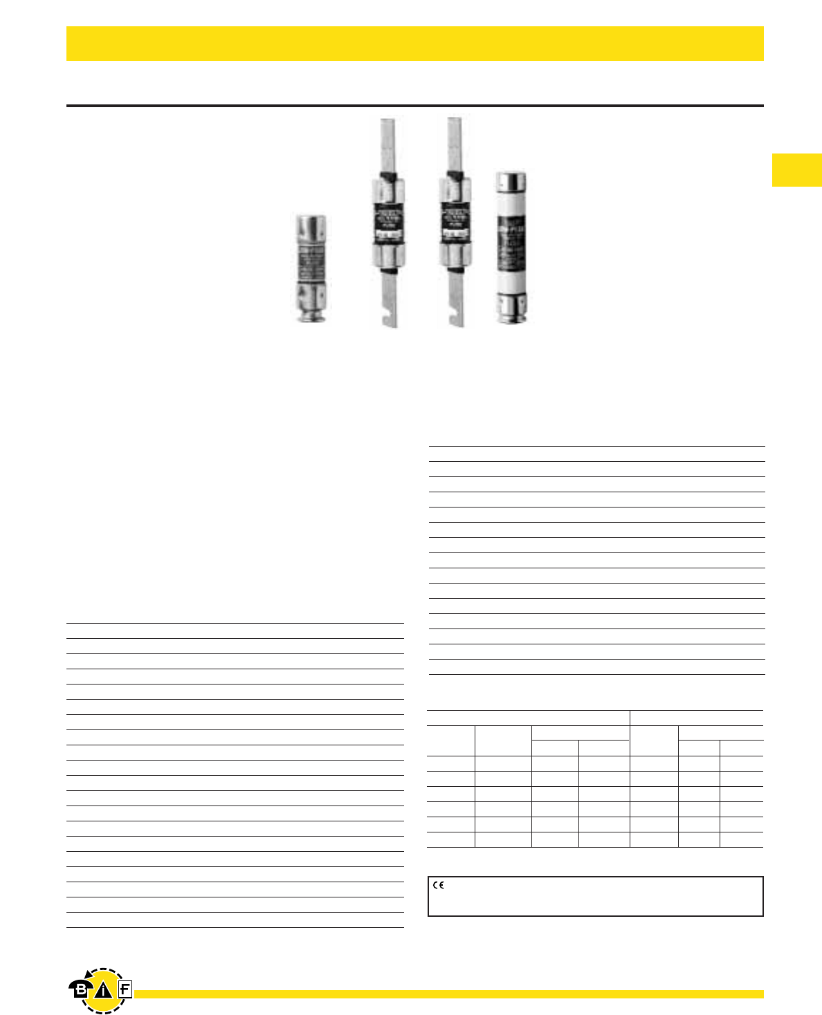
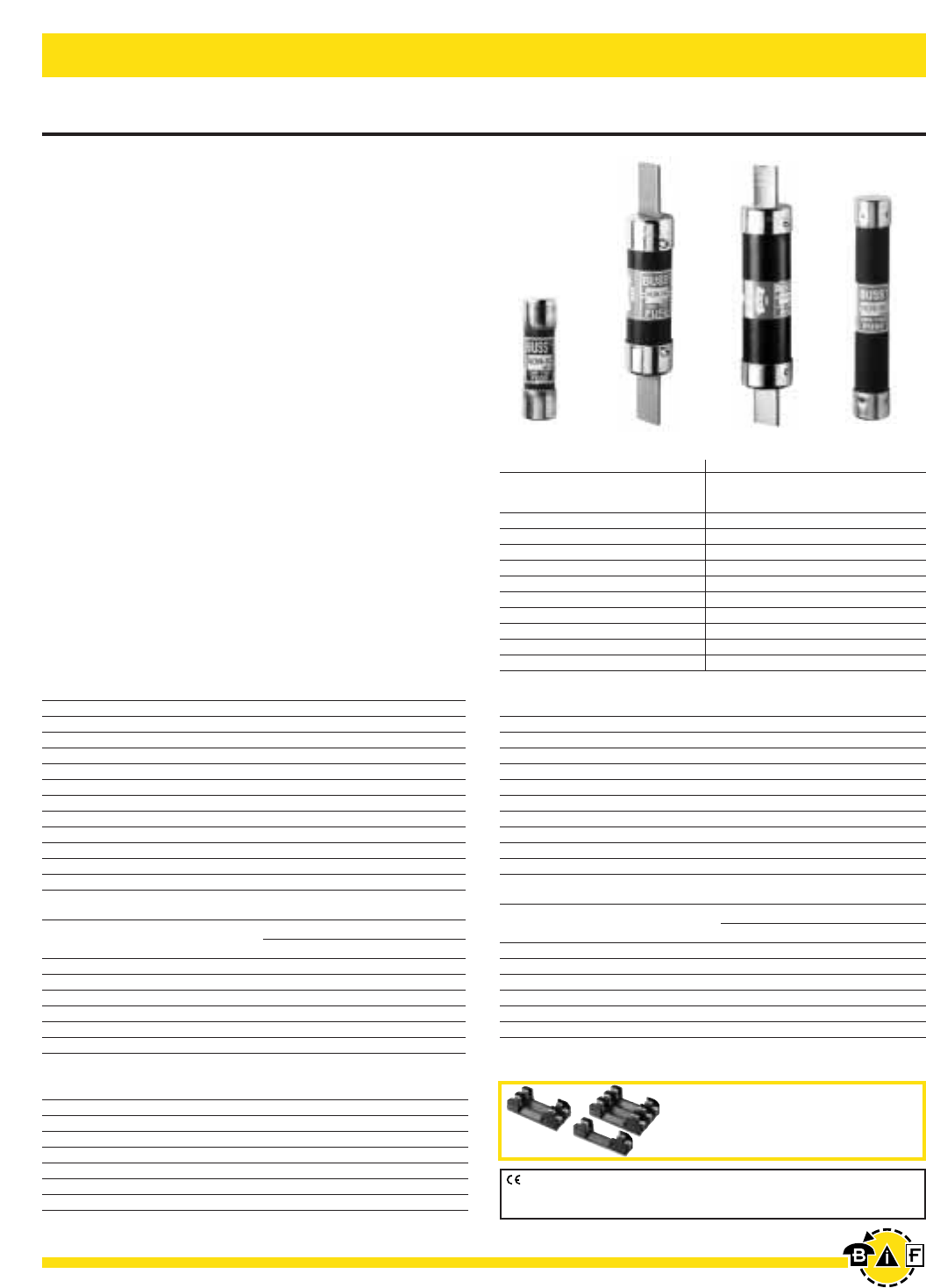
NON and NOS
General Purpose Application
Non-Current Limiting
Ampere Ratings: ⁄Ω•-600A
Voltage Rating: NON: 250Vac, 125Vdc (0-100A);
NOS: 600Vac
Interrupting Rating: 50,000A RMS Sym. (0-60A),
10,000A RMS Sym. (65-600A), 50,000A @ 125Vdc
(NON 0-60),
10,000A @ 125Vdc (NON 65-100A)
Agency Information:
UL Listed – 250V: Class K5 (0-60A), Std. 248-9
Class H (65-600A), Std. 248-6
(125Vdc: NON 0-100)
600V: Class K5 (0-60A), Std. 248-9
Class H (70-600A), Std. 248-6
Guide JDDZ, File E4273
CSA Certified – 250V: (0-12, 65-600)†
600V: (0-600)
Class 1421-01, File 53787
Dimensions: See pages 2-3 for dimensional data under
Class RK5/RK1.
† For CSA Certified 15-60A Ratings, see PON Data Sheet 4126
Catalog Numbers (250Vac)
NON-⁄Ω• NON-5 NON-40 NON-175
NON-⁄Ω™ NON-6 NON-45 NON-200
NON-‹Ω¢ NON-6⁄Ω¢ NON-50 NON-225
NON-°Ω¡º NON-7 NON-60 NON-250
NON-1 NON-8 NON-65 NON-300
NON-1⁄Ω¢ NON-9 NON-70 NON-350
NON-1⁄Ω™ NON-10 NON-75 NON-400
NON-1flꭧ NON-12 NON-80 NON-450
NON-2 NON-15 NON-90 NON-500
NON-2⁄Ω™ NON-20 NON-100 NON-600
NON-3 NON-25 NON-110 —
NON-3¤Ω¡º NON-30 NON-125 —
NON-4 NON-35 NON-150 —
Carton Quantity and Weight
Ampere Carton Weight*
Ratings Qty. Lbs. Kg.
NON ⁄Ω•-30 10 0.38 0.172
NON 35-60 10 1.00 0.453
NON 65-100 5 0.79 0.358
NON 110-200 1 0.79 0.358
NON 225-400 1 1.65 0.748
NON 450-600 1 2.76 1.25
Data Sheet: 1030
One-Time General Purpose Fuses
CE logo denotes compliance with European Union Low Voltage Directive
(50-1000Vac, 75-1500Vdc). Refer to Data Sheet: 8002 or contact
Bussmann Application Engineering at 636-527-1270 for more information.
Catalog Symbol & Current Ratings
Symbol Rating Class Volt IR
NON 0-60 K5 250ac 50,000
65-600 H 250ac 10,000
0-60 K5 125dc 50,000
65-100 H 125dc 10,000
NOS 0-60 K5 600 50,000
70-600 H 600 10,000
*Weight per carton.
Recommended fuseblocks for
Class H (K) 250 & 600V fuses
See pages 47-52
Bussmann®
17
For complete specification data, call Bussmann Information Fax ~ 636.527.1450
Electrical - Power Fuses
Data Sheet: 1006 (0-60) and 1007 (70-600)
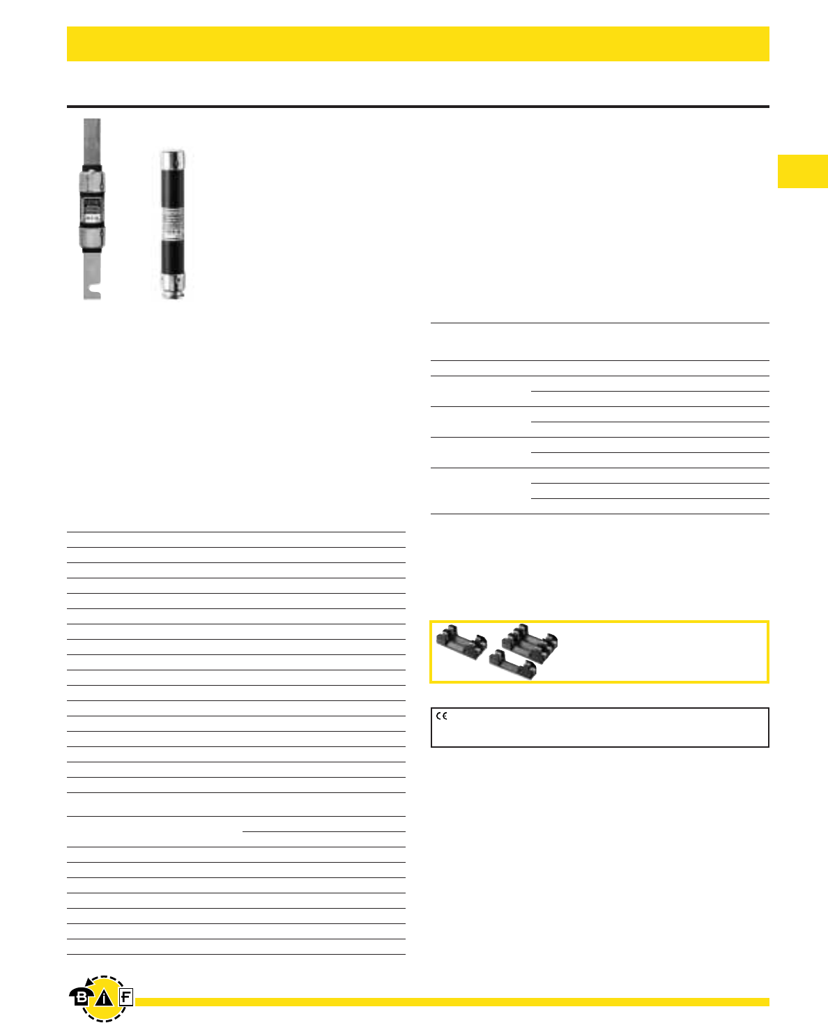
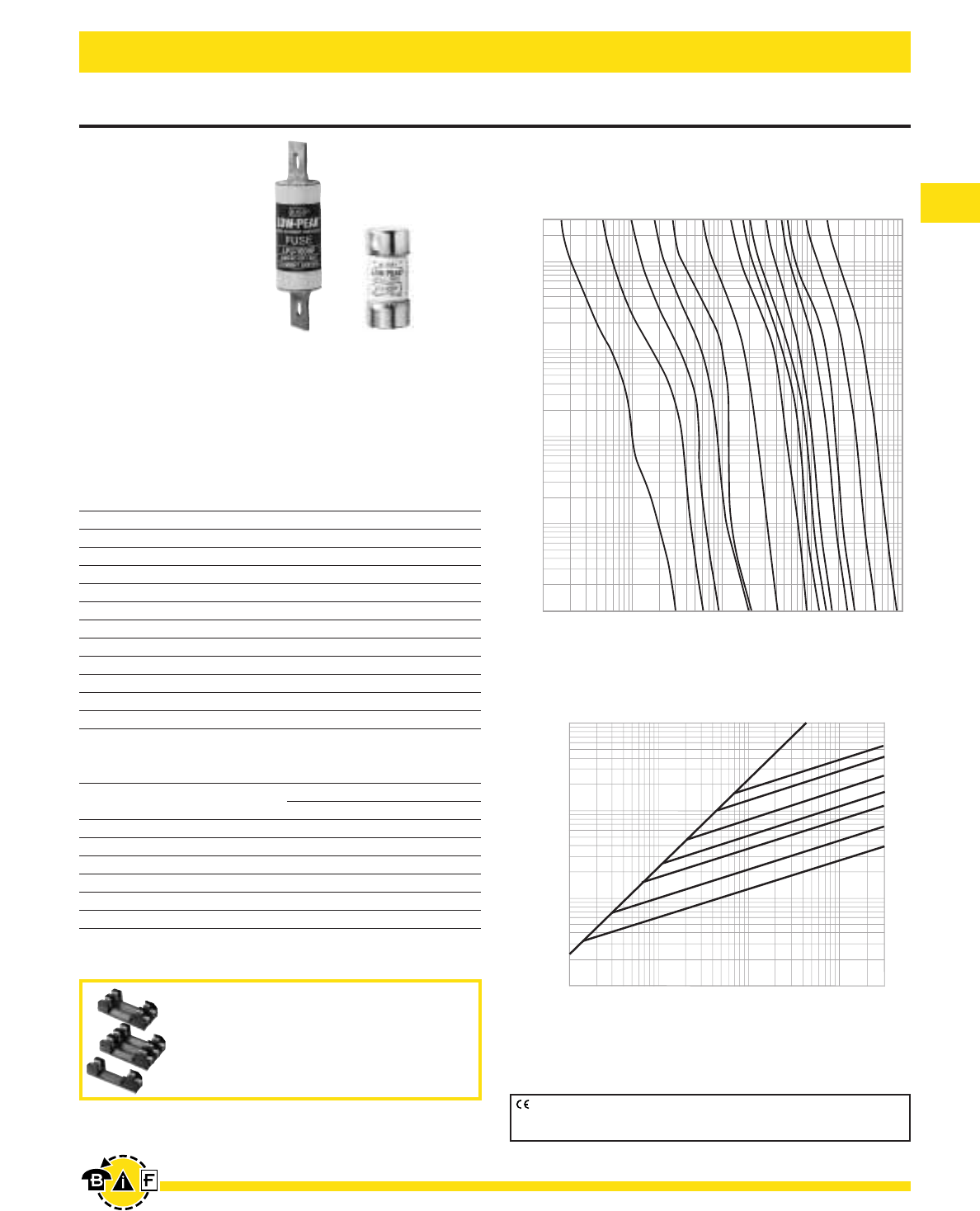
Low-Peak®Dual-Element, Time-Delay, Class J Fuses
LPJ_SP
Dual-Element,
Time-Delay –
10 seconds (minimum) at
500% rated current
Ampere Ratings:
1-600A
Voltage Rating:
600Vac (or less),
300Vdc (or less)
Current Limiting
Interrupting Rating:
ac – 300,000A RMS Sym. dc – 100,000A
Agency Information:
UL Listed - Special Purpose**, Guide JFHR, File E56412
CSA Certified (200,000 AIR) Class J per CSA-22.2 No. 248.8,
Class 1422-02, File 53787
Dimensions: See pages 2-3 for Class J dimensional data.
Catalog Numbers
LPJ-1SP LPJ-4⁄Ω™SP LPJ-25SP LPJ-125SP
LPJ-1⁄Ω¢SP LPJ-5SP LPJ-30SP LPJ-150SP
LPJ-1flꭧSP LPJ-5flꭧSP LPJ-35SP LPJ-175SP
LPJ-1°Ω¡ºSP LPJ-6SP LPJ-40SP LPJ-200SP
LPJ-2SP LPJ-7SP LPJ-45SP LPJ-225SP
LPJ-2⁄Ω¢SP LPJ-8SP LPJ-50SP LPJ-250SP
LPJ-2⁄Ω™SP LPJ-9SP LPJ-60SP LPJ-300SP
LPJ-2°Ω¡ºSP LPJ-10SP LPJ-70SP LPJ-350SP
LPJ-3SP LPJ-12SP LPJ-80SP LPJ-400SP
LPJ-3¤Ω¡ºSP LPJ-15SP LPJ-90SP LPJ-450SP
LPJ-3⁄Ω™SP LPJ-17⁄Ω™SP LPJ-100SP LPJ-500SP
LPJ-4SP LPJ-20SP LPJ-110SP LPJ-600SP
**Meets all performance requirements of UL Standard 248-8 for Class J fuses.
Available with silver plated terminals. Add SP/ in front of part number.
Carton Quantity and Weight
Ampere Carton Weight*
Ratings Qty. Lbs. Kg.
0-30 10 1.09 0.49
35-60 10 1.78 0.81
70-100 5 1.69 0.77
110-200 5 4.21 1.91
225-400 1 1.67 0.76
450-600 1 2.80 0.27
*Weight per carton.
AMPERE
RATING
1A
3A
6A
300
100
10
1
.1
.01
TIME IN SECONDS
10A
15A
30A
60A
100A
400A
1,000
100
CURRENT IN AMPERES
600A
125A
250A
200A
80A
200
10
10,000
1
INSTANTANEOUS PEAK LET-THRU CURRENT IN AMPS
100,000
10,000
1,000
100
B
A
PROSPECTIVE SHORT-CIRCUIT CURRENT
SYMMETRICAL RMS AMPS
100
1,000
10,000
100,000
200,000
600A
400A
200A
100A
60A
30A
15A
RA
AMPERE
TING
LPJ Current Limitation Curves
300,000
Time-Current Classification Curves—Average Melt
Current Limitation Curves
CE logo denotes compliance with European Union Low Voltage Directive
(50-1000Vac, 75-1500Vdc). Refer to Data Sheet: 8002 or contact
Bussmann Application Engineering at 636-527-1270 for more information.
Recommended fuseblocks/fuseholders for
Class J 600V fuses
• Open fuseblocks - see pages 53-55
• Finger-safe fuseholders for 30A & 60A-
see pages 57-58
• Modular fuseblocks - see page 67
Bussmann®
18 For complete specification data, call Bussmann Information Fax ~ 636.527.1450
Electrical - Power Fuses
Data Sheet: 1026 (1-60A), 1027 (70-600A)
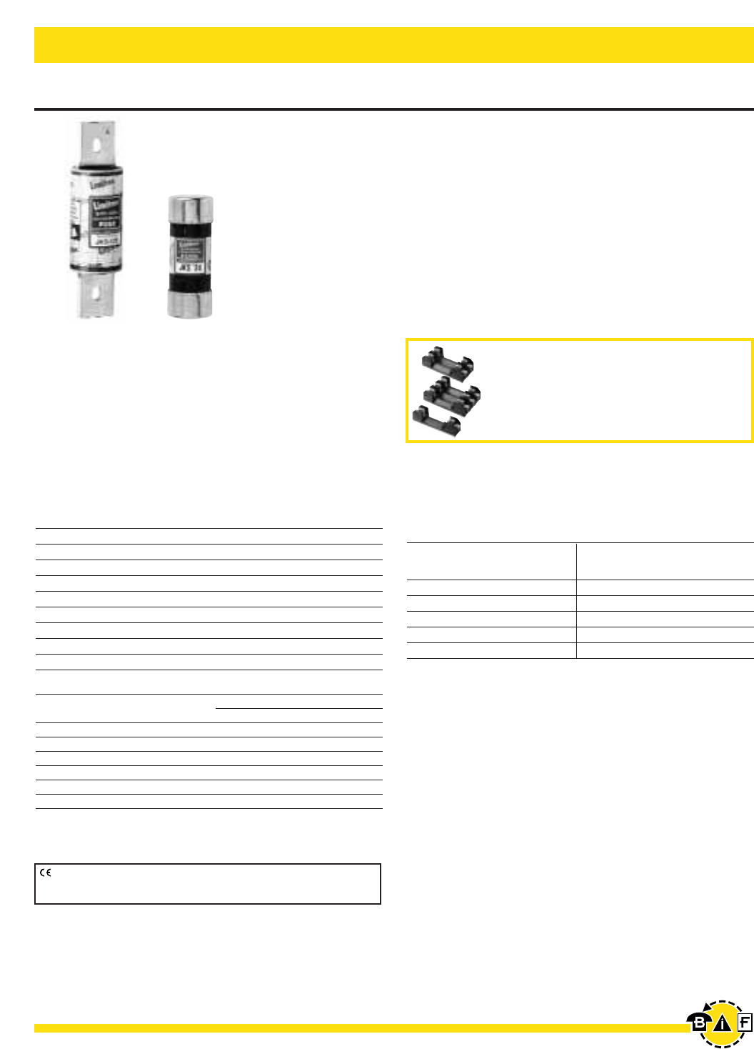
Limitron®Quick Acting, Class J Fuses
JKS
Quick Acting
Ampere Ratings: 1-600A
Voltage Rating: 600Vac (or less)
Current Limiting
Interrupting Rating: 200,000A RMS Sym.
Agency Information: Std. 248-8, Class J
UL Listed, Guide JDDZ, File E4273
CSA Certified, Class 1422-02, File 53787
Dimensions: See pages 2-3 for Class J dimensional data.
Catalog Numbers
JKS-1 JKS-15 JKS-70 JKS-225
JKS-2 JKS-20 JKS-80 JKS-250
JKS-3 JKS-25 JKS-90 JKS-300
JKS-4 JKS-30 JKS-100 JKS-350
JKS-5 JKS-35 JKS-110 JKS-400
JKS-6 JKS-40 JKS-125 JKS-450
JKS-8 JKS-45 JKS-150 JKS-500
JKS-10 JKS-50 JKS-175 JKS-600
JKS-12 JKS-60 JKS-200
Carton Quantity and Weight
Ampere Carton Weight*
Ratings Qty. Lbs. Kg.
1-30 10 0.95 0.43
35-60 10 1.175 0.53
70-100 5 0.28 0.13
110-200 1 0.86 0.39
225-400 1 1.78 0.81
450-600 1 3.07 1.39
*Weight per carton.
Fuse Reducers for J Dimension Fuses
Cat. Weight Cat. Weight
Clip Fuse No. Carton* Clip Fuse No. Carton*
Size Size (Pair) (lbs) Size Size (Pair) (lbs)
60A 30A J63 0.38 400A 100A J41 4.90
100A 30A J13 1.73 400A 200A J42 2.75
100A 60A J16 1.85 600A 400A J64 3.55
200A 60A J26 2.55 600A 200A J62 3.55
200A 100A J21 1.36 ————
*Carton quantity—10 pair.
CE logo denotes compliance with European Union Low Voltage Directive
(50-1000Vac, 75-1500Vdc). Refer to Data Sheet: 8002 or contact
Bussmann Application Engineering at 636-527-1270 for more information.
Recommended fuseblocks/fuseholders for
Class J 600V fuses
• Open fuseblocks - see pages 53-55
• Finger-safe fuseholders for 30A & 60A-
see pages 57-58
• Modular fuseblocks - see page 67
Bussmann®
19
For complete specification data, call Bussmann Information Fax ~ 636.527.1450
Electrical - Power Fuses
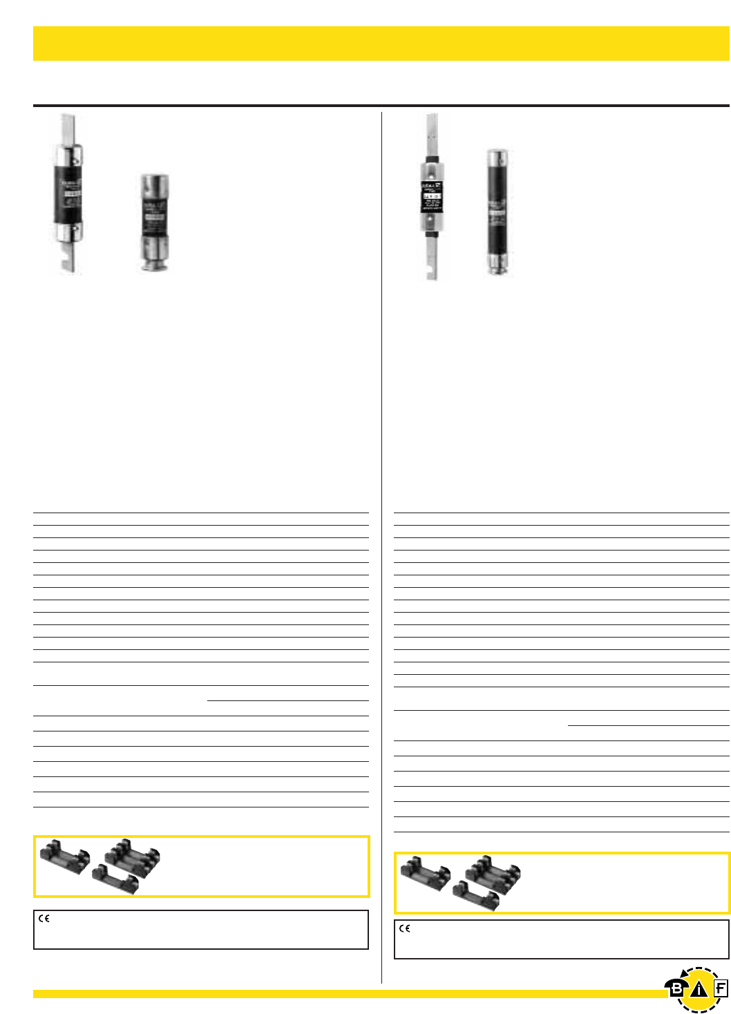
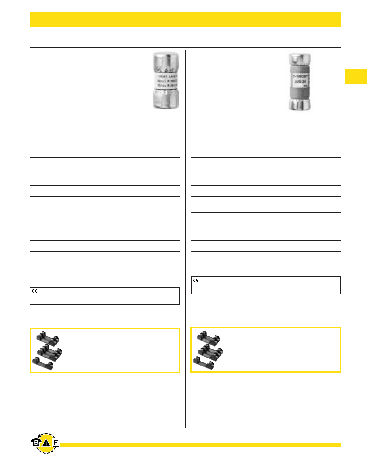
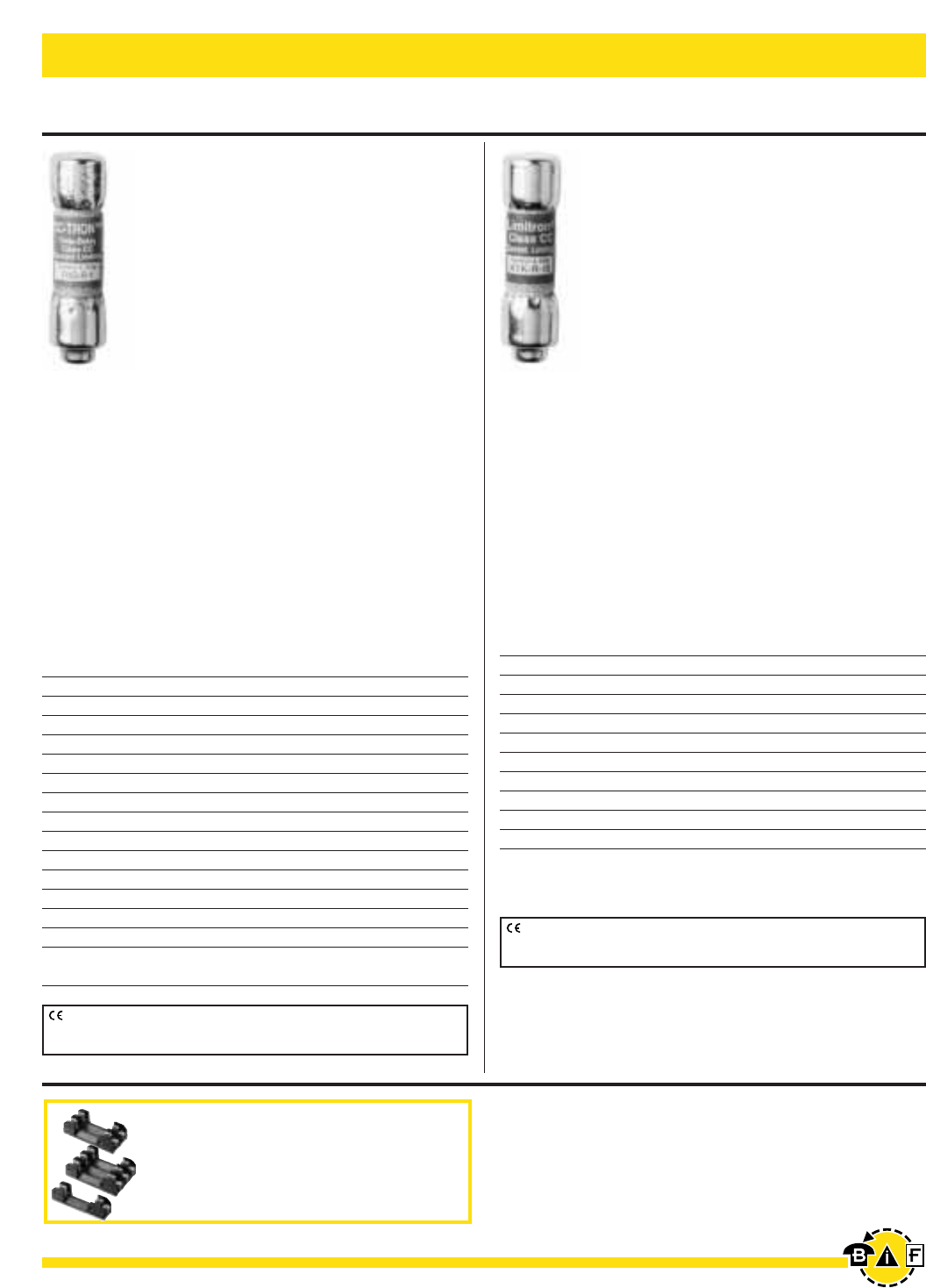
T- Tr o n ®Very Fast Acting, Class T Fuses
JJN
Very Fast Acting
Ampere Ratings: 1-1200A
Voltage Rating: 300Vac (or less),
(15-600A 160Vdc; 601-1200 170Vdc)
Current Limiting
(curves on page 208)
Interrupting Rating: 200,000A RMS Sym.
(20,000A dc @ 160Vdc & 100,000A dc @ 170Vdc)
Agency Information: Std. 248-15, Class T
UL Listed, Guide JDDZ, File E4273
CSA Certified, Class 1422-02, File 53787
Dimensions: See pages 2-3 for Class T dimensional data.
Catalog Numbers
JJN-1 JJN-35 JJN-110 JJN-400
JJN-2 JJN-40 JJN-125 JJN-450
JJN-3 JJN-45 JJN-150 JJN-500
JJN-6 JJN-50 JJN-175 JJN-600
JJN-10 JJN-60 JJN-200 JJN-700
JJN-15 JJN-70 JJN-225 JJN-800
JJN-20 JJN-80 JJN-250 JJN-1000
JJN-25 JJN-90 JJN-300 JJN-1200
JJN-30 JJN-100 JJN-350
Carton Quantity and Weight
Ampere Carton Weight*
Ratings Qty. Lbs. Kg.
1-30 10 0.12 0.054
35-60 10 0.23 0.104
70-100 5 0.36 0.163
110-200 1 0.14 0.063
225-400 1 0.25 0.113
450-600 1 0.44 0.200
700-800 1 0.80 0.363
1000-1200 1 1.45 0.658
*Weight per carton.
JJS
Very Fast Acting
Ampere Ratings: 1-800A
Voltage Rating: 600Vac (or less)
Current Limiting (curves on
page 208)
Interrupting Rating: 200,000A
RMS Sym.
Agency Information: Std. 248-
15, Class T
UL Listed, Guide JDDZ, File E4273
CSA Certified, Class 1422-02, File 53787
Dimensions: See pages 2-3 for Class T dimensional data.
Catalog Numbers
JJS-1 JJS-30 JJS-90 JJS-250
JJS-2 JJS-35 JJS-100 JJS-300
JJS-3 JJS-40 JJS-110 JJS-350
JJS-6 JJS-45 JJS-125 JJS-400
JJS-10 JJS-50 JJS-150 JJS-450
JJS-15 JJS-60 JJS-175 JJS-500
JJS-20 JJS-70 JJS-200 JJS-600
JJS-25 JJS-80 JJS-225 JJS-800
Carton Quantity and Weight
Ampere Carton Weight*
Ratings Qty. Lbs. Kg.
1-30 10 0.33 0.149
35-60 10 0.82 0.371
70-100 5 0.51 0.231
110-200 1 0.192 0.087
225-400 1 0.46 0.208
450-600 1 0.85 0.385
800 1 1.65 0.748
*Weight per carton.
Data Sheet: 1025 Data Sheet: 1029
CE logo denotes compliance with European Union Low Voltage Directive
(50-1000 Vac, 75-1500Vdc). Refer to Data Sheet: 8002 or contact
Bussmann Application Engineering at 636-527-1270 for more information.
CE logo denotes compliance with European Union Low Voltage Directive
(50-1000Vac, 75-1500Vdc). Refer to Data Sheet: 8002 or contact
Bussmann Application Engineering at 636-527-1270 for more information.
Recommended fuseblocks/fuseholders for
Class T 300V fuses
• Open fuseblocks - see pages 59-60
• Modular fuseblocks - see page 67
Recommended fuseblocks/fuseholders for
Class T 600V fuses
• Open fuseblocks - see pages 61-62
• Modular fuseblocks - see page 67
Bussmann®
20 For complete specification data, call Bussmann Information Fax ~ 636.527.1450
Electrical - Power Fuses
Data Sheet: 1024 (0-60)
Time-Delay Class G Fuses
SC
Fast Acting (⁄Ω™-6A), Class G
Time-Delay (7-60A), Class G
Construction: Melamine Tube
Ampere Ratings: ⁄Ω™-60A
Voltage Rating: ⁄Ω™-20: 600Vac/170Vdc
25-60: 480Vac/300Vdc (only UL)
Interrupting Rating: 100,000A RMS Sym., 10,000A dc
Agency Information: Std. 248-5, Class G, UL Listed,
Guide JDDZ, File E4273
CSA Certified, Class 1422-01, File 53787
Catalog Symbol & Current Ratings
SC-⁄Ω™ SC-6 SC-25
SC-1 SC-7 SC-30
SC-1⁄Ω™ SC-8 SC-35
SC-2 SC-9 SC-40
SC-2⁄Ω™ SC-10 SC-45
SC-3 SC-12 SC-50
SC-4 SC-15 SC-60
SC-5 SC-20 —
Carton Quantity and Weight
Ampere Carton Weight*
Ratings Qty. Lbs. Kg.
⁄Ω™-15 4 0.06 0.03
20 4 0.06 0.03
25-30 2 0.04 0.02
35-60 2 0.08 0.03
*Weight per carton.
Physical Size:
Fuse (Amps) (Length)
SC-⁄Ω™ to -15 1.31
SC-20 1.41
SC-25 to -30 1.62
SC-35 to -60 2.25
•Compact branch-circuit units with high interrupting rating
and current limitation.
•With a 600 volt rating, they can be used in 120/208,
120/240 and 277/480 volt circuits.
•Length variations relative to case size make the “rejection”
type fuses.
•SC fuses with ampere ratings above 6 amps have a degree
of overload time-delay which permits them to pass tempo-
rary overloads. At 200% load, they have a minimum open-
ing time of 12 seconds.
A
(Length)
.41"
(10.3mm)
CE logo denotes compliance with European Union Low Voltage Directive
(50-1000Vac, 75-1500Vdc). Refer to Data Sheet: 8002 or contact
Bussmann Application Engineering at 636-527-1270 for more information.
Recommended fuseblocks/fuseholders
for Class G
• Open fuseblocks - see page 64
• Panel-mount fuseholders - see page 78
• In-line fuseholders - see page 80
Bussmann®
21
For complete specification data, call Bussmann Information Fax ~ 636.527.1450
Electrical - Power Fuses
Data Sheet: 1023 (0-30)
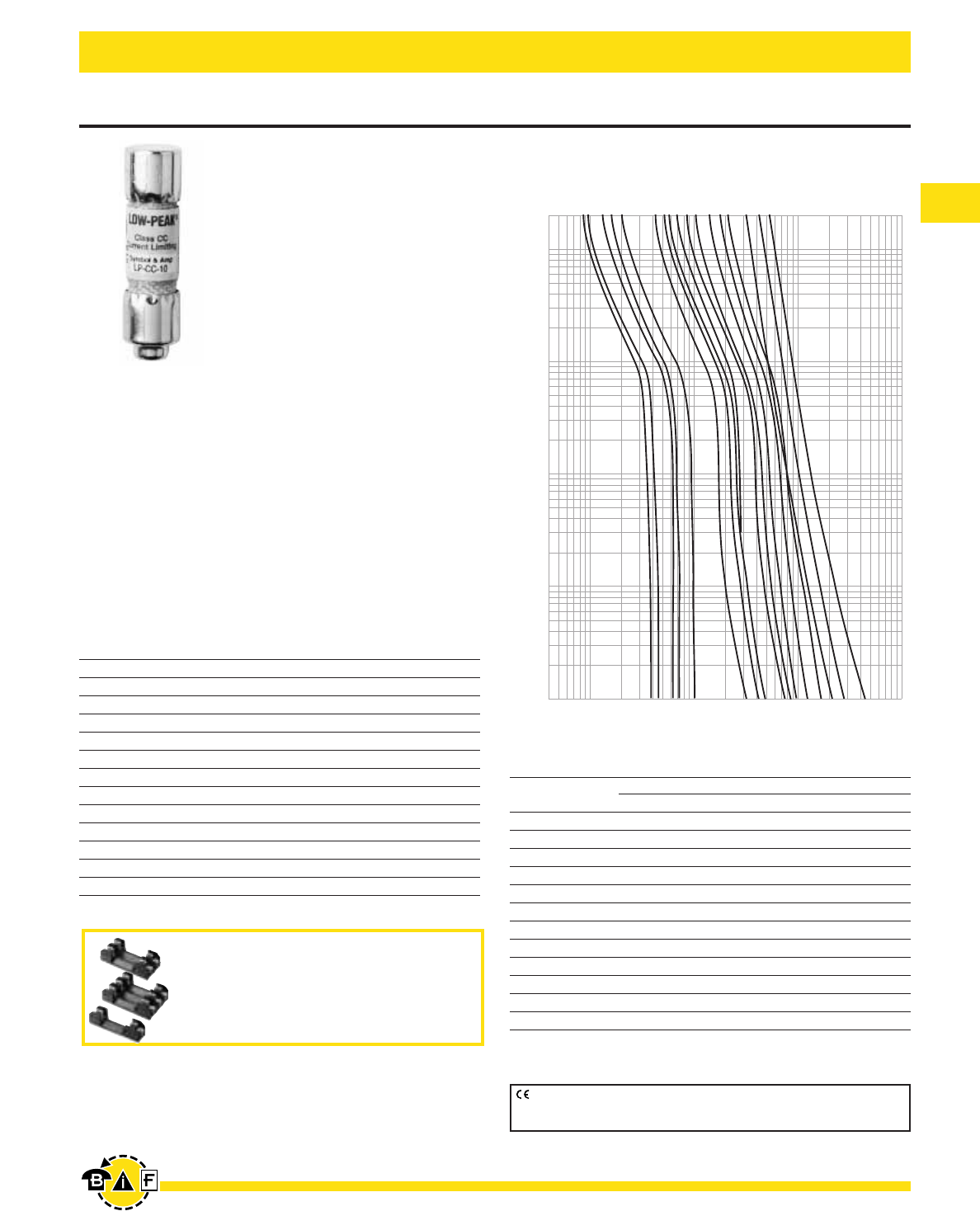
Low-Peak®Time-Delay, Class CC Fuses
LP-CC Low-Peak®Fuse
Time-Delay Current Limiting,
Class CC - Rejection Type
Physical Size:
⁄‹Ω£™∑ ≈ 1⁄Ω™∑
(10.3mm ≈38.1mm)
Ampere Ratings: ⁄Ω™ - 30A
Voltage Rating: 600Vac (or less), 300Vdc (⁄Ω™-2°Ω¡ºA
& 20-30A), 150Vdc (3-15A)
Interrupting Rating: 200,000A RMS Sym; 20,000A dc
Construction: Melamine Tube
Agency Information: Std. 248-4, Class CC
UL Listed, Guide JDDZ, File E4273
CSA Certified; Class 1422-02, File 53787
Catalog Symbol
600Vac
LP-CC-⁄Ω™ LP-CC-2⁄Ω™ LP-CC-7⁄Ω™
LP-CC-flΩ¡º LP-CC-2°Ω¡º LP-CC-8
LP-CC-°Ω¡º LP-CC-3 LP-CC-9
LP-CC-1 LP-CC-3¤Ω¡º LP-CC-10
LP-CC-1⁄Ω• LP-CC-3⁄Ω™ LP-CC-12
LP-CC-1⁄Ω¢ LP-CC-4 LP-CC-15
LP-CC-1›Ω¡º LP-CC-4⁄Ω™ LP-CC-20
LP-CC-1⁄Ω™ LP-CC-5 LP-CC-25
LP-CC-1flꭧ LP-CC-5flꭧ LP-CC-30
LP-CC-1°Ω¡º LP-CC-6
LP-CC-2 LP-CC-6⁄Ω¢
LP-CC-2⁄Ω¢ LP-CC-7
Current-Limiting Effects
Prospective Short- *Let-Thru Current (Apparent RMS Symmetrical)
Circuit Current 1⁄Ω¢A2°Ω¡ºA 15A 20A 25A 30A
1000 100 135 240 305 380 435
3000 140 210 350 440 575 580
5000 165 255 420 570 690 710
10,000 210 340 540 700 870 1,000
20,000 260 435 680 870 1,090 1,305
30,000 290 525 800 1,030 1,300 1,520
40,000 315 610 870 1,150 1,390 1,700
50,000 340 650 915 1,215 1,520 1,820
60,000 350 735 1,050 1,300 1,650 1,980
80,000 390 785 1,130 1,500 1,780 2,180
100,000 420 830 1,210 1,600 2,000 2,400
200,000 525 1,100 1,600 2,000 2,520 3,050
*RMS Symmetrical Amperes Short-Circuit
NOTE: To calculate Ip(Ipeak) multiply IRMS value ≈2.3.
200
100
10
TIME IN SECONDS
1
.1
.01
⁄Ω™
flꭧ
°Ω¡º
1
1⁄Ω¢
3
3⁄Ω™
4
4⁄Ω™
6
8
10
12
15
20
25
30
AMPERE
RATING
.4
1
10
100
1000
CURRENT IN AMPERES
Time Current Characteristics—Average Melt
CE logo denotes compliance with European Union Low Voltage Directive
(50-1000Vac, 75-1500Vdc). Refer to Data Sheet: 8002 or contact
Bussmann Application Engineering at 636-527-1270 for more information.
Recommended fuseblocks/fuseholders for
Class CC 600V fuses
• Open fuseblocks - see page 64
• Finger-safe fuseholders - see pages 41-44, 65
• Panel-mount fuseholders - see page 78
• In-line fuseholders - see page 80
Bussmann®
22 For complete specification data, call Bussmann Information Fax ~ 636.527.1450
Electrical - Power Fuses
Data Sheet: 1014 Data Sheet: 1015
Class CC Rejection-Type Fuses
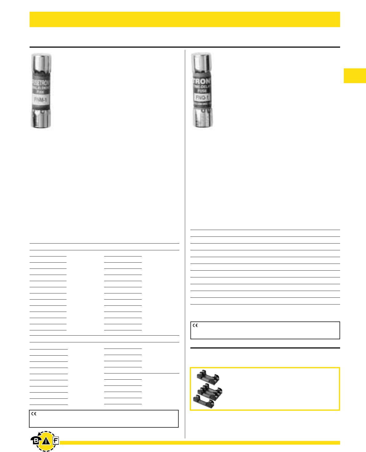
FNQ-R
Time-Delay, Rejection Type
Branch Circuit Fuse
Class CC
Physical Size:
⁄‹Ω£™∑ ≈ 1⁄Ω™∑ (10.3mm ≈38.1mm)
Construction: Melamine Tube
Ampere Ratings: ⁄Ω¢-30A.
Voltage Rating: 600Vac or less
Interrupting Rating: 200,000A RMS Sym.
Agency Information: Std. 248-4, Class CC
UL Listed, Guide JDDZ, File E4273
CSA Certified, Class 1422-01, File 53787
Catalog Symbol & Current Ratings
600Vac
FNQ-R-⁄Ω¢ FNQ-R-1flΩ¡º FNQ-R-7
FNQ-R-‹Ω¡º FNQ-R-1°Ω¡º FNQ-R-7⁄Ω™
FNQ-R-›Ω¡º FNQ-R-2 FNQ-R-8
FNQ-R-⁄Ω™ FNQ-R-2⁄Ω¢ FNQ-R-9
FNQ-R-flΩ¡º FNQ-R-2⁄Ω™ FNQ-R-10
FNQ-R-‹Ω¢ FNQ-R-2°Ω¡º FNQ-R-12
FNQ-R-°Ω¡º FQN-R-3 FNQ-R-15
FNQ-R-1 FNQ-R-3¤Ω¡º FNQ-R-17⁄Ω™
FNQ-R-1⁄Ω• FNQ-R-3⁄Ω™º FNQ-R-20
FNQ-R-1⁄Ω¢ FNQ-R-4 FNQ-R-25
FNQ-R-1‹Ω¡º FNQ-R-5 FNQ-R-30
FNQ-R-1›Ω¡º FNQ-R-6 —
FNQ-R-1⁄Ω™ FNQ-R-6⁄Ω¢ —
Time-Current Curves on page 225.
KTK-R Limitron®Fuse
Fast Acting; Branch Circuit Fuse
Class CC - Rejection Feature
Physical Size:
⁄‹Ω£™∑ ≈ 1⁄Ω™∑ (10.3mm ≈38.1mm)
Construction: Melamine Tube
Ampere Ratings: ⁄Ω¡º-30A.
Voltage Rating: 600Vac (or less).
Interrupting Rating: 200,000A RMS Sym.
Agency Information: Std. 248-4, Class CC
UL Listed, Guide JDDZ, File E4273
CSA Certified, File 53787, Class 1422-02
Catalog Symbol & Current Ratings
600Vac
KTK-R-⁄Ω¡º KTK-R-1 KTK-R-7
KTK-R-⁄Ω• KTK-R-1⁄Ω™ KTK-R-8
KTK-R-¤Ω¡º KTK-R-2 KTK-R-9
KTK-R-⁄Ω¢ KTK-R-2⁄Ω™ KTK-R-10
KTK-R-‹Ω¡º KTK-R-3 KTK-R-12
KTK-R-›Ω¡º KTK-R-3⁄Ω™ KTK-R-15
KTK-R-⁄Ω™ KTK-R-4 KTK-R-20
KTK-R-flꭧ KTK-R-5 KTK-R-25
KTK-R-‹Ω¢ KTK-R-6 KTK-R-30
Time-Current Curves on page 226.
CE logo denotes compliance with European Union Low Voltage Directive
(50-1000Vac, 75-1500Vdc). Refer to Data Sheet: 8002 or contact
Bussmann Application Engineering at 636-527-1270 for more information.
CE logo denotes compliance with European Union Low Voltage Directive
(50-1000Vac, 75-1500Vdc). Refer to Data Sheet: 8002 or contact
Bussmann Application Engineering at 636-527-1270 for more information.
Recommended fuseblocks/fuseholders for
Class CC 600V fuses
• Open fuseblocks - see page 64
• Finger-safe fuseholders - see pages 41-44, 65
• Panel-mount fuseholders - see page 78
• In-line fuseholders - see page 80
Bussmann®
23
For complete specification data, call Bussmann Information Fax ~ 636.527.1450
Electrical - Power Fuses
Data Sheet: 2010 (0-30A)
Data Sheet: 2045
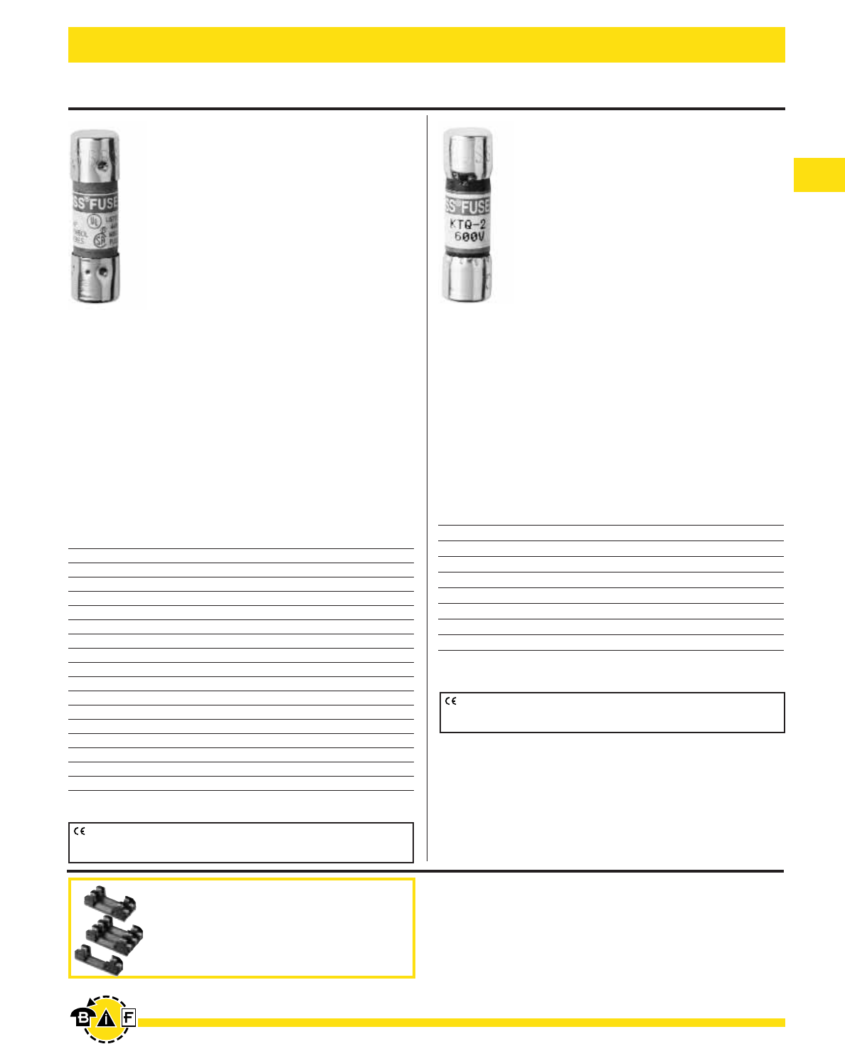
⁄‹Ω£™∑ ≈ 1‹Ω•∑ Supplementary Fuses
BBS
Fast Acting
Physical Size:
⁄‹Ω£™∑ ≈ 1‹Ω•∑ (10.3mm ≈35mm)
Construction: Fibre Cartridge
Interrupting Rating: 10,000A RMS Sym.
Ampere Ratings: ⁄Ω¡º-30A
Voltage Rating: 600Vac (⁄Ω¡º-5A), 250Vac (6-10A),
48Vac (12-30A)
Agency Information: Std. 248-14
UL Listed, 0-5A/600V, Guide JDYX, File E19180
CSA Certified, 0-5A/600V, Class 1422-01, File 53787
Catalog Symbol & Current Ratings
600Vac 250Vac 48Vac
BBS-
⁄Ω¡º BBS-6 BBS-12
BBS-¤Ω¡º BBS-7 BBS-15
BBS-⁄Ω¢ BBS-8 BBS-20
BBS-›Ω¡º BBS-10 BBS-25
BBS-⁄Ω™ —BBS-30
BBS-flΩ¡º ——
BBS-‹Ω¢ ——
BBS-°Ω¡º ——
BBS-1 ——
BBS-1⁄Ω™ ——
BBS-1flΩ¡º ——
BBS-1°Ω¡º ——
BBS-2 ——
BBS-3 ——
BBS-4 ——
BBS-5 ——
KTQ
Fast Acting
Physical Size:
⁄‹Ω£™∑ ≈ 1‹Ω•∑ (10.3mm ≈34.9mm)
Construction: Fibre Cartridge
Ampere Ratings: 1-6A
Voltage Rating: 600Vac
Interrupting Rating: 10,000A RMS Sym.
Agency Information: Std. 248-14
UL Recognized, 4-6A, Guide JDYX2, File E19180
Catalog Symbol & Current Ratings
600Vac
KTQ-1
KTQ-1flꭧ
KTQ-2
KTQ-3
KTQ-4
KTQ-5
KTQ-6
CE logo denotes compliance with European Union Low Voltage Directive
(50-1000Vac, 75-1500Vdc). Refer to Data Sheet: 8002 or contact
Bussmann Application Engineering at 636-527-1270 for more information.
CE logo denotes compliance with European Union Low Voltage Directive
(50-1000Vac, 75-1500Vdc). Refer to Data Sheet: 8002 or contact
Bussmann Application Engineering at 636-527-1270 for more information.
Recommended fuseblocks/fuseholders for
13/32” x 1-1/2” fuses
• Open fuseblocks - see page 64, 66
• Finger-safe fuseholders - see pages 41-44, 65
• Panel-mount fuseholders - see page 78-79
• In-line fuseholders - see page 80-81
Electrical - Power Fuses Bussmann®
24 For complete specification data, call Bussmann Information Fax ~ 636.527.1450
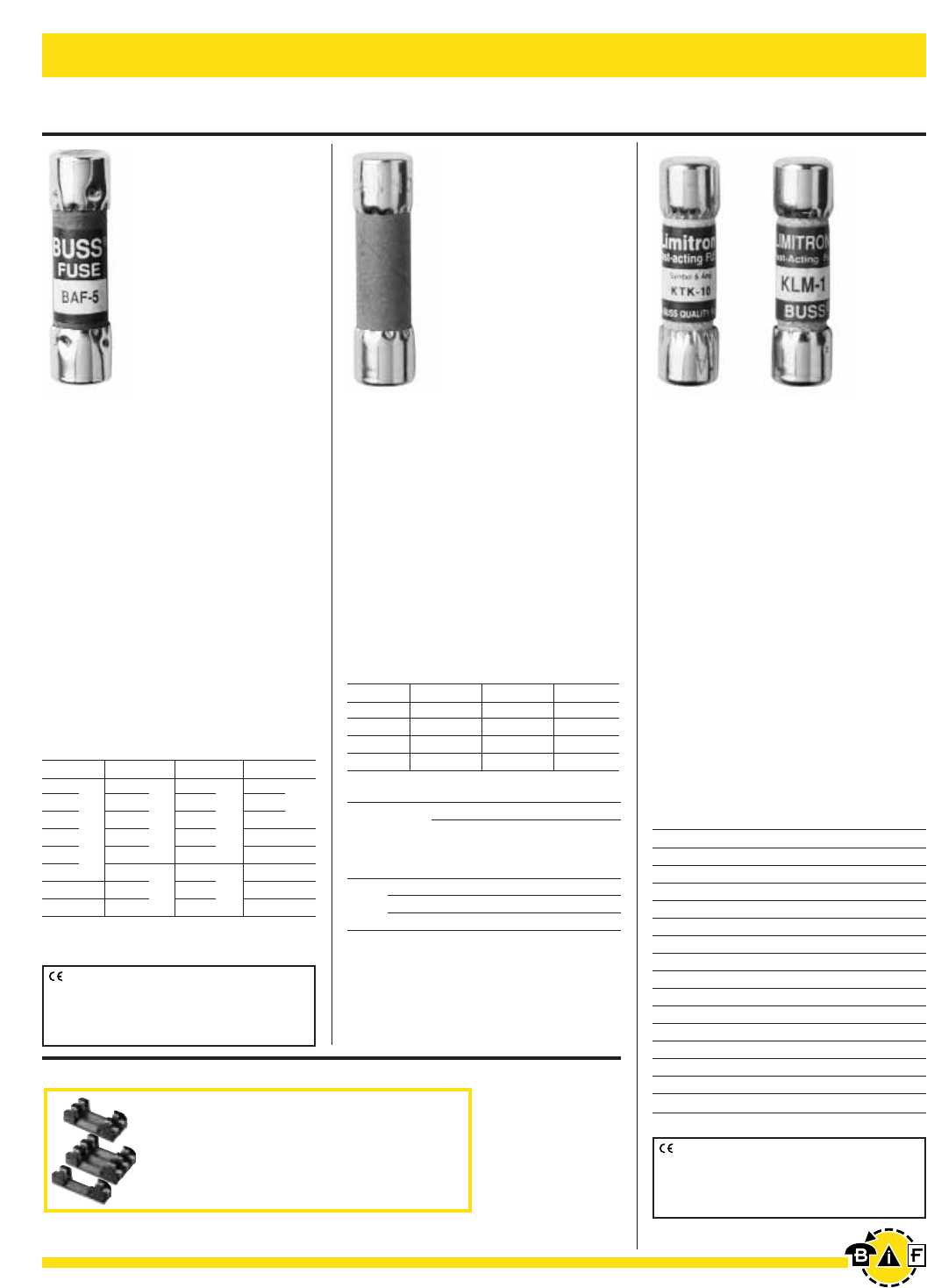
KTK and KLM
Fast Acting
Physical Size:
⁄‹Ω£™∑ ≈ 1⁄Ω™∑ (10.3mm ≈38.1mm)
Construction: Melamine Tube;
Nickel Plated Brass Endcaps
Voltage Rating:
KTK - 600Vac or less
KLM - ⁄Ω¡º-⁄Ω•A: 500Vac/600Vdc
¤Ω¡º-10A: 500Vac/dc,
12-30A: 500Vac/600Vdc
Interrupting Rating:
100,000A - KTK; 10,000A - KLM,
RMS SYM. (UL)
Agency Information: Std. 248-14
KTK-UL Listed, Guide JDYX,
File E19180
KLM-UL Recognized, Guide JFHR2,
File E56412
CSA Certified, File 53787, Class
1422-01, HRC-Misc
Data Sheet: KTK-1011
KLM-2020
Data Sheet: 2046 (0-30)
Data Sheet: 2011 (0-30)
⁄‹Ω£™∑ ≈ 1⁄Ω™∑ Supplementary Fuses
Catalog Symbol & Current Ratings
250V IR* 250V IR* 250V IR* 125V
*All have interrupting rating of 10,000A at 125V.
Catalog Symbol & Current Ratings
250V 250V 250V 250V
BAN-1 BAN-5 BAN-12 BAN-30
BAN-2 BAN-6 BAN-15 —
BAN-3 BAN-8 BAN-20 —
BAN-4 BAN-10 BAN-25 —
Catalog Symbol & Current Ratings
600Vac - UL Listed and C.S.A.
KTK-
⁄Ω¡º KTK-‹Ω¢ KTK-4 KTK-12
KTK-⁄Ω• KTK-1 KTK-5 KTK-15
KTK-¤Ω¡º KTK-1⁄Ω¢ KTK-6 KTK-20
KTK-⁄Ω¢ KTK-1⁄Ω™ KTK-7 KTK-25
KTK-‹Ω¡º KTK-2 KTK-7⁄Ω™ KTK-30
KTK-›Ω¡º KTK-2⁄Ω™ KTK-8 —
KTK-⁄Ω™ KTK-3 KTK-9 —
KTK-flΩ¡º KTK-3⁄Ω™ KTK-10 —
*500Vac/dc - UL Recognized and C.S.A.
KLM-
⁄Ω¡º KLM-‹Ω¢ KLM-5 KLM-20
KLM-⁄Ω• KLM-1 KLM-6 KLM-25
KLM-¤Ω¡º KLM-1⁄Ω™ KLM-8 KLM-30
KLM-⁄Ω¢ KLM-2 KLM-10 —
KLM-‹Ω¡º KLM-3 KLM-12 —
KLM-⁄Ω™ KLM-4 KLM-15 —
*KLM-(⁄Ω¡º-⁄Ω• & 12-30): 500VAC/600Vdc
BAF
Fast Acting
Physical Size:
⁄‹Ω£™∑ ≈ 1⁄Ω™∑
(10.3mm ≈38.1mm)
Construction: Fibre Tube;
Nickel Plated Brass Endcaps
Voltage Rating: 250Vac (¤Ω¡º-15A),
125Vac (20-30A)
Interrupting Rating: 10,000A at
125Vac
Agency Information: Std. 248-14
UL 0-15/250V, Guide JDYX,
File E19180
CSA Certified, 0-15/250V,
Class 1422-01, File 53787
BAN
Fast Acting
Physical Size:
⁄‹Ω£™∑ ≈ 1⁄Ω™∑
(10.3mm ≈38.1mm) - 5AG
Construction: Fibre Tube
Voltage Rating: 250Vac
Interrupting Ratings: Military Tested
35A (1.1.-3.5A)
100A (3.6-10A)
200A (10.1-15A)
750A (15.1-30A)
BAF-¤Ω¡º
BAF-⁄Ω¢
BAF-⁄Ω™ IR
BAF-flꭧ 35A
BAF-°Ω¡º
BAF-1
—
—
BAF-1⁄Ω™
BAF-1°Ω¡º IR
BAF-2100A
BAF-2⁄Ω™
BAF-3
BAF-4IR
BAF-5200A
BAF-6
BAF-6⁄Ω¢
BAF-7IR
BAF-8200A
BAF-9
BAF-10
BAF-12 IR
BAF-15 750A
—
BAF-20 IR
BAF-25
10000A
BAF-30
—
—
—
—
—
Recommended Fuseblocks
Terminal Type
Screw Pressure
with Plate w/
Quick Quick Box
Amps Poles Connect Connect Lug
⁄Ω¡º 1 BM6031SQ BM6031PQ BM6031B
to 2 BM6032SQ BM6032PQ BM6032B
30 3 BM6033SQ BM6033PQ BM6033B
CE logo denotes compliance with European
Union Low Voltage Directive (50-1000Vac,
75-1500Vdc). Refer to Data Sheet: 8002 or
contact Bussmann Application Engineering at
636-527-1270 for more information.
CE logo denotes compliance with European
Union Low Voltage Directive (50-1000Vac,
75-1500Vdc). Refer to Data Sheet: 8002 or
contact Bussmann Application Engineering at
636-527-1270 for more information.
Recommended fuseblocks/fuseholders for
13/32” x 1-1/2” fuses
• Open fuseblocks - see page 64, 66
• Finger-safe fuseholders - see pages 41-44, 65
• Panel-mount fuseholders - see page 78-79
• In-line fuseholders - see page 80-81
Bussmann®
25
For complete specification data, call Bussmann Information Fax ~ 636.527.1450
Electrical - Power Fuses
Data Sheet: 2028
Data Sheet: 1012
⁄‹Ω£™∑ ≈ 1⁄Ω™∑ Supplementary Fuses
250Vac IR 125Vac IR
FNQ
Time-Delay
Physical Size:
⁄‹Ω£™∑ ≈ 1⁄Ω™∑ (5 AG)
(10.3mm ≈38.1mm)
Construction: Fibre Tube
Ampere Ratings: ⁄Ω¡º - 30A
Voltage Rating: 500Vac or less
Interrupting Rating: 10,000A RMS Sym.
Agency Information: Std. 248-14
UL Listed, Guide JDYX, File E19180
CSA Certified, Class 1422-01, File 53787
Catalog Symbol & Current Ratings
500Vac
FNQ-⁄Ω¡º FNQ-°Ω¡º FNQ-3¤Ω¡º FNQ-8
FNQ-⁄Ω• FNQ-1 FNQ-3⁄Ω™ FNQ-9
FNQ-⁄fiΩ¡ºº FNQ-1⁄Ω• FNQ-4 FNQ-10
FNQ-‹Ω¡§ FNQ-1⁄Ω¢ FNQ-4⁄Ω™ FNQ-12
FNQ-¤Ω¡º FNQ-1⁄Ω™ FNQ-5 FNQ-14
FNQ-⁄Ω¢ FNQ-1flΩ¡º FNQ-5flΩ¡º FNQ-15
FNQ-‹Ω¡º FNQ-2 FNQ-6 FNQ-20
FNQ-›Ω¡º FNQ-2⁄Ω¢ FNQ-6⁄Ω¢ FNQ-25
FNQ-⁄Ω™ FNQ-2⁄Ω™ FNQ-7 FNQ-30
FNQ-flΩ¡º FNQ-3 ——
FNM Fusetron®Fuse
Time-Delay
Physical Size: ⁄‹Ω£™∑ ≈ 1⁄Ω™∑ (5 AG)
(10.3mm ≈38.1mm)
Construction: Fibre Tube
Ampere Ratings: ⁄Ω¡º - 30A.
Voltage Rating: 250Vac (or less).
Interrupting Rating: See Table Below.
Agency Information: Std. 248-14
UL Listed, 0-10/250V; 12-15/125V;
File E19180, Guide JDYX
CSA Certified, 1-10/250V; Class 1422-01, 12-15/125V;
File 53787
NOTE: For 250V applications from 12-30A use FNW.
Catalog Symbol & Current Ratings
250Vac IR 250Vac IR
FNM-⁄Ω¡º
FNM-⁄Ω•
FNM-⁄fiΩ¡ºº
FNM-¤Ω¡º
FNM-⁄Ω¢ 35A
FNM-‹Ω¡º @ 250Vac
FNM-›Ω¡º 10,000A
FNM-⁄Ω™ @ 125Vac
FNM-flꭧ
FNM-‹Ω¢
FNM-°Ω¡º
FNM-1
—
FNM-1⁄Ω•
FNM-1⁄Ω¢
FNM-1›Ω¡º
FNM-1⁄Ω™
FNM-1flꭧ 100A
FNM-1°Ω¡º @ 250Vac
FNM-2 10,000A
FNM-2⁄Ω¢ @ 125Vac
FNM-2⁄Ω™
FNM-2°Ω¡º
FNM-3
FNM-3¤Ω¡º
FNM-3⁄Ω™
FNM-4
FNM-4⁄Ω™
FNM-5
FNM-5flꭧ 200A
FNM-6 @ 250Vac
FNM-6⁄Ω¢ 10,000A
FNM-7 @ 125Vac
FNM-8
FNM-9
FNM-10
FNM-12
FNM-15 10,000A
—@ 125Vac
—
32Vac
FNM-20
FNM-25
FNM-30
—
—
CE logo denotes compliance with European Union Low Voltage Directive
(50-1000Vac, 75-1500Vdc). Refer to Data Sheet: 8002 or contact
Bussmann Application Engineering at 636-527-1270 for more information.
CE logo denotes compliance with European Union Low Voltage Directive
(50-1000Vac, 75-1500Vdc). Refer to Data Sheet: 8002 or contact
Bussmann Application Engineering at 636-527-1270 for more information.
Recommended fuseblocks/fuseholders for
13/32” x 1-1/2” fuses
• Open fuseblocks - see page 64, 66
• Finger-safe fuseholders - see pages 41-44, 65
• Panel-mount fuseholders - see page 78-79
• In-line fuseholders - see page 80-81
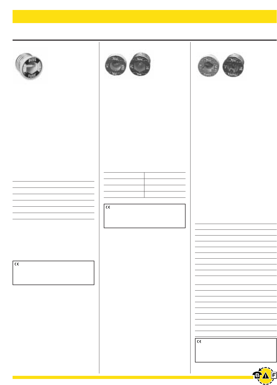
Electrical - Power Fuses Bussmann®
26 For complete specification data, call Bussmann Information Fax ~ 636.527.1450
Plug Fuses
Data Sheet: 1032 (S)
& 1034 (T)
Data Sheet: 1033 (SL) & 1035 (TL)Data Sheet: 1036
W Series
Fast Acting
Ampere Ratings: ⁄Ω™ - 12A
Voltage Rating: 125Vac
IR: 10,000A RMS Sym.
Element is a simple fusible, metal link.
For general purpose circuit protection.
Quickly opens when short-circuit or
overload occurs. Use for lighting and
other non-motor circuits. Edison base.
Agency Information: Std. 248-11
UL Listed, Guide JEFV, File E12112
SL and TL Series
Time-Delay, Loaded Link
Ampere Ratings: 15 - 30A
Voltage Rating: 125Vac
IR: 10,000A RMS Sym.
Heat absorbing metal bead on ele-
ment link for time-delay. Passes motor
overload starting currents without
needlessly opening.
Edison base (TL), Rejection base (SL).
Agency Information: Std. 248-11
UL Listed, Guide JEFV, File E12112
S and T Series
Time-Delay, Dual-Element
Ampere Ratings:
Type S: ⁄Ω¢ - 30A
Type T: ‹Ω¡º - 30A
Voltage Rating: 125Vac
IR: 10,000A RMS Sym.
For all-purpose application. Like two
fuses in one. A simple link element for
short-circuits and dangerous overloads
plus a series-connected element which
lets the harmless overload starting cur-
rents of motors pass without opening.
Uses less energy; operates cooler;
provides superior protection.
Edison base (T), Rejection base (S).
Agency Information: Std. 248-11
Type S: UL Listed (0-6⁄Ω¢) Guide JFHR,
File E56412 (7-30A) Guide JEFV,
File E12112;
CSA Certified, Class 1423-01, File 53787
Type W
W-⁄Ω™ W-4 W-10
W-1 W-5 W-12
W-1°Ω¡º W-6
W-2 W-6⁄Ω™
W-2⁄Ω™ W-7
W-3 W-8
Type SL Type TL
SL-15 TL-15
SL-20 TL-20
SL-25 TL-25
SL-30 TL-30
S-⁄Ω¢ S-1›Ω¡º S-3⁄Ω™ S-9
S-‹Ω¡º S-1flΩ¡º S-4 S-10
S-›Ω¡º S-1°Ω¡º S-4⁄Ω™ S-12
S-⁄Ω™ S-2 S-5 S-14
S-flΩ¡º S-2⁄Ω¢ S-5flΩ¡º S-15
S-°Ω¡º S-2⁄Ω™ S-6 S-20
S-1 S-2°Ω¡º S-6⁄Ω¢ S-25
S-1⁄Ω• S-3 S-7 S-30
S-1⁄Ω¢ S-3¤Ω¡º S-8
Type T
T-‹Ω¡º T-1flΩ¡º T-4 T-10
T-›Ω¡º T-1°Ω¡º T-4⁄Ω™ T-12
T-⁄Ω™ T-2 T-5 T-14
T-flΩ¡º T-2⁄Ω¢ T-5flΩ¡º T-15
T-°Ω¡º T-2⁄Ω™ T-6 T-20
T-1 T-2°Ω¡º T-6⁄Ω¢ T-25
T-1⁄Ω• T-3 T-7 T-30
T-1⁄Ω¢ T-3¤Ω¡º T-8
T-1›Ω¡º T-3⁄Ω™ T-9
CE logo denotes compliance with European
Union Low Voltage Directive (50-1000Vac,
75-1500Vdc). Refer to Data Sheet: 8002 or
contact Bussmann Application Engineering at
636-527-1270 for more information.
CE logo denotes compliance with European
Union Low Voltage Directive (50-1000Vac,
75-1500Vdc). Refer to Data Sheet: 8002 or
contact Bussmann Application Engineering at
636-527-1270 for more information.
CE logo denotes compliance with European
Union Low Voltage Directive (50-1000Vac,
75-1500Vdc). Refer to Data Sheet: 8002 or
contact Bussmann Application Engineering at
636-527-1270 for more information.
W-15, W-20, W-25, and W-30
Plug Fuses Obsoleted.
Suggest Replacing with either
T-(Amp) or TL-(Amp) Plug Fuses.
Bussmann®
27
For complete specification data, call Bussmann Information Fax ~ 636.527.1450
Electrical - Power Fuses
Plug Fuses
Fustat Fuse Adaptors
Fustat Adaptors (various ampere ratings) screw into the
“Edison” Thread fuse sockets of standard household fuse
boxes. Adaptors serve the purpose of preventing the wrong
size fuse from being used.
Carton
Catalog Number Prefix Ampere Rating Qty. Wt.
SA- 15, 20, 30
(Branch Circuits) 0.03
SA- 1, 1⁄Ω¢, 1flΩ¡º, 2, 2⁄Ω™,4(lbs)
(Single Motor Circuits) 3¤Ω¡º, 4, 5, 6⁄Ω¢, 8, 10
ENA Edison base neutral
Dual-Element Fustat®Fuses and Adaptors for Small
Motor Protection.
(Both Motor Running and Short-Circuit Protection)
Adaptor Accepts Fuses
SA-1 S-1 or smaller
SA-1-1/4 S-1-1/4 or smaller
SA-1-6/10 S-1-6/10 or smaller
SA-2 S-2 or S-1-8/10
SA-2-1/2 S-2-1/2 to S-1-8/10
SA-3-2/10 S-3-2/10 to S-1-8/10
SA-4 S-4 to S-3-1/2
SA-5 S-5 to S-3-1/2
SA-6-1/4 S-6-1/4 to S-3-1/2
SA-8 S-8 to S-7
SA-10 S-10 to S-7
SA-15 S-15 to S-7
SA-20 S-20
SA-30 S-30 to S-20
Branch Circuit Protection
Adaptor Accepts Fuses
SA-15 S-15 to S-7
SA-20 S-20
SA-30 S-25
SA 30 S-30 to S-20
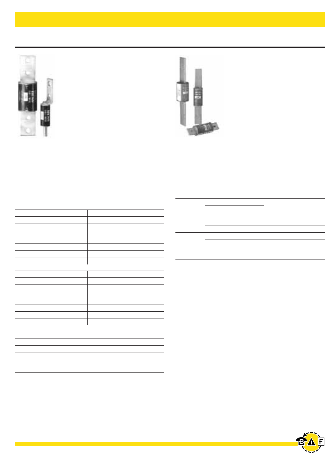
Bussmann®
28 For complete specification data, call Bussmann Information Fax ~ 636.527.1450
Electrical - Power Fuses
Cable Limiters & Welder Limiters
Data Sheet: 1042 Data Sheet: 1045
68000 & 64000 Series
Welder Limiters for Class H and J Fuseholders
Voltage Rating: 600Vac or less
Interrupting Rating: 200,000 Amps RMS Symmetrical
Catalog Symbol & Current Ratings
Type Catalog Amp Rating Carton Weight Each
Fuseholder Number (Nominal) Quantity Lbs. Kg.
68150 150 1 1.40 0.63
68200 200
Class H 68300 300 1 2.75 1.25
68400 400
68600 600 1 4.25 1.92
64200 200 1 1.00 0.45
64300 300 1 1.75 0.79
Class J 64400 400 1 1.75 0.79
64600 600 1 3.50 1.59
•Current-limiting devices designed specially for use on
welder circuits only.
•Time-current characteristics are designed to hold on the
intermittent overloading encountered in welder operation,
while providing short-circuit protection to the circuit and
equipment.
•Welder limiters have excess current capacity in the operat-
ing range as needed for this type of service.
•Because of the special characteristics of the welder limiters,
they are not intended for application on general-use circuits.
K Series
Cable Limiters
Interrupting Rating: 200,000A, 600Vac
RMS Symmetrical
UL Listing: KDM, KDR, KDP and KFM
Copper Cable Limiter — 600 Volts
Catalog Cable Catalog Cable
Symbol Size Symbol Size
Tubular Terminals
KCY #4 KCF 4/0
KCZ #3 KCH 250 MCM
KCA #2 ††KCJ 350 MCM
KCB #1 †† †KCM1, KCM-B1500 MCM
KCC 1/0 KCV 600 MCM
††KCD 2/0 ††KCR1750 MCM
KCE 3/0 KCS 1000 MCM
Tubular Terminal and Offset Bolt-Type Terminal
KQV #12 KDD 2/0
KQT #10 KDE 3/0
KFZ #8 KDF 4/0
KIG #6 KDH 250 MCM
KDY #4 ††KDJ 350 MCM
KDA #2 †KDM1500 MCM
KDB #1 KDU 600 MCM
KDC 1/0 ††KDR1750 MCM
Compression Connector Rod Terminal and Tubular Terminal
KEX 4/0 KQO 350 MCM
KFH-A 250 MCM ††KDT 500 MCM
*Center Bolt-Type Terminal and Off-Set Bolt-Type Terminal
KPF 4/0 KDP1500 MCM
KFT 250 MCM KFM1750 MCM
KEW 350 MCM
†Available with molded rubber boots. Add “–B” to end of part number.
Boot can be purchased separa tely.
•KCM: Part# - ______Boot-KCM
•KDM: Part# - ______Boot-KDM
††Available with shrink tube “_V” suffix.
*Copper or aluminum cable; sizes of all other limiters pertain to copper only.
1UL Listed (File E90818)
•Crimp Tool: TBM-14M
•Die: 15506 KDM
15515 KDR
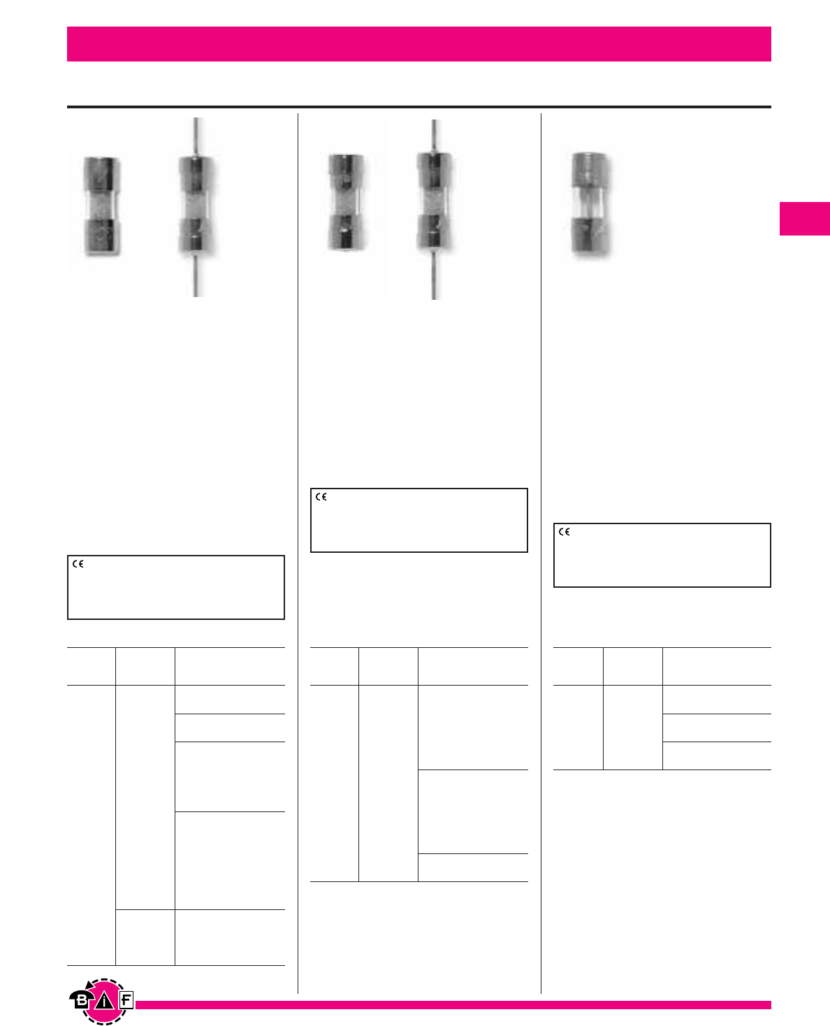
Bussmann®
29
Electronic – PC Board and Small Dimension Fuses
125mA 35A/250V 10kA/125V
250mA p.f. = 0.7 - 0.8
350mA 35A/250V 10kA/125V
25A/600V p.f. = 0.7 - 0.8
375mA
500mA 35A/250V
600mA 10kA/125V
750mA 250V p.f. = 0.7 - 0.8
1A
1.25A
1.5A
1.6A 100A/250V
2A 10kA/125V
2.25A p.f. = 0.7 - 0.8
2.5A
3A
3.5A
4A 400A/125V
5A 125V p.f. = 1.0
7A
Electrical Characteristics
Rated
Current Voltage Interrupting
Rating ac Rating
5mm ≈ 15mm Fuses
Data Sheet: 2025
Data Sheet: 2026 (C518)
& 2027 (C520)
Data Sheet: 2006 (C515)
& 2007 (C519)
For complete specification data, call Bussmann Information Fax ~ 636.527.1450
C515 (Axial Leads)
C519
Time-Delay
Physical Size:
0.197∑ ≈ 0.591∑ (5mm ≈15mm)
Construction: Glass Tube
Agency Information:
UL Listing File E19180, Guide JDYX
125mA-250mA and 375mA-3A
CSA Certification File LR65063,
Class 1422-01, 125mA-250mA and
375mA-3A
UL Recognized, File E19180,
Guide JDYX2, 350mA and 3.5A-7A
C518 (Axial Leads)
C520
Fast-Acting
Physical Size:
0.197∑ ≈ 0.591∑ (5mm ≈15mm)
Construction: Glass Tube
Agency Information:
UL Listing File E19180, Guide JDYX
CSA Certification File LR65063,
Class 1422-01
C517 (Axial Leads)
Fast-Acting, Light Ballast
Protection
Physical Size:
0.197∑ ≈ 0.591∑ (5mm ≈15mm)
Construction: Ceramic
Agency Information:
UL Listing File E19180, Guide JDYX
CSA Certification File LR65063,
Class 1422-01
UL Recognized, File E19180,
Guide JDYX2
100mA
125mA 35A/250V
250mA 10kA/125V
375mA p.f. = 0.7 - 0.8
500mA
750mA 250V
1A
1.5A
2A 100A/250V
2.5A 10kA/125V
3A p.f. = 0.7 - 0.8
3.5A
4A 200A/250V 10kA/125V5A
5A p.f. = 0.7 - 0.8
Electrical Characteristics
Rated
Current Voltage Interrupting
Rating dc Rating
100A/350Vac
p.f. = 1.0
3A 350V* 100A/250Vac
p.f. = 0.7 - 0.8
10kA/125Vac
p.f. = 0.7 - 0.8
*350Vac/100A is UL Recognized
Electrical Characteristics
Max. Rated
Current Voltage Interrupting
Rating ac Rating
CE logo denotes compliance with European
Union Low Voltage Directive (50-1000Vac,
75-1500Vdc). Refer to Data Sheet: 8002 or
contact Bussmann Application Engineering at
636-527-1270 for more information.
CE logo denotes compliance with European
Union Low Voltage Directive (50-1000Vac,
75-1500Vdc). Refer to Data Sheet: 8002 or
contact Bussmann Application Engineering at
636-527-1270 for more information.
CE logo denotes compliance with European
Union Low Voltage Directive (50-1000Vac,
75-1500Vdc). Refer to Data Sheet: 8002 or
contact Bussmann Application Engineering at
636-527-1270 for more information.
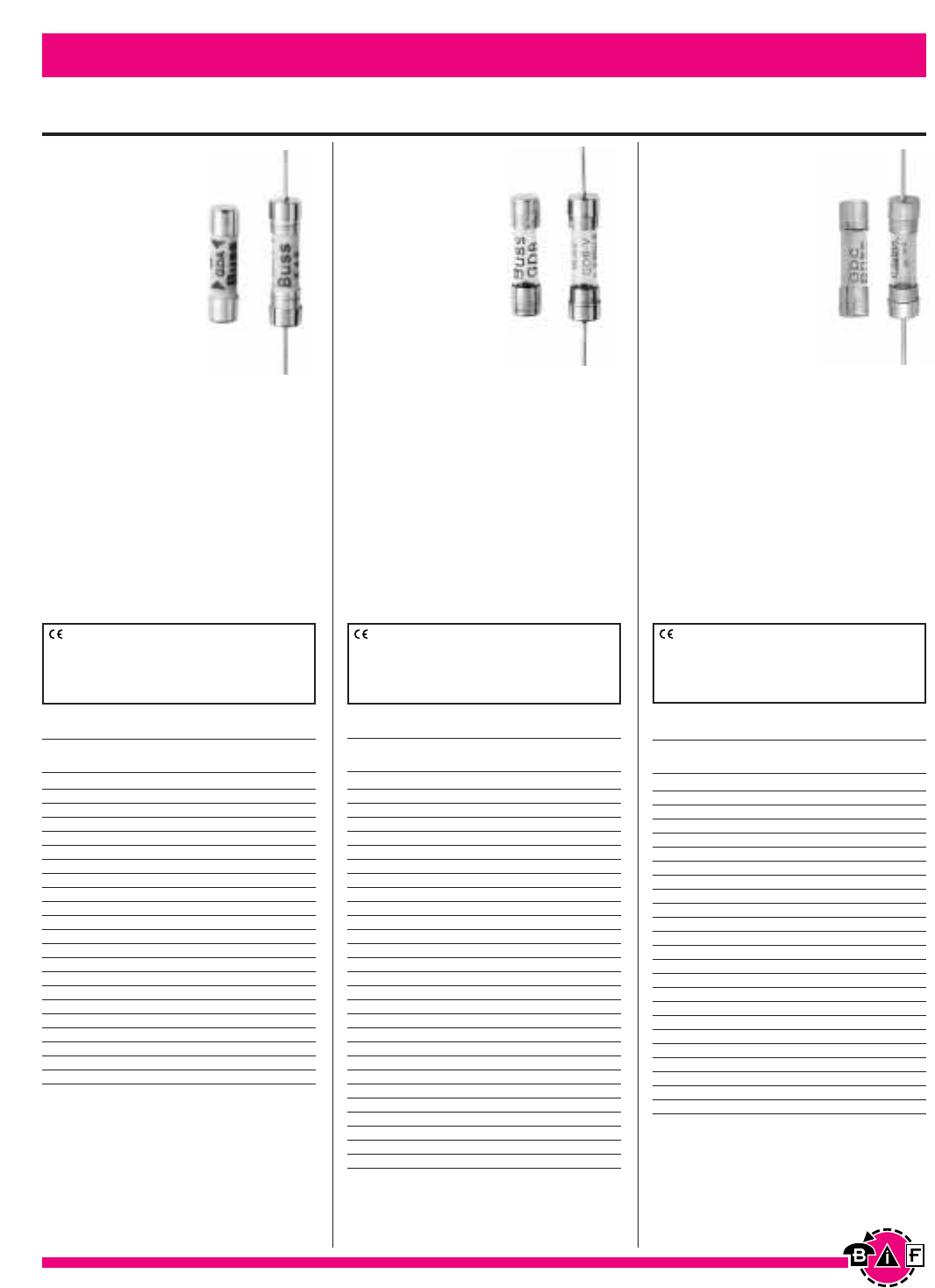
GDC
GDC-V (Axial
Leads)
Time Delay,
Low Breaking
Capacity
Physical Size:
0.197∑ ≈ 0.788∑
(5mm ≈20mm)
Construction:
Glass Tube
End caps: Nickel plated brass
Voltage Rating: 250Vac or less
Interrupting Rating: 35A @ 250Vac
Agency Information:
Designed to IEC (Pub 127) Sheet III
British Standard Approval
SEMKO Approval
VDE Approval, IMQ
UL Recognized, Guide JDYX2,
File E19180, 32mA-6.3A
Bussmann®
30
Data Sheet: 2016Data Sheet: 2015Data Sheet: 2014
For complete specification data, call Bussmann Information Fax ~ 636.527.1450
Electronic – PC Board and Small Dimension Fuses
5mm ≈ 20mm — IEC Standards
GDA
GDA-V (Axial
Leads)
Fast-Acting,
High Breaking
Capacity
Physical Size:
0.197∑ ≈ 0.788∑
(5mm ≈20mm)
Construction:
Ceramic Tube
End caps: Nickel plated brass
Voltage Rating: 250Vac or less
Interrupting Rating: 1500A @
250Vac
Agency Information:
UL Recognized, Guide JDYX2,
File E19180, 50mA and 315mA-6.3A
SEMKO Approval 50mA, 200mA and
315mA-6.3A
IEC 127-SI
VDE Approval 1.25A-6.3A
GDB
GDB-V (Axial
Leads)
Fast-Acting,
Low Breaking
Capacity
Physical Size:
0.197∑ ≈ 0.788∑
(5mm ≈20mm)
Construction:
Glass Tube
End caps: Nickel plated brass
Voltage Rating: 250Vac or less
Interrupting Rating: 35A @ 250Vac
Agency Information:
Designed to IEC (Pub 127) Sheet II
British Standard Approval
SEMKO Approval
VDE Approval, IMQ
UL Recognized, Guide JDYX2,
File E19180, 32mA-6.3A
50mA 0.0017 9000
63mA 0.0005 3300
80mA 0.0011 2600
100mA 0.0018 2300
125mA 0.0037 1900
160mA 0.008 1600
200mA 0.020 1350
250mA 0.027 1300
315mA 0.010 1400
400mA 0.018 1200
500mA 0.038 1050
630mA 0.064 1200
800mA 0.097 490
1A 0.480 230
1.25A 0.9 200
1.6A 1.9 180
2A 2.0 205
2.5A 3.9 190
3.15A 8.1 160
4A 14 160
5A 25 155
6.3A 48 150
Electrical Characteristics
Current Max Voltage
Rating I2t Drop (mV)
32mA 0.000047 10000
40mA 0.00011 8000
50mA 0.00020 3200
63mA 0.00057 2500
80mA 0.0012 2200
100mA 0.003 2100
125mA 0.005 2000
160mA 0.008 1950
200mA 0.016 1600
250mA 0.028 1400
315mA 0.058 1150
400mA 0.018 950
500mA 0.018 220
630mA 0.035 220
800mA 0.067 180
1A 0.60 200
1.25A 0.84 200
1.6A 1.6 190
2A 4.2 160
2.5A 6.1 145
3.15A 13 130
4A 22 120
5A 42 115
6.3A 69 110
8A* — —
10A* — —
12A* — —
16A* — —
*IEC Standard 127 Sheet II does not include ratings above
6.3A.
Electrical Characteristics
Current Max Voltage
Rating I2t* Drop (mV)
32mA 0.0014 1050
40mA 0.0034 920
50mA 0.006 800
63mA 0.012 760
80mA 0.015 580
100mA 0.022 490
125mA 0.034 390
160mA 0.052 320
200mA 0.078 340
250mA 0.17 270
315mA 0.41 250
400mA 0.61 210
500mA 0.75 168
630mA 1.3 158
800mA 3.1 132
1A 3.6 85
1.25A 7 80
1.6A 10 80
2A 17 80
2.5A 34 80
3.15A 56 75
4A 91 75
5A 133 75
6.3A 270 65
Electrical Characteristics
Current Max Voltage
Rating I2t Drop (mV)
CE logo denotes compliance with European
Union Low Voltage Directive (50-1000Vac,
75-1500Vdc). Refer to Data Sheet: 8002 or
contact Bussmann Application Engineering at
636-527-1270 for more information.
CE logo denotes compliance with European
Union Low Voltage Directive (50-1000Vac,
75-1500Vdc). Refer to Data Sheet: 8002 or
contact Bussmann Application Engineering at
636-527-1270 for more information.
CE logo denotes compliance with European
Union Low Voltage Directive (50-1000Vac,
75-1500Vdc). Refer to Data Sheet: 8002 or
contact Bussmann Application Engineering at
636-527-1270 for more information.
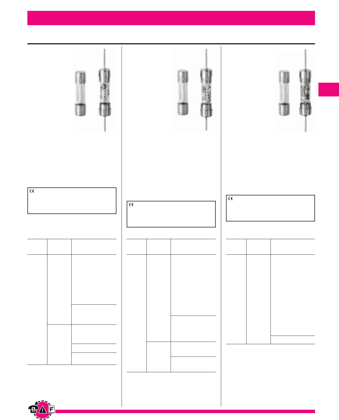
Bussmann®
Electronic – PC Board and Small Dimension Fuses Bussmann®
31
5mm ≈20mm – N. American Standards
Data Sheet:2019Data Sheet: 2018Data Sheet: 2017
For complete specification data, call Bussmann Information Fax ~ 636.527.1450
GMA
GMA-V
(Axial Leads)
Fast Acting
Physical Size:
0.197∑ ≈ 0.788∑
(5mm ≈20mm)
Construction:
Glass Tube
End Caps; nickel
plated brass
Agency
Information:
Std. 248-14
UL Listed Guide JDYX, File E19180, 0-6A
UL Recognized, Guide JDYX2,
File E19180, 7-15A
CSA Certified, Class 1422-01,
File E65063, 0-6A
GMC
GMC-V
(Axial
Leads)
Medium Time-
Delay
Physical Size:
0.197∑ ≈ 0.788∑
(5mm ≈20mm)
Construction:
Glass Tube
End Caps; nickel
plated brass
Agency Information:
Std. 248-14
UL Listed Guide JDYX, File E19180, 0-
6.3A
UL Recognized, Guide JDYX2,
File E19180, 7-8A
CSA Certified, Class 1422-01,
File 65063, 0-6.3A
GMD
GMD-V
(Axial
Leads)
Time-Delay
Physical Size:
0.197∑ ≈ 0.788∑
(5mm ≈20mm)
Construction:
Glass Tube
End Caps; nickel
plated brass
Agency
Information:
Std. 248-14
UL Listed Guide JDYX, File E19180, 0-3A
UL Recognized, Guide JDYX2,
File E19180, 4A
CSA Certified, Class 1422-01,
File 65063, 0-3A
63mA
100mA
125mA
200mA
250mA 35A/250V
300mA 10kA/125V
315mA p.f. = 0.7 – 0.8
500mA
600mA
750mA 250
800mA
1A
1.25A
1.5A 100A/250V
1.6A 10kA/125V
2A p.f. = 0.7 – 0.8
2.5A
3.15A
3.5A 10kA/125V
4A p.f. = 0.7 – 0.8
5A
6A 125
7A 200A/125V
8A p.f. = 1.0
10A
15A 150A/125V
p.f. = 1.0
Electrical Characteristics
Rated
Current Voltage Breaking
Rating (Vac) Capacity
63mA
80mA
100mA
125mA
150mA
200mA 35A/250V
250mA 10kA/125V
300mA p.f. = 0.7 – 0.8
315mA
400mA
500mA 250
600mA
630mA
750mA
800mA
1A
1.25A
1.5A
1.6A 100A/250V
2A 10kA/125V
2.5A p.f. = 0.7 – 0.8
3A
3.15A
3.5A
4A 10kA/125V
5A p.f. = 0.7 – 0.8
6A 125
6.3A
7A 200A/125V
8A p.f. = 1.0
10A
Electrical Characteristics
Rated
Current Voltage Breaking
Rating (Vac) Capacity
125mA
150mA
200mA
250mA
300mA
315mA
400mA 100A/250V
500mA 10kA/125V
600mA 250 p.f. = 0.7 – 0.8
630mA
750mA
800mA
1A
1.2A
1.25A
1.5A
1.6A
2A
2.5A
3A
4A 200A/250V
10kA/125V, p.f. = 1
Electrical Characteristics
Rated
Current Voltage Breaking
Rating (Vac) Capacity
CE logo denotes compliance with European
Union Low Voltage Directive (50-1000Vac,
75-1500Vdc). Refer to Data Sheet: 8002 or
contact Bussmann Application Engineering at
636-527-1270 for more information.
CE logo denotes compliance with European
Union Low Voltage Directive (50-1000Vac,
75-1500Vdc). Refer to Data Sheet: 8002 or
contact Bussmann Application Engineering at
636-527-1270 for more information.
CE logo denotes compliance with European
Union Low Voltage Directive (50-1000Vac,
75-1500Vdc). Refer to Data Sheet: 8002 or
contact Bussmann Application Engineering at
636-527-1270 for more information.
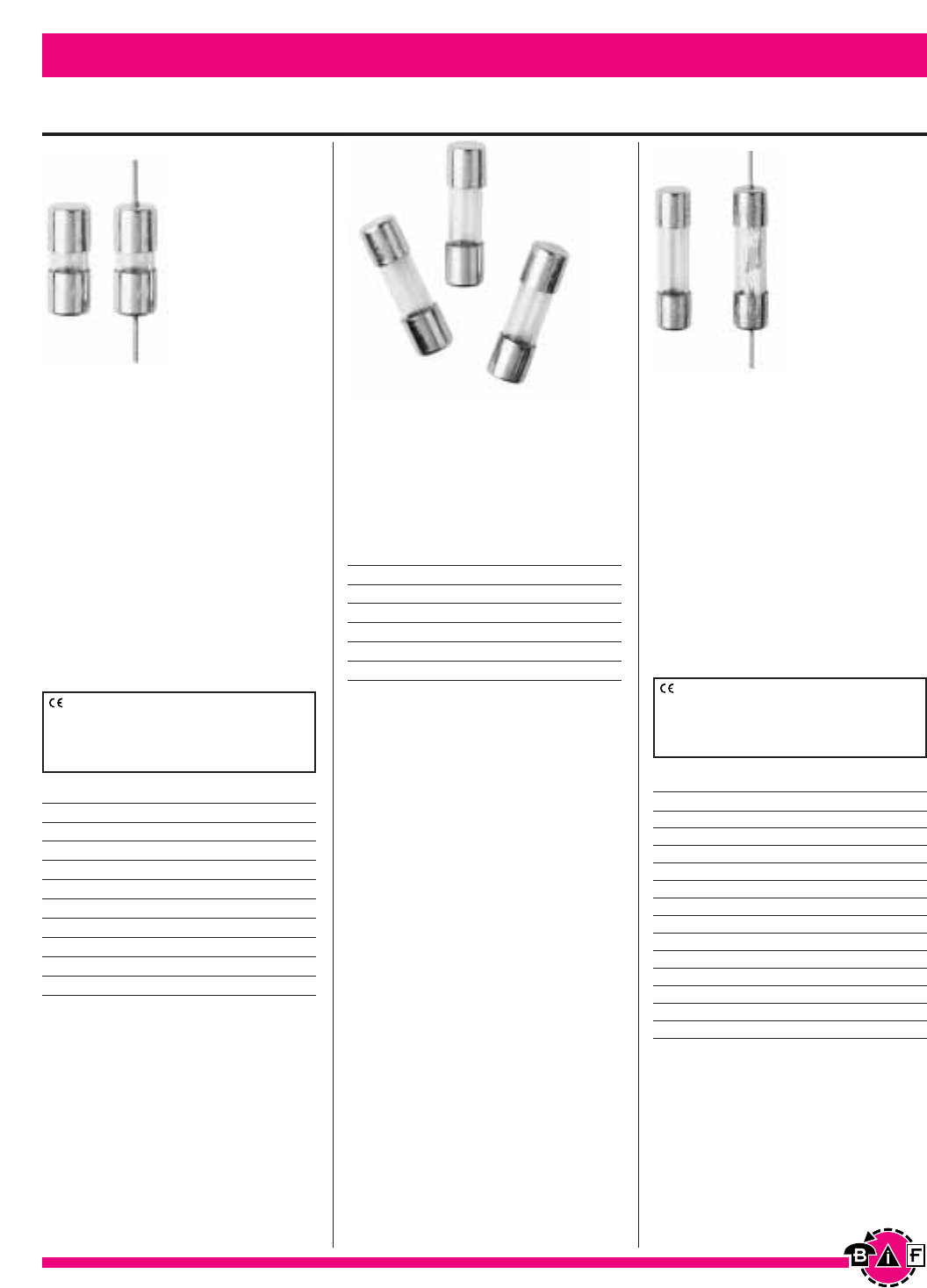
Bussmann®
Data Sheet: 2041Data Sheet: 2040
Electronic – PC Board and Small Dimension Fuses Bussmann®
32
AGA-⁄Ω¡§ AGA-⁄Ω™ AGA-2
AGA-⁄Ω¡º AGA-flΩ¡º AGA-2⁄Ω™
AGA-⁄Ω• AGA-‹Ω¢ AGA-3
AGA-⁄Ω¢ AGA-1AGA-5
AGA-‹Ω• AGA-1⁄Ω™ —
32Vac/1kA
AGA-6 AGA-10 AGA-25
AGA-7 AGA-15 AGA-30
AGA-7⁄Ω™ AGA-20 —
Catalog Symbol & Current Ratings
125Vac/10kA (⁄Ω¡§-1⁄Ω™), 200A (2-5A) AGX-⁄Ω∞ºº AGX-‹Ω¡§ AGX-‹Ω¢
AGX-⁄Ω™ºº AGX-¤Ω¡º AGX-1
AGX-⁄Ω¡ºº AGX-⁄Ω¢ AGX-1⁄Ω¢
AGX-⁄Ω£™ AGX-‹Ω¡º AGX-1⁄Ω™
AGX-⁄Ω¡§ AGX-‹Ω• AGX-2
AGX-⁄Ω¡º AGX-›Ω¡º —
AGX-⁄Ω• AGX-⁄Ω™ —
125Vac/10kA
AGX-2⁄Ω™ AGX-4 AGX-6
AGX-3 AGX-5 AGX-7
32 V/1kA
AGX-8 AGX-15 AGX-25
AGX-10 AGX-20 AGX-30
Catalog Symbol & Current Ratings
250Vac/35A (⁄Ω∞ºº-⁄Ω™A), 100A (‹Ω¢-1⁄Ω™A)
AGW-1 AGW-4 AGW-15
AGW-1⁄Ω™ AGW-5 AGW-20
AGW-2 AGW-6 AGW-25
AGW-2⁄ Ω™ AGW-7⁄Ω™ AGW-30
AGW-3 AGW-10 —
Catalog Symbol & Current Ratings
32Vac
⁄Ω¢∑ Diameter ≈fiΩ•∑ to
1
∑Lengths
Data Sheet: 2039
For complete specification data, call Bussmann Information Fax ~ 636.527.1450
AGA
AGA-V* (Axial Leads)
Fast Acting
Physical Size:
⁄Ω¢∑ ≈ fiΩ•∑ (1AG)
(6.4mm ≈15.9mm)
Construction: Glass Tube
Voltage Rating: See table below.
Agency Information: Std. 248-14
UL File E19180,
UL Listed, Guide JDYX 0-1⁄Ω™A
UL Recognized, Guide JDYX2 2-12A,
AGX
AGX-V (Axial Leads)*
Fast Acting
Physical Size:
⁄Ω¢∑ ≈ 1∑ (8AG)
(6.4mm ≈25.4mm)
Construction: Glass Tube
Voltage Rating: See table below.
Agency Information: Std. 248-14
UL File E19180
UL Listed, Guide JDYX, 0-5A
UL Recognized, Guide JDYX2, 6-20A
CSA File 47233; Class 1422-01, 0-5A
AGW
Fast Acting
Physical Size:
⁄Ω¢∑ ≈ ‡Ω•∑ (7AG)
(6.4mm ≈22.2mm)
Construction: Glass Tube
Voltage Rating: 32V
CE logo denotes compliance with European
Union Low Voltage Directive (50-1000Vac,
75-1500Vdc. Refer to Data Sheet: 8002 or
contact Bussmann Application Engineering at
636-527-1270 for more information.
CE logo denotes compliance with European
Union Low Voltage Directive (50-1000Vac,
75-1500Vdc). Refer to Data Sheet: 8002 or
contact Bussmann Application Engineering at
636-527-1270 for more information.
*AGA-V is UL Listed 0-5A, UL Recognized 6-12A
* AGX-V is UL Recognized from 6-20A @ 32Vac
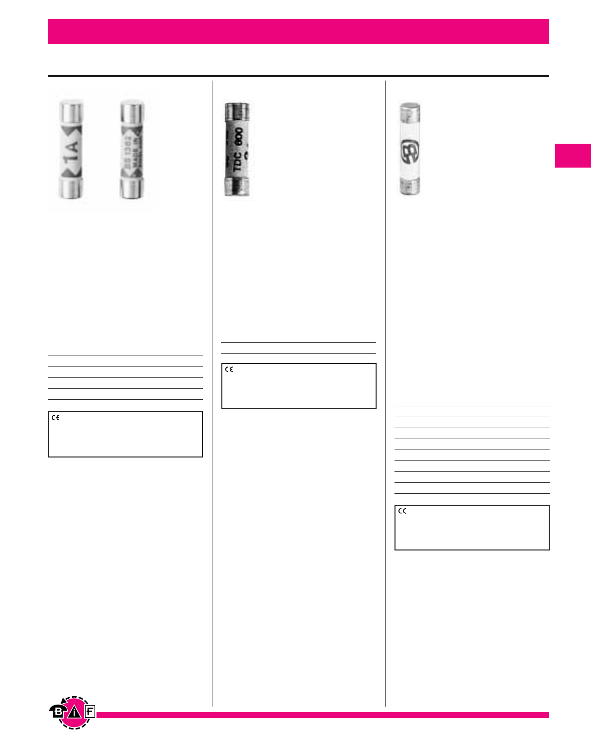
Electronic – PC Board and Small Dimension Fuses Bussmann®
33
⁄Ω¢∑ Diameter ≈
1
∑Lengths
Data Sheet: 720038 (Fuse)
Time-Current 35785256, 50955
Data Sheet: 2081Data Sheet: 2042
For complete specification data, call Bussmann Information Fax ~ 636.527.1450
Catalog Symbol & Current Ratings
240Vac
TDC180-1 TDC180-5 TDC180-13
TDC180-2 TDC180-7 —
TDC180-3 TDC180-10 —
TDC180
British Household Plug Fuse
Fast/Medium
Physical Size:
⁄Ω¢∑ ≈ 1∑
(6.4mm ≈ 25.4mm)
Construction: Ceramic Tube
End Caps: Silver-plated copper
Agency Information:
BS1362, IEC 269-3A
CE logo denotes compliance with European
Union Low Voltage Directive (50-1000Vac,
75-1500Vdc). Refer to Data Sheet: 8002 or
contact Bussmann Application Engineering at
636-527-1270 for more information.
Catalog Symbol & Current Ratings
TDC600-2A TDC600-10A
TDC600
Fast Acting
Physical Size:
⁄Ω¢∑ ≈ 1∑
(6.3mm ≈ 25.4mm)
Construction: Ceramic Tube
Voltage Rating: 600Vac
Agency Information:
UL Recognized, Std. 248-14, BS1362
CE logo denotes compliance with European
Union Low Voltage Directive (50-1000Vac,
75-1500Vdc). Refer to Data Sheet: 8002 or
contact Bussmann Application Engineering at
636-527-1270 for more information. Catalog Symbol & Current Ratings
FWH-.250A6F FWH-010A6F
FWH-.500A6F FWH-12.5A6F
FWH-001A6F FWH-015A6F
FWH-002A6F FWH-016A6F
FWH-3.15A6F FWH-020A6F
FWH-005A6F FWH-025A6F
FWH-6.30A6F FWH-030A6F
FWH-007A6F
FWH
Semiconductor Fuse
Physical Size:
⁄Ω¢∑ ≈ 1⁄Ω¢∑
(6.3mm ≈ 32mm)
Construction: Ceramic Tube
Voltage Rating:
500Vac/50kA (.25-20A)
500Vac/20kA (25A, 30A)
Agency Information: Std. 248-14
UL Recognized .25-7, 500Vac,
File E91958, Guide JFHR2
UL Recognized 10-30, 500Vac,
File E56412, Guide JFHR2
CE logo denotes compliance with European
Union Low Voltage Directive (50-1000Vac,
75-1500Vdc). Refer to Data Sheet: 8002 or
contact Bussmann Application Engineering at
636-527-1270 for more information.
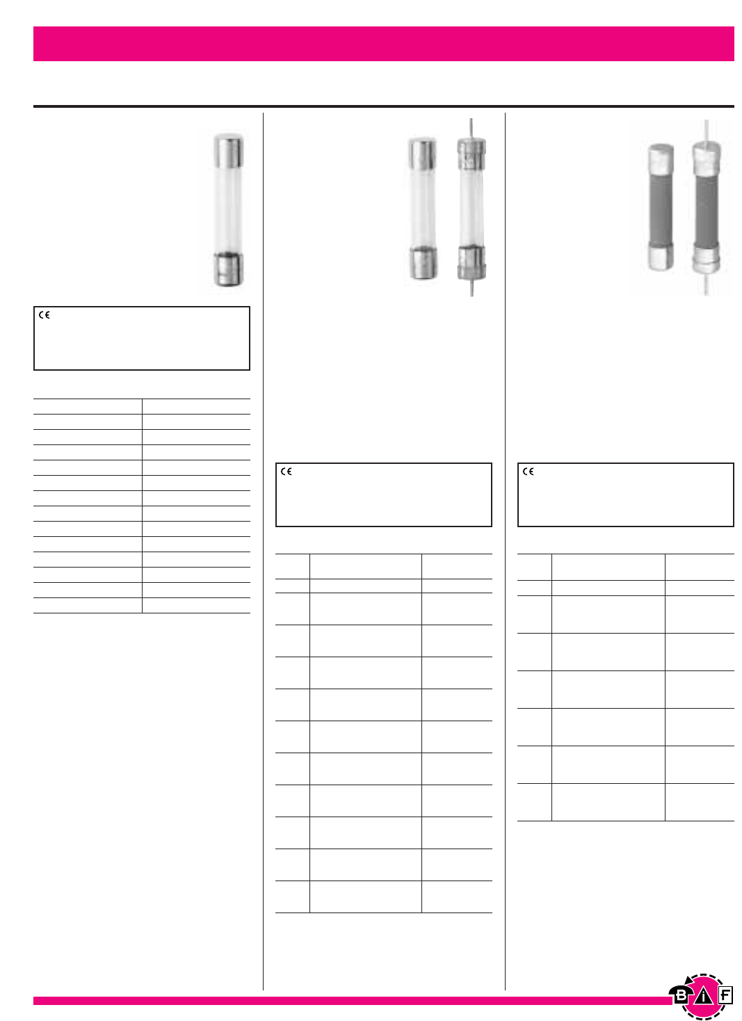
Electronic - PC Board and Small Dimension Fuses Bussmann®
34
Data Sheet: 2000Data Sheet: 2001Data Sheet: 2043
For complete specification data, call Bussmann Information Fax ~ 636.527.1450
⁄Ω¢
∑≈
1⁄Ω¢
∑Fast Acting Fuses
TDC10
Fast Acting
Physical Size:
⁄Ω¢∑ ≈ 1⁄Ω¢∑ (3AG)
(6.3mm ≈32mm)
Construction: Glass Tube
Voltage Rating: See Below
Agency Information:
Conforms to British Standard
BS-2950A, I.R. 10Im@Vm.
AGC
AGC-V (Axial
Leads)
Fast Acting
Physical Size:
⁄Ω¢∑ ≈ 1⁄Ω¢∑ (3AG)
(6.3mm ≈32mm)
Construction:
Glass Tube
Nickel Plated Brass
End Caps
Voltage Rating: See Below
Interrupting Rating: See Below
Agency Information: Std. 248-14
UL Listed, Guide JDYX, File E19180, 0-10A
UL Recognized, Guide JDYX2,
File E19180, 15-30A
CSA Certification, Class 1422-01,
File 53787
ABC
ABC-V (Axial
Leads)
Fast Acting
Physical Size:
⁄Ω¢∑ ≈ 1⁄Ω¢∑ (3AB)
(6.3mm ≈32mm)
Construction:
Ceramic Tube
Nickel Plated
Brass End Caps
Voltage Rating: See Below
Interrupting Rating: See Below
Agency Information: Std. 248-14
UL Listed, Guide JDYX File E19180, 0-15A
UL Recognized, Guide JDYX2,
File E19180, 20-25A
CSA Certification, Class 1422-01,
File 53787, 0-15A, Class 1422-30,
File 53787, 20-25A
Electrical Characteristics
Current Rated Interrupting
Rating Voltage Rating1
ac (Max.) ac
⁄Ω™º 250V 35A
⁄Ω¡§ 250V 35A
⁄Ω¡º 250V 35A
⁄Ω• 250V 35A
‹Ω¡§ 250V 35A
¤Ω¡º 250V 35A
⁄Ω¢ t250V 35A
‹Ω¡º 250V 35A
‹Ω• 250V 35A
›fiΩ¡ºº t250V 35A
⁄Ω™ 250V 35A
‹Ω¢ 250V 35A
1250V 35A
1⁄Ω¢ 250V 100A
1⁄Ω™ 250V 100A
2250V 100A
2⁄Ω¢ 250V 100A
2⁄Ω™ 250V 100A
3250V 100A
4250V 200A
5250V 200A
6250V 200A
7250V 200A
8250V 200A
9250V 200A
10 250V 200A
15 32V 1000A
20 32V 1000A
25 32V 1000A
30 32V 1000A
1Interrupting ratings were measured at 70% – 80% power
factor on AC, and at a time constant described in UL 248.
Electrical Characteristics
Current Rated Interrupting
Rating Voltage Rating1
ac (Max.) dc (Max.) ac dc
⁄Ω¢ 250V 125V 35A 10kA
⁄Ω™ 250V 125V 35A 10kA
‹Ω¢ 250V 125V 35A 10kA
1250V 125V 35A 10kA
1⁄Ω™ 250V 125V 100A 10kA
2250V 125V 100A 10kA
2⁄Ω™ 250V 125V 100A 10kA
3250V 125V 100A 10kA
4250V 125V 200A 10kA
5250V 125V 200A 10kA
6250V 125V 200A 10kA
7250V 125V 200A 10kA
8250V 125V 200A 10kA
10 250V 125V 200A 10kA
15 250V 125V 750A 10kA
20 250V 125V 400A 10kA
25 125V 125V 1000A 400A
30 125V 125V 1000A 400A
1Interrupting ratings were measured at 70% – 80% power
factor on AC, and at a time constant described in UL 248.
1000Vac
TDC10-50mA
TDC10-60mA
TDC10-100mA
TDC10-150mA
TDC10-250mA
750Vac
TDC10-500mA
500Vac
TDC10-750mA
350Vac
TDC10-1A
—
—
250Vac
TDC10-1.5A
TDC10-2A
TDC10-3A
TDC10-5A
150Vac
TDC10-7A
100Vac
TDC10-10A
32Vac
TDC10-12A
TDC10-15A
TDC10-20A
TDC10-25A
Catalog Symbol & Current Ratings
CE logo denotes compliance with European
Union Low Voltage Directive (50-1000Vac,
75-1500Vdc). Refer to Data Sheet: 8002 or
contact Bussmann Application Engineering at
636-527-1270 for more information.
CE logo denotes compliance with European
Union Low Voltage Directive (50-1000Vac,
75-1500Vdc). Refer to Data Sheet: 8002 or
contact Bussmann Application Engineering at
636-527-1270 for more information.
CE logo denotes compliance with European
Union Low Voltage Directive (50-1000Vac,
75-1500Vdc). Refer to Data Sheet: 8002 or
contact Bussmann Application Engineering at
636-527-1270 for more information.
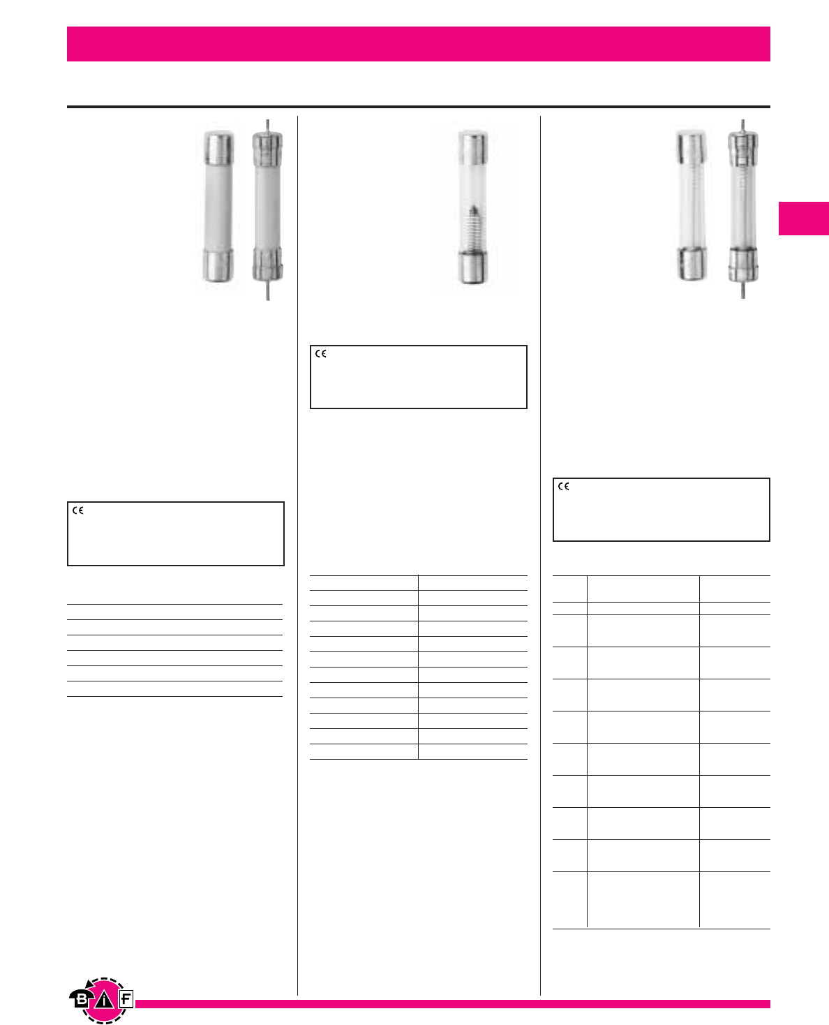
Bussmann®
35
Data Sheet:2004Data Sheet: 2043Data Sheet: 2013
For complete specification data, call Bussmann Information Fax ~ 636.527.1450
1000Vac
TDC11-50mA
TDC11-60mA
TDC11-100mA
TDC11-150mA
TDC11-250mA
750Vac
TDC11-500mA
500Vac
TDC11-750mA
350Vac
TDC11-1A
250Vac
TDC11-1.5A
TDC11-2A
TDC11-3A
TDC11-5A
150Vac
TDC11-7A
100Vac
TDC11-10A
—
—
—
GBB
GBB-V
(Axial Leads)
Very Fast Acting
Physical Size:
⁄Ω¢∑ ≈ 1⁄Ω¢∑ (3AB)
(6.3mm ≈32mm)
Construction:
Ceramic Cartridge
Nickel Plated
Brass End Caps
Voltage Rating: 250Vac/125Vdc
Interrupting Rating:
200A @ 250Vac
10kA @ 125Vac/dc (1-15A),
200A @ 125Vac/dc (20-30A)
Agency Information: Std. 248-14
UL Recognized, 1-30, 125Vdc/250Vac,
File E56412, Guide JFHR2
CSA Certified, 1-10, 125Vdc/250Vac,
File 53787, Class 1422-01
TDC11
Time Lag
Physical Size:
⁄Ω¢∑ ≈ 1⁄Ω¢∑ (3AG)
(6.3mm ≈32mm)
Construction:
Glass Tube
Voltage Rating:
See Below
Interrupting
Rating: 10 times rated
current @ Vm.
Catalog Symbol and Current Ratings
GBB-1 GBB-6 GBB-15
GBB-1⁄Ω¢ GBB-7 GBB-20
GBB-2 GBB-8 GBB-25
GBB-3 GBB-9 GBB-30
GBB-4 GBB-10 —
GBB-5 GBB-12 —
Electronic - PC Board and Small Dimension Fuses
Catalog Symbol and Current Ratings
⁄Ω¢
∑≈
1⁄Ω¢
∑Fuses
MDL
MDL-V (Axial
Leads)
Time-Delay
Physical Size:
⁄Ω¢∑ ≈ 1⁄Ω¢∑ (3AG)
(6.3mm ≈32mm)
Construction:
Glass Tube
Nickel Plated
Brass End Caps
Voltage Rating: See Below
Interrupting Rating: See Below
Agency Information: Std. 248-14
UL Listed, Guide JDYX, File E19180;
⁄Ω¡§-8A
CSA Certification Class 1422-01,
File 53787, ⁄Ω¡§-8A
UL Recognized, Guide JDYX2,
File E19180, 8.1-30A
Electrical Characteristics
Current Rated Interrupting
Rating Voltage Rating1
ac (Max.) ac
⁄Ω¡§ 250V 35A
⁄Ω¡º 250V 35A
⁄Ω• 250V 35A
¤Ω¡º 250V 35A
‹Ω¡§ 250V 35A
⁄Ω¢ 250V 35A
‹Ω¡º 250V 35A
‹Ω• 250V 35A
⁄Ω™ 250V 35A
‹Ω¢ 250V 35A
1250V 35A
1⁄Ω¢ 250V 100A
1⁄Ω™ 250V 100A
2250V 100A
2⁄Ω¢ 250V 100A
2⁄Ω™ 250V 100A
3250V 100A
4250V 200A
5250V 200A
6250V 200A
7250V 200A
8250V 200A
932V 1000A
10 32V 1000A
12 32V 1000A
15 32V 1000A
20 32V 1000A
25 32V 1000A
30 32V 1000A
1Interrupting ratings were measured at 70% – 80% power
factor on ac, and at a time constant described in UL 198L.
CE logo denotes compliance with European
Union Low Voltage Directive (50-1000Vac,
75-1500Vdc). Refer to Data Sheet: 8002 or
contact Bussmann Application Engineering at
636-527-1270 for more information.
CE logo denotes compliance with European
Union Low Voltage Directive (50-1000Vac,
75-1500Vdc). Refer to Data Sheet: 8002 or
contact Bussmann Application Engineering at
636-527-1270 for more information.
CE logo denotes compliance with European
Union Low Voltage Directive (50-1000Vac,
75-1500Vdc). Refer to Data Sheet: 8002 or
contact Bussmann Application Engineering at
636-527-1270 for more information.
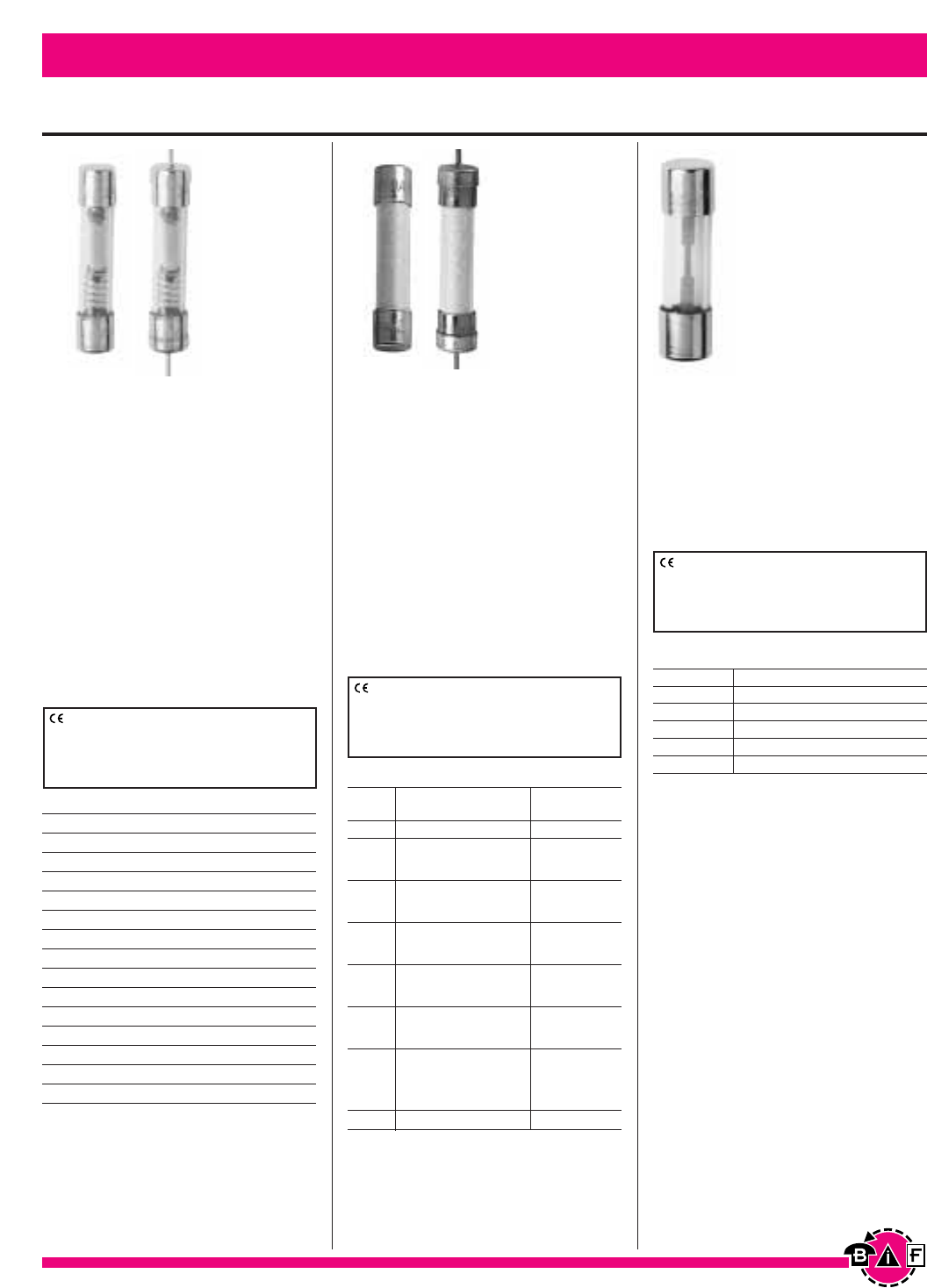
Electronic - PC Board and Small Dimension Fuses Bussmann®
36
Data Sheet: 2008Data Sheet: 2002Data Sheet: 2044
For complete specification data, call Bussmann Information Fax ~ 636.527.1450
⁄Ω¢
∑≈
1⁄Ω¢
∑and
⁄‹Ω£™
∑≈
1⁄Ω™
∑Fuses
MDQ
MDQ-V (Axial Leads)
Dual Element Time-Delay
Physical Size:
⁄Ω¢∑ ≈ 1⁄Ω¢∑ (3AG)
(6.3mm ≈32mm)
Construction: Glass Tube; Nickel
Plated Brass End Caps
Agency Information: Std. 248-14
UL Listed, File E19180; Guide JDYX,
⁄Ω¡§-7A
CSA Certification, File 47233,
Class 1422-01, ⁄Ω¡§-7A
UL Recognized, Guide JDYX2,
File E19180, 7.1-30A
Catalog Symbol & Current Ratings
250Vac
MDQ-⁄Ω¡ºº MDQ-‹Ω• MDQ-1°Ω¡º MDQ-7
MDQ-⁄Ω£™ MDQ-›Ω¡º MDQ-2
MDQ-⁄Ω¡§ MDQ-⁄Ω™ MDQ-2⁄Ω¢
MDQ-⁄Ω¡º MDQ-flΩ¡º MDQ-2⁄Ω™
MDQ-⁄Ω• MDQ-‹Ω¢ MDQ-2°Ω¡º
MDQ-⁄fiΩ¡ºº MDQ-°Ω¡º MDQ-3
MDQ-⁄‡fiΩ¡ººº MDQ-1MDQ-3¤Ω¡º
MDQ-‹Ω¡§ MDQ-1¤Ω¡º MDQ-4
MDQ-¤Ω¡º MDQ-1⁄Ω¢ MDQ-5
MDQ-⁄Ω¢ MDQ-1⁄Ω™ MDQ-6
MDQ-‹Ω¡º MDQ-1flΩ¡º MDQ-6⁄Ω¢
32Vac
MDQ-7⁄Ω™ MDQ-9 MDQ-12
MDQ-8 MDQ-10MDQ-15
MDA
MDA-V (Axial Leads)
Time-Delay
Physical Size:
⁄Ω¢∑ ≈ 1⁄Ω¢∑ (3AB)
(6.3mm ≈32mm)
Construction: Ceramic Tube; Nickel
Plated Brass End Caps
Agency Information: Std. 248-14
UL Listed, Guide JDYX, File E19180,
0-15A
CSA Certification, Class 1422-01,
File 53787, 0-15A
Electrical Characteristics
Current Rated Interrupting
Rating Voltage Rating1
ac (Max.) dc (Max.) ac dc
¤Ω¡º 250V 35A
⁄Ω¢ 250V 35A
⁄Ω™ 250V 35A
‹Ω¢ 250V 35A
1250V 35A
1⁄Ω™ 250V 100A
2250V 100A
2⁄Ω™ 250V 100A
3250V 100A
4250V 200A
5250V 200A
6250V 200A
7250V 200A
8250V 200A
10 250V 200A
MDA-12
15 250V 1500A
20 250V 125V 1500A 10kA
25 250V 125V 1000A 10kA
30 250V 125V 1000A 10kA
1Interrupting ratings were measured at 70% – 80% power
factor on ac, and at a time constant described in UL 248.
Catalog Symbol & Current Ratings
250Vac 32Vac
AGU-1 AGU-4 AGU-20 AGU-50
AGU-2 AGU-5 AGU-25 AGU-60
AGU-3 AGU-8 AGU-30 —
— AGU-10 AGU-35 —
— AGU-15 AGU-40 —
AGU
Fast Acting
Physical Size:
⁄‹Ω£™∑ ≈ 1⁄Ω™∑ (5 AG)
(10.3mm ≈38.1mm)
Construction: Glass Tube
No Agency Listings
CE logo denotes compliance with European
Union Low Voltage Directive (50-1000Vac,
75-1500Vdc). Refer to Data Sheet: 8002 or
contact Bussmann Application Engineering at
636-527-1270 for more information.
CE logo denotes compliance with European
Union Low Voltage Directive (50-1000Vac,
75-1500Vdc). Refer to Data Sheet: 8002 or
contact Bussmann Application Engineering at
636-527-1270 for more information.
CE logo denotes compliance with European
Union Low Voltage Directive (50-1000Vac,
75-1500Vdc). Refer to Data Sheet: 8002 or
contact Bussmann Application Engineering at
636-527-1270 for more information.
Voltage: 250Vac (⁄Ω¡ººA-7A)
32Vac (7⁄Ω™A-7A)
Interrupting Rating:
35A @ 250Vac (⁄Ω¡§A-1A)
100A @ 250Vac (1⁄Ω¢A-3A)
200A @ 25Vac (4A-7A)
1kA @ 32Vac (7⁄Ω™A-12A)
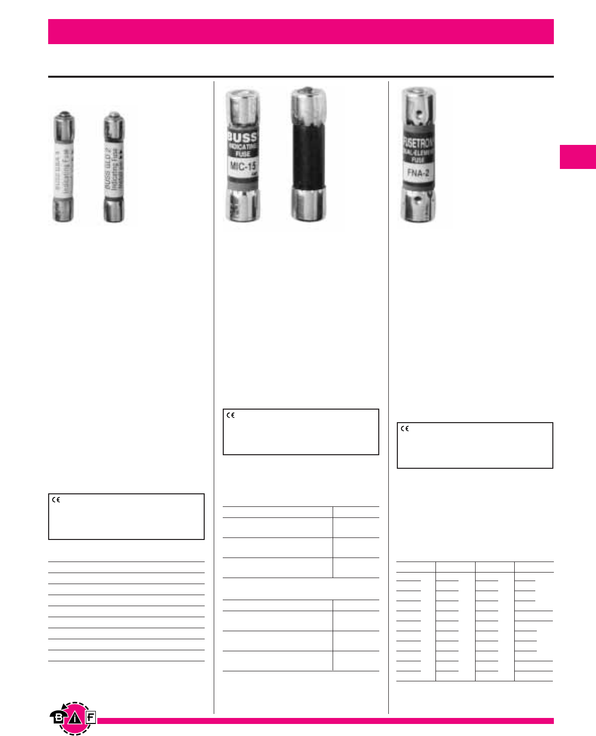
Bussmann®
37
Data Sheet: 2029Data Sheet: 2047Data Sheet: 2012
For complete specification data, call Bussmann Information Fax ~ 636.527.1450
Electronic - PC Board and Small Dimension Fuses
Catalog Symbol & Current Ratings
GLD-⁄Ω™ GLD-2 GLD-6
GLD-‹Ω¢ GLD-3 GLD-10
GLD-1GLD-4 GLD-12
GLD-1⁄Ω™ GLD-5 GLD-15
GBA-⁄Ω™ GBA-2 GBA-8
GBA-‹Ω¢ GBA-3 GBA-10
GBA-1GBA-4 GBA-15
GBA-1⁄Ω™ GBA-5
Catalog Symbol & Current Ratings
250Vac 32V
MIC-1MIC-5 MIC-20
(IR = 35A) (IR = 200A) (IR = 10kA)
MIC-2MIC-10 MIC-25
(IR = 100A) (IR = 200A) (IR = 10kA)
MIC-3MIC-15 MIC-30
(IR = 100A) (IR = 750A) (IR = 10kA)
MIC - (1-15)UL Listed 125Vac / IR = 10kA
250Vac 32V
MIN-1MIN-5 MIN-20
(IR = 35A) (IR = 200A) (IR = 10kA)
MIN-2MIN-10 MIN-25N
(IR = 100A) (IR = 200A) (IR = 10kA)
MIN-3MIN-15 MIN-30
(IR = 100A) (IR = 750A) (IR = 10kA)
Pin Indication Type
GBA and GLD
Fast Acting
Physical Size:
⁄Ω¢∑ ≈ 1⁄Ω¢∑ (3AG)
(6.6mm ≈31.8mm)
Agency Information: Std. 248-14
UL Listed, 0-5A/125Vac,
10,000 AIC, Guide JDYX,
File E19180
UL Recognized,
6A/125Vac, 1000AIC
8-15A/50Vac/dc, 300 AIC
Guide JDYX2, File E19180
CSA Certified:
0-5A/125Vac, 10,000 AIC
Class 1422-01, File 53787
General Information: Type GBA
has a “red” pin for high visibility. Type
GLD has an Albaloy-plated pin for
positive, electrical signal circuit
activation.
MIC and MIN
Fast Acting
Physical Size:
⁄‹Ω£™∑ ≈ 1⁄Ω™∑ (5AG)
(10.3mm ≈38.1mm)
Agency Information: Std. 248-14
MIC—0-15A UL Listed, Guide JDYX,
File E19180
MIN—1-5A CSA Certified,
Class 1422-01, File 53787
General Information: Type MIN
has a “red” pin for high visibility. Type
MIC has a silver-plated pin for positive,
electrical signal activation.
CE logo denotes compliance with European
Union Low Voltage Directive (50-1000Vac,
75-1500Vdc). Refer to Data Sheet: 8002 or
contact Bussmann Application Engineering at
636-527-1270 for more information.
CE logo denotes compliance with European
Union Low Voltage Directive (50-1000Vac,
75-1500Vdc). Refer to Data Sheet: 8002 or
contact Bussmann Application Engineering at
636-527-1270 for more information.
FNA
Time-Delay
Physical Size:
⁄‹Ω£™∑ ≈ 1⁄Ω™∑
(10.3mm ≈38.1mm)
Agency Information: Std. 248-14
UL Listed ⁄Ω¡º-°Ω¡ºA, IR 35A@ 250V
IR 10kA@ 125V
1-15A, IR 10kA@ 125V
Guide JDYX, File 19180
CSA Certified, 0-°Ω¡º A/250V,
1-10A/125V, Class 1422-01,
File 53787
General Information: Fuses above
10A have dual-tube construction.
Catalog Symbol & Current Ratings
250Vac IR* 125Vac IR 125Vac IR 125Vac
*Interrupting rating of 10,000A at 125V.
†
Interrupting rating of 1,000A at 32V.
FNA-⁄Ω¡º
FNA-⁄Ω•
FNA-⁄fiΩ¡ºº
FNA-¤Ω¡º
FNA-⁄Ω¢ IR
FNA-‹Ω¡º 35A
FNA-›Ω¡º
FNA-⁄Ω™
FNA-flꭧ
FNA-‹Ω¢
FNA-°Ω¡º
FNA-1
FNA-1⁄Ω•
FNA-1⁄Ω¢
FNA-1›Ω¡º
FNA-1⁄Ω™ IR
FNA-1flꭧ
10,000A
FNA-1°Ω¡º
FNA-2
FNA-2⁄Ω¢
FNA-2⁄Ω™
FNA-2°Ω¡º
FNA-3
FNA-3¤Ω¡º
FNA-3⁄Ω™
FNA-4
FNA-4⁄Ω™ IR
FNA-5
10,000A
FNA-5flꭧ
FNA-6
FNA-6⁄Ω¢
FNA-7
FNA-8
FNA-9
FNA-10 IR
FNA-12 10,000A
FNA-15
32 Volts
†
FNA-20
FNA-25
FNA-30
—
—
—
CE logo denotes compliance with European
Union Low Voltage Directive (50-1000Vac,
75-1500Vdc). Refer to Data Sheet: 8002 or
contact Bussmann Application Engineering at
636-527-1270 for more information.
IR%
1kA@
32V
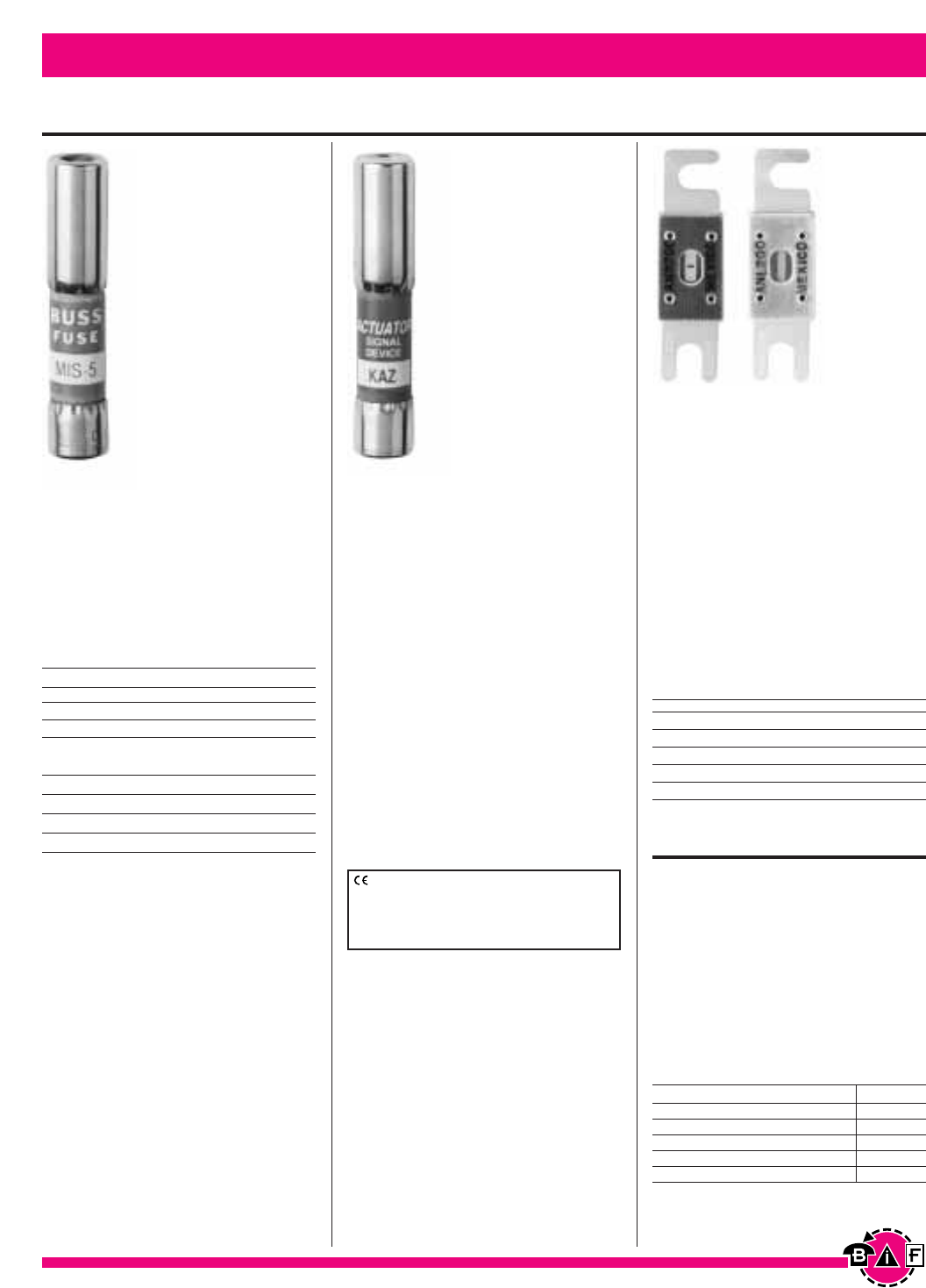
Bussmann®
38
Data Sheet: 2024 & 2133Data Sheet: 2021
For complete specification data, call Bussmann Information Fax ~ 636.527.1450
Electronic - PC Board and Small Dimension Fuses
MIS-1MIS-4 MIS-10
MIS-2MIS-5 MIS-12
MIS-3MIS-8
Test Specifications
Fuse Load Opening Time
All 110% 4 hrs. (min.)
1-5A 150% 6 min. (max.)
6-12A 150% 12 min. (max.)
Catalog Symbol & Current Ratings
600Vac
ANN-10 ANN-90 ANN-225 ANN-400
ANN-35 ANN-100 ANN-250 ANN-500
ANN-40 ANN-125 ANN-275 ANN-600
ANN-50 ANN-150 ANN-300 ANN-700
ANN-60 ANN-175 ANN-325 ANN-800
ANN-80 ANN-200 ANN-350
Catalog Symbol & Current Ratings
Pin Indication Type/Actuators/Limiters
MIS
Non-Time-Delay
Physical Size:
⁄‹Ω£™∑ ≈ 2∑
(10.3mm ≈50.8mm)
Voltage Rating: 600Vac
Interrupting Rating: 200,000 AIC
KAZ
Actuator (Not a Fuse)
Physical Size:
⁄‹Ω£™∑ ≈ 2∑
(10.3mm ≈50.8mm)
Voltage Rating: 600Vac
Interrupting Rating: 200,000A
Agency Information:
UL Listed, Guide JDVS,
File E58836
Recommended Use: Mounts in
Buss signal blocks 2778, 2837 and
2838.
General Information: Connects in
parallel with fuses having a rating of
50 amperes or larger and opens at
10A or more.
ANN Limiter
Very Fast Acting
Physical Size:
‡Ω•∑ ≈ 3‹Ω¡§∑
(22.2mm ≈81.0mm)
Voltage Rating: 125Vac IR = 2500A
80Vdc IR = 2700 A
Agency Information: 35-400A @
125Vac, IR=2500A and 80Vdc,
IR=2700A: UL Recognized Guide
JFHR2, File E56412; CSA Certified Class
1422-30, File 53787
CE for 35-400A
Fuseholder: 4164
Catalog Symbol & Current Ratings
ANL-35 ANL-125 ANL-250 ANL-500
ANL-40 ANL-130 ANL-275 ANL-600
ANL-50 ANL-150 ANL-300 ANL-675
ANL-60 ANL-175 ANL-325 ANL-750
ANL-80 ANL-200 ANL-350 —
ANL-100 ANL-225 ANL-400 —
ANL
Non-Time Delay
Voltage Rating: 80Vdc
Agency Information:
UL Recognized, CSA Certified,
35-750A @ 80Vdc, IR = 2700A
Guide JFHR2, File E56412
Class 1422-30, File 53787
Fuseholder: 4164
CE logo denotes compliance with European
Union Low Voltage Directive (50-1000Vac,
75-1500Vdc). Refer to Data Sheet: 8002 or
contact Bussmann Application Engineering at
636-527-1270 for more information.
Data Sheet: 2023 & 2133
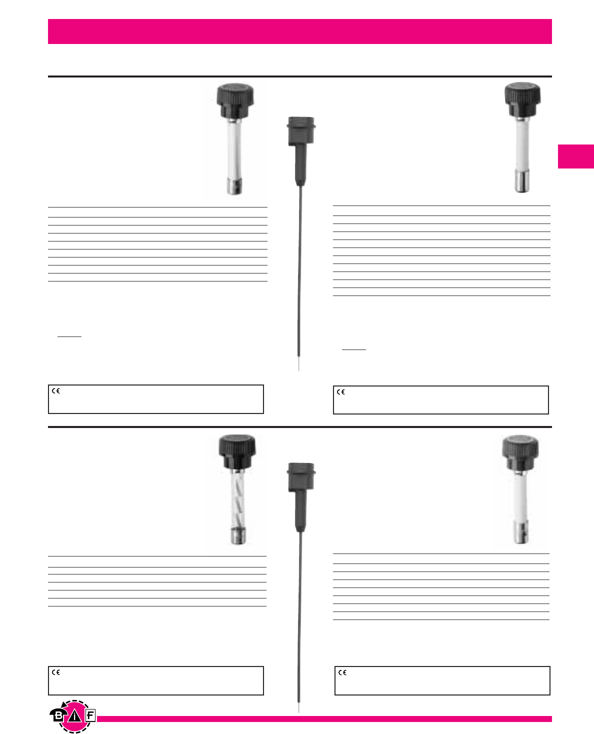
Bussmann®
39
Data Sheet: 2030
Data Sheet: 2033
For complete specification data, call Bussmann Information Fax ~ 636.527.1450
Data Sheet: 2032 Data Sheet: 2031
GLR
Fast Acting, Non-rejecting
Voltage Rating: 300Vac or less
Interrupting Rating: 10,000A
Agency Information: Std. 248-14
UL Listed, 0-15A/300Vac
(Guide JDYX, File E19180)
CSA Certified, 0-10A/300V
(Class 1422-01, File 53787)
GMF and GRF
Time Delay, Non-rejecting
Voltage Rating: 300Vac or less
Interrupting Rating: 10,000A
Agency Information: Std. 248-14
0-10A, UL Listed (Guide JDYX,
File E19180)
CSA Certified, (Class 1422-01,
File 53787)
In-Line Fuse and Fuseholders
Electronic - PC Board and Small Dimension Fuses
GLQ
Fast-Acting, Size Rejecting
Voltage Rating: 300Vac or less
Interrupting Rating: 10,000A
Agency Information: Std. 248-14
UL Listed (Guide JDYX,
File E19180)
CSA Certified, (Class 1422-01,
File 53787)
GMQ
Time-Delay, Size Rejecting
Voltage Rating: 300Vac or less
Interrupting Rating: 10,000A
Agency Information: Std. 248-14
UL Listed (Guide JDYX, File E19180)
CSA Certified, (Class 1422-01,
File 53787)
Electrical Ratings for Type GMF and
GRF Fuses and Non-Rejection Style Carriers
Fuse Carrier1, 2 Fuse Carrier1, 2
GMF-‹Ω¡º HLR GMF-3 HLR
GMF-⁄Ω™ HLR GMF-3 ¤Ω¡º HLR
GMF-flꭧ HLR GMF-4 HLR
GMF-°Ω¡º HLR GMF-5* HLR
GMF-1HLR GMF-6⁄Ω¢ HLR
GMF-1⁄Ω¢ HLR GMF-10 HLR
GMF-1flꭧ HLR GRF-7 HLR
GMF-2 HLR GRF-8 HLR
GMF-2⁄Ω™ HLR GRF-10 HLR
GMF-2°Ω¡º HLR
Electrical Ratings for Type GMQ Fuses
and Rejection Style Carriers
Fuse Carrier3, 4 Fuse Carrier3, 4
GMQ-⁄Ω™ HLQ-⁄Ω™ GMQ-2⁄Ω™ HLQ-3¤Ω¡º
GMQ-flΩ¡º HLQ-1flΩ¡º GMQ-3 HLQ-3¤Ω¡º
GMQ-°Ω¡º HLQ-1flΩ¡º GMQ-3¤Ω¡º HLQ-3 ¤Ω¡º
GMQ-1HLQ-1flꭧ GMQ-4 HLQ-5
GMQ-1⁄Ω¢ HLQ-1flΩ¡º GMQ-6 HLQ-8
GMQ-1flΩ¡º HLQ-1flΩ¡º GMQ-6⁄Ω¢
GMQ-2HLQ-3¤Ω¡º
*HLR
Fuseholder
HLQ3
Fuseholder
Electrical Ratings for Type GLR Fuses
and Non-Rejection Style Carriers
Fuse Carrier1, 2 Fuse Carrier1, 2
GLR-‹Ω¡§ HLR GLR-5 HLR
GLR-⁄Ω™ HLR GLR-6 HLR
GLR-1HLR GLR-7 HLR
GLR-1⁄Ω™ HLR GLR-8 HLR
GLR-1flꭧ HLR GLR-9 HLR
GLR-2HLR GLR-10 HLR
GLR-3 HLR GLR-12 HLR
GLR-4HLR GLR-15 HLR-2A
Electrical Ratings for Type GLQ
Fuses and Rejection Style Carriers
Fuse Carrier3, 4 Fuse Carrier3, 4
GLQ-1HLQ-1flΩ¡º GLQ-3 HLQ-3 ¤Ω¡º
GLQ-1⁄Ω™ HLQ-1flΩ¡º GLQ-4 HLQ-5
GLQ-1flꭧ HLQ-1flꭧ GLQ-5 HLQ-5
GLQ-2HLQ-3¤Ω¡º GLQ-9 HLQ-10
GLQ-2⁄Ω™ HLQ-3 ¤Ω¡º GLQ-10 HLQ-10
CE logo denotes compliance with European Union Low Voltage Directive (50-
1000Vac, 75-1500Vdc). Refer to Data Sheet: 8002 or contact Bussmann
Application Engineering at 636-527-1270 for more information.
CE logo denotes compliance with European Union Low Voltage Directive (50-
1000Vac, 75-1500Vdc). Refer to Data Sheet: 8002 or contact Bussmann
Application Engineering at 636-527-1270 for more information.
CE logo denotes compliance with European Union Low Voltage Directive (50-
1000Vac, 75-1500Vdc). Refer to Data Sheet: 8002 or contact Bussmann
Application Engineering at 636-527-1270 for more information.
CE logo denotes compliance with European Union Low Voltage Directive (50-
1000Vac, 75-1500Vdc). Refer to Data Sheet: 8002 or contact Bussmann
Application Engineering at 636-527-1270 for more information.
1) Carrier is UL Recognized, Guide IZLT2, File E14853 and CSA Certified,
Class 6225-01, File 47235 12A, 300Vac.
2) Units can be panel-mounted either in a knockout hole with a separate steel clip (BK/A-
104) or in a keyhole punch using separate mounting clip #6374 for panels of thickness
0.043”to 0.062” or #4909 for thickness 0.030” to 0.042”
*For two leads order HLR-2A, 15A, 300V
• An alternative to the HLR fuseholder is the A fuseholder. The A fuseholder comes
WITHOUT leads. The customer inserts #18 insulated solid copper wire into the line side
receptacle as well as into the load side receptacle. It has the same body dimensions,
utilizes the same mounting hole, and takes the same mounting clips as the HLR. The A
fuseholder is UL Recognized, 10A, 300Vac, Guide IZLT2, File E14853 and CSA
Certified, 10A, 300Vac, Class 6225-01, File 47235.
• Do not put tension on line (rear) terminal of fuseholder.
3) Carrier is UL Recognized, Guide IZLT2, File E14853 and CSA Certified,
Class 6225-01, File 47235 10A, 300Vac.
4) Units can be panel-mounted either in a knockout hole with a separate steel clip (BK/A-
104) or in a keyhole punch using separate mounting clip #6374 for panels of thickness
0.043”to 0.062” or #4909 for thickness 0.030” to 0.042”
• Do not put tension on line (rear) terminal of fuseholder.
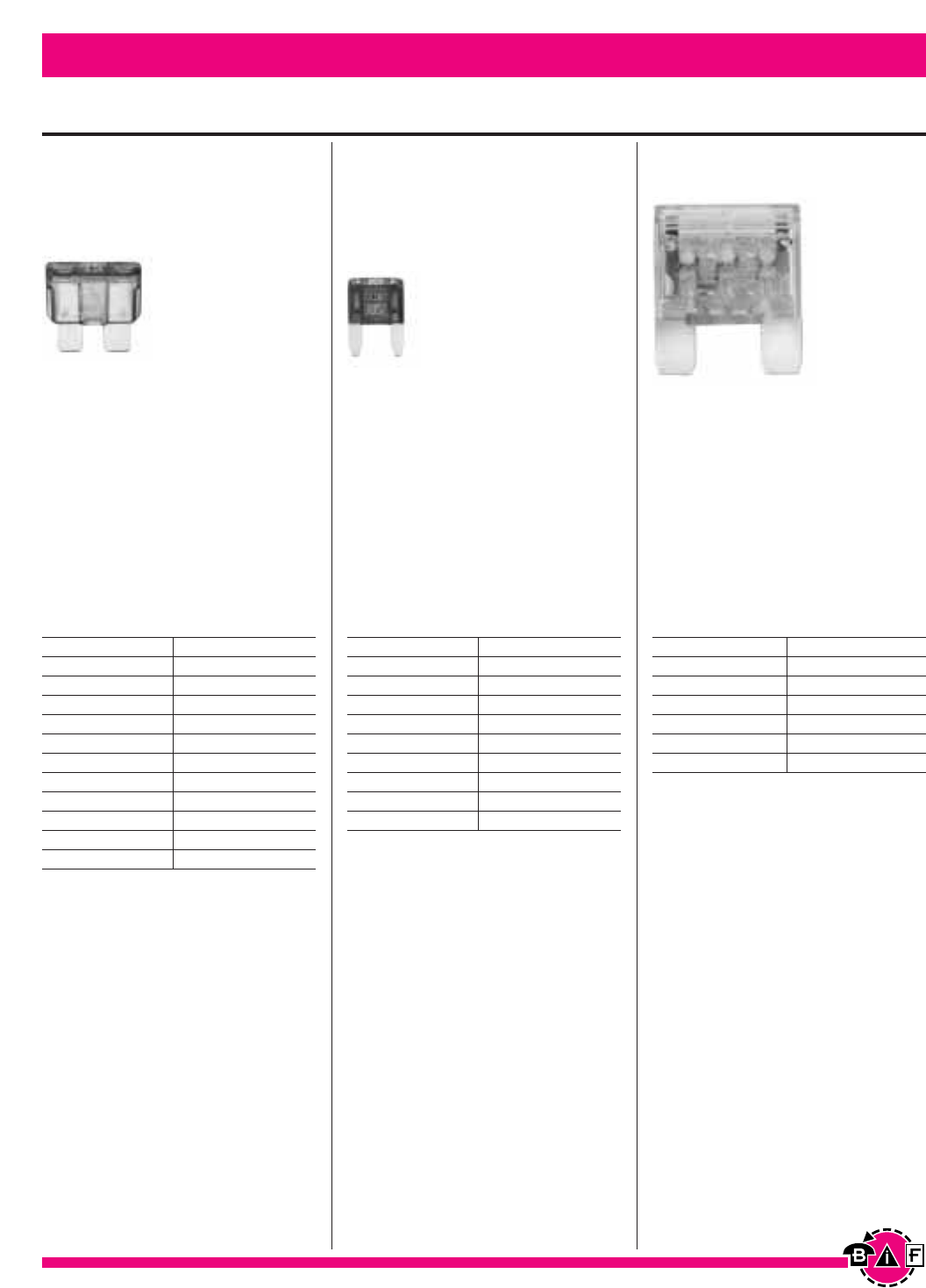
Catalog Symbol & Current Ratings
MAX-20
Yellow
MAX-30
Green
MAX-40
Orange
MAX-50
Red
MAX-60
Blue
MAX-70
Tan
MAX-80
Clear
Refer to page 82 for In-Line Fuseholders for Blade
Type Fuses.
Electronic - PC Board and Small Dimension Fuses Bussmann®
40
Data Sheet: 2049Data Sheet: 2048Data Sheet: 2009
For complete specification data, call Bussmann Information Fax ~ 636.527.1450
Blade-Type Fuses
ATC®Blade-Type Fuse
Fast Acting
Voltage Rating: 32Vdc
Interrupting Rating: 1,000A
Agency Information:
UL Recognized, (3-40A)
(Guide JFHR2, File E56412)
ATM Mini–Fuse®
Fast Acting
Voltage Rating: 32Vdc
Interrupting Rating: 1,000A
MAX Maxi–Fuse®
Fast Acting
Voltage Rating: 32Vdc
Interrupting Rating: 1,000A
Catalog Symbol & Current Ratings
ATC-1 Black
ATC-2 Gray
ATC-3 Violet
ATC-4 Pink
ATC-5 Tan
ATC-7
⁄Ω™ Brown
ATC-10
Red
ATC-15
Blue
ATC-20
Yellow
ATC-25
Clear
ATC-30
Green
ATC-40
Orange
Refer to page 82 for In-Line Fuseholders for Blade
Type Fuses.
Catalog Symbol & Current Ratings
ATM-2 Gray
ATM-3 Violet
ATM-4 Pink
ATM-5 Tan
ATM-7
⁄Ω™
Brown
ATM-10 Red
ATM-15
Blue
ATM-20
Yellow
ATM-25
Clear
ATM-30
Green
Refer to page 82 for In-Line Fuseholders for Blade
Type Fuses.
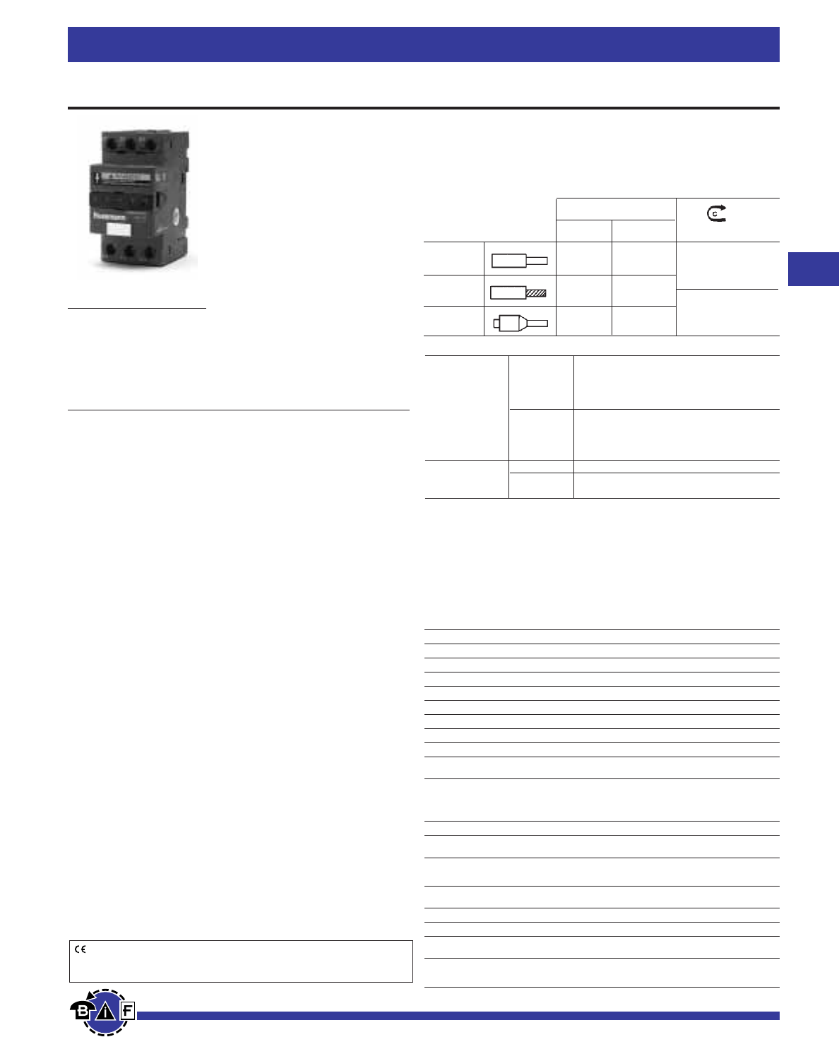
Bussmann®
41
For complete specification data, call Bussmann Information Fax ~ 636.527.1450
Fuseblocks, Holders and Terminal Blocks
Data Sheet: 1109
CE logo denotes compliance with European Union Low Voltage Directive
(50-1000 Vac, 75-1500 Vdc). Refer to Data Sheet: 8002 or contact
Bussmann Application Engineering at 636-527-1270 for more information.
75°CU Only
AWG [mm2](
Nm)/lb in
18-8 x1 1..6 x1
Solid 18-8 x2 1..6 x2 18-12Single/Dual
18-8 x1 1.5..6 x1 15 lb in
Stranded 18-8 x2 1.5..6 x2
1..4 x1 10-8 Single/Dual
Ferrules 1..4 x2 20 lb in
(1.7 )
Nm
(2.5)
Nm
Optima®Three Pole Overcurrent Protection Module
Class CC Version
Catalog Symbol: OPM-NG-SC3
Electrical Rating: 30A, 600Vac (or less)
Withstand Rating: 200kA
Use with Class CC fuse type: LP-CC, FNQ-R, KTK-R
13/32” x 1-1/2” and 10,3 x 38mm Version
Catalog Symbol: OPM-NG-SM3
Electrical Rating: UL and CSA 30A, 600Vac (or less)
IEC 32A, 690Vac (or less)
Withstand Rating: Limited by fuse IR, 200kA maximum
Use with 13/32” x 1-1/2” fuse types: KTK, FNQ, KLM
Use with 10 x 38mm fuse types: FWA, FWC,
C10G_ _, C10M_ _
Agency Information:
UL
OPM-NG-SC3
UL Listed, UL 512, File E14853, Guide IZLT
OPM-NG-SM3
UL Recognized, UL512, File E14853, Guide IZLT2
CSA Certified, C22.2 No. 39, Class C6225-01, File 47235
IEC 60947-3 Utilization Category AC20B
Packaging Weight: 0.39lb. (0.18 kg)
Handling & Storage Specifications:
Storage Temperature: -10°C to 65°C
Attributes:
• 45mm width matches IEC starters.
• Phil-slot screws.
• Pressure plate terminations.
• Integrated collapsible handle.
• Fuse carrier cannot be removed from holder base.
• IP20 finger safe to IEC60529
• Auxilliary contacts. - optional accessory
• Dual-wire rated terminals (see Wire Table).
• 35mm DIN rail or panel mounting feature. Maximum
screw size #8 (M4).
• Padlockable
Optional Accessories:
Comb Bar (Max. current rating = 63A)
OPMNGSA245 2 circuit, 45mm between same phases
OPMNGSA254 2 circuit, 54mm between same phases
OPMNGSA272 2 circuit, 72mm between same phases
OPMNGSA345 3 circuit, 45mm between same phases
OPMNGSA354 3 circuit, 54mm between same phases
OPMNGSA445 4 circuit, 45mm between same phases
OPMNGSA454 4 circuit, 54mm between same phases
OPMNGSA472 4 circuit, 72mm between same phases
OPMNGSA554 5 circuit, 54mm between same phases
Input Terminal Block (Max. current rating=63A)
OPMNGSA005 Input/Feed Through Power Terminal,
Supports feed through
to another system, DIN-rail mount only
OPMNGSA009 Input Power Terminal
Cover
OPMNGSA010 Protective Cover for unused terminals on
comb bar
Auxilliary Contacts
OPMNGSAAUX11 NO/NC
OPMNGSAAUX20 NO/NO
Marking Tabs
OPMNGSA101 Marking Tab - Mounts to front of carrier,
quantity 100
Materials:
Housing: Thermoplastic- UL V-2
Clip: Tin plated copper alloy
Contact Lubricant: Fluoroether grease
Saddle screw: Plated steel
DIN rail springs: Stainless steel
Input Power Terminal Wire Range:
Wiring Solid (1) #14 to #2 (1.5 to 25mm2
2)
Conductor conductor or
(2) #14 to #6 (1.5 to 10mm2
2)
conductors
Stranded (1) #14 to #2 (1.5 to 25mm2
2)
Conductor conductor or
(2) #12 to #6 (2.5 to 10mm2
2)
conductors
Tightening Connector 20 lb..in. (2.2 N.m)
Torque: Screw 15 lb..in. (1.7 N.m)
Clamp
Fuseholder Wire Range:
75°CU Only
#18-12 Single/Dual, torque 15 lb: in.
#10-8 Single/Dual, torque 20 lb: in.
Dual wire. Wire with same guage and type
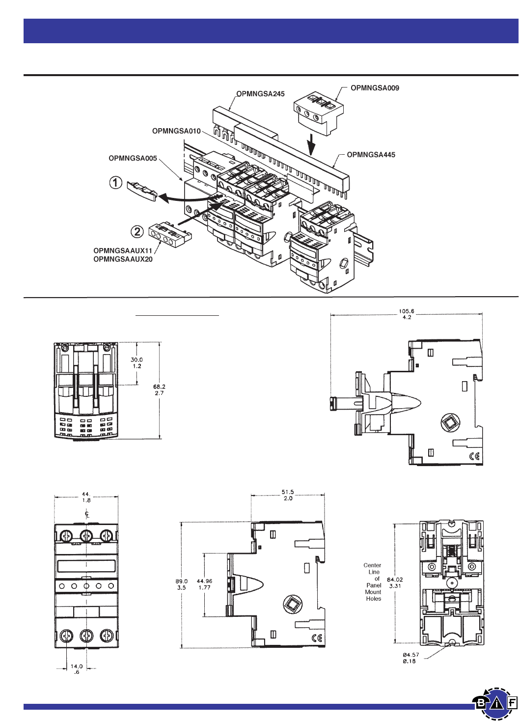
Bussmann®
42 For complete specification data, call Bussmann Information Fax ~ 636.527.1450
Fuseblocks, Holders and Terminal Blocks
Data Sheet: 1109
Optima®Three Pole Overcurrent Protection Module
Optional Accessories
Dimensional Data Millimeters (± 0.38)
Inches (± .015)
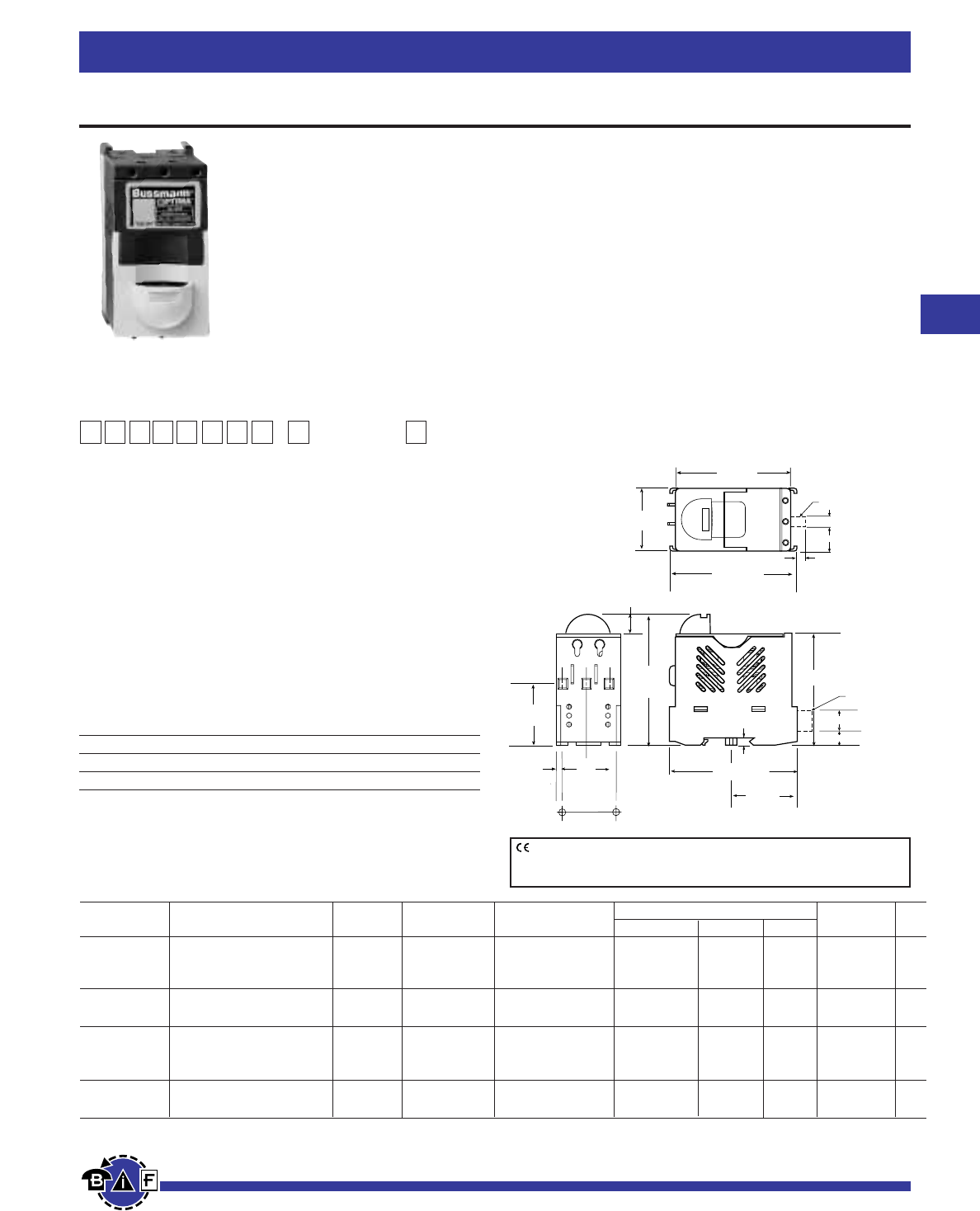
BUSS
3.74 (± .03)
(95.0mm)
(± .76)
.57
(14.5mm)
0.23
(5.8mm)
3.17
(80.5mm)
3.22 (± .03)
.27
.31
(81.8mm) (± .76)
3.60 (± .03)
(91.4mm) (± .76)
1.76 (± .03)
(44.7mm) (± .7 )
1.65 (± .03)
(41.9mm) (±. 76)
1.312∑
(± .01)
(33.3mm)
(± .25)
Panel Mount
Hole Pattern
1.86 (± .03)
(47.2mm)
(± .76)
Panel Mount
Hole Pattern
3.60 (± .03)
(91.4mm) (± .76)
Communication
Port
.74
Communication
Port
(6.9mm)
(18.8mm)
(7.9mm)
.50 (12.7mm)
.44 (11.2mm)
2T1
4T2
6T3
IL1
3L2
5L3
.224"
(5.6mm)
43
For complete specification data, call Bussmann Information Fax ~ 636.527.1450
Optima®Overcurrent Protection Module -Fuseholder
Data Sheet: 1102
Non-Switch Series
for ⁄‹Ω£™∑ ≈ 1⁄Ω™∑ (10mm x 38mm) Fuses
Materials: Grey Thermoplastic
UL Flammability: UL 94V0
Agency Information:
UL (see table)
CSA Certified, C22.2 No. 39, Class 6225-01, File 47235
IEC (see table)
Shipping Weight: Approximately 213g/.47 lb.
Carton Quantity: 1
Recommended Fuse Types
Class CC Midget (Non-Rejection) European
LP-CC KTK C10M
KTK-R FNM C10G
FNQ-R FNQ
Physical Characteristics
• Small size matches 45mm IEC starter width.
• Accepts #8-18 AWG stranded, #10-18 AWG solid wire.
• 3-pole.
Fuseblocks, Holders and Terminal Blocks
Product Features
• “Open” fuse indication lights.
• Cam action handle for easy removal.
• Finger safe terminals. (Qualified as IP20 per IEC 529)
• Removable module for convenient fuse loading.
• 35mm DIN-rail or screw panel mounting (#8 screw,
1⁄Ω¢” long).
• Dead-front construction.
• Padlockable.
Additional Features
• Option for remote “open fuse” status indication feature
available (less downtime!). See Data Sheet for additional
wiring details.
• Offered with Class CC rejection clips or European
10 ≈38mm clips to meet global needs.
• Wire ready: Saves time as terminals are ready to
accept wires.
Bussmann®
Dimensional Data
CE logo denotes compliance with European Union Low Voltage Directive
(50-1000Vac, 75-1500Vdc). Refer to Data Sheet: 8002 or contact
Bussmann Application Engineering at 636-527-1270 for more information.
Non-Switch Series
Catalog SC Remote Open UL Information
Number Electrical Rating Rating Clips Fuse Indication Std. File Guide IEC CE
OPM-1038 30A, 600V UL/CSA** * Non-rejection, No Recognized
(Max. 3 Watts per fuse) 10 x38mm or
32A, 660V IEC 13/32” x 1-1/2” UL 512 E14853 IZLT2 IEC 269-2-1 Yes
OPM-1038R 30A, 600V UL/CSA** 200kA Rejection, No Listed
Class CC UL 512 E14853 IZLT Yes
OPM-1038C 30A, 600V UL/CSA** * Non-rejection, Yes Recognized
(Max. 3 Watts per fuse) 10 x38mm or
32A, 660V IEC 13/32” x 1-1/2” UL 512 E14853 IZLT2 IEC 269-2-1 No
OPM-1038RC 30A, 600V UL/CSA** 200kA Rejection, Yes Listed
Class CC UL 512 E14853 IZLT No
*Rating varies depending on fuse used in module; 200kA maximum
**DC voltage rating: 600V UL/CSA
O P M - 1 0 3 8
Series Fuse Type Communication
C- Communication
Feature
Blank - 10 x 38mm
or 13/32” x 1-1/2”
R- Class CC
Catalog Symbol:
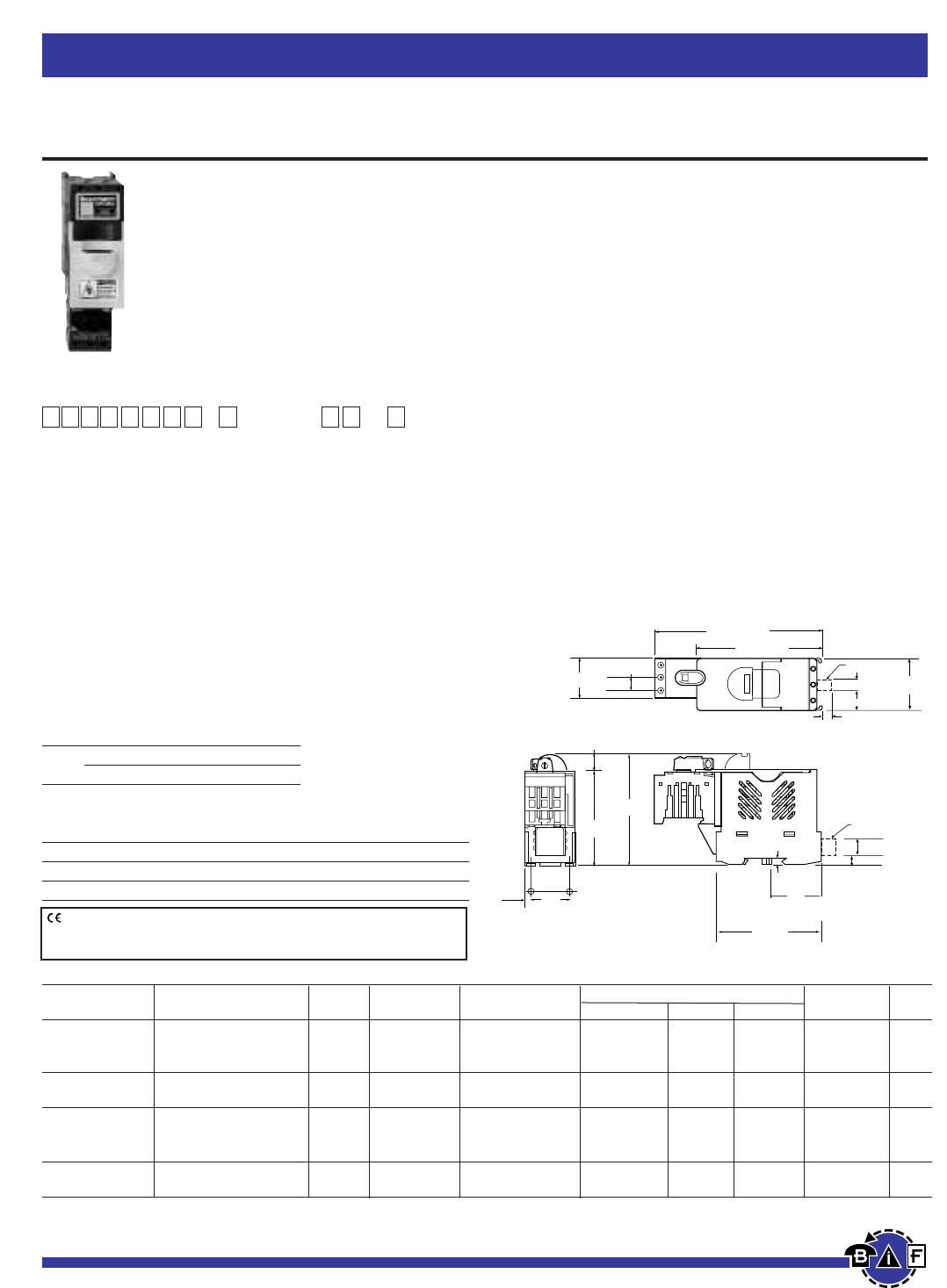
4.25 (± .03)
(108.0mm) (± .76)
(6.9mm)
(18.8mm)
(7.9mm)
BUSS
5.72 (± .045)
(145.3mm) (± 1.14)
0.43 (± .03)
(10.9mm) (± .76)
1.38
(35.0mm)
0.23
1.86
(5.8mm)
3.17
(80.5mm)
1.312
(± .01)
(33.3mm)
(± .25)
Panel Mounting
Hole Pattern
(47.2mm)
Panel Mounting
Hole Pattern
3.74 (± .03)
(95.0mm) (± .76)
0.57 (± .03)
(14.5mm) (± .76)
.27
.31
Communication
Port
.74
.50 (12.7mm)
Communication
Port
.44 (11.2mm)
2T1 1L1
3L2
5L3
4T 2
6T3
1.76
3.60
(91.4mm)
(44.7mm)
.224
(5.6mm)
Bussmann®
44 For complete specification data, call Bussmann Information Fax ~ 636.527.1450
Optima®Overcurrent Protection Module - Fuseholder
and Disconnect Switch
Fuseblocks, Holders and Terminal Blocks
Data Sheet: 1103
Load Break Disconnect Switch
for ⁄‹Ω£™∑ ≈ 1⁄Ω™∑ (10mm x 38mm) Fuses
Materials: Grey Thermoplastic
UL Flammability: UL 94V0
Agency Information:
UL (see table)
CSA Certified, C22.2 No. 39, Class 6225-01, File 47235
IEC (see table)
Shipping Weight: Approximately 335g/.74 lb.
Carton Quantity: 1
Horsepower Rating of Switch
3PH V 240 480 600
HP 5 10 15
Recommended Fuse Types
Class CC Midget (Non-Rejection) European
LP-CC KTK C10M
KTK-R FNM C10G
FNQ-R FNQ
Physical Characteristics
• Small size matches 45mm IEC starter width.
• Accepts #8-18 AWG stranded, #10-18 AWG solid wire.
• 3 pole.
• Handle and shaft required for through the door operation.
See BIF document for details.
Product Features
• “Open” Fuse indication lights.
• Finger safe terminals.(Qualified as IP20 per IEC 529)
• Cam action handle for easy module removal.
• 35mm DIN-rail or screw panel mounting (#8 screw,
1⁄Ω¢” long).
• Dead front construction. No exposed contacts for added
safety.
• Padlockable.
• Option for remote “open fuse” status indication feature
available (reduces downtime!). See Data Sheet for
additional wiring details.
• Offered with Class CC rejection clips or European
10 ≈38mm clips to meet global needs.
• Wire ready: Saves time as terminals are ready to
accept wires.
Dimensional Data
CE logo denotes compliance with European Union Low Voltage Directive
(50-1000Vac, 75-1500Vdc). Refer to Data Sheet: 8002 or contact
Bussmann Application Engineering at 636-527-1270 for more information.
Switch Series
Catalog SC Remote Open UL Information
Number Electrical Rating Rating Clips Fuse Indication Std. File Guide IEC CE
OPM-1038SW 30A, 600Vac UL/CSA * Non-rejection, No Recognized
10x38mm or
32A, 660Vac IEC 13/32” x 1-1/2” UL 508 E161278 NLRV2 IEC 947-3 Yes
OPM-1038RSW 30A, 600Vac UL/CSA 100kA Rejection, No Listed
Class CC UL 508 E161278 NLRV Yes
OPM-1038SWC 30A, 600Vac UL/CSA * Non-rejection, Yes Recognized
10x38mm or
32A, 660Vac IEC 13/32” x 1-1/2” UL 508 E161278 NLRV2 IEC 947-3 No
OPM-1038RSWC 30A, 600Vac UL/CSA 100kA Rejection, Yes Listed
Class CC UL 508 E161278 NLRV No
*Rating varies depending on fuse used in module; 100kA maximum
O P M - 1 0 3 8 S W
Series Fuse Type Communication
C- Communication
Feature
Catalog Symbol:
Blank - 10 x 38mm
or 13/32” x 1-1/2”
R- Class CC

Blank Page 45
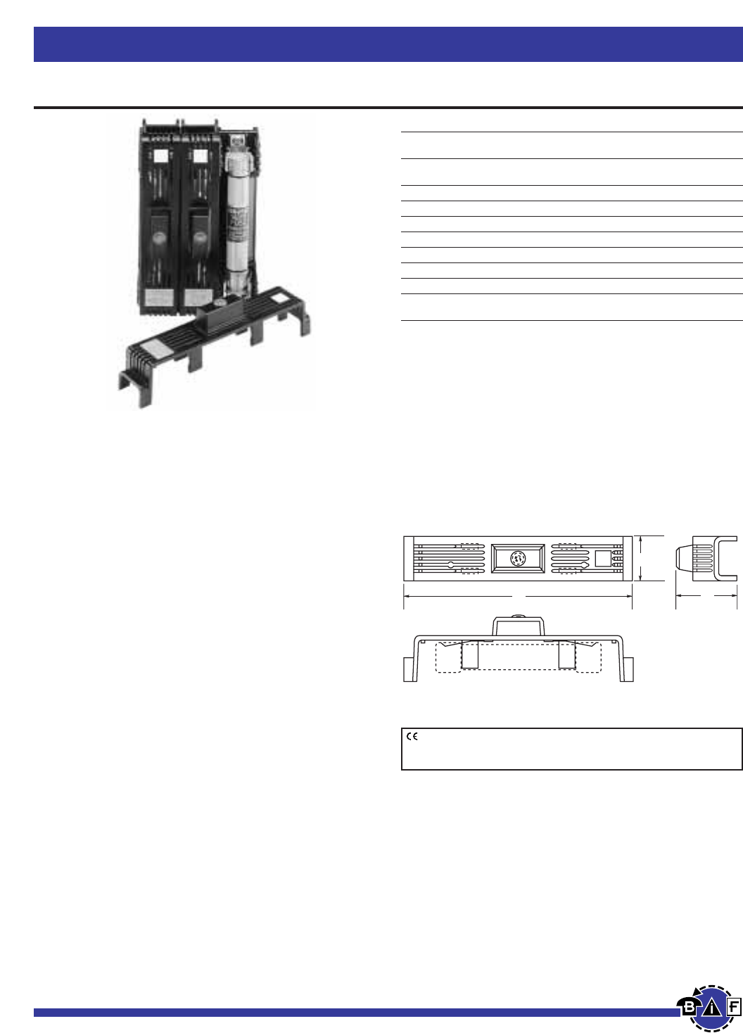
Bussmann®
46 For complete specification data, call Bussmann Information Fax ~ 636.527.1450
SAMI Fuse Covers
Fuseblocks, Holders and Terminal Blocks
SAMI Series
For Class J, RK1, RK5, H, K5, CC, G (0-30A) and
Midget type fuses.
Voltage Rating:
Non-Indicating - 0-600Vac/dc
Indicating - 90 to 600Vac
-115 to 600Vdc
Ampere Rating: 0-100A
Agency Information: UL Listed; SAMI-1I through SAMI-6I
SAMI-8I and SAMI-9I, SAMI-1N through SAMI-6N, SAMI-8N
and SAMI-9N
UL Recognized; SAMI-7I and SAMI-7N
CSA Certified, File LR47235-93C
• Innovative design, covers exposed terminals and contacts
of Bussmann fuseblocks.
• Fits most competitive fuseblocks.
• Buss Yellow light on indicating SAMI shows when the fuse
is open—helps trouble shoot the system and reduces
downtime.
• All versions are reusable—no need to pay for indication
every time a fuse opens.
• Indication contacts have teeth to break oxidation layer on
the existing fuse endcap to provide a clear signal path.
• Less than .6mA leakage current at 600 volt.
• Visual marking of line and load side.
• SAMI cover ends can easily be cut away if necessary, to fit
cover over existing wiring or to fit most safety switches.
• Dead front construction provides added protection against
accidental contact by maintenance personnel.
• Labels are provided with the SAMI fuse cover for writing in
circuit or fuse information.
• One cover is required for each pole.
Dimensional Data (inches)
Catalog
Number** Description A B C
SAMI-1_ 600V, J (0-30A) and 600V, T (35-60A)*
250V, RK, K5, H (35-60A) 5.02 1.03 1.94
SAMI-2_ 600V, RK, K5, H (0-30A) 7.03 1.30 2.07
SAMI-3_ 600V, J (65-100A) 7.03 1.30 2.33
SAMI-4_ 250V, RK, K5, H (65-100A) 8.20 1.30 2.18
SAMI-5_ 600V, RK, K5, H (35-60A) 8.20 1.30 2.18
SAMI-6_ 600V, J (35-60A) 4.98 1.17 2.14
SAMI-7_ 600V, Midget, Class CC, G (0-30A) 3.82 0.75 1.72
SAMI-8†_ 600V, RK, K5, H (65-100A) 10.38 1.50 2.33
SAMI-9_ 250V, RK, K5, H (0-30A) and 600V,
T (0-30A) 3.82 0.75 1.72
*Available in non-indicating only.
†SAMI-8A adapter available for small fusetron body design. SAMI-8I and SAMI-8N come
standard with adapter (SAMI-8A).
**Catalog Numbers
For Indicating Cover, add suffix I.
For Non-indicating cover, add suffix N.
Example: SAMI-7I = Indicating
SAMI-7N = Non-indicating
Indicating feature requires a minimum of 90Vac or 115Vdc to illuminate lamp.
WARNING: To avoid electrical shock, turn power off before
installing, removing or servicing.
Dimensional Data
LINE
Buss
SAMI -2
LOAD
TEST PROBE TEST PROBE
C
B
A
FUSE
CE logo denotes compliance with European Union Low Voltage Directive
(50-1000Vac, 75-1500Vdc). Refer to Data Sheet: 8002 or contact
Bussmann Application Engineering at 636-527-1270 for more information.
Data Sheet: 1204 (Trimming Guides: 12041, 12042, 12043,
12044, 12045, 12046, 12048, 12049)
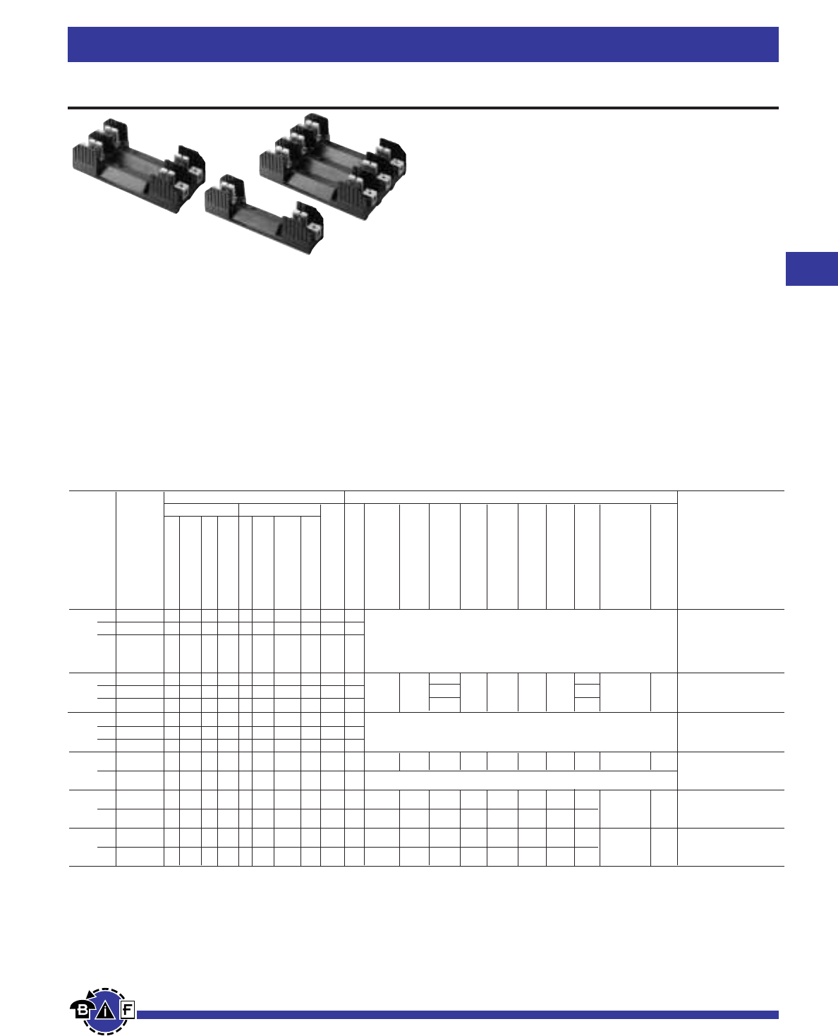
Class H Fuseblocks (250V) Catalog Data (for NON and REN Fuses)
Terminal Type (Suffix No.) Dimensions (Inches) – See Next Page For Figures
Screw Box Lug w/
Basic J Dia.
Catalog Fig. x Wire
Number No. A B C D E F G H C’ Bore K Range
⁄Ω¡º 1 H25030-1 S SR P PR C CR COR CO Q 1 C, CR #2-14 CU, #2-12 AL
to 2 H25030-2 S SR P PR C CR COR CO Q 2 (See Figures) CO, COR #6-14 CU ONLY
30 3 H25030-3 S SR P PR C CR COR CO Q 3 P, PR #10-18 CU ONLY
Q N/A
S, SR #10-18 CU ONLY
31 1 H25060-1 — — — — C CR COR CO — 4 1.5 — C, CR #2-14 CU, #2-8 AL
to 2 H25060-2 — — — — C CR COR CO — 5 4.25 1.73 2.81 1.5 0.5 0.5 1.25 1.31 0.22 ≈0.41 0.27 CO, COR #2-14 CU ONLY
60 3 H25060-3 — — — — C CR COR CO — 6 4.125 1.31
61 1 H25100-1 — SR — — — CR COR — — 7 COR #1/0-8 CU ONLY
to 2 H25100-2 — SR — — — CR COR — — 8 (See Figures) CR #1/0-8 CU/AL
100 3 H25100-3 — SR — — — CR COR — — 9 SR #8W/ Ring Terminal
101 1H25200-1 — — — — — CR — — — 10 7.125 3.09 3.0 2.06 0.5 2.0 3.0 0.75 — 0.31 CR 250kcmil-6 CU/AL
to
200 3H25200-3 — — — — — CR — — — 11 (See Figures)
201 1 H25400-1 — — — — — CR* — — — 10 9.06 4.0 3.0 3.02 0.63 1.75 3.0 1.0 CR 500kcmil-4 CU/AL
to — 0.31
400 3 H25400-3 — — — — — CR† — — — 12 9.06 4.0 4.0 2.50 0.82 9.25 10.88 1.0
401 1 H25600-1 — — — — — CR — — — 10 11.0 4.97 3.0 4.0 1.125 1.75 4.0 1.00 CR (2) 500kcmil-4/0 CU/AL
to — 0.31
600 3 H25600-3 — — — — — CR† — — — 12 11.0 4.97 5.0 3.0 1.87 11.0 14.74 1.00
*UL Recognized, CSA Certification.
†No UL, No CSA Certification.
Bussmann®
47
For complete specification data, call Bussmann Information Fax ~ 636.527.1450
Fuseblocks, Holders and Terminal Blocks
Data Sheet:H250 Series,1112; R250 Series, 1110
Class H(K) and R Fuseblocks – 250V
H250 Series For use with Class H Fuses
(Bussmann NON and REN).
R250 Series For use with Class R Fuses
(Bussmann LPN-RK and FRN-R, DLN-R and KTN-R).
Construction: Thermoplastic, UL Flammability: 94VO
Ampere Ratings: ⁄Ω¡º-600A.
Withstand Ratings: H250 Series - 10,000A RMS Sym.;
R250 Series - 200,000A RMS Sym.
Voltage Rating: H250, 250V; R250, 250V
Agency Information: UL Listed UL512, Guide IZLT,
File E14853; CSA Certified, Class 6225-01, File 47235
Poles
Amps
—
Clip with
Reinforced Spring
Pressure Plate
Pressure Plate & Clip
with Reinforced
Spring
—
Clip with
Reinforced Spring
Clip w/ Reinforced
Spring (Copper Only)
Copper Only
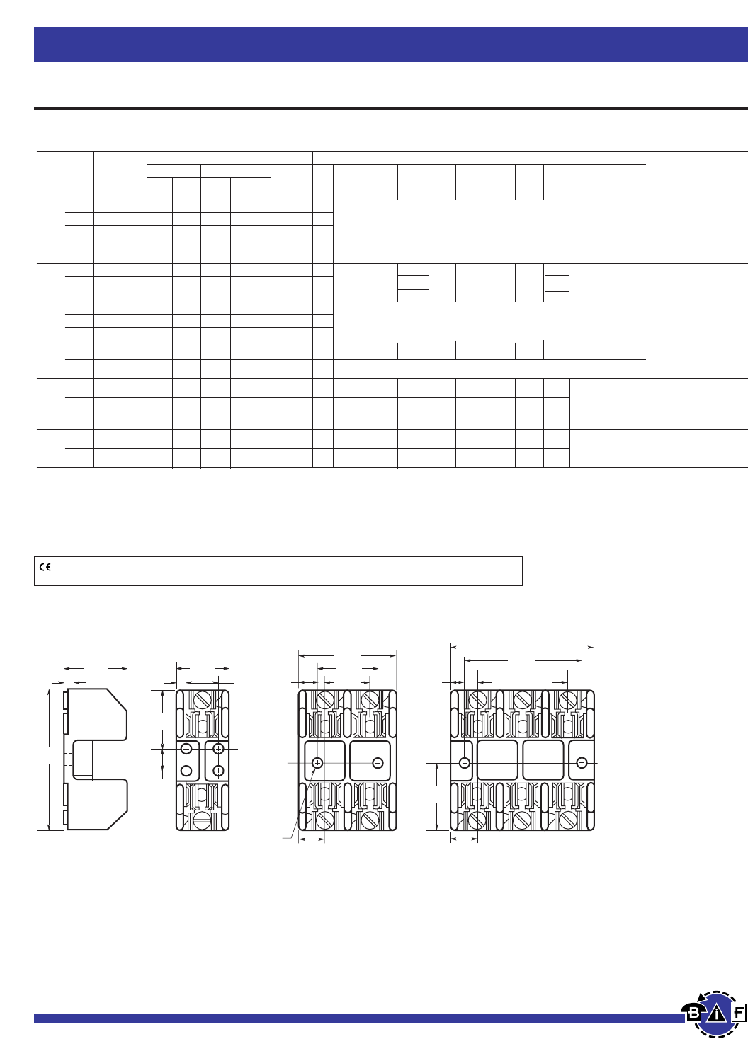
Bussmann®
48 For complete specification data, call Bussmann Information Fax ~ 636.527.1450
Fuseblocks, Holders and Terminal Blocks
Class H(K) and R Fuseblocks – 250V
Class R Fuseblocks (250V) Catalog Data (for LPN-RK, FRN-R, DLN-R and KTN-R Fuses)
Terminal Type (Suffix No.) Dimensions (Inches)
Basic Screw w/ Box Lug w/ 0.25J Dia.
Catalog Pres. Clip Quick- Fig. x Wire
Number — Plate — Cu Only Connect No. A B C D E F G H C’ Bore K Range
⁄Ω¡º 1 R25030-1 SR PR CR COR QR* 1 COR #6-14 CU ONLY
to 2 R25030-2 SR PR CR COR QR* 2 CR #2-14 CU, #2-12 AL
30 3 R25030-3 SR PR CR COR QR* 3 (See Figures) PR #10-18 CU ONLY
QR N/A
SR #10-18 CU ONLY
31 1 R25060-1 — — CR COR — 4 1.5 — COR #2-14 CU ONLY
to 2 R25060-2 — — CR COR — 5 4.25 1.73 2.81 1.5 0.5 0.5 1.25 1.31 0.22 x 0.41 0.27 CR #2-14 CU, #2-8 AL
60 3 R25060-3 — — CR COR — 6 4.125 1.31
61 1 R25100-1 — — CR COR — 7
to 2 R25100-2 — — CR COR — 8 (See Figures) COR 1/0-8 CU ONLY
100 3 R25100-3 — — CR COR — 9 CR 1/0-8 CU/AL
101 1 R25200-1 — — CR — — 10 7.125 3.15 3.0 2.06 0.5 2.0 3.0 0.75 — 0.31 CR 250kcmil-6 CU/AL
to
200 3 R25200-3 — — CR — — 11 (See Figure)
201 1 R25400-1 — — CR‡ COR‡ — 10 9.06 4.0 3.0 3.02 0.91 1.75 3.0 1.0 COR 500kcmil-4/0
to CU ONLY
400 — 0.56
3 R25400-3 — — CR† COR† — 12 9.06 4.0 4.0 2.5 0.82 9.25 10.88 1.0 CR 500kcmil-4 CU/AL
401 1 R25600-1 — — CR — — 10 11.0 4.97 3.0 4.0 1.125 1.75 4.0 1.0
to — 0.56 CR (2) 500kcmil-4/0 CU/AL
600 3 R25600-3 — — CR† — — 12 11.0 4.97 5.0 3.0 1.87 11.0 14.74 1.0
*UL Recognized, No CSA Certification.
†No UL, No CSA Certification.
‡UL Recognized, CSA Certification
Poles
Amps
CE logo denotes compliance with European Union Low Voltage Directive (50-1000Vac, 75-1500Vdc). Refer
to Data Sheet: 8002 or contact Bussmann Application Engineering at 314-527-1270 for more information.
1.41"
0.22"
1.09"
3.03"
0.5"
0.17" 0.75" 0.25"
1.25"
0.95"
0.22" DIAMETER
0.41"
2.05"
2 SPACES AT
0.95" - 1.91"
2.5"
3"
0.55"
1.27"
1.52"
0.55"
Dimensional Data
250V ⁄Ω¡ºA to 30A
FIGURE 1. FIGURE 2. FIGURE 3.
Data Sheet: H250 Series,1112; R250 Series, 1110
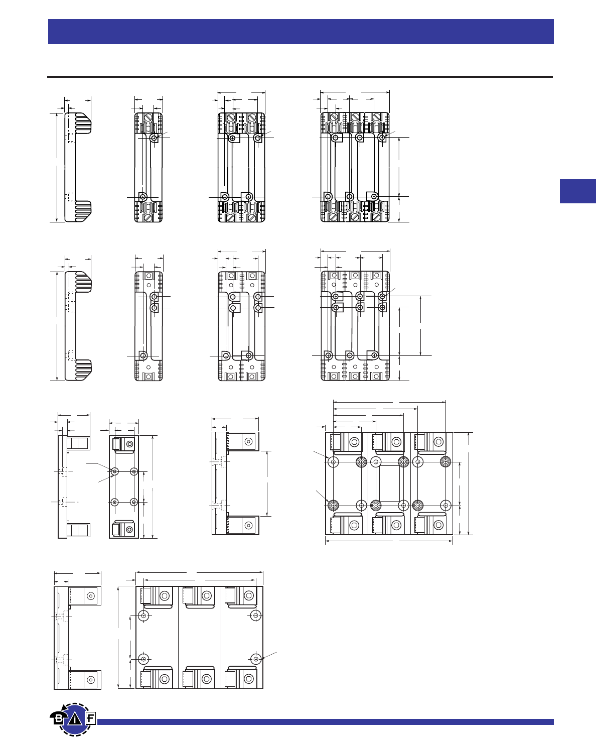
49
For complete specification data, call Bussmann Information Fax ~ 636.527.1450
Bussmann®
Fuseblocks, Holders and Terminal Blocks
Class H(K) and R Fuseblocks – 250V
A
K
BC
F
C
EH
F
H
C
G
D
F
HE
J
JJ
250V, 31A to 60A
FIGURE 4. FIGURE 5. FIGURE 6.
250V, 61A to 100A
FIGURE 7. FIGURE 8. FIGURE 9.
7.36"
0.25"
2.06" 1.81"
0.62"
3.38"
0.59"
0.62"
4.94"
2.38"
2.125"
0.62"
0.28" DIA. x
0.5" C'BORE
0.59"
1.56" 1.56"1.56"
3.125"
250V, 101A to 600A
250V, 201A to 600A
250V, 101A to 200A
B
H
KEF
0.75"
C'BORE
0.34
DIAMETER
G
C
D
A
FIGURE 10. FIGURE 11.
FIGURE 12.
3.4"
4.5"
1" .5"
EYELETS
TO ACCEPT
.25" DIA.
SCREW
.34" DIA.
HOLE
THROUGH
8"
6"
5"
3"
2"
3"
2.06"
7.13"
9"
C.34" DIA.
HOLE
THRU
A
B
H
G
F
E
D
Data Sheet: H250 Series,1112; R250 Series, 1110
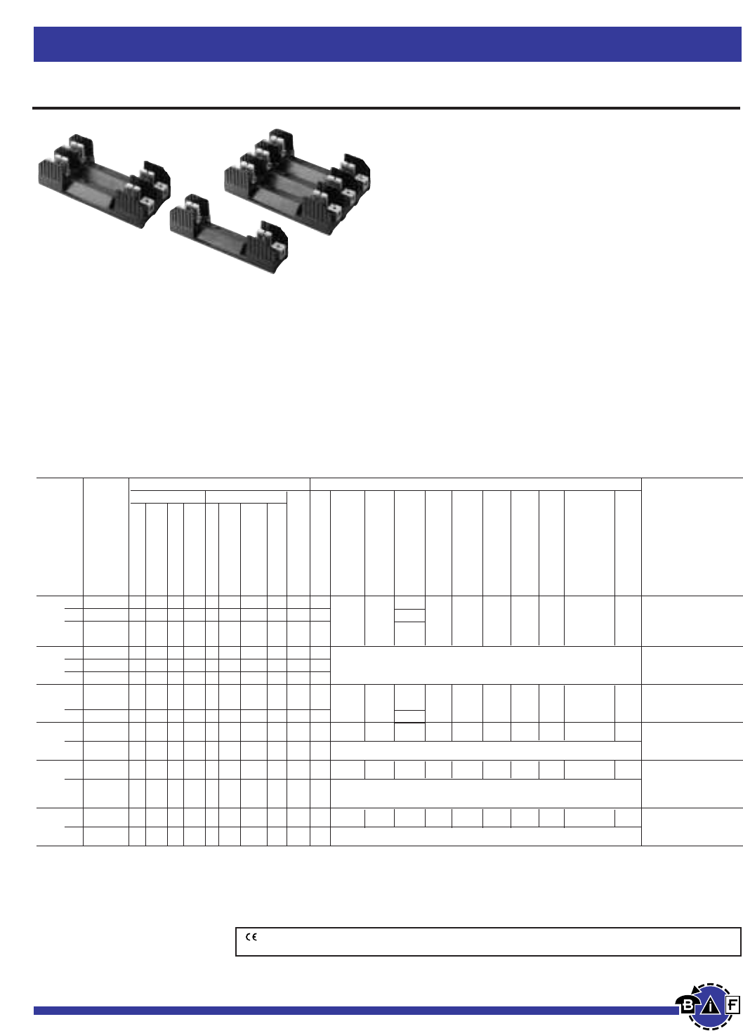
Bussmann®
Fuseblocks, Holders and Terminal Blocks
50 For complete specification data, call Bussmann Information Fax ~ 636.527.1450
Class H(K) and R Fuseblocks – 600V
H600 Series For use with Class H Fuses
(Bussmann NOS and RES).
R600 Series For use with Class R Fuses
(Bussmann LPS-RK, FRS-R, DLS-R and KTS-R).
Construction: Thermoplastic, UL Flammability: 94VO
Ampere Ratings: ⁄Ω¡º-600A
Withstand Ratings: H600Series - 10,000A RMS Sym.;
R600 Series - 200,000A RMS Sym.
Voltage Rating: H600, 600V; R600, 600V
Agency Information: UL Listed UL512, Guide IZLT, File
E14853; CSA Certified, Class 6225-01, File 47235
CE logo denotes compliance with European Union Low Voltage Directive (50-1000Vac, 75-1500Vdc). Refer to
Data Sheet #8002 or contact Bussmann Application Engineering at 636-527-1270 for more information.
Class H Fuseblocks (600V) Catalog Data (for NOS and RES Fuses)
Terminal Type (Suffix No.) Dimensions (Inches) – See Next Page For Figures
Screw Box Lug w/
Basic J Dia.
Catalog Fig. ≈ Wire
Number No. A B C D E F G H C’ Bore K Range
⁄Ω¡º 1 H60030-1 S SR P PR C CR COR CO — 1 1.54 C, CR #2-14 CU, #2-12 AL
to 2 H60030-2 S SR P PR C CR COR CO — 2 6.25 1.73 2.90 1.56 .25 0.62 3.13 1.56 0.28 ≈0.5 .26 CO, COR #6-14 CU ONLY
30 3 H60030-3 S SR P PR C CR COR CO — 3 4.25 P, PR, S, SR #10-18
CU ONLY
31 1 H60060-1 — — — — C CR COR CO — 4 C, CR #2-14 CU, #2-8 AL
to 2 H60060-2 — — — — C CR COR CO — 5 (See Figures) CO, COR #4-14 CU ONLY
60 3 H60060-3 — — — — C CR COR CO — 6
61 1 H60100-1 — SR‡— — — CR COR — — 1 2.22 COR 1/0-8 CU ONLY
to 2 H60100-2 — SR‡— — — CR COR — — 2 9.5 2.38 4.03 2.63 0.67 0.88 4.25 1.81 0.28 ≈ 0.50 .34 CR 1/0-8 CU/AL
100 3 H60100-3 — SR‡— — — CR COR — — 3 5.84 SR #8w/ Ring Terminal
101 1 H60200-1 — — — — — CR — — — 7 9.63 3.09 3.0 3.31 0.5 2.0 3.0 0.75 — 0.31 CR 250kcmil-6 CU/AL
to
200 3 H60200-3 — — — — — CR — — — 8 (See Figures)
201 1 H60400-1 — — — — — CR‡COR‡— — 7 12.0 4.0 3.0 4.5 0.63 1.75 3.0 1.0 — 0.56 COR 500kcmil-4/0
to CU ONLY
400 3 H60400-3 — — — — — CR†— — — 9 (See Figures) CR 500kcmil-4 CU/AL
401 1 H60600-1 — — — — — CR — — — 7 14.0 4.97 3.0 5.5 1.125 1.75 4.0 1.0 — 0.56 CR 500kcmil-4/0 CU/AL
to
600 3 H60600-3 — — — — — CR†— — — 10 (See Figures)
†No UL, No CSA Certification.
‡UL Recognized, CSA Certification
Poles
Amps
—
Clip with
Reinforced Spring
Pressure Plate
Pressure Plate & Clip
with Reinforced
Spring
—
Clip with
Reinforced Spring
Clip w/ Reinforced
Spring (Copper Only)
Copper Only
Data Sheet: H600 Series, 1113; R600 Series, 1111
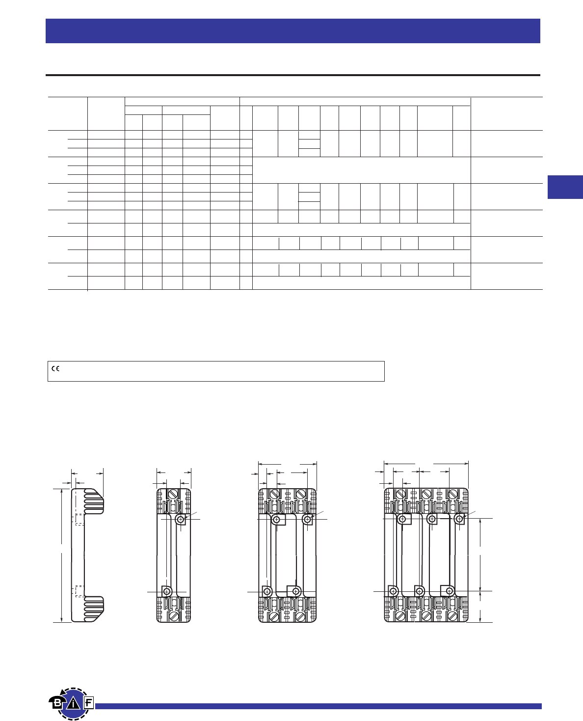
51
For complete specification data, call Bussmann Information Fax ~ 636.527.1450
Data Sheet: H600 Series, 1113; R600 Series, 1111
Bussmann®
Fuseblocks, Holders and Terminal Blocks
A
K
BC
F
C
EH
F
H
C
G
D
F
HE
J
JJ
Dimensional Data
600V, ⁄Ω¡º to 30A
and 61A to 100A
FIGURE 1. FIGURE 2. FIGURE 3.
Class R Fuseblocks (600V) Catalog Data (for LPS-RK, FRS-R, DLS-R and KTS-R Fuses)
Terminal Type (Suffix No.) Dimensions (Inches)
Basic Screw w/ Box Lug w/ 0.25J Dia.
Catalog Pres. Clip Quick- Fig. x Wire
Number — Plate — Cu Only Connect No. A B C D E F G H C’ Bore K Range
⁄Ω¡º 1 R60030-1 SR PR CR COR — 1 1.54 COR #6-14 CU ONLY
to 2 R60030-2 SR PR CR COR — 2 6.25 1.73 2.90 1.56 0.25 0.62 3.13 1.56 0.28 x 0.5 .26 CR #2-14 CU, #2-12 AL
30 3 R60030-3 SR PR CR COR — 3 4.25 PR, SR #10-18 CU ONLY
31 1 R60060-1 — — CR COR — 4 COR #2-14 CU ONLY
to 2 R60060-2 — — CR COR — 5 (See Figures) CR #2-14 CU, #2-8 AL
60 3 R60060-3 — — CR COR — 6
61 1 R60100-1 — — CR COR — 1 2.22
to 2 R60100-2 — — CR COR — 2 9.5 2.38 4.03 2.63 0.67 0.88 4.25 1.81 0.28 x 0.5 0.34 COR 1/0 -8 CU ONLY
100 3 R60100-3 — — CR COR CRQ† 3 5.84 CR, CRQ 1/0-8 CU/AL
101 1 R60200-1 — — CR — CRQ† 7 9.63 3.09 3.0 3.31 0.5 2.0 3.0 0.75 — 0.31 CR, CRQ
to
200 3 R60200-3 — — CR — — 8 (See Figures) 250kcmil-6 CU/AL
201 1 R60400-1 — — CR‡ COR‡ — 7 12.0 4.0 3.0 4.5 0.63 1.75 3.0 1.0 — 0.56 COR 500kcmil-4/0
to CU ONLY
400 3 R60400-3 — — CR† — — 9 (See Figures) CR 500kcmil-4 CU/AL
401 1 R60600-1 — — CR — — 7 14.0 4.97 3.0 5.5 1.125 1.75 4.0 1.0 — 0.56 CR (2) 500kcmil-4/0 CU/AL
to
600 3 R60600-3 — — CR† — — 10 (See Figures)
†No UL, No CSA Certification.
‡UL Recognized, CSA Certification
Amps
Poles
CE logo denotes compliance with European Union Low Voltage Directive (50-1000 Vac, 75-1500 Vdc). Refer
to Data Sheet: 8002 or contact Bussmann Application Engineering at 314-527-1270 for more information.
Class H(K) and R Fuseblocks – 600V
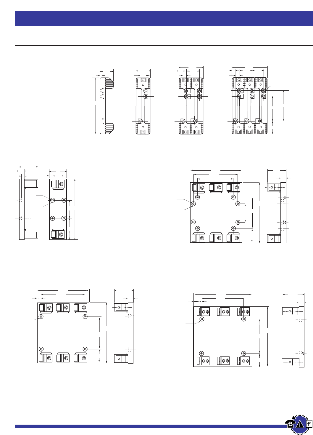
52 For complete specification data, call Bussmann Information Fax ~ 636.527.1450
Data Sheet: H600 Series, 1113; R600 Series, 1111
Bussmann®
Fuseblocks, Holders and Terminal Blocks
Class H(K) and R Fuseblocks – 600V
7.36"
0.25"
2.06" 1.81"
0.62"
3.38"
0.59"
0.62"
4.94"
2.38"
2.125"
0.62"
0.28" DIA. x
0.5" C'BORE
0.59"
1.56" 1.56"1.56"
3.125"
Dimensional Data
600V, 31A to 60A
FIGURE 4 FIGURE 5 FIGURE 6
B
H
KEF
0.75"
C'BORE
0.34
DIAMETER
G
C
D
A
600V, 101A to 600A
6.5"
8.0"
0.75" DIA.
C'BORE
.50" Deep
0.34
DIAMETER
9.0"
5.5"
9.58"
3.0"
2.04"
3.15"
.75"
600V, 101A to 200A
11.0"
0.34
DIAMETER
0.75" DIA.
C'BORE
.67" Deep 14.00"
2.5"
4.987"
1.00"
2.13"
15.26"
8.00"
9.25"
0.75" DIA.
C'BORE
.67" Deep
0.34
DIAMETER
11.63"
7.00"
12.00"
2.5"
4.02"
1.00"
1.19"
600V, 201A to 400A 600V, 401A to 600A
FIGURE 7 FIGURE 8
FIGURE 9
FIGURE 10
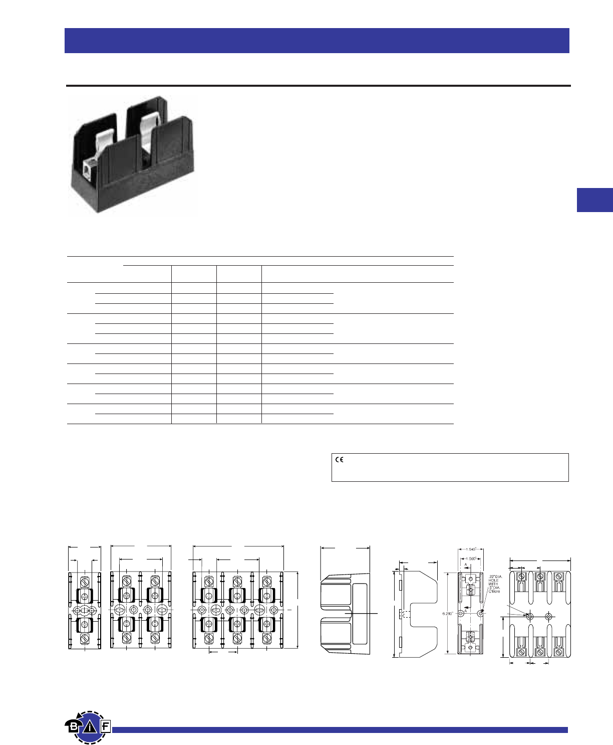
53
For complete specification data, call Bussmann Information Fax ~ 636.527.1450
Bussmann®
Fuseblocks, Holders and Terminal Blocks
Class J Fuseblocks
Data Sheet: 1114
Dimensional Data All dimensions (±0.015)
J600 Series For use with Class J Fuses
(Bussmann® LPJ and JKS).
Catalog Symbol: J600 Series
Ampere Rating: ⁄Ω™-600A
Voltage Rating: 600V
Withstand Rating: 200,000 RMS Sym. Amps
Agency Information:
UL Listed, UL 512, Guide IZLT, File E14853
CSA Certified, C22.2 No. 39, Class 6225-01, File 47235
Materials: Thermoplastic
UL Flammability: UL 94V0
.30"
2.28"
6.28"
.94"
.22"
Dia.
.5"
C'Bore
1.583"
5"
3.14"
1.75" 1.5"
⁄Ω™-60A 61-100A
Standard J Fuseblocks (600V) Catalog Data
Catalog Numbers
Pressure Box Box Lug w/ Fig. Wire
Amps Poles Screw† Plate† Lug Retaining Clip No. Range
1 J60030-1S(2) J60030-1P J60030-1C J60030-1CR†† 1 C, CR #2-14 CU, #2-8 AL
⁄Ω™-30 2 J60030-2S(2) J60030-2P J60030-2C J60030-2CR†† 2 COR #2-14 CU ONLY
3 J60030-3S(2) J60030-3P J60030-3C J60030-3CR†† 3 P, PR, S, SR #10-14 CU ONLY
1 — — J60060-1C J60060-1CR†† 1 C, CR, #2-14 CU/AL
31-60 2 — — J60060-2C J60060-2CR†† 2 COR #4-14 CU ONLY
3 — — J60060-3C J60060-3CR†† 3
61-100 1 — — — J60100-1CR 4 COR 1/0-8 CU ONLY
3 — — — J60100-3CR†† 5 CR, CRQ 1/0-8 CU/AL
101-200 1 — — — J60200-1CR 6 CR 250kcmil-6 CU/AL
3 — — — J60200-3CR 7
201-400 1 — — — J60400-1CR(3) 8 CR 500kcmil -4 CU/AL
3 — — — J60400-3CR(3) 9
401-600 1 — — — J60600-1CR 10 CR (2) 500kcmil-4/0 CU/AL
3 — — — J60600-3CR(2) 11
†Clip reinforcing springs are standard on fuseblocks rated 100A and above. Available on 30A and 60A blocks by adding the letter “R” to the end of
the part number.
††Copper only connections available by changing “CR” suffix to “COR”.
(2)No UL, No CSA Certification
(3)UL Recognized, CSA Certification CE logo denotes compliance with European Union Low Voltage Directive
(50-1000 Vac, 75-1500 Vdc). Refer to Data Sheet: 8002 or contact
Bussmann Application Engineering at 636-527-1270 for more information.
2.250
3.202
.750
4.702
2.250
C
L
L
1.500
4.005
C
2.415"
.750
1.702
FIGURE 1. FIGURE 2. FIGURE 3. FIGURE 4. FIGURE 5.
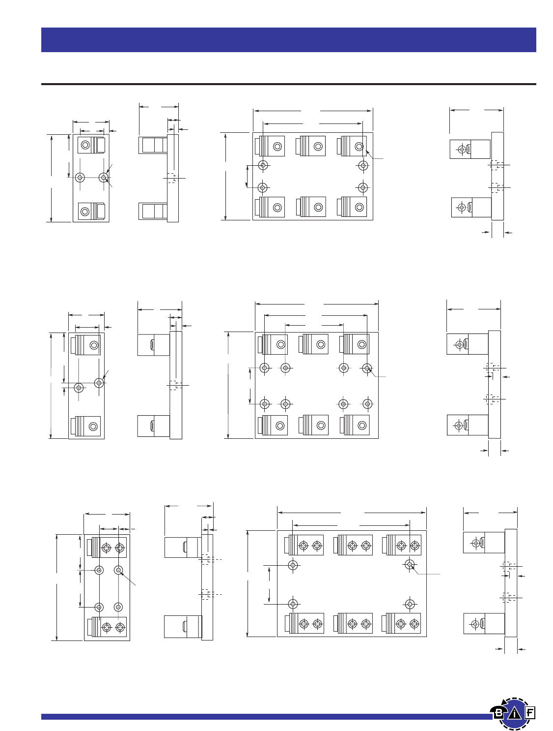
Bussmann®
54 For complete specification data, call Bussmann Information Fax ~ 636.527.1450
Fuseblocks, Holders and Terminal Blocks
Class J Fuseblocks
Data Sheet: 1114
3.5"
1.75"
3"
.625"
.75"
C'Bore
.34"
DIA.
.5"
7.5"
1"
4"
.56"
.75"
3.1"
.31"
6.125"
3.06"
2"
3"
.5"
.75"
C'Bore
.34"
DIA.
FIGURE 6.
101-200A
201-400A
6.125"
7.00"
8.31"
1.69"
.344" Dia. hole thru
.750 Dia. c'bore
3.15"
.750"
FIGURE 7.
9.00"
10.51"
7.50"
2.00"
.344" Dia. hole thru
.750 Dia. c'bore
4.00"
1.00"
6.00"
.50"
FIGURE 8. FIGURE 9.
.56"
8.875"
3.25"
1.75"
.75"
C'Bore
.34" Dia.
4"
2.375"
1.125"
1"
4.99"
401-600A
FIGURE 10.
8.875"
11.00"
14.144"
.344" Dia.
hole thru
.750 Dia.
c'bore
2.88"
4.987"
1.00"
.50"
FIGURE 11.
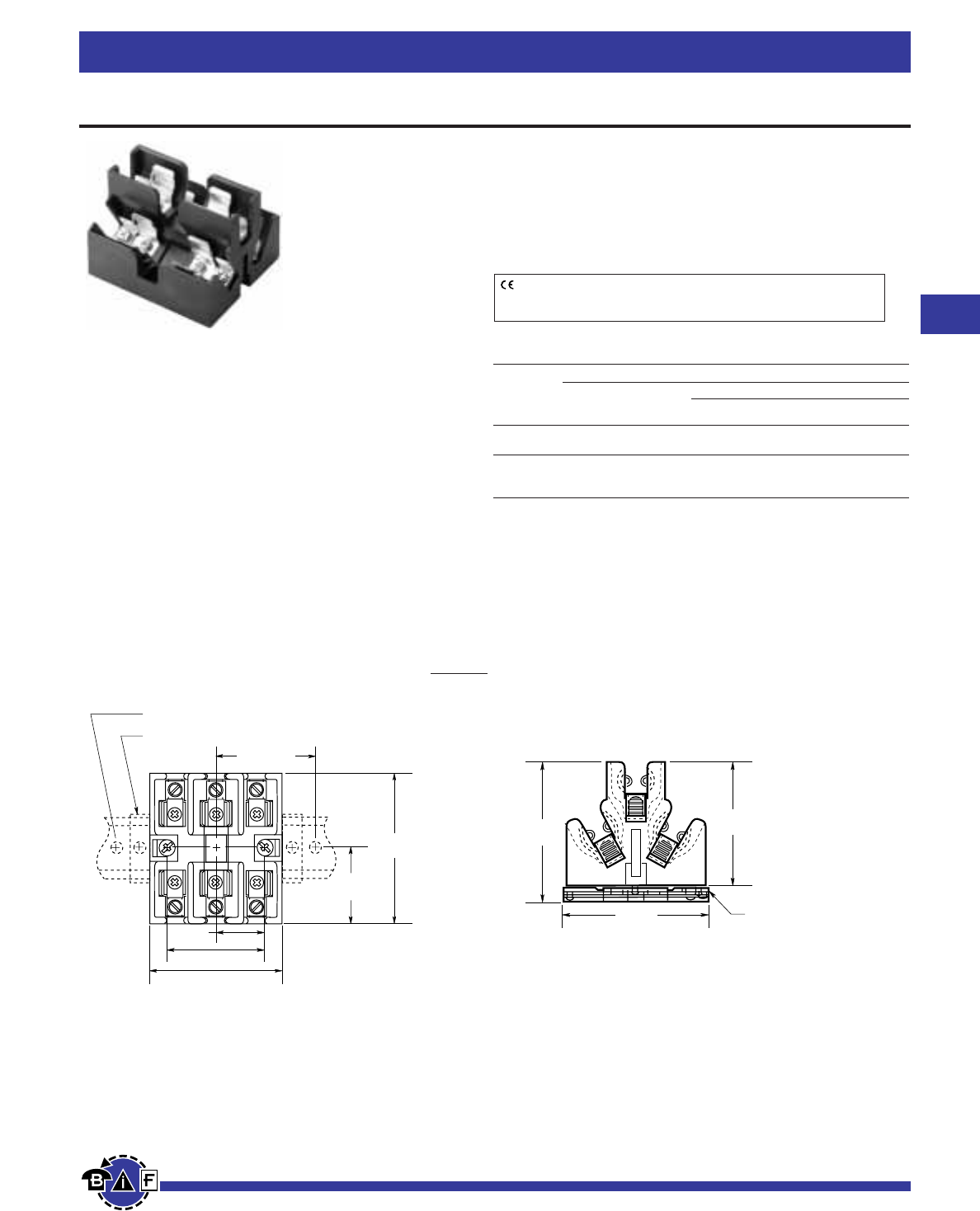
Bussmann®
55
For complete specification data, call Bussmann Information Fax ~ 636.527.1450
Fuseblocks, Holders and Terminal Blocks
Data Sheet:1108
Class J Fuseblocks
ADAPTOR FOR 35mm
SYMMETRICAL DIN-RAIL MOUNTING
2.78"
(70.6mm)
3.06"
(77.8mm)
3.13"
(79.5mm)
JP Series For use with Class J Fuses
(Bussmann LPJ,JKS).
Pyramid Style Fuseblock
Ampere Rating: 30A
Voltage Rating: 600V
Withstand Rating: 200,000 RMS Sym. Amps
Agency Information:
UL Listed, U.L. 512, Guide IZLT, File E14853
CSA Certified, C22.2 No. 39, Class 4225-04, File 47235
Material: Thermoplastic
UL Flammability: UL 94V0
3.29"
(83.6mm)
END STOPS - PREVENT BLOCK MOVEMENT WHEN CHANGING FUSES
DIN-RAIL MOUNTING SCREW 8" (203.2mm) APART
4.00" MAX.
(101.6mm)
1.19"
(30.2mm)
3.75" (±0.02)
(95.3mm (±0.50)
1.88"
(47.6mm)
2.38"
(60.4mm)
Dimensional Data *All other dimensions (± 0.015∑)
(± 0.40mm)
CE logo denotes compliance with European Union Low Voltage Directive
(50-1000 Vac, 75-1500 Vdc). Refer to Data Sheet: 8002 or contact
Bussmann Application Engineering at 314-527-1270 for more information.
Pyramid®J Fuseblock; 30A, 600V; 3-Pole; Panel or 35mm
DIN-Rail Mount; Clips with Reinforcing Springs
Mounting Catalog Numbers
Screws with Box
Pressure Copper
Plate Aluminum Only
Panel JP60030-3PR JP60030-3CR JP60030-3COR
(#10-14 CU ONLY) (#2-14 CU/AL) (#2-14 CU ONLY)
With JP60030-3PRA JP60030-3CRA JP60030-CORA
DIN-Rail (#10-14 CU ONLY) (#2-14 CU/AL) (#2-14 CU ONLY)
Adapter*
*Adapter Only for DIN-Rail - Cat No. JPA-3.
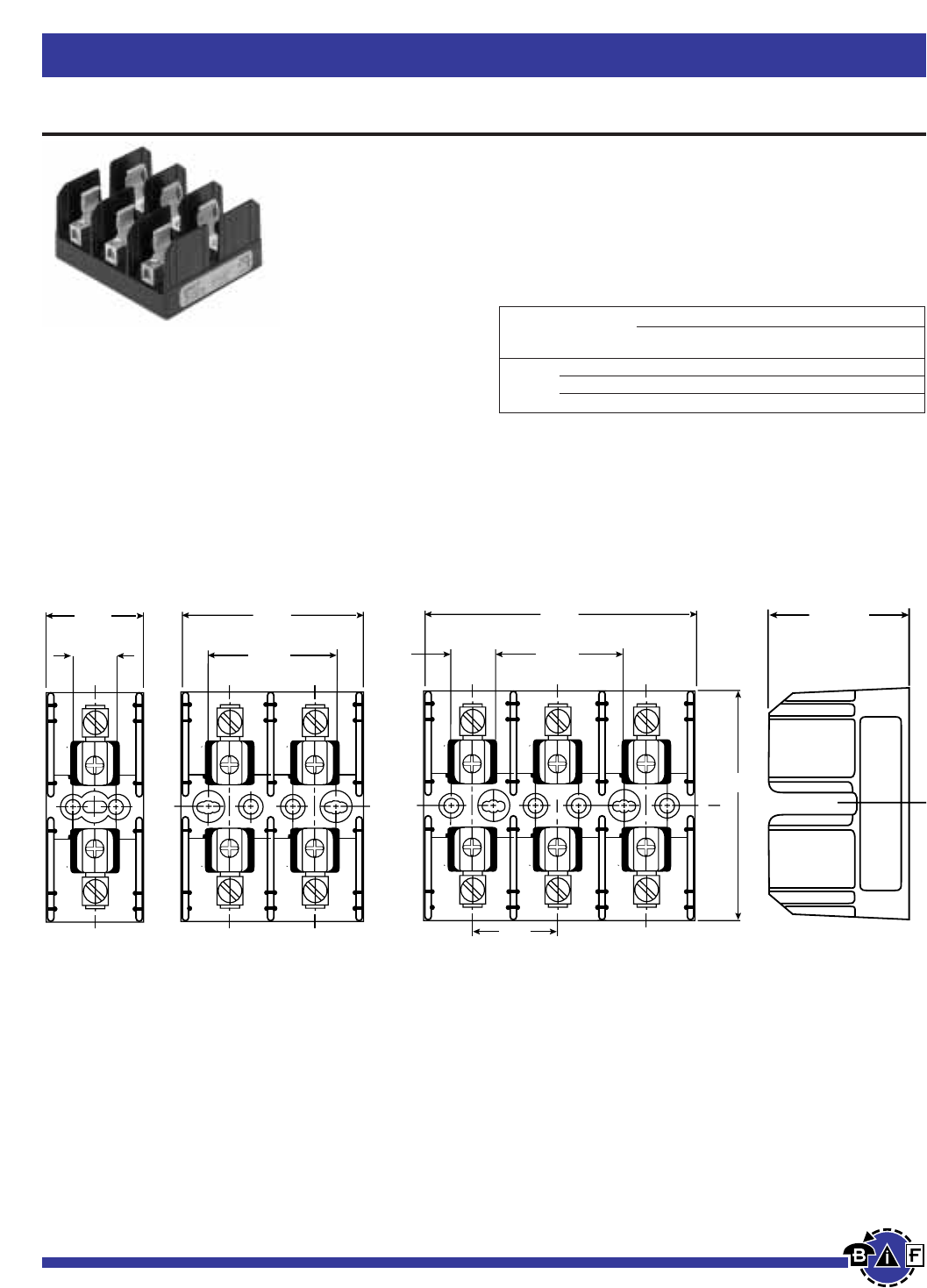
Bussmann®
56 For complete specification data, call Bussmann Information Fax ~ 636.527.1450
Fuseblocks, Holders and Terminal Blocks
Data Sheet: 1211
Semiconductor Fuseblocks
J70100
Ampere Rating: 100A
Voltage Rating: 700V
Agency Information:
UL Recognized, Guide IZLT2, File E14853
Withstand Rating: 200,000 RMS Sym. Amps
For use with 22 ≈ 58mm fuses
(FWP-40A22F, FWP-100A22F, etc.)
Materials: Thermoplastic
UL Flammability: UL 94V0
Catalog Numbers
Box Lug w/ Fig. Wire
Amps Poles Retaining Clip No. Range
1 J70100-1CR 1 #2-14 CU/AL
100 2 J70100-2CR 2 #2-14 CU/AL
3 J70100-3CR 3 #2-14 CU/AL
2.250
3.202
.750
4.702
2.250
C
L
L
1.500
4.005
C
2.415
Dimensional Data
100A
.750
1.702
FIGURE 1 FIGURE 2 FIGURE 3
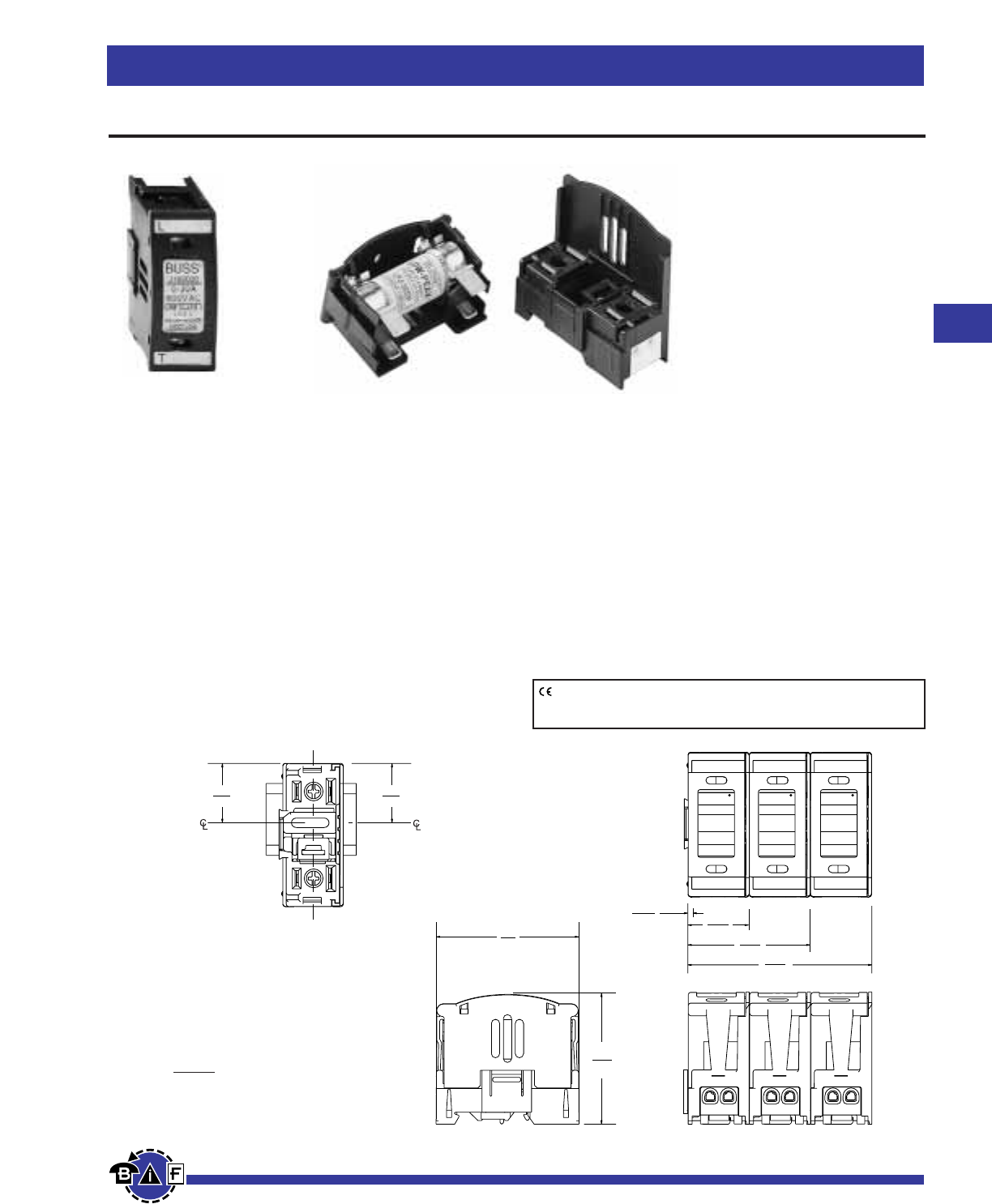
57
For complete specification data, call Bussmann Information Fax ~ 636.527.1450
Bussmann®
Fuseblocks, Holders and Terminal Blocks
Class J (Finger-Safe) Fuseholders
JT(N)60030 and JT(N)60060
For use with Bussmann Class “J” fuses - (Bussmann LPJ, JKS)
Catalog Numbers:
JT60030 and JT60060 - Non-Indicating
JTN60030 and JTN60060 - Indicating (Neon)
Construction: Thermoplastic, UL Flammability; 94VO
Voltage Ratings: 600V
Amperage Rating: JT(N)60030 - 30A,
JT(N)60060 - 60A
Withstand Rating: 200,000A RMS Sym.
(Self Certified at 300,000A using Bussmann
LPJ_SP fuses)
Agency Information:
Listed to UL 512: Guide IZLT, File 14853
CSA Certified: Class 6225-01, File 47235
Indication: Min. voltage: 90 VAC, 115 VDC; Neon Lamp
“ON” when fuse opens, voltage source and current path
are present.
Finger-Safe: IP20 per IEC 60529
Terminations: 30A Dual Port Torque 20 lb. in.,
60A Single Port Torque 45 lb. in., Terminal Construction,
Tin plated Copper Alloy
Wire Size: JT(N)60030 - Rated for 75°C, AWG#18-#8;
CU only, JT(N)60060 - Rated for 75°C, AWG#14-#4;
CU only.
(Note: For JT(N)60030 use both stranded or solid, in a variety of
dual wire combinations of same wire size and type.)
Packaging: 12 in a carton
Safety J
1.14
(29.0)
1.05
(26.7)
Slot
MOUNTING
Shown without fuse
pullout cover
BUSS
0 – 30A
600VAC
USE CLASS J
FUSES
DO NOT REMOVE
UNDER LOAD
JT60030
BUSS
0 – 30A
600VAC
USE CLASS J
FUSES
DO NOT REMOVE
UNDER LOAD
JT60030
BUSS
0 – 30A
600VAC
USE CLASS J
FUSES
DO NOT REMOVE
UNDER LOAD
JT60030
3.60
(91.4)
2.42
(61.3)
1.23
(31.2)
.07
(1.8)
1 pole
2 pole
3 pole
2.75
(69.9)
2.52
(64.1)
Din-rail
Dim. = in.
(mm.) JT60030
JTN60030
CE logo denotes compliance with European Union Low Voltage Directive
(50-1000Vac, 75-1500Vdc). Refer to Data Sheet: 8002 or contact
Bussmann Application Engineering at 636-527-1270 for more information.
Data Sheet: 1152
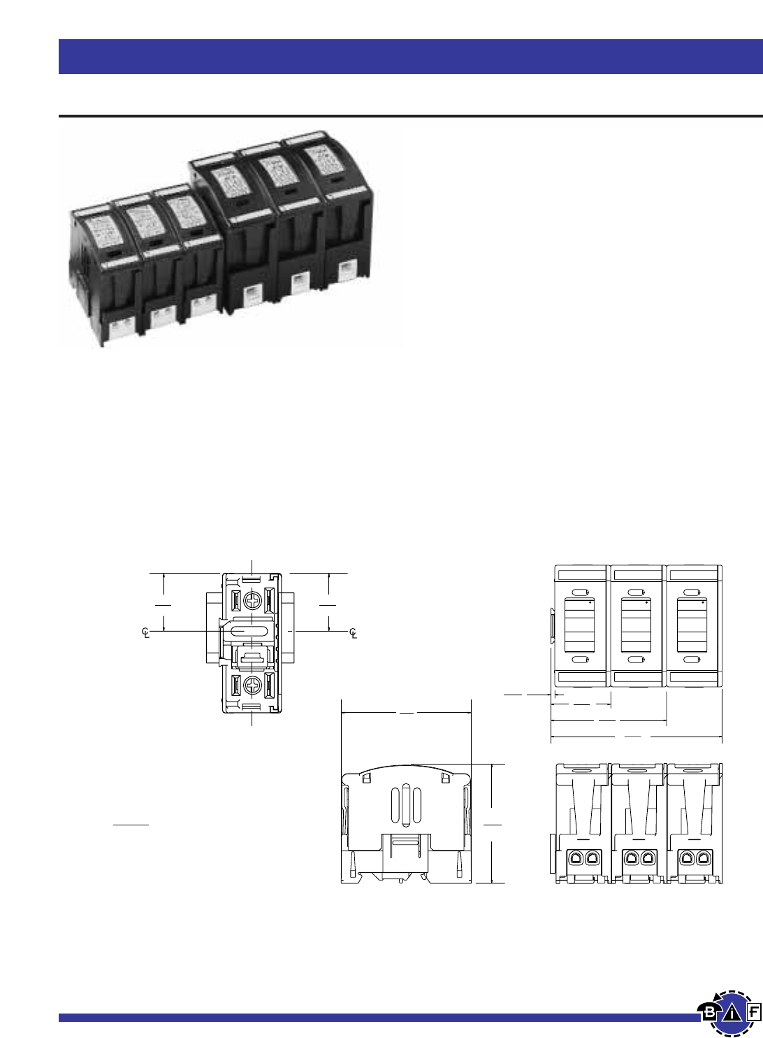
Bussmann®
Fuseblocks, Holders and Terminal Blocks
58 For complete specification data, call Bussmann Information Fax ~ 636.527.1450
Class J (Finger-Safe) Fuseholders
JT(N)600 Series fuseblocks can be dovetailed together within the same current rating to provide multiple pole block
configurations.
NOTE: JT(N)60030 cannot be dovetailed to JT(N)60060.
JT60060
JTN60060
Dim. = in.
(mm.)
3.10
(78.7)
3.06
(77.7)
1.31
(33.3)
1.25
(31.8)
Din-rail
Slot
MOUNTING
Shown without fuse
pullout cover
4.40
(111.7)
2.96
(75.2)
1.52
(38.1)
.10
(2.6)
BUSSBUSS
35 – 60A
600VAC
USE CLASS J
FUSES
DO NOT REMOVE
UNDER LOAD
JT60060
BUSSBUSS
35 – 60A
600VAC
USE CLASS J
FUSES
DO NOT REMOVE
UNDER LOAD
JT60060
BUSSBUSS
35 – 60A
600VAC
USE CLASS J
FUSES
DO NOT REMOVE
UNDER LOAD
JT60060
1 pole
2 pole
3 pole
Data Sheet: 1152
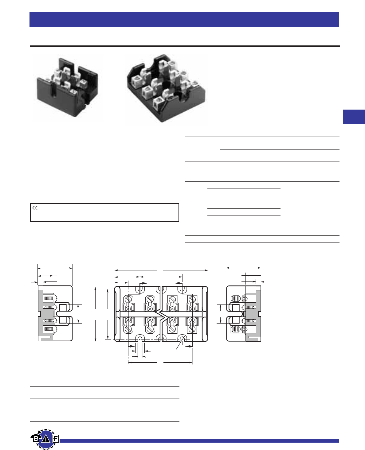
Bussmann®
Fuseblocks, Holders and Terminal Blocks
59
For complete specification data, call Bussmann Information Fax ~ 636.527.1450
Data Sheet: 1115
Class T Fuseblocks – 300V
T30030-S
SECTION X-X
0.91"
1.63"
0.72"
0.16"
Z
XFull
Radius
ZX
0.44"
0.20"
C
B
1.20"
A
0.69"
2.5"
2.75"
T30060-C
SECTION Z-Z
0.91"
1.63"
0.72"
0.16"
Dimensional Data
Figure 1. ⁄Ω™A to 60A
T300 (300V) For use with Class T Fuses
(Bussmann JJN)
Construction: Glass Polyester, Phenolic on 600A,
UL Flammability: 94VO
Rating: ⁄Ω™-600A
Withstand Rating: 200,000A RMS Sym.
Agency Information:
UL Listed UL512, Guide IZLT, File E14853
CSA Certified, Class 6225-01, File 47235.
Class T Fuseblocks (300V) Catalog Data
Catalog Numbers
Box Fig. Wire
Amps Poles Screw Lug No. Range
2 T30030-2SR T30030-2CR SR #10-18 CU
⁄Ω™-30 3 T30030-3SR T30030-3CR 1
4 T30030-4SR T30030-4CR CR #6-14 CU-AL
2 T30060-2SR T30060-2CR
31-60 3 T30060-3SR T30060-3CR 1 CR #2-14 CU-AL
4 T30060-4SR T30060-4CR SR #10-18 CU ONLY
1 — T30100-1CR
61-100 2 — T30100-2CR 2 1/0-8 CU-AL
3 — T30100-3CR
1 — T30200-1C 3 250kcmil-6 CU-AL
101-200 3 — T30200-3C 4
201-400 1 — T30400-1C 5 600kcmil-2/0 CU-AL
401-600 1 — T30600-1C 6 (2) 600kcmil-4/0 CU-AL
CE logo denotes compliance with European Union Low Voltage Directive
(50-1000Vac, 75-1500Vdc). Refer to Data Sheet: 8002 or contact
Bussmann Application Engineering at 636-527-1270 for more information.
Class T Fuseblocks (300V) Catalog Numbers
Block Dimensions (Inches)
Type A B C
T30030-2 2.41 — 1.03
T30060-2
T30030-3 3.44 1.03 2.06
T30060-3
T30030-4 4.47 2.06 3.09
T30060-4
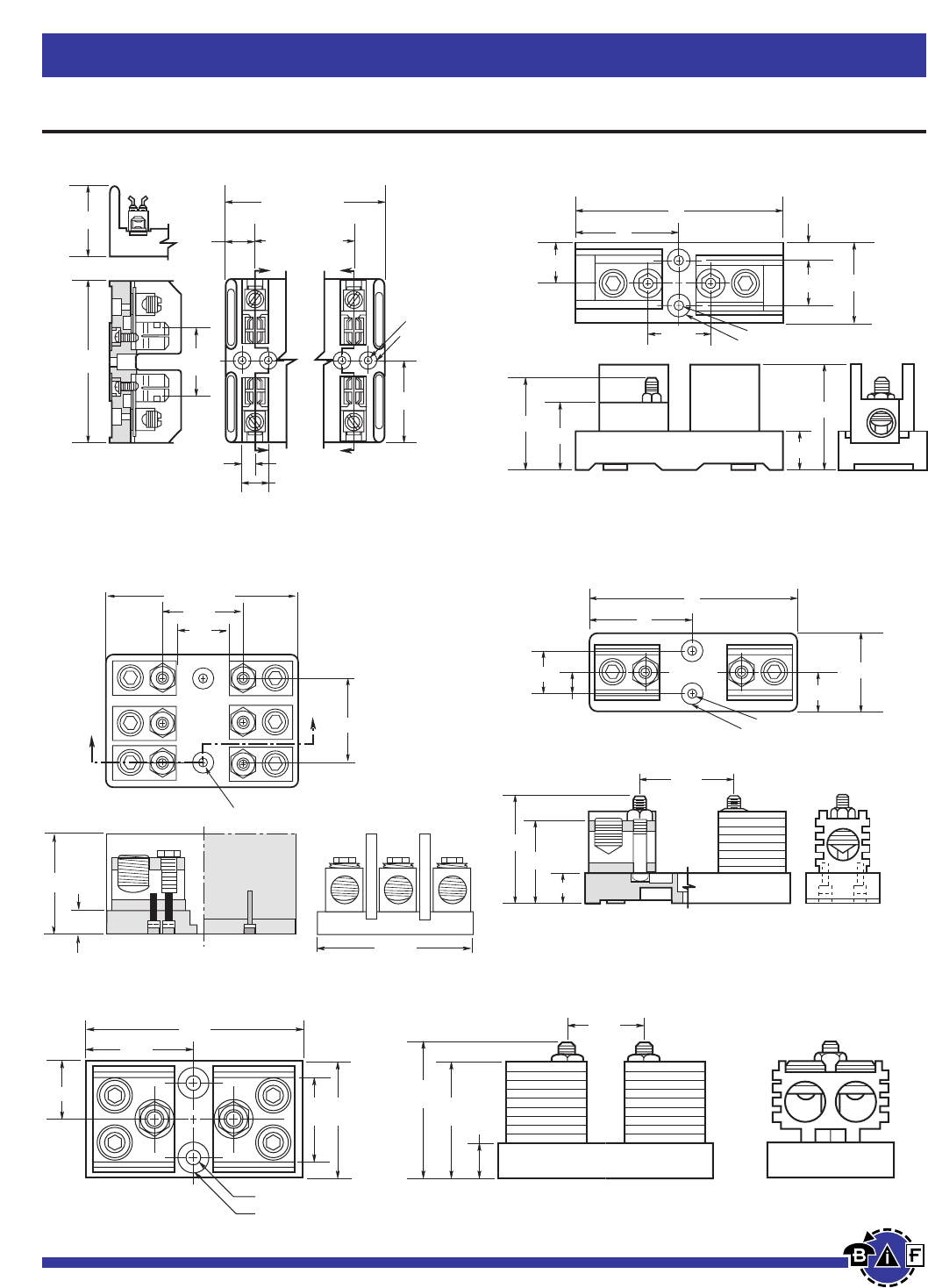
Bussmann®
60 For complete specification data, call Bussmann Information Fax ~ 636.527.1450
Fuseblocks, Holders and Terminal Blocks
Data Sheet: 1115
Class T Fuseblocks – 300V
Z
Z
0.52" C'BORE
0.55" DEEP
0.22" DIA.
X
X
2.39"
2.25"
REF.
4.78"
2.06"
1.69" (1 POLE)
3.09" (2 POLE)
4.5" (3 POLE)
1.41" (2 POLE)
2.81" (3 POLE)
0.84"
0.38"
0.75"
0.625" C'BORE 0.438" DEEP
0.282" DIAMETER THRU HOLE
.996"
A
A2.75"
1.695"
4.87"
0.625"
2.375"
4.46"
Figure 2. 61A to 100A
3"
6"
0.28" DIAMETER
0.63" C'BORE 0.5" DEEP
1.125"
2.56"
1.94"
0.81"
3.06"
1.69"
0.05"
1.25" 2.25"
Figure 3. 101A to 200A
Figure 4. 200A
0.63" C'BORE 0.5" DEEP
6"
0.28" DIAMETER
1.125"
2.25"
0.63"
3"
1.25"
1.84"
0.81"
2.38"
3.06"
Figure 5. 201A to 400A
3.44"
0.75"
3"
2.03"
3"2"
1.5"
5.75"
2.88"
0.33" DIAMETER
0.75" C'BORE 0.5" DEEP
Figure 6. 401A to 600A
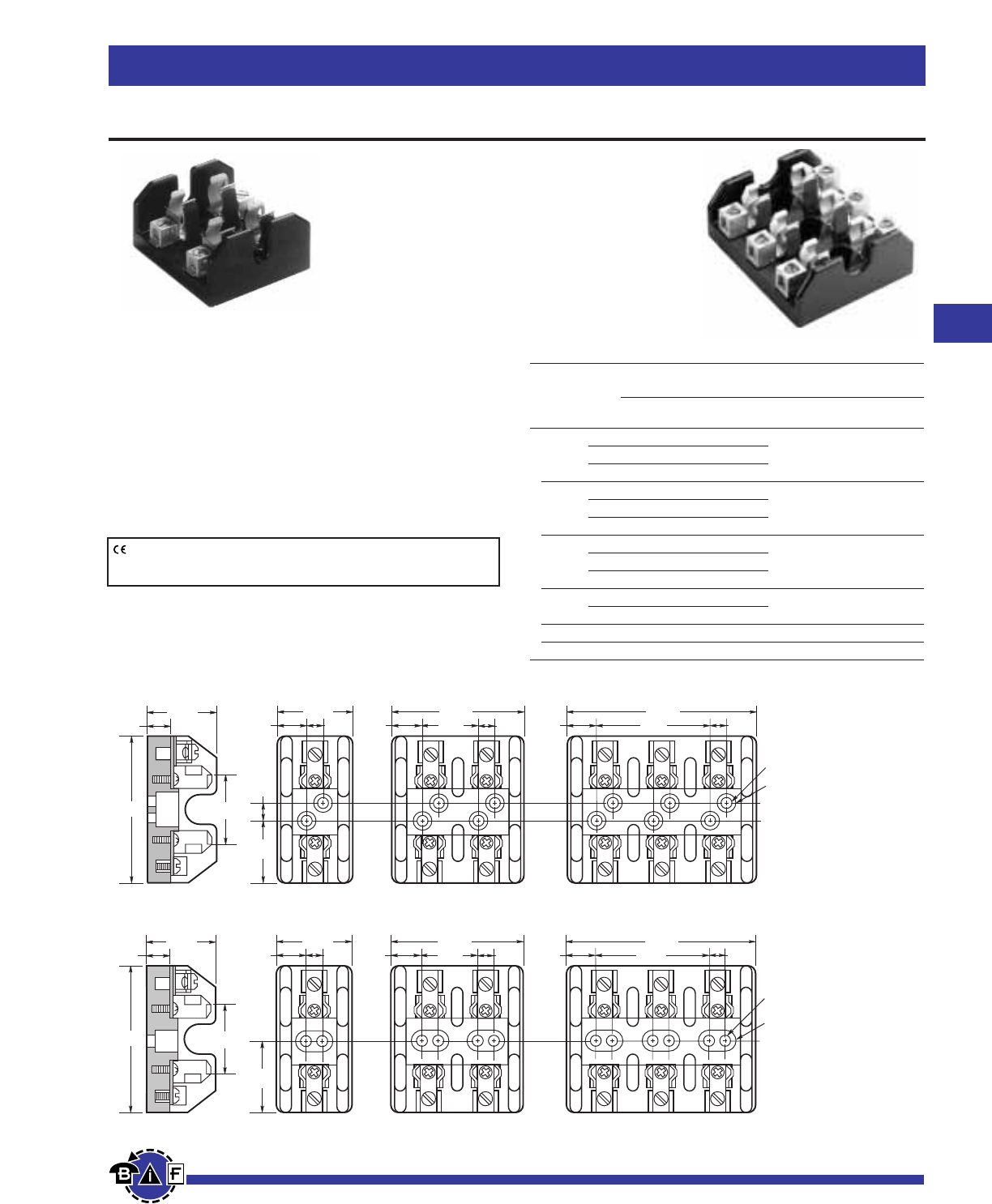
61
For complete specification data, call Bussmann Information Fax ~ 636.527.1450
Bussmann®
Fuseblocks, Holders and Terminal Blocks
Data Sheet: 1116
Class T Fuseblocks – 600V
Figure 1. ⁄Ω™A to 30A
3.19"
1.44"
1.563"
0.33"
1.42"
0.5"
1.44"
0.55" 0.33" 0.55"
2.59"
1.16" 0.33" 0.55"
3.75"
2.31" 0.33"
0.22" DIAMETER
0.5" C'BORE
2.94"
1.75"
1.63"
1.47"
0.5"
1.81"
0.59" 0.63" 0.59"
3.34"
1.53" 0.63" 0.59"
4.86"
3.06" 0.63"
0.22" DIAMETER
0.5" C'BORE
Figure 2. 31A to 60A
T600 (600V) For use with Class T Fuses
(Bussmann JJS)
Construction: Glass Polyester, Phenolic on 600A,
UL Flammability: 94VO
Rating: ⁄Ω™-600A
Withstand Rating: 200,000A RMS Sym.
Agency Information:
UL Listed UL512, Guide IZLT, File E14853
CSA Certified, Class 6225-01, File 47235.
Class T Fuseblocks (600V) Catalog Data
Catalog Numbers
Box Fig. Wire
Amps Poles Screw Lug No. Range
1 T60030-1SR T60030-1CR SR #10-18 CU
⁄Ω™-30 2 T60030-2SR T60030-2CR 1
3 T60030-3SR T60030-3CR CR #2-14 CU-AL
1 T60060-1SR T60060-1CR CR #2-14 CU-AL
31-60 2 T60060-2SR T60060-2CR 2
3 T60060-3SR T60060-3CR SR #10-18 CU ONLY
1 — T60100-1C
61-100 2 — T60100-2C 3 2/0-14 CU-AL
3 — T60100-3C
101-200 1 — T60200-1C 4 250kcmil-6 CU-AL
3 — 1B0089*
201-400 1 — T60400-1C 5 600kcmil-2/0 CU-AL
401-600 1 — T60600-1C 6 (2) 600kcmil-4/0 CU-AL
* UL Listed, Guide IZLT, File E14853,
CSA Certified Class 6225-01, File 21455M18
CE logo denotes compliance with European Union Low Voltage Directive
(50-1000Vac, 75-1500Vdc). Refer to Data Sheet: 8002 or contact
Bussmann Application Engineering at 636-527-1270 for more information.
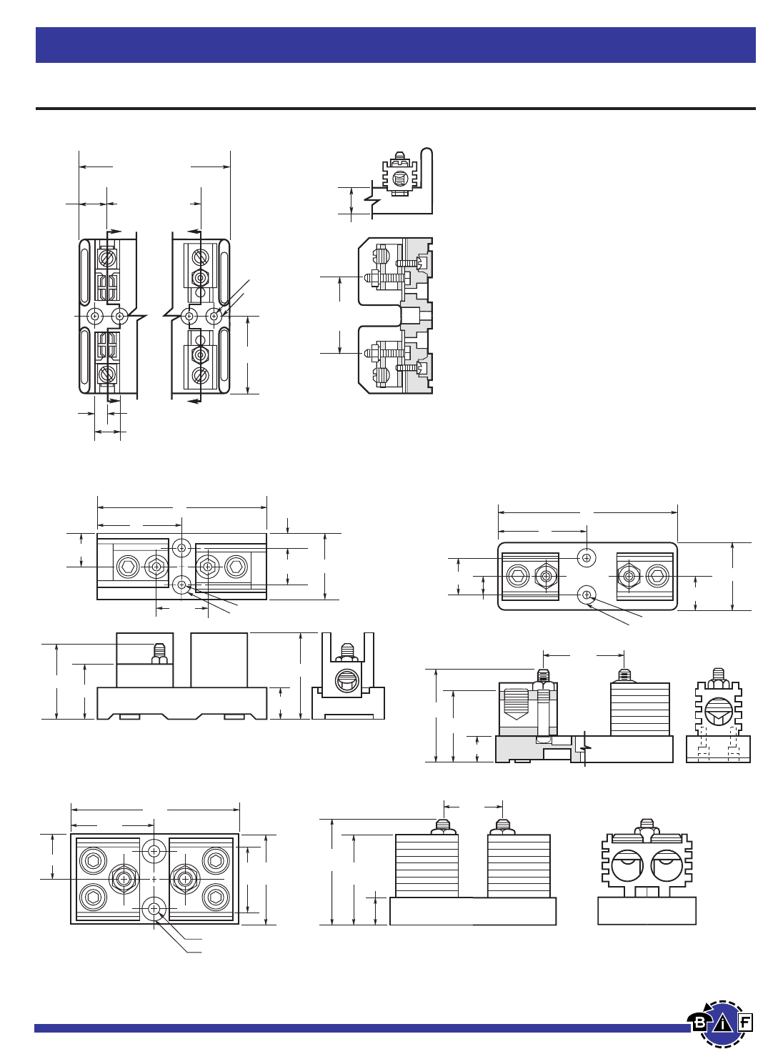
Bussmann®
62 For complete specification data, call Bussmann Information Fax ~ 636.527.1450
Fuseblocks, Holders and Terminal Blocks
Data Sheet: 1116
Class T Fuseblocks – 600V
Figure 5. 201A to 400A
0.63" C'BORE 0.5" DEEP
6"
0.28" DIAMETER
1.125"
2.25"
0.63"
3"
1.25"
2.72"
0.81"
2.38"
3.06"
Figure 4. 101A to 200A
3"
6"
0.28" DIAMETER
0.63" C'BORE 0.5" DEEP
1.125"
2.56"
1.94"
0.81"
3.06"
2.5"
0.05"
1.25" 2.25"
Figure 3. 61A to 100A
Z
Z
0.52" C'BORE
0.55" DEEP
0.22" DIA.
X
X
2.39"
1.69" (1 POLE)
3.09" (2 POLE)
4.5" (3 POLE)
1.41" (2 POLE)
2.81" (3 POLE)
0.84"
0.38" SECTION Z-Z
0.78"
2.34"
REF.
0.75"
Figure 6. 401A to 600A
3.44"
0.75"
3"
2.95"
3"2"
1.5"
6.75"
3.38"
0.33" DIAMETER
0.75" C'BORE 0.5" DEEP
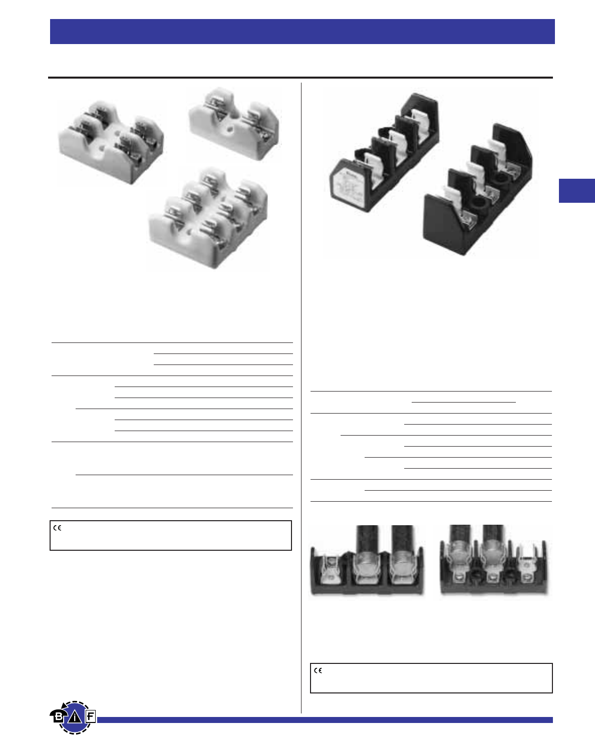
Modular Type Fuseblocks
Class H & J Fuses
Reinforced retaining clips standard
Available in 30A and 60A, 3-pole models only.
Agency Information: UL Recognized, Guide IZLT2,
File E14853
CSA Certified, Class 6225-01, File 47235
Modular Type For Class H & J Fuses
Fuse Volts Amps Catalog Number Figure
Type Screw Pressure Number
11241-3SR 11241-3PR 1
250 60 11242-3SR 11242-3PR 2
H30 11241-3SR 11241-3PR 1
600 11242-3SR 11242-3PR 2
11239-3SR 11239-3PR 1
60 11240-3SR 11240-3PR 2
J600 30 11241-3SR 11241-3PR 1
60 11239-3SR 11239-3PR 1
Note: Order two blocks per fuse (matched or mixed.)
63
For complete specification data, call Bussmann Information Fax ~ 636.527.1450
Bussmann®
Fuseblocks, Holders and Terminal Blocks
Class H(K), J and R Fuseblocks
CE logo denotes compliance with European Union Low Voltage Directive
(50-1000Vac, 75-1500Vdc). Refer to Data Sheet: 8002 or contact
Bussmann Application Engineering at 636-527-1270 for more information.
Porcelain Type Fuseblocks
Class H(K) and R Dimensions
Agency Information: UL Listed, Guide IZLT, File E14853
Class H and K Dimension Fuseblocks - Porcelain Type
Fuseblocks
Terminal Type
Volts Amps Poles Screw Box Lug
⁄Ω¡º 1 2601 —
to 2 2604 —
250 30 3 2607 —
31 1 — 2602
to 2 — 2605
60 3 — 2608
⁄Ω¡º
to 1 2610 —
600 30
31
to 1 — 2611
60
CE logo denotes compliance with European Union Low Voltage Directive
(50-1000Vac, 75-1500Vdc). Refer to Data Sheet: 8002 or contact
Bussmann Application Engineering at 636-527-1270 for more information.
Notes:
1. 11239 and 11241 have wire terminals and mounting holes located under
fuse. (Figure 1)
2. 11240 and 11242 have wire terminals and mounting holes located at end
of fuse. (Figure 2)
Figure 1 Figure 2
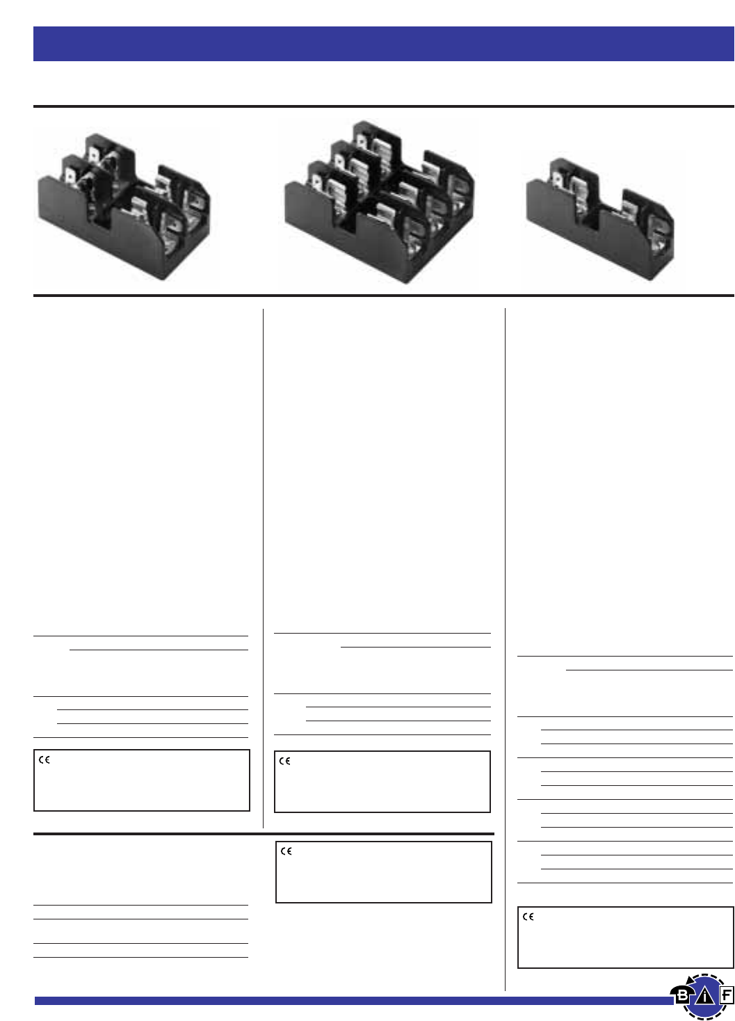
Fuseblocks, Holders and Terminal Blocks Bussmann®
64 For complete specification data, call Bussmann Information Fax ~ 636.527.1450
Data Sheet: 1106 Data Sheet: 1106
Class CC, Type M and Class G Fuseblocks
Data Sheet: 1104Data Sheet: 1105
Catalog Data
Terminal Type
Screw Pressure
with Plate w/
Quick Pressure Quick Box
Amps Screw Connect* Plate Connect* Lug
⁄Ω¡º 1 BC6031S BC6031SQ BC6031P BC6031PQ BC6031B
to 2 BC6032S BC6032SQ BC6032P BC6032PQ BC6032B
30 3 BC6033S BC6033SQ BC6033P BC6033PQ BC6033B
Catalog Data
Terminal Type
Screw with Pressure Plate
Quick Connect* w/Quick Connect*
BCCM6033SQ BCCM6033PQ
Catalog Data
Terminal Type
Screw Pressure
with Plate w/
Quick Quick Box
Amps Poles Connect
*
Connect
*
Lug
⁄Ω¡º 1 BM6031SQ BM6031PQ BM6031B
to 2 BM6032SQ BM6032PQ BM6032B
30 3 BM6033SQ BM6033PQ BM6033B
Catalog Data
Terminal Type
Screw Pressure
with Plate w/ Box Lug
Quick Quick Box w/retaining
Amps Poles Connect* Connect* Lug clip
1 1 BG3011SQ BG3011PQ BG3011B —
to 2 BG3012SQ BG3012PQ BG3012B —
15 3 BG3013SQ BG3013PQ BG3013B —
1 BG3021SQ BG3021PQ BG3021B —
20 2 BG3022SQ BG3022PQ BG3022B —
3 BG3023SQ BG3023PQ BG3023B —
25 1 BG3031S BG3031P BG3031B —
to 2 BG3032S BG3032P BG3032B —
30 3 BG3033S BG3033P BG3033B —
35 1 — — — G30060-1CR
to 2 — — — G30060-2CR
60 3 — — G30060-3C G30060-3CR
BC Series
Class CC Fuseblocks
For use with Class CC Fuses
(Bussmann LP-CC, KTK-R, and
FNQ-R)
Construction:
Base - Thermoplastic
Clips - Bright tin-plated bronze
Ratings: 600V, 30A
Withstand Rating:
200,000A RMS Sym.
Agency Information:
UL Listed (Guide IZLT,
File E14853)
CSA (Class 6225-01, File 47235)
UL Flammability: 94VO
Dimensional Data:
See Data Sheet.
DIN-RAIL Adaptors: Page 204
DRA-1 & DRA-2
BCCM Series
For use with (2) Class CC Fuses and
(1) ⁄‹Ω£™x 1⁄Ω™Fuse.
BM Series Type M
Supplementary Fuseblocks
For use with any ⁄‹Ω£™∑ ≈ 1⁄Ω™∑ Fuses
(Bussmann KTK, FNQ, FNM, BAF,
BAN, and AGU)
Construction: Thermoplastic
Ratings: 600V, 30A
Withstand Rating:
10,000A RMS Sym.
Agency Information:
UL Recognized (Guide IZLT2,
File E14853)
CSA (Class 6225-01, File 47235)
UL Flammability: 94VO
Dimensional Data:
See Data Sheet.
DIN-RAIL Adaptors: Page 204
DRA-1 & DRA-2
BG Series and G Series
Class G Fuseblocks
For use with Class G Fuses
(Bussmann SC)
Construction: (0-30) Thermoplastic
(35-60) Phenolic
Ratings: 600V, 0-20A
480V, 25-60A
Withstand Rating:
100,000A RMS Sym.
Agency Information:
UL Listed 35-60A (Guide IZLT,
File E14853)
UL Recognized 1-30A, (Guide IZLT2,
File E14853)
CSA (Class 6225-01, File 47235)
Dimensional Data:
See Data Sheet.
DIN-RAIL Adaptors: Page 204
DRA-1 & DRA-2
Poles
CE logo denotes compliance with European
Union Low Voltage Directive (50-1000Vac,
75-1500Vdc). Refer to Data Sheet: 8002 or
contact Bussmann Application Engineering at
636-527-1270 for more information.
CE logo denotes compliance with European
Union Low Voltage Directive (50-1000Vac,
75-1500Vdc). Refer to Data Sheet: 8002 or
contact Bussmann Application Engineering at
636-527-1270 for more information.
CE logo denotes compliance with European
Union Low Voltage Directive (50-1000Vac,
75-1500Vdc). Refer to Data Sheet: 8002 or
contact Bussmann Application Engineering at
636-527-1270 for more information.
CE logo denotes compliance with European
Union Low Voltage Directive (50-1000Vac,
75-1500Vdc). Refer to Data Sheet: 8002 or
contact Bussmann Application Engineering at
636-527-1270 for more information.
*Quick connect terminal rated for 20A max.
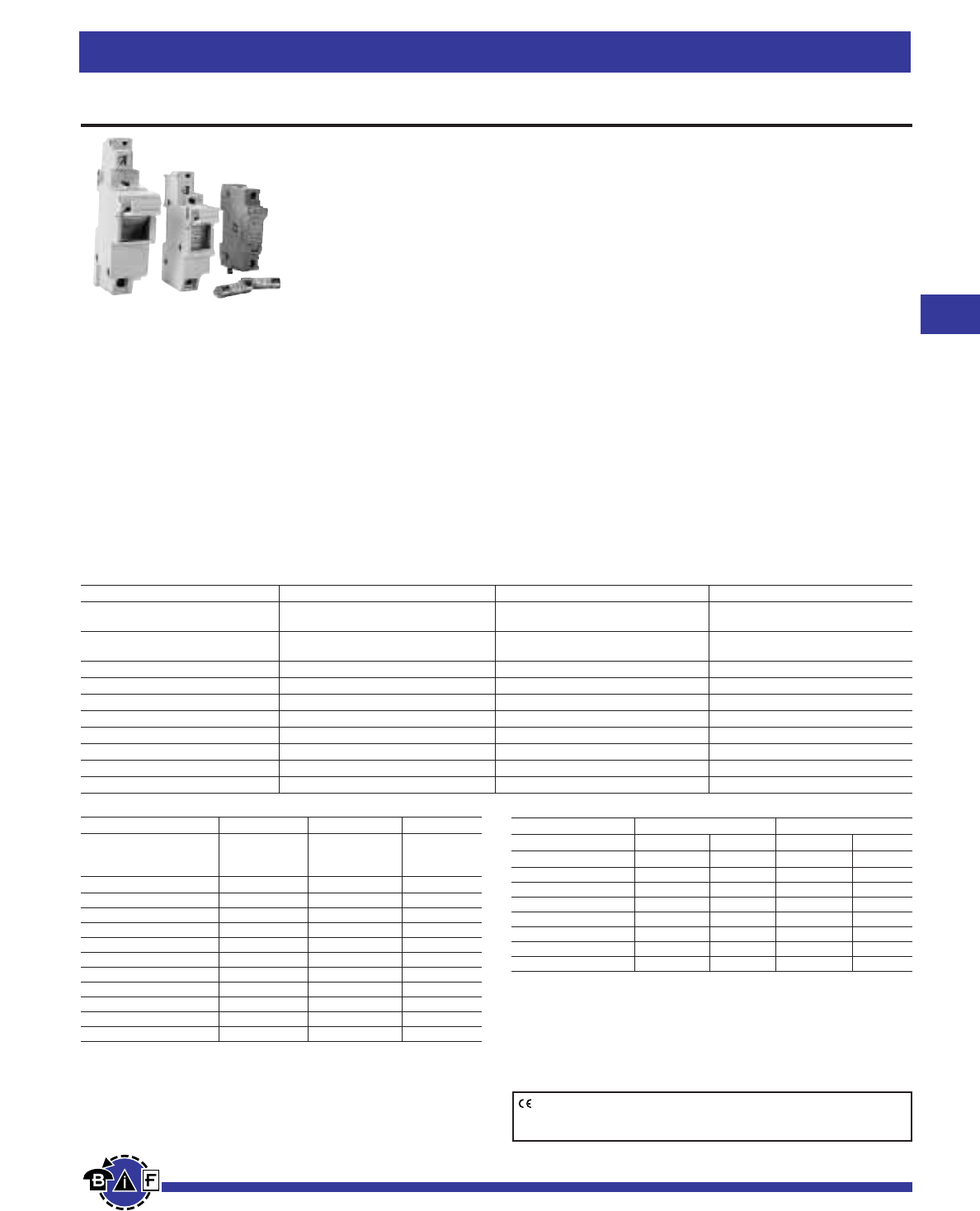
65
For complete specification data, call Bussmann Information Fax ~ 636.527.1450
Bussmann®
Fuseblocks, Holders and Terminal Blocks
Data Sheet: 1151
Modular Fuseholders
CE logo denotes compliance with European Union Low Voltage Directive
(50-1000Vac, 75-1500Vdc). Refer to Data Sheet: 8002 or contact
Bussmann Application Engineering at 636-527-1270 for more information.
Specifications
Fuse Size (mm) 10 ≈ 38 14 ≈ 51 22 ≈ 58
Voltage UL/CSA 600V 750V*** 750V***
IEC 690V 660V 660V
Amperage UL/CSA 30A 30A*** 50A***
IEC 32A (See Watts Loss) 50A (See Watts Loss) 125A (See Watts Loss)
Wire Size #8 - #18 CU only #6 - #14 CU only #1 - #14 CU only
Wire Type (& Temp.) Solid/Stranded (75°) Solid/Stranded (75°) Solid/Stranded (75°)
Torque (in-lbs) 12 in-lbs 17.7 in-lbs 22.1 in-lbs
IP Rating IP 20 IP 20 IP 20
Contact Material (fuseclip) Tin-plated copper Tin-plated copper Tin-plated copper
Connector Material Steel Steel Steel
Maximum Watts Loss of Fuse 3W‡ 5W‡ 9.5W‡
Dual Wire Rating Please consult factory
10 ≈ 38 30A, 600V 30A, 600V 32A, 690V
North American North American European
Class CC Midget 10 ≈38
Description Fuseholder Fuseholder Fuseholder
1 Pole CHCC1 CHM1 CH101
1 Pole w/Indication CHCC1ICHM1ICH101I
2 Pole CHCC2 CHM2 CH102
2 Pole w/Indication CHCC2ICHM2ICH102I
3 Pole CHCC3 CHM3 CH103
3 Pole w/Indication CHCC3ICHM3ICH103I
*Assembly Pins - 2 Poles CH102AP CH102AP CH102AP
*Assembly Pins - 3 Poles CH103AP CH103AP CH103AP
**Circuit markers CH10CM CH10CM CH10CM
**Circuit marker labels CH10CL CH10CL CH10CL
Spare Fuseholder 5TPH 5TPH 5TPH
‡Refer to Data Sheets 720003, 720008, 720025 and 720028 for watts loss of
applicable fuses.
*CH102AP and CH103AP are packaged in quantities of ten pins. One pin is required to
gang units together, and rating multiple poles.
**CH10CM are packaged in quantities of ten. CH10CL are packaged in quantities of ten
sheets of labels.
***UL/CSA part numbers include U.L. suffix. (i.e. -14x51 with UL rating is CH141GUL for
a single pole device)
14 ≈ 51 22 ≈ 58
Description Part No. Ctn. Qty. Part No. Ctn. Qty.
1 Pole CH141G 6 CH221G 6
1 Pole w/UL markings CH141GUL 6 CH221GUL 6
1 Pole w/microswitch CH141MSG 6 CH221MSG 6
2 Pole CH142G 3 CH222G 3
3 Pole CH143G 2 CH223G 2
3 Pole w/microswitch CH143MSG 2 CH223MSG 2
Handle Profile - 2 Poles CH142HCG 10 CH222HCG 10
Handle Profile - 3 Poles CH143HCG 10 CH223HCG 10
CH Series
Features:
• 10 ≈38 Dovetail design provides maximum flexibility in
assembling multiple poles
• Touchsafe design - No exposed contacts
• DIN rail mount (35mm)
• Optional open fuse indication lights
• Excellent for switchboard panel, control consoles, small
motors, transformers, and similar applications
• Handle/fusepuller to install and remove fuses easily
• Available in single and multi-pole configurations
• Circuit marking system (P/N CH10CL and CH10CM)
• Wire ready: Saves time as terminals are ready to accept wires.
• CE marking
Standards:
North American Class CC
Listed UL 512, Guide IZLT, File E14853
Certified CSA Std. C22.2 No. 39, Class 6225-01, File LR47235
North American Midget
⁄‹Ω£™
∑ x 1
⁄Ω™
∑
UL Recognized 512, Guide IZLT2, File E14853
CSA Certified, Std. C22.2 No. 39, Class 6225-01,
File LR47235
European 10 ≈ 38 IEC 269-2-1
14 ≈ 51 IEC 269-2
UL Recognized, CSA Certified***
22 ≈ 58 IEC 269-2
UL Recognized, CSA Certified***
Recommended Buss®Fuse Types:
North American Class CC Fuses - LP-CC, FNQ-R, KTK-R
North American Midget Fuses - FNQ, KTK, AGU, KLM, BAF, BAN,
FNM, FWA, FWC, & FNQ
10 ≈38 European Fuses - C10M, C10G
14 ≈51 Fuses - FWX, FWH, FWP, NON, C14M, C14G
22 ≈58 Fuses - FWP, C22M, C22G
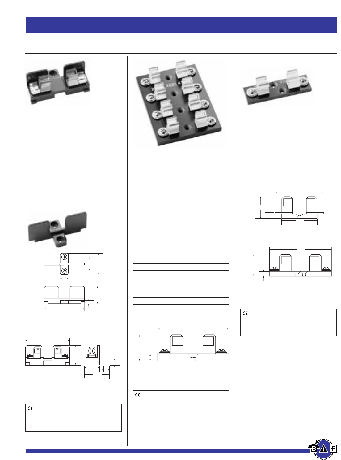
Bussmann®
66 For complete specification data, call Bussmann Information Fax ~ 636.527.1450
Fuseblocks, Holders and Terminal Blocks
Data Sheet: 2104
Cat. No. No of Base Length
Poles Inches mm
3835-1 1 ¤‡Ω£™∑ 21.4
3835-2 2 1⁄‹Ω¡§∑ 46.0
3835-3 3 2¤fiΩ£™∑ 70.6
3835-4 4 3‹Ω¢∑ 95.2
3835-5 5 4¤‹Ω£™∑ 119.9
3835-6 6 5⁄⁄Ω¡§∑ 144.5
3835-7 7 6¤⁄Ω£™∑ 169.0
3835-8 8 7fiΩ•∑ 193.7
3835-9 9 8⁄·Ω£™∑ 218.8
3835-10 10 9·Ω¡§∑ 242.9
3835-12 12 11⁄Ω™∑ 292.1
*Base width—2‹Ω¢∑ (69.9mm)
For
⁄‹Ω£™
∑≈
1⁄Ω™
∑Fuses
3743
Add-on Fuseblocks for ⁄‹Ω£™∑ ≈
1⁄Ω™∑ (10.3mm ≈38.1mm) Fuses
UL Recognized Guide IZLT2,
File E14853
Block with One Pole. Single pole
blocks lock into each other and can
be added at any time. Each has a sin-
gle end barrier. Molded phenolic base;
screw terminal; beryllium copper,
bright-dipped clips. Rated 30A, 600V.
No. 3742—End Barrier Only.
3835
Series Multiple Pole Fuseblocks
for ⁄‹Ω£™∑ ≈1⁄Ω™∑ (10.3mm ≈
38.1mm) Fuses
4421 and 4515
Single Pole Fuseblocks for ⁄‹Ω£™∑
≈ 1⁄Ω™∑ (10.3mm ≈38.1mm) Fuses
Electrical Ratings: 30A, 250Vac
(or less)
No. 3723—Marking Strip. Length is
9‹Ω•∑ (23.8cm). Block and end barrier.
Silver-plated, beryllium copper clips.
Rated 30A, 250V. No side barriers.
Screw terminals. Phenolic base.
No. 4421—Solder Terminals. Base
width fiΩ•∑ (15.9mm).
No. 4515—Screw Terminals. Base
width ‹Ω¢∑ (19mm).
Note—Mounting screw hole diameter is 0.147∑
(3.7mm). Countersink, 0.312∑(7.9mm). Max.
Mounting Screw No. 6.
Note—Mounting screw hole diameter is 0.148∑
(3.7mm). Countersink, 0.313∑(7.9mm). Max.
Mounting Screw No. 6.
Note—Mounting screw hole diameter is
0.147∑(3.7mm). Counterbore diameter,
0.636∑(8.0mm) Max. Mounting Screw No. 6.
B U S S 3 7 4 2
0.25"
2.56"
1.125"
1.29"0.84"
0.500"
1.125"
(28.6mm)
2.56"
(65.1mm)
0.78"
(19.8mm)
1.34"
(34.1mm)
0.25"
(6.4mm)
0.323"
(8.2mm)
0.144"
2.75"
(69.9mm)
0.25"
(6.4mm)
1.0"
(25.4mm)
0.19"
(4.8mm)
0.897"
(22.78mm)
2.5"
(63.5mm)
1.63"
(41.3mm)
2.56"
(65.1mm)
0.19"
(4.8mm)
0.897"
(22.78mm)
CE logo denotes compliance with European
Union Low Voltage Directive (50-1000Vac,
75-1500Vdc). Refer to Data Sheet: 8002 or
contact Bussmann Application Engineering at
636-527-1270 for more information.
CE logo denotes compliance with European
Union Low Voltage Directive (50-1000Vac,
75-1500Vdc). Refer to Data Sheet: 8002 or
contact Bussmann Application Engineering at
636-527-1270 for more information.
CE logo denotes compliance with European
Union Low Voltage Directive (50-1000Vac,
75-1500Vdc). Refer to Data Sheet: 8002 or
contact Bussmann Application Engineering at
636-527-1270 for more information.
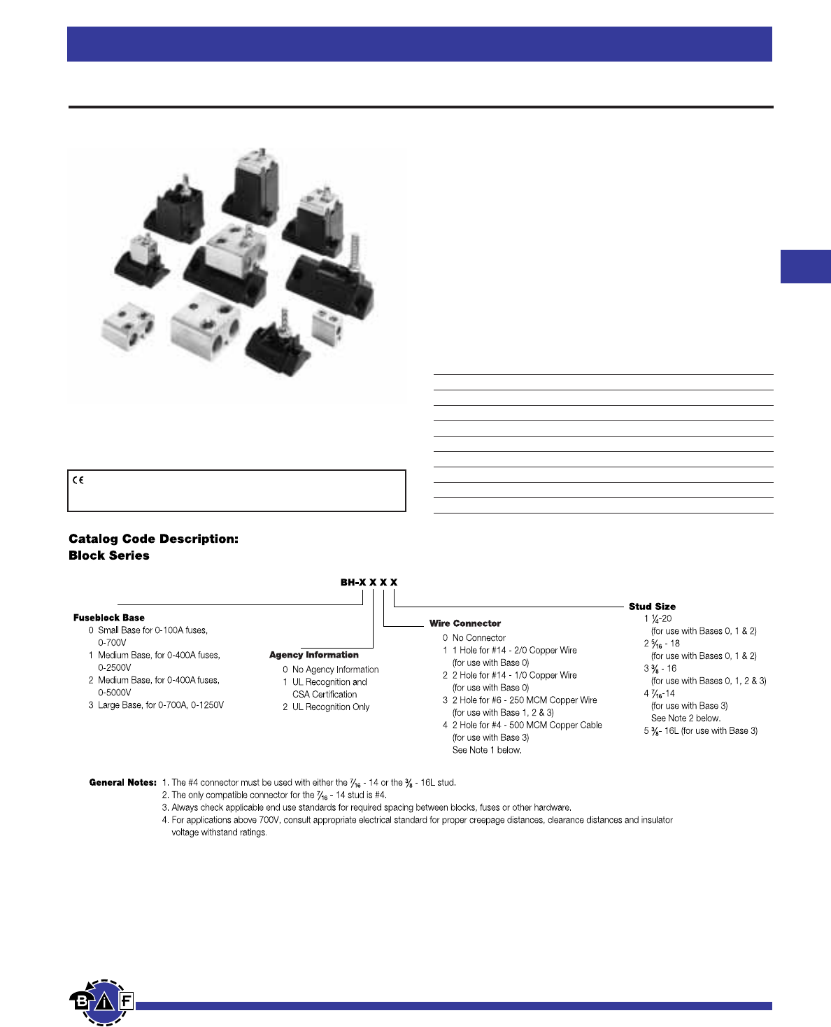
Bussmann®
67
For complete specification data, call Bussmann Information Fax ~ 636.527.1450
Fuseblocks, Holders and Terminal Blocks
Modular Fuseblocks
Data Sheet: (BH-0) 1200; (BH-1) 1201; (BH-2) 1202; (BH-3) 1203
BH Series
For use with Bussmann semiconductor fuses.
Base: Light weight, high temperature thermoplastic
Mounting Studs: Plated steel
Nut: Plated steel
Washer: Spring steel
Agency Information:
UL Recognized, Guide EZLT2, File No. E14853 up to
700V
CSA Certified, Class 6225-01, File No. 47235 up to 700V
Withstand Rating: 200,000A RMS Sym., or interrupting
rating of the fuse used, whichever is smaller.
Available Part Numbers
BH-0001 BH-1001 BH-2001 BH-3004
BH-0002 BH-1002 BH-2002 BH-3033
BH-0003 BH-1003 BH-2003 BH-3144
BH-0111 BH-1131 BH-2031 BH-3145
BH-0112 BH-1132 BH-2032
BH-0113 BH-1133 BH-2033
BH-0121 BH-3003
BH-0122
CE logo denotes compliance with European Union Low Voltage Directive
(50-1000Vac, 75-1500Vdc). Refer to Data Sheet: 8002 or contact
Bussmann Application Engineering at 636-527-1270 for more information.
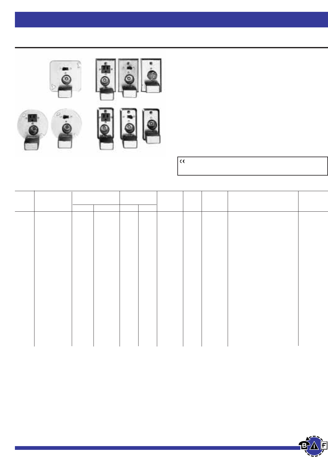
Bussmann®
68 For complete specification data, call Bussmann Information Fax ~ 636.527.1450
Fuseblocks, Holders and Terminal Blocks
Selection Data - Plug Fuse Box Cover Units
Box Receptacle Motor Agency4
Cover Fuseholder Outlet to Load Switch Switch Size Listing/
Cat. No. Type Box Single Double 125V 250V Control1Light2(Max.) General Data Certification
SOU X ‹Ω¢ HP 125V, 15A UL, CSA
_________ _______________________________________________________________________________________________________________________
SRU 2⁄Ω¢∑ Handy X X ⁄Ω™ HP 125V, 15A UL
_________ _______________________________________________________________________________________________________________________
SSU5XX⁄Ω™ HP 125Vac, (do not use on dc), 15A UL, CSA
__________________________________________________________________________________________________________________________________________________
SOW X ‹Ω¢ HP 125V, 15A UL, CSA
_________ _______________________________________________________________________________________________________________________
SRW 2‹Ω¢∑ Switch X X ⁄Ω™ HP 125V, 15A UL
_________ _______________________________________________________________________________________________________________________
SSW X X ⁄Ω™HP 125Vac, (do not use on dc), 15A UL, CSA
__________________________________________________________________________________________________________________________________________________
SOX X ‹Ω¢ HP 125V, 15A UL, CSA
_________ _______________________________________________________________________________________________________________________
SRX 4∑Octagon X X ⁄Ω™ HP 125V, 15A UL
_________ _______________________________________________________________________________________________________________________
SSX X X ⁄Ω™ HP 125Vac, (do not use on dc), 15A UL, CSA
__________________________________________________________________________________________________________________________________________________
SOY X ‹Ω¢ HP 125V, 15A UL, CSA
_________ _______________________________________________________________________________________________________________________
SRY X X ⁄Ω™ HP 125V, 15A UL
_________ _______________________________________________________________________________________________________________________
SSY X X ⁄Ω™ HP 125Vac, (do not use on dc), 15A UL, CSA
_________ _______________________________________________________________________________________________________________________
SSY-RL 4∑Square X X X X ⁄Ω™ HP 125Vac, (do not use on dc), 15A —
_________ _______________________________________________________________________________________________________________________
STY3XX⁄Ω™ HP 125Vac, (do not use on dc), 15A UL
_________ _______________________________________________________________________________________________________________________
SCY X X(2) ⁄Ω™ HP (2) 125Vac, (do not use on dc),
can protect two motors, 15A UL
_________ _______________________________________________________________________________________________________________________
SOY-B X ‹Ω¢ HP 125V, protects two motors, 15A UL
__________________________________________________________________________________________________________________________________________________
SKA 4⁄⁄Ω¡§∑ Square X X(15A) 2 HP 250V, 15A single phase UL
_________________________________________________________________________________________________________________________________________________
1Switch turns power to fused load OFF or ON.
2Switch light indicates power to load (dark when switch OFF or fuse open).
3Double-pole switch opens both side of circuit. STY can be used for two separate 125V motors not larger than 1/2 HP with the common switch, or a single motor not
larger than 2 HP at 250V (Maximum of 150V to ground).
4UL Guide JAMZ, File IE6491; CSA Class 6225-01, File 47235.
5Weatherproof version available, Part No. SSN.
Data Sheet: 1129
Box Cover Units for Plug Fuses
BOX COVER UNITS
SOU, SRU, SSU, SOW, SRW, SSW, SOX, SRX,
SSX, SOY, SRY, SSY, SSY-RL, SSY-L, STY, SCY,
SOY-B & SKA
• Plug-fuse Box Cover Units provide a simple inexpensive
way to protect small motors with Buss dual-element
FUSETRON Type T or FUSTAT Type S plug fuses.
• Box Cover Units are easily installed in standard electric
boxes.
• Using fuses sized at the ampere rating of a motor or
slightly larger, will provide optimum overload and short-
circuit protection.
CE logo denotes compliance with European Union Low Voltage Directive
(50-1000Vac, 75-1500Vdc). Refer to Data Sheet: 8002 or contact
Bussmann Application Engineering at 636-527-1270 for more information.
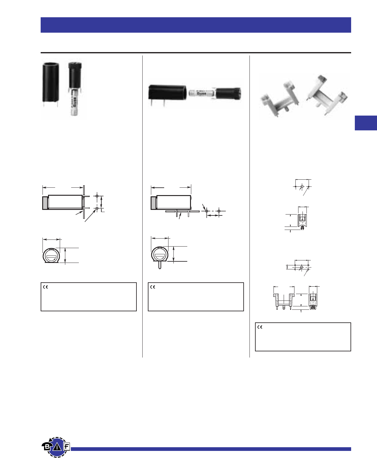
Bussmann®
69
For complete specification data, call Bussmann Information Fax ~ 636.527.1450
Fuseblocks, Holders and Terminal Blocks
Printed Circuit Board Mount for 5mm ≈20mm Fuses
Data Sheet: 2110Data Sheet: 2110Data Sheet: 2110
HTC-45M
PCB Vertical Mount
250V, 6.3A, 2.5W
Bayonet Cap/Carrier
See specifications below
HTC-50M
PCB Horizontal Mount
250V, 6.3A, 2.5W
Bayonet Cap/Carrier
See specifications below
HTC-60M, HTC-65M
250V, 6.3A
Body Material: Valox DR48
Terminals: Phosphor bronze
F
U
S
E
.461"
(11.7mm)
1.303"
(33.1mm)
.512"
(13.0mm)
Printed Circuit
Board
.394"
(10.0mm)
Mounting Holes
.051" + .002" Dia. (Typ.)
_
(1.30 + .05mm)
_
.197"
(5.0mm)
.102" Dia. Hole
(2.6mm) .051" Dia. Hole
(1.3mm)
.591"
(15.0mm)
.886"
(22.5mm)
.138"
(3.5mm)
.354"
(9.0mm)
.551"
(14.0mm)
.102" Dia. Hole
(2.6mm) .051" Dia. Hole
(1.3mm)
.591"
(15.0mm)
.138"
(3.5mm)
.354"
(9.0mm)
.512"
(13.0mm)
F
U
S
E
.461"
(11.7mm)
1.303"
(33.1mm)
.512"
(13.0mm)
Printed Circuit
Board .051" + .002" Dia. (Typ.)
_
(1.30 + .05mm)
_
.394"
(10.0mm)
Mounting Holes
Specifications
Terminals: For HTC-45M, HTC-50M Tin-plated.
Molded Materials: High temperature thermoplastic that meets the flammability ratings of UL 94VO;
Glow Wire Test: 960°C per IEC 695-2-1.
Solderability: In accordance with IEC 68-2-20.
Electrical: Contact Resistance: ≤10mΩ; Insulation Resistance: ≥10mΩ; Dielectric Strength ≥2000 Vac.
Shock Safety: PC2 (fuseholders).
Agency Information:
HTC-45M, HTC-50M UL Recognized, (Guide IZLT2, File E14853; 6.3A, 250V; CSA Certified, (Class
6225-01, File 47235; 6.3A, 250V) SEMKO: (9226032; 6.3A, 250V).
Packaging: Standard Qty 10 (No Prefix), Bulk Qty 100 (Prefix Catalog Number with BK/).
HTC-60M (2 Legs)
HTC-65M (4 Legs)
CE logo denotes compliance with European
Union Low Voltage Directive (50-1000Vac,
75-1500Vdc). Refer to Data Sheet: 8002 or
contact Bussmann Application Engineering
at 636-527-1270 for more information.
CE logo denotes compliance with European
Union Low Voltage Directive (50-1000Vac,
75-1500Vdc). Refer to Data Sheet: 8002 or
contact Bussmann Application Engineering
at 636-527-1270 for more information.
CE logo denotes compliance with European
Union Low Voltage Directive (50-1000Vac,
75-1500Vdc). Refer to Data Sheet: 8002 or
contact Bussmann Application Engineering
at 636-527-1270 for more information.
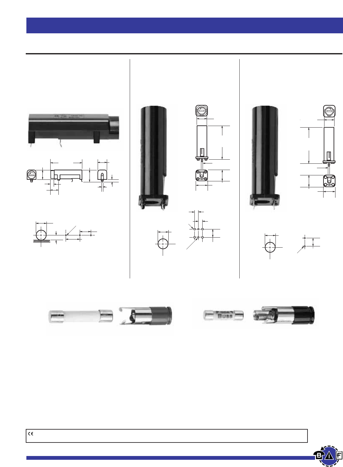
Bussmann®
70 For complete specification data, call Bussmann Information Fax ~ 636.527.1450
Fuseblocks, Holders and Terminal Blocks
Specifications
Electrical Ratings: UL — 16A @ 250V; CSA — 12A @ 250V; VDE — 6.3A @ 250V; SEMKO — 10A @ 250V
Insulation resistance — 10,000 megohm at 500Vdc. Contact resistance — less than 0.005 ohms
@ 20mV. Dielectric strength — over 200V/mil.
Molded Material: High dielectric molded phenolic with a UL 94VO flammability rating.
Fuse Carrier & Knob: Spring-loaded, bayonet type. Tin plated brass. Screwdriver slotted.
Mounting: “Kicked” terminals (all models) and stabilizer pins on HBV model for increased stability.
Environmental: Maximum operating temperature — (-40°C to +85°C).
Agency Information: UL Recognized — Guide IZLT2, File EI4853;
CSA Certified — Class 6225-01, File 47235
VDE — 41421
SEMKO — 9308147 (HBH, HBV) 9222106 (HBW)
0.200"
(5.0mm)
0.200"
(5.0mm)
0.100" Dia. 4 Holes
(2.54mm)
Panel PC Board
0.531"
(13.5mm)
0.400"
(10.0mm)
0.050" Dia. 2 Holes
(1.3mm)
PC Board Mount for 5mm
≈
20mm and ⁄Ω¢∑
≈
1⁄Ω¢∑ Fuses
Data Sheet: 2118Data Sheet: 2118Data Sheet: 2118
HBH-I (for ⁄Ω¢∑ ≈ 1⁄Ω¢∑ fuses)
HBH-M (for 5mm ≈ 20mm fuses)
Horizontal Mount
HBV-I (for ⁄Ω¢∑ ≈ 1⁄Ω¢∑ fuses)
HBV-M (for 5mm ≈ 20mm fuses)
Vertical Mount with
Stability Pins
HBW-I (for ⁄Ω¢∑ ≈ 1⁄Ω¢∑ fuses)
HBW-M (for 5mm ≈20mm fuses)
Vertical Mount without
Stability Pins
Panel PC Board
0.531"
(13.5mm)
0.400"
(10.0mm)
0.050"
Dia. 2 Holes
(1.3mm)
HBV
0.510"
(13.0mm
)
1.855"
(47.0mm
)
0.040"
(1.05mm
)
0.580"
(14.9mm
)
HBW
0.510"
(13.0mm)
1.855"
(47.0mm)
0.040"
(1.05mm)
0.580"
(14.9mm)
0.469"
(12.0mm)
0.250"
(6.4mm)
Panel
0.700"
(17.8mm)
0.600"
(15.2mm)
0.050" Dia. 3 Holes
(1.3mm)
PC Board
Fuseholder Caps (Fit all three shown above)
0.437"
(11.1mm)
0.197"
(5.0mm)
0.244"
(6.2mm)
1.77"
(45.0mm)
0.480"
(12.2mm) 0.490"
(12.4mm)
0.040"
(1.0mm) 0.140"
(3.5mm)
CE logo denotes compliance with European Union Low Voltage Directive (50-1000Vac, 75-1500Vdc). Refer to Data Sheet: 8002 or contact
Bussmann Application Engineering at 636-527-1270 for more information.
FBI FBM
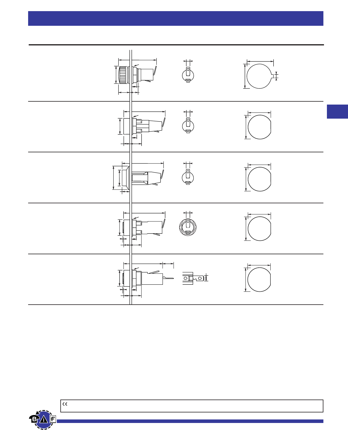
Bussmann®
71
For complete specification data, call Bussmann Information Fax ~ 636.527.1450
Fuseblocks, Holders and Terminal Blocks
Panel Mounted for 5mm ≈20mm Fuses
3.0x0.51mm
34.2mm
6.8mm
4mm
Ø16mm
Ø16mm 3.0x0.51mm 14.00mm
1.8mm
13.0mm
12.00mm+0.0
–0.1
12.70mm+0.0
–0.1
12.00mm+0.0
–0.1
12.70mm+0.0
–0.1
12.00mm+0.0
–0.1
12.70mm+0.0
–0.1
12.00mm+0.0
–0.1
12.70mm+0.0
–0.1
3.0x0.51mm
3.0x0.51mm
4.8x0.51mm
11mm
37.5mm
4mm
Ø15mm
Ø16mm
11mm
5.5mm
Ø22mm
6.5mm
Ø15mm
37.5mm
36mm
4mm
Ø15mm
Ø16mm
11mm
5.5mm
0.5mm
35.5mm
4mm
Ø15mm
Ø16mm
11mm
5.5mm
0.5mm
10.2mm
HTC-30M
Ratings: 250V, 6.3A, 2.5W
Screwdriver slot
HTC-35M
Ratings: 250V, 6.3A, 2.5W
Threaded cap
HTC-40M
Ratings: 250V, 6.3A, 2.5W
Screwdriver slot
HTC-55M
Ratings: 250V, 6.3A, 2.5W
Fuse carrier: bayonet type
Data Sheet: 2110
Data Sheet: 2110
Data Sheet: 2110
Data Sheet: 2110
Data Sheet: 2110
HTC-70M
Ratings: 250V, 10A, 2.5W
Fuse carrier: bayonet type
Specifications
Terminals: Brass, tin-plated.
Molded Materials: High temperature thermoplastic that meets the flammability ratings of UL 94VO; Glow Wire Test: 960°C
per IEC 695-2-1.
Solderability: In accordance with IEC 68-2-20.
Agency Information:
UL Recognized — Guide IZLT2, File E14853;
CSA Certified — Class 6225-01, File 47235;
SEMKO — 9226031 (HTC-30M, HTC-35M); 9226032 (HTC-40M); 9226033 (HTC-55M); 9226034
(HTC-70M)
Electrical: Contact Resistance: ≤10mΩ; Insulation Resistance: ≥10mΩ; Dielectric Strength ≥2000 Vac.
Shock Safety: PC2 (fuseholders).
Packaging: Standard Qty 10 (No Prefix), Bulk Qty 100 (Prefix Catalog Number with BK/).
CE logo denotes compliance with European Union Low Voltage Directive (50-1000Vac, 75-1500Vdc). Refer to Data Sheet: 8002 or contact
Bussmann Application Engineering at 636-527-1270 for more information.
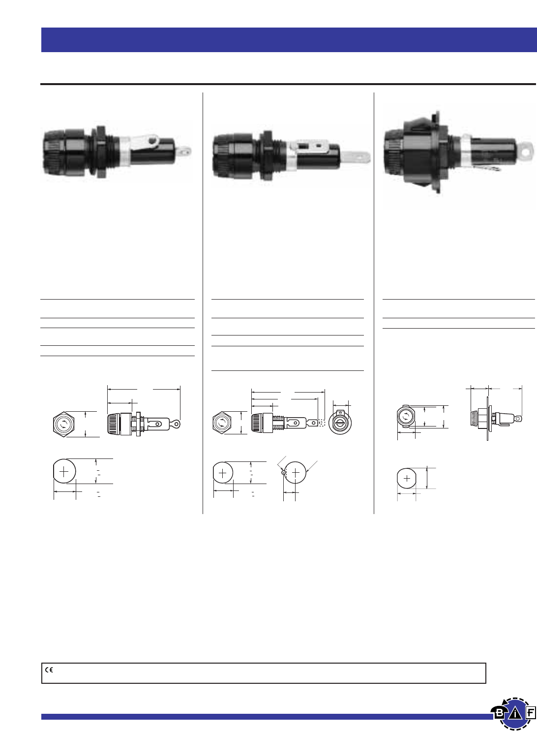
Bussmann®
72 For complete specification data, call Bussmann Information Fax ~ 636.527.1450
Fuseblocks, Holders and Terminal Blocks
Panel Mounted for
⁄Ω¢
∑≈
1⁄Ω¢
∑Fuses
Data Sheet: 2106Data Sheet: 2106Data Sheet: 2106
HKP, HKP-L, HKP-W
Standard Fuseholders
HKP-BBHH, HKP-HH
and HKP-LW-HH
Fuseholders with
⁄/¢
∑Quick-
connects
HKP-OO
Snap-Lock Fuseholders
Specifications
Terminals: Bayonet-type knob.
Vibration resistant.
For panels up to fiΩ¡§∑ (7.9mm) thick.
Agency Information: UL Recognized — Guide IZLT2, File E14853
CSA Certified — Class 6225-01, File 47235
Replacement Parts: Knob: 9435-⁄/™∑
Plastic Nut: BK/1A4287
Metal Nut: BK/1A4806-2
Washer: 9732
Electrical Ratings for HPF Series
Catalog
Symbol Amps Volts Fuse Description
HKP 30 250 —
HKP-L 30 250 HKP with 2250V stand-off
barrier.
HKP-W 30 250 HKP with drip-proof knob.
Electrical Ratings for HPF Series
Catalog
Symbol Amps Volts Fuse Description
HKP-BBHH 15 250 HKP with ⁄Ω¢∑ quick connects,
nut and washer assembled.
HKP-HH 15 250 HKP with ⁄Ω¢∑ quick-connect.
HKP-LW-HH 15 250 HKP with drip-proof knob,
2250V stand-off barrier and
quick-connects.
Electrical Ratings for HPF Series
Catalog
Symbol Amps Volts Fuse Description
HKP-OO 30 250 HKP with snap-lock.
0.69"
(17.5mm)
0.75"
(19.1mm)
2.31"
(58.7mm)
.473" + .005"
(12.0mm + .13mm)
.505" + .005"
(12.8mm + .13mm)
Punched Mounting Hole
F
U
S
E
F
U
S
E
F
U
S
E
0.463"
REF.
.473" + .005"
(12.0mm + .13mm)
.505" + .005"
(12.8mm + .13mm)
Punched Mounting Hole
0.27"
0.5" DRILL
#41 DRILL
Drilled Mounting Hole
0.69"
2.64"
2.44"
WHEN FUSE IS INSERTED
0.69"
.800"
(20.3mm)
Punched Mounting Hole
.811"
(20.6mm)
.890"
(22.6mm)
1.56"
(39.7mm)
.75"
(19.1mm)
.855"
(21.7mm) 1.17"
F
U
S
E
F
U
S
E
F
U
S
E
CE logo denotes compliance with European Union Low Voltage Directive (50-1000Vac, 75-1500Vdc). Refer to Data Sheet: 8002 or contact
Bussmann Application Engineering at 636-527-1270 for more information.
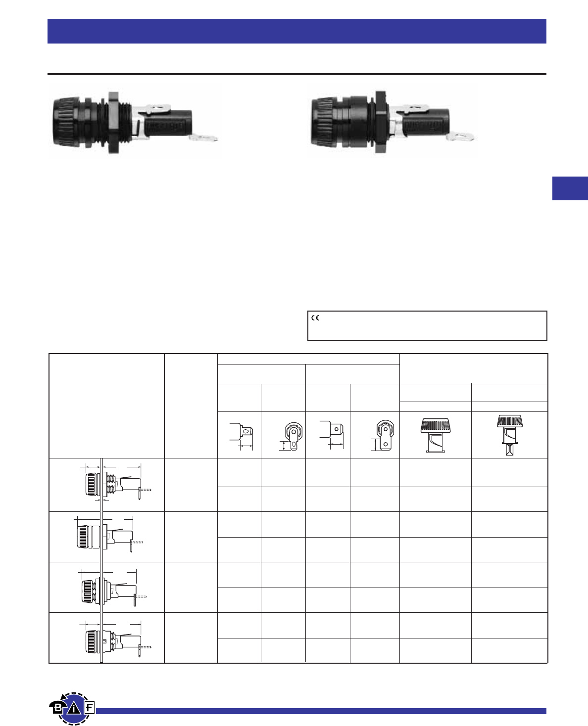
Bussmann®
73
For complete specification data, call Bussmann Information Fax ~ 636.527.1450
Fuseblocks, Holders and Terminal Blocks
Data Sheet: 2119
Panel Mounted for 5mm ≈20mm and ⁄Ω¢∑ ≈ 1⁄Ω¢∑ Fuses
HTB-8
HTB-6
HTB-2
HTB-4
Dimensional Data
Terminal Options
Knob Type Carrier Solder/ Carrier Options
‹Ω¡§∑ Quick-Connect ⁄Ω¢∑ Quick-Connect
⁄Ω¢∑ x 1⁄Ω¢∑ 5mm x 20mm
In-Line Rt. Angle In-Line Rt. Angle (“I” Equals Inches) (“M” Equals Metric)
Common Dimensional Data: Knob Knob
Length (Knob Type) - 1.69∑
(42.9mm) Plus In-Line Terminal
(Screwdriver Slotted)
1.75∑(44.5mm)
NOTE: Plus In-Line Terminal
HTB-22I HTB-24I HTB-26I HTB-28I ✓—
HTB-22M HTB-24M HTB-26M HTB-28M —✓
HTB-42I HTB-44I HTB-46I HTB-48I ✓—
HTB-42M HTB-44M HTB-46M HTB-48M —✓
HTB-62I HTB-64I HTB-66I HTB-68I ✓—
HTB-62M HTB-64M HTB-66M HTB-68M —✓
HTB-82I HTB-84I HTB-86I HTB-88I ✓—
HTB-82M HTB-84M HTB-86M HTB-88M —✓
1.125"
(28.6mm)
0.47"
(11.9mm)
0.09" NOM.
(2.4mm)
1.125"
(28.6mm)
0.47"
(11.9mm)
0.92"
(23.4mm)
0.67"
(17.1mm)
0.91"
(23.0mm)
0.69"
(17.5mm)
HTB Series
Fuseholders with Knob-Type Carriers
Agency Information:
UL Recognized — Guide IZLT2, File E14853
20A (‹Ω¡§quick-connect 15A) @ 250V
CSA — 16A @ 250V Class 6225-01 File 47235;
VDE* — 6.3A @ 250V, 49890
SEMKO* — 6.3A @ 250V, 8945092, 9005230
*Screwdriver slot carrier only
Electrical Data: Insulation resistance (per IEC #257) —
10,000 ohms @ 500Vdc; contact resistance (per IEC #257) —
0.005 ohms max. @ 1A; standoff voltage (per IEC #257) —
480V/Mil @ .125 in. thickness.
Environmental: Maximum operating temperature
-55°C to 85°C.
Molded Components: High temperature, flame retardant,
thermoplastic; UL Component Recognized; 94VO; mounting
nut, spacer-black polycarbonate.
Terminals: Tin-plated brass.
Mounting: Withstands 15 to 20 lbs-ins torque to mounting
nut when mounting fuseholder to panel. Maximum panel
thickness 0.300 inches.
0.34"
(8.7mm)
0.33"
(8.3mm)
0.47"
(11.9mm)
0.45"
(11.5mm)
Fuseholders and fuse carriers may be ordered separately.
0.30∑
7.62mm
0.125∑
3.18mm
0.30∑
7.62mm
0.125∑
3.18mm
Maximum
Panel
Thickness
Low Profile
Rear Hex Nut
High
Profile
Rear Hex Nut
Front
Hex Nut
Low Profile
Snap-In
CE logo denotes compliance with European Union Low Voltage Directive
(50-1000Vac, 75-1500Vdc). Refer to Data Sheet: 8002 or contact
Bussmann Application Engineering at 636-527-1270 for more information.
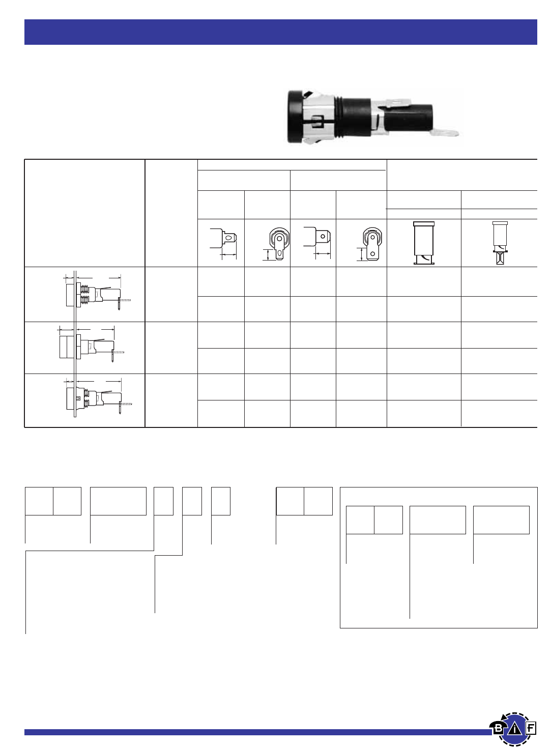
Bussmann®
74
Fuseblocks, Holders and Terminal Blocks
For complete specification data, call Bussmann Information Fax ~ 636.527.1450
HTB-3
HTB-5
HTB-9
0.17"
(4.37mm)
1.58"
(40.03mm)
0.17"
(4.37mm)
1.59"
(40.08mm)
0.41"
(10.31mm)
1.34"
(34.13mm)
0.34"
(8.7mm)
0.33"
(8.3mm)
0.47"
(11.9mm)
0.45"
(11.5mm)
HTB Series
Fuseholders with Screwdriver Slotted Carriers
S
Packing
(Blank) – Std.
BK/ – Bulk
Rear Terminal Configuration
2 — Solder / ‹Ω¡§∑ Quick-Connect
Solder / ‹Ω¡§∑ Quick-Connect
(In-Line)
4 —
(Right Angle)
6 — ⁄Ω¢∑ Quick-Connect (In-Line)
8 — ⁄Ω¢∑ Quick-Connect (Right Angle)
Fuse Carrier
I — ⁄Ω¢∑ x 1-1⁄Ω¢∑
M — 5mm x 20mm
Splash Proof
(Optional on -2,
-4, -6, and -8)
Body Configuration and Mounting
Finger Grip Holders
2 — Low Profile (Rear Panel Hex-Nut)
4 — High Profile
*6 — (Front Panel Hex-Nut)
8 — Low Profile (Snap-In)
Screwdriver Slotted Holders
3 — Low Profile
5 — High Profile
9 — Low Profile (Snap-In)
Product
Symbol
HTB-
Packaging
(Blank) – Std.
BK/ – Bulk
Fuse Carrier
I — ⁄Ω¢∑ x 1⁄Ω¢∑
M — 5mm x 20mm
Product
Symbol
FT — Knob Type
(For 20, 40, 60,
and 80 Series
Only)
ST — Screwdriver
Slotted (For 30,
50, and 90 Series
Only)
P
*Profile varies with panel thickness. Holder installs thru rear of panel.
FUSE CARRIER ONLY
Ordering Information
Dimensional Data
Terminal Options
Knob Type Carrier Solder/ Carrier Options
‹Ω¡§∑ Quick-Connect ⁄Ω¢∑ Quick-Connect
⁄Ω¢∑ ≈ 1⁄Ω¢∑ 5mm ≈20mm
In-Line Rt. Angle In-Line Rt. Angle (“I” Equals Inches) (“M” Equals Metric)
Common Dimensional Data: Screwdriver Screwdriver
Length (Knob Type) - 1.69∑
(42.9mm) Plus In-Line Terminal
(Screwdriver Slotted)
1.75∑(44.5mm)
NOTE: Plus In-Line Terminal
HTB-32I HTB-34I HTB-36I HTB-38I ✓—
HTB-32M HTB-34M HTB-36M HTB-38M —✓
HTB-52I HTB-54I HTB-56I HTB-58I ✓—
HTB-52M HTB-54M HTB-56M HTB-58M —✓
HTB-92I HTB-94I HTB-96I HTB-98I ✓—
HTB-92M HTB-94M HTB-96M HTB-98M —✓
Fuseholders and fuse carriers may be ordered separately.
0.30∑
7.62mm
0.125∑
3.18mm
0.125∑
3.18mm
Maximum
Panel
Thickness
Low Profile
Rear Hex Nut
High Profile
Rear Hex Nut
Low-Profile
Snap-In
Data Sheet: 2119
Panel Mounted for 5mm ≈20mm and ⁄Ω¢∑ ≈ 1⁄Ω¢∑ Fuses
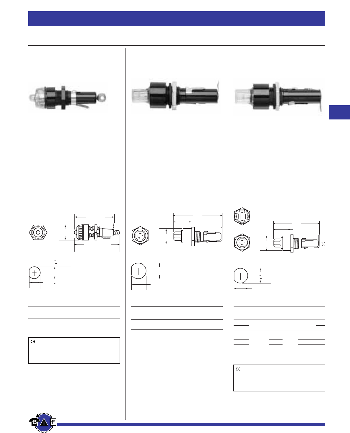
Bussmann®
75
For complete specification data, call Bussmann Information Fax ~ 636.527.1450
Fuseblocks, Holders and Terminal Blocks
Data Sheet: 2105Data Sheet: 2121Data Sheet: 2120
Panel-Mounted for Indicating Type Fuses
HLD
Pin Indicating
for ⁄Ω¢∑ ≈ 1⁄Ω¢∑ Fuses
Voltage Rating: 250V, 15A
Agency Information:
UL Recognized, (File E14853,
Guide IZLT2)
HJL
Lamp Indicating
for
⁄Ω¢
∑ ≈ 1∑ Fuses
Voltage Rating: 250V, 15A
No Agency Information
Electrical Ratings
Lamp Knob
Symbol Amps Volts Type Color Type
90 to
HJL 15 250 Neon Clear Oct
Use w/AGX, MKB Fuses
For panels up to ⁄Ω•∑thick.
Electrical Ratings
Lamp Knob
Symbol Amps Volts Type Color Type
Electrical Ratings
Symbol Amps Volts Features
HLD 15 250 Solder terminals
HLD-HH 15 250 ⁄Ω¢∑ quick-connect terminals
Use w/GBA, GLD Fuses
Octagonal Sides
.505" + .005"
(16.0mm + .13mm)
.473" + .005"
(12.0mm + .13mm)
Punched Mounting Hole
0.69"
(17.5mm)
2.5" (HLD)
(63.5mm)
2.75" (HLD-HH)
(69.9mm)
.630" + .005"
(16.0mm + .13mm)
.590" + .003"
(14.6mm + .08mm)
Punched Mounting Hole
Octagonal Sides
0.81"
(20.6mm)
1.19"
(30.2mm)
2.81"
(71.4mm)
.630" + .005"
(16.0mm + .13mm)
.573" + .003"
(14.6mm + .08mm)
Punched Mounting Hole
Octagonal Sides
0.81"
(20.6mm)
1.19"
(30.2mm)
2.81"
(71.4mm)
Flat-Sides
HK Series
Lamp Indicating
for
⁄Ω¢
∑ ≈ 1⁄Ω¢∑ Fuses
Voltage Rating: 250V, 15A or 20A
Agency Information:
UL Recognized, (Guide IZLT2,
File E14853)
CSA Certified (Class 6225-01,
File 47235)
HKL* 15
HKL-X*
HKR
HKT 20
HKU
HKX
90 to 250 Neon
22 to 30 **
13 to 22 **
4 to 6 **
22 to 33 **
Clear Oct
FS
Amber Oct
Oct
Red Oct
Amber FS
* UL Recognized and CSA Certified
** Incandescent
CE logo denotes compliance with European
Union Low Voltage Directive (50-1000Vac,
75-1500Vdc). Refer to Data Sheet: 8002 or
contact Bussmann Application Engineering
at 636-527-1270 for more information.
CE logo denotes compliance with European
Union Low Voltage Directive (50-1000Vac,
75-1500Vdc). Refer to Data Sheet: 8002 or
contact Bussmann Application Engineering
at 636-527-1270 for more information.
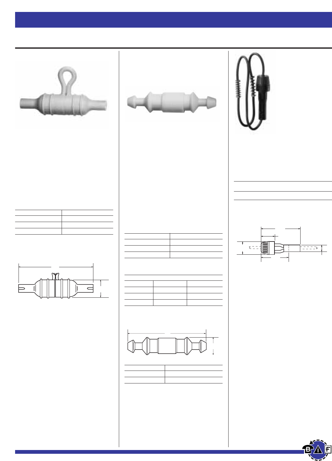
Data Sheet: 2111Data Sheet: 2103Data Sheet: 2102
In-Line Fuseholders for
⁄Ω¢
∑≈
‡Ω•
∑to 1
⁄Ω¢
∑Fuses
HFB
Waterproof In-Line Fuseholder
for ⁄Ω¢∑ ≈ 1⁄Ω¢∑ Fuses
Voltage Rating: 32V, 30A
Construction:
Body - Thermoplastic rubber;
Contacts - Copper tin plated
HHB
Universal In-Line Fuseholder
for ⁄Ω¢∑ ≈ ‡Ω•∑,1∑ and 1⁄Ω¢∑ Fuses
Voltage Rating: 32V, 30A
Construction:
Body - Nylon;
Contacts - Copper tin plated
Pull Force: 5 lbs. minimum to sepa-
rate fuseholder housing with fuse
installed.
UL Flammability Rating: 94 V2
HRK
Universal In-Line Fuseholder
for ⁄Ω¢∑ ≈ ‡Ω•∑ to 1⁄Ω¢∑ Fuses
Voltage Rating: 32V, 15A
Electrical Ratings
Catalog
Fuse
Symbol Amps Volts Description
HRK 15 32 ⁄Ω¢∑ diameter fuses
of different lengths.
Dimensional Data
0.75"
(19.1mm)
3"
(76.2mm)
Catalog Numbers
Description Catalog Number
Standard Pack (10-in) HFB
Bulk Pack (20-in) BK/HFB
Replacement Contact Clip BK/1A2294
Dimensional Data
Catalog Numbers
Holder (Without Leads)
Description Catalog Number
Standard Pack (10-in) HHB
Bulk Pack (100-in) BK/HHB
Holder With Pre-attached Lead
Wires
(#14 Insulated)
Wire Color 19∑Length 8∑Length
Yellow BK/HHB-Y419 BK/HHB-Y408
Red BK/HHB-R419 BK/HHB-R408
Black BK/HHB-B419 BK/HHB-B408
Dimensional Data
L
0.53"
(13.5mm)
Fuse Length Fuseholder Length “L”
‡Ω•∑ (AGW) 2.100 Max.
1∑ (AGX) 2.250 Max.
1⁄Ω¢∑ (AGC, MDL) 2.420 Max.
• Accepts #12 to #16 wire leads (not
provided with basic fuseholder).
• See Data Sheet for recommended
crimp tools.
0.75"
(19.1mm)
2.19"
(55.6mm)
1.56"
(39.7mm)
0.69"
(17.5mm)
0.38"
(9.5mm)
• Three springs furnished with fuse-
holder afford acceptance of ⁄Ω¢∑ fuses
of different lengths.
• Wire leads are staked and soldered to
the contacts of the fuseholder.
• Leads are 8∑(203mm) long.
• Wire size - #14.
• Ideal for harsh environments:
• –40°to 150°temp. range
• Withstands many organic solvents
and rigorous shock and vibration.
• Accepts #12 to #18 wire leads
(not provided).
• Simple assembly.
• One-piece molded thermo-plastic.
• High visibility yellow color for easy
identification in dark or hard-to-
access locations.
• Important information molded into
body.
• See Data Sheet for recommended
crimp tools.
Bussmann®
76 For complete specification data, call Bussmann Information Fax ~ 636.527.1450
Fuseblocks, Holders and Terminal Blocks
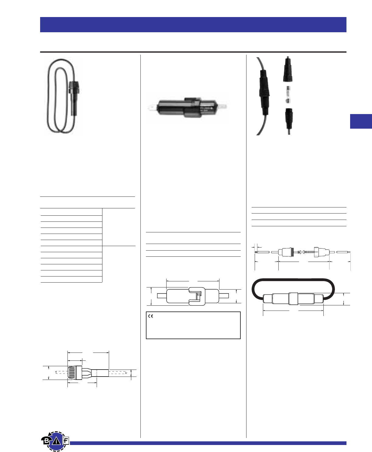
Bussmann®
77
For complete specification data, call Bussmann Information Fax ~ 636.527.1450
Fuseblocks, Holders and Terminal Blocks
Data Sheet: 2138Data Sheet: 2115Data Sheet: 2122
Electrical Ratings
Catalog Includes
Symbol Fuse Wire
Electrical Ratings
Catalog
Symbol Amps Volts Terminals
HFA 20 250 Crimp #12 - #16
HFA-HH* 20 250 ⁄Ω¢∑ Q.C.
*No UL Recognition.
In-Line Fuseholders
HR and HM Series
In-Line Fuseholders for SFE
and ⁄Ω¢∑ ≈ Various Length
Fuses
Voltage Rating: 32V, 20A
No agency listings.
HFA Series
In-Line Waterproof Fuseholders
for ⁄Ω¢∑ ≈ 1⁄Ω¢∑ Fuses
Construction:
Body - Phenolic;
Contacts - Copper crimp leads
Voltage Rating: 250V, 20A
Agency Information:
UL Recognized, (Guide IZLT2,
File E14853)
UL Flammability Rating: 94VO
HHT Series
In-Line Fuseholders
for 5 x 15mm or 5 x 20mm
Fuses
Construction:
Body - Black Thermoplastic
Contacts - Brass
Wire - 16 awg, red
Electrical Ratings
Amps Volts
5 x 15mm 5 32
5 x 20mm 10 32
HRJ* SFE-20
HRI SFE-14
HRH SFE-9
HRE SFE-7⁄Ω™
HRG SFE-6
HRF SFE-4
HMJ** SFE-20
HMI SFE-14
HMH SFE-9
HME SFE-7⁄Ω™
HMG SFE-6
HMF SFE-4
8"of #14
19"of #14
*Also available as in-line fuseholder only with lead wire contacts,
HRJ-LES-Fuse.
**Also available as in-line fuseholder only with lead wire contacts,
HMJ-LES-Fuse.
HHJ-A For ⁄Ω¢1⁄Ω¢ fuse, no wire or fuse included, accepts
#18 - #22 wire.
HHJ-B For ⁄Ω¢1⁄Ω¢ fuse, no wire or fuse included, accepts
#12 - #16 wire.
HHI-B For ⁄Ω¢1⁄Ω¡§ fuse, no wire or fuse included, accepts
#12 - #16 wire.
0.75"
(19.1mm)
2.19"
(55.6mm)
1.56"
(39.7mm)
0.69"
(17.5mm)
0.38"
(9.5mm)
Dimensional Data
2.34"
(59.5mm)
.600"
(15.2mm)
.800"
(20.3mm)
(IN ASSEMBLED POSITION)
1/4" ± 1/32"
1.84"
6-3/16" ± 1/4" 6-1/16" ± 1/4"
1.84"
0.42" DIA.
WIRE LENGTH: 13" ± 0.5"
Dimensional Data
Dimensional Data
CE logo denotes compliance with European
Union Low Voltage Directive (50-1000Vac,
75-1500Vdc). Refer to Data Sheet: 8002 or
contact Bussmann Application Engineering
at 636-527-1270 for more information.
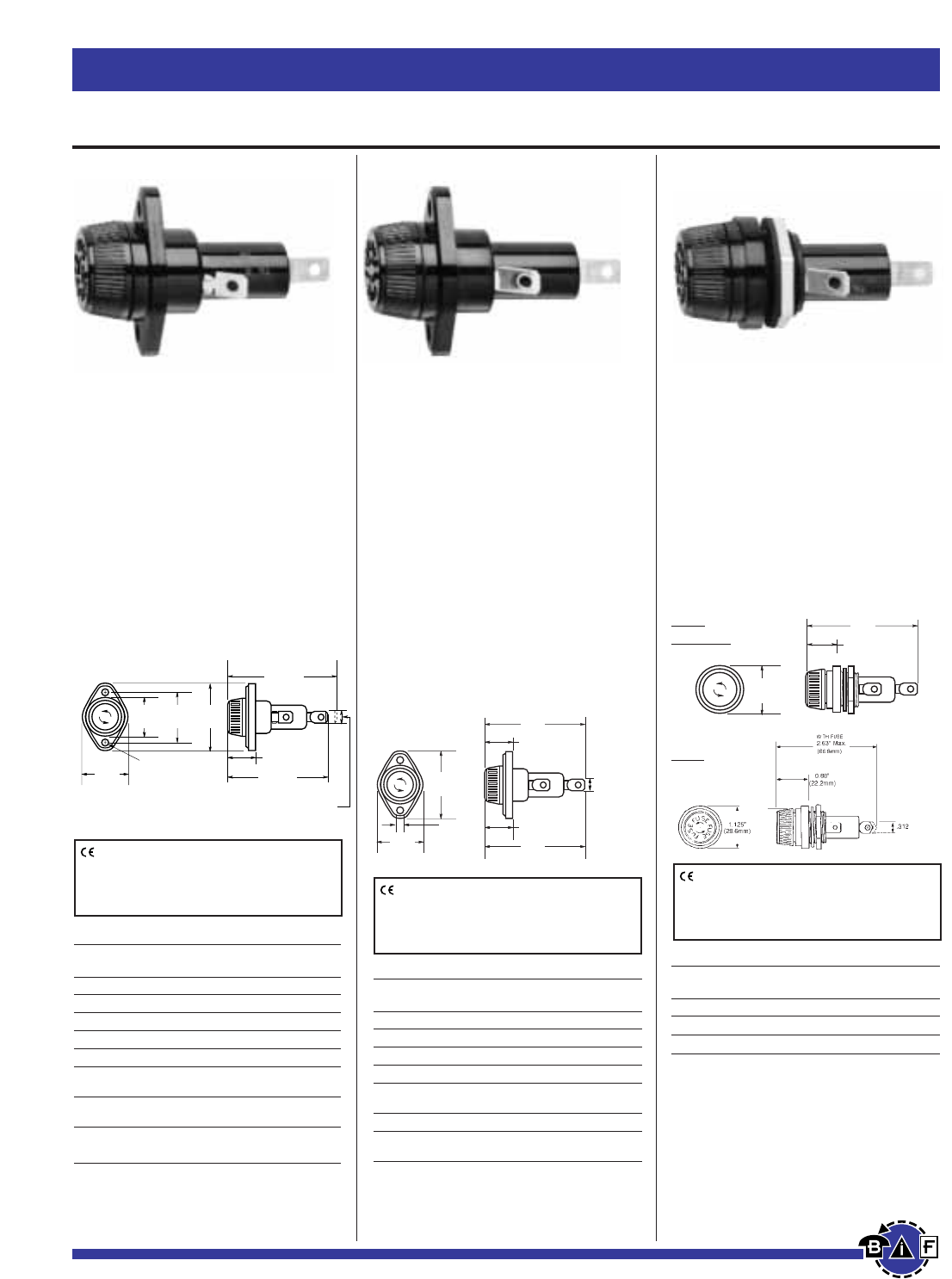
Bussmann®
78 For complete specification data, call Bussmann Information Fax ~ 636.527.1450
Fuseblocks, Holders and Terminal Blocks
Data Sheet: 2108Data Sheet: 2113Data Sheet: 2114
Panel-Mounted for
⁄‹Ω£™
∑≈
1fiΩ¡§
∑to
1⁄Ω™
∑Fuses
HPF
Standard Fuseholders with
Screw-type Knob for
⁄‹Ω£™
∑ ≈ 1fiΩ¡§∑ to 1⁄Ω™∑ Fuses
Agency Information:
UL Recognized, (Guide IZLT2, File
E14853)
CSA Certified (Class 6225-01, File
47235)
Flammability Rating: UL 94HB
•Combination ⁄Ω¢∑ quick-connect/solder
terminals.
HPG and HPD
Standard Fuseholders with
Bayonet-type Knob for
⁄‹Ω£™
∑ ≈ 1⁄Ω™∑ Fuses
Agency Information:
UL Recognized, (Guide IZLT2, File
E14853)
Flammability Rating: UL 94V0 - Fuse-
holder body
UL 94HB - Knob
Electrical Ratings
Catalog
Symbol Amps Volts Fuse Description
HPS 30
(3)(4)
600 ⁄‹Ω£™∑ 1⁄Ω™∑
HPS-L 5 600 BBS, ⁄‹Ω£™∑ 1‹Ω•∑ fuses.
HPS-EE 15 600 SC 0-15, ⁄‹Ω£™∑ 1fiΩ¡§∑ fuses.
HPS-JJ 20 600 SC 20, ⁄‹Ω£™∑ 1⁄‹Ω£™∑ fuses.
HPS-F-EE
(2)
15 600 Sleeve on body, leaded for
⁄‹Ω£™∑ 1fiΩ¡§∑ fuses.
HPS-FF
(2)
30
(3)
480 SC 25 & 30, ⁄‹Ω£™∑ 1fiΩ•∑ fuses.
HPS-RR
(2)
30
(3)
600 KTK-R, LP-CC, FNQ-R Class
CC fuses.
(1)
No UL Recognition
(2)
No CSA Certification
(3)20A max when used with quick connect terminals.
(4)HPS rated at 25V for CSA
Electrical Ratings
Catalog
Symbol Amps Volts Fuse Description
HPF 30
(3)
600 1⁄Ω™∑ (38.1mm)
HPF-C 30
(4)
600
(4)
1⁄Ω™∑ (38.1mm) clear knob.
HPF-L 5 600 BBS, ⁄‹Ω£™∑ 1‹Ω•∑ fuses.
HPF-EE 15 600 SC 0-15, ⁄‹Ω£™∑ 1fiΩ¡§∑ fuses.
HPF-JJ 20 600 SC 20, ⁄‹Ω£™∑ 1⁄‹Ω£™∑ fuses.
HPF-FF
(2)
30
(3)
480 SC 25 & 30, ⁄‹Ω£™∑ 1fiΩ•∑
fuses.
HPF-RR 30
(3)
600 KTK-R, LP-CC & FNQ-R Class
CC fuses.
HPF-WT 30
(3)
600 Splash-proof knob. ⁄‹Ω£™∑ 1⁄Ω™∑
(38.1mm)
(2)
No CSA Certification
(3)20A max when used with quick connect terminals.
(4)HPF-C ratings for CSA-15A, 250V
0.180" DIA.
(4.6mm)
1.125"
(28.6mm)
1.00"
(25.4mm)
Without Fuse
2.69" Max.
(68.3mm)
0.88"
(22.2mm)
1.78"
(45.2mm)
1.31"
(33.3mm)
2.81" Max.
(71.4mm)
With Fuse
F
U
S
E
F
U
S
E
F
U
S
E
.250" ± .003"
(6.35 ± .08mm)
(Typ.2)
0.88"
(22.2mm)
2.81"
(71.4mm)
With Fuse
Without Fuse
2.41"
(64.3mm)
0.80"
(20.2mm)
1.78"
(45.2mm)
0.180"
(4.6mm)
1.125"
(28.6mm)
.250" ± .003"
(6.35 ± .08mm)
(Typ.2)
CE logo denotes compliance with European
Union Low Voltage Directive (50-1000Vac,
75-1500Vdc). Refer to Data Sheet: 8002 or
contact Bussmann Application Engineering
at 636-527-1270 for more information.
CE logo denotes compliance with European
Union Low Voltage Directive (50-1000Vac,
75-1500Vdc). Refer to Data Sheet: 8002 or
contact Bussmann Application Engineering
at 636-527-1270 for more information.
CE logo denotes compliance with European
Union Low Voltage Directive (50-1000Vac,
75-1500Vdc). Refer to Data Sheet: 8002 or
contact Bussmann Application Engineering
at 636-527-1270 for more information.
1.125"
(28.6mm)
0.88"
(22.2mm)
2.81"
(71.4mm)
HPG
HPG-EE
HPD
Electrical Ratings
Catalog
Symbol Amps Volts Fuse Description
HPG 30(3) 600 ⁄‹Ω£™∑x 1
⁄Ω™∑ fuses
HPG-EE 15 600 SC 0-15, ⁄‹Ω£™∑ ≈ 1fiΩ¡§∑ fuses.
HPD 30(3) 600 ⁄‹Ω£™∑x 1
⁄Ω™∑ fuses
(3)20A max when used with quick connect terminals.
NOTE:
•HPG and HPG-EE has combination ⁄Ω¢∑ quick-
connect/solder terminals on both side (load)
and rear (line) terminals.
•HPD has combination ⁄Ω¢∑ quick-connect/solder
terminal on side (load) terminal only. Rear (line)
terminal is 3/16∑ shorter than HPG. Rear Terminal
solder only.
HPS
Standard Fuseholders with
Bayonet-type Knob for
⁄‹Ω£™
∑ ≈ 1fiΩ¡§∑ to 1⁄Ω™∑ Fuses
Agency Information:
UL Recognized, (Guide IZLT2, File
E14853)
CSA Certified (Class 6225-01, File
47235)
Flammability Rating: UL 94HB
•Combination ⁄Ω¢∑ quick-connect/solder
terminals.
•The -EE, -JJ, -FF and -RR are UL
Recognized for applications requiring
branch circuit prtection.
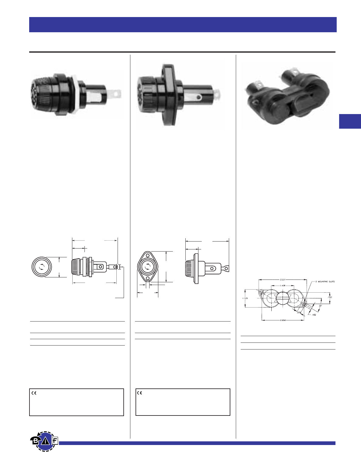
Fuseblocks, Holders and Disconnect Switches
79
For complete specification data, call Bussmann Information Fax ~ 636.527.1450
Fuseblocks, Holders and Terminal Blocks Bussmann®
Panel-Mounted for
⁄‹Ω£™
∑≈
1⁄Ω™
∑Fuses
Data Sheet: 2109 Data Sheet: 2140
Data Sheet: 2112
HPM
Standard Fuseholder with
Screw-type Knob for
⁄‹Ω£™
∑ ≈ 1⁄Ω™∑ Fuses
Agency Information:
UL Recognized, (Guide IZLT2,
File E14853)
CSA Certified (Class 6225-01,
File 47235)
Flammability Rating: UL 94HB
HPC-D
Fuseholder with
Screw-type Knob for
⁄‹Ω£™
∑ ≈ 1⁄Ω™∑ Fuses
Agency Information:
UL Recognized, (Guide IZLT2,
File E14853)
•Supplied with O-ring and panel
gasket.
Flammability Rating: UL 94HB
Electrical Ratings
Catalog
Symbol Amps Volts Description
HPC-D 30
(3)
600 Mount in panels up to ⁄ Ω¢∑ thick.
(1)No UL Recognition
(3)20A max when used with quick-connect terminals.
Replacement knob - BK/9987SA
Electrical Ratings
Catalog
Symbol Amps Volts Description
HPM 30
(3)
600 ⁄Ω¢∑ quick-connect/solder
HPM-D 30
(3)
600 Splash-resistant knob
(4)
(3)20A max when used with quick-connect terminals.
(4)HPM-D has ⁄Ω¢∑ quick-connect/solder terminal on rear (load) terminal
only. The side (line) terminal is ⁄Ω¢∑ quick-connect only.
1.41"
(30.6mm)
0.94"
(23.8mm)
With Fuse
Without Fuse
2.73"
(69.5mm)
2.594"
(65.89mm)
.250" ± .003"
(6.35 ± .08mm)
1.775"
(45.1mm)
0.180"
(4.6mm)
1.120"
(30.5mm)
0.88"
(22.2mm)
2.48"
(63.1mm)
With Fuse
CE logo denotes compliance with European
Union Low Voltage Directive (50-1000Vac,
75-1500Vdc). Refer to Data Sheet: 8002 or
contact Bussmann Application Engineering
at 636-527-1270 for more information.
CE logo denotes compliance with European
Union Low Voltage Directive (50-1000Vac,
75-1500Vdc). Refer to Data Sheet: 8002 or
contact Bussmann Application Engineering
at 636-527-1270 for more information.
HPS2
Catalog Symbol: HPS2
Description: Meets requirement of
UL 1598 that both poles be removed
simultaneously.
Fuse Type: 13/32” x 1-1/2”
Agency Information:
UL 512 recognized,
(Guide IZLT2, File E14853)
CSA certified: (Class 6225-01, File
47235)
Flammability Rating: UL 94V0
Terminals: 1/4” quick connect / sol-
der
Electrical Rating: 30A @ 600V (20A
max when used with quick-connect
terminals.)
Catalog Symbol
HPS2 standard 10-in carton
BK/HPS2 bulk 100-in carton
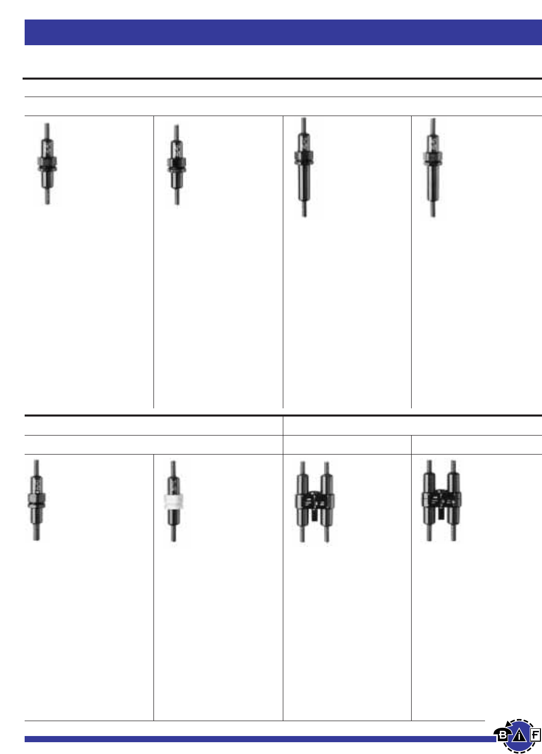
Bussmann®
80 For complete specification data, call Bussmann Information Fax ~ 636.527.1450
Fuseblocks, Holders and Terminal Blocks
Tron®In-Line Fuseholders
Single Pole
Type SC Fuses
Single Pole
⁄‹Ω£™
∑≈
1⁄Ω™
∑Fuses
Double Pole
KTK-R Fuses ⁄‹Ω£™
∑≈
1⁄Ω™
∑
Fuses
HEG
Series
In-Line Fuseholders
Single-Pole
Voltage Rating: 600V, 15A
Non-Breakaway Holders
For SC Fuses 0 to 15A,
480V (or less).
Fuse size ⁄‹Ω£™∑ ≈ 1fiΩ¡§∑.
Data Sheet: 2124
HEH
Series
In-Line Fuseholders
Single-Pole
Non-Breakaway Holders
Voltage Rating: 600V
Current Rating: 20A
(CSA - 15A)
For Type SC-20 Fuses; 20A,
600V (or less). Also fuse
types BBS & KTQ (nominal
size ⁄‹Ω£™∑ ≈ 1‹Ω•∑).
HEC
Series
In-Line Fuseholders
Single-Pole
Voltage Rating: 480V, 30A
Non-Breakaway Holders
For SC-25, & SC-30 Fuses
Fuse size ⁄‹Ω£™∑ ≈ 1fiΩ•∑.
HEJ
Series
In-Line Fuseholders
Single-Pole
Non-Breakaway Holders
Voltage Rating: 480V, 60A
For SC Fuses; 35A to 60A and
Type HVW fuses, ⁄Ω™ to 6A.
Fuse size ⁄‹Ω£™∑ ≈ 2⁄Ω¢∑.
Data Sheet: 2124 Data Sheet: 2124 Data Sheet: 2123
HEB
Series
In-Line Fuseholders
Single-Pole
Voltage Rating: 600V, 30A
For any ⁄‹Ω£™∑ ≈ 1⁄Ω™∑ fuse.
Typical fuse types: BAF, FNM,
FNQ, and KTK (⁄Ω¡º - 30A).
HET Series
In-Line Fuseholders
Single-Pole
An HEB - Fuseholder with a
permanently installed solid
neutral. Easily identified by
white plastic coupling nut.
HEY
Series
In-Line Fuseholders
Double-Pole
Voltage Rating: 600V, 30A
Optional Breakaway recep-
tacle, polarized, and accepting
Class CC branch circuit fuses
(Buss type KTK-R, FNQ-R &
LP-CC; 600V or less, 200,000A
interrupting rating).
HEX
Series
In-Line Fuseholders
Double-Pole
Voltage Rating: 600V, 30A
For any ⁄‹Ω£™∑ ≈ 1⁄Ω™∑ fuse.
Typical fuse types: BAF, FNM,
FNQ, and KTK (⁄Ω¡º - 30A).
Data Sheet: 2125 Data Sheet: 2126 Data Sheet: 2126
Data Sheet: 2127
Note: For agency and CE information see the appropriate data sheet.
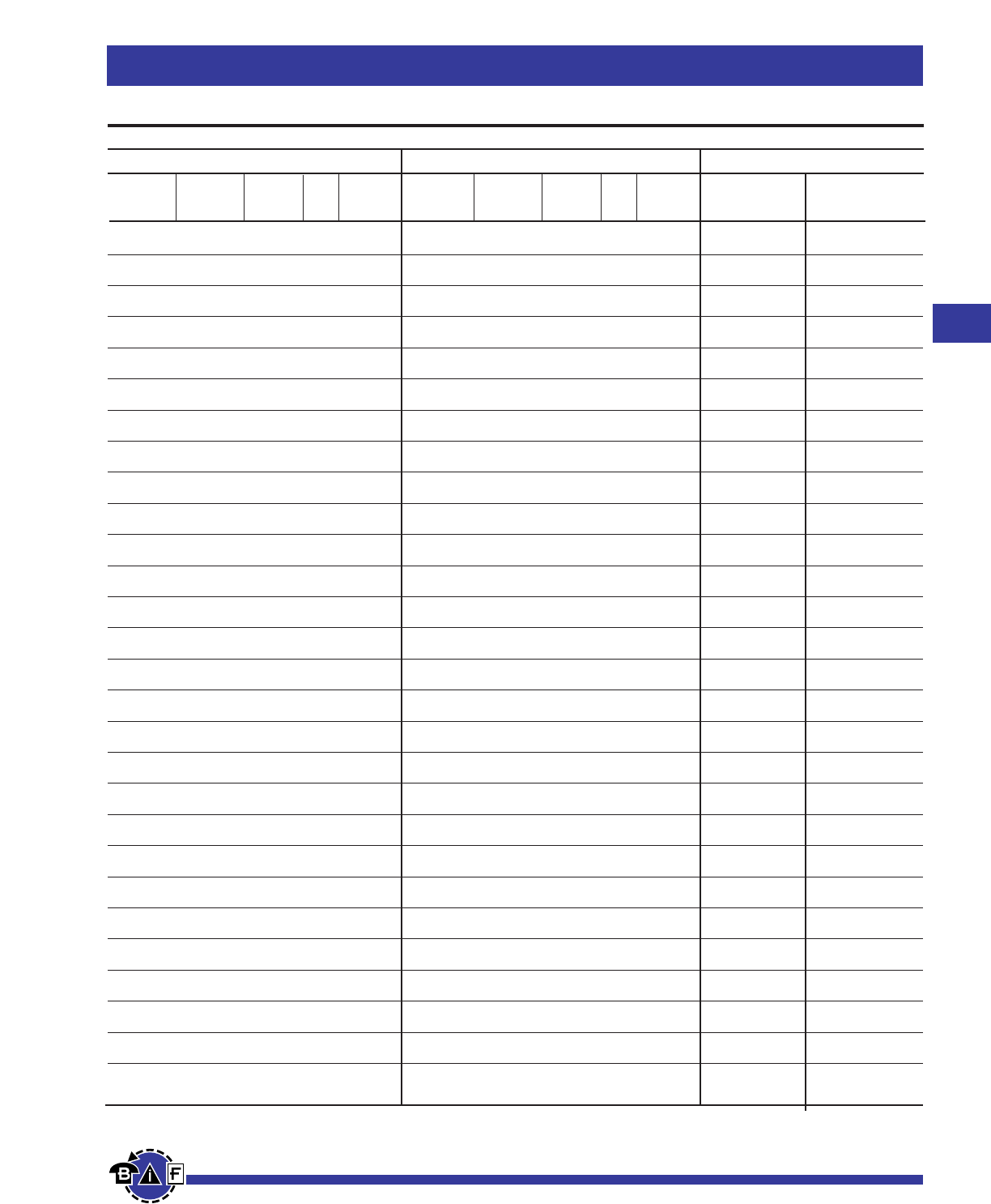
Copper #12 to #8 1 Y Y
Crimp #12 2 Y Y
Copper #12 to #8 1 Y Y
Crimp #12 2 Y Y
Copper #12 to #8 1 Y Y
Crimp #12 2 Y Y
Copper #12 to #8 1 Y Y
Crimp #12 2 Y Y
Copper #12 to #8 1 Y Y
Crimp #12 2 Y Y
Copper #12 to #8 1 Y Y
Crimp #12 2 Y Y
Copper #12 to #8 1 Y Y
Crimp #12 2 Y Y
Copper #12 to #8 1 Y Y
Crimp #12 2 Y Y
Copper #12 to #8 1 Y Y
Crimp #12 2 Y Y
Copper #12 to #8 1 Y Y
Crimp #12 2 Y Y
Copper #6, #4 1 Y Y
Crimp #10 2 Y Y
Copper #6, #4 1 Y Y
Crimp #10 2 Y Y
Copper #6, #4 1 Y Y
Crimp #10 2 Y Y
Copper #6, #4 1 Y Y
Crimp #10 2 Y Y
Copper #4 1 N Y
Crimp #8 2 Y Y
Copper #2 1 N Y
Crimp #6 2 Y Y
Copper #20, #18 1 Y Y
Crimp
Copper #12 to #3 1 Y Y
Set-Screw
Copper #12 to #3 1 Y Y
Set-Screw
Copper #12 to #3 1 Y Y
Set-Screw
Copper #12 to #3 1 Y Y
Set-Screw
Aluminum #12 to #2 1 Y Y
Set-Screw
Aluminum #8 1 N Y
Crimp #6 1 Y N
Aluminum #6 1 N Y
Crimp #4 1 Y N
Aluminum #3, #4 1 N Y
Crimp #2 1 Y N
Aluminum #1, #2 1 N Y
Crimp
Aluminum 1/0 1 N Y
Crimp
SolidTerminal #8 to #12 1 Y N
for aluminum
connector #10 to #14 1 N Y
Copper #12 to #8 1 Y Y
Crimp #12 2 Y Y
Copper #6 to #4 1 Y Y
Crimp #10 2 Y Y
Copper #4 1 N Y
Crimp #8 2 Y Y
Copper #2 1 N Y
Crimp #6 2 Y Y
Copper 2/0 1 N Y
Crimp #3 2 N Y
Copper #12 to #3 1 Y Y
Set-Screw
Copper #12 to #3 2 Y Y
set-screw
Aluminum #12 to #2 1 Y Y
Set-Screw
Aluminum #12 to #2 2 Y Y
Set-Screw
Aluminum #1, #2 1 N Y
Crimp
Copper #12 to #8 1 Y Y
Crimp #12 2 Y Y
Copper #6, #4 1 Y Y
Crimp #10 2 Y Y
Copper #4 1 N Y
Crimp #8 2 Y Y
Copper #2 1 N Y
Crimp #6 2 Y Y
Copper #4 1 N Y
Crimp #8 2 Y Y
Copper #2 1 N Y
Crimp #6 2 Y Y
Copper #12 to #8 1 Y Y
Crimp #12 2 Y Y
Copper #12 to #3 1 Y Y
Set-Screw
Copper #12 to #3 2 Y Y
Set-Screw
Aluminum #12 to #2 1 Y Y
Set-Screw
Aluminum #12 to #2 2 Y Y
Set-Screw
Aluminum #12 to #2 1 Y Y
Set-Screw
Aluminum #8 1 N Y
Crimp #6 1 Y N
Aluminum #6 1 N Y
Crimp #4 1 Y N
Aluminum #3, #4 1 N Y
Crimp #2 1 Y N
Aluminum #1, #2 1 N Y
Crimp
Aluminum 1/0 1 N Y
Crimp
SolidTerminal #8 to #12 1 Y N
for aluminum
connector #10 to #14 1 N Y
Bussmann®
81
For complete specification data, call Bussmann Information Fax ~ 636.527.1450
Fuseblocks, Holders and Terminal Blocks
For HEB Holders Only
Terminal No. of
Wire Size Wires per Solid Stranded
Type Terminal Wire Wire
Load Terminal
Directions:To select complete holder P/N, work from left to right starting with load terminal options and then line terminal options. Then determine breakaway or non-breakaway style.
Terminal No. of
Wire Size Wires per Solid Stranded
Type Terminal Wire Wire
Line Terminal Available P/N’s
Non-Breakaway Breakaway
P/N P/N
(Boots not included) (Boots included)
HEB-AA(1)(2) HEB-AW-RLC-A(1)(2)
HEB-AB(2) HEB-AW-RLC-B
HEB-AC(2) HEB-AW-RLC-C
HEB-AD(2) N/A
HEB-AE(2) N/A
HEB-AJ HEB-AW-RLC-J
HEB-AK HEB-AW-RYC
HEB-AL HEB-AW-RLA
HEB-AY HEB-AW-RYA
HEB-AR N/A
HEB-BA(2) HEB-BW-RLC-A
HEB-BB(2) HEB-BW-RLC-B
HEB-BC(2) N/A
HEB-BD(2) N/A
HEB-CC(2) N/A
HEB-DD(2) N/A
HEB-ZA N/A
HEB-JJ HEB-JW-RLC-J
HEB-JK HEB-JW-RYC
HEB-JL N/A
HEB-JY N/A
HEB-LL HEB-LW-RLA
HEB-NN N/A
HEB-PP(2) N/A
HEB-QQ(2) N/A
HEB-RR(2) N/A
HEB-TT(2) N/A
HEB-SS N/A
(3)
(3)
(1)UL Recognized, Guide IZLT2, File E14853
(2)CSA Certified, Class 6225-01, File 47235
(3)CE
Contact your local Bussmann representative for other possible terminations not listed.
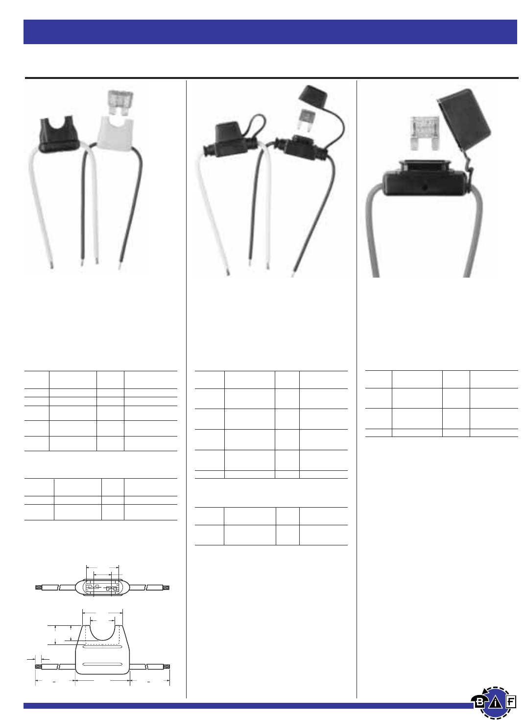
Bussmann®
Fuseblocks, Holders and Terminal Blocks
82 For complete specification data, call Bussmann Information Fax ~ 636.527.1450
Bulk Products
(Bulk Quantity - 1000 Pieces)
Catalog Fuse Electrical
Symbol Description Size Connection
BK/HHL-R Black fuseholder 2-20A #16 red leadwire,
– body only 4” length
stripped to ⁄Ω¢”
Electrical Ratings
Catalog Fuse Electrical
Symbol Description Size Connection
HHC Yellow fuseholder 3-20A #16 black leadwire
HHD Black fuseholder 3-30A #12 yellow leadwire
HHD-C Cover only Fits HHD Clear polycarbonate
only
HHF Black fuseholder 3-20A #16 yellow leadwire
with cover
HHG Black fuseholder 3-30A #12 yellow leadwire
with cover
Electrical Ratings
Catalog Fuse Electrical
Symbol Description Size Connection
HHL Black fuseholder #16 black lead-
w/cover 2-20A wire, 4” length
stripped to ⁄Ω¢”
HHL-B Black fuseholder #16 black lead-
– body only 2-20A wire, 4” length
stripped to ⁄Ω¢”
HHM Black fuseholder #12 red leadwire,
w/cover 2-30A 4” length
stripped to ⁄Ω¢”
HHM-B Black fuseholder #12 red leadwire,
– body only 2-30A 4” length
stripped to ⁄Ω¢”
HHM-C Black cover only
Data Sheet: 2129Data Sheet: 2128Data Sheet: 2107
In-Line Fuseholders for Automotive Blade-Type Fuses
HHC, HHD, HHF and HHG
In-Line Fuseholders for
ATC®Blade-Type Fuses
Voltage Rating: 32Vdc
Current Rating: See Table. Rated to
carry 80% of Fuse Rating continuously.
HHL and HHM
In-Line Fuseholders for
MINI-Fuses®
Voltage Rating: 32Vdc
Current Rating: See Table. Rated to
carry 80% of Fuse Rating continuously.
HHX
In-Line Fuseholders for
MAXI-Fuses™
Voltage Rating: 32Vdc
Current Rating: See Table. Rated to
carry 80% of Fuse Rating continuously.
0.78"
0.91"
0.5"
0.38" 0.30"
4.0" + 0.25" 4.0" + 0.25"
1.125"
0.364"
0.25"
Bulk Products
(Bulk Quantity - 1000 Pieces)
Catalog Fuse Electrical
Symbol Description Size Connection
BK/HHC-R Yellow fuseholder 3-20A #16 red leadwire
BK/HHF-B Black fuseholder 3-20A #16 black leadwire
with cover
A fuse must be properly and fully inserted into
the holder to provide a solid connection. Poor or
improper insertion of the fuse can result in failure
of the fuse and holder, thus not protecting the
device for which it was intended.
A fuse must be properly and fully inserted into
the holder to provide a solid connection. Poor or
improper insertion of the fuse can result in failure
of the fuse and holder, thus not protecting the
device for which it was intended.
A fuse must be properly and fully inserted into
the holder to provide a solid connection. Poor or
improper insertion of the fuse can result in failure
of the fuse and holder, thus not protecting the
device for which it was intended.
Electrical Ratings
Catalog Fuse Electrical
Symbol Description Size Connection
HHX Black fuseholder #6 red leadwire,
w/cover 20-60A 5” with
blunt ends
HHX-B Black fuseholder #6 red leadwire,
– body only 20-60A 5” with
blunt ends
HHX-C Black cover only
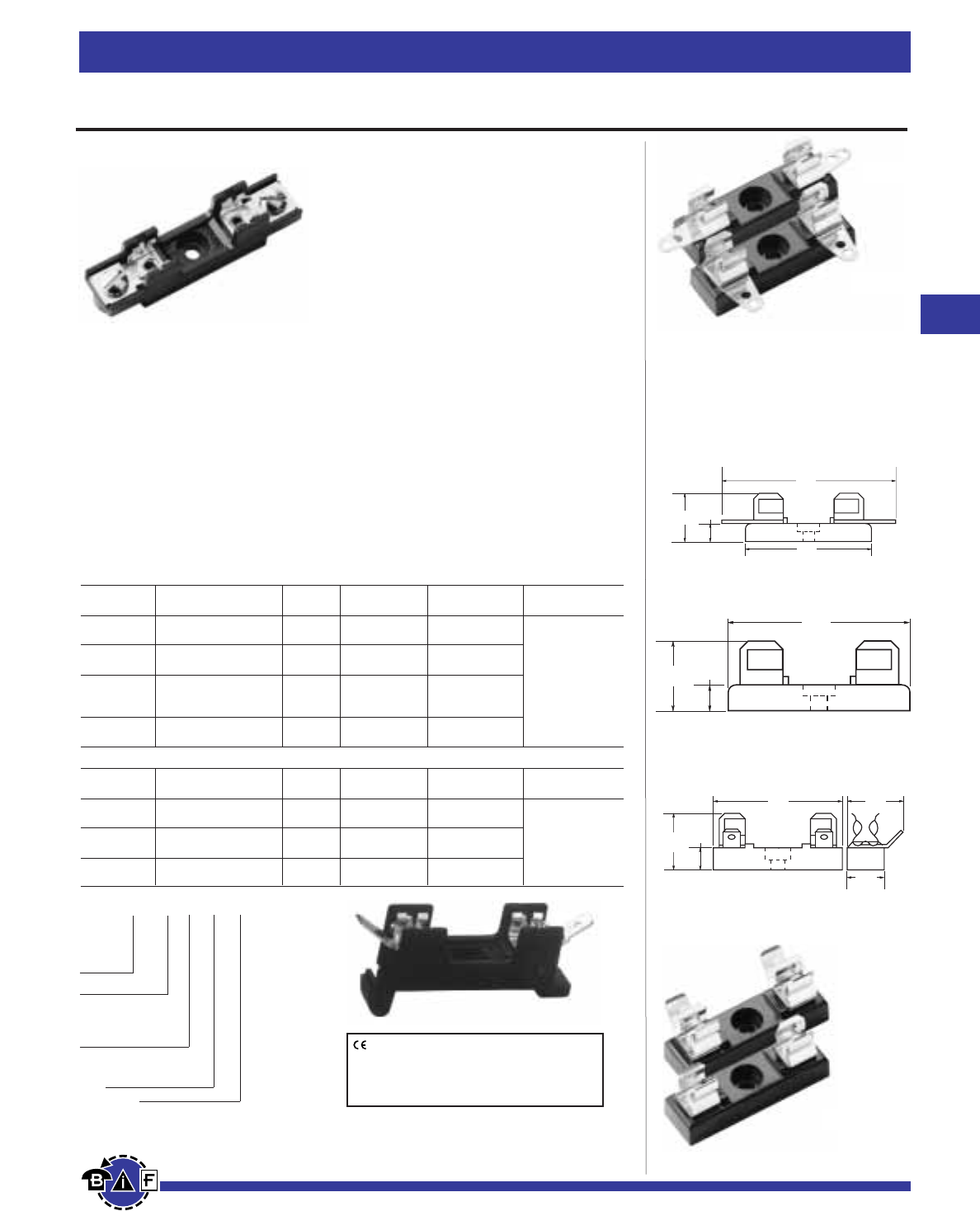
83
For complete specification data, call Bussmann Information Fax ~ 636.527.1450
Bussmann®
Fuseblocks, Holders and Terminal Blocks
Data Sheet: 2101
For
⁄Ω¢
∑≈
1⁄Ω¢
∑Fuses
⁄Ω¢∑ ≈1⁄Ω¢∑ Single Pole
(6.4mm ≈31.8mm)
Bakelite base; spring-bronze, bright
tin-lead plate clips; 30A, 250V; base
width ⁄Ω™∑ (12.7mm).
No. 4405—0°Solder Terminals.
Integral terminal and clip.
No. 4406—Side Solder Terminal
No. 4574—Spare Fuseblock
No. 2499—Side Quick-Connect
Terminals. ⁄Ω¢∑ (6.4mm); 15A, 250V.
UL Recognized,
Guide IZLT2, File E14853.
Note—Mounting screw hole diameter is 0.147∑
(3.7mm). Counterbore diameter, 0.636∑(8.0mm).
Max. Mounting Screw No. 6.
1.63"
(41.3mm)
0.27"
(6.7mm)
0.69"
(17.5mm)
2.31"
(58.7mm)
1.63"
(41.3mm)
0.27"
(6.7mm)
0.69"
(17.5mm)
0.27"
(6.7mm)
0.75"
(19.1mm)
0.5"
(12.7mm)
0.72"
(18.3mm)
1.63"
(41.3mm)
Series 8000
Bolt-in and Snap-in Mounting for ⁄Ω¢∑ ≈1⁄Ω¢∑ Fuses
Construction: Blocks are molded flame retarded thermoplastic. Clips are spring-bronze.
Voltage Rating: 300V
Agency Information:
UL Recognized ; File E14853A, Guide IZLT2
CSA Certified Class 6225-01, File 47235
Anti-Rotation Pin: Single pole blocks may be ordered without the antirotational pin simply
by adding an “X” to the number of poles (Example: BK/S-8000-1X).
Carton Quantity: 10; shelf package: 100.
Bulk Carton: Single-pole and 2-pole fuse blocks–1,000; Multiple-pole fuse blocks–3-8 pole:
200; 9-12 pole: 50. When ordering bulk quantities, prefix “BK/” to catalog number: (Example:
BK/S-8001-1-SNP).
Bolt-in Mounting
Basic Poles
Series Terminal Angle Cat. No. Amperes (Suffix)
8000 Solder 0°S-8001- UL 25A
40°S-8002- CSA 21A
8100 ‹Ω¡§∑ Quick 0°S-8101- UL 20A
Connect 40°S-8102- CSA 13A
⁄Ω¢∑ Quick 0°S-8201- UL 20A 1 - 12
8200 40°S-8202-
Connect Side S-8203- CSA 16A
8300 Screw —S-8301- UL 30A
CSA 25A
Snap-in Mounting
Poles
Series Terminal Angle Cat. No. Amperes (Suffix)
8000 Solder 0°S-8001-1-SNP UL 25A
40°S-8002-1-SNP CSA 21A
8100 ‹Ω¡§∑ Quick 0°S-8101-1-SNP UL 20A
Connect 40°S-8102-1-SNP CSA 13A
8200 ⁄Ω¢∑ Quick 0°S-8201-1-SNP UL 20A
Connect Side S-8203-1-SNP CSA 16A
Catalog Code
BK/ S-8 0 00 -00
Prefix for
Bulk
Packing
Series 8000
Product Line
Terminal Angle
“01” - straight (0°,)
“02”- 40°
“03” - side*
Type Terminal
“0”-Solder
“1”-‹Ω¡§∑
Quick Connect
“2” - ⁄Ω¢∑ Quick Connect
“3” - Screw
Number of Poles (1-12)
*Available only in single pole
Available
only in
single
pole
4574
2499
4406
4405
CE logo denotes compliance with European
Union Low Voltage Directive (50-1000Vac,
75-1500Vdc). Refer to Data Sheet: 8002 or
contact Bussmann Application Engineering
at 636-527-1270 for more information.
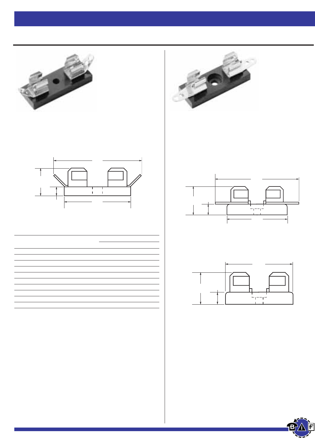
Bussmann®
84 For complete specification data, call Bussmann Information Fax ~ 636.527.1450
Fuseblocks, Holders and Terminal Blocks
For
⁄Ω¢
∑≈
1
∑Fuses
Series 3828
Solder Terminals Fuseblock for ⁄Ω¢∑ ≈1∑ Fuses
(6.4mm ≈25.4mm)
4520 and 4393
Single Pole Fuseblock for ⁄Ω¢∑ ≈1∑ Fuses
Bakelite base; Width ⁄Ω™∑ (12.7mm). Spring-bronze, bright
tin-lead plated clips. Rated 30A, 250V.
Catalog And Dimensional Data
Catalog No. of *Base Length
Number Poles inches mm
3828-1 1 ⁄Ω™ 12.7
3828-2 2 1⁄Ω• 28.6
3828-3 3 1‹Ω¢ 44.5
3828-4 4 2‹Ω• 60.3
3828-5 5 3 76.2
3828-6 6 3fiΩ• 92.1
3828-7 7 4⁄Ω¢ 108.0
3828-8 8 4‡Ω• 123.8
3828-10 10 6⁄Ω• 155.6
3828-12 12 7‹Ω• 187.3
*Small phenolic base, base width 1‹Ω•∑ (34.9mm)
Note—Mounting screw hole diameter is 0.147∑ (3.7mm) Max. Mounting
Screw No. 6.
No. 4520—Solder terminals; straight; integral clip and
terminal.
No. 4393—Spare fuseblock.
Note—Mounting screw hole diameter is 0.147∑(3.7mm), counterbore
0.636∑(8.0mm) diameter. Max. Mounting Screw No. 6.
0.19"
(4.8mm)
0.63"
(15.9mm)
1.88"
(47.6mm)
1.38"
(34.9mm)
1.38"
(34.9mm)
.188"
(4.8mm)
.598"
(15.2mm)
1.94"
(49.2mm)
1.38"
(34.9mm)
.188"
(4.8mm)
.598"
(15.2mm)
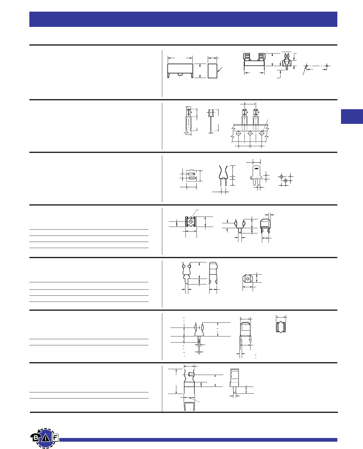
Bussmann®
85
For complete specification data, call Bussmann Information Fax ~ 636.527.1450
Fuseblocks, Holders and Terminal Blocks
Printed Circuit Board for 5mm Diameter Fuses
HTC-15M, HTC-140M
PCB Fuseblock and Snap-On Cover
Voltage Rating: 250V, 6.3A, 1.6W
HTC-15M (Fuseholder), HTC-140M (Natural Cover),
HTC-150M* (Transparent Cover)
*Available in bulk only. Use this format: BK/HTC-150M
HTC-200M
PC Board Mount Fuseclip
Construction: Tin plated bronze
Tape and Fan Fold packed
Ammo Pack (AP/HTC-200M) 1000 pieces per box
HTC-210M
PC Board Mounted Fuseclip with End Stops
1A3399 Series
Fuseclips with End Stops and Straight Leads
1A5018 Series
Fuseclips with End Stops and Straight Leads
1A5601 Series
Fuseclips (0-7A)
1A5602 Series
Fuseclips (0-7A)
Data Sheet: 2110
Data Sheet: 2110
Data Sheet: 2110
Data Sheet: 2131
Data Sheet: 2131
Data Sheet: 2131
Catalog Number Clip Material* Finish
1A3399-01 Beryllium Copper* Silver
1A3399-04 Beryllium Copper* Bright Tin
1A3399-10 Spring Bronze Bright Tin
*Beryllium copper recommended for currents higher than 15 amps (⁄Ω¢∑ clips).
.031"
(.79mm) .217"
(5.5mm)
.012"
(.3mm)
.177"
(4.5mm)
.319"
(8.1mm)
BUSS
.61"
(15.5mm)
.929"
(23.6mm)
BUSS
BUSS
.50"
(12.7mm)
.50"
(12.7mm)
.50"
(12.7mm)
.157"
(3.99mm)
2.54mm
1.46mm
2.29mm
4.32mm
8.73mm
3.91mm
2.85mm
6.26mm
6.22mm
2.54mm 2.54mm
.115"
(2.9mm)
.062"
(1.6mm)
.254"
(6.5mm) .237"
(6.0mm)
.125"
(3.2mm)
.225"
(5.7mm)
.125"
(3.2mm)
.060"
(1.5mm) .188"
(4.8mm)
.030"
(1.6mm)
.180"
(4.57mm)
.230"
(5.84mm)
()
.440"
(11.2mm)
.140"
(3.7mm)
.047"
(1.2mm)
.180"
(4.6mm)
High Profile
Catalog Number Clip Material* Finish
1A5018-7 Spring Bronze Silver
1A5018-10 Spring Bronze Bright Tin
*Beryllium copper recommended for currents higher than 15 amps (⁄Ω¢∑ clips).
Catalog Number Clip Material Finish
1A5601 Cartridge Brass Bright Tin
Catalog Number Clip Material Finish
1A5602 Cartridge Brass Bright Tin
.250"
(6.35mm)
.060"
(1.5mm)
.246"
(6.3mm)
.344" + .015"
(8.73mm + 0.38mm)
.266"
(6.75mm)
.344" + .015"
(8.73mm + 0.38mm)
.141" + .015"
(3.58mm + 0.38mm)
.022" + .002"
(0.56mm + 0.05mm) .032" + .002"
(.81mm + .05mm)
.216"
(5.48mm) LEGS TO FIT
IN .052" (1.3mm) DIA.
HOLES ON CENTER
.219"
(5.57mm)
.047"
(1.19mm)
.093"
(2.36mm)
.500"
(12.70mm) .250"
(6.35mm) .140"
(3.56mm)
HTC-140M
Cover
1.047"
(26.6mm)
217"
.345"
(9.0mm)
.571"
(14.5mm)
.866"
(22.0mm)
.217"
(5.5mm)
.177"
(4.5mm)
.890"
(22.60mm)
Mounting Holes
.059" + .002" Dia. (Typ.)
_
(1.50 + .05mm)
_
.531"
(13.5mm)
Data Sheet: 2131
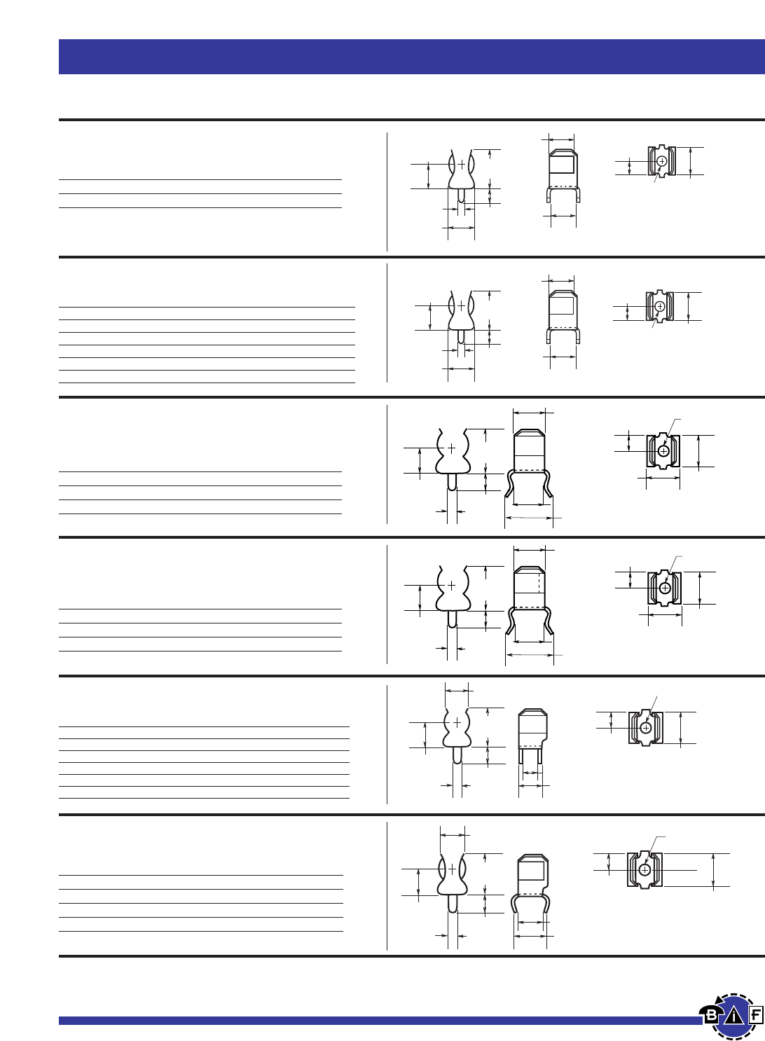
Bussmann®
86 For complete specification data, call Bussmann Information Fax ~ 636.527.1450
Fuseblocks, Holders and Terminal Blocks
Catalog Number Clip Material* Finish
1A4534-01 Beryllium Copper* Bright Tin
1A4534-06 Cartridge Brass Bright Tin
1A4534-07 Spring Bronze Bright Tin
*Beryllium copper recommended for currents higher than 15A (⁄Ω¢∑ clips).
Printed Circuit Board for
⁄Ω¢
∑Diameter Fuses
1A3398 Series
Fuseclips without End Stops and Straight Leads
1A4533 Series
Fuseclips without End Stops and
Angled Out Leads
Data Sheet: 2131
Data Sheet: 2131
Catalog Number Clip Material Finish
1A3398-07 Cartridge Brass Bright Tin
1A3398-08 Spring Bronze Bright Tin
Catalog Number Clip Material* Finish
1A4533-01 Beryllium Copper* Bright Tin
1A4533-06 Cartridge Brass Bright Tin
1A4533-07 Spring Bronze Bright Tin
*Beryllium copper recommended for currents higher than 15A (⁄Ω¢∑ clips).
.280"
(7.1mm)
.155"
(3.94mm)
.102" Dia.
(
2.6mm
)
.245"
(6.2mm)
.280"
(7.1mm)
.
280"
(7.1mm)
.410"
(10.4mm)
.140"
(3.6mm)
.060"
(1.5mm)
.320"
(8.13mm)
.
102"
Dia
.
(2.6mm)
.255"
(6.5mm)
.255"
(6.5mm)
.410"
(10.4mm)
.060"
(1.5mm)
.150"
(3.81mm)
.245"
(6.2mm)
.228"
(5.79mm)
.323"
(8.20mm)
.280"
(7.11mm)
.102"
(2.6mm)
.155"
(3.94mm)
.320"
(8.13mm)
1A1907 Series
Fuseclips with End Stops and Straight Leads
1A1119 Series
Fuseclips with End Stops and Angled In Leads
1A4534 Series
Fuseclips with End Stops and
Angled Out Leads
1A1120 Series
Fuseclips without End Stops and Angled In Leads
Data Sheet: 2131
Data Sheet: 2131
Data Sheet: 2131
Data Sheet: 2131
Catalog Number Clip Material* Finish
1A1119-04 Beryllium Copper* Bright Tin
1A1119-05 Beryllium Copper* Silver
1A1119-10 Cartridge Brass Bright Tin
1A1119-13 Spring Bronze Bright Tin
*Beryllium copper recommended for currents higher than 15A (⁄Ω¢∑ clips).
Catalog Number Clip Material* Finish
1A1120-02 Cartridge Brass None/Bright Dipped
1A1120-05 Beryllium Copper* Silver
1A1120-06 Beryllium Copper* Bright Tin
1A1120-09 Cartridge Brass Bright Tin
1A1120-11 Spring Bronze None/Bright Dipped
1A1120-12 Spring Bronze Bright Tin
*Beryllium copper recommended for currents higher than 15A (⁄Ω¢∑ clips).
.255"
(6.5mm)
.410"
(10.4mm)
.060"
(1.5mm)
.150"
(3.81mm)
.245"
(6.2mm)
.228"
(5.79mm)
.323"
(8.20mm)
.280"
(7.11mm)
.102"
(2.6mm)
.155"
(3.94mm)
.320"
(8.13mm)
.250"
(6.5mm)
.420"
(10.67mm)
.080"
(2.03mm)
.285"
(7.24mm)
.155"
(3.9mm)
.290"
(7.4mm)
.360"
(9.14mm)
.132"
(3.4mm)
.187"
(4.8mm) .312"
(7.9mm)
.245"
(6.2mm)
.280"
(7.1mm)
.280
(7.1mm)
.410"
(10.4mm)
.140"
(3.6mm)
.060"
(1.5mm)
.320"
(8.13mm)
.102 Dia.
(2.6mm)
.255"
(6.5mm)
.280"
(7.1mm)
.155"
(3.94mm)
.102" Dia.
(2.6mm)
.255"
(6.5mm)
.410"
(10.4mm)
.080"
(2.03mm)
.265"
(6.7mm)
.155"
(3.9mm)
.290"
(7.4mm)
.360"
(9.14mm)
.312"
(7.9mm)
.132"
(3.4mm)
.187"
(4.8mm)
Catalog Number Clip Material* Finish
1A1907-02 Cartridge Brass None/Bright Dipped
1A1907-03 Beryllium Copper* Bright Tin
1A1907-05 Beryllium Copper* Silver
1A1907-06 Cartridge Brass Bright Tin
1A1907-08 Spring Bronze None/Bright Dipped
1A1907-09 Spring Bronze Bright Tin
*Beryllium copper recommended for currents higher than 15A (⁄Ω¢∑ clips).
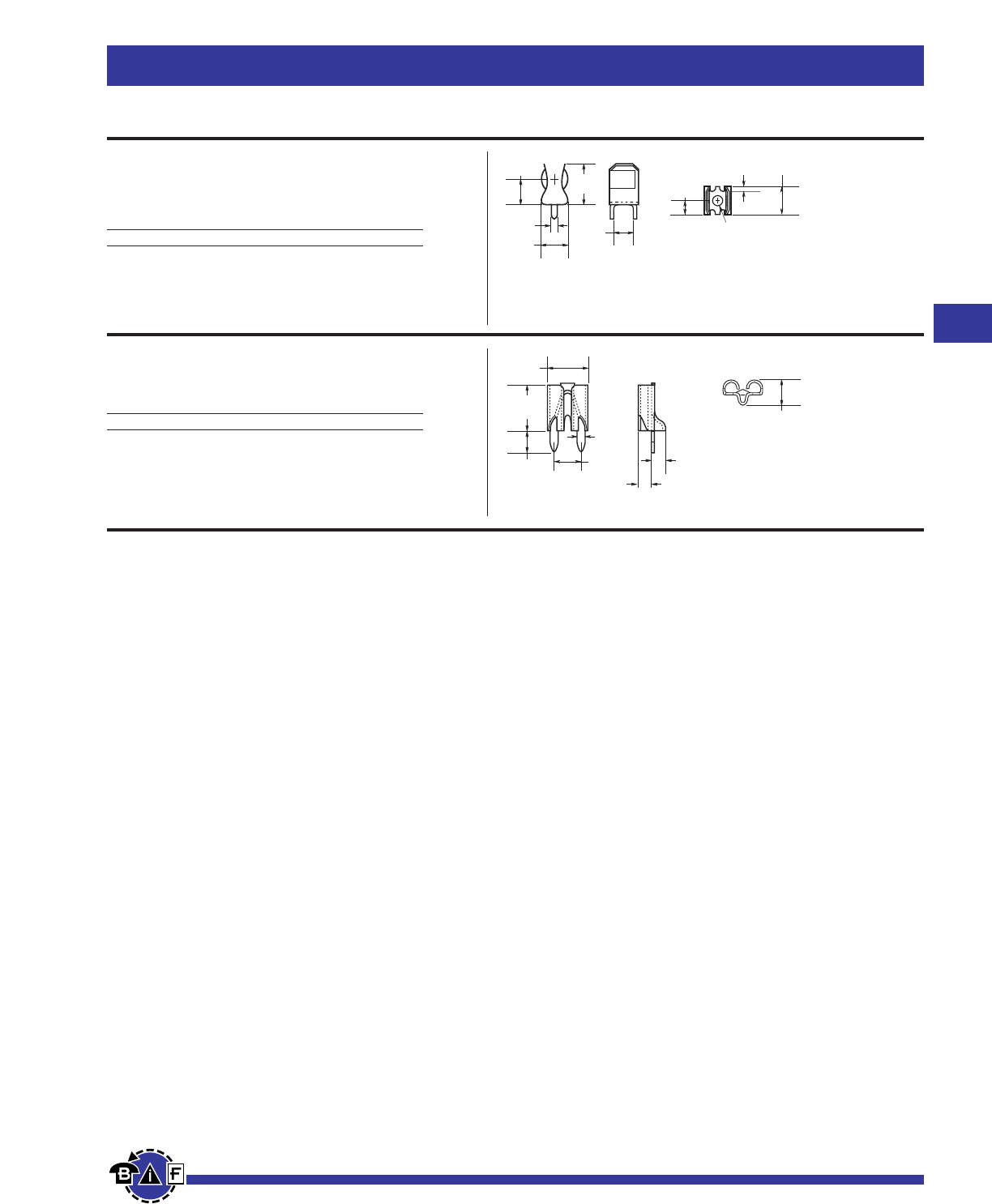
Bussmann®
For complete specification data, call Bussmann Information Fax ~ 636.527.1450
Fuseblocks, Holders and Terminal Blocks
Printed Circuit Board Fuseclips
1A3400 Series
Fuseclips for ⁄‹Ω£™∑ diameter fuses with
End Stops and Straight Leads
1A5600 Series
Fuseclips for ATC®Fuses (0-20A)
Data Sheet: 2131
Data Sheet: 2131
Catalog Number Clip Material Finish
1A3400-09 Spring Bronze Bright Tin
20A Maximum
Catalog Number Clip Material Finish
1A5600 Brass Satin Finish Tin
.710"
(18.0mm)
.080"
(2.0mm)
.470"
(11.9mm)
()
.470"
(11.9mm)
.380"
(9.7mm)
.218"
(5.5mm)
.142" Dia.
(3.6mm)
.050"
(1.27mm)
.437"
(11.1mm)
.150"
(3.81mm)
.330"
(8.38mm)
.295"
(7.49mm)
.200"
(5.08mm)
.053"
(1.35mm)
.090"
(2.29mm)
.090"
(2.29mm)
.180"
(4.57mm)
87
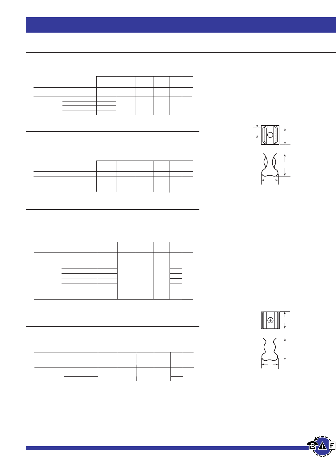
Bussmann®
88 For complete specification data, call Bussmann Information Fax ~ 636.527.1450
Fuseblocks, Holders and Terminal Blocks
Data Sheet: 2132
Printed Circuit Board Fuseclips
5681 & 5682 Series
Fuseclips with Mounting Holes For ⁄Ω¢∑ Diameter Fuses
5672 & 5674 Series
Fuseclips with Mounting Holes For ·Ω£™∑ Diameter Fuses
Data Sheet:
2132
Data Sheet:
2132
B
C
D
E
FIGURE 1
C
D
E
FIGURE 2
5956 & 5960 Series
Fuseclips with Mounting Holes For ⁄‹Ω£™∑ Diameter Fuses
5591 & 5592 Series
Fuseclips with Mounting Holes For ·Ω¡§∑ Diameter Fuses
Data Sheet:
2132
5681-08 No
5681-15
5682-01
5682-02 Yes
5682-41
5682-44
Dimensions (Inches)
Catalog End Clip B (To C D E Hole Fig.
Number Stop Mat.** Finish End Stop) (Contact) (Height) (Width) Dia. Ref.
5591-42 Yes
5592-01
5592-11 No
5592-33
Spg. Br. Bright Dip* .260 .510 .890 .600
BeCU Silver
Spg. Br. Silver †.505 .890 .600
Spg. Br. Bright Dip*
.172 1
.200
.200 2
.172
Dimensions (Inches)
Catalog End Clip B (To C D E Hole Fig.
Number Stop Mat.** Finish End Stop) (Contact) (Height) (Width) Dia. Ref.
5672-11 No Spg. Br. Bright Tin
†
.362 .520 .380 .172 2
5674-01 BeCU Silver
5674-10 Yes BeCU Bright Tin .168 .356 .520 .380 .172 1
5674-41 Spg. Br. Bright Tin
Dimensions (Inches)
Catalog End Clip B (To C D E Hole Fig.
Number Stop Mat.** Finish End Stop) (Contact) (Height) (Width) Dia. Ref.
5956-16 No Spg. Br. Bright Tin †.312 .710 .470 .172 2
5960-07 BeCU Silver .168 .196
5960-09 BeCU Silver .200 .172
5960-51 Yes Spg. Br. Bright Dip* .168 .389 .710 .470 .196 1
5960-53 Spg. Br. Bright Dip* .200 .172
5960-61 Spg. Br. Bright Tin .168 .196
5960-62 Spg. Br. Bright Tin .168 .132
5960-63 Spg. Br. Bright Tin .200 .172
5960-64 Spg. Br. Bright Tin .200 .128
* Bright Dip is actually treated bare metal with no plating.
** Spg. Br. — Spring Bronze; BeCU — Beryllium Copper.
†Hole in center of both clip and contact area.
Dimensions (Inches)
Catalog End Clip B (To C D E Hole Fig.
Number Stop Mat.** Finish End Stop) (Contact) (Height) (Width) Dia. Ref.
Spg. Br. Nickel †.265 .410 .320 .132 2
Spg. Br. Bright Tin
BeCU Silver .106
BeCU Silver .132
Spg. Br. Bright Tin .106
.260 .410 .320 .132 1
Spg. Br. Bright Tin .132
1A1837 For
⁄‹Ω¡§∑
Diameter Fuses
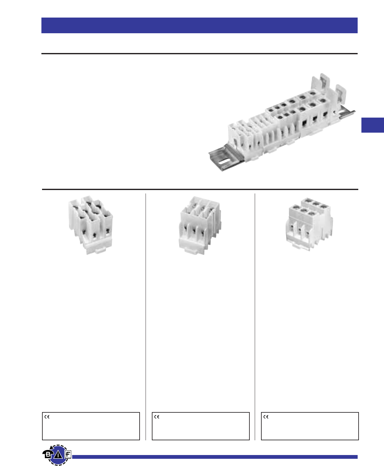
Bussmann®
89
For complete specification data, call Bussmann Information Fax ~ 636.527.1450
Fuseblocks, Holders and Terminal Blocks
Rail Mount Terminal Blocks
NDNV4-__ __(color)
Ratings: NDNV4 30A, 600V; UL/CSA
Center Spacing: .250∑(6.35)
Number of Poles: 4
Circuits per Foot: 48
Circuit Jumper: JN4, 4 circuits
Wire Size: AWG #10-22 CU
Screw Size: #6-32
Mounting Options: 35mm DIN rail,
C-rail
Marking Tape: MTC6
Torque Rating: 18 in/lb max.
NDNV4 Colors: YE - Yellow
WH - White
NDN3-__ __(color)
Ratings: 30A - field wiring;
40A - factory wiring 600V; UL/CSA
Center Spacing: .300∑(7.62)
Number of Poles: 3
Circuits per Foot: 38
Circuit Jumper: JNDN3, 2 circuits
Wire Size: AWG #10-22 CU
Screw Size: #6-32
Mounting Options: 35mm DIN rail,
C-rail
Marking Tape: MT12-⁄Ω™
Torque Rating: 18 in/lb max.
NDN3 Colors: YE - Yellow
WH - White
NDN63-__ __(color)
Ratings: 65A, 600V; UL/CSA
Center Spacing: .375∑(9.52)
Number of Poles: 3
Circuits per Foot: 30
Circuit Jumper: JN3, 2 circuits
Wire Size: AWG #6-18 CU
Screw Size: #10-32
Mounting Options: 35mm DIN rail,
C-rail
Marking Tape: MT12-⁄Ω™
Torque Rating: 35 in/lb max.
NDN63 Colors: YE - Yellow
WH- White
Series NDN
35mm DIN Rail Compatible
High Density Design: Up to 48 circuits per foot
Clamping Collar: Secures wires
Large, Captive, Wire-ready Screws: Speeds assembly
Snap-on Installation to DIN Rail: Fast, easy assembly
Fully Shielded Construction: 600V spacings
Unique One-piece Construction: Increases reliability
Thermoplastic Moldings: Strong and impact resistant
Material: UL Recognized 94V-2 thermoplastic
Collars: Heat treated stainless steel
Terminals: Tin plated copper alloy
Screws: Zinc plated steel
Agency Information: UL E62622; CSA LR15364
CE logo denotes compliance with European
Union Low Voltage Directive (50-1000Vac,
75-1500Vdc). Refer to Data Sheet: 8002 or
contact Bussmann Application Engineering
at 636-527-1270 for more information.
CE logo denotes compliance with European
Union Low Voltage Directive (50-1000Vac,
75-1500Vdc). Refer to Data Sheet: 8002 or
contact Bussmann Application Engineering
at 636-527-1270 for more information.
CE logo denotes compliance with European
Union Low Voltage Directive (50-1000Vac,
75-1500Vdc). Refer to Data Sheet: 8002 or
contact Bussmann Application Engineering
at 636-527-1270 for more information.
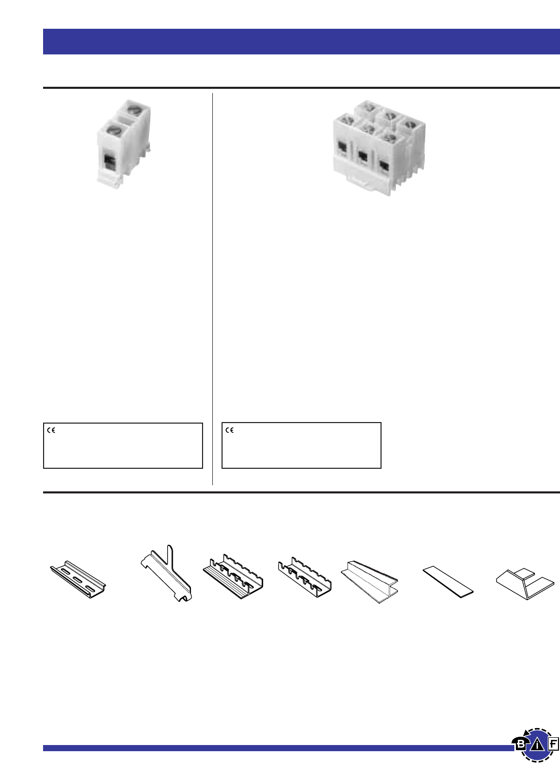
Bussmann®
90 For complete specification data, call Bussmann Information Fax ~ 636.527.1450
Fuseblocks, Holders and Terminal Blocks
Rail Mount Terminal Blocks
NDN1-WH
Ratings: 90A, 600V
Center Spacing: .635∑(16.13)
Number of Poles: 1
Circuits per Foot: 18
Circuit Jumper: JN1, 2 circuits
Wire Size: AWG #2-18 CU
Screw Size: ⁄Ω¢-28
Mounting Options: 35mm DIN rail,
C-rail (Dove-tail option is available for
mounting side-by-side. Order part no.
NDN1A-WH.)
Marking Tape: MT12-⁄Ω™
Torque Rating: 32 in/lb max.
NDN1Colors: WH -White
NDN111-__ __(color)
Ratings: 90A, 600V; UL/CSA
Center Spacing: .635∑(16.13)
Number of Poles: 3
Circuits per Foot: 18
Circuit Jumper: JN1, 2 circuits
Wire Size: AWG #2-18 CU
Screw Size: ⁄Ω¢-28
Mounting Options: 35mm DIN rail,
C-rail, Base Mount. (Dove tail option is
available for mounting side-by-side.
Order part no. NDN111A-WH.)
Marking Tape: MT12-⁄Ω™
Torque Rating: 32 in/lb max.
NDN111 NDN111A
Colors: Colors:
YE - Yellow YE - Yellow
WH- White WH- White
Series NDN Terminal Block Accessories
NDNA NDNAS NFTA NRA37-1
/
2SOA72 MARKING JUMPERS
35mm DIN rail 35mm DIN rail C-rail C-rail 72” long TAPE See series
Aluminum End Stop Aluminum Low profile Stand-Off Channel See series specifications
NDNA 100 1 meter NFTA36 No flange for C-rail specifications
NDNA 200 2 meters 36” long Aluminum
NFTA72 37⁄Ω™∑ length
72” long
CE logo denotes compliance with European
Union Low Voltage Directive (50-1000Vac,
75-1500Vdc). Refer to Data Sheet: 8002 or
contact Bussmann Application Engineering
at 636-527-1270 for more information.
CE logo denotes compliance with European
Union Low Voltage Directive (50-1000Vac,
75-1500Vdc). Refer to Data Sheet: 8002 or
contact Bussmann Application Engineering
at 636-527-1270 for more information.
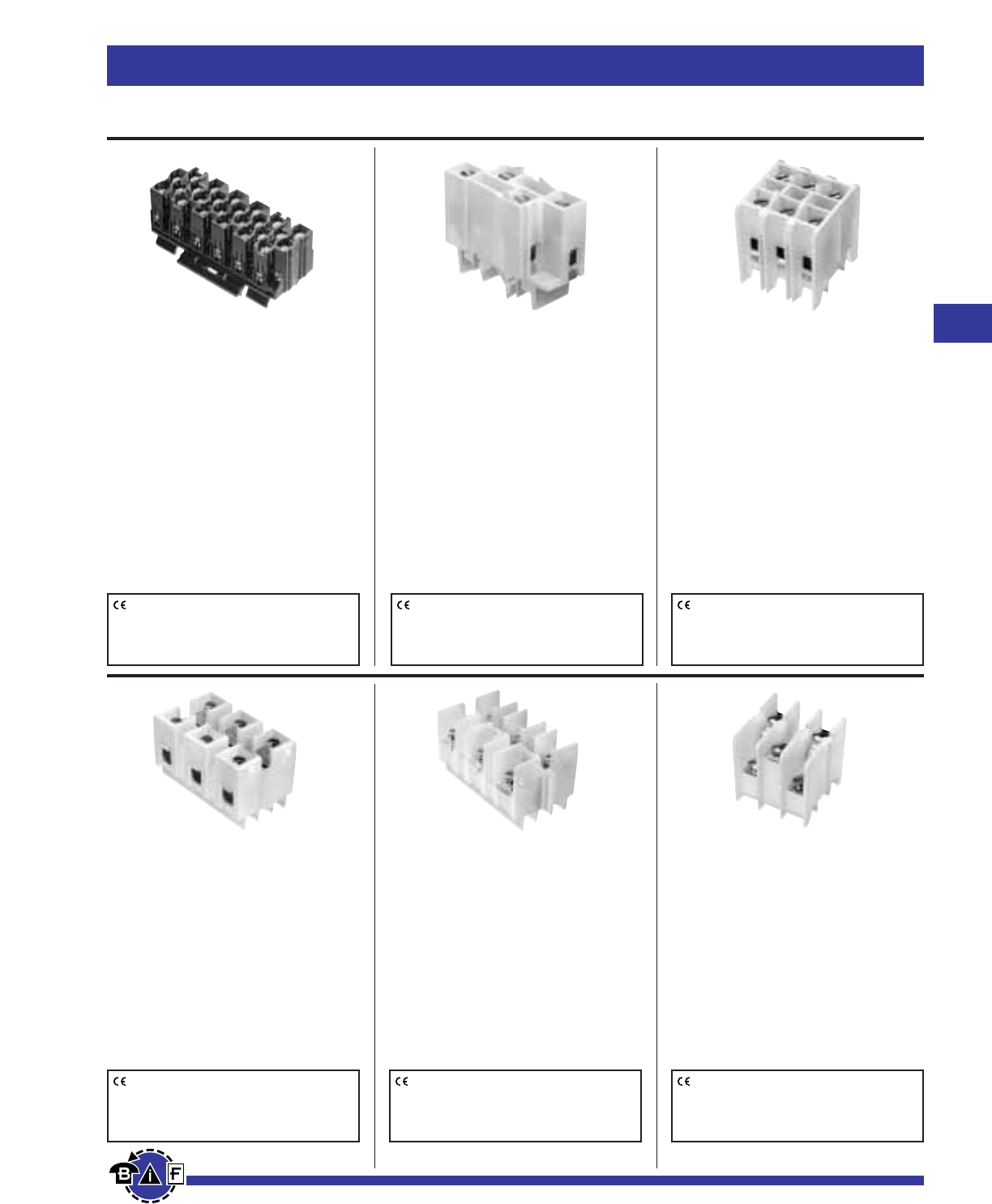
Bussmann®
91
For complete specification data, call Bussmann Information Fax ~ 636.527.1450
Fuseblocks, Holders and Terminal Blocks
N512-BK
Ratings: 5A, 600V; UL/CSA
20A, 300V; UL/CSA
Center Spacing: .197∑(5.00)
Number of Poles: 12
Circuits per Foot: 60
Circuit Jumper: JN512, 12 circuits
Wire Size: AWG #12-22 CU
Screw Size: #4-48
Mounting Options: C-rail, 15mm
DIN rail
Marking Tape: AT512
Torque Rating: 12 in/lb max.
Color: Black-BK
NFT2-__ __(color)
Ratings: 40A, 600V; UL/CSA; 55A
factory wired.
Center Spacing: .281∑(7.13)
Number of Poles: 2
Circuits per Foot: 38
Circuit Jumper: JN2, 2 circuits
Wire Size: AWG #8-22 CU
Screw Size: #8-32
Mounting Options: C-rail
Marking Tape: MT12-⁄Ω™
Torque Rating: 18 in/lb max.
NFT2 Colors: WH - White
NFT3-__ __(color)
Ratings: 40A, 600V; UL/CSA; 55A
factory wired.
Center Spacing: .390∑(9.91)
Number of Poles: 3
Circuits per Foot: 28
Circuit Jumper: JN3, 2 circuits
Wire Size: AWG #8-22 CU
Screw Size: #8-32
Mounting Options: C-rail
Marking Tape: MT12-⁄Ω™
Torque Rating: 18 in/lb max.
NFT3 Colors:
YE - Yellow WH - White
Rail Mount Terminal Blocks
NC3-WH
Ratings: 175A, 600V; UL/CSA
Center Spacing: 1.06∑(26.92)
Number of Poles: 3
Circuits per Foot: 11
Wire Size: 2/0-#14 CU/AL
Screw Size: fiΩ¡§-24
Mounting Options: C-rail,
Base Mount
Marking Tape: MT12-⁄Ω™
Torque Rating: 45 in/lb max.
NC3 Colors: WH - White
NSE3-WH
Ratings: 115A, 600V; UL/CSA
Center Spacing: 1.06∑(26.92)
Number of Poles: 3
Circuits per Foot: 11
Wire Size: For use with wire crimped
to ring terminal.
Screw Size: ⁄Ω¢-28
Mounting Options: C-rail,
Base Mount
Marking Tape: MT12-⁄Ω™
NSS3-WH
Ratings: 30A, 600V; UL/CSA
Center Spacing: .385∑(9.77)
Number of Poles: 3
Circuits per Foot: 28
Circuit Jumper: JNSS3, 2 circuits
Wire Size: For use with wire crimped
to ring terminal.
Screw Size: #6-32
Mounting Options: C-rail
Marking Tape: MT12-⁄Ω™
NSS3 Colors: WH - White
CE logo denotes compliance with European
Union Low Voltage Directive (50-1000Vac,
75-1500Vdc). Refer to Data Sheet: 8002 or
contact Bussmann Application Engineering
at 636-527-1270 for more information.
CE logo denotes compliance with European
Union Low Voltage Directive (50-1000Vac,
75-1500Vdc). Refer to Data Sheet: 8002 or
contact Bussmann Application Engineering
at 636-527-1270 for more information.
CE logo denotes compliance with European
Union Low Voltage Directive (50-1000Vac,
75-1500Vdc). Refer to Data Sheet: 8002 or
contact Bussmann Application Engineering
at 636-527-1270 for more information.
CE logo denotes compliance with European
Union Low Voltage Directive (50-1000Vac,
75-1500Vdc). Refer to Data Sheet: 8002 or
contact Bussmann Application Engineering
at 636-527-1270 for more information.
CE logo denotes compliance with European
Union Low Voltage Directive (50-1000Vac,
75-1500Vdc). Refer to Data Sheet: 8002 or
contact Bussmann Application Engineering
at 636-527-1270 for more information.
CE logo denotes compliance with European
Union Low Voltage Directive (50-1000Vac,
75-1500Vdc). Refer to Data Sheet: 8002 or
contact Bussmann Application Engineering
at 636-527-1270 for more information.
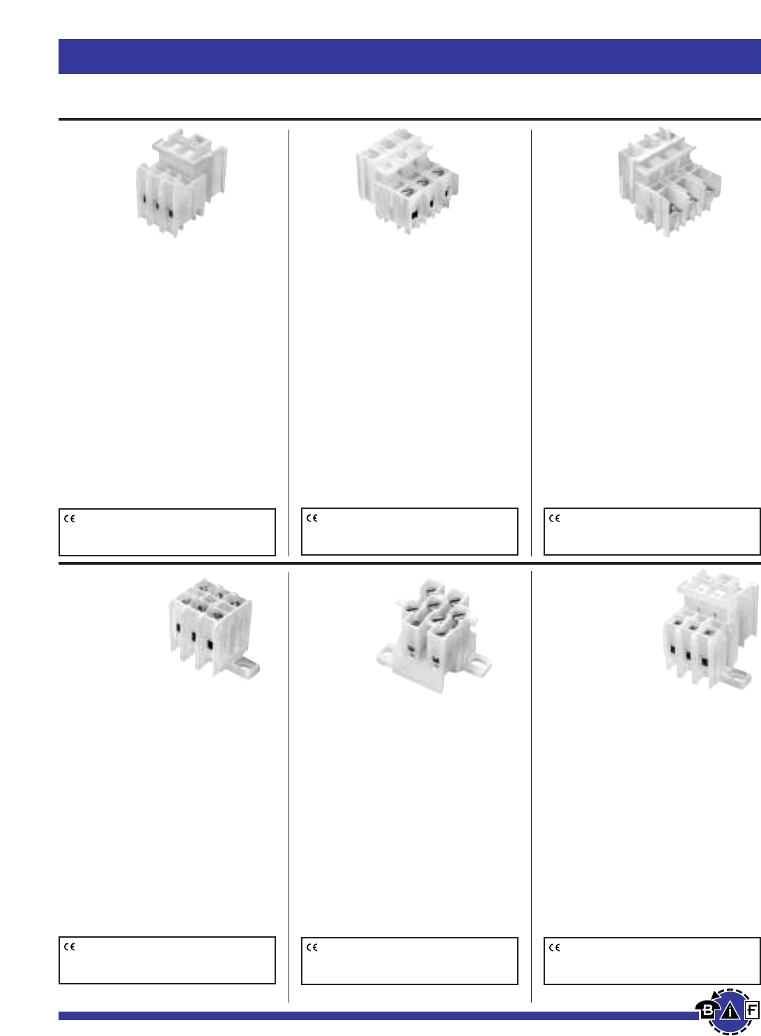
Bussmann®
92 For complete specification data, call Bussmann Information Fax ~ 636.527.1450
Fuseblocks, Holders and Terminal Blocks
PLU3-_ _(color)
Depluggable Rail Mount
Ratings: 40A, 600V; UL/CSA
Center Spacing: .390∑(9.91)
Number of Poles: 3
Circuits per Foot: 28
Circuit Jumper: JN3, 2 circuits
Wire Size: AWG #8-22 CU
Screw Size: #8-32
Mounting Options: C-rail, Stackable
Marking Tape: MT12-⁄Ω™
Torque Rating: 18 in/lb max.
PLU3 Colors: YE - Yellow
WH - White
Sectional Terminal Blocks
PLU1-WH
Depluggable Rail Mount
Ratings: 70A, 600V; UL/CSA
Center Spacing: .625∑(15.88)
Number of Poles: PLU1-WH (1 pole);
PLU11-WH (2 poles); PLU111-WH (3 poles)
Circuits per Foot: 19
Circuit Jumper: JN1, 2 circuits
Wire Size: AWG #4-18 CU
Screw Size: ⁄Ω¢-28
Mounting Options: C-rail, Stackable
Marking Tape: MT12-⁄Ω™
Torque Rating: 32 in/lb max.
PLU1 PLU11 PLU111
Colors: Colors: Colors:
WH- White WH -White WH- White
PSU1-WH
Depluggable Rail Mount
Ratings: 45A*, 600V; UL/CSA
(*45A rating achieved with ring
terminal crimped to wire)
Center Spacing: .625∑(15.88)
Number of Poles: PSU1-WH (1 pole);
PSU11-WH (2 poles); PSU111-WH (3 poles)
Circuits per Foot: 19
Wire Size: For use with crimp on
connectors only.
Screw Size: #10-32
Mounting Options: C-rail, Stackable
Marking Tape: MT12-⁄Ω™
Torque Rating: 32 in/lb max.
PSU1 PSU11 PSU111
Colors: Colors: Colors:
WH- White WH -White WH- White
KT3-WH
Base Mount
Ratings: 40A, 600V; UL/CSA
Center Spacing: .390∑(9.91)
Number of Poles: 3
Circuits per Foot: 28
Circuit Jumper: JN3, 2 circuits
Wire Size: #8-22 CU
Screw Size: #8-32
Mounting Options: Base Mount,
Stackable. KAD end mount adapter
optional.
Marking Tape: MT12-⁄Ω™
Torque Rating: 18 in/lb max.
KT3 Colors: WH - White
KT4-WH
Base Mount
Ratings: 30A, 600V; UL/CSA
Center Spacing: .250∑(6.35)
Number of Poles: 4
Circuits per Foot: 48
Circuit Jumper: JN4, 4 circuits
Wire Size: AWG #10-22 CU
Screw Size: #6-32
Mounting Options: Base Mount.
Mounting screws recommended every
12 circuits.
Marking Tape: MTC6
Torque Rating: 18 in/lb max.
KT4 Colors: WH - White
PLK3-_ _(color)
Base Mount
Ratings: 40A, 600V; UL
Center Spacing: .390∑(9.91)
Number of Poles: 3
Circuits per Foot: 28
Circuit Jumper: JN3, 2 circuits
Wire Size: AWG #8-22 CU
Screw Size: #8-32
Mounting Options: Base Mount,
Stackable. End Piece (Part No. KAD) is
required for mounting. Mounting
screws recommended every 15 circuits.
Marking Tape: MT12-⁄Ω™
Torque Rating: 18 in/lb max.
PLK3 Colors: YE - Yellow
WH - White
CE logo denotes compliance with European Union Low
Voltage Directive (50-1000Vac, 75-1500Vdc). Refer to
Data Sheet: 8002 or contact Bussmann Application
Engineering at 636-527-1270 for more information.
CE logo denotes compliance with European Union Low
Voltage Directive (50-1000Vac, 75-1500Vdc). Refer to
Data Sheet: 8002 or contact Bussmann Application
Engineering at 636-527-1270 for more information.
CE logo denotes compliance with European Union Low
Voltage Directive (50-1000Vac, 75-1500Vdc). Refer to
Data Sheet: 8002 or contact Bussmann Application
Engineering at 636-527-1270 for more information.
CE logo denotes compliance with European Union Low
Voltage Directive (50-1000Vac, 75-1500Vdc). Refer to
Data Sheet: 8002 or contact Bussmann Application
Engineering at 636-527-1270 for more information.
CE logo denotes compliance with European Union Low
Voltage Directive (50-1000Vac, 75-1500Vdc). Refer to
Data Sheet: 8002 or contact Bussmann Application
Engineering at 636-527-1270 for more information.
CE logo denotes compliance with European Union Low
Voltage Directive (50-1000Vac, 75-1500Vdc). Refer to
Data Sheet: 8002 or contact Bussmann Application
Engineering at 636-527-1270 for more information.
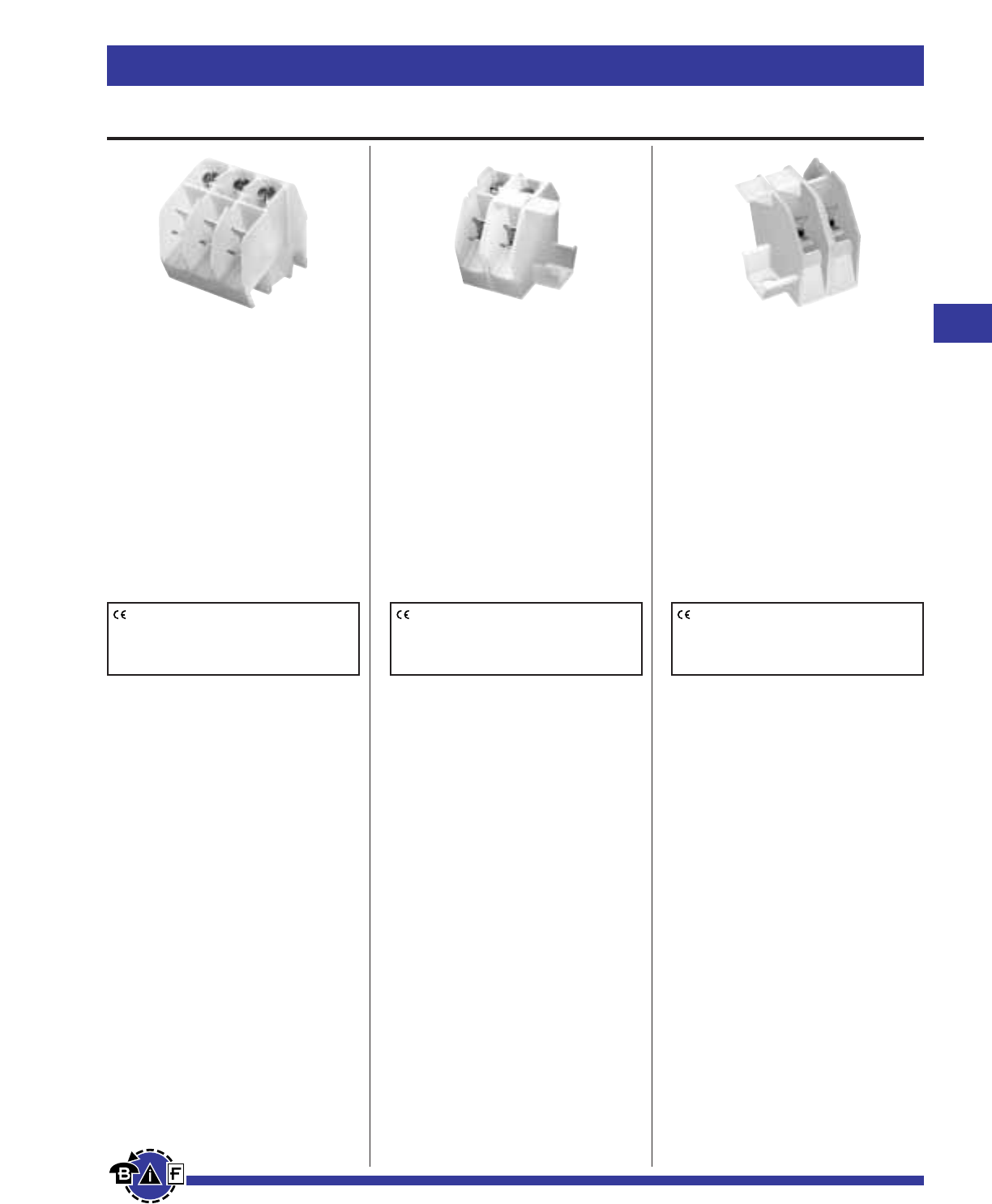
Bussmann®
93
For complete specification data, call Bussmann Information Fax ~ 636.527.1450
Fuseblocks, Holders and Terminal Blocks
Quick Connect Terminal Blocks
NTQ23-WH
Ratings: 40A, 600V
Center Spacing: .390∑(9.91)
Number of Poles: 3
Circuits per Foot: 28
Wire Size: AWG #8-22 CU
Screw Size: #8-32
Mounting Options: C-rail
Marking Tape: MT12-⁄Ω™
Color: White-WH
Torque Rating: 18 in/lb max.
BNQ21-WH
Ratings: 40A, 600V; UL/CSA
Center Spacing: .437∑(11.10)
Number of Poles: 1
Circuits per Foot: 24
Wire Size: AWG #8-22 CU
Screw Size: #8-32
Quick Connects: .250∑≈.031∑
Mounting Options: Base Mount,
Stackable. End Piece (Part No. BQE)
is required for mounting. Mounting
screws recommended every 8 circuits.
Torque Rating: 18 in/lb max.
BQQ41-WH
Ratings: 30A, 600V; UL/CSA
Center Spacing: .437∑(11.10)
Number of Poles: 1
Circuits per Foot: 24
Wire Size: For use with quick
connect terminals only.
Quick Connects: .250∑≈.031∑
Mounting Options: Base Mount,
Stackable. End Piece (Part No. BQE)
is required for mounting. Mounting
screws recommended every 8 circuits.
CE logo denotes compliance with European
Union Low Voltage Directive (50-1000Vac,
75-1500Vdc). Refer to Data Sheet: 8002 or
contact Bussmann Application Engineering
at 636-527-1270 for more information.
CE logo denotes compliance with European
Union Low Voltage Directive (50-1000Vac,
75-1500Vdc). Refer to Data Sheet: 8002 or
contact Bussmann Application Engineering
at 636-527-1270 for more information.
CE logo denotes compliance with European
Union Low Voltage Directive (50-1000Vac,
75-1500Vdc). Refer to Data Sheet: 8002 or
contact Bussmann Application Engineering
at 636-527-1270 for more information.
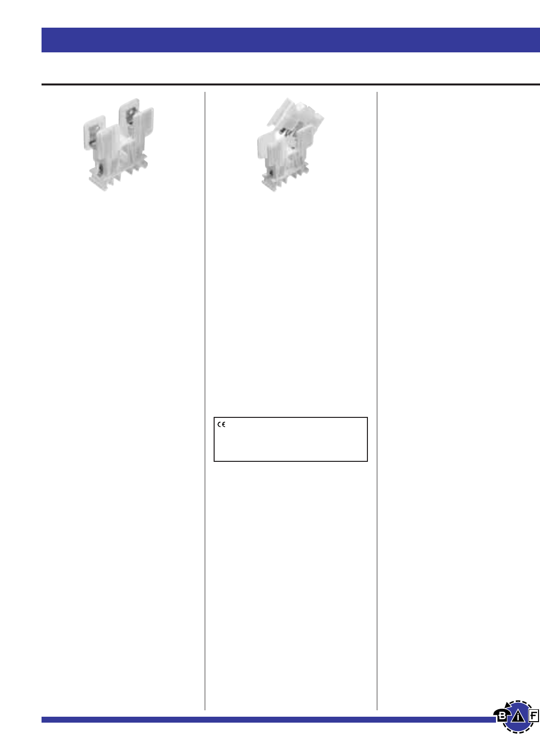
Bussmann®
94 For complete specification data, call Bussmann Information Fax ~ 636.527.1450
Fuseblocks, Holders and Terminal Blocks
Rail Mount Fuseholders and Circuit Breakers
NDNF1-WH
Ratings: 30A, 600V; UL/CSA
Number of Poles: 1
Fuse Size: ⁄‹Ω£™∑ ≈ 1⁄Ω™∑
(KTK, FNQ).
Circuit Jumper: JF1, 2 circuits
Wire Size: AWG #8-22 CU
Mounting Options: 35mm DIN rail,
C-rail
Marking Tape: MT12-⁄Ω™
Torque Rating: 18 in/lb max.
NDNF1 Colors: WH - White
Fuse Pullers (Optional):
PF1
Lighted neon or incandescent –
LPF-(Voltage rating)
LPF1-24
LPF1-120
LPF1-120-C
LPF1-220
LPF1-440
NDNLFD1
Ratings:
NDND1: 30A, 600V; UL/CSA (non-fused)
NDNFD1: 15A, 600V/CSA (fused)
NDNLFD1*: 15A, 600V (fused)
Number of Poles: 1
Fuse Size: ⁄Ω¢∑ ≈ 1⁄Ω¢∑
(Buss®AGC, MDL or equivalent.)
Circuit Jumper: JF1, 2 circuits
Wire Size: AWG #8-22 CU
Mounting Options: 35mm DIN rail,
C-rail
Marking Tape: MT12-⁄Ω™
Torque Rating: 18 in/lb max.
Extension: WH - White
*WH24 - 24V White
(Only available with NDNLFD1)
CE logo denotes compliance with European
Union Low Voltage Directive (50-1000Vac,
75-1500Vdc). Refer to Data Sheet: 8002 or
contact Bussmann Application Engineering
at 636-527-1270 for more information.
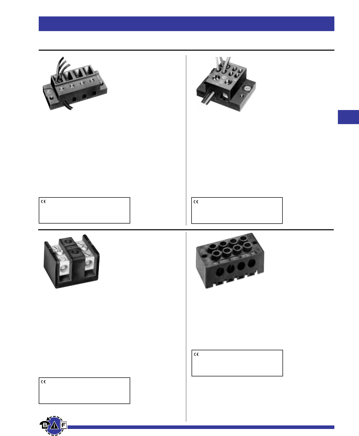
Bussmann®
95
For complete specification data, call Bussmann Information Fax ~ 636.527.1450
Fuseblocks, Holders and Terminal Blocks
Power Distribution Blocks
Series 11675
Quick-Connect Power
Distribution Block
Ratings: 40A, 250V; UL/CSA
Poles: 2 to 6 poles with (3) .250∑quick-connect terminals
per pole.
Input Wire Sizes: #8 – #14 CU
Torque Rating: 9 in/lb max.
Design: For equipment that requires
screw connections in the field. Reduces assembly costs of
internal wiring.
Agency Information: UL E62622; CSA LR15364
Series 11725
Quick-Connect Power
Distribution Block
Ratings: 70A, 600V; UL/CSA
Poles: 2, 3 or 4 poles with (4) .250∑quick-connect terminals
per pole.
Input Wire Sizes: #2 – #14 CU/#8 AL
Torque Rating: 45 in/lb max.
Design: For equipment that requires screw connections in
the field. Reduces assembly costs of internal wiring.
Agency Information: UL E62622; CSA LR15364
Series 14002
Barrier Terminal Block
Ratings: 115A, 600V; UL/CSA
Poles: 2 to 6 poles
Wire Sizes: #2 – #14 CU/#8 AL
Marking: Marking strip optional, consult factory.
Options For Load Side Connector:
CP: Sems pressure plate, rated 60A, 600V
Q: Quick-Connect, rated 50A, 600V
To order options, enter letter code in front of
Part No.: ie; CP14002-2.
Agency Information: UL E62622; CSA LR15364
Series 14004
Dead Front Terminal Block
Ratings: 90A, 600V; UL/CSA
Poles: 2 to 12 poles
Wire Sizes: #4 – #14 CU/#8 AL
Marking: Marking strip optional, consult factory.
Agency Information: UL E62622; CSA LR15364
CE logo denotes compliance with European
Union Low Voltage Directive (50-1000Vac,
75-1500Vdc). Refer to Data Sheet: 8002 or
contact Bussmann Application Engineering
at 636-527-1270 for more information.
CE logo denotes compliance with European
Union Low Voltage Directive (50-1000Vac,
75-1500Vdc). Refer to Data Sheet: 8002 or
contact Bussmann Application Engineering
at 636-527-1270 for more information.
CE logo denotes compliance with European
Union Low Voltage Directive (50-1000Vac,
75-1500Vdc). Refer to Data Sheet: 8002 or
contact Bussmann Application Engineering
at 636-527-1270 for more information.
CE logo denotes compliance with European
Union Low Voltage Directive (50-1000Vac,
75-1500Vdc). Refer to Data Sheet: 8002 or
contact Bussmann Application Engineering
at 636-527-1270 for more information.
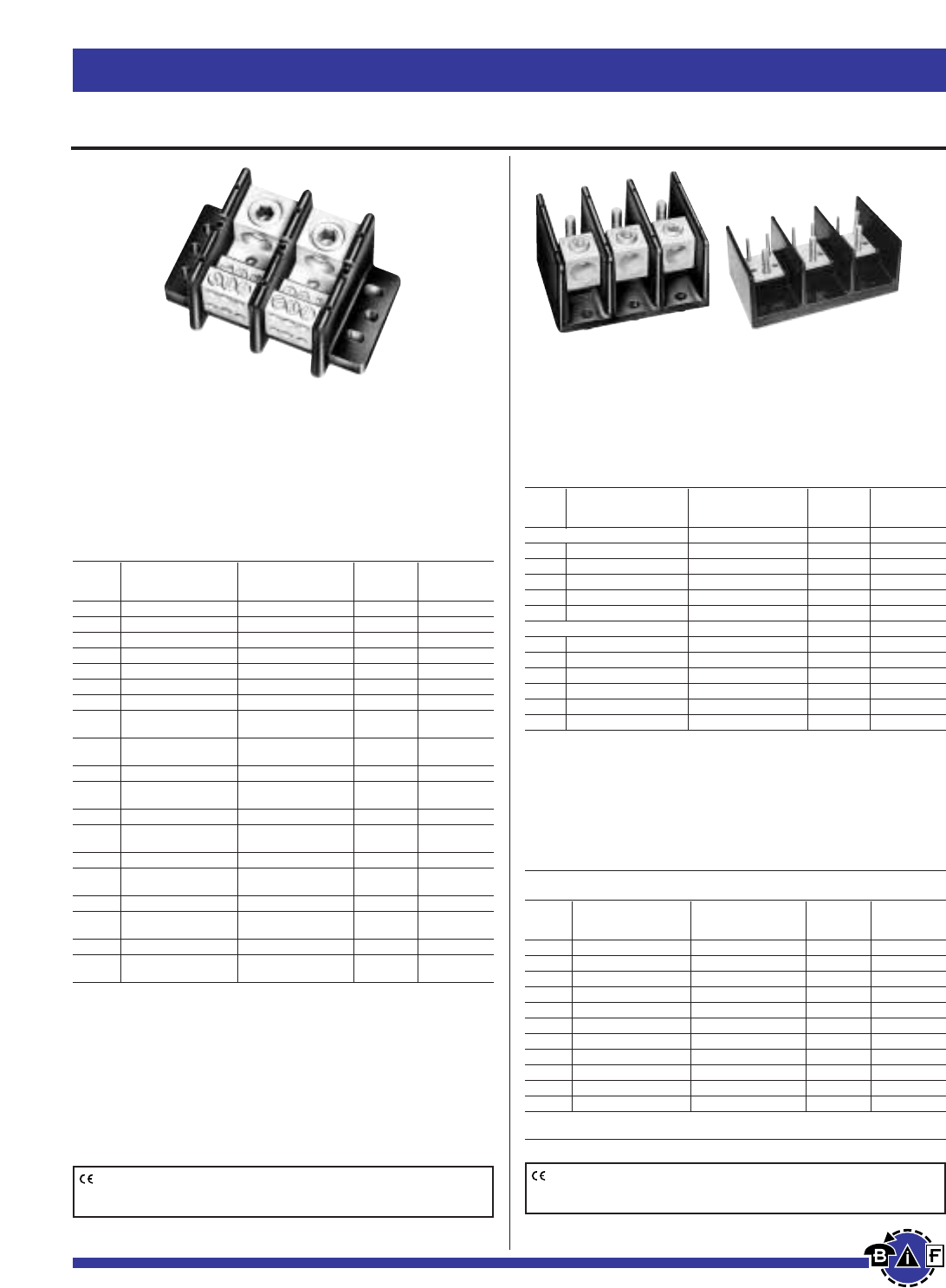
Series 160, 162, 163 & 165
Ratings: To 840A, 600V; UL Recognized/CSA. See Table.
Materials: Molded material: Black, UL rated 94V-0
thermoplastic.
Agency Information: UL E221592 General Industrial Class
per UL 1059; CSA Class 6228-01, File 53787.
Power Distribution Blocks (600V) Catalog Data
Connector
Part Line Load Material & Agency
Number Connection Connection Ampacity Information
*16021 2/0-#14CU, 2/0-#8AL (6)#4-#14CU, #4-#8AL AL-175A UL CSA
*16023 350kcmil-#6CU-AL 6)#4-#14CU, #4-#12AL AL-310A UL CSA
16220 2/0-#14CU, 2/0-#8AL (4)#4-#14CU, #4-#8AL AL-175A UL CSA
16321 2/0-#14CU, 2/0-#8AL (6)#4-#14CU, #4-#8AL AL-175A UL CSA
16323 350kcmil-#6CU-AL (6)#4-#14CU, #4-#12AL AL-310A UL CSA
16325 (2)2/0-#14CU, 2/0-#8AL (6)#4-#14CU, #4-#8AL AL-350A UL CSA
16330 500kcmil-#6CU-AL (6)#2-#14CU, #2-#12AL AL-380A UL CSA
16332 350kcmil-#6CU-AL
(3)#2-#14CU, #2-#8AL AL-310A UL CSA
(2)1/0-#14CU, 1/0-#8AL
16335 500kcmil-#6CU-AL
(3)#2-#14CU, #2-#8AL AL-380A UL CSA
(2)1/0-#14CU, 1/0-#8AL
16370 350kcmil-#6CU-AL (12)#4-#14CU, #4-#12AL AL-310A UL CSA
16371 350kcmil-#6CU-AL
(6)#2-#14CU, #2-#8AL AL-310A UL CSA
(3)1/0-#14CU, 1/0-#8AL
16372 350kcmil-#6CU-AL (21)#10-#14CU, #10AL AL-310A UL CSA
16373 350kcmil-#6CU-AL
(3)1/0-#14CU-AL AL-310A UL CSA
(14)#10-#14CU, #10AL
16375 600kcmil-#2CU-AL (12)#4-#14CU, #4-#12AL AL-420A UL CSA
16376 600kcmil-#2CU-AL
(6)#2-#14CU, #2-#8AL AL-420A UL CSA
(3)1/0-#14CU, 1/0-#8AL
16377 (2)300kcmil-#4CU-AL (12)#4-#14CU, #4-#12AL AL-570A UL CSA
16528 (2)600kcmil-#2CU-AL
(4)3/0-#6CU-AL AL-840A UL CSA
(4)#4-#14CU-AL
16530 (2)500kcmil-#6CU-AL (12)#4-#14CU-AL AL-760A UL CSA
16541 500kcmil-#6CU-AL (21)#6-#14CU-AL AL-380A UL CSA
*160 Series Bases have mounting holes outside the barriers. Other bases (162 through 165)
have mounting holes within barriers. See Data Sheet for dimensional drawings.
How To Order: Catalog Number + # of Poles
Example: 16020 – 3 (complete part number)
Optional covers: 160 Series: CPB160 - (pole)
162 Series: CPB162 - (pole)
163 Series: CPDB- (pole)
165 Series: CPDB165 (1 for each pole)
Bussmann®
96 For complete specification data, call Bussmann Information Fax ~ 636.527.1450
Fuseblocks, Holders and Terminal Blocks
Data Sheet: 1117 (Series 160, 162, 165); 1148 (Series 163) Data Sheet: 1117 (Series 160, 162, 165)
Power Distribution & Terminal Blocks
CE logo denotes compliance with European Union Low Voltage Directive
(50-1000Vac, 75-1500Vdc). Refer to Data Sheet: 8002 or contact
Bussmann Application Engineering at 636-527-1270 for more information.
CE logo denotes compliance with European Union Low Voltage Directive
(50-1000Vac, 75-1500Vdc). Refer to Data Sheet: 8002 or contact
Bussmann Application Engineering at 636-527-1270 for more information.
Series 162, 163, 165
Ratings: To 760A, 600V; UL Recognized/CSA. See Table.
Materials: Molded material: Black, UL rated 94V-0 thermoplastic.
Agency Information: UL E221592 General Industrial Class
per UL 1059; CSA Class 6228-01, File 53787.
Connector–Stud Blocks (600V) Catalog Data
Connector
Part Line Load Material & Agency
Number Connection Connection Ampacity Information
Connector to Stud
16280 2/0-#14CU-AL ⁄Ω¢-20 ≈ ‹Ω¢ Stud AL-175A UL —
16281 2/0-#14CU-AL ⁄Ω¢-20 Tapped hole AL-175A UL —
16378 500kcmil-#6CU-AL (2)⁄Ω¢-20 ≈ 1 Stud AL-380A UL CSA
16383 500kcmil-#6CU-AL (1)‹Ω•-16 ≈1 Stud AL-380A UL CSA
16582 (2)500kcmil-#6CU-AL (2)‹Ω•-16 ≈1fiΩ• Stud AL-760A UL CSA
Stud to Stud
16290 ⁄Ω¢-20 ≈ ‹Ω¢ Stud ⁄Ω¢-20 ≈ ‹Ω¢ Stud CU-175A UL —
16390 ‹Ω•-16 ≈1⁄Ω• Stud ‹Ω•-16 ≈1⁄Ω• Stud CU-250A UL CSA
16394 ⁄Ω™-13 ≈1⁄Ω¡§ Stud ⁄Ω™-13 ≈1⁄Ω¡§ Stud CU-400A UL CSA
16395 ‹Ω•-16 ≈1‡Ω¡§ Stud (2)⁄Ω¢-20 ≈ ·Ω¡§ Stud CU-310A UL CSA
16591 ‹Ω•-16 ≈1‡Ω¡§ Stud (2)‹Ω•-16 ≈ 1‡Ω¡§ Stud CU-400A UL CSA
16593 ⁄Ω™-13 ≈1 Stud ⁄Ω™-13 ≈1 Stud CU-600A UL CSA
Series 160, 162, 163 and 165
Ratings: To 620A, 600V; UL Recognized/CSA. See Table.
Materials: Molded material: Black, UL rated 94V-0 thermoplastic.
Agency Information: UL E221592 General Industrial Class
per UL 1059; CSA Class 6228-01, File 53787.
Power Distribution Blocks (600V) Catalog Data
Connector
Part Line Load Material & Agency
Number Connection Connection Ampacity Information
*16000 2/0-#8CU-AL 2/0-#8CU-AL AL-175A UL —
*16003 250kcmil-#6CU Only 250kcmil-#6CU Only CU-255A UL —
*16005 350kcmil-#6CU-AL 350kcmil-#6CU-AL AL-310A UL —
16200 #2-#14CU, #2-#8AL #2-#14CU, #2-#8AL AL-115A UL —
16201 1/0-#14CU Only 1/0-#14CU Only CU-150A UL —
16204 2/0-#8CU-AL 2/0-#8CU-AL AL-175A UL —
16301 250kcmil-#6CU Only 250kcmil-#6CU Only CU-255A UL CSA
16303 350kcmil-#6CU-AL 350kcmil-#6CU-AL AL-310A UL CSA
16306 500kcmil-#6CU-AL 500kcmil-#6CU-AL AL-380A UL CSA
16500 (2)350kcmil-#4CU-AL (2)350kcmil-#4CU-AL AL-620A UL CSA
16504 (2)500kcmil-#6CU-AL (2)500kcmil-#6CU-AL AL-760A UL CSA
*160 Series Bases have mounting holes outside the barriers. Other bases (162 through 165)
have mounting holes within barriers. See Data Sheet for dimensional drawings.
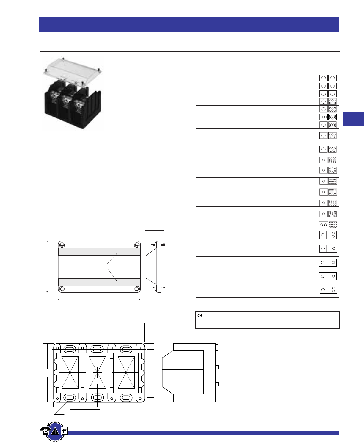
Bussmann®
97
For complete specification data, call Bussmann Information Fax ~ 636.527.1450
Fuseblocks, Holders and Terminal Blocks
Data Sheet: 1148
Power Distribution Blocks
Supplied with (4) #4 thread-cutting
screws assembled as shown
Textured surface for marking
CPDB-1 (single pole) 2.10"
CPDB-2 (two pole) 3.72"
CPDB-3 (three pole) 5.34"
4.14"
1-pole
1.96"
2-pole
3.58"
3-pole
5.20"
.31"
1.62"
3.25"
Mtg. hole .21 x .41,
c'bore .42 x .62 x .12 deep
3.32"
.97"
4.00" 3.37"
Ordering Information:
163 Series blocks are available in 1, 2 or 3 poles.
To order: Basic Part No. + Number of poles
Examples:
16301-1 = (one-pole block)
16303-3 = (three-pole block)
CE logo denotes compliance with European Union Low Voltage Directive
(50-1000Vac, 75-1500Vdc). Refer to Data Sheet: 8002 or contact
Bussmann Application Engineering at 636-527-1270 for more information.
163 Series
(Replaces Bussmann 164 Series)
Ampere Ratings: up to 420A
Voltage Ratings: 600V
Construction: UL 94VO. Tin-plated aluminum connectors.
Agency Information:
UL Recognized: UL E221592
General Industrial Class per UL1059
CSA Certified: CSA LR15364
Optional Covers:
Covers ordered and shipped separately.
Input/Output Termination Options
Basic Wire Size Amps/
Part No. Line Side Load Side Pole Line/Load
16301* 250kcmil-#6CU Only 250kcmil-#6CU Only 255
16303 350kcmil-#6CU-AL 350kcmil-#6CU-AL 310
16306 500kcmil-#6CU-AL 500kcmil-#6CU-AL 380
16321 2/0-#14CU, 2/0-#8AL (6)#4-#14CU, #4-#8AL 175
16323 350kcmil-#6CU-AL (6)#4-#14CU, #4-#12AL 310
16325 2/0-#14CU, 2/0-#8AL (6)#4-#14CU, #4-#8AL 350
16330 500kcmil-#6CU-AL (6) #2-#14CU, #2-#12AL 380
16332 350kcmil-#6CU-AL (3) #2-#14CU, #2-#8AL
(2) 1/0-#14CU, 1/0-#8AL 310
16335 500kcmil-#6CU-AL (3) #2-#14CU, #2-#8AL
(2) 1/0-#14CU, 1/0-#8AL 380
16370 350kcmil-#6CU-AL (12)#4-#14CU, #4-#12AL 310
16371 350kcmil-#6CU-AL (6) #2-#14CU, #2-#8AL
(3) 1/0-#14CU, 1/0-#8AL 310
16372 350kcmil-#6CU-AL (21) #10-#14CU, #10AL 310
16373 350kcmil-#6CU-AL (14) #10-#14CU, #10AL
(3) 1/0-#14CU-AL 310
16375 600kcmil-#2CU-AL (12)#4-#14CU, #4-#12AL 420
16376 600kcmil-#2CU-AL (6) #2-#14CU, #2-#8AL
(3) 1/0-#14CU, 1/0-#8AL 420
16377 (2)300kcmil-#4CU-AL (12)4-#14CU, #4-#12AL 570
16378 500kcmil-#6CU-AL Stud Size
(2) ⁄Ω¢-20 x 1 380
16383 500kcmil-#6CU-AL Stud Size
(1) ‹Ω•-16 x 1 380
16390 Stud Size Stud Size
‹Ω•-16 x 1⁄Ω• ‹Ω•-16 x 1⁄Ω• 250
16394 Stud Size Stud Size
⁄Ω™-13 x 1⁄Ω¡§ ⁄Ω™-13 x 1⁄Ω¡§ 400
16395 Stud Size Stud Size
‹Ω•-16 x 1‡Ω¡§ (2) ⁄Ω¢-20 x ·Ω¡§ 310
*Copper connectors for use with copper wire only.
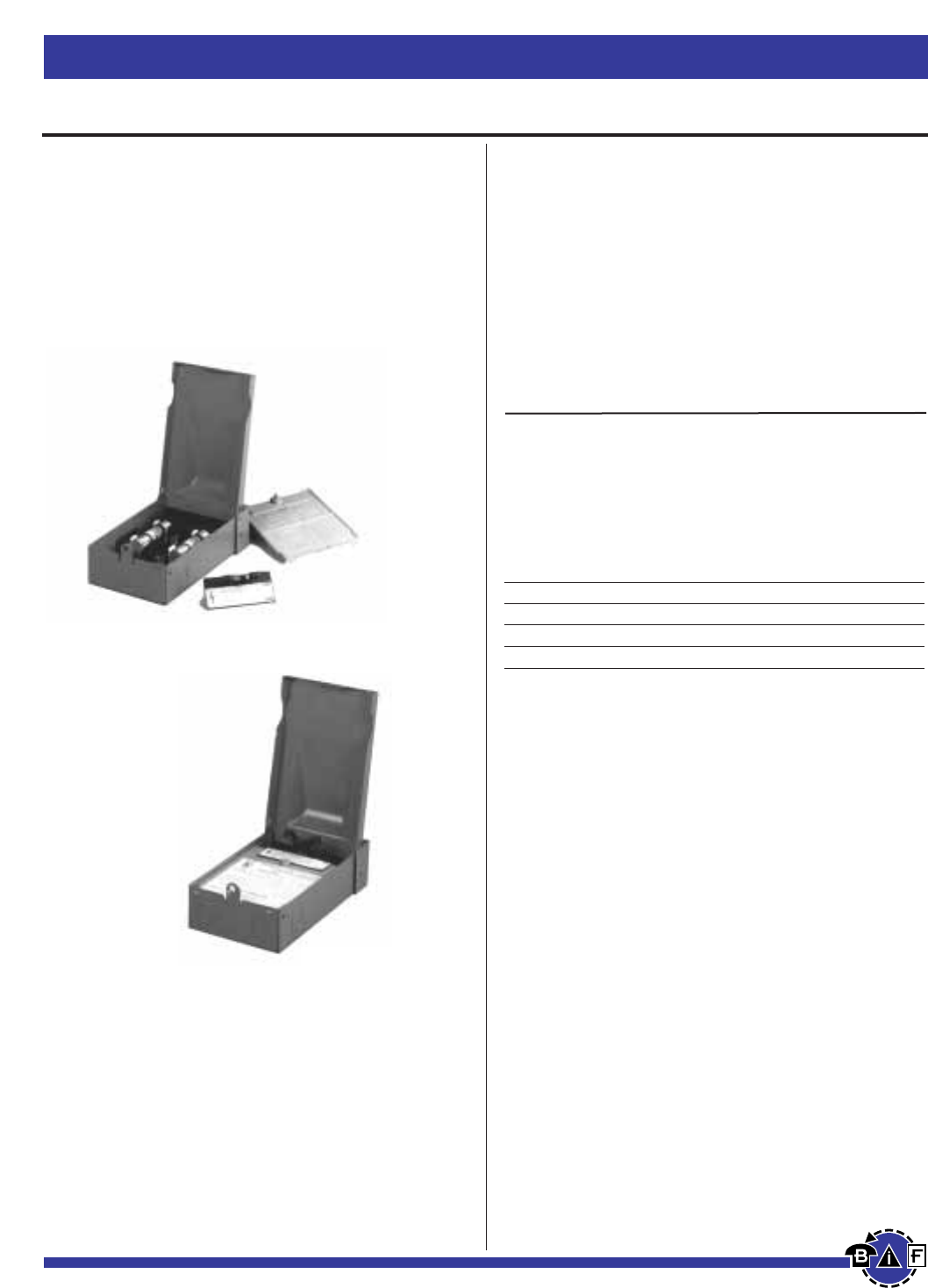
Bussmann®
98 For complete specification data, call Bussmann Information Fax ~ 636.527.1450
Fuseblocks, Holders and Terminal Blocks
Data Sheet: 1143
Power Distribution & Terminal Blocks
HVAC Disconnects
Series B22__
Fused and Non-Fused
Single Phase 2W, 240Vac
UL Guide WGEW
Wire Range: 14 - 2 awg, Al-Cu wire
Main Catalog Maximum HP1Apprx. Dimensions
Rating Number 120V 240V H x W x D(in.)
30A B221-30F (Fused) 2 3 8 ‹/¢ x 5 ‹/• x 2 ‡/•
60A B222-60F (Fused) 3 10 8 ‹/¢ x 5 ‹/• x 2 ‡/•
60A B222-60NF (Non-fused) 10 8 ‹/¢ x 5 ‹/• x 2 ‡/•
60A B222-60NFNA (Non-fused Switch) 10 8 ‹/¢ x 5 ‹/• x3 fi/•
- 96-3258-4 Replacement Pullout Head
*Suitable for use as service equipment with optional field
installed lug kit Number DPFG
Shipping Weight - 2.7 lbs. per unit.
Case pack quantity 10, Case pack weight 30 lbs.
RAINPROOF AIR CONDITIONER PULLOUT UNITS
Fused and Non-Fused Features:
•NEMA 3R Rainproof.
•Compact design but offers ample working space.
•Internal shield can be removed without tools.
•Specifications are embossed on internal shield.
•Knockouts on back, bottom, and both sides.
•Touchproof construction.
•Padlockable
•Agency Approvals:
UL Listed to UL 1429
CUL Certified
1 Rated with Bussmann LPN-RK Data Sheet 1003, FRN-R
Data Sheet 1019, DLN-R Data Sheet 1021, and HAC-R
Data Sheet 1038, Dual Element Time Delay Fuses.
Metallic
Fused Disconnect
Metallic
Non-Fused Disconnect
METALLIC
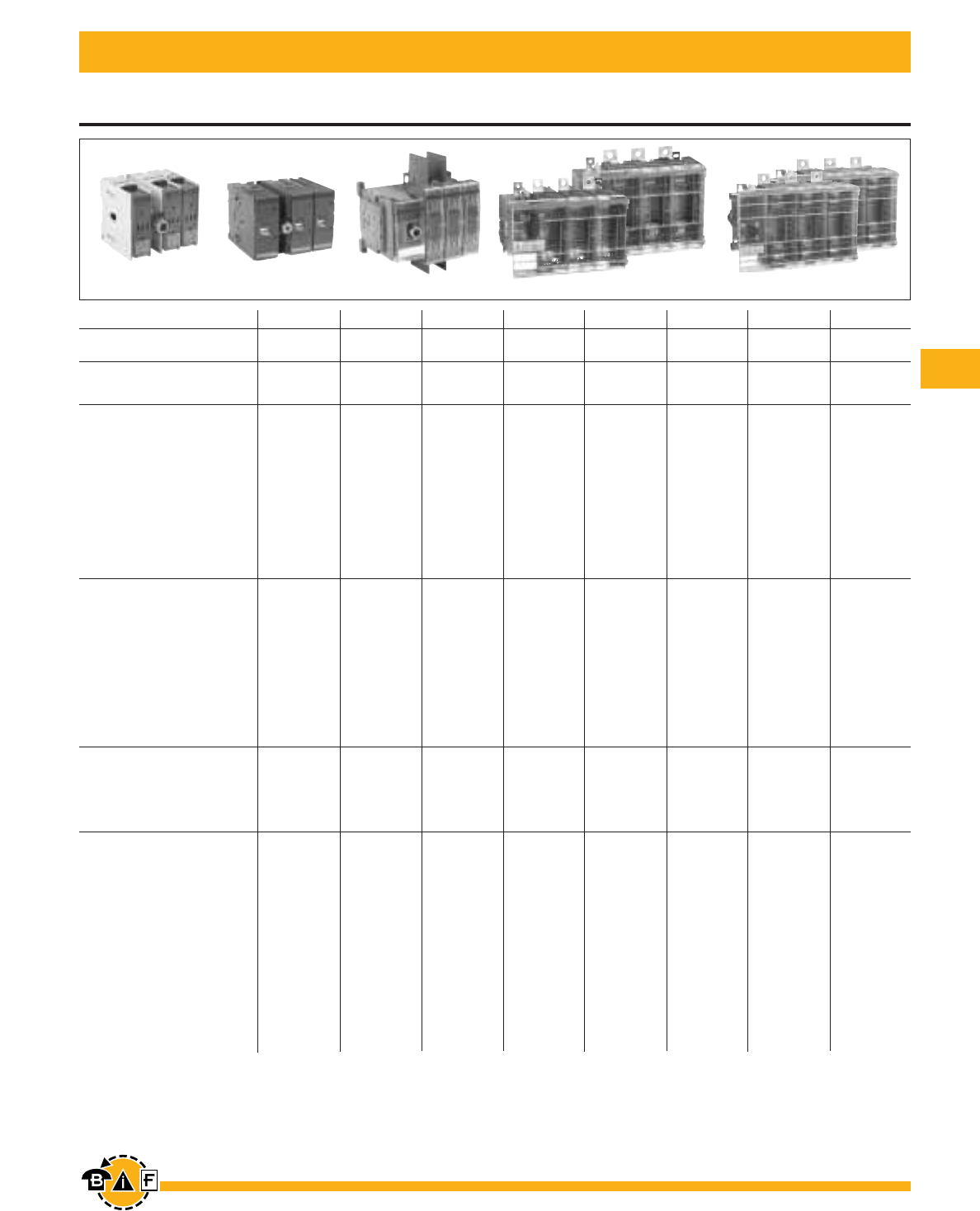
Bussmann®
99
For complete specification data, call Bussmann Information Fax ~ 636.527.1450
Catalog number 3 pole CFD30CC3 CFD30J3 CFD60J3 CFD100J3 FD200J3 FD400J3 FD600J3 FD800L3
General purpose
amp rating A 30 30 60 100 200 400 600 800
Approvals12 pole N/A N/A N/A UL98 & IEC UL98 & IEC UL98 & IEC UL98 & IEC UL98 & IEC
3 pole UL98 & IEC UL98 & IEC UL98 & IEC UL98 & IEC UL98 & IEC UL98 & IEC UL98 & IEC UL98 & IEC
4 pole UL98 & IEC UL98 & IEC UL98 & IEC UL98 & IEC UL98 & IEC UL98 & IEC UL98 & IEC UL98 & IEC
Technical ratings
(UL,CSA)
Max operating voltage V 600 600 600 600 600 600 600 600
Max horsepower rating
Three phase
200 – 208V HP 5/7.5 5/7.5 15 25 50 100/125 150 200
240V HP 7.5 7.5 15 30 60 125 200 250
480V HP 15 15 30 60 125 250 400 500
600V HP 20 20 50 75 150 350 500 600
Single phase
120V HP 2 2 — — — — — —
240V HP 3 3 — — — — — —
UL fuse class CC J J J J,T J,T J,T L
Technical ratings
(IEC)
Rated insulation and operational
voltage. ac20 and dc2021000 1000 750 750 1000 1000 1000 1000
Rated thermal current, Ith
ac 20/dc 20 open A 32 32 63 125 250 400 630 800
ac 20/dc 20 enclosed A 32 32 63 125 250 400 600 720
ac 21A ≤500V A 32 32 63 125 250 400 630 800
≤690V A 32 32 63 125 250 400 630 800
Rated operational power ac23
400/415V kW 14/15 14/15 30 80/90 132/140 210/230 315/340 350/380
690V kW 25 25 60 132 230 330 540 600
Physical characteristics
Weight 3 pole switch lb 1.54 1.54 2.86 3.30 15.21 17.2 37.48 37.48
4 pole lb 1.98 1.98 3.52 3.96 17.4 19.4 46.3 46.3
Dimension 3 pole H in 3.82 3.82 3.94 5.66 7.87 7.87 11.42 11.42
W in 4.17 4.17 5.63 7.06 10.31 11.22 14.69 14.69
D in 4.21 4.21 5.04 5.09 7.83 8.11 9.21 9.21
Accessories
Double break contacts S SSSS SSS
Fuse cover S S S • S S S S
Terminal lug kit Integral Integral Integral BDTL24 BDTL25 BDTL26 BDTL27 BDTL27
Terminal shroud Not required Not required Not required • • • • •
Auxiliary contact • •••• •••
Handle UL/NEMA type
Type 1, 3R, 12 • •••• •••
Type 1, 3R, 4, 4X, 12 • •••• •••
Conversion kit
6 pole • •••• •••
Transfer • •••• •••
Bypass — — — — • • • •
Mechanical interlock • • — — • • • •
Electrical interlock — — — — • • • •
Overview
for Fusible Disconnect Switches CFD30CC3 – FD800L3
CFD30J3 CFD60J3 CFD100J3 FD200J3 FD400J3 FD600J3 FD800L3
S = Standard
• = Available
— = Not available
1UL listed switches are also CSA approved.
21000V IEC 408 UL listed, CSA approved, IEC rated, CE marked
For additional information and detail, see the Bussmann Disconnect Switch Catalog, Item Number 3006
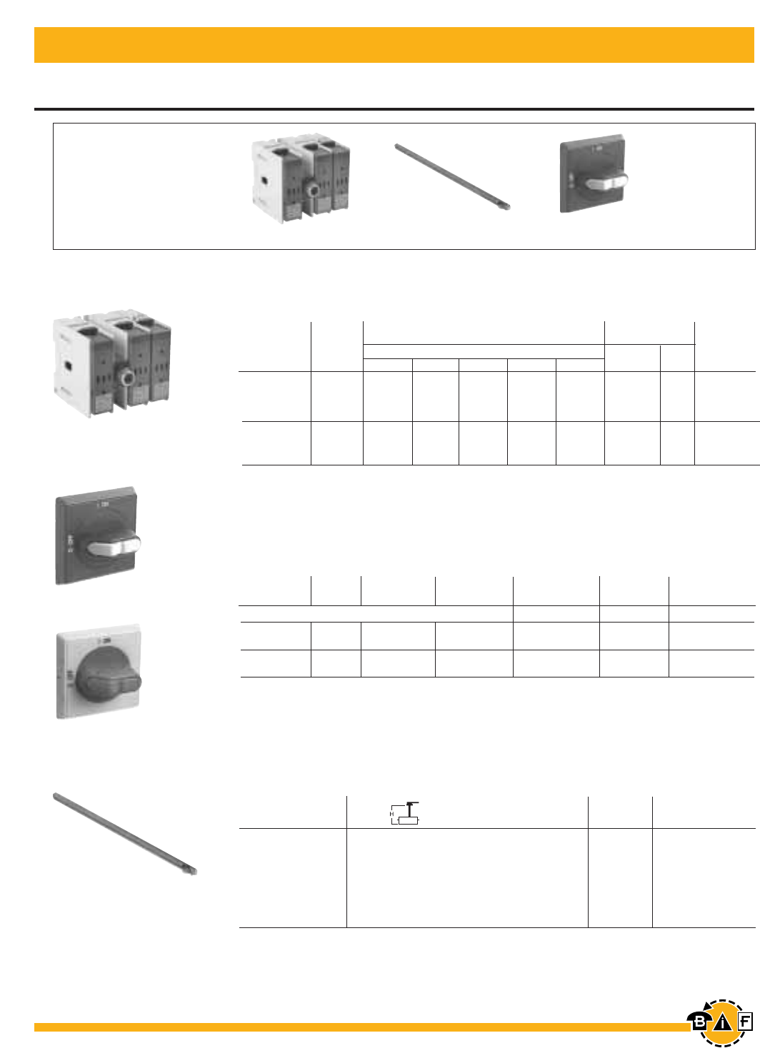
Bussmann®
100 For complete specification data, call Bussmann Information Fax ~ 636.527.1450
30A Fusible Disconnect Switches
Base & DIN Rail Mounted UL Fuse Class J, CC
3.3/85 5.5 – 5.7 0.04 CDS85S
4.1/105 5.5 – 6.5 0.04 CDS105S
4.7/120 5.5 – 7.1 0.05 CDS120S
5.1/130 5.5 – 7.5 0.05 CDS130S
7.1/180 6.3 – 9.4 0.08 CDS180S
9.8/250 9.1 – 12.2 0.10 CDS250S
13.0/330 12.2 – 15.4 0.14 CDS330S
For additional information and detail see the Bussmann Disconnect Switch Catalog item number 3006
For a complete assembly,
please select one of each:
1 switch
1 handle
1 shaft
CFD30J3 + CDS180S + CDH3S
CFD30J3
Shaft Length Mounting Depth1Weight Catalog
(inches/mm) (in inches) (lbs.) Number
Shafts — For use with CDH selector handles .20 x .20" (5 x 5 mm)
CDS_ _S
30A Switches, 600V
UL IEC
General Fuse Maximum Horsepower Rating Terminal Lugs
Purpose Type Three Phase Wire Wire Catalog
Amp Rating 600V 200V 208V 240V 480V 600V Size Type Number
3 pole
30 J 5 7.5 7.5 15 20 #18 – 8 CU CFD30J3
30 CC 5 7.5 7.5 15 20 #18 – 8 CU CFD30CC3
4 pole
30 J 5 7.5 7.5 15 20 #18 – 8 CU CFD30J4
30 CC 5 7.5 7.5 15 20 #18 – 8 CU CFD30CC4
Selector Handles — For use with shafts .20 x .20" (5 x 5 mm)
NEMA IEC Weight Catalog
Type Type Color Defeatable Padlockable (lbs) Number
CDH3S, 5S
CDH4S, 6S
All marked both O/I & Off/On
1,3R,12 IP65 Black — Yes 0.16 CDH3S
1,3R,12 IP65 Red/Yellow — Yes 0.16 CDH4S
1,3R,12 IP65 Black Yes Yes 0.16 CDH5S
1,3R,12 IP65 Red/Yellow Yes Yes 0.16 CDH6S
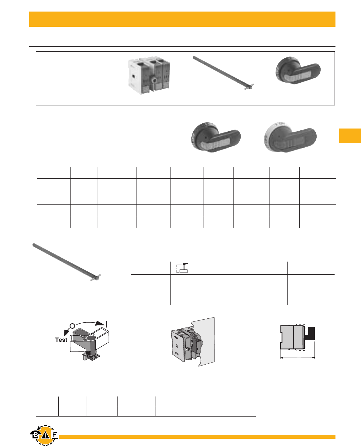
Bussmann®
101
For complete specification data, call Bussmann Information Fax ~ 636.527.1450
NEMA Length Weight Catalog
Type Color Marking (Inches/mm) Padlockable (lbs.) Number
Shaft length Mounting Depth Weight Catalog
(inches/mm) (in inches) (lbs.) Number
5.9/150 4.9 – 8.9 0.07 CDS48P
6.7/170 5.9 – 9.7 0.08 CDS67P
10.4/265 9.5 – 13.4 0.12 CDS49P
15.8/400 15.0 – 18.7 0.18 CDS50P
19.7/500 20.5 – 22.6 0.23 CDS99P
NEMA IEC Length Weight Catalog
Type Type Color Marking (inches/mm) Defeatable Padlockable (lbs.) Number
1,3R,12 IP65 Black O/I&Off/On 1.8/45 Yes Yes 0.28 BDH104
1,3R,12 IP65 Red/Yellow O/I&Off/On 1.8/45 Yes Yes 0.28 BDH105
1,3R,12 IP65 Black O/I&Off/On 2.6/65 Yes Yes 0.29 BDH106
1,3R,12 IP65 Red/Yellow O/I&Off/On 2.6/65 Yes Yes 0.29 BDH107
1,3R,4,4X,12 IP65 Black O/I&Off/On 2.6/65 Yes Yes 0.29 CDHXB65
1,3R,4,4X,12 IP65 Red/Yellow O/I&Off/On 2.6/65 Yes Yes 0.29 CDHXY65
1,3R,12 IP65 Black Off/On/Test 2.6/65 Yes Yes 0.29 BDH106T
1,3R,12 IP65 Red/Yellow Off/On/Test 2.6/65 Yes Yes 0.29 BDH107T
Handles & Shafts
For 30A Fusible Disconnect Switches
For a complete assembly,
please select one of each:
1 switch
1 handle
1 shaft
Pistol Handles
For use with shafts .20 x .20" (5 x 5 mm)
CDS__ __P
5.20"
132
mm
CFD30J3 + CDS67P + BDH106
BDH104, 106 BDH105, 107
Shafts
For use with pistol handles .20 x .20" (5 x 5 mm)
1 Black O/I/Test 50 Yes 0.10 BDH79
Direct Mount Handle
Mounts directly to switch, no shaft necessary
BDH79
5.20"/132mm
BDH79 Mounted Depth
BDH79 Mounted
For additional information and detail see the Bussmann Disconnect Switch Catalog item number 3006
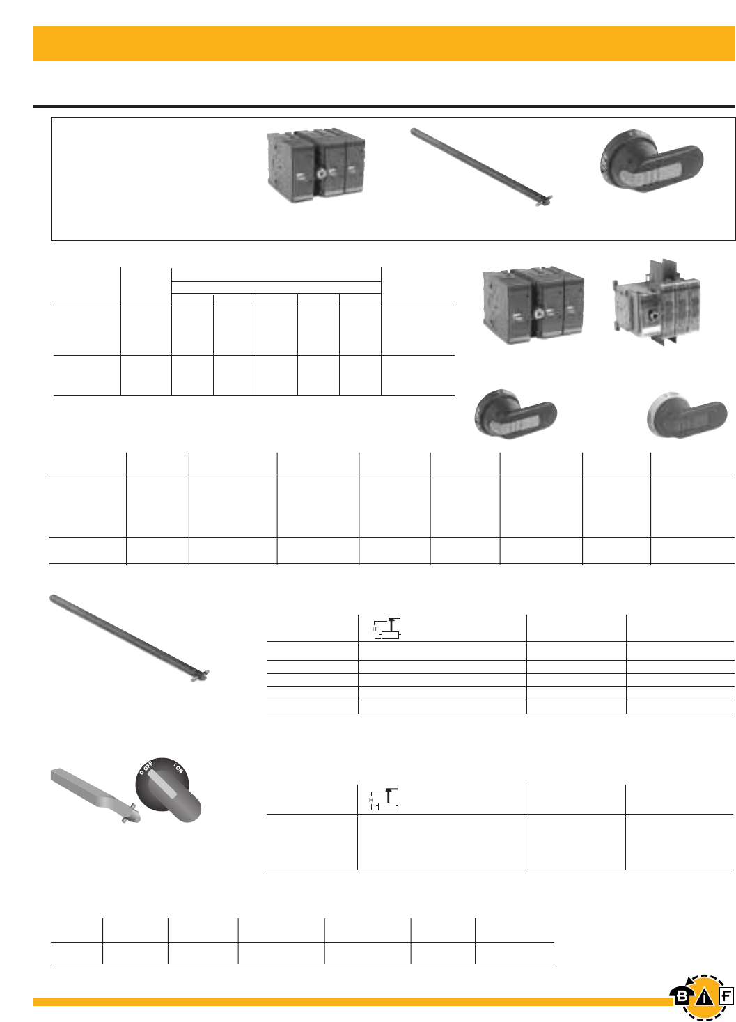
Bussmann®
102 For complete specification data, call Bussmann Information Fax ~ 636.527.1450
BDH58, 60 BDH59, 61
For Fusible Disconnect Switches UL Fuse Class J
60A - 100A
For additional information and detail see the Bussmann Disconnect Switch Catalog item number 3006 For additional information and detail see the Bussmann Disconnect Switch Catalog item number 3006
For a complete assembly,
please select one of each:
1 switch
1 handle
1 shaft
1 terminal lug kit
CFD60J3 CFD100J3
Shaft Length Mounting Depth Weight Catalog
(inches/mm) (in inches) (lbs.) Number
5.1/130 4.8 – 7.8 0.08 BDST4
8.3/210 8.0 – 11.0 0.13 BDST25
11.4/290 11.0 – 14.0 0.18 BDST29
14.2/360 13.8 – 16.8 0.23 BDST30
BDST__
Twisted Shafts
Rotates handle 45° .24 x .24" (6 x 6 mm)
NEMA Length Weight Catalog
Type Color Marking (Inches/mm) Padlockable (lbs.) Number
1 Black O/I/Test 50 Yes 0.10 CDH4
Direct Mount Handle
Mounts directly to switch, no shaft necessary
Shaft Length Mounting Depth Weight Catalog
(inches/mm) (in inches) (lbs.) Number
5.9/150 5.5 – 8.5 0.09 BDS150
8.3/210 8.0 – 11.0 0.13 BDS210
11.4/290 11.0 – 14.0 0.18 BDS290
14.2/360 13.8 – 16.8 0.23 BDS360
16.9/430 16.5 – 19.7 0.27 BDS430
Shafts — .24 x .24" (6 x 6 mm)
NEMA/UL IEC Length Weight Catalog
Type Type Color (inches/mm) Marking Defeatable Padlockable (lbs.) Number
1,3R,12 IP65 Black 2.6/65 O/I & Off/On Yes Yes 0.29 BDH58
1,3R,12 IP65 Red/Yel 2.6/65 O/I & Off/On Yes Yes 0.29 BDH59
1,3R,12 IP65 Black 3.1/80 O/I & Off/On Yes Yes 0.30 BDH60
1,3R,12 IP65 Red/Yel 3.1/80 O/I & Off/On Yes Yes 0.30 BDH61
1,3R,4,4X,12 IP65 Black 3.1/80 O/I & Off/On Yes Yes 0.30 CDHXB86
1,3R,4,4X,12 IP65 Red/Yel 3.1/80 O/I & Off/On Yes Yes 0.30 CDHXY86
Pistol Handles — .24 x .24" (6 x 6 mm)
BDS__
60 —100A Switches, 600V
UL General UL Fuse Maximum Horsepower Rating
Purpose Type Three Phase Catalog
Amp Rating 600V 200V 208V 240V 480V 600V Number
3 pole 3 pole
60 J 15 15 15 30 50 CFD60J3
100 J 25 25 30 60 75 CFD100J3
4 pole 4 pole
60 J 15 15 15 30 50 CFD60J4
100 J 25 25 30 60 75 CFD100J4
CFD60J3 + BDS210 + BDH58
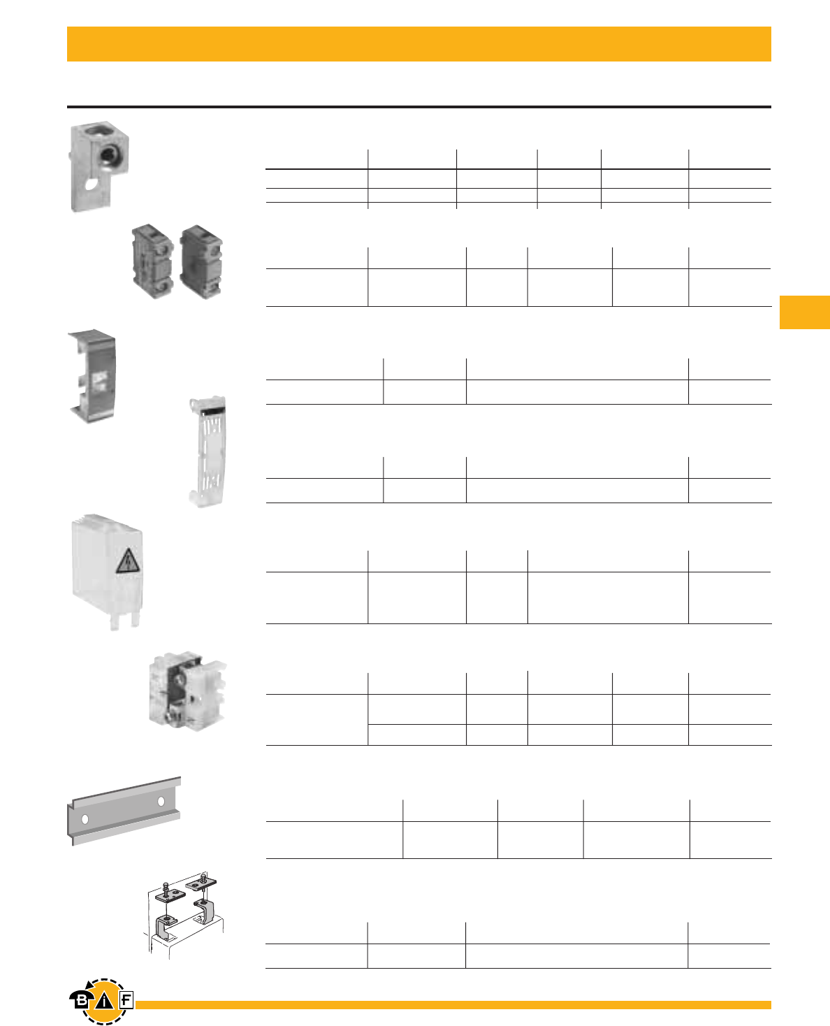
Bussmann®
103
For complete specification data, call Bussmann Information Fax ~ 636.527.1450
For 60A - 100A Fusible Disconnect Switches
Accessories
Includes one
terminal shroud CFD100, 1-POLE 0.04 CFTS100
for line or load side
For additional information and detail see the Bussmann Disconnect Switch Catalog item number 3006 For additional information and detail see the Bussmann Disconnect Switch Catalog item number 3006
“T” Type Fuse Adapter Kit
Catalog
Description For Use On: Number
100A, 600V CFD100 BDTA1
Replacement Fuse Clip
Catalog
Description For Use On: Number
Removable fuse carrier CFD60 CFC60J
Terminal Lug Kit
Kit Weight Wire Terminal Catalog
For Use On: Wire Size (lbs.) Type Lugs Per Kit Number
CFD60J_ #14 – 4 — CU — Integral
CFD100J_ #14 – 2/0 0.43 CU/AL 6 BDTL24
Replacement Fuse Covers
Catalog
Description For Use On: Number
Transparent fuse cover CFD100 CFCVR100
Terminal Shroud
Weight Catalog
Description For Use On: (lbs.) Number
Auxiliary Contacts
Weight AC Thermal AC Rated Catalog
Description For Use On: (lbs.) Amp Rating Voltage Number
1 N.O. 0.07 10 600 CDAUX10
1 N.C. CFD60 – CFD100 0.07 10 600 CDAUX01K
Detachable neutral CFD60 0.13 63 600 CFZ1
mounts on side
of switch or DIN rail CFD100 0.31 125 600 CFZ2
Terminal Poles
Weight AC Thermal AC Rated Catalog
Description For Use On: (lbs.) Amp Rating Voltage Number
35mm Aluminum DIN Rail CFD60 .38 39.4/1000 NDNA100
35mm Aluminum DIN Rail CFD60 .75 78.8/1000 NDNA200
DIN Rail
WeIght Length Catalog
Description For Use On: (lbs.) (inches/mm) Number
BDTA1
NDNA100
CFZ1
CDAUX10 CDAUX01K
BDTL24
CFC60J
CFCVR100
CFTS100
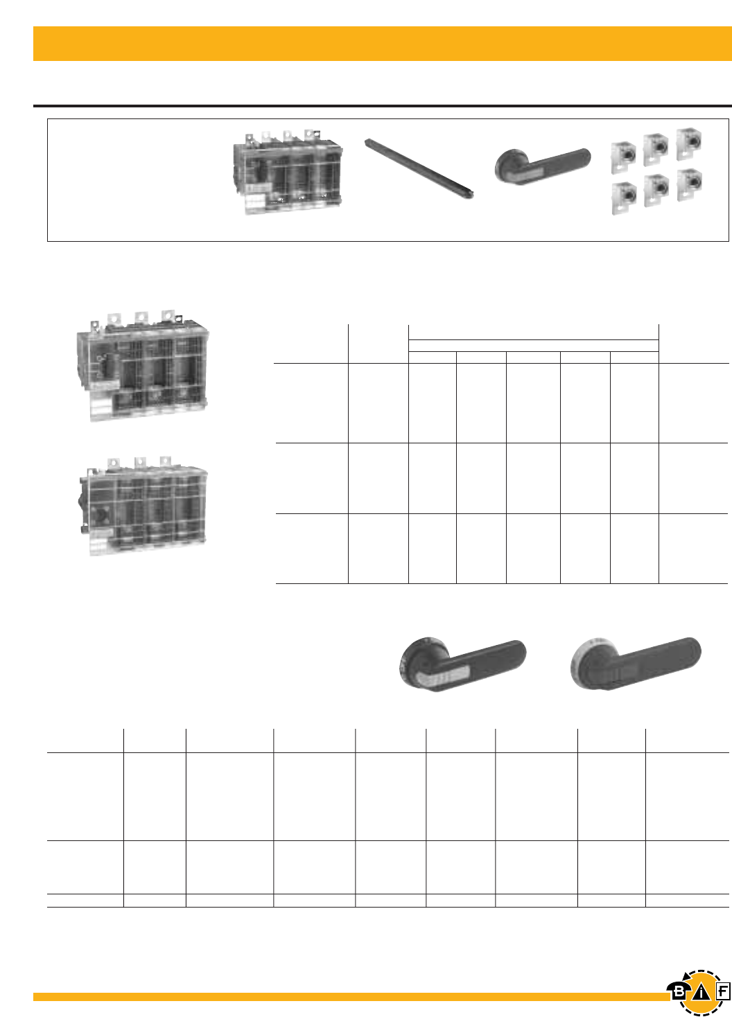
Bussmann®
104 For complete specification data, call Bussmann Information Fax ~ 636.527.1450
Fusible Disconnect Switches UL Fuse Class J, T, L
200A - 800A
For additional information and detail see the Bussmann Disconnect Switch Catalog item number 3006
BDH112 BDH113
For a complete assembly,
please select one of each:
1 switch
1 handle
1 shaft
1 terminal lug kit
FD600J3
FD800L3
NEMA IEC Length Weight Catalog
Type Type Color (inches/mm) Marking Defeatable Padlockable (lbs.) Number
1,3R,12 IP65 Black 4.9/125 O/I & Off/On Yes Yes 0.39 BDH112
1,3R,12 IP65 Red/Yellow 4.9/125 O/I & Off/On Yes Yes 0.39 BDH113
1,3R,12 IP65 Black 5.7/145 O/I & Off/On Yes Yes 0.39 BDH114
1,3R,12 IP65 Red/Yellow 5.7/145 O/I & Off/On Yes Yes 0.39 BDH115
1,3R,12 IP65 Black 6.9/175 O/I & Off/On Yes Yes 0.41 BDH116
1,3R,12 IP65 Red/Yellow 6.9/175 O/I & Off/On Yes Yes 0.41 BDH117
1,3R,4,4X,12 IP65 Black 5.7/145 O/I & Off/On Yes Yes 0.39 CDHXB12
1,3R,4,4X,12 IP65 Red/Yellow 5.7/145 O/I & Off/On Yes Yes 0.39 CDHXY12
1,3R,4,4X,12 IP65 Black 6.9/175 O/I & Off/On Yes Yes 0.41 CDHXB22
1,3R,4,4X,12 IP65 Red/Yellow 6.9/175 O/I & Off/On Yes Yes 0.41 CDHXY22
1,3R,4,4X,12 IP65 Metal 8.7/220 Off/On — Yes 1.50 BDH8
Pistol Handles — .47 x .47" (12 x 12 mm)
200 — 800A Switches, 600V
UL General UL Fuse Maximum Horsepower Rating
Purpose Type Three Phase Catalog
Amp Rating 600V 200V 208V 240V 480V 600V Number
2 pole 2 pole
200 J1— — — — — FD200J2
400 J1— — — — — FD400J2
600 J1— — — — — FD600J2
800 L — — — — — FD800L2
3 pole 3 pole
200 J150 50 60 125 150 FD200J3
400 J1100 125 125 250 350 FD400J3
600 J1150 150 200 400 500 FD600J3
800 L 200 200 250 500 600 FD800L3
4 pole 4 pole
200 J150 50 60 125 150 FD200J4
400 J1100 125 125 250 350 FD400J4
600 J1150 150 200 400 500 FD600J4
800 L 200 200 250 500 600 FD800L4
FD200J3 + BDS280 + BDH114 + BDTL25
1J type fuse clips are standard. If 600V Type “T” clips are desired, please order a "T" type fuse adapter kit.
FD400J3
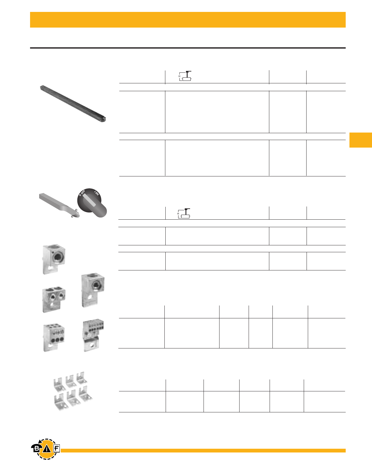
Bussmann®
105
For complete specification data, call Bussmann Information Fax ~ 636.527.1450
For 200A - 800A Fusible Disconnect Switches
Accessories
“T” Type Fuse Adapter Kit
AC Thermal AC Rated Catalog
For Use On: Amp Rating Voltage Poles Number
FD200J_ 200 600 3 BDTA2
FD400J_ 400 600 3 BDTA4
FD600J_ 600 600 3 BDTA6
Terminal Lug Kit
Kit Weight Wire Terminal Catalog
For Use On: Wire Size (lbs.) Type Lugs Per Kit Number
Shaft Length Mounting Depth Weight Catalog
(inches/mm) (in inches) (lbs.) Number
Twisted Shafts
Rotates handle 45° .47 x .47" (12 x 12 mm)
Shaft Length Mounting Depth1Weight Catalog
(inches/mm) (in inches) (lbs.) Number
Shafts — .47 x .47" (12 x 12 mm)
For additional information and detail see the Bussmann Disconnect Switch Catalog item number 3006
1Mounting depth is the distance from the outside of the door to the disconnect switch mounting plate. Shaft can be cut to desired length.
BDTA
BDTL25
BDTL175 BDTL175/400
BDTL26
BDTL27
For use on FD200J_ – FD400J_
11.0/280 10.2 – 14.5 0.77 BDS28045
12.8/325 12.0 – 16.3 0.90 BDS32545
18.3/465 17.5 – 21.9 1.32 BDS46545
For use on FD600J_ – FD800J_
11.0/280 11.2 – 14.0 0.77 BDS28045
12.8/325 13.0 – 15.8 0.90 BDS32545
18.3/465 18.5 – 21.3 1.32 BDS46545
BDS_45
BDS_
For use on FD200J_ – FD400J_
8.7/220 7.9 – 12.2 0.61 BDS220
9.8/250 9.1 – 13.4 0.70 BDS250
11.0/280 10.2 – 14.5 0.77 BDS280
12.8/325 12.0 – 16.3 0.90 BDS325
15.6/395 14.8 – 19.1 1.10 BDS395
18.3/465 17.5 – 21.9 1.32 BDS465
21.1/535 20.3 – 24.6 1.54 BDS535
For use on FD600J_ – FD800J_
9.8/250 10.0 – 12.8 0.70 BDS250
11.0/280 11.2 – 14.0 0.77 BDS280
12.8/325 13.0 – 15.8 0.90 BDS325
15.6/395 15.8 – 18.6 1.10 BDS395
18.3/465 18.5 – 21.3 1.32 BDS465
21.1/535 21.1 – 24.1 1.54 BDS535
FD200J_ #6 – 300 kcmil 0.93 Cu/Al 6 BDTL25
FD200J (6) #14 – 6 kcmil 0.93 Cu/Al 3 BDTL175
FD400J_ #2 – 600 kcmil 3.50 Cu/Al 6 BDTL26
FD600J – FD800L (12) #14 – 16–600 kcmil 1.10 Cu/Al 3 BDTL175/400
FD600J_ & FD800L_ (2) #2 – 600 kcmil 4.62 Cu/Al 6 BDTL27
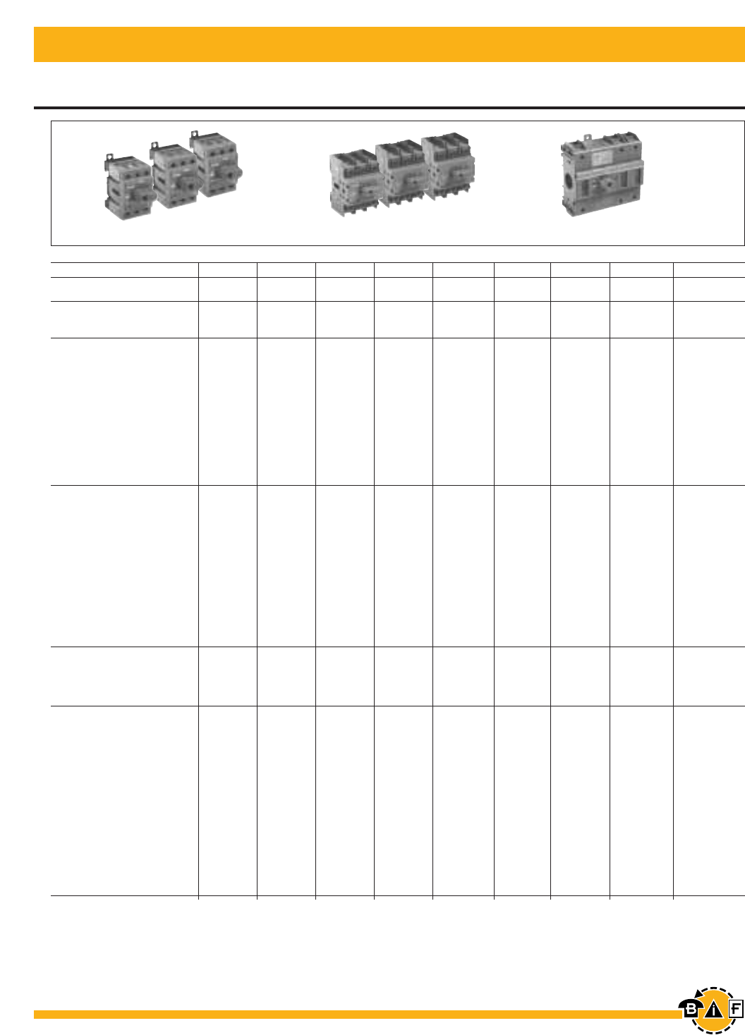
Bussmann®
106 For complete specification data, call Bussmann Information Fax ~ 636.527.1450
• = Available
— = Not available
1UL listed switches are also CSA approved.
For additional information and detail see the Bussmann Disconnect Switch Catalog item number 3006
For Non-Fusible Disconnect Switches CDNF16 - CDNF160
Overview
CDNF160
CDNF30 CDNF60 CDNF100
CDNF16 CDNF25 CDNF32
Catalog Number 3 pole CDNF16 CDNF25 CDNF32 CDNF45 CDNF63 CDNF30 CDNF60 CDNF100 CDNF160
General Purpose A 16 25 40 60 80 30 60 100 125
Amp Rating
Approvals12 pole N/A N/A N/A N/A N/A N/A N/A N/A UL98
3 pole UL508 UL508 UL508 UL508 UL508 UL98 UL98 UL98 UL98
4 pole UL508 UL508 UL508 UL508 UL508 UL98 UL98 UL98 UL98
Technical Ratings
UL,CSA
Max operating voltage V 600 600 600 600 600 600 600 600 600
Max horsepower rating
Three phase
200 – 208V HP 3 7.5 10 15 20 10 20 25 30
240V HP 5 7.5 10 15 20 10 20 30 30
480V HP 10 15 20 30 40 20 40 50 75
600V HP 10 20 25 30 40 30 40 50 100
Single phase
120V HP 1/2 3/4 1 2 2 2 3 5 7.5
240V HP 1.5 2 3 5 5 5 7.5 15 20
Technical Ratings
IEC
Rated insulation and
operational voltage.
ac20 and dc20 V 750 750 750 750 750 750 750 750 750
Rated thermal current, Ith
ac 20/dc 20 open A 25 32 40 63 80 40 63 115 200
ac 20/dc 20 enclosed A 25 32 40 63 80 40 63 115 160
ac 21A 500V A 16 25 32 63 80 40 63 100 160
690V A 16 25 32 63 80 40 63 100 160
Rated operational power ac23
400/415V kW 7.5 9 11 22 37 15 18.5 37 75
690V kW 7.5 9 11 15 18.5 15 15 37 75
Physical Characteristics
Weight 3 pole lb 0.24 0.24 0.24 0.59 0.59 0.79 0.79 0.79 2.42
Dimension 3 pole] H in 2.68 2.68 2.68 3.60 3.60 3.94 3.94 3.94 5.00
W in 1.38 1.38 1.38 2.07 2.07 2.76 2.76 2.76 4.96
D in 2.20 2.20 2.20 2.85 2.85 2.95 2.95 2.95 2.93
Accessories
Terminal lug kit Integral Integral Integral Integral Integral Integral Integral Integral Integral
Terminal shroud • • • • • • • • •
Auxiliary contact • • • • • • • • •
Handle UL/NEMA type
Type 1, 3R, 12 • • • • • • • • •
Type 1, 3R, 4, 4X, 12 • • • • • • • • •
Handle type
Selector • • • • • — — — —
Pistol • • • • • • • • •
Conversion kits
6 pole • • • • • • • • •
Transfer • • • • • • • • •
Bypass • • • • • • • • •
Mechanical interlock • • • • • • • — •
Electrical interlock — — — — — — — — —
UL listed, CSA approved, IEC rated, CE marked
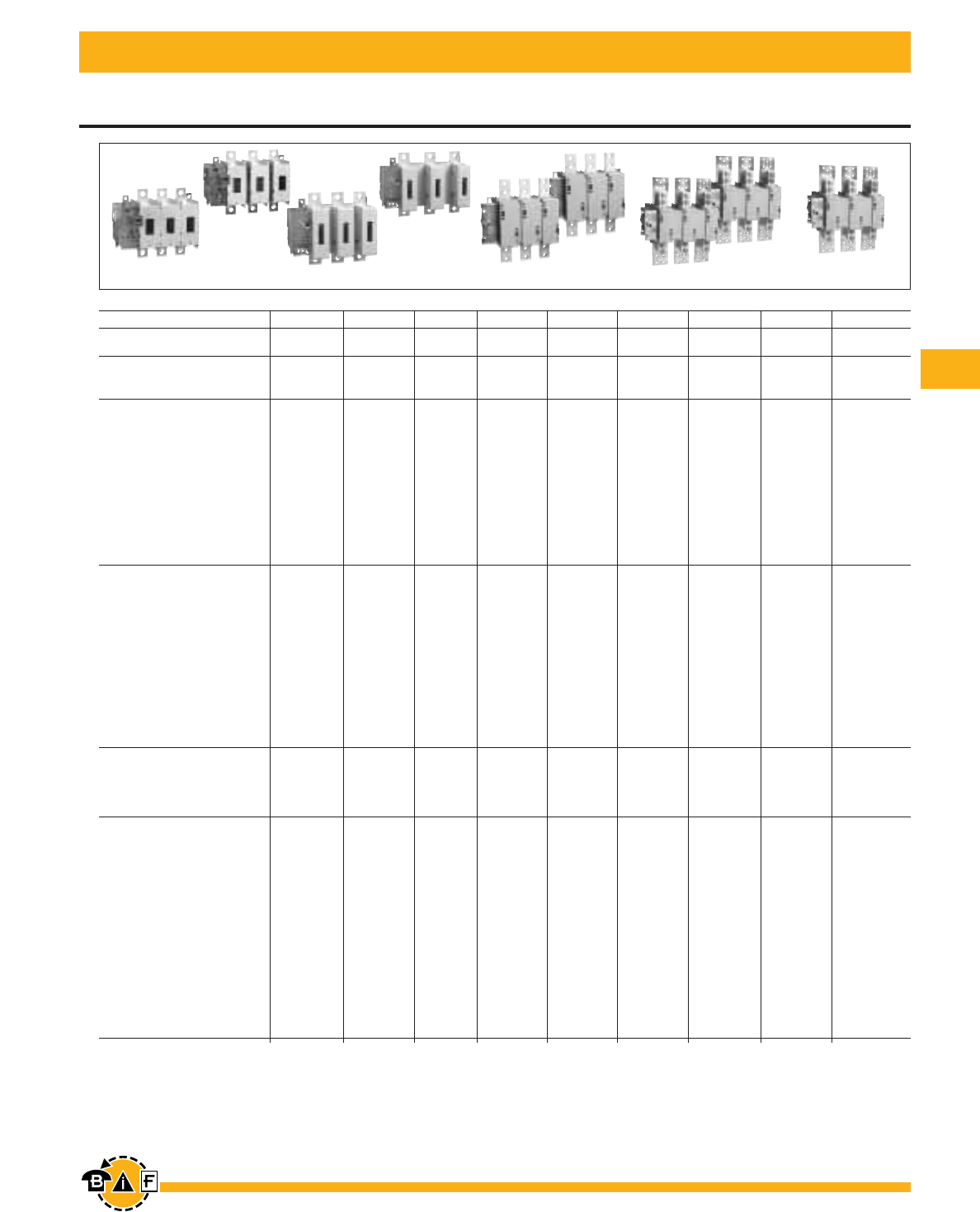
Bussmann®
107
For complete specification data, call Bussmann Information Fax ~ 636.527.1450
Overview
For Non-Fusible Disconnect Switches BDNF200A - BDNF3150
S = Standard feature
• = Available
— = Not available
1UL listed switches are also CSA approved.
For additional information and detail see the Bussmann Disconnect Switch Catalog item number 3006
Catalog Number 3 pole BDNF175A BDNF200A BDNF400 BDNF600A BDNF800A BDNF1200 BDNF1600 BDNF2000 BDNF3150
General Purpose A 175 200 400 600 800 1200 1600 2000 3150
Amp Rating
Approvals12 pole UL508 & IEC UL98 & IEC UL98 & IEC UL98 & IEC UL98 & IEC UL98 & IEC UL98 & IEC UL98 & IEC IEC
3 pole UL508 & IEC UL98 & IEC UL98 & IEC UL98 & IEC UL98 & IEC UL98 & IEC UL98 & IEC UL98 & IEC IEC
4 pole IEC IEC UL98 & IEC UL98 & IEC IEC IEC IEC IEC IEC
Technical Ratings
UL, CSA
Max operating voltage V 600 600 600 600 600 600 600 600 600
Max horsepower rating
Three phase
200 – 208V HP 30 60 100 150 200 — — — —
240V HP 40 75 125 200 250 — — — —
480V HP 75 150 250 400 500 — — — —
600V HP 100 200 350 500 600 — — — —
Single phase
120V HP — — — — — — — — —
240V HP — — — — — — — — —
Technical Ratings
IEC
Rated insulation and
operational voltage.
ac20 and dc20 V 1000 1000 1000 1000 1000 1000 1000 1000 1000
Rated thermal current, Ith
ac 20/dc 20 open A 200 315 630 800 1250 1600 2500 2500 3150
ac 20/dc 20 enclosed A 200 270 630 720 1250 1600 2300 2300 2600
ac 21A 500V A 200 250 630 800 1250 1600 2500 2500 3150
690V A 200 250 630 800 1250 1600 2500 2500 3150
Rated operational power ac23
400/415V kW 90 132 315 355 400 400 400 400 400
690V kW 170 200 355 355 — — — — —
Physical Characteristics
Weight 3 pole lb 6.61 6.61 13.66 13.66 35.9 38.55 127.7 127.7 127.7
Dimension 3 pole H in 8.35 8.35 11.81 11.77 19.09 19.09 25.04 25.04 25.04
W in 7.83 8.62 10.24 11.93 14.29 14.29 18.43 18.43 18.43
D in 4.55 4.55 5.12 5.12 4.92 4.92 10.67 10.67 10.67
Accessories
Terminal lug kit BDTL25 BDTL25 BDTL26 BDTL27 BDTL30 BDTL28 BDTL28 BDTL28/2 BDTL28/2
Terminal shroud • • • • • • — — —
Auxiliary contact • • • • • • • • •
Handle UL/NEMA type
Type 1, 3R, 12 • • • • • • • • •
Type 1, 3R, 4, 4X, 12 • • • • • • • • •
Handle type
Selector — — — — — — — — —
Pistol ••••••• • •
Conversion kits
6 pole • • • • • • — — —
Transfer • • • • • • — — —
Bypass • • • • • • — — —
Mechanical interlock • • • • • • • • •
Electrical interlock • • • • • • • • •
UL listed, CSA approved, IEC rated, CE marked
BDNF175A BDNF200A BDNF400A BDNF600A BDNF800A BDNF1200 BDNF1600 BDNF2000 BDNF3150
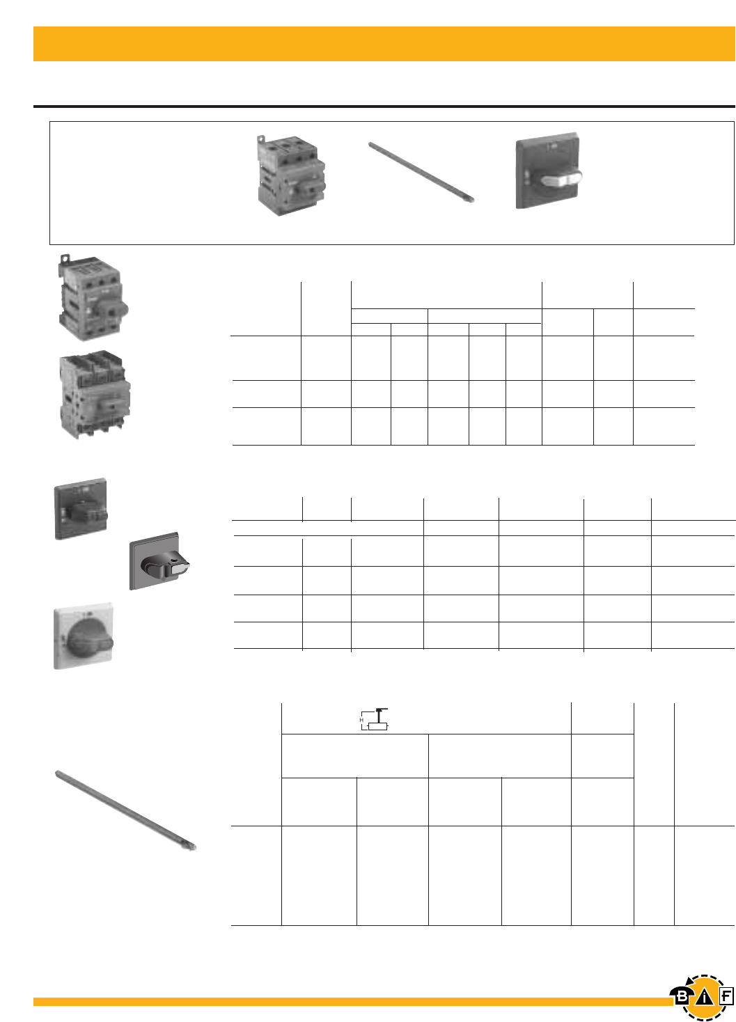
Bussmann®
108 For complete specification data, call Bussmann Information Fax ~ 636.527.1450
3.3/85 4.2 – 5.0 3.6 – 4.3 4.9 – 5.6 4.4 – 5.0 3.9 – 4.9 0.04 CDS85S
4.1/105 5.0 – 5.8 4.4 – 5.1 5.7 – 6.4 5.1 – 5.8 4.7 – 5.7 0.04 CDS105S
4.7/120 5.6 – 6.4 5.0 – 5.8 6.3 – 7.0 5.7 – 6.4 5.3 – 6.3 0.05 CDS120S
5.1/130 6.0 – 6.7 5.4 – 6.1 6.7 – 7.4 6.1 – 6.8 5.6 – 6.7 0.05 CDS130S
7.1/180 7.1 – 8.7 7.4 – 8.1 8.6 – 9.4 8.1 – 8.7 7.6 – 8.6 0.08 CDS180S
9.8/250 10.7 – 11.5 10.1 – 10.8 11.4 – 12.1 10.9 – 11.5 10.4 – 11.4 0.10 CDS250S
13/330 13.8 – 14.6 13.3 – 14.0 14.6 – 15.3 14.0 – 14.7 13.5 – 14.5 0.14 CDS330S
16A - 100A
For Non-Fusible Disconnect Switches Base & DIN Rail Mounted
For additional information and detail see the Bussmann Disconnect Switch Catalog item number 3006
For a complete assembly,
please select one of each:
1 switch
1 handle
1 shaft
CDNF30
CDNF60
CDNF100
16 — 100 Amp Switches, 600V, 3 Pole1
UL IEC
General AC21 Maximum Horsepower Rating Terminal Lugs
Purpose Amp Single Phase Three Phase Wire Wire Catalog
Amp Rating Rating 120V 240V 240V 480V 600V Size Type Number
16 16 1/2 1.5 5 10 10 #18 – 8 CU CDNF16
25 25 3/4 2 7.5 15 20 #18 – 8 CU CDNF25
40 40 1 3 10 20 25 #18 – 8 CU CDNF32
60 63 2 5 15 30 30 #14 – 4 CU CDNF45
80 80 2 5 20 40 40 #14 – 1 CU CDNF63
30 40 2 5 10 20 30 #14 – 4 CU CDNF30
60 63 3 7.5 20 40 40 #14 – 4 CU CDNF60
100 115 5 15 30 50 50 #8 – 1/0 CU CDNF100
CDNF63 + CDS85S + CDH3S
CDNF16
CDNF25
CDNF32
Mounting depth3in inches
CDNF16 CDNF45 CDNF30
CDNF25 CDNF63 CDNF60
CDNF32 CDNF100
Shaft CDH1S CDH3S CDH1S CDH3S CDH3S
Length CDH2S CDH4S CDH2S CDH4S CDH4S
(inches CDH15S CDH5S CDH15S CDH5S CDH5S Weight Catalog
/mm) CDH16S CDH6S CDH16S CDH6S CDH6S (lbs.) Number
Shafts — For use with CDH selector handles .20 x .20" (5 x 5 mm)
CDS_ S
I ON
O OFF
1A snap on fourth pole may be added
2Not suitable for use with CDNF30, 60, 100.
3Mounting depth is the distance from the outside of door to the disconnect switch mounting plate. Shaft can be cut to desired length.
Selector Handles — For use with shafts .20 x .20" (5 x 5 mm)
All marked both O/I & Off/On
1 IP54 Black — — 0.09 CDH1S2
1 IP54 Red/Yellow — — 0.09 CDH2S2
1 IP54 Black — Yes 0.12 CDH15S2
1 IP54 Red/Yellow — Yes 0.12 CDH16S2
1,3R,12 IP65 Black — Yes 0.16 CDH3S
1,3R,12 IP65 Red/Yellow — Yes 0.16 CDH4S
1,3R,12 IP65 Black Yes Yes 0.16 CDH5S
1,3R,12 IP65 Red/Yellow Yes Yes 0.16 CDH6S
NEMA IEC Weight Catalog
Type Type Color Defeatable Padlockable (lbs) Number
CDH15S
CDH1S
CDH6S
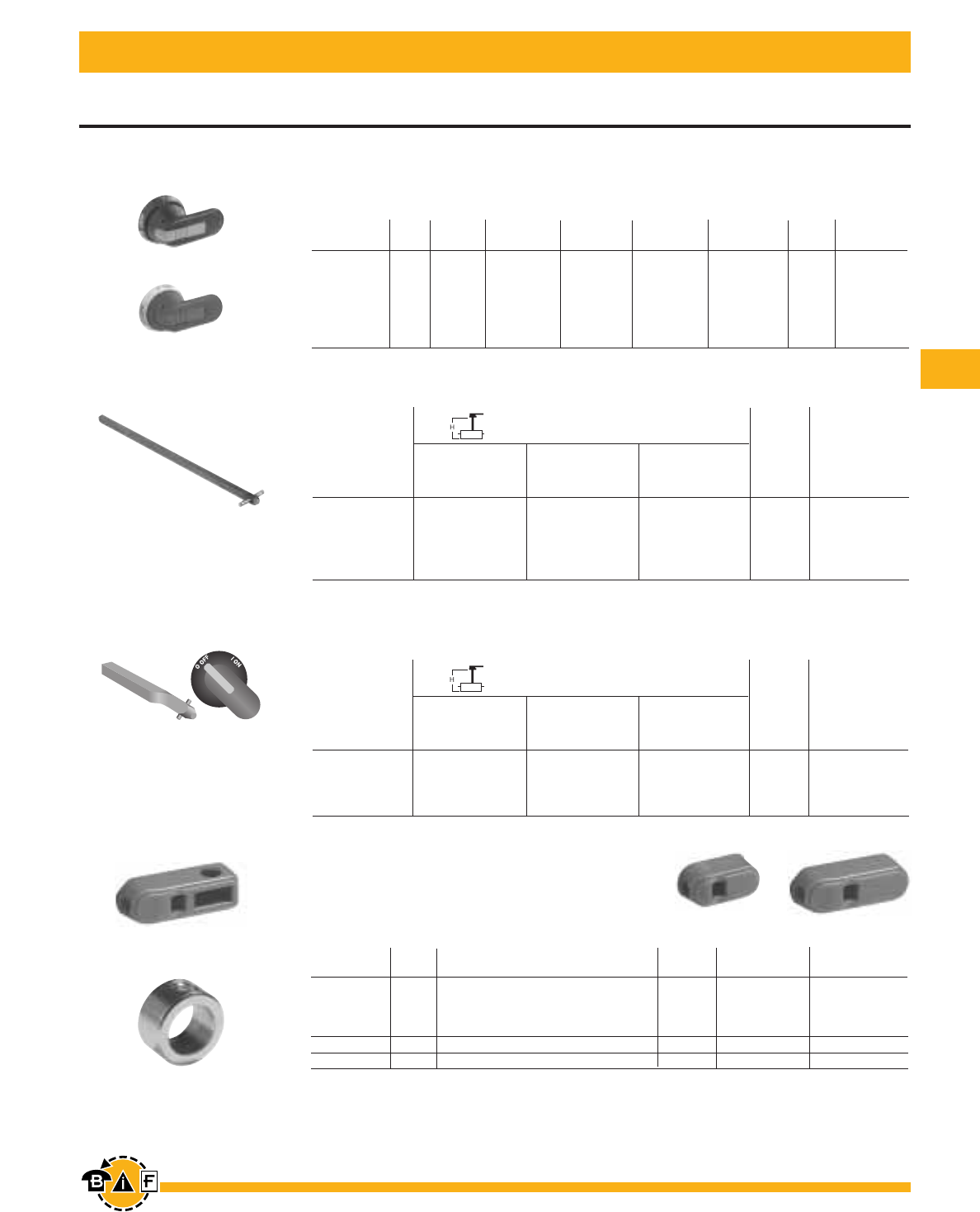
Bussmann®
109
For complete specification data, call Bussmann Information Fax ~ 636.527.1450
For 16A-100A Non-Fusible Disconnect Switches
Handles & Shafts
Replacement Knob
Mounts directly to switch; no shaft necessary
NEMA Length Catalog
Type Color For Use On: (inches) Padlockable Number
1 Red CDNF16, 25, 32 1.0 — OPMRH
1 Red CDNF30, 45, 60, 63,100 1.4 — CDBY683063
1 Red CDNF30, 45, 60, 63,100 1.6 Yes2CDBY68419/13
Metal collar CDNF16 – CDNF100 — — CDMC1
Set screw CDNF16, 25, 30, 32, 45, 60, 63, 100 — — CDSWM5X8
Pistol Handles — For use with shafts .20 x .20" (5 x 5 mm)
NEMA IEC Length Weight Catalog
Type Type Color Marking (inches/mm) Defeatable Padlockable (lbs.) Number
1,3R,12 IP65 Black O/I & Off/On 1.8/45 Yes Yes 0.28 BDH104
1,3R,12 IP65 Red/Yel O/I & Off/On 1.8/45 Yes Yes 0.28 BDH105
1,3R,12 IP65 Black O/I & Off/On 2.6/65 Yes Yes 0.29 BDH106
1,3R,12 IP65 Red/Yel O/I & Off/On 2.6/65 Yes Yes 0.29 BDH107
1,3R,12,4,4X IP66 Black O/I & Off/On 2.6/65 Yes Yes 0.29 CDHXB65
1,3R,12,4,4X IP66 Red/Yel O/I & Off/On 2.6/65 Yes Yes 0.29 CDHXY65
Twisted Shafts
Rotates handle 45° .20 x .20" (5 x 5 mm)
For additional information and detail see the Bussmann Disconnect Switch Catalog item number 3006
CDMC1
CDS_P
BDH107
BDH104, 106
Base & DIN Rail Mounted
5.9/150 6.2 – 6.7 6.9 – 7.4 6.4 – 7.4 0.07 CDS48P
6.7/170 7.0 – 7.5 7.7 – 8.1 7.2 – 8.1 0.08 CDS67P
10.4/265 10.7 – 11.3 11.4 – 11.9 10.9 – 11.9 0.12 CDS49P
15.8/400 16.0 – 16.6 16.8 – 17.2 16.2 – 17.2 0.18 CDS50P
19.7/500 20.0 – 20.5 20.7 – 21.1 20.1 – 21.1 0.23 CDS99P
Mounting depth1in inches
Shaft CDNF16 CDNF45 CDNF30
Length CDNF25 CDNF63 CDNF60 Weight Catalog
(inches/mm) CDNF32 CDNF100 (lbs.) Number
Shafts — For use with pistol handles .20 x .20" (5 x 5 mm)
1Mounting depth is the distance from the outside of door to the disconnect switch mounting plate. Shaft can be cut to desired length.
2.1875" (3/16") diameter shackle required.
3Set screw CDSWM5X8 needed with replacement knobs CDBY__.
5.9/150 6.2 – 6.7 6.9 – 7.4 6.4 – 7.4 0.07 CDS48T
6.7/170 7.0 – 7.5 7.7 – 8.1 7.2 – 8.1 0.08 CDS67T
10.4/265 10.7 – 11.3 11.4 – 11.9 10.9 – 11.9 0.12 CDS49T
15.8/400 16.0 – 16.6 16.8 – 17.2 16.2 – 17.2 0.18 CDS50T
Mounting depth1in inches
Shaft CDNF16 CDNF45 CDNF30
Length CDNF25 CDNF63 CDNF60 Weight Catalog
(inches/mm) CDNF32 CDNF100 (lbs.) Number
CDS_T
OPMRH CDBY68306
CDBY68419/1
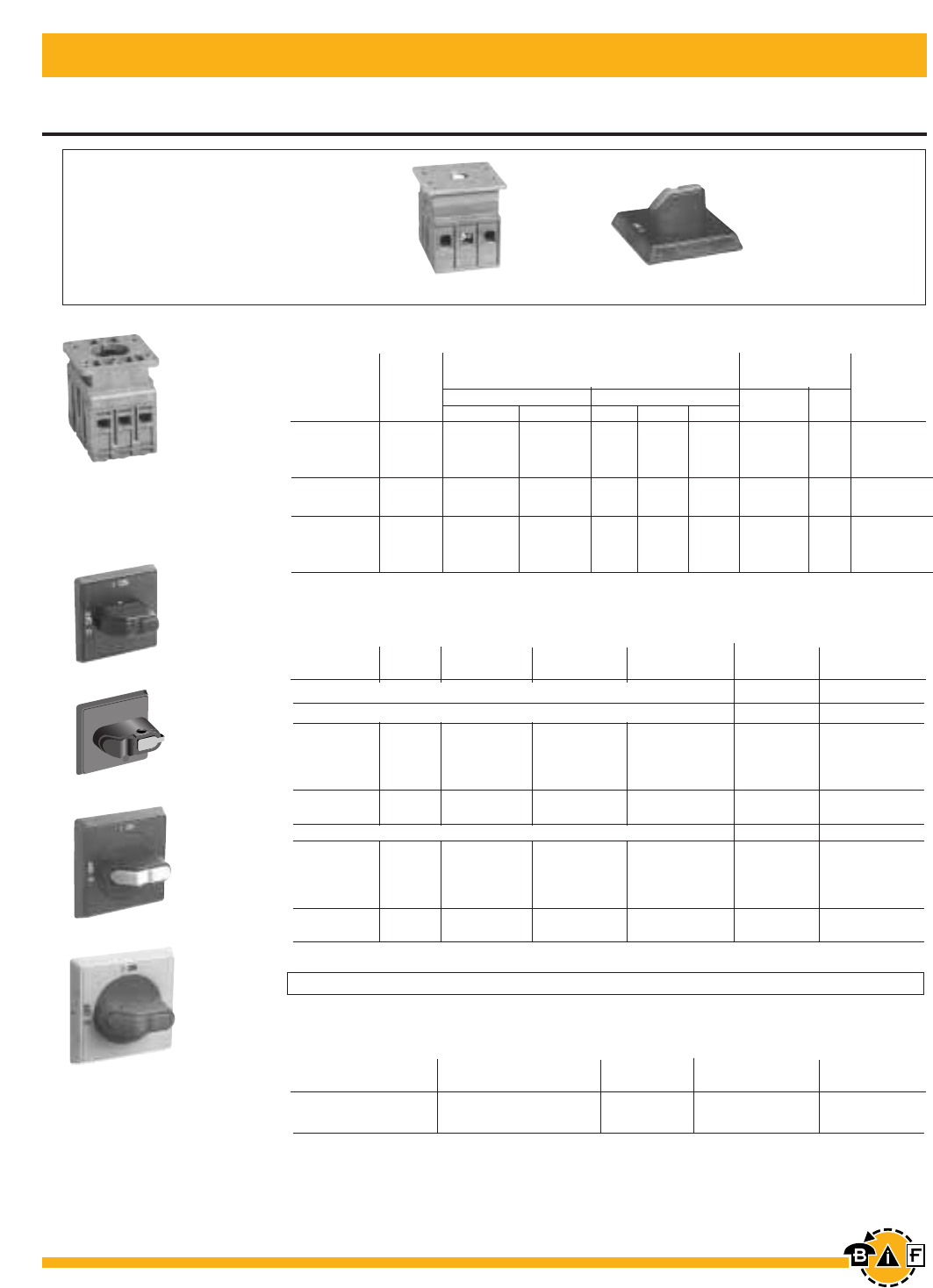
Bussmann®
110 For complete specification data, call Bussmann Information Fax ~ 636.527.1450
NEMA/UL IEC Weight Catalog
Type Type Color Defeatable Padlockable (lbs) Number
Adapter piece CDNF30, CDNF60, 0.18 CDHZX6
for pistol grip handle CDNF100
Non-Fusible Disconnect Switches Door Mounted
16A - 100A
For additional information and detail see the Bussmann Disconnect Switch Catalog item number 3006
For a complete assembly,
please select one of each:
1 switch
1 handle
CDH8S
CDH12S
16 — 100 Amp Switches, 600V, 3 Pole123
UL IEC
General AC21 Maximum Horsepower Rating Terminal Lugs
Purpose Amp Single Phase Three Phase Wire Wire Catalog
Amp Rating Rating 120V 240V 240V 480V 600V Size Type Number
16 16 1/2 1.5 5 10 10 #18 – 8 CU CDNF16D
25 25 3/4 2 7.5 15 20 #18 – 8 CU CDNF25D
40 40 1 3 10 20 25 #18 – 8 CU CDNF32D
60463 2 5 15 30 30 #14 – 4 CU CDNF45D
80480 2 5 20 40 40 #14 – 1 CU CDNF63D
30440 2 5 10 20 30 #14 – 4 CU CDNF30D
60463 3 7.5 20 40 40 #14 – 4 CU CDNF60D
1004115 5 15 30 50 50 #8 – 1/0 CU CDNF100D
CDNF45D CDH9S
CDNF16D
CDNF25D
CDNF32D
I ON
O OFF
Selector Handles
CDH9S
CDH13S
CDH17S
CDH19S
CDH10S
CDH14S Pistol Grip Handle Adapter
Weight Catalog
Description For Use On: (lbs) Number
1A snap on fourth pole may be added
2Door mounted switches do not require shafts.
3CDNF16, 25, 32, 45 & 63 door mounted switches will not accept pistol handles.
4CDNF45 & 63 door mounted switches can only use screw mounted handles.
Door mounted switches do not provide door interlock
All marked both O/I & Off/On
Snap-on mounting — for use on CDNF16, 25, 32D
1 IP54 Black — — 0.10 CDH7S
1 IP54 Red/Yellow — — 0.10 CDH8S
1 IP54 Black — Yes 0.13 CDH19S
1 IP54 Red/Yellow — Yes 0.13 CDH20S
1,3R,12 IP65 Black — Yes 0.17 CDH9S
1,3R,12 IP65 Red/Yellow — Yes 0.17 CDH10S
Screw mounting — for use on CDNF16, 32, 45 & 63D
1 IP54 Black — — 0.11 CDH11S
1 IP54 Red/Yellow — — 0.11 CDH12S
1 IP54 Black — Yes 0.14 CDH17S
1 IP54 Red/Yellow — Yes 0.14 CDH18S
1,3R,12 IP65 Black — Yes 0.18 CDH13S
1,3R,12 IP65 Red/Yellow — Yes 0.18 CDH14S
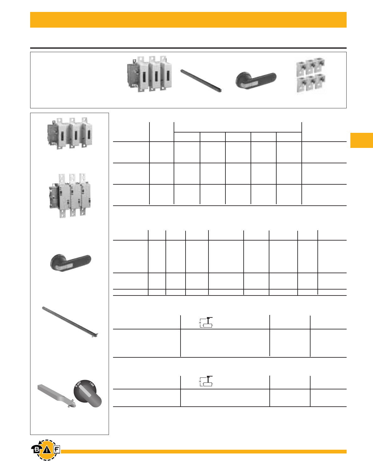
Bussmann®
111
For complete specification data, call Bussmann Information Fax ~ 636.527.1450
Non-Fusible Disconnect Switches
400A – 800A
BDNF600A
BDNF400
BDNF800A
BDS280 BDH116
BDH112-117
BDS280
BDS_45
BDTL26
For a complete assembly,
please select one of each:
1 switch
1 handle
1 shaft
1 terminal lug kit
400 – 800 Amp switches, 600V
UL IEC Maximum horsepower rating
general AC21
purpose amp Catalog
amp rating rating 200V 208V 240V 480V 600V number
2 pole
400 630 — — — — — BDNF4002
600 800 — — — — — BDNF600A2
800 1250 — — — — — BDNF800A2
3 pole
400 630 100 100 125 250 350 BDNF400
600 800 150 150 200 400 500 BDNF600A
800 1250 200 200 250 500 600 BDNF800A
4 pole
400 630 100 100 125 250 350 BDNF4004
600 800 150 150 200 400 500 BDNF600A4
— 1250 200 200 250 500 600 BDNF800A4
Pistol handles — for use with shafts .47 x .47” (12 x 12 mm)
NEMA IEC Color Length Marking Defeatable Padlockable Weight Catalog
type type in/mm (lbs) number
1,3R,12 IP65 Blk 4.9/125 O/I & Off/On Yes Yes 0.39 BDH112
1,3R,12 IP65 R/Y 4.9/125 O/I & Off/On Yes Yes 0.39 BDH113
1,3R,12 IP65 Blk 5.7/145 O/I & Off/On Yes Yes 0.39 BDH114
1,3R,12 IP65 R/Y 5.7/145 O/I & Off/On Yes Yes 0.39 BDH115
1,3R,12 IP65 Blk 6.9/175 O/I & Off/On Yes Yes 0.41 BDH116
1,3R,12 IP65 R/Y 6.9/175 O/I & Off/On Yes Yes 0.41 BDH117
1,3R,4,4X,12 IP66 Blk 5.7/145 O/I & Off/On Yes Yes 0.39 CDHXB12
1,3R,4,4X,12 IP66 R/Y 5.7/145 O/I & Off/On Yes Yes 0.39 CDHXY12
1,3R,4,4X,12 IP66 Blk 6.9/175 O/I & Off/On Yes Yes 0.41 CDHXB22
1,3R,4,4X,12 IP65 Metal 8.7/220 Off/On — Yes 1.50 BDH8
Shafts — for use with pistol handles .47 x .47" (12 x 12 mm)
Shaft length Mounting depth1Weight Catalog
inches/mm in inches (lbs) number
11.0/280 10.2 – 14.5 0.77 BDS280
12.8/325 12.0 – 16.3 0.90 BDS325
15.6/395 14.8 – 19.1 1.10 BDS395
18.3/465 17.5 – 21.9 1.32 BDS465
21.1/535 20.3 – 24.6 1.54 BDS535
Twisted shafts — Rotates handle 45° .47 x .47" (12 x 12 mm)
Shaft length Mounting depth1Weight Catalog
inches/mm in inches (lbs) number
11.0/280 10.2 – 14.5 0.77 BDS28045
12.8/325 12.0 – 16.3 0.90 BDS32545
18.3/465 17.5 – 21.9 1.32 BDS46545
1Mounting depth is the distance from the outside of the door to the disconnect switch mounting plate. Shaft can be cut to desired length.
For additional information and detail, see the Bussmann Disconnect Switch Catalog, Item Number 3006
Bussmann®
112 For complete specification data, call Bussmann Information Fax ~ 636.527.1450
for 400A – 800A Non-Fusible Disconnect Switches
Accessories
Terminal lug kits
For use on: Wire Kit weight Wire Terminal Kit catalog
size (lbs.) type lugs per kit number
BDNF400 #2 – 600 kcmil 3.50 CU/AL 6 BDTL26
BDNF400 (2) #2 – 500 kcmil 4.62 CU/AL 6 BDTL262
BDNF600A (2) #2 – 600 kcmil 4.62 CU/AL 6 BDTL27
BDNF800A (2) #2 – 600 kcmil 6.90 CU/AL 6 BDTL30
BDNF800A1 (8) 2/0 + (2)#2 600 kcmil 6.90 CU/AL 3 BDTL32
BDNF400 – BDNF600A1(12) #14 – 6 1.10 CU/AL 3 BDTL175/400
Auxiliary contacts 22
Description For use on: Weight ac thermal ac rated Catalog
(lbs) amp rating voltage number
1 N.O. + 1 N.C. 0.20 10 600 BDAUX1
2 N.O. + 2 N.C. 0.26 10 600 BDAUX2
4 N.O. + 4 N.C BDNF400 – 0.40 10 600 BDAUX3
2 N.O. BDNF800A 0.18 10 600 BDAUX4
4 N.O. 0.25 10 600 BDAUX5
8 N.O. 0.40 10 600 BDAUX6
Terminal poles
Description For use on: Weight ac thermal ac rated Catalog
(lbs) amp rating voltage number
Detachable neutral BDNF400 –
mounts on side of BDNF600A 1.04 400 600 BDZX85
switch or DIN rail
Terminal shrouds
Description For use on: Weight Catalog
(lbs) number
Includes one BDNF400 0.62 BDTS4
shroud for line or BDNF600A 0.66 BDTS6A
load side BDNF800A 0.88 BDTS8A
Handle support bracket
Description For use on: Weight Catalog
(lbs) number
Allows handle to be directly BDNF400 – 0.51 BDZX73
mounted to switch BDNF600A
behind the door BDNF800A 0.88 BDZX71
1A load side distribution lug eliminates the need to purchase, install and wire a separate distribution block.
2UL File E57057
For additional information and detail, see the Bussmann Disconnect Switch Catalog, Item Number 3006
BDTL26 BDTL27
BDTL30 BDTL175/400
BDTL32
BDAUX1-6
BDZX85
BDTS_
BDZX71
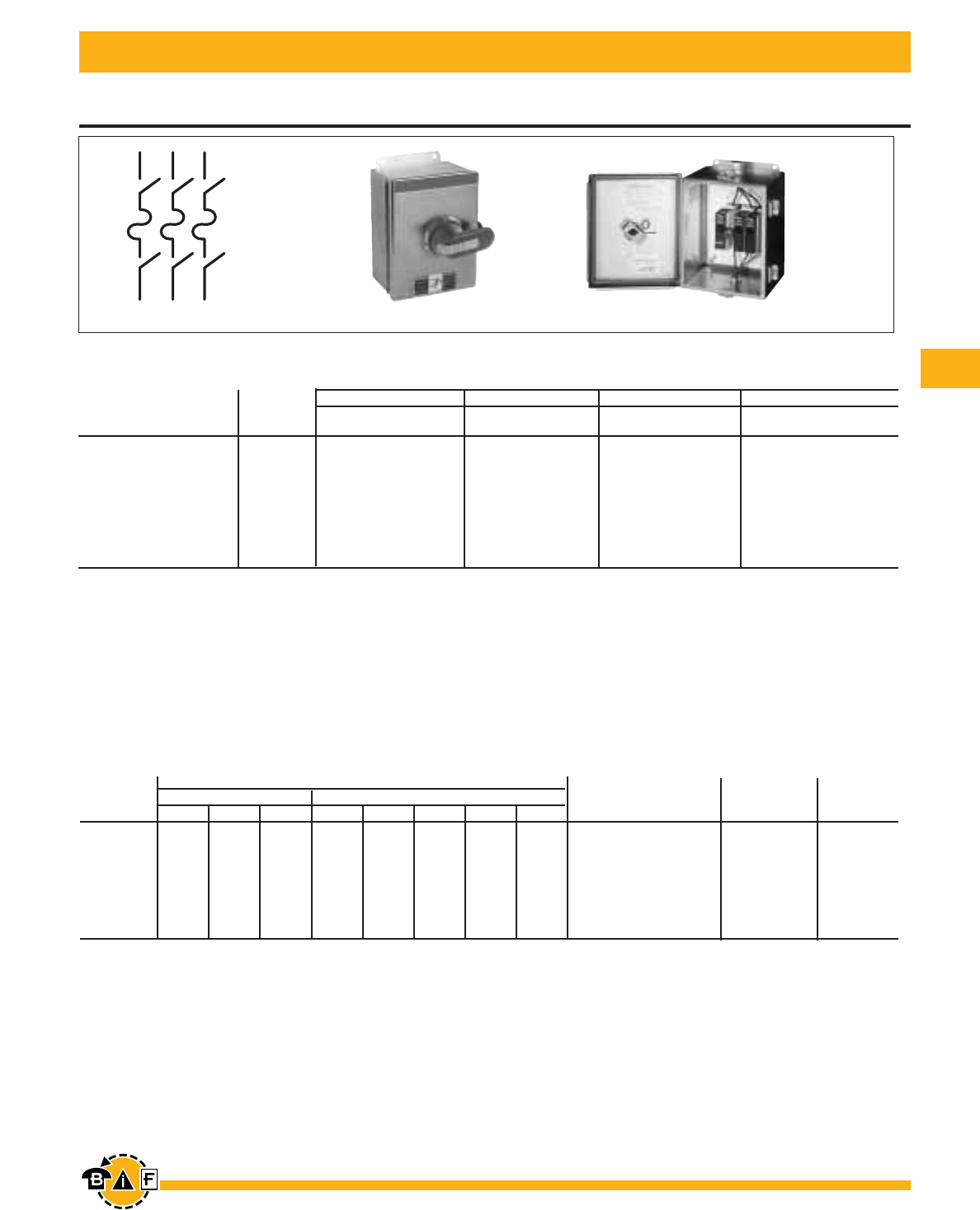
Bussmann®
113
For complete specification data, call Bussmann Information Fax ~ 636.527.1450
30A – 800A
Enclosed Fusible Disconnect Switches
For additional information and detail, see the Bussmann Disconnect Switch Catalog, Item Number 3006
3 Pole1, 600V, 30A – 3150A
NEMA / UL Enclosure type
1 3R 4 4X Stainless
UL General purpose Fuse Catalog Catalog Catalog Catalog
amp rating Type number number number number
30 J EFJ301-3PB6 EFJ303-3PB6 EFJ304-3PB6 EFJ30X-3PB6
30 CC EFC301-3PB6 EFC303-3PB6 EFC304-3PB6 EFC30X-3PB6
60 J2EFJ601-3PB6 EFJ603-3PB6 EFJ604-3PB8 EFJ60X-3PB8
100 J2EFJ1001-3PB8 EFJ1003-3PB8 EFJ1004-3PB8 EFJ100X-3PB8
200 J2EFJ2001-3PB4 EFJ2003-3PB4 EFJ2004-3PB4 EFJ200X-3PB4
400 J2EFJ4001-3PB4 EFJ4003-3PB4 EFJ4004-3PB4 EFJ400X-3PB4
600 J2EFJ6001-3PB4 EFJ6003-3PB4 EFJ6004-3PB4 EFJ600X-3PB4
800 J2EFL8001-3PB4 EFL8003-3PB4 EFL8004-3PB4 EFL800X-3PB4
Switch ratings
UL general Maximum horsepower rating
purpose Single phase Three phase Wire size for terminal lugs For wire type Approval1
amp rating 120V 200V 240V 200V 208V 240V 480V 600V
30 2 3 5 5 7.5 7.5 15 20 #18 – 8 CU CSA, UL
60 3 7.5 10 15 15 15 30 50 #14 – 4 CU CSA, UL
100 5 10 15 25 25 30 60 75 #14 – 2/0 CU/AL CSA, UL
200 — — — 50 50 60 125 150 #6 – 300 kcmil CU/AL CSA, UL
400 — — — 100 125 125 250 350 #2 – 600 kcmil CU/AL CSA, UL
600 — — — 150 150 200 400 500 (2) #2 – 600 kcmil CU/AL CSA, UL
800 — — — 200 200 250 500 600 (2) #2 – 600 kcmil CU/AL CSA, UL
1Fusible switches are UL listed to the UL98 standard.
2600V T type fuse clips may be substituted at no charge. Please change the second character of the catalog number from "J" to "T."
EFJ30X-3PB6
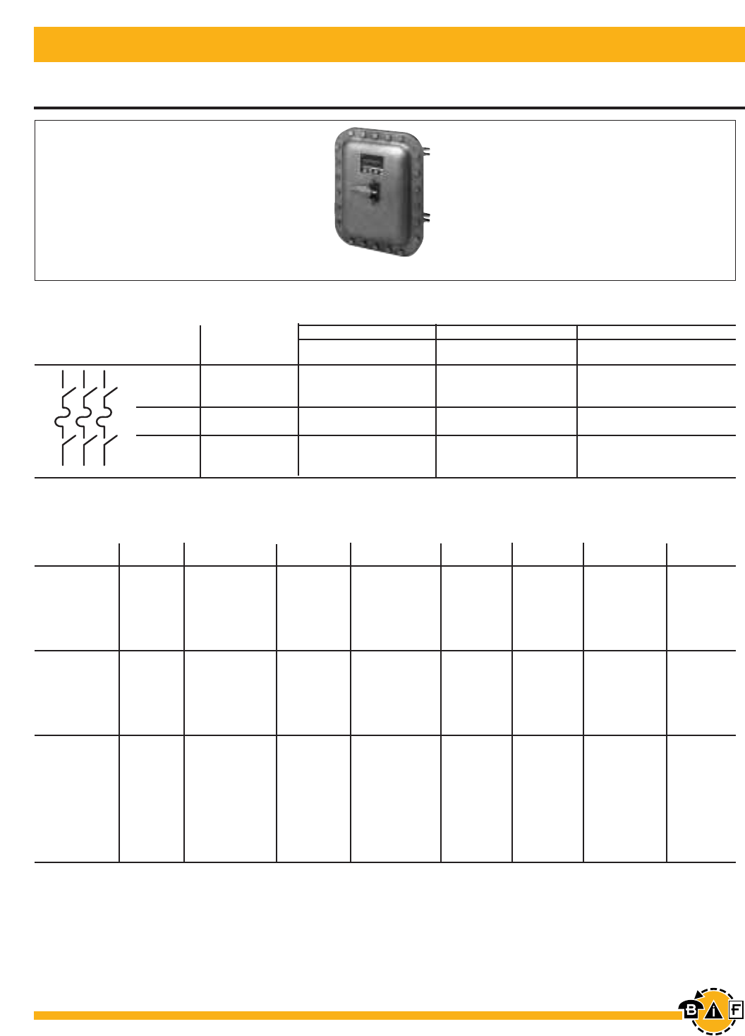
Bussmann®
114 For complete specification data, call Bussmann Information Fax ~ 636.527.1450
30A – 800A
Enclosed Fusible Disconnect Switches
3 Pole1, 600V, 30A – 3150A
NEMA / UL Enclosure type
4X Plastic 12 7 & 9
UL General purpose Fuse Catalog Catalog Catalog
amp rating Type number number number
30 J EFJ30P-3PB6 EFJ302-3PB6 EFJ307-3PB
30 CC EFC30P-3PB6 EFC302-3PB6 EFC307-3PB
60 J2EFJ60P-3PB8 EFJ602-3PB6 EFJ607-3PB
100 J2EFJ100P-3PB8 EFJ1002-3PB8 EFJ1007-3PB
200 J2EFJ200P-3PB4 EFJ2002-3PB4 EFJ2007-3PB
400 J2EFJ400P-3PB4 EFJ4002-3PB4 EFJ4007-3PB
600 J2EFJ600P-3PB4 EFJ6002-3PB4 EFJ6007-3PB
800 J2EFL800P-3PB4 EFL8002-3PB4 EFL8007-3PB
Handle ratings
Amperage Style NEMA Color Marking Defeatable Padlockable Catalog number Catalog
range type suffix number
Selector 1,3R,12 Black 0/I & Off/On Yes Yes BJ CDH5S
Selector 1,3R,12 Red/Yel 0/I & Off/On Yes Yes YJ CDH6S
30 Pistol 1,3R,12 Black 0/I & Off/On Yes Yes B6 BDH106
Pistol 1,3R,12 Red/Yel 0/I & Off/On Yes Yes Y6 BDH107
Pistol 1,3R,4,4X,12 Black 0/I & Off/On Yes Yes B6 CDHXB65
Pistol 1,3R,4,4X,12 Red/Yel 0/I & Off/On Yes Yes Y6 CDHXY65
Pistol 1,3R,12 Black 0/I & Off/On Yes Yes B6 BDH58
Pistol 1,3R,12 Red/Yel 0/I & Off/On Yes Yes Y6 BDH59
60 – 100 Pistol 1,3R,12 Black 0/I & Off/On Yes Yes B8 BDH60
Pistol 1,3R,12 Red/Yel 0/I & Off/On Yes Yes Y8 BDH61
Pistol 1,3R,4,4X,12 Black 0/I & Off/On Yes Yes B8 CDHXB86
Pistol 1,3R,4,4X,12 Red/Yel 0/I & Off/On Yes Yes Y8 CDHXY86
Pistol 1,3R,12 Black 0/I & Off/On Yes Yes B4 BDH114
Pistol 1,3R,12 Red/Yel 0/I & Off/On Yes Yes Y4 BDH115
Pistol 1,3R,12 Black 0/I & Off/On Yes Yes B7 BDH116
Pistol 1,3R,12 Red/Yel 0/I & Off/On Yes Yes Y7 BDH117
200 – 800 Pistol 1,3R 4,4X,12 Black 0/I & Off/On Yes Yes B4 CDHXB12
Pistol 1,3R,4,4X,12 Red/Yel 0/I & Off/On Yes Yes Y4 CDHXY12
Pistol 1,3R,4,4X,12 Black 0/I & Off/On Yes Yes B7 CDHXB22
Pistol 1,3R,4,4X,12 Red/Yel 0/I & Off/On Yes Yes Y7 CDHXY22
Pistol 1,3R,4,4X,12 Metal 0/I & Off/On No Yes 8 BDH8
1Fusible switches are UL listed to the UL98 standard.
2600V T type fuse clips may be substituted at no charge. Please change the second character of the catalog number from "J" to "T."
EFJ607-3P
For additional information and detail, see the Bussmann Disconnect Switch Catalog, Item Number 3006
Bussmann®
115
For complete specification data, call Bussmann Information Fax ~ 636.527.1450
for Enclosed Fusible Disconnect Switches 30A – 800A
Other Configurations
NEMA Enclosure type
UL 1 3R 4 4X Stainless
general purpose Type of Switch Catalog Catalog Catalog Catalog
amp rating number number number number
4 Pole1EFJ301-4PB6 EFJ303-4PB6 EFJ304-4PB6 EFJ30X-4PB6
6 Pole EFJ301-6PB6 EFJ303-6PB6 EFJ304-6PB6 EFJ30X-6PB
30 (J fuses) Transfer EFJ301-3TB8 EFJ303-3TB8 EFJ304-3TB8 EFJ30X-3TB8
Bypass EFJ301-3BB6 EFJ303-3BB6 EFJ304-3BB6 EFJ30X-3BB6
Mech. interlock EFJ301-3MB6 EFJ303-3MB6 EFJ304-3MB6 EFJ30X-3MB6
4 Pole1EFC301-4PB6 EFC303-4PB6 EFC304-4PB6 EFC30X-4PB6
6 Pole EFC301-6PB6 EFC303-6PB6 EFC304-6PB6 EFC30X-6PB6
30 (CC fuses) Transfer EFC301-3TB8 EFC303-3TB8 EFC304-3TB8 EFC30X-3TB8
Bypass EFC301-3BB6 EFC303-3BB6 EFC304-3BB6 EFC30X-3BB6
Mech. interlock EFC301-3MB6 EFC303-3MB6 EFC304-3MB6 EFC30X-3MB6
4 Pole1EFJ601-4PB6 EFJ603-4PB6 EFJ604-4PB6 EFJ60X-4PB6
60 6 Pole EFJ601-6PB4 EFJ603-6PB4 EFJ604-6PB4 EFJ60X-6PB4
Transfer EFJ601-3TB8 EFJ603-3TB8 EFJ604-3TB8 EFJ60X-3TB8
Mech. interlock EFJ601-3MB6 EFJ603-3MB6 EFJ604-3MB6 EFJ60X-3MB6
2 Pole1EFJ1001-2PB8 EFJ1003-2PB8 EFJ1004-2PB8 EFJ100X-2PB8
100 4 Pole1EFJ1001-4PB8 EFJ1003-4PB8 EFJ1004-4PB8 EFJ100X-4PB8
6 Pole EFJ1001-6PB4 EFJ1003-6PB4 EFJ1004-6PB4 EFJ100X-6PB4
Transfer EFJ1001-3TB8 EFJ1003-3TB8 EFJ1004-3TB8 EFJ100X-3TB8
Mech. interlock EFJ1001-3MB8 EFJ1003-3MB8 EFJ1004-3MB8 EFJ100X-3MB8
2 Pole1EFJ2001-2PB8 EFJ2003-2PB8 EFJ2004-2PB8 EFJ200X-2PB8
4 Pole1EFJ2001-4PB4 EFJ2003-4PB4 EFJ2004-4PB4 EFJ200X-4PB4
200 6 Pole EFJ2001-6P8 EFJ2003-6P8 EFJ2004-6P8 EFJ200X-6P8
Transfer EFJ2001-3TB4 EFJ2003-3TB4 EFJ2004-3TB4 EFJ200X-3TB4
Bypass EFJ2001-3B6 EFJ2003-3B6 EFJ2004-3B6 EFJ200X-3B6
Mech. interlock EFJ2001-3MB4 EFJ2003-3MB4 EFJ2004-3MB4 EFJ200X-3MB4
2 Pole1EFJ4001-2PB4 EFJ4003-2PB4 EFJ4004-2PB4 EFJ400X-2PB4
4 Pole1EFJ4001-4PB4 EFJ4003-4PB4 EFJ4004-4PB4 EFJ400X-4PB4
400 6 Pole EFJ4001-6P8 EFJ4003-6P8 EFJ4004-6P8 EFJ400X-6P8
Transfer EFJ4001-3TB4 EFJ4003-3TB4 EFJ4004-3TB4 EFJ400X-3TB4
Bypass EFJ4001-3B6 EFJ4003-3B6 EFJ4004-3B6 EFJ400X-3B6
Mech. interlock EFJ4001-3MB4 EFJ4003-3MB4 EFJ4004-3MB4 EFJ400X-3MB4
2 Pole1EFJ6001-2PB4 EFJ6003-2PB4 EFJ6004-2PB4 EFJ600X-2PB4
4 Pole1EFJ6001-4PB4 EFJ6003-4PB4 EFJ6004-4PB4 EFJ600X-4PB4
600 6 Pole EFJ6001-6P8 EFJ6003-6P8 EFJ6004-6P8 EFJ600X-6P8
Transfer EFJ6001-3TB4 EFJ6003-3TB4 EFJ6004-3TB4 EFJ600X-3TB4
Bypass EFJ6001-3B6 EFJ6003-3B6 EFJ6004-3B6 EFJ600X-3B6
Mech. interlock EFJ6001-3MB4 EFJ6003-3MB4 EFJ6004-3MB4 EFJ600X-3MB4
2 Pole1EFL8001-2PB4 EFL8003-2PB4 EFL8004-2PB4 EFL800X-2PB4
4 Pole1EFL8001-4PB4 EFL8003-4PB4 EFL8004-4PB4 EFL800X-4PB4
800 6 Pole EFL8001-6P8 EFL8003-6P8 EFL8004-6P8 EFL800X-6P8
Transfer EFL8001-3TB4 EFL8003-3TB4 EFL8004-3TB4 EFL800X-3TB4
Bypass EFL8001-3B6 EFL8003-3B6 EFL8004-3B6 EFL800X-3B6
Mech. interlock EFL8001-3MB4 EFL8003-3MB4 EFL8004-3MB4 EFL800X-3MB4
1IEC rated only.
2= Three poles
For additional information and detail, see the Bussmann Disconnect Switch Catalog, Item Number 3006
2 Pole 4 Pole 6 Pole
2
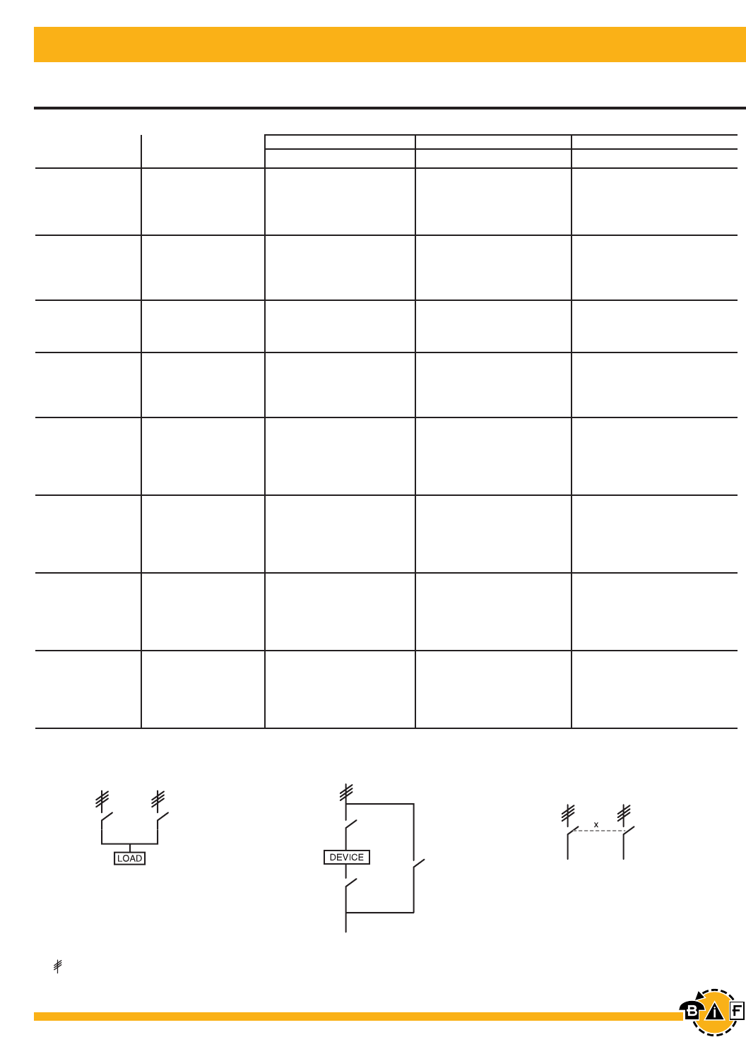
Bussmann®
116 For complete specification data, call Bussmann Information Fax ~ 636.527.1450
for Enclosed Fusible Disconnect Switches 30A – 800A
Other Configurations
NEMA Enclosure type
UL 4X Plastic 12 7 & 9
General purpose Type of Switch Catalog Catalog Catalog
amp rating number number number
4 Pole1 EFJ30P-4PB6 EFJ302-4PB6
6 Pole EFJ30P-6PB6 EFJ302-6PB6
30 (J fuses) Transfer EFJ30P-3TB8 EFJ302-3TB8 2
Bypass EFJ30P-3BB6 EFJ302-3BB6
Mech. interlock EFJ30P-3MB6 EFJ302-3MB6
4 Pole1EFC30P-4PB6 EFC302-4PB6
6 Pole EFC30P-6PB6 EFC302-6PB6
30 (CC fuses) Transfer EFC30P-3TB8 EFC302-3TB8 2
Bypass EFC30P-3BB6 EFC302-3BB6
Mech. interlock EFC30P-3MB6 EFC302-3MB6
4 Pole1EFJ60P-4PB6 EFJ602-4PB6
60 6 Pole EFJ60P-6PB4 EFJ602-6PB4 2
Transfer EFJ60P-3TB8 EFJ602-3TB8
Mech. interlock EFJ60P-3MB6 EFJ602-3MB6
2 Pole1EFJ100P-2PB8 EFJ1002-2PB8
100 4 Pole1EFJ100P-4PB8 EFJ1002-4PB8
6 Pole EFJ100P-6PB4 EFJ1002-6PB4 2
Transfer EFJ100P-3TB8 EFJ1002-3TB8
Mech. interlock EFJ100P-3MB8 EFJ1002-3MB8
2 Pole1EFJ200P-2PB8 EFJ2002-2PB8
4 Pole1EFJ200P-4PB4 EFJ2002-4PB4
200 6 Pole EFJ200P-6P8 EFJ2002-6P8 2
Transfer EFJ200P-3TB4 EFJ2002-3TB4
Bypass EFJ200P-3B6 EFJ2002-3B6
Mech. interlock EFJ200P-3MB4 EFJ2002-3MB4
2 Pole1EFJ400P-2PB4 EFJ4002-2PB4
4 Pole1EFJ400P-4PB4 EFJ4002-4PB4
400 6 Pole EFJ400P-6P8 EFJ4002-6P8 2
Transfer EFJ400P-3TB4 EFJ4002-3TB4
Bypass EFJ400P-3B6 EFJ4002-3B6
Mech. interlock EFJ400P-3MB4 EFJ4002-3MB4
2 Pole1EFJ600P-2PB4 EFJ6002-2PB4
4 Pole1EFJ600P-4PB4 EFJ6002-4PB4
600 6 Pole EFJ600P-6P8 EFJ6002-6P8 2
Transfer EFJ600P-3TB4 EFJ6002-3TB4
Bypass EFJ600P-3B6 EFJ6002-3B6
Mech. interlock EFJ600P-3MB4 EFJ6002-3MB4
2 Pole1EFL800P-2PB4 EFL8002-2PB4
4 Pole1EFL800P-4PB4 EFL8002-4PB4
800 6 Pole EFL800P-6P8 EFL8002-6P8 2
Transfer EFL800P-3TB4 EFL8002-3TB4
Bypass EFL800P-3B6 EFL8002-3B6
Mech. interlock EFL800P-3MB4 EFL8002-3MB4
1IEC rated only.
2Consult factory for pricing and availability.
3= Three poles
Transfer
3
Bypass
3
Mechanical
Interlock
3
For additional information and detail, see the Bussmann Disconnect Switch Catalog, Item Number 3006
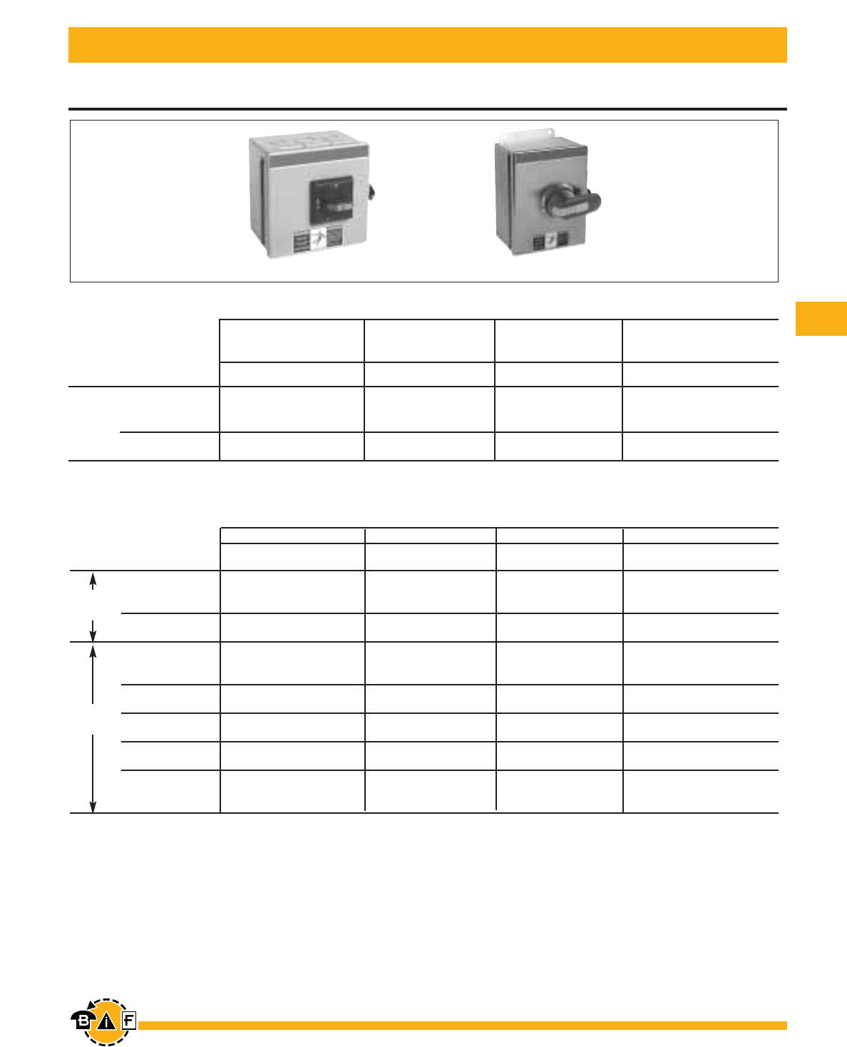
Bussmann®
117
For complete specification data, call Bussmann Information Fax ~ 636.527.1450
16A – 3150A
Enclosed Non-Fusible Disconnect Switches
ENF321-3PBJ ENF63X-3PB6
3 Pole, 600V, 16A – 100A — Selector handle
NEMA Enclosure type
41 4X Stainless11
13RSelector handles are only Selector handles are only
NEMA rated 1, 3R, 12 NEMA rated 1, 3R, 12
UL general purpose Catalog Catalog Catalog Catalog
amp rating number number number number
16 ENF161-3PBJ ENF163-3PBJ ENF164-3PBJ ENF16X-3PBJ
25 ENF251-3PBJ ENF253-3PBJ ENF254-3PBJ ENF25X-3PBJ
40 ENF321-3PBJ ENF323-3PBJ ENF324-3PBJ ENF32X-3PBJ
60 ENF451-3PBJ ENF453-3PBJ ENF454-3PBJ ENF45X-3PBJ
80 ENF631-3PBJ ENF633-3PBJ ENF634-3PBJ ENF63X-3PBJ
3 Pole, 600V, 16A – 3150A — Pistol handle
NEMA Enclosure type
1 3R 4 4X Stainless
UL general purpose Catalog Catalog Catalog Catalog
amp rating number number number number
16 ENF161-3PB6 ENF163-3PB6 ENF164-3PB6 ENF16X-3PB6
25 ENF251-3PB6 ENF253-3PB6 ENF254-3PB6 ENF25X-3PB6
40 ENF321-3PB6 ENF323-3PB6 ENF324-3PB6 ENF32X-3PB6
60 ENF451-3PB6 ENF453-3PB6 ENF454-3PB6 ENF45X-3PB6
80 ENF631-3PB6 ENF633-3PB6 ENF634-3PB6 ENF63X-3PB6
30 ENF301-3PB6 ENF303-3PB6 ENF304-3PB6 ENF30X-3PB6
60 ENF601-3PB6 ENF603-3PB6 ENF604-3PB6 ENF60X-3PB6
100 ENF1001-3PB6 ENF1003-3PB6 ENF1004-3PB6 ENF100X-3PB6
125 ENF1251-3PB6 ENF1253-3PB6 ENF1254-3PB6 ENF125X-3PB6
200 ENF2001-3PB8 ENF2003-3PB8 ENF2004-3PB8 ENF200X-3PB8
400 ENF4001-3PB4 ENF4003-3PB4 ENF4004-3PB4 ENF400X-3PB4
600 ENF6001-3PB4 ENF6003-3PB4 ENF6004-3PB4 ENF600X-3PB4
800 ENF8001-3PB4 ENF8003-3PB4 ENF8004-3PB4 ENF800X-3PB4
1200 ENF12001-3PB4 ENF12003-3PB4 ENF12004-3PB4 ENF1200X-3PB4
1600 ENF16001-3P8 ENF16003-3P8 ENF16004-3P8 ENF1600X-3P8
2000 ENF20001-3P8 ENF20003-3P8 ENF20004-3P8 ENF2000X-3P8
31502ENF31501-3P8 ENF31503-3P8 ENF31504-3P8 ENF3150X-3P8
1 Enclosures are rated as listed, selector handles are only NEMA rated 1, 3R, 12. The overall NEMA rating of an enclosed switch with a selector handle is 1, 3R, 12.
2IEC rated only.
UL 508
UL 98
For additional information and detail, see the Bussmann Disconnect Switch Catalog, Item Number 3006
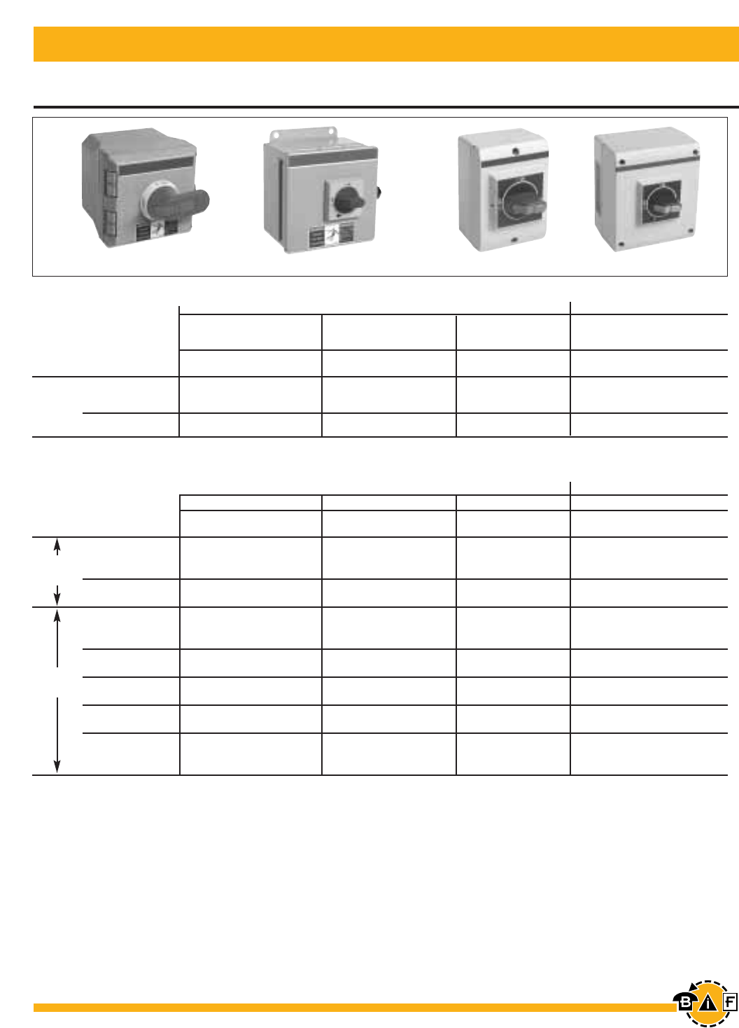
Bussmann®
118 For complete specification data, call Bussmann Information Fax ~ 636.527.1450
16A – 3150A
Enclosed Non-Fusible Disconnect Switches
ENF25P-3PY6 ENF252-3PYJ ENF16E-3PBJ ENF45E-3PBJ
3 Pole, 600V, 16A – 100A — Selector handle
NEMA Enclosure type IEC Enclosure type
4X Plastic11
Selector handles are only 12 7 & 9 IP65 Plastic
NEMA rated 1, 3R, 12
UL general purpose Catalog Catalog Catalog Catalog
amp rating number number number number
16 ENF16P-3PBJ ENF162-3PBJ — ENF16E-3PBJ
25 ENF25P-3PBJ ENF252-3PBJ — ENF25E-3PBJ
40 ENF32P-3PBJ ENF322-3PBJ — ENF32E-3PBJ
60 ENF45P-3PBJ ENF452-3PBJ — ENF45E-3PBJ
80 ENF63P-3PBJ ENF632-3PBJ — ENF63E-3PBJ
3 Pole, 600V, 16A – 3150A — Pistol handle
NEMA Enclosure type IEC Enclosure type
4X Plastic 12 7 & 9 IP65 Plastic
UL general purpose Catalog Catalog Catalog Catalog
amp rating number number number number
16 ENF16P-3PB6 ENF162-3PB6 ENF167-3P ENF16E-3PB4
25 ENF25P-3PB6 ENF252-3PB6 ENF257-3P ENF25E-3PB4
40 ENF32P-3PB6 ENF322-3PB6 ENF327-3P ENF32E-3PB4
60 ENF45P-3PB6 ENF452-3PB6 ENF457-3P ENF45E-3PB4
80 ENF63P-3PB6 ENF632-3PB6 ENF637-3P ENF63E-3PB4
30 ENF30P-3PB6 ENF302-3PB6 ENF307-3P ENF30E-3PB6
60 ENF60P-3PB6 ENF602-3PB6 ENF607-3P ENF60E-3PB6
100 ENF100P-3PB6 ENF1002-3PB6 ENF1007-3P ENF100E-3PB6
125 ENF125P-3PB6 ENF1252-3PB6 ENF1257-3P ENF125E-3PB6
200 ENF200P-3PB8 ENF2002-3PB8 ENF2007-3P —
400 ENF400P-3PB4 ENF4002-3PB4 ENF4007-3P —
600 ENF600P-3PB4 ENF6002-3PB4 ENF6007-3P —
800 ENF800P-3PB4 ENF8002-3PB4 ENF8007-3P —
1200 ENF1200P-3PB4 ENF12002-3PB4 ENF12007-3P —
1600 ENF1600P-3P8 ENF16002-3P8 ENF16007-3P —
2000 ENF2000P-3P8 ENF20002-3P8 ENF20007-3 —
31502ENF3150P-3P8 ENF31502-3P8 ENF31507-3P —
NOTE: All enclosed switches are provided with a black handle; however, most handles can be substituted with a red and yellow handle if desired.
Please substitute the handle suffix code (2nd and 3rd from last characters) with the red/yellow handle catalog number suffix from page 3.12.
There is no additional price adder for changing to a red/yellow handle of equal ratings and style.
EXAMPLE: A red/yellow selector handle for an ENF161-3PBJA can be substituted for the black selector handle by using the "YJ" suffix instead of the "BJ"
suffix, new catalog #ENF161-3PYJA.
1 Enclosures are rated as listed, selector handles are only NEMA rated 1, 3R, 12. The overall NEMA rating of an enclosed switch with a selector handle is 1, 3R, 12.
2IEC rated only.
UL 508
UL 98
For additional information and detail, see the Bussmann Disconnect Switch Catalog, Item Number 3006
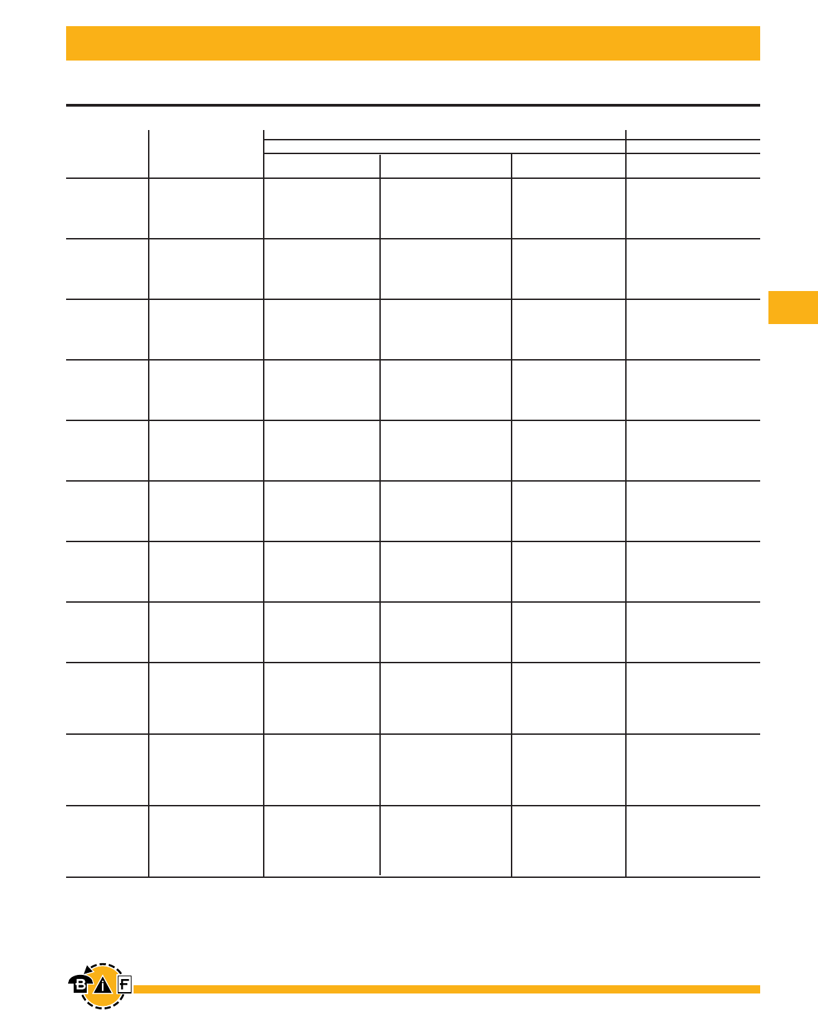
Bussmann®
119
For complete specification data, call Bussmann Information Fax ~ 636.527.1450
NEMA Enclosure type
UL 1 3R 4 4X Stainless
General purpose Type of switch Catalog Catalog Catalog Catalog
amp rating number number number number
4 Pole ENF161-4PB6 ENF163-4PB6 ENF164-4PB6 ENF16X-4PB6
6 Pole ENF161-6PB6 ENF163-6PB6 ENF164-6PB6 ENF16X-6PB6
16 Transfer ENF161-3TB8 ENF163-3TB8 ENF164-3TB8 ENF16X-3TB8
Bypass ENF161-3BB8 ENF163-3BB8 ENF164-3BB8 ENF16X-3BB8
Mech. interlock ENF161-3MB6 ENF163-3MB6 ENF164-3MB6 ENF16X-3MB6
4 Pole ENF251-4PB6 ENF253-4PB6 ENF254-4PB6 ENF25X-4PB6
6 Pole ENF251-6PB6 ENF253-6PB6 ENF254-6PB6 ENF25X-6PB6
25 Transfer ENF251-3TB8 ENF253-3TB8 ENF254-3TB8 ENF25X-3TB8
Bypass ENF251-3BB8 ENF253-3BB8 ENF254-3BB8 ENF25X-3BB8
Mech. interlock ENF251-3MB6 ENF253-3MB6 ENF254-3MB6 ENF25X-3MB6
4 Pole ENF321-4PB6 ENF323-4PB6 ENF324-4PB6 ENF32X-4PB6
6 Pole ENF321-6PB6 ENF323-6PB6 ENF324-6PB6 ENF32X-6PB6
40 Transfer ENF321-3TB8 ENF323-3TB8 ENF324-3TB8 ENF32X-3TB8
Bypass ENF321-3BB8 ENF323-3BB8 ENF324-3BB8 ENF32X-3BB8
Mech. interlock ENF321-3MB6 ENF323-3MB6 ENF324-3MB6 ENF32X-3MB6
4 Pole ENF451-4PB6 ENF453-4PB6 ENF454-4PB6 ENF45X-4PB6
60 6 Pole ENF451-6PB6 ENF453-6PB6 ENF454-6PB6 ENF45X-6PB6
Transfer ENF451-3TB8 ENF453-3TB8 ENF454-3TB8 ENF45X-3TB8
Bypass ENF451-3BB8 ENF453-3BB8 ENF454-3BB8 ENF45X-3BB8
Mech. interlock ENF451-3MB6 ENF453-3MB6 ENF454-3MB6 ENF45X-3MB6
4 Pole ENF631-4PB6 ENF633-4PB6 ENF634-4PB6 ENF63X-4PB6
80 6 Pole ENF631-6PB6 ENF633-6PB6 ENF634-6PB6 ENF63X-6PB6
Transfer ENF631-3TB8 ENF633-3TB8 ENF634-3TB8 ENF63X-3TB8
Bypass ENF631-3BB8 ENF633-3BB8 ENF634-3BB8 ENF63X-3BB8
Mech. interlock ENF631-3MB6 ENF633-3MB6 ENF634-3MB6 ENF63X-3MB6
4 Pole ENF301-4PB6 ENF303-4PB6 ENF304-4PB6 ENF30X-4PB6
30 6 Pole ENF301-6PB6 ENF303-6PB6 ENF304-6PB6 ENF30X-6PB6
Transfer ENF301-3TB8 ENF303-3TB8 ENF304-3TB8 ENF30X-3TB8
Bypass ENF301-3BB8 ENF303-3BB8 ENF304-3BB8 ENF30X-3BB8
Mech. interlock ENF301-3MB6 ENF303-3MB6 ENF304-3MB6 ENF30X-3MB6
4 Pole ENF601-4PB6 ENF603-4PB6 ENF604-4PB6 ENF60X-4PB6
60 6 Pole ENF601-6PB6 ENF603-6PB6 ENF604-6PB6 ENF60X-6PB6
Transfer ENF601-3TB8 ENF603-3TB8 ENF604-3TB8 ENF60X-3TB8
Bypass ENF601-3BB8 ENF603-3BB8 ENF604-3BB8 ENF60X-3BB8
Mech. interlock ENF601-3MB6 ENF603-3MB6 ENF604-3MB6 ENF60X-3MB6
4 Pole ENF1001-4PB6 ENF1003-4PB6 ENF1004-4PB6 ENF100X-4PB6
100 6 Pole ENF1001-6PB6 ENF1003-6PB6 ENF1004-6PB6 ENF100X-6PB6
Transfer ENF1001-3TB8 ENF1003-3TB8 ENF1004-3TB8 ENF100X-3TB8
Bypass ENF1001-3BB8 ENF1003-3BB8 ENF1004-3BB8 ENF100X-3BB8
Mech. interlock ENF1001-3MB6 ENF1003-3MB6 ENF1004-3MB6 ENF100X-3MB6
2 Pole ENF1251-2PB6 ENF1253-2PB6 ENF1254-2PB6 ENF125X-2PB6
4 Pole ENF1251-4PB6 ENF1253-4PB6 ENF1254-4PB6 ENF125X-4PB6
125 6 Pole ENF1251-6PB2 ENF1253-6PB2 ENF1254-6PB4 ENF125X-6PB4
Transfer ENF1251-3TB8 ENF1253-3TB8 ENF1254-3TB8 ENF125X-3TB8
Bypass — — — —
Mech. interlock ENF1251-3MB6 ENF1253-3MB6 ENF1254-3MB8 ENF125X-3MB8
2 Pole ENF2001-2PB8 ENF2003-2PB8 ENF2004-2PB8 ENF200X-2PB8
4 Pole ENF2001-4PB8 ENF2003-4PB8 ENF2004-4PB8 ENF200X-4PB8
200 6 Pole ENF2001-6PB4 ENF2003-6PB4 ENF2004-6PB4 ENF200X-6PB4
Transfer ENF2001-3TB4 ENF2003-3TB4 ENF2004-3TB4 ENF200X-3TB4
Bypass ENF2001-3BB4 ENF2003-3BB4 ENF2004-3BB4 ENF200X-3BB4
Mech. interlock ENF2001-3MB8 ENF2003-3MB8 ENF2004-3MB8 ENF200X-3MB8
2 Pole ENF4001-2PB4 ENF4003-2PB4 ENF4004-2PB4 ENF400X-2PB4
4 Pole ENF4001-4PB4 ENF4003-4PB4 ENF4004-4PB4 ENF400X-4PB4
400 6 Pole ENF4001-6P8 ENF4003-6P8 ENF4004-6P8 ENF400X-6P8
Transfer ENF4001-3TB4 ENF4003-3TB4 ENF4004-3TB4 ENF400X-3TB4
Bypass ENF4001-3B6 ENF4003-3B6 ENF4004-3B6 ENF400X-3B6
Mech. interlock ENF4001-3MB4 ENF4003-3MB4 ENF4004-3MB4 ENF400X-3MB4
16A – 400A Other Configurations
Enclosed Non-Fusible Disconnect Switches
For additional information and detail, see the Bussmann Disconnect Switch Catalog, Item Number 3006
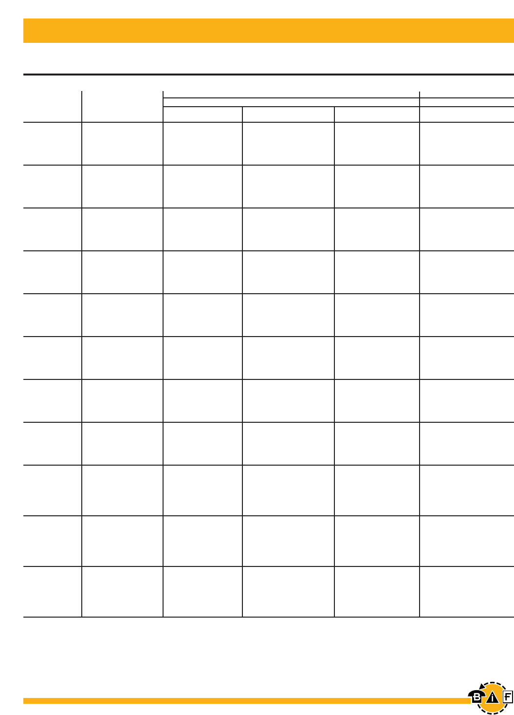
Bussmann®
120 For complete specification data, call Bussmann Information Fax ~ 636.527.1450
16A – 400A Other Configurations
Enclosed Non-Fusible Disconnect Switches
For additional information and detail, see the Bussmann Disconnect Switch Catalog, Item Number 3006
NEMA Enclosure type IEC Enclosure type
UL 4X Plastic 12 7 & 9 IP65
General purpose Type of switch Catalog Catalog Catalog Catalog
amp rating number number number number
4 pole ENF16P-4PB6 ENF162-4PB6 ENF167-4P ENF16E-4PBJ
16 6 pole ENF16P-6PB6 ENF162-6PB6 ENF167-6P ENF16E-6PBJ
Transfer ENF16P-3TB8 ENF162-3TB8 ENF167-3T —
Bypass ENF16P-3BB8 ENF162-3BB8 ENF167-3B —
Mech. interlock ENF16P-3MB6 ENF162-3MB6 — —
4 pole ENF25P-4PB6 ENF252-4PB6 ENF257-4P ENF25E-4PBJ
25 6 pole ENF25P-6PB6 ENF252-6PB6 ENF257-6P ENF25E-6PBJ
Transfer ENF25P-3TB8 ENF252-3TB8 ENF257-3T —
Bypass ENF25P-3BB8 ENF252-3BB8 ENF257-3B —
Mech. interlock ENF25P-3MB6 ENF252-3MB6 — —
4 Pole ENF32P-4PB6 ENF322-4PB6 ENF327-4P ENF32E-4PBJ
6 Pole ENF32P-6PB6 ENF322-6PB6 ENF327-6P ENF32E-6PBJ
40 Transfer ENF32P-3TB8 ENF322-3TB8 ENF327-3T —
Bypass ENF32P-3BB8 ENF323-3BB8 ENF327-3B —
Mech. interlock ENF32P-3MB6 ENF322-3MB6 — —
4 Pole ENF45P-4PB6 ENF452-4PB6 ENF457-4P ENF45E-4PBJ
60 6 Pole ENF45P-6PB6 ENF452-6PB6 ENF457-6P ENF45E-6PBJ
Transfer ENF45P-3TB8 ENF452-3TB8 ENF457-3T —
Bypass ENF45P-3BB8 ENF452-3BB8 ENF457-3B —
Mech. interlock ENF45P-3MB6 ENF452-3MB6 — —
4 Pole ENF63P-4PB6 ENF632-4PB6 ENF637-4P ENF63E-4PBJ
80 6 Pole ENF63P-6PB6 ENF632-6PB6 ENF637-6P ENF637-6PBJ
Transfer ENF63P-3TB8 ENF632-3TB8 ENF637-3T —
Bypass ENF63P-3BB8 ENF632-3BB8 ENF637-3B —
Mech. interlock ENF63P-3MB6 ENF632-3MB6 — —
4 Pole ENF30P-4PB6 ENF302-4PB6 ENF307-4P ENF30E-4PB4
30 6 Pole ENF30P-6PB6 ENF302-6PB6 ENF307-6P ENF30E-6PB6
Transfer ENF30P-3TB8 ENF302-3TB8 ENF307-3T —
Bypass ENF30P-3BB8 ENF302-3BB8 ENF307-3B —
Mech. interlock ENF30P-3MB6 ENF302-3MB6 — —
4 Pole ENF60P-4PB6 ENF602-4PB6 ENF607-4P ENF60E-4PB4
60 6 Pole ENF60P-6PB6 ENF602-6PB6 ENF607-6P ENF60E-6PB6
Transfer ENF60P-3TB8 ENF602-3TB8 ENF607-3T —
Bypass ENF60P-3BB8 ENF602-3BB8 ENF607-3B —
Mech. interlock ENF60P-3MB6 ENF602-3MB6 — —
4 Pole ENF100P-4PB6 ENF1002-4PB6 ENF1007-4P ENF100E-4PB4
100 6 Pole ENF100P-6PB6 ENF1002-6PB6 ENF1007-6P ENF100E-6PB6
Transfer ENF100P-3TB8 ENF1002-3TB8 ENF1007-3T —
Bypass ENF100P-3BB8 ENF1002-3BB8 ENF1007-3B —
Mech. interlock ENF100P-3MB6 ENF1002-3MB6 — —
2 Pole ENF125P-2PB6 ENF1252-2PB6 ENF1257-2P —
4 Pole ENF125P-4PB6 ENF1252-4PB6 ENF1257-4P —
125 6 Pole ENF125P-6PB2 ENF1252-6PB2 ENF1257-6P —
Transfer ENF125P-3TB8 ENF1252-3TB8 ENF1257-3T —
Bypass — — — —
Mech. interlock ENF125P-3MB6 ENF1252-3MB6 — —
2 Pole ENF200P-2PB8 ENF2002-2PB8 ENF2007-2P —
4 Pole ENF200P-4PB8 ENF2002-4PB8 ENF2007-4P —
200 6 Pole ENF200P-6PB4 ENF2002-6PB4 ENF2007-6P —
Transfer ENF200P-3TB4 ENF2002-3TB4 ENF2007-3T —
Bypass ENF200P-3BB4 ENF2002-3BB4 ENF2007-3B —
Mech. interlock ENF200P-3MB8 ENF2002-3MB8 — —
2 Pole ENF400P-2PB4 ENF4002-2PB4 ENF4007-2P —
4 Pole ENF400P-4PB4 ENF4002-4PB4 ENF4007-4P —
400 6 Pole ENF400P-6P8 ENF4002-6P8 ENF4007-6P —
Transfer ENF400P-3TB4 ENF4002-3TB4 ENF4007-3T —
Bypass ENF400P-3B6 ENF4002-3B6 ENF4007-3B —
Mech. interlock ENF400P-3MB4 ENF4002-3MB4 — —
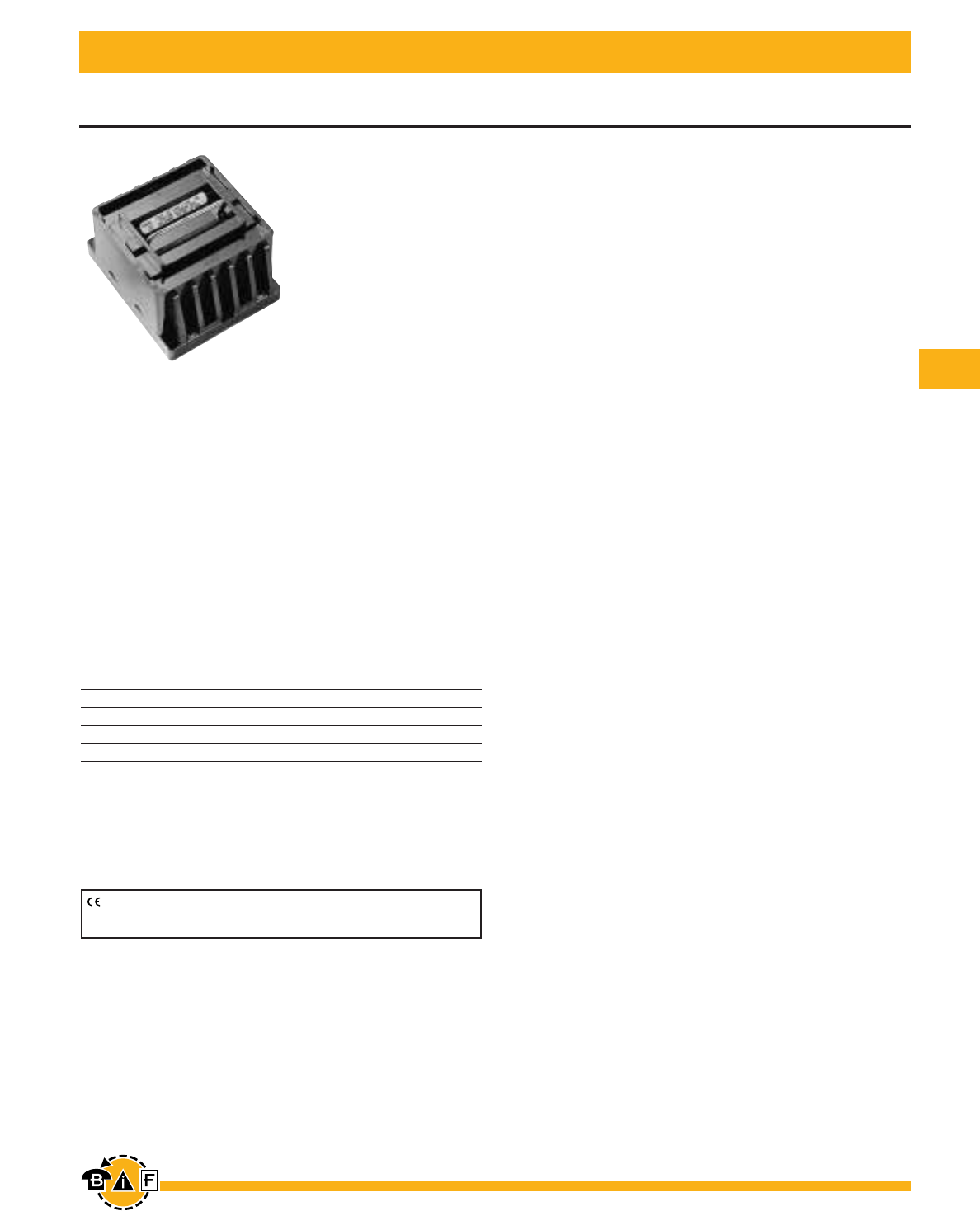
Bussmann®
121
For complete specification data, call Bussmann Information Fax ~ 636.527.1450
Disconnect Switches
Fused, Dead Front, Disconnect Switches
15149 Series
Voltage Ratings: 600Vac, 30A
Agency Information:
UL Recognized, file E116716 for General Industrial
installations. Guide WFXV2.
CSA certified, file LR37129-6
• In 2 and 3 poles.
• Class J fuses.
• Fuse holders in the pull-out head eliminate possibility of
electric shock while changing fuse.
• Examined under the new proposed standard UL 1429
which imparts a stricter set of test conditions than the
former program that combined the applicable portions for
UL 512 (Fuse Holders) and UL 98 (Enclosed Switches).
Specifications
Voltage Rating 600V AC (maximum)
Current Rating 0 to 30A
Motor Rating 5 HP
Dielectric Withstand 2200V
Current Withstand 200,000 RMS Symmetrical Amperes
CE logo denotes compliance with European Union Low Voltage Directive
(50-1000Vac, 75-1500Vdc). Refer to Data Sheet: 8002 or contact
Bussmann Application Engineering at 636-527-1270 for more information.
Data Sheet: 1141
Ordering information:
15149 is available in 2 or 3 poles.
To order: Basic Part No. + number of poles.
Example: 15149-2 = 2-pole device.
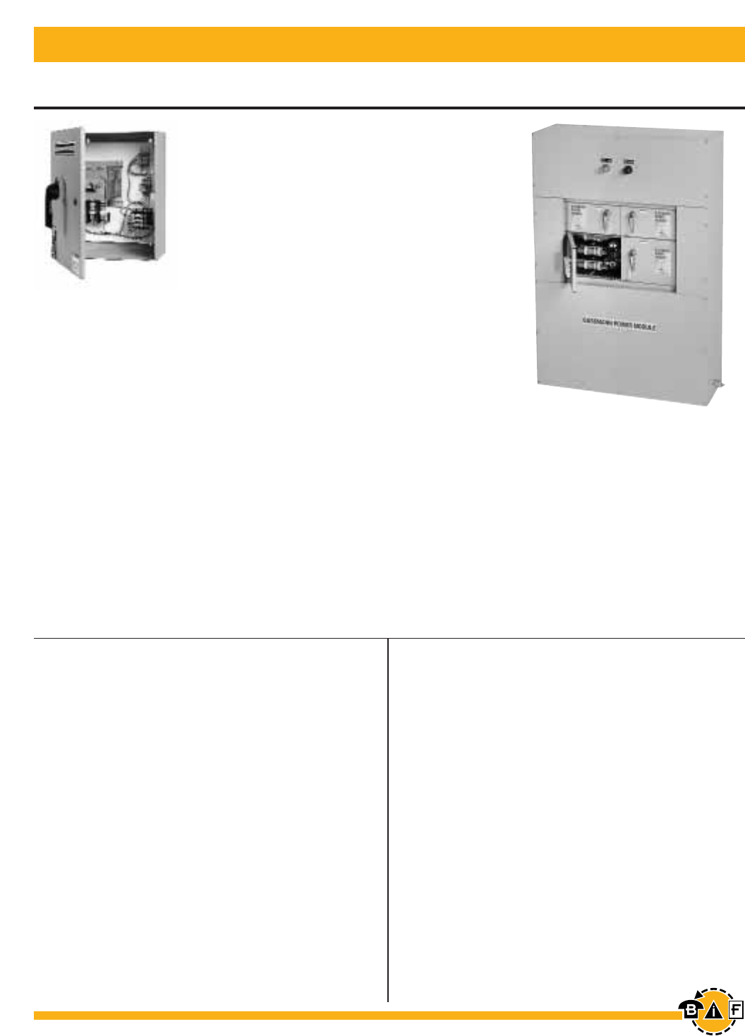
Bussmann®
122 For complete specification data, call Bussmann Information Fax ~ 636.527.1450
Disconnect Switches
Data Sheet: 1145 Data Sheet: 1146
PMP
Power Module™ Panel
(Multiple Elevator Applications)
Ampere Ratings:
Feeder Switches - 30-400A
Main Switches2- 400-800A
Agency Information:
UL Listed (UL 67) Panel Boards or (UL 891)
Dead Front Switchboard, File E181664
ULc per Canadian Standards
Service Entrance Rated
2Contact Bussmann for applications greater than 800A
Power Module™ —All-in-one Elevator Disconnect
PS
Power Module™ Switch
(Single Elevator Applications)
Ampere Ratings:
30-400A
Agency Information:
UL Listed (UL 98) Enclosed and Dead front switch
Guide 96NK3917, File E182262
NEMA 1, UL 50 Listed enclosure1
ULc per Canadian Standards C22.2, No. 0-M91-
CAN/CSA C22.2, No. 4-M89 Enclosed switch.
1NEMA 12, 3R, and 4 enclosures also available
Bussmann®Power Module™
(Fusible switch with shunt trip and fire safety
interface to allow for single point tie in with
fire alarm system.)
Complies with:
NFPA 70 (NEC®; National Electrical Code®)
ANSI/ASME A17.1 (Safety Code for Elevators
and Escalators)
NFPA 72 (National Fire Alarm Code®)
Features and Accessories:
• Shunt trip 120V
• Accepts LPJ-(amp)SP Class J fuses
• Control Power Transformer
• Fire Safety Interface Relay
• Key to Test Switch
• Pilot Light (on)
• Mechanically Interlocked Auxiliary Contact
• Neutral (200% Capability)
• Control Power Fuses and Blocks
• For added safety, use the Bussmann SAMI fuse
covers to improve maintenance personnel
protection (OSHA 1910.333, paragraph C).
Voltage Ratings:
600Vac, 3Ø Fused Power Switch
Short-Circuit Current Rating:
200,000A RMS
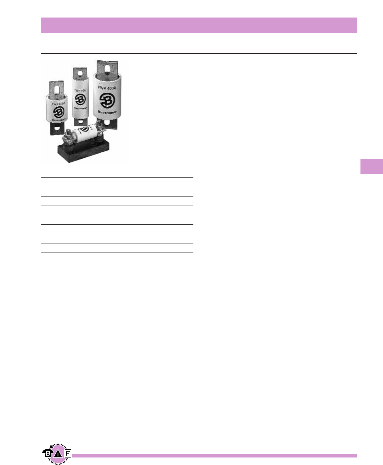
Bussmann®
123
For complete specification data, call Bussmann Information Fax ~ 636.527.1450
North American Style — General Information
High Speed Fuses
Characteristics:
• Low energy let-thru (I2t)
• Low watts loss
• Superior cycling capability
• Low arc voltage
• Excellent dc performance
North American style fuses provide an excellent solution for
medium power applications. While there are currently no pub-
lished standards for these fuses, the industry has standardized
on mounting centers that accept Bussmann fuses.
Accessories
Bussmann offers a comprehensive line of fuse bases that pro-
vide the user with design and manufacturing flexibility.
Voltage Rating
130Vac/dc 1000 to 4000A
150Vac/dc 70 to 1000A
250Vac/dc 35 to 2500A
500Vac/dc 35 to 1600A
600Vac 1 to 1000A
700Vac/dc 5 to 1200A
800Vdc 35 to 600A
1000Vac, 700Vdc 35 to 2000A
All Bussmann North American Style fuses are certified for their
rated voltage.
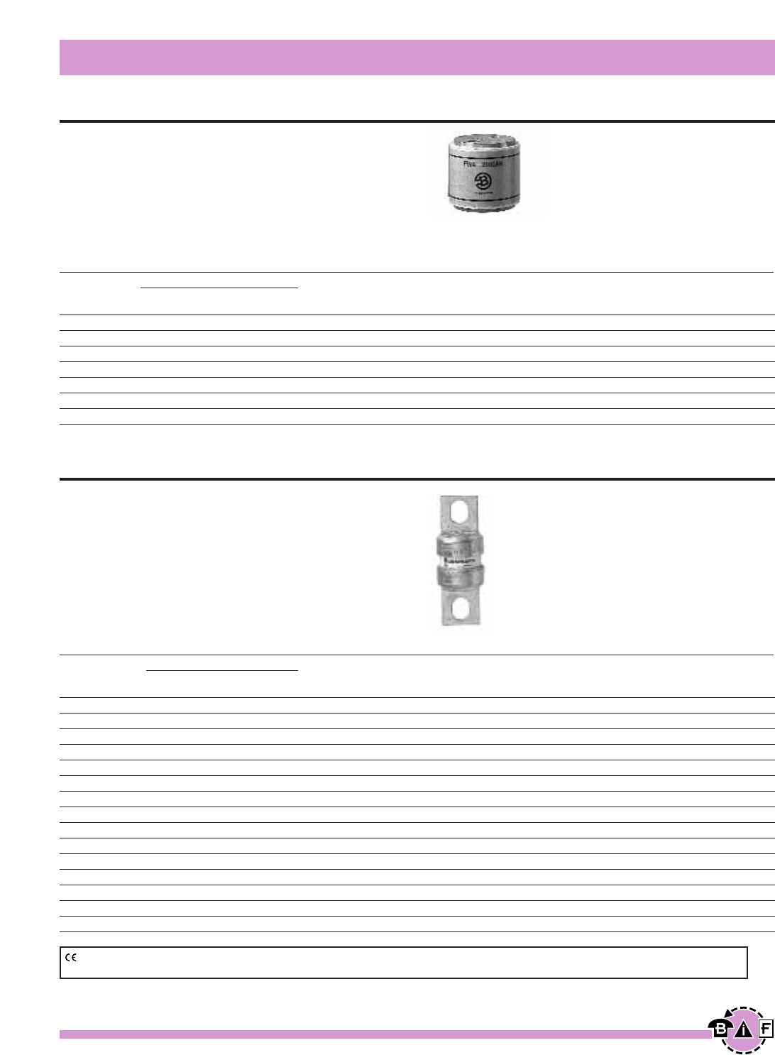
Bussmann®
124 For complete specification data, call Bussmann Information Fax ~ 636.527.1450
North American Style
High Speed Fuses
Data Sheet: 720001
Data Sheet: 720002
FWA 130V
Voltage Rating: 130Vac/130Vdc (130Vdc rating
applies to 1000 through 2000A only.)
Interrupting Rating: 200kA RMS Symmetrical.
Agency Information: UL Recognized, Std. 248-13
Watts loss provided at rated current.
Ordering Information
Part Number Carton Qty. Carton Weight (lbs)
FWA-1000AH 1 3.3
FWA-1200AH 1 3.3
FWA-1500AH 1 3.3
FWA-2000AH 1 3.3
FWA-2500AH 1 3.3
FWA-3000AH 1 3.3
FWA-4000AH 1 3.3
Electrical Characteristics
Rated I2t (A2SEC) @ 100kA
Current Clearing Watts
RMS-Amps Pre-arc at 150V Loss
70 470 4000 6.9
80 670 6000 7.7
100 1200 12000 9.0
125 1870 18000 11.2
150 2700 26000 13.5
200 4780 45000 17.6
250 7470 70000 22.5
300 10760 100000 27.0
350 15700 140000 30.6
400 20300 180000 35.2
500 39000 120000 35.0
600 46000 140000 47.0
700 75000 220000 49.0
800 92000 280000 58.0
1000 170000 510000 60.0
Ordering Information
Part Number Carton Qty. Carton Weight (lbs)
FWA-70B 10 1.76
FWA-80B 10 1.76
FWA-100B 10 1.76
FWA-125B 10 1.76
FWA-150B 10 1.76
FWA-200B 10 1.76
FWA-250B 10 1.76
FWA-300B 10 1.76
FWA-350B 10 1.76
FWA-400B 10 1.76
FWA-500A 5 2.42
FWA-600A 5 2.42
FWA-700A 5 2.42
FWA-800A 5 2.42
FWA-1000A 5 2.42
FWA 150V
Voltage Rating: 150Vac/150Vdc (150Vdc rating
applies to 70 through 800A only.)
Interrupting Rating: 100kA RMS Symmetrical. (70-400A)
200kA RMS Symmetrical. (450-1000A)
Agency Information: UL Recognized, Std. 248-13
Watts loss provided at rated current.
Electrical Characteristics
Rated I2t (A2SEC) @ 100kA
Current Clearing Watts
RMS-Amps Pre-arc at 130V Loss
1000 170000 460000 60.0
1200 270000 730000 70.0
1500 520000 1400000 78.0
2000 860000 2400000 108.0
2500 1500000 4100000 130.0
3000 2100000 5700000 150.0
4000 3400000 9200000 257.0
CE logo denotes compliance with European Union Low Voltage Directive (50-1000Vac, 75-1500Vdc). Refer to Data Sheet: 8002 or contact Bussmann
Application Engineering at 636-527-1270 for more information.
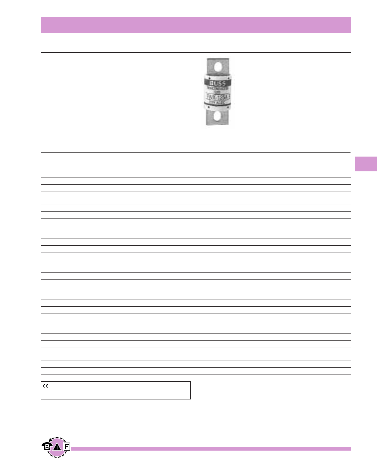
Bussmann®
125
For complete specification data, call Bussmann Information Fax ~ 636.527.1450
North American Style
High Speed Fuses
Data Sheet: 720005
FWX 250V
Voltage Rating: 250Vac/250Vdc (250Vdc rating on
35 through 800A only.)
Interrupting Rating: 200kA RMS Symmetrical,
AC 50kA DC
Agency Information:
CSA Component Acceptance, 35-800A
UL Recognized, Std. 248-13, 35-800A
Watts loss provided at rated current.
Ordering Information
Part Number Carton Qty. Carton Weight (lbs)
FWX-35A 5 1.40
FWX-40A 5 1.40
FWX-45A 5 1.40
FWX-50A 5 1.40
FWX-60A 5 1.40
FWX-70A 1 0.32
FWX-80A 1 0.32
FWX-90A 1 0.32
FWX-100A 1 0.32
FWX-125A 1 0.32
FWX-150A 1 0.32
FWX-175A 1 0.32
FWX-200A 1 0.32
FWX-225A 1 0.52
FWX-250A 1 0.52
FWX-275A 1 0.52
FWX-300A 1 0.52
FWX-350A 1 0.52
FWX-400A 1 0.52
FWX-450A 1 0.52
FWX-500A 1 0.52
FWX-600A 1 0.52
FWX-700A 1 0.90
FWX-800A 1 0.90
FWX-1000AH 1 2.86
FWX-1200AH 1 2.86
FWX-1500AH 1 2.86
FWX-1600AH 1 2.86
FWX-2000AH 1 2.86
FWX-2500AH 1 2.86
Electrical Characteristics
Rated I2t (A2SEC) @ 100kA
Current Clearing Watts
RMS-Amps Pre-arc at 250V Loss
35 50 230 4.2
40 60 310 5.2
45 80 390 5.7
50 100 520 6.0
60 140 740 8.1
70 330 1400 7.2
80 430 1850 8.1
90 570 2450 9.0
100 740 3150 10.0
125 1130 4850 12.5
150 1620 6950 15.7
175 2170 9300 18.5
200 2790 12000 22
225 3210 14700 24
250 3960 18100 27
275 4720 21600 31
300 6000 27300 32
350 10600 48600 39
400 14500 66100 44
450 22100 101000 49
500 28000 128000 54
600 41100 188000 62
700 48800 190000 72
800 59000 230000 84
1000 44000 360000 100
1200 92000 750000 103
1500 120000 880000 140
1600 160000 1200000 140
2000 320000 2300000 151
2500 670000 4700000 163
CE logo denotes compliance with European Union Low Voltage Directive
(50-1000Vac, 75-1500Vdc). Refer to Data Sheet: 8002 or contact
Bussmann Application Engineering at 636-527-1270 for more information.
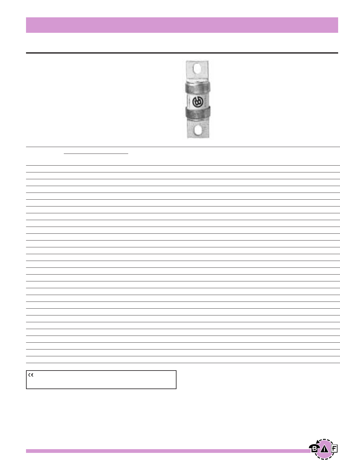
Bussmann®
126 For complete specification data, call Bussmann Information Fax ~ 636.527.1450
North American Style
High Speed Fuses
Data Sheet: 720007
FWH 500V
Voltage Rating: 500Vac/500Vdc (500Vdc rating applies
to 35 through 800A only.)
Interrupting Rating: 200kA RMS Symmetrical.
Agency Information: UL Recognized, Std. 248-13,
35-1200A; CSA Component Acceptance 35-1600A
Watts loss provided at rated current.
Ordering Information
Part Number Carton Qty. Carton Weight (lbs)
FWH- 35B 10 1.34
FWH-40B 10 1.34
FWH-45B 10 1.34
FWH-50B 10 1.34
FWH-60B 10 1.34
FWH-70B 10 2.05
FWH-80B 10 2.05
FWH-90B 10 2.05
FWH-100B 10 2.05
FWH-125B 5 1.65
FWH-150B 5 1.65
FWH-175B 5 1.65
FWH-200B 5 1.65
FWH-225A 1 0.57
FWH-250A 1 0.57
FWH-275A 1 0.57
FWH-300A 1 0.57
FWH-325A 1 0.57
FWH-350A 1 0.57
FWH-400A 1 0.57
FWH-450A 1 1.00
FWH-500A 1 1.00
FWH-600A 1 1.00
FWH-700A 1 2.14
FWH-800A 1 2.14
FWH-1000A 1 4.62
FWH-1200A 1 4.62
FWH-1400A 1 11.66
FWH-1600A 1 11.66
Electrical Characteristics
Rated I2t (A2SEC) @ 100kA
Current Clearing Watts
RMS-Amps Pre-arc at 500V Loss
35 34 150 .8
40 76 320 7.5
45 105 450 7.5
50 135 670 7.5
60 210 900 9.9
70 210 900 10.6
80 305 1400 12.7
90 360 1600 15
100 475 2000 17
125 800 3500 25
150 1100 4600 30
175 1450 6200 35
200 1900 8500 40
225 4600 23300 39
250 6300 32200 41
275 7900 40300 46
300 9800 49800 51
325 13700 63800 53
350 14500 72900 58
400 19200 96700 65
450 24700 127000 74
500 29200 149000 84
600 41300 206000 108
700 55000 298000 120
800 76200 409000 129
1000 92000 450000 145
1200 122000 600000 180
1400 200000 1000000 210
1600 290000 1400000 230
CE logo denotes compliance with European Union Low Voltage Directive
(50-1000Vac, 75-1500Vdc). Refer to Data Sheet: 8002 or contact
Bussmann Application Engineering at 636-527-1270 for more information.
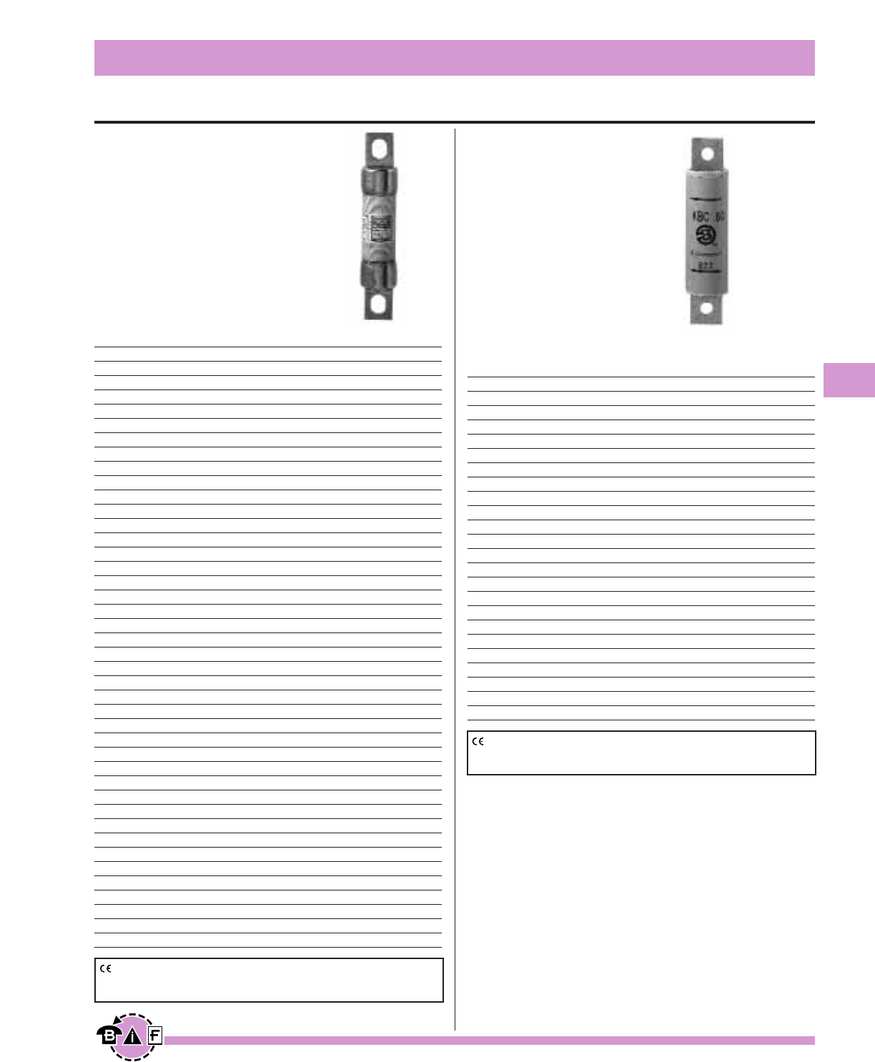
Bussmann®
127
For complete specification data, call Bussmann Information Fax ~ 636.527.1450
North American Style
High Speed Fuses
Data Sheet: 720009 Data Sheet: 720010
KAC 600V
Voltage Rating: 600Vac
Interrupting Rating: 200kA
RMS Symmetrical.
Agency Information:
UL Recognized, Std. 248-13,1-600A
• For new installations, Bussmann
recommends the 700V FWP series
fuse. The 600V fuses are
supplied as replacements only.
Ordering Information
Part Number Carton Qty. Carton Weight (lbs)
KAC-1 10 0.50
KAC-2 10 0.50
KAC-3 10 0.50
KAC-4 10 0.50
KAC-5 10 0.50
KAC-6 10 0.50
KAC-7 10 0.50
KAC-8 10 0.50
KAC-9 10 0.50
KAC-10 10 0.50
KAC-12 10 0.50
KAC-15 10 0.50
KAC-17.5 10 0.50
KAC-20 10 0.50
KAC-25 10 0.50
KAC-30 10 0.50
KAC-35 10 1.40
KAC-40 10 1.40
KAC-45 10 1.40
KAC-50 10 1.40
KAC-60 10 1.40
KAC-70 5 1.56
KAC-80 5 1.56
KAC-90 5 1.56
KAC-100 5 1.56
KAC-110 1 0.78
KAC-125 1 0.78
KAC-150 1 0.78
KAC-175 1 0.78
KAC-200 1 0.78
KAC-225 1 1.92
KAC-250 1 1.92
KAC-300 1 1.92
KAC-350 1 1.92
KAC-400 1 1.92
KAC-450 1 3.16
KAC-500 1 3.16
KAC-600 1 3.16
KAC-700 1 3.16
KAC-800 1 3.16
KAC-1000 1 6.24
KBC 600V
Voltage Rating: 600Vac
Interrupting Rating: 200kA
RMS Symmetrical.
Agency Information:
UL Recognized, Std. 248-13,
35-600A
• For new installations,
Bussmann recommends the
700 Volt FWP series fuse.
The 600V fuses are supplied
as replacements only.
Ordering Information
Part Number Carton Qty. Carton Weight (lbs)
KBC-35 10 1.40
KBC-40 10 1.40
KBC-45 10 1.40
KBC-50 10 1.40
KBC-60 10 1.40
KBC-70 5 1.44
KBC-80 5 1.44
KBC-90 5 1.44
KBC-100 5 1.44
KBC-110 1 0.48
KBC-125 1 0.48
KBC-150 1 0.48
KBC-175 1 0.48
KBC-200 1 0.48
KBC-225 1 0.77
KBC-250 1 0.77
KBC-300 1 0.77
KBC-350 1 0.77
KBC-400 1 0.77
KBC-450 1 1.32
KBC-500 1 1.32
KBC-600 1 1.32
KBC-800 1 4.50
CE logo denotes compliance with European Union Low Voltage Directive
(50-1000Vac, 75-1500Vdc). Refer to Data Sheet: 8002 or contact
Bussmann Application Engineering at 636-527-1270 for more information.
CE logo denotes compliance with European Union Low Voltage Directive
(50-1000Vac, 75-1500Vdc). Refer to Data Sheet: 8002 or contact
Bussmann Application Engineering at 636-527-1270 for more information.
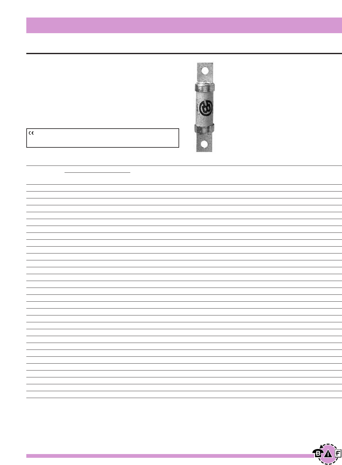
Bussmann®
128 For complete specification data, call Bussmann Information Fax ~ 636.527.1450
North American Style
High Speed Fuses
Data Sheet: 720012
FWP 700V
Voltage Rating: 700Vac/700Vdc (700Vdc rating applies
to 5 through 800A only.)
Interrupting Rating: 200kA RMS Symmetrical,
AC 50kA DC
Agency Information: UL Recognized, Std. 248-13;
CSA Component Acceptance, 35-800A
Watts loss provided at rated current.
Ordering Information
Part Number Carton Qty. Carton Weight (lbs)
FWP-5B 10 2.25
FWP-10B 10 2.25
FWP-15B 10 2.25
FWP-20B 10 2.25
FWP-25B 10 2.25
FWP-30B 10 2.25
FWP-35B 10 2.42
FWP-40B 10 2.42
FWP-50B 10 2.42
FWP-60B 10 2.42
FWP-70B 10 2.42
FWP-80B 10 2.42
FWP-90B 10 2.42
FWP-100B 10 2.42
FWP-125A 1 0.65
FWP-150A 1 0.65
FWP-175A 1 0.65
FWP-200A 1 0.65
FWP-225A 1 1.17
FWP-250A 1 1.17
FWP-300A 1 1.17
FWP-350A 1 1.17
FWP-400A 1 1.17
FWP-450A 1 2.39
FWP-500A 1 2.39
FWP-600A 1 2.39
FWP-700A 1 1.21
FWP-800A 1 1.21
FWP-900A 1 6.60
FWP-1000A 1 6.60
FWP-1200A 1 6.60
Electrical Characteristics
Rated I2t (A2SEC) @ 100kA
Current Clearing Watts
RMS-Amps Pre-arc at 700V Loss
5 1.6 10 1.5
10 3.6 20 4
15 10 75 5.5
20 26 180 6
25 44 340 7
30 58 450 9
35 34 160 12
40 76 320 12
50 135 600 12
60 210 950 15.5
70 305 1400 18
80 360 1600 21
90 415 1900 25
100 540 2500 27
125 1800 7300 28
150 2900 11700 32
175 4200 16700 35
200 5500 22000 43
225 7700 31300 45
250 10500 42500 48
300 17600 71200 58
350 23700 95600 65
400 31000 125000 78
450 36400 137000 94
500 45200 170000 107
600 66700 250000 122
700 54000 300000 125
800 78000 450000 140
900 91500 530000 150
1000 120000 600000 170
1200 195000 1100000 190
CE logo denotes compliance with European Union Low Voltage Directive
(50-1000Vac, 75-1500Vdc). Refer to Data Sheet: 8002 or contact
Bussmann Application Engineering at 636-527-1270 for more information.
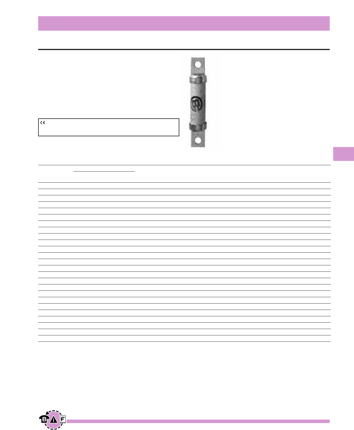
Bussmann®
129
For complete specification data, call Bussmann Information Fax ~ 636.527.1450
North American Style
High Speed Fuses
Data Sheet: 720027
FWJ 1000V
Voltage Rating: 1000Vac/800Vdc (Ampere ratings
35-200 and 500-600 rated up to 800Vdc)
Interrupting Rating: 25kA for 35-200A,
100kA for 250-600A
Agency Information:
UL Recognition on 35 through 600A only, Std. 248-13
Watts loss provided at rated current.
Ordering Information
Part Number Carton Qty. Carton Weight (lbs)
FWJ-35A 10 4.18
FWJ-40A 10 4.18
FWJ-50A 10 4.18
FWJ-60A 10 4.18
FWJ-70A 10 4.18
FWJ-80A 10 4.18
FWJ-90A 10 4.18
FWJ-100A 10 4.18
FWJ-125A 1 4.40
FWJ-150A 1 4.40
FWJ-175A 1 4.40
FWJ-200A 1 4.40
FWJ-250A 1 4.84
FWJ-300A 1 4.84
FWJ-350A 1 4.84
FWJ-400A 1 4.84
FWJ-500A 1 4.84
FWJ-600A 1 4.84
FWJ-800A 1 5.28
FWJ-1000A 1 5.28
FWJ-1200A 1 5.28
FWJ-1400A 1 5.28
FWJ-1600A 1 5.28
FWJ-1800A 1 5.28
FWJ-2000A 1 5.28
Electrical Characteristics
Rated I2t (A2SEC) @ 100kA
Current Clearing Watts
RMS-Amps Pre-arc at 1000V Loss
35 210 2000 7
40 300 2500 8
50 470 3500 10
60 670 5000 11
70 1100 6900 12
80 1550 9700 13
90 1900 12000 14
100 2800 17500 15
125 4800 35000 16
150 6300 45000 25
175 7500 65000 30
200 11700 80000 32
250 9000 50000 50
300 15000 80000 56
350 22000 120000 62
400 32000 180000 67
500 28500 155000 95
600 46500 260000 105
800 87000 500000 182
1000 190000 1100000 206
1200 370000 2100000 240
1400 470000 2700000 248
1600 700000 4000000 267
1800 925000 5300000 239
2000 1330000 7600000 244
CE logo denotes compliance with European Union Low Voltage Directive
(50-1000Vac, 75-1500Vdc). Refer to Data Sheet: 8002 or contact
Bussmann Application Engineering at 636-527-1270 for more information.
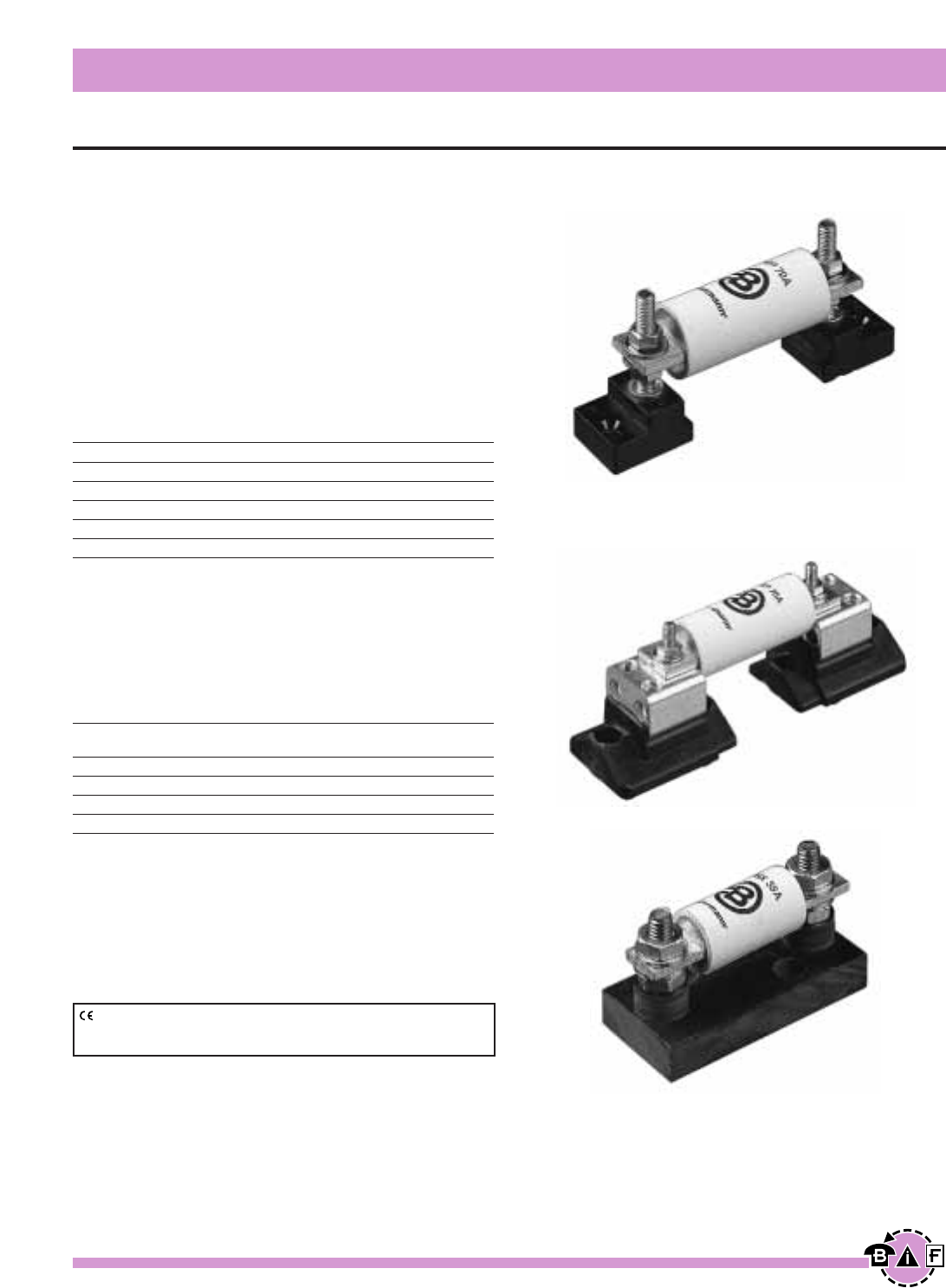
Bussmann®
130 For complete specification data, call Bussmann Information Fax ~ 636.527.1450
North American Style Fuseblocks
High Speed Fuses
Data Sheet: 720033
Modular Style
Bussmann offers a comprehensive line of fuse bases that pro-
vide the user with design and manufacturing flexibility. Two
identical half bases make up a Buss Modular fuse base.
These “split” units can be panel mounted any distance
apart to accommodate any length fuse.
Stud Type
The simpler design is the C5268 Series Modular fuse
base. With this design, the fuse terminal and cable (with
termination) are mounted on the same stud, minimizing labor
needed for installation. The stud Type Base is available in the
configuration shown in the table below. (Must order 2 pieces
per fuse, they do not come in pairs.)
Part No. Stud Heights Stud Dia. & Threads
C5268-1 1.00∑ fiΩ¡§-18
C5268-2 1.75∑ fiΩ¡§-18
C5268-3 0.75∑ fiΩ¡§-18
C5268-4 1.00∑ ⁄Ω¢-20
C5268-5 1.75∑ ⁄Ω¢-20
Connector Type
Bussmann also offers a modular style fuse base that
utilizes a tin plated connector (for wire termination and heat
dissipation) and a plated steel stud (for fuse mounting). The
connector type fuse base is available in the configurations
shown below. Consult Bussmann for additional product
details. (Order 1 piece per fuse, parts come in pairs.)
Modular Max. Fuse
Base Style Max. Voltage Current Rating
BH-0 Series 700V 100A
BH-1 Series 2500V 400A
BH-2 Series 5000V 400A
BH-3 Series 1250V 700A
See page 67.
Fixed Center Base Style
Bussmann offers a comprehensive line of fixed mount style fuse
bases under the trademark TRON®Rectifier Fuseblocks. The
cable and fuse connections are similar to the Stud Type fuse
base — both are mounted on the same stud. Consult
Bussmann for complete product details.
CE logo denotes compliance with European Union Low Voltage Directive
(50-1000Vac, 75-1500Vdc). Refer to Data Sheet: 8002 or contact
Bussmann Application Engineering at 636-527-1270 for more information.
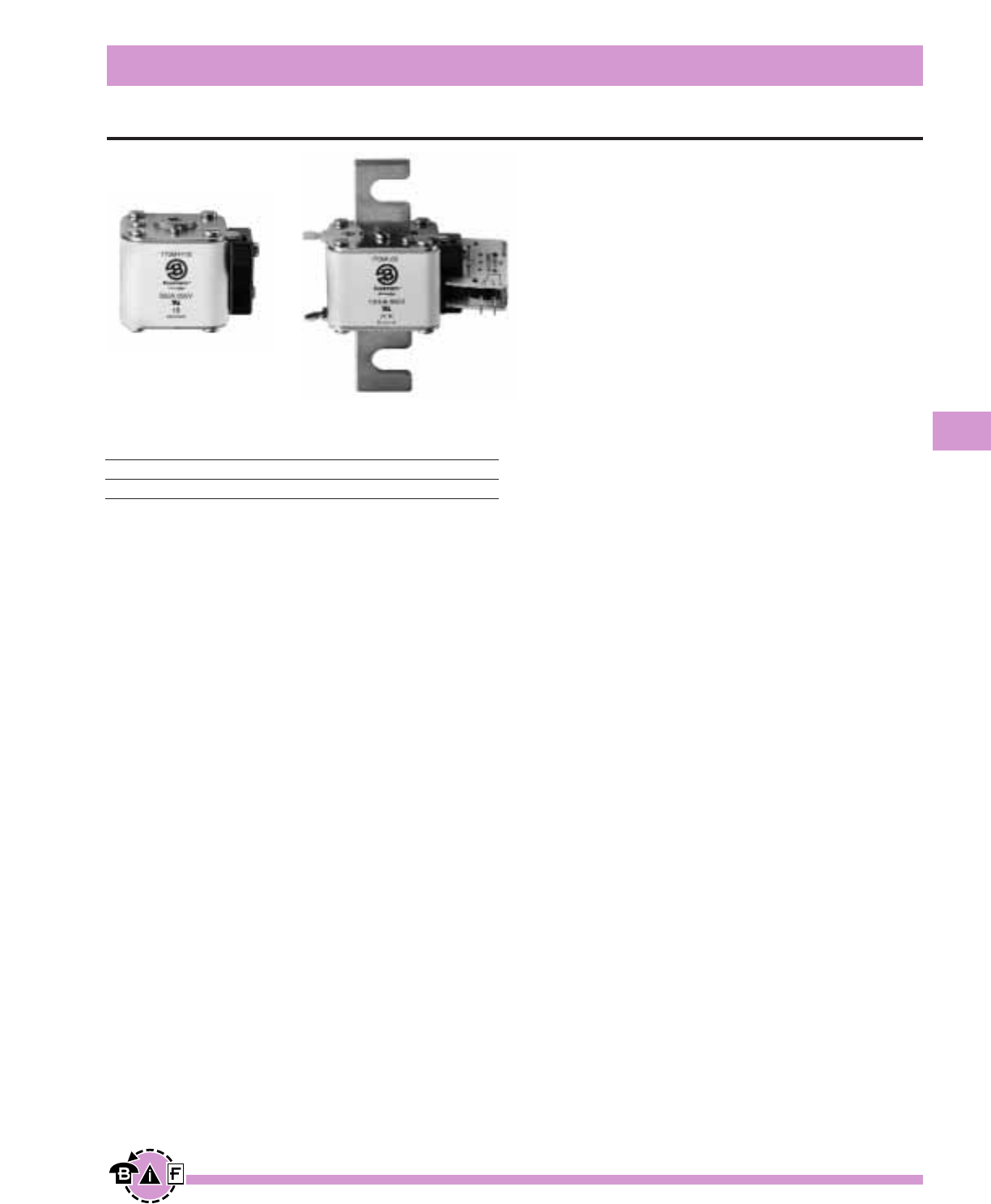
Bussmann®
131
For complete specification data, call Bussmann Information Fax ~ 636.527.1450
European Style Square Body — General Information
High Speed Fuses
Voltage Rating
690Vac 10 to 7500A
1250Vac 50 to 1400A
All Bussmann European Style fuses are tested to IEC 60269,
Part 4. This standard requires a test voltage which is 10%
higher than the rated voltage. In North America, fuses are
required to clear only their rated voltage.
Characteristics
Designed and tested to:
• IEC 60269: Part 4
• UL Recognized
• Minimal energy let-thru (I2t)
• Low operating temperature
• Low Watts loss
General Information
Each European Style fuse is available with a number of differ-
ent end fittings. Options include:
• DIN 43 653
• North American Slotted Blade
• DIN 43 620
• Flush End (Metric/U.S.)
• French Style
Accessories
European Style fuses are available with three different open
fuse indicator systems. Options include visual indication and
indication utilizing a microswitch. Fuseblocks are also available
for most applications.
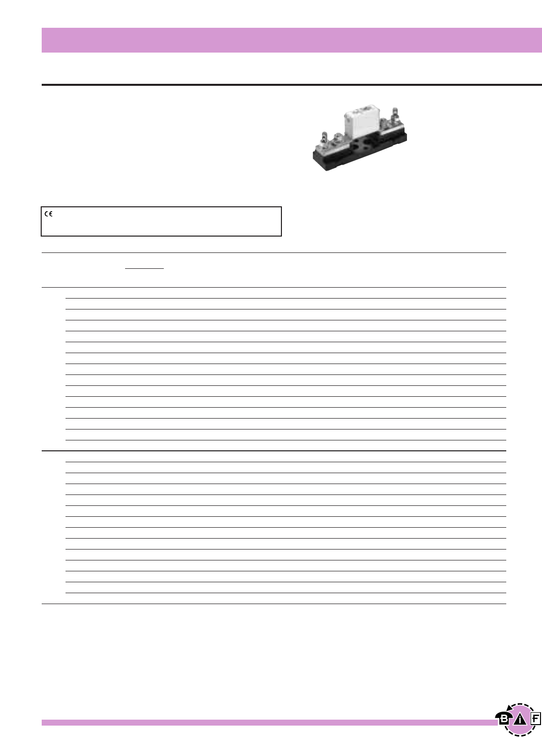
Bussmann®
132 For complete specification data, call Bussmann Information Fax ~ 636.527.1450
European Style Square Body
High Speed Fuses
Data Sheet: 720013
Ordering Information
-TN/80
-U/80 -/80 Type T Carton
Without Visual Indicator Carton Weight
Indicator Indicator for Micro Qty. (Kg)
170M1308* 170M1358* 170M1408* 10 1.34
170M1309* 170M1359* 170M1409* 10 1.34
170M1310* 170M1360* 170M1410* 10 1.34
170M1311* 170M1361* 170M1411* 10 1.34
170M1312* 170M1362* 170M1412* 10 1.34
170M1313* 170M1363* 170M1413* 10 1.34
170M1314* 170M1364* 170M1414* 10 1.34
170M1315* 170M1365* 170M1415* 10 1.34
170M1316* 170M1366* 170M1416* 10 1.34
170M1317* 170M1367* 170M1417* 10 1.34
170M1318* 170M1368* 170M1418* 10 1.34
170M1319* 170M1369* 170M1419* 10 1.34
170M1320* 170M1370* 170M1420* 10 1.34
170M1321* 170M1371* 170M1421* 10 1.34
170M1322* 170M1372* 170M1422* 10 1.34
— 170M2608 170M2658 5 1.05
— 170M2609 170M2659 5 1.05
— 170M2610 170M2660 5 1.05
— 170M2611 170M2661 5 1.05
— 170M2612 170M2662 5 1.05
— 170M2613 170M2663 5 1.05
— 170M2614 170M2664 5 1.05
— 170M2615 170M2665 5 1.05
— 170M2616 170M2666 5 1.05
— 170M2617 170M2667 5 1.05
— 170M2618 170M2668 5 1.05
— 170M2619 170M2669 5 1.05
— 170M2620 170M2670 5 1.05
— 170M2621 170M2671 5 1.05
Electrical Characteristics
I2t (A2s)
Rated Current Clearing Watts
Size RMS-Amps Pre-arc at 660V Loss
10 3.8 25.5 3.0
16 7.2 48 5.5
20 11.5 78 7
25 19 130 9
32 40 270 10
40 69 460 12
000 50 115 770 15
63 215 1450 16
80 380 2550 19
100 695 4650 24
125 1200 8500 28
160 2300 16000 32
200 4200 28000 37
250 7750 51500 42
315 12000 80500 52
25 19 130 6
32 28.5 195 7
40 50 360 9
50 95 640 10
63 170 1200 12
80 310 2100 15
00 100 620 4150 20
125 1000 6950 25
160 1900 13000 30
200 3400 23000 35
250 6250 42000 45
315 10000 68500 55
350 13500 91500 60
400 18000 125000 70
*UL Recognized / CSA Component Accepted on size 000.
CE logo denotes compliance with European Union Low Voltage Directive
(50-1000Vac, 75-1500Vdc). Refer to Data Sheet: 8002 or contact
Bussmann Application Engineering at 636-527-1270 for more information.
DIN 43 653 —10-400A
Voltage Rating: 690V (IEC) & 700V (UL)
Interrupting Rating: 200kA (estimated 300kA) RMS Symmetrical
Agency Information:
UL Recognized, Std. 248-13
CSA Component Acceptance on Size 000
Watts loss provided at rated current.
Microswitch indicator ordered separately.
See bottom of page 146.
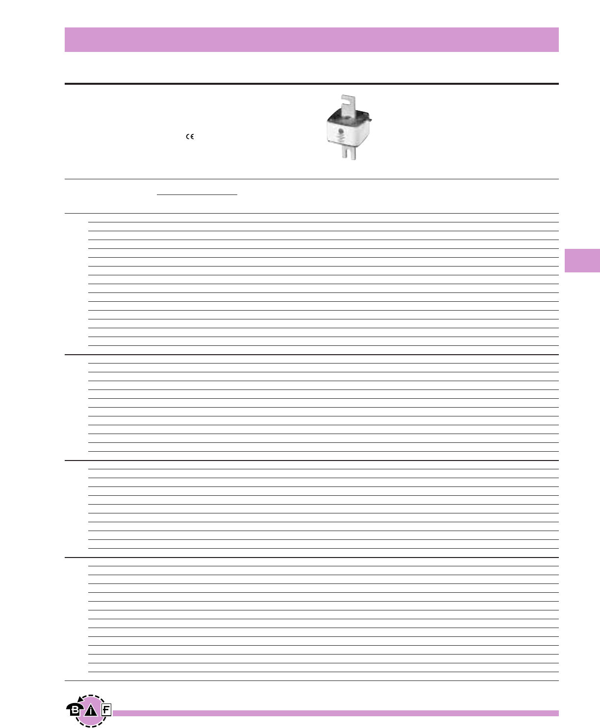
Bussmann®
133
For complete specification data, call Bussmann Information Fax ~ 636.527.1450
European Style Square Body
High Speed Fuses
Data Sheet: 720014
DIN 43 653 — 40-2000A
Voltage Rating: 690V (IEC) & 700V (UL)
Interrupting Rating: 200kA (estimated 300kA) RMS Symmetrical
Agency Information: CSA Component Acceptance
UL Recognized, Std. 248-13
Watts loss provided at rated current.
Microswitch indicator ordered separately. See bottom of page 146.
Ordering Information
-TN/80 -TN/110
-/80 Type T -/110 Type T Carton
Visual Indicator Visual Indicator Carton Weight
Indicator for Micro Indicator for Micro Qty. (Kg)
170M3008* 170M3058* 170M3158* 170M3208* 5 1.50
170M3009* 170M3059* 170M3159* 170M3209* 5 1.50
170M3010* 170M3060* 170M3160* 170M3210* 5 1.50
170M3011* 170M3061* 170M3161* 170M3211* 5 1.50
170M3012* 170M3062* 170M3162* 170M3212* 5 1.50
170M3013* 170M3063* 170M3163* 170M3213* 5 1.50
170M3014* 170M3064* 170M3164* 170M3214* 5 1.50
170M3015* 170M3065* 170M3165* 170M3215* 5 1.50
170M3016* 170M3066* 170M3166* 170M3216* 5 1.50
170M3017* 170M3067* 170M3167* 170M3217* 5 1.50
170M3018* 170M3068* 170M3168* 170M3218* 5 1.50
170M3019* 170M3069* 170M3169* 170M3219* 5 1.50
170M3020* 170M3070* 170M3170* 170M3220* 5 1.50
170M3021* 170M3071* 170M3171* 170M3221* 5 1.50
170M3022* 170M3072* 170M3172* 170M3222* 5 1.50
170M3023* 170M3073* 170M3173* 170M3223* 5 1.50
170M4008* 170M4058* 170M4158* 170M4208* 3 1.29
170M4009* 170M4059* 170M4159* 170M4209* (-/80) —
170M4010* 170M4060* 170M4160* 170M4210* — —
170M4011* 170M4061* 170M4161* 170M4211* 2 0.94
170M4012* 170M4062* 170M4162* 170M4212* (-/110) —
170M4013* 170M4063* 170M4163* 170M4213* — —
170M4014* 170M4064* 170M4164* 170M4214* — —
170M4015* 170M4065* 170M4165* 170M4215* — —
170M4016* 170M4066* 170M4166* 170M4216* — —
170M4017* 170M4067* 170M4167* 170M4217* — —
170M4018* 170M4068* 170M4168* 170M4218* — —
170M4019 170M4069 170M4169 170M4219 — —
170M5008* 170M5058* 170M5158* 170M5208* 2 1.20
170M5009* 170M5059* 170M5159* 170M5209* 2 1.20
170M5010* 170M5060* 170M5160* 170M5210* 2 1.20
170M5011* 170M5061* 170M5161* 170M5211* 2 1.20
170M5012* 170M5062* 170M5162* 170M5212* 2 1.20
170M5013* 170M5063* 170M5163* 170M5213* 2 1.20
170M5014* 170M5064* 170M5164* 170M5214* 2 1.20
170M5015* 170M5065* 170M5165* 170M5215* 2 1.20
170M5016* 170M5066* 170M5166* 170M5216* 2 1.20
170M5017* 170M5067* 170M5167* 170M5217* 2 1.20
170M5018* 170M5068* 170M5168* 170M5218* 2 1.20
170M6008* 170M6058* 170M6158* 170M6208* 2 1.66
170M6009* 170M6059* 170M6159* 170M6209* (-/80) —
170M6010* 170M6060* 170M6160* 170M6210* — —
170M6011* 170M6061* 170M6161* 170M6211* 1 0.89
170M6012* 170M6062* 170M6162* 170M6212* (-/110) —
170M6013* 170M6063* 170M6163* 170M6213* — —
170M6014* 170M6064* 170M6164* 170M6214* — —
170M6015* 170M6065* 170M6165* 170M6215* — —
170M6016* 170M6066* 170M6166* 170M6216* — —
170M6017* 170M6067* 170M6167* 170M6217* — —
170M6018* 170M6068* 170M6168* 170M6218* — —
170M6019* 170M6069* 170M6169 170M6219 — —
170M6020 170M6070 170M6170 170M6220 — —
170M6021 170M6071 170M6171 170M6221 — —
Electrical Characteristics
I2t (A2s)
Rated Current Clearing Watts
Size RMS-Amps Pre-arc at 660V Loss
40 40 270 9
50 77 515 11
63 115 770 14
80 185 1250 18
100 360 2450 21
125 550 3700 26
160 1100 7500 30
200 2200 15000 35
1* 250 4200 28500 40
315 7000 46500 50
350 10000 68500 55
400 15000 105000 60
450 21000 140000 65
500 27000 180000 70
550 34000 230000 75
630 48500 325000 80
200 1650 11500 45
250 3100 21000 55
315 6200 42000 58
350 8500 59000 60
400 13500 91500 65
1450 17000 120000 70
500 25000 170000 72
550 34000 230000 75
630 52000 350000 80
700 69500 465000 85
800 105000 725000 95
‡900 155000 ‡850000 100
400 11000 74000 65
450 15500 105000 70
500 21500 145000 75
550 28000 190000 80
630 41000 275000 90
2 700 60500 405000 95
800 86000 575000 105
900 125000 840000 110
1000 180000 1250000 115
1100 245000 1600000 120
1250 365000 2400000 130
500 14000 95000 95
550 19500 135000 100
630 31000 210000 105
700 44500 300000 110
800 69500 465000 115
900 100000 670000 120
31000 140000 945000 125
1100 190000 1300000 130
1250 290000 1950000 140
1400 370000 2450000 155
1500 460000 3100000 160
1600 580000 3900000 160
†1800 880000 †5250000 165
‡2000 1150000 ‡6350000 175
*UL Recognized / CSA Component Accepted. Rated voltage †600V ‡550V

Bussmann®
134 For complete specification data, call Bussmann Information Fax ~ 636.527.1450
European Style Square Body
High Speed Fuses
Data Sheet: 720015
DIN 43 653 — 40-2000A
Voltage Rating: 690V (IEC) & 700V (UL)
Interrupting Rating: 200kA (estimated 300kA) RMS Symmetrical
Agency Information: CSA Component Acceptance
UL Recognized, Std. 248-13
Watts loss provided at rated current.
Microswitch indicator ordered separately. See bottom of page 146.
Ordering Information
-KN/80 -KN/110
Type K Type K
Indicator Indicator Carton Carton
for Micro for Micro Qty. Weight (Kg)
170M3108* 170M3258* 5 1.60
170M3109* 170M3259* 5 1.60
170M3110* 170M3260* 5 1.60
170M3111* 170M3261* 5 1.60
170M3112* 170M3262* 5 1.60
170M3113* 170M3263* 5 1.60
170M3114* 170M3264* 5 1.60
170M3115* 170M3265* 5 1.60
170M3116* 170M3266* 5 1.60
170M3117* 170M3267* 5 1.60
170M3118* 170M3268* 5 1.60
170M3119* 170M3269* 5 1.60
170M3120* 170M3270* 5 1.60
170M3121* 170M3271* 5 1.60
170M3122* 170M3272* 5 1.60
170M3123* 170M3273* 5 1.60
170M4108* 170M4258* 3 1.38
170M4109* 170M4259* (-/80) —
170M4110* 170M4260* — —
170M4111* 170M4261* 2 1.00
170M4112* 170M4262* (-/110) —
170M4113* 170M4263* — —
170M4114* 170M4264* — —
170M4115* 170M4265* — —
170M4116* 170M4266* — —
170M4117* 170M4267* — —
170M4118* 170M4268* — —
170M4119 170M4269 — —
170M5108* 170M5258* 2 1.26
170M5109* 170M5259* 2 1.26
170M5110* 170M5260* 2 1.26
170M5111* 170M5261* 2 1.26
170M5112* 170M5262* 2 1.26
170M5113* 170M5263* 2 1.26
170M5114* 170M5264* 2 1.26
170M5115* 170M5265* 2 1.26
170M5116* 170M5266* 2 1.26
170M5117* 170M5267* 2 1.26
170M5118* 170M5268* 2 1.26
170M6108* 170M6258* 1 0.92
170M6109* 170M6259* 1 0.92
170M6110* 170M6260* 1 0.92
170M6111* 170M6261* 1 0.92
170M6112* 170M6262* 1 0.92
170M6113* 170M6263* 1 0.92
170M6114* 170M6264* 1 0.92
170M6115* 170M6265* 1 0.92
170M6116* 170M6266* 1 0.92
170M6117* 170M6267* 1 0.92
170M6118* 170M6268* 1 0.92
170M6119* 170M6269* 1 0.92
170M6120 170M6270 1 0.92
170M6121 170M6271 1 0.92
Electrical Characteristics
I2t (A2s)
Rated Current Clearing Watts
Size RMS-Amps Pre-arc at 660V Loss
40 40 270 9
50 77 515 11
63 115 770 14
80 185 1250 18
100 360 2450 21
125 550 3700 26
160 1100 7500 30
200 2200 15000 35
1* 250 4200 28500 40
315 7000 46500 50
350 10000 68500 55
400 15000 105000 60
450 21000 140000 65
500 27000 180000 70
550 34000 230000 75
630 48500 325000 80
200 1650 11500 45
250 3100 21000 55
315 6200 42000 58
350 8500 59000 60
400 13500 91500 65
450 17000 120000 70
1500 25000 170000 72
550 34000 230000 75
630 52000 350000 80
700 69500 465000 85
800 105000 725000 95
‡900 155000 ‡850000 100
400 11000 74000 65
450 15500 105000 70
500 21500 145000 75
550 28000 190000 80
630 41000 275000 90
2 700 60500 405000 95
800 86000 575000 105
900 125000 840000 110
1000 180000 1250000 115
1100 245000 1600000 120
1250 365000 2400000 130
500 14000 95000 95
550 19500 135000 100
630 31000 210000 105
700 44500 300000 110
800 69500 465000 115
900 100000 670000 120
31000 140000 945000 125
1100 190000 1300000 130
1250 290000 1950000 140
1400 370000 2450000 155
1500 460000 3100000 160
1600 580000 3900000 160
†1800 880000 †5250000 165
‡2000 1150000 ‡6350000 175
*UL Recognized / CSA Component Accepted. Rated voltage †600V ‡550V
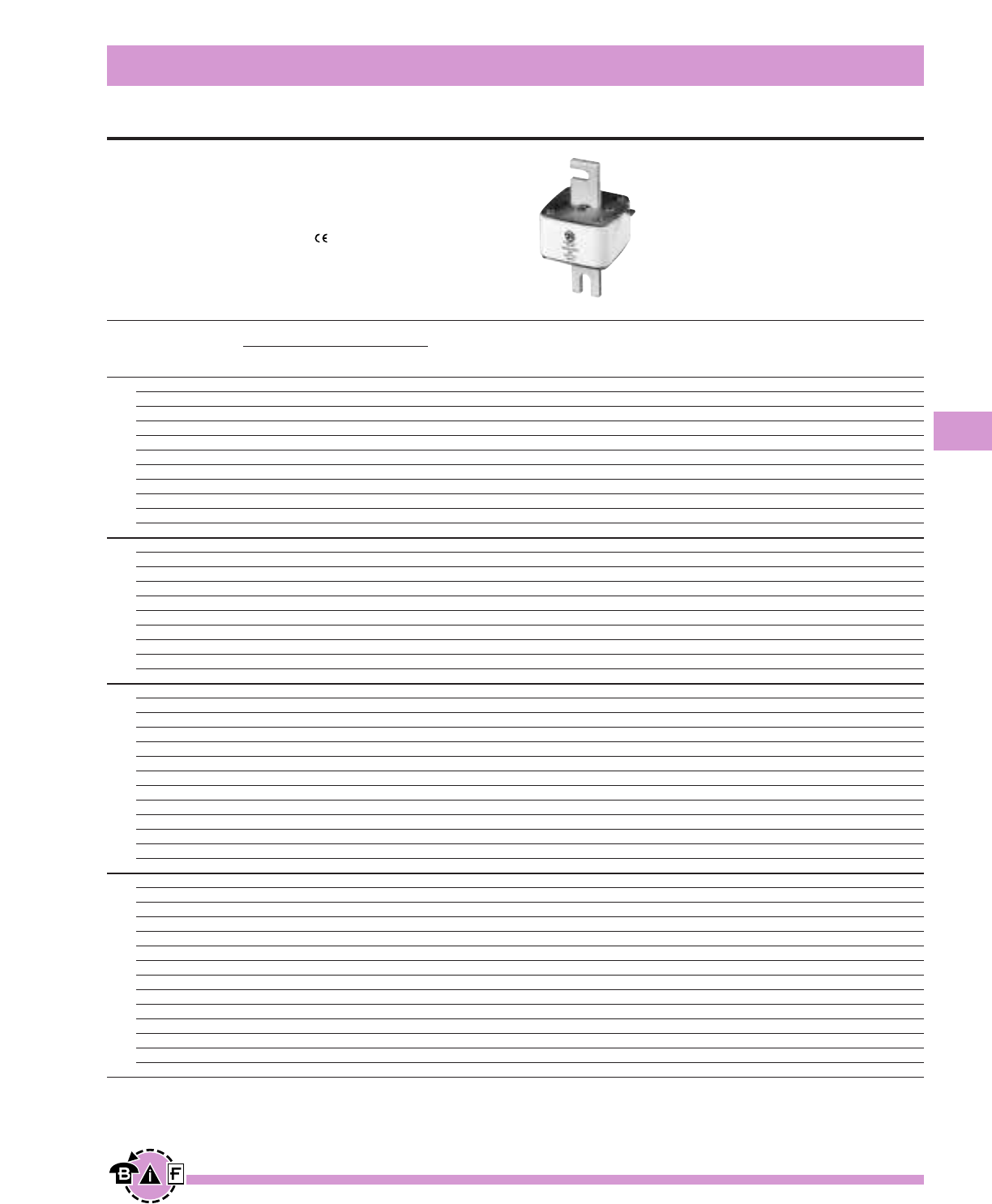
Bussmann®
135
For complete specification data, call Bussmann Information Fax ~ 636.527.1450
European Style Square Body
High Speed Fuses
Data Sheet: 720029
DIN 43 653 — 50-1400A
Voltage Rating: 1250V (IEC)/1300V (UL)
Interrupting Rating: 100kA RMS Symmetrical
Agency Information: CSA Component Acceptance
UL Recognized, Std. 248-13
Watts loss provided at rated current.
Microswitch indicator ordered separately. See bottom of page 146.
Ordering Information
-TN/110
-/110 Type T
Visual Indicator Carton Carton
Indicator for Micro Qty. Weight (Kg)
170M3138* 170M3188* 5 1.90
170M3139* 170M3189* 5 1.90
170M3140* 170M3190* 5 1.90
170M3141* 170M3191* 5 1.90
170M3142* 170M3192* 5 1.90
170M3143* 170M3193* 5 1.90
170M3144* 170M3194* 5 1.90
170M3145* 170M3195* 5 1.90
170M3146* 170M3196* 5 1.90
170M3147* 170M3197* 5 1.90
170M3148* 170M3198* 5 1.90
170M4138* 170M4188* 2 1.18
170M4139* 170M4189* 2 1.18
170M4140* 170M4190* 2 1.18
170M4141* 170M4191* 2 1.18
170M4142* 170M4192* 2 1.18
170M4143* 170M4193* 2 1.18
170M4144* 170M4194* 2 1.18
170M4145* 170M4195* 2 1.18
170M4146* 170M4196* 2 1.18
170M4147 170M4197 2 1.18
170M5138* 170M5188* 2 1.58
170M5139* 170M5189* 2 1.58
170M5140* 170M5190* 2 1.58
170M5141* 170M5191* 2 1.58
170M5142* 170M5192* 2 1.58
170M5143* 170M5193* 2 1.58
170M5144* 170M5194* 2 1.58
170M5145* 170M5195* 2 1.58
170M5146* 170M5196* 2 1.58
170M5147* 170M5197* 2 1.58
170M5148* 170M5198* 2 1.58
170M5149 170M5199 2 1.58
170M5150 170M5200 2 1.58
170M6138* 170M6188* 1 1.23
170M6139* 170M6189* 1 1.23
170M6140* 170M6190* 1 1.23
170M6141* 170M6191* 1 1.23
170M6142* 170M6192* 1 1.23
170M6143* 170M6193* 1 1.23
170M6144* 170M6194* 1 1.23
170M6145* 170M6195* 1 1.23
170M6146 170M6196* 1 1.23
170M6147 170M6197* 1 1.23
170M6148 170M6198* 1 1.23
170M6149 170M6199* 1 1.23
170M6150 170M6200 1 1.23
170M6151 170M6201 1 1.23
Electrical Characteristics
I2t (A2s)
Rated Current Clearing Clearing Watts
Size RMS-Amps Pre-arc at 1000V at 1250V Loss
50 135 815 1100 15
63 215 1300 1750 20
80 420 2500 3350 25
100 750 4450 5950 30
125 1450 9000 11500 35
1* 160 2600 16000 21000 40
200 5150 31000 41000 45
250 9200 54500 73000 55
315 18500 115000 150000 60
350 27000 165000 220000 65
400 53000 265000 335000 70
160 1900 11500 15500 45
200 3800 22500 30000 50
250 7750 46000 61500 60
315 15000 90000 120000 65
1 350 20000 125000 165000 70
400 29500 175000 235000 75
450 42000 250000 335000 80
500 69500 340000 435000 85
550 95000 465000 590000 95
†630 130000 660000 — 100
250 6500 38500 51500 65
280 9350 55500 74500 70
315 13000 77500 105000 75
350 16500 97500 135000 80
400 23000 140000 180000 85
2 450 34000 205000 270000 90
500 48000 285000 380000 95
550 62000 370000 495000 100
630 115000 575000 730000 110
700 160000 795000 1050000 115
800 245000 1200000 1550000 120
†900 360000 1750000 — 125
†1000 480000 2350000 — 135
315 9500 58000 77500 85
350 13500 81500 110000 90
400 19500 120000 160000 95
450 31000 185000 245000 100
500 39000 235000 310000 105
550 55000 325000 435000 110
630 83500 495000 665000 115
3 700 115000 705000 940000 120
‡800 205000 995000 1300000 125
‡900 305000 1500000 1900000 130
‡1000 450000 2150000 2750000 135
‡1100 575000 2800000 3600000 140
†1250 810000 †3950000 — 145
†1400 1250000 †6000000 — 150
*UL Recognized / CSA Component Accepted. Rated voltage †1100V ‡1250V
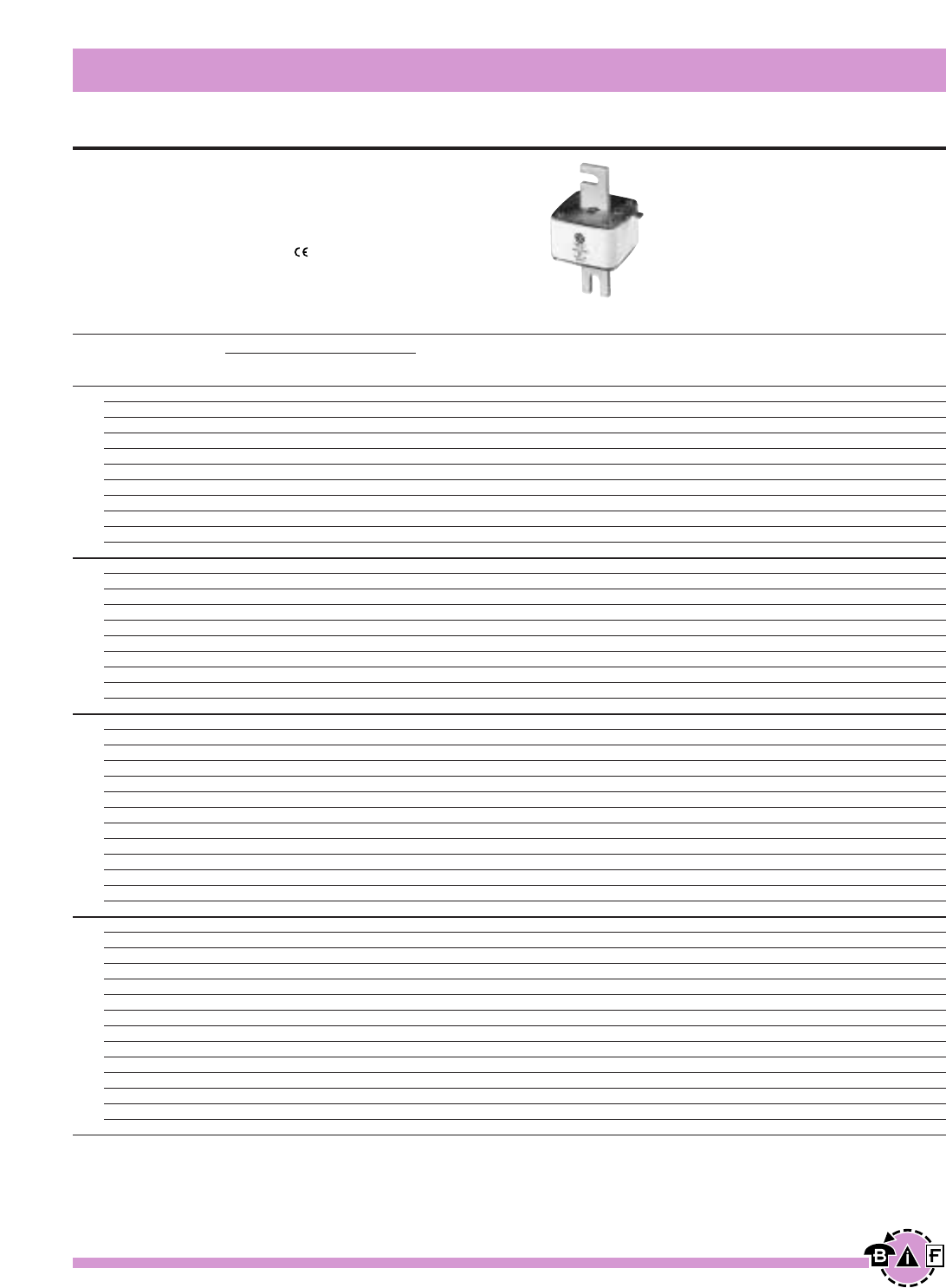
Bussmann®
136 For complete specification data, call Bussmann Information Fax ~ 636.527.1450
European Style Square Body
High Speed Fuses
Data Sheet: 720030
DIN 43 653 — 50-1400A
Voltage Rating: 1250V (IEC)/1300V (UL)
Interrupting Rating: 100kA RMS Symmetrical
Agency Information: CSA Component Acceptance
UL Recognized, Std. 248-13
Watts loss provided at rated current.
Microswitch indicator ordered separately. See bottom of page 146.
Ordering Information
-KN/110 Type K Carton Carton
Indicator for Micro Qty. Weight (Kg)
170M3238* 2 0.84
170M3239* 2 0.84
170M3240* 2 0.84
170M3241* 2 0.84
170M3242* 2 0.84
170M3243* 2 0.84
170M3244* 2 0.84
170M3245* 2 0.84
170M3246* 2 0.84
170M3247* 2 0.84
170M3248* 2 0.84
170M4238* 2 1.26
170M4239* 2 1.26
170M4240* 2 1.26
170M4241* 2 1.26
170M4242* 2 1.26
170M4243* 2 1.26
170M4244* 2 1.26
170M4245* 2 1.26
170M4246* 2 1.26
170M4247 2 1.26
170M5238* 2 1.66
170M5239* 2 1.66
170M5240* 2 1.66
170M5241* 2 1.66
170M5242* 2 1.66
170M5243* 2 1.66
170M5244* 2 1.66
170M5245* 2 1.66
170M5246* 2 1.66
170M5247* 2 1.66
170M5248* 2 1.66
170M5249 2 1.66
170M5250 2 1.66
170M6238* 1 1.27
170M6239* 1 1.27
170M6240* 1 1.27
170M6241* 1 1.27
170M6242* 1 1.27
170M6243* 1 1.27
170M6244* 1 1.27
170M6245* 1 1.27
170M6246 1 1.27
170M6247 1 1.27
170M6248 1 1.27
170M6249 1 1.27
170M6250 1 1.27
170M6251 1 1.27
Electrical Characteristics
I2t (A2s)
Rated Current Clearing Clearing Watts
Size RMS-Amps Pre-arc at 1000V at 1250V Loss
50 135 815 1100 15
63 215 1300 1750 20
80 420 2500 3350 25
100 750 4450 5950 30
125 1450 9000 11500 35
1* 160 2600 16000 21000 40
200 5150 31000 41000 45
250 9200 54500 73000 55
315 18500 115000 150000 60
350 27000 165000 220000 65
400 53000 265000 335000 70
160 1900 11500 15500 45
200 3800 22500 30000 50
250 7750 46000 61500 60
315 15000 90000 120000 65
1 350 20000 125000 165000 70
400 29500 175000 235000 75
450 42000 250000 335000 80
500 69500 340000 435000 85
550 95000 465000 590000 95
†630 130000 660000 — 100
250 6500 38500 51500 65
280 9350 55500 74500 70
315 13000 77500 105000 75
350 16500 97500 135000 80
400 23000 140000 180000 85
2 450 34000 205000 270000 90
500 48000 285000 380000 95
550 62000 370000 495000 100
630 115000 575000 730000 110
700 160000 795000 1050000 115
800 245000 1200000 1550000 120
†900 360000 1750000 — 125
†1000 480000 2350000 — 135
315 9500 58000 77500 85
350 13500 81500 110000 90
400 19500 120000 160000 95
450 31000 185000 245000 100
500 39000 235000 310000 105
550 55000 325000 435000 110
630 83500 495000 665000 115
3 700 115000 705000 940000 120
‡800 205000 995000 1300000 125
‡900 305000 1500000 1900000 130
‡1000 450000 2150000 2750000 135
‡1100 575000 2800000 3600000 140
†1250 810000 †3950000 — 145
†1400 1250000 †6000000 — 150
*UL Recognized / CSA Component Accepted. Rated voltage †1100V ‡1250V
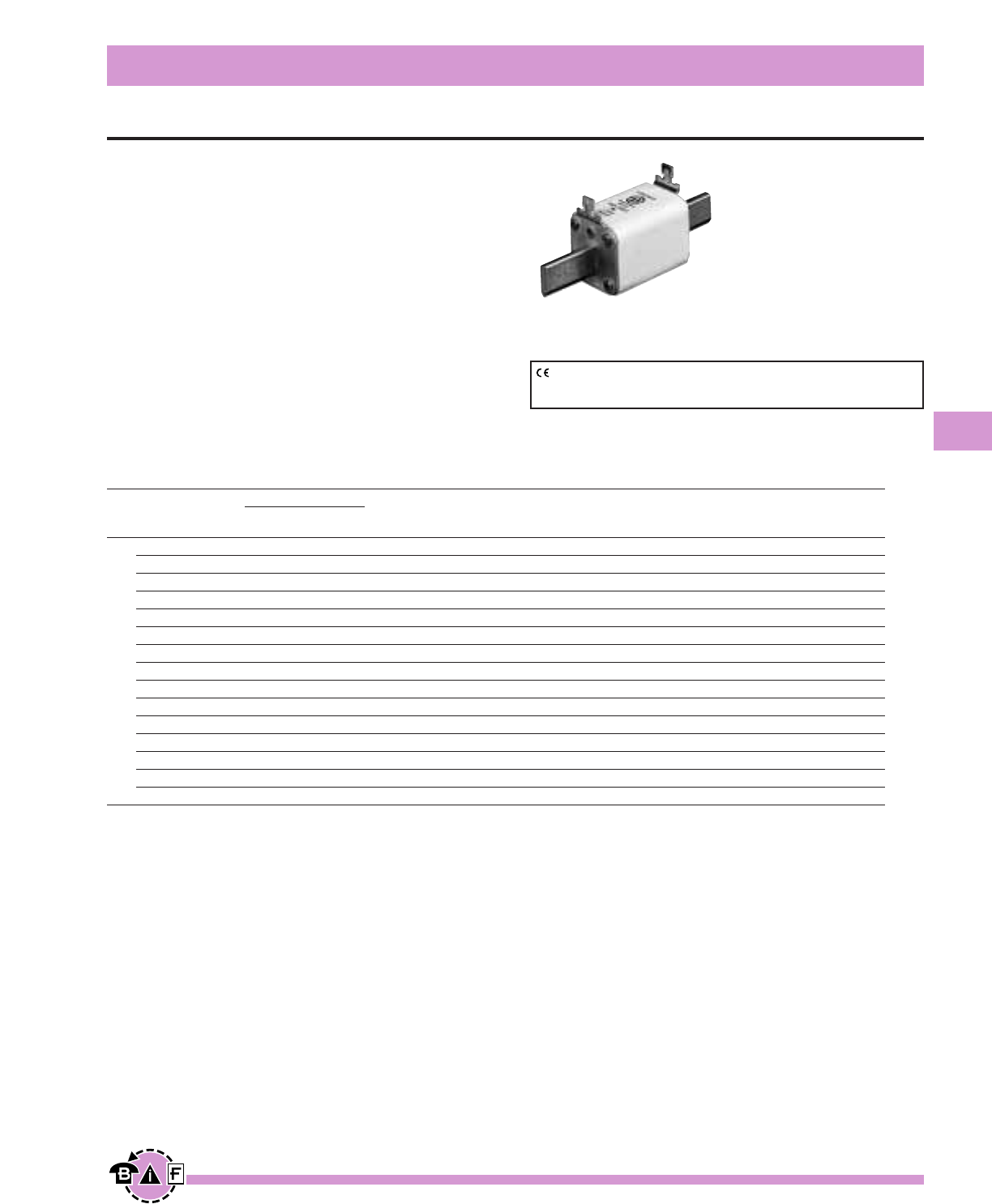
Bussmann®
137
For complete specification data, call Bussmann Information Fax ~ 636.527.1450
European Style Square Body
High Speed Fuses
Data Sheet: 720016
Ordering Information
DIN 000 Type T Carton Carton
Indicator for Micro Qty. Weight (Kg)
170M1558* 10 1.30
170M1559* 10 1.30
170M1560* 10 1.30
170M1561* 10 1.30
170M1562* 10 1.30
170M1563* 10 1.30
170M1564* 10 1.30
170M1565* 10 1.30
170M1566* 10 1.30
170M1567* 10 1.30
170M1568* 10 1.30
170M1569* 10 1.30
170M1570* 10 1.30
170M1571* 10 1.30
170M1572* 10 1.30
Electrical Characteristics
I2t (A2s)
Rated Current Clearing Watts
Size RMS-Amps Pre-arc at 660V Loss
10 3.8 25.5 3.0
16 7.2 48 5.5
20 11.5 78 7
25 19 130 9
32 40 270 10
40 69 460 12
000 50 115 770 15
63 215 1450 16
80 380 2550 19
100 695 4650 24
125 1200 8500 28
160 2300 16000 32
200 4200 28000 37
250 7750 51500 42
315 12000 80500 52
*UL Recognized
CE logo denotes compliance with European Union Low Voltage Directive
(50-1000Vac, 75-1500Vdc). Refer to Data Sheet: 8002 or contact
Bussmann Application Engineering at 636-527-1270 for more information.
DIN 43 620 —10-315A
Voltage Rating: 690V (IEC/UL)
Interrupting Rating: 200kA (estimated 300kA) RMS Symmetrical
Agency Information:
UL Recognized, Std. 248-13
Rated Current: The rated current of this fuse range has
been given with copper conductors that have a current
density of 1.3 A/mm2(IEC 60269-4). For conductor cross
section according to IEC 60269-1, the fuses with a rated
current higher than 125A must be derated. Please contact
Bussmann for application assistance.
Watts loss provided at rated current.
Microswitch indicator ordered separately.
See bottom of page 146.
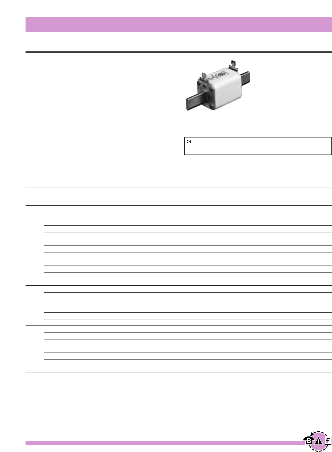
Bussmann®
138 For complete specification data, call Bussmann Information Fax ~ 636.527.1450
European Style Square Body
High Speed Fuses
Data Sheet: 720017
Ordering Information
DIN Type T Carton Carton
Indicator for Micro Qty. Weight (Kg)
170M3808* 5 1.85
170M3809* 5 1.85
170M3810* 5 1.85
170M3811* 5 1.85
170M3812* 5 1.85
170M3813* 5 1.85
170M3814* 5 1.85
170M3815* 5 1.85
170M3816* 5 1.85
170M3817* 5 1.85
170M3818* 5 1.85
170M3819* 5 1.85
170M5808* 5 3.00
170M5809* 5 3.00
170M5810* 5 3.00
170M5811* 5 3.00
170M5812* 5 3.00
170M5813* 5 3.00
170M6808* 1 1.15
170M6809* 1 1.15
170M6810* 1 1.15
170M6811* 1 1.15
170M6812* 1 1.15
170M6813* 1 1.15
170M6814* 1 1.15
Electrical Characteristics
I2t (A2s)
Rated Current Clearing Watts
Size RMS-Amps Pre-arc at 660V Loss
40 40 270 9
50 77 515 11
63 115 770 14
80 185 1250 18
100 360 2450 21
125 550 3700 26
1* 160 1100 7500 30
200 2200 15000 35
250 4200 28500 40
315 7000 46500 50
350 10000 68500 55
400 15000 105000 60
400 11000 74000 65
450 15500 105000 70
2500 21500 145000 75
550 28000 190000 80
630 41000 275000 90
700 60500 405000 95
500 14000 95000 95
550 19500 135000 100
630 31000 210000 105
3 700 44500 300000 110
800 69500 465000 115
900 100000 670000 120
1000 140000 945000 125
*UL Recognized
CE logo denotes compliance with European Union Low Voltage Directive
(50-1000Vac, 75-1500Vdc). Refer to Data Sheet: 8002 or contact
Bussmann Application Engineering at 636-527-1270 for more information.
DIN 43 620 — 40-1000A
Voltage Rating: 690V (IEC)/700V (UL)
Interrupting Rating: 200kA (estimated 300kA) RMS Symmetrical
Agency Information:
UL Recognized, Std. 248-13
Rated Current: The rated current of this fuse range has
been given with copper conductors that have a current
density of 1.3 A/mm2(IEC 60269-4). For conductor cross
section according to IEC 60269-1, the fuses with a rated
current higher than 125A must be derated. Please contact
Bussmann for application assistance.
Watts loss provided at rated current.
Microswitch indicator ordered separately.
See bottom of page 146.
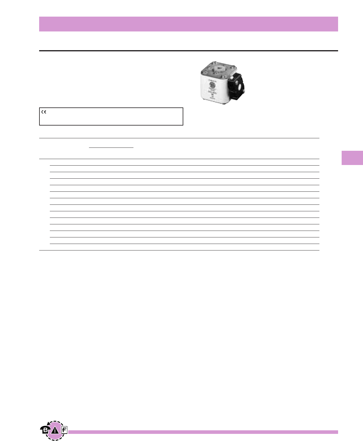
Bussmann®
139
For complete specification data, call Bussmann Information Fax ~ 636.527.1450
European Style Square Body
High Speed Fuses
Data Sheet:720018
Ordering Information
00BTN/60
00B/60 Type T
Visual Indicator for Carton Carton
Indicator Microswitch Qty. Weight (Kg)
170M2708 170M2758 5 1.35
170M2709 170M2759 5 1.35
170M2710 170M2760 5 1.35
170M2711 170M2761 5 1.35
170M2712 170M2762 5 1.35
170M2713 170M2763 5 1.35
170M2714 170M2764 5 1.35
170M2715 170M2765 5 1.35
170M2716 170M2766 5 1.35
170M2717 170M2767 5 1.35
170M2718 170M2768 5 1.35
170M2719 170M2769 5 1.35
170M2720 170M2770 5 1.35
170M2721 170M2771 5 1.35
Electrical Characteristics
I2t (A2s)
Rated Current Clearing Watts
Size RMS-Amps Pre-arc at 660V Loss
25 19 130 6
32 28.5 195 7
40 50 360 9
50 95 640 10
63 170 1200 12
80 310 2100 15
00 100 620 4150 20
125 1000 6950 25
160 1900 13000 30
200 3400 23000 35
250 6250 42000 45
315 10000 68500 55
350 13500 91500 60
400 18000 125000 70
CE logo denotes compliance with European Union Low Voltage Directive
(50-1000Vac, 75-1500Vdc). Refer to Data Sheet: 8002 or contact
Bussmann Application Engineering at 636-527-1270 for more information.
Flush End Contact 25-400A
Voltage Rating: 690V (IEC)
Interrupting Rating: 200kA (estimated 300kA) RMS Symmetrical
Watts loss provided at rated current.
Microswitch indicator ordered separately.
See bottom of page 146.
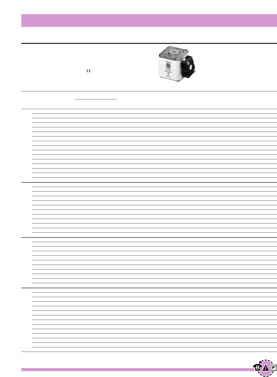
Bussmann®
140 For complete specification data, call Bussmann Information Fax ~ 636.527.1450
European Style Square Body
High Speed Fuses
Data Sheet: 720019
Flush End Contact 40-2000A
Voltage Rating: 690V (IEC) 700V (UL)
Interrupting Rating: 200kA (estimated 300kA) RMS Symmetrical
Agency Information: CSA Component Acceptance
UL Recognized, Std. 248-13
Watts loss provided at rated current.
Microswitch indicator ordered separately. See bottom of page 146.
Ordering Information
-BKN/- -GKN/-
-B/- Type K -G/- Type K Carton
Visual Indicator Visual Indicator Carton Weight
Indicator for Micro Indicator for Micro Qty. (Kg)
170M3408* 170M3458* 170M3508* 170M3558* 10 2.40
170M3409* 170M3459* 170M3509* 170M3559* (-B/-) —
170M3410* 170M3460* 170M3510* 170M3560* — —
170M3411* 170M3461* 170M3511* 170M3561* 10 2.40
170M3412* 170M3462* 170M3512* 170M3562* (-G/-) —
170M3413* 170M3463* 170M3513* 170M3563* — —
170M3414* 170M3464* 170M3514* 170M3564* 6 1.62
170M3415* 170M3465* 170M3515* 170M3565* (-BKN/-) —
170M3416* 170M3466* 170M3516* 170M3566* — —
170M3417* 170M3467* 170M3517* 170M3567* — —
170M3418* 170M3468* 170M3518* 170M3568* 6 1.62
170M3419* 170M3469* 170M3519* 170M3569* (-GKN/-) —
170M3420* 170M3470* 170M3520* 170M3570* — —
170M3421* 170M3471* 170M3521* 170M3571* — —
170M3422* 170M3472* 170M3522* 170M3572* — —
170M3423* 170M3473* 170M3523* 170M3573* — —
170M4408* 170M4458* 170M4508* 170M4558* 6 2.40
170M4409* 170M4459* 170M4509* 170M4559* 6 2.40
170M4410* 170M4460* 170M4510* 170M4560* 6 2.40
170M4411* 170M4461* 170M4511* 170M4561* 6 2.40
170M4412* 170M4462* 170M4512* 170M4562* 6 2.40
170M4413* 170M4463* 170M4513* 170M4563* 6 2.40
170M4414* 170M4464* 170M4514* 170M4564* 6 2.40
170M4415* 170M4465* 170M4515* 170M4565* 6 2.40
170M4416* 170M4466* 170M4516* 170M4566* 6 2.40
170M4417* 170M4467* 170M4517* 170M4567* 6 2.40
170M4418* 170M4468* 170M4518* 170M4568* 6 2.40
170M4419 170M4469 170M4519 170M4569 6 2.40
170M5408* 170M5458* 170M5508* 170M5558* 6 3.30
170M5409* 170M5459* 170M5509* 170M5559* 6 3.30
170M5410* 170M5460* 170M5510* 170M5560* 6 3.30
170M5411* 170M5461* 170M5511* 170M5561* 6 3.30
170M5412* 170M5462* 170M5512* 170M5562* 6 3.30
170M5413* 170M5463* 170M5513* 170M5563* 6 3.30
170M5414* 170M5464* 170M5514* 170M5564* 6 3.30
170M5415* 170M5465* 170M5515* 170M5565* 6 3.30
170M5416* 170M5466* 170M5516* 170M5566* 6 3.30
170M5417* 170M5467* 170M5517* 170M5567* 4 2.40
170M5418* 170M5468* 170M5518* 170M5568* 4 2.40
170M6408* 170M6458* 170M6508* 170M6558* 3 2.52
170M6409* 170M6459* 170M6509* 170M6559* 3 2.52
170M6410* 170M6460* 170M6510* 170M6560* 3 2.52
170M6411* 170M6461* 170M6511* 170M6561* 3 2.52
170M6412* 170M6462* 170M6512* 170M6562* 3 2.52
170M6413* 170M6463* 170M6513* 170M6563* 3 2.52
170M6414* 170M6464* 170M6514* 170M6564* 3 2.52
170M6415* 170M6465* 170M6515* 170M6565* 3 2.52
170M6416* 170M6466* 170M6516* 170M6566* 3 2.52
170M6417* 170M6467* 170M6517* 170M6567* 3 2.52
170M6418* 170M6468* 170M6518* 170M6568* 3 2.52
170M6419* 170M6469* 170M6519* 170M6569* 2 1.82
170M6420 170M6470 170M6520 170M6570 2 1.82
170M6421 170M6471 170M6521 170M6571 2 1.82
Electrical Characteristics
I2t (A2s)
Rated Current Clearing Watts
Size RMS-Amps Pre-arc at 660V Loss
40 40 270 9
50 77 515 11
63 115 770 14
80 185 1250 18
100 360 2450 21
125 550 3700 26
160 1100 7500 30
200 2200 15000 35
1* 250 4200 28500 40
315 7000 46500 50
350 10000 68500 55
400 15000 105000 60
450 21000 140000 65
500 27000 180000 70
550 34000 230000 75
630 48500 325000 80
200 1650 11500 45
250 3100 21000 55
315 6200 42000 58
350 8500 59000 60
400 13500 91500 65
450 17000 120000 70
1 500 25000 170000 72
550 34000 230000 75
630 52000 350000 80
700 69500 465000 85
800 105000 725000 95
‡900 155000 ‡850000 100
400 11000 74000 65
450 15500 105000 70
500 21500 145000 75
550 28000 190000 80
630 41000 275000 90
2 700 60500 405000 95
800 86000 575000 105
900 125000 840000 110
1000 180000 1250000 115
1100 245000 1600000 120
1250 365000 2400000 130
500 14000 95000 95
550 19500 135000 100
630 31000 210000 105
700 44500 300000 110
800 69500 465000 115
900 100000 670000 120
3 1000 140000 945000 125
1100 190000 1300000 130
1250 290000 1950000 140
1400 370000 2450000 155
1500 460000 3100000 160
1600 580000 3900000 160
†1800 880000 †5250000 165
‡2000 1150000 ‡6350000 175
*UL Recognized / CSA Component Accepted. Rated voltage †600V ‡550V
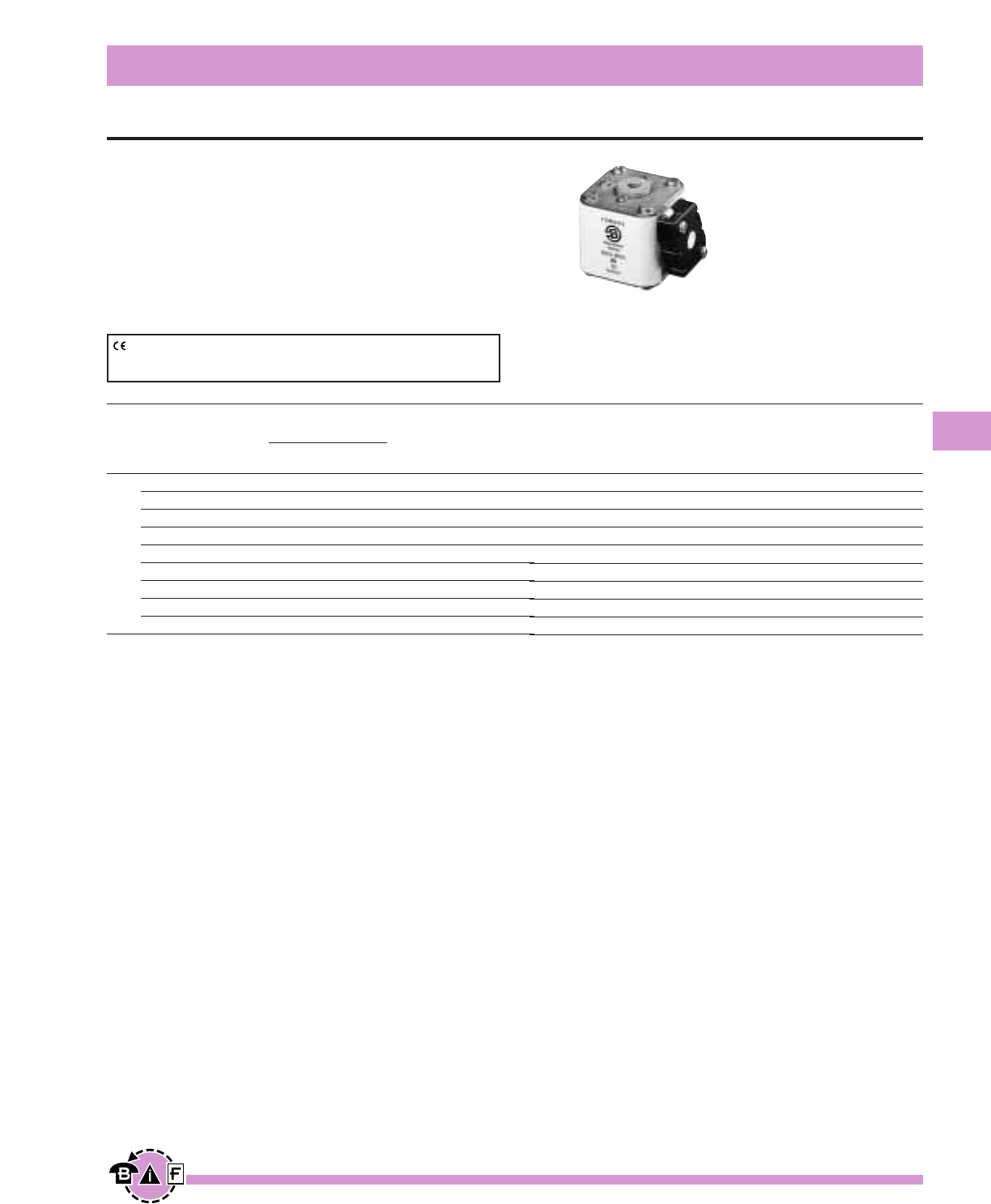
Bussmann®
141
For complete specification data, call Bussmann Information Fax ~ 636.527.1450
European Style Square Body
High Speed Fuses
Data Sheet: 720020
Flush End Contact —1000-4000A
Voltage Rating: 690V (IEC)
Interrupting Rating: 200kA (estimated 300kA) RMS Symmetrical
Agency Information: UL Recognized, Std. 248-13
Watts loss provided at rated current.
Microswitch indicator ordered separately.
See bottom of page 146.
Ordering Information
-BKN/- -GKN/-
-B/- Type K -G/- Type K Carton
Visual Indicator Visual Indicator Carton Weight
Indicator for Micro Indicator for Micro Qty. (Kg)
170M7058 170M7078 170M7098 170M7118 2 1.80
170M7059 170M7079 170M7099 170M7119 2 1.80
170M7060 170M7080 170M7100 170M7120 2 1.80
170M7061 170M7081 170M7101 170M7121 2 1.80
170M7062 170M7082 170M7102 170M7122 2 1.80
170M7063 170M7083 170M7103 170M7123 2 1.80
170M7064 170M7084 170M7104 170M7124 2 1.80
170M7065 170M7085 170M7105 170M7125 2 1.80
170M7066 170M7086 170M7106 170M7126 2 1.80
Electrical Characteristics
Rated Rated
Current Current Watts Watts
RMS- RMS- I2t (A2s) Loss Loss
Norm Liquid Clearing Norm. Liquid
Size Cool. Cool. Pre-arc at 660V Cool. Cool.
1000 1350 76000 505000 175 315
1250 1700 145000 965000 195 355
1400 1900 205000 1400000 205 375
1600 2200 305000 2050000 220 405
4 2000 2700 600000 3950000 245 445
2500 3400 1200000 7800000 275 495
3000 4100 2000000 13500000 305 555
3500 4700 3250000 22000000 325 585
†4000 †5400 4700000 †28000000 355 640
Rated voltage †500V.
Liq. Cool. - Liquid cooling. Temperature on the terminals not to exceed 60°C.
CE logo denotes compliance with European Union Low Voltage Directive
(50-1000Vac, 75-1500Vdc). Refer to Data Sheet: 8002 or contact
Bussmann Application Engineering at 636-527-1270 for more information.
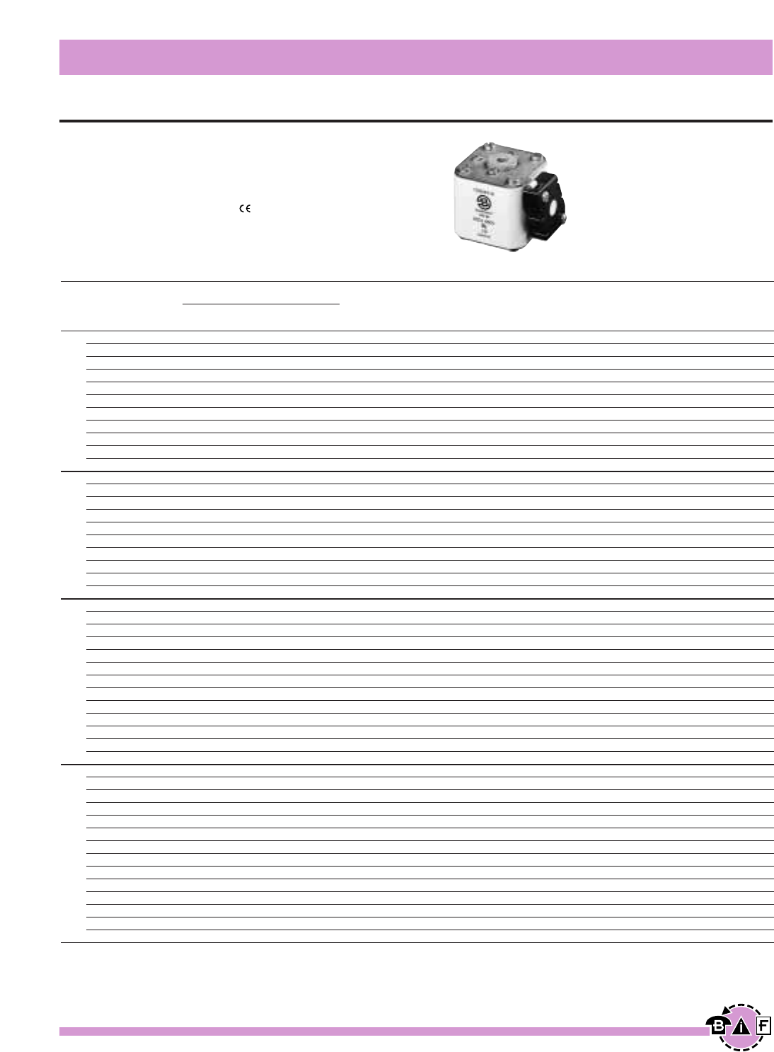
Bussmann®
142 For complete specification data, call Bussmann Information Fax ~ 636.527.1450
European Style Square Body
High Speed Fuses
Data Sheet: 720031
Flush End Contact — 50-1400A
Voltage Rating: 1250V (IEC) 1300V (UL)
Interrupting Rating: 100kA RMS Symmetrical
Agency Information: CSA Component Acceptance
UL Recognized, Std. 248-13
Watts loss provided at rated current.
Microswitch indicator ordered separately. See bottom of page 146.
Ordering Information
-BKN/75 -BKN/80 -BKN/90 -GKN/75 -GKN/90
Type K Type K Type K Type K Type K
Indicator Indicator Indicator Indicator Indicator
for Micro for Micro for Micro for Micro for Micro
170M3388* 170M3438* — 170M3488* —
170M3389* 170M3439* — 170M3489* —
170M3390* 170M3440* — 170M3490* —
170M3391* 170M3441* — 170M3491* —
170M3392* 170M3442* — 170M3492* —
170M3393* 170M3443* — 170M3493* —
170M3394* 170M3444* — 170M3494* —
170M3395* 170M3445* — 170M3495* —
170M3396* 170M3446* — 170M3496* —
170M3397* 170M3447* — 170M3497* —
— 170M3448* — — —
170M4388* 170M4438* — 170M4488* —
170M4389* 170M4439* — 170M4489* —
170M4390* 170M4440* — 170M4490* —
170M4391* 170M4441* — 170M4491* —
170M4392* 170M4442* — 170M4492* —
170M4393* 170M4443* — 170M4493* —
170M4394* 170M4444* — 170M4494* —
†170M4395 170M4445* — †170M4495 —
‡170M4396 170M4446* — ‡170M4496 —
‡170M4397 †170M4447 — ‡170M4497 —
170M5388* 170M5438* — 170M5588* —
170M5389* 170M5439* — 170M5589* —
170M5390* 170M5440* — 170M5590* —
170M5391* 170M5441* — 170M5591* —
170M5392* 170M5442* — 170M5592* —
170M5393* 170M5443* — 170M5593* —
170M5394* 170M5444* 170M5494* 170M5594* 170M5644*
170M5395* 170M5445* 170M5495* 170M5595* 170M5645*
†170M5396 170M5446* 170M5496* †170M5596 170M5646*
‡170M5397 †170M5447 170M5497* ‡170M5597 170M5647*
‡170M5398 ‡170M5448 170M5498* ‡170M5598 170M5648*
— — 170M5499 — 170M5649
— — 170M5500 — 170M5650
170M6338* 170M6538* — 170M6588* —
170M6339* 170M6539* — 170M6589* —
170M6340* 170M6540* — 170M6590* —
170M6341* 170M6541* — 170M6591* —
170M6342* 170M6542* — 170M6592* —
170M6343* 170M6543* — 170M6593* —
170M6344* 170M6544* 170M6494* 170M6594* 170M6644*
170M6345* 170M6545* 170M6495* 170M6595* 170M6645*
†170M6346 170M6546* ¥170M6496 †170M6596 ¥170M6646
‡170M6347 †170M6547 ¥170M6497 ‡170M6597 ¥170M6647
‡170M6348 †170M6548 ¥170M6498 ‡170M6598 ¥170M6648
‡170M6349 ‡170M6549 ¥170M6499 ‡170M6599 ¥170M6649
— — 170M6500 — 170M6650
— — 170M6501 — 170M6651
Electrical Characteristics
I2t (A2s)
Rated Current Clearing Clearing Watts
Size RMS-Amps Pre-arc at 1000V at 1250V Loss
50 135 815 1100 15
63 215 1300 1750 20
80 420 2500 3350 25
100 750 4450 5950 30
125 1450 9000 11500 35
1* 160 2600 16000 21000 40
200 5150 31000 41000 45
250 9200 54500 73000 55
315 18500 115000 150000 60
350 27000 165000 220000 65
400 53000 265000 335000 70
160 1900 11500 15500 45
200 3800 22500 30000 50
250 7750 46000 61500 60
315 15000 90000 120000 65
1 350 20000 125000 165000 70
400 29500 175000 235000 75
450 42000 250000 335000 80
500 69500 340000 435000 85
550 95000 465000 590000 95
630 130000 660000 — 100
250 6500 38500 51500 65
280 9350 55500 74500 70
315 13000 77500 105000 75
350 16500 97500 135000 80
400 23000 140000 180000 85
2 450 34000 205000 270000 90
500 48000 285000 380000 95
550 62000 370000 495000 100
630 115000 575000 730000 110
700 160000 795000 1050000 115
800 245000 1200000 1550000 120
†900 360000 1750000 — 125
†1000 480000 2350000 — 135
315 9500 58000 77500 85
350 13500 81500 110000 90
400 19500 120000 160000 95
450 31000 185000 245000 100
500 39000 235000 310000 105
550 55000 325000 435000 110
630 83500 495000 665000 115
3 700 115000 705000 940000 120
800 205000 995000 1300000 125
900 305000 1500000 1900000 130
1000 450000 2150000 2750000 135
1100 575000 2800000 3600000 140
†1250 810000 3950000 — 145
†1400 1250000 6000000 — 150
*UL Recognized / CSA Component Accepted. Rated voltage †1100 ‡1000V ¥1250V
Individual Fuse Weight: Size 1* = 0.380 Kg
Size 1 = 0.580 Kg
Size 2 = 0.900 Kg
Size 3 = 1.250 Kg
1 kg = 2.2 lbs. 1 lb = 0.45 kg

Bussmann®
143
For complete specification data, call Bussmann Information Fax ~ 636.527.1450
European Style Square Body
High Speed Fuses
Data Sheet: 720022
French Standard — 40-1500A
Voltage Rating: 690V (IEC), 700V (UL)
Interrupting Rating: 200kA (estimated 300kA) RMS Symmetrical
Agency Information: CSA Component Acceptance
UL Recognized, Std. 248-13
Watts loss provided at rated current.
Microswitch indicator ordered separately. See bottom of page 146.
Ordering Information
-E/ -EKN/
Type T Type K
Indicator Indicator Carton Carton
for Micro for Micro Qty. Weight (Kg)
170M3308* 170M3358* 1 0.300
170M3309* 170M3359* 1 0.300
170M3310* 170M3360* 1 0.300
170M3311* 170M3361* 1 0.300
170M3312* 170M3362* 1 0.300
170M3313* 170M3363* 1 0.300
170M3314* 170M3364* 1 0.300
170M3315* 170M3365* 1 0.300
170M3316* 170M3366* 1 0.300
170M331z7* 170M3367* 1 0.300
170M3318* 170M3368* 1 0.300
170M3319* 170M3369* 1 0.300
170M3320* 170M3370* 1 0.300
170M3321* 170M3371* 1 0.300
170M4308* 170M4358* 1 0.470
170M4309* 170M4359* 1 0.470
170M4310* 170M4360* 1 0.470
170M4311* 170M4361* 1 0.470
170M4312* 170M4362* 1 0.470
170M4313* 170M4363* 1 0.470
170M4314* 170M4364* 1 0.470
170M4315* 170M4365* 1 0.470
170M4316* 170M4366* 1 0.470
170M4317* 170M4367* 1 0.470
170M4318* 170M4368* 1 0.470
170M5308* 170M5358* 1 0.620
170M5309* 170M5359* 1 0.620
170M5310* 170M5360* 1 0.620
170M5311* 170M5361* 1 0.620
170M5312* 170M5362* 1 0.620
170M5313* 170M5363* 1 0.620
170M5314* 170M5364* 1 0.620
170M5315* 170M5365* 1 0.620
170M5316* 170M5366* 1 0.620
170M6308* 170M6358* 1 0.930
170M6309* 170M6359* 1 0.930
170M6310* 170M6360* 1 0.930
170M6311* 170M6361* 1 0.930
170M6312* 170M6362* 1 0.930
170M6313* 170M6363* 1 0.930
170M6314* 170M6364* 1 0.930
170M6315* 170M6365* 1 0.930
170M6316* 170M6366* 1 0.930
170M6317* 170M6367* 1 0.930
170M6318* 170M6368* 1 0.930
Electrical Characteristics
I2t (A2s)
Rated Current Clearing Watts
Size RMS-Amps Pre-arc at 660V Loss
40 40 270 9
50 77 515 11
63 115 770 14
80 185 1250 18
100 360 2450 21
125 550 3700 26
1* 160 1100 7500 30
200 2200 15000 35
250 4200 28500 40
315 7000 46500 50
350 10000 68500 55
400 15000 105000 60
450 21000 140000 65
500 27000 180000 70
200 1650 11500 45
250 3100 21000 55
315 6200 42000 58
350 8500 59000 60
400 13500 91500 65
1 450 17000 120000 70
500 25000 170000 72
550 34000 230000 75
630 52000 350000 80
700 69500 465000 85
800 105000 725000 95
400 11000 74000 65
450 15500 105000 70
500 21500 145000 75
550 28000 190000 80
2 630 41000 275000 90
700 60500 405000 95
800 86000 575000 105
900 125000 840000 110
1000 180000 1250000 115
500 14000 95000 95
550 19500 135000 100
630 31000 210000 105
700 44500 300000 110
800 69500 465000 115
3 900 100000 670000 120
1000 140000 945000 125
1100 190000 1300000 130
1250 290000 1950000 140
1400 370000 2450000 155
1500 460000 3100000 160
*UL Recognized / CSA Component Accepted.
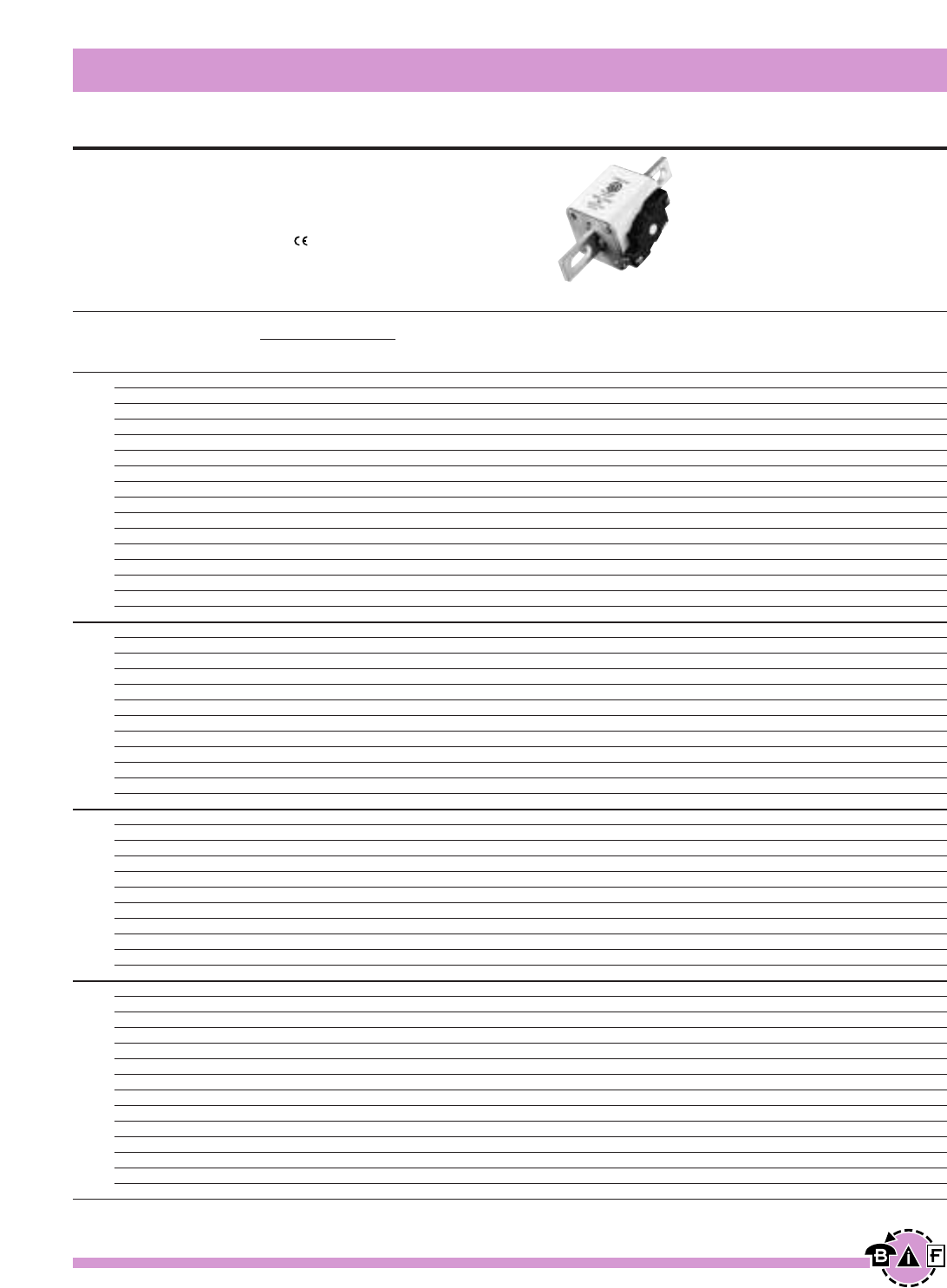
US Standard — 40-2000A
Voltage Rating: 690V (IEC), 700V (UL)
Interrupting Rating: 200kA (estimated 300kA) RMS Symmetrical
Agency Information: CSA Component Acceptance
UL Recognized, Std. 248-13
Watts loss provided at rated current.
Microswitch indicator ordered separately. See bottom of page 146.
Bussmann®
144 For complete specification data, call Bussmann Information Fax ~ 636.527.1450
European Style Square Body
High Speed Fuses
Data Sheet: 720023
Ordering Information
-FKE/- -FKE/115
-FU/- Type K -FU/115 Type K Carton
Without Indicator Without Indicator Carton Weight
Indicator for Micro Indicator for Micro Qty. (Kg)
170M3608* 170M3658* 170M3708* 170M3758* 1 0.340
170M3609* 170M3659* 170M3709* 170M3759* 1 0.340
170M3610* 170M3660* 170M3710* 170M3760* 1 0.340
170M3611* 170M3661* 170M3711* 170M3761* 1 0.340
170M3612* 170M3662* 170M3712* 170M3762* 1 0.340
170M3613* 170M3663* 170M3713* 170M3763* 1 0.340
170M3614* 170M3664* 170M3714* 170M3764* 1 0.340
170M3615* 170M3665* 170M3715* 170M3765* 1 0.340
170M3616* 170M3666* 170M3716* 170M3766* 1 0.340
170M3617* 170M3667* 170M3717* 170M3767* 1 0.340
170M3618* 170M3668* 170M3718* 170M3768* 1 0.340
170M3619* 170M3669* 170M3719* 170M3769* 1 0.340
170M3620* 170M3670* 170M3720* 170M3770* 1 0.340
170M3621* 170M3671* 170M3721* 170M3771* 1 0.340
170M3622* 170M3672* 170M3722* 170M3772* 1 0.340
170M3623* 170M3673* 170M3723* 170M3773* 1 0.340
170M4608* 170M4658* 170M4708* 170M4758* 1 0.500
170M4609* 170M4659* 170M4709* 170M4759* 1 0.500
170M4610* 170M4660* 170M4710* 170M4760* 1 0.500
170M4611* 170M4661* 170M4711* 170M4761* 1 0.500
170M4612* 170M4662* 170M4712* 170M4762* 1 0.500
170M4613* 170M4663* 170M4713* 170M4763* 1 0.500
170M4614* 170M4664* 170M4714* 170M4764* 1 0.500
170M4615* 170M4665* 170M4715* 170M4765* 1 0.500
170M4616* 170M4666* 170M4716* 170M4766* 1 0.500
170M4617* 170M4667* 170M4717* 170M4767* 1 0.500
170M4618* 170M4668* 170M4718* 170M4768* 1 0.500
170M4619 170M4669 170M4719 170M4769 1 0.500
170M5608* 170M5658* 170M5708* 170M5758* 1 0.630
170M5609* 170M5659* 170M5709* 170M5759* 1 0.630
170M5610* 170M5660* 170M5710* 170M5760* 1 0.630
170M5611* 170M5661* 170M5711* 170M5761* 1 0.630
170M5612* 170M5662* 170M5712* 170M5762* 1 0.630
170M5613* 170M5663* 170M5713* 170M5763* 1 0.630
170M5614* 170M5664* 170M5714* 170M5764* 1 0.630
170M5615* 170M5665* 170M5715* 170M5765* 1 0.630
170M5616* 170M5666* 170M5716* 170M5766* 1 0.630
170M5617* 170M5667* 170M5717* 170M5767* 1 0.630
170M5618* 170M5668* 170M5718* 170M5768* 1 0.630
170M6608* 170M6658* 170M6708* 170M6758* 1 0.950
170M6609* 170M6659* 170M6709* 170M6759* 1 0.950
170M6610* 170M6660* 170M6710* 170M6760* 1 0.950
170M6611* 170M6661* 170M6711* 170M6761* 1 0.950
170M6612* 170M6662* 170M6712* 170M6762* 1 0.950
170M6613* 170M6663* 170M6713* 170M6763* 1 0.950
170M6614* 170M6664* 170M6714* 170M6764* 1 0.950
170M6615* 170M6665* 170M6715* 170M6765* 1 0.950
170M6616* 170M6666* 170M6716* 170M6766* 1 0.950
170M6617* 170M6667* 170M6717* 170M6767* 1 0.950
170M6618* 170M6668* 170M6718* 170M6768* 1 0.950
170M6619* 170M6669* 170M6719* 170M6769* 1 0.950
170M6620 170M6670 170M6720 170M6770 1 0.950
170M6621 170M6671 170M6721 170M6771 1 0.950
Electrical Characteristics
I2t (A2s)
Rated Current Clearing Watts
Size RMS-Amps Pre-arc at 660V Loss
40 40 270 9
50 77 515 11
63 115 770 14
80 185 1250 18
100 360 2450 21
125 550 3700 26
160 1100 7500 30
200 2200 15000 35
1* 250 4200 28500 40
315 7000 46500 50
350 10000 68500 55
400 15000 105000 60
450 21000 140000 65
500 27000 180000 70
550 34000 230000 75
630 48500 325000 80
200 1650 11500 45
250 3100 21000 55
315 6200 42000 58
350 8500 59000 60
400 13500 91500 65
1450 17000 120000 70
500 25000 170000 72
550 34000 230000 75
630 52000 350000 80
700 69500 465000 85
800 105000 725000 95
‡900 155000 ‡850000 100
400 11000 74000 65
450 15500 105000 70
500 21500 145000 75
550 28000 190000 80
630 41000 275000 90
2 700 60500 405000 95
800 86000 575000 105
900 125000 840000 110
1000 180000 1250000 115
1100 245000 1600000 120
1250 365000 2400000 130
500 14000 95000 95
550 19500 135000 100
630 31000 210000 105
700 44500 300000 110
800 69500 465000 115
900 100000 670000 120
1000 140000 945000 125
31100 190000 1300000 130
1250 290000 1950000 140
1400 370000 2450000 155
1500 460000 3100000 160
1600 580000 3900000 160
†1800 880000 †5250000 165
‡2000 1150000 ‡6350000 175
*UL Recognized / CSA Component Accepted. Rated voltage †600V ‡550V
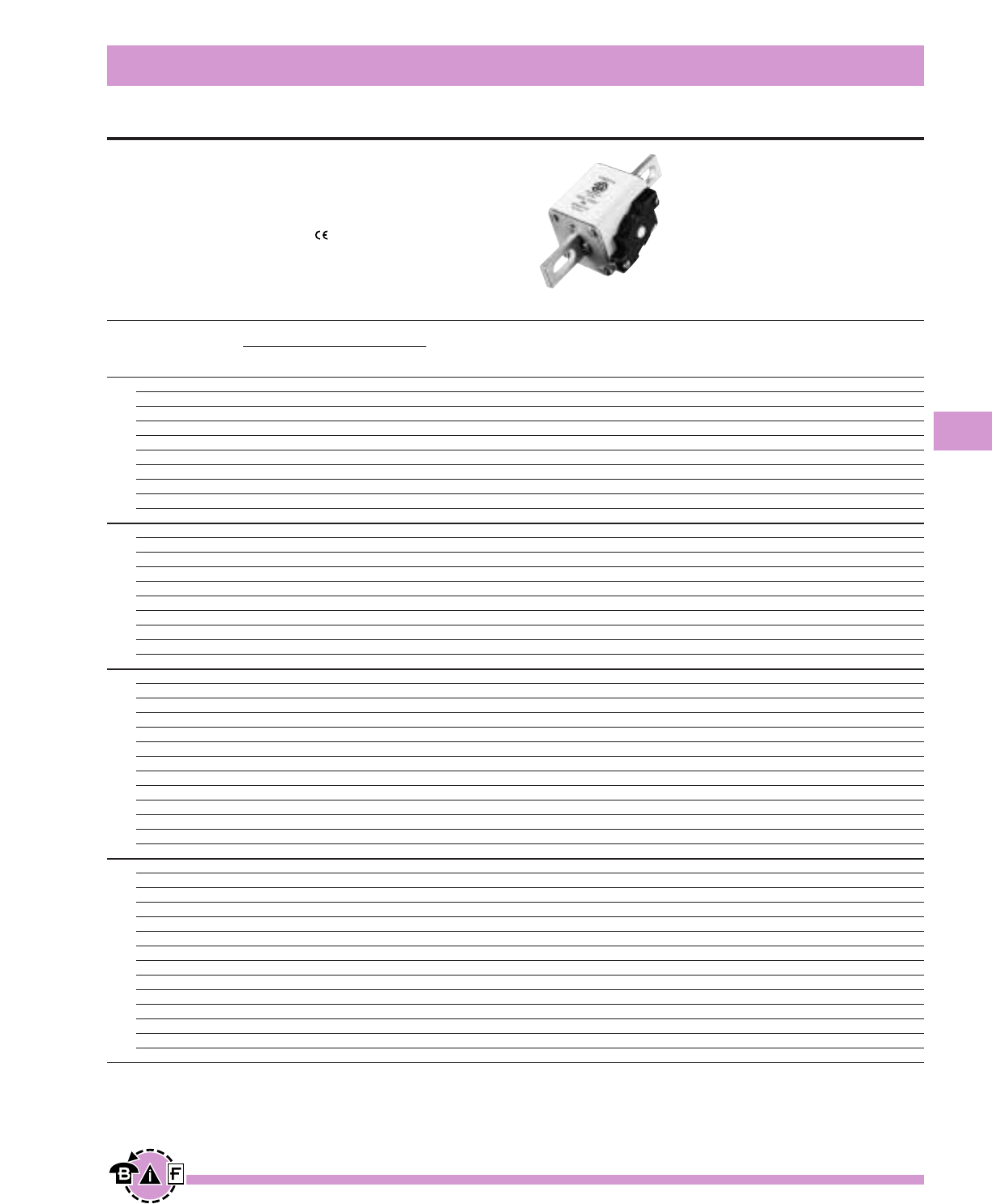
Bussmann®
145
For complete specification data, call Bussmann Information Fax ~ 636.527.1450
European Style Square Body
High Speed Fuses
Data Sheet: 720032
Ordering Information
-FKE/115
-FU/115 Type K
Without Indicator Carton Carton
Indicator for Micro Qty. Weight (Kg)
170M3688* 170M3738* 1 0.425
170M3689* 170M3739* 1 0.425
170M3690* 170M3740* 1 0.425
170M3691* 170M3741* 1 0.425
170M3692* 170M3742* 1 0.425
170M3693* 170M3743* 1 0.425
170M3694* 170M3744* 1 0.425
170M3695* 170M3745* 1 0.425
170M3696* 170M3746* 1 0.425
170M3697* 170M3747* 1 0.425
170M4688* 170M4738* 1 0.675
170M4689* 170M4739* 1 0.675
170M4690* 170M4740* 1 0.675
170M4691* 170M4741* 1 0.675
170M4692* 170M4742* 1 0.675
170M4693* 170M4743* 1 0.675
170M4694* 170M4744* 1 0.675
170M4695 170M4745 1 0.675
170M4696 170M4746 1 0.675
170M4697 170M4747 1 0.675
170M5688* 170M5738* 1 0.740
170M5689* 170M5739* 1 0.740
170M5690* 170M5740* 1 0.740
170M5691* 170M5741* 1 0.740
170M5692* 170M5742* 1 0.740
170M5693* 170M5743* 1 0.740
170M5694* 170M5744* 1 0.740
170M5695* 170M5745* 1 0.740
170M5696* 170M5746* 1 0.740
170M5697 170M5747 1 0.740
170M5698 170M5748 1 0.740
170M5699 170M5749 1 0.740
170M5700 170M5750 1 0.740
170M6688* 170M6738* 1 1.250
170M6689* 170M6739* 1 1.250
170M6690* 170M6740* 1 1.250
170M6691* 170M6741* 1 1.250
170M6692* 170M6742* 1 1.250
170M6693* 170M6743* 1 1.250
170M6694* 170M6744* 1 1.250
170M6695* 170M6745* 1 1.250
170M6696* 170M6746* 1 1.250
170M6697* 170M6747* 1 1.250
†170M6698* †170M6748* 1 1.250
†170M6699* †170M6749* 1 1.250
‡170M6700* ‡170M6750* 1 1.250
‡170M6701* ‡170M6751* 1 1.250
Electrical Characteristics
I2t (A2s)
Rated Current Clearing Clearing Watts
Size RMS-Amps Pre-arc at 1000V at 1250V Loss
50 135 815 1100 15
63 215 1300 1750 20
80 420 2500 3350 25
100 750 4450 5950 30
125 1450 9000 11500 35
1*
160 2600 16000 21000 40
200 5150 31000 41000 45
250 9200 54500 73000 55
315 18500 115000 150000 60
350 27000 165000 220000 65
160 1900 11500 15500 45
200 3800 22500 30000 50
250 7750 46000 61500 60
315 15000 90000 120000 65
1350 20000 125000 165000 70
400 29500 175000 235000 75
450 42000 250000 335000 80
†500 69500 340000 435000 85
†550 95000 465000 590000 95
‡630 130000 660000 — 100
250 6500 38500 51500 65
280 9350 55500 74500 70
315 13000 77500 105000 75
350 16500 97500 135000 80
400 23000 140000 180000 85
450 34000 205000 270000 90
2 500 48000 285000 380000 95
550 62000 370000 495000 100
630 115000 575000 730000 110
†700 160000 795000 1050000 115
†800 245000 1200000 1550000 120
†900 360000 1750000 — 125
‡1000 480000 2350000 — 135
315 9500 58000 77500 185
350 13500 81500 110000 90
400 19500 120000 160000 95
450 31000 185000 245000 100
500 39000 235000 310000 105
550 55000 325000 435000 110
630 83500 495000 665000 115
3700 115000 705000 940000 120
800 205000 995000 1300000 125
900 305000 1500000 1900000 130
¥1000 450000 2150000 2750000 135
¥1100 575000 2800000 3600000 140
¥1250 810000 3950000 — 145
¥1400 1250000 6000000 — 150
*UL Recognized / CSA Component Accepted. Rated voltage †1100V ‡1000V
¥ UL Recognized / CSA Component Accepted at 1000V
US Standard — 50-1400A
Voltage Rating: 1250V (IEC), 1300V (UL)
Interrupting Rating: 100kA RMS Symmetrical
Agency Information: CSA Component Acceptance
UL Recognized, Std. 248-13
Watts loss provided at rated current.
Microswitch indicator ordered separately. See bottom of page 146.
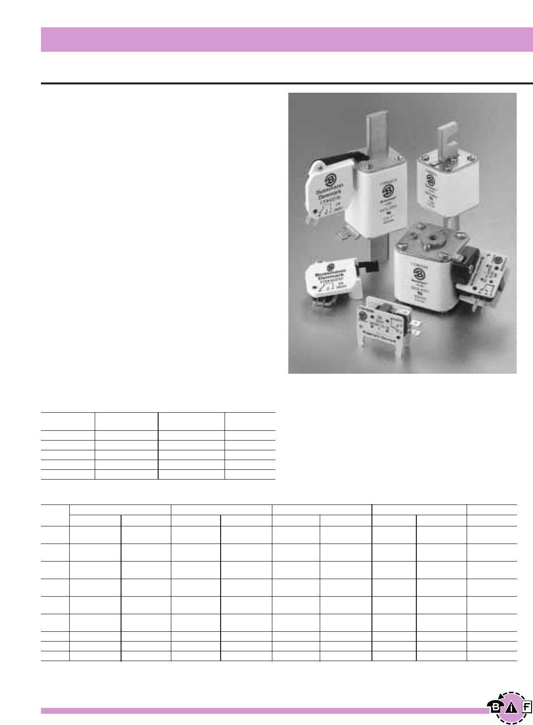
Bussmann®
146 For complete specification data, call Bussmann Information Fax ~ 636.527.1450
Indicator System
High Speed Fuses
Data Sheet: 720034
Indicators
Typower ZILOX fuses are available with three different indica-
tor systems.
Visual Indicator
The indicator situated in one cover plate is clearly visible as
soon as the fuse has operated. The minimum voltage for
operating the indicator is 20V.
Type T Indicator
The indicator is situated on one cover plate with a cover
plate tag to accommodate an auxiliary switch. The minimum
voltage for operating the indicator is 20V. A special low volt-
age indicator (1.5V) is available on request.
Type K Indicator
This indicator is situated on the fuse body. It is covered by
an adaptor for snap-on mounting of an auxiliary switch. The
operating voltage of the indicator is 1.5V. As a matter of
safety, the factory mounted adaptor must not be removed
from the fuse.
Microswitch
The Typower ZILOX fuses with either type T indicator or
type K indicator can be equipped with a microswitch for
remote electrical indication of fuse operations. All micro-
switches have one normally open and one normally closed
contact. Ratings are 2A, 250Vac.
DIN 43 653 DIN 43 620 French Style Flush End US Style
Size Type T Type K Type T Type K Type T Type K Type T Type K Type K
000 170H0236 170H0236
170H0238 170H0238
00 170H0235 170H0235
170H0237 170H0237
1* 170H0235 170H0069 170H0235 170H0236 170H0069 170H0069 170H0069
170H0237 170H0237 170H0238
1170H0235 170H0069 170H0236 170H0069 170H0069 170H0069
170H0237 170H0238
2170H0235 170H0069 170H0235 170H0236 170H0069 170H0069 170H0069
170H0237 170H0237 170H0238
3170H0235 170H0069 170H0236 170H0236 170H0069 170H0069 170H0069
170H0237 170H0238 170H0238
4170H0069
23 170H0069
24 170H0069
6.3 x 0.8 mm 2.8 x 0.5 mm Indicator
Microswitch Lugs Lugs Type
170H0235 ≈ T
170H0236 ≈ T
170H0237 ≈ T
170H0238 ≈ T
170H0069 ≈ K
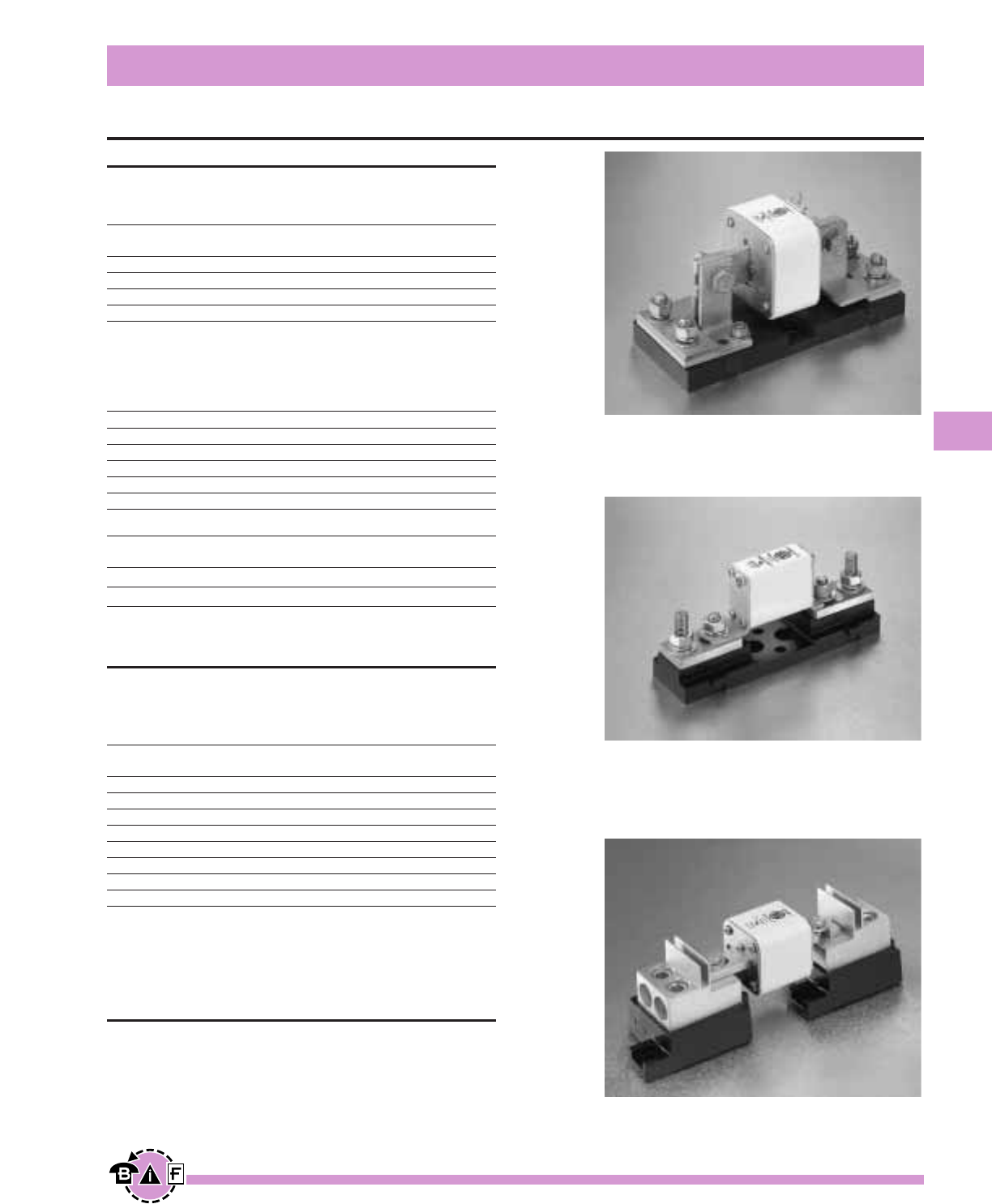
Bussmann®
147
For complete specification data, call Bussmann Information Fax ~ 636.527.1450
Fuse Bases (Blocks)
High Speed Fuses
Data Sheet: 720036
DIN 43 653 Fuse Bases
For the Typower ZILOX fuses according to DIN 43 653, the
following fuse bases are available:
Part Max. Rated Center
Number Voltage Current Distance
170H3003 1000V 630A 80mm
170H3004 1000V 1250A 80mm
170H3005 1400V 630A 110mm
170H3006 1400V 1250A 110mm
The fuse bases rated 1250A can also be used for the fuses
with higher rated current if the maximum load current is
derated according to the table below:
Fuse Rating Max. Load Current In Fuse Base
1400A 1325A
1500A 1400A
1600A 1500A
1800A 1650A
2000A 1800A
Fixed Center Max. Fuse Fuse
Base Style Max. Voltage Current Rating Size
170H1007* 1000V 400A 00, 000
170H1013* 660V 200A 0000,000
*UL Recognized to UL 512.
Universal Fuse Bases
For the Typower ZILOX fuses according to DIN 43 653,
French style and North American style, the following fuse
bases are available:
Modular Max. Fuse BIF
Base Style Max. Voltage Current Rating Document
1BS101 600V 100A 1206
1BS102 600V 400A 1207
1BS103 600V 400A 1208
1BS104 600V 600A 1209
BH-0XXX 700V 100A 1200
BH-1XXX 2500V 400A 1201
BH-2XXX 5000V 400A 1202
BH-3XXX 1250V 700A 1203
Universal fuse bases are UL Recognized to UL 512 and meet
the spacing requirements of UL 347. Contact Bussmann
sales representative for more complete ordering information.
DIN 43 620 Fuse Bases
For fuse bases used with Typower ZILOX fuses according to
DIN 43 620, please contact your local Bussmann sales
representative.
1BS104
170H3003
170H1007
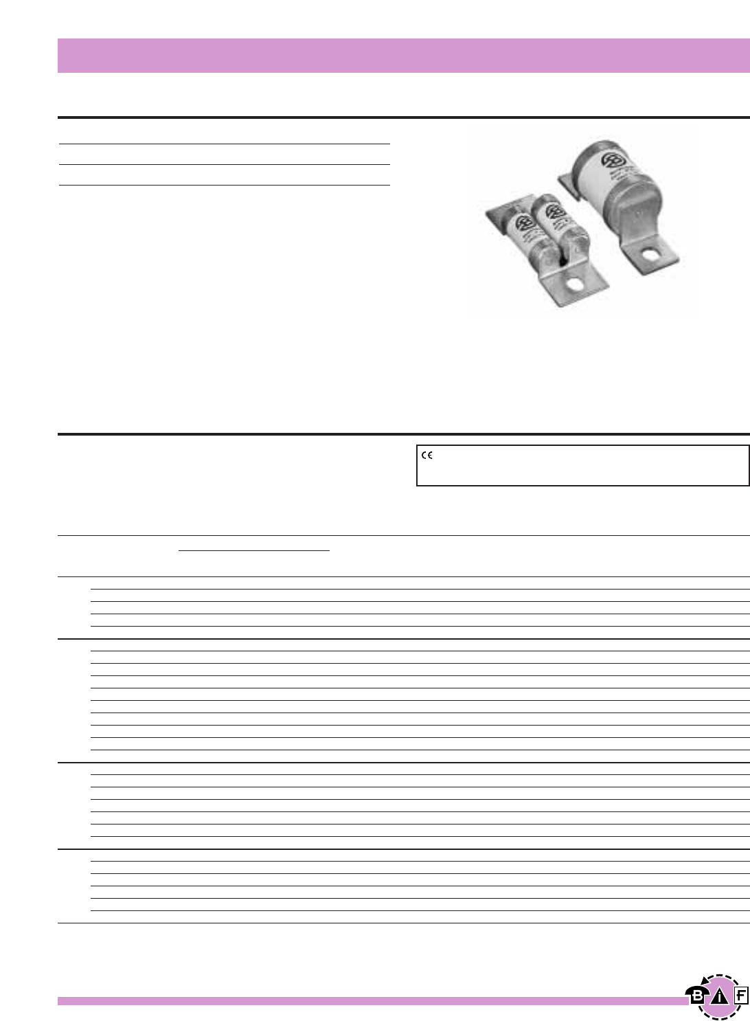
Bussmann®
148 For complete specification data, call Bussmann Information Fax ~636.527.1450
High Speed Fuses
British Standard BS88: Part 4
Data Sheet: 720004
240Vac/150Vdc - 6 to 900A
Interrupting Rating: 200kA RMS Symmetrical.
Agency Information: UL Recognized, Std. 248-13
Watts loss provided at rated current.
Ordering Information
Part Number Carton Qty. Carton Weight (Kg)
6LCT 20 0.110
10LCT 20 0.110
12LCT 20 0.110
16LCT 20 0.110
20LCT 20 0.110
25LET 10 0.310
32LET 10 0.310
35LET 10 0.310
50LET 10 0.310
63LET 10 0.310
80LET 10 0.310
100LET 10 0.310
125LET 10 0.310
160LET 10 0.310
180LETa 10 0.310
160LMT 1 0.180
200LMT 1 0.180
250LMT 1 0.180
315LMT 1 0.180
355LMT 1 0.180
400LMT 1 0.180
450LMT 1 0.180
400LMMT 1 0.370
500LMMT 1 0.370
630LMMT 1 0.370
710LMMT 1 0.370
800LMMT 1 0.370
900LMMT 1 0.370
Voltage Rating
240Vac/150Vdc 6 to 900A
690Vac/450Vdc 6 to 700A
All Bussmann British Style fuses are tested to IEC 269: Part
4. This standard requires a test voltage which is 10% higher
than the rated voltage. In North America, fuses are required
to clear only their rated voltage.
Designed and tested to:
• BS 88: Part 4
• IEC 60269: Part 4
• UL Recognized, Std. 248-13
Bussmann British Style products use innovative arc quench-
ing techniques and high grade materials to provide:
• Minimal energy let-thru (I2t)
• Excellent DC performance
• Good surge withstand profile
Accessories
Trip-indicator fuses are available for use in parallel with the
main fuse. Indicator fuses can be attached to the associated
fuselink, or mounted separately in panel-mounted fuseclips.
In addition, a push-on adaptor and microswitch attachment
are available, to provide remote indication. Fuseblocks are
also available for most applications.
Electrical Characteristics
I2t (A2SEC)
Rated Current Clearing Clearing Watts
Size RMS-Amps Pre-arc at 120V at 240V Loss
6 2 6 9 1.0
10 3.8 12 22 2.5
LCT 12 7 22 32 2.5
16 20 50 100 2.5
20 25 80 160 4.0
25 18 120 250 4.0
32 32 200 450 5.0
35 50 320 600 5.0
50 100 500 1400 7.0
LET 63 180 1100 2200 9.0
80 300 1900 3800 10.0
100 600 3800 7500 10.0
125 600 3800 7500 16.0
160 1100 7000 16000 20.0
180 1600 12000 29000 21.0
160 1100 7000 16000 17.0
200 1500 10000 20000 28.0
250 3200 20000 40000 28.0
LMT 315 6000 35000 75000 35.0
355 8000 50000 100000 35.0
400 14000 70000 160000 40.0
450 18000 100000 220000 42.0
400 6000 35000 80000 60.0
500 14000 80000 170000 64.0
630 24000 150000 300000 75.0
LMMT 710 32000 200000 460000 77.0
800 52000 300000 600000 82.0
900 75000 400000 800000 97.0
Note: 7LET, 10LET, 12LET and 16LET are available for replacement purposes on existing equipment (not UL recognized).
CE logo denotes compliance with European Union Low Voltage Directive
(50-1000Vac, 75-1500Vdc. Refer to Data Sheet: 8002 or contact
Bussmann Application Engineering at 636-527-1270 for more information.
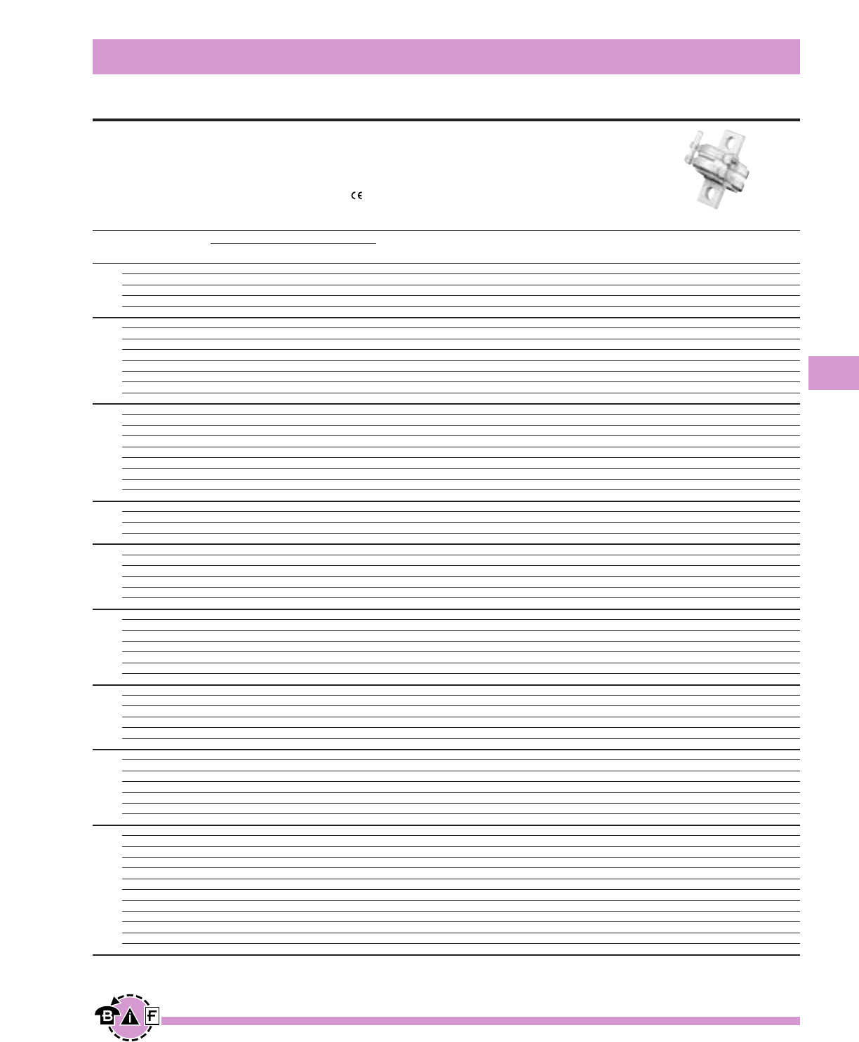
Bussmann®
149
For complete specification data, call Bussmann Information Fax ~ 636.527.1450
High Speed Fuses
British Standard BS88: Part 4
Data Sheet: 720024
690Vac/500Vdc 6-700A
Interrupting Rating: 200kA RMS Symmetrical.
UL Recognized, Std. 248-13, Watts loss provided at rated current.
MT, MMT and additional ratings of ET and EET are available for replacement purposes on existing
equipment and are BS 88: Part 4 approved.
Ordering Information
Part Number Carton Qty. Carton Weight (Kg)
6CT 20 0.160
10CT 20 0.160
12CT 20 0.160
16CT 20 0.160
20CT 20 0.160
25ET 10 0.420
32ET 10 0.420
35ET 10 0.420
40ET 10 0.420
45ET 10 0.420
56ET 10 0.420
63ET 10 0.420
80ET 10 0.420
35FE 10 0.420
40FE 10 0.420
45FE 10 0.420
50FE 10 0.420
63FE 10 0.420
71FE 10 0.420
80FE 10 0.420
90FE 10 0.420
100FE 10 0.420
90EET 5 0.450
110EET 5 0.450
140EET 5 0.450
160EET 5 0.450
100FEE 5 0.450
120FEE 5 0.450
140FEE 5 0.450
160FEE 5 0.450
180FEE 5 0.450
200FEE 5 0.450
180FM 1 0.240
200FM 1 0.240
225FM 1 0.240
250FM 1 0.240
280FM 1 0.240
315FM 1 0.240
350FM 1 0.240
400FMM 1 0.450
450FMM 1 0.450
500FMM 1 0.450
550FMM 1 0.450
630FMM 1 0.450
700FMM 1 0.450
160MT 1 0.260
180MT 1 0.260
200MT 1 0.260
250MT 1 0.260
280MT 1 0.260
315MT 1 0.260
355MT 1 0.260
180MMT 1 .0470
200MMT 1 .0470
225MMT 1 .0470
280MMT 1 .0470
315MMT 1 .0470
355MMT 1 .0470
400MMT 1 .0470
450MMT 1 .0470
500MMT 1 .0470
560MMT 1 .0470
630MMT 1 .0470
710MMT 1 .0470
Electrical Characteristics
I2t (A2SEC)
Rated Current Clearing Clearing Watts
Size RMS-Amps Pre-arc at 415V at 660V Loss
6 1.8 8.5 12 2
10 7 30 48 3
CT 12 10 40 65 3
16 16 66 110 7
20 32 150 220 7
25 25 150 250 7
32 32 190 350 11
35 52 310 500 11
40 103 600 900 9
ET 45 103 680 1100 11
56 135 950 1500 14
63 171 1200 2000 16
80 360 2500 4000 18
35 33 130 200 9
40 52 180 300 9
45 76 270 450 11
50 103 380 600 11
FE 63 135 480 750 12
71 210 600 950 17
80 250 900 1500 20
90 360 1300 2100 20
100 470 1800 2800 23
90 490 3000 4500 19
110 600 4000 6500 27
EET 140 1050 7000 12000 35
160 1500 10000 17000 39
100 400 1600 2400 24
120 540 1900 3100 32
140 850 2500 3800 36
FEE 160 1000 3700 5700 46
180 1400 5300 8400 46
200 1900 7100 11400 52
180 1400 7500 13500 40
200 2600 10500 18500 40
225 3700 14500 26500 44
FM 250 5200 20500 37500 48
280 7000 30500 55000 48
315 10000 40000 77000 55
350 15000 60000 105000 55
400 10000 40000 72500 85
450 15000 60000 105000 90
500 20000 82000 150000 100
FMM 550 30000 120000 215000 100
630 45000 180000 310000 100
700 60000 245000 420000 120
160 2400 15000 25000 26
180 3800 25000 38000 26
200 6000 40000 58000 27
MT† 250 11500 80000 110000 32
280 16500 100000 150000 35
315 19000 125000 180000 42
355 22000 160000 200000 51
180 1650 12000 18000 42
200 2200 16000 23000 42
225 3700 26000 40000 42
280 6600 47000 70000 47
315 8600 62000 91000 51
MMT† 355 13500 97000 140000 54
400 21000 150000 220000 60
450 30000 220000 320000 57
500 42000 300000 450000 64
560 60000 430000 640000 64
630 68500 500000 720000 86
710 78000 600000 850000 105
Note: 8ET, 12ET, 15ET, 20ET, 65EET and 75EET are available for replacement purposes on existing equipment (not UL recognized).
† 350Vdc (IEC) rating. No UL Recognition.
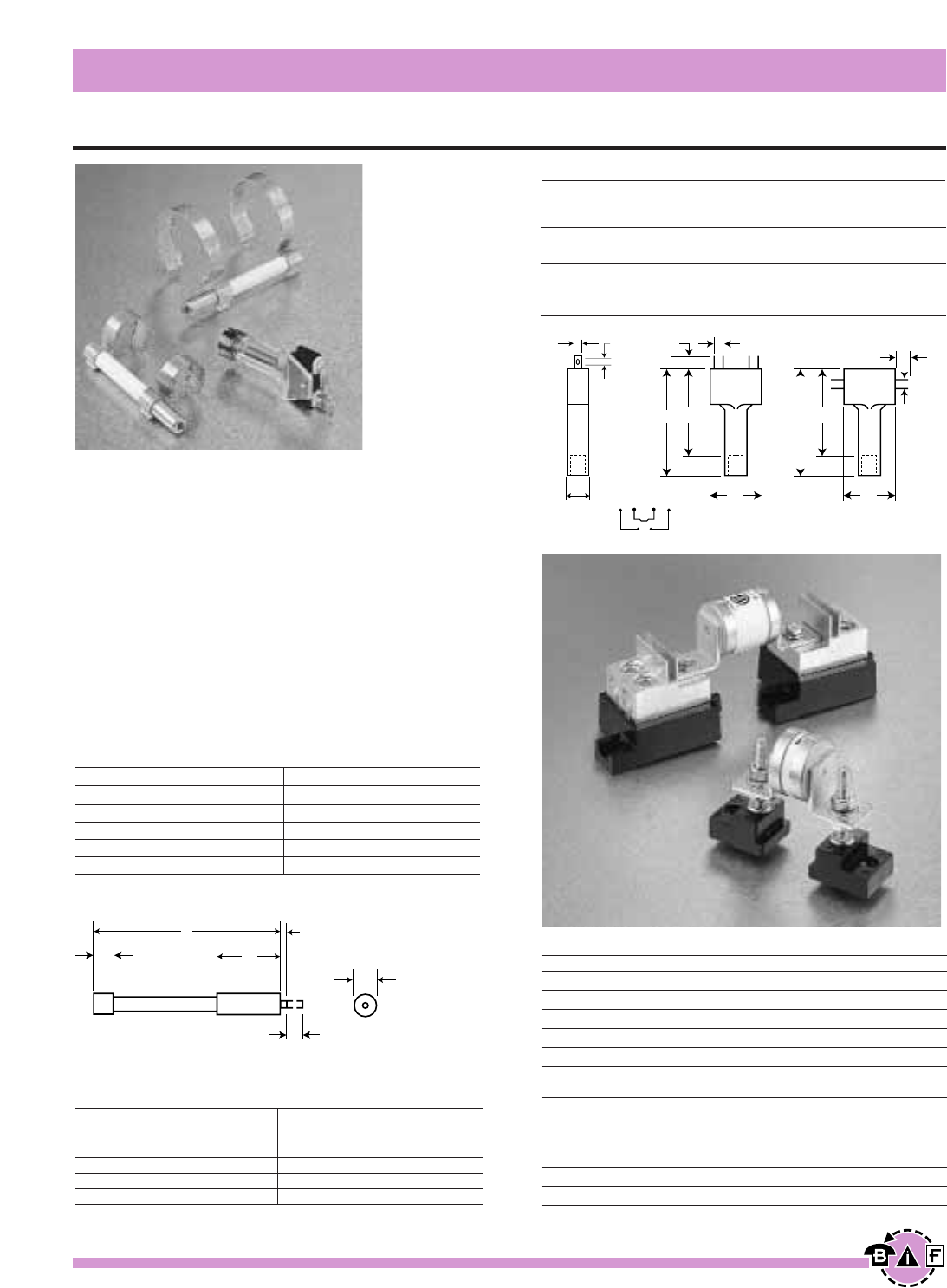
Bussmann®
150 For complete specification data, call Bussmann Information Fax ~ 636.527.1450
High Speed Fuses
Indicator System and Fuse Bases (Blocks)
Data Sheet: 720037
Trip-indicator fuselinks are available for use in parallel
with the main fuselinks. They can either be attached to
the associated fuselink or mounted separately in panel
mounted fuse clips, Part No. CL1. A push-on adaptor
and microswitch attachment is available for use with the
trip indicator to give the facility of remote indication,
reference MAI or MBI.
Fuse ratings of 20A and below cannot usually accommo-
date a trip fuselink in parallel.
Where trip indicator fuselinks are to be attached to the
main fuselink, an accessory pack comprising a pair of
mounting clips and an appropriate trip indicator fuselink
will be required.
The ordering code references for these packs are listed
below:
621
A0.8
6.35
6
2.8 2.4 3.6
3.6
5.2
5.2
21 21
36
44 36
44
9.5
NC NC NONO MAI or MBI
Fuse Type Order Ref. Fuse Type Order Ref.
ET EC-600 FM MC-600
EET EC-600 FMM MC-600
FE EC-600 LMT MC-250
FEE EC-600 LMMT MC-250
LET EC-250
Trip-indicator Fuselink Data
Dim. ‘A’ Voltage Dim. ‘A’ Voltage
Type Max. Rating Type Max. Rating
TI250 37.6 250 TI1100 98.4 1100
TI500 47.5 500 TI1500 120.8 1500
TI600 55.7 600 TI2000 147.5 2000
TI700 61.8 700 TI2500 198.3 2500
Microswitch and Adaptor Type MAI
Current Rating:
ac 50/60Hz resistive load @ 250 VRMS 4A
ac 50/60Hz resistive load @ 127 VRMS 6A
dc, resistive load @ 110 Vdc 0.7
dc, resistive load @ 30 Vdc 2
Maximum Working Voltage:
Contact-to-contact (RMS) 1000V
Contact-to-contact (RMS) 1500V
Stud Fuseblocks
Part No. Stud Height Stud Dia. & Threads
C5268-1 1.00∑ fiΩ¡§-18
C5268-2 1.75∑ fiΩ¡§-18
C5268-3 0.75∑ fiΩ¡§-18
C5268-4 1.00∑ ⁄Ω¢-20
C5268-5 1.75∑ ⁄Ω¢-20
Universal Fuseblocks
Modular Max. Max. Fuse Data
Base Voltage Current Rating Sheet
1BS101 600V 100A 1206
1BS102 600V 400A 1207
1BS103 600V 400A 1208
1BS104 600V 600A 1209
Dimensions in mm.
1mm = 0.0394∑ 1∑ = 25.4mm
Trip Indicator
Universal and Stud Fuseblocks
MAI or MBI
Bussmann®
151
For complete specification data, call Bussmann Information Fax ~ 636.527.1450
High Speed Fuses
Ferrule Style
Data Sheet: 720003
Ordering Information
Part Number Carton Qty. Carton Weight (Kg)
FWA-5A10F 10 0.100
FWA-10A10F 10 0.100
FWA-15A10F 10 0.100
FWA-20A10F 10 0.100
FWA-25A10F 10 0.100
FWA-30A10F 10 0.100
FWA-35A21F 10 0.600
FWA-40A21F 10 0.600
FWA-45A21F 10 0.600
FWA-50A21F 10 0.600
FWA-60A21F 10 0.600
Select Fuses designed and tested to:
• IEC 60269: Part 4
• UL Recognized, Std. 248-13
Bussmann offers a full line of Ferrule Style (cylindrical and
clip-mounted) fuses, designed and tested to meet standards
and requirements in various locations around the world. Their
unique design and construction provide:
• Superior cycling capability
• Low energy let-thru (I2t)
Ferrule fuses provide an excellent solution for small UPS,
small AC drives and other low power applications where
space is at a premium.
Accessories
Ferrule fuses may be mounted in fuse clips, fuseholders,
fuseblocks or fused switches. A variety of products are avail-
able to suit most end-use requirements.
Electrical Characteristics
I2t (A2SEC)
Rated Current Clearing Watts
Size RMS-Amps Pre-arc at 150V Loss
5 1.6 8 1
10 3.6 16 2.7
10 x 38 mm 15 14 55 3.3
(⁄‹Ω£™∑) 20 33 130 3.8
25 58 220 4.9
30 100 400 4.9
35 75 800 4.5
21 x 51 mm 40 100 1000 5.1
(⁄‹Ω¡§∑) 45 130 1300 6
50 170 1600 7.3
60 250 2400 8.0
Voltage Rating
150Vac/dc 5 to 60A
250Vac/dc* 1 to 50A
500Vac/dc* 0.25 to 30A
600 ac/400 dc 6 to 32A
700Vac/dc** 1 to 50A
700Vac 1 to 100A
750Vac/dc 5 to 60A
1000 ac/800 dc 20 to 30A
1250 ac/1000 dc 20 to 30A
1500 ac/1000 dc 8 to 15A
2000/1000Vac/dc 2 to 6A
*dc is for 5-30A
**500Vdc for 63-100A
All Bussmann Ferrule fuses—except 690V—have been tested
at their rated voltage. The 690V Ferrule fuse has been tested
to the IEC 60269 standard, which requires clearing at the
rated voltage +5%.
FWA 150Vac/150Vdc
Interrupting Rating: 100kA RMS Symmetrical.
Agency Information: UL Recognized, 150V, Std. 248-13
Watts loss provided at rated current.
Ordering Information
Part Number Carton Qty. Carton Weight (Kg)
FWX-1A14F 10 0.225
FWX-2A14F 10 0.225
FWX-3A14F 10 0.225
FWX-4A14F 10 0.225
FWX-5A14F 10 0.225
FWX-10A14F 10 0.225
FWX-15A14F 10 0.225
FWX-20A14F 10 0.225
FWX-25A14F 10 0.225
FWX-30A14F 10 0.225
FWX-50A14F 10 0.225
Electrical Characteristics
I2t (A2SEC)
Rated Current Clearing Watts
Size RMS-Amps Pre-arc at 250V Loss
1———
2———
3———
4———
14 ≈51mm 5 1.6 13 1.3
10 3.6 24 3.4
15 14 83 3.8
20 33 200 4.6
25 58 300 5.3
30 100 500 5.9
50 200 1800 5.7
Bussmann®
152 For complete specification data, call Bussmann Information Fax ~ 636.527.1450
High Speed Fuses
Ferrule Style
Data Sheet: 720006
Data Sheet: 14mm ≈51mm, 720008 & 6mm ≈32mm, 720038
FWX 250Vac/250Vdc (250Vdc on 5 through 30)
Interrupting Rating: 200kA RMS Symmetrical.
Agency Information: UL Recognized, 250V, Std. 248-13 & CSA Component Acceptance
Watts loss provided at rated current.
FWH 500Vac/500Vdc
Interrupting Rating: 6 mm ≈32 mm (Interrupting rating
varies—See Data Sheet for details)
14 mm x 51 mm (200kA RMS Symmetrical).
Ordering Information
Part Number Carton Qty. Carton Weight (Kg)
FWH-.250A6F* 10 0.03
FWH-.500A6F* 10 0.03
FWH-001A6F* 10 0.03
FWH-002A6F* 10 0.03
FWH-3.15A6F* 10 0.03
FWH-005A6F* 10 0.03
FWH-6.30A6F* 10 0.03
FWH-007A6F* 10 0.03
FWH-010A6F 10 0.03
FWH-12.5A6F 10 0.03
FWH-015A6F 10 0.03
FWH-016A6F 10 0.03
FWH-020A6F 10 0.03
FWH-025A6F 10 0.03
FWH-030A6F 10 0.03
FWH-1A14F 10 0.250
FWH-2A14F 10 0.250
FWH-3A14F 10 0.250
FWH-4A14F 10 0.250
FWH-5A14F** 10 0.250
FWH-6A14F** 10 0.250
FWH-10A14F** 10 0.250
FWH-12A14F** 10 0.250
FWH-15A14F** 10 0.250
FWH-20A14F** 10 0.250
FWH-25A14F** 10 0.250
FWH-30A14F** 10 0.250
Electrical Characteristics
I2t (A2SEC)
Rated Current Clearing Watts
Size RMS-Amps Pre-arc at 500V Loss
0.25 0.01 0.05 2.7
0.5 0.05 0.25 1.2
1 0.4 2 1.7
2 1.3 3.5 3.2
3.15 3.1 7.7 2.9
5 15 40 2.1
6.3 36 90 2.3
6 x32 mm 7 50 125 2.5
(⁄Ω¢∑ ≈ 1⁄Ω¢∑) 10 9.9 139 2.86
12.5 20 60 3.53
15 44 146 3.08
16 48 177 4.48
20 75 259 4.26
25 126 345 —
30 145 430 —
1———
2———
3 — — 2.3
4———
14 ≈51mm 5 1.6 6.4 1.5
(·Ω¡§∑) 6 1.6 6.4 1.5
10 3.6 13 4
12 — — —
15 10 40 5.5
20 26 96 6
25 49 191 7
30 58 232 9
Agency Information: UL Recognized, 500V, Std. 248-13 &
CSA Component Acceptance
Watts loss provided at rated current.
CE logo denotes compliance with European Union Low Voltage Directive (50-1000Vac,
75-1500Vdc). Refer to Data Sheet: 8002 or contact Bussmann Application Engineering at
636-527-1270 for more information.
*CSA Component Acceptance
**UL Recognized & CSA Component Acceptance at 500Vdc
Fuse Block: 1976 - (pole) Data Sheet: 1210
Ordering Information
Part Number Carton Qty. Carton Weight (Kg)
FWP-1A14F 5 0.113
FWP-2A14F 5 0.113
FWP-2.5A14F 5 0.113
FWP-3A14F 5 0.113
FWP-4A14F 5 0.113
FWP-5A14F 10 0.225
FWP-6.3A14F 10 0.225
FWP-10A14F 10 0.225
FWP-15A14F 10 0.225
FWP-20A14F 10 0.225
FWP-25A14F 10 0.225
FWP-30A14F 10 0.225
FWP-32A14F 5 0.113
FWP-40A14F 5 0.113
FWP-50A14F 5 0.113
Electrical Characteristics
I2t (A2SEC)
Rated Current Clearing Watts
Size RMS-Amps Pre-arc at 660V Loss
1———
2———
2.5 — — —
3———
4———
5 1.6 4 1.5
6.3 — — —
10 3.6 10 4
14 x 51mm 15 10 22 5.5
(·Ω¡§∑ ) 20 26 60 6
25 44 130 7
30 58 150 9
32 95 800 7.6
40 110 980 8
50 220 1800 9
Bussmann®
153
For complete specification data, call Bussmann Information Fax ~ 636.527.1450
High Speed Fuses
Ferrule Style
Data Sheet: 720011
Data Sheet: 720025
FWC 600Vac
Interrupting Rating: 200kA RMS Symmetrical.
Agency Information: UL Recognized, 600V, Std. 248-13
Watts loss provided at rated current.
FWP 690V/700V (IEC/UL)
Interrupting Rating: 200kA RMS Symmetrical.
Agency Information: UL Recognized, 700V, Std. 248-13 &
CSA Component Acceptance.
Watts loss provided at rated current.
Ordering Information
Part Number Carton Qty. Carton Weight (Kg)
FWC-6A10F 10 0.100
FWC-8A10F 10 0.100
FWC-10A10F 10 0.100
FWC-12A10F 10 0.100
FWC-16A10F 10 0.100
FWC-20A10F 10 0.100
FWC-25A10F 10 0.100
FWC-32A10F 10 0.100
Electrical Characteristics
I2t (A2SEC)
Rated Current Clearing Watts
Size RMS-Amps Pre-arc at 600V Loss
6 4 30 1.5
8 6 50 2.0
10 9 70 2.5
10 x 38 mm 12 15 120 3.0
(⁄‹Ω£™∑) 16 25 150 3.5
20 34 260 4.8
25 60 390 6.0
32 95 600 7.5
CE logo denotes compliance with European Union Low Voltage Directive
(50-1000Vac, 75-1500Vdc). Refer to Data Sheet: 8002 or contact
Bussmann Application Engineering at 636-527-1270 for more information.
CE logo denotes compliance with European Union Low Voltage Directive
(50-1000Vac, 75-1500Vdc). Refer to Data Sheet: 8002 or contact
Bussmann Application Engineering at 636-527-1270 for more information.
Fuse Block: 1976 - (pole) Data Sheet: 1210 ▫CSA Component Acceptance 5-30A
Fuse Block: BM Series Data Sheet: 1104 400Vdc UL Recognition: 32A: Interrupting Rating = 50kA
700VdcUL Recognition: 6-25A: Interrupting Rating = 50kA
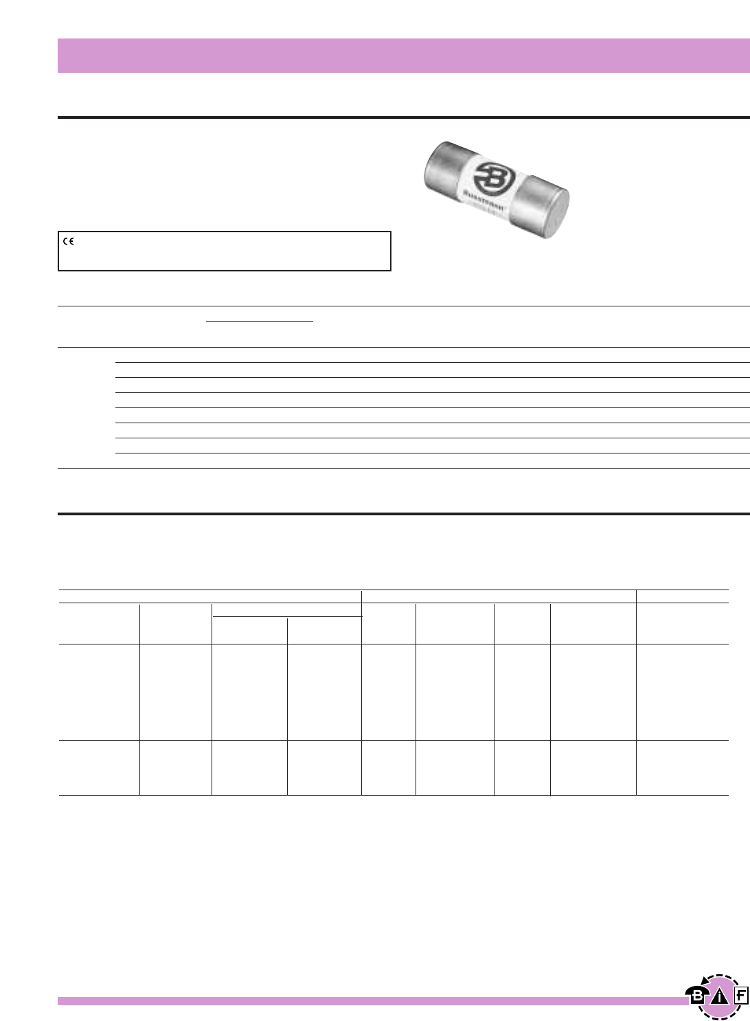
Bussmann®
154 For complete specification data, call Bussmann Information Fax ~ 636.527.1450
High Speed Fuses
Ferrule Style
Data Sheet: 720026
FWP 690V/700V (IEC/UL)
Interrupting Rating: 200kA RMS Symmetrical.
Agency Information: UL Recognized, 700V, Std. 248-13 &
CSA Component Acceptance
Watts loss provided at rated current.
Electrical Characteristics
I2t (A2SEC)
Rated Current Clearing Watts
Size RMS-Amps Pre-arc at 660V Loss
20 34 370 4.6
25 60 560 5.6
32 95 850 7.0
22 ≈58 mm 40 185 1350 8.5
(‡Ω•∑) 50 155 1120 9.5
63 310 2700 11
80 620 5100 13.5
100 1250 10000 16
Ordering Information
Part Number Carton Qty. Carton Weight (Kg)
FWP-20A22F 10 0.450
FWP-25A22F 10 0.450
FWP-32A22F 10 0.450
FWP-40A22F 10 0.450
FWP-50A22F 10 0.450
FWP-63A22F 10 0.450
FWP-80A22F 10 0.450
FWP-100A22F 10 0.450
CE logo denotes compliance with European Union Low Voltage Directive
(50-1000Vac, 75-1500Vdc). Refer to Data Sheet: 8002 or contact
Bussmann Application Engineering at 636-527-1270 for more information.
Data Sheet: 720039
FWK 750V 5-60A
Electrical Characteristics Ordering Information Dimensions
Rated I2t (A2S) Carton
Current Clearing Watts Part Carton Weight Figure
Size RMS-Amps Pre-arc at 750 VDC Loss Number Qty. (kg) Number
5 8.5 16 — FWK-5A20F
8 50 100 — FWK-8A20F
20 ≈ 127mm 10 95 200 — FWK-10A20F
(⁄‹Ω¡§∑) 15 100 240 — FWK-15A20F 10 0.95 Fig. 1
20 125 315 — FWK-20A20F
25 400 1100 — FWK-25A20F
30 800 2600 — FWK-30A20F
35 1300 4300 — FWK-35A25F
25 ≈ 146mm 40 1600 5300 — FWK-40A25F 10 1.65 Fig. 2
(1∑) 50 3100 12000 — FWK-50A25F
60 5900 24000 — FWK-60A25F
Interrupting rating 45kA RMS symmetrical. 1 kg = 2.2 lbs. 1 lb = 0.45 kg
750Vdc rating for 5 through 60A (Time constant = 10-15 mS).
Fuse Block: J70100 - (pole) CR Data Sheet: 1211 500Vdc UL Recognition: Interrupting Rating = 50kA
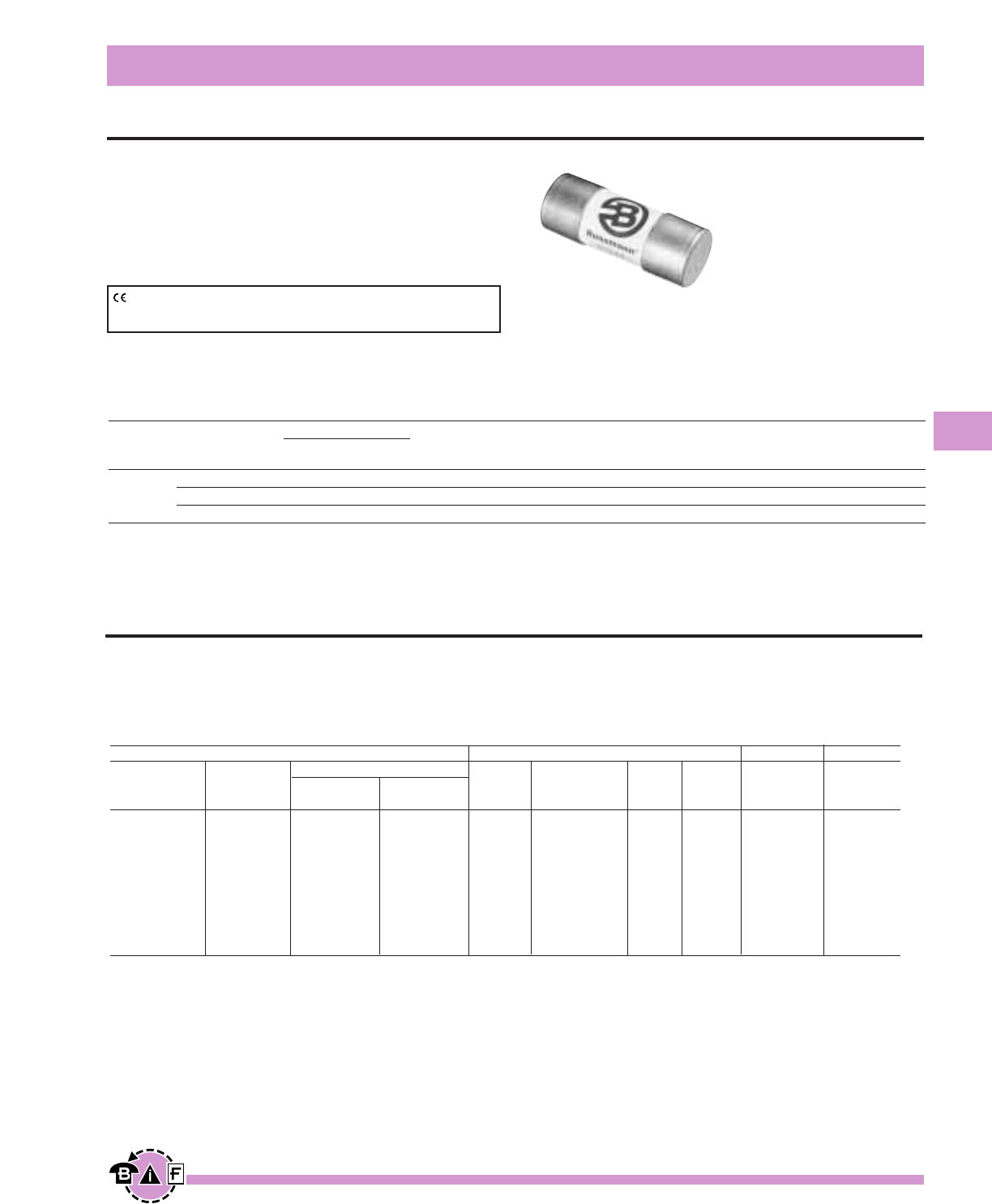
Bussmann®
155
For complete specification data, call Bussmann Information Fax ~ 636.527.1450
Ferrule Style
High Speed Fuses
Data Sheet: 720028
FWJ 1000Vac
Interrupting Rating: 25kA RMS Symmetrical.
Agency Information: UL Recognized, 1000Vac/800Vdc,
Std. 248-13
Watts loss provided at rated current.
Electrical Characteristics
I2t (A2SEC)
Rated Current Clearing Watts
Size RMS-Amps Pre-arc at 1000V Loss
14 ≈67 mm 20 25 220 9
(·Ω¡§∑) 25 33 350 11
30 52 450 14
Ordering Information
Part Number Carton Qty. Carton Weight (Kg)
FWJ-20A14F 10 0.300
FWJ-25A14F 10 0.300
FWJ-30A14F 10 0.300
CE logo denotes compliance with European Union Low Voltage Directive
(50-1000Vac, 75-1500Vdc). Refer to Data Sheet: 8002 or contact
Bussmann Application Engineering at 636-527-1270 for more information.
800Vdc UL Recognition
Electrical Characteristics Ordering Information Dimensions Curves
Rated I2t (A2S) Carton
Current Clearing Watts Part Carton Weight Figure
Size RMS-Amps Pre-arc at 1000 Vdc Loss Number Qty. (kg) Number See Page
¥2 0.8 2.4 4.4 FWS-2A20F
¥6 27 81 6.7 FWS-6A20F
†8 64 192 7.6 FWS-8A20F
†10 118 277 3.0 FWS-10A20F
20 ≈ 127mm †12 170 380 3.4 FWS-12A20F 10 1.00 Fig. 1 page 108
(⁄‹Ω¡§∑) †15 209 500 5.0 FWS-15A20F
‡20 675 1550 5.9 FWL-20A20F
‡25 1200 2760 6.5 FWL-25A20F
‡30 1850 4300 7.5 FWL-30A20F
Interrupting rating 45kA RMS Symmetrical. 1 kg = 2.2 lbs. 1 lb = 0.45 kg
Rated voltage (IEC) ¥2000V †1500V ‡1250V
1000Vdc/30kA rating.
Data Sheet: 720040
FWL/FWS 1250V/1500V/2000V

Page 156
BLANK
(Do NOT Print)
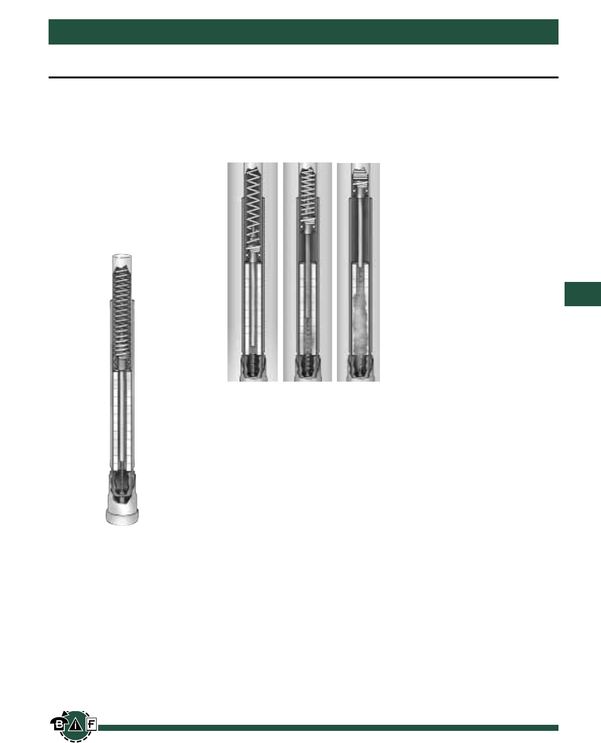
Bussmann®
157
For complete specification data, call Bussmann Information Fax ~ 636.527.1450
BBU Boric Acid Fuse-Features
Medium Voltage Fuses and Fuse Links
Element
Melts
Rod withdraws,
elongating arc
and vaporizing
Boric Acid
Vapor
quenches
arc at first
current zero
When the fuse operates, the upward
motion of the spring forces the top of
the arcing rod to penetrate the upper
seal, striking the latch mechanism.
On indoor applications, this action
caused the blown fuse indicator to
actuate.
When replacing the blown fuse, the
end fittings should be removed from
the operated fuse unit, and if undam-
aged, clamped onto the new fuse
unit.
Application
The BBU Boric acid Fuse provides
effective protection for circuits and
equipment which operate on voltage
systems up to 34,500V. They can be
used on industrial distribution sys-
tems and all fuses are designed for
use on the following:
Power Transformers
Feeder Circuits
Distribution Transformers
Metal-enclosed Switchgear
Pad Mount Switches
BBU Fuse units can be used in
indoor applications, and can be used
to directly replace competitive equiva-
lent units.
BBU End Fittings
End Fittings are required to complete
the electrical connection between the
fuse unit and the live parts and
mounting.
End fittings are positioned on the top
and bottom of the fuse unit. They
can be used over again if they remain
undamaged.
The indoor fittings accept a Muffler
attachment to limit noise and contam-
ination to indoor equipment. The
blown fuse indicator located on the
top end fitting, provides visual indica-
tion of a faulted fuse unit.
Construction
Principle parts of the replaceable BBU
fuse unit are shown in the cross sec-
tion view. Main operating parts are
the silver element, arcing rod, boric
acid cylinder, and spring. A glass
epoxy tube encloses the assembly.
The use of a pure silver element and
Nichrome wire strain element makes
the BBU less susceptible to outages
caused by vibration, corona corrosion,
and aging of the fuse elements.
BBU Fuse Construction
The components are housed in a
fiberglass reinforced resin tube with
plated copper contacts. Positive con-
nection is maintained between the
arcing rod and contact with a sliding
tulip contact.
Operation
BBU Expulsion Fuses utilize the
proven performance of boric acid to
create the de-ionizing action needed
to interrupt the current. Fault interru-
ption is achieved by the action of an
arcing rod and a charged spring, elon-
gating the arc through a boric acid
chamber upon release by the fuse
element.
At high temperatures, boric acid
decomposes producing a blast of
water vapor and inert boric anhydride.
Electrical interruption is caused by the
steam extinguishing the arc, as the
arc is being elongated through the
cylinder.
Higher particle turbulence of the boric
acid causes the rate of de-ionization
in the cylinder to exceed the ioniza-
tion of the electrical arc. Both high
and low current faults are interrupted
in the same manner with no foreign
material other than the boric acid
required. This enables the fuse to
interrupt short circuits within one-half
cycle and prevents the arc from
restriking after a current zero.
After interruption, the gases are
expelled from the bottom of the fuse.
The arching rod is prevented from
falling back into its original position by
a friction stop at the top of the fuse
unit.
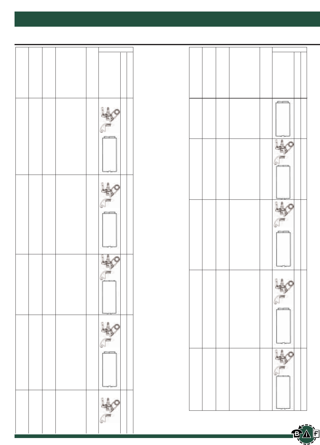
Bussmann®
158 For complete specification data, call Bussmann Information Fax ~ 636.527.1450
Medium Voltage Fuses and Fuse Links
3 k 17 BBU17-3K
6 k 17 BBU17-6K
8 k 17 BBU17-8K
10 k 17 BBU17-10K
12 k 17 BBU17-12K
15 k 17 BBU17-15K
20 k 17 BBU17-20K 14
25 k 17 BBU17-25K
30 k 17 BBU17-30K
40 k 17 BBU17-40K
50 k 17 BBU17-50K
65 k 17 BBU17-65K
80 k 17 BBU17-80K
100 k 17 BBU17-100K
140 k 17 BBU17-140K
200 k 17 BBU17-200K
5 E 17 BBU17-5E
7 E 17 BBU17-7E
10 E 17 BBU17-10E
13 E 17 BBU17-13E
15 E 17 BBU17-15E
20 E 17 BBU17-20E
25 E 17 BBU17-25E
30 E 17 BBU17-30E 14
40 E 17 BBU17-40E
50 E 17 BBU17-50E
65 E 17 BBU17-65E
80 E 17 BBU17-80E
100 E 17 BBU17-100E
125 E 17 BBU17-125E
150 E 17 BBU17-150E
175 E 17 BBU17-175E
200 E 17 BBU17-200E
15 SE 17 BBU17-15SE
20 SE 17 BBU17-20SE
25 SE 17 BBU17-25SE
30 SE 17 BBU17-30SE
40 SE 17 BBU17-40SE
50 SE 17 BBU17-50SE
65 SE 17 BBU17-65SE 14
80 SE 17 BBU17-80SE
100 SE 17 BBU17-100SE
125 SE 17 BBU17-125SE
150 SE 17 BBU17-150SE
175 SE 17 BBU17-175SE
200 SE 17 BBU17-200SE
3 k 27 BBU27-3K
6 k 27 BBU27-6K
8 k 27 BBU27-8K
10 k 27 BBU27-10K
12 k 27 BBU27-12K
15 k 27 BBU27-15K
20 k 27 BBU27-20K
25 k 27 BBU27-25K
30 k 27 BBU27-30K 12.5
40 k 27 BBU27-40K
50 k 27 BBU27-50K
65 k 27 BBU27-65K
80 k 27 BBU27-80K
100 k 27 BBU27-100K
140 k 27 BBU27-140K
200 k 27 BBU27-200K
5 E 27 BBU27-5E
7 E 27 BBU27-7E
10 E 27 BBU27-10E
13 E 27 BBU27-13E
15 E 27 BBU27-15E
20 E 27 BBU27-20E
25 E 27 BBU27-25E
30 E 27 BBU27-30E
40 E 27 BBU27-40E
Catalog
Number
Max. Int. kA Sym
Amps
Fuse Type
Voltage (kV)
End Fittings
Catalog Number
Ampere Rating
Indoor
BBU-EFID
3K to 200K
BBU-EFID
5E to 200E
BBU-EFID
15SE to 200SE
BBU-EFID
3K to 200K
BBU-EFID
5E to 200E
50 E 27 BBU27-50E 12.5
65 E 27 BBU27-65E
80 E 27 BBU27-80E
100 E 27 BBU27-100E
125 E 27 BBU27-125E
150 E 27 BBU27-150E
175 E 27 BBU27-175E
200 E 27 BBU27-200E
15 SE 27 BBU27-15SE
20 SE 27 BBU27-20SE
25 SE 27 BBU27-25SE
30 SE 27 BBU27-30SE
40 SE 27 BBU27-40SE
50 SE 27 BBU27-50SE
65 SE 27 BBU27-65SE
80 SE 27 BBU27-80SE 12.5
100 SE 27 BBU27-100SE
125 SE 27 BBU27-125SE
150 SE 27 BBU27-150SE
175 SE 27 BBU27-175SE
200 SE 27 BBU27-200SE
3 k 38 BBU38-3K
6 k 38 BBU38-6K
8 k 38 BBU38-8K
10 k 38 BBU38-10K
12 k 38 BBU38-12K
15 k 38 BBU38-15K
20 k 38 BBU38-20K 10
30 k 38 BBU38-30K
40 k 38 BBU38-40K
50 k 38 BBU38-50K
65 k 38 BBU38-65K
80 k 38 BBU38-80K
100 k 38 BBU38-100K
140 k 38 BBU38-140K
200 k 38 BBU38-200K
5 E 38 BBU38-5E
7 E 38 BBU38-7E
10 E 38 BBU38-10E
13 E 38 BBU38-13E
15 E 38 BBU38-15E
20 E 38 BBU38-20E
25 E 38 BBU38-25E
30 E 38 BBU38-30E
40 E 38 BBU38-40E
50 E 38 BBU38-50E 10
65 E 38 BBU38-65E
80 E 38 BBU38-80E
100 E 38 BBU38-100E
125 E 38 BBU38-125E
150 E 38 BBU38-150E
175 E 38 BBU38-175E
200 E 38 BBU38-200E
15 SE 38 BBU38-15SE
20 SE 38 BBU38-20SE
25 SE 38 BBU38-25SE
30 SE 38 BBU38-30SE
40 SE 38 BBU38-40SE
50 SE 38 BBU38-50SE
65 SE 38 BBU38-65SE
80 SE 38 BBU38-80SE 10
100 SE 38 BBU38-100SE
125 SE 38 BBU38-125SE
150 SE 38 BBU38-150SE
175 SE 38 BBU38-175SE
200 SE 38 BBU38-200SE
*Note: Muffler can be ordered separately. Order Catalog number
BBU-MFLR.
Catalog
Number
Max. Int. kA Sym
Amps
Fuse Type
Voltage (kV)
End Fittings
Catalog Number
Ampere Rating
Indoor
BBU-EFID
15SE to 200SE
BBU-EFID
3K to 200K
BBU-EFID
5E to 200E
BBU-EFID
15SE to 200SE
BBU-EFID
5E to 200E
BBU Boric Acid Fuses for Use Indoors
Bussmann®
159
For complete specification data, call Bussmann Information Fax ~ 636.527.1450
Medium Voltage Fuses and Fuse Links
Data Sheet: 9002
E-Rated Medium Voltage Fuses: CL-14 & Bolt-In
Electrical Characteristics
Bussmann Ampere IR # of
Number Rating Voltage Max Sym. Barrels Figure # Style
ECL055-10E 10E 5.5kV 63kA 1 1 Clip-Lock
ECL055-15E 15E 5.5kV 63kA 1 1 Clip-Lock
ECL055-20E 20E 5.5kV 63kA 1 1 Clip-Lock
ECL055-25E 25E 5.5kV 63kA 1 1 Clip-Lock
ECL055-30E 30E 5.5kV 63kA 1 1 Clip-Lock
ECL055-40E 40E 5.5kV 63kA 1 1 Clip-Lock
ECL055-50E 50E 5.5kV 63kA 1 1 Clip-Lock
ECL055-65E 65E 5.5kV 63kA 1 1 Clip-Lock
ECL055-80E 80E 5.5kV 63kA 1 1 Clip-Lock
ECL055-100E 100E 5.5kV 63kA 1 1 Clip-Lock
ECL055-125E 125E 5.5kV 63kA 1 1 Clip-Lock
ECL055-150E 150E 5.5kV 63kA 1 1 Clip-Lock
ECL055-200E 200E 5.5kV 63kA 1 2 Clip-Lock
ECL055-250E 250E 5.5kV 63kA 1 2 Clip-Lock
ECL055-300E 300E 5.5kV 63kA 2 3 Clip-Lock
ECL055-400E 400E 5.5kV 63kA 2 3 Clip-Lock
ECL055-450E 450E 5.5kV 63kA 2 3 Clip-Lock
ECL055-500E 500E 5.5kV 63kA 2 3 Clip-Lock
ECL055-600E 600E 5.5kV 63kA 2 3 Clip-Lock
EBI055-750E 750E 5.5kV 63kA 3 4 Bolt-In
EBI055-900E 900E 5.5kV 63kA 3 4 Bolt-In
Part Number Construction
Catalog Symbol Voltage Rating Ampere Rating
Example ECL 055 500E
055 = 5.5 kV
Catalog Number Cross Reference
Ferraz-Shawmut Ferraz-Shawmut
Bussmann New Catalog # Old Catalog #
ECL055-10E A055C1DORO-10E 225-007-937
ECL055-15E A055C1DORO-15E 225-007-938
ECL055-20E A055C1DORO-20E 225-007-939
ECL055-25E A055C1DORO-25E 225-007-940
ECL055-30E A055C1DORO-30E 225-007-941
ECL055-40E A055C1DORO-40E 225-007-942
ECL055-50E A055C1DORO-50E 225-007-943
ECL055-65E A055C1DORO-65E 225-007-944
ECL055-80E A055C1DORO-80E 225-007-945
ECL055-100E A055C1DORO-100E 225-007-946
ECL055-125E A055C1DORO-125E 225-007-947
ECL055-150E A055C1DORO-150E 225-007-948
ECL055-200E A055C1DORO-200E 225-007-949
ECL055-250E A055C1DORO-250E 225-007-950
ECL055-300E A055C1DORO-300E 225-007-951
ECL055-400E A055C1DORO-400E 225-007-952
ECL055-450E A055C2DORO-450E 225-007-953
ECL055-500E A055C2DORO-500E 225-007-954
ECL055-600E A055C2DORO-600E 225-007-955
EBI055-750E AO55B3DORO-750E A055X750E-4
EBI055-900E AO55B3DORO-900E A055X900E-4
CATALOG SYMBOL: ECL055 & EBI055
E-RATED MEDIUM VOLTAGE FUSES:
Meets E requirements per ANSI C37.46
Meets General Purpose requirements per ANSI C37.40
FOR TRANSFORMER AND FEEDER PROTECTION
VOLTAGE RATING: 5.5 KV
INTERRUPTING RATING: 63KA Maximum Sym.
CURRENT LIMITING
CONSTRUCTION:
• Silver element in a double concentric helical configuration
• Silica filler
• Silver plated copper terminals and endcaps
• Filament wound, glass epoxy fuse tube
FEATURES:
•General Purpose Fuses. Bussmann’s medium voltage
fuses provide general purpose protection and are capable of
interrupting fault currents up to 63,000A RMS sym.
•Clip-lock and bolt-in style available in double and triple
barrel fuse designs.
•Indoor and Outdoor Usage. The filament wound, glass
epoxy fuse tube provides UV and moisture protection for the
fuse. This makes Bussmann’s medium voltage fuses suitable
for both indoor and outdoor applications.
•Open Fuse Indication. Indicator travel distance is 16mm.
•Operating Frequency: 50/60 Hz
Current-limiting medium voltage fuses are
classified into three categories:
Full Range - defined by ANSI as “a fuse capable of inter-
rupting all currents from the maximum rated interrupting
current down to the minimum continuous current that caus-
es melting of the fusible element(s), when the fuse is applied
at the maximum ambient temperature specified by the man-
ufacturer.” It is able to interrupt any normal 60 cycle current
that will melt its element.
General Purpose - defined by ANSI C37.40 as “a fuse
capable of interrupting all currents from the maximum rated
interrupting current down to the current that causes melting
of the fusible element in one hour.” Not all currents fall with-
in this range. It is possible to receive an overcurrent lower
than the value given by the one hour criterion.
Back-up - defined by ANSI C37.40 as “a fuse capable of
interrupting all currents from the maximum rated interrupting
current down to the rated minimum interrupting current.”
The minimum rated interrupting current is the lowest current
that the fuse will be able to clear properly. This creates a
need to place a low current interrupting device in series with
the back-up rated fuse.
Bussmann®
160 For complete specification data, call Bussmann Information Fax ~ 636.527.1450
Medium Voltage Fuses and Fuse Links
BIF document: #9004
E-Rated Medium Voltage Fuses: CL-14
CATALOG SYMBOL: ECL155
E-RATED MEDIUM VOLTAGE FUSES:
Meets E requirements per ANSI C37.46
Meets General Purpose requirements per ANSI C37.40
FOR TRANSFORMER AND FEEDER PROTECTION
VOLTAGE RATING: 15.5 KV
INTERRUPTING RATING: See table.
CURRENT LIMITING
CONSTRUCTION:
• Silver element in a double concentric helical configuration
• Silica filler
• Silver plated copper terminals and endcaps
• Filament wound, glass epoxy fuse tube
FEATURES:
•General Purpose Fuses. Bussmann’s medium voltage
fuses provide general purpose protection and are capable
of interrupting fault currents up to 50,000A RMS sym.
•Clip-Lock Double Barrel Fuse Design.
•Indoor and Outdoor Usage. The filament wound, glass
epoxy fuse tube provides UV and moisture protection for
the fuse. This makes Bussmann’s medium voltage fuses
suitable for both indoor and outdoor applications.
•Open Fuse Indication. Indicator travel distance is 16mm.
•Operating Frequency: 50/60 Hz
Electrical Characteristics
Bussmann Ampere IR # of
Number Rating Voltage Max Sym. Barrels Figure # Style
ECL155-10E 10E 15.5kV 63KA 1 1 Clip-Lock
ECL155-15E 15E 15.5kV 63KA 1 1 Clip-Lock
ECL155-20E 20E 15.5kV 63KA 1 1 Clip-Lock
ECL155-25E 25E 15.5kV 63KA 1 1 Clip-Lock
ECL155-30E 30E 15.5kV 63KA 1 1 Clip-Lock
ECL155-40E 40E 15.5kV 63KA 1 1 Clip-Lock
ECL155-50E 50E 15.5kV 63KA 1 1 Clip-Lock
ECL155-65E 65E 15.5kV 63KA 1 2 Clip-Lock
ECL155-80E 80E 15.5kV 63KA 1 2 Clip-Lock
ECL155-100E 100E 15.5kV 63KA 1 2 Clip-Lock
ECL155-125E 125E 15.5kV 63KA 1 2 Clip-Lock
ECL155-150E 150E 15.5kV 63KA 2 3 Clip-Lock
ECL155-200E 200E 15.5kV 63KA 2 3 Clip-Lock
ECL155-250E 250E 15.5kV 50kA 2 3 Clip-Lock
ECL155-300E 300E 15.5kV 50kA 2 3 Clip-Lock
Part Number Construction
Catalog Symbol Voltage Rating Ampere Rating
Example ECL 155 300E
155 = 15.5 kV
Catalog Number Cross Reference
Ferraz-Shawmut Ferraz-Shawmut
Bussmann New Catalog # Old Catalog #
ECL155-10E A155C1DORO-10E 225-007-967
ECL155-15E A155C1DORO-15E 225-007-968
ECL155-20E A155C1DORO-20E 225-007-969
ECL155-25E A155C1DORO-25E 225-007-970
ECL155-30E A155C1DORO-30E 225-007-971
ECL155-40E A155C1DORO-40E 225-007-972
ECL155-50E A155C1DORO-50E 225-007-973
ECL155-65E A155C1DORO-65E 225-007-974
ECL155-80E A155C1DORO-80E 225-007-975
ECL155-100E A155C1DORO-100E 225-007-976
ECL155-125E A155C2DORO-125E 225-007-977
ECL155-150E A155C3DORO-150E 225-007-978
ECL155-200E A155C3DORO-200E 225-007-979
ECL155-250E A155C3DORO-250E 225-007-980
ECL155-300E A155C3DORO-300E 225-007-981
Current-limiting medium voltage fuses are
classified into three categories:
Full Range - defined by ANSI as “a fuse capable of inter-
rupting all currents from the maximum rated interrupting
current down to the minimum continuous current that
causes melting of the fusible element(s), when the fuse is
applied at the maximum ambient temperature specified by
the manufacturer.” It is able to interrupt any normal 60
cycle current that will melt its element.
General Purpose - defined by ANSI C37.40 as “a fuse
capable of interrupting all currents from the maximum rated
interrupting current down to the current that causes melting
of the fusible element in one hour.” Not all currents fall
within this range. It is possible to receive an overcurrent
lower than the value given by the one hour criterion.
Back-up - defined by ANSI C37.40 as “a fuse capable of
interrupting all currents from the maximum rated interrupting
current down to the rated minimum interrupting current.”
The minimum rated interrupting current is the lowest current
that the fuse will be able to clear properly. This creates a
need to place a low current interrupting device in series with
the back-up rated fuse.
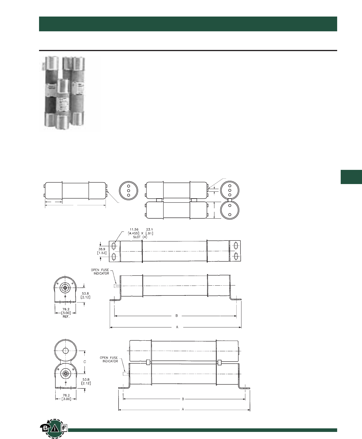
Bussmann®
161
For complete specification data, call Bussmann Information Fax ~ 636.527.1450
Medium Voltage Fuses and Fuse Links
Data Sheet: 6001
R-Rated Fuses for Motor Circuit Protection
JCK, JCK-A, JCK-B, JCH, JCL, JCL-A,
JCL-B, JCG, JCR, & JCR-B
R-Rated
Medium Voltage
Current Limiting
2400V AC — JCK, JCK-A, JCK-B, JCH
4800V AC — JCL, JCL-A, JCL-B, JCG
7200V AC — JCR, JCR-B
Max. Design Voltage: 2540Vac — JCK, JCK-A,
JCK-B, JCH
5080Vac — JCL, JCL-A
JCL-B, JCG
8300Vac — JCR, JCR-B
Agency Information:
UL Recognized : 2540Vac — JCK, JCK-A
5080Vac — JCL, JCL-A
UL Recognized (Guide #MSSS2, File #E96676)
0.38"
(9.5mm)
B
INDICATOR
Showing Fuse is Open
INDICATOR
Showing Fuse
is Open
A
C
Dimensional Data
Figure 1
Figure 2

Bussmann®
162 For complete specification data, call Bussmann Information Fax ~ 636.527.1450
Medium Voltage Fuses and Fuse Links
Specifications
Buss Maximum Dimensions (Inches) Max. Int. Cap. Min. Int. Cap.
Catalog No. Amperage Design Voltage A B C Construction Amps (Asym.) Amps (Sym.) Amps (Sym.)
2400V; R-Rated; Indoor/Enclosure (See Figure 1)
JCK-2R 70 2R 2540V 11.24 3.0 3.0 Single 80,000 50,000 165
JCK-3R 100 3R 2540V 11.24 3.0 3.0 Single 80,000 50,000 220
JCK-4R 130 4R 2540V 11.24 3.0 3.0 Single 80,000 50,000 320
JCK-5R 150 5R 2540V 11.24 3.0 3.0 Single 80,000 50,000 410
JCK-6R 170 6R 2540V 11.24 3.0 3.0 Single 80,000 50,000 480
JCK-9R 200 9R 2540V 11.24 3.0 3.0 Single 80,000 50,000 720
JCK-12R 230 12R 2540V 11.24 3.0 3.0 Single 80,000 50,000 970
JCK-18R 390 18R 2540V 11.24 3.0 3.0 Double 80,000 50,000 1,430
JCK-24R 450 24R 2540V 11.24 3.0 3.0 Double 80,000 50,000 1,880
2400V; R-Rated; Indoor/Enclosure; With Westinghouse Ampguard Hookeye (See Figure 1)
JCK-A-2R 70 2R 2540V 11.24 3.0 3.0 Single 80,000 50,000 165
JCK-A-3R 100 3R 2540V 11.24 3.0 3.0 Single 80,000 50,000 220
JCK-A-4R 130 4R 2540V 11.24 3.0 3.0 Single 80,000 50,000 320
JCK-A-5R 150 5R 27540V 11.24 3.0 3.0 Single 80,000 50,000 410
JCK-A-6R 170 6R 2540V 11.24 3.0 3.0 Single 80,000 50,000 480
JCK-A-9R 200 9R 2540V 11.24 3.0 3.0 Single 80,000 50,000 720
JCK-A-12R 230 12R 2540V 11.24 3.0 3.0 Single 80,000 50,000 970
JCK-A-18R 390 18R 2540V 11.24 3.0 3.0 Double 80,000 50,000 1,430
JCK-A-24R 450 24R 2540V 11.24 3.0 3.0 Double 80,000 50,000 1,880
2400V; R-Rated; Indoor/Enclosure; Bolt-On (See Figure 2)
JCK-B-30 25 2540V 14.18 12.81 - Single 80,000 50,000 90
JCK-B-2R 70 2R 2540V 14.18 12.81 - Single 80,000 50,000 170
JCK-B-3R 100 3R 2540V 14.18 12.81 - Single 80,000 50,000 245
JCK-B-4R 130 4R 2540V 14.18 12.81 - Single 80,000 50,000 340
JCK-B-5R 150 5R 2540V 14.18 12.81 - Single 80,000 50,000 430
JCK-B-6R 170 6R 2540V 14.18 12.81 - Single 80,000 50,000 500
JCK-B-9R 200 9R 2540V 14.18 12.81 - Single 80,000 50,000 1,000
JCK-B-12R 230 12R 2540V 14.18 12.81 - Single 80,000 50,000 1,250
JCK-B-18R 390 18R 2540V 14.18 12.81 3.56 Double 80,000 50,000 1,700
JCK-B-24R 450 24R 2540V 14.18 12.81 3.56 Double 80,000 50,000 1,210
2400V; R-Rated; Indoor; Hermetically Sealed, Class 1, Group D, Div. 2, Hazardous Locations; For Use with Ampgard Motor Starters (See Figure 1)
JCH-30 25 2540V 10.81 3.0 3.0 Single 80,000 50,000 90
JCH-2R 70 2R 2540V 10.81 3.0 3.0 Single 80,000 50,000 170
JCH-3R 100 3R 2540V 10.81 3.0 3.0 Single 80,000 50,000 245
JCH-4R 130 4R 2540V 10.81 3.0 3.0 Single 80,000 50,000 340
JCH-5R 150 5R 2540V 10.81 3.0 3.0 Single 80,000 50,000 430
JCH-6R 170 6R 2540V 10.81 3.0 3.0 Single 80,000 50,000 500
JCH-9R 200 9R 2540V 10.81 3.0 3.0 Single 80,000 50,000 1,000
JCH-12R 230 12R 2540V 10.81 3.0 3.0 Single 80,000 50,000 1,250
JCH-18R 390 18R 2540V 10.81 3.0 3.0 Double 80,000 50,000 1,700
JCH-24R 450 24R 2540V 10.81 3.0 3.0 Double 80,000 50,000 2,100
4800V; R-Rated; Indoor/Enclosure (See Figure 1)
JCL-2R 70 2R 5080V 15.76 3.0 3.0 Single 80,000 50,000 165
JCL-3R 100 3R 5080V 15.76 3.0 3.0 Single 80,000 50,000 220
JCL-4R 130 4R 5080V 15.76 3.0 3.0 Single 80,000 50,000 320
JCL-5R 150 5R 5080V 15.76 3.0 3.0 Single 80,000 50,000 410
JCL-6R 170 6R 5080V 15.76 3.0 3.0 Single 80,000 50,000 480
JCL-9R 200 9R 5080V 15.76 3.0 3.0 Single 80,000 50,000 720
JCL-12R 230 12R 5080V 15.76 3.0 3.0 Single 80,000 50,000 970
JCL-18R 390 18R 5080V 15.76 3.0 3.0 Double 80,000 50,000 1,430
JCL-24R 450 24R 5080V 15.76 3.0 3.0 Double 80,000 50,000 1,880
R-Rated Fuses for Motor Circuit Protection
Bussmann®
163
For complete specification data, call Bussmann Information Fax ~ 636.527.1450
Medium Voltage Fuses and Fuse Links
Specifications
Buss Maximum Dimensions (Inches) Max. Int. Cap. Min. Int. Cap.
Catalog No. Amperage Design Voltage A B C Construction Amps (Asym.) Amps (Sym.) Amps (Sym.)
4800V; R-Rated; Indoor/Enclosure; With Westinghouse Ampguard Hookeye (See Figure 1)
JCL-A-2R 70 2R 5080V 15.76 3.0 3.0 Single 80,000 50,000 165
JCL-A-3R 100 3R 5080V 15.76 3.0 3.0 Single 80,000 50,000 220
JCL-A-4R 130 4R 5080V 15.76 3.0 3.0 Single 80,000 50,000 320
JCL-A-5R 150 5R 5080V 15.76 3.0 3.0 Single 80,000 50,000 410
JCL-A-6R 170 6R 5080V 15.76 3.0 3.0 Single 80,000 50,000 480
JCL-A-9R 200 9R 5080V 15.76 3.0 3.0 Single 80,000 50,000 720
JCL-A-12R 230 12R 5080V 15.76 3.0 3.0 Single 80,000 50,000 970
JCL-A-18R 390 18R 5080V 15.76 3.0 3.0 Double 80,000 50,000 1,430
JCL-A-24R 450 24R 5080V 15.76 3.0 3.0 Double 80,000 50,000 1,880
4800V; R-Rated; Indoor/Enclosure; Bolt-On (See Figure 2)
JCL-B-30 30 5080V 19.25 17.88 - Single 80,000 50,000 95
JCL-B-2R 70 2R 5080V 19.25 17.88 - Single 80,000 50,000 180
JCL-B-3R 100 3R 5080V 19.25 17.88 - Single 80,000 50,000 270
JCL-B-4R 130 4R 5080V 19.25 17.88 - Single 80,000 50,000 350
JCL-B-5R 150 5R 5080V 19.25 17.88 - Single 80,000 50,000 450
JCL-B-6R 170 6R 5080V 19.25 17.88 - Single 80,000 50,000 540
JCL-B-9R 200 9R 5080V 19.25 17.88 - Single 80,000 50,000 700
JCL-B-12R 230 12R 5080V 19.25 17.88 - Single 80,000 50,000 1,000
JCL-B-18R 390 18R 5080V 19.25 17.88 3.31 Double 80,000 50,000 1,450
JCL-B-24R 450 24R 5080V 19.25 17.88 3.31 Double 80,000 50,000 2,000
4800V; R-Rated; Indoor; Hermetically Sealed, Class 1, Group D, Div. 2, Hazardous Locations; For Use with Ampgard Motor Starters (See Figure 1)
JCG-30 30 5080V 15.91 3.0 3.0 Single 80,000 50,000 95
JCG-2R 70 2R 5080V 15.91 3.0 3.0 Single 80,000 50,000 180
JCG-3R 100 3R 5080V 15.91 3.0 3.0 Single 80,000 50,000 270
JCG-4R 130 4R 5080V 15.91 3.0 3.0 Single 80,000 50,000 350
JCG-5R 150 5R 5080V 15.91 3.0 3.0 Single 80,000 50,000 450
JCG-6R 170 6R 5080V 15.91 3.0 3.0 Single 80,000 50,000 540
JCG-9R 200 9R 5080V 15.91 3.0 3.0 Single 80,000 50,000 700
JCG-12R 230 12R 5080V 15.91 3.0 3.0 Single 80,000 50,000 1,000
JCG-A-18R 390 18R 5080V 15.91 3.0 3.0 Double 80,000 50,000 1,450
JCG-A-24R 450 24R 5080V 15.91 3.0 3.0 Double 80,000 50,000 2,000
7200V; R-Rated; Indoor/Enclosure; With Ampgard Hookeye (See Figure 1)
JCR-A-2R 70 2R 8300V 15.85 3.0 3.0 Single 80,000 50,000 160
JCR-A-3R 100 3R 8300V 15.85 3.0 3.0 Single 80,000 50,000 250
JCR-A-4R 130 4R 8300V 15.85 3.0 3.0 Single 80,000 50,000 325
JCR-A-5R 150 5R 8300V 15.85 3.0 3.0 Single 80,000 50,000 390
JCR-A-6R 170 6R 8300V 15.85 3.0 3.0 Single 80,000 50,000 500
JCR-A-9R 200 9R 7200V 15.85 3.0 3.0 Single 80,000 50,000 750
JCR-A-12R 230 12R 7200V 15.85 3.0 3.0 Single 80,000 50,000 1,000
JCR-A-18R 390 18R 7200V 15.85 3.0 3.0 Double 80,000 50,000 1,450
JCR-A-24R 450 24R 7200V 15.85 3.0 3.0 Double 80,000 50,000 2,500
7200V; R-Rated; Indoor/Enclosure; Bolt-On (See Figure 2)
JCR-B-2R 70 2R 8300V 19.25 17.88 - Single 80,000 50,000 160
JCR-B-3R 100 3R 8300V 19.25 17.88 - Single 80,000 50,000 250
JCR-B-4R 130 4R 8300V 19.25 17.88 - Single 80,000 50,000 325
JCR-B-5R 150 5R 8300V 19.25 17.88 - Single 80,000 50,000 390
JCR-B-6R 170 6R 8300V 19.25 17.88 - Single 80,000 50,000 500
JCR-B-9R 200 9R 7200V 19.25 17.88 - Single 80,000 50,000 750
JCR-B-12R 230 12R 7200V 19.25 17.88 - Single 80,000 50,000 1,000
JCR-B-18R 390 18R 7200V 19.25 17.88 3.31 Double 80,000 50,000 1,450
JCR-B-24R 450 24R 7200V 19.25 17.88 3.31 Double 80,000 50,000 2,500
R-Rated Fuses for Motor Circuit Protection
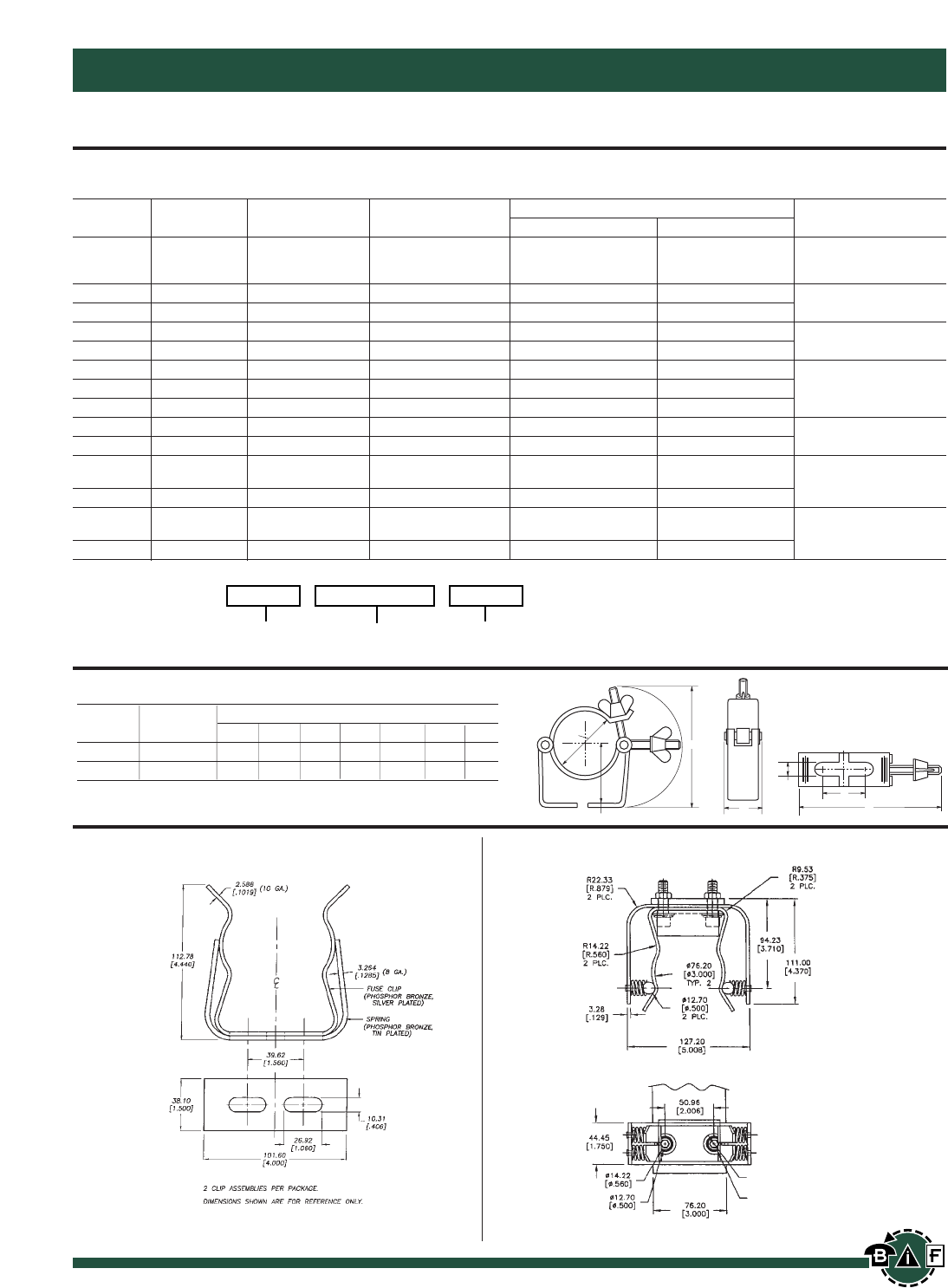
Bussmann®
164 For complete specification data, call Bussmann Information Fax ~ 636.527.1450
Medium Voltage Fuses and Fuse Links
Medium Voltage for Motor Circuit Protection
Table of Ratings
Code Breaking Current Dimensions Dimensional
kV Reference Capacity (kA) Rating (A) Length Diameter Standard
5 6.3 10 BS2692 (TA1)
3.6 WJON6 50 16 20 25 7.56∑(192mm) 1.4∑(35mm) Interchangeable with
31.5 40 50 GEC type K2 PA
3.6 WDOH6 50 50 63 80 100 125 7.56∑(192mm) 2∑(51mm) BS 2692 (TA1)
3.6 WFOH6 50 160 200 11.5∑(292mm) 3∑(76mm) or DIN 43625
3.6 WDLSJ 50 50 63 80 100 125 11.5∑(292mm) 2∑(51mm)
3.6 WFLSJ 50 160 200 11.5∑(292mm) 3∑(76mm) DIN 43625
3.6 WDFHO 50 50 63 80 100 125 10∑(254mm) 2∑(51mm)
3.6 WFFHO 50 160 200 10∑(254mm) 3∑(76mm) BS 2692 (TA2)
3.6 WKFHO 50 250 315 355 400 10∑(254mm) 3∑(76mm)
5.5 VFNHA 60 2R-6R 15.86∑(403mm) 3∑(76mm) N. American
5.5 VKNHA 60 9R-24R 15.86∑(403mm) 3∑(76mm) Practice
7.2 WFNHO 40 25 31.5 40 50 63
80 100 125 160 15.86∑(403mm) 3∑(76mm)
7.2 WKNHO 40 200 224 250 315 15.86∑(403mm) 3∑(76mm) BS2692 (TA4)
7.2 WFMSJ 40 25 31.5 40 50
63 80 125 160 17.40∑(442mm) 3∑(76mm)
7.2 WKMSJ 40 200 224 250 315 355 17.40∑(442mm) 3∑(76mm) DIN 43625
Catalog Code:
Current
Rating
Code
Reference
kV
C
B
A
G
E
F
D
Recommended Fuse Clips for Medium Voltage Fuses
Part Fuse Clip Dimensions
No. Diameter A B C D E F G
A3354710 23.741.972.001.184.531.50.39
A3354730 34.132.443.001.185.631.50.39
Fuseclips are for single barrel applications only. Are not sold in pairs.
1A0065
3” Diameter Clip
9078A67G04
3” Diameter Clip
2 CUP ASSEMBLIES PER PACKAGE.
DIMENSIONS SHOWN ARE FOR REFERENCE ONLY.
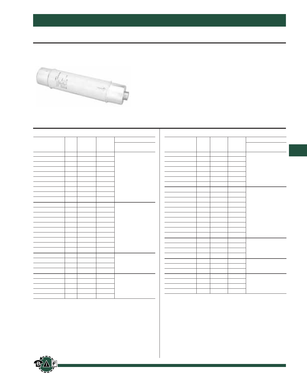
Bussmann®
165
For complete specification data, call Bussmann Information Fax ~ 636.527.1450
Medium Voltage Fuses and Fuse Links
Electrical Characteristics 15.5kV
Min. Max. Physical Size
Part Ampere Melt Clear Clip
Number Rating I2tI
2t
Length Dia. Center Barrels
MV155F1CBX5E 5A 180 2,900
MV155F1CBX7E 7A 850 8,000
MV155F1CBX10E 10A 850 8,000
MV155F1CBX15E 15A 2,070 12,000 18.75 2 15 1
MV155F1CBX20E 20A 2,370 23,000
MV155F1CBX25E 25A 4,650 31,000
MV155F1CBX30E 30A 9,490 45,000
MV155F1DBX10E 10A 850 8,000
MV155F1DBX15E 15A 2,070 12,000
MV155F1DBX20E 20A 2,370 23,000
MV155F1DBX25E 25A 4,650 31,000
MV155F1DBX30E 30A 9,490 45,000
MV155F1DBX40E 40A 9,490 45,000 18.75 3 15 1
MV155F1DBX50E 50A 13,600 90,000
MV155F1DBX65E 65A 30,700 181,000
MV155F1DBX80E 80A 54,600 270,000
MV155F1DBX100E 100A 116,200 600,000
MV155F2DBX125E 125A 123,000 677,000
MV155F2DBX150E 150A 218,700 1,287,000 18.75 3 15 2
MV155F2DBX175E 175A 314,700 1,689,000
MV155F2DBX200E 200A 465,100 2,405,000
MV155F1DCX65E 65A 30,700 181,000
MV155F1DCX80E 80A 54,600 270,000 21.75 3 18 1
MV155F1DCX100E 100A 116,200 600,000
MV155F2DCX125E 125A 123,000 677,000
MV155F2DCX150E 150A 218,700 1,287,000
MV155F2DCX175E 175A 314,700 1,689,000 21.75 3 18 2
MV155F2DCX200E 200A 465,100 2,405,000
E-Rated Medium Volt for Transformers and Feeders
Data Sheet: 6700 Data Sheet: 6701
MV055 and MV155
E-Rated Medium Voltage Fuses
Meets E requirements per ANSI C37.46
Meets full range requirements per ANSI C37.40
For Transformer and Feeder Protection
Current Limiting
Voltage Rating: 5.5 kV and 15.5 kV
Interrupting Rating: 50KA Maximum Sym.
Construction: Silver ribbon element surrounded by silica
filler housed in a fiberglass tube and plated endcaps. An
epoxy paint protects the fuse tube from the surrounding
environment.
Electrical Characteristics 5.5kV
Min. Max. Physical Size
Part
Ampere
Melt Clear Clip
Number
Rating
I2tI
2t
Length Dia. Center Barrels
MV055F1CAX5E 5A 180 2,400
MV055F1CAX7E 7A 850 8,000
MV055F1CAX10E 10A 850 8,000
MV055F1CAX15E 15A 2,070 11,000
MV055F1CAX20E 20A 2,370 23,000 15.75 2 12 1
MV055F1CAX25E 25A 4,650 31,000
MV055F1CAX30E 30A 9,490 45,000
MV055F1CAX40E 40A 9,490 45,000
MV055F1CAX50E 50A 13,600 90,000
MV055F1CAX65E 65A 30,700 181,000
MV055F1DAX10E 10A 850 8,000
MV055F1DAX15E 15A 2,070 12,000
MV055F1DAX20E 20A 2,370 23,000
MV055F1DAX25E 25A 4,650 31,000
MV055F1DAX30E 30A 9,490 45,000 15.75 3 12 1
MV055F1DAX40E 40A 9,490 45,000
MV055F1DAX50E 50A 13,600 90,000
MV055F1DAX65E 65A 30,700 181,000
MV055F1DAX80E 80A 54,600 270,000
MV055F1DAX100E 100A 116,200 580,000
MV055F1DAX125E 125A 167,400 600,000
MV055F1DAX150E 150A 218,700 786,000
MV055F1DAX175E 175A 227,900 1,100,000 15.75 3 12 1
MV055F1DAX200E 200A 297,600 1,520,000
MV055F2DAX250E 250A 669,600 2,400,000
MV055F2DAX300E 300A 874,800 3,149,000
MV055F2DAX350E 350A 911,600 4,376,000 15.75 3 12 2
MV055F2DAX400E 400A 1,190,400 6,071,000
MV055F2DAX450E 450A 1,555,000 9,796,000
Bussmann®
166 For complete specification data, call Bussmann Information Fax ~ 636.527.1450
Medium Voltage Fuses and Fuse Links
Data Sheet: 6002
E-Rated Medium Volt for Potential & Sm Power Transformers
JCD, JCW, JCE, JCQ, JCI & JCT
Current Limiting
Indicating/Non-Indicating
Plated Ferrules
Voltage Rating: (Max. Design) 2750, 5500,
8300, 15,500
Current Ratings: 1/2E through 10E
Specifications
Buss Maximum Maximum Interrupting Capacity Dimensions
Catalog No. Amperage Design Voltage Construction Amps (Asym.) Amps (Sym.) Length Diameter
2400V; E-Rated Fuse; Indicating
JCD-⁄Ω™E 0.50E 2750V Single 100,000 63,000 4.50∑.80∑
JCD-1E 1.00E 2750V Single 63,000 40,000 (114mm) (20.32mm)
JCD-2E 2.00E 2750V Single 63,000 40,000
JCD-5E 5.00E 2750V Single 40,000 25,000
2450/5500V; E-Rated Fuse; Non-Indicating
JCW-⁄Ω™E 0.50E 2750V/5500V Single 60,000 40,000
JCW-1E 1.00E 2750V/5500V Single 60,000 40,000
JCW-2E 2.00E 2750V/5500V Single 60,000 40,000 7.312∑1.563∑
JCW-3E 3.00E 2750V/5500V Single 60,000 40,000 (185.72mm) (39.70mm)
JCW-4E 4.00E 2750V/5500V Single 60,000 40,000
JCW-5E 5.00E 2750V/5500V Single 60,000 40,000
5500V; E-Rated Fuse; Non-Indicating
JCE-⁄Ω™E 0.50E 5500V Single 60,000 50,000
JCE-1E 1.00E 5500V Single 60,000 50,000
JCE-2E 2.00E 5500V Single 60,000 50,000 5.625” .81”
JCE-3E 3.00E 5500V Single 60,000 50,000 (142.88mm) (20.32mm)
JCE-4E 4.00E 5500V Single 60,000 50,000
JCE-5E 5.00E 5500V Single 60,000 50,000
5500V; E-Rated Fuse; Indicating
JCQ-⁄Ω™E 0.50E 5500V Single 130,000 80,000 9.5∑
JCQ-1E 1.00E 5500V Single 130,000 80,000 (241.3mm)
JCQ-1⁄Ω™E 1.50E 5500V Single 130,000 80,000 1.6∑
JCQ-3E 3.00E 5500V Single 130,000 80,000 9.44∑(40.64mm)
JCQ-5E 5.00E 5500V Single 130,000 80,000 (239.78mm)
JCQ-10E 10.00E 5500V Single 130,000 80,000
8300V; E-Rated Fuse; Indicating
JCI-⁄Ω™E 0.50E 8300V Single 130,000 80,000 9.5∑
(241.3mm)
JCI-3E 3.00E 8300V Single 130,000 80,000 12.88∑1.6∑
JCI-5E 5.00E 8300V Single 130,000 80,000 (327.15mm) (40.64mm)
JCI-10E 10.00E 8300V Single 130,000 80,000
15,500V; E-Rated Fuse; Indicating
JCT-⁄Ω™E 0.50E 15500V Single 130,000 80,000 12.93∑
JCT-1E 1.00E 15500V Single 130,000 80,000 (328.42mm)
JCT-1⁄Ω™E 1.50E 15500V Single 130,000 80,000 1.6∑
JCT-3E 3.00E 15500V Single 130,000 80,000 17.5∑(40.64mm)
JCT-5E 5.00E 15500V Single 130,000 80,000 (444.5mm)
JCT-10E 10.00E 15500V Single 130,000 80,000
Fuse clip for 1.6∑Diameter Fuses - 1A0835.
Fuse clip for .81∑Diameter Fuses - 1A1837.
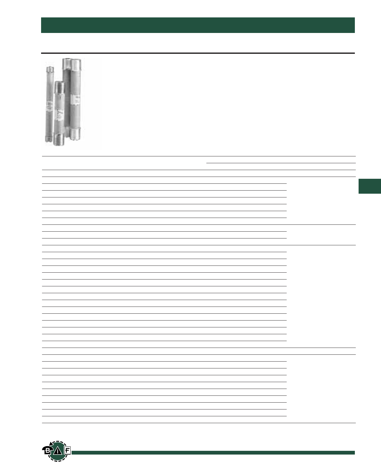
Bussmann®
167
For complete specification data, call Bussmann Information Fax ~ 636.527.1450
Medium Voltage Fuses and Fuse Links
E-Rated Fuses for Trans. & Feeder Protection
E-Rated
Current Limiting
Blown Fuse Indication
Construction: Plated Ferrules
Voltage Ratings: (Max. Design): 2,750, 5,500, 8,300,
15,500V
Current Ratings: ⁄Ω™E through 750E
Specifications
Buss Maximum Maximum Interrupting Capacity Dimensions
Catalog No. Amperage Design Voltage Construction Amps. (Asym.) Amps. (Sym.) Length Diameter
2400V; E-Rated; Indoor/Enclosure
JCX-⁄Ω™E⁄Ω™E 2750V Single 60,000 40,000
JCX-1E 1E 2750V Single 60,000 40,000
JCX-2E 2E 2750V Single 60,000 40,000
JCX-3E 3E 2750V Single 60,000 40,000
JCX-5E 5E 2750V Single 60,000 40,000 9.19∑2∑
JCX-7E 7E 2750V Single 60,000 40,000 (233.38mm) (50.8mm)
JCX-10E 10E 2750V Single 60,000 40,000
JCX-15E 15E 2750V Single 80,000 50,000
JCX-20E 20E 2750V Single 80,000 50,000 9.5” 2.1”
JCX-25E 25E 2750V Single 80,000 50,000
JCX-30E 30E 2750V Single 80,000 50,000
JCX-40E 40E 2750V Single 80,000 50,000
JCX-50E 50E 2750V Single 80,000 50,000
JCX-65E 65E 2750V Single 80,000 50,000
JCX-80E 80E 2750V Single 80,000 50,000
JCX-100E 100E 2750V Single 80,000 40,000
JCX-125E 125E 2750V Single 80,000 50,000
10.81∑3∑
JCX-150E 150E 2750V Single 80,000 50,000 (276.35mm) (76.2mm)
JCX-200E 200E 2750V Single 80,000 50,000
JCX-225E 225E 2750V Single 80,000 50,000
JCX-250E/280X 250E/280X 2750V Double 80,000 50,000
JCX-300E/325X 300E/325X 2750V Double 80,000 50,000
JCX-350X 350X 2750V Double 80,000 50,000
JCX-400X 400X 2750V Double 80,000 50,000
JCX-450X 450X 2750V Double 80,000 50,000
5500V; E-Rated; Indoor/Enclosure
JCY-⁄Ω™E⁄Ω™E 5500V Single 60,000 40,000
JCY-1E 1E 5500V Single 60,000 40,000
JCY-2E 2E 5500V Single 60,000 40,000
JCY-3E 3E 5500V Single 60,000 40,000
JCY-5E 5E 5500V Single 60,000 40,000 11.19∑2∑
JCY-7E 7E 5500V Single 60,000 40,000 (284.18mm) (50.8mm)
JCY-10E 10E 5500V Single 60,000 40,000
JCY-15E 15E 5500V Single 60,000 40,000
JCY-20E 20E 5500V Single 60,000 40,000
JCY-25E 25E 5500V Single 60,000 40,000
Contact Bussmann for the latest product information on E-Rated Fuses for Transformer and feeder protection.
Recommended Fuse Clips: 3- 1A0065, 9078A67G04, A3354730

Bussmann®
168 For complete specification data, call Bussmann Information Fax ~ 636.527.1450
Medium Voltage Fuses and Fuse Links
E-Rated Fuses for Trans. & Feeder Protection
Specifications
Buss Maximum Maximum Interrupting Capacity Dimensions
Catalog No. Amperage Design Voltage Construction Amps. (Asym.) Amps. (Sym.) Length Diameter
5500V; E-Rated; Indoor/Enclosure
JCU-10E 10E 5500V Single 80,000 50,000 17.81∑3∑
(452.4mm) (76.2mm)
JCU-15E 15E 5500V Single 80,000 50,000 12.88∑2.1∑
JCU-20E 20E 5500V Single 80,000 50,000 (327.0mm) (53.34mm)
JCU-25E 25E 5500V Single 80,000 50,000
JCU-30E 30E 5500V Single 100,000 63,000
JCU-40E 40E 5500V Single 100,000 63,000
JCU-50E 50E 5500V Single 100,000 63,000
JCU-65E 60E 5500V Single 100,000 63,000
JCU-80E 80E 5500V Single 100,000 63,000
JCU-100E 100E 5500V Single 100,000 63,000
JCU-125E 125E 5500V Single 100,000 63,000 17.88”3∑
JCU-150E 150E 5500V Single 100,000 63,000 (454.15mm) (76.20mm)
JCU-175E 175E 5500V Single 100,000 63,000
JCU-200E 200E 5500V Single 100,000 63,000
JCU-250E 250E 5500V Single 100,000 63,000
JCU-300E 300E 5500V Double 100,000 63,000
JCU-350E 350E 5500V Double 100,000 63,000
JCU-400E 400E 5500V Double 100,000 63,000
JCU-450E 450E 5500V Double 100,000 63,000
JCU-600E 600E 5500V Double* 80,000 50,000 28.81∑4”
JCU-750E 750E 5500V Double* 80,000 50,000 (731.77mm) (101.60mm)
8300V; E-Rated; Indoor/Enclosure
JCZ-15E 15E 8300V Single 80,000 50,000
15.51∑2.1∑
JCZ-20E 20E 8300V Single 80,000 50,000 (393.95mm) (53.34mm)
JCZ-25E 25E 8300V Single 80,000 50,000
JCZ-30E 30E 8300V Single 80,000 50,000
JCZ-40E 40E 8300V Single 80,000 50,000
JCZ-50E 50E 8300V Single 80,000 50,000
JCZ-65E 65E 8300V Single 80,000 50,000
JCZ-80E 80E 8300V Single 80,000 50,000 17.88∑3∑
JCZ-100E 100E 8300V Single 80,000 50,000 (454.15mm) (76.2mm)
JCZ-125E 125E 8300V Single 80,000 50,000
JCZ-150E 150E 8300V Single 80,000 50,000
JCZ-200E 200E 8300V Double 80,000 50,000
JDZ-20E 20E 8300V Single 80,000 50,000
JDZ-25E 25E 8300V Single 80,000 50,000
JDZ-30E 30E 8300V Single 80,000 50,000
JDZ-40E 40E 8300V Single 80,000 50,000 15.88∑3∑
JDZ-50E 50E 8300V Single 80,000 50,000 (403.2mm) (76.2mm)
JDZ-65E 65E 8300V Single 80,000 50,000
JDZ-80E 80E 8300V Double 80,000 50,000
JDZ-100E 100E 8300V Double 80,000 50,000
JDZ-125E 125E 8300V Double 80,000 50,000
Recommended Fuse Clips: 3- 1A0065, 9078A67G04, A3354730
General Notes:
1. All fuses are fitted with a striker pin which can be used for indication or tripping purposes.
2. The fuses are suitable for use either indoors or outdoors.
3. These fuses are interchangeable with corresponding fuses produced by most other leading North American manufacturers.
Contact Bussmann for the latest product information on E-Rated Fuses for Transformer and feeder protection.
*Bolt on mounting
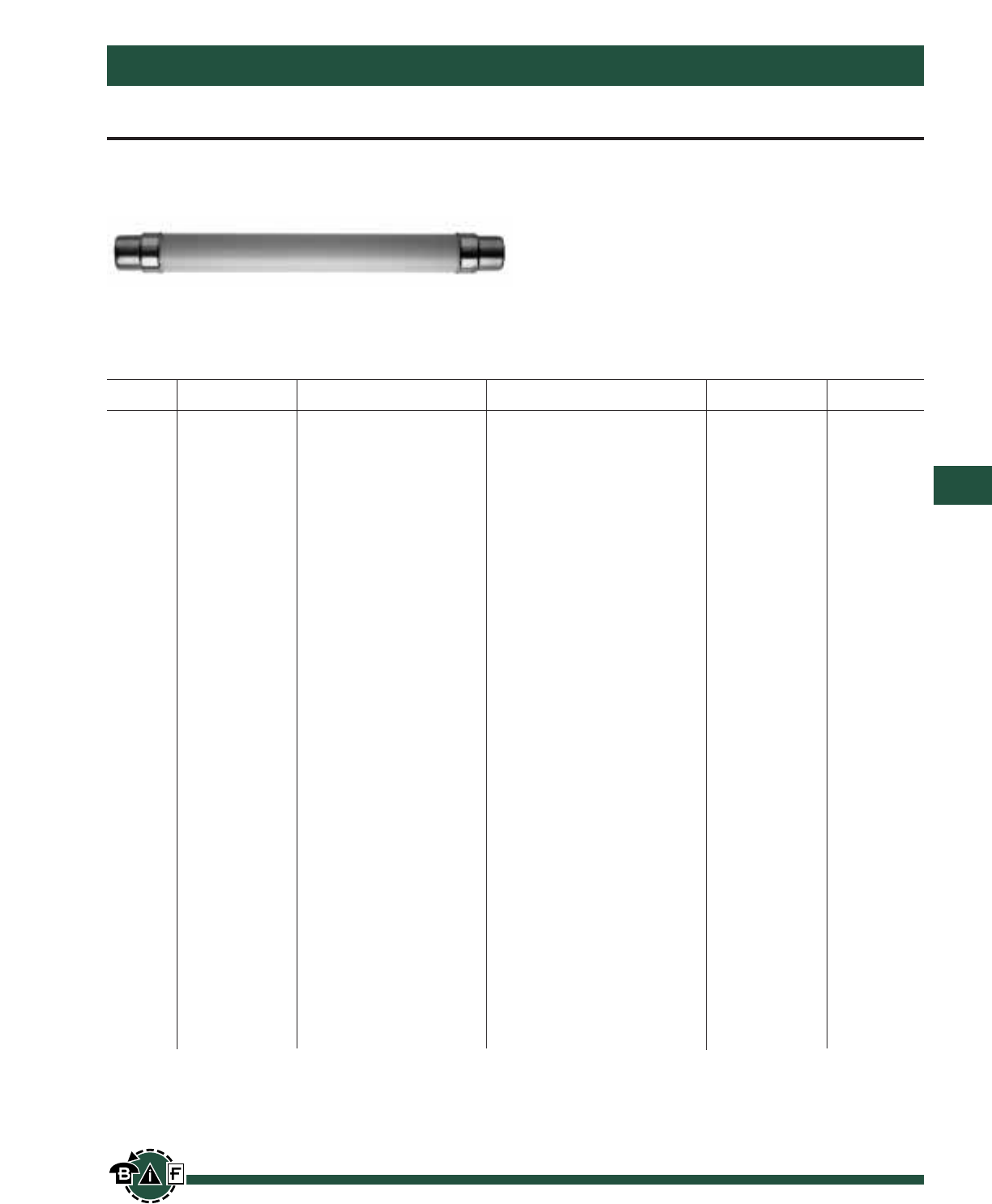
Bussmann®
169
For complete specification data, call Bussmann Information Fax ~ 636.527.1450
Medium Voltage Fuses and Fuse Links
Medium Voltage DIN Distribution Fuses
DIN Dimension Fuses To Spec. DIN 43625
This product group covers current limiting fuses with dimen-
sions to DIN 43625 and performance in compliance with IEC
282-1.
Striker Characteristics
The spring operated striker pin has a travel and energy output
in compliance with the requirements of DIN 43625 and IEC
282-1.
Current Ratings
These are in accordance with the R10 and, in some cases,
the R20 series of preferred numbers.
Table of Ratings and Dimensions
Dimensions Inches and mm IR
kV Code Ref. Current Rating Diameter ≈Length DIN Series RMS Symm
ADOSJ 6.3, 16, 20, 25, 31.5, 40, 2.00∑≈7.56∑
WDOSJ 50, 63, 80, 100, 125 51 ≈192 3.6/7.2
__________________________________________________________________________________
3.00∑≈7.56∑
WFOSJ 160, 200 76 ≈192
____________________________________________________________________________________________________
3.6 ADLSJ 6.3, 10, 16, 20, 25, 31.5, 2.00∑≈11.50∑50KA
WDLSJ 40, 50, 63, 80, 100, 125 51 ≈292
__________________________________________________________________________________
WFLSJ 160 10/12
WFLSJ 200 3.00∑≈11.50∑
WKLSJ 250 76 ≈292
WKLSJ 315, 400
_______________________________________________________________________________________________________________________________
SDLSJ 6.3, 10, 16, 20, 25, 31.5 2.00∑≈11.50∑
SDLSJ 40, 50, 63 51 ≈292
__________________________________________________________________________________
SFLSJ 80
7.2 SFLSJ 100 3.00∑≈11.50∑
10/12
40KA
SFLSJ 125 76 ≈292
SFLSJ 160
____________________________________________________________________________________________________
WKMSJ 200 3.00∑≈17.41∑20/24
WKMSJ 250, 315, 355 76 ≈442
_______________________________________________________________________________________________________________________________
SDLSJ 6.3, 10, 16, 20, 25 2.00∑≈11.50∑
SDLSJ 31.5, 40 51 ≈292
12 SDLSJ 50, 63 50KA
__________________________________________________________________________________
SFLSJ 63, 80 3.00∑≈11.50∑10/12
SFLSJ 100 76 ≈292
SKLSJ 125, 160, 200
_______________________________________________________________________________________________________________________________
SDLSJ 6.3, 10, 16 2.00∑≈11.50∑
SDLSJ 20, 25 51 ≈292
SDLSJ 40 10/12
__________________________________________________________________________________
SFLSJ 31.5 3.00∑≈11.50∑
17.5
SFLSJ 40, 50 76 ≈292 35.5KA
____________________________________________________________________________________________________
SDMSJ 6.3, 10, 16 2.00∑≈17.41∑
SDMSJ 20, 25, 31.5 51 ≈442
SDMSJ 40
__________________________________________________________________________________
SFMSJ 50 3.00∑≈17.41∑20/24
SFMSJ 63, 80 76 ≈442
_______________________________________________________________________________________________ ________________
15.5 SFMSJ 100 3.00∑≈17.41∑
SKMSJ 125 76 ≈442 25KA
_______________________________________________________________________________________________________________________________
SDMSJ 6.3, 16 2.00∑≈17.41∑
SDMSJ 20, 25, 31.5 51 ≈442
24
SDMSJ 40 (24kv application only)
20/24 50KA
__________________________________________________________________________________
SFMSJ 40, 50 3.00∑≈17.41∑
SFMSJ 63 76 ≈442
SFMSJ 71 (24kv application only)
_______________________________________________________________________________________________________________________________
SDQSJ 6.3, 10, 16, 20, 25, 31.5 2.00∑≈21.16∑
3.15 51 ≈442
__________________________________________________________________________________
36 SFQSJ 31.5, 40, 50, 56 3.00∑≈21.16∑30/36 35.5KA
76 ≈537
_______________________________________________________________________________________________________________________________
Recommended Fuseclips for DIN Style Fuses: Bussmann Part Number 270303
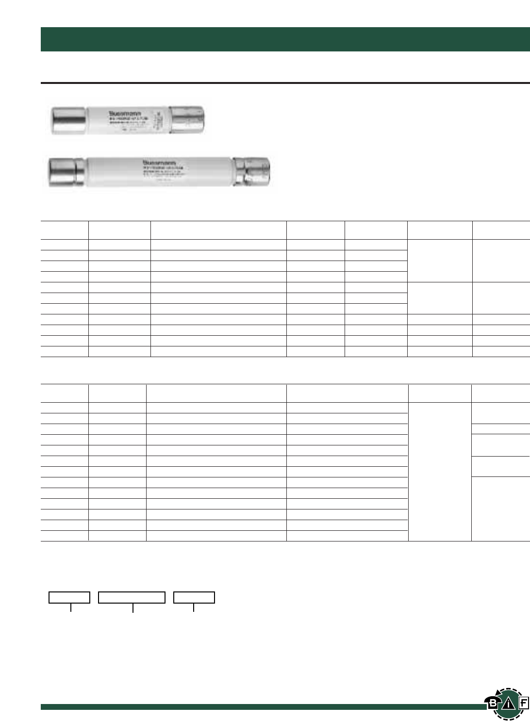
Bussmann®
170 For complete specification data, call Bussmann Information Fax ~ 636.527.1450
Medium Voltage Fuses and Fuse Links
Potential Transformer Fuses
Recommended Fuse Clips: 1dia. - A3354705
1.63” dia. - 1A0835
.81dia. - 1A1837
Contact Bussmann for complete specifications on Potential Transformer Fuses
These are a range of fuses with low current rating, for use
with voltage transformers or operating transformers to provide
isolation of the associated system in the event of faults in the
transformer circuit.
“AB” & “AM” Series
Code
kV Reference Current Ratings Type Length Diameter IR
3.6 ABWNA 3.15, 6.3 AB 5.6∑1∑
3.6 ABCNA 3.15, 6.3, 10 AB 7.69∑1∑50KA
5.5 ABWNA 0.5E, 1E, 2E, 3E, 5E AB 5.6∑1∑
5.5 AMWNA 0.5E, 1.0E, 2.0E, 3.0E, 4.0E, 5.0E AM 5.6∑.81∑
7.2 ABWNA 3.15, 6.3 AB 5.6∑1∑
7.2 ABCNA 3.15, 6.3 AB 7.69∑1∑45KA
12.0 ABCNA 3.15 AB 7.69∑1∑
15.5 ABFNA 3.15 AB 10.00∑1∑ 32KA
17.5 ABGNA 3.15 AB 14.13∑1∑ 35KA
24.0 ABGNA 3.15 AB 14.13∑1∑ 25KA
36.0* ABGNA 3.15 AB 14.13∑1∑ 31.5KA
Recommended fuse clip for 1∑diameter fuses – A3354705.
“CAV” Series
Code
kV Reference Current Ratings Length Diameter IR
3.6 CAV 2 8.66∑
5.5 CAV 15E 7.375∑40KA
5.5 CAVH 0.5E, 1E, 2E 7.375∑50KA
7.2 CAV 2, 10 8.66∑
12 CAV 2 8.66∑40KA
15.5 CAV 0.5E, 1E, 2E, 3E, 7E 12.87∑
15.5 CAVH 0.5E, 1E, 2E 12.87∑1.63∑80KA
17.5 CAV 2, 4, 6, 10 8.66∑
24 CAV 2, 3, 4 13.39∑
36 CAV 2, 4 17.32∑40KA
36 CAVH 2 17.32∑
38 CAV 4E 17.32∑
38 CAVH 0.5E, 1E, 2E 17.32∑
*For clean indoor applications only.
Type CAVH are fitted with a striker pin for indication.
C
atalog Code:
Current
Rating
Code
Reference
kV
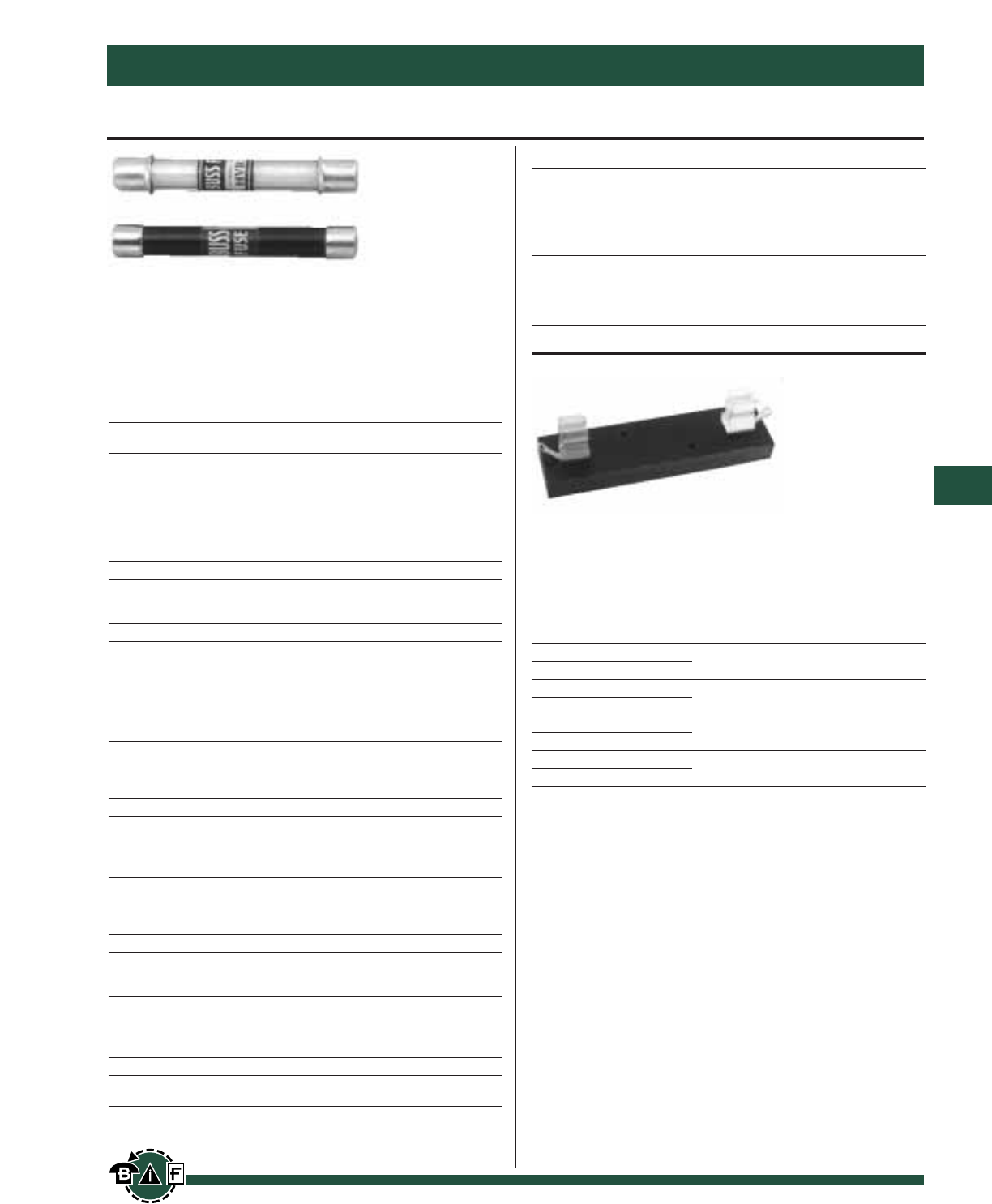
Bussmann®
171
For complete specification data, call Bussmann Information Fax ~ 636.527.1450
Medium Voltage Fuses and Fuse Links
Data Sheet: 6003
Medium Voltage, Fast Acting Fuses
HVA, HVB, HVJ, HVL, HVR, HVT, HVU,
HVW & HVX
Non-Time Delay
Ampere Ratings:
Voltage Rating: 1000 to 10,000V
HVA (1000 Volts) (Max. S.C. 20KW dc, 30KVA ac)
Length *Wt./100
Amps Dia. In. mm Lbs. Kg
⁄Ω¡§ ‹Ω¢
⁄Ω• 1
⁄Ω¢ 1⁄Ω™
⁄Ω¡º 2 0.41∑ 3∑ 76.1 2 0.91
¤Ω¡º 3
‹Ω¡º 4
‹Ω• 6
⁄Ω™ 10
HVB (2500V) (Max. S.C. 20KW dc, 30KVA ac)
⁄Ω™ 1⁄Ω™
‹Ω¢ 2 0.41∑4.5∑114.2 3 1.36
13
HVJ (5000V) (Max. S.C. 20KW dc, 30KVA ac)
⁄Ω¡§ 1⁄Ω™
⁄Ω• 2
⁄Ω¢ 40.81∑5∑126.9 9 4.08
⁄Ω™ 6
‹Ω¢ 10
1—
HVL (10,000V) (Max. S.C. 20KW dc, 30KVA ac)
⁄Ω¡§ 1
⁄Ω• 1⁄Ω™
⁄Ω¢ 20.81∑10∑253.8 15 6.80
⁄Ω™ 3
HVR (1000V) (Max. S.C. kVA-500 ac only)
⁄Ω™ 3
1 4 0.41∑3∑76.1 3 1.36
25
HVW (1200V) (Max. S.C. kVA-12,000 ac only)
—3
14 0.41∑2.25∑57.1 2 0.91
25
—8
HVT (2500V) (Max. S.C. kVA-1250 ac only)
⁄Ω™ 3
1 5 0.41∑4.5∑114.2 4 1.81
2—
HVU (5000V) (Max. S.C. kVA-2500 ac only)
⁄Ω™ 3
1 4 0.81∑5∑126.9 19 8.62
25
HVX (10,000V) (Max. S.C. kVA-5,000 ac only)
⁄Ω™ 3
15 0.41∑10.0∑253.8 36 16.33
*Shipping.
Carton quantity: 10.
4528, 4529, 4530 & 2960
Fuseblocks
Voltage Rating: 1000 to 10,000V
For Block
Fuse Cat.
Sym. No.
HVA
HVR 4528
HVB
HVT 4529
HVJ
HVU 4530
HVL
HVX 2960
Use #8 screws on blocks 4528 and 4529.
Use #10 screws on blocks 4530 and 2960.
Test Specifications
Catalog
Number Load Opening Time
HVA
HVB 110% 4 Hours (min.)
HVJ 135% 1 Hour (max.)
HVL
HVR
HVT 100% 4 Hours (min.)
HVU
HVW 150% 1 Hour (max.)
HVX
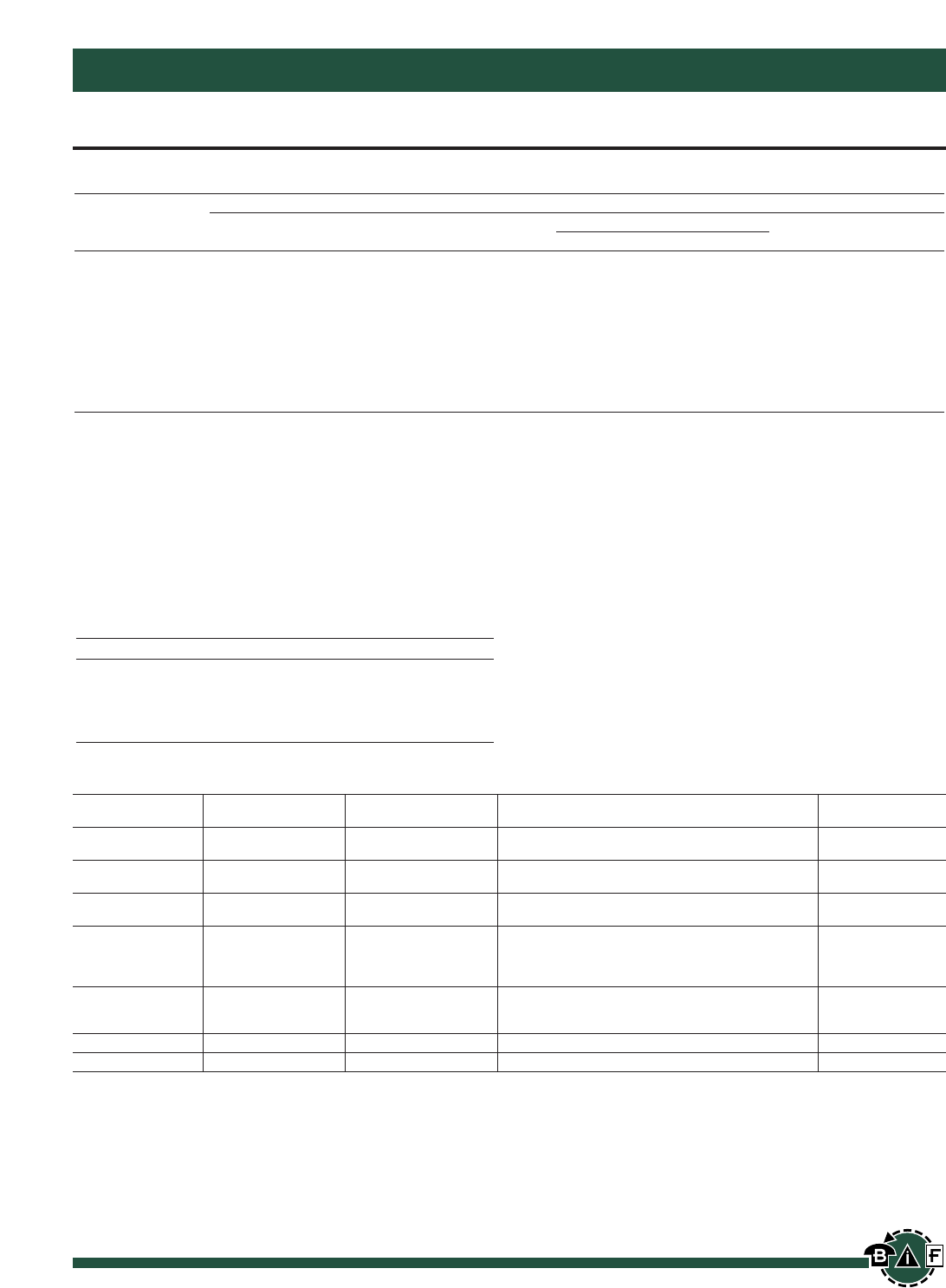
172 For complete specification data, call Bussmann Information Fax ~ 636.527.1450
Contact Bussmann for complete specifications on Medium Voltage Fuses
Bussmann®
Medium Voltage Fuses and Fuse Links
Medium Voltage —BS2692-1 Fuses
Code References in Table
Letter Reference Explanation
1st Type O = Oiltight
2nd Diameter E, H, L = 63.5 mm
3rd Length F = 254 mm, G = 359 mm
4th Striker M = As specified in BS 2692 table 11.
5th Tags A = none, i.e. plain caps
General Guide to the Selection of HV Fuse Links, used in oilfield switchgear. For use in the Primary Circuit of Three
Phase 50 Hz Transformers
Transformer Primary Voltage
Transformer 11kV
kVA 3.3kV 6.6kV ESI 12-8 Ref. Fuse Rating 13.8kV
200 3.6kV OEFMA 63 12kV OEFMA 31.5 01 12kV OEFMA 25 15.5kV OEFMA 16
250 3.6kV OEFMA 80 12kV OEFMA 40 — 12kV OEFMA 25 15.5kV OEFMA 20
300/315 3.6kV OEFMA 100 12kV OEFMA 50 02 12kV OEFMA31.5 15.5kV OEFMA 25
400 3.6kV OEFMA 125 12kV OEFMA 63 — 12kV OEFMA 40 15.5kV OEFMA 31.5
500 3.6kV OEFMA 160 12kV OHFMA 71 03 12kV OEFMA 50 15.5kV OEFMA 40
630 3.6kV OEFMA 200 7.2kV OEFMA 100 — 12kV OEFMA 63 15.5kV OEFMA 50
750/800 3.6kV OLGMA 250 7.2kV OHGMA 125 04 12kV OHFMA 80 15.5kV OEFMA 63
1000 3.6kV OLGMA 250* 7.2kV OHGMA 140 05 12kV OHGMA 90** 15.5kV OHGMA 71
1250 — 7.2kV OHGMA 160* — 12kV OHGMA 100 15.5kV OHGMA 90
1600 — — — 12kV OLGMA 125* 15.5kV OLGMA 100*
This selection table has been based upon the following criteria:
1. Withstand against magnetizing inrush current taken as 12 times full-load current for 0.1 second.
2. Withstand against 150% permissible overload current. Recommendations marked with asterisks have the following significance:-
*Limited to permissible overloads of 130%.
**Permits use of a 12kV OHFMA 80A fuse with a 100kVA transformer where permissible overload does not exceed 130%.
3. For 6.6kV systems, 12kV fuse links are recommended where possible in the interests of standardization.
4. Wherever possible, 10 inch long FO1 fuse links are offered rather than equivalent 14 inch FO2 types.
5. The above recommendations are not generally applicable to transformers feeding motor circuits with starting currents in excess of the trans-
former full load current. In this event, please consult Bussmann.
Table of Preferred Ratings
Code Dimensional Current Ratings Breaking
Rated kV Reference Ref. BS 2692 (amps) Capacity (kA)
3.6 OEFMA FO1 6.3, 10, 16, 20, 25, 31.5, 40, 50, 63, 50
80, 100, 125, 160, 200
3.6 OEGMA FO2 100, 125, 160, 200 50
3.6 OLGMA FO2 250 50
7.2 OEFMA FO1 80, 100, 112 45
7.2 OHGMA FO2 125, 140, 160 45
12.0 OEFMA FO1 6.3, 10, 16, 20, 25, 31.5, 40, 50, 63 40
12.0 OHFMA FO1 71, 80 40
12.0 OHGMA FO2 6.3, 10, 16, 20, 25, 31.5, 40, 50, 63, 71, 80, 90, 100 40
12.0 OLGMA FO2 125 40
15.5 OEFMA FO1 6.3, 10, 16, 20, 25, 31.5, 40, 50, 63 40
15.5 OHGMA FO2 71, 80, 90 40
15.5 OLGMA FO2 100 40
17.5 OHGMA FO2 6.3, 10, 16, 20, 25, 31.5, 40, 50, 63, 80 35
24.0 OEGMA FO2 6.3, 10, 16, 20, 25, 31.5, 40, 50 25
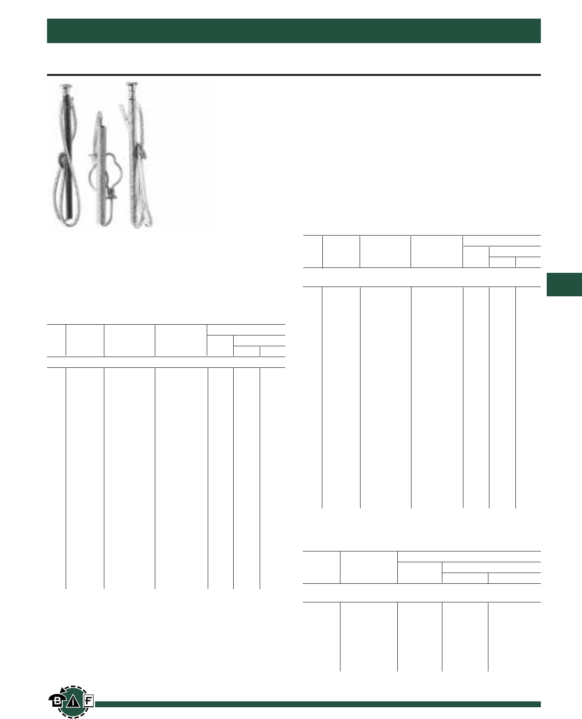
Removable Button-Head For Cutouts Requiring Removable-Button
Links*
1 — FL3K1 FL3T1
_______________________________________________
2 — FL3K2 FL3T2
_______________________________________________
3 — FL3K3 FL3T3
_______________________________________________
5 — FL3K5 FL3T5
_______________________________________________
6 — FL3K6 FL3T6
_______________________________________________
8 — FL3K8 FL3T8 25 1.81 0.82
_______________________________________________
10 — FL3K10 FL3T10
_______________________________________________
12 — FL3K12 FL3T12
_______________________________________________
15 — FL3K15 FL3T15
_______________________________________________
20 — FL3K20 FL3T20
_______________________________________________
25 — FL3K25 FL3T25
______________________________________________________________________
30 — FL3K30 FL3T30
_______________________________________________
40 — FL3K40 FL3T40 25 3.44 1.56
_______________________________________________
50 — FL3K50 FL3T50
______________________________________________________________________
65 — FL3K65 FL3T65
_______________________________________________
80 — FL3K80 FL3T80 15 3.63 1.65
_______________________________________________
100 — FL3K100 FL3T100
______________________________________________________________________
140 — FL3K140 FL3T140 10 7.63 3.46
_______________________________________________
200 — FL3K200 FL3T200
______________________________________________________________________
*Adapter-type removable-button links with ferrule adapter to convert to double-leader links
are available in K and T types. Order by description.
Catalog Data—EEI-NEMA Type K Universal Silver-Element
Fuse Links for Cutouts Rated through 27kV
Link Carton Data
Rating EEI-Nema Qty.
Weight
Amps Type K Lbs. Kg's.
Non-Removable Button-Head For Standard Open Or Enclosed
Cutouts
8 FL12K8
____________________________
10 FL12K10
____________________________
12 FL12K12 25 2 0.91
____________________________
15 FL12K15
____________________________
25 FL12K25
______________________________________________________________________
50 FL12K50 25 3 1.34
______________________________________________________________________
Catalog Data-EEI-NEMA and High-Surge Universal Tin
Element Fuse Links for Cutouts. Rated to 27kV
Type H EEI-Nema EEI-Nema Carton Data
Link (High Type K Type T Qty.
Weight
Amps Surge) (Fast) (Slow) Lbs. Kg's.
Non-Removable Button-Head For Standard Open Or Enclosed Cutouts
1 FL11H1 FL11K1 FL11T1
_______________________________________________
2 FL11H2 FL11K2 FL11T2 25 2 0.91
_______________________________________________
3 FL11H3 FL11K3 FL11T3
_______________________________________________
5 FL11H5 FL11K5 FL11T5
______________________________________________________________________
6 — FL11K6 FL11T6
_______________________________________________
8 FL11H8 FL11K8 FL11T8
_______________________________________________
10 — FL11K10 FL11T10
_______________________________________________
12 — FL11K12 FL11T12 25 2 0.91
_______________________________________________
15 — FL11K15 FL11T15
_______________________________________________
20 — FL11K20 FL11T20
_______________________________________________
25 — FL11K25 FL11T25
______________________________________________________________________
30 — FL11K30 FL11T30
_______________________________________________
40 — FL11K40 FL11T40 25 4 1.82
_______________________________________________
50 — FL11K50 FL11T50
______________________________________________________________________
65 — FL11K65 FL11T65 5 2.27
_______________________________________________ _______________
80 — FL11K80 FL11T80 15 5.5 2.49
_______________________________________________ _______________
100 — FL11K100 FL11T100 6 2.72
______________________________________________________________________
140 — FL11K140 FL11T140 7 3.17
_______________________________________________ _______________
200 — FL11K200 FL11T200
10
10 4.53
______________________________________________________________________
Bussmann®
173
For complete specification data, call Bussmann Information Fax ~ 636.527.1450
Medium Voltage Fuses and Fuse Links
Catalog Data-EEI-NEMA and High-Surge Universal Tin
Element Fuse Links for Cutouts. Rated to 27kV
Type H EEI-Nema EEI-Nema Carton Data
Link (High Type K Type T Qty.
Weight
Amps Surge) (Fast) (Slow) Lbs. Kg's.
Medium Voltage Fuse Links
EEI-NEMA Type K and T Fuse Links
These fuse links afford effective overcurrent protection to sys-
tems and equipment. In addition to apparatus protection, they
can be coordinated with other overcurrent protective devices
for sectionalizing in order to isolate feeder branches.
High-Surge Type H Fuse Links
High-surge, Type H fuse links are manufactured in ratings of
1, 2, 3, 5, and 8A. They have been developed principally for
primary fusing of small-sized transformers. Type H links are
manufactured in the universal buttonhead design.
Type N Fuse Links
Type N fuse links conform to previous NEMA standards and
have been superseded by Type K and T links. Type N fuse
links are manufactured in the universal button design in ratings
of 5 through 200A for use in NEMA standard dimensioned
cutouts rated through 27 kv.

Page 174
BLANK
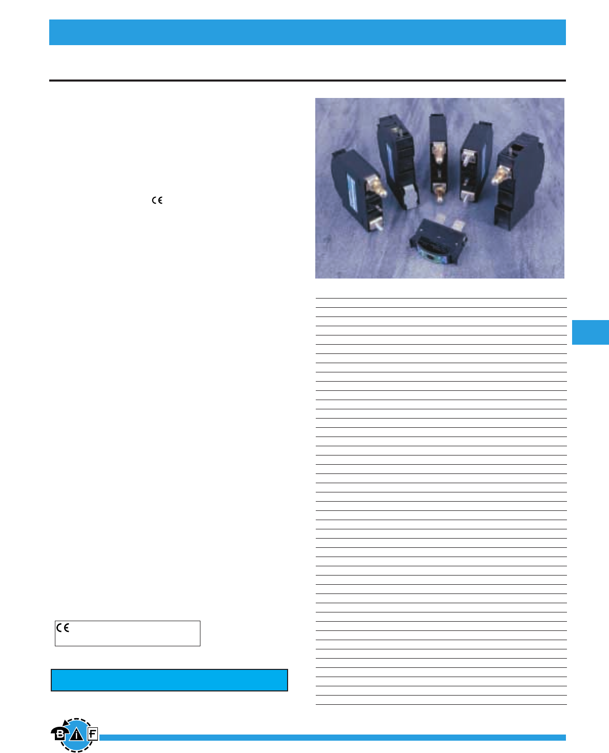
Bussmann®
175
For complete specification data, call Bussmann Information Fax ~ 636.527.1450
Data Sheet: 5023
Telpower®DC Power Protection Systems
Telpower®Compact Fused Disconnect Switch TPC & TPCDS
TPC & TPCDS
TPCDS - Telpower®Compact Fused Disconnect Switch
TPC - Telpower®Compact Fuse - Current Limiting
Ampere Ratings: 3-125A
Available Ratings: 3, 4, 5, 6, 7, 8, 10, 12, 15, 20, 25, 30,
40, 50, 60, 75, 90, 100, 125A
Voltage Rating: 80Vdc
Interrupting Rating: 100,000A
Agency Information:
UL Recognized (investigated to UL 1801) as a
disconnect switch for the interruption of load current
by means of withdrawing the fuse pullout.
Recognized to U.S. and Canadian requirements under the
component recognition program of Underwriters
Laboratories Inc.
Files E219046 and E56412.
General Information:
• Fusible solution for replacement of existing DC Telecom
circuit breakers.
• Compact size fused disconnect switch.
• AmpColor ID™ System for easy fuse replacement.
• Available in two disconnect switch profiles in addition to a
variety of terminal styles.
• Local and remote open fuse indication.
Local alarm indication provided by LED on TPC fuse.
• Remote alarm terminal available in three positions
common to DC circuit protection devices.
• Recommended .75 inch center-to-center product spacing.
• Current-limiting capability
• Complete system coordination capability.
• Highest interrupting rating (100,000A) available
for DC circuit protection of this footprint.
• No venting of arc or molten metals and gases during
opening.
• Fuse material: Black thermoplastic, UL rated 94 V-O,
170° C RTI.
• Housing material: Black thermoplastic, UL rated 94 V-O,
120° C RTI.
*Not investigated to Canadian Requirements.
CE logo denotes compliance with European Union Low
Voltage Directive (50-1000Vac, 75-1500Vdc). Refer
to Data Sheet: 8002 or contact Bussmann Application
Engineering for more information.
Catalog Number Description Ampere Rating
TPC-3 Compact Fuse 3A
TPC-4 Compact Fuse 4A
TPC-5 Compact Fuse 5A
TPC-6 Compact Fuse 6A
TPC-7 Compact Fuse 7A
TPC-8 Compact Fuse 8A
TPC-10 Compact Fuse 10A
TPC-12 Compact Fuse 12A
TPC-15 Compact Fuse 15A
TPC-20 Compact Fuse 20A
TPC-25 Compact Fuse 25A
TPC-30 Compact Fuse 30A
TPC-40 Compact Fuse 40A
TPC-50 Compact Fuse 50A
TPC-60 Compact Fuse 60A
TPC-75 Compact Fuse 75A
TPC-90 Compact Fuse 90A
TPC-100 Compact Fuse 100A
TPC-125 Compact Fuse 125A
TPCDS-BBE-1 Compact Disconnect 3-125A
TPCDS-BBE-2 Compact Disconnect 3-125A
TPCDS-BBE-3 Compact Disconnect 3-125A
TPCDS-BBM-1 Compact Disconnect 3-125A
TPCDS-BBM-2 Compact Disconnect 3-125A
TPCDS-BBM-3 Compact Disconnect 3-125A
TPCDS-BSE-1 Compact Disconnect 3-125A
TPCDS-BSE-2 Compact Disconnect 3-125A
TPCDS-BSE-3 Compact Disconnect 3-125A
TPCDS-BSM-1 Compact Disconnect 3-125A
TPCDS-BSM-2 Compact Disconnect 3-125A
TPCDS-BSM-3 Compact Disconnect 3-125A
TPCDS-SSE-1 Compact Disconnect 3-125A
TPCDS-SSE-2 Compact Disconnect 3-125A
TPCDS-SSE-3 Compact Disconnect 3-125A
TPCDS-SSM-1 Compact Disconnect 3-125A
TPCDS-SSM-2 Compact Disconnect 3-125A
TPCDS-SSM-3 Compact Disconnect 3-125A
TPCDS-D-BC1* Compact Disconnect 3-125A
TPCDS-D-BC2* Compact Disconnect 3-125A
TPCDS-D-CC1* Compact Disconnect 3-125A
TPCDS-D-SEC1* Compact Disconnect 3-125A
TPCDS-D-SEC2* Compact Disconnect 3-125A
TPCDS-D-SMC1* Compact Disconnect 3-125A
TPCDS-D-SMC2* Compact Disconnect 3-125A
Look for Telpower® BLUE™ fuses exclusively from
Cooper Bussmann.
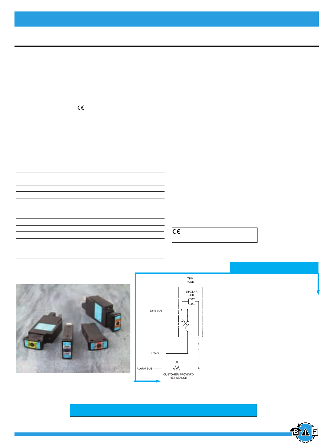
Bussmann®
176 For complete specification data, call Bussmann Information Fax ~ 636.527.1450
Data Sheet: 5022
Telpower®Miniature Fused Disconnect Switch TPM & TPMDS
Telpower®DC Power Protection Systems
TPM & TPMDS
TPMDS - Telpower®Miniature Fused Disconnect Switch
TPM - Telpower®Miniature Fuse - Current Limiting
Ampere Ratings: 3-30A
Voltage Rating: 80Vdc
Interrupting Rating: 20,000A
Agency Information:
UL Recognized (investigated to UL 1801) as a
disconnect switch for the interruption of load current
by means of withdrawing the fuse pullout.
Recognized to U.S. and Canadian requirements under the
component recognition program of Underwriters
Laboratories Inc.
Files E219046 and E56412.
General Information:
• Smallest and most versatile fused disconnect
switch available.
• Small size allows for assembly into 1 U (1.75 inch /
44.5 mm) panel.
• AmpColor ID™ System for easy fuse replacement.
• Switch design provides for easy panel mounting by single
captive 4-40 (M3) nut and panel notch integral to switch
footprint.
• Local and remote open fuse indication. Local alarm
indication provided by LED on TPM fuse.
• Current-limiting capability
• Complete system coordination capability
• Load connection: 1/4 inch quick-connect or bolted
connection with 10-32 (M5) captive nut.
• Line connection: 1/4 inch quick-connect or screw
connection with clearance hole for #10 (M5) bolt.
• Maximum alarm circuit current: 20 mA
• Materials:
Fuse housing - black thermoplastic, UL 94 V-0, 170ºC RTI
Switch housing - black thermoplastic, UL 94 V-0, 140ºC RTI
Catalog Number Description Ampere Rating
TPM-3 Miniature Fuse 3A
TPM-4 Miniature Fuse 4A
TPM-5 Miniature Fuse 5A
TPM-6 Miniature Fuse 6A
TPM-7 Miniature Fuse 7A
TPM-8 Miniature Fuse 8A
TPM-10 Miniature Fuse 10A
TPM-12 Miniature Fuse 12A
TPM-15 Miniature Fuse 15A
TPM-20 Miniature Fuse 20A
TPM-25 Miniature Fuse 25A
TPM-30 Miniature Fuse 30A
TPMDS-E
Miniature Disconnect, English
3-30A
TPMDS-M
Miniature Disconnect, Metric
3-30A TPM Alarm Schematic
NOTES:
1. The resistance, R, must be provided by the end-user
to limit the alarm output current to a maximum of
20 mA. The value, R, should be calculated using the
system voltage value.
•If remote alarm functionality is not required,
the END-USER CIRCUITRY must still be supplied
to provide a resistive path to the return for the
local alarm to properly function.
2. The fuse is polarized to maintain proper orientation with
the switch housing. The line and load terminals are
identified on the switch housing.
Look for Telpower® BLUE™ fuses exclusively from Cooper Bussmann.
CE logo denotes compliance with European Union Low
Voltage Directive (50-1000Vac, 75-1500Vdc). Refer
to Data Sheet: 8002 or contact Bussmann Application
Engineering for more information.
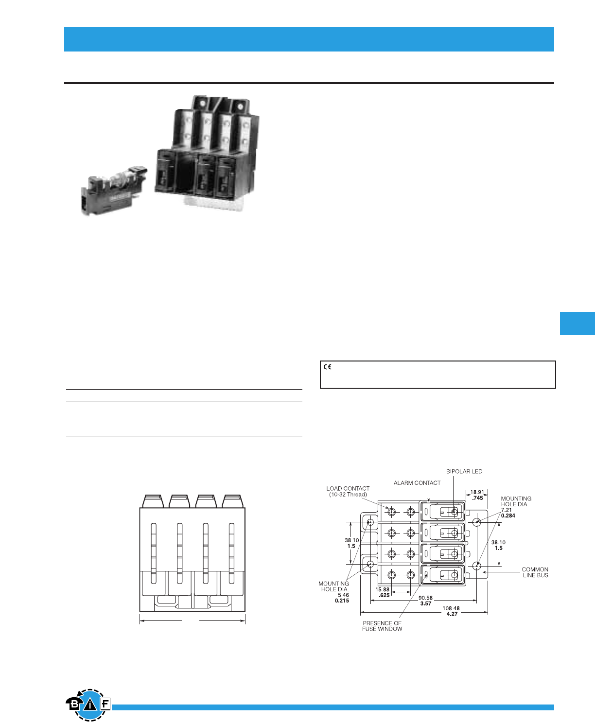
Bussmann®
177
For complete specification data, call Bussmann Information Fax ~ 636.527.1450
Telecommunications Protection
Data Sheet: 5011
Fused Disconnect Switch
• Front access load and line connection standard—double
lug load connections 8 AWG wire.
• Recognized branch circuit protection device.
• Modular design—4 poles per module up to four modules
banked together.
• Ease of installation—Connection directly to bus bar.
• Reduces external wiring—per pole.
• LED alarm signaling (LED current 30mA max.).
• Blown fuse indication.
• Alarm test probe point, to allow on-site checking of alarm
circuitry.
• Snap into alarm bus.
• Bi-polar LED provides capability for both –48Vdc
and +24Vdc applications.
• Fuse presence indication.
• Fuse orientation rejection feature.
• Totally enclosed module.
• Spare fuseholders: Part No. 5TPH and TPSFH-A
• Remote alarm.
• Contact Bussmann for options on standard module
(Hardware, Color, Front line connection, Mounting bezel).
76.07
3.0
TP15914
4 Pole Disconnect Switch and TPA Series Fuses
Ampere Rating: 50A per pole
Voltage Rating: 145Vdc
Agency Information:
UL recognized as a disconnect switch for interruption of
load current by means of withdrawing the fuse carrier.
UL recognized as a component for telecommunication
power distribution equipment (UL category QPQYZ).
UL recognized fuses for branch circuit protection.
CSA component acceptance for the system.
Material: UL rated 94V-0, 140°C rated
Fuse
Fuse Type TPA TPA-B
Current 3, 5, 10, 15, 20, 25, 30, 40, 50 20, 25
Voltage 170Vdc 65Vdc
Interrupting 100 kA 20 kA
UL Recognized, Guide JFHR2, File E56412
CSA Certified, Class 1422-30, File 53787
Dimensional Data
MM
Inches
TOP
CE logo denotes compliance with European Union Low Voltage Directive
(50-1000Vac, 75-1500Vdc). Refer to Data Sheet: 8002 or contact
Bussmann Application Engineering at 636-527-1270 for more information.
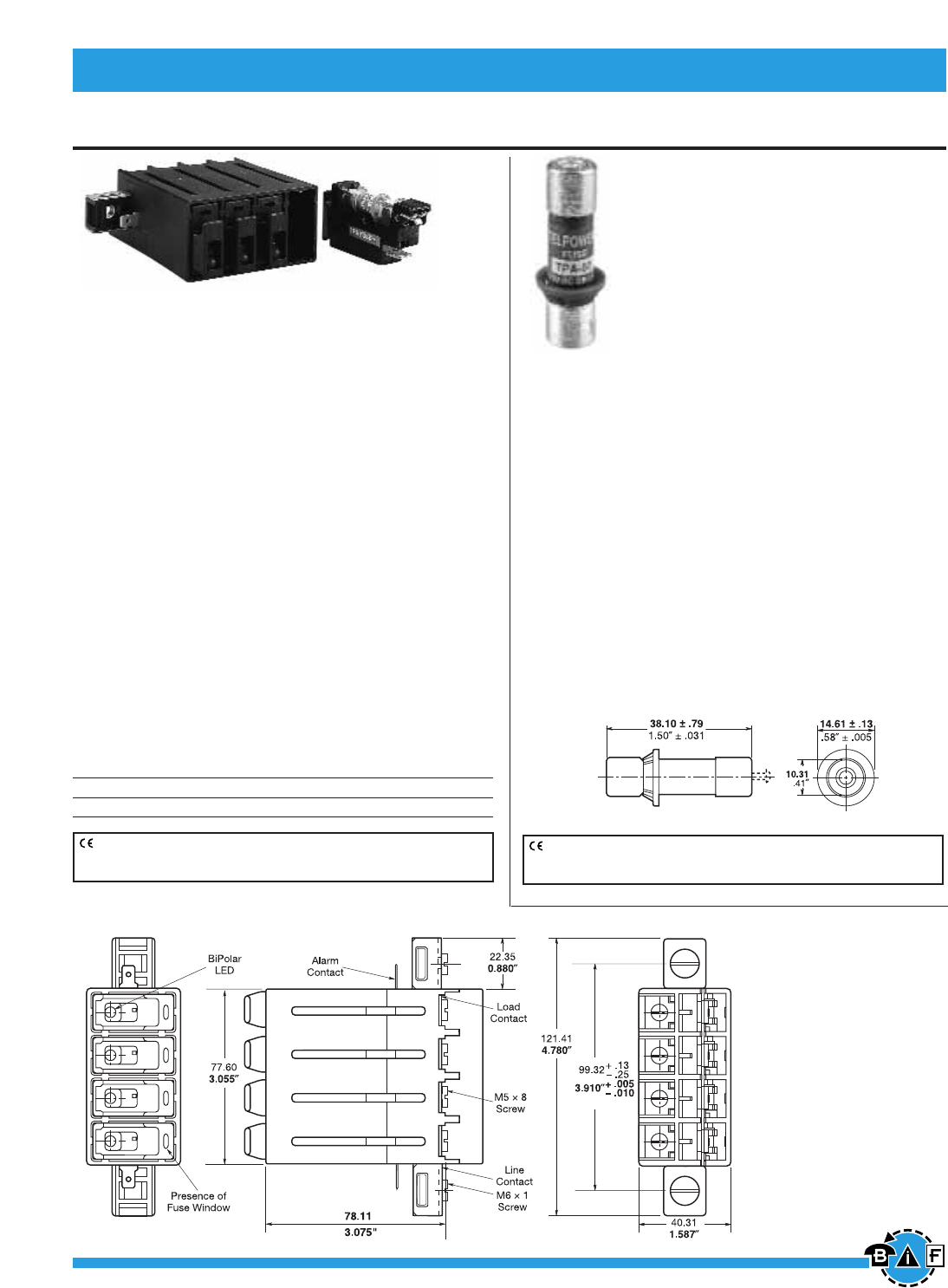
Bussmann®
178 For complete specification data, call Bussmann Information Fax ~ 636.527.1450
Telpower® DC Power Protection Systems
Dimensional Data
Data Sheet: 5001 Data Sheet: 5012
CE logo denotes compliance with European Union Low Voltage Directive
(50-1000Vac, 75-1500Vdc). Refer to Data Sheet: 8002 or contact
Bussmann Application Engineering at 636-527-1270 for more information.
CE logo denotes compliance with European Union Low Voltage Directive
(50-1000Vac, 75-1500Vdc). Refer to Data Sheet: 8002 or contact
Bussmann Application Engineering at 636-527-1270 for more information.
Fused Disconnect Switch & TPA Fuses
TP15900-4
4-Pole Disconnect Switch
For use with Telpower®fuses Type TPA & TPA-B.
Electrical Ratings: 40A per pole at 145Vdc
50A per pole at 80Vdc
Agency Information:
UL Recognized as a disconnect switch for interruption of
load current by means of withdrawing the fuse carrier.
UL Recognized as a component for telecommunication
power distribution equipment (UL category QPQY2).
UL Recognized fuses for branch circuit protection.
CSA Component Acceptance for the system.
General Information:
• Ease of installation - connection directly to bus bar.
• Reduces external wiring per pole.
• LED alarm signaling (LED current 30mA max.).
• Local and remote open-fuse indication.
• Alarm test probe point, to allow on-site checking of alarm
circuitry.
• Fuse presence indication.
• Fuse orientation rejection feature.
• Rear accessibility for line and load terminations.
Material: UL rated 94V-0, 140°C rated
Catalog Numbers
TP15900-4
TP15900-41 Split Alarm, Split Line
TPA & TPA-B
DC Power Distribution Indicating Fuses
Ampere Rating: TPA: 3, 5, 10, 15, 20, 25, 30, 40, 50
TPA-B: 20, 25, 30
Voltage Rating: TPA, 170 Vdc; TPA-B, 65 Vdc
Interrupting Rating: TPA, 100 kA; TPA-B, 20 kA
Agency Information:
UL Recognized, Guide JFHR2, File E56412
CSA Certified, Class 1422-30, File 53787
Construction:
• Silver-plated brass ferrules and indicator pin on TPA 3-15
and TPA-B. Tin-plated brass on TPA 20-50 on indicator
end.
• Glass melamine tube.
• Spare fuseholders: 5 position holder; 5TPH;
6 position holder; TPSFH-AS
Dimensional Data
mm
inches
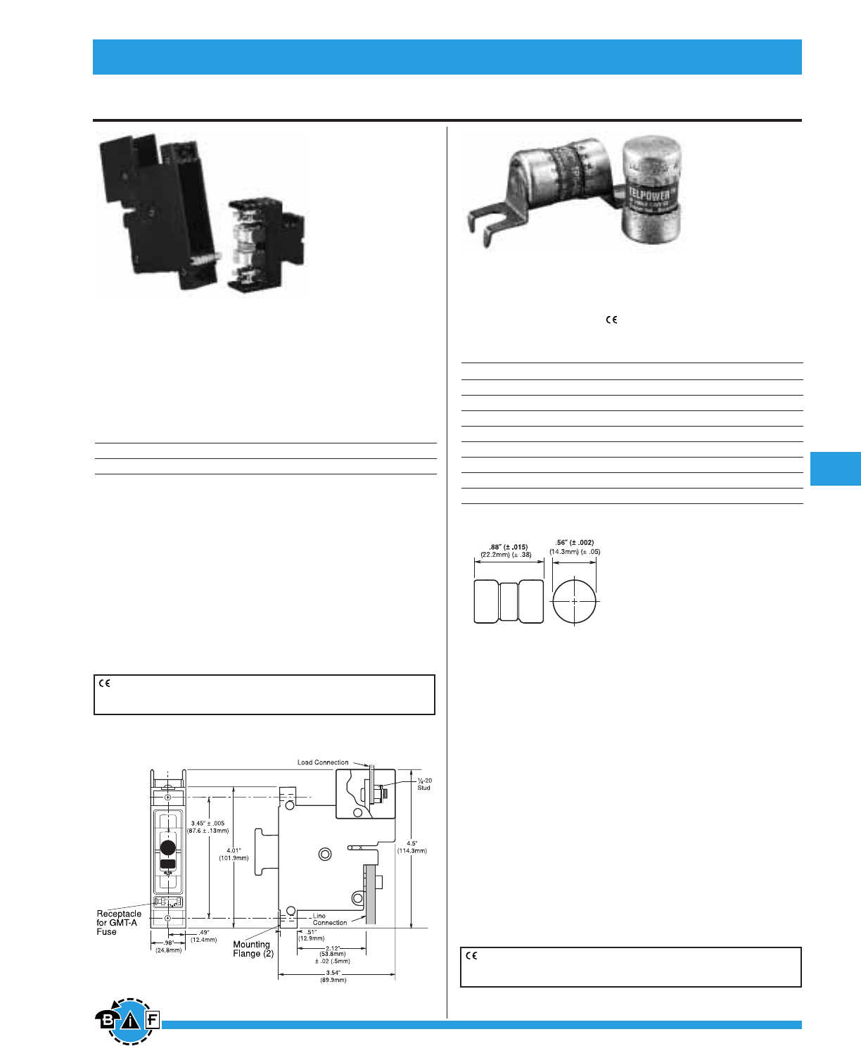
Fused Disconnect Switch
Data Sheet: 5002 Data Sheet: 5009
Bussmann®
179
For complete specification data, call Bussmann Information Fax ~ 636.527.1450
Telpower® DC Power Protection Systems
15800
Fused Disconnect Switch
Ampere Ratings: 3 to 70A.
Voltage Rating: 60Vdc
Agency Information:
UL Recognized, Guide QPQY2, File E97649
UL Withstand Rating: 100,000A,
Catalog Numbers
15800-R-200 Rear Access Panel Mounting
15800-F-200 Front Access Panel Mounting
• For use with the following fuses only:
Main: Telpower®TPS 3 to 70 Amp
Alarm: Bussmann GMT-A only (page 183).
Recommend GMT-X Cover (page 183).
• Alarm output with wire wrap terminal or connection to .063”
thick common alarm bus.
• Thermoplastic housing material UL rated
94V-0, 150°C.
• Spare alarm and power fuse compartment.
• Mounting hardware included.
• Spare fuseholders:
for TPS fuses (TPSFH-AS);
for GMT fuses (TPSFH-T), see page 196.
TPS
Ampere Ratings: 1 to 70A.
Voltage Rating: 170Vdc
Agency Information:
UL Recognized, Guide JFHR2, File E56412
Catalog Numbers
TPS-1 TPS-6L TPS-30 TPS-50V
TPS-1L TPS-10 TPS-30L TPS-60
TPS-2 TPS-10L TPS-35 TPS-60L
TPS-2L TPS-15 TPS-35L TPS-70
TPS-3 TPS-15L TPS-40 TPS-70L
TPS-3L TPS-20 TPS-40L TPS-70LB
TPS-5 TPS-20L TPS-40V —
TPS-5L TPS-25 TPS-50 —
TPS-6 TPS-25L TPS-50L —
• TELPOWER fuse line is the first to be specifically designed
to meet the unique needs of DC Power Distribution
Systems.
• The UL Recognized ratings of 170Vdc and 100,000A
interrupting rating along with the fuse’s current limiting
capability make this fuse ideal for cable protection on exist
ing DC Distribution Systems.
• A unique BLUE label is used on all TELPOWER fuses to
designate their DC capability.
• Circuit board applications available.
• Silver-plated brass ferrules.
• Glass melamine tube.
• For use with Bussmann Fused Disconnect Switch 15800.
• Spare Fuseholder: TPSFH-AS, see page 198.
• Printed circuit board variations available.
Dimensional Data
Dimensional Data
CE logo denotes compliance with European Union Low Voltage Directive
(50-1000Vac, 75-1500Vdc). Refer to Data Sheet: 8002 or contact
Bussmann Application Engineering at 636-527-1270 for more information.
CE logo denotes compliance with European Union Low Voltage Directive
(50-1000Vac, 75-1500Vdc). Refer to Data Sheet: 8002 or contact
Bussmann Application Engineering at 636-527-1270 for more information.
15800-R-200
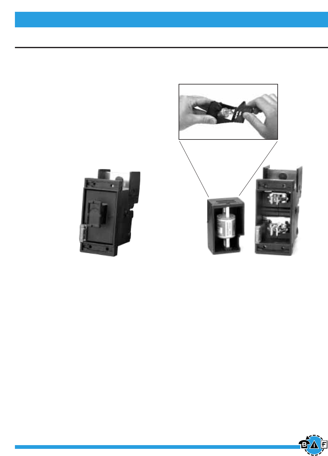
Bussmann®
180 For complete specification data, call Bussmann Information Fax ~ 636.527.1450
Data Sheet: 5021
Fused Disconnect Switch TP158HC
Telpower®DC Power Protection Systems
General Information:
• High amp version of Bussmann 15800 series
Fused Disconnect Switch.
• Similar profile, mounting method, and backplane
configuration as 15800 Series. The TP158HC
can be installed into existing 15800 Series panels
using the space of two 15800 disconnects.
• Innovative new fuse pullout design eliminates
need for tools to replace the Telpower® type
TPL-B fuse.
• For use with the following fuses only:
Main: Telpower® TPL-B 70-250 Amperes.
Alarm: Bussmann GMT-A only.
• Alarm output with wire wrap terminal or connection to
.063 inch (1.6mm) thick common alarm bus.
• Hardware included:
Load: washer, split lockwasher, and 5/16 _18 nut
(metric-M8 x 1.25)
• Thermoplastic housing material UL rated 94V-0, 150°C.
• Spare fuseholders:
for TPL-B fuses (TPSFH-LB), see page 14;
for GMT fuses (TPSFH-T), see page 14.
• Application Note: The line connection uses a 1/4-20 bolt
(metric – M6X1) that threads into the line terminal. The line
terminal is designed with a float of ±.02 in. (± .50mm) to
allow for variation in the distance between the TP158HC
mounting flange and the line bus bar (see dimensional
data). Equipment should be designed to eliminate any rel-
ative movement between the TP158HC mounting flange
and the line bus bar.
• Application Note: The alarm circuit is not intended for
precharging of capacitive circuits. Alarm circuit current
1A maximum.
TP158HC
Fused Disconnect Switch
For use with Telpower® Fuses Type TPL-B.
Ampere Ratings: 70-250A
Voltage Rating: 80Vdc
UL Withstand Rating: 100,000A
Agency Information:
UL Recognized (investigated to UL 1801) as a
disconnect switch for the interruption of load current
by means of withdrawing the fuse pullout.
Guide QPQY2, File E97649.
Catalog Numbers:
TP158HC: Rear Access, Panel Mounting, English
TP158HC: Rear Access, Panel Mounting, Metric
Easy Fuse Replacement
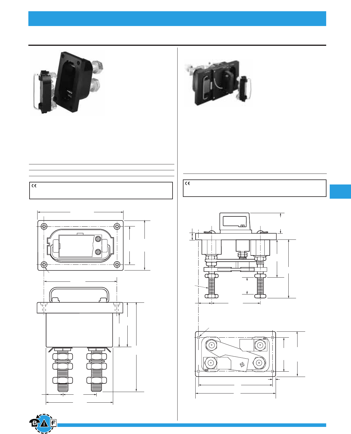
Bussmann®
181
For complete specification data, call Bussmann Information Fax ~ 636.527.1450
Data Sheet: 5003 Data Sheet: 5004
Telpower® DC Power Protection Systems
Fused Disconnect Switches
15100
Fused Disconnect
System
For use with Telpower®
Fuses Type TPL.
Ampere Ratings: 70-800A.
Voltage Rating: 60Vdc
UL Withstand Rating: 100,000A
Agency Information:
UL Recognized, Guide QPQY2, File E97649
Catalog Numbers
15100-401 For Use With TPL series fuses 70-400A
15100-601 For Use With TPL series fuses 300-800A
15200
Fused Disconnect
System
For use with Telpower®
Fuses Type TPL.
Ampere Ratings: 70-800A
Voltage Rating: 60Vdc
UL Withstand Rating: 100,000A
Agency Information:
UL Recognized, Guide QPQY2, File E97649
Catalog Numbers
15200-602 For Use With TPL 70 to 800A
Dimensional Data 15200-602
0.27" (6.75mm) Dia. Hole with 0.5" (12.7mm)
Dia. x 0.16" (3.97mm) Deep C'bore (4 Holes)
2.63"
(66.67mm)
1.31"
(33.33mm)
4"
(101.6mm)
3"
(76.2mm)
5.25"
(133.35mm)
7.13"
(181.10mm)
3.63"
(92.07mm)
2.75"
(69.85mm)
6.75"
(171.45mm)
5.75"
(146.05mm)
7.25"
(184.15mm)
0.88"
(22.22mm)
#14 Thd.
0.31" (7.93mm) #18 Tap x 0.5" (12.7mm) Deep (4 Holes)
11"
(279.4mm)
0.5"
(12.7mm)
12"
(304.8mm)
1"
(25.4mm)
8.69"
(220.66mm)
5.86"
(149.22mm)
3"
(76.2mm)
2"
(50.8mm)
1.88"
(47.62mm)
6.75"
(171.45mm)
5"
(127.0mm)
Dimensional Data 15100-401
CE logo denotes compliance with European Union Low Voltage Directive
(50-1000Vac, 75-1500Vdc). Refer to Data Sheet: 8002 or contact
Bussmann Application Engineering at 636-527-1270 for more information.
CE logo denotes compliance with European Union Low Voltage Directive
(50-1000Vac, 75-1500Vdc). Refer to Data Sheet: 8002 or contact
Bussmann Application Engineering at 636-527-1270 for more information.
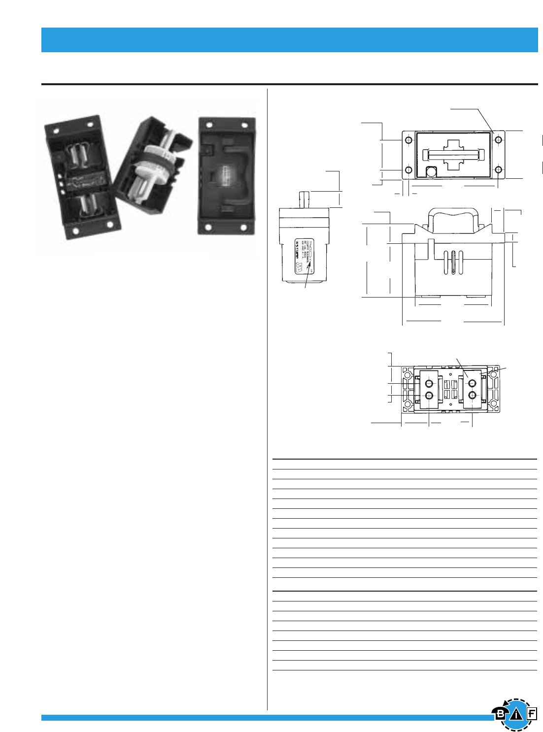
Bussmann®
182 For complete specification data, call Bussmann Information Fax ~ 636.527.1450
Telpower® DC Power Protection Systems
Telpower
®
High Current Switch
Data Sheet: 5020
TPHCS
Telpower®High Current Switch
For use with Telpower®Fuses Type TPL-B, TPL-C
and TPH.
Ampere Ratings: 70 to 800A
Voltage Rating: 80Vdc
UL Withstand Rating: 100,000A
Agency Information:
UL Recognized (investigated to UL 1801) as a
disconnect switch for the interruption of load current
by means of withdrawing the fuse carrier.
UL Recognized to meet the requirements for Canadian
Standards.
General Information:
• Innovative new design eliminates need for tools to
replace the Telpower®type TPL-B, TPL-C or
TPH fuse.
• Easy to install–captive fasteners allow for direct
busbar mounting (bolts not included).
• Optional new electronic alarm provides both local
and remote open-fuse indications.
—Bipolar alarm designed for both Central Office and
Radio applications.
—Local LED alarm indication for ease-of-viewing.
—Standard ⁄Ω¢∑ male quick-connect terminal for
effortless remote alarm connection (Maximum
remote alarm current: 20mA).
—Eliminates need for parallel indicating fuses.
• Fuse presence window allows for easy viewing of
installed fuse ampere rating.
• Compact design for today’s high power, high-density
cabinets.
• Available as complete switch or pullout and base
may be purchased separately.
Catalog Numbers-Switches (Pullout and Base) Series Fuse Ampere Rating
TPHCS250-M High Current Switch, Metric TPL-B 70 to 250A
TPHCS250-E High Current Switch, English TPL-B 70 to 250A
TPHCS250-ML High Current Switch, Metric, LED TPL-B 70 to 25 A
TPHCS250-EL High Current Switch, English, LED TPL-B 70 to 250A
TPHCS250-MAV High Current Switch, Metric, Alarm TPL-B 70 to 250A
TPHCS250-EAV High Current Switch, English, Alarm TPL-B 70 to 25 A
TPHCS800-M High Current Switch, Metric TPL-C or TPH 300 to 800A
TPHCS800-E High Current Switch, Englis TPL-C or TPH 300 to 800A
TPHCS800-ML High Current Switch, Metric, LED TPL-C or TPH 300 to 800A
TPHCS800-EL High Current Switch, English, LED TPL-C or TPH 300 to 800A
TPHCS800-MAV High Current Switch, Metric, Alarm TPL-C or TPH 300 to 800A
TPHCS800-EAV High Current Switch, English, Alarm TPL-C or TPH 300 to 800A
Catalog Numbers – Components
Series Fuse Ampere Rating
TPHCS250-P Pullout only – 250 A TPL-B 70 to 250A
TPHCS800-P Pullout only – 800 A TPL-C or TPH 300 to 800A
TPHCS-B-M Base only, Metric — 800A Max.
TPHCS-B-E Base only, English — 800A Max.
TPHCS-B-ML Base only, Metric, LED — 800A Max.
TPHCS-B-EL Base only, English, LED — 800A Max.
TPHCS-B-MAV Base only, Metric, Alarm — 800A Max.
TPHCS-B-EAV Base only, English, Alarm — 800A Max
.
TPHCS800-MAV (shown)
TPHCS-Dimensional Data mm
(in)
NOTES:
1. TPHCS250 and
TPHCS800
pullouts and bases
are the same with
exception to the
type of fuse, TPL-B,
TPL-C or TPH the
pullout will carry.
2. Plastic rated UL94
V-0, 140°C RTI.
22.2
(0.88)
41.02
(1.615)
Ø
7.62
(0.300)
Typ. 4
12.7
(0.50)
74.6
(2.94)
25.9
(1.02)
122.43
(4.820)
8.8
(0.34)
See table for part
number format
▲
▲
▲
▲
▲
▲
▲
▲
▲
▲
▲
▲
▲
▲
▲
100.5 REF
(3.96)
▲
▲
▲
▲
▲
▲
▲
66.4
(2.62)
▲
▲
105.2
(4.14)
▲
▲
Threaded Insert, 4 Places
M8x1.25 (-M Series) 5/16-18 (-E Series)
Recommended Torque 15N • m (11 Ft-lb)
Tin Plated
Copper
Terminals
▲
▲
▲
▲
139.7
(5.50)
24.8 REF
(0.98)
39.2 REF
(1.54)
16.76
(0.660)
▲
▲
▲
13.2
(0.52)
17.3
(0.68)
▲
▲
▲
61.47
(2.420)
▲
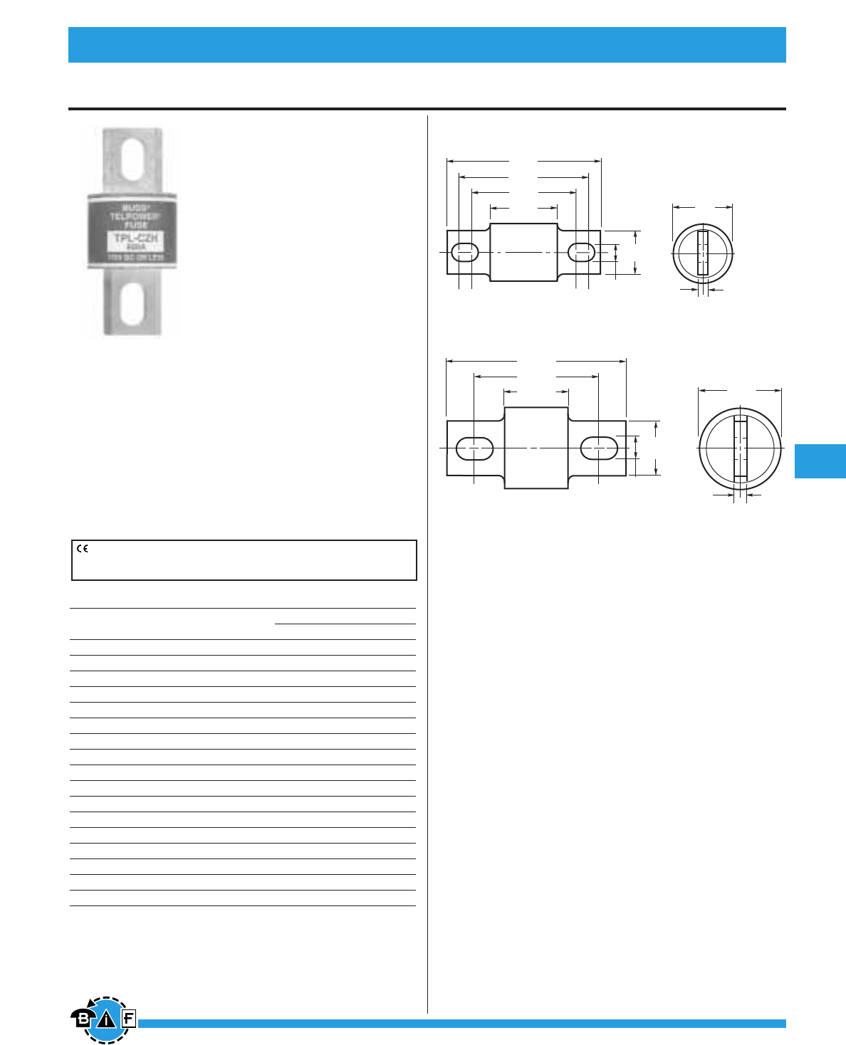
Bussmann®
183
For complete specification data, call Bussmann Information Fax ~ 636.527.1450
Telpower® DC Power Protection Systems
Telpower
®
Fuses, 70-600 Amps, 170 Volts DC
Data Sheet: 5005
TPL
DC Power Distribution Fuses
Ampere Ratings: 70-800A
Voltage Rating: 170Vdc
Current Limiting
Interrupting Rating: 100,000A
Construction: Silver-Plated Terminals
Agency Information:
UL Recognized Guide JFHR2, File E56412
Bellcore
Ordering Information:
TPL Telpower®(170Vdc)
Catalog Ampere Carton Weight*
Number Rating Qty. Lbs. Kg.
TPL-BA 70 5 .93 .42
TPL-BB 80 5 .93 .42
TPL-BC 90 5 .93 .42
TPL-BD 100 5 .93 .42
TPL-BE 125 5 .93 .42
TPL-BF 150 5 .93 .42
TPL-BG 175 5 .93 .42
TPL-BH 200 5 .93 .42
TPL-BK 225 5 .93 .42
TPL-BL 250 5 .93 .42
TPL-CN 300 1 .49 .22
TPL-CO 350 1 .49 .22
TPL-CR 400 1 .49 .22
TPL-CU 450 1 .49 .22
TPL-CV 500 1 .49 .22
TPL-CZ 600 1 .49 .22
TPL-CZH 800 1 .49 .22
*Weight per carton.
• Designed for DC power distribution systems.
• Recognized branch circuit protection.
• Current-limiting capability.
• Complete system coordination capability.
• Energy savings with low watts loss, low operating tempera-
tures, and minimum I2t levels.
• Use with Telpower 15100, 15200, TP158HC and TPHCS
disconnect systems.
• For replacement of Bussmann’s UBO fuses a TPL-TA adap-
tor kit is necessary.
• Spare fuseholders:
TPSFH-LB (for TPL-B fuses)
TPSFH-LC (for TPL-C fuses)
Dimensional Data
CE logo denotes compliance with European Union Low Voltage Directive
(50-1000Vac, 75-1500Vdc). Refer to BIF document #8002 or contact
Bussmann Application Engineering at 636-527-1270 for more information.
.33"
(8.3mm)
2.66"
(67.5mm)
2.19"
(55.6mm)
1.91"
(48.4mm)
1.16"
(29.4mm)
BUSS
TPL–BL
.75"
(19.1mm)
.19"
(4.8mm)
1.0"
(25.4mm)
.25"
(6.4mm)
1.50"
(38.1mm)
TPL-BA, TPL-BD, TPL-BF, TPL-BH, TPL-BK, AND TPL-BL
TPL-CN, TPL-CR, TPL-CV, AND TPL-CZ
3.50"
(88.9mm)
2.44"
(61.9mm)
1.25"
(31.8mm)
1.00"
(25.4mm)
.41"
(10.3mm)
BUSS
TPL–CZ
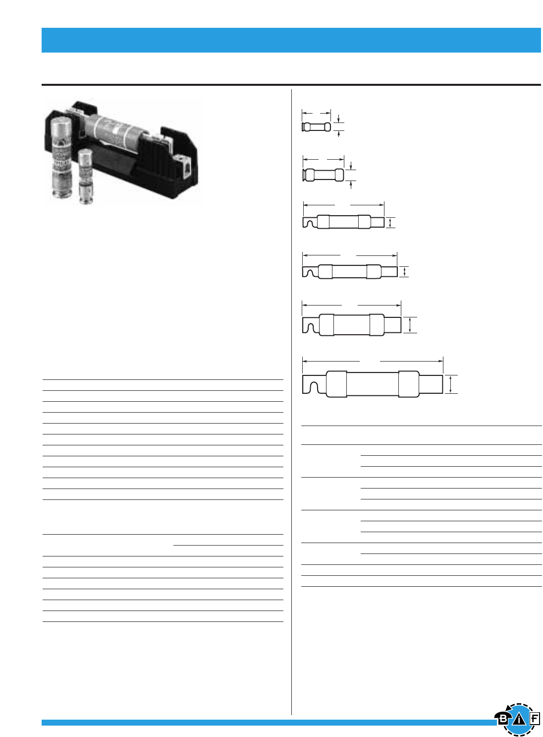
Bussmann®
184 For complete specification data, call Bussmann Information Fax ~ 636.527.1450
Data Sheet: 5006
Telpower
®
Fuses, 1-600 Amps, 170 Volts DC
TPN
Current Limiting
DC Power Distribution Fuses
Ampere Ratings: 1-600A
Voltage Rating: 170Vdc
Interrupting Rating: 100,000A
Construction: Silver-Plated Terminals
Agency Information:
UL Recognized, Guide JFHR2, File E56412
Catalog Numbers
TPN-1 TPN-45 TPN-200
TPN-3 TPN-50 TPN-225
TPN-5 TPN-60 TPN-250
TPN-6 TPN-70 TPN-300
TPN-10 TPN-80 TPN-350
TPN-15 TPN-90 TPN-400
TPN-20 TPN-100 TPN-450
TPN-25 TPN-110 TPN-500
TPN-30 TPN-125 TPN-600
TPN-35 TPN-150
TPN-40 TPN-175
Carton Quantity and Weight
TPN Telpower (170Vdc)
Catalog Carton Weight*
Number Qty. Lbs. Kg.
1-30 10 0.45 0.204
35-60 10 1.82 0.824
70-100 5 1.85 0.838
110-200 1 1.05 0.476
225-400 1 2.38 1.078
450-600 1 3.50 1.587
*Weight per carton.
• Designed for DC power distribution systems.
• The TPN series of fuses are dimensionally similar to Class R
fuses.
• Recognized branch circuit protection.
• Current-limiting capability.
Recommended Class R Fuseblocks
Catalog
Amps Poles Number
1 R25030-1CR
1to 30 2 R25030-2CR
3 R25030-3CR
1 R25060-1CR
35 to 60 2 R25060-2CR
3 R25060-3CR
1 R25100-1CR
70 to 100 2 R25100-2CR
3 R25100-3CR
110 to 200 1 R25200-1CR
3 R25200-3CR
225 to 400 1 R25400-1CR
450 to 600 1 R25600-1CR
0.81"
(20.6mm)
3"
(76.2mm)
35A to 60A
2"
(50.8mm)
0.56"
(14.3mm)
1A to 30A
5.88"
(149.2mm)
70A to 100A
7.13"
(181.0mm)
110A to 200A
225A to 400A
8.63"
(219.1mm)
450A to 600A
10.38"
(263.5mm)
2.50"
(63.5mm)
2.00"
(50.8mm)
1.50"
(38.1mm)
1.00"
(25.4mm)
• Complete system coordination capability.
• Energy savings with low watts loss, low operating tempera-
tures, and minimum I2t levels.
• Spare fuseholders:
TPSFH-N30 (for TPN 1-30)
TPSFH-N60 (for TPN 35-60)
Telpower® DC Power Protection Systems
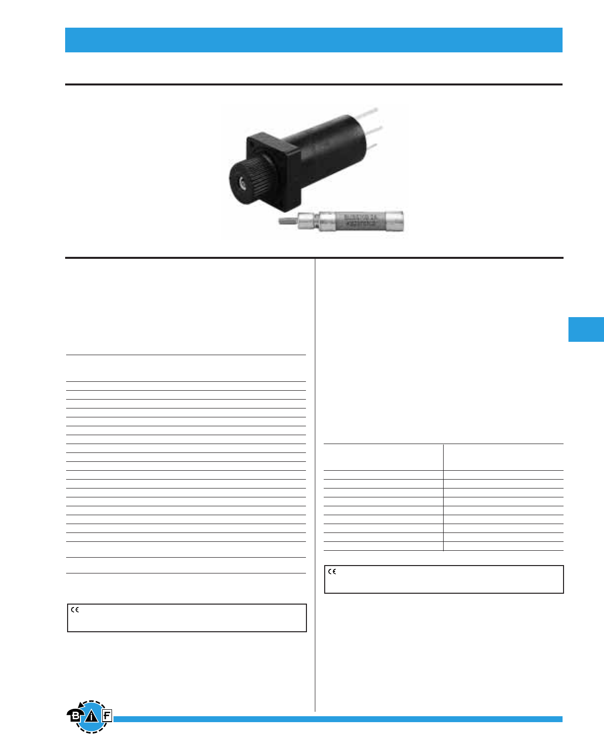
Bussmann®
185
For complete specification data, call Bussmann Information Fax ~ 636.527.1450
Telpower® DC Power Protection Systems
Data Sheet: 5007 Data Sheet: 5007
Indicating Fuse & Holder
70 Series
Indicating Type Fuse
Voltage Rating: 125Vac; 300Vdc
Agency Information:
UL Recognized, Guide JDYX2, File E19180
Bellcore
70 Series Telpower (125Vac, 300Vdc)
Lucent
Catalog Ampere Voltage Rating Color Comcode Code/
Number Rating AC DC Code Ref. No. List No.
70P-⁄Ω¡ºA* ⁄Ω¡º 125V 300V Gray/Wh 100203413 KS23751-L10
70R-⁄fiΩ¡ººA* ⁄fiΩ¡ºº 125V 300V Red/Wh 101384550 KS23751-L11
70E-⁄°Ω¡ººA* ⁄°Ω¡ºº 125V 300V Yellow 100203363 KS23751-L5
70X-¤Ω¡ºA¤Ω¡º 125V 300V Black — —
70F-⁄Ω¢A* ⁄Ω¢ 125V 300V Violet 100203371 KS23751-L6
70K-⁄Ω¢A* ⁄Ω¢ 125V 300V Violet/Wh 100203405 KS23751-L9
70G-⁄Ω™A* ⁄Ω™ 125V 300V Red 100203389 KS23751-L7
70H-‹Ω¢A* ‹Ω¢ 125V 300V Brown 100203397 KS23751-L8
70I-1A 1 125V 300V Pink — —
70A-1-⁄Ω£A* 1⁄Ω£ 125V 300V White 100203322 KS23751-L1
70B-2A* 2 125V 300V Orange 100203330 KS23751-L2
70C-3A* 3 125V 300V Blue 100203348 KS23751-L3
70J-3⁄Ω™A3⁄Ω™ 125V 300V Black/Wh — —
70D-5A* 5 125V 300V Grn/Blk 100203355 KS23751-L4
70L-6A 6 125V 300V Grn/Wh — —
70M-8A 8 125V 300V Brown/Wh — —
70N-10A 10 125V 300V Violet/Yel — —
GKB-10A 10 125V 300V Violet/Yel — —
72A Dummy — — — 100203421 —
Plastic Case
72B Dummy — — — 103757977 —
Blister Pack
*Product designed to comply with Bellcore Technical Reference TR-TSY-000799 Issue 1,
December 1988.
15087 Fuseholder
For 70 Series Fuses
Ampere Ratings: 12A
Voltage Rating: 300Vdc
Agency Information:
UL Recognized, Guide IZLT2, File E14853
Construction:
Body: Thermoplastic, UL 94VO flammability rating
Terminals: Copper alloy, tin plating
Screws: 3-24 ≈ ‹Ω•∑ steel, zinc plated
• Panel mount fuseholder for 70 Type fuses supplied with
two screws.
• Remote alarm capability.
Optional Color Code Eyelets (order separately)
Amp Amp
Catalog Rating Color Catalog Rating Color
Symbol Ref. Code Symbol Ref. Code
1A1706-01 ⁄°Ω¡ºº Yellow 1A1706-10 3 Blue
1A1706-02 ¤Ω¡º Black 1A1706-11 5 Green/Black
1A1706-03 ⁄Ω¢ Violet 1A1706-12 6 Green/White
1A1706-04 ⁄Ω¢ Violet/White 1A1706-13 8 Brown/White
1A1706-05 ⁄Ω™ Red 1A1706-14 10 Violet/Yellow
1A1706-06 ‹Ω¢ Brown 1A1706-15 ⁄Ω¡º Gray/White
1A1706-07 1 Pink 1A1706-16 3⁄Ω™ Black/White
1A1706-08 1⁄Ω£ White 1A1706-17 ⁄fiΩ¡ºº Red/White
1A1706-09 2 Orange — — —
CE logo denotes compliance with European Union Low Voltage Directive
(50-1000Vac, 75-1500Vdc). Refer to Data Sheet: 8002 or contact
Bussmann Application Engineering at 636-527-1270 for more information.
CE logo denotes compliance with European Union Low Voltage Directive
(50-1000Vac, 75-1500Vdc). Refer to Data Sheet: 8002 or contact
Bussmann Application Engineering at 636-527-1270 for more information.
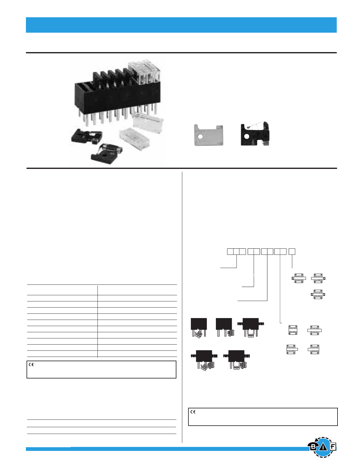
Bussmann®
186 For complete specification data, call Bussmann Information Fax ~ 636.527.1450
Data Sheet: 5008
Indicating Fuses & Holders
Data Sheet: 5010
GMT
Fast Acting Fuses
Voltage Rating: 60Vdc; 125Vac
Interrupting Rating: 450A, 60Vdc;
300A, 125Vac
Agency Information:
UL Recognized, Guide JFHR2, File E56412
Materials:
Body: Thermoplastic, UL 94VO flammability rating
Terminals: Tin-plated Beryllium copper
Carton Qty. and Weight: 100 Fuses per carton;
0.33 lbs. (150g)
Fuseholders: Catalog No. HLT, HLS, and PCT
Spare Fuseholder: TPSFH-T
Catalog Numbers
Catalog Color Catalog Color
Symbol Code Symbol Code
GMT-⁄°Ω¡ººA Yellow GMT-3A Blue
GMT-⁄Ω¢A Violet GMT-3⁄Ω™A White/Blue
GMT-‹Ω•A White/Gray GMT-4A White/Brown
GMT-⁄Ω™A Red GMT-5A Green
GMT-flfiΩ¡ººA Black GMT-7⁄Ω™A Black/White
GMT-‹Ω¢A Brown GMT-10A Red/White
GMT-1A Gray GMT-12A Yellow/Green
GMT-1⁄Ω£A White GMT-15A Red/Blue
GMT-1⁄Ω™A White/Yellow GMT-Dummy Gray Body
GMT-2A Orange GMT-X Clear Cover
HLS, HLT, PCT
Fuseholders for GMT Type Indicating Fuses
Voltage Rating: 60Vdc; 125Vac
Agency Information:
UL Recognized, Guide IZLT2, File E14853, 15A (60Vdc)
Materials:
Body: Thermoplastic, UL 94VO flammability rating
Terminals: Tin-plated copper
Multiple Fuseholders with bus bars
Ordering Information— Catalog No.
Type of bus bars used***
B1*, B2, B3,
B4, B5, SL** (Short Leads .135")
ML** (Medium Leads .250")
** Not available with bus bars
Bus Bar Position
P4
(Outside—
Left Only)
P3
(Outside—
Right Only)
P2
(Outside—
Both Sides)
P1†
(Inside—
Both Sides)
B3
(“U” Bar Only)
B2
(“L” Bar Only)
B1
(Angle Bar Only)*
B5
(“L” & “U” Bars)
B4
(Angle & “L” Bars)
Body Style HLT
HLS (No flanges)
No. of Poles 01 thru 25
(Min. of 2 poles required for bus bars)
Termination Location
B
(Both ends)
L
(Left only)
R
(Right only)
*Angle Bar mounts on common or center terminals only.
**SL Version is not available with bus bars.
†Minimum of 4 Poles Required.
***.38 max. leads if not specified.
CE logo denotes compliance with European Union Low Voltage Directive
(50-1000Vac, 75-1500Vdc). Refer to Data Sheet: 8002 or contact
Bussmann Application Engineering at 636-527-1270 for more information.
CE logo denotes compliance with European Union Low Voltage Directive
(50-1000Vac, 75-1500Vdc). Refer to Data Sheet: 8002 or contact
Bussmann Application Engineering at 636-527-1270 for more information.
GMT - Dummy GMT - A (Alarm)
Some GMT sizes may be sold in bulk pack only.
GMT-A
•The GMT-A is designed specifically for use in the Telpower®
series 15800 Fused Disconnect Switch (page 177).
• The GMT-A has the same ratings and agency approvals
as the standard GMT fuses as shown above.
Catalog Symbol Color Code
GMT-AYellow
Telpower® DC Power Protection Systems
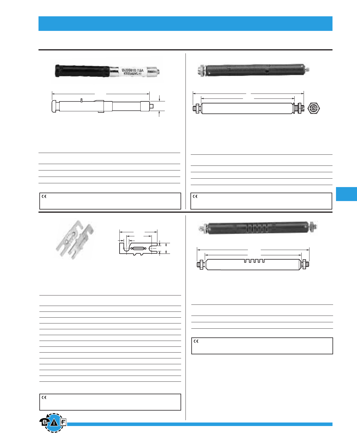
187
For complete specification data, call Bussmann Information Fax ~ 636.527.1450
Telecommunications Protection Bussmann®
For complete specification data, call Bussmann Information Fax ~ 636.527.1450
Telpower® DC Power Protection Systems
Telpower
®
Specialty Fuses
CE logo denotes compliance with European Union Low Voltage Directive
(50-1000Vac, 75-1500Vdc). Refer to Data Sheet: 8002 or contact
Bussmann Application Engineering at 636-527-1270 for more information.
CE logo denotes compliance with European Union Low Voltage Directive
(50-1000Vac, 75-1500Vdc). Refer to Data Sheet: 8002 or contact
Bussmann Application Engineering at 636-527-1270 for more information.
CE logo denotes compliance with European Union Low Voltage Directive
(50-1000Vac, 75-1500Vdc). Refer to Data Sheet: 8002 or contact
Bussmann Application Engineering at 636-527-1270 for more information.
CE logo denotes compliance with European Union Low Voltage Directive
(50-1000Vac, 75-1500Vdc). Refer to Data Sheet: 8002 or contact
Bussmann Application Engineering at 636-527-1270 for more information.
81 Type
Description: Cylindrical, fast acting, non-indicating high
current companion to the 80 Type. UL Recognized, Guide
JDYX2, File E19180.
Catalog Data
Catalog Ampere Voltage Rating Color Lucent Comcode Code/
Symbol Rating ac dc Code Ref. No. List No.
81B-7⁄Ω™ 7.5 250V 65V Gray 103828141 KS23824-L12
81A-10 10 250V 65V Yellow 103752176 KS23824-L11
81C-12 12 250V 65V Lt Blue 104391842 KS23824-L13
7 Type
Description: Fiber tube, threaded ends. Typically used
on wall type main distribution frames and central battery
substations.
24 and WER Type
Description: Flat, nonindicating visible link element mounted
on 1 inch centers using either No. 6 or No. 10 screws.
Catalog Data
Catalog Ampere dc Color Lucent Comcode Dimension
Symbol Rating Volt. Code Ref. No. A Length
WER-⁄Ω¢ ⁄Ω¢ 32V — — —
24E-⁄Ω™*⁄Ω™ 60V Red 100202894 .200
24D-‹Ω¢*‹Ω¢ 60V Black 100202886 .150
WER-1 1 32V — — —
24G-1⁄Ω£*1⁄Ω£ 60V White 100202910 .200
24C-2*2 60V Orange 100202878 .200
24B-3*3 60V Blue 100202852 .150
WER-3⁄Ω™ 3⁄Ω™ 32V — — —
24B-4*4 60V Yellow 100202860 .150
24F-5*5 60V Green 100202902 .150
WER-8 8 32V — — —
WER-10 10 32V — — —
64A-Dummy — — — 100203280 —
*Designed to comply with Bellcore Technical Reference TR-TSY-000799 Issue 1, Dec. 1988.
.280"
(7.11mm)
2.685"
(68.20mm)
Dimensional Data
4.062"
4.625"
Dimensional Data
4.093"
A
Dimensional Data
A .375"
A
.938"
1.406"
Dimensional Data
Catalog Data
Catalog Ampere Lucent Comcode Dimension
Symbol Rating Ref. No. A Length
7 Type
7A-7 7 100863737 4.562
7T-7 7 100202753 4.828
11 Type
Description: Fiber tube, threaded ends, identical to 7 Type
except for vent slots in fiber tube.
Catalog Data
Catalog Ampere Lucent Comcode Dimension
Symbol Rating Ref. No. A Length
11 Type
11C-7 7 100863745 —
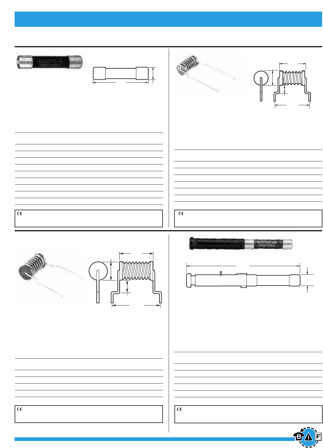
Bussmann®
188 For complete specification data, call Bussmann Information Fax ~ 636.527.1450
Telpower
®
Specialty Fuses
75 Type
Description: Cylindrical with leads, designed to provide
protection against currents resulting from the application of
foreign voltages. Application for data sets and telephones.
Catalog Data
Catalog Ampere Voltage Rating Lucent Comcode Code/
Symbol Rating AC DC Ref. No. List No.
75C .007 135V 440V 103260816 KS23825-L3
75F .063 135V 220V 104172861 KS23825-L6
75B .115 135V 220V 102732112 KS23825-L2
75D .129 135V 220V 104013180 KS23825-L4
75A .200 135V 220V 102660008 KS23825-L1
75E .230 135V 220V 104015292 KS23825-L5
74 Type
Description: .281∑ ≈ 1.25∑cylindrical fuse, fast acting.
Designed to comply with Lucent specification KS23753.
High current companion to 70 Type Fuse.
Catalog Data
Catalog Ampere Voltage Rating Lucent Comcode Code/
Symbol Rating DC Ref. No. List No.
74A-1⁄Ω¢ 1⁄Ω¢ 60V 102630290 KS23753-L1
74G-2 2 60V 103064952 KS23753-L7
74B-3 3 60V 102630308 KS23753-L2
74H-4 4 60V 103264669 KS23753-L8
74C-5 5 60V 102630316 KS23753-L3
74J-7⁄Ω™ 7⁄Ω™ 60V 103228425 KS23753-L9
74D-10 10 60V 102630324 KS23753-L4
74E-15 15 60V 102630332 KS23753-L5
74F-20 20 60V 102630340 KS23753-L6
1.25"
(31.75mm) .281"
(7.14mm)
Dimensional Data
BUSS
——A
.445"
(11.30mm)
.320"
(8.13mm)
1.125"
(28.58mm)
.830"
(21.08mm)
Dimensional Data
.280"
(7.11mm)
2.685"
(68.20mm)
Dimensional Data
.190"
(4.83mm)
.325"
(8.26mm)
.620"
(15.75mm)
.800"
(20.32mm)
BUSS
——A
Dimensional Data
76 Type
Description: Cylindrical with leads, designed to provide
protection against currents resulting from the application of
foreign voltages. Application for data sets and telephones.
Catalog Data
Catalog Ampere Voltage Rating Lucent Comcode Code/
Symbol Rating AC DC Ref. No. List No.
76D .012 135V 440V 103798245 KS23825-L10
76B .191 135V 440V 102965688 KS23825-L8
76A .231 135V 440V 102810181 KS23825-L7
76C .412 135V 440V 103656625 KS23825-L9
80 Type
Description: A fuse designed for high reliability applications
where high ambient temperatures, low circuit voltages, low
power dissipation and low contact resistance are prime con-
siderations. The 80 Type is a visual indicating fuse with remote
electrical alarm capability. UL Recognized, Guide JDYX2,
File E19180.
Catalog Data
Catalog Ampere Voltage Rating Color Lucent Comcode Code/
Symbol Rating AC DC Code Ref. No. List No.
80G-⁄Ω™ .50 250V — Red 103839916 KS23824-L6
80M-1⁄Ω£ 1.33 250V — White 408078657 KS23824-L8
80B-2 2 250V — Orange 103752150 KS23824-L2
80C-3 3 250V — Blue 103752168 KS23824-L3
80D-5 5 250V — Green 103800637 KS23824-L4
CE logo denotes compliance with European Union Low Voltage Directive
(50-1000Vac, 75-1500Vdc). Refer to Data Sheet: 8002 or contact
Bussmann Application Engineering at 636-527-1270 for more information.
CE logo denotes compliance with European Union Low Voltage Directive
(50-1000Vac, 75-1500Vdc). Refer to Data Sheet: 8002 or contact
Bussmann Application Engineering at 636-527-1270 for more information.
CE logo denotes compliance with European Union Low Voltage Directive
(50-1000Vac, 75-1500Vdc). Refer to Data Sheet: 8002 or contact
Bussmann Application Engineering at 636-527-1270 for more information.
CE logo denotes compliance with European Union Low Voltage Directive
(50-1000Vac, 75-1500Vdc). Refer to Data Sheet: 8002 or contact
Bussmann Application Engineering at 636-527-1270 for more information.
Telecommunications Protection

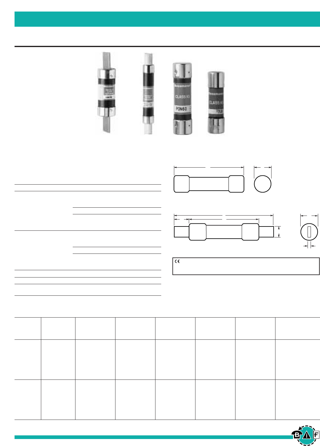
190 For complete specification data, call Bussmann Information Fax ~ 636.527.1450
Bussmann®
CSA Type P and Type D Fuses
British, European, & Canadian Standard Industrial Fuses
CDS, CDN & PON
Voltage Ratings: 250V (CDN & PON) & 600V (CDS)
Interrupting Rating: 10kA minimum
Agency Information: CSA Certified to C22.2 No. 59.1
Time-Delay CSA Type “D”
Volts Cat. No. Amp Ratings Ctn. Qty.
Below 10A use FRN-R
10, 12, 15, 20, 25, 30, 10
35, 40, 45, 50, 60
250V CDN 70, 80, 90, 100 5
110, 125, 150, 175, 200,
225, 250, 300, 350, 400, 1
450, 500, 600
Below 10A use FRS-R
10, 12, 15, 20, 25, 30, 10
35, 40, 45, 50, 60
600V CDS 70, 80, 90, 100 5
110, 125, 150, 175, 200,
225, 250, 300, 350, 400, 1
450, 500, 600
One-Time CSA Type “P”
Volts Cat. No. Amp Ratings Ctn. Qty.
250V PON 15, 20, 25, 30, 35, 10
40, 45, 50, 60
ABCDE F
Catalog Maximum Minimum Minimum Blade Blade
Number Overall Diameter Blade Length Barrel Length Thickness Width
and Volts Amps Inches (mm) Inches (mm) Inches (mm) Inches (mm) Inches (mm) Inches (mm)
1-30 2.0 (50.8) .56 (14.3) — — — — — — — —
CDN 35-60 3.0 (76.2) .81 (20.6) — — — — — — — —
PON 70-100 5.88 (149.4) — — 1.0 (25.4) — — .13 (3.2) .75 (19.1)
250 Vac 110-200 7.3 (185.4) — — 1.38 (34.9) 4.13 (104.8) .19 (4.8) 1.13 (28.6)
225-400 8.63 (219.2) — — 1.88 (47.6) 4.63 (117.5) .25 (6.4) 1.63 (41.3)
450-600 10.38 (263.7) — — 2.25 (57.2) 5.19 (131.8) .25 (6.4) 2 (50.8)
1-30 5.0 (127.0) .81 (20.6) — — — — — — — —
35-60 5.5 (139.7) 1.06 (27.0) — — — — — — — —
CDS 70-100 7.88 (200.2) — — 1.0 (25.4) — — .13 (3.2) .75 (19.1)
600V 110-200 9.63 (244.6) — — 1.38 (34.9) 6.13 (115.6) .19 (4.8) 1.13 (28.6)
225-400 11.63 (295.4) — — 1.88 (47.6) 7.13 (118.1) .25 (6.4) 1.63 (41.3)
450-600 13.38 (339.9) — — 2.25 (57.2) 8.19 (208.0) .25 (6.4) 2 (50.8)
E
B
F
A
DC
Knife Blade 70 through 600A
AB
Ferrule Design 1 through 60A
Dimensional Data
CE logo denotes compliance with European Union Low Voltage Directive
(50-1000Vac, 75-1500Vdc). Refer to Data Sheet: 8002 or contact
Bussmann Application Engineering at 636-527-1270 for more information.
Data Sheet: 4126
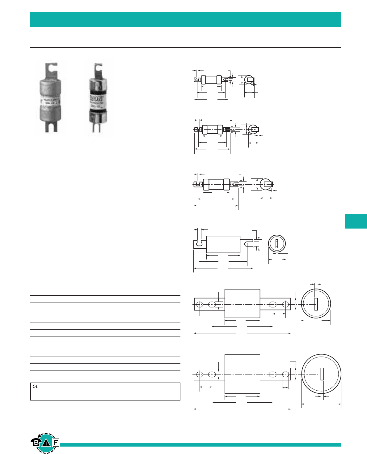
Bussmann®
191
For complete specification data, call Bussmann Information Fax ~ 636.527.1450
HRC Form II Class C Fuses
British, European, & Canadian Standard Industrial Fuses
Data Sheet: 4125
CGL
Tron®HRC Form II Class C Fuses
Ampere Ratings: 2 to 600A.
Voltage Rating: 600Vac, 250Vdc (1-30A)
Interrupting Rating: 200,000A (40,000A dc)
Current Limiting
Agency Information: CSA Certified, C22.2 No. 106
•Tron
®HRCII-C fuses are designed to withstand inrush cur-
rents on typical motor start-ups while offering high current
limitation in the short-circuit region.
• The Tron®HRCII-C fuses can be sized close to the motor
nameplate rating.
• Closer protection is offered for many motor sizes with the
availability of these additional fuse ratings.
•Tron
®HRCII-C fuses have a high degree of current limitation
greatly reducing the magnetic forces and thermal stresses
produced in today’s high capacity systems.
Catalog Numbers (Ampere ratings)
CGL-1 CGL-40 CGL-175
CGL-2 CGL-45 CGL-200
CGL-3 CGL-50 CGL-225
CGL-4 CGL-60 CGL-250
CGL-6 CGL-70 CGL-300
CGL-10 CGL-80 CGL-350
CGL-15 CGL-90 CGL-400
CGL-20 CGL-100 CGL-450
CGL-25 CGL-110 CGL-500
CGL-30 CGL-125 CGL-600
CGL-35 CGL-150 —
2.0"
(50.8mm)
2.80"
(71.04mm)
3.5"
(88.9mm)
0.94"
(23.81mm)
0.06"
(1.59mm)
2.0"
(50.8mm)
2.80"
(71.04mm)
3.31"
(84.14mm)
0.81"
(20.64mm)
0.22"
(5.56mm)
0.22"
(5.56mm)
0.34"
(8.73mm)
CGL 1-30
CGL 35-60
0.50"
(12.7mm)
0.81"
(20.64mm)
0.22"
(5.56mm)
0.22"
(5.56mm)
1.06"
(26.92mm)
0.06"
(1.59mm)
CGL 70-100
0.75"
(19.05mm)
1.34"
(34.04mm)
0.343"
(8.71mm)
0.343"
(8.71mm)
2.39"
(60.72mm)
3.64"
(92.47mm)
4.31"
(109.54mm)
1.375"
(34.93mm)
0.09"
(2.29mm)
CGL 110-200
0.75"
(19.05mm)
0.343
(8.71mm)
0.343"
(8.71mm)
3.00"
(76.2mm)
4.30"
(109.22mm)
5.31"
(134.87mm)
1.50"
(38.1mm)
0.125"
(3.18mm)
CGL 225-400
1.0"
(25.4mm)
0.38"
(9.53mm)
3.0"
(76.2mm)
5.25"
(133.35mm)
8.19"
(207.96mm)
2.38"
(60.33mm)
0.19"
(4.76mm)
1.0"
(25.4mm)
CGL 450-600
0.41"
(10.32mm)
3.00"
(76.2mm)
1.0"
(25.4mm)
1.0"
(25.4mm)
0.375"
(9.53mm)
3.0"
(76.2mm)
5.25"
(133.35mm)
8.19"
(207.96mm)
.60"
(15.24mm)
Dimensional Data
CE logo denotes compliance with European Union Low Voltage Directive
(50-1000Vac, 75-1500Vdc). Refer to Data Sheet: 8002 or contact
Bussmann Application Engineering at 636-527-1270 for more information.
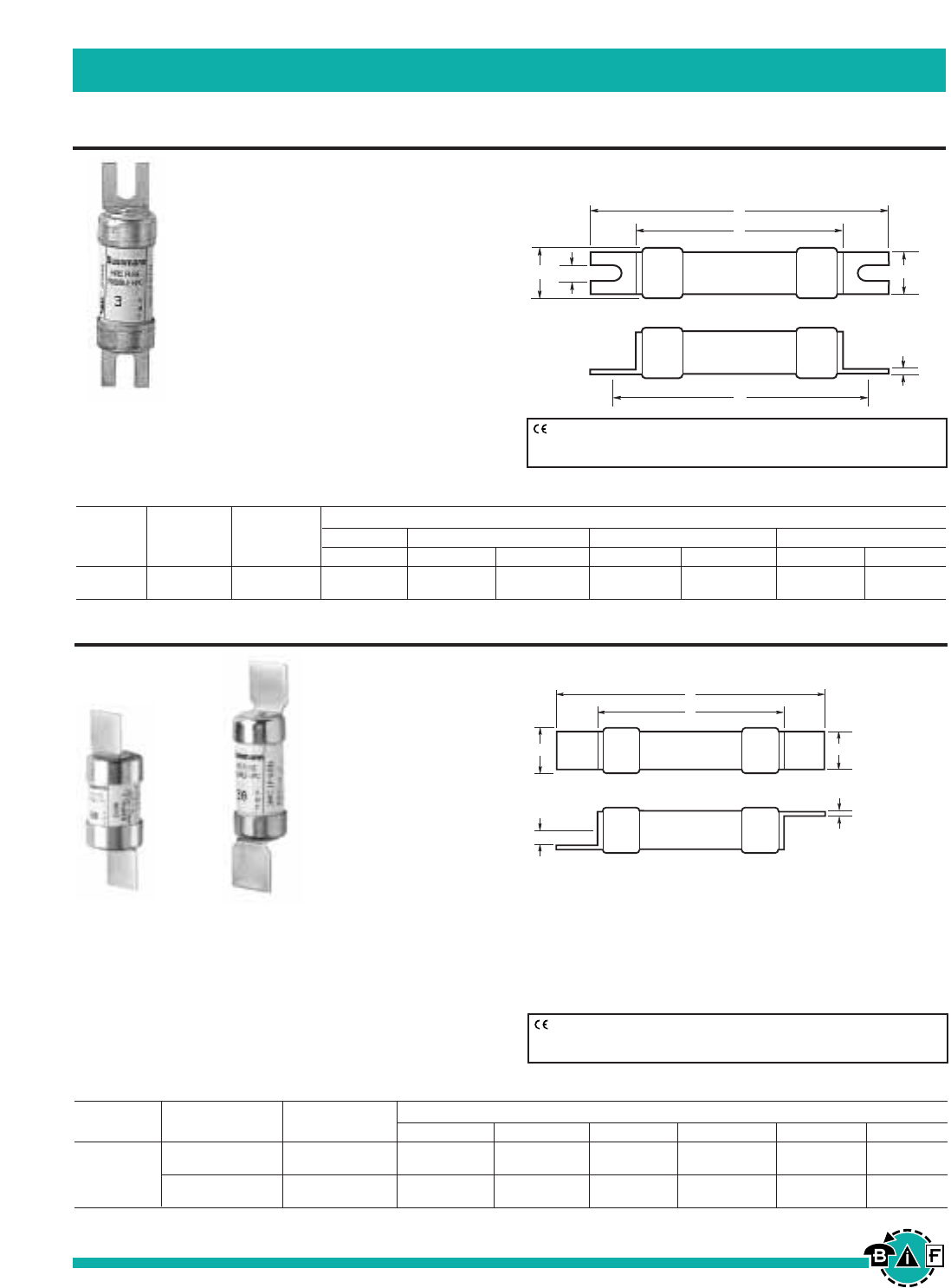
Bussmann®
192 For complete specification data, call Bussmann Information Fax ~ 636.527.1450
HRCI Industrial Ceramic Body Fuses
British, European, & Canadian Standard Industrial Fuses
Data Sheet: 4128
Dimensions in Inches and (mm)
Catalog Current Overall Tags Mounting Body
Type Symbol Ratings A E F G H C D
1, 3, 10, 15, 2.15 .44 .03 1.75 .19 1.44 .54
HRCI-CA (AMP) CIF21 20, 25, 30 (54.50) (11.10) (0.81) (44.50) (4.70) (35.50) (13.80)
CIF21
HRCI-CA Bolt-On Mounting
Ampere Ratings: 1-30A
Voltage Rating: 600Vac; 250Vdc
Interrupting Rating: 200,000A RMS
Symmetrical
Agency Information: CSA C22.2
No. 106-M92
• Provides both overload and short-
circuit protection to HRCI requirements.
• Offset blades for bolt-on mounting.
• CIF21 fuse fits the Bussmann-Camaster
Fuseholder.
Data Sheet: 4127
CIF06 & EK
HRCI-CB Clip-In Mounting
Ampere Ratings: CIF06: 1-30A, EK: 35-60A
Voltage Rating: 600Vac; 250Vdc
Interrupting Rating: 200,000A RMS Symmetrical
Agency Information: CSA C22.2 No. 106-M92
Catalog Current Dimensions in Inches and (mm)
Type Symbol Ratings A E F N C D
1, 10, 15, 2.38 .50 .03 .14 1.44 .54
HRCI-CB
(AMP) CIF06 20, 25, 30 (60.40) (12.70) (0.81) (3.50) (35.50) (13.80)
30, 35, 40, 2.65 .58 .05 .14 1.44 .8
EK (AMP) 50, 60 (67.30) (14.80) (1.22) (3.50) (36.30) (21.40)
A
C
DE
G
H
F
Dimensional Data
A
C
DE
NF
Dimensional Data
CE logo denotes compliance with European Union Low Voltage Directive
(50-1000Vac, 75-1500Vdc). Refer to Data Sheet: 8002 or contact
Bussmann Application Engineering at 636-527-1270 for more information.
CE logo denotes compliance with European Union Low Voltage Directive
(50-1000Vac, 75-1500Vdc). Refer to Data Sheet: 8002 or contact
Bussmann Application Engineering at 636-527-1270 for more information.
• Industrial miniature fuse with offset blades for clip-in
mounting.
• Ground ceramic body with plated endcaps.
• Provides both short-circuit and overload protection.
• CIF06 fits the 30A SafeLOC fuseholder.
EK fits the 60A SafeLOC fuseholder.
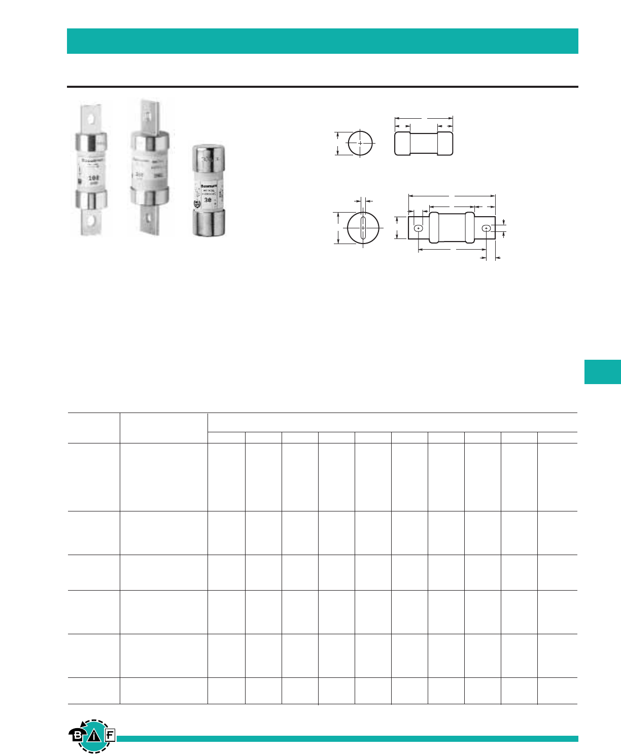
Bussmann®
193
For complete specification data, call Bussmann Information Fax ~ 636.527.1450
HRCI-J Fast Acting Fuses
British, European, & Canadian Standard Industrial Fuses
Data Sheet: 4129
Current
Ratings Catalog Dimensions in Inches and (mm)
(Amps) Number A B C D E F G H J K
1 1CJ
3 3CJ
6 6CJ
10 10CJ 2.25 .5 .81 — — —————
15 15CJ (57) (12.7) (20.6)
20 20CJ
25 25CJ
30 30CJ
35 35CJ
40 40CJ 2.38 .63 1.06 — — —————
45 45CJ (60) (16) (27)
50 50CJ
60 60CJ
70 70CJ
80 80CJ 4.63 3.63 1.13 .75 .13 1 .5 .28 .38 2.63
90 90CJ (117) (92) (28) (19) (3.2) (25.4) (12.7) (7.1) (9.5) (67)
100 100CJ
110 110CJ
125 125CJ 5.75 4.38 1.63 1.13 .19 1.38 .69 .28 .38 3
150 150CJ (146) (111) (41) (28.6) (4.8) (35) (17.5) (7.1) (9.5) (76)
175 175CJ
200 200CJ
225 225CJ
250 250CJ 7.13 5.25 2.13 1.63 .25 1.88 .94 .41 .53 3.38
300 300CJ (181) (133) (54) (41) (6.3) (47.6) (24) (10.3) (13.5) (86)
350 350CJ
400 400CJ
450 450CJ 8 6 2.63 2 .38 2.13 1 .53 .69 3.75
500 500CJ (203) (152) (66) (51) (9.5) (54) (25.4) (13.5) (17.5) (96)
600 600CJ
CJ
HRCI-J Fast Acting Fuses
Voltage Rating: 600Vac or less, 250Vdc
Construction: Ceramic Body Fuse
Interrupting Rating: 200,000A I.R.
Agency Information: CSA C22.2 No. 106 M92;
Designed to BS88:2, IEC 60269-2
•Industrial duty fuses with ceramic bodies.
•The excellent current limiting characteristics of fast-acting
HRCI-J fuses limits damage to equipment and installations
by the thermal and magnetic energy associated with a
large short-circuit fault current.
•Overload characteristics limit cable damage due to low
overload currents.
A
JF
K
B
H
DC
E
G
A
BB
C
Dimensional Data
1CJ to 60CJ
70CJ to 600CJ
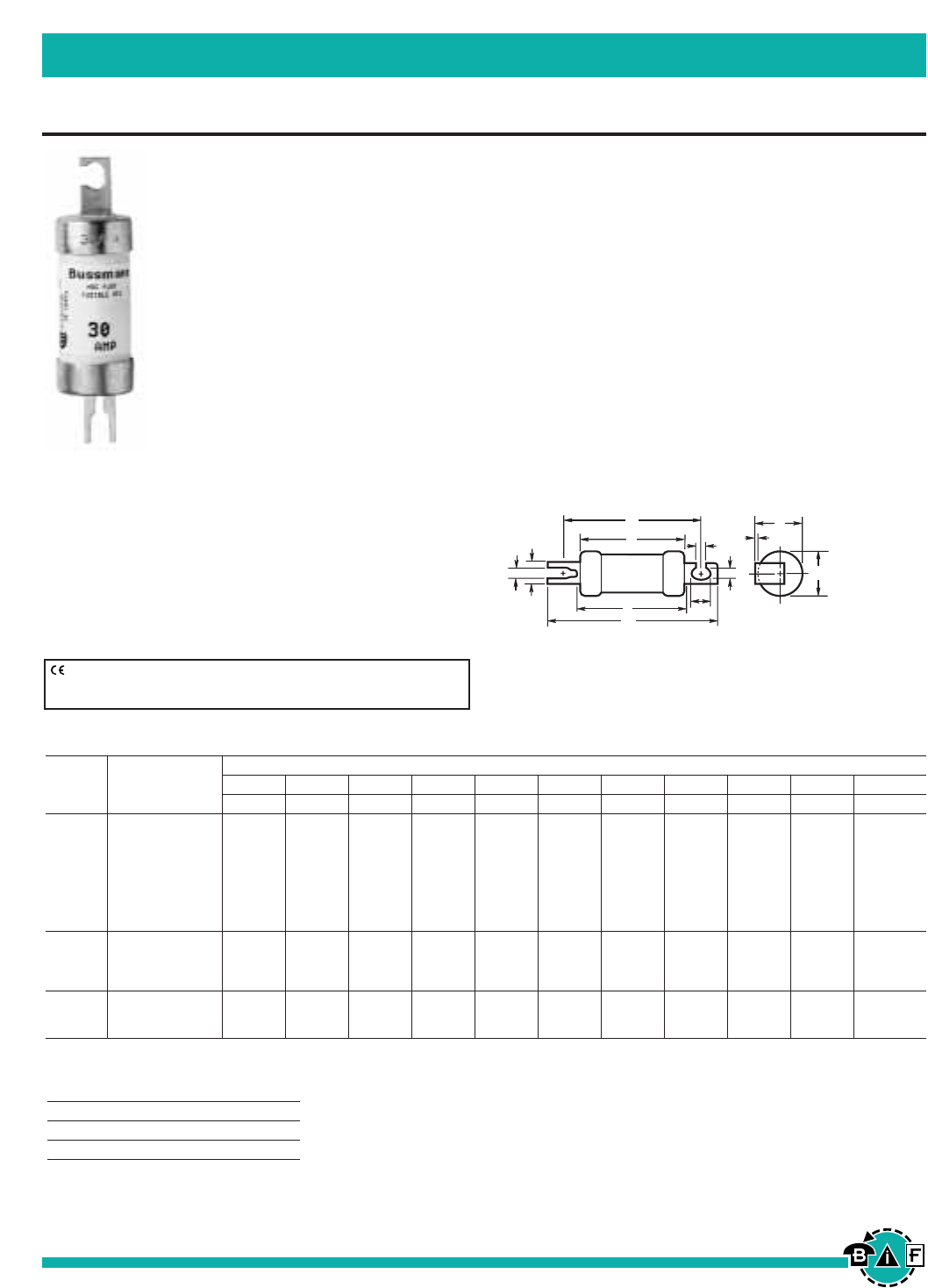
Bussmann®
194 For complete specification data, call Bussmann Information Fax ~ 636.527.1450
HRCI-Misc. Type K Fuses
British, European, & Canadian Standard Industrial Fuses
Data Sheet: 4130
CIH, CIK & CIL
HRI Ceramic Body Fuses
Ampere Ratings: 30, 60 & 100A
Voltage Rating: 600V
Interrupting Rating: 200,000A at 600V
Agency Information: CSA C22.2 No. 106 M92
• Offset blades for bolt down mounting.
• Provides both overload and short-circuit protection.
E
G
G
H
D
K
F
A
L
C
J
B
Dimensional Data
(The CIL14 has a rejection hole, not a slot as shown above.)
CE logo denotes compliance with European Union Low Voltage Directive
(50-1000Vac, 75-1500Vdc). Refer to Data Sheet: 8002 or contact
Bussmann Application Engineering at 636-527-1270 for more information.
Recommended Fuseholders
Fuse Fuseholder
1-30A CM30CF
35-60A CM60CF
Ratings, Categories and Dimensions
Current Dimensions in Inches and (mm)
Ratings Catalog ABCDEFGHJK L
(Amps) Number Max. Max. Max. Nom. Nom. Nom. Nom. Nom. Max. Nom. Max.
1 1CIH07
3 3CIH07
6 6CIH07
10 10CIH07 2.25 .94 3.38 .38 .04 2.88 .21 .31 1 .10 2.38
15 15CIH07 (57) (24) (86) (9.2) (1.0) (73) (5.2) (8) (25.4) (2.6) (60)
20 20CIH07
25 25CIH07
30 30CIH07
35 35CIK07
40 40CIK07 2.28 1.06 3.56 .5 .05 2.88 .21 .41 1.09 .13 2.38
50 50CIK07 (58) (27) (91) (12.7) (1.2) (73) (5.2) (10.5) (28) (3.2) (61)
60 60CIK07
80 80CIL14 2.75 1.44 4.38 .75 .09 3.69 .34 .41 1.5 — 2.91
90 90CIL14 (70) (37) (111) (19) (2.5) (94) (8.7) (10.5) (38.5) — (74)
100 100CIL14
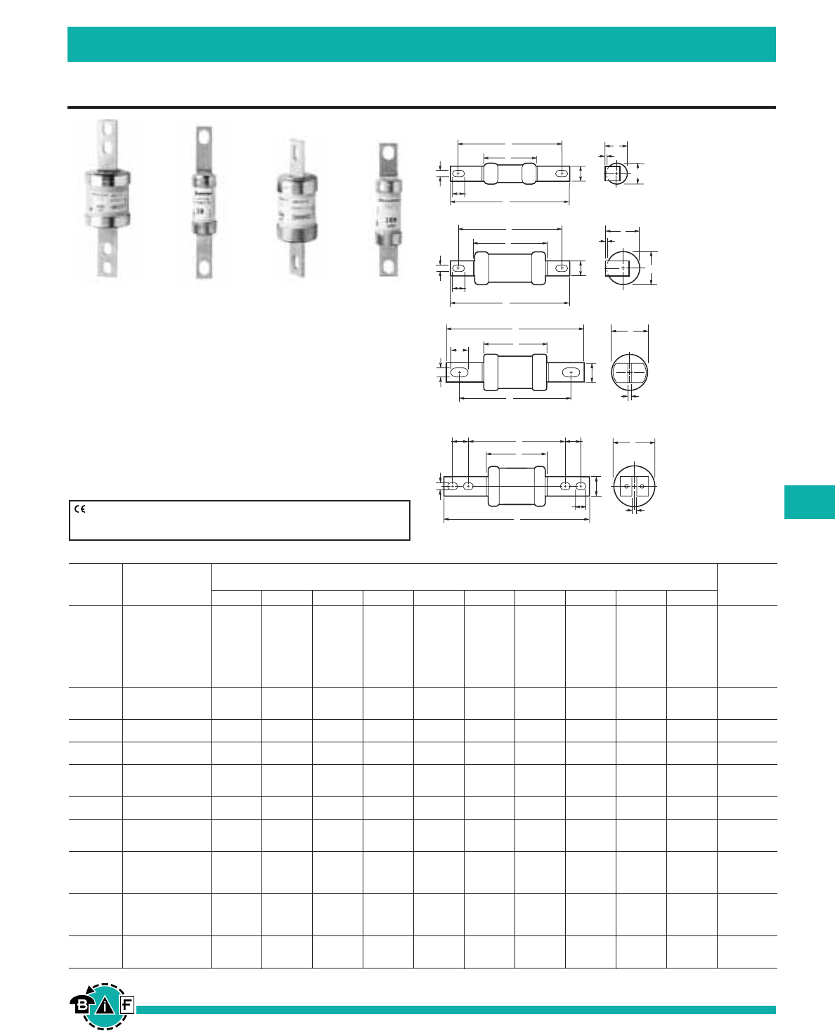
Bussmann®
195
For complete specification data, call Bussmann Information Fax ~ 636.527.1450
HRC Form II Current Limiting Fuses
British, European, & Canadian Standard Industrial Fuses
Data Sheet: 4131
Current
Ratings Catalog Dimensions in Inches and (mm) CSA
(Amps) Number A B C D E F G H J K Category
2 2H07C
4 4H07C
6 6H07C
10 10H07C 1.38 .56 3.38 .38 .06 2.88 .22 .31 .56 —
15 15H07C (35) (14) (85) (9) (1.2) (73) (5.6) (8) (14) — HRCII-C
20 20H07C
25 25H07C
30 30H07C
40 40K07C 2.19 .88 3.44 .5 .06 2.88 .22 .31 .88 —
50 50K07C HRCII-C
60 60K07C (56) (22) (87) (13) (1.2) (73) (5.6) (8) (22) —
80 80K07CR 2.19 .88 3.75 .5 .06 2.88 .22 .31 .88 — HRCII-MISC
100 100K07CR (56) (22) (95) (13) (1.2) (73) (5.6) (8) (22) —
80 80L14C 2.38 .88 4.38 .56 .13 3.69 .34 .44 1 — HRCII-C
100 100L14C (60) (21.4) (111) (14.3) (3.2) (94) (8.7) (11) (25.4) —
125 125M14C 2.56 1.5 4.38 .75 .09 3.69 .34 .44 — —
150 150M14C HRCII-MISC
200 200M14C (65) (38) (111) (19) (2.4) (94) (8.7) (11) — —
80 80L09C 2.38 .88 5 .56 .13 4.38 .34 .44 — — HRCII-MISC
100 100L09C (60) (21.4) (127) (14) (3.2) (111) (8.7) (11) — —
125 125M09C 2.56 1.5 5.38 .75 .13 4.38 .34 .56 — —
150 150M09C HRCII-C
200 200M09C (65) (38) (136) (19) (3.2) (111) (8.7) (14) — —
250 250P09C
300 300P09C 3.06 2.31 5.38 1 .19 4.38 .34 .5 — —
350 350P09C (178) (59) (136) (25.4) (4.8) (111) (8.7) (13) — — HRCII-MISC
400 400P09C
250 250P11C
300 300P11C 3.06 2.31 8.25 1 .19 5.25 .41 .63 — 1 HRCII-C
350 350P11C (178) (59) (210) (25.4) (5) (133) (10) (16) — 25
400 400P11C
450 450R11C 3.19 2.88 8.25 1 .25 5.25 .41 .63 — 1
500 500R11C HRCII-C
600 600R11C (81) (73) (210) (25.4) (6.3) (133) (10) (16) — 25
HRC Form II Current Limiting Fuses
Voltage Rating: 600Vac or less, 250Vdc
Construction: Ceramic Body
Interrupting Rating: 200,000A RMS Symmetrical
Agency Information:
CSA C22.2 No.106M1992; BS88:2, IEC269:2
Applications
• HRC FORM II fuses are often used to protect motor control
circuits, together with contactors and overload protection
relays.
• Type 2 coordination - per IEC 947-4.
E
D
G
F
A
H
C
J
B
E
D
G
F
A
H
C
J
B
D
G
C
A
F
B
E
H
FB
E
G
C
A
K
D
K
H
H07C (Offset Blades)
K07C/K07CR/
L14C/M14C
(Offset Blades)
L09C/M09C/P09C
(Center Blades)
P11C/R11C
(Center Blades)
Dimensional Data
CE logo denotes compliance with European Union Low Voltage Directive
(50-1000Vac, 75-1500Vdc). Refer to Data Sheet: 8002 or contact
Bussmann Application Engineering at 636-527-1270 for more information.
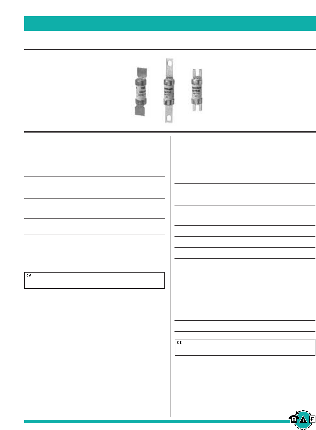
SSD, NSD, ESD
Offset Blades
Meets the requirements of BS88 Part 1 and IEC269-1.
The NSD and ESD fuses comply with general purpose gG
characteristics.
Maximum
Catalog Voltage Rating BS88 Data
No. Ampere Ratings ac dc Ref. Sheet
SSD 2, 4, 6, 10, 16, 20, 25, 32 240 — E1 4105
NSD 2, 4, 6, 10, 16, 20, 25, 32 550 — F1
20M25*, 20M32*
20M36*, 32M36*, 32M40*, 415 — — 4100
32M50*, 32M63* 415 — —
ESD 2, 4, 6, 10, 16, 25, 32 550 250 F2
40, 50, 63 415 250 F2 4101
63M80, 63M100 415 — —
*“M” indicates motor starter ratings.
Recommended Fuseholders
NSD 32NNSF
ESD 63ENSF
STD, NITD, AAO, BAO, OSD, CEO, DEO
Offset Bolted Blades
Meets the requirements of BS88 Part 1 and IEC269-1.
The NITD to DEO types comply with general purpose gG
characteristics. The STD type are used in 240V street lighting
cut-outs.
Maximum
Catalog Voltage Rating BS88 Data
No. Ampere Ratings ac dc Ref. Sheet
STD 2, 4, 6, 10, 16, 20, 25, 32 240 — — 4123
NITD 2, 4, 6, 10, 16, 20 550 — A1
25, 32 550 — —
20M25*, 20M32* 550 — A1 4106
32M40*, 32M50*, 32M63* 415 — —
AAO 2, 4, 6, 10, 16, 20, 25, 32 550 — A2
32M40*, 32M50*, 32M63* 550 — A2 4109
BAO 40, 50, 63 550 — A3
63M80*, 63M100* 550 — A3 4112
OSD 80, 100 550 — —
100M125*, 100M160* 415 — — 4107
CEO 32, 40, 50, 63, 80, 100 550 — A4
100M125*, 100M160* 415 — A4 4115
100M200* 415 — A4
DEO 125, 160, 200 415 — —
200M250*, 200M315* 415 — — 4117
*“M” indicates motor starter ratings.
Recommended Fuseblock & Holders
NITD CM32FC
AAO CM32F
BAO CM63F
OSD CM100F
CEO BH-0111
Bussmann®
196 For complete specification data, call Bussmann Information Fax ~ 636.527.1450
BS88 British Standard Low Voltage Fuses
British, European, & Canadian Standard Industrial Fuses
CE logo denotes compliance with European Union Low Voltage Directive
(50-1000Vac, 75-1500Vdc). Refer to Data Sheet: 8002 or contact
Bussmann Application Engineering at 636-527-1270 for more information.
CE logo denotes compliance with European Union Low Voltage Directive
(50-1000Vac, 75-1500Vdc). Refer to Data Sheet: 8002 or contact
Bussmann Application Engineering at 636-527-1270 for more information.
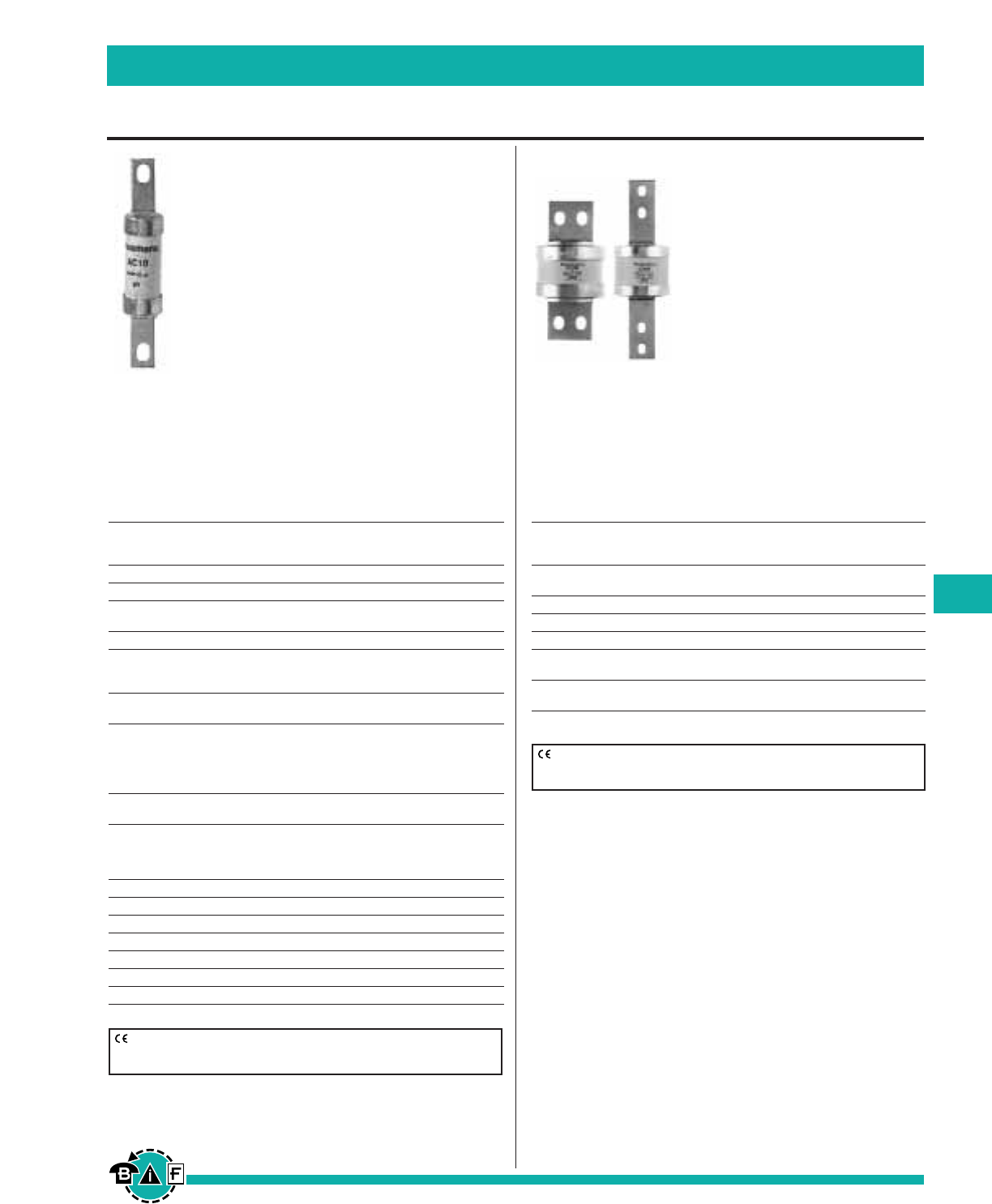
AC, AD, BC, BD, CD, DD, ED, EFS
Center Bolted Blades, Two Hole Mount
Meets the requirements of BS88 Parts 1 and 2 and IEC269-1.
Complies with general purpose gG characteristics and avail-
able up to 400A with two hole mount and up to 1250A with
four hole mount.
Maximum
Catalog Voltage Rating BS88 Data
No. Ampere Ratings ac dc Ref. Sheet
AC 2, 4, 6, 10, 16, 20, 25, 32 550 250 — 4110
AD 2, 4, 6, 10, 16, 20, 25, 32 550 250 — 4111
BC 40, 50, 63 550 250
63M80*, 63M100* 550 — — 4113
BD 40, 50, 63 550 250 — 4114
CD 80, 100 550 — B1
100M125*, 100M160* 415 — B1 4116
100M200* 415 — B1
DD 125, 160, 200 415 — B2
200M250*, 200M315* 415 — B2 4118
ED 250 415 — B3
315 415 — B3
315M400* 415 — B3 4119
355, 400 415 — B4
400M500* 550 — B4
EFS 125, 160, 200, 250 415 — —
315 415 — — 4121
*“M” indicates motor starter ratings.
Recommended Fuseblock/Holder
AC BH-0111 Modular Fuseblock
AD 200DF Fuseholder
BC BH-0111 Modular Fuseblock
BD 200DF Fuseholder
CD 200DF Fuseholder
DD 200DF Fuseholder
ED BH-1131 Modular Fuseblock
EF, FF, FG, GF, GG, GH
Center Bolted Blades, Four Hole Mount
Meets the requirements of BS88 Parts 1 and 2 and IEC269-1.
Complies with general purpose gG characteristics and avail-
able up to 400A with two hole mount and up to 1250A with
four hole mount.
Maximum
Catalog Voltage Rating BS88 Data
No. Ampere Ratings ac dc Ref. Sheet
EF 355, 400 415 — C1
400M500* 550 — C1 4120
FF 450, 500, 560, 630 550 400 C2 4102
FG 450, 500, 560, 630 550 400 — 4122
GF 710, 800 550 250 C3 4103
GG 710, 800 550 250 —
1000, 1250 550 — — 4104
GH 710, 800 550 250 D1
1000, 1250 550 — D1 4108
*“M” indicates motor starter ratings.
Bussmann®
197
For complete specification data, call Bussmann Information Fax ~ 636.527.1450
BS88 British Standard Low Voltage Fuses
British, European, & Canadian Standard Industrial Fuses
CE logo denotes compliance with European Union Low Voltage Directive
(50-1000Vac, 75-1500Vdc). Refer to Data Sheet: 8002 or contact
Bussmann Application Engineering at 636-527-1270 for more information.
CE logo denotes compliance with European Union Low Voltage Directive
(50-1000Vac, 75-1500Vdc). Refer to Data Sheet: 8002 or contact
Bussmann Application Engineering at 636-527-1270 for more information.
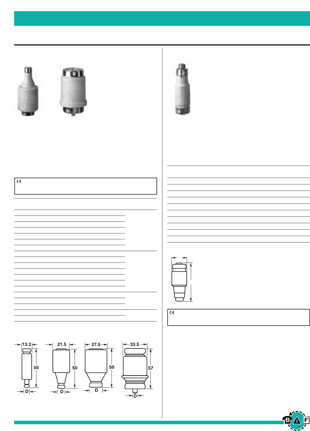
Bussmann®
198 For complete specification data, call Bussmann Information Fax ~ 636.527.1450
DIN Style Type D and Neozed Low Voltage Fuses
British, European, & Canadian Standard Industrial Fuses
Data Sheet: 4124 Data Sheet: 4124
Type D Fuse
Ampere Ratings: 2 to 100A.
Voltage Ratings: 500Vac
Interrupting Rating: 100kA
Agency Information:
“D” type fuses complying with DIN 49360 Part 2 and DIN
49515, operating class gL
Catalog Dimension Ampere Color Figure
Number “D” Rating Code Number
2D16 6 2 Pink
4D16 6 4 Brown
6D16 6 6 Green
10D16 7 10 Red 1
16D16 10 16 Grey
20D16 12 20 Blue
25D16 14 25 Yellow
2D27 6 2 Pink
4D27 6 4 Brown
6D27 6 6 Green
10D27 8 10 Red 2
16D27 10 16 Grey
20D27 12 20 Blue
25D27 14 25 Yellow
35D33 16 35 Black
50D33 18 50 White 3
63D33 20 63 Copper
80D125 5 80 Silver
100D125 7 100 Red 4
Additional Fuselinks: Quick acting fuselinks in body sized D16, D27, D33 and D125 rated
2-100A. Reference number suffixed Q, i.e. 10D27Q. Voltage rating 500V. Gauge rings and
keys can also be supplied.
Neozed Fuse
Also suitable for use on 250Vdc systems
Ampere Ratings: 2 to 63A
Voltage Rating: 400Vac
Interrupting Rating: 100kA
Catalog Dimension Ampere Color
Number D (mm) Rating Code
2NZ01 11 2 Pink
4NZ01 11 4 Brown
6NZ01 11 6 Green
10NZ01 11 10 Red
16NZ01 11 16 Grey
20NZ02 15 20 Blue
25NZ02 15 25 Yellow
35NZ02 15 35 Black
50NZ02 15 50 White
63NZ02 15 63 Copper
D
36
Figure 1 Figure 2 Figure 3 Figure 4
CE logo denotes compliance with European Union Low Voltage Directive
(50-1000Vac, 75-1500Vdc). Refer to Data Sheet: 8002 or contact
Bussmann Application Engineering at 636-527-1270 for more information.
CE logo denotes compliance with European Union Low Voltage Directive
(50-1000Vac, 75-1500Vdc). Refer to Data Sheet: 8002 or contact
Bussmann Application Engineering at 636-527-1270 for more information.
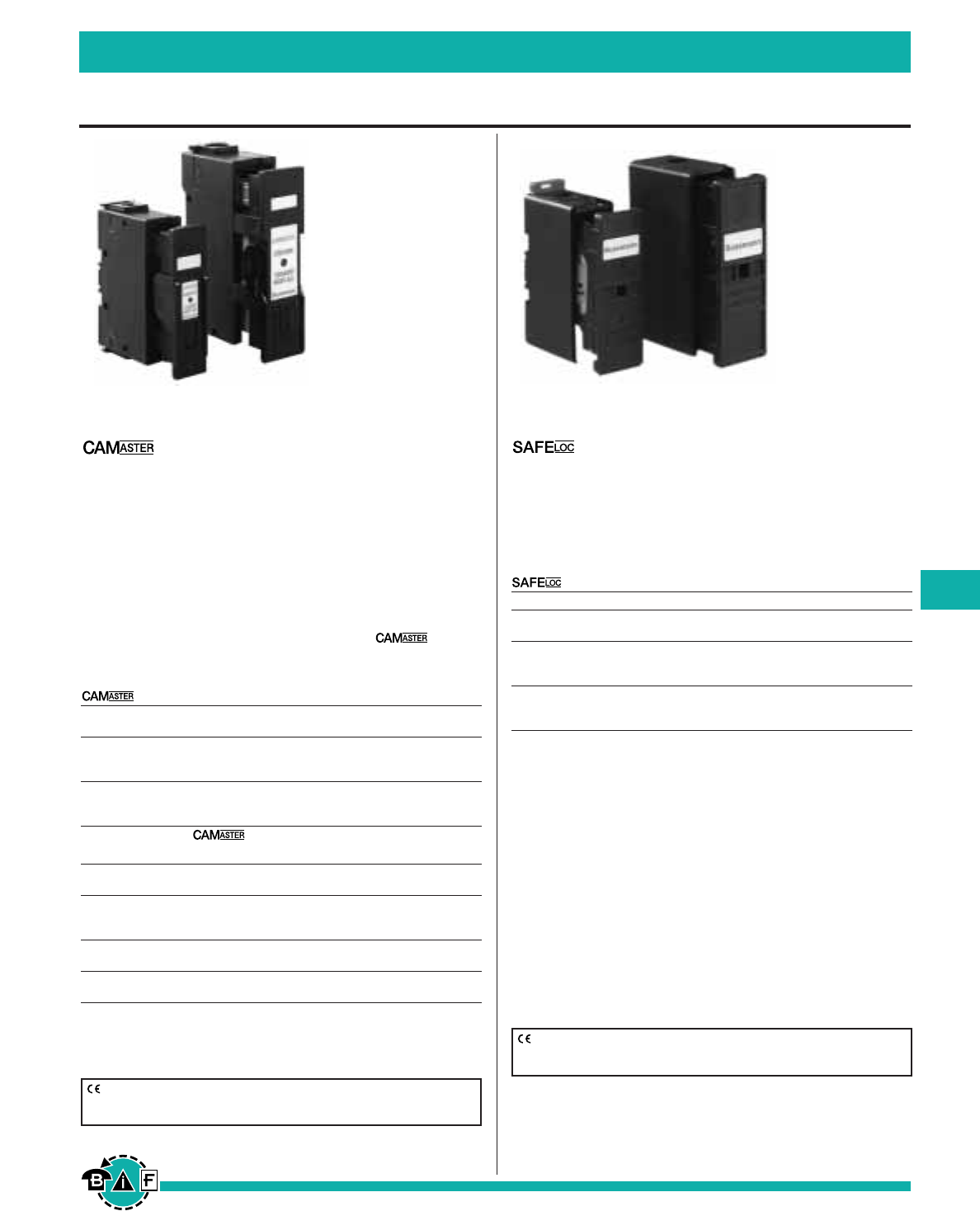
Bussmann®
199
For complete specification data, call Bussmann Information Fax ~ 636.527.1450
HRC Fuseholders
British, European, & Canadian Standard Industrial Fuses
Data Sheet: 4132 Data Sheet: 4133
HRC Fuseholders
For use with HRCI-CB fuses. Suitable for bolted panel
mounting or DIN rail mounting.
Ampere Ratings: 30 and 60A
Ratings
For use with HRCI-CB Fuses
Catalog Fuse
Rating Connection Number Accommodated
Front C30F
30A Back C30BS CIF06
Front-Back C30FBS
Front C60F
60A Back C60BS EK-Amp
Front-Back C60FBS
Features
• Designed to accommodate the compact range of offset
blade fuse to CSA C22.2 No. 106, HRCI-CB.
• Carrier provides a positive, stress free fitting of fuse and
locks the fuse in position ensuring safe insertion and with-
drawal from the base.
• Base Contacts are fully shrouded to help protect against
electric shock.
• Shrouds utilize simple slide/snap action allowing access to
the contact terminal screws.
• 35mm DIN-rail mounting.
• Single screw mounting.
HRC Fuseholders
Ampere Ratings: 30, 60 and 100A
Agency Information: CSA C22.2 No. 39; IEC 269 AND
BS88
• Unique Cam-Action for ease of removal from the Fuse
Bases allowing significantly improved contact pressure
between Fuse Carrier and Fuse Base contacts, with a
corresponding enhanced electrical performance level.
• A range of Lockable Safety Carriers for the
Fuseholder (Cat ref: LSC), are available.
Ratings
Catalog Fuse
Rating Details Number Accommodated
For
30A HRCI-CA CM20CF —C1F21
Applications
30A For CM30CF —H07C
60A HRCII CM60CF —K07C
100A Applications CM100CF —K07CR
Accessories for Units
Catalog Fuseholder
Rating Details Number Accommodated
30A 20BS For CM20CF
30A Back Stud 32BS For CM30CF
60/100A 60/100BS For CM60/100CF
All Ganging GLP For 3 Pole
Link Kit
All 660V Neon NI —
Indicator
30A Security 20LSC For CM20CF
30A Carrier 30LSC For CM30CF
CE logo denotes compliance with European Union Low Voltage Directive
(50-1000Vac, 75-1500Vdc). Refer to Data Sheet: 8002 or contact
Bussmann Application Engineering at 636-527-1270 for more information.
CE logo denotes compliance with European Union Low Voltage Directive
(50-1000Vac, 75-1500Vdc). Refer to Data Sheet: 8002 or contact
Bussmann Application Engineering at 636-527-1270 for more information.
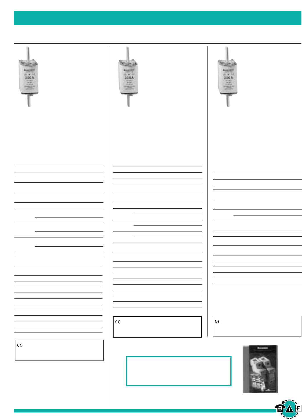
NH_G-690
Voltage Rating: 690Vac/250Vdc
gL/gG Category
Agency Information:
IEC269, DIN43620 Part 1
A range of industrial fuse links for a
wide variety of applications where 690V
is needed.
The ordering code is made up as follows:
Rating Product Code Body Category
250 NH 2 G-690
Fuse Body
Type Rating (A) Size
NH00G-690 10, 16, 20, 25, 32, 40, C00
50, 63, 80, 100
NH1G-690 32, 40, 50, 63, 80, 100 01
125, 160, 200, 200, 224, 225, 250 1
NH2G-690 100, 125, 160, 200, 224, 250, 2
315, 350, 400
NH3G-690 315, 350, 400, 500, 630 3
Dimensional Detail (mm)
Overall
Type Ratings Depth Width Length
NH00G-690 10-100A 38 29 78.5
NH1G-690 32-100A 45 29 135
NH1G-690 125-250A 50 44.5 135
NH2G-690 100-400A 50 44.5 150
NH3G-690 315-630A 58 50 150
NH_M
Voltage Rating: 500Vac
aM Category
Agency Information:
IEC269, VDE, DIN43620 Part 1
A range of industrial fuse links for the
protection of motor circuits.
The ordering code is made up as follows:
Rating Product Code Body Category
100 NH 1 M
Fuse Body
Type Rating (A) Size
NHC00M 4, 6, 8, 10, 12, 16, 20, 25, 32, C00
40, 50
NH00M 63, 80, 100 00
NH1M 40, 50, 63, 80, 100, 125, 160 01
200, 250 02
NH2M 125, 160, 200, 250 02
315, 400 2
NH3M 315, 400 03
500, 630 3
Dimensional Detail (mm)
Overall
Type Ratings Depth Width Length
NHC00M 4-50A 39.5 20.5 78.5
NH00M 63-100A 38 29 78.5
NH1M 40-160A 45 29 135
NH1M 200-250A 50 44.5 135
NH2M 125-250A 50 44.5 150
NH2M 315-400A 58 50 150
NH3M 315-400A 58 50 150
NH3M 500-630A 73 71 150
British, European, & Canadian Standard Industrial Fuses
Bussmann®
200
NH Low Voltage Fuse Links
Data Sheet: 4173
Data Sheet: 4173
Data Sheet: 4173
For complete specification data, call Bussmann Information Fax ~ 636.527.1450
CE logo denotes compliance with European Union Low
Voltage Directive (50-1000Vac, 75-1500Vdc). Refer to
Data Sheet: 8002 or contact Bussmann Application
Engineering at 636-527-1270 for more information.
CE logo denotes compliance with European Union Low
Voltage Directive (50-1000Vac, 75-1500Vdc). Refer to
Data Sheet: 8002 or contact Bussmann Application
Engineering at 636-527-1270 for more information.
CE logo denotes compliance with European Union Low
Voltage Directive (50-1000Vac, 75-1500Vdc). Refer to
Data Sheet: 8002 or contact Bussmann Application
Engineering at 636-527-1270 for more information.
NH_G
Voltage Rating: 500Vac
gL/gG Category
Agency Information:
IEC269, VDE, DIN43620 Part 1
A range of industrial fuse links for a
wide variety of applications.
The ordering code is made up as follows:
Rating Product Code Body Category
50 NH 00 G
Fuse Body
Type Rating (A) Size
NHC00G 6, 10, 16, 20, 25, 32, C00
35, 40, 50, 63, 80, 100
NH00G 125, 160 00
6, 10, 16, 20, 25, 25, 32, 35, 01
NH1G 40, 50, 63, 80, 100, 125, 160
200, 224, 225, 250 1
35, 40, 50, 63, 80, 100, 125, 02
NH2G 160, 200, 224, 250
315, 350, 400, 425 2
NH3G 100, 125, 160, 200, 224, 250, 03
315, 350, 400
500, 630 3
NH4AG 800, 1000, 1250, 1600 4a
Dimensional Detail (mm)
Overall
Type Ratings Depth Width Length
NHC00G 6-100A 39.5 20.5 78.5
NH00G 125 & 160A 38 29 78.5
NH1G 6-160A 45 29 135
NH1G 200-250A 50 44.5 135
NH2G 35-250A 50 44.5 150
NH2G 315-425A 58 50 150
NH3G 100-400A 58 50 150
NH3G 500-630A 73 71 150
NH4AG 800-1000A 102 87 200
NH4AG 1250-1600A 110 95 200
For additional information on the
IEC Cylindrical Fuse System, visit
www.bussmann.co.uk/products.htm
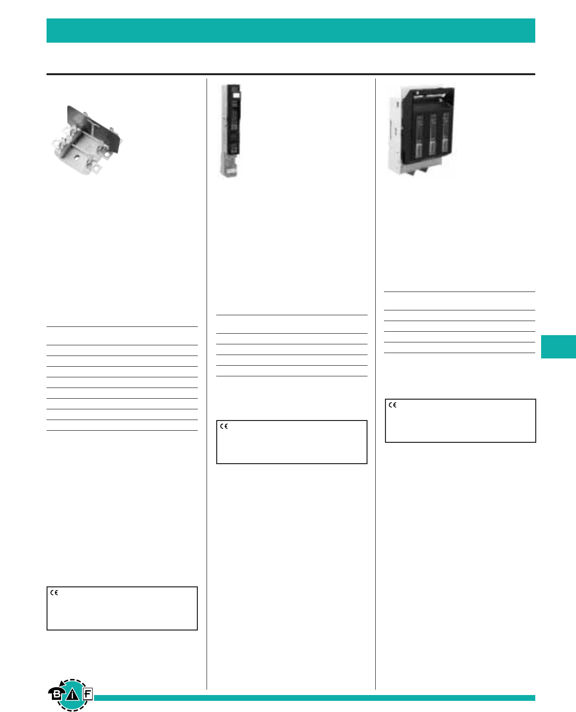
British, European, & Canadian Standard Industrial Fuses
Bussmann®
201
NH Fuse System
Data Sheet: 4169
For complete specification data, call Bussmann Information Fax ~ 636.527.1450
SB, TB
NH-LV Fuse Bases
Voltage Rating: 660Vac
Agency Information:
DIN43620/1, VDE
A range of single and triple pole fuse
bases with dimensions to DIN43620/1.
The ordering code is made up as
follows:
Rating: 400
Product Code: SB2
Fuse Body
Type Rating (A) Size*
SB00 160 00
SB1 250 1
SB2 400 2
SB3 630 3
SB4 1250 4 A
TB00 160 0
TB1 250 01
TB2 400 2
SB - Single Pole Base
TB - Triple Pole Base
*Size 00 is available with “V” shaped terminal lugs,
when ordering add “V” to part number i.e.
SB00V/TB00V
N.B. Size 1 bases will accommodate size 0 fuse
links.
Photo shown with side walls. To order side wall,
reference “PB” followed by the fuse body size (i.e.
PB00).
Vertical Fuse bases in size 00 to size 3 are
available, details upon request.
Universal Handle: Type 630 for sizes 00 to 3.
1250A size 4A Switchable base available.
CE logo denotes compliance with European
Union Low Voltage Directive (50-1000Vac,
75-1500Vdc). Refer to Data Sheet: 8002 or
contact Bussmann Application Engineering at
636-527-1270 for more information.
VLB
NH-LV Vertical Load Break Fuse
Switch Disconnector
Agency Information:
IEC, DIN43620/1
A range of LV Vertical Load Break Fuse
Switch Disconnectors to take NH Fuse
Links in sizes 00, 1, 2 and 3.
The ordering codes are shown in the
table below.
Fuse Body
Type Rating (A) Size
VLB00 160 00
VLB1 250 1
VLB2 400 2
VLB3 630 3
Insulated and touch protected.
High Switching capacity.
Cable terminal top or bottom entry.
CE logo denotes compliance with European
Union Low Voltage Directive (50-1000Vac,
75-1500Vdc). Refer to Data Sheet: 8002 or
contact Bussmann Application Engineering at
636-527-1270 for more information.
CE logo denotes compliance with European
Union Low Voltage Directive (50-1000Vac,
75-1500Vdc). Refer to Data Sheet: 8002 or
contact Bussmann Application Engineering at
636-527-1270 for more information.
LBS
NH Fuse Switch Disconnector
Agency Information:
IEC, VDE, DIN
A range of Switch Fuses to take NH
fuse link sizes 00, 1, 2 and 3.
The ordering codes are shown in the
table below.
Fuse Body
Type Rating (A) Size
LBS00 160 00
LBS1 250 1
LBS2 400 2
LBS3 630 3
HRC LV Fuse Switch Disconnectors are available
for back panel mounting, size 00 can be adapted
for DIN rail mounting. A range of accessories are
also available.
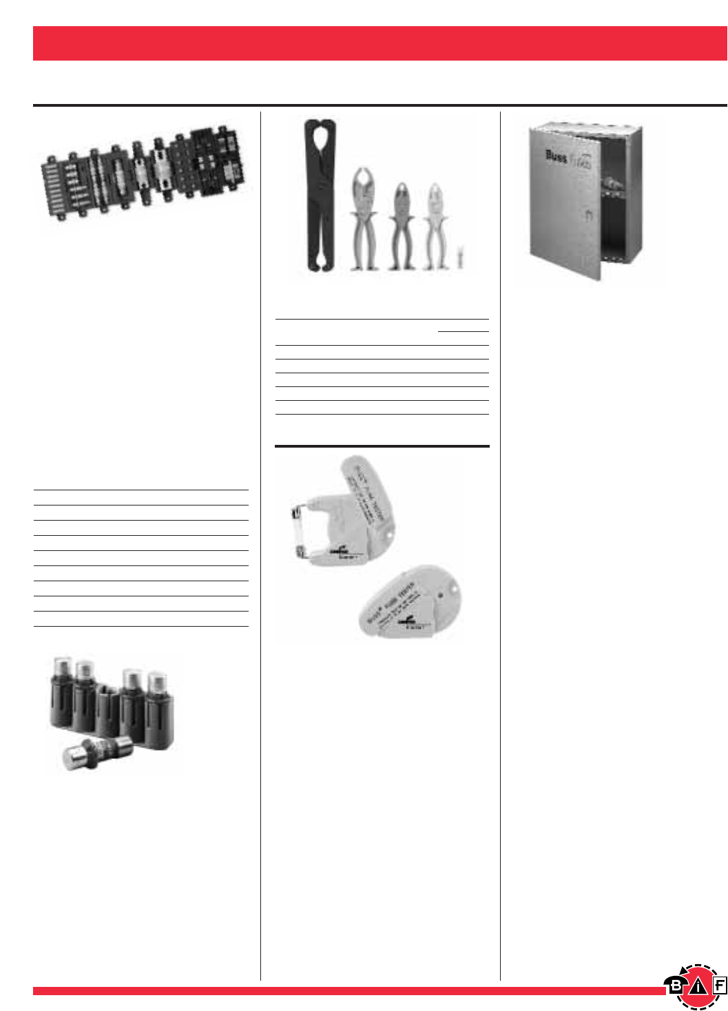
Fuse Accessories, Displays, Kits, Etc. Bussmann®
202 For complete specification data, call Bussmann Information Fax ~ 636.527.1450
Accessories
Data Sheet: 1119
SFC-FUSE-CAB
Spare Fuse Cabinet
Size: 24∑wide ≈30∑high x 12∑deep
• Five cubic feet of storage space.
• Sturdy storage cabinet conveniently
holds spare fuses.
• Constructed of heavy gauge steel.
• Cabinet door equipped with locking
handle.
• Durable baked ASA 61 grey enamel.
• Mounting holes with key slot 16
inches on center.
SFC SHELF
• Extra shelf for fuse cabinet.
5TPH
Midget Fuse Spare Fuse Holder
Size: 2.98∑wide ≈1.03∑high ≈.63∑
deep
• 5-position spare fuse holder for
midget size and class CC fuses
(⁄‹Ω£™∑ diameter).
• Constructed of grey thermoplastic.
• Adhesive tape on back for easy
mounting on cabinet doors.
Fusepullers
Cat. Carton Weight
No. Application Qty. Lbs. Kg.
FP-2 ⁄‹Ω£™∑ to ⁄‹Ω¡§∑ dia. fuses 1 .125 .057
FP-3 1∑to 1‹Ω¢∑ dia. fuses 1 .173 .078
FP-4 1‹Ω¢∑ to 2⁄Ω™∑ dia. fuses 1 .53 .24
FP-6 0-60A T-Tron fuses 1 .123 .056
FP-A3 Glass Tube & ATC fuses 10 0.08 .04
Fuse pullers are only to be used when the associated cir-
cuit has been de-energized.
FT-2
Fuse Tester
24V Maximum
• Test automotive, glass tube and fer-
rule fuses up to 1‡Ω•∑ length.
• Batteries are included.
WARNING: DO NOT test electrical
fuses in the fuse panel.
Spare Fuseholders
• Durable construction using black ther-
moplastic with UL94-VO flammability
rating.
• Common mounting using #6 screws
or bolts on 5-inch centers.
• Dovetailed interlocking between
fuseholders simplifies installation
and reduces needed hardware.
• Common footprint allows for any
combination of fuseholders to be
mounted together.
• Built-in retaining clips secure fuses.
Catalog
Numbers Capacity For Use With
TPSFH-CW 4-position TPC and /or TPW fuses
TPSFH-M 4-position TPM fuses
TPSFH-70 12-position Series 70 fuses
TPSFH-LC 1-position TPL-C series fuses
TPSFH-LB 1-position TPL-B series fuses
TPSFH-N60 1-position TPN (35-60A) fuses
TPSFH-N30 4-position TPN (1-30A) fuses
TPSFH-AS 6-position TPA & TPS fuses
TPSFH-T 10-position GMT fuses
FP-4 FP-A3FP-6FP-3 FP-2
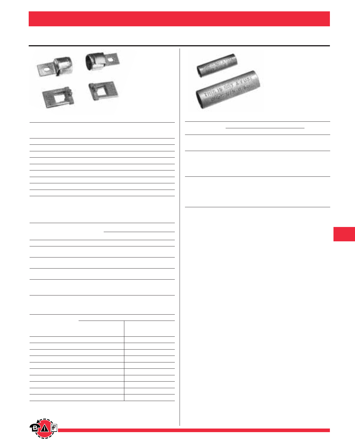
Fuse Accessories, Displays, Kits, Etc. Bussmann®
203
For complete specification data, call Bussmann Information Fax ~ 636.527.1450
Accessories
Data Sheet: 1118
Fuse Reducers for Class J Dimension Fuses-LPJ, JKS
Catalog No. *Carton
Fuse (Case) Equipment (Pair) Weight
Size Clip Size Reducer No. (Lbs.)
30A 60A J-63 0.38
30A 100A J-13 1.73
60A 100A J-16 1.85
60A †200A J-26 2.55
100A †200A J-21 1.36
100A †400A J-41 4.90
200A †400A J-42 2.75
200A †600A J-62 1.80
400A †600A J-64 3.55
*Carton quantity—10 pair.
†Not for Bolt-on Applications.
Fuse Reducers for Class R Dimension Fuses
FRN-R, LPN-RK—FRS-R, LPS-RK
Catalog No. (Pairs)
Fuse (Case) Equipment
Size Clip Size 250V 600V
30A 60A No. 263-R No. 663-R
30A 100A No. 213-R No. 216-R
60A No. 216-R No. 616-R
60A 200A No. 226-R No. 626-R
100A No. 2621-R No. 2621-R
100A 400A No. 2641-R No. 2641-R
200A No. 242-R No. 642-R
100A No. 2661-R No. 2661-R
200A 600A No. 2662-R No. 2662-R
400A No. 2664-R** No. 2664-R**
**Single reducer only (pair not required).
Fuse Reducers for Class H & K Dimension Fuses
NON, REN—NOS, RES
Catalog No. (Pairs)
Equipment 250V *Carton 600V *Carton
Fuse (Case) Clip Reducer Weight Reducer Weight
Size Size No. (Lbs.) No. (Lbs.)
30A 60A No. 263 0.38 No. 663 1.00
30A 100A No. 213 1.73 No. 216 1.73
60A 100A No. 216 1.73 No. 616 1.85
60A 200A No. 226 3.00 No. 626 3.33
100A 200A No. 2621 1.63 No. 2621 1.63
100A 400A No. 2641 4.90 No. 2641 4.90
200A 400A No. 2642 3.50 No. 2642 3.50
100A 600A No. 2661 8.70 No. 2661 8.70
200A 600A No. 2662 6.85 No. 2662 6.85
400A 600A No. 2664 4.45 No. 2664 4.45
*Carton quantity—10 pair.
Dummy Fuse “Neutrals” (These are not fuses)
Fuse Equivalent Carton
Catalog Numbers Voltage Dimension Amperes Quantity
NNB — ⁄‹Ω£™∑ ≈ 1⁄Ω™∑ —10
NNB-R — Class CC — 10
NNC — ⁄Ω¢∑ ≈ 1⁄Ω¢∑ —10
NTN-R-30 30A 10
NTN-R-60 60A 10
NTN-R-100 250V R/H 100A 5
NTN-R-200 200A 1
NTN-R-400 400A 1
NTS-R-30 30A 10
NTS-R-60 60A 10
NTS-R-100 100A 1
NTS-R-200 600V R/H 200A 1
NTS-R-400 400A 1
NTS-R-600 600A 1
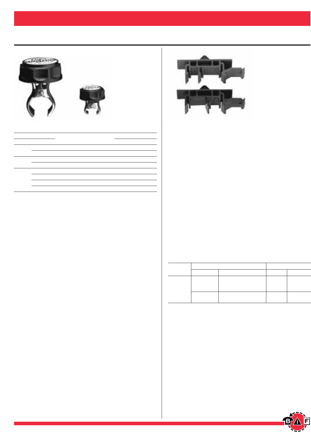
Accessories
Bussmann®
204 For complete specification data, call Bussmann Information Fax ~ 636.527.1450
Fuse Accessories, Displays, Kits, Etc.
TRON Clip-Clamps
Clamp Size Ctn. Weight
Volts Amps Cat. No. Qty. Lbs. Kg
250 0-30A No. 1 12 0.66 .30
35-60A No. 2 12 0.96 .44
600 0-30A No. 2 12 0.96 .44
35-60A No. 4 12 1.44 .65
70-100A No. 5 12 1.20 .54
250 110-200A No. 6 6 1.26 .57
or 225-400A No. 7 6 1.86 .84
600
450-600A No. 8 6 2.52 1.14
Adapters for DIN and American Rails
• Buss DIN-Rail Adapters permit secure, positive snap-on
mounting of Buss 0 to 30 ampere fuseblocks (one, two, or
three pole) on the various size rails. (Rail mounting elimi-
nates costly and time consuming drilling, tapping, and
screw mounting.)
• Molded from “Lexan™141”…a very high strength but
flexible material.
• Adapter mechanically locks into mounting hole of fuseblock
in seconds to become an integral part of the block.
• One adapter is required for Buss one and two pole blocks.
Two adapters are required for three pole blocks.
• With the exception of the 32mm DIN-rail, all blocks with
adapters can be removed from a rail simply by pulling up its
release tab.
• Use of rail end-stops on both sides of adapters is
recommended.
Adapter Catalog Data (For 0-30 Ampere Fuseblocks)
Fuseblock Rails Adapter
Class Type Size Color Cat. No.
15mm (Symm.)
DIN 32mm (Asymm.) Black DRA-1
35mm (Symm.)
⁄‡Ω§¢∑ (Symm.)
American (also 35mm DIN) Gray DRA-2
Package Quantities: standard—10; bulk—100 (Cat. No. BK/DRA-1 or BK/DRA-2.)
*Mounting on 15mm rails is not recommended.
NOTE—New model Buss fuseblocks have elongated block-to-adapter mounting holes
(old style fuseblocks will not accept the rail adapters).
CC
G
*H (250V)
*R (250)
M Type
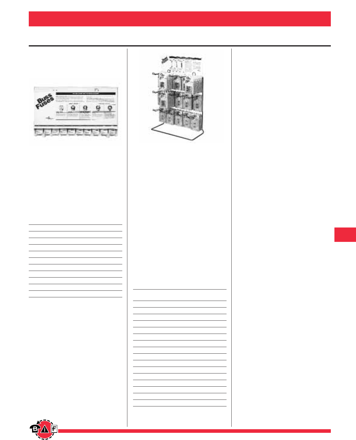
Bussmann®
205
For complete specification data, call Bussmann Information Fax ~ 636.527.1450
Fuse Accessories, Displays, Kits, Etc.
Fuse Display Racks
Plug Fuse Display
Catalog Symbol: PFD-948
Sturdy plastic display features complete
assortment of plug fuses.
Each display comes with a set of labels
that permits customizing the product
mix.
Display measures 29∑wide x 15∑tall x
5∑deep.
PFD-948 Display
Contents Boxes* Fuses
W-15 25 100
W-20 25 100
W-25 12 48
W-30 25 100
TL-15 25 100
TL-20 25 100
TL-30 25 100
SL-15 25 100
SL-20 25 100
SL-30 25 100
*Each box contains 4 fuses.
Displays without fuses are also avail-
able. Order EMPTY-PFD to receive the
display only.
The PFD-948 is packed one per carton.
Carton size is 18⁄Ω™∑ ≈ 13⁄Ω™∑ ≈ 31⁄Ω¢∑,
weight is 75 lbs. The EMPTY-PFD is
also packed one per carton. Carton
size is 16∑≈6∑≈31⁄Ω¢∑, weight is 6 lbs.
Electronic Fuse Display
Catalog Symbol: No.15
A complete assortment of 125 volt and
250 volt fuses for electronic equipment.
The No. 15 display contains fifteen of
the most popular fuses for electronic
equipment, such as microwaves, com-
puters, stereos, CB radios, or office
equipment. The sturdy wire rack holds
twelve cards of each fuse, and can be
hung from a pegboard or stood on a
shelf.
•Header card explains fuse types
and offers safety precautions.
•Sturdy wire rack can be hung from
a pegboard or stood on a shelf.
There is no charge for the rack, when
purchased with the display.
No. 15 Display and Refills
Fuses/ Cards/
Contents Card Display
BP/AGC-⁄Ω™ 55
BP/AGC-1 5 10
BP/AGC-1⁄Ω™ 55
BP/AGC-2 5 5
BP/AGC-3 5 10
BP/AGC-4 5 5
BP/AGC-5 5 10
BP/MDL-⁄Ω™ 25
BP/MDL-1 2 5
BP/MDL-1⁄Ω™ 25
BP/MDL-2 2 5
BP/MDL-3 2 5
BP/MDL-5 2 5
BP/ABC-10 2 5
BP/ABC-15 2 5
No. 15 (Display) — 90
Display rack measures: 18⁄Ω¢∑ ≈ 10⁄Ω™∑ ≈ 24∑
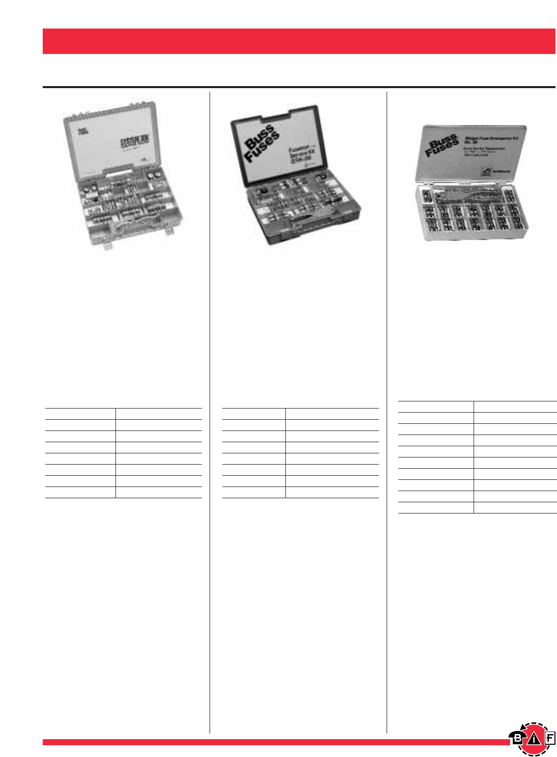
Fusetron®Fuse
Service Kit
Catalog Symbol: ERK-28
• Convenient, compact kit to hold
spare fuses.
• Sturdy nylon box with handle rugged
enough to withstand field use.
• Extra spaces and changeable com-
partments make it easy to customize
for your particular need.
Contents
(2) FRN-R-3¤Ω¡º (2) FRN-R-40
(2) FRN-R-6⁄Ω¢ (2) FRN-R-50
(2) FRN-R-10 (3) FRN-R-60
(2) FRN-R-15 (2) FRN-R-100
(3) FRN-R-20 (2) No. 263-R Reducers
(2) FRN-R-25 (2) No. 1 Clip Clamps
(4) FRN-R-30 (2) No. 2 Clip Clamps
(2) FRN-R-35
Service Kits
Fuse Accessories, Displays, Kits, Etc. Bussmann®
206 For complete specification data, call Bussmann Information Fax ~ 636.527.1450
Low-Peak®Fuse
Service Kit
Catalog Symbol: LPRK-28
• Convenient, compact kit to hold
spare fuses.
• Sturdy nylon box with handle rugged
enough to withstand field use.
• Extra spaces and changeable com-
partments make it easy to customize
for your particular need.
Contents
(2) LPN-RK-3¤Ω¡º SP (2) LPN-RK-40 SP
(2) LPN-RK-6⁄Ω¢ SP (2) LPN-RK-50 SP
(2) LPN-RK-10 SP (3) LPN-RK-60 SP
(2) LPN-RK-15 SP (2) LPN-RK-100 SP
(3) LPN-RK-20 SP (2) No. 263-R Reducers
(2) LPN-RK-25 SP (2) No. 1 Clip Clamps
(4) LPN-RK-30 SP (2) No. 2 Clip Clamps
(2) LPN-RK-35 SP (1) FP-2 Fusepuller
Midget Fuse
Emergency Kit
Quick Service Replacement for
⁄‹Ω£™∑ ≈ 1⁄Ω™∑ fuses
Catalog Symbol: No. 36
• A sturdy nylon box is ideal for factory
or service truck use.
• Cross reference makes it easy to
install correct fuse in any application.
• Free fuse puller enclosed in box.
Contents
(2) FNQ-R-⁄Ω™ (2) KTK-R-1
(2) FNQ-R-1 (2) KTK-R-2
(2) FNQ-R-2 (2) KTK-R-3
(2) FNQ-R-3 (2) KTK-R-5
(2) FNQ-R-4 (2) KTK-R-6
(2) FNQ-R-5 (2) KTK-R-10
(2) FNQ-10 (2) KTK-R-15
(2) FNQ-15 (2) KTK-R-20
(2) FNQ-20 (2) KTK-R-30
(1) FP-2
Kit size: 10‡Ω•∑ ≈ 6fiΩ•∑ ≈ 1‹Ω¢∑.
Fuse Accessories, Displays, Kits, Etc. Bussmann®
207
For complete specification data, call Bussmann Information Fax ~ 636.527.1450
Service Kits
Small Dimension Fuse
Assortment Kit
Catalog Symbol: No. 270
Voltage Rating: 125V and 250V
Contains 270 assorted fuses plus
fuseholders, fuseblocks and fuse clips
to fit most electronic equipment.
Electronic Fuse Assortment
(5) MDL-⁄Ω• (5) ABC-10
(5) MDL-⁄Ω¢ (5) ABC-15
(5) MDL-⁄Ω™ (5) ABC-20
(5) MDL-‹Ω¢ (5) ABC-30
(5) MDL-1(5) GMA-250mA
(5) MDL-1⁄Ω™ (5) GMA-500mA
(5) MDL-2(5) GMA-1A
(5) MDL-3(5) GMA-2A
(5) MDL-4(5) GMA-3A
(5) MDL-5(5) GMA-4A
(5) MDL-6(5) GMA-6A
(5) MDA-8(5) GMC-1A
(5) MDA-10 (5) GMC-2A
(5) MDA-15 (5) GMC-3A
(5) MDA-20 (5) GMC-4A
(5) MDA-30 (5) GMC-6A
(5) AGC-⁄Ω• (5) AGC-V-⁄Ω™
(5) AGC-⁄Ω¢ (5) AGC-V-1
(5) AGC-⁄Ω™ (5) AGC-V-2
(5) AGC-‹Ω¢ (5) AGC-V-3
(5) AGC-1(5) MDL-V-⁄Ω™
(5) AGC-1⁄Ω™ (5) MDL-V-1
(5) AGC-2(5) MDL-V-2
(5) AGC-2⁄Ω™ (5) MDL-V-3
(5) AGC-3(1) S-8202-2
(5) AGC-4(1) HTB-26I
(5) AGC-5(1) HTB-28M
(5) AGC-6(2) Pr. 4121 Fuseclips
(5) AGC-7(2) HHB
(5) AGC-8
Small Dimension Fuse
Assortment Kit
Catalog Symbol: No. 140
Voltage Rating: 125V & 250V
Contains 140 assorted fuses plus
fuseholders, fuseblocks and fuse clips
to fit most electronic equipment.
Electronic Fuse Assortment
(5) MDL-⁄Ω™ (5) AGC-1⁄Ω™
(5) MDL-1(5) AGC-2
(5) MDL-1⁄Ω™ (5) AGC-3
(5) MDQ-2(5) MTH-4
(5) MDQ-3(5) MTH-5
(5) MDQ-4 (5) MTH-6
(5) MDQ-5(5) MTH-7
(5) MDQ-6(5) MTH-8
(5) MDA-8(5) ABC-10
(5) MDA-10 (5) ABC-15
(5) MDA-15 (5) ABC-20
(5) MDA-20 (5) ABC-30
(5) MDA-30 (2) Pr. #4121 Fuseclips
(5) AGC-⁄Ω¢ (2) HHB
(5) AGC-⁄Ω™ (1) FP-A3
(5) AGC-1
5mm ≈20mm Fuse
Assortment Kit
Catalog Symbol: No. 220
Voltage Rating: 125V & 250V
A complete assortment of 125V and
250V 5mm x 20mm size fuses for the
repair of both electrical and electronic
devices.
Contents
Product Ampere Ratings
Type Contains 5 each
GMA 250ma, 500ma, 1, 1.5,
2, 2.5, 3, 4, 5, 10
GDA 630ma, 1, 2, 3.15, 5, 6.3
GDB 630ma, 2, 3.15, 4
GMC 500ma, 750ma, 1, 2,
2.5, 3, 3.15, 4, 5, 6.3
GMD 200ma, 500ma, 1, 1.6, 2, 3
GDC 250ma, 500ma, 1, 1.6,
2, 3.15, 4, 5
HTB-28m,
FP-A3
Fuse Display Racks
Fuse Accessories, Displays, Kits, Etc. Bussmann®
208 For complete specification data, call Bussmann Information Fax ~ 636.527.1450
Electronic Fuse Display
Catalog Symbol: No. 205
Compact display of 125V and
250V fuses.
Size: 6‹Ω¢∑ W ≈ 16∑ H x 4∑ D
Fuse Quantity Fuse Quantity
AGC-⁄Ω™ 5 MDL-1 10
AGC-1 10 MDL-1⁄Ω™ 5
AGC-1⁄Ω™ 5 MDL-2 10
AGC-2 10 MDL-3 10
AGC-3 10 MDL-4 5
AGC-4 5 MDL-5 5
AGC-5 10 MDL-6 5
AGC-6 5 MDL-7 5
AGC-7 5 MDL-8 5
AGC-8 5 GLH-7 15
AGC-10 5 GMA-500mA 5
ABC-10 5 GMA-1A 5
ABC-15 15 GMA-2A 5
ABC-20 5 GMA-3A 5
MDL⁄Ω™ 5 GMA-5A 5
No. 200 & No. 201
Glass Tube and Blade-Type
Automotive Fuses
The “200”—40 boxes (172 fuses).
Size: 4∑ ≈ 6‹Ω¢∑ x 10∑ (270 cu. in.)
Fuse Quantity Fuse Quantity
AGC-15 ATM-2 5
AGC-2 5 ATM-3 5
AGC-3 5 ATM-4 5
AGC-5 5 ATM-5 5
AGC-7⁄Ω™ 5 ATM-7⁄Ω™ 5
AGC-10 5 ATM-10 5
AGC-15 5 ATM-15 5
AGC-20 5 ATM-20 5
AGC-25 5 ATM-25 5
AGC-30 5 ATM-30 5
ATC-3 5 GBC-8 5
ATC-4 5 MAX-20 5
ATC-5 5 MAX-30 5
ATC-7⁄Ω™ 5 MAX-40 2
ATC-10 5 MAX-50 1
ATC-15 5 MAX-60 2
ATC-20 10 SFE-14 5
ATC-25 5 SFE-20 5
ATC-30 5
The “201”—40 boxes (172 fuses).
Comes in handy, clear plastic service kit.
Fuse assortment same as the “200”.
3∑ ≈ 4∑ x 10∑ (142.5 cu. in.)
Christmas Light Fuses
and Displays
Bussmann offers a comprehensive line
of replacement fuses for all Christmas
tree lights and decorative light
products.
Display Cartons
Carton
Part No. Description Quantity
BP/AGX-7X5 5 AGX-7A, 125V Fuses 20 Cards
⁄Ω¢∑ ≈ 1∑ Glass Tube
BP/GLH-7X5 5 GLH-7A, 125V Fuses 20 Cards
⁄Ω¢∑ ≈ 1⁄Ω¢∑ Glass Tube
BP/MAS-3X5 5 MAS-3A, 125V Fuses 20 Cards
3.6mm x 10mm Glass Tube
BP/XMAS-6F Assortment: 6 Fuses 20 Cards
(2 ea. AGX-7, GLH-7, MAS-3)
Clip Strip
CS/XMAS-6F Assortment: 6 Fuses 20 Cards
(2 ea. AGX-7, GLH-7, MAS-3)
Note: Order by the card (each in multiples of 20).
Package Specifications
Card Size Display Carton
Part No. H W D H W Weight
BP/AGX-7X5 4‹Ω¢∑ 2‹Ω¢∑ 7⁄Ω¢∑ 6⁄Ω¢∑ 5‹Ω¢∑ 1 lb. 10 oz.
BP/GLH-7X5 4‹Ω¢∑ 2‹Ω¢∑ 7⁄Ω¢∑ 6⁄Ω¢∑ 5‹Ω¢∑ 1 lb. 10 oz.
BP/MAS-3X5 4‹Ω¢∑ 2‹Ω¢∑ 7⁄Ω¢∑ 6⁄Ω¢∑ 5‹Ω¢∑ 1 lb. 10 oz.
BP/XMAS-6F 4‹Ω¢∑ 2‹Ω¢∑ 7⁄Ω¢∑ 6⁄Ω¢∑ 5‹Ω¢∑ 1 lb. 10 oz.
CS/XMAS-6F 4‹Ω¢∑ 2‹Ω¢∑ 6⁄Ω™∑ 2‡Ω•∑ 6⁄Ω¢∑ 1 lb. 4 oz.
No. 2880
Empty Counter or Wall Stock
Display Rack
• Holds 2880 fuses (574 boxes of
5 each).
• Six removable sections with four
channels. Units may be interlocked
without screws.
Fuse Accessories, Displays, Kits, Etc. Bussmann®
209
For complete specification data, call Bussmann Information Fax ~ 636.527.1450
Fuse Display Racks
FDM-1
Fuse Display Merchandiser
• Bussmann tilt-bin display maximizes your space and stimu-
lates impulse purchases.
• Interlocking bins can be stacked or mounted on peg board.
• Header card easily attaches with plastic push pegs.
• Provides a flexible system to best fit your needs and space
requirements.
• The tilt bins are available in five and six bin models.
Fuse Display Merchandiser will consist of any number of either
size bins; header card push pegs to attach and part number
labels.
Part Number Description
1A9721 5 Bin Display 23fiΩ•long x 6⁄Ω™tall x 5⁄Ω™deep
1A9722 6 Bin Display 23fiΩ•long x 4⁄Ω™tall x 3fiΩ•deep
FSD
Key Features & Benefits:
• Prominent “Silent Salesman”.
• Sturdy Steel Construction.
• Selection of fastest selling sizes and amps.
• Flip chart for applications, cross referencing
and fuse types.
• Clear tilt bins allow for quick identification,
easy access, inventory restocking.
• Heavy duty casters allow for easy repositioning.
• Modular system provides flexibility for growth
by joining two or more units together.
(Back-to-back or side-by-side).
• Product part number adhesive labels.
• Standard Gondola Measures:
24" wide x 66" tall x 21⁄Ω™" deep
FNQ-R-1/4 10
FNQ-R-1/2 10
FNQ-R-1 10
FNQ-R-1-1/2 10
FNQ-R-2 10
FNQ-R-3 10
FNQ-R-4 10
FNQ-R-5 10
FNQ-R-10 10
FNQ-15 10
FNQ-20 10
FNQ-25 10
FNQ-30 10
FP2 10
FP3 10
KTK-R-5 10
KTK-R-10 10
KTK-R-15 10
KTK-R-20 10
KTK-R-30 10
FNM-2 10
FNM-5 10
FNM-10 10
FNM-15 10
LP-CC-5 10
LP-CC-10 10
LP-CC-15 10
LP-CC-20 10
LP-CC-30 10
FRN-R-5 10
FRN-R-10 10
FRN-R-15 10
FRN-R-20 10
FRN-R-25 10
FRN-R-30 10
FRN-R-35 10
FRN-R-40 10
FRN-R-45 10
FRN-R-50 10
FRN-R-60 10
NON-3 10
NON-6 10
NON-10 10
NON-15 10
NON-20 10
NON-30 10
NON-35 10
NON-40 10
NON-45 10
NON-50 10
NON-60 10
T-15 4
T-20 4
T-30 4
W-15 4
W-20 4
FRS-R-5 10
FRS-R-10 10
FRS-R-15 10
FRS-R-20 10
FRS-R-25 10
FRS-R-30 10
FRS-R-35 10
FRS-R-40 10
FRS-R-50 10
FRS-R-60 10
FRS-R-100 1
FRS-R-200 1
Part Carton
Number Quantity
Part Carton
Number Quantity
Part Carton
Number Quantity

Bussmann®
210
Fuse Technology
Circuit Protection
Electrical distribution systems are often quite complicated. They
cannot be absolutely fail-safe. Circuits are subject to destructive
overcurrents. Harsh environments, general deterioration, acci-
dental damage, damage from natural causes, excessive expan-
sion, and/or overloading of the electrical distribution system are
factors which contribute to the occurrence of such overcurrents.
Reliable protective devices prevent or minimize costly damage to
transformers, conductors, motors, and the other many compo-
nents and loads that make up the complete distribution system.
Reliable circuit protection is essential to avoid the severe mone-
tary losses which can result from power blackouts and prolonged
downtime of facilities. It is the need for reliable protection, safety,
and freedom from fire hazards that has made the fuse a widely
used protective device.
Overcurrents
An overcurrent is either an overload current or a short-circuit cur-
rent. The overload current is an excessive current relative to nor-
mal operating current, but one which is confined to the normal
conductive paths provided by the conductors and other compo-
nents and loads of the distribution system. As the name implies,
a short-circuit current is one which flows outside the normal con-
ducting paths.
Overloads
Overloads are most often between one and six times the normal
current level. Usually, they are caused by harmless temporary
surge currents that occur when motors are started-up or trans-
formers are energized. Such overload currents, or transients, are
normal occurrences. Since they are of brief duration, any tem-
perature rise is trivial and has no harmful effect on the circuit
components. (It is important that protective devices do not react
to them.)
Continuous overloads can result from defective motors (such as
worn motor bearings), overloaded equipment, or too many loads
on one circuit. Such sustained overloads are destructive and
must be cut off by protective devices before they damage the
distribution system or system loads. However, since they are of
relatively low magnitude compared to short-circuit currents,
removal of the overload current within minutes will generally pre-
vent equipment damage. A sustained overload current results in
overheating of conductors and other components and will cause
deterioration of insulation, which may eventually result in severe
damage and short-circuits if not interrupted.
Short-Circuits
Whereas overload currents occur at rather modest levels, the
short-circuit or fault current can be many hundred times larger
than the normal operating current. A high level fault may be
50,000A (or larger). If not cut off within a matter of a few thou-
sandths of a second, damage and destruction can become
rampant—there can be severe insulation damage, melting of
conductors, vaporization of metal, ionization of gases, arcing,
and fires. Simultaneously, high level short-circuit currents can
develop huge magnetic-field stresses. The magnetic forces
between bus bars and other conductors can be many hundreds
of pounds per linear foot; even heavy bracing may not be ade-
quate to keep them from being warped or distorted beyond
repair.
Fuses
The fuse is a reliable overcurrent protective device. A “fusible” link
or links encapsulated in a tube and connected to contact termi-
nals comprise the fundamental elements of the basic fuse.
Electrical resistance of the link is so low that it simply acts as a
conductor. However, when destructive currents occur, the link
very quickly melts and opens the circuit to protect conductors
and other circuit components and loads. Fuse characteristics are
stable. Fuses do not require periodic maintenance or testing.
Fuses have three unique performance characteristics:
1. Modern fuses have an extremely “high interrupting
rating”—can withstand very high fault currents without
rupturing.
2. Properly applied, fuses prevent “blackouts.” Only the
fuse nearest a fault opens without upstream fuses
(feeders or mains) being affected—fuses thus provide
“selective coordination.” (These terms are precisely
defined in subsequent pages.)
3. Fuses provide optimum component protection by
keeping fault currents to a low value…They are said to
be “current limiting.”
Voltage Rating
The voltage rating of a fuse must be at least equal to or greater
than the circuit voltage. It can be higher but never lower. For
instance, a 600V fuse can be used in a 208V circuit.
The voltage rating of a fuse is a function of its capability to
open a circuit under an overcurrent condition. Specifically,
the voltage rating determines the ability of the fuse to suppress
the internal arcing that occurs after a fuse link melts and an arc
is produced. If a fuse is used with a voltage rating lower than the
circuit voltage, arc suppression will be impaired and, under some
fault current conditions, the fuse may not clear the overcurrent
safely. Special consideration is necessary for semiconductor fuse
and medium voltage fuse applications, where a fuse of a certain
voltage rating is used on a lower voltage circuit.
Ampere Rating
Every fuse has a specific ampere rating. In selecting the ampere
rating of a fuse, consideration must be given to the type of load
and code requirements. The ampere rating of a fuse normally
should not exceed the current carrying capacity of the circuit. For
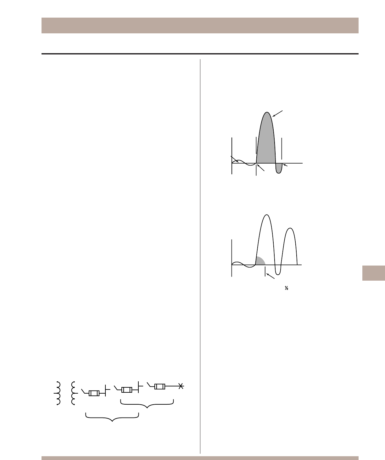
Bussmann®
211
Fuse Technology
instance, if a conductor is rated to carry 20A, a 20A fuse is the
largest that should be used. However, there are some specific
circumstances in which the ampere rating is permitted to be
greater than the current carrying capacity of the circuit. A typical
example is the motor circuit; dual-element fuses generally are
permitted to be sized up to 175% and non-time-delay fuses up
to 300% of the motor full-load amperes. As a rule, the ampere
rating of a fuse and switch combination should be selected at
125% of the continuous load current (this usually
corresponds to the circuit capacity, which is also selected at
125% of the load current). There are exceptions, such as when
the fuse-switch combination is approved for continuous opera-
tion at 100% of its rating.
Interrupting Rating
A protective device must be able to withstand the destructive
energy of short-circuit currents. If a fault current exceeds the
capability of the protective device, the device may actually rup-
ture, causing additional damage. Thus, it is important when
applying a fuse or circuit breaker to use one which can sustain
the largest potential short-circuit currents. The rating which
defines the capacity of a protective device to maintain its integ-
rity when reacting to fault currents is termed its “interrupting
rating”. The interrupting rating of most branch-circuit, molded
case, circuit breakers typically used in residential service entrance
panels is 10,000A. (Please note that a molded case
circuit breaker’s interrupting capacity will typically be lower than
its interrupting rating.) Larger, more expensive circuit breakers
may have interrupting ratings of 14,000A or higher. In contrast,
most modern, current-limiting fuses have an interrupting rating of
200,000 or 300,000A and are commonly used to protect the
lower rated circuit breakers. The National Electrical Code,
Section 110-9, requires equipment intended to break current at
fault levels to have an interrupting rating sufficient for the current
that must be interrupted.
Selective Coordination – Prevention of Blackouts
The coordination of protective devices prevents system power
outages or blackouts caused by overcurrent conditions. When
only the protective device nearest a faulted circuit opens and
larger upstream fuses remain closed, the protective devices are
“selectively” coordinated (they discriminate). The word “selective”
is used to denote total coordination…isolation of a faulted circuit
by the opening of only the localized protective device.
This diagram shows the minimum ratios of ampere ratings of LOW-PEAK
YELLOW fuses that are required to provide “selective coordination”
(discrimination) of upstream and downstream fuses.
Unlike electro-mechanical inertial devices (circuit breakers), it is a
simple matter to selectively coordinate fuses of modern design.
By maintaining a minimum ratio of fuse-ampere ratings between
an upstream and downstream fuse, selective coordination is
assured.
Current Limitation – Component Protection
A non-current-limiting protective device, by permitting a short-
circuit current to build up to its full value, can let an immense amount of
destructive short-circuit heat energy through before opening the circuit.
A current-limiting fuse has such a high speed of response that it cuts off a
short-circuit long before it can build up to its full peak value.
If a protective device cuts off a short-circuit current in less than
one-quarter cycle, before it reaches its total available (and highly
destructive) value, the device is a “current-limiting” device. Most
modern fuses are current-limiting. They restrict fault currents to
such low values that a high degree of protection is given to circuit
components against even very high short-circuit currents. They
permit breakers with lower interrupting ratings to be used. They
can reduce bracing of bus structures. They minimize the need of
other components to have high short-circuit current “withstand”
ratings. If not limited, short-circuit currents can reach levels of
30,000 or 40,000A or higher in the first half cycle (.008 seconds,
60 hz) after the start of a short-circuit. The heat that
can be produced in circuit components by the immense energy
of short-circuit currents can cause severe insulation damage or
even explosion. At the same time, huge magnetic forces
developed between conductors can crack insulators and distort
and destroy bracing structures. Thus, it is important that
a protective device limit fault currents before they reach their
full potential level.
KRP-C
1200SP
2:1 (or more)
LPS-RK
600SP
LPS-RK
200SP
2:1 (or more)
Normal
load current
Initiation of
short-circuit
current
Circuit breaker trips
and opens short-circuit
in about 1 cycle
Areas within waveform
loops represent destructive
energy impressed upon
circuit components
Fuse opens and clears
short-circuit in less
than
cycle
Operating Principles of Bussmann®Fuses
The principles of operation of the modern, current-limiting Buss
fuses are covered in the following paragraphs.
Non-Time-Delay Fuses
The basic component of a fuse is the link. Depending upon the
ampere rating of the fuse, the single-element fuse may have one
or more links. They are electrically connected to the end blades (or
ferrules) (see Figure 1) and enclosed in a tube or cartridge sur-
rounded by an arc quenching filler material. BUSS®LIMITRON®
and T-TRON®fuses are both single-element fuses.
Under normal operation, when the fuse is operating at or near its
ampere rating, it simply functions as a conductor. However, as
illustrated in Figure 2, if an overload current occurs and persists for
more than a short interval of time, the temperature of the link even-
tually reaches a level which causes a restricted segment of the link
to melt. As a result, a gap is formed and an electric arc estab-
lished. However, as the arc causes the link metal to burn back, the
gap becomes progressively larger. Electrical resistance of the arc
eventually reaches such a high level that the arc cannot be sus-
tained and is extinguished. The fuse will have then completely cut
off all current flow in the circuit. Suppression or quenching of the
arc is accelerated by the filler material. (See Figure 3.)
Single-element fuses of present day design have a very high
speed of response to overcurrents. They provide excellent short-
circuit component protection. However, temporary, harmless
overloads or surge currents may cause nuisance openings unless
these fuses are oversized. They are best used, therefore, in cir-
cuits not subject to heavy transient surge currents and the tem-
porary over-load of circuits with inductive loads such as motors,
transformers, solenoids, etc. Because single-element, fast-acting
fuses such as LIMITRON and T-TRON fuses have a high speed of
response to short-circuit currents, they are particularly suited for
the protection of circuit breakers with low interrupting ratings.
Whereas an overload current normally falls between one and
six times normal current, short-circuit currents are quite high.
The fuse may be subjected to short-circuit currents of 30,000
or 40,000A or higher. Response of current limiting fuses to such
currents is extremely fast. The restricted sections of the fuse link
will simultaneously melt (within a matter of two or three-thou-
sandths of a second in the event of a high-level fault current).
The high total resistance of the multiple arcs, together with the
quenching effects of the filler particles, results in rapid arc sup-
pression and clearing of the circuit. (Refer to Figures 4 & 5) Short-
circuit current is cut off in less than a half-cycle, long before the
short-circuit current can reach its full value (fuse operating in its
current limiting range).
Bussmann®
212
Fuse Technology
Figure 2. Under sustained overload, a section of the link melts and an
arc is established.
Figure 3. The “open” single-element fuse after opening a circuit
overload.
Figure 4. When subjected to a short-circuit current, several
sections of the fuse link melt almost instantly.
Figure 5. The “open” single-element fuse after opening a short circuit.
Figure 1. Cutaway view of typical single-element fuse.
Bussmann®
213
Fuse Technology
There are many advantages to using these fuses. Unlike single-element fuses, the Bussmann®dual-element, time-delay fuses can be sized closer to provide both high performance short-
circuit protection and reliable overload protection in circuits subject to temporary overloads and surge currents. For ac motor loads, a single-element fuse may need to be sized at 300% of an
a.c. motor current in order to hold the starting current. However, dual-element, time delay fuses can be sized much closer to motor loads. For instance, it is generally possible to size FUSETRON®
Dual-Element Fuses, FRS-R and FRN-R and LOW-PEAK®Dual-Element Fuses, LPS-RK_SP and LPN-RK_SP, at 125% and 130% of motor full load current, respectively. Generally, the LOW-
PEAK®Dual-Element Fuses, LPJ_SP, and CUBEFuseTM, TCF, can be sized at 150% of motor full load amperes. This closer fuse sizing may provide many advantages such as: (1)
smaller fuse and block, holder or disconnect ampere rating and physical size, (2) lower cost due to lower ampere rated devices and possibly smaller required panel space, (3) better
short-circuit protection – less short-circuit current let-through energy, and (4) potential reduction in the arc flash hazard.
Figure 6. This is the LPS-RK100SP, a 100A, 600V LOW-PEAK®, Class RK1, Dual-Element Fuse that has excellent time-delay, excellent current-limitation and a 300,000A interrupting rat-
ing. Artistic liberty is taken to illustrate the internal portion of this fuse. The real fuse has a non-transparent tube and special small granular, arc-quenching material completely filling the
internal space.
Figure 7. The true dual-element fuse has distinct and separate overload
element and short-circuit element.
Short-circuit element
Overload element
Spring
Filler quenches the arcs
Small volume of metal to vaporize
Filler material
Insulated end-caps to help prevent
accidental contact with live parts.
Figure 8. Overload operation: Under sustained overload conditions, the trigger spring
fractures the calibrated fusing alloy and releases the “connector”. The insets represent a
model of the overload element before and after. The calibrated fusing alloy connecting the
short-circuit element to the overload element fractures at a specific temperature due to a
persistant overload current. The coiled spring pushes the connector from the short-circuit
element and the circuit is interrupted.
Figure 9. Short-circuit operation: Modern fuses are designed with minimum metal in the
restricted portions which greatly enhance their ability to have excellent current-limiting
characteristics – minimizing the short circuit let-through current. A short-circuit
current causes the restricted portions of the short-circuit element to vaporize and arcing
commences. The arcs burn back the element at the points of the arcing. Longer arcs result,
which assist in reducing the current. Also, the special arc quenching filler material con-
tributes to extinguishing the arcing current. Modern fuses have many restricted portions,
swhich results in many small arclets – all working together to force the current to zero.
Figure 10. Short-circuit operation: The special small granular, arc-quenching material
plays an important part in the interruption process. The filler assists in quenching the arcs;
the filler material absorbs the thermal energy of the arcs, fuses together and creates an
insulating barrier. This process helps in forcing the current to zero. Modern current-limit-
ing fuses, under short-circuit conditions, can force the current to zero and complete the
interruption within a few thousandths of a second.
When the short-circuit current is in the current-limiting range of a fuse, it is not possible for the full available short-circuit current to flow through the fuse – it’s a matter of physics. The small
restricted portions of the short-circuit element quickly vaporize and the filler material assists in forcing the current to zero. The fuse is able to “limit” the short-circuit current.
Overcurrent protection must be reliable and sure. Whether it is the first day of the electrical system or thirty or more years later, it is important that overcurrent protective devices perform under
overload or short-circuit conditions as intended. Modern current-limiting fuses operate by very simple, reliable principles.
Bussmann®Dual-Element Fuses
Before
After
Fuse Time-Current Curves
When a low level overcurrent occurs, a long interval of time will
be required for a fuse to open (melt) and clear the fault. On the
other hand, if the overcurrent is large, the fuse will open very
quickly. The opening time is a function of the magnitude of the
level of overcurrent. Overcurrent levels and the corresponding
intervals of opening times are logarithmically plotted in graph
form as shown to the right. Levels of overcurrent are scaled on
the horizontal axis; time intervals on the vertical axis. The curve is
thus called a “time-current” curve.
This particular plot reflects the characteristics of a 200A, 250V,
LOW-PEAK YELLOW dual-element fuse. Note that at the 1,000A
overload level, the time interval which is required for the fuse to
open is 10 seconds. Yet, at approximately the 2,200A overcur-
rent level, the opening (melt) time of a fuse is only 0.01 seconds.
It is apparent that the time intervals become shorter as the over-
current levels become larger. This relationship is termed an
inverse time-to-current characteristic. Time-current curves are
published or are available on most commonly used fuses show-
ing “minimum melt,” “average melt” and/or “total clear” charac-
teristics. Although upstream and downstream fuses are easily
coordinated by adhering to simple ampere ratios, these time-cur-
rent curves permit close or critical analysis of coordination.
Better Motor Protection in Elevated Ambients
The derating of dual-element fuses based on increased ambient
temperatures closely parallels the derating curve of motors in ele-
vated ambient. This unique feature allows for optimum protection
of motors, even in high temperatures.
Affect of ambient temperature on operating characteristics of FUSETRON
and LOW-PEAK YELLOW Dual-Element Fuses.
Bussmann®
214
Fuse Technology
400
300
200
100
80
60
40
30
20
10
8
6
4
3
2
1
.8
.6
.4
.3
.2
.1
.08
.06
.04
.03
.02
.01
100
200
300
400
600
800
1,000
2,000
3,000
4,000
6,000
8,000
10,000
TIME IN SECONDS
CURRENT IN AMPERES
LOW-PEAK YELLOW
LPN-RK200 SP (RK1)
150
140
130
120
110
100
90
80
70
60
50
40
30
AMBIENT
PERCENT OF RATING OR
OPENING TIME
Affect on Carrying
Capacity Rating
Affect on
Opening Time
–76°F
(–60°C)
–40°F
(–40°C)
–4°F
(–20°C)
–32°F
(0°C)
68°F
(20°C)
104°F
(40°C)
140°F
(60°C)
176°F
(80°C)
212°F
(100°C)
Bussmann®
215
Fuse Technology
In the above illustration, a grooved ring in one ferrule provides the
rejection feature of the Class R fuse in contrast to the lower
interrupting rating, non-rejection type.
Branch-Circuit Listed Fuses
Branch-circuit listed fuses are designed to prevent the installation
of fuses that cannot provide a comparable level of protection to
equipment.
The characteristics of Branch-circuit fuses are:
1. They must have a minimum interrupting rating of 10,000A
2. They must have a minimum voltage rating of 125V.
3. They must be size rejecting such that a fuse of a lower
voltage rating cannot be installed in the circuit.
4. They must be size rejecting such that a fuse with a current
rating higher than the fuseholder rating cannot be installed.
Better Protection Against Motor Single Phasing
When secondary single-phasing occurs, the current in the remain-
ing phases increases to approximately 200% rated full load
current. (Theoretically 173%, but change in efficiency and power
factor make it about 200%.) When primary single-phasing
occurs, unbalanced voltages occur on the motor circuit causing
currents to rise to 115%, and 230% of normal running currents
in delta-wye systems.
Dual-element fuses sized for motor running overload protection
will help to protect motors against the possible damages of
single-phasing.
Classes of Fuses
Safety is the industry mandate. However, proper selection, overall
functional performance and reliability of a product are factors
which are not within the basic scope of listing agency activities.
In order to develop its safety test procedures, listing agencies
develop basic performance and physical specifications or stan-
dards for a product. In the case of fuses, these standards have
culminated in the establishment of distinct classes of low-voltage
(600V or less) fuses; classes RK1, RK5, G, L, T, J, H and CC being
the more important.
The fact that a particular type of fuse has, for instance, a classifi-
cation of RK1, does not signify that it has the identical function or
performance characteristics as other RK1 fuses. In fact, the LIM-
ITRON®non-time-delay fuse and the LOW-PEAK YELLOW™
dual-element, time-delay fuse are both classified as RK1.
Substantial differences in these two RK1 fuses usually requires
considerable difference in sizing. Dimensional specifications of
each class of fuse does serve as a uniform standard.
Class R Fuses
Class R (“R” for rejection) fuses are high performance, ⁄Ω¡º to 600A
units, 250V and 600V, having a high degree of current limitation
and a short-circuit interrupting rating of up to 300,000A (rms sym-
metrical). BUSS Class R's include Classes RK1 LOW-PEAK YEL-
LOW™and LIMITRON®fuses, and RK5 FUSETRON®fuses. They
have replaced BUSS K1 LOW-PEAK and LIMITRON fuses and
K5 FUSETRON fuses. These fuses are identical, with the excep-
tion of a modification in the mounting configuration called a “rejec-
tion feature”. This feature permits Class R fuses to be mounted in
rejection type fuseclips. “R” type fuseclips prevent older type
Class H, ONE-TIME and RENEWABLE fuses from being installed.
The use of Class R fuseholders is thus an important safeguard.
The application of Class R fuses in such equipment as disconnect
switches permits the equipment to have a high interrupting rating.
NEC Articles 110-9 and 230-65 require that protective devices
have adequate capacity to interrupt short-circuit currents. Article
240-60(b) requires fuseholders for current-limiting fuses to reject
non-current-limiting type fuses.
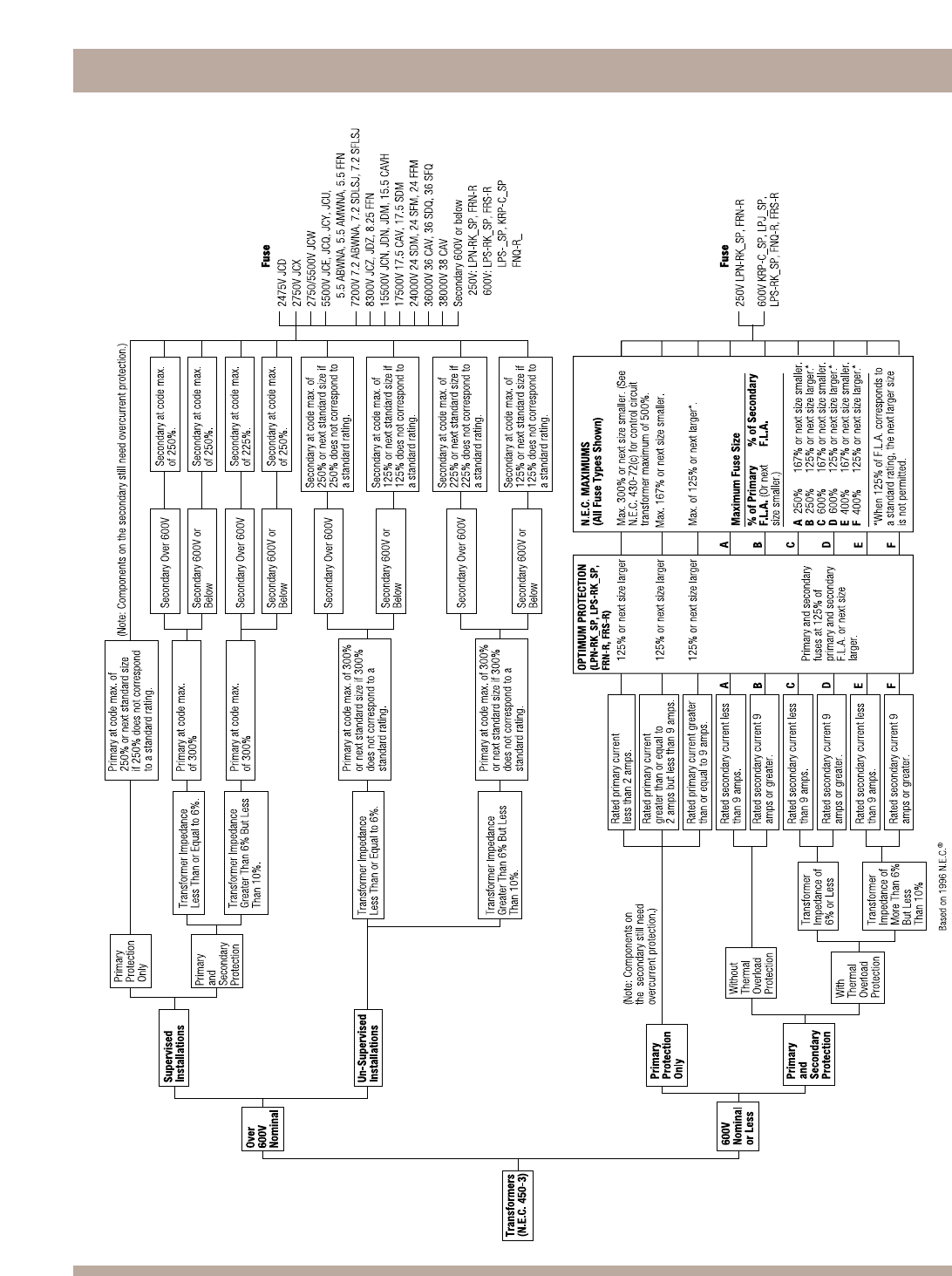
Bussmann®
216
Fuse Technology
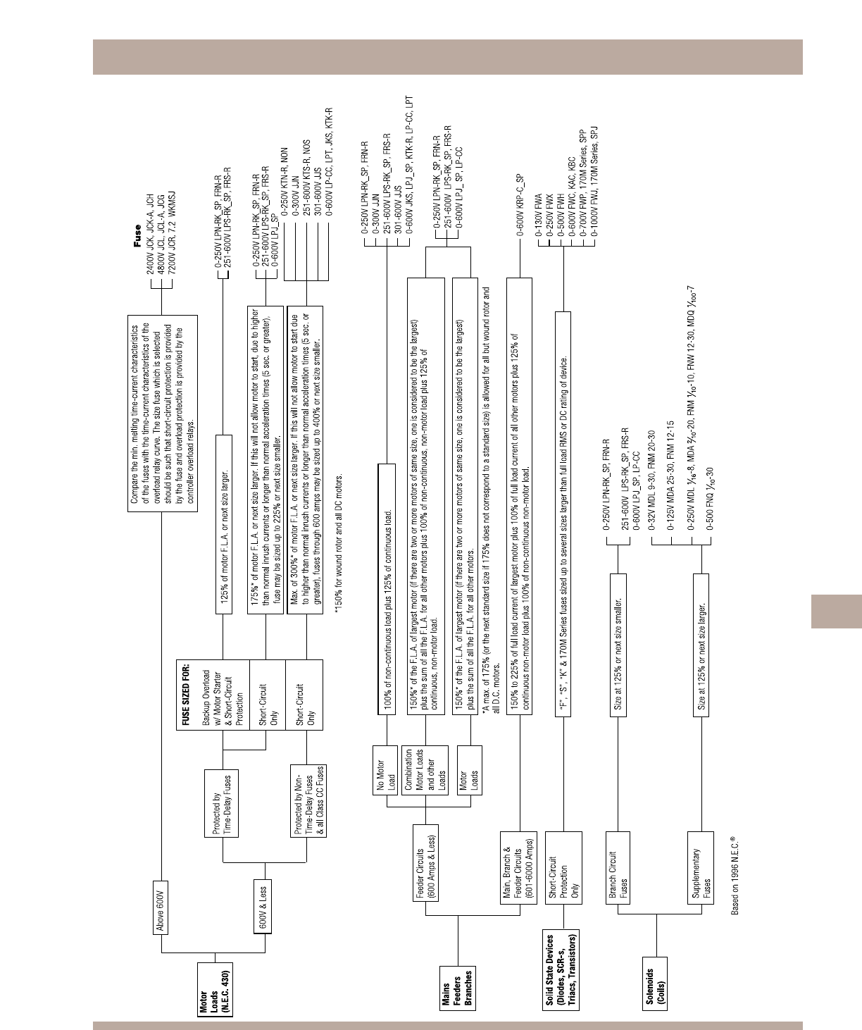
Bussmann®
217
Fuse Diagnostic Chart
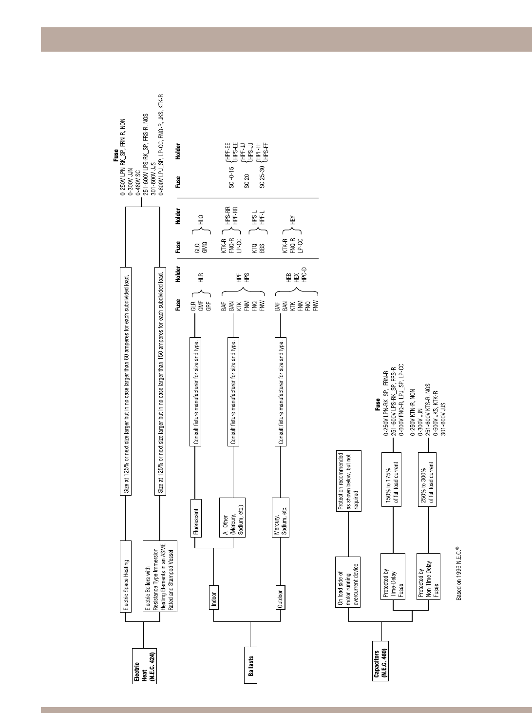
218
Bussmann®
Fuse Diagnostic Chart
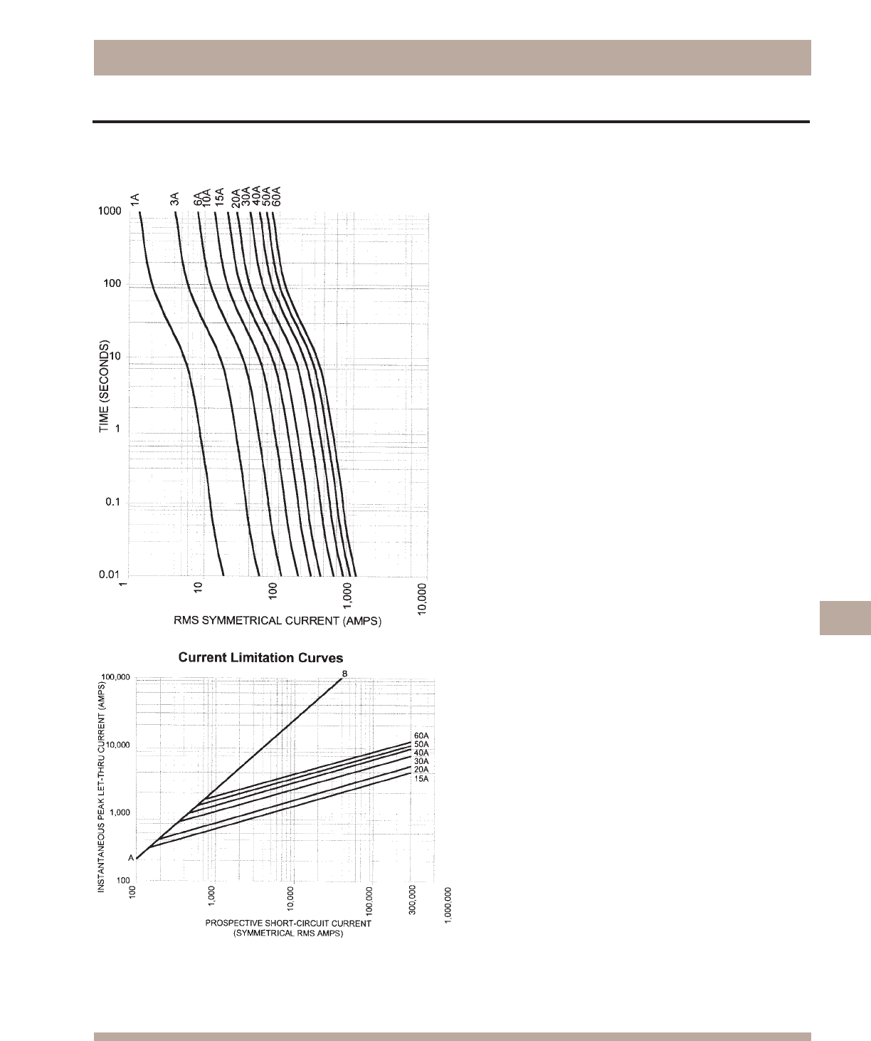
Bussmann®
219
Time-Current & Current Limitation Curves
TCF & TCFH CUBEFuseTM Fuses
TCF & TCFH Time-Current Characteristic Curves–
Average Melt
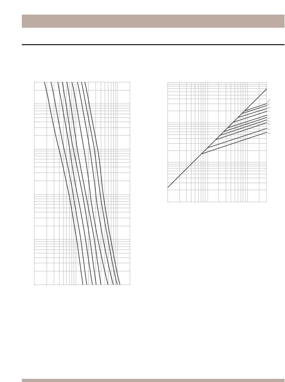
Bussmann®
220
KRP-C, Class L Fuses
Time-Current & Current Limitation Curves
300
100
10
1
.1
.01
1,000
10,000
100,000
200,000
CURRENT IN AMPERES
TIME IN SECONDS
800A
1200A
1600A
2000A
2500A
3000A
4000A
5000A
6000A
AMPERE
RATING
1000,000
10,000
1,000
10,000
300,000
PROSPECITVE SHORT-CIRCUIT CURRENT
SYMMETRICAL RMS AMPERES
100,000
100,000
6,000A
5,000A
4,000A
3,000A
2,500A
2,000A
1,600A
1,200A
800A
601A
A
AMPERE
RATING
B
1,000
KRP-C Time-Current Characteristic Curves—
Average Melt
KRP-C Current Limitation Curves
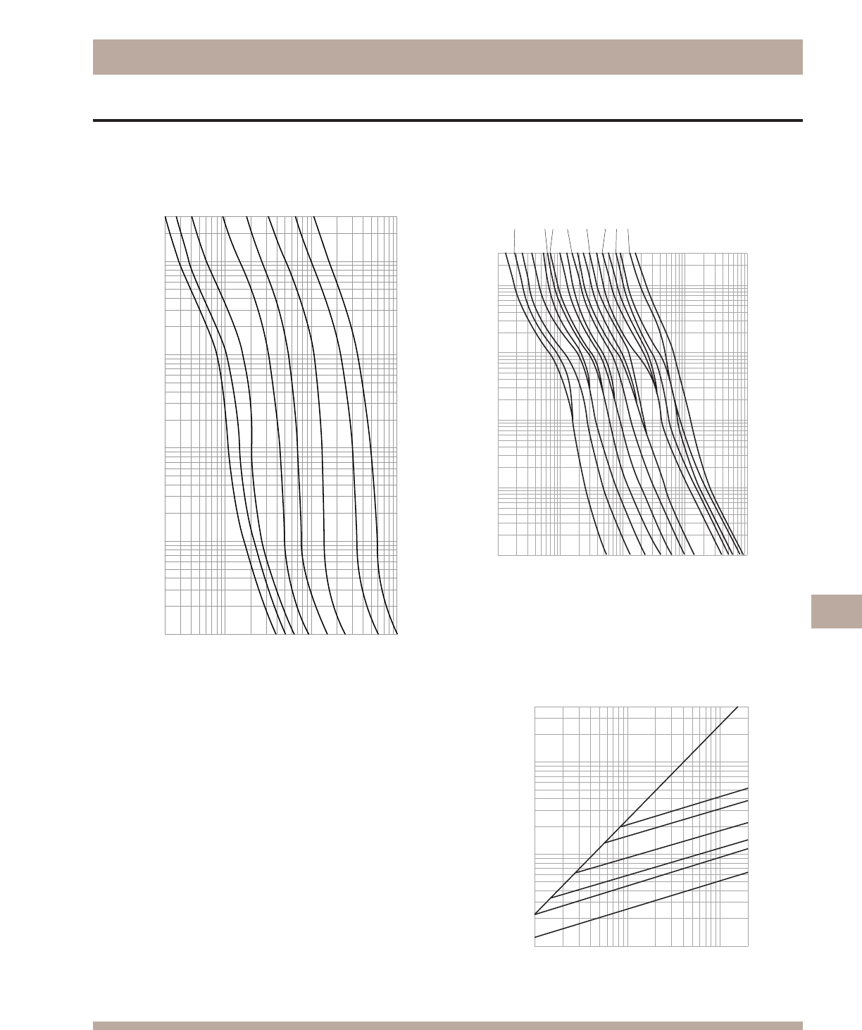
Bussmann®
221
LPN-RK (250V) Class RK1 Fuses
LPN-RK_SP (250V)
300
100
10
1
.1
.01
20
100
1,000
10,000
RMS SYMMETRICAL CURRENT IN AMPERES
TIME IN SECONDS
20A
60A
100A
200A
30A
400A
600A
15A
AMPERE
RATING
LPN-RK_SP (250V)
1/10
2/10 15/100
3/10
4/10
6/10
1/2
8/10
1 1-1/4
1-6/10
22-1/2
3-2/10
4
56-1/4
810
12
AMPERE
RATING
300
10
1
.1
.01
TIME IN SECONDS
.1
1
10
100
1,000
CURRENT IN AMPERES
Time-Current Characteristic Curves—Average Melt Time-Current Characteristic Curves—Average Melt
Time-Current & Current Limitation Curves
Current Limitation Curves
A
B
600
400
200
100
AMPERE
RATING
400,000
100,000
10,000
1,000
1,000
10,000
100,000
200,000
RMS SYMMETRICAL CURRENTS IN AMPERES
A–B=ASYMMETRICAL AVAILABLE PEAK (2.3 X SYMM RMS AMPS)
INSTANTANEOUS PEAK LET-THRU CURRENT IN AMPS
60
30
LPN-RK_SP (250V)
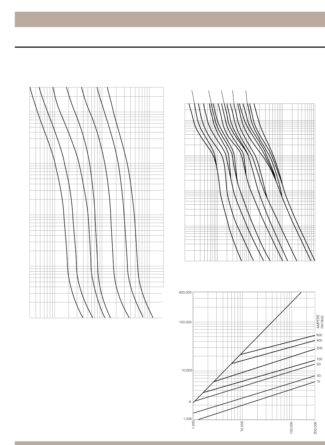
Bussmann®
222
Time-Current & Current Limitation Curves
LPS-RK (600V) Class RK1 Fuses
20A
60A
100A
200A
30A
400A
AMPERE
RATING
600A
LPS-RK
(600V)
30
100
1,000
10,000
20,000
300
100
10
1
.1
.01
CURRENT IN AMPERES
TIME IN SECONDS
1
2
4
5
8
10
AMPERE RATING
300
100
10
1
.1
.01
.1
1
10
100
1,000
TIME IN SECONDS
RMS SYMMETRICAL CURRENT IN AMPERES
1/10 15/100
2/10
3/10
4/10 1/2
6/10
8/101-1/4
1-6/10
2-1/2
3-2/10
6-1/4
Time-Current Characteristic Curves—Average Melt Time-Current Characteristic Curves—Average Melt
B
INSTANTANEOUS PEAK LET-THRU CURRENT IN AMPS
Current Limitation Curves
LPS-RK
(600V)
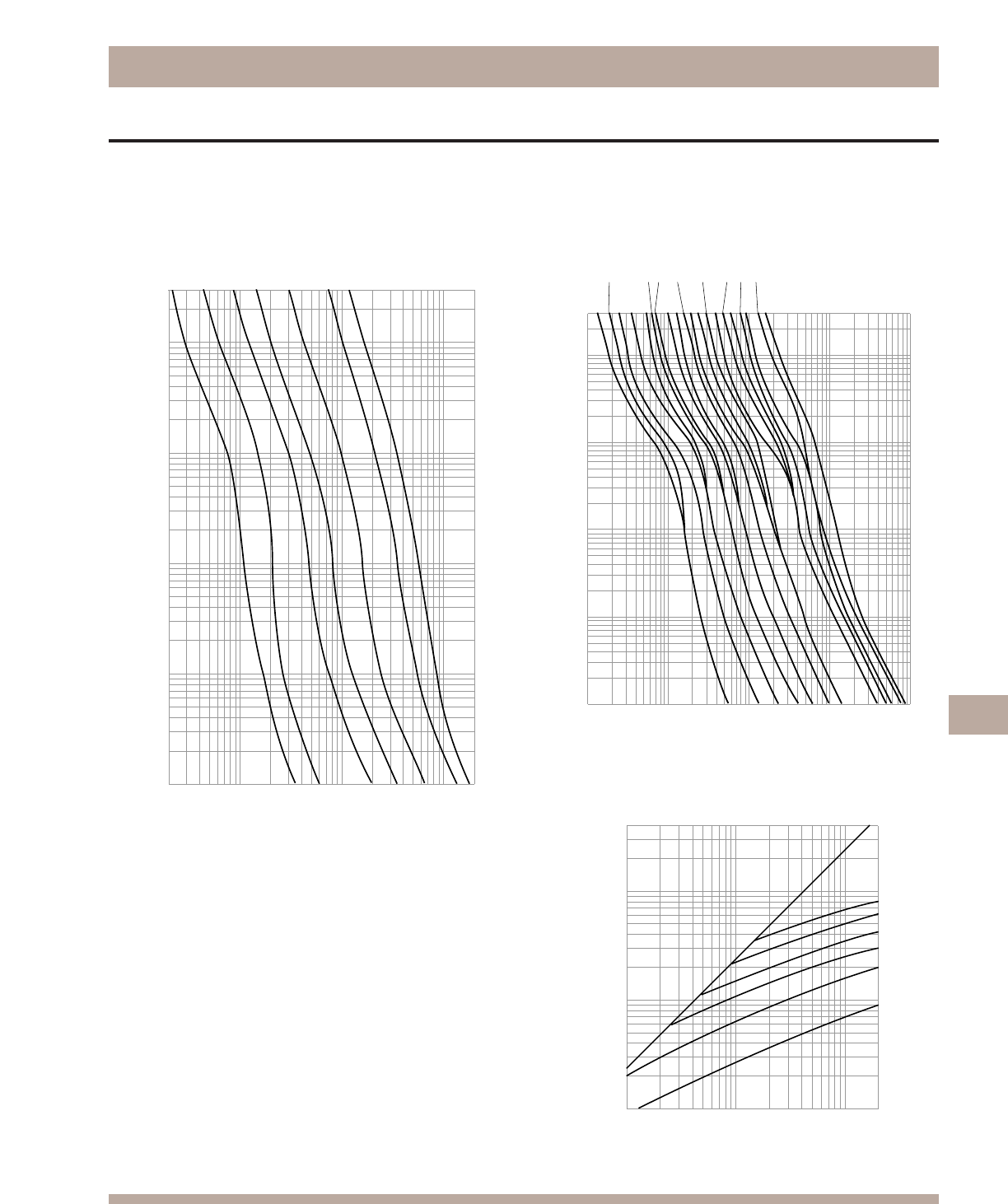
Bussmann®
223
FRN-R (250V) Class RK5 Fuses
Time-Current & Current Limitation Curves
20
100
1,000
10,000
20,000
10
1
.1
.01
TIME IN SECONDS
CURRENT IN AMPERES
FRN-R
(250V)
60A
100A
200A
30A
400A
AMPERE
RATING
600A
15A
300
100 FRN-R (250V)
1/10
2/10 15/100
3/10
4/10
6/10
1/2
8/10
1 1-1/4
1-6/10
22-1/2
3-2/10
4
56-1/4
810
12
AMPERE
RATING
300
100
10
1
.1
.01
TIME IN SECONDS
.1
1
10
100
1,000
CURRENT IN AMPERES
Time-Current Characteristic Curves—Average Melt Time-Current Characteristic Curves—Average Melt
Current Limitation Curves
INSTANTANEOUS PEAK LET-THRU CURRENT AMPERES
PROSPECTIVE SHORT CIRCUIT CURRENT
SYMMETRICAL RMS AMPERES
400,000
100,000
10,000
1,000
1,000
10,000
100,000
200,000
60
600
100
AMPERE
RATING
400
200
B
A
30
FRN-R (250V)
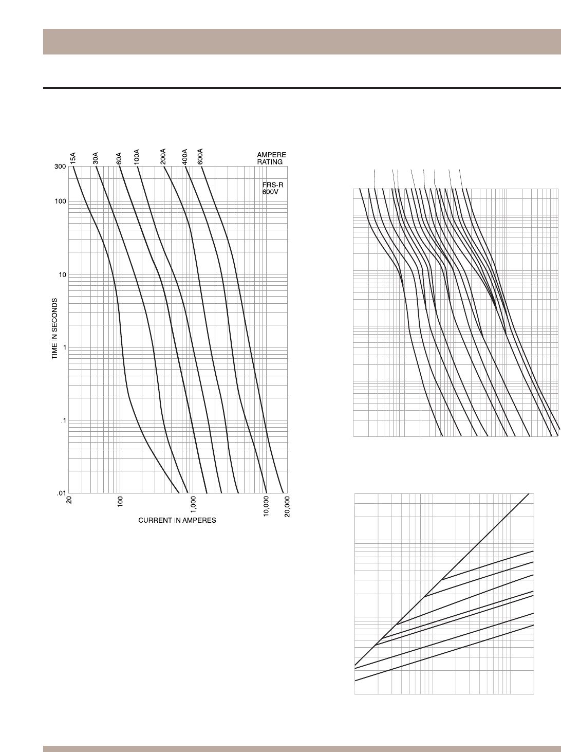
Bussmann®
224
FRS-R (600V) Class RK5 Fuses
Time-Current & Current Limitation Curves
1/10
2/10
15/100
3/10
4/10
6/10
1/2
8/10
11-1/4
1-6/10
2
2-1/2 3-2/10
4
56-1/4
810
12
AMPERE
RATING
FRS-R
(600V)
300
100
10
1
.1
TIME IN SECONDS
.01
.1
1
10
100
1
,
000
CURRENT IN AMPERES
Time-Current Characteristic Curves—Average Melt Time-Current Characteristic Curves—Average Melt
Current Limitation Curves
600A
100A
AMPERE
RATING
400A
200A
60A
INSTANTANEOUS PEAK LET THRU CURRENT AMPERES
PROSPECTIVE SHORT CIRCUIT CURRENT
SYMMETRICAL RMS AMPERES
B
A
400,000
100,000
10,000
1,000
1,000
10,000
100,000
FRS-R (600V)
30A
200,000
15A
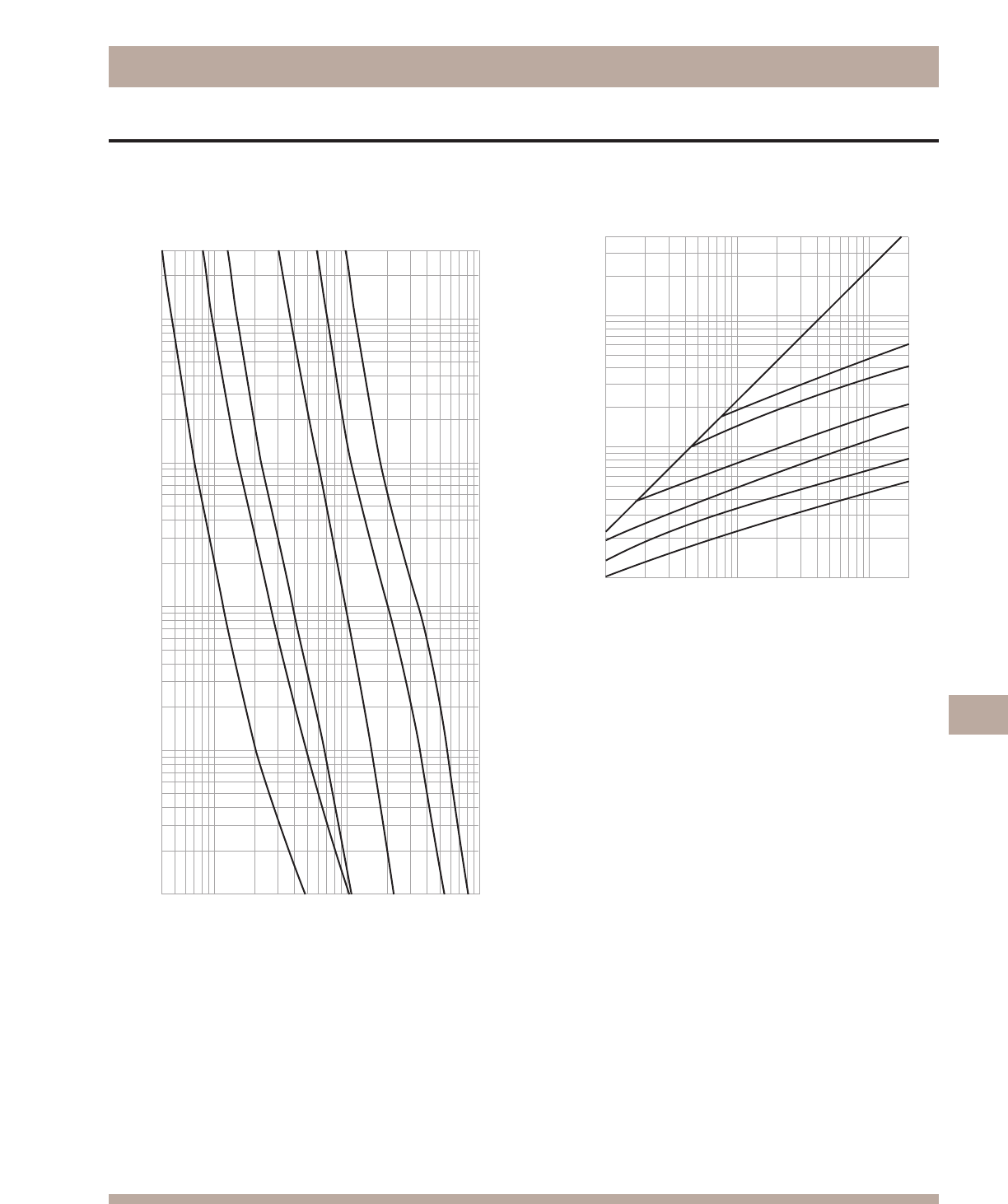
Bussmann®
225
KTN-R (250V) Class RK1 Fuses
Time-Current & Current Limitation Curves
RMS SYMMETRICAL CURRENT IN AMPERES
TIME IN SECONDS
300
100
10
1
.1
.01
40
100
1,000
10,000
30A
60A
100A
200A
400A
600A
AMPERE
RATING
600
100
60
AMPERE
RATING
30
400
200
INSTANTANEOUS PEAK LET-THRU CURRENT IN AMPS
400,000
100,000
10,000
1,000
1,000
10,000
100,000
200,000
RMS SYMMETRICAL CURRENTS IN AMPERES
A–B=ASYMMETRICAL AVAILABLE PEAK (2.3 X SYMM RMS AMPS)
A
B
Time-Current Characteristic Curves—Average Melt Current Limitation Curves
KTN-R
(250V)
KTN-R
(250V)
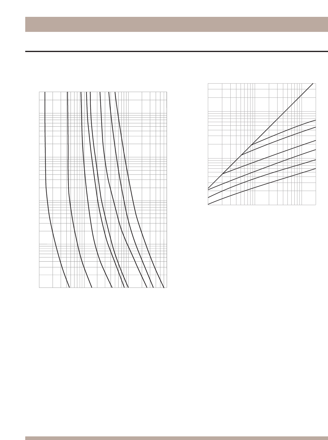
Bussmann®
226
KTS-R (600V) Class RK1 Fuses
Time-Current & Current Limitation Curves
1
100
10
1
.1
.01
10
100
200
TIME IN SECONDS
CURRENT IN AMPERES
300
200
400
500
2
20
600
700
300
1
3
6
8
10
15
25
30
CURRENT IN
AMPERES
600
100
60
AMPERE
RATING
30
400
200
200,000
100,000
10,000
1,000
1,000
INSTANTANEOUS PEAK LET-THRU CURRENT IN AMPS
400,000
100,000
10,000
RMS SYMMETRICAL CURRENTS IN AMPERES
A–B=ASYMMETRICAL AVAILABLE PEAK (2.3 X SYMM RMS AMPS)
B
A
Time-Current Characteristic Curves—Average Melt Current Limitation Curves
KTS-R
(600V)
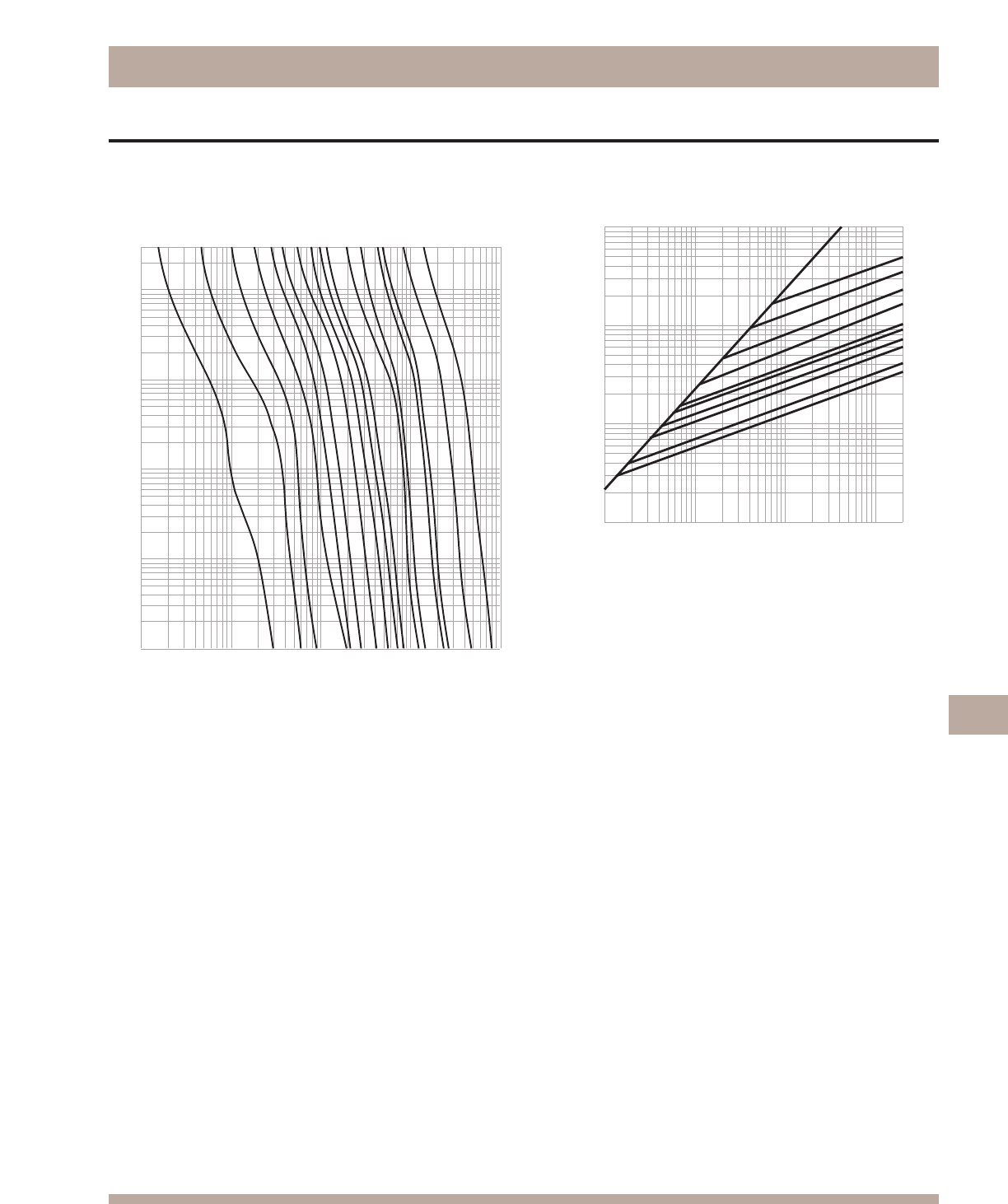
Bussmann®
227
LPJ (600V), Class J Fuses
Time-Current & Current Limitation Curves
AMPERE
RATING
1A
3A
5A
10A
15A
20A
30A
40A
50A
60A
300
100
10
1
.1
.01
TIME IN SECONDS
10,000
1,000
100
10
1
RMS SYMMETRICAL CURRENT IN AMPERES
100A
125A
200A
225A
400A
600A
INSTANTANEOUS PEAK LET-THRU CURRENT IN AMPS
100,000
10,000
1,000
100
B
A
PROSPECTIVE SHORT-CIRCUIT CURRENT
SYMMETRICAL RMS AMPS
100
1,000
10,000
100,000
200,000
600A
400A
200A
100A
60A
50A
40A
30A
20A
15A
AMPERE
RATING
Time-Current Characteristic Curves—
Average Melt
Current Limitation Curves
LPJ LPJ
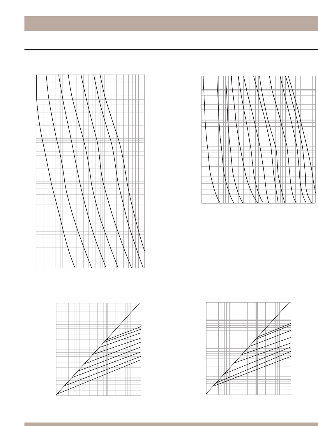
Bussmann®
228
JJN & JJS, Class T Fuses
Time-Current & Current Limitation Curves
Time-Current Characteristic Curves—Average Melt Time-Current Characteristic Curves—Average Melt
Current Limitation Curves Current Limitation Curves
600
400
200
100
60
30
15
AMPERE
RATING
800
1200
INSTANTANEOUS PEAK LET-THRU CURRENT IN AMPS
RMS SYMMETRICAL CURRENTS IN AMPERES
A-B = ASYMMETRICAL AVAILABLE PEAK (2.3 x SYMM RMS AMPS)
100,000
10,000
1,000
200
100
1,000
10,000
100,000
200,000
400,000
B
A
600
400
200
100
60
30
AMPERE
RATING
800
1200
INSTANTANEOUS PEAK LET-THRU CURRENT IN AMPS
100,000
10,000
1,000
200
100
1,000
10,000
100,000
200,000
400,000
B
A
RMS SYMMETRICAL CURRENTS IN AMPERES
A–B=ASYMMETRICAL AVAILABLE PEAK (2.3 X SYMM RMS AMPS)
RMS SYMMETRICAL CURRENT IN AMPERES
TIME IN SECONDS
20
100
1,000
10,000
300
100
10
1
.1
.01
60A
100A
200A
30A
400A
AMPERE
RATING
600A
15A
JJN
1A
3A
5A
10A
30A
15A
60A
200A
400A
500A
100A
800A
AMPERE
RATING
10,000
1,000
100
10
1
300
100
10
1
.1
.01
CURRENT IN AMPERES
TIME IN SECONDS
(300V)
JJS
(600V)
JJS
(600V)
JJN
(300V)
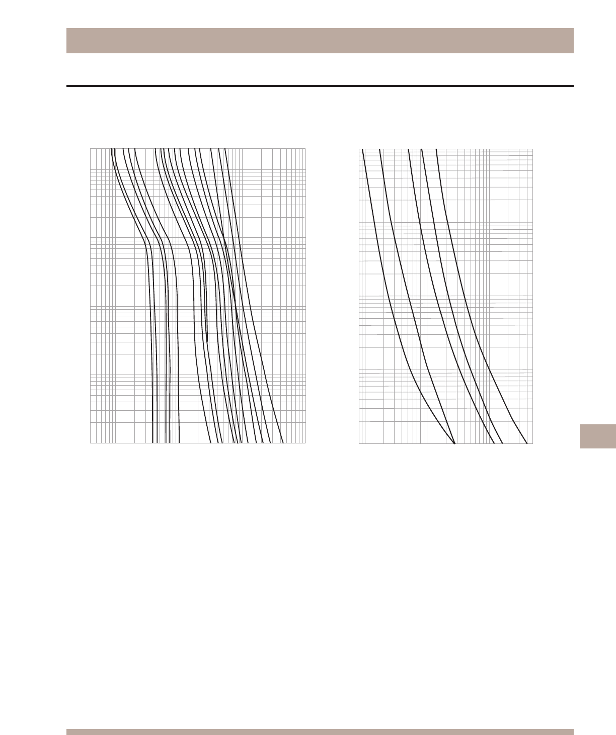
Bussmann®
229
LP-CC & FNQ-R Class CC Fuses
Time-Current & Current Limitation Curves
200
100
10
TIME IN SECONDS
1
.1
.01
⁄Ω™
flꭧ
°Ω¡º
1
1⁄Ω¢
3
3⁄Ω™
4
4⁄Ω™
6
8
10
12
15
20
25
30
AMPERE
RATING
.4
1
10
100
1000
CURRENT IN AMPERES
AMPERE
RATING
100
10
1
.01
.08
1
10
100
200
CURRENT IN AMPERES
300
400
500
TIME IN SECONDS
FNQ-R-1/2
FNQ-R-1
FNQ-R-3
FNQ-R-5
FNQ-R-7-1/2
0.01
Time-Current Characteristic Curves—Average Melt Time-Current Characteristic Curves—Average Melt
LP-CC
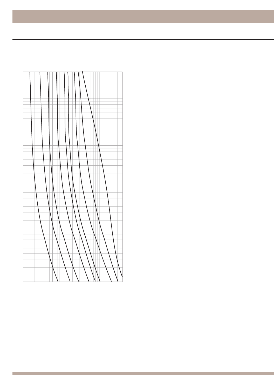
Bussmann®
230
KTK-R, Class CC Fuses
Time-Current & Current Limitation Curves
RMS SYMMETRICAL CURRENT IN AMPERES
TIME IN SECONDS
10
100
400
1
10A
20A
3A
AMPERE
RATING
2A
1A
5A
8A
15A
30A
300
100
10
1
.1
.01
Time-Current Characteristic Curves—Average Melt
KTK-R

Ampere
The measurement of intensity of rate of flow of
electrons in an electric circuit. An ampere is
the amount of current that will flow through a
resistance of one ohm under a pressure of one
volt.
Ampere Rating
The current-carrying capacity of a fuse. When
a fuse is subjected to a current above its
ampere rating, it will open the circuit after a
predetermined period of time.
Ampere Squared Seconds, l2t
The measure of heat energy developed within
a circuit during the fuse’s clearing. It can be
expressed as “melting l2t”, “arcing l2t” or the
sum of them as “Clearing l2t”. “l” stands for
effective let-through current (RMS), which is
squared, and “t” stands for time of opening, in
seconds.
Arcing Time
The amount of time from the instant the fuse
link has melted until the overcurrent is inter-
rupted, or cleared.
Breaking Capacity
(See Interrupting Rating)
Cartridge Fuse
A fuse consisting of a current responsive ele-
ment inside a fuse tube with terminals on both
ends.
Class CC Fuses
600V, 200,000A interrupting rating, branch
circuit fuses with overall dimensions of ⁄‹Ω£™∑ ≈
1⁄Ω™∑. Their design incorporates a rejection
feature that allows them to be inserted into
rejection fuse holders and fuse blocks that
reject all lower voltage, lower interrupting rat-
ing ⁄‹Ω£™∑ ≈ 1⁄Ω™∑ fuses. They are available from
⁄Ω¡ºA through 30A.
Class G Fuses
480V, 100,000A interrupting rating branch cir-
cuit fuses that are size rejecting to eliminate
overfusing. The fuse diameter is ⁄‹Ω£™∑ while
the length varies from 1fiΩ¡§∑ to 2⁄Ω¢∑. These are
available in ratings from 1A through 60A.
Class H Fuses
250V and 600V, 10,000A interrupting rating
branch circuit fuses that may be renewable or
non-renewable. These are available in ampere
ratings of 1 amp through 600A.
Class J Fuses
These fuses are rated to interrupt a minimum
of 200,000A ac. They are labelled
as “Current-Limiting”, are rated for 600Vac, and
are not interchangeable with other classes.
Class K Fuses
These are fuses listed as K-1, K-5, or K-9
fuses. Each subclass has designated I2t and lp
maximums. These are dimensionally the same
as Class H fuses, and they can have interrupt-
ing ratings of 50,000, 100,000, or 200,000 A.
These fuses are current-limiting. However,
they are not marked “current-limiting” on their
label since they do not have a rejection
feature.
Class L Fuses
These fuses are rated for 601 through 6000A,
and are rated to interrupt a minimum of
200,000A ac. They are labelled “
Current-
Limiting” and are rated for 600Vac. They are
intended to be bolted into their mountings and
are not normally used in clips. Some Class L
fuses have designed in time-delay features for all
purpose use.
Class R Fuses
These are high performance fuses rated ⁄Ω¡º-
600A in 250V and 600V ratings. All are
marked “Current Limiting” on their label
and all have a minimum of 200,000A inter-
rupting rating. They have identical outline
dimensions with the Class H fuses but have a
rejection feature which prevents the user from
mounting a fuse of lesser capabilities (lower
interrupting capacity) when used with special
Class R Clips. Class R fuses will fit into either
rejection or non-rejection clips.
Class T Fuses
An industry class of fuses in 300V and 600V
ratings from 1 amp through 1200A. They are
physically very small and can be applied
where space is at a premium. They are fast
acting and time-lag fuses, with an interrupting
rating of 200,000A RMS.
Classes of Fuses
The industry has developed basic physical
specifications and electrical performance
requirements for fuses with voltage ratings of
600V or less. These are known as standards.
If a type of fuse meets the requirements of a
standard, it can fall into that class. Typical
classes are K, RK1, RK5, G, L, H, T, CC, and J.
Clearing Time
The total time between the beginning of the
overcurrent and the final opening of the circuit
at rated voltage by an overcurrent protective
device. Clearing time is the total of the melt-
ing time and the arcing time.
Current Limitation
A fuse operation relating to short circuits only.
When a fuse operates in its current-limiting
range, it will clear a short circuit in less than ⁄Ω™
cycle. Also, it will limit the instantaneous peak
let-through current to a value substantially
less than that obtainable in the same circuit if
that fuse were replaced with a solid conduc-
tor of equal impedance.
Dual Element Fuse
Fuse with a special design that utilizes two
individual elements in series inside the fuse
tube. One element, the spring actuated trig-
ger assembly, operates on overloads up to
5-6 times the fuse current rating. The other
element, the short circuit section, operates on
short circuits up to their interrupting rating.
Electrical Load
That part of the electrical system which actu-
ally uses the energy or does the work
required.
Fast Acting Fuse
A fuse which opens on overload and short
circuits very quickly. This type of fuse is not
designed to withstand temporary overload
currents associated with some electrical
loads.
Fuse
An overcurrent protective device with a fusible
link that operates and opens the circuit on an
overcurrent condition.
High Speed Fuses
Fuses with no intentional time-delay in the
overload range and designed to open as
quickly as possible in the short-circuit range.
These fuses are often used to protect solid-
state devices.
Inductive Load
An electrical load which pulls a large amount
of current—an inrush current—when first
energized. After a few cycles or seconds the
current “settles down” to the full-load running
current.
Interrupting Capacity
See Interrupting Rating
Interrupting Rating
(Breaking Capacity)
The rating which defines a fuse’s ability to
safely interrupt and clear short circuits. This
rating is much greater than the ampere rating
of a fuse. The NEC®defines Interrupting
Rating as “The highest current at rated volt-
age that an overcurrent protective device is
intended to interrupt under standard test
conditions.”
Melting Time
The amount of time required to melt the fuse
link during a specified overcurrent. (See
Arcing Time and Clearing Time.)
“NEC” Dimensions
These are dimensions once referenced in the
National Electrical Code. They are common to
Class H and K fuses and provide inter-
changeability between manufacturers for
fuses and fusible equipment of given ampere
and voltage ratings.
Ohm
The unit of measure for electric resistance. An
ohm is the amount of resistance that will allow
one ampere to flow under a pressure of one
volt.
Bussmann®
231
Glossary of Terms

Threshold Current
The symmetrical RMS available current at the
threshold of the current-limiting range, where
the fuse becomes current-limiting when test-
ed to the industry standard. This value can be
read off of a peak let-through chart where the
fuse curve intersects the A-B line. A threshold
ratio is the relationship of the threshold cur-
rent to the fuse’s continuous current rating.
Time-Delay Fuse
A fuse with a built-in delay that allows tempo-
rary and harmless inrush currents to pass
without opening, but is so designed to open
on sustained overloads and short circuits.
Voltage Rating
The maximum open circuit voltage in which a
fuse can be used, yet safely interrupt an over-
current. Exceeding the voltage rating of a fuse
impairs its ability to clear an overload or short
circuit safely.
Withstand Rating
The maximum current that an unprotected
electrical component can sustain for a speci-
fied period of time without the occurrence of
extensive damage.
R.M.S. Current
The R.M.S. (root-mean-square) value of any
periodic current is equal to the value of the
direct current which, flowing through a resis-
tance, produces the same heating effect in
the resistance as the periodic current does.
Semiconductor Fuses
Fuses used to protect solid-state devices.
See “High Speed Fuses”.
Short Circuit
Can be classified as an overcurrent which
exceeds the normal full load current of a cir-
cuit by a factor many times (tens, hundreds or
thousands greater). Also characteristic of this
type of overcurrent is that it leaves the normal
current carrying path of the circuit—it takes a
“short cut” around the load and back to the
source.
Short-Circuit Rating
The maximum short-circuit current an electri-
cal component can sustain without the occur-
rence of excessive damage when protected
with an overcurrent protective device.
Short-Circuit Withstand Rating
Same definition as short-circuit rating.
Single Phasing
That condition which occurs when one phase
of a three phase system opens, either in a low
voltage (secondary) or high voltage (primary)
distribution system. Primary or secondary sin-
gle phasing can be caused by any number of
events. This condition results in unbalanced
currents in polyphase motors and unless pro-
tective measures are taken, causes overheat-
ing and failure.
Ohm’s Law
The relationship between voltage, current,
and resistance, expressed by the equation E
= IR, where E is the voltage in volts, I is the
current in amperes, and R is the resistance in
ohms.
One Time Fuses
Generic term used to describe a Class H
nonrenewable cartridge fuse, with a single
element.
Overcurrent
A condition which exists on an electrical
circuit when the normal load current is
exceeded. Overcurrents take on two separate
characteristics—overloads and short circuits.
Overload
Can be classified as an overcurrent which
exceeds the normal full load current of a circuit.
Also characteristic of this type of overcurrent is
that it does not leave the normal current car-
rying path of the circuit—that is, it flows from
the source, through the conductors, through
the load, back through the conductors, to the
source again.
Peak Let-Through Current, lp
The instantaneous value of peak current let-
through by a current-limiting fuse, when it
operates in its current-limiting range.
Renewable Fuse (600V & below)
A fuse in which the element, typically a zinc
link, may be replaced after the fuse has
opened, and then reused. Renewable fuses
are made to Class H standards.
Resistive Load
An electrical load which is characteristic of
not having any significant inrush current.
When a resistive load is energized, the current
rises instantly to its steady-state value, with-
out first rising to a higher value.
Bussmann®
232
Glossary of Terms
Catalog
Symbol Page
Catalog
Symbol Page
Catalog
Symbol Page
Catalog
Symbol Page
Catalog
Symbol Page
AAO 196
ABC 34
ABCNA 170
ABFNA 170
ABGNA 170
ABWNA 170
AC 197
AD 197
ADLSJ 169
ADOSJ 169
AGA 32
AGC 34
AGU 36
AGW 32
AGX 32
AMWNA 170
ANL 38
ANN 38
ATC 40
ATM 40
BAF 24
BAN 24
BAO 196
BBS 23
BBU 157-158
BC 197
BC6031 64
BC6032 64
BC6033 64
BCCM 64
BD 197
BDAUX 112
BDH 101-102, 104, 109, 111, 114
BDNF 107, 111
BDS 102, 104, 105, 111
BDST 102
BDTA 103, 105
BDTL 103, 104, 105, 112
BDTS 112
BDZX 112
BG 64
BG3011 64
BG3012 64
BG3013 64
BG3021 64
BG3022 64
BG3023 64
BG3031 64
BG3032 64
BG3033 64
BH-0_ _ _ 67, 130, 147
BH-1_ _ _ 67, 130, 147
BH-2_ _ _ 67, 130, 147
BH-3_ _ _ 67, 130, 147
BM 64
BM6031 64
BM6032 64
BM6033 64
BNQ21-WH 93
BP/AGX 208
BP/GLH 208
BP/MAS 208
BP/XMAS 208
BQQ41-WH 93
C30F 199
C515 29
C517 29
C518 29
C519 29
C520 29
C5268 130, 150
C60F 199
CAV 170
CAVH 170
CD 197
CDAUX 103
CDBY 109
CDH 100, 102, 108, 110, 114
CDHX 101-102, 109, 111
CDHXB 104, 114
CDHXY 104, 114
CDHZX 110
CDMC 109
CDN 189
CDNF 106, 108, 110
CDS 100-101, 108-109, 186
CDSWM 109
CEO 196
CFC 103
CFD 99, 100, 101, 103, 102
CFTS 103
CFZ 103
CGL 190
CH 65
CIF06 191
CIF21 191
CIH 194
CIK 194
CIL 194
CJ 192
CM_ _CF 194
CS/XMAS 2048
CT 149
DD 197
DEO 196
DIN 132-138
DLN-R 14
DLS-R 14
DRA 204
ECL055 159
ECL155 160
ED 197
EDA 27
EET 149-150
EF 1937
EFC 113-116
EFJ 113-116
EFL 113-114, 116
EFS 197
EK 191
ENA 27
ENF 117-120
ERK-28 206
ESD 196
ET 149-150
FD 99, 104
FDM 209
FE 149-150
FEE 149-150
FF 197
FG 197
FL11H_ _ 173
FL11K_ _ 173
FL11T_ _ 173
FM 149-150
FMM 149-150
FNA 37
FNM 25
FNQ 25
FNQ-R 22
FP 202
FR-1000 205
FRN-R 12, 205
FRS-R 13, 205
FSD 209
FT 202
FWA 124, 151
FWC 153
FWH 33, 126, 152
FWJ 129, 155
FWK 154
FWL 155
FWP 128, 153-154
FWS 155
FWX 125, 152
G64
GBA 37
GBB 35
GDA 30
GDB 30
GDC 30
GF 197
GG 197
GH 197
GLD 37
GLQ 39
GLR 39
GMA 31
GMC 31
GMD 31
GMF 39
GMQ 39
GMT 186
GRF 39
H07C 194
H25_ _ _ 47
H60_ _ _ 48
HBH 70
HBV 70
HBW 70
HEB 80, 81
HEC 80
HEG 80
HEH 80
HEJ 80
HET 80
HEX 80
HEY 80
HFA 77
HFB 76
HHB 76
HHC 82
HHD 82
HHF 82
HHG 82
HHL 82
HHM 87
HHT 77
HHX 82
HJL 75
HK 75
HKL 75
HKP 72
HKR 75
HKT 75
HKU 75
HKX 75
HLD 75
HLQ 39
HLR 39
HLS 186
HLT 186
HM 77
HME 77
HMF 77
HMG 77
HMH 77
HMI 77
HMJ 77
HPC-D 79
HPD 78
HPF 78
HPG 78
HPM 79
HPS 78
HPS2 79
HR 77
HRC 195, 199
HRE 77
HRF 77
HRG 77
HRH 77
HRI 77
HRJ 77
HRK 76
HTB 73, 74
HTC-140M 85
HTC-15M 85
HTC-200M 85
HTC-210M 85
HTC-30M 71
HTC-35M 71
HTC-40M 71
HTC-45M 69
HTC-50M 69
HTC-55M 71
HTC-60M 69
HTC-65M 69
HTC-70M 71
HVA 171
HVB 171
HVJ 171
HVL 171
HVR 171
HVT 171
HVU 171
HVW 171
HVX 171
IBS 150
J-_ _ 203
J60030 53, 54
J60060 53, 54
J60100 53, 54
J60200 53, 54
J60400 53, 54
J60600 53, 54
J70100 56
JCD 166
JCE 166
JCG 161, 163
JCH 161, 162
JCI 166
JCK 162, 162
JCL 161, 162, 163
JCQ 166
JCR 161, 163
JCT 166
JCU 168
JCW 166
JCX 167
JCY 167
JCZ 168
JDZ 168
JJN 19
JJS 19
JKS 18
JP60030 55
JT(N)60030 57, 58
JT(N)60060 57, 58
K28
K07C 194
KAC 127
KAZ 38
KBC 127
KCA 28
KCB 28
KCC 28
KCD 28
KCE 28
KCF 28
KCH 28
KCJ 28
KCM 28
KCR 28
KCS 28
KCY 28
KCZ 28
KDA 28
KDB 28
KDC 28
KDD 28
KDE 28
KDF 28
KDH 28
KDJ 28
KDM 28
KDP 28
KDR 28
KDT 28
KDY 28
KEW 28
KEX 28
KFH-A 28
KFM 28
KFT 28
Bussmann®
233
Index by Part Number
Bussmann®
234 Printed with Recyclable Paper using Soy Ink
Index by Part Number
Catalog
Symbol Page
Catalog
Symbol Page
Catalog
Symbol Page
Catalog
Symbol Page
Catalog
Symbol Page
KFZ 28
KIG 28
KLM 24
KLU 8
KPF 28
KQO 28
KQT 28
KQV 28
KRP-CL 7
KRP-C_SP 6
KT3 92
KT4 92
KTK 24
KTK-R 22
KTN-R 15
KTQ 23
KTS-R 15
KTU 8
L09C 195
L14C 195
LBS 201
LCT 148
LET 148, 150
LMMT 148, 150
LMT 148, 150
LP-CC 21
LPJ_SP 17
LPN-RK_SP 9
LPRK-28 20
LPS-RK_SP 9
M09C 195
M14C 195
MAX 40
MDA 36
MDL 35
MDQ 36
MIC 37
MIN 37
MIS 38
MMT 149
MT 149
MV055 165
MV155 165
N512 91
NC3 91
NDN 91
NDN1 90
NDN111 90
NDN3 89
NDN63 89
NDNA 90, 103
NDNAS 91
NDNF1 94
NDNLFD1 94
NDNV4 89
NFT2 91
NFT3 91
NFTA 91
NH_G 200
NH_G-690 200
NH_M 200
NITD 196
NNB 203
NNB-R 203
NNC 203
No. 1 2004
No. 140 207
No. 2 204
No. 200 208
No. 201 208
No. 205 208
No. 213 203
No. 216 203
No. 220 207
No. 226 203
No. 242 203
No. 2621 203
No. 263 203
No. 2641 203
No. 2642 203
No. 2661 203
No. 2662 203
No. 2664 203
No. 270 207
No. 2880 208
No. 36 206
No. 4 204
No. 5 204
No. 6 204
No. 626 203
No. 7 204
No. 8 204
No.15 205
NON 16
NOS 16
NRA 91
NSD 196
NSE3 91
NSS3 91
NTN-R 203
NTQ23-WH 94
NTS-R 203
NZ_ _ _ 198
OEFMA 172
OEGMA 172
OHFMA 172
OHGMA 172
OLGMA 172
OPM-1038 44
OPM-NG-SC3 41, 42
OPM-NG-SM3 41, 42
OPM-SW 45
OPMRH 109
OSD 196
P09C 195
P11C 195
PCT 187
PFD-948 205
PLK3 92
PLU1 92
PLU3 92
PMP 122
PON 189
PS 122
PSU1 92
R11C 195
R25030 47, 48, 49
R25060 47, 48, 49
R25100 47, 48, 49
R25200 47, 48, 49
R25400 47, 48, 49
R25600 47, 48, 49
R60030 50, 51, 52
R60060 50, 51, 52
R60100 50, 51, 52
R60200 50, 51, 52
R60400 50, 51, 52
R60600 50, 51, 52
S26
S-8001 83
SA 27
SAMI 46
SB 201
SC 20
SCY 68
SDLSJ 169
SDMSJ 169
SDQSJ 169
SFC 202
SFLSJ 169
SFMSJ 169
SFQSJ 169
SKA 68
SKLSJ 169
SKMSJ 169
SL 26
SOA72 91
SOU 68
SOW 68
SOX 68
SOY 68
SOY-B 68
SRU 68
SRW 68
SRX 68
SRY 68
SSD 196
SSU 68
SSW 68
SSX 68
SSY 68
SSY-L 68
SSY-RL 68
STD 196
STY 68
T26
T30030 59, 60
T30060 59, 60
T30100 59, 60
T30200 59, 60
T60030 61, 62
T60060 61, 62
T60100 61, 62
T60200 61, 62
T60400 61, 62
T60600 61, 62
TB 1201
TCF 4
TCFH 4
TDC10 34
TDC11 35
TDC180 33
TDC600 33
TL 26
TP158HC 180
TP15900-4 178
TP15914 177
TPA 178
TPA-B 178
TPC &TPCDS 175
TPHCS 182
TPL 183
TPC &TPCDS 176
TPN 184
TPS 179
TPSFH 202
TYPE D (_D_ _) 198
VFNHA 164
VKNHA 164
VLB 201
W26
WDFHO 164
WDLSJ 164, 169
WDOH6 164
WDOSJ 169
WER 187
WFFHO 164
WFLSJ 164, 169
WFMSJ 164
WFNHO 164
WFOH6 164
WJON6 164
WKFHO 164
WKLSJ 169
WKMSJ 164, 169
WKNHO 164
11 Type 187
11239 63
11240 63
11241 63
11242 63
11675 95
11725 95
14002 95
14004 95
15087 185
15100 178
15149 121
15200 178
15800 177
160_ _ _ 96
162_ _ _ 96
163_ _ _ 96, 97, 98
165_ _ _ 96, 97
170H_ _ _ _ 146-147
170M_ _ _ _ 132-145
1A1119 86
1A1120 86
1A1907 86
1A3398 86
1A3399 85
1A3400 87
1A4533 86
1A4534 86
1A5018 85
1A5600 87
1A5601 85
1A5602 85
1BS 147
24 Type 187
2499 83
2601 63
2602 63
2604 63
2605 63
2607 63
2608 63
2610 63
2611 63
2960 171
2NZ01 198
3723 66
3742 66
3743 66
3828 84
3835 66
4393 84
4421 66
4515 66
4520 84
4528 171
4529 171
4530 171
4574 83
4NZ01 198
5591 88
5592 88
5672 88
5674 88
5681 88
5682 88
5956 88
5960 88
5TPH 202
6NZ01 197
64000 28
64200 28
64300 28
64400 28
64600 28
68000 28
68150 28
68200 28
68300 28
68400 28
68600 28
7 Type 187
70 Series 185
74 Type 188
75 Type 188
76 Type 188
8000 83
80 Type 188
81 Type 187

The Power to Protect.
™
Bussmann®
This catalog is intended to present product data and provide technical information that will
help the end user with design application. Bussmann reserves the right, without notice,
to change design or construction of any products and to discontinue or limit distribution
of any products. Bussmann also reserves the right to change or update, without notice,
any technical information contained in this catalog. Once a product has been selected, it
should be tested by the user in all possible applications.
©2003 Cooper Bussmann
Printed in the U.S.A.
COOPER BUSSMANN • P.O. BOX 14460 • ST. LOUIS, MO 63178-4460 • (636) 394-2877
World Wide Web: www.bussmann.com
The Power to Protect.
Bussmann
®
HEADQUARTERS
Cooper Bussmann
P. O. Box 14460
St. Louis, Missouri 63178-4460, USA
Telephone: 636 394 2877
Fax: 800 544 2570
International: 636 527 1413
Email: fusebox@buss.com
COOPER BUSSMANN CHICAGO
175 Hansen Court
Wood Dale, IL 60191
Telephone: 630 422 2400
Fax: 630 422 2500
EUROPEAN HEADQUARTERS
Cooper (UK) Ltd.
Bussmann Division
Burton-on-the-Wolds
Leicestershire LE12 5th, England
Telephone: 44 1509 882737
Fax: 44 1509 882786
Email: info@bussmann.co.uk
BUSSMANN ASIA-PACIFIC
1 Jalan Kilang Timor
#06-01 Pacific Tech Centre
Singapore 159303
Republic of Singapore
Telephone: 65 278 6151
Fax: 65 278 3151
Email: bussmann@bussasiapac.com.sg
BUSSMANN AUSTRALIA
205-209 Woodpark Road
PO Box 2577
Smithfield NSW 2164
Australia
Telephone: 61 2 8787 2700
Fax: 61 2 9609 2342
BUSSMANN BRASIL
Bussmann do Brasil Ltda.
Rodovia Santos Dumont, Km 23
Cruz das Almas
Itu - Sao Paulo- 13 300-000
Brasil
Telephone: 55 11 4024 8400
Fax: 55 11 4024 8424
BUSSMANN DENMARK
5 Literbuen
DK-2740 Skovlunde
Copenhagen, Denmark
Telephone: 45 4485 0900
Fax: 45 4485 0901
Email: bussmann@bussmann.dk
BUSSMANN INDIA
EVR Street, Sedarapet
Pondicherry - 605 111
India
Telephone: 91 413 678203
or 91 984 678204
Fax: 91 413-677010
BUSSMANN MEXICO
Arrow-Hart, S.A. de C.V.
Poniente 148, No. 933
02300 Mexico, D.F. Mexico
Telephone: 52 5 587 0211
Fax: 52 5 567 4049
COOPER ELECTRONIC TECHNOLOGIES, INC.
3601 Quantum Blvd.
Boynton Beach, Fl 33426
Tel: 561 752 5000
Fax: 561 742 1178
ENBRAY CONTACTORS
Cooper Bussmann (UK) Limited
Salterbeck Trading Estate
Workington, Cumbria
CA14 5TD
United Kingdom
Tel : +44 0 1946 839000
Fax : +44 0 1946 833000
REORDER #1007 6-03-40M
World’s leading supplier of fuses and fusible protection
systems, Bussmann continues its 89-year history of blazing new
trails of innovative technologies. Maker of the industry’s first
truly global product line, each item is backed by an efficient
worldwide network of distribution, customer service and
technical support. Bussmann products include the most
extensive circuit protection solutions approved for use in
a variety of major standards: UL, CSA, IEC. . . Not to
mention both European (DIN, British Standard) and
North American styled fuses for a wide range of
applications: industrial motor protection, power
conversion, medium voltage, power distribution,
telecommunications network equipment, electronics,
and automotive. Manufacturing operations in the U.S.,
Denmark, and the United Kingdom have earned ISO
9000 certification. Bussmann customers are assured
of only the utmost quality across every product line.
Knowledgeable. Responsive. Customer focused.
Bussmann continues to set the standard for circuit
protection solutions around the world.
™
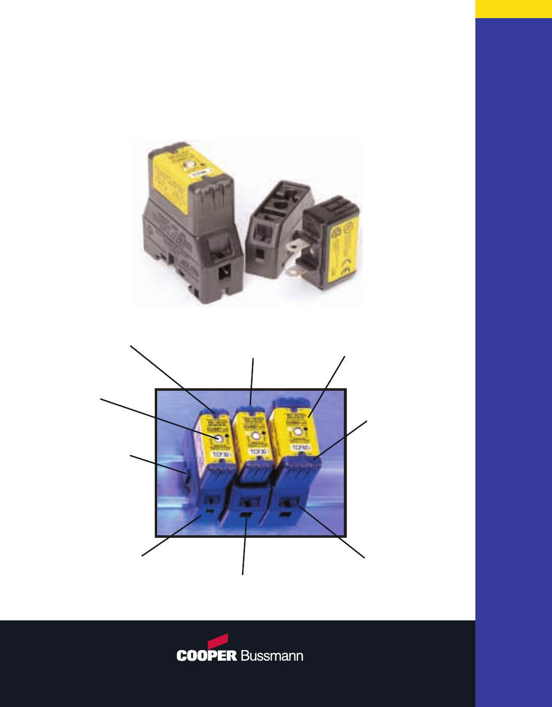
Circuit Protection Solutions
Bussmann®
B
U
S
S
M
A
N
N
Finger-Safe
Test Points
•
30-Amp Fuses
Plug Into 60-Amp
Fuseholders
Fuseholder
Mounted by 35mm
DIN Rail or by
Standard Hardware
Finger-Safe Fuse,
Fuseholder, and
Wire Ports (IP-20)
Class J Time-
Delay Electrical
Performance
Wire Ports Can
Accept Dual Wires
Smaller Footprint
Than Class J and
Class CC
Dovetail Fuseholder
Design for Ganging 30-
Amp and 60-Amp Poles
Permanent “Open-
Fuse” Indication
•
•
•
•
•
•
•
•
©2003, Cooper Bussmann, Inc. • St. Louis, MO 63178 • 636-394-2877
www.bussmann.com
www.cubefuse.com
REORDER #1007 6-03-40M
CUBEFuse™
The World’s First
“Finger-Safe” Industrial Fuse.
3814-16891-01 VHG DATE 01-04-02 #0615 BLACK CYAN MAGENTA YELLOW
