ABB Jokab Safety Handbook Brochure
2014-11-11
: Pdf 137538-Brochure 137538-Brochure Batch12 unilog
Open the PDF directly: View PDF ![]() .
.
Page Count: 34
ABB
Sensors/switches/locks

ABB 9:1
1
9
2
3
4
5
6
7
8
10
11
13
14
12
Contents Page
Sensors/switches/locks Why should you use sensors/switches? ________________________________9:2
How safe is a switch/sensor? _________________________________________9:3
Non-contact safety sensor Eden _______________________________________9:4
Safety Interlock switch JSNY5 _________________________________________9:8
Magnetic Switch JSNY7 _____________________________________________9:10
Safety Interlock Switch JSNY8 ______________________________________ 9:12
Safety Interlock Switch JSNY9 _______________________________________9:14
Magnetic lock Magne _______________________________________________9:16
Process lock Dalton _______________________________________________ 9:22
Safety lock Knox __________________________________________________ 9:28
Descriptions and examples in this book show how the products work and can be used. This does not mean that they can meet the requirements for
all types of machines and processes. The purchaser/user is responsible for ensuring that the product is installed and used in accordance with the
applicable regulations and standards. We reserve the right to make changes in products and product sheets without previous notice. For the latest
updates, refer to www.abb.com/lowvoltage. 2011.
ABB
9:2
Why should you use
sensors/switches?
Assurance that a machine stops when a door or a hatch is
opened can be solved by using different types of switches
and sensors which are monitored with a safety relay or a
safety PLC. Switches and sensors are available both as
non-contact (dynamic or magnetic) and various types of
interlocking devices. Interlocking devices can be used when
it is required, via a signal, to lock a gate during processes
that cannot be stopped during certain operations. They are
also used with machines that have a long stopping time to
prevent someone from entering before the machine has
stopped.
- to manage the safety in harsh
environments!
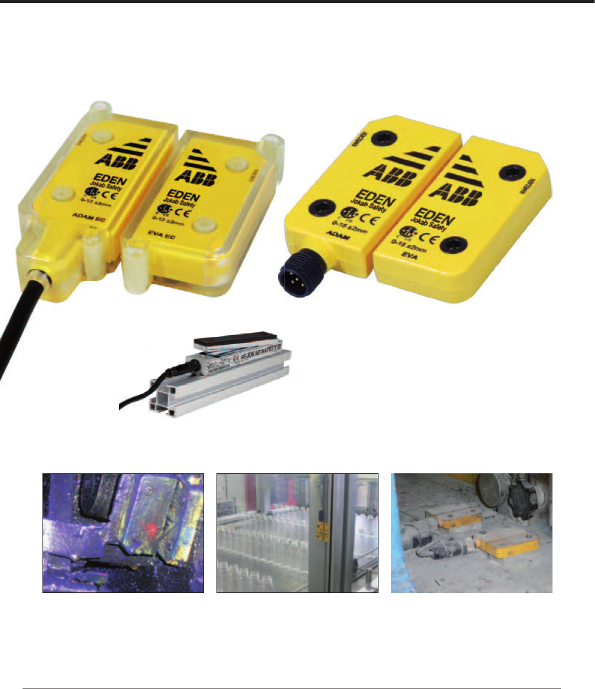
Non-contact dynamic sensors have a long lifetime because
they are not physically mechanically operated. They also
endure very harsh environments, e.g. cold, heat, high-
pressure wash-down which is important in the food industry
for example. Because the sensors are small, they are very
easy to position and can even be completely concealed in
doors and hatches.
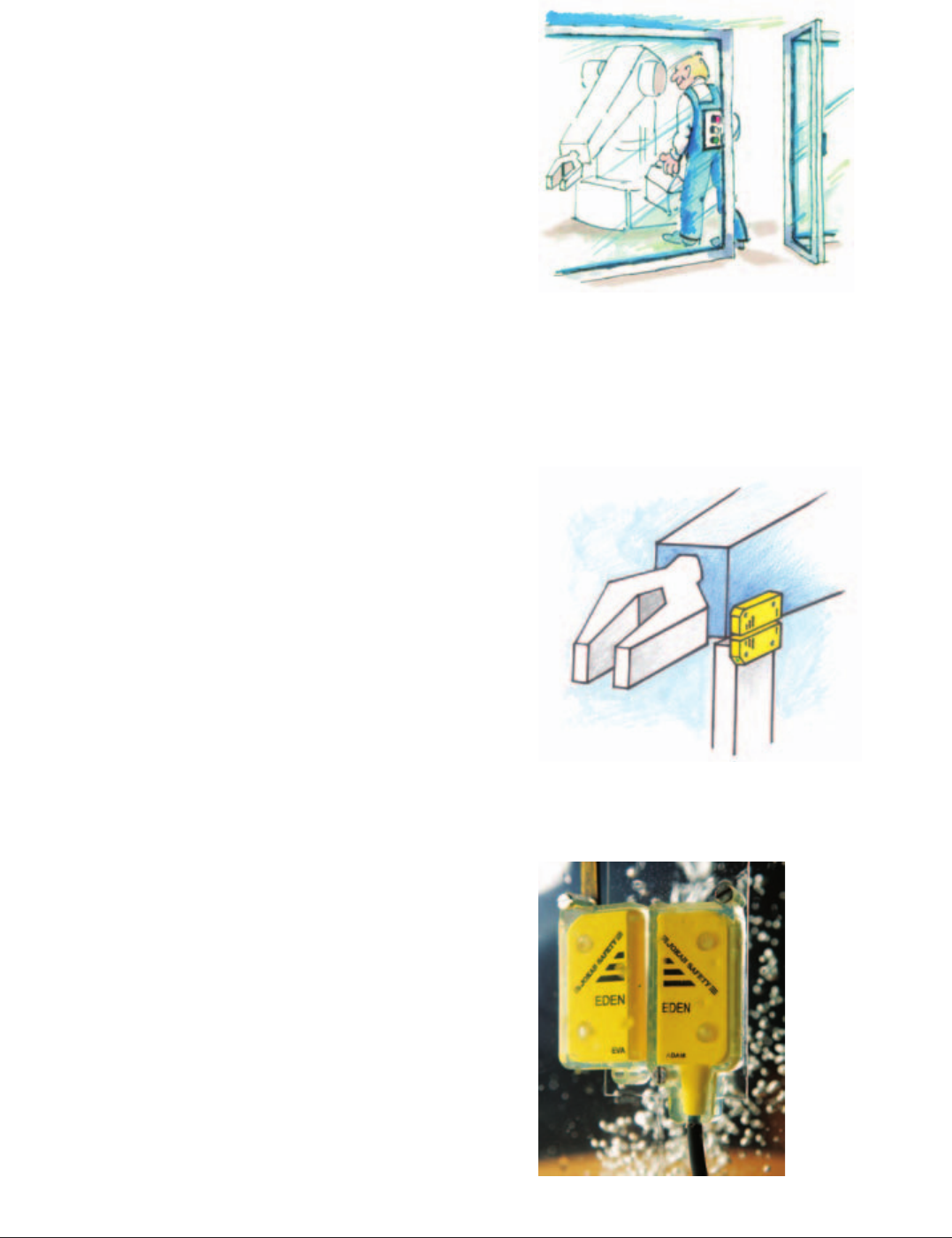
- to ensure that a position is reached!
- to supervise doors and hatches around
dangerous machines!
The sensor monitors that the robot is standing still in a
monitored position when someone enters the robot´s work-
ing area. The robot is then only stopped by the program. If
the robot leaves the position the power will be cut directly.
This is used when the robot does not stop safely without
restarting problems.
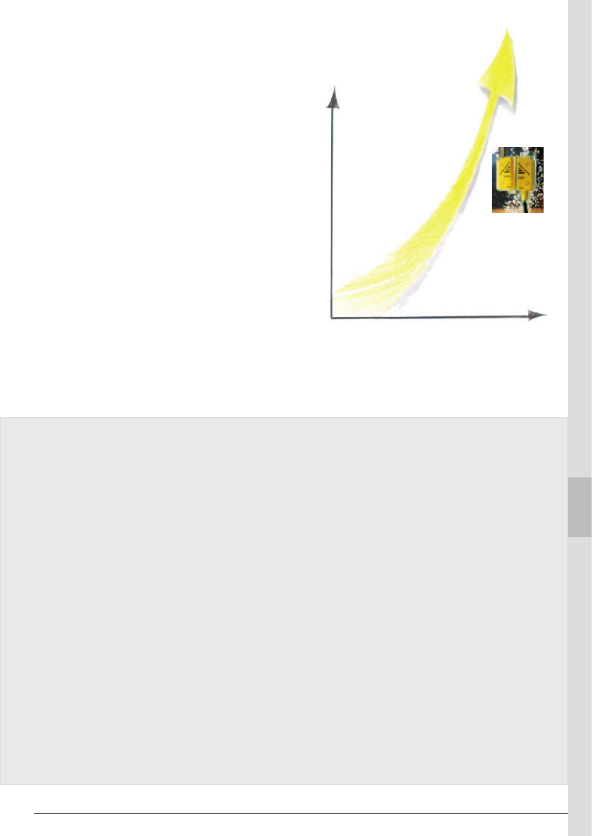
ABB 9:3
1
9
2
3
4
5
6
7
8
10
11
13
14
12
What requirements should one have on
sensors/switches?
The sensor/switch shall be reliable from both the safety
and production point of view.
• A person must be able to trust that dangerous
movements and functions are safely stopped by the
sensors/switches.
• From the production point of view unintentional stops
should be avoided.
• Standard EN ISO 13 855 now includes requirements
for safety distances for interlocked doors without locking
function.
Eden -
highest safety level and reliability
Our recommendation is to use the Eden sensor because
it is the safest and most reliable solution. The Eden sensor
is a non-contact switch and has a dynamic function. Also
it is possible to connect up to 30 Eden sensors in series
and still achieve PL e according to 13849-1.
How safe is a sensor/switch?
In order to trust the safety function it is essential to be aware that a safety
sensor/switch must be mounted and be used according to the specifications.
The certification authorities only test the product according to the appropriate
standards and to the specifications from the manufacturer.
Mechanical switches
For mechanical switches, e.g. key operated, this means that
a door or a hatch has to constructed to small tolerances in
order for the switch, the key or the mounting brackets to last
according to the life time specification from the supplier. The
screws holding the parts have to be locked in such a way
that they cannot be loosened. In order to prevent material
from getting into the slot for the key the environment has to
be clean. If a door goes outside the design tolerances from
wear, the screws loosen or material comes into the slot, this
may lead to the interlocked switch not giving a stop signal
when the door is opened. Even two mechanical switches
on a door could fail to an unsafe state if the door somehow
gets outside the tolerances of the switches. To prevent ac-
cidents the mechanical switch normally needs continuous
checks of both the switch and the installation.
Non-contact sensors/switches
For non contact sensors the risks associated with mechani-
cal switches (see above) do not exist. If screws, brackets
or sensors get loose, it will lead to a stop signal. Therefore
only one sensor with dual or dynamic function is needed in
order to reach the highest safety level. There are two types
of non-contact sensors - active and passive. The active
sensor, Eden, is constantly communicating via a dynamic
signal between the two parts and any failure will directly
lead to a stop signal. The passive type, a magnet switch, has
two reed contacts which are activated by a coded magnet.
Both the passive and the active sensors are checked every
time a door is opened. From a safety point of view the ac-
tive sensor, Eden, is to be preferred because it is checked
constantly whereas the passive sensor is only checked
when a door opens.
From the reliability point of view a long detection distance
with large tolerances and a well defined on and off position
is needed. The active sensor, Eden, fulfils these demands. A
magnet switch has smaller tolerances and an intermediate
position where only one contact opens. A bad installation
or vibrations can lead to an unintentional stop if one contact
opens and closes again. The supervision of a two channel
system is based on both contacts having to be operated
in order to permit a new start. In a dynamic safety circuit
there is only one pulsed signal and therefore no intermedi-
ate position.
Reliability
Safety Interlock
switch
Magnetic switch
Eden -
sensor with
dynamic signal
Safety level
ABB
9:4
15 ± 2
15
± 2
13 ± 2
13 ± 2
13 ± 2
± 2
mm
mm
13
5
5
A non-contact safety sensor for
the highest
safety level
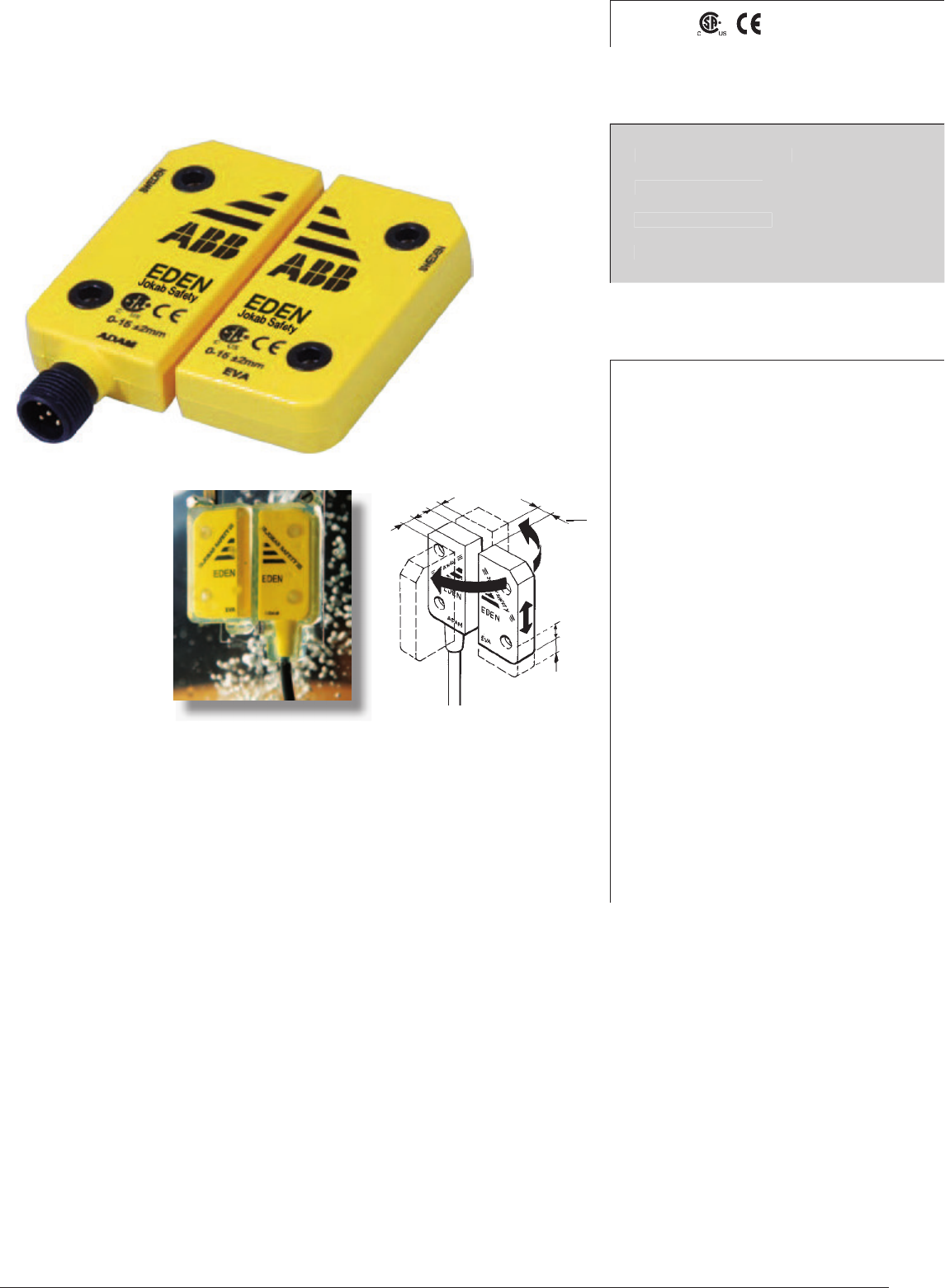
Eden - Adam and Eva is a non-contact safety sensor for use on
interlocked gates, hatches etc. A coded signal is transmitted from
the control device Vital or from the safety PLC Pluto via Adam
to Eva which modifies the signal and sends it back again. The
maximum sensing distance between Adam and Eva is currently
15 mm ± 2 mm.
Up
to 30 Edens can be connected in series to Vital and still
achieve the same safety level in the safety circuit. It is also
possible to connect safety light beams and E-stops in the same
safety circuit.
Adam
is available with cable lengths up to 10 m and with
M12 connectors. The LED on Adam provides indication of three
different conditions, contact/non-contact between Adam and
Eva and safety status. The same information is also available
via the Adam connection cable. Eden E is available for harsh
environments, as are Adam E and Eva E. Rapid blinking serves
as an alignment aid. There are also coded versions, Eden C,
Eden EC, Adam EC and Eva EC.
Flexible mounting and
The ability to operate at
long distances.
Approvals:
TÜV Nord
Safety sensor for:
Doors and hatches
Position control
Sector detection
Slot detection
Features:
Cat. 4/PL
e according to
EN
ISO 13849-1 together
with Vital or Pluto
Non-contact detection, large
sensing distance 0 - 15 mm
± 2 mm
Up to 30 sensors in series
with the highest level of
safety PL e
Versitile mounting, 360°
detection
Protection class IP 67/IP69.
The dynamic signal passes
through wood and plastic
(not metal)
Status information with LED
on the sensor and in the
cable connection.
Small hysteresis (< 1mm)
Non-contact safety sensor
Eden
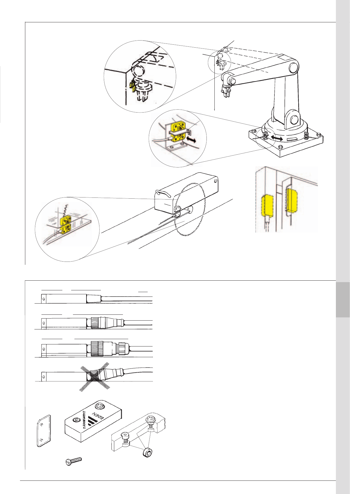
ABB 9:5
DA2
DA1
DA1 x 2
80
mm
115
*
120
1
9
2
3
4
5
6
7
8
10
11
13
14
12
Mounting – Eden
Eden to detect position
Metal stops the signal between Adam and
Eva. Additional Eden sensor(s) can be
mounted to detect metal plate(s) in place.
Eden used to detect the position of the
saw guard.
Wood, plastic and other non-metallic
materials let the signal pass between
Adam and Eva.
Eden can be hidden in doors and hatches
Eden used for sector detection
Non-metallic door material between
Adam and Eva allows the signal through
Adam and Eva has contact
only if they are within 15 mm
from each other.
Adam on
wall.
Eva on robot.
Application examples - Eden
Metal
Wood, plastic
etc
Notes:
Four protection plates plates are supplied with Adam M12.
To protect Adam and Eva protection plate (DA1) can be
used on both sides.
Mounting Adam with integral cable.
Mounting with one protection plate (DA1) for Adam
M12 using prewired moulded M12 connector. For M12
connection, a straight contact is recommended.
Mounting with two protection plates (DA1) for Adam
M12 using M12 connector with glanded cable.
Wrong mounting without protection plate may
cause permanent damage to sensor.
DA2 mounting
The DA2 mounting spacer must be used in order to
physically protect Eden from damage. Four spacers are
provided with each Adam and Eva.
DA1, protection plate 2,5 mm
* Safety screw
ABB
9:6
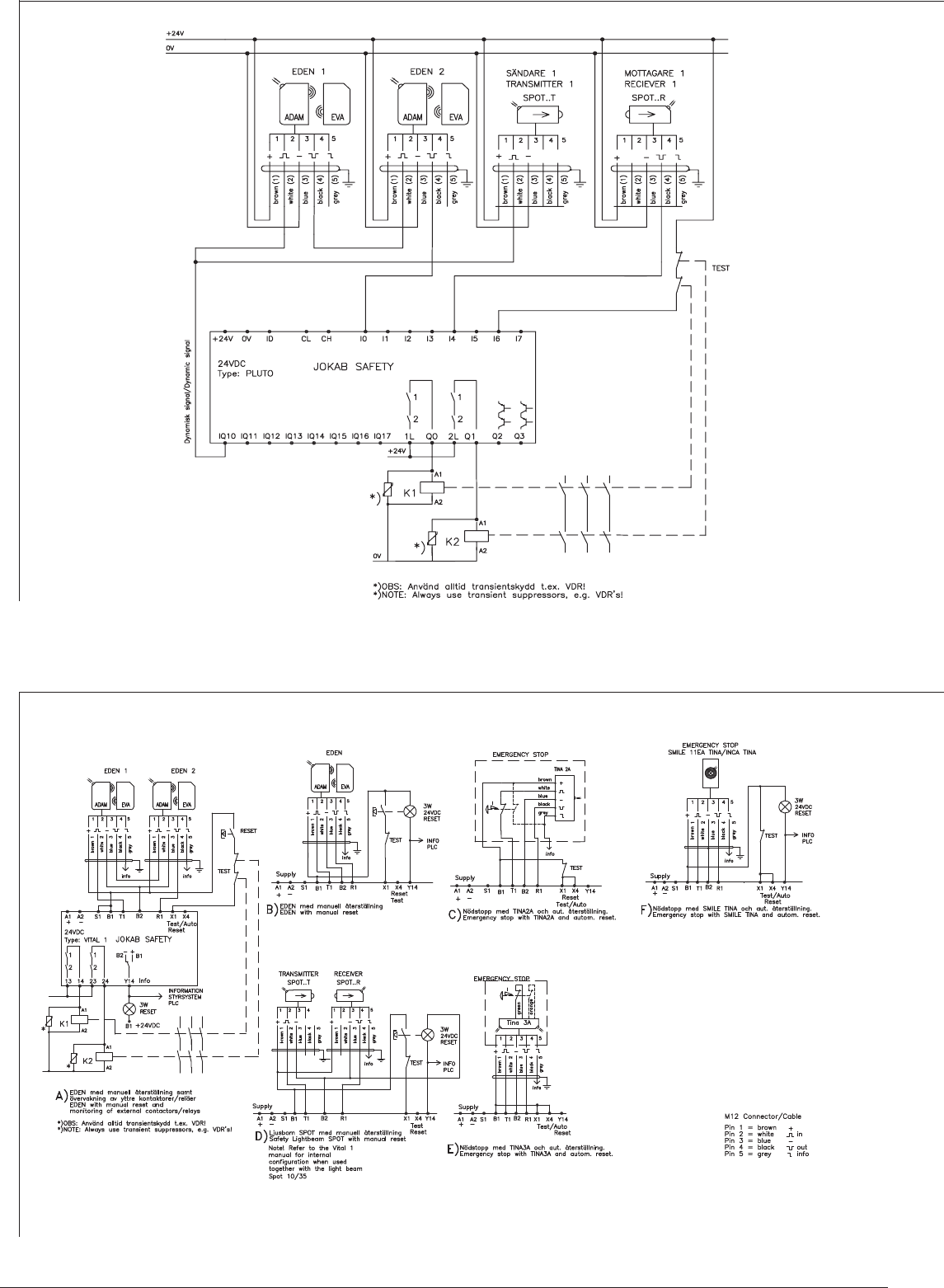
Connection of Eden to Pluto
Connection of Eden to Vital 1
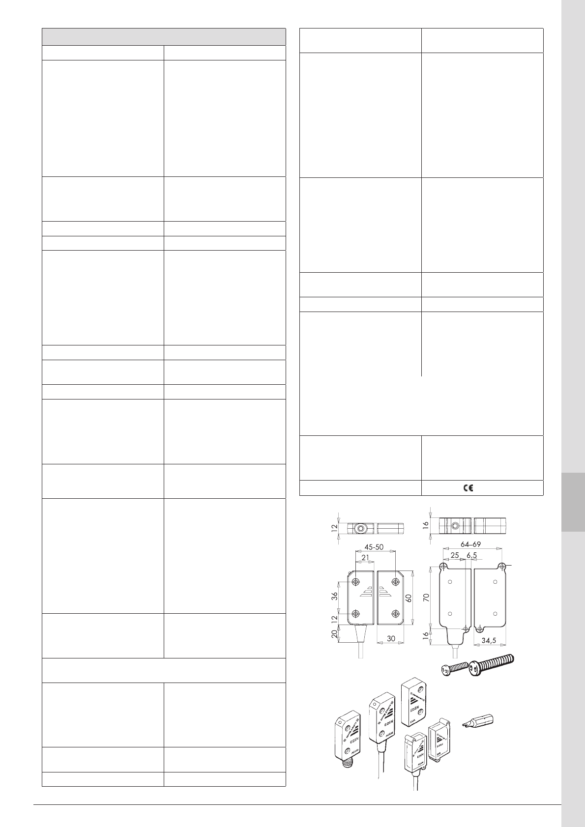
ABB 9:7
1
9
2
3
4
5
6
7
8
10
11
13
14
12
Technical data – Eden
Manufacturer ABB AB/Jokab Safety, Sweden
Article number/Ordering data:
Eva* 2TLA020046R0000
Eva E* 2TLA020046R0600
Adam M12* 2TLA020051R0000
Adam 3 m* 2TLA020051R0200
Adam 10 m* 2TLA020051R0400
Adam 20 m 2TLA020051R0500
Adam E 10 m 2TLA020051R0600
Adam E 0,5 M12* 2TLA020051R0700
Adam E 20 m 2TLA020051R0800
* also available in grey
Safety level
IEC/EN 61508-1...7
EN 62061
EN ISO 13849-1
SIL3
SIL3
kat. 4/PL e
PFHD4,50×10-9
Colour Yellow and black
Weight Eva: 26 g
Eva E: 36 g
Adam M12: 30 g
Adam 3 m: 220 g incl. cable
Adam 10 m: 650 g incl. cable
Adam E10 m: 660 g incl. cable
Adam EC 10 m: 660 g incl. cable
Adam E 0,5 m + M12: 100 g
incl. cable
Power supply 24VDC +15%-25%
Power consumption Adam: without info output 45 mA
with info output max 55 mA
Max cable length see Vital technical data
Ambient temperature
Eden/Eden C
Eden E/EC
-40°C … +70°C (operation)
-25°C … +70°C (stock)
-40°C … +70°C (operation)
(Test ok +90°C ... +100°C)
-25°C … +70°C (stock)
Protection class
Eden
Eden E
IP67
IP69K
Mounting Installation Eden
M4 screw, e.g. safety screw
20-053-42. Max. torque 2 Nm.
Screw to be locked with Loctite
or similar.
Installation Eden E
M4 screw, e.g. safety screw
20-053-42. Max. torque 2 Nm.
Screw to be locked with Loctite
or similar.
Detection distance max
Adam/Eva 15 ± 2 mm
Adam E/Eva E 12 ± 2 mm
Hysteresis approx. 1 mm
Flash 2 mm before red position.
Flash 2 mm before red position.
Metal may have influence on detection distance.
This can be prevented by protection plates, DA1.
Minimum distance to metal
when there is metal on one or
more sides.
Adam/Eva
Adam E/Eva E
One More
0 mm 2,5 mm
0 mm 0 mm
Minimum distance between
Eden pairs 50 mm
Life >107 cycles
Material Macromelt (Based on polyamid)
Eden E for extreme surroundings.
Chemical resistance
Macromelt:
PU (EdenE):
Cutting oils, vegetable and
animal oils, hydrogen peroxide,
diluted acids and bases: good
Alcohol and strong acids: not
recommended
Cutting oils, vegetable and
animal oils,hydrogen peroxide,
diluted acids and bases,
alcohols: good
Strong oxidating acids: not
recommended
LED on Adam
Green:
Flashing:
Red:
Fast flashing:
Eva within range, safety circuit
closed (door closed)
Eva within range, earlier safety
circuit open (door closed)
Eva out of range, safety circuit
open (door open)
Eva is within 2 mm from maximum
sensing distance (door closed)
Cable 3 or 10 m, ø 5.7mm, black, PVC
5 x 0.34mm² + screen, UL 2464
Connector M12: 5-pin male contact
Connections
Brown (1)
White (2)
Blue (3)
Black (4)
Grey (5)
+24 VDC
Dynamic signal in
0 VDC
Dynamic signal out
Info output, see below
24 VDC when LED is green or flashing
(tolerance -2 VDC), 10 mA max
0 VDC when LED is red. (tolerance +2 VDC)
Warning: Incorrect connection may cause permanent damage to
Adam devices.
Conformity 2006/42/EG
EN ISO 12100 1/2, EN 954-1,
EN 60204-1, EN ISO 13849-1,
EN 1088, GS-ET 15
Certifications TÜV Nord
Adam 3 m
Adam 10 m
Adam M12
M12
Eva
Adam E 0,5 M12,
Adam E 10 m
and Eva E
for extreme
surroundings.
Eden E/EC Eden
Safety screw. For more
screw options see the
product list.
Safety screwdriver bit
ABB
9:8
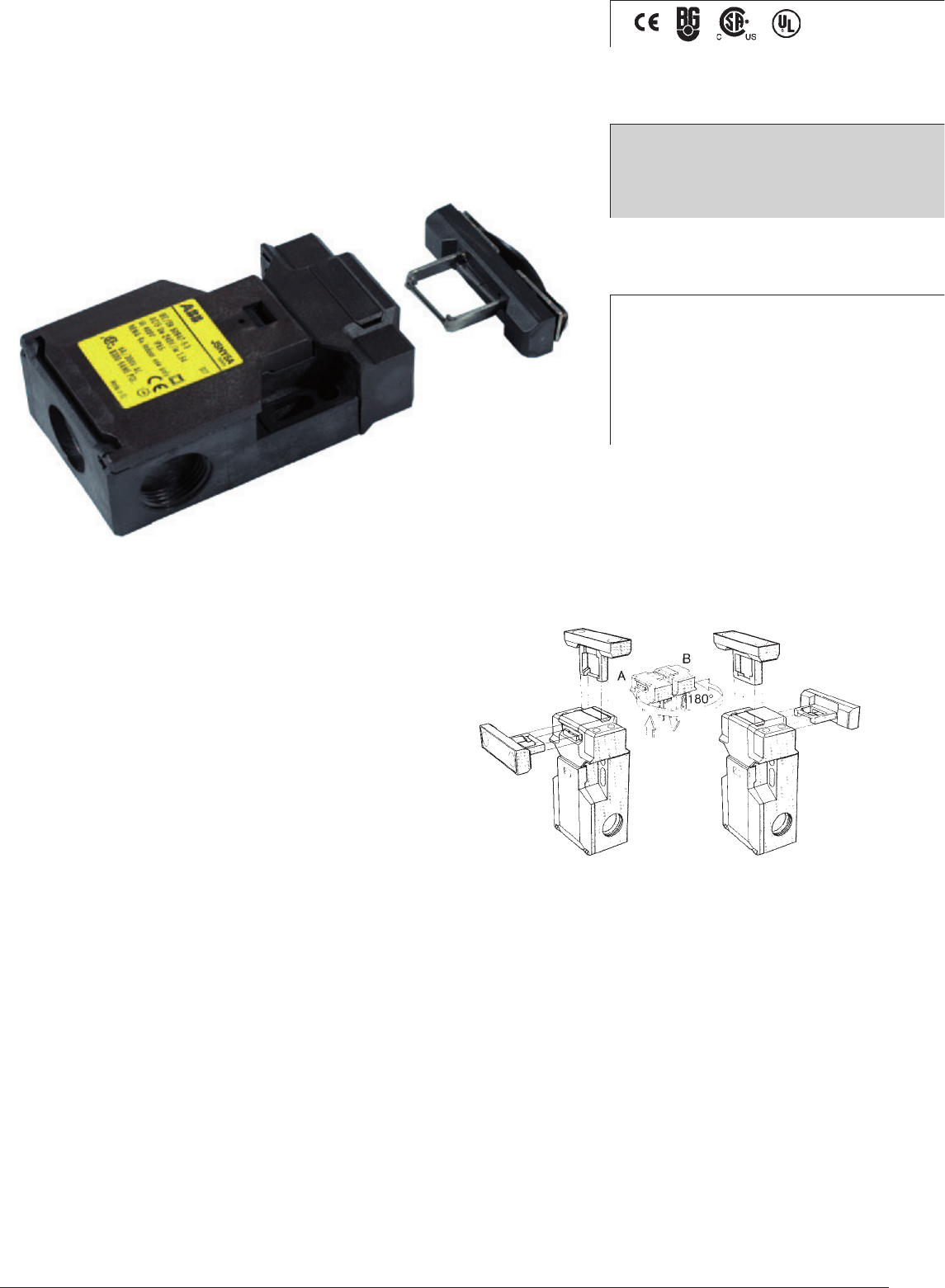
Switch operational description
JSNY5 offers three contacts which gives both the two con-
tacts needed for high safety level as well as a contact for
the indication of operating status.
The advanced design offers the choice of four operating
positions from only two actuator entries by simply rotating
the head through 180o.
However, when installed and in it's working condition only
one entry can be used, ensuring no other element can tamper
with the switch function.
When mounting the switch from the front two elongated
holes are provided to aid alignment with two set screw holes
for accurate fixing. Top fixing is also possible.
Three cable entries allow for a variety of cabling options
including through wiring.
Positive forced disconnected contacts
The design assures that the contacts will not fail or be held
in a normally closed position, due to failure of the spring
mechanism or the welding/sticking of the contacts.
Protection from unauthorised or incidental access
To avoid unauthorised operation the JSNY5 switch is
manufactured using multicoding to GS-ET 15. The switch
cannot be defeated by screwdrivers, magnets or any other
mechanism.
Safety level
The positive forced disconnect contacts gives a high safety
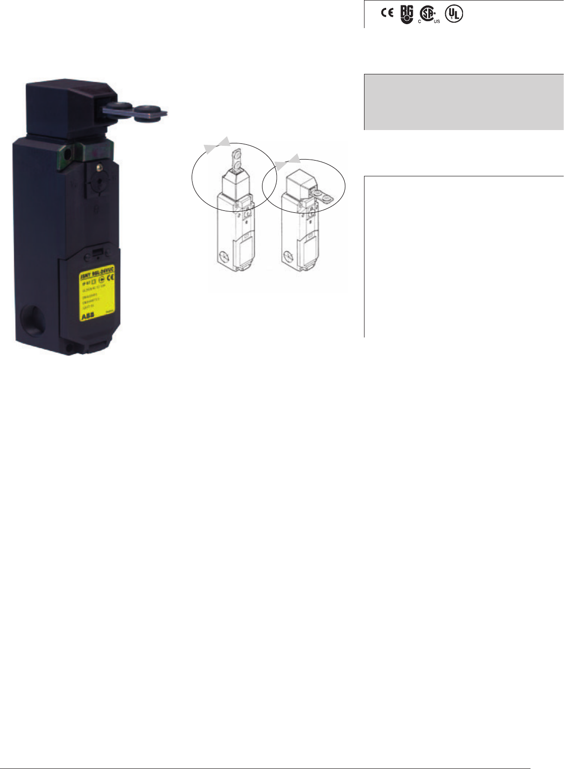
level. By combining the JSNY 5 with one of our suitable safety
After opening the snap-on cover, the head portion can be removed
(version A), after turning the head through 1800 (version B) it
can be replaced onto the body of the switch and be locked into
position by closing the snap-on cover. This ensures 4 actuating
positions are possible.
relays as for example from the RT-series, the safety PLC
Pluto or Vital (Tina) the requirements for both hatch and gate
switch supervision can be fulfilled. To obtain the same level
of safety as Eden, two switches per gate are required.
Regulations and Standards
The JSNY5 is designed and approved in accordance with
appropriate directives and standards. See technical data
Approvals:
Application:
Gates
Hatches
Features:
2 NC + 1 NO (actuator in)
4 actuating positions
Actuator holding force 10 or
30 N
Safety Interlock switch
JSNY5
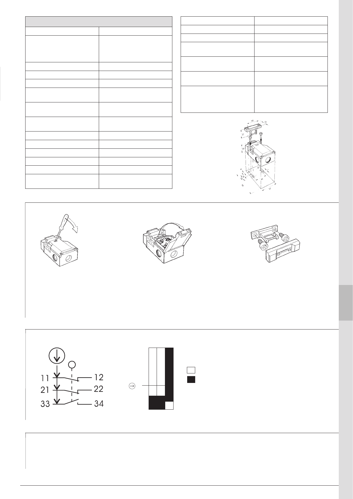
ABB 9:9
1
9
2
3
4
5
6
7
8
10
11
13
14
12
Easy accessibility for wiring
The snap-on cover is released by a screw-
driver and can be opened to an angle of
1350 providing easy access to the wir-
ing terminals. Should the snap-on cover
not provide adequate security, a retaining
screw can be used.
Protected contact block
A transparent cover protects the contact
block from external elements during the
installation and wiring process.
Prevention of actuator dismantling
A cover plate with a one-way snap-fit
which seals the mounting screws prevents
unauthorised dismantling of the actuator
assembly. The cover plate must be mount-
ed to prevent overtravel of the switching
mechanism.
Overlapping contact 33 - 34.
The overlapping contact 33 -34 enables
operational status indication of eg. incorrect
adjustment of switch before the positive
forced disconnect NC contacts open.
Note!
The switch must not be used as an end
stop!
Actuator
withdrawn
Actuator
inserted
Accessories and spare parts
• Standard actuator
• Flexible key for smaller opening radius
• Cable gland
• Snap-on cover
Traction travel
Assembly - JSNY5
Contact Description - JSNY5
• Tina 2A with M20 connection for a dynamic loop
• Tina 2B with cable connection
• Tina 3A with M12 and M20 connections for a dynamic loop
11-12
21-22
33-34
5
3,5
3,0
mm
21,5
Technical data – JSNY5
Manufacturer ABB AB/Jokab Safety, Sweden
Article number/
Ordering data:
JSNY5A holding force 10 N
JSNY5B holding force 30 N
2TLA020022R0000
2TLA020022R0100
Colour Black and yellow label
Enclosure/Cover PA 6 (UL94-VO)
Actuator Steel
Min. opening radius for
actuator on a hatch 150 mm
Ambient operating
temperature -30°C to +80°C
Contacts
(actuator key inserted)
2 NC + 1NO
(NC are direct opening action)
Mechanical life 1 Million switch operations
Max switching frequency 30/min
Fixing body 2 x M5, actuator 2 x M5
Cable entry 2 x M20 x 1,5
Weight approx. 0.13 kg
Degree of protection IP65 IEC 60529 / DIN VDE
0470 T1
Rated insulation voltage 400 V AC
Rated operational current 5A
Utilisation category AC-15/DC-13
Short-circuit protection Fuse 6A Slow acting, 16A
quick acting
CSA 5A 300V AC B300
(same polarity)
B10d JSNY 5A: 2,00×10⁶
JSNY 5B: 2,00×10⁶
Conformity 2006/42/EG
EN ISO 12100 1/2, EN 954-1,
EN 60204-1, EN ISO 13849-1,
EN 1088, GS-ET 15
ABB
9:10
Switch operation description
The magnetic switch is designed to operate in dirty indus-
trial environ ments and is certified to the highest level of
safety regulation when working together with a suitable
ABB JokabSafety safety relay or Safety-PLC Pluto. The
magnetic switch is small and resistant to both dirt and wa-
ter, and has no dust collecting cavities making it usefull in
environments where hygiene is paramount. The small size
of the switch makes it easy to position and hide on gates
and hatches.
The magnetic switch has a long working life since no
mechanical contact is made during operation.
Contacts
The magnetic switch has one closing and one opening
contact. Both contacts have to be monitored. The contacts
may be monitored by either the RT9 safety relay or other
suitable relays in the new RT-series, i.e. RT6, RT9 or Safety
PLC Pluto.
Protection from unauthorised or incidental access
To avoid unauthorised operation of the JSNY7 switch it is
only possible to actuate the JSNY7R with the coded magnet,
JSNY7M. Other magnets, screwdrivers and tools have no
affect on the switch contacts.
Safety level
The JSNY7 is approved to the highest level of safety
regulations,PLe according to EN ISO 13849-1 together
with safety relay in the RT-series or Pluto PLC.
Regulations and Standards
The JSNY7 is designed and approved in accordance with
appropriate directives and standards. See technical data.
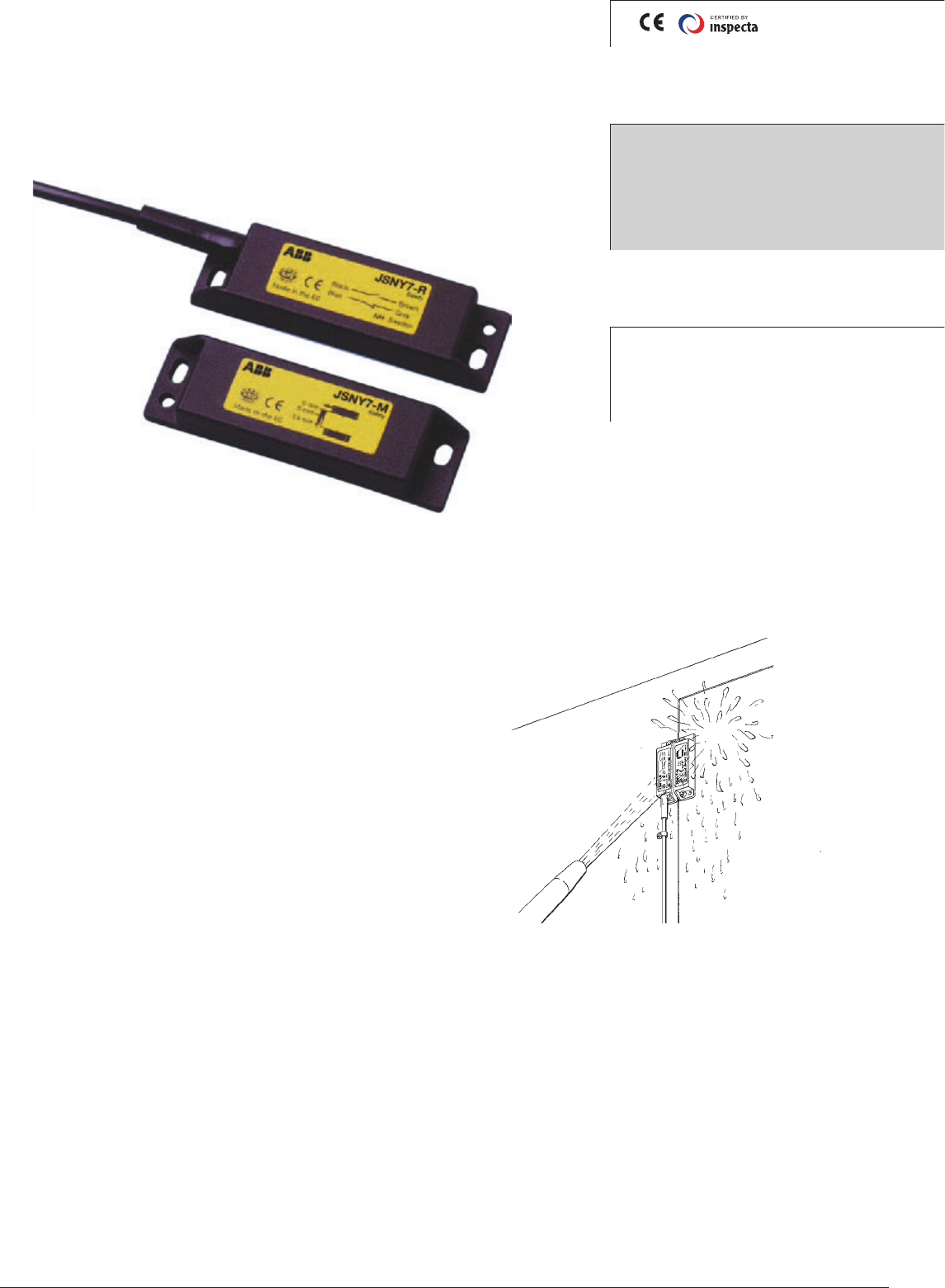
JSNY7 is resistant to both dirt and water.
Approvals:
Application:
Gates
Hatches
Position control
Features
Small size
IP 67
Magnetic Switch
JSNY7
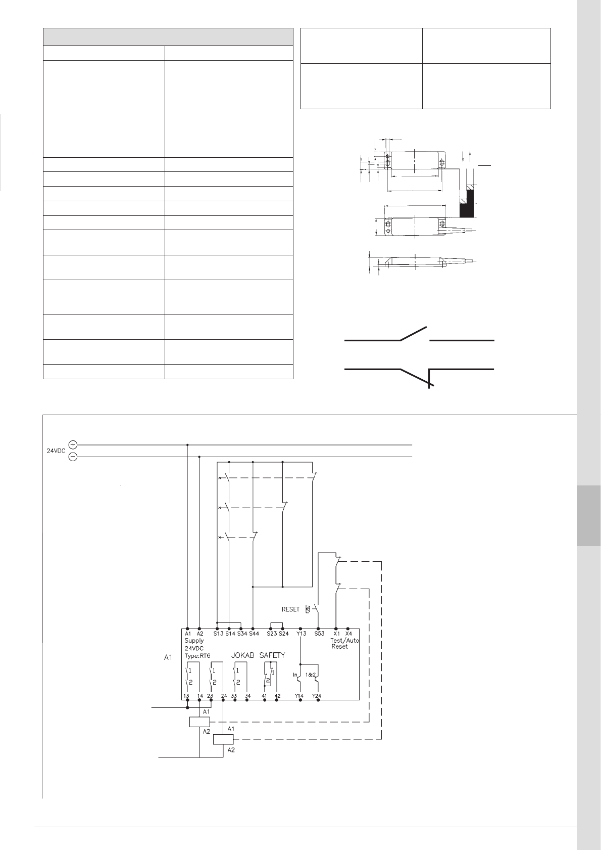
ABB 9:11
0
5
14
mm
68
78
88
4,5
6,5
2,5
7,2
10,7
25
13
3
1
9
2
3
4
5
6
7
8
10
11
13
14
12
Technical data – JSNY7
Manufacturer ABB AB/Jokab Safety, Sweden
Article number/ordering
data
JSNY7R-3 Magnetic switch
3 m cable
JSNY7R-6 Magnetic switch
6 m cable
JSNY7R-10 Magnetic switch
10 m cable
JSNY7M Magnetic switch
2TLA020023R0000
2TLA020023R0100
2TLA020023R0200
2TLA020024R0000
Colour Black
Enclosure/Cover PA 6 (UL94-VO)
Supply voltage max 30 VDC
Switch current max 100 mA
Max switching frequency 1 Hz
Mechanical life 3 x 10⁸ switch operations,
depending on load
Operating temperature
range
-5°C to +70°C (moveable)
-20°C to +70°C (fixed)
Connection Cable ø4.5, 4x0.25 mm2, 3
meter ; PVC
(other lengths upon request)
Switching point Min. switch-on point 5 mm
Max. switch-off point 14 mm
Weight Coded magnet: 32 g
Sensor with 3m cable: 133 g
Protection class IP67
Electrical connection description - JSNY7
Electrical connection
Two-channel switching, high safety level.
NOTE!
Safety components drawn in re-
leased position.
NOTE!
This solution with 3 magnetic
switches only complies with cat-
egory 3 as per EN 954-1/EN ISO
13849-1.
To reach highest level of safety only
one magnetic switch should be
connected to the safety relay.
Electrical Connection example
Three JSNY7 connected to RT6
safety
relay.
brownblack
bluegrey
Door 1
Door 2
Door 3
B10d JSNY 7R-3: 3,00×10⁷
JSNY 7R-6: 3,00×10⁷
JSNY 7R-10: 3,00×10⁷
Conformity 2006/42/EG
EN ISO 12100 1/2, EN 954-1,
EN 60204-1, EN ISO 13849-1,
EN 1088, GS-ET 15
ABB
9:12
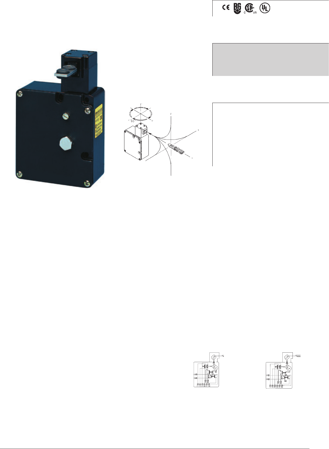
Description
The JSNY8 Safety Interlock Switch, in conjunction with the
machine control system, enables gates/movable guards etc to
be locked in their protective positions, thus preventing access
to machinery until dangerous operations have ceased.
Applications include:
• processes which cannot be interrupted, such as welding.
• machinery with a long stopping procedure, such as paper
machinery that requires a long braking operation.
• prevention of unauthorised access to a particular area.
The JSNY8 has 2 NC + 2 NC positive force disconnection
contacts. The first pair closes when the actuator key is pushed
into the head. The other pair closes when the locking mechanism
is in the locked position. The head can be set in four positions,
thus providing the safety device with four different operating
positions. These are selected by twisting the head as shown
in the diagram above. The leading edges of the actuator key
are reinforced and bevelled in order to guide it properly into the
hole. The JSNY8 is encased in a robust metal housing (IP67)
providing a high level of protection to the internal operating
components.
Two versions
The JSNY8 is available in two basic versions, either with a spring
lock or a magnetic lock.
In the spring lock (JSNY8S) version, the locking mechanism
moves into the locked position directly when the door is closed
and the actuator key is pushed into the lock. The actuator key can
only be released and the gate opened by supplying operational
voltage to the solenoid (E1-E2).
The JSNY8S also has a emergency ’unlocking’ facility to en-
able the actuator key to be released without the energisation
of the solenoid (E1-E2).
In the magnetic lock (JSNY8M) version, the locking mecha-
nism is only in the locked position when the solenoid (E1-E2)
is supplied with operating voltage. Release of the actuator key
is only possible when the operating voltage is removed from
the solenoid (E1-E2).
Optional features
The following optional features are available:
• actuator to operate at smaller radius.
• customer specific applications.
Tamper-proof
The JSNY8 is tamper-proof. The safety device cannot be ma-
nipulated by screwdrivers, magnets or other tools.
Safety level
The JSNY8 has double forced disconnection contacts to the
actuator key and the locking mechanism. The actuator key has
a triple coding design. To achieve maximum safety level in the
connection to the machine’s control system, it is recommended
that the JSNY8 is monitored by an appropriate ABB JokabSafety
safety relay, Pluto safety-PLC or Vital. To obtain the same level
of safety as Eden, two switches per gate are required.
Regulations and Standards
The JSNY8 is designed and approved in accordance with ap-
propriate directives and standards. See technical data.
JSNY8S JSNY8M
Safety Interlock Switch
JSNY8
Approvals:
Application:
Gates
Hatches
Features:
Robust design
Universal installation
2 NC + 2 NC outputs
1000 N actuator holding
force
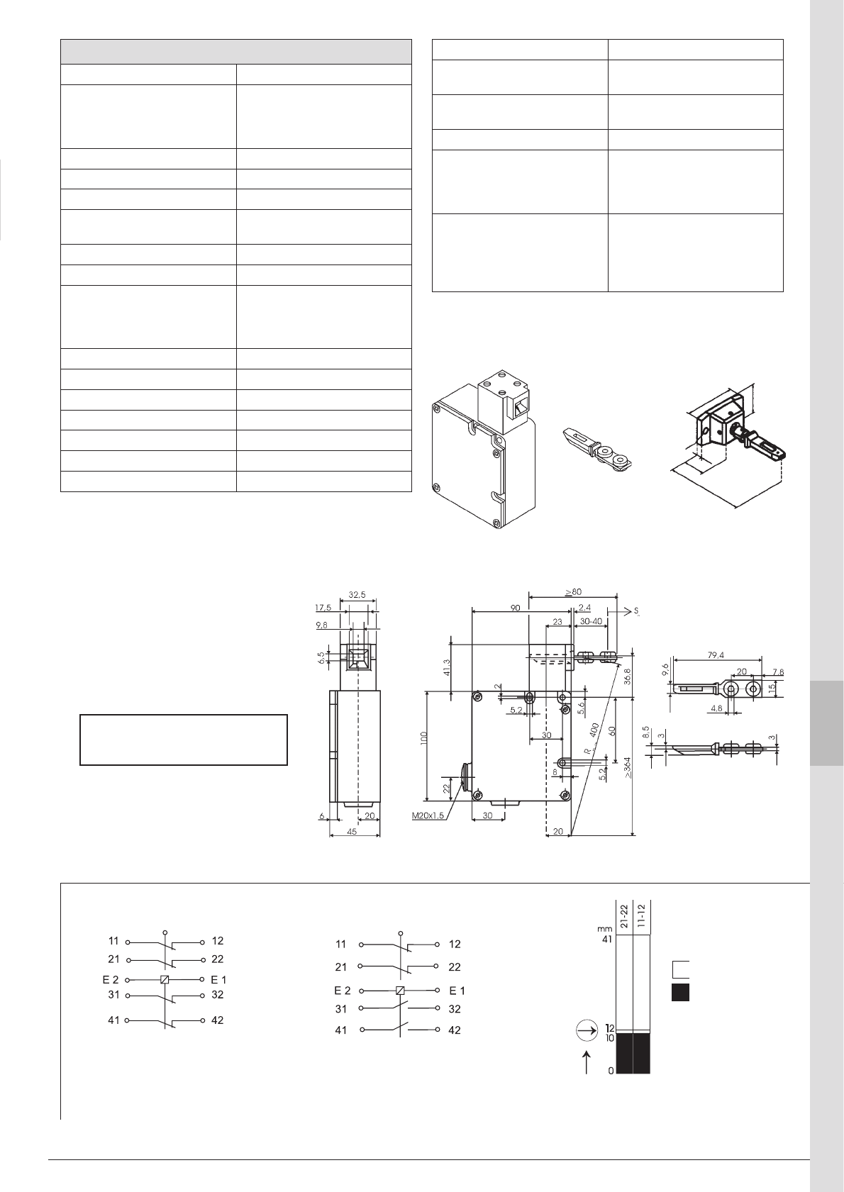
ABB 9:13
1
9
2
3
4
5
6
7
8
10
11
13
14
12
Contact description JSNY8S/M - JSNY8S/M
JSNY8S
Key actuator inserted
Normally locked
(E1-E2 unpowered)
JSNY8M
Key actuator inserted
Normally unlocked
(E1-E2 unpowered)
Contact opened
Contact closed
Contact
travel Actuator withdrawn
Actuator inserted
Fmin= 20 N
Technical data – JSNY8
Manufacturer ABB AB/Jokab Safety, Sweden
Article number/Ordering
data:
JSNY8M 24DC
JSNY8S 24DC
2TLA020030R0000
2TLA020030R0100
Colour Black
Enclosure Metal housing
Actuator key Steel & plastic (PA6)
Min. operating radius for
hatch
400 mm (smaller radius on
request)
Actuator holding force 1000 N
Working temperature -30°C to +60°C
Contacts
actuator key inserted
locking mechanism, locked
position
2 NC
2 NC
Mechanical service life 1 million switch operations
Installation fixings 3 x M5
Cable entry 2x M20 x 1.5
Weight 550 g
Enclosure class IP67
Operating voltage 24V DC, 230 V AC
Rated insulation voltage 250V
Note: Do not use switch as end
stop!
Rated operating current 10A
Utilisation category AC 12 250V/10A
AC 15 230V/4A
Short-circuit protection Fuse 10A slow-acting, 16A
quick-acting
Power consumption 5.2 W
B10d JSNY 8M 24 VDC: 2,00×10⁶
JSNY 8M 230 VAC: 2,00×10⁶
JSNY 8S 24 VDC: 2,00×10⁶
JSNY 8S 230 VAC: 2,00×10⁶
Conformity 2006/42/EG
EN ISO 12100 1/2, EN 954-1,
EN 60204-1, EN ISO 13849-1,
EN 1088, GS-ET 19,
EN 60947-5-1
81
5
50
30
ø5,5
20
JSNY8/9N2
Rmin: 150 mm
Flexible actuator.
ABB
9:14
The control unit offers eight op-
erating positions that provide the
actuator with eight different input
options.
Description
The JSNY9 is used for locking a gate/hatch, to prevent access
to machinery, until hazardous operations have ceased.
Applications include:
• processes which cannot be interrupted, e.g. welding.
• machinery with a long stopping time, e.g. paper machinery
which requires a long braking operation.
• prevention of unauthorised access to a particular area.
The JSNY9 is equipped with a 2 x (1NO +1 NC) contact
configuration, the first pair of contacts changeover when the
key is inserted. The second pair of contacts changeover when
the locking mechanism is in the locked position.
The JSNY9 switch is encased in a robust plastic housing
and can be mounted either horizontally or vertically. The
advanced design of the head provides eight possible key
insertion options, this is achieved by mounting the head
either vertically or horizontally on the base unit, as shown in
the diagram. The location for the actuator key is reinforced
and bevelled to ensure a smooth operation.
Two versions
The JSNY9 switch is available in two basic versions, either with
a spring lock or an electro-magnetic locking mechanism.
The JSNY9S (spring lock) switch operates immediately
when the gate/hatch is closed, i.e. when the key actuator is
inserted into the locking mechanism. The gate/hatch can be
opened and the actuator key released only by supplying the
operational voltage to the solenoid connections (E1 E2). The
JSNY9S also has a manual emergency unlocking facility to
enable authorised release of the actuator key.
In the JSNY9M (magnetic lock) version, the mechanism
is only locked when the gate/hatch is closed i.e. the actua-
tor key inserted and the solenoid (E1 E2) supplied with the
operating voltage. The gate/hatch can only be opened when
this operating voltage is removed.
Optional features
The following optional features are available:
• LED display, indicating the status of the actuator key,
locking mechanism and contacts.
• Actuator to operate at smaller radii.
• Customer specific applications.
Protection from unauthorised access
The JSNY9 is designed to protect against unauthorised
access; screwdrivers, magnets or similar tools cannot
operate the safety switch.
Safety level
In order to achieve a high safety level, the JSNY9 switch is
equipped with dual sets of contacts operated with a coded
actuator key . In order to meet the required installation safety
level it is recommended that the JSNY9 safety switch is
monitored by an appropriate ABB JokabSafety safety relay.
To obtain the same level of safety as Eden, two switches per
gate are required.
Regulations and Standards
The JSNY9 is designed and approved in accordance with ap-
propriate directives and standards. See technical data.
Approvals:
Application:
Gates
Hatches
Features:
Compact and robust
Universal installation
2 X (1NO+1NC)
Actuator holding force
1500N
Eight head configurations
LED status indication
(optional)
Safety Interlock switch
JSNY9
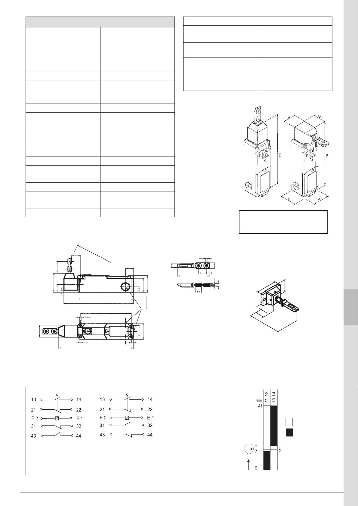
ABB 9:15
JSNY8/9N2
Rmin: 150 mm
81
20
5
50
30
ø5,5
7,820
9
315
79,4
9,6
42,530
184
2 5
124
32
ø5,3
ø4,8
ø14
22,4
170
135
19,5
32-36
51
21
5
15
37,5
45
3xM20
Rmin: 400
JSNY8/9N1
1
9
2
3
4
5
6
7
8
10
11
13
14
12
Contact description - JSNY9 S/M
NB.
The safety switch must not be
used as an end stop!
JSNY9S
Actuator inserted
Locked position
(E1-E2 unpowered)
JSNY9M
Actuator inserted
Unlocked position
(E1-E2 unpowered)
Technical data – JSNY9
Manufacturer ABB AB/Jokab Safety, Sweden
Article number/Ordering
data:
JSNY9S 24V AC/DC
JSNY9M 24V AC/DC
2TLA020036R4400
2TLA020036R4500
Colour Black
Enclosure/Cover Polyamid PA6
Actuator Steel & plastic (PA6)
Min. key operating radius 400 mm (smaller radius
available on request)
Actuator holding force 1500 N
Operating temperature - 25° C to + 70° C
Contacts
actuator in
Locking mechanism in locked
position
1 NO + 1 NC
1 NO + 1 NC (NC are direct
opening action)
Mechanical life 1 million switch operations
Installation fixing 4 x M5
Cable entry 3 x M20 x 1.5
Weight approx. 300 g
Enclosure Class IP67
Operating voltage 24 V AC/DC
Isolation voltage 250 V
Thermal Current 2.5 A
JSNY9SLA/MLA
See separate data sheet
for switches with LED
indication.
Contact open
Contact closed
Actuator travel Actuator extracted
Actuator inserted
Fmin= 27 N ± 15%
Utilisation category AC 15 230V / 4A
Short-circuit protection Fuse 6 A slow acting
Power consumption 1.1 VA (56 VA during 0.2s)
B10d JSNY 9M: 2,00E+06
JSNY 9S: 2,00E+06
Conformity 2006/42/EG
EN ISO 12100 1/2, EN 954-1,
EN 60204-1, EN ISO 13849-1,
EN 1088, GS-ET 19,
EN 60947-5-1
ABB
9:16
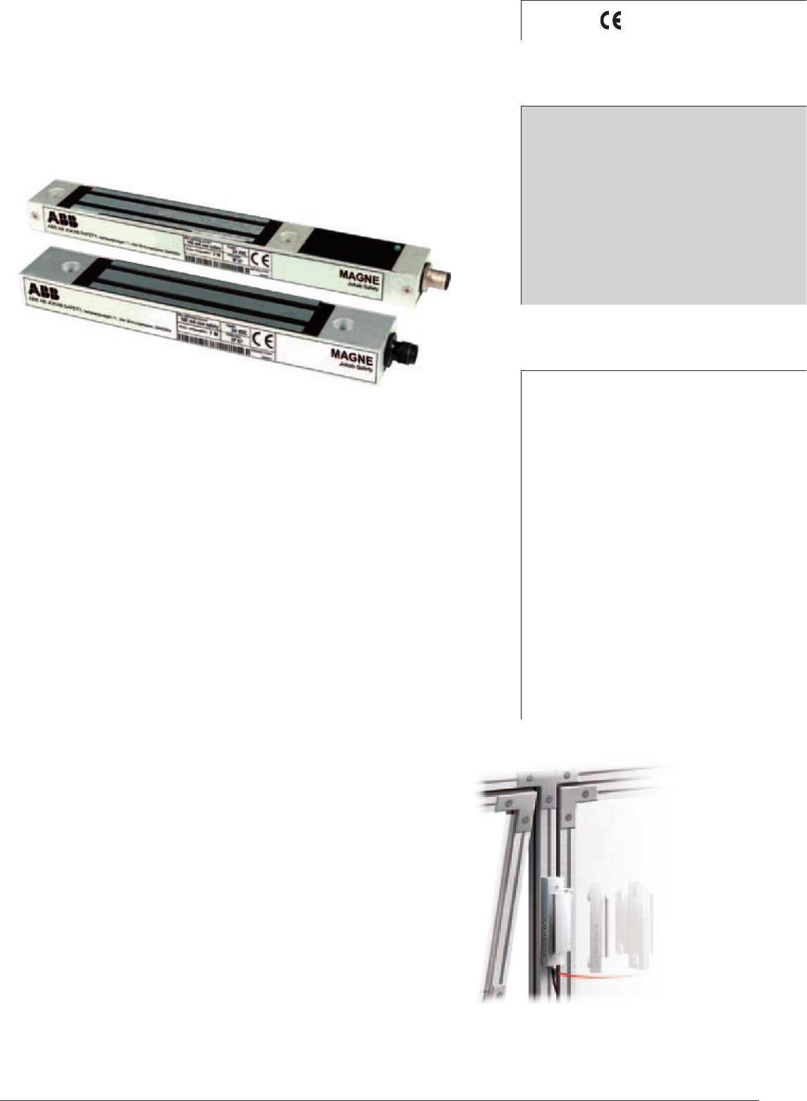
Magne 1
Magne 2
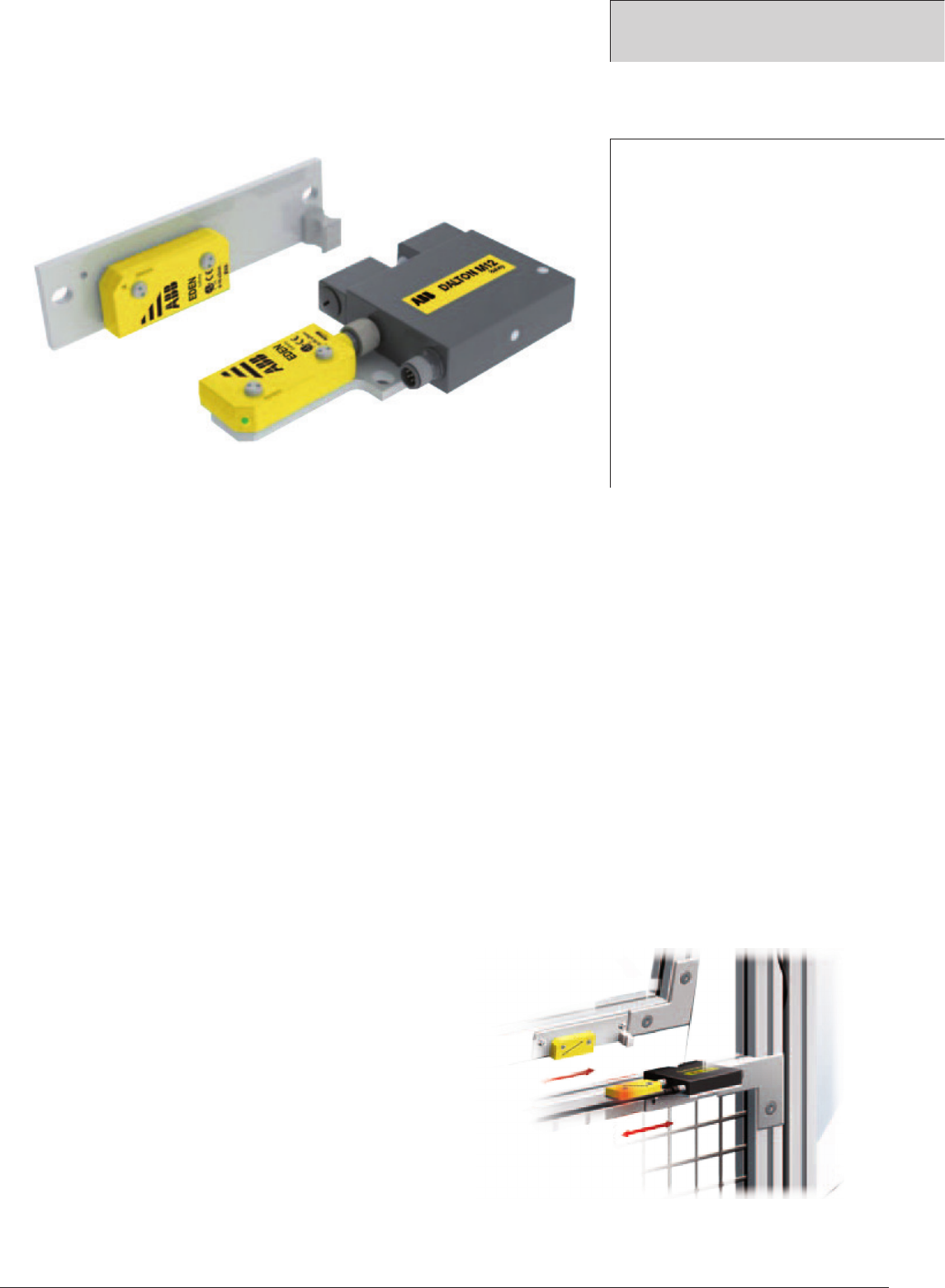
Magnetic lock with indication
Magne is a magnetic lock that is designed for industrial
applications and that can withstand harsh environments.
As it is designed with no moving parts, it is durable and
long lasting. Magne, with its electro-magnet, keeps a
door locked with a holding force up to 1,500 N and also
magnetic material does not attach to the magnetic surface
when the power is off.
Use of M12 connectors makes it easy to connect several
Magne units and Eden sensors in series enabling control
and monitoring by either a Pluto safety PLC or a Vital safety
controller. Via the connection cable it is also possible to
obtain an indication signal informing if the Magne unit is
locked or not.
Accessories:
• Mounting kit for conventional door, with fitting and
screws for assembly on ABB JokabSafety Quick-Guard
fencing system (5-15 mm door gap)
• Plastic handle
• Handle profile for mounting on a hinged door with
ABBJokabSafety’s Quick-Guard fencing system
(5-15mm door gap).
Magne is easy to assemble, adjust and dismantle
in and out of the T-slot of the Quick-Guard fencing
system.
Approval:
TÜV Nord
Application:
Electrical locking of doors
and hatches to production
applications that are
sensitive to unintentional/
unnecessary interruptions.
For safety supervision the
Magne 2 has an integrated
Eden.
Features:
No moving parts
Strong Magnetic holding
force: 1500N
Can stand and operate in
harsh environments
Locked/unlocked
indicationPossible to
connect in series with Eden
sensors
No current peaks on
activation
Magne 2 in combination with
a handle profile provides a
complete door solution
Magnetic lock
Magne
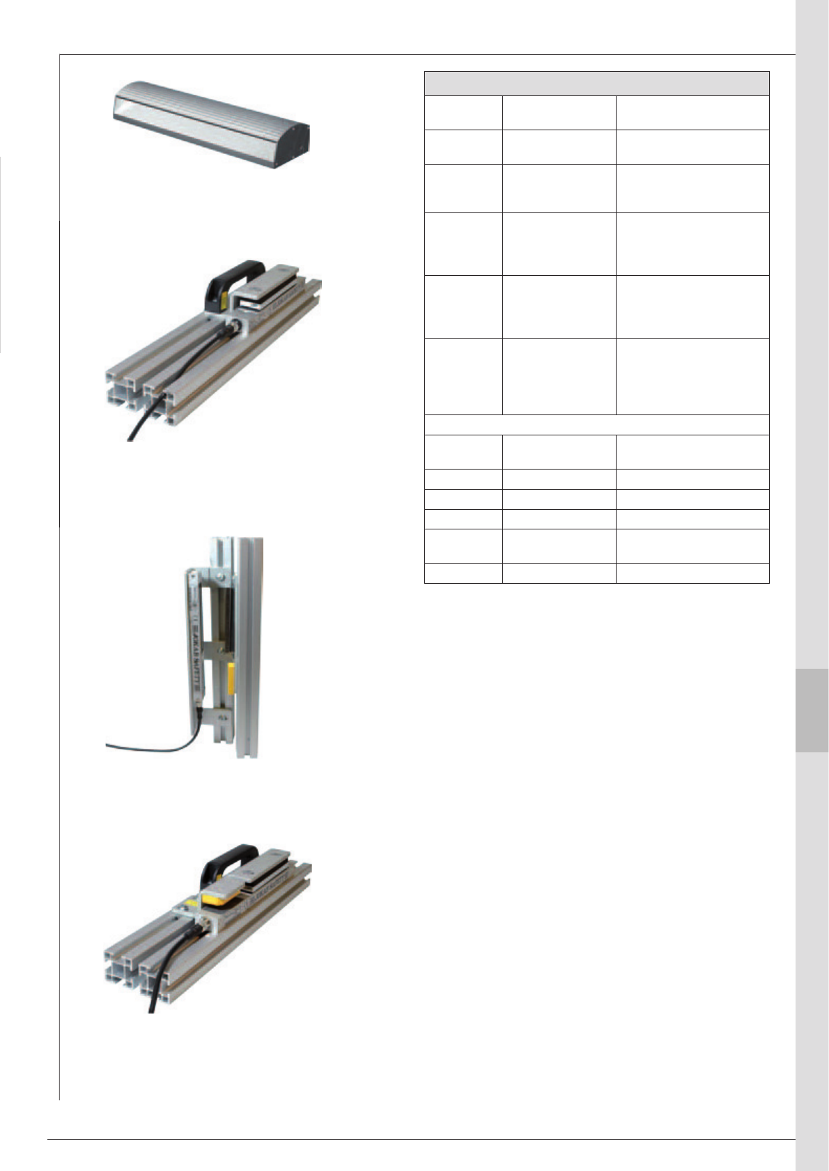
ABB 9:17
1
9
2
3
4
5
6
7
8
10
11
13
14
12
Models and ordering data
Magne 1A 2TLA042022R0000 Process lock, Incl. anchor
plate
Magne 2A 2TLA042022R1000 Process lock with built-in
Eden, incl. anchor plate
Magne 1B 2TLA042022R0100 Process lock incl.
anchor plate with built-in
permanent magnet (30 N)
Magne 2B 2TLA042022R1200 Process lock incl. anchor
plate with built-in Eden and
built-in permanent magnet
(30 N)
Magne 2Ax 2TLA042022R1300 Process lock with built-
in Eden and 5-pin M12
connector for Urax, incl.
anchor plate
Magne 2Bx 2TLA042022R1400 Process lock with built-
in Eden and 5-pin M12
connector for Urax, incl.
anchor plate with built-in
permanent magnet (30 N)
Accessories
JSM D21B 2TLA042023R0500 Assembly kit for anchor
plate
2TLA042023R0100 Handle profile for Magne
JSM D23 2TLA042023R0200 Fixture for sliding door
JSM D24 2TLA042023R0300 Assembly kit for Eva
2TLA042023R0400 Anchor plate with
permanent magnet
2TLA042023R1000 Handle for JSM D21B
Magne 2A with installation kit
(JSM D21B, JSM D24) and handle
(incl. screw) fitted on profile.
Magne 2A with installation kit
(JSM D23) for sliding door fitted on profile.
Magne 1A with installation kit
(JSM D21B) and handle (incl. screw) fitted
on profile.
Handle profile that hides Magne completely
when the door is closed.
Models and accessoris - Magne
ABB
9:18
Technical data – Magne
Manufacturer ABB AB/Jokab Safety, Sweden
Safety level
IEC/EN 61508-1...7
EN 62061
EN ISO 13849-1
SIL3
SIL3
Kat. 4/PL e
PFHD4,50×10-9
Power supply Magnet: 24 VDC + 15% -20%
Eden: 17–27 VDC, ripple max
10%
Power consumption Magnet: 7 W (300 mA at
24VDC)
Eden: 45–55 mA (see data for
Eden)
Operating temp. range -20°C to +50°C
Protection class IP67
Weight Magne 1: 610 g
Magne 2: 700 g
Anchor: 290 g
Material Anchor plate and magnet: steel
Housing: Aluminium
Holding force 24 VDC: Min 1500 N
0 VDC: 0 N (Magne 1A/2A)
0 VDC: 30 N (Magne 1B/2B)
Contacts Reed sensor (not safe)
Switch current max 100 mA
Mechanical life >107 switch operations
Connector M12 5-pole male connector
(Magne 1A, 1B, 2Ax, 2Bx)
M12 8-pole male connector
(Magne 2A, 2B)
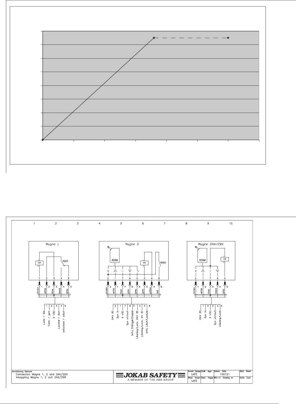
Connections Magne 1A/B:
(1) Brown: Locking, +24 VDC
(2) White: Sensor supply
(3) Blue: 0 VDC
(4) Black: NO-contact
(5) Grey: NC-contact
Magne 2A/B:
(1) White: Dynamic signal input
(2) Brown: +24V DC
(3) Green: Locking, +24V DC
(4) Yellow: Locking, 0V DC
(5) Grey: Info closed
(max 10 mA)
(6) Pink: Dynamic signal output
(7) Blue: 0V DC
(8) Red: Info locked
(max 100 mA)
Magne 2Ax/Bx:
(1) Brown: +24 VDC
(2) White: Dynamic signal input
(3) Blue: 0 VDC
(4) Black: Dynamic signal output
(5) Grey: Locking
Conformity 2006/42/EG
EN ISO 12100-1/2:2003,
EN ISO 13849-1:2008,
EN 62061:2005, EN 1088
Certifications TÜV Nord
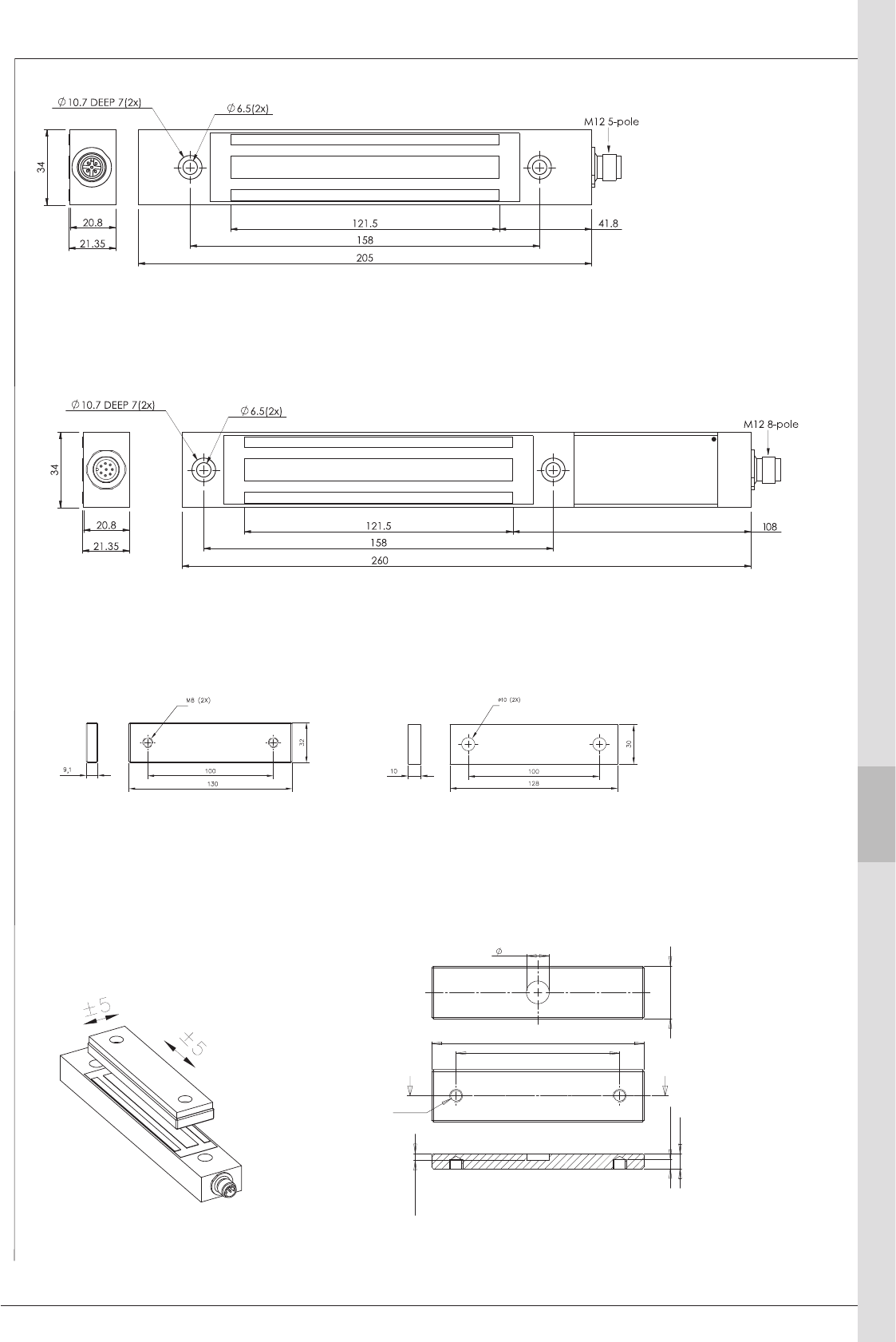
ABB 9:19
1
9
2
3
4
5
6
7
8
10
11
13
14
12
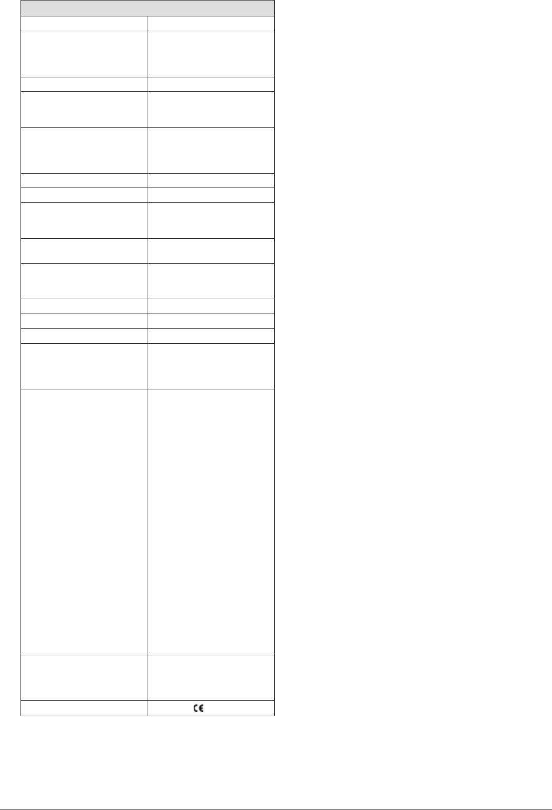
Dimensions Magne 1A/B
Dimensions Anchor plate
(without permanent magnet)
Dimensions Anchor plate
(with permanent magnet)
Dimensions - cell rubber
Installation tolerance (general)
Dimensions Magne 2A/B
Dimensions - Magne
130
100 ±0,20
M8 (2X)
AA
32
14
SECTION A-A
±0,10
9,10
5,50
4,10 0
+0,10
ABB
9:20
Connection example - Magne 1 and 2
Holding force - Magne 1 and 2
!"#$%&'(!)*+',' -"".)/(0
!
"
#
$
%
%!
%"
%#
& % %& ! !& ' '&
1!"0
2+30!%
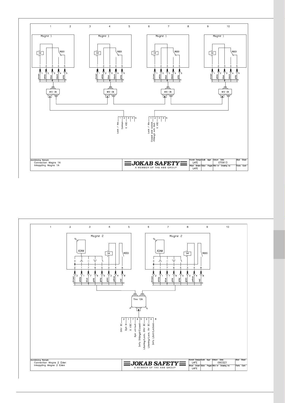
ABB 9:21
1
2
3
4
5
6
7
8
9
10
11
13
12
1
9
2
3
4
5
6
7
8
10
11
13
14
12
Connection example - Magne 2 in series
Connection example - Magne 1 in series
ABB
9:22
Dalton – the intelligent process lock
Dalton is a locking unit that is intended for use in preventing
unnecessary process stoppages, i.e. it is not a safety lock. It
can be used either as a free-standing lock or integrated with
Eden as a safety sensor. In the unlocked state the door is
held closed by a ball catch and in locked state the balls are
mechanically blocked so the lock tongue can not be pulled
out. If necessary, the holding force of the ball catch can be
adjusted. The device only allows to lock when the ball latch
is centred around the lock tongue, and when Eva is with
Adam (depending on version). When an input is supplied
with voltage, the ball catch is locked.
Dalton is easily connected with an M12 connector. The
Tina junction block can be used for distribution of both the
safety and locking functions. The Dalton status is indicated
by LEDs and can also be read by a PLC via the information
output.
Dalton has a modular structure
The Dalton process lock has a modular structure and can be
combined in different ways depending on position, installation
and function. You choose the lock housing, lock tongue and
fixing plate yourself to create a complete Dalton.
Installation
Dalton offers many different installation possibilities as the
lock tongue may enter the ball catch from three directions.
In order to ensure that Dalton works without any problems,
the ball catch must be resting, i.e. the balls not pressed in by
the lock tongue when the door is in closed position. Dalton's
brackets are therefore made to ensure easy adjustment of
the lock tongue and ball latch positions.
Use:
Doors and hatches
Advantages:
Small and robust
Integrated with Eden
Flexible installation
High enclosure classification
– IP 67
Withstands severe
environments
Low current consumption
Status information with LED
on the lock housing and in
the cable connection.
Dalton is easy to install, adjust and dismantle in
the Quick-Guard fence system's T-slots.
Process lock
Dalton
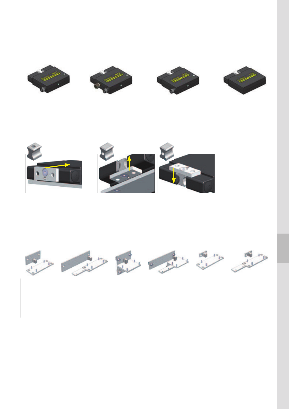
ABB 9:23
1
9
2
3
4
5
6
7
8
10
11
13
14
12
1. Choose Dalton lock housing according to your preferences:
• Dalton M11/M31 If you only need to be able to lock your door/hatch (8-pin/5-pin M12)
• Dalton M12 If you want to lock your door/hatch and also have the interlocking switch Eden
installed with one cable, common for both Dalton and Eden.
• Dalton L00 If you only need to use Dalton to keep the door fixed and closed
2. Choose a lock tongue depending on how the door/hatch is closed.
3. Choose a fixing kit that fits your installation.
Dalton M12
with 8-pin male contact,
5 pin female contact for
Adam
Dalton M31
with 5-pin male contact
Dalton M11
with 8-pin male contact
Dalton L00
as ball latch, no electrical
functions.
Lock tongue A
Selected when the door
closes to the Dalton front
Fixing kit 1
for Dalton and
lock tongue
Fixing kit 4
for Dalton and Eden
adapted to ABB
Jokab Safety fencing
system
Fixing kit 2
for Dalton and Adam and
also for lock tongue and
Eve
Fixing kit 5
for Dalton, small
bracket for lock
tongue
Fixing kit 3
for Dalton
adapted to
ABB Jokab
Safety fencing
system
Fixing kit 6
for Dalton and
Eden, small bracket
for lock tongue
Lock tongue B
Selected when the door closes to Dalton's upper or lower side
Tina 12A junction block
Tina 12A can be used to connect two Daltons with Edens
with one cable to the apparatus enclosure. The summed
information that indicates the states of both the Dalton and
Eden also goes to the apparatus enclosure.
Modular structure - Dalton
Accessories - Dalton
Transfer cables
A transfer cable can be used when the Dalton's 8-pole con-
nector is to be connected to the 5-pole M12 connector of
Tina 4A or Tina 8A. Note that the info-signals from Dalton
and Adam cannot be used.
For Dalton L00 both lock tongues can be used regardless of the operating direction
Read the manual for further information about correct installation of Dalton
ABB
9:24
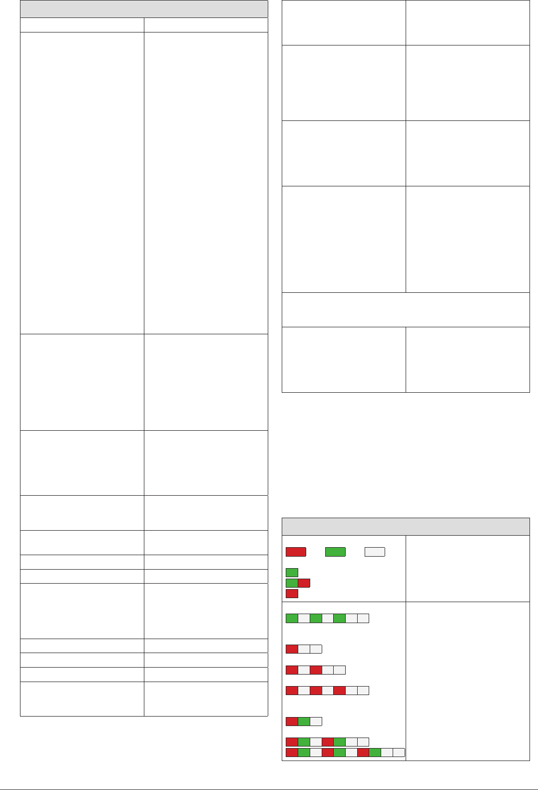
LED indication – Dalton
LED indication
=Red =Green =Paus Information function
1 Locked
0 Closed but unlocked
0 Open
Alarm:
1Hz Lock has not entered the
unlocked state
1Hz Eden or ball catch not in
position = open
1Hz Open, locking not permitted
1Hz Lock has not entered the
locked state
1Hz Undervoltage - locking not
permitted
1Hz Overvoltage
1Hz Overtemperature (> 80°C)
Technical data – Dalton
Manufacturer ABB AB/Jokab Safety, Sweden
Artikelnummer/
beställningsdata:
Dalton L00 – Only ball latch, no
electrical functions 2TLA020038R3000
Dalton M11 – 8-pin male plug 2TLA020038R3100
Dalton M12 – 8-pin male plug,
5-pin female to Adam 2TLA020038R3200
Dalton M31– 5-pin male plug 2TLA020038R3300
Lock tongue A – Lock tongue
for front entry 2TLA020039R0800
Lock tongue B – Lock tongue
for top and bottom entry 2TLA020039R1000
Fixing kit 1 – Fixing plates for
Dalton and lock tongue 2TLA020039R0000
Fixing kit 2 – Fixing plates for
Dalton and Adam and also for
lock tongue and Eve 2TLA020039R0100
Fixing kit 3 – Fixing plates for
Dalton adapted to ABB Jokab
Safety fencing system 2TLA020039R0200
Fixing kit 4 – Fixing plates for
Dalton and Eden adapted to
ABB Jokab Safety fencing system 2TLA020039R0300
Fixing kit 5 – Fixing plate for
Dalton, small bracket for lock
tongue 2TLA020039R0400
Fixing kit 6 – Fixing plate for
Dalton and Eden, small bracket
for lock tongue 2TLA020039R0500
Accessories
DA 1 – Spacer 2.5 mm for
Adam and Eva. 2TLA020053R0000
M12-CT0214 – Transfer cable
0.2 m M12 5-pole male plug
and 8-pole female plug 2TLA020060R0100
Tina 12A – Distribution block
for two Dalton Edens with
8-pole cables 2TLA020054R1800
Safety level
For interlocking switch Eden.
Not valid for locking function.
IEC/EN 61508-1...7
EN 62061
EN ISO 13849-1
SIL3
SIL3
Kat. 4/PL e
PFHD
For interlocking switch Eden.
Not valid for locking function.
4,50×10⁻⁹
Locking function M - Locked when energised
L - Only ball latch
Colour Black
Operating voltage 24 VDC +25/–20%
Current consumption
Unlocked
Locked
Lock input
Information output
40 mA
130 mA
5 mA
Max. 10 mA
Eden See the data for Adam M12
Operating temp. range -10°C to +55°C
Enclosure classification IP67
Holding force
Unlocked
Locked
25-100 N
2000 N
Material
Ball catch, securing plate
Enclosure
Lock tongue, securing plate
Anodised aluminium
Anodised aluminium
Stainless steel
Chemical resistance
Stainless steel
Anodised aluminium
Good resistance against most
acids except hydrochloric acid
and sulphuric acid.
Very good resistance against
corrosion, good resistance to
most acids.
Connections Connector to connect Dalton
(varies depending on type)
8-pole male plug, M12
5-pole male plug, M12
Outlet for externally connected
Adam female plug M12, 5-pole
Colour markings (pins)
Function
Dynamic input signal, Adam
+24 VDC
Lock signal
Not used
Information Adam
Dynamic output signal, Adam
0 VDC
Information Dalton
8-pole Colour 5-pole Colour
1 (White)
2 (Brown) 1 (Brown)
3 (Green) 4 (Black)
4 (Yellow) 2 (White)
5 (Grey)
6 (Pink)
7 (Blue) 3 (Blue)
8 (Red) 5 (Grey)
Warning
Dalton locks mechanically. If the lock is forced, the Dalton can be
permanently damaged.
Conformity 2006/42/EG
EN ISO 12100-1:2003
EN ISO 12100-2:2003
EN ISO 60204-1
EN ISO 954-1
EN ISO 13849-1:2008
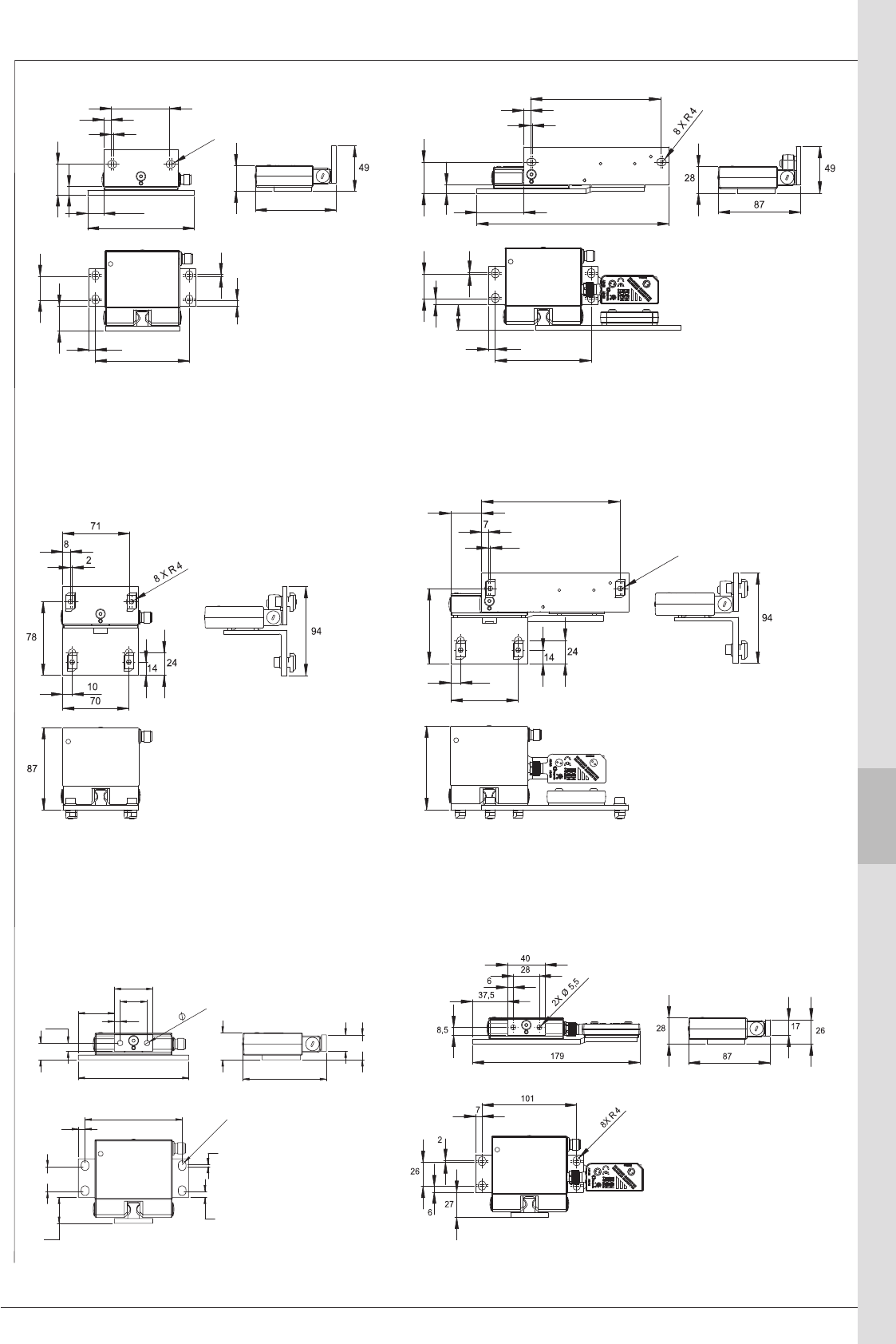
ABB 9:25
1
9
2
3
4
5
6
7
8
10
11
13
14
12
!
"
#
$
%&'(
%%(
)*
$
#&
#$
#
&
%+%
#"
"&
!
&
#
% &
*!'(
#+#'(
#
#&
#$
$
&
%+%
,%+%,
,&,
,#$,
,#&,
,"-,)*,
,$,
,#,
,%%(,
, &'(,
,$,
,#",
,#-,
('(,
,*+,
,%&'(,
,"'(,
,%&,
,#$,
,#",
,"&,
&"
%+
&+
#
#
%**
",.,) *
"&
Bracket 1 with Dalton Bracket 2 with Dalton and Eden
Bracket 5 with Dalton Bracket 6 with Dalton and Eden
Bracket 3 with Dalton Bracket 4 with Dalton and Eden
Dimensions – Dalton
ABB
9:26
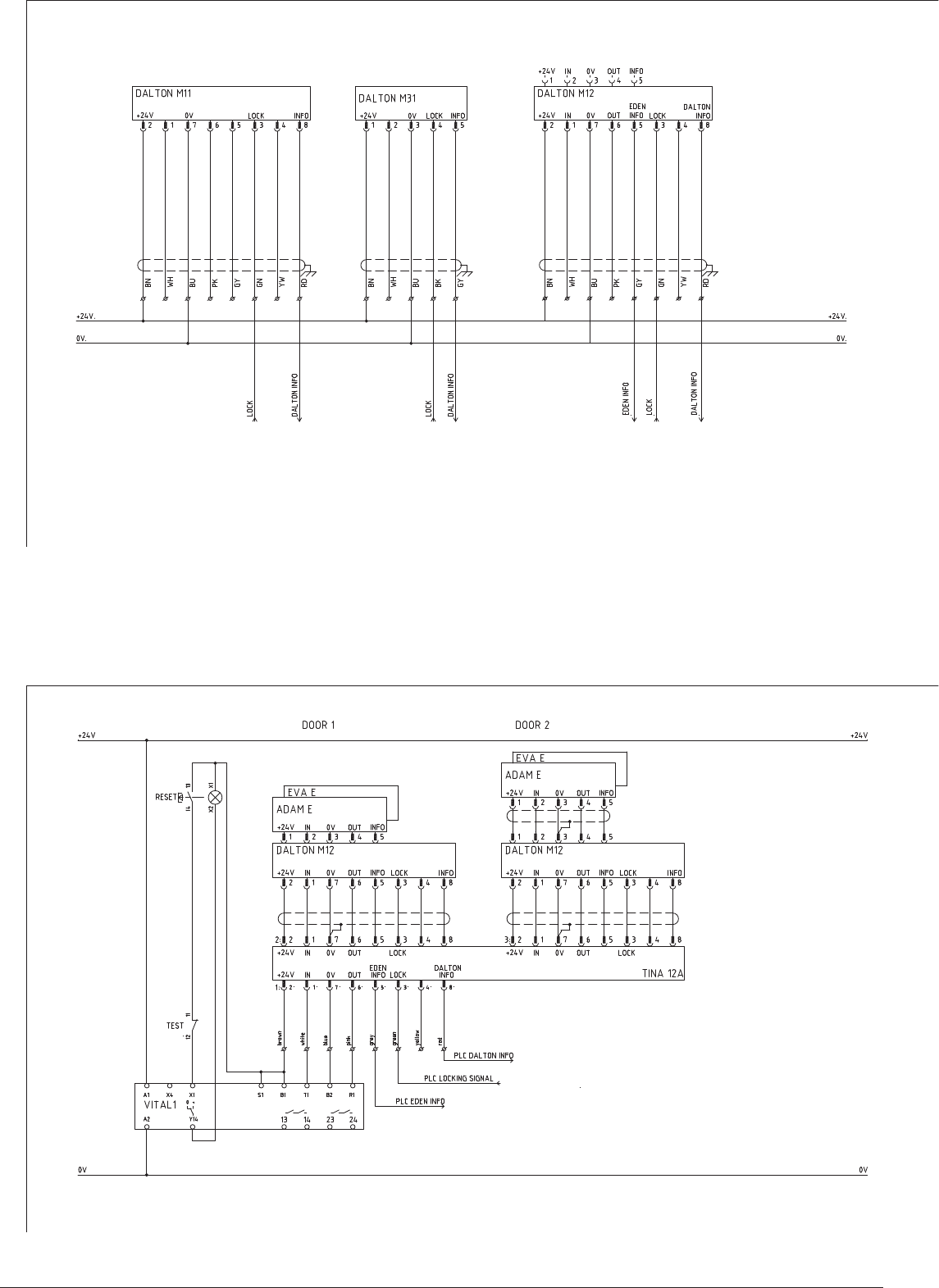
Connection example – Dalton M11, M31 and M12
Connection example – Dalton M12 and Vital
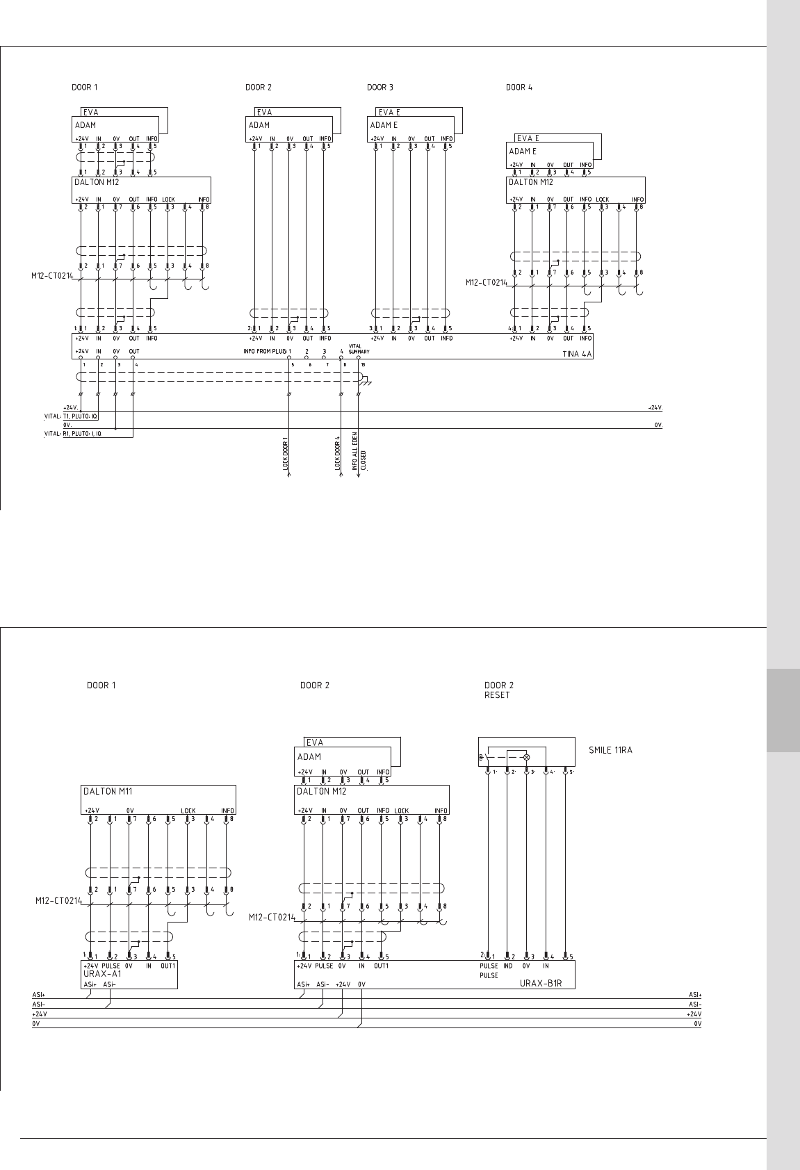
ABB 9:27
1
9
2
3
4
5
6
7
8
10
11
13
14
12
Connection example – Dalton M12 and Eden through Tina 4A
Connection example – Dalton M12 and Eden through Urax A1 (AS-i)
ABB
9:28
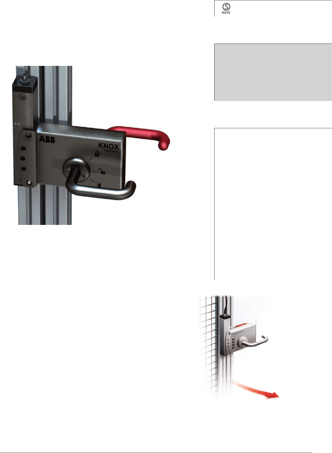
Knox - Double safety lock as specified in PLe/cat.4
Knox is a double lock that complies with the highest safety
level (two lock cylinders with monitored positions) that can
be used both as a safety and process lock. The locking func-
tion is electrically controlled and is bi-stable, i.e. it retains its
position (unlocked/locked) in the event of a power failure.
Dual signal for unlocking is safe at both short-circuits and
cable breaks.
The handles operate as they would on a normal door but
the exterior handle also have a reset function, why a separate
reset button is not necessary and the interior handle that
can be used for emergency opening also in locked state.
The design and durability of the lock mean that it is ideal for
harsh environments as the sensors are non-contact and the
lock is manufactured of stainless steel. Knox is available in
a number of adaptations such as left-hung door, right-hung
door, inward and outward opening, with manual unlocking
and for sliding door.
Approval:
Application:
Safe locking of door to a
cell/line with long stopping
time.
Prevents unintentional
interrupts of processes
Advantages:
Double locking function as
specified in PLe/cat.4
(EN ISO 13849-1)
Withstands harsh
environments
Status information with
LEDs on the lock and at
cable connection.
Controlled to locked and
unlocked positions - position
remains in the event of
power failure.
Electronic connection only
on the door frame
Robust design
Knox is easy to assemble, adjust and dismantle in
and out of the T-slot of the Quick-Guard fencing
system.
Safety and process lock
Knox
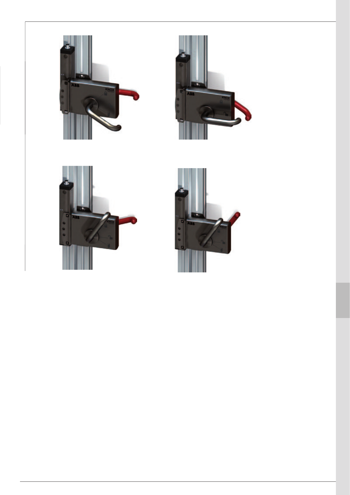
ABB 9:29
1
9
2
3
4
5
6
7
8
10
11
13
14
12
Operational mode
locked and reset
(emergency opening only)
Reset,
openable
Emergency openedOpen
Knox in 4 different states
ABB
9:30
Models and ordering data
Door part
Knox 1A-R v2
2TLA020105R5000
Knox door part for outward-
opening right-hung door
Knox 1A-L v2
2TLA020105R5100
Knox door part for outward-
opening left-hung door
Knox 1B-R v2
2TLA020105R5200
Knox door part for inward-
opening right-hung door
Knox 1B-L v2
2TLA020105R5300
Knox door part for inward-
opening left-hung door
Knox 1AX-R v2
2TLA020105R5800
Knox door part for outward-
opening right-hung door with
the option for manual unlocking
from the outside
Knox 1AX-L v2
2TLA020105R5900
Knox door part for outward-
opening left-hung door with
the option for manual unlocking
from the outside
Knox 1F-R v2
2TLA020105R6000
Knox door part for sliding door
that opens to the right. Incl.
additional fastening fixtures for
the frame.
Knox 1F-L v2
2TLA020105R6100
Knox door part for a sliding
door that opens to the left. Incl.
additional fastening fixtures for
the frame.
Knox 1BX-R v2
2TLA020105R6200
Knox door part for inward-
opening right-hung door with
the option for manual unlocking
from the outside
Knox 1BX-L v2
2TLA020105R6300
Knox door part for inward-
opening left-hung door with
the option for manual unlocking
from the outside
Knox 1FX-R v2
2TLA020105R6400
Knox door part for sliding door
that opens to the right with the
option for manual unlocking
from the outside. Incl. additional
fastening fixtures for the frame.
Knox 1FX-L v2
2TLA020105R6500
Knox door part for sliding door
that opens to the left with the
option for manual unlocking
from the outside. Incl. additional
fastening fixtures for the frame.
Frame part
Knox 2A v2
2TLA020105R2200
Standard Knox frame part
8-pin M12 contact, supplied
for right-hung door. For
instructions for turning, see the
Knox manual
Knox 2X v2
2TLA020105R2300
Knox process lock, no
duplicate unlocking signal, with
5-pin M12 contact
Accessories
PC plate for Knox on mesh
door
2TLA020106R0000
When mounting Knox on door
with mesh the accessory PC
plate for Knox is recommended.
This is to avoid emergency
opening from the outside.
Escutcheon plate for Knox
(without emergency release
handle)
2TLA020106R0600
When mounting Knox on a
low door it is recommended
to replace emergency release
handle to prevent opening from
the outside by reaching over.
Tina 12A
2TLA020054R1800 Distribution block for two Knox
Knox door part 1A-R and
frame part 2A
Knox door part 1B-R
and frame part 2A
Knox door part 1B-L and
frame part 2A
Knox door part 1F-R
and frame part 2A
Door part Knox1 Frame part Knox 2
Knox door part 1A-L and
frame part 2A
Knox door part 1F-L and
frame part 2A
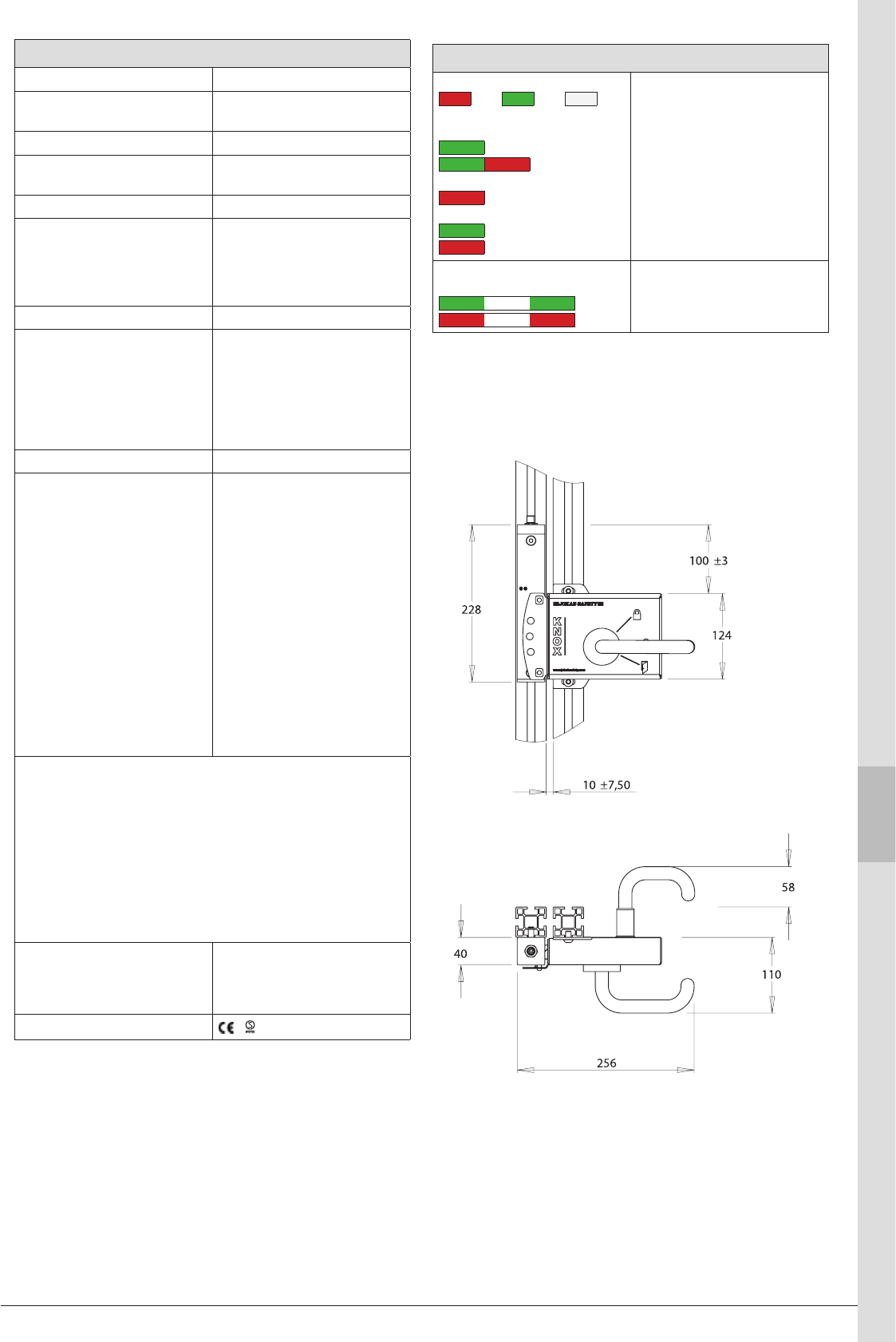
ABB 9:31
1
9
2
3
4
5
6
7
8
10
11
13
14
12
Technical data – Knox
Make ABB AB/Jokab Safety, Sweden
Safety level
EN ISO 13849-1 Kat. 4/PL e
PFHD4,50×10-9
Lock function S/M - unlocked and locked with
voltage.
Operating voltage 24 VDC +/- 15%
Power consumption
Electronics
Lock/lock inverse
Total max
Information output
70 mA (in locked position)
135 mA (when locking/unlocking)
150 mA
Max. 10 mA
Insulation class IP65
Holding strength
Unlocked
Locked
5000 N
(10,000 N ultimate breaking
strength)
5000 N
(10,000 N ultimate breaking
strength)
Connection Male plug M12, 8-pole
Connections Knox 2A
Function
Dynamic input signal
+24 VDC
Lock
Lock inverse
Information Locked
Dynamic output signal
0 VDC
Information reset
Connections Knox 2X
Function
+24 VDC
Dynamic signal input
0 VDC
Dynamic signal output
Lock
8-pole Colour
1 (White)
2 (Brown)
3 (Green)
4 (Yellow)
5 (Grey)
6 (Pink)
7 (Blue)
8 (Red)
5-pole Colour
1 (Brown)
2 (White)
3 (Blue)
4 (Black)
5 (Grey)
Warning
Knox locks mechanically. Forcing the lock may damage Knox perma-
nently.
When mounting Knox on door with mesh the accessory PC plate
for Knox is recommended. This is to prevent emergency opening
from the outside.
When mounting Knox on a low door it is recommended to replace
emergency release handle with the accessory Escutcheon plate for
Knox to prevent opening from the outside by reaching over.
Conformity 2006/42/EG
EN ISO 12100-1/2:2003,
EN ISO 13849-1:2008,
EN 62061:2005, EN 1088
Certifications
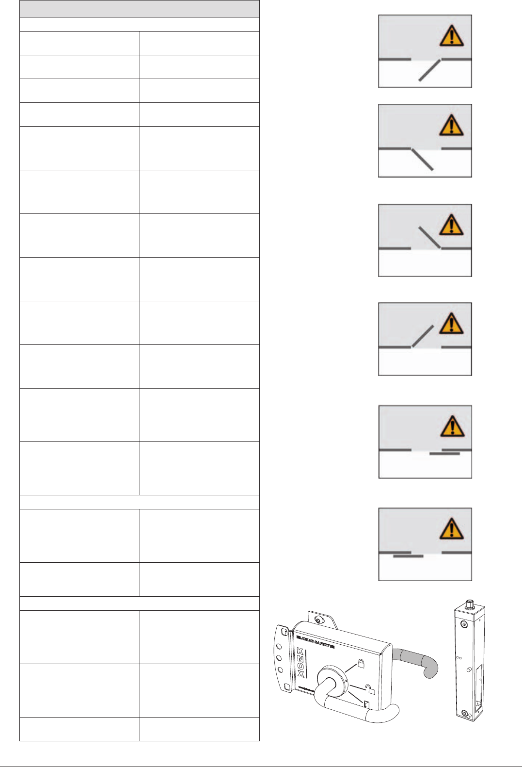
LED indicator – Knox
LED indicator
=Red =Green =Paus
LED 1
LED 2
Function
Locked (and reset)
Locked, no dynamic signal in
Unlocked
Reset
Not reset
Alarm LED 2 Dirt indicator reset sensor
Reset
Not reset
ABB
9:32
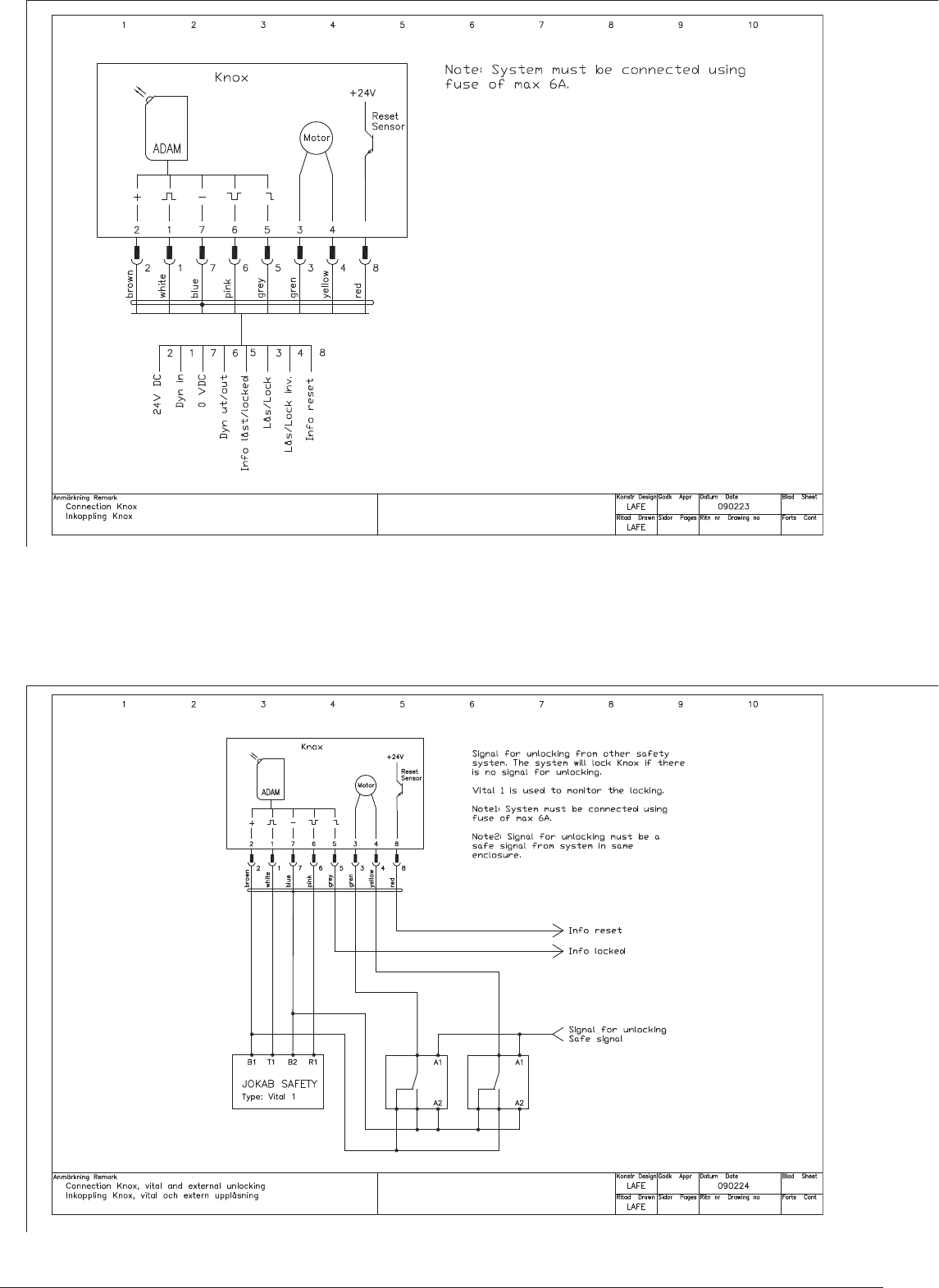
Connection example - Knox with other unlocking
Connection example - Knox
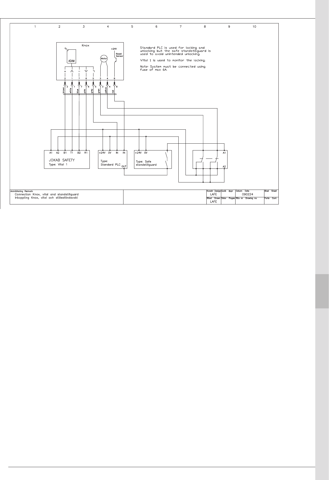
ABB 9:33
1
9
2
3
4
5
6
7
8
10
11
13
14
12
Connection example - Knox with downtime monitor
