Product Detail Manual
2014-11-11
: Pdf 137716-Attachment 137716-Attachment Batch12 unilog
Open the PDF directly: View PDF ![]() .
.
Page Count: 152 [warning: Documents this large are best viewed by clicking the View PDF Link!]
L
C
&
D
C
E
L
E
B
R
A
T
I
N
G
O
F
E
X
C
E
L
L
E
N
T
S
E
R
V
I
C
E
Years

1
800-345-4448 • www.lightingcontrols.com


3
800-345-4448 • www.lightingcontrols.com

4
www.lightingcontrols.com • 800-345-4448

5
800-345-4448 • www.lightingcontrols.com
6
www.lightingcontrols.com • 800-345-4448
7
800-345-4448 • www.lightingcontrols.com

800-345-4448 • www.lightingcontrols.com
10
www.lightingcontrols.com • 800-345-4448
11
800-345-4448 • www.lightingcontrols.com

13
800-345-4448 • www.lightingcontrols.com
14
www.lightingcontrols.com • 800-345-4448
DAYCARE
15
800-345-4448 • www.lightingcontrols.com
17
800-345-4448 • www.lightingcontrols.com
19
800-345-4448 • www.lightingcontrols.com

21
800-345-4448 • www.lightingcontrols.com
22
www.lightingcontrols.com • 800-345-4448
23
800-345-4448 • www.lightingcontrols.com
24
www.lightingcontrols.com • 800-345-4448
25
800-345-4448 • www.lightingcontrols.com

26
www.lightingcontrols.com • 800-345-4448

27
800-345-4448 • www.lightingcontrols.com

28
www.lightingcontrols.com • 800-345-4448
29
800-345-4448 • www.lightingcontrols.com
30
www.lightingcontrols.com • 800-345-4448

31
800-345-4448 • www.lightingcontrols.com
32
www.lightingcontrols.com • 800-345-4448
33
800-345-4448 • www.lightingcontrols.com
34
www.lightingcontrols.com • 800-345-4448
35
800-345-4448 • www.lightingcontrols.com
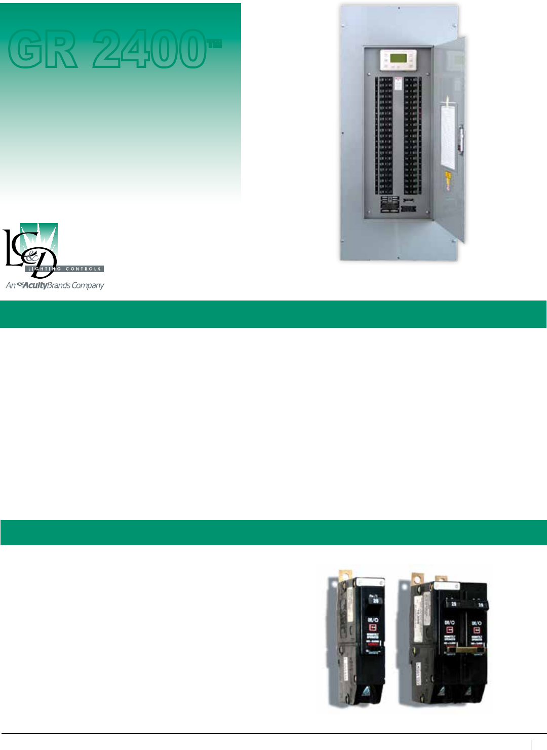
Specifications:
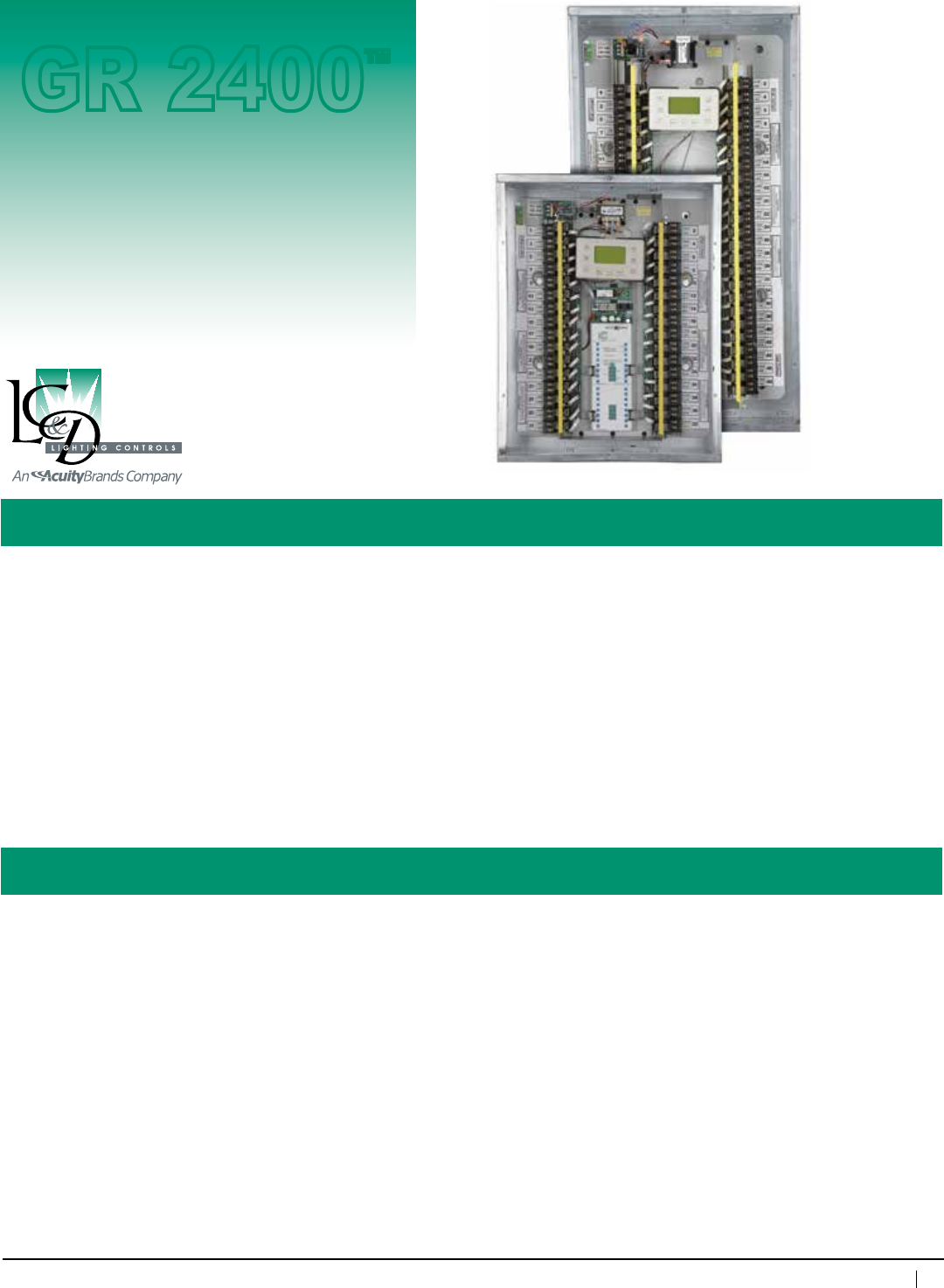
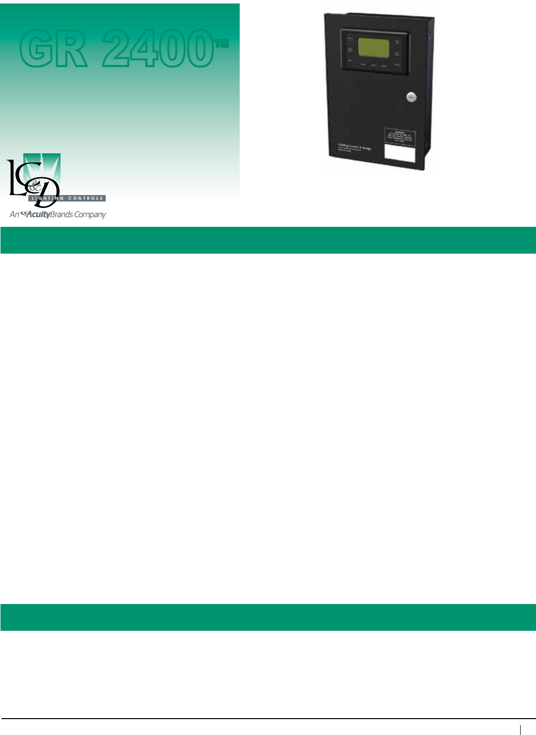
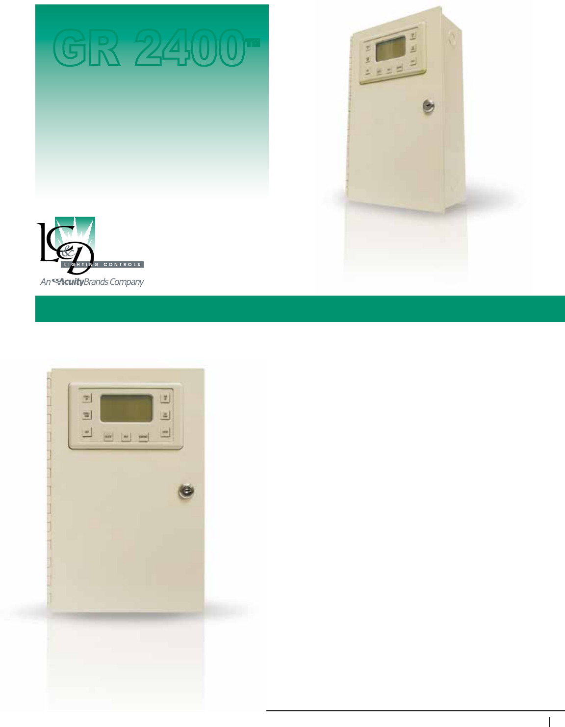
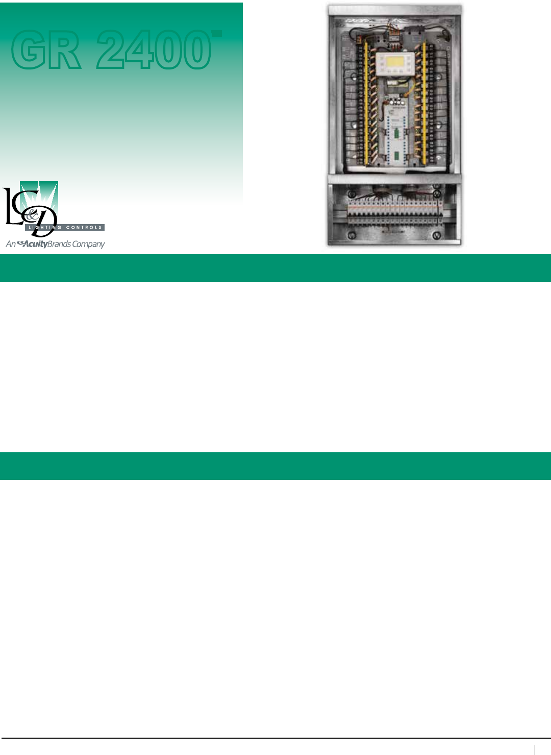
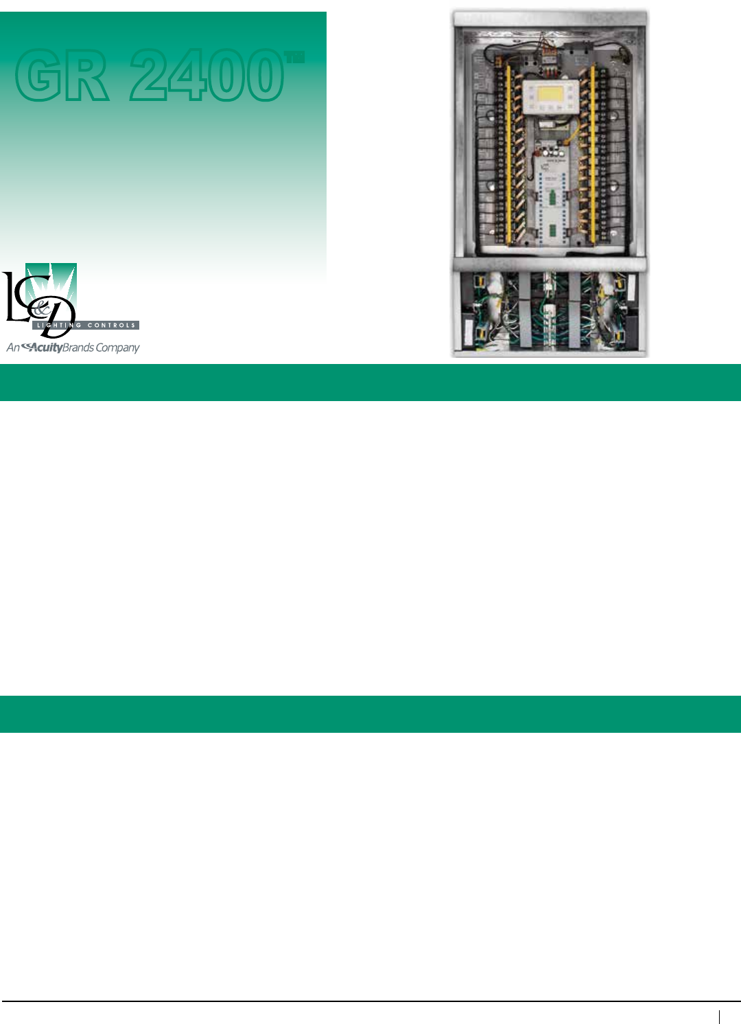
GR 2400™ Relay Panel
Description: The GR 2400 system is a 100% digital solution to lighting control. Panels and switches daisy-chain
together, using Cat. 5 patch cable with RJ45 connectors in any sequence.
Features: • 32-channel,365-day/astronomicaltimeclock.Largedisplay(21x8characters)actsasthe
programming interface for the entire system. Non-volatile memory holds all programming indefinitely.
Ten-yearbatteryback-upfortime-of-day
• Modemincludesfreelifetimefactoryprogramming
• Maycontrolmixedvoltages(i.e.,120VAC,277VAC)
• Maycontrolnormaloremergencypower
• Idealforallapplications
• Manualoverrideofindividualrelays,zonesorentirepanel
• Linkupto127addressesofdigitaldevicesviaCat.5patchcablewithRJ45connectors
Enclosuredimensions: 32Relays
NEMA1-20"wx25.5"hx6"d
NEMA4/4X/12-24”wx36”hx8”d
48Relays
NEMA1-20"wx37.5"hx6"d
NEMA4/12-24”wx48”hx10”d
NEMA4X-36”wx48”hx10”d
Enclosuretype: Surfacemount,hingedlockingdoor,NEMA1
Relay: NormallyClosed(NCL)
30A@277VACBallast
20A@120VACTungsten
20A@347VACBallast
SCCR18kA@277VAC
Rated250,000Cycles
Addressesused: GR2432(4),GR2448(6)
Optional relays: NormallyOpen(NOL),Normally
Closed(NCL),
TwoPole—NOorNC(480VAC);
DoubleThrow20A277VAC
Listings: ULandcUL916listed,
ETLlistedtoUL924(for
emergencycircuituse)
Programming: ViaDTC,viaPCwith
Unity 2™ Software
Max.humidity: 10 – 90%non-condensing
Ambienttemperature: 32–104°F(0–40°C)
Powersupplyvoltage: 120/277VACor120/347VAC
Busphysicallayer: RS485(GR2400bus)
Busconnector: RJ45connectors
Control Panel
GR 2400™
36
www.lightingcontrols.com • 800-345-4448
ORDERING INFORMATION
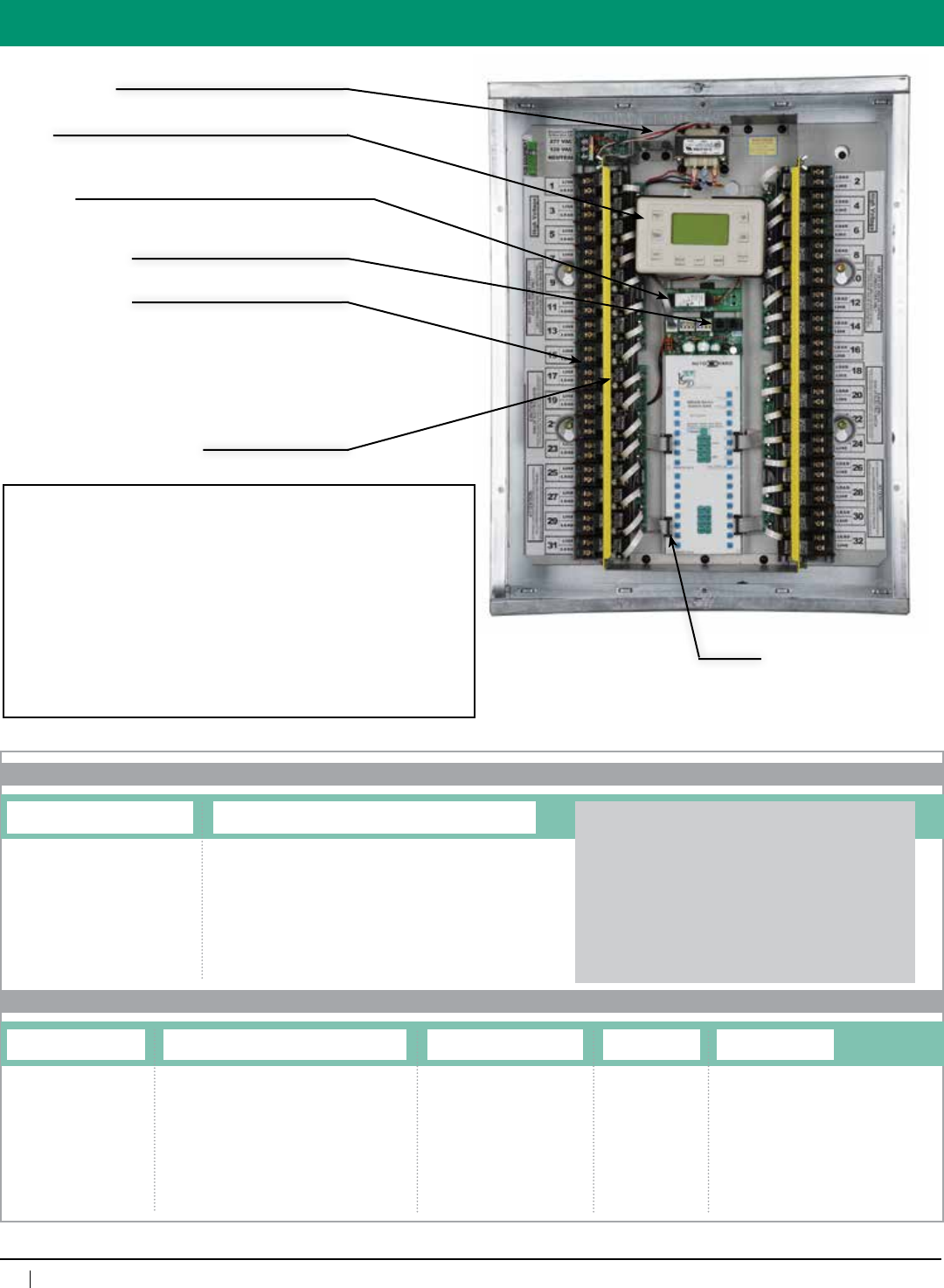
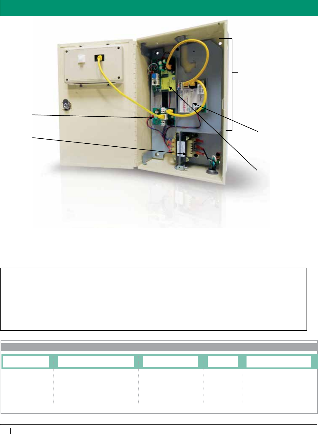
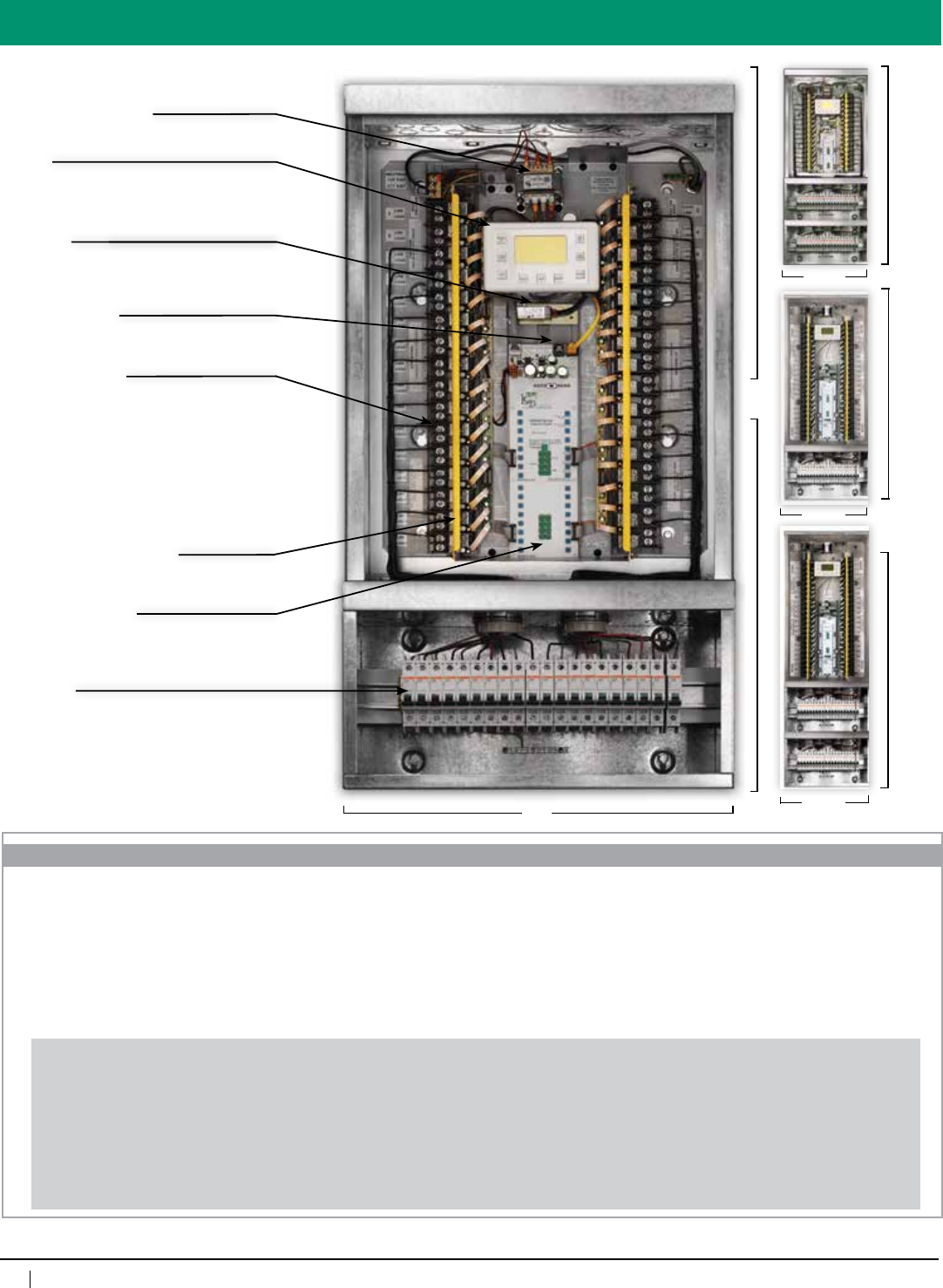
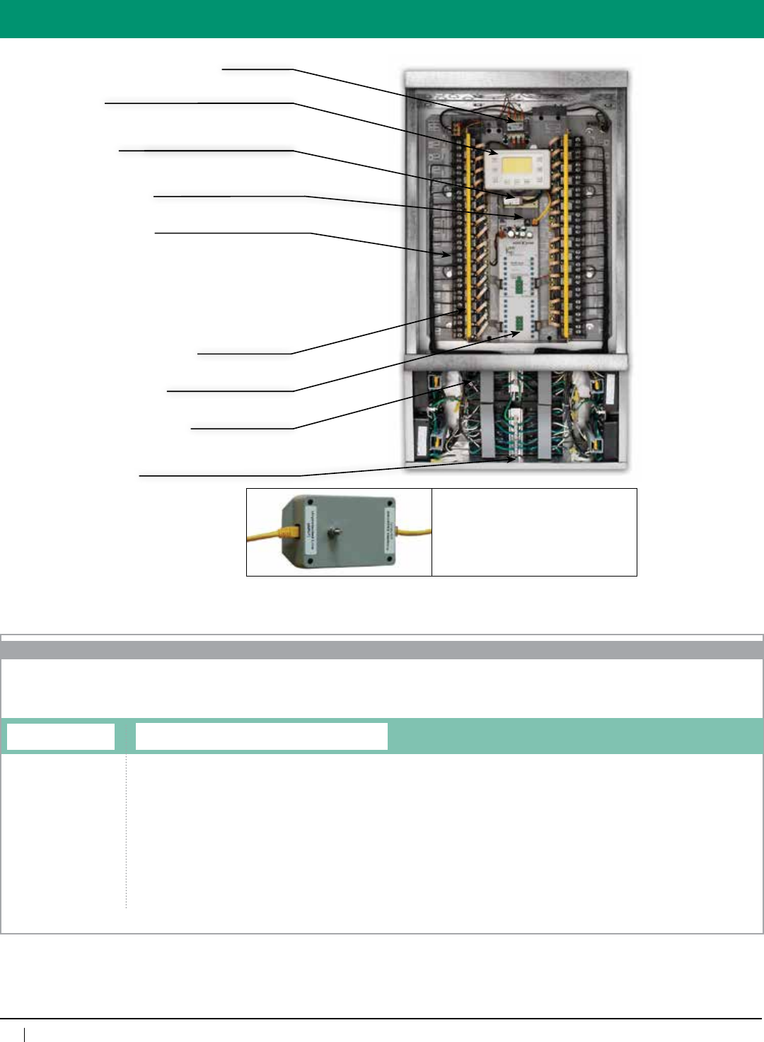
Overview
Power Supply:
120/277VACor
120/347VAC
Lighting Relays:
Normally Closed (NCL), 30A @ 277V Ballast,
20A @ 120V Tungsten, 20A @ 347V Ballast,
SCCR 18kA @ 277V, Rated 250,000 Cycles
Optional Relays:
Normally Open, (NOL) Spec same as NCL,
Two Pole — NO or NC (480VAC); Double Throw 20A
277VAC
High/Low Voltage Barrier:
(16gaugesteel)
Modem:
Remote programming and control, includes free
lifetime dial-up programming
DTC:
32-channel,365-dayastroclock
Accessandprogramtheentiresystem
Bus connectors
RJ45 connectors
Relay Control Card
(manualcontrolofzones
orindividualrelays)
Relay Panel Enclosure
GR2448ENC=48RelayEnclosure
GR2432ENC=32RelayEnclosure
Relay Panel Interior
GR2448INT=48Relay
Interior
GR2432INT=32Relay
Interior
Clock Option
DTCMOD=Digitaltimeclock
with modem
DTC=Digitaltimeclock
without modem
REMOTE= Remotepanel,
noclock
Transformer
DV=Dualvoltage
120/277V
CNDV=120/347V
Voltage Barrier1
[blank]=Nobarrier
1VB=1barrier
2VB=2barriers
3VB=3barriers
4VB=4barriers
Enclosure Mounting, NEMA Rating, Knockouts
SMNE1=SurfaceMount,NEMA1withknockouts
FMNE1=FlushMount,NEMA1withknockouts
SMNE1NKO=SurfaceMount,NEMA1noknockouts
FMNE1NKO=FlushMount,NEMA1noknockouts
SMNE4=SurfaceMount,NEMA4
SMNE12=SurfaceMount,NEMA12
SMNE4X=SurfaceMount,NEMA4X
Relays
[qty]NCL=NormallyClosedLatching
[qty]NOL=NormallyOpenLatching
[qty]DPNC=DoublePoleNormallyClosed
[qty]DPNO=DoublePoleNormallyOpen
[qty]RRNO=ReedRelayNormallyOpen(pair)
[qty]SPDT=SinglePoleDoubleThrow
[qty]SPDTC=
Single Pole Double Throw Contactor
Examples:
GR2448ENCSMNE1
GR2448INT12NCL12DPNCDTCMODDV
48relay,surfacemountNEMA1enclosurewithknockouts,
with12normallyclosedrelays,12doublepolenormally
closedrelays,withadigitaltimeclockandmodem(master
panel),anda120/277Vdualvoltagetransformer(also,no
voltagebarriers).
Enclosure
Interior
1 = Check with NEC or
CEC, State or Province,
and local regulations as
well as your electrical
inspector about
allowances for voltage
barriers within panels.
Seismic Certification:
•PreapprovedforuseinCategoryIVstructureswithanImportanceFactorof
1.5
•CaliforniaOfficeofStatewideHealthPlanningandDevelopment(OSHPD)
SpecialSeismicCertificationPreapproval(#OSP-0091-10)
Evaluated per the requirements of:
•2007/2010CaliforniaBuildingCode
•Section13.2.5of(AmericanSocietyofCivilEngineers/StructuralEngineering
Institute)ASCE/SEI7-05
•Testedto:ICC-ESAC156
37
800-345-4448 • www.lightingcontrols.com
ORDERING INFORMATION
Specifications:
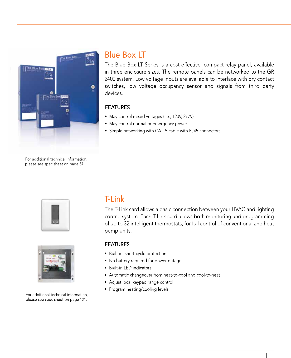
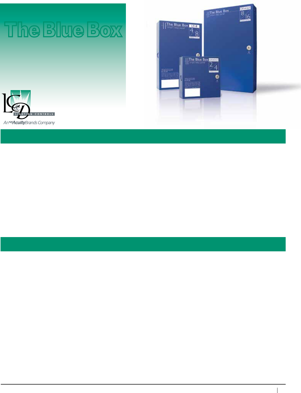
The Blue Box LT Series
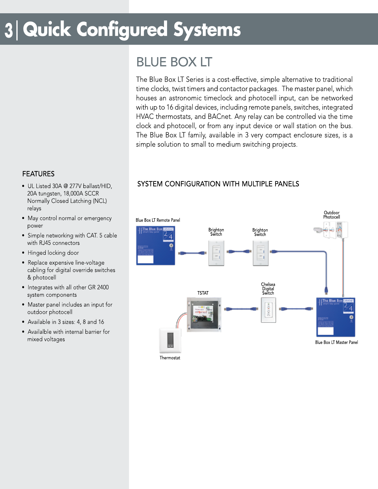
Description: TheBlueBoxLTSeriesisacost-effective,simplealternativetotraditionaltimeclocks,twisttimersand
contactorpackages.Itcomesinthreeenclosuresizes,eachwithacompactfootprint.TheBlueBoxLT
Series is ideal for small-to-medium projects, and arrives pre-assembled and ready for installation. The
MasterPanelmaybenetworkedwithupto16digitaldevicesincludingremoterelaypanels,switches
andphotocell.TheMasterPanelhasaninputforanoutdoorphotosensorwhichmaybeprogrammed
tocontrolanyrelay(s)onthebus.TheBlueBoxLTSeriesiscompatiblewithLC&D’sGR2400system
accessories.BlueBoxLTremotepanelsmaybeusedonGR2400systems.
Features: •100%digital
•ULListed30A@277Vballast/HID,20Atungsten,18,000ASCCRnormallyclosedlatchinglighting
relays(NCL)
•SimplenetworkingwithCat.5cablewithRJ45connectors
•Hingedlockingdoor
•Replaceexpensiveline-voltagecablingforoverrideswitchesandphotocells
•IntegrateswithallotherGR2400systemcomponents
Enclosure dimensions: GR1404LT (2or4relays)
NEMA1-8.4"wx8.4"hx3.125"d
NEMA4/4X/12-12”wx16”hx6”d
GR1408LT(4or8relays)
NEMA1-8.4"wx13.4"hx3.125"d
NEMA4/4X/12-16”wx20”hx6”d
GR
1416LT(8or16relays)
NEMA1-10.6"wx17.1"hx
3.125"d
NEMA4X-16”wx24”hx8”d
NEMA4/12-16”wx24”hx6”d
Enclosure type:
SurfaceMount,HingedLockingDoor,NE1
FlushMountoptional
Optionalenclosures: NEMA4,NEMA12
Relay: NormallyClosed(NCL)
30A@277VACBallastandHID
20A@120VACTungsten
20A@347VACBallast
SCCR18kA@277VAC
Rated250,000Cycles
Optionalrelays: NormallyOpen(NOL)
2-PoleRelayinremotepanelsonly
Max.devicesperbus: 16digitaldevicesw/BlueBoxLT
MasterPanel
#ofAddresses:
GR1404(1),GR1408(1),GR1416(2)
Programming: ViaDTC
Max.humidity: 10– 90%non-condensing
Ambienttemperature: 32–104°F(0–40°C)
Powersupplyvoltage: 120/277VAC(forall)
120/347VAC(for1408&1416)
347VAC(for1404only)
Busphysicallayer: RS485(GR2400bus)
Busconnector: RJ45connectors
Listings: ULandcUL916listed,ETL
listedtoUL924(for
emergencycircuituse)
Control Panel
The Blue Box
38
www.lightingcontrols.com • 800-345-4448
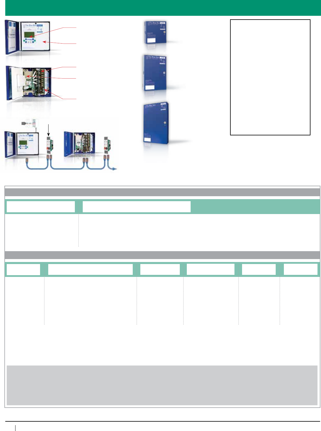
One Product...Three Solutions
MasterRelay
Panel
Cat. 5 patch cable with RJ45 connectors
Upto16digitaldeviceswithaBlue Box LT SeriesMasterPanel
Upto127digitaldeviceswithaGR 2400MasterPanel
Upto4,000ft.buslength
Chelsea
DigitalSwitch™
Remote Relay Panel
1400 DTC:
32-channel,365-dayastroclockto
access and program the entire system.
Dead Front
UL Listed 30A @ 277VAC 18,000A
SCCR Relays
Optional Modem:
Forremoteprogrammingand
control, includes free lifetime dial-up
programming.
Removable Interior
GR 1404 LT
• With 2 or 4 relays
• Master or remote
• 8.4"wx8.4"hx3.125"d
Photosensor GR 1416 LT
• With 8 or 16 relays
• Master or remote
•10.6"wx17.1"hx3.125"d
Chelsea
DigitalSwitch™
GR 1408 LT
• With 4 or 8 relays
• Master or remote
• 8.4"wx13.4"hx3.125"d
ORDERING INFORMATION
Enclosure
Interior
Relay Panel Enclosure
GR1416LTENC=16RelayEnclosure
GR1408LTENC=8RelayEnclosure
GR1404LTENC=4RelayEnclosure
Relay Panel
Interior
GR1416LTINT=
16RelayInterior
GR1408LTINT=
8RelayInterior
GR1404LTINT=
4RelayInterior
Relays
[qty]NCL=NormallyClosedLatching
[qty]NOL=NormallyOpenLatching
[qty]DPNC=DoublePoleNormallyClosed
[qty]DPNO=DoublePoleNormallyOpen
[qty]RRNO=ReedRelayNormallyOpen(pair)
[qty]SPDT=SinglePoleDoubleThrow
[qty]SPDTC=SinglePoleDoubleThrowContactor
Clock Option
DTCMOD=Digitaltime
clockwithmodem
DTC=Digitaltime
clockwithoutmodem
REMOTE=Remote
panel,noclock
Transformer
DV=Dualvoltage120/277V
CNDV=Canadiandual
voltage120/347V
(GR1408&GR1416
only)
347=347volt(GR1404only)
Dry Contacts
(optional)
D6=6inputs
(withenable/disable)
D14=14inputs
(noenable/disable)
Totalquantityofrelayspacesspecifiedmusteitherequalto,orhalfof,thetotalallowedinanygivenenclosure.TheGR1416mayonlyhave16or8relays,
theGR1408mayonlyhave8or4,andtheGR1404mayonlyhave4or2(example:GR1416LTINT8NCL=aquantityof8normallyclosed,latchingrelays
fortheGR1416LTinterior).
2-polerelays,reedrelaypairs,andcontactorrelaysallcountastworelayspaces(example:aGR1416LTINTmaynothavemorethan82-polerelays).
2-pole and contactor relays may not be combined into the DTC or DTCMOD option panel.
Enclosure Mounting, NEMA Rating
SMNE1=SurfaceMount,NEMA1
FMNE1=FlushMount,NEMA1
SMNE4=SurfaceMount,NEMA4
SMNE12=SurfaceMount,NEMA12
Examples:
GR1416LTENCSMNE1
R1416LTINT16NCLDTCMODDVD14
GR1416BlueBoxLTmasterpanelwithamodem,inasurfacemounted,NEMA1enclosure,with16normallyclosedrelays,120/277Vdualvoltagetransformerand14drycontactinputs.
GR1408LTENCSMNE1
GR1408LTINT4NCL2DPNCREMOTEDV
GR1408BlueBoxLTremotepanel,inasurfacemounted,NEMA1enclosure,with4normallyclosedrelaysand22-polenormallyclosedrelays,anda120/277Vdualvoltagetransformer.
Seismic Certification:
•PreapprovedforuseinCategoryIV
structureswithanImportanceFactor
of 1.5
•California Office of Statewide
Health Planning and Development
(OSHPD)SpecialSeismicCertification
Preapproval(#OSP-0091-10)
Evaluated per the requirements of:
•2007/2010CaliforniaBuildingCode
•Section13.2.5of(American
SocietyofCivilEngineers/Structural
EngineeringInstitute)ASCE/SEI7-05
•Testedto:ICC-ESAC156
Voltage Barrier
1VB=1Voltage
Barrier
39
800-345-4448 • www.lightingcontrols.com
XPoint™ Router Fixture-Level Digital Control
XPoint Router
GR 2400™
Information: AnXPointRouterconsistsoftwotypesofcontrolcard:
a)TheXPointRouterBoard b)TheXPointDriverBoard
Driver boards are available as: a)RelayDrivers b)DimDrivers
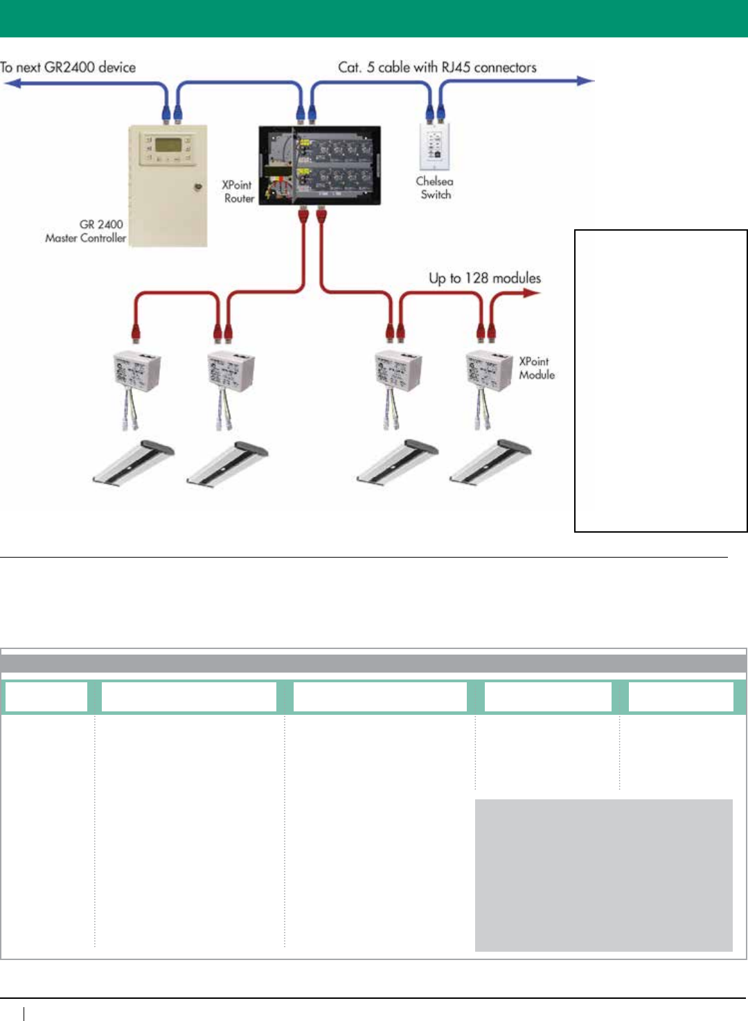
XPoint Router
Board:
TherouterboardhasapairofyellowRJ45sfortheGR2400busandapairofwhiteRJ45sfortheXPointbus.Thewhite
RJ45sareconsideredtheXPointPortandeachRJ45maydrivea“String”ofupto2,000ft.ofCat.5wirewithupto64
modulesonit.Thus,onecouldconsidertheXPointbustobe4,000ft.longwithupto128modulesonlydrivenfromthecenter
of the bus.
Relay Driver
Cards:
RelaydriversplugintotheXPointRouterboardandemulateasingleGR2448relaypanel.Uptotwodriver boards may drive
asingleXPointportgivingamaximumof96relays/zonesemulated.TherelaysintheXPointModulesaresoftwareassignedto
operateasoneoftheemulatedrelays,nowcalledaZone.OneorasmorerelaysfromtheXPointModulesonthebusmaybe
assignedtoazone.Thus,ifonewishestohaveindividualcontrol,onemayhaveupto96zones/relaysonthebus.Itisfarmore
usualtohaveabout12zonesofcontrolwithalltherelaysassignedtothesezones.
Dim Driver
Cards:
DimdriversalsoplugintotheXPointRouterBoardandsimilarlyemulateaGR2408iDimoriDHpanel.Theseareonly
availablewith4(0–10volt)dimmers(inaDHcardthesearerelays),4sceneaccessiblerelays,4photosensorinputsand8
drycontactsceneinputs.Eachdimmerorrelaycanbeconsideredasazone.Dimmersonthebuscanbeassignedtodimming
zones,relaystorelayzones.Upto4drivercardscandriveasingleXPointport.Thesecanbeamixofbothdimmerandrelay
drivers.(Nomorethantworelaydrivers.)Ifallfourboardsaredimmers,therewillbe16availablezonesofdimmingonasingle
bus.XPointDimandDHmodulesadditionallyhaveaphotosensorandacontactclosureinputoneachmodule.Thesemaybe
assignedtoanyavailable“softinput”oneachofthedrivercardsthroughsoftware.Eachdrivercardhas4“soft”photosensor
inputsand8“soft”sceneinputs.AsinglephotosensormaybeusedtocontrolDim/DHsinall4cards.Inthesamewaythe
contactclosureinputcanbeassignedandcanhaveanoccupancysensorconnectedthatoperatesscenesinone(orallfour)
oftheemulatedDim/DHcards.Occupantsensorinputscanbe“soft”programmabletobeusedwithpullhighorpulllowstyle
sensors. Only one style may be used on a bus. Note: The photosensor and contact closure inputs only operate on relays or
dimmersassignedtoDim/DHcards.Theydonotworkwithrelaysassignedtorelaydriversonthesameport.
Listing: ETLListedtoUL916,UL924,CSAC22.2#205
40
www.lightingcontrols.com • 800-345-4448
ORDERING INFORMATION
XPoint™ Router
Overview
XPoint Router XPoint Router Card 1
Relay Switching Only
48RZX1=48relayzones
96RZX1=96relayzones
Dimming Only
4DZX1=4dimmingzones
8DZX1=8dimmingzones
12DZX1=12dimmingzones
16DZX1=16dimmingzones
Relay Switching and Dimming Mixed
48RZX14DZX1=48relay&4dimmingzones
48RZX18DZX1=48relay&8dimmingzones
48RZX112DZX1=48relay&12dimmingzones
96RZX14DZX1=96relay&4dimmingzones
96RZX18DZX1=96relay&8dimmingzones
XPoint Router Card 2 (optional)
Relay Switching Only
48RZX2=48relayzones
96RZX2=96relayzones
Dimming Only
4DZX2=4dimmingzones
8DZX2=8dimmingzones
12DZX2=12dimmingzones
16DZX2=16dimmingzones
Relay Switching and Dimming Mixed
48RZX24DZX2=48relay&4dimmingzones
48RZX28DZX2=48relay&8dimmingzones
48RZX212DZX2=48relay&12dimmingzones
96RZX24DZX2=96relay&4dimmingzones
96RZX28DZX2=96relay&8dimmingzones
Transformer
DV=Dualvoltage120/277V
CNDV=Canadiandual
voltage120/347V
Mount & NEMA Type
SMNE1=Surfacemount,
NEMA1
FMNE1= Flushmount,
NEMA1
GR2400XP
Examples:
GR2400XP 96RZX1 DV SM NE1
XPointRouterwithoneXPointRouterCardconfiguredfor96relay
zones,120/277Vdualvoltagetransformer,inasurfacemount
NEMA1enclosure
GR2400XP 96RZX1 8DZX1 48RZX2 12DZX2 CNDV SM NE1
XPointRouterwithtwoXPointRouterCards,oneconfiguredfor
96relayzonesand8dimmingzones,theotherconfiguredfor
48relayzonesand12dimmingzones,120/347Vdualvoltage
transformer for Canadian voltage, in a surface mount
NEMA1enclosure
Ordering Information:
Note:RoutersareorderedseparatelyfromXPointModules.Asingleroutercardhastwoports.Eachportmaydriveupto64modulesand
shallnotexceed2000feet.
Seismic Certification:
•Preapproved for use in Category
IVstructureswithanImportance
Factorof1.5
•California Office of Statewide
Health Planning and Development
(OSHPD)SpecialSeismic
CertificationPreapproval(#OSP-
0091-10)
Evaluated per the requirements of:
•2007/2010CaliforniaBuilding
Code
•Section13.2.5of(American
SocietyofCivilEngineers/
StructuralEngineeringInstitute)
ASCE/SEI7-05
•Testedto:ICC-ESAC156
41
800-345-4448 • www.lightingcontrols.com
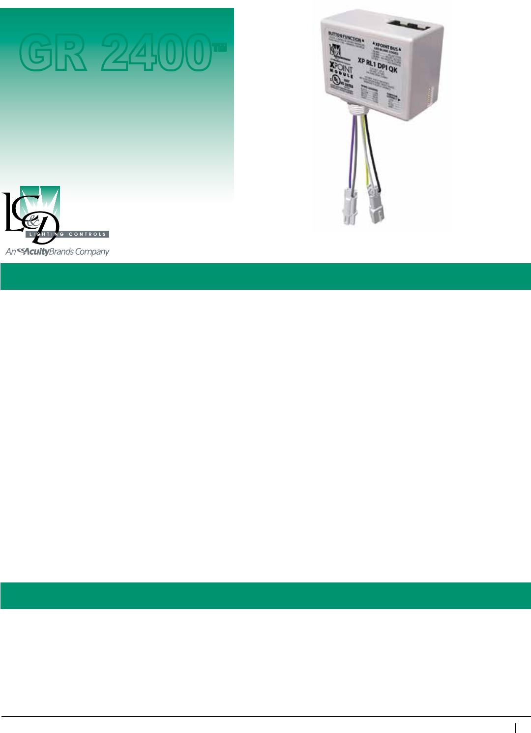
Specifications:
XPoint™ Module Fixture-Level Digital Control
Overall dimensions: 2"wx2.375"hx2.625"d
Ambienttemperature: 32–104°F(0– 40°C)
Humidity: 10–90%non-condensing
Listings: ETLListedtoUL916,UL924,
CSAC22.2#205
#Operations: 250,000cycles
Powerconsumption: Lessthan2mA@24VDCperXPoint
(forXPoint1andXPoint2).XDimhas
additionaluniversal120/277VACpower
supplytopower0–10VDCdrive
Contact rating: 30A@277VACballast,20A@120VAC
tungsten,20A@347VACballast,
1.4hp@120VAC,3hp@277VAC
XPoint Module
Description:
The XPointModulesprovideallthefeaturesofanetworkedRelayor(0–10V)Dimmerwithoutthepanel.UsetheXPointModuleto
controlanindividualfixture,astringoffixtures,a30Acircuitoranythinginbetween.Precisecontrolexactlywhereyouneedit.
Daisychainupto128XPointModulesfromasingleportonanXPoint Router.ModulesareplacedonastringofCat.5cablewithRJ45
connectors.RouterscomewithdriverboardsthatemulateeitherarelaypaneloradimmingpanelontheGR2400system.TheXPoint
Modulesmaybeassignedtoanyoneofupto96RelayzonesandDimmingModulestoanyoneofupto16dimmingzones.Program
eachzoneasrequired.ReprogrammingisassimpleasremotelyaccessingtheLC&DGR2400system.
Relaysaresoftwareselectablenormallyclosed(N/C),normallyopen(N/O),or“Latching”(nochangeonpowerfailure).
Note: XPointModulesmayonlybepluggedintoanXPointRouterbusport.
Features: • Controlanystandardballast—idealforbothnewconstructionandretrofits
• Fitsintoastandard1/2"KOinanyfixtureorJ-box
• EachPortfromanXPointrouterdrivestwostringsofupto2000ft,eachstringsupportsupto64modules
foratotalof128modulesonarouterport.(Onecouldthinkofthisasa4000ftbuswith128modulesdriven
fromthecenterofthebusinordertominimizevoltagedropsinceModulesarepoweredfromtherouter.)
• Upto128modulesoneachport
• Dualrelaycountsasasinglemoduleallowing256relaysperport
• Fieldinstalledorshippedtofixturemanufacturerforfactoryinstallation
• DimandDHModuleshaveinputsforphotosensorandoccupantsensor(mustusespecifiedoccupant
sensor—eachsensorreducesmodulesonbusby3)
• Optional0–10VDCcontrolfordimmers
• Relaydefaultstosoftwareselectablestateatlossofbuspowerorlossofcommunicationwithrouter
box(N/O,N/CorLatched)
GR 2400™
42
www.lightingcontrols.com • 800-345-4448
Overview
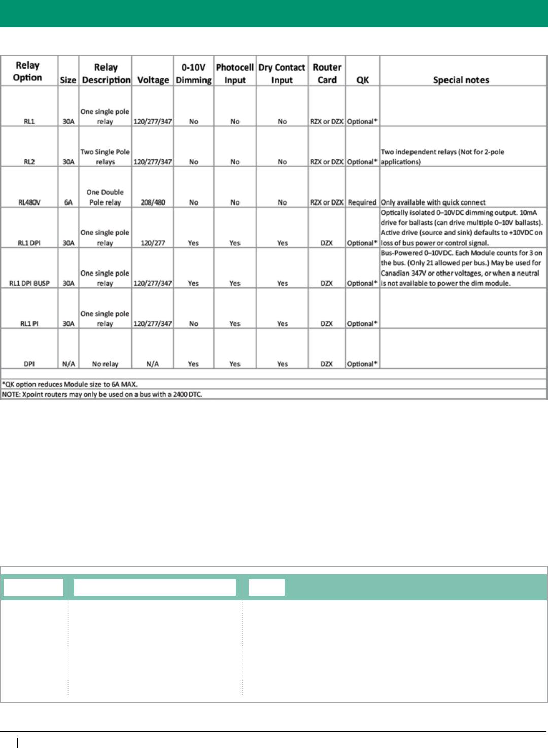
XPoint Module Relay Type, Input/Output Options
RL1=Singlerelay
RL2=Dualrelay
RL1DPI=Singlerelay,dimmingoutput,sensorinputs
RL1DPIBUSP=Singlerelay,dimmingoutput,sensorinputs,
bus powered dimming
RL1PI=Singlerelay,sensorinputs
DPI=Dimmingoutput,sensorinputs
RL480VQK=Doublepole,480VACwithquickconnector
RL1PD2=Singlerelay,2-wiredimmingballasts
RL1PD3=Singlerelay,3-wiredimmingballasts
QuicK Connector
[blank]=Standardwireleads
QK=QuicKConnector(6ampmax)
ORDERING INFORMATION
XP
43
800-345-4448 • www.lightingcontrols.com
Specifications:
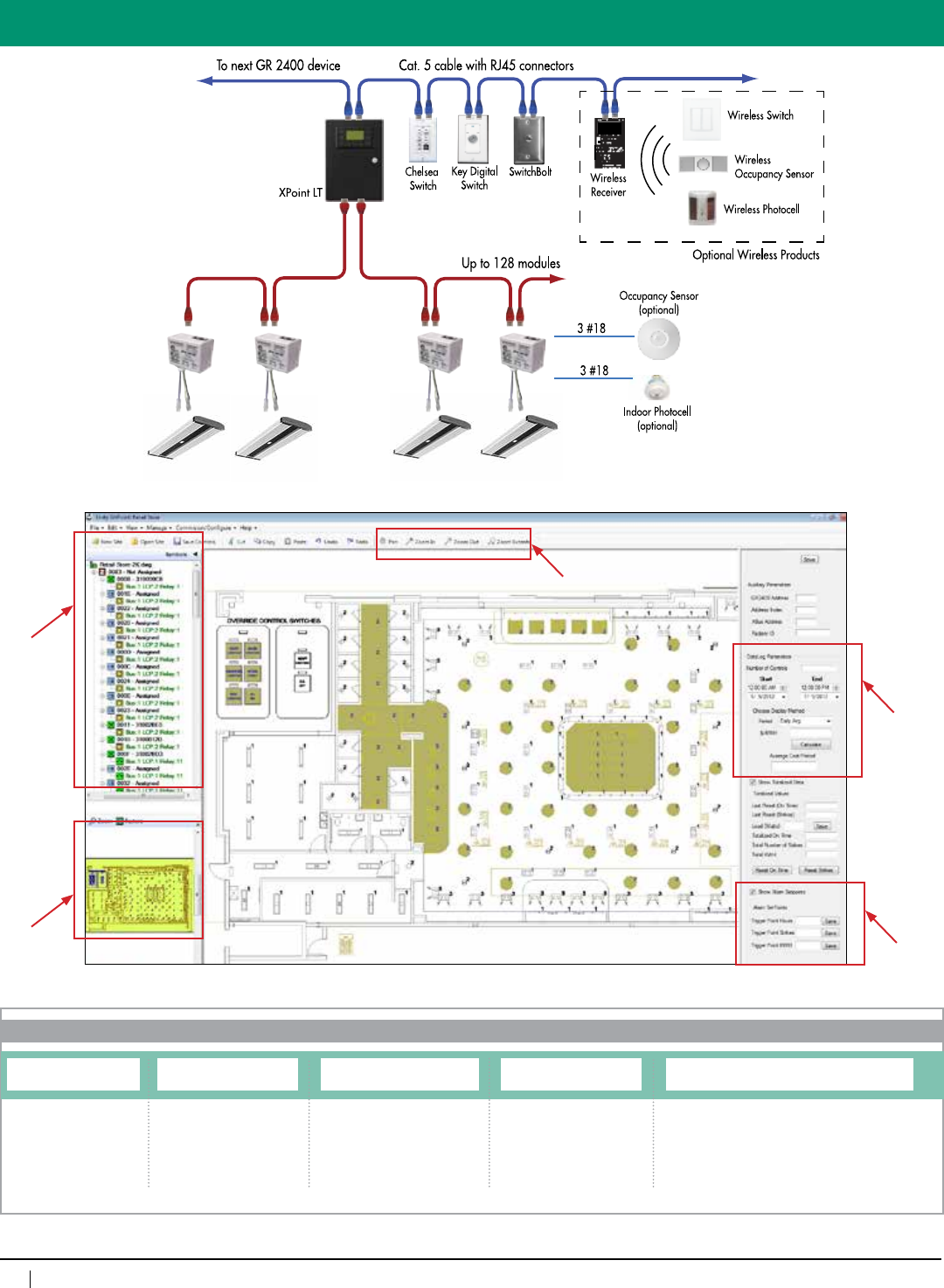
XPoint™ LT
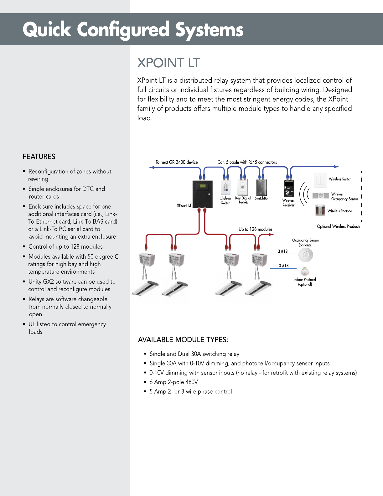
Description: XPointLTisalowcostoptionspecificallydesignedforsmallscaleXPointprojectswhere128orlessXPointmodulesareneeded.
XPointLTcombinestheGR2400DTC,GR2400ModemandXPointroutercardintooneenclosure.XPointLTenclosurehas
spaceforoneadditionalaccessorycard,suchasaLink-ToEthernetcard.StandardXPointroutercardscannotbeconnected
tothissystem.IfalargerXPointsystemisneeded,pleaserefertothestandardXPointsystem.XPointLTisavailableintwo
configurations:
Switching
Configuration: TheswitchingversionofXPointLTprovidescontrolofupto128modulesin96discretezones.Multiplerelayscanbeputinto
thesamezone.Ifeachrelaymustbecontrolledseparately,then96relaysshouldnotbeexceeded.ApplicableXPointmodules
include:XPRL1,XPRL2andXPRL480QK.PleaserefertotheXPointmoduletechsheetfordetails.
Dimming/DLH
Version: ThedimmingversionofXPointLTprovidescontrolofupto128modulesin(8)0-10Vdimmingand(8)switchingzones.Multiple
relayscanbeputintothesamezone.TheDimming/DLHversionprovides8photocelland16drycontactgroups.Theseinputs
canbeaccessedthroughtheXPointDim(XPRL1DPI)andXPointDH(XPRL1PI)moduleswhichhaveaphotocellanda
contactclosureinputoneachmodule.ThesemoduleswillonlyworkwiththeDimming/DHXPointroutercard.
Features: •Reconfigurationofzoneswithoutrewiring
•SingleenclosureforDTC,routercards,andinterfacesforquickandeasyinstallation
•Enclosureincludesspaceforoneadditionalinterfacecardsuchas:aLink-ToEthernetcard,Link-ToBAScardora
Link-ToPCserialcardtoavoidmountinganextraenclosure
•ProvidesvoltagetotheGR2400bustohelppowerpassivedevicestoavoidextrapowerboosters
•Controlofupto128(standardXPoint)modules
Graphical
Option:•UnityGX2softwareprovidesavisualfloorplanrepresentationoflighting,includingfixtureandcontrolstatus
•WiththeLink-ToPCEthernetcardandUnityGX,configurationbecomessimplified
•PanandzoomwithoutdistortionusingAutoCADvector-basedgraphics
•Virtualkeypadsprovideeasylocalandglobalcontrol
•Easyactivationofload-shedding
•Allowsforzone/fixtureenergymanagementwithtrendingreportcapabilities
Enclosuredimensions: 8.25"wx13.25"hx4"d
Enclosure type:
SurfaceMountorflushmount,NEMA1
Max.devicesperbus: 128devices
Listings: ULandcULlisted
XPoint LT
Max.humidity: 10– 90%non-condensing
Ambienttemperature: 0–90°F
Powerconsumption: 112VA
Operatingvoltage: 120/277VAC
Busphysicallayer: RS485
GR 2400™
44
www.lightingcontrols.com • 800-345-4448
ORDERING LOGIC
System
XPointLT
*Foradditionaloptions,pleasecontactthefactory.
Digital Clock/Modem
DTC=DigitalTimeClock
DTCMOD=DigitalTime
Clock&Modem
GR2400XP LT
Transformer, Mount and Enclosure Type
DVSMNE1=Surfacemount,NEMA1
DVFMNE1=Flushmount,NEMA1
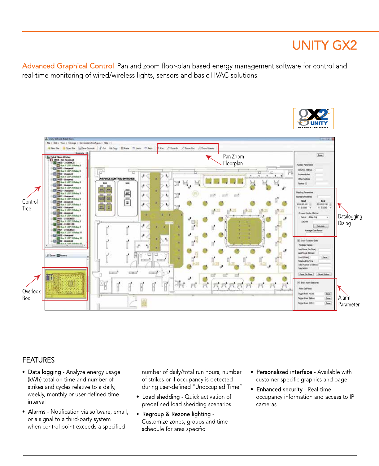
Unity GX2 Software
Control
Tree
Overlook
Box
Datalogging
Dialog
Alarm
Parameters
Overview
XPoint Cards
8DZX1=8dimmingzones
96RZX1=96relayzones
Additional Cards*
PCETHERNET=PCEthernet
Pan/Zoom
Floorplan
45
800-345-4448 • www.lightingcontrols.com
Transformer, Mount and Enclosure Type
DVSMNE1=Surfacemount,NEMA1
DVFMNE1=Flushmount,NEMA1
MicroPanel4(2)addresses
MicroPanel8(4)addresses
32–104°F(0–40°C), non-condensing
ULandcULtoUL916,availablefor
mountinginanairplenum(with
suitableenclosure)forCityofChicago,
ETLlistedtoUL924foremergency
circuituse)
4(8withoptional2ndcontrolcard)
8(16withoptional2ndcontrolcard)
4(8withoptional2ndcontrolcard,
15mAperchannel)
24VDC/300mA
120/277VACor347VAC
ViaDTC,viaPCwith
Unity™ Lighting Control Software
Specifications:
Micro
Panel™
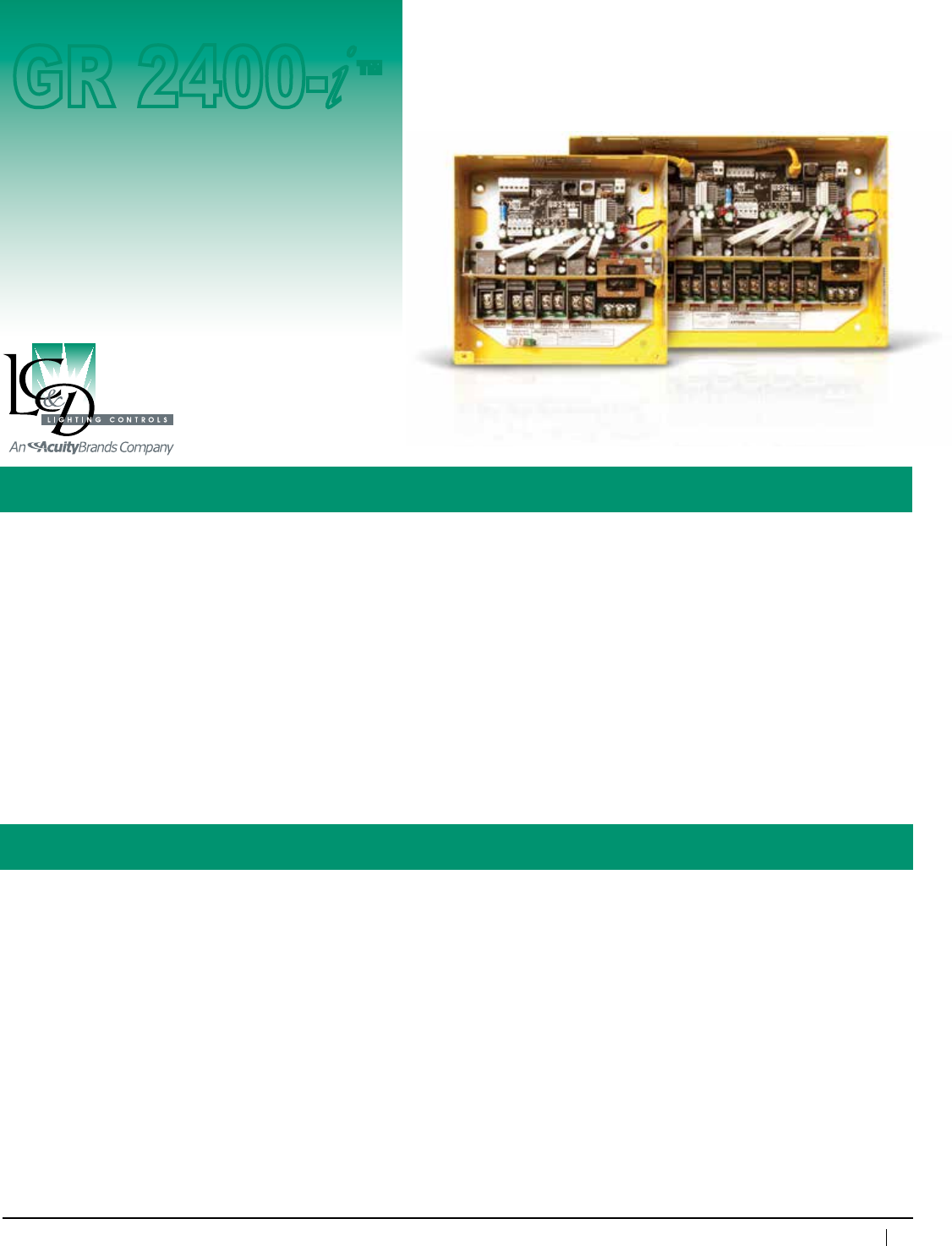
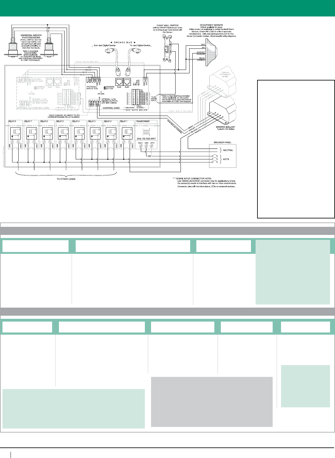
Description: The MicroPanel™comesstandardequippedwithfourrelays(MicroPanel-4)andprovidesintegrationfeatures
simplynotavailableanywhereelse;particularlytheadvanceddaylightharvestingproperties.Initsextended
versionitisacompactlightingcontrollerwithuptoeightswitching(iDH)andfour0–10Vdimming(iDim)
outputsthatlinkseveryroomintoonedigital,easy-to-usesystem.
The MicroPanel-8(witheightrelays)provideseightswitchedoutputs,fourofwhichcanbedimmedoutputs
using a single control card.Itistheidealsolutionforapplicationsrequiringmorethanfourswitchlegsper
classroom.Example:“a,b,c”lightingwithdimming,alegforpresentationlightingoverawhiteboard,
emergencylighting,andacontactclosureforthethermostat.Forapplicationsthatrequiremorethanfour
(0–10V)dimmingoutputs,asecondcontrolcardmaybeadded.
Features: • Digital(global)orlocalwallswitches
• Digital(global)orlocalphotosensorsandoccupantsensors
• IntegrateswiththeentireGR2400™systemincludingcentralizedcontrolpanels
• Time-of-dayscheduling
• Backplatemountingallowsenclosureonlytobeshippedforrough-in
• RatedforNormalorEmergencyPower(mixedsourcesrequireanadjacentenclosure)
Control Panel
GR 2400-
i
™
Enclosure dimensions:
Enclosure type:
Optional Enclosures:
Relays:
Optional Relays:
MicroPanel-4(2-4relays)
NEMA1-8.375"wx8.375"hx3.125"d
NEMA4/4X/12-12”wx16”hx6”d
MicroPanel-8(5-8relays)
NEMA1-12.875"wx8.375"hx3.125"d
NEMA4/4X/12-16”wx20”hx6”d
Surfacemount,screwcoverdoor,NEMA1,EZ-Find™
yellow powdercoat
NEMA4,NEMA4X,NEMA12
NormallyClosed(NCL)30A@277VACBallast,
20A@120VACTungsten,20A@347VACBallast,
SCCR18kA@277VAC,Rated250,000Cycles
NormallyOpen,(NOL)SpecsameasNCL,
NOorNC;TwoPole—NOorNC(480VAC);
DoubleThrow20A,277VAC
NumberofAddresses:
Ambienttemp:
Listings:
Photosensor inputs:
Localswitchinputs:
0–10VDCoutputs:
Power for Occupant Sensor:
PowerSupplyVoltage:
Programming:
46
www.lightingcontrols.com • 800-345-4448
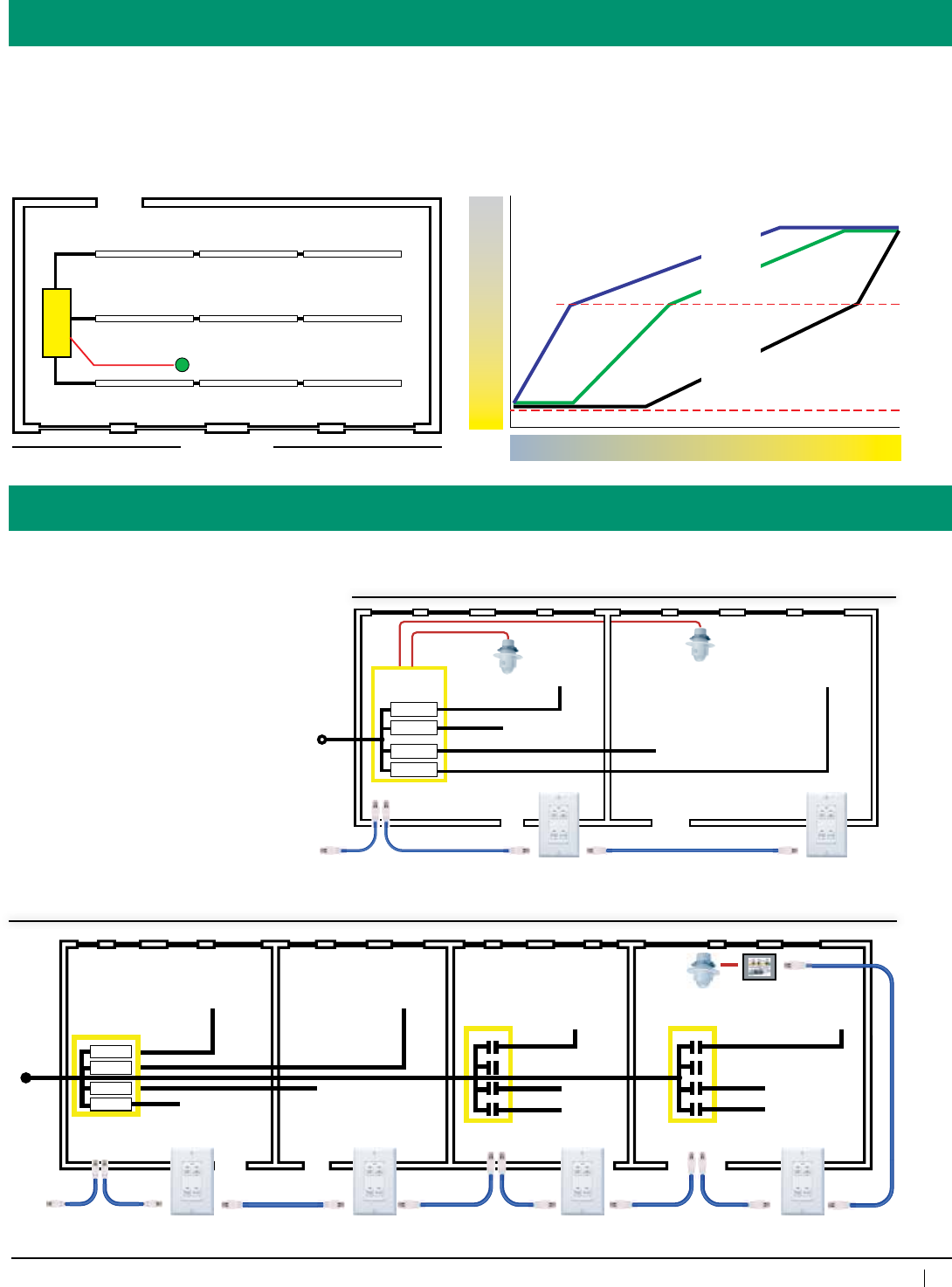
The Digital Daylight Harvesting Solution
Becauseourcompetitor’sdaylight
harvesting controls are not part of a
system, commissioning and any later
adjustments often require on-site or
hardwiring changes.
The MicroPanel-iDH and -iDim solve
this with our 100% digital lighting control
system.
Withproperinstallation,expensive
on-site commissioning can be eliminated.
Commissioning can be accomplished
remotely(viadial-uporinternet)fromthe
factory.
Anyadjustments(e.g.,toadaptto
interiordesignchanges)canbemade
with a phone call.
Adjustments can
be made with a
phone call
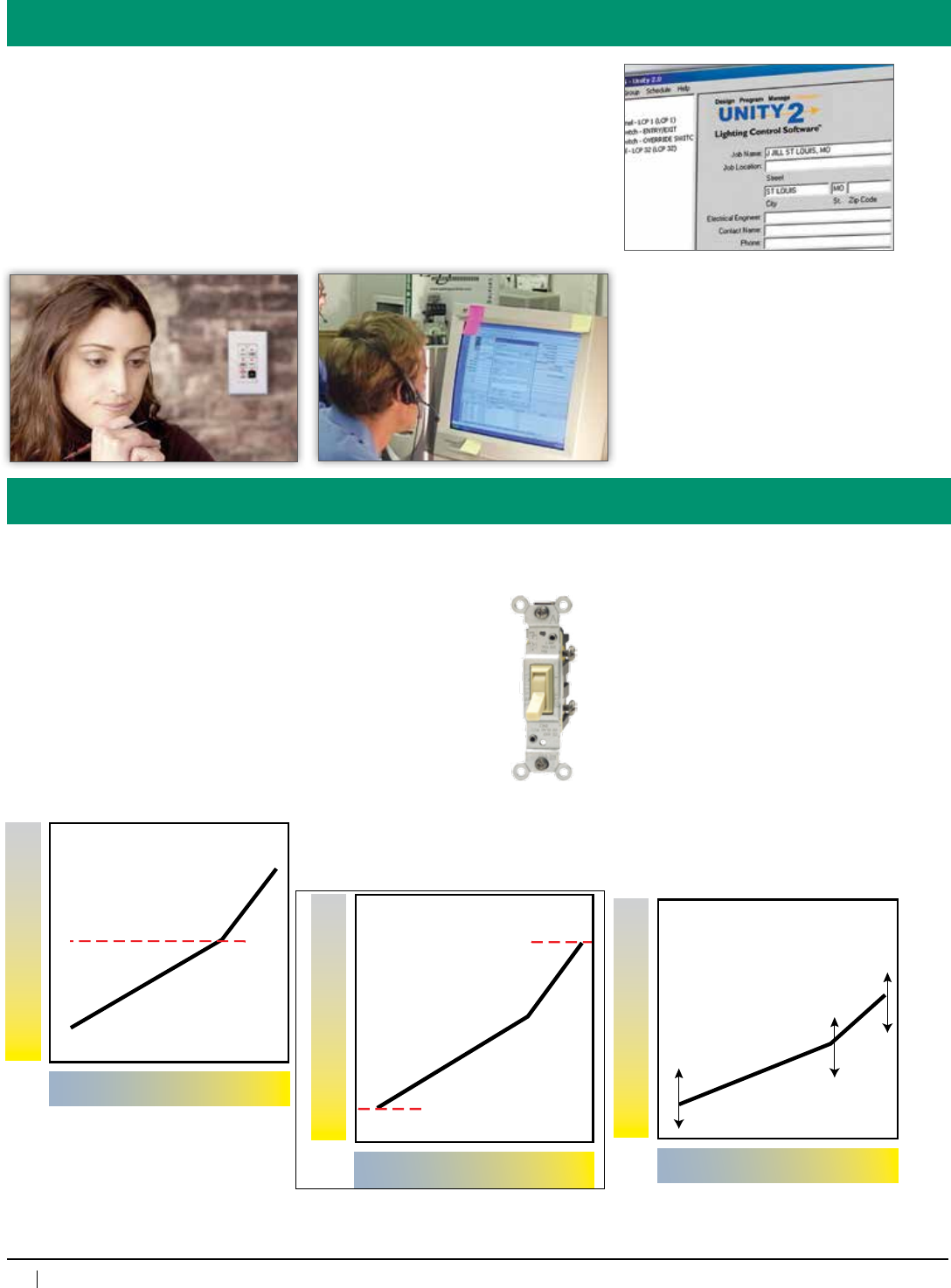
Response Curve. Individuallysetthree
points on the response curve, start dim
level, mid-point and turn off or end point.
Thisisamajorbreakthroughindaylight
harvesting, as almost any architectural
setting can be compensated for after
photosensor placement.
Fade Rates. Separate raise and lower
faderates(0secondsto100minutes)
in response to the photosensor helps
accommodate human eye response.
12 Scenes. Accommodatedaylight
harvesting presets for seasonal
changesorfixedlevelpresetsfor
architectural dimming.
Local Override. Room occupants may
temporarily override automatic lighting
levels. Even operates with
inexpensive(3-way)low
voltage wall switches.
Time Delay. Prevents
nuisancecycling.Adjust
from0secondsto99
minutes.
Trim. Individualtrim
levels may be set for
each dimmer to compensate for
manufacturers’ballastresponse(for
example,2–8Vinsteadof0–10V).
Baseline. Ifroomoccupantsfeelthe
automatic settings are too bright or too
dim, they can adjust the baseline with
an optional slider switch. The adjustment
range of the slider can be set remotely.
Occupants offered a degree of control are
lesslikelytodisablethesystem.
"Must Turn On" Level. Alightlevel
below which electric lighting is switched
onwithnotimedelay(butwiththe
properfaderate).Sometimesrequired
whenblindsareclosedordarkclouds
pass overhead.
Unprecedented Daylight Harvesting
Trim
Trim
Daylight Levels
BrightNight
Dimming Output
10v
0v
Daylight Levels BrightNight
Dimming Output
10v
0v
start dim
mid-point
stop dim
Daylight Levels
Night Bright
5v
Dimming Output
0v
10v
start dim
mid-point
stop dim
47
800-345-4448 • www.lightingcontrols.com
Local & Global Photosensors
Multi-Zone Dimming & Switching
The really big news is the ability of
the MicroPanel to control multiple
daylightharvestingzones(dimmingor
switching)withasingle(localorglobal)
photosensor.
Eachdimmer(orrelay)mayhaveitsown
dimming curve appropriate to its location
in the room. These multiple dimming
curves are ideal for open loop or closed
loop daylight harvesting.
Nomatterwhattheexposuremaybe
(north,south,eastorwest),theright
curve can be precisely set for any
architectural setting.
Local Photosensors
Global Photosensor
LC&Dclientsareusedtohavinglocaland
global switches, occupancy sensors and
programming. Now we also offer global
daylighting photosensors!
Localphotosensorsareusedwhen
separate responses are required for each
room to account for individual blinds or
window treatments.
Multipleroomsthatsharethesame
exposureandwindowtreatmentcanshare
thesamephotosensoroverthenetwork.
Globalphotosensorsarealsousedfortop-
lit applications such as warehouses.
-iPC photosensor
Glazing
Row 1
Row 2
Row 3
-iDim
Dimming Output
10v
0v
5v
Row 1
Row 2
Row 3
Daylight Levels Bright
Night
dim 1
dim 2
dim 3
dim 4
Hot
MicroPanel-iDim
Daylit
dimming
zone
General
lighting zone
Daylit
dimming
zone
General lighting zone
-iPC-L
Local
Photosensor
-iPC-L
Digital Switch (local and global control)
dim 1
dim 2
dim 3
dim 4
Digital Switch (local and global control)
Hot
MicroPanel-iDim
Daylit
dimming
zone
General
lighting zone
Daylit
dimming
zone
General
lighting zone
MicroPanel-iDH
Daylit zone
“c” leg
-iPC-G
Global
Photosensor PCC1
“b” leg
“a” leg
MicroPanel-iDH
Daylit zone
“c” leg
“b” leg
“a” leg
PCELL 3WI TZ
PCELL 3WI TZ
PCELL 3WI TZ
PCELL 2WI
48
www.lightingcontrols.com • 800-345-4448
Single Line Drawings
ORDERING INFORMATION
Enclosure
Interior
Relay Panel Enclosure
GR2404ENC=4RelayEnclosure
GR2408ENC=8RelayEnclosure
Relay Panel Interior
GR2404INT=
4RelayInterior
GR2408INT=
8RelayInterior
Enclosure Mounting, NEMA Rating
SMNE1=SurfaceMount,NEMA1
FMNE1=FlushMount,NEMA1
SMNE4=SurfaceMount,NEMA4
SMNE12=SurfaceMount,NEMA12
SMNE4X=SurfaceMount,NEMA4X
Relays
[qty]NCL=NormallyClosedLatching
[qty]NOL=NormallyOpenLatching
[qty]DPNC=DoublePoleNormallyClosed
[qty]DPNO=DoublePoleNormallyOpen
[qty]RRNO=ReedRelayNormallyOpen(pair)
[qty]SPDT=SinglePoleDoubleThrow
[qty]SPDTC=SinglePoleDoubleThrowContactor
Emergency Options
(optional)
EMSMDM
EMSMDH
1VB=1VoltageBarrier
Control Card
IDH4=iDHcontrolcardforGR2404
IDH8=iDHcontrolcardforGR2408
IDIM4=iDimcontrolcardforGR2404
IDIM8=iDimcontrolcardforGR2408
Transformer
DV=Dualvoltage120/277V
347=347volt
Input Card (optional)*
D6=6inputs(enable/disable)
D14=14inputs
(noenable/disable)
Ifthisisnotbeingusedforseparating
normal and emergency circuits, then leave
thisblank.OtherwiseputEMforemergency,
SMforsurfacemount(flushmountis
notavailableinthisconfiguration),then
depending on your control card choice for
theinterior,putDMifyouchoseiDim,orDH
if you chose iDH.
Example:EMSMDHwouldbefora
MicroPaneliDHforemergencycircuitsina
surface mount enclosure.
*Inputcardoptionfor
GR2404INTrequiresa
GR2408ENC.Inputcard
optionforGR2408INT
requires an additional
GR2404ENCtobe
specified.
Where[qty]isinthenomenclature,replacewithquantityofrelays,andleavenospace
betweennumberandcode(example:8NOL=aquantityof8normallyopen,latchingrelays).
Totalmaynotexceed4forGR2404,or8forGR2408andquantitymustbeinpairsforsingle
relays(NCL,NOL,andSPDT)oreachforanydoublerelays(DPNC,DPNO,RRNO,and
SPDTC)astheycountastwo:example,aGR2408mayonlyhave2,4,6or8NCLrelays,or
1,2,3or4DPNCrelays).
Example:
GR2408ENCSMNE1EMSMDM
GR2408INT8NCLIDIM4DVD6
8relayMicroPaneliDimforemergencycircuits,surfacemountNEMA1
enclosure,with8normallyclosedrelays,iDimcontrolcardwith6dry-contact
enable/disableinputs,anda120/277Vdualvoltagetransformer.
Seismic Certification:
•Preapproved for use in Category
IVstructureswithanImportance
Factorof1.5
•California Office of Statewide
Health Planning and Development
(OSHPD)SpecialSeismic
CertificationPreapproval(#OSP-
0091-10)
Evaluated per the requirements of:
•2007/2010CaliforniaBuilding
Code
•Section13.2.5of(American
SocietyofCivilEngineers/
StructuralEngineeringInstitute)
ASCE/SEI7-05
•Testedto:ICC-ESAC156
49
800-345-4448 • www.lightingcontrols.com
ORDERING INFORMATION
Smart
Breaker™ Panel
Description: The GR 2400 SmartBreakerPanelusessolenoid-operatedthermalmagneticbreakers.Combineover-
currentprotectionandlightingcontrolinasinglepackage.Mixcontrolledandconventionalbreakersin
the same panelboard.
The SmartBreaker Panel is part of the GR 2400 system and seamlessly integrates with GR 2400 relay
panels, digital switches, the MicroPanel and all of our digital devices.
DirectlycontroleachbreakerusingUnity™ Lighting Control Software or Unity GX™ Advanced
Graphical Software, or from the DTC located in the master panel.
Features: • Mainlugsormainbreakers
• Retrofitchassis
• RJ45connectors
• Modemincludesfreelifetimefactoryprogramming
• ULlisted
Control Panel
GR 2400™
Specifications:
Double Pole
Enclosure dimensions:
20"wx45"hx6"d@225Awithmain
lugs(panelheightmayvarydepending
onmains)
Type:
NEMA1(otherNEMAtypesoptional)
Standard Panel configurations:
• 100–600A
• Mainlugsormainbreakers
• 120/208VAC(3phase,4wire)
• 120/240VAC(1phase,3wire)
• 277/480VAC(3phase,4wire)
Solenoidbreakerconfigurations:
• Singlepole15A,20A,30A
• Doublepole20A,30A
AICRating:
65k@120/208VAC(MAINonly)
14k@277/480VAC
• AICto65k
• Linkupto127digitaladdressesvia
Cat. 5 patch cable with RJ45 connectors
• Temperature32 –105°F(0–41°C)
Single Pole
50
www.lightingcontrols.com • 800-345-4448
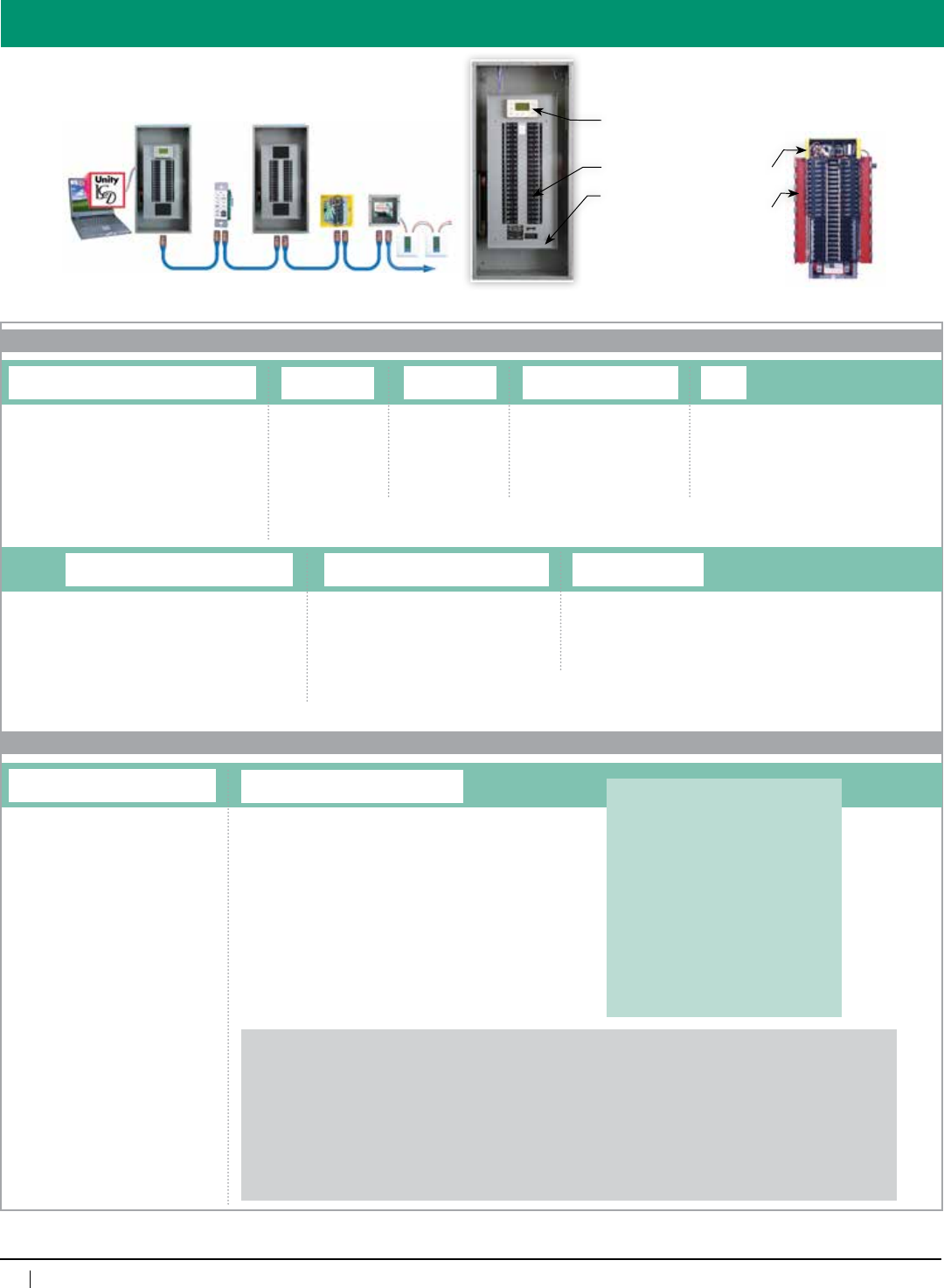
System Design
When placing an order, please contact the factory
for a schedule form, so we may populate the
Smart BreakerPanelwiththecorrectbreakertypes.
DTC:
32-channel,365-dayastroclocktoaccess
and program the entire system
Circuit Breakers
Dead Front
Low Voltage Compartment
(holdsBusConnectors,
RJ45Connectors)
Low Voltage Compartment
(containsCircuitBreaker
ControlCards)
Chassis for Retrofit
(holdsupto42Breakers)
Cat. 5 patch cable with RJ45 connectors • upto127digitaladdresses• up to 4,000 feet
Anycomputer
running:
Unity™ Lighting
Control Software
or Unity GX™
Advanced
Graphical
Software
Smart BreakerPanel
(masterpanel)
Smart Breaker Panel
(remotepanel)
MicroPanel
Chelsea
DigitalSwitch
Digital
Thermostats
T-Link
ORDERING INFORMATION
GR2400SBP CHASSIS
SmartBreaker Panel
Feed Voltage
120V208V
120V240V
277V480V1
Alternate feed voltages, AIC ratings, feed currents, as well as other non-standard options are available. Please contact the factory for quotation of panels beyond the options outlined here.
Feed Current
100AMP
225AMP
400AMP
600AMP
Feed Type2
MAIN1=MainBreaker
MLO2=MainLugOnly
MLODL2=MainLugOnly
withDoubleLugs
1=Iffeedvoltageisspecified277V480VandAICisspecified65K,thenfeedtypemustbeMAIN.
2=AICRatingforMLOorMLODLpanel(s)issetat14kAIC.
AIC
14K2
65K1
Enclosure Mounting & NEMA Rating
SMNE1=SurfaceMount,NEMA1
FMNE1=FlushMount,NEMA1
SMNE4=SurfaceMount,NEMA4
SMNE4X=SurfaceMount,NEMA4X
SMNE12=SurfaceMount,NEMA12
Feed Orientation
BOTTOM=BottomFeed
TOP=TopFeed
Clock Option
DTC=DigitalTimeClock
DTCMOD=DigitalTimeClockwithModem
REMOTE=RemotePanel
System and Type
p
p
GR2400SBP BRKR
SmartBreaker Panel Breakers
Breakers and Breaker Accessories
1P[amp]ARB=1-PoleRemoteBreaker
2P[amp]ARB=2-PoleRemoteBreaker
1P[amp]ABB=1-PoleBranchBreaker
2P[amp]ABB=2-PoleBranchBreaker
3P[amp]ABB=3-PoleBranchBreaker
BSPC=BreakerSpacer
CLIP=LockingClips
System and Type
Where[amp]is,replacewithampereratingforthatbreaker(pleaserefertothe
AmpereRatingTabletoselecttheproperratingforaspecificbreakertype).
Duetothecomplexityofthisproduct,breakers
must be entered as separate line items following
the chassis code. Enter quantities as part of the
lineentry.Notethatone20A1Pbreakermustbe
reserved to provide power for control electronics.
Ifyouhavenotfilledall42breakerpositions,
youmustorderthedifferenceinbreakerspacers
(BSPC)(example:ifa225Afeedcurrentpanelhad
321-polebreakerswerespecified,then10breaker
spacerswouldberequired,orIf202-polebreakers
werespecified,2BSPCwouldbeneeded,orfor
123-polebreakers,youwouldneed6).
Ampere Rating Table
----------------------------------------------------------------------
RemoteBreakers BranchBreakers
----------------------- ---------------------------------------
1-or2-Pole 1-Pole 2-or3-Pole
-------------- ----------- ---------------
15 15 15
20 20 20
25 25 25
30 30 30
35 35
40 40
45 45
50 50
60 60
80 70
90
95
100
Example: GR2400SBPDMXCHASSIS120V208V225AMPMAIN65KDTCMODSMNE1BOTTOM
GR2400SBPBRKR1P15ARB(quantityisspecifiedonlineentry–14forthisexample)
GR2400SBPBRKR1P20ARB(quantityisspecifiedonlineentry–10forthisexample)
GR2400SBPBRKR2P30ABB(quantityisspecifiedonlineentry–5forthisexample)
GR2400SBPBRKR3P100ABB(quantityisspecifiedonlineentry–2forthisexample)
GR2400SBPBSPC(quantityisspecifiedonlineentry–2forthisexample)
GR2400SBPCLIP(quantityisspecifiedonlineentry–6forthisexample)
120/208VDMXSmartBreakerpanelratedat65kAIC,witha225Amainbreaker,configuredasamasterpanelwithdigitaltimeclockandmodem,
containing1415Aand1020A1-poleremotebreakers,530A2-poleand2100A3-polebranchbreakers,2breakerspacersand6lockingclips,
surfacemountNEMA1enclosurewithknockouts,designedforbottomlinevoltagefeed.
p
p
51
800-345-4448 • www.lightingcontrols.com
Specifications:
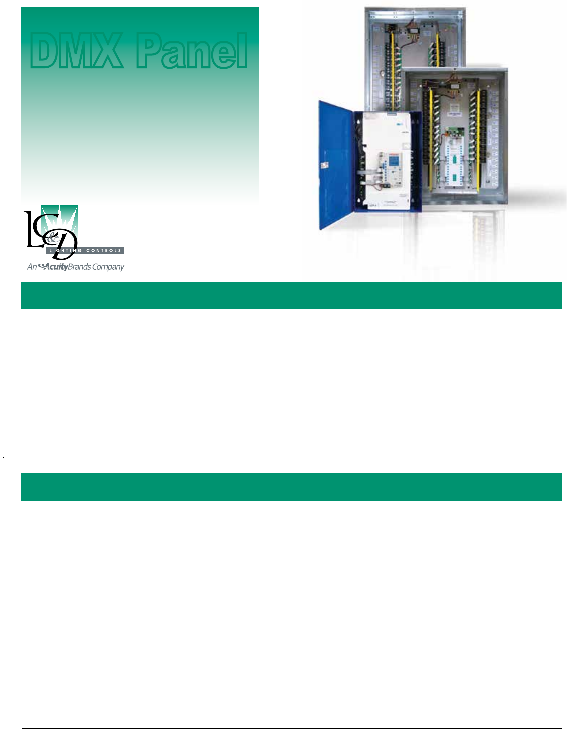
DMX512A Relay Panels
Description: ADMX-onlypanelwhichemploysaDMX512commandtoturnonandoffSnapLink™relays.TheDMX
relaypanelmayuseanystartaddress.WillnotinterfacetoaGR2400™system.DMXrelaypanelsare
DMX512Acompatible.
ForapplicationswhichrequirebothGR2400digitallightingcontrolsandaDMXtake-over,refertothe
Link-To™DMXcard.
Features: • Manualoverrideofindividualrelays,zones,orentirepanelifnoDMXsignalorauto-handswitch.
• Panelsmaybecontrolledin“ZoneMode”or“DiscreteMode.”Zonemodeallowsmultiplerelaystobe
controlledbythesameDMXaddress
• Maycontrolmixedvoltages(i.e.,120V,277V)
• Maycontrolnormaloremergencypower
Enclosure dimensions: 16relays
NEMA1-12"wx18"hx6"d
NEMA4X-16”wx24”hx8”d
NEMA4/12-16”wx24”hx6”d
upto32relays:
NEMA1-20"wx25.5"hx6"d
NEMA4/4X/12-24”wx36”hx8”d
upto48relays:
NEMA1-20"wx37.5"hx6"d
NEMA4/12-24”wx48”hx10”d
NEMA4X-36”wx48”hx10”d
Enclosuretype: NEMA1surfacemount,hingedlockingdoor
Optional enclosure rating: NEMA4,NEMA12,NEMA4Xor
flushmountNEMA1
Relays: NormallyClosed(NCL)
30A@277VACBallast
20A@120VACTungsten
20A@347VACBallast
SCCR18kA@277VAC
Rated250,000Cycles
Optionalrelays: NormallyOpen,(NOL)Specsame
asNCL,TwoPole—NOorNC
(480VAC);DoubleThrow20A
277VAC
Listings: ULandcULtoUL916,
ETLlistedtoUL924(for
emergencycircuituse)
Max.humidity: 10–90%non-condensing
Ambienttemperature: 32–104°F(0–40°C)
Powersupplyvoltage: 120/277VACor120/347VAC
Protocol: DMX512A
Control Panel
DMX Panel
52
www.lightingcontrols.com • 800-345-4448
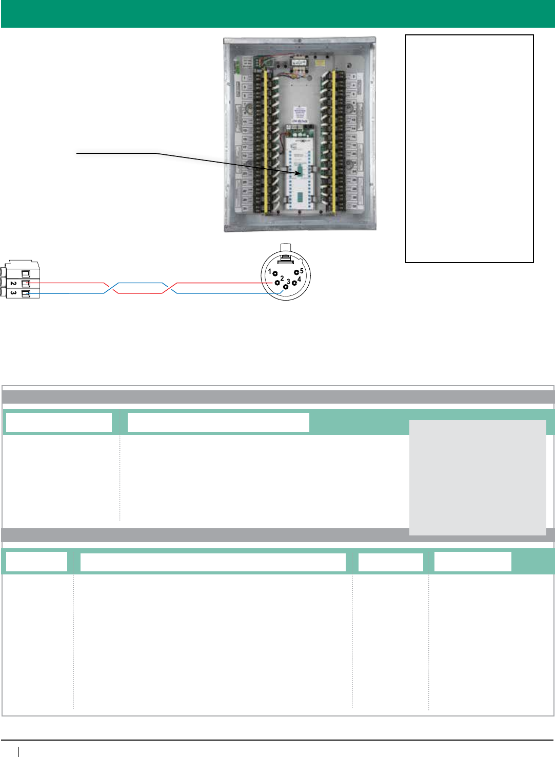
Details
DigitalDMXConnectors:
Depluggable Screw Connectors
Notes:
• Pin#3oftheXLRConnectorisroutedtoTerminal#3oftheDigitalDMXConnector
• Pin#2oftheXLRConnectorisroutedtoTerminal#2oftheDigitalDMXConnector
• IfendofthelineisaXLRconnector,thenterminatetheendofthenetworkwith120ohmend-of-lineresistor.
InthecaseoftheDigitalDMXconnector,end-of-lineresistorsshouldbeacrossTerminals#2and#3.
• Ifthereisa2pinterminatorconnectoronthepanel,useBluejumpertoenableit.
GND
ORDERING INFORMATION
DMX Enclosure
DMX Interior
Enclosure Mounting, NEMA Rating, Knockouts1
SMNE1=SurfaceMount,NEMA1withknockouts
FMNE1=FlushMount,NEMA1withknockouts
SMNE1NKO1=SurfaceMount,NEMA1noknockouts
FMNE1NKO1=FlushMount,NEMA1noknockouts
SMNE4=SurfaceMount,NEMA4
SMNE12=SurfaceMount,NEMA12
SMNE4X=SurfaceMount,NEMA4X
1=“Noknockouts”optiononly
availableforDMX32andDMX48
enclosures.DMX16NEMA1
enclosurescomewithknockouts
bydefault.AllotherNEMA
ratings(4,4Xand12)come
withoutknockoutsbydefault.
Total quantity of relay spaces
specifiedmustnotexceedthetotal
allowed in any given enclosure. The
DMX16mayonlyhaveupto16
relays,theDMX32mayonlyhave
upto32,andtheDMX48mayonly
haveupto48.(example:DMX16INT
10NCL=aquantityof10normally
closed,latchingrelaysfortheDMX16
interior).2-polerelays,reedrelay
pairs, and contactor relays all count
astworelayspaces(example:a
DMX32INTmaynothavemorethan
162-polerelays).
Example:
DMX48ENCSMNE1
DMX48INT12NCL12SPDT12DPNODV1VB
48relayDMXpanel,surfacemountNEMA1
enclosurewithknockouts,with12normally
closedrelays,12singlepoledoublethrow
relays,12doublepolenormallyopenrelays,
a120/277Vdualvoltagetransformer,andone
voltage barrier.
2=Voltagebarriersareonlyavailablein
theDMX32andDMX48panels.Check
with NEC or CEC, State or Province,
and local regulations as well as your
electrical inspector about allowances
for voltage barriers within panels.
DMX Relay
Panel Interior
DMX16INT=
16RelayInterior
DMX32INT=
32RelayInterior
DMX48INT=
48RelayInterior
Relays
[qty]NCL=NormallyClosedLatching
[qty]NOL=NormallyOpenLatching
[qty]DPNC=DoublePoleNormallyClosed
[qty]DPNO=DoublePoleNormallyOpen
[qty]RRNO=ReedRelayNormallyOpen(pair)
[qty]SPDT=SinglePoleDoubleThrow
[qty]SPDTC=SinglePoleDoubleThrowContactor
Transformer
DV=Dualvoltage
120/277V
CNDV=Canadian
dual voltage
120/347V
Voltage Barrier2
[blank]=Nobarrier
1VB=1barrier
2VB=2barriers
3VB=3barriers
4VB=4barriers
DMX Relay Panel Enclosure
DMX16ENC=16RelayEnclosure
DMX32ENC=32RelayEnclosure
DMX48ENC=48RelayEnclosure
Lighting Relays:
Normally Closed (NCL), 30A @ 277V Ballast,
20A @ 120V Tungsten, 20A @ 347V Ballast, SCCR 18kA
@ 277V, Rated 250,000 Cycles
Optional relays:
Normally Open, (NOL) Spec same as NCL,
Two Pole — NO or NC; Double Throw 20A 277V
Relay Control Card:
Manualcontrolofzonesorindividualrelays
High/LowVoltageBarrier:
(16gaugesteel)
DigitalDMXConnector
inDMXPanel
Useaproperdatacable.
Twisted pair with foil and twisted braids.
Balancedaudiocablewillnotdo. MaleXLRpinconnector
(frontview)
Seismic Certification:
•Preapproved for use in Category
IVstructureswithanImportance
Factorof1.5
•California Office of Statewide
Health Planning and Development
(OSHPD)SpecialSeismic
CertificationPreapproval(#OSP-
0091-10)
Evaluated per the requirements of:
•2007/2010CaliforniaBuilding
Code
•Section13.2.5of(American
SocietyofCivilEngineers/
StructuralEngineeringInstitute)
ASCE/SEI7-05
•Testedto:ICC-ESAC156
53
800-345-4448 • www.lightingcontrols.com
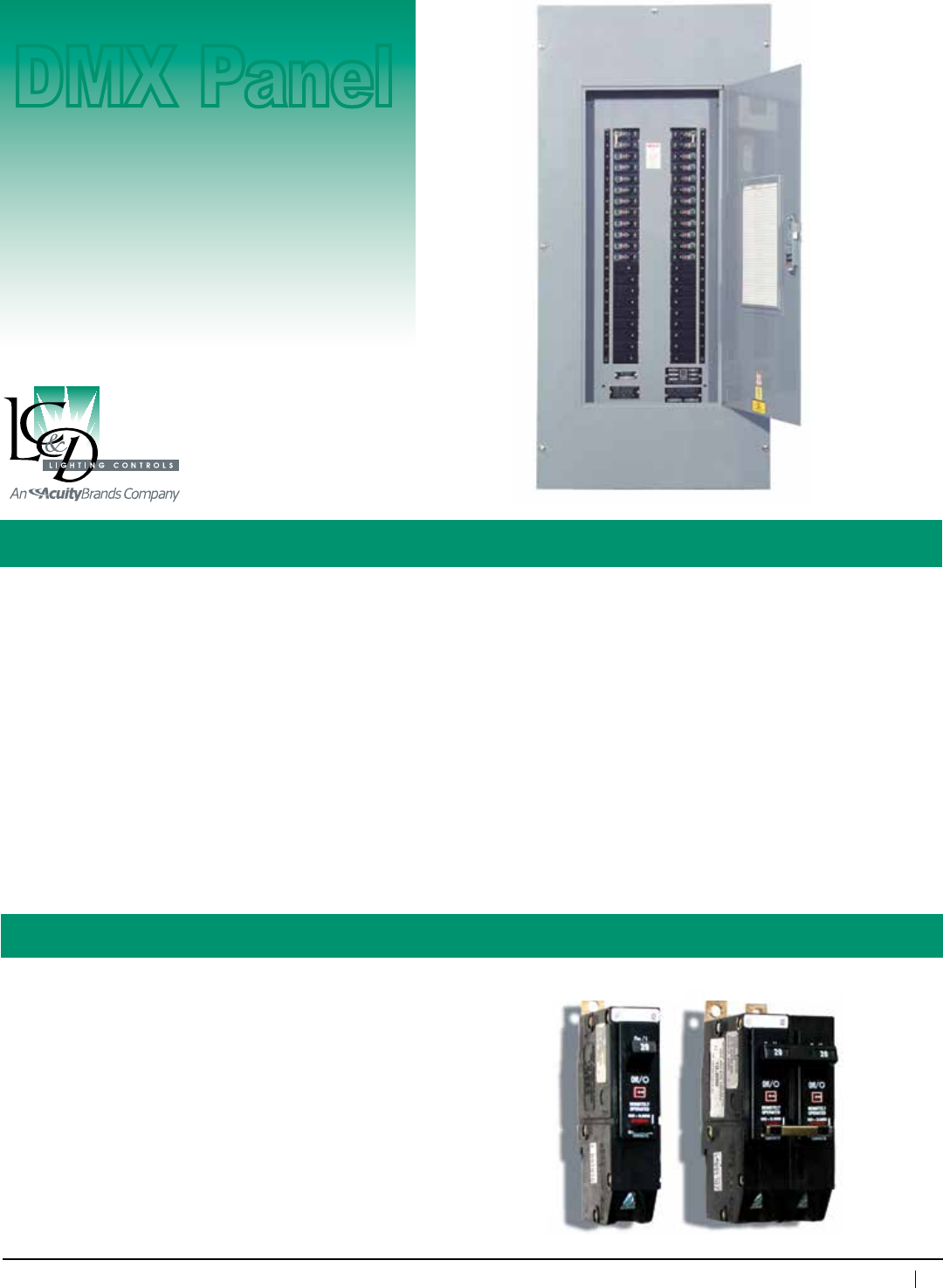
DMX512A
Smart
Breaker™ Panel
Description: ADMX-onlypanelwhichemploysaDMX512commandtoturnonandoffSmartBreakers.
The DMX SmartBreaker Panelusessolenoidoperatedthermalmagneticbreakerstocombineover-current
protectionandlightingcontrolintoasinglepackage.
The DMX SmartBreaker Panel mayuseanystartaddressfrom1–512.Allbreakeraddressesconsecutively
follow the start address.
IntegrateaDMXsystemtoaGR 2400 digital lighting control system with the Link-To™ DMX card.
Features: • SeamlessintegrationtoanyDMX-basedcontrolsystem
• Mixcontrolledandconventionalbreakersinthesamepanelboard
• Mainlugsormainbreakers
• Retrofitchassis
• ULlisted
• DMX512Acompatible
Control Panel
DMX Panel
Single Pole Double Pole
Specifications:
Enclosure dimensions:
20"wx45"hx6"d@225Awithmainlugs)
Type:
NEMA1(otherNEMAtypesoptional)
Standard Panel configurations:
• 100–600A
• Mainlugsormainbreakers
• 120/208VAC(3 phase, 4wire)
• 120/240VAC(1 phase, 3wire)
• 277/480VAC(3 phase, 4wire)
Solenoidbreakerconfigurations:
Singlepole15A,20A
DoublePole20A,30A
AICRating:
65k@120/208VAC,14k@277/480VAC
Listings:
ULlisted
54
www.lightingcontrols.com • 800-345-4448
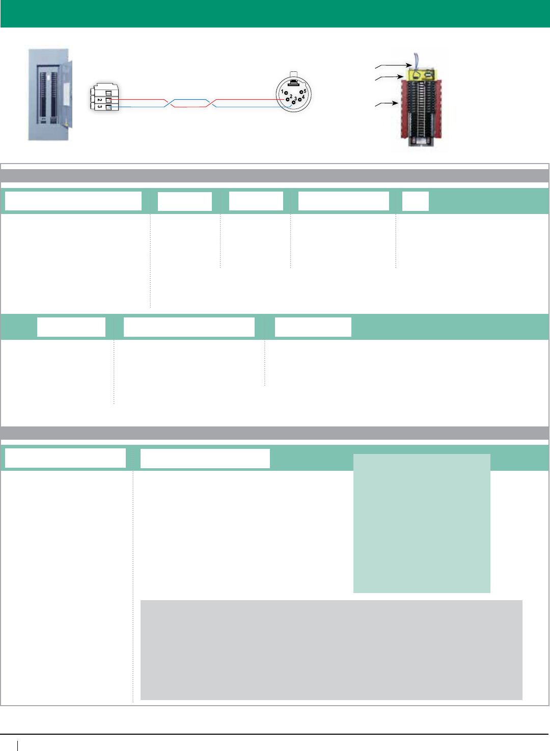
System Design
DMX SmartBreaker Panel
LowVoltageCompartment
(holdsDigitalDMX
Connectors)
LowVoltageCompartment
(containscircuitbreaker
controlcard)
Chassis for retrofit (holdsupto42Breakers)
Data cable
Retrofit an existing breaker panel
with a SmartBreaker DMX
chassis. Contact the factory for
assistance.
GND
ORDERING INFORMATION
DMXSBP CHASSIS
REMOTE
DMX SmartBreaker Panel
Feed Voltage
120V208V
120V240V
277V480V1
Alternate feed voltages, AIC ratings, feed currents, as well as other non-standard options are available. Please contact the factory for quotation of panels beyond the options outlined here.
Feed Current
100AMP
225AMP
400AMP
600AMP
Feed Type2
MAIN1=MainBreaker
MLO2=MainLugOnly
MLODL2=MainLugOnly
withDoubleLugs
1=Iffeedvoltageisspecified277V480VandAICisspecified65K,thenfeedtypemustbeMAIN.
2=AICRatingforMLOorMLODLpanel(s)issetat14kAIC.
AIC
14K
65K1
Enclosure Mounting & NEMA Rating
SMNE1=SurfaceMount,NEMA1
FMNE1=FlushMount,NEMA1
SMNE4=SurfaceMount,NEMA4
SMNE4X=SurfaceMount,NEMA4X
SMNE12=SurfaceMount,NEMA12
Feed Orientation
BOTTOM=BottomFeed
TOP=TopFeed
Clock Option
System and Type
p
p
GR2400SBP BRKR
DMX SmartBreaker Panel Breakers
Breakers and Breaker Accessories
1P[amp]ARB=1-PoleRemoteBreaker
2P[amp]ARB=2-PoleRemoteBreaker
1P[amp]ABB=1-PoleBranchBreaker
2P[amp]ABB=2-PoleBranchBreaker
3P[amp]ABB=3-PoleBranchBreaker
BSPC=BreakerSpacer
CLIP=LockingClips
System and Type
Where[amp]is,replacewithampereratingforthatbreaker(pleaserefertothe
AmpereRatingTabletoselecttheproperratingforaspecificbreakertype).
Duetothecomplexityofthisproduct,breakers
must be entered as separate line items following
the chassis code. Enter quantities as part of the
lineentry.One20A1Pbreakermustbereserved
to provide power for control electronics.
Ifyouhavenotfilledall42breakerpositions,
youmustorderthedifferenceinbreakerspacers
(BSPC)(example:ifa225Afeedcurrentpanelhad
321-polebreakerswerespecified,then10breaker
spacerswouldberequired,orIf202-polebreakers
werespecified,2BSPCwouldbeneeded,orfor
123-polebreakers,youwouldneed6).
Ampere Rating Table
----------------------------------------------------------------------
RemoteBreakers BranchBreakers
----------------------- ---------------------------------------
1-or2-Pole 1-Pole 2-or3-Pole
-------------- ----------- ---------------
15 15 15
20 20 20
25 25 25
30 30 30
35 35
40 40
45 45
50 50
60 60
80 70
90
95
100
Example: GR2400SBPDMXCHASSIS120V208V225AMPMAIN65KDTCMODSMNE1BOTTOM
GR2400SBPBRKR1P15ARB(quantityisspecifiedonlineentry–14forthisexample)
GR2400SBPBRKR1P20ARB(quantityisspecifiedonlineentry–10forthisexample)
GR2400SBPBRKR2P30ABB(quantityisspecifiedonlineentry–5forthisexample)
GR2400SBPBRKR3P100ABB(quantityisspecifiedonlineentry–2forthisexample)
GR2400SBPBSPC(quantityisspecifiedonlineentry–2forthisexample)
GR2400SBPCLIP(quantityisspecifiedonlineentry–6forthisexample)
120/208VDMXSmartBreakerpanelratedat65kAIC,witha225Amainbreaker,configuredasamasterpanelwithdigitaltimeclockandmodem,
containing1415Aand1020A1-poleremotebreakers,530A2-poleand2100A3-polebranchbreakers,2breakerspacersand6lockingclips,
surfacemountNEMA1enclosurewithknockouts,designedforbottomlinevoltagefeed.
p
p
55
800-345-4448 • www.lightingcontrols.com
Specifications:
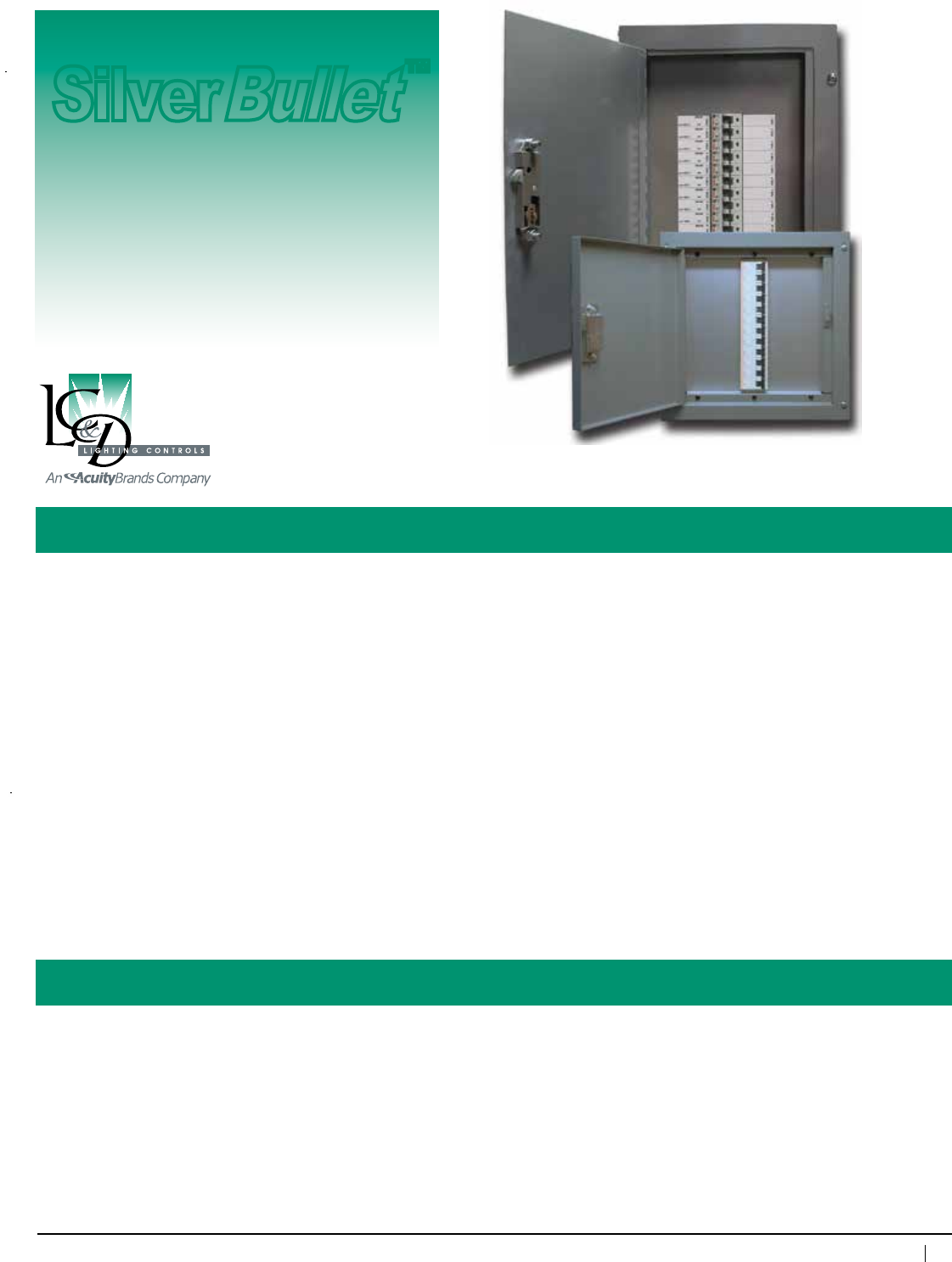
The SilverBullet™ Sub-Branch Circuit Current Limiter
Description: Lightingcalculationsformostenergycodesincludeadeductionforeachlinearfootoftrack.California’s
Title24“charges”45watts/linearfootoftracklighting.Seattle“charges”70watts/foot.ASHRAE,30
watts/foot.Withtoday’slightingtechnologytheconnectedloadisfarlessthantheper-footrequirements
of these codes.
The SilverBullet,a“Sub-BranchCircuitCurrentLimiter”solvesthisrequirementbyenforcingadefinite
currentlimittolowertheVAratingofeachtracklightingcircuit.
Forexample,California’sTitle24wouldrequirethreetrackcircuitswithatotallength100fttobe
calculatedataminimumof4500watts(45watts/footx100ft).WiththeSilverBullet thosethreetracks
couldbelimitedto8ampseachtoreducethelightingloadcalculationto2880watts(120Vx24amps).
Features: • Currentlimitingforupto21circuits
• Currentlimitingavailablefrom1-8,10,13&15amps
• CompactSizes12"wx18"hx4"dor12″wx12″hx4″d
• AICRatingof10,000A@120VAC
• Factorypre-assembled
• Eachloadfactorylabeledonthedoorsheet
• Noprogrammingrequired
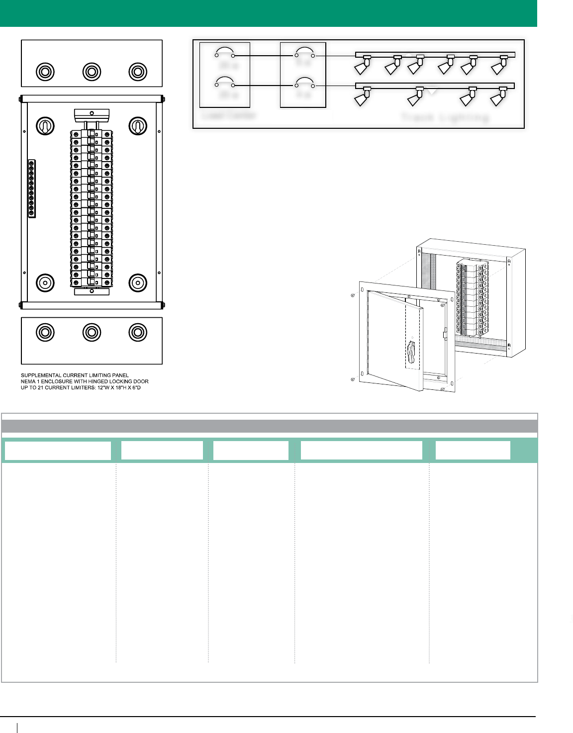
Enclosuredimensions: 12″wx12″hx4″d,(1-12supplementarybreakers)
12″wx18″hx4″d,(6-21supplementarybreakers)
Enclosuretype: Surfacemount,hingedlockingdoor,NEMA1
Optionalenclosures: Flushmount
Certifications: PanelcomplieswithUL508,breakerscomplywithUL489
Max.humidity: 10–90%non-condensing
Ambienttemperature: 32–104°F(0–40°C) (Note: Thermal magnetic breakers. De-rate to 80% of load for temperatures over 70° F)
Silver
Bullet
™
Current
Limiting
Panel
56
www.lightingcontrols.com • 800-345-4448
6 a
4 a
20 a
Load Center SilverBullet Track Lighting
20 a
How It Works
More Track—Less Penalty
The SilverBulletisULListedtobeplaced
in-linebetweenthebranchcircuitbreaker
andthetrackmountedlightingloads.
California 2005 Title 24, Section 130
C(3) states:
(c) Luminaire power.Luminairewattage
incorporated into the installed lighting
power shall be determined in accordance
with the following criteria: The wattage
oflinevoltagelightingtrackandplug-
in busway which allows the addition or
relocation of luminaires without altering
the wiring of the system shall be the
volt-ampere rating of the branch circuit
feeding the luminaires.
This is what the SilverBullet does.
When doing energy calculations, use
the ampere rating of the supplementary
breakerintheSilverBullet as opposed to
thelinearfootageoftherack.Nomagic.
Just a SilverBullet.
SilverBullet
SilverBullet mini
COMPACT 12” X 12” X 4”
HOUSING FOR 1-12
RELAYS
ORDERING INFORMATION
SilverBullet
System
T24=Standard(21breakersmax.)
T24M=Mini(12breakersmax.)
Breaker UL Listing
489UL=Standard
1077UL=(requiredforCity
ofLosAngeles)
Breaker Positions
[qty]BP=#ofpositions
Breakers
1A[qty]=1ampbreaker
2A[qty]=2ampbreaker
3A[qty]=3ampbreaker
4A[qty]=4ampbreaker
5A[qty]=5ampbreaker
6A[qty]=6ampbreaker
7A[qty]=7ampbreaker
8A[qty]=8ampbreaker
10A[qty]=10ampbreaker
13A[qty]=13ampbreaker
15A[qty]1=15ampbreaker
1 = only available with 1077UL option
Enclosure Mountings
SM=SurfaceMount
FM=FlushMount
Where [qty] is, replace
with the total number of
breakers needed in a panel,
within a range depending
upon the specified panel:
T24 is from 6 and 21
breakers, T24M is from
1 to 12.
Where [qty] is, replace with the quantity of
breakers of that amperage. Total quantity of
breaker spaces specified must fall within the
number specified under Panel Size. 3A2 is
two 3 amp breakers, 10A10 is ten 10 amp
breakers.
57
800-345-4448 • www.lightingcontrols.com
ORDERING INFORMATION
GR 2400 Master Controller
Master
Controller
GR 2400™
Description:
GR2400Systemswithdistributedcontrolarenotalwaysspecifiedwith
amasterpanel(whichwouldcontaintheDTC.)Inthesesituations,the
DTC is mounted by itself in its own enclosure with a power supply in the
base.Additionalinterfacecardsmayalsobemountedandpoweredbythe
enclosuretomakeforamorecompactsystem.
Features:
• Self contained DTC may mount at any convenient point on the
GR2400buswithaccesstoaphonelineforusebythemodem
• ProvidesvoltagetotheGR2400bustohelppowerarunofswitches
• MayalsocontainadditionalinterfacecardsincludingaLink-ToBAS
card or a server card
• Paintedinivory.Maybemountedinanofficeifneededtoprovide
convenient access to the system
• Universalenclosuremaybesurfaceorflushmounted
• Enclosure dimensions: 8.25"wx13.25"hx4"d
• ULandcULListed
58
www.lightingcontrols.com • 800-345-4448
Note About NEMA 4 Enclosures: WhenorderingtheNEMA4enclosureoption,youwillreceiveaflushmountNEMA1enclosure
mountedinsideofasurfacemountNEMA4enclosure.
Note About Additional Cards: Whenorderingadditionalitemstobemountedinthesamebox,followtheexamplebelow:
Forinstance,aLink-toPCneedstobeorderedwiththissystem,usuallyitwouldgetitsownenclosureandbeorderedas:
GR2400 L2 PC232 115K DV SM NE1
(DV SM NE1 means it comes with a dual voltage transformer in a surface mount NEMA 1 enclosure)
Instead,orderGR2400L2PC232115K(withnoDVSMNE1)onthelinesfollowingtheMasterControllerentry.
Note: XPoint Router Cards are excluded from the options available for additional cards.
Overview
ORDERING INFORMATION
GR2400
GR 2400 Master Controller
Digital Clock/Modem
DTC=DigitalTimeClock
DTCMOD=DigitalTimeClock&Modem
Transformer
DV=DualVoltage120/277V
347V=347volt
Dry Inputs
D6=6inputs
D14=14inputs
Mount and Enclosure Type
SMNE1=SurfaceMount,NEMA1
FMNE1=FlushMount,NEMA1
SMNE4=SurfaceMount,NEMA4
System
Bus
Booster
Additional
cards
(optional)
Link-To PC
(optional)
Extra space for
additional cards
Power
Supply
Seismic Certification:
•PreapprovedforuseinCategoryIVstructureswithanImportanceFactorof1.5
•CaliforniaOfficeofStatewideHealthPlanningandDevelopment(OSHPD)SpecialSeismicCertificationPreapproval(#OSP-0091-10)
Evaluated per the requirements of:
•2007/2010CaliforniaBuildingCode
•Section13.2.5of(AmericanSocietyofCivilEngineers/StructuralEngineeringInstitute)ASCE/SEI7-05
•Testedto:ICC-ESAC156
59
800-345-4448 • www.lightingcontrols.com
Specifications:
GR 2400 Relay Panel/Silver
Bullet
Description: Factorypre-wired,pre-assembledcomponentsintegratetheGR2400RelayPanelwiththeSilverBullet
“Sub-BranchCircuitCurrentLimiter”tosolvetherequirementsofenergycodelightingcalculations,by
enforcingadefinitecurrentlimittolowertheVAratingoftracklightingcircuits.
• 32-channel,365-day/astronomicaltimeclockinterfacefortheentiresystem.Non-volatilememory
holdsallprogrammingindefinitely.Ten-yearbatteryback-upfortime-of-day
• Maycontrolmixedvoltages(i.e.,120V,277V),normaloremergencypower
• Manualoverrideofindividualrelays,zonesorentirepanel
• Linkupto127addressesofdigitaldevicesviaCat.5patchcablewithRJ45connectors
• ULlistedcurrentlimitingforupto21circuitsper10"extensionbox
• AICRatingof10,000A@120V
• Factorypre-wired,pre-assembledcomponents
Enclosuredimensions: 20"wx35.5"hx6"d(32relays)21Breakers
20"wx45.5"hx6"d(32relays)42Breakers
20"wx47.5"hx6"d(48relays)21Breakers
20"wx57.5"hx6"d(48relays)42Breakers
SilverBulletmountedin10"extensionenclosure(s)
Enclosuretype: Surfacemount,hingedlockingdoor,NEMA1
Relay: NormallyClosed(NCL),30A@277VACBallast
20A@120VACTungsten,20A@347VACBallast
SCCR18kA@277VAC,Rated250,000Cycles
Optionalrelays: NormallyOpen,(NOL)SpecsameasNCL,Two
Pole—NOorNC(480VAC);DoubleThrow20A
277VAC
Addressesperbus: 127
#ofAddressesused: GR2432(4),GR2448(6)
Relaypanellistings: ULandcULtoUL916,ETLlistedtoUL924
(foremergencycircuituse)
Programming: ViaDTC,viaPCwithUnity™ Lighting
Control Software
Max.humidity: 10 – 90%non-condensing
Ambienttemperature: 32–105°F(0–41°C)
Powersupplyvoltage: 120/277VAC
Busphysicallayer: RS485(GR2400bus)
Busconnector: RJ45connectors
SilverBullet Sub-Branch Circuit Current Limiter
Enclosuredimensions: 20"wx12"hx4"d(6-12
supplementarybreakers)
Enclosuretype: Surfacemount,hingedlocking
door,NEMA1
MaxHumidity: 10–90%non-condensing
Certifications: PanelcomplieswithUL508,
BreakerscomplywithUL489
Ambienttemperature: 32–104°F(0–40°C)
Quintessence
GR 2400™
GR2400RelayPanel
SilverBullet
(Sub-Branch Circuit
Current Limiter)
Features:
60
www.lightingcontrols.com • 800-345-4448
ORDERING INFORMATION
For Nomenclature:
Overview
Power Supply (input):
120/277V
Lighting Relays:
Normally Closed (NCL), 30A @ 277V
Ballast, 20A @ 120V Tungsten, 20A
@ 347V Ballast, SCCR 18kA @ 277V,
Rated 250,000 Cycles
Optional Relays:
Normally Open, (NOL) Spec same as
NCL, NO or NC (120V); Two Pole — NO
or NC (480V); Double Throw 20A 277V
High/Low Voltage Barrier:
(16gaugesteel)
DTC:
32-channel,365-dayastroclock.Access
and program the entire system
Modem:
Remote programming and control,
includes free lifetime dial-up
programming
Bus connectors
RJ45 connectors
Limiters:
ULlistedcurrentlimitingavailable
from1-8,10,13&15amps.
Relay Control card:
(manualcontrolofzonesor
individualrelays)
45.5"
35.5" 47.5"
57.5"
20" 20"
20"
20"
Please see the tech sheet for the GR 2400 Relay Panel and enter as usual with these exceptions:
• MustchooseSurfaceMount,NEMA1withknockouts(SMNE1)
Please see the tech sheet for the SilverBullet and enter as usual with these exceptions:
• Adda“Q”tothebeginningofthenomenclature(T24becomesQT24,T24MisnotavailableforQuintessence)
• Youmayexceedthemaximumnumberofbreakersby1(upto22breakerstotal)
• YoumustchooseSurfaceMount(SM)
Examples: GR2448 ENC SM NE1
GR2448 INT 22NCL 14SPDT 6DPNC DTCMOD DV
QT24 1077UL 22BP 4A10 10A8 13A2 15A2 SM
48relaypanelwith22normallyclosedrelays,14singlepoledoublethrowrelays,6doublepolenormallyclosedrelays,withadigitaltimeclockand
modem(masterpanel),anda120/277Vdualvoltagetransformer(novoltagebarriers)aspartofaQuintessencepackageprewiredtoaSilverBullet
panelconfiguredwith22breakerpositions,andcontaining104A,810A,213Aand215Abreakers,allinstalledinacombined,surfacemountNEMA1
enclosurewithknockouts.
61
800-345-4448 • www.lightingcontrols.com
Specifications:
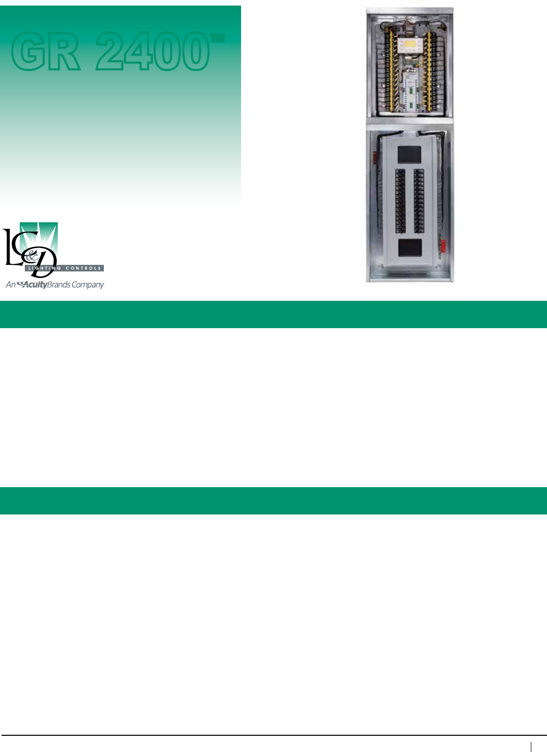
GR 2400 Relay Panel/Breaker Panel
Description: Factorypre-wiredassemblyofacircuitbreakerandGR 2400 relay panel
Features: • Providesthesamefeaturesasacontrollablebreakerpanelinthesamefootprint
• Availableintopfeedorbottomfeedpanels
• MLOorwithaMasterbreaker
• Yourchoiceofbreakerpanel
• Savesonsitelabor
• AllthestandardfeaturesofaGR2400panel
Relay enclosure dimensions: 20"wx63"hx6"d(32relays)
20"wx75"hx6"d(48relays)
Enclosuretype: Surfacemount,hingedlockingdoor,NEMA1
Relay: NormallyClosed(NCL)
30A@277VACBallast
20A@120VACTungsten
20A@347VACBallast
SCCR18kA@277VAC
Rated250,000Cycles
Optionalrelays: NormallyOpen,(NOL)SpecsameasNCL,
Two Pole — NO or NC (480VAC);Double
Throw20A,277VAC
Addressesperbus: 127
#
Addressesused:
GR2432(4),GR2448(6)
Relaypanellistings: ULandcULtoUL916,
ETLlistedtoUL924(for
emergencycircuituse)
Programming: ViaDTC,viaPCwith
Unity™ Lighting Control
Software
Max.humidity: 10–90%non-condensing
Ambienttemperature: 32–104°F(0–40°C)
Powersupplyvoltage: 120/277VAC
Busphysicallayer: RS485(GR2400bus)
Busconnector: RJ45connectors
Quintessence
GR 2400™
ORDERING INFORMATION
62
www.lightingcontrols.com • 800-345-4448
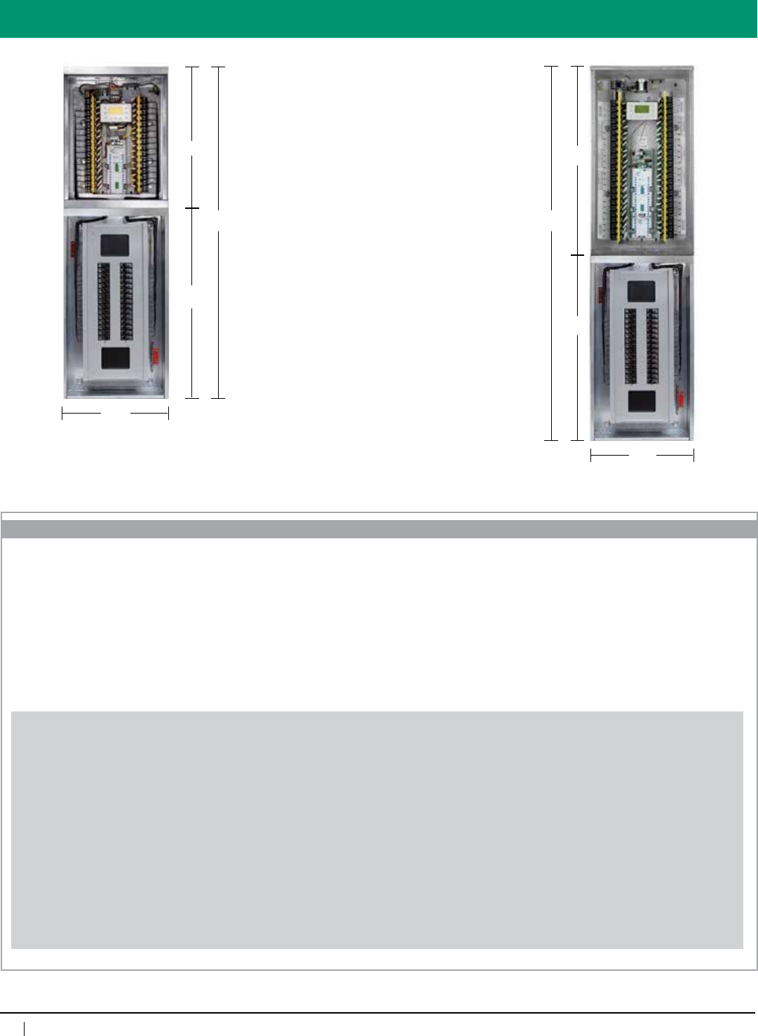
Overview
GR2432orGR2448digitalrelaypanel
Pre-wiredtostandardcircuitbreaker
panel
•120Vor277V
•NEMA1Enclosures
•Upto400A
•Hingedlockingdoors
•Breakersprewiredtospecificrelayper
approved submital
Note:Breakerpanellengthmaychange
basedonamperageandbrandofbreaker
panel specified.
25.5''
63''
37.5''
20''
Depth6''
37.5''
75''
37.5''
GR2432 GR2448
20''
Depth6''
Weight 140 Pounds
Weight160Pounds
ORDERING INFORMATION
For Nomenclature:
Please see the tech sheet for the GR 2400 Relay Panel and enter as usual with these exceptions:
• YoumustchooseSurfaceMount,NEMA1withknockouts(SMNE1)
Please see the tech sheet for the Smart Breaker Panel and enter as usual with these exceptions:
• Use“QBP”inplaceof“GR2400SBP”forthepanelandbreakers
• YoumustchooseSurfaceMount,NEMA1(SMNE1)
• Youmustchoosebottomfeedorientation(BOTTOM)
• Youmustchooseremotefortheclockoption(REMOTE)
• Youmaynotselectremotebreakers,allotherbreakertypesareavailableinidenticalquantities
• Enterthebreakersasseparatelineitemsperthetechsheetwithnovariationsinthenomenclature
Examples: GR2448 ENC SM NE1
GR2448 INT 12NCL 12SPDT 12DPNC DTCMOD DV
QBP CHASSIS 120V208V 225AMP MAIN 65K REMOTE SM NE1 BOTTOM
QBP BRKR 1P15ABB (quantityisspecifiedonlineentry–14forthisexample)
QBP BRKR 1P20ABB (quantityisspecifiedonlineentry–10forthisexample)
QBP BRKR 2P30ABB (quantityisspecifiedonlineentry–5forthisexample)
QBP BRKR 3P100ABB (quantityisspecifiedonlineentry–2forthisexample)
QBP BSPC (quantityisspecifiedonlineentry–2forthisexample)
QBP CLIP (quantityisspecifiedonlineentry–6forthisexample)
48relaypanelwith12normallyclosedrelays,12singlepoledoublethrowrelays,12doublepolenormallyclosedrelays,withadigitaltimeclockandmodem(masterpanel),
anda120/277Vdualvoltagetransformer(novoltagebarriers)aspartofaQuintessencepackageprewiredtoa120/208Vbreakerpanelratedat65kAIC,witha225Amain
breaker,configuredasaremotepanel,containing1415Aand1020A1-pole,530A2-pole,2100A3-polebranchbreakers,2breakerspacersand6lockingclips,allinstalled
inacombined,surfacemountNEMA1enclosurewithknockouts,designedforbottomlinevoltagefeed.
63
800-345-4448 • www.lightingcontrols.com
ORDERING INFORMATION
Specifications:
GR 2400™ Relay Panel w/Surge Suppression
Description: GR 2400 panelprewiredtostate-of-the-arttransientvoltagesurgesuppression(TVSS)typeprotection.
SurgeSuppressionbrandprotectionhasthelowestlet-throughvoltagesintheindustryandisbacked
bya25-yearwarranty.
Features: • 32-channel,365-day/astronomicaltimeclock.Largedisplay(21x8characters)actsasprogramming
interface for the entire system. Non-volatile memory holds all programming indefinitely. Ten-year
batteryback-upfortime-of-day
• Modemincludesfreelifetimefactoryprogramming
• Maycontrolmixedvoltages(i.e.,120V,277V)
• Maycontrolnormaloremergencypower
• Idealforallapplications
• Manualoverrideofindividualrelays,zonesorentirepanel
• Linkupto127digitaldevicesviaCat.5patchcablewithRJ45connectors
Surge Protection
• ProtectionElementStatusLEDindicatorlight—onepercircuit
• CompactEnclosure(UL94V-0RatedABS)
• HighDensity/HighEnergyIndividualCircuitProtection
Enclosuredimensions: 20"wx35.5"hx6"d(32relays)
20"wx47.5"hx6"d(48relays)
SurgeSuppressionmountedin10”extension
enclosure(s).Contactfactoryfornumberof
extensionsrequired.
Enclosuretype: Surfacemount,hingedlockingdoor,NEMA1
Relay: NormallyClosed(NCL),30A@277VACBallast
20A@120VACTungsten,20A@347VACBallast
SCCR18kA@277VAC,Rated250,000Cycles
Optionalrelays: NormallyOpen,(NOL)SpecsameasNCL,Two
Pole—NOorNC(480VAC);DoubleThrow20A
277VAC
Addressesperbus: 127
#Addressesused: GR2432(4),GR2448(6)
Relaypanellistings: ULandcULtoUL916,ETLlisted
toUL924(foremergencycircuituse)
Programming: ViaDTC,viaPCwithUnity™Lighting
Control Software
Max.humidity: 10 – 90%non-condensing
Ambienttemperature: 32–104°F(0–40°C)
Powersupplyvoltage: 120/277VAC
Busphysicallayer: RS485(GR2400bus)
Busconnector: RJ45connectors
SurgeProtection: DiscreteAllModeProtection
ComponentLevel/PhaseLevelFusing
60kA(60,000amps)percircuitPeak
Control Panel
GR 2400™
64
www.lightingcontrols.com • 800-345-4448
Overview
Phone Jack:
(Prewiredifrequired)
GR 2400 Bus Surge Protection: Surge
protection is available for the power
supply (input), relay panel output and for
low voltage wiring such as the modem/
ethernet connections. Contact our Sales
Hot Line for ordering information.
Contact factory for exact ordering information.
Power Supply (input) 120/277V
(Optional Surge Protection available)
Lighting Relays:
Normally Closed (NCL), 30A @ 277VAC Ballast,
20A @ 120VAC Tungsten, 20A @ 347VAC Ballast,
SCCR 18kA @ 277VAC, Rated 250,000 Cycles
Optional Relays:
Normally Open, (NOL) Spec same as NCL, NO or
NC (120V); Two Pole — NO or NC (480V); Double
Throw 20A 277V
High/Low Voltage Barrier:
(16gaugesteel)
DTC:
32-channel,365-dayastroclock.Access
and program the entire system
Modem:
Remote programming and control, includes
free lifetime dial-up programming
Bus connectors
RJ45 connectors
Output Surge Protection:
ProtectionElementStatusLEDindicator
light—one per circuit.
Relay Control card:
(manualcontrolofzonesorindividualrelays)
ORDERING INFORMATION
LCDACC
GR 2400 Relay Panel with Surge Suppression
Type
SSPT21205=RelayPanelProtection,120V5A
SSPT22775=RelayPanelProtection,277V5A
SFSP2120P1=LoadProtection,120V
SFSP2120P1DIN=LoadProtection,120V,DINRailMount
SFSP2277P1=LoadProtection,277V
SFSP2277P1DIN=LoadProtection,277V,DINRailMount
SRJ14R=AnalogModemProtection
SRJ45122M=SystemBusProtection,2Mbps
RJ4512100M=SystemBusProtection,100Mbps
System & Type
For Nomenclature:
Please see the tech sheet for the GR 2400 Relay Panel and enter as usual with these exceptions:
Must choose Surface Mount, NEMA 1 with knockouts (SM NE1)

65
800-345-4448 • www.lightingcontrols.com
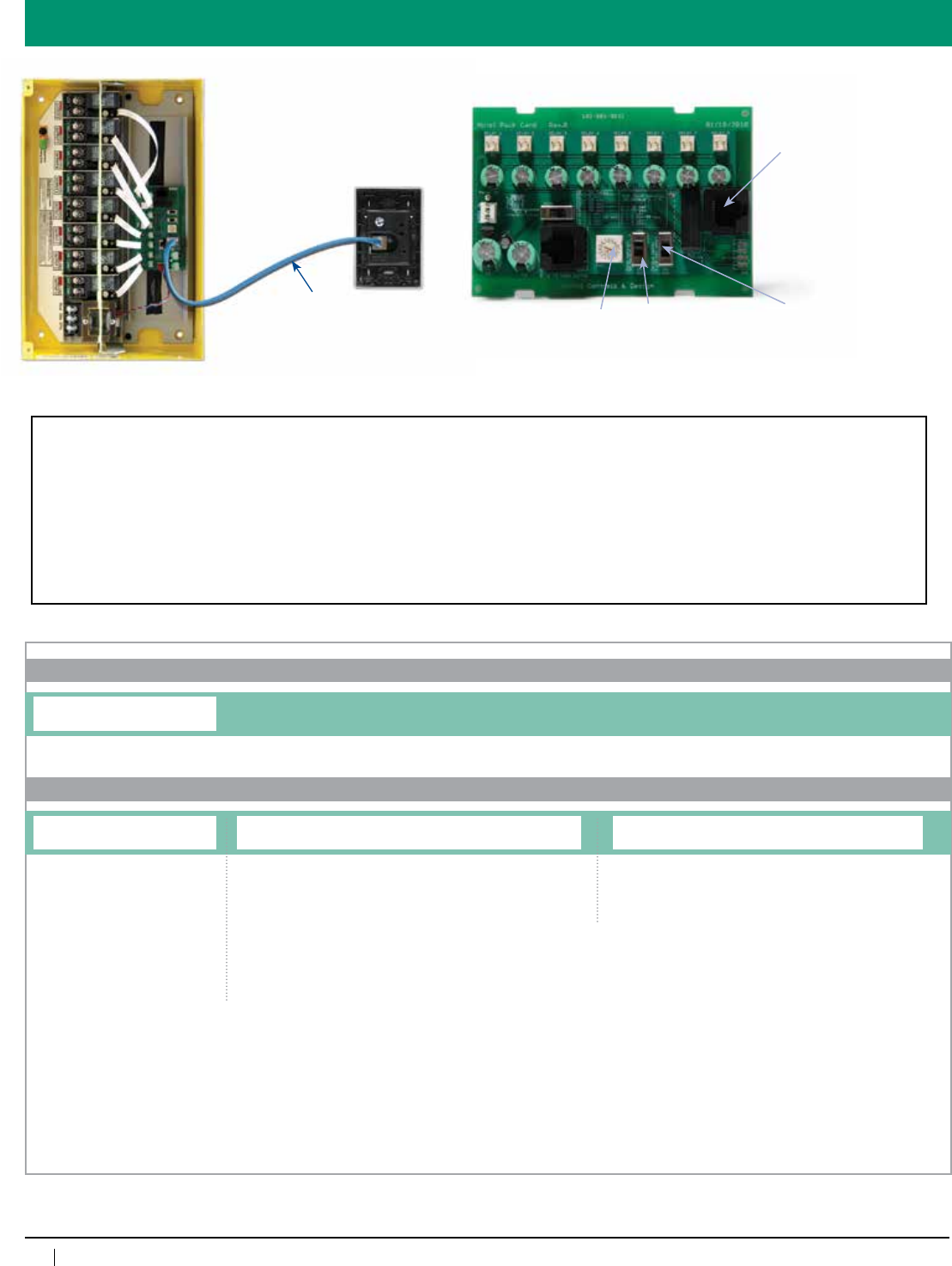
Hotel Pack Energy Conservation System
Hotel Pack
Stand-Alone
Control Panel
Description: CardKeySwitchenablespowerforhotelrooms.Theinfraredcarddetectorneverwearsout.Providesa
signaltothecost-effectiveHotelPackRelayPanel.
Features: • Cleanlines —CardKeyhasnovisiblescrews
• Supersimpleinstallation.Periforraldevicesconnectwirelesslytothepanel.
• Upto8Relayoutputs.Single-ordual-polerelaysavailable.
• RotaryswitchsetsdelaybeforeOFFtoallowoccupanttimetoleavetheroombeforepowerdown.
• Costeffective
Specifications:
Card Key:
Color: White
Dimensions: 3.3"wx4.9"h
Power: 24VDCfromHotelPack
Hotel Pack:
Color: Yellow
Dimensions: 12.5"wx8.25"hx3.3"d
Power: 120/277VACor347VACtransformer
NumberofRelays: Upto8
optional2-Poletakes2positions
RelaySpec: 30A277VACballast
20A120Vincandescent
1.5hpat120VAC
3hpat277VAC
Listings:
ULandcULListed
COMPATIBLE WITH WIRELESS PRODUCTS
66
www.lightingcontrols.com • 800-345-4448
Layout
HOTPACK HCS
ORDERING INFORMATION
Card Switch
Hotel Pack
Hotel Pack Card Switch
Hotel Pack Enclosure Size
HOTPACK4=4relayenclosure
HOTPACK8=8relayenclosure
Relays
[qty]NCL=NormallyClosedLatching
[qty]NOL=NormallyOpenLatching
[qty]DPNC=DoublePoleNormallyClosed
[qty]DPNO=DoublePoleNormallyOpen
[qty]RRNO=ReedRelayNormallyOpen(pair)
[qty]SPDT=SinglePoleDoubleThrow
[qty]SPDTC=SinglePoleDoubleThrowContactor
Transformer, Enclosure Mount, NEMA Rating
DVSMNE1=Dualvoltage120/277V,SurfaceMount,NEMA1
DVFMNE1=Dualvoltage120/277V,FlushMount,NEMA1
Hotel Pack
14 ft. Cat 5 Cable with RJ 45
Connectors
(Provided with Hot Pac)
Optional connector
to additional HotPac
if required
Select Off Delay
after removing card
Enable Blink
Warnings on
Relays 5-8
Enable
sequencing
Loads
Where[qty]isinthenomenclature,replacewith
quantity of relays, and leave no space between
numberandcode(example:8NOL=aquantity
of8normallyopen,latchingrelays).
Totalmustbefrom3to8forsinglerelays
(NCL,NOL,andSPDT)orfrom1to4eachfor
any2-polerelays(DPNC,DPNO,RRNO,and
SPDTC)astheycountastwo.OneDormPack
enclosuremaycontainmixedrelaytypes.
Seismic Certification:
•PreapprovedforuseinCategoryIVstructureswithanImportanceFactorof1.5
•CaliforniaOfficeofStatewideHealthPlanningandDevelopment(OSHPD)SpecialSeismicCertificationPreapproval(#OSP-0091-10)
Evaluated per the requirements of:
•2007/2010CaliforniaBuildingCode
•Section13.2.5of(AmericanSocietyofCivilEngineers/StructuralEngineeringInstitute)ASCE/SEI7-05
•Testedto:ICC-ESAC156
OneHotPacandoneHotPacHotelCardSwitchperhotelroomisrequired.IfneededasecondaryHotPacmaybepurchasedwithitsown
configuration if you require more relays for larger rooms. One HotPac Hotel Card Switch is needed to operate one or two HotPacs.

67
800-345-4448 • www.lightingcontrols.com
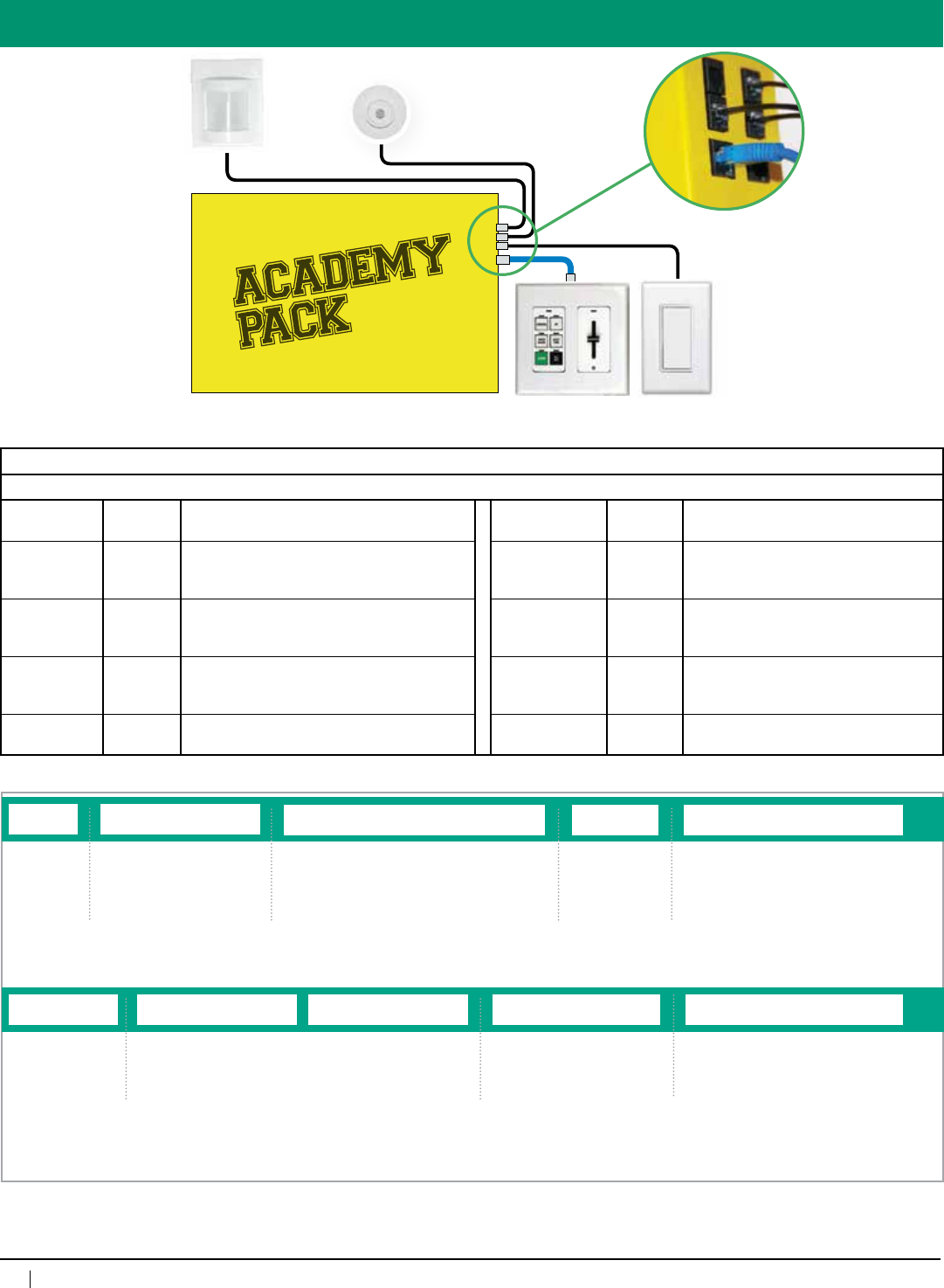
Academy Pack Classroom Solution
Academy
Pack
Specifications:
Dimensions: 13"wx8.5"hx3.125"d
NumberofRelays: Upto8relays(optionalemergency,dry
contactclosure)
HighVoltageRelaySpec: 30A@277VACballast
20A@120VACincandescent
1.5hp@120VAC
3hp@277VAC
SCCR18kA@277VAC
#Operations: 250,000cycles
Programming: Pre-programmed or adjustable on site
with optional Hand Held Programmer
Description: TheAcademyPackisacomplete,stand-alone,dimming/switchingcontrolsolution.Itisdesignedtoenhance
thelearningenvironment,reduceenergyexpenditures,andhelpsupportemergencylightingintoday’s
classrooms, lecture halls and universities.
Features: • Program wall stations to provide single button control of lighting scenes, toggle of lights, variable timers,
overrides,blinkwarning,controlofshadesandskylightlouvers.
• Intelligentoccupancydetection,selectbetweenvacancyandoccupancysensing.
• Intelligentdaylightharvesting:useasinglephotocelltoindependentlydimmultiplefixturesbasedon
contribution of natural light.
• Comespre-programmedorcanbefieldadjustedwiththeoptionalHandHeldProgrammer.
• Integralemergencyrelaysection(andbarrier)providesUL924compliancewithoutadditionalshuntrelay
equipment.
• Quickinstall:hangpre-programmedpanel,landloads,installwallstations,plugandplay
• Easytomaintain:operateswithoutnetworkedcomponents,butcanbefutureupgradedtointegradewith
BMSorAV(additionalequipmentrequired).
Stand-Alone
Control Panel
AmbientTemp: 32-105°F(0-40°C),non-condensing
Listings: UL/CULandETLlisted
Inputs/Outputs: Photosensorinputs-1
Occ. sensor inputs - 1
Localswitchinputs-2
Digitalswitchinputs-2
0-10Voutputs-4,15mAperchannel
PowerforOcc.Sensor: 24VDC/450mA
PowerSupplyVoltage: 120/277VACor347VAC
COMPATIBLE WITH WIRELESS PRODUCTS
68
www.lightingcontrols.com • 800-345-4448
Academy Pack Overview
WideView
Occupancy
Sensor
Teacher
Control Station
PHONECABLE
WITHRJ11CONNECTORS
Entry
Switch
Indoor
Photosensor
ORDERING LOGIC
System
APAC
Teacher Control Station3
Switch Slider (optional)
TCS6CH-6ButtonswitchTCS1SS-SingleSlider
TCS4CH-4ButtonswitchTCS2SS-DualSlider
[blank]-noswitch [blank]-NoSlider
TCS1-Preconfigured6buttonswitchwithSlider
TCS2-Preconfigured4buttonswitchwithSlider
TCS3-Preconfigured4buttonswitch
APAC
Occupancy Sensor4
Panel Type1
AP2408-AcademyPackpanel
[blank]-Nopanel
Voltage
DV-120V/277V
347V-347Volt
Emergency Options
EMSMDM-Emergencyenclosure
1VB-1Voltagebarrier
[blank]-noEmergencyoptions
Entry Switch
1RSCC-1contactclosureRocker
2RSCC-2contactclosureRocker
[blank]-noentryswitch
Photocell2
PCELL1-1Photocell
[blank]-no Photocell
[qty]WVPDT16R-wideview
[qty]CMPDT9R-standardrange
[qty]CMPDT10R-extendedrange
[blank]-nosensor
Relays
[qty]NCL-NormallyClosedLatching
[qty]NOL-NormallyOpenLatching
[qty]DPNC-DoublePoleNormallyClosed
[qty]DPNO-DoublePoleNormallyOpen
[qty]RRNO-ReedRelayNormallyOpen
[qty]SPDT-SinglePoleDoubleThrow
[qty]SPDTC-SinglePoleDoubleThrowContactor
TEACHER CONTROL STATION
TYPICAL BUTTON OPERATIONS
LABEL BUTTON
COLOR
FUNCTION LABEL BUTTON
COLOR
FUNCTION
Teach White Front of the room with brighter light levels,
white board illuminated, student area
dimmed lower, photocell enabled
Enable Slider White Override control of dimming zones
A/V White Front of the room with lower light levels,
white board light turned off, student area
with higher light levels, photocell disabled
Sensor Override White Disables occupancy sensor for one
hour
Energy Saver Green Light levels lowered, photocell enabled for
daylight harvesting to further reduce energy
consumption
White Board White Toggle whiteboard lights on and off
General White Uniform light levels throughout, photocell
enabled
All Off Black Turns off all lights
Notes:
1.Relay,VoltageandEmergencyoptionsarenotavailableifAP2408isnotselected.
2.Formultiplephotocellspleasecontactfactory.
3.Custombuttonengravingandcolorsavailable,pleasecontactfactory.
4.Maximumof2sensorsperroom,ifmoreareneeded,pleasecontactfactory.
5.Toupdateprogrammingonsite,orderHandHeldProgrammerseparately(APACHHR).
TYPICAL PACKAGE:
APAC AP2408 DV 6NCL
PCELL1 TCS6CH TCS1SS 1RSCC WV16R

69
800-345-4448 • www.lightingcontrols.com
RF Pack Energy Conservation System
RF Pack
Stand-Alone
Control Panel
Specifications:
Dimensions: 8.375”wx8.375”hx3.125”d(4relaypanel)
12.875”wx8.375”hx3.125”d(8relaypanel)
Power: 120/277VACor347VACtransformer
NumberofRelays: Upto16relays(upto8relaysintheenclosureand8wirelessrelays)
optional2-Polerelaytakes2positionsinthepanel
RelaySpec: 30A277VACballast
20A120Vincandescent
1.5hpat120VAC
3hpat277VAC
Listings:
ULandcULListed
Max.humidity: 10–90%non-condensing
Ambienttemperature: 32–104°F(0–40°C)
COMPATIBLE WITH WIRELESS PRODUCTS
Description: TheRFPackisawirelessplatformspeciallydesignedforsmalltomediumspaces,suchaslivingspacesor
office environments.
Features: • Quickandeasyinstallation.
• Upto8internaland8wirelessrelayoutputs.
• Intuitiveuserinterfaceforquickprogrammingandcommissioning.
• Costeffective
• MaycontainNormaland/orEmergencyrelays
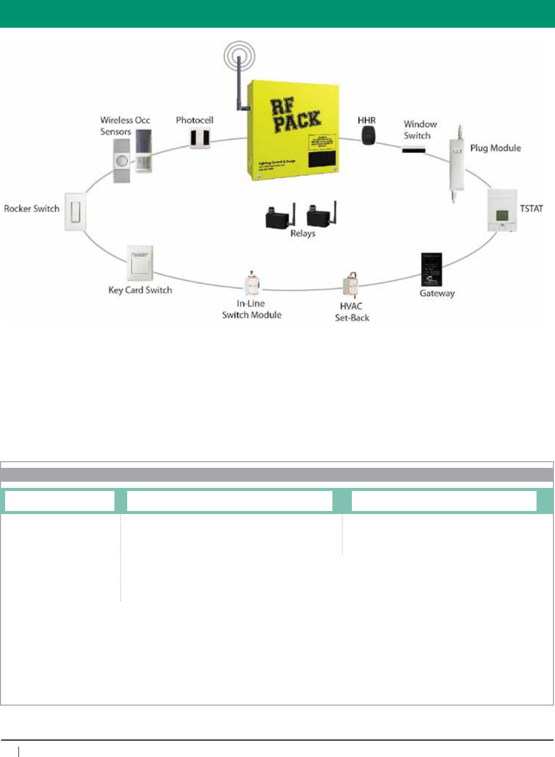
70
www.lightingcontrols.com • 800-345-4448
Layout
ORDERING INFORMATION
RF Pack
RF Pack Enclosure Size
RF2404=4relayenclosure
RF2408=8relayenclosure
Relays
[qty]NCL=NormallyClosedLatching
[qty]NOL=NormallyOpenLatching
[qty]DPNC=DoublePoleNormallyClosed
[qty]DPNO=DoublePoleNormallyOpen
[qty]RRNO=ReedRelayNormallyOpen(pair)
[qty]SPDT=SinglePoleDoubleThrow
[qty]SPDTC=SinglePoleDoubleThrowContactor
[qty]RFNODE=RFNode
Transformer, Enclosure Mount, NEMA Rating
DVSMNE1=Dualvoltage120/277V,SurfaceMount,NEMA1
Where[qty]isinthenomenclature,replacewith
quantity of relays, and leave no space between
numberandcode(example:8NCL=aquantity
of8normallyclosed,latchingrelays).
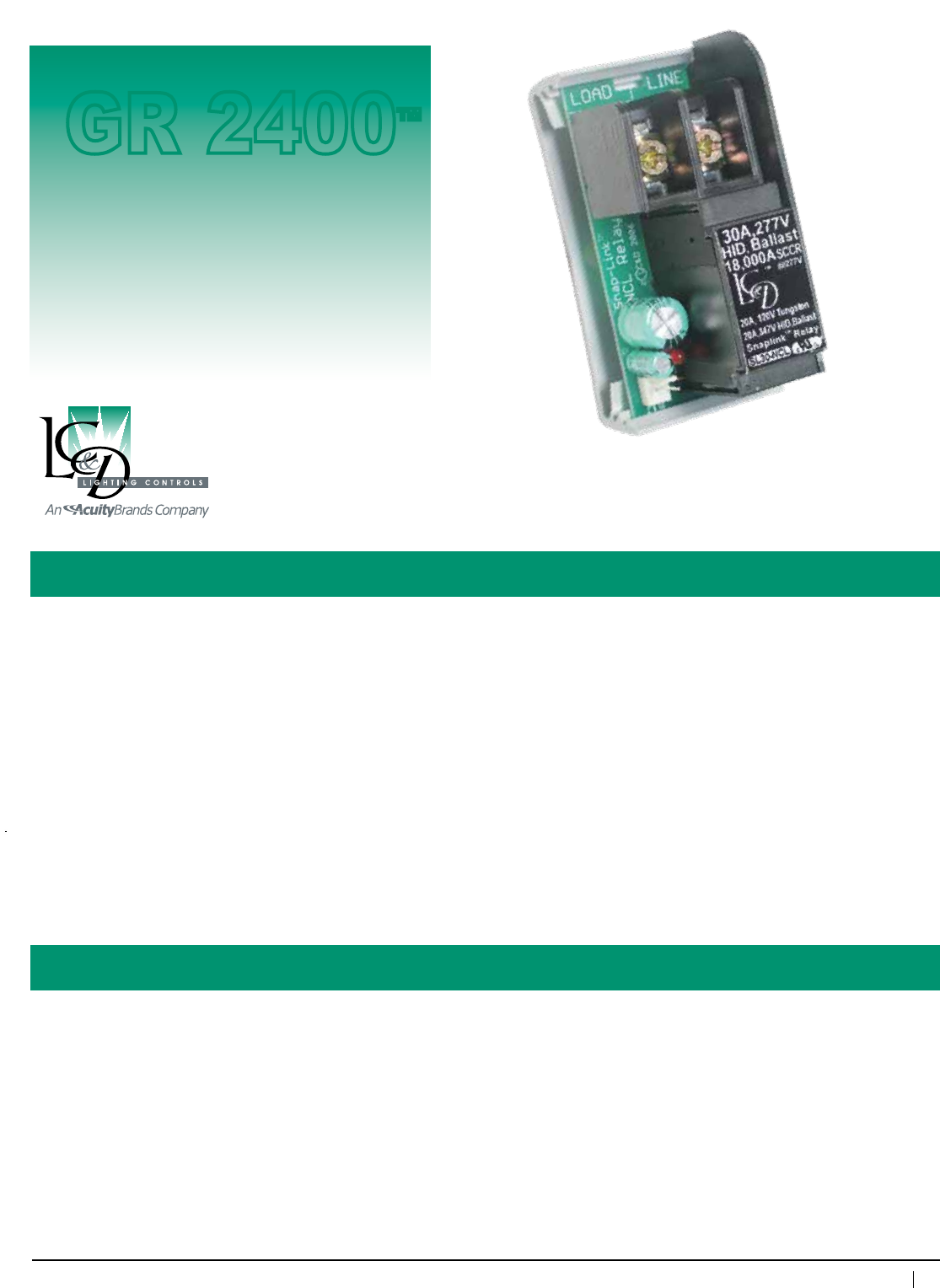
71
800-345-4448 • www.lightingcontrols.com
Specifications:
SnapLink™ Latching Relay
Description: TheSnapLink™LatchingRelayfromLC&Disasingle-pole,lightingrelaydesignedtomeetthe
demandsoftoday’shigh-efficiencyballastloads.Thislatchingrelaycanbespecifiedtodefaulttoopen
(simulatedNO)ortodefaulttoclosed(simulatedNC)uponlossofpower.TheNormallyClosedrelayis
the default relay shipped unless otherwise noted.
Features: • Newlargercontactsallowswitchingupto30ampslighting(ballast,HID)at277V,20ampsat347V
and20ampsTungstenat120V
• ULlistedfor18,000ampsSCCR(ShortCircuitCurrentRating)at277V
• Eliminateszero-crosscircuitry—idealformanymoderntypesofballast,particularlyHIDwhichcan
become“core-saturated”whencontrolledbyzero-crosslightingrelays
• Newheavy-duty,high-conductivityterminalblocksallowupto2#8AWGwiresperlug
• 3-yearwarranty
• Sincerelaysarelatching,noenergyisusedtoholdcontacts,creatinglessheat
Relay
GR 2400™
Contacts: Normally Closed
(optionalNormallyOpen)
Typeofaction: Latching
(Innovativeelectronics
allows default to NC or NO
onpowerfailure)
Operationsat30ampload: 250,000cycles
ULratedfor: 30A@277VAC,20A@347VACBallast/HID
20A@120VACTungsten
1.5hp@120VAC
3hp@277VAC
Not rated for DC current
Conductors: 2ea#8AWGperlug
Listings: ULandcULRecognizedassembly
ULtestedSCCRrating: 18,000A@277VAC
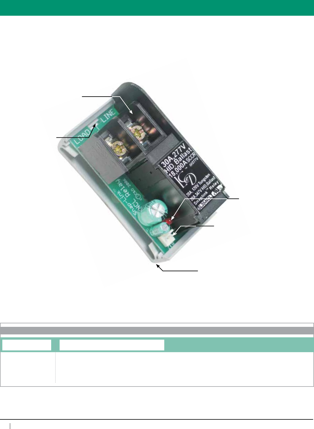
72
www.lightingcontrols.com • 800-345-4448
Overview
30A, 277V HID, Ballast Relay
High Conductivity
Terminal Block
Quick Removal Slot
SnapTrak
Status Indicator LED
Low Voltage Connector
ORDERING INFORMATION
LCDACC
SnapLink Latching Relay
Category Relay Type
SL30NCL=SnapLink30ANormallyClosedLatchingRelay
SL30NOL=SnapLink30ANormallyOpenLatchingRelay
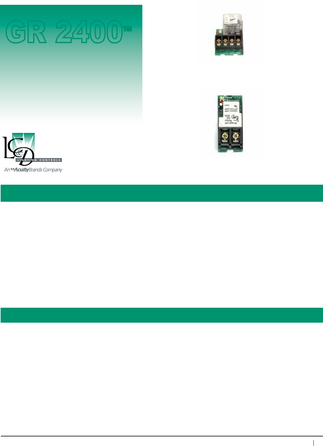
73
800-345-4448 • www.lightingcontrols.com
ORDERING INFORMATION
Optional
Replacement
Relays
GR 2400™
SnapLink™ Relays
Specifications:
Description: Double-Pole Relay: The double-pole relay occupies the footprint of two single-pole relays when
mountedintheSnapTrakwithintherelaypanel.Therelayisidealfor208V,240Vor480Vtwo-pole
loads.
ZeroCross™ (120V, 277V): This electrically-held relay uses special circuitry to switch loads both
ONandOFFwhentheinstantaneousACvoltagevalueiszero.ThisrelayisavailableaseitherNormally
Closed(default)ororNormallyOpen.(Forreplacementpartsonly)
Contact ratings:
Voltage: 480VAC,Amperage:20A
Rated for: Ballast/HID
Horsepower: 1hp@208or240VAC,
2hp@480VAC
AWG Ratings for Lugs: 2#12AWG,2#10AWG,2#8AWG
SCCR: 5000A*
ZeroCross™ SnapLink Relay (120V, 277V)
Double-Pole Relay
Contact ratings:
Voltage: 277VAC
Rated for: Tungsten/ballast/HID(NotratedforDCcurrent)
Horsepower: 1hp@120VAC,2hp@277VAC
AWG Ratings for Lugs: #12AWG,2#10AWG,2#8AWG
SCCR: 5000A*
Operations at Full Load: 250,000cycles(NOorNC)
ZeroCross™
(120V, 277V)
Double-Pole
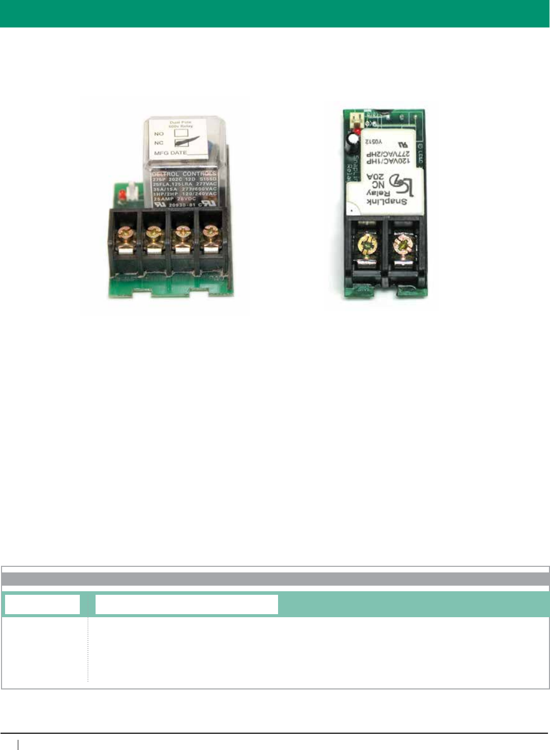
74
www.lightingcontrols.com • 800-345-4448
SnapLink Relays
ORDERING INFORMATION
LCDACC
Additional SnapLink Relays
Category Relay Type
SL20NCZC=SnapLink20ANormallyClosedZeroCrossRelay
SL20NOZC=SnapLink20ANormallyOpenZeroCrossRelay
SLDPNC=SnapLink20ADoublePoleNormallyClosedRelay
SLDPNO=SnapLink20ADoublePoleNormallyOpenRelay
ZeroCross™
(120V, 277V)
Double-Pole
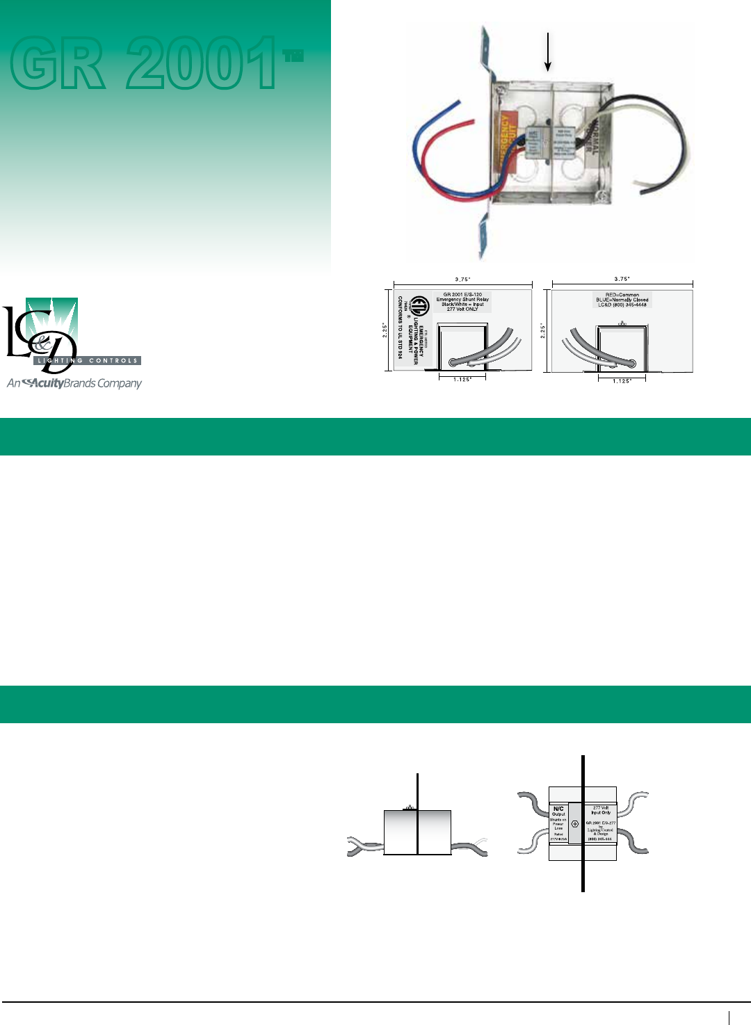
75
800-345-4448 • www.lightingcontrols.com
Specifications:
Emergency Shunt Relay
Description: Normally-closed,electrically-heldrelaytobewiredinparallelwithawallswitch.Manuallycontrolled
emergency lighting will be automatically shunted on during a power outage.
The Emergency Shunt Relaycomesinatwo-gangjunctionboxwithavoltage-separatingbarrierand
isshippedwithaplasterringseparatingnormalandemergencypower.Thecompactsizeallowswall
switchestobemounteddirectlyonthejunctionbox.
Features: • Manualcontrolofemergencylightingissafelyaccomplished
• Notwattage-dependent,idealforwalldimmers
• Optionalenclosurewillholduptoeightshuntrelaysforfeed-throughdimmingpanels
• ETLlistedtoUL924
Junctionboxdimensions: 4"wx4"hx2.125"d
Plasterringdepth: 0.625"(5/8")
Ambienttemperature: 32–105°F(0–41°C)
Humidity: 10–90%non-condensing
Power consumption: 1 watt
Coilrating: Specify120VACor277VAC
Contactrating: 20Aupto277VAC
#Operations: 40,000@20A277VAC
Listings: ETLlistedtoUL924(emergencysystems)
Relay
GR 2001™
SideView
TopView
Normal
Power
Emergency
Power
BarrierSeparatesNormal/
Emergency Power
Emergency Shunt Relay
(mountedinenclosure)
Normal Power
FrontView
Emergency Power
BackView
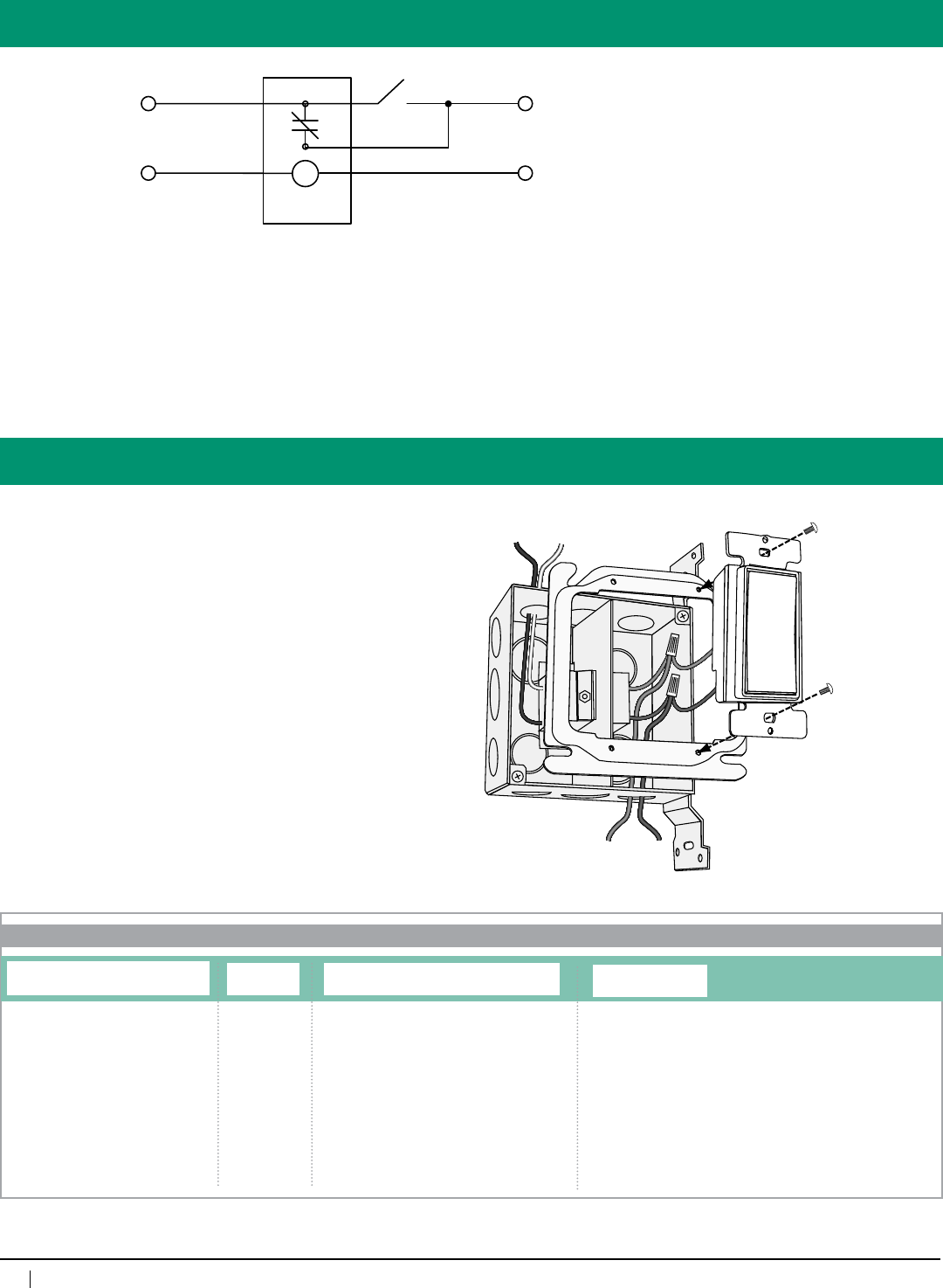
76
www.lightingcontrols.com • 800-345-4448
Schematic/Specs
The GR 2001™ EMSHUNT isolates
the normal and emergency power both
electrically and mechanically.
The major advantage of the
GR 2001 EMSHUNTisitssmallsize
— a wall switch may be mounted in the
sameboxastheGR 2001 EMSHUNT,
simplifying installation.
Drawing and specs are available at
www.lightingcontrols.com
1. MountGR 2001enclosuretostudusingmountingbrackets.
2. Routenormalandemergencyconductorstoappropriate
compartment.
3. Ensurethatthecoilisfedbythecorrectvoltage
(i.e.,120Vor277V).
4. Wire the relay contacts in parallel with the switch.
5. MountswitchtotheplasterringprovidedbyLC&D.
6. Mountatwo-gangcoverplate(suppliedbycontractor).
Coverplateshouldhaveablankononesideandtheswitch
punch-out on the other.
Emergency Power
Normal Power
Hot Neutral
Hook Up
C
Emergency Breaker
Normal Breaker
To Load
Emergency Shunt Relay
(Gr 2001 ES-120)
Neutral
Wall Switch (Typ.)
Emergency Shunt Relay to be factory mounted in a 4" x 4" junction box and two-gang deep
plaster ring. Emergency circuit wall switch shall mount in same enclosure.
Contractor to supply two-gang wall plate and single wall switch appropriately rated per
NEC and any local electrical codes.
Emergency Shunt Relay is ETL Listed to UL STD 924 with a 16-gauge
steel barrier to separate normal and emergency power, manufactured by LC&D Lighting
Controls (800) 345-4448.
ORDERING INFORMATION
GR2001 EMSHUNT
Emergency Shunt Relay
System and Type Voltage
120
277
Number of Relays per Enclosure
1SR=1EmergencyShuntRelay
2SR=2EmergencyShuntRelays
4SR=4EmergencyShuntRelays
6SR=6EmergencyShuntRelays
8SR=8EmergencyShuntRelays
DUAL=2EmergencyShuntRelays
to control normal and emergency
lighting from single-pole wall switch
Enclosure Type
NE1=NEMA1
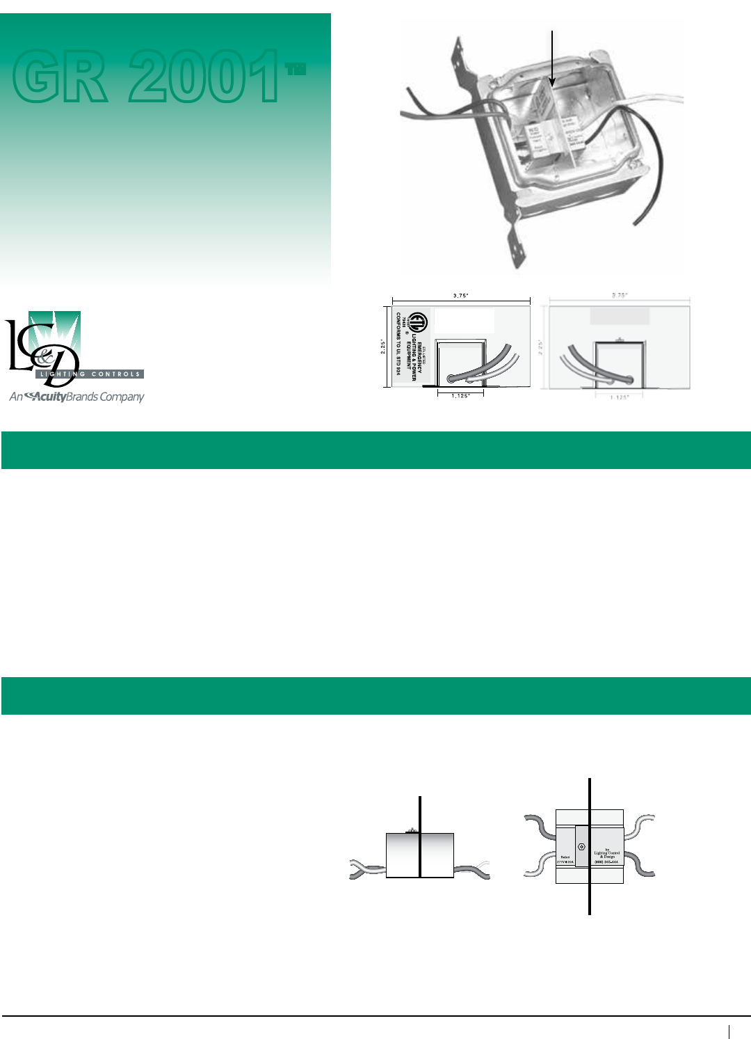
77
800-345-4448 • www.lightingcontrols.com
ORDERING INFORMATION
Specifications:
Dual Voltage Switch
Description: Normally Open, electrically held relay which allows a single-pole switch to control loads operating at two
differentvoltages(i.e.,120Vand277V).
The Dual Voltage Switchisshippedinatwo-gangjunctionboxwithavoltage-separatingbarrierand
isshippedwithaplasterring.ItscompactsizeallowsawallswitchtobemounteddirectlyontotheGR
2001boxandplasterringpackage.
Features: • Built-involtagebarrier
• Shippedfromfactoryintwo-gangboxandplasterring.Nootherpartstopurchase.
• ETLListedtoUL924
Junctionboxdimensions: 4"wx4"hx2.125"d
Plasterringdepth: 0.625"(5/8")
Ambienttemperature: 32–104°F(0–40°C)
Humidity: 10–90%non-condensin
Power consumption: 1 watt
Coilrating: Specify120VACor277VAC
Contactrating: 20Aupto277VAC
#Operations: 40,000@20A277VAC
Listings: ETLListedtoUL924
Relay
GR 2001™
SideView
TopView
Coil
Side
Contact
Side
120 Volt
Input Only
GR2001 D/V - 120
N/O
Output
Follows
Input
Barrier
Coil
Side
FrontView
Contact
Side
BackView
GR2001 D/V - 120
Dual Voltage
Black/White = Input
120 Volt ONLY
Red=common
BLUE=Normally Open
LC&D (800) 345-4448
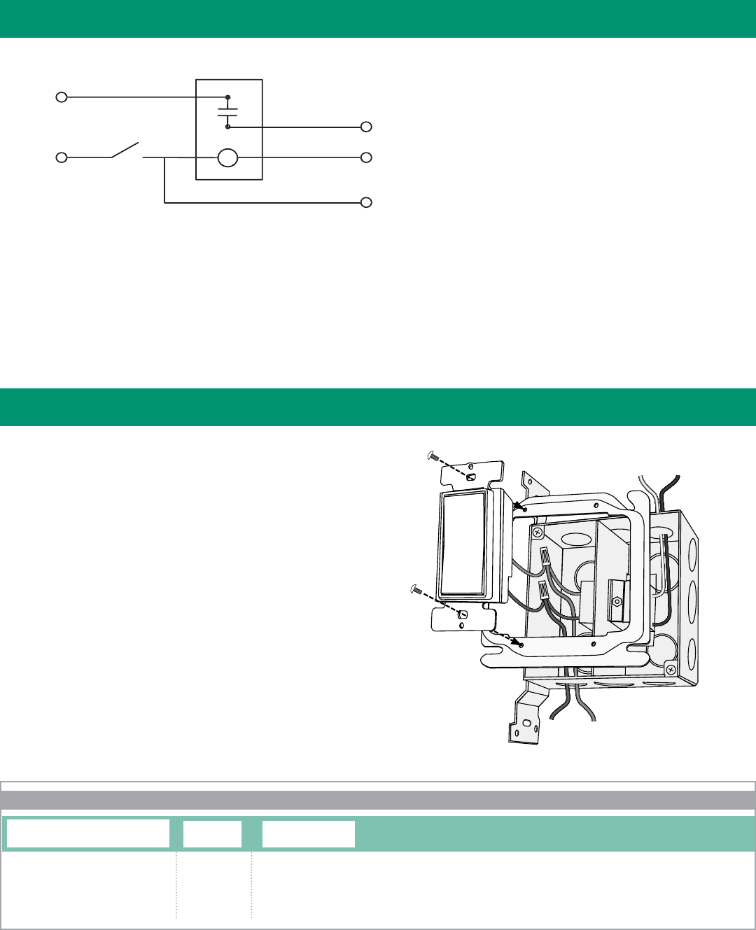
Schematic / Specs
The GR 2001™ DUALV isolates the two
voltages both electrically and mechanically.
The major advantage of the GR
2001 DUALVisitssmallsize—awall
switch may be mounted in the same
boxastheGR 2001 DUALV, simplifying
installation.
Drawing and specs are available at
www.lightingcontrols.com
Hook Up
1. Mountthedualvoltageswitchenclosuretostudusing
mountingbrackets.
2. Routeconductorstoappropriatevoltagecompartment.
3. Ensurethatthecoilisfedbythecorrectvoltage(i.e.,
120VACor277VAC).
4. Wire the relay coil in parallel with the load.
5. MountswitchtotheplasterringprovidedbyLC&D.
6. Mountatwo-gangcoverplate(suppliedbycontractor).
Coverplateshouldhaveablankononesideandtheswitch
punch-out on the other.
Second Power
Line Load
To
Line
To
Load
Dualvoltageswitchtobefactorymountedina4"x4"junctionboxandtwo-gang,deepplaster
ring. Emergency circuit-wall switch shall mount in same enclosure.
Contractor to supply two-gang wall plate and single-wall switch appropriately rated per NEC or
CEC and any local electrical codes.
DualvoltageswitchisETLListedtoUL924witha16-gaugesteelbarriertoseparatehighand
lowvoltage.TobemanufacturedbyLightingControl&Design
(800)345-4448.
The GR 2001™ DV isolates the two
voltages both electrically and mechanically.
The major advantage of the GR 2001 DV
is its small size — a wall switch may
be mounted in the same box as the
GR 2001 DV, simplifying installation.
Drawing and specs are available at
C
277 v
ac
12
0
vac
T
O
277v L
O
AD
Dual Volta
g
e Switc
h
(
GR 2001 DV-120
)
NE
U
TRA
L
WALL
S
WIT
C
H
(
TYP.
)
T
O
12
0
v L
O
AD
277VAC
120VAC
ORDERING INFORMATION
GR2001 DUALV
Dual Voltage Switch
System and Type Voltage
120
277
Enclosure Type
NE1=NEMA1
277V
277V
120V
120V
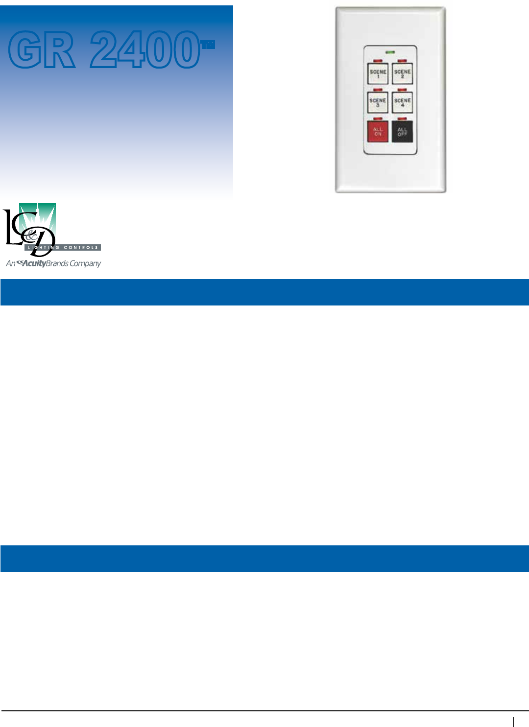
79
800-345-4448 • www.lightingcontrols.com
ORDERING INFORMATION
Specifications:
Chelsea
Digital
Switch™
Description: The Chelsea DigitalSwitch is a 100% digital switch which connects directly to the GR 2400 bus via
Cat. 5 patch cable with RJ45 connectors. Chelsea DigitalSwitchescanbeorderedwith1,2,3,4or6
buttonspergangandcanbemountedinanystandard2.25"deepswitchboxwithadecoratorstyle
switchplate.AllChelsea DigitalSwitchesare100%backwardscompatiblewithallLC&Dsystems.
Features:
Advanced
Programming
Features:
Dimensions: 1.3"wx4"hx1.3"d
Switch plate: Decorator style
Mounting: 2.25"deep-switchbox
(Waterproofbellbox-Waterproof
option only
Addressesavailable: 1–119
Addressperswitch: 1
Function: ON,OFF,Mixed,GroupControl,
Toggle, Scene Control
Programming: ViaDTC
Humidity: 10 – 90%non-condensing(100%rain
proof-Waterproofoptiononly)
Ambienttemperature: 32–104°F(0–40°C)
Powersupply: PoweredfromGR2400bus
Busconnector: TwoRJ45connectors
Bustermination: Manualend-of-lineterminationwith
jumper
GR 2400™
Cover plate provided by contractor
• Maybeprogrammedtocontrolanyrelay,
SmartBreaker™ or dimmer in any panel
• Custom button engraving at no cost
(2lines8character/line)
• Allpushbuttonsareannunciatedwithapilotlight
• AvailableasaWaterproofoption
• Factorypreprogrammed.Maybereprogrammed
inthefieldusingtheDTC(DigitalTimeClock)
• Linkupto127digitaladdressesviaCat.5patch
cable with RJ45 connectors
• Canbeenabled/disabledbyoptional
KeyEnable™ switch
• Aprogrammablegreen“LocatorLight”atthetop
of each unit is always on, can be programmed
toblinktoshowHornDriverModeorhelplocate
a switch
• ProgrammableStatusLEDlogic
• Adjustabledebouncetimetoavoid
accidental trigger
• Audiblebeepalertforwarningorswitchlocating
• Alternatebuttonprogrammingtoallowmore
flexibilityofuse,forexamplethesamebutton
canperformadifferenttaskatdifferenttimesof
the day
• Capableofbeingdigitallyenabled/disabledover
the bus on a per button or per switch basis
Switch
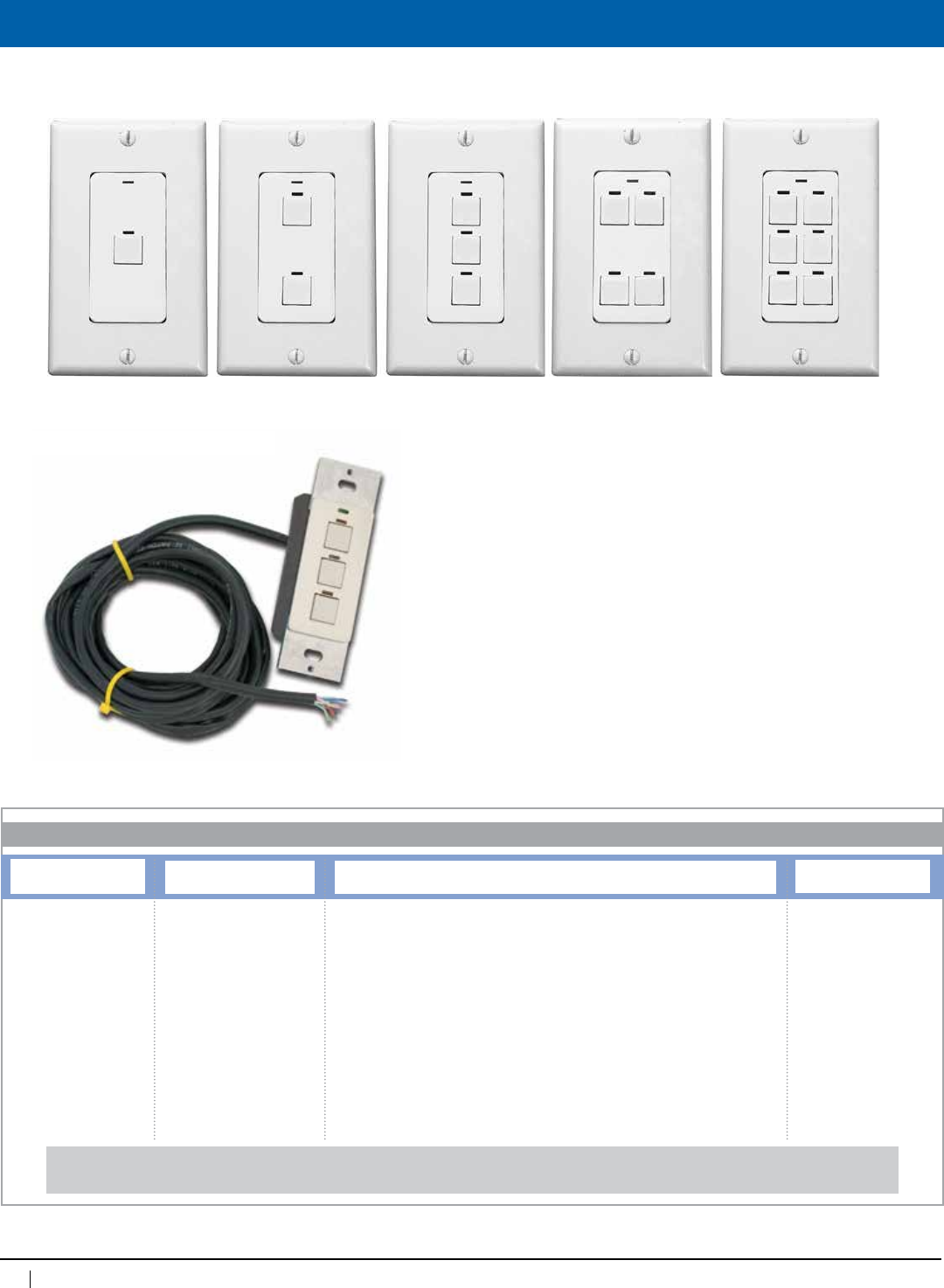
80
www.lightingcontrols.com • 800-345-4448
Ordering Information
Chelsea DigitalSwitches™areavailablein1,2,3,4or6buttons.Centerplatesareavailableinwhite,ivoryandbrushedstainlesssteel.
Indicatorlightisredandlocatorlightisgreen.
Number of Buttons
CH1=1buttonChelsea
CH2=2buttonChelsea
CH3=3buttonChelsea
CH4=4buttonChelsea
CH6=6buttonChelsea
When ordering Waterproof
Chelsea, add WP to the
ordering nomenclature.
Example:
CH1WP,CH2WP,CH3WP,
CH4WP,CH6WP
Single/Multicolor
BWH=Allbuttonswhite
BIV=Allbuttonsivory
BGY=Allbuttonsgray
BBK=Allbuttonsblack
BRD=Allbuttonsred
BGR=Allbuttonsgreen
BBU=Allbuttonsblue
BYL=Allbuttonsyellow
BOR=Allbuttonsorange
MC=Multicoloredbuttons
(pleaseselectquantitiesfrom
themulticolorbuttonsection)
Multicolor Button Colors
Button Quantity
1B=1button
2B=2buttons
3B=3buttons
4B=4buttons
6B=6buttons
Color
WH=White
IV=Ivory
GY=Gray
BK=Black
RD=Red
GR=Green
BU=Blue
YL=Yellow
OR=Orange
Multicolor Examples:
CH6 MC 2BWH 4BBK PST
6buttonChelseawith2whiteand4blackbuttonsand
a stainless steel faceplate
CH4 MC 2BBU 1BGR 1BYL PWH
4buttonChelseawith2blue,1green,and1yellow
button and a white faceplate
Button Quantity represents the number of buttons on
a switch that will be in the selected color— number may
notexceedtotalnumberofbuttonsonswitch-totalof
all button color quantities must equal total number of
buttonsonswitch(refertoexamples).
Examples: CH6BWHPWH=6buttonChelseawithallwhitebuttonsandawhitefaceplate
CH3WPMC1BRD2BBKPIV=3buttonwaterproofChelseawith1redbutton,2blackbuttons,andanivoryplate
Plate Colors
PWH=Whiteplate
PIV=Ivoryplate
PST=Stainlesssteelplate
PBK=Blackplate
ORDERING INFORMATION
Chelsea Digital Switch™
Waterproof Chelsea DigitalSwitch™
Note: Sealed Switch is provided with a 10ft
standard Cat. 5 connection cable and may be cut
to a more convenient length.
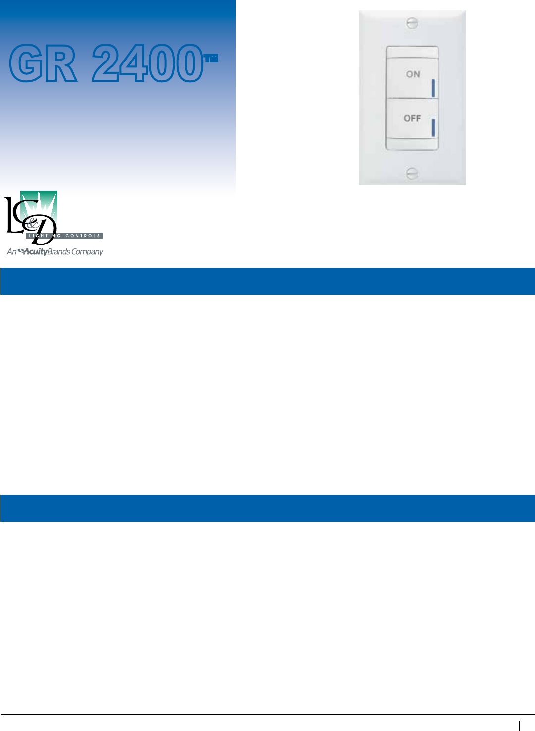
81
800-345-4448 • www.lightingcontrols.com
Specifications:
Brighton
Digital
Switch™
Description: TheBrighton DigitalSwitch is a 100% digital switch which connects directly to the GR 1400 bus via
Cat. 5 patch cable with RJ45 connectors. Brighton DigitalSwitchescanbeorderedwith2,4,5,6,7or
8buttonspergang,andcanbemountedinanystandard2.25"deepswitchboxwithadecoratorstyle
switch plate.
Features:
Dimensions: 1.7"wx4.17"hx1.82"d
Switch plate: Decorator style
Mounting: 2.25"deep-switchbox
Addressesavailable: 1–119
Addressperswitch: 1
Function: ON,OFF,Mixed,GroupControl,
Toggle, Scene Control
Programming: ViaDTC
Humidity: 10 – 90%non-condensing
Ambienttemperature: 32–104°F(0–40°C)
Powersupply: PoweredfromGR2400bus
Busconnector: TwoRJ45connectors
Bustermination: Manualend-of-lineterminationwith
jumper
GR 2400™
• MaybeprogrammedtocontrolanyrelayinaGR2400system.
• Allpushbuttonsareannunciatedwithapilotlight
• FactorypreprogrammedorcanbeprogrammedinthefieldusingtheDTC(DigitalTimeClock)
• Standard engraving included with all switch configurations. Custom engraved buttons are available to
be ordered separately from the factory.
Switch
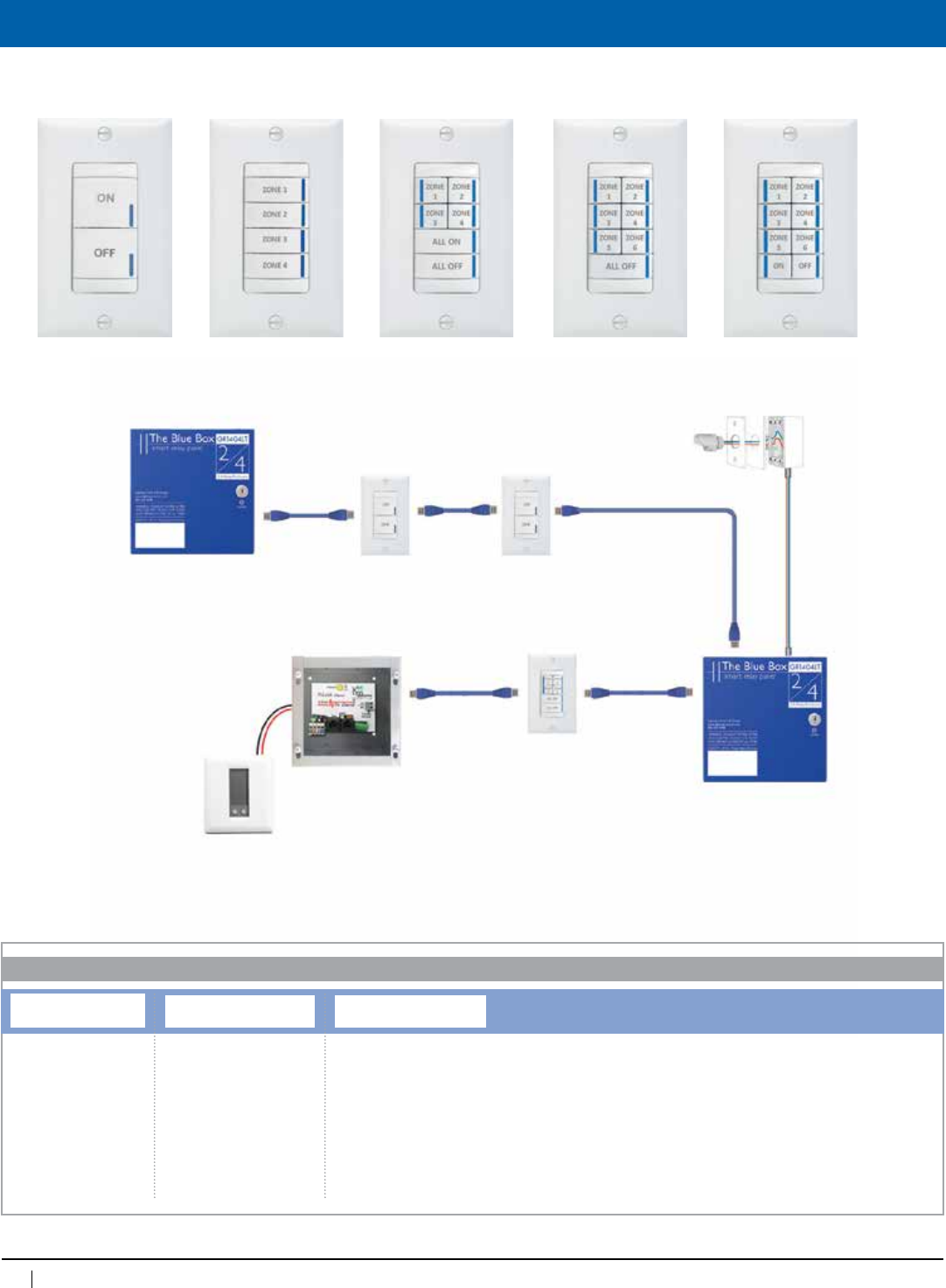
82
www.lightingcontrols.com • 800-345-4448
Overview
Brighton DigitalSwitchesareavailablein2,4,5,6,7and8buttons.
Number of Buttons
BR2=2buttonBrighton
BR4=4buttonBrighton
BR5=5buttonBrighton
BR6=6buttonBrighton
BR7=7buttonBrighton
BR8=8buttonBrighton
Button Color
BWH=Allbuttonswhite
Plate Colors
PWH=Whiteplate
ORDERING INFORMATION
Brighton DigitalSwitch™
BlueBoxLT
MasterPanel
BlueBoxLT
Remote Panel
Photocell
BrightonSwitches
Brighton
Switch
Link-ToTSTAT
Thermostat
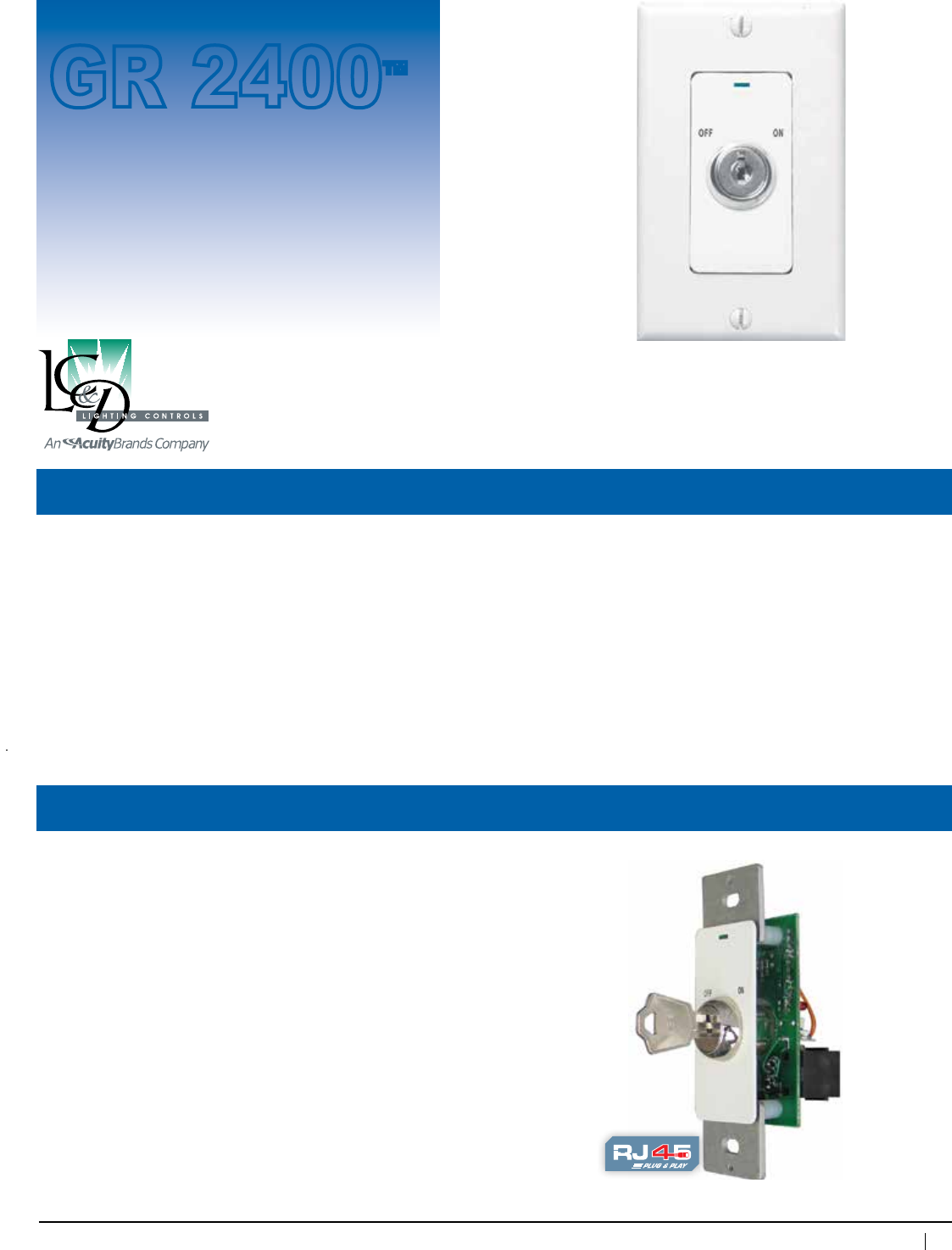
83
800-345-4448 • www.lightingcontrols.com
Specifications:
Key
Digital
Switch™
Description: The Key DigitalSwitch™ is a 100% digital switch which connects directly to the GR 2400 bus via
Cat. 5 patch cable with RJ45 connectors. Key DigitalSwitchescanbemountedinany2.25"switchbox
withadecoratorstyleswitchplate.ThismakestheKey DigitalSwitch ideal for schools, gymnasiums,
site-lighting and high-security applications.
Features: • Factorypre-programmed.Maybereprogrammedinthefieldorremotely
• Key DigitalSwitchisavailableasmomentaryon/offoras“captive”(CT24requiredcaptivekey)
• PilotLEDindicatesstatusofcontrolledloads(onoroff)
• Maybeprogrammedtocontrolanyrelay,SmartBreaker or dimmer in any panel
• Linkupto127digitaladdressesviaCat.5patchcablewithRJ45connectors
• Usetoenable/disablemultipleChelseaDEorChelseaAPswitches
Dimensions: 1.3"wx4"hx1.625"d
Switch plate: Decorator style
Mounting: 3"deep-switchbox
Switch addresses available:
1–119
Addressesperswitch: 1
Function: PositiveON,PositiveOFF,GroupControl,
Toggle,BypassorSceneControl
Action: Center-offmomentary(positive-on/positive-off)
Programming: ViaDTC,viaPCwith
Unity™ Lighting Control Software
Humidity: 10–90%non-condensing
Ambienttemperature: 32–104°F(0–40°C)
Powersupply: 12VDCfrombus
Busphysicallayer: RS485(GR2400bus)
Busconnector: RJ45connectors
Switch
GR 2400™
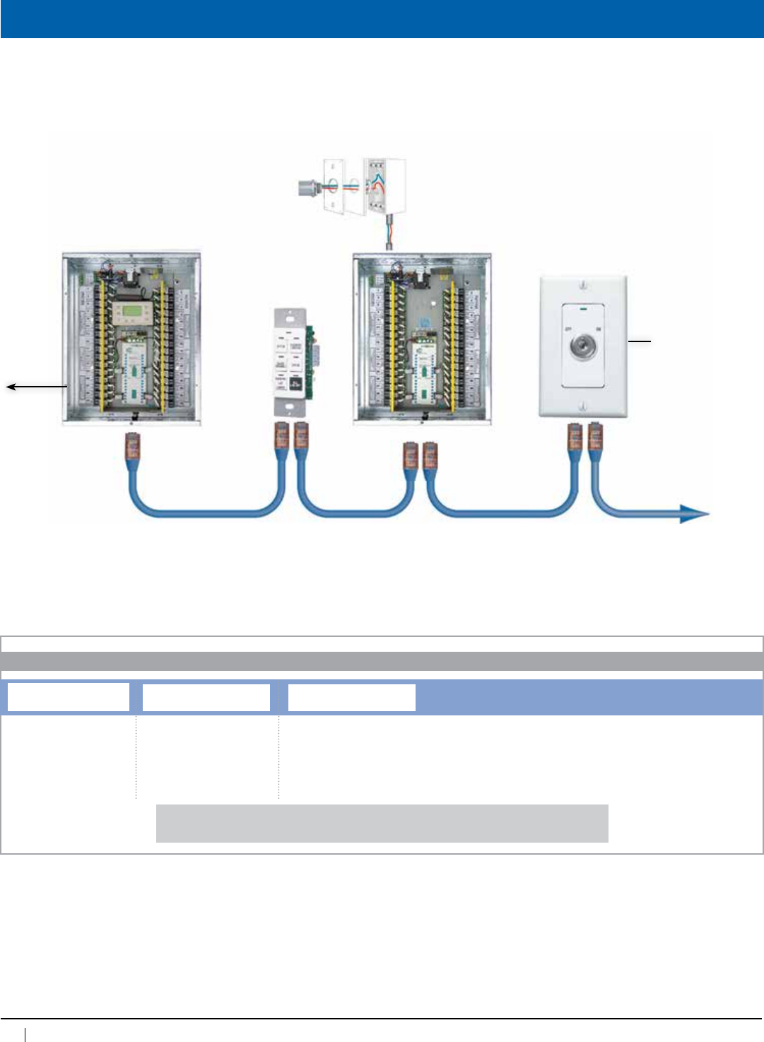
84
www.lightingcontrols.com • 800-345-4448
Hook Up
To phone
line for
remote
dial up
GR2400™
MasterRelayPanel
Outdoor Photosensor
(facingnorth)
Chelsea
DigitalSwitch™
Key
DigitalSwitch™
Cat.5patchcablewithRJ45connectors•Upto127digitaladdresses•Upto4,000ft.
GR2400Remote
Relay Panel
ControlsLoads
directly
KS
ORDERING INFORMATION
Key DigitalSwitch
Switch Plate Color
PWH=Whiteplate
PIV=Ivoryplate
PST=Stainlesssteelplate
Captive Key
[blank]=Nocaptivekey
CK=Captivekey
Examples: KSPWH=KeyDigitalSwitchwithwhiteplate
KSPST=KeyDigitalSwitchwithstainlesssteelplate
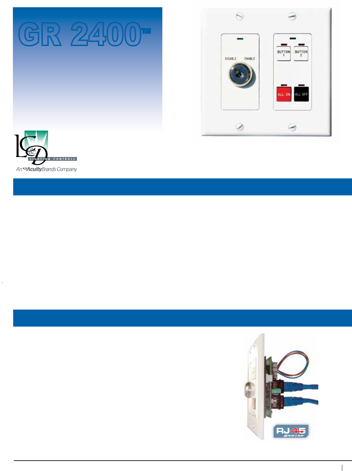
85
800-345-4448 • www.lightingcontrols.com
Specifications:
KeyEnable™ Switch
Description: The KeyEnable Switchreplacesmultiple-gangkeyswitches.TheKeyEnable may be mounted
with up to three Chelsea DigitalSwitches,withuptosixbuttonseach.ThebuttonsoftheChelsea
DigitalSwitch are enabled and disabled by the KeyEnable Switch. This eliminates the requirement for
unwieldymultiple-gangkeyswitches.
Features: • Noprogrammingrequired
• Idealforsitelighting,schools,theatres,gymnasiums,prisonsandotherhigh-securityapplications
• PilotLEDindicatesstatusofcontrolledChelsea DigitalSwitches(enabledordisabled)
• Captivekeyoptionavailable,sothatthekeycanonlyberemovedinthe“disabled”position
• PushbuttonswitchLEDsfunctionwhetherornotbuttonsareenabled
Dimensions: 1.3"wx2.6"hx1.625"d
Switch plate: Decorator style
Mounting: 2.25"deep-switchbox
Action: Maintained
Function: PositiveON,PositiveOFF,GroupControl,
Toggle,BypassorSceneControl
Humidity: 10 – 90%non-condensing
Ambienttemperature: 32–104°F(0–40°C)
Powersupply: Poweredfromadjacent12VDC
Chelsea DigitalSwitch
Switch
GR 2400™
Decora plate provided by contractor
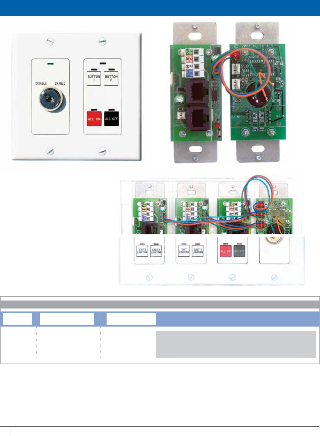
86
www.lightingcontrols.com • 800-345-4448
Hook Up
1. Starting with the topmost, connect a jumper from
theKeyEnable™ Switch to the disable pins on the
custom Chelsea DigitalSwitch™.
2. Usingthesecondandthirdconnectors,connect
jumpers to Chelsea DigitalSwitches2&3(ifneeded).
3. Connect all switches to the bus. Program Chelsea
DigitalSwitchesifnotalreadydone(seemanual).
4. MountswitchesinDecoraplate(notsupplied).
Note:
Factory pre-wired Key Enabled Chelsea
Digital Switches are available—please
specify prior to purchase.
KE
ORDERING INFORMATION
KeyEnable Switch
Switch Plate Color
PWH=Whiteplate
PIV=Ivoryplate
PST=Stainlesssteelplate
Captive Key
[blank]=Nocaptivekey
CK=Captivekey
Examples: KEPWH=KeyEnableSwitchwithwhiteplate
KEPST=KeyEnableSwitchwithstainlesssteelplate
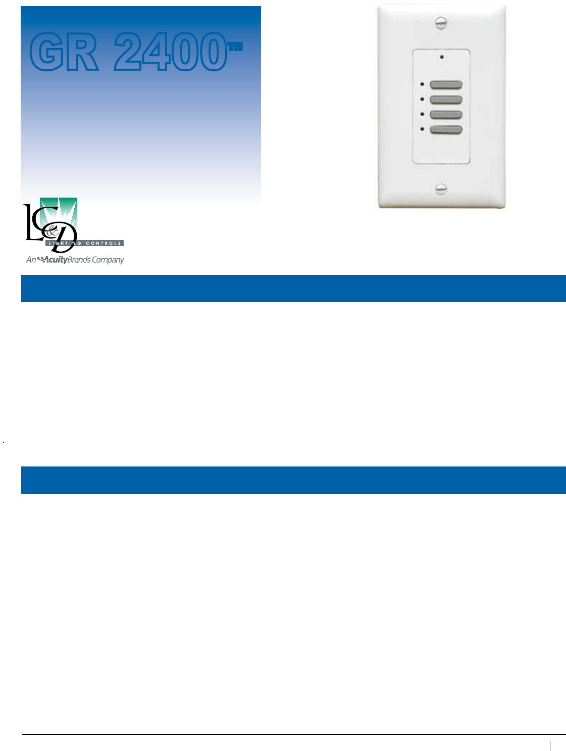
87
800-345-4448 • www.lightingcontrols.com
ORDERING INFORMATION
Specifications:
KnightsBridge
Digital
Switch™
Description: The KnightsBridge DigitalSwitch is a 100% digital momentary switch which connects directly to
the GR 2400 bus via Cat. 5 patch cable with RJ45 connectors. KnightsBridge DigitalSwitches can
beorderedwithonetosixbuttonspergangandcanbemountedinanystandardswitchboxwitha
decorator style switch plate.
Features: • Factorypreprogrammed
• Availableinpaintedwhite,ivoryandbrushedstainlesssteelplates
• Buttonpositionsonethroughsixarealsoavailableasrockerbuttonsforon/offcontrol
• Maybeprogrammedtocontrolanyrelays,SmartBreakers or dimmers in any panels
• Customengraving(oneline)
• Linkupto127digitaladdressesviaCat.5patchcablewithRJ45connectors
Dimensions: 1.6"wx4"hx1.625"d
Switch plate: Decorator style
Mounting: 2.25"deep-switchbox
SwitchAddressesavailable:
1–119
Addressesperswitch: 1
Function: Positiveon,Positiveoff,GroupControl,Toggle,
BypassorSceneControl
Programming: ViaDTC,viaPCwith
Unity™ Lighting Control Software
Humidity: 10–90%non-condensing
Ambienttemperature: 32–104°F(0–40°C)
Powersupply: 12VDCfrombus
Busphysicallayer: RS485(GR 2400bus)
Busconnector: RJ45connectors
Switch
GR 2400™
Decora plate provided by contractor
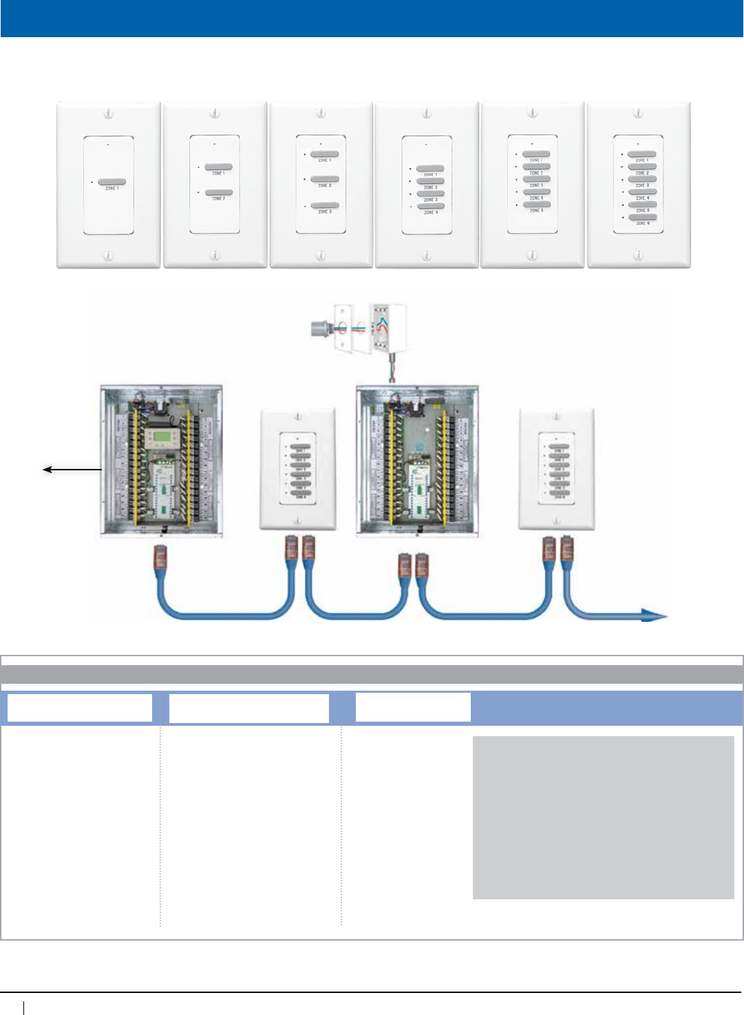
88
www.lightingcontrols.com • 800-345-4448
KnightsBridge DigitalSwitches™areavailablein1,2,3,4,5or6buttons.Centerplatesareavailableinwhite,ivory,andbrushed
metal.Indicatorlightisredandlocatorlightisgreen.
Ordering Information
Outdoor Photosensor
(facingnorth)
KnightsBridge
DigitalSwitch KnightsBridge
DigitalSwitch
To phone line for
remote dial up
GR2400™Master
Relay Panel
GR2400Remote
Relay Panel
Cat.5patchcablewithRJ45connectors•Upto127digitaladdresses•Upto4,000ft.
ORDERING INFORMATION
KnightsBridge DigitalSwitch
Total Number of Buttons
KB1=1buttonKnightsBridge
KB2=2buttonKnightsBridge
KB3=3buttonKnightsBridge
KB4=4buttonKnightsBridge
KB5=5buttonKnightsBridge
KB6=6buttonKnightsBridge
Button Color/Type
BGY=Graystandardbutton
BBK=Blackstandardbutton
BIV=Ivorystandardbutton
RKRGY[qty]RKR=Grayrockerbutton
RKRBK[qty]RKR=Blackrockerbutton
RKRIV[qty]RKR=Ivoryrockerbutton
[qty} represents the number of buttons on the
switchthatarerockerbuttons.Noteaspace
belong just before the quantity number and no
spaceafter(betweenthenumberandRKR).The
quantity may be any number from 1 up to the
maximumofthatswitch.
Plate Type
PWH=Whiteplate
PIV=Ivoryplate
PST=Stainlesssteelplate
Examples: KB4BGYPWH=4button
KnightsBridgeDigitalSwitchwith
gray standard buttons, and a
white faceplate
KB6RKRBK3RKRPST=6button
KnightsBridgeDigitalSwitchwith3
standardbuttons,and3rocker
buttons,allinblack,andastainless
steel faceplate
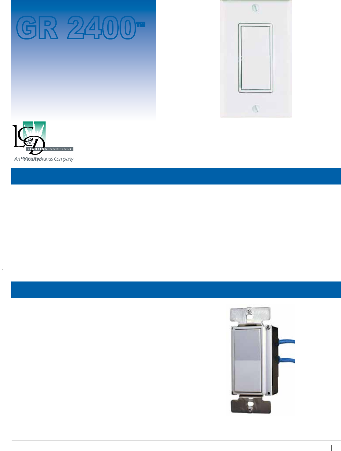
89
800-345-4448 • www.lightingcontrols.com
ORDERING INFORMATION Specifications:
Rocker
Digital
Switch™
Description: The Rocker DigitalSwitch providesafamiliarinterfacetoamodernlightingcontrolsystemasitlooks
likean ordinary wall switch. The Rocker DigitalSwitch is a center-off momentary switch, is 100%
digital and sits directly on the GR 2400 bus.
Itisalsoavailableinacontactclosureversionwhichishome-runeithertothecontactclosureinputsof
a DigiLink™ or MicroPanel™.IfconnectedtoaDigiLink™ card, the Rocker Contact Closure can be
programmedtocontrolanyrelay(s)inanypanel(s)ontheGR 2400 bus.
Dimensions: 1.6"wx4"hx2.5"d
Switch plate: Decorator style
Mounting: 3.5"deepswitchbox
Action: Momentary-Off-Momentary
Humidity: 10–90%non-condensing
Ambienttemperature: 32–104°F(0–40°C)
Switch
GR 2400™
Decora plate provided by contractor
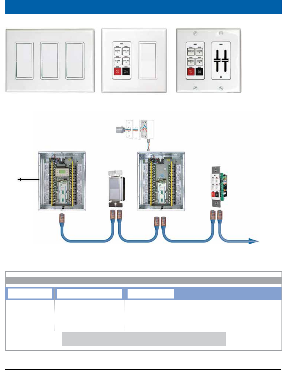
90
www.lightingcontrols.com • 800-345-4448
Overview
To phone line for
remote dial up
GR2400™Master
Relay Panel
Outdoor Photosensor
(facingnorth)
Chelsea
DigitalSwitch™
Rocker
DigitalSwitch™
GR2400Remote
Relay Panel
Cat.5patchcablewithRJ45connectors•Upto127digitaladdresses•Upto4,000ft.
Rocker DigitalSwitchcanbeutilizedincombinationwithotherswitchestoachieveavarietyofcontrolpossibilities.
RS
ORDERING INFORMATION
Rocker DigitalSwitch
Switch Digital Switch / Contact Closure
DGS=DigitalSwitch
CCS=ContactClosureSwitch
Button Color
BWH=Whitebuttons
BIV=Ivorybuttons
Examples: RSDGSBWH=RockerDigitalSwitchwithwhitebutton
RSCCSBIV=RockerDigitalSwitchwithivorybutton
91
800-345-4448 • www.lightingcontrols.com
ORDERING INFORMATION
Specifications:
Slider
Digital
Switch™
Description: AnaccessoryfortheMicroPanel-iDim, the Slider Switchisusedformanualraise/loweroflighting
levels. Simply raise sliders for more light and lower them for less.
Features: • Elegantdesignisidealinanyarchitecturalsetting
• 1or2sliderspergangforcompactplacementonwall
• Willoperatewithany(0–10V)dimmedloadthroughtheMicroPanel-iDim™ analog inputs
• Digitalslideroperatesoverthebus
Applications: • DaylightDimminginDaylitOffices,Classrooms,Labs
• Restaurants(formanualcontrolofdiningarea)
• Presentation/MeetingRooms
Dimensions: 1.6"wx4"hx1.625"d
Switch plate: Decorator style
Mounting: 2.25"deep-switchbox
SwitchAddressesavailable:
1–119(max.sliderswitchesinabusis16)
Addressesperswitch: 1
Function: ManualRaiseLower
Programming: AtMicroPanel-iDim, DTC, or via PC with Unity™
Lighting Control Software
Humidity: 10– 90%non-condensing
Ambienttemperature: 32–104°F(0–40°C)
Powersupply: Accepts12VDCforDigitalSliderand24VDCfor
analog slider
Busphysicallayer: ContactclosureandanalogvoltageorGR 2400 bus
Connector: 5 conductor depluggable connectors or RJ45
Switch
GR 2400™
Decora plate provided by contractor
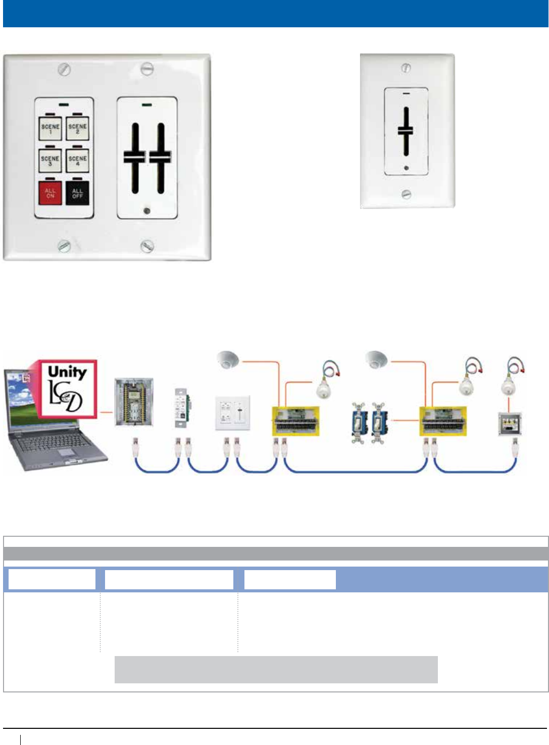
92
www.lightingcontrols.com • 800-345-4448
TheSliderSwitchisonecomponentofacomprehensivedaylightdimmingpackagewiththeMicroPanel-iDIM™. The MicroPanel-iDIM
is part of the 100% digital GR 2400™LightingControlSystem,thatlinksalllightingcontrolsinabuildingintoaunifiedlightingcontrol
solution.
Slider switches
may be mounted
beside a Chelsea
DigitalSwitch to
combine manual
raise/lowerand
scene control
(upto4scenes).
Slider Switchesareavailablewith1or2sliders.
Center decorator-style places are available in white,
ivory, or brushed steel.
Overview
Cat. 5 patch cable with RJ45 connectors • upto127digitaladdresses• up to 4,000 feet
1#18perswitch
and1#18common
3#18 3#18
3#18 3#18
Micro-8
Micro-8
GR 2400
Relay Panel
Laptopcomputerrunning
Unity™Software
2#18
PCC1
PCELL 3WI TZ PCELL 3WI TZ PCELL 2WI
Occ. Sensor
Occ. Sensor
3 Way
Toggle Switch
Chelsea
DigitalSwitch
SLIDER
ORDERING INFORMATION
Slider DigitalSwitch
Switch # of Sliders and Digital / Analog
1DGS=1slideranddigital
2DGS=2slidersanddigital
1ANS=1sliderandanalog
2ANS=2slidersandanalog
Plate Color
PWH=Whiteplate
PIV=Ivoryplate
PST=Stainlesssteelplate
Examples: Slider1DGSPWH=Digitalsinglesliderswitchwithwhiteplate
Slider2DGSPIV=Digitaldualsliderswitchwithivoryplate
93
800-345-4448 • www.lightingcontrols.com
ORDERING INFORMATION
Specifications:
Switch
Bolt™
Digital
Switch
Description: The SwitchBolt DigitalSwitch replaces conventional toggle or push-button switches in installations
where they may be subject to abuse or severe conditions. The SwitchBolt is a virtually indestructible
stainless-steel bolt that mounts on a face plate or in a panel so that only the head of the switch is
exposed.Withatouchofyourfinger,theSwitchBoltcancontrolanyrelay,dimmer,grouporzonein
any GR 2400 panel.
Features: • Idealforsecurity,highabuseandfoodpreparationareas.Faceplatemaybehoseddownifproperly
usedwithgasket.Suitableforindoororoutdooruse
• SwitchBolt DigitalSwitch sits directly on the digital bus
• SwitchBolt DigitalSwitch mountsinanyplateupto1/4"thick.Requires2"minimumdeepbox.
Specify standard single gang plate or contractor may supply own plate
• Hosedownversionavailable
• Multi-gangversionavailable
Optional: • Capableofbeingdigitallyenabled/disabledoverthebus
Boltdimensions: 5/16"(#20thread)x1.75"long
Mountingholediameter: 0.5"
Boltmaterial: Stainlesssteel
Switch plate: Stainless steel 1 gang plate
Max. SwitchBolt
Switch addresses available:
1–119
Addressesperswitch: 1
Switch
GR 2400™
Function: PositiveON,PositiveOFF,Group
Control,Toggle,Bypass,Raise,
LowerorSceneControl
Programming: ViaDTC,viaPCwith
Unity™ Lighting Control
Software
Ambienttemperature: 32–104°F(0–40°C)
Powersupply: Accepts12VDCfrombus
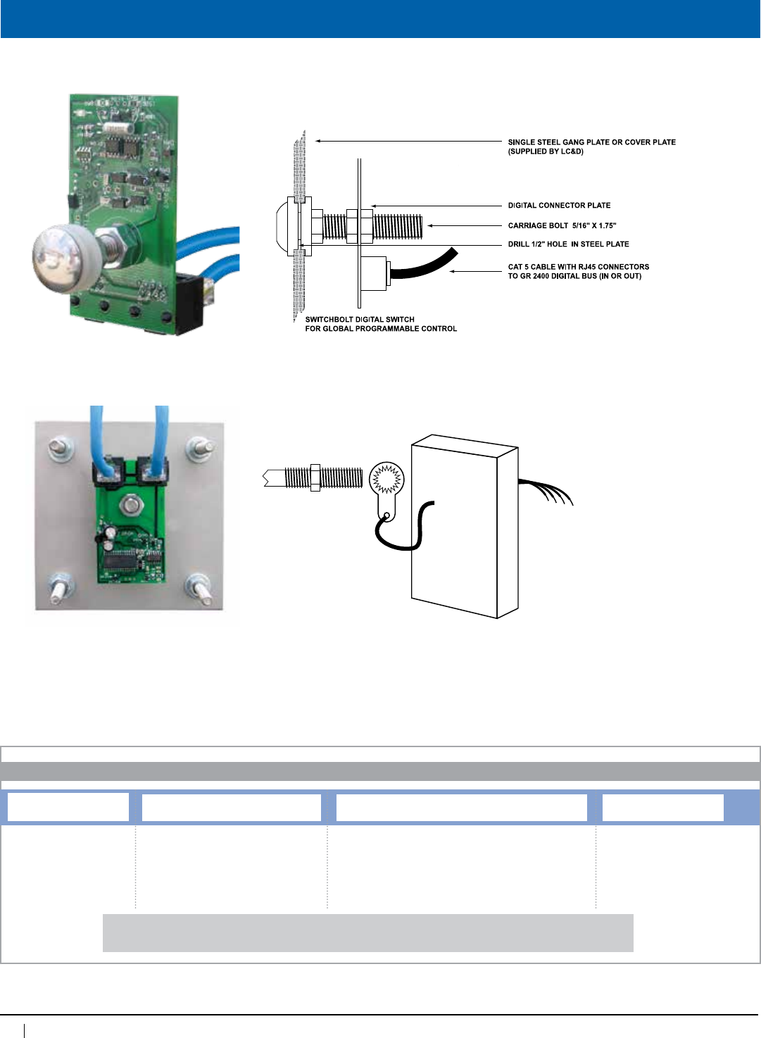
94
www.lightingcontrols.com • 800-345-4448
Hook Up - Details
HoseDownVersion
BackView
(Inthisexamplefaceplateand
backboxsuppliedbyothers)
4 FLY WIRES ARE CONNECTED TO
BUS BY WATER TIGHT
CONNECTORS. SUGGESTED
CONNECTORS ARE “JELLY BEAN”
STYLE TELEPHONE COMPANY
CONNECTORS
ELECTRONICS IN
EPOXY (1.65” X 2.3”)
WITH CONNECTOR TO
SLIP OVER BOLT
MOUNTED IN FACE
PLATE SUPPLIED BY
OTHERS.
SBOLT
ORDERING INFORMATION
SwitchBolt DigitalSwitch
Switch Hose Down
[blank]=Nohosedownoption
HD=Hosedownoption
Plate Type
PSS=Stainlesssteelplate
PBO=Platebyothers
# of SwitchBolts and Digital
1DGS=1boltper1-gangdigitalswitch
2DGS=2boltsper1-gangdigitalswitch
4DGS=4boltsper2-gangdigitalswitch
6DGS=6boltsper3-gangdigitalswitch
Examples: SBOLT1DGSPSS=DigitalSwitchBoltwith1boltandstainlesssteelplate
SBOLT2DGSPSS=DigitalSwitchBoltwith2boltsandstainlesssteelplate
CircuitBoardFrontView
95
800-345-4448 • www.lightingcontrols.com
ORDERING INFORMATION
Plate Type
PSS=Stainlesssteelplate
PBO=Platebyothers
Specifications:
Wireless Photosensor
Description: TheWirelessPhotosensor(PCELLWRI)isdesignedtobeceilingmountedwhereoneofthe
photovoltaic collectors is facing a window or source of light. The photosensor can transmit a signal
toareceiverupto90ftaway.Thephotovoltaiccellmustreceiveatleast20footcandlesoflightfor
severalhoursadaytochargethestoragecapacitor.AWirelessReceiver(GR2400WREC)mustbe
ontheGR2400Buswithinthetransmittingdistance.
Features: •Extendedsensitivityrange
•Transmitsdataevery10secondsiflightlevelchangeisdetected
•UsesSTM110CEnOceanTransmitterModule
•EasyInstallation
•Canbeusedinbothopenloopandclosedloopapplications
•315MHzfrequency
•Optionalcoinbatteryifrequiredformorefrequentupdatesorlowlightlevels
Colors: White
Sensitivity: 1–1000 fc
Dimensions: 3.125"wx2.5"hx.75"d
Mounting: Surfacemountingsubplatemaybetapedorscrewedtosurface
Mayalsobesuspendedontheendofa3/8"thread
Power: Photovoltaic
Humidity: 10–90%non-condensing
Ambienttemperature: 32 –140°F(0–60°C)
EnOcean Wireless Technology
TransmissionPowerMax.10mW
Datarate/Modulation125kbs/ASK
ConformswithFCC15.231andRSS-210forUSAandCanada
Wireless
Photosensor
GR 2400™
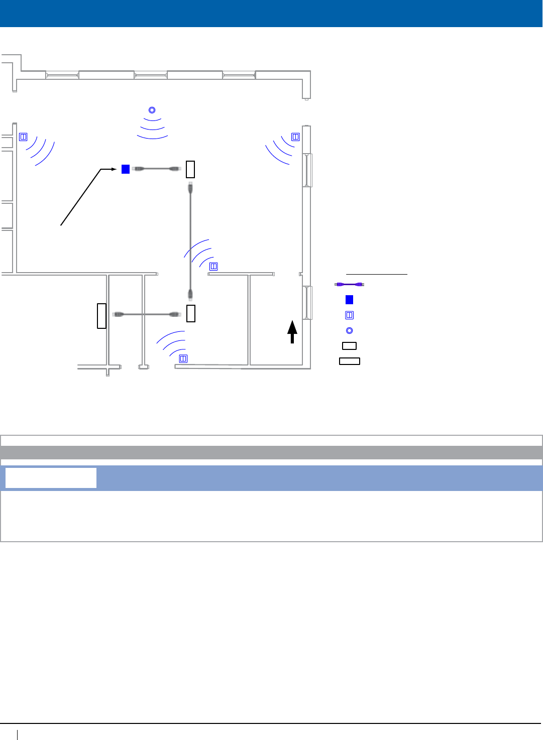
96
www.lightingcontrols.com • 800-345-4448
Drawings
Cat. 5 with RJ45’s
Wireless Receiver
Wireless Switch
Wireless Photosensor
GR 2404/8 MicroPanel (Slave)
GR 2400 Panel (Master)
Symbol Legend:
Accepts communication
from wireless switches
and photocells in multiple
rooms.
Wireless Switch 4
Wireless Photosensor 1
Wireless Switch 3
Wireless Switch 2
Wireless Switch 1
Wireless
Receiver 1
MicroPanel
LCP 2
MicroPanel
LCP 3
Master Panel with DTC Clock
LCP 1
ELECTRICAL ROOM
Notes:
1. Wireless receiver is powered by the digital bus.
2.Wirelessreceivercancommunicatewithupto
14singleswitchesor7doubleswitchesand3
wireless photosensors.
3.Wirelessswitchesandphotosensorsmustnot
bemorethan90ft.fromwirelessreceiver.
4. Switches and receivers must have a minimum
clearanceof12"fromreflectivesurfaces(metal
surfaces,orgridsof“rebar”)toavoidsignal
cancellation.
PCELL WRI
ORDERING INFORMATION
Wireless Photosensor
Wireless Photosensor
N
97
800-345-4448 • www.lightingcontrols.com
ORDERING INFORMATION
Specifications:
Wireless Switch
Description: TheLC&Dwirelessswitchcanbestuckorscrew-mountedontoanyflatsurface,providinginstant
controlofanyofLC&D’slightingcontrolsystems.Everytransmitterismanufacturedwithaunique
32-bitaddressallowingmultiplewirelessswitches.TheWirelessReceiversitsontheGR2400bus
and is mounted within a reasonable distance from the transmitting Wireless Switches. The Wireless
Switchisfullydigital,maintenancefreeanddoesnotrequirebatteries.(Required:WirelessReceiver
GR2400WREC)
Features: •90ftmax.indoorrange
•1rockeror2rockersperswitch
•Eachrockerpositioncanbeprogrammed:
□On
□Off
□Raise
□Lower
•Easysetup
•315MHz(UnlicensedFrequencyBand)
Colors: White
Mounting: Surface,stickerorscrewed
Power: Notrequired(nobatteries,nowires)
Humidity: 10–90%non-condensing
Ambienttemperature: 32–140°F(0–60°C)
Wireless
Switch
GR 2400™
Format: EnOceanWirelessTechnology
TXPowerMax.: 10mW
Datarate/Modulation: 125kbs/ASK
Certifications: ConformswithFCC15.231and
RSS-210forUSAandCanada
}
i.e. for dimmer
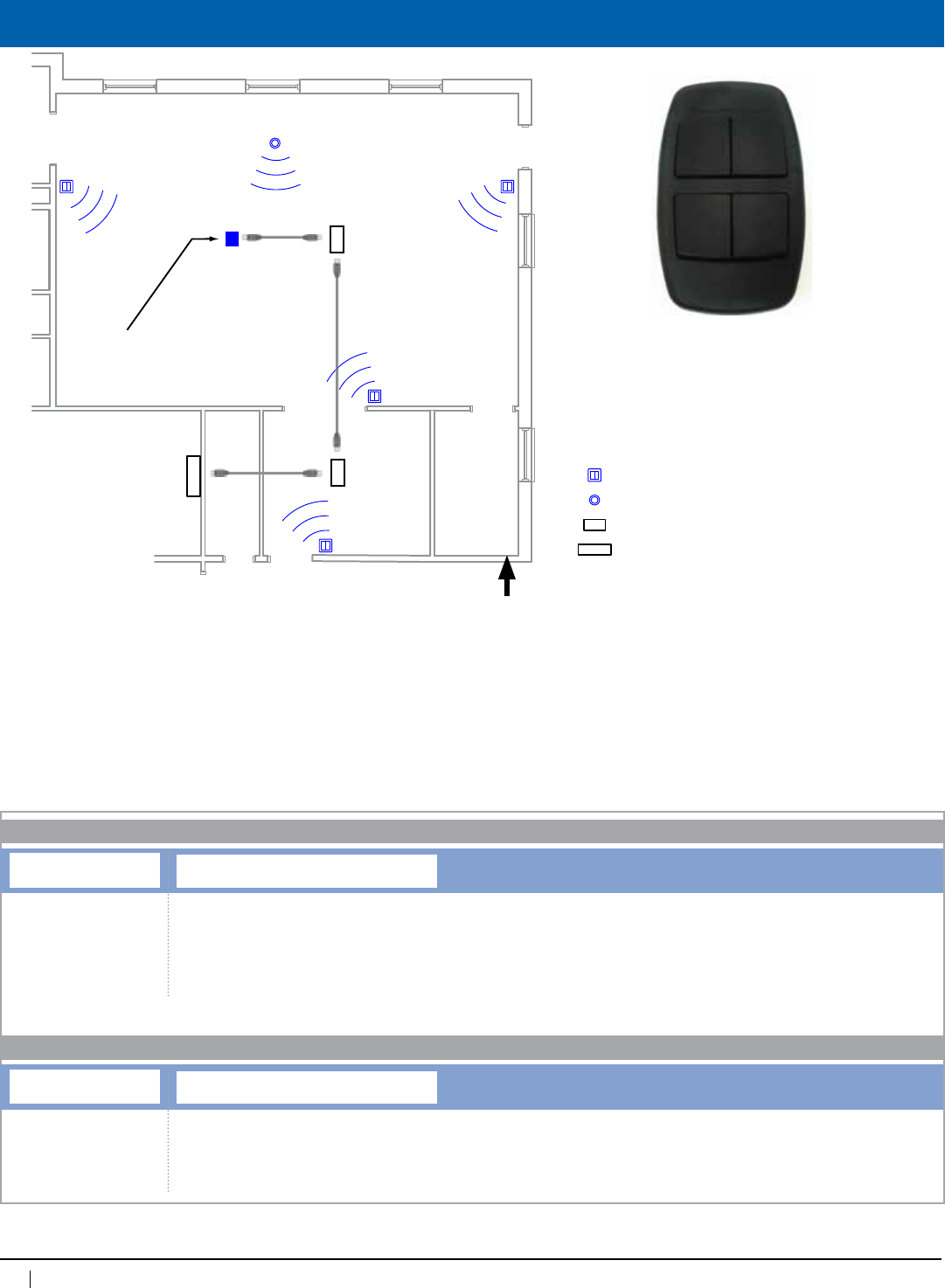
98
www.lightingcontrols.com • 800-345-4448
Drawings
Notes:
1. Wireless receiver is powered by the
digital bus.
2. Wireless receiver can communicate
with up to 28 single switches or 14
double switches and 3 wireless
photosensors.
3. Wireless switches anf photosen-
sors must not be more than 100 ft.
from wireless receiver.
4. Switches and receivers must have
a minimum clearance of 12” from
reflective surfaces (metal surfaces,
or grids of “rebar”) to avoid signal
cancellation.
Cat. 5 with RJ45’s
Wireless Receiver
Wireless Switch
Wireless Photosensor
GR 2404/8 MicroPanel (Slave)
GR 2400 Panel (Master)
Symbol Legend:
Accepts communication
from wireless switches
and photocells in multiple
rooms.
Wireless Switch 4
Wireless Photosensor 1
Wireless Switch 3
Wireless Switch 2
Wireless Switch 1
Wireless
Receiver 1
MicroPanel
LCP 2
MicroPanel
LCP 3
Master Panel with DTC Clock
LCP 1
ELECTRICAL ROOM
Notes:
1. Wireless receiver is powered by the
digital bus.
2.Wirelessreceivercancommunicatewith
upto14singleswitchesor7double
switchesand3wirelessphotosensors.
3.Wirelessswitchesandphotosensorsmust
notbemorethan90ft.fromwireless
receiver.
4. Switches and receivers must have a
minimumclearanceof12”fromreflective
surfaces(metalsurfaces,orgridsof
“rebar”)toavoidsignalcancellation.
Notes:
1. Wireless receiver is powered by the digital bus.
2.Wirelessreceivercancommunicatewithupto14singleswitchesor7doubleswitchesand3wirelessphotosensors.
3.Wirelessswitchesandphotosensorsmustnotbemorethan90ft.fromwirelessreceiver.
4.Switchesandreceiversmusthaveaminimumclearanceof12"fromreflectivesurfaces(metalsurfaces,orgridsof“rebar”)toavoidsignal
cancellation.
WRSWT
ORDERING INFORMATION
Wireless Digital Switch
Switch Button Type/Color
1BWH=1buttonrocker,singlegang,classicstyle,whitefaceplate
2BWH=2buttonrocker,singlegang,classicstyle,whitefaceplate
1BBK=1buttonrocker,singlegang,classicstyle,blackfaceplate
2BBK=2buttonrocker,singlegang,classicstyle,blackfaceplate
1PWH=1buttonswitch,singlegang,padstyle,whitefaceplate
2PWH=2buttonswitch,doublegang,padstyle,whitefaceplate
N
WRSWT
Hand Held Remote
Remote
HHRBBK=Blackhandheldremote
HHRBWH=Whitehandheldremote
Hand Held Remote
99
800-345-4448 • www.lightingcontrols.com
ORDERING INFORMATION
Specifications:
Wireless Occupancy Sensor
Description: The Wireless Occupancy Sensors communicate to the lighting control system to automatically turn
off lighting when the space is not in use. The occupancy sensors are powered by built-in solar cells
andusepassiveinfrared(PIR)motiondetectors
Features: •EasyInstallation
•Transmitsdataevery10secondsiflightlevelchangeisdetected
•Optionalcoinbatteryifrequiredformorefrequentupdatesorlowlightlevels
Colors: White
Dimensions: 5.83"wx2.52"hx1.8"dWallmountsensor
6.5”wx2.36”hx1.47”dCeilingmountsensor
Mounting: Surfacemountingsubplatemaybetapedorscrewedtosurface
Power: Photovoltaic
Humidity: 10–90%non-condensing
Ambienttemperature: 32 –140°F(0–60°C)
EnOcean Wireless Technology
ConformswithFCC15.231andRSS-210forUSAandCanada
Wireless
Occupancy
Sensor
GR 2400™
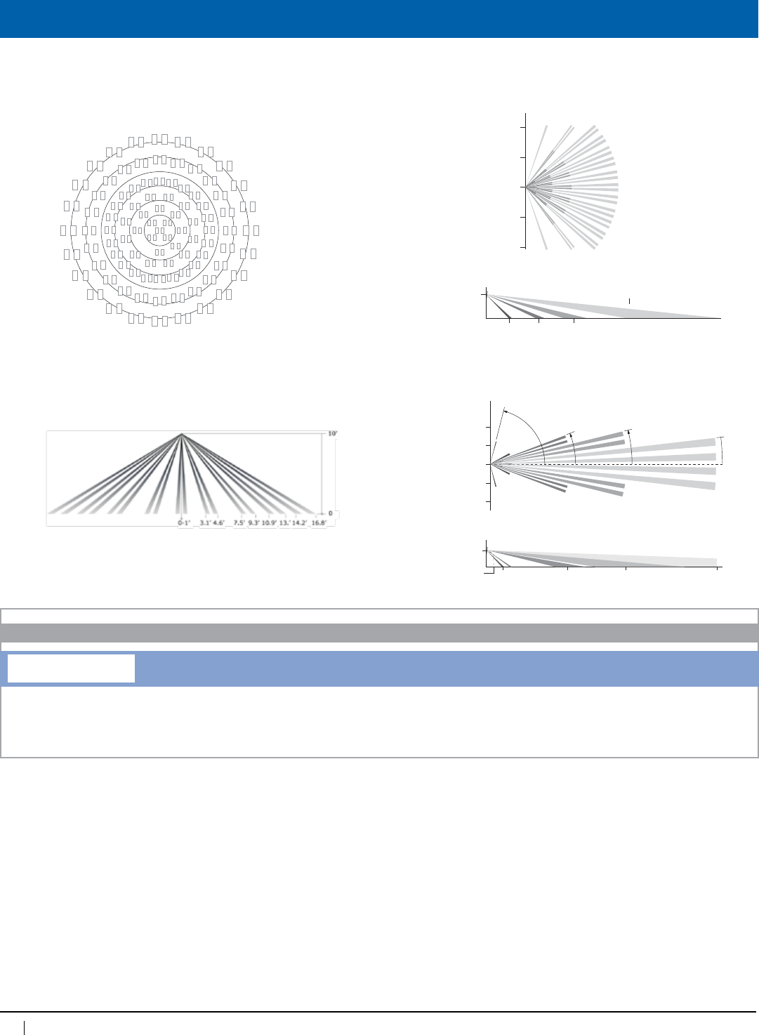
100
www.lightingcontrols.com • 800-345-4448
Sensor Coverage Patterns
Cat. 5 with RJ45’s
Wireless Receiver
Wireless Switch
Wireless Photosensor
GR 2404/8 MicroPanel (Slave)
GR 2400 Panel (Master)
Symbol Legend:
Accepts communication
from wireless switches
and photocells in multiple
rooms.
Wireless Switch 4
Wireless Photosensor 1
Wireless Switch 3
Wireless Switch 2
Wireless Switch 1
Wireless
Receiver 1
MicroPanel
LCP 2
MicroPanel
LCP 3
Master Panel with DTC Clock
LCP 1
ELECTRICAL ROOM
ORDERING INFORMATION
Wireless Occupancy Sensor
Type
WRCM = Wireless ceiling mount occupancy sensor
WRWM = Wireless wall mount occupancy sensor
Occupancy Sensor – Ceiling Mounted • Installation Guide page 2 of 4
Verve™ Living Systems
Coverage Diagrams
Tip: To provide coverage for very high ceilings, a wall sensor can
be incorporating in the plan for complete coverage.
Installing estimated time: 20 minutes
The occupancy sensor can be mounted on most ceilings with the
provided screws, or mounted on dropped ceilings, using the
provided wire bracket.
1. Decide where you want to install the occupancy sensor.
Tip: For visual alignment, orient the sensor parallel to one of
the walls.
2. Remove the mounting plate from the sensor.
3. Decide which of the two installation options is appropriate.
Screw Mounting Plate to the Ceiling
a. Hold the mounting plate in place on the ceiling and use a
pencil to lightly mark two small dots for the screw drill
points.
b. Drill two holes with a 3/16” drill bit and insert the wall
anchors.
c. Insert the first screw
loosely and level the
mounting plate.
d. Insert the second screw
and then hand-tighten the
first screw.
Mount Using the Wire Bracket
a. Remove the ceiling tile where you want to mount the
sensor.
b. Place the mounting plate squarely on the ceiling tile and
use the wire to mark two points for the holes.
c. Punch two small holes through the ceiling tile at the
marked points.
d. Insert the wire bracket
through the two holes in
the mounting plate.
Make sure the ends are
roughly even.
e. Feed the wires through the
holes in the ceiling tile.
f. On the front of the ceiling
tile, flatten the wire bracket
so it is snug against the
mounting plate.
g. On the back of the ceiling
tile, twist the wires
together to hold the
mounting plate securely.
h. Replace the ceiling tile.
4.5m
3m
1.5m
5’
10’
15’
Top View
Side View
1’ 3.1’ 4.6’ 7.5’ 9.3’ 10.9’ 13.0’ 14.2’ 16.8’
0
10’
0
0-1’ 3.1’ 4.6’ 7.5’ 9.3’ 16.8’14.2’13.’10.9’
10’
0
Verve™ Living Systems
Installation Guide
Model: VOSW
Occupancy Sensor – Wall Mounted
Product Description
The Verve wall-mounted Occupancy Sensor saves energy and
adds convenience by accurately detecting when an area is
occupied or vacant.
It is a wireless, solar-powered sensor that detects occupancy
using passive infrared (PIR) heat and motion sensing. The sensor
transmits RF messages to Verve lighting, HVAC, and outlets to
use energy more efficiently.
Features Include:
• Sends wireless messages to other devices whenever motion
is detected
• Harvests ambient solar energy to power the sensor and
wireless communication
• Mounts flush on the wall or in a corner; adjustable ceiling
corner bracket sold separately
• Works with other sensors for enhanced occupancy tracking
• Interchangeable lenses for tailored sensor coverage
• Built-in tests to confirm operation at installed location
• Supplemental battery option for extreme low-light failover
Specifications
Planning
Take a moment to plan for the sensor’s successful operation and
optimal communication with other system components.
Remove the sensor from its packaging and place it in a strong
light to provide the required startup charge.
Tip: To quickly ensure the sensor energy storage is fully charged,
insert a CR2032 battery for 30 seconds.
• Ensure the location provides consistent and adequate light
• Install with the appropriate lens for the required coverage
• Locate the sensor between 8 and 10 ft (2.4 to 3 m) high with
an unobstructed view of the space
• For wide angle coverage, locate the sensor where traffic
moves across the detection pattern, not in and out
• Provide a minimum clearance of 4 ft. (1.2m) away from heat
sources, light bulbs, forced air, or ventilation systems
• Consider the construction materials in the space and
obstacles that may interfere with RF signals
Package Contents
• Occupancy Sensor
• 2 screws, 2 wall anchors
• 1 wide angle lens
(installed)
• 1 long range lens
Tools Required
• Power drill, 3/16” bit
• Screwdriver
• Leveling tool
• Light meter
• Battery (CR2032) for
testing
64mm
148mm
5.8”
2.5”
45.7mm
1.8”
28mm
1.1”
Button interface
Lens
Solar cell
Power Supply Solar harvesting
supplemental battery option
Transmission Range 80 ft. (25 m)
Radio Frequency 315 MHz
Light Required to
Maintain Operation
15 lux for 6 transmissions/hour
50 lux for 30 transmissions/hour
100 lux for 60 transmissions/hour
Charge Time to
Startup
1 minute @ 15 lux
5 seconds @ 200 lux
Charge Time to
Fully Charge
3 hours @ 200 lux (after startup)
6 hours @ 200 lux (cold start)
Fully Charged Operating
Life in Darkness
48 hours
Dimensions 5.83” L x 2.52” W x 1.8” D
(148mm x 64mm x 45.7mm)
Weight 4.09oz. (116 g)
Environment • Indoor use only
• 14° to 131°F (-10° to 55°C)
• 20% to 95% relative humidity
(non-condensing)
Agency Compliance FCC and I.C.
Occupancy Sensor – Wall Mounted • Installation Guide page 2 of 4
Verve™ Living Systems
Sensor Range
A single occupancy sensor provides sufficient coverage for most
applications. Make sure the sensor is installed with the correct
lens type for the area.
Note: For some applications, multiple sensors may be required
to provide complete coverage.
For detailed information, see the Verve System Planning Guide
at www.vervelivingsystems.com.
Wide Angle Coverage
Long Range Coverage
Installing estimated time: 20 minutes
The mounting plate can be installed flush to the wall or angled in
a corner.
1. Remove the mounting plate from the sensor assembly.
2. Using a level and a pencil, lightly mark two small dots to
align the upper edge of the mounting plate.
3. Decide which of the two installation options is appropriate.
Flush to the Wall
a. Orient the mounting plate
using the pencil marks. Mark
the two mounting screw
drill points.
b. Drill two holes with a
3/16” drill bit and insert the
wall anchors.
c. Insert the first screw loosely
and level the mounting
plate.
d. Insert the second screw and
then hand-tighten the first screw.
Angled in a Corner
a. Orient the mounting plate using the pencil marks.
b. Carefully drill through two
of the four blind holes on
the angled sides of the
mounting plate (one on
each side).
c. Mark the two mounting
screw drill points and drill
two pilot holes with a
3/16” drill bit and insert the
wall anchors.
d. Insert the two screws and
hand-tighten them.
5. Fit the sensor into the groove at the bottom of the
mounting plate and close the top.
16ft (5m)
33ft (10m)
33ft (10m)
16ft (5m)
0
19.4° To p Vi ew
50ft
6.8ft
(2.1m)
6ft 15ft 25ft
Side View
Top View
16ft
8ft
0
77°
21.5° 14° 6.5°
29°
16ft
8ft
center line
6.8ft
(2.1m)
3ft
(1m)
7ft
(2.2m)
10ft
(3m)
60ft
(18.3m)
100ft
(30.5m)
35ft
(10.7m)
Side View
Blind holes
CeilingMountOccupancySensor WallMountOccupancySensor
Side View
101
800-345-4448 • www.lightingcontrols.com
Specifications:
Wireless Door/Window Sensor
Wireless
Door/Window
Sensor
GR 2400™
Description: TheWindow/DoorSensorcommunicateswirelesslytotheLC&Dsystemwheneveritdetectsthat
adoororwindowhasbeenopenedorclosed.TheWirelessDoor/WindowSensorcanbeeasily
mountedonanystandarddoororwindowframetodisableHVACorotherelectricloads.Thesensor
is completely self-powered by harvesting ambient solar energy so there are no wires to run or
batteries to replace, reducing installation time and eliminating the need for on-going maintenance.
Features: •Extendedsensitivityrange
•Integratedsolarcellpowersthesensorwithnobatteriesorwires
•Removablemountingplateallowsforeasyinstallation
•Optionalbatteryforlowlightlevelinstallations
Colors: White
Dimensions: 3.15"wx0.83"hx0.59"dsensor
3.15”wx0.47”hx0.5”dmagnet
Mounting: Surfacemountingsubplatemaybetapedorscrewedtosurface
Power: Photovoltaic
Humidity: 10–90%non-condensing
Ambienttemperature: 32 –140°F(0–60°C)
EnOcean Wireless Technology
TransmissionPowerMax.10mW
Datarate/Modulation125kbs/ASK
ConformswithFCC15.231andRSS-210forUSAandCanada
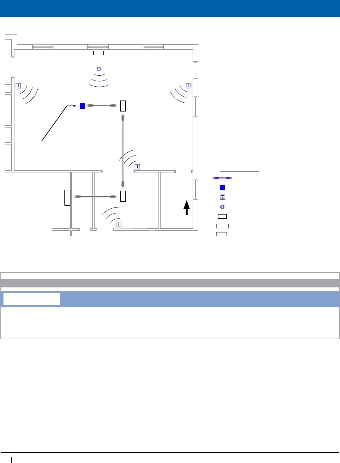
102
www.lightingcontrols.com • 800-345-4448
Drawings
Cat. 5 with RJ45’s
Wireless Receiver
Wireless Switch
Wireless Photosensor
GR 2404/8 MicroPanel (Slave)
GR 2400 Panel (Master)
Symbol Legend:
Accepts communication
from wireless switches
and photocells in multiple
rooms.
Wireless Switch 4
Wireless Photosensor 1
Wireless Switch 3
Wireless Switch 2
Wireless Switch 1
Wireless
Receiver 1
MicroPanel
LCP 2
MicroPanel
LCP 3
Master Panel with DTC Clock
LCP 1
ELECTRICAL ROOM
Notes:
1. Wireless receiver is powered by the digital bus.
2.Wirelessreceivercancommunicatewithupto
14singleswitchesor7doubleswitchesand3
wireless photosensors.
3.Wirelessswitchesandsensorsmustnotbe
morethan90ft.fromwirelessreceiver.
4. Switches and receivers must have a minimum
clearanceof12"fromreflectivesurfaces(metal
surfaces,orgridsof“rebar”)toavoidsignal
cancellation.
WRCS
ORDERING INFORMATION
Wireless Contact/Window/Door Sensor
Wireless Contact Sensor
N
Wireless Window Sensor
Wireless Window Sensor

103
800-345-4448 • www.lightingcontrols.com
Specifications:
Wireless Receiver
Description: TheWirelessReceiverworkstogetherwiththeWirelessSwitch,theWirelessOccupancySensor,the
WirelessDoor/WindowSensor,theWirelessHandheldRemoteand/ortheWirelessPhotosensor.The
GR2400WirelessReceiverispoweredbytheGR2400bus(12VDC).TheunititselfiswiredwithCat.5
cables and RJ-45 connectors. Each receiver is programmable to allow up to 14 Wireless Switches when
noWirelessPhotosensorsareused,orupto7WirelessSwitchesandupto3WirelessPhotosensors
whenphotosensorsareused.Aswithanywirelesssystem,caremustbetakentoensurethatthesignalis
receivedfromeachofthewirelessdevices.Thereceiverlocationmaybemovedtooptimizethesystem.
Features: •120Ohmsterminationresistance(Usesslideswitchtoactivatetheterminator)
•RCM130CEnOceanReceiverModule
•Takes2consecutivebusaddresses
•Easytoprogram
•14WirelessRockerSwitches(Single)(WRSWT1BWH)
• 7WirelessRockerSwitches(Double)(WRSWT2BWH)
• 3WirelessPhotosensors(PCELLWRI)
• PoweredbytheGR2400SystemBus
• 315MHzFrequency
• 15cmantenna
Dimensions: 2.25"wx3.625"hx1"d(casing)
Mounting: Surface
WirelessRXPower: +12VDCbuspower
Humidity: 10 –90%non-condensing
Ambienttemperature: 32–150°F(0–66°C)
Wireless
Receiver
GR 2400™
Format: EnOceanWirelessTechnology
Busphysicallayer: RS485(GR2400bus)
BusConnector: RJ45Connectors
Programming: ViaDTC
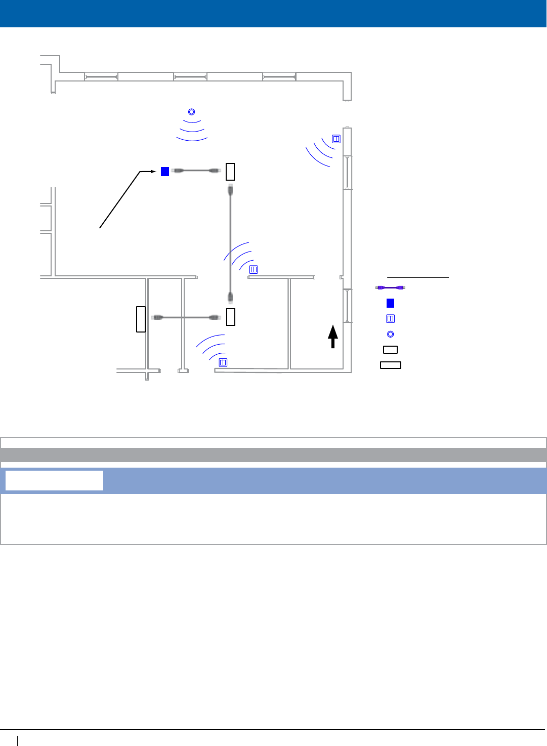
104
www.lightingcontrols.com • 800-345-4448
Drawings
Cat. 5 with RJ45’s
Wireless Receiver
Wireless Switch
Wireless Photosensor
GR 2404/8 MicroPanel (Slave)
GR 2400 Panel (Master)
Symbol Legend:
Accepts communication
from wireless switches
and photocells in multiple
rooms.
Wireless Switch 4
Wireless Photosensor 1
Wireless Switch 3
Wireless Switch 2
Wireless Switch 1
Wireless
Receiver 1
MicroPanel
LCP 2
MicroPanel
LCP 3
Master Panel with DTC Clock
LCP 1
ELECTRICAL ROOM
Notes:
1. Wireless receiver is powered by the digital bus.
2.Wirelessreceivercancommunicatewithupto
14singleswitchesor7doubleswitchesand3
wireless photosensors.
3.Wirelessswitchesandphotosensorsmustnot
bemorethan90ft.fromwirelessreceiver.
4. Switches and receivers must have a minimum
clearanceof12"fromreflectivesurfaces(metal
surfaces,orgridsof“rebar”)toavoidsignal
cancellation.
GR2400 WREC
ORDERING INFORMATION
Wireless Receiver
Wireless Receiver
N
Power Supply:
Specify120V,277V
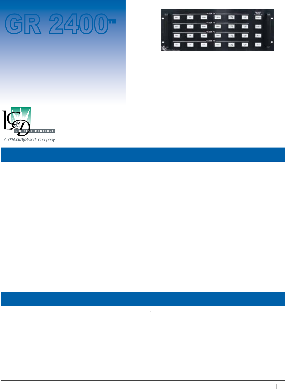
105
800-345-4448 • www.lightingcontrols.com
ORDERING INFORMATION
• Prisons
• StageWorkLights
• NurseCallStations
• Building-WideControls
• Secureareacontrols
Specifications:
Custom Switches and Controls
Description: Aspartofits100%digitallightingcontrols,LC&Dofferscustommanufacturedswitch-banksandtouch-
screenbasedcontrol.Wecanmatchexistingequipmentorassistindesigningacompletelycustomproduct
to meet almost any requirement. Custom fabrication is available in a variety of materials including stainless
steel,aluminum,lexan,orvariouslaminates.
Hundredsofdifferentswitchtypesareavailable,withandwithoutpilotlights,orwithexternalLEDpilot
lights.Alsoavailableareboltswitches,mushroomswitches,bi-colorpilot-litswitchesandmore.
Touch-screen controls are interactive and available with multiple virtual pages and include real-time status
(ONorOFF)ofanyarea.Addnewcustomgraphicsatanytimetomeetchangingconditionsoruse.
Features: • Availableforindoor,outdoororharshenvironments
• Matchnewcontrolstoexistingcontrols
• Linkeachswitch-bankorconsoleviaCat.5patchcablewithRJ45connectors
• Manufacturedtoanyspecification
• Mixtouch-screensandpushbuttonswitchesinasingleconsole
• Centrallycontrolalllightinginafacility—evenovertheinternet
• Digitalorkey-basedenableordisable
Applications:
Function: On,Off,Toggle,Mixedmode,Dimup,Dim
down,Raise,Lower,Interactionwithother
equipment including thermostats, security,
alarms, motor controls and more
Programming: AtDTC,orviaPCwith
Unity™ Lighting Control Software
Custom
Switch
GR 2400™
Powersupply: Accepts12VDCfrombus
Onboard power supply available for
largeconsoles(120VAC,277VACor
347VAC)
Busphysicallayer: RS485(GR 2400bus)
Connector: Cat. 5 patch cable with RJ45
connectors
Dimensions,mounting,otherratingsincludingNEMAratingsallperownerspecs.
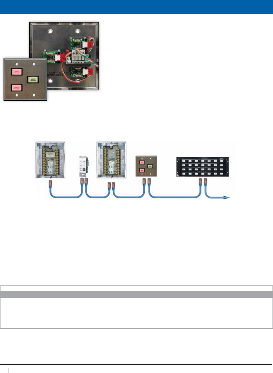
106
www.lightingcontrols.com • 800-345-4448
Theatrical-gradework-lightswitch.
Custommanufacturedforeachproject.Rackmounting,consolemounting,andwall
mountinginsingle,ormulti-gangboxesarethemountingoptionsavailable.Positive
annunciationtoindicatestatusofloads(green=ON,red=OFF).Linkhundredsof
buttonstotheGR2400systemwithCat5.cable.
Contact factory for specs, ordering codes and pricing
Overview
Cat.5patchcablewithRJ45connectors•Upto127digitaladdresses•Upto4,000ft.
ORDERING INFORMATION
Custom Switches and Controls
107
800-345-4448 • www.lightingcontrols.com
ORDERING INFORMATION
Outdoor Photosensors
The hood protects the photosensor from
directexposuretothesun.The Outdoor
Digital Photosensor is usually roof-
mounted and aimed North.
Fordaylightharvestingapplications,refer
to the Indoor Digital Photosensor.
Operating range: 0–1000 fc
Programming at: DTC
PC(with Unity™
Lighting Control
Software)
Specifications:
Outdoor Digital Photosensor
Description: The Outdoor Digital Photosensor isdesignedforsingle-zoneormulti-zoneoutdoorlightingcontrol
applications.Itsglobalcontrolabilitymakesitidealforbothsimpleandcomplexsite-lighting
controls. The GR2400 PCC1 2WOisthe2-wireoutdoorphotosensorshippedwithaphotocellcontrol
cardwhichmaybelocatedanywhereontheGR2400Bus.ThePCELL 2WO is shipped without a con-
trolcardtobepluggeddirectlyintoaBlueBoxMastercontrolcard.
Features: • ReadoutofthephotosensorisdigitallydisplayedattheDTCandremotelyataPCoperatingUnity™
Lighting Control Software
• TheGR2400 PCC1 2WO may be programmed with up to 14 different trigger points, each controlling
auniquerelaygroupatdifferentONandOFFlightlevelsinasmanyas64relaypanels.
• ThePCELL 2WO operates with a single schedule with a single trigger point to provide photocell ON,
timeclockOFFcontroltoaGR1400system.Thiswilloperateonanyrelayonthebus.
• Totallysealedandsuitable for wet locations
Photosensor
GR 2400™
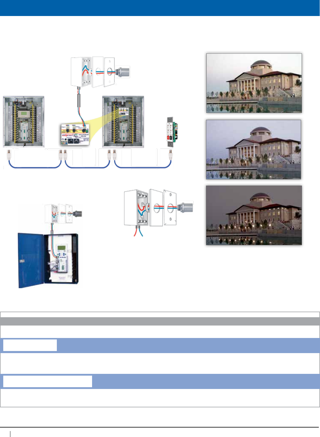
108
www.lightingcontrols.com • 800-345-4448
Lightingcanbestaggeredonasoutdoor
light levels decrease with a single
photosensor.
Single Line
2#18AWG
2#18AWG
PCELL2WO
GR2400™ Relay
Panel
Chelsea
DigitalSwitch™
Cat.5patchcable•upto4,000ft.•upto127digitaladdresses
Global Photosensor
Global Photosensor
GR2400PCC1
Photosensor input
8V(common)
BellBoxor
outdoor
rated
enclosure
PCELL 2WO
PCELL 2WO
TheBlueBox™
PCELL 2WO
GR2400 PCC1 2WO
ORDERING INFORMATION
Outdoor Digital Photosensor
Two-Wire Outdoor Photosensor for GR 1400 system
Two-Wire Outdoor Photosensor with PCC-1 control card for GR 2400 system
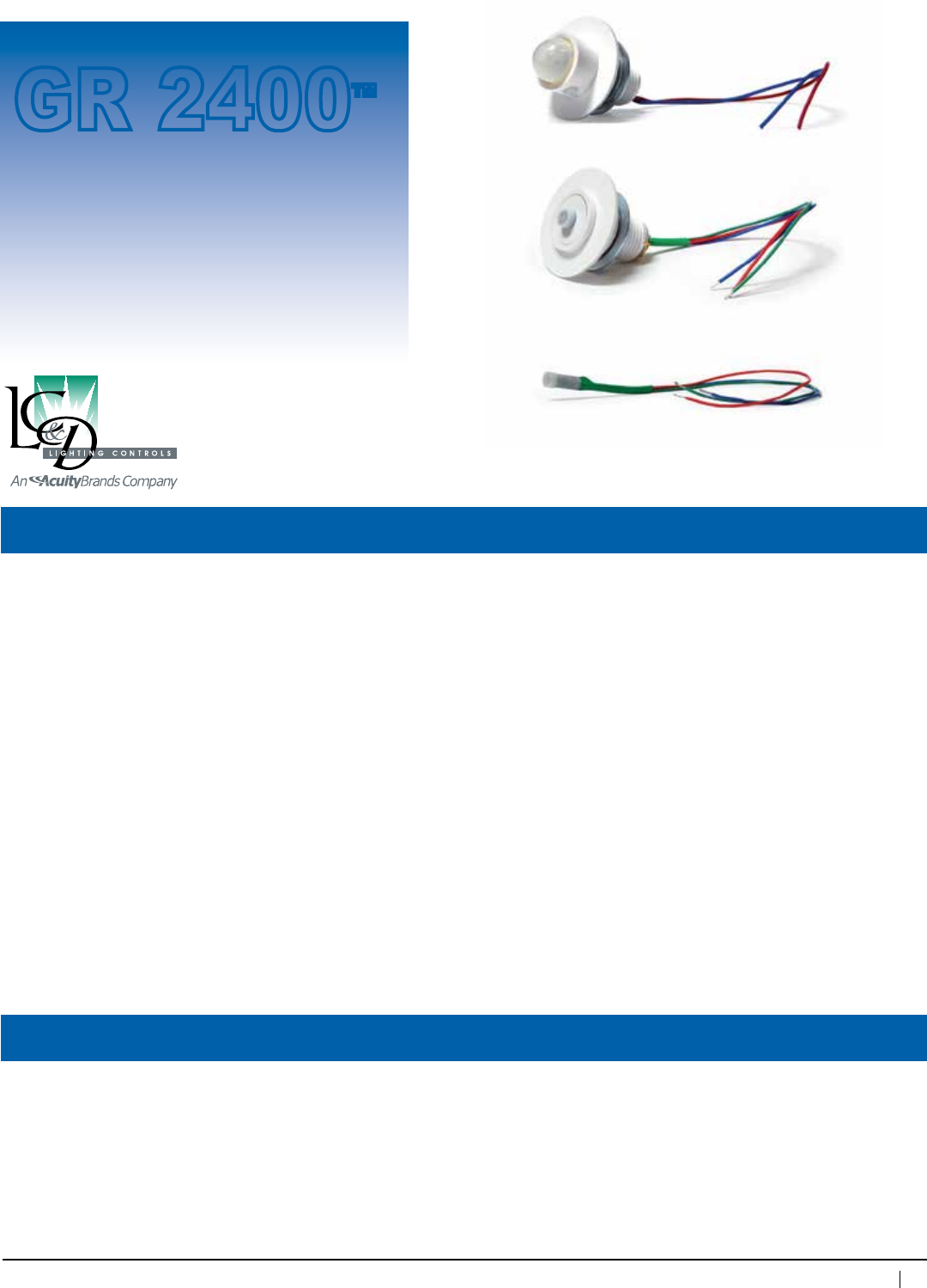
109
800-345-4448 • www.lightingcontrols.com
ORDERING INFORMATION
Spectral sensitivity: Similar to human eye
Operatingrange: 0–1000fcfor2-wire
0–100fcfor3-wire
Programmingat: DTCw/PC(withUnity™
Lighting Control
Software)
Specifications:
Indoor Digital Photosensors
Description: TheIndoorDigitalPhotosensorshaveanextendedsensitivityrangethatallowsittobeusedin
almostanylocationwithoutneedingadjustmentforthereflectivityoftheenvironment.Additionally,
itsdualhousingconstructionallowsittobeusedasafull-sizedsensororthecentersectionmaybe
separatedforadiminutiveceilingfootprint.TheIndoorDigitalPhotosensorcomesinfourstyles:
2-Wire Global Photosensor: Photosensors when combined with a photocell card, have up to 14 dif-
ferenttriggerpoints,eachcontrollingauniquerelaygroupinasmanyas64relaypanels.Moreover,
eachdimmer(0-10Vor120V“phase”)maybeseparatelycontrolledtomaintainauniquelightlevel.
3-Wire Local Photosensor:TentozerousedwiththeMicroPanel or other integrated distributed
controlpanelswhichhaveon-boardphotosensorinputs.ZerototenusedwithXPointdevices.
3-Wire Local Slimline Photosensor:Sameas3-WireLocalPhotosensorbutwithsmallerfootprint,
makesitidealformountingdirectlytoluminaires.
2-Wire Global Slimline Photosensor:Sameas2-WireLocalPhotosensorbutwithsmallerfootprint,
makesitidealformountingdirectlytoluminaires.
Features: • Smallanddiscreteceilingmountorfixturemount
• Extendedsensitivityrange;noadjustmentneeded
• Canbeusedinbothopenloopandclosedloopapplications
• Lowvoltagepower
Photosensor
GR 2400™
2-Wire Global
3-Wire Local
3-Wire Local Slimline
Max.humidity: 10 – 90%non-condensing
Ambienttemperature: 32–104°F(0–40°C)
Voltage: 3-wireoperateson12–30VDC
2-wirepoweredby
PhotosensorInputCard
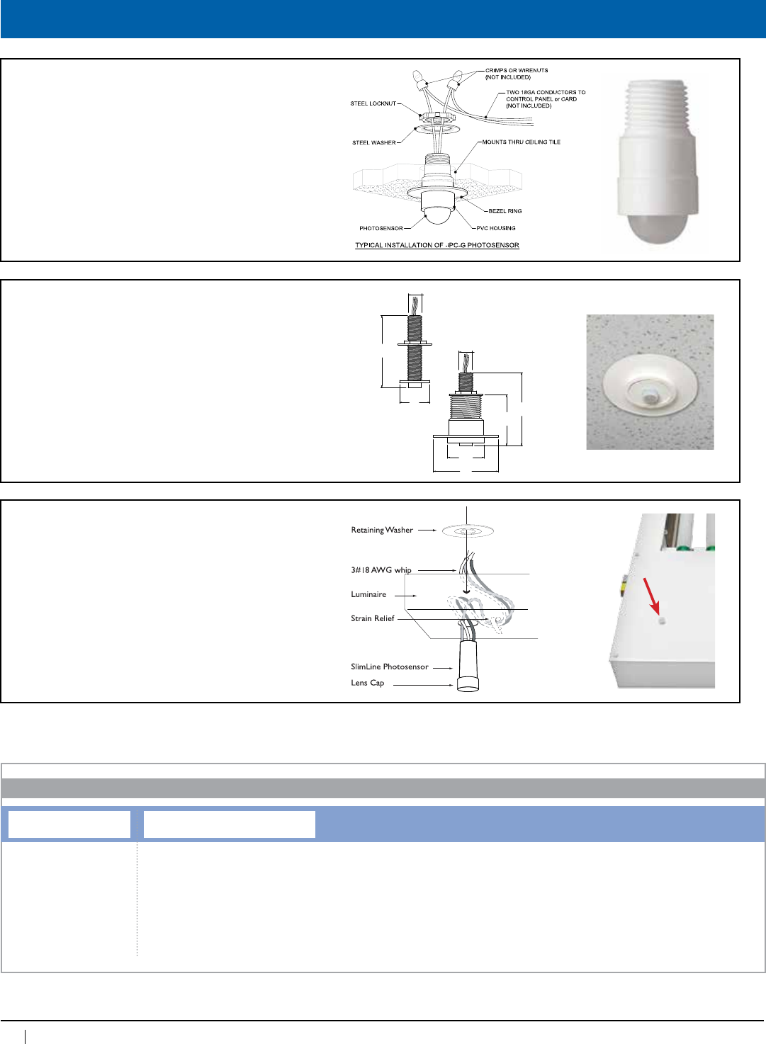
110
www.lightingcontrols.com • 800-345-4448
Drawings
Global Indoor Photosensor
2-Wire Indoor
• Global Photosensor
• Requires PCC3 control card
Local Indoor Photosensor
3-Wire Indoor
• Local Photosensor for MicroPanels
• Full Daylight Harvesting Features
1 1/4"
11/16"
17/8"
11/2"
7/8"
1 1/4"
Universal Indoor
Photosensor
in luminaire
Luminaire
configuration
Ceiling mount
configuration
The Universal Indoor Photosensor is ideal for
either ceiling placement or mounting into an
indirect luminaire. It should be mounted so that it
can “see” a surface that represents the contribu-
tion of both electric light and daylight in the
space. If placed in a luminaire, the photosensor
and wiring must be separated from the high
voltage compartment.
Universal Indoor
Photosensor in ceiling
.385”
.385”
Standard
Ceiling Mount
Conguration
Tight Space
Ceiling Mount
Conguration
Local & Global
Indoor Photosensor
SlimLine 2 & 3-Wire Indoor
• Local Photosensor for MicroPanels
• Global Photosensor for PCC3
• Miniature Prole .276" dia. (7mm)
hole in Luminaire
PCELL
ORDERING INFORMATION
Indoor Digital Photosensor
Photosensors Type and Subtype
2WI=TwoWireIndoor
3WITZ=ThreeWireIndoor,TentoZero
3WIZT=ThreeWireIndoor,ZerotoTen
3WISLITZ=ThreeWire,SlimlineIndoor,TentoZero
3WISLIZT=ThreeWire,SlimlineIndoor,ZerotoTen
2WISLI=SlimlineIndoor,TwoWireIndoor
Note: 2WI Requires PCC3
control card: GR2400 PCC3
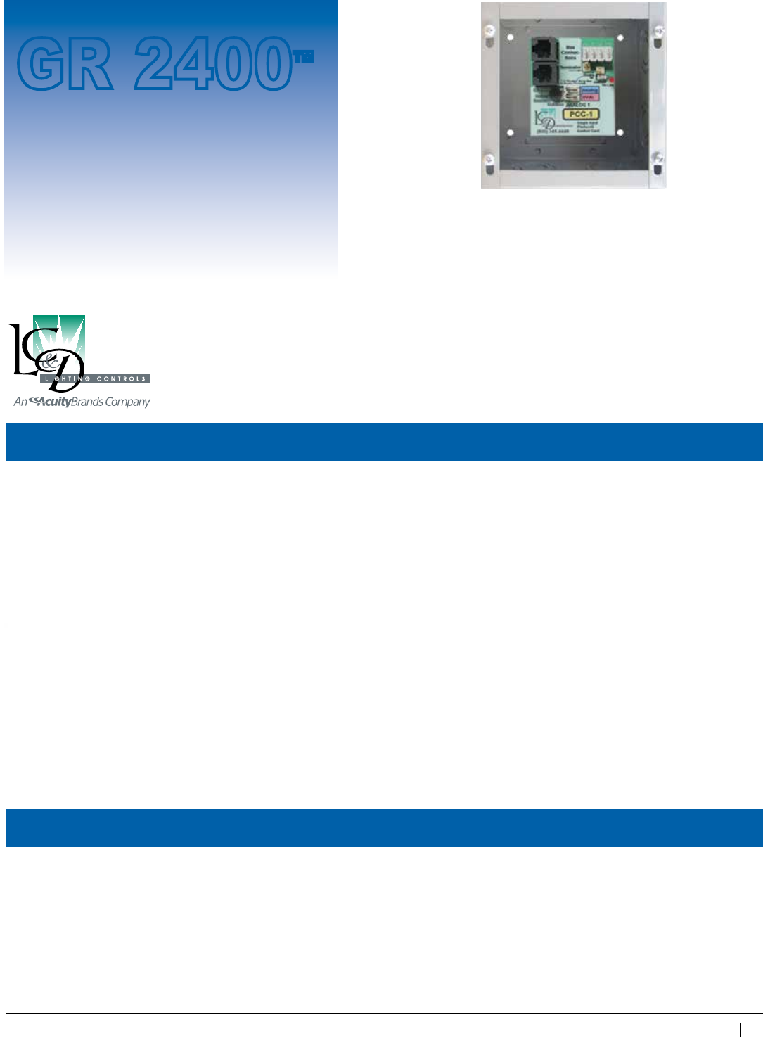
111
800-345-4448 • www.lightingcontrols.com
Specifications:
Photosensor Input Cards
Description: Photosensorinputcardwhicha)convertsthesignalofaphotosensorintoadigitalstream,andb)stores
“global”switchingtriggers.Triggersareglobal“On”and“Off”commandsprogrammedatauniquelight
level,eachwithauniquegroupofrelays,smartbreakersordimmers.
ThePCC1isusedforoutdoorphotosensors(PCELL2WO)andhasasinglephotosensorinput.
ThePCC3isusedforindoorphotosensors(PCELL2WI)andhasinputsforupto3separate
photosensors.
Features: •LightlevelsfromeachphotosensormaybedisplayedorreadattheDTC
• LightlevelsmayalsobedisplayedviaUnity™ Lighting Control Software or Unity GX™ Advanced
Graphical Software
• Upto14switch-triggerpoints
• MaybepolledbyGR2400Dimmersoverthebus
• ProgramminglocallyattheDTC,orremotelyviaUnity™ Lighting Control Software or Unity GX™
Advanced Graphical Software
• TheinputsofaPCC-3maybedigitallyenabledordisabledviatimeclock,orothercontrollerssuch
as digital switch, building automation, occupant sensors, etc.
• Advanceddaylightharvestingfeatures—pleaserefertoIndoorPhotosensortechsheetformore
details
Photosensor
Input Cards
GR 2400™
Enclosure: 6"wx6"hx4"d
NEMA1ScrewCover
#ofAddresses: 1(PCC1andPCC3)
Power supply: FromGR2400bus
Humidity: 10 – 90%non-condensing
Ambienttemperature: 32–104°F(0–40°C)
Maxwiringdistance: 300ft.toeachphotosensor
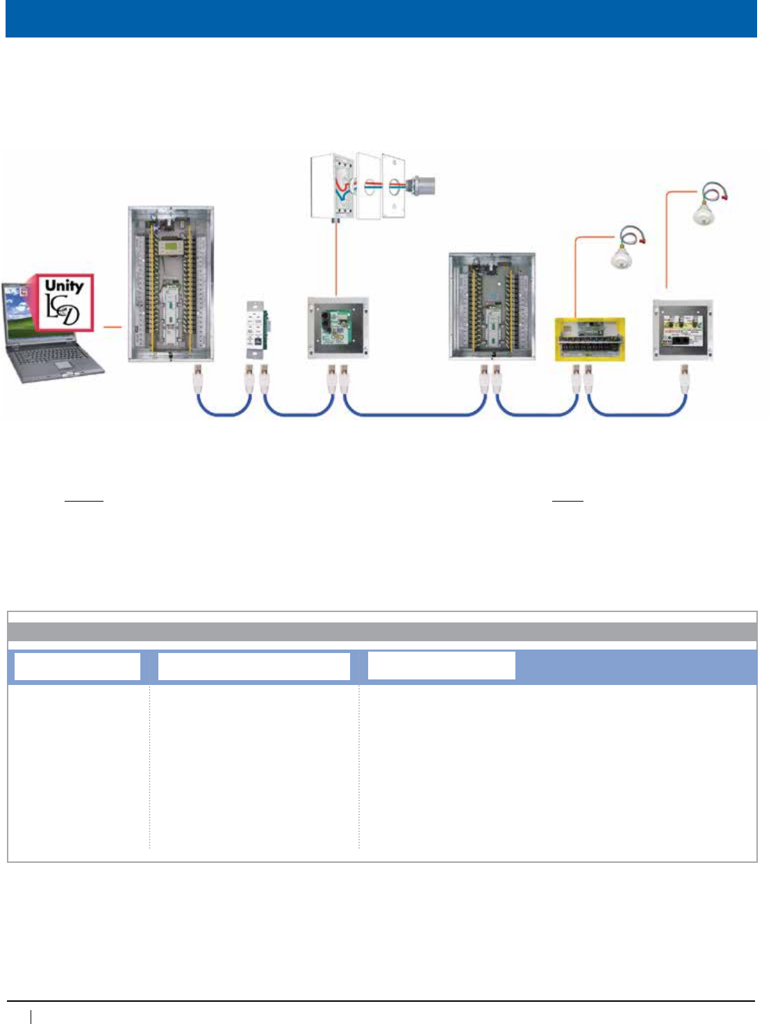
112
www.lightingcontrols.com • 800-345-4448
Hook up / Programming
Photosensorsdonotalwaysrequireaphotosensorcard.TheBlueBoxMasterPanel(notshown)hasanonboardinputfor
one outdoorphotosensorwith8globaltriggers.TheMicroPanelhasonboardinputsforupto4localindoor photosensors.
Cat. 5 patch cable with RJ45 connectors • upto127digitaladdresses• up to 4,000 feet
3#18
GR 2400
Relay Panel
Laptopcomputerrunning
Unity™Software
2#18
PCELL 2WO
PCC3
GR2408
PCELL 2WI
PCELL 3WI TZ
PCC1
Chelsea
DigitalSwitch
GR 2400
Relay Panel
GR2400
ORDERING INFORMATION
Photosensor Control Cards
System Type Photosensor Card
(with or without Photosensor)1
PCC1=Outdoorcard,1input,nosensor
PCC12WO=Outdoorcard,1input,one2WO
PCC3=Indoorcard,3inputs,nosensor
PCC32WI=Indoorcard,3inputs,one2WI
PCC32WO=Indoorcard,3inputs,one2WO
1=IndoorPhotosensorcardPCC3includes
digitalenable/disablefeature
Enclosure
[blank]=cardonly,noenclosure
SMNE1=SurfaceMount,NEMA1
FMNE1=FlushMount,NEMA1
SMNE4=SurfaceMount,NEMA4
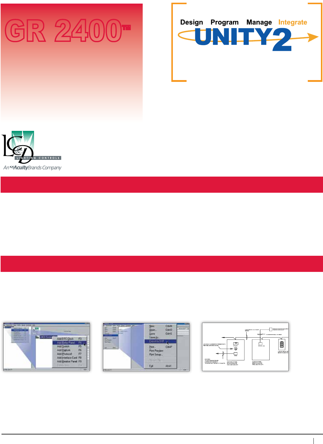
113
800-345-4448 • www.lightingcontrols.com
ORDERING INFORMATION
Add relay panels, switches or any of our
many accessories. Simply point your mouse
totheleftwindowpaneandright-click.You
willseeapulldownboxwhichallowsyouto
select whatever device you require. You can
do this as many times as needed.
Download Unity2 at: www.lightingcontrols.com
Submit your lighting control system in
AUTOCADformatoroutputyourdesignto
a Unityfile(.bus2)andemailittous.LC&D
can build your system according to your
specifications.
Export your lighting control system design to
CAD(.DXFformat)inseconds.Unity2
will generate a single-line drawing, panel
schedules, switch schedules and
specifications.
Design
Unity2 Lighting Control Software
One of the best features of Unity2 Lighting Control Softwareisitseaseofuseandeasypointandclickfeatures.Quicklydesignacomplete
lighting control system from the ground up in minutes.
• Setuprelaypanels,switches,photosensors,timeschedules—anyaspectofasystem
• OutputadesigntoAUTOCADinafewseconds,includingjob-specificsingle-linedrawings,panelschedules,switchschedulesandspecs
• Whenready,theUnityfilecanbeemailedtoLightingControl&Designandwillbebuiltandprogrammedexactlyaslaidout
Software
GR 2400™
TM
Lighting Control Software
Unity2 Lighting Control Software bundles design(specification),programming and management of a lighting control system into a single
softwarepackage.It’sfree.Anditrequiresnoformaltraining.
Specifiers use our Unity2 Lighting Control Software to rapidly design a new lighting control system. Unity files may be saved and output to
AUTOCADinafewseconds.LC&Dwillpreprogram(uploadthespecifier’sUnityfile)priortoshipment—atnocost.
BuildingengineersmayuseUnity2tomonitorandcontrolthelightingcontrolsinrealtimefromthedisplayofourclockorfromadesktopPC.
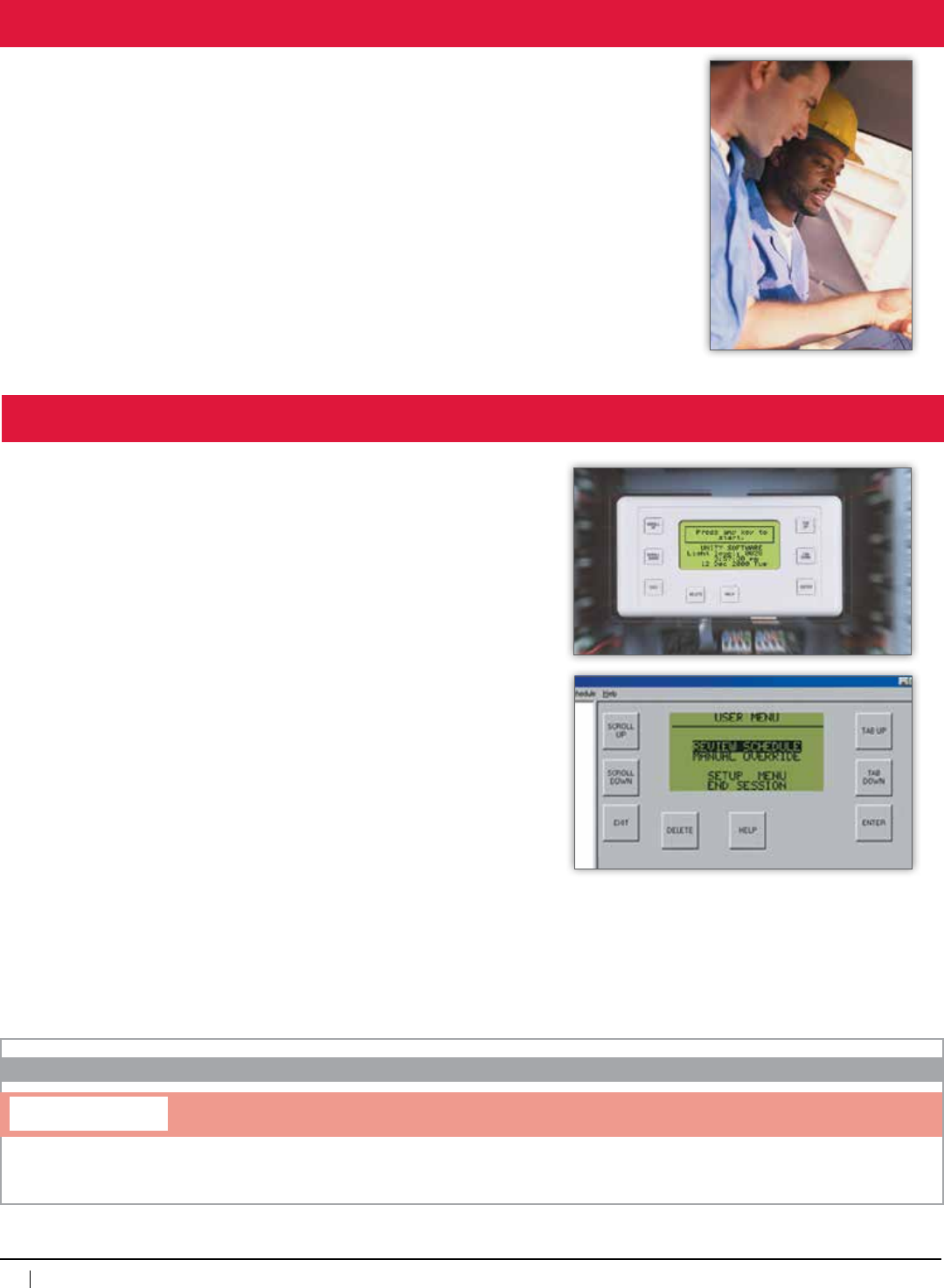
114
www.lightingcontrols.com • 800-345-4448
Program
Lighting Control & Design uses our carefully prepared Unity submittal to preprogram panels,
switches and time schedules—the entire lighting control system prior to shipment. New settings may
be programmed in real time.
AllthetoolsneededtoprogramyourlightingcontrolsystemareincorporatedinUnity. Programming
or adjusting switches, photosensors, relay panels, etc., is fast and simple. Easily connect to your
lighting system to modify your system.
Remotely access the GR 2400 bus with Unity Software. Connection options include:
• Dial-upconnection(builtinmodeminthemasterLCP)
• Directserialconnection(Link-To PC)
Control relays and groups, modify schedules and much more.
TheDigitalTimeClock(DTC)mountedinthemasterrelaypanelusesUnity to:
• Manuallycontrolallrelaysinrealtime
• Program switches and photosensor trip points
• Program time schedules
• Program all aspects of the system
Manage
UNITY
ORDERING INFORMATION
Software
Unity Software
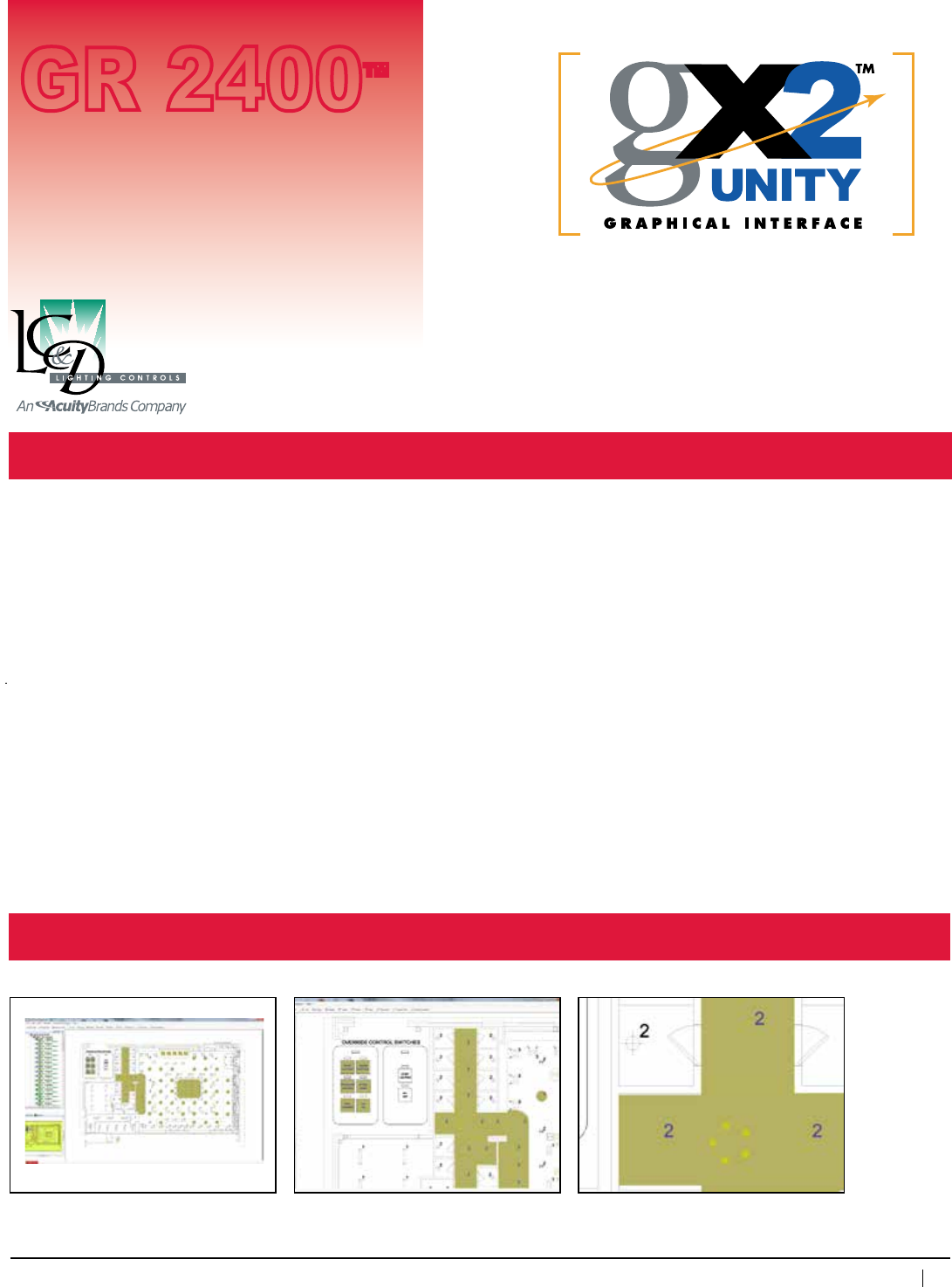
115
800-345-4448 • www.lightingcontrols.com
Infinite Pan & Zoom
Unity GX2™ Graphical Management Software
Description:
Software
GR 2400™
UnityGX2isanapplicationspecific“Pan&Zoom”floor-planbasedenergymanagementsoftwarethatprovidescontrolandrealtimemonitoring
ofwired/wirelesslights,sensors,andbasicHVACsolutions.Thissoftwareisdesignedforusewithbothindoorandoutdoorfacilitiestoprovide
centralizedandremoteaccesstolightingandsensors.Additionalusesincludeenhancedsecurity,loadsheddingmanagement,datalogging
andeveryday/basicusagealarms.Thissoftwarewasspecificallydesignedwiththeenduserinmindtoperformquickrezoningandscheduling
by the facilities, security, building occupant, or the system administrator.
Features:
•AunifiedindoorandoutdoorcontrolthatintegratestheGR2400system
andROAMnodesontoasingleplatform
•Configurabledataloggingforperiodspecificorongoingenergyusage
statistic.Alarmscanbesetfornumberoflampstrikes,kWhorrunhours
eclipses a pre-determined amount.
•Effectivemanagementofload-sheddingscenarios
•Embeddedzonesallowforcontrolandreorganizationofmultiple
group of lights
•GreenScreenprovidesavisualdisplayofsystemsavingsandusage
•Personalizedinterfaceforimprovedlookandfeeloficonsandcontrols
•Virtualswitchesprovideeasylocalandglobalcontrol
•Accessmultiplefloors/areasandusepan/zoomfeaturetoquickly
navigate the floor plan
•Thesymbollibraryallowsforfastercreationandeditingofcontrol
points on the floor plan
•Overviewwindowtoindicatewhereyouarezoomedinonthegraphic
•Treestructureforquickselectandviewingofcontrolzonesand
system hardware
•Propertiesboxprovidesinformationonselectedcontrolzoneor
hardware device
•ExportthecontrolslayertoDWGforinclusioninbuildingdesigns
PanandzoomwithoutthedistortionorpixelationassociatedwithDWG/CADbasedgraphics.
25%orlessmagnification 300%magnification 1000% or more magnification
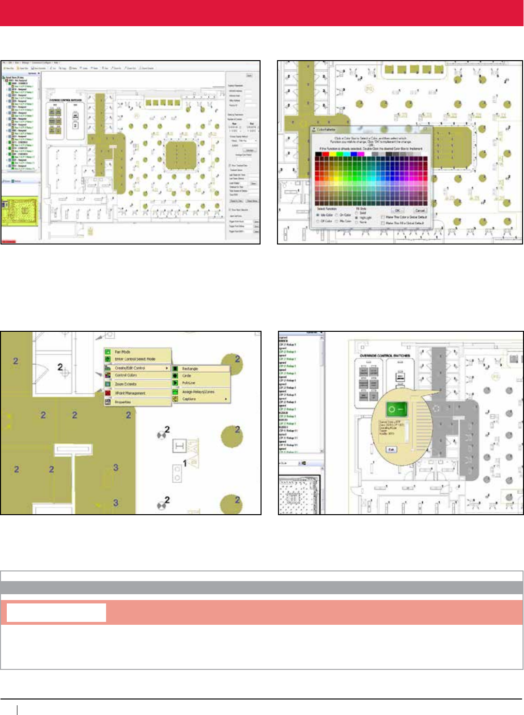
116
www.lightingcontrols.com • 800-345-4448
Professional Tool Set
UNITY GX2
ORDERING INFORMATION
Software
Unity GX2™ usesintuitivegraphicalcontrolsandaneasy-to-understandinterfacetomakemanagingyourlightingcontrolsasstraightforward
aspointingandclickingonanobject.
Control Tree
Allowstheusertoseeallcontrolzonesandsystemhardware.
Data Logging & Alarms
The user is able to configure the data logging for a specified period of
time or ongoing energy usage statistics. The alarm can be set for the
numberoflampstrikes,kWhorrunhoursexlipsesforapredertmined
amount of time.
Color Palette
Userisabletochoosecolorforidleandrunmodes(see-through,
opaqueoroutlinemodes).
Shapes-Draw/Edit Controls
Mapareasusingthebox,ellipticalorpolygontool.
Switch Properties
Byhoveringovertheswitch,theuserisabletoseethepropertiesof
theswitch,including:thezonelocationoftheswitchanditscurrent
state.
Unity GX2 Software
Version2,compatiblewithXPoint,NOTcompatiblewithVersion1(GXVector)sites.Licenseisforoneseat.
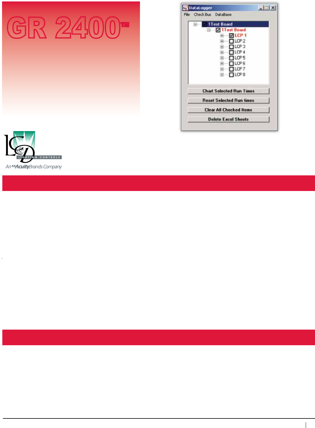
117
800-345-4448 • www.lightingcontrols.com
Specifications:
DataLogger™
GR 2400™
Description: DataLogger™lightingmanagementsoftwarereadsandthenlogsinformationaboutthelightingcontrols
whichcanbeusedtobettermanageafacility.DataLoggeroffersthreedifferentsoftwaremodules:
RuntimeModulekeepsalogofthetotalruntimeoflightingloads.Thiscanbeusedtoschedulelamp
changesandtokeeptrackoflamplife(inhours).
The ON event total counts the number of ON events for each relay. This is useful for lamp life
calculations.
EventLoggingModulekeepsalogofalleventswhichaffectthestatusofrelays,dimmers,
SmartBreakers,andotherdigitaldevices.Forexample:theactualonandofftimesofrelays,which
deviceorscheduleturnedarelayorgroupofrelayson/offorhowoftenlightingisextendedafter
hours.
TheGR2400DigitalBuswritesthelogsdirectlytotheUpLink™network multiplex cardforeachGR2400
DigitalBus.LogscanbedownloadedandmanagedfromaworkstationwhichhasinstalledDataLogger.
AMetaServer™digital web serveractsastheportaltotheUpLinkCardsandcanbeaccessedoverthe
localareanetworkortheinternet.
RefertotheUpLinkandMetaServerTechSheetsformoreinformationabouttheseproducts.
Features: • Managelampchangeschedulingformultiplesites
• Isolatethecauseofhigh(orlow)energybills
Logstorages: UpLinkCard
Maxstorageon
Uplinkcard: 8MB
Accessvia: MetaServer
Hard drive space
forDataLogger: 20MB
Accessory
Workstation
(notprovided): Midlevelcurrenttechnology
WindowsXPoremulation
Chartoutputformat: MS-Excel® Spreadsheets
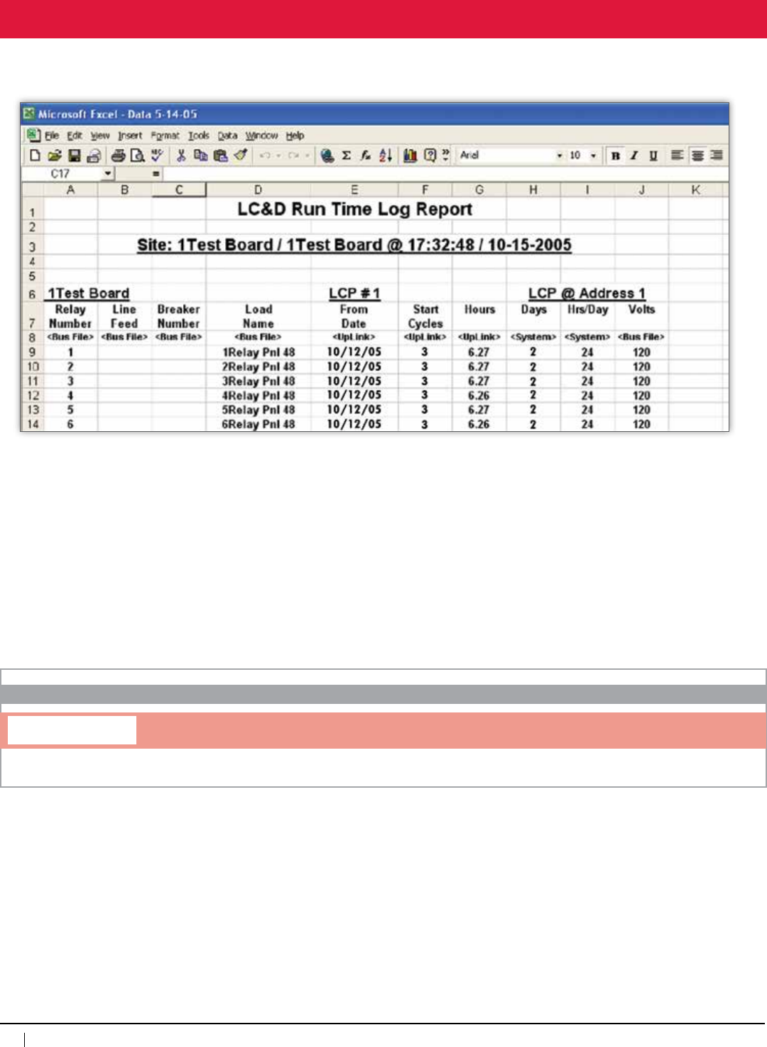
118
www.lightingcontrols.com • 800-345-4448
Hook up / Programming
LogsareoutputasMS-Excel® Spreadsheets, allowing true management of lighting data:
• Create charts
• Manipulateandmanagedata
• Combine or compare logs from multiple sites or over time
• Predict and schedule lamp changes
• Compare lamp life predictions against actual lamp life
UNITY DLOG
ORDERING INFORMATION
Datalogger™
Datalogger Software
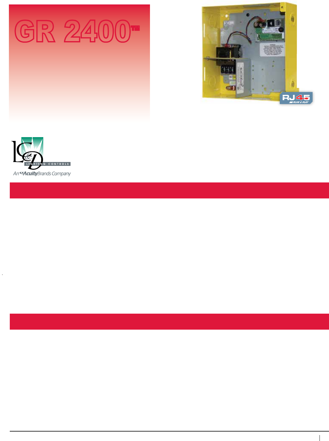
119
800-345-4448 • www.lightingcontrols.com
ORDERING INFORMATION
Specifications:
DigiLink™ Contact Closure Interface
Description: The DigiLink is a gateway for contact closure devices to the GR 2400 system. The DL 2400 is typically
mountedinanexternalenclosure.
Features: Contact closure devices may be programmed to control any relays, SmartBreakers™ or dimmers in
anypanel.ControlrelaysthroughtimeschedulesofanyBuildingAutomationSystem.
Upto14contactclosureinputs.Optional6inputcardallowsfordigitalenable/disableoverthebus.
CantakeadrycontactfromBMSsystemtoinitiatecontrolofrelaysthroughtimeschedulesordoload
shedding.
Interfaceto:
• Buildingautomation
• Occupancysensors
• Securitysystems—lifesafety
• Contactclosurelowvoltageswitches
• Linkupto127digitaladdressesviaCat.5patchcablewithRJ45connectors
Enclosuretype: NEMA1,Flushmountoptional
8.375"wx8.375"hx3.125"d
Optionalenclosure: NEMA4,NEMA12
Carddimensions: 1.90"x2.75"
Inputpower: Buspoweredor120/277VACor347VAC
Contact closure inputs: 14
Ambienttemperature: 32–104°F(0–40°C)
Busphysicallayer: RS485(GR2400bus)
#ofAddresses: 1
Programming: via DTC
Busconnectors: RJ45connectors
Digilinkwith Suppliesupto350mA@
24VDCforoccupancysensor
power
GR 2400™
Accessory
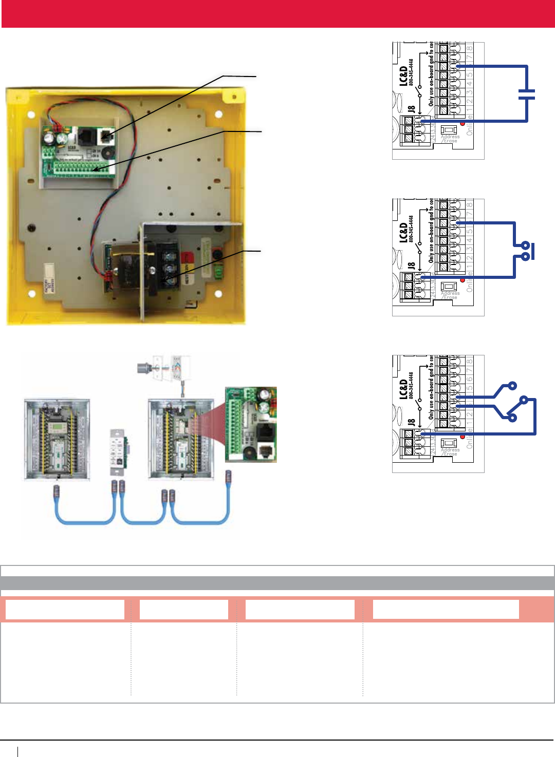
120
www.lightingcontrols.com • 800-345-4448
Hook Up / Wiring Details
Power Supply
Specify120V,277V
DigiLink™
(shownwithoptionalenclosure
andpowersupply) (2)BusConnectors
14ContactClosureInputs
Master
Relay Panel
Photosensor
Cat.5patchcablewithRJ45connectors•Upto127digitaladdresses•Upto4,000ft.
Chelsea
DigitalSwitch™
Remote Relay Panel
GR2400 DIGILINK
ORDERING INFORMATION
DigiLink Dry Contact Closure Gateway
System and Accessory Type Transformer
[blank]=Buspowered
DV=Dualvoltage120/277V
347=347V
Dry Contact Inputs
D6=6inputs(withenable/disable)
D14=14inputs(noenable/disable)
Enclosure Mounting, NEMA Rating
SMNE1=SurfaceMount,NEMA1
FMNE1=FlushMount,NEMA1
SMNE4=SurfaceMount,NEMA4
SMNE12=SurfaceMount,NEMA12
Maintained Contact Closure
Momentary Contact Closure
Positive On/Off Contact Closure
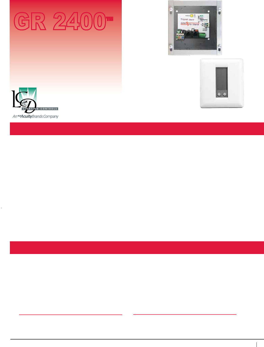
121
800-345-4448 • www.lightingcontrols.com
Specifications:
T-Link™ (Link-To™ T-Stat)
Description: Each T-Linkcardallowsbothmonitoringandprogrammingofupto32intelligentthermostats,forfull
controlofconventionalandheatpumpunits.ThermostatmanufacturedbyXCICorp*.
Thermostatdimensions: 4"wx4.5"hx.875"d
Addresses: 1per8T-Statcontrolled
Controlrange: Heating:38–88°F(3–31°C)
Cooling:60–108°F(16–42°C)
Measurementrange: 28–124°F(-2–51°C)
Control accuracy: +/-1°F(.55°C)@68°F(20°C)
Minimumdeadband: 2°F(1.11°C)
betweenheating/cooling
Carddimensions: 3.65"wx2.75"h
Enclosure: 6"wx6"hx4"dNEMA1
Powersupply: Accepts12VDCfromGR 2400 bus
Ambienttemperature: 32–104°F(0–40°C)
Humidity: 10–90%non-condensing
Max#thermostats
per T-Link: 32
Programming: ViaDTCprogrammer,via PC with
Unity™ Lighting Control Software
To download specs, drawings and instructions go to
http://www.lightingcontrols.com
*Formorespecsgoto:http://www.xcicorp.com
Features: • Completeremotecontrolandstatus
ofupto32thermostatsviathe
T-Link control card
• Adjustandmonitorallsettings
locally at the master relay panel
or remotely from a PC via dial-up,
internet or intranet
• Thermostatsareemulatedonthe
busbyarelaypanelatLCP32.
When the relay is ON the program is
intheDay/Occupiedmode.Whenoff
thethermostatisinsetlevelNight/
Unoccupiedmode
• Programheating/coolinglevels
• Programday/night,occupied/unoccupied
setbackset-points
• UsetheChelsea DigitalSwitch™ to
temporarilyoverridelightingandHVAC
thermostat features
• Fanselectorforcontinuousfanoperation
• Built-in,short-cycleprotection
• Nobatteryrequiredforpoweroutage
• Built-inLEDindicators
• Automaticchangeoverfromheat-to-cooland
cool-to-heat
• Optionalremoteindoorandoutdoorsensors
• Adjustlocalkeypadrangecontrol
GR 2400™
Accessory
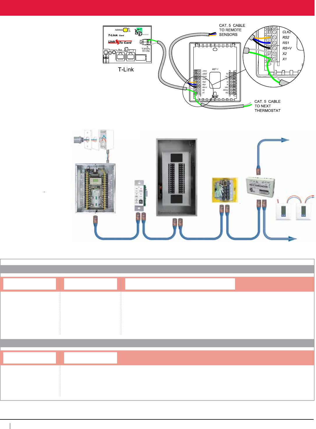
122
www.lightingcontrols.com • 800-345-4448
The T-Link card is the
interface from the GR 2400
systemtotheXCIDigital
Thermostats. One T-Link will
interfacewithupto32digital
thermostats.
ConnectX1andX2inputs/
outputs in parallel in all
thermostats and to the
T-Link card.
Each thermostat has outputs
forauxiliaryexternalsensors,
ideal for measuring
outside temp, duct temp
or for mounting the Digital
Thermostat in a secure
location with remote sensors.
Overview
Photosensor
GR2400™
MasterPanel
Chelsea
DigitalSwitch™
SmartBreaker™ Panel
MicroPanel™ T-Link
Cat. 5 patch cable with RJ45 connectors •Upto127digitaladdresses•Upto4,000ft.
GR2400 L2
TSTAT
TSTAT
ORDERING INFORMATION
T-Link™
T-STAT™
System and Type
Thermostat
Link-to Type
TSTAT=TSTAT(Thermostat)
Link-to Type
MST=Multi-StageThermostat
HPT - Heat Pump Thermostat
RIS-RemoteIndoorSensor
RDS=RemoteDuctSensor
Mounting and Enclosure Type
SMNE1=Surfacemount,NEMA1
FMNE1=Flushmount,NEMA1
SMNE4=Surfacemount,NEMA4
RETRO=Retrofitenclosure

123
800-345-4448 • www.lightingcontrols.com
Specifications:
Link-To™ PC/Ethernet and Link-To™ PC/RS232-USB
GR 2400™
Description: Two different interface cards which allow multiple computers to connect to the GR 2400 system.
Connectionisfromanyserial/commport(RS232),USBportorethernetnetworkconnection.
USBversioncomeswithRS232toUSBadapters.
Features: EthernetVersion: • LinkstoGR 2400LAN and via a gateway to the internet
• Unity™ Remote Clock
•Unity GX™ Vector Advanced Graphical Software
RS232/USBVersion: Workswith:
• Unity Lighting Control Software
• Unity Remote Clock
• Unity GX Vector Advanced Graphical Software
Carddimensions: 3.65"wx2.75"h
Powerconsumption: 80mA@12VDC
Optionalenclosurerating: NEMA4
Enclosure dimensions: 8.375"wx8.375"hx3.125"d
Optionalmounting: Inrelaypanel
MaxL2-PCcards: 6perGR 2400 bus
Programming: None required
Max.humidity: 10– 90%non-condensing
Ambienttemperature: 32–104°F(0–40°C)
Powersupply: Accepts12VDCfrombusorin-box
supply(specify120/277VACor
347VAC)
Busphysicallayer: RS485(GR 2400bus)
Serialcabling: ToDB9serialportsuppliedbyLC&D
USBcabling: In-lineadaptorsuppliedbyLC&D
Ethernet cabling option: Cat. 5 cable with RJ45 connectors
RJ45 connectors supplied by others
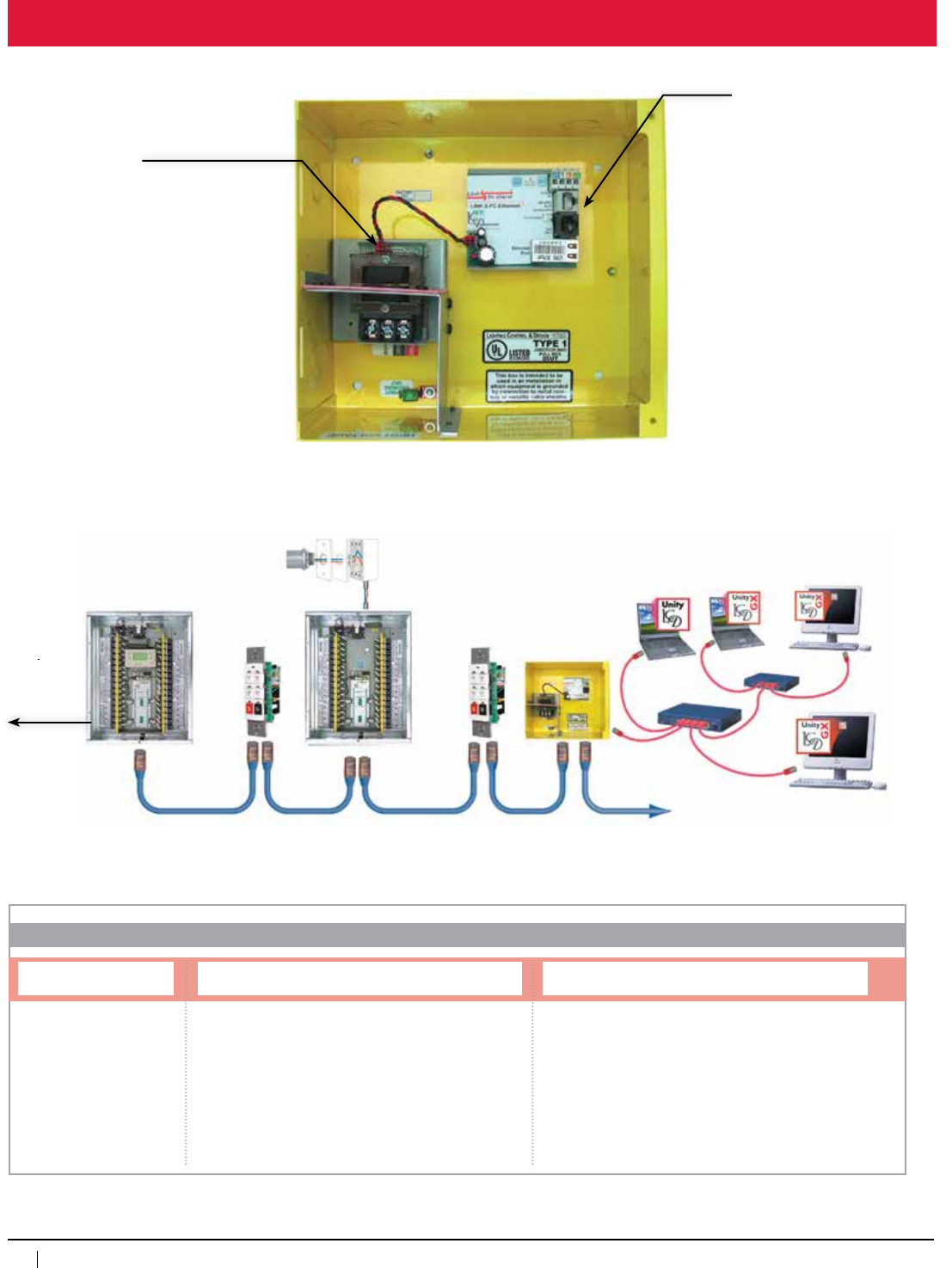
124
www.lightingcontrols.com • 800-345-4448
Hook Up Programming
Link-ToPC/Ethernet
Power Supply:
Specify120V,277V
GR 2400BusConnectors
(2)RJ45Connectors
To phone
line for
remote
dial up
Ethernet
Hub
Computers running Unity GX™
Advanced Graphical Software
Outdoor
Photosensor™
Link-To™PC
(Ethernet
Version)
MasterRelay
Panel
Chelsea
DigitalSwitch™
Cat. 5 patch cable with RJ45 connectors
Upto127digitaladdresses•Upto4,000ft.
Remote
Relay
Panel Chelsea
DigitalSwitch™
GR2400 L2
ORDERING INFORMATION
Link-To™ PC
System and Type Link-to Type
PCETH=PCEthernet1
PC232115K=PCRS2322,115kbaud(standard)
PC2329600=PCRS2322,9600baud
PCUSB115K=PCUSB2,115kbaud(standard)
PCUSB9600=PCUSB2,9600baud
1 = Required to choose a transformer, mount and enclosure type
2 = Transformer, mount and enclosure optional (device may be
ordered as card only)
Transformer, Mount and Enclosure Type
DVSMNE1=Dualvoltage120/277V,surfacemount,NEMA1
DVFMNE1=Dualvoltage120/277V,flushmount,NEMA1
DVSMNE4=Dualvoltage120/277V,surfacemount,NEMA4
347SMNE1=347volt,surfacemount,NEMA1
347FMNE1=347volt,flushmount,NEMA1
347SMNE4=347volt,surfacemount,NEMA4
RETRO=Retrofitenclosure
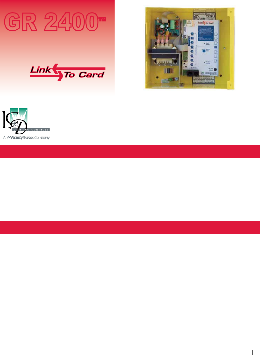
125
800-345-4448 • www.lightingcontrols.com
Specifications:
Link-To™ DMX
Description: LinksaDMX-basedsystemtoaGR 2400lightingcontrolsystem.Idealforapplicationswhichrequirethe
powerful features of the GR 2400systemandaDMX“take-over”
Features: • SinglepointofinterfacefromaDMX-basedcontrolsystemallows14globalcommandstoallrelay
panels in the GR 2400 bus
• DMXstartaddressmaybemanuallysettoanyaddressatthe Link-To DMX card via the multifunction
push buttons.Controlsautomaticallyrespondtothenext13addressesforatotalof14programmable
inputs
• Linkupto127digitaldevicesviaCat.5patchcablewithRJ45connectors
Power consumption: 80mA@12VDC
Power supply voltage: 120/277VACor347VAC
Cardsize: 4"wx6.25"h
Enclosuresize: 8.375"wx8.375"hx3.125"d
Enclosure rating: NEMA1,flushmountoptional
Optionalenclosures: NEMA4
Addresses: 1 per card
Max.humidity: 10 – 90%non-condensing
Ambienttemperature: 32–104°F(0–40°C)
Busphysicallayer: RS485
Interfaceprotocol: DMX512&DMX512Acompatible
Approvals: ULandcULlisted
Line-Voltage Compartment
Powersupply120/277VAC
or347VAC
Low-Voltage Compartment
Link-To DMX card
• DMXinput(screwterminal)
• GR 2400bus(RJ45)
• Manual(test)pushbuttons
foreachDMXchannel
(ifnoDMXsignal)
• DMXaddressbuttons
(seemanual)
• GR 2400 address button
GR 2400™
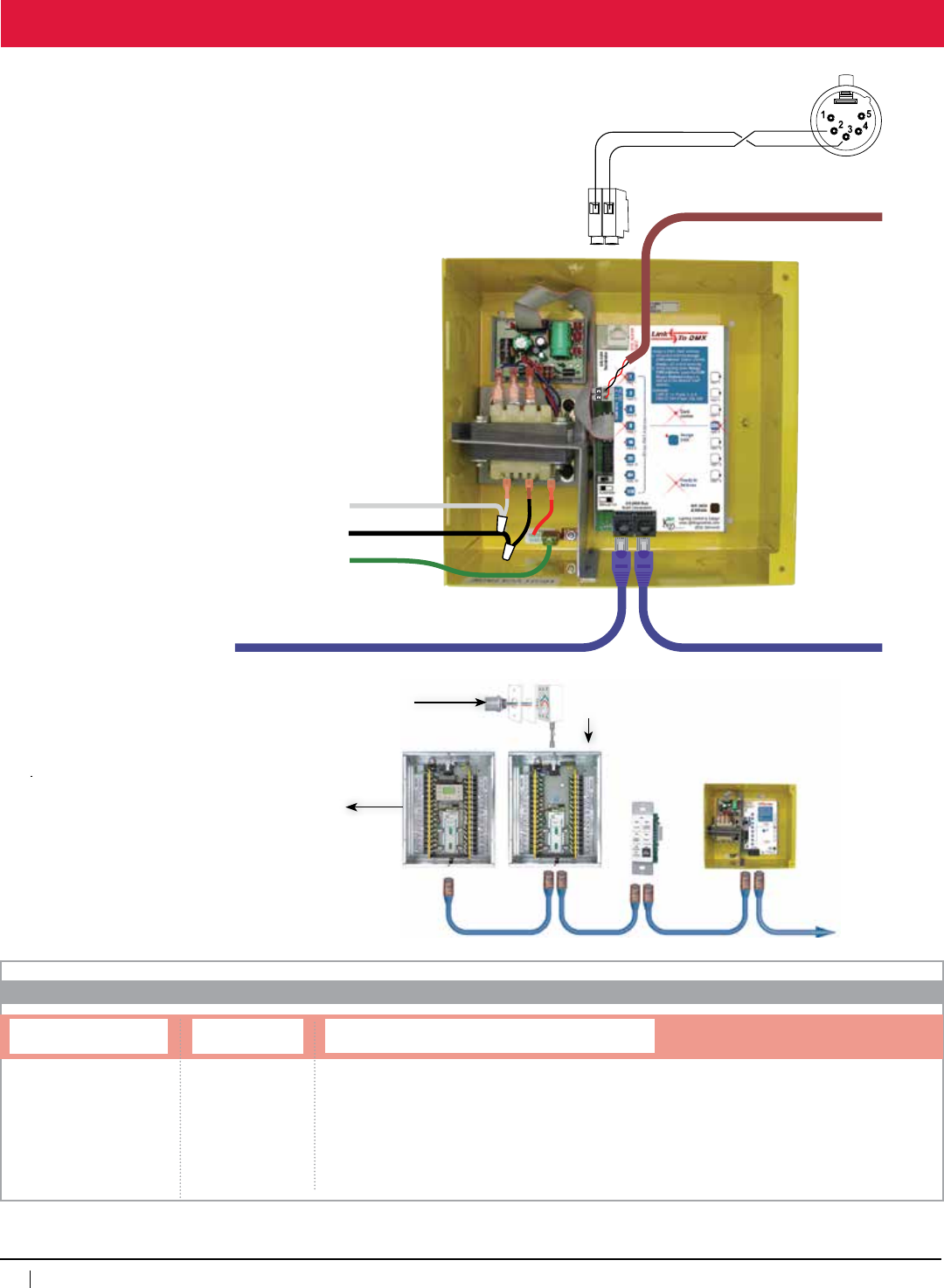
126
www.lightingcontrols.com • 800-345-4448
Hook Up
Neutral
Hot
Ground
Data Cable for
DMX 512 System
Cat 5 with RJ45 connectors
for GR 2400 system
277 VAC
120 VAC
Neutral
3 2
Use a proper data cable.
Twisted pair with foil and twisted braids.
Balanced audio cable will not do.
DMX Connector
Male XLR connector
Overview
The Link-To DMX control card converts 14
contiguous DMX channels into 14 global
GR 2400 switch commands. When the
level set to that channel exceeds 90% the
switch sends out an ON command. When
it drops to less than 10% it sends out an
OFF command. See the GR 2400 manual
for switch programming information.
Line and Low Voltage Connections
Panel power supply may be 120V or 277V.
Ground is for equipment only.
Connect XLR Pin #2 to DMX input #2 and
XLR Pin #3 to DMX input #3. If end of line,
connect a 120 ohm resistor across DMX
inputs #2 and #3.
GR2400
(Master)
Outdoor Photocell
(facingnorth)
Link-ToDMX
Chelsea
DigitalSwitch™
To phone line for
remote dial-up
GR2400
(Remote)
GR2400 L2 512A
ORDERING INFORMATION
Link-To™ DMX
System and Type Link-to Type
512A=DMX1
1 = Required to choose
a transformer, mount
and enclosure type
Transformer, Mount and Enclosure Type
DVSMNE1=Dualvoltage120/277V,surfacemount,NEMA1
DVFMNE1=Dualvoltage120/277V,flushmount,NEMA1
DVSMNE4=Dualvoltage120/277V,surfacemount,NEMA4
347SMNE1=347volt,surfacemount,NEMA1
347FMNE1=347volt,flushmount,NEMA1
347SMNE4=347volt,surfacemount,NEMA4
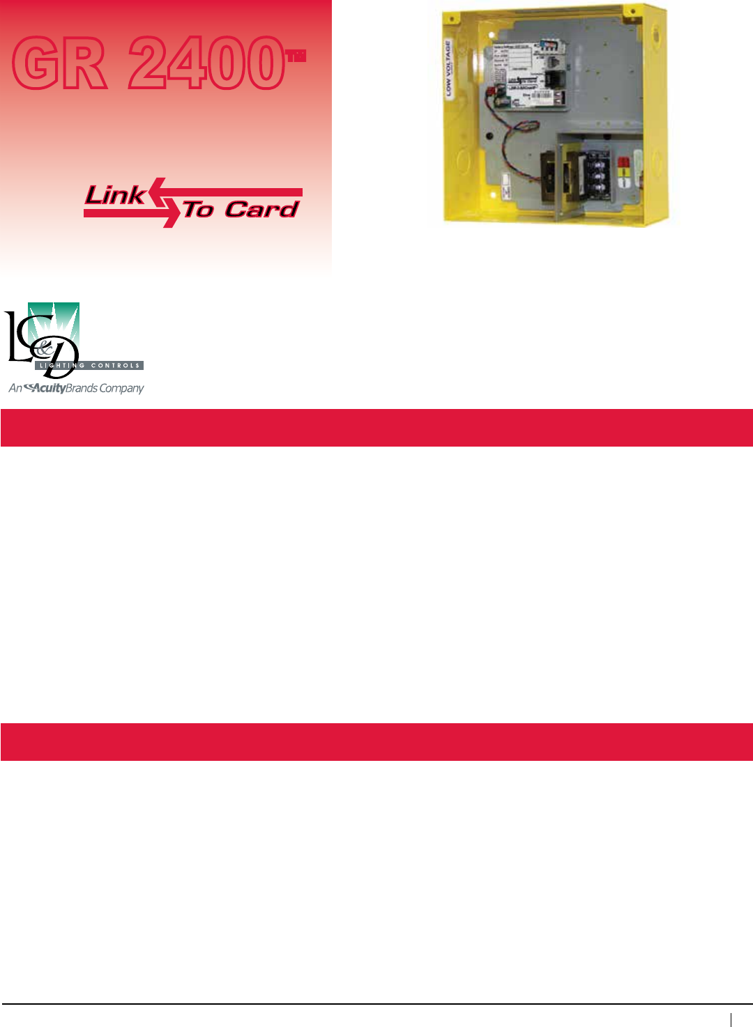
127
800-345-4448 • www.lightingcontrols.com
Specifications:
Link-To™ Building Automation
GR 2400™
Description: LC&Dofferstwomethodsofbuildingautomationinterfaces:
1)GatewaycardsusingDDCprotocolssuchasBACnet™andMetasys™(N2)accepton/offcommands,
time schedules and report status of all relays in all panels in real time.
2)Thesecondmethodgreatlysimplifiesinterfacetobuildingautomationthroughdrycontactclosure.
Features: • CertifiedConnectivityPartnerwithJohnsonControls©,N2protocol
• Anumberofbuildingautomationprotocolsareavailableaswellascontactclosure
• Programschedulesfrombuildingautomationpackage
• Expandanybuildingautomationpackagetoinclude:
a)Communication-basedChelsea DigitalSwitches™
b)“FlickWarn”optionfornotifyingroomoccupantsofanimpendinglightingshut-off
c)Remotelyadjustablemulti-trip-pointphotosensor(s)
d)Gatewaycardsacceptcontrolandreportreal-timestatusofallrelays
• Linkupto127digitaladdressesviaCat.5patchcablewithRJ45connectors
Enclosurerating: NEMA1
Enclosure dimensions: 8.375"wx8.375"hx3.125"d
Optionalmounting: Inrelaypanel
Max.humidity: 10 – 90%non-condensing
Ambienttemperature: 32–104°F(0–40°C)
Powersupply: 120/277VACor347VAC
Busphysicallayer: RS485(GR 2400bus)
Interfaceprotocol: Specifictobuildingautomationsystem
Approvals: ULandcULlisted
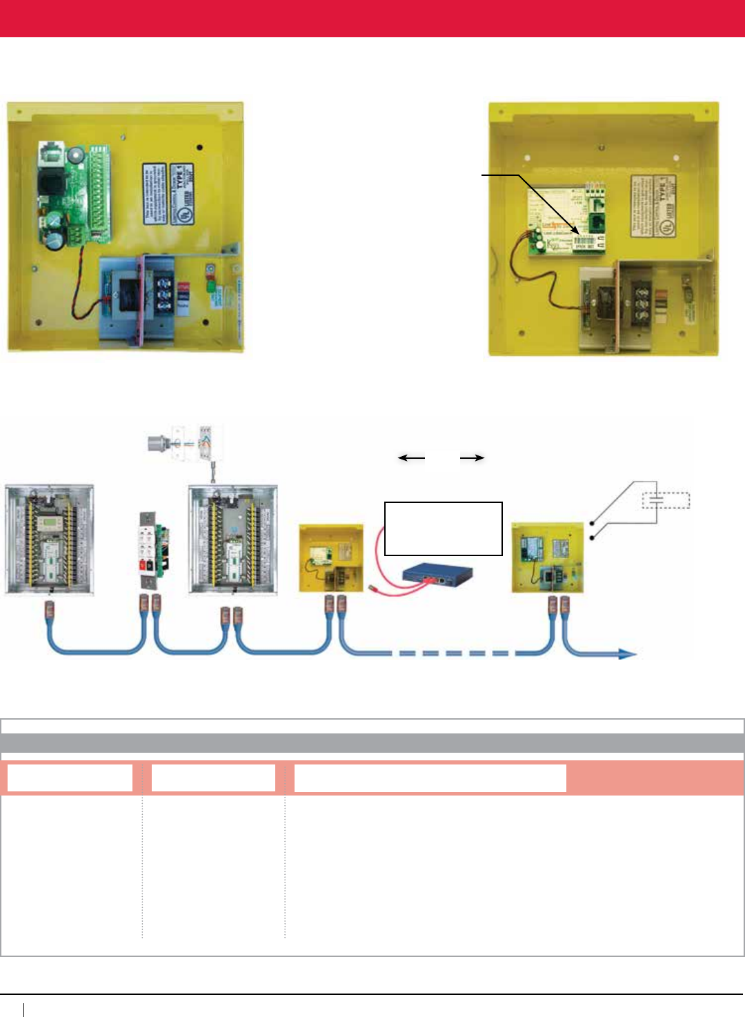
128
www.lightingcontrols.com • 800-345-4448
Details
14 contact closure inputs
Power Supply:
Specify transformer
120/277VACor347VAC
Link-To Building Automation
(DigiLink™)
Link-To Building Automation
(BACnet® Gateway)
GR2400BusConnectors
(2)RJ45Connectors
(1)Spring-cageterminalblock
direct plug-in
Low-VoltageCompartment
AccessDoor
Ethernet Output
toBACnet
Master
Relay
Panel Chelsea
DigitalSwitch
Photosensor
Cat.5patchcablewithRJ45connectors•Upto127digitaladdresses•Upto4,000ft.
Link-ToBuilding
Automation
(BACnet)
Remote
Relay
Panel
Ethernet Hub
BuildingAutomation
Packageusing
BACnet
Link-ToBuilding
Automation
(DigiLink)
Contact Closure
fromanyBuilding
AutomationPackage
OR
GR2400 L2
ORDERING INFORMATION
Link-To™ Building Automation
System and Type Link-to Type
MODB232=ModBusRS2321
MODB485=ModBusRS4851
BACNETIP=BacNetIP1
BACNETMSTP=BacNetMSTP1
METN2=N2Metasys2
1 = Required to choose a
transformer, mount and
enclosure type
2 = Transformer, mount and
enclosure optional (device may
be ordered as card only)
Transformer, Mount and Enclosure Type
DVSMNE1=Dualvoltage120/277V,surfacemount,NEMA1
DVFMNE1=Dualvoltage120/277V,flushmount,NEMA1
DVSMNE4=Dualvoltage120/277V,surfacemount,NEMA4
347SMNE1=347volt,surfacemount,NEMA1
347FMNE1=347volt,flushmount,NEMA1
347SMNE4=347volt,surfacemount,NEMA4 FOR DRY CONTACT
INPUTS, SEE DIGILINK
TECH SHEET
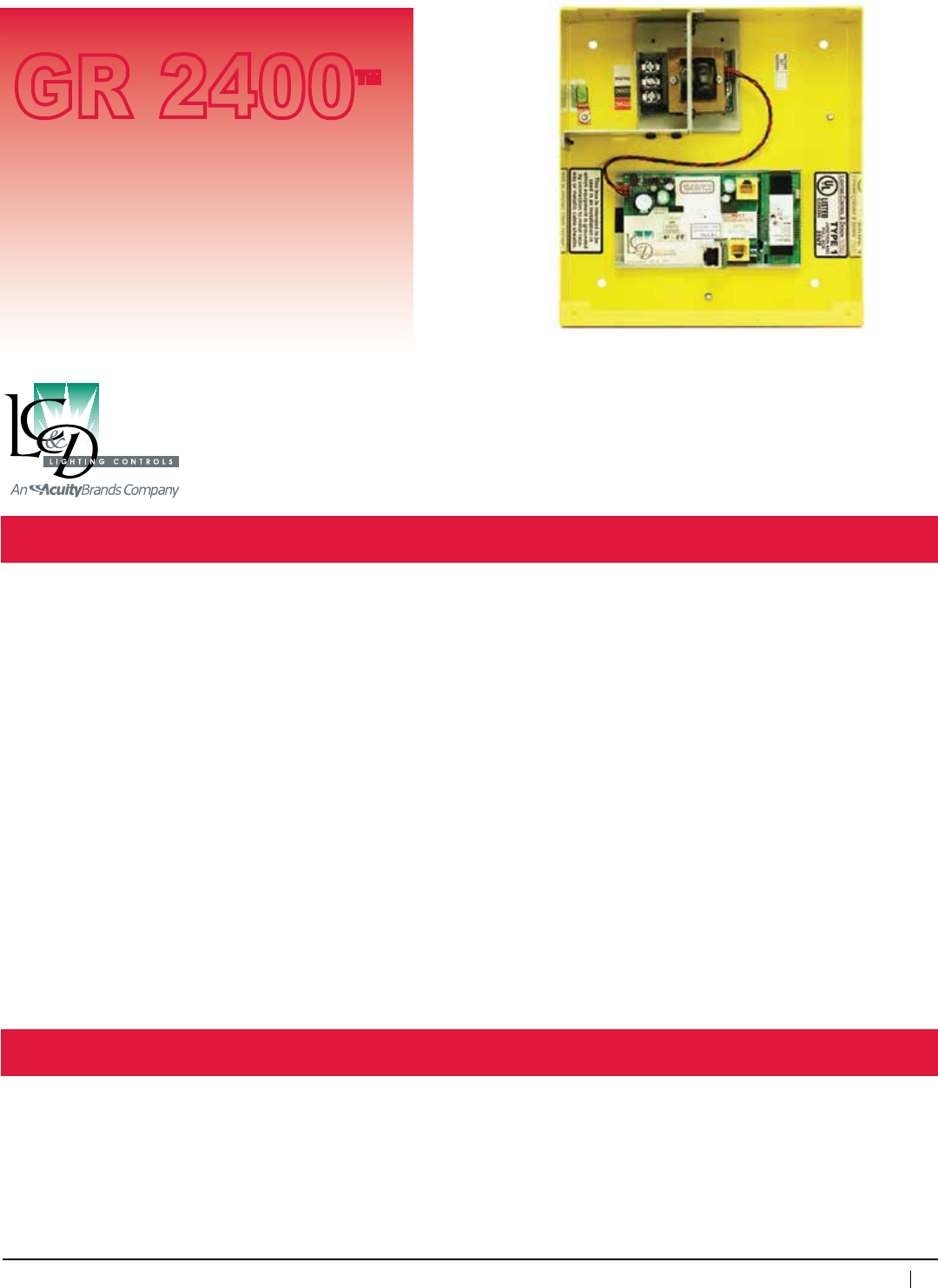
129
800-345-4448 • www.lightingcontrols.com
Specifications:
MetaServer™ and UpLink™
GR 2400™
Description: TheUpLink™networkmultiplexcardlinksupto99digitalbusestogethertocreateasystemwithover12thousanddigitallighting
control devices.
TheMetaServer™digitalwebserverisagatewaythatprovidesInternetorcomputeraccesstothesedevices.
Here’showtheywork:Upto127digitaladdresses(relaypanels,digitalswitches,etc)maybelinkedtogetherwithinaGR2400digi-
talbus.Exceptforthelargestprojects,thisprovestobemorethanenoughcapacity.Forlargerinstallationswheremultiplebusesare
neededtoaccommodatethelargenumberofdigitaldevices,LC&DhasdevelopedaBackBoneBususingtheUpLink™cardand
MetaServer™tolinkupto99GR2400busestogether.
AttheheadoftheBackBoneBusisaMetaServerthatdoesthedutyofconnectingthewholesystemviaEthernetorModemtoa
computerortheinternet.ConnectingeachdigitalbustotheBackBoneBusisanUpLinkcard.Itcapturespacketsmeantforthat
particularbusandroutesthedatacorrectly.TheUpLinkcardhasalargememorycapacitywhichactsasamirrorofthestatusofthe
GR2400busformorerapidcommunication.Italsokeepslogsofthenumberoftimesarelayhasbeenoperated,thetimeithas
beenONsincelastresetandalogofeachevent(seeDataLogger™techsheetformoreinformation).
Features: • Analmostunlimitednumberofcommandsmaymovefromonedigitalbustoanother.SwitchesfromoneGR2400bus
maycontrolallrelays,dimmers,scenes,groups,orSmartBreakersinotherdownstreambusseswithfullfeedback.
• Run-timeandevent-loggingarestoredinFlashmemoryuntildownloadedbyanadministrator(seetechsheetfor
DataLoggersoftware)
• Connectasmanyas99UpLinkcardstotheinternet
• AccessmultiplebusesusingUnityGXAdvancedGraphicalSoftware
• TheMetaServerrequiresonlyasingleIPandprovidescompleteaccesstooneormultiplebuildings
Enclosure dimensions: 8.375"wx8.375"hx3.125"d
Enclosure type: SurfacemountNEMA1,
flush mount optional
Optionalenclosure: NEMA4
Powersupply: 120/277VAC(DV)or347VAC
Ambienttemperature: 32–104°F(0–40°C)
Programming: via PC
(withadministratoraccess)
Approvals: ULandcULlisted
Accessory
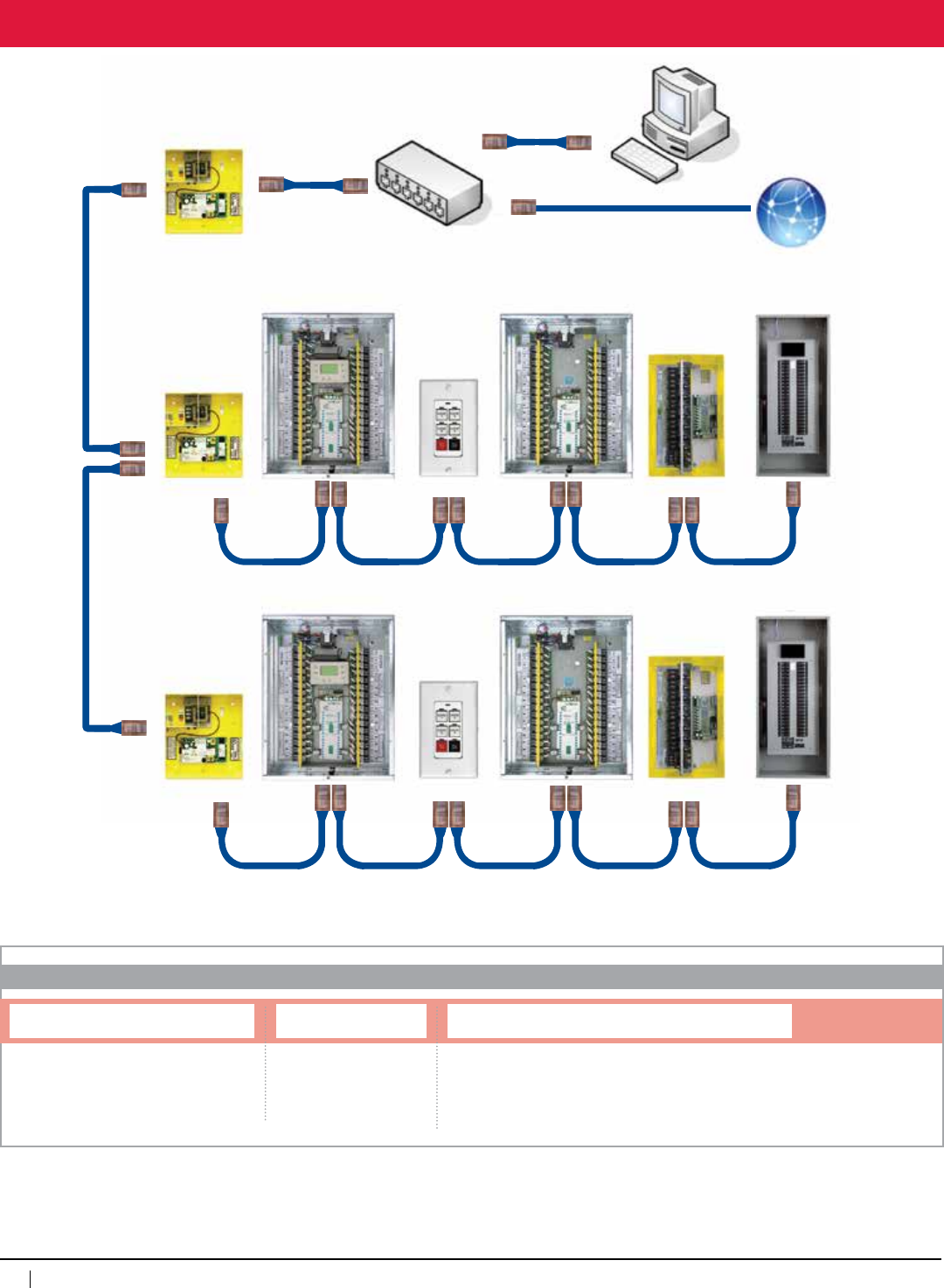
130
www.lightingcontrols.com • 800-345-4448
Hook up / Programming
Note: MetaServer • 1 per system, UpLink • 1 per bus
GR2400
MasterPanel
GR2400
Remote Panel
Chelsea
DigitalSwitch
UplinkCard
SmartBreaker
Panel
MicroPanel
GR2400
MasterPanel
GR2400
Remote Panel
Chelsea
DigitalSwitch
UplinkCard
SmartBreaker
Panel
MicroPanel
Server Card
Hub Internet
BackBoneBus
BackBoneBus
ORDERING INFORMATION
MetaServer™ and UpLink™
System and Type
GR2400UH4=UpLink
GR2400SH4MOD=MetaServerwithmodem
GR2400SH4MUH4=Server-Uplinkwithmodem
Transformer
DV=Dualvoltage120/277V
347=347volt
Mount and Enclosure Type
SMNE1=Surfacemount,NEMA1
FMNE1=Flushmount,NEMA1
SMNE4=Surfacemount,NEMA4
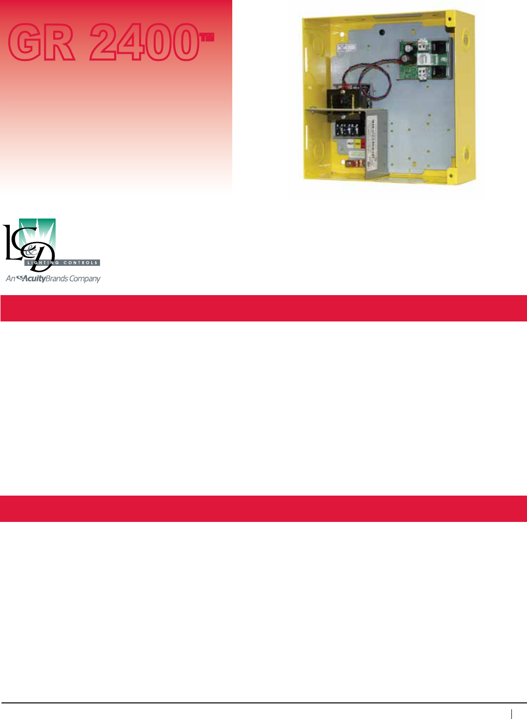
131
800-345-4448 • www.lightingcontrols.com
Bus Booster
GR 2400™
Accessory
Description: TheBusBoosterisusedontheGR2400Systemwhenthedistancebetweenswitchesandarelaypanel
cause voltage drop.
SwitchesaresuppliedwithpowerovertheGR2400bus.Whilethedatacantravel4,000ft.,thepowerto
a switch needs to be fed with a relay panel or a bus booster every few hundred feet.
Features: •Providesupto0.8ampat12voltsDCtothesystembus
•Simplypowerupandpluginthebus
•Currentlimited
Specifications:
Enclosurerating: NEMA1
Enclosuredimensions: 8.375"wx8.375"hx3.125"d
RJ45Connectors: SocketsforBusIn&OutandClock
Input: 120/277VAC,347VAC
Output: 12VDCupto800mA
Approvals: ULandcULlistedtoUL916
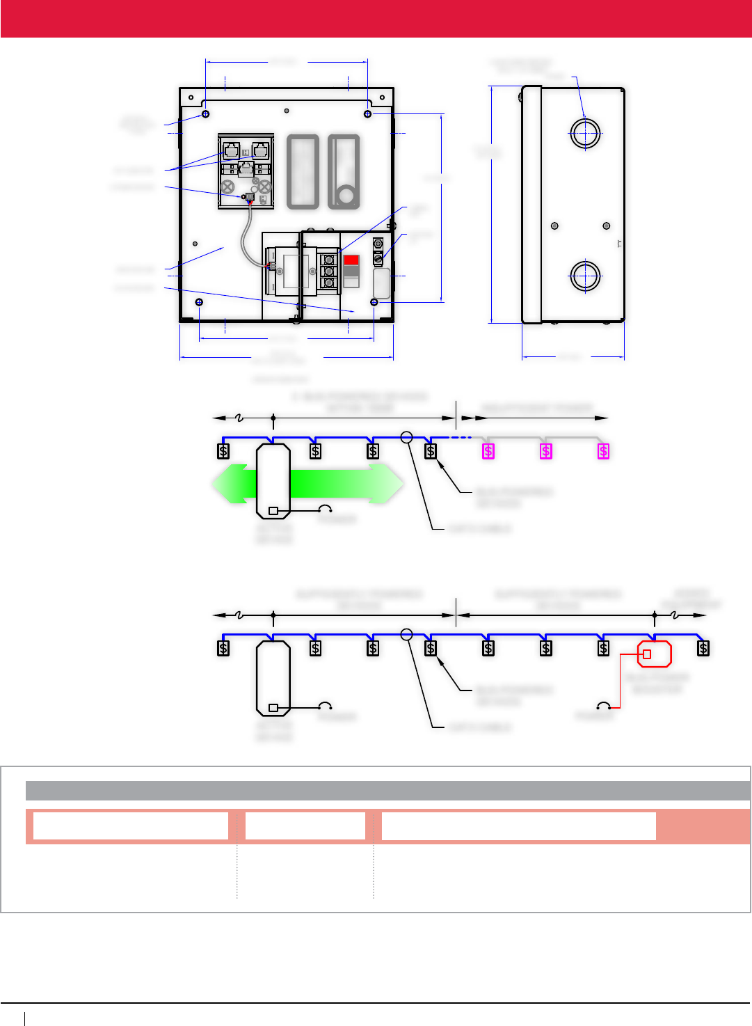
132
www.lightingcontrols.com • 800-345-4448
3 BUS-POWERED DEVICES
WITHIN 1000ft INSUFFICIENT POWER
DEVICES WITHIN
ALLOWED LIMIT
POWER
ACTIVE
DEVICE
POWER
ACTIVE
DEVICE
POWER
BUS-POWER
BOOSTER
ADDED
EQUIPMENT
SUFFICIENTLY POWERED
DEVICES
SUFFICIENTLY POWERED
DEVICES
CAT.5 CABLE
CAT.5 CABLE
BUS-POWERED
DEVICES
BUS-POWERED
DEVICES
+12
GND
GND
+24
BUS BUS
CLOCK
277VAC
120VAC
Neutral
EQUIPMENT
GROUNDING
ONLY
This box is intended to be
used in an installation in
which equipment is grounded
by connection to metal race-
way or metalic cable sheaths.
LIGHTING CONTROL & DESIGN LOS ANGELES
CALIFORNIA
TYPE 1
JUNCTION AND
PULL BOX
25UT
LISTED
E226385
U
®
L
LED
6.25" [15.9cm]
6.75" [17.2cm]
8.25" [21cm]
(8.4" [21.3cm] WITH COVER)
LED POWER INDICATOR
1.125/.875 DOUBLE KNOCKOUT,
FOR 1/2" - 3/4" CONDUIT
8 PLACES
.25" [.7cm]
MOUNTING HOLES
4 PLACES
9.15" [23.3cm]
WITH COVER
7.25" [18.4cm]
CAT. 5 CONNECTORS
3.94" [10cm]
LOW-VOLTAGE AREA
HIGH-VOLTAGE AREA
GROUNDING
LUG
TERMINAL
STRIP
COVER NOT SHOWN IN VIEW
Layout
Insufficient Power
Normally,upto3bus-powered
devices may be powered across
1000 feet of Cat. 5 cable. This
ensures that the power supplied
bytheMasterLCPissufficientfor
each device.
SpecifyingaBusBoosterallows
you to add more devices without
dropping voltage, because it
provides additional power to the bus.
GR2400 BOOSTER
ORDERING INFORMATION
Bus Booster
System and Type Transformer
DV=Dualvoltage120/277V
347=347volt
Mount and Enclosure Type
SMNE1=Surfacemount,NEMA1
FMNE1=Flushmount,NEMA1
133
800-345-4448 • www.lightingcontrols.com
Specifications:
Modem Switch
Description: TheModemSwitchmakesthemostofasinglephonelinebymakingitavailabletothephone,a
faxand/oramodem.TheModemSwitchactsasadigitalcallprocessortoautomaticallyscreenand
route incoming analog signals to the right equipment.
Features: • Easytoinstall
• Eliminatestheneedfordedicatedphonelines
• Plug-and-Play™device
• NoPCinterfaceordriversneeded
• Non-volatilememoryholdsallprogrammingindefinitely
• Barge-inprotectionpreventsinterruptionofongoingcallstoconnecteddevices
Enclosuredimensions: 8.15"wx1.4"hx2.4"d
Function: ON/OFF(statusLEDcanbefoundonthefrontofthedevice)
Powersupply: 12VDC
Busconnector:: RJ-11
Ambienttemperature: 32–104°F(0–40°C)
GR 2400™
Accessory
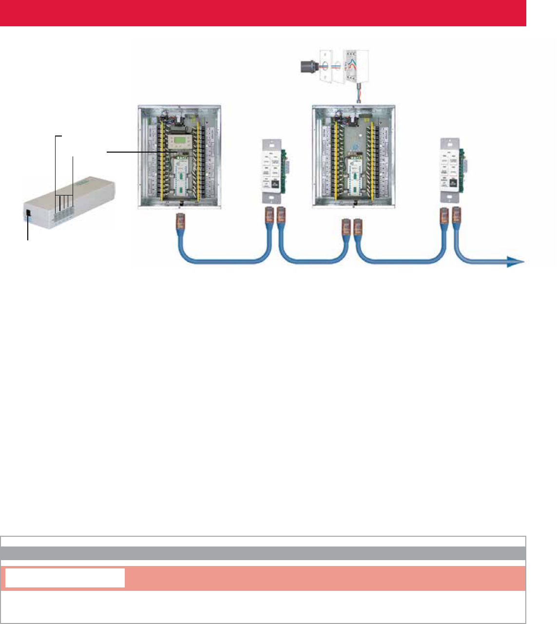
Hook Up Diagram
Power Supply
Modem
Cat. 5 patch cable with RJ45 connectors
Upto
127digital
addresses
Upto
4,000 ft.
Chelsea
DigitalSwitch
Photosensor
Remote Relay Panel
MasterRelayPanel
MicroPanel
LCDACC MODSW
ORDERING INFORMATION
Modem Switch
Modem Switch
ToFax/
Other Devices
135
800-345-4448 • www.lightingcontrols.com
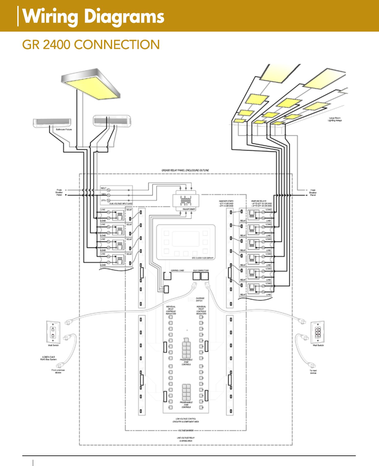
136
www.lightingcontrols.com • 800-345-4448
Recessed Fixture
Up/Down Fixture
6
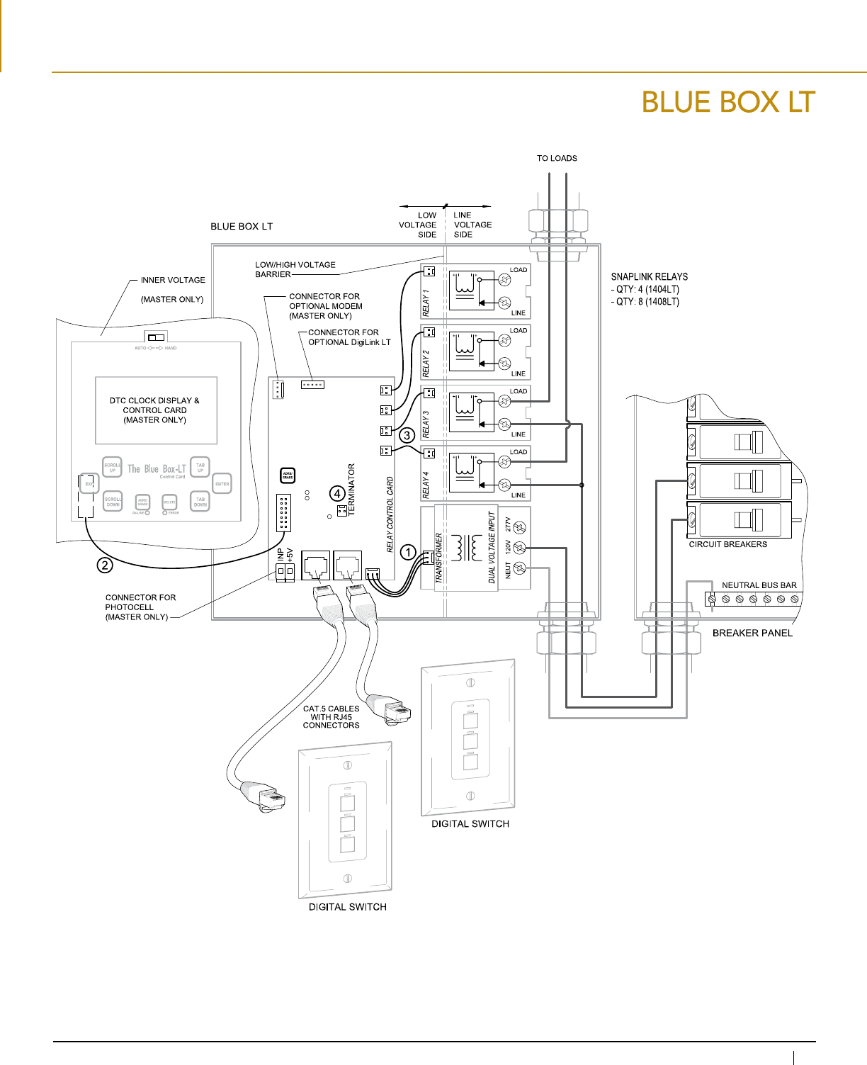
137
800-345-4448 • www.lightingcontrols.com
DEAD FRONT
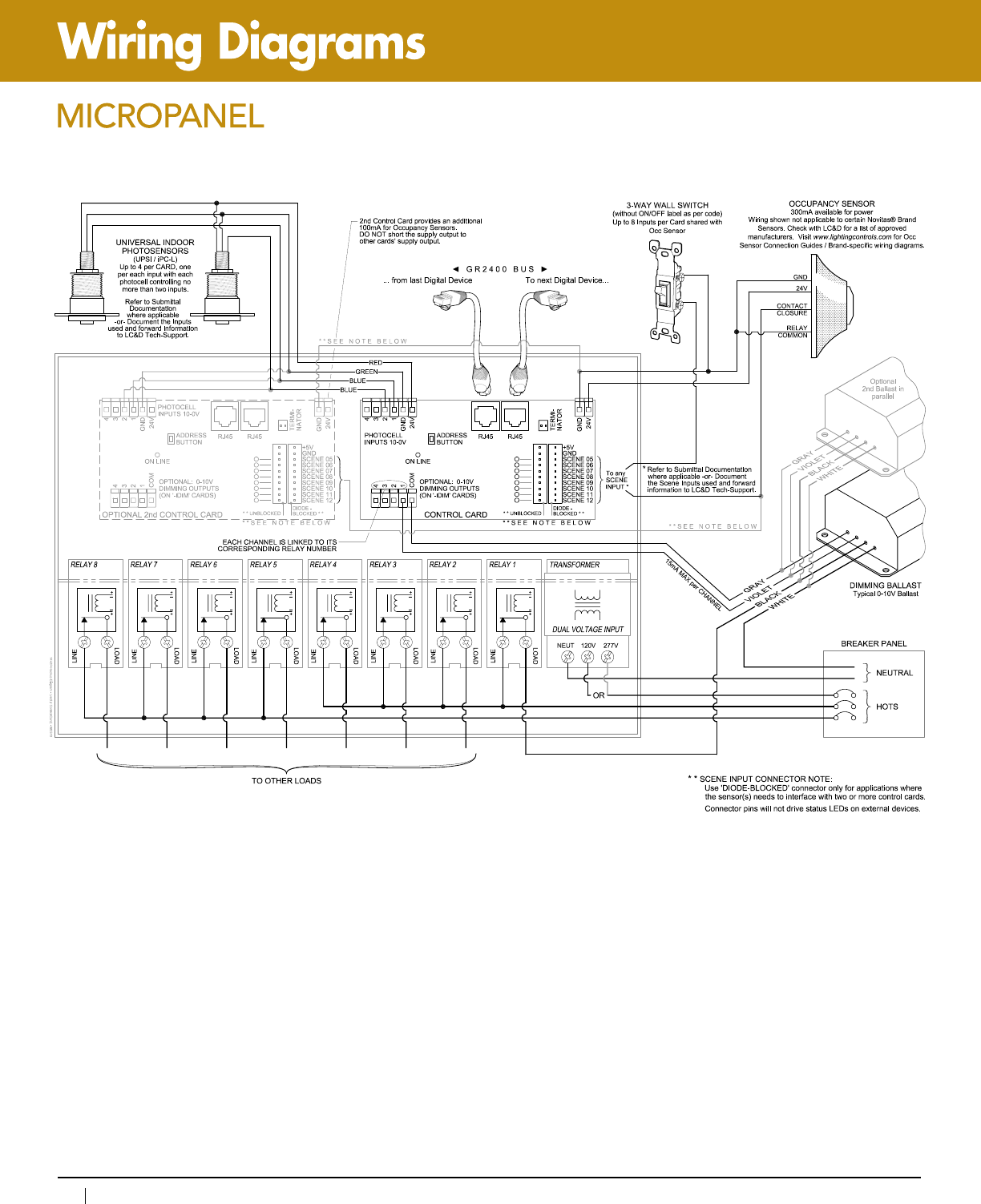
138
www.lightingcontrols.com • 800-345-4448
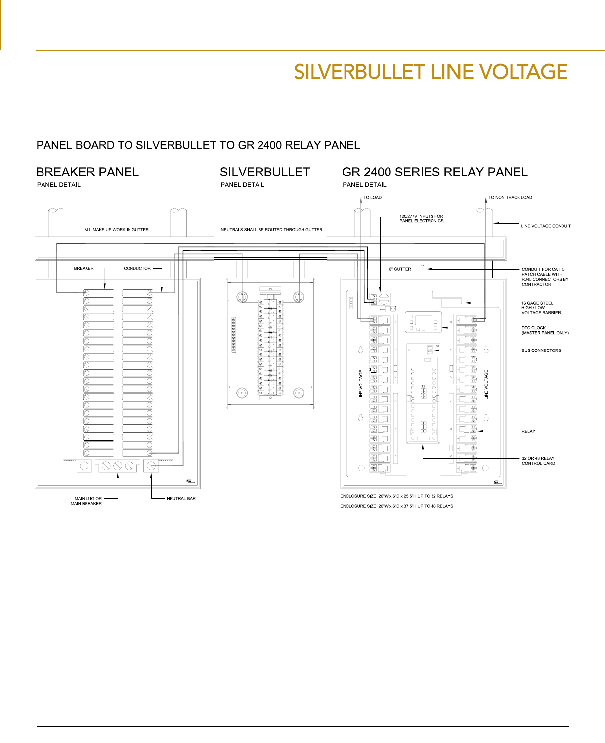
139
800-345-4448 • www.lightingcontrols.com
TYPICAL LINE VOLTAGE HOOK UP
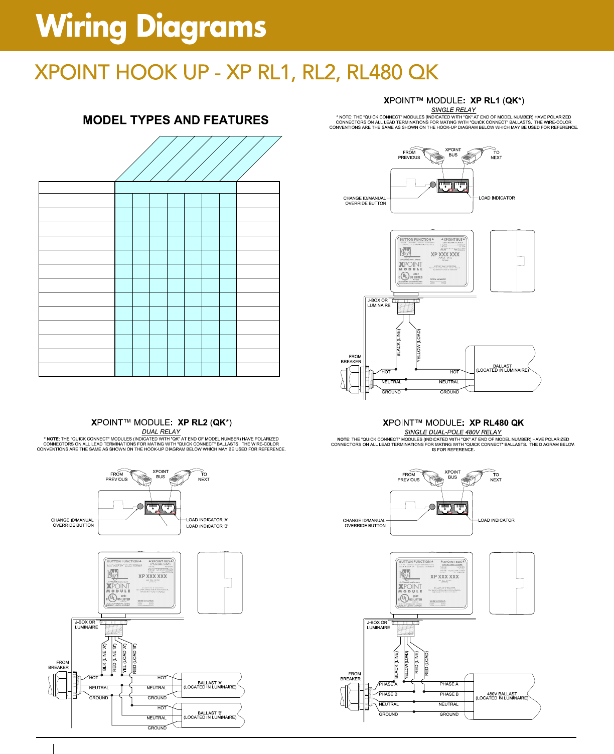
140
www.lightingcontrols.com • 800-345-4448
SINGLE RELAY
DUAL RELA
Y
SENSOR INPUTS
DIMMING OUTPUT
BUS-PWR DIM 347V
QUICK CONNECT
DUAL POLE 480V
FEATURES MARGAIDEPYT
XP RL1
●
A
XP RL1 QK
●
A (REF)
XP RL2
●
B
XP RL2 QK
● ●
B (REF)
XP RL1 PI
● ●
C
XP RL1 PI QK
● ● ●
C (REF)
XP RL1 DPI
● ● ●
D
XP RL1 DPI QK
● ● ● ●
D (REF)
XP DPI
● ●
E
XP DPI QK
● ● ●
E (REF)
XP RL1 DPI BUSP
● ● ● ●
F
XP RL1 DPI BUSP QK
● ● ●●●
F (REF)
XP RL480 QK
● ●
G (REF)
FEATURES
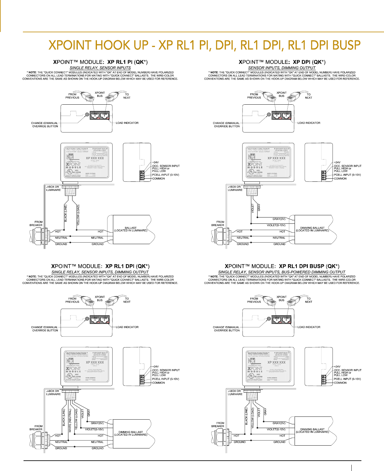
141
800-345-4448 • www.lightingcontrols.com
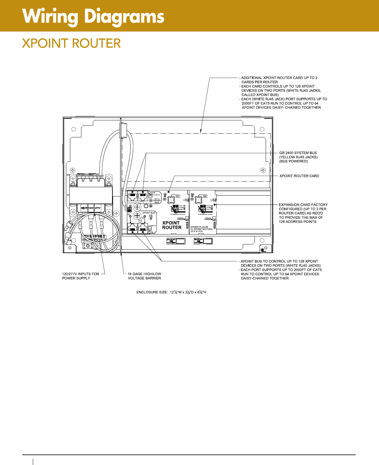
142
www.lightingcontrols.com • 800-345-4448
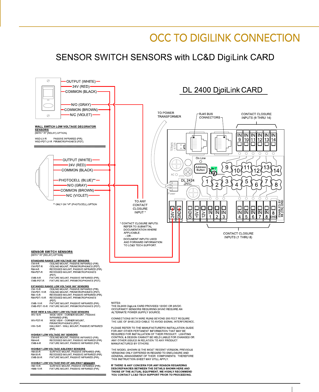
143
800-345-4448 • www.lightingcontrols.com
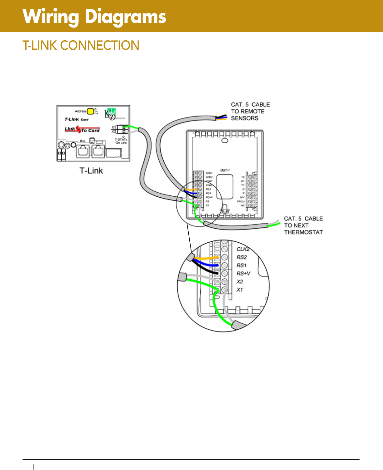
144
www.lightingcontrols.com • 800-345-4448
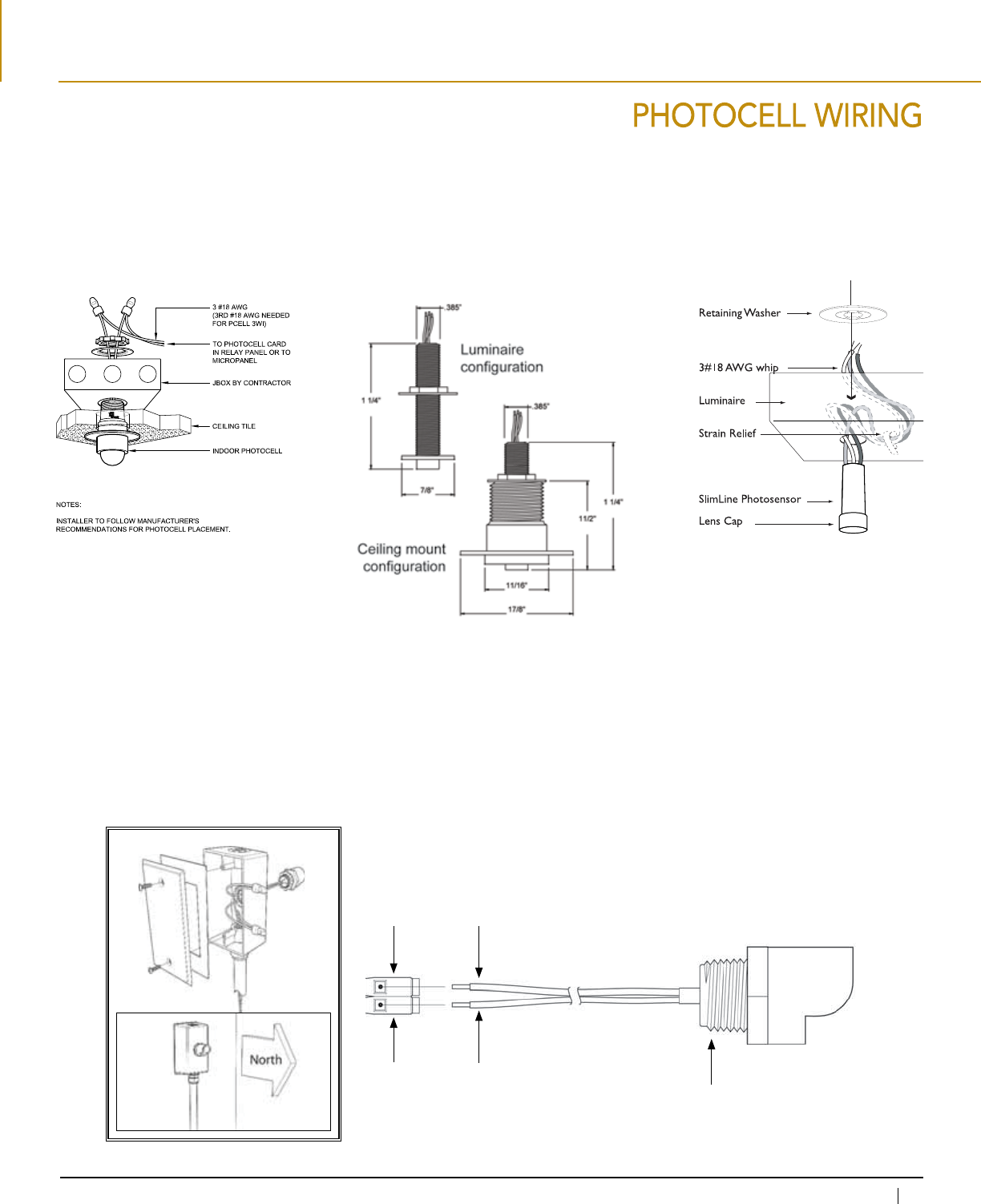
145
800-345-4448 • www.lightingcontrols.com
TWO-WIRE INDOOR PHOTOCELL THREE-WIRE PHOTOCELL SLIMLINE PHOTOCELL
8v Red conductor
Input Blue conductor
PCO has a 1/2 threaded
nipple, with a locking ring
(if needed).
OUTDOOR PHOTOCELL
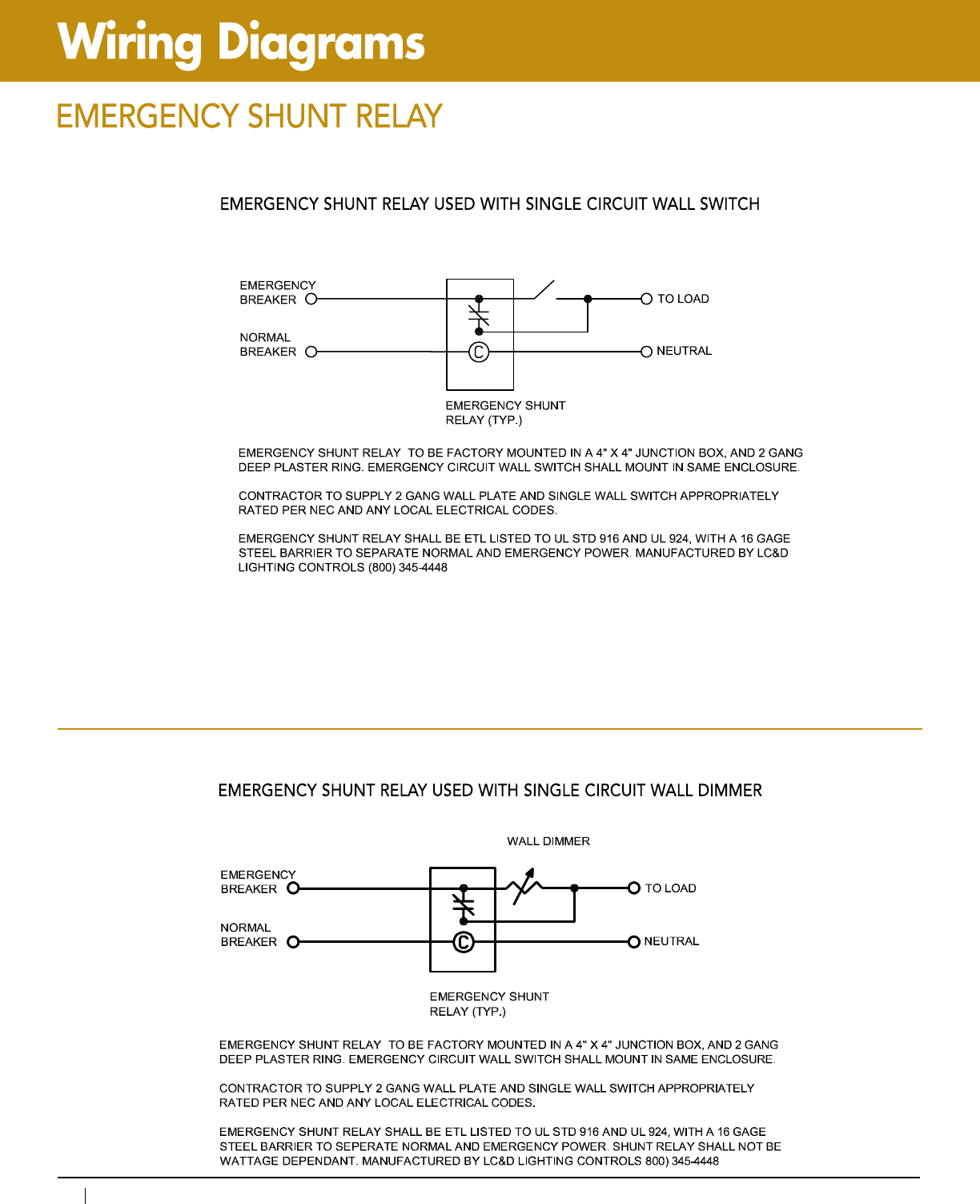
146
www.lightingcontrols.com • 800-345-4448
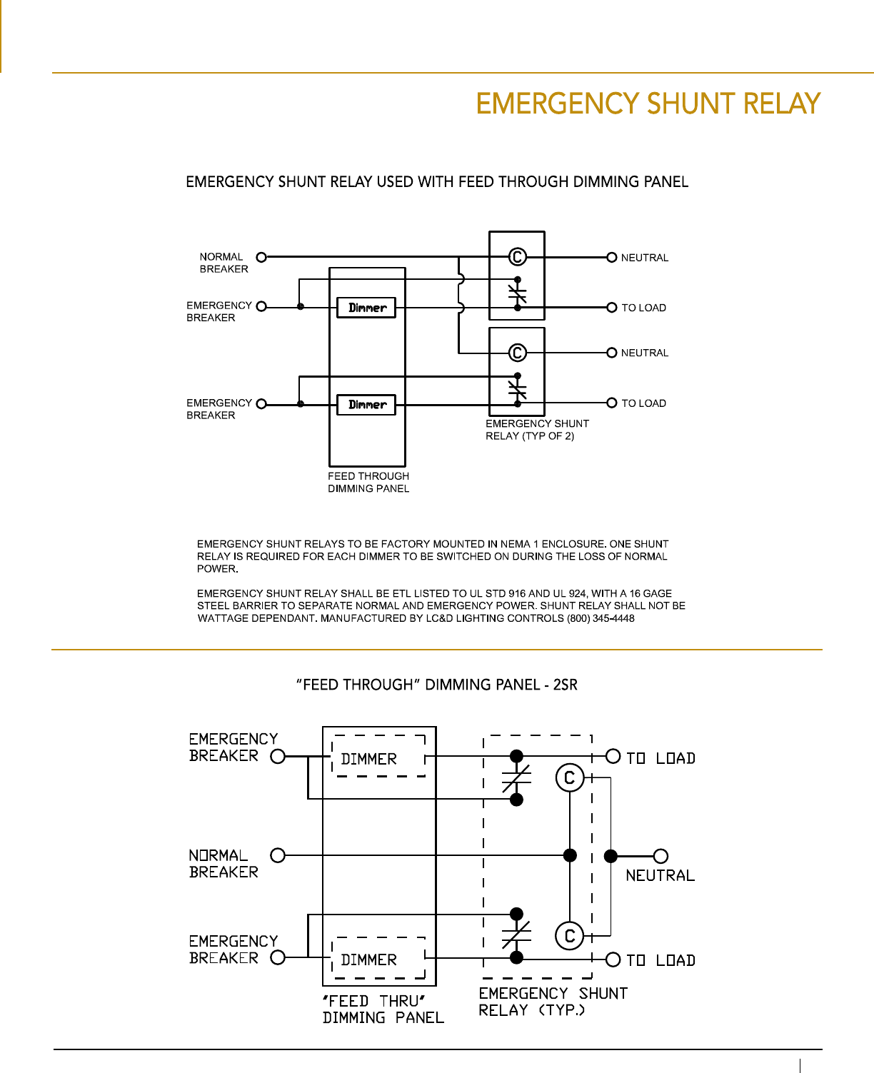
147
800-345-4448 • www.lightingcontrols.com
EMERGENCY SHUNT
RELAY (TYP.)
EMERGENCY
BREAKER
DIMMER
EMERGENCY
BREAKER
NORMAL
BREAKER
DIMMER
TO LOAD
NEUTRAL
TO LOAD
"Feed Through" Dimming Panel - 2SR
"FEED THRU"
DIMMING PANEL
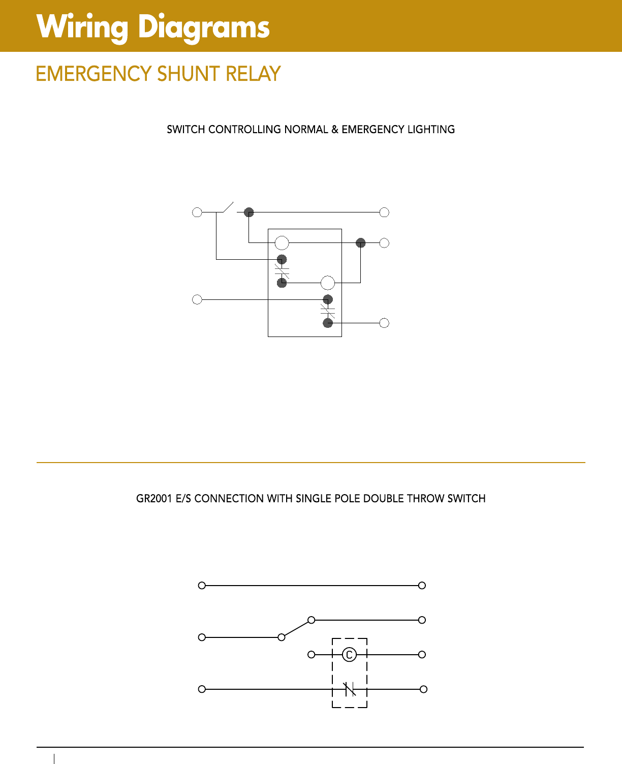
148
www.lightingcontrols.com • 800-345-4448
NEUTRAL
NORMAL
EMERGENCY
SPDT SWITCH
TO LOAD
GR2001 E/S
TO LOAD
NORMAL
NEUTRAL
TO LOAD
GR2001 E/S CONNECTION WITH SINGLE POLE DOUBLE THROW SWITCH
C
C
TO LOAD
NEUTRAL
TO LOAD
WALL SWITCH
NORMAL
BREAKER
EMERGENCY
BREAKER
DUAL EMERGENCY
SHUNT RELAY (TYP)
SWITCH CONTROLLING NORMAL & EMERGENCY LIGHTING