Installation Directions
1000397340-Brochure 1000397340-Brochure 1000397340-Brochure B5 unilog cesco-content
664942-Installationsheet 664942-InstallationSheet 664942-InstallationSheet 785991 Batch6 unilog cesco-content
2016-07-29
: Pdf 139053-Installationsheet 139053-InstallationSheet B2 unilog
Open the PDF directly: View PDF ![]() .
.
Page Count: 5
FPT4 SERIES POKE-THROUGHS
INSTALLATION INSTRUCTIONS
TA03724 E Page 1 of 5
COLUMN CATALOG NUMBER NEMA NUMBERS DESCRIPTION FURNISHED
A
FPT4-4P-4C-BRS
FPT4-4P-4C-ALM
FPT4-4P-4C-BLK
NEMA 5-20R
20A-125V
4 POWER RECEPTACLES
4 COMMUNICATION JACKS
POKE-THROUGH COMPLETE WITH
COVER
FPT4-4P-4C
FPT4-4P-4C-C
POKE-THROUGH
BASE UNIT ONLY
--COVER MUST
BE ORDERED
SEPARATELY--
BFPT4-2P-6C
FPT4-2P-6C-C
2 POWER RECEPTACLES
6 COMMUNICATION JACKS
CFPT4-8C
FPT4-8C-C N/A 8 COMMUNICATION JACKS
D
FPT4-1TL21-2C
FPT4-1TL21-2C-C
NEMA L5-20R
20A-125V 1 LOCKING POWER
RECEPTACLE
2 COMMUNICATION JACKS
FPT4-1TL22-2C
FPT4-1TL22-2C-C
NEMA L6-20R
20A-250V
FPT4-1TL31-2C
FPT4-1TL31-2C-C
NEMA L5-30R
30A-125V 1 LOCKING POWER
RECEPTACLE
2 COMMUNICATION JACKS
FPT4-1TL32-2C
FPT4-1TL32-2C-C
NEMA L6-30R
30A-250V
IMPORTANT - PLEASE READ ALL
INSTRUCTIONS BEFORE BEGINNING.
WARRANTY AND FIRE RESISTANCE RATING
ARE VOID IF PRODUCT INSTALLATION IS NOT
IN COMPLIANCE WITH THESE INSTRUCTIONS.
WARNING
ELECTRICAL HAZARD!
BE SURE POWER IS OFF!
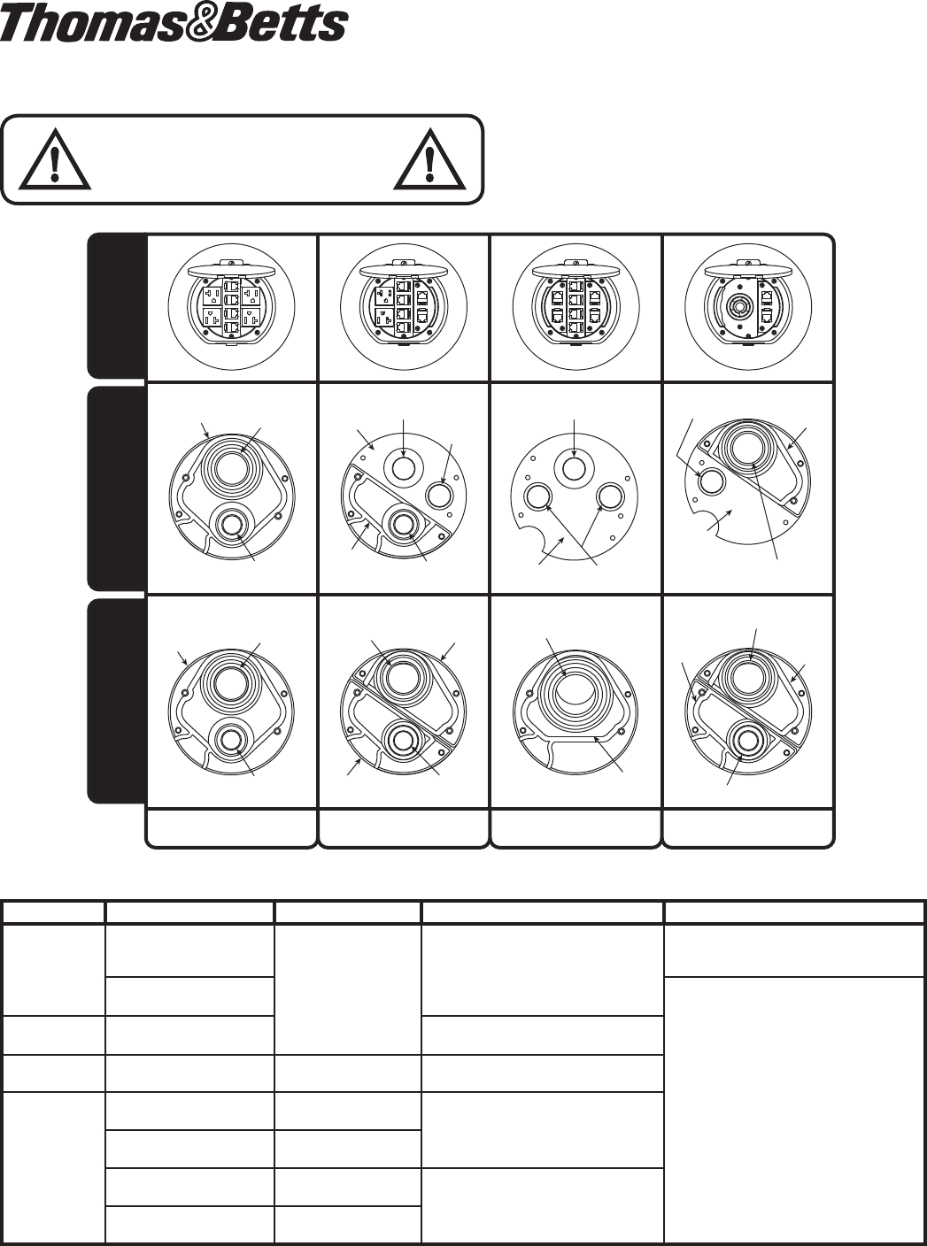
NOTE: “-C” at the end of Catalog Number indicates that the Poke-Through is approved for the City of Chicago
TOP VIEWS are shown with FPT4-CVR-XXX covers.
FPT4 Series Poke-Throughs will accept 2 styles of Covers: FPT-CVR-XXX and FPT-CVR-TXXX.
Check Thomas & Betts Catalog or website for details.
TOP VIEWSBOTTOM HUB VIEW
BOTTOM HUB VIEW
(City of Chicago ONLY!)
4P4C
Hub
1” NPS
Threads
Comm
1/2” NPS
Threads Power
Metal
Bottom
Plate
3/4” Center Thru
Hole Comm
1/2” NPS
Threads Power
Metal
Bottom
Plate
6C Hub
Metal
Bottom
Plate
1” NPS Threads Reduced
to 1/2” NPS for Power
4P4C
Hub
1” NPS
Threads
Comm
1/2” NPS
Threads Power
1” NPS
Threads
Comm 6C Hub
1/2” NPS
Threads Power
2P
Hub
2P
Hub
1-1/4” NPS Threads Comm
8C
Hub
1” NPS Threads Reduced to
1/2” NPS for Power
2P
Hub 6C
Hub
1/2” NPS Threads Comm
COLUMN A COLUMN B COLUMN C COLUMN D
3/4” Center Thru
Hole Comm
3/4” Side Thru
Hole Comm
3/4” Side Thru
Holes Comm
3/4”
Side Thru
Hole
Comm
IMPORTANT NOTES:
1. See product category “Outlet boxes and fittings”
classified for fire resistance in the current “Underwriters
Laboratories, Inc.” “Fire Resistance Directory” for the
fire resistance classification of the Thomas & Betts
Poke-Through System. Suitable for use in air handling
spaces in accordance with Sec. 300-22 (C) of the
National Electrical Code.
2. POKE-THROUGH FLOOR FITTING (Base Unit) IS
ONLY TO BE USED WITH A THOMAS & BETTS COVER
LISTED FOR USE WITH THIS UNIT. The system is
designed to maintain the hourly rating of concrete floors
having a fire rating of 1, 1-1/2 and 2 hours, only when
installed in accordance with these instructions.
3. TO MAINTAIN FIRE RESISTANCE CLASSIFICATION
RATING a complete Thomas & Betts service fitting,
including the service fitting base unit and service fitting
cover must be installed.
4. CONCRETE THICKNESS Min/Max:
1-HOUR RATED FLOOR: 2-1/4” min over top of deck
(or 3” thick reinforced concrete slab) to a maximum of
7-1/2”.
2-HOUR RATED FLOOR: 3-1/4” min over top of deck
(or 4” thick reinforced concrete slab) to a maximum of
7-1/2”.
5. SPACING:
Minimum of 2 ft. on center and not more than one device
per 65 sq. ft. of floor area in each span.
6. INSTALLATION:
Mount in a 4” diameter core-drilled hole in accordance
with these instructions.
7. FLOOR COVERINGS:
When installed in accordance with these instructions, this
Poke-Through is fire rated for carpet and wood covered
concrete floors, tile floor coverings up to 3/4” maximum
thickness, and linoleum floor coverings up to a maximum
of 1/8” thickness. Poke-Through may be installed directly
on concrete floor when no floor covering is planned.
8. MAXIMUM ALLOWABLE COPPER
CROSS-SECTIONAL AREA FOR
COMMUNICATIONS CABLING:
CAUTION
Receptacles supplied with these Poke-Throughs
are not suitable for direct field wiring. Electrical
conductor leads must be installed by manufacturer.
Contact Thomas & Betts for replacement. Field
modification will void UL Listing and Classification.
Use replacement (2-power) receptacles, complete
with conductor leads. Order Thomas & Betts
catalog number: FPT4-2P-RPL.
POKE-THROUGH
SERIES
SIDE
THROUGH
HOLE
CENTER
THROUGH
HOLE
SIDE
THROUGH
HOLE
FPT4-4P-4C SERIES
POWER .01630
SQ. IN. POWER
FPT4-2P-6C
SERIES
POWER .01630
SQ. IN.
.01536
SQ. IN.
FPT4-8C SERIES .01536
SQ. IN.
.01630
SQ. IN.
.01536
SQ. IN.
FPT4-1TL-2C SERIES POWER POWER .01536
SQ. IN.
NOTE: All power conductors are type THHN.
COPPER CROSS SECTIONAL AREA OF
COMMONLY USED CONDUCTORS
SIZE SOLID
#24 .00032 SQ. IN.
#22 .00050 SQ. IN.
#14 00323 SQ. IN.
#12 .00512 SQ. IN.
#10 .00815 SQ. IN.
#8 .01296 SQ. IN.
NOTE: Use above values for solid or stranded
conductors.
WARRANTY: Thomas & Betts sells this product with the
understanding that the user will perform all necessary
tests to determine the suitability of this product for the
user’s intended application. Thomas & Betts warrants
that this product will be free from defects in materials and
workmanship for a period of two (2) years following the date
of purchase. Upon prompt notification of any warranted
defect, Thomas & Betts will, at its option, repair or replace
the defective product or refund the purchase price.
Proof of purchase is required. Misuse or unauthorized
modification of the product voids all warranties.
Limitations and Exclusions: THE ABOVE WARRANTY IS
THE SOLE WARRANTY CONCERNING THIS PRODUCT,
AND IS IN LIEU OF ALL OTHER WARRANTIES EXPRESS
OR IMPLIED, INCLUDING BUT NOT LIMITED TO ANY
IMPLIED WARRANTY OF MERCHANTABILITY OR
FITNESS FOR A PARTICULAR PURPOSE, WHICH ARE
SPECIFICALLY DISCLAIMED. LIABILITY FOR BREACH
OF THE ABOVE WARRANTY IS LIMITED TO COST OF
REPAIR OR REPLACEMENT OF THE PRODUCT, AND
UNDER NO CIRCUMSTANCES WILL THOMAS & BETTS
BE LIABLE FOR ANY INDIRECT, SPECIAL,
INCIDENTAL
OR CONSEQUENTIAL DAMAGES.
TA03724 E Page 2 of 5
Thomas & Betts Corporation
Memphis, Tennessee
www.tnb.com
© 2010 Thomas & Betts. All Rights Reserved.
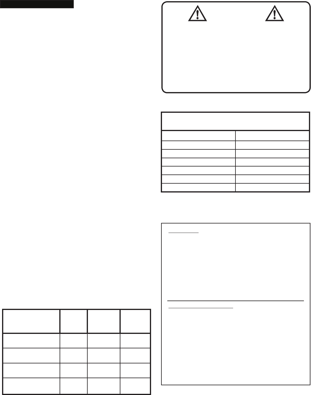
Step 1 -
Layout and Location Position of Hole:
CAUTION: See spacing note 5
under “Important Notes Section”.
NOTE: Be certain to drill hole at least 4-1/4”
from any wall or pillar to leave enough room for
Poke-Through and cover installation.
24” Minimum
Center to center
INSTALLATION STEPS:
FPT4-4P-4C and FPT4-2P-6C-C are used
in installation figures. These instruction steps
are applicable to all FPT4 series Poke-Throughs.
Temporary
Cover Screws
Touch Concrete
Floor
Top of
Concrete
Floor
TA03724 E Page 3 of 5
Step 2 - Drill Hole in Floor:
2.1 Install or cut hole from Carpet,
Wood, Tile or Linoleum Floor. Use
template provided with cover instructions.
(Poke-Through may be installed directly
on concrete floor if no finished floor is
planned).
2.2 Core Drill a 4” Diameter Hole. Actual
hole size may be 4-1/16” diameter due to
drill bit and jobsite construction tolerances.
Finished Floor
See Step 2.1
Concrete
See Step 2.2
Poke - Through
may be Installed
Directly on
Concrete Floor
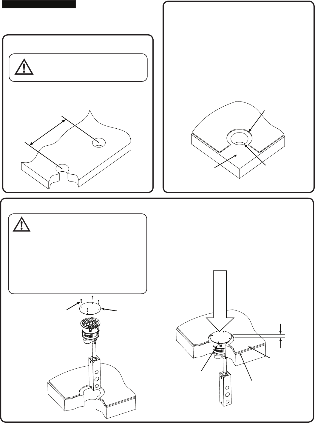
Step 3 - Base Unit Assembly:
CAUTION:
Poke-Through cannot
be rotated after inserting into hole.
Verify receptacles and communication
outlets are in desired orientation before
inserting unit into hole. (Temporary cover
may need to be removed to see device
layout). Replace temporary cover before
installing base unit into floor. Keep
temporary cover in place until step 4.
IMPORTANT! If flexible conduit is used, electrical
connections may be made before inserting
base unit into hole. (Except City of Chicago)
See note C in Step 5.
Insert base unit into hole and push down until
screws in temporary cover contact concrete floor.
Temporary
Cover Screw
Temporary Cover
3/4” off Concrete
Floor
Temporary Cover
Not For
Abandonment Use
Carpet,
Wood,Tile or
Linoleum Floor
( )
TA03724 E Page 4 of 5
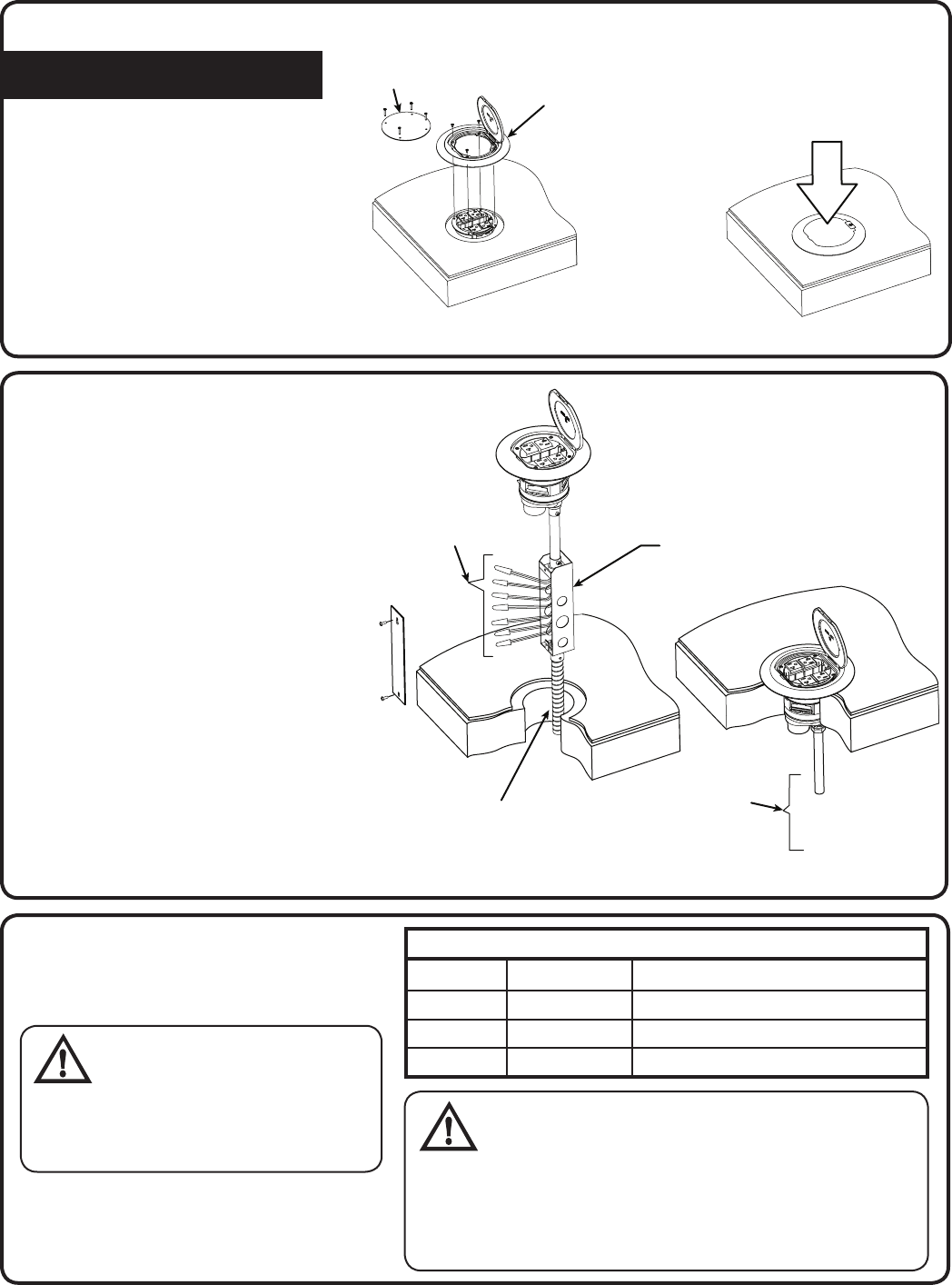
Step 4 - Cover Assembly:
Install FPT4 series cover using
instructions provided with cover.
Remove
Temporary
Cover
Install FPT4 Series
Cover per Instructions
Provided with Cover
Step 5 - Electrical Connections:
Remove two screws and remove cover
from junction box. See Step 6 for
Wiring Diagram. Locking receptacles
have only one circuit.
Attach conduit and provide wiring
connections as required by national
and local electrical codes.
NOTE A: Factory supplied junction box
shown.
NOTE B: City of Chicago Approved
Poke-Through units must use an EMT
compression fitting (not furnished) and
a Chicago Approved Junction Box (not
furnished). Electrical connections must
be made after Poke-Through is pushed
firmly into hole and cover is installed.
Junction Box 27 CU. IN.
Make Wiring
Connections
per Wiring
Diagram,
see Step 6
NOTE D: For City of
Chicago use EMT
Compression Fitting
and City of Chicago
Approved Junction Box
NOTE C: If Flexible Conduit is attached
to bottom of junction box, Poke-Through
Electrical Connections may be Completed
before Poke-Through is installed in Hole
Step 6 - Wiring Diagram:
Connect receptacle conductor leads to
the branch circuit conductors, as required.
WARNING: Ground screw
in junction box must be
connected
to SYSTEM GROUND
as required by national and local
electrical codes.
ELECTRICAL WIRING CHART
CIRCUIT “A” CIRCUIT “B”
HOT BLACK BLACK WITH YELLOW TRACER
NEUTRAL WHITE WHITE WITH YELLOW TRACER
GROUND GREEN GREEN WITH YELLOW TRACER
CAUTION:
RECEPTACLE MOUNTING
MEANS
not grounded for FPT4-4P-4C series
and FPT-2P-6C series Poke-Throughs. Grounding
wire connection required. For isolated ground wiring;
connect ground leads to separate isolated grounding
conductor, see Step 7. See NEC 250-146 (D).
After Cover is Screwed to
Poke-Through, Close Lid
and Push Down on Top
(Step on Cover) to Fully
Seat Cover to Floor
A
A
B
B
TA03724 E Page 5 of 5
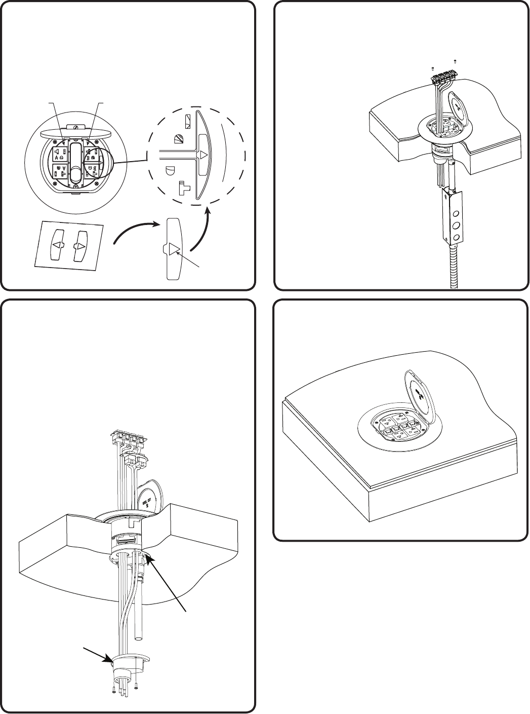
Step 7 - Isolated Ground Labels:
If circuit is connected to an isolated ground, apply
IG label (orange triangle) on side of receptacle as
shown.
NOTE: Only use IG label on devices wired for
isolated ground. See NEC 250-146 (D).
Circuit “A”
Circuit “B”
Step 8 - Communication Connections:
Communication cable, jacks and mounting plates
can be installed after cover is installed to floor.
All FPT4 series
Poke-Throughs come
complete with
Thomas & Betts
Omni-Plus™
Category 5e
jacks and
communication
plates.
Other style
communication plates
are available: consult
Thomas & Betts catalog
or customer service.
IMPORTANT: See Step
9 for additional City of
Chicago instructions
Step 9 - Communication Hub Connections
City of Chicago Only:
NOTE: Bottom communication hub must be
removed to route communication cable into
conduit. Re-attach hub after routing cable
through. Threaded NPS connection is provided
on Communication Hub to provide EMT conduit
connection.
Bottom
Communication Hub
Must be Removed to
Route Cable.
Re-Install after
Cable is Routed
FPT4-2P-6C-C
Shown
Step 10 - Installation Complete
Orange
Triangle
IG Labels
