Catalog_2016_COVER_WEB Brochure
2016-10-06
: Pdf 139387-Brochure 139387-Brochure B5 unilog
Open the PDF directly: View PDF ![]() .
.
Page Count: 266 [warning: Documents this large are best viewed by clicking the View PDF Link!]

35TH ANNUAL CATALOG
aeesolar.com 2016 CATALOG & DESIGN GUIDE 800.777.6609
The Essential Guide To Everything Solar
Delivering Success
Contents
System Design ....................................1
Grid-Tie Systems ................................... 1
Battery Backup Systems .............................. 4
AC-Coupled Systems ................................ 6
Off-Grid Systems ................................... 7
Solar Modules ....................................12
System Design ................................... 12
Multi-Crystalline (Poly) Modules ....................... 14
Mono-Crystalline Modules ........................... 16
12 VDC Modules .................................. 17
Mounting Structures ..............................19
SnapNrack ...................................... 19
Roof Attachments ................................. 28
Commercial Roof and Ground ......................... 33
Pole Mounts ..................................... 39
Trackers ........................................ 45
Wind Power ......................................48
System Design ................................... 48
Wind Measurement ................................ 49
Wind Turbines .................................... 50
Grid-Tie Inverters .................................54
System Design ................................... 54
Module-Level Power Electronics ....................... 55
String Inverters ................................... 65
Battery-Based Inverters ............................79
System Design ................................... 79
OutBack Inverters & Accessories ....................... 83
Grid-Interactive Inverters ............................ 93
Off-Grid Inverters ................................. 97
Pre-Wired Power Panels .............................105
Converters & Controls ............................107
Transformers .....................................107
Converters ......................................108
Generator Start Controls ............................109
Relays and Controls ................................110
Battery Chargers ..................................112
Diversion Loads ...................................114
Charge Controllers ...............................116
Outback Power ...................................118
Midnite Solar ....................................120
Magnum-Dimensions ...............................123
Schneider Electric .................................125
Morningstar .....................................127
Blue Sky Energy ..................................133
Atkinson ........................................136
Meters & Monitoring .............................137
DC Meters ......................................137
AC Kilowatt-Hour Meters ............................139
Grid-Tie System Monitoring ..........................141
Batteries ........................................147
System Design ...................................147
Sealed Batteries ..................................152
Flooded Batteries .................................160
High Cycle-Life Batteries ............................163
Enclosures ......................................164
Accessories ......................................167
Electrical Distribution Parts ........................168
Power Panels ....................................168
Fuses and Breakers ...............................173
Surge Protection .................................181
Grounding .....................................183
Array Combiners .................................185
Disconnects ....................................194
Load Centers ...................................196
Connectors, Blocks and Transfer Switches ...............197
Wire & Cable ....................................199
Battery Cables. . . . . . . . . . . . . . . . . . . . . . . . . . . . . . . . . . . 199
Array Cables and Connectors ........................202
Wire-Management Hardware ........................203
Water Pumps ....................................205
System Design ..................................205
Submersible Pumps ...............................207
Surface Pumps ..................................214
Pump Accessories ................................230
Water-Powered Pumps .............................231
Tools ...........................................232
Array and Battery Cable Tools ........................ 232
System Commissioning Tools ........................234
Safety Labels ....................................236
Electric Vehicle Charging Stations ..................241
Reference .......................................243
Maximum Ampacities for Wire .......................243
Inverter Cable and Overcurrent Protection ...............244
Wire Loss Tables .................................245
Solar Insolation ..................................247
Peak Sun Hours per Day - Lowest Monthly Average .........248
Glossary .......................................253

Delivering Success
A family of passionate, committed professionals that leverages our rich solar heritage
to ensure that our customers and partners succeed
in building the solar ecosystem that will create a planet run by the sun.

2016 AEE Solar
RENEWABLE ENERGY DESIGN GUIDE & CATALOG
2015 was another record year for AEE Solar. Thanks to our valued employees and loyal customers we con-
tinue to grow well above industry average and this trend is expected to continue. We remain committed
to improving our level of service, product offering and overall support to our customers. Throughout 2015,
signicant investments in people and infrastructure came to fruition. Our new East Coast warehouse in
Pennsylvania and the launch of AEE Express, our new Ecommerce platform, are just two great examples.
We can now reach more customers with one-day delivery than ever before as well as provide our dealers
with a great online shopping experience. It is now easier than ever to shop and buy products online from
AEE Solar.
We are optimistic and excited about 2016! Despite a high level of uncertainty with regards to the Invest-
ment Tax Credit, we are convinced that this will be another record year. The fundamentals of our industry
have not changed and, if anything, are getting better, not worse. Our cause is just, our dealers are savvy
and customer demand remains very strong. AEE Solar will continue to expand its product offering, its dis-
tribution footprint and leverage the signicant investments made by our parent company, Sunrun, to the
benet of AEE Solar dealers.
But 2016 marks another important milestone. This will be our 35th year publishing the AEE Solar Renewable
Energy Design Guide and Catalog. I can proudly say that there is no other book in the industry that offers
this level of detailed information acquired through eld experience. In addition to exciting new products
and the usual updates, we’ve revised our system-sizing worksheets and added signicantly to the informa-
tional content, including an all-new glossary in the reference section that explains some of the jargon you
hear around the industry.
I’m especially excited about some of the new products and services we’re planning to roll out later this year,
from new racking and energy-management solutions to automated system-design support. I hope you’ll
keep in touch via our Facebook® and YouTube® pages or our e-mail lists so that you don’t miss the latest
products and tools to help you grow your solar business. I look forward to supporting all of you as we make
2016 the solar industry’s biggest year yet. Stay tuned!
Sincerely,
Antonio Cintra, President, AEE Solar
Help Us Keep This Resource Up-to-Date
Keeping this catalog accurate and up-to-date is very important to us. While we do our best, we cannot
guarantee that every specication and detail is current since products and specications can change with-
out notice, as can availability. Please let us know if you suspect any information may be inaccurate. We
always appreciate your feedback and can be reached anytime at salessupport@aeesolar.com.
Contact Us for All Your Renewable Energy Needs
As questions arise, we look forward to answering them. Please call us at 800-777-6609, email us at salessup-
port@aeesolar.com, or visit our contact page at www.aeesolar.com/contact. We thank you and look forward
to working closely with you to take advantage of all the great opportunities that 2016has to offer.
For the latest on AEE Solar products, trainings and dealer services, visit www.aeesolar.com
SYSTEM DESIGN
1
Grid-Tie Systems
Utility Grid-Tie PV System Design
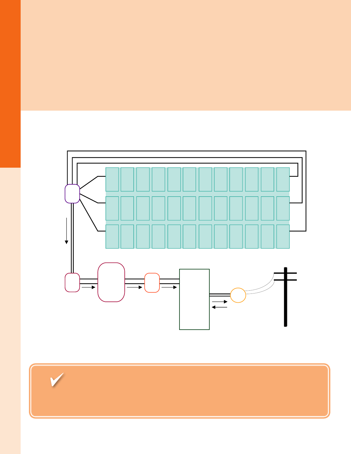
A grid-connected PV system consists of PV modules, output cables, a module mounting structure, AC and DC disconnect switches,
inverter(s), grounding equipment, and a metering system, as shown in the diagram below. The Grid-Tie System Worksheet is designed
to help size a PV array to offset a site’s electrical usage with the largest system that would be cost-effective to install. A smaller system
can reduce part of the electric bill, and in locations with tiered or progressive rates, it may have a faster nancial payback. Compare the
worksheet result with the amount of space available to mount the PV array in order to get a rough idea of the maximum PV array size.
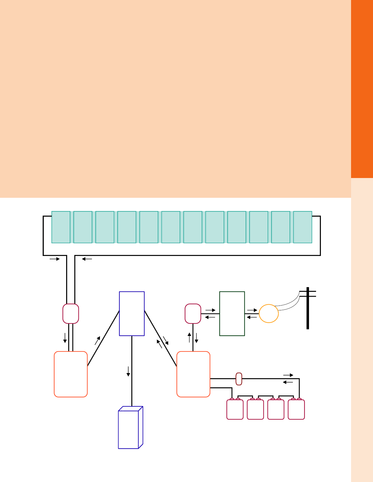
Below is a diagram of a typical grid-tie system (utility intertie) without energy storage. Many grid-tie inverters have built-in DC
disconnect switches, while some have both a DC and an AC disconnect. Many models also contain a PV array string combiner so a
separate one may not be necessary. Separate overcurrent protection for each series string of modules in a PV array (typically provided
in the array combiner box) is required only if there are three or more series strings of modules connected to a single inverter input.
Inverters with multiple MPPT input channels can have one or two series strings per channel without individual string fusing.
Utility
Service/Load
Center
Solar PV Array
String 1
String 3
String 2
Array String
Combiner
(3 or more strings)
DC Disconnect
(typically packaged
with inverter)
Grid-Tie
Inverter
AC
Disconnect
Utility
Grid
Utility
Meter
AEE Solar was born in 1979, long before grid-tie, when off-grid solar was the only
form of domestic solar PV. So when it comes to off-grid know-how and equipment knowledge,
AEE Solar’s experience, expertise, and product selection is unsurpassed.

For the latest on AEE Solar products, trainings and dealer services, visit www.aeesolar.com
SYSTEM DESIGN
2
Grid-Tie Systems
Worksheet: Grid-Tie PV System Design
Determine PV array size for a grid-tied system (no energy storage)
Step 1: Determine the daily average electricity usage from the electric bills.
This will be in kilowatt-hours (kWh). Due to air conditioning, heating, and other seasonal usage, it is
a good idea to add up all the kWh for the year and then divide by 365 to nd the average daily usage.
Step 2: Find the location's average peak sun-hours per day.
See the map below and/or the insolation map in the Reference section near the end of the catalog. For
example, the average for Central California is 5 sun-hours. NREL’s PVWatts online sizing program (http://
pvwatts.nrel.gov/) can provide this data as well as monthly and yearly expected AC production totals. It
can also account for array tilt-angle and azimuth to get more accurate results.
Step 3: Calculate the system size (AC watts) needed to offset the average usage.
Divide the daily average electricity use by average sun-hours per day. For example, if the daily average
electricity use is 30 kWh and the site is in Central California, system size would be: 30 kWh / 5 h = 6
kW AC. Multiply kW by 1,000 to get AC watts.
Step 4: Calculate total required nameplate power of the PV array.
Divide the AC watts from Step 3 by the system derate factor. Use a derate factor of 0.82 for most systems
(this is the standard derate used by PVWatts). For example, if an array size of 6,000 WAC is calculated
in Step 3, divide 6,000 WAC by 0.82 to get 7,318 WDC based on the module’s STC rating.
NOTE: Derating factors
The overall system derating factor represents losses in the system due to the difference between the
PV module’s nameplate DC ratings, and actual expected output in real-world conditions, module
mismatch, losses in diodes, connections and wiring, module soiling, array shading, tracking error,
system aging, and the inverter efciency at maximum power. The default derate typically used
is 0.82, but specic site conditions and equipment used may cause variations. The 0.82 derate is
based on 14% systemic losses and 96% inverter efciency.
Step 5: Calculate the number of PV modules required for this system.
Divide the system DC wattage in Step 4 by the nameplate rating of the chosen modules to calculate the
number of PV modules needed to provide the desired AC output.
Step 6: Select the inverter/module combination from the table on the next page that is closest
to the desired system size.
The table on the next page shows inverter and
module combinations for our most popular mod-
ules and grid-tie inverters. For a given inverter and
module combination, the table displays the recom-
mended number of series strings of modules and
the number of modules per string for temperatures
between 14 °F and 104 °F. Where the inverter will
support more than one string of modules, the table
also shows the maximum number of modules that
can be used with multiple strings.
Sizing is accurate in locations where the maximum
temperature is lower than 104 °F and the minimum
temperature is higher than 14 °F. In locations where the minimum temperature is lower than 14 °F, the
maximum number of modules per string may need to be lower in order to prevent over-voltage.
The line labeled “PTC” is the expected output of the modules at normal operating temperature in full
sun. The approximate power output of a system in full sun will be the number of modules multiplied by
the watt rating of the modules and then multiplied by the inverter efciency from the second column in
the table. Other factors, such as high or low temperatures, shading, array orientation, roof pitch, and dirt
on the modules, will affect the system’s actual output.
For the latest on AEE Solar products, trainings and dealer services, visit www.aeesolar.com
SYSTEM DESIGN
3
Grid-Tie Systems
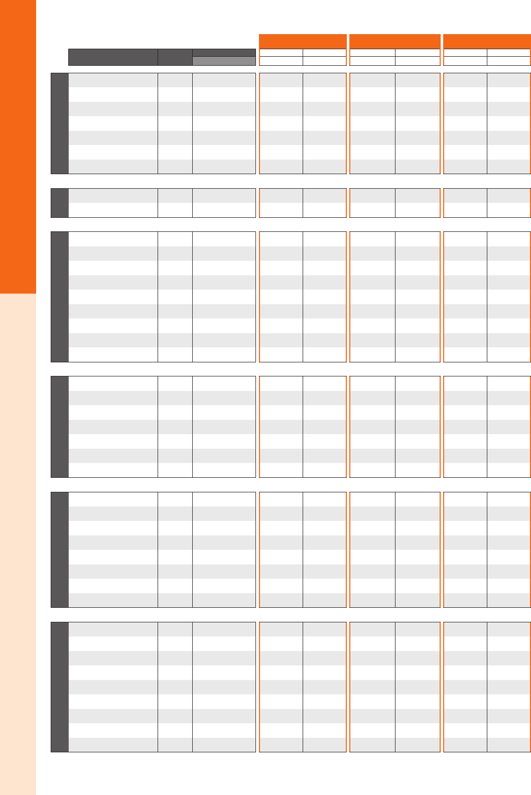
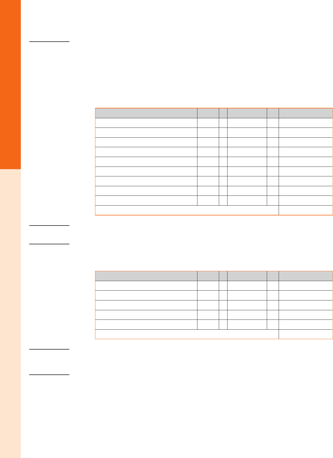
REC TP LG Suniva
Inverter ↓ CEC
% V ↓
Module → REC275TP REC280TP LG310N1CG4 LG315N1CG4 OPT275 OPT280
CEC → 252.4 257.1 282.7 287.4 244.5 249.1
Solar Edge
SE3000A-US-U 98.0% string/max mods 8-13 / 13 8-13 / 13 8-12 / 12 8-11 / 11 8-13 / 13 8-13 / 13
SE3800A-US-U 97.5% string/max mods 8-17 / 17 8-16 / 16 8-15 / 15 8-15 / 15 8-17 / 17 8-16 / 16
SE5000A-US-U 97.5% string/max mods 8-19 / 22 8-18 / 22 8-16 / 20 8-16 / 19 8-19 / 22 8-18 / 22
SE6000A-US-U 97.5% string/max mods 8-19 / 27 8-18 / 26 8-16 / 24 8-16 / 23 8-19 / 27 8-18 / 26
SE7600A-US-U 97.5% string/max mods 8-19 / 34 8-18 / 34 8-16 / 30 8-16 / 30 8-19 / 34 8-18 / 34
SE10000A-US-U 97.5% string/max mods 8-19 / 45 8-18 / 44 8-16 / 40 8-16 / 39 8-19 / 45 8-18 / 44
SE11400A-US-U 97.5% string/max mods 8-19 / 52 8-18 / 51 8-16 / 46 8-16 / 45 8-19 / 52 8-18 / 51
Enphase
Enphase M215 96.5% One module No No No No No No
Enphase M250 96.5% One module Yes Yes Yes Yes Yes Yes
Fronius
Primo 3.8-1 95.5% string/max mods 6-13 / 17 6-13 / 17 6-13 / 15 6-13 / 15 6-13 / 17 6-13 / 17
Primo 5.0-1 96.5% string/max mods 7-13 / 22 7-13 / 22 7-13 / 20 7-13 / 19 7-13 / 22 7-13 / 22
Primo 6.0-1 96.5% string/max mods 7-13 / 27 7-13 / 26 7-13 / 24 7-13 / 23 7-13 / 27 7-13 / 26
Primo 7.6-1 97.0% string/max mods 7-13 / 34 8-13 / 34 7-13 / 31 7-13 / 30 7-13 / 34 7-13 / 34
Primo 8.2-1 97.0% string/max mods 8-13 / 37 8-13 / 36 7-13 / 33 7-13 / 32 8-13 / 37 8-13 / 36
Primo 10.0-1 est 96.5% string/max mods 7-13 / 45 7-13 / 44 7-13 / 40 7-13 / 39 7-13 / 45 7-13 / 44
Primo 11.4-1 est 96.5% string/max mods 7-13 / 51 7-13 / 50 7-13 / 46 7-13 / 45 7-13 / 51 7-13 / 50
Primo 12.5-1 est 96.5% string/max mods 8-13 / 56 7-13 / 55 7-13 / 50 7-13 / 49 8-13 / 56 8-13 / 55
Primo 15.0-1 est 96.5% string/max mods 9-13 / 68 9-13 / 66 8-13 / 60 7-13 / 59 9-13 / 68 9-13 / 66
SMA
SB3000TL-22 96.5% string/max mods 6-13 / 13 6-13 / 13 6-12 / 12 6-11 / 11 6-13 / 13 6-13 / 13
SB3800TL-22 97.0% string/max mods 6-13 / 17 6-13 / 17 6-13 / 15 6-13 / 15 6-13 / 17 6-13 / 17
SB4000TL-22 97.0% string/max mods 6-13 / 18 6-13 / 17 6-13 / 16 6-13 / 15 6-13 / 18 6-13 / 17
SB5000TL-22 97.0% string/max mods 6-13 / 22 6-13 / 22 6-13 / 20 6-13 / 19 6-13 / 22 6-13 / 22
SB6000TL-22 97.0% string/max mods 7-13 / 27 7-13 / 26 7-13 / 24 7-13 / 23 7-13 / 27 7-13 / 26
SB7000TL-22 96.5% string/max mods 8-13 / 31 8-13 / 31 7-13 / 28 7-13 / 27 8-13 / 31 8-13 / 31
SB7700TL-22 96.5% string/max mods 8-13 / 34 8-13 / 34 8-13 / 31 8-13 / 30 8-13 / 34 8-13 / 34
ABB
PVI-3.0-OUTD-S-US-A 96.0% string/max mods 5-13 / 13 5-13 / 13 5-12 / 12 5-11 / 11 5-13 / 13 5-13 / 13
PVI-3.6-OUTD-S-US-A 96.0% string/max mods 5-13 / 16 5-13 / 16 4-13 / 14 4-13 / 14 5-13 / 16 5-13 / 16
PVI-3.8-OUTD-S-US-A 96.0% string/max mods 5-13 / 17 5-13 / 17 5-13 / 15 5-13 / 15 5-13 / 17 5-13 / 17
PVI-4.2-OUTD-S-US-A 96.0% string/max mods 5-13 / 19 5-13 / 18 5-13 / 17 5-13 / 16 5-13 / 19 5-13 / 18
PVI-5000-OUTD-S-US-A 96.5% string/max mods 6-13 / 22 6-13 / 22 6-13 / 20 6-13 / 19 6-13 / 22 6-13 / 22
PVI-6000-OUTD-S-US-A 96.5% string/max mods 6-13 / 27 6-13 / 26 6-13 / 24 6-13 / 23 6-13 / 27 6-13 / 26
UNO-7.6-TL-OUTD-S-US-A 96.5% string/max mods 6-13 / 34 6-13 / 34 6-13 / 30 6-13 / 30 6-13 / 34 6-13 / 34
UNO-8.6-TL-OUTD-S-US-A 96.5% string/max mods 6-13 / 39 6-13 / 38 6-13 / 34 6-13 / 34 6-13 / 39 6-13 / 38
Ginlong
SOLIS-1K-2G-US 96.0% string/max mods 4 / 4 4 / 4 4 / 4 - 4 / 4 4 / 4
SOLIS-1.5K-2G-US 96.0% string/max mods 5-6 / 6 5-6 / 6 5-6 / 6 5 / 5 5-6 / 6 5-6 / 6
SOLIS-2K-2G-US 96.0% string/max mods 6-9 / 9 6-8 / 8 6-8 / 8 6-7 / 7 6-9 / 9 6-8 / 8
SOLIS-2.5K-2G-US 96.5% string/max mods 5-11 / 11 5-11 / 11 5-10 / 10 5-9 / 9 5-11 / 11 5-11 / 11
SOLIS-3K-2G-US 96.5% string/max mods 5-13 / 13 5-13 / 13 5-12 / 12 5-11 / 11 5-13 / 13 5-13 / 13
SOLIS-3.6K-2G-US 96.5% string/max mods 6-13 / 16 6-13 / 16 6-13 / 14 6-13 / 14 6-13 / 16 6-13 / 16
SOLIS-4K-2G-US 97.0% string/max mods 5-13 / 18 5-13 / 17 5-13 / 16 5-13 / 15 5-13 / 18 5-13 / 17
SOLIS-4.6K-2G-US 97.0% string/max mods 6-13 / 21 6-13 / 20 5-13 / 18 5-13 / 18 6-13 / 21 6-13 / 20
SOLIS-5K-2G-US 97.0% string/max mods 6-13 / 22 6-13 / 22 6-13 / 20 6-13 / 19 6-13 / 22 6-13 / 22
Recommended number of modules per string
Min v > min MPPT Updated 8/26/2015
temp 14 °F to 104 °F
For the latest on AEE Solar products, trainings and dealer services, visit www.aeesolar.com
SYSTEM DESIGN
4
Battery Backup Systems
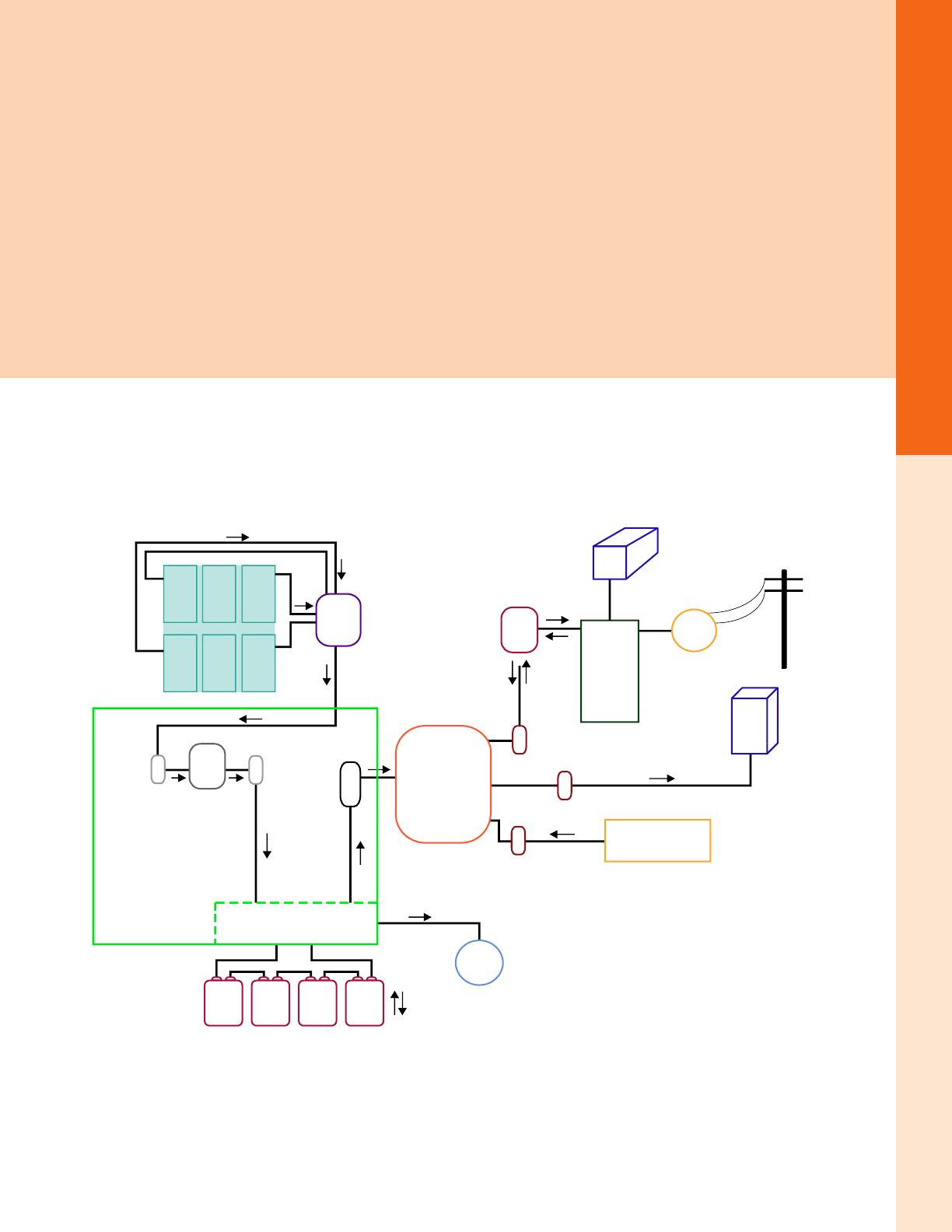
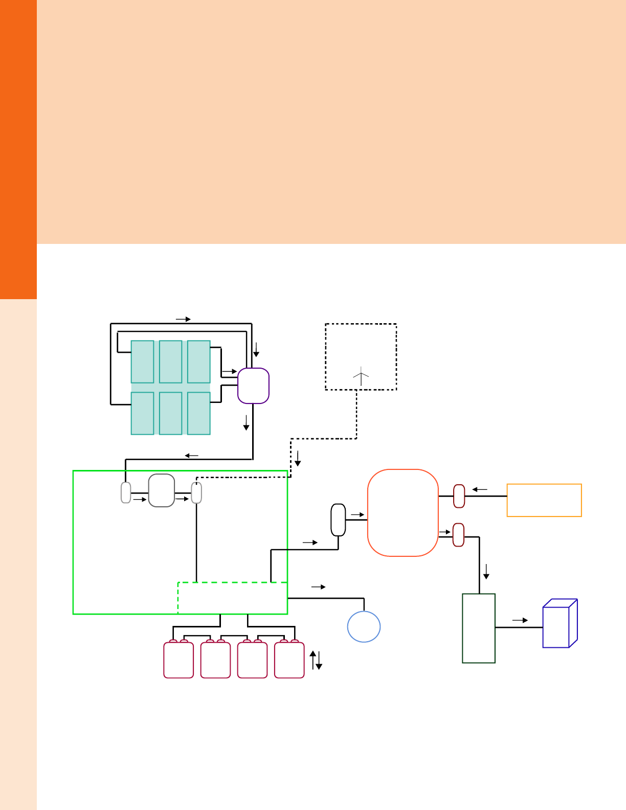
Grid-Tie with Battery Backup
Many solar customers are surprised and disappointed to learn that their typical grid-tie solar PV system will not power their home
during a utility outage. In areas where blackouts and extended weather-related outages are common, a battery backup system, like
the one shown in the diagram below, can add substantial value.
Sizing and designing a grid-tie system with battery backup is more complex than designing a typical system without energy storage.
They perform two separate functions: offsetting the power purchased from the electric utility, just like a standard system, and provid-
ing emergency backup power during utility outages. Both of these functions require separate design considerations and calculations.
The “grid-tie” part of the system is designed to offset kilowatt-hour energy consumption using the average peak sun-hours available
where the PV array is located.
The “battery backup” part of the system is designed to meet the power draw of the critical loads that need to operate during a grid
outage for however long the outage is expected to occur. These systems are generally designed to run only specic circuits located
in a separate sub-panel. They are not designed to power the whole house; although this can be done, it adds considerable cost and
complexity.
Battery backup systems require specialized inverters and other components and must be carefully sized, so be sure to call AEE Solar’s
Technical Support Team for assistance if you’re unfamiliar with this type of system.
Critical Loads
Solar PV Array
DC Bus
DC Inverter
Breaker
Utility
Service/
Load
Center
Non-Critical Loads
DC Breaker
Charge
Controller
Battery Bank
DC Breaker
Input AC Breaker
Output AC Breaker
Input AC Breaker
Battery
Meter
AC
Disconnect
Utility
Grid
DC Power Center
Utility
Meter
Battery-
Based
Inverter
Generator
Combiner
Box

For the latest on AEE Solar products, trainings and dealer services, visit www.aeesolar.com
SYSTEM DESIGN
5
Battery Backup Systems
Inverters for Grid-Tie with Battery Backup
OutBack GFX and FXR inverters and switch gear, as well as OutBack Radian inverters, can power loads individually from 2
to 8 kW and multiple inverters can be combined in a single system up to 80 kW in size.
The Schneider Conext XW+ series of inverters offers grid-tie inverters with battery backup capability in 4 kW, 5.5 kW, and
6.8 kW increments. Up to four units can be paralleled for battery backup systems up to 27.2 kW.
The SMA Sunny Island inverters, in conjunction with a Sunny Boy inverter and PV array, can be used to provide backup
power in a grid-tied home or business using AC-Coupling. Backup systems can be congured with up to 24 kW single-phase
output using up to four Sunny Island inverters or up to 72 kW of three-phase output with up to 12 Sunny Island inverters and
a Multi-Cluster Box.
See Battery-Based Inverters for more information on these inverters
Follow steps 1-6 on the Grid-Tie PV System Design Worksheet (on page 2) to determine the size of the PV array required to
provide the desired percentage of total power, then calculate the inverter size and battery capacity needed using the work-
sheet below.
Worksheet: Inverter and Battery Sizing for Grid-Tie with Backup System
Determine energy storage requirement for backup system.
Step 1: Find the power requirements (watts) for the appliances that need power during an outage.
Make a list of the loads and appliances that need power during an outage, such as refrigerators, safety
lighting, etc. Only list the essential items, since the system size (and cost) will vary widely with power
needed. The wattage of individual appliances can usually be found on the back of the appliance or in the
owner’s manual. If an appliance is rated in amps, multiply amps by the operating voltage (usually 120 or
240 VAC) to nd watts. Add up the wattage of all the items on the list that may need to run simultaneously
to arrive at the total amount of watts. This is the “peak wattage” inverter requirement and will determine
the minimum size of the dual-function inverter that you will need. If the PV array total wattage is larger
than the peak wattage required to run the chosen loads, then ensure that the inverter capacity is equal to
or greater than the PV array nameplate capacity.
Step 2: Dene how long of an outage the system must accommodate.
Power outages last from a few minutes, to a day or more. This decision will greatly affect the system size
and cost, so the desired length of time should be traded against the total loads supported. If the system
needs to provide power for an indenite period of time, use the array and battery bank sizing instructions
for an off-grid system on the following pages.
Step 3: Determine the amount of energy (kWh or watt-hours) that would need to be consumed
during the length of the expected outage.
Multiply the power requirements (in step 1) by duration in hours (in step 2). The result will be watt-
hours. For example, powering a 350 W refrigerator, a 150 W computer, and a 500 W lighting system
for 2 hours would require 2,000 watt-hours (or 2 kWh) of energy storage.
Step 4: Factor in the inverter losses.
Multiply the total watt-hours or kWh to be supplied to the loads by 0.87 to account for inverter losses.
Step 5: Calculate the minimum energy storage needed.
Divide the Step 3 result by 0.8 (batteries should not be discharged past 80%). For example, if the bat-
tery bank needs to supply 2 kWh of energy, at least 2 kWh ÷ 0.8 = 2.4 kWh of nominal battery energy
storage is needed.
Step 6: Calculate battery capacity needed.
Divide the energy storage requirement from step 4 by the DC voltage of the system (usually 48 VDC,
but sometimes 24 VDC) to get battery amp-hour (Ah) capacity. Most backup systems use sealed batteries
due to their reduced maintenance requirements and because they can be more easily placed in enclosed
battery compartments. Flooded batteries are not recommended for backup or standby applications.
For the latest on AEE Solar products, trainings and dealer services, visit www.aeesolar.com
SYSTEM DESIGN
6
AC-Coupled Systems
AC-Coupled Systems
An AC-coupled power system is another form of battery-based system. It can be used either in a grid-tie system with a battery backup
application, or in a completely off-grid system. Instead of using a battery charge controller with the PV array, these systems utilize
standard grid-tie inverters that produce AC power (usually 240 VAC), which can be “sold” to the utility grid when the grid is con-
nected or can be used by a separate battery-based inverter to charge a battery bank during a grid outage.
Along with the standard grid-tie inverter, a second, bidirectional, battery-based inverter is used with a battery bank to provide AC
power during a grid outage. Both the AC output of the grid-tie inverter and the AC output of the battery inverter are connected in the
protected loads sub-panel. During normal operation when the grid is “up”, the power from the PV array and grid-tie inverter simply
passes through the sub-panel and the battery inverter’s built-in AC transfer switch and on to the utility main panel. From there it is
either consumed by house loads connected there or exported to the grid. If a grid outage occurs, the grid-tie inverter will automatically
shut off. At the same time, the battery-based inverter will automatically switch off the grid connection and begin to power the loads
in the protected loads panel using energy drawn from the battery bank. Since the grid-tie inverter is connected in this sub-panel, it
detects the AC power from the battery inverter and, (after a 5-minute delay) will turn back on. The power output from the array and
grid-tie inverter will then be used directly by the protected loads connected to the sub-panel or be used to charge the batteries via the
battery-based inverter/charger.
The SMA Sunny Island battery inverters are designed to work with SMA Sunny Boy inverters and will communicate with each other
to control the battery charging process. Other brands of battery-based inverters, such as OutBack, Schneider XW+, and Magnum
MS models can be used with most grid-tie inverters in an AC-coupled system; most however have no built-in way to control battery
charging from the grid-tie inverter. A relay can be placed in the AC connection to the grid-tie inverter, controlled by a battery voltage
activated switch (such as the AUX relay built into many inverters) to disconnect the grid-tie inverter when the battery voltage rises
to the full-charge voltage, ending the charge cycle. Alternatively, a diversion controller connected to the battery, can be used with an
AC or DC diversion load to consume the excess power and keep the batteries from being overcharged.
Battery Bank
AC
Disconnect
Array DC
Disconnect
Protected
Loads
Sub-
Panel
Protected Loads
DC Inverter Breaker
Utility
Grid
Utility
Meter
Battery
Inverter
Grid-Tie
Inverter
Utility
Service
Panel
For the latest on AEE Solar products, trainings and dealer services, visit www.aeesolar.com
SYSTEM DESIGN
7
Off-Grid Systems
DC Power Center
Generator
Battery-
Based
Inverter
Optional Wind
Turbine or other
Renewable Energy
Generator
DC Inverter
Breaker
Solar PV Array
Load
Center
Combiner
Box
Charge
Controller
AC Breakers
Battery
Monitor
AC
Loads
DC Breakers
DC Breakers
DC Bus
Battery Bank
Off-Grid System Sizing Information
Off-grid solar PV systems, like the one shown in the diagram below, are one of the most economical ways to provide electricity in the
absence of an electrical power grid. Off-grid systems are useful for remote homes and cabins, RVs and boats, and even for industrial
applications like remote telemetry, cathodic protection, and telecommunications.
The size of an off-grid solar electric system depends on the amount of power that is required (watts), the amount of time it is used
(hours), and the amount of energy available from the sun in a particular area (sun-hours per day).
Off-grid power systems are designed differently than grid-tie systems. With a typical grid-tie system, sizing calculations are based
on the yearly average peak sun-hours available at the site, and are used to offset the annual power consumption drawn from the util-
ity grid. With an off-grid system design, the calculations are usually based on the peak sun-hour gures for the darkest month of the
year, rather than the yearly average, in order to provide sufcient on-site power year-round. In locations where it is not practical to
install a PV power system that will provide 100% autonomy during the darkest time of the year, a generator may be used to help run
loads and charge the battery bank, or if site conditions allow, other energy producing systems, such as wind or micro-hydroelectric
turbines can be used to supplement the PV array.
Off-grid power system design is complex, and these systems require specialized inverters, charge controllers, and battery banks.
Please contact the AEE Solar Technical Support Team for system design assistance.

For the latest on AEE Solar products, trainings and dealer services, visit www.aeesolar.com
SYSTEM DESIGN
8
Off-Grid Systems
Efciency and Energy Conservation
Energy-efcient appliances and lighting, and non-electric alternatives, can help to reduce the cost of
producing and storing energy in off-grid systems. Every watt that doesn’t need to be used is a watt that
doesn’t have to be produced or stored. The information below pertains mostly to off-grid systems, but can
also help to reduce the size and cost of grid-tied PV systems, with or without battery backup capability.
Cooking, Heating and Cooling
Each burner on an electric range uses about 1,500 W, which is why bottled propane or natural gas is a
popular alternative for cooking. A microwave oven has about the same power draw, but since food cooks
more quickly in a microwave oven, the amount of kilowatt hours used is typically lower. Propane, wood
or solar-heated water are generally better alternatives for space heating than electric baseboards. Good
passive solar design and proper insulation can reduce the need for winter heating. Evaporative cooling
is a more reasonable load than air conditioning and in locations with low humidity, it’s a great alternative.
Lighting
Lighting requires careful study since type, size, voltage and placement can all signicantly impact the
power required. In a small cabin, RV, or boat, low voltage DC lighting with LEDs is sometimes the best
choice. DC wiring runs can be kept short, allowing the use of fairly small gauge wire. Since an inverter
is not required, the system cost is lower. In a large installation with many lights, using an inverter to
supply AC power for conventional lighting is more cost-effective. AC LED lights are now common and
very efcient, but it is a good idea to have a DC-powered light in the same room as the inverter and bat-
teries in case of an inverter fault. Finally, AC light dimmers will only function properly with inverters
that have true sine-wave output.
Refrigeration
Gas powered absorption refrigerators can work well in small systems when bottled gas is available.
Modern absorption refrigerators consume approximately 5-10 gallons of LP gas per month. If an electric
refrigerator will be used in a standalone system, it should be a high-efciency type. High-efciency DC
refrigerators are also available and can offer signicant energy savings.
Major Appliances
Standard AC electric motors in washing machines, larger shop machinery and tools, swamp coolers, and
pumps, are usually ¼ to ¾ horsepower and consume relatively large amounts of electricity, thus requiring
a large inverter. These electric motors can also be hard to start on inverter power, due to the large surge
of power they need for starting, which can be as much as three-times or more of the power as they draw
while running. Variable-frequency drives can be used with large motors to provide a “soft-start”, reduc-
ing the surge load on the inverter system. A standard top-loading washing machine uses between 300
and 500 watt-hours per load, but new front-loading models can use less than half the energy per load.
If the appliance is used more than a few hours per week, it is often more economical to pay more for a
high-efciency appliance rather than make the electrical system larger to support a low efciency load.
Small Appliances
Many small appliances with heating elements such as irons, toasters and hair dryers consume a very
large amount of power when they are used but, by their nature, require only short or infrequent use. With
a sufciently large inverter system and batteries, they will operate, but the user may need to schedule
those activities with respect to the battery charging cycle. For example, by ironing in the morning, the
PV system can then recharge the battery bank during the day. Or, if these loads can be run during a sunny
day, the energy from the PV array can supply the power to run the appliance without needing to draw
energy from the battery bank.
Electronic equipment, such as stereos, televisions, DVD players and computers, draw less power than
appliances with heating elements, but these loads can add up, so opt for more efcient models when
possible, such as an LED or LCD TV instead of a plasma or CRT design.
Phantom Loads
Many appliances, especially ones with wireless remote controls, draw power even when turned “off”.
While each load may be small, the energy consumption of multiple appliances over a 24 hr period can
add up and be quite large. Placing these loads on a switchable outlet or plug strip can save a consider-
able amount of energy.
For the latest on AEE Solar products, trainings and dealer services, visit www.aeesolar.com
SYSTEM DESIGN
9
Off-Grid Systems
Worksheet: Off-Grid Load Analysis
Determine the total kilowatt-hours (kWh) per day used by the AC and DC loads.
Step 1: List all AC loads, wattage and hours of use per week in the table below.
(If there are no AC loads, skip to Step 5)
Multiply watts by hours/week to get AC watt-hours per week. Add up all the watt hours per week to
determine total AC watt-hours per week.
NOTE: Wattage of appliances can usually be determined from tags on the back of the appliance or from
the owner’s manual. If an appliance is rated in amps, multiply amps by operating voltage (120 or 240
VAC) to nd watts. Energystar.gov lists annual Wh consumption for Energy Star electrical appliances;
divide this number by 52 to get watt-hours per week.
Calculate AC loads (If there are no AC loads, skip to Step 3)
Description of AC loads run by inverter watts x hours/week = watt-hours/week
x =
x =
x =
x =
x =
x =
x =
x =
x =
Total watt-hours per week:
Step 2: Convert to DC watt-hours per week.
Multiply the result of Step 1 by 1.13 to correct for inverter loss.
Step 3: List all DC loads, wattage and hours of use per week in the table below.
Multiply watts by hours/week to get DC watt-hours per week (Wh/Wk). Add up all the watt hours per
week to determine total DC watt-hours per week.
Calculate DC loads (if applicable)
Description of DC loads run by inverter watts x hours/week = watt-hours/week
x =
x =
x =
x =
x =
Total watt-hours per week:
Step 4: Calculate total DC watt-hours per week.
Add the total DC watt-hours per week used by AC loads from Step 2 to the watt-hours per week used
by DC loads from Step 3 to get the total DC watt-hours per week used by all loads.
Step 5: Calculate your total watt-hours per day consumption.
Divide the total DC watt-hours per week from Step 4 by 7 days to get the total average watt-hours per
day that needs to be supplied by the battery.
You will need this number to begin sizing the PV array and battery bank. Note that the Solar Array
Sizing Worksheet in this section, as well as the Battery Sizing Worksheet in the Batteries Section, both
begin with this number in their Step 1.

For the latest on AEE Solar products, trainings and dealer services, visit www.aeesolar.com
SYSTEM DESIGN
10
Off-Grid Systems
Worksheet: Off-Grid Solar Array Sizing
Determine how much energy (kWh) the solar array must produce to size the PV array
and determine the total number of solar modules required for the system.
Step 1: List the total average watt-hours per day needed to power the electrical loads.
Obtain this number from the Off-Grid Loads Worksheet on the previous page.
Step 2: Calculate the minimum watt-hours needed per day.
Multiply the watt-hours per day needed by 1.25 to compensate for PV array and battery charge/dis-
charge losses. This is the minimum total watt-hours that the PV array needs to produce, on average,
each day. However, increasing the array size further will allow the system to provide some additional
charging during cloudy weather and catch up more quickly after a cloudy period. Increasing the array
size can also allow for reduced battery storage requirements.
Step 3: List the average sun-hours per day at the system’s location.
Check local weather data, look at the map below, or nd a city on the Solar Insolation Table in the Ref-
erence Section that has similar latitude and weather to your location. If you want year-round autonomy,
use the lower winter insolation. If you want 100% autonomy only in summer, use the higher summer
insolation. If you have a utility grid-tie system with net metering, use the yearly average gure.
Step 4: Determine the minimum nameplate capacity.
Divide the result of Step 2 by the average sun-hours per day from Step 3 to determine the minimum
nameplate capacity of the PV array.
NOTE: Sizing Solar Arrays with PWM or MPPT Charge Controllers
If you are planning a small low-cost system with a PWM charge controller, with 12 or 24 VDC
“nominal” PV modules (36 or 72 cells), continue to Step 5 below. If you are planning a system with an
MPPT charge controller, go to Step 5 in “Sizing Solar Arrays with MPPT Charge Controllers”. Infor-
mation on the different types of PV charge controllers can be found in the Charge Controller section.
Step 5: Calculate peak amps.
Divide the total solar array wattage required from Step 4 by the system’s DC battery voltage (usually
12, 24, or 48 VDC) to get the total peak amps (A) that the PV array must produce.
Step 6: Find the peak-power current (Imp) of the module you will be using from its specications
or Data Sheet.
Step 7: Calculate the number of parallel strings.
Divide the result of Step 5 by the result of Step 6. Round up to the next whole number. This is the total
number of parallel module strings required to produce the total array current needed.
Step 8: Use the table below to determine the number of modules in each series string needed
to match the DC battery voltage of the power system.
Nominal System Voltage Number of Series Connected Modules per String
Volts 12 V module 24 V module
12 1 --
24 2 1
48 4 2
Step 9: Calculate the minimum number of solar modules.
Multiply the number of strings from Step 7 by the number of modules per string from Step 8 to get the
total minimum number of solar modules required with a PWM charge controller.
Step 10: Calculate minimum PWM charge controller rating.
Multiply the number of strings from Step 7 by the module’s short-circuit current (ISC) and then by
a 1.25 Code-required safety factor. The current rating of the selected PWM charge controller must
exceed this number.
For the latest on AEE Solar products, trainings and dealer services, visit www.aeesolar.com
SYSTEM DESIGN
11
Off-Grid Systems
Sizing Solar Arrays with MPPT Charge Controllers
Step 5: Note the minimum solar array nameplate capacity required from Step 4.
Step 6: Enter the nameplate power (in watts) of the PV module you plan to use.
Step 7: Determine the minimum number of modules needed.
Divide the PV array capacity from Step 5 by the module nameplate power from Step 6 to determine
the minimum number of modules needed. Round up to the nearest whole number. (NOTE: This num-
ber may need to be adjusted in Step 10).
Step 8: Determine the number of modules in each series string.
Use the table below to determine the number of modules needed in each series string based on the
system’s battery voltage and PV charge controller used.
MPPT Charge Controller Sizing Table – Range of Modules in Series1
Charge controller
model
Max DC
input voltage
Nominal
battery voltage
Cell count of PV module used
36 54 60 72
OutBack FM 60 & 80
Schneider XW-MPPT150-60
Morningstar TriStar 45 & 60
150 VDC
12 VDC 1 to 5 1 to 3 1 to 3 1 or 2
24 VDC 2 to 5 2 or 3 2 or 3 1 or 2
48 VDC 4 or 5 3 3 2
MidNite Solar Classic 150 150 VDC
12 VDC 1 to 5 1 to 3 1 to 3 1 or 2
24 VDC 2 to 6 2 to 4 2 or 3 1 to 3
48 VDC 4 to 6 3 or 4 3 2 or 3
MidNite Solar Classic 200
Magnum PT-100 200 VDC
12 VDC 1 to 7 1 to 5 1 to 4 1 to 3
24 VDC 2 to 7 2 to 5 2 to 4 1 to 4
48 VDC 4 to 7 3 to 5 3 to 4 2 to 4
MidNite Solar Classic 250 250 VDC
12 VDC 1 to 9 1 to 6 1 to 5 1 to 4
24 VDC 2 to 9 2 to 6 2 to 5 1 to 4
48 VDC 4 to 9 3 to 6 3 to 5 2 to 4
Schneider XW-MPPT600-80 600 VDC 24-48 VDC 14 to 22 9 to 15 9 to 13 7 to 11
Morningstar TS-MPPT-60-
600V-48 (DB) 600 VDC 48 VDC 5 to 23 3 to 15 3 to 12 3 to 10
Magnum PT-100 200 VDC
12 VDC 1 to 7 1 to 5 1 to 4 1 to 3
24 VDC 2 to 7 2 to 5 2 to 4 1 to 3
48 VDC 4 to 7 3 to 5 3 to 4 2 to 4
1Based on temp range of 14°F to 104°F. Adjustments may be needed in locations with temps outside this range.
Step 9: Calculate the number of series strings needed.
Divide the total number of modules from Step 7 by the number of modules per series string from Step
8. Round up to a whole number. This is the total number of array series strings needed.
Step 10: Determine the total number of modules needed.
Multiply the number of module strings from Step 9 by the number of modules per string from Step 8
to determine the total number of modules needed.
Step 11: Find the total number of chosen controllers needed.
Multiply the total number of modules needed (from Step 10) by the rated wattage of the module being
used. This is the adjusted total PV array nameplate capacity. Using the chart below, nd a controller
rated for the total array wattage (or more). If the total array wattage is more than a single controller
can handle, either use a larger controller or use multiple controllers in parallel. NOTE: Most charge
controllers must have their own separate PV array, so larger arrays need to be divided into sub-arrays
for each charge controller.
Max Array Wattage per Controller Size
Battery voltage Controller rated output amps
15 A 20 A 30A 45 A 60 A 75 A 80 A 95 A 100 A
12 V 216 W 265 W 431 W 647 W 862 W 1100 W 1149 W 1379 W 1437 W
24 V 431 W 530 W 862 W 1293 W 1724 W 2100 W 2299 W – 2874 W
48 V -- – 1724 W 2586 W 3448 W 4000 W 4598 W – 5747 W

For the latest on AEE Solar products, trainings and dealer services, visit www.aeesolar.com
SOLAR MODULES
12
System Design
Photovoltaic (PV) Modules
Solar photovoltaic modules, often referred to as solar panels, convert light energy into a direct electrical current (DC). As solid-state
devices, solar modules have no moving parts and are extremely reliable and durable compared to any other generator technology.
While solar modules have become somewhat commoditized in recent years, there are important differences in form, quality, and
performance that can impact both installation time and long-term system performance. This section of our catalog presents a selection
of high-quality crystalline modules with a variety of features and price points to suit virtually any project.
Output Characteristics
The output power, voltage, and current prole of the solar module will dictate the number of modules needed and what inverters or
charge controllers can be used. Small off-grid applications often require 12 VDC output modules to directly charge batteries and/
or operate DC loads. Larger modules with output voltages ranging from 24 to 50 VDC are more commonly used in grid-tie systems
where a high DC voltage is required to operate the inverter.
Mechanical Characteristics
Basic mechanical characteristics, such as dimensions, frame prole, and static load rating, as well as grounding and mounting locations
will need to be understood when designing your system. Frame and back sheet color may also come into play for residential customers,
particularly when they are part of a homeowner’s association. Also be sure you know what type of connector the module output has,
if any, since this can impact selection of optimizers, microinverters, and cabling.
Solar Modules at a Glance1
Power Brand/model Cell
type Frame Power
tolerance Vpeak2Ipeak Area
efciency
Dimensions
(L" x W" x D") Weight Static load
rating Item code
260 W Hyundai HiS-M260RG Poly Black -0/+3% 31.1 VDC 8.4 A 15.9% 64.6 x 39.3 x 1.38 in 40 lbs 40 psf 011-04000
260 W Q-Cells Q.PRO BFR-G4
260 Poly Black -0/+3% 30.2 VDC 8.5 A 15.6% 65.7 × 39.4 x 1.26 in 41 lbs 75 psf 011-06533
265 W Q-Cells Q.PRO BFR-G4
265 Poly Black -0/+3% 30.8 VDC 8.62 A 15.9% 65.7 × 39.4 x 1.26 in 41 lbs 75 psf 011-06532
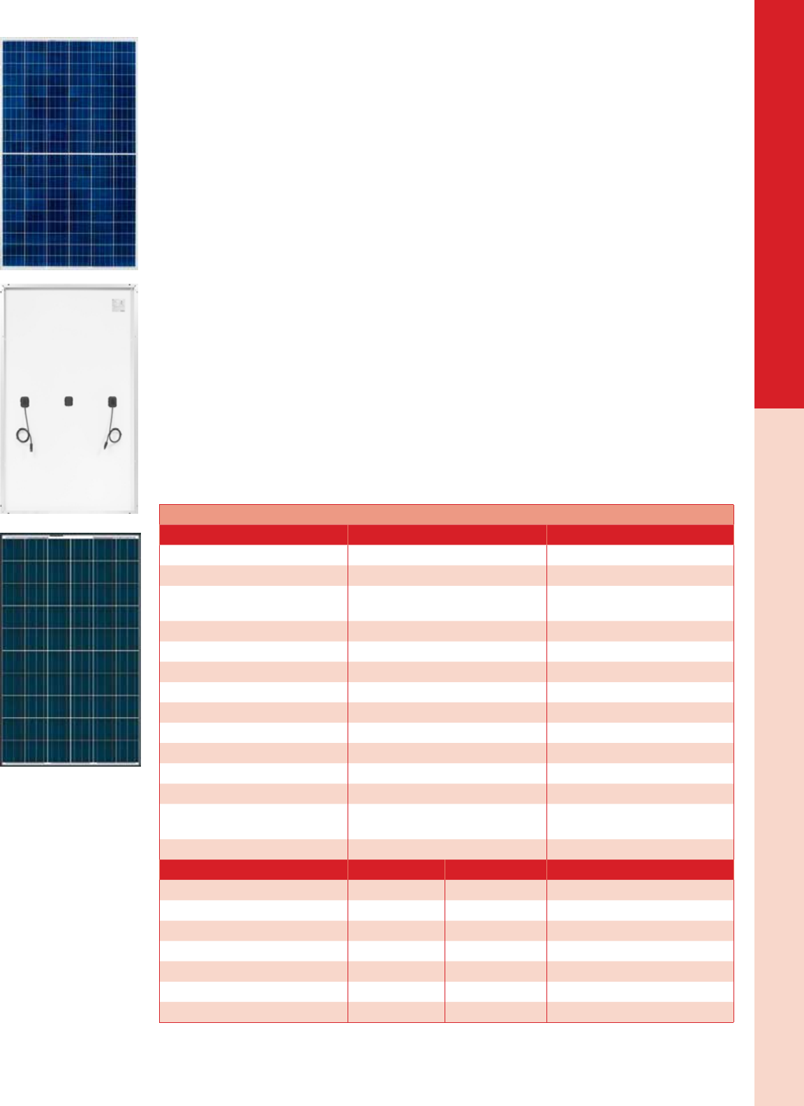
275 W REC 275TP Poly Black -0/+5 W 31.4 VDC 8.76A 16.7% 65.5 x 39.0 x 1.5 in 40 lbs 75 psf 011-02599
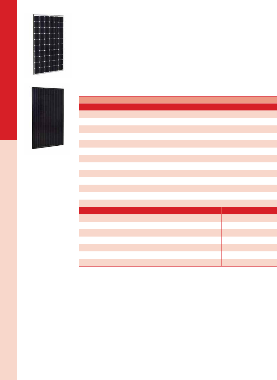
275 W Suniva OPT275-60-4-1B0 Mono Black ±3% 32.0 VDC 8.59 A 16.7% 65.4 x 39.0 x 1.37 in 40 lbs 113 psf 011-09239
280 W Suniva OPT280-60-4-100 Mono Clear ±3% 31.8 VDC 8.81 A 17.0% 65.4 x 39.0 x 1.37 in 40 lbs 113 psf 011-09238
280 W REC 280TP Poly Black -0/+5 W 31.9 VDC 8.78 A 17.0% 65.5 x 39.0 x 1.5 in 40 lbs 75 psf 011-02598
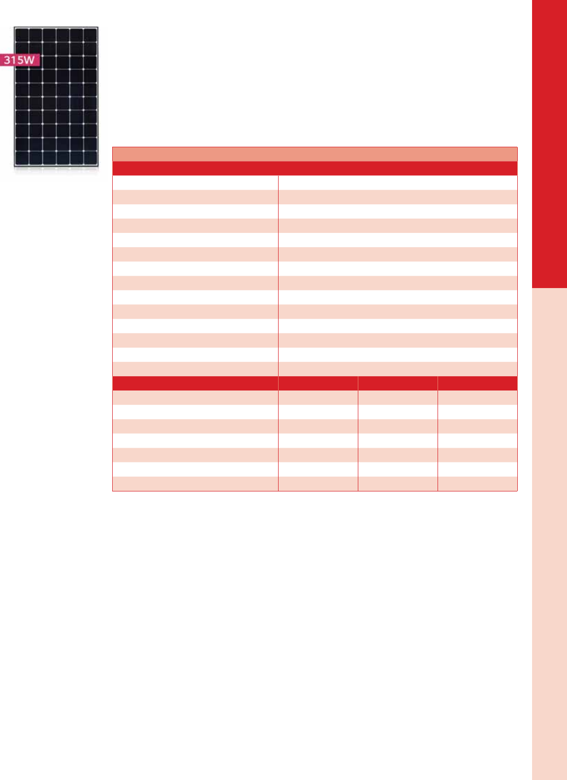
310 W LG 310N1C-G4 Mono Black -0/+3% 32.8 VDC 9.45 A 18.9% 64.6 x 39.4 x 1.57 in 37 lbs 125 psf 011-00213
315 W REC 315PE72 Poly Clear -0/+5 W 36.8 VDC 8.62 A 16.2% 77.5 x 39.0 x 1.75 in 60 lbs 75 psf 011-02570
315 LG 315N1C-G4 Mono Black -0/+3% 33.2 VDC 9.50 A 19.2% 64.6 x 39.4 x 1.57 in 37 lbs 125 psf 011-00212
320 LG 320N1C-G4 Mono Black -0/+3% 33.6 VDC 9.53 A 19.5% 64.6 x 39.4 x 1.57 in 37 lbs 125 psf 011-00214
1Module availability may vary - Visit www.AEEexpress.com for latest pricing and availability.
2See Dasol listing on page 17 for our selection of nominal 12 VDC modules.

PID
Free
100%
PID
Free
100%
PID
Free
100%
More PoWer
oUTPUT Per FT²
100%
PID Free
IMProveD PerForMance
In shaDeD conDITIons
reDUces BaLance
oF sYsTeM cosTs
PREMIUM SOLAR PANELS
WITH SUPERIOR PERFORMANCE
rec TwinPeak
→ 120 half-cut cells
→ 265 – 285 Wp (poly)
→ Available in black or silver frame
→ Industry-leading product quality
→ From the largest European brand of solar panels
www.recgroup.com
For the latest on AEE Solar products, trainings and dealer services, visit www.aeesolar.com
SOLAR MODULES
14
Multicrystalline (Poly) Modules
REC Solar
These modules, made by REC in Singapore, offer exceptional quality and performance at a reasonable price.
Rigorous quality control is applied throughout the production process from silicon to cell to module. The
-0/+5 W power tolerance guarantees you the power you pay for and minimizes mismatch losses.
TwinPeak Series PV Modules
Based on a multicrystalline cell platform, the REC TwinPeak Series encompasses a number of new and
innovative technologies that provide performance comparable to monocrystalline p-type and n-type modules.
Most visibly, these modules use “half-cut” cells with 60 cells on each side of the module wired in paral-
lel. This keeps the voltage similar to 60-cell modules, while improving shade tolerance and reducing
energy loss due to cell resistance.
The cells themselves feature state-of-the-art Passivated Emitter Rear Cell (PERC), aka “backside pas-
sivation” technology that improves the light capture of the cell, resulting in improved energy harvest in
real-world conditions.
The modules are equipped with a novel “split” junction box that places the PV wire cables with MC4-
type connectors near each side of the module. The PV wire output cables are long enough to enable
landscape array layouts.
PE72 Series PV Modules
PE72 series modules are equipped with an environmentally sealed junction box and PV wire cables with
MC4-type connectors. The 72-cell PE series modules have clear anodized frames and white back sheets.
Warranty
REC modules come with a ten-year workmanship warranty and a 25-year linear power guarantee that
allows for no more than 0.7% degradation per year. All modules are listed to UL 1703 for the U.S.A.
and Canada.
REC Solar PE Series PV Modules1
Technical Data 120-cell TP Series 72-cell PE series
Cells (qty/size) 120 / 156 x 78 mm 72 / 156 mm
Power output tolerance -0/+5 W -0/+5 W
Nominal Operating Cell Temperature
(NOCT) 112.3 +/-3.6 °F [44.6 °C (±2 °C)] 112.3 +/-3.6 °F [44.6 °C (±2 °C)]
Voltage temperature coefcient -0.56%/°F [-0.31%/ °C] -0.49%/°F [-0.27%/ °C]
Fire rating/type Class C / Type 2 Class C / Type 1
Connector type MC4 MC4 connectable
Cable length 35 in (pos) / 47 in (neg) 47 in [1.2 m]
Static load rating 75 psf [3600 Pa] 75 psf [3600 Pa]
Quantity per pallet 25 25
Quantity per 53' trailer 900 900
Max. system voltage 1,000 VDC 1,000 VDC
Series fuse rating 15 A 20 A
Dimensions (L x W x D) 65.5 x 39 x 1.5 in [1665 x 991 x 38 mm] 77.5 x 39 x 1.75 in [1969 x 991 x 44.5
mm]
Weight 39.5 lbs [18 kg] 59.5 lbs [30 kg]
Module REC275TP REC280TP REC 315PE72
Peak power 275 W 280 W 315 W
Voltage at peak power 31.4 VDC 31.9 VDC 36.8 VDC
Current at peak power 8.76 A 8.78 A 8.62 A
Open circuit voltage 38.8 VDC 39.2 VDC 45.5 VDC
Short circuit current 9.40 A 9.44 A 9.09 A
Module area efciency 16.7% 17.0% 16.2%
Item code 011-02599 011-02598 011-02570
1Data subject to change without notice

For the latest on AEE Solar products, trainings and dealer services, visit www.aeesolar.com
SOLAR MODULES
15
Multicrystalline (Poly) Modules
Hanwa Q-Cells
NEW! Q.Pro BFR-G4 Series PV Modules
The European-made BFR-G4 modules represent the latest advances in Q-Cells’s workhorse multi-
crystalline Q.Pro PV module line. These modules feature black anodized frames with white back sheets
and are suitable for most residential and commercial applications.
As a global manufacturer of a wide variety of products, Hanwha backs these modules with 25-year linear
performance guaranty and 12-year product warranty. These modules are listed to UL 1703, IEC 61215,
and IEC 61730-Ed 2.
Q-Cells Q.PRO BFR-G4 PV Modules1
Technical data
Cells (qty/size) 60 / 6 in x 6 in [156.75 mm]
Power output tolerance -0/+5 W
Nominal Operating Cell Temperature (NOCT) 113 +/- 5.4°F [45 °C +/-3 °C]
Voltage temperature coefcient -0.74%/°F [-0.41%/°C]
Fire rating/type Class C / Type 1
Connector type Tyco PV4 (MC4 connectable )
Cable length 39.4 in [1 m]
Static load rating 75 psf [3,600 Pa] (max load)
Quantity per pallet 32
Quantity per 53' trailer 1,024
Max. system voltage 1,000 VDC
Series fuse rating 20 A
Dimensions (L x W x D) 65.7 × 39.4 x 1.26 in [1670 × 1000 × 32 mm]
Weight 41.5 lbs [18.8 kg]
Module BFR-G4 260 BFR-G4 265
Peak power 260 W 265 W
Voltage at peak power 30.18 VDC 30.75 VDC
Current at peak power 8.53 A 8.62 A
Open circuit voltage 37.77 VDC 38.01 VDC
Short circuit current 9.15 A 9.23 A
Module area efciency 15.6% 15.9%
Item code 011-06533 011-06532
1Data subject to change without notice
For the latest on AEE Solar products, trainings and dealer services, visit www.aeesolar.com
SOLAR MODULES
16
Monocrystalline Modules
LG Solar
NEW! NeON2 Series PV Modules
LG’s NeON2 monocrystalline PV modules are among the most efcient PV modules available thanks
to a host of innovative technologies and enhancements at both the cell and module level. These modules
feature high-gloss black frames, white back sheets, and thinner cell busses for a sleek appearance.
As a world-leading diversied manufacturer, LG backs these modules with 25-year linear performance
guaranty and 12-year product warranty. These modules are listed to UL 1703, IEC 61215, IEC 61730-
1/-2, IEC 62716, and IEC 61701 and produced in an ISO 9001 certied factory.
LG NeON2 PV Modules1
Technical data
Cells (qty/size) 60 / 6 x 6 in [156.75 mm]
Power output tolerance -0/+3%
Nominal Operating Cell Temperature (NOCT) 114.8 +/-5.4 °F [46 °C +/-3 °C]
Voltage temperature coefcient -0.50%/°F [-0.28%/°C]
Fire rating/type Class C / Type 2
Connector type MC4 connectable
Cable length 39.4 in [1 m]
Static load rating 125 psf [6,000 Pa] front load / 113 psf [5,000 Pa] rear load
Quantity per pallet 25
Quantity per 53' trailer 850
Max. system voltage 1,000 VDC
Series fuse rating 20 A
Dimensions (L x W x D) 64.57 x 39.37 x 1.57 in [1640 x 1000 x 40 mm]
Weight 37.5 lbs [17 kg]
Module LG310N1C-G4 LG315N1C-G4 LG320N1C-G4
Peak power 310 W 315 W 320 W
Voltage at peak power 32.8 VDC 33.2 VDC 33.6 VDC
Current at peak power 9.45 A 9.50 A 9.53 A
Open circuit voltage 40.4 VDC 40.6 VDC 40.9 VDC
Short circuit current 9.96 A 10.02 A 10.05 A
Module area efciency 18.9% 19.2% 19.5%
Item code 011-00213 011-00212 011-00214
1Data subject to change without notice
For the latest on AEE Solar products, trainings and dealer services, visit www.aeesolar.com
SOLAR MODULES
17
Monocrystalline Modules
Suniva
Optimus Series PV Modules
Suniva employs a variety of patented and proprietary technologies to produce their mono-crystalline
cells and Optimus PV modules. Suniva modules carry a ten-year product workmanship warranty and a
25-year linear power output guaranty. The modules presented here meet Buy America Act requirements.
Modules are listed to UL 1703 for the U.S.A. and Canada and CEC 61215 for Europe.
The OPT275-60-4-100 and OPT280-60-4-100 solar modules offer good area efciency and performance.
These high-efciency modules feature clear-anodized aluminum frames and a white back sheet and are
suitable for most commercial and residential applications.
The OPT275-60-4-1B0 solar module offers great aesthetics without sacricing efciency. This 275 W
module features black-anodized aluminum frames and a black back sheet for a sleek appearance on any
rooftop.
Suniva Optimus PV Modules1
Technical data
Cells (qty/size) 60 / 156 mm
Power output tolerance -0/+3%
Nominal Operating Cell Temperature (NOCT) 114.8 +/-3.6 °F [46.0 +/-2 °C]
Voltage temperature coefcient -0.60%/°F [-0.34%/°C]
Fire rating Class C / Type 2
Connector type MC4 connectable
Cable length 43.3" [1.1 m]
Static load rating 113 psf [5400 Pa]
Quantity per pallet / truckload 25 / 900
Max. system voltage 1,000 VDC
Series fuse rating 15 A
Dimensions (L x W x D) 65.35 x 38.98 x 1.37 in [1660 x 990 x 35 mm]
Weight 39.5 lbs [17.9 kg]
Module OPT275-4-1B0 OPT280-4-100
Peak power 275 W 280 W
Voltage at peak power 32.0 VDC 31.8 VDC
Current at peak power 8.59 A 8.81 A
Open circuit voltage 39.1 VDC 38.8 VDC
Short circuit current 9.32 A 9.57 A
Module area efciency 16.7% 17.0%
Item code 011-09239 011-09238
1Data subject to change without notice.
For the latest on AEE Solar products, trainings and dealer services, visit www.aeesolar.com
SOLAR MODULES
18
12 VDC Modules
Dasol Energy
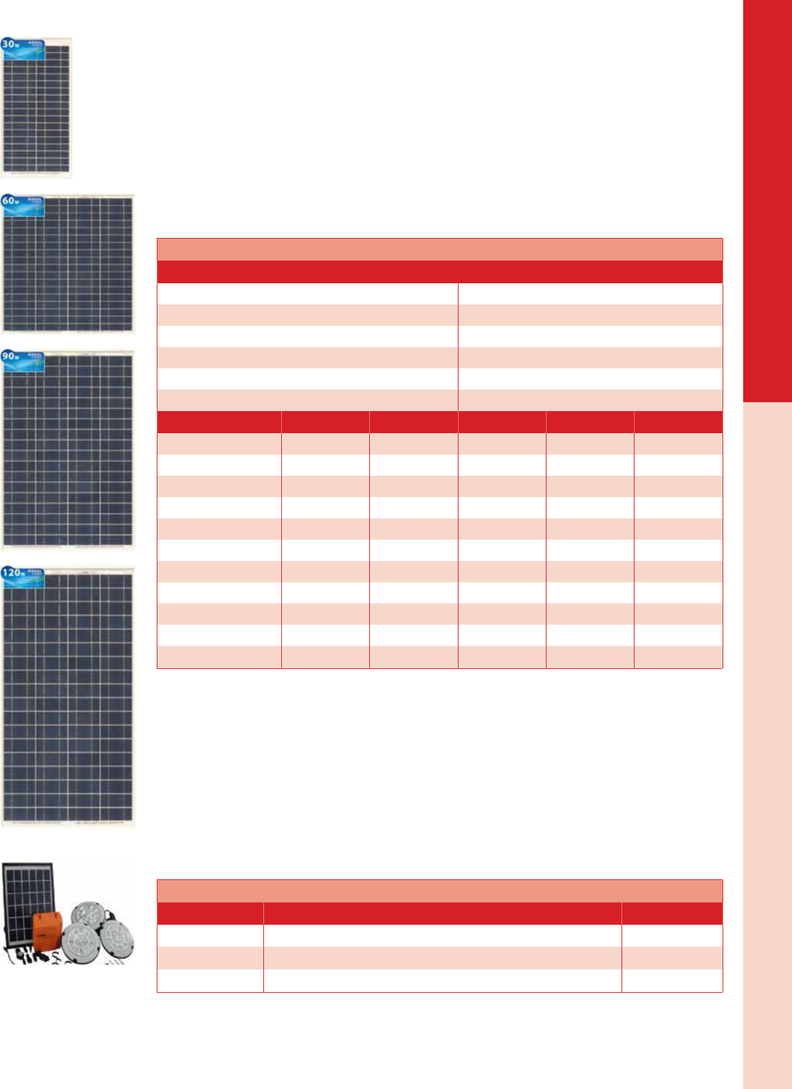
DS-A18 Series PV Modules
These 12 VDC nominal modules have an output voltage that is well-suited for charging 12-Volt batteries
and can be wired in series for charging 24- or 48-Volt battery banks. They can be used with inexpensive
PWM controllers (see Charge Controllers for more information).
These modules, from Dasol Energy, are efcient and robust with tempered glass, tough polymer back
sheets, and anodized aluminum frames. The modules offered here are listed to UL 1703, CSA 5311-10
& 90 as well as IEC 61215 and are produced in an ISO 9001 certied facility. The DS-A18-10 has wire
leads. The DS-A18-30 has a single-port J-box and can be ordered with a 2-conductor lead. The larger
modules feature diode-accessible junction boxes with pre-assembled MC4/H4-style leads. Made in China.
Dasol Energy DS-A18 Series PV Modules
Technical data
Number of cells 36
Power output tolerance +/- 5%
Voltageoc temp coefcient -0.38%/ °C
Fire rating Class C
Connector type Wire leads (10-30 W) or J-box with MC4-type leads
Maximum system voltage 600 VDC
Module DS-A18-10 DS-A18-30 DS-A18-60 DS-A18-90 DS-A18-135
Peak power 10 W 30 W 60 W 90 W 135 W
Voltage at max power 18.0 VDC 18.0 VDC 18.0 VDC 18.0 VDC 18.0 VDC
Current at max power 0.56 A 1.67 A 3.33 A 5.0 A 7.5 A
Open circuit voltage 22.3 VDC 22.3 VDC 22.3 VDC 22.3 VDC 22.3 VDC
Short circuit current 0.61 A 1.82 A 3.64 A 5.45 A 8.18 A
Series fuse rating 1 A 3 A 6 A 8 A 12 A
Length 27.2" [690 mm] 27.2" [690 mm] 27.2" [690 mm] 39.0" [990 mm] 56.7" [1440 mm]
Width 13.8" [350 mm] 13.8" [350 mm] 26.2" [665 mm] 26.2" [665 mm] 26.2" [665 mm]
Depth 1" [25 mm] 1" [25 mm] 1.38" [35 mm] 1.38" [35 mm] 1.38" [35 mm]
Weight 6.6 lbs [3 kg] 6.6 lbs [3 kg] 12.8 lbs [5.8 kg] 17.0 lbs [7.7 kg] 24.7 lbs [11.2 kg]
Item code 011-08964 011-08960 011-08961 011-08962 011-08965
Off-Grid Solar PV Lighting Kits
These portable solar lighting kits include a small PV module, three high-efciency hanging LED lamps
and a lithium ion battery pack with USB ports for charging portable devices. With at least six hours in the
sun, the kits can keep the lights running for four to eight hours, give or take charging your smartphone.
These kits are cost-effective solutions for camping, disaster preparedness, or even replacing costly kero-
sene lamps in un-electried parts of the world.
The S10030A3 kit is 6 VDC with a 3 W module, 353 mAh battery, and 60 lm lamps. The SLK201003B3
kit is 12 VDC with a 10 W module, 556 mAh battery, and 100 lm lamps. This larger kit also includes
an adapter for charging from an AC outlet. The S100505B3 kit is similar to S100303A3, but includes a
larger module and 5 Ah battery as well as brighter 100 lm lamps.
Dasol Energy Solar PV Lighting Kits
Model Description Item code
S100303A3 6 VDC solar lighting kit with 3 W module and 3 LED lamps 010-01010
SLK201003B3 12 VDC solar lighting kit with 10 W module, 3 LED lamps and AC adapter 010-01011
S100505B3 6 VDC solar lighting kit with 5 W module and 3 LED lamps 010-01012

For the latest on AEE Solar products, trainings and dealer services, visit www.aeesolar.com
MOUNTING STRUCTURES
19
SnapNrack
Mounting Structures
Mounting structures are used to x PV modules to the roof or to the ground so they aren’t moved by wind or snow. Be sure to con-
sult the PV module manufacturer’s installation manual when selecting and conguring a mounting system as not all modules are
compatible with all mounting methods. If the manufacturer doesn’t explicitly allow for the type of clamp and mounting locations or
grounding method used by the mounting system, it may not pass inspection.
Most modules can be fastened via holes in the bottom ange of the frame but this can be awkward and time consuming. Some
ground-mounting systems fasten to the bottom ange using specialized clips, enabling installers to perform virtually all of their work
underneath the modules. Top clamps, which clamp the module frame to a mounting rail or roof attachment, are most popular today as
the clamps can double as spacers and clamp two modules simultaneously, reducing the total number of fasteners required. Regardless
of clamp type, it is also important to clamp the module in the right places.
Most PV modules are designed to be clamped at the quarter-points where the mounting holes typically are. This ensures optimal load-
ing on the module frame and provides maximum static and dynamic load capacity. Some manufacturers also allow for mounting on
the short ends of the module, which can allow two rows of modules to share a rail. However, mounting on the ends typically reduces
the load ratings of the module, which is why most manufacturers don’t allow it.
Early equipment grounding for module frames was accomplished with a bolt or screw with a star washer attached to the grounding
wire. AEE Solar later introduced grounding lugs which provided a faster and more secure method for attaching the ground wire and
these have since given way to WEEB clips (See Electrical Distribution Gear) which enabled module grounding through the rail. With
the advent of the UL 2703 mounting and grounding standard, many mounting systems, such as SnapNrack, accomplish grounding
through the mounting components so that the installer only needs to run a grounding wire to the end of each row.
Note that specialized PV products like frameless or exible modules typically require their own proprietary mounting and grounding
components.
SnapNrack
Solar Mounting Solutions
SnapNrack was developed by a team of veteran solar engineers working with installers in the eld to
ensure a quick, efcient installation using modules from virtually any manufacturer. The SnapNrack roof
mounting system simplies and reduces the cost of the solar installation process.
The rail is a lightweight aluminum extrusion that is easy to transport, handle, and install. Snap-in sliding
channel nuts ensure quick and easy installation and precise alignment of module clamps. Every bolt in
the system uses the same sized wrench, ensuring efcient installations and reducing labor hours on the
roof. Standoffs and L-feet connect to the rails using the same snap-in channel nuts as the module clamps
and no drilling is required.
SnapNrack is engineered for durability and structural integrity in all environments, providing excellent
seismic, wind, and snow loading protection on all products. Its compact and efcient rail design reduces
material requirements and ensures a low-prole installation on any roof. SnapNrack has been engineered
from the ground up with maximum standoff adjustability for a clean, level installation even on irregular
roof surfaces.
Online Conguration Tools for Series 100 and 200 are available on AEE Express or the SnapNrack
website (SnapNrack.com), as are installation manuals. The SnapNrack manuals are a complete how-to
guide full of color photos, illustrations, and step-by-step instructions.
UL 2703 Grounding and Bonding Compliance
SnapNrack 100 and 200 systems are fully listed to the UL 2703 Standard for Grounding and Bonding.
As of January 1st, 2016, all SnapNrack system products offered through AEE have been certied by
UL for electrical continuity, eliminating the need for additional grounding hardware. Bonding pins are
integrated into product assemblies including module clamps and rail splices, eliminating the need for
bonding washers on each PV module or rail splice jumpers. Only one SnapNrack Grounding Lug is
required per individual row of modules (not per rail).
UL 2703 Class A Fire Rating Compliance
In addition to grounding and bonding, SnapNrack’s UL 2703 Certication and Compliance ensures that
the Series 100 roof mount system is Class A Fire Rated when installed with Type 1 and Type 2 pho-
tovoltaic modules. SnapNrack achieved the Class A re rating through stringent testing that included
the Spread of Flames tests and the Burning Brand tests. The system also meets the requirements of the
California building codes set by local jurisdictions and the 2012 International Building Codes which
went into effect on January 1, 2015.
For the latest on AEE Solar products, trainings and dealer services, visit www.aeesolar.com
MOUNTING STRUCTURES
20
SnapNrack
Warranty
All SnapNrack products are covered by a ten-year limited warranty. For complete details please visit
www.SnapNrack.com/system-overview to view the warranty PDF.
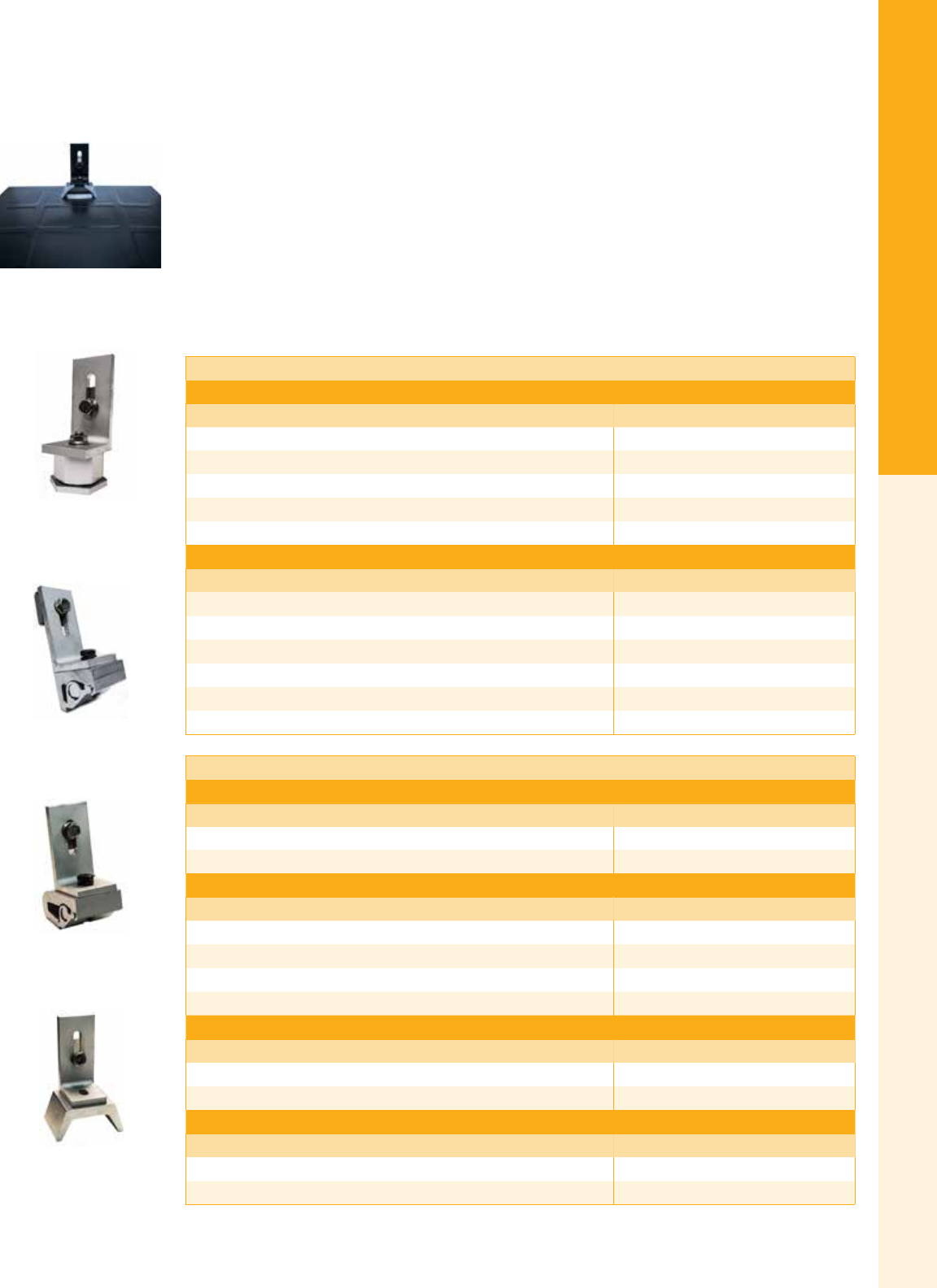
SnapNrack Series 100 Roof Attachments
SnapNrack offers a variety of roof attachment methods by combining familiar parts with more special-
ized hardware. The L Foot, Flashing & Base Kit, is recommended for simple ush mounts to a roof
with composition shingles only. The Metal Roof Base provides a robust self-sealing EPDM rubber
washer and a sealing top cap mounting base for common corrugated metal roof proles. The Standard
and Wide Base Seam Clamps are made from a high tensile strength aluminum that will work with a
range of metal roof designs. The Corrugated Straddle Block allows attachment of the L Foot directly
to a structural member covered with a corrugated metal roof without collapsing or crushing the ridge in
the metal roof material. Units are sold individually, unless otherwise noted, but full case discounts are
available when ordering multiples of 20.
L Foot Mounts for Composition Roofs
Composition L Foot Flashing Kits
Description Item code
Black L Foot, Black Galv Flashing, and Base Kit 242-92051
Silver L Foot, Black Galv Flashing, and Base Kit 242-92050
Black L Foot, Black Alum Flashing, and Base Kit 242-92048
Silver L Foot, Silver Alum Flashing, and Base Kit 242-92047
L Foot Base and Black Galv Flashing Kit (no L Foot) 242-92049
Composition L Foot Accessories
Description Item code
L Foot Flashing, 12” x 12”, Black Galv 232-01060
L Foot Flashing, 12” x 12”, Black Alum 232-01151
L Foot Flashing, 12” x 12”, Silver Alum 232-01150
L Foot Base (includes ange nut) 242-00016
Black Composition L Foot (92˚) 242-09015
Silver Composition L Foot (92˚) 242-09005
L Foot Mounts for Metal Roofs
Metal Roof Base
Description Item code
Metal Roof Base with L Foot 242-02037
Metal Roof Base 242-02036
Seam Clamp
Description Item code
Standard Base Seam Clamp with L Foot 242-05150
Standard Base Seam Clamp 242-05000
Wide Base Seam Clamp with L Foot 242-05151
Wide Base Seam Clamp 242-05001
Corrugated Straddle Block
Description Item code
Corrugated Straddle Block with L Foot Kit 242-02046
Corrugated Straddle Block 232-02421
All Purpose L Foot
Description Item code
Black All Purpose L Foot (90˚) 242-09020
Silver All Purpose L Foot (90˚) 242-09019
Bonding Metal Roof Base
with L Foot
Standard Base Seam Clamp
with L Foot
Wide Base Seam Clamp
with L Foot
Corrugated Straddle Block with
L Foot Kit
Black L-Foot, Black Galv
Flashing, and Base Kit
For the latest on AEE Solar products, trainings and dealer services, visit www.aeesolar.com
MOUNTING STRUCTURES
21
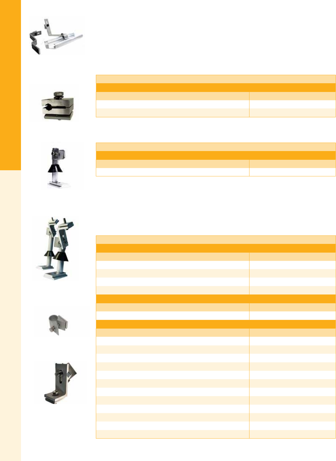
SnapNrack
The Universal Tile Hook is designed to work with Flat, S, and W shaped tile roofs which can typically
install with minimal cutting/grinding of tiles. Provides enhanced install exibility regardless of the rafter
location due to the 1.25” vertical adjustability and 6” horizontal adjustability of the tile hook in relation
to the large 4” x 8” base. Its 1/4” steel arm is thicker and more rigid compared to competing products
on the market, requiring less roof attachments per installation. The Flat Tile Hook offers the most cost
effective and efcient solution for mounting on at concrete tile rooftops. Utilizing many of the same
features as the Universal Tile Hook, the design focuses on maximizing speed and efciency for installing
specically with concrete at tiles.
Tile Roof Hooks
All Purpose L Foot
Description Item Code
Flat Tile Hook 242-02045
Universal Tile Hook 242-02044
The Hanger Bolt Clamp allows a versatile installation on roof surfaces that will not allow for L Feet or
standoffs. These can be used with EJOT solar fastening systems.
Hanger Bolt Attachments
Hanger Bolt
Description Item Code
Hanger Bolt Clamp 242-01102
Standoffs can be used on at roofs or pitched roofs, comp shingle or tile and include a one-hole base,
anodized standoff shaft, rubber rain collar and a standoff clamp assembly. The HD Standoffs are typi-
cally used on at roofs with built up foam insulation where a taller standoff is required. They include a
six-hole HD base, anodized HD standoff shaft, rubber rain collar and standoff clamp assembly. Tilt Kits
can be used to tilt up arrays on low-slope roofs. The kits include two standoff mounts with base (one-hole
for standard and six-hole for HD), anodized standoff shafts, rubber rain collars and the Standoff Clamp
and L Foot Assembly.
Standoff Mounts for All Roof Types
Standoff Kits
Description Item code
Standoff Kit, 5 ½” 242-92057
Standoff Kit, 7” 242-92059
Standoff Kit, 8 ½” 242-92061
Standoff Kit, 10” 242-92055
Tilt Kits
Description Item code
10° Tilt Kit w/ 5 ½” and 10” Standoffs 242-92077
Standoff Accessories
Description Item code
Standoff Base, one-Hole 242-00017
Standoff Base, four-Hole 232-02412
Standoff Shaft, 3” 232-01048
Standoff Shaft, 5 ½” 232-01054
Standoff Shaft, 7” 232-01055
Standoff Shaft, 8 ½” 232-01057
Standoff Shaft, 10” 232-02406
1” Standoff Spacer w/ Connector Screw 242-92081
Rubber Rain Collar 232-01000
Standoff Clamp Assembly 242-04100
Standoff Clamp and L Foot Assembly 242-09002
10° - 45° Variable Tilt Hardware Kit 242-92083
Standoff Clamp Assembly
10° Tilt Kit w/ 5 ½” and
10” Standoffs
Hanger Bolt Clamp
Standoff Kit, 5 ½"
Flat Tile Hook &
Universal Tile Hook
Standoff Clamp and
L Foot Assembly
For the latest on AEE Solar products, trainings and dealer services, visit www.aeesolar.com
MOUNTING STRUCTURES
22
SnapNrack
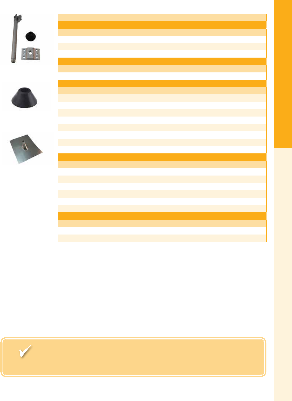
HD Standoff Mounts for All Roof Types
HD Standoff Kits
Description Item code
HD Standoff Kit, 7” 242-92073
HD Standoff Kit, 12” 242-92074
HD Standoff Kit, 18” 242-92075
HD Tilt Kits
Description Item code
20° HD Tilt Kit w/ 7” and 18” HD Standoffs 242-92079
HD Standoff Accessories
Description Item code
HD Standoff Base, 6-Hole 232-02413
HD Standoff Shaft, 7” 232-01062
HD Standoff Shaft, 12” 232-01063
HD Standoff Shaft, 18” 232-01021
Rubber Rain Collar 232-01000
Standoff Clamp Assembly 242-04100
Standoff Clamp and L Foot Assembly 242-09002
10° - 45° Variable Tilt Hardware Kit 242-92083
Standoff Flashings
Description Item code
Standoff Flashing, 3” Straight Cone, 20” x 20”, Dead Soft AL w/ Rolled Edges 175-05001
Standoff Flashing, 4” Offset Cone, 11” x 13”, Galv (Box of 25) 175-05012
Standoff Flashing, 4” Offset Cone, 18 ¾” x 15”, Galv 131-01216
Standoff Flashing, 4” Straight Cone, 18” x 18”, Galv (Box of 12) 131-01214
Standoff Flashing, Oatey No Caulk (11830), 12 ½” x 8 ¾”, Galv 015-00162
Standoff Sub Base Flashing, Verde Industries, 12” x 10”, Galv 175-05005
Lag Screws
Description Item code
Lag Screw and Washer, 5/16" x 3 ½”, SS (Pack of 100) 014-06508
Lag Screw and Washer, 5/16” x 5”, SS (Pack of 100) 014-06509
Fast, Accurate Shipping to Your Job Site. With just-in-time delivery and blind
drop shipping, we can ship directly to your customers, just as if it came straight from you.
HD Standoff Kit, 12"
Rubber Rain Collar
Standoff Flashing, 4” Offset
Cone, 18 ¾” x 15”, Galv

For the latest on AEE Solar products, trainings and dealer services, visit www.aeesolar.com
MOUNTING STRUCTURES
24
SnapNrack
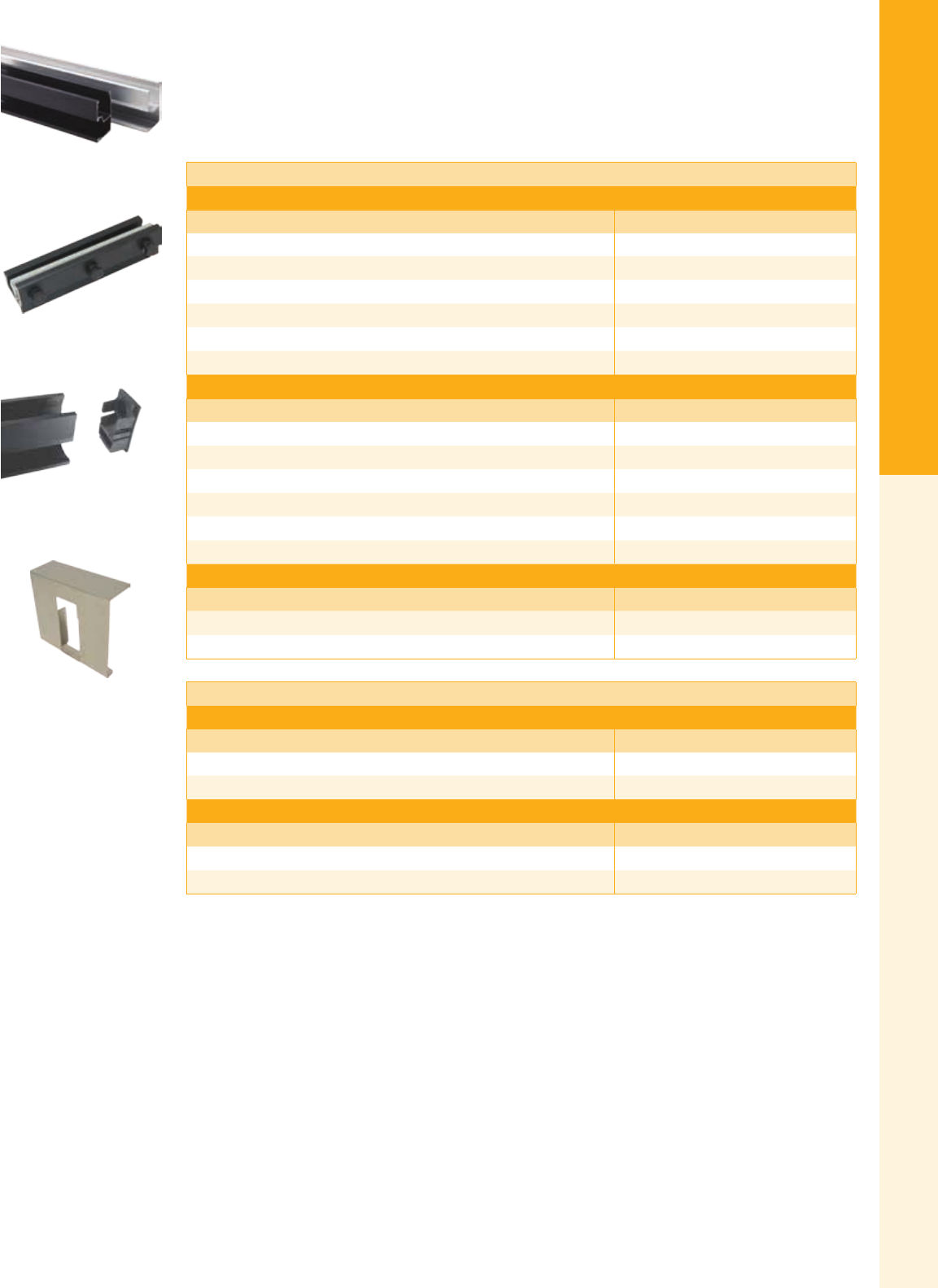
SnapNrack Series 100 Rails
Rail sets consist of two, six, or 112 rails and are offered in two lengths to simplify planning. 122" rail can
accommodate a single row of three standard 60-cell or 72-cell modules. 162" rail will accommodate four
modules. Use the UEC Rail Cutting Tool to protect the module frames from scratches while making a
straight cut when using Universal End Clamps.
Standard Rail
Black Standard Rails
Description Item code
Standard Rail Set, 122”, Black (Box of two) 015-09816
Standard Rail Set, 122”, Black (Box of six) 015-09822
Standard Rail, 122”, Black (Bundle of 112, priced as each) 232-01067
Standard Rail Set, 162”, Black (Box of two) 015-09818
Standard Rail Set, 162”, Black (Box of six) 015-09826
Standard Rail, 162”, Black (Bundle of 112, priced as each) 232-01069
Clear Standard Rail
Description Item code
Standard Rail Set, 122”, Clear (Box of two) 015-09814
Standard Rail Set, 122”, Clear (Box of six) 015-09813
Standard Rail, 122”, Clear (Bundle of 112, priced as each) 232-01068
Standard Rail Set, 162”, Clear (Box of two) 015-09817
Standard Rail Set, 162”, Clear (Box of six) 015-09824
Standard Rail, 162”, Clear (Bundle of 112, priced as each) 232-01070
Mill Standard Rail
Description Item code
Standard Rail, 122”, Mill (Bundle of 112, priced as each) 232-02112
Standard Rail, 162”, Mill (Bundle of 112, priced as each) 232-02113
Standard Rail Splices & Accessories
Standard Rail Splices
Description Item Code
Bonding Standard Rail Splice, Black 242-04015
Bonding Standard Rail Splice, Clear 242-04014
Standard Rail Accessories
Description Item Code
Standard Rail End Cap 232-01023
UEC Rail Cutting Tool 232-02284
Bonding Rail Splice, Black
Standard Rail End Cap
UEC Rail Cutting Tool
Standard Rail, Black & Clear
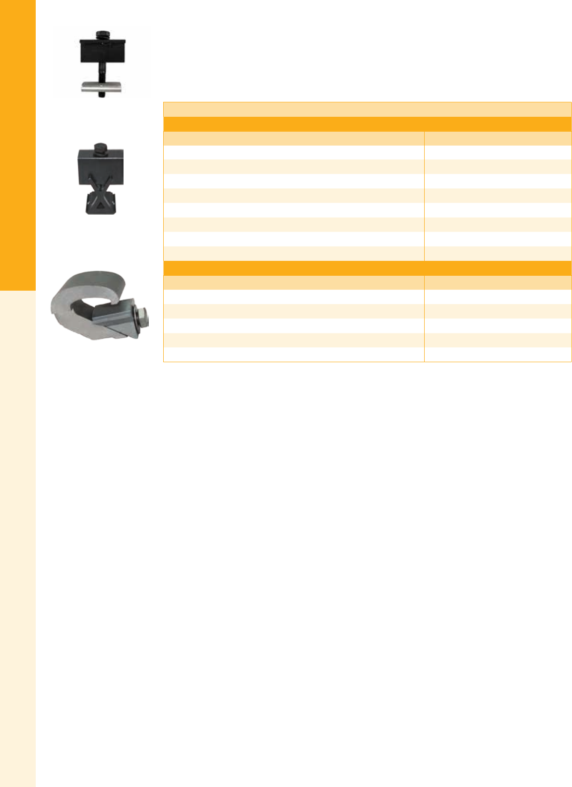
For the latest on AEE Solar products, trainings and dealer services, visit www.aeesolar.com
MOUNTING STRUCTURES
25
SnapNrack
SnapNrack Module Attachments
Module Clamps are available in different sizes to match PV module frame thickness/depth. Universal
End Clamps are a unique one-size-ts-all time saver that slips inside the module frame – completely
out of sight. The rails are cut ush with the modules and nished with SnapNrack end caps to create a
system with a ush, clean line homeowners love.
Module Clamps
Mid Clamps
Description Item code
Bonding Mid Clamp, 1.20” - 1.48”, Black 242-02053
Bonding Mid Clamp, 1.20” - 1.48”, Clear 242-02050
Bonding Mid Clamp, 1.31” - 1.77”, Black 242-02054
Bonding Mid Clamp, 1.31” - 1.77”, Clear 242-02051
Bonding Mid Clamp, 1.50” - 2.00”, Black 242-02055
Bonding Mid Clamp, 1.50” - 2.00”, Clear 242-02052
Bonding Mid Clamp, 1.95" - 2.23", Black 242-02057
Bonding Mid Clamp, 1.95" - 2.23", Clear 242-02056
End Clamps
Description Item code
Universal End Clamp 242-02215
Bonding Adjustable End Clamp, 1.20” - 1.48”, Black 242-02067
Bonding Adjustable End Clamp, 1.20” - 1.48”, Clear 242-02065
Bonding Adjustable End Clamp, 1.49” - 2.00”, Black 242-02068
Bonding Adjustable End Clamp, 1.49” - 2.00”, Clear 242-02066
Bonding Mid Clamp Assembly,
Black
Bonding Adjustable End Clamp
1.20”-1.48”, Black
Universal End Clamp
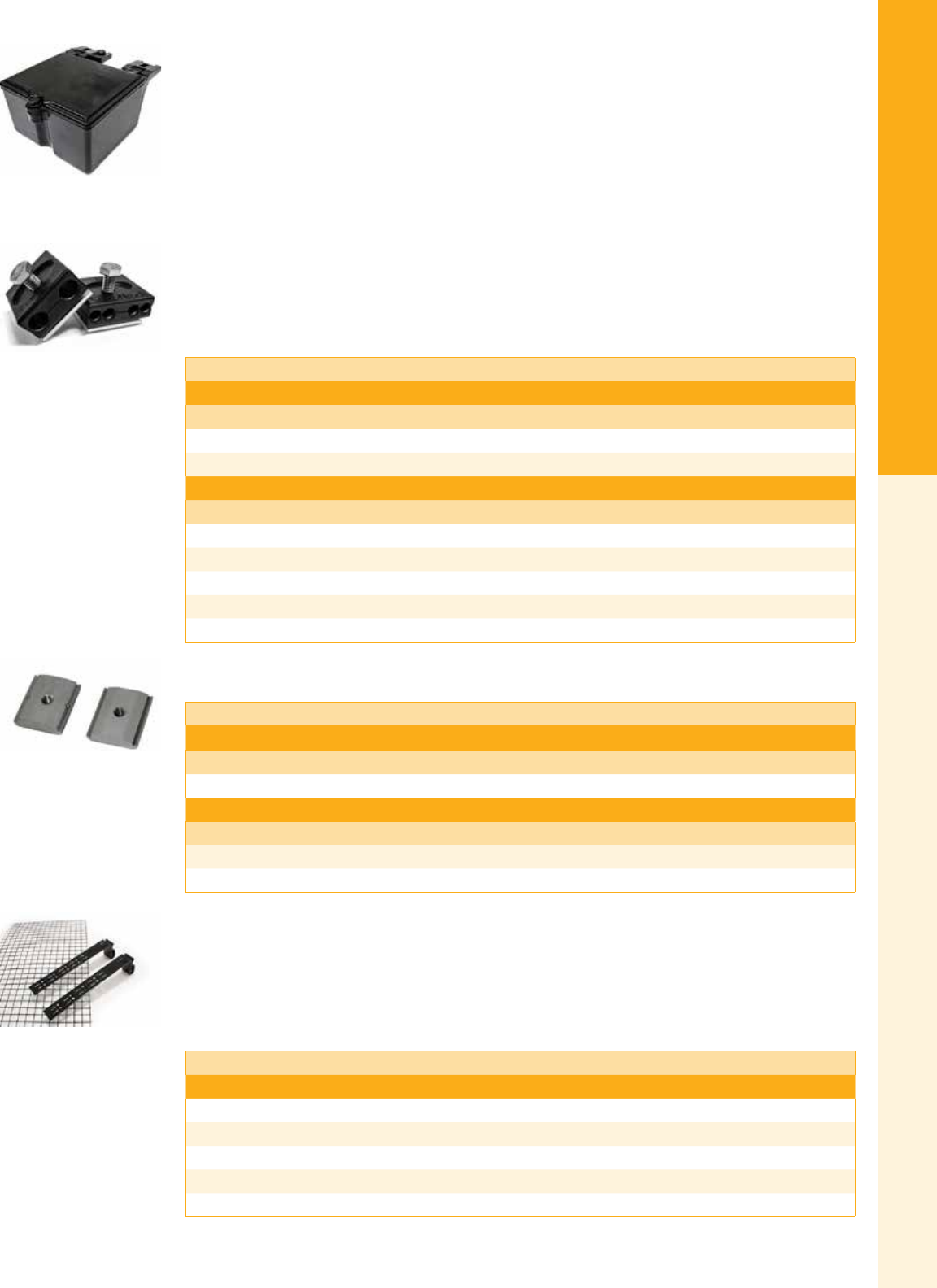
For the latest on AEE Solar products, trainings and dealer services, visit www.aeesolar.com
MOUNTING STRUCTURES
26
SnapNrack
SnapNrack Grounding and Wire Management
SnapNrack’s Ground Lug R is a fully custom solution for grounding the completed system. Only one lug
is required per individual row of modules (not per rail). The lug is secured with a single 5/16" bolt just
like every other product in the system and requires no drilling of the rails. SnapNrack Wire Management
Solutions comprise a set of dedicated components to reliably and cost effectively secure PV module and
microinverter leads. All components are made of materials which have been selected for their ability to
handle high UV exposure and extreme rooftop temperatures common under solar arrays. The SnapNrack
UL-listed Junction Box provides a quick and easy installation utilizing snap-in features and NEMA 4X
rating to conceal and protect electrical connections. It is 6” x 5” x 3” and fully integrated with DIN rail
mounts inside. The Four-Wire Clamp and Trunk Cable Clamp offer a strong and reliable solution for
securing up to four PV conductor cables or up to two Microinverter AC trunk cables along SnapNrack
rail channels, transitioning in and out of channels, and even routing across rails. Snap-In Wire Reten-
tion Clips allow you to quickly secure PV conductor and AC trunk lines into our standard rail channels.
Combining these solutions will not only provide a high quality wire management solution for the life of
the system but will provide a faster and easier installation.
SnapNRack Grounding and Wire Management
Grounding
Description Item code
Ground Lug R for 6-12 AWG 242-02101
Lay-in Lug w/ Bolt and Keps Lock Nut, 4-14 AWG (Pack of ten) 051-03418
Wire Management
Junction Box R 242-01104
Trunk Cable Clamp for Rail 242-02103
4-Wire Clamp for Rail 242-02102
Snap-in Wire Retention Clip 232-01106
48" Rail Cover, Aluminum 232-01033
SnapNrack Attachment Accessories
Attachment Accessories
Module Level Power Electronics
Description Item code
MLPE Rail Attachment Kit 232-02009
Channel Nuts
Description Item code
Bonding Channel Nut 232-02009
Original Channel Nut 232-02005
SnapNrack Array Edge Screen
The Array Edge Screen is designed to keep birds and rodents from making their home under the array,
potentially damaging the system. The clips attach to the bottom ange of each module frame and have
hooks to snap the screen into place. The clips are painted steel and can be “snapped” to the appropriate
length to accommodate height variations. The mesh screen is vinyl-coated steel, rigid enough to keep
out even the most industrious squirrel.
Array Edge Screen
Description Item code
Array Edge Screen Kit, 4” x 100’ 015-11176
Array Edge Screen Kit, 8” x 100’ 015-11177
Array Edge Screen Clip, 4” 232-03993
Array Edge Screen Clip, 8” 232-03994
Add-A-Lip Box Frame Adapter 242-01101
Bonding & Original
Channel Nut
Trunk Cable Clamp &
4-Wire Clamp for Rail
Junction Box R
Array Edge Screen Kit, 4”x100’
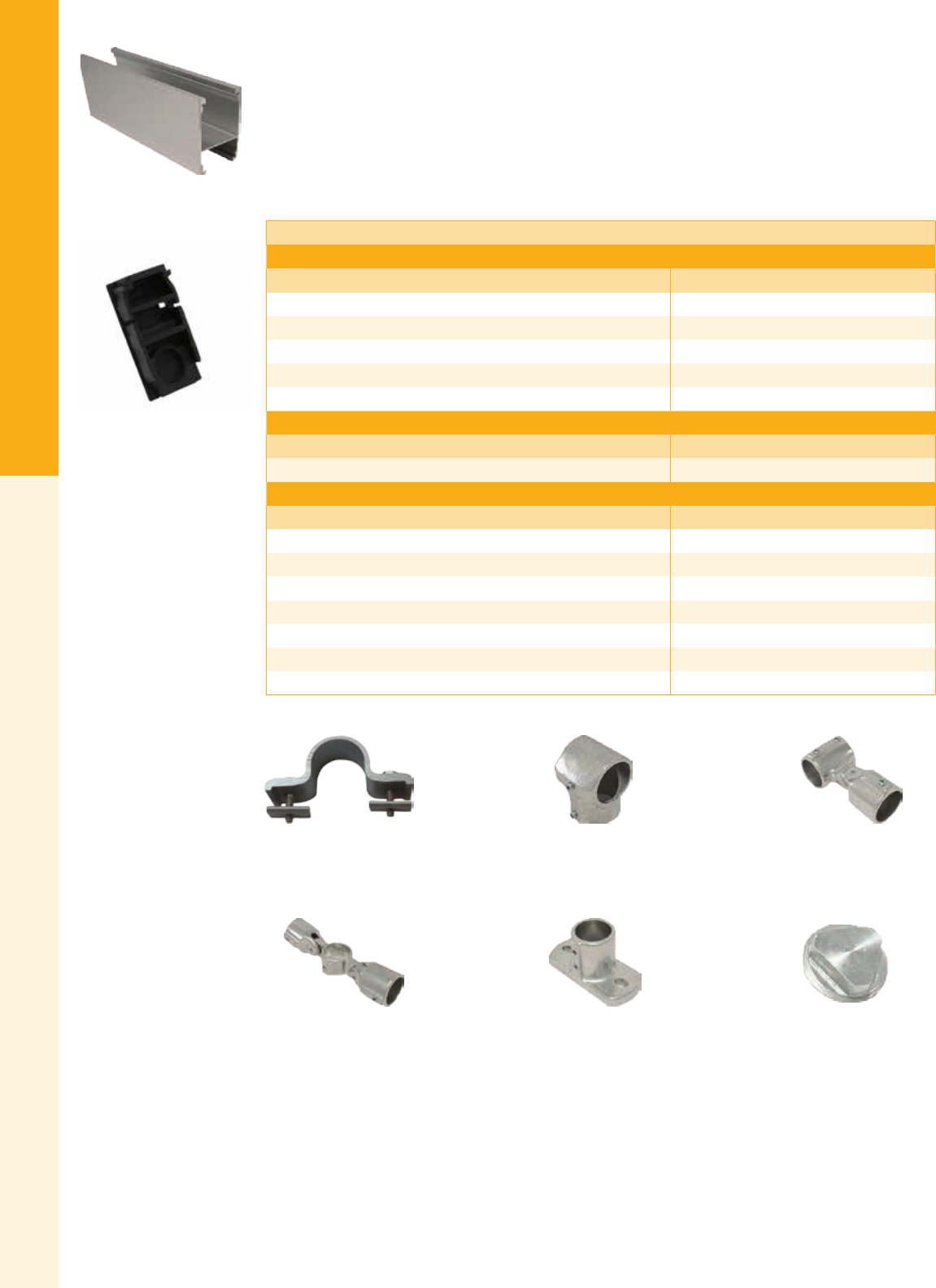
For the latest on AEE Solar products, trainings and dealer services, visit www.aeesolar.com
MOUNTING STRUCTURES
27
SnapNRack
SnapNrack Series 200 Ground Mount
The SnapNrack 200 Ground Mount system is a solar module installation system that is low prole
and visually appealing. This innovative suite of racking products simplies installation to save time and
money. The SnapNrack ground rail and rail-to-pipe clamp creates a multi-pole, xed-tilt ground mount.
The ground rail accepts all Series 100 module mounting clamps and the pipe clamp is designed for 1.5"
(1.9" outside diameter) schedule 40 or 80 steel pipe substructures. It can be installed with tilt angles up to
45° and in locations that may see wind speeds up to 170 mph and snow loads up to 120 psf. For module
attachment hardware refer to the SnapNrack Module Attachments section.
Ground Mount System
Ground Rail
Description Item code
Ground Rail Set, 122”, Clear (Box of four) 015-09839
Ground Rail, 122”, Clear (Bundle of 112, priced as each) 232-02183
Ground Rail Set, 162”, Clear (Box of two) 015-09819
Ground Rail Set, 162”, Clear (Box of four) 015-09855
Ground Rail, 162”, Clear (Bundle of 112, priced as each) 232-01072
Ground Rail Accessories
Description Item code
Ground Rail End Cap 232-01043
Structural Fittings
Description Item code
Bonding Pipe Clamp for 1 ½” 242-09004
Single Socket Tee, Hollaender (5E-8), 1 ½”, AL-MG 172-05800
Single Adjustable Socket Tee, Hollaender (17-8), 1 ½”, AL-MG 172-05803
Double Adjustable Socket Tee, Hollaender (19E-8), 1 ½”, AL-MG 172-05804
Rectangular Base Flange, Hollaender (46-8), 1 ½”, AL-MG 172-05807
Plug End, Hollaender (62-8), 1 ½” Sched 40, AL 172-05808
Plug End, Hollaender (62P-8), 1 ½” Sched 40, Plastic 172-05811
Ground Rail Set, 122”, Clear
Bonding Pipe Clamp for 1 ½” Single Socket Tee,
Hollaender (5E-8)
Single Adjustable Socket Tee,
Hollaender (17-8)
Double Adjustable Socket Tee,
Hollaender (19E-8)
Rectangular Base Flange,
Hollaender (46-8)
Plug End,
Hollaender (62-8)
Ground Rail End Cap
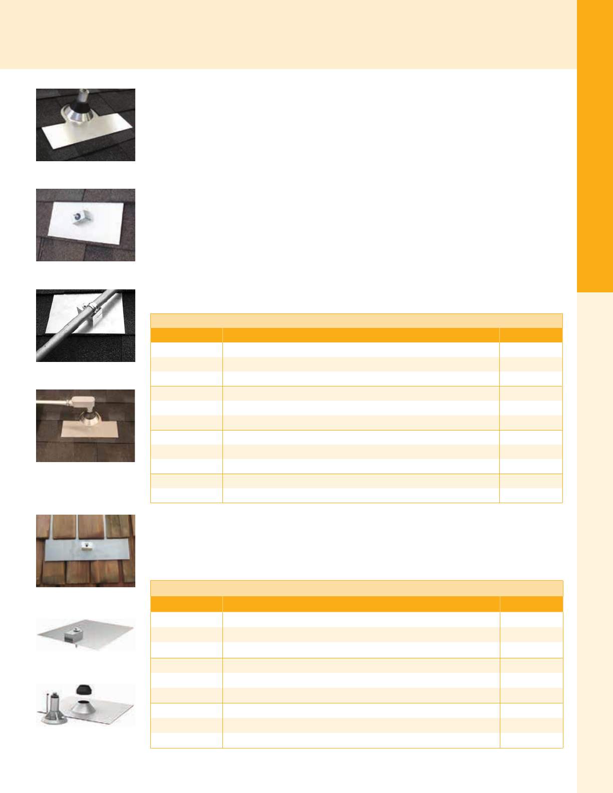
For the latest on AEE Solar products, trainings and dealer services, visit www.aeesolar.com
MOUNTING STRUCTURES
28
Roof Attachments
Roof Attachments
These specialized roof attachments can be used with a variety of mounting systems to meet special requirements.
Quick Mount PV
All-In-One Waterproof Flashed Mounts
Quick Mount PV waterproof ashing and mounts are designed by roong professionals to anchor pho-
tovoltaic racking systems to most types of roofs, including composition, tile, shake, and low-slope roofs.
All Quick Mount PV ashed mounts are sold in boxes of 12, and are available with a mill, clear-anodized,
or black-anodized nish, unless otherwise noted. All exposed hardware is made from stainless steel to
ensure long-term protection against water intrusion.
Flashed Composition Shingle Mounts
The QMNC QBase Composition Mount is a base-and-post mount designed for use when integrating
a solar array into new roof construction. The QBase foundation is protected by a 12" x 12" spun cone
aluminum ashing. 12" x 12" QMSC Classic Composition and Classic Shake Mounts are ICC-ES cer-
tied (ICC-ESR-2835) and incorporate ashing seamlessly integrated with a standoff block. Stainless
steel hardware attaches the block by L-foot to most racking systems, including DPW and SnapNrack,
and enables an attractive low-prole array. The QMSC Classic Conduit Mount is similar to the Classic
PV mounts but has a narrower ashing and accepts a standard conduit clamp. The QMSE E-Mount is a
smaller, lighter more economical version of the Classic Mount. The QMPC Conduit Penetration Flash-
ing provides an easy method to install conduit through the roof while protecting against water intrusion.
Quick Mount PV Shingle Mounts
Model Description Item code
QMNC A 12 QBase Composition Mounts - 12", mill nish, 12-pack 014-06313
QMNC B 12 QBase Composition Mounts - 12", bronze anodized nish, 12-pack 014-06314
QMNC C 12 QBase Composition Mounts - 12", clear anodized nish, 12-pack 014-06312
QMSC-A 12 Classic Composition Mounts - 12" x 12", mill nish, 12-pack 014-06315
QMSC-B 12 Classic Composition Mounts - 12" x 12", bronze anodized nish, 12-pack 014-06316
QMSC-C 12 Classic Composition Mounts - 12" x 12", clear anodized nish, 12-pack 014-06317
QMCC-A 12 Classic Conduit Mounts - 9" x 12", mill nish, 12-pack 014-06222
QMCC-B 12 Classic Conduit Mounts - 9" x 12", bronze anodized nish, 12-pack 014-06223
QMCC-C 12 Classic Conduit Mounts - 9" x 12", clear anodized nish, 12-pack 014-06224
QMSE-A 12 E-Mount Composition Mount – 9” x 12”, mill nish aluminum, 12-pack 014-06332
QMPC-A 12 Conduit Penetration Flashing – 12” mill nish, 12-pack 014-06359
Flashed Shake Mounts
Similar to the composition shingle mount, the QMLC Classic Shake Mount uses larger 18" x 18" alu-
minum ashing to integrate with most wood shake roofs. The QMLCC Classic Shake Conduit mounts
for shake roofs are similar to the PV mounts but have a narrower ashing and accept a standard conduit
clamp. The QMNS QBase Shake and Slate mount is utilized when installing solar on a new shake roof.
Quick Mount PV Flashed Shake Mounts
Model Description Item code
QMLC-A 12 Classic Shake Mounts – 18" x 18", mill nish, 12-pack 014-06319
QMLC-B 12 Classic Shake Mounts – 18" x 18", bronze-anodized nish, 12-pack 014-06321
QMLC-C 12 Classic Shake Mounts – 18" x 18", clear-anodized nish, 12-pack 014-06320
QMLCC-A 12 Classic Shake Conduit Mounts – 12" x 18", mill nish, 12-pack 014-06225
QMLCC-ABA 12 Classic Shake Conduit Mounts – 12" x 18", bronze-anodized nish, 12-pack 014-06226
QMLCC-ACA 12 Classic Shake Conduit Mounts – 12" x 18", clear-anodized nish, 12-pack 014-06227
QMNS-A 12 QBase Shake and Slate Mount – 18” x 18”, mill nish, 12-pack 014-06360
QMNS-B 12 QBase Shake and Slate Mount – 18” x 18”, bronze-anodized nish, 12-pack 014-06361
QMNS-C 12 QBase Shake and Slate Mount – 18” x 18”, clear-anodized nish, 12-pack 014-06362
Conduit Penetration
QBase Composition
Classic Composition
Classic Conduit
Classic Shake
QBase Shake
Classic Shake Conduit
For the latest on AEE Solar products, trainings and dealer services, visit www.aeesolar.com
MOUNTING STRUCTURES
29
Roof Attachments
Quick Mount PV Flashed Tile Mounts
The QMUTM Universal Tile Mount incorporates Quick Mount PV's new QBase foundation and two
aluminum cone ashings. The malleable top ashing conforms to t virtually any tile roof, including
curved tile.
Quick Mount PV Flashed Tile Mounts
Model Description Item code
QMUTM-A 12 QBase Universal Tile Mounts - 18" x 18", mill nish, 12-pack 014-06328
QMUTM-B 12 QBase Universal Tile Mounts - 18" x 18", bronze-anodized nish, 12-pack 014-06329
Quick Mount PV Accessories for Composition and Shake Mounts
QMEXT Height Extensions work with any of the Classic Composition and Classic Shake Mounts to
adjust the angle or clearance between the array and roof. Longer QMHS Hanger Bolt Sets are also avail-
able to accommodate extra thick roong or insulation material.
Quick Mount PV's unique QMRB Shingle Ripper is ideal for cleanly removing nails, shingles, or shakes
without damaging the roof shingles or other shakes.
Quick Mount PV Accessories
Model Description Item code
QMEXT-2.5 A 12 Height Extension - 2 ½", mill nish, 12-pack 014-06338
QMEXT-2.5 B 12 Height Extension - 2 ½", bronze-anodized nish, 12-pack 014-06351
QMEXT-2.5 C 12 Height Extension - 2 ½", clear-anodized nish, 12-pack 014-06350
QMEXT-3.25 A 12 Height Extension - 3 ¼", mill nish, 12-pack 014-06339
QMEXT-3.25 B 12 Height Extension - 3 ¼", bronze-anodized nish, 12-pack 014-06353
QMEXT-3.25 C 12 Height Extension - 3 ¼", clear-anodized nish, 12-pack 014-06352
QMEXT-4.0 A 12 Height Extension - 4", mill nish, 12-pack 014-06340
QMEXT-4.0 B 12 Height Extension - 4", bronze-anodized nish, 12-pack 014-06355
QMEXT-4.0 C 12 Height Extension - 4", clear-anodized nish, 12-pack 014-06354
QMHS-6 12 Hanger Bolt Set - 6", stainless steel, 12-pack 014-06344
QMHS-8 12 Hanger Bolt Set - 8", stainless steel, 12-pack 014-06345
QMHS-10 12 Hanger Bolt Set - 10", stainless steel, 12-pack 014-06346
QMHS-12 12 Hanger Bolt Set - 12", stainless steel, 12-pack 014-06347
QMRB-12 24" Shingle Ripper – nail removal tool 094-00143
QBase Universal Tile
Height Extensions
Hanger Bolts
Shingle Ripper
For the latest on AEE Solar products, trainings and dealer services, visit www.aeesolar.com
MOUNTING STRUCTURES
30
Roof Attachments
Quick Mount PV Low Slope Roof Mounts
Quick Mount PV's new QMLSH Low Slope Roof Mount, which also incorporates the new QBase foun-
dation, is one of the strongest base-and-post PV mounts available for mechanically attaching commercial
PV systems to TPO, PVC, EPDM, built-up asphalt, and virtually all other non-metal low slope roofs.
For built-up asphalt roofs (BUR) and other bituminous and modied bitumen roofs, conical aluminum
ashings are available in 4" and 8" heights (sold separately). When installing the Low Slope Roof Mount
on membrane roofs, Quick Mount PV strongly recommends utilizing the roofer of record to ash the
mounts using their QMLSF ashing.
Quick Mount PV Low Slope Roof Mounts
Model Description Item code
QMLSH-3.75 A 12 QBase Low Slope Mounts - 3.75", mill nish, 12-pack 014-06300
QMLSH-3.75 B 12 QBase Low Slope Mounts - 3.75", bronze-anodized, 12-pack 014-06303
QMLSH-3.75 C 12 QBase Low Slope Mounts - 3.75", clear-anodized, 12-pack 014-06304
QMLSH-7 A 12 QBase Low Slope Mounts - 7", mill nish, 12-pack 014-06301
QMLSH-7 B 12 QBase Low Slope Mounts - 7", bronze-anodized, 12-pack 014-06305
QMLSH-7 C 12 QBase Low Slope Mounts - 7", clear-anodized, 12-pack 014-06306
QMLSH-9 A 12 QBase Low Slope Mounts - 9", mill nish, 12-pack 014-06302
QMLSH-9 B 12 QBase Low Slope Mounts - 9", bronze-anodized, 12-pack 014-06307
QMLSH-9 C 12 QBase Low Slope Mounts - 9", clear-anodized, 12-pack 014-06308
QMLSF-4 A 12 QBase Low Slope Flashing - 17" x 4", mill nish, 12-pack 014-06309
QMLSF-8 A 12 QBase Low Slope Flashing - 17" x 8", mill nish, 12-pack 014-06310
Quick Hook Tile Mounts
Quick Mount PV’s new Quick Hook line features the QMFTHA 4 ½” (Flat Tile) or QMHSS 6” (Flat
or Curved Tile) sliding base and hook to provide a low prole roof attachment. Included is a unique 9” x
12” (Flat Tile) or 9” x 14” (Flat or Curved Tile) all aluminum sub-ashing. Quick Hooks can be installed
without cutting or drilling tiles, resulting in fewer broken tiles and less dust.
Quick Mount PV Quick Hook Tile Mounts
Model Description Item code
QMFTH A 12 Quick Hook for Flat Tile, Mill-nish aluminum, 12-pack 014-06330
QMHSS A 12 Quick Hook for Curved Tile, Side Mount Rails, Mill-nish aluminum, 12-pack 014-06331
Chem Link
E-Curbs
E-Curbs seal penetrations by using a plastic mold and a pour-in-place polymer seal. E-Curbs are designed
for use on granulated modied bitumen, asphalt and coal tar B.U.R. (built up roong), and are specied
for PVC, PIB, and TPO single-ply roong membranes. The service temperature range for the E-Curbs
is -40 °F to 200 °F, but should not be applied at temperatures below 32 °F.
Chem Link E-Curbs
Description Item code
E-Curb, 4" round, gray - four E-Curbs, 1/2 gal one-part pourable sealer, two 10.1 oz cartridge of M-1 131-01350
E-Curb, 6" round, gray – three E-Curbs, two 1/2 gal pouches of one-part pourable sealer, two 10.1
oz cartridges of M-1 131-01351
E-Curb, 6" round, TPO white – three - E-Curbs, two - 1/2 gal pouches of one-part pourable sealer,
two 10.1 oz cartridge of M-1, one 1/2 pint TPO primer, CANNOT BE SHIPPED BY AIR (HAZMAT) 131-01352
Quick Hook Tile Mount and
Included Flashing
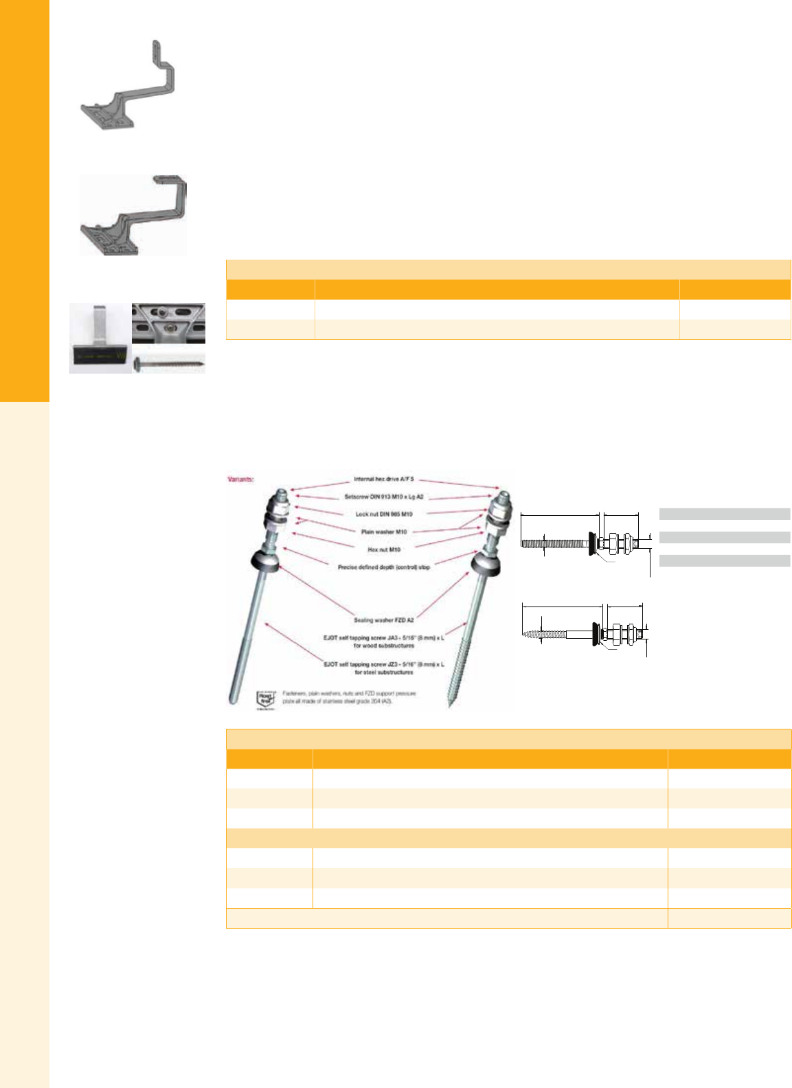
For the latest on AEE Solar products, trainings and dealer services, visit www.aeesolar.com
MOUNTING STRUCTURES
31
Roof Attachments
EJOT
Cast Aluminum Roof Hook Kits
These high-quality cast-aluminum roof attachments make it easy to put solar on tile roofs without cutting
or drilling the tiles. They can support up to 600 pounds and their wide mounting ange allows for correct
placement on the tile even when the rafter does not line up well. The kits come complete with two T25
6.0 x100 mm stainless steel screws and a sealing washer applied to the base of the hook.
The EJ00000002 Front-mount roof hook allows rails to run across the roof, and the EJ00000003 Top-
mount roof hook can be used with L-feet for rails running parallel or perpendicular to the roof. Roof
hooks can be made to work with most popular PV mounting systems.
Note: L-Feet and mounting hardware are not included in the kits. Please order separately to attach the hook
to the roof structure and the appropriate bolts, channel nuts, and L-Feet to attach to the mounting rails.
EJOT Cast Aluminum Roof Hook Kits
Model Description Item code
EJ00000002 EJOT Front-Mount Roof Hook Kit (Includes hook, two screws, seal) 014-09813
EJ00000003 EJOT Front-Mount Roof Hook Kit (Includes hook, two screws, seal) 014-09814
Solar Fastening Systems JZ3 & JA3
These specially designed solar fasteners can be used with SnapNrack Hanger Bolt Clamps to support rails
on exposed fastener metal roofs. The top is threaded (length 1.969’’, dia. M10) and comes with metric
nuts and washers. The wood substructure fasteners have a 5/16’’ lag screw on the bottom. For metal
substructures the bottom part is a high-quality thread-forming screw. Note that the warranty requires
that metric drills be used for pre-drilling the appropriate holes before installation.
ø0.394”
(10)
1.969” (50)
5.118’’ (130)
FZD ø0.984”
(25)
ø 5/16’’
(8)
LLg
D
setscrew ø
FZD
Product key:
D = diameter of screw (lower part)
L = length of screw (lower part)
Lg = length of setscrew (upper part)
JZ3 = thread type for steel substructures
JA3 = thread type for wood substructures
Standard is a Ø 5/16’’ (8 mm) fastener with M10 x 1.969’’
(50 mm length) setscrew; the length L is variable and has
to be chosen according to the respective project.
JA3 (or JZ3) - SB - D x L / Lg + FZD
7.3 inches EJOT Solar Fastening System for wood
substructure
Code: JA3-SB-8.0 x 130/50 FZD
(in inches: JA3-SB-5/16‘‘ x 5.118‘‘/1.969‘‘ FZD)
General:
Example:
EJOT Solar Fastening System for Wood Substructures
Model Description Item code
3150851905 JA3-SB-8.0 x 80/50 FZD (JA3-SB-5/16'' x 3.150''/1.969'' FZD) 014-06451
3151351905 JA3-SB-8.0 x 130/50 FZD (JA3-SB-5/16'' x 5.118''/1.969'' FZD) 014-06452
3152051905 JA3-SB-8.0 x 200/50 FZD (JA3-SB-5/16'' x 7.874''/1.969'' FZD) 014-06453
EJOT Solar Fastening System for Metal Substructures
3130851905 JZ3-SB-8.0 x 80/50 FZD (JZ3-SB-5/16'' x 3.150''/1.969'' FZD) 014-06462
3131251905 JZ3-SB-8.0 x 125/50 FZD (JZ3-SB-5/16'' x 4.921''/1.969'' FZD) 014-06464
3132051905 JZ3-SB-8.0 x 200/50 FZD (JZ3-SB-5/16'' x 7.874''/1.969'' FZD) 014-06466
Hanger Bolt Clamp (for use with SnapNrack rail) 242-01102
EJOT Front Mount Roof Hook
EJOT Top Mount Roof Hook
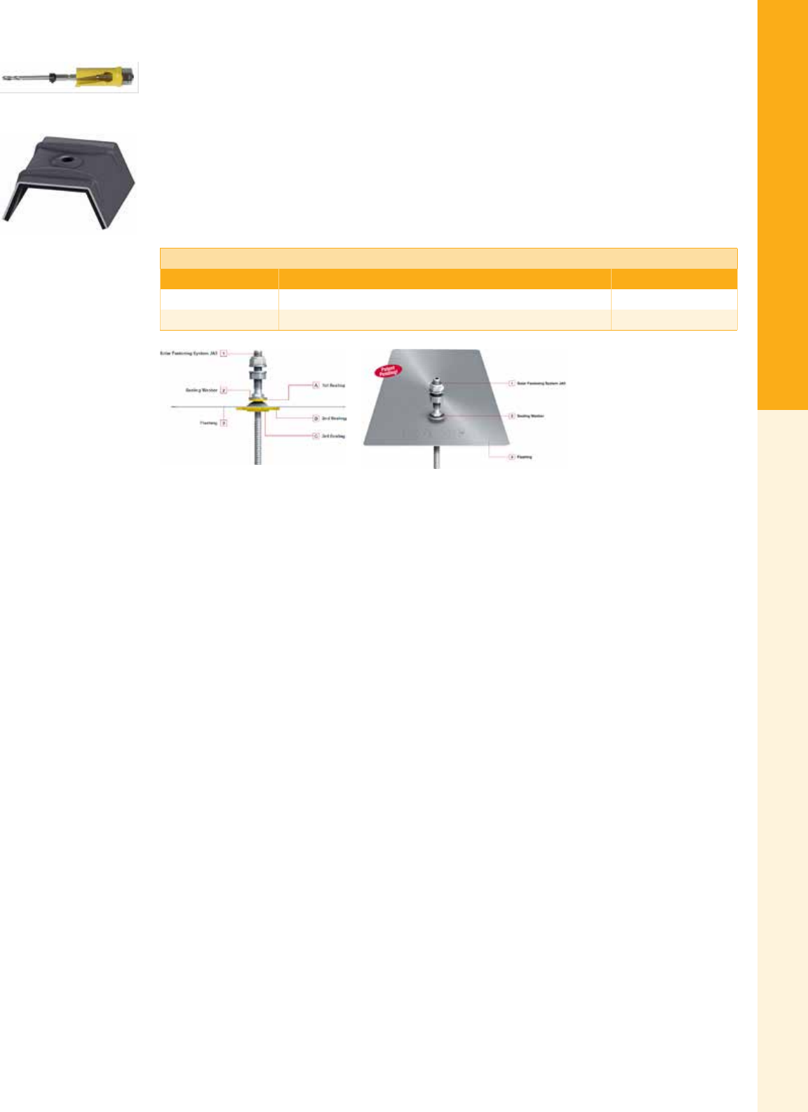
For the latest on AEE Solar products, trainings and dealer services, visit www.aeesolar.com
MOUNTING STRUCTURES
32
Roof Attachments
EJOT Solar Flashing
These specially designed ashings are to be used on three-tab asphalt shingle roofs. With the three seal-
ing elements they provide for watertight seals on top of the ashing, the top shingle and the bottom
shingle. Kit includes ashing and EJOT Solar Fastening System JA3-8.0x80/70 E22/3 for wood sub-
structures. The top portion of the fastener is threaded (length 2.756’’, dia. M10) and comes with metric
nuts and washers. The fastener has a 5/16’’ lag screw on the bottom and can be used with L-feet or
SnapNrack Hanger Bolt Clamps to support rails. For the installation preparation in the shingle and wood
substructure use the 9250027006 EJOT Click & Drill Hole Saw.
Products are also available upon request with the EJOT ORKAN Storm Washer. The Storm Washer
has to be dened by crown width and angle of the trapezoidal metal roof prole. Please contact AEE
Solar for assistance in determining the right solution for your project.
EJOT Solar Flashing
Model Description Item code
EJ00000001 EJOT Solar Flashing (Kit) 014-06468
9250027006 EJOT Click & Drill Hole Saw 094-00113

For the latest on AEE Solar products, trainings and dealer services, visit www.aeesolar.com
MOUNTING STRUCTURES
33
Commercial Roof and Ground
Commercial Roof and Ground Mounting Structures
Commercial PV systems tend to be signicantly larger than residential ones, but also more price sensitive – requiring installers to
achieve economies of scale to keep the price per watt or kilowatt-hour as low as possible. In addition, commercial rooftops are sel-
dom the sloped composition or tile roofs so common in residential settings, so specialized mounting systems can be make-or-break
for a commercial PV project. Most of the systems presented here are highly customizable and must be specically engineered for
each building or site so you’ll need to contact your AEE Solar representative with the particulars of your project for a custom quote.
AET
Rayport-B ECO Flat Roof Solar Mounting System
The Rayport-B ECO Ballasted Mount System for at roof commercial installations is designed to
be functional, lightweight, durable, strong, and easy to install. The ECO range of products focuses
on achieving cost savings, while maintaining quality and function. The system is wind-tunnel tested;
UL2703 listed, and comes with a 25-year limited warranty. It ts all major solar modules on the market.
Extensive engineering and loading analysis from AET's product design group help to provide a low-cost,
high-quality product that minimizes assembly time. Modules are mounted in a landscape orientation at
either 5° or 10°. Installed dimensions vary depending on module width and array tilts.
Rayport ballasted systems are wind-tunnel tested to 120 mph.
Integrated fasteners and supplied grounding hardware between the modules and the frames allow for
quick, easy installation. Support rails fold down to reduce shipping costs, and are assembled using two
bolts on site. Optional additions include the Rayport™-I Inverter Mounting Kit, providing installers
with a secure, ballasted mounting solution for storing and positioning inverters on solar installation sites.
Additionally, mounts and penetrations can be added for areas that are subjected to high wind loading or
seismic activity.
Contact AEE Solar with your array layout for a custom quote with ballast recommendations based on building height, module
type, wind and snow load requirements, and exposure category.
Rayport-G ECO Ground Mounting System
The Rayport-G ECO Ground Mount System from AET is a lightweight galvanized
steel ground mount system that minimizes components, is fast to deploy, and comes
preassembled for quick deployment.
Submit your design request to AEE for a custom-engineered solution to t the
specic needs of your site and installation.
Key Features:
• Two-high portrait design optimized for maximum number of panels per post
• UL 2703 approved; Single point of connection for system ground
• G90 Galvanized for corrosion resistance
• Minimal fasteners and connection points
• Seven pre-assembled parts to order
• Top down panel clamps with integrated grounding
• No drilling or cutting required; designed for two-man assembly crews
• Fits all major solar modules
• Custom-engineered proles, with full layout and loading analysis for every project
• Options available for Ballasted, Helical, or Screw-Pile mounts
RAYPORT™SOLAR MOUNTING SOLUTIONS
• Lightweight, durable and cost-effective
• Fully galvanized steel
• Roof-top and ground mount availability
• Industry-leading installation time
• Engineering support from concept to completion
• More than 275 MW installed
100% on time. 100% on budget.
Zero warranty claims.
Get a Quote Today
www.AETenergy.com
info@aetenergy.com
586-466-5073
Save money and installation time
with AET’s ECO line of high quality
solar mounting solutions.
RAYPORT™-G ECO GROUND MOUNT SYSTEM RAYPORT™-B ECO ROOF BALLAST SYSTEM
For the latest on AEE Solar products, trainings and dealer services, visit www.aeesolar.com
MOUNTING STRUCTURES
34
Commercial Roof and Ground
Aerocompact
NEW! Aerocompact 2.0 South and Aerocompact+ East/West
Flat Roof Ballast Racking System
Aerocompact offers an affordable, highly aerodynamic, fast to assemble, and fully engineered ballasted
racking system for at commercial roof mounts. Each racking system is designed with site-specic
information, and a detailed layout, ballast plan, and engineering report are provided for every project.
The reports generated are very detailed, and can be used in sales presentations, and in obtaining permits
for your projects.
Aerocompact 2.0 is the new South-oriented aerodynamic racking
solution for framed modules on at roofs. It is ETL listed to UL 2703,
TUV Certied, wind tunnel tested up to 150 mph, and is provided with
a 25-year limited warranty. It is fast and easy to install, and can be
designed with 5°, 10°, and 15° tilt angles. Module clamps come with
integrated grounding, and a new Alpine Version is available in areas
with high snow loads. The redesigned ballast tray can accommodate
more ballast to allow the system to be installed in high wind areas.
Aerocompact+ is a 10°, East/West mounting system. This racking solution allows more modules to be
placed on a roof surface by eliminating the inter-row shading that occurs with a south facing system. The
east/west solution allows the placement of up to 30% more modules on a given roof surface with a mini-
mal loss in production per module, resulting in more generated kWh to the end customer. It also benets
from having fewer components, thus less racking cost per module.
Since the modules are placed edge to edge, there is less wind loading,
thus lower the ballast requirements for this system. Therefore, it can
be deployed on more roofs with less roof loading. An Alpine Version
is available for the Aerocompact+ where high snow loads are expected.
Both versions of Aerocompact racking can be fully ballasted with no
penetrations, or with limited penetrations for reduced ballast require-
ments, or where required due to seismic concerns.
Contact your AEE Solar representative with your array layout and site information to receive a custom quote and engineering
report with ballast recommendations. Be prepared to supply site information such as building height, roof material, module
quantity and type, wind and snow load requirements, and exposure category.
Aerocompact 2.0 South System
Aerocompact 2.0 Ballast Trays
Aerocompact+
East/West System
Aerocompact+
with ballast and trays
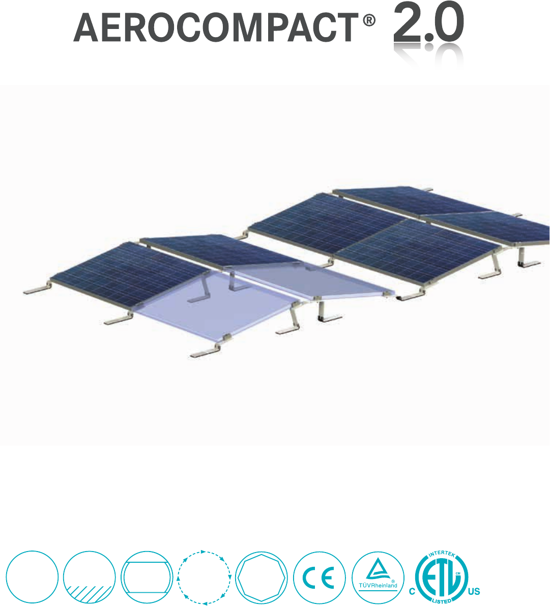
1 kWp /
2.5 min.
ETL
listed to
UL 2703
PATENT
PENDING
WIND
TUNNEL
TESTED
Y
E
A
R
S
L
I
M
I
T
E
D
W
A
R
R
A
N
T
Y
25
East/West
also available in south 5°, 10°, 15°
the unbeatable flat-roof solution
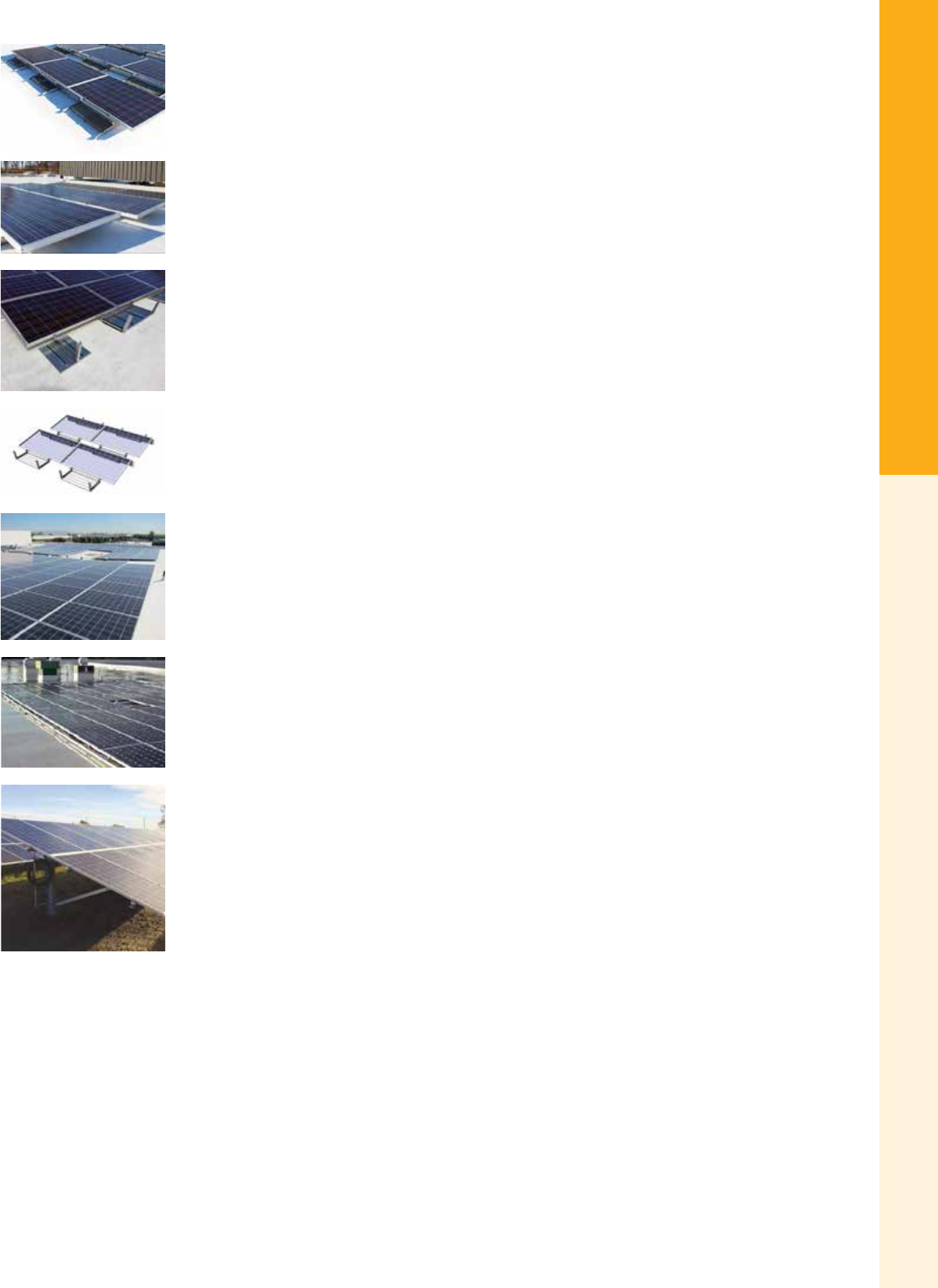
For the latest on AEE Solar products, trainings and dealer services, visit www.aeesolar.com
MOUNTING STRUCTURES
36
Commercial Roof and Ground
DPW Solar
POWER-FAB CRS G2 Non-Penetrating Flat Roof Mounting System
The POWER-FAB™ CRS G2 top-clamping module mounting system is designed to install quickly and
provide a secure mounting structure for any framed module. The system's ballasted design minimizes
the impact of dead loads on the roof and minimizes roof penetrations. The system meets UL standards
for integrated grounding. The included EPDM rubber base protects the roof surface, and the system is
assembled using a single tool. The CRS system typically adds less weight per square foot than competi-
tive products. Full-scale wind tunnel results qualify the system's performance in high wind speed areas.
The POWER-FAB™ CRS system offers tilt angles of 5° to 10°, and features the exibility to design the
racking around roof obstructions and shaded areas to maximize the number of modules and total energy
production. Due to the custom nature of this rack, all parts are non-returnable.
Contact AEE Solar with the details of the array layout for your project to get a custom quote for the CRS G2 system. Full-scale
wind-tunnel data used to calculate ballast weights along with ASCE 07-05 and building-code requirements.
Power Xpress™ Ballasted Flat Roof Mounting System
The DPW Power Xpress™ mounting system is a fully-ballasted, high-strength mounting structure
developed with the professional installer in mind. Featuring two main components with no loose hard-
ware and assembled with a single tool, the Power Xpress™ is designed to provide a faster assembly
and shorter learning curve. Integrated grounding eliminates the need for grounding clips or WEEBs.
The modular design simplies roof layouts, ordering and nal installation while stackable components
reduce shipping volume and provide easy transport of materials to the roof. This racking is available in
5° and 10° tilt congurations, and has options for wire management and EPDM rubber pads to further
protect the roof surface.
Contact your AEE Solar sales representative with the details of the array layout for your project to get a custom quote. Full-scale
wind-tunnel data used to calculate ballast weights along with ASCE 07-05 and building-code requirements.
Ballasted Power Rail™ (BPRM) Flat Roof Mounting System
The DPW Ballasted Power Rail™ mounting system is a 0° tilt, non-penetrating at roof mounting system.
This mounting system provides for very high module density, and provides a secure mounting structure
for standard 60-cell and 72-cell framed modules, and the system can be designed for use in up to 150 mph
wind zones. The system assembles fast using a single tool with no cutting, drilling or punching required
and assembly requiring one tool, and the slotted ballast pans allow for leveling on uneven roof surfaces.
This system requires less ballast weight when compared to other ballasted systems, and provides exibly
to design and install the mounting system around roof obstructions and avoid shaded areas. Integrated
wiring channels and the top-down clamping system speeds installation, ballast pans provide precise rail
alignment, and factory installed EPDM pad material protects the roof surface.
Contact your AEE Solar sales representative with the details of the array layout for your project to get a custom quote. Full-scale
wind-tunnel data used to calculate ballast weights along with ASCE 07-05 and building-code requirements.
Power Peak™ AL and GS Commercial Ground Mount System
The DPW Power Peak™ Ground System is designed for larger-scale ground-mount installations that
require faster build rates, and combines high strength steel attachment components, lightweight module
rails, and are optimized to site-specic conditions and assemble over pre-drilled, pile-driven galvanized
steel “I” beams. Component attachments feature built-in eld adjustments for post misalignment and
include captive bolts and integrated wire management. The single-row, vertical-post design greatly reduces
the number of ground penetrations while providing increased ground-clearance options. Power Peak™
GS utilizes galvanized components, while the Power Peak™ AL substitutes aluminum components for
greater corrosion resistance in coastal and humid environments
Contact your AEE Solar sales representative with the site details for your project to get a custom quote.
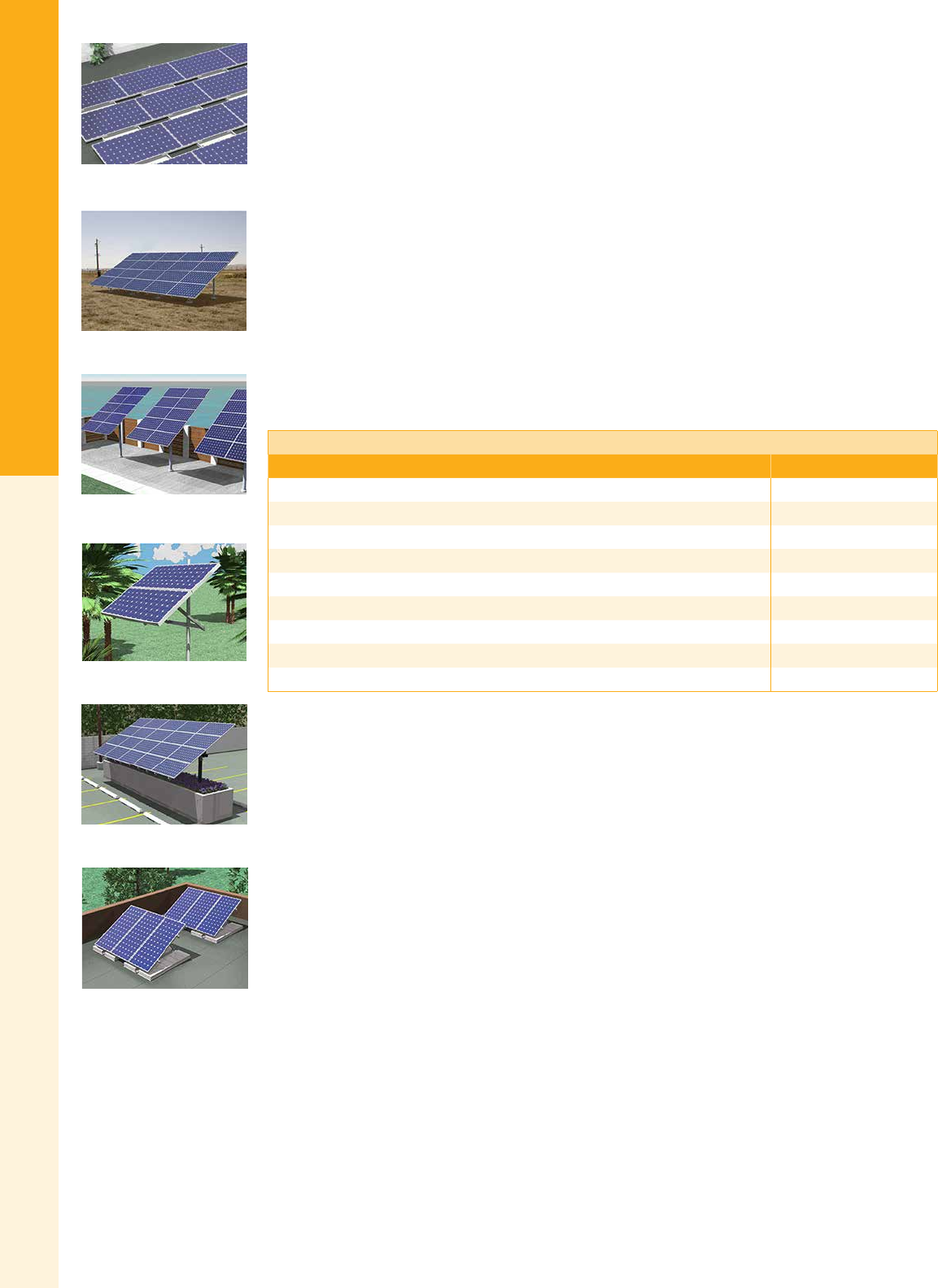
For the latest on AEE Solar products, trainings and dealer services, visit www.aeesolar.com
MOUNTING STRUCTURES
37
Commercial Roof and Ground
DPW Solar Racking
DPW Solar products are made in the U.S.A. and can be ordered to t virtually any module. DPW offers a
variety of made-to-order DPW Roof/Ground Mounts, Top-of-Pole Mounts, Side-of-Pole Mounts, Multi-
Pole Mounts, and Ballasted Roof Mounts. Compare the dimensions of the module you plan to use with
the sizing chart below to determine the module series.
When ordering, be sure to include a copy of the data sheet for the module you plan to use. For modules
having dimensions that fall outside of the chart, use the next larger size. Some DPW mounting systems
fasten to the modules using the mounting holes on the module frame rather than top clamps. If you are
working with modules that lack a bottom ange, be sure to check for compatibility when ordering.
The High Wind Version upgrade (not available for MPM's) is made for winds up to 130 mph, class C
Wind Zones.
Stainless steel module mounting hardware is provided with all mounts. Stainless steel hardware for the
racking assembly is available as an option.
Use the Module Sizing Chart below to determine the frame size of the DPW racking needed. While
only options for frame size G and H modules are listed, other sizes are available upon request. Call your
AEE representative for more details.
Note: DPW products are built to order and cannot be returned nor exchanged.
Module Series Sizing Chart
Module size range (W x L) DPW module series
19"-23" x 35"-44" A
20"-26" x 39"-53" B
22"-27" x 56"-63" C
31"-33" x 60"-67" D
38"-40" x 51"-56" E
38"-40" x 58"-61" F
37"-42" x 61"-67" G or GL*
38"-40" x 77"-82" H or HL*
50"-52" x 65"-79" I
*GL or HL – Includes longer module rails for module widths greater than 39.45" (i.e. SunPower 305, Sunpower 400)
DPW Ballasted Flat Roof Mount
DPW Ground Mount
DPW Top-of-Pole Mount
DPW Side-of-Pole Mount
DPW Multi-Pole Mount
Ballasted Roof Mounts (BRM)
For the latest on AEE Solar products, trainings and dealer services, visit www.aeesolar.com
MOUNTING STRUCTURES
38
Commercial Roof and Ground
DPW Solar POWER-FAB Roof/Ground Mounts (RGM)
Power-Fab Roof/Ground Mounts are available in several sizes and styles. In addition to the standard
conguration, both low-prole and two-tier designs are available. Unless otherwise indicated, the rails
and legs are mill-nish 6061-T6 structural aluminum angle (AL), and have adjustable, telescoping back
legs (TL). Anodized or powder-coated nishes are available at an additional cost. All RGMs use DPW’s
Power Rail™, so be sure to order the appropriate number of mid and end clamps..
RGM Design Strength
Wind speed Snow load (lbs. per sq. ft.)
0 10 20 30 40 50 60 70 80
90 mph SD SD SD SD HD HD HD HD HD
100 mph SD SD SD HD HD HD HD HD
110 mph HD HD HD HD HD HD HD
120 mph HD HD HD HD HD HD Please contact
130 mph HD HD HD HD AEE Solar
Use the Module Series Sizing Chart on the previous page to determine module series.
Use the RGM Design Strength Chart above to determine whether an SD (Standard Design) or HD (Heavy
Duty) rack is required.
Order the appropriate number of End and Mid Clamps from the RAD Mid and End Clamp table below.
DPW RAD End and Mid Clamps are used in all Roof/Ground Mounts (SRGM, LPRGM, and TTRGM)
as well as the Multi-Pole Mount (MPM). These units are made from Type 304 stainless steel, and the
mid clamps are 3/8" wide. Please be sure to provide a module data sheet with any orders.
RAD Roof/Ground Mount Mid and End Clamps
DPW part # Description Item code
Clear Black
EC-XX-RAD Module End Clamp w/ RAD Hardware (specify module thickness) 013-10961 013-10962
MC-28-33-RAD Module Mid Clamp w/ RAD Hardware for 28-33 mm (1.1" - 1.3") 013-10963 013-10964
MC-34-39-RAD Module Mid Clamp w/ RAD Hardware for 34-39 mm (1.31" - 1.54") 013-10965 013-10966
MC-40-46-RAD Module Mid Clamp w/ RAD Hardware for 40-46 mm (1.55" - 1.81") 013-10967 013-10968
MC-47-52-RAD Module Mid Clamp w/ RAD Hardware for 47-52 mm (1.85" - 2.0") 013-10969 013-10970
MC-53-59-RAD Module Mid Clamp w/ RAD Hardware for 53-59 mm (2.1" - 2.32") 013-10971 013-10972
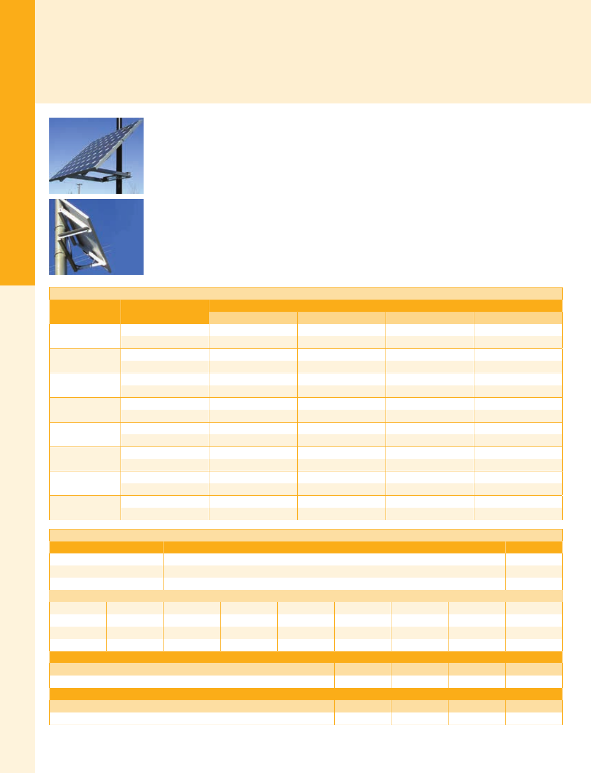
For the latest on AEE Solar products, trainings and dealer services, visit www.aeesolar.com
MOUNTING STRUCTURES
39
Pole Mounts
Pole Mounts
Pole mounts represent a simple, cost-effective approach to mounting small PV arrays without the need for complex foundations or
leveling. A Schedule 40 or 80 rigid steel pole with a deep concrete anchor is typically sufcient. However, specic requirements may
vary due to soil type and expected wind loads. Most pole-mount systems are made-to-order so be sure to include a module data sheet
and double-check your requirements as they typically cannot be returned.
DPW Solar
POWER-FAB® Side-Pole Mounts (SPM)
Power-FAB SPM mounts are made from mill-nish aluminum. Upgrades to anodized or powder-coated
aluminum are available for an additional charge. Stainless-steel module mounting hardware is provided
with all mounts, and tamper-resistant hardware kits are also available for installations that may be left
unattended for long periods. Stainless-steel fastener kits and high-wind upgrades are also available for
the mounting structure itself.
All single-module mounts, and the two-module mounts for size A-C modules come with stainless-steel
band clamps for 2-3.5” diameter pole sizes. All other SPM mounts come with stainless-steel clamps
for 3-4.5” diameter poles. Upgrade clamps sized for larger diameter poles are listed below. Most SPM
mounts can also be attached to at vertical surfaces using installer-supplied lag bolts or through-bolts.
Use the Module Series Sizing Chart on page 37 to determine module series.
POWER-FAB Side-Pole Mounts (SPM)
Module size Number of modules
One Two Three Four
ADPW part # DP-SPM1-A DP-SPM2-A -- --
Item code 013-11101 013-11102 -- --
BDPW part # DP-SPM1-B DP-SPM2-B DP-SPM3-B DP-SPM4-B
Item code 013-11201 013-11202 013-11203 013-11204
CDPW part # DP-SPM1-C DP-SPM2-C DP-SPM3-C DP-SPM4-C
Item code 013-11301 013-11302 013-11303 013-11304
DDPW part # DP-SPM1-D DP-SPM2-D DP-SPM3-D DP-SPM4-D
Item code 013-11401 013-11402 013-11403 013-11404
EDPW part # DP-SPM1-E DP-SPM2-E DP-SPM3-E --
Item code 013-11501 013-11502 013-11503 --
FDPW part # DP-SPM1-F DP-SPM2-F DP-SPM3-F --
Item code 013-11601 013-11602 013-11603 --
GDPW part # DP-SPM1-G DP-SPM2-G DP-SPM3-G --
Item code 013-11701 013-11702 013-11703 --
HDPW part # DP-SPM1-H DP-SPM2-H DP-SPM3-H --
Item code 013-11801 013-11802 013-11803 --
DP Solar Side-Pole Mounts (SPM) – Optional Upgrades
DPW part # Description Item code
HWV High-Wind Version (add 25%) 013-04000
PCA Powder-Coated Aluminum Components (add 25%) 013-11910
AA Anodized Aluminum Components (add 35%) 013-11915
Band Clamp Upgrade
Upgrade to 3-4.5" 4-5.5" 5-6.5" 6-7.5" 7-8.5" 9-9.5" 9-11" 10-12"
DPW part # 4" 5" 6" 7" 8" 9" 11" 12"
From 2-3.5" 013-11930 013-11931 013-11932 013-11933 013-11934 013-11935 013-11936 013-11937
From 3-4.5" -- 013-11938 013-11939 013-11940 013-11941 013-11942 013-11943 013-11944
Stainless steel hardware for rack assembly - SSH
Number of modules One Two Three Four
Item code 013-11921 013-11922 013-11923 013-11924
Tamper-resistant hardware for module mounting - TRH
Number of modules One Two Three Four
Item code 013-10941 013-10942 013-10943 013-10944

For the latest on AEE Solar products, trainings and dealer services, visit www.aeesolar.com
MOUNTING STRUCTURES
40
Pole Mounts
POWER-FAB Top-of-Pole Mounts (TPM)
DPW POWER-FAB® TPM standard
mounts have heavy steel mounting
sleeves, elevation pivots, and strong-
backs that are coated with durable
outdoor paint. The module rails are
6061-T6 mill-nish structural alu-
minum angles. Stainless steel mod-
ule mounting hardware is provided.
Standard top-of-pole mounts are
adjustable from 15° to 65°, in 10°
increments, and t on Schedule 40
or 80 steel pipe.
For harsh environments, upgrades to
hot-dip-galvanized steel or anodized
aluminum rails are available. Use the
tables below to determine the layout
and minimum pipe size.
The DPW Online Congurator at dpwsolar.com can be used to
generate the specic conguration and bill of materials needed
based on module number and type, array location, and environmen-
tal conditions (wind, snow, desired tilt, etc.). A DPW Request for
Information Form provides the TPM’s foundation specications
including the correct pipe length, schedule, and foundation size
requirements, and is available online at www.dpwsolar.com. An
Engineering Stamp can be included from DPW through a third
-party engineer for additional cost.
POWER-FAB Top-Pole Mounts (TPM)
Module
size
DPW
part #
# of
modules Pole size Conguration Item code
A
TPM1-A 12"SCH40 1H x 1W-P 013-10101
TPM2-A 2 1H x 2W-P 013-10102
TPM3-A 3 2.5"SCH40 1H x 3W-P 013-10103
TPM4-A 4 3"SCH40 1H x 4W-P 013-10104
TPM6-A 64"SCH40 2H x 3W-P 013-10106
TPM8-A 8 2H x 4W-P 013-10108
TPM10-A 10
6"SCH40
5H x 2W-L 013-10110
TPM12-A 12 6H x 2W-L 013-10112
TPM14-A 14 7H x 2W-L 013-10114
TPM16-A 16 6"SCH80 8H x 2W-L 013-10116
B
TPM1-B 12"SCH40 1H x 1W-P 013-10201
TPM2-B 2 1H x 2W-P 013-10202
TPM3-B 3 2.5"SCH40 1H x 3W-P 013-10203
TPM4-B 4 3"SCH40 1H x 4W-P 013-10204
TPM6-B 64"SCH40 2H x 3W-P 013-10206
TPM8-B 8 2H x 4W-P 013-10208
TPM10-B 10 6"SCH40 5H x 2W-L 013-10210
TPM12-B 12 6H x 2W-L 013-10212
TPM14-B 14 6"SCH80 7H x 2W-L 013-10214
TPM16-B 16 8H x 2W-L 013-10216
POWER-FAB Top-Pole Mounts (TPM)
Module
size
DPW
part #
# of
modules Pole size Conguration Item code
C
TPM1-C 1 2"SCH40 1H x 1W-P 013-10301
TPM2-C 2 2.5"SCH40 1H x 2W-P 013-10302
TPM3-C 3 3"SCH40 1H x 3W-P 013-10303
TPM4-C 4 4"SCH40 1H x 4W-P 013-10304
TPM6-C 6 4"SCH80 2H x 3W-P 013-10306
TPM8-C 8
6"SCH40
4H x 2W-L 013-10308
TPM9-C 9 3H x 3W-P 013-10309
TPM10-C 10 5H x 2W-L 013-10310
TPM12-C 12 6"SCH80 6H x 2W-L 013-10312
TPM14-C 14 8"SCH40 7H x 2W-L 013-10314
TPM16-C 16 8"SCH80 8H x 2W-L 013-10316
TPM18-C 18 3H x 6W-P 013-10318
D
TPM1-D 1 2"SCH40 1H x 1W-P 013-10401
TPM2-D 2 3"SCH40 1H x 2W-P 013-10402
TPM3-D 3 4"SCH40 1H x 3W-P 013-10403
TPM4-D 4 4"SCH80 2H x 2 W-P 013-10404
TPM6-D 6 6"SCH40 2H x 3W-P 013-10406
TPM8-D 8 4H x 2W-L 013-10408
TPM9-D 9 6"SCH80 3H x 3W-P 013-10409
TPM10-D 10 8"SCH40 5H x 2W-L 013-10410
TPM12-D 12 3H x 4W-P 013-10412
TPM14-D 14
8"SCH80
7H x 2W-L 013-10414
TPM15-D 15 3H x 5W-P 013-10415
TPM16-D 16 4H x 4W-P 013-10416
TPM18-D 18 6H x 3W-L 013-10418
E
TPM1-E 1 2"SCH40 1H x 1W-P 013-10501
TPM2-E 2 3"SCH40 1H x 2W-P 013-10502
TPM3-E 3 4"SCH40 1H x 3W-P 013-10503
TPM4-E 4 2H x 2 W-P 013-10504
TPM6-E 6 6"SCH40 3H x 2W-L 013-10506
TPM8-E 8 4H x 2W-L 013-10508
TPM9-E 9 6"SCH80 3H x 3W-P 013-10509
TPM10-E 10 8"SCH40 5H x 2W-L 013-10510
TPM12-E 12 3H x 4W-P 013-10512
TPM14-E 14
8"SCH80
7H x 2W-L 013-10514
TPM15-E 15 5H x 3W-L 013-10515
TPM16-E 16 4H x 4W-P 013-10516
TPM18-E 18 6H x 3W-L 013-10518

For the latest on AEE Solar products, trainings and dealer services, visit www.aeesolar.com
MOUNTING STRUCTURES
41
Pole Mounts
POWER-FAB Top-Pole Mounts (TPM)
Module
size
DPW
part #
# of
modules Pole size Conguration Item code
F
TPM1-F 1 2"SCH80 1H x 1W-P 013-10601
TPM2-F 2 3"SCH40 1H x 2W-P 013-10602
TPM3-F 3 4"SCH40 1H x 3W-P 013-10603
TPM4-F 4 4"SCH80 2H x 2 W-P 013-10604
TPM6-F 6 6"SCH40 3H x 2W-L 013-10606
TPM8-F 8 6"SCH80 4H x 2W-L 013-10608
TPM9-F 9 3H x 3W-P 013-10609
TPM10-F 10 8"SCH40 5H x 2W-L 013-10610
TPM12-F 12
8"SCH80
3H x 4W-P 013-10612
TPM14-F 14 7H x 2W-L3 013-10614
TPM15-F 15 5H x 3W-L 013-10615
TPM16-F 16 4H x 4W-P2 013-10616
TPM18-F 18 6H x 3W-L4 013-10618
G
TPM1-G 1 2"SCH80 1H x 1W-P 013-10701
TPM2-G 2 3"SCH40 1H x 2W-P 013-10702
TPM3-G 3 4"SCH40 1H x 3W-P 013-10703
TPM4-G 4 4"SCH80 2H x 2 W-P1 013-10704
TPM6-G 6 6"SCH40 3H x 2W-L 013-10706
TPM8-G 8 6"SCH80 4H x 2W-L 013-10708
TPM9-G 9 8"SCH40 3H x 3W-P 013-10709
TPM10-G 10 5H x 2W-L 013-10710
TPM12-G 12
8"SCH80
3H x 4W-P 013-10712
TPM14-G 14 7H x 2W-L3 013-10714
TPM15-G 15 5H x 3W-L 013-10715
POWER-FAB Top-Pole Mounts (TPM)
Module
size
DPW
part #
# of
modules Pole size Conguration Item code
H
TPM1-H 1 2.5"SCH40 1H x 1W-P 013-10801
TPM2-H 2 3"SCH80 1H x 2W-P 013-10802
TPM3-H 3 4"SCH40 1H x 3W-P 013-10803
TPM4-H 4 6"SCH40 2H x 2 W-P 013-10804
TPM6-H 6 3H x 2W-L 013-10806
TPM8-H 8 8"SCH40 4H x 2W-L 013-10808
TPM9-H 9
8"SCH80
3H x 3W-P 013-10809
TPM10-H 10 5H x 2W-L 013-10810
TPM12-H 12 3H x 4W-P1013-10812
I
TPM1-I 1 3"SCH40 1H x 1W-P 013-10901
TPM2-I 2 4"SCH80 2H x 1W-L 013-10902
TPM3-I 3 6"SCH40 3H x 1W-L 013-10903
TPM4-I 4 2H x 2 W-P 013-10904
TPM6-I 6 8"SCH40 3H x 2W-L 013-10906
TPM8-I 8
8"SCH80
4H x 2W-L 013-10908
TPM9-I 9 3H x 3W-P 013-10909
TPM10-I 10 5H x 2W-L 013-10960
Conguration: Array Layout and Module Orientation (P= Portrait L=Landscape)
All pipe recommendations conform to ASCE 7-05, IBC2006, and are based on 90mph, Exposure C, 65-degree max tilt, 12" max front edge ground clearance except for those noted:
16" max front edge clearance 255-degree max tilt 36" max front edge clearance nad 55-degree max tilt 445-degree max tilt

For the latest on AEE Solar products, trainings and dealer services, visit www.aeesolar.com
MOUNTING STRUCTURES
42
Pole Mounts
All standard TPM mounts are available for locations with higher wind speeds of up 130 MPH or snow loads up to 60 psf by adding
the High-Wind Option (adds 25% to the price). This upgrades the mount with sturdier rails, and may require changes to the pole and
foundation specications. See the table below for some congurations which require a change in the module layout.
Alternative Layouts Based on Wind Speed
DPW part # 90 mph standard 130 mph HWV
TPM6-D 2H X 3W-P 3H X 2W-L
TPM12-D 3H X 4W-P 6H X 2W-L
TPM12-E 3H X 4W-P 6H X 2W-L
TPM12-F 3H X 4W-P 6H X 2W-L
TPM12-G 3H X 4W-P 6H X 2W-L
TPM12-H 3H X 4W-P 6H X 2W-L
TPM15-D 3H X 5W-P 5H X 3W-L
POWER-FAB Top Pole Mounts (TPM) – Upgrade Options
Stainless steel hardware for rack assembly - SSH
Number of modules One Two Three Four Six Eight Nine Ten Twelve Fourteen Fifteen Sixteen Eighteen
Item code 013-
10921
013-
10922
013-
10923
013-
10924
013-
10926
013-
10928
013-
10929
013-
10930
013-
10932
013-
10934
013-
10935
013-
10936
013-
10938
Tamper resistant hardware for module mounting - TRH
Number of modules One Two Three Four Six Eight Nine Ten Twelve Fourteen Fifteen Sixteen Eighteen
Item code 013-
10941
013-
10942
013-
10943
013-
10944
013-
10946
013-
10948
013-
10949
013-
10950
013-
10952
013-
10954
013-
10955
013-
10956
013-
10958
DPW part # Description Item code
HWV High-Wind Version (add 25%) 013-04000
HGS Hot-dip Galvanized Steel Components (add 60%) 013-10905
PCS Powder-Coated Steel Components (add 25%) 013-10907
PCA Powder-Coated Aluminum Components (add 20%) 013-10910
AA Anodized Aluminum Components (add 20%) 013-10915
Mounting sleeve upgrade
Upgrade to: 2.5" 3" 4" 6" 8"
Standard
Mounting Pole
2" 013-03069 013-03070 013-03071 013-03072 013-03073
2.5" -- 013-03074 013-03075 013-03076 013-03077
3" -- -- 013-03078 013-03079 013-03080
4" -- -- -- 013-03081 013-03082
6" -- -- -- -- 013-03083
For the latest on AEE Solar products, trainings and dealer services, visit www.aeesolar.com
MOUNTING STRUCTURES
43
Pole Mounts
Multi-Pole Mounts
The DPW Multi-Pole Mounts (MPM) are designed to mount on 3, 4, or 6-inch Schedule 40 galvanized
steel pipe (installer supplied), Multi-Pole Mounts (MPM) support two to four modules high in landscape
orientation. These mounts can be horizontally expanded as far as necessary by installing additional verti-
cal pipe supports. This type of mount requires fewer ground penetrations than traditional ground mounts
and offers a full range of seasonal elevation adjustability.
MPMs use a 4" x 4" square or 4" x 5" rectangular steel horizontal tube (also installer supplied) as well as
DPW’s Power Rail for module mounting. Multi-Pole mounts are ideal for shade and carport structures
because the design is capable of signicant ground clearance. Please complete a DPW MPM Request
for Quote Form in order to properly obtain the foundation design and to generate a bill-of-materials. The
form can be found at www.dpwsolar.com. Use the Module Series Sizing Chart on page 37 to determine
module series. Order the appropriate number of End and Mid Clamps from the RAD Mid and End Clamp
table on page 38.
Multi-Pole Mounts
Module size For 4" x 4" square steel horizontal tube For 5" x 4" square steel horizontal tube
# of modules DPW part # Item code # of modules DPW part # Item code
D
two MPM2-D-4x4 013-13442 two MPM2-D-5x4 013-13452
three MPM3-D-4x4 013-13443 three MPM3-D-5x4 013-13453
four MPM4-D-4x4 013-13444 four MPM4-D-5x4 013-13454
E
two MPM2-E-4x4 013-13542 two MPM2-E-5x4 013-13552
three MPM3-E-4x4 013-13543 three MPM3-E-5x4 013-13553
four MPM4-E-4x4 013-13544 four MPM4-E-5x4 013-13554
F
two MPM2-F-4x4 013-13642 two MPM2-F-5x4 013-13652
three MPM3-F-4x4 013-13643 three MPM3-F-5x4 013-13653
four MPM4-F-4x4 013-13644 four MPM4-F-5x4 013-13654
G or GL
two MPM2-G-4x4 013-13742 two MPM2-G-5x4 013-13752
three MPM3-G-4x4 013-13743 three MPM3-G-5x4 013-13753
four MPM4-G-4x4 013-13744 four MPM4-G-5x4 013-13754
H or HL two MPM2-H-4x4 013-13842 two MPM2-H-5x4 013-13852
three MPM3-H-4x4 013-13843 three MPM3-H-5x4 013-13853
Itwo MPM2-I-4x4 013-13942 two MPM2-I-5x4 013-13952
three MPM3-I-4x4 013-13943 three MPM3-I-5x4 013-13953
Multi-Pole Mount Pipe Caps (includes U-Bolts)
Description DPW part # Item code
For connecting 3" SCH 40/80 vertical steel pipe to 4"x4" horizontal steel tube PC -3V4x4H 013-02093
For connecting 4" SCH 40/80 vertical steel pipe to 4"x4" horizontal steel tube PC-4V4x4H 013-02094
For connecting 4" SCH 40/80 vertical steel pipe to 5"x4" horizontal steel tube PC-4V5x4H 013-02095
For connecting 6" SCH 40/80 vertical steel pipe to 4"x4" horizontal steel tube PC-6V4x4H 013-02096
For connecting 6" SCH 40/80 vertical steel pipe to 5"x4" horizontal steel tube PC-6V5x4H 013-02097
Multi-Pole Mount – Optional Upgrades
DPW part # Description Item code
DP-MPM-PCA Powder-Coated Aluminum Components (add 25%) 013-14925
DP-MPM-AA Anodized Aluminum Components (add 35%) 013-14915
DP-MPM-HGS Hot-dip Galvanized Steel Components (add 60%) 013-14925
Stainless steel hardware for rack assembly - SSH
Number of modules Two Three Four
Item code 013-14932 013-14933 013-14934
Tamper resistant hardware for module mounting - TRH
Number of modules Two Three Four
Item code 013-10942 013-10943 013-10944
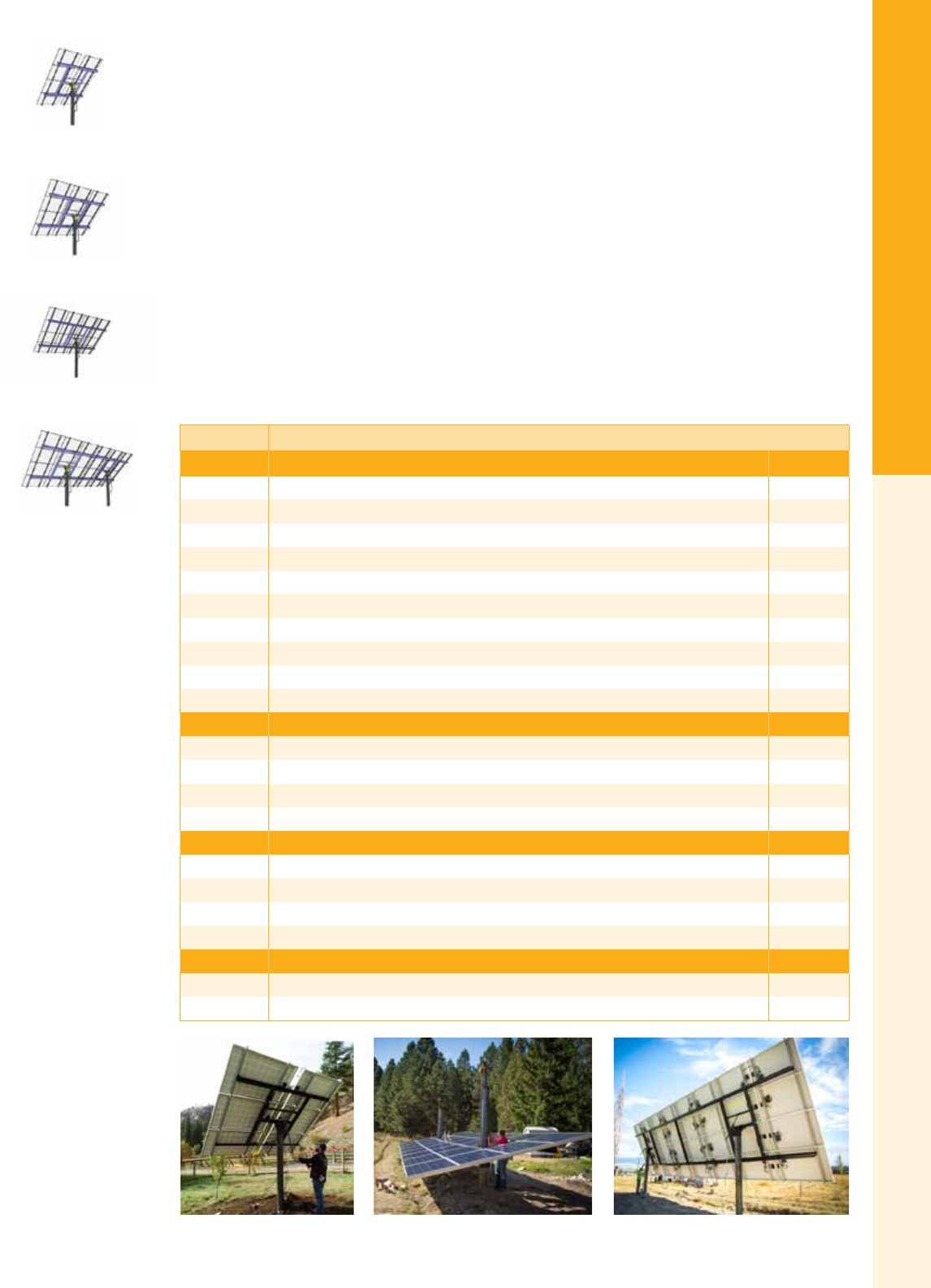
For the latest on AEE Solar products, trainings and dealer services, visit www.aeesolar.com
MOUNTING STRUCTURES
44
Trackers
MT Solar
Top-of-Pole Mount (TPM) Solar Rack
The MT Solar Top-of-Pole Mount Racking system is designed to be assembled and wired at ground level
then lifted to nal position via a chain hoist – without the need for cranes, scaffolding, or dangerous
ladder work. Once installed, the mounts are fully adjustable from 0° to 90° from ground level with a
hand crank. Single-pole mounts are available supporting from two to sixteen 60-cell modules and from
eight to twelve 72-cell modules. Installers realize cost savings without needing to schedule a crane or
scaffolding to install these mounts.
Standard engineering supports up to 130 mph wind speeds, with 30 psf. snow load. Foundation recom-
mendations are provided, and stamped engineering documents are available for an additional fee for all
50 states. Custom engineering is also available for conditions outside those listed. Top down clamping
provides a truly universal mount for most solar modules. Options are available for 10’ pipe for the larger
TPM mounts.
Two-pole mounts may be linked together to support larger multi-pole mounts for up to 32 modules.
This racking solution is manufactured, assembled, and ships direct from the manufacturer in the state
of Montana. Larger arrays requiring three or more pole mounts, and linked arrays for 72-cell modules
available upon request. Contact AEE Solar for details.
MT Solar Top of Pole Mount
MT Part # Single Pole Mounts for 60-Cell Modules Item code
4-TOP-2 TPM Mount for two 60-cell modules, on 4” dia. Schd. 40 pipe 013-00006
4-TOP-3 TPM Mount for three 60-cell modules, on 4” dia. Schd. 40 pipe 013-00007
4-TOP-4 TPM Mount for four 60-cell modules, on 4” dia. Schd. 40 pipe 013-00008
6-TOP-6 TPM Mount for six 60-cell modules, on 6” dia. Schd. 40 pipe 013-00009
8-TOP-8 TPM Mount for eight 60-cell modules, on 8” dia. Schd. 40 pipe 013-00010
8-TOP-9 TPM Mount for nine 60-cell modules, on 8” dia. Schd. 40 pipe 013-00011
8-TOP-10 TPM Mount for ten 60-cell modules, on 8” dia. Schd. 40 pipe 013-00012
8-TOP-12 TPM Mount for twelve 60-cell modules, on 8” dia. Schd. 40 pipe 013-00013
8-TOP-15 TPM Mount for fteen 60-cell modules, on 8” dia. Schd. 40 pipe 013-00014
8-TOP-16 TPM Mount for sixteen 60-cell modules, on 8” dia. Schd. 40 pipe 013-00015
MT Part # Two Pole Mounts for 60-Cell Modules Item code
8-TOP-20 TPM Mount for twenty 60-cell modules, on two 8” dia. Schd. 40 pipes 013-00016
8-TOP-24 TPM Mount for twenty-four 60-cell modules, on two 8” dia. Schd. 40 pipes 013-00017
8-TOP-28 TPM Mount for twenty-eight 60-cell modules, on two 8” dia. Schd. 40 pipes 013-00018
8-TOP-32 TPM Mount for thirty 60-cell modules, on two 8” dia. Schd. 40 pipes 013-00019
MT Part # Single Pole Mounts for 72-Cell Modules Item code
8-TOP-8-72 TPM Mount for eight 72-cell modules, on 8” dia. Schd. 40 pipe 013-00024
8-TOP-9-72 TPM Mount for nine 72-cell modules, on 8” dia. Schd. 40 pipe 013-00025
8-TOP-10-72 TPM Mount for ten 72-cell modules, on 8” dia. Schd. 40 pipe 013-00026
8-TOP-12-72 TPM Mount for twelve 72-cell modules, on 8” dia. Schd. 40 pipe 013-00027
MT Part # MT Solar Accessories Item code
250155 1 Ton Chain Hoist – can be used on multiple installs 013-00020
SM-MICRO MT Solar Microinver ter/Optimizer attachment kit 013-00021
12 Panel Pole Mount
24 Panel Pole Mount
8 Panel Pole Mount
16 Panel Pole Mount

For the latest on AEE Solar products, trainings and dealer services, visit www.aeesolar.com
MOUNTING STRUCTURES
45
Trackers
Trackers
Tracking can increase a PV array's power production up to 40% depending on the season and location. Trackers are particularly useful
when energy demand peaks during the summer months, such as for solar-powered irrigation systems. Trackers can also maximize
net-metered electricity production in the summer, building up a credit toward high winter power bills.
Array Technologies
Active Trackers
Array Technologies DuraTrack® trackers use electronic sensors to track the sun from East to West. Dual
Axis adds elevation tracking as well. The tracker xes on the brightest area of the sky, capturing the
maximum amount of sunlight available. Each night it returns to the morning sunrise position, ready to
start tracking when the sun rises again.
These trackers are durable, and come with standard powder coating on the Steel drive and gimbal com-
ponents. They are also offered with corrosion-resistant coatings on major components for harsh environ-
ments. All frames are made of galvanized steel tubing and anodized aluminum rails.
Manual controls are now standard on all trackers. These exterior switches on the controller cover plate
allow the owner to turn off automatic tracking. They can then rotate the tracker east or west and/or up
and down. This is useful for shedding snow, or to lay the tracker at in extremely high wind conditions.
The DuraTrack®-AZ single-axis tracker automatically tracks the sun's path by rotating the PV array
around the post, providing greater stability for larger arrays. The bottom edge of the array remains parallel
to the ground and, therefore, requires less ground clearance than tilt-and-roll trackers. Array Technologies’
azimuth trackers provide nearly 270° of rotational movement and can adjust from 5° to 60° of elevation tilt.
The DuraTrack®-DA gear drive, dual-axis tracker can hold up to twelve 60-cell solar modules. It is
powered by a 24 VDC motor running a heavy-duty ball bearing/ worm-gear drive. Dual-axis operation
ensures the maximum energy harvest. The DuraTrack®-DA mounts on a 8" Schedule 40 or 80 steel pole.
If your system’s voltage is other than 24 VDC, an additional voltage converter is required to supply 24
VDC @ 5 A maximum output to power the tracker and controller. See power supply option below to
power the array from a 120 or 240 VAC source. This power supply can also be used with DC input for
PV-direct water pumping applications in some situations.
DA trackers are available with either the standard powder-coat nish, or with galvanized corrosion-
resistant components for harsh climates. All AZ trackers come with the galvanized nish.
These mounts are also available as a manually-adjustable Top-of-Pole Mount – without the tracking
features – that can be seasonally adjusted. Please call AEE for pricing and ordering. Trackers include
a ten-year standard warranty on all structural materials, with two years on electronic controller and all
moving parts.
Array Technologies DuraTrack Single and Dual-Axis Trackers
Cell and
module size
Module
quantity
Layout
(Rows x columns)
landscape
Single axis - AZ -
corrosion resistant
Dual axis - DA -
powder coated
Dual axis - DA -
corrosion resistant
Array
technologies
part #
Item code
Array
technologies
part #
Item code
Array
technologies
part #
Item code
5" (72-Cell)
32" x 62"
12 4x3 15009-004 014-08270 15015-004 014-08253 15022-004 014-08265
16 4x4 15009-002 014-08268 15015-002 014-08251 15022-002 014-08263
20 4x5 15009-101 014-08272 -- -- -- --
5" (96-Cell)
41" x 62"
9 3x3 -- -- 15015-004 014-08253 15022-004 014-08265
12 4x3 15009-002 014-08268 15015-002 014-08251 15022-002 014-08263
16 4x4 15009-101 014-08260 -- -- -- --
6" (60-Cell)
39" x 66"
9 3x3 15009-004 014-08270 15015-004 014-08253 15022-004 014-08265
12 4x3 15009-001 014-08267 15015-001 014-08250 15022-001 014-08262
16 4x4 15009-102 014-08273 -- -- -- --
6" (72-Cell)
39" x 77"
9 3x3 15009-005 014-08271 15015-005 014-08254 15022-005 014-08266
10 3-4-3 15009-003 014-08269 15015-003 014-08252 15022-003 014-08264

For the latest on AEE Solar products, trainings and dealer services, visit www.aeesolar.com
MOUNTING STRUCTURES
46
Trackers
Array Technologies Tracker Power Supply Option
Model Description Item code
IDEC PS5R-SF24
Accepts 120 or 240 VAC input or 100-350 VDC input and outputs 24 VDC at 5 A
maximum. One power supply unit required for each motorized tracker. Power sup-
ply unit needs to be mounted in a rain-tight box if located outside.
014 -07115
Single-Axis Row Tracker (DT-HZLA)
Array Technologies Single-Axis Row Tracker is an East-to-West sun-tracking single-axis ground-mount
system. Each rack holds up to 4 kW in portrait over its typical 50-foot length. The DT-HZLA can improve
performance by 25% over a static xed rack. All parts are made from galvanized steel and anodized
aluminum. Installer must provide one 5" and four 4" vertical pipes. Above-ground height is typically 5-6'
above grade. Foundation requirements are site specic, so be ready to provide wind speed and exposure
category, snow load, and soil conditions. Please call AEE Solar to get a custom quote on these trackers
for your project.
Array Technologies Single-Axis Row Tracker (DT-HZLA)
Module size
(approximate) Description Module
quantity Item code
1
(32" x 62") Array Technologies DT-HZLA Seasonal Adjustable Rack for 32" x 62" modules 18 CALL
2
(39" x 66") Array Technologies DT-HZLA Seasonal Adjustable Rack for 39" x 66" modules 16 CALL
3
(39" x 78") Array Technologies DT-HZLA Seasonal Adjustable Rack for 39" x 78" modules 14 CALL
Seasonal Adjustable Rack (DR-LA)
The Array Technologies Seasonal Adjustable Rack is an adjustable single-axis ground-mount system
with a tilt range from 0° to 60°. Each rack holds up to 4 kW in portrait over its typical 50-foot length.
The DRLA is easily adjustable in order to maximize seasonal production, or to aid snow removal. One
person can adjust the rack with a cordless drill in minutes. All parts are made from galvanized steel and
anodized aluminum. Installer must provide one 5" and four 4" vertical pipes. Above-ground height is
typically 5-6' above grade. Foundation requirements are site specic, so be ready to provide wind speed
and exposure category, snow load, and soil conditions.
Array Technologies Seasonal Adjustable Rack (DR-LA)
Module size
(approximate) Description Module
quantity Item code
1
(32" x 62") Array Technologies DR-LA Seasonal Adjustable Rack for 32" x 62" modules 18 014-08301
2
(39" x 66") Array Technologies DR-LA Seasonal Adjustable Rack for 39" x 66" modules 16 014-08302
3
(39" x 78") Array Technologies DR-LA Seasonal Adjustable Rack for 39" x 78" modules 14 014-08303

For the latest on AEE Solar products, trainings and dealer services, visit www.aeesolar.com
MOUNTING STRUCTURES
47
Trackers
Zomeworks
Universal Track Rack™
Passive Solar Tracker for PV Modules
The Zomeworks passive Track Rack™ uses no motors, no gears, and no controls, eliminating common
failure modes. The sun’s heat moves liquid from side to side so that gravity naturally turns the Track
Rack™ to follow the sun.
The Zomeworks Universal Track Rack™ system allows for adjustment in both the East-West and North-
South directions. Available in ve standard sizes for holding two to 32 modules, Universal Track Racks™
are designed to t all common photovoltaic modules. The F-Series Track Racks ship partially assembled
for easy installation. The new UTRF168HD comes with heavy-duty rails. Both UTRF168 trackers come
with a high-wind kit. All of these mounts come with stainless steel and zinc-plated hardware and a ten-
year standard warranty.
Please specify number of modules to be mounted on the tracker and include the module data sheet with
your order. The tracker will be customized with the correct hardware, and in some cases the rail length
will be adjusted for a better t. Some module quantities require an additional rail set at an extra charge.
These racks are made-to-order and cannot be returned or exchanged.
Passive Solar Tracker for PV Modules
Model UTRK020 UTRK040 UTRF72 UTRF90 UTRF120 UTRF168-2
Item code 014-09020 014-09043 014-09072 014-09090 014-09120 014-09130
Pole size SCH40 steel 2.5" 3" 6" 6" 6" 8"
Min. pole height 76" 84" 96" 108" 120" 144"
Min. pole depth 38" 42" 48" 54" 60" 72"
Shipping weight 101 lbs 170 lbs 400 lbs 490 lbs 525 lbs 650 lbs
Module type Number of modules that t each Zomeworks model (top row)
REC
REC PE and TP Series one two three four, ve 1 six 1seven1,
eight, nine1
Suniva
Suniva OPT60 250-285 one two three four, ve 1 six1seven1,
eight, nine1
1Additional rail required for this number of modules (Item code: 014-09155)
UTRK040
UTRF72
UTRF120
UTRF168
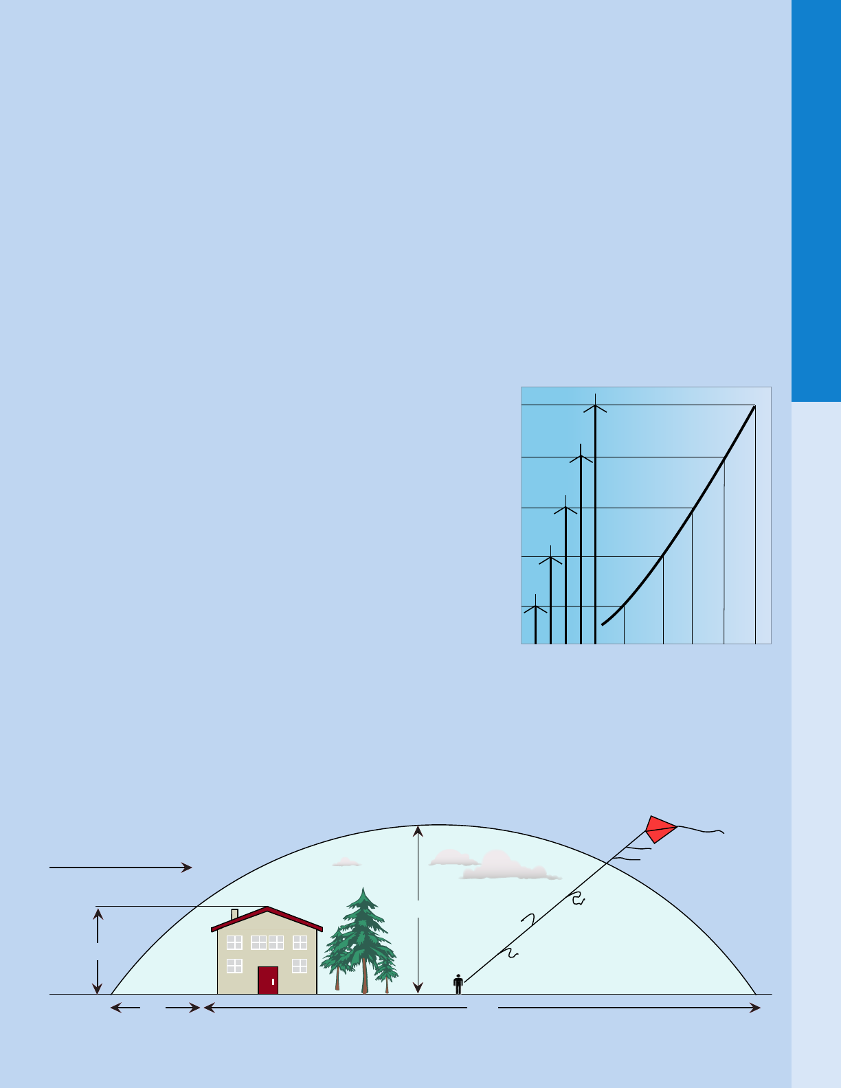
For the latest on AEE Solar products, trainings and dealer services, visit www.aeesolar.com
WIND POWER
48
System Design
Wind Power
Wind-power systems can be cost effective if the average wind speed is 9 mph or more at the location of the wind generator. Adding
a secondary charging source, like wind power, to PV can make an off-grid power system more stable by increasing the amount of
time that energy is being produced, reducing dependence on energy stored in the batteries. Using off-grid wind to supplement solar
photovoltaic power can be cost effective even if good wind is only partially available throughout the year, especially if the solar
potential is low at that time.
Siting Considerations
The amount of power generated by a wind turbine is dependent on wind turbulence, wind speed, and tower height. Like water, air is
a uid, and is subject to the same uid dynamics principles, such as turbulence created by obstructions in the ow. A stream owing
over boulders becomes turbulent, creating wakes and eddies, and is robbed of much of its energy by friction.
Similarly, wind blowing over a landscape with trees and buildings obstructing its ow also becomes turbulent and loses energy to
friction. Turbulence degrades the wind resource, both upwind and downwind of obstructions. Wind turbines placed in turbulent air
wear out prematurely and produce little usable power.
To avoid air turbulence, wind turbines should be placed on a tower high enough that the bottom of the turbine rotor’s swept area is
at least 20’ to 30’ higher than any buildings, trees, or other obstructions within a 300’ to 500’ radius. If the wind at the site primarily
comes from a particular direction, and the obstructions are not in the wind path, then less clearance may be allowable as long as the
owing air is laminar. In the illustration below, a kite with long streamers tied to the line at 10’ intervals can be used to nd the height
above ground level where the air ow smooths out. Look for the rst streamer to be fully furled out.
The power available in the wind increases with the cube of the wind speed.
This means that there is nearly twice as much power available in a 10 mph
wind as there is at an 8 mph wind. Wind speed increases as you get higher
above the ground due to the loss of friction between the air and the ground.
You can expect that the wind speed at 30’ above the ground will be about
25% greater than at eye level (at 60’, it’s about 37% greater; at 90’ about 45%
greater; and at 120’, about 50% greater). And since power output increases
exponentially with increases in wind speed, a turbine mounted on a 60’ tower
can produce about 40% more power than the same turbine would on a 30’
tower (75% more power at 90’ and 100% more power at 120’ compared to
30’). Therefore, increasing tower height can be a cost effective way to get
more power out of a wind turbine.
The power output of a wind generator decreases roughly 3% for every 1,000’
of elevation above sea level due to lower air pressure.
Measuring Wind Speed
Before installing a wind-power generator, measure the wind-power resource
at the site. Local weather data will be helpful, but wind is very site-specic
based on local terrain, site elevation, wind direction, and any obstructions such as trees or buildings. Average wind speeds should
be calculated along with peak wind speeds during storm events. Installing a wind data logger and monitoring site conditions for a
year, or for the target season, will yield enough information to predict the amount of power that can be produced by a wind turbine.
20H2H
2H
Prevailing Wind
H
Region of highly
disturbed airow
Percentage Increase in Available Wind Energy Compared to 30ft Tower
125%
40% 75% 100%
0
Tower Height (ft)
150
120
90
60
30
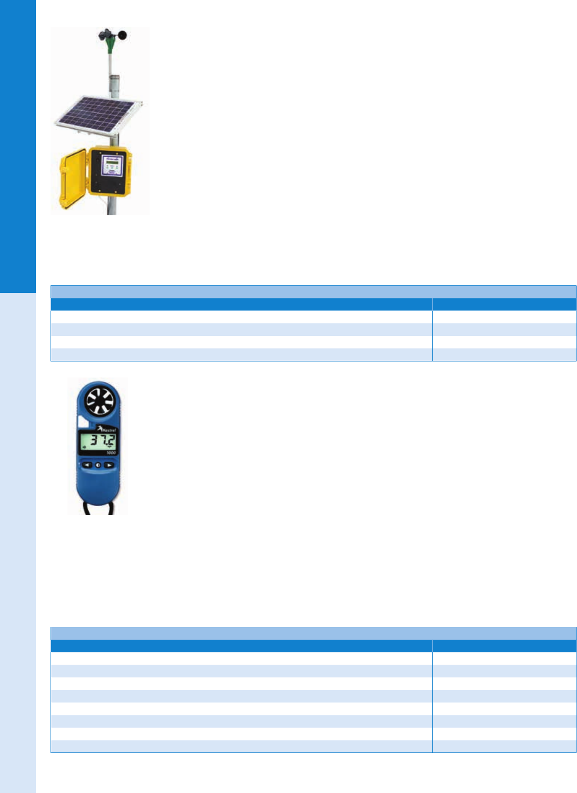
For the latest on AEE Solar products, trainings and dealer services, visit www.aeesolar.com
WIND POWER
49
Wind Measurement
APRS
Wind Data Loggers
The Wind Data Logger is an affordable and easy-to-use tool for wind site evaluation and wind generator
performance analysis. It records wind speed, time, and date directly to a Secure Digital (SD) card for
convenient data downloads. The logging interval is adjustable from 10 to 60,000 seconds (16.6 hours).
The two gigabyte SD card (included) will store a year of data at 30-second intervals or more at longer
logging intervals. Common spreadsheet software (i.e. MS Excel™) can be used to view, graph, and analyze
your wind data. Easy to use web-based software is provided. Simply upload the data, and the software
will automatically plot the data as well as provide basic statistics. A 16-character two-line backlit LCD
screen displays current information and is used for conguring the data logger. A simple menu-driven
interface using the LCD and three front panel buttons makes setup easy. A bright backlight makes the
data logger easy to use at night. The data logger is housed in a waterproof enclosure.
The solar powered models work well for wind data logging in remote areas without access to AC power.
The included 10 W solar panel and sealed battery will run the data logger almost indenitely. They come
with a 10 W PV module, a side-of-pole mount for the module, a charge controller, and a 7 Ah battery.
The AC model comes with a Universal AC power supply that accepts 90–264 VAC, 125-370 VDC, 47-63 Hz instead of a solar mod-
ule and battery; however, it does have a space for eight D-cell alkaline batteries for 30-day power backup (batteries not included).
The optional #40 R anemometer is a more rugged, extra heavy duty version of the standard three-cup anemometer. Both AC and DC models
are housed in a weatherproof Pelican™ case with self-resetting fusing, and have lightning protection for all sensor channels and solar input.
APRS Wind Data Loggers
Description Item code
APRS 6060 wind data logger - solar powered 016-00270
APRS 6063 #40 R wind data logger - solar powered 016-00271
APRS 6061 wind data logger - AC powered 016-00273
APRS 6062 #40 R wind data logger - AC powered 016-00274
Kestrel
Wind and Weather Meters
The Kestrel 1000 measures instantaneous maximum and average wind speeds in knots, meters per second,
kilometers per hour, miles per hour, feet per minute, and Beaufort. Hold it up to measure wind speed. It offers
a large, easy-to-read liquid crystal display with ±3% accuracy, and measures down to 0.3 m/s (0.67 mph). Its
impeller and protective housing pop out for easy and inexpensive replacement, and it includes a slip-on hard
case that protects the impeller, buttons, and display from damage in your pocket or toolbox. It is waterproof
and it oats. The replaceable battery provides up to 400 hours of use. The standard warranty is ve years.
The Kestrel 2000 has all the features of the Kestrel 1000, and is also capable of measuring temperature.
The Kestrel 2000’s external temperature sensor and waterproof casing allow you to gauge the tempera-
ture of water and snow, as well as open air. Includes hard slip-on case and standard ve-year warranty.
The Kestrel 4000 has all the features of the Kestrel 2000, plus the capability to store up to 2,000 points of weather data in order to
track changes over time with data storage, and analyze with graphing functions, and computer interface technology. You can view
data as graphs on the Kestrel 4000 display, or with Kestrel’s Communicator Software and a Kestrel interface. Data can be downloaded
to a PC or Mac for long-term storage, in-depth analysis, and detailed charting. Kestrel Interface kits are available with either a serial
or USB port connection, and include an interface cradle unit, serial or USB cable, and CD with easy-to-use software. The Kestrel
4000 is also available with integrated Bluetooth® wireless data transfer, allowing both real-time and logged data to be transferred
wirelessly and automatically to a laptop or PDA, eliminating the need for a separate interface and cabling. The 4000 comes with a
soft carry pouch. Carry case optional. The standard warranty is ve years.
Kestrel Wind and Weather Meters
Description Item code
Kestrel 1000 pocket wind meter 016-00253
Kestrel 2000 pocket thermo/wind meter 016-00256
Kestrel 4000 pocket weather station 016-00259
Kestrel 4000 pocket weather station with Bluetooth 016-00258
Kestrel 4000 computer interface - USB 016-00260
Kestrel 4000 computer interface – serial port 016-00261
Kestrel 4000 K4000 carry case 016-00263
Kestrel replacement impeller for all models 016-00255
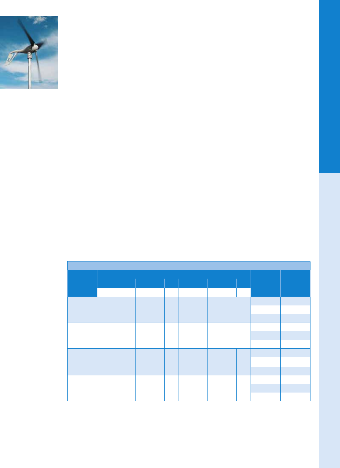
For the latest on AEE Solar products, trainings and dealer services, visit www.aeesolar.com
WIND POWER
50
Wind Turbines
Primus
AIR Wind Turbines
AIR wind turbines harness the wind’s energy to charge an off-grid battery bank. AIR turbines are
extremely popular and frequently used in sailboats, RVs, remote cabins, and offshore platforms.
The AIR wind turbine incorporates a three-phase brushless permanent magnet alternator and integrated
microprocessor-based charge controller to optimize power production capability. The microprocessor
continuously adjusts the loading of the alternator to keep the turbine operating efciently in most wind
regimes.
The AIR Breeze is designed for battery-charging applications in coastal areas, on boats, and for other
marine uses. Corrosion-resistant for use in coastal and nautical applications, it has a white powder-coated
housing and sealed electronics designed to prevent damage from salt spray. The rated power is 160 W
at 28 mph (12.5 m/s).
The AIR 40 provides energy for off-grid homes, water pumping, lighting, telecom, and anywhere you
need electricity and have average annual wind speeds under 15 mph. It has a bare aluminum nish for
use in non-corrosive environments, so it is not suitable for marine use. The AIR 40 israted for 160 W at
28 mph (12.5 m/s).
The AIR 30 provides reliable battery-charging in areas where average annual wind speed is above 15 mph.
(The AIR Breeze or the AIR 40 should be used for slower average wind speeds). It has a bare aluminum
nish for use in non-corrosive environments, so it is not suitable for marine use. The AIR 30 is listed by
CSA to UL 1004 and C22.2 No. 100 for the U.S.A. and Canada and rated for 400 W at 28 mph (12.5 m/s).
The AIR X Marine is the marine version of the AIR 30. It has a white powder-coated housing and sealed
electronics designed to prevent damage from salt spray. The AIR X Marine is designed for the most rug-
ged, high-wind applications, such as SCADA, telecom, security, cathodic protection, etc.
Both the AIR Breeze and AIR 40 are designed to be very quiet and are recommended for residential
use. The AIR 30 and AIR X Marine, due to the different blade design, produce more noise, and are not
recommended for use in residential areas.
Select the corresponding AIR wind turbines for use in 12, 24, and 48 VDC battery systems.
All units weigh 13 lbs, have a 46” rotor diameter (11.5 ft2 swept area) and mount on a 1.5” Schedule
40 steel pipe (1 7/8” [48 mm] outer diameter). Made in U.S.A. All AIR models have a ve-year limited
warranty.
AIR Wind Turbines
Model
Approximate monthly kWh production vs. average annual wind speeds
DC battery
voltage Item code
mph →8 9 10 11 12 13 14 16 18
m/sec → 3.57 4 4.5 4.9 5.36 5.8 6.25 7.15 8
AIR Breeze 13
kWh
17
kWh
22
kWh
28
kWh
38
kWh
43
kWh
50
kWh --
12 016-00987
24 016-00989
48 016-00990
AIR 40 13
kWh
17
kWh
22
kWh
28
kWh
38
kWh
43
kWh
50
kWh --
12 016-01038
24 016-01039
48 016-01040
AIR 30 7
kWh
10
kWh
14
kWh
20
kWh
25
kWh
31
kWh
35
kWh
50
kWh
60
kWh
12 016-01032
24 016-01035
48 016-01037
AIR X Marine 7
kWh
10
kWh
14
kWh
20
kWh
25
kWh
31
kWh
35
kWh
50
kWh
60
kWh
12 016-01042
24 016-01043
48 016-01044
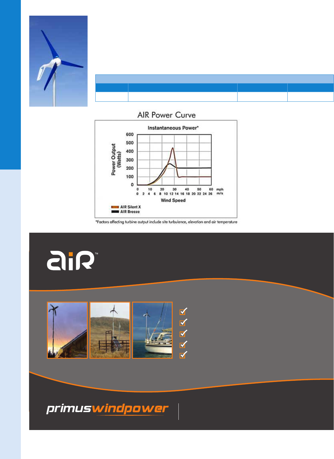
COMPLETES ANY OFF GRID SYSTEM
SIMPLE, AFFORDABLE, RELIABLE POWER
MAXIMUM POWER IN WINTER
EASILY INTEGRATES WITH PV
NIGHT TIME POWER PRODUCTION
OVER 150,000 UNITS INSTALLED SINCE 1995
MANUFACTURED IN COLORADO, USA
www.primuswindpower.com
For the latest on AEE Solar products, trainings and dealer services, visit www.aeesolar.com
WIND POWER
51
Wind Turbines
NEW! AIR Silent X Wind Turbine
The Primus AIR Silent X wind turbine utilizes the proven, AIR X turbine with a quiet carbon ber
“blue blade” set. Intended primarily for the marine market, the AIR Silent X is designed to be quiet and
lightweight while providing up to 400 W from a 1.2 m rotor diameter. As with all the other AIR models,
the AIR X Silent has a built-in charge controller, so no additional battery charging controller is needed.
Available for 12 VDC systems only. Made in USA with a standard ve-year warranty. CSA listing is
pending.
Midnite Solar Stop Switch
Model Description DC Voltage Item code
AIR Silent X AIR Silent X with carbon ber blade set 12 VDC 016-01048
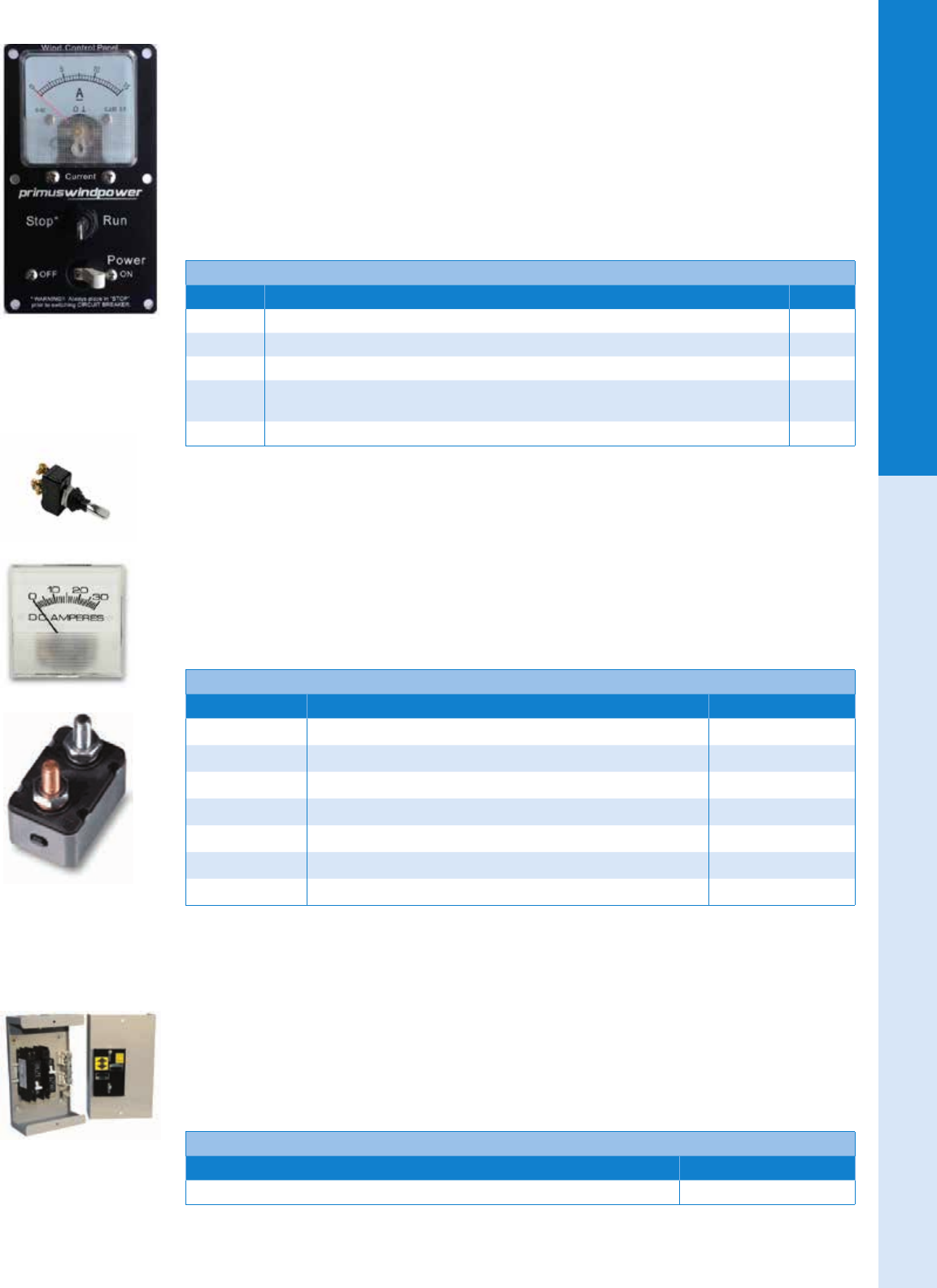
For the latest on AEE Solar products, trainings and dealer services, visit www.aeesolar.com
WIND POWER
52
Wind Turbines
Wind Control Panel
The Primus Wind Control Panel (WCP) is a low cost analog control panel for use with AIR Breeze and
AIR 40 12, 24, and 48 VDC and AIR X Marine/AIR 30/Silent X 12 VDC wind turbines. The WCP
controls and monitors the AIR wind turbine and is equipped with a power On/Off circuit breaker, analog
ammeter (indicating wind turbine current production) and a Stop/Run switch (for direct control of the
turbine). A clearly marked rear terminal block is provided for easy interconnect of the two turbine wires
and two battery power wires. It is available in a 25 A version for 12 VDC systems, a 10 A version for 24
VDC systems, and a 5 A version for 48 VDC systems which are fully calibrated and ready for installa-
tion. The panel measures 3.5” x 5” and the Surface-mount black plastic enclosure allows for mounting
of the WCP on a at surface.
Primus Windpower Wind Control Panels
Model Description Item code
2-ARAC-103 Primus Windpower Wind Control Panel for 12 VDC AIR Breeze/AIR 40, 25 A breaker, 15 A meter 016-01352
2-ARAC-104 Primus Windpower Wind Control Panel for 24 VDC AIR Breeze/AIR 40, 10 A breaker, 8 A meter 016-01353
2-ARAC-107 Primus Windpower Wind Control Panel for 48 VDC AIR Breeze/AIR 40, 5 A breaker, 8 A meter 016-01355
2-ARAC-108 Primus Windpower Wind Control Panel for 12 VDC AIR X Marine / AIR 30 / Silent X,
40 A breaker, 30 A meter 016-01356
2-ARAC-106 Surface-mount enclosure for Wind Control Panel 016-01354
AIR Accessories
The Primus AIR Stop Switch is a simple panel-mount inline brake switch used for stopping the move-
ment of the blades.
The 30 A ammeter is an analog meter for measuring the output current of the AIR turbines. Analog meters
are recommended for wind turbines as digital meters tend to scroll too fast in uneven wind to read properly.
The Primus Circuit Breakers are self-resetting DC breakers that can be used as simple over-current
protection for mobile and marine applications. If using an AIR turbine in a power system that has a DC
power center or load center in it, it’s recommended to use a DC circuit breaker of the proper rating that
will t in the DC power center (OutBack GSLC or FLEXware-DC, MidNite E-Panel, Magnum MP, etc.) .
Air Turbine Accessories
Model Description Item code
2-ARAC-101 AIR Stop Switch (not code compliant). No enclosure included 016-01351
2-ARAC-102 Amp Meter Kit (30 Amp) for all AIR units 016-01223
3-ELOT-1147-01 5 A circuit breaker kit - for 48 V AIR Breeze / AIR-40 053-17005
3-ELOT-1147-02 10 A circuit breaker kit - for 24 V AIR Breeze /AIR-40 ; 48 V AIR-30 053-17006
3-ELOT-1147-03 20 A circuit breaker kit - for 12 V AIR Breeze /AIR-40 ; 24 V AIR-30 053-17007
3-ELOT-1147-04 40 A circuit breaker kit - for 12 V AIR-30 053-17008
3-ELOT-1147-05 50 A circuit breaker kit - for 12 V AIR-30 (very high wind area) 053-17009
MidNite Solar
Stop Switch
MidNite Solar’s Stop Switch allows you to stop an AIR wind generator and disconnect it from the battery,
all in one motion. The MN-Stop Switch comes with a neutral bus bar and ground box terminal. Rated
for wind turbines up to 63 A at up to 150 VDC. The switch is listed for the U.S.A. and Canada, measures
9”H x 5”W x 4”D and weighs 3 lbs.
Midnite Solar Stop Switch
Description Item code
MidNite Solar Stop Switch (code compliant) 053-00121
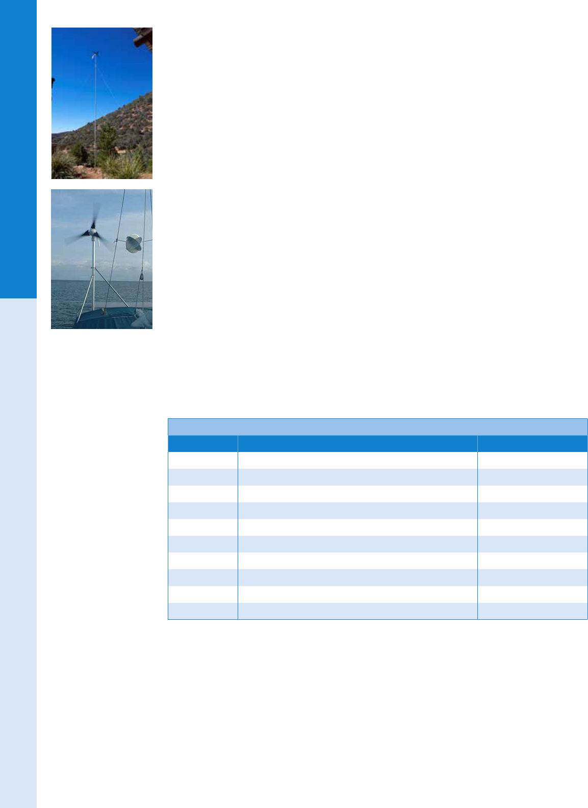
For the latest on AEE Solar products, trainings and dealer services, visit www.aeesolar.com
WIND POWER
53
Wind Turbines
AIR Turbine Tower Kits and Accessories
AIR tilt-up tower kits are available as hardware kits (not including the tower pole) in 27’ (8.1 m) and 45’
(13.5 m) heights, and in a 29’ (8.8 m) EZ Tower™ kit that includes the pole for the tower. All towers use
a four-guy-wire set-up, and are assembled on the ground with the wind generator and tilted up into place.
The 27’ and 45’ tower kits come with all the hardware necessary to install a tower, except guy-wire
anchors, pipe, and concrete. All parts bolt or clamp together, and no welding is required. Purchase 1 7/8”
steel tubing from a local chain link fence supplier (for up to 90 mph at 27’, or 70 mph at 45’), or use
1.5” Sch 40 Galvanized water pipe (1 7/8” OD and up to 120 mph at 27’ and 90 mph at 45’), to build the
tower. These tower kits include a simple elbow/tee for its base that, when combined with a short length
of pipe, eliminates the need for a concrete pad, swivel, and base plate. Two people can erect one of these
towers without using winches or vehicles. AIR towers are PE stamped. Contact us for engineering “wet
stamps” (additional cost).
The 29’ EZ Tower™ kit comes with all the parts you’ll need, including Galvanized tubing, cable and
hardware. This tower uses lightweight tubing while providing plenty of strength to withstand winds up
to 110 mph. Two people can easily erect the EZ Tower™ without winches or vehicles. The EZ Tower™
includes a simple, yet effective, tower base and anchoring system which eliminates the need for a con-
crete pad. The kit comes with guy-wire anchors that are driven into the ground (depending on the soil
conditions, concrete may be necessary for proper guy anchoring). Can ship via UPS in one 74” (1.9 m)
box weighing 80 lbs.
The AIR Marine Tower is the easiest way to mount your AIR Breeze Marine turbine on a boat and
is designed to withstand even hurricane-force winds. It’s simple to install on wood or berglass decks.
The 9’ (2.7 m) white powder-coated aluminum mast has an outside diameter of 1.9” (48 mm) and two
9’ (2.7 m) long fully-adjustable stays with a 1” (25.4 mm) outer diameter. The Hardware Kit contains
stainless-steel hardware with self-locking nuts, and vibration mounts to minimize sound transmission.
Order the mast and hardware kit separately.
Earth Auger Sets
Screw-in “auger” type guy anchors can be used in loamy and gravelly soils. Other soil types may require
concrete footings or expansion bolts. Consult an engineer or geologist if you have questions about guy
supports.
Air Turbine Tower Kits and Accessories
Model Description Item code
1-TWA-20-03 AIR Marine Tower hardware kit 016-01128
1-TWA-20-02 9’ AIR Marine aluminum mast and two stays 016-01131
1-TWA-19-02 Roof Mount kit without roof seal 016-01134
1-TWA-19-01 Roof Mount kit with roof seal 016-01137
2-TWA-100 Roof seal – for Roof Mount kit 016-01140
1-TWA-10-01 27’ AIR guyed tower kit 016-01086
1-TWA-10-02 45’ AIR guyed tower kit 016-01092
1-TWA-11-01 29’ EZ Tower kit including pipe and anchors 016-01081
1-TWA-12-02 36” Galvanized Auger - set of four; use with 24' & 27' towers 016-01116
1-TWA-12-04 48” Galvanized Auger - set of four; use with 32'-50' towers 016-01122
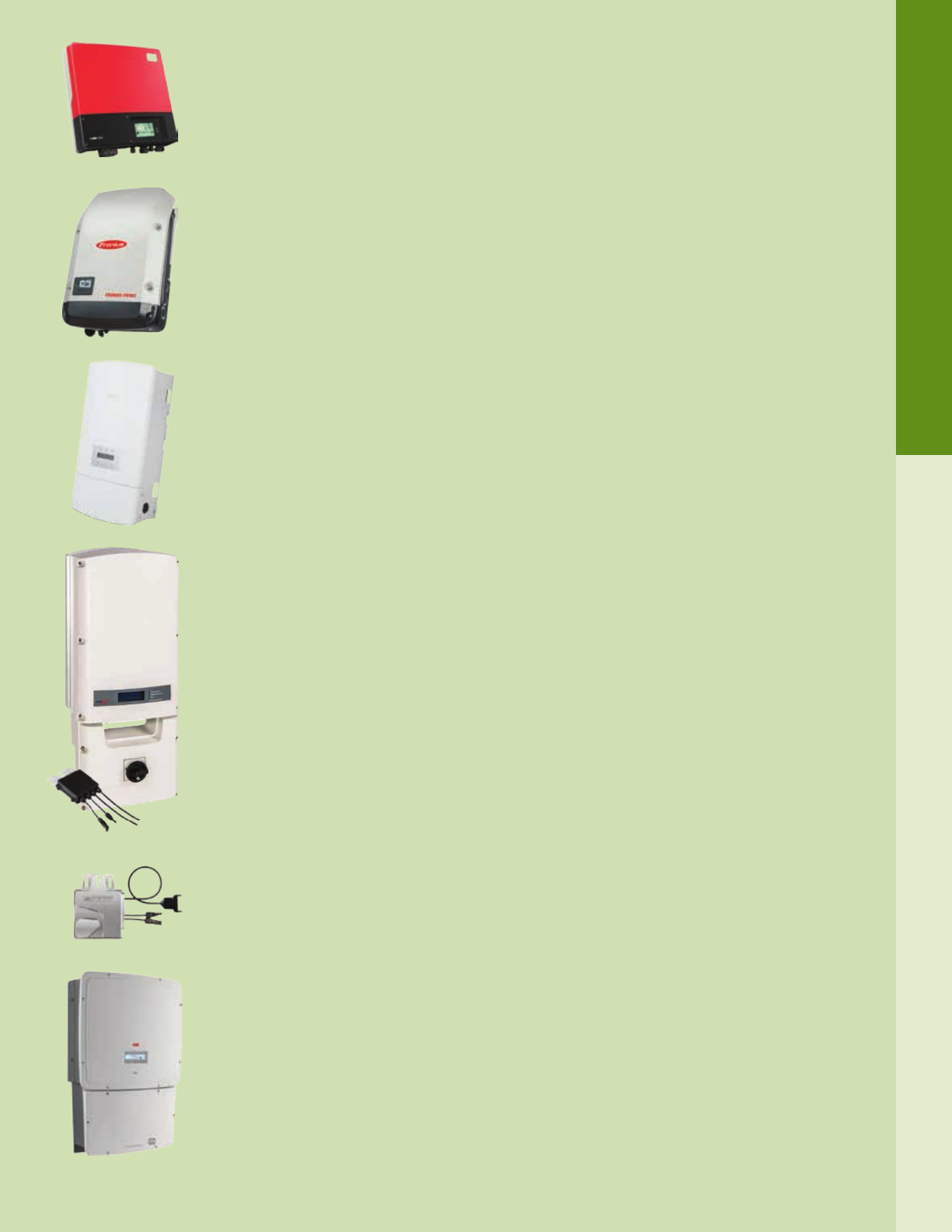
For the latest on AEE Solar products, trainings and dealer services, visit www.aeesolar.com
GRID-TIE INVERTERS
54
System Design
Grid-Tie Inverters
Often referred to as the “brains” of a renewable energy system, an inverter is an electronic device that
converts direct current (DC) from batteries or solar modules into alternating current (AC) at the voltage
and frequency required to run electrical loads or feed into the grid.
Grid-tie, or utility intertie, inverters convert DC power from photovoltaic (PV) modules directly into
AC power to be fed into the utility grid. Batteries are not needed, as any power that is not consumed
by the owner’s electrical loads is fed into the utility grid to be used elsewhere. Due to the high voltages
involved, grid-tie inverters should be installed and serviced only by qualied personnel.
Grid-tie PV systems typically use the utility grid for energy storage. Whenever the PV array is generat-
ing more power than the loads are using, excess energy is fed into the grid, turning the meter backward.
When the loads require more power than the PV array can supply, the utility makes up the difference.
Known as “net metering,” this arrangement is the most efcient and cost-effective for grid-tied applica-
tions since there are no batteries to maintain. However, most grid-tie inverters are required by law to
shut down during a utility outage per IEEE 1547, which is incorporated into UL 1741. Battery-based
grid interactive inverters (See Battery-Based Inverters) are required for back-up power applications.
Most batteryless grid-tie inverters are called “string” inverters because the PV modules must be wired
together in series to obtain a higher input voltage. String Inverters are designed to run at voltages up
to 600 VDC in residential systems and up to 1,000 VDC for commercial and industrial systems. String
wiring is quick and easy to install, and the higher voltage helps to minimize line losses and required wire
size. However, in string wiring, maximum power point tracking (MPPT), along with any monitoring
output, is performed at the string or array level.
An important trend to note is that most string inverter manufacturers have introduced Transformerless
(aka non-isolated) inverters due to the higher efciency and lower manufacturing costs of that topol-
ogy. While transformerless inverters have dominated the European market and are arguably even safer
than their isolated counterparts, they do impose special “ungrounded system” requirements according
to NEC 690.35. This includes the use of PV-Wire for DC connections, including the module outputs,
as well as fusing and switching on both output legs. The term ungrounded should not be confused with
the equipment ground, which is still required; it means that neither the positive nor negative outputs are
connected to ground. Some jurisdictions will also require special circuit labels noting that both conduc-
tors are “hot”. See Electrical Distribution Parts for compliant combiners, switches, and Tools for labels.
Module Optimizers can be deployed behind each module to provide individual module-level MPPT
tracking and monitoring, optimizing the DC output that is connected to a string inverter for very high
efciency. Systems that combine optimizers with low-cost high-efciency string inverters can simplify
system design and maximize safety and energy harvest with minimal impact on cost.
Microinverters are typically mounted behind each solar module. They convert the DC output of each
module to AC, replacing the high DC voltages (up to 1,000 VDC) with comparatively lower AC poten-
tials (240 VAC or less) and simplifying system design. The microinverter output connects directly to the
breakers in the AC load center using conventional wiring. Since microinverters provide MPPT tracking
and monitoring for individual modules, the impact of differences in orientation or shading between
modules is reduced. Microinverters are a popular solution for electrical contractors that are new to solar
as DC wiring is essentially eliminated.
Three-Phase Inverters are used in larger commercial grid-tie systems, and output at 208 VAC or 480
VAC, which is more common in larger buildings. Many of these 10 to 50 kW inverters are available with
input voltage ratings of 1,000 VDC. This higher input voltage enables longer module strings, which can
improve design exibility and eliminate external combiners. Traditional Central Inverters are rarely
used anymore for systems under several megawatts in scale.
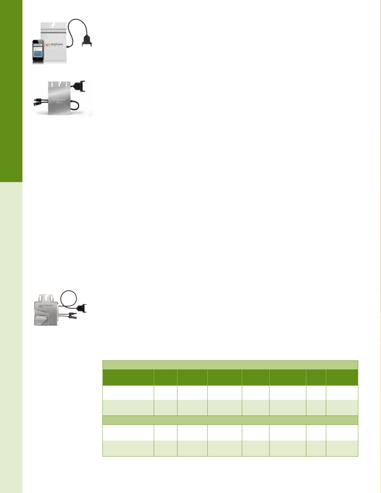
Enphase
AC Battery™
Enphase
Envoy™
Enphase
MyEnlighten™
Enphase
Microinverter™
Enphase is revolutionizing clean energy on a global scale.
Integrated, efficient and extraordinarily reliable, the Enphase
Home Energy Solution beautifully combines solar generation,
storage and load management technologies into one system
that is a pleasure to install and use.
That’s smart energy. That’s energy evolved.
For the latest on AEE Solar products, trainings and dealer services, visit www.aeesolar.com
GRID-TIE INVERTERS
55
Module-Level Power Electronics
Enphase
Grid-Tie Single-Phase Microinverter System
The Enphase Microinverter System consists of microinverters, Engage trunk cables, the Envoy Com-
munications Gateway, and the web-based Enlighten monitoring and analysis service.
Through individualized MPPT, Enphase microinverters help mitigate the effects of shading, dust, debris,
module mismatch, and thermal differences. With module-level monitoring, performance issues can be
traced to individual modules to expedite troubleshooting. Each PV module is connected directly to its
own microinverter, typically mounted on the racking underneath. The microinverters’ AC wire harnesses
are connected to form an AC branch circuit that leads to the AC utility distribution center. System safety
is enhanced since all of the output wiring from the PV array is AC and no high-voltage DC is present
once the AC power is shut down, reducing risk for maintenance personnel or reghters. Microinverters
are inherently compliant with the NEC 690.12 rapid shutdown requirement.
The Engage Trunk Cable allows Enphase Microinverters to be used for both 240 VAC single-phase and
208 VAC three-phase output. Each Enphase branch circuit is protected by a 20 A circuit breaker, and
multiple circuits can be used for larger installs.
Features:
• Module-level monitoring - requires Envoy Communications Gateway
• Integrated grounding feature eliminates need for separate equipment ground wire
• Operates at full power in ambient temperatures from -40 °C (-40 °F) to 65 °C (149 °F)
• NEMA6 sealed enclosures
• 25-year warranty
• Listed to UL 1741 for U.S.A. and Canada
• Compliant with: IEEE 1547, FCC Part 15 Class B, CAN/CSA-C22.2 NO. 0-91, .4-04, and 107.1-01
Enphase M215 and M250 Microinverters
The M215 microinverter is recommended for 60-cell modules up to 260 Watts. The maximum number
of M215 microinverters in an AC branch circuit is 17 for 240 VAC single-phase systems and 25 for 208
VAC three-phase systems.
The M250 microinverter is recommended for 60-cell modules up to 300 Watts. Each AC branch circuit
must be protected with a 20 A circuit breaker. The maximum number of M250 microinverters in an AC
branch circuit is 16 for 240 VAC single-phase systems and 24 for 208 VAC three-phase systems.
NEW! Enphase S230 and S280 Microinverter
The new, fth Generation Enphase S230 and S280 microinverters are CEC rated at 97.0% when used
in a 240VAC single-phase systems. The S-Series microinverters are designed to be compatible with
Enphase’s forthcoming energy storage system. These microinverters work with 60-cell solar modules;
use the S230 for modules up to 300 watts, and the S280 for modules up to 360 watts.
These microinverters include advanced grid functions, and can be remotely updated, via Internet, in
response to changing grid requirements or regional grid proles, like Hawaiian Electric Company (HECO)
Rule 14H, California Rule 21, and others.
Enphase M215 & M250 Microinverters
Model Max AC
Output
DC module
voltage MPPT range CEC
efciency
Max
AC current Weight Item code
M215-60-2LL-S22-IG 215 W <45 VDC 22 to 36 VDC 96.0% 1.0 A @ 208V
0.9 A @ 240V 3.5 lbs 030-07724
M250-60-2LL-S22 250 W <48 VDC 27 to 39 VDC 96.5% 1.15 A @ 208V
1.0A @ 240V 4.4 lbs 030-07722
Enphase S230 & S280 Microinverters
S230-60-LL-X-US 230 W <48 VDC 27 to 37 VDC 97.0% 1.06 A @ 208V
0.92 A @ 240V 4.0 lbs 030-07729
S280-60-LL-X-US 280 W <48 VDC 27 to 37 VDC 97.0% 1.30 A @ 208V
1.13 A @ 240V 4.0 lbs 030-07730
Enphase M215 and M250
Microinverters
Enphase S230 and
S280 Microinverters

Enphase
AC Battery™
Enphase
Envoy™
Enphase
MyEnlighten™
Enphase
Microinverter™
Enphase is revolutionizing clean energy on a global scale.
Integrated, efficient and extraordinarily reliable, the Enphase
Home Energy Solution beautifully combines solar generation,
storage and load management technologies into one system
that is a pleasure to install and use.
That’s smart energy. That’s energy evolved.
For the latest on AEE Solar products, trainings and dealer services, visit www.aeesolar.com
GRID-TIE INVERTERS
57
Module-Level Power Electronics
Enphase Engage Cable System
The Enphase Engage Cable is a continuous 12 AWG (2.5 mm²) outdoor-rated cable with integrated con-
nectors for Enphase microinverters. The connectors are preinstalled at intervals to accommodate PV
module widths or lengths. The microinverters plug directly into the connectors, and the Engage cable
can be terminated into a junction box that feeds electricity back to the system’s AC disconnect. Engage
cables are specic to portrait (ET10) or landscape (ET17) module orientation as well as 208 VAC or 240
VAC output. The gap between connectors on a portrait cable of either voltage is 40” while the landscape
cable has a 67” connector spacing to accommodate the width and length of a standard 60-cell module.
The Engage cable is attached directly to the solar racking using Enphase Cable Clips. One cable end is
wired directly into a junction box connected to the branch circuit array wiring. The other end is sealed using
an Engage Cable Branch Terminator. The AC output cable from the Enphase microinverters are plugged
directly into the regularly-spaced Engage Cable connectors. Any unused connectors must be protected
with an Enphase waterproof sealing cap. (The plastic covers that ship with the cable are not weather tight
and cannot be used in place of a sealing cap).
Both types of Engage cables are available in bulk lengths with 240 connectors. Accessories can be ordered
individually or as an ET-INSTL and ET10-240, as well as ET17-240 cables can be cut to order.
A Branch Terminator (ET-TERM) is used to seal the stub ends of each branch circuit. The terminator
separates and insulates the individual conductors contained in the Engage trunk cable. One terminator is
needed per branch circuit. NOTE: The terminator is intended for one-time use only. The latching mecha-
nism will be damaged if the terminator is removed after installation.
A watertight Sealing Cap (ET-SEAL) is used to seal any unused trunk cable connectors to IP67 weath-
erproong standards. Unused trunk cable connectors generally occur where the trunk cable transitions to
another module row or needs to span a gap in the array.
The Engage Coupler (ET-SPLK) is used to connect cut ends ofEngage cable together or to join it to a
lower cost standard cable without a junction box.
Stainless Steel Cable Clips (ET-CLIP) are used to fasten Engage trunk cable to racking or to secure looped
cabling and are available in packs of 100.
The Disconnect Tool (ET-DISC) is required to safely disconnect the microinverter AC-output cable from
the Engage Trunk Cable connector. The tool is reusable, so one per job is usually sufcient.
The Enphase Frame Mount Adapter (EFM) is used for rail-less mounting systems to attach an Enphase
Microinverter directly to a solar module. There are currently two versions available, for use with 35mm
and 40mm module frames, and these attachment kits come in boxes of 12.
The Enphase Connector Clip (EFM-CC) is a convenient method for attaching the Enphase Engage Cable
directly to a module frame for use especially with rail-less racking systems. It is designed to be used with
any module frame size. It is made from anodized aluminum, and engineered to be used with the Enphase
Engage Cable. These are sold in boxes of 12.
Branch Terminator
Sealing Caps
Engage Coupler
Engage Cable Disconnect Tool
Engage Cable
Inverter Attachment
Frame Mount Adapter (EFM)
Enphase Connector Clip

Fast, Accurate Shipping to Your Job Site. With just-in-time delivery and blind
drop shipping, we can ship directly to your customers, just as if it came straight from you.
For the latest on AEE Solar products, trainings and dealer services, visit www.aeesolar.com
GRID-TIE INVERTERS
58
Module-Level Power Electronics
Enphase Installation Cable Kits and Accessories
Model Description Item code
ET10-240 Trunk Cable, Single Connector, Portrait, 240 VAC 052-10106
ET10-240-BULK Bulk Trunk Cable, 240 Connectors, Portrait, 240 VAC 030-07739
ET17-240 Trunk Cable, Single Connector, Landscape, 240 VAC 052-10107
ET17-240-BULK Bulk Trunk Cable, 240 Connectors, Landscape, 240 VAC 030-07741
ET10-208-BULK Bulk Trunk Cable, 240 Connectors, Portrait, 208 VAC 030-07743
ET17-208-BULK Bulk Trunk Cable, 240 Connectors, Landscape, 208 VAC 030-07745
ET-INSTL Install Kit for M215 (includes four Branch Terminators, Cable Disconnect Tool, and ve Sealing Caps) 030-07721
ET-TERM Branch Terminator for M215 Trunk Cable 030-07711
ET-DISC Cable Disconnect Tool - for Disconnecting Inverter Cable from Trunk Cable 030-07715
ET-SEAL Sealing Cap, watertight cap for unused trunk cable connector socket 030-07717
ET-CLIP-100 Cable Clips, 100-pack 030-07719
ET-SPLK Engage Cable Coupler - Splice Kit 030-07713
EFM-35MM Frame Mount Adapter for use with 35mm framed modules, 12 pack 300-00172
EFM-35MM Frame Mount Adapter for use with 40mm framed modules, 12 pack 300-00173
EFM-CC Connector Clip, for attaching Engage Cable to module frame, 12 pack 300-00174
For the latest on AEE Solar products, trainings and dealer services, visit www.aeesolar.com
GRID-TIE INVERTERS
59
Module-Level Power Electronics
Enphase Module-Level Monitoring
Enphase Energy’s monitoring technology is integrated into their microinverters. However, the Envoy
Energy Management Unit (ENV-120-M) is required to interface with the microinverters and includes
access to the Enphase Enlighten online monitoring service. The Envoy plugs into any standard AC outlet
and collects microinverter performance information over the existing power line. An Ethernet cable can
then be used to connect the Envoy to the installation site’s existing Internet access point or local area
network. Once online, the Envoy will automatically access the Enphase Enlighten web service. One Envoy
is required for monitoring on each installation of up to 250 inverters. The Envoy is listed to UL 60950.
Enphase’s Enlighten Manager installer portal enables installers and O&M providers to monitor and manage
multiple Enphase systems and receive alerts by e-mail in the event of underperforming modules or equipment
faults. The accompanying MyEnlighten™ user view provides a more streamlined interface for individual
system owners and includes social media sharing tools as well as simplied system performance data.
An Enphase Line Communication Filter (ELCF) is required for installations with more than 250
inverters. The ELCF includes an Envoy and terminals for connecting the combined circuits from the
micro-inverters it is monitoring. Each ELCF can monitor up to 111 micro-inverters at 240 VAC single-
phase, and 166 micro-inverters at 208 VAC three-phase. External communication is by Ethernet. This is
all mounted in an outdoor NEMA4 enclosure. The ELCF is listed to UL508A.
The Enphase RGM-MTR-01 is a revenue grade metering solution for 240 VAC single-phase Enphase
systems. This Form 2S kWh meter is installed on the combined output circuits from the entire solar array.
Communication from the RGM to the envoy is via ZigBee wireless. The RGM-ZGB-01 USB ZigBee stick is
required for the Envoy. The RGM-RR-01 ZigBee repeater can be used to increase the ZigBee wireless range.
NEW! Enphase Envoy-S Communications Gateway
The Envoy-S Gateway collects and delivers solar and energy consumption data to the Enphase Enlighten
monitoring platform, for monitoring and remote maintenance and management of an Enphase system,
and can monitor up to 600 connected M-series or S-series microinverters. The Envoy-S (ENV-S-AB-
120-A), Standard is a +/-5% accurate reporting device used in many situations. Where revenue grade,
+/-0.5% accurate reporting is required, or where optional consumption monitoring is needed, the Envoy-S,
Metered (ENV-S-AM1-120) version is used.
Networking to the Enlighten Monitoring Portal can be through Ethernet, WiFi, or optional cellular con-
nections by installing the plug and play Enphase Mobile Connect (CELLMODEM-01) cellular modem,
which has an included ve-year data plan.
NEW! Enphase AC Combiner Box with Envoy-S
The Enphase AC Combiner Box with Envoy-S Metered Gateway (XAM1-120) simplies and consolidates
interconnection to the utility into a single enclosure and streamlines PV installations with a pre-wired
solution for residential applications. The Envoy-S is included and exible networking supports Ethernet,
WiFi, or optional cellular connection to the Enlighten Monitoring Portal. Three pre-installed 20 A / 240
VAC breakers allow up to three Enphase branch circuits to be quickly wired with a common output to
the main interconnection point. The enclosure is NEMA 3R rated, and has a ve-year warranty.
Enphase Module Level Monitoring
Model Description Item code
ENV-120-M Envoy Energy Management Unit, indoor enclosure 030-03715
WF-01 Enphase WiFi Adapter Stick 029-09009
EPLC-01 Enphase Power Line Carrier – Ethernet Bridge Pair 030-03752
RGM-MTR-01 Enphase compatible GE i210+ revenue grade meter with ZigBee wireless 030-07710
RGM-RR-01 ZigBee repeater for RGM 030-07708
RGM-ZGB-01 ZigBee USB stick for Envoy communication with RGM 030-07709
ECLF-120-001 ECLF-120-001, Line Communication Filter 208/240V 030-09750
ENV-S-AB-120-A Envoy-S, Standard 300-00175
ENV-S-AM1-120 Envoy-S, Metered for revenue grade PV production metering 300-00176
CELLMODEM-01 Enphase Mobile Connect cellular modem with ve-year data plan option for Envoy-S 300-00177
XAM1-120 AC Combiner Box with Envoy-S, Metered for integrated revenue grade PV production
metering 300-00178
CT-200-SPLIT Consumption Monitoring CTs, allows whole home consumption metering for XAM1-120 300-00179
Enphase Envoy Energy
Management Unit
Enphase Revenue Grade
Meter with ZigBee Wireless
Communications
Enphase Envoy-S
Gateway Device
XAM1-120 AC Combiner Box
with Envoy-S
Enphase Line
Communication Filter
CELLMODEM-01 Enphase
Mobile Connect
CT-200-SPLIT Consumption
Monitoring CT
For the latest on AEE Solar products, trainings and dealer services, visit www.aeesolar.com
GRID-TIE INVERTERS
60
Module-Level Power Electronics
SolarEdge
Distributed MPPT Grid-Tie Inverter System
The SolarEdge distributed grid intertie system combines module-level maximum power point tracking
(MPPT), DC-DC power optimizers, and monitoring with high-efciency transformerless string inverters
to maximize the energy yield of a PV installation. The SolarEdge system provides design exibility by
mitigating shading, module mismatch, uneven soiling, and aging variance losses. It automatically main-
tains a xed string voltage so the inverter operates at peak efciency regardless of string size, shading,
or temperature. This allows exible string lengths ranging from eight to 25 modules for single-phase and
16 to 50 for three-phase inverters as well as varying module sizes, tilts, and orientations. The system is
scalable and simplies expansions and replacements since future modules need not electrically match
existing ones. Fewer, but longer, strings can also reduce DC-side balance-of-system (BOS) requirements.
SolarEdge inverters are ungrounded (non-isolated) on the DC side, so all PV array wiring must use PV
Wire. The SolarEdge power optimizers have a 25-year warranty, and the SolarEdge inverters have a
12-year warranty (extendable to 20 or 25 years). Power optimizers and inverters are listed to UL 1741
for the U.S.A. and Canada.
SolarEdge P-Series Power Optimizers
All SolarEdge power optimizers can be used with crystalline silicon PV modules to provide module-level
MPPT and performance monitoring, and are designed to work exclusively with SolarEdge inverters. All
power optimizers have 99.5% peak efciency and are backward compatible with older SolarEdge products.
The P300, P320, and P400 optimizers can be used with any SolarEdge inverter, while the P600 and P700
dual-module optimizers are compatible only with three-phase inverters. The P320 is designed for use with
60-cell modules that have nameplate ratings of between 300 and 320 watts DC. SolarEdge optimizers
can be attached to most PV mounting systems using a single fastener; grounding can be accomplished
via the included star washer, a WEEB, or through a lug, depending on racking.
Features:
•
Module-level shutdown (1 VDC per module) inherently compliant with NEC 690.12 requirements
• NEMA 4, IP65 environmental protection rating
• Operating temperatures of -40 °F to +185 °F (-40 °C to +85 °C)
• Available for 60-cell PV modules up to 300 W and 72-cell modules up to 400 W
• 99.5% efciency
• 25-year warranty
• Listed to UL 1741 for U.S.A. and Canada
• Compliant with: IEC61000-6-2, IEC61000-6-3, FCC Part 15 B, IEC62109-1 Class II
SolarEdge Power Optimizers
Model Max
DC input
Max
input voltage MPPT range Module type Input connector Item code
P300-5 SERIES 300 W 48 VDC 8 - 48 VDC 60-cell MC4-Type 300-00118
P320-5 SERIES 320 W 48 VDC 8 – 48 VDC 60-cell MC4-Type 300-00153
P400-5 SERIES 400 W 80 VDC 8 – 80 VDC 72-cell MC4-Type 300-00119
P600-2NA4ARL 600 W 96 VDC 12.5 – 80 VDC two 60-cell MC4-Type 300-00090
P700-2NM4ARL 700 W 125 VDC 12.5 – 105 VDC two 72-cell MC4-Type 300-00108

For the latest on AEE Solar products, trainings and dealer services, visit www.aeesolar.com
GRID-TIE INVERTERS
62
Module-Level Power Electronics
SolarEdge Single-Phase Inverters
SolarEdge inverters are designed to work exclusively with SolarEdge power optimizers. MPPT tracking
and voltage management is handled by the power optimizers allowing for a very high-efciency, low
cost inverter. These inverters operate at a xed voltage supplied by the SolarEdge Power Optimizers,
are lightweight, and have built-in Module-Level Monitoring. They include an integrated code-compliant
DC disconnect, Ethernet interface, and RS-485 serial port. All SolarEdge inverters are listed to UL 1741
and UL 1699B for the U.S. and Canada and are NEMA 3R rated. The inverters are rated for use from
-4 °F to 140 °F temperatures.
The optimizers automatically limit the DC voltage to 1 VDC per module when detecting excessive heat,
or when the inverter is not connected to the grid, improving installer and reghter safety.
Features:
• 3,000 Watts to 11,400 Watts AC Output
• Internal Arc Fault Circuit Interrupter (AFCI) for added safety per NEC 2011: 690.11
• Inherently compliant with NEC 2014 690.12 rapid shutdown requirement
• RS485 and Ethernet Communications interface included
• Optional ZigBee Wireless Communication Kit
• Operating temperatures of -13 °F to +140 °F (-25 °C to +60 °C)
• NEMA 3R Enclosure
• Available from 3 kW to 11.4 kW sizes
• 12-year inverter warranty, extendable to 20 or 25 years through SolarEdge
• Listed to UL 1741, UL1998 and UL1699B for U.S.A. and Canada
• Compliant with: IEEE 1547, FCC Part 15 B, CSA 22. 2
SolarEdge Single-Phase Inverters
Model Max AC output CEC efciency Max AC current Weight Item code
208 V 240 V
SE3000A-US 3,000 W 97.5% -- 12.5 A 51 lb 030-09469
SE3800A-US 3,800 W 98.0% -- 16 A 51 lb 030-09470
SE5000A-US 5,000 W 98.0% 24 A 21 A 55 lb 030-09471
SE6000A-US 6,000 W 97.5% -- 25 A 55 lb 030-09472
SE7600A-US 7,600 W 97.5% -- 32 A 55 lb 030-09443
SE10000A-US 10,000 W 97.5% 48 A 42 A 88 lb 030-09445
SE11400A-US 11,400 W 97.5% -- 47.5 A 88 lb 030-09446
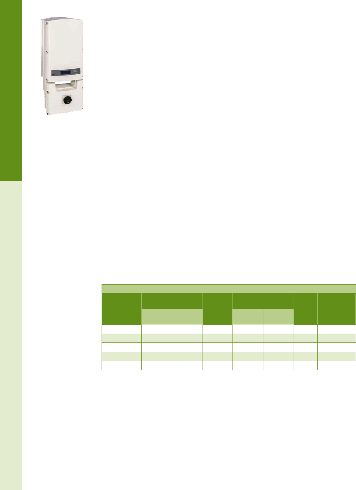
For the latest on AEE Solar products, trainings and dealer services, visit www.aeesolar.com
GRID-TIE INVERTERS
63
Module-Level Power Electronics
SolarEdge Three-Phase Inverters
SolarEdge offers three models of three-phase commercial inverters. The SE9kUS and SE14.4kUS model
can be used at 208 VAC 3-P WYE or Delta congurations, and the SE10kUS, SE20kUS, and SE33.3kUS
inverters can connect to 480 VAC 3-P WYE conguration grids. The SolarEdge inverters are designed
to work exclusively with SolarEdge power optimizers, and can use either single-module optimizers, or
P600/P700 dual-module optimizers. MPPT and voltage management is handled by the power optimizers,
allowing for a very high-efciency, low-cost inverter.
The SE9kUS and SE14.4kUS inverters have a xed input voltage of 400 VDC, while the SE10kUS,
SE20kUS, and SE33.3kUS inverters operate with xed input voltage of 850 VDC. The xed input voltage
from the optimizers allows for longer module string lengths, resulting in less wire line losses and fewer
system components. These wall-mountable inverters are lightweight, and have built in module-level
monitoring. They include an integrated code-compliant DC disconnect, Ethernet interface, and RS-485
serial port. All SolarEdge inverters are listed to UL 1741 and UL 1699B for the U.S. and Canada and
are NEMA 3R rated. The inverters are rated for use from -4 °F to 140 °F temperatures. The SE14.4kUS
and the SE33.3kUS inverters also come with three fused DC+ and DC- inputs, eliminating the need for
a third-party fused combiner box.
The optimizers automatically shut down the DC current and voltage when detecting excessive heat, or when
the SolarEdge inverter is turned off or disconnected from the grid, to ensure installer and reghter safety.
Monitoring can be enabled by connecting the inverter directly to an Internet router with a CAT5 cable,
or through the use of the SolarEdge Zigbee Gateway Kit and Slave Modules.
Features:
• Internal Arc Fault Circuit Interrupter (AFCI) for added safety per NEC 2011: 690.11
• Inherently compliant with NEC 2014 690.12
•
Five Models: SE9kUS and SE14kUS with 208 VAC output, SE10kUS, SE20kUS , and SE33.3kUS
with 408 VAC Output
• RS485 and Ethernet Communications interface included
• Optional ZigBee Wireless Communication Kit
• Operating temperatures of -13 °F to +140 °F (-25 °C to +60 °C)
• NEMA 3R Enclosure
• 12-year inverter warranty, extendable to 20 or 25 years through SolarEdge
• Listed to UL 1741, UL1998 and UL1699B for U.S.A. and Canada
• Compliant with: IEEE 1547, FCC Part 15 B, CSA 22. 2
SolarEdge Three-Phase Inverters
Model
Max AC output CEC
efciency
Max continuous AC
outputcurrent per phase Weight Item Code
208 WYE or
208 Delta 480 WYE 208 WYE or
208 Delta 480 WYE
SE9kUS 9,000 W -- 96.5% 25.0 A -- 80 lbs 030-09481
SE14.4kUS 14,400 W -- 97.0% 40.0 A -- 106 lbs 030-09516
SE10kUS -- 10,000 W 98.0% -- 12.0 A 80 lbs 030-09478
SE20kUS -- 20,000 W 98.0% -- 24.0 A 80 lbs 030-09500
SE33.3kUS -- 33,000 W 98.5% -- 40.0 A 106 lbs 030-09517
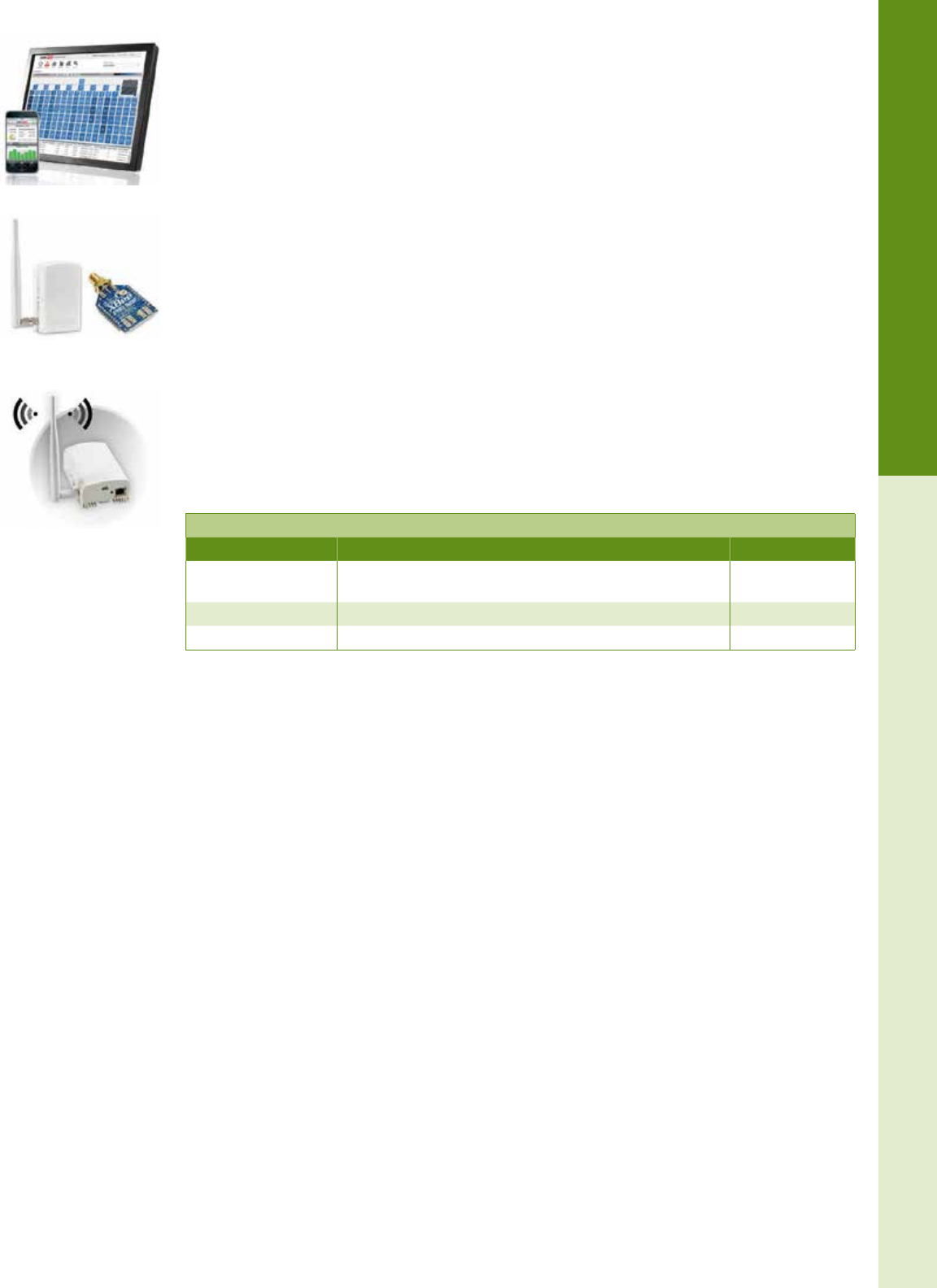
For the latest on AEE Solar products, trainings and dealer services, visit www.aeesolar.com
GRID-TIE INVERTERS
64
Module-Level Power Electronics
SolarEdge Module-Level Monitoring
SolarEdge provides free web-based monitoring for the rst 25 years. The system provides PV performance
monitoring, fault detection, and troubleshooting at module, string, and system levels. Web-based software
provides real-time monitoring, facilitating increased system uptime, and lowering maintenance costs.
Remote fault detection pinpoints the location of underperforming modules on a virtual PV site map. The
monitoring sensors and transmitters are built-in and data is transmitted over the DC power lines. Connection
between the inverter(s) and the Internet can either be by Ethernet or a wireless connection using a ZigBee
gateway with connections between multiple inverters using their RS-485 connection ports.
A free monitoring iPhone app is available as a download from the Apple iTunes Store. Registered users
can monitor multiple sites from their iPhone. The application provides an at-a-glance view of past and
present energy production. Current weather conditions and forecasts are also presented to aid in assessing
the system’s performance. For commercial systems, the monitoring portal is easily congured for display
in a public display through a public web address. The display is refreshed every ve minutes and shows
the site production, and environmental benets, along with the installer logo and the site image.
The Site Mapping Tool software is also available free on the SolarEdge website, which allows barcode
scanning for creation of a virtual site map using an iPhone. The Site Designer software and an Inverter
Conguration Tool for on-site conguration and module-level installation verication are available free
online as well.
The ZigBee Gateway Kit (SE1000-ZBGW-K5-NA) includes the ZigBee home gateway and a single ZigBee
card with extended- range antenna for connecting a single inverter wirelessly to an existing network router.
A ZigBee Slave Kit (SE1000-ZB05-SLV-NA) can be used to connect each additional inverter and the
ZigBee Repeater (SE1000-ZBRPT05-NA) can be used to extend the range of the network up to 800 feet.
ZigBee Wireless for SolarEdge
Model Description Item code
SE1000-ZBGW-K5-NA ZigBee-to-Ethernet gateway kit with extended range antenna and
one slave module 029-01641
SE1000-ZB05-SLV-NA ZigBee wireless slave module – one per each additional inverter 029-01642
SE1000-ZBRPT05-NA ZigBee repeater – range extender 029-01643
SolarEdge ZigBee Gateway Kit
ZigBee Repeater
Web-based Monitoring
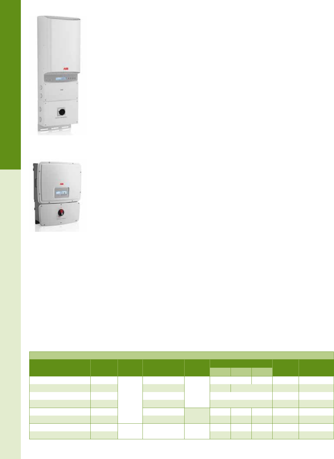
GRID-TIE INVERTERS
65
String Inverters
ABB
ABB Inverters
ABB inverters offer wide voltage ranges, and two MPPT circuit inputs, increasing exibility in module
installation and string sizing. Most inverters are congurable for 240 VAC single-phase, 208 VAC three-
phase, or 277 VAC single-phase output.
ABB PVI Series grid-tie inverters feature high energy yield and performance efciencies of up to 97%.
These inverters have a eld-adjustable “start-up voltage” point that allows low-end PV operating voltage
down to 90 VDC. While there is some loss of efciency at lower voltage settings, inverters can operate
with as few as ve standard 60-cell modules in series. Please see the inverter sizing chart in the System
Design section for congurations that work in most areas. All ABB inverters come with a ve-year war-
ranty that can be extended to ten years.
ABB PVI and UNO Transformerless Inverters
The ABB PVI and UNO series of inverters are some of the most exible string inverters available. These
ABB inverters have two separate MPPT inputs, allowing for two sub-arrays to be congured with differing
string lengths, orientations, or even different PV modules. Conditions on one MPPT will not affect the
other. Additionally, the 5 kW and larger inverters have two input terminals for each separate MPPT sec-
tion allowing as many as four strings of modules (two on each MPPT) to be connected without separate
string fusing. Both MPPT inputs can also be paralleled for use with a single array. A wide input voltage
range allows for smaller installations with reduced string sizes where needed.
An integrated LCD displays real-time operating parameters, and RS-485 and USB interfaces can con-
nect remote monitoring systems. An integrated DC disconnect is standard on all models shown here.
ABB inverters can produce full-rated power at ambient temperatures up to 122 °F (50 °C). The fan-less
design and NEMA 4X enclosure enable deployment in extreme environments. Output voltage can be
set for 240 VAC split-phase, or 208 VAC or 277 VAC (480 VAC WYE) for three-phase systems (three
inverters required for phase balancing).
Where NEC 2014 690.12 Rapid Shutdown code requirements have been adopted, ABB has introduced
three versions of the ABB Rapid Shutdown Box which cuts off DC voltage and current between the
array and the inverter when activated.
ABB transformerless single-phase inverters are available in sizes covering most common residential
requirements, and can be used in groups of three for commercial three-phase applications. The transfor-
merless design reduces internal power losses for high efciencies. Output voltage can be set to 240 VAC
split-phase, or 208 VAC or 277 VAC (480 VAC WYE) for three-phase systems.
Features:
• Available in sizes from 3 kW to 12 kW with dual-MPPT DC intputs
• Internal Arc Fault Circuit Interrupter (AFCI) for added safety per NEC 2011
• Field selectable 208, 240 or 277 VAC output
• RS485 Communications interface included
• Operating temperatures of -13 °F to +131 °F (-25 °C to +55 °C)
• Active and reactive power control, low voltage ride-through
• Five-year warranty, extendable up to ten years
• Listed to UL 1741-2010 for U.S.A. and Canada
• Compliant with: IEEE 1547-2003, IEEE 1547.1, UL1699B-2013, ANSI/IEEE C62.41, FCC Part
15 A & B, C22. 2 No. 107.1-01 (Sept. 2011)
ABB PVI Aurora and UNO Transformerless Inverters
Model Max AC
output
DC array
voltage MPPT range CEC
efciency
MAX AC current Weight Item code
208 V 240 V 277 V
PVI-3.0-OUTD-US-A 3,000 W
120 to
600 VDC
160 to 530 VDC
96.0%
14.5 A 12.0 A 47 lbs 030-09705
PVI-3.6-OUTD-US-A 3,600 W 120 to 530 VDC 17.2 A 16.0 A 47 lbs 030-09706
PVI-3.8-OUTD-US-A 3,800 W 140 to 530 VDC 16.0 A 47 lbs 030-09707
PVI-4.2-OUTD-US-A 4,200 W 140 to 530 VDC 20.0 A 47 lbs 030-09708
PVI-5000-OUTD-US-A 5,000 W 200 to 530 VDC 96.5% 27.0 A 23.0 A 20.0 A 60 lbs 030-09709
PVI-6000-OUTD-US-A 6,000 W 200 to 530 VDC 30.0A 28.0 A 24.0 A 60 lbs 030-09710
UNO-7.6-TL-OUTD-S-US-A 7,600 W 200 to
600 VDC 200 to 480 VDC 96.5% 36.5 A 32.0 A 27.5 A 81.5 lbs 030-09719
UNO-8.6-TL-OUTD-S-US-A 8,600 W --- 36.0 A 31.0 A 81.5 lbs 030-09720
ABB PVI Series Inverter
ABB UNO Series Inverter
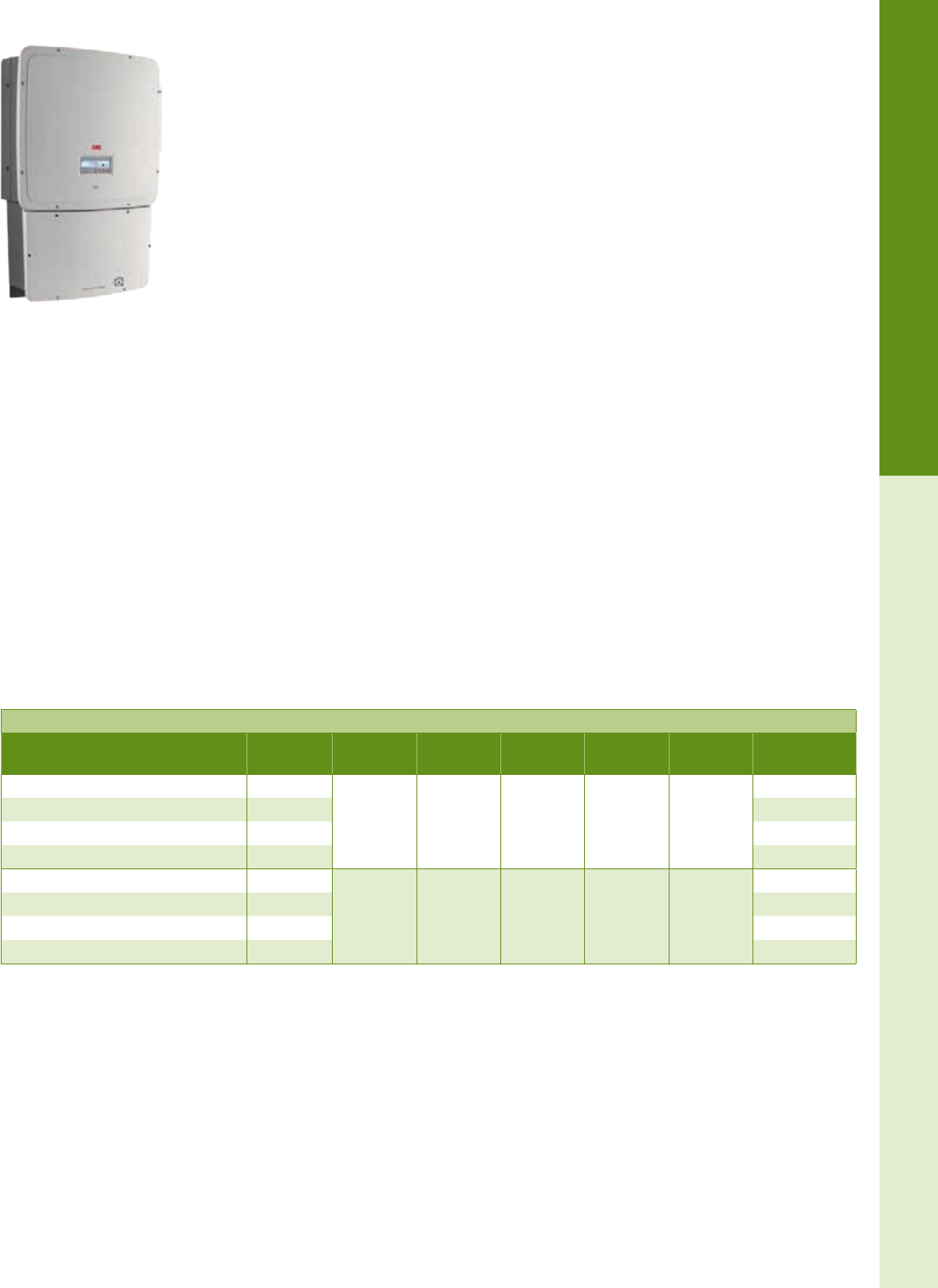
For the latest on AEE Solar products, trainings and dealer services, visit www.aeesolar.com
GRID-TIE INVERTERS
66
String Inverters
ABB TRIO Transformerless Three-Phase Inverters
The ABB TRIO inverters led the trend away from larger 600 VDC central inverters for commercial
systems by shortening cable runs and eliminating external combiners and concrete foundations to reduce
total installed costs. The 1,000 VDC rated input allows more modules per string, further reducing labor
and BOS costs. TRIO inverters have two separate MPPT inputs, allowing for two sub-arrays to be
congured with differing string lengths, orientations, or even different PV modules. Conditions on one
MPPT will not affect the other.
TRIO S models feature a standard integrated DC disconnect only and have two inputs on each MPPT
channel. With only two strings on each channel (four strings total), they can be connected without separate
string fusing. Additional strings will require an external fused combiner. S1 models integrate DC-side
string overcurrent protection and provide terminals for up to eight module strings, four strings per MPPT
channel. The S1A models add DC and AC surge protection and the S1B adds DC surge protection and
an internal AC fused disconnect switch.
An integrated LCD displays real-time operating parameters, and RS-485 interfaces can connect remote
monitoring systems.
TRIO inverters can produce full rated power at ambient temperatures up to 113 °F (45 °C) and can oper-
ate at reduced power levels up to 140 °F (60 °C). The fan-less design and NEMA 4X enclosure provide
a water and airtight seal. Output voltage is 480 VAC WYE, four wires plus ground. All TRIO inverters
come with a ve-year warranty, and can be extended to ten years.
Features:
• Dual-MPPT DC inputs
• Internal Arc Fault Circuit Interrupter (AFCI) for added safety per NEC 2011
• Output 480 VAC, three phase, four-wire + Ground
• RS485 Communications interface included
• Operating temperatures of -13 °F to +140 °F (-25 °C to +60 °C)
• Active and reactive power control, low voltage ride-through
• Available in 20 kW and 27.6 kW sizes
• Five-year warranty, extendable up to ten years
• Listed to UL 1741 and UL 1699B for U.S.A. and Canada
• Compliant with: IEEE 1547, IEEE 1547.1, FCC Part 15 B, C22. 2 No. 107.1-01-2001
ABB TRIO Three-Phase Inverters
Model Max AC
output
DC array
voltage MPPT range CEC
efciency
Max AC
current Weight Item code
TRIO-20.0-TL-OUTD-S-US-480-A 22 kW
200 to 950
VDC
450 to 800
VDC 97.5% 27.0 A 157 lbs
030-09751
TRIO-20.0-TL-OUTD-S1-US-480-A 22 kW 030-09752
TRIO-20.0-TL-OUTD-S1A-US-480-A 22 kW 030-09753
TRIO-20.0-TL-OUTD-S1B-US-480-A 22 kW 030-09754
TRIO-27.6-TL-OUTD-S-US-480-A 30 kW
200 to 950
VDC
520 to 800
VDC 97.5% 36.0 A 168 lbs
030-09755
TRIO-27.6-TL-OUTD-S1-US-480-A 30 kW 030-09756
TRIO-27.6-TL-OUTD-S1A-US-480-A 30 kW 030-09757
TRIO-27.6-TL-OUTD-S1B-US-480-A 30 kW 030-09758
ABB TRIO Series Inverter
For the latest on AEE Solar products, trainings and dealer services, visit www.aeesolar.com
GRID-TIE INVERTERS
67
String Inverters
ABB Monitoring Options
ABB offers direct monitoring of their residential and commercial inverters via the ‘Aurora Vision’
monitoring portal, and offers free monitoring over the inverter warranty period. To connect wirelessly
to the portal, one WiFi Logger card must be purchased for each inverter. This card can be used with all
ABB inverters, both single and three-phase. Wired connections can be enabled by purchasing one of
the ABB Data Logger units, depending on the number of inverters that are to be monitored. One Data
Logger can monitor multiple inverters through an RS485 modbus wired connector by daisy chaining the
inverters to the logger, and then connecting to a wired Ethernet router port. Optional third-party Ethernet
wireless bridges or Ethernet-over-powerline adapters can be used if direct wired Ethernet connections
are not available.
ABB Residential Data Monitoring and Communications Accessories
Description Item code
VSN300 WiFi Logger Card (300’ range line-of-site, one required per inverter) 029-07009
VSN700-01 ‘Aurora Logger - Residential Data Logger’, up to ve single-phase inverters per site 029-07008
VSN700-03 ‘Aurora Logger - Commercial’, up to ten single or three-phase inverters per site 029-07010
VSN700-05 ‘Aurora Logger - Max’, up to 32 single or three-phase inverters per site 029-07011
ABB Rapid Shutdown Box
ABB now offers a NEC 2014 compliant box for use with ABB inverters to meet NEC 2014 690.12 rapid
shutdown requirements. The shutdown occurs at the rooftop when utility power is lost or when the PV
Inverter disconnect switch is opened. This box can mount directly on solar racking systems, and lay par-
allel to the roof surface. It is NEMA 4X rated, and can be installed at 0 to 90° angles while maintaining
the water-tight seal, even from snow or driving rain.
There are three versions of the ABB Rapid Shutdown Box. One conguration allows one or two strings
input with one or two strings output, and does not have an external disconnect switch. The other two
boxes allow strings to be combined prior to passing to the inverter DC Disconnect. These boxes are rated
for 600 VDC maximum, and each DC string has a maximum input current of 11.25A.
ABB Rapid Shutdown Box for ABB Inverters
Description Item code
ABB, Rapid Shutdown Combiner Box with Disconnect Switch , two DC strings input – one combined DC
output, RS2-1CN6-KIT 053-01800
ABB, Rapid Shutdown Combiner Box with Disconnect Switch , two pairs of DC strings input – two sets of
combined DC strings output, RS4-2CN6-KIT 053-01802
ABB, Rapid Shutdown Pass-Through Box, No Disconnect Switch, two DC strings input - two DC strings
output, (Pass through only, no combining) RS2-2PN6-KIT 053-01801
Aurora Vision Portal
and Mobile App
VSN300 WiFi Logger Card
VSN700-1 Residential
Data Logger
ABB Rapid Shutdown Box
with Disconnect Switch

ABB’s Rapid Shutdown units are NEC 2014 code compliant and cost effective.
This new solution strategically fits within 10 feet of the array and will shut power
down within 10 seconds or less—all without the need of extra conduit. It’s a simple
path to full compliance. This is just one of the ways that we at ABB empower solar
installers with the latest technology to make their jobs easier and the world better.
Visit abb-solarinverters.com/rapidshutdown to learn more.
Rapid Shutdown. You don’t want to worry
about NEC™ 2014. So we did.
For the latest on AEE Solar products, trainings and dealer services, visit www.aeesolar.com
GRID-TIE INVERTERS
69
String Inverters
Fronius
Primo Single Phase Inverters
The Fronius Primo is a lightweight, transformerless, single-phase inverter that allows for fast installation
and easy setup. The Primo utilizes the Fonius SnapINverter™ hinge mounting system, which allows for
tool-free attachment and removal of the inverter from the wall mounting plate and integrated discon-
nect, making it practical for one person to install. The NEMA 4X enclosure allows installation in harsh
environments. Dual MPPT circuits and wide voltage windows allow for exible design on two exposures
with different module-string lengths.
Larger Primo inverters have been introduced this year, in 10.0 kW, 11.4 kW, 12.5 kW, and 15.0 kW
congurations. These inverters feature four DC inputs for MPPT1 and two DC inputs for MPPT2 with
integrated fuse holders, eliminating the need for third-party combiner boxes.
The built-in WiFi Fronius Datamanager 2.0 card enables Internet monitoring via the Fronius Solar.web
portal on computer or smartphone. The RS485 port can also be used when a WiFi network is not available
All Primo Inverters are designed to work with the Fronius Rapid Shutdown box for NEC 2014 690.12
compliance. Rapid Shutdown is triggered whenever AC is not present, and the DC voltage and current
between the array and the inverter is quickly discharged. One box is required per DC string. Fronius
Primo inverters are covered by a ten-year warranty, which can be extended to 15 or 20 years.
These transformerless inverters work with an ungrounded PV array topology so the requirements of NEC
690.35 apply, including use of PV Wire for exposed array string wiring.
Features:
• Internal Arc Fault Circuit Interrupter (AFCI) for added safety per NEC 2011
• Inverter sizes available from 3.8 kW to 8.2 kW
• Dual MPPT inputs
• WiFi, wired Ethernet, or Serial monitoring through preinstalled Datamanager Card
• Easy-to-mount SnapINverter concept and NEMA 4X enclosure
• Monitoring included via Fronius Solar.Web Portal
• Ten-year warranty, extendable up to 20 years
• Listed to UL 1741-2010 and UL1699B-2013 for U.S.A. and Canada
Fronius Primo Inverters
Model Max AC
output AC voltage DC array
voltage MPPT range CEC
efciency
Max AC
current Weight Item code
Primo 3.8-1 3,800 W 240 VAC
208 VAC
80-600 VDC
200-480 VDC 95.0% 15.8 A
18.3 A
47.0
lbs
030-08514
Primo 5.0-1 5,000 W 240 VAC
208 VAC 240-480 VDC 95.5% 20.8 A
24.0A 030-08515
Primo 6.0-1 6,000 W 240 VAC
208 VAC 240-480 VDC 96.0% 25.0 A
28.8 A 030-08516
Primo 7.6-1 7,600 W 240 VAC
208 VAC 250-480 VDC 96.0% 31.7A
36.5 A 030-08517
Primo 8.2-1 8,200 W 240 VAC
208 VAC 270-480 VDC 96.5% 34.2 A
38.0 A 030-08518
Primo 10.0-1 10 kW 240 VAC
208 VAC
80-600 VDC
220-480 VDC 96.9%1
41.7 A
48.1 A
76.7
lbs
030-08528
Primo 11.4-1 11.4 kW 240 VAC
208 VAC 240-480 VDC 96.9% 1
47.5 A
54.8 A 030-08529
Primo 12.5-1 12 kW 240 VAC
208 VAC 260-480 VDC 96.9% 1
52.1 A
60.1 A 030-08530
Primo 15.0-1 13.75 kW
15 kW
240 VAC
208 VAC 320-480 VDC 96.9% 1
62.5 A
66.1 A 030-08531
For the latest on AEE Solar products, trainings and dealer services, visit www.aeesolar.com
GRID-TIE INVERTERS
70
String Inverters
Fronius Symo Three-Phase Commercial Inverters
The Fronius Symo Three-Phase Commercial inverter utilizes the Fonius SnapINverter™ hinge mounting
system, which enables tool-free attachment and removal of the inverter from the wall mounting plate and
integrated disconnect, making it easier than ever to install large solar arrays. Power ranges from 10 kW
to 24 kW. A wide MPPT voltage range, two MPPT input circuits, and the NEMA 4X enclosure provides
greater exibility in system design even in extreme environments. Each MPPT circuit has built-in fuse
holders for up to three DC inputs to fuse both positive and negative wires. Fuse holders ship with slugs,
so appropriate fuses must be ordered separately (See Electrical Distribution Parts).
Fronius Symo inverters can be equipped with the WiFi Fronius Datamanager 2.0 card that enables Internet
monitoring via the Fronius Solar.web portal on computer or smartphone. Only one card is required for
multiple Symo inverters installed in the same location. The inverters also support a Modbus interface
for third-party monitoring and datalogging. The Fronius.Web monitoring portal can also utilize the free
Fronius Solar.TV service, to transmit monitoring data to a public display, which includes system yield,
energy production, and environmental benets.
Fronius Symo inverters are covered by a ten-year warranty, which can be extended to 15 or 20 years.
These transformerless inverters work with an ungrounded PV array topology so the requirements of NEC
690.35 apply, including use of PV Wire for exposed array string wiring.
Features:
• Dual-MPPT DC inputs
• Internal Arc Fault Circuit Interrupter (AFCI) for added safety per NEC 2011
• Inverter sizes available from 10.0 kW to 24.0 kW
• Easy-to-mount SnapINverter concept and NEMA 4X enclosure
• WiFi, wired Ethernet, or Serial monitoring through preinstalled Datamanager Card
• Monitoring included via Fronius Solar.Web Portal
• 10-year warranty, extendable up to 20 years
• Listed to UL 1741-2010, UL 1699B Issue 2-2013 and CSA TIL M-07 Issue 1-2013 for USA and
Canada
• Complies with: IEEE 1547-2003, IEEE 1547.1, ANSI/IEEE C62.41, FCC Part 15 A & B, C22.2
No. 107.1-01 (Sept 2001)
Fronius Symo Inverters
Model Max AC
output AC voltage DC array voltage MPPT range CEC
efciency
Max AC
current Weight Item code
SYMO 10.0-3 208/240 9,995 W 240 VAC 200-600 VDC 300-500 VDC 96.5% 24.0A 91.9 lbs 030-08424
208 VAC 96.5% 27.7 A
SYMO 10.0-3 480 9,995 W 480 VAC 200-1,000 VDC 300-800 VDC 96.5% 12.0 A 76.7 lbs 030-08425
SYMO 12.0-3 208/240 11,995 W 240 VAC 200-600 VDC 300-500 VDC 96.5% 28.9 A 91.9 lbs 030-08426
208 VAC 96.5% 33.3 A
SYMO 12.5-3 480 12,495 W 480 VAC 200-1,000 VDC 350-800 VDC 97.0% 15.0 A 76.7 lbs 030-08427
SYMO 15.0-3 480 14,995 W 480 VAC 200-1,000 VDC 350-800 VDC 97.0% 18.0 A 95.7 lbs 030-08428
SYMO 17.5-3 480 17,495 W 480 VAC 200-1,000 VDC 400-800 VDC 97.5% 21.0A 95.7 lbs 030-08429
SYMO 20.0-3 480 19,995 W 480 VAC 200-1,000 VDC 450-800 VDC 97.5% 24.0 A 95.7 lbs 030-08430
SYMO 22.7-3 480 22,727 W 480 VAC 200-1,000 VDC 500-800 VDC 97.5% 27.3 A 95.7 lbs 030-08431
SYMO 24.0-3 480 23,995 W 480 VAC 200-1,000 VDC 500-800 VDC 97.5% 28.9 A 95.7 lbs 030-08432
Inverter technology is complex and constantly evolving. Get the best
inverter tech support in the industry – give us a call at 800-777-6609.
For the latest on AEE Solar products, trainings and dealer services, visit www.aeesolar.com
GRID-TIE INVERTERS
71
String Inverters
Fronius Monitoring and Accessories
The Fronius Datamanager 2.0 Card is a plug-in card that sends data directly to the free
Fronius Solar.web online portal. The connection from the Datamanager card to the site router can be
made with either WiFi or Ethernet cable. Open interfaces allow connection to third-party monitoring
solutions. Only one Datamanager card is needed for up to 100 Fronius inverters.
Additional Fronius inverters can be connected by adding a Fronius Com Card, and daisy chaining them
together with Ethernet Cable to the inverter with the Datamanager Card. Alternatively, each inverter can
have a Datamanager card for all wireless communications.
(Note: the Fronius Primo inverters have factory-installed DM 2.0 Cards, and therefore have built in WiFi
and Ethernet connectivity. Symo inverters instead ship with a Com Card instead of the DM 2.0 card, as
only one DM 2.0 card is required for a bank of Symo commercial inverters.)
The Fronius Modbus Card is required for some third-party monitoring systems utilizing Modbus RTU
protocol. One Modbus Card is required for each inverter to be monitored.
A Sensor Box or Sensor Card is required to add weather sensors. The Sensor Box and card each have 6
inputs—two for measuring temperature, one for measuring irradiance, two digital inputs for a wind speed
sensor and/or kilowatt-hour meter, and one 20 mA current interface for a humidity sensor.
Fronius Inverter Accessories
Model Mfg. # Description Item code
Datamanager 2.0 Card 4,240,038,Z Datamanager 2.0 Card for Galvo, Primo, and Symo inverters 300-00132
Modbus Card 4,240,021,Z Modbus card for third-party monitoring 300-00066
Sensor card 4,240,004,Z Monitoring interface with six sensor input channels-mounts in inverter 030-03443
Sensor box 4,240,104 Monitoring interface with six sensor input channels 030-03442
Sensor, wind speed 42,0411,0027 Measures wind speed, requires Sensor box 030-03446
Sensor, ambient temperature 43,0001,1188 Measures ambient temperature, requires Sensor box 030-03448
Sensor, module temperature 43,0001,1190 Adheres to back of PV module and measures temperature, requires Sensor box 030-03449
Sensor, irradiance 43,0001,1189 Measures solar insolation, requires Sensor box 030-03444
Cat 5 cable 3.3 feet 43,0004,2435 Connects inverters to each other or to Sensor Box and Datalogger Box 030-03455
Smart Converter USB 4,240,119 Converts the DATCOM system interface into USB interface 030-03447
Fronius Rapid Shutdown Box
The Fronius Rapid Shutdown Box enables compliance with NEC 2014 article 690.12 which requires a
rapid shutdown function for PV systems on buildings. The box is reliable and easy to install for Fronius
Galvo and Primo single-phase inverters from 1.5 kW to 15 kW.
The box is triggered whenever AC is not present, and the voltage and current within the DC wiring
between the array and the inverter is quickly discharged. The box is NEMA4X rated, and can accom-
modate a single string with a maximum rating of 600 VDC and 20 A.
Fronius Rapid Shutdown Box for Fronius Inverters
Description Item code
Fronius Rapid Shutdown Box, one string input, one string output,12 A max, 600 VDC max (4,240,151) 300-00137
Datamanager Card
Com Card
Modbus Card
Sensor Box Irradiance Sensor Wind Speed Sensor Fronius Solar Web Portal
/ Perfect Welding / Solar Energy / Perfect Charging
VISIT FRONIUS-USA.COM
FOR THE LATEST UPDATES!
RESIDENTIAL SOLUTIONS THAT LAST
THE FRONIUS PRIMO
FRONIUS PRIMO: NOW AVAILABLE FROM 3.8 - 15.0 KW
/ Experience high quality power conversion from a leader in innovation.
/ Fully integrated features include Wi-Fi, free lifetime monitoring, AFCI, and DC disconnect.
/ Rapid Shutdown NEC 690.12 compliant with the Fronius Rapid Shutdown Box, a simple solution to safety.
/ New option recently debuted allows for easy revenue grade metering by being completely integrated into the inverter.
/ Conveniently installed in under 15 minutes.
AEE Directory Ad.indd 1 9/28/2015 9:51:43 AM
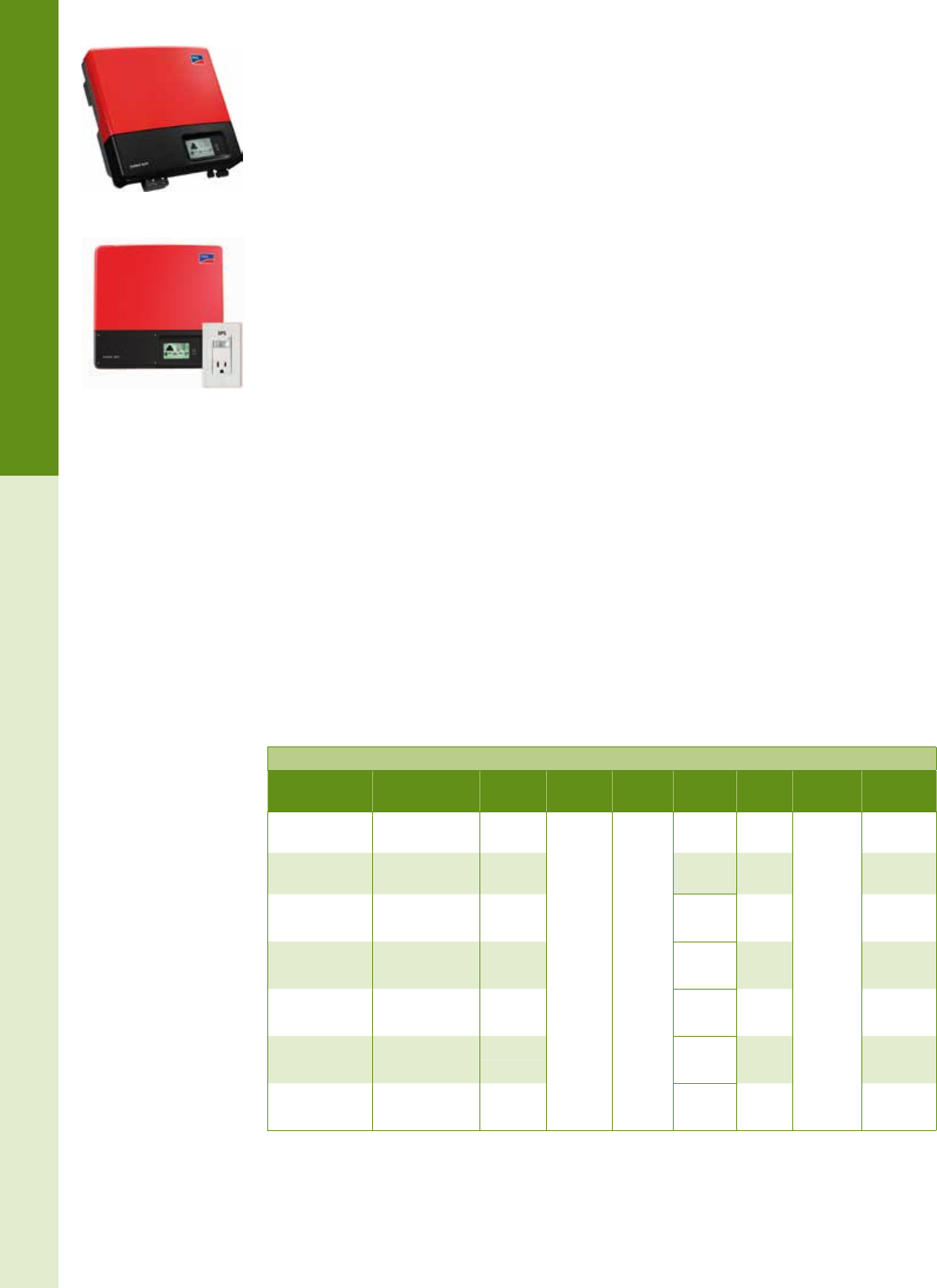
For the latest on AEE Solar products, trainings and dealer services, visit www.aeesolar.com
GRID-TIE INVERTERS
73
String Inverters
SMA
SMA Sunny Boy Grid-Tie Inverters
SMA Sunny Boy string inverters are available in sizes from 3 kW to 24 kW and can be used in a wide
range of applications from small residential systems at 240 VAC to very large 480 VAC three-phase
industrial installations. All SMA inverters come standard with built-in LCD digital monitors that display
instantaneous power output, the current day’s power production, and the total energy produced since
installation. All SMA inverters presented here are listed to UL 1741, UL 1998 for the U.S.A. and Canada,
and are compliant with IEEE-929, IEEE-1547, and FCC Part 15 A & B and are covered by a standard
ten-year warranty, with ve and ten-year extensions available.
SMA Sunny Boy 3000 to 7700 TL-22 Inverters with Secure Power Supply
The Sunny Boy TL-22 transformerless inverters feature high efciency and reduced weight along with
both ground and arc fault detection per NEC 2011. A wide input voltage range of 175 VDC to 600 VDC
and dual MPPT inputs dramatically increases module selection and string-sizing exibility as well as
better production when parts of the solar array are shaded. A graphic display and an integrated DC dis-
connect switch are included.
The unique SMA Secure Power Supply feature enables these inverters to supply up to 12 A (1,500 W)
at 120 VAC to a single dedicated outlet for recharging portable devices or a small UPS directly from
the PV array. Optional RS485 or Webconnect data modules enable web-based system monitoring with
SMA Sunny Portal. These transformerless inverters work with an ungrounded PV array topology so the
requirements of NEC 690.35 apply, including use of PV Wire for exposed array string wiring.
Features:
• CEC Rated Efciencies of 96.5%
• Secure Power Supply (requires dedicated outlet)
• Operating temperatures of -40 °F to +140 °F
• Dual MPPT input circuits – with tracking range from 175 to 500 VDC
• Integrated AFCI for arc-fault protection
• Available in sizes from 3 kW to 7.7 kW
• Field selectable 240 VAC Single-Phase or 208 VAC Three-Phase output
• Ten-year warranty, extendable up to 20 years
• Listed to UL 1741 and UL1699B for U.S.A. and Canada
• Compliant with: IEEE 1547, IEEE 929, FCC Part 15 A& B , CSA C22.2 107.1-1
SMA Sunny Boy TL-US-22 Inverters
Model Max AC output AC
voltage
DC array
voltage
MPPT
range
CEC
efciency
Max AC
current Weight Item code
SB3000TL-US-22 3,000 W 240 VAC
208 VAC
125-600
VDC
125-500
VDC
96.5% 15 A
61 lbs
including
DC
disconnect
030-03204
SB3800TL-US-22 3,840 W 240 VAC
208 VAC
97.0%
96.5% 16 A 030-03207
SB4000TL-US-22 4,000 W 240 VAC 97.0%
96.5% 20 A 030-03205
208 VAC
SB5000TL-US-22 5,000 W 240 VAC 97.0%
96.5% 22 A 030-03206
4,550 W 208 VAC
SB6000TL-US-22 6,000 W 240 VAC 97.0%
96.5% 25 A 030-03007
5,200 W 208 VAC
SB7000TL-US-22 7,000 W 240 VAC 96.5% 29.2 A 030-03008
6,000 W 208 VAC
SB7700TL-US-22 7,680 W 240 VAC 96.5% 32 A 030-03009
6,650 W 208 VAC
SMA TL-22 Inverter
SMA Secure Power Supply
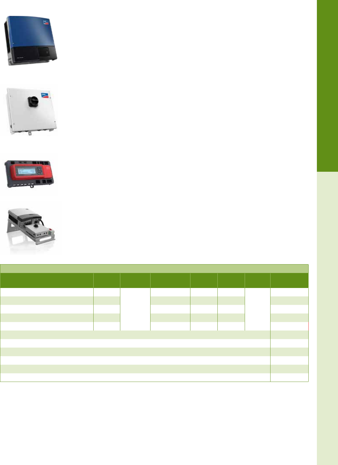
For the latest on AEE Solar products, trainings and dealer services, visit www.aeesolar.com
GRID-TIE INVERTERS
74
String Inverters
For the latest on AEE Solar products, trainings and dealer services, visit www.aeesolar.com
SMA Tripower Three-Phase Inverters
SMA offers ve three-phase commercial inverter options, ranging from 12 kW to 30 kW. All inverters
connect to 480 VAC three-phase utility service. The Detachable DC Connection Unit has fusing for both
MPPT inputs, and allows for easy swap out of the inverter for servicing. Tripower inverters all feature
Integrated DC AFCI.
MPPT Circuits and a wide MPPT operating voltage range, combined with a low startup voltage, allow
for very high efciencies. They can be congured for either 600 VDC or 1,000 VDC installations.
The Tripower inverters can be mounted on the roof, next to the array. This allows compliance with NEC
2014 Rapid Shutdown requirements without additional components. The optional SMA ReadyRack™
allows for simplied installation of the AC Disconnect, combiners, and cabling on at commercial rooftops.
Monitoring through the free SMA Sunny Portal can be easily congured, as these inverters come pre-
installed with the SMA Speedwire Card. Up to four inverters can be daisy chained together and viewed
as a plant. For larger installations, the optional SMA Cluster Controller can be added for plant-level
monitoring of up to 75 SMA inverters, and communication to third-party devices through Modbus pro-
tocol. The cluster controller enables multiple inverters to be viewed and reported on at the plant level,
and enables remote operation of reactive power adjustments as well as remote shutdown of the PV Plant,
if required. (Alternatively, the SMA Webbox can be utilized to connect to the SMA Sunny Portal, but
RS485 cards must be purchased and exchanged for the preinstalled Speedwire Cards.) NOTE: Cluster
controller requires a 24 VDC power supply, which is not included.
Features:
• Three-phase 480 VAC output
• Five models: 12 kW, 15 kW, 20 kW, 24 kW , and 30 kW
• 600 VDC or 1,000 VDC input conguration
• Dual MPPT DC inputs
• DC reverse polarity indicator
• Internal Arc-Fault Detection (AFCI) and Ground Fault Detection (GFCI) per NEC 2011
• Integrated SMA Speedwire Card for monitoring connection with free monitoring
• Optional SMA Cluster Controller for plant-level monitoring of multiple Tripower inverters
• Operating temperatures of -13 °F to +140 °F (-25 °C to +60 °C)
• Listed to UL 1741, UL1998, UL 1699B
•
Compliant with: IEEE 1547-2003, IEEE 1547.1, FCC Part 15 A&B, CAN/CSA C22. 2 No. 107.1-01
SMA Tripower Three-Phase 480V Inverters
Model Max AC
output
DC array
voltage MPPT range CEC
efciency
Max AC
current Weight Item code
Tripower 12000TL-US 12 kW
150 to 1000
VDC
300 to 800 VDC 97.5% 14.4 A
121 lbs
030-03055
Tripower 15000TL-US 15 kW 300 to 800 VDC 97.5% 18.0 A 030-03056
Tripower 20000TL-US 20 kW 380 to 800 VDC 030-03044
Tripower 24000TL-US 24 kW 450 to 800 VDC 98.0% 29.0 A 030-03047
Tripower 30000TL-US 30 kW 500 to 800 VDC 98.5% 36.2 A 030-03039
SMA String Combiner w/ Disconnect (CU1000-US-10) 030-03160
SMA Cluster Controller (CLCON-10) 300-00076
SMA, Readyrack for Tripower STP12000 014-10003
SMA, Readyrack for Tripower STP15000 014-10002
SMA, Readyrack for Tripower STP20000 014-10001
SMA, Readyrack for Tripower STP24000 014-10000
For the latest on AEE Solar products, trainings and dealer services, visit www.aeesolar.com
SMA ReadyRack for
Tripower Inverters
SMA Tripower Three-Phase
Commercial Inverter
SMA Cluster Controller
CU1000-US-10 Combiner/
Disconnect
For the latest on AEE Solar products, trainings and dealer services, visit www.aeesolar.com
GRID-TIE INVERTERS
75
String Inverters
SMA Sunny Boy Data Monitoring and Communications Accessories
SMA offers free monitoring for their entire line of inverter solutions through the SMA Sunny Portal
The Sunny Portal can be accessed by computer, smartphone or tablet, allowing users to access key data
at any time. Users can congure the portal to analyze data in many ways. Multiple inverters at a site can
be monitored and tracked, and reporting functions can provide updates via e-mail to help ensure yields.
Connection to the portal via a customer-supplied Internet access point varies by the SMA inverter used.
SMA Webconnect Cards – Sunny Portal Connection
The SMA SpeedWire Webconnect card provides a connection to the free Sunny Portal
(www.sunnyportal.com) through an Ethernet connection to the customer’s router. The SWPB-US-10
card is used to connect one US-12 or TLUS-12 inverter, while the SWDM-US-10 card allows the TL-22
model inverters to be connected to monitoring. Multiple inverters with Webconnect Cards can be daisy
chained together, and up to four inverters can be viewed as a single plant on the Sunny Portal.
SMA Webconnect Cards for SMA US, TL-12, TL-22 Inverters
Description Item code
SpeedWire SWDM-US-10 WebConnect card for TL-22 inverters 300-00069
SpeedWire SWPB-US-10 WebConnect card for US-12 or TLUS-12 inverters 300-00094
SMA Sunny WebBox – Sunny Portal Connection
The Sunny WebBox provides a connection between SMA inverters and the free Sunny Portal website
(www.sunnyportal.com). The Sunny WebBox stores system performance data in its internal 8 MB
memory (12.5 MB with the Bluetooth version) or on a standard SD memory card and can be set to upload
the data to the Sunny Portal website at user-selectable intervals. The WebBox can be connected to Sunny
Boy or Sunny Island inverters, and to Sunny SensorBox devices (up to 50 units total). The Sunny Web-
Box reports faults immediately by e-mail or text message. Measurement data can be transmitted to the
Sunny Portal via GSM modem from remote locations where no DSL or telephone connection is avail-
able. Connections to inverters or SensorBox devices are made with a four-conductor twisted-pair cable
between the inverter’s RS-485 output and the WebBox terminals. Each inverter requires an RS-485-N
Communication Card. The Sunny WebBox connects to a local area network (LAN) with an Ethernet cable
or to a phone line with a modem. Both are password protected and are covered by a ve-year warranty.
The compact Sunny SensorBox installs at the PV array to continuously monitor solar irradiation and
module temperature, which can be used to calculate the expected output of the PV array for comparison
to the actual power output of the inverters. This can help identify and troubleshoot reductions in energy
yield. The included Power Injector feed-in unit connects to the SensorBox via the RS485 communica-
tion bus to provide power to the SensorBox and includes a plug-in power supply (120 VAC required).
The Sunny SensorBox sends data to the Sunny WebBox via an RS-485 data link or by wireless commu-
nication with the addition of the Bluetooth version of the Power Injector (purchased separately). From
there, the data can be transferred to a PC for further processing or to the Sunny Portal for automatic
performance analysis. The Sunny SensorBox can accommodate up to three additional sensors, such as
ambient temperature, wind speed, and an additional irradiance sensor. The Sunny SensorBox is covered
by a ve-year warranty.
SMA Sunny Boy Data Monitoring and Communications Accessories
Description Item code
Sunny WebBox - RS-485 connection port (US-12, TL-12, TL-22 , and SI inverters) 030-03141
Sunny SensorBox with Irradiance Sensor - RS-485 connection port 030-03191
Sunny SensorBox Anemometer 030-03193
Sunny SensorBox Ambient Temp Sensor 030-03195
Sunny SensorBox Additional Module Temp Sensor 030-03197
RS 485 Communication Card for Sunny Boy (US-12 and TLUS-12 inverters) 030-03123
RS 485 Communication Card for Sunny Boy (TL-22 inverters) 300-00068
For the latest on AEE Solar products, trainings and dealer services, visit www.aeesolar.com
Sunny WebBox
Sunny SensorBox
Sunny SensorBox
Temperature Sensor
Sunny Anemometer
For the latest on AEE Solar products, trainings and dealer services, visit www.aeesolar.com
GRID-TIE INVERTERS
76
String Inverters
Ginlong
NEW! Solis Series Grid-Tie Inverters
Ginlong Solis inverters offer exceptional value with sizes up to 5 kW AC output with integrated AFCI
and Ground Fault protection. All Solis inverters feature low start-up voltages, with wide MPPT oper-
ating ranges. The 1 kW, 1.5 kW, and 2 kW inverters have one MPPT channel, and can accommodate
one string of modules with a 500 VDC max input limit. The 2.5 kW to 5 kW inverters have two MPPT
operating channels, with a 600 VDC max input limit. These inverters can also be congured for 208VAC
three-phase output.
The Solis inverters come with an integrated DC Disconnect switch, and a standard ten-year warranty.
The inverters feature a RS485 output jack that can connect to an Internet router or switch to connect to
the Solis monitoring portal. The optional WiFi Datalogging Stick can connect a single inverter to the
monitoring portal through an existing WiFi network. Alternatively, the Data Logging Box WiFi Internet
Gateway can connect up to ten daisy-chained inverters to the monitoring portal through a WiFi or wired
connection to the Internet .
Features:
• Dual MPPT input circuits (2.5 kW and larger)
• CEC efciencies on inverters range from 96.0% to 97.0%
• NEMA 4X enclosure
• Operating temperatures of -13 °F to +140°F (-25 °C to +60 °C)
• Congurable for 240 VAC single phase or 208 VAC three-phase output
• Integral Arc Fault Detection (AFCI) and Ground Fault Detection (GFCI
• Integrated Wi-Fi communications or RS485 port monitoring connection
• Listed to UL 1741-2010, UL 1998, and UL 1699B for U.S. and Canada
• Compliant with:
- FCC Part 15 Class B
- CAN/CSAC22.2 No. 107.1
Ginlong Solis Inverters
Model
Nominal
AC output
power
Mac AC
output
current
DC input
voltage range
(startup to max)
Full power
MPPT voltage
range
# of MPPT
inputs / # of
inputs per
MPPT
Max usable
input current
per MPPT
CEC efciency
Weight Item code
240 V / 208 V
Solis-2K-2G-US 2000 W 10.5 A 120 to 500 VDC 200 to 400 VDC 1 / 1 10 A 96.5% / 96.5% 21.6 lbs 030-11002
Solis-2.5K-2G-US 2500 W 13.3 A 120 to 600 VDC 125 to 500 VDC 2 / 1 10+10 A 96.5% / 96.5% 33.1 lbs 030-11003
Solis-3K-2G-US 3000 W 15.7 A 120 to 600 VDC 150 to 500 VDC 2 / 1 10+10 A 96.0% / 97.0% 33.1 lbs 030-11004
Solis-3.6K-2G-US 3600 W 16.0 A 120 to 600 VDC 180 to 500 VDC 2 / 1 10+10 A 96.5% / 96.5% 33.1 lbs 030-11005
Solis-4K-2G-US 4000 W 21.0 A 120 to 600 VDC 145 to 500 VDC 2 / 1+2 10+18 A 97.0% / 97.0% 38.6 lbs 030-11006
Solis-4.6K-2G-US 4600 W 23.8 A 120 to 600 VDC 165 to 500 VDC 2 / 1+2 10+18 A 97.0% / 97.0% 38.6 lbs 030-11007
Solis-5K-2G-US 5000 W 23.8 A 120 to 600 VDC 180 to 500 VDC 2 / 1+2 10+18 A 97.0% / 97.0% 38.6 lbs 030-11008
Ginlong Solis Inverter Accessories Item code
Ginlong Solis Data Logging Box WiFi (GL-WE01) 300-00161
Ginlong Solis Datalogging WiFi Stick (GINLONG-DLS) 300-00160
Solis 4kW Inverter
WiFi Datalogging Stick
Datalogging Box WiFi
Internet Gateway
For the latest on AEE Solar products, trainings and dealer services, visit www.aeesolar.com
GRID-TIE INVERTERS
77
String Inverters
HiQ Solar
NEW! HiQ Solar 8kW 480V TrueString™ Inverter
The new HiQ Solar TrueString™ Inverter System is a small, exible, reliable, roof-mounted, 480 VAC
three-phase commercial inverter solution. The modular HiQ Solar TS-480-8K inverters have NEMA6
-rated enclosures, and can be mounted on the solar racking under the PV array. Each inverter has two
MPPT inputs and can be strung at either 600 VDC or 1,000 VDC, due to the wide MPPT tracking win-
dow. Strings may be different lengths, increasing layout exibility. Inverters are small and each unit
weighs just 24 lbs.
Each inverter allows for two strings of modules on separate DC inputs for the two MPPT circuits. These
inverters are ideal for new or retrot installs, installation in desert and coastal environments, and do not
require any wall space or concrete pads. They have arc-fault protection and are 690.12 (rapid shutdown)
compliant when mounted under the solar array.
Installers will utilize the HiQ Solar AC Trunk Cables, offered in 5, 15, and 30-foot lengths, to connect the
inverters to the HiQ Solar AC Splice Box or Subpanel. The HiQ Solar AC Splice Box enables combining
up to three HiQ Solar Inverters into one common AC home run, which then terminates in a subpanel on
a 40 A three-phase breaker. Multiple combiners can be used for larger solar arrays.
The HiQ Solar Gateway Device connects to a 120 or 277 VAC power source and auto-discovers any
connected inverters then communicates via data over power line technology. The entire HiQ system is
fast and easy to commission, and can easily track performance and detect issues on each module string.
A 5.75 kW HiQ Solar Truestring™ 208V three-phase inverter is expected in early 2016.
Features:
• Three-Phase 480 VAC output transformerless inverter with dual-MPPT DC inputs
• NEC 690.11 compliant arc-fault protection
• NEC 2014 690.12 rapid shutdown compliant
• Ten-year standard warranty, extendable to 25 years
•
Monitoring Gateway over powerline communications with plant, inverter, and MPPT level visibilityª
•
High reliability with NEMA6 enclosure, and no electrolytic capacitors, operating temperature range
of -40 °F to 145 °F (-40 °C to +65 °C)
• No high-voltage DC-wiring runs outside of array, and utilizes common AC branch-circuit wiring
from inverters to interconnection.
• Listed to UL 1741
• Designed and manufactured in the USA
HiQ Solar TrueString 480 VAC Three-Phase Inverter and Accessories
Model Description Max AC
output
DC array
voltage MPPT range CEC
efciency
Max AC
current Weight Item code
HiQ Solar TS480-8k
Truestring Inverter
Roof Mounted, 8kW, 480 VAC,
isolated string inverter 8 kW 200 to 1,000
VDC
425 to 850
VDC 98.0% 9.6 A 24 lbs 030-12000
HiQ Solar AC Trunk
Cables
CBL-480A-05, 5-foot AC Trunk Cable 030-02011
CBL-480A-15, 15-foot AC Trunk Cable 300-00164
CBL-480A-30, 30-foot AC Trunk Cable 300-00165
HiQ Solar AC Splice Box ACSPL-40, AC Combiner Splice Box, NEMA 4X Enclosure
(Used to combine up to three HiQ Solar 8 kW Inverters to common AC output) 300-00162
HiQ Solar Gateway
Communications Device GW-A HiQ Communications Gateway with Ethernet Cable and memory card 300-00166
HiQ Solar Gateway
Power Supply
CBL-GW120A-6, HiQ Gateway with 120 VAC 6-foot plug 300-00167
CBL-GW277A-6, HiQ Gateway with 277 VAC 6-foot plug 300-00168
HiQ Solar Warranty
Extension
Extended warranty for HiQ Solar TrueString inverters from ten to 25 years
(15-year warranty extension) 300-00169
HiQ Solar AC Connector
Unlatching Tool Tool for unlatching HiQ Solar AC Trunk connectors 100-04156
HiQ Solar 8kW480V
TrueString Inverter
HiQ Solar Gateway
HiQ Solar AC Splice Box
For the latest on AEE Solar products, trainings and dealer services, visit www.aeesolar.com
GRID-TIE INVERTERS
78
String Inverters
Schneider Electric
Schneider Conext CL Three-Phase Inverters
The Conext CL Series of commercial inverters from Schneider Electric is highly suitable for three-phase,
480 VAC installations, and is designed for high efciency and exibility, as well as easy installation
and servicing. These inverters feature wide MPPT voltage windows on dual MPPT input circuits. The
NEMA 3R enclosure enables outdoor use. Inverters may be installed at an angle from 10 to 90°allowing
the inverters to be mounted on the roof next to the array if necessary to comply with NEC 690.12 Rapid
Shutdown requirements. Two inverter sizes are offered; the CL18000NA has an 18-kilowatt maximum AC
power output and supports 600 VDC and 1,000 VDC solar arrays, while the CL2500NA has a 25-kilowatt
maximum AC power output supporting 1,000 VDC solar arrays.
Conext CL inverters include an embedded Ethernet gateway, enabling connection of up to eight invert-
ers to the Conext Insight Portal without any additional hardware required, by directly wiring them to
an Internet router. For advanced features, including real-time event logging and reactive-power control,
or for monitoring more than eight inverters, the outdoor-rated Conext Smartbox Datalogger device is
available in ‘basic’ and ‘essential’ conguration models. The communication interface on these inverters
also supports RS485 MODBUS RTU and Ethernet MODBUS TCP connection to third-party monitoring
devices and services.
The inverters offered through AEE feature arc-fault protection, touch-safe fuse holders, and included
AC and DC disconnect switches. The upgraded models feature integrated DC and AC Surge Suppres-
sion Devices.
Features:
• Two models available 18 kW and 25 kW:
- 18 kW model allows 600 VDC or 1,000 VDC input congurations
- 25 kW model supports 1,000 VDC installation
• Three-phase 480 VAC output
• DC to AC Conversion Efciencies up to 98%
• Dual-MPPT DC Inputs
• Internal Arc Fault Detection (AFCI) and Ground Fault Detection (GFCI) per NEC 2011
• Operating temperatures of –13 °F to +140 °F (-25 °C to +60 °C)
• Listed to UL 1741 and 1699B
• Compliant with: IEEE 1547.1, CSA C22.2 107.1-01
Schneider Electric Conext CL Series Three-Phase Inverters
Model Description Max AC
output
DC array
voltage MPPT range CEC
efciency
Max AC
current Weight Item code
PVSCL18NA201 Touch Safe Fuse Holder, DC
Switch, and AC Connector, AFD 18 kW
250 to 1,000
VDC
300 to 800
VDC 97.5% 25.0 A 152 lbs
030-02010
PVSCL18NA301
Touch Safe Fuse Holder, DC
Switch, and AC Connector, AFD,
preinstalled AC and DC Surge
Protection Device
18 kW 030-02011
PVSCL25NA201 Touch Safe Fuse Holder, DC
Switch, and AC Connector, AFD 25 kW
250 to 1,000
VDC
500 to 800
VDC 98.0% 33.0 A
030-02012
PVSCL25NA301
Touch Safe Fuse Holder, DC
Switch, and AC Connector, AFD,
preinstalled AC and DC Surge
Protection Device
25 kW 030-02013
For the latest on AEE Solar products, trainings and dealer services, visit www.aeesolar.com
Conext CL Three-Phase
Inverter
Conext Smartbox
Datalogger
For the latest on AEE Solar products, trainings and dealer services, visit www.aeesolar.com
BATTERY-BASED INVERTERS
79
System Design
Battery-Based Inverters
A battery-based inverter converts direct current (DC) from batteries into alternating current (AC) at the
appropriate voltage and frequency to operate lights, appliances or anything else that normally operates
on electricity supplied by the utility grid. All battery-based inverters can be used in off-grid systems
and some can also feed power back into the utility grid using net metering, similar to the more common
grid-tie inverters. All of these battery-based inverters require a battery bank to function.
Grid-Interactive Inverters for Backup Power Applications
Grid-interactive inverters, also called dual-function or hybrid inverters, can export power to the utility
grid, but can also supply backup power to protected loads during a grid outage. These inverters use a
battery bank for energy storage, will not operate without batteries, and include an automatic transfer
switch that enables them to safely operate off-grid during a blackout.
The grid-interactive inverter is connected to the battery bank (usually 24 or 48 VDC), an AC sub-panel
for protected loads, and the building’s utility entrance load center. The battery bank is charged by the
PV array connected through a charge controller (see Charge Controllers) or through the battery inverter
via AC coupling. Under normal conditions, it will export surplus power produced by the PV array. Dur-
ing a grid outage, the inverter will automatically disconnect from the grid and supply AC power to the
protected load subpanel by drawing energy from the battery bank and solar array. When the outage is
over, the inverter will automatically switch back to grid-tie operation and recharge the batteries.
It is important to note that a signicant amount of energy is used to maintain the battery bank. For this
reason, systems with battery backup typically provide 5 to 10% less energy (kWh) per kW of PV array
than equivalent grid-tie systems that don’t include batteries.
Off-Grid Inverters
Off-grid battery-based inverters convert DC electricity from a battery bank to AC. In this case, the PV
array and/or wind generator is used to charge the batteries via a charge controller (see Charge Control-
lers for more information) and only the power demanded by the loads is inverted to AC. Because these
systems do not have access to the electrical grid, it is important to properly size the inverter and battery
bank (see System Design and Batteries for more information on sizing inverters and battery banks).
The nameplate capacity of an inverter is measured by its maximum continuous output in watts. The
inverter capacity limits the sum of all AC loads you can operate simultaneously. Most AC appliances list
their consumption on a tag located near the power cord and/or in the owner’s manual. You will need to
add up the consumption of all the appliances you may need to operate at once – that will represent your
minimum inverter size. If your appliances include induction motors, like washers, dryers, dishwashers,
furnace electronic controls, and large power tools, be sure to select an inverter with sufcient surge
capability to accommodate the higher start-up loads.
Off-grid inverters will output either sine-wave or modied-sine-wave (modied-square-wave) AC wave-
forms. Sine-wave inverters can closely mimic utility-grid power and will run virtually any AC appliance.
Modied-sine-wave inverters are an economical choice when waveform is not critical. They often have
a high surge capacity for motor starting and generally retain good efciency when partially loaded.
Unfortunately, this type of inverter may damage or fail to operate some sensitive appliances, such as
rechargeable tools and ashlights, laser printers, copiers, variable speed drives, and any equipment with
silicon controlled rectiers (SCRs). Some audio equipment will have a background buzz when operated
with a modied-sine-wave inverter.
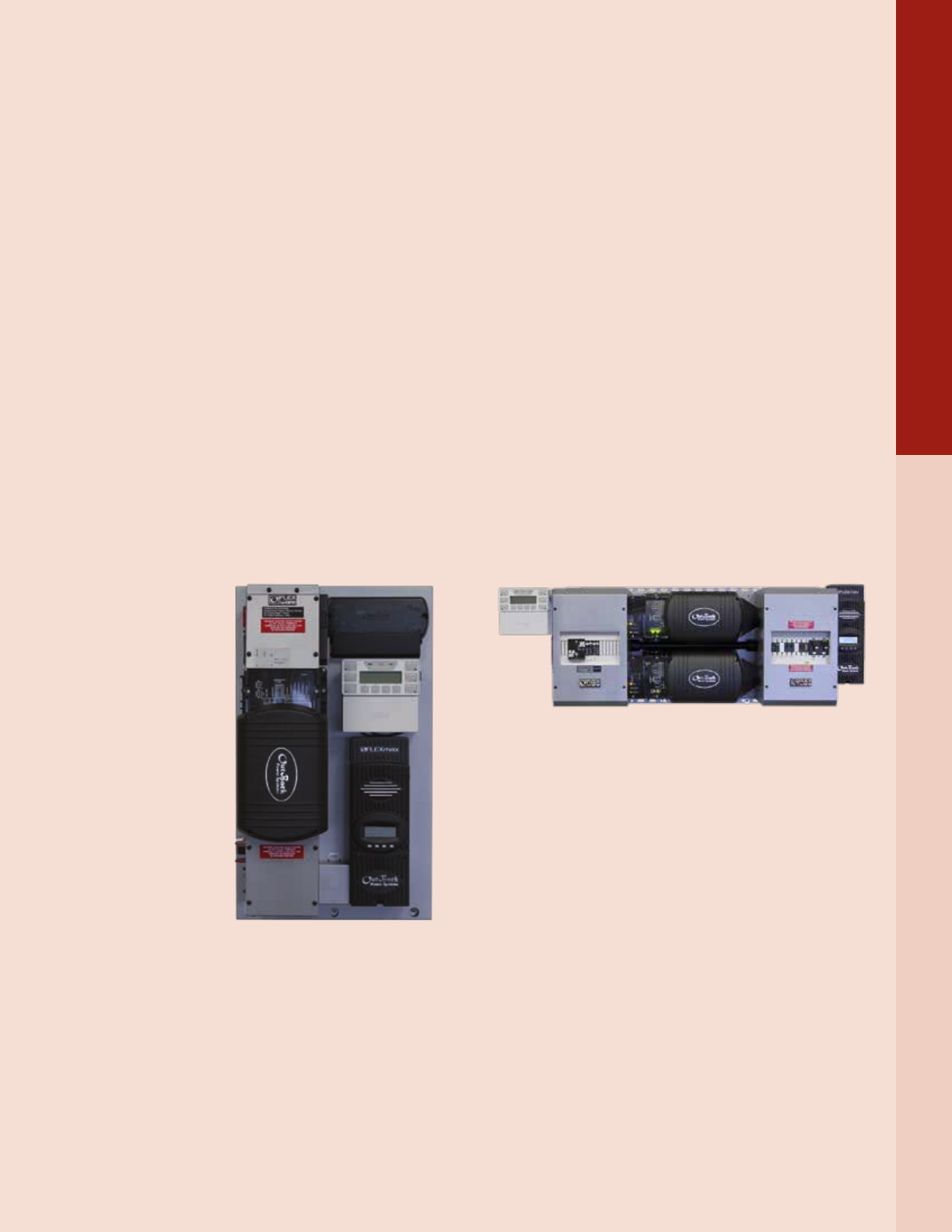
For the latest on AEE Solar products, trainings and dealer services, visit www.aeesolar.com
BATTERY-BASED INVERTERS
80
System Design
Output Voltage
In the past, most battery-based inverters supplied only 120 VAC 60 Hz single-phase outputs. Now, many
of the more popular residential-sized inverters, like the OutBack Radian, Schneider XW, and Magnum
MS-PAE inverters, deliver 120/240 VAC power from one inverter. These inverters can also be wired in
parallel for greater power output. Pairs of some 120 VAC output inverters like the OutBack FX series
and Sunny Island inverters can also be wired in series for 120/240 VAC split-phase, or 120/208 VAC
three-phase output.
Inverters that supply 50 Hz power are also available for most product lines. Please contact us with any
special requirements you may have.
Interference
Battery-based inverters may interfere with radio and television reception, causing noise on telephones
or buzz in audio equipment. Interference can be minimized by using sine wave inverters and by locating
the inverter as close to the batteries as practical, twisting together the cables that connect the inverter
to the battery, running AC lines separate from other wiring (such as telephone wires), and locating the
inverter away from appliances that are susceptible to interference. All inverters can cause interference
with AM radio reception.
Wiring Considerations
Battery-based inverters require high current from a battery bank to operate large loads. A 2 kW inverter
will draw nearly 200 A from a 12 VDC battery bank. Large cables and good connections are required
for safe operation. Use caution when plugging a small inverter into a lighter outlet in a vehicle, as these
outlets are usually not robust enough to handle high current for long periods of time. All battery-based
inverters require proper fusing between the battery and the inverter.
Pre-wired power systems are available with most battery-based inverters to minimize design and wiring
issues. Custom congurations are available for most OutBack FLEXware-based power systems. Please
contact us for additional information.
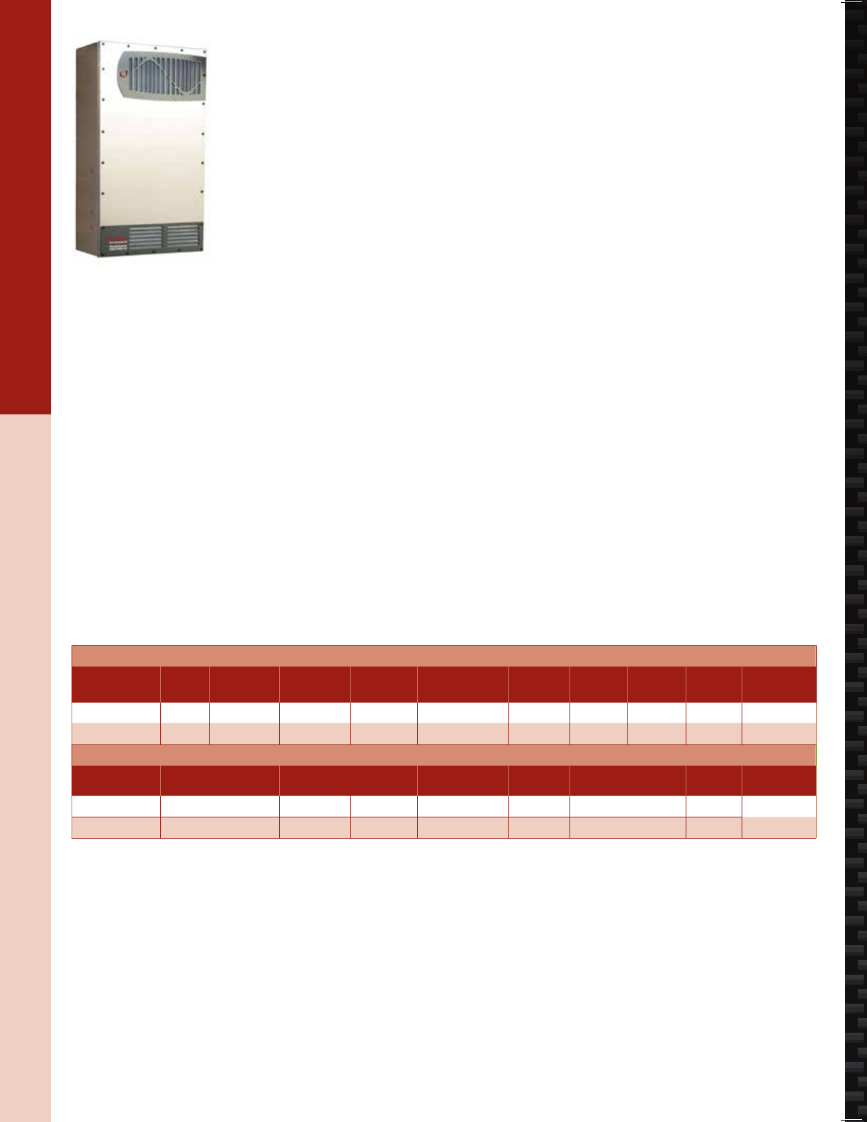
deliberate design
For more information, please visit www.outbackpower.com
As an industry leader in full system solutions
for off-grid and Grid-Hybrid renewable energy
applications, all OutBack components are
deliberately designed to function together.
Seamlessly. As a complete system.
The result?
System efficiency, simplified installation and
single-source product and technical support.
Deliberate design means every OutBack product
is engineered to provide best-in-class reliability,
serving one of the three key functions in a
complete renewable energy system:
Make the Power
Store the Energy
Manage the System
For the latest on AEE Solar products, trainings and dealer services, visit www.aeesolar.com
BATTERY-BASED INVERTERS
81
OutBack Inverters & Accessories
OutBack Power
Radian Grid-Hybrid™ Inverters
OutBack Radian inverters work equally well as a grid-tie or off-grid inverter. There are two separate
AC inputs, one for the bi-directional grid connection and one for a backup generator. There is a built-in
50 A transfer switch at 120/240 VAC. The output is 120/240 VAC split phase in each unit for easy tie-in
to US standard wiring and grid connections. The Radian features 4 kW (GS4048A) or 8 kW (GS8048A)
of continuous output power and can support large dynamic load variations and surge loads, making it
well suited for demanding commercial applications as well as residential use. With two power stages
(one on the GS4048A), it is able to provide high efciency and redundancy for critical applications,
and the modular design is eld serviceable. The Radian can be parallel stacked with up to ten inverters
for 80 kW total output. The Radian also has auxiliary controls that include a contact closure, a 12 VDC
output signal, and terminals for a remote on/off switch as well as a remote temperature sensor (RTS) for
the battery bank. Each GS8048A inverter requires dual 2/0 AWG battery cables (two positive and two
negative) for connection to the battery bank. In fully off-grid applications, the minimum recommended
battery size is 175 Ah for the GS4048A and 350 Ah for the GS8048A for each inverter installed in a
power system (See Batteries).
The GS4048A and GS8048A inverters are made to work in off-grid, grid-tied, or grid-supported systems
using OutBack’s “GridZero” mode, optimizing solar production where net metering is not available.
The “A” inverters also have an adjustable input-voltage range so they can be made to work with most
lithium-ion, aqueous sodium-ion and other advanced battery technologies.
EXPORT Radian Grid-Hybrid Inverters
The GS3548E and GS7048E include a built-in 50 A transfer switch at 230 VAC. The output is 230 VAC
50 Hz (or 60 Hz) single-phase in each unit for easy tie-in to most international standard wiring and grid
connections. These inverters feature 3.5 kW or 7 kW of continuous output power and can support large
dynamic load variations and surge loads up to 11.5 kW. The Radian can be parallel stacked with up
to ten inverters for 70 kW total output. The Radian also has auxiliary controls which include a contact
closure, a 12 VDC output signal and terminals for a remote on/off switch.
Each inverter comes with a standard ve-year warranty. An optional ten-year extended warranty is avail-
able where required by state incentive programs. The Radian is not rated for outdoor use. Dimensions
are 28"H x 16"W x 8.7"D. Weight is 84 lbs for the GS4048A/GS3548E and 125 lbs for the GS8048/
GS8048A/GS7048E. Listed to UL 1741 for U.S.A. and Canada.
A MATE3, HUB4 or HUB10, and an appropriate GSLC are needed to complete a Radian system.
OutBack Radian Inverters
Model CEC
rating
CEC grid-tie
output
Continuous
output
Battery
voltage
AC out
volts/hertz
No load
draw
Charger
output AC surge Weight Item code
GS4048A 92.5% 3,600 W 4,000 W 48 VDC 124/240 V 60 Hz 34 W 57 A 6,000 W 82 lbs 030-04058
GS8048A 92.5% 7,650 W 8,000 W 48 VDC 124/240 V 60 Hz 34 W 115 A 12,000 W 125 lbs 030-04060
EXPORT OutBack Radian Inverters
Model Continuous output Battery
voltage
AC out
volts/hertz No load draw Charger
amps AC surge output Weight Item code
GS3548E 3,500 W 48 VDC 230 V/50 Hz N/A 50 A 5,800 W 84 lbs 030-04059
GS7048E 7,000 W 48 VDC 230 V/50 Hz 30 W 100 A 11,500 W 125 lbs 030-04038
deliberate design
For more information, please visit www.outbackpower.com
As an industry leader in full system solutions
for off-grid and Grid-Hybrid renewable energy
applications, all OutBack components are
deliberately designed to function together.
Seamlessly. As a complete system.
The result?
System efficiency, simplified installation and
single-source product and technical support.
Deliberate design means every OutBack product
is engineered to provide best-in-class reliability,
serving one of the three key functions in a
complete renewable energy system:
Make the Power
Store the Energy
Manage the System
For the latest on AEE Solar products, trainings and dealer services, visit www.aeesolar.com
BATTERY-BASED INVERTERS
83
OutBack Inverters & Accessories
Radian GSLC Load Centers
The GS Load Center (GSLC) is a wiring and circuit-protection enclosure that mounts under the Radian
inverter. It is available in multiple versions:
The base GSLC includes positive and negative main inverter busbars, a 500 A 50 mV shunt with negative
terminal bar, the main DC positive breaker plate, ground and neutral terminal bars, and two PV-positive
terminal bars. It can also accommodate up to 18 AC or DC panel-mount breakers (ten top, eight bottom),
two main 175 A DC breakers and a FLEXnetDC, which can be purchased separately. Up to two charge
controllers can mount on the right side (mounting brackets sold seperately), and either the HUB4 or
HUB10 can mount on the left side.
The GSLC175-120/240 includes the base unit plus two 175 A DC main breakers, an AC output and
bypass breakers with interlock plate, AC grid and generator-input breakers (50 A two-pole), and six AC
terminal bars (three black, three red). It can also accommodate ten additional panel-mount breakers,
(purchased separately).
The GSLC175-120/240 includes the base unit plus two 175 A DC main breakers, an AC output and
bypass breakers with interlock plate, AC-grid and generator-input breakers (50 A two-pole), and six AC
terminal bars (three black, three red). It can also accommodate ten additional panel-mount breakers,
(purchased separately).
The GSLC175-PV-120/240 works with the GS8048A inverters, or the GS4048A inverter with an extra
175 A breaker, and includes items in the 175-120/240 unit plus two 80 A PV array breakers, a two-pole
GFDI 80 A breaker, three 500 A 50 mV shunts with shunt bus, and a FLEXnetDC. The GFDI acts as the
breaker between the control and positive bus; there are no other breakers added for this purpose. It can
also accommodate ve additional panel-mount breakers, (purchased separately).
The GSLC175-PV1-120/240 works with the GS4048A inverter and one charge control, and includes
one 175 ADC main breaker plus one 80 A PV breaker, one two-pole GFDI 80 A breaker, two 500 A 50
mV shunts with shunt bus, and a FLEXnetDC.
The AC bypass assembly is only for use with a single Radian inverter. For multiple inverters, use the
base GSLC with added DC and AC breakers as needed (no bypass) and use external transfer switches
for bypass and external AC load centers for output combining and input distribution. One GSLC is
required for each Radian inverter. Each 8 kW inverter requires two 175 A main DC breakers and each
4 kW inverter requires one.
Outback's GSLC175-AC-120/240 load center simplies installation of Radian inverters into an AC-
coupled system. It has all of the connections, breakers and relays needed for adding a battery-based
backup system to an existing or new grid-tie system utilizing a Radian inverter and battery bank. There
are controls and relays to manage battery charging from the grid-tie system with battery-temperature
compensation. A second AC input is available for a backup generator to assist in powering the loads
during an extended outage if there is not enough sun or there are more loads than expected. There is an
auto generator start relay with grid-tie inverter lockout when under generator power. No diversion loads
or other external relays are required. There are connection points for the utility grid, the protected loads
panel, the grid-tie inverter, an optional backup generator, and the battery bank. The required MATE3
now has a new AC-coupling function which should be used with this GSLC. The rating of the grid-tie
inverter should not exceed 6 kW when used with a GS8048A, and not more than 3 kW when used with
the GS4048A. You will also need a GS inverter, MATE3, battery bank, protected load center, and the
existing GT inverter system to complete an AC-coupled Radian system.
The GSLC is not rated for outdoor use. Dimensions are 17"H x 16"W x 8.5"D. Weight is 26, 37, or 38
lbs. Listed to UL 1741 for U.S.A. and Canada. More accessories for OutBack Power can be found on
the following pages.

For the latest on AEE Solar products, trainings and dealer services, visit www.aeesolar.com
BATTERY-BASED INVERTERS
84
OutBack Inverters & Accessories
GS Load Centers
Model Description Item code
GSLC GS Load Center with inverter bars, breaker bus, shunt, neg, ground, neutral, and PV-pos busbars 053-02250
GSLC175-120/240 GS Load Center with all items above plus two main 175 A breakers, AC IO/Bypass, and 6 AC busbars 053-02251
GSLC175-PV-120/240 GS Load Center with all items above with three shunts, FNDC, two-pole GFDI, and dual PV-input breakers 053-02252
GSLC175-PV1-120/240 GS Load Center with one 175A main breaker with two shunts, FNDC, single-pole GFDI, and single PV-input breakers 053-02256
GSLC175-AC-120/240 GS Load Center for AC Coupling, with generator & GT inverter inputs & lockouts 053-02255
GS Load Center Accessories
GS-IOB-120/240 VAC GS AC input/output/bypass kit split phase 120/240VAC for single inverter only 053-07818
GS-IOB-AC-120/240 GS AC-coupling parts kit , one ROCB, one 12VDC relay, one 48 VDC relay 053-07816
GS-SBUS DC shunt bus for GS Load Center 053-00130
STBB-BLACK Short busbar kit with black insulators for GS Load Center 053-00132
STBB-RED Short busbar kit with red insulators for GS Load Center 053-00133
STBB-WHITE Short busbar kit with white insulators for GS Load Center 053-00134
PNL-50D-AC-120/240 Circuit breaker, 50 A, 120/240 VAC, two-pole, panel mount for GSLC (takes two ¾" spaces) 053-17004
PNL-175-DC Circuit breaker, 175 A, 125 VDC, single-pole, main DC breaker for GS inverter (two required per inverter) 053-01053
EXPORT GS Load Centers
GSLC GS Load Center with inverter bars, breaker bus, shunt, neg, ground, neutral, and PV pos busbars 053-02250
GSLC175-230 GS Load Center with all base items plus two main 175 A breakers, single-leg 230 VAC IO/Bypass, and three AC busbars 053-02253
GSLC175-PV-230 GS Load Center with all items above plus three shunts, FNDC, two-pole GFDI, and dual PV-input breakers 053-02254
GSLC175-PV1-230 GS Load Center with one 175A main breaker plus two shunts, FNDC, single-pole GFDI, and single PV-input breakers 053-02257
EXPORT GS Load Center Accessories
GS-IOB-230VAC GS AC input/output/bypass kit, one-leg 230 VAC for single inverter only 053-07817
GS-SBUS DC-shunt bus for GS Load Center 053-00130
STBB-BLUE Short busbar kit with blue Insulators for GS Load Center for EXPORT GSLC 053-00135
STBB-BROWN Short busbar kit with brown Insulators for GS Load Center for EXPORT GSLC 053-00136
PNL-30-AC Circuit breaker, 30 A, 250 VAC, single-pole, panel mount for 230 VAC GSLC (takes one ¾" space) 053-16998
PNL-50-AC-240 Circuit breaker, 50 A, 250 VAC, single-pole, panel mount for 230 VAC GSLC (takes one ¾" space) 053-16999
PNL-175-DC Circuit breaker, 175 A, 125 VDC, single-pole, main DC breaker for GS inverter (two required per inverter) 053-01053
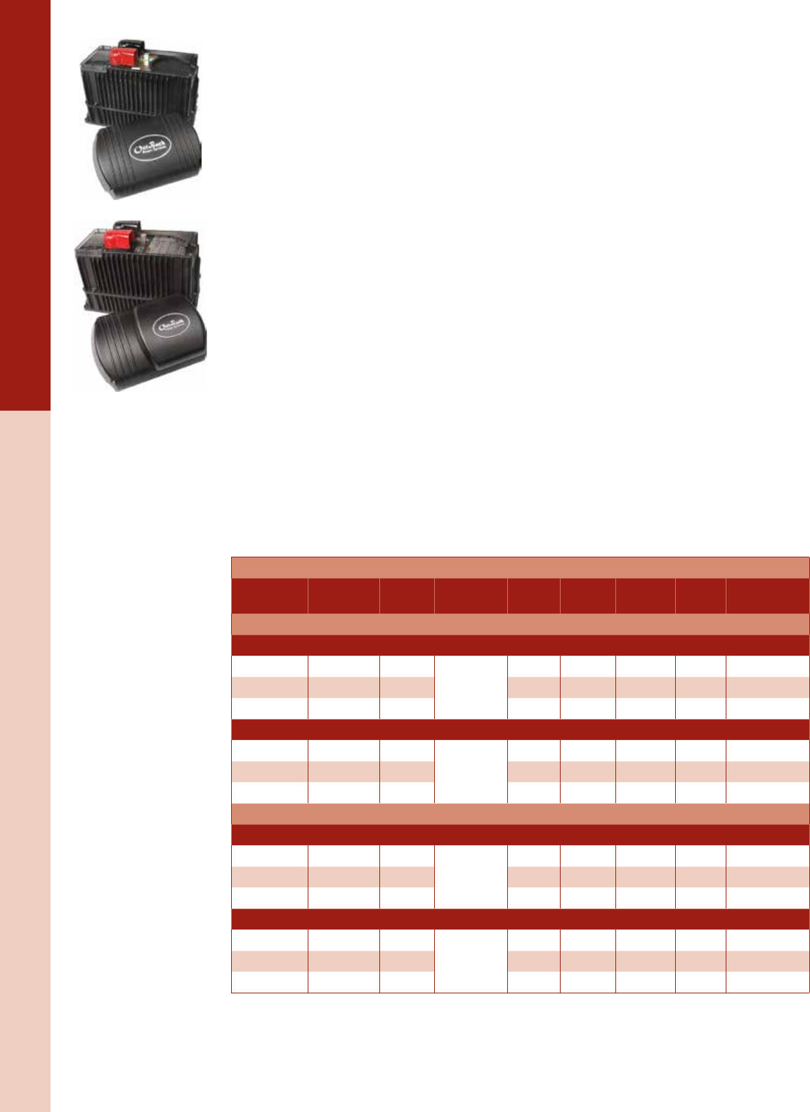
For the latest on AEE Solar products, trainings and dealer services, visit www.aeesolar.com
BATTERY-BASED INVERTERS
85
OutBack Inverters & Accessories
NEW! OutBack VFXR and FXR Hybrid Inverters
The OutBack FXR series inverters are a more advanced version of the venerable FX series. These new
inverters are a good choice for off-grid or, with the 24 VDC and 48 VDC inverters, can be used in a
grid-tied system. They have expanded voltage ranges for use with advanced-technology batteries, and
have the advanced OutBack features including Grid Zero and Offset modes.
The ventilated OutBack VFXR inverters offer more power in high ambient-temperature applications,
and more throughput for generator-powered battery charging. The sealed, externally fan-cooled FXR is
designed to be used in coastal or dusty environments.
Each inverter/charger is a multi-mode power conversion unit that includes an inverter, battery charger,
and an AC transfer switch. Up to ten inverters can be stacked in parallel (120 VAC), up to eight inverters
can be stacked in a series conguration (120/240 VAC), and up to nine inverters can be stacked for three-
phase (120Y208 VAC) congurations. The 50 Hz export inverters can be stacked up to ten in parallel
(230 VAC), and up to nine inverters in a three-phase conguration (230Y400 VAC). When stacking, all
of the inverters must be the same model. The X-240 and similar transformers are not used with the FXR
inverters. Due to the added control features, FXR series inverters should be deployed with the MATE3
controller (or AXS Port) and the Hub10.3; older models may not function properly. These inverters, with
the MATE3 or AXS port, are compatible with OutBack OpticsRE.
VFXR inverters have a programmable, auxiliary relay output connection (AUX) that provides 12 VDC
output to run cooling or ventilation fans or to operate an external relay for other functions, such as remote
generator starting (two-wire). Sealed FXR inverters use this relay to power the external cooling fan, so
it is not available for other uses.
The internal transfer switch is rated for 60 A. When an external source of AC power (either a generator
or the utility grid) is detected at the “AC in” terminal on the inverter, the switch operates to transfer the
loads to the external power source, and then activates the battery charger to recharge the battery bank
depending on what mode is programmed. Use the FlexWare 250, 500, or 1000 components with these
inverters or refer to the pre-wired FLEXpower systems featuring FXR series inverters.
Dimensions: 16.25"L x 8.25"W x 11.5"H. Listed to UL 1741 (2nd edition) and CSA 22.2 by ETL for the
U.S.A. and Canada and covered by a ve-year warranty.
OutBack VFXR and FXR Inverters
Model Continuous
output
Battery
voltage
AC out
volts/hertz
No load
draw
Charger
output
AC surge
output Weight Item code
US Models - can be connected in series 120/240, parallel or three-phase Y 120/208 VAC
Ventilated Cooled Inverters
VFXR2812A 2,800 W 12 VDC
120 V/60 HZ
34 W 125 A 4,800 W 61 lbs 030-04064
VFXR3524A 3,500 W 24 VDC 34 W 82 A 6,000 W 61 lbs 030-04065
VFXR3648A 3,600 W 48 VDC 34 W 45 A 6,000 W 61 lbs 030-04066
Sealed/Turbo-Cooled Inverters
FXR2012A 2,000 W 12 VDC
120 V/60 HZ
34 W 100 A 4,800 W 62 lbs 030-04061
FXR2524A 2,500 W 24 VDC 34 W 55 A 6,000 W 62 lbs 030-04062
FXR3048A 3,000 W 48 VDC 34 W 35 A 6,000 W 62 lbs 030-04063
EXPORT Models - can be connected in parallel or 3-phase Y 230/400 VAC
Ventilated Inverters
VFXR2612E 2,600 W 12 VDC
230 V/50 HZ
34 W 120 A 4,600 W 61 lbs 030-04070
VFXR3024E 3,000 W 24 VDC 34 W 80 A 5,750 W 61 lbs 030-04071
VFXR3048E 3,000 W 48 VDC 34 W 40 A 5,750 W 61 lbs 030-04072
Sealed/Turbo-Cooled Inverters
FXR2012E 2,000 W 12 VDC
230 V/50 HZ
34 W 100 A 4,600 W 62 lbs 030-04067
FXR2024E 2,000 W 24 VDC 34 W 55 A 5,750 W 62 lbs 030-04068
FXR2348E 2,300 W 48 VDC 34 W 35 A 5,750 W 62 lbs 030-04069
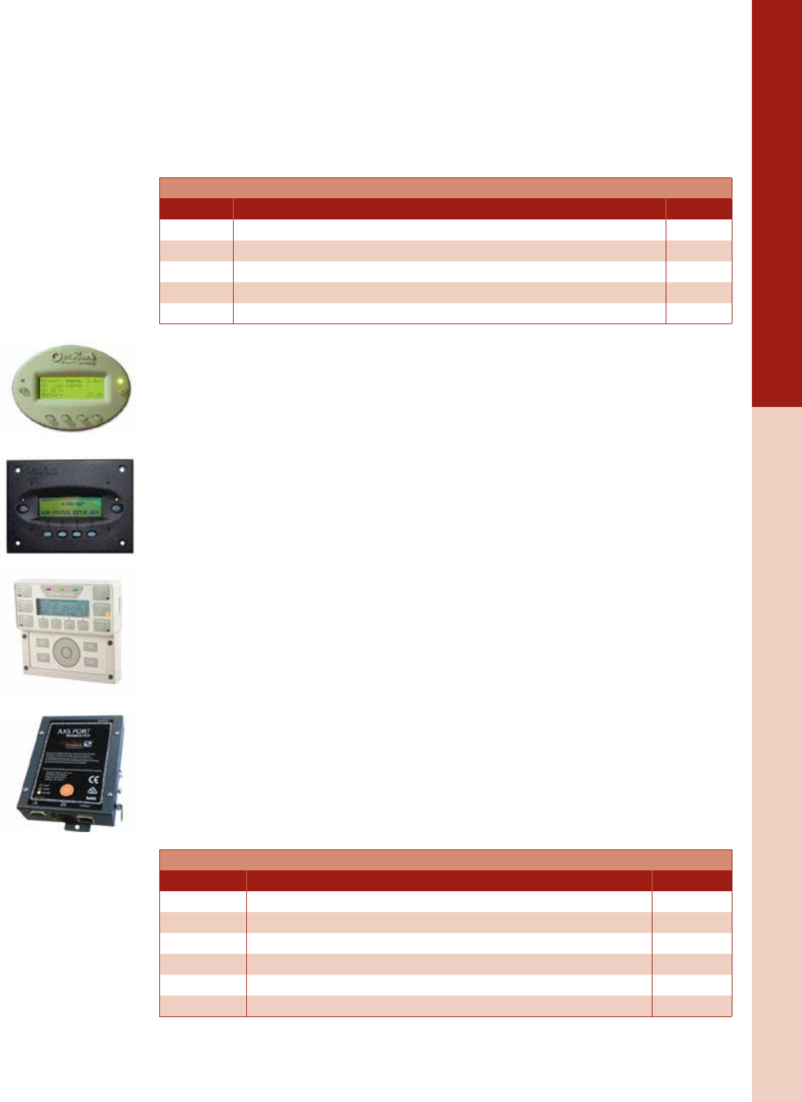
For the latest on AEE Solar products, trainings and dealer services, visit www.aeesolar.com
BATTERY-BASED INVERTERS
86
OutBack Inverters & Accessories
OutBack Inverter Accessories
Use the FX-DCA to connect 2" conduit to the DC side of the inverter or to connect inverters to the
FW- 500DC or FW-1000DC. Use the FX-ACA or SP-ACA to connect to the AC side of the inverter.
The FW-SP-ACA can be used in place of the FXACA and offers surge protection. Use either one to con
-
nect inverters to the FW-500DC or FW-1000DC. Use the FW-SP-250 to replace the lid on the FW250.
These surge protectors offer protection on both input and output AC and inverter DC surge protection.
A separate SP should be used with each inverter.
OutBack Inverter Accessories
Model Description Item code
DCA 2" conduit adapter – required to mount inverter to FLEXware 500 or 1000 030-04163
FW-ACA AC wiring compartment extension – required to mount FX or VFX to FLEXware 500 or 1000 030-04169
FW-SP-ACA AC wiring compartment extension with AC and DC surge arrestor 030-04290
FW-SP-250 Surge arrestor for FW250 - replaces the lid of the FW250 030-04292
FW-SP-R Replacement surge protector board for FW-SP-ACA and FW250 030-04294
OutBack MATE Remote Monitors
The OutBack MATE is able to connect multiple inverter/chargers to OutBack FM charge controllers and
to other OutBack power conversion and control products. Up to ten OutBack products can be connected
to a single MATE via Cat 5 cabling with eight-wire RJ45 modular connectors and the OutBack HUB-10
communication manager. The OutBack MATE also includes an opto-isolated RS-232 port with a DB9
jack for connection to the serial port of a PC or laptop. The MATE2 has a ush-mount black face for
panel or in-wall mounting, but offers the same functionality as the MATE.
The MATE3 system display and controller is the latest generation communication interface – providing
control of every aspect of an OutBack Power System. Program and monitor your power system with
an intuitive user interface and integrated conguration wizard. An easy-to-read backlit graphical LCD
display, a user-set favorite key, and scroll-wheel operation allow easy adjustment of system set points.
Expandable SD card memory allows you to increase data-logging capacity as well as upgrade units in
the eld. Built-in clock and calendar enable timer-based programming, permitting the user to set the
system up to work with time-of-use utility rates, or set up a generator to only run at certain times of the
day or week. The MATE3 has permanent memory and includes OutBack’s best-in-class OPTICS Internet
monitoring platform.
OPTICS RE is a user-friendly online monitoring and control system that displays instantaneous and
historical system performance via the Internet as well as provides remote troubleshooting and control
functionality. Automated e-mail alerts can be set up to notify when faults or other events occur, enabling
proactive maintenance. Most MATE3 system settings can be viewed and adjusted remotely via OPTICS
RE – minimizing the need for on-site troubleshooting.
The MATE3-USB card can be installed in the MATE3 so it can be connected to a local PC via a USB
port. This enables PC command and control of the MATE3 system. The USB cable is included. The USB
driver and manual are available for download at www.outbackpower.com.
The SunSpec-compliant AXS Port Modbus/TCP Interface provides similar functionality to the
MATE3, including access to OutBack’s OPTICS RE platform, but must be accessed via Ethernet. Cus-
tom user interfaces can be developed if an independent monitoring system is used. System data logs
can be downloaded using Modbus-read or FTP transfer.
MATE Remote Monitors
Model Description Item code
MATE Original MATE, grey oval housing with a Cat 5 cable 030-04180
MATE-B Black version of original MATE, oval black housing with cable 030-04180-B
MATE2 Flush-mount version of original MATE, black square housing with cable 030-04181
MATE3 System Control with full graphical display and CAT 5 cable 030-04178
MATE3-USB MATE3 USB card for PC connection to a MATE3 300-00065
AXS Port AXS MODBUS interface for Internet control of selected OutBack devices 029-06500
For the latest on AEE Solar products, trainings and dealer services, visit www.aeesolar.com
BATTERY-BASED INVERTERS
87
OutBack Inverters & Accessories
OutBack FLEXnet DC System Monitor
The FLEXnet DC System Monitor integrates with an OutBack MATE communications device, providing
data concerning system health, performance and efciency. Easily see your system’s current condition
with this at-a-glance display. The FLEXnet DC shows battery state-of-charge and monitors the amount
of power your system is currently producing and consuming as well as the amount of power going IN
or OUT of your battery bank. It allows the MATE3 to display real-time production monitoring of DC
sources, such as a solar array or small wind turbine, as well as consumption by loads. It also displays the
cumulative energy your system has produced and consumed as well as the total amount of energy that
has gone to charging your batteries each day. You can also view each day’s lowest state-of-charge, see
how your overall system production compares to system consumption, review historical energy produc-
tion and consumption data for the most recent 128 days, including the minimum battery state-of-charge
reached for each day, and watch power system production and consumption trends. A HUB is required
to use the FLEXnet DC.
A HUB is required to connect inverters, MATEs, FLEXnet DCs and FLEXmax charge controllers to
allow programming and monitoring of the entire system by the MATE3 as well as deploying multiple
inverters in the same system.
The remote temperature sensor (RTS) is important for accurate battery charging, especially if the batter-
ies get very warm or cold. If used with a HUB, one temperature sensor can be shared by all connected
OutBack inverters and FM charge controllers.
HUBs and The FLEXnet DC System Monitor
Model Description Item code
FLEXnet DC Advanced DC System Monitor, uses one DC breaker space, requires a MATE 030-04187
HUB10.3 Communications HUB for up to ten devices (inverters, charge controllers, FNDC)
in addition to a MATE 030-04188
RTS Remote temperature sensor for inverter or charge control with 20' cable 030-04190
make THE POWER
OutBack Inverter/Chargers, Charge Controllers
and Integrated FLEXpower Systems
OutBack Power has built its reputation by developing the
industry’s most robust, reliable and innovative inverter/chargers.
Built around ground breaking, forward-thinking design, OutBack
Power’s Radian and FXR Series inverter/chargers and FLEXmax
charge controllers are the recognized standard for o-grid and
grid-connected applications.
hMultiple operating modes designed to meet almost any
renewable energy scenario
hPure sinewave output capable of producing power that is
cleaner than power from the grid
hStandardized design approach oers simplied system
installation and conguration
For more information, please visit www.outbackpower.comOutBack’s FLEXpower systems are designed for fast and easy installation.
For the latest on AEE Solar products, trainings and dealer services, visit www.aeesolar.com
BATTERY-BASED INVERTERS
88
OutBack Inverters & Accessories
OutBack FLEXware
FLEXware 250
The FW250 offers a low-cost solution for single-inverter installations where space and budget are of
primary concern. Use one FLEXware250 on each end of the inverter, one for DC and one for AC. There
is space for an array breaker and single-pole GFDI for one charge controller. Use panel-mount breakers
(see Electrical Distribution) for both DC and AC circuits, and one 175 A or 250 A breaker for the main
inverter breaker.
FLEXware 500 and 1000
The FW500 supports up to two inverter/chargers and two charge controllers in an attractive, versatile, and
code-compliant package for installations where more power is needed. The FW1000 accommodates up
to four inverter/chargers and four charge controllers. Multiple power panels can be used for systems up
to 36 kW. Both the FLEXware 500 and 1000 systems provide ample locations for AC and DC breakers,
DC current shunts, an autotransformer, and other items required in higher kW systems. The FW-MP
mounting plate is used with both FW500 and FW1000 enclosures. Use two mounting plates for the
FW 1000. Use ¾" panel-mount breakers for DC circuits up to 100 A and 1" or 1 ½" panel-mount breakers
(see Electrical Distribution Parts) for 125, 175, or 250 A inverter breakers. For AC, use DIN mount breakers.
FLEXware Integration Hardware FW250, FW500, and FW1000
Model FLEXware 250 Power System Box and IOB Kits Inverters Item code
FW250 FLEXware 250 enclosure with TBB-ground, for one inverter
(one for DC and one for AC) and one charge control
one
030-04205
FW-IOBS-120VAC IOB kit includes three 60 A 120 VAC breakers and AC breaker
bypass slide plate 030-04230
FW-IOBS-230VAC IOB kit includes three 30 A 230 VAC breakers and breaker
bypass slide plate - EXPORT 030-04233
FLEXware Mounting Plate
FW-MP FLEXware Mounting plate for FLEXware 500 and 1000 enclosures
(two required for FW1000 systems) two 030-04260
FLEXware 500 Power System Boxes and IOB Kits
FW500-AC FLEXware 500 enclosure with TBB-ground, DIN rail for AC
breakers
one or
two
030-04215
FW500-DC FLEXware 500 enclosure with DC breaker bracket, TBB, BBUS,
500 A shunt 030-04212
FW-IOBD-120/240VAC IOB kit includes six 60 A 120 VAC breakers and AC breaker
bypass slide plate, busbars, wire 030-04237
FW-IOBD-120VAC IOB kit includes six 60 A 120 VAC breakers and AC breaker
bypass slide plate, busbars, wire 030-04240
FW-IOBD-230VAC IOB kit includes six 30 A 230 VAC breakers and breaker
bypass slide plate, TBB, wire - EXPORT 030-04243
FLEXware 1000 Power System Boxes and IOB Kits
FW1000-AC FLEXware 1000 enclosure with TBB-ground, DIN Rail for AC
breakers up to four 030-04223
FW1000-DC FLEXware 1000 enclosure with DC Breaker bracket, TBB,
two SBUS, BBUS, 500 A Shunt up to four 030-04221
FW-IOBQ-120/240VAC IOB kit includes twelve 60 A 120 VAC breakers and AC breaker
bypass slide plate, busbars, wire four
030-04247
FW-IOBQ-230/AC IOB kit includes twelve 30 A 230 VAC breakers and
bypass slide plate, TBB, wire EXPORT 030-04251
FW-IOBT-120/208VAC IOB kit includes nine 60 A 120 VAC breakers and AC breaker
bypass slide plate, busbars, wire three
030-04253
FW-IOBT-230/400VAC IOB kit includes nine 30 A 230 VAC breakers and
bypass slide plate, TBB, wire - EXPORT ONLY 030-04255

For the latest on AEE Solar products, trainings and dealer services, visit www.aeesolar.com
BATTERY-BASED INVERTERS
89
OutBack Inverters & Accessories
FLEXware Options
When adding charge controllers, additional inverters or circuit breakers, these components may be
necessary.
FLEXware Options
Model Description Item code
FW-X2401 4 kVA 120/240 VAC autotransformer with 20 A two-pole breaker for
mounting inside FLEXware 500 and 1000 AC enclosures 030-04270
OBR-16-30 VDC250
VAC-DIN Relay 16 A maximum 30 VDC/250 VAC rated DIN-rail mount 030-04193
PNL-GFDI-80 PV ground-fault detector interrupter, 150 VDC, 80 A, one-pole, panel mount 053-03144
PNL-GFDI-80D PV ground-fault detector interrupter, 150 VDC, 80 A, two-pole, panel mount 053-03145
PNL-GFDI-80Q PV ground-fault detector interrupter, 150 VDC, 80 A, four-pole, panel mount 053-03146
FW-SHUNT250 500 A 50 mv current shunt for top of vented inverter under top cover, with
busbar to connect to negative post 030-04275
FW-SHUNT500 500 A 50 mv current shunt for FW500 and FW1000 includes terminal
busbar with white insulator 030-04277
TBB-GROUND Ground/neutral terminal busbar with mounting screws (no insulators) 030-04356
TBB-WHITE Busbar with white insulators for grounded conductors (usually negative or
neutral) 030-04354
TBB-BLACK Busbar with black insulators 030-04353
TBB-RED Busbar with red insulators 030-04355
TBB-BLUE Busbar with blue insulators (for three-phase and EXPORT versions) 030-04359
TBB-BROWN Busbar with brown insulators (for EXPORT versions) 030-04352
FW-BBUS FLEXware Breaker Bus connector two 175-250 A, three 100-125 A, four
1-80 A DC breakers or three 500 A DC shunts 030-04280
FW-SBUS FLEXware shunt bus connector allows up to four high-current cable
connections on same side of DC shunt 030-04284
FW-CCB FLEXmax charge-controller mounting bracket for one side-mounted on
FW500 or FW1000 DC enclosures – with hardware 030-04263
FW-CCB2 FLEXmax charge-controller mounting bracket for two side-mounted on
FW500 or FW1000 DC enclosures – with hardware 030-04265
FW-CCB2-T FLEXmax charge controller mounting bracket for two top-mounted on
FW500 or FW1000 DC enclosures – with hardware 030-04267
FW-MB1 MATE mounting bracket for the side of a FLEXware enclosure 030-04182
FW-MB2 MATE2 mounting bracket for the side of a FLEXware enclosure 030-04183
FW-MB3 MATE3 mounting bracket for the side of a FLEXware enclosure 030-04175
FW-MB3-F MATE3 at mounting plate for ush mounting 030-04176
FW-MB3-S MATE3 surface-mounting bracket 030-04177
1The FW-X240 Autotransformer cannot be used for stacking with a grid-interactive FX system. However, the FW-X240 can be
used to step up the AC output of a single grid-interactive FX system from 120 VAC to 240 VAC.
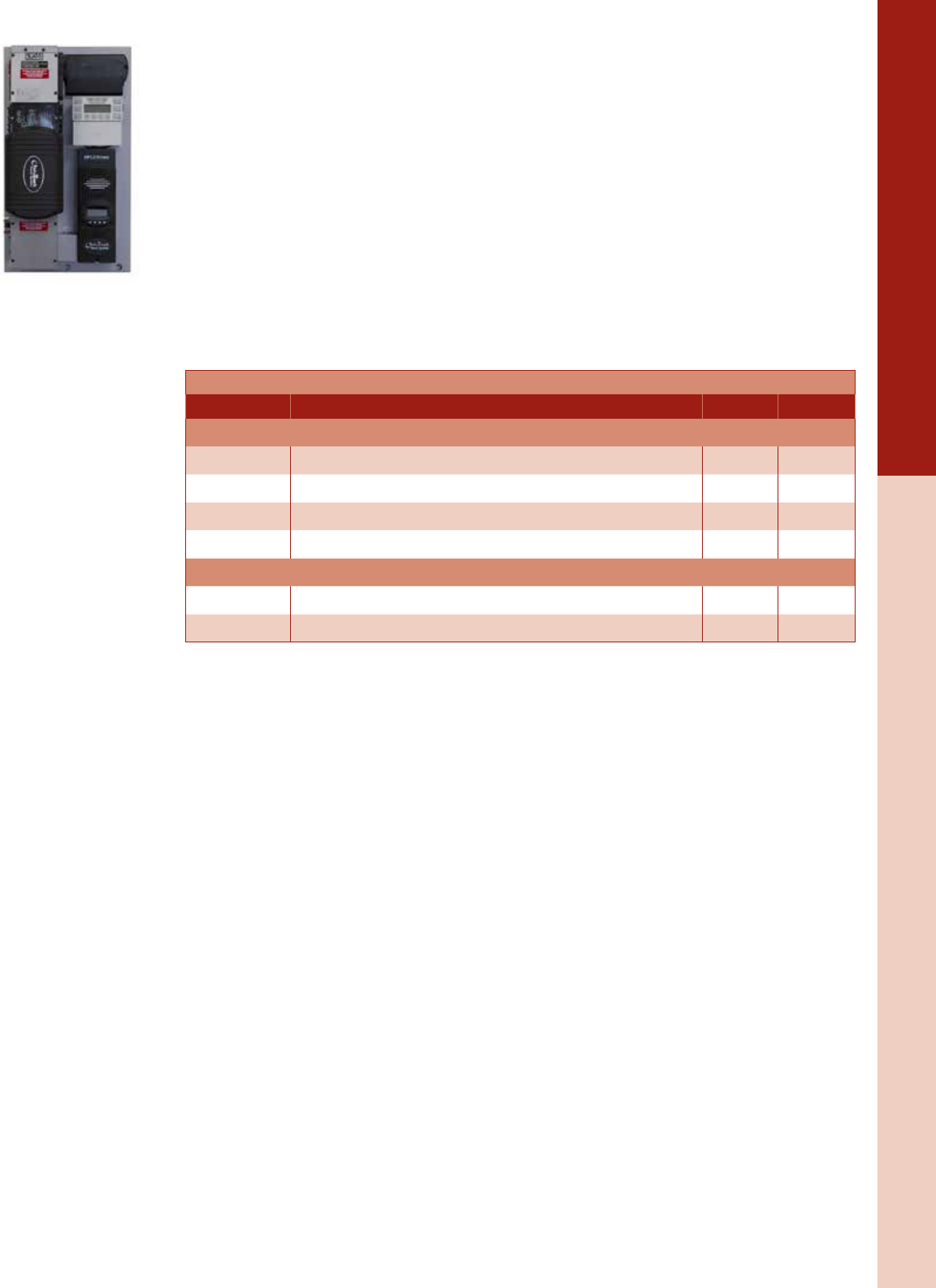
For the latest on AEE Solar products, trainings and dealer services, visit www.aeesolar.com
BATTERY-BASED INVERTERS
90
OutBack Inverters & Accessories
FLEXpower ONE Pre-Wired Power System
The FLEXpower One (FP1) pre-wired power panel integrates one inverter/charger, one charge control,
and all the essential protective devices in a small space at a low installed cost. They are ideal for applica-
tions with modest power requirements, such as cabins, chalets, homes, remote communication sites, and
backup-power systems. Utilizing a compact design all on one back panel, they are fully pre-wired and
factory tested as well as NRTL marked for streamlined inspections.
The FP1 with VFXR and FXR inverters can be used for either grid-tied or off-grid systems and have the
capacity to use and charge a variety of battery types, and have the advanced OutBack features including
Grid Zero™ and Offset modes.
Each FP1 power panel includes a single inverter/charger, AC and DC wiring boxes, and a single FM 80
charge controller, MATE3, HUB, FLEXnet DC, and AC-DC surge protector. The system is also equipped
with an inverter breaker, PV array breaker, PV GFDI breaker, and AC input-output-bypass assembly.
There are mounting locations for both AC GFCI Type B and EU Type F style outlets and additional
AC breakers. FP1 components are listed to applicable UL standards for a code-compliant installation.
Dimensions are 33.44"H x 19.69"W x 12.88"D. Weight is 98 lbs.
FXR FLEXpower ONE Pre-Wired
Model Description Inverter Item code
FLEXpower ONE Pre-Wired
FP1 VFXR3524A Pre-wired inverter system, 3.5 kW 120 VAC, 24 VDC, 80 A PV control VFXR3524 033-04090
FP1 VFXR3648A Pre-wired inverter system, 3.6 kW 120 VAC, 48 VDC, 80 A PV control VFXR3648A 033-04091
FP1 FXR2524A Pre-wired inverter system, 2.5 kW 120 VAC, 24 VDC, 80 A PV control FXR2524A 033-04088
FP1 FXR3048A Pre-wired inverter system, 3.0 kW 120 VAC, 48 VDC, 80 A PV control FXR3048A 033-04089
EXPORT FLEXpower ONE Pre-Wired
FP1 VFXR3024E Pre-wired inverter system, 3.0 kW 230 VAC 50 Hz, 24 VDC, 80 A PV control VFXR3024E 033-04082
FP1 VFXR3048E Pre-wired inverter system, 3.0 kW 230 VAC 50 Hz, 48 VDC, 80 A PV control VFXR3048E 033-04083
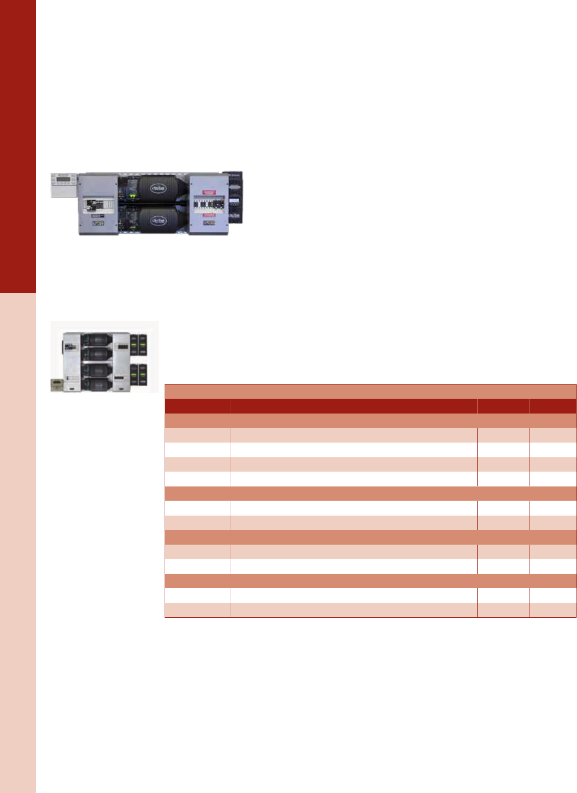
For the latest on AEE Solar products, trainings and dealer services, visit www.aeesolar.com
BATTERY-BASED INVERTERS
91
OutBack Inverters & Accessories
FLEXpower Multi-inverter Pre-Wired Power Systems
The OutBack FLEXpower pre-wired power panels integrate inverter/chargers, FM80 charge controls,
and all of the essential protective devices in an easy-to-install, fully pre-wired and factory-tested system.
The FLEXpower is applicable for either grid-tied or off-grid applications with modest power require-
ments, such as homes, light commercial or larger backup-power systems. Utilizing a compact all-on-one
mounting plate design, they are fully pre-wired and factory tested. A FLEXpower can be mounted in
either a horizontal or vertical orientation to allow installation in space-limited locations. There are also
mounting locations for an AC GFCI Type B outlet and additional DC and AC breakers.
FP systems with VFXR or FXR inverters can be used for either grid-tied or off-grid applications and
have the capacity to work with a variety of batteries, as well as advanced OutBack features including
Grid Zero and Offset modes.
Each FP2 is designed for 120/240 VAC single-phase output. Each power panel
includes two inverter/chargers, two FM80 charge controllers, FlexNetDC, AC
and DC wiring boxes, a MATE3, HUB10, and an AC/DC Surge Protector, X-240
transformer (not on FXR systems), inverter and controller breakers with GFDI,
and an AC Input-Output-Bypass Assembly. Dimensions are 59"W x 21"H x 13"D.
Weight is 260 lbs.
Each FP3 is designed for 120/208 VAC three-phase output. Each power panel includes three inverter/
chargers, three FM80 charge controllers, FlexNetDC, AC and DC wiring boxes, a MATE3, HUB10, and
an AC/DC Surge Protector, inverter and controller breakers with GFDI, and an AC Input-Output-Bypass
Assembly. Dimensions are 59"W x 46"H x 13"D. Weight is 430 lbs.
Each FP4 is designed for 120/240 VAC single-phase output. Each power panel includes four inverter/
chargers, four FM80 charge controllers, FlexNetDC, AC and DC wiring boxes, a MATE3, HUB10, and
an AC/DC Surge Protector, X-240 transformer (not on FXR systems), inverter and controller breakers
with GFDI, and an AC Input-Output-Bypass Assembly. Dimensions are 59"W x 46"H x 13"D. Weight
is 520 lbs.
FLEXpower components are listed to applicable UL standards for code-compliant installation.
FXR FLEXpower Pre-Wired
Model Description Inverter Item code
FLEXpower TWO Pre-Wired
FP2 VFXR3524A Pre-wired dual-inverter system, 7.0 kW 120/240 VAC, 24 VDC VFXR3524A 033-04094
FP2 VFXR3648A Pre-wired dual-inverter system, 7.2 kW 120/240 VAC, 48 VDC VFXR3648A 033-04095
FP2 FXR2524A Pre-wired dual-inverter system, 5.0 kW 120/240 VAC, 24 VDC FXR2524A 033-04092
FP2 FXR3048A Pre-wired dual-inverter system, 6.0 kW 120/240 VAC, 48 VDC FXR3048A 033-04093
EXPORT FLEXpower TWO - System Description
FP2 VFXR3024E EXPORT pre-wired dual-inverter system, 6 kW 230 VAC 50 Hz, 24 VDC VFXR3024E 033-04284
FP2 VFXR3048E EXPORT pre-wired dual-inverter system, 6 kW 230 VAC 50 Hz, 48 VDC VFXR3048E 033-04285
FLEXpower THREE - System Description
FP3 VFXR3648A Pre-wired triple-inverter system, 10.8 kW 120/208 3Ø VAC, 48 VDC VFXR3648A 033-04097
FP3 FXR3048A Pre-wired triple-inverter system, 9.0 kW 120/208 3Ø VAC, 48 VDC FXR3048A 033-04096
FLEXpower FOUR - System Description
FP4 VFXR3648A Pre-wired quad-inverter system, 14.4 kW 120/240 VAC, 48 VDC VFXR3648A 033-04099
FP4 FXR3048A Pre-wired quad-inverter system, 12.0 kW 120/240 VAC, 48 VDC FXR3048A 033-04098
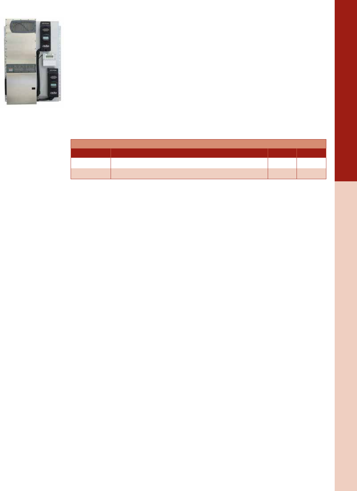
For the latest on AEE Solar products, trainings and dealer services, visit www.aeesolar.com
BATTERY-BASED INVERTERS
92
OutBack Inverters & Accessories
NEW! OutBack FLEXpower Radian Pre-Wired Power Systems
The OutBack FLEXpower FPR pre-wired power panels integrate Radian inverter/chargers, FM80 charge
controls, and all of the essential protective devices in an easy-to-install, fully pre-wired and factory-tested
system. FLEXpower FPR systems are available with either 4.0 kW or 8.0 kW inverter sizes. The Radian
inverters can be used for either grid-tied or off-grid systems and have the capacity to use and charge
any technology batteries, as well as advanced OutBack features including Grid Zero and Offset modes.
Dual AC inputs allow connection to both the utility and a backup generator set. Compatible with system
monitoring and control via OpticsRE. Utilizing a compact all-on-one mounting plate design, they are
fully pre-wired and factory-tested.
Each FPR is designed for 120/240 VAC single-phase output. Each power panel includes one inverter/
chargers, one or two FM80 charge controllers, FlexNetDC, AC and DC wiring box, a MATE3, HUB10,
inverter and controller breakers with GFDI, and an AC Input-Output-Bypass Assembly. FLEXpower
components are listed to applicable UL standards and the assemblies are marked for streamlined inspec-
tions. Dimensions are 47"H x 33.5"W x 9.84"D. Weight is 195 lbs for the FPR-4048A and 250 lbs for
the FPR-8048A
FLEXpower Radian Pre-Wired
Model Description Inverter Item code
FPR-4048A Pre-wired inverter system, 4.0 kW 120/240 VAC, 48 VDC, single FM80 GS-4048A 033-04080
FPR-8048A Pre-wired inverter system, 8.0 kW 120/240 VAC, 48 VDC, dual FM80 GS-8048A 033-04081
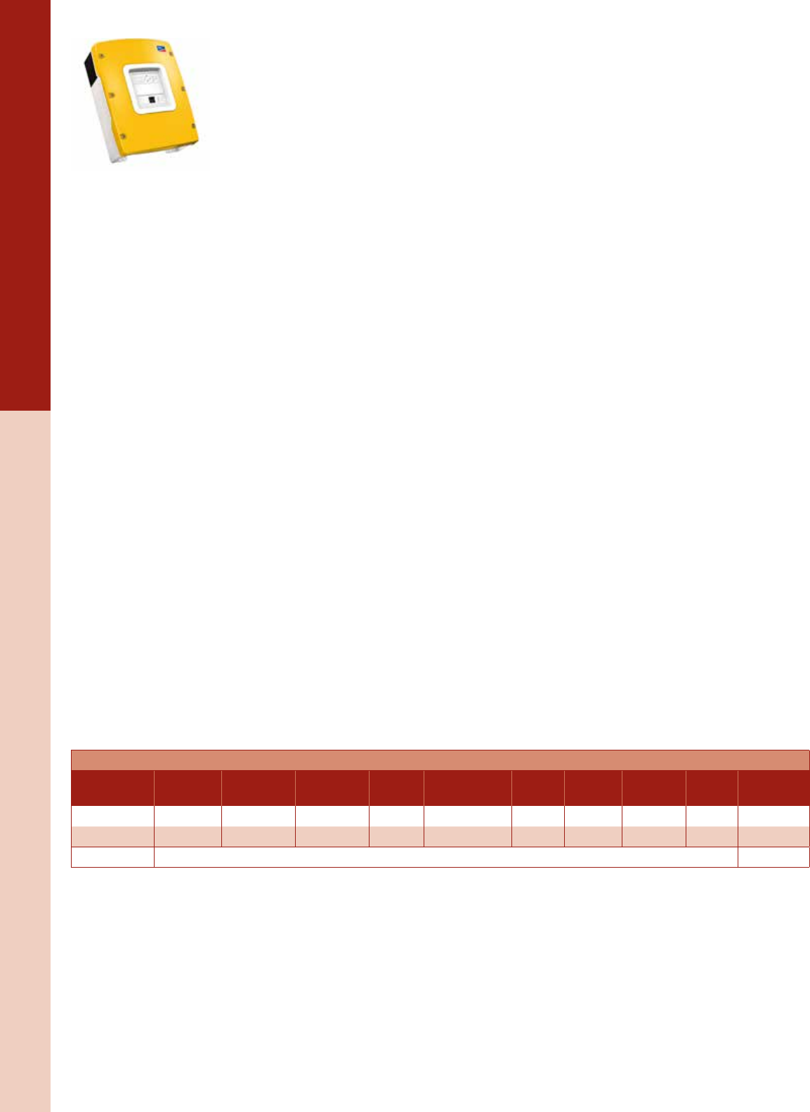
For the latest on AEE Solar products, trainings and dealer services, visit www.aeesolar.com
BATTERY-BASED INVERTERS
93
Grid-Interactive Inverters
SMA
Sunny Island Battery-Based Inverter
The Sunny Island inverters are bi-directional battery-based inverter/chargers that can be used completely
off-grid, or for battery backup in grid-tie systems either with charge controllers or with Sunny Boy grid-
tie inverters. The Sunny Island includes sine-wave output power and low idle losses as well as a 100 A
battery charger, and offers an integrated data monitoring system with battery disconnect.
Grid-Tie System Backup with AC Coupling
The Sunny Island can provide backup power for protected loads during utility grid blackouts. Combined
with a Sunny Boy grid-tie inverter system and a bank of batteries, the Sunny Island will enable the PV
array to power loads and charge the batteries. As an “AC-Coupled” system, the AC output of a Sunny
Boy grid-tie inverter is connected to a protected-loads subpanel rather than the main panel. The subpanel
is also connected to the AC output of one or more Sunny Island inverters. Under normal conditions, the
power from the PV array and the Sunny Boy inverters passes through the subpanel and the Sunny Island’s
built-in transfer switch on its way to the grid, without loss of efciency. Likewise, grid power can pass the
other direction when needed. During a power outage, the Sunny Island isolates itself from the grid and
provides AC power to the protected-loads subpanel, drawing energy from the battery bank. The grid-tie
Sunny Boy inverter will shut down during a blackout but will turn back on (after a ve-minute period)
when AC power from the Sunny Island is present. The Sunny Boy inverter(s) will supply AC power to
the backup load panel and, if enough power is available, will be used by the Sunny Island to charge the
batteries. If the batteries are full, and the PV system is producing more power than the loads require,
the Sunny Island will communicate with the Sunny Boy inverter to curtail its power output. If there are
no loads and the batteries are full, the Sunny Boy inverter will automatically shut off to prevent battery
over-charging. The battery bank is recommended to have 100 Ahr of capacity per kilowatt of PV array
for best performance.
Off-Grid Power
In off-grid systems, the Sunny Island works with Sunny Boy inverters exactly as it does with grid-tie
systems during a grid outage. A generator can be connected to the Sunny Island’s AC input to provide
backup and battery charging. The battery bank can also be charged using a PV array with a standard PWM
or MPPT charge controller, or by other power sources like micro-hydro and wind turbines.
Data Monitoring
The Sunny Island utilizes removable SD cards to store performance data from the integrated data logger
and to perform rmware upgrades. State-of-charge metering helps with battery management to ensure
maximum battery life. The Sunny Island works with the SMA Sunny WebBox and SensorBox monitoring
accessories, but not Bluetooth. One RS485 card is needed for communications. Only one card is needed
for the master inverter in a multiple Sunny Island system. For an AC-coupled system an RS485 card
(SI-485PB-NR) is needed in each Sunny Boy inverter.
The Sunny Island inverters are 24"H x 18"W x 9"D, listed to UL 1741 for the U.S.A. and Canada and
carry a ve-year warranty.
SMA Sunny Island
Model CEC rating CEC grid-tie
output
Continuous
output
Battery
voltage
AC out
volts/hertz
No load
draw
Charger
output
AC surge
output Weight Item code
SI4548-US 94.5% 4,000 W 4,500 W 48 VDC 120 VAC/60 Hz 25 W 100 A 11,000 W 139 lbs 030-03068
SI6048-US 94.0% 5,000 W 5,750 W 48 VDC 120 VAC/60 Hz 25 W 100 A 11,000 W 139 lbs 030-03069
SI-485PB-NR RS 485 card, terminator, and RJ45 cable for Sunny Island 310-00113
For the latest on AEE Solar products, trainings and dealer services, visit www.aeesolar.com
BATTERY-BASED INVERTERS
94
Grid-Interactive Inverters
SMA SI-TD-BOX-10 Smartformer for the Sunny Island
The SI-TD-BOX-10 Smartformer for the Sunny Island makes an easily-installed solution to AC couple
a single Sunny Island inverter with a single Sunny Boy inverter for either an off-grid system or a grid-
tied battery-backup system. The Smartformer provides the transformer needed to couple the 120 VAC
Sunny Island to the 240 VAC Sunny Boy inverters, and provide 120/240 VAC power to the protected-load
panel. The grid-tie feed is 120 VAC only. The Smartformer also provides a pre-wired bypass function
and load-shedding contactor and disconnects for all of the AC wiring.
The Smartformer has a NEMA 1 enclosure that measures 24"H x 24"W x 9.25"D, weighs 124 lbs, is
listed to UL 1741 for the U.S.A. and Canada and is covered by a ve-year warranty.
SMA Multicluster Box for the Sunny Island
The Multicluster Box MC-12U for Sunny Island inverters enables easy installation of three-phase hybrid
systems. Connect up to four parallel three-phase clusters, each consisting of three Sunny Island battery
inverters, for up to 72 kW of inverter capacity. The Multicluster Box is pre-wired with 300 A main dis-
connect breakers for the grid or generator connections, loads, Sunny Boy inverters, plus 70 A AC input
breakers for up to 12 Sunny Island battery inverters. The Multicluster Box also includes a load -hedding
contactor and communication cables. Each Multicluster Box requires a Piggyback card and each Sunny
Boy and Sunny Island inverter requires an RS485 card.
NEMA 12 enclosure standard: NEMA 4 or 4X available. Either enclosure measures 65"H x 48"W x
14"D and weighs 485 lbs. Multicluster boxes are listed to UL 508A and covered by a ve-year warranty.
SMA Sunny Island
Model Description Item code
SI-TD-BOX-10 SMA Smartformer 300-00060
MC-12U SMA Multicluster Box, three-phase only, up to 72 kW 030-03152
MC-PB SMA Multicluster Piggyback Board, one per cluster 030-03153
DM-485CB-US-10 SMA RS-485 card, one per SB TL-22 inverter 300-00068
SI-485PB-NR RS 485 card, terminator, and RJ45 cable for Sunny Island 310-00113
See Electrical Distribution Parts section for additional Sunny Island integration equipment.
For the latest on AEE Solar products, trainings and dealer services, visit www.aeesolar.com
BATTERY-BASED INVERTERS
95
Grid-Interactive Inverters
Schneider Electric
Conext XW+ Grid-Tie or Off-Grid Inverters and Systems
The Conext XW+ Series hybrid inverter/charger has an innovative, integrated design that minimizes
external balance-of-system components allowing for quick and easy installation as either a grid-tie battery
backup system or a fully off-grid power system. The XW+ offers split-phase 120/240 VAC output from
a single inverter. Up to four inverters can be paralleled for up to 27 kW of total output in a 120/240 VAC
split-phase system. The XW+ inverters can be converted to 120 VAC only and three inverters can be
congured into a 120/208 VAC three-phase system. Charge controllers, such as the Schneider Electric XW-
MPPT60-150 or the XW-MPPT80-600, are required for use with any PV array (see Charge Controllers).
Dual AC inputs enable AC generator input as well as grid interaction. An optional automatic generator
start (AGS) unit is also available. A congurable auxiliary relay with an output of 250 mA at 12 VDC
is included in each inverter. A battery-temperature sensor is included with each inverter, but only one is
needed per system. The inverter is eld-serviceable on the wall.
The XW+ Mini Power Distribution Panel mounts under an XW+ inverter and has all AC/DC discon-
nects and AC bypass with wiring to support a single inverter. This distribution panel has enough space
to install two DC breakers for charge controllers.
The XW+ Power Distribution Panel includes a conduit box and all AC/DC disconnects with wiring
to support a single inverter. The distribution panel has enough space and knockouts to add up to three
inverters and/or four charge controllers. A eld-reversible door with a magnetic catch simplies access
to wiring. Each charge controller requires the input breaker, or DC disconnect, and output breaker listed
in the table below.
The XW+ Connection Kit and XW+ split phase 120/240 VAC breaker kit contain everything needed
to add a second inverter. For a third inverter, use one more Connection Kit and one of the AC breaker
kits depending on split or three-phase conguration, plus a pair of 5-ft 4/0 AWG inverter cables (see
Wire and Cable). An external transfer switch will be required to enable the inverter bypass function. For
four inverters, use two Power Distribution Panels and two Connection Kits. Use the XW+ conduit box
to retrot XW+ inverters into existing systems that already have AC/DC disconnects .
The XW+ comes with a ve-year warranty and is listed to UL 1741 for the U.S.A. and Canada. Dimen-
sions of the inverter are 23"H x 16"W x 9"D.
A Conext System Control Panel, is needed to complete a Schneider system. This and other accessories
are on the next page.
Schneider Electric Inverter/Charger System
Model CEC
rating
CEC grid-
tie output
Continuous
output
Battery
voltage
AC out
volts/hertz
No load
draw
Charger
output
AC surge
output
Inverter
weight Item code
XW+5548NA 93.5% 4,491 W 5,500 W 48 VDC 120/240 VAC
60 Hz 26 W 110 A 9,500 W 118 lbs 030-01227
XW+6848NA 92.5% 6,000 W 6,800 W 48 VDC 120/240 VAC
60 Hz 28 W 140 A 12,000 W 122 lbs 030-01228
EXPORT Schneider Electric Inverter/Charger System
XW+7048E N/A N/A 5,500 W 48 VDC 230 V 50 Hz 26 W 110 A 9,500 W 118 lbs 030-01229
XW+8548E N/A N/A 6,800 W 48 VDC 230 V 50 Hz 28 W 140 A 12,000 W 122 lbs 030-01230
XW Accessories
RNW865101301 XW+ Mini Power Distribution Panel for only one XW+ inverter 030-01185
RNW865101501 XW+ Power Distribution Panel with conduit box for one XW+ inverter (add a connection kit for each additional inverter) 030-01168
RNW865102002 XW+ Connection Kit is needed for each additional inverter, includes DC breaker and conduit box, add AC breaker kit 030-01170
RNW865102501 XW+ empty conduit box raceway 030-01174
RNW865101401 XW+ Power Distribution Panel with conduit box for one XW inverter, without any AC breakers 030-01171
RNW865131501 XW+ three-phase 120/208 VAC breaker kit 030-01173
RNW865121501 XW+ split-phase 120/240 VAC breaker kit 030-01180
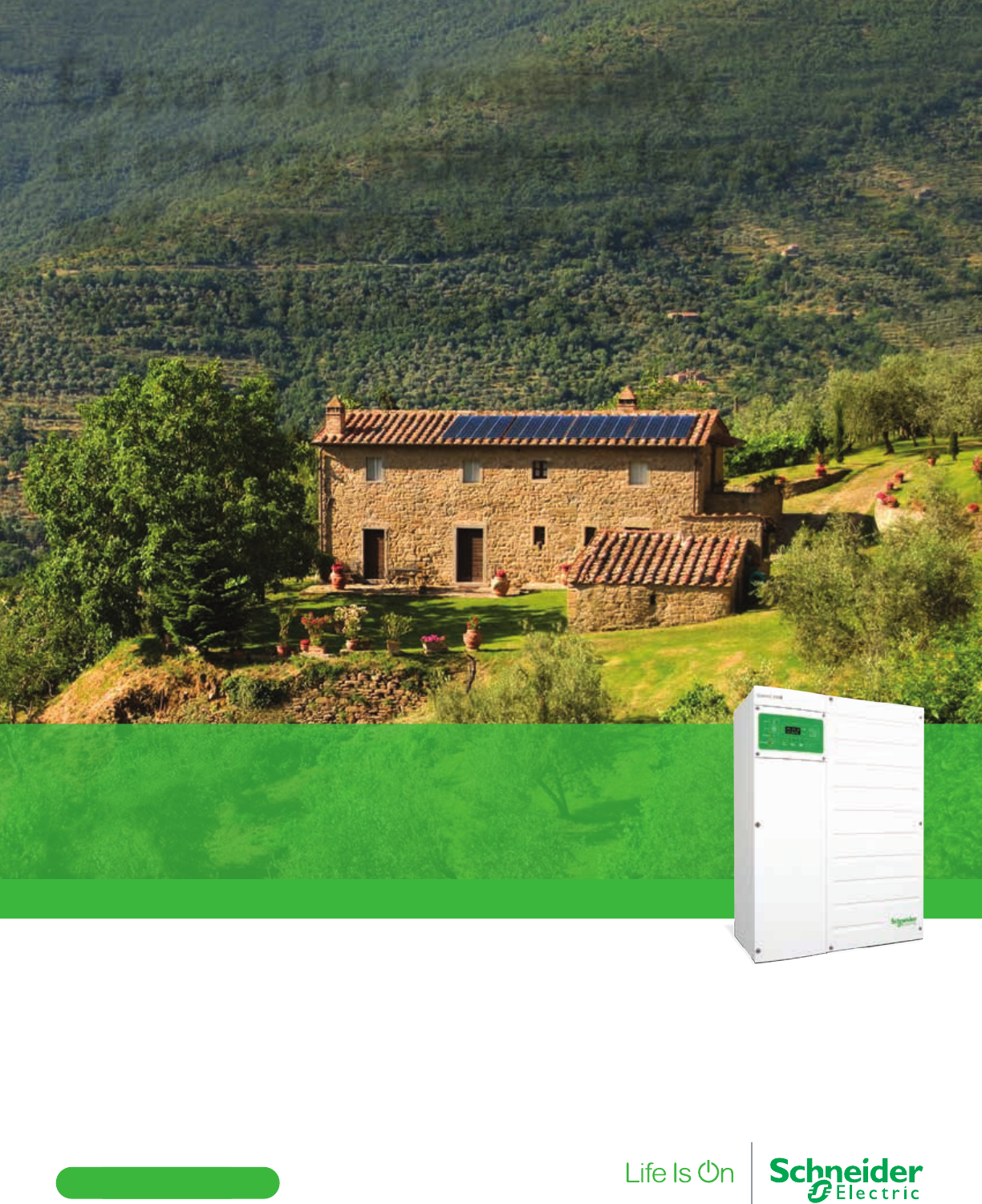
solar.schneider-electric.com
©2015 Schneider Electric. All Rights Reserved.
All trademarks are owned by Schneider Electric Industries SAS or its affiliated companies.
Introducing the next generation hybrid inverter, the Conext™ XW+,
with new adaptable and scalable features:
• Energy management solutions: PriorityPower, ParallelPower, GridSell, ChargePower
• Modular multi-cluster architecture up to 102 kW
• Flexible combination of AC and DC coupled PV power
• Equipped with smart inverter features for grid stability
• Remote system monitoring and configuration
Conext™ XW+, the scalable hybrid solution for o-grid
solar, self-consumption, and long-term backup for
homes, small businesses, and remote communities.
Expand the possibility
of energy independence,
self-consumption, and
secure backup power.
Storage available from 5.5 - 102 kW
For the latest on AEE Solar products, trainings and dealer services, visit www.aeesolar.com
BATTERY-BASED INVERTERS
97
Off-Grid Inverters
Conext SW Off-Grid Inverters and Systems
The Conext SW is an economical sine wave, off-grid or backup-power inverter-charger. The SW series
offers generator support for loads larger than the generator can power on its own. The US version has
split-phase 120/240 VAC output from each inverter, while the EXPORT version has 230 VAC 50 Hz
output. Use the stacking kits for two inverters to double the power output per system. Battery input for
all Conext SW inverters is 24 VDC. The XW System Control Panel (SCP), Automatic Generator Start
(AGS), and Conext CM Communication devices work with these inverters. Compatible with XW and
other charge controls. Comes with a battery temperature sensor. 16.5"H x 13.4"W x 7.6"D. Listed to UL
1741, CE for EXPORT versions and covered by a two-year standard warranty.
Conext SW Inverters and Accessories
Model Continuous
output
Battery
voltage
AC out
volts/hertz
No load
draw
Charger
output
AC surge
output Weight Item code
SW 2524 2,400 W 24 VDC 120/240 VAC 60 Hz 38 W 65 A 4,000 W 49 lbs 030-02059
SW 4024 3,400 W 24 VDC 120/240 VAC 60 Hz 27 W 90 A 7,000 W 62 lbs 030-02060
SW 4048 3,400 W 48 VDC 120/240 VAC 60 Hz 27 W 45 A 7,000 W 62 lbs 030-02058
Conext SW Inverters - EXPORT
SW 2524 E 2,500 W 24 VDC 230 VAC 50 Hz 38 W 65 A 5,000 W 49 lbs 030-02061
SW 4024 E 3,400 W 24 VDC 230 VAC 50 Hz 27 W 90 A 7,000 W 62 lbs 030-02062
SW 4048 E 3,400 W 48 VDC 230 VAC 50 Hz 27 W 45 A 7,000 W 62 lbs 030-02057
Conext SW Accessories
RNW8651016 Conext SW DC Breaker Panel, 250 A main breaker, Positive and Negative busbars 053-00050
RNW8651017 Conext SW AC Breaker Panel, 120/240 VAC output/bypass and input breakers, pre-wired 053-00051
RNW865101761 Conext SW Export AC Breaker Panel, 230 VAC output/bypass and input breakers, pre-wired 053-00052
RNW8651019 Conext SW AC Breaker kit stacked 120/240 VAC 053-00053
RNW865101961 Conext SW Export AC Breaker kit stacked 230 VAC 053-00054
RNW8651052 Conext SW Remote On/Off switch 053-00055
Conext XW and SW Accessories
The Conext SCP System Control Panel plugs into the Xanbus network and provides a central user
interface to congure and monitor all components in the system. One is used per XW+ or SW system.
The Conext Battery Monitor can be used in the Xanbus network to keep track of the battery state of
charge. The Conext AGS auto generator start can be used in the Xanbus network to supply the logic to
remotely start a backup generator.
The Conext ComBox can be used to view, datalog, and control XW and SW inverters over the Internet.
With a web browser or Android device, the user or installer can view current and historical system per-
formance, see system alerts, and remotely change settings. A Micro-SD card provides additional data
storage. 6.7"W x 4.5"H x 2.1"D. Five-year warranty.
The Conext Modbus Converter links the Conext devices to a third-party monitoring system.
For more information on the Schneider charge controls listed here, see the Charge Controllers section.
Conext SW Inverters and Accessories
Model Description Item code
RNW865105001 Conext SCP System Control Panel central user interface for XW and SW systems 300-00128
RNW865108001 Conext Battery Monitor for XW and SW systems 030-01182
RNW865106001 Conext AGS automatic generator start module for XW and SW systems 030-01183
RNW8651058 Conext ComBox for XW and SW inverters 300-00073
RNW8651059 Conext Modbus Converter 300-00074
808-0232-02 Replacement BTS Battery Temperature Sensor for XW and SW 300-00129
XW-MPPT60-150 XW 60 A MPPT charge controller with built-in ground fault protection - 150 VDC max input voltage 020-08040
BREAKER 60A Input circuit breaker for MPPT60-150 charge controller; 60 A 160 VDC 053-01038
BREAKER 80A Output circuit breaker for MPPT60-150 charge controller; 80 A 125 VDC 053-01039
XW-MPPT80-600 XW 80 A MPPT charge controller with built-in ground fault protection - 600 VDC max input voltage 020-08048
SQD HU361RB Input disconnect for MPPT80-600 charge controller; 30 A 600 VDC 3 pole 053-02312
BREAKER 100A Output circuit breaker for MPPT80-600 charge controller; 100 A 125 VDC 053-01034
For the latest on AEE Solar products, trainings and dealer services, visit www.aeesolar.com
BATTERY-BASED INVERTERS
98
Off-Grid Inverters
Magnum Energy
True Sine-Wave Off-Grid Inverter/Chargers
MMS-Series Sine-Wave Inverter/Charger
The MMS Series sine-wave inverters provide a cost-effective solution for smaller power needs in mobile
applications. The MMS is smaller, lighter, and less expensive, while retaining all the built-in protection
and reliability of the larger ME and MS models. The MMS charger has an 85% efcient PFC (power factor
corrected) charger. The MMS1012G model comes with a exible cord on the AC input and a GFCI outlet
for easy connection to AC appliances. Optional MMS-RC-25 remote control available. The MMS Series
is listed to UL 458 for the U.S.A. and Canada. MMS units have a two-year warranty. Made in U.S.A.
MS-Series Sine-Wave Inverter/Chargers
The MS Series inverter/charger is a sine-wave inverter designed for the most demanding mobile and
off-grid applications. The powerful easy-to-use MS Series inverters are available in 12, 24, and 48 VDC
versions. The MS4024 can be series stacked, using the ME-SSI, for 120/240 VAC operations, and 8 kW
total output. The MS2012-20B has two 20 A AC breakers built-in. The M4024-PAE and MS4448-PAE
have 120/240 VAC split-phase output and can power 240 VAC loads without stacking. As many as four
MS-PAE inverters can be paralleled for larger systems up to 17.6 kW with 120/240 VAC split-phase output
(ME-RTR router required). The ME-RC50, ME-ARC50, or ME-RTR controller is required for inverter
programming. The MS Series is listed to UL 458 for mobile use and UL 1741 for off-grid installations.
The MS-PAE series is listed to UL1741. Dimensions: 13.75"H x 12.65"W x 8"D. MS units have a three-
year warranty, which is extended to ve-years when installed with the Magnum panels. Made in U.S.A.
MSH-Series Sine Wave Inverter/Chargers
The Magnum MSH series inverters are similar to the MS Series, but add the generator-support feature.
When the generator is supplying power through the inverter, and the load is too large for the generator
alone, the inverter will add battery power to help power the loads. The RE version is listed to UL 1741
and the M versions are listed to UL 458 for mobile applications. The MSH inverters use the same op-
tions and accessories as the MS inverters.
Magnum True Power Systems Sine Wave Inverter/Chargers
Model Continuous
output
Battery
voltage
AC out
volts/hertz
No load
draw
Charger
output
AC surge
output
(5 sec)
Weight Item code
MMS1012 1,000 W 12 VDC
120 VAC / 60 Hz
19 W 50 A 1,750 W 23 lbs 030-02320
MMS1012G 030-02321
MS2012 2,000 W 12 VDC 25 W 100 A 3,300 W 42 lbs 030-02332
MS2012-20B 030-02334
MS2812 2,800 W 12 VDC 30 W 125 A 3,900 W 55 lbs 030-02336
MS2024 2,000 W 24 VDC 25 W 105 A 5,800 W 55 lbs 030-02338
MS4024 4,000 W 24 VDC 25 W 105 A 5,800 W 55 lbs 030-02338
MS4048 4,000 W 48 VDC 25 W 60 A 8,500 W 55 lbs 030-02363
MS4024-PAE 4,000 W 24 VDC 120/240 VAC / 60 Hz 27 W 105 A 5,800 W 55 lbs 030-02342
MS4448-PAE 48 VDC 25 W 60 A 8,500 W 55 lbs 030-02341
Magnum Sine Wave MSH Inverter/Chargers
MSH4024RE 4,000 W 24 VDC
120 VAC / 60 Hz
25 W 110 A 5,800 W 58 lbs 030-02347
MSH3012M 3,000 W 12 VDC 30 W 125 A 3,900 W 55 lbs 030-02348
MSH4024M 4,000 W 24 VDC 25 W 110 A 5,800 W 55 lbs 030-02349
Magnum Sine Wave Inverter/Chargers - EXPORT
MMS912E 900 W 12 VDC
230 VAC / 50 Hz
19 W 40 A 1,600 W 23 lbs 030-02346
MS1512E 1,500 W 12 VDC 20 W 75 A 3,100 W 53 lbs 030-02345
MS2712E 2,700 W 12 VDC 34 W 125 A 4,100 W 53 lbs 030-02344
MS4124PE 4,100 W 24 VDC 30 W 105 A 6,300 W 53 lbs 030-02343
MS4348PE 4,300 W 48 VDC 28 W 55 A 7,500 W 53 lbs 030-02331
For the latest on AEE Solar products, trainings and dealer services, visit www.aeesolar.com
BATTERY-BASED INVERTERS
99
Off-Grid Inverters
Magnum Energy Modied-Square-Wave Inverter/Chargers
MM-Series Inverters for mobile use
The MM Series inverter and inverter/charger are designed for small appliances in mobile systems, boats
and RV’s. The MM is smaller, lighter, and less expensive than the ME while retaining all the built-in
protection and reliability of ME models. The MM1212 model uses an efcient PFC (power-factor- cor-
rected) charger. The MM612 model comes with an AC transfer switch but does not have a battery charger.
The easy-to-use MM Series are cost-effective and come with a two-year warranty. Listed to UL 458.
Dimensions: 16.6"H x 8.4"W x 4.7"D.
ME-AE Series Inverters for residential use
The MM-AE Series inverter/charger is designed for entertainment systems and small appliances in
smaller remote homes. The MM is smaller, lighter, and less expensive than the ME while retaining
all the built-in protection and reliability of ME models. The MM models use an efcient PFC (power-
factor-corrected) charger and the same charger topology as all Magnum models. The 600 and 1,500 W
models have a 12 VDC input; a 1,500 W model with a 24 VDC input is also available. The powerful,
easy-to-use MM-AE Series are cost-effective and come with a two-year warranty. Not listed. Dimen-
sions: 16.6"H x 8.4"W x 4.7"D.
ME-Series Inverters for mobile use
Designed for RV use, the ME Series 12 VDC inverter/charger charges batteries efciently even at low
AC voltage from low-cost generators. The modied-square-wave inverter keeps the cost down and a
battery-temperature sensor optimizes charging. ME inverters have three power levels and built-in ground
switching required for mobile inverters that may connect to utility power. ME inverters are listed to
UL 458 in the U.S.A. and Canada for RV, marine and mobile use and come with a two-year warranty.
Dimensions: 13.8"H x 12.7"W x 8"D.
RD-Series Inverters
The RD Series 12 VDC inverter/charger is designed specically for off-grid use with the same chassis
as the MS sine-wave inverters. Includes power-factor-corrected charger, modied-square-wave inverter
and battery-temperature sensor. The RD inverters are listed to UL 1741 and include a two-year warranty.
Dimensions: 13.8"H x 12.7"W x 8"D.
Magnum Modied-Sine Wave Inverter/Chargers
Model Continuous
output
Battery
voltage
AC out
volts/hertz
No load
draw
Charger
output
Peak AC
surge Weight Item code
MM612 600 W 12 VDC
120 VAC / 60 Hz
10 W N/A 1,100 W 14 lbs 030-02308
MM1212 1,200 W 12 VDC 16 W 70 A 2,100 W 20 lbs 030-02309
MM612-AE 600 W 12 VDC 10 W 30 A 1,100 W 16 lbs 030-02302
MM1512-AE 1,500 W 12 VDC 18 W 70 A 2,100 W 22 lbs 030-02306
MM1524-AE 1,500 W 24 VDC 9 W 35 A 2,650 W 22 lbs 030-02303
ME2012 2,000 W 12 VDC 20 W 100 A 3,700 W 37 lbs 030-02305
ME2512 2,500 W 12 VDC 23 W 120 A 5,000 W 41 lbs 030-02311
ME3112 3,100 W 12 VDC 25 W 160 A 6,000 W 46 lbs 030-02315
RD2212 2,200 W 12 VDC 20 W 110 A 3,700 W 37 lbs 030-02326
RD1824 1,800 W 24 VDC 12 W 50 A 4,000 W 35 lbs 030-02322
RD2824 2,800 W 24 VDC 19 W 80 A 6,000 W 42 lbs 030-02324
RD3924 3,900 W 24 VDC 25 W 105 A 9,000 W 53 lbs 030-02328
For the latest on AEE Solar products, trainings and dealer services, visit www.aeesolar.com
BATTERY-BASED INVERTERS
100
Off-Grid Inverters
Magnum Energy Accessories and Options
The optional ME-RC50 remote control is simple to use yet enables use of all the set-up features of the
ME, MS, MS-ME, and RD Series inverters. The ME-RC50 controls the ME-AGS automatic generator
start using a network connection to the inverter. This remote has convenient ngertip operation, includ-
ing one-knob programming. The ME-ARC50 advanced remote offers even more control of the setup
including custom battery-charge set-points. The ME-RTR has all of the functions of the ME-ARC50
and is required for paralleling PAE inverters. An ME-RC50 can be used with the ME-RTR as a remote
display. The MM-RC25 provides on/off control and a quick indication of inverter and charger operation
for the MM and MMS inverters.
The ME-BMK monitors battery percentage state-of-charge (SOC), along with amps, voltage, amp-hours
and min/max DC volts, and then provides this information in an easy-to-understand display via the ME-
ARC50, or ME-RTR remotes. Kit includes a sense module, shunt, and wiring.
The ME-MW-E Magweb with Ethernet connects the Magnum system to the Internet for remote moni-
toring via the data.magnumenergy.com site. This unit connects to your broadband router via Ethernet
cable. It monitors the inverter, battery monitor and generator-start module. The ME-MW-W is similar
to the Ethernet version except that it will communicate to your broadband router via a wireless bridge.
Maximum range for the wireless is up to 300' if unobstructed. There is both a transmitter and receiver
gateway that wires to your network. The receiver gateway requires 120 VAC power. Both units are sup-
plied with all the needed cables. They are compatible with the ME-RC50, ME-ARC50, and ME-RTR.
With the ME-RTR it can only monitor one inverter in the system.
The optional Auto Generator Start (ME-AGS) module automatically starts and stops most major-brand
generators. The generator can automatically start based on low battery voltage or on the inside tem-
perature, starting a generator to run an air conditioner when the temperature of an RV or cabin rises to
a user-dened level.
The ME-AGS-S is the stand-alone version of Magnum Energy's Automatic Generator Start controllers
and can be used in power systems that don't have a Magnum inverter.
The ME-AGS-N is the network version of Magnum Energy's Automatic Generator Start controllers
and is set up and operated via a Magnum Energy Inverter and ME-RC50 or ME-ARC50 remote panel.
When using the ME-RC50 Remote, the ME-AGS-N has basic adjustments starting on battery voltage or
temperature. When using the ME-ARC50 Remote, the ME-AGS-N has advanced start and stop settings
based on: time of day, battery State-of-Charge, battery voltage, high temperature, or inverter load amps.
The ME-AGS-N also includes the ability to manually turn the generator on and off, generator exercise,
warm-up and cool-down.
The optional ME-SSI allows a series connection of two MS4024 inverters for 120/240 VAC split-phase
output at 8 kW total output power.
Magnum Accessories and Options
Model Descriptions Weight Item code
MM-RC25 Remote control for MM, MM-AE, and MMS inverters 2 lbs 030-02355
ME-RC50 Remote control for Magnum inverters with 50' cable for all inverters 2 lbs 030-02351
ME-ARC50 Advanced Remote for Magnum inverters with 50'cable for ME, MS, MS- PAE, RD 2 lbs 030-02352
ME-RTR Magnum Router for parallel stacking of MS-PAE inverter, Stacking cables included 2 lbs 030-02350
ME-BMK Battery monitor kit - ME-ARC50 or ME-RTR required with this item 4 lbs 020-06379
ME-BMK- NS Battery monitor kit without Shunt- ME-ARC50 or ME-RTR required with this item 2 lbs 020-06380
ME-MW-W Magweb Web-based monitoring kit - Wireless 3 lbs 029-08000
ME-MW-E Magweb Web-based monitoring kit - Ethernet 3 lbs 029-08001
ME-AGS-N Automatic generator start – network version for use with Magnum inverters and ME-RC50 4 lbs 020-06377
ME-AGS-S Automatic generator start – standalone version 4 lbs 020-06375
ME-SSI Series stacking cable kit for MS-4024 ONLY 10 lbs 030-02362
ME-CB Conduit Box for ME, MS, ME-AE, and RD inverters 4 lbs 030-02360
ME-RC-BZ Bezel for RC50 (standard on the ARC50) 1 lb 310-00115
PT-100 Magnum 100 A MPPT charge control 13.6 lbs 020-06371
ACLD-40 Magnum 4 kW AC Load Diversion Control 20 lbs 020-06372
For the latest on AEE Solar products, trainings and dealer services, visit www.aeesolar.com
BATTERY-BASED INVERTERS
101
Off-Grid Inverters
Magnum Energy MMP Mini Magnum Panel
The MMP - Mini Magnum Panel is an inclusive, easy-to-install panel designed to work with one Magnum
MS-AE, MS, RD or other inverter/charger. The MMP features a small footprint and comes prewired
for fast installation. Circuit breakers and the optional remote control mount on the front of the cabinet.
Dimensions are 12.5"W x 18"H x 8"D. They are listed to UL 1741 and CSA C22.2 107-01. Each MMP
includes one DC breaker – 175 A or 250 A, one AC bypass breaker – 30 A two-pole or 60 A single-pole,
one AC input breaker – 30 A two-pole or 60 A single-pole, a 500 A/50 mV shunt, DIN rail provided
for up to eight DC ½" DIN-mount breakers, or if the DIN rail is removed, four 1" wide surface-mount
breakers (see Electrical Distribution Parts). Panels are available for inverters with 120 VAC output and
120/240 VAC output.
MMP Mini Magnum Panel
Model DC main breaker AC output breaker Use with Item code
MMP250-30D 250 A 30 A @120/240 VAC MS4024-PAE 030-02380
MMP250-60S 250 A 60 A @ 120 VAC All ME, MS4024, MS2812,
MS2012, RD3924 030-02381
MMP175-30D 175 A 30 A @120/240 VAC MS4448-PAE 030-02382
MMP175-60S 175 A 60 A @ 120 VAC RD2824, RD1824 030-02383
BP-MMP Back Plate MMP (ts 1 - MMP) 030-02396
Export MMP Mini Magnum Panel
MMP250-30S-E 250 A 30 A @ 230 VAC MS1512E, MS2712E, MS4124E 030-02390
MMP175-30S-E 175 A 30 A @ 230 VAC MS4348E 030-02391
Magnum Panel Parts
BR-DC175 Replacement main inverter breaker, 175 A 053-01059
BR-DC250 Replacement main inverter breaker, 250 A 053-01060
For the latest on AEE Solar products, trainings and dealer services, visit www.aeesolar.com
BATTERY-BASED INVERTERS
102
Off-Grid Inverters
Magnum Energy MP Magnum Panels
The MP Magnum Panels are available in three sizes, each with either a 30 A two-pole 120/240 VAC
output breaker or a 60 A 120 VAC output breaker. They are designed for use with two series-stacked
MS4024 inverters, or up to four parallel-connected MS-PAE inverters.
The MPSL (Magnum panel, single enclosure, low capacity) accommodates one or two inverters with
the use of an MPX Extension Box. It includes a 175 or 250 A DC breaker, a 125 A AC bypass breaker, a
500 A/50 mV shunt and inverter AC input protection, and all AC/DC wiring for dual inverters (source/
load wiring not included). There is space for ve 1" back-mount breakers or ten ½" DIN-mount breakers
on the DC side.
The MPSH (Magnum panel, single enclosure, high capacity) accommodates a maximum of three invert-
ers. One inverter can be connected directly to the MPSH. Each additional inverter requires an MPX. The
MPSH includes one 175 or 250 A DC breaker, a 125 A AC bypass breaker, a 1,000 A/100 mV shunt and
inverter AC input protection, and AC/DC wiring for dual inverters (source/load wiring not included).
NOTE: There are no spaces for extra DC breakers in the MPSH, so it may be limited to backup systems.
Use the MPDH for three or four-inverter systems with solar or other DC input.
The MPDH (Magnum panel, dual enclosure, high capacity) accommodates as many as four inverters
with two enclosures – one for AC and one for DC connections. Two inverters can be connected to the
MPDH. The third and fourth inverters require one MPX for each. The MPDH includes two 175 or 250
A DC breakers, a 125 A AC bypass breaker, a 1,000 A/100 mV shunt and inverter AC input protection,
and all AC/ DC wiring for dual inverters (source/load wiring not included). There is room for seven 1"
back-mount breakers or fourteen ½" DIN-mount breakers on the DC side.
Mount and connect additional inverters to MP Series Systems Panels using MPX Series Extension Boxes.
They mate to the bottom of Magnum MS4024 or the MS-PAE inverters. The boxes include a 175 or 250
A DC breaker and wiring for an additional inverter. Left and right-hand versions mount on either side of
an MP Panel. An MP-HOOD inverter hood (not shown) allows vertical mounting. Choose the extension
box model that corresponds to the MP enclosure and which side it will be installed on.
MP Magnum Panels
Model DC main
breaker quantity
Main breaker
spaces
AC bypass
breaker assembly Use with Item code
MPSL175-30D 1 - 175 A two 60 A MS4448-PAE 030-02406
MPSL250-30D 1 - 250 A two 60 A MS4024-PAE 030-02384
MPSL250-60S 1 - 250 A two 60 A MS4024 030-02385
MPSH175-30D 1 - 175 A three 125 A MS4448-PAE 030-02407
MPSH250-30D 1 - 250 A three 125 A MS4024-PAE 030-02388
MPDH175-30D 2 - 175 A four 125 A MS4448-PAE 030-02408
MPDH250-30D 2 - 250 A four 125 A MS4024-PAE 030-02389
MPXS175-30D-L 1 - 175 A LEFT-side mounting MPSL175-30D,
MPSH175-30D
030-02409
MPXS175-30D-R 1 - 175 A RIGHT-side mounting 030-02410
MPXS250-30D-L 1 - 250 A LEFT-side mounting MPSL250-30D,
MPSH250-30D
030-02399
MPXS250-30D-R 1 - 250 A RIGHT-side mounting 030-02400
MPXS250-60S-L 1 - 250 A LEFT-side mounting MPSL-60S 030-02401
MPXS250-60S-R 1 - 250 A RIGHT-side mounting 030-02402
MPXD175-30D-L 1 - 175 A LEFT-side mounting MPHD175-30D 030-02411
MPXD175-30D-R 1 - 175 A RIGHT-side mounting 030-02412
MPXD250-30D-L 1 - 250 A LEFT-side mounting MPHD250-30D 030-02403
MPXD250-30D-R 1 - 250 A RIGHT-side mounting 030-02404
BP-S Back plate single (ts 1 MPSL, 1 MPSH, 1 MPX) 030-02394
BP-D Back plate double (ts 1 MPDH, or 1 MPSL + 1 MPX, or 1 MPSH + 1 MPX) 030-02395
MP-CCB Charge-controller bracket for mounting controller on MP or MMP 030-02405
MPX-CB Panel-extension conduit box (conduit box only – no AC or DC breakers, no wiring) 030-02397
MP-RFC Router front-cover for MP enclosures 310-00117
For the latest on AEE Solar products, trainings and dealer services, visit www.aeesolar.com
BATTERY-BASED INVERTERS
103
Off-Grid Inverters
Morningstar
SureSine™ 300 W Off-Grid Inverters
The Morningstar SureSine™ SI-300 pure-sine-wave inverter is designed to meet the needs of rural PV
electrication requiring AC power. This inverter is also a good choice for small PV systems for telecom,
remote cabins and weekend homes, as well as RV/caravans and boats. The SureSine handles a 200%
surge to a maximum of 600 W.
The SureSine uses epoxy encapsulation, conformal coating, stainless-steel hardware, and an anodized
-aluminum enclosure to protect against harsh tropical and marine environments. AC output connection does
not have an AC receptacle and must be hardwired. These inverters are covered by a two-year warranty.
Dimensions are 8.4"H x 6"W x 4.1"D. The 115 VAC inverter is UL listed for the U.S.A. and to CSA
C22.2 No. 107.1-01 for Canada.
Morningstar SureSine 300 W
Model Continuous
output
Battery
voltage
AC out
volts/hertz
No load
draw
Standby
draw
AC surge
output Weight Item code
SI-300-115VUL 300 W 12 VDC 115 V/60 Hz 450 mA 55 mA 600 W 10 lbs 030-08022
SI-300-220V 300 W 12 VDC 220 V/50 Hz 450 mA 55 mA 600 W 10 lbs 030-08033
Samlex
PST Sine Wave Off-Grid Inverters
Samlex PST sine-wave inverters offer a small, affordable, sine-wave inverter for remote homes, RVs
and boats. The 120 VAC output is overload protected. All of these inverters have AC receptacles and
low-battery alarms. If you plan to use these inverters with reactive loads, such as motors and compact
uorescent lights or other ballasted light, size the inverter for four times the continuous watts required.
Listed to UL 458 (except PST-15S-12A). Each inverter includes a two-year warranty.
The Samlex RC-15A is a remote control panel for the PST-600 and PST-1000 inverters. It has three
LED indicators for overload, over-temperature, and power and includes an on/off switch. The Samlex
RC-200 is a remote control panel for the PST-1500 and PST-2000 inverters. It has three LED indicators
for overload, over-temperature, and power. It has an LCD display showing AC Voltage (V), AC current
(A), frequency (Hz), active power (Watts), apparent power (VA) and power factor (PF) in addition to
the LED indicators. Both remotes are ush-mount and come with a 15' cable to connect to the inverter.
Each unit is covered by a two-year warranty.
Samlex Sine Wave Inverters
Model Continuous
output
Battery
voltage
AC out
volts/hertz
No load
watts Surge watts Dimensions
(H" x W" x D") Weight Item code
PST-15S-12 A 150 W 12 VDC 120 V/60 Hz 7 W 250 W 8.3 x 5.8 x 2.5 4.2 lbs 030-07123
PST-300-12 300 W 12 VDC 120 V/60 Hz 8 W 500 W 8.3 x 5.8 x 2.5 4.2 lbs 030-07126
PST-600-12 600 W 12 VDC 120 V/60 Hz 10 W 1,000 W 11 x 9.5 x 3.5 6.8 lbs 030-07129
PST-1000-12 1,000 W 12 VDC 120 V/60 Hz 10 W 1,500 W 15.5 x 9.5 x 3.5 8.2 lbs 030-07130
PST-1500-12 1,500 W 12 VDC 120 V/60 Hz 12 W 3,000 W 16 x 11.3 x 4 12.6 lbs 030-07128
PST-600-24 600 W 24 VDC 120 V/60 Hz 11 W 1,000 W 11 x 9.5 x 3.5 6.8 lbs 030-07132
PST-1000-24 1,000 W 24 VDC 120 V/60 Hz 14 W 1,500 W 15.5 x 9.5 x 3.5 8.2 lbs 030-07134
PST-1500-24 1,500 W 24 VDC 120 V/60 Hz 19 W 3,000 W 16 x 11.3 x 4 12.6 lbs 030-07127
PST-2000-24 2,000 W 24 VDC 120 V/60 Hz 19 W 3,500 W 18.5 x 10.4 x 4.2 15.6 lbs 030-07125
RC-15A Remote for PST-600 / PST-1000 3.54 x 2.54 x 1.1 0.1 lbs 310-00111
RC-200 Remote for PST-1500 and PST-2000 4.33 x 2.56 x 0.97 0.12 lbs 310-00112
For the latest on AEE Solar products, trainings and dealer services, visit www.aeesolar.com
BATTERY-BASED INVERTERS
104
Off-Grid Inverters
MidNite Solar
MidNite Solar offers pre-assembled and tested power panels using Magnum, SMA, and Schneider invert-
ers. These power panels offer a space-saving fully-integrated power-panel system. All assemblies are
thoroughly tested and crating is included.
Pre-Wired Magnum Power Panels
Magnum inverters are installed on the MidNite MNE250(175)STM-L gray steel E-Panel with an ME-
RC50 remote display, a BMK-NS, 1 MNEPV2 breaker for BMK, a MidNite Classic 150 charge con-
troller with built in DC-GFP and arc-fault detector, an MNDC array breaker, an MNDC charge- control
breaker, two or three MNSPD surge arrestors, and battery-temperature sensors. (See Electrical Distribu-
tion Parts for details on these components) Also available with CL200 and CL250 charge controls. (See
Charge Controllers)
The MidNite MND3R4024PAE-UPS is a battery-based backup system in a battery and equipment en-
closure. It is made specically for AC backup power. It has 120/240 VAC output, and is fully assembled
and tested. Includes a Magnum MS4024 PAE inverter, Magnum ARC50, and MidNite Enclosure. It can
hold four Group 31 or GC2 or GC2 tall batteries (batteries not included). 49”H x 39”W x 21”D
The MidNite MNEMS4024PAEACCPL is a Magnum battery-based inverter system, made for AC
coupling to a grid-tie inverter. It is available with 120/240 VAC output, and is fully assembled and
tested. Includes a Magnum MS4024 PAE inverter, Magnum RTR router, MidNite E-Panel, two SPD
surge arrestors, and GT-inverter-circuit relay. The maximum size grid-tie inverter that can be installed
with this system is 3.6 kW. 30”H x 16”W x 12”D.
The MidNite MND3RACCPLME is a Magnum battery-based inverter system, made for AC coupling
to a grid-tie inverter, in an outdoor enclosure with room for batteries. It has 120/240 VAC output, and is
fully assembled and tested. Includes a Magnum MS4024 PAE inverter, Magnum RTR router, MidNite
E-Panel, two SPD surge arrestors, and GT-inverter-circuit relay. This is all installed inside a MidNite
MNBE-D3R battery enclosure which, in this conguration, can hold four Group 31 or GC2 or GC2 tall
batteries (batteries not included). The maximum size grid-tie inverter that can be installed with this system
is 3.6 kW. 49”H x 39”W x 21”D. The dimensions and weights are approximate and do not include crating.
Please note that not all grid-tie inverters are suitable for AC coupling; check with the inverter manufacturer.
MidNite Pre-Wired Magnum Power Systems
Model Description Inverter Weight Item code
MNEMS4024CL150 Magnum 120 VAC Off-Grid 4,000 Watt 24 VDC Inverter with Classic 150 MS4024 140 lbs 033-04301
MNEMS4024PAECL150 Magnum 120/240 VAC Off-Grid 4,000 Watt 24 VDC Inverter with Classic 150 MS4024PAE 140 lbs 033-04303
MNEMS4448PAECL150 Magnum 120/240 VAC Off-Grid 4,400 Watt 48 VDC Inverter with Classic 150 MS4448PAE 140 lbs 033-04305
MND3R4024PAE-UPS Magnum 120/240 VAC Off-Grid 4,000 Watt 24 VDC Inverter Backup system,
outdoor equipment and battery enclosure MS4024PAE 200 lbs 033-04330
MidNite Pre-Wired Magnum AC Coupled Power Systems
MNEMS4024PAEACCPL Magnum 120/240 VAC AC coupled 4 kW/24 VDC Inverter system, GT
inverter not included MS4024PAE 140 lbs 033-04322
MND3RACCPLME Magnum 120/240 VAC AC coupled 4 kW/24 VDC Inverter system, outdoor
equipment and battery enclosure, GT inverter not included MS4024PAE 200 lbs 033-04323
For the latest on AEE Solar products, trainings and dealer services, visit www.aeesolar.com
BATTERY-BASED INVERTERS
105
Pre-Wired Power Panels
MidNite Pre-Wired SMA Power Panels
The MidNite MNSMA SMA Sunny Island systems are available with 120 VAC, 120/240 VAC, or 120/208
VAC three-phase output, fully assembled and tested.
The MNSI6048-CL150 single-inverter system includes one SMA SI6000-US inverter, MidNite E-Panel,
one Classic 150 charge controller, SPD surge arrestors, all on a mounting plate. The Classic 150 charge
controller and Sunny Island communicate over the SMA network to coordinate charging and display
system performance. 50”W x 27”H x 12”D.
The MNSI6048-240V-CL150 single inverter system includes one SMA SI6000-US inverter, One MN-X240
autoformer for 120/240 VAC output, MidNite E-Panel, one Classic 150 charge controller, SPD surge
arrestors, all on a mounting plate. The Classic 150 charge controller and Sunny Island communicate
over the SMA network to coordinate charging and display system performance. 66”W x 27”H x 12”D.
The MNSI6048D-2CL150 dual inverter system includes two SMA SI6000-US inverters, MidNite
E-Panels, two Classic 150 charge controllers, SPD surge arrestors, all on two mounting plates. The Clas-
sic 150 charge controllers and Sunny Island communicate over the SMA network to coordinate charging
and display system performance. Two panels at 50”W x 27”H x 12”D each.
Also available with CL200 and CL250 charge controls. (See Charge Controllers)
The MNSI6048-ACCPL is based on the SMA Sunny Island battery-based inverter setup for AC cou-
pling to a grid-tie inverter. This system can be retrotted to an existing Sunny Boy grid-tied system, or
many other grid-tie inverter systems, for battery-backup power during an outage. It comes with 120/240
VAC output and connection to the grid-tie inverter, but only 120 VAC for the grid connection. Includes
a Sunny Island SI6000-US, MidNite E-Panel, MidNite Autoformer, all on a mounting plate, and is fully
assembled and tested. 66”W x 24”H x 12”D. The MNSI6048-ACCPL-SMARB also includes a relay
board for up to 12 kW of grid-tie inverter input.
The MNSI6048D-ACCPL is a dual-inverter system with 120/240 VAC output and grid connection.
Includes two Sunny Island SI6000-US inverters, MidNite E-Panels, on two mounting plates, and is fully
assembled and tested. Two panels at 50”W x 24”H x 12”D each. The MNSI6048D-ACCPL-SMARB
also includes a relay board for up to 18 kW of grid-tie inverter input.
The MNSI6048-3PHASE is a three-inverter system with 120/208 VAC three-phase output and grid con-
nection. Includes three Sunny Island SI6000-US inverters, MidNite E-Panels, on three mounting plates,
and is fully assembled and tested. Three panels at 50”W x 24”H x 12”D each.
The MNSI6048-QUAD is a four inverter system with 120/240 VAC output and grid connection. Includes
four Sunny Island SI6000-US inverters, MidNite E-Panels, on four mounting plates, and is fully assembled
and tested. Four panels at 50”W x 24”H x 12”D each.
Dimensions and weights are approximate and do not include crating.
MidNite Pre-Wired SMA Power Systems
Model Description Inverter Weight Item code
MNSI6048-CL150 SMA Sunny Island, Classic 150, 120 VAC 6 kW 48 VDC system SI6048-US 225 lbs 033-04320
MNSI6048-240V-CL150 SMA Sunny Island, Classic 150, 120/240 VAC 6 kW 48 VDC system SI6048-US 400 lbs 033-04356
MNSI6048D-2CL150 SMA dual Sunny Island, dual Classic 150, 120/240 VAC 12 kW 48 VDC system 2x SI6048-US 450 lbs 033-04336
MNSI6048-ACCPL SMA Sunny Island, 120/240 VAC 6 kW 48 VDC AC-coupled system SI6048-US 375 lbs 033-04321
MNSI6048-ACCPL-
SMARB
SMA Sunny Island, 120/240 VAC 6 kW 48 VDC AC-coupled system w/ SMARB for
12kW GT input SI6048-US 375 lbs 033-04324
MNSI6048D-ACCPL SMA dual Sunny Island, 120/240 VAC 12 kW 48 VDC AC-coupled system 2x SI6048-US 450 lbs 033-04337
MNSI6048D-ACCPL-
SMARB
SMA dual Sunny Island, 120/240 VAC 12 kW 48 VDC AC-coupled system w/ SMARB
for 18kW GT input 2x SI6048-US 450 lbs 033-04363
MNSI6048-3PHASE SMA triple Sunny Island, 120/208 VAC three-phase 18 kW 48 VDC AC-coupled
system 3x SI6048-US 675 lbs 033-04339
MNSI6048-QUAD SMA quad Sunny Island, 120/240 VAC 24 kW/48 VDC AC-coupled system 4x SI6048-US 900 lbs 033-04340
For the latest on AEE Solar products, trainings and dealer services, visit www.aeesolar.com
BATTERY-BASED INVERTERS
106
Pre-Wired Power Panels
MidNite Pre-Wired Schneider-Electric Power Panels
The MidNite Schneider Electric XW+ power panels are available as either single or dual-inverter sys-
tems. The MNXWP6848-CL150 includes one XW+6848 inverter, MidNite E-panel, SCP, four MNSPD,
and one MidNite Classic 150 charge control. The MNXWP6848D-2CL150 includes two XW+6848
inverters, two MidNite E-panels, SCP, ve MNSPD, and two MidNite Classic 150 charge controls. This
system is partially pre-wired and will require 6 AWG wire between the E-panels. Also available with
the XW+5548 inverter.
The MidNite MNXWPAC6846 and MNXWPAC6848D power panels are set up for AC-coupled systems
with an existing grid-tie inverter; similar to the off-grid power panels above, but without a charge control.
Each XW+6848 inverter can have up to 5,400 W of grid-tie inverter capacity connected. These are also
available with XW+5548 inverters and/or CL200 and CL250 charge controls. The MNXWP6848-CL150
is 50”H x 27”W x 12”D. The MNXWP6848D-2CL150 is two panels, each 50”H x 27”W x 12”D.
MidNite Pre-Wired Schneider-Electric Off-Grid Power Systems
Model Description Inverter Weight Item code
MNXWP6848-CL150 Schneider XW+ single 120/240 VAC Grid-Tie or
Off-Grid 6800 Watt 48 VDC Inverter XW+6848 200 lbs 033-04343
MNXWP6848D-2CL150 Schneider XW+ dual 120/240 VAC Grid-Tie or
Off-Grid 13600 Watt 48 VDC Inverters 2 x XW+6848 400 lbs 033-04344
MNXWP5548-Cl150 Schneider XW+ single 120/240 VAC Grid-Tie or
Off-Grid 5500 Watt 48 VDC Inverter XW+5548 200 lbs 033-04360
MNXWP5548D-2CL150 Schneider XW+ dual 120/240 VAC Grid-Tie or
Off-Grid 11000 Watt 48 VDC inverters 2 x XW+5548 400 lbs 033-04361
MidNite Pre-Wired Schneider-Electric AC Coupled Power Systems
MNXWPAC6848 Schneider XW+ single 120/240 VAC AC
coupled 6,800 W 48 VDC Inverter XW+6848 215 lbs 033-04374
MNXWPAC6848D Schneider XW+ dual 120/240 VAC AC coupled
13,600 W 48 VDC Inverters 2 x XW+6848 440 lbs 033-04375
MNXWPAC5548 Schneider XW+ single 120/240 VAC AC
coupled 5,500 W 48 VDC Inverter XW+5548 215 lbs 033-04388
MNXWPAC5548D Schneider XW+ dual 120/240 VAC AC coupled
11,000 W 48 VDC Inverters 2 x XW+5548 440 lbs 033-04389
The MidNite MNSW off-grid power panels are available with any of the SW inverters and either a KID
or Classic charge controller. They come with one Schneider Electric SW inverter, Conext SCP, MidNite
SW E-panel with DC breakers and AC bypass, either KID or Classic 150 charge control, WhizBangJr,
and MNSPD. Also available with CL200 and CL250 charge controls.
MidNite Pre-Wired Power Systems for Schneider SW
Model Description Inverter Weight Item code
MNSW2524-KID-B Schneider SW single 120/240 VAC Off-Grid
2400 W 24 VDC Inverter, KID control SW2524 120 lbs 033-04378
MNSW4024-KID-B Schneider SW single 120/240 VAC Off-Grid
3400 W 24 VDC Inverter, KID control SW4024 120 lbs 033-04379
MNSW4048-KID-B Schneider SW single 120/240 VAC Off-Grid
3400 W 48 VDC Inverter, KID control SW4048 120 lbs 033-04381
MNSW2524-CL150 Schneider SW single 120/240 VAC Off-Grid
2400 W 24 VDC Inverter,CL150 control SW2524 130 lbs 033-04366
MNSW4024-CL150 Schneider SW single 120/240 VAC Off-Grid
3400 W 24 VDC Inverter, CL150 control SW4024 130 lbs 033-04367
MNSW4048-CL150 Schneider SW single 120/240 VAC Off-Grid
3400 W 48 VDC Inverter, CL150 control SW4048 130 lbs 033-04382

For the latest on AEE Solar products, trainings and dealer services, visit www.aeesolar.com
CONVERTERS & CONTROLS
107
Transformers
AC Transformers
Use an autotransformer as a step-down to connect the 240 VAC output of a generator to the 120 VAC input on an inverter. This allows
full output power of a 240 VAC generator to be used for battery charging. Autotransformers can also step-up voltage to operate 240
VAC appliances and motors from the 120 VAC output of an inverter.
OutBack Power
PSX-240 Autotransformer
The OutBack PSX-240 autotransformer can be used for step-up, step-down, generator, and split-phase
output balancing, or with series-stacked inverters as a load-balancing auto-former.
The PSX-Relay version has a relay assembly, which is required when split-phase stacking with
120/208 VAC power sources.
Both units have a built-in two-pole 20 A AC breaker and cooling fan.
OutBack PSX-240 Autotransformer
Model Description Item code
PSX-240 6 kW autotransformer 030-04429
PSX-240-Relay 6 kW autotransformer with relay 030-04430
DC-DC Converters
DC-to-DC converters are used to power appliances requiring a different voltage than the battery bank supplies. For example, pow-
ering a 12 VDC appliance that needs to be run from a 24 VDC or 48 VDC battery bank. Using a DC-DC converter is preferred for
powering loads that require a different voltage than the battery bank’s system voltage as center-tapping causes cell imbalances that
shorten the useful life of the battery bank.
Samlex
DC-Step-Down Power Converters
These switching DC-DC step-down power converters are designed to decrease DC voltage. They oper-
ate at high efciency and provide regulated 13.8 VDC output from an input of 20-30 VDC. Use them to
power 12 VDC lights and appliances from a 24 VDC system. Covered by a two-year warranty.
Samlex DC-Step-Down Power Converters
Model 13.8 VDC output max amps Item code
SDC-15 12 A 030-08720
SDC-23 20 A 030-08725
SDC-30 30 A 030-08727
For the latest on AEE Solar products, trainings and dealer services, visit www.aeesolar.com
CONVERTERS & CONTROLS
108
Converters
Isolated DC-DC Converters
These isolated, enclosed DC-DC converters are designed to increase or decrease DC voltage. 100 W,
200 W, and 360 W versions are available.
Samlex Isolated DC-DC Converters
Model Input voltage Output voltage Max output amps Item code
IDC-100A-12 9-18 VDC 12.5 VDC 8 A 030-08740
IDC-100B-12 20-35 VDC 12.5 VDC 8 A 030-08741
IDC-100C-12 30-60 VDC 12.5 VDC 8 A 030-08742
IDC-100A-24 9/18 VDC 24.5 VDC 4 A 030-08744
IDC-100C-24 30-60 VDC 24.5 VDC 4 A 030-08746
IDC-200A-12 9-18 VDC 12.5 VDC 16 A 030-0xxxx
IDC-200B-12 20-35 VDC 12.5 VDC 16 A 030-08748
IDC-200C-12 30-60 VDC 12.5 VDC 16 A 030-08749
IDC-200A-24 9-18 VDC 24.5 VDC 8 A 030-08751
IDC-200C-24 30-60 VDC 24.5 VDC 8 A 030-08753
IDC-360A-12 9-18 VDC 12.5 VDC 30 A 030-08755
IDC-360B-12 20-35 VDC 12.5 VDC 30 A 030-08756
IDC-360C-12 30-60 VDC 12.5 VDC 30 A 030-08757
IDC-360A-24 9-18 VDC 24.5 VDC 15 A 030-08758
IDC-360C-24 30-60 VDC 24.5 VDC 15 A 030-08760
IDC-360B-48 20-35 VDC 48 VDC 7.5 A 030-0xxxx
Solar Converters Inc.
DC-Step-Down Power Converters
These high-efciency DC to DC converters can be used to step down from a higher voltage battery to
power lower voltage loads. The output voltage is set at the factory but can be user adjusted. These are
covered buy a one-year warranty.
Solar Converters DC-DC Converters
Model Min input voltage Output voltage Output amps Item code
PPT 12/24-2 R5 22 VDC 5 VDC 2 A 038-08738
PPT 12/24-5 R9 22 VDC 9 VDC 5 A 038-08739
PPT 12/24-20 R13.8 22 VDC 13.8 VDC 20 A 038-08740
PPT 12/24-30 R13.8 22 VDC 13.8 VDC 30 A 038-08764
PPT 12/24-40 R13.8 22 VDC 13.8 VDC 40 A 038-08765
PPT 36-20 R13.8 33 VDC 13.8 VDC 20 A 038-08741
PPT 48-10 R13.8 44 VDC 13.8 VDC 10 A 038-08742
PPT 48-10 R27.6 44 VDC 27.6 VDC 10 A 038-08743
PPT 48-20 R13.8 44 VDC 13.8 VDC 20A 038-08766
PPT 48-20 R27.6 44 VDC 27.6 VDC 20 A 038-08767
PPT 48-30 R13.8 44 VDC 13.8 VDC 30A 038-08768
PPT 48-30 R27.6 44 VDC 27.6 VDC 30 A 038-08769
For the latest on AEE Solar products, trainings and dealer services, visit www.aeesolar.com
CONVERTERS & CONTROLS
109
Generator Start Controls
Generator Start Controls
It is very important to prevent battery banks from being discharged too far. These specialized controllers send a start-up signal to a
backup or remote power generator when the battery bank reaches a given voltage set point. It is important to note that not all start
controllers work with all generators. Please contact AEE Solar to assess or conrm compatibility.
Magnum
AGS - RV Auto Generator Start
The Magnum Automatic Generator Start (AGS) is designed to automatically start a mobile generator
based on low battery condition or the inside temperature of the RV and is compatible with most major
generators, including Onan, Powertech, Generac, and Weterbeke.
Battery start voltage can be set from 10-12.2 VDC or 20-24.4 VDC or 40-48.8 VDC, the start tempera-
ture from 65-95 °F, the run time from 0.5 to 25.5 hours, and the quiet time with an easy-to-set clock.
Automatic Generator Start settings do not interfere with the manual start/stop operation of the generator.
Two models are available. The standalone AGS-S works well for installation and operation without an
inverter. The networked AGS-N allows operation of the AGS via the ME Series remote panel.
Magnum Auto Generator Start
Model Description Item code
AGS-S Automatic generator start standalone 020-06375
AGS-N Automatic generator start network version (for use with Magnum inverters only) 020-06377
Atkinson
GSCM
The Atkinson GSCM (generator start controller module) is a microprocessor-based generator-starting
controller that receives start commands from any 12 VDC output or dry-contact switch, including an
inverter or charge controller's auxiliary relay, a voltage-controlled relay, a timer, a water-tank oat switch,
or any user-supplied contact closure. It automatically controls a gas/propane or diesel powered generator
or pump, and is sealed for harsh-environment operation.
The GSCM provides contact signal relays to start the engine and to disconnect the starter when a mini-
mum generator frequency output is measured. It can monitor the generator operation, shutting it down
and displaying the fault conditions detected. The GSCM must be manually reset after a generator fault.
The GSCM is powered by 12 to 24 VDC from a battery bank and will start generators for 12 to 48 VDC
systems. For 48 VDC systems the GSCM must be powered by a 24 VDC-or-less tap on the 48 VDC
battery bank, or from the generator’s starting battery. The GSCM provides a 30-day exercise function
that can be synchronized with a photovoltaic input to only start each 30-day period at the beginning of
the solar charge day. It also has a timed relay that can be used for diesel engine glow plugs and is covered
by a two-year limited warranty. Dimensions are 5.5"H x 3.3"W x 1.5"D.
GSCM-mini
This GSCM-mini start controller is optimized for use with OutBack inverters. It supports three types of
three-wire gas-generator control: momentary, maintained, or ignition. It has a xed crank time and over
and under frequency shutdown and is covered by a two-year limited warranty.
Atkinson Auto Generator Start
Model Description Item code
GSCM Generator start control module 020-06341
GSCM-mini Generator start control module - mini 020-06343
For the latest on AEE Solar products, trainings and dealer services, visit www.aeesolar.com
CONVERTERS & CONTROLS
110
Relays and Controls
Relays and Controls
The simple controls presented here enable you to automate certain functions for your renewable energy system, such as turning on/
off a load or starting/stopping a generator, or inverter, based on logical conditions, such as, battery voltage, time of day, or sensor
reading. Relays enable a small control voltage signal to open or close a switch for a much larger voltage and current. Select relays
and design your system so that it will "fail safe" if the control signal is lost.
Morningstar
Relay Driver
The Morningstar Relay Driver is a logic module that provides control functions such as high/low-voltage
alarms, load control, and generator start functions for 12, 24 or 48 VDC battery systems. It controls four
independent relay driver outputs by reading battery voltage or by digital data inputs from any Morning-
star controller or inverter, which includes an RJ-11 meter port (TriStar, TriStar MPPT, SunSaver Duo,
SunSaver MPPT or SureSine). Multiple Relay Drivers can connect to a single controller or to multiple
devices in a MeterHUB/MeterBus network. Outputs can be used to operate any mechanical or solid-state
relay with a coil voltage that is the same as the battery voltage used to power the Relay Driver. Maximum
current for each output channel is 750 mA.
The Relay Driver is pre-programmed with four commonly-used settings and may be mounted to a DIN
rail or a at surface. An RS-232 port and PC software (MS View or MODBUS commands) is included
for custom programming, detailed monitoring and driver control. The driver terminals can accept 16 or
24 AWG wire. Self-consumption is less than 20 mA and the unit operates from 8 to 68 VDC. The Relay
Driver is highly reliable: each channel has complete electronic protections for short circuit, overcurrent,
reverse polarity, as well as lightning and transient surges. LED indicators display power and status for each
channel as well as faults and data sampling intervals. Operating temperature range is -40 °C to +45 °C.
Dimensions are 6.4"H x 3.2"W x 1.3"D and it weighs 0.4 lb. These are covered by a ve-year warranty.
Morningstar Relay Driver
Model Description Item code
RD-1 Morningstar Relay Driver 020-01255
RSC-1 Communications Adapter EIA-485 / RS-232 020-01256
HUB-1 MeterHUB 020-01260
DIN-1 DIN Rail Clips for Installing the Relay Driver to DIN Rails 020-01259
Solar Converters Inc.
Voltage-Controlled Switches
These Voltage-Controlled Switches are user-adjustable voltage-activated relays with single pole, double
throw (SPDT) contacts rated for 30 A. The relay coil in the “Active-High” version is powered when the
voltage rises to the high set point; “Active-Low” is powered when voltage drops to the low set point. The
SPDT relay allows the switch to either connect or disconnect a circuit or turn one load on while turning
another off. Voltage settings are user adjustable and can be read with a voltmeter.
An active-high relay can be used as a DC pump controller, a diversion load controller, or to operate a
large relay for a high-powered charge controller. An active-low relay can be used as a 2-wire genera-
tor start controller or as a low-battery-voltage load disconnect. These devices consume 17 mA when
off. Maximum switched current is 30 A at 12/24 VDC, 3 A at 48 VDC. VCS-1 measures approximately
3"H x 5.3"W x 1.75"D. VCS-2 comes in a 5"H x 7"W x 2"D enclosure and is covered by a one-year warranty.
Voltage Controlled Switches
Model Mode of operation Enclosure Item code
VCS-1AH Active high No 020-06218
VCS-2AH Active high Yes 020-06215
VCS-1AL Active low No 020-06221
VCS-2AL Active low Yes 020-06224
For the latest on AEE Solar products, trainings and dealer services, visit www.aeesolar.com
CONVERTERS & CONTROLS
111
Relays and Controls
SPDT 12 VDC 40 A Relay
This single-pole, double-throw (SPDT), 40 A enclosed relay is widely used in the automotive industry.
Wires may be attached with ¼" quick-connect terminals or a relay socket. Nominal operating current is
140 mA. The corresponding Relay Socket has 2' of wire.
SPST N.O. 12 VDC 75 A Relay
This enclosed single-pole, single-throw (SPST) relay has one set of contacts that closes when power is
applied to the coil terminals. It can be used to turn on 12 VDC loads of up to 75 A. Power terminals are
#10-32 screws and coil terminals are quick disconnects. Nominal operating current is 300 mA.
DPDT 30 A Relay
This double-pole, double-throw (DPDT) relay can be used for up to 30 A at 12, 24, or 48 VDC or 120
or 240 VAC. All contact surfaces are silver alloy with gold ashing. Contact terminals are #8-32 screws,
and coil terminals are #6-32 screws. Relays with 120 VAC or 240 VAC coils can be used to build simple
transfer switches. Relays with DC coils can be used for remote operation of pumps and fans. By con-
necting a relay with a DC coil to a voltage-controlled switch, AC or DC loads may be turned on or off
based on battery voltage levels.
Omron SPST 10 A Relay
This enclosed surface-mount single-pole, single-throw (SPST) relay has one set of contacts that closes
when power is applied to the coil terminals. It can be used with an inverter or charge controller's
12 VDC auxiliary output to provide a contact closure for generator start or other controls. The terminals
are quick connect. It draws a small 44 mA coil current.
Relays
Description Coil current Item code
40 A SPDT 12 VDC relay 140 mA 053-08290
Relay socket for 40 A relay -- 053-08291
75 A SPST relay 300 mA 053-08293
DPDT 30 A relay - 12 VDC coil 170 mA 053-08281
DPDT 30 A relay - 24 VDC coil 53 mA 053-08287
DPDT 30 A relay - 48 VDC coil 42 mA 053-08288
DPDT 30 A relay - 120 VAC coil 83 mA 053-08278
DPDT 30 A relay - 240 VAC coil 42 mA 053-08284
Omron relay SPST 10 A 12 VDC coil 44 mA 053-08298
For the latest on AEE Solar products, trainings and dealer services, visit www.aeesolar.com
CONVERTERS & CONTROLS
112
Battery Chargers
Battery Chargers
AC input battery chargers can be used with AC generators to provide battery charging on an emergency basis or in the absence of
a renewable energy source. Since proper charging is vital to battery health, a high-quality charger is recommended if you plan to
charge batteries from an engine generator.
IOTA
DLS Converter/Chargers
The IOTA DLS series converter/chargers quickly and efciently charge batteries with full rated output
and then maintain the batteries using only the output required by the load or battery self-discharge, cut-
ting back to milliamps as the battery requires. They are protected against low line-voltage spikes from
the AC power source, and are reverse-polarity and short-circuit protected on the DC side. They also have
current limit, thermal and overload protection
When used as a DC power supply, the DLS converter/chargers will only supply the amount of power
required by the load, with very clean output power. When not in use, it is essentially off, minimizing
electricity usage.
The Power Factor Correction (PFC) design provides efcient energy consumption, operating at a power
factor of greater than 0.9 at full load with typical operating efciency greater than 80%. The proportional
fan control enables quiet, efcient operation. External fuses can be quickly and easily replaced and there
is a socket and jumper that can be used to change the charge voltage limit to either 13.6 or 14.2 VDC
(multiply by two for 24 VDC and four for 48 VDC batteries).
These converter/chargers can also be wired in series to increase voltage or in parallel to increase the
charging amperage, or a combination of both. For example, four 12V/55 A chargers connected in series
would have a total output of 55 A at 48 VDC. Or the same four 12V/55 A chargers can be wired in paral-
lel for 12 VDC and 220 A output.
For 120 VAC / 60 Hz input the DLS-75 and DLS-27-40 models have 120 VAC 20 A plugs (NEMA 5-20).
All other 120 VAC models have standard 15A AC plugs (NEMA 5-15). 240 VAC models come with NEMA
6-15P three-prong 240 VAC plugs. The 240 VAC models can also operate on 230 VAC/50 Hz power.
DLS chargers are UL-listed for the US and Canada (except for models DLS-90 and DLS-54-13) and are
covered by a two-year warranty.
IOTA Battery Chargers
Model Battery
voltage
Charge
current
AC input
voltage
Max AC
amps
Dimensions
(L" x W" x H") Weight Item code
DLS-15 12 VDC 15 A
120
VAC
3.7 A 9.7 x 6.7 x 3.4 5.0 lbs 045-02112
DLS-30 12 VDC 30 A 7.3 A 9.7 x 6.7 x 3.4 5.0 lbs 045-02115
DLS-45 12 VDC 45 A 11 A 9.7 x 6.7 x 3.4 5.0 lbs 045-02118
DLS-55 12 VDC 55 A 13.4 A 9.7 x 6.7 x 3.4 5.0 lbs 045-02121
DLS-75 12 VDC 75 A 18.2 A 13 x 6.7 x 3.4 7.8 lbs 045-02124
DLS-90 12 VDC 90 A 21.8 A 13 x 6.7 x 3.4 7.8 lbs 045-02127
DLS-27/15 24 VDC 15 A 7.3 A 9.7 x 6.7 x 3.4 5.0 lbs 045-02130
DLS-27/25 24 VDC 25 A 12.2 A 9.7 x 6.7 x 3.4 5.0 lbs 045-02133
DLS-27/40 24 VDC 40 A 19.5 A 13 x 6.7 x 3.4 7.8 lbs 045-02136
DLS-54/13 48 VDC 13 A 12.6 A 9.7 x 6.7 x 3.4 5.0 lbs 045-02147
IOTA 230/240 VAC 50/60 Hz Converters / Battery Chargers
DLS-240-30 12 VDC 30 A
230 - 240
VAC
3.7 A 9.7 x 6.7 x 3.4 5.0 lbs 054-02152
DLS-240-45 12 VDC 45 A 5.5 A 9.7 x 6.7 x 3.4 5.0 lbs 054-02153
DLS-240-55 12 VDC 55 A 6.7 A 9.7 x 6.7 x 3.4 5.0 lbs 054-02154
DLS-240-27-25 24 VDC 25 A 6 A 9.7 x 6.7 x 3.4 5.0 lbs 054-02155
DLS-240-27-40 24 VDC 40 A 10 A 13 x 6.7 x 3.4 7.8 lbs 054-02156
For the latest on AEE Solar products, trainings and dealer services, visit www.aeesolar.com
CONVERTERS & CONTROLS
113
Battery Chargers
IOTA IQ-4 Smart Controller
The IQ-4 module upgrades any DLS battery charger to an automatic four-stage charger, using bulk,
absorption, oat charging, and equalization stages
The Bulk Stage of the IQ4 allows the batteries to be charged from the full rated output of the charger. It
will bulk charge to 14.8 VDC (multiply by two for 24 VDC and four for 48 VDC batteries). It will then
absorb charge at 14.2 VDC for up to eight hours, and then drop to oat charge at 13.6 VDC. If the bat-
tery remains in oat stage for seven days, the IQ4 will switch the DLS charger into a pre-programmed
Equalization Stage, which will cycle the battery through the Bulk and Absorption Stages before returning
the battery to the Float Stage.
IQ4 for Parallel Charging
IOTA offers a specialized IQ4 module for use with parallel battery-charging applications. The specialized
IQ4 Parallel attaches to two DLS chargers operating in parallel and monitors both units for delivering
the appropriate charge level. Contact AEE Solar for IQ4 options for parallel charging with more than
two DLS chargers.
IOTA also makes DLS converter/chargers with the IQ4 Smart Controller built-in. Contact AEE for
information.
NOTE: The IQ-4 Smart Controllers are not recommended for generator-powered battery charging if the
generator is only run for short periods of time. In this case, it's better to not taper the charging current,
but instead control the charging time by limiting generator run times.
IOTA Accessories
Model DC Voltage Description Item code
IQ4 12-24 VDC Smart controller for 12 to 24 VDC chargers 045-02103
IQ4-54V 48 VDC Smart controller for 48 VDC charger 045-02104
IQ4 Parallel 12-24 VDC Smart Controller for parallel operation of two 12 or 24 VDC DLS
chargers 045-02105
Schneider Electric
Truecharge2 12 VDC Battery Charger
The Truecharge2 is available as a 20 or 40 A electronic battery charger for deep-cycle batteries. Switch
settings give correct charge for ooded, gel, or absorbed glass mat (AGM) batteries. These chargers
include: selectable two or three-stage charging (three-stage includes oat charge), manual equalize
charge button, and manual or automatic temperature compensation. The optional temperature sensing
probe corrects charge voltage for actual battery temperature. These chargers have full output even with
low-cost 1,000 to 3,000 W generators and are covered by a one-year warranty.
Schneider Truecharge2 Battery Charger
Model Battery voltage Charge current Dimensions (L" x W" x H") Weight Item code
TC2-40 12 VDC 40 A 9.8 x 6.7 x 2.8 4.8 lbs 045-02896
TC2-20 12 VDC 20 A 9.8 x 6.7 x 2.8 4.8 lbs 045-02895
808-0232-01 Remote temperature sensor 045-02898
808-8040-01 Remote control panel 045-02897
For the latest on AEE Solar products, trainings and dealer services, visit www.aeesolar.com
CONVERTERS & CONTROLS
114
Diversion Loads
Diversion Loads
Wind and hydroelectric generators can be damaged if they are allowed to run without a steady load. Battery banks can also be com-
promised if they are overcharged. Diversion loads, usually resistive heating elements, are used to provide a safety load for when the
battery bank is fully charged and cannot accept more energy. The diversion load is generally switched on by a controller, or relay,
driven by battery voltage.
Low-Voltage Water Heating Elements
These low-voltage water heating elements are used as diversion loads for wind or hydroelectric systems.
Use one or more of these heating elements with a charge controller designed for load diversion, such as
the Xantrex C-40 or C-60, or the Morningstar TriStar PWM controllers to turn your excess power into
hot water. They t most electric water heaters with screw-in elements. One model is available for 12 and
24 VDC systems and another for higher power 24 and 48 VDC systems. Each unit has two elements that
can be wired in series, parallel, or used individually, depending on voltage and desired current draw. See
table below to determine what each element will draw at various charging voltages.
These elements have 1" NPT male pipe threads and are covered by a two-year warranty.
If your water heater tank is designed for square ange elements, use one square ange adapter for each
element.
Low-Voltage Water Heating Elements
Regulation voltage 14 V 28 V 56 V Item code
Model Wiring Ohms Amps Watts Amps Watts Amps Watts
12/24 VDC
series 0.96 Ω14.6 A 204 W 29.2 A 817 W --
021-09275single 0.48 Ω29.2 A 408 W -- --
parallel 0.24 Ω58.3 A 817 W -- --
12/24/48 VDC
series 2.48 Ω5.6 A 79 W 11.3 A 316 W 22.6 A 1,265 W
021-09279single 1.24 Ω11.3 A 158 W 22.6 A 632 W --
parallel 0.62 Ω22.6 A 316 W 45.2 A 1,265 W --
Square ange element adapter 021-09285
NEW! APRS World DC Air Heater Dump Loads
APRS World's dump load is a building block element. The base block is a 600 watt load which can be
purchased as a 12/24 VDC model or a 48 VDC model. Wall mounting boxes are required and are avail-
able for single and multiple dump loads. Designed for safe, easy, and Code-compliant wiring.
APRS World DC Air Heater Dump Loads
Model DC voltage Resistance Load
amps Weight Item code
APRS8420 12 VDC 0.375 Ω 40 A
8 lbs
021-09340
24 VDC 1.5 Ω 20 A 021-09341
APRS8421 48 VDC 6.0 Ω 10 A 021-09342
APRS8425 Wall mount – single 600 W dump load 021-09350
APRS8426 Wall mount for up to four 600 W dump loads 021-09351
APRS8426
APRS8426
For the latest on AEE Solar products, trainings and dealer services, visit www.aeesolar.com
CONVERTERS & CONTROLS
115
Diversion Loads
MidNite Solar Clipper
The MidNite Clipper is designed to control wind or hydro turbines and work with the MidNite Classic
charge controllers. The Clipper communicates with the Classic to slow the turbine when the batteries are
full, and also contains a stand-alone self-powered adjustable max VOC limiting circuit, which protects the
turbine from over-speed. The Clipper has a settable voltage threshold and a breaking feature that provides
convenient switching between run/turbine slowing, all in a rugged powder-coated enclosure.
The Clipper protects charge controllers and other electronics by sensing the incoming voltage from the
turbine and using its internal loads as needed to hold down the incoming voltage to a eld-adjustable
set-point.
When used with a Classic MPPT charge controller, the Classic uses its auxiliary output to control the
Clipper for optimum performance. The internal load should be sized according to the turbine that it is
used with to provide adequate braking, without overloading the turbine. When the slider on the side of
the Clipper is in the stop position, the input voltage (DC or three-phase) is held to zero volts through
50 A circuit breakers to provide emergency braking. All models have a temperature-controlled internal fan.
The Clipper should be installed only in a protected dry indoor location with adequate ventilation on all
sides. The air exiting the exhaust of the Clipper will be hot when the Clipper is slowing the turbine. A
minimum of 8" of clearance on the sides and bottom and 24" above the Clipper are recommended.
The AC Clippers are designed to work with AC turbines that have wild three-phase AC output and they
convert the AC into DC for input into charge controllers such as the MidNite Classic. The AC Clipper
contains two 277 VAC 50 A three-phase AC breakers (one for a stop switch) and a 1,200 V 200 A three-
phase bridge rectier.
The 1,500 W AC Clipper is for AC turbines up to 1,500 W. Standard values available are 0.8 and 2.0 Ω
per phase.
The 4,000 W AC Clipper is for AC turbines up to 4,000 W. Standard values available are 0.4, 1.0, 1.6
and 4.0 Ω per phase.
The 1,500 W DC Clipper is for DC turbines up to 1,500 W. Standard values available are 0.7 and 2.4 Ω.
The 4,000 W DC Clipper is for turbines with direct DC output. The standard values available are 0.5,
1.2, 1.3, 3.0, 4.8 and 12 Ω.
MidNite Solar can custom-build other resistance values upon request and have designed an easy-to-change
resistor insert for the Clipper allowing changes in the eld. Please contact AEE Solar for help selecting
the correct resistance or if you need a value not listed.
Dimensions for all Clipper models are 25.5"H x 15.5"W x 5.25"D and weight is 50 lbs.
MidNite Solar Clipper
Model Input power type Rated wattage
(max) Resistance value Item code
MNCLIP1.5KAC0.8
AC
1,500 W 0.8 Ω 021-00201
MNCLIP1.5KAC2.0 2.0 Ω 021-00202
MNCLIP4KAC0.4
4,000 W
0.4 Ω 021-00301
MNCLIP4KAC1.0 1.0 Ω 021-00303
MNCLIP4KAC1.6 1.6 Ω 021-00305
MNCLIP4KAC4 4.0 Ω 021-00307
MNCLIP1.5DC0.7
DC
1,500 W 0.7 Ω 021-00203
MNCLIP1.5DC2.4 2.4 Ω 021-00204
MNCLIP4DC0.5
4,000 W
0.5 Ω 021-00401
MNCLIP4DC1.2 1.2 Ω 021-00403
MNCLIP4DC1.3 1.3 Ω 021-00405
MNCLIP4DC3.0 3.0 Ω 021-00407
MNCLIP4DC4.8 4.8 Ω 021-00408
MNCLIP4DC12 12.0 Ω 021-00410

CHARGE CONTROLLERS
116
Charge Controllers
A charge controller is used to keep the voltage across the battery within acceptable limits. The charge controller automatically tapers,
stops, or diverts power when batteries become fully charged. Charge controller capacities range from 4 A to 100 A and multiple charge
controllers can be used in parallel for larger systems. Some charge controllers offer additional features including charge status display,
data logging, automatic battery equalization charging, generator starting, and even lighting controls.
The simplest charge controllers disconnect the power source when the battery reaches a set voltage, and turn it on when a low volt-
age set point is reached. Pulse Width Modulated (PWM) charge controllers turn on and off very rapidly, maintaining the batteries at
full charge voltage, which results in quicker and more complete battery charging. Maximum Power Point Tracking (MPPT) charge
controllers optimize the voltage of the PV array to maximize total power output then convert that to the correct voltage to charge the
battery. This process signicantly increases the power from a solar array, particularly in low temperatures when battery voltage is
signicantly below the PV array voltage. Most MPPT charge controllers work with higher array voltages, which can greatly reduce
the required wire size between the array and the charge controller. While more expensive than PWM controllers, MPPT charge con-
trollers can boost system performance by up to 30% making them very cost effective.
MPPT Charge Controllers
The table below shows recommended maximum nameplate PV array sizes. The wattages shown can be exceeded by up to 20%
without damaging the controller, but some “clipping” of potential peak current may occur under cool, clear conditions at the peak
of the day. While exceeding these wattages may reduce power harvest at peak times of the day, the total daily amp-hours delivered
to the battery bank will be greater because the larger array will produce more power in less-than-peak conditions such as mornings,
afternoons, and in hazy or cloudy weather.
MPPT Charge Controllers at a Glance
Model Max output
current
Maximum recommended PV array size Max PV array
voltage (VOC)Item code
12 VDC 24 VDC 48 VDC
OutBack FLEXmax 60 60 A 862 W 1,724 W 3,448 W 150 VDC 020-02017
OutBack FLEXmax 80 80 A 1,149 W 2,299 W 4,598 W 150 VDC 020-02020
OutBack FLEXmax Extreme 80 A 1,149 W 2,299 W 4,598 W 150 VDC 020-02030
MidNite Classic 150
Or Classic SL
Or Classic Lite
96 A at 12 VDC 1
94 A at 24 VDC 1
86 A at 48 VDC 1
1,379 W 2,701 W 4,770 W 150 VDC 2
020-02405
020-02404
020-02412
MidNite Classic 200
Or Classic SL
Or Classic Lite
79 A at 12 VDC 1
78 A at 24 VDC 1
76 A at 48 VDC 1
1,106 W 2,126 W 4,023 W 200 VDC 2
020-02407
020-02406
020-02413
MidNite Classic 250
Or Classic SL
Or Classic Lite
61 A at 12 VDC 1
62 A at 24 VDC 1
55 A at 48 VDC 1
876 W 1,782 W 3,161 W 250 VDC 2
020-02409
020-02408
020-02414
MidNite KID 30 A 431 W 862 W 1,724 W 150 VDC 020-02400
Magnum PT-100 100 A 1437 W 2,874 W 5,747 W 200 VDC 2 020-06371
Schneider XWMPPT60-150 60 A 862 W 1,724 W 3,448 W 150 VDC 020-08040
Schneider XWMPPT80-600 80 A -- 2,299 W 4,598 W 600 VDC 020-08048
Morningstar SS-15MPPT 15 A 216 W 431 W -- 75 VDC 020-01261
Morningstar TS-MPPT-30 30 A 431 W 862 W 1,724 W 150 VDC 020-01116
Morningstar TS-MPPT-45 45 A 647 W 1,293 W 2,586 W 150 VDC 020-01109
Morningstar TS-MPPT-60 60 A 862 W 1,724 W 3,448 W 150 VDC 020-01110
Morningstar TS-MPPT-60-600 60 A 800 W 1,600 W 3,200 W 600 VDC 020-01103
Blue Sky SB3000i 30 A w / 36-cell input
22 A w / 60-cell input
400 W
290 W -- -- 50 VDC 020-03121
Blue Sky SB2512i-HV 20 A w / 60-cell input 264 W -- -- 50 VDC 020-03164
Blue Sky SB1524iX 20 A at 12 VDC
15 A at 24 VDC 250 W 375 W -- 57 VDC 020-03118
Blue Sky SB3024iL 40 A at 12 VDC
30 A at 24 VDC 500 W 750 W -- 57 VDC 020-03158
1Amps shown are reduced at the higher end of the controller’s array voltage range. Consult product manual for details.
2Absolute max open circuit voltage is the value listed, plus the nominal battery voltage.
System Design

For the latest on AEE Solar products, trainings and dealer services, visit www.aeesolar.com
CHARGE CONTROLLERS
117
System Design
PWM Charge Controllers
It is important to note that PWM charge controllers have limited voltage correction capabilities and
should only be used with 36 or 72-cell modules (See Solar Modules) in series or parallel to match the
battery voltage.
PWM Charge Controllers at a Glance
Model Max output
current
Maximum recommended PV array
size Item code
12 VDC 24 VDC 48 VDC
SmartHarvest SCCP10-050 10 A 120 W 240 W -- 020-02039
SmartHarvest SCCP05-050 5 A 60 W 120 W -- 020-02038
MidNite MNBRAT
20 A charger
w/10 A load control
or 30 A charger
360 W 720 W -- 020-02435
Schneider C-35 35 A 420 W 840 W -- 020-08004
Schneider C-40 40 A 480 W 960 W 1,920 W 020-08005
Schneider C60 60 A 720 W 1,440 W -- 020-08040
Schneider C-12 12 A 144 W -- -- 020-08048
Morningstar TS-45 45 A 540 W 1,080 W 2,160 W 020-01105
Morningstar TS-60 60 A 720 W 1,440 W 2,880 W 020-01108
Morningstar PS-15
Morningstar PS-15M 15 A 180 W 360 W -- 020-01120
020-01123
Morningstar PS-15M-48
Morningstar PS-15M-48-PG 15 A -- -- 720 W 020-01126
020-01129
Morningstar PS-30
Morningstar PS-30M
Morningstar PS-30M-PG
30 A 360 W 720 W 1,440 W
020-01132
020-01135
020-01138
Morningstar SS-6-12V
Morningstar SS-6L-12V 6 A 72 W -- -- 020-01230
020-01233
Morningstar SS-10-12V
Morningstar SS-10L-12V 10 A 120 W -- -- 020-01230
020-01233
Morningstar SS-10L-24V 10 A -- 240 W -- 020-01236
Morningstar SS-20L-12V 20 A 240 W -- -- 020-01239
Morningstar SS-20L-24V 20 A -- 480 W -- 020-01242
Morningstar SL-10-12V 10 A 120 W -- 020-01218
Morningstar SL-10-24V 10 A -- 240 W 020-01221
Morningstar SL-20-12V 20 A 240 W -- 020-01224
Morningstar SL-20-24V 20 A -- 480 W 020-01227
Morningstar SG-4 4.5 A 54 W -- -- 020-01215
Morningstar SK-6 6 A 72 W -- -- 020-01252
Morningstar SK-12 12 A 144 W -- -- 020-01253
Morningstar SSD-25RM 25 A 300 W -- -- 020-01250
Blue Sky SC30
Blue Sky SC30-LVD 30 A 360 W -- -- 020-03180
020-03181
Atkinson PVLC-15
Atkinson PVLC-15MD 15 A 180 W 360 W -- 020-05425
020-05432
Atkinson PVLC-40
Atkinson PVLC-40MD 40 A 480 W 960 W -- 020-05427
020-05435
For the latest on AEE Solar products, trainings and dealer services, visit www.aeesolar.com
CHARGE CONTROLLERS
118
OutBack Power
FLEXmax MPPT Charge Controllers
The original maximum power point tracking (MPPT) charge controller, the FLEXmax, increases PV
array yield b y up to 30% compared to non-MPPT controllers. FLEXmax charge controllers can operate
at their maximum rated current in ambient temperatures up to 104 °F (40 °C) and can be used with bat-
tery systems from 12 to 60 VDC with PV open-circuit voltage as high as 150 VDC. The controller’s set
points are fully adjustable to allow use with a variety of battery types and charging proles.
Maximum PV Array
Battery bank voltage Model 12 VDC 24 VDC 48 VDC
Max PV array FM 60 862 W 1,724 W 3,448 W
FM 80 1,149 W 2,299 W 4,598 W
FLEXmax controllers come standard with a four-line, 80-character backlit LCD screen that displays PV
system performance with a 128-day history and can also be used for programming and monitoring system
operation. Both controllers have a programmable AUX relay that can be used for control functions such
as battery-enclosure fans, generator starting, or load control. The AUX output is 200 mA at 12 VDC. Use
it to power a separate relay with a 12 VDC coil if you need to control more current or to control volt-
ages (AC or DC) other than 12 VDC. For larger systems, OutBack’s MATE3 system controller enables
monitoring of up to 8 FM controllers from up to 300' away (also requires HUB).
FLEXmax charge controllers are covered by a ve-year standard warranty and are listed to UL 1741 and
C22.2 No. 107.1 for the U.S.A. and Canada.
FLEXmax Extreme MPPT Charge Controller
OutBack Power’s sealed, outdoor-rated charge controller has improved thermal management capabilities
and sealed construction designed for the most extreme environmental conditions. The FLEXmax Extreme
provides full power output from -20 °C to 45 °C without a cooling fan. With circuit boards and other
sensitive electronics fully protected from dust, dirt, insects, and other external sources of contamination,
the charge controller ensures reliability and quiet long-term operation. An OutBack MATE or AXS Card
MODBUS/TCP interface is required to program these controllers.
The FLEXmax Extreme can be used in negative, positive, or oating ground systems. It has ample wire-
bending space and oversized terminals for easier installation with larger gauge wire, and a mechanical
design that permits servicing and replacing all power components while the unit is mounted on a wall
and attached to conduit.
Output is rated 80 A at 40 °C (104 °F), and the operating temperature range is -40 °C to +60 °C. The
optional external Extreme Fan is available to keep the controller cool in hotter conditions. It can be
used to charge 12, 24, 36, 48, and 60 VDC battery systems from PV arrays with voltage up to 150 VDC
(open circuit).
NEMA 3R rated. Dimensions: 18.6”H x 8.8”W x 6.0”D. Listed to UL1741, IEC 62109 and IEC 62509
and covered by a ve-year warranty.
The optional remote temperature sensor (RTS) comes with a 20’ cable to read the battery temperature. This
will allow all OutBack charge controllers to adjust the charge set-points if the battery is above or below
77 °F (25 °C). Works with all FLEXmax charge controllers. Charge controls connected to an OutBack
inverter system with a HUB, can use the system RTS connected to the master inverter.
OutBack MPPT Charge Controllers
Model Description Dimensions
(H" X W" x D") Weight Item code
FM80 OutBack 80 A MPPT charge control 16.25 x 5.75 x 4 12 lbs 020-02020
FM60 OutBack 60 A MPPT charge control 13.5 x 5.75 x 4 12 lbs 020-02017
Extreme OutBack Extreme 80 A charge control 18.6 x 8.8 x 6 22.6 lbs 020-02030
Extreme fan OutBack Extreme Turbo Fan 020-02035
RTS OutBack Remote Temperature Sensor with 20' cable 030-04190
AXS Card OutBack AXS communication card for Extreme 029-06501
Outback Power
For the latest on AEE Solar products, trainings and dealer services, visit www.aeesolar.com
CHARGE CONTROLLERS
119
NEW! SmartHarvest Charge Controllers
SmartHarvest, by OutBack Power, are value-priced charge controllers for small PV systems. These charge
controllers are ideal for worldwide markets for residential, rural power, backup lighting, communications
and monitoring systems.
MPPT Charge Controllers
The SCCM20-100 and SCCM10-100 charge controls utilize Maximum Power Point Tracking to get the
maximum yield from modern PV modules. They work with a wide variety of modules including those
with 36, 60, or 72 cells in series with a maximum array voltage under 100 VDC. They can be used to
charge either 12 or 24 VDC nominal battery systems, and have a three or four-stage charging algorithm.
three LED lights indicate control status, and there is internal protection for mis-connections and overloads.
These are for use only indoors, protected from the elements, with an operating temperature range from
-40 °C to 60 °C. A remote probe is included for temperature-compensated charging. A load connection is
included with low-voltage disconnect. These controllers are CE, IEC/EN 62109-1 certied and covered
by a two-year standard warranty.
NOTE: The RJ-45 port on the SmartHarvest controllers is not compatible with most Ethernet devices,
including HUBs, and connecting such devices may damage them.
MPPT Charge Controllers
Battery bank voltage Model 12 VDC 24 VDC
Max PV array SCCM10-100 150 W 300 W
SCCM20-100 300 W 600 W
PWM Charge Controllers
The SCCP10-050 and SCCM05-050 charge controls utilize pulse-width modulation (PWM) to control
the charge from modules for either 12 V or 24 V batteries. They can be used with 36-cell modules for
charging a 12 VDC battery, or with 72-cell modules (or a pair of 36-cell modules) for charging a 24VDC
battery. There is a three or four-stage charging algorithm, and three LED lights to indicate the control
status. Internal protection is included for mis-connections and overloads. These are for use only indoors,
protected from the elements, with an operating temperature range from -40 °C to 60 °C. A remote probe is
included for temperature-compensated charging. A load connection is included with low-voltage discon-
nect. These controllers are CE, IEC/EN 62109-1 certied and covered by a two-year standard warranty.
NOTE: The RJ-45 port on the SmartHarvest controllers is not compatible with most Ethernet devices,
including HUBs, and connecting such devices may damage them.
Maximum PV Array
Model Description Dimensions
(H" x W" x D") Weight Item code
SCCM20-100 Smart Harvest 20 A MPPT charge control 4.3 x 7.8 x 2.2 2.16 lbs 020-02037
SCCM10-100 Smart Harvest 10 A MPPT charge control 4.3 x 7.8 x 1.8 1.10 lbs 020-02036
SCCP10-050 Smart Harvest 10 A PWM charge control 2.6 x 6.3 x 1.0 0.39 lbs 020-02039
SCCP05-050 Smart Harvest 5 A PWM charge control 2.6 x 6.3 x 1.0 0.39 lbs 020-02038
Outback Power
For the latest on AEE Solar products, trainings and dealer services, visit www.aeesolar.com
CHARGE CONTROLLERS
120
MidNite Solar
Classic MPPT Charge Controller
MidNite Classic charge controllers offer many useful features including arc-fault detection (not currently
listed to UL 1699B) and Ground Fault Protection (GFP) which eliminates the need for a separate GFP
breaker assembly.
Three sizes are available to accommodate solar arrays with operating voltages up to 150, 200, or 250 VDC.
A feature called HyperVOC protects the controller from damage when open-circuit voltage exceeds the
operating voltage by a margin equal to or less than the battery bank voltage. The table below represents
maximum power only – be sure to consult the power curves in the user's manual when sizing your PV
array as allowable current varies with array voltage.
Maximum PV Array Size
Battery bank voltage →
(nominal) 12 VDC 24 VDC 48 VDC
Classic 150 1,379 W 2,701 W 4,770 W
Classic 200 1,106 W 2,126 W 4,023 W
Classic 250 876 W 1,782 W 3,161 W
MidNite Solar’s Classic controllers have MPPT modes for solar, wind, or hydro with user-adjustable
power curves, and a learning mode for self-optimization. Classics can be stacked to act as one large
controller without a separate hub. They have two auxiliary outputs, a dry-contact relay and a 12 VDC
output. The Classic has built-in Ethernet and USB and RS-232 ports for two-way communication. Each
unit has 32 MB of internal memory for data storage. Firmware is user upgradeable using downloaded
les. Each unit includes a sealing kit for dusty or salt-air environments, but sealing can reduce output by
up to 20%. Use MidNite 300 VDC breakers (see Electrical Distribution Parts) for power-source voltages
over 150 VDC. Make sure that the breaker will t into your DC power center, or use a separate MidNite
Big Baby Box (see Electrical Distribution Parts) to accommodate the breaker. On the battery side of the
controller, breakers need only be rated for the highest battery-charging voltage.
The Classic 150, 200 and 250 are listed to UL 1741 and CAN/CSA C22.2 No. 107.1:2001/09/01 Ed:
3 (R2006) and are covered by a ve-year warranty. Dimensions are 15"H x 6"W x 4"D, and weight is
11.5 lbs for all units. Made in USA.
NEW! The Classic SL is a lower-cost solar-only version similar to the standard Classic. They do not
have wind or hydro modes. SL versions have a streamlined menu, and built in ground-fault protection,
but no arc-fault detection. BTS sold separately for these models.
The Classic Lite is a lower-cost version of each controller that omits the programmable user interface
in favor of simple DIP-switch programming. The Lite does not have arc-fault detection. BTS sold
separately for these models.
The MidNite Graphics Display Panel (MNGP) is a remote LCD display that mimics the interface on
the Classic charge controllers. It can also be used with the Lite versions of the Classic series.
The MidNite MNSICOMM is an adapter that allows the SMA Sunny Island to control the set points
on a Classic control and will read the Classic data on SMA’s monitoring platform.
MidNite Solar Classic MPPT Charge Controllers
Model Maximum output current at battery voltage 1 Item code
12 VDC 24 VDC 48 VDC Lite version SL version Full version
Classic 150 96 A 94 A 86 A 020-02412 020-02404 020-02405
Classic 200 79 A 78 A 76 A 020-02413 020-02406 020-02407
Classic 250 61 A 62 A 55 A 020-02414 020-02408 020-02409
MNGP MidNite Classic remote graphics display 020-02422
MNSICOMM MidNite communication modules for use with Sunny Island 020-02434
MNBTS MidNite Battery Temperature Sensor 020-02425
MNNW10 MidNite 10 inch long communications cable 020-02420
MNNW3 MidNite 3 foot long communications cable 020-02423
1Maximum output current is reduced at higher array voltages. See manual for more detail.
MNGP
Lite Version
Full Version
Midnite Solar
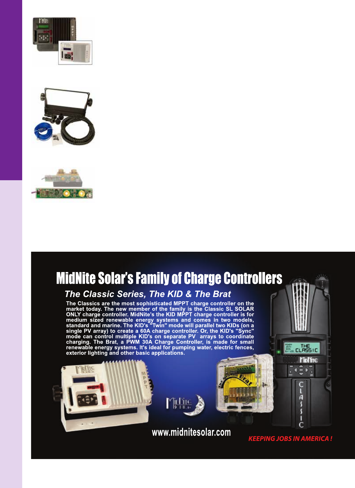
For the latest on AEE Solar products, trainings and dealer services, visit www.aeesolar.com
CHARGE CONTROLLERS
121
KID 30 A MPPT Charge Controllers
The MNKID 30 A MPPT charge controllers from MidNite Solar are versatile charge controllers for
small to medium-sized renewable energy systems. The KID works with 12, 24, 36, and 48 VDC battery
systems and has a 150 VDC operating limit; but is not damaged with DC voltages as high as 162 VDC,
due to MidNite’s HyperVOC circuitry. The KID has a three-LED bar graph, showing battery-charge
status, and a keypad to access extensive menu items and set-points.
The KID controllers include a load control with load low-voltage disconnect (LVD). This can also be
programmed as a lighting controller with dusk-to-dawn or various other on and off times. There is also
a programmable AUX relay.
Sealed electronics and passive cooling (no fans) make it ideal for use in harsh environments. There
are front-panel breakers for input, battery, and load. The controller’s operating temperature range is
-40 ºC to +50 ºC but the controller will automatically de-rate at temperatures above 25 ºC. Add the
battery-temperature sensor (BTS) to these models.
Listed for the U.S.A. and Canada. CE Certied. FCC Class B compliant. Dimensions are 9.25”L x 5”H
(6.6”H with wall-mount adaptor) x 3.4”D. NEMA 1 (IP64) indoor rating. Available in either white or
black casing, the KID is made in the USA and is covered by a two-year warranty.
The MNKID-M Marine version comes standard with the MNKID-M-BKT Boat Mounting Bracket,
exible conduit, battery-temperature sensor and extra conformal coating.
MNKID-ASSY KIT comes with Boat Mounting Bracket, knobs, screws, 3' ex conduit, battery-tem-
perature sensor, and four 1/2" connectors. Available in White or Black.
MNKID-CDT KIT contains two 1/2" straight connectors, two 1/2" elbow connectors and 3 ft ex con- duit.
The MidNite Whiz Bang Jr is a current-sense module that attaches to a standard Deltec 500 A / 50 mV
shunt and wires into the MidNite Classic or KID charge controllers to give amperage readings from the
shunt enabling absorb charge to stop according to a current set point. In this mode, if the battery current
falls below a programmable threshold for one minute, the Classic or KID will recognize that the batteries
are fully charged and switch to oat mode.
MNKID
Assembly Kit
Whiz Bang Jr.
Midnite Solar
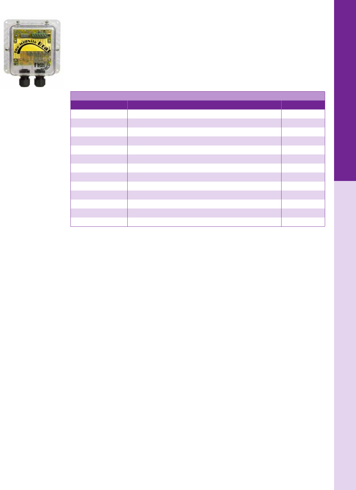
For the latest on AEE Solar products, trainings and dealer services, visit www.aeesolar.com
CHARGE CONTROLLERS
122
NEW! BRAT 30 A PWM Charge Controllers
The MNBRAT is a PWM charge controller with either a 20 A charger and 10 A load control, or a 30 A
charger without load control. Usable with 36-cell modules to charge 12 or 24 VDC battery banks, with
three or four-stage charging. It has no relays, fans or external heat sink, and is in a clear polycarbonate
NEMA 3R outdoor enclosure with 4 LED’s to display system status. The 10 A load control can be used as
a low voltage disconnect or a 16-position lighting control. The controller’s operating temperature range
is -40 ºC to +60 ºC but the controller will automatically de-rate at temperatures above 25 ºC. Ambient
temperature sensing for charge voltage compensation is internal to these models. Dimensions are 7” H
x 6” W x 2.4” D, 2 year warranty, made in USA.
MidNite Solar KID Charge Controllers and Accessories
Model Description Item code
MNKID-B MidNite KID charge controller with Wall-Mount Bracket - black 020-02400
MNKID-W MidNite KID charge controller with Wall-Mount Bracket - white 020-02401
MNKID-M-B MidNite KID Marine charge controller with Boat-Mount Bracket - black 020-02403
MNKID-M-W MidNite KID Marine charge controller with Boat-Mount Bracket - white 020-02402
Whiz Bang Jr Current-sense module 020-02426
MNBTS Battery -temperature sensor 020-02425
MNKID-M-BKT-B Boat mount bracket - black 020-02428
MNKID-M-BKT-W Boat mount bracket - white 020-02427
MNKID-ASSY KIT-B KID Assembly Kit - black 020-02430
MNKID-ASSY KIT-W KID Assembly Kit - white 020-02429
MNKID-CDT KIT KID Conduit Kit 020-02431
MNKID-BREAKER-30A Replacement 30 A breaker for KID charge control 053-03074
MNBRAT BRAT 20 A with load or 30 A without load PWM charge controller 020-02435
Midnite Solar
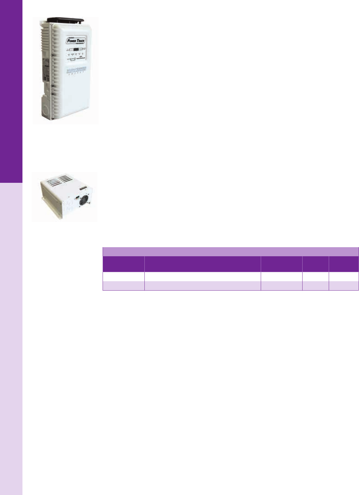
For the latest on AEE Solar products, trainings and dealer services, visit www.aeesolar.com
CHARGE CONTROLLERS
123
Magnum-Dimensions
Magnum-Dimensions
NEW! Magnum PT-100 Charge Controller
The PT-100 is an MPPT (Maximum Power Point Tracker) charge control with a maximum 100 A output.
It can charge 12, 24, and 48 VDC battery banks with typical 99% efciency. It comes standard with both
arc-fault detection (not currently listed to UL 1699B) and ground-fault protection (GFP) which eliminates
the need for a separate GFP breaker assembly. The array open-circuit voltage can be as high as 200 VDC
+ battery voltage or 240 VDC, whichever is lower. The array operating voltage is up to 187 VDC, and
battery-charging voltage range is 10 to 66 VDC.
An auxiliary dry-contact relay is available for control of generator start or load shedding or similar func-
tions. The wiring box can be separated from the control for convenient installation and ease of service.
There is extensive electronic protection for PV short circuit, high voltage, over-current, and power
derating with over-temperature.
A digital screen and LED indicators provide system information. There is internal data logging with har-
vest information data up to 255 days. Use the Magnum system remote display to read this information.
Firmware is user upgradeable using downloaded les. Use 300 VDC breakers (see Electrical Distribution
Parts) for power source voltages over 150 VDC. On the battery side of the controller, breakers need only
be rated for the highest battery-charging voltage.
Listed to UL 1741 and CSA C22.2 No. 107.1, CE. Covered by a ve-year warranty and made in USA.
NEW! Magnum ACLD-40 AC Diversion Charge Controller
The ACLD-40 diversion charge control is made specically for battery charge control in an AC-coupled
grid-tied system. It provides PWM (Pulse-Width Modulation) three-stage battery charging utilizing com-
mon AC heater loads when an AC-coupled system is functioning in off-grid mode. This is more effective
than the on/off mode used in most AC-coupled systems for getting the battery to a full state of charge
during extended utility outages. Up to 4,000 W of AC loads can be utilized with the option of having
primary and secondary loads. It works with 12, 24, and 48 VDC battery systems, and must be connected
to an MS-PAE inverter system. Listed to UL 1741 and CSA C22.2 No. 107.1. Covered by a three-year
warranty extended to ve years when used with a Magnum MP or MMP panel and made in USA.
Maximum PV Array
Model Description Dimensions
(H" x W" x D") Weight Item code
PT-100 Magnum 100 A MPPT charge control 15.5 x 8.5 x 4.0 13.6 lbs 020-06371
ACLD-40 Magnum 4 kW AC Load Diversion Control 13.75 x 11.5 x 7 20 lbs 020-06372

PT-100 MPPT CHARGE CONTROLLER
POWER FOR WORK. POWER FOR LIFE.
Your customers have come to rely on Magnum Energy products for their vital off-grid
applications. Easy-to-install, easy-to-use, and reliable. We have expanded our balance
of system components with the new PT-100 Charge Controller. The PT-100 links with
Magnum Inverter/Chargers to provide a complete solution to maximize their PV yield.
EXCELLENCE: EXPANDED
Integrated PV GFDI
and Arc Fault Detector
High effi ciency, 100 Amp output,
regardless of battery system voltage
240 Voc maximum input to
support more panels in a string
Reliable Solutions For Off-Grid • Backup • AC Coupling
Check www.magnum-dimensions.com to see what we mean by #ExcellenceExpanded.
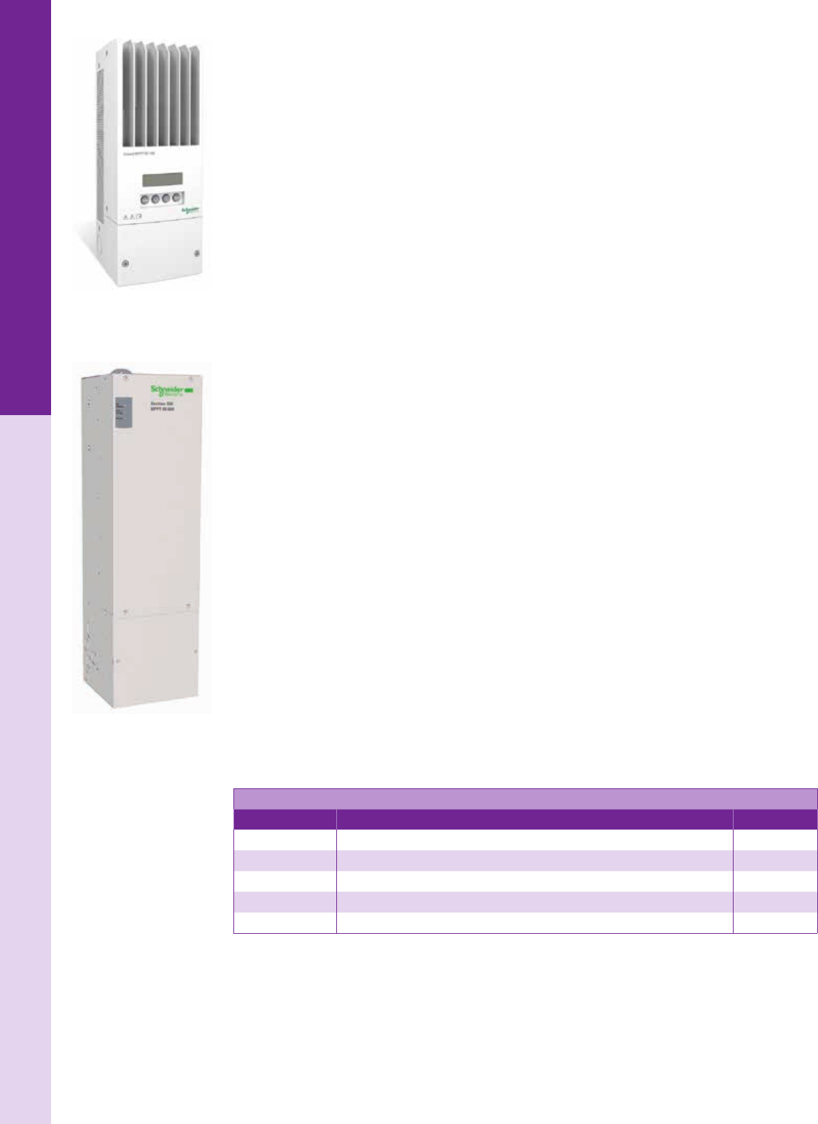
For the latest on AEE Solar products, trainings and dealer services, visit www.aeesolar.com
CHARGE CONTROLLERS
125
Schneider Electric
Schneider Electric XW-MPPT60-150 Charge Controller
The XW-MPPT60-150 can be used with PV arrays at voltages up to 150 VDC and can support an out-
put of up to 60 A for battery voltages between 12 to 60 VDC. Maximum power point tracking (MPPT)
maximizes energy harvest and provides increased exibility in module selection and string sizing.
A large aluminum heat sink eliminates the need for an internal fan for added reliability. Built-in ground
fault protection (GFP) eliminates the need for a separate GFP breaker. The XW-MPPT60-150 can be
mounted on the side or top of the XW power distribution panel, or used stand-alone in other PV systems.
The front panel features a 2-line 16-character display and 4 buttons for conguration and system moni-
toring. A battery temperature sensor is included with the controller.
The charge controller has a congurable single-function auxiliary output (producing 5 to 13 VDC at 200
mA) that can drive a relay for load control or activate devices, such as vent fans or indicator alarms. The
XW-MPPT60-150 is able to communicate its settings and activity to other Xanbus- enabled devices,
such as XW Series inverter/chargers, the System Control Panel II (SCP), XW Automatic Generator Start
(XW-AGS), and other XW-MPPT solar charge controllers through the Xanbus network.
The dimensions are 14"H x 5"W x 5"D, weight is 12 lbs and it is covered by a ve-year warranty with
an optional extension to 10 years. Listed to UL 1741 for the U.S.A. and Canada.
Schneider Electric XW-MPPT80-600 Charge Controller
The XW-MPPT80-600 can accommodate open circuit voltages of up to 600 VDC, which reduces wiring
needs, increases module selection and string sizing exibility, and enables greater distance between the
power source and battery bank. The MPPT PV array input window is 195 to 550 VDC, which supports
an output of up to 80 A for 24 or 48 VDC battery banks. Standby power draw is less than 1 W.
The charge controller has a congurable single-function auxiliary output to drive a load control relay or
to activate devices such as vent fans or indicator alarms. Full output current of 80 A is available without
de-rating in ambient temperatures up to 113 °F (45 ºC). Over-temperature protection de-rates the power
throughput when ambient temperatures are higher. The XW-MPPT80-600 also features protections for
input over/under voltage, output over current, and back-feed (reverse current). Built-in ground-fault
protection (GFP) eliminates the need for a separate GFP breaker. This unit is congurable for positive,
negative, and ungrounded PV systems.
The XW-MPPT80-600 can be used with the XW power distribution panel, or stand-alone in other PV
systems, with a Square-D HU361RB 600 VDC array disconnect. For two strings, wire two poles of the
disconnect into the controller terminals. Use a 100 A breaker on the battery side of the control.
A battery temperature sensor is included with the controller. The XW-MPPT80-600 is compatible
with Xanbus-enabled devices, such as the XW Series inverter/charger, the System Control Panel, XW
Automatic Generator Start Module, and other XW solar charge controllers through the Xanbus network.
It can also be installed in a stand-alone mode with an XW System Control Panel.
XW-MPPT80-600 dimensions are 30"H x 8.63"W x 8.63"D, weight is 29.8 lbs. and it is covered by
a ve-year warranty with an optional extension to 10 years. Listed to UL 1741 and CSA 107.1 for the
U.S.A. and Canada.
Schneider Electric XW Charge Controllers
Model Description Item code
XW-MPPT60-150 XW 60 A 150 VDC MPPT charge control 020-08040
XW-MPPT80-600 XW 80 A 600 VDC MPPT charge control 020-08048
SQD HU361RB PV Array disconnect switch for MPPT80-600 charge controller 053-02312
XW SCP XW System Control Panel - provides central user interface for Xanbus network 300-00128
XW AGS XW Automatic Generator Start Module 030-01183
Schneider Electric
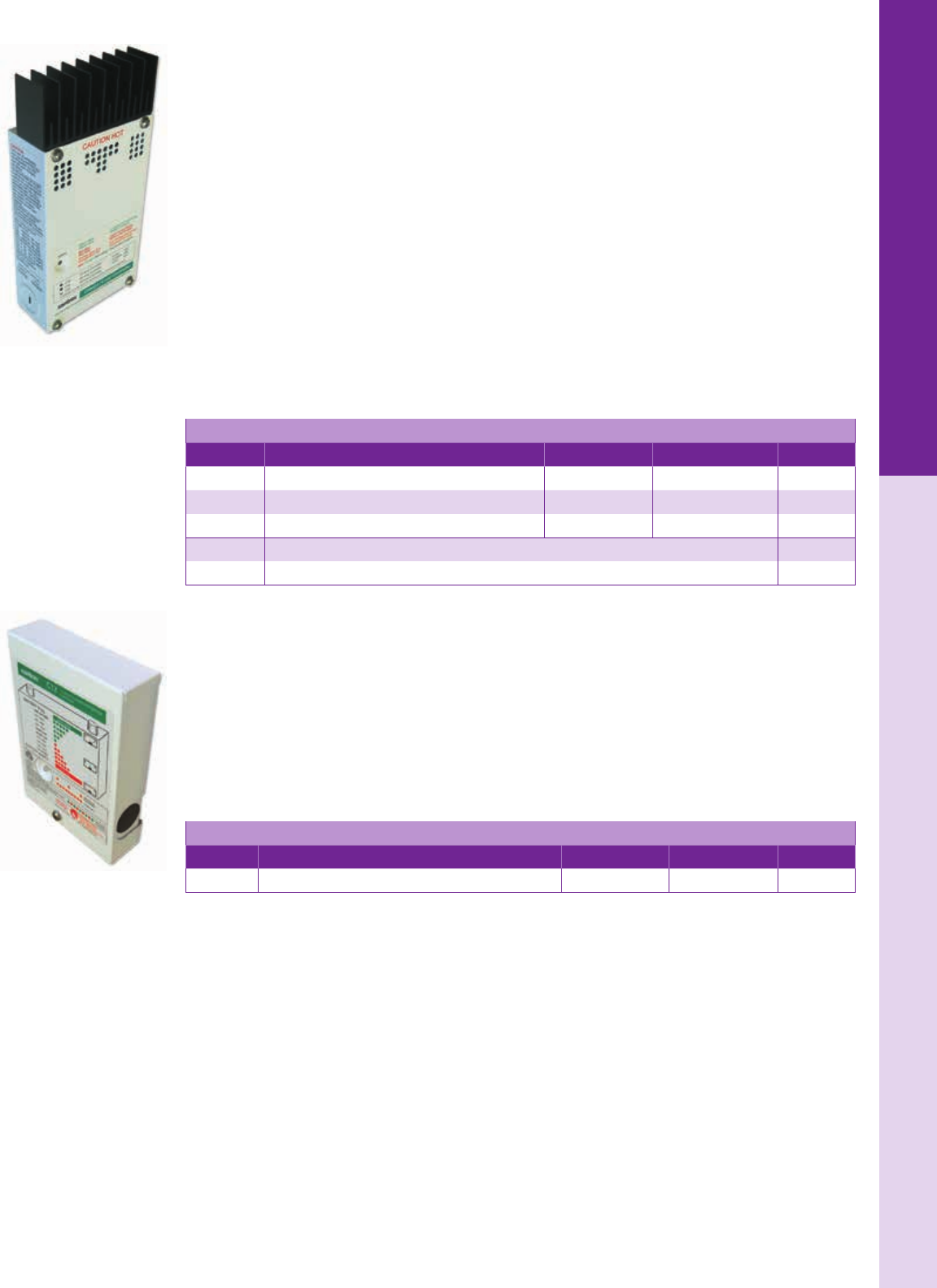
For the latest on AEE Solar products, trainings and dealer services, visit www.aeesolar.com
CHARGE CONTROLLERS
126
Schneider Electric C-35, C-40 and C-60 PWM Controllers
The Schneider Electric C-35, C-40, and C-60 PWM (pulse-width modulation) controllers can be used
as either PV charge controllers, DC load controllers or DC diversion regulators in 12 and 24 VDC sys-
tems (the C-40 can also be used in 48 VDC systems). Two controllers can be used together to provide
multiple functions.
As DC load controllers, they disconnect the load at a user-dened low voltage and reconnect at a higher
voltage reconnect point. As diversion controllers, they send excess power to a diversion load (see Controls
and Relays) to regulate hydroelectric or wind generators. The maximum current throughput is reduced
by 25% when used in diversion mode.
All Schneider Electric C-Series charge controllers have eld-adjustable bulk and oat set points and
perform automatic equalization every 30 days or whenever low-voltage disconnect (LVD) is reached.
Equalization can be manually initiated with automatic shut-off. The optional BTS-15 Battery Temperature
Sensor can be used to increase accuracy of the control algorithms. The optional CM/R50 display shows
battery voltage, array current and power, cumulative amp-hours, and a separately resettable “trip” amp-
hour measurement. The digital display can be mounted on the front of the charge controller, or with a
cable for remote mounting in a double-gang electrical box up to 100' away.
These controllers are listed to UL 1741 and CSA 22.2 No 107.1-95 and covered by a two-year warranty.
Schneider Electric C-Series PWM Charge Controllers
Model Description System voltage Charge current Item code
C-35 Charge/Load/Diversion controller 12 or 24 VDC 13.6 lbs 020-06371
C-40 Charge/Load/Diversion controller 12, 24, or 48 VDC 40 A 020-08005
C-60 Charge/Load/Diversion controller 12 or 24 VDC 60 A 020-08009
BTS-15 Battery temperature sensor with 15' cable (C-series only) 020-08025
CM/R50 Remote display with 50' cable 020-08019
Schneider Electric C-12 Charge & Lighting Controller
The C-12 controller is PWM microprocessor-based and has a 12 A low-voltage disconnect (LVD) and
an automatic lighting control, making it well suited for small remote loads such as signs, cabins and bus
shelters. The lighting control activates the light at dusk, has an adjustable duration timer for 2 to 8 hours
of run time, and can be set to run until dawn. The LVD shuts off the load when the battery voltage falls
below a user-dened set-point.
Use one of the C-Series Battery Temperature Sensors for more accurate battery charging.
For use in 12 VDC systems only. The C-12 can be mounted outdoors. Its dimensions are 6.5" x 4.3" x
1.5" and it is UL listed and covered by a two-year warranty.
Schneider Electric C-12 Charge/Lighting Controller
Model Description System voltage Charge current Item code
C-12 Schneider C-12 Charge controller / Lighting controller 12 VDC 12 A 020-08002
Schneider Electric
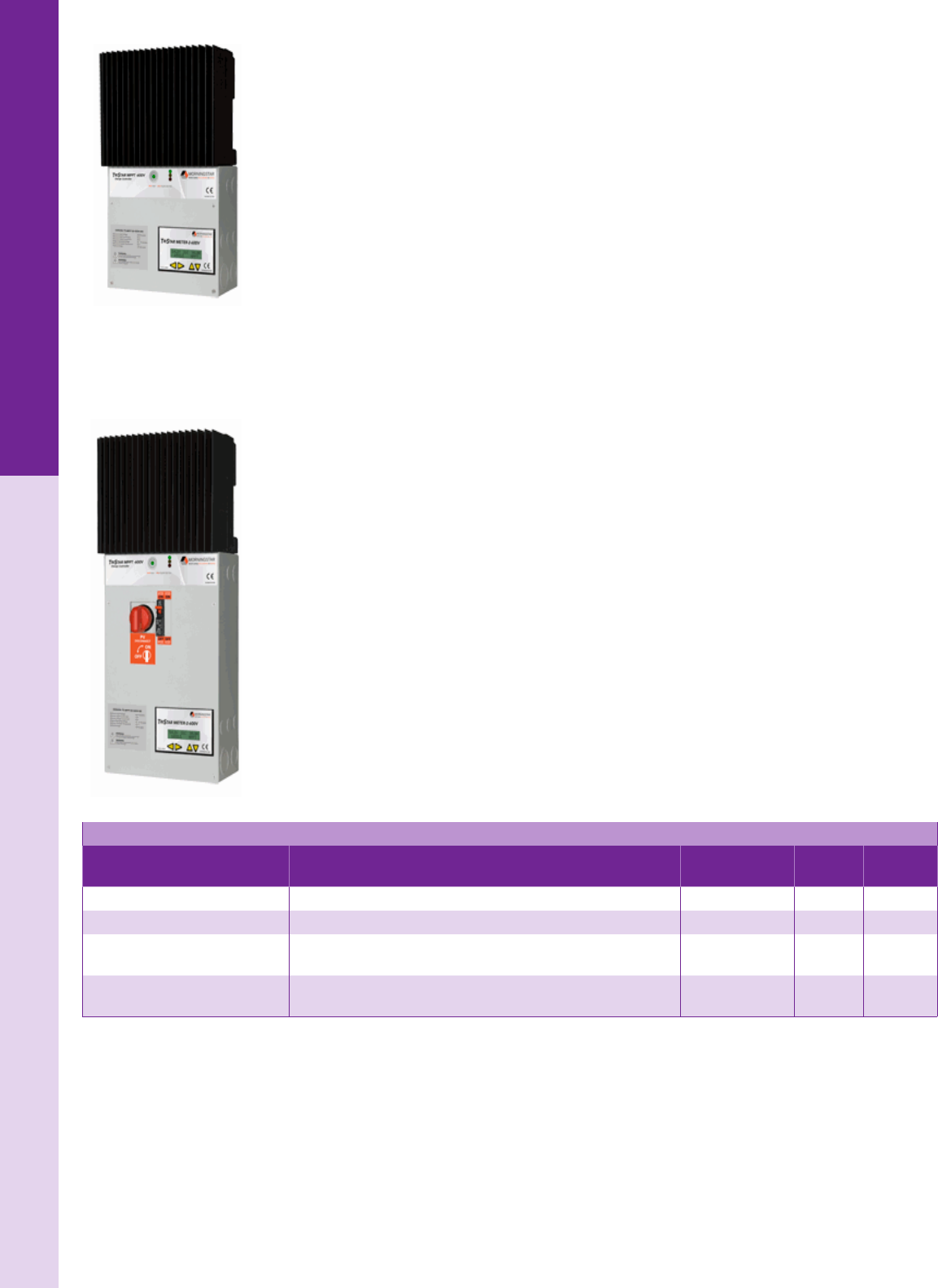
For the latest on AEE Solar products, trainings and dealer services, visit www.aeesolar.com
CHARGE CONTROLLERS
127
Morningstar
TriStar MPPT 600 VDC Charge Controllers
The TS-MPPT-600V uses Morningstar’s TrakStar™ MPPT technology coupled with the widest PV
input operating-voltage range available in a PV controller. The high-speed sweeping algorithm of the
TrakStar™ MPPT technology enables this charge controller to harvest the maximum energy from a solar
array under all ambient conditions.
The TS-MPPT-600V charge controllers are rated for 60 A output to charge 48 VDC battery systems, and
can be programmed to charge 24 VDC or 60 VDC battery systems. Their wide input operating voltage
range of 100-525 VDC, 600 VDC maximum open-circuit voltage limit, and buck-boost design, allow
exible string sizing that also mitigates PV shading. A four-stage charging algorithm helps to optimize
battery health.
The TS-MPPT-600V controller is Ethernet enabled for remote communications, data logging, adjust-
ability, and metering. Communication ports/interfaces include Ethernet, EIA-485, RS-232 and MeterBus.
Built-in lightning protection protects the circuitry from nearby lightning-induced voltage/current spikes.
The large heat sink provides convective cooling without fans, so there are no moving parts. Continuous
full power operation up to 45 °C ambient temperatures. The printed circuit boards are conformal coated
for protection against moisture and dust. Self-diagnostics and electronic error protections help reduce
the risk of installation missteps.
The TriStar MPPT 600 V charge controller is available with or without a pre-wired DC Disconnect Box.
The pre-wired DC Disconnect Box version, the TS-MPPT-60-600V-48-DB, can be used with positively-
grounded or negatively-grounded PV systems and has both array and battery disconnects.
NEW! TriStar MPPT 600 VDC Charge Controllers w/ Array Transfer Switch
The TriStar charge controller is now available as the TS-MPPT-60-600V-48-DB-TR with an array trans-
fer switch. This 30 A, 600 VDC double-pole, double-throw switch will enable the Tristar to be installed
between the PV array and a grid-tie inverter so that during a utility outage, the array can be switched to
charge a battery-backup system. This arrangement does not require any compatibility between the grid-tie
inverter and battery inverter, and is extremely reliable as a retrot backup-power solution to a grid-tie PV
system. The backup system can be made to t only the backup requirements, not the equipment require-
ments. A larger PV array can be fed into one charge control for higher output during cloudy periods, and
will simply limit the charge at 60 A (or lower setting) when there is more power available from the array.
The TS-MPPT-60-600V-48-DB-TR-GFPD is the same control with transfer switch, and includes Morn-
ingstar’s advanced ground-fault-protection device with the control.
A battery-temperature sensor (RTS) is included. Wire terminals accept #14 to #2 AWG wire. All units are
NEMA1 rated for indoor installation (IP20). Listed to UL 1741 and Canadian CSA C22.2 No. 107.1.01.
FCC Class B Part 15 compliant. Ambient operating temperature range: -40 ºF to +113 ºF (-40 ºC to +45 ºC).
Morningstar TriStar MPPT 600 VDC Charge Controllers
Model Description Dimensions
(H" x W" x D") Weight Item code
TS-MPPT-60-600V- 48 TriStar 60 A/600 VDC 48 V MPPT charge controller 15.4 x 8.7 x 5.9 19.8 lbs 020-01103
TS-MPPT-60-600V-48-DB TriStar 60 A/600 VDC 48 V MPPT charge controller with DC disconnect 21.4 x 8.7 x 5.9 28.1 lbs 020-01104
TS-MPPT-60-600V-48-DB-TR TriStar 60 A/600 VDC 48 V MPPT charge controller w/ DC disconnect
and transfer switch 21.4 x 8.7 x 5.9 28.1 lbs 020-01101
TS-MPPT-60-600V-48-DB-TR-GFPD TriStar 60 A/600 VDC 48 V MPPT charge controller w/ DC disconnect
and transfer switch and GFPD 35.5 x 8.7 x 5.9 37 lbs. 020-01102
Morningstar
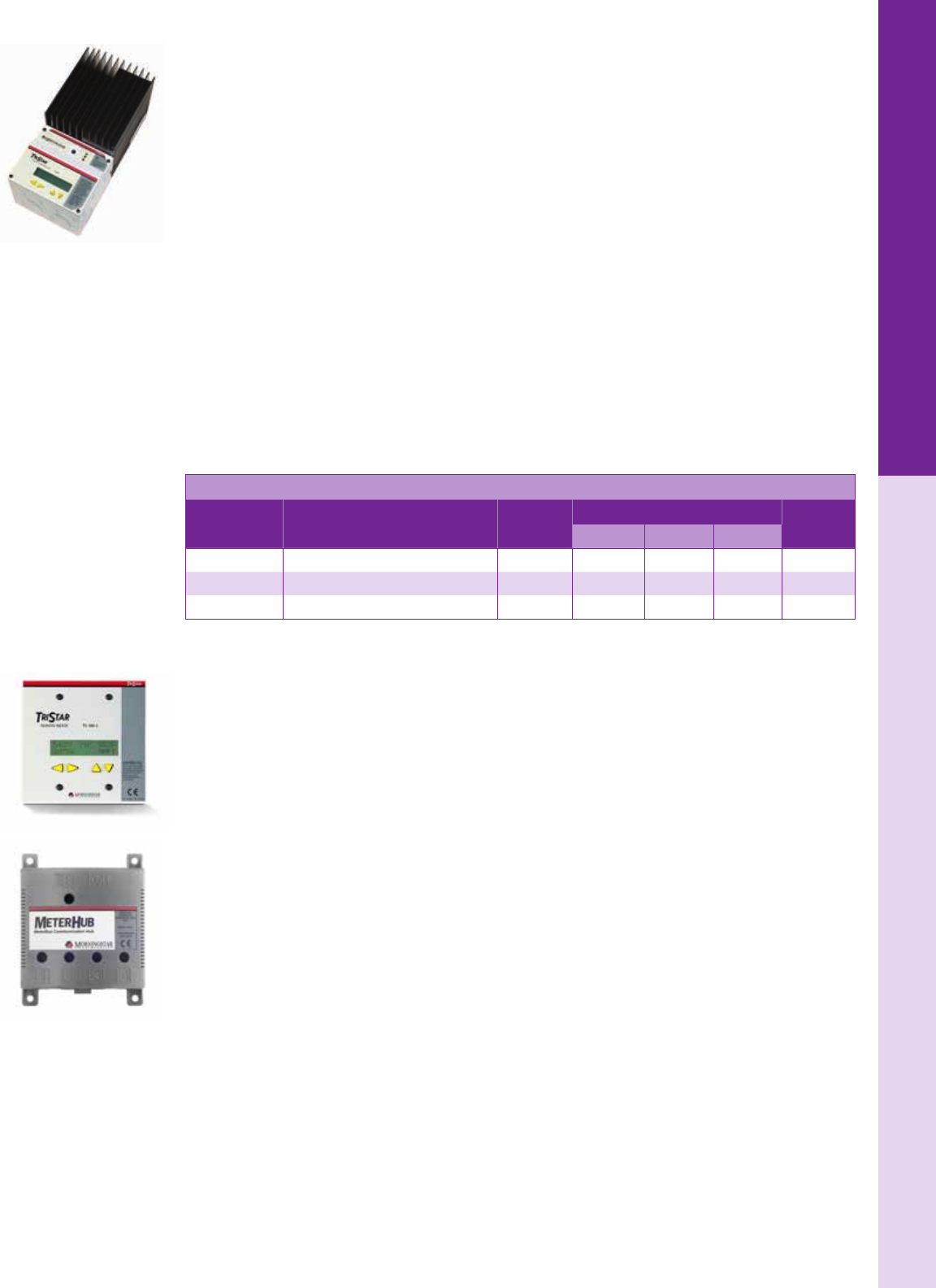
For the latest on AEE Solar products, trainings and dealer services, visit www.aeesolar.com
CHARGE CONTROLLERS
128
TriStar MPPT Charge Controllers
Morningstar's TriStar TS-MPPT-30, TS-MPPT-45, and TS-MPPT-60 solar charge controllers with
TrakStar™ Technology are advanced maximum power point tracking (MPPT) controllers for photovoltaic
(PV) systems up to 3 kW. These controllers work well in a variety of applications including: residential
and commercial systems, remote telecommunications, 12 VDC RV & marine applications, trafc &
highway telemetry, industrial automation & control, and solar outdoor lighting. The TS-MPPT control-
lers can be used with arrays having a maximum open-circuit voltage of 150 VDC and have a charging
range of 8 to 72 VDC.
Optional local and remote meters (see accessories section) provide detailed operating data, alarms and
faults with three LED indicators to display system status. The TS-MPPT has a simple DIP-switch setup
for plug-and-play operation or is fully programmable with a PC connection. The chassis on the TriStar
controllers is isolated from the power circuits, allowing use in both negative and positive-grounded systems.
Extensive Networking and Communications Capabilities enable system monitoring, data logging, and
remote adjustments. All models offer open standard MODBUS protocol and Morningstar's MS View
software and allow a Serial RS-232 connection to a PC or laptop. In addition, the TS-MPPT-60 includes
a built-in Ethernet port for a fully web-enabled interface to view data from a web browser to display
up to 200 days of data logging and send email/text and messages. The TS-MPPT-60 also has a built-in
RS-485 port for connecting to an EIA-485 network.
A remote temperature sensor (RTS) is included. Dimensions are 11.4"H x 5.1"W x 5.6"D, weight is 9.2
lbs. Covered by a ve-year warranty and listed to UL 1741.
Morningstar TriStar MPPT Charge Controllers
Model Description Web
enabled
Nominal maximum array power Item code
12 VDC 24 VDC 48 VDC
TS-MPPT-30 TriStar MPPT 30 A charge controller Yes* 431 W 862 W 1,724 W 020-01116
TS-MPPT-45 TriStar MPPT 45 A charge controller Yes* 647 W 1,294 W 2,588 W 020-01109
TS-MPPT-60 TriStar MPPT 60 A charge controller Yes 862 W 1,724 W 3,448 W 020-01110
* Requires HUB-1
TriStar MPPT Accessories
Optional TriStar Meters have a 2 x 16 character LCD display that shows extensive system and controller
information, logged data, bar graph metering as well as alarms and fault codes for easy troubleshooting.
The information may be shown in English, French, German, Portuguese or Spanish. The TS-M-2-600V
can be mounted on the front of the TS-MPPT-60-600V-48 controllers, the TS-M-2 can be mounted on
the front of the TS-MPPT 150 VDC controllers. The TS-RM-2 is a remote display with a 100 ft cable.
In addition to computer networking, Morningstar has developed the ability to set up a separate Meterbus
network. The meter ports allow for communications between compatible products and Morningstar's
MeterHub (HUB-1) allows multiple Morningstar products to communicate over an expanded Meterbus
network to provide improved data monitoring, additional capabilities, and lower system cost. It enables
multiple controllers to share a single TriStar meter and display individual controller data as well as
aggregated data for the entire system. The HUB-1 also enables multiple controllers to share a single
Relay Driver (RD-1). See Converters and Controls for more info on the RD-1
The RSC-1 communications adapter converts an RS-232 serial connector to a standard RS-485 port and
may be used to include the TS-MPPT-30, TS-MPPT-45 and TriStar (PWM) controllers and Morningstar’s
Relay Driver in an TIA-485 Network.
The Morningstar GFPD-150V and GFPD-600V are advanced ground fault detection and protection
devices. See Electrical Distribution Parts for more information.
Morningstar
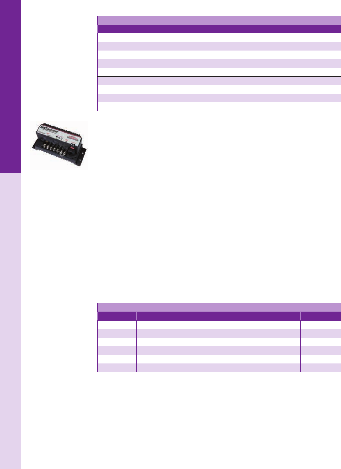
For the latest on AEE Solar products, trainings and dealer services, visit www.aeesolar.com
CHARGE CONTROLLERS
129
TriStar MPPT Accessories
Model Description Item code
TS-M-2-600V Optional digital display for front of all TS-MPPT-60-600V-48 controls 020-01114
TS-M-2 Optional digital display for front of all TS-MPPT 150 V controls 020-01111
TS-RM-2 TriStar Remote Meter Display with 100' cable 020-01112
HUB-1 MeterHub controller communications HUB for up to 15 devices 020-01260
RD-1 Relay driver with four independent outputs for system control functions 020-01255
RSC-1 Communications adapter RS-232 to TIA-485 (For TS-MPPT-30 and TS-MPPT-45 only) 020-01256
RTS Remote temperature sensor (replacement – one RTS is included with the controller) 020-01141
GFPD-600V DC Ground-Fault-Protection Device, two-pole, 50 A, 600 VDC 053-03165
GFPD-150V DC Ground-Fault-Protection Device, two-pole, 60 A, 150 VDC 053-03164
SunSaver MPPT 15 A Charge Controller
The SunSaver MPPT (Maximum Power Point Tracking) charge controller is designed for 12 and 24
VDC battery charging from a PV array with a maximum open circuit voltage of 75 VDC. Use up to three
36-cell PV modules in series or a single 60-cell or 72-cell module to provide up to 200 W when charging
a 12 VDC battery or up to 400 W when charging a 24 VDC battery. The SunSaver MPPT maximizes the
output of the PV array by rapidly nding the array’s peak power point with extremely fast sweeping of
the entire I-V curve, providing an estimated 5-25% power boost over PWM or simple on-off control-
lers, especially during periods of colder temperatures and low battery voltages when it is most needed.
The controller features electronic protection from short circuit, overcurrent, reverse polarity, high
temperature, high voltage, lightning, and transient surges. An adjustable low-battery load disconnect
protects the battery from over-discharge. LED indicators indicate charging, low-battery and faults. The
optional meter provides detailed system information, 30 days of logged data, alarms, and faults. The
SS-15MPPT has a simple DIP-switch setup for plug-and-play operation or is fully programmable for
custom and advanced programming with a PC connection using the PC MeterBus Adapter (MSC)
and Morningstar’s MSView software (available for free on Morningstar’s website). Also compatible
with Morningstar’s MeterHub (see previous page). The UMC-1 communications adapter converts
the Morningstar MeterBus RJ-11 electrical interface to a standard USB 2.0 interface which allows
communication between a Morningstar charge controller or inverter and a PC computer.
The SunSaver MPPT now features programmable lighting control for up to four time periods and is
adjustable with respect to hours/minutes after/before – Dusk/Dawn/Solar Midnight/Solar Noon. Mounts
on DIN rail with DIN-1 rail clip.
SS-15MPPT dimensions are 6.6"H x 2.75"W x 2.2"D, weight is 1.65 lbs, and it is covered by a ve-year
warranty. Listed to UL 1741 CSA 107.1 for U.S.A. and Canada
Morningstar SunSaver MPPT Charge Controllers
Model Description DC system voltage Charge current Item code
SS-15MPPT SunSaver MPPT charge controller 12 or 24 VDC 15 A 020-01261
RM-1 SunSaver MPPT remote meter 020-01258
RTS Battery-temperature sensor 020-01141
MSC MeterBus adapter 020-01257
UMC-1 Communications adapter Morningstar MeterBus to USB 020-01251
DIN-1 Din-rail clip - each 020-01259
Morningstar

For the latest on AEE Solar products, trainings and dealer services, visit www.aeesolar.com
CHARGE CONTROLLERS
130
TriStar PWM Charge Controllers
The TriStar pulse-width modulation (PWM) controllers can operate as solar charge controllers, load
controllers, or diversion regulators in 12, 24 or 48 VDC systems. They can also be custom programed
for 36 VDC. Two or more controllers can be used to provide multiple functions. PWM may be changed
to on/off operation to prevent telecom noise.
Two models are available with current ratings of 45 A and 60 A. Seven different set points are selectable
via DIP switches for plug-and-play operation. An RS-232 communications port enables PC or laptop
connection to adjust controller set points, to download internally-logged data, or to congure detailed
PC data logging. A PC can communicate with the TriStar via open-standard MODBUS protocol and
Morningstar's MS View software. The RSC-1 communications adapter can be used to convert the RS-232
serial connector to TIA-485 to be included in an TIA-485 network.
The TriStar also has a lighting control feature with 7 DIP-switch presets or custom programmed settings
with up to two ON-OFF time periods after/before dusk and dawn.
An optional TS-M-2 Digital Display can be mounted on the front of the controller or up to 100' away
using four-conductor phone cable with RJ-11 jacks. The meters can provide in-depth system informa-
tion, including 60 days of internally-logged data. They can also be connected to a MeterHub network
with the MeterHub (HUB-1) to be displayed on a TriStar Meter or networked with a Relay Driver for
relay switch operation.
Battery-temperature compensation may be added with the optional Remote Temperature Sensor (RTS).
Dimensions: 10.25"H x 5"W x 2.8"D, weight is 3.5 lbs. and covered by a ve-year warranty. Listed to
UL 1741 for U.S.A. and Canada.
Morningstar TriStar PWM Charge Controllers
Model Description DC system voltage Charge current Item code
TS-45 TriStar 45 charge controller 12, 24, or 48 VDC 45 A 020-01105
TS-60 TriStar 60 charge controller 12, 24, or 48 VDC 60 A 020-01108
RTS Battery-temperature sensor 020-01141
TS-M-2 TriStar Meter-2 mounts on front of charge controller 020-01111
TS-RM-2 TriStar Remote Meter-2 display with 100' cable 020-01112
ProStar PWM Charge Controllers
ProStar (PS) PWM charge controllers have automatic equalization and temperature compensation, and
provide four-stage charging including a monthly equalization charge. The ProStar controllers can be
used on 12, 24, and 48 VDC systems with AGM, gel, and ooded lead-acid batteries. Front-panel LEDs
indicate charging status and state-of-charge. Reverse-polarity protection on input and output prevents
inadvertently damaging the controller. Short-circuited loads are automatically disconnected.
M models include an LCD meter to display battery voltage, PV charging current, and load current. Low-
voltage disconnect (LVD) is current-compensated to prevent false disconnect when the battery is heavily
loaded. Internal circuitry is conformal coated to guard against corrosion.
ProStar dimensions are 6.01"H x 4.14"W x 2.2"D and it is covered by a ve-year warranty.
Morningstar Prostar PWM Charge Controllers
Model Description DC system
voltage
Charge
current Item code
PS-15 ProStar 15 12 or 24 VDC 15 A 020-01120
PS-15M ProStar 15 with digital display 12 or 24 VDC 15 A 020-01123
PS-15M-48 ProStar 15 48 VDC with digital display 48 VDC 15 A 020-01126
PS-15M-48-PG ProStar 15 48 VDC with digital display,
positive ground 48 VDC 15 A 020-01129
PS-30 ProStar 30 12 or 24 VDC 30 A 020-01132
PS-30M ProStar 30 w/ digital display 12 or 24 VDC 30 A 020-01135
PS-30M-PG ProStar 30 w/ digital display positive ground 12 or 24 VDC 30 A 020-01138
RTS Remote temperature sensor 020-01141
Morningstar
For the latest on AEE Solar products, trainings and dealer services, visit www.aeesolar.com
CHARGE CONTROLLERS
131
SunSaver Gen3 Charge Controllers
SunSaver Gen3 controllers are advanced PWM solar battery charging and load controllers for smaller
stand-alone 12 and 24 VDC PV systems. A rugged anodized-aluminum case, marine-rated terminals,
and epoxy-encapsulated electronics enhance durability. A temperature-compensation sensor in the charge
controller varies full-charge voltage with temperature.
SunSavers are eld-selectable for sealed or ooded batteries and have a four-stage battery charging
process (including auto-equalization for ooded batteries) optimized for long battery life and improved
system performance. Self-diagnostics and electronic error protection prevent damage when installation
mistakes or system faults occur and reset automatically when resolved. The Gen3 controllers include a
multi-color status LED as well as three Battery LED indicators, which together communicate system
status, battery state of charge and 13 possible error conditions. The terminal cover prevents contact with
the wiring terminals. The load output connections can provide power to DC loads up to the unit’s current
rating, and “L” models provide low-voltage disconnect (LVD) for connected loads. Telecom mode and
15 VDC charge limit for sensitive loads.
Negative ground only. Operating temperature range of –40 °C to +60 °C.
SunSaver dimensions are 6"H x 2.2"W x 1.3"D. These Gen3 SunSaver Controllers are approved for
Class 1 Div 2 for hazardous locations and are Listed to UL1741 for the U.S.A. and Canada, CSA C22.2
No. 107.1-01 certication and are covered by a ve-year warranty.
Morningstar TriStar MPPT 600 VDC Charge Controllers
Model Description DC system voltage Charge current LVD current Item code
SS-6-12V SunSaver 12 VDC 6 A N/A 020-01245
SS-6L-12V SunSaver with LVD 12 VDC 6 A 6 A 020-01248
SS-10-12V SunSaver 12 VDC 10 A NA 020-01230
SS-10L-12V SunSaver with LVD 12 VDC 10 A 10 A 020-01233
SS-20L-12V SunSaver with LVD 12 VDC 20 A 20 A 020-01239
SS-10L-24V SunSaver with LVD 24 VDC 10 A 10 A 020-01236
SS-20L-24V SunSaver with LVD 24 VDC 20 A 20 A 020-01242
DIN 1 DIN-rail clip for mounting SunSaver and SunLight controllers on a DIN rail - each (two needed
per controller) 020-01259
SunLight Charge Controller with Lighting Control
The SunLight (SL) is a SunSaver Gen2 controller that includes a rotary switch which allows it to turn on
the loads after dusk for 2, 4, 6, 8, or 10 hours. One option turns loads on at dusk then off and on again
before dawn. In this conguration, you can choose the following settings (in hours): 3/off/1, 4/ off/2, or
6/off/2. “On” from dusk to dawn is also possible. A test button turns light(s) on for ve minutes. Covered
by a ve-year warranty with dimensions of 6.6"H x 2.2"W x 1.3"D.
Morningstar SunLight Charge/Lighting Controllers
Model Description DC system voltage Charge current LVD current Item code
SL-10-12V SunLight with LVD 12 VDC 10 A 10 A 020-01218
SL-20-12V SunLight with LVD 12 VDC 20 A 20 A 020-01224
SL-10-24V SunLight with LVD 24 VDC 10 A 10 A 020-01221
SL-20-24V SunLight with LVD 24 VDC 20 A 20 A 020-01227
SunGuard Charge Controller
The SunGuard SG-4 uses the same charging circuit as the SunSaver and works well as a 12 VDC,
low-power controller for up to 75 W of PV module(s). Since it is epoxy encapsulated, it can be used
outdoors in harsh environments. The SunGuard’s dimensions are 2.5"H x 2"W x 1.6"D with wire leads
for connecting module and battery, and it is covered by a ve-year warranty.
Morningstar SunGuard Charge Controller
Model Description System voltage Charge current Item code
SG-4 SunGuard 12 VDC 4.5 A 020-01215
Morningstar
For the latest on AEE Solar products, trainings and dealer services, visit www.aeesolar.com
CHARGE CONTROLLERS
132
SunKeeper Charge Controller
Morningstar’s SunKeeper solar controller provides a low cost regulated output directly from the solar
module to maximize battery life in small solar power applications. The SunKeeper is epoxy encapsulated
and rated for outdoor use. By mounting directly to the module junction box and wiring through the junc-
tion box knockout, the connection is weather-proof. This eliminates the need for an additional housing for
the controller. It’s designed to mount in a ½" knockout in a PV module junction box or other enclosure.
The SunKeeper is available in 6 A or 12 A versions for small 12 VDC systems, and provides PWM three-
stage charging. Includes temperature compensation at the controller or alternatively at the battery when
used with the optional Remote Temperature Sensor. A bi-color LED indicates solar charging, regulation,
normal nighttime operation, and any controller or system faults
The SunKeeper has been designed with extremely efcient power electronics and is rated to 70 °C so
it can be mounted behind a PV module. The SunKeeper is also certied for use in Class 1, Division 2
hazardous locations, making it well suited for solar powered oil/gas applications. It's covered by a ve-
year warranty and listed to UL 1604 and CSA 22.2.
Morningstar SunGuard Charge Controller
Model Description System voltage Charge current Item code
SK-6 SunKeeper 6 12 VDC 6 A 020-01252
SK-12 SunKeeper 12 12 VDC 12 A 020-01253
RTS Remote battery temperature sensor 020-01141
SunSaver Duo RV Charge Controller
The SunSaver Duo two-battery charge controller will charge two separate and isolated batteries at the
same time, such as a ‘house’ battery and an engine battery in an RV or yacht. This controller also includes
a backlit remote meter that may be ush or surface mounted, and displays alpha-numeric and graphical
information about the solar power system status. Epoxy-encapsulated electronics for environmental
protection. User adjustable via DIP switch or connection to a personal computer.
Optional Remote Temperature Sensor for battery bank. Covered by a ve-year warranty.
Morningstar SunGuard Charge Controller
Model Description DC system voltage Charge / load current Item code
SSD-25RM SunSaver Duo with remote meter 12 VDC 25 A 020-01250
RTS Remote temperature sensor 020-01141
MSC MeterBus adapter 020-01257
UMC-1 Communications adapter Morningstar MeterBus to USB
Morningstar
For the latest on AEE Solar products, trainings and dealer services, visit www.aeesolar.com
CHARGE CONTROLLERS
133
Blue Sky Energy
Solar Boost™ Charge Controllers
The Blue Sky Solar Boost charge controllers feature Maximum-Power-Point Tracking (MPPT), reverse-
polarity protection, selectable charge-voltage set points, and an equalize function. An optional user-friendly
digital display is available to monitor PV charge performance. The display shows battery voltage, solar
current, charge current, and charge mode, either in the controller, as a remote panel installed up to 300'
away, or both. Optional temperature compensation of charge voltage is also available to further improve
charge controller and battery performance. Solar Boost controllers are available with or without the digital
display and optional remote display. Covered by a ve-year limited warranty.
Solar Boost 3024iL
The SB3024iL is designed to charge 12 and 24 DC battery systems from a 24 VDC array (maximum
open-circuit voltage is 57 VDC). Maximum charge current is 40 A output at 12 VDC and 30 A at 24 VDC.
It has an auxiliary output that can serve as a 20 A load controller or as a 2 A battery charger.
The SB3024DiL version converts the 20 A auxiliary output into a separate 20 A diversion-type charge
controller for hydroelectric, wind, or similar generator-type power sources. The Diversion-Control
upgrade also allows the 3024 to divert full available PV and generator power which is not required for
battery charging to a useful purpose, such as heating water.
The SB3024iL and SB3024DiL are both IPN network interface enabled, and include load-control outputs
so they can also serve as lighting controllers. An IPNPro remote is required to enable and congure
dusk-to-dawn lighting control. Listed to UL 1741 and CSA STD E335-1/2E.
Solar Boost 2512i-HV and 2512iX-HV, and 1524iX
The SB 2512i-HV is a fully automatic three-stage charge controller system. A partial IPN network inter-
face is also included to allow use of the Universal Communication Module (UCM), and IPN-Remote
and IPN-ProRemote displays. This controller is a cost-effective choice for 12 VDC systems. Rated for
25 A maximum output with a 36-cell module, and 20 A with a 60-cell module.
The Solar Boost SB2512iX-HV and SB1524iX provide additional features including automatic or manual
equalization, remote battery-temperature sensor input, full IPN network compatibility, and an auxiliary
output. The user-congurable auxiliary output can serve as either a 25 A (15/20 in 1524iX) load controller
or a 2 A auxiliary battery charger for a separate battery, such as the starter battery in an RV. The auxiliary
output can also provide fully-adjustable dusk-to-dawn lighting control.
All three of these Solar Boost charge controllers can charge a 12 VDC battery from a single 60-cell
module or by using 36-cell modules. The 1524iX can be used for 24 VDC systems, however two 36-cell
modules in series, or a 72-cell module should be used in 24 VDC systems with this controller.
Open frame construction with conformal-coated electronics mounted to rear of 5.3” x 5.3” (13.5 cm x
13.5 cm) clear-anodized aluminum face plate. Black ABS corrosion-proof mounting box is included,
2.5” (6.4 cm) deep.
Blue Sky Energy IPN Charge/Lighting Controllers
Model Description DC system voltage Charge current Max PV array
voltage Item code
SB3024iL Charge controller 12 / 24 VDC 40 / 30 A1 57 VDC 020-03158
SB3024DiL Controller with digital display 12 / 24 VDC 40 / 30 A1 57 VDC 020-03159
SB3024PDiL Front cover with digital display for SB3024i – retrot for unit without display 020-03157
SB2512i-HV Charge controller 12 VDC 25 / 20 A2 50 VDC 020-03164
SB2512iX-HV Charge controller 12 VDC 25 / 20 A2 50 VDC 020-03165
SB1524iX Charge controller 12 or 24 VDC 20 / 15 A2 57 VDC 020-03118
930-0022-20 Battery-temperature sensor 020-03149
1 With 12 VDC battery / with 24 VDC battery
2 With 36-cell modules / 60-cell modules
Blue Sky Energy
For the latest on AEE Solar products, trainings and dealer services, visit www.aeesolar.com
CHARGE CONTROLLERS
134
Solar Boost 3000i
Blue Sky Energy’s SB3000i panel-mount solar charge controller charges 12 VDC batteries at up to 30 A
from conventional 36-cell 12 VDC PV modules (up to about 400 W), or with a single 60-cell PV module
at up to 22 A of output current (up to about 290 W). The maximum input voltage limit is 50 VDC, so it
cannot be used with72-cell modules.
Solar Boost 3000i’s sophisticated three-stage charge control plus auto/manual equalization optimally
charges ooded, gel and AGM lead-acid batteries. A user-congurable auxiliary output is also provided
which can serve as a 20 A LVD load controller, 20 A lighting controller with LVD, or 2 A auxiliary bat-
tery charger for a second battery such as the engine-starting battery in an RV. All set-points for charge
control and load control are user adjustable.
The LED display combines excellent readability with very low power consumption and includes an
automatic night-time diming feature, or it may be turned off completely.
Solar Boost 3000i may also operate as an IPN Network Master controlling up to seven remote Blue Sky
Energy IPN-compatible charge controllers such as the SB3024iL. All networked controllers display
through the SB3000i’s digital display and may share a battery-temperature sensor. Dimensions are 6.4”W
x 4.6”H x 2.2”D. Operating temperature range of -40 ºC to +45 ºC. Can be panel or wall mounted using
the optional surface-mount box (see Accessories).
Sun Charger 30 PWM Charge Controller
Blue Sky Energy’s Sun Charger 30 (SC30) panel-mount solar charge controller will charge a 12 VDC
battery bank at up to 30 A from a 12 VDC (nominal) PV array, but cannot be used with 60-cell or 72-cell
modules. It uses PWM charge voltage control (not MPPT) with a three-stage charge algorithm to charge
ooded, gel, or AGM lead-acid batteries. All charge settings are user adjustable.
The built-in low-power LED digital display combines readability with very low power consumption,
includes an automatic night-time diming feature and may be turned off completely.
Conformal-coated electronics, anodized face plate and stainless-steel fasteners resist corrosion. Built-in
protection for reverse polarity, battery/PV swap, transient voltage, over-current, and over-temperature helps
prevent installation errors from damaging the unit. The operating temperature range is -40 °C to+45 °C.
The SC30-LVD is similar to the SC-30 but includes a low-voltage disconnect & lighting-control feature
via a 50 mA drive signal to a power relay with a 12 VDC coil (not included - see Converters and Controls
for the Omron SPST 10 A relay which draws 44 mA) The dimensions of the Solar Boost Sun Charger
30 are 4 5/8"H x 6 3/8"W x 1 1/4"D and is covered by a ve-year warranty.
Blue Sky Energy RV Charge Controllers
Model Description System voltage Max charge
current Item code
SB3000i 30 / 22 A MPPT panel-mount charge controller 12 VDC 30 / 22 A* 020-03121
SC30 30A PWM panel-mount charge controller 12 VDC 30 A 020-03180
SC30-LVD 30A PWM panel-mount charge controller w/
low-voltage disconnect signal 12 VDC 30 A 020-03181
720-0011-01 Wall-mount box for SB3000i, SC30, SC30-LVD 020-03119
SC30-ADAPTER 7.5" x 4.6" (19.1 cm x 11.7 cm) Black-panel existing-cutout adapter. Covers existing
large cutout & accepts SC30 020-03184
930-0022-20 Battery-temperature sensor 020-03149
*30 A with 36-cell modules and 22 A with 60-cell module
Blue Sky Energy
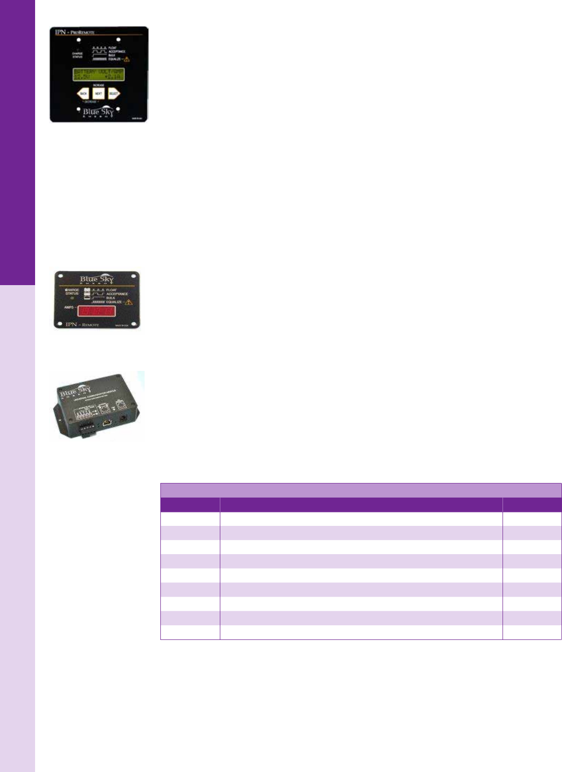
For the latest on AEE Solar products, trainings and dealer services, visit www.aeesolar.com
CHARGE CONTROLLERS
135
Blue Sky Energy
IPN Remotes and Optional Controller Accessories
Blue Sky Energy’s Integrated Power Net™, or IPN Network provides an integrated charge-controller
communication strategy. The advanced high-speed digital network allows up to eight IPN-capable
charge controllers to communicate with each other and operate in a master/slave conguration. Charge
parameters are set in the master, and the slaves automatically take on these settings and work with the
master to behave as a single charge-control machine. The IPN Network also allows networked controllers
to share an optional battery-temperature sensor and remote display. The IPN Network does not require
an additional controller, display, or other special communication hardware or software to operate.
The Solar Boost 3024iL, 2512iX-HV, and 1524iX charge controllers include load-control outputs so they
can also serve as lighting controllers. An IPN Pro-remote is required to enable and congure dusk-to-
dawn lighting control but does not need to remain connected to the system.
The IPNPRO Remote combines charge-controller monitoring and battery system monitoring in a
single remote display, eliminating the need for a separate battery monitor. A high-accuracy calculation
of remaining battery capacity compensates for a variety of factors, including charge/discharge current,
battery size, type, and temperature. Information learned from past battery behavior is used to continu-
ously improve metering accuracy. The IPN-ProRemote also monitors and controls Blue Sky's IPN-based
charge controllers. It can monitor both the combined total and individual status of up to 8 IPN charge
controllers on a single IPN network. Dimensions are 4½”H x 4½”W x 1½”D (11.4 cm x 11.4 cm x 3.8
cm) and it ts in a standard duplex wall-mount box.
The IPNREM remote display provides basic monitoring for IPN compatible charge controllers. The unit
displays battery voltage, output current and charge controller system status for up to eight controllers on
a single IPN network. An LED display is used to provide readability in any lighting. The charge-status
indicator displays system status and battery state-of-charge. When the battery is being charged, the dis-
play toggles between battery voltage and charge-controller-output current. The current display can be
congured to show the total output current from all controllers on the IPN network, or the output current
from a particular controller. Multiple IPN remote displays can be placed on a single IPN network even
if an IPN Pro-Remote is already present. Dimensions are 2 ½”H x 3”W x 1 ⅛”D (6.3 cm x 7.6 cm x 2.8
cm).
The Universal Communications Module (UCM) acts as a bridge between Blue Sky’s IPN Network and
external systems. A standard MODBUS RTU interface is provided both as isolated RS-485 and TCP\IP
Ethernet based MODBUS/IP and includes a built-in HTTP web server allowing data view and parameter
setup with a standard web browser either locally or globally over the Internet.
The Battery Temperature Sensor has 20' of cable can be used with any Solar Boost controller. Optional
shunts allow the IPN remotes to monitor other charging sources and loads.
The IPN Remotes are designed to be panel mounted (through a hole in a wall or panel). Use the MTG
BOX 2512 Wall-Mount Box for surface mounting.
Blue Sky Energy IPN Network Monitors and Controller Accessories
Model Description Item code
IPNPRO-S IPN Pro-Remote display with 500 A shunt 020-03161
IPNPRO IPN Pro-Remote display 020-03162
IPNREM IPN-Remote 020-03163
UCM Universal Communication Module – IPN to RS-485/Ethernet connection module 020-03166
930-0022-20 Battery-temperature sensor 020-03149
CS-100 Remote shunt 100 A / 100 mV 028-09245
CS-500 Remote shunt 500 A / 50 mV 028-09253
720-0011-01 Wall-Mount box for SB2000E, SC30, SC30-LVD, 3000i 020-03119
MTG BOX 2512 Plastic ABS wall-mount box - 2.50" (7 cm) deep. For SB2512i(X) and SB1524iX 020-03120

For the latest on AEE Solar products, trainings and dealer services, visit www.aeesolar.com
CHARGE CONTROLLERS
136
Atkinson
Atkinson Electronics Lighting Controllers
The fully-waterproof PVLC series charge and lighting controllers can be used with 12 or 24 VDC sys-
tems and are well suited for operating area lighting or signage. MD-designated controllers have a motion
sensor to activate the light or load when motion is sensed. Controllers with and without motion detectors
are available in 15 A and 40 A versions.
All controllers have low-voltage load disconnect (LVD) and temperature compensation and can be used
with sealed or ooded batteries.
Atkinson Lighting Controllers
Model System voltage PV and load cur-
rent Dimensions (H" x W" x D") Item code
PVLC-15 12 or 24 VDC 15 A 2 x 3 x 1.25 020-05425
PVLC-40 12 or 24 VDC 40 A 3.3 x 5.5 x 1.7 020-05427
PVLC-15MD 12 or 24 VDC 15 A 2 x 3 x 1.25 020-05432
PVLC-40MD 12 or 24 VDC 40 A 3.3 x 5.5 x 1.7 020-05435
Atkinson
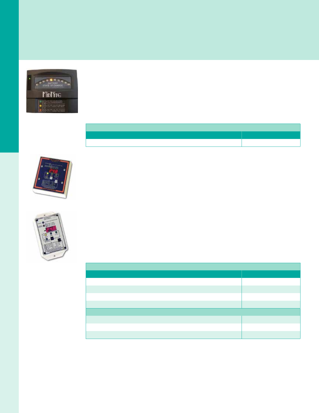
For the latest on AEE Solar products, trainings and dealer services, visit www.aeesolar.com
METERS & MONITORING
137
DC Meters
Battery Meters
Battery-capacity meters serve as a fuel gauge for a battery bank and are an important part of any battery system, both to ensure usability
and to properly maintain the battery bank. Simple battery-capacity meters read the voltage across the battery bank and determine a
state of charge accordingly. More sophisticated monitoring systems also use a DC shunt to monitor charge and discharge amp-hours.
In both cases, it is important that they be installed and calibrated according to manufacturer's instructions to ensure accuracy. See
Battery-Based Inverters for battery meters that are deployed as part of a larger power system, such as OutBack's FLEXnet™ DC.
MidNite Solar
Battery-Capacity Meter
Designed to simplify battery management, this Battery-Capacity Meter can be used on 12, 24, 36, and
48 VDC battery systems using ooded, AGM, and gel batteries. LEDs on the upper dial show present
battery capacity. Three lower LEDs show the time frame of the last full charge as “less than one week,”
“longer than one week,” or “longer than two weeks.” Handy for at-a-glance readings on golf carts, fork-
lifts, or any battery-powered devices. The meter face is 5"W x 4"H.
MidNite Solar Battery Capacity Meter
Description Item code
MidNite Battery-Capacity Meter 028-02260
Bogart Engineering
TriMetric 2030 and 2030-RV
This meter operates on 12, 24 or 48 VDC. LEDs show volts, amps, and amp-hours. Amp-hours can be
displayed directly or as “% full.” One LED indicates charging and fully-charged states. Another LED
indicates when charging or equalization is needed and warns of low battery-voltage events. The meters
also record minimum and maximum voltage, days since last charge, days since last equalized, and to-
tal lifetime amp-hours withdrawn. The TriMetric can be located up to hundreds of feet away from bat-
teries using inexpensive four-conductor twisted-pair meter wire. A shunt is required for operation. Use
the 500 A shunt on a 12 VDC inverter larger than 800 W, or a 24 VDC inverter larger than 1,600 W.
Use a 1,000 A, 100 mV shunt for systems with stacked inverters or where continuous current is over
300 A. The 1,000 A/100 mV shunt has the same resistance as the 500 A/50 mV shunt and may be used
interchangeably. Order the shunt separately. These meters work with battery banks up to 2,500 Ah.
The positive lead to the TriMetric should be fused with the included 1 A fuse. This meter can be
mounted ush or with a wire mold. Trimetric meters are made in U.S.A., have dimensions of 4.5"W x
4.75"H, and are covered by a two-year warranty.
Bogart Engineering TriMetric Amp-Hour Meters and Accessories
Description Item code
TriMetric 2030-A-F amp-hour meter 028-00028
TriMetric 2030-RV-F amp-hour meter 028-00027
Surface-mount box 028-00026
Four-conductor 18 AWG wire 050-01237
Shunts
500 A/50 mV shunt 028-09253
100 A/100 mV shunt 028-09245
1,000 A/100 mV shunt 028-09254
TM 2030 A-F
TM2030-RV-F
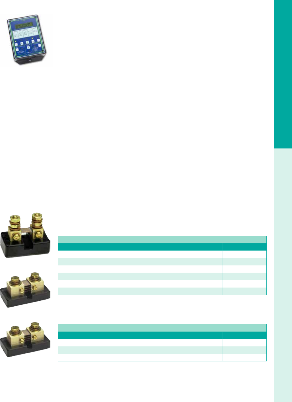
For the latest on AEE Solar products, trainings and dealer services, visit www.aeesolar.com
METERS & MONITORING
138
DC Meters
Bogart Engineering PentaMetric Battery Monitor
The PentaMetric Battery Monitor measures up to two separate battery systems with a common nega-
tive. The meter monitors battery current plus two charging sources/loads. The complete system consists
of an input unit placed near the batteries, a display unit that can be placed up to 1,000' from the battery
bank, and a computer-interface unit. It can monitor up to three shunts; for example, it can measure solar
input, wind input, and battery state-of-charge. Audible and visual alarms warn of high and low battery
conditions. An optional Windows software interface allows control of and access to all data from the
computer. A relay output enables control of a generator or external alarm. The PentaMetric is covered
by a standard two-year warranty.
Basic measurements
• Two voltage channels: 8-100 VDC
• Three current channels
- 200 ± 0.01 A with 100 A/100 mV shunt
- 1,000 ± 0.1 A with 500 A/50 mV or 1,000 A/10 mV shunt
• Temperature -20 °C to +65 °C
Secondary measurements
• Amp-hour (3 channels): up to ±83,000 Ah
• Cumulative (negative) battery amp-hours (two channels)
• Smoothed (time ltered) amps
• Volts (two channels): 0 to 100 VDC
• Watts (two channels) ±.01 up to 20,000 W
• Watt-hours (two channels) up to ±21,000 kWh
• Battery % full (two channels) 0 to 100%
• Days since batteries charged (two channels) .01 to 250 days
• Days since batteries equalized (two channels) .01 to 250 days
Data-logging functions
The Pentametric Battery Monitor has three data-logging modes that can run simultaneously. With the
computer interface, all three types can be output to a spreadsheet le. Periodically Logged data mode
records three amp-hour channels, two watt-hour channels, temperature max/min, voltage, and current at
regular intervals (once per day to once per minute). Battery Discharge Voltage Prole mode logs voltage
and current every time the charge level changes by 5% (or 10%) for up to two battery systems. Battery
Cycle Efciency mode documents system efciency for up to two battery systems.
Bogart Engineering PentaMetric Battery Monitor and Accessories
Description Item code
PentaMetric display unit PM-100D 028-00011
PentaMetric input unit PM-5000U 028-00013
Computer interface PM-100C with RS232 port 028-00015
Computer interface PM-101CE with Ethernet 028-00016
Computer interface PM-101USB with USB 028-00010
Temperature sensor TS-1 028-00018
Shunts
Use these shunts with Bogart Engineering TriMetric and Pentametric Battery Monitoring systems. These
shunts can also be used in other types of DC amp meters that use a remote shunt.
Shunts
Description Item code
500 A/50 mV shunt 028-09253
100 A/100 mV shunt 028-09245
1,000 A/100 mV shunt 028-09254
500 A/50 mV shunt
100 A/100 mV shunt
1,000 A/100 mV shunt
PM100D
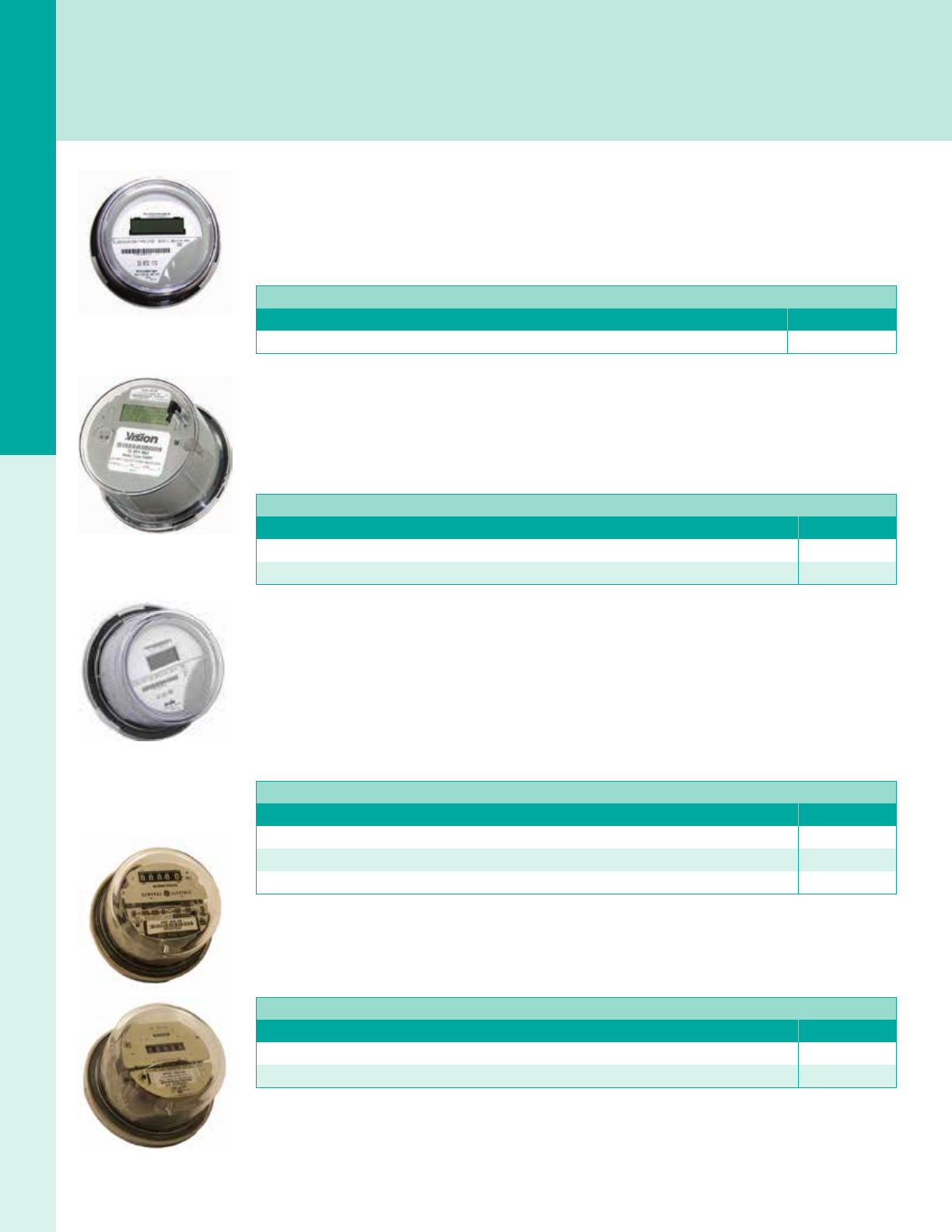
For the latest on AEE Solar products, trainings and dealer services, visit www.aeesolar.com
METERS & MONITORING
139
AC Kilowatt-Hour Meters
AC Kilowatt-Hour Meters
These meters are like those found near a typical residential or commercial utility-service entrance and can be used to meet nancing
or incentive-program requirements for PV-system output metering. Be sure to verify which meters are approved by the nancing
provider or incentive program you are using.
AC Kilowatt-Hour Meters
The ITRON LCD meter is the standard utility-grade meter seen on most homes. These reconditioned,
certied, utility-grade meters are an economical means for keeping track of how much net energy is
exported to the utility grid. The 028-03012 meter (Form 2S) works for 120 VAC or 120/240 VAC systems
with a maximum current of less than 200 A.
AC Kilowatt-Hour Meters
Description Item code
Kilowatt hour meter Form 2S ITRON LCD Digital 240 VAC CL200 028-03012
Vision Meter
These utility-grade digital smart kilowatt-hour meters employ current transformers for extremely accu-
rate measurement and long-term stability, even at low power levels. Non-volatile memory protects data
in the event of a power failure. The Vision Meter can display kWh delivered, kWh received, kWh net,
instantaneous demand, voltage, current, phase angle, and segment check.
Vision Meter Smart Kilowatt-Hour Meters
Description Item code
Vision kilowatt-hour meter form 2S 028-03061
Vision kilowatt-hour meter 3-phase form 14/15/16S 028-03063
Performance Based Initiative Approved Meters
These Smart meters appear on the gosolarcalifornia.org website list of approved meters for Performance
Based Initiative (PBI) systems. The ABB Alpha-A1D+ is designed for especially harsh climates and is
suitable for 600 VDC applications.
The Form 2S meter is used for single-phase, 120/240 VAC, three-wire installations.
The Form 9S meter is used for three-phase, 208 VAC, four-wire delta installations.
The Form 16S meter is used for three-phase, 208 or 480 VAC, four-wire Wye installations
PBI Approved Kilowatt-Hour Meters
Description Item code
ABB kilowatt-hour meter - PBI APPROVED, single-phase Form 2S, SP-AB-ALPHA-A1D+-FM2S 028-03093
ABB kilowatt-hour meter - PBI APPROVED, three-phase Form 9S, PP-AB-ALPHA-A1D+-FM9S 028-03094
ABB kilowatt-hour meter - PBI APPROVED, three-phase Form 16S, PP-AB-ALPHA-A1D+-FM16S 028-03095
Analog Form 2S Meters
These are 120/240 VAC Form 2S meters with visual cyclometer and analog gauges, with 100 A and 200 A
rated versions available. These meters are great for use as demonstration meters or for off-grid applications.
Itron Digital Meter with Cellular Modem
Description Item code
Analog kWh meter, EZ-read cyclometer, Form 2S, 240 V, 100A, Reconditioned 029-09016
Analog kWh meter, Form 2S, CL200, 200A, 240V, Reconditioned 029-09018
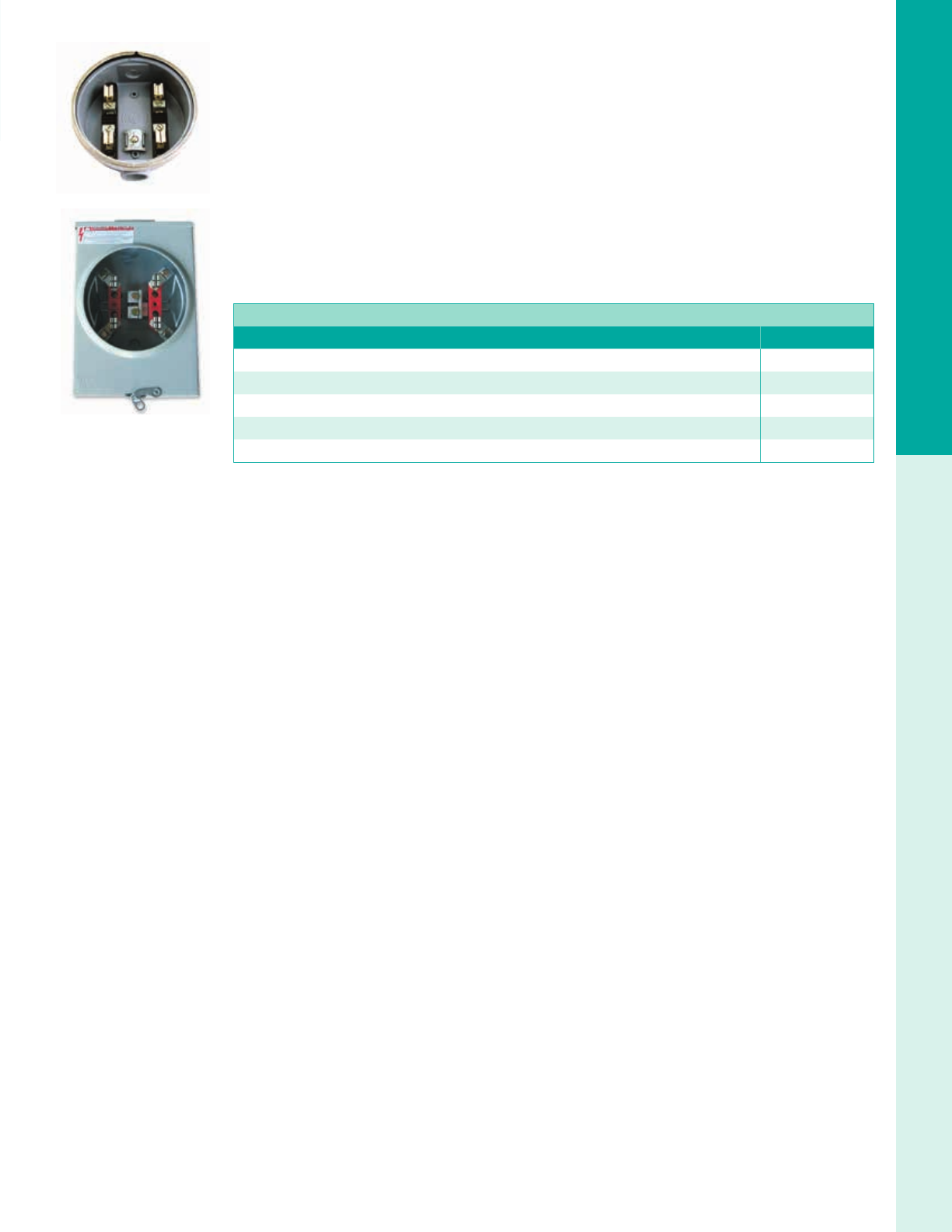
METERS & MONITORING
140
AC Kilowatt-Hour Meters
Kilowatt-Hour Meter Sockets
There are two types of kilowatt-hour meter bases available for single-phase two- or three-wire 100 A
service, and each includes a sealing ring.
The cast, Round base has 1 ½" threaded holes in the top and bottom and is not UL Listed.
The sheet-metal four-terminal sockets are rated for 100 A or 200 A, 240 VAC, and are used with the Form
2S meter for 120/240 VAC systems. UL listed and NEMA 3R rated for outdoor use.
For three-phase systems, use the appropriate socket for the meter form. The seven-terminal socket is
13"W x 19"H, rated at 200 A, 600 VAC and is used with Form 16S meters. It is a ringless socket with
a lever bypass, which allows removal of the meter without interrupting service. Use this socket for the
Locus Energy L-Gate 320 monitoring option. UL listed and NEMA 3R rated for outdoor use. The clos-
ing plate is used to cover the overhead entry into the sheet metal base when entering from either the
side or the bottom.
Kilowatt-Hour Meter Sockets
Description Item code
Kilowatt-hour meter socket 2S 120/240 VAC – Round, four-terminal 028-03025
Kilowatt-hour meter socket 2S 120/240 VAC NEMA 3R, 100 A, #12-1/0 AWG, four-terminal 048-09220
Kilowatt-hour meter socket 2S 120/240 VAC NEMA 3R, 200 A, #6 AWG-350 kcmil, four-terminal 048-09200
Kilowatt-hour meter socket 16S three-phase, four wire Wye, seven -terminal 048-09215
Closing plate 028-03032
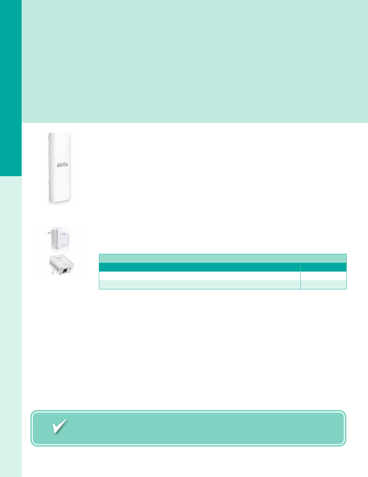
Need assistance? Call your AEE Solar rep, or Sales Support at 800-777-6609.
For the latest on AEE Solar products, trainings and dealer services, visit www.aeesolar.com
METERS & MONITORING
141
Grid-Tie System Monitoring
Grid-Tie System Monitoring
As grid-tied solar PV systems become more popular, online monitoring is playing an increasingly important role in both residential
and commercial systems. Most commercial PPA and residential leasing nanciers require revenue-grade monitoring to be coupled with
online reporting tools. Many incentive programs, particularly performance-based and renewable energy credit-based ones, also require
accurate real-time monitoring and some form of automated reporting. Many commercial and residential customers want something
they can point to when bragging about their solar PV system and an online monitoring system with a smart-phone app ts the bill
nicely. Savvy installers are also nding that online monitoring enables them to be proactive in managing their brand and often pair a
monitoring system with a service agreement that includes periodic cleaning and maintenance of the system. Whatever the motive, a
good online monitoring system can help reinforce the value of a solar PV system for years after installation.
In addition to the proprietary monitoring offered by most inverter manufacturers, we offer a variety of solutions that work with most
inverters to meet different application needs. Our monitoring partners can also set up branded solutions for your company that enable
you to centrally monitor all of your installed systems while putting your brand in front of the end-users every time they view their
system performance. Contact our AEE Solar (800-777-6609) for details.
Wireless Communications
EnGenius Outdoor-Rated Long-Range Wireless Bridge
The EnGenius ENH202 is a long-range, commercial grade, 802.11b/g/n outdoor 2.4 GHz wireless access
point/client bridge for transmitting monitoring data from a ground mount or remote building directly
to a wireless router. Capable of ranges as far as 2.5 miles (limited to the range of the router). For long
range transmission, two units may be needed with one unit located near the router. 64/128-bit WEP data
encryption and WPA/ WPA2 data security protocols are supported. A MAC address lter can be used to
limit network access to specic computers or devices.
Enphase Power Line Carrier – Ethernet Bridge Pair
The Enphase Power Line Carrier connects two Ethernet devices through existing electrical lines in
place of a hard-wired Ethernet cable. One device is plugged in to a nearby wall socket and the other
device is plugged into a socket near the router. Both devices should be plugged into a circuit fed by the
same main/sub panel to avoid noise from other appliances interfering with the signal. An Ethernet cable
is used to connect the bridge to either the monitoring device or router.
Ethernet Bridges
Description Item code
EnGenius outdoor-rated long-range wireless bridge 029-01607
Enphase Power Line Carrier - Ethernet bridge pair, EPLC-01 030-03752
EnGenius ENH202
EnPhase Power Line Carrier
Ethernet Bridge Pair
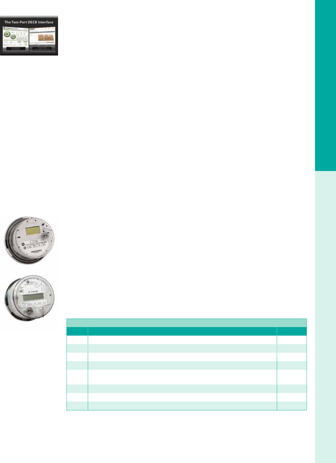
For the latest on AEE Solar products, trainings and dealer services, visit www.aeesolar.com
METERS & MONITORING
142
Grid-Tie System Monitoring
DECK
DECK Monitoring, now part of ALSO Energy, pairs advanced software with customer service to provide
a exible and scalable monitoring solution that is suitable for most residential and commercial applica-
tions. The customizable DECK Dashboard has many features to promote the end user's organization and
generate green PR. DECK alarms and analytics provide clear, actionable data and responsive support
services are available to assist in every aspect of system management.
DECK Monitoring
The monitoring solution from DECK is web-based software that lets you see your system data on comput-
ers and mobile devices. Each monitoring package includes a revenue-grade meter along with a gateway
device to prepare data for the web. Data is pushed out through the local web network (or by a cellular
modem for remote locations). Data goes rst to DECK web servers, then it populates to your two web
interfaces: the Dashboard and the Admin Panel. Here you will nd a suite of software tools to help man-
age your system, along with customizable “green PR” tools to promote your project and organization.
Additional features for expanded monitoring capabilities:
• Inverter communications (available with most brands)
• On-site weather station
• Satellite irradiance data
• DC-side granular monitoring
• Wireless communication aids
• Touchscreen monitors
• Software contract extensions
DECK monitoring solutions are highly customizable. Contact AEE Solar with the particulars of your
project to get a custom quote or go with one of the meter-based solutions on the following page.
Deck Residential and Light Commercial Monitoring Solutio
Deck Monitoring has released a new socket-meter-based solution that eliminates he need for on-site
Internet connection. Each meter includes a cellular modem, so the installer won’t have to deal with
comunications wiring and IT connections. The meter will measure the total kWh production of your
rsidential PV system. Data is recorded in 15-minute intervals throughout the day. Data sets are uploaded
o DECK data servers once daily at midnight, so your website displays show data from the previous day.
Also included is a ve-year data plan from Verizon.
DECK Residential is meant for 120/240 VAC split-phase residential systems up to 200 A, and utilizes
the I-210+c socket meter from GE. 2S meter socket not included.
Commercial Light projects must be three-phase four-wire projects with a system size no larger than
200 A. Qualifying systems also must not require any additional meters or devices; this solution is limited
to one revenue-grade meter for total system generation. The Commercial Lite utilizes the kV2c meter
from GE. 16S meter socket not included.
Deck Residential and Light Commercial Cellular Based Meters
Deck # Description Item code
211A Deck Residential meter with ve years monitoring, Form 2S 029-04099
2121 Deck Residential meter with ten years monitoring, Form 2S 029-04100
211B Deck Commercial meter with ve years monitoring, Form 16S 029-04101
2120 DeckCommercial meter with ten years monitoring, Form 16S 029-04102
210A Revenue-grade-meter, DataLogger and CT's, 100-277 VAC, ve-year subscription, unas-
sembled 029-04000
-- Kilowatt-hour meter socket 2S 120/240 VAC NEMA 3R, 200 A, #6 AWG-350 kcmil, four-terminal 028-09200
-- Kilowatt-hour meter socket 16S three-phase, four-wire Wye, seven-terminal 048-09215
-- Meter-socket closing plate 028-03032
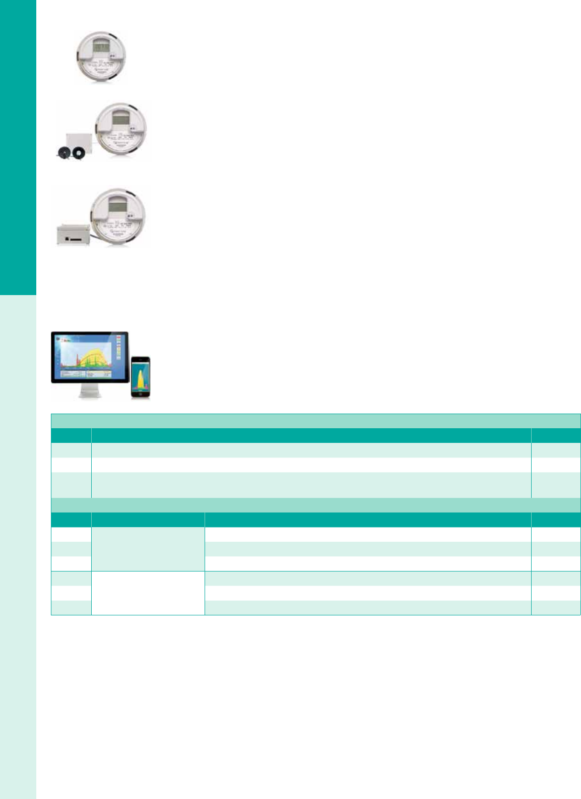
For the latest on AEE Solar products, trainings and dealer services, visit www.aeesolar.com
METERS & MONITORING
143
Grid-Tie System Monitoring
Solar Data Systems
Solar-Log® Residential PV Monitoring and Metering
The Solar-Log® Residential PV Monitoring solution is integrated into a high-quality General Electric
(GE) residential meter, and can be installed in a standard Form 2S meter socket for single-phase 120/240
VAC systems with up to 200 A output current. Direct connection and reporting is through the AT&T
cellular network, with the cellular plan and portal access included for the initial ve years. Additional
ve-year portal access and monitoring can be added at time of purchase, or in the future. Units utilizing
the T-Mobile network are also available upon request. System performance can be viewed over the Solar-
Log Dashboard monitoring portal, viewable on computer, iPhone, or Android devices. The monitoring
system is compatible with both micro and string inverters, and certied Revenue Grade Metering (RGM)
for incentive reporting.
The Solar-Log 350 & GE Meter is a plug-and-play device, and does not require onsite conguration,
allowing portal view of the PV plant yield and revenue-grade reporting. The Solar-Log 360 adds site
power and self-consumption data from current transformers placed around the utility-feed connections,
and allows plant owners to verify utility bills in addition to plant PV monitoring and reporting. The Solar-
Log 370 offers numerous I/O ports, like Ethernet and two RS485 ports that provide access to multiple
inverters, weather stations, or for additional power management current transformers to be added.
Solar-Log WEB® Online Monitoring Portal
Solar-Log WEB® enables installers and their customers to monitor installed systems from either PC or
Mac computers. The centralized control center provides easy management of an entire installed base of
systems. Precautionary monitoring identies faults quickly and easily to improve system uptime, increas-
ing customer loyalty and revenue from service contracts. For commercial systems, damage scope analysis
helps document insurance claims against loss of revenue due to system failure.
Solar-Log® Smart Phone Apps
The Solar-Log
®
Apps allow the convenient monitoring of solar PV plants from smart phones and tablets.
Customized daily, monthly, and annually, and overall performance information is presented graphically
and numerically in an easy-to-understand way. Both iOS (iPod / iPhone / iPad) and Android devices are
supported.
Solar-Log Residential Revenue Grade Meter
Model Description Item code
255850 Solar-Log 350 & GE Meter, with ve-year cellular plan and portal access, AT&T Network 029-06024
255851 Solar-Log 360 & GE Meter, adds site consumption monitoring, current transducers included, AT&T Network 029-06025
255852 Solar-Log 370 & GE Meter, adds I/O ports allowing consumption monitoring, inverter-direct monitoring, and/or weather station
through additional communication accessories, AT&T Network 029-06026
Solar-Log Accessories for Solar-Log 370 & GE Meter
Model Application Description Item code
220060
Solar-Log®
Weather Monitoring
Weather monitoring kit, includes irradiation and module temperature sensors 029-06309
220061 Wind sensor - connects to irradiation sensor 029-06310
220062 Ambient temperature sensor - connects to irradiation sensor 029-06311
806320
Solar-Log Meter CTs
Solar-Log CT 200 A (200 A CT for Solar-Log® Meter - closed core 200 A:200 mA) 029-06027
255640 Solar-Log CT 100 A (100 A CT for Solar-Log® Meter - closed core 100 A:200 mA) 029-06375
255638 Solar-Log CT 100 A (100 A CT for Solar-Log® Meter - split core 100 A:200 mA) 029-06376
Solar-Log 350 & GE Meter
Solar-Log 360 Including
Self-Consumption CTs
Solar-Log 370 Including
Ethernet & RS-485 Ports
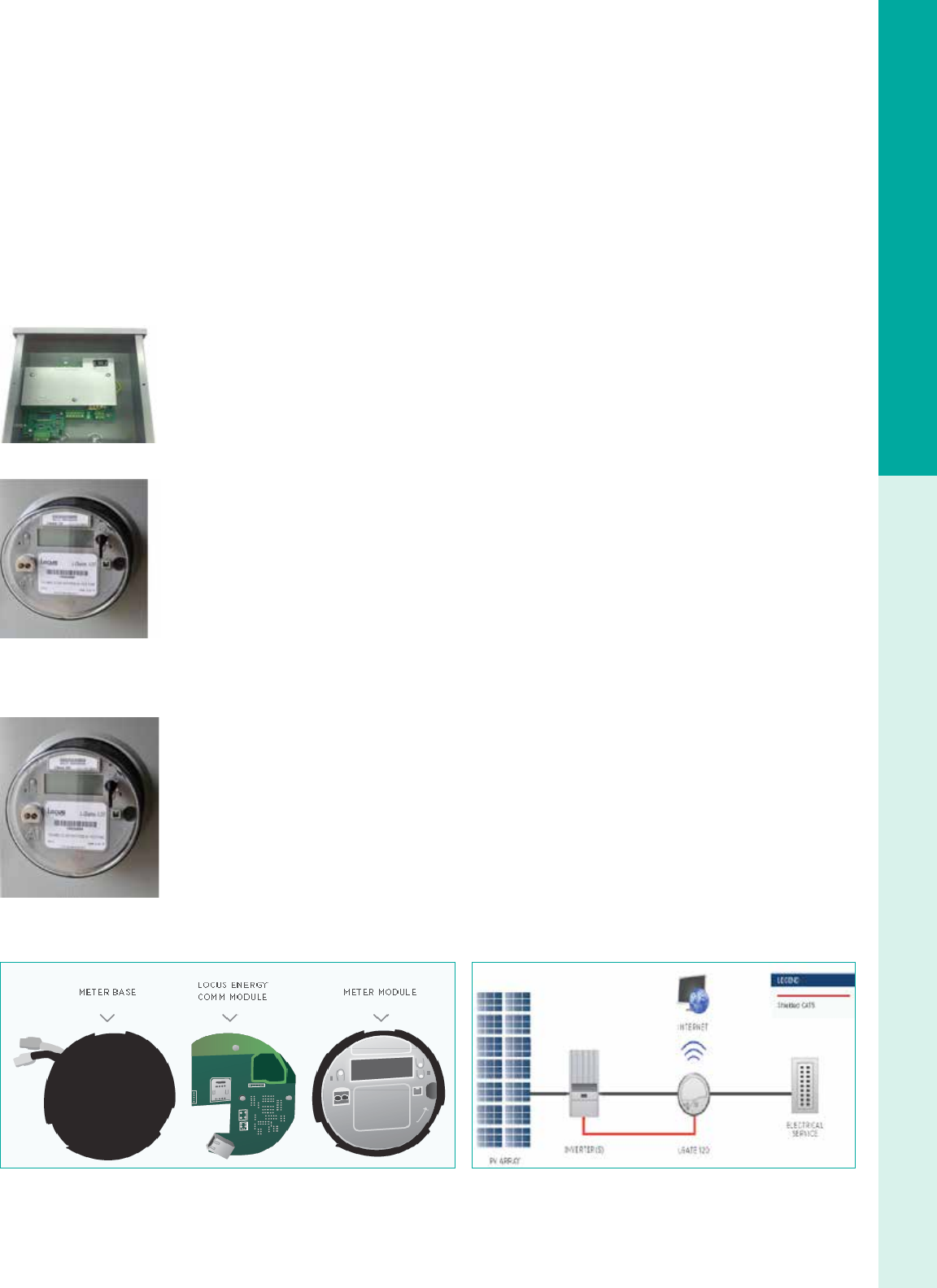
For the latest on AEE Solar products, trainings and dealer services, visit www.aeesolar.com
METERS & MONITORING
144
Grid-Tie System Monitoring
Locus Energy
Locus Energy offers pre-packaged metering and communications hardware with web-based software to
provide monitoring solutions for solar PV and thermal integrators. Locus hardware ships precongured
to upload system performance data to hosted servers. Installers and site owners can then track energy
generation via customized web portals.
Installers have access to eet monitoring tools to streamline operations and maintenance activities. Indi-
vidual site owners are given logins to portals branded by their installers so they can easily visualize and
understand how their systems are performing. The datalogger can communicate over Ethernet, power line
carrier (PLC), or cellular networks. Data is transmitted only in outbound sessions over open ports requir-
ing no additional network or rewall conguration. All data feeds are stored in nonvolatile memory and
then uploaded with unique identiers to provide maximum exibility in online data presentation. LED
lights indicate communication status without installers having to log in or call home. The datalogger is
housed in a NEMA 3R enclosure for the LGate 101.
LGate 101
The LGate 101 is a CT-based revenue-grade residential monitoring solution. It uses solid-core CTs to
measure power. There are inputs for up to three CTs allowing the LGate to measure both solar-energy
generation and whole-house electrical consumption. It can also gather data from up to 16 third-party
devices simultaneously, which is collected via RS485 and Modbus RTU protocols. Hard-wired Ethernet
is the preferred connection method, but the LGate also features a built-in 110 VAC outlet for easy instal-
lation of a PLC adapter or Ethernet bridge.
LGate 120
The LGate 120 combines a 240 VAC revenue-grade, solid-state power meter with an integrated datalog-
ger, communications gateway, and a 3G GSM cellular modem. These components work in conjunction to
remotely monitor the performance of residential solar-energy installations regardless of panel or inverter
type. The LGate 120 is a one-piece, completely-under-glass-meter, which installs easily using a stan-
dard Form 2S socket base. Performance data is uploaded in near real-time to the Locus Energy SolarOS
monitoring platform, which provides a suite of tools and analytics for asset managers.
The communications gateway inside the LGate 120 supports plug-and-play connectivity through Ethernet
or cellular network connection through AT&T. Additional system performance data, including inverter-
direct from supported inverters and meteorological sensors, can be collected directly via RS-485 or
Zigbee connections.
LGate 320
The LGate 320 is a three-phase 208 or 480 VAC electronic watt-hour meter for remote monitoring of
light commercial solar PV systems up to 320 A. Like the LGate 120, the LGate 320 combines a revenue-
grade, solid-state power meter with an advanced communications gateway which can communicate over
cellular or Ethernet networks.
The meter installs easily on a Form 16S meter socket. Additional system performance data, including
inverter-direct from supported inverters and meteorological sensors, can be collected directly via RS-485
or Zigbee connections.
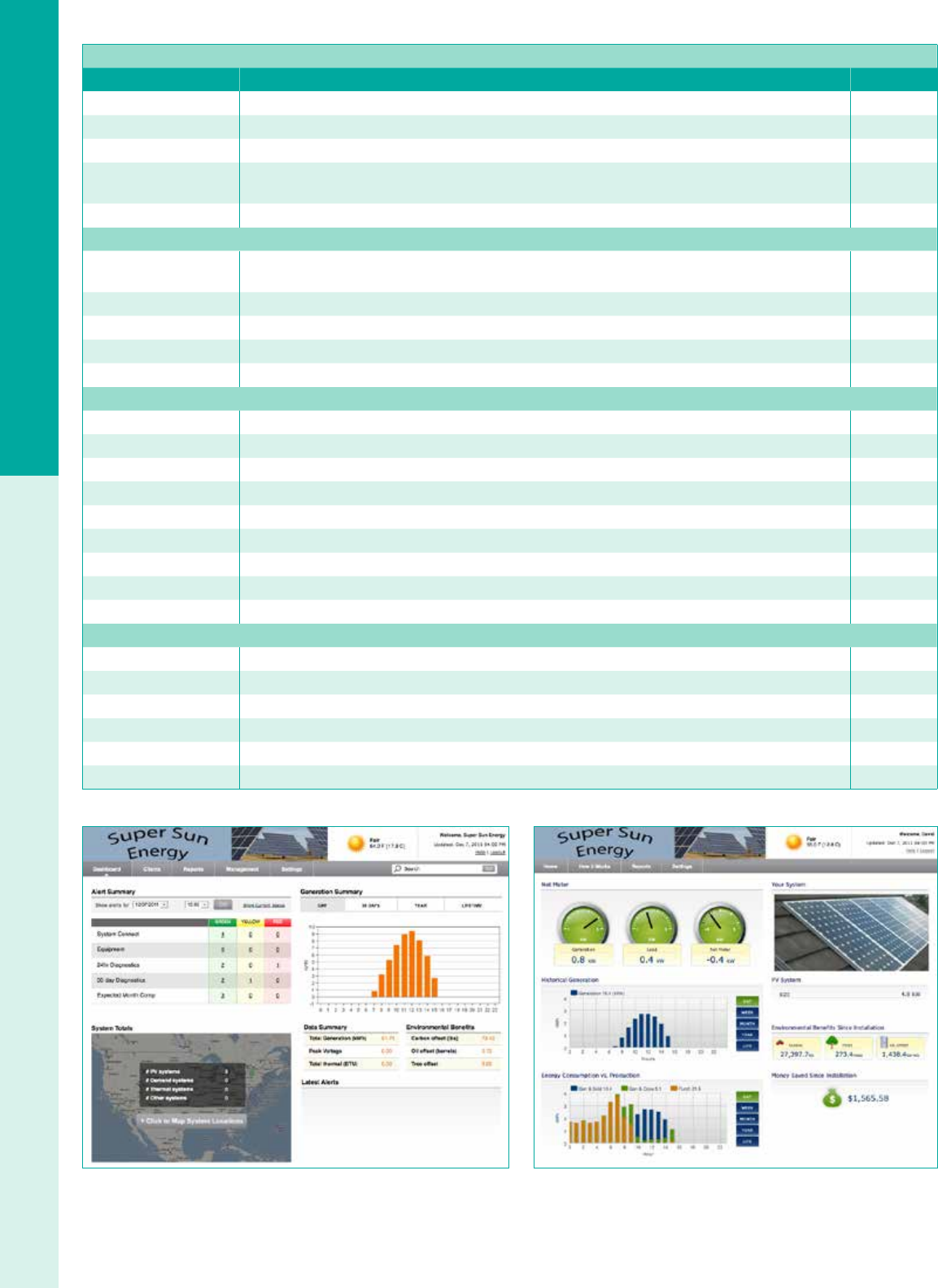
For the latest on AEE Solar products, trainings and dealer services, visit www.aeesolar.com
METERS & MONITORING
145
Grid-Tie System Monitoring
Locus Energy L Gate PV Monitoring Systems
Model Residential bundles Item code
SPPVB5-101 Single-Phase Revenue-grade PV monitoring. Includes LGate101 data logger & ve years PV monitoring 029-05205
SP-ADD-CONS-5YR Two split-core CTs (200 A rated) & ve years consumption monitoring 029-05211
SP-ADD-CONS-600-5YR Two split-core CTs (600 A rated) & ve years consumption monitoring 029-05212
LGate-120-5YR LGate 120 single-phase revenue-grade PV monitoring. Includes socket meter, one time set-up fee,
cellular modem, & ve years PV monitoring. (Note: add cellular service plan below) 029-05243
CPLAN-ATT-1MB-5YR Five-year cellular service plan AT&T - 1 MB (LGate 120) 029-05247
Light Commercial Bundles Including Metering Hardware and Monitoring Service
LGate-320-5YR LGate 320 three-phase revenue-grade PV monitoring. Includes socket meter (rated up to 320 A AC),
one time set-up fee, cellular modem & ve years PV monitoring. (Note: add cellular service plan above) 029-05244
CPLAN-ATT-10MB-5YR Five-year cellular service plan AT&T - 10 MB (LGate 320) 029-05248
KPC Hard drive pre-congured for kiosk 029-02526
KSOF-001 Kiosk software per location 029-02525
KCT-001 Kiosk custom tab or additional images 029-05246
Licensing and Data Hosting
C-PVM-5YR Three-phase PV data feed for ve years 029-02529
C-LOM-5YR Three-phase load monitoring for ve years 029-05236
C-IDM-5YR Large three-phase inverter-direct monitoring for ve years 029-02545
C-MS-IDM-5YR Mid-Size three-phase inverter-direct monitoring for ve years 029-05237
C-SM-IDM-5YR Small or single-phase inverter-direct monitoring for ve years 029-05238
C-STM-5YR String monitoring - rst feed for ve years 029-05239
C-COM-5YR Commercial combiner-box monitoring - rst feed for ve years 029-02547
C-DCC-1YR Commercial DC combiner-box monitoring - rst feed for one year 029-05240
C-ADM-5YR Additional feed for string or combiner-box monitoring ONLY 029-05241
Hardware Accessories
WIS114-101 Irradiance sensor measures panel temp, single port 029-02520
F-IMT Full weather station with irradiance, ambient temp, cell temp, and wind speed 029-05245
WIS114-102 Irradiance sensor with two ports, allows for the ability to measure ambient temp and wind speed 029-02517
WAT114-100 Ambient temperature sensor 029-02518
WPT114-103 Back-panel-temperature sensor 029-02515
WWS114 Wind-speed sensor 029-02519
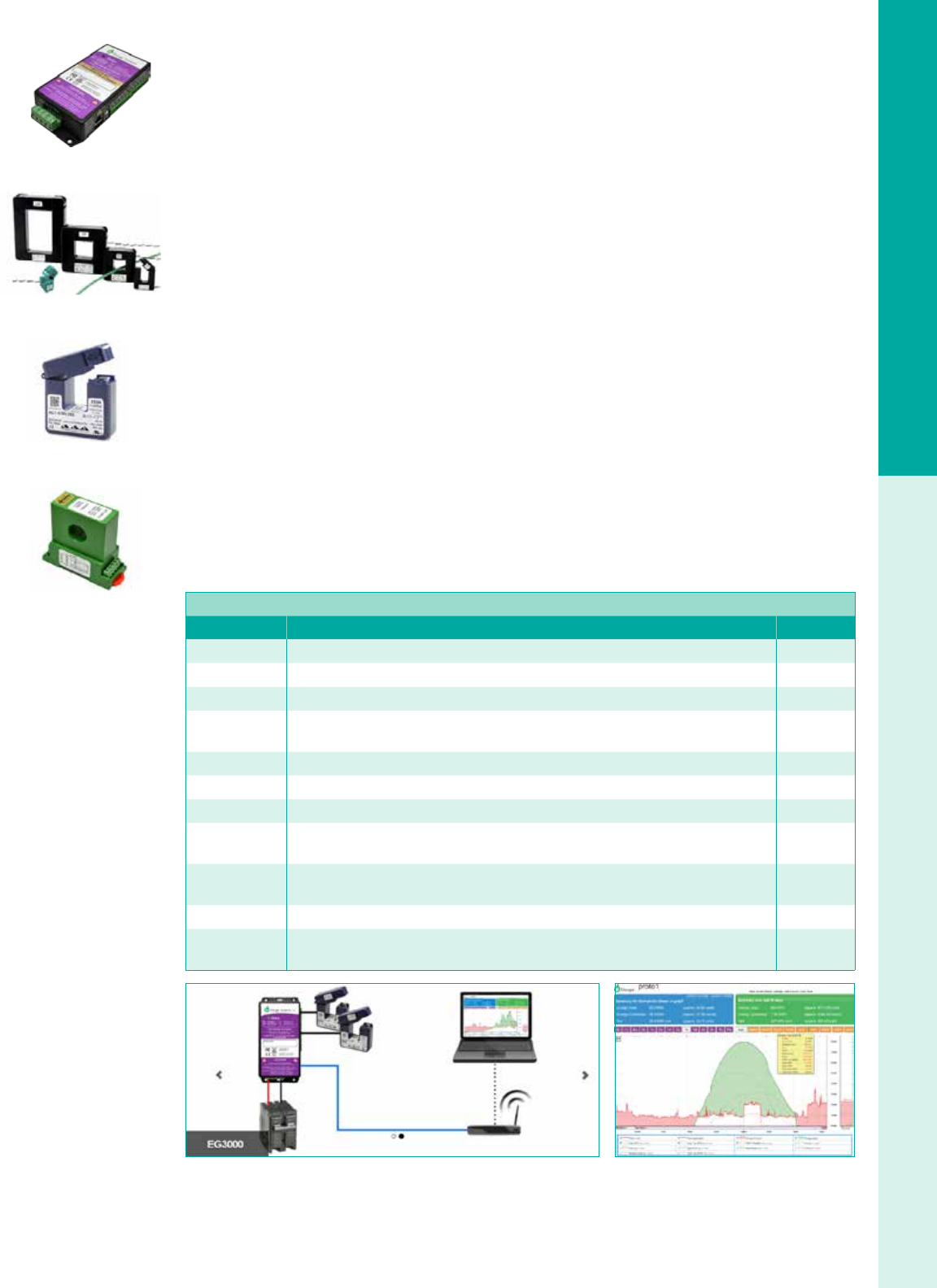
For the latest on AEE Solar products, trainings and dealer services, visit www.aeesolar.com
METERS & MONITORING
146
Grid-Tie System Monitoring
eGauge Consumption Level and Renewable Energy Monitoring
eGauge combines consumption and renewable energy production monitoring in one unit for both
commercial and residential applications. Up to 12 current transformers (CT’s) can be attached to the
Datalogger and up to 16 registers can be reported per datalogger and monitored through the web portal.
Multiple dataloggers may be linked together and set up on one portal display if more CT inputs or output
registers are needed.
The eGague EG3000 datalogger can be mounted directly in a power distribution panel for easy access
and wiring or inside a separate enclosure if space inside the panel is limited, and is directly wired to the
power panel on a 20 A two or three-pole breaker. The eGague EG3010 includes an Ethernet-over-powerline
adapter allowing additional Internet connection options. eGague can be utilized for single-phase 240
VAC applications, as well as 208 VAC or 480 VAC three-phase applications.
The eGauge CT’s are installed around the service conductors to the building to determine utility supply,
around the renewable energy source circuits to determine PV production, and around individual circuits
for specic consumption monitoring. Users may choose which information is displayed on the portal
view. Split Core AC-CTs are used for AC circuits, and Solid Core DC-CTs can be used for DC circuits.
Specify amperage of circuits when ordering. Typical CT’s for residential and commercial applications are
listed, other ranges available upon request. Revenue Grade AC Accu-CTs are available with +/-0.5%
Accuracy when paired with an eGauge datalogger that has been certied to higher accuracy levels.
The eGauge monitoring system can be congured to provide:
• Real-time energy consumption from utility or per-load circuits
• Renewable energy production monitoring for multiple inverters
• Establishing building benchmark and LEED points
• Analyzing and reducing peak demand
• Providing analysis for Energy Efciency Product and system commissioning
• User-dened email or text alerts
eGauge Systems EG3000 Series Energy Meters
Model Description Item code
A000-ETH-016 EG3000 datalogger with Ethernet connection 029-05300
A005-ETH-016 EG3000 with Ethernet connection and +/- 0.5% certication report 029-05301
A000-PLC-016 EG3010 datalogger with Ethernet connection and HomePlug® AV 029-05302
A005-PLC-016 EG3010 datalogger with Ethernet connection, HomePlug® AV,
and +/- 0.5% certication report 029-05303
SCT0400-050 Split-core CT – AC current sensor - #14 to #2 AWG, 50 A (other amperages available) 029-05304
SCT0750-100 Split-core CT – AC current sensor – 1/0 to 4/0 AWG, 100 A (other amperages available) 029-05305
SCT0750-150 Split-core CT – AC current sensor – 1/0 to 4/0 AWG, 150 A (other amperages available) 029-05306
SCT1250-200 Split-core CT – AC current sensor – 250 to 750 MCM, 200 A
(other amperages available) 029-05307
SCT1250-400 Split-core CT – AC current sensor – 250 to 750 MCM, 400 A
(other amperages available) 029-05308
ACT-0750-xxx Split-core Accu-CT – Revenue-grade AC current sensor (specify amperage rating) CALL
CR-5220-xxx Solid-core DC-CT – DC current sensor, with 120 VAC power supply
(specify amperage rating) CALL
eGauge EG3000
Split Core AC-CT
Revenue Grade AC Accu-CT
Solid Core DC-CT

For the latest on AEE Solar products, trainings and dealer services, visit www.aeesolar.com
BATTERIES
147
System Design
Batteries
Virtually all power generation systems require some form of energy storage. For grid-tied systems, the utility accepts surplus power
and gives it back when needed. A battery bank is required for systems that need to function without the grid, either all of the time or
during an outage. In these systems, the solar array or wind turbine charges the batteries whenever they are producing power, and the
batteries supply power whenever it is needed.
Battery Technologies
The most common battery technology used is lead-acid, in which lead plates are used with a sulfuric acid electrolyte. The electrolyte can
be uid or absorbed in berglass mats (AGM), or gelled. AGM and gel batteries are together known as VRLA (Valve Regulated Lead
Acid) and are sealed, do not require water addition, and do not emit gases when operated within specications. Lead-acid batteries are
relatively inexpensive and readily available compared to other battery types. New advanced lead-acid batteries have carbon additives in
the negative plate to prevent sulfation at partial states of charge (PSoC), while remaining less expensive than high-technology batteries.
Lithium Ion batteries can handle large charging and load currents. They are also lighter weight and compact for their power and
energy capacity. One advantage of Li-Ion batteries is their long life even when cycled heavily, and without needing to be brought to
a full state of charge each cycle. This makes them particularly suitable for short to long-duration use in self-consumption systems
where net metering is unavailable or utility rate structures otherwise disincentivize energy exports during peak solar production hours.
Aqueous hybrid sodium-ion batteries, e.g. Aquion, have signicant safety and environmental advantages over traditional batteries.
They are made from non-toxic materials and have an aqueous electrolyte that is non-ammable. They have the ability to cycle for
many years at any state of charge, making them suitable for systems that need to take advantage of charging when available, and
do not need to be fully charged like lead batteries. They are ideal for long duration applications such as off-grid systems, or larger
capacity self-consumption systems. These batteries are very robust, but are similar in size and weight to lead-acid batteries and must
be sized carefully to ensure appropriate current for loads or charging.
Standby or Cycling Batteries
Batteries come in a wide variety of sizes and types, but the most important designation is whether they are made for daily cycle service
or standby service. Automobile starting batteries should not be used for renewable energy systems.
Standby power batteries are designed to supply power to loads for occasional use, and are preferred for grid-tied solar systems with
battery backup. They are optimized to supply moderate to large amounts of power only during utility power outages, and oat at full
charge most of the time. They are designed to use a minimal amount of energy to stay fully charged. They are not made for frequent
deep discharges and have a limited cycle life but often very long calendar life when kept in oat conditions. AGM batteries are most
common for standby power applications as they are less expensive, have low self-discharge and require little to no manual maintenance.
Deep cycle batteries, are designed to be repeatedly discharged by as much as 80% of their capacity and are therefore a better choice for
off-grid PV systems. Even when designed to withstand deep cycling, most batteries will have a longer life if the cycles are kept shallower.
Deep cycle batteries can be either ooded or sealed lead-acid variants or, increasingly, newer chemistries like lithium-ion or sodium-ion.
Caring for Batteries
Maintenance requirements vary by battery chemistry and conguration. Additionally, some maintenance tasks, such as adding water or
equalization, require on-site manual operations and/or oversight, while charge regulation, voltage checks and related measurements can be
automated via sophisticated charge controllers or battery management systems, which are a de facto requirement for lithium-ion batteries.
Sealed lead-acid batteries, gel cells and AGM (Absorbed Glass Mat), are often referred to as maintenance-free because they don’t
require watering or an equalization charge. This makes them well-suited for remote or unattended power systems. However, sealed
batteries require accurate regulation to prevent overcharge and over-discharge.
Lead-acid batteries should always be recharged as soon as possible. The positive plates change from lead oxide, when charged, to
lead sulfate, when discharged. The longer they remain in the lead sulfate state, the more of the plate remains lead sulfate when the
battery is recharged. The portion of the plates that become “sulfated” can no longer store energy. Batteries that are deeply discharged
and then only partially charged on a regular basis often fail in less than one year. The new lead-carbon batteries substantially reduce
sulfation. Always use temperature compensation when charging batteries to prevent over or under-charging. NOTE: Battery warran-
ties do NOT cover damage due to poor maintenance or loss of capacity from sulfation.
Check the electrolyte level in wet-cell, or “ooded” batteries, at least once every three months and top-off each cell with distilled water.
Do not add water to discharged batteries! Electrolyte is absorbed when batteries are discharged, so if you add water at this time and then
recharge the battery, electrolyte will overow and create a safety hazard. Keep the tops of your batteries clean and check that cables are
tight. Do not tighten or remove cables while charging or soon after charging! Any spark around batteries can cause a hydrogen explosion
inside the case and potentially ignite a re or an even larger explosion if the batteries are not properly vented. Use a hydrometer to check
the specic gravity of your ooded lead-acid batteries. If batteries are cycled very deeply and then recharged slowly, the specic gravity
reading will be lower because of incomplete mixing of electrolyte. An equalizing charge will help mix the electrolyte.
An “equalization” charge should be performed on ooded batteries whenever cells show a variation of 0.05 or more in specic gravity
from each other. This is a long steady overcharge, bringing the battery to a gassing or bubbling state. Do not equalize VRLA batteries!
With proper care, lead-acid batteries will have a long service life and work very well in almost any power system.
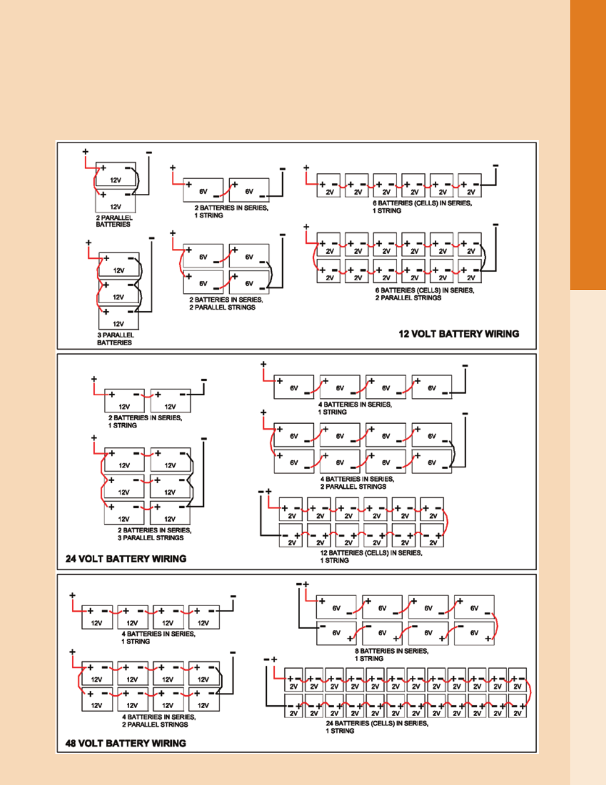
For the latest on AEE Solar products, trainings and dealer services, visit www.aeesolar.com
BATTERIES
148
System Design
Always use extreme caution when handling batteries and electrolyte (sulfuric acid). Wear appropriate personal protective equipment,
including electrical- and chemical-resistant gloves with sleeves, goggles, and acid-resistant clothing. “Battery acid” will instantly
burn skin and eyes and destroy cotton and wool clothing. Similar precautions apply to other battery types – always read and adhere
to manufacturer safety recommendations when handling batteries. For any type of battery, be sure to remove any metal jewelry and
avoid shorting the battery terminals.
Battery Wiring Diagrams
The diagrams below show typical 12 VDC, 24 VDC and 48 VDC battery wiring congurations. Batteries can deliver extremely high
current. Always install overcurrent protection on any positive wiring connected to batteries.

For the latest on AEE Solar products, trainings and dealer services, visit www.aeesolar.com
BATTERIES
149
System Design
Battery State-of-Charge
Battery state-of-charge (SOC) can be measured by an amp-hour meter, voltage, or by specic gravity. Some care and knowledge is
required to interpret state-of-charge from voltage or specic gravity readings. We recommend amp-hour meters for all systems with
batteries. An amp-hour meter is like a fuel gauge for batteries and provides all the information needed to keep batteries charged. At
a glance, the user can see system voltage, current, and battery condition (see Meters and Monitoring).
Battery voltage will vary for the same state-of-charge depending on whether the battery is being charged or discharged, and what
the current is in relation to the size of the battery. The table below shows typical battery voltages at each state-of-charge for various
battery conditions in ooded lead-acid batteries. Voltage varies with temperature. While charging, a lower temperature will increase
battery voltage. Full-charge voltage on a 12 VDC battery is 0.9 VDC higher at 32 °F than at 70 °F. While discharging, a higher
temperature will increase battery voltage. There is little temperature effect while a battery is idle, though higher temperatures will
increase the self-discharge rate.
Source: Ralph Heisey of Bogart Engineering.
Battery Voltage at Various States of Charge
Battery condition at 77 °F Nominal battery voltage
12 VDC 24 VDC 48 VDC
Battery during equalization charge > 15 VDC > 30 VDC > 60 VDC
Battery near full charge while charging 14.4 – 15 VDC 28.8 – 30 VDC 57.6 – 60 VDC
Battery near full discharge while charging 12.3 – 13.2 VDC 24.6 – 26.4 VDC 49.2 – 52.8 VDC
Battery fully charged with light load 12.4 – 12.7 VDC 24.8 – 25.4 VDC 49.6 – 50.8 VDC
Battery fully charged with heavy load 11.5 – 12.5 VDC 23 – 25 VDC 46 – 50 VDC
No charge or discharge for six hours - 100% charged 12.7 VDC 25.4 VDC 50.8 VDC
No charge or discharge for six hours - 80% charged 12.5 VDC 25 VDC 50 VDC
No charge or discharge for six hours - 60% charged 12.2 VDC 24.4 VDC 48.8 VDC
No charge or discharge for six hours - 40% charged 11.9 VDC 23.8 VDC 47.6 VDC
No charge or discharge for six hours - 20% charged 11.6 VDC 23.2 VDC 46.4 VDC
No charge or discharge for six hours -fully discharged 11.4 VDC 22.8 VDC 45.6 VDC
Battery near full discharge while discharging 10.2 – 11.2 VDC 20.4 – 22.4 VDC 40.8 – 44.8 VDC
A hydrometer is very accurate at measuring battery state-of-charge in ooded lead-acid batteries if you measure the electrolyte near
the plates. Unfortunately, you can only measure the electrolyte at the top of the battery, which is not always near the plates. When
a battery is being charged or discharged, a chemical reaction takes place at the border between the lead plates and the electrolyte.
The electrolyte changes from water to sulfuric acid while charging. The acid becomes stronger, increasing the specic gravity, as the
battery charges. Near the end of the charging cycle, gas bubbles rising through the acid stir the uid. It takes several hours for the
electrolyte to mix so that you get an accurate reading at the top of the battery. Always try to take readings after the battery has been
idle or slowly discharging for some time.
This table shows the battery state-of-charge corresponding to various specic gravities for a battery bank in an ambient temperature
of 75 °F. Some batteries will have a different specic gravity density by design, check with the manufacturer.
Hydrometer Readings at Ambient Temperature of 75˚F
State-of-charge Specic gravity
100% charged 1.265
75% charged 1.239
50% charged 1.2
25% charged 1.17
Fully discharged 1.11

For the latest on AEE Solar products, trainings and dealer services, visit www.aeesolar.com
BATTERIES
150
System Design
Worksheet: Battery Size
To properly design a battery bank, you need to account for the storage capacity required, the maximum discharge rate (the sum of
all the loads which might be run simultaneously), the maximum charge rate (the current output from the solar array or wind turbine
though the charge controller), and the minimum ambient temperature at which the batteries will be used. Whichever of these factors
requires the largest capacity will dictate the size of the battery bank. The storage capacity of a battery, the amount of electrical energy
it can hold, is usually expressed in amp-hours (Ah). Using one amp for 100 hours means 100 Ah have been used. The Ah capacity
of a battery will change depending on the rate of discharge. The faster the power is drawn out, the less overall capacity the battery
will have. A battery bank in a PV power system should have sufcient capacity to supply needed power during the longest expected
period of cloudy weather when the solar array cannot keep up. This can be anywhere from two days to two weeks or more. If there is
a source of on-demand backup power, such as a standby generator with a battery charger, the battery bank does not have to be sized
for worst-case weather conditions. In an off-grid system the battery is usually three or more days at 80% depth of discharge, sizing
for two days or less will degrade the system performance and require more frequent use of a backup generator.
Use this worksheet to determine what size battery bank is required for your system. Battery voltage is determined by the number of
“cells” in series. All lead-acid battery cells have a nominal output of 2 VDC. Actual cell voltage varies from about 1.7 VDC at full
discharge to 3.0 VDC at full charge. 12 VDC lead-acid batteries are made of six separate cells in one case. 6 VDC batteries are made
of three cells in one case. Putting battery cells in parallel increases amp-hour capacity, but does not change voltage.
Contact AEE technical support for systems with particularly large loads, charging currents, or other unusual parameters.
Step 1: Total watt-hours per day required (see Off-Grid Load Worksheet on page 9).
Step 2: Maximum number of continuous cloudy days of desired backup (usually three or more days).
Step 3: Multiply Step 1 result by Step 2 result.
Step 4: Divide the Step 3 result by 0.5 for 50% depth of discharge or
by 0.8 for 80% depth of discharge (Using 0.5 will maintain
a 50% reserve and maximize battery life, 0.8 will maintain a
20% reserve and minimize battery bank size).
Step 5: If you are using a lead-acid battery, select the multiplier from
the table that corresponds to the battery’s wintertime aver-
age ambient temperature and multiply by the result from
Step 4 to get total energy storage required in kilowatt-hours
(Battery temperature varies over a period of many days, not
day to night).
Step 6: Divide the energy storage requirement from step 5 by the DC
voltage of the system (48 VDC is preferred, but sometimes
24 VDC) to get battery amp-hour (Ah) capacity needed.
Step 7: Capacity of preferred battery in amp-hours.
Step 8: Divide the Step 6 result by the Step 7 result and round up to a whole number to determine total
parallel strings required. (Best to have two or fewer parallel strings, not more than three strings.
Check battery specs to make sure the charging current will not be too high for the chosen battery).
Step 9: Divide the system voltage (12 VDC, 24 VDC, or 48 VDC) by the voltage of the chosen battery
(2 VDC, 6 VDC or 12 VDC) to determine the number of batteries in each string.
Step 10: Multiply the Step 8 result by the Step 9 result to determine the total number of batteries needed.
Battery Bank Average Low
Temperature Sizing Multiplier
Battery temperature Multiplier
80 ºF [26.7 ºC] 1
70 ºF [21.2 ºC] 1.04
60 ºF [15.6 ºC] 1.11
50 ºF [10.0 ºC] 1.19
40 ºF [4.4 ºC] 1.3
30 ºF [-1.1 ºC] 1.4
20 ºF [-6.7 ºC] 1.59
Optimize Your FLEXpower System with EnergyCell Batteries
Large or small, o-grid or on, OutBack power has EnergyCell batteries to t virtually any renewable energy scenario. Designed for a
wide range of applications, every EnergyCell battery is optimized for use with OutBack power electronics.
FLEXpower Radian
FLEXpower FOURFLEXpower ONE
Take the guesswork
out of your best work—
OutBack Power based its FLEXware platform on proven customer designs to
provide a factory-built, pre-configured, pre-wired and pre-tested alternative
to designing individual projects from scratch. FLEXpower quickly became a
best seller in the demanding o-grid market.
Now there are FLEXpower solutions for all renewable energy projects,
including the NEW FLEXpower Radian—based on OutBack’s Grid/Hybrid Radian
Series. All advanced Radian Series features, including GridZero energy blending,
Advanced Battery Charging and dual AC inputs, are available in 4kW or 8kW systems
designed to take the guesswork out of your installations.
OutBack’s industry-leading FX-based FLEXpower systems are also now available
with the advanced FXR, putting the latest Grid/Hybrid technology into OutBack’s
classic FX form factor.
Your time is valuable—with FLEXpower you can spend less time on
balance-of-system, and more time adding value to all of your installations.
with custom systems from OutBack Power.
For the latest on AEE Solar products, trainings and dealer services, visit www.aeesolar.com
BATTERIES
152
Sealed Batteries
OutBack Power
EnergyCell™ RE Top-Terminal Batteries
The EnergyCell™ RE Top-Terminal Absorbed Glass Mat (AGM) batteries are available in a variety of
capacities from 33 to 100 Ah. These 12 VDC batteries feature low prole terminals with threaded copper
alloy inserts that take 10-32 UNF screws for the 34RE and 52RE sizes, and 1/4"-20 UNC for the larger
sizes. These are rated for 1,800 cycles at 50% depth of discharge. They are appropriate for most moderate
power applications and are designed to t in standard Case 31 enclosures. Made in U.S.A.
EnergyCell™ RE Batteries
These front-terminal (FT) batteries and enclosure install more easily and in less space than other rack-
mounted solutions. As sealed AGM batteries, they require no electrolyte maintenance and are made for
both cycle and oat service. The large capacity of these batteries reduces the number of parallel strings
required to serve a stand-alone or backup power system. These are rated for 1,800 cycles at 50% depth
of discharge. Maximum continuous charge rate is 35 A. The protected front-terminal cable attachment
allows safe, easy, space-efcient installations. One busbar is included with each battery and is used to
make series connections between side-by-side batteries. Made in U.S.A.
EnergyCell™ GH Batteries
The OutBack EnergyCell™ GH front-terminal rack-mount batteries are made for backup power applica-
tions. These have very low self-discharge and very high charge and discharge efciency, making them
ideal for grid-tied solar systems with backup. GH batteries are rated for ten years or more of service in
oat charge but are not intended for repeated deep cycle applications. Maximum charge rate is 102 A. The
protected front-terminal cable attachment allows safe, easy, space-efcient installations. One busbar is
included with each battery and is used to make series connections between side-by-side batteries. Imported.
OutBack EnergyCell Batteries and Racks
Model Volts Capacity Dimensions
(L" x W" x H") Weight Item code
3-hr rate 8-hr rate 20-hr rate 100-hr rate
34RE 12 VDC 26 Ah 30 Ah 33 Ah 34 Ah 7.8 x 5.2 x 6.8 27 lbs 040-01175
52RE 12 VDC 39 Ah 46 Ah 50 Ah 52 Ah 9.0 x 5.5 x 8.1 40 lbs 040-01176
78RE 12 VDC 58 Ah 70 Ah 75 Ah 78 Ah 10.8 x 6.8 x 8.0 54 lbs 040-01177
95RE 12 VDC 66 Ah 79 Ah 88 Ah 95 Ah 12.5 x 6.9 x 8.1 64 lbs 040-01178
106RE 12 VDC 70 Ah 89 Ah 100 Ah 106 Ah 13.5 x 6.8 x 8.5 69 lbs 040-01179
170RE 12 VDC 114 Ah 137 Ah 153.8 Ah 169.8 Ah 22 x 4.95 x 11.14 115 lbs 040-01170
200RE 12 VDC 132 Ah 158 Ah 178 Ah 200 Ah 22 x 4.95 x 12.6 131 lbs 040-01171
200GH 12 VDC 148 Ah 169 Ah 191 Ah 200 Ah 22.1 x 4.9 x 11.1 116 lbs 040-01173
220GH 12 VDC 166 Ah 189 Ah 214 Ah 220 Ah 22.1 x 4.9 x 12.4 132 lbs 040-01174
For the latest on AEE Solar products, trainings and dealer services, visit www.aeesolar.com
BATTERIES
153
Sealed Batteries
OutBack Integrated Battery Racks and Enclosures
The IBR-2 and IBR-3 racks are designed to work with the OutBack EnergyCell™ front-terminal bat-
teries and provides best-in-class safety and ease of install. They are set up for a 48 VDC nominal battery
system with one, two, or three parallel strings of OutBack EnergyCell™ front-terminal RE, NC, or GH
batteries. Each string is wired with 1/0 AWG cable and a 175 A circuit breaker. The enclosure is heavy
powder-coated aluminum with clear polycarbonate covers for the front and electrical connections.
The OBE-3-48-FT and OBE-3-48 are outdoor enclosures made to t up to 12 of the front-terminal or
top-terminal batteries respectively. These racks feature welded aluminum construction with a 175 A
breaker and pre-installed cables for each 48 VDC string. It has screened vents, and lockable doors. The
OBE-3 PAD is available for ground mounting the OBE-3-48.
The IBE-1 and IBE-2 are indoor enclosures made to hold up to one or two strings of 106RE or smaller
batteries in strings of four in series for 48 VDC systems. They are welded aluminum assemblies with
screened vents and locking doors. Each enclosure includes cables and a 175 A fuse for each string.
All enclosures and racks come pre-assembled. Made in U.S.A.
OutBack Battery Racks and Enclosures
Model Description Dimensions
(W" x D" x H") Weight Item code
IBR-3-48-175 Indoor integrated battery rack, three shelves, up to twelve front terminal batteries 27 x 24.4 x 48.6 89 lbs 048-03000
IBR-2-48-175 Indoor integrated battery rack, two shelves, up to eight front terminal batteries 27 x 21.25 x 33 60 lbs 048-03001
OBE-3-48-FT Outdoor integrated battery enclosure, three shelves, up to twelve front terminal batteries 30 x 34.6 x 51 308 lbs 048-03008
OBE-3-48 Outdoor integrated battery enclosure, three shelves, up to twelve 106RE batteries 41.5 x 17 x 46.8 64 lbs 040-01178
OBE-3 PAD Polymer concrete mounting pad for OBE-3-48 44 x 27 x 3 190 lbs 048-03007
IBE-1-48 Indoor battery enclosure for up to four 106RE batteries 26 x 15 x 33.5 61 lbs 048-03005
IBE-2-48 Indoor battery enclosure for up to 8 106RE batteries 26 x 15 x 48 75 lbs 048-03004
store THE ENERGY
OutBack EnergyCell Batteries, Indoor/Outdoor
Enclosures and Racking Solutions
True energy independence is only achieved when energy storage
is part of the system design. OutBack products are the industry
standard for o-grid energy storage applications. That same
product expertise is leveraged in Grid/Hybrid applications that
strike an economical balance between grid-supplied and readily-
accessible stored renewable energy.
hMultiple EnergyCell battery models and chemistries to meet
the needs of any scenario
hNumerous battery storage racking options to accommodate
any size EnergyCell battery bank
hOutBack’s OnSite Direct battery program saves time and
money on battery shipping
For more information, please visit www.outbackpower.comOutBack oers energy storage solutions for any application.
For the latest on AEE Solar products, trainings and dealer services, visit www.aeesolar.com
BATTERIES
154
Sealed Batteries
NEW! OutBack Nano-Carbon Batteries
OutBack's new EnergyCell™ Nano-Carbon AGM maintenance-free batteries have carbon on the negative
plate to prevent battery sulfation. This allows for prolonged use at Partial State of Charge (PSoC) and
opportunistic charging applications such as off-grid, generator-supported, Grid-Zero, energy arbitrage,
and load shifting due to net-metering limitations. Cycle life is comparable to the traditional battery in oat
applications, but is increased up to 44% in partial state-of-charge use. They have a particularly long life
when cycled between 30% and 80% state of charge. With PSoC cycling, round-trip energy efciency is
as high as 95%. A full charge is only needed once per month to once per quarter. The standard cycle life
of the 12 VDC batteries is 1,800 cycles at 50% depth of discharge. For the high-capacity batteries, the
rating is 2,000 cycles at 50% depth of discharge. The 12 VDC NC batteries will t all the same enclosures
and racks as their RE equivalents. The high-capacity NC batteries come with a rack, interconnect bars,
terminals, and covers. Two-year warranty in PSoC applications. Made in USA.
OutBack Nano-Carbon Batteries
Model Volts Capacity Dimensions
(L" x W" x H") Weight Item code
4-hr rate 8-hr rate 20-hr rate 100-hr rate
106NC 12 VDC 76 Ah 89 Ah 100 Ah 106 Ah 13.5 x 6.8 x 8.52 69 lbs 040-01167
170NC 12 VDC 121 Ah 137 Ah 153.8 Ah 169.8 Ah 22 x 4.95 x 11.14 115 lbs 040-01168
200NC 12 VDC 140 Ah 158 Ah 178 Ah 200 Ah 22 x 4.95 x 12.6 131 lbs 040-01169
1100NC 48 VDC 674 Ah 794 Ah 918 Ah 1,060 Ah 28.3 x 26.4 x 45.8 3230 lbs 040-01163
1600NC 48 VDC 1,012 Ah 1,191 Ah 1,376 Ah 1,600 Ah 28.3 x 26.4 x 63.8 4420 lbs 040-01164
2000NC 48 VDC 1,264 Ah 1,490 Ah 1,720 Ah 1,990 Ah 28.3 x 26.4 x 77.3 5365 lbs 040-01165
2200NC 48 VDC 1,349 Ah 1,589 Ah 1,834 Ah 2,130 Ah 28.3 x 26.4 x 81.8 5740 lbs 040-01166
For the latest on AEE Solar products, trainings and dealer services, visit www.aeesolar.com
BATTERIES
155
Sealed Batteries
EnergyCell™ RE High-Capacity Batteries
OutBack's new EnergyCell™ RE high-capacity battery employs a modular design concept with an inte-
gral racking system that can be installed more quickly and easily than most Valve Regulated Lead Acid
(VRLA) batteries of this size.
The Absorbed Glass Mat (AGM) cell design incorporates thick positive plates to extend battery life.
These are rated for 1,800 cycles at 50% depth of discharge. The maximum continuous charge rate for
these is 22% of the capacity at the 20-hour rate. Each module (one or two cells depending on cell size) is
encased in its own steel can and features a welded/epoxy dual-post sealed design and large copper posts to
enhance performance and safety in high current applications. Unlike ooded batteries, these high capacity
AGM cells provide full rated capacity from the rst cycle and do not require watering or active venting.
The included racking system is deployed with four cells per shelf so a 48 VDC system typically uses six
shelves. The 1600RE is three modules per shelf and eight high. The 24 VDC batteries are half as high. Ter-
minals and connecting plates as well as clear safety covers are also included. Standard string terminations are
for the top of the rack, but optional side terminations can be specied with longer lead time. Made in China.
OutBack EnergyCell Batteries and Racks
Model Volts Capacity Dimensions
(L" x W" x H") Weight Item code
3-hr rate 8-hr rate 20-hr rate 100-hr rate
800RE
48 VDC
492 Ah 600 Ah 672 Ah 810 Ah 27.4 x 23.5 x 60.7 2,622 lbs 040-01180
1100RE 702 Ah 864 Ah 960 Ah 1,150 Ah 37.2 x 23.5 x 60.7 3,797 lbs 040-01181
1300RE 822 Ah 1,008 Ah 1,148 Ah 1,340 Ah 37.2 x 26.3 x 60.7 4,330 lbs 040-01182
1600RE 987 Ah 1,208 Ah 1,378 Ah 1,600 Ah 33.3 x 26.3 x 78.0 5,082 lbs 040-01183
2000RE 1,260 Ah 1,512 Ah 1,716 Ah 2,070 Ah 44.4 x 27.5 x 74.9 6,464 lbs 040-01184
2200RE 1,317 Ah 1,616 Ah 1,836 Ah 2,140 Ah 55.2 x 26.3 x 60.7 6,707 lbs 040-01185
2700RE 1,680 Ah 2,016 Ah 2,288 Ah 2,770 Ah 56.4 x 27.5 x 74.9 8,266 lbs 040-01186
800RE-24
24 VDC
492 Ah 600 Ah 672 Ah 810 Ah 27.4 x 23.5 x 34.8 1,351 lbs 040-01187
1100RE-24 702 Ah 864 Ah 960 Ah 1,150 Ah 37.2 x 23.5 x 34.8 1,935 lbs 040-01188
1300RE-24 822 Ah 1,008 Ah 1,148 Ah 1,340 Ah 37.2 x 26.3 x 34.8 2,202 lbs 040-01189
1600RE-24 987 Ah 1,208 Ah 1,378 Ah 1,600 Ah 33.3 x 26.3 x 43.5 2,577 lbs 040-01190
2000RE-24 1,260 Ah 1,512 Ah 1,716 Ah 2,070 Ah 44.4 x 27.5 x 41.9 3,273 lbs 040-01191
2200RE-24 1,317 Ah 1,616 Ah 1,836 Ah 2,140 Ah 55.2 x 26.3 x 34.8 3,396 lbs 040-01192
2700RE-24 1,680 Ah 2,016 Ah 2,288 Ah 2,770 Ah 56.4 x 27.5 x 41.9 4,177 lbs 040-01193
For the latest on AEE Solar products, trainings and dealer services, visit www.aeesolar.com
BATTERIES
156
Sealed Batteries
East Penn
MK Sealed PV/Solar Batteries
MK sealed batteries are designed for maintenance-free operation for the life of the battery. Sealed con-
struction eliminates periodic watering, corrosive acid fumes, and spills. Tank-formed plates ensure volt-
age matching between cells. Most models are rated non-spillable by ICAO, IATA, and DOT, allowing
them to be transported by air and requiring no special containers for ground shipping. Exceptions are
noted in the table, which must be shipped by truck freight on pallets. MK sealed gel and AGM batteries
are covered by a one-year warranty. Delivered from one of 20 East Penn Battery warehouses across the
U.S.A. Made in U.S.A.
MK Sealed Gel Batteries
The gelled electrolyte won’t stratify, so no equalization charging is required. Less than 2% per month
standby loss means low dis- charge during transport and storage. These batteries are rated for 1,000
cycles at 50% depth of discharge. Gel batteries are often the best choice for cycling operations where
very cold temperatures are expected. They can operate at temperatures from -76 to 140 °F. The maximum
continuous charge rate for these is 30% of the capacity at the 20-hour rate.
MK HD Sealed Gel Batteries
The 8GGC2 battery has long been known for its superior industrial deep-cycle capability. With its spe-
cial active material, this battery is rated for 2,000 cycles at 50% depth of discharge. The 8G4DLTP and
8G8DLTP batteries are made using the same construction for similar deep-cycle capability and ruggedness.
MK Sealed Gel Solar Batteries
Model Volts Terminal Capacity Dimensions
(L" x W" x H") Weight Item code
3-hr rate 8-hr rate 20-hr rate 100-hr rate
8GU1 12 V T874 25.5 Ah 28.5 Ah 31.2 Ah 36.1 Ah 7.8 x 5.2 x 7.3 24 lbs 040-03015
8G22NF 12 V T881 40 Ah 46 Ah 50 Ah 57 Ah 9.38 x 5.5 x 9.25 38 lbs 040-03018
8G24UT 12 V T881 59 Ah 66 Ah 73.6 Ah 84 Ah 10.9 x 6.8 x 9.9 53.6 lbs 040-03022
8G27 12 V T876 70 Ah 78 Ah 86.4 Ah 99 Ah 12.75 x 6.75 x 9.75 63.2 lbs 040-03024
8G30H 12 V T876 79 Ah 88 Ah 97.6 Ah 108 Ah 12.94 x 6.75 x 9.75 71.7 lbs 040-03027
8G5SHP 12 V T876 88 Ah 104 Ah 125 Ah 137 Ah 13.58 x 6.77 x 11.42 85 lbs 040-03029
MK Sealed HD Gel Solar Batteries
8G4DLTP 12 V T975 148 Ah 166 Ah 183 Ah 210 Ah 21.0 x 8.5 x 10.8 137 lbs 040-03030
8G8DLTP 12 V T975 182 Ah 204 Ah 225 Ah 265 Ah 21.0 x 11 x 10.8 166 lbs 040-03033
8GGC2 6 V DT 136 Ah 160 Ah 180 Ah 198 Ah 10.3 x 7.2 x 10.9 68 lbs 040-03036
1-1/16"
1"
FITS 1/4" BOLT
T874
1-3/6"
3/8" DIA.
2-9/16"
T876 DT
3/8" DIA.
1-7/8"
1-7/8"
T975
For the latest on AEE Solar products, trainings and dealer services, visit www.aeesolar.com
BATTERIES
157
Sealed Batteries
East Penn MK Sealed AGM Batteries
These are completely sealed, absorbed glass mat, valve-regulated batteries with efcient recombination.
AGM batteries are recommended for battery backup standby power systems where batteries are in oat
service with occasional deep discharges. These batteries are rated for 500 cycles at 50% depth of dis-
charge. They can operate at temperatures from -40 to 140 °F. Delivered from one of 20 MK warehouses
across the U.S.A.
MK Sealed AGM Batteries
Model Volts Terminal Capacity Dimensions
(L" x W" x H") Weight Item code
3-hr rate 8-hr rate 20-hr rate 100-hr rate
8AU1H 12 V T874 26.4 Ah 29.6 Ah 32.5 Ah 37 Ah 7.8 x 5.2 x 7.3 24 lbs 040-03117
8A22NF 12 V T881 45 Ah 50 Ah 55 Ah 63 Ah 9.38 x 5.5 x 9.25 38 lbs 040-03120
8A24DT 12 V T881 65 Ah 72 Ah 79 Ah 91 Ah 10.9 x 6.8 x 9.9 53.6 lbs 040-03123
8A27 12 V T876 75 Ah 84 Ah 92 Ah 106 Ah 12.75 x 6.75 x 9.75 63.2 lbs 040-03126
8A31DT112 V DT 85 Ah 90 Ah 105 Ah 116 Ah 12.94 x 6.75 x 9.75 71.7 lbs 040-03129
8A4DLTP112 V T975 150 Ah 176 Ah 200 Ah 216 Ah 20.8 x 8.5 x 10 130 lbs 040-03132
8A8DLTP112 V T975 182 Ah 212 Ah 245 Ah 257 Ah 20.8 x 11 x 10 161 lbs 040-03135
8AGC2 6 V DT 145 Ah 174 Ah 190 Ah 220 Ah 10.3 x 7.2 x 10.9 69 lbs 040-03137
1Must be shipped by truck freight
East Penn Unigy I AGM Battery
These Deka Unigy I sealed AGM batteries are well suited for use in backup power systems with occasional
cycling during power outages. They have very high efciency in oat charge, and low self-discharge.
Front terminal design for easy installation in battery racks. Rated for a ten-year life in backup use, made
in U.S.A.
Unigy I Sealed AGM Batteries
Model Volts Terminal Capacity Dimensions
(L" x W" x H") Weight Item code
3-hr rate 8-hr rate 20-hr rate
12AVR-170ET 12 V Front 138 Ah 170 Ah 188 Ah 22.0 x 4.9 x 12.6 120 lbs 040-03152
12AVR-200ET 12 V Front 181 Ah 200 Ah 212 Ah 24.3 x 4.97 x 12.74 151 lbs 040-03153
For the latest on AEE Solar products, trainings and dealer services, visit www.aeesolar.com
BATTERIES
158
Sealed Batteries
For the latest on AEE Solar products, trainings and dealer services, visit www.aeesolar.com
Deka Unigy II Sealed Industrial Batteries
The Deka Unigy II line features a wide range of capacities to t the requirements of renewable energy
applications. These batteries are well-suited for oat applications with an occasional deep discharge,
such as battery backup for grid-connected systems. These are rated for 1,800 cycles at 50% depth of
discharge. The maximum continuous charge rate for these is 15% of the capacity at the 20-hour rate.
The front safety shield easily clips on and off without tools for quick assembly. The modules are coated
with acid-resistant paint, and each module has mounting holes for a grounding option. They come with
ame retardant polyethylene cases.
These batteries are available with interlocked frames to meet local seismic requirements, and non- inter-
locked frames where this is not required. The interlocking module frames require only front access bolts
for mounting, providing quick and safe installation. Their standard one-piece base can be used as an
anchoring template or anchors can be drilled and installed with the base in place. They are certied to
UBC 97 Zone 4 Top of Building up to eight modules high.
The non-interlock modules require front and rear access bolts for mounting. The standard two-piece base
enables anchors to be drilled and installed with base in place. The non-interlock version is certied to
UBC 97 Zone 2B Top of Building up to eight modules high. Made in USA.
Deka Unigy II Sealed Industrial Batteries
Model Volts Capacity Dimensions 1, 2
(W" x H" x D") Weight Item code3
3-hr rate 8-hr rate 20-hr rate 100-hr rate
6AVR95-7 12 VDC 228 Ah 285 Ah 388 Ah 400 Ah 19 x 9.48 x 27.12 339 lbs 040-06006-NL
6AVR95-9 12 VDC 305 Ah 380 Ah 452 Ah 540 Ah 23.5 x 9.48 x 27.12 426 lbs 040-06007-NL
6AVR95-11 12VDC 381 Ah 475 Ah 564 Ah 670 Ah 28 x 9.48 x 27.12 512 lbs 040-06008-NL
6AVR95-13 12 VDC 457 Ah 570 Ah 678 Ah 810 Ah 32.5 x 9.48 x 27.12 600 lbs 040-06009-NL
6AVR95-15 12 VDC 533 Ah 665 Ah 791 Ah 941 Ah 37 x 9.48 x 27.12 688 lbs 040-06028-NL
3AVR95-17 6 VDC 609 Ah 760 Ah 904 Ah 1,076 Ah 21.9 x 9.48 x 27.12 404 lbs 040-06029-NL
3AVR95-19 6 VDC 685 Ah 855 Ah 1,016 Ah 1,210 Ah 24.15 x 9.48 x 27.12 448 lbs 040-06030-NL
3AVR95-21 6 VDC 761 Ah 950 Ah 1,129 Ah 1,345 Ah 26.4 x 9.48 x 27.12 491 lbs 040-06031-NL
3AVR95-23 6 VDC 838 Ah 1,045 Ah 1,242 Ah 1,479 Ah 28.65 x 9.48 x 27.12 535 lbs 040-06032-NL
3AVR95-25 6 VDC 914 Ah 1,140 Ah 1,355 Ah 1,614 Ah 30.9 x 9.48 x 27.12 578 lbs 040-06033-NL
3AVR95-27 6 VDC 990 Ah 1,235 Ah 1,468 Ah 1,748 Ah 33.15 x 9.48 x 27.12 618 lbs 040-06034-NL
3AVR95-29 6 VDC 1,066 Ah 1,330 Ah 1,581 Ah 1,882 Ah 35.4 x 9.48 x 27.12 665 lbs 040-06035-NL
3AVR95-31 6 VDC 1,142 Ah 1,425 Ah 1,694 Ah 2,017 Ah 37.65 x 9.48 x 27.12 705 lbs 040-06036-NL
3AVR95-33 6 VDC 1,218 Ah 1,520 Ah 1,807 Ah 2,151 Ah 39.9 x 9.48 x 27.12 749 lbs 040-06037-NL
2AVR125-33 4 VDC 1,551 Ah 2,000 Ah 2,367 Ah 2,930 Ah 27.32 x 11.7 x 31.12 753 lbs 040-06038-IL
1 Height, depth and weight are slightly greater for interlock modules
2 Overall battery height = (module height - 1.44") x # modules + 4"
3 For interlock use -IL instead of -NL sufx (040-06038 is IL only)
East Penn MK 8L-16 Flooded 6-Volt Deep Cycle Battery
East Penn’s version of the L-16 ooded battery features ag terminals and a heavy-duty polymer case.
MK 8L-16 batteries are made in the U.S.A. Cycle life is 825 cycles at 50% depth of discharge. This is
one of the most economical deep-cycle lead-acid batteries available.
MK L16 Flooded Batteries
Model Volts Terminal Capacity Dimensions
(L" x W" x H") Weight Item code
6-hr rate 20-hr rate 100-hr rate
8L-16 6 V DT 295 Ah 370 Ah 420 Ah 11.75 x 7 x 17.3 113 lbs 040-01957
For the latest on AEE Solar products, trainings and dealer services, visit www.aeesolar.com
BATTERIES
159
Sealed Batteries
Absolyte GP Industrial Sealed Batteries
GNB Industrial Power
The Absolyte GP series of industrial sealed battery is a valve-regulated lead-acid (VRLA) large-capacity,
deep-cycle battery. In oat conditions, these batteries can last up to 20 years at 25 °C (77 °F) with proper
charging; in cycling conditions, they are designed for 1,200 cycles to 80% DOD with proper charging.
Sealed cells with absorbed-glass-mat (AGM) separators eliminate the need for periodic water additions.
Periodic visual inspections, voltage readings, and connection re-torqueing are still required.
Protective steel tray housings offer maximum installation exibility, and the Absolyte GP is normally
stacked horizontally up to eight high for use in earthquake-prone areas. This yields high capacity in a
small footprint and frees up oor space for other equipment, and because they are sealed, they do not
require a separate battery room. These batteries meet the stringent IEC 896 and BS 6290 standards and
are UL recognized. They are manufactured in accordance to ISO 9001:2000 standards and are designed
to meet Network Equipment Building System (NEBS) level 3 requirements.
When ordering, please specify the positive and negative terminal locations and stacking conguration.
All cell connections are included for single series-string congurations. Connections for parallel strings
are sold separately.
GNB Absolyte GP Industrial Sealed Batteries
Model Volts Capacity Dimensions
(W" x H" x D") Weight Item code
3-hr rate 8-hr rate 20-hr rate 100-hr rate
Six-Cell 12 VDC Battery Modules
6-90G07 12 VDC 207 Ah 256 Ah 300 Ah 360 Ah 21.69 x 8.53 x 23.56 316 lbs 040-04430
6-90G09 12 VDC 276 Ah 344 Ah 400 Ah 480 Ah 26.19 x 8.53 x 23.56 396 lbs 040-04433
6-90G11 12 VDC 345 Ah 432 Ah 500 Ah 600 Ah 30.69 x 8.53 x 23.56 477 lbs 040-04436
6-90G13 12 VDC 414 Ah 520 Ah 600 Ah 720 Ah 35.19 x 8.53 x 23.56 557 lbs 040-04439
6-90G15 12 VDC 486 Ah 608 Ah 700 Ah 840 Ah 39.69 x 8.59 x 23.56 637 lbs 040-04442
Three-Cell 6 VDC Battery Modules
3-100G13 6 VDC 474 Ah 600 Ah 680 Ah 790 Ah 19.93 x 8.53 x 26.38 328 lbs 040-04313
3-100G15 6 VDC 552 Ah 696 Ah 800 Ah 920 Ah 22.18 x 8.59 x 26.38 374 lbs 040-04316
3-100G17 6 VDC 633 Ah 800 Ah 900 Ah 1,000 Ah 24.5 x 8.59 x 26.38 424 lbs 040-04319
3-100G19 6 VDC 711 Ah 896 Ah 1,020 Ah 1,100 Ah 26.75 x 8.59 x 26.38 470 lbs 040-04322
3-100G21 6 VDC 792 Ah 1,000 Ah 1,140 Ah 1,300 Ah 29 x 8.59 x 26.38 515 lbs 040-04325
3-100G23 6 VDC 870 Ah 1,096 Ah 1,260 Ah 1,400 Ah 31.25 x 8.59 x 26.38 561 lbs 040-04328
3-100G25 6 VDC 948 Ah 1,200 Ah 1,360 Ah 1,500 Ah 33.5 x 8.59 x 26.38 608 lbs 040-04331
3-100G27 6 VDC 1,029 Ah 1,296 Ah 1,460 Ah 1,700 Ah 35.75 x 8.59 x 26.38 653 lbs 040-04334
3-100G29 6 VDC 1,107 Ah 1,400 Ah 1,580 Ah 1,800 Ah 38 x 8.59 x 26.38 704 lbs 040-04337
3-100G31 6 VDC 1,188 Ah 1,496 Ah 1,700 Ah 1,900 Ah 40.25 x 8.59 x 26.38 750 lbs 040-04340
3-100G33 6 VDC 1,266 Ah 1,600 Ah 1,820 Ah 2,100 Ah 42.5 x 8.59 x 26.38 795 lbs 040-04343
Parallel-Cell 2 VDC Battery Modules
1-100G39 2 VDC 1,422 Ah 1,800 Ah 2,040 Ah 2,370 Ah 19.93 x 8.53 x 26.38 328 lbs 040-04225
1-100G45 2 VDC 1,656 Ah 2,088 Ah 2,340 Ah 2,760 Ah 22.18 x 8.59 x 26.38 374 lbs 040-04228
1-100G51 2 VDC 1,899 Ah 2,400 Ah 2,700 Ah 3,000 Ah 24.5 x 8.59 x 26.38 424 lbs 040-04231
1-100G57 2 VDC 2,133 Ah 2,688 Ah 3,060 Ah 3,300 Ah 26.75 x 8.59 x 26.38 470 lbs 040-04234
1-100G63 2 VDC 2,376 Ah 3,000 Ah 3,420 Ah 3,900 Ah 29 x 8.59 x 26.38 515 lbs 040-04237
1-100G69 2 VDC 2,610 Ah 3,288 Ah 3,780 Ah 4,200 Ah 31.25 x 8.59 x 26.38 561 lbs 040-04240
1-100G75 2 VDC 2,844 Ah 3,600 Ah 4,080 Ah 4,500 Ah 33.5 x 8.59 x 26.38 608 lbs 040-04243
1-100G81 2 VDC 3,087 Ah 3,888 Ah 4,440 Ah 5,100 Ah 35.75 x 8.59 x 26.38 653 lbs 040-04246
1-100G87 2 VDC 3,321 Ah 4,200 Ah 4,800 Ah 5,400 Ah 38 x 8.59 x 26.38 704 lbs 040-04249
1-100G93 2 VDC 3,564 Ah 4,488 Ah 5,100 Ah 5,700 Ah 40.25 x 8.59 x 26.38 750 lbs 040-04252
1-100G99 2 VDC 3,798 Ah 4,800 Ah 5,460 Ah 6,300 Ah 42.5 x 8.59 x 26.38 795 lbs 040-04255
Fast, Accurate Shipping to your Job Site. With just-in-time delivery and blind
drop shipping, we can ship directily to your customers, just as if it came straight from you.
For the latest on AEE Solar products, trainings and dealer services, visit www.aeesolar.com
BATTERIES
160
Sealed Batteries
Trojan Battery Company
Trojan Reliant™ AGM with C-Max Technology™
Trojan’s new Reliant™ line of sealed AGM batteries are a deep-cycle design that will work well in off-
grid applications or as backup to grid-tied systems. These batteries are manufactured in Trojan’s new
advanced factory located in Sandersville, Georgia. C-Max technology™ assures high-quality paste for-
mula and separators for a long-life design. These are rated for 1,000 cycles at 50% depth of discharge.
Each cell has its own pressure vent and ame arrestor for safety. They are made with a high-strength
polymer case and come with low-prole threaded insert terminals for corrosion-free connections. Four
of the J305-AGM will t into the MidNite MND3RACCPLM (AC-coupled Magnum in battery cabinet).
They feature a limited two-year warranty.
MK L16 Flooded Batteries
Model Volts Capacity Dimensions
(L" x W" x H") Weight Item code
3-hr rate 8-hr rate 20-hr rate
T1275-AGM 12 VDC 111 132 150 12.96 x 7.06 x 10.96 97.3 040-02038
J185-AGM 12 VDC 139 166 200 14.97 x 6.94 x 14.07 118.3 040-02039
T875-AGM 8 VDC 120 138 160 10.3 x 7.06 x 10.73 69.1 040-02040
T105-AGM 6 VDC 155 181 217 10.3 x 7.06 x 10.73 68.4 040-02041
J305-AGM 6 VDC 225 266 310 11.66 x 6.94 x 13.99 96.8 040-02042
L16-AGM 6 VDC 259 309 370 11.66 x 6.94 x 16.31 115.3 040-02043
For the latest on AEE Solar products, trainings and dealer services, visit www.aeesolar.com
BATTERIES
161
Flooded Batteries
Trojan Premium Deep Cycle Lead-Acid Batteries with Smart Carbon™
Trojan’s Premium line of deep-cycle lead-acid batteries are optimized for renewable energy applications,
such as solar PV, small wind, and micro-grid. They have heavy-duty separators and plates designed for
longer life. They feature a full warranty up to two years and are prorated up to ve years.
Trojan Industrial Deep Cycle Lead-Acid Batteries with Smart Carbon™
Trojan’s Industrial line of batteries is made specically for off-grid renewable energy systems and other
deep cycle applications where a long lifetime with daily cycling is desired. Designed for reliable power,
they feature dual container housings for extra protection against acid spills and case damage. Rated for
1,500 cycles at 80% depth of discharge. They feature a full warranty for three years and are prorated up
to eight years.
Smart Carbon™
For enhanced life and improved performance in applications operating in Partial State of Charge (PSOC),
Trojan’s Industrial and Premium Line batteries now feature Smart Carbon™ technology to improve
partial state-of-charge performance and longevity. Trojan’s propriety carbon formula, Smart Carbon™,
increases the electrochemically active surface area which enhances charge acceptance and efciency in
applications where the batteries are not fully recharged on a regular basis.
Model Volts Capacity Dimensions
(L" x W" x H") Weight Item code
6-hr rate 20-hr rate 100-hr rate
T-105 RE 6 VDC 185 Ah 225 Ah 250 Ah 10.30 x 7.11 x 11.67 67 lbs 040-01937
L16RE-A 6 VDC 267 Ah 325 Ah 360 Ah 11.67 x 6.95 x 17.56 115 lbs 040-01965
L16RE-B 6 VDC 303 Ah 370 Ah 410 Ah 11.67 x 6.95 x 17.56 118 lbs 040-01967
L16RE-2V 2 VDC 909 Ah 1,110 Ah 1,235 Ah 11.67 x 6.95 x 17.56 119 lbs 040-01920
IND9-6V 6 VDC 365 Ah 464 Ah 601 Ah 15.32 x 10.24 x 23.54 220 lbs 040-02026
IND13-6V 6 VDC 545 Ah 695 Ah 902 Ah 22.36 x 10.34 x 23.92 315 lbs 040-02027
IND17-6V 6 VDC 727 Ah 925 Ah 1,202 Ah 27.21 x 10.38 x 23.73 415 lbs 040-02028
IND23-4V 4 VDC 1,000 Ah 1,270 Ah 1,654 Ah 22.38 x 10.34 x 23.56 370 lbs 040-02029
IND29-4V 4 VDC 1,274 Ah 1,618 Ah 2,105 Ah 27.10 x 10.35 x 23.81 465 lbs 040-02030
IND27-2V 2 VDC 1,215 Ah 1,520 Ah 1,954 Ah 15.28 x 10.38 x 24.00 228 lbs 040-02031
IND33-2V 2 VDC 1,455 Ah 1,849 Ah 2,405 Ah 17.33 x 10.22 x 24.01 278 lbs 040-02032
Trojan Industrial Line Accessories
Model Description Item code
210100 RE Battery Watering Kit 12 VDC with tubing, ttings, hand pump, manual 040-09924
210101 RE Battery Watering Kit 24 VDC with tubing, ttings, hand pump, manual 040-09925
210102 RE Battery Watering Kit 48 VDC with tubing, ttings, hand pump, manual 040-09926
210073 L16RE-2V Battery Watering Kit 12 VDC with tubing, ttings, hand pump, manual 040-09928
210114 L16RE-2V Battery Watering Kit 24 VDC with tubing, ttings, hand pump, manual 040-09929
210113 L16RE-2V Battery Watering Kit 48 VDC with tubing, ttings, hand pump, manual 040-09930
220006 IND Battery Owners Kit with hydrometer, log book and manual 040-09920
220003 IND Battery Watering Kit 12 VDC with tubing, ttings, hand pump, manual 040-09921
220004 IND Battery Watering Kit 24 VDC with tubing, ttings, hand pump, manual 040-09922
220005 IND Battery Watering Kit 48 VDC with tubing, ttings, hand pump, manual 040-09923
For the latest on AEE Solar products, trainings and dealer services, visit www.aeesolar.com
BATTERIES
162
Flooded Batteries
Rolls
S-Series Batteries
These S-4000 series L16-sized batteries are rated at 800 cycles to 80% depth of discharge. The S-4500 EX
series batteries, S-500EX and S-1400EX, are made with extra thick industrial-grade plates for longer cycle
life. These are rated at 1,750 cycles to 80% depth of discharge. Shipping requirements and free-shipping
threshold quantities vary by region, so be sure to indicate your commercial ship-to address when ordering.
Rolls S-Series Batteries
Model Volts Capacity Dimensions
(L" x W" x H") Weight Item code
6-hr rate 20-hr rate 100-hr rate
S-480 6 VDC 278 Ah 375 Ah 486 Ah 12.5 x 7.12 x 16.8 113 lbs 040-02107
S-550 6 VDC 317 Ah 428 Ah 554 Ah 12.5 x 7.12 x 16.8 123 lbs 040-02108
S-605 6 VDC 346 Ah 468 Ah 605 Ah 12.5 x 7.12 x 16.8 125 lbs 040-02111
S-1450 2 VDC 832 Ah 1,124 Ah 1,452 Ah 12.5 x 7.12 x 16.8 120 lbs 040-02116
S-1660 2 VDC 950 Ah 1,284 Ah 1,660 Ah 12.5 x 7.12 x 16.8 127 lbs 040-02117
S-1860 2 VDC 1,069 Ah 1,445 Ah 1,869 Ah 12.5 x 7.12 x 16.8 131 lbs 040-02118
S-500EX 6 VDC 253 Ah 357 Ah 504 Ah 12.5 x 7.12 x 16.8 132 lbs 040-02119
S-1400EX 2 VDC 710 Ah 1,000 Ah 1,410 Ah 13.4 x 7.12 x 17 128 lbs 040-02120
Deep-Cycle Industrial Flooded Batteries
These dual-container Rolls Deep-Cycle Industrial Flooded batteries are high-capacity batteries with a
heavy-duty plate grid to resist positive plate breakdown. The plates are double insulated with a glass mat
and a polyethylene envelope to prevent separator misalignment, cracked separators, treeing, or shorting
at the bottoms or sides. Rolls batteries are rated at 3,200 cycles at 50% depth of discharge. Each 2 VDC
cell is built into its own lightweight container made of durable polypropylene with the cover thermally
bonded to the container to prevent acid leakage. The cells are then assembled into a tough, lightweight
polyethylene outer container with a removable lid. Even if the outer case is broken, the battery remains
operable and spill-free. The individual cells of the CS and KS series are bolted together, allowing the
battery to be disassembled. The cells can be independently removed, which facilitates easy on-site instal-
lation, disassembly, assembly, or replacements of individual cells without special tools. All 5000 Series
Rolls Batteries, including the CS & KS models, come with a ten-year limited warranty, three-year full
warranty, and seven-year prorated warranty.
Rolls Deep Cycle Industrial Flooded Batteries
Model Volts Capacity Dimensions
(L" x W" x H") Weight Item code
6-hr rate 20-hr rate 100-hr rate
12-CS-11P 12 VDC 253 Ah 357 Ah 503 Ah 22 x 11.25 x 18.25 272 lbs 040-02259
4-CS-17P 4 VDC 388 Ah 546 Ah 770 Ah 14.38 x 8.25 x 18.25 128 lbs 040-02223
6-CS-17P 6 VDC 388 Ah 546 Ah 770 Ah 22 x 8.25 x 18.25 221 lbs 040-02232
8-CS-17P 8 VDC 388 Ah 546 Ah 770 Ah 28.25 x 8.25 x 18.25 294 lbs 040-02247
6-CS-21P 6 VDC 485 Ah 683 Ah 963 Ah 22 x 9.75 x 18.25 271 lbs 040-02235
6-CS-25P 6 VDC 582 Ah 820 Ah 1,156 Ah 23 x11.25 x 18.25 318 lbs 040-02238
8-CS-25P 8 VDC 582 Ah 820 Ah 1,156 Ah 28.25 x 11.25 x 18.25 424 lbs 040-02250
4-KS-21P 4 VDC 784 Ah 1,104 Ah 1,557 Ah 15.75 x 9.38 x 24.75 267 lbs 040-02226
4-KS-25P 4 VDC 959 Ah 1,350 Ah 1,900 Ah 15.75 x 10.63 x 24.75 315 lbs 040-02229
2-KS-33P 2 VDC 1,254 Ah 1,766 Ah 2,491 Ah 15.44 x 8.31 x 24.81 208 lbs 040-02220
2-YS-31P 2 VDC 1,725 Ah 2,430 Ah 3,435 Ah 15.50 x 9 x 31.63 285 lbs 040-02221
Protective polycarbonate
covers not shown.
For the latest on AEE Solar products, trainings and dealer services, visit www.aeesolar.com
BATTERIES
163
High Cycle-Life Batteries
Solar-One®
HuP® Industrial Batteries
The Solar-One® battery with HuP® Technology is optimized for renewable energy systems. It has a
slightly enlarged epoxy-coated steel case that allows cell removal so it can be installed by parts without
a forklift or crane. Solar-One® batteries are designed with 0.310” thick positive plates and a patented
technology that allows them to be warranted for 4,000 cycles to 50% depth of discharge. The ten-year
warranty, seven-year full replacement, and three-year prorated, is the best in the industry. Each Solar-
One® battery is made up of six 2 VDC cells and comes with stainless steel hardware, lead-plated copper
busbars, a cell-lifting strap and an operator/installation manual. Order two for 24 VDC systems or four
for 48 VDC systems. Please allow up to eight weeks for delivery. Free shipping to commercial locations
in the continental U.S.A.
Solar-One® HuP® Batteries
Model Volts Capacity Dimensions
(L" x W" x H") Weight Item code
6-hr rate 20-hr rate
SO-6-85-17 12 VDC 680 Ah 845 Ah 40 x 7.75 x 25 742 lbs 040-05269-A
SO-6-85-19 12 VDC 765 Ah 950 Ah 40 x 8.25 x 25 808 lbs 040-05272-A
SO-6-85-21 12 VDC 850 Ah 1,055 Ah 40 x 8.75 x 25 880 lbs 040-05275-A
SO-6-85-23 12 VDC 935 Ah 1,160 Ah 40 x 9 x 25 959 lbs 040-05278-A
SO-6-85-25 12 VDC 1,020 Ah 1,270 Ah 40 x 10.25 x 25 1,036 lbs 040-05281-A
SO-6-85-27 12 VDC 1,105 Ah 1,375 Ah 40 x 11.25 x 25 1,102 lbs 040-05284-A
SO-6-85-31 12 VDC 1,275 Ah 1,585 Ah 40 x 12.75 x 25 1,252 lbs 040-05290-A
SO-6-85-33 12 VDC 1,360 Ah 1,690 Ah 40 x 13.5 x 25 1,336 lbs 040-05293-A
SO-6-100-33 12 VDC 1,600 Ah 1,990 Ah 40 x 13.5 x 28 1,550 lbs 040-05295
SO-6-125-33 12 VDC 2,000 Ah 2,490 Ah 40 x 13.5 x 33 1,695 lbs 040-05296
Aquion
NEW! Aqueous Hybrid Ion Batteries
The aqueous hybrid ion battery by Aquion is the only battery that is Cradle to Cradle™ Certied. They
are made from non-toxic materials and have a safe aqueous electrolyte that is neither ammable nor
caustic. The electrolyte is absorbed and the battery is sealed and does not require watering. They have
the ability to cycle for many years at any state of charge, making them suitable for systems that need to
take advantage of charging when available, but do not need to be always fully charged. They are ideal for
long duration applications such as off-grid systems, or larger capacity self-consumption systems. These
batteries are very robust, but are similar to lead-acid batteries in terms of size and weight. They must be
sized properly to supply the appropriate current for loads or charging.
They are rated for 6,000 cycles at 50% depth of discharge and 3,000 cycles at 100% depth of discharge.
Their life is less affected by high temperatures than most other batteries. Optimum life is attained when
used between -5 °C (23 °F) and 40 °C (104 °F). It comes as a 48 VDC package, either as separate stacks
at about 2 kWh each or as a pre-assembled module with 12 stacks at about 24 kWh. Please allow up to
ten weeks for delivery. Made in U.S.A.
MK L16 Flooded Batteries
Model Volts Capacity Dimensions
(L" x W" x H") Weight Item code
4-hr rate 8-hr rate 20-hr rate
S30-008 48 28.7 37 48.3 13 x 122.2 x 36.8 260 040-08200
M110-LS83 48 344.4 444 580 52 x 40 x 45.6 3,309 040-08202
BMS200 Battery monitoring system, must be ordered with battery 040-08220
For the latest on AEE Solar products, trainings and dealer services, visit www.aeesolar.com
BATTERIES
164
Enclosures
MidNite Solar
Battery Enclosures
Choose the proper enclosure for the size and number of batteries needed. Use multiple enclosures, side-
by-side, for larger battery banks. These are all designed for use with sealed batteries only.
The MNBE-A, MNBE-C and MNBE-D are grey powder-coated steel battery enclosures with locking
doors and are listed for indoor use in the U.S. and Canada. The MNBE-D3R and MNBE-8D2x2 are
white aluminum outdoor enclosures.
The MNBE-C comes in versions with two, three or four shelves depending on which battery it is made
for. Extra shelves can be added to the MNBE-C and MNBE-D.
The MNBE-8D2x2 enclosures hold two 4D or 8D batteries on each shelf for a total of four batteries. The
MNBE-8D2x2 BASIC has spaces for a single 175 A or 250 A and up to four MNDC breakers, which
are not included. The MNBE-8D2x2 DELUXE comes with a 250 A breaker, two 12” 4/0 AWG cables,
and one 36” 4/0 AWG cable for interconnecting batteries. It also has spaces for up to 4 MNDC breakers.
The MNBE- 8D2x2 enclosures can be stacked two high or side-by-side.
The MNBE-A may ship via UPS, but all other sizes ship by truck freight.
MidNite Solar Battery Enclosures
Model Battery type Battery
capacity
Shelves
included
Dimensions
(L" x W" x H")
Shipping
dimensions
(L" x W" x D")
Weight Item code
MNBE-A 27 or 31 six two 27.25 x 14.5 x 29.5 30 x 33 x 8
knockdown 65 lbs 048-05501
8D two
MNBE-C 27 or 31
or GC2 twelve three
36.5 x 16 x 55 Ships by truck on a
42 x 42 x 60 pallet 190 lbs
048-05505
add crate fee1
MNBE-C8D 4D or 8D four four 048-05509
add crate fee1
MNBE-CL16 L-16 eight two 048-05510
add crate fee1
MNBE-D
27, 31, GC2 eight two 34 x 15.5 x 42
43 x 19 x 8 &
43 x 19 x 9
knockdown
117 lbs 048-05506
MNBE-D3R
49 x 19 x 8 &
50 x 19 x 9
knockdown
82 lbs 048-05507
MNBE-8D2x2
BASIC 4D or 8D four one 28.5 x 26.3 x 36 38 x 28 x 11
knockdown
90 lbs 048-05502
MNBE-8D2x2
DELUXE 91 lbs 048-05522
Fan Bracket Fan bracket for adding 120 mm square fan in MNBE-C or D enclosures 048-05521
MN-SHELF Extra shelf for MNBE-C, MNBE-D, MNBE-D3R or MNBE-E 048-05520
1Crate fee applies, up to two enclosures on one fee
MNBE-A
MNBE-C
MNBE-8D2X2
MNBE-D
For the latest on AEE Solar products, trainings and dealer services, visit www.aeesolar.com
BATTERIES
165
Enclosures
Heavy Duty Plastic Battery Enclosures
These battery enclosures are made from high-density polyethylene (HDPE), the same material used to
manufacture the outside cases of batteries. A removable lid with handles allows easy access to the bat-
teries for service. Enclosures for L-16s are made with a removable middle section that minimizes lifting
when installing the batteries. The HDPE is acid resistant and very strong but easy to drill with a hole saw
for adding conduit ttings or battery lling tubes. The hydrogen vent tting on the lid should be extended
to the exterior of the building. Not intended for outdoor use.
Heavy Duty Plastic Battery Enclosures
Battery type Battery capacity Drain Dimensions
(W" x L" x H") Item code
L16 four No 33 x 14 x 22.5 048-04014
L16 four Yes 048-04015
L16 eight No 33 x 27 x 22.5 048-04016
L16 eight Yes 048-04017
T105 four No 32.5 x 12.5 x 17 048-04018
T105 four Yes 048-04019
T105 eight No 32.5 x 23.5 x 17 048-04020
T105 eight Yes 048-04021
DPW Solar
POWER-FAB Pole-Mount Aluminum Battery Boxes
These side-of-pole-mount aluminum NEMA 3R hinged-door boxes from DPW Solar are available for
several battery sizes and battery/equipment congurations. They are made to order from 0.125" 5052-
H32 aluminum with white powder coating, and can be built to meet specic application requirements.
The doors have padlock hasps and stainless-steel continuous hinges. Each box has a removable control-
mounting plate, screened vents, and two 7/8" diameter wire-entrance holes.
DPW POWER-FAB Pole-Mount Battery Boxes
Battery type Part # Batteries
spaces
Dimensions
(D" x W" x H") Item code
27/30
BB1-8G30H-HC one 9 x 16 x 20 048-04179
BB2-8G30H-HC two 16 x 16 x 20 048-04188
BB4-8G30H-HC four 16 x 16 x 34 048-04200
BB6-8G30H-HC six 16 x 25 x 34 048-04201
Golf Cart GC2 BB2-6V/220AH-HC two 14 x 18 x 22 048-04197
4D BB1-8G4D-HC one 12 x 24 x 22 048-04282
BB2-8G4D-HC two 12 x 24 x 36 048-04291
8D BB1-8G8D-HC one 15 x 24 x 22 048-04285
BB2-8G8D-HC two 15 x 24 x 36 048-04294
For the latest on AEE Solar products, trainings and dealer services, visit www.aeesolar.com
BATTERIES
166
Enclosures
DPW Solar POWER-FAB Chest Style Battery Enclosures
Pad-mount, chest-style enclosures are manufactured with 0.125" 5052-H32 aluminum sheets. All die
marks and welds are sanded smooth, and the boxes are nished with a reective bright white polyester
powder coat to minimize internal heat gain. All enclosures are provided with integrated louvers located
to promote convective air ow through the enclosure to reduce internal temperatures and remove gasses.
Filters are located over the louvers to keep out dust and insects. The lters are removable for cleaning
or replacement. All standard enclosures are built to meet NEMA 3R specications. Other sizes are avail-
able. Contact your AEE Solar Sales Representative for sizes not listed here.
DPW Solar POWER-FAB Chest-Style Battery Enclosures
Battery size Model Battery
spaces Layout Dimensions
(W" x L" x H", non-insulated)
Weight
(non-insulated)
Item code
Non-insulated Insulated
27/30
BB2-GRP30 two 2 x 1 16 x 16 x 16 26 lbs 048-04030 048-04033
BB4-GRP30 four 2 x 2 18 x 30 x 16 39 lbs 048-04031 048-04034
BB4-GRP30-1X4 four 1 x 4 16 x 34 x 16 37 lbs 048-04032 048-04035
BB6-GRP30 six 2 x 3 25 x 30 x 16 50 lbs 048-04140 048-04143
BB8-GRP30 eight 2 x 4 30 x 33 x 16 60 lbs 048-04036 048-04043
BB12-GRP30-4X3 twelve 4 x 3 33 x 44 x 16 79 lbs 048-04038 048-04039
4D, 8D
BB2-8G8D two 2 x 1 24 x 26 x 16 44 lbs 048-04057 048-04065
BB4-8G8D four 2 x 2 26 x 46 x 16 68 lbs 048-04116 048-04119
BB4-8G8D-1X4 four 1 x 4 24 x 50 x 16 65 lbs 048-04066 048-04067
BB6-8G8D six 2 x 3 38 x 46 x 16 90 lbs 048-04128 048-04131
BB8-8G8D eight 2 x 4 46 x 50 x 16 111 lbs 048-04068 048-04069
BB12-8G8D-4X3 twelve 4 x 3 50 x 68 x 16 150 lbs 048-04071 048-04078
Golf cart
GC2
BB2-6V200 two 2 x 1 13 x 18 x 17 25 lbs 048-04080 048-04079
BB4-6V200-1X4 four 1 x 4 14 x 35 x 17 36 lbs 048-04076 048-04081
BB8-6V200 eight 2 x 4 25 x 32 x 17 56 lbs 048-04152 048-04155
BB12-6V200-4x3 twelve 4 x 3 34 x 35 x 17 74 lbs 048-04084 048-04091
BB16-6V200-4X4 sixteen 4 x 4 35 x 47 x 17 89 lbs 048-04040 048-04041
L-16, S460,
S530
BB2-SS530 two 2 x 1 16 x 19 x 24 31 lbs 048-04088 048-04095
BB4-SS530-1X4 four 1 x 4 16 x 36 x 24 46 lbs 048-04096 048-04097
BB8-SS530 eight 2 x 4 29 x 36 x 24 70 lbs 048-04158 048-04161
BB12-SS530-4X3 twelve 4 x 3 36 x 43 x 24 91 lbs 048-04171 048-04172
BB16-SS530-2X8 sixteen 2 x 8 29 x 70 x 24 114 lbs 048-04176 048-04177
BB16-SS530-4X4 sixteen 4 x 4 36 x 56 x 24 111 lbs 048-04178 048-04181

For the latest on AEE Solar products, trainings and dealer services, visit www.aeesolar.com
BATTERIES
167
Accessories
Zephyr
Power Vent Battery Box Vent
Lead-acid batteries produce hydrogen gas when charging, but leaving a battery box lid open to vent gas
in cold climates can reduce battery capacity. Proper venting and thermal management is especially impor-
tant when battery boxes are placed in basements, garages and sheds. As heat rises in the structure, a low
pressure area forms around the battery box and pushes cool air into the box, which forces gases out and
into the structure. The Power Vent controls battery box venting, removing hydrogen gas while reducing
cold air inltration into the box. The Power Vent contains a gravity-operated damper that normally stays
closed. When connected to a voltage-controlled relay, the fan operates only when the batteries are being
charged and blows gas vapors out. Designed for battery banks under 2,200 Ah and charge rates under
125 A. The fan can be operated from the auxiliary relay on high-end charge controllers or by a voltage-
controlled switch (see Converters and Controls). The 12 and 24 VDC units use 3 W and push air at 6
CFM. They are 4" in diameter and 7.25" long with a 2" PVC pipe socket on the inlet and outlet. The 48
VDC unit uses 6 W and pushes 8 CFM. It measures 4" in diameter and is 10" long, with a 3" PVC pipe
socket on the inlet and outlet.
Zephyr Power Vent Battery Box Vents
Description Item code
Power Vent 12 VDC 085-08205
Power Vent 24 VDC 085-08207
Power Vent 48 VDC 085-08209
QuickCote
Anti-Corrosion Protectant
QuickCote offers a complete acid neutralizing coating formulated especially for battery terminals and
exposed electrical connections. The 8 oz can has a brush-on applicator that will give years of use and
will not clog like aerosol coatings.
QuickCote Anti-Corrosion Protectant
Description Item code
QuickCote 8 oz 046-00195
Water Miser Battery Caps
Water Misers are molded plastic “ip-top” vent caps designed to reduce and ease maintenance on ooded
lead-acid batteries. There is no need to remove the caps when charging, lling, or equalizing the batteries.
When charging, the plastic pellets capture up to 90% of the moisture and acid droplets. This reduces
acid fumes and corrosion, and keeps the battery tops much cleaner and dryer. Excess water is dropped
back into the battery cell. Water loss is reduced, which extends time between watering. These caps t all
batteries with standard bayonet caps.
Water Miser Battery Caps
Description Item code
Water Miser battery cap 040-09913
MidNite Hydro-volt hydrometer
An easy to use, temperature-compensated and accurate hydrometer. Use for measuring the specic gravity
of ooded-battery electrolyte for state-of-charge determination. Made in Switzerland.
MidNite Hydro-volt
Description Item code
Hydro-volt battery hydrometer 040-09918
Power Vent 12 VDC
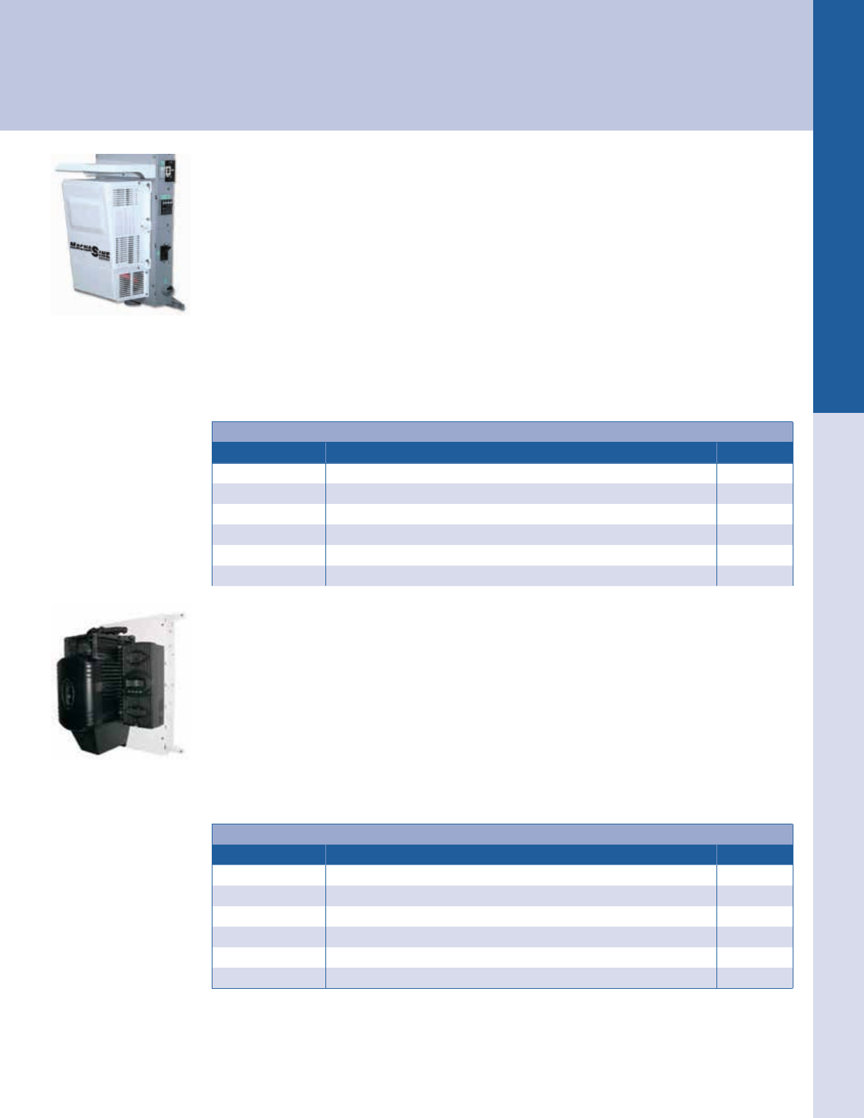
For the latest on AEE Solar products, trainings and dealer services, visit www.aeesolar.com
ELECTRICAL DISTRIBUTION PARTS Power Panels
168
Power Panels
Power panels provide a central location for mounting inverters and charge controllers in battery systems and include enclosures for
wiring, over-current protection, ground-fault and surge protection, bypasses and related hardware. See Battery-Based Inverters for
OutBack Flexware™ power panels as well as prewired OutBack Power and MidNite Solar power systems.
MidNite Solar
E-Panel
The MidNite Solar E-Panel can help streamline the installation of battery-based inverters. They come
standard with the basic overcurrent protection and disconnects required to install your renewable energy
system in compliance with the NEC. They are internally pre-wired and labeled to save time and hassle
in the eld. E-Panels are listed to applicable UL and CSA standards for the U.S.A. and Canada. See
Battery-Based Inverters for pre-wired MidNite Solar E-Panels.
MidNite Solar E-Panels for Magnum Inverters
Magnum inverters are mounted on a unique hinged door to minimize system footprint. Mounting brackets
are included to aid in one-person installations. They come with a main breaker, inverter connection, a 500
A/50 mV shunt for battery monitoring systems, an AC input and bypass, PV input busbars, DIN rails, 3
panel-mount breaker knockouts, ground bus, remote display mounting brackets, a charge controller bracket,
a wall-mount bracket and other hardware. 120/240 VAC models are for Magnum MS-PAE inverters.
MidNite Solar E-Panels for Magnum Inverters
Model Description Item code
MNE175STM-L Gray steel chassis with 125 A inverter breaker 034-05160
MNE250STM-L Gray steel chassis with 250 A inverter breaker 034-05164
MNE175ALM-L White aluminum chassis with 175 A inverter breaker 034-05168
MNE250ALM-L White aluminum chassis with 250 A inverter breaker 034-05166
MNE175STM-L-240 White steel chassis with 175 A inverter breaker 120/240 VAC 034-05167
MNE250STM-L-240 White steel chassis with 250 A inverter breaker 120/240 VAC 034-05169
MidNite Solar E-Panels for OutBack Inverters
OutBack inverters are mounted on a unique hinged door to minimize system footprint. They come stan-
dard with a left-hand hinge, allowing the charge controller to be mounted on the right. The STS version
has additional space for the OutBack AC box with a surge arrestor for grid-tie applications, and the AL-
PLUS version has room to mount an inverter and a charge controller on the door. Right-hand hinged
doors are available by special order. Mounting brackets are included to aid in one-person installations. A
main breaker, inverter cables, a 500 A/50 mV shunt for battery monitoring systems, a 175 A AC power-
distribution block, a 50 A AC-input disconnect for a generator or utility input, and a 50 A AC bypass
switch are included and pre-wired. E-Panels for OutBack inverters also include a mounting bracket for
an OutBack FM-series controller. Cutouts for mounting up to six additional 13 mm DIN-mount breakers
are provided, as are cutouts for GFCI-style AC outlets and three panel-mount DC-breaker slots. Circuit
breakers and DC GFP are sold separately.
MidNite Solar E-Panels for OutBack Inverters
Model Description Item code
MNE125STS-L Gray steel stretched chassis with 125 A inverter breaker 15" wide – left hinge 034-05127
MNE175STS-L Gray steel stretched chassis with 175 A inverter breaker 15" wide – left hinge 034-05131
MNE250STS-L Gray steel stretched chassis with 250 A inverter breaker 15" wide – left hinge 034-05135
MNE125AL-PLUS White alum wide chassis with 125 A inverter breaker with charge-controller mount 034-05147
MNE175AL-PLUS White alum wide chassis with 175 A inverter breaker with charge-controller mount 034-05148
MNE250AL-PLUS White alum wide chassis with 250 A inverter breaker with charge-controller mount 034-05149
MNE STM Series E-Panel
(Inverter Not Included)
MNE AL-PLUS Series E-Panel
(Inverter And Controller
Not Included)
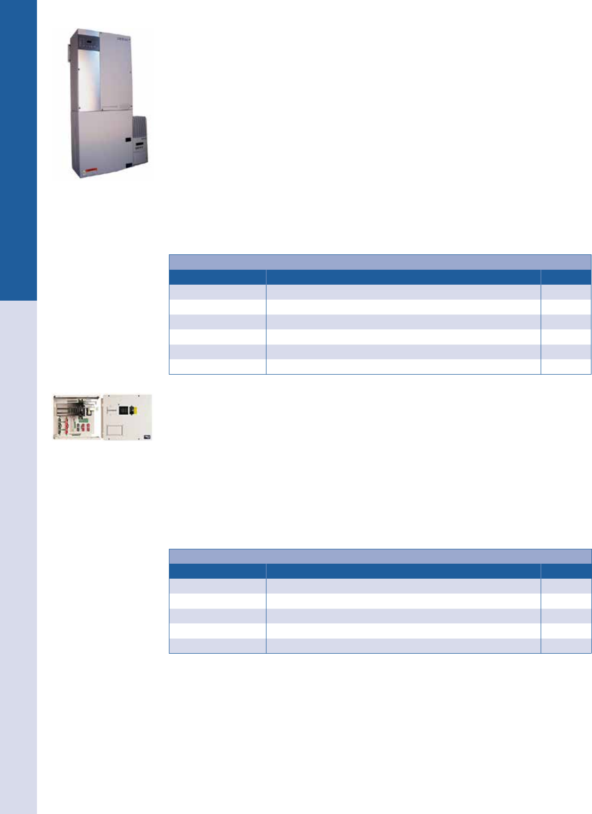
For the latest on AEE Solar products, trainings and dealer services, visit www.aeesolar.com
ELECTRICAL DISTRIBUTION PARTS Power Panels
169
MidNite Solar E-Panel for Schneider Electric Conext XW+
The MNE250XWP-SINGLE or MNE175XWP-SINGLE is mounted directly below the XW+ inverter.
It includes a 250 A, or 175 A inverter/battery breaker, AC inputs for generator and utility, knockouts for up
to seven DIN-mount breakers and 12 panel-mount breakers, and a 500 A shunt. Tin-plated copper busbars
connect to the XW’s battery terminals. There are busbars for AC inputs, AC output, neutral, ground, PV +
in, PV - in, Bat +, and Bat - covered by a metal dead-front behind the reversible door. Charge controllers
mount to either or both sides. The AC bypass can be congured as input and output on/off as well as AC
bypass. The XW MPPT controller requires no mounting bracket. FM60, FM80, and Classic controllers
require right or left E-Panel charge controller mounting brackets. A right-hand bracket is included. The
color-matched enclosure is 16"W x 17"H x 8.5"D, and weighs 38 lbs.
The MNE250XWP-MASTER and MNE250XWP-SLAVE, and the 175 A versions, can be used for
a dual-inverter setup. The master E-panel has a 120 A AC bypass assembly and all of the other items
listed for the single E-panel. The master E-panel is mounted under one XW+ inverter and the slave
E-panel is mounted under the second inverter. They can then be wired together. The slave E-panel has
60A AC input breakers for utility and generator and knockouts for up to seven DIN-mount breakers and
12 panel-mount breakers, and a 500 A shunt, as well as the bus bars for DC and AC connections. The
color-matched enclosure is 16"W x 17"H x 8.5"D, and weighs 38 lbs.
MidNite Solar E-Panels for Schneider Electric Conext XW+ Inverters
Model Description Item code
MNE250XWP-SINGLE E-Panel for one XW+ inverter, 250 A main DC breaker 034-05181
MNE175XWP-SINGLE E-Panel for one XW+ inverter, 175 A main DC breaker 034-05184
MNE250XWP-MASTER E-Panel for dual XW+ inverter system, 250 A main DC, add one slave E-Panel 034-05175
MNE175XWP-MASTER E-Panel for dual XW+ inverter system, 175 A main DC, add one slave E-Panel 034-05176
MNE250XWP-SLAVE E-Panel slave for dual XW+ inverter system, 250 A main DC 034-05177
MNE175XWP-SLAVE E-Panel slave for dual XW+ inverter system, 175 A main DC 034-05178
MidNite Solar E-Panel for Schneider Electric Conext SW
The MNE250SW or MNE175SW is mounted next to the SW inverter. It includes a 250 A, or 175 A
inverter/battery breaker. There are knockouts for up to seven DIN-mount breakers and 12 panel-mount
breakers, and a 500 A shunt. Tin-plated copper busbars connect to the XW’s battery terminals. There
are busbars for AC inputs, AC output, neutral, ground, PV + in, PV - in, Bat +, and Bat -. There are
knockouts on top for two charge controllers. The color-matched enclosure is 17.6"W x 15.2"H x 7.5"D,
and weighs 23 lbs.
The MNSW-SLIDER-30 has 30 A input and 50 A output/bypass breakers for a single-inverter instal-
lation. The MNSW-SLIDER-50 has 50 A input/output/bypass breakers for a dual-inverter installation.
The MNSW-BACKPLATE will mount both the SW E-panel and one SW inverter. Dimensions are 20”H
x 33”L x 1.5”D, and weighs 15 lbs.
MidNite Solar E-Panels for Schneider Electric Conext SW Inverters
Model Description Item code
MNE250SW E-Panel for one SW inverter, 250 A main DC breaker 034-05188
MNE175SW E-Panel for one SW inverter, 175 A main DC breaker 034-05189
MNSW-BACKPLATE Backplate for one SW E-panel and inverter 034-05190
MNSW-SLIDER-50 AC breakers and bypass assy for 120/240 VAC, 50 A breakers 034-05191
MNSW-SLIDER-30 AC breakers and bypass assy for 120/240 VAC, 30 A breakers, 50 A bypass 034-05192
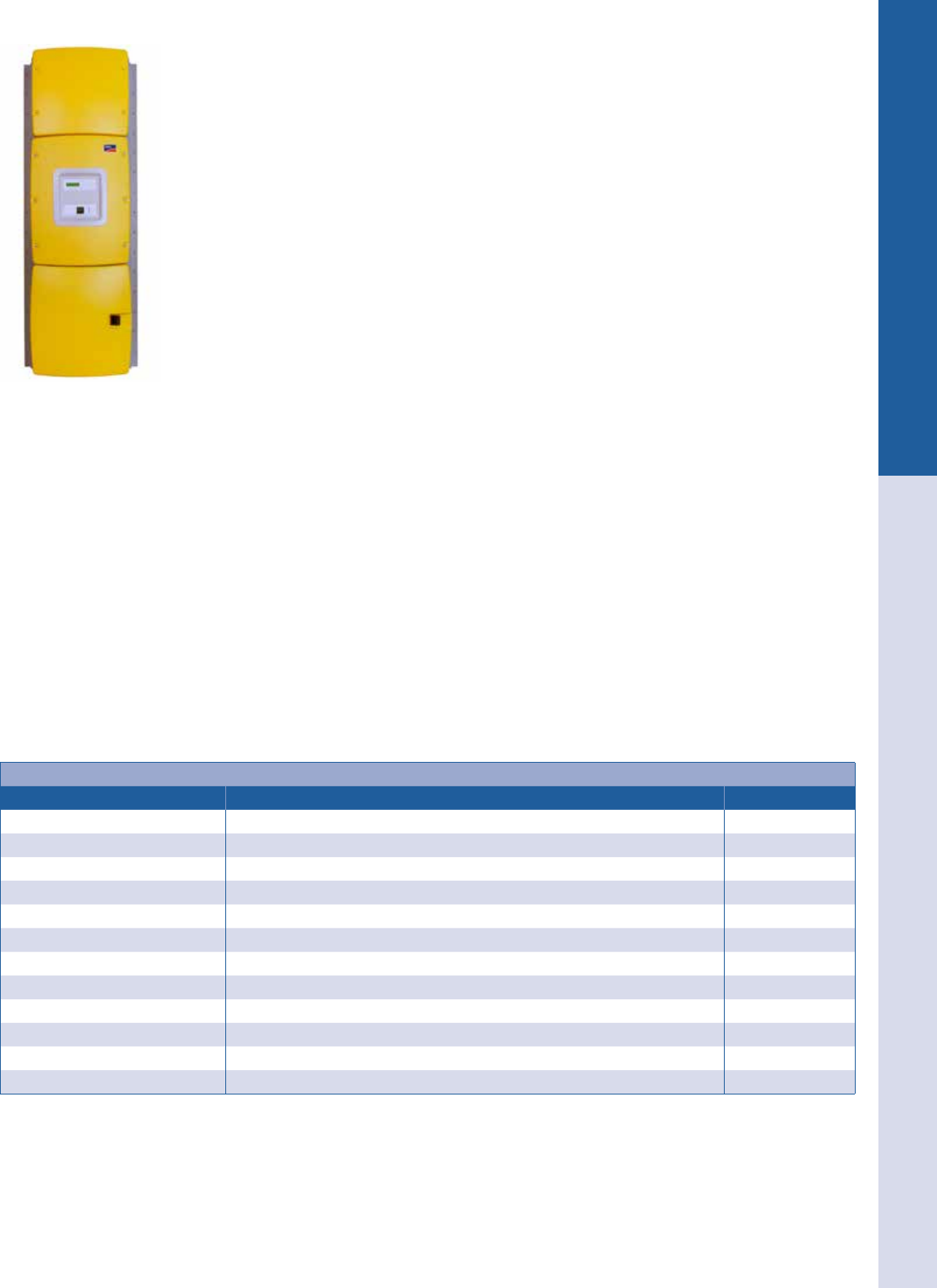
For the latest on AEE Solar products, trainings and dealer services, visit www.aeesolar.com
ELECTRICAL DISTRIBUTION PARTS Power Panels
170
MidNite Solar E-Panels for SMA Sunny Island Inverters
MidNite Solar E-Panels and accessories are color matched to the Sunny Island inverter. SMA E-Panels
are available to work with single, two or four-inverter congurations with 120/240 VAC or 120/208
VAC three-phase output (Requires three inverters). These can be used in either AC-coupled or DC-
coupled systems, either grid-tied or off-grid. For AC-coupled systems with Sunny Boy inverters, an
RS 485 card should be used in each Sunny Island master inverter and each Sunny Boy inverter (see
Grid-Tie Inverters). Use the appropriate back plates.
The MNE250SMA-AC-SINGLE is an E-Panel used with the MNSMA Autoformer in an AC-coupled
system with a single Sunny Island inverter. It is mounted directly below the Sunny Island inverter. The
protected loads panel will have 120/240 VAC available and the utility connection will be 120 VAC
only.
The MNE250SMA-OG-SINGLE is an E-Panel used in an off-grid system with a single Sunny Island
inverter. For a dual Sunny Island installation, either AC-coupled or off-grid, use one MNE250SMA-
OG/AC-DM and one MNE250SMA-SLAVE E-Panel. For a quad-stack Sunny Island installation,
either AC-coupled or off-grid, use one MNE250SMA-QUAD MASTER and three MNE250SMA-
SLAVE E-Panels. For a three-phase triple-stack Sunny Island installation, either AC-coupled or off-
grid, use one MNE250SMA-3PH MASTER and two MNE250SMA-SLAVE E-Panels.
The MNE250SMA-SLAVE works with the dual, quad and three-phase master E-Panels.
Included in each master E-Panel is a 250 A inverter battery breaker, 60 AAC bypass (125 A on the
Quad master), input and output breakers, terminal busbars for all connections, 500 A shunt, spaces for
DIN and panel-mount DC breakers, and wiring for the connections to the Sunny Island.
The MNX-240 AUTOFORMER is used in single Sunny Island systems to produce 120/240 VAC
output for AC coupling. It mounts above the Sunny Island.
One MNSMA Back Short back plate is used for each Sunny Island and E-Panel combination.
The MNSMA Back Long back plate is used for a single Sunny Island, E-Panel and MNX-240.
The MNSMA E-Panels are 20.5” x 18.6” x 9.6”, weight 42 lbs. The MNSMA-Autoformer is 18.1” x
16.4” x 9.2”, weight 74 lbs.
The MNSICOMM translator box will allow the SMA system to read and control up to four Classic
charge controllers to make an integrated system.
The MNTRB-80 is a relay board that can be used to transfer the AC input from grid to generator.
The MNSMARB-KIT is used to allow greater grid-tie inverter capacity for an AC-coupled system, up
to 12 kW for a single Sunny Island, and up to 18 kW for dual Sunny Island.
MidNite Solar E-Panels for SMA Sunny Island Inverters
Model Description Item code
MNE250SMA-AC-SINGLE E-Panel for single Sunny Island inverter for AC-coupled system, 250 A DC main 034-00000
MNE250SMA-OG-SINGLE E-Panel for single Sunny Island inverter for off-grid system, 250 A DC main 034-00001
MNE250SMA-OG/AC-DM E-Panel for dual SI inverter system, add one slave E-Panel, 250 A DC main 034-00002
MNE250SMA-QUAD MSTR E-Panel for quad SI inverter system, add three slave E-Panels, 250 A DC main 034-00004
MNE250SMA-3PH MASTER E-Panel for three-phase SI inverter system, add two slave E-Panels, 250 A DC main 034-00003
MNE250SMA-SLAVE E-Panel Slave for multiple-inverter systems, 250 A DC main breaker 034-00005
MNX-240 AUTOFORMER Autoformer for 120/240 VAC output from single Sunny Island, use with AC SINGLE 038-00001
MNSMA-TALL-BP Back plate for one Sunny Island, Autoformer, and E-Panel 034-00007
MNESMAXW-SHORT BP Back plate for each Sunny Island and one E-Panel 034-00008
MNSICOMM Translator box so MidNite Classic control can be read by the SMA system 020-02434
MNTRB-80 Transfer relay board, 80 A, 240 VAC for grid-to-generator transfer 053-02951
MNSMARB-KIT Relay-board kit for extra PV capacity in an AC-coupled system 034-00048
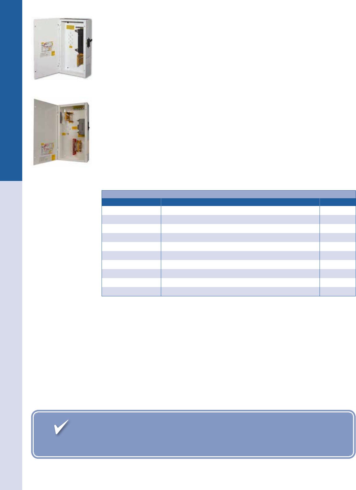
Fast, Accurate Shipping to your Job Site. With just-in-time delivery and blind
drop shipping, we can ship directily to your customers, just as if it came directly from you.
For the latest on AEE Solar products, trainings and dealer services, visit www.aeesolar.com
ELECTRICAL DISTRIBUTION PARTS Power Panels
171
MidNite Solar Mini-DC Disconnect Power Center (MNDC)
Use this small DC disconnect, which includes the inverter breaker (not in the MNDC-C), to provide
overcurrent protection for any single inverter. The MNDC comes with a DIN rail for ve additional DC
breakers for DC loads, a charge controller disconnect, and a battery-status monitor. They also include
a ground bus, and a 5/16" bonding battery-negative stud. Mounting holes for a 500 A shunt are built
in. The white powder-coated aluminum chassis measures 10"H x 5"W x 18"D and weighs 7 lbs. Three
main-breaker sizes are available. Left-side main-breaker placement is available by special order.
The MNDC Plus version has an additional DIN rail allowing up to ten DIN-mount breakers. Two DIN
rail cover plates and two panel-mount plates are included. The panel-mount plates allow for mount-
ing the 3/4" 150 VDC breakers that range from 60 A to 100 A. Additional congurations include: an
MNDC-GFP80 with four panel-mount breakers, or one MNDC-GFP, one 3/4" panel-mount breaker
and ve DIN-mount breakers with a 125-250 A inverter breaker. Circuit breakers and DC GFP are sold
separately. Mounting is provided for a 500 A shunt and an MNTBB-R terminal busbar. Battery-negative
stud and ground busbar included.
The MINI DC X2 versions have two DC battery breakers, one on each side of the enclosure. The MINI
DC 125 X2 Disconnect is a white powder-coated aluminum enclosure while the MINI DC 175 X2 and
the 250 X2 are powder-coated gray steel. They all come with the 125, 175 or 250 A battery breakers.
The MNDC X2 accepts an additional ve din-rail breakers or three panel-mount breakers. The boxes all
come with grounding busbars and space to mount a 500 A shunt.
The MNDC125-X2 measures 25"H x 11"W x 4"D and weighs 13 lbs.
The MNDC175-X2 and the MNDC250-X2 measure 25"H x 16"W x 4"D and weigh 29 lbs.
MidNite Mini-DC Disconnect Power Center (MNDC)
Model Description Item code
MNDC-C Mini DC disconnect with space for 3/4" panel-mount breaker 053-00094
MNDC125 125 A Mini DC disconnect 053-00091
MNDC175 175 A Mini DC disconnect 053-00092
MNDC250 250 A Mini DC disconnect 053-00093
MNDC125-Plus 125 A Mini DC disconnect Plus version 053-00096
MNDC175-Plus 175 A Mini DC disconnect Plus version 053-00097
MNDC250-Plus 250 A Mini DC disconnect Plus version 053-00098
MNDC125-X2 125 A Mini DC X2 with two 125 A DC breakers 053-00122
MNDC175-X2 175 A Mini DC X2 with two 175 A DC breakers 053-00123
MNDC250-X2 250 A Mini DC X2 with two 250 A DC breakers 053-00124
MNDC Series E-Panel
MNDC PLUS Series E-Panel
For the latest on AEE Solar products, trainings and dealer services, visit www.aeesolar.com
ELECTRICAL DISTRIBUTION PARTS Power Panels
172
MidNite Solar Breaker Boxes and Wiring Accessories
The Baby Box and Big Baby Box are small general purpose breaker boxes that will hold up to four
DIN-mount breakers from 1 to 63 A. The Big Baby Box also includes a ground box lug and mounting
provisions for a short insulated busbar. The Big Baby Box's dimensions are 9"H x 5"W x 4"D, and it
weighs 3 lbs. The MNEDC Quad is the same size as the Big Baby but holds up to 4 MNEDC-type
panel-mount AC/DC breakers or panel-mount GFP breakers. The MNDC15 is a general-use enclosure
that will hold up to 15 MNEDC type panel-mount breakers, and one larger 175 or 250 A breaker on the
end. Breakers are sold separately. The MNDC15 dimensions are 23"H x 12"W x 3.5"D, and it weighs
25 lbs. These breaker boxes are listed to applicable UL standards.
The MNBCB-1000/100 Battery Combiner can be used to combine circuits from multiple inverters or
battery strings or both. There are spaces for six large 175 A or 250 A breakers on both ends. 35.5” W x
22”H x 9.75”D, and weighs 50 lbs. The MNBCB-1000/50 is similar, but has a shunt with the correct
ratio for the SMA Sunny Island system.
Add the MNBCB-Busbar for more connections, useful for the inverter side of the shunt. It has ve 3/8”
studs and hole for the shunt connection and comes with red and white insulators.
Busbars
These UL-listed busbars can be used in the Mini-DC Disconnect above. Each MNT bar has colored
insulation, four 0 AWG and eleven 6 AWG usable wire slots with 10-32 UNF screws, and is 4.63" long.
The MNS is a shorter version, useful for PV + input on the narrow OB E-Panel, Big Baby Box, Quad
box and for a separate PV busbar for charge controllers. The MNS has four 6 AWG and two 0 AWG wire
slots. The MNG ground busbar is 3.45" long with green screws and has two 0 AWG and seven 6 AWG
wire slots with mounting screws. The MNIBIGBUSBAR is a pair for positive and negative with ve
battery connections and six small wires. The MNSHUNT has four studs besides the shunt connection.
The MNBREAKER-BB-PLUS has eight studs besides the large breaker connection.
The MNBREAKERADAPTER allows the mounting of a 3/4"-wide panel-mount breaker in a 1” breaker
space.
MidNite Breaker Boxes and Busbars
Model Description Item code
MNBABYBOX Baby Box breaker center holds four DIN-mount breakers 053-00089
MNBIGBABY Big Baby Box breaker center holds four DIN-mount DC breakers 053-00088
MNEDC QUAD Quad breaker center holds four MNEDC 3/4" DC breakers 053-00087
MNDC-15 Circuit breaker box for 15 panel-mount and one large panel-mount breaker 053-00086
MNBCB-1000/100 Combiner for multiple inverters or battery strings w/ 1000 A 100 mv shunt 034-00006
MNBCB-1000/50 Combiner for multiple inverters or battery strings w/ 1000 A 50 mv shunt for
SMA Sunny Island 034-00009
MNTBB-R Long red terminal busbar 053-00105
MNTBB-B Long black terminal busbar 053-00106
MNTBB-W Long white terminal busbar 053-00107
MNGBB Long ground busbar - 3.45" long 053-00100
MNSBB-R Short red terminal busbar 053-00108
MNSBB-B Short black terminal busbar 053-00109
MNSBB-W Short white terminal busbar 053-00110
MNBIGBUSBAR Big busbar with ve studs, insulator mounts, aux terminal bar, 280 A 053-00115
MNSHUNT Shunt busbar with four studs and short aux terminal bar 053-00117
MNBREAKER-BB-PLUS Big breaker bus with eight studs 053-00116
MNBREAKER ADAPTER Adapter to mount a 3/4" panel mount breaker in a larger breaker space 053-03106
MNBCB-BUSBAR 1,000 A bus bar for the Battery Combiner 053-00118
MNDC-15
MN Battery Combiner
Big Baby Box
Quad Box
Long Terminal Busbar Short Terminal Busbar Big Busbar Shunt Busbar Big Breaker Plus
Baby Box
For the latest on AEE Solar products, trainings and dealer services, visit www.aeesolar.com
ELECTRICAL DISTRIBUTION PARTS Fuses and Breakers
173
Fuses and Breakers
Fuses and breakers are designed to prevent excessive current from overheating conductors or devices by opening the circuit. Special-
ized breakers can also be deployed to open the circuit in case of ground or arc-fault conditions. Fuses and breakers should be sized
according to NEC and/or manufacturer guidelines to ensure that they open the circuit before conductors or equipment can become
damaged. See Reference for typical ampacity limits by wire size.
Morningstar
NEW! DC Ground-Fault Protection Devices
These two GFPD devices from Morningstar Corp. have more advanced safety features than the traditional
method of breaking the grounded conductor bond. It detects a current imbalance between the conductors
and breaks both conductors in the faulted circuit, isolating the circuit. It does not break the grounded
conductor bond to ground and allows unaffected controller circuits to continue to function normally.
The battery and DC loads in the system will continue to function in a safe grounded manner. The trip
threshold is 300 mA for extra safety and is more accurate than a breaker-type GFP. There is visual and
audible trip notication, LED status, and a test button. It does require a small amount of power from the
system battery bank at 12 VDC to 48 VDC. Both units are listed to UL 1741, additionally the GFPD-
150V is listed to UL-489 and the GFPD-600V is listed to UL-1077.
DC Ground Fault Protection Devices
Model Poles Current Voltage rating Dimensions
(H" x W' x D") Weight Item code
GFPD-150V two 60 A 150 VDC 10.6 x 5.1 x 4.4 5 lbs 053-03164
GFPD-600V two 50 A 600 VDC 14.1 x 8.7 x 4.2 9 lbs 053-03165
Circuit Breakers
DC Ground-Fault-Protection Circuit Breakers
These breakers use a trip mechanism to connect battery negative and earth ground to open the larger
breaker in case of a ground fault. The NEC requires DC ground-fault protection on all solar installations.
The DIN rail mount GFPs will mount in the Magnum MMP and MidNite E-Panels. The panel-mount
GFPs will mount in the OutBack FLEXware enclosures and one or two poles in MidNite E-Panels. The
100 A unit can be used normally as a two-pole GFP, or with ungrounded arrays breaking positive and
negative, or shunt tripped by a signal from a MidNite Classic charge controller or MNBDM.
DC Ground Fault Protection Circuit Breakers
Amps Poles Mount type Voltage rating Width Model Item code
80 A one Panel with ¼" studs 150 VDC 1.5" PNL-GFDI-80 053-03144
80 A two Panel with ¼" studs 150 VDC 2.25" PNL-GFDI-80D 053-03145
80 A four Panel with ¼" studs 150 VDC 3.75" PNL-GFDI-80Q 053-03146
63 A one DIN rail with screw lugs 150 VDC 1" MNDC-GFP63 053-03147
80 A one Panel with ¼" studs 150 VDC 1.5" MNDC-GFP80 053-03148
50 A one DIN rail with screw lugs 300 VDC 2" MNDC-GFP50-300 053-03149
100 A two Panel with ¼" studs 150 VDC 3" MNDC-GFP100RT-2P 053-03150
For the latest on AEE Solar products, trainings and dealer services, visit www.aeesolar.com
ELECTRICAL DISTRIBUTION PARTS Fuses and Breakers
174
DIN-mount AC Circuit Breakers
These are DIN-mount AC breakers with set-screw compression terminals for 14 to 2 AWG wire. Use
these for AC in OutBack FLEXware, MidNite E-Panels, and Magnum panels.
DIN-mount AC Circuit Breakers
Amps Poles Voltage
rating Width OutBack model MidNite model Item code
10 A one 120 VAC 0.5" DIN-10-AC-277 MNEAC10 053-03060
15 A one 120 VAC 0.5" DIN-15-AC MNEAC15 053-03061
15 A two 120/240 VAC 1" DIN-15D-AC MNEAC15-2P 053-03062
20 A one 120 VAC 0.5" DIN-20-AC MNEAC20 053-03063
20 A two 120/240 VAC 1" DIN-20D-AC MNEAC20-2P 053-03064
25 A two 120/240 VAC 1" DIN-25D-AC MNEAC25-2P 053-03065
30 A one 120 VAC 0.5” -- MNEAC30 053-03171
30 A two 120/240 VAC 1" -- MNEAC30-2P 053-03175
35 A two 120/240 VAC 1" -- MNEAC35-2P 053-03176
40 A one 120 VAC 0.5” -- MNEAC40 053-03172
40 A two 120/240 VAC 1" -- MNEAC40-2P 053-03177
50 A one 120 VAC 0.5” -- MNEAC50 053-03173
50 A two 120/240 VAC 1" -- MNEAC50-2P 053-03178
60 A one 120 VAC 0.5” -- MNEAC60 053-03174
60 A two 120/240 VAC 1" -- MNEAC60-2P 053-03179
10 A one 277 VAC 0.5" DIN-10-AC-277 MNEAC10QZD 053-03060
15 A one 277 VAC 0.5" DIN-15-AC-277 MNEAC15QZD 053-03066
30 A one 277 VAC 0.5" DIN-30-AC-277 MNEAC30QZD 053-03067
30 A two 277 VAC 1" DIN-30D-AC-480 MNEAC30QZD2P 053-03068
30 A three 277/480 VAC 1.5" DIN-30T-AC-480 MNEAC30QZD3P 053-03069
50 A one 277 VAC 0.5" DIN-50-AC-277 MNEAC50QZD 053-03070
50 A two 277 VAC 1" DIN-50D-AC-480 MNEAC50QZD2P 053-03071
50 A three 277/480 VAC 1.5" DIN-50T-AC-480 MNEAC50QZD3P 053-03072
60 A one 277 VAC 0.5" DIN-60-AC-277 -- 053-03073
60 A two 277 VAC 1" DIN-60D-AC-480 MNEAC60QZD2P 053-03036
For the latest on AEE Solar products, trainings and dealer services, visit www.aeesolar.com
ELECTRICAL DISTRIBUTION PARTS Fuses and Breakers
175
DIN-mount DC Circuit Breakers
DIN-mount breakers t MidNite and Magnum enclosures, and MNPV and OutBack PV array combin-
ers. The positive line should be connected to the + pole of the breaker. The maximum PV array voltage
must not exceed the voltage rating of the breakers used. The 600 VDC breakers also have a remote-trip
actuator, useful for Rapid Shutdown.
DIN-mount 150 VDC Circuit Breakers
Amps Voltage rating Width OutBack model MidNite model Item code
1 A 150 VDC 0.5" DIN-1-DC MNEPV1 053-03033
2 A 150 VDC 0.5" DIN-2-DC MNEPV2 053-03034
3 A 150 VDC 0.5" DIN-3-DC MNEPV3 053-03024
4 A 150 VDC 0.5" DIN-4-DC MNEPV4 053-03020
5 A 150 VDC 0.5" DIN-5-DC MNEPV5 053-03025
6 A 150 VDC 0.5" DIN-6-DC MNEPV6 053-03021
8 A 150 VDC 0.5" DIN-8-DC MNEPV8 053-03022
9 A 150 VDC 0.5" DIN-9-DC MNEPV9 053-03023
10 A 150 VDC 0.5" DIN-10-DC MNEPV10 053-03026
12 A 150 VDC 0.5" -- MNEPV12 053-03027
15 A 150 VDC 0.5" DIN-15-DC MNEPV15 053-03029
20 A 150 VDC 0.5" -- MNEPV20 053-03030
30 A 150 VDC 0.5" -- MNEPV30 053-03032
40 A 150 VDC 0.5" -- MNEPV40 053-03039
50 A 150 VDC 0.5" -- MNEPV50 053-03035
60 A 150 VDC 0.5" -- MNEPV60 053-03037
63 A 150 VDC 0.5" -- MNEPV63 053-03038
80 A 150 VDC 1.0" -- MNEPV80 053-03133
100 A 150 VDC 1.0" -- MNEPV100 053-03134
DIN-mount 300 VDC Circuit Breakers
Amps Mount type Voltage rating Width MidNite model Item code
7 A DIN rail with screw lugs 300 VDC 1" MNEPV7-300 053-03107
10 A DIN rail with screw lugs 300 VDC 1" MNEPV10-300 053-03110
12 A DIN rail with screw lugs 300 VDC 1" MNEPV12-300 053-03112
15 A DIN rail with screw lugs 300 VDC 1" MNEPV15-300 053-03115
20 A DIN rail with screw lugs 300 VDC 1" MNEPV20-300 053-03120
30 A DIN rail with screw lugs 300 VDC 1" MNEPV30-300 053-03125
50 A DIN rail with screw lugs 300 VDC 1" MNEPV50-300 053-03130
DIN-mount 600 VDC Circuit Breakers
16 A DIN rail with screw lugs 600 VDC 2" MNEPV16-600-RT 053-03116
20 A DIN rail with screw lugs 600 VDC 2" MNEPV20-600-RT 053-03121
For the latest on AEE Solar products, trainings and dealer services, visit www.aeesolar.com
ELECTRICAL DISTRIBUTION PARTS Fuses and Breakers
176
Panel-mount AC/DC Circuit Breakers
These are single-pole ¾"-wide breakers with ¼" stud connections and require ring terminals on wires
connected to them. These breakers can be used for DC protection in OutBack FLEXware enclosures,
and MidNite E-Panels (three spaces), or as AC breakers in the OutBack FLEXware 250. The 300 VDC
and two-pole AC breakers are double width and take two spaces. The AC breakers are for use with the
Radian inverter GSLC panels.
Panel-mount AC/DC Circuit Breakers
Amps Poles AC voltage
rating
DC voltage
rating Width OutBack model MidNite model Item code
1 A one 120 VAC 150 VDC 0.75" PNL-1-AC/DC -- 053-03135
5 A one 120 VAC 150 VDC 0.75" PNL-5-AC/DC MNEDC-5 053-03136
10 A one 120 VAC 150 VDC 0.75" PNL-10-AC/DC MNEDC-10 053-03137
15 A one 120 VAC 150 VDC 0.75" PNL-15-AC/DC MNEDC-15 053-03138
20 A one 120 VAC 150 VDC 0.75" PNL-20-AC/DC MNEDC-20 053-03139
30 A one 120 VAC 150 VDC 0.75" PNL-30-AC/DC MNEDC-30 053-03140
40 A one 120 VAC 150 VDC 0.75" PNL-40-AC/DC MNEDC-40 053-03141
50 A one 120 VAC 150 VDC 0.75" PNL-50-AC/DC MNEDC-50 053-03142
60 A one 120 VAC 150 VDC 0.75" PNL-60-AC/DC MNEDC-60 053-03143
70 A one -- 150 VDC 0.75" -- MNEDC-70 053-03151
80 A one -- 150 VDC 0.75" PNL-80-DC MNEDC-80 053-03152
90 A one 150 VDC 0.75” MNEDC-90 053-03156
100 A one -- 150 VDC 0.75" -- MNEDC-100 053-03153
30 A one 300 VDC 1.5” -- MNEDC30-300 053-03126
60 A one -- 300 VDC 1.5" -- MNEDC60-300 053-03132
80 A one -- 300 VDC 1.5" -- MNEDC80-300 053-03131
30 A one 250 VAC -- 0.75" PNL-30-AC -- 053-16998
50 A one 250 VAC -- 0.75" PNL-50D-AC-250 -- 053-16999
50 A two 240 VAC -- 1.5" PNL-50D-AC-120/240 -- 053-17004
For the latest on AEE Solar products, trainings and dealer services, visit www.aeesolar.com
ELECTRICAL DISTRIBUTION PARTS Fuses and Breakers
177
CD and GJ Panel-mount DC Circuit Breakers
These are single-pole panel-mount breakers with stud terminals that require ring terminals on the wires
connected to them (except the two items with lugs). Breakers up through 80 A can be used in the Conext
XW+ Distribution Panel. The 100 A and larger DC breakers t in the OutBack FLEXware enclosures and
MidNite E-Panels. Rated for 125 VDC only (except the 60 A lug breaker, which is rated at 160 VDC).
The remote trip breakers can be used with the MNBDM for Rapid Shutdown.
Panel-mount DC Circuit Breakers CD and GJ
Amps Poles Stud size Voltage
rating Width OutBack model MidNite model Generic
model Item code With
remote trip
10 A one 1/4" 125 VDC 1" -- -- CD10 053-01010 --
15 A one 1/4" 125 VDC 1" -- -- CD15 053-01015 --
20 A one 1/4" 125 VDC 1" -- -- CD20 053-01020 --
30 A one 1/4" 125 VDC 1" -- -- CD30 053-01025 --
50 A one 1/4" 125 VDC 1" -- -- CD50 053-01030 --
60 A one 1/4" 125 VDC 1" -- -- CD60 053-01035 --
60 A one 1/0 AWG 160 VDC 1" -- -- BKR 60 053-01038 --
75 A one 1/4" 125 VDC 1" -- -- CD75 053-01040 --
80 A one 1/4" 125 VDC 1" -- -- CD80 053-01045 --
80 A one 1/0 AWG 125 VDC 1" -- -- BKR 80 053-01039 --
100 A one 1/0 AWG 125 VDC 1" -- -- BKR 100 053-01034 --
100 A one 5/16" 125 VDC 1" PNL-100-DC -- -- 053-01050 --
125 A one 5/16" 125 VDC 1" PNL-125-DC MNEDC125-RT --- 053-01052 053-01047
175 A one 3/8" 125 VDC 1.5" PNL-175-DC MNEDC175 -- 053-01053 053-01048
250 A one 3/8" 125 VDC 1.5" PNL-250-DC MNEDC250 -- 053-01054 053-01049
CF and GJ Surface (Back) Mount DC Circuit Breakers
These are surface-mount breakers with screw lug terminals and a 10,000 A interrupting current for direct
connection to a battery. Mounting feet on 10-100 A allow them to be bolted to the back panel in an
enclosure. The breakers up through 100 A can be used in the Magnum MP panels and the Conext XW+
Distribution Panel and for custom DC control panels. All are rated for 125 VDC. The 175 A and 250 A
require one rear-mount kit each. These breakers can also be panel-mounted from the front; however the
panel may prevent access to the wire terminal screws on the breaker.
CF and GJ Surface (Back) Mount DC Circuit Breakers
Amps Max lug wire size DC voltage rating Width Generic model Item code
10 A 1 AWG 125 VDC 1" CF-10 053-01011
15 A 1 AWG 125 VDC 1" CF-15 053-01016
20 A 1 AWG 125 VDC 1" CF-20 053-01021
30 A 1 AWG 125 VDC 1" CF-30 053-01026
50 A 1 AWG 125 VDC 1" CF-50 053-01031
60 A 1 AWG 125 VDC 1" CF-60 053-01036
75 A 1 AWG 125 VDC 1" CF-75 053-01041
100 A 1 AWG 125 VDC 1" CF-100 053-01051
175 A 4/0 AWG 125 VDC 1.5" GJ1-175-H3 053-01056
250 A 4/0 AWG 125 VDC 1.5" GJ1-250-H3 053-01061
Rear-mount kit for GJ1 breakers above 053-01066
For the latest on AEE Solar products, trainings and dealer services, visit www.aeesolar.com
ELECTRICAL DISTRIBUTION PARTS Fuses and Breakers
178
Square D QO Plug on Circuit Breakers
QO circuit breakers snap into QO load centers and are UL-listed for DC branch circuits up to 48 VDC
(not for use in 48 VDC systems). They can be used for 120 VAC (single-pole), 120/240 VAC (two-pole)
circuits, and 120/208 VAC three-phase (3-pole). Circuit breakers in 10 A to 30 A sizes can handle one
or two 14 to 10 AWG or one 8 AWG wire. Circuit breakers 40 A to 70 A will handle 8 to 2 AWG wire.
Square D QO Plug on (For SqD Load Centers) Circuit Breakers
Poles Amps AC voltage rating Width Panel spaces Model Item code
One
10 A 120 VAC 0.75" one QO110 053-02063
15 A 120 VAC 0.75" one QO115 053-02065
20 A 120 VAC 0.75" one QO120 053-02071
30 A 120 VAC 0.75" one QO130 053-02075
40 A 120 VAC 0.75" one QO140 053-02080
50 A 120 VAC 0.75" one QO150 053-02083
60 A 120 VAC 0.75" one QO160 053-02086
70 A 120 VAC 0.75" one QO170 053-02090
Two
15 A 120/240 VAC 1.5" two QO215 053-02067
20 A 120/240 VAC 1.5" two QO220 053-02073
25 A 120/240 VAC 1.5" two QO225 053-02076
30 A 120/240 VAC 1.5" two QO230 053-02077
40 A 120/240 VAC 1.5" two QO240 053-02081
45 A 120/240 VAC 1.5" two QO245 053-02079
50 A 120/240 VAC 1.5" two QO250 053-02084
60 A 120/240 VAC 1.5" two QO260 053-02088
Three
15 A 120/208 VAC 2.25" three QO315 053-16451
20 A 120/208 VAC 2.25" three QO320 053-16453
25 A 120/208 VAC 2.25" three QO325 053-16454
30 A 120/208 VAC 2.25" three QO330 053-16450
40 A 120/208 VAC 2.25" three QO340 053-16455
50 A 120/208 VAC 2.25" three QO350 053-16452
60 A 120/208 VAC 2.25" three QO360 053-00209
1Not rated for use in 48 VDC systems
For the latest on AEE Solar products, trainings and dealer services, visit www.aeesolar.com
ELECTRICAL DISTRIBUTION PARTS Fuses and Breakers
179
Square D QOU Pass-Through Circuit Breakers
QOU circuit breakers are designed for surface or DIN mounting. They are UL-listed for DC branch
circuits up to 48 VDC (not for use in 48 VDC systems) and can be used for 120 VAC (single-pole) and
120/240 VAC (two-pole). Circuit breakers in 10 A to 30 A sizes can handle one or two 14 to 10 AWG or
one 8 AWG wire. Circuit breakers in 40 A to 70 A sizes will handle 8 to 2 AWG wire.
Square D QOU (DIN or Surface Mount) Pass-Through Circuit Breakers
Poles Amps AC voltage rating DC voltage rating1Width Model Item code
One
10 A 120 VAC 48 VDC 0.75" QOU110 053-02006
15 A 120 VAC 48 VDC 0.75" QOU115 053-02009
20 A 120 VAC 48 VDC 0.75" QOU120 053-02015
30 A 120 VAC 48 VDC 0.75" QOU130 053-02024
40 A 120 VAC 48 VDC 0.75" QOU140 053-02030
50 A 120 VAC 48 VDC 0.75" QOU150 053-02036
60 A 120 VAC 48 VDC 0.75" QOU160 053-02042
70 A 120 VAC 48 VDC 0.75" QOU170 053-02048
Two
15 A 120/240 VAC 48 VDC 1.5" QOU215 053-02012
20 A 120/240 VAC 48 VDC 1.5" QOU220 053-02018
30 A 120/240 VAC 48 VDC 1.5" QOU230 053-02027
40 A 120/240 VAC 48 VDC 1.5" QOU240 053-02033
50 A 120/240 VAC 48 VDC 1.5" QOU250 053-02039
60 A 120/240 VAC 48 VDC 1.5" QOU260 053-02045
1Not rated for use in 48 VDC systems
Fuses
600 and 1,000 VDC Midget Fuses and DIN Rail Mount Fuse Holders
The fuse holder and fuses below t MidNite MNPV and OutBack FLEXPV and other 600 and 1,000
VDC array combiners, but these fuse holders do NOT t SolaDeck combiners. These fuses are also used
in the integrated combiners in many commercial grid-tie inverters.
Midget Fuses 600 VDC
Amps Description Item code
-- CHM1 Fuse Holder - 600 V 30 A Max - DIN-mount 053-03040
-- USM1-DC1000 Fuse Holder 1000 VDC – DIN-mount 053-03170
1 A 1 A 600 VDC fuse, KLKD or equivalent 053-03155
2 A 2 A 600 VDC fuse, KLKD or equivalent 053-03052
4 A 4 A 600 VDC fuse, KLKD or equivalent 053-03051
6 A 6 A 600 VDC fuse, KLKD or equivalent 053-03050
8 A 8 A 600 VDC fuse, KLKD or equivalent 053-03048
10 A 10 A 600 VDC fuse, KLKD or equivalent 053-03046
12 A 12 A 600 VDC fuse, KLKD or equivalent 053-03044
15 A 15 A 600 VDC fuse, KLKD or equivalent 053-03043
20 A 20 A 600 VDC fuse, KLKD or equivalent 053-03042
30 A 30 A 600 VDC fuse, KLKD or equivalent 053-03041
Midget Fuses 1,000 VDC
1 A 1 A 1,000 VDC fuse, HP10M01 or equivalent 053-03166
15 A 15 A 1,000 VDC fuse, HP10M15 or equivalent 053-03167
20 A 20 A 1,000 VDC fuse, HP10M20 or equivalent 053-03168
30 A 30 A 1,000 VDC fuse, HP10M30 or equivalent 053-03169
For the latest on AEE Solar products, trainings and dealer services, visit www.aeesolar.com
ELECTRICAL DISTRIBUTION PARTS Fuses and Breakers
180
Class-R Fuses
The 250 VAC/125 VDC Class R
fuses can be used in AC circuits
up to 250 VAC or DC circuits up
to 125 VDC. The 600 VAC/VDC
fuses can be used for AC or DC cir-
cuits. They have the high amp inter-
rupting capacity (AIC) required for
fusing circuits powered by batteries.
They can be used to protect wiring
to small inverters (100-700 W) and
wiring from charging sources. These
UL-listed fuses can be used in fused
safety disconnect switches and most
large system sub-array combiners.
Class-R Fuse Holders
Use these fuse blocks with the Class-
R 250 VAC fuses. Bare wire ends t
into the screw terminals on each end
of the fuse block. The 0.1-30 A and
31-60 A holders accept up to 2 AWG
wire and are available in single-pole
and two-pole versions. The 61-100
A block accepts up to 0 AWG wire.
These do NOT t the 600 V fuses.
Class-T Fuse Blocks
with Fuses
Use these single-pole fuse blocks to
fuse inverters or other large loads.
A 5/16" stud-mount at each end of
the fuse allows connection of a cable
with a ring-lug terminal end. To con-
nect an inverter, order two cables
with lugs on both ends: one to go
from the battery to the fuse and one
to go from the fuse to the inverter.
Class T fuses exceed the 10,000 A
interrupting capacity (AIC) required
to protect Square-D brand circuit
breakers in DC load centers. They
are UL-listed for up to 160 VDC and
NEC compliant for inverter use. A
fuse comes installed in the block.
Order spare fuses separately.
Class-T JJN Fuses
These Class T fuses are rated for 160
VDC and 300 VAC as protection for
circuit breakers, load centers, and
inverters where high available short-
circuit currents are possible. These
fuses t the fuse blocks described
above.
Class-R Fuses
Amps Item code
250 VAC/125 VDC 600 VAC/VDC
10 A 053-02441 053-02442
15 A 053-02444 053-02447
20 A 053-02450 053-02453
30 A 053-02456 053-02459
40 A 053-02462 053-02463
50 A 053-02465 053-02466
60 A 053-02468 053-02471
70 A 053-02469 053-02470
80 A 053-02475 053-02472
90 A 053-02476 053-02473
100 A 053-02474 053-02477
110 A 053-02484 053-02445
125 A 053-02478 053-02481
150 A 053-02479 053-02482
200 A 053-02480 053-02483
Class-R Fuse Holders 250 VAC/125 VDC
Description Item code
Class-R fuse block 0.1-30 A single-pole 053-02423
Class-R fuse block 0.1-30 A two-pole 053-02426
Class-R fuse block 31-60 A single-pole 053-02429
Class-R fuse block 31-60 A two-pole 053-02432
Class-R fuse block 61-100 A single-pole 053-02435
Class-T Fuse Holders and Fuses
Model Description Item code
FB1-200 200 A fuse and holder with studs 053-02526
FB2-300 300 A fuse and holder with studs 053-02544
FB2-400 400 A fuse and holder with studs 053-02559
Class-T Fuses
Model Description Item code
JJN110 110 A replacement fuse 053-02509
JJN200 200 A replacement fuse 053-02520
JJN300 300 A replacement fuse 053-02538
JJN400 400 A replacement fuse 053-02556
For the latest on AEE Solar products, trainings and dealer services, visit www.aeesolar.com
ELECTRICAL DISTRIBUTION PARTS Surge Protection
181
Surge Protection
Photovoltaic, wind, and hydroelectric systems usually have long runs of exposed wire that can pick up surges from lightning, even
if the lightning strike is only nearby. These power surges can damage sensitive electronic components in meters, charge controllers,
and inverters. Surges can also damage telephone, audio, and video equipment connected to the power system. It is a good idea to
install surge protection on all incoming wires in the system, including incoming photovoltaic, wind, or hydroelectric power lines;
AC generator lines; and telephone and antenna leads. Proper grounding is absolutely necessary for lightning protection to be effec-
tive. In the event of a direct strike, damage may occur, even with surge protectors installed. Type 1 heavy-duty surge protectors are
recommended when a direct lightning strike is possible on the installation.
MidNite Solar
MidNite Surge-Protector Device (MNSPD)
The MidNite Solar Surge-Protector Device (MNSPD) is a Type 2 device designed for both AC and DC
systems and provides protection to service panels, load centers, or where the SPD is directly connected
to the electronic device requiring protection. Maximum protection will only be achieved if the SPD is
properly installed.
The MidNite Solar SPD is offered in four versions to maximize the required protection level. Protection
is achieved by reducing the clamping voltage to a safe voltage that your system can sustain without dam-
aging the electronics. The MidNite Solar SPD voltage rating should be chosen according to the nominal
voltage of the system. Response time is 8/20 μs to clamp 128,000 A. There are two LEDs in each unit
that will indicate when the unit is functioning correctly and there is voltage to it.
Install the MNSPD-115 for surge protection on wires coming from a 12, 24, or 48 VDC PV array, DC
wind generator or DC hydroelectric turbine. The MNSPD-300-DC unit works well for systems rated at
150 VDC and larger systems with sources up to 300 VDC. The MNSPD-300-AC can be used on120/240
VAC split-phase or two legs each on 208 VAC circuits. The MNSPD-600 is designed for high-voltage
grid-tie PV arrays, or two legs each on 480 VAC circuits. Lightning protection can be installed in a
combiner box, DC or AC load center or grid-tie inverter. These devices can be used on your AC load
center to protect your equipment from surges from the utility lines and on AC wiring running outside of
the building, to generators, to pumps, or to outbuildings. These surge arrestors mount in a ½" knockout
and are covered by a ve-year material and workmanship warranty.
MidNite Solar Surge Protector Devices
Model Description Nominal DC voltage Nominal AC voltage Item code
MNSPD-115 Surge-Protector Device 0-115 VDC -- 053-04141
MNSPD-300-DC Surge-Protector Device 0-300 VDC -- 053-04143
MNSPD-300-AC Surge-Protector Device -- 120/240 or 208 VAC 053-04142
MNSPD-600 Surge-Protector Device 0-600 VDC 480 VAC 053-04146
MNSPD FMB Flush-mount box for SPD 053-04140
For the latest on AEE Solar products, trainings and dealer services, visit www.aeesolar.com
ELECTRICAL DISTRIBUTION PARTS Surge Protection
182
Citel
Citel DS2xxDC Off-Grid Surge Arrestors
The Citel DS2xxDC series is designed to protect the charge controller and other system electronics in
12 VDC, 24 VDC, 48 VDC, 150 VDC and 250 VDC off-grid PV systems. The maximum voltage should
not be exceeded in any conditions; use the next higher rated unit if necessary. DS2xxDC series protectors
automatically reset after each lightning surge or electrical transient. These DIN-mount surge arrestors
offer superior protection for charge controllers and inverters in low-voltage DC systems.
Citel DS50PV and DS60VGPV Grid-Tie Surge Arrestor
The DS50PV-600 is designed to protect the solar array at the solar PV array combiner box for a utility-
interactive PV system. The DIN-mount DS50PV is designed for moderate lightning areas and has
replaceable modules. Use the DS50PV-600 for systems with inverters that have an upper limit of up to
600 VDC. The DS60VGPV-1000 (1500G) are DIN-mount heavy-duty surge protectors, recommended
for high lightning areas. Use the DS60VGPV-1000 for systems with inverters that have an upper limit
of up to 600 VDC or 1,000 VDC. Use the DS60VGPV-1500G/51 for systems with inverters that have
an upper limit of up to 1,500 VDC. The use of a surge protector is recommended at both ends of the DC
power supply line (solar array side and inverter/converter side).
Citel DS7xRS-120 and SP120 AC Surge Arrestor
The DS7xRS-120 series are DIN-mount Type 4 heavy-duty surge protectors recommended for the AC side
of PV inverters and branch AC panels. The DS73RS-120 is a three-pole design to be used with 120/240
VAC split-phase and the DS74RS-120 is a four-pole design to be used with 120/208 VAC WYE connec-
tions. The DS25xVG-120 is a DIN-mount heavy-duty surge protector, recommended for high lightning
areas or wherever extra protection is desired. The DS253VG-120 is a three-pole design to be used with
120/240 VAC split-phase and the DS254VG-120 is a four-pole design to be used with 120/208 VAC WYE
connections. Additional Citel surge arrestors for specialized applications are available by special order.
DC Citel Surge Arrestors
Model Maximum volts Max surge rating Width Item code
DS220-12DC 24 VDC 20 kA 8/20 µs 0.7" (18 mm) 053-04234
DS220-24DC 38 VDC 20 kA 8/20 µs 0.7" (18 mm) 053-04235
DS230-48DC 65 VDC 30 kA 8/20 µs 0.7" (18 mm) 053-04236
DS240-130DC 180 VDC 40 kA 8/20 µs 0.7" (18 mm) 053-04237
DS240-280DC 350 VDC 40 kA 8/20 µs 0.7" (18 mm) 053-04238
DS50PV-600 680 VDC 40 kA 8/20 µs 1.4" (36 mm) 053-04219
DS60VGPV-1000 1,200 VDC 40 kA 8/20 µs 2.8" (72 mm) 053-04231
DS60VGPV-1500G/51 1,500 VDC 40 kA 8/20 µs 2.8" (72 mm) 053-04239
AC Citel Surge Arrestors
Model Maximum volts Max surge rating Width Item code
DS73RS-120 240 VAC 70 kA 8/20 µs 2.1" (54 mm) 053-04228
DS74RS-120 208 VAC 3Ph 70 kA 8/20 µs 2.8" (72 mm) 053-04229
DS253VG-120 240 VAC 70 kA 8/20 µs 4.25" (108 mm) 053-04232
DS254VG-120 208 VAC 3Ph 70 kA 8/20 µs 5.67" (144 mm) 053-04233
For the latest on AEE Solar products, trainings and dealer services, visit www.aeesolar.com
ELECTRICAL DISTRIBUTION PARTS Array Grounding
183
Grounding
Proper equipment grounding helps to ensure that any electrical faults that may develop in a PV system have minimal opportunities to
cause res or electrical shocks. It is just as important to be familiar with NEC 250’s general grounding requirements when installing
PV as it is to know 690. Jurisdictions and inspectors may vary on the grounding equipment and techniques they consider acceptable,
so it is also important to know what your inspector will be looking for.
SnapNrack, as well as some other mounting system brands, now offer UL 2703 listed racking packages that incorporate much of the
equipment grounding by bonding modules and related gear to the rails. However, not all equipment is considered compatible or likely
to be accepted by a particular inspector, so it’s important to have some other options like those offered here.
Lay-in Lugs for Module Grounding
These UL -listed tin-plated copper lugs have stainless-steel set screws and come with either stainless-steel
thread-forming screws and lock washers, or a longer thread-cutting stainless steel screw with stainless-
steel star-washer captive on the nut. Consult the module manufacturer's installation guide to see which
type(s) meet NEC requirements for connecting a continuous ground wire to that module. Available in
packages of ten.
Lay-in Lugs
Description Item code
Bag of ten lay-in lugs with screws 051-03414
Bag of ten lay-in lugs with long screws and nuts 051-03418
Tyco Grounding Connector
This all-stainless steel grounding lug is like a split bolt with a mounting stud and can be used on most
modules and mounting rails. The mounting stud is 8 AWG and comes with a star washer captive on the
nut. It takes 6 or 8 AWG solid copper ground wire. Use this grounding lug where corrosion is a consid-
eration. Listed to UL 467.
Tyco Grounding Connector
Description Item code
Tyco solar grounding connector 051-03420
Tyco solar grounding connector, 100 pack 051-03419
For the latest on AEE Solar products, trainings and dealer services, visit www.aeesolar.com
ELECTRICAL DISTRIBUTION PARTS Array Grounding
184
Burndy
Wiley WEEB Grounding Products
Washer, electrical equipment bonding (WEEB) products are used to bond solar modules to aluminum
solar mounting rails. This replaces the lay-in lug and ground wire to each module since the mounting
rails can be wired to an equipment grounding terminal in the inverter or disconnect, grounding the entire
assembly. Listed to ANSI-UL 467.
WEEB-9.5
The WEEB-9.5 is used for bonding modules to mounting structures when the modules are directly bolted
to the rails using ¼" bolts through the mounting holes on the rear of the module frames. This type of
mounting is typical on DPW systems (see Mounting Systems) and on ArrayTech and Zomeworks track-
ers. The WEEB-9.5NL is used for bonding strong-back structures and legs to the rail where 3/8" bolts
are used. Available in packages of ten.
WEEB Grounding Clips
WEEB grounding clips are used between modules and rails when front-mount clamps are used to hold
the module to the rails. One clip grounds the frame of two adjoining modules to one of the mounting
rails. Two clips are required for each pair of modules so that the modules will be bonded to both rails.
available in packages of ten.
WEEB-PMC for SnapNrack and ProSolar rails
WEEB-DMC for Direct Power PowerRail
WEEB-UMC for UniRac Solar Mount rails
WEEBLug-6.7
The WEEBLug-6.7 provides a connection to the mounting system and has lay-in provision for an equip-
ment ground conductor. The WEEBLug-6.7 kit includes the lay-in lug, matching WEEB washer, bolt,
nut, at washer, and lock washer. Two WEEB lugs and a short piece of bare wire or a WEEB bonding
jumper can be used to connect across a rail splice.
WEEBLug-8.0
The WEEBLug-8.0 is similar to the WEEBLug-6.7 but is slightly wider and is used to bond Direct Power
PowerGrid and CRS using a 5/16” bolt (not included).
WEEB-BJ-6.7
The WEEB Bonding Jumper is used to electronically bond mounting rails together at a splice. Use one
at each splice.
Wiley Electronics WEEB Grounding
Model Description Item code
WEEB-9.5 WEEB for 1/4" bolted connections, order in multiples of 10 051-04007
WEEB-9.5NL WEEB for 3/8" bolted connections, order in multiples of 10 051-04008
WEEB-11.5 WEEB for 3/8" bolted connections, order in multiples of 10 051-04009
WEEB-PMC WEEB for use with SnapNrack and ProSolar rails, order in multiples of 10 051-04001
WEEB-DMC WEEB for use with DPW Power Rail, order in multiples of 10 051-04004
WEEB-UMC WEEB for use with Unirac SolarMount Rail, order in multiples of 10 051-04003
WEEBLug-6.7 Lay-in lug with mounting hardware and WEEB, 0.71" wide, for 1/4" bolt 051-04015
WEEBLug-8.0 Lay-in lug with mounting hardware and WEEB, 0.87" wide, for 5/16" bolt, 100 pack 051-04025
WEEB-BJ-6.7 Splice jumper with two WEEB 051-04019
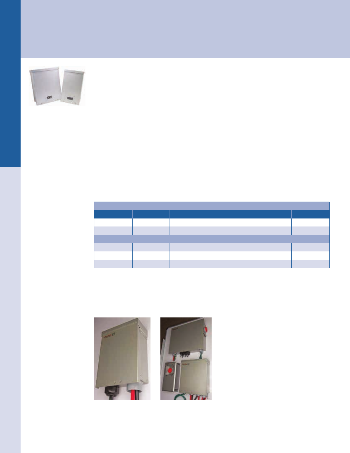
For the latest on AEE Solar products, trainings and dealer services, visit www.aeesolar.com
ELECTRICAL DISTRIBUTION PARTS Array Combiners
185
Array Combiners
Array combiners are used to electrically combine the output of multiple series strings of PV modules into a single wire to simplify
the connection to an inverter or charge controller. They typically include string-level overcurrent protection and sometimes host other
functions such as monitoring, a disconnect, or even AFCI and remote shutdown. It is important that the combiner used be rated for
the worst-case voltage and current the array can output.
OutBack
FLEXware PV Combiners
The FLEXware PV8 and PV12 accommodate overcurrent protection requirements for off-grid and
grid-connected applications. The DIN rail can be tted with 150 VDC circuit breakers for low-voltage
PV arrays or 600 VDC fuse holders for grid-tie arrays. Rated NEMA 3R, the powder-coated aluminum
chassis can be mounted on a wall, a sloped roof, or a pole. Dual output lugs allow connection for up to
2/0 AWG wire. An easily-removable ame-retardant polycarbonate deadfront panel prevents accidental
contact with live terminals. FWPV8 has one output circuit and FWPV12 can be congured to have one
or two output circuits. Negative and ground terminal busbars are included. The two output circuits can be
used for fuses in both the negative and positive legs for up to four strings into transformerless inverters.
Limited to 15 A breakers or fuses. Listed to UL 1741.
FLEXware ICS PV Combiners
The FLEXware ICS PV combiners come with or without fuse holders pre-installed in the combiner, and
include distribution blocks and cable gland. The FWPV6 can be used with up to six strings at 600 VDC.
Fuse holders need to be added in the quantity needed. The FWPV6-FH600 comes with six touch-safe
midget fuse holders, and FWPV4-FH600 comes with four touch-safe midget fuse holders. Listed to
UL 1741.
OutBack FLEXware PV Combiners
Model # of breakers # of fuse holders Dimensions (L"x W"x H") Weight Item code
FWPV8 eight (not incl.) six (not incl.) 15.2 x 9.2 x 3.9 4.4 lbs 053-03012
FWPV12 twelve (not incl.) eight (not incl.) 15.2 x 12.7 x 3.9 5.9 lbs 053-03014
OutBack FLEXware ICS PV Combiners
FWPV6 -- six (not incl.) 11.5 x 8.25 x 3.75 2.5 lbs 053-03006
FWPV6-FH600 -- six 11.5 x 8.25 x 3.75 3.2 lbs 053-03007
FWPV4-FH600 -- four 11.5 x 8.25 x 3.75 3.5 lbs 053-03008
COMING SOON! FLEXware ICS Plus Combiner Solution
The FLEXware ICS Plus system will offer a complete UL-listed solution to meet the new 2014 NEC
requirements for arc-fault protection, rapid shutdown, advanced ground fault, and combiner DC disconnect.
Used with OutBack power conversion and energy storage equipment, it represents the only end-to-end
single manufacturer UL-1741 solution on the market for battery-based systems.
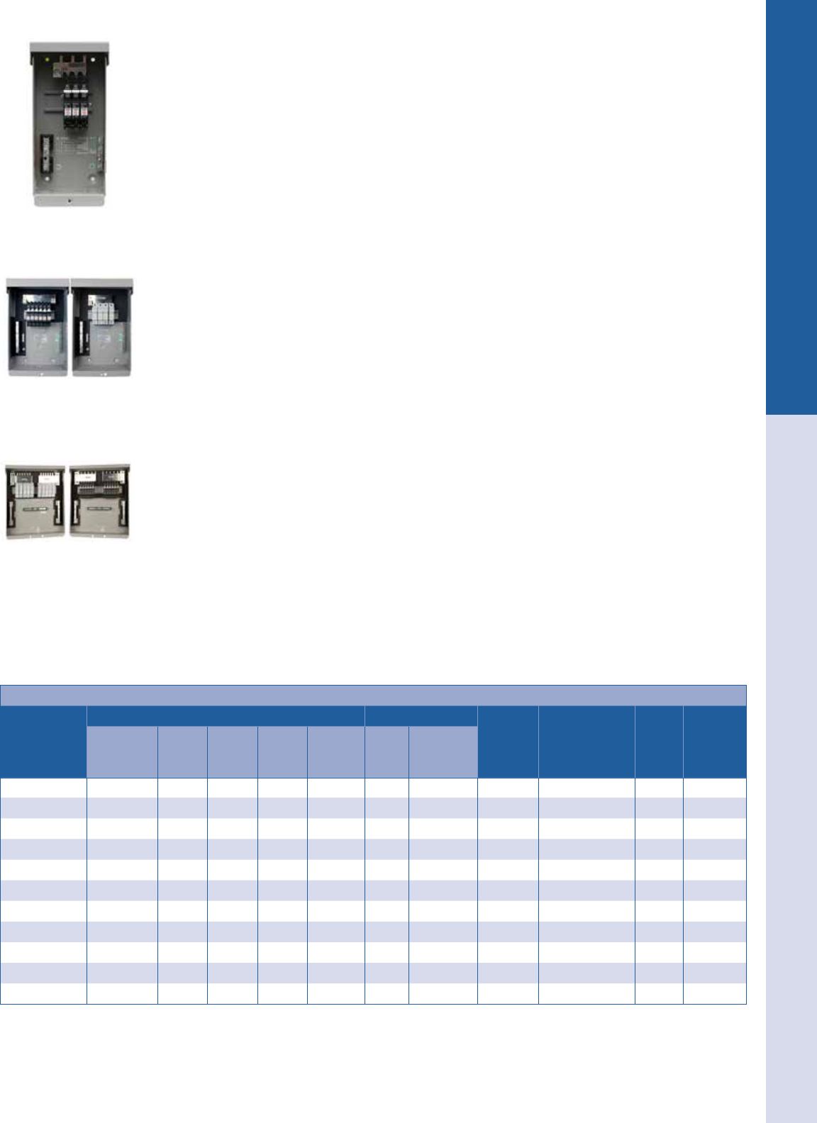
For the latest on AEE Solar products, trainings and dealer services, visit www.aeesolar.com
ELECTRICAL DISTRIBUTION PARTS Array Combiners
186
MidNite Solar
MNPV Combiners
These powder-coated aluminum rainproof array combiners will accept DIN-mount 150 V circuit breakers,
MidNite 300 VDC breakers, Midnite 600 VDC breakers, or 600 VDC fuse holders for grid-tie arrays. A
plastic cover provides a dead front for safety and can be knocked out for either breakers or fuse holders.
Both a negative and ground busbar are included. The aluminum NEMA 3R enclosures are approved to be
mounted at angles from 90° to 14° (vertical to 3/12 slope). Listed to UL 1741 for the U.S.A. and Canada.
Breakers and fuse holders are not included.
The MNPV3 will accept three single-pole 150 VDC (MNEPV) breakers or two 600/1,000 VDC fuse
holders. Includes a 60 A positive busbar, six-position PV-negative busbar and a six-position ground bus-
bar. A single 300 VDC breaker from 7 to 50 A may be installed as a disconnect (no combining busbar).
The MNPV6 will accept six single-pole 150 VDC breakers or four 600/1,000 VDC fuse holders. Includes
15-position PV-negative bus bar, 14-position ground busbar, 120 A positive bus bar for breakers and
80 A busbar for fuses. The positive busbar may be split to support two grid-tie inverters or two charge
controllers. Most charge controllers and grid-tie inverters can have a common negative PV bus (except
Schneider XW and BlueSky).
The MNPV6-250 will hold up to three single-pole 300 VDC circuit breakers for charge controllers
accepting input voltages up to 300 VDC.
The MNPV12 will accept 12 single-pole 150 VDC breakers or ten 600/1,000 positive VDC fuse holders.
It includes a 15-position PV-negative busbar, 15-position ground bus bar, and two 200 A Plus busbars
for breakers or fuses. Positive busbars can be combined or separated to support two grid-tie inverters or
two charge controllers. Most charge controllers and grid-tie inverters can have a common negative PV
bus (except Schneider XW and BlueSky).
The MNPV12-250 will hold up to six single-pole 300 VDC circuit breakers for charge controllers accept-
ing input voltages up to 300 VDC.
The MNPV16 will accept 16 single-pole 600 VDC fuse holders. Includes 21-position PV-negative busbar,
18-position ground busbar, and 240 A positive and negative busbars.
The MNPV16-24 PV combiner can hold up to 24 single-pole 150 VDC breakers. The 240 A busbar can
take two dozen 10 A breakers or sixteen 15 A breakers or twelve 20 A breakers.
The MNPV16-250 will accept 12 single-pole 300 VDC breakers. Includes 21-position PV-negative
busbar, 18-position ground busbar, and 240 A positive and negative busbars.
The MNPVxx-1000 combiners use 1,000 VDC fuse holders and fuses, which are not included and must
be added. The MNPV10-1000 only can be split into two output circuits.
MidNite PV Combiners without Disconnect
Model
PV source circuit options Output circuits Max
output
wire size
MNPV combiner
dimensions
(L" x W" x H")
Weight Item code
Max #
150 VDC
breakers
Max #
300 VDC
breakers
Max #
600 VDC
breakers
Max #
600 VDC
fuses
Max #
1,000 VDC
fuses
Max #
output
circuits
Max
current
output
MNPV3 three -- -- two -- one 60 A 1/0 AWG 10.5 x 4.5 x 3.5 2 lbs 053-03017
MNPV6 six -- one four -- two1120 - 802 A 1/0 AWG 13.5 x 8 x 3.5 4 lbs 053-03018
MNPV6-250 -- three -- -- -- one 120 A 1/0 AWG 13.5 x 8 x 3.5 4 lbs 053-03081
MNPV12 twelve -- two ten -- two 200 A 2/0 AWG 14.5 x 12 x 3.5 6 lbs 053-03015
MNPV12-250 -- six -- -- -- two 168 A 2/0 AWG 14.5 x 12 x 3.5 6 lbs 053-03082
MNPV16 -- -- -- sixteen -- one 240 A 250 mcm 21.8 x 16 x 3 13 lbs 053-03016
MNPV16-24 twenty-four -- -- -- -- one 240 A 250 mcm 21.8 x 16 x 3 13 lbs 053-03087
MNPV16-250 -- twelve -- -- -- one 240 A 2/0 AWG 21.8 x 16 x 3 13 lbs 053-03083
MNPV2-1000 -- -- -- -- two one 40 A 1/0 AWG 10.5 x 4.5 x 3.5 2 lbs 053-03078
MNPV4-1000 -- -- -- -- four one 80 A 1/0 AWG 13.5 x 8 x 3.5 4 lbs 053-03079
MNPV10-1000 -- -- -- -- ten two 200 A 1/0 AWG 14.7 x 12.2 x 3.5 6 lbs 053-02960
1 Only with breakers, and one negative busbar
2 120 A for 150 VDC breakers and 80 A with 600 VDC fuses
MNPV12
MNPV6 with 150VDC breakers
and with 600VDC fuses
MNPV3
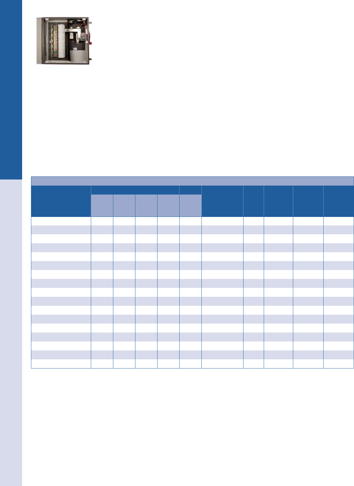
For the latest on AEE Solar products, trainings and dealer services, visit www.aeesolar.com
ELECTRICAL DISTRIBUTION PARTS Array Combiners
187
MidNite Solar MNPV Combiners with Disconnect Switch
The MidNite Disco line of PV combiners with disconnects are made to meet NEC requirements. The
disconnect handle is bright red for visibility and can be locked in the off position. Several models can be
congured for bi-polar or non-isolated inverters where both the positive and negative legs of the array
need circuit protection. Models are available for 150 VDC, 300 VDC, or 600 VDC arrays. All of the
combiners are made from powder-coated aluminum for long life in harsh conditions. A clear see-through
dead front is supplied with all Disco combiners. Models are available with either NEMA 3R or NEMA
4X ratings. Many of these come with a shunt-trip disconnect and when supplied with the PSB circuit
board, are compatible with the MidNite Rapid-Shutdown system to meet NEC 2014 requirements. Breaker
versions do not include breakers. HV versions come with fuse holders except for the MNPV4HV Disco
3R Basic which needs fuse holders added.
The MidNite DLTL disconnect combiners have both dual-string fusing and dual-channel output. These
work for inverters with ungrounded conductors and dual-MPPT input channels which are becoming
common. Both the positive and negative legs are fused, and the fuse holders are included. They are also
available with the Rapid-Shutdown PSB circuit board installed.
The MidNite SOB disconnect boxes, are not actually combiners but are used to transition from array to
conduit wiring with an array disconnect. They have either two or four poles, so can disconnect dual chan
-
nel output, either one or two strings. These work for inverters with grounded or ungrounded conductors
and dual-MPPT input channels. The MNSOB boxes with sufx “-75A” are rated at 75A per pole for use
with combined circuits. They are also available with the Rapid-Shutdown PSB circuit board installed.
MidNite PV Disconnect Combiners
Model
PV source circuit options Outputs MNPV combiner
dimensions
(L" x W" x H")
Weight Birdhouse
compatible? Item code Item code
w/ PSB
Max #
150 VDC
breakers
Max #
300 VDC
breakers
Max #
600 VDC
breakers
Max #
600 VDC
fuses
Max #
output
circuits
MNPV6 Disco six -- one -- two 13.2 x 8 x 6.2 6 lbs No 053-03000 --
MNPV6-250 Disco -- three -- -- one 13.2 x 8 x 6.2 6 lbs No 053-03001 --
MNPV4HV Disco 3R Basic -- -- -- four one 13.7 x 10.4 x 4.4 8 lbs No 053-02990 --
MNPV4HV Disco 3R Dlx -- -- -- four one 13.7 x 10.4 x 4.4 10 lbs Yes 053-02991 053-02972
MNPV6HV Disco 4X -- -- -- six one 16.8 x 12.4 x 5.6 14 lbs Yes 053-02992 053-02973
MNPV8HV Disco 3R -- -- -- eight two 18.5 x 14 x 4.6 16 lbs Yes 053-02993 053-02974
MNPV8HV Disco 4X -- -- -- eight two 19.5 x 14.8 x 5.8 18 lbs Yes 053-02994 053-02975
MNPV16HV Disco 4X -- -- -- sixteen two 21.6 x 19.9 x 5.8 27 lbs Yes 053-02995 053-02976
MNPV8HV-DLTL-3R -- -- -- eight two 19.5 x 14.8 x 5.8 18 lbs Yes 053-02969 053-02977
MNPV8HV-DLTL-4X -- -- -- eight two 19.5 x 14.8 x 5.8 18 lbs Yes 053-02970 053-02978
MNPV16HV-DLTL-4X -- -- -- sixteen two 26 x 24 x 6 25 lbs Yes 053-02971 053-02979
MNSOB 3R-2P -- -- -- -- two 13.7 x 10.4 x 4.4 10 lbs Yes 053-02961 053-02962
MNSOB 4X-2P -- -- -- -- two 16.8 x 12.4 x 5.6 14 lbs Yes 053-02963 053-02966
MNSOB 3R-4P -- -- -- -- four 13.7 x 10.4 x 4.4 10 lbs Yes 053-02964 053-02967
MNSOB 4X-4P -- -- -- -- four 16.8 x 12.4 x 5.6 14 lbs Yes 053-02965 053-02968
MNSOB 3R-2P-75A -- -- -- -- two 13.7 x 10.4 x 4.4 10 lbs Yes 053-02947 053-02948
MNSOB 4X-4P-75A -- -- -- -- four 16.8 x 12.4 x 5.6 14 lbs Yes 053-02949 053-02950
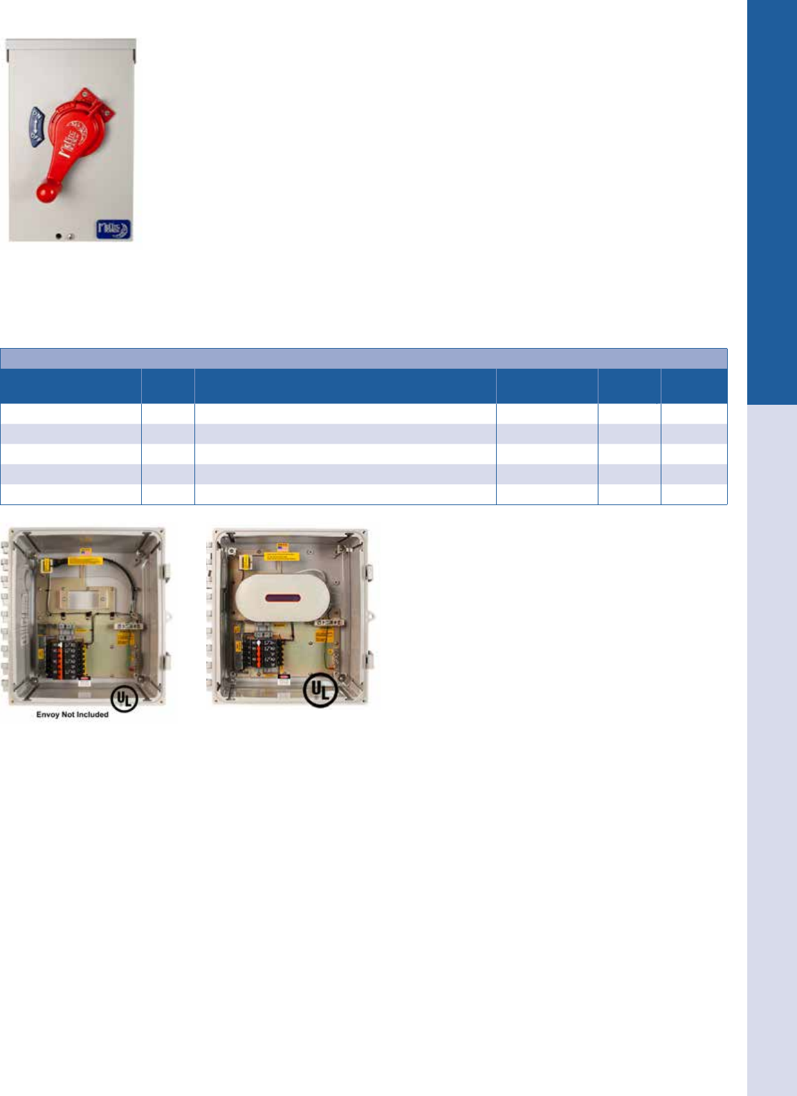
For the latest on AEE Solar products, trainings and dealer services, visit www.aeesolar.com
ELECTRICAL DISTRIBUTION PARTS Array Combiners
188
NEW! MidNite Solar Micro-inverter and Enphase combiners
The MidNite MNPV6-DISCO AC MICRO is a basic disconnecting combiner for up to three 120/240
VAC micro-inverter circuits. The disconnect handle is bright red for visibility and can be locked in the
off position. Made from powder-coated aluminum for long life in any environment. Add AC DIN-mount
breakers from page 176. Add one two-pole breaker for each micro-inverter circuit, up to three circuits.
The MidNite MNACENPR combiners were developed in conjunction with Enphase. They give the
installer a single outdoor enclosure for combining two or three Enphase 120/240 VAC micro-inverter
circuits, and the Envoy. This makes installation of an Enphase system easy and saves installation time. It
is available for either two or three circuits, and with or without the Envoy included. The close proximity
of the Envoy to the Enphase circuits ensures the best power line carrier performance from the inverters.
The Envoy can be connected to an Internet router by direct Ethernet cable, a WiFi stick on the Envoy
(there is room in the enclosure for this), or by Ethernet-over-power-line adapters. There is a 5A recep-
tacle inside for an Ethernet-over-power-line adapter if it is used. The enclosure easily accommodates a
MidNite SPD300AC for surge protection. They are made of polycarbonate for toughness and corrosion
resistance, which also allows maximum WiFi transmission.
All of these combiners come with a clear dead front and are NEMA 3R rated. Listed to UL1741, and
made in the USA.
MidNite PV Disconnect Combiner Accessories
Model # of
circuits Description Dimensions
(L" x W" x H") Weight Item code
MNPV6-DISCO AC MICRO three Disconnecting combiner three 20 A AC circuits, add breakers 13.2 x 8 x 6.2 7 lbs. 053-02984
MNACENPR-2P20NE two Enphase two-circuit combiner, Envoy not included 15.4 x 14.6 x 7.6 11 lbs. 053-02955
MNACENPR-3P20NE three Enphase three-circuit combiner, Envoy not included 15.4 x 14.6 x 7.6 11 lbs. 053-02954
MNACENPR-2P20 two Enphase two-circuit combiner, with Envoy 15.4 x 14.6 x 7.6 13 lbs. 053-02953
MNACENPR-3P20 three Enphase three-circuit combiner, with Envoy 15.4 x 14.6 x 7.6 13 lbs. 053-02952
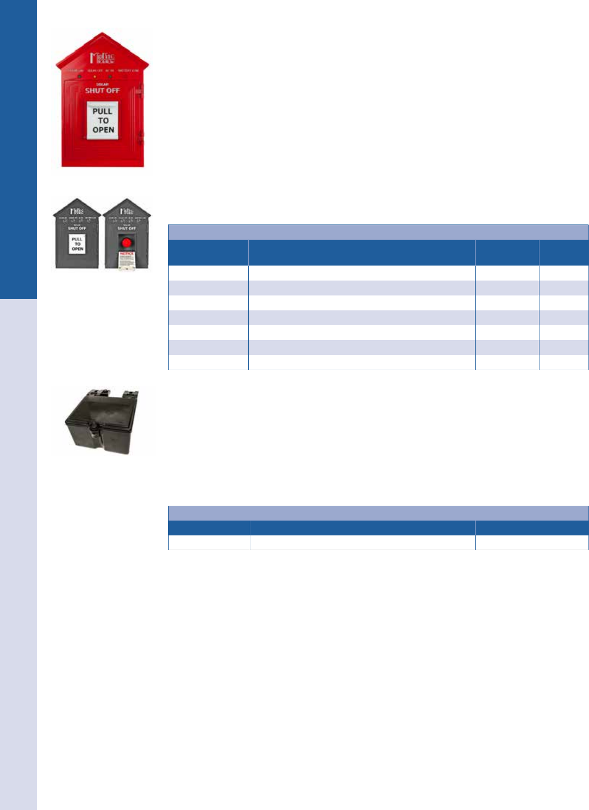
For the latest on AEE Solar products, trainings and dealer services, visit www.aeesolar.com
ELECTRICAL DISTRIBUTION PARTS Array Combiners
189
MidNite Solar Rapid Shutdown Components
The reghter-approved MNBirdhouse1 remote actuator should be installed in a visible, easily acces-
sible location so that the array combiners can safely be disconnected from the ground when necessary.
The hard-wired connection to the disconnect combiners provides positive feedback that the disconnect
on the roof has actually been thrown. One MNBirdhouse1 can be used to disconnect multiple combiners.
The MNBirdhouse1 has a speaker and will announce when it is safe to climb onto the roof, and during
the day it will inform that there is still voltage present up to the combiner. At night, it will announce
that there is no PV voltage present. The MNBirdhouse1 is powered by multiple redundant sources. It is
available in either red or gray. Each combiner can be powered using the array with the MNDiscoPSB
power supply that will also power the MNBirdhouse1. The MNBirdhouse1 also comes with an indoor
120 VAC power supply that can be used as a DC supply, and has an internal backup battery. The power
draw of the MNBirdhouse1 is only 1 W. Use the special MNCAT5-600 600 V CAT5 USE-2 compliant
wire to connect the Birdhouse and combiners. The MNBDM battery disconnect module can be used to
power a remote actuating breaker to disconnect other circuits including battery or generator circuits. The
MNFX-CABLE should be used in the MNBirdhouse1 when there are no combiners connected to it.
MidNite PV Disconnect Combiner Accessories
Model Description Dimensions
(L" x W" x H") Item code
MNBirdhouse1-Red Emergency remote disconnect switch - Red 12.1 x 8.3 x 4.6 053-02985
MNBirdhouse1-Gray Emergency remote disconnect switch - Gray 12.1 x 8.3 x 4.6 053-02959
MNDiscoPSB Power supply for disconnect combiners 9.5 x 4 x 3.25 053-02987
MNBDM-48 Power supply 48 VDC for remote-actuated breakers 4 x 2 x 1.25 053-02958
MNBDM-24 Power supply 24 VDC for remote-actuated breakers 4 x 2 x 1.25 053-02957
MNFX-CABLE Cable for use in Birdhouse when no PSB combiner is used -- 053-02956
MNCAT5-600 Communication cable 600 V CAT5 USE-2 outdoor wire, per foot -- 053-02983
SnapNrack
NEW! SnapNrack Junction Box R
The SnapNrack UL-listed Junction Box provides a quick and easy installation utilizing snap-in features
and NEMA 4X rating. It is large enough for wire management but small enough to be adaptable to any
mounting conguration. It works well to conceal and protect electrical connections under the array. It has
internal dimensions approximately 6” x 5” x 3” with DIN-rail mounting bosses inside. The lid is hinged
and gasketed, and has a single screw to close. It comes with a SnapNrack channel nut and is made of
polycarbonate as well as covered under a ten-year product warranty.
Tyco Grounding Connector
Model Description Item code
JUNCTION BOX R SnapNrack array J-box for SnapNrack rails 242-01104

For the latest on AEE Solar products, trainings and dealer services, visit www.aeesolar.com
ELECTRICAL DISTRIBUTION PARTS Array Combiners
190
SolaDeck
PV Roof-Mount Enclosure/Combiner
These are NEMA 3R enclosures that provide a ashed roof penetration for the array cables. They are all
made from 18 gauge galvanized steel with a powder-coated nish providing a professional look. All have
a dual ground lug, a 6" (150 mm) universal DIN rail to mount fuse holders or terminal blocks. There are
three roof-deck knockouts (½", ¾", and 1") and dimples to center a punch or drill for entry conduit or
ttings, as well as a built-in roof ashing.
The SD-0786-41 is a DC combiner and can be used with terminals or fuse holders for array wiring. For
combining circuits, use up to four DIN-mount fuse holders, each 18 mm wide, a positive and negative
busbar, and a PASS-THRU kit to combine up to four module strings. Or use the two-position positive
(0784 BB) and negative (0785 BB) busbars for combining two strings, with or without fuses (fuses not
included). These are listed to UL 1741 for DC Photovoltaic Combiner Enclosures.
The SD-0786-3R is listed as a j-box and can be used for pass-through wiring of both DC and AC circuits
without combining. Both SD-0786 are only 2.5" deep and can t under the array.
The SD-0760-41 AD is a combiner for both AC and DC circuits and has a bump in the lid to accom-
modate DIN-mount DC or AC breakers. The SD-0766-41 AD is 6" deep for use on tile roofs. It comes
with a 30" square soft aluminum ashing and can be used as both AC and DC combiner or pass-through.
These are listed to UL 1741 for DC Photovoltaic Combiner Enclosures.
To make pass-through connections inside a SolaDeck, use one or more PASS-THRU kits. This kit has
four DIN-mount terminals that can be used with 16 to 6 AWG wire and hardware to hold them in place.
Each terminal is 10 mm wide. See the next page for Soladeck combiner and pass-through kits.
For combining two AC micro-inverter circuits, use 0784 AC 2K and two appropriately rated S202U
breakers. For combining three AC micro-inverter circuits, use 0784 AC 3K and three S202U breakers
SolaDeck PV Roof-Mount Enclosures and Accessories
Model Description Item code
SD-0786-41 SolaDeck enclosure combiner DC only 053-00226
SD-0786-3R SolaDeck enclosure pass-through AC/DC (no combining) 053-00225
SD-0760-41 AD SolaDeck enclosure combiner AC/DC bump lid ts breakers 053-00223
SD-0766-41 AD SolaDeck enclosure combiner AC/DC deep tile roof, large soft ashing 053-00224
0784 BB Positive busbar for four fuse holders 053-00227
0785 BB Negative busbar for four terminals 053-00228
0784 FBB-2 Positive busbar for two fuse holders 053-00229
0785 TBB-2 Negative busbar for two terminals 053-00230
1452 Fuse holder for DIN-mount 600 VAC/DC 053-00240
0784 AC 2K Dual busbar kit for two AC branch circuits 240 V 053-00232
0784 AC 3K Dual busbar kit for three AC branch circuits 240 V 053-00233
S202U Z20A AC breaker two-pole 240 VAC 20 A 053-00210
S202U Z15A AC breaker two-pole 240 VAC 15 A 053-00211
S280UC K16 DC breaker single-pole 250 VDC 16 A 053-00212
1440.080 Distribution block 80 A three-pole primary 14-4 AWG, four-pole secondary 14-100AWG 053-00241
1440 Distribution block 175 A two-pole primary 8-2/0 AWG, four-pole secondary 14-8 AWG 053-00243

For the latest on AEE Solar products, trainings and dealer services, visit www.aeesolar.com
ELECTRICAL DISTRIBUTION PARTS Array Combiners
191
SolaDeck Combiner Kits
These kits simplify selection of combiner-box components. Select a kit that has the conguration you
need for the parts that will allow you to put it together. The combiner kits come with fuse holders and 15
A fuses. All kits come with strain-relief ttings. The kits with breakers must use the bump-lid enclosure.
SolaDeck Pass-Through and Combiner Kits
Model Description Item code
DC Pass-Through Kits
01601 SolaDeck DC pass-through kit for one string 053-00250
01602 SolaDeck DC pass-through kit for two strings 053-00251
01603 SolaDeck DC pass-through kit for three strings 053-00252
01604 SolaDeck DC pass-through kit for four strings 053-00253
01605 SolaDeck DC pass-through kit for ve strings 053-00254
DC Fused Combiner Kits
0786K-2C SolaDeck DC combiner kit for two strings 053-00259
0786K-3C SolaDeck DC combiner kit for three strings 053-00260
0786K-4C SolaDeck DC combiner kit for four strings 053-00261
0786K-5C SolaDeck DC combiner kit for ve strings 053-00262
DC Dual Fused Combiner Kits
01632 SolaDeck DC combiner kit for two strings, both positive and negative fused 053-00273
01633 SolaDeck DC combiner kit for three strings, both positive and negative fused 053-00274
01634 SolaDeck DC combiner kit for four strings, both positive and negative fused 053-00275
AC Pass-Through Kits
01611 SolaDeck AC pass-through kit for one string 053-00255
01612 SolaDeck AC pass-through kit for two strings 053-00256
01613 SolaDeck AC pass-through kit for three strings 053-00257
01614 SolaDeck AC pass-through kit for four strings 053-00258
AC Fused Kits
01641 SolaDeck AC fused pass-through kit for one circuit 053-00263
01642 SolaDeck AC fused combiner kit for two circuits 053-00264
01643 SolaDeck AC fused combiner kit for three circuits 053-00265
AC Breaker Kits
0760K2AC-PB15 SolaDeck 15A AC breaker combiner kit for two circuits, use bump lid box 053-00276
0760K3AC-PB15 SolaDeck 15A AC breaker combiner kit for three circuits, use bump lid box 053-00277
0760K2AC-PB20 SolaDeck 20A AC breaker combiner kit for two circuits, use bump lid box 053-00278
0760K3AC-PB20 SolaDeck 20A AC breaker combiner kit for three circuits, use bump lid box 053-00279
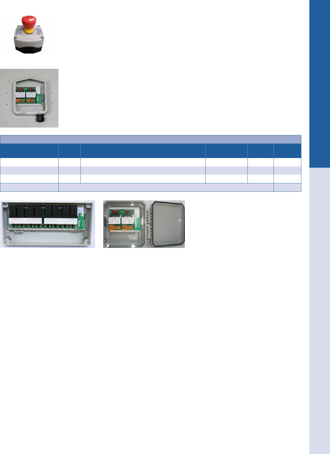
For the latest on AEE Solar products, trainings and dealer services, visit www.aeesolar.com
ELECTRICAL DISTRIBUTION PARTS Array Combiners
192
NEW! Rapid Shutdown Devices
These rapid shutdown devices meet the NEC 690.12 requirements in a single box. These are made for all
grid-tie inverters, and will disconnect the solar array and discharge the inverter capacitors on loss of the
grid or an optional stop switch. When the power supply or stop switch interrupts the low voltage current
to the unit, it will shut down the connection and discharge the capacitors in the inverter. The signal power
to operate the system is 15-30 VDC or 12-18 VAC. 2.5 W is needed per unit to operate, make sure the
power supply is adequate for all of the units installed. They are not made to work with charge controllers,
and should not be used with them. They are available in three forms, inside a Soladeck enclosure, in a
small polycarbonate box, and in a larger box. The RS6-D2-S1CAC is installed in a Soladeck enclosure,
the RS6-D2-P1CAC is in a NEMA 4X polycarbonate enclosure, and both units have two channels with
two poles each, one positive and one negative. The RS6-D4-S2CAC has four channels with one positive
and one negative each, in a NEMA 3R box. Each pole is rated at 600 VDC and 20 A continuous (16 A
Isc) so for most modules is limited to one string per pole. The units include surge protection to 20 kA at
8/20 μs impulse. Rated at -40 °C to 70 °C ambient temperatures. TUV tested to UL1741. Covered by a
ten-year warranty.
The E-stop switches can be used to shut down the array in addition to the loss of utility power.
Rapid Shutdown Devices
Model # of
circuits Description Dimensions
(L" x W" x H") Weight Item code
RS6-D2-S1CAC two Rapid shutdown box in Soladeck enclosure 10.4 x 8.7 x 2.6 10 lbs 053-00215
RS6-D2-P1CAC two Rapid shutdown box in NEMA 4X enclosure 9.5 x 8.5 x 3.5 3.5 lbs 053-00216
RS6-D4-S2CAC four Rapid shutdown box in NEMA 3R enclosure 23.6 x 7.9 x 3.1 13.1 lbs 053-00217
0232-00/A E-stop switch, w/ power supply 053-00220

AEE Express is your 24/7 Online Energy Store. If you’re an AEE Solar dealer,
log in to the store at aeeexpress.com. Get prices, inventory, account status and
more!
For the latest on AEE Solar products, trainings and dealer services, visit www.aeesolar.com
ELECTRICAL DISTRIBUTION PARTS Array Combiners
193
AMtec Combiners
AMtec manufactures a variety of 600 VDC to 1500 VDC combiners and re-combiners, including options
for string monitoring, disconnect, and remote contactor. A choice between enclosure materials is available
including berglass, painted steel, and stainless steel. Custom devices are also available. Call AEE for
assistance in choosing a combiner for your needs. Made to UL standards in USA.
SolarBOS Combiners
SolarBOS manufactures a wide variety of 600 VDC to 1500 VDC combiners and re-combiners for
commercial applications, including options for string monitoring, disconnect, remote contactor, and arc
fault protection. A choice between enclosure materials is available including berglass, painted steel,
and stainless steel. Custom devices are also available. Call AEE for assistance in choosing a combiner
for your needs. Made to UL standards in USA.
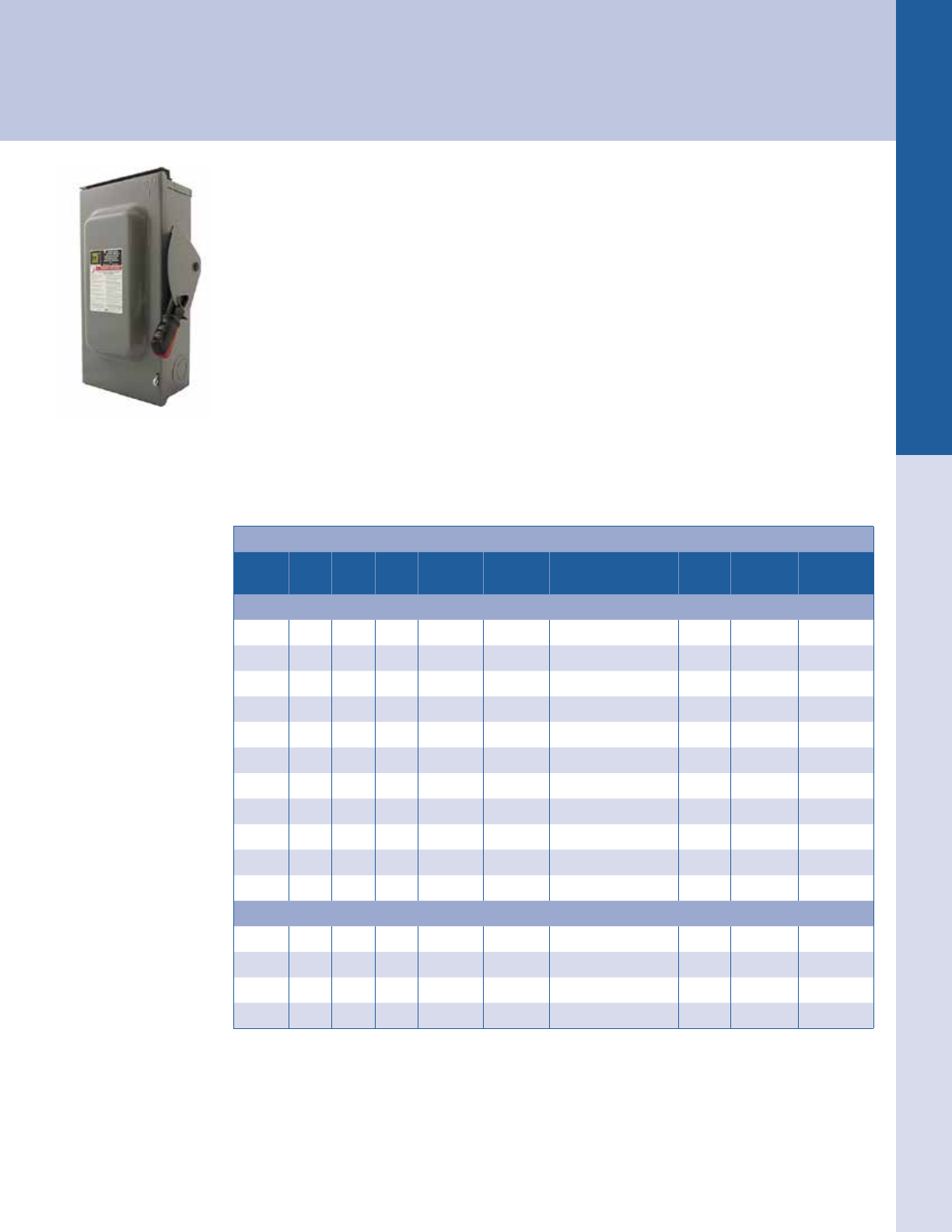
For the latest on AEE Solar products, trainings and dealer services, visit www.aeesolar.com
ELECTRICAL DISTRIBUTION PARTS Disconnects
194
Disconnects
Disconnect switches provide a means for safely opening a circuit between the power supply and any loads that may be present. Some
disconnects also offer fusing, remotely-actuated contactors or other specialized functions. The NEC requires listed disconnects in a
variety of situations. Be sure to choose a disconnect that is rated for the AC or DC voltage and current that may be present on the circuit.
Square-D
240 V and 600 V NEMA 3R Safety Switch Disconnects
For inverters that do not include a DC disconnect, or when an additional DC disconnect is required, one
of these 600 VDC disconnects can be used. Many utilities require an AC disconnect between a grid-tie
inverter and the AC load center, close to the AC service entrance, and with a visible and lockable handle.
The Square-D 600 VDC-rated 30 A, 60 A, and 100 A three-pole safety switches are rated by Square-D to
handle one 600 VDC circuit per pole for PV (although they are not UL-listed for this purpose). The 30 A
switch is rated for 16 A short-circuit current (I
sc
at PV module STC) for non-fused versions, and 12.8 A (I
sc
)
for fused versions. The 60 A switch is rated for 48 A (Isc) for non-fused versions and 38 A (Isc) for fused
versions. The 100 A switch is rated for 80 A (Isc) for non-fused versions and 64 A (Isc) for fused versions.
All of the Square-D 600 VDC non-fused disconnects are rated for disconnecting one circuit at full rated
current using two poles in series. Fused disconnects are rated for 80% of switch current rating at up to
600 VDC.
Use Class-R fuses of the proper voltage and amperage for fused disconnects. 600 V fuses will not t into
240 VDC disconnects, and 250 VAC/125 VDC fuses will not t into 600 V disconnects, and vice-versa.
Heavy-Duty (HD) switches are rated for “Service duty”. Use the fused versions for AC line-side taps.
Square-D Disconnects
Amps AC/DC Fused Poles Neutral kit Ground kit Dimensions
(H" x W" x D") Weight Model Item code
600 VAC or DC 3-Pole NEMA 3R Heavy-Duty Switches
30 A Yes No three SN03 GTK03 14.88 x 6.63 x 4.88 9.3 lbs HU361RB 053-02312
30 A Yes Yes three SN03 GTK03 14.88 x 6.63 x 4.88 9.8 lbs H361RB 053-02313
60 A Yes No three SN0610 GTK0610 17.50 x 9 x 6.38 16 lbs HU362RB 053-02339
60 A Yes Yes three SN0610 GTK0610 17.50 x 9 x 6.38 16 lbs H362RB 053-02341
100 A Yes No three SN0610 GTK0610 21.25 x 8.50 x 6.38 24 lbs HU363RB 053-02357
100 A Yes Yes three SN0610 GTK0610 21.25 x 8.50 x 6.38 24 lbs H363RB 053-02355
200 A Yes No three1SN20A PKOGTA2 29.25 x 17.25 x 8.50 44 lbs HU364RB 053-02364
200 A Yes Yes three1SN20A PKOGTA2 29.25 x 17.25 x 8.50 -- H364NRB 053-02366
400 A Yes Yes three1included PKOGTA2 50.31 x 27.88 x 10.13 -- H365NR 053-02407
800 A Yes Yes three1included PKOGTA7 69.13 x 36.62 x 17.75 -- H367NR 053-02373
1,200 A Yes Yes three1included PKOGTA8 69.13 x 36.62 x 17.75 -- H368NR 053-02409
240 VAC/125 VDC2 NEMA 3R Heavy-Duty Switches
30 A Yes Yes three included GTK03 14.88 x 6.63 x 4.88 9.8 lbs H321NRB 053-02315
60 A Yes Yes three included GTK03 14.88 x 6.63 x 4.88 10 lbs H322NRB 053-02336
100 A Yes Yes three included GTK0610 21.25 x 8.50 x 6.38 19 lbs H323NRB 053-02351
200 A Yes Yes three included PKOGTA2 29.25 x 17.25 x 8.50 43 lbs H324NRB 053-02363
1 Uses two poles (and two fuses) in series for 600 VDC, no PV rating per pole.
2 Switches are rated for 250 VDC, but available fuses are only rated for 125 VDC.
For the latest on AEE Solar products, trainings and dealer services, visit www.aeesolar.com
ELECTRICAL DISTRIBUTION PARTS Disconnects
195
AC-Only NEMA 3R Safety Switch Disconnects
Use these General-Duty Square-D AC safety switches for single-phase or three-phase grid-tie inverter
outputs if you are back-feeding a circuit breaker to make the connection to the service panel. They can
also be used as a disconnect for the AC output of off-grid inverters.
Use Class-R 250 VAC/125 VDC fuses with the fused versions of these disconnects.
Square-D NEMA 3R General-Duty Switches - 240 V Max AC Only
Amps AC/DC Fused Poles Neutral kit Ground kit Dimensions
(H" x W" x D") Weight Model Item code
30 A AC only No two SN20A PK3GTA1 9.63 x 7.25 x 3.75 4.4 lbs DU221RB 053-02318
30 A AC only Yes two included PK3GTA1 9.63 x 7.25 x 3.75 4.5 lbs D221NRB 053-02326
30 A AC only No three SN20A PK3GTA1 9.63 x 7.25 x 3.75 4.7 lbs DU321RB 053-02319
30 A AC only Yes three included PK3GTA1 9.63 x 7.25 x 3.75 5.1 lbs D321NRB 053-02329
60 A AC only Yes two included GTK03 14.88 x 6.63 x 4.88 9.7 lbs D222NRB 053-02334
60 A AC only No three SN20A PK3GTA1 9.63 x 7.25 x 3.75 5.0 lbs DU322RB 053-02342
60 A AC only Yes three included GTK03 14.88 x 6.63 x 4.88 9.8 lbs D322NRB 053-02343
100 A AC only Yes two included GTK0610 17.50 x 8.50 x 6.50 16 lbs D223NRB 053-02358
100 A AC only No three SN0610 GTK0610 17.50 x 8.50 x 6.50 15 lbs DU323RB 053-02359
100 A AC only Yes three included GTK0610 17.50 x 8.50 x 6.50 16 lbs D323NRB 053-02361
200 A AC only Yes two included PKOGTA2 29.25 x 17.25 x 8.25 29 lbs D224NRB 053-02371
200 A AC only Yes three included PKOGTA2 29.25 x 17.25 x 8.25 30 lbs D324NRB 053-02372
Square-D Disconnect Accessories
These conduit Top-Mount Hubs connect conduit or a kWh meter socket to the top of the disconnect. The
neutral and ground busbars are used to land these conductors in the disconnect switch box. Appropriate
busbars for each disconnect are identied in the tables above.
Square-D Disconnect Switch Accessories
Description Item code
SN03 Neutral busbar 053-02389
SN0610 Neutral busbar 053-02381
SN20A Neutral busbar 053-02383
GTK03 Ground busbar 053-02387
PK3GTA1 Ground busbar 053-02395
GTK0610 Ground busbar 053-02386
PKOGTA2 Ground busbar 053-02388
PKOGTA7 Ground busbar 053-02385
PKOGTA8 Ground busbar 053-02384
Top Mount hub 3/4" 053-02305
Top Mount hub 1" 053-02306
Top Mount hub 1-1/4" 053-02307
Top Mount hub 1-1/2" 053-02308
Top Mount hub 2" 053-02309
SN0610 Neutral busbar
SN20A Neutral busbar
PKOGTA2 Ground busbar
Top Mount hub 3/4"
For the latest on AEE Solar products, trainings and dealer services, visit www.aeesolar.com
ELECTRICAL DISTRIBUTION PARTS Load Centers
196
Load Centers
Load centers provide a central location for mounting busses and breakers to feed multiple load circuits from a single power supply,
such as a utility service or inverter output. The NEC requires NRTL-listed load centers for most applications. Be sure to choose a load
center that is rated for the AC or DC voltage and current supplied as well as any application-specic requirements.
Square-D QO Load Centers
Square-D brand load centers are multi-purpose for wiring that meets the National Electric Code (NEC).
These can be used as AC load centers or subpanels. Panels using QO plug-in breakers are rated up to
48 VDC for use as 12 VDC or 24 VDC load centers. They can also be used to combine the AC output
from multiple inverters feeding the grid. When used as DC load centers, they should be protected by a
high-interrupt capacity fuse or circuit breaker between the load center and the battery. The Class-T and
R fuses, as well as the DC breakers used in the OutBack and Xantrex DC power centers, work in these
load centers.
When used to combine the AC output of multiple grid-tie inverters, in order to meet the requirements
of NEC 690.64(B)(2), the bus amp rating for the load center must be larger than the sum of all of the
overcurrent devices feeding it, from both the utility and all inverters. Load centers are not supplied with
breakers—order breakers and conduit hubs for outdoor load centers separately.
Square-D QO Load Centers1
Spaces
(single)
Bus
rating Outdoor Cover Max wire
main lug
Ground
kit
Dimensions
(L" x W" x H") Weight Model Item code
120/240 V AC Single-Phase Main Lug Load Centers
two 70 A yes incl. 4 AWG PK4GTA 9.38 x 4.88 x 4 5 lbs QO24L70RB 053-02141
two 70 A no incl. 4 AWG PK4GTA 9.30 x 4.81 x 3.19 3.8 lbs QO24L70S 053-02144
six 100 A yes incl. 1 AWG PK7GTA 12.62 x 8.88 x 4.27 9.7 lbs QO612L100RB 053-02147
six 100 A no incl. 1 AWG PK7GTA 12.57 x 8.88 x 3.8 8.3 lbs QO612L100DS 053-02153
12 125 A yes incl. 2/0 AWG incl. 19 x 14.25 x 4.5 23 lbs QO112L125GRB 053-02163
12 125 A no add 2/0 AWG incl. 18 x 14.25 x 3.75 15 lbs QO112L125G 053-02162
12 200 A yes incl. 250 kcmil incl. 26.25 x 14.25 x 4.5 27 lbs QO112L200GRB 053-02165
12 200 A no add 250 kcmil PK15GTA 29.86 x 14.25 x 3.75 18 lbs QO112L200G 053-02164
120/208 V AC Three-Phase Main Lug Load Centers
12 125 A yes incl. 2/0 AWG incl. 19 x 14.25 x 4.52 22 lbs QO312L125GRB 053-02181
12 125 A no add 2/0 AWG incl. 19 x 14.25 x 3.75 11 lbs QO312L125G 053-02183
18 200 A yes incl. 250 kcmil incl. 30 x 14.25 x 4.52 31 lbs QO318L200GRB 053-02185
18 200 A no add 250 kcmil incl. 30 x 14.25 x 3.75 17 lbs QO318L200G 053-02187
1Uses QO plug-in breakers
Square D Load Center Covers and Ground Busbars for QO Load Centers
Description Weight Model Item code
Surface cover for twelve-space 125 A Load Centers 053-02162 & 053-02183 6 lbs GOC16US 053-02159
Flush cover for twelve-space 125 A Load Centers 053-02162 & 053-02183 7 lbs GOC16UF 053-02156
Surface cover for all 200 A Load Centers 053-02164 & 053-02187 9.2 lbs GOC30US 053-02169
Flush cover for all 200 A Load Centers 053-02164 & 053-02187 11 lbs GOC30UF 053-02170
Ground Busbar for two-space Load Centers PK4GTA 053-02390
Ground Busbar for six-space Load Centers PK7GTA 053-02391
Ground Busbar for twelve-space Load Centers PK9GTA 053-02392
Ground Busbar for twelve-space 200 A Load Centers PK15GTA 053-02393
Ground Busbar for 30-space Load Centers PK18GTA 053-02394
QO24L70RB
QO612L100RB
QO312L125GRB
GOC30US
PK15GTA
For the latest on AEE Solar products, trainings and dealer services, visit www.aeesolar.com
ELECTRICAL DISTRIBUTION PARTS Connectors, Blocks and Transfer Switches
197
Insulated Cable Connector Blocks
This insulated connector is molded for a precise t and supplied with removable access plugs over the
hex screws. Available with two to four wire-entry ports on one side for 14 to 4 AWG wire. This can be
used to transition from exposed PV-wire cables to conduit wiring on roof to PV arrays or for any paral-
lel wiring connection. Use the two-pole units just to splice two wires together (one in and one out). The
three-pole block can be used to splice two wires together, such as two strings of PV modules, with a single
wire output. The four-pole block can be used to splice three wires together with a single wire output.
Use one block for positive and one block for negative in DC circuits. Use one block for each phase, and
one block for the neutral, in AC circuits. UL-listed for 600 Volts.
Insulated Cable Connector Blocks
Number of poles Wire range Item code
two 14 to 4 AWG 054-01142
three 14 to 4 AWG 054-01143
four 14 to 4 AWG 054-01144
Wire Connectors, Outdoor Wire Nuts, J-Boxes
Piercing Tap Connectors are for making wire connections where termination is not possible or desir-
able. Twist-on Wire Nuts are lled with silicone sealant for use in damp/wet locations. General purpose
Rigid Non-Metallic Conduit Junction Boxes are rated NEMA 6P and are UL Listed.
Insulated Cable Connector Blocks
Description Wire range Item code
Insulation-piercing tap connector, silicone lled,
600 V, IPC-4/0-6 AWG
Main 4 to 4/0 AWG tap
14 to 6 AWG stranded 157-04550
Insulation- piercing tap connector, silicone lled,
600 V, IPC-4/0-2/0 AWG
Main 4 to 4/0 AWG tap
6 to 2/0 AWG stranded 157-04551
Wire nut with silicone ll, blue/red, IDEAL 62 AWG (100pk) Up to three 10 AWG 157-04011
Wire nut with silicone ll, blue/purple, IDEAL 63 AWG (100pk) Up to two 8 AWG and one 10 AWG 157-04016
Rigid non-metallic NEMA 6P J-box 4" x 4" x 4" 048-06590
Rigid non-metallic NEMA 6P J-box 6" x 6" x 4" 048-06595
Rigid non-metallic NEMA 6P J-box 6" x 6" x 6" 048-06600
Rigid non-metallic NEMA 6P J-box 8" x 8" x 4" 048-06610
Rigid non-metallic NEMA 6P J-box 12" x 12" x 6" 048-06620
Waterproof Strain Reliefs
Use the 1/2" NPT threaded connectors to provide a waterproof entrance or exit for wiring on PV module
junction boxes and outdoor combiner boxes. Use the 3/4" NPT connector for cables up to 5/8" diameter
Made of Nylon with Buna-N seals. Resistant to salt water, and most mild chemicals and oils, these strain
reliefs are noncorrosive and suitable for direct-burial installations. The oval-hole 1/2" strain relief works
for two-conductor TC cable used for module interconnects, PV outputs, or UF cable. The two-hole 1/2"
connector is designed for use with two 10 or 12 AWG type USE conductors. UL-listed for use in NEMA
4, 6 and 12 applications.
Waterproof Strain Reliefs
Description Fits cable size Item code
½" thread with one round hole USE 12 to 10 AWG 054-03243
½" thread with two round holes USE 12 to 10 AWG 054-03252
½" thread with two round holes PV WIRE 0.20" to 0.27" diameter 054-03242
½" thread with one round hole 0.25" to 0.5" diameter wire 054-03241
½" thread with one oval hole 14/2, 12/2, 10/2 TC 054-03257
¾" thread with one round hole 0.4" to 0.7" diameter cable 054-03261
¾ " thread with two round holes PV WIRE 0.20" to 0.35" diameter 054-03247
1" thread with ve round holes PV WIRE 0.10" to 0.33" diameter 054-03255
Steel lock nut ½" 054-03238
Steel lock nut ¾" 054-03244
IPC-4/0-6 AWG
IPC-4/0-2/0 AWG
For the latest on AEE Solar products, trainings and dealer services, visit www.aeesolar.com
ELECTRICAL DISTRIBUTION PARTS Connectors, Blocks and Transfer Switches
198
Barrel Connectors
These UL-listed connectors are tin-plated high strength aluminum alloy and can be used with copper or
aluminum wire. Single- and double-barrel connectors utilize set screws to secure wires in place. These
are not approved for use with ne stranded wire.
Barrel Connectors
Type Wire size Hole size Item code
Single 14 to 2 AWG 1/4" 051-03319
Single 14 to 2/0 AWG 1/4" 051-03327
Double 14 to 2/0 AWG 1/4" 051-03324
Single 6 to 4/0 AWG 3/8" 051-03334
Double 6 to 4/0 AWG 3/8" 051-03330
Power Distribution Blocks
Use these two-pole blocks to split primary power into secondary circuits, or join cables from a solar
array to a power lead-in cable. Just install cables and tighten the set screws. Terminal blocks are made
of zinc-plated aluminum for use with aluminum or copper conductors. Primary side accepts one large
cable; secondary side accepts six smaller cables. UL recognized for up to 600 VDC.
Power Distribution Blocks
Primary wire size Taps Secondary wire size Taps Rating Item code
2/0 to 8 AWG one 14 to 6 AWG six 175 A 054-01024
6/0 to 6 AWG one 14 to 4 AWG six 350 A 054-01027
500 mcm to 4 AWG one 14 to 2/0 AWG four 380 A 054-01025
350 mcm to 8 AWG one 14 to 4 AWG twelve 310 A 054-01023
Splicer Blocks
Use these blocks to splice wires of up to 2/0 AWG. The terminal blocks are made of zinc-plated alumi-
num, for use with aluminum or copper conductors. Two-pole and three-pole blocks have one connection
on each side. UL recognized for up to 600 VDC.
Splicer Blocks
Wire size Poles Rating Item code
8 to 2/0 AWG two 175 A 054-01030
8 to 2/0 AWG three 175 A 054-01033
MidNite Solar Manual Transfer Switch
These 120/240 VAC manual transfer switches have a neutral busbar and ground box lug terminal.
Dimensions are 9" H x 5" W x 4" D. It can be used with up to 6 AWG wire to connect utility power and
a generator to inverters with one AC input.
Manual Transfer Switch
Description Weight Item code
Dual 30 amp 240 VAC transfer switch 4 lbs 053-07851
Dual 60 amp 240 VAC transfer switch 4 lbs 053-07853
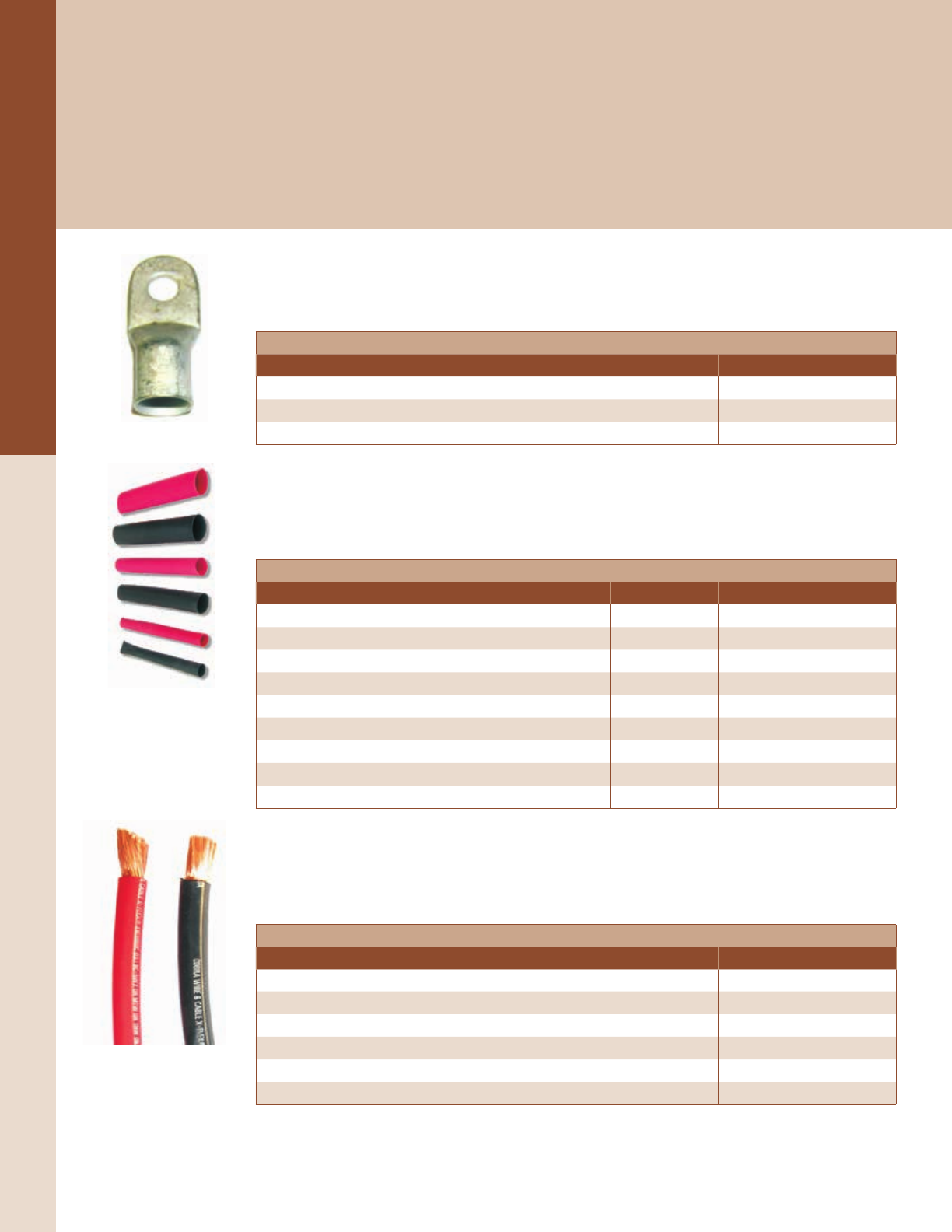
For the latest on AEE Solar products, trainings and dealer services, visit www.aeesolar.com
WIRE & CABLE
199
Battery Cables
Battery Cables
Why Use Larger Cable?
Low-voltage power systems with inverters can have very high current through the cables that connect the inverter to the batteries.
Large AC loads like microwave ovens, toasters, irons, and washers can cause an inverter operating on a 12 VDC battery system to
draw over 100 A. Large motors may draw 300 to 500 A during startup. When cables between batteries, and from the battery bank to
the inverter, are too small, the current available to the inverter is limited and it may fail to supply larger loads. Properly sized cables
also impose less resistance and thereby help maximize system efciency. See the table showing recommended cables sizes for invert-
ers in the Reference Section.
Plated Copper Lugs
These UL-listed lugs are made from tin-plated copper tubing with 3/8" holes. Solder or crimp to stranded
cable.
Plated Copper Lugs
Description Item code
Copper lug 3/8" ring 2 AWG 051-03234
Copper lug 3/8" ring 2/0 AWG 051-03231
Copper lug 3/8" ring 4/0 AWG 051-03228
Heat Shrink Tubing
Use this tubing to insulate copper lugs and compression terminals. Tubing shrinks and glue inside melts
when heated with a heat gun or torch, sealing wires against corrosion and moisture. Maximum shrinkage
is listed below. Sold in 6" lengths.
Heat Shrink Tubing
Description Shrinks to Item code
Heat shrink tubing 1/2" x 6" black 3/16" 051-01132-B
Heat shrink tubing 1/2" x 6" red 3/16" 051-01132-R
Heat shrink tubing 1/2" x 6" white 3/16" 051-01132-W
Heat shrink tubing 3/4" x 6" black 1/4" 051-01135-B
Heat shrink tubing 3/4" x 6" red 1/4" 051-01135-R
Heat shrink tubing 3/4" x 6" white 1/4" 051-01135-W
Heat shrink tubing 1" x 6" black 3/8" 051-01137-B
Heat shrink tubing 1" x 6" red 3/8" 051-01137-R
Heat shrink tubing 1" x 6" white 3/8" 051-01137-W
UL-listed Battery Cable
This ne-stranded, very exible cable is UL listed for use as battery cable. It is rated MTW or THW or
AWM, 600 V, sunlight resistant, direct burial, 105 °C. 2, 2/0 and 4/0 AWG sizes are available with red
or black insulation.
UL Listed Battery Cable
Description Item code
X-Flex battery cable 4/0 AWG black 050-01470
X-Flex battery cable 4/0 AWG red 050-01472
X-Flex battery cable 2/0 AWG black 050-01476
X-Flex battery cable 2/0 AWG red 050-01478
X-Flex battery cable 2 AWG black 050-01487
X-Flex battery cable 2 AWG red 050-01488
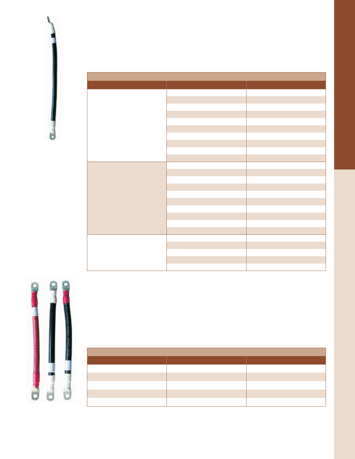
For the latest on AEE Solar products, trainings and dealer services, visit www.aeesolar.com
WIRE & CABLE
200
Battery Cables
Battery Cables with Lugs
Use these cables between a battery bank and inverter, fuse or power center. They have exible stranded
UL-listed copper wire and 3/8" diameter lugs. Lug barrels are covered with glue-lled heat-shrink tub-
ing. Cables are marked in red heat-shrink tubing for positive and white heat-shrink tubing on black wire
for negative. Append –R to the item number for a red cable with red ends (positive), -B for a black
cable with black ends, or –W for a black cable with white ends (negative). For example, a red 4/0 AWG
cable with a 2' length would be 052-04002-R.
Battery Cables with Two Lugs
Cable Length Item code
4/0 AWG
2' 052-04002
3' 052-04003
4' 052-04004
5' 052-04005
6' 052-04006
7' 052-04007
8' 052-04008
10' 052-04010
12' 052-04012
15' 052-04015
2/0 AWG
2' 052-02002
3' 052-02003
4' 052-02004
5' 052-02005
6' 052-02006
7' 052-02007
8' 052-02008
10' 052-02010
12' 052-02012
15' 052-02015
2 AWG
2' 052-01002
3' 052-01003
5' 052-01005
8' 052-01008
10' 052-01010
Battery Interconnects
Use these cables between individual battery cells or between battery banks. Circuits protected by 250 A
breakers or 400 A fuses should use 4/0 AWG cables. Use 2/0 AWG cables for 175 A breakers and 200
A fuses. Use 2 AWG cables for 110 A or smaller fuses or breakers. Cables with red ends are for positive
battery parallel jumpers. Cables with white ends are for negative battery parallel jumpers. Cables with
black both ends, or red and black ends, are used for series battery interconnects. When ordering, append
“-R” to the item number for red (positive), “-W” for white (negative), “-B” for black or “-BR” for one
end red and one end black (series connections). For example, a red 9" cable used to connect positive
cells in parallel would be 052-05122-R.
Battery Interconnects
Wire size Length of cable Item code
2/0 AWG 9" 052-05122
2/0 AWG 12" 052-05121
2/0 AWG 20" 052-05124
4/0 AWG 12" 052-05142
4/0 AWG 20" 052-05145
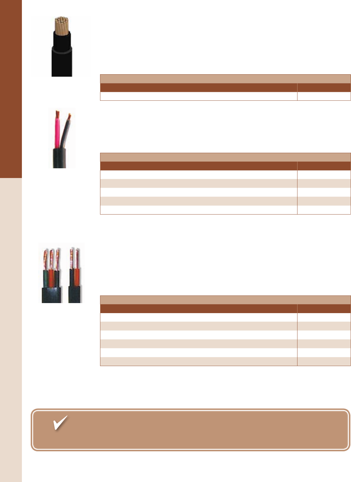
For the latest on AEE Solar products, trainings and dealer services, visit www.aeesolar.com
WIRE & CABLE
201
Bulk Wire
Bulk Wire
PV Wire Sunlight Resistant Cable
This single-conductor wire features heat and moisture resistant, crosslinked-polyethylene insulation
(XLPE) (Type PV wire, USE-2, RHH, RHW, RHW-2). Rated for direct burial or in conduit this cable
is sunlight resistant, ame retardant, and rated for temperatures from -40 to 90°C. This cable is listed to
UL 854 as Type PV Wire, USE-2 1,000V for use with transformerless inverters.
PV Wire Sunlight Resistant Cable
Description Item code
10 AWG, PV wire, USE-2, 1,000V, black, 500' roll 050-01149
Tray Cable (TC)
This exible two-conductor wire is well-suited for outdoor applications such as PV array lead-in and
sub-array wiring. It may be buried directly in the ground or exposed to direct sunlight. 10 and 12 AWG
stranded type THHN/THWN conductors often work well for array interconnects with currents less than
25 A. Conductor insulation is red for positive and black for negative. UL-listed.
Tray Cable (TC)
Description Item code
8 AWG two-conductor TC cable, 100' 050-01157
10 AWG two-conductor TC cable, 100' 050-01163
12 AWG two-conductor TC cable, 100' 050-01175
16 AWG two-conductor TC cable, 100' 050-01178
18 AWG two-conductor TC cable, 100' 050-01181
Pump Cable
This 10 AWG two-conductor cable works well with the SHURo 9300 submersible pump, providing a
good seal in the cable gland. Grundfos SQFlex pumps require cables with a ground.
Shielded Control and Communication Cable
This 16 AWG, two-conductor cable is useful for pump controls that are far from a remote tank. It is a
shielded, twisted-pair cable rated for 600 volts, direct burial, and is sunlight resistant. Shielded cable
can help prevent transient surges caused by lightning. Shielding should be grounded on one end of cable
run only. Sold in 50’ increments.
Pump Cable and Sensor Wire
Description Item code
10 AWG two-conductor without ground 050-01637
12 AWG two-conductor with ground 050-01635
10 AWG two-conductor with ground 050-01638
8 AWG two-conductor with ground 050-01643
16 AWG two-conductor Shielded Control cable 050-01151
Underwater wire splice kit. Enough parts for ten splices. 075-00130
It’s your best source for timely, comprehensive information on federal, state, local and
utility incentives: www.dsireusa.org
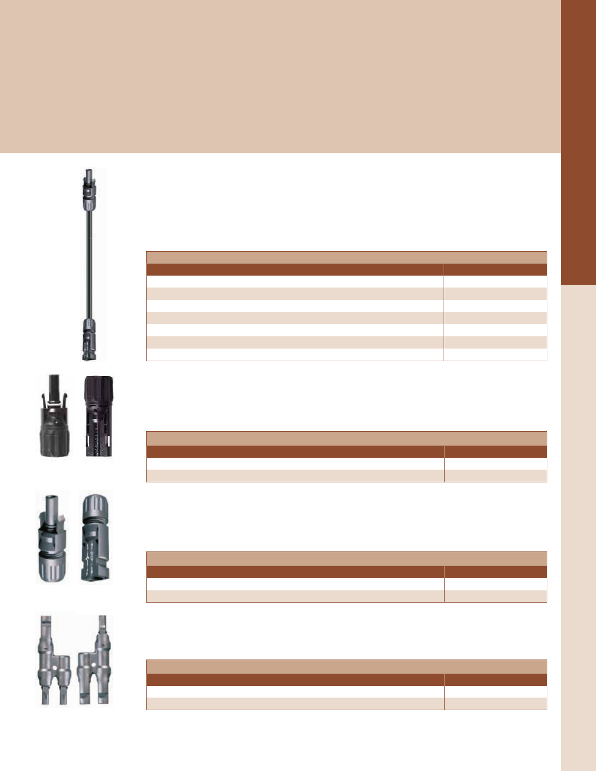
For the latest on AEE Solar products, trainings and dealer services, visit www.aeesolar.com
WIRE & CABLE
202
Array Wiring & Accessories
Array Cables and Connectors
Grid-tie modules generally ship with attached cables that are listed to UL 1703 with the module. The cable connectors on these are
fully waterproof when connected, touch-protected and designed for up to 1,000 VDC and 30 A, but cannot be safely disconnected
under load.
Our output cables are made with 10 AWG PV Wire, and Amphenol H4 connectors, and can be used in solar arrays up to 1,000 VDC.
All of our array output cables are made with PV wire that is listed to UL 854, which is required by the NEC for use with transformer-
less inverters (See bulk PV Wire description on previous page for more information).
Additionally, we stock the common styles of crimp-on connectors for use with 10 AWG PV stranded wire. Proper crimping to the
wire and insulator assembly requires special tools (see Tools).
PV Wire Array Cables
These Output Cables feature Amphenol H4 connectors and are compatible with most module brands
to connect strings to junction boxes or grid-tie inverters. They have a male connector on one end and a
female connector on the other end, so they can be used to extend the cables on the modules or be cut in
half and used to connect to a roof-top j-box or combiner. For example, if you need a 30' male and a 20'
female, order a 50' cable. Made with black 10 AWG 1,000 VDC-rated PV-WIRE cable.
PV Wire Array Cables
Cable length Item code
6' 052-09720
15' 052-09722
30' 052-09724
50' 052-09725
70' 052-09726
100' 052-09727
125' 052-09728
Amphenol Helios H4 Connectors
The 1,000 VDC-rated Amphenol Helios H4 connector includes the pins and can be made quickly, enabling
custom cables to be made at the job site. A special crimping tool and wrench set are required to assemble
the connector (See Tools). These connectors are for use with 10 AWG PV wire and sold in packs of 25.
Amphenol Helios H4 Connectors
Description Item code
Amphenol Helios H4 male neutral connector, 25 pack 097-01414
Amphenol Helios H4 female negative connector, 25 pack 097-01415
MC4-Solarline 2 Connectors
The 600 VDC-rated MC-4 connectors include pins and can be assembled quickly enabling custom cables
to be made at the job site. A special crimping tool and wrench set are required to assemble the connector
(See Tools). These connectors are for use with 10 AWG PV wire and sold in packs of 25.
MC4-Solarline 2 Connectors
Description Item code
Male MC4 locking connector for PV wire 097-01411
Female MC4 locking connector for PV wire 097-01413
MC4-Solarline 2 Branch Connectors
These waterproof Y-connectors make it possible to parallel wire PV modules with Multi-Contact output
cables. Branch connectors are rated for maximum current of 30 A and maximum voltage of 600 VDC.
MC4-Solarline 2 Branch Connectors
Description Item code
Solarline 2 branch cable coupler female - two male 052-09403
Solarline 2 branch cable coupler male - two female 052-09404
For the latest on AEE Solar products, trainings and dealer services, visit www.aeesolar.com
WIRE & CABLE
203
Wire Management Hardware
Wire-Management Hardware
As most experienced PV installers will attest, good wire management is a hallmark of high-quality installations, and its lack can lead
to inspectors and customers alike looking for other potential issues. Cables and wires should be kept off the roof or ground and water
should not be allowed to pool at the entrances of enclosures, splices and junction boxes. Given that a solar PV system is designed
to last for 25 years or more, it is vital to use wire-management hardware that will hold up in the environment and allow deployment
with minimal strain on the components.
Stainless-steel cable clips
Use these clips to keep PV-Wire module-interconnect cables and PV-array output cables neatly secured
to module frames so they do not drop below the array. Use these clips with REC modules. These clips
are available in packs of 25 or 100.
Stainless steel cable clips for PV wire
Description Item code
Stainless steel cable clips Pack of 25 052-09126
Stainless steel cable clips Pack of 100 052-09125
HellermannTyton
Solar E-clips
HellermannTyton’s 304-Stainless-Steel Cable Clip can hold one or two cables at a time, accommodat-
ing cable diameters from 0.20" (5 mm) to 0.30" (7.6 mm). These clips use a dedicated spring to hold the
cables in place without causing abrasion. The at pushing surface also makes it much easier to install on
module frames or other edges from 0.04" (1 mm) to 0.12" (3 mm) without sacricing pull-out resistance.
These clips are available in packs of 100.
HellermannTyton’s Edge Clip with Cable-Tie Assemblies are an easy and cost-effective way to secure
thick cables, such as microinverter trunk lines as well as bundles of smaller cables. The clips feature an
integrated metal clamp that secures the assembly while enabling easy installation. The cable ties are made
from UV-stabilized polyamide material which will not chafe cable insulation. The 1-3 mm clips will
fasten securely to most module frame anges while the 3-6 mm clips can be fastened to SnapNrack rail.
Once secured, the clips can only be removed by prying them apart, which means they can’t be reused.
Removing a clip will also leave scratches on the surface it was attached to. These clips are available in
packs of 100.
HellermannTyton’s Edge Cable Clips are similar to the edge clips above, but have a re-closable clam
shell rather than a cable tie. There is a single-cable version and a dual-cable version, either of which
should secure a pair of PV-wire cables in most situations.
Stainless Steel Cable Clip
Module edge thickness Cable diameter Orientation to edge Quantity Item code
0.04" - 0.12" (1 - 3 mm) 0.20" - 0.30" (5 - 7.6 mm) Parallel under 100 052-09140
Edge Clips with Cable Ties
Module edge thickness Max cable bundle diameter Orientation to edge Quantity Item code
0.04" - 0.12" (1 - 3 mm)
(Attaches to Module Frame)
1.8" (45 mm)
Perpendicular under 100 052-09141
Parallel under 100 052-09142
0.12" - 0.23" (3 – 6 mm)
(Attaches to Mounting Rail)
Parallel 100 052-09143
Perpendicular 100 052-09144
Perpendicular under 100 052-09145
Parallel under 100 052-09146
Edge Cable Clip
Edge thickness Max cable diameter Orientation to edge Quantity Item code
0.04" - 0.12" (1 - 3 mm)
(Attaches to Module Frame)
0.62" (15.6 mm) (single) Parallel 250 052-09147
0.32" (8 mm) (double) Parallel 750 052-09148
Parallel Edge Clip with
Cable Tie
Perpendicular Edge Clip
with Cable Tie
Edge Cable Clip Single Wire
Edge Cable Clip Double Wire
Stainless Steel Cable Clip
For the latest on AEE Solar products, trainings and dealer services, visit www.aeesolar.com
WIRE & CABLE
204
Wire-Management Hardware
HellermannTyton’s C Clips are available with an integrated cable tie that can accommodate up to 1.8"
diameter or with a “r tree” base that can be pushed into a 0.25" diameter threaded or unthreaded hole.
The cable-tie version comes in packs of 500 and works well for attaching cables from 0.16" to 0.4"
diameter to conduit, rails or posts. The UV-stabilized polyamide r-tree version comes in packs of 100
and works well for quickly securing 0.24" to 0.30" diameter cables using available mounting holes, such
as a SnapNrack channel nut or module-mounting hole.
A Cable Tie with Fir-Tree Mount is also available for securing bundles up to 1.4" (35 mm) to a quarter-
inch diameter hole. These are made from the same material as the C-Clip with Fir-Tree Mount and come
in packs of 1,000.
Cable Clips
Mounting type Cable diameter Quantity Item code
C clip with Cable Tie 0.16" – 0.40" [4 – 10 mm] 500 052-09149
C clip with Fir Tree – 0.24" - 0.28" [6.3 – 7 mm] 0.24" to .0.30" [6 – 7.6 mm] 100 052-09150
Cable Ties with Fir Tree – 0.24" - 0.28" [6.3 – 7 mm] 0.06" - 1.40" [1.5 - 35 mm] 1,000 052-09151
Specially designed for prolonged use in extreme outdoor environments, these Cable Ties are made from
UV-stabilized polyamide material to ensure long-term performance. The tensile strength of these ties
varies according to the width.
The corresponding Mounting Base will accommodate cable ties up to 0.18" wide. The base is UV sta-
bilized and employs a VHB acrylic adhesive to achieve a strong bond to most smooth surfaces. As with
any adhesive product, be sure to clean the mounting surface thoroughly for best results.
Note: Mounting anything to a module’s back sheet may void the module warranty.
Cable Ties
Strength Max bundle Length Width Quantity Item code
30 lbs 1.38" (35 mm) 5.9" (150 mm) 0.14" (3.5 mm) 100 052-09152
50 lbs 1.97" (50 mm) 7.9" (200 mm) 0.18" (4.6 mm) 100 052-09153
50 lbs 4.33" (110 mm) 15.4" (390 mm) 0.18" (4.6 mm) 100 052-09154
120 lbs 4.13" (105 mm) 15.2" (387 mm) 0.30" (7.6 mm) 100 052-09155
Mounting Base 0.18" (4.6 mm) 500 052-09156
C Clip with Fir-Tree Mount
C Clip with Cable-Tie Mount
Cable Tie with Fir-Tree Mount
Cable Ties
Self-Adhesive Mounting Base

For the latest on AEE Solar products, trainings and dealer services, visit www.aeesolar.com
WATER PUMPS
205
System Design
Solar Water Pumping
Solar pumps operate anywhere the sun shines, making them ideal for an independent water supply. While energy production from
solar pumps is impacted by cloudy weather, having adequate water storage and decreasing water needs during cool or rainy weather
mitigates these impacts.
Most solar water pumping systems operate on direct current (DC). The output of the solar power system varies throughout the day
and with changes in sunlight intensity and weather conditions, requiring specialized pumps and controls that operate within a wider
range of voltage and current compared to most AC pumps.
Conventional AC pumps are usually centrifugal pumps that spin at high speed to pump as many gallons per minute as possible. They
also consume a large amount of power and their efciency suffers at low speeds and when pumping against high pressure. If you run
a centrifugal pump at half speed, it pumps one quarter of the volume.
To minimize the size of the solar PV system required, solar pumps generally use more efcient motors and pumping mechanisms.
The most efcient pumps are “positive displacement” pumps, which pump a xed amount of water with each rotation. If it is cloudy
or early morning, the pump will receive less energy and run more slowly, but with no loss of efciency—so at half speed, it simply
pumps half the amount of water at the same pressure.
To use solar energy economically, solar pumping systems typically pump more slowly than conventional well pumps (many solar
pumps are designed to produce less than 6 gallons per minute) and they don’t run at all between sunset and sunrise, so an adequately-
sized storage tank is usually required. Instead of pumping a large volume of water in a short time and then turning off, the solar water
pump works slowly and efciently all day to provide the same volume of water. Often, a solar pump can be used in a well with a
recovery rate too slow for a conventional AC pump.
If your water sources are remote from power lines, compare the cost of a low-maintenance solar pumping system to what you would
spend on a generator, with continual fuel and maintenance costs, or on a utility power-line extension. In most cases, a good solar
pumping system is far more economical, which is why many non-prots and NGOs use solar pumping to provide clean water to
remote villages around the world.
Submersible Pumps
If you are pumping from a well, we have solar pumps that can deliver from 1 gallon per minute to over 75 gpm
at peak output.
The SHURo 9300 and Aquatec SWP pumps can be powered by a PV array as small as two 50 to 100 W solar
modules, or a single larger 60-cell or 72-cell module, depending on the “head” (vertical distance or elevation
change) they are pumping. They can pump 500 to 1,000 gallons per day and lift water up to 230 feet. These
pumps require service every two to four years.
If you have a higher lift, need more water, or want a pump that does not require service for 15 to 20 years, the
Grundfos SQFlex pumps are a good choice. These pumps can be used in wells up to 800 feet deep and can pump
up to 20,000 gallons per day from shallower wells using solar modules, a fuel-powered generator, an inverter/
battery system, the utility grid, or a combination of these power sources.
Surface Pumps
Surface pumps are typically less expensive than submersible pumps and can draw water from a spring, pond,
river, or tank, and push it far uphill and through long pipes to ll a storage tank or to pressurize it for home use
or for irrigation, livestock, etc. The pump may be placed at ground level, or suspended in a well in some cases.
All pumps are better at pushing than pulling, since the vacuum a pump can draw is limited to atmospheric
pressure (about 14 psi). At sea level, a pump can be placed no higher than 10 or 20 feet, depending on
the type of pump, above the surface of the water source (subtract one foot per 1,000 feet elevation).
Most wells are much deeper than this and therefore require a submersible pump, which can push the
water up to the surface.
Suction piping for surface-type pumps must be oversized a bit and not allow air entrapment (much like
a drain line) and should be as short as possible.
Pumps can push water very long distances through a pipe. The vertical lift and ow rates are the primary factors that determine power
requirements.

For the latest on AEE Solar products, trainings and dealer services, visit www.aeesolar.com
WATER PUMPS
206
System Design
Water Storage and Pressurization
Many conventional AC-powered water systems pump from a well or other water source into a pressure tank that stores water and
stabilizes the pressure for household use. When you turn on a tap in the house, an air-lled bladder in the tank forces the water into
the pipes. When the pressure drops, a pressure switch turns on the pump, relling and re-pressurizing the tank. This works because
an AC pump delivers high volume and pressure on demand; however, this will not work with pumps operating directly from PV
modules because the sun may not be shining when you want to take a long hot shower.
For pumps operating directly from PV modules, a non-pressurized water tank or cistern is used to store water for use during times
when the sun is not shining. If the tank can be located above the house on a hill or on a tower, gravity can supply the water pressure.
Gravity water pressure can be calculated in two ways:
Pressure (in psi) = Head (in feet) ÷ 2.31, or
Head (in feet) = Pressure (in psi) x 2.31
For reasonable pressure, the tank needs to be at least 40 feet above the house, although to obtain a pressure of 30 psi will require
about 70 feet of elevation.
Alternatively, a DC or AC pressure booster pump, powered from a battery or battery/inverter system, can be used to maintain a
pressure tank as needed from a storage tank that is lled by a solar pump during the day. You must use a pressure pump that can
deliver the maximum ow rate required by the house, or have a pressure tank that is large enough to make up the difference between
what the pressure pump can deliver and what is required for as long as it may be required. This is called the “draw-down volume”
of the pressure tank.
Calculation of Solar Power Needs
If you are using a pump driven directly by PV modules, the array’s nameplate output should be at least 20% higher than the power
required by the pump to achieve the desired head and ow rate. A larger array or a tracking system can maximize the amount of time
each day that full rated power is available to the pump, providing more gallons per day.
Since the pump will only draw the power it needs, it will not be damaged by oversizing the array. A larger array will produce the
needed power in less light, extending the pumping time and volume delivered in the morning, afternoon, and on cloudy days. For
instance, a 1 kW array will produce 200 W in 1/5 the amount of sunlight that you would get on a sunny day at noon.
Designing a Solar Pumping System
AEE Solar carries many types of pumps that can be used in a variety of applications. Which pump and related equipment are needed
for a solar pumping system depends on many factors, including what the water source is, how much water is needed, when the water
is needed, how far the water source is from another power source, etc.
If the well or other water source is close to an existing source of power, such as the utility grid or the power system of an off-grid
house, it’s usually better to power the pump from that existing source rather than set up a dedicated PV array. If grid power is available,
it can be used to power a water pump, and if desired, a grid-tied PV system can be installed to offset the cost of the grid power.
In off-grid situations, if the well or other water source is close to the house’s off-grid power system, it’s usually easier to power the
pump using the house’s power system, either directly from the battery bank with DC, or with AC from the inverter. Additional PV
modules may be needed to accommodate the pump’s energy requirement, but they can be added to the house’s PV system and used
to help charge the batteries when the pump isn’t running.
AEE Solar is happy to help you design a pumping system, but please have the following information ready when you call:
• Total amount of water, on average, needed in gallons per day (gpd). Because solar pumps deliver water in variable amounts due
to the variable nature of sunlight, you will need to know the total daily water need. Any seasonal changes in water requirements
also need to be considered.
• Total head that the pump has to lift. This is the actual elevation difference between the water level in the well (or other water
source) and the top of the storage tank. This is not just the length of the water line, although internal pipe friction needs to be
considered if the distance is great or the pipe is small.
• Solar insolation at the site. Local insolation data can be obtained using PV Watts (online) or using the charts and maps at the
end of this catalog. Any shading of the potential array needs to be taken into account, along with seasonal variations.
Additional information, such as well-casing diameter, water quality, well-regeneration capacity, etc., may also be needed, depending
on the specic application.

For the latest on AEE Solar products, trainings and dealer services, visit www.aeesolar.com
WATER PUMPS
207
Submersible Pumps
Grundfos
Grundfos SQFlex Submersible Pumps
The Grundfos SQFlex are industry-leading submersible pumps for water lifts of up to 800 feet. SQFlex
pumps can be directly powered by a PV array or can be run on an inverter, generator, 48 VDC battery,
utility grid, or any combination of these sources. Virtually any source of power, 30 to 300 VDC or 90 to
240 VAC, can be used to run these pumps.
SQFlex pumps feature Maximum Power-Point Tracking (MPPT) of the PV array, and can operate on a
series string of PV modules with a total peak-power voltage of at least 30 VDC. Efciency will be highest
at voltages over 100 VDC (10% less efcient at 60 VDC, and 20% less efcient at 35 VDC). The motor
has a maximum current draw of 8.4 A.
Designed for high efciency and reliability, the motor features integrated electronics, which eliminate
the need for complicated external controls. A single motor size covers the entire pump range.
The 11 different pump models available can deliver from 77 gpm at 6' of head to 3.5 gpm at 800' with a
1.6 kW or smaller solar array. Systems with even larger arrays will produce the required power with less
light, extending the pump’s peak running time, and delivering more water per day.
The models 3SQF, 6SQF and 11SQF, are helical rotor pumps, for high-head applications, and will t
into a 3-1/4” ID or larger well casing (4” or larger recommended). The positive displacement helical
pump ends are 3” in diameter and available in ve models ranging from 3 to 11 gpm (0.68 to 2.50 m3/h)
of peak output. These pumps are designed for higher head and/or lower ow requirements. The pump’s
rotor is a single-twisted helix (spiral) made of hard-chromium-plated stainless steel. During operation,
the rotor rotates eccentrically in a double-helical elastic stator.
The 16SQF, 25SQF, 40SQF and 60SQF models are centrifugal pumps, for lower-head/ higher-volume
applications, and will t into a 4-1/4" ID or larger well casing (5” or larger recommended).
The SQFlex pumps have built-in protection from dry-running, overloading, and overheating. A dry-running
sensor is integrated in the pump’s wire lead, about 18” above the pump. However, this sensor only has a
differential of about 1 inch in water level, and should not be used as the primary dry-run system in wells
that consistently run low on water. A separate water level pump control should be used, which will allow
longer on/off cycling periods if he well runs dry often.
While these pumps were designed to pump water from wells, they can also be installed in tanks or
cisterns to pump water further uphill, provided that they are installed inside of a 4” or 6” pipe sleeve to
providedproper cooling water ow.
Grundfos makes several accessories for these pumps (see next page for details).
SQFlex pumps have a two-year warranty from the date of purchase. A ve-year extended warranty is
available. These pumps cannot be used in GFDI protected AC circuits.
Helical Rotor Versions
Centrifugal Versions
For the latest on AEE Solar products, trainings and dealer services, visit www.aeesolar.com
WATER PUMPS
208
Submersible Pumps
Grundfos SQFlex Optional Controls
SQFlex controls can be combined if you need more features than one control can provide.
The CU 200 interface box communicates with the pump and monitors operating conditions. Built-in
diagnostics indicate faults and dry-running, as well as display operating status, power consumption,
and water level switch input. The water Level Switch interfaces with the CU 200 control to turn off the
pump when the tank is full.
Since the CU 200 control circuit uses only 15 mA, the water level switch can be located in a tank as
far away as 2,000 feet from the pump, using a minimum 18 AWG two-conductor wire. Shielded cable
is recommended to minimize the potential for voltage surges due to lightning (see the Wire and Cable
section for shielded wire.) The CU 200 is covered by a standard two-year warranty.
The IO 50 switch box includes cable terminations and a simple manual on/off switch that interfaces
between a solar array and the pump to allow you to turn off the high-voltage array when servicing the
pump or plumbing. This switch can also be used at the PV array, as an array disconnect switch, if the
array is a long distance from the wellhead.
The IO 101 AC interface box is for using AC backup on a solar pump. It must be manually switched to
the AC power source, such as a generator, utility connection, or inverter. However, when the AC power
stops or is disconnected, it automatically reconnects to the PV array to let the sun continue pumping.
Available for either 120 VAC or 240 VAC input. The SQFlex pumps will not function with an AC GFCI
in the supply circuit and should not be used where a GFCI is required.
NOTE: the IO-101 is only rated for 225 VDC, so make sure that the PV array will not exceed this volt-
age, even in cold weather.
Grundfos SQFlex CIU 273 GRM Control Unit
The CIU 273 SQFlex Communication Interface Unit is designed to work directly with the SQFlex
pump and is a combined monitoring, control and communication unit for these pumps. The CIU 273
enables monitoring of the system’s operation anywhere in the world through Grundfos Remote Monitor-
ing. It also has connections for a start/stop switch, level switch and pulsating water meter. It comes in a
NEMA 3R enclosureand has a voltage range of 24-240 VAC/VDC.
The CIU 273 offers system monitoring and alarm indication. It monitors the oat-switch pump running
status, and provides alarm indications for dry running, no contact to pump, over-voltage, over-temperature,
and over-load.
Communication between the CIU 273 and the Grundfos pump takes place via the pump power-supply
cable (power-line communication), so no extra cables between the CIU 273 and the pump are required.
It is possible to start, stop and reset the pump with the start/stop switch.
With the addition of a CIM communication interface module the CIU enables data communication
via open and interoperable networks such as Modbus RTU, GSM/GPRS, and by using Grundfos Remote
Management (contract required). Connection through twisted-pair wire (24-12 AWG) with a maximum
length of 4,000 ft. Will also operate with Probus DP, LONWorks, and BACnet MS/TP® networks with
the proper CIM module (call for availability).
NOTE: CIU 273 can replace the CU 200 in the installation.
CIU 273 Communication
Interface Unit
CU 200 Interface Box
IO 50 Control Box
IO 101 AC Interface Box

For the latest on AEE Solar products, trainings and dealer services, visit www.aeesolar.com
WATER PUMPS
209
Submersible Pumps
Grundfos SQFlex Pump and Array Sizing
To choose a pump and array size appropriate for your project, consult the table on the opposite page. The left column shows total
head in feet and meters, the top row shows array wattage/number and suggested type of modules, and the boxes show seasonal pump
performance and maximum ow. Select the row with the head (total lift) that most closely matches your application then move across
the row to the column that contains the desired daily volume or peak ow rate. Note the pump model in that block and wattage of
the PV array in that column.
Table Key
60 SQF-3 ← Pump model
24,885 gpd ← Estimated daily summer volume (gpd)
19,944 gpd ← Estimated daily winter volume (gpd)
42 gpm ← Peak ow rate (gpm)
NOTE: Daily volume and ow calculations in the table are based on Fresno, CA data at a 36° xed tilt. Daily summer volume assumes
7.8 kWh/m2/day of insolation and winter volume assumes 4.7 kWh/m2/day. These gures, and therefore the volume of water delivered,
will need to be adjusted to the local insolation conditions at the actual installation site.
Larger PV array wattages than shown in the chart can also be used to increase water delivery quantities. Since the pump will only
draw the power it needs, it will not be damaged by oversizing the array. A larger array will produce the needed power in less light,
extending the pumping time and volume delivered in the morning, afternoon, and on cloudy days. The only requirement is that the
PV array’s open-circuit voltage (corrected for low temperature) does not exceed the 300 VDC limit for the SQFlex pump (typically
six to seven 60-cell modules in series (depending on maximum low temperature of the site). If more power is desired, parallel strings
of PV modules can be used.
Most solar pumping systems will provide signicantly more output in Summer than in Winter. The typical ow rate is calculated at
800 W/m2 and can be up to 25% greater under bright conditions. Also, up to 40% more water can be pumped in the summer if the
array is on a tracking mount. The output can vary by location and weather patterns, and is not guaranteed. Contact AEE Solar if you
need help sizing your specic system.
Grundfos SQFlex Pumps and Accessories
Description Item code
SQFlex 3 SQF-2 pump - helical rotor, 3" diameter 075-01012
SQFlex 3 SQF-3 pump - helical rotor, 3" diameter 075-01013
SQFlex 6 SQF-2 pump - helical rotor, 3" diameter 075-01015
SQFlex 6 SQF-3 pump - helical rotor, 3" diameter 075-01016
SQFlex 11 SQF-2 pump - helical rotor, 3" diameter 075-01018
SQFlex 16 SQF-10 pump - centrifugal, 4" diameter 075-01020
SQFlex 25 SQF-3 pump - centrifugal, 4" diameter 075-01021
SQFlex 25 SQF-7 pump - centrifugal, 4" diameter 075-01025
SQFlex 40 SQF-3 pump - centrifugal, 4" diameter 075-01027
SQFlex 40 SQF-5 pump - centrifugal, 4" diameter 075-01028
SQFlex 60 SQF-3 pump - centrifugal, 4" diameter 075-01029
SQFlex extended ve-year warranty 075-01001
IO 50 On/Off switch 075-01038
CU 200 status, control and communications interface 075-01033
Level switch (use with CU 200 or CIU 273 only) – stops pump when tank is full 075-01042
Pressure switch – reverse-action (use with CU 200 or CIU 273 only) 075-01044
IO 101 AC interface box (115 V) 075-01036
IO 101 AC interface box (230 V) 075-01037
CIU 273 SQFlex GRM Communications Interface Unit – product number 97980341 075-01050
Antenna, roof mounting, complete – for CIU 273 - product number 97631956 075-01051
Antenna, desk mounting, complete – for CIU 273 - product number 97631957 075-01052
CIM communication interface module - Modbus 075-01055
CIM communication interface module - GSM/GPRS 075-01056

For the latest on AEE Solar products, trainings and dealer services, visit www.aeesolar.com
WATER PUMPS
210
Submersible Pumps
Grundfos SQFlex Submersible Pump Selection Chart
Head
Module watts 250 W 60-cell modules
X # of modules → 234567
= Array watts → 500 W 750 W 1,000 W 1,250 W 1,500 W 1,750 W
6'
(2 m)
Model 60 SQF-3 60 SQF-3 60 SQF-3 60 SQF-3 60 SQF-3 60 SQF-3
7.8 kWh/m224,885 gpd 31,609 gpd 37,627 gpd 42,809 gpd 46,335 gpd 49,272 gpd
4.7 kWh/m219,944 gpd 26,177 gpd 31,410 gpd 35,264 gpd 38,204 gpd 40,675 gpd
Max ow 42 gpm 52 gpm 61 gpm 68 gpm 73 gpm 77 gpm
25'
(8 m)
Model 40 SQF-3 40 SQF-3 60 SQF-3 60 SQF-3 60 SQF-3 60 SQF-3
7.8 kWh/m213,027 gpd 20,089 gpd 26,345 gpd 31,950 gpd 35,680 gpd 38,605 gpd
4.7 kWh/m29,539 gpd 15,049 gpd 19,889 gpd 24,146 gpd 27,295 gpd 30,149 gpd
Max ow 24 gpm 35 gpm 47 gpm 56 gpm 62 gpm 66 gpm
50'
(15 m)
Model 11 SQF-2 40-SQF-5 40 SQF-5 40 SQF-5 40 SQF-5 40 SQF-5
7.8 kWh/m25,582 gpd 10,139 gpd 14,817 gpd 19,166 gpd 22,462 gpd 25,183 gpd
4.7 kWh/m24,287 gpd 7,001 gpd 10,684 gpd 13,909 gpd 16,552 gpd 18,838 gpd
Max ow 9.6 gpm 19 gpm 27 gpm 35 gpm 40 gpm 44 gpm
75'
(23 m)
Model 11 SQF-2 11 SQF-2 25 SQF-7 25 SQF-7 40 SQF-5 40 SQF-5
7.8 kWh/m24,580 gpd 6,300 gpd 9,221 gpd 11,832 gpd 14,602 gpd 17,381 gpd
4.7 kWh/m23,410 gpd 5,067 gpd 6,691 gpd 8,624 gpd 10,184 gpd 12,345 gpd
Max ow 8.0 gpm 11 gpm 17 gpm 21 gpm 27 gpm 31 gpm
100'
(30 m)
Model 11 SQF-2 11 SQF-2 11 SQF-2 11 SQF-2 25 SQF-7 25 SQF-7
7.8 kWh/m23,606 gpd 5,617 gpd 6,695 gpd 7,303 gpd 10,833 gpd 12,536 gpd
4.7 kWh/m22,639 gpd 4,182 gpd 5,439 gpd 6,021 gpd 7,662 gpd 9,065 gpd
Max ow 6.4 gpm 10 gpm 12 gpm 14 gpm 19 gpm 22 gpm
125'
(38 m)
Model 11 SQF-2 11 SQF-2 11 SQF-2 16 SQF-10 16 SQF-10 25 SQF-7
7.8 kWh/m22,897 gpd 4,769 gpd 6,145 gpd 7,864 gpd 7,693 gpd 10,006 gpd
4.7 kWh/m22,085 gpd 3,435 gpd 4,807 gpd 5,833 gpd 5,664 gpd 7,055 gpd
Max ow 5.3 gpm 8.3 gpm 11 gpm 12 gpm 14 gpm 18 gpm
150'
(46 m)
Model 6 SQF-2 11 SQF-2 11 SQF-2 11 SQF-2 11 SQF-2 16 SQF-10
7.8 kWh/m22,454 gpd 4,041 gpd 5,675 gpd 6,565 gpd 6,952 gpd 7,535 gpd
4.7 kWh/m21,851 gpd 2,903 gpd 4,198 gpd 5,114 gpd 5,543 gpd 5,531 gpd
Max ow 4.5 gpm 7.2 gpm 10 gpm 12 gpm 12 gpm 13 gpm
175'
(53 m)
Model 6 SQF-2 11 SQF-2 11 SQF-2 11 SQF-2 11 SQF-2 11 SQF-2
7.8 kWh/m22,282 gpd 3,450 gpd 5,024 gpd 6,114 gpd 6,633 gpd 6,926 gpd
4.7 kWh/m21,672 gpd 2,442 gpd 3,594 gpd 4,682 gpd 5,233 gpd 5,531 gpd
Max ow 4.1 gpm 6.3 gpm 8.8 gpm 11 gpm 12 gpm 12 gpm
200'
(61 m)
Model 6 SQF-2 6 SQF-2 11 SQF-2 11 SQF-2 11 SQF-2 11 SQF-2
7.8 kWh/m22,050 gpd 2,885 gpd 4,237 gpd 5,593 gpd 6,199 gpd 6,586 gpd
4.7 kWh/m21,480 gpd 2,288 gpd 3,015 gpd 4,036 gpd 4,777 gpd 5,207 gpd
Max ow 3.8 gpm 5.4 gpm 7.6 gpm 10 gpm 12 gpm 12 gpm
250'
(76 m)
Model 6 SQF-2 6 SQF-2 6 SQF-2 11 SQF-2 11 SQF-2 11 SQF-2
7.8 kWh/m21,584 gpd 2,585 gpd 3,056 gpd 4,202 gpd 5,268 gpd 5,816 gpd
4.7 kWh/m21,097 gpd 1,970 gpd 2,466 gpd 2,872 gpd 3,720 gpd 4,425 gpd
Max ow 3.0 gpm 4.9 gpm 5.5 gpm 7.5 gpm 9.6 gpm 11 gpm
300'
(91 m)
Model 6 SQF-3 6 SQF-3 6 SQF-3 6 SQF-3 6 SQF-3 6 SQF-3
7.8 kWh/m21,524 gpd 2,516 gpd 3,058 gpd 3,379 gpd 3,556 gpd 3,628 gpd
4.7 kWh/m21,091 gpd 1,835 gpd 2,439 gpd 2,752 gpd 2,957 gpd 3,058 gpd
Max ow 2.8 gpm 4.5 gpm 5.7 gpm 5.9 gpm 5.9 gpm 5.9 gpm
400'
(122 m)
Model 3 SQF-3 6 SQF-3 6 SQF-3 6 SQF-3 6 SQF-3 6 SQF-3
7.8 kWh/m2974 gpd 1,859 gpd 2,613 gpd 3,025 gpd 3,216 gpd 3,365 gpd
4.7 kWh/m2719 gpd 1,315 gpd 1,942 gpd 2,360 gpd 2,564 gpd 2,737 gpd
Max ow 1.8 gpm 3.4 gpm 4.8 gpm 5.7 gpm 5.7 gpm 5.7 gpm
500'
(152 m)
Model 3 SQF-3 3 SQF-3 6 SQF-3 6 SQF-3 6 SQF-3 6 SQF-3
7.8 kWh/m2814 gpd 1,287 gpd 2,000 gpd 2,593 gpd 2,857 gpd 3,025 gpd
4.7 kWh/m2585 gpd 987 gpd 1,402 gpd 1,902 gpd 2,212 gpd 2,398 gpd
Max ow 1.5 gpm 2.4 gpm 3.7 gpm 4.9 gpm 5.5 gpm 5.5 gpm
650'
(198 m)
Model 3 SQF-3 3 SQF-3 3 SQF-3 3 SQF-3 6 SQF-3 6 SQF-3
7.8 kWh/m2498 gpd 990 gpd 1,298 gpd 1,470 gpd 2,149 gpd 2,415 gpd
4.7 kWh/m2316 gpd 692 gpd 1,015 gpd 1,170 gpd 1,473 gpd 1,819 gpd
Max ow 0.9 gpm 1.9 gpm 2.5 gpm 2.6 gpm 4.1 gpm 4.9 gpm
800'
(244 m)
Model -- -- -- 6 SQF-3 6 SQF-3 6 SQF-3
7.8 kWh/m2-- -- -- 871 gpd 1,325 gpd 1,741 gpd
4.7 kWh/m2-- -- -- 470 gpd 796 gpd 1,111 gpd
Max ow -- -- -- 1.6 gpm 2.5 gpm 3.4 gpm
For the latest on AEE Solar products, trainings and dealer services, visit www.aeesolar.com
WATER PUMPS
211
Submersible Pumps
SHURo
SHURo 9300 Submersible Pump
The SHURo 9300 is a positive-displacement diaphragm pump with very high efciency; however, its
diaphragm should be replaced every two to four years, depending on the pumping volume.
The SHURo 9300 can be operated on a 12 or 24 VDC battery, or using a SHURo pump controller,
directly with a PV array. The pump can lift 1.3 gpm to 230' and can pump nearly 2 gpm from very shallow
wells. It measures only 3.75" diameter and 12" long. Performance on a 12 VDC battery or solar array
will be less than half the ow shown on the table below.
The 9300 carries a one-year warranty, and the pump should be pulled up out of the well every two to four
years to replace the brushes, diaphragm, and valves. Occasionally, the cable plug, which is the connec-
tion between the cable and the pump, also needs to be replaced due to corrosion or abrasion. To reduce
current loss and plug corrosion in SHURo 9300 installations, always use a 10 AWG, two-conductor, no
ground, solid-core submersible pump cable. The selected pump cable, such as the sub pump cable 10-2C
listed in the table below, needs to have a smooth outer jacket with no “valleys” in the shape (round or
oval) in order to properly seal out water.
SHURo 9300 Solar Pump Controllers
These solid-state controllers will protect the 9300 pump from over-voltage and over-current conditions and will
provide current boosting in low sunlight conditions, providing both protection and maximum water delivery.
SHURo 9300 Pump Controllers optimize your solar water pumping system by translating the current and
voltage available from your photovoltaic panels into a combination better matched to the pump require-
ments. With an optional Float Switch installed, the controller will automatically stop pumping when the
storage reservoir is full. One of these controllers is required for PV array-direct pumping systems with
the SHURo 9300 submersible pump.
The SHURo 902-100 pump controller is not waterproof, so it must be mounted in a dry location or
an appropriate weather-tight enclosure. For use with a 24 VDC nominal PV array (two 36-cell 12 VDC
nominal modules wired in series—see Solar Modules). Maximum input voltage is 45 VDC, and max
output is 28 VDC and 5 A.
The SHURo 902-200 pump controller has all the features of the 902-100 and more. This controller is
switch-selectable for 12 or 24 VDC operation and includes a manual on/off switch for easy pump main-
tenance. The 902-200 controller comes complete with three high/low water level sensors and sensor wire.
Water sensors hang in the well and are used to prevent dry-running in low yield wells. Maximum input
voltage is 45 VDC, and max output is 28 VDC and 7 A. Use a single 36-cell 12 VDC module (reduced
water delivery) or two in series for 24 VDC nominal operation. The 902-200 includes a weatherproof
enclosure suitable for outdoor mounting.
A single common 60-cell module can also be used with either controller, and will produce the 4 A max
current that the pump draws with only about 50% of full sunlight. This will increase the amount of water
delivered per day by increasing water output early and late in the day or in cloudy weather.
SHURo 9300 Submersible Pump and Accessories SHURo 9300 Array Direct Performance (Nominal 24 VDC Array)
Description Item code Vertical lift Minimum
solar array size Flow Current draw
@ 30V
SHURo 9300 submersible pump 12-24 VDC 075-05817 20 ft 2 x 32 W 1.95 gpm 1.5 A
SHURo 902-100 pump controller 24 VDC only 075-05823 40 ft 2 x 32 W 1.90 gpm 1.7 A
SHURo 902-200 pump controller 12-24 VDC 075-05820 60 ft 2 x 50 W 1.81 gpm 2.1 A
Sub pump cable 10-2C (no ground) 050-01637 80 ft 2 x 50 W 1.76 gpm 2.4 A
Replacement Parts for 9300 Pump 100 ft 2 x 50 W 1.71 gpm 2.6 A
SHURo 9300 end-bell brush kit 075-05742 120 ft 2 x 50 W 1.68 gpm 2.8 A
SHURo 9300 diaphragm kit -lower housing 075-05838 140 ft 2 x 80 W 1.65 gpm 3.1 A
SHURo 9300 valve kit 075-05832 160 ft 2 x 80 W 1.63 gpm 3.3 A
SHURo 9300 cable-plug kit 075-05826 180 ft 2 x 80 W 1.55 gpm 3.6 A
SHURo 9300 O-ring kit 075-05841 200 ft 2 x 80 W 1.52 gpm 3.8 A
SHURo 9300 motor kit - replacement motor 075-05829 230 ft 2 x 80 W 1.36 gpm 4.1 A
SHURo 9300 canister kit 075-05845
SHURo 9300 lift-plate kit 075-05835
For the latest on AEE Solar products, trainings and dealer services, visit www.aeesolar.com
WATER PUMPS
212
Submersible Pumps
Aquatec
Aquatec SWP-4000 Submersible Pump
The Aquatec SWP-4000 submersible pump is designed for home or livestock water needs in off-grid
locations. It is a positive-displacement diaphragm pump, constructed with high-grade materials and is
NSF approved for potable water use.
This pump is designed to operate from any 12-30 VDC power source, including a 72-cell series array, a
60 or 72-cell module, or a 12 or 24 VDC battery bank. The pump requires about 110 W for nominal rated
performance; however a larger array will produce the needed power in less light, extending the pumping
time and volume delivered in the morning, afternoon, and on cloudy days.
For PV-direct operation, an LCB pump controller should be used. Either the Aquatec APC-30-250 (see
next page), the SHURo pump controllers (see previous page), or the Solar Converters PPT 12/24-7
(see page 230) can be used. The pump can also be powered from a 12 or 24 VDC battery bank. 12 VDC
operation reduces water ow and production by about half of the 24 VDC rating. An LCB is not needed
when the pump is powered from a battery, however a DC fuse or circuit breaker rated for 5 A should be
installed in the positive conductor.
The SWP-4000 can pump up to 230’ of head (elevation change from top of water surface in the well to
the top of the storage tank). It measures 3.75” at its maximum diameter, so it will t into a 4” or larger
diameter well casing.
It is protected from internal over-pressure and moisture intrusion by double O-rings. A rugged stain-
less steel outer shell provides high durability and corrosion resistance. The built-in 50-mesh stainless
steel water intake screen prevents debris intrusion. It comes with a factory installed 36” cable lead (use
underwater splice kit for attaching power cable). Dual-size stainless-steel outlet nipple ts 1/2” hose-barb
tubing (0.50 inch ID) or 1/2” poly pipe (0.62 inch ID). Outlet pipe should be rated for at least 150 psi.
The SWP-4000 is eld serviceable and should be serviced after two to four years of operation (replace
diaphragm, valves and motor brushes). Made in U.S.A. Warranty is 12 months from date of purchase or
18 months from date of manufacture.
NOTE: The amperages in the table below represent the current drawn by the pump when running. PV
array nameplate current needs to exceed these gures by at least 25%.
Aquatec SWP-4000 Pump Performance
Pressure 12 VDC Performance 24 VDC Performance 30 VDC Performance
Head [psi] Flow Current draw Flow Current draw Flow Current draw
20 ft [9 psi] 0.62 gpm [2.35 lpm] 1.3 A 1.35 gpm [5.11 lpm] 1.3 A 1.70 gpm [6.44 lpm] 1.40 A
40 ft [17 psi] 0.60 gpm [2.27 lpm] 1.6 A 1.32 gpm [5.00 lpm] 1.6 A 1.65 gpm [6.25 lpm] 1.70 A
60 ft [26 psi] 0.58 gpm [2.20 lpm] 1.8 A 1.28 gpm [4.84 lpm] 1.8 A 1.60 gpm [6.06 lpm] 1.90 A
80 ft [35 psi] 0.57 gpm [2.15 lpm] 2.0 A 1.25 gpm [4.73 lpm] 2.0 A 1.55 gpm [5.87 lpm] 2.10 A
100 ft [43 psi] 0.56 gpm [2.12 lpm] 2.3 A 1.22 gpm [4.62 lpm] 2.3 A 1.50 gpm [5.68 lpm] 2.40 A
120 ft [52 psi] 0.53 gpm [2.00 lpm] 2.5 A 1.20 gpm [4.54 lpm] 2.5 A 1.48 gpm [5.60 lpm] 2.60 A
140 ft [61 psi] 0.52 gpm [1.97 lpm] 2.6 A 1.15 gpm [4.35 gpm] 2.6 A 1.42 gpm [5.37 lpm] 2.80 A
160 ft [69 psi] 0.51 gpm [1.93 lpm] 2.8 A 1.12 gpm [4.24 lpm] 2.8 A 1.40 gpm [5.30 lpm] 3.00 A
180 ft [78 psi] 0.49 gpm [1.85 lpm] 3.1 A 1.08 gpm [4.09 lpm] 3.1 A 1.35 gpm [5.11 lpm] 3.20 A
200 ft [87 psi] 0.48 gpm [1.82 lpm] 3.3 A 1.06 gpm [4.01 lpm] 3.3 A 1.30 gpm [4.92 lpm] 3.40 A
230 ft [100 psi] 0.43 gpm [1.63 lpm] 3.5 A 1.00 gpm [3.79 lpm] 3.5 A 1.25 gpm [4.73 lpm] 3.70 A
Aquatec SWP-4000 Submersible Pump and Replacement Parts
Aquatec model Description Item Code
SWP-4000 SWP-4000 Submersible Pump 075-04850
SWP-4000 Replacement Parts
SWP4000LHA Diaphragm kit – replacement lower housing and diaphragm assembly for SWP-4000 075-04855
SWP4000VHA Valve kit – replacement valve assembly for SWP-4000 075-04856
SWP4000EBK Motor-brush kit (motor end cap) – replacement motor brushes for SWP-4000 075-04857
SWP4000MTR Motor kit - complete replacement motor for SWP-4000 075-04858
SWP4000SKA Screen kit – replacement water-inlet strainer 075-04859
For the latest on AEE Solar products, trainings and dealer services, visit www.aeesolar.com
WATER PUMPS
213
Submersible Pumps
Aquatec SWP-6000
The new Aquatec SWP-6000 is a larger version of the SWP-4000 model, providing all the same features
while allowing for greater pumping volume from depths to 80 feet.
This pump requires a well casing diameter of 6” or greater.
The SWP-6000 is eld serviceable and should be serviced after two to four years of operation (replace
diaphragm, valves and motor brushes). Made in U.S.A. Warranty is 12 months from date of purchase or
18 months from date of manufacture.
NOTE: The amperages in the table below represent the current drawn by the pump when running. PV
array nameplate current needs to exceed these gures by at least 25%.
Aquatec SWP-6000 Pump Performance
Pressure 12 VDC Performance 24 VDC Performance 30 VDC Performance
Flow Current draw Flow Current draw Flow Current draw
0 ft [0 psi] 2.10 gpm [7.95 lpm] 0.80 A 4.00 gpm [15.14 lpm] 2.00 A 5.00 gpm [18.92 lpm] 2.00 A
20 ft [9 psi] 1.75 gpm [6.62 lpm] 1.70 A 3.80 gpm [14.38 lpm] 2.50 A 4.70 gpm [17.80 lpm] 2.50 A
40 ft [17 psi] 1.60 gpm [6.05 lpm] 2.30 A 3.40 gpm [12.87 lpm] 3.30 A 4.50 gpm [17.03 lpm] 3.10 A
60 ft [26 psi] 1.40 gpm [5.30 lpm] 3.00 A 3.20 gpm [12.11 lpm] 3.50 A 3.90 gpm [14.76 lpm] 3.70 A
80 ft [35 psi] 1.30 gpm [4.92 lpm] 3.50 A 3.10 gpm [11.73 lpm] 4.30 A 3.70 gpm [14.00 lpm] 4.30 A
Aquatec SWP-6000 Submersible Pump and Replacement Parts
Aquatec model Description Item Code
SWP-6000 SWP-6000 DC Submersible Pump 075-04870
SWP-6000 Replacement Parts
SWP6000LHA Diaphragm kit – replacement lower-housing diaphragm assembly for SWP-6000 075-04875
SWP6000VHA Valve kit – replacement valve assembly for SWP-6000 075-04876
SWP6000EBK Motor brush kit (motor end cap) – replacement motor brushes for SWP-6000 075-04877
SWP6000MTR Motor kit - complete replacement motor for SWP-6000 075-04878
SWP6000SKA Screen kit – replacement water-inlet strainer 075-04879
Aquatec Pump Controller
The US-made APC-30-250 Linear Current Booster & Pump Controller features high quality and innova-
tive state-of-the-art micro-processor controlled functions. This LCB controller is designed as the interface
between a DC-powered pump and any DC power source. The APC-30-250 will protect DC pumps from
over-voltage, over-current, and dry-run conditions and will provide current boosting in low sunlight condi-
tions, providing both protection and maximum water delivery. The APC-30-250 incorporates terminals
for remote oat switch sensing (ow or pressure) to stop pumping when the storage reservoir is full.
The APC-30-250 functions to maximize daily water delivery, protect the pump, and protect the power
source.
Features:
• UV-stabilized NEMA 4 Weather-proof enclosure
• Incorporates Linear Current Booster
• Nominal output voltage 30 VDC and Maximum open-circuit voltage 45 VDC
• Maximum load current 8 A
• Maximum load power 250 W
• Terminals for remote switch (oat or pressure)
• Dry-run protection with automatic restart at incremental intervals while the well recovers, but can
also be manually reset
Aquatec Pump Controller
Aquatec model Description Item Code
APC-30-250 Linear Current Booster & Pump Controller 075-04895
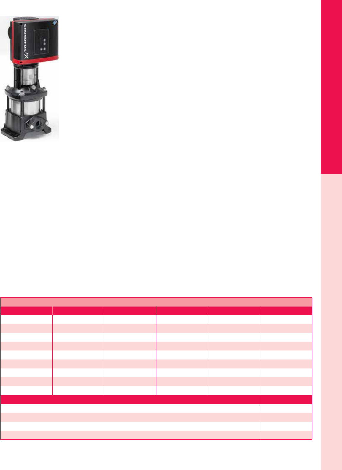
For the latest on AEE Solar products, trainings and dealer services, visit www.aeesolar.com
WATER PUMPS
214
Surface Pumps
Grundfos
Grundfos CRFlex Surface Pumps
Grundfos CRFlex solar surface pumps provide a reliable and cost-efcient solution for water systems
where a conventional AC power supply is not available. The CRFlex is designed for applications such
as irrigation, livestock watering, sh farming, water transfer, and pressure boosting. They can also be
used to supply water and pressure for cabins, off-grid homes, or remote villages. With the addition of a
suitable leaf and debris trap installed on the input, they can be used for swimming pools.
Grundfos has developed the MGFlex brushless DC motors for optimal performance using solar power
for surface pump applications. In addition to a PV array, Grundfos solar surface pumps can be run from
the grid or a generator providing 120 or 240 VAC. With variable speed operation and motor protection
built in, Grundfos CRFlex solar surface pumps offer easy installation, virtually no maintenance, and
highly efcient pumping.
The MGFlex motors provide Maximum Power Point Tracking (MPPT) of the PV array, assuring maxi-
mum output and efciency. The motor continuously optimizes the speed according to the input power
available from the PV array. The wide voltage range enables the motor to operate at any voltage from
30-300 VDC or 90-240 VAC at 50 or 60 HZ. The 1 HP motor draws up to 880 W, with a maximum input
current of 4.6 A. The 2 HP motor draws up to 1,730W with a maximum input current of 8.9 A. Both
motors have a speed range of 1,000 – 3,600 RPM.
Max suction lift is 19 feet at sea level (subtract 1 foot per 1,000 ft above sea level). Use a foot valve on the inlet pipe if water source
is below pump level, or a check valve on the output if the water source is above the pump (ooded input). The built-in Advanced
Function Module (FM 300) has connections for a dry-running sensor and/or a oat switch, along with multiple analog and digital
sensor inputs and outputs designed for control and alarm functions.
The MGFlex motors will cut out if the voltage falls outside the permissible voltage range, and they will restart automatically when
the voltage returns to its normal operating range. No extra protection relay is required. The motor is supplied with built-in thermal
protection according to IEC60034-11, for both a steady overload and a stalled condition. These pumps are not outdoor rated, so they
must be protected from direct sunlight and rain.
Nine models are available for heads (lift) up to 490 feet and max ows to 140 gallons per minute (gpm).
The Grundfos IO-50 switchbox enables manual starting and stopping of the pump in a solar-powered system, or can act as a DC
disconnect switch for the PV array, while providing a connection box to join all necessary cables, and is outdoor rated.
The Grundfos IO-101 control enables the connection of a backup generator, or other AC power source, if there is insufcient solar
energy to pump enough water. The switching between the PV array and the generator must be made manually, but if the generator
is stopped manually or runs out of fuel, the IO 101 will automatically switch back to the PV array. Max DC voltage is 225 VDC, so
make sure that the PV-array voltage does not exceed this limit in the coldest expected weather. The IO-101 comes in an outdoor-rated
enclosure.
The Dry-Run Sensor prevents damage to the pump if the suction prime is lost, or the water source runs dry.
Grundfos CRFlex Surface Pumps
Model Max head Max ow Power rating Pipe connection size Item code
CRF 1-9 263 ft 17.5 gpm 1 hp 1" NPT 075-01111
CRF 1-17 492 ft 17 gpm 2 hp 1" NPT 075-01112
CRF 3-5 148 ft 29 gpm 1 hp 1" NPT 075-01113
CRF 3-11 328 ft 30 gpm 2 hp 1" NPT 075-01114
CRF 5-2 59 ft 51 gpm 1 hp 1-1/4" NPT 075-01116
CRF 5-6 181 ft 57 gpm 2 hp 1-1/4" NPT 075-01117
CRF 10-01 46 ft 82.5 gpm 1 hp 2" NPT 075-01118
CRF 10-02 82 ft 90 gpm 2 hp 2" NPT 075-01119
CRF 15-01 59 ft 141 gpm 2 hp 2" NPT 075-01121
Description Item code
IO-50 On/Off switch 075-01038
IO-101 AC interface box (115 VAC) 075-01036
IO-101 AC interface box (230 VAC) 075-01037
Dry-run sensor for CRFlex pumps 075-01130
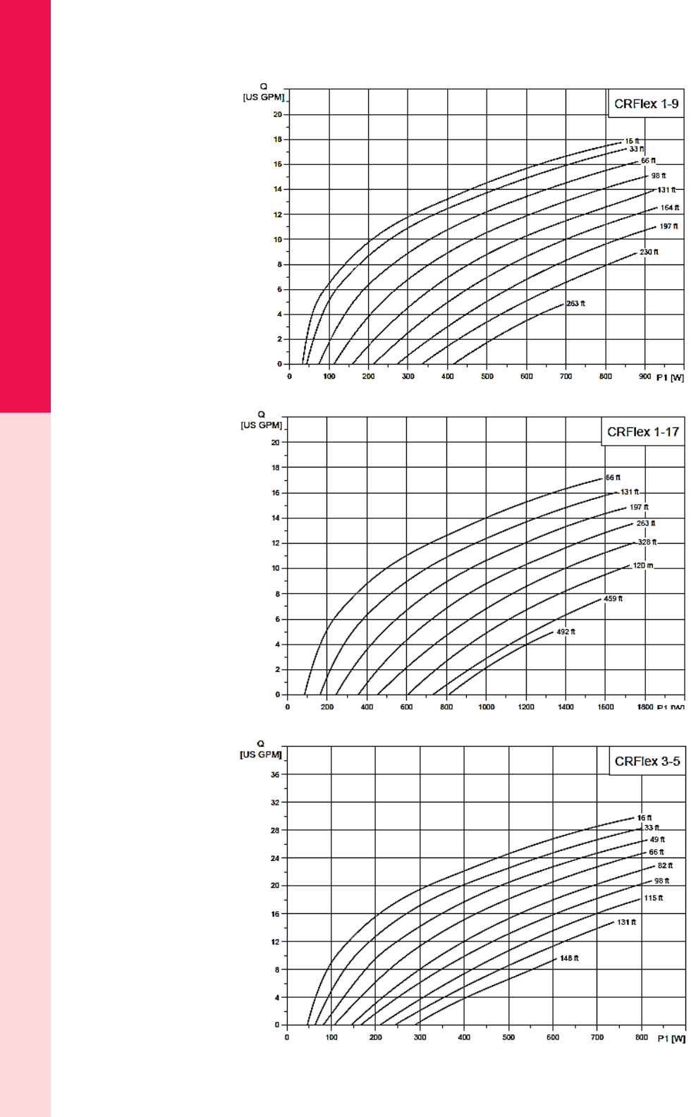
For the latest on AEE Solar products, trainings and dealer services, visit www.aeesolar.com
WATER PUMPS
215
Surface Pumps
Grundfos CRFlex Pump Performance Charts
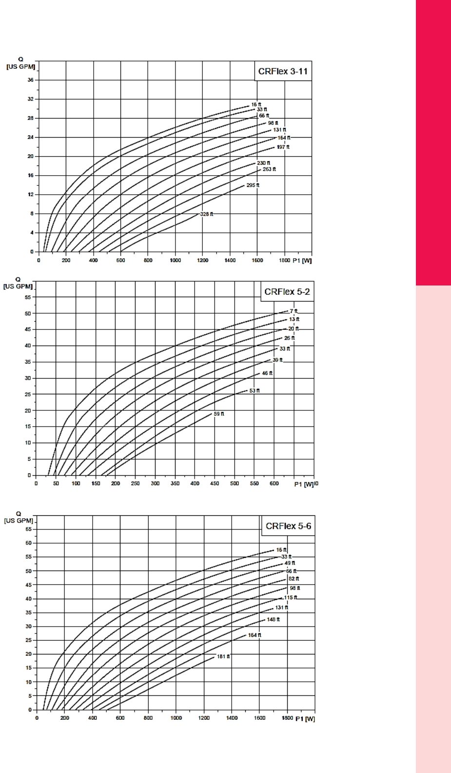
For the latest on AEE Solar products, trainings and dealer services, visit www.aeesolar.com
WATER PUMPS
216
Surface Pumps
Grundfos CRFlex Pump Performance Charts
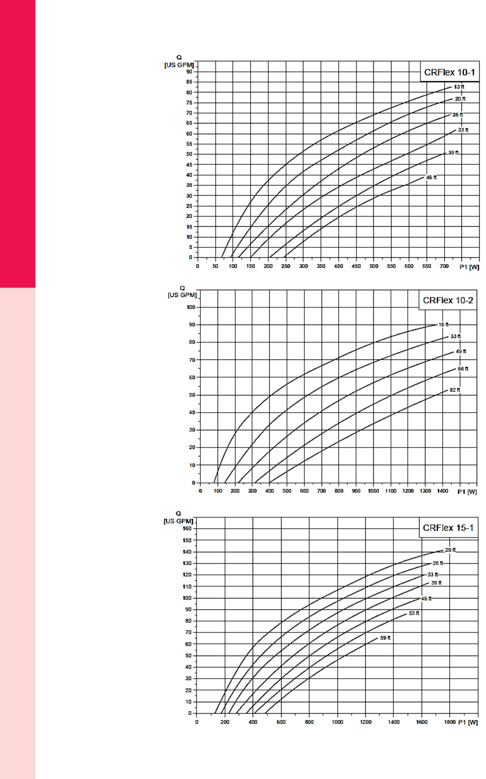
For the latest on AEE Solar products, trainings and dealer services, visit www.aeesolar.com
WATER PUMPS
217
Surface Pumps
Grundfos CRFlex Pump Performance Charts
For the latest on AEE Solar products, trainings and dealer services, visit www.aeesolar.com
WATER PUMPS
218
Surface Pumps
Aquatec Diaphragm Pumps
Aquatec 550 Series Pressure Pumps
These Aquatec booster pumps provide “town pressure” for remote home water supplies where 12 or 24
VDC power is available, or the 120 VAC version can be used on remote power systems with inverters.
They have a longer life and greater ow rate than other diaphragm booster pumps, and they use less than
half the energy consumed by an AC jet pump.
Aquatec’s 550 pressure pumps deliver up to 4.5 gpm ow rates at pressures up to 60 psi. These pumps
operate with minimal pulsations and noise and are designed for intermittent duty, though most models can
be run continuously for hours at a time. They are commonly used to pressurize water from an atmospheric
tank, to deliver puried water to a specic point of use, or simply to increase pressure when required.
The built-in pressure switch is set for 60 psi off and 40 psi on. The pumps come with straight threaded
male 1/2” ttings that snap into the quick-disconnect ports. The optional strainer is highly recommended
to keep debris out of the pump and thereby prolong diaphragm life.
All Aquatec 550 pressure pumps are made in the USA, weigh 8 lbs each and are covered by a one-year
warranty.
Aquatic 550 Pressure Pumps
Model Voltage Flow Operating
pressure
Current
draw Item code
5503-AEE-B636 12 VDC
4.10 gpm [15.52 lpm] 30 psi 11.0 A
075-048053.80 gpm [14.38 lpm] 40 psi 13.0 A
3.55 gpm [13.44 lpm] 50 psi 14.6 A
5503-AEE-B736 24 VDC
4.10 gpm [15.52 lpm] 30 psi 5.5 A
075-048093.80 gpm [14.38 lpm] 40 psi 6.5 A
3.55 gpm [13.44 lpm] 50 psi 7.3 A
5503-AEE-B656 120 VAC
4.10 gpm [15.52 lpm] 30 psi 1.4 A
075-048133.80 gpm [14.38 lpm] 40 psi 1.6 A
3.55 gpm [13.44 lpm] 50 psi 1.8 A
25-181 High ow 50-mesh in-line strainer 075-04821
QTS-556 1/2" NPT male pipe fitting, straight, replacement 075-04820
QBS-554 1/2" barbed pipe fitting, straight 075-04818
QBE-554 1/2" barbed pipe fitting, 90° elbow 075-04819
Aquatec 550 Pump Replacement Parts
55-LHA-AEE Lower housing kit (Diaphragm kit) 075-04822
55-VHA-AEE Valve-housing assembly kit (Valve kit) 075-04823
55-UHA-AEE Upper-housing assembly kit (includes pressure switch) 075-04824
55-PHK-AEE Complete pump-head kit with 60 psi pressure switch (for all models) 075-04825
12VDCEBK Motor-brush kit – 550 pumps (motor end-cap with brushes) 12 VDC 075-04826
24VDCEBK Motor-brush kit – 550 pumps (motor end-cap with brushes), 24 VDC 075-04827
115VACEBK Motor-brush kit – 550 pumps (motor end-cap with brushes), 48 VAC 075-04828
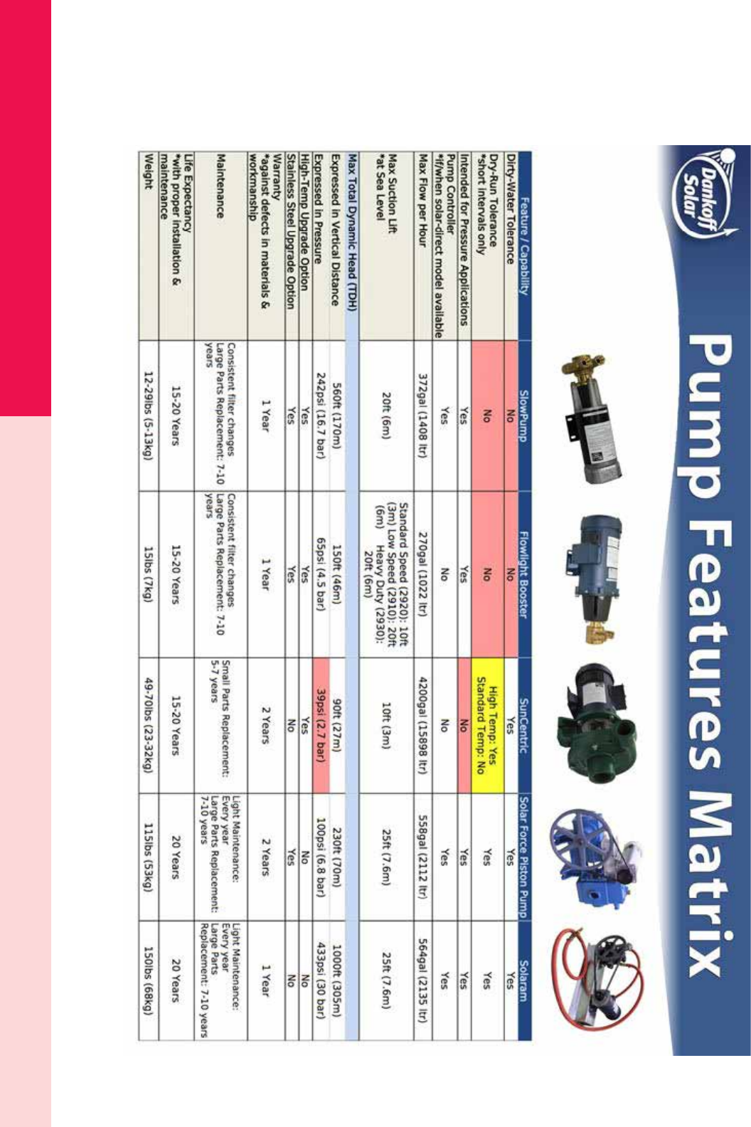
For the latest on AEE Solar products, trainings and dealer services, visit www.aeesolar.com
WATER PUMPS
219
Surface Pumps
Dankoff Solar Pumps
Dankoff Water Pump Matrix
Dankoff makes water pumps for a wide range of uses. Use this handy guide, and the information on the following pages for the
individual models, to choose the correct pump for your needs.
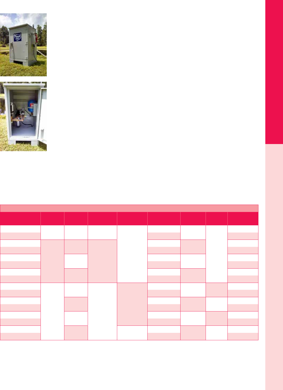
For the latest on AEE Solar products, trainings and dealer services, visit www.aeesolar.com
WATER PUMPS
220
Surface Pumps
Dankoff SIP Kits™
Dankoff Pump’s Simple Independent Pumping Kits (SIP Kits™) are pre-engineered and pre-assembled
stand-alone off-grid water pumping systems designed for moving and pressurizing surface water with
solar panels and batteries. They are turn-key easy-to-install kits which can produce ow rates between
200 and 375 gallons per hour (gph).
They are available as PV-direct units, with or without batteries, to provide a backup water supply at night
or during inclement weather. They use Dankoff’s high-efciency SlowPumps to provide water ow of
up to 6 gallons per minute (gpm) with total lifts (head) of up to 280’ (84 m or about 87 psi).
Save time and the potential for error in sizing, selecting, and sourcing the various plumbing and electrical
parts and save installation time by having pre-wired and pre-plumbed major system components, securely
mounted inside an outdoor-rated enclosure that has pre-installed water-tight input/output connections.
No time wasted fabricating an enclosure on-site. They solve the ner points of the installation process
- proper system ventilation, system grounding, over-current protection, portability, battery and charge
controller sizing and selection and priming of the pump.
Each kit contains a SlowPump™, a Dry-Run Switch , a SlowPump EZ Install Kit, a 10” lter kit (includ-
ing mounting bracket and spanner wrench), one set of 10” replacement lters (two total), a disconnecting
combiner box with external throw switch, PV-module connectors, a switch connection for automatic
control (for a oat switch, timer or pressure switch), a 0.6 gallon expansion tank, a pressure-relief valve,
a pressure gauge, 1/2” electrical ttings, 1” electrical ttings, 1” plumbing ttings, wire, and hardware.
The SIP PV-direct kits also include a pump controller (LCB), PV module(s), a choice of either a ballasted
ground mount or a pole mount for the PV. Available with 1, 2, or 3 PV modules.
The SIP SP1-B battery kits also include gel-cell sealed deep-cycle batteries, a charge controller, battery-
interconnect cables, a dedicated load controller, battery-system DC circuit breakers, and a junction box to
protect the electronics from water. The Small Trusted (ST) and Large Trusted (LT) models are designed
for non-essential needs and have 2.5 days of back-up power. The Small Ideal (SI) and Large Ideal (LI)
systems are designed for essential needs and have 4.5 days of back-up power.
SIP Kits™ are available with either a ballasted ground mount (BGM) or a top-of-pole mount (TPM),
for the PV modules.
NOTE: Listed specications and product appearance are subject to change.
Dankoff SIP Kits™
Model SlowPump
model
Max lift
(head) Flow range Enclosure size
(L" x W" x H")
Type of
PV mount
Number of
PV modules
Number of
batteries Item code
SP1-BGM 2507-24 140 ft 3.65-4.0 gpm
24 x 24 x 36
Ballasted Ground one
N/A
075-11001
SP1-TPM Top-of-Pole 075-11002
SP2-1-BGM
2607-24
60 ft
5.59 - 6.2 gpm
Ballasted Ground one 075-11010
SP2-1-TPM Top-of-Pole 075-11011
SP2-2-BGM 200 ft Ballasted Ground two 075-11020
SP2-2-TPM Top-of-Pole 075-11021
SP2-3-BGM 280 ft Ballasted Ground three 075-11030
SP2-3-TPM Top-of-Pole 075-11031
SP1-B-ST-BGM
2507-24
60 ft
2.65 - 3.37 gpm
24 x 24 x 36
Ballasted Ground one two 075-11040
SP1-B-ST-TPM Top-of-Pole 075-11041
SP1-B-LT-BGM 140 ft Ballasted Ground two four 075-11050
SP1-B-LT-TPM Top-of-Pole 075-11051
SP1-B-SI-BGM 60 ft Ballasted Ground one four 075-11060
SP1-B-SI-TPM Top-of-Pole 075-11061
SP1-B-LI-BGM 140 ft 48 x 24 x 36 Ballasted Ground two eight 075-11070
SP1-B-LI-TPM Top-of-Pole 075-11071
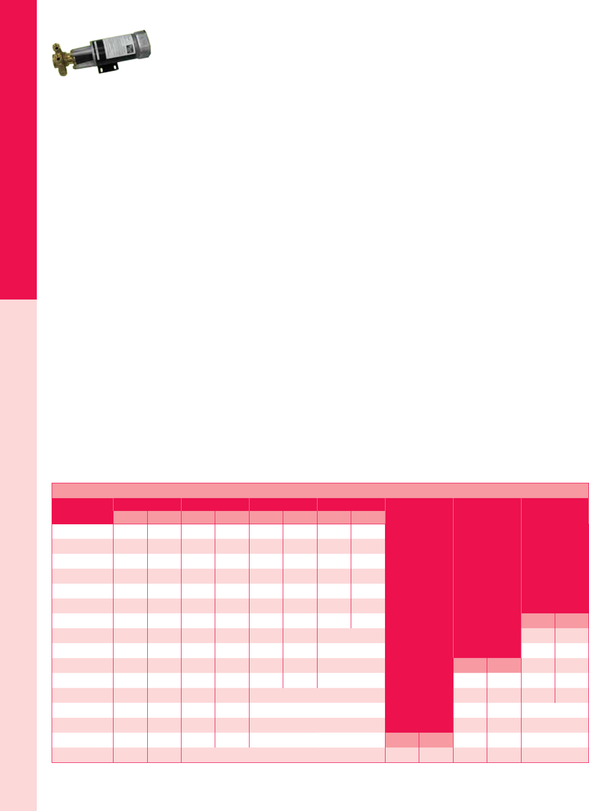
For the latest on AEE Solar products, trainings and dealer services, visit www.aeesolar.com
WATER PUMPS
221
Surface Pumps
Dankoff SlowPump™ Surface Pumps
The SlowPump™ can push water uphill as high as 450 vertical feet. It runs on very low power, with or
without batteries, to supply between 200 and 2,600 gallons per day (gpd). The rotary-vane pump mecha-
nism is housed in forged brass for durability. Because of tight tolerances, the water must be very clean,
so ne ltration is required to protect the pump (10 micron ltration is recommended).
The chart below shows the gallons per minute (gpm) output from the pump and power (Watts) consumed
by the pump for various vertical lifts (this is the “total head” or the lift from the water level at the source
to the top of the storage tank, in actual elevation change, not simply pipe distance). The pump perfor-
mance in the chart is measured at array-direct voltages. The peak power voltage of a nominal 12 VDC PV
module is about 18 VDC. A battery-powered pump will have about 20% lower output and power draw
because the battery is operating at a lower voltage. Flow rates are in gpm. To estimate the gallons per
day delivered, multiply the gpm by 60 (minutes) to get the gallons per hour (gph) amount. Then multiply
by the peak-sun-hours per day at the site location (this data is available from NREL’s PVWATTS Solar
Calculator) to get the gallons per day (gpd).
For PV-direct operation (without batteries), the PV-array nameplate output must exceed the required
pump power by at least 20%. Oversizing the array will increase the amount of water delivered per day
because a higher wattage array will enable the pump to run at full speed for more hours each day, or in
cloudy weather. For example, a 100 W module will produce 50 W in half the amount of sunlight present
at noon on a sunny day. The extra available power will not damage the pump as long as the array voltage
is within the voltage range of the pump motor.
For array-direct operation, a linear current booster (LCB) with the required output current must be
used. Determine the correct amperage rating for the LCB by dividing pump power shown below by pump
voltage. (See page 228 for a selection of LCB units). For 48 VDC models, use the Solar Converters PPT
48-10 LCB listed on page 230. AC models use a low-surge permanent-magnet motor that greatly reduces
starting surge, relieving stress on inverters and generators.
SlowPumps are NSF approved for pumping potable water and can also be used to pump saltwater. These
pumps are 5.7” W x 15.5” L, weigh 16 lbs. and are covered by a one-year warranty.
1/4 HP SlowPumps (model series 1300 and 2500) are available with 12, 24 or 48 VDC motors, for
array-direct operation or with battery systems. Performance will be slightly lower on battery systems
due to the lower operating voltage compared to PV-direct. These are also available in 120 VAC versions
for inverter, generator, or grid connection. These models have 1/2” female pipe ttings.
1/2 HP SlowPumps (model series 1400 and 2600) are available with 24 or 48 VDC motors, for use with
battery systems, or PV direct with a 36 VDC nominal array. Also available in 120 VAC versions for
inverter, generator, or grid connection. These models have 3/4” male pipe ttings.
SlowPump™ Model, Performance, and Power Requirement
Vertical lift
(head)
Model 1322 Model 1308 Model 1303 Model 2507
gpm Wgpm Wgpm Wgpm W
20 ft 0.51 27 1.25 30 2.50 48 4.00 57
Model 1408
Model 1403
Model 2607
40 ft 0.51 32 1.25 48 2.50 60 3.95 78
60 ft 0.51 36 1.20 54 2.40 78 3.90 102
80 ft 0.49 40 1.20 60 2.30 93 3.90 120
100 ft 0.49 45 1.20 66 2.30 105 3.85 144
120 ft 0.48 50 1.20 70 2.25 121 3.80 165
140 ft 0.47 56 1.20 75 2.20 138 3.65 195 gpm W
160 ft 0.47 62 1.20 84 2.20 153 4.30 283
180 ft 0.47 66 1.18 93 2.15 165 4.25 305
200 ft 0.45 74 1.16 101 2.15 180 gpm W4.20 338
240 ft 0.44 90 1.14 117 2.15 204 2.55 266 4.05 396
280 ft 0.41 102 1.12 135 2.50 302 4.00 444
320 ft 0.41 120 1.10 153 2.50 338
360 ft 0.41 134 1.05 171 2.50 374
400 ft 0.40 150 1.00 198 gpm W2.50 406
440 ft 0.39 168 1.10 269 2.50 451

For the latest on AEE Solar products, trainings and dealer services, visit www.aeesolar.com
WATER PUMPS
222
Surface Pumps
Dankoff SlowPump™ Surface Pumps
Model Power
Item code
12 V PV
direct or battery
24 V PV
direct or battery
48 V PV
direct or battery 120 VAC
1303
1/4 hp
075-04172 075-04174 075-04178 075-04139
1308 075-04160 075-04162 075-04161 075-04137
1322 075-04168 075-04170 075-04176 075-04135
2507 075-04180 075-04182 075-04184 075-04141
1403
1/2 hp
-- 075-04193 075-04195 075-04144
1408 -- 075-04185 075-04187 075-04142
2607 -- 075-04201 075-04203 075-04146
Dankoff SlowPump™ Accessories
Inline lter – This is a plastic lter housing with 3/4” female NPT inlet and outlet ttings. Filter Car-
tridges are sold separately.
30” Intake lter/foot valve – This lter, with a 3/4” female pipe tting, replaces an intake strainer and
foot valve in a single unit. Use in silty streams or other problem applications. A spare 30” lter cartridge
is included.
Dry-run switch – This switch provides automatic shut-off in case the pump runs dry. Order the correct
model for the SlowPump that you are using.
Dankoff SlowPump™ Accessories
Description Weight Item code
Dry-run switch - for 1300 and 1400 series SlowPumps 1 lbs 075-04213
Dry-run switch - for 2500 and 2600 series SlowPumps 1 lbs 075-04215
Inline lter housing - 10" with 3/4" female NPT pipe ports 3 lbs 078-01125
Filter for above housing - 10", 10-micron (two-pack) 4 lbs 078-01130
30" lter and foot-valve assembly 3 lbs 075-04207
Filter cartridge for 30" lter assembly above (three-pack) 6 lbs 075-04209
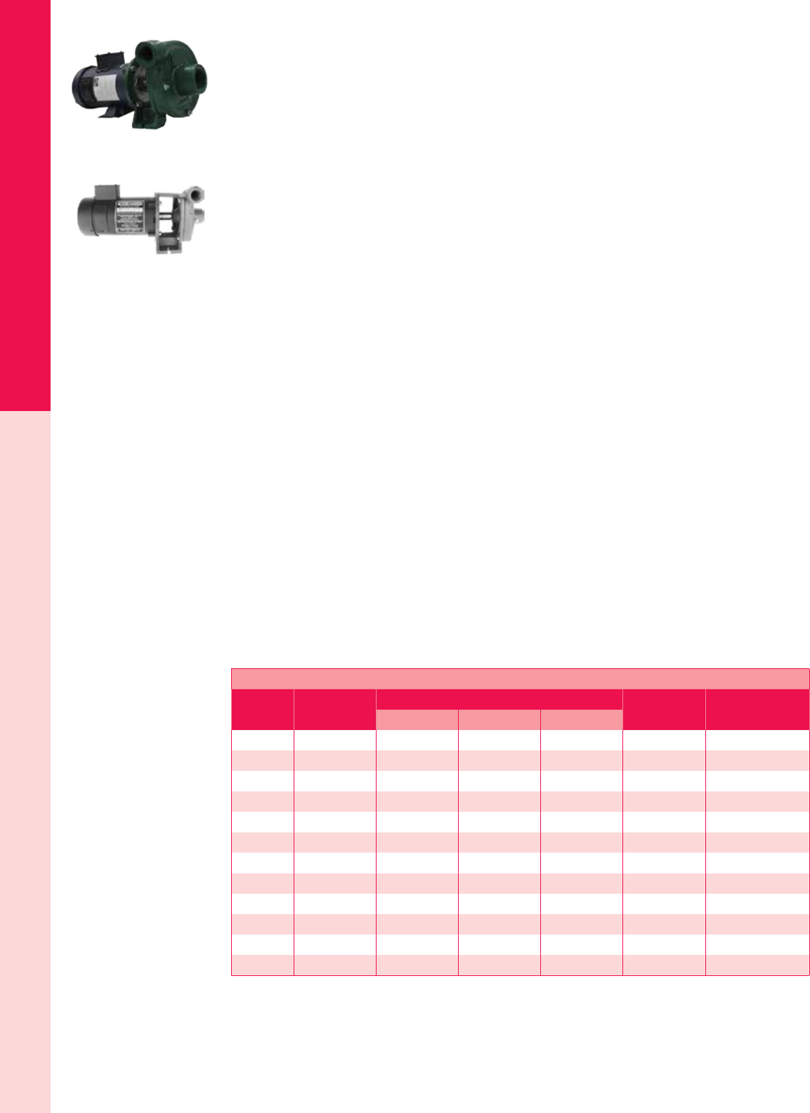
For the latest on AEE Solar products, trainings and dealer services, visit www.aeesolar.com
WATER PUMPS
223
Surface Pumps
Dankoff SunCentric® Centrifugal Pumps
The SunCentric® Centrifugal Pumps use solar-electric power to pump as much as 50,000 gallons (200
m³) per day from shallow water sources. Applications include irrigation, livestock, domestic water, pond
management, water treatment, solar water heating, hydronic space heating, hot-water circulation, and
re protection. They can tolerate silty water and deliver up to 70 gpm.
These centrifugal pumps have been in worldwide use since 1989. They can be used PV array-direct without
batteries and do not require a pump controller or linear current booster (LCB). Maximum suction lift is
10 vertical feet (3 m). Use a foot valve on the intake pipe if the pump is mounted higher than the water
source. For pumps mounted below the source’s water level, use a check valve on the outlet pipe to keep
water from back-draining from the outlet pipe. The pump must be kept from freezing.
No routine maintenance is required. These pumps can be repaired in the eld using ordinary tools and
skills, without removing the pipes. They feature a cast-iron pump body with polycarbonate impeller. The
included instruction manual shows illustrated repair details. For best reliability, minimize or eliminate
suction lift by placing the pump low and close to the water source, minimizing the possibility of cavita-
tion, which causes excessive wear and loss of performance.
The chart on the next page for the SunCentric® pumps is for PV-array-direct applications. Models for
12, 24, and 48 VDC batteries are available; call for information. PV-array size should exceed the pump
wattage shown in the chart by at least 25%. Larger array sizing will improve pumping in low-light condi-
tions, in the morning, afternoon, and on cloudy days. A PV array twice the size as listed (plus 25%), will
produce the pump’s rated power in one-half the amount of sunlight and can greatly enhance the quantity
of water pumped per day.
The temperature limit for the standard pumps listed here is 140 °F (60 °C). The SunCentric® pumps
are also available in High-Temperature models, which raise the temperature limit to 240 °F (115 °C).
The High-Temperature versions have a brass impeller which reduces ow by about 15% using the same
wattage. Call AEE Solar for more information on High-Temperature models.
Array voltages shown are “nominal” voltages, and are based on using 36-cell modules with one (12
VDC), two (24 VDC), three (36 VDC), or four (48 VDC) per series string. 72-cell modules can be used
in parallel for 24 VDC pumps, and in series strings of two for 48 VDC pumps. 12 VDC and 36 VDC
pumps must use 36-cell modules.
If using 60-cell PV modules, use them in parallel for 24 VDC pumps and in series strings of two for 48
VDC pumps. Pumping speed, and water delivery, will be lower when using 60-cell modules compared
to using 36-cell or 72-cell modules, due to lower operating voltage. However, daily pumping volumes
can be raised by using a higher wattage 60-cell PV array.
These pumps are covered by a two-year warranty.
Dankoff SunCentric® Centrifugal Pumps
Model Nominal PV
array voltage
Pump load Min PV array
nameplate Item code
Voltage Current Power
7212 12 VDC 15 V 19.3 A 290 W 380 W 075-04299
7322 24 VDC 30 V 9.7 A 290 W 380 W 075-04307
7324 12 VDC 15 V 6.0 A 90 W 117 W 075-04311
7325 12 VDC 15 V 7.4 A 111 W 144 W 075-04313
7424 24 VDC 30 V 16.0 A 480 W 624 W 075-04319
7442 36 VDC 45 V 3.5 A 158 W 205 W 075-04325
7444 48 VDC 60 V 8.0 A 480 W 624 W 075-04329
7445 24 VDC 30 V 3.7 A 111 W 144 W 075-04331
7446 36 VDC 45 V 6.9 A 311 W 404 W 075-04333
7521 36 VDC 45 V 16.4 A 738 W 960 W 075-04337
7526 24 VDC 30 V 24.4 A 732 W 960 W 075-04339
7622 36 VDC 45 V 19.0 A 855 W 1,120 W 075-04341
See the next page for a SunCentric® pump-curve chart to pick the correct model pump for your needs.
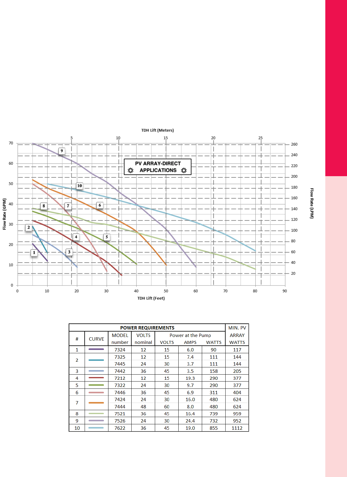
For the latest on AEE Solar products, trainings and dealer services, visit www.aeesolar.com
WATER PUMPS
224
Surface Pumps
Dankoff SunCentric® Pump Application Chart
To use the chart below:
• Use the bottom of the chart for Total Dynamic Head (TDH) in feet, and use the top of the chart
for Total Dynamic Head (TDH) in meters.
• Use the left side of chart for ow in gallons per minute (gpm) and use the right side for ow in
liters per minute (l/m).
• Locate the intersection of the lines for the required head and ow then nd the pump curve that
is nearest to that point.
• If there is more than one curve to choose from, compare the power requirements.
• The curve that goes higher will work better in low-light conditions.
• For PV-Direct systems, array size (watts) is critical. Do not undersize the array. Oversizing the
array will improve performance in low sunlight conditions.
• Multiple pumps can be used to provide greater ow.
Dankoff SunCentric® PV-Direct Application Chart Key
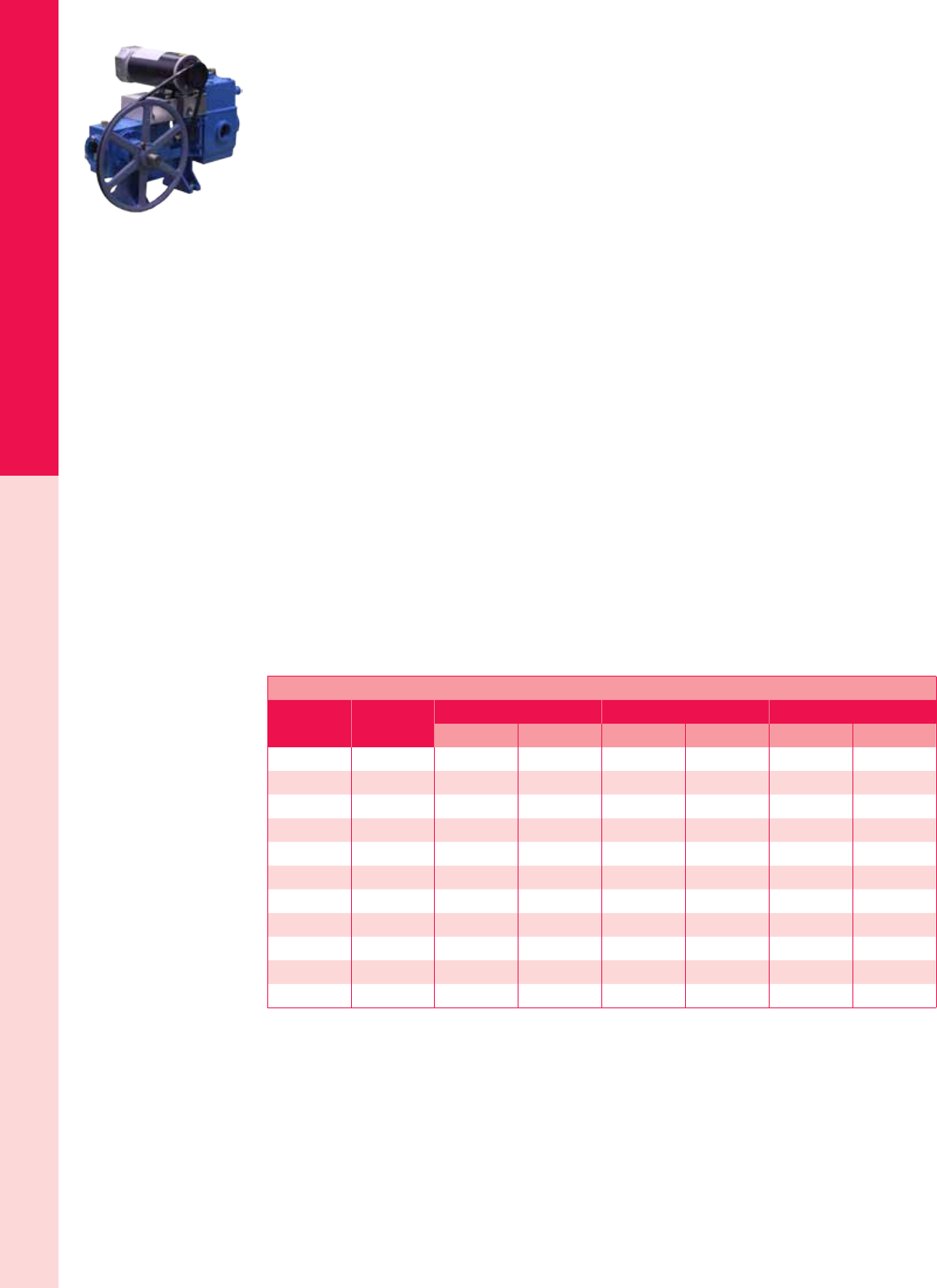
For the latest on AEE Solar products, trainings and dealer services, visit www.aeesolar.com
WATER PUMPS
225
Surface Pumps
Dankoff Solar Force™ Piston Pumps
The Solar Force™ piston pumps operate directly from a PV array or battery bank. They can draw water
from a shallow well, pond, stream, river, or storage tank and push water up-hill (230’ maximum head),
through miles of pipeline, or pressurize a water system (100 psi max; minimum 60 gallon pressure tank
required). They can be used for domestic, agricultural, commercial, or industrial applications. Suction
capacity is 25’ at sea level (subtract 1’ for each 1,000’ above sea level) with 5 to 9 gpm pumping capacity.
Solar Force™ pumps use less energy per gallon of water delivered than any other pump that we sell. The
pump head is cast iron with a brass cylinder. These pumps have a proven design with a 20-year life, and
are simple to maintain with common hand tools. Leather piston seals are easy to replace (ve to ten-year
maintenance interval). The illustrated installation and repair manuals make it easy to install and service.
The DC models are the most efcient, but the AC models use low-surge motors with low starting torque,
reducing inverter and wire-size requirements. Available with 12, 24, or 48 VDC motors, or with 120
VAC or 230 VAC, 50-60 Hz motors.
For PV-array-direct systems, a linear current booster (LCB) with the required output current is required.
Use the Solar Converters LCB controllers on the LCB page of this catalog section (determine the correct
amperage rating for the LCB by dividing pump power shown below by pump voltage).
For pressurized systems, whether battery-powered or AC-powered, use a pressure switch and a captive-
air pressure tank at least 60 gallons in size.
Solar Force™ pumps have 1.5” NPT female intake ports and 1” NPT female outlet ports. A surge tank
is included and will reduce the amount of water pulsation that the pump produces. They measure about
22” x 13” x 16”, and have a maximum weight of 115 lbs. ship in two boxes and are covered by a two-
year warranty.
The watt values listed in the following chart represent power used by the pump. For PV-array-direct
operation, the array must be at least 20% larger. Oversizing the array further will increase the amount of
water delivered per day as a larger array will enable the pump to run at full speed for more hours each
day, or in cloudy weather. A tracking PV mount will also increase the amount of daily water delivery.
For example, a 560 W array will produce 280 W in half the amount of sunlight present at noon. The extra
available power will not damage the pump motor or LCB as long as the array voltage doesn’t exceed the
voltage range of the pump motor or LCB.
Dankoff Solar Force™ Piston-Pump Sizing Chart
Lift (head) Pressure Model 3010 Model 3020 Model 3040
Flow Power Flow Power Flow Power
20 ft 8.7 psi 5.9 gpm 77 W 5.2 gpm 110 W 9.3 gpm 168 W
40 ft 17.4 psi 5.6 gpm 104 W 5.2 gpm 132 W 9.3 gpm 207 W
60 ft 26 psi 5.3 gpm 123 W 5.1 gpm 154 W 9.2 gpm 252 W
80 ft 35 psi 5.2 gpm 152 W 5.1 gpm 182 W 9.2 gpm 286 W
100 ft 43 psi 5.1 gpm 171 W 5 gpm 202 W 9.1 gpm 322 W
120 ft 52 psi 4.9 gpm 200 W 5 gpm 224 W 9.1 gpm 364 W
140 ft 61 psi 4.9 gpm 226 W 5 gpm 252 W 9.1 gpm 403 W
160 ft 70 psi -- -- 4.9 gpm 269 W -- --
180 ft 78 psi -- -- 4.9 gpm 280 W -- --
200 ft 86 psi -- -- 4.8 gpm 308 W -- --
220 ft 95 psi -- -- 4.7 gpm 314 W -- --

For the latest on AEE Solar products, trainings and dealer services, visit www.aeesolar.com
WATER PUMPS
226
Surface Pumps
Dankoff Solar Force™ Piston Pumps
Model Operating voltage Power source Item code
3010-12B 12 VDC Battery 075-04265
3010-24B 24 VDC Battery 075-04267
3010-48B 48 VDC Battery 075-04268
3020-12B 12 VDC Battery 075-04271
3020-12PV 12 VDC PV array direct 075-04273
3020-24B 24 VDC Battery 075-04275
3020-24PV 24 VDC PV array direct 075-04277
3020-48B 48 VDC Battery 075-04279
3020-48PV 48 VDC PV array direct 075-04281
3020-120VAC 120 VAC Inverter, generator or grid 075-04269
3020-230VAC 230 VAC Inverter, generator or grid 075-04282
3040-12B 12 VDC Battery 075-04285
3040-12PV 12 VDC PV array direct 075-04287
3040-24B 24 VDC Battery 075-04289
3040-24PV 24 VDC PV array direct 075-04291
3040-48B 48 VDC Battery 075-04293
3040-48PV 48 VDC PV array direct 075-04295
3040-120VAC 120 VAC Inverter, generator or grid 075-04283
3040-230VAC 230 VAC Inverter, generator or grid 075-04284
Dankoff Solar Force™ Piston Pump Accessories & Parts
The Solar Force™ Easy Installation Kit contains: Brass Manifold, Ball Valve, Check Valve, Pressure
Gauge, Pressure Switch, Hose Bibb, and Fittings.
Use the empty tank oat switch, 11002, to turn the pump off if the tank or cistern that the pump is draw-
ing water from runs dry. Use the full-tank oat switch, 11003, to turn the pump off when the tank it is
pumping into gets full. Both switches can be used on the same pump.
The basic repair parts kits, 3521 & 3522, contain: one packing kit, and one set each of water-box gaskets,
neoprene valve discs, valve springs w/washers & cotter pins, and one set of cup leathers.
Long-term repair kits are available that contain two packing kits, one drive belt, one pair of motor brushes,
one brass cylinder, three pairs of cup leathers, and two water-box gaskets, valve springs w/ washers &
cotter pins, and eight neoprene valve discs, (does not include oil). These kits are specic for each model
of Solar Force™ pump. Contact AEE Solar for more information.
Dankoff Solar Force™ Piston Pump Accessories and Parts
Model Description Item code
EZ3000 Easy-install kit for Solar Force™ piston pumps 075-04248
11002 Float-switch kit for LCB - empty-tank shutoff 075-04217
11003 Float-switch kit for LCB - full-tank shutoff 075-04218
11023 Pressure switch, heavy-duty 1HP DC rated 075-04297
3513 Quart of food-grade 30wt non-toxic oil 075-10380
3521 Basic repair kit for 3010/3020 models 075-10250
3522 Basic repair kit for 3040 models 075-10251
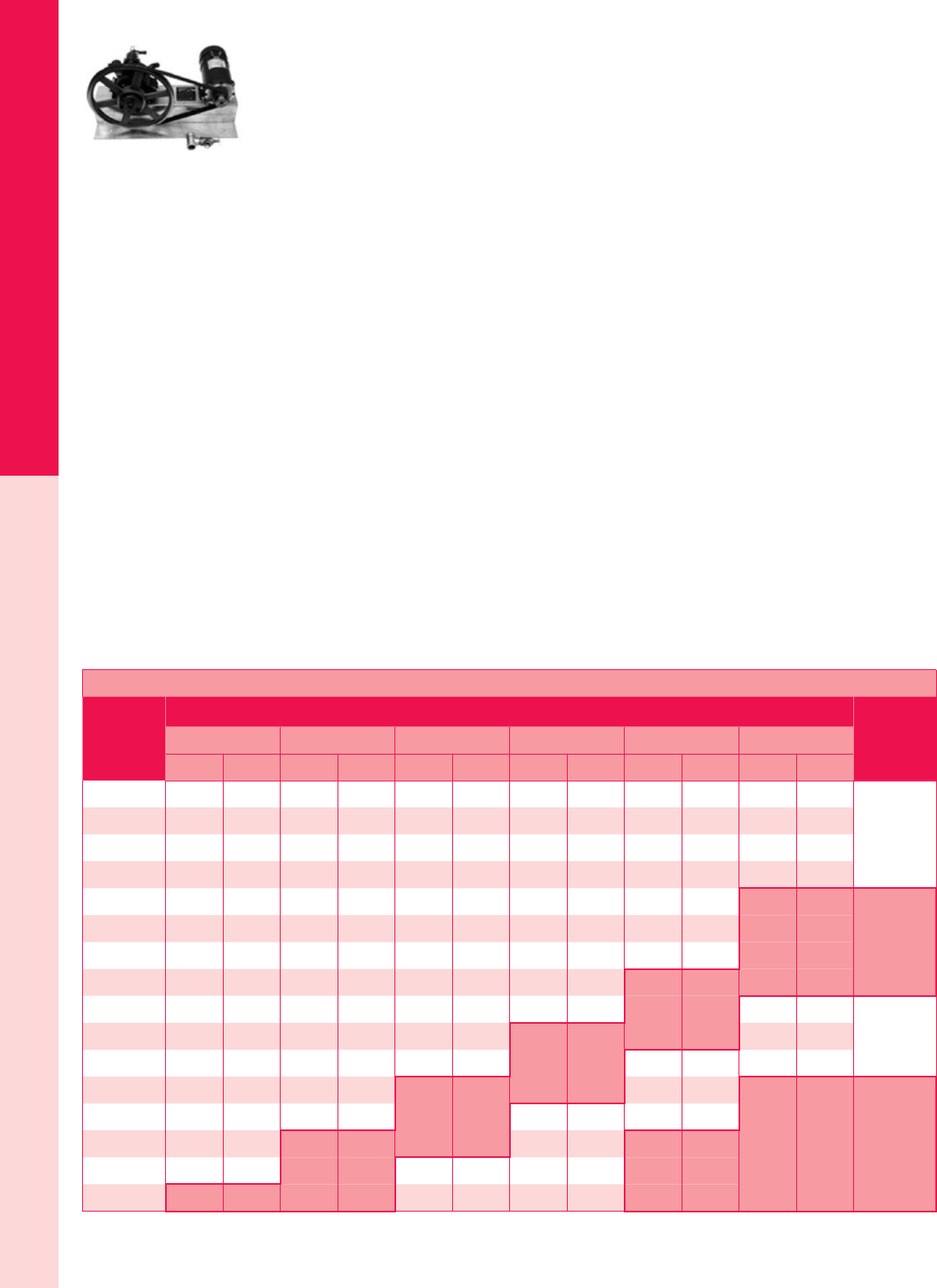
For the latest on AEE Solar products, trainings and dealer services, visit www.aeesolar.com
WATER PUMPS
227
Surface Pumps
Dankoff Solaram™ Diaphragm Pumps
Solaram™ diaphragm pumps use industrial-grade, high-pressure, multiple-diaphragm pump heads, and
permanent-magnet motors for either 24 VDC array-direct or battery operation, or 120 VDC (nominal)
array-direct operation. Solaram™ pumps can be used for most pumping applications.
The Solaram™ is Dankoff’s most powerful surface pump. They can draw water from a shallow well,
pond, stream, river or storage tank. They can push water very high uphill (960’ maximum head), through
miles of pipeline, or pressurize water systems (415 psi max; minimum 60 gallon pressure tank required).
Suction capacity is 20’ at sea level (subtract 1’ for each 1,000’ above sea level). With 2.5-9 gpm of pump
-
ing capacity, Solaram pumps can supply up to 5,400 gallons per day (gpd), while using less power than
any other pump in its range. They start pumping even in low light conditions.
These pumps are rugged and reliable, as well as dirt and dry-run tolerant. They feature multiple-diaphragm
industrial construction, a cast-aluminum body, ball bearings, and permanent-magnet motors. An oil change
(non-toxic oil) and diaphragm replacement are required for every two years of continuous use, but these
pumps otherwise have a 20-year life expectancy. A pressure-relief valve is included.
For array-direct operation at 24 VDC, use 36-cell PV modules in strings of two to get the total power
needed, or use 60-cell or 72-cell modules in parallel. For array-direct operation at 120 VDC, use ten
36-cell modules in series, ve 72-cell modules in series, or six 60-cell modules in series. Add module
strings in parallel if more power is needed. As with other array-direct pumps, the PV array needs to be
sized at least 20% larger than the pump watts, and even larger arrays can be used to extend pumping in
lower light conditions. An 11053 or 11054 linear current booster (LCB) is required to prevent stalling in
low light conditions. LCB’s for 120 VDC Solaram™ pumps are custom built by special order. Contact
AEE Solar for more information.
Solaram pumps can develop pulsating water pressure up to 400 psi, so the piping system must be designed
for high-pressure use; a rating of at least 600 psi is recommended for the rst 200’ or more of head (this
generally requires steel pipe). The pulsation and pressure diminishes as the pipe climbs the hill, so pipe
with a lower pressure rating can often be used closer to the output.
Suction capacity is 25’ at sea level (subtract 1’ for each 1,000’ above sea level). Fittings are 1”-1.25” on
the intake, and 1” on the outlet. Dimensions are 28”W x 16.5”H x 16”D, weight is 150 lbs (max, depend-
ing on model) and they are covered by a one-year warranty.
Dankoff Solaram™ Diaphragm Pump-Sizing
Total head
↓
Last 2 digits of model number ↓
First 2 digits
of model # ↓
Model _ _ 21 Model _ _ 22 Model _ _ 23 Model _ _ 41 Model _ _ 42 Model _ _ 43
Flow Watts Flow Watts Flow Watts Flow Watts Flow Watts Flow Watts
0-80' 3.0 gpm 170 W 3.7 gpm 207 W 4.6 gpm 285 W 6.2 gpm 258 W 7.5 gpm 339 W 9.4 gpm 465 W
81_ _ 24 V
120' 2.9 gpm 197 W 3.7 gpm 238 W 4.5 gpm 319 W 6.0 gpm 305 W 7.3 gpm 396 W 9.1 gpm 539 W
160' 2.9 gpm 225 W 3.6 gpm 268 W 4.5 gpm 352 W 5.8 gpm 354 W 7.2 gpm 453 W 8.9 gpm 619 W
200' 2.9 gpm 247 W 3.6 gpm 296 W 4.5 gpm 388 W 5.7 gpm 400 W 7.1 gpm 513 W 8.9 gpm 693 W
240' 2.8 gpm 265 W 3.6 gpm 327 W 4.5 gpm 427 W 5.6 gpm 453 W 7.0 gpm 572 W 8.6 gpm 724 W
82_ _ 24 V
280' 2.8 gpm 286 W 3.6 gpm 356 W 4.4 gpm 466 W 5.5 gpm 499 W 6.9 gpm 628 W 8.4 gpm 801 W
320' 2.8 gpm 315 W 3.5 gpm 388 W 4.4 gpm 496 W 5.4 gpm 548 W 6.8 gpm 686 W 8.3 gpm 869 W
360' 2.8 gpm 342 W 3.5 gpm 416 W 4.4 gpm 536 W 5.4 gpm 592 W 6.6 gpm 733 W 8.2 gpm 927 W
400' 2.7 gpm 363 W 3.4 gpm 450 W 4.4 gpm 572 W 5.3 gpm 649 W 6.5 gpm 782 W 8.7 gpm 1,122 W
83_ _ 120 V480' 2.7 gpm 416 W 3.4 gpm 505 W 4.3 gpm 649 W 5.3 gpm 717 W 6.5 gpm 900 W 8.5 gpm 1,265 W
560' 2.7 gpm 456 W 3.3 gpm 570 W 4.3 gpm 693 W 5.2 gpm 800 W 6.5 gpm 1,045 W 8.4 gpm 1,397 W
640' 2.7 gpm 502 W 3.3 gpm 623 W 4.2 gpm 774 W 5.1 gpm 893 W 6.5 gpm 1,116 W 8.2 gpm 1,540 W
85_ _120 V
720' 2.6 gpm 551 W 3.2 gpm 690 W 4.1 gpm 856 W -- -- 6.4 gpm 1,287 W 8.1 gpm 1,683 W
800' 2.6 gpm 589 W 3.2 gpm 715 W 4.1 gpm 931 W -- -- -- -- 8.0 gpm 1,815 W
880' 2.6 gpm 647 W 3.2 gpm 774 W -- -- -- -- -- -- 8.0 gpm 1,958 W
960' 2.6 gpm 705 W 3.1 gpm 838 W -- -- -- -- -- -- 8.0 gpm 2,145 W

For the latest on AEE Solar products, trainings and dealer services, visit www.aeesolar.com
WATER PUMPS
228
Surface Pumps
Dankoff Solaram™ Diaphragm Pumps
Model DC voltage Item code Model DC voltage Item code
8121-24
24 VDC
075-08121 8342-120
120 VDC
075-08342
8122-24 075-08122 8343-120 075-08343
8123-24 075-08123 8543-120 075-08543
8141-24 075-08140
8142-24 075-08142
8143-24 075-08143
8221-24 075-08221
8222-24 075-08222
8223-24 075-08223
8241-24 075-08241
8242-24 075-08242
8243-24 075-08243
Dankoff Solaram™ Diaphragm Pump Accessories and Parts
Choose the correct Linear Current Booster (LCB), 11053 or 11054, based on the voltage of the pump
motor. Use the Empty-Tank Float Switch, 11002, to turn the pump off if the tank or cistern that the pump
is drawing water from runs dry. Use the Full-Tank Float Switch, 11003, to turn the pump off when the
tank it is pumping into gets full. Both switches can be used on the same pump.
Dankoff Solaram Accessories
Dankoff model # Description Item code
11053 30 Amp Solaram™ LCB controller for 24 VDC models 075-08560
11054 10 Amp Solaram™ LCB controller for 120 VDC models 075-08561
11056 Heat sink and diode kit for combining like PPT controllers in parallel 075-08562
11002 Float-switch kit for LCB - empty-tank shutoff 075-04217
11003 Float-switch kit for LCB - full-tank shutoff 075-04218
11044 Foot valve, 1 ¼" lead-free bronze w/ stainless-steel screen 075-08570
11045 Foot valve, 2" lead-free bronze w/ stainless-steel screen 075-08571
11017 Check valve, lead-free bronze, 3/4" 075-08572
11025 Check valve, lead-free bronze , 1" 075-08573
11100 Check valve, lead-free bronze, 2" 075-08574
3513 Quart of food-grade 30wt non-toxic oil 075-10380
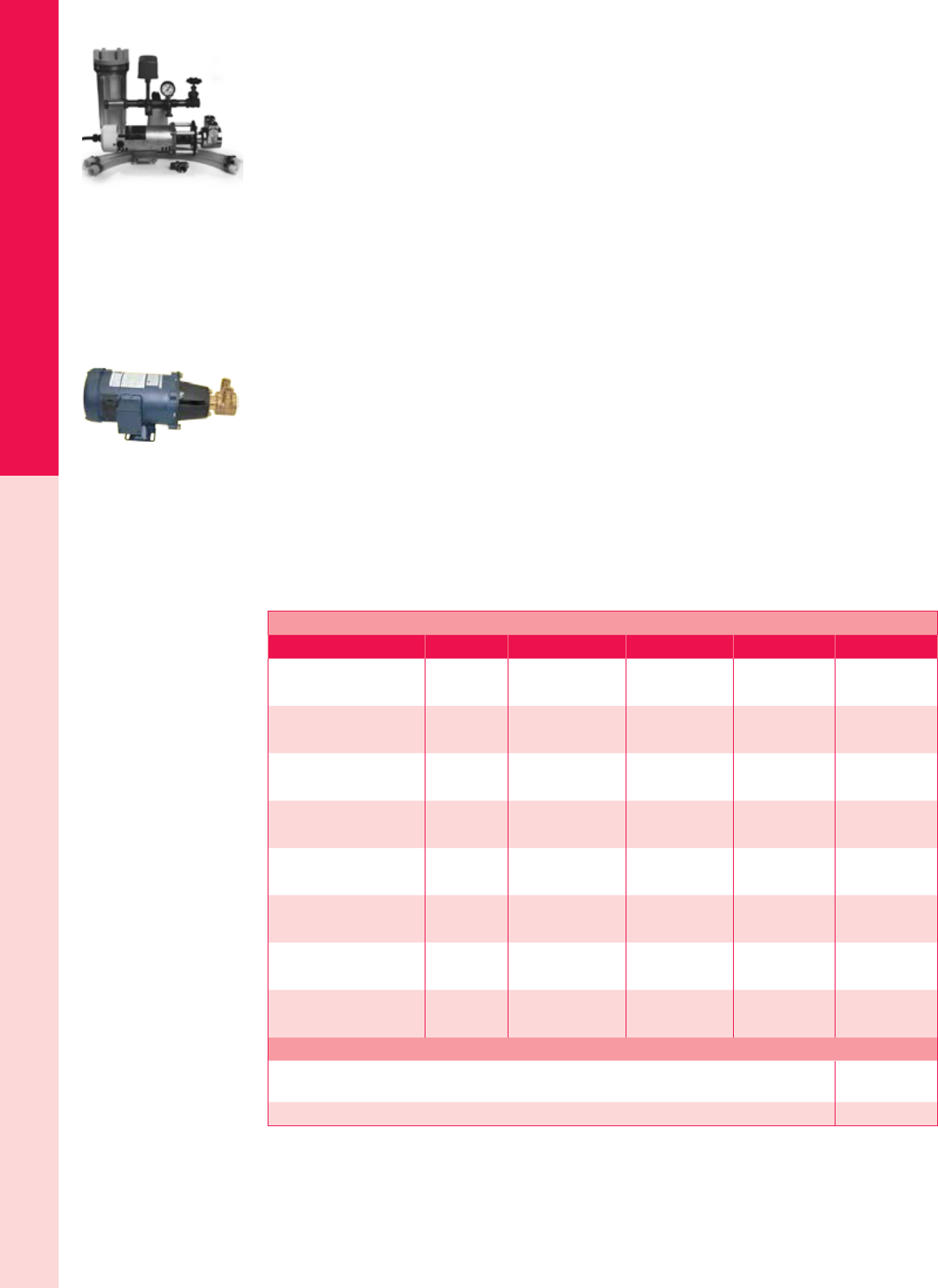
For the latest on AEE Solar products, trainings and dealer services, visit www.aeesolar.com
WATER PUMPS
229
Surface Pumps
Dankoff Flowlight® Booster Pumps
The Flowlight® Booster Pumps provide “town pressure” for off-grid home water supplies. They have
longer life, greater ow rates, and quieter operation than diaphragm pumps, and use about half the energy
consumed by an AC jet-pump running on an inverter.
The Flowlight® needs to have clean water to prevent damage to the pump head, and can also be damaged
by running dry. The optional lter and Dry-Run Switch are highly recommended. To make installation
easier, exible hose connectors with 3/4” threaded adaptors are included.
A pressure tank with a minimum size of 40 gallons, available at most local plumbing supply stores, is
required for all Flowlight® installations. The larger the tank size, the more water is stored under pressure,
allowing the pump to come on less often and run for a longer period each time. This reduces wear on the
pump. Wearing parts are replaceable and typically last ve to ten years. Overall life expectancy is 15-20
years. Pumps can be mounted horizontally or vertically.
The Standard model has the highest water ow and should be used where suction lift is less than 10’.
The Standard is available with 12, 24 or 48 VDC motors for battery operation, or with a 120 VAC PM
motor (300 W or larger inverter required).
The Low-Flow model has a higher pressure capacity and should be used where suction lift is over 10’
or where the suction pipe is smaller than 1” inside diameter. Maximum suction lift at sea level is 20’.
Deduct 1’ for each 1,000’ above sea level. The Low-Flow models are available with 12, 24, or 48 VDC
motors for battery operation.
Both models are NSF approved for potable water. Flowlight® Booster pumps can also be used to pump
saltwater. These pumps are 5.7”W x 16.5”L, Weigh 15 lbs. and are covered by a one-year warranty.
The E-Z Installation Kit includes an accessory tee, adjustable pressure switch, pressure gauge, check
valve, drain valve, shutoff valve, and exible pipe nipples. All components are copper or brass. Order
lter housing and lter cartridges (30” or 10”) separately (see listings under “SlowPump™ Accessories”).
The Dry-Run Switch provides automatic shut-off in case the pump runs dry, preventing costly damage
to the pump head.
Dankoff Flowlight® Booster Pumps and Accessories
Model Voltage Max ow Pressure Current draw Item code
Standard 12 VDC
2920-12 12 VDC 4.5 gpm 30 psi 13.0 A 075-04125
50 psi 16.0 A
Standard 24 VDC
2920-24 24 VDC 4.5 gpm 30 psi 6.5 A 075-04127
50 psi 8.0 A
Standard 48 VDC
2920-48 48 VDC 4.5 gpm 30 psi 3.25 A 075-04129
50 psi 4.0 A
Standard 48 VDC 1/2 HP
2930-48 48 VDC 5.5 gpm 30 psi 3.75 A 075-04130
50 psi 4.0 A
Standard 120 VAC
2920-115 120 VAC 4.5 gpm 30 psi 1.7 A 075-04131
50 psi 2.1 A
Low Flow 12 VDC
2910-12 12 VDC 3.4 gpm 30 psi 10.0 A 075-04121
50 psi 12.0 A
Low Flow 24 VDC
2910-24 24 VDC 3.4 gpm 30 psi 5.0 A 075-04123
50 psi 6.0 A
Low Flow 48 VDC
2910-48 48 VDC 3.4 gpm 30 psi 2.5 A 075-04124
50 psi 3.0 A
Accessories for Booster Pumps
E-Z installation kit - includes an accessory tee, adjustable pressure switch, pressure gauge, check
valve, drain valve, shutoff valve, and pipe nipples – EZ2900 075-04205
Dry-Run Switch for Booster pumps 075-04215
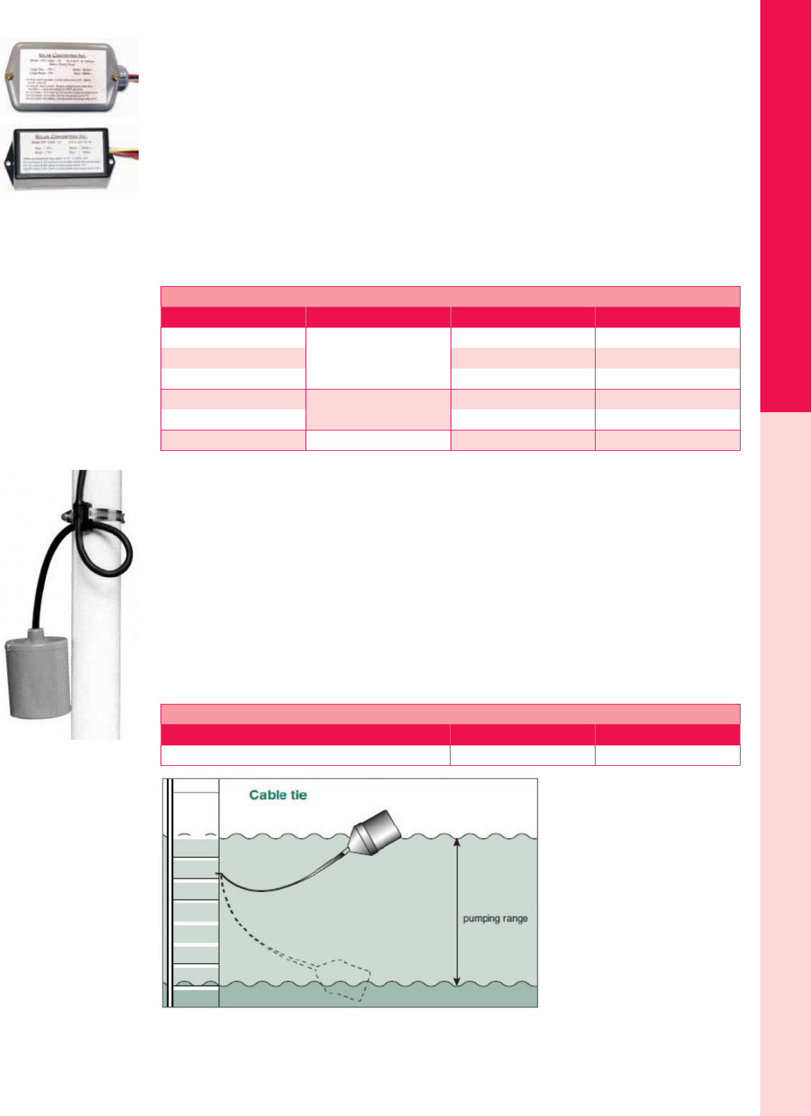
For the latest on AEE Solar products, trainings and dealer services, visit www.aeesolar.com
WATER PUMPS
230
Pump Accessories
Water Pumping Accessories
Linear Current Boosters for DC Pumps
Linear current boosters from Solar Converters Inc. are used in solar-direct pumping applications. They
can achieve a 30-90% increase in water pumped compared to connecting the pump directly to the solar
modules. The pump motor will last longer as well because the LCB will keep the motor from stalling in
low-light conditions. These LCB’s are covered by a one-year warranty.
90 and 120 VDC LCB units that can operate 12, 24, 36 and 48 VDC pumps from several modules in
series are available by special order. These can be useful when the array must be a long distance from the
motor as they allow smaller-gauge wire since the current is reduced. The wire savings alone can offset
the cost of the controller. Call AEE Solar for details.
All units have terminals for connection of a oat or pressure switch. Use a “reverse-action” switch to
turn the pump off when the storage tank is full.
Solar Converters Inc. Linear Current Boosters
Model DC array voltage (nominal) Max DC current Item code
PPT 12/24-7
12 or 24 VDC
7 A 075-00124
PPT 12/24-10 10 A 075-00125
PPT 12/24-30 30 A 075-00128
PPT 48-10 48 VDC 10 A 075-00136
PPT 48-20 20 A 075-00137
PPT 90-12 90 VDC 12 A 075-00141
Float Switch
SPDT Float Switch
This SPDT oat switch can be used to turn a pump on and off in tank-lling or tank-emptying operation,
depending on which two of the three wires are connected.
Contacts located in the oat will switch at 12° above and below horizontal. Use a pipe clamp or cable
tie to secure the cable to a pipe or weight in tank. The length of cable from clamp to oat determines the
difference between turn-on level and turn-off level.
Maximum amp rating is 5 A. For larger pumps, use the oat switch to turn a relay on and off and let
relay contacts control the pump. This switch can also be used with LCBs and other pump controllers
that have oat switch contacts.
These mercury-free switches are safe for domestic water systems and are covered by a two-year warranty.
SPDT Float Switch
Description Maximum amps Item code
Single-pole double-throw (SPDT) oat switch 5 A 075-05270
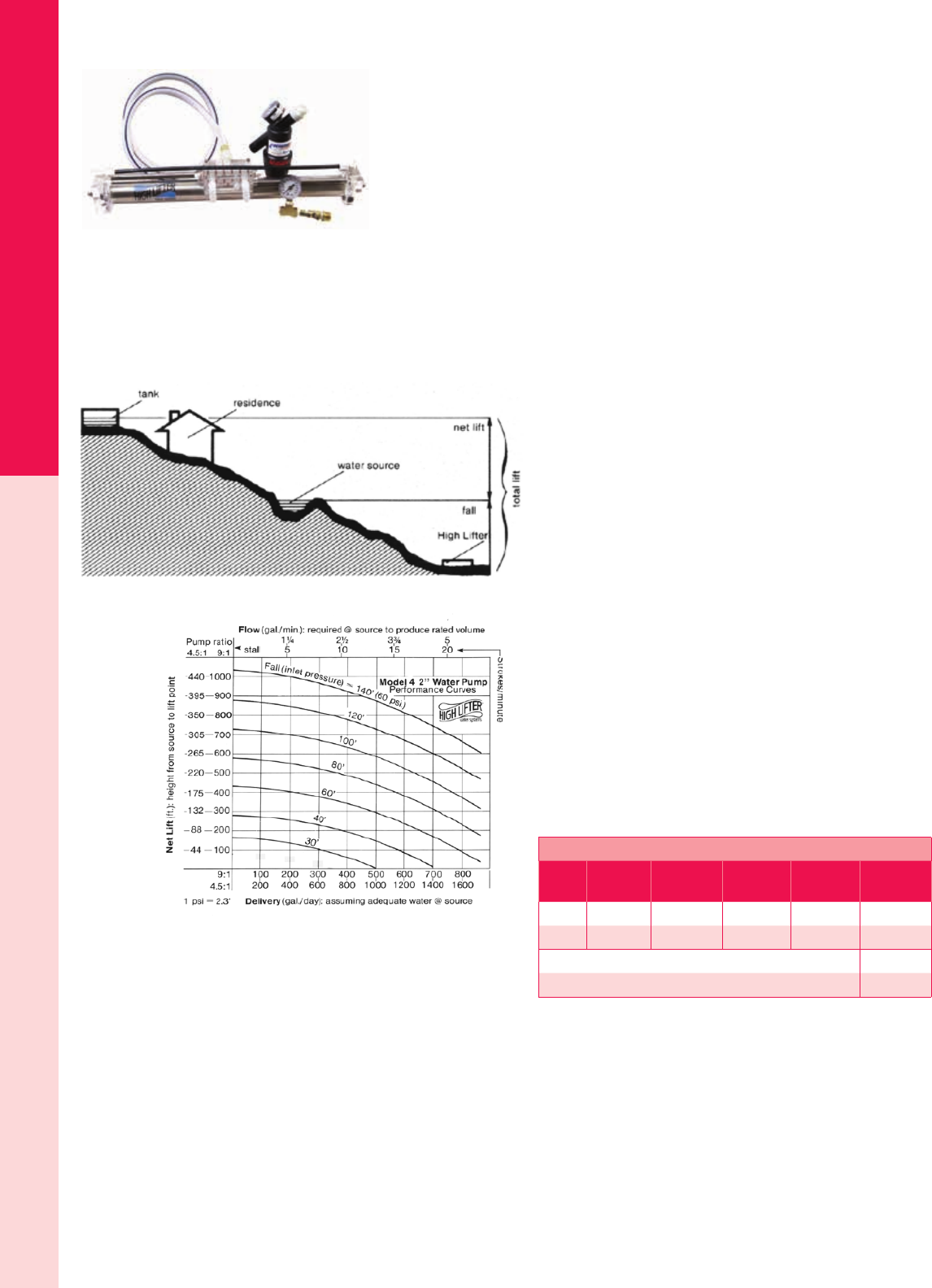
For the latest on AEE Solar products, trainings and dealer services, visit www.aeesolar.com
WATER PUMPS
231
Water-Powered Pumps
High Lifter Water-Powered Pumps
The High Lifter Water-Powered Pump is designed to move water uphill without
using gasoline or electricity. Positioned below the water source (see gure, below),
the High Lifter uses gravity-induced pressure to lift water up to nine times the head
(See performance chart, below). With adequate water and pressure, it can pump up
to 1,500 gallons of water per day as high as 300’, or it can pump 200 gallons per
day as high as 1,000’. It can also pump smaller amounts on as little as one quart per
minute of source water, and can pump to lower elevations with as little as a 30’ drop
from the water source.
It is self-starting and requires no lubrication, priming, or tuning, and is quiet compared to gas engine
pumps. Due to its light weight, ease of installation, and lack of fuel requirements, it is ideally suited for
hilly or remote terrain. Simply run a pipe downhill to your High Lifter from a pond, stream, or spring,
lay out a pipe to your high tank, and start pumping. Designed to be installed and maintained by the user
with basic hand tools, the High Lifter requires little attention, other than lter cleaning, for years of service.
Depending on how clean the water source is, a High Lifter can operate continuously for up to three years
between piston replacements; longer if the inlet water is processed through a settling tank to remove grit.
The High Lifter can be used for domestic water pumping,
irrigation, range cattle and similar applications. All High Lifter
parts are made from stainless steel, Teon and polyethylene.
As illustrated in the chart, the High Lifter responds to both
inlet and output pressure. Increasing the elevation between
the pump and the water source will increase pressure and/or
ow rate. Conversely, if the outlet is too high relative to the
water source, the pump may stall. Stalling will not damage the
pump, but no water will be delivered. To determine how much
water will be pumped, nd the net lift for either the 4.5:1 or 9:1
pump on the left side of the performance chart. Move across
the graph horizontally to the right until you cross the curve
for the fall (inlet pressure). From the point where lift and fall
cross, move vertically down to the bottom of the graph and read
the “Delivery (gal/day)” for the type of pump being used. To
get this delivery amount, the input ow to the pump must be
equal to or greater than the “Flow (gal/min)” at the top of the
graph in line with the point where the lift and fall lines cross.
If the input ow is less than this number, the output will be
correspondingly lower.
Both models of the High Lifter pump are 26” long. One-year
warranty on materials and workmanship.
High Lifter Water-Powered Pumps
Model Pump
ratio
Max
output/day
Max
net lift
Max
total lift Item code
H44 4.5:1 1,500 gal 440 ft 580 ft 076-09002
H49 9:1 750 gal 1,000 ft 1,140 ft 076-09005
Rebuild kit for H44 High Lifter - 4.5:1 076-01118
Rebuild kit for H49 High Lifter - 9:1 076-01124
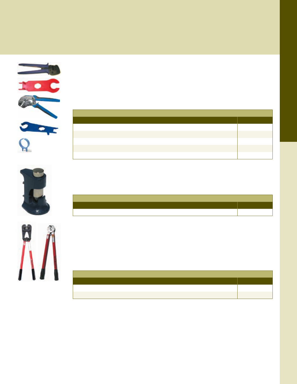
For the latest on AEE Solar products, trainings and dealer services, visit www.aeesolar.com
TOOLS
232
Array and Battery Cable Tools
PV Cable Assembly Tools
Crimp-on PV cable connectors (See Wire and Cable section) require special tools to properly attach the connectors. Single-purpose
tools from Multi-Contact or Amphenol work with only that type of connector and are often the best option for installers who work
only with modules that have that same connector type. For those who encounter several different types of connectors, one of the
Rennsteig tool sets that have a set of dies and positioners can be more convenient and economical than carrying a different tool for
each connector type.
MC4 and Helios Crimp Tools
The Multi-Contact MC4 crimping tool is used to assemble MC4 (Solarline 2) locking connectors with10
or 12 AWG stranded wire. A set of two plastic wrenches is used to tighten the sealing nut in the connec-
tor and to unlock the male and female connector. The Amphenol Helios H4 Crimp Tool, Wrench, and
Assembly/Disconnect Tool are used with the Helios H4 connectors, and are similar to the MC4 tools.
The Amphenol Helios H4 Ring Tool can be worn on a nger and used to unlock the H4 male and female
connectors.
Multi-Contact MC4 & Amphenol H4 Tools
Description Item code
MC Solarline 2 MC4 pin crimper for 10/12 AWG wire 094-00104
MC Solarline 2 MC4 open-end spanner set (2-pack) 094-00112
Amphenol Helios H4 Crimp Tool, 2.5mm – 6mm 094-00007
Amphenol Helios H4 Wrench and Disconnect Tool 094-00008
Amphenol Helios H4 Ring Tool 094-00010
Hammer Crimp Tool
This simple, inexpensive crimping tool can be used to crimp ring-terminal lugs and other connectors
onto 8 through 4/0 AWG wire. Spring-loaded pin locks in “up” position for loading connector and cable.
When released, the pin holds the connector securely during crimping. Use with a hammer or vice.
Hammer Crimp Tool
Description Item code
Hammer crimp tool 094-00013
Battery Cable Tools
Use the cable crimper to crimp battery terminals, copper lugs, and splices on wire from 8 to 4/0 AWG.
Adjustable crimp dies are clearly marked and easy to rotate into position. This UL-listed, 26" tool gives
you plenty of leverage for secure crimping.
Use the 22" long cutter to cut inverter cables and battery interconnects up to 6/0 AWG. Available in a
bench-mount version as well as hand-held, the high-carbon steel blades are removable for sharpening or
replacement. All of these tools are made in the U.S.A.
Battery Cable Tools
Description Item code
Cable cutter with 22" handles 094-00004
Cable crimper with 26" handles 094-00011
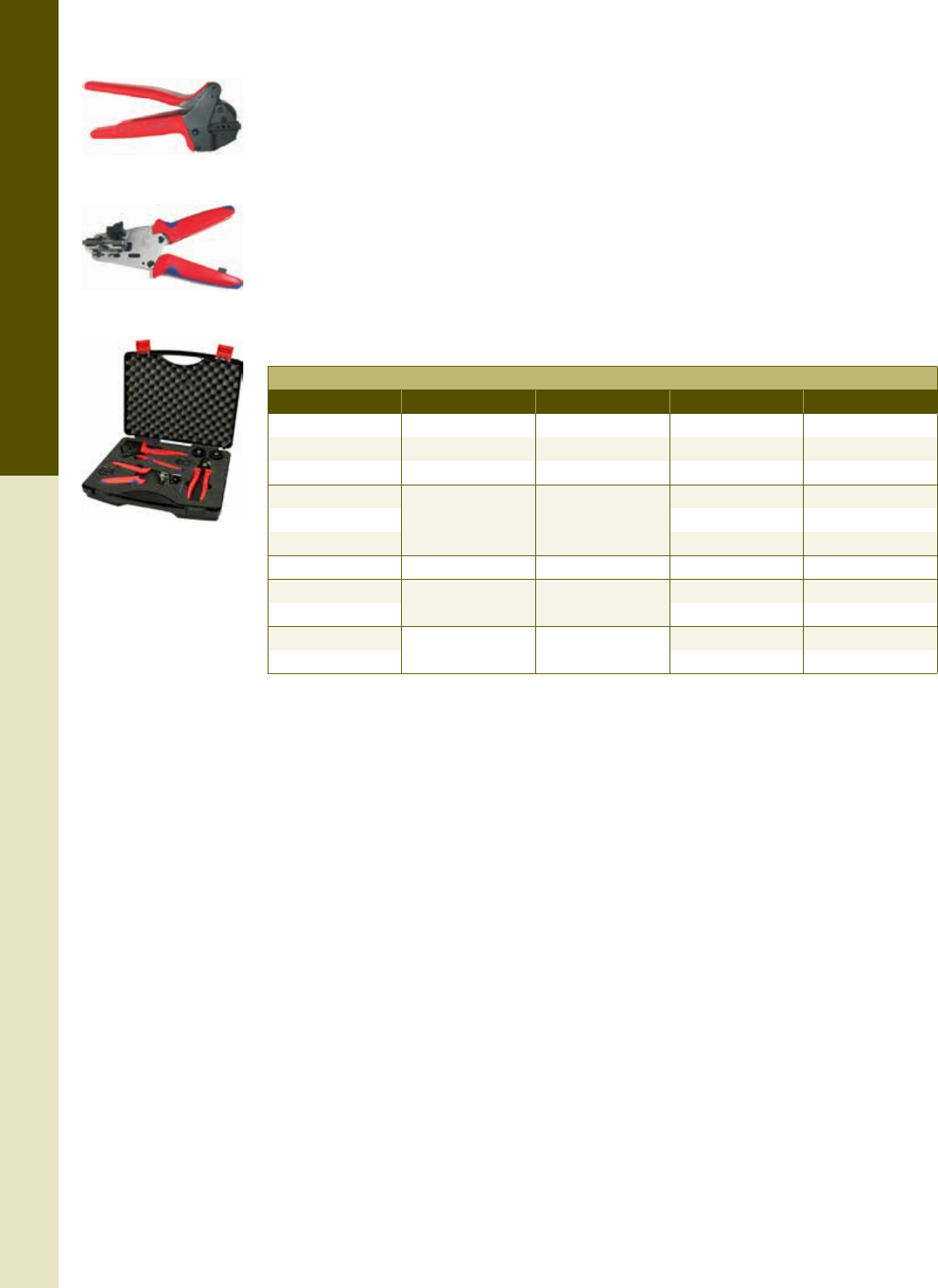
For the latest on AEE Solar products, trainings and dealer services, visit www.aeesolar.com
TOOLS
233
Array and Battery Cable Tools
Rennsteig
Crimping Tool Sets and Accessories
These Rennsteig tool sets are helpful for installers who wish to make their own extensions and con-
nections. The tools presented here cover the most popular connectors, including those using MC4 or
Amphenol H4 connectors. Tools for crimping other connector types are available upon request. All of
these tools are made in Germany.
The Tyco/MC4/H4 Solarkit comes with three die-sets and three pin locators for crimping Tyco Solar-
Lok, Solar-Line 2 (MC4), or Amphenol Helios (H4) pins as well as a cutter and stripper tool, all in a
hard-shell case.
The Solar Crimp Tools include the preassembled tool frame, die, and pin locator, but no case. Additional
dies and pin locators can be added to expand the tool. The Insulation Stripper strips and removes the
insulation in a single motion. The blades are replaceable. The Wire Cutter features a specially curved
set of shears that cuts stranded wire without signicant deformation. The Empty Tool Frame can be
used with separately-purchased crimping Dies and Pin Locators, which are interchangeable.
Rennsteig Kits, Sets and Crimping Tools
Description Connector type Wire size Model Item code
Solarkit Tyco, MC4, H4 Varies by connector 624 105-H4M4TE 094-00148
Solar Crimp Tool MC4 Solarline 2 12/10/8 AWG 624 1193 3 1 094-00144
Solar Crimp Tool Amphenol H4 14/12/10/8 AWG 624 1194 3 1 094-00135
Insulation Stripper
NA 16/14/12/10 AWG
707-226-1-6US 094-00128
Replacement Blades 708 226 1 3 0 094-00138
Wire Cutter 700-016-36 094-00129
Empty tool frame (Use with pins & dies) NA 624 000 3 094-00146
Die only MC4 Solarline 2 12/10/8 AWG 624 570 3 0 094-00126
Pin Locator only 624 194 0 01 094-00132
Die only Amphenol H4 14/12/10/8 AWG 624 1194 3 0 094-00130
Pin Locator only 624 1194 0 01 094-00131
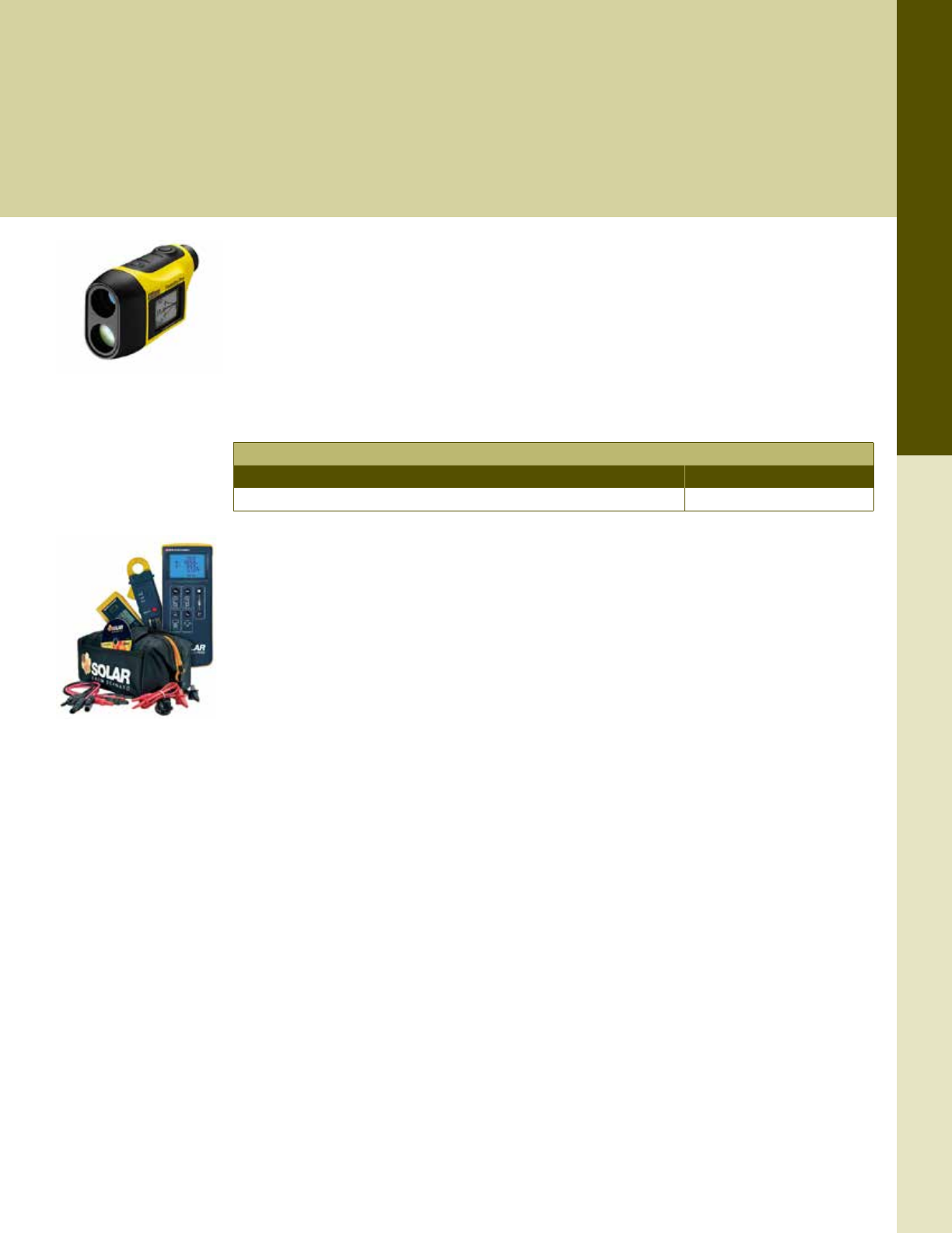
For the latest on AEE Solar products, trainings and dealer services, visit www.aeesolar.com
TOOLS
234
System Commissioning Tools
System Survey and Commissioning Tools
Commissioning a PV system is an important nal step in the installation process, and it’s worth doing properly and consistently.
Commissioning standards, such as IEC 62446 and related NABCEP guidelines, provide visual and physical inspections as well as
electrical tests that should be performed prior to activating a new PV system. Common electrical tests made during commissioning
include: continuity, phasing, and voltage for AC circuits; continuity of grounding conductors; DC circuit polarity verication; string
I-V curves; string open-circuit voltage; string short circuit current; insulation resistance testing of PV source and output circuits; and,
nally, a full-up system functionality test. With proper documentation, these same tests can be repeated periodically as systems age
to ensure that they are operating efciently.
Nikon
Forestry Pro Laser Rangender
The Nikon Forestry Pro Laser Rangender can be used during eld survey work to determine distance,
height, and angle measurements that are useful for rening aerial-imagery-based estimates. This tool is
equipped with three-point measurement in addition to the conventional vertical separation. Three-point
measurement provides the difference in height between two targets by measuring horizontal distance
to a target then angles to the target base and the top. It is very useful when the laser beam is blocked by
the bushes or branches that cover the base or top of a tree. Results are displayed on internal and external
LCD panels. The high-quality 6x monocle with multilayer coating produces clear, bright images.
Solar Site Survey Tools
Description Item code
Nikon Forestry Pro Laser Rangender 094-000240
Seaward Solar
Solar Installation Test Kit
The PV150 Solar Link Kit includes everything needed to test to the IEC 62446 system commissioning
standard as well as the latest NABCEP recommendations. The all-in-one PV installation tester, using
simple direct connections to PV systems, performs open circuit voltage, short circuit current, and insula-
tion resistance tests with a single button press. It can also be used to perform operating current (using
the supplied current clamp) and Earth continuity measurements as well as determine voltage polarity.
The connectors feature non-accessible conductive parts for safe use with PV systems that may be ener-
gized. The PV150 can also wirelessly receive and record irradiance and temperature measurements from
the Solar Survey 200R in real-time as electrical tests are conducted.
The PV150 solar PV tester has memory to store up to 200 complete test records, and USB connectiv-
ity enables these to be downloaded to a PC. Seaward’s SolarCert Elements software program (supplied
separately) can then be used to automate generation of test certicates and documentation.
The PV150 Test Kit includes: a PV150 solar installation tester, AC/DC current clamp, carry bag, MC4
test lead adaptors, red and black test leads, test probe with detachable alligator clips, Quick Start Guide,
support-software CD, and calibration certicate.
Solar Survey Multifunction Solar-Irradiance Meters
These handheld solar-irradiance meters include a built-in inclinometer to measure roof pitch, compass to
measure roof orientation, and thermometer to measure ambient air and module temperature. These meters
display irradiance measurements in either W/m2 or BTU/hr-ft2, so they work for both solar photovoltaic
(PV) and solar thermal applications.
The use of a photovoltaic reference cell provides a more representative measurement of solar energy and
greater accuracy and repeatability compared to irradiance meters that use simple photo-diode detectors.
The Solar Survey 100 and 200R irradiance meters both incorporate a display-hold feature, which enables
the user to easily capture readings in difcult locations.
The 200R can wirelessly give the PV150 Solar Installation Test Kit real-time irradiance, ambient tem-
perature, and PV module-temperature measurement results simultaneous to electrical tests, as required
by MCS and IEC 62446 standards. The PV150 can then download the data into the SolarCert Elements
software program. The 200R model also includes data logging with a USB interface for data download

For the latest on AEE Solar products, trainings and dealer services, visit www.aeesolar.com
TOOLS
235
System Commissioning Tools
to a PC. This allows for irradiance and temperature to be recorded at user-dened intervals over a num-
ber of hours or days. The collected data can then be downloaded to a PC for analysis or for inclusion in
solar installation reports.
Solar Power Clamp
Seaward’s Solar Power Clamp is a specialized power meter that clamps over the cable to measure the AC
or DC current. If a PV system isn’t generating the expected level of power under known irradiance and
temperature conditions, this may indicate a fault with one or more components in the system. In addition
to power and efciency measurements, the harmonic analysis function of the Solar Power Clamp can be
used as a means of detecting faults within the inverter.
Solar Power Clamp functions include: DC power measurement, AC and AC+DC true continuous power
(RMS) reading, power factor, total harmonic distortion and harmonics 1 – 25, phase-rotation indication,
current and voltage measurement, smart data hold and peak hold, and non-contact voltage indicator.
SolarCert Elements Solar PV Software
The Seaward SolarCert Elements Solar PV Software enables solar PV system installers to produce custom-
ized client-facing test reports and certicates using user input or data downloaded from the PV150 tester.
The software allows PV installers to create customized test certication and inspection reports and
installation layout diagrams that can be stored alongside photographs and other information relevant to
PV installations, such as datasheets or operating manuals. A checklist feature helps ensure that all of the
necessary information is included. Company logos and signatures can be added to the templates for a
branded professional image. Once compiled, the complete data package can quickly be searched within
the solar PV software and emailed or printed for delivery to the client.
Seward Solar Commissioning Tools
Description Item code
PV150 Solar Link Kit (Includes PV150, AC/DC current clamp, SolarLink Connectivity, SolarCert Elements Software, and Accessories) 094-00279
PV150 Installation Tester 094-00282
Solar Survey 100 irradiance meter 094-00290
Solar Survey 200R irradiance meter with SolarLink wireless data transfer 094-00291
AC/DC Solar Power Clamp power analyzer 094-00292
SolarCert Elements software 094-00289
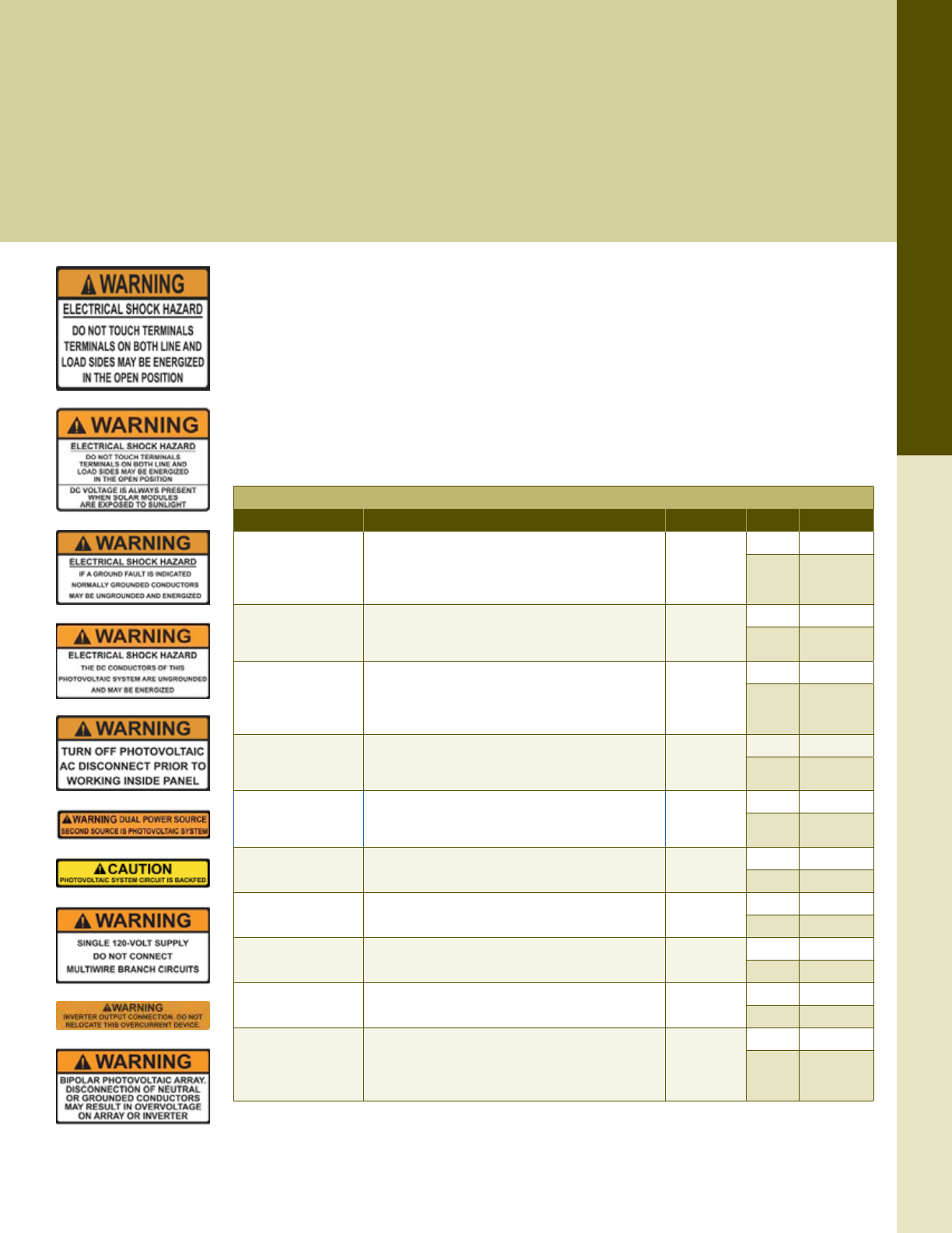
For the latest on AEE Solar products, trainings and dealer services, visit www.aeesolar.com
TOOLS
236
Safety Labels
Solar Safety Labels
The NEC and International Fire Code (IFC) require specic components of a PV system to be labeled for the safety of operators,
maintenance, and emergency-responder personnel. The Code also requires these labels to be appropriately weather resistant (IFC
605.11.1.1.3) and durable (NEC 110.21). These labels are UV and weather resistant and should meet Code requirements in most
jurisdictions. Note that some jurisdictions may still require engraved placards. The labels are designed to permanently adhere to
metallic, baked enamel, or powder-coated surfaces in most outdoor environments.
Local jurisdictions and company policies often call for unique language or types of labels that are not available in preprinted form. If
this is a frequent requirement, a label printing system can be an economical way to get exactly what you need when you need it. The
ability to produce custom labels also presents opportunities for branding as well as organization, theft prevention, and identication.
HellermannTyton
Preprinted Safety Labels
The language and letter height on these Standard Labels is designed to meet NEC 110, NEC 690 and IFC
605 requirements and have been updated for NEC 2014 compliance. Reective Labels are available for
disconnect and conduit markers as required by the Code. The Fill-In-The-Blank Labels have white blanks
that can be lled in with system parameters ahead of time using a 4" or larger thermal transfer printer,
such as the TT230SMC. They can also be lled out in the eld using a permanent marker so long as the
transparent laminate is then placed over them. The labels will remain adhered in temperatures down to
-40 °C and as high as 175 °F [79 °C] but must be applied when temperatures are above 50 °F [10 °C].
UL 969 Recognized.
Standard Labels
Placement1Label text Dimensions Pkg qty Item code
Combiners,
Enclosures,
AC Disconnect
“WARNING ELECTRICAL SHOCK HAZARD DO NOT
TOUCH TERMINALS. TERMINALS ON BOTH LINE
AND LOAD SIDES MAY BE ENERGIZED IN THE
OPEN POSITION”
3.75" x 2"
10 188-09043
50 188-09029
DC Disconnect
Includes label above and appends “DC VOLTAGE IS
ALWAYS PRESENT WHEN SOLAR MODULES ARE
EXPOSED TO SUNLIGHT”
3.75" x 2.5"
10 188-09042
50 188-09028
Meter,
Breaker panel,
Inverter
“WARNING ELECTRICAL SHOCK HAZARD IF A
GROUND FAULT IS INDICATED, NORMALLY
GROUNDED CONDUCTORS MAY BE
UNGROUNDED AND ENERGIZED”
4.12" x 2"
10 188-09044
50 188-09030
Combiners,
Enclosures,
Breaker panel
“WARNING ELECTRIC SHOCK HAZARD THE DC
CONDUCTORS OF THIS PHOTOVOLTAIC SYSTEM
ARE UNGROUNDED AND MAY BE ENERGIZED”
4.12" x 2"
10 188-09047
50 188-09031
Combiners,
Breaker panels,
Service disconnect
“WARNING TURN OFF PHOTOVOLTAIC AC
DISCONNECT PRIOR TO WORKING INSIDE PANEL” 4.12" x 2"
10 188-09045
50 188-09032
Breaker panel “WARNING DUAL POWER SOURCE SECOND
SOURCE IS PV SYSTEM" 4.12" x .75" 10 188-09041
50 188-09027
Breaker panel “CAUTION PV SYSTEM CIRCUIT IS BACKFED" 4.12" x .75" 10 188-09046
50 188-09033
Breaker panel “WARNING - 120-VOLT SUPPLY DO NOT CONNECT
MULTIWIRE BRANCH CIRCUITS” 3.75" x 2" 10 188-09050
50 188-09034
Breaker panel “WARNING - INVERTER OUTPUT CONNECTION. DO
NOT RELOCATE THIS OVERCURRENT DEVICE” 4.12" x .75" 10 188-09048
50 188-09036
Combiners,
Enclosures, Breaker
panel
"WARNING - BIPOLAR PV ARRAY DISCONNECTION
OF NEUTRAL OR GROUNDED CONDUCTORS MAY
RESULT IN OVERVOLTAGE ON ARRAY OR
INVERTER”
3.75" x 2"
10 188-09049
50 188-09035
1 Placement suggestions are the most common applications for the given label; it is, by no means, an exhaustive list of where
the label may be required.
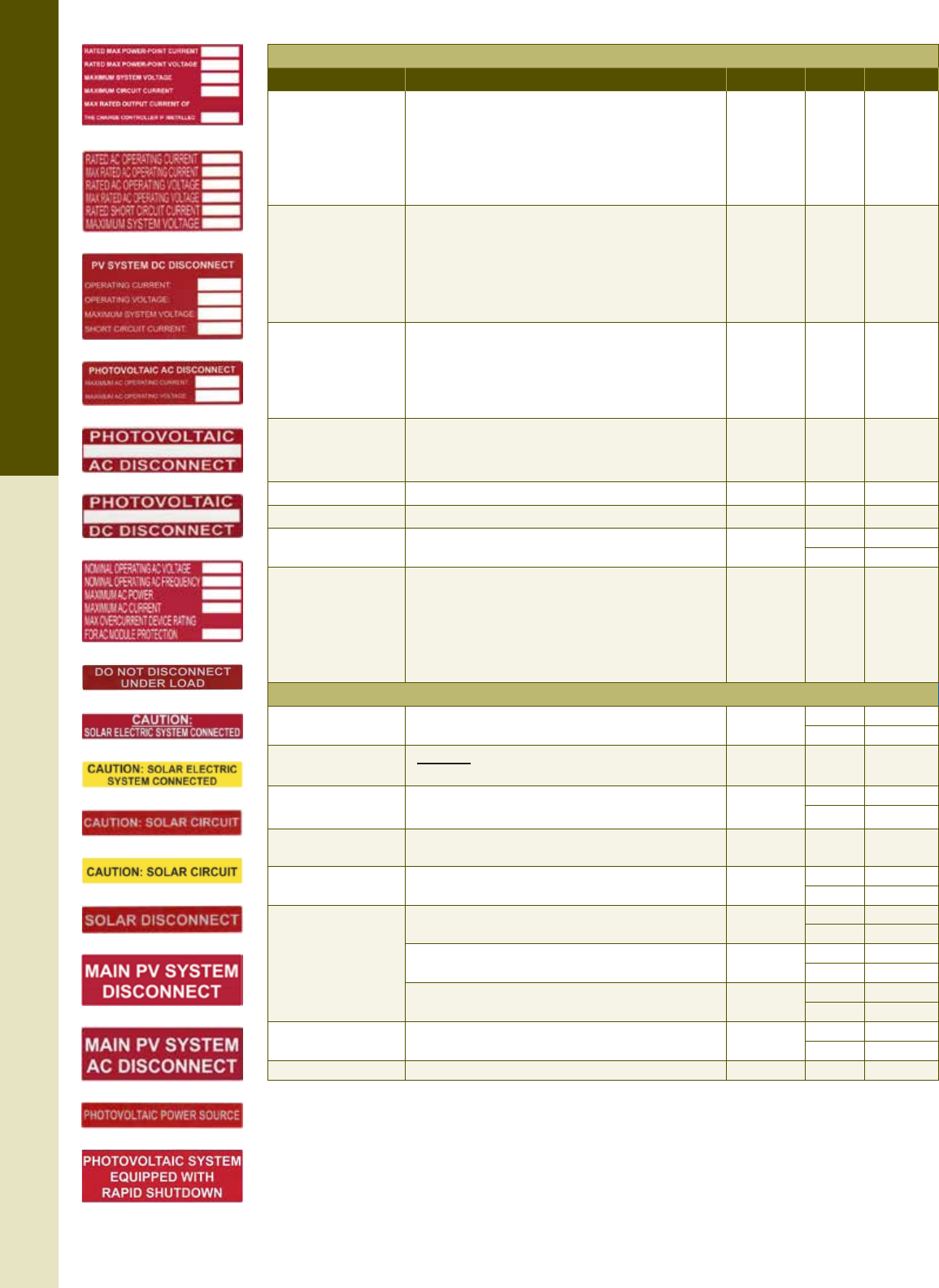
For the latest on AEE Solar products, trainings and dealer services, visit www.aeesolar.com
TOOLS
237
Safety Labels
Fill-In-The-Blank Labels
Placement1Label text Dimensions Pkg qty Item code
DC module rating
"RATED MAX POWER POINT CURRENT __________
RATED MAX POWER POINT VOLTAGE __________
MAXIMUM SYSTEM VOLTAGE __________
SHORT CIRCUIT CURRENT __________
MAX RATED OUTPUT CURRENT OF THE CHARGE
CONTROLLER IF INSTALLED __________"
4" x 2" 50 188-09014
DC backup
system rating
“RATED AC OPERATING CURRENT __________
MAX RATED AC OPERATING CURRENT __________
RATED AC OPERATING VOLTAGE __________
MAX RATED AC OPERATING VOLTAGE __________
RATED SHORT CIRCUIT CURRENT __________
MAXIMUM SYSTEM VOLTAGE __________”
4" x 2" 50 188-09015
System DC
disconnect
"PV SYSTEM DC DISCONNECT
OPERATING CURRENT __________
OPERATING VOLTAGE __________
MAXIMUM SYSTEM VOLTAGE __________
SHORT CIRCUIT CURRENT __________"
3.75" x 2" 50 188-09016
System AC
disconnect
"PHOTOVOLTAIC AC DISCONNECT
MAXIMUM AC OPERATING CURRENT __________
MAXIMUM AC OPERATING VOLTAGE __________"
3.75" x 1" 50 188-09017
AC disconnect "PHOTOVOLTAIC ____ AC DISCONNECT" 3.75" x 1" 50 188-09018
DC disconnect "PHOTOVOLTAIC ____ DC DISCONNECT" 3.75" x 1" 50 188-09019
Over lamination for
eld-written labels "CLEAR ADHESIVE LAMINATE" 4.2" x 2.25" 10 188-09059
50 188-09020
System label for
AC modules and
microinverter
systems
"NOMINAL OPERATING VOLTAGE __________
NOMINAL OPERATING AC FREQUENCT __________
MAXIMUM AC POWER __________
MAXIMUM AC CURRENT __________
MAX OVERCURRENT DEVICE RATING FOR AC
MODULE PROTECTION __________"
4" x 2" 50 188-09021
Reective Labels
Breaker panel “DO NOT DISCONNECT UNDER LOAD” 6.5" x 1" 10 188-09052
50 188-09007
Service disconnect “CAUTION: SOLAR ELECTRIC SYSTEM CONNECTED"
(White on Red background) 6.5" x 1" 50 188-09008
Service disconnect "CAUTION: SOLAR ELECTRIC SYSTEM CONNECTED"
(Black on Yellow background) 5.5" x 1” 10 188-09057
50 188-09037
Combiners,
Enclosures, Conduit
“CAUTION: SOLAR CIRCUIT"
(White on Red background) 6.5" x 1" 10 188-09009
Combiners,
Enclosures, Conduit
"CAUTION: SOLAR CIRCUIT"
(Black on Yellow background) 6.5" x 1" 10 188-09058
50 188-09038
Service disconnect
“SOLAR DISCONNECT” 6.5" x 1" 10 188-09053
50 188-09010
“MAIN PV SYSTEM DISCONNECT” 5.5" x 1.75" 10 188-09051
50 188-09011
“MAIN PV SYSTEM AC DISCONNECT” 5.5" x 1.75" 10 188-09055
50 188-09012
Combiners,
Enclosures, Conduit “PHOTOVOLTAIC POWER SOURCE” 6.5" x 1" 10 188-09054
50 188-09013
Service disconnect "PV SYSTEM EQUIPPED WITH RAPID SHUTDOWN" 5.5” x 1.75” 10 188-09056
1 Placement suggestions are the most common applications for the given label; it is, by no means, an exhaustive list of where
the label may be required.
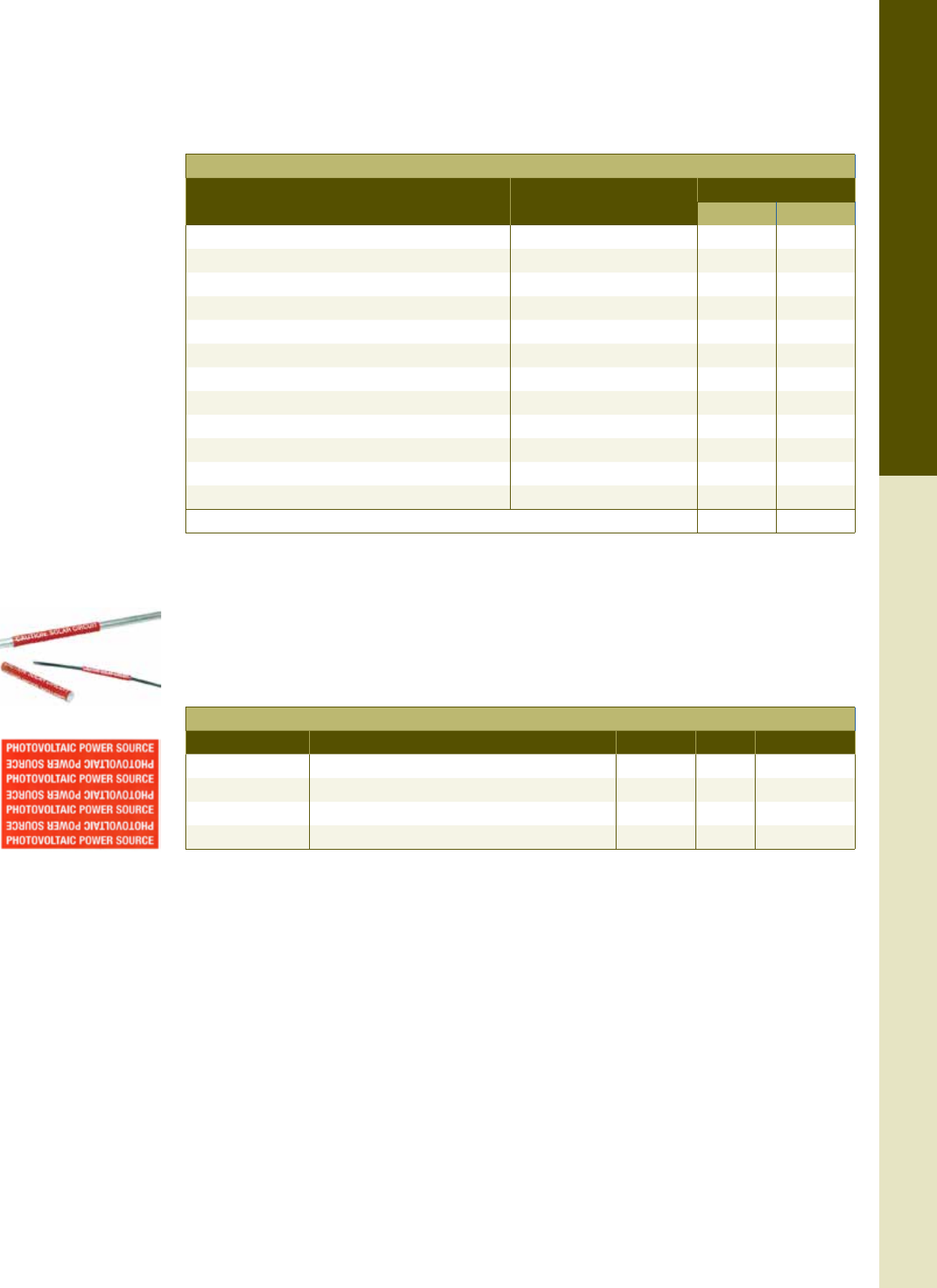
For the latest on AEE Solar products, trainings and dealer services, visit www.aeesolar.com
TOOLS
238
Safety Labels
Label Kits
For convenience, pre-cut Safety Label Kits are available in two sizes. The small kit is suitable for most
systems under 7 kW while the large kit is suitable for most systems between 7 and 15 kW. The label
188-09031 is included and used when installing non-isolated (transformerless) inverters or systems
with all ungrounded DC conductors.
Safety Label Kits
Placement1Labels included Label quantity
Small kit Large kit
AC disconnecting means-switch or circuit breaker 188-09029 2 2
DC combiner, DC disconnect, any wire-splice JBOX 188-09028 3 6
Inverter 188-09030 1 3
DC combiner, DC disconnect, wire-splice JBOX 188-09031 1 3
Interconnection point supplied by a tap connection 188-09027 1 1
Interconnection point 188-09037 1 1
DC disconnect 188-09019 2 3
EMT conduit inside building 188-09013 10 20
DC disconnect and/or Inverter 188-09014 1 3
AC disconnecting means 188-09017 1 1
AC disconnect 188-09018 1 1
Lamination for eld-written labels 188-09020 5 8
Item Code 188-09100 188-09101
1 Placement suggestions are the most common applications for the given label; it is, by no means, an exhaustive list of where
the label may be required.
Solar Circuit Markers
These markers are pre-printed, non-adhesive, coiled labels that can be opened and recoiled around cables
up to 0.25" diameter and conduit up to 1" diameter. The markers are made from UV-stable vinyl and
come in packages of 25.
Non-Adhesive Circuit Markers
Placement1Label text (repeated in alternating directions) Dimensions Pkg qty Item code
PV cables "CAUTION: SOLAR CIRCUIT" 4" x 2" 25 188-09022
Conduit "CAUTION: SOLAR CIRCUIT" 7.2" x 5" 25 188-09023
PV cables "PHOTOVOLTAIC POWER SOURCE" 4" x 2" 25 188-09024
Conduit "PHOTOVOLTAIC POWER SOURCE" 7.2" x 5" 25 188-09025
1 Placement suggestions are the most common applications for the given label; it is, by no means, an exhaustive list of where
the label may be required.
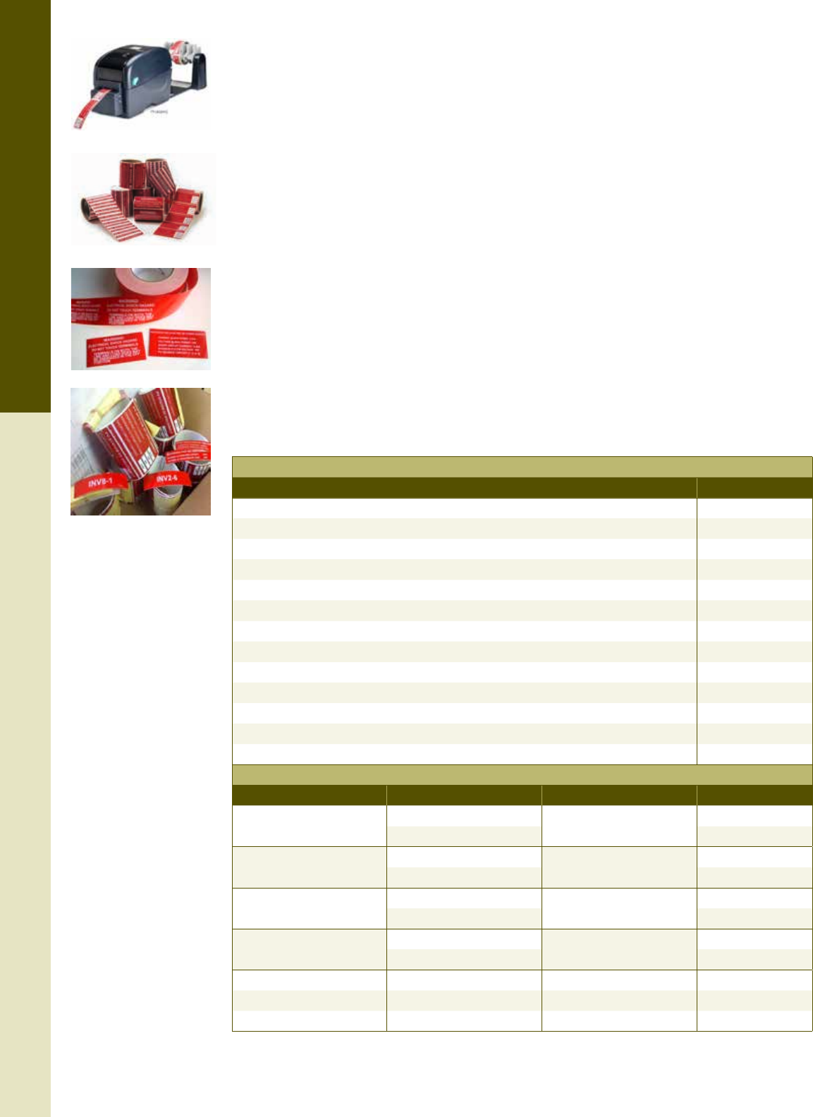
For the latest on AEE Solar products, trainings and dealer services, visit www.aeesolar.com
TOOLS
239
Safety Labels
Thermal-Transfer Printers
The HellermannTyton TT230MC desktop thermal-transfer printer is designed for printing safety and
identication signs and labels up to 4" wide. Use black or white printer ink ribbons to print on blank
continuous vinyl material. This printer also incorporates a cutter that automatically cuts the labels as
they are printed, saving time in the eld. An optional hard-shell case and battery pack are also available
to enable operation on a jobsite.
The TT230MC Starter Kit includes the printer, plus a sturdy hard-shell case, white and black ribbons,
the label caddy, and TagPrint Pro 3.0 label design software.
The portable HellermannTyton TT130MC enables shop or jobsite printing of all current solar and safety
warning labels. Prints on 250’ continuous vinyl rolls of material up to 2” wide using continuous black
or white printer ink ribbon. Values can also be printed on rolls of preprinted labels where site-specic
information such as voltage and current values need to be added. The printer has an Ethernet port, allow-
ing connection to a network or wireless router, and includes a label caddy and integrated label cutter.
The TT130MC Starter Kit includes the printer, a hard case that can accommodate two TT130MC units,
white and black print ink ribbons, the label caddy, and the TagPrint 3.0 label design software.
The TagPrint Pro 3.0 software is required for using the printer with a Windows PC. The software is
preloaded with standard NEC safety-label templates and enables customization of those as well as design
capability. TagPrint Pro can also be set up to print sets of consecutively-numbered labels and similar
batch processes.
Blank self-adhesive 250’ continuous rolls of vinyl are available in white, black, red, and yellow with
widths of 1" or 2" (4" vinyl available by special order). The vinyl material is UV stable and rated for a
minimum of ve years of outdoor use without signicant fading or adhesive degradation.
Thermal Transfer Printers and Accessories
Description Item code
TT230MC printer only 094-09000
White ink ribbon for TT230MC 094-09001
Black ink ribbon for TT230MC 094-09002
TT230MC Starter Kit (includes printer, software, black and white ink ribbons, and case) 094-09033
TagPrint Pro 3.0 software 094-09011
Hard-shell case for TT230MC 094-09012
Battery pack for TT230MC 094-09013
TT130MC printer (includes integrated label cutter and label caddy) 094-09036
White ink ribbon for TT130MC (2”x154’) 188-09060
Black ink ribbon for TT130MC (2”x242’) 188-09061
TT130MC Starter Kit (includes printer, software, black and white ink ribbons, and case) 094-09035
TagPrint Pro 3.0 software 094-09011
Hard-shell case for TT130MC (Case holds up to two printers) 094-09037
Blank Vinyl for Desktop Thermal Transfer Printers
Color Width Roll length Item code
White 1" 250' 094-09003
2" 094-09004
Yellow 1" 250' 094-09005
2" 094-09006
Red 1" 250' 094-09007
2" 094-09008
Black 1" 250' 094-09009
2" 094-09010
White with Orange Header 2” 250’ 188-08997
Orange 1” 250’ 188-08998
Red Reective 1” 250’ 188-08999
The Solar Advantage
Doing it Right the First Time
Saves You Money Every Time
HellermannTyton Delivers Proven Performance and Savings to the Solar Energy Market
SOLAR TIES
• Specially designed and manufactured in
materials suited for solar applications
• Offered in an assortment of sizes, lengths
and tensile strengths
SOLAR E-CLIPS
• Engineered from specially-formulated UV stabilized
materials, these fasteners allow for the exible
routing of PV cable, with or without pre-drilled holes
• Designed for easy placement and removal for faster
installations and reduced labor costs
SOLAR IDENTIFICATION
• Printers, software and labeling options to create
distinguishing identication to meet industry
regulations
• Assorted labeling products for tagging assets,
organizing relays, and identifying circuits and switches
SOLAR WIRE PROTECTION
• A line of durable enclosure products for organizing and
safeguarding wires and cables within combiner boxes,
inverters and control panels
• Lightweight and exible protection offering superior
performance and reduced installation complexity
www.hellermann.tyton.com • 800.537.1512
Through-Hole Fastening Solutions
Edge Fastening Solutions
Nylon 6
Slit Conduit
Nylon 12
Slit Conduit
Nylon 6
Double Slit conduit
Labeling
Software
Thermal Transfer
Printers
Solar Label
Design Mobile
App
Solar Specic
Labels
UV Stabilized
Nylon
UV & Heat Stabilized
Nylon w/High
Impact Resistance
Nylon 12 Stainless Steel

For the latest on AEE Solar products, trainings and dealer services, visit www.aeesolar.com
ELECTRIC VEHICLE CHARGING STATIONS
241
Electric Vehicle Charging Stations
A charging station is a great companion to a grid-tied PV system because it extends the nancial and
environmental savings of solar power to transportation, directly offsetting oil consumption and vehicle
exhaust.
There are three categories of EV charging stations:
Level 1: This is a simple device that plugs into a 120 VAC 20 A outlet. It looks like a conventional
AC outlet but with one blade turned 90°. Typically delivered with the vehicle from the dealer or
manufacturer, Level 1 charging stations are limited to a maximum of 2 kW and take 10 to 20 hours to
fully charge an all-electric car.
Level 2: These charging stations are typically hardwired into a 240 VAC 40 A circuit and range in output
from 6 to 12 kW. Level 2 charging stations can fully charge an electric vehicle in 3 to 8 hours. Installed
on a dedicated circuit, they feed power to the vehicle’s built-in charger through an SAE J1772 plug
that resembles the nozzle of a gas pump. Most residential and commercial charging stations currently
available are Level 2.
Level 3: This is a high-powered charger that delivers 20 kW or more of 300+ VDC power directly to
the EV battery. These chargers require three-phase power and a large commercial service panel. Level 3
CHAdeMO connectors are an option on the Nissan Leaf and other electric vehicles, but Level 3 charging
stations are best suited for commercial vehicle and eet applications due to their size and cost.
Federal and state tax credits may be available to lower the cost of equipment and installation of charging
stations.
Schneider Electric
Schneider Electric offers a suite of electric vehicle charging stations for both residential and commercial
applications. These Level 2 charging stations can charge most EV batteries in three to eight hours via
the standard SAE J1772 compliant output plug, which ts the receptacles of the most popular EVs and
Plug-in Hybrid- Electric Vehicles such as the Nissan Leaf, Chevy Volt, and Toyota’s new plug-in Prius.
The Schneider EVlink™ charging stations also feature a user-friendly interface, integrated ground-fault
protection, and automatic restart following a corrected ground fault or temporary loss of power.
For maximum output, installation will require a 240 VAC source with a 40 A two-pole circuit breaker
capable of a 30 A continuous load per charging unit. Dual chargers require twice the current or two
separate circuits.
EVlink Wall-Mounted Level 2 Charging Stations
These charging stations mount on the wall of a garage or outdoors on the side of a building. Installation
with a standard 240 VAC socket and plug can be used to keep the unit portable, but be sure to check
with your local code inspector as some jurisdictions have additional requirements for these outlets. RFID
access is only available on the outdoor version, which also features a NEM A 3R weatherproof enclosure.
Listed to UL 2594, 2231, 991, 1998, and 2251.
Schneider Electric EVlink Wall Mounted EV Charging Stations
Model Description Item code
EV230WS Indoor-only 120/240 VAC 089-01500
EV230WSR Outdoor 120/208/240 VAC 089-01501
EV230WSRR Outdoor 120/208/240 VAC with RFID access 089-01504
EV230WSRR
EV230WS
For the latest on AEE Solar products, trainings and dealer services, visit www.aeesolar.com
ELECTRIC VEHICLE CHARGING STATIONS
242
EVlink Pedestal-Mounted Level 2 Charging Stations
These NEMA 3R rated outdoor Level 2 charging stations can be deployed in parking spaces or dedicated
EV charging areas. Both the single and dual output versions are available with RFID access to ensure
security. Listed to UL 2594, 2231, 991, 1998, and 2251.
Schneider Electric EVlink Pedestal EV Charging Stations
Model Description Item code
EV230PSR Outdoor 120/208/240 VAC single output 089-01502
EV230PDR Outdoor 120/208/240 VAC dual output 089-01503
EV230PSRR Outdoor 120/208/240 VAC single output with RFID Access 089-01505
EV230PDRR Outdoor 120/208/240 VAC dual output with RFID Access 089-01506
EVlink RFID Accessories
RFID-accessible versions are available for all outdoor-rated EVlink charging stations. This enables the
user to set up and manage up to 480 users for each charging station by issuing authentication cards.
Authentication cards and associated pin numbers can be activated or inactivated for each charging
station using the handheld programmer.
Scheider Electric EVlink RFID Accessories
Model Description Item code
EVRFIDHP RFID Handheld programmer 089-01507
EVRFIDKF-10 RFID Authentication cards, 10 pack 089-01508
EVlink Level 2 Charging Stations with ChargePoint®
These Outdoor charging stations are similar to the other EVlink NEMA 3R rated outdoor Level 2 charging
stations but offer cellular communication with the ChargePoint® network to process contactless credit
card or ChargePoint® card payments. These stations also feature a backlit color LCD screen to facilitate
payment and charging instructions. At least one gateway unit is required to facilitate the cellular network
connection. The gateway unit will then network each non-gateway station within a 150-foot line-of-sight
range. An EVNETCOMM service plan is required for each station output (dual-output stations require
two service plans). The service plans enable centralized management of the charging stations and facilitate
pricing updates, payment options, reservations, advertising and revenue reporting.
Schneider Electric EVlink Outdoor Charging Stations with ChargePoint®
Model Description Item code
EV230PSRACG Pedestal 208/240 VAC single output gateway 089-01529
EV230PSRACNG Pedestal 208/240 VAC single output 089-01530
EV230PDRACG Pedestal 208/240 VAC dual output gateway 089-01531
EV230PDRACNG Pedestal 208/240 VAC dual output 089-01532
EV230WDRACG Wall Mount 208/240 VAC dual output gateway 089-01533
EV230WDRACNG Wall Mount 208/240 VAC dual output 089-01534
EVNETCOMM1 One-year Service plan 089-01535
EVNETCOMM2 Two-year Service plan 089-01536
EVNETCOMM3 Three-year Service plan 089-01537
EVNETKF50 ChargePoint® payment cards (50-pack) 089-01538
Need assistance? Call your AEE Solar rep, or Sales Support at 800-777-6609.
EV230PDR
EVRFIDHP
EV230PDRACG
For the latest on AEE Solar products, trainings and dealer services, visit www.aeesolar.com
REFERENCE
243
Maximum Ampacities for Wire
Reference
Maximum Ampacities for Wire
The table below shows allowable ampacities of conductors (wires) in conduit, raceway, and cable or
directly buried, in an ambient temperature of 30 °C (86 °F). National Electrical Code (NEC) allows
rounding up cable ampacity to the next size standard fuse or breaker.
For ambient temperatures above 30 °C (86 °F), multiply the allowable ampacities shown at right by the
correction factor listed under the insulation temperature rating below.
Maximum Ampacity of Copper and Aluminum Conductors at 30 °C
Wire size Copper conductor-temperature rating (A) Aluminum conductor-temperature rating (A)
75 °C (167 °F) 90 °C (194 °F) 75 °C (167 °F) 90 °C (194 °F)
114 AWG 20 A 25 A -- --
112 AWG 25 A 30 A 20 A 25 A
110 AWG 35 A 40 A 30 A 35 A
8 AWG 50 A 55 A 40 A 45 A
6 AWG 65 A 75 A 50 A 60 A
4 AWG 85 A 95 A 65 A 75 A
2 AWG 115 A 130 A 90 A 100 A
1 AWG 130 A 150 A 100 A 115 A
1/0 AWG 150 A 170 A 120 A 135 A
2/0 AWG 175 A 195 A 135 A 150 A
3/0 AWG 200 A 225 A 155 A 175 A
4/0 AWG 230 A 260 A 180 A 205 A
1NEC species that the overcurrent-protection device not exceed 30 A for 10 AWG wire, 20 A for 12 AWG wire, and 15 A for 14
AWG wire.
Temperature-Correction Factors for Ampacity
Temperature range 75 °F insulation 90 °F insulation
31-35 °C 87-95 °F 0.94 0.96
36-40 °C 96-104 °F 0.88 0.91
41-45 °C 105-113 °F 0.82 0.87
46-50 °C 114-122 °F 0.75 0.82
51-55 °C 123-131 °F 0.67 0.76
56-60 °C 132-140 °F 0.58 0.71
For the latest on AEE Solar products, trainings and dealer services, visit www.aeesolar.com
REFERENCE
244
Inverter Cable and Overcurrent Protection
Recommended Inverter Cable and Overcurrent Protection
Use this table to determine cable size and fuse or breaker size for common battery-based inverter models.
Smaller cable sizes can be used if fuse or breaker size is reduced, but this can cause nuisance-tripping
if the inverter is running near its maximum output. Larger cables may be necessary if the distance from
the inverter to the battery is greater than 10'.
Use this table to choose the correct inverter breaker or fuse size required when choosing a pre-assembled
power center that contains an over-current protection device (fuse or circuit breaker). Examples are
MidNite Solar’s E-Panels, Magnum Energy’s MP and MMP panels, and OutBack Power’s FLEXware
power centers.
AEE Solar stocks battery-to-inverter cables in 2, 2/0 and 4/0 AWG.
Cable and Overcurrent Protection Sizing
Inverter input
voltage
Continuous
watts
Max inverter
input Fuse size Circuit breaker Recommended
wire size
12 VDC
300 W 40 A 50 A 50 A 4 AWG
600 W 80 A 110 A 100 A 2 AWG
800 W 107 A 110 A 110 A 2 AWG
1,000 W 135 A 200 A 175 A 2/0 AWG
1,500 W 200 A 300 A 250 A 4/0 AWG
2,000 W 265 A 300 A 250 A 4/0 AWG
2,400 W 320 A 400 A 250* A 4/0 AWG
2,500 W 334 A 400 A 250* A 4/0 AWG
2,800 W 382 A 400 A 250* A 4/0 AWG
3,000 W 400 A 400 A 250* A 4/0 AWG
24 VDC
600 W 40 A 50 A 50 A 6 AWG
800 W 54 A 70 A 75 A 4 AWG
1,000 W 67 A 80 A 75 A 2 AWG
1,500 W 100 A 110 A 110 A 2/0 AWG
2,000 W 135 A 200 A 175 A 2/0 AWG
2,400 W 160 A 200 A 175 A 2/0 AWG
2,500 W 167 A 200 A 175 A 2/0 AWG
3,000 W 200 A 300 A 250 A 4/0 AWG
3,500 W 230 A 300 A 250 A 4/0 AWG
4,000 W 265 A 300 A 250 A 4/0 AWG
48 VDC
3,000 W 100 A 110 A 110 A 2/0 AWG
3,600 W 120 A 200 A 125 A 2/0 AWG
4,000 W 135 A 200 A 175 A 2/0 AWG
4,500 W 155 A 200 A 175 A 2/0 AWG
5,500 W 185 A 200 A 250 A 4/0 AWG
6,800 W 200 A 300 A 250 A 4/0 AWG
8,000 W 270 A 400 A 175 A (2 each) 2/0 AWG (2 each)
*These amperages exceed the capacity of a 250 A breaker and 4/0 AWG cable. Use two 2/0 AWG cables with two 175 A
breakers if possible, or reduce loads to prevent tripping the breaker or blowing the fuse.
For the latest on AEE Solar products, trainings and dealer services, visit www.aeesolar.com
REFERENCE
245
Wire Loss Tables
Wire Loss Tables for 12 VDC and 24 VDC Systems
Use this table to determine the maximum distance from power source to load for 2% voltage drop. If
a 4% loss is acceptable, the distance can be doubled, but do not exceed 2% drop for wire between PV
modules and batteries. A 4% to 5% loss is acceptable between batteries and lighting circuits in most cases.
Note that a 24 VDC array can be placed much further from the battery bank than a 12 VDC array of the
same wattage size because the voltage is doubled and the current is cut in half. This increases distance
by a factor of four with the same wire gauge.
12-volt System Maximum Wire Runs
AMPS 14 AWG 12 AWG 10 AWG 8 AWG 6 AWG 4 AWG 2 AWG 1/0 AWG 2/0 AWG 4/0 AWG
2% voltage drop
1 A 45' 70' 115' 180' 290' 456' 720' -- -- --
2 A 22.5' 35' 57.5' 90' 145' 228' 360' 580' 720' 1,060'
4 A 10' 17.5' 27.5' 45' 72.5' 114' 180' 290' 360' 580'
6 A 7.5' 12' 17.5' 30' 47.5' 75' 120' 193' 243' 380'
8 A 5.5' 8.5' 15' 22.5' 35.5' 57' 90' 145' 180' 290'
10 A 4.5' 7' 12' 18' 28.5' 45.5' 72.5' 115' 145' 230'
15 A 3' 4.5' 7' 12' 19' 30' 48' 76.5' 96' 150'
20 A 2' 3.5' 5.5' 9' 14.5' 22.5' 36' 57.5' 72.5' 116'
25 A 1.8' 2.8' 4.5' 7' 11.5' 18' 29' 46' 58' 92'
30 A 1.5' 2.4' 3.5' 6' 9.5' 15' 24' 38.5' 48.5' 77'
40 A -- -- 2.8' 4.5' 7' 11.5' 18' 29' 36' 56'
50 A -- -- 2.3' 3.6' 5.5' 9' 14.5' 23' 29' 46'
100 A -- -- -- -- 2.9' 4.6' 7.2' 11.5' 14.5' 23'
150 A -- -- -- -- -- -- 4.8' 7.7' 9.7' 15'
200 A -- -- -- -- -- -- 3.6' 5.8' 7.3' 11'
24-volt System Maximum Wire Runs
AMPS 14 AWG 12 AWG 10 AWG 8 AWG 6 AWG 4 AWG 2 AWG 1/0 AWG 2/0 AWG 4/0 AWG
2% voltage drop
1 A 90' 140' 230' 360' 580' 912' 1,440' -- -- --
2 A 45' 70' 115' 180' 290' 456' 720' 1,160' 1,440' 2,120'
4 A 20' 35' 55' 90' 145' 228' 360' 580' 720' 1,160'
6 A 15' 24' 35' 60' 95' 150' 240' 386' 486' 760'
8 A 11' 17' 30' 45' 71' 114' 180' 290' 360' 580'
10 A 9' 14' 24' 36' 57' 91' 145' 230' 290' 460'
15 A 6' 9' 14' 24' 38' 60' 96' 153' 192' 300'
20 A 4' 7' 11' 18' 29' 45' 72' 115' 145' 232'
25 A 3.6' 5.6' 9' 14' 23' 36' 58' 92' 116' 184'
30 A 3' 4.8' 7' 12' 19' 30' 48' 77' 97' 154'
40 A -- -- 5.6 ' 9' 14' 23' 36' 58' 72' 112'
50 A -- -- 4.6' 7.2' 11' 18' 29' 46' 58' 92'
100 A -- -- -- -- 5.8' 9.2' 14.4' 23' 29' 46'
150 A -- -- -- -- -- -- 9.6' 15.4' 19.4' 30'
200 A -- -- -- -- -- -- 7.2' 11.6' 14.6' 22'
For the latest on AEE Solar products, trainings and dealer services, visit www.aeesolar.com
REFERENCE
246
Wire Loss Tables
Wire Loss Tables - 48 V and 120 V
Use these tables to determine the maximum distance one-way in feet of two-conductor copper wire from
power source to load for 2% voltage drop in 48 VDC and 120 VDC system wiring. You can go twice
the distance where a 4% loss is acceptable but do not exceed 2% drop for wire between PV modules and
batteries. A 4 to 5% loss is acceptable between batteries and lighting circuits in most cases.
48-volt System Maximum Wire Runs
AMPS 14 AWG 12 AWG 10 AWG 8 AWG 6 AWG 4 AWG 2 AWG 1/0 AWG 2/0 AWG 4/0 AWG
2% voltage drop
1 A 180' 280' 460' 720' 1,160' 1,824' 2,880' -- -- --
2 A 90' 140' 230' 360' 580' 912' 1,440' 2,320' 2,880' 4,240'
4 A 40' 70' 110' 180' 290' 456' 720' 1,160' 1,440' 2,320'
6 A 30' 48' 70' 120' 190' 300' 480' 772' 972' 1,520'
8 A 22' 34' 60' 90' 142' 228' 360' 580' 720' 1,160'
10 A 18' 28 ' 48' 72' 114' 182' 290' 460' 580' 920'
5 A 12' 18' 28' 48' 76' 120' 192' 306' 384' 600'
20 A 8' 14' 22' 36' 58' 90' 144' 230' 290' 464'
25 A 7.2' 11.2' 18' 28' 46' 72' 116' 184' 232' 368'
30 A 6' 9.6' 14' 24' 38' 60' 96' 154' 194' 308'
40 A -- -- 11.2' 18' 28' 46' 72' 116' 144' 224'
50 A -- -- 9.2' 14.4' 22' 36' 58' 92' 116' 184'
100 A -- -- -- -- 11.6' 18.4' 28.8' 46' 58' 92'
150 A -- -- -- -- -- -- 19.2' 30.8' 38.8' 60'
200 A -- -- -- -- -- -- 14.4' 23.2' 29.2 ' 44'
120-volt System Maximum Wire Runs
AMPS 14 AWG 12 AWG 10 AWG 8 AWG 6 AWG 4 AWG 2 AWG 1/0 AWG 2/0 AWG 4/0 AWG
2% voltage drop
1 A 450' 700' 1,150' 1,800' 2,900' 4,560' 7,200' -- -- --
2 A 225' 350' 575' 900' 1,450' 2,280' 3,600' 5,800' 7,200' 10,600'
4 A 100' 175' 275' 450' 725' 1,140' 1,800' 2,900' 3,600' 5,800'
6 A 75' 120' 175' 300' 475' 750' 1,200' 1,930' 2,430' 3,800'
8 A 55' 85' 150' 225' 355' 570' 900' 1,450' 1,800' 2,900'
10 A 45' 70' 120' 180' 285' 455' 725' 1,150' 1,450' 2,300'
15 A 30' 45' 70' 120' 190' 300' 480' 765' 960' 1,500'
20 A 20' 35' 55' 90' 145' 225' 360' 575' 725' 1,160'
25 A 18' 28' 45' 70' 115' 180' 290' 460' 580' 920'
30 A 15' 24' 35' 60' 95' 150' 240' 385' 485' 770'
40 A -- -- 28' 45' 70' 115' 180' 290' 360' 560'
50 A -- -- 23' 36' 55' 90' 145' 230' 290' 460'
100 A -- -- -- 18' 29' 46' 72' 115' 145' 230'
150 A -- -- -- -- -- -- 48' 77' 97' 150'
200 A -- -- -- -- -- -- 36' 58' 73' 110'
For the latest on AEE Solar products, trainings and dealer services, visit www.aeesolar.com
REFERENCE
247
Solar Insolation
Solar Insolation
This table shows solar insolation in kilowatt-hours per square meter per day in many U.S. locations, known as “sun-hours" per day.
To nd average sun-hours per day in your area, check local weather data, look at the maps on the following pages, or nd a city in
the table below that has similar latitude and weather to your location.
For year-round autonomy, use the low gure. For autonomy in summer only, use the high number. For a utility grid-tie system with
net metering, use the average gures.
State City High Low Avg State City High Low Avg State City High Low Avg
AK Fairbanks 5.87 2.12 3.99 KS Manhattan 5.08 3.62 4.57
NY
Schenectady 3.92 2.53 3.55
Matanuska 5.24 1.74 3.55 Dodge City 6.50 4.20 5.60 Rochester 4.22 1.58 3.31
AL Montgomery 4.69 3.37 4.23 KY Lexington 5.97 3.60 4.94 New York City 4.97 3.03 4.08
AR Bethel 6.29 2.37 3.81
LA
Lake Charles 5.73 4.29 4.93 OH Columbus 5.26 2.66 4.15
Little Rock 5.29 3.88 4.69 New Orleans 5.71 3.63 4.92 Cleveland 4.79 1.99 3.94
AZ
Tucson 7.42 6.01 6.57 Shreveport 4.99 3.87 4.63 OK Stillwater 5.52 4.22 4.99
Page 7.30 5.65 6.36
MA
E. Wareham 4.48 3.06 3.99 Oklahoma City 6.26 4.98 5.59
Phoenix 7.13 5.78 6.58 Boston 4.27 2.99 3.84
OR
Astoria 4.67 1.99 3.72
CA
Santa Maria 6.52 5.42 5.94 Blue Hill 4.38 3.33 4.05 Corvallis 5.71 1.90 4.03
Riverside 6.35 5.35 5.87 Natick 4.62 3.09 4.10 Medford 5.84 2.02 4.51
Davis 6.09 3.31 5.10 Lynn 4.60 2.33 3.79 PA Pittsburgh 4.19 1.45 3.28
Fresno 6.19 3.42 5.38 MD Silver Hill 4.71 3.84 4.47 State College 4.44 2.79 3.91
Los Angeles 6.14 5.03 5.62 ME Caribou 5.62 2.57 4.19 RI Newport 4.69 3.58 4.23
Soda Springs 6.47 4.40 5.60 Portland 5.23 3.56 4.51 SC Charleston 5.72 4.23 5.06
La Jolla 5.24 4.29 4.77 MI Sault Ste. Marie 4.83 2.33 4.20 SD Rapid City 5.91 4.56 5.23
Inyokern 8.70 6.87 7.66 E. Lansing 4.71 2.70 4TN Nashville 5.20 3.14 4.45
CO
Granby 7.47 5.15 5.69 MN St. Cloud 5.43 3.53 4.53 Oak Ridge 5.06 3.22 4.37
Grand Lake 5.86 3.56 5.08 MO Columbia 5.50 3.97 4.73
TX
San Antonio 5.88 4.65 5.30
Grand Junction 6.34 5.23 5.85 St. Louis 4.87 3.24 4.38 Brownsville 5.49 4.42 4.92
Boulder 5.72 4.44 4.87 MS Meridian 4.86 3.64 4.43 El Paso 7.42 5.87 6.72
DC Washington 4.69 3.37 4.23
MT
Glasgow 5.97 4.09 5.15 Midland 6.33 5.23 5.83
FL
Apalachicola 5.98 4.92 5.49 Great Falls 5.70 3.66 4.93 Fort Worth 6.00 4.80 5.43
Belie Is. 5.31 4.58 4.99 Summit 5.17 2.36 3.99 UT Salt Lake City 6.09 3.78 5.26
Miami 6.26 5.05 5.62 NM Albuquerque 7.16 6.21 6.77 Flaming Gorge 6.63 5.48 5.83
Gainesville 5.81 4.71 5.27 NB Lincoln 5.40 4.38 4.79 VA Richmond 4.50 3.37 4.13
Tampa 6.16 5.26 5.67 N. Omaha 5.28 4.26 4.90
WA
Seattle 4.83 1.60 3.57
GA Atlanta 5.16 4.09 4.74 NC Cape Hatteras 5.81 4.69 5.31 Richland 6.13 2.01 4.44
Grifn 5.41 4.26 4.99 Greensboro 5.05 44.71 Pullman 6.07 2.90 4.73
HI Honolulu 6.71 5.59 6.02 ND Bismarck 5.48 3.97 5.01 Spokane 5.53 1.16 4.48
IA Ames 4.80 3.73 4.40 NJ Sea Brook 4.76 3.20 4.21 Prosser 6.21 3.06 5.03
ID Boise 5.83 3.33 4.92 NV Las Vegas 7.13 5.84 6.41 WI Madison 4.85 3.28 4.29
Twin Falls 5.42 3.42 4.70 Ely 6.48 5.49 5.98 WV Charleston 4.12 2.47 3.65
IL Chicago 4.08 1.47 3.14 NY Binghamton 3.93 1.62 3.16 WY Lander 6.81 5.50 6.06
IN Indianapolis 5.02 2.55 4.21 Ithaca 4.57 2.29 3.79

For the latest on AEE Solar products, trainings and dealer services, visit www.aeesolar.com
REFERENCE
248
Peak Sun-Hours per Day - Lowest Monthly Average
These maps show the average value of total solar energy received in peak-sun-hours per day on an optimally-tilted surface during
the month with the lowest solar radiation (not the yearly average). This is the best number to use in off-grid system design where
the electrical demand is continuous or is not expected to vary seasonally and the system must be designed to operate year-round (Use
this number for line 3 in the Off-Grid Solar-Array Sizing Worksheet in the System Design section).
North America

For the latest on AEE Solar products, trainings and dealer services, visit www.aeesolar.com
REFERENCE
249
Peak Sun-Hours per Day - Lowest Monthly Average
South America

For the latest on AEE Solar products, trainings and dealer services, visit www.aeesolar.com
REFERENCE
250
Peak Sun-Hours per Day - Lowest Monthly Average
Europe
Africa

For the latest on AEE Solar products, trainings and dealer services, visit www.aeesolar.com
REFERENCE
251
Peak Sun-Hours per Day - Lowest Monthly Average
India

For the latest on AEE Solar products, trainings and dealer services, visit www.aeesolar.com
REFERENCE
252
Peak Sun-Hours per Day - Lowest Monthly Average
Asia
New ZealandAustralia

For the latest on AEE Solar products, trainings and dealer services, visit www.aeesolar.com
REFERENCE
253
Glossary
Glossary
Absorbed Glass Mat (AGM): A valve-regulated lead-acid battery with the electrolyte suspended in a berglass
matrix. (See also: Lead-acid battery)
Alternating Current (AC): An electric current which switches voltage polarity at a given frequency; the US electrical
grid supplies AC electricity with a frequency of 60 Hz.
American National Standards Institute (ANSI): Originally established by multiple engineering societies and sev-
eral government agencies as the American Engineering Standards Committee, ANSI is responsible for reviewing,
approving and maintaining standards for measurements, manufacturing and safety.
Ampere (A or Amp): The standard unit of electrical current, equal to 1 Coulomb per second.
Anode: The proper term for the “negative” terminal in a discharging battery, an anode is any material or component
that acts as a current input point for an electrochemical reaction. The anode eventually dissolves in such reactions
and coats the positively charged cathode material. Recharging a battery effectively reverses the anode and cathode.
(See also: Cathode)
Anodized: Refers to metal components, such as aluminum module frames or rails, that have a thick layer of oxida-
tion to protect them from the environment. Anodized components are typically also sealed and can be dyed as well.
Arc-Fault Circuit Interrupter (AFCI): A device designed to detect an unintended electrical arc and disconnect the
power before the arc starts a re.
American Society of Civil Engineers (ASCE): The oldest national engineering society, ASCE publishes a wide
variety of engineering standards and recommendations, such as wind-loading guidance and soil mechanics data.
Amorphous silicon (a-Si): A non-crystalline form of silicon used in some thin-lm transistors and PV cells.
Authority Having Jurisdiction (AHJ): The state or local agency responsible for permitting and inspection of new
construction or electrical installations.
Azimuth: For PV systems, the azimuth is the angle between a line normal to the face of the PV modules and true
North. Ideal azimuth for PV arrays in the Northern hemisphere is typically 180°.
Back Plate: A specialized wall-mount bracket for mounting inverters or power systems.
Back Sheet: The material, usually high-density polyethylene, that protects the rear surface of a PV module.
Balance of System (BOS): All parts needed to complete the PV system that are not expressly called out. i.e.
"modules, inverter and BOS.”
Ballasted mounting: Typically refers to PV mounting systems on at roofs that use ballast blocks or stones to
reduce the number of roof penetrations.
Battery: A device that stores electrical energy by converting it to chemical energy. Several chemistries and form-factors
are used for batteries. (See Also: Lead-Acid Battery, Lithium-ion Battery, Sodium-ion battery, Nickel-iron battery)
Battery Backup: A battery bank and inverter used to provide power during a grid outage.
Battery-based inverter: An inverter that converts DC power from a battery bank into AC power suitable for use by
common loads or for export to the grid. Typically, battery-based inverters must be installed with batteries in order to
function and may or may not be grid interactive. (See also: Inverter, Grid-interactive)
Battery Management System (BMS): A computer-controlled-electronics package that ensures a battery bank is
properly charged and discharged. Many advanced chemistries, such as lithium-ion, require a BMS for safety and
longevity.
Bonding (electrical): Bonding refers to the practice of electrically connecting all exposed metal components so that
they can be reliably connected to ground for safety. Also referred to as equipment grounding.
British Standard (BS) 6290: A safety standard relating to stationary lead-acid batteries that species mechanical,
electrical and material requirements.
Bronze anodized: Typically refers to aluminum rail or other mounting components that are anodized with a dark
bronze dye so as to appear black. (See also anodized)
Bus/busbar: A conductor used to distribute current between multiple sources and loads, analogous to a manifold.
Cathode: The proper term for the “positive” terminal of a discharging battery, a cathode is the material and/or point
where current leaves an electrochemical reaction.
Cell: A photovoltaic cell generates a DC voltage (usually ~0.5 V) when exposed to light. Cells are typically assembled
into modules prior to use.

For the latest on AEE Solar products, trainings and dealer services, visit www.aeesolar.com
REFERENCE
254
Glossary
California Energy Commission (CEC): The CEC is California’s primary energy policy and planning agency. It is
responsible for energy forecasting, setting energy efciency standards, supporting, promoting and developing renew-
able energy technologies and resources, certifying thermal power plants and responding to energy emergencies.
Canadian Standards Association (CSA): Now CSA Group, CSA is a standards organization similar to Underwrit-
ers’ Laboratories (See UL) in the USA. Like UL, CSA also performs certication testing as an NRTL to its own and
many other US and Canadian standards.
Combiner: A bus assembly used to connect module strings in parallel. Usually includes overcurrent protection for
each string. May be integrated with inverter or in separate enclosure.
Composition (Comp) shingle: Also known as asphalt shingles, this thin, exible roong material is common on
sloped residential roofs and is relatively easy to work with.
CSA 22: Also known as the Canadian Electrical Code, CSA 22.1 contains prescriptive standards for electrical and
related work while CSA 22.2 contains safety and testing standards for related equipment. Analogous to the NEC
and associated UL standards used in the USA.
Class I Division 2 (CI-D2): Usually encountered in oil & gas extraction applications, special equipment certication
(typically by Factory Mutual) is required to operate in a Class I environment – where ammable gasses or vapors
are likely to be present in sufcient concentrations to ignite. Division refers to whether the ammables are normally
present (Division 1) or only in abnormal conditions (Division 2). Certication testing is designed to verify that the
product does not present an ignition source, such as a spark or hot surface.
Cradle to Cradle™ (C2C): A product standard that evaluates products with respect to material health and reutiliza-
tion, energy and carbon management, water stewardship and social fairness.
Current transducer (CT): A current sensor that generates a voltage signal proportional to the current passing
through a conductor it is placed around. Most revenue-grade metering systems use CTs.
Demand Charge: Part of a utility rate structure that assesses a xed charge based on the peak kW demand, usually
sustained for 15 minutes or more.
Derate Factor (Derate): Can apply to any reduction of a device’s safety or output ratings when normal operating
conditions (usually temperature) are exceeded. Often also applied to a value used in the PVWatts calculator where
it represents losses in the system due to the difference between the PV module’s nameplate DC ratings, and actual
expected output in real-world conditions, module mismatch, losses in diodes, connections and wiring, module soiling,
array shading, tracking error, system aging, and the inverter efciency at maximum power. The default 0.82 derate
is based on 14% systemic losses and 96% inverter efciency.
Direct Current (DC): An electric current with constant voltage; PV modules and batteries supply DC electricity.
Dual in-line package (DIP) switch: A manual switch packaged in a group on a circuit board; typically used to
customize an electrical device, such as a charge controller, by changing settings or logic.
Delta: A three-phase power conguration where transformers or loads are connected between each of the current-
carrying lines. (See also: Three-phase power)
Deutsches Institut für Normung (DIN) rail: A standard rail used to mount circuit breakers or other control equip-
ment in enclosures or racks. Several DIN standards are used globally, but the top hat EN 50022 prole is most
common in the USA.
Disconnect (Disco): A switch that electrically isolates a given component or portion of a system from the load or
generator. i.e. Most inverters feature a DC Disco that isolates the PV array from the inverter.
Dynamic load: A load who’s direction and amplitude changes with time, i.e. a PV module in gusty winds will tend
to ex toward and away from the roof.
Electric Current: The ow of an electric charge, typically carried by electrons through a conductor; analogous to
the ow of liquid through a pipe.
Electrolyte: Any substance that forms an electrically conductive solution with water. While electrolytes such as
sulfuric acid are vital to battery chemistry, others, such as salt water or even rain, are the primary cause of corro-
sion in metal components.
Energy: The ability of a system to perform work; the standard unit of energy is the Joule, but electrical energy is
most often measured in kilowatt-hours.
Equalization charge (Equalize): A sustained charge cycle intended to “boil” the electrolyte in a ooded battery in
order to prevent or correct stratication of varying electrolyte concentration.
Flash test: A test performed on PV modules to determine their nameplate capacity. The ash test is performed under
standard test conditions (1,000 W/m2 of light at 25 °C) typically at the factory or by an NRTL.

For the latest on AEE Solar products, trainings and dealer services, visit www.aeesolar.com
REFERENCE
255
Glossary
Flashing: Thin pieces of material, usually aluminum or steel, used to prevent water intrusion through a roong
system at joints and transitions.
Federal Communications Commission (FCC) Part 15: Properly known as the Code of Federal Regulations, Title
47, part 15, “FCC Part 15” regulates unlicensed radio emissions, such as those from power electronics like invert-
ers. Any product sold in the USA that emits radio energy, but doesn’t require a license to operate, must comply with
47 CFR 15.
Float Charge: A low-current charge applied to a battery bank at roughly the rate of self-discharge. Float charge
voltage is regulated to prevent overcharging the battery.
Flooded battery: Refers to battery types where the electrolyte is in liquid form and can be added to or spilled.
Typically applied to traditional lead-acid batteries, but also describes some nickel-iron batteriesl.
Galvanized: Refers to iron or steel that has been coated with zinc to prevent corrosion. The zinc provides both a
protective layer as well as a sacricial anode to both prevent and mitigate rust formation.
Galvanic corrosion: Dissimilar metals, such as copper and steel, brought into contact by a conductive electrolyte,
such as rain or salt-spray, will react much like a battery and dissolve the anode into the electrolyte. This is why
equipment grounding methods must prevent dissimilar metals from coming into contact with one another.
Grid: The electric grid is an electric distribution system that provides power to connected loads from geographically-
dispersed generators.
Grid-interactive: Able to export power to the electrical grid. Usually refers to a battery-based “Hybrid” or “dual-
function” inverter that can operate with or without a grid connection.
Grid-tied: Connected to the electrical grid; usually referring to a PV system.
Hanger bolt: A specialized fastener used for mounting structures that has wood-screw thread on the bottom and
machine thread on the top.
Harmonic: A whole-number multiple of a fundamental frequency. i.e. an inverter outputting 60 Hz may have harmonic
outputs at 120 Hz, 180 Hz and so on, so distortions caused by certain types of loads (battery chargers, variable
frequency drives, etc.) will also have effects at each of the higher harmonic frequencies.
Harmonic Distortion: The extent to which certain types of electrical loads can cause increased peak currents,
heating and EMF emissions in an inverter or other AC power source.
Head: The vertical distance, typically expressed in feet, between a water source and where it is being delivered.
Also used as a shorthand for pressure, 1 foot of head = .43 psi.
Hybrid Inverter: A battery inverter that can interconnect with the grid for net metering.
IEEE 1547: The Standard for Interconnecting Distributed Resources with Electric Power Systems establishes accept-
able frequency and voltage windows, and related parameters, that govern how and when a generator or inverter
can feed into the electrical grid. Compliance with IEEE 1547 is part of the UL 1741 test standard.
IEEE 929: IEEE’s Recommended Practice for Utility Interface of Photovoltaic (PV) Systems contains guidance to
ensure that grid-tied PV systems are safe and effective.
IEEE C62.41: IEEE’s Recommended Practice for Surge Voltages in Low-Voltage AC Power Circuits provides guid-
ance for testing whether a given device can withstand surge voltage.
IEC 60034: IEC’s standard for rotating electrical machines, such as motors and generators.
IEC 60896: This section of IEC’s battery standard covers stationary lead-acid batteries. Various subsections cover
materials and test protocols.
IEC 61000: Refers to IEC standards starting with 61, which covers most electrical devices.
IEC 61215: The IEC standard for testing PV modules, analogous to UL 1703.
IEC 62109: The IEC standard dening minimum requirements for power-conversion equipment in PV systems. IEC
62109 is analogous to UL 1741, but includes performance requirements as well as safety standards.
IEC 62509: The IEC standard that establishes minimum requirements for function and performance of battery charge
controllers used with lead-acid batteries in PV systems.
IEC 62446: IEC’s Grid connected photovoltaic systems - Minimum requirements for system documentation, com-
missioning tests and inspection denes the minimal tests, inspections and documentation that should be presented
to a customer upon completion of a PV installation.
Institute of Electrical and Electronics Engineers (IEEE): The largest association of electrical engineers, IEEE
is very active in the development of codes and standards. While not typically binding as such, IEEE standards are
often incorporated into IEC, UL, ANSI and other standards that are referenced by building and electrical codes.

For the latest on AEE Solar products, trainings and dealer services, visit www.aeesolar.com
REFERENCE
256
Glossary
International Electrotechnical Commission (IEC): The leading global standards developer and publisher. IEC
standards are commonly referred to in the European Union and other parts of the world, much like UL standards in
the USA. While IEC standards are not binding in the USA, they are often incorporated, in part or in whole, into UL,
ANSI and other standards that are referenced by building and electrical codes.
International Fire Code (IFC): A comprehensive re safety code, similar to the NFPA, parts of which are incorporated
into the building codes of some jurisdictions in the USA.
Inspector: A Code inspector is a representative of the AHJ who physically inspects construction or electrical instal-
lations to determine whether they are compliant with the standards of the jurisdiction.
Inverter: A device that converts DC electric power into AC power for use by AC loads and/or for export to the
electric grid.
Ingress Protection (IP ##): The IP rating species the level of environmental protection provided by an enclosure.
The rst number rates protection from particulates (e.g. dust) from zero to six, with zero being unprotected and six
being completely protected. The second number rates protection against liquid ingress from zero (no protection)
to eight, which denotes fully submersible. IP 67 is typical for module junction boxes.
Insolation: The amount of solar energy received over a unit of time per a unit of surface area. Often expressed as
sun-hours, which is equivalent to kWh/m2. Most solar resource maps provide sun-hours per day. (See also: irradiance)
Irradiance: The amount of electromagnetic or solar power received by a unit surface area. Standard solar irradiance
is considered to be 1,000 W/m2, also referred to as one sun. (See also: insolation)
Junction Box (J-box): A container for electrical connections that protects them from weather and/or tampering.
Many types of electrical j-box are used for PV installation and modules typically feature a sealed j-box on the back
which connects the output leads to the positive and negative bus.
Jurisdiction Having Authority (JHA): See: Authority Having Jurisdiction.
Kilowatt (kW): A commonly used unit of power equal to 1,000 W. A PV system is typically referred to by the kilowatt
rating of either the modules or inverter
Kilowatt-hour (kWh): A common unit of energy used to express the consumption or production of electrical power over
time, especially for billing purposes. A PV system which produces 1 kW consistently for 1 hour will have produced 1 kWh.
Laminate: A subassembly of a PV module consisting of the cells, busses, encapsulant, glass and back sheet.
Lead-acid battery: A rechargeable battery which makes use of the conversion between lead-oxide and lead-sulfate
in sulfuric acid to charge and discharge. Common variants include ooded, sealed and valve-regulated.
Listed: Certied by an NRTL as meeting the requirements of a given standard. PV modules must be listed to UL
1703 and inverters must be listed to UL 1741 per NEC article 690.
Lithium-ion (Li-ion) battery: A rechargeable battery which relies on the transfer of lithium ions to charge and dis-
charge. Lithium-ion batteries offer higher energy and power density than most other battery chemistries but require
sophisticated battery management systems to operate.
Lithium-cobalt-oxide (LiCoO2): Most notably used by Tesla for both EVs and stationary power, LiCoO2 batteries
provide greater energy density than other common lithium chemistries, but are susceptible to thermal runaway when
overcharged or over-heated.
Lithium-iron-phosphate (LiFePO4) battery: Common in power tools and most stationary energy storage with
lithium-ion batteries, LiFePO4 batteries provide less energy density than their cobalt counterparts, but offer improved
safety and cycle life due to greater thermal stability.
Marked: Products listed by an NRTL are allowed to bare the mark of that laboratory. Inspectors look for these marks
whenever a listing is required by the Code.
Maximum-Power Point (MPP): The corresponding voltage and current that yields maximum power from a PV
cell, module, or array in the given conditions. The MPP will vary according to available light and cell temperature.
Maximum-Power-Point-Tracking (MPPT): A feature of most grid-tie inverters, optimizers and MPPT charge control-
lers that continually seeks the maximum-power point of the module or array to ensure maximum energy harvest.
Meter: An electric meter is used to measure the amount of energy produced or consumed. (see also: Meter form,
Revenue-grade metering)
Meter form: The meter form designation, i.e. Form 2S, Form 16S, etc, describes the number and arrangement of
meter terminals as well as the number and internal connection of meter elements.
Microinverter: A small inverter used with a single module.
Mill-nish: Typically refers to stamped or extruded metals that have been formed but not polished, anodized,
painted nor otherwise nished.

For the latest on AEE Solar products, trainings and dealer services, visit www.aeesolar.com
REFERENCE
257
Glossary
Modbus: Originally developed by Modicon (now part of Schneider Electric) and maintained by the non-prot Modbus
Organization, Modbus is an open serial-communications protocol commonly used for communication between industrial
devices and controllers. Most PV inverters use Modbus to communicate with third-party monitoring or control platforms.
Module-Level Power Electronics (MLPE): Refers to optimizers or microinverters used with each module. (See
also: Microinverters, Optimizers)
Module: An assembly of PV cells (usually 36, 60 or 72 in series) that outputs a DC voltage when exposed to light.
“AC modules” incorporate a microinverter to output AC power.
Monocrystalline (mono): Refers to wafers or cells made from a single crystal of silicon, which tend to have higher
efciencies than multi-crystalline cells.
Multicrystalline: Commonly referred to as “poly-crystalline,” this refers to wafers or cells that are made from a
silicon casting, which tends to have lower production costs than the monocrystalline process.
National Electrical Code (NEC): Also known as NFPA 70, the NEC is a standard published by the National Fire
Protection Association (NFPA) for the safe installation of electrical wiring and related equipment. It is generally adopted
with or without modication by states or city/county AHJs. Article 690 addresses solar PV installation specically but
many other sections, such as article 250, apply as well.
Nationally Recognized Testing Laboratory (NRTL): Laboratories designated by the federal Occupational Safety
& Health Administration (OSHA) to test products for adherence to applicable standards. Solar products sold in the
USA are most often Listed by Underwriters’ Laboratories (UL) or Intertek (ETL).
Nameplate Capacity: The nominal output or throughput of a device or machine. PV modules typically have a
nameplate capacity based on the output of the module at standard test conditions as determined by a “ash test”
National Electrical Manufacturers Association (NEMA): An association of electrical equipment and medical
imaging manufacturers, NEMA provides standards for electrical connectors and Enclosures. (See also: NEMA
enclosure types, Ingress Protection)
NEMA enclosure types: Dened in the NEMA ICS 6 Enclosures Standard, common NEMA enclosure types include
NEMA 1 – indoor use only, NEMA 3/3R – weather resistant and 4 – watertight. X (as in NEMA 4X) denotes additional
corrosion resistance.
Net Energy Metering (NEM): The prevalent utility billing mechanism for distributed energy systems, such as solar
PV, which credits energy exported to the grid at the same (retail) rate as energy consumed from the grid. Such
systems are said to be "net metered."
Network Equipment Building System (NEBS): Developed by Bell Labs, NEBS provides a standard for communica-
tions equipment used in a central ofce and is now managed by Telcordia. NEBS has three levels that each refer to
various parts of the GR-63-CORE and GR-1089-CORE standards. Level 1 concerns just personnel and equipment
safety while Levels 2 and 3 expand to cover operability and reliability requirements.
Non-isolated: Most transformerless inverters are “ungrounded” on the DC side in that there is no “neutral” wire.
Rather, both the positive and negative inputs have an absolute voltage and require “bipolar” combiner circuits with
overcurrent protection on both legs.
Normal Operating Cell Temperature (NOCT): The temperature of a particular PV cell when operated at 800 W/
m2 of irradiance in average 20 °C ambient air with a 1 m/s average wind velocity across the back of the module. In
order to better understand the performance of a PV module through a variety of operating conditions, the NOCT is
typically measured by an NRTL for a sample set and reported on the module data sheet.
Off-grid: Not connect to the electrical grid; usually referring to a standalone PV or wind system on a home or
industrial site. See also: Grid
Ohm (Ω): The standard unit of electrical resistance; a circuit with 1 Ω resistance will induce 1 A of current when 1
V of electric potential is applied.
Ohm’s Law (V=IR): The mathematical relationship between the current (I), voltage (V) and resistance (R) of an
electric circuit.
Open-circuit voltage (VOC): The absolute difference in electrical potential across a device, such as a battery or PV
module, when it is not connected in a circuit. For PV modules, VOC is typically measured and reported at standard
test conditions and must be corrected for actual temperature and irradiance.
Optimizer: module-level power-electronics device that provides MPPT and monitoring for each individual module
in the array.

For the latest on AEE Solar products, trainings and dealer services, visit www.aeesolar.com
REFERENCE
258
Glossary
Panel:
• Several PV modules mounted together on a single rail set.
• An electrical load center or breaker access point.
• A solar-radiation collector used for a solar hot-water system.
• See: Module
Parallel: Electrical wiring scheme where the positive leads/terminals from multiple modules, batteries or strings are
connected together to increase current.
Partial State of Charge (PSoC): PSoC refers to the status of batteries that are less than fully charged. Lead-acid
batteries can experience irreversible sulfation if in a PSoC condition for more than a week or two. (See also: Sulfation)
Photovoltaic (PV): Famously characterized by Einstein, the photovoltaic effect is the physical phenomenon at the
heart of all technology for generating electricity from light. See also: Cell and Module
Powder coated: A type of surface coating that is applied as a powder then cured at elevated temperatures. Powder
coating can provide thicker layers in a single coat than is achievable from liquid paints and is often used for metal
components, such as steel racking or metal enclosures.
Power: The rate at which work is performed or energy converted from one type to another.
Power factor: The ratio, from -1 to 1, of real power (ability to do work) going to the load vs. apparent power (V x I)
in the circuit. A power factor less than 1 indicates that voltage and current waveforms are out of phase, leading to
losses in the power system.
Polyamide 6,6 (PA66): More commonly known as Nylon 66, PA66 is a common industrial polymer often used in
molded parts for its high strength and dimensional stability. The addition of carbon to improve UV resistance typi-
cally renders it black.
Polycrystalline (poly): See Multi-crystalline.
Polysilicon (poly-Si): Typically refers to the puried silicon feedstock used to produce multicrystalline and mono-
crystalline silicon wafers, the precursors to PV cells.
PV-direct (or Array-direct): A type of off-grid system where the load is run directly from a PV module or array rather
than from a battery bank.
PV System: Usually refers to complete system and includes all components necessary for energy production:
modules, inverter, racking, etc.
Photovoltaics for Utility Scale Applications (PVUSA): A joint government/industry project in the 1980’s that included
a 650 kW PV array in Davis, CA and another in Kerman, CA. The project led to a number valuable insights and estab-
lished some of the earliest benchmarks and best practices for utility-scale solar, most notably the PTC module rating.
PVUSA Test Conditions (PTC): Developed by the PVUSA project to better characterize eld performance of PV
modules, PTC tests are performed at 1,000 W/m2 with 20 °C ambient temperature and a 1 m/s average wind speed.
The California Energy Commission lists PTC values in the equipment listings for the CSI incentive program.
Quarter points: The ideal mounting points for a beam (or PV module frame) are 25% of the total length from each
end. i.e. if a module frame is 1 m long, the quarter points are located 25 cm from each end. This is typically where
the mounting holes in the bottom ange of the module are located.
Racking: Typically refers to the module mounting system, which xes the PV modules to a roof, carport or other
ground-mount structure.
Rapid Shutdown (RSD): NEC 2014 article 690.12 requires a means of shutdown, accessible to emergency
responders, that can limit the DC voltage in any conductor on a building that is more 10 feet from the PV array to 40
VDC or less within 10 seconds. Most module-level power electronics are inherently compliant, but string inverters
typically require a separate device.
Rate Structure: The calculation method used by the electric utility to determine how a rate payer’s electricity use is
billed. Common rate structures include “at” $/kWh rates, “tiered” rates that increase as more energy is consumed
and “time-of-use (TOU)” rates which vary throughout the day. Commercial rate structures often include demand
charges based on peak kW use.
Relay: An electrically-operated switch where a low-voltage/low power control signal is used to switch a much larger
load or power source. A wide variety of relay types are used for different applications.
Remote Temperature Sensor (RTS): Also referred to as a battery temperature sensor (BTS) this is a temperature
probe, usually a thermocouple, used to measure the operating temperature of a battery so that the associated
charge controller can adjust charging voltage appropriately. A missing or improperly installed RTS is the leading
cause of premature battery failure.

For the latest on AEE Solar products, trainings and dealer services, visit www.aeesolar.com
REFERENCE
259
Glossary
Revenue-Grade Metering (RGM): RGM as a requirement or capability typically refers to an electric meter that meets
ANSI C12.20 standards. RGM can be Class .5 (± 0.5%) or Class .2 (± 0.2%). Which class is required depends on
whose revenue you’re interested in.
Recommended Standard (RS)-485: Ofcially known as TIA-485-A, the RS-485 standard is maintained by the
Telecommunications Industry Association (TIA) and denes the electrical characteristics of the signal generator
and receiver in a local communications network. Most solar inverter communication gear is compliant to RS-485
regardless of protocol.
Rectier: An electrical device that converts AC into DC power.
Registered Jack (RJ): A standardized telecommunications network interface for voice and data signals.
RJ-11: This four-pin connector is most commonly used for single-line telephone jacks but is often adapted for use
with proprietary Datacom systems, such as connecting temperature sensors to battery-based inverters.
RJ-45: Also specied by IEEE 802, this eight-pin connector is used world-wide for Ethernet devices and often for
many RS485/Modbus devices used in PV installations.
S-Tile: A type of roof tile, usually terra cotta or ceramic, with an “S” shaped cross-sectional prole. This type of
roong material requires special care and often special attachment hardware to prevent breaking the tiles and/or
leaving the under layer exposed.
Self-Consumption: In solar industry parlance, self-consumption refers to an application were all PV electricity
generated on site is consumed rather than exported to the grid – as distinct from net-metered applications. Most
self-consumption applications require batteries.
Self-Discharge: Batteries slowly lose charge over time, even when no loads are applied. The rate of self-discharge
increases with temperature and varies according to battery type and chemistry.
Series: Electrical wiring scheme where the positive lead/terminal from a module or battery is connected to the
negative lead lead/terminal of the next one to increase the voltage of the resulting string.
Shake: Typically refers to a wooden roong material. Primarily used for aesthetic reasons, shake roofs can become
re hazards and are not recommended for use with PV systems.
Short Circuit Current (ISC): In solar PV applications, ISC usually refers to the prospective short-circuit current or
available fault current. In this case, it represents the maximum electrical current that a device, such as a battery
or PV module, can output. ISC is typically measured and reported at standard test conditions and may need to be
adjusted for expected temperature, irradiance, etc. ISC is important to know for sizing current-carrying components
such as breakers, wires, charge controllers and inverters.
Sodium-Ion Battery: A type of rechargeable battery that uses sodium ions as charge carriers. While comparable
to lead-acid batteries in terms of size and weight, sodium-ion batteries have much longer cycle life, can remain at
low states of charge for extended periods without damage and can be manufactured without hazardous or toxic
materials. Aquion Energy is the rst commercial manufacturer of sodium-ion batteries.
Standard Test Conditions (STC): Typically refers to the conditions, (1,000 W/m2 of light at 25 °C) under which,
a PV module’s nameplate capacity is measured. More broadly, the term can refer to any set of conditions deemed
standard for rating a particular device.
Static Load: A load that is steady or xed for a long period of time, i.e. snow or constant wind on a PV module.
String: A group of modules or batteries wired in series is a string.
Sulfation: The crystallization of lead sulfate on the plates of lead-acid batteries. Sulfation typically results from
leaving the battery at a partial state of charge for an extended period of time.
Sun-hour: A unit of solar insolation equivalent to 1 kWh/m2. (See also: Insolation)
SunSpec Alliance: A solar/storage distributed energy trade alliance dedicated to establishing standards, protocols
and related documents that improve the interoperability of solar and energy storage equipment.
Three-phase power (3-P or 3Φ): Commonly used for larger, non-residential loads, a three-phase power system
applies an AC current using three separate conductors with the voltage waveform offset by one-third of the period.
This arrangement enables much greater power delivery using fewer conductors since each of the conductors can
serve as a return path for the others. (See also: Wye and Delta)
Transformerless (TL): Most inverter manufacturers have transitioned to topologies that use high-speed switching
to avoid the need for a transformer. These inverters are typically non-isolated.
Telcordia Technologies: Formerly known as Bellcore and now a subsidiary of Ericsson, Telcordia provides technol-
ogy and other standards for the telecommunications industry.

For the latest on AEE Solar products, trainings and dealer services, visit www.aeesolar.com
REFERENCE
260
Glossary
Telcordia SR4228: Now GR-4228, this standard covers the design, testing, installation and maintenance of VRLA
batteries used in telecommunications backup applications.
Thin-lm PV: Refers to a class of photovoltaic cells that are produced by depositing nm or µm-thick layers of PV
material on a metal, glass or polymer substrate. Popular thin-lm PV chemistries include Amorphous silicon (a-Si),
Cadmium telluride (CdTe or Cad-tel), Copper indium gallium selenide (CIGS) and Gallium Arsenide (GaAs).
Tilt Angle (Array tilt): Typically refers to the angle between a line normal to the face of the PV modules and at
ground. Tilt is an important variable when determining expected kWh production of a PV array.
Ungrounded System: See Non-isolated.
Uniform Building Code (UBC): Now the International Building Code, the UBC is published by the International
Council of Building Ofcials and contains construction and materials standards for buildings.
Underwriter’s Laboratory (UL): Both an NRTL and a creator of safety-related testing standards, UL standards are
some of the most referenced in the NEC and related safety codes. (See also: Marked, Listed)
UL 1004: The NEC-referenced test standard for motors and generators, including wind turbines.
UL 1703: The NEC-referenced test standard for PV modules includes tests for re resistance, electrical insulation,
etc. The tests are designed to demonstrate safety of the module in operation or failure conditions. (See also: Listed)
UL 1741: The NEC-referenced test standard for inverters and related equipment incorporates IEEE 1547 intercon-
nection requirements as well as additional safety requirements. (See also: Listed)
UL 2703: The NEC-referenced test standard for PV module racking and grounding systems.
UL 1699B: The NEC-referenced standard for Arc-Fault Circuit Interrupt (AFCI) devices
UL 1998: A safety standard for software used in programmable embedded microprocessors that is primarily con-
cerned with preventing res.
UL 467: The NEC-referenced standard for grounding and bonding equipment.
UL508A: The NFPA-referenced standard for industrial control panels.
UL 60950: The NEC-referenced standard for IT equipment.
Valve-Regulated Lead Acid (VRLA): A type of “sealed” lead-acid battery where the electrolyte is suspended in
some form and outgassing is regulated by check valves on the lid; includes Gel and AGM battery types.
Volt (V): The standard unit of electric potential; One V of potential with an electric current of 1 A will dissipate 1 W
of power between the points, across which, it is measured.
Watt (W): The standard unit of power; equal to 1 Joule/second.
Washer, Electrical Equipment Bonding (WEEB): Used to bond solar modules to aluminum solar mounting rails,
eliminating the need for a bare copper wire to each module.
Wild AC: Wind turbines with brushless AC generators often output voltage and frequency that varies with wind
speed. Wild AC typically must be rectied before it can be used by loads.
Wye: A three-phase power conguration where three current-carrying lines use a common reference point and/or
neutral line. (See also: Three-phase power)

Thank You to our 2016 Advertisers
ABB .........................................68
Aerocompact ................................35
AET .........................................34
Enphase .....................................56
Fronius ......................................72
HellermanTyton ..............................240
MidNite Solar ................................121
Magnum ....................................124
OutBack ..........................82, 87, 151, 153
REC ....................................13, Back
Schneider ...................................96
SnapNrack ...................................23
SolarEdge .................................... 61