139454 Catalog
2016-10-06
: Pdf 139454-Catalog 139454-Catalog B5 unilog
Open the PDF directly: View PDF ![]() .
.
Page Count: 176 [warning: Documents this large are best viewed by clicking the View PDF Link!]

204 EATON CA08103003Z-EN-INT
The high-performance, robust and compact T rotary switches and P
switch-disconnectors are used in industry, trade and building engineering
applications. The degree of protection IP65 with the switch mounts and
the switch front enables use in harsh environments. Ten basic switch
types in four different construction types, in a whole range of standard
switches and across a wide performance range are available.
Customised circuits can also be implemented in addition to the standard
configurations. The possibilities are almost unlimited. A comprehensive
accessory range complements the switch range and rounds off the range
of applications. All contacts feature double breaking contacts.
With the metal extension shafts our reliable P1 and P3 switches can be
mounted in electrical cabinets of up to 600 mm deep and with several
Handle and Shaft options a solution can be found for every application.
Also the most common types are available as a complete switch/shaft/
handle package.
Safe Switching, Isolating and Control with
Rotary Switch T and Switch Disconnector P
Power control.
Eaton significantly speeds time to market for
machine builders and reduces the footprint and
operating costs of machines without compromising
performance. We reduce the time and expense of
machine wiring, testing and commissioning up to
85% with our unique Smartwire-DT panel-wiring
solution.
Increase energy efficiency with Eaton solutions
that enable advanced control of electric motors and
hydraulic pumps. Eaton’s safety solutions safeguard
people, machines and systems, by reducing the risk
of machine overload, damage and fire.

Control and indication
22.5mm Pushbuttons pg 145
30.5mm Pushbuttons pg 155
Stacklights - SL7 series pg 172
Stacklights - SL4 series pg 177
Cam switches pg 182
Motor control
Xstart IEC Motor control pg 194
Xstart IEC Contactors pg 195
Contactor monitoring device pg 204
Overload Relays pg 205
IEC Manual Motor Protectors PKZM pg 212
IEC Electronic Motor Protectors PKE pg 214
IEC Motor control Busbar Adapters pg 219
Dimensions pg 220
DOL Starters pg 240
Star-delta Starters pg 242
1000V Mining Contactors pg 243
Drives and soft starters
DS7 Soft starters pg 246
S811+ Soft starters pg 248
M-Max Variable speed drives pg 249
DG1 Variable speed drives pg 250
Soft starter dimensions pg 252
Drives dimensions pg 255
Automation
Easy relay controllers pg 258
Programmable logic controllers pg 266
ELC Graphic Touch Panels pg 277
HMI Operator interface pg 279
LS-Titan Position Switches pg 281
Limit Switches pg 285
Global proximity sensors pg 297
Photoelectric Sensors pg 302
VoltageWatch EVT range switches pg 305
CurrentWatch ECS range switches pg 306
Plug-in Relays pg 308
EMR measuring & monitoring relays pg 311
Timers pg 313
Timeswitches pg 314
DC power supplies pg 315
Pressure switches pg 316
Power control
144
2015/2016 Product guide AUS15_007 - February 2016

Power control
145 2015/2016 Product guide AUS15_007 - February 2016
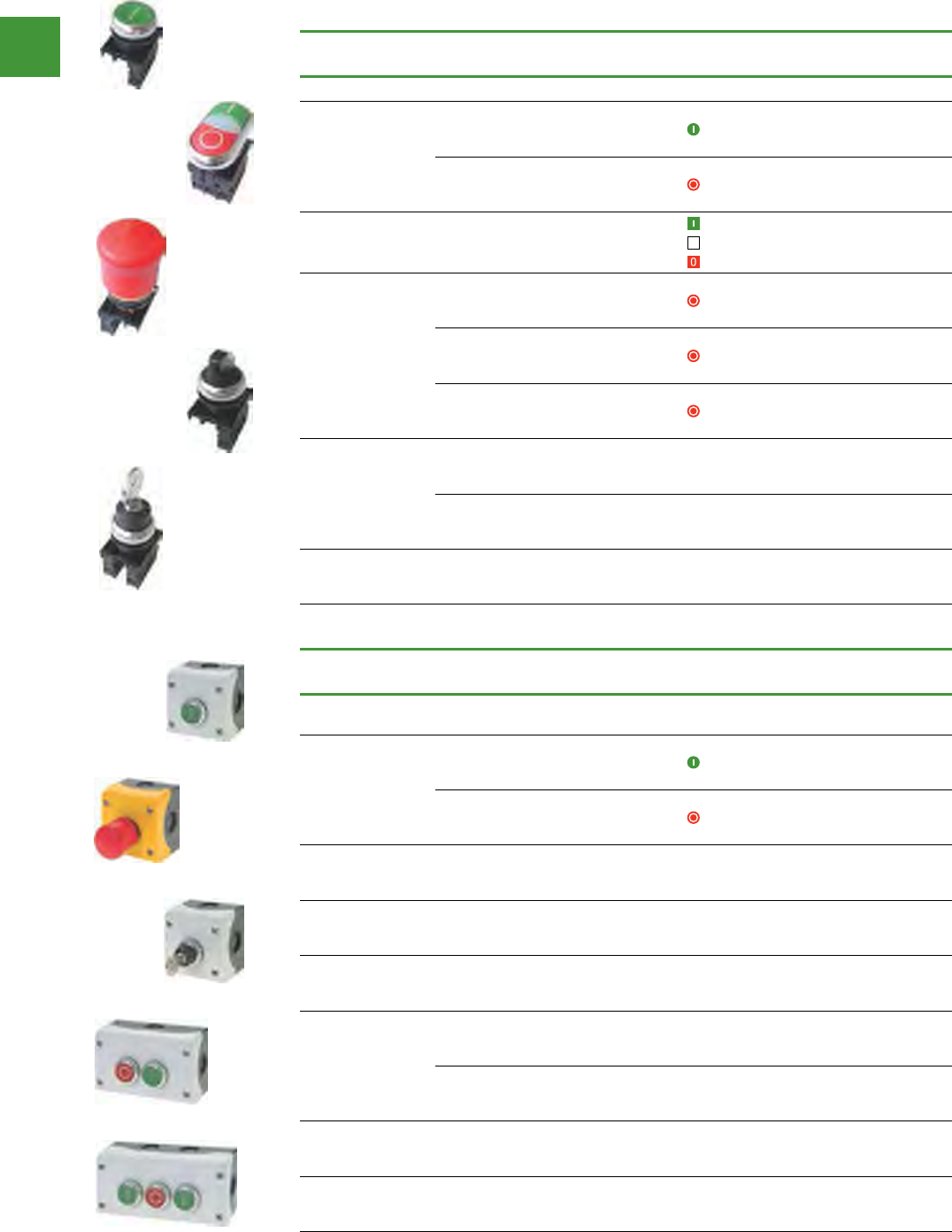
22.5mm Pushbuttons
RMQ - Titan, system overview
Control and indication
Moeller SK0211-1158GB-AUS
Control circuit devices
1/2 System overview
RMQ-Titan
Contact blocks
Contact blocks
Enclosure
Contact blocks
Contact block
Contact blocks
Top-hat rail
adaptor
Telescopic clip
Centring
adaptor
Fixing adaptor
Fixing adaptor
Complete
legend plate
Fixing adaptor
Key-operated
actuator
Selector switch
actuator
Pushbutton
actuator
Emergency-Stop
actuator
4-way joystick
4-way pushbutton
4-way
selector switch
Button plate/
button lens
Indicator
light
Buzzer
Acoustic
indicator
Acoustic indicator cap
Potentiometer
(Titanium appearance standard, black and gold options)
Front rings
SK1158GB-INT.book Seite 2 Donnerstag, 2. Oktober 2008 2:27 14

Power control
146
2015/2016 Product guide AUS15_007 - February 2016
Control and indication
Features & benefits:
• Ergonomic design ensuring ease of operation & bright illumination
• IP66 degree of protection as standard (many devices IP67, IP69K) for use in the harshest
of industrial environments
• Vibration resistant LEDs giving a minimum life of 100,000 hours for improved reliability
& high integrity
• Fitting in the standard 22.5 mm hole, the snap fitting modular system saves both assembly
& fitting time
Colour Description Contact
blocks
LED
light unit Legend plate(s) Item no.
Pushbutton
Flush 1NO/1NC - Run, 1 M22-D-S-K11-P
Extended 1NO/1NC - Stop, off M22-DH-R-K11-P
Flush 1NO/1NC - Start, on M22-D-G-K11-P
Illuminated pushbutton
Extended 1NO/1NC 12-30V AC/DC Stop, off M22-DLH-R-K11-R-P
Extended 1NO/1NC 85-264VAC Stop, off M22-DLH-R-K11-230R-P
Flush 1NO/1NC 12-30V AC/DC Run, 1 M22-DRL-W-K11-W-P
Flush 1NO/1NC 85-264VAC Run, 1 M22-DRL-W-K11-230W-P
Indicating light
- - 12-30V AC/DC Stop, off, fault M22-L-R-R-P
- - 12-30V AC/DC Start, on, run M22-L-G-G-P
- - 85-264VAC Stop, off, fault M22-L-R-230R-P
- - 85-264VAC Start, on, run M22-L-G-230G-P
Emergency stop
Non-illuminated
twist-to-release 1NO/2NC - Emergency stop M22-PVT-K12-P
Illuminated
push-pull 1NO/2NC 12-30V AC/DC Emergency stop M22-PVL-K12-R-P
Illuminated
push-pull 1NO/2NC 85-264VAC Emergency stop M22-PVL-K12-230R-P
Selector switch
2 Position
momentary 1NO/1NC - 0 I, man auto M22-WKV-K11-P
3 Position
momentary 1NO/1NC - I 0 II, hand 0
auto M22-WK3-K22-P
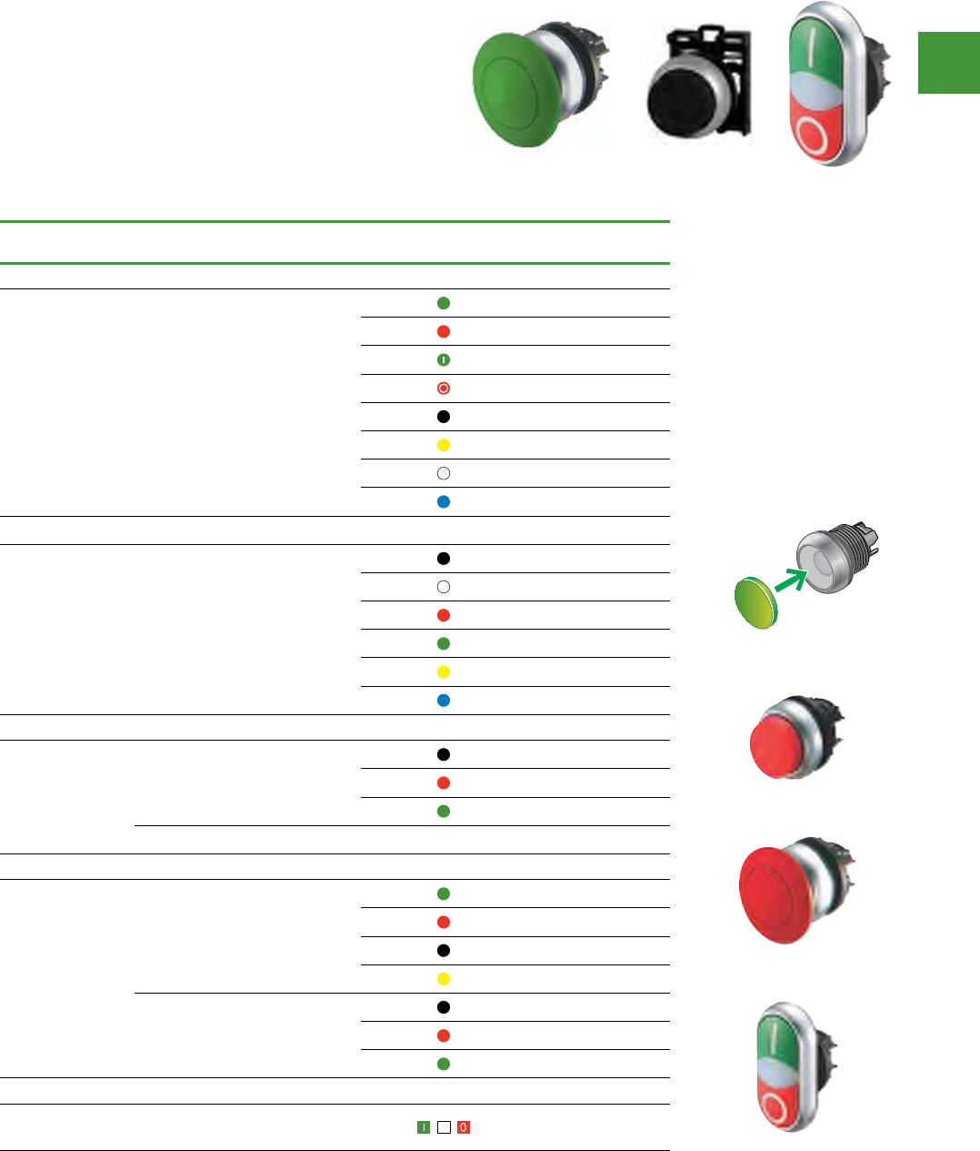
22.5mm Pushbuttons
RMQ - Titan
Competitively priced, Eaton's RMQ-Titan range
comprises pushbuttons, selector switches,
joysticks, Emergency-Stop & key-operated
actuators. The system includes a variety of indicator
lights & illuminated pushbuttons in white, red,
yellow, blue & green. They are available in two
voltage ranges 12 – 30 V AC/DC & 85 – 264 V AC
covering all standard applications.
Meeting all relevant international standards, this
attractive, co-ordinated product range will add
significant value to any machine or system.
M22-PVL-K12-R-P
M22-L-G-G-P
M22-DLH-R-K11-R-P
Control and indication
Power control
147 2015/2016 Product guide AUS15_007 - February 2016
Complete units
Description Button
plate Contacts Item no.
Complete units for front mounting
Pushbutton
actuators
Start 1NO M22-D-G-X1/K10
Stop 1NC M22-D-R-X0/K01
Double actuators With white LED element lens, 85
– 264 V AC 1NO/1NC M22-DDL-GR-X1/
X0/K11/230-W
Emergency-stop
actuators
Key-release mushroom button
with 1 key, MS1 individual lock
mechanism
1NC M22-PVS/K01
Pull to release 1NC M22-PV/K01
Pull to release 1NO/1NC M22-PV/K11
Selector switch
actuators
Two positions, stay-put – 1NO M22-WRK/K10
Three positions, stay-put – 2NO M22-WRK3/K20
Key-operated
actuators Two positions, stay-put, with 1 key – 1NO/1NC
Enclosed units
Description Button
plate Contacts Item no.
Enclosed units for surface mounting
Pushbutton
actuators
Start 1NO/1NC M22-D-G-X1/KC11/I
Stop 1NO/1NC M22-D-R-X0/KC11/I
Emergency-stop
actuator Pull to release, yellow enclosure – 1NO/1NC M22-PV/KC11/IY
Emergency-
stop key-release
mushroom button
Red actuator with 1 key – 1NO/1NC M22-PVS/KC11/IY
Key-operated
selector switch 2 positions, stay-put, with 1 key – 1NO/1NC M22-WRS/KC11/I
Two-way
pushbutton stations
Without indicator light – - M22-I2-M1
With indicator light, white LED
element, 85 – 264 V AC – - M22-I3-M2
Three-way
pushbutton station Without indicator light – - M22-I3-M1
Four-way
pushbutton station Without indicator light – - M22-I4-M1
22.5mm Pushbuttons
RMQ - Titan
M22-D-G-X1/K10
M22-DDL-GR-X1/
X0/K11/230-W
M22-PV/K01
M22-WRK/K10
M22-WRS/K11
M22-PV/KC11/IY
M22-I2-M1
M22-I3-M1
M22-D-G-X1/KC11/I
M22-WRS/KC11/I
Control and indication
Power control
148
2015/2016 Product guide AUS15_007 - February 2016
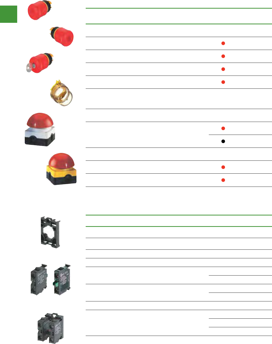
22.5mm Pushbuttons
RMQ - Titan
Pushbutton actuators, IP67
• Front ring titanium, also
available in black
• Snap-fitting
modular system
• Mounting diameter
22.3 mm
• Minimum grid dimensions
30 x 40 mm
• Up to six contacts
per location
• Switching of different
potentials
• Worldwide approval
Actuators
Description Colour of button
plate/mushroom head Item no.
Flush design
Flush actuator Spring-return
M22-D-G
M22-D-R
M22-D-G-X1
M22-D-R-X0
M22-D-S
M22-D-Y
M22-D-W
M22-D-B
Flush actuator Spring-return Without button plate M22-D-X
button plate for use with M22-D-X
M22-XD-S
M22-XD-W
M22-XD-R
M22-XD-G
M22-XD-Y
M22-XD-B
Extended Design
Extended actuator
Spring-return
M22-DH-S
M22-DH-R
M22-DH-G
Spring-return, with guard ring Without M22-DG-X
Mushroom actuators, IP67
Spring-return
M22-DP-G
M22-DP-R
M22-DP-S
M22-DP-Y
Stay-put
M22-DRP-S
M22-DRP-R
M22-DRP-G
Double actuator, IP66
Stop-start button plate. Optional
indicator light M22-LED230-W M22-DDL-GR-X1/X0
Moeller SK0211-1158GB-AUS
Control circuit devices
1/2 System overview
RMQ-Titan
Contact blocks
Contact blocks
Enclosure
Contact blocks
Contact block
Contact blocks
Top-hat rail
adaptor
Telescopic clip
Centring
adaptor
Fixing adaptor
Fixing adaptor
Complete
legend plate
Fixing adaptor
Key-operated
actuator
Selector switch
actuator
Pushbutton
actuator
Emergency-Stop
actuator
4-way joystick
4-way pushbutton
4-way
selector switch
Button plate/
button lens
Indicator
light
Buzzer
Acoustic
indicator
Acoustic indicator cap
Potentiometer
(Titanium appearance standard, black and gold options)
Front rings
SK1158GB-INT.book Seite 2 Donnerstag, 2. Oktober 2008 2:27 14
M22-XD-G
M22-DH-R
M22-DP-R
M22-DDL-GR-X1/X0
Control and indication
Power control
149 2015/2016 Product guide AUS15_007 - February 2016
Actuators
Description
Colour of
mushroom
head
Item no.
Emergency-stop actuators, IP66. Snap-action & positive non-tease action, yellow base
Pull to release.
After actuation, plunger remains in the actuated position. M22-PV
Twist to release. One or two contact blocks can be fitted. M22-PVT
Illuminated. Pull to release. After actuation, plunger remains in the
actuated position. One or two contact blocks can be fitted. M22-PVL
Key-operated, with 1 key M22-PVS
Sealable shroud. Transparent with collapse point, reusable after
Emergency-stop operation. Suitable for M22-PV & M22-PVL
Emergency-stop actuators & M22-PVS key-release mushroom
actuator.
– M22-PL-PV
Foot & palm switches, IP67
Spring-return mushroom head
FAK-R/KC11/I
FAK-S/KC11/I
Emergency-stop actuators, IP67
Stay-put, pull to release FAK-R/V/KC01/IY
Stay-put, pull to release FAK-R/V/KC11/IY
22.5mm Pushbuttons
RMQ - Titan
Fixing adapters, contact blocks
Description Contacts Item no.
Fixing adapters
Front fixing, for 3 M22-K... contact elements & M22-LED... LED
elements. – M22-A
For 4 contact blocks – M22-A4
Contact blocks with screw terminals
Front fixing
1 NO M22-K10
1 NC M22-K01
Base fixing
1 NO M22-KC10
1 NC M22-KC01
Complete modules. Combination of contact elements with screw terminals & fixing adapter
Front fixing
1 NO, 1 NC M22-AK11
1 NO M22-AK10
1 NC M22-AK01
M22-PV
M22-PVS
M22-PVL
M22-PL-PV
FAK-R/V/KC01/IY
FAK-R/V/KC11/IY
M22-A
M22K10
M22-AK11
Control and indication
Power control
150
2015/2016 Product guide AUS15_007 - February 2016
22.5mm Pushbuttons
RMQ - Titan
LED elements
Description Rated operational voltage, Ue, V Colour Item no.
LED elements with screw terminals
Front fixing
12 – 30 V AC/DC
M22-LED-W
M22-LED-R
M22-LED-G
M22-LED-B
85 – 264 V AC,
50/60 Hz
M22-LED230-W
M22-LED230-R
M22-LED230-G
M22-LED230-B
Base fixing
12 – 30 V AC/DC
M22-LEDC-W
M22-LEDC-R
M22-LEDC-G
M22-LEDC-B
85 – 264 V AC,
50/60 Hz
M22-LEDC230-W
M22-LEDC230-R
M22-LEDC230-G
M22-LEDC230-B
LED test elements
For non-interacting function test
(lamp test) for connection to:
12 – 240 V AC/DC – M22-XLED-T
85 – 264 V AC – M22-XLED230-T
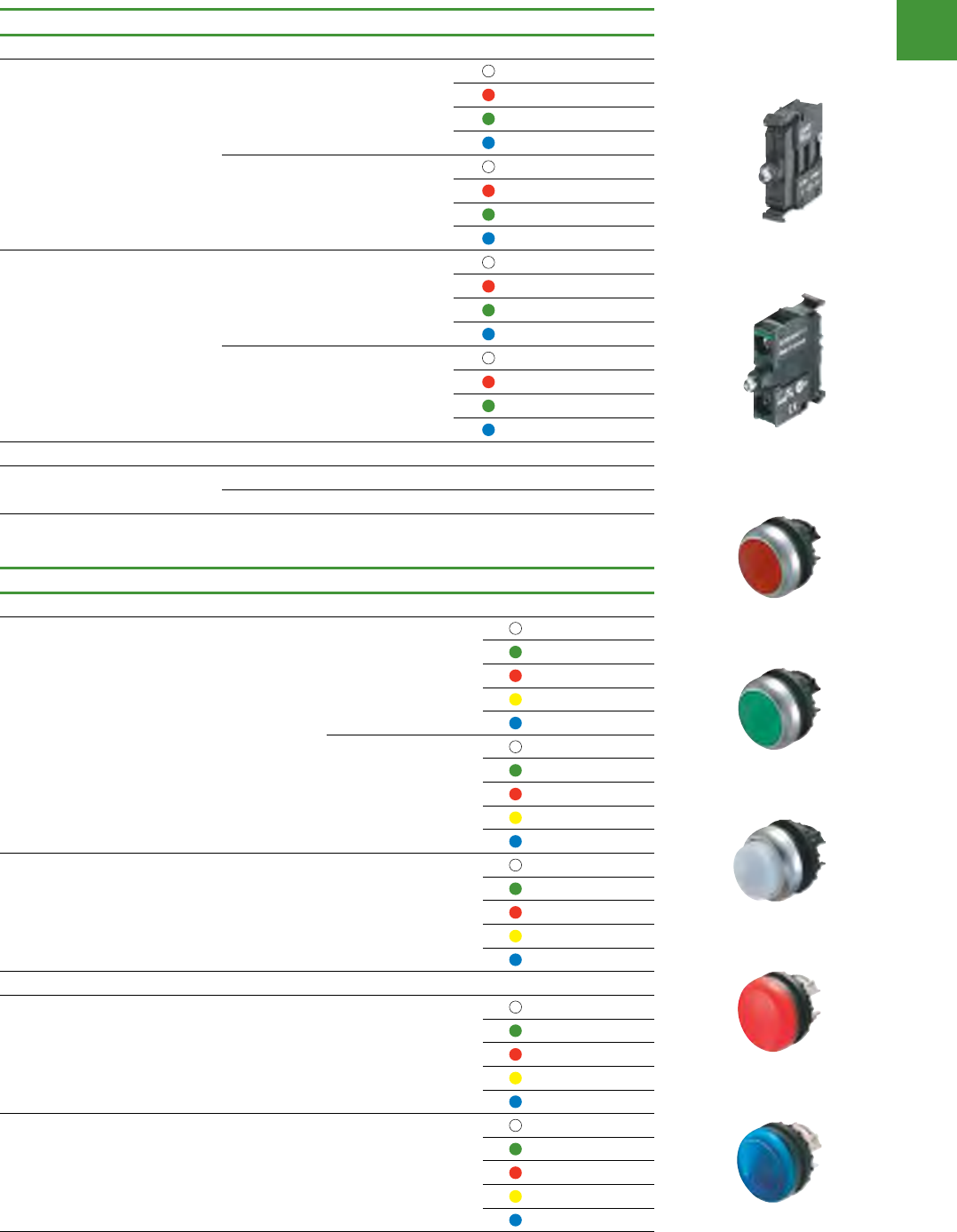
Illuminated pushbutton actuators, indicator lights
Description Colour Item No.
Illuminated pushbutton actuators, IP67
Flush design
Spring-return
M22-DL-W
M22-DL-G
M22-DL-R
M22-DL-Y
M22-DL-B
Stay-put, press again
to release.
M22-DRL-W
M22-DRL-G
M22-DRL-R
M22-DRL-Y
M22-DRL-B
Extended design Spring-return
M22-DLH-W
M22-DLH-G
M22-DLH-R
M22-DLH-Y
M22-DLH-B
Indicator lights, IP67
Flush -
M22-L-W
M22-L-G
M22-L-R
M22-L-Y
M22-L-B
Extended, conical -
M22-LH-W
M22-LH-G
M22-LH-R
M22-LH-Y
M22-LH-B
M22-A
M22-A
M22-DL-R
M22-DRL-G
M22-DLH-W
M22-L-R
M22-LH-B
Control and indication
Power control
151 2015/2016 Product guide AUS15_007 - February 2016
22.5mm Pushbuttons
RMQ - Titan
Set of coding adapters for selector switches
Description For use
with Colour Item no.
Used to convert key
withdraw position to non-key
withdrawn position
M22(S)-
WRS(3) -M22-XC-R
Supplied with standard
switches
Used to convert maintained
operation to momentary
operation
M22(S)-
WR(L)(K)(3)
M22(S)-
WRS(3)
-M22-XC-Y
Adapter Description For Use With…Catalog NumberPrice
Maintained to Momentary Operation
Supplied with standard
switches
Used to convert Main-
tained operation to
Momentary operation
•
•
M22(S)-WR(L)(K)(3)
M22(S)-WRS(3) M22-XC-Y 2.50
Bottom affects
Left position (I)
Top affects Right
position (II)
Insert for Momentary
Remove for Maintained
Bottom affects
Left position (I)
Top affects Right
position (II)
Insert for no key withdraw
Remove for ey withdraw
The same slots
on keyed selector
switches are shared
between these two
coding adapters.
All possible
combinations and
detailed in the
tables below.
Key Withdraw to Non-Key Withdraw
Used to convert
Key withdraw position
to non-key withdraw
position
M22(S)-WRS(3) M22-XC-R 2.50
Two-Position
Adapter
Switching Positions
O
I
maintained
O
I
maintained
O
I
momentary
Key Withdraw Positions
O I O I O I
Top Slot
–
Bottom Slot
(not implemented with
2-position switches)
–––
O
I
O
I
O
I
O I O I O I
–
–––
Three-Position
Adapter
Switching Positions
O
I II
maintained
O
I II
maintained
O
I II
maintained
O
I II
maintained
O
I II
momentary
O
I II
O
I II
O
I II
O
I II
Key Withdraw Positions
I O II I O II I O II I O II I O II I O II I O II I O II I O II
Top Slot
– – –
Bottom Slot
– – –
O
I II
O
I II
O
I II
O
I II
O
I II
O
I II
O
I II
O
I II
O
I
II
I O II I O II I O II I O II I O II I O II I O II I O II I O
II
– – –
– – –
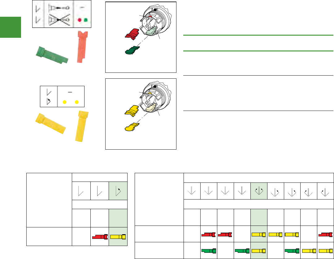
The same slots on keyed sector switches are shared between
these two difference sets of coding adapters.
All possible combinations and their effects are detailed in the
tables below.
Adapter Description For Use With…Catalog NumberPrice
Maintained to Momentary Operation
Supplied with standard
switches
Used to convert Main-
tained operation to
Momentary operation
•
•
M22(S)-WR(L)(K)(3)
M22(S)-WRS(3) M22-XC-Y 2.50
Bottom affects
Left position (I)
Top affects Right
position (II)
Insert for Momentary
Remove for Maintained
Bottom affects
Left position (I)
Top affects Right
position (II)
Insert for no key withdraw
Remove for ey withdraw
The same slots
on keyed selector
switches are shared
between these two
coding adapters.
All possible
combinations and
detailed in the
tables below.
Key Withdraw to Non-Key Withdraw
Used to convert
Key withdraw position
to non-key withdraw
position
M22(S)-WRS(3) M22-XC-R 2.50
Two-Position
Adapter
Switching Positions
O
I
maintained
O
I
maintained
O
I
momentary
Key Withdraw Positions
O I O I O I
Top Slot
–
Bottom Slot
(not implemented with
2-position switches)
–––
O
I
O
I
O
I
O I O I O I
–
–––
Three-Position
Adapter
Switching Positions
O
I II
maintained
O
I II
maintained
O
I II
maintained
O
I II
maintained
O
I II
momentary
O
I II
O
I II
O
I II
O
I II
Key Withdraw Positions
I O II I O II I O II I O II I O II I O II I O II I O II I O II
Top Slot
– – –
Bottom Slot
– – –
O
I II
O
I II
O
I II
O
I II
O
I II
O
I II
O
I II
O
I II
O
I
II
I O II I O II I O II I O II I O II I O II I O II I O II I O
II
– – –
– – –
M22-XC-Y
Adapter Description For Use With…Catalog NumberPrice
Maintained to Momentary Operation
Supplied with standard
switches
Used to convert Main-
tained operation to
Momentary operation
•
•
M22(S)-WR(L)(K)(3)
M22(S)-WRS(3) M22-XC-Y 2.50
Bottom affects
Left position (I)
Top affects Right
position (II)
Insert for Momentary
Remove for Maintained
Bottom affects
Left position (I)
Top affects Right
position (II)
Insert for no key withdraw
Remove for ey withdraw
The same slots
on keyed selector
switches are shared
between these two
coding adapters.
All possible
combinations and
detailed in the
tables below.
Key Withdraw to Non-Key Withdraw
Used to convert
Key withdraw position
to non-key withdraw
position
M22(S)-WRS(3) M22-XC-R 2.50
Two-Position
Adapter
Switching Positions
O
I
maintained
O
I
maintained
O
I
momentary
Key Withdraw Positions
O I O I O I
Top Slot
–
Bottom Slot
(not implemented with
2-position switches)
–––
O
I
O
I
O
I
O I O I O I
–
–––
Three-Position
Adapter
Switching Positions
O
I II
maintained
O
I II
maintained
O
I II
maintained
O
I II
maintained
O
I II
momentary
O
I II
O
I II
O
I II
O
I II
Key Withdraw Positions
I O II I O II I O II I O II I O II I O II I O II I O II I O II
Top Slot
– – –
Bottom Slot
– – –
O
I II
O
I II
O
I II
O
I II
O
I II
O
I II
O
I II
O
I II
O
I
II
I O II I O II I O II I O II I O II I O II I O II I O II I O
II
– – –
– – –
M22-XC-R
Adapter Description For Use With…Catalog NumberPrice
Maintained to Momentary Operation
Supplied with standard
switches
Used to convert Main-
tained operation to
Momentary operation
•
•
M22(S)-WR(L)(K)(3)
M22(S)-WRS(3) M22-XC-Y 2.50
Bottom affects
Left position (I)
Top affects Right
position (II)
Insert for Momentary
Remove for Maintained
Bottom affects
Left position (I)
Top affects Right
position (II)
Insert for no key withdraw
Remove for ey withdraw
The same slots
on keyed selector
switches are shared
between these two
coding adapters.
All possible
combinations and
detailed in the
tables below.
Key Withdraw to Non-Key Withdraw
Used to convert
Key withdraw position
to non-key withdraw
position
M22(S)-WRS(3) M22-XC-R 2.50
Two-Position
Adapter
Switching Positions
O
I
maintained
O
I
maintained
O
I
momentary
Key Withdraw Positions
O I O I O I
Top Slot
–
Bottom Slot
(not implemented with
2-position switches)
–––
O
I
O
I
O
I
O I O I O I
–
–––
Three-Position
Adapter
Switching Positions
O
I II
maintained
O
I II
maintained
O
I II
maintained
O
I II
maintained
O
I II
momentary
O
I II
O
I II
O
I II
O
I II
Key Withdraw Positions
I O II I O II I O II I O II I O II I O II I O II I O II I O II
Top Slot
– – –
Bottom Slot
– – –
O
I II
O
I II
O
I II
O
I II
O
I II
O
I II
O
I II
O
I II
O
I
II
I O II I O II I O II I O II I O II I O II I O II I O II I O
II
– – –
– – –
Adapter Description For Use With…Catalog NumberPrice
Maintained to Momentary Operation
Supplied with standard
switches
Used to convert Main-
tained operation to
Momentary operation
•
•
M22(S)-WR(L)(K)(3)
M22(S)-WRS(3) M22-XC-Y 2.50
Bottom affects
Left position (I)
Top affects Right
position (II)
Insert for Momentary
Remove for Maintained
Bottom affects
Left position (I)
Top affects Right
position (II)
Insert for no key withdraw
Remove for ey withdraw
The same slots
on keyed selector
switches are shared
between these two
coding adapters.
All possible
combinations and
detailed in the
tables below.
Key Withdraw to Non-Key Withdraw
Used to convert
Key withdraw position
to non-key withdraw
position
M22(S)-WRS(3) M22-XC-R 2.50
Two-Position
Adapter
Switching Positions
O
I
maintained
O
I
maintained
O
I
momentary
Key Withdraw Positions
O I O I O I
Top Slot –
Bottom Slot
(not implemented with
2-position switches)
–––
O
I
O
I
O
I
O I O I O I
–
–––
Three-Position
Adapter
Switching Positions
O
I II
maintained
O
I II
maintained
O
I II
maintained
O
I II
maintained
O
I II
momentary
O
I II
O
I II
O
I II
O
I II
Key Withdraw Positions
I O II I O II I O II I O II I O II I O II I O II I O II I O II
Top Slot – – –
Bottom Slot – – –
O
I II
O
I II
O
I II
O
I II
O
I II
O
I II
O
I II
O
I II
O
I
II
I O II I O II I O II I O II I O II I O II I O II I O II I O
II
– – –
– – –
maintained maintained momentary
Adapter Description For Use With…Catalog NumberPrice
Maintained to Momentary Operation
Supplied with standard
switches
Used to convert Main-
tained operation to
Momentary operation
•
•
M22(S)-WR(L)(K)(3)
M22(S)-WRS(3) M22-XC-Y 2.50
Bottom affects
Left position (I)
Top affects Right
position (II)
Insert for Momentary
Remove for Maintained
Bottom affects
Left position (I)
Top affects Right
position (II)
Insert for no key withdraw
Remove for ey withdraw
The same slots
on keyed selector
switches are shared
between these two
coding adapters.
All possible
combinations and
detailed in the
tables below.
Key Withdraw to Non-Key Withdraw
Used to convert
Key withdraw position
to non-key withdraw
position
M22(S)-WRS(3) M22-XC-R 2.50
Two-Position
Adapter
Switching Positions
O
I
maintained
O
I
maintained
O
I
momentary
Key Withdraw Positions
O I O I O I
Top Slot
–
Bottom Slot
(not implemented with
2-position switches)
–––
O
I
O
I
O
I
O I O I O I
–
–––
Three-Position
Adapter
Switching Positions
O
I II
maintained
O
I II
maintained
O
I II
maintained
O
I II
maintained
O
I II
momentary
O
I II
O
I II
O
I II
O
I II
Key Withdraw Positions
I O II I O II I O II I O II I O II I O II I O II I O II I O II
Top Slot
– – –
Bottom Slot
– – –
O
I II
O
I II
O
I II
O
I II
O
I II
O
I II
O
I II
O
I II
O
I
II
I O II I O II I O II I O II I O II I O II I O II I O II I O
II
– – –
– – –
maintained maintained maintained maintained momentary
Adapter Description For Use With…Catalog NumberPrice
Maintained to Momentary Operation
Supplied with standard
switches
Used to convert Main-
tained operation to
Momentary operation
•
•
M22(S)-WR(L)(K)(3)
M22(S)-WRS(3) M22-XC-Y 2.50
Bottom affects
Left position (I)
Top affects Right
position (II)
Insert for Momentary
Remove for Maintained
Bottom affects
Left position (I)
Top affects Right
position (II)
Insert for no key withdraw
Remove for ey withdraw
The same slots
on keyed selector
switches are shared
between these two
coding adapters.
All possible
combinations and
detailed in the
tables below.
Key Withdraw to Non-Key Withdraw
Used to convert
Key withdraw position
to non-key withdraw
position
M22(S)-WRS(3) M22-XC-R 2.50
Two-Position
Adapter
Switching Positions
O
I
maintained
O
I
maintained
O
I
momentary
Key Withdraw Positions
O I O I O I
Top Slot
–
Bottom Slot
(not implemented with
2-position switches)
–––
O
I
O
I
O
I
O I O I O I
–
–––
Three-Position
Adapter
Switching Positions
O
I II
maintained
O
I II
maintained
O
I II
maintained
O
I II
maintained
O
I II
momentary
O
I II
O
I II
O
I II
O
I II
Key Withdraw Positions
I O II I O II I O II I O II I O II I O II I O II I O II I O II
Top Slot
– – –
Bottom Slot
– – –
O
I II
O
I II
O
I II
O
I II
O
I II
O
I II
O
I II
O
I II
O
I
II
I O II I O II I O II I O II I O II I O II I O II I O II I O
II
– – –
– – –
Three position adapter configurations
Three position
adapter
congurations
Switching positions
Key withdraw positions
I O II I O II I O II I O II I O II I O II I O II I O II I O II
Two slot
affects right position _ _ _
Bottom slot
affects left position _ _ _
Shading indicates standard switch configuration
Two position adapter configurations
Two position
adapter
congurations
Switching positions
Key withdraw positions
O I O IO I
Two slot
affects right position _
Bottom slot not implemented with two
position switches
Shading indicates standard switch configuration

Control and indication
Power control
152
2015/2016 Product guide AUS15_007 - February 2016
22.5mm Pushbuttons
RMQ - Titan
Selector switch actuators
Description
Function:
= Stay-put
= V position
Button
plate
Front ring:
titanium
Item no.
Selector switch actuators, 2 positions, IP66
Rotary button – 40° M22-W
– 60° M22-WR
Thumb-grip – 40° – M22-WK
– 60° – M22-WRK
Thumb-grip, V position – 60° – M22-WKV
Selector switch actuators, 3 positions, IP66
Rotary button 40° 40° M22-W3
60° 60° M22-WR3
Thumb-grip 40° 40° – M22-WK3
60° 60° – M22-WRK3
Selector switch actuators, 4 positions, IP66.
Rotary button 45° – M22-WR4
Thumb-grip 45° – M22-WRK4
Key-operated actuators, IP66, with 1 key
2 positions, 60° turn, stay-put – 60° – M22-WRS
3 positions, 60° turn, stay-put 60° 60° – M22-WRS3
Key for MS1 individual lock mechanism – – – – M22-ES-MS1
Illuminated selector switch actuators, key-operated actuators
Description
Function:
= Stay-put
= Spring-return
Colour of
thumb-grip Item No.
Illuminated selector switch actuators, IP66. Thumb grip handle
2 positions
–
Spring-return
– 40° M22-WLK-W
– 40° M22-WLK-G
– 40° M22-WLK-R
– 40° M22-WLK-Y
– 40° M22-WLK-B
Stay-put
– 60° M22-WRLK-W
– 60° M22-WRLK-G
– 60° M22-WRLK-R
– 60° M22-WRLK-Y
– 60° M22-WRLK-B
3 positions
–
Spring-return
40° 40° M22-WLK3-W
40° 40° M22-WLK3-G
40° 40° M22-WLK3-R
40° 40° M22-WLK3-Y
40° 40° M22-WLK3-B
Stay-put
60° 60° M22-WRLK3-W
60° 60° M22-WRLK3-G
60° 60° M22-WRLK3-R
60° 60° M22-WRLK3-Y
60° 60° M22-WRLK3-B
= Spring-
return
M22-WRLK-R
M22-WRS
M22-WR4
M22-W3
M22-WK
M22-WRK4
M22-WK3
M22-WKV
M22-W
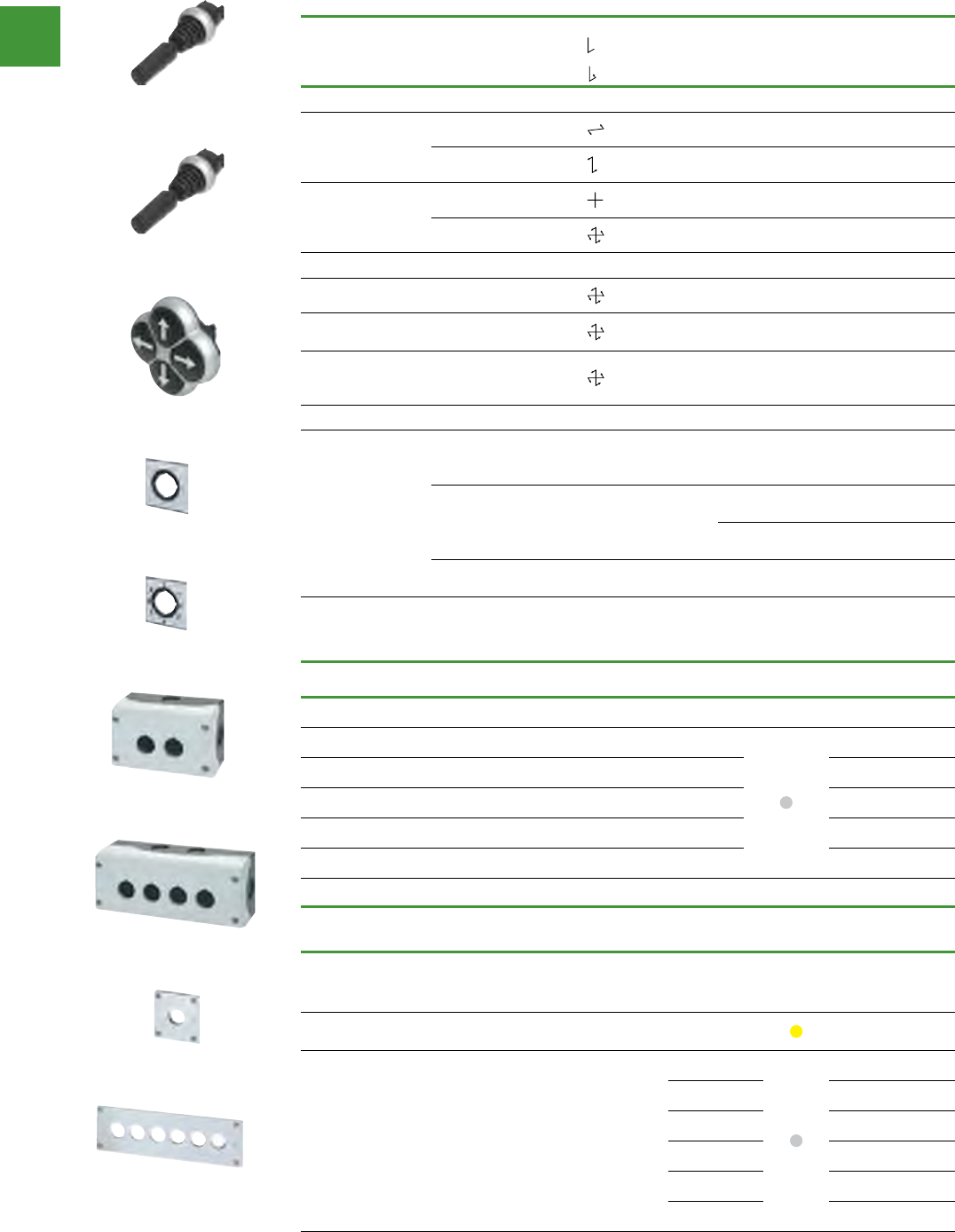
Control and indication
Power control
153 2015/2016 Product guide AUS15_007 - February 2016
22.5mm Pushbuttons
RMQ - Titan
Four-way operators
Description Inscription
Function:
= Stay-put
= Spring-return
For use with
Front ring:
titanium
Item no.
Joysticks, IP66
2 positions
– – M22-WJ2H
– – M22-WJ2V
4 positions
– – M22-WRJ4
– – M22-WJ4
Pushbuttons, 4-way, IP66
No inscription, actuator colour black – M22-D4-S
Inscription with direction arrows, actuator
colour: black – M22-D4-S-X7
Inscription with direction arrows,
actuator colour: black, opposing buttons
mechanically interlocked
– M22-DI4-S-X7
Labels
–
Blank –
Joystick 4-way
selector switch
actuators
M22-XCK
Direction arrows –
Joystick 4
positions M22-XCK1
Joystick 2
positions M22-XCK3
0-1-0-2-0-3-0-4 – 4-way selector
switch actuators M22-XCK2
Surface mounting enclosures, flush mounting plates
Number of ways Qty. Colour Item no.
Surface mounting enclosures
1M22-I1
2M22-I2
3M22-I3
4M22-I4
6M22-I6
Description Number of
ways Qty. Colour Item no.
Flush mounting plates
Legend plates cannot be used if pushbuttons are fitted in vertical column without
apertures, if required.
Aluminium with yellow paint finish for emergency-stop
buttons 1 M22-EY1
Aluminium, light anodized
1 M22-E1
2 M22-E2
3 M22-E3
4 M22-E4
5 M22-E5
6 M22-E6
M22-WJ2H
M22-WRJ4
M22-D4-S
M22-XCK
M22-XCK2
M22-I2
M22-I4
M22-EY1
M22-E6
Control and indication
Power control
154
2015/2016 Product guide AUS15_007 - February 2016
22.5mm Pushbuttons
RMQ - Titan, Accessories
Description Number
of ways Item no.
Shrouds, IP55 Plastic, light grey 1 M22-H1
Plastic, light grey 2 M22-H2
Blanking plugs, IP66. Round style, for
blanking off reserve locations
Grey – M22-B
Black – M22S-B
Actuator diaphragms, IP67. Transparent diaphragms for severe environmental conditions & use in the
food industry. Do not use with legend plates since degree of protection is not guaranteed
For use with M22(S)-D(R)-... pushbutton actuators, M22(S)-DL-...,
M22(S)-DRL-..., illuminated pushbutton actuators, M22-D(C)-... flush
indicator lights
– M22-T-D
For use with M22(S)-DD(L)-... double actuators – M22-T-DD
Telescopic clips. For adjusting depth of rear mounting devices in CI enclosures & panels with a
mounting depth of 115 – 155 mm. Stepless adjustment, screw fixing & snap fitting (top hat rails to
IEC/EN 60715). Maximum of 10 x M22-TC per enclosure, 5 of which can hold stay-put actuators. Do
not use with Emergency-Stop actuators
For 3 contacts/LED elements, base fixing, with centering adapter – M22-TC
Extension for telescopic clip; for mounting depths up to 205 mm – M22-TCV
Adapter rings. Set of adapter rings 30/22.3 mm, black, consists of adapter ring & lock nut
For fitting 22.3 mm diameter buttons into 30.5 mm diameter holes – M22S-R30
Threaded ring M22 x 1.5 mm – M22-GR
Acoustic indicator housing IP40 Black front, without buzzer -M22-AMC
Buzzer - for use with M22-AMC
18 - 30 V AC/DC, 83 dB / 10 cm, 100
% DF, Positive pole connected to X1
Continuous tone -M22-XAM
Pulsed tone -M22-XAMP
NEMA/UL Type 1.
Description Circuit
symbol
Resistance,
R, kW Item no.
Potentiometers,
IP66
3 individual screw terminals,
Pmax = 0.5 W Accuracy of
resistance value: ±10% (linear)
1 M22-R1K
4.7 M22-R4K7
10 M22-R10K
47 M22-R47K
100 M22-R100K
470 M22-R470K
Description Inscription Colour Item no.
Emergency-stop
labels, IP66
Lettering black, 30 X 50
mm
Emergency-stop M22-XZK-GB99
Blank M22-XZK
Diameter = 90 mm Emergency-stop
in 4 languages M22-XAK1
Legend holders
without label, IP66.
Round, black
For actuators, 30 x 50 mm –M22S-ST-X
For double actuators, 30 x
75 mm –M22S-STDD-X
Insert plate for legend
holder Blank Aluminium M22-XST
Description Item no.
Combination box spanner For threaded ring M22-MS
Top-hat rail adapter IEC/EN 60715 top-hat rail, for front fixing M22-IVS
Plunger bridge. For actuating the
middle contact element of the M22-
W...3 non-illuminated 3-position
selector switch actuator
Middle contact of 3-position selector
switch, non-illuminated, (1 off) black M22-XW
Guard ring, IP66. To protect against
accidental operation For pushbutton & selector switch actuators M22-XGWK
Front ring: gold (24 carat). Front ring not supplied individually: M22-FR-AU
IP65 external reset button M22-DZ-B-GB14
M22-XAK1
M22-R10K
M22-DZ-B-GB14
M22-XGWK
M22-XW
M22-IVS
M22-MS
M22-AMC
M22-GR
M22-R30
M22-TC
M22-T-DD
M22-T-D
M22-B
M22-H1

Control and indication
Power control
155 2015/2016 Product guide AUS15_007 - February 2016
30.5mm Pushbuttons
Eaton’s 30.5mm pushbuttons are versatile, durable, rugged, & stand the test of time in even the most
hostile environments.
The range includes momentary, illuminated & mushroom head pushbuttons, selector switches,
indicating lights & push-pull units.
The T Series Chrome 30.5 mm pushbutton line features a zinc die cast construction with chrome-plated
housing & mounting nut. The same durable construction is also available with the corrosive resistant
E34 line of pushbuttons.
All operators are IP66 rated to protect against dirt & moisture. Additionally, most devices come
complete with grounding hardware to prevent electrical shock. Rugged metal construction, handsome
appearance, extra features, & competitive prices makes Eaton’s 30.5mm range of pushbuttons the
logical choice for OEM’s & board builders looking for value, durability, & reliability.
Features
• Die-cast metal housings create robust & heavy-duty devices
that can endure repetitive & heavy handed use in industrial
environments.
• IP66 rated for protection against dirt & moisture.
• The corrosion resistant E34 range can with stand extremely
harsh environments.
• Contact blocks are colour coded (green for N.O. & red for
N.C.) to permit easy identification & troubleshooting.
• Up to 6 contact blocks can stack on each other, allowing for
up to 12 circuits per operator.
• Heavy-duty zinc die cast construction
• Enclosed silver contacts with reliability nibs
• All normally closed contacts have positive opening operation,
i.e., normally closed contacts are forced open in the event of
contact weld or spring breakage.
• Diaphragm seals with drainage holes
• Grounding nibs on the operator casing.
• Logic level contact blocks have palladium tipped contacts to
ensure circuit integrity down to 1mA @ 5V AC/DC.
• Bright, long-lasting & vibration-proof LED’s are available for
illuminated operators.
Standards
• CE EN60947-5-1
• UL 508 — File No. 131568
• CSA C22.2 No. 14 — File No. LR68551
Contact blocks
Eaton’s contact blocks feature enclosed silver contacts with
pointed “reliability nibs” for reliable performance from logic
level up to 600V. To ensure reliable switching, nibs bite through
oxide which can form on silver contacts, eliminating the need
for expensive logic level blocks for most applications. Reliability
nibs improve performance in dry circuit, corrosive, fine dust &
other contaminated atmospheres. Under normal environmental
conditions, the minimum operational voltage is 5V & the minimum
operational current is 1 mA, AC/DC. For operation under a wider
range of environmental conditions, logic level contact blocks with
inert palladium tipped contacts are recommended. Diaphragm Seal
with Drainage Holes Eaton’s pushbutton operators offer front-of-
panel drainage via holes in the operator bushing. Hidden from view
by the mounting nut, these holes prevent buildup of liquid inside
the operator, which can prevent operation in freezing environments.
The holes also provide a route for escaping liquid in high pressure
washdowns, effectively relieving pressure from the internal
diaphragm seal, ensuring reliable sealing every time.
Grounding nibs
Most operators have green earthing screws to prevent electrical
shock. Operators also have “grounding nibs” — four metal points
on the operator casting designed to bite through most paints &
other coatings on metal panels to enhance the ground connection
when the operator is securely tightened.
Standard Pushbuttons
Chrome, T Series pushbuttons
Chrome
The 30.5 mm pushbutton
line features a zinc die cast
construction with chrome-plated
housing & mounting nut.
Applications for the
chrome operators:
• Aggregate
• Automotive
• Construction Vehicles
• Industrial Equipment
• Material Handling
• Metal Forming
• Metal Stamping
• Mining
• Petrochemical
• Pulp & Paper
Corrosion resistant
Eaton’s Corrosion Resistant E34
Range of 30.5 mm pushbuttons
features the same rugged
die cast construction of our T
Series with an additional two-
layer 100% solid thermosetting
cathodic epoxy coating. This
coating provides a smooth
flat black smooth, flat back,
corrosion resistant surface that
has passed a demanding 600
hour salt spray test.
Applications for corrosion
resistant operators:
• Automotive
• Chemical Plants
• Food & Beverage
• Food Service Equipment
• Industrial Equipment
• Mining
• Pulp & Paper
• Waste Water Treatment
Plants
Ultraviolet light
E34 cathodic coating is not
recommended for use in
applications where exposure
to ultraviolet light exists, use
chrome operators.
Corrosion Resistant, E34 Pushbuttons

Control and indication
Power control
156
2015/2016 Product guide AUS15_007 - February 2016
30.5mm Pushbuttons
Standard Pushbuttons, flush, extended & half-shrouded buttons,
Half-shrouded
Colour Chrome Corrosion
resistant
Black T501 E34EVB1
Red T502 E34EVB2
Green T503 E34EVB3
Yellow T504 E34EVB4
Blue T508 E34EVB6
Extended button
Colour Chrome Corrosion
resistant
Black T111 E34EB1
Red T112 E34EB2
Green T113 E34EB3
Yellow T120 E34EB4
White T116 -
Blue T118 E34EB6
Flush button
Colour Chrome Corrosion
resistant
Black T101 E34PB1
Red T102 E34PB2
Green T103 E34PB3
Yellow T104 E34PB4
Grey T105 -
White T106 E34PB5
Brown T107 -
Blue T108 E34PB6
Standard contact blocks
Description Item no.
1NO 1NC T1P
2NO T2P
2NC T3P
1NC T51P
1NO T53P
2NO 2NC T44
1LONC 1ECNO T55
1ECNO 1NO T57
1LONC T71
2LONC T45
Base mounted contact blocks
Description Item no.
1NO 1NC T6
2NO T7
2NC T8
1NC T52
1NO T54
1LONC 1ECNO T56
1LONC 1ECNO T58
Logic level contact blocks
Description Item no.
1NO 1NC T1E
2NO T2E
2NC T3E
1NC T51E
1NO T53E
NO = Normally Open, NC = Normally Closed, LONC = Late Open Normally Closed,
ECNO = Early Close Normally Open, Logic Level contact blocks have palladium contacts.
Select
Pushbutton
operator
above.
Select
contact
block
above
STEP 1 STEP 2
T1P
T44
T57

Control and indication
Power control
157 2015/2016 Product guide AUS15_007 - February 2016
30.5mm Pushbuttons
Mushroom operators momentary
Mushroom button 38.1mm
Colour Chrome Corrosion
resistant
Black T121 E34LB1
Red T122 E34LB2
Green T123 E34LB3
Yellow T124 E34LB4
Blue T129 E34LB6
Palm head button 63.5mm zinc
Colour Chrome Corrosion
resistant
Black T171 E34JB1
Red T172 E34JB2
Red
(Emergency
Stop)
T17213 E34JB2N
Green T173 E34JB3
Accessories for complete push-pull
operators*
Description Item no.
Padlock Assembly Kit 6-A474
Replacement Locking Tongue 6-A475
Padlock with Chain 52-A1617
Legend Plates
Engraving Material Item no.
STOP Pull to
reset Metal D2179-53CP
STOP Pull to
reset Plastic E34LP179
* For use with push-pull mushroom operators
maintained.
Select
Pushbutton
operator
above.
STEP 1
Select
contact
block.
STEP 2
(previous page)
Mushroom operators components
Bare shaft operator for mushroom or
palm pushbutton
Description Item no.
Momentary, Spring Return T100
Auto-Latch - Twist Base to
Release T140
38.1 Mushroom button for bare
shaft operators
Colour Item no.
Black T281
Red T282
Green T283
Yellow T284
Blue T288
63.5Mm palm button (anodized
aluminium) for bare shaft operators
Colour Item no.
Black T291
Red T292
Green T293
Select
bare shaft
operator
above.
STEP 1
Select
mushroom
button
above
STEP 2
Select
contact
block.
STEP 3
(previous page)

30.5mm Pushbuttons
Control and indication
Power control
158
2015/2016 Product guide AUS15_007 - February 2016
Push-pull mushroom operators maintained
Push-pull operators complete padlockable
Head
diameter Colour Material Chrome Corrosion
resistant
45mm Red Zinc T129P E34129P
63.5mm Red Zinc T176P E34176P
Push-pull operators complete non-padlockable
Head
diameter Colour Material Chrome Corrosion
resistant
38mm Red Plastic T129S E34129S
45mm Red Zinc T129M E34129M
63.5mm Red Zinc T176M E34176M
Select
Pushbutton
operator
above.
STEP 1
Select
contact
block.
STEP 2
(previous page)
Push-pull operators
Description Position Chrome Corrosion
resistant
Maintained
Push & Pull 2T5 E34GDB
Momentary
Push & Pull 3T4 E34GEB
Maintained
Push &
Momentary
Pull
3T9 E34GFB
38.1Mm mushroom button
for push-pull operators
Description Colour Item no.
Operator
Head Black E34C1
Operator
Head Red E34C2
Operator
Head
Red
(Emergency
Stop)
10250TB63
Operator
Head Green E34C3
63.5Mm palm button (anodized
aluminium) for push-pull operators
description Colour Item no.
Operator Head Red E34J2
Operator Head
Red
(Emergency
Stop)
E34J2N8
Push-Pull operators components
Select
push-pull
operator
above.
STEP 1
Select
mushroom
button
above
STEP 2
Select
contact
block.
STEP 3
(previous page)
T129P T176P E34129ST129M

30.5mm Pushbuttons
Illuminated operators, indicating light lenses
Control and indication
Power control
159 2015/2016 Product guide AUS15_007 - February 2016
Select a
lens from
above.
STEP 1
Indicating Light Units
Plastic lenses
Colour Plastic
Red E34H2
Green E34H3
Amber E34H9
Clear E34H0
Yellow E34H4
White E34H5
Blue E34H6
Glass lenses (chrome)
colour Glass (chrome)
Red TC7N
Green TC8N
Amber TC9N
Clear TC11N
White TC12N
Blue TC10N
Glass lenses (corrosion resistant)
Colour Glass (corrosion
resistant)
Red E34G2
Green E34G3
Amber E34G9
Clear E34G0
Yellow E34G4
White E34G5
Blue E34G6
Incandescent bulb indicating light units
Description Voltage Chrome Corrosion
resistant
With
incandescent
bulb supplied
6T197N/2 E34FB06
12 T197N/3 E34FB12
24 T197N/4 E34FB24
48 T197N/5 E34FB48
110 T197N/7 E34FB110
240 T197N/8 E34FB240
Transformer type indicating light units
Description Voltage Chrome Corrosion
resistant
Transformer
Type 6V
Secondary
bulb
supplied
110/120 T181N E34TB120
220/240 T182N E34TB240
380/415 T183N E34TB380
440/480 T184N E34TB480
550/600 T185N E34TB600
415 -E34TB415
Resistor type indicating light units
Description Voltage Chrome Corrosion
resistant
Resistor Type
120V bulb
supplied
110/120 T201N E34RB120
220/240 T202N E34RB240
Select
indicating
light above
STEP 2
Select bulb
(if not
supplied)
STEP 3
(next page)
Select
contact
block.
STEP 4
(previous page)
Direct voltage indicating light unit
Description Voltage Chrome Corrosion
resistant
Direct voltage
- order bulb
separately
6 - 240V T197N E34FB
197L*
See next page for bulbs.
Can be used with LEDs.
*LED only 6-240V
30.5mm Pushbuttons
Illuminated operators, illuminated pushbutton lenses
Control and indication
Power control
160
2015/2016 Product guide AUS15_007 - February 2016
Select a
lens from
above.
STEP 1
Select light
from above
STEP 2
Select bulb
(if not
supplied)
STEP 3
(next page)
Select
contact
block.
STEP 4
(previous page)
Plastic illuminated lenses
Colour Plastic
Red E34V2
Green E34V3
Amber E34V9
Clear E34V0
Yellow E34V4
White E34V5
Blue E34V6
Glass illuminated lenses (chrome)
Colour Glass (chrome)
Red TC13N
Green TC14N
Amber TC15N
Clear TC17N
White TC18N
Blue TC16N
Glass illuminated lenses (chrome)
(corrosion resistant)
Colour Glass (chrome)
Red E34P2
Green E34P3
Amber E34P9
Clear E34P0
Yellow E34P4
White E34P5
Blue E34P6
Direct Voltage Indicating Light Unit
Description Supply
voltage Chrome Corrosion
resistant
Direct voltage
- order bulb
separately
6 - 240V T441 E34CB
497L*
See next page for bulbs.
Can be used with LEDs.
*LED only 6-240V
Illuminated pushbuttons -
transformer type
Description Supply
voltage Chrome Corrosion
resistant
Transformer
type 6V
secondary
bulb supplied
110/120 T411 E34XB120
220/240 T412 E34XB1240
380/415 T413 E34XB380
440/480 T414 E34XB480
Press-To-Test Indicating Lights -
Direct Voltage
Description Supply
voltage Chrome Corrosion
resistant
Direct voltage
order bulb
separately
6-240V T230N E34FPB
380/415 T413 E34XB380
See next page for bulbs.
Can be used with LEDs.
Press-to-test indicating lights -
transformer type
Description Supply
voltage Chrome Corrosion
resistant
Transformer
Type 6V, 1W
secondary
bulb supplied
110/120 T221N E34TPB120
220/240 T222N E34TPB240
380/415 T223N E34TPB380
Press-to-test indicating lights -
resistor type
Description Supply
voltage Chrome Corrosion
resistant
Resistor Type
120V, bulb
supplied
110/120 T231N E34RPB120
220/240 T240N E34RPB240
Illuminated pushbutton light unitsPress-to-test light units
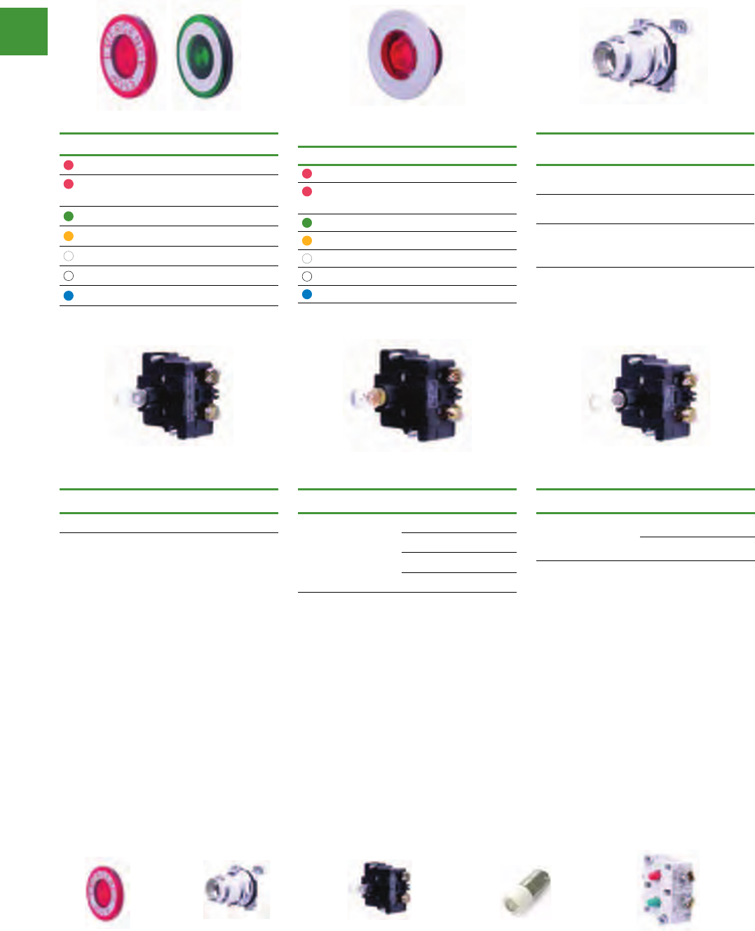
30.5Mm pushbuttons
Illuminated operators, push-pull mushroom lenses
Control and indication
Power control
161 2015/2016 Product guide AUS15_007 - February 2016
Standard push-pull lenses
Colour Item no.
Red E34M2
Red
(Emergency Stop) E34M2N8
Green E34M3
Amber E34M9
Clear E34M0
White E34M5
Blue E34M6
Side lighted anodised
aluminium lenses
Colour Item no.
Red 10250TC57
Red
(Emergency Stop) 10250TC63
Green 10250TC58
Amber 10250TC64
Clear 10250TC62
White 10250TC61
Blue 10250TC59
Illuminated push-pull operators
Description Supply
voltage Chrome Corrosion
resistant
Maintained
Push & Pull 2T5 E34GDB
Momentary
Push & Pull 3T4 E34GEB
Maintained
Push &
Momentary Pull
3T9 E34GFB
Illuminated push-pull operators
Light units for illuminated push-pull operators
Resistor type light modules for push-
pull operators
Description Voltage Item no.
Resistor Type
120V bulb
supplied
120 10250T80
240 10250T81
Direct voltage light modules for push-
pull operators
Description Voltage Item no.
Direct Voltage 6-240V 10250T70
Order bulb separately - see next page for bulbs.
Can be used with LEDs.
Transformer type light modules
for push-pull operators
Description Voltage Item no.
Transformer Type
6V secondary
bulb supplied
110/120 10250T63
220/240 10250T65
380/415 10250T66
440/480 10250T67
Select
push-pull
operator
from above
Select a
lens from
above.
STEP 2STEP 1
Select light
unit from
above
STEP 3
Select bulb
(if not
supplied)
STEP 4
Select
contact
block.
STEP 5
(previous page)

30.5Mm pushbuttons
Illuminated operators, bulbs
Control and indication
Power control
162
2015/2016 Product guide AUS15_007 - February 2016
Incandescent bulbs
Supply voltage Watts Item no.
6.3V 0.9W 28-2225-33
24V 1.2W 28-2225-13
130V 2.2W 28-2225-24
Bright LED bulbs - single chip (ac/dc)
Colour 6V 12V 24V
Red 21BA9SL6R 21BA9SL12R 21BA9SL24R
Green 21BA9SL6V 21BA9SL12V 21BA9SL24V
Yellow 21BA9SL6G 21BA9SL12G 21BA9SL24G
White 21BA9SL6W 21BA9SL12W 21BA9SL24W
Bright LED bulbs - single chip (ac/dc)
Colour 110V 240V
Red 21BA9SL110R 21BA9SL240R
Green 21BA9SL110V 21BA9SL240V
Yellow 21BA9SL110Y 21BA9SL240A
White 21BA9SL110W 21BA9SL240W
Super bright LED bulbs
(recognisable in outdoor daylight applications - ac/dc)
Colour 6-12V 24V 120V
Red E22LED612RN E22LED024RN E22LED120RN
Green E22LED612GN E22LED024GN E22LED120GN
Yellow E22LED612YN E22LED024YN E22LED120YN
White E22LED612WN E22LED024WN E22LED120WN
Neon bulbs
Supply voltage Colour Item no.
110V Clear BA9S110N
240V Clear BA9S240N
240V Green BA9S240NG
240V Red BA9S240NR

30.5Mm pushbuttons
Selector switch operators,
Control and indication
Power control
163 2015/2016 Product guide AUS15_007 - February 2016
Selector switch
knobs & levers
Knobs & levers
Description Material Item
no.
Knob Plastic E34K1
Metal T341M
Lever Plastic E34L1
Plastic E34A1*
* For maintained operators only.
2 Position selector switches
Description
(M = Maintained,
S = Spring Return)
Chrome Corrosion
resistant
M M
M M
M
M S
M
M S
MS
M
S S
M
MM
MM
T4011 E34VFB
M M
M M
M
M S
M
M S
MS
M
S S
M
MM
MM
T4081 E34VEB
4 Position selector switches
Description
(M = Maintained,
S = Spring Return)
Cam
code* Chrome Corrosion
resistant
Maintained 7 T4067 E34VTB
* See cam selection chart to determine cam code.
3 Position selector switches
Description
(M = Maintained
S = Spring Return)
Cam
code* Chrome Corrosion
resistant
M M
M M
M
M S
M
M S
MS
M
S S
M
MM
MM
2T4022 E34VGB
3T4023 E34VHB
4T4024 -
6T4026 -
M M
M M
M
M S
M
M S
MS
M
S S
M
MM
MM
2T4032 E34VJB
3T4033 E34VKB
M M
M M
M
M S
M
M S
MS
M
S S
M
MM
MM
2T4042 E34VLB
3T4043 E34VMB
M M
M M
M
M S
M
M S
MS
M
S S
M
MM
MM
2T4052 E34VNB
3T4053 E34VPB
Selector switches & joystick operators, cam selection guide
Cam selection chart showing contact sequence
Item No.
of contact
block
Circuit
Position selector switch
233334
Cam
code
no. 1
Cam
code
no. 2
Cam
code
no. 3
Cam
code
no. 4
Cam
code
no.6
Cam
code
no.7
T1P A.N.C. XO OXO OXX XOO XOO XOOO
B.N.O. OX OOX OOX OXO OXO OXOO
T1P A.N.O. OX XOX XOO OXX OOX OOXO
B.N.C. XO XXO XXO XOX OOX OOOX
T2P A.N.O. OX XOX XOO OXX OOX OOXO
B.N.O. OX OOX OOX OXO OXO OXOO
T3P A.N.C. XO OXO OXX XOO XOO XOOO
B.N.C. XO XXO XXO XOX OOX OOOX
Switching angle 60o between each position. Rated for ac only. Refer to
actual installation instructions given with each switch for additional switching
combinations. To determine the number of the cam you require & the
correct contact block, select the contact sequence desired from table above.
O = contacts open, x = contacts closed. The cam number is shown at top
of column. The item number of the appropriate contact block is shown in
column 1. At extreme left of table.
Each contact block contains two contact circuits. The top set of contacts
is identified as ‘circuit a’ & the lower set as ‘circuit b’ is indicated in the table.
The chart shows the contact arrangements with the three contact blocks
available & in each operator position. Additional contacts are obtainable
by stacking contact blocks up to a maximum of 6 blocks (12 circuits). A
maximum of 2 can be used with cam 6.
Select
bare shaft
operator
STEP 1
Choose cam based on
contact sequence from cam
selection guide table above
(applies to 3 position
selector switches only)
STEP 2
Select knob
or lever
STEP 3
Select
contact
block.
STEP 3
(previous page)(previous page)
E34K1 T341M
E34L1 E34A1
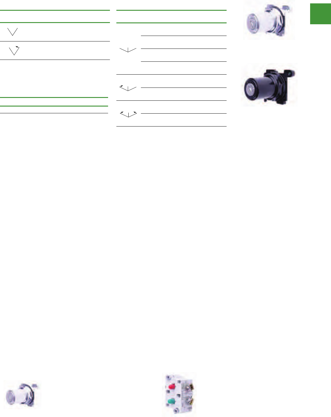
30.5mm Pushbuttons
Control and indication
Power control
164
2015/2016 Product guide AUS15_007 - February 2016
Spare key
Description Item no.
Replacement Keys (2) TA152
Other key codes are available contact eaton for
more information.
Key operated selector switches
2 Position key operated selector switches
2 Position Cam Key
removal Chrome Corrosion
resistant
M M
M M
M
M S
M
M S
MS
M
S S
M
MM
MM
-Right &
Left T15113 E34KFB3
M M
M M
M
M S
M
M S
MS
M
S S
M
MM
MM
-Left Only T15712 E34KEB2
3 Position key operated selector switches
3 Position Cam Key
removal Chrome Corrosion
resistant
M M
M M
M
M S
M
M S
MS
M
S S
M
MM
MM
2Left Right
& Centre T15227 E34KGB7
3Left Right
& Centre T15237 E34KHB7
4Left Right
& Centre T15247 -
6Left Right
& Centre T15267 -
M M
M M
M
M S
M
M S
MS
M
S S
M
MM
MM
2Right &
Centre T15325 E34KJB5
3Right &
Centre T15335 E34KKB5
M M
M M
M
M S
M
M S
MS
M
S S
M
MM
MM
2Centre
Only T15424 E34KLB4
3Centre
Only T15434 E34KMB4
Select
switch
operator
STEP 1
Choose cam based on
contact sequence from cam
selection guide table above
(applies to 3 position
selector switches only)
STEP 2
Select
contact
block.
STEP 3
(previous page)
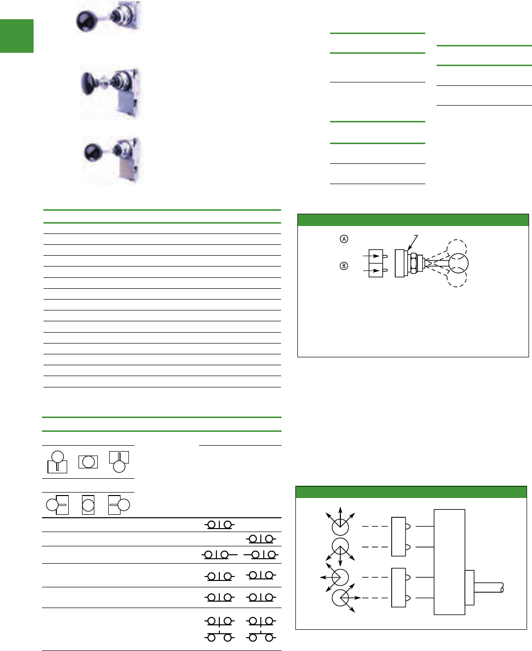
Control and indication
Power control
165 2015/2016 Product guide AUS15_007 - February 2016
Maintained positions
Up Down Left Right Suffix No.*
X — — — 1
— X — — 2
— — X — 3
— — — X 4
X X — — 5
X — X — 6
X — — X 7
— X X — 8
— X — X 9
— — X X 10
X X X — 11
X X — X 12
X — X X 13
— X X X 14
X X X X 15
Two-position joystick operators - contact block operation
Figure 47-97. A and B Mounting Location
Up
Center
Down
Locating Nib
Top
contacts
Bottom
contacts
Centre
All NC and NO
contacts are open
(1/2 Way) late
Opening NC is
closed
Up
NC contact at
the top is closed
NO at the
bottom is closed
Down
NC contact at
the bottom is
NO at the top
is closed
closed
Figure 1, A and B Mounting Location
Contact block selection & mounting
Handle position Contact block Mounting location
Up Centre Down
Item
no. Type
Top Bottom
A B
Left Centre Right
X O O T51P 1NC
O O X T51P 1NC
O X O T45 2LONC
X
O
O
O
O
XT3P 1NC
1NC
X
O
X
X
O
XT45 1LONC
1LONC
X
O
O
V
O
O
O
O
O
X
X
O
T44
1NC
1NO
1NC
1NO
X = closed circuit, O = open circuit.
NO = Normally Open, NC = Normally Closed, LONC = Late
Opening Normally Closed.
Four circuits in single block depth — rated 300V max.
Four-position joystick operators - contact block operation
Contact blocks mount directly on the back of the operator. For
reliable operation, the maximum number of contact blocks that
should be installed behind each operator lever is 2 (4 contacts
total). Figure 2 identifies the circuits activated by each of the eight
possible lever positions. Contact block plungers 1, 2, 3, 4 are
depressed (change state) when handle is in the position indicated
by arrows in Figure 2.
:tisiv noitamrofni erom roFE10020180AC www.eaton.com
1
2
3
4
Contact Blocks . . . . . . . . . . . . . . . . . . . Page 47-148
Discount Symbol . . . . . . . . . . . . . . . . . . 1CD1C
Application caution
Joystick operators are not recommended on certain DC
applications above 24V DC which may involve lightly engaging the
contacts (teasing) to achieve speed control, positioning, jogging,
etc. Excessive arcing & deterioration of the contacts will occur.
Figure 2, Circuit Activation
Two-Position Joystick Operators
The device mounts in the standard 30.5
mm mounting hole.
Four-Position Joystick Operators
The joystick operated control unit is
intended for AC application only. The
panel area required for the 4-position
operator is equivalent to two standard
pushbutton operators.
Latched Joystick Operators
The latch holds the lever in the centre
position. The trigger latch must be
released before lever can moved into any
position.
2 Position
joystick operator
Description
Item
no.
2 position operator
- Momentary Up &
Down
T452
4 Position
joystick operators
(spring return only)
Description
Item
no.
4 position -
Without Latch T450
4 position -
With Latch T460
4 Position
joystick operators
(maintained)
Description Item
no.
4 position -
Without Latch
10250
T451_*
4 position - With
Latch
10250
T461_*
*Maintained Position
For maintained position
(non-spring return), locate
required maintained position or
positions of operating lever in
the Maintained table below &
add appropriate Suffix Number
to the Item Number selected
from the table above.
Selector switches & joystick operators, joystick operators
30.5Mm pushbuttons
Latched
Operator
2 position
Operator
4 position
without latch
30.5Mm pushbuttons control station and enclosures
Standard pushbuttons, flush, extended & half-shrouded buttons,
Control and indication
Power control
166
2015/2016 Product guide AUS15_007 - February 2016
Diecast aluminium enclosures
Standard
No. Of
holes
Single - depth
T series
Corrosion
resistant
1TN1 E34N1
2TN2 E34N2
3TN3 E34N3
4TN4 E34N4
Stainless steel enclosures
Stainless steel
No. of holes 316 Stainless
1XBS130
2XBS230
3XBS330
4XBS430
6XBS630
8XBS830
9XBS930
Corrosion resistant
No. of
holes
Double depth
T series
Corrosion
resistant
1TN11 E34N11
2TN12 E34N12
3TN13 E34N13
4TN14 E34N14
6TN15 -
1-2 Hole: 3/4 inch conduit entry hole, 2-6 hole:
1 inch conduit bottom-entry hole, 1.5 Inch unf
thread IP66.
Fibreglass enclosures
Fibreglass
No. of holes Item no.
1TFG11
2TFG12
3TFG13
20mm non-threaded conduit bottom-entry hole
IP66, UV stabilised.
Assembled control stations
Push-pull stop stations (padlockable)
Operator head Contacts Item no.
Metal mushroom
45mm
1LONC 10250T700M
1ECNO,1LONC 10250T701M
Metal palm
63.5mm
1LONC 10250T700P
1ECNO,1LONC 10250T701P
“Staylock” push-pull stop stations (non-padlockable)
Operator head Contacts Padlock
included Item no.
Metal Mushroom
45mm
1LONC NO ESM9/5
1LONC YES ESM9/5P
1ECNO,1LONC NO ESM9/6
1ECNO,1LONC YES ESM9/6P
Metal Palm
63.5mm
1LONC NO ESP6/5
1LONC YES ESP6/5P
1ECNO,1LONC NO ESP6/6
1ECNO,1LONC YES ESP6/6P
Stop start pushbutton station
Description Item no.
Fibreglass Enclosure. Start: green pushbutton with boot
Stop: red padlockable mushroom with boot T3500
TN4
XBS330 TFG12
TN2 TN11
ESM9/6
10250T700P
T3500

30.5mm Pushbuttons accessories
Control and indication
Power control
167 2015/2016 Product guide AUS15_007 - February 2016
Padlock attachments Description Item no.
With hinged transparent flap. For flush or extended
pushbuttons, & knob-operated selector switches Plastic Cover TA38
For flush stop button. Permits locking NC contacts in open
position with padlock. Prevents operation of button. Will not
lock NO contact
Chrome TA2
Corrosion resistant E34TA2
For extended pushbutton. Permits locking NC contacts in
open position with padlock Chrome TA26
For illuminated pushbuttons. Locks in down position only Chrome 10250TA64
Boots Colour Item no.
Protective boot for flush pushbutton operators
Clear 10250TA46
Blue 91000TA46
Black TA47
Red TA48
Green TA49
Yellow TA50
Protective boot for extended pushbutton operators
Black TA3
Red TA4
Green TA10
Clear TA85
Protective boot for illuminated pushbuttons. Clear TA25
Protective boot for momentary mushroom operators on page
295. Not suitable for use with T140 operator. Black TA88
Shrouds & guards Description Item no.
Shroud for Mushroom
Head Operator
Prevents accidental operation. Not for push-pull
operators. Momentary operators only
10250TA6
E34TA6
Extended Retaining Nut Replaces standard nut &
provides guard for flush head pushbutton operators.
10250TA12
E34TA12
Guard for Illuminated
Pushbutton Guard for Illuminated Pushbutton 10250TA15
E34TA15
Shroud
For jumbo mushroom head
operator. Available in Grey & Yellow (Not for push-
pull operators, momentary operators only.)
TA56
10250TA56Y
Half Shroud – Yellow For jumbo mushroom head operator. 10250ED1241
Hardware & kits Description Item no.
Fingerproof
Shroud 10 per Package Fits new style contact blocks & light units. 10250TA101
Spacer Ring Used when legend plate is not required. Set of 5 TA8
Base Mounting
Spacers
Equivalent to contact block in depth — Complete with
screws, washers, etc. For use in pushbutton stations for
base mounting contact blocks.
1 Block Deep
2 Blocks Deep
TA22
TA23
TA38
TA26
TA25
TA48
10250TA12
E34TA12
TA56
10250TA56Y
TA8
TA2
TA85
10250TA64
10250TA6
E34TA6
10250TA15
E34TA15
10250ED1241
TA22

30.5mm Pushbuttons accessories
Control and indication
Power control
168
2015/2016 Product guide AUS15_007 - February 2016
Special operators & attachments Description Item no.
Wobble Stick Complete with retaining nut —
fits standard button. TA5
Maintained Contact
Attachment
Mechanically interlocks two buttons &
provides position indication for one. Use
with two pushbutton operators & one or
more contact blocks.
TA1
Hole plugs Description Item no.
Plug For unused holes — Steel, painted grey 10250TA7
Stainless Steel Plug For unused holes —
Stainless Steel - Square E30KT5
Tools Description Item no.
Octagonal Tool Octagonal notched to fit over selector
switch lever 10250TA95
Tool for Tightening Boots Used to install boot TA96
Allen Key Used for removal of jumbo mushroom head. 10250TA102
Special light modules Description Item no.
Flasher Module
Changes any AC illuminated device to a
controlled flashing light.
24V s
120V
TFL2
TFL1
Legend Plates
Description Item no.
Aluminium T-Range, large size, black unless marked “red” TJ_ _
Aluminium T-Range, medium size, black unless marked “red” TM_ _
Stainless steel T-Range, medium size, black, blank TM36S
Stainless steel T-Range, medium size, red, blank TM37S
Plastic E34 range universal size, black unless marked “red” E34SP_ _
Legend T-Range large
Item no.
T-Range medium
Item no.
E34 universal
Item no.
Blank TJ36 TM36 TSP76
Blank (red) TJ37 TM37 TSP77
Off (red) TJ24 TM24 E34SP24
On TJ25 TM25 E34SP25
Run TJ31 TM31 E34SP31
Start TJ33 TM33 E34SP33
Stop (red) TJ34 TM34 E34SP34
TJ34
TM31
E34SP34
TA5
10250TA7
TA96
TFL2
TA1
10250TA95
10250TA102

30.5mm Pushbuttons
30.5mm Pushbuttons, dimensions & technical data
Control and indication
Power control
169 2015/2016 Product guide AUS15_007 - February 2016
Diecast aluminium enclosure dimensions
Wide High Single depth Double depth
1 98.6 101.6 57.2 76.3
2 98.6 149.4 57.2 76.3
3 98.6 196.9 57.2 76.3
4 98.6 244.6 57.2 76.3
Fibreglass enclosure dimensions
Wide High Deep
1 97 100 75
2 97 150 75
3 97 200 75
316 Stainless steel enclosure dimensions
Wide High Deep
1120 120 84
2120 160 84
3120 220 84
4120 280 84
47-161
Approximate Dimensions in mm
19.1 21.3 23.9
41.4 52.3
9.7
21.3 38.1
6.4
26.9
47.8
95.3
Lever Operator
(For Use with Two Vertically
Mounted Flush Pushbuttons)
Catalog No. 10250TA14
Padlock Attachment
for Flush Pushbutton
Catalog No. 10250TA2
Padlock Attachment
for Extended Pushbutton
Catalog No. 10250TA26
55.6 91.2
Cam
2-position joystick operator 4-position joystick operator
101.6
47.8 95.3
31.8
30.2
22.4
per unit
52.3 63.5
main.
55.9
mom.
54.1
31.8
98.622.6
22.4
per block
1.5 to 6.6
Panel thickness
Contact
block
Maintained Pushbutton
Catalog No. 10250TA66
Typical
Flexible boot for
protecting flush
or long push button
Catalogue no.
10250TA3
Typical 40.4
37.3
Transparent flexible boot for
illuminated pushbutton
Catalogue no. 10250TA25
33.840.4
47.8
22.6
Adjustable
22.4
for each additional
contact block 27.2
41.1
Min.
63.5
Max.
35.1
28.7
44.5
Key operated
selector switch
35.1
28.7
27.7 49.8
Illuminated Selector
Switch
A
Lever
Knob
Operator Dim. A
Knob
Lever
35.1
38.1
24.6
41.4
Padlock Attachment
for Knob Selector Switch
Catalog No. 10250TA11
Maintained Contact
Attachment
Catalog No. 10250TA17 Typical
11.2
23.1
41.4
Min.
58.7
Max.
28.7
35.1
28.7
38.9
9.7
Long
Button
Only
35.1
kcitS elbboW
Catalog No. 10250TA5
Roto-Push
36.6
31
62
21°
21°
Press-To-Test Indicating Light – Resistor Type
epyT noeN dna rotsiseR – thgiL gnitacidnI
46
47.8
47.8 39.6
A
27.9
48.5
Pushbutton with
Cylinder Lock
28.7
35.1
Flush and long pushbutton half shroud is the same as the
long pushbutton with lower half of guard ring cut back
46 27.7 26.9 9.7
35.1
45.2
Long
button
only
Mushroom and
jumbo head pushbutton
28.7
22.4
For each additional
contact block
44.5
41.4
38.1
63.5
1.5 to 6.4
Panel thickness
Illuminated Pushbutton
27.7 27.7 17.5
28.7
35.1
Flush Pushbutton Operator
with Padlock Attachment
51.6 50.827.7
28.7
45.2
45.2 35.1
45.2 35.1
Indicating Light – Transformer Type
45.7
45.2
A
27.9
35.1
Jumbo Mushroom Head Pushbutton Operator
with Padlock Attachment
63.5
58.7 60.5
44.5
Press-To-Test Indicating Light – Transformer Type
49.3 39.6
35.1
55.6
45.2
Mushroom Head Pushbutton Operator
with Padlock Attachment
38.1
41.4
63.5 50.8
44.5
Push-Pull Switch
66.8
41.9
45.26.4
1.5 to 6.4
Panel thickness
22.4 22.4
28.7
Approximate Dimensions in mm
Lens Dimension A
Plastic 35.1
Glass 39.6

30.5mm Pushbuttons
30.5mm Pushbuttons, dimensions & technical data
Control and indication
Power control
170
2015/2016 Product guide AUS15_007 - February 2016
47
41.9
Protecting Shroud for
Jumbo Mushroom Head Button
Catalog No. 10250TA56
82.6
44.5
38.1
21.3
Protecting Shroud for
Illuminated Pushbutton
Catalog No. 10250TA15
Protecting Shroud for
Mushroom Head Button
Catalog No. 10250TA6
Padlock Hasp or
Flip-Up Guard
Catalog No. TA38
38.9 38.1
44.5
42.9
9.7
Padlock Cover Guard
for Flush Pushbutton
Catalog No. 10250TA36
29.5 25.4
48.5
55.6
19.1
23.1
Padlock Attachment
for Maintained Push-Pull Operator
Catalog No. 10250TA64
55.6
37.3 31.8
9.7
23.9
41.4
29
6 Mounting Holes
45.2 A
33.3
Master Test Module,
Flasher Module Legend Plate
B
A C
D
Chain Hook Bracket
BE
9.7
Dia. Hole
Approximate Dimensions in mm
Enclosure size
(No. of
elements)
Dimensions in inches (mm)
Mounting
Wide
A
High
B
Deep
CD E
Panel drilling and
minimum spacing
If Jumbo plates are to be placed
one above the other vertically, add
3.3 to minimum dimensions listed.
Note: Locating nib hole or notch
is 3.45 - 3.56 mm #29 drill.
Legend
plate
Dim. in mm
A Min
1 or 2 Circuit contact blocks
4 Circuit contact block 10250T44
Small or None 41.4 57.2
Standard 44.5 57.2
Jumbo 57.2 57.2
Extra Large 63.5 66
Small or None 47.8 57.2
Standard 47.8 57.2
Jumbo 57.2 57.2
Extra Large 63.5 66
B Min.
For plastic legend plate,
Dimension B is 28.4
1/2 Round Legend Plates
Square Legend Plates
Legend
plate
Small 39.6 23.1
Standard 40.4 27.2
Jumbo 52.3 38.9
Small 40.4 Sq. 22.9
Standard 44.5 Sq. 26.9
Jumbo 55.6 Sq. 38.1
Extra Large62.0 Sq. 41.4
Dim. in mm
AB
Number of
elements
Dimension
A
2 101.6
3 149.4
4 202.2
7 339.9
54.9
33.3
47.8
19.1
Multiple Button Guard
A
B
Min.
A
Min.
Terminals on Top
A
Min.
15.2
31
B
Min.
Terminals at
Side
Horizontal Rows Vertical Rows
Extended Retaining Nut
Catalog No. 10250TA12
35.1
33.3
31.8

Control and indication
Power control
171 2015/2016 Product guide AUS15_007 - February 2016
Features
• Heavy-duty zinc die cast construction
• Enclosed silver contacts with reliability nibs
• Diaphragm seals with drainage holes
• Grounding nibs on the operator casing
Benefits
• Reliability nibs improve contact reliability even under dry circuit
& fine dust conditions
• Drainage holes prevent buildup of liquid inside the operator
which can prevent operation in freezing environments
• Grounding nibs bite through paint & other coatings to provide
secure ground
Contact operation
Slow make & break. All normally closed contacts have positive
opening operation, i.e., normally closed contacts are forced open in
the event of contact weld or spring breakage.
Standards & certifications
• CE EN60947-5-1
• UL 508 — File No. 131568
• CSA C22.2 No. 14 — File No. LR68551
Ingress protection (when mounted in similarly rated enclosure):
• Standard Indicating Lights: UL (NEMA) Type 1, 2, 3, 3R, 3S, 4,
4X, 12, 13, IEC IP65
• All Other Operators: UL (NEMA) Type 1, 2, 3, 3R, 4, 4X, 12, 13,
IEC IP65
Technical data & specifications
Mechanical ratings:
• Frequency of operation: All pushbuttons 6000 operations/hr,
Key & lever selector switches 3000 operations/hr, Auto-latch
devices 1200 operations/hr.
• Life: Pushbuttons 10 x 106 operations, Contact blocks: 10 x
106 operations, PresTest units 10 x 106 operations, Lever &
key selector switches 0.25 x 10⁶ operations, Twist to release
pushbuttons 0.3 x
106 operations,
• Shock resistance: Duration 20 mS 5g
Climate conditions:
• Operating Temperature (-17° to 66°C), Storage Temperature
(-40° to 80°C), Altitude 2,000m (6,562 ft.), Humidity Max. 95%
RH @ 60°C
Terminals:
• Marking: NC-NO on the contact block to meet the NEMA
requirements. Dual marking system 1 – 2 for normally closed,
3 – 4 for normally open to meet BS5472 (Cenelec EN50 005)
• Clamps: Terminals are saddle clamp type for 1 x 22 AWG (0.34
mm2) to 2 x 14 AWG (2.5 mm2) conductors
• Torque = 7 lb-in (0.8 Nm)
• Degree of protection against direct electrical contact: IP2X
with fingerproof shroud
Light units:
• Transformers: will withstand short circuit for 1 hour per IEC
60997-5-1
• Bulbs — average life: Transformer type 20,000 hrs., Resistor/
direct voltage type 2500 hrs. minimum @ rated V, LED 60,000
to 100,000 hrs.
Electrical ratings:
• Insulation: Ui = 660V AC or DC
• Thermal: lth = 10A
• Short Circuit Coordination to IEC/EN 60947-5-1:
• Rated conditional short circuit current: 1 kA
• Fuse type: GE Power Controls TIA 10, Red Spot Type gG, 10A,
660V AC, 460V DC, BS88-2, IEC 60269-2-1
•
• UL rating: A600, P600: AC load life duty cycle 1200 operations/
hour (– 10A: 110V pf 0.4 – 1 x 10⁶ operations, – 5A: 250V
pf 0.4 – 1 x 10⁶ operations, – 2A: 660V pf 0.4 – 1 x 10⁶
operations)
• Switching capacity: AC15 rated make/break (11 x le at 1.1 x
Ue),
(– 6A: 120V pf 0.3, – 4A: 240V pf 0.3, – 2A: 660V pf 0.3).
DC13 rated make/break (1.1 x le at 1.1 x Ue), (– 1.0A: 125V L/R
0.95 at 300 mS, – .55A: 250V L/R 0.95 at 300 mS, – .1A: 660V
L/R 0.95 at 300 mS, – 10A: 110V pure resistive)
• Maximum ratings for logic level & hostile atmosphere
application: Maximum amperes: 0.5A
Maximum volts: 120V AC/DC
Contact block
Meet or exceed NEMA rating designations A600, A300 and B300 AC
P600 DC
Description Volts SC 50 or 60 Hz Volts DC
120 240 480 60 24 125 250
Make and Emerg. Interruptimng capacity (Amp) 60 30 15 12 5.7 1.1 0.55
Normal load break (Amp) 6 3 1.5 1.2 5.7 1.1 0.55
Thermal current (Amp) 10 10 10 10 5.0 5.0 5.0
Voltampress(VA)
Make and Emerg. Interruptimng capacity 7200 7200 7200 7200 138 138 138
Normal load break 720 720 720 720 138 138 138
30.5mm Pushbuttons, dimensions & technical data

Control and indicationControl and indication
Power control
172
2015/2016 Product guide AUS15_007 - February 2016
Stacklights - SL7 range
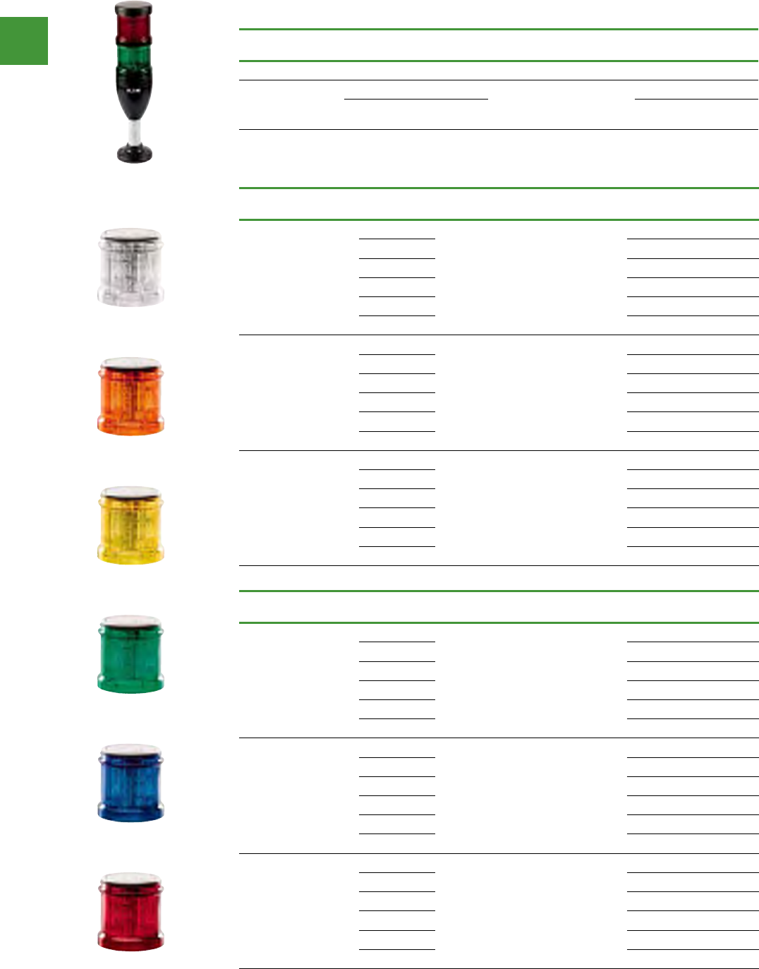
Control and indication
Power control
173 2015/2016 Product guide AUS15_007 - February 2016
Complete devices
Continuous light, LED, UL type 4/4X/13, IP66
Rated operational
voltage (Ue V)
Number of
modules Color Function Standard
pack Item no.
Base Module with Foot and 100 mm Tube
24 Vac/Vdc
2 Red/Green
1
SL7-100-L-RG-24LED
3Red/Amber/
Green SL7-100-L-RAG-24LED
Light Module with LED
Continuous light, UL type 4/4X/13, IP66
Rated operational
voltage (Ue V) Color Function Standard
pack Item no.
24 Vac/Vdc
Blue
1
SL7-L24-B
Green SL7-L24-G
Red SL7-L24-R
White SL7-L24-W
Yellow SL7-L24-Y
Amber SL7-L24-A
110/120 Vac
Blue
1
SL7-L120-B
Green SL7-L120-G
Red SL7-L120-R
White SL7-L120-W
Yellow SL7-L120-Y
Amber SL7-L120-A
230/240 Vac
Blue
1
SL7-L230-B
Green SL7-L230-G
Red SL7-L230-R
White SL7-L230-W
Yellow SL7-L230-Y
Amber SL7-L230-A
Flashing light, UL type 4/4X/13, IP66, 2 Hz
Rated operational
voltage (Ue V) Color Function Standard
pack Item no.
24 Vac/Vdc
Blue
1
SL7-BL24-B
Green SL7-BL24-G
Red SL7-BL24-R
White SL7-BL24-W
Yellow SL7-BL24-Y
Amber SL7-BL24-A
110/120 Vac
Blue
1
SL7-BL120-B
Green SL7-BL120-G
Red SL7-BL120-R
White SL7-BL120-W
Yellow SL7-BL120-Y
Amber SL7-BL120-A
230/240 Vac
Blue
1
SL7-BL230-B
Green SL7-BL230-G
Red SL7-BL230-R
White SL7-BL230-W
Yellow SL7-BL230-Y
Amber SL7-BL230-A
Stacklights - SL7 range
White
Yellow
Blue
Amber
Green
Red
SL7-100-L-RG-24LED
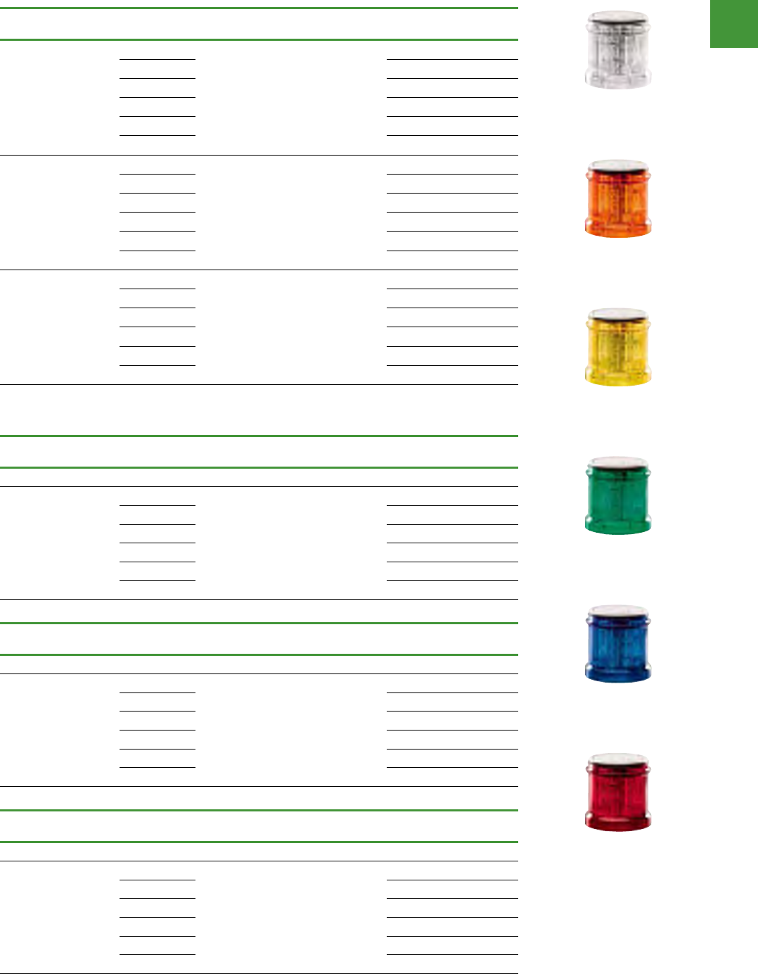
Control and indication
Power control
174
2015/2016 Product guide AUS15_007 - February 2016
Light module with LED
Strobe light, UL type 4/4X/13, IP66, 1.4 Hz
Rated operational
voltage (Ue V) Color Function Standard
pack Item no.
24 Vac/Vdc
Blue
1
SL7-FL24-B
Green SL7-FL24-G
Red SL7-FL24-R
White SL7-FL24-W
Yellow SL7-FL24-Y
Amber SL7-FL24-A
110/120 Vac
Blue
1
SL7-FL120-B
Green SL7-FL120-G
Red SL7-FL120-R
White SL7-FL120-W
Yellow SL7-FL120-Y
Amber SL7-FL120-A
230/240 Vac
Blue
1
SL7-FL230-B
Green SL7-FL230-G
Red SL7-FL230-R
White SL7-FL230-W
Yellow SL7-FL230-Y
Amber SL7-FL230-A
SL7 Light module with high-output LED
Continuous light, UL type 4/4X/13, IP66
Rated operational
voltage (Ue V) Color Function Standard
pack Item no.
High-performance LED for maximum signaling effect
24 Vac/Vdc
Blue
1
SL7-L24-B-HP
Green SL7-L24-G-HP
Red SL7-L24-R-HP
White SL7-L24-W-HP
Yellow SL7-L24-Y-HP
Amber SL7-L24-A-HP
Strobe light, UL type 4/4X/13, IP66
Rated operational
voltage (Ue V) Color Function Standard
pack Item no.
High-performance LED for maximum signaling effect, 1.4 Hz
24 Vac/Vdc
Blue
1
SL7-FL24-B-HP
Green SL7-FL24-G-HP
Red SL7-FL24-R-HP
White SL7-FL24-W-HP
Yellow SL7-FL24-Y-HP
Amber SL7-FL24-A-HP
Multi-Strobe light, UL type 4/4X/13, IP66
Rated operational
voltage (Ue V) Color Function Standard
pack Item no.
High-performance LED for maximum signaling effect, 1–2.6 Hz
24 Vac/Vdc
Blue
1
SL7-FL24-B-HPM
Green SL7-FL24-G-HPM
Red SL7-FL24-R-HPM
White SL7-FL24-W-HPM
Yellow SL7-FL24-Y-HPM
Amber SL7-FL24-A-HPM
Stacklights - SL7 range
White
Yellow
Blue
Amber
Green
Red

Control and indication
Power control
175 2015/2016 Product guide AUS15_007 - February 2016
SL7 Light module for incandescent bulb
Continuous light, UL type 4/4X/13, IP66
Rated operational
voltage (Ue V) Color Function Standard
pack Item no.
Without Light Elements, Incandescent Bulb, Maximum 7W
<250 Vac/Vdc
Blue
1
SL7-L-B
Green SL7-L-G
Red SL7-L-R
White SL7-L-W
Yellow SL7-L-Y
Amber SL7-L-A
Stacklights - SL7 range
SL7 Acoustic modules
Continuous tone or pulsed tone, UL type 4/4X/13, IP66
Rated operational
voltage (Ue V)
Rated operational
current (Ie mA) Color Function Sound type Standard
pack Item no.
Adjustable with internal DIP switches.
Sound pressure 100 dB, adjustable with internal potentiometer.
f = 2800 Hz.
24 Vac/Vdc Maximum 92
Black 1
SL7-AP24
110/120 Vac Maximum 41 SL7-AP120
230/240 Vac Maximum 43 SL7-AP230
Continuous tone or pulsed tone, external actuation, UL type 4/4X/13, IP66
Rated operational
voltage (Ue V)
Rated operational
current (Ie mA) Color Function Sound type Standard
pack Item no.
Assigned two inputs (two modules).
Sound pressure 100 dB, adjustable with internal potentiometer.
f = 2800 Hz.
24 Vac/Vdc Maximum 92
Black 1
SL7-AP24-E
110/120 Vac Maximum 41 SL7-AP120-E
230/240 Vac Maximum 43 SL7-AP230-E
Continuous tone or pulsed tone, external actuation, UL type 4/4X/13, IP66
Rated operational
voltage (Ue V)
Rated operational
current (Ie mA) Color Function Sound type Standard
pack Item no.
Adjustable with internal DIP switch.
Sound pressure 100 dB, adjustable with internal potentiometer.
f = 500–2700 Hz.
24 Vac/Vdc Maximum 115
Black 1
SL7-AP24-M
110/120 Vac Maximum 45 SL7-AP120-M
230/240 Vac Maximum 43 SL7-AP230-M
Place only at the highest position on a pole.
SL7-AP24
SL7-AP230-M
SL7-AP120-E
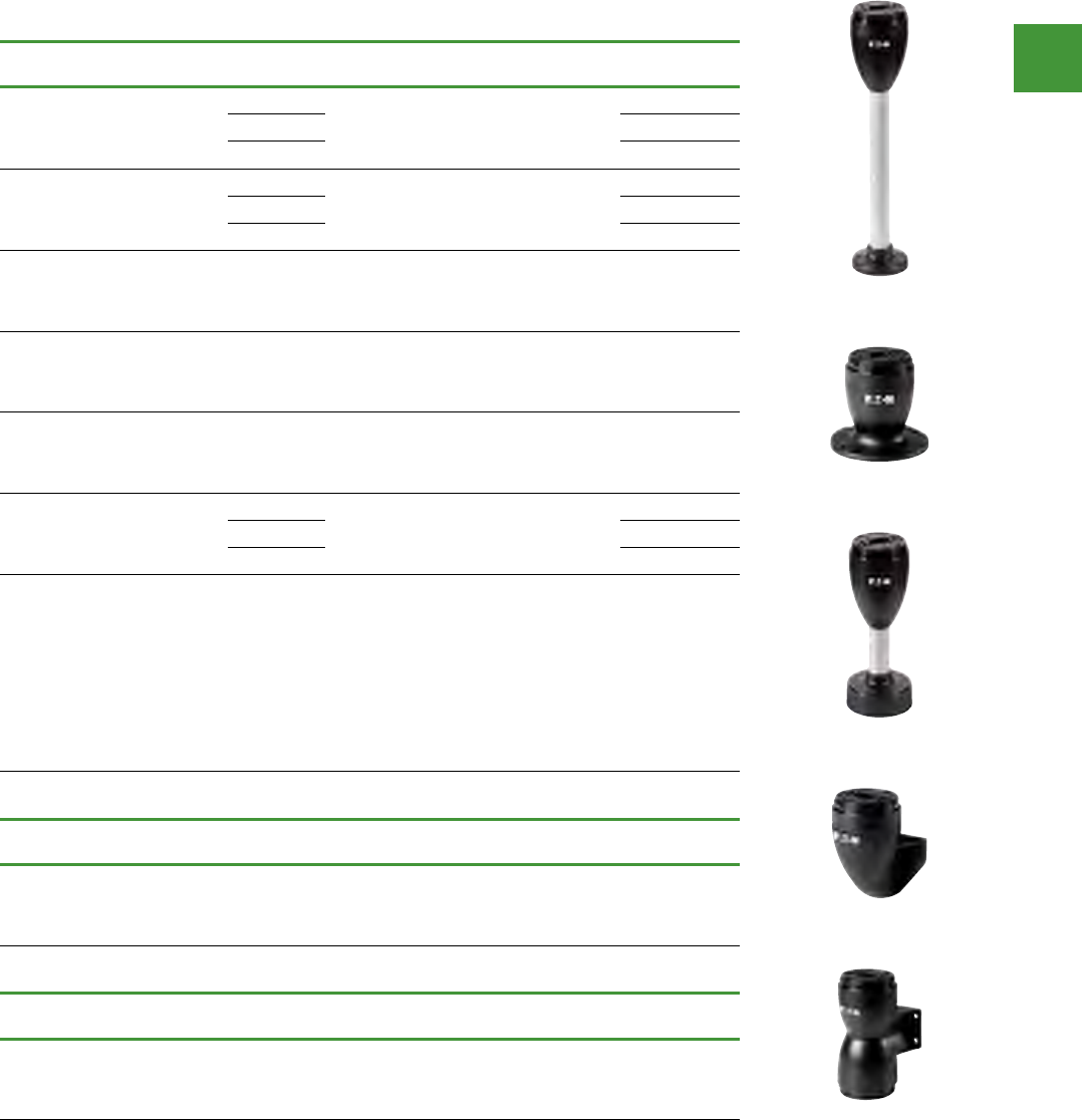
Control and indication
Power control
176
2015/2016 Product guide AUS15_007 - February 2016
Stacklights - SL7 range
SL7 Base modules
For horizontal mounting—Includes cover, maximum 5 modules
Description Tube
length Color Standard
pack
For use
with.. Item no.
Base with aluminum tube and
plastic foot
Spring-loaded terminals
100 mm Black
aluminum
color tube
1
SL7-L-…
SL7-BL-…
SL7-FL-…
SL7-AP-…
SL7-CB-100
250 mm SL7-CB-250
400 mm SL7-CB-400
Base with aluminum tube and
3/4 in NPT threaded base
Spring-loaded terminals
100 mm Black
aluminum
color tube
1
SL7-L-…
SL7-BL-…
SL7-FL-…
SL7-AP-…
SL7-CB-T-100
250 mm SL7-CB-T-250
400 mm SL7-CB-T-400
Base with internal (on the
inside)xingholes
Spring-loaded terminals
Black 1
SL7-L-…
SL7-BL-…
SL7-FL-…
SL7-AP-…
SL7-CB-IMH
Base with built-in
(pre-assembled)xingscrews
Spring-loaded terminals
Black 1
SL7-L-…
SL7-BL-…
SL7-FL-…
SL7-AP-…
SL7-CB-IMS
Basewithexternalxingholes
Spring-loaded terminals Black 1
SL7-L-…
SL7-BL-…
SL7-FL-…
SL7-AP-…
SL7-CB-EMH
Base with base adapter for
slipping onto place (rapid
mounting and wiring system)
Screw terminals
100 mm Black
aluminum
color tube
1
SL7-L-…
SL7-BL-…
SL7-FL-…
SL7-AP-…
SL7-FMS-100
250 mm SL7-FMS-250
400 mm SL7-FMS-400
Base with base adapter for
slipping onto place (rapid
mounting
and wiring system)
Blade terminal SWD4-8MF2
Maximum 0.3A per module
External power supply con-
nectable (24 Vdc)
CongurablewithSWD-Assist
(planning and ordering help)
100 mm 1
SL7-L-…
SL7-BL-…
SL7-FL-…
SL7-AP-…
SL7-SWD
For vertical mounting—includes cover, maximum 5 modules
Description Tube
length Color Standard
pack
For use
with.. Item no.
Vertical base with bracket
Spring-loaded terminals Black 1
SL7-L-…
SL7-BL-…
SL7-FL-…
SL7-AP-…
SL7-CB-FW
For mounting on both sides—includes cover, maximum 2 x 5 modules
Description Tube
length Color Standard
pack
For use
with.. Item no.
Basewithexternalxing
holes
Spring-loaded terminals
Black 1
SL7-L-…
SL7-BL-…
SL7-FL-…
SL7-AP-…
SL7-CB-D
SL7-CB-D
SL7-CB-FW
SL7-CB-_
SL7-CB-EMH
SL7-CB-250
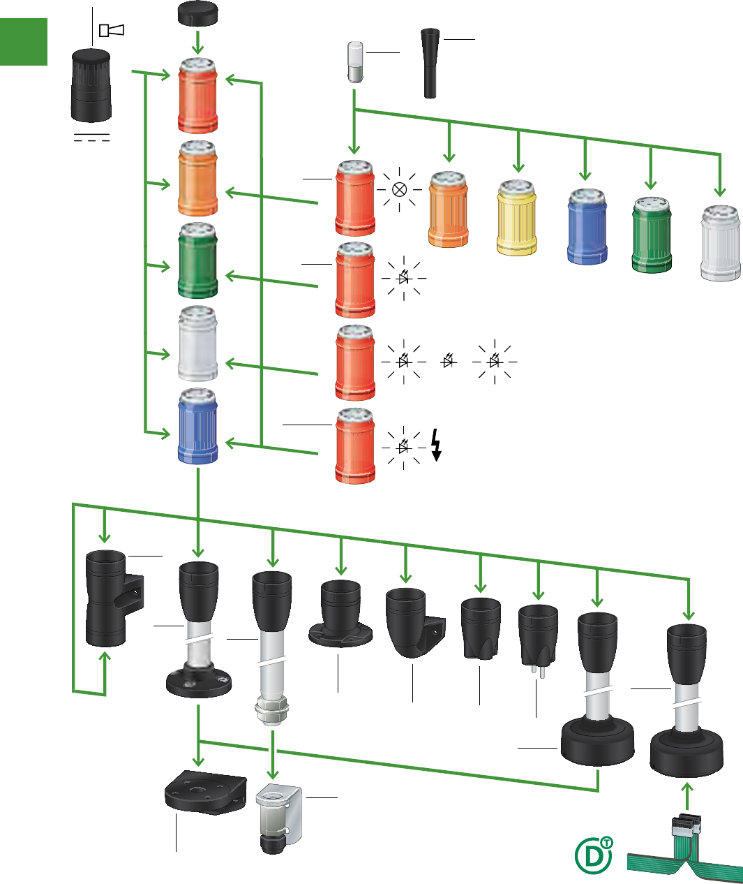
Control and indication
Power control
177 2015/2016 Product guide AUS15_007 - February 2016
Stacklights - SL4 range
3

Control and indication
Power control
178
2015/2016 Product guide AUS15_007 - February 2016
Complete devices
Continuous light, LED, UL type 4/4X/13, IP66
Rated operational
voltage (Ue V)
Number of
modules Color Function Standard
pack Item no.
Base Module with Foot and 100 mm Tube
24 Vac/Vdc
2 Red/Green
1
SL4-100-L-RG-24LED
3Red/Amber/
Green SL4-100-L-RAG-24LED
Light module with LED
Continuous light, UL type 4/4X/13, IP66
Rated operational
voltage (Ue V) Color Function Standard
pack Item no.
24 Vac/Vdc
Blue
1
SL4-L24-B
Green SL4-L24-G
Red SL4-L24-R
White SL4-L24-W
Yellow SL4-L24-Y
Amber SL4-L24-A
110/120 Vac
Blue
1
SL4-L120-B
Green SL4-L120-G
Red SL4-L120-R
White SL4-L120-W
Yellow SL4-L120-Y
Amber SL4-L120-A
230/240 Vac
Blue
1
SL4-L230-B
Green SL4-L230-G
Red SL4-L230-R
White SL4-L230-W
Yellow SL4-L230-Y
Amber SL4-L230-A
Flashing light, UL type 4/4X/13, IP66, 2 Hz
Rated operational
voltage (Ue V) Color Function Standard
pack Item no.
24 Vac/Vdc
Blue
1
SL4-BL24-B
Green SL4-BL24-G
Red SL4-BL24-R
White SL4-BL24-W
Yellow SL4-BL24-Y
Amber SL4-BL24-A
110/120 Vac
Blue
1
SL4-BL120-B
Green SL4-BL120-G
Red SL4-BL120-R
White SL4-BL120-W
Yellow SL4-BL120-Y
Amber SL4-BL120-A
230/240 Vac
Blue
1
SL4-BL230-B
Green SL4-BL230-G
Red SL4-BL230-R
White SL4-BL230-W
Yellow SL4-BL230-Y
Amber SL4-BL230-A
Stacklights - SL4 range
White
Yellow
Blue
Amber
Green
Red
SL7-100-L-RG-24LED

Control and indication
Power control
179 2015/2016 Product guide AUS15_007 - February 2016
Light module with LED
Strobe light, UL type 4/4X/13, IP66, 1.4 Hz
Rated operational
voltage (Ue V) Color Function Standard
pack Item no.
24 Vac/Vdc
Blue
1
SL4-FL24-B
Green SL4-FL24-G
Red SL4-FL24-R
White SL4-FL24-W
Yellow SL4-FL24-Y
Amber SL4-FL24-A
110/120 Vac
Blue
1
SL4-FL120-B
Green SL4-FL120-G
Red SL4-FL120-R
White SL4-FL120-W
Yellow SL4-FL120-Y
Amber SL4-FL120-A
230/240 Vac
Blue
1
SL4-FL230-B
Green SL4-FL230-G
Red SL4-FL230-R
White SL4-FL230-W
Yellow SL4-FL230-Y
Amber SL4-FL230-A
Multi-strobe light, UL type 4/4X/13, IP66
Rated operational
voltage (Ue V) Color Function Standard
pack Item no.
LED for effective signaling effect with various strobe sequences, 1–2.6 Hz
24 Vac/Vdc
Blue
1
SL4-FL24-B-M
Green SL4-FL24-G-M
Red SL4-FL24-R-M
White SL4-FL24-W-M
Yellow SL4-FL24-Y-M
Amber SL4-FL24-A-M
Stacklights - SL4 range
SL4 Light module for Incandescent bulb
Continuous light, UL type 4/4X/13, IP66
Rated operational
voltage (Ue V) Color Function Standard
pack Item no.
Without light elements, incandescent bulb, maximum 4W
<250 Vac/Vdc
Blue
1
SL4-L-B
Green SL4-L-G
Red SL4-L-R
White SL4-L-W
Yellow SL4-L-Y
Amber SL4-L-A
SL4 Acoustic modules
Continuous tone or pulsed tone, UL type 4/4X/13, IP66
Rated operational
voltage (Ue V)
Rated operational
current (Ie mA) Color Function Sound type Standard
pack Item no.
Adjustable with internal DIP switches.
Sound pressure 80 dB, adjustable with internal potentiometer.
f = 4000 Hz.
24 Vac/Vdc Maximum 39
Black 1
SL4-AP24
110/120 Vac Maximum 21 SL4-AP120
230/240 Vac Maximum 21 SL4-AP230
White
Yellow
Blue
Amber
Green
Red
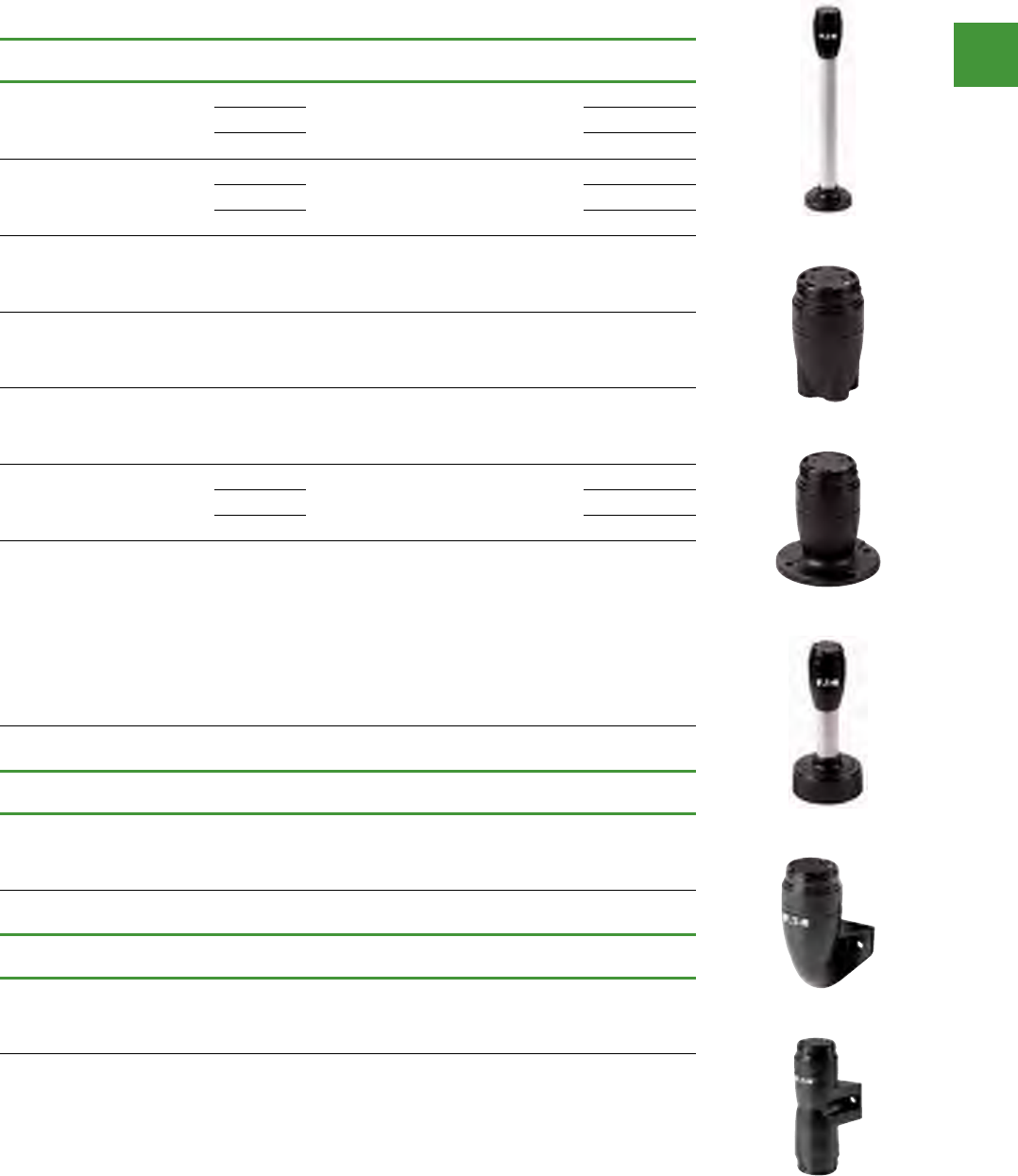
Control and indication
Power control
180
2015/2016 Product guide AUS15_007 - February 2016
Stacklights - SL4 range
SL7 Base modules
For horizontal mounting—Includes cover, maximum 5 modules
Description Tube
length Color Standard
pack
For use
with.. Item no.
Base with aluminum tube and
plastic foot
Spring-loaded terminals
100 mm Black
aluminum
color tube
1
SL4-L-…
SL4-BL-…
SL4-FL-…
SL4-AP-…
SL4-PIB-100
250 mm SL4-PIB-250
400 mm SL4-PIB-400
Base with aluminum tube and
3/4 in NPT threaded base
Spring-loaded terminals
100 mm Black
aluminum
color tube
1
SL4-L-…
SL4-BL-…
SL4-FL-…
SL4-AP-…
SL4-PIB-T-100
250 mm SL4-PIB-T-250
400 mm SL4-PIB-T-400
Base with internal (on the
inside)xingholes
Spring-loaded terminals
Black 1
SL4-L-…
SL4-BL-…
SL4-FL-…
SL4-AP-…
SL4-PIB-IMH
Base with built-in
(pre-assembled)xingscrews
Spring-loaded terminals
Black 1
SL4-L-…
SL4-BL-…
SL4-FL-…
SL4-AP-…
SL4-PIB-IMS
Basewithexternalxingholes
Spring-loaded terminals Black 1
SL4-L-…
SL4-BL-…
SL4-FL-…
SL4-AP-…
SL4-PIB-EMH
Base with base adapter for
slipping onto place (rapid
mounting and wiring system)
Screw terminals
100 mm Black
aluminum
color tube
1
SL4-L-…
SL4-BL-…
SL4-FL-…
SL4-AP-…
SL4-FMS-100
250 mm SL4-FMS-250
400 mm SL4-FMS-400
Base with base adapter for
slipping onto place (rapid
mounting
and wiring system)
Blade terminal SWD4-8MF2
Maximum 0.3A per module
External power supply con-
nectable (24 Vdc)
CongurablewithSWD-Assist
(planning and ordering help)
100 mm 1
SL4-L-…
SL4-BL-…
SL4-FL-…
SL4-AP-…
SL4-SWD
For vertical mounting—includes cover, maximum 5 modules
Description Tube
length Color Standard
pack
For use
with.. Item no.
One-sided base with bracket
Spring-loaded terminals Black 1
SL4-L-…
SL4-BL-…
SL4-FL-…
SL4-AP-…
SL4-PIB-FW
For mounting on both sides—includes cover, maximum 2 x 5 modules
Description Tube
length Color Standard
pack
For use
with.. Item no.
Basewithexternalxing
holes
Spring-loaded terminals
Black 1
SL4-L-…
SL4-BL-…
SL4-FL-…
SL4-AP-…
SL4-PIB-D
SL4-PIB-_
SL4-PB-EMH
SL4-FMS-_
SL4-PIB-FW
SL4-PIB-D
SL4-PIB-IMH

Control and indication
Power control
181 2015/2016 Product guide AUS15_007 - February 2016
Stacklights - SL range accessories
Mounting brackets
Description Standard pack For use with.. Item no.
Mounting brackets for vertical
Mounting, plastic 1SL4-PIB..
SL7-CB.. SL7/4-FW
M20 cable gland for vertical mounting,
Metal (includes mounting bracket) 1SL4-PIB-T…
SL7-CB-T... SL7/4-FW-T
Incandescent bulb tool
Description Standard pack For use with.. Item no.
Tool for replacing incandescent bulb 1 SL7-L-…
SL4-L-… SL7/4-BET
Incandescent bulbs
Mounting: Ba15d - SL7 series
Lifespan (h) Rated operational
voltage (Ue V)
Power
(Watts)
Standard
pack
For use
with.. Item no.
3000
12 5
1 SL7-L-…
SL7-L12
24 6.5 SL7-L24
120 7SL7-L120
230 6.5 SL7-L230
Mounting: Ba15d - SL4 series
Lifespan (h) Rated operational
voltage (Ue V)
Power
(Watts)
Standard
pack
For use
with.. Item no.
3000
12
4 1 SL4-L-…
SL4-L12
24 SL4-L24
120 SL4-L120
230 SL4-L230
SL7/4-FW
SL7/4-FW-T
SL7/4-BET
SL7-L12

Control and indication
Power control
182
2015/2016 Product guide AUS15_007 - February 2016
206 EATON CA08103003Z-EN-INTComplete assortment -> Online Catalog
206 EATON CORPORATIONCA08103003Z-DE-DE
Cam switches, switch-disconnectors
System overview
Cam switches, switch-disconnectorsSystem overview
ON-OFF switches P1, P3
1 Service distribution board mounting
2 Rear mounting
3 Flush mounting
4 Neutral conductors, auxiliary contacts
5 Surface mounting
6 Safety switch
7Main switch (kit) for use as emergency
switching o device
ON OFF
switches P5
8 Main switch (kit)
9 Thumb-grip, for use as emergency
switching o device
10 Thumb-grip
11 Coupling drive
12 Protective conductor terminal
13 Neutral terminal
Control switches T0, T3, T5B, T5
1 Service distribution board mounting
2 Rear mounting
3 Flush mounting
4 Surface mounting
5 Thumb-grip
6 Coupling drive
8
7
5
2
3
1
1
4
4
6
11
11
10
9
4
12
3
10
8
7
2
4
12
13
10
8
4
4
13
7
1
1
5
5
2
6
6
3
4
ON-OFF switches - P1, P3
ON-OFF switches - P5
1 Service distribution
board mounting
2 Rear mounting
3 Flush mounting
4 Neutral conductors,
auxiliary contacts
5 Surface mounting
6 Safety switch
7 Main switch (kit) for use as
emergency switching off
device
8 Main switch (kit)
9 Thumb-grip, for use as
emergency switching off
device
10 Thumb-grip
11 Coupling drive
12 Protective conductor
terminal
13 Neutral terminal
Cam switches

Control and indication
Power control
183 2015/2016 Product guide AUS15_007 - February 2016
207
Power Management
EATON CA08103003Z-EN-INT
Complete assortment -> Online Catalog EATON CORPORATION CA08103003Z-DE-DE 207
Cam switches, switch-disconnectors
System overview
Energiemanagement
Cam switches, switch-disconnectors System overview
On-O switch P1, P3 with metal shaft
1 Neutral conductor
2 P1 rear-mounting switch
3 Auxiliary contact
4 P3 rear-mounting switch
5 Metal shaft
6, 7 Centring tip
8 Centring adapter
9 Thumb-grip
10 Main switch kit (black)
11 Main switch kit for use as emergency
switching o device (red)
12 Thumb-grip kit, for use as emergency
switching o device (red)
13 Thumb-grip kit for padlock (grey)
14 Thumb-grip kit with cylinder lock (blue)
On-O switch DMM, DMV
1 On-O switch DMM, DMV
2 Clamp cover
3 Auxiliary contact
4 Metal shaft
5 Thumb-grip, for use as emergency
switching o device (red)
6 Thumb-grip for direct mounting
7 Thumb-grip for door mounting, with
cylinder lock
8 Thumb-grip for door mounting with
padlock
Rated operational data Switch type
T0
T3
T5B
T5
P1-25
P1-32
P3-63
P3-100
P5-125
P5-160
P5-250
P5-315
DMM-125
DMM-160
DMV-250
DMV-400
Motor rating AC-23 400/415V kW 6.5 13 22 30 13 15 30 50 45 55 90 110 59 75 147 180
Motor load switch AC-3 400/415V kW 4 12 22 30 7.5 13 30 40 37 45 55 75 - - - -
Rated uninterrupted current I
UA 20 32 63 100 25 32 63 100 125 160 250 315 125 160 250 400
8
12 13
10
11
14
9
6
10
11
2
3
4
5
7
7
1
2
11
3
7
8
4
5
6
On-Off switch P1, P3 with metal shaft
Cam switches
1 Neutral conductor
2 P1 rear-mounting switch
3 Auxiliary contact
4 P3 rear-mounting switch
5 Metal shaft
6 Centring tip
7 Centring tip
8 Centring adapter
9 Thumb-grip
10 Main switch kit (black)
11 Main switch kit for use
as emergency switching
off device (red)
12 Thumb-grip kit, for use
as emergency switching
off device (red)
13 Thumb-grip kit for
padlock (grey)
14 Thumb-grip kit with
cylinder lock (blue)
206 EATON CA08103003Z-EN-INTComplete assortment -> Online Catalog
206 EATON CORPORATIONCA08103003Z-DE-DE
Cam switches, switch-disconnectors
System overview
Cam switches, switch-disconnectorsSystem overview
ON-OFF switches P1, P3
1 Service distribution board mounting
2 Rear mounting
3 Flush mounting
4 Neutral conductors, auxiliary contacts
5 Surface mounting
6 Safety switch
7Main switch (kit) for use as emergency
switching o device
ON OFF switches P5 8 Main switch (kit)
9 Thumb-grip, for use as emergency
switching o device
10 Thumb-grip
11 Coupling drive
12 Protective conductor terminal
13 Neutral terminal
Control switches T0, T3, T5B, T5
1 Service distribution board mounting
2 Rear mounting
3 Flush mounting
4 Surface mounting
5 Thumb-grip
6 Coupling drive
8
7
5
2
3
1
1
4
4
6
11
11
10
9
4
12
3
10
8
7
2
4
12
13
10
8
4
4
13
7
1
1
5
5
2
6
6
3
4
Control switches - T0, T3, T5B, T5
1 Service distribution
board mounting
2 Rear mounting
3 Flush mounting
4 Surface mounting
5 Thumb-grip
6 Coupling drive

Control and indication
Power control
184
2015/2016 Product guide AUS15_007 - February 2016
Cam switches
Main circuit poles
Flush
mounting
Centre
mounting
Surface
mounting
Service distribution
board mounting
Rear
mounting
Front IP65 Front IP65 IP65 Front IP30 Front IP65
N/O B Item no. Item no. Item no. Item no. Item no.
On-Off switches 20A
1 - - T0-1-8200/E T0-1-8200/EZ T0-1-8200/I1 T0-1-8200/IVS T0-1-8200/Z
2 - - T0-1-102/E T0-1-102/EZ T0-1-102/I1 T0-1-102/IVS T0-1-102/Z
3 - - T0-2-1/E T0-2-1/EZ T0-2-1/I1 T0-2-1/IVS T0-2-1/Z
3 1 0 T0-2-15679/E T0-2-15679/EZ T0-2-15679/I1 T0-2-15679/IVS T0-2-15679/Z
3 + N - - T0-2-8900/E T0-2-8900/EZ T0-2-8900/I1 T0-2-8900/IVS T0-2-8900/Z
Changeover switches 20A
1 - - T0-1-8210/E T0-1-8210/EZ T0-1-8210/I1 T0-1-8210/IVS T0-1-8210/Z
2 - - T0-2-8211/E T0-2-8211/EZ T0-2-8211/I1 T0-2-8211/IVS T0-2-8211/Z
3 - - T0-3-8212/E T0-3-8212/EZ T0-3-8212/I1 T0-3-8212/IVS T0-3-8212/Z
4 - - T0-4-8213/E T0-4-8213/EZ T0-4-8213/I1 T0-4-8213/IVS T0-4-8213/Z
1 - - T0-1-8220/E T0-1-8220/EZ T0-1-8220/I1 T0-1-8220/IVS T0-1-8220/Z
2 - - T0-2-8221/E T0-2-8221/EZ T0-2-8221/I1 T0-2-8221/IVS T0-2-8221/Z
3 - - T0-3-8222/E T0-3-8222/EZ T0-3-8222/I1 T0-3-8222/IVS T0-3-8222/Z
4 - - T0-4-8223/E T0-4-8223/EZ T0-4-8223/I1 T0-4-8223/IVS T0-4-8223/Z
1 - - T0-1-8214/E T0-1-8214/EZ T0-1-8214/I1 T0-1-8214/IVS T0-1-8214/Z
2 - - T0-2-8215/E T0-2-8215/EZ T0-2-8215/I1 T0-2-8215/IVS T0-2-8215/Z
3 - - T0-3-8216/E T0-3-8216/EZ T0-3-8216/I1 T0-3-8216/IVS T0-3-8216/Z
Reversing switches 20A
3 - - T0-3-8401/E T0-3-8401/EZ T0-3-8401/I1 T0-3-8401/IVS T0-3-8401/Z
ON-OFF switches 20A
1 - - T0-1-15401/E T0-1-15401/EZ T0-1-15401/I1 T0-1-15401/IVS T0-1-15401/Z
2 - - T0-1-15402/E T0-1-15402/EZ T0-1-15402/I1 T0-1-15402/IVS T0-1-15402/Z
3 - - T0-2-15403/E T0-2-15403/EZ T0-2-15403/I1 T0-2-15403/IVS T0-2-15403/Z
Voltmeter selector switches 20A
3 + N - - T0-3-8007/E T0-3-8007/EZ T0-3-8007/I1 T0-3-8007/IVS T0-3-8007/Z
Ammeter selector switches 20A
3 - - T0-3-8048/E T0-3-8048/EZ T0-3-8048/IVS T0-3-8048/Z
Step switches 20A
1 - - T0-2-8231/E T0-2-8231/EZ T0-2-8231/I1 T0-2-8231/IVS T0-2-8231/Z
1 - - T0-2-8241/E T0-2-8241/EZ T0-2-8241/I1 T0-2-8241/IVS T0-2-8241/Z
Changeoverswitches 20A
1 - - T0-1-15431/E T0-1-15431/EZ T0-1-15431/I1 T0-1-15431/IVS T0-1-15431/Z
2 - - T0-2-15432/E T0-2-15432/EZ T0-2-15432/I1 T0-2-15432/IVS T0-2-15432/Z
3 - - T0-3-15433/E T0-3-15433/EZ T0-3-15433/I1 T0-3-15433/IVS T0-3-15433/Z
The high-performance, robust and compact T rotary
switches and P switch-disconnectors are used in industry,
trade and building engineering applications. The degree
of protection IP65 with the switch mounts and the switch
front enables use in harsh environments. Ten basic switch
types in four different construction types, in a whole range
of standard switches and across a wide performance
range are available. Customised circuits can also be
implemented in addition to the standard configurations.
The possibilities are almost unlimited. A comprehensive
accessory range complements the switch range and
rounds off the range of applications. All contacts feature
double breaking contacts.
With the metal extension shafts our reliable P1 and P3
switches can be mounted in electrical cabinets of up to
600 mm deep and with several Handle and Shaft options
a solution can be found for every application. Also the
most common types are available as a complete switch/
shaft/handle package. T0-1-8200..
T0-1-8210..
T0-3-8212..
T0-2-8400..
T0-3-8622...
T0-1-8240..
T0-3-8048...
204 EATON CA08103003Z-EN-INT
The high-performance, robust and compact T rotary switches and P
switch-disconnectors are used in industry, trade and building engineering
applications. The degree of protection IP65 with the switch mounts and
the switch front enables use in harsh environments. Ten basic switch
types in four different construction types, in a whole range of standard
switches and across a wide performance range are available.
Customised circuits can also be implemented in addition to the standard
configurations. The possibilities are almost unlimited. A comprehensive
accessory range complements the switch range and rounds off the range
of applications. All contacts feature double breaking contacts.
With the metal extension shafts our reliable P1 and P3 switches can be
mounted in electrical cabinets of up to 600 mm deep and with several
Handle and Shaft options a solution can be found for every application.
Also the most common types are available as a complete switch/shaft/
handle package.
Safe Switching, Isolating and Control with
Rotary Switch T and Switch Disconnector P

Control and indication
Power control
185 2015/2016 Product guide AUS15_007 - February 2016
208 EATON CORPORATIONCA08103003Z-DE-DE
Nockenschalter, Lasttrennschalter
Hauptschalter, Wartungsschalter, Reparaturschalter
Nockenschalter, LasttrennschalterHauptschalter, Wartungsschalter, Reparaturschalter
Haupt-
strom-
bahnen
Pole
Hilfsstrom-
bahnen
S Ö Iu
A
Hauptschalter, Wa
mit rotem Drehgri und gelbem Sperrkranz
abschließbar in 0-Stellung
1 - - 20
32
63
100 -
2 - - 20
32
63
100
3 - - 20 T0-2-1/I1/SVB
25 P1-25/I2/SVB 172875
32 P1-32/I2/SVB 172865
63 P3-63/I4/SVB 207343 P3-63/EA/SVB 031607 P3-63/V/SVB 048218 P3-63/M4/SVB 172784
100 P3-100/I5/SVB 207373 P3-100/EA/SVB 074320 P3-100/V/SVB 088558 P3-100/M4/SVB172818
125 DMM-125/3/I5/P-R 172851 P5-125/EA/SVB 280898 P5-125/V/SVB 280914 DMM-125/3/M4/P-R 6094964
160 DMM-160/3/I5/P-R 172794 P5-160/EA/SVB 280922 P5-160/V/SVB 280928 DMM-160/3/M4/P-R 6094965
250 - P5-250/EA/SVB 280936 P5-250/V/SVB 280942 DMV-250/3/M4/P-R 6094966
315 - P5-315/EA/SVB 280950 P5-315/V/SVB 280956 -
400 - - - DMV-400/3/M4/P-R 6094967
3 + N - - 20 T0-2-8900/I1/SVB 207151 - - -
25 P1-25/I2/SVB/N207298 P1-25/EA/SVB/N 081587 P1-25/V/SVB/N 086333 P1-25/M4/SVB/N 172877
32 P1-32/I2/SVB/N207319 P1-32/EA/SVB/N 091079 P1-32/V/SVB/N 095825 P1-32/M4/SVB/N 172867
63 P3-63/I4/SVB/N207349 P3-63/EA/SVB/N 010398 P3-63/V/SVB/N 015144 P3-63/M4/SVB/N 172786
100 P3-100/I5/SVB/N 207379 P3-100/EA/SVB/N 019890 P3-100/V/SVB/N 024636 P3-100/M4/SVB/N 172820
125 DMM-125/4/I5/P-R 172854 P5-125/EA/SVB/N 280910 P5-125/V/SVB/N 280916 DMM-125/4/M4/P-R 6094968
160 DMM-160/4/I5/P-R 172797 P5-160/EA/SVB/N 280924 P5-160/V/SVB/N 280930 DMM-160/4/M4/P-R 6094969
250 - P5-250/EA/SVB/N 280938 P5-250/V/SVB/N 280944 DMV-250/4/M4/P-R 6094970
315 - P5-315/EA/SVB/N 280952 P5-315/V/SVB/N 280958 -
400 - - - DMV-400/4/M4/P-R 6094971
3 1 0 20 T0-2-15679/I1/SVB 207149 T0-2-15679/EA/SVB 081588 T0-2-15679/V/SVB 086334 -
3 1 1 25 P1-25/I2/SVB/HI11 207297 P1-25/EA/SVB/HI11 091080 P1-25/V/SVB/HI11 095826 P1-25/M4/SVB/HI11 172767
32 P1-32/I2/SVB/HI11 207318 P1-32/EA/SVB/HI11 072567 P1-32/V/SVB/HI11 015145P1-32/M4/SVB/HI11 172869
63 P3-63/I4/SVB/HI11 207348 P3-63/EA/SVB/HI11 019891 P3-63/V/SVB/HI11 024637 P3-63/M4/SVB/HI11 172788
100 P3-100/I5/SVB/HI11 207378 P3-100/EA/SVB/HI11 029383 P3-100/V/SVB/HI11 034129 P3-100/M4/SVB/HI11 172822
3 + N 1 1 20 T0-3-15680/I1/SVB 207153 T0-3-15680/EA/SVB 038875 T0-3-15680/V/SVB 043621 -
25 - P1-25/EA/SVB/N/HI11 048367 P1-25/V/SVB/N/HI11 053113 P1-25/M4/SVB/N/HI11 172769
32 T3-3-15680/I2/SVB 207202 P1-32/EA/SVB/N/HI11 057859 P1-32/V/SVB/N/HI11 062605 P1-32/M4/SVB/N/HI11 172871
63 P3-63/I4/SVB/N/HI11 207350 P3-63/EA/SVB/N/HI11 067351 P3-63/V/SVB/N/HI11 072097 P3-63/M4/SVB/N/HI11 172808
100 P3-100/I5/SVB/N/HI11207380 P3-100/EA/SVB/N/HI11076843 P3-100/V/SVB/N/HI11081589 P3-100/M4/SVB/N/HI11 172824
3 2 1 20 T0-3-15683/I1/SVB 207157 T0-3-15683/EA/SVB 015571 T0-3-15683/V/SVB 015634 -
6 - - 20 T0-3-8342/I1/SVB 207159 T0-3-8342/EA/SVB 029382 T0-3-8342/V/SVB 034128 -
32 T3-3-8342/I2/SVB 207208 T3-3-8342/EA/SVB 071326 T3-3-8342/V/SVB 076072 -
63 T5B-3-8342/I4/SVB 207242 T5B-3-8342/EA/SVB 092308 T5B-3-8342/V/SVB 092300 -
100 T5-3-8342/I5/SVB 207279 T5-3-8342/EA/SVB 096383 T5-3-8342/V/SVB 096381 -
CA08103003Z-de-DE_208__Nockenschalter_A4_g.fm Se ite 208 Dienstag, 14. Oktober 2014 8:44 08
208 EATON CORPORATIONCA08103003Z-DE-DE
Nockenschalter, Lasttrennschalter
Hauptschalter, Wartungsschalter, Reparaturschalter
Nockenschalter, LasttrennschalterHauptschalter, Wartungsschalter, Reparaturschalter
Haupt-
strom-
bahnen
Pole
Hilfsstrom-
bahnen
S Ö Iu
A
Hauptschalter, Wa
mit rotem Drehgri und gelbem Sperrkranz
abschließbar in 0-Stellung
1 - - 20
32
63
100 -
2 - - 20
32
63
100
3 - - 20 T0-2-1/I1/SVB
25 P1-25/I2/SVB 172875
32 P1-32/I2/SVB 172865
63 P3-63/I4/SVB 207343 P3-63/EA/SVB 031607 P3-63/V/SVB 048218 P3-63/M4/SVB 172784
100 P3-100/I5/SVB 207373 P3-100/EA/SVB 074320 P3-100/V/SVB 088558 P3-100/M4/SVB172818
125 DMM-125/3/I5/P-R 172851 P5-125/EA/SVB 280898 P5-125/V/SVB 280914 DMM-125/3/M4/P-R 6094964
160 DMM-160/3/I5/P-R 172794 P5-160/EA/SVB 280922 P5-160/V/SVB 280928 DMM-160/3/M4/P-R 6094965
250 - P5-250/EA/SVB 280936 P5-250/V/SVB 280942 DMV-250/3/M4/P-R 6094966
315 - P5-315/EA/SVB 280950 P5-315/V/SVB 280956 -
400 - - - DMV-400/3/M4/P-R 6094967
3 + N - - 20 T0-2-8900/I1/SVB 207151 - - -
25 P1-25/I2/SVB/N207298 P1-25/EA/SVB/N 081587 P1-25/V/SVB/N 086333 P1-25/M4/SVB/N 172877
32 P1-32/I2/SVB/N207319 P1-32/EA/SVB/N 091079 P1-32/V/SVB/N 095825 P1-32/M4/SVB/N 172867
63 P3-63/I4/SVB/N207349 P3-63/EA/SVB/N 010398 P3-63/V/SVB/N 015144 P3-63/M4/SVB/N 172786
100 P3-100/I5/SVB/N 207379 P3-100/EA/SVB/N 019890 P3-100/V/SVB/N 024636 P3-100/M4/SVB/N 172820
125 DMM-125/4/I5/P-R 172854 P5-125/EA/SVB/N 280910 P5-125/V/SVB/N 280916 DMM-125/4/M4/P-R 6094968
160 DMM-160/4/I5/P-R 172797 P5-160/EA/SVB/N 280924 P5-160/V/SVB/N 280930 DMM-160/4/M4/P-R 6094969
250 - P5-250/EA/SVB/N 280938 P5-250/V/SVB/N 280944 DMV-250/4/M4/P-R 6094970
315 - P5-315/EA/SVB/N 280952 P5-315/V/SVB/N 280958 -
400 - - - DMV-400/4/M4/P-R 6094971
3 1 0 20 T0-2-15679/I1/SVB 207149 T0-2-15679/EA/SVB 081588 T0-2-15679/V/SVB 086334 -
3 1 1 25 P1-25/I2/SVB/HI11 207297 P1-25/EA/SVB/HI11 091080 P1-25/V/SVB/HI11 095826 P1-25/M4/SVB/HI11 172767
32 P1-32/I2/SVB/HI11 207318 P1-32/EA/SVB/HI11 072567 P1-32/V/SVB/HI11 015145P1-32/M4/SVB/HI11 172869
63 P3-63/I4/SVB/HI11 207348 P3-63/EA/SVB/HI11 019891 P3-63/V/SVB/HI11 024637 P3-63/M4/SVB/HI11 172788
100 P3-100/I5/SVB/HI11 207378 P3-100/EA/SVB/HI11 029383 P3-100/V/SVB/HI11 034129 P3-100/M4/SVB/HI11 172822
3 + N 1 1 20 T0-3-15680/I1/SVB 207153 T0-3-15680/EA/SVB 038875 T0-3-15680/V/SVB 043621 -
25 - P1-25/EA/SVB/N/HI11 048367 P1-25/V/SVB/N/HI11 053113 P1-25/M4/SVB/N/HI11 172769
32 T3-3-15680/I2/SVB 207202 P1-32/EA/SVB/N/HI11 057859 P1-32/V/SVB/N/HI11 062605 P1-32/M4/SVB/N/HI11 172871
63 P3-63/I4/SVB/N/HI11 207350 P3-63/EA/SVB/N/HI11 067351 P3-63/V/SVB/N/HI11 072097 P3-63/M4/SVB/N/HI11 172808
100 P3-100/I5/SVB/N/HI11207380 P3-100/EA/SVB/N/HI11076843 P3-100/V/SVB/N/HI11081589 P3-100/M4/SVB/N/HI11 172824
3 2 1 20 T0-3-15683/I1/SVB 207157 T0-3-15683/EA/SVB 015571 T0-3-15683/V/SVB 015634 -
6 - - 20 T0-3-8342/I1/SVB 207159 T0-3-8342/EA/SVB 029382 T0-3-8342/V/SVB 034128 -
32 T3-3-8342/I2/SVB 207208 T3-3-8342/EA/SVB 071326 T3-3-8342/V/SVB 076072 -
63 T5B-3-8342/I4/SVB 207242 T5B-3-8342/EA/SVB 092308 T5B-3-8342/V/SVB 092300 -
100 T5-3-8342/I5/SVB 207279 T5-3-8342/EA/SVB 096383 T5-3-8342/V/SVB 096381 -
CA08103003Z-de-DE_208__Nockenschalter_A4_g.fm Seite 208 Dienstag, 14. Oktober 2014 8:44 08
Main
circuit
poles
Auxiliary
circuits
Rated
uninterupted
current
Main switches
surface mounting
Main switches
flush mounting
Main switches
rear mounting
Main switches
rear mounting
front IP65
N/O B I IP65 front IP65 front IP65 IP20 with terminal cover
A Item no. Item no. Item no. Item no.
Main switches, maintenance switches, repair switches
With red rotary handle and yellow locking ring
Note: All types are available with a black thumb-grip
Lockable in the 0 (Off) position
1
- - 20 T0-1-8200/I1/SVB T0-1-8200/EA/SVB T0-1-8200/V/SVB -
32 T3-1-8200/I2/SVB T3-1-8200/EA/SVB T3-1-8200/V/SVB -
63 T5B-1-8200/I4/SVB T5B-1-8200/EA/SVB T5B-1-8200/V/SVB -
100 - T5-1-8200/EA/SVB T5-1-8200/V/SVB -
2
- - 20 T0-1-102/I1/SVB T0-1-102/EA/SVB T0-1-102/V/SVB -
32 T3-1-102/I2/SVB T3-1-102/EA/SVB T3-1-102/V/SVB -
63 T5B-1-102/I4/SVB T5B-1-102/EA/SVB T5B-1-102/V/SVB -
100 T5-1-102/I5/SVB T5-1-102/EA/SVB T5-1-102/V/SVB -
3
- - 20 T0-2-1/I1/SVB T0-2-1/EA/SVB T0-2-1/V/SVB -
25 P1-25/I2/SVB P1-25/EA/SVB P1-25/V/SVB P1-25/M4/SVB
32 P1-32/I2/SVB P1-32/EA/SVB P1-32/V/SVB P1-32/M4/SVB
63 P3-63/I4/SVB P3-63/EA/SVB P3-63/V/SVB P3-63/M4/SVB
100 P3-100/I5/SVB P3-100/EA/SVB P3-100/V/SVB P3-100/M4/SVB
125 - P5-125/EA/SVB P5-125/V/SVB -
160 - P5-160/EA/SVB P5-160/V/SVB -
250 - P5-250/EA/SVB P5-250/V/SVB -
315 - P5-315/EA/SVB P5-315/V/SVB -
400 - - - -
3 + N
- - 20 T0-2-8900/I1/SVB - - -
25 P1-25/I2/SVB/N P1-25/EA/SVB/N P1-25/V/SVB/N P1-25/M4/SVB/N
32 P1-32/I2/SVB/N P1-32/EA/SVB/N P1-32/V/SVB/N P1-32/M4/SVB/N
63 P3-63/I4/SVB/N P3-63/EA/SVB/N P3-63/V/SVB/N P3-63/M4/SVB/N
100 P3-100/I5/SVB/N P3-100/EA/SVB/N P3-100/V/SVB/N P3-100/M4/SVB/N
125 - P5-125/EA/SVB/N P5-125/V/SVB/N -
160 - P5-160/EA/SVB/N P5-160/V/SVB/N -
250 - P5-250/EA/SVB/N P5-250/V/SVB/N -
315 - P5-315/EA/SVB/N P5-315/V/SVB/N -
400 - - - -
3
1 0 20 T0-2-15679/I1/SVB T0-2-15679/EA/SVB T0-2-15679/V/SVB -
1 1 25 P1-25/I2/SVB/HI11 P1-25/EA/SVB/HI11 P1-25/V/SVB/HI11 P1-25/M4/SVB/HI11
32 P1-32/I2/SVB/HI11 P1-32/EA/SVB/HI11 P1-32/V/SVB/HI11 P1-32/M4/SVB/HI11
63 P3-63/I4/SVB/HI11 P3-63/EA/SVB/HI11 P3-63/V/SVB/HI11 P3-63/M4/SVB/HI11
100 P3-100/I5/SVB/HI11 P3-100/EA/SVB/HI11 P3-100/V/SVB/HI11 P3-100/M4/SVB/HI11
3 + N
1 1 20 T0-3-15680/I1/SVB T0-3-15680/EA/SVB T0-3-15680/V/SVB -
25 - P1-25/EA/SVB/N/HI11 P1-25/V/SVB/N/HI11 P1-25/M4/SVB/N/HI11
32 T3-3-15680/I2/SVB P1-32/EA/SVB/N/HI11 P1-32/V/SVB/N/HI11 P1-32/M4/SVB/N/HI11
63 P3-63/I4/SVB/N/HI11 P3-63/EA/SVB/N/HI11 P3-63/V/SVB/N/HI11 P3-63/M4/SVB/N/HI11
100 P3-100/I5/SVB/N/HI11 P3-100/EA/SVB/N/HI11 P3-100/V/SVB/N/HI11 P3-100/M4/SVB/N/HI11
32120 T0-3-15683/I1/SVB T0-3-15683/EA/SVB T0-3-15683/V/SVB -
6
- - 20 T0-3-8342/I1/SVB T0-3-8342/EA/SVB T0-3-8342/V/SVB -
32 T3-3-8342/I2/SVB T3-3-8342/EA/SVB T3-3-8342/V/SVB -
63 T5B-3-8342/I4/SVB T5B-3-8342/EA/SVB T5B-3-8342/V/SVB -
100 T5-3-8342/I5/SVB T5-3-8342/EA/SVB T5-3-8342/V/SVB -
Cam switches

Control and indication
Power control
186
2015/2016 Product guide AUS15_007 - February 2016
Cam switches
Description Emergency switching
off/emergency stop For use with Item no.
Main switch assembly kits
With red rotary
handle and yellow
locking
collar
As an emergency switching
off/emergency stop device
To IEC/EN 60204-1,
VDE 0113 Part 1
T0-…/E, …/Z, …/I1
T3-…/E, …/Z, …/I2
P1-…/E, …/Z, …/I2
SVB-T0
T5B-…/E, …/Z, …/I4
T5-.../E, .../Z, .../I5
P3-63/E, …/Z, …/I4
P3-100/E, …/Z, …/I5
SVB-P3
With black rotary
handle and black
locking collar
Without emergency switch-
ing off/emergency stop
function
T0-…/E, …/Z, …/I1
T3-…/E, …/Z, …/I2
P1-…/E, …/Z, …/I2
SVB-SW-T0
T5B-…/E, …/Z, …/I4
T5-.../E, .../Z, .../I5
P3-63/E, …/Z, …/I4
P3-100/E, …/Z, …/I5
SVB-SW-P3
Main switch assembly kits with PE terminal and N terminal
With red rotary
handle and
yellow locking
collar
As an emergency
switching off/
emergency stop device
To IEC/EN 60204-1,
VDE 0113 Part 1
T0-…/E, …/Z
T3-…/E, …/Z V/EA/SVB-T0
T5(B)-…/E, …/Z V/EA/SVB-T5
With black
rotary handle
and black
locking collar
Without emergency
switching off/ emergency
stop function
T0-…/E, …/Z
T3-…/E, …/Z V/EA/SVB-SW-T0
T5(B)-…/E, …/Z V/EA/SVB-SW-T5
Thumb-grips
Black
T0-…/E, …/EZ, …/IVS, …/Z, …/I1
T3-…/E, …/EZ, …/IVS, …/Z, …/I2
P1-…/E, …/EZ, …/IVS, …/Z, …/I2
KNB-T0
Red
Only for emergency
switching off/ emergency
stop switches To IEC/EN
60204-1, VDE 0113 Part 1
T0-…/E, …/IVS, …/Z, …/I1
T3-…/E, …/IVS, …/Z, …/I2
P1-…/E, …/IVS, …/Z, …/I2
KNB-RT-T0
Black
T5(B)-…/E, …/Z, …/I4
P3-63/E, …/Z, …/I4
P3-100/E, …/Z, …/I5
KNB-P3
Red
Only for emergency
switching off/ emergency
stop switches To IEC/EN
60204-1, VDE 0113 Part 1
T5(B)-…/E, …/Z, …/I4
P3-63/E, …/Z, …/I4
P3-100/E, …/Z, …/I5
KNB-RT-P3
Maintenance key for interlocked main switches
T0…
P1… KNK-T0
P3… KNK-P3
ATEX type
With metric
knock-outs M20 T0-…/I1 +ATEX-I1
With solid side
walls
T3-…/I2
P1-…/I2 +ATEX-I2
T5B-…/I4
P3-…/I4 +ATEX-I4
T5-…/I5
P3-…/I5 +ATEX-I5
SVB-T0
SVB-SW-T0
V/EA/SVB-T0
V/EA/SVB-SW-T0
KNB-T0
KNB-RT-P3
Control and indication
Power control
187 2015/2016 Product guide AUS15_007 - February 2016
Cam switches
Switch size Dimensions mm
(w x h x d) For use with Item no.
Standard front plate
T0, T3, P1 45 x 45 for frame 48 x 48) FS(*)-T0
P3, T5, T5B 84 x 84 (for frame 88 x 88) FS(*)-P3
Emergency switching off/emergency stop front plates
T0, T3, P1 45 x 45 for frame 48 x 48) FS908GE-T0
P3, T5, T5B 84 x 84 (for frame 88 x 88) FS908GE-P3
Blank plate
P3, T5, T5B 84 x 84 (for frame 88 x 88) FS-ALU980-P3
T0, T3, P1 45 x 45 for frame 48 x 48) FS-ALU980-T0
Cam switches, switch-disconnectors
Front plates
2010 CA08103002Z-EN www.eaton.com
4/59
Front plates
Blank plate
Can be engraved
Switch size Dimensions
(W x H x D)
For use with Part no.
Article no. Price
See
price list
Std. pack Information relevant for export to
North America
mm
Standard front plate
Suitable for laser inscription
T0, T3, P1 45 x 45 (for frame 48 x 48) FS(*)-T0
231893
10 off UL/CSA certification not required
P3, T5, T5B 84 x 84 (for frame 88 x 88) FS(*)-P3
231895
10 off
Emergency switching off/emergency stop front plates
T0, T3, P1 45 x 45 (for frame 48 x 48) FS908GE-T0
003198
5 off
P3, T5, T5B 84 x 84 (for frame 88 x 88) FS908GE-P3
031475
5 off
Blank plate
Can be engraved
P3, T5, T5B 84 x 84 (for frame 88 x 88) FS-ALU980-P3
266906
10 off
T0, T3, P1 45 x 45 (for frame 48 x 48) FS-ALU980-T0
266905
50 off
Notes
Standard front plate
For standard switches the normal front plate can be replaced if required with the front plate shown here (not with T6, T8 and TM).
This is provided the switching angle, number of positions and the position of the 0 position are the same.
Switching angle 30°
Switching angle 45°
Switching angle 60°
Switching angle 90°
318
1
23
0
309
1
234
317
1
234
0
308
1
2
345
316
1234
5
0
307
1
2
345
6
315
1
2345
6
0
314
12345
6
7
0
305
1
23456
7
8
313
12345
6
7
8
0
304
1
23456
7
8
9
312
42
0
3
9
6
8
15
7
303
1
23456
7
8
9
10
311
12345
6
7
8
9
10
0
302
1
23456
7
8
9
10
11
310
12345
6
7
8
9
10
11
0
301
1
23456
7
8
9
10
11
12
OFF
ON
STOP
START
AUTO
HAND
START
STOP
AUTO
HAND
HAND AUTO AU TO
OFF
AUTO
AUS
HAND
416
0
1
1
2
402
01
415 142003 147472 141883 455
1
0
142010
1
0
141879 4721
1
4722
10
4723
0
496
12
41409
12
0
429
0
21
1401
0
1413905
0
14140004117
201
462
2
1
0
4026
2
0
1
461
012
147767
1
0
14153814031404
14751420
1411
4011
0
12
458
012
1426
0
14988
0
147474
0
1413903
0
1446
0
456
0 1
1423
1
14510
1
141537 1413890
0
418
2
1
0
404
3
2
1
420
2
1
0
3
406
23
1
4
422
2
1
0
3
4
408
3
24
5
1
441
1
0
1
22
453
2
31
4
0
4017
Y
0
Y
459
2
1
0
2
1
1409
0
21
140660
0
12
14712 142074
0
21
424
2
1
0
3
4
5
410
3
24
5
1
6
426
2
1
0
3
4
65
412
3
2
1
76
5
4
449
0
2
1
1
2
33
428
0
2
13
4
5
6
7
414
2
1
34
5
6
87
1410757
0
14196
0
1410755
0
14195
0
1410756
0
1410758
0
1410759
0
147479 14944
0
1410763 140055
0
194321 194323
HAND AUTO
OFF
LANG-
SAM
AUS
SCHNELL ZU-
RUCK
LINKS RECHTS
HALT HALT
VOR.
STOP
START
FORW. REV. HAND
TRIP
EIN CLOSE
AUS ZU
AUF
RAISE LOWER
LINKS RECHTS
EIN
AUS START
STOP
STOP
FORW. REV. START
START
AUTO HAND
START
START
START
REV.
STOP
START
FORW.
START
START
START
START
L2-N
L3-NL1-N
S-O
T-O
R-O
L2-L3
L3-L1
L1-L2
L2-N
L3-N
L1-N
L2-L3
L3-L1
L1-L2
S-T
T-R
R-S L2-L3
L3-L1
L1-L2
L2-N
L3-N
L1-N
L1-N
L1-L2 L2-N
L3-N
L1-N
L2-L3
L3-L1
L1-L2
OFF OFF
L2-L3
L3-L1
L1-L2
L2-N
L3-N L1-N
OFF OFF
L2-L3
L3-L1
L1-L2
L2-L3
L3-L1 L1-L2
S-T
T-R
R-S
S-O
T-O
R-O
S-T
T-R
R-S R-S
S-T
T-R
START
RUN
STOP
START
RUN
SLOW
FAST
STOP
SLOW
FAST
STOP
AUTO
SLOW
HAND
FAST STOP
START
RUN NETZ
AUF
HALT
NO T-
STROM
AB AUF AB
HALTHALT
LINKS RECHTS
AUTO
AUS
HAND AUTO
AUS
HAND AUTO
OFF
HAND
OFF
L2-N L2-L3
AUTO
OFF
MAN REV.
OFF
FORW.
STOP
SLOW FAST REV.
STOP
FORW. L1-N L3-N
0
1
611
1
2
601 1601
0
1
2
644 16052 635
Y
0
16616 684
0
12
621
0
12
161629
0
161570
0
161359 161358 1610 1614 1673 1617
21
6034
0Y
606
2
4
1
3
160772616
1
0
2
3
604
2
1
3
614
0
21
164854164855655
2
13
1665
16621628
1627
0
1
164222
2
1
3
4
0
667 645
2
1
3
4
0
629
1
0
1
22
161002 638
Y
0
Y
161683
1
0
2
3
4
618 620
1
0
2
3
4
5
610
2
1
3
4
5
6
640
2
1
0
0
2
1
Y
0
0
Y
6010 164721 661
L1-L2 L3-L1
HIGH
OFF
MED.
LOW
S-T
T-R
R-O
R-S
T-O
S-O
L2-L3
L3-L1L1-L2
L3-N L1-N
L2-N
START
HEIZUNG-
NOTSCHALTER
AUS
EIN
STOP
ON OFF
EIN START AUTO ZU SLOW
ZU
OFF
AUS STOP HAND AUF AB
AUF DOWN
UP FAST
AUTO
AUF
AUS
L3
L2
L1
908
0
1
9508
2
1
902 190719
1
193935
0
1
907
01
945 1992
12
943 19334 190550 19143 193975 190431
192219589
0
TR
S
935
0
9440
2
13
4
906
1
02
3
912
1+2
1
0
2
1938409441
0
0
12
1
22
1
923
1
2
00
9281921911957
1
00
1
926
2
13
904
2
1
192190
0
12
953
02
1
910
190334
L3
L2
L1
OFF
ONON ON
OFFOFF OFF
ON
OFF
ON
OFF
911
13
0
2
FS...-T0(P3)
HPL04059EN
Notes
Standard front plate
For standard switches the normal front plate can be replaced if required with the front plate shown here (not with T6, T8 and TM). This is provided the switch-
ing angle, number of positions and the position of the 0 position are the same.
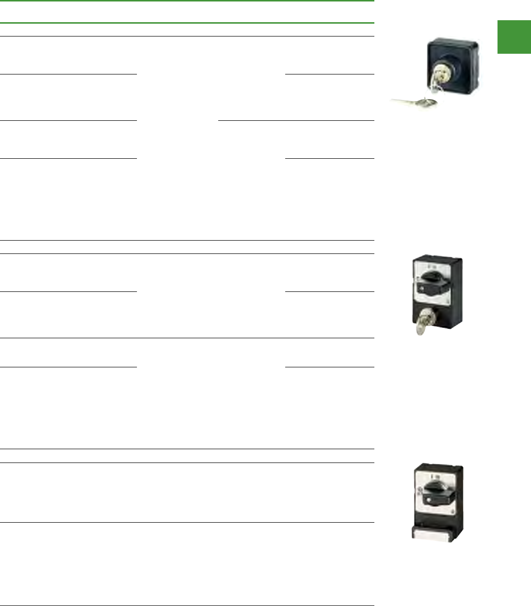
Control and indication
Power control
188
2015/2016 Product guide AUS15_007 - February 2016
Cam switches
Description For use with Withdrawability Item no.
S-T0 key operated lock mechanism, front IP53
KMS 1 lock mechanism: individual lock
mechanism, not suitable for master
key systems
Key withdrawable in all positions
T0-1.../I1 to T0-4.../I1
T0-1.../E to T0-6.../E
T0-1.../Z to T0-6.../Z
T3-1.../E to T3-5.../E
T3-1.../Z to T3-5.../Z
T3-1.../I2 to T3-4.../I2
P1-.../E
P1-.../I2
P1-.../Z
Withdrawable
positions can be
programmed by
user
S-T0
KMS 2-10, KMS 201-400 lock
mechanisms: individual lock
mechanisms, not suitable for master
key systems. Key withdrawable in all
positions
S-SOND-KMS(*)-T0
Lock KMS1: Switches with FS908 are
possible as main
switch. Key can be withdrawn in
positions as specified
Withdrawable
positions
programmed at
factory as
ordered
S(*)-T0
SA(...) = master key system (master-
key facility) with security certificate.
Ordering only with lock plan filled out
with the full configuration of the
envisaged lock system. When
reordering state item number from the
lock plan, e.g (A 6294-1.2).
Key can be withdrawn in positions as
specified
S(*)-SOND-SA(*)-T0
SVA-T3 cylinder lock, front IP65
KMS 1 lock mechanism: individual lock
mechanism, not suitable for master
key systems
Key withdrawable in all positions
T0-…/E, T0-…/I1,
T0-…/Z
T3-…/E, T3-…/I2,
T3-…/Z
P1-…/E, P1-…/I2,
P1-…/Z
Withdrawable
positions can be
programmed by
user
SVA-T3
KMS 2-10, KMS 201-400 lock
mechanisms: individual lock
mechanisms, not suitable for master
key systems. Key withdrawable in all
positions
SVA-SOND-KMS(*)-T3
Lock KMS1: Switches with FS908 are
possible as main switch. Key can be
withdrawn in positions as specified
T0-1-… to T0-4-…/I1
T0-1-.../E to T0-4-.../E
T3-1-... to T3-5-.../I2
T3-1-... to T3-6-.../E
P1-.../I2, P1-.../E
Withdrawable
positions
programmed at
factory as
ordered
SVA(*)-T3
SA(...) = master key system (master-
key facility) with security certificate.
Ordering only with lock plan filled out
with the full configuration of the
envisaged lock system. When
reordering state item number from the
lock plan, e.g (A 6294-1.2).
Key can be withdrawn in positions as
specified
SVA(*)-SOND-SA(*)-T3
SVC-T3 padlocking feature, front IP65
ll positions can be locked
T0-…/E, T0-…/I1,
T0-…/Z
T3-…/E, T3-…/I2,
T3-…/Z
P1-…/E, P1-…/I2,
P1-…/Z
The positions that
can be locked
can be
programmed by
the user
SVC-T3
Specific positions or ranges can be
locked
Switches with FS908
can be used as main
switches for:
T0-1-... to T0-4-.../
I1, .../E
T3-1-... to T3-5-.../I2
T3-1-... to T3-6-.../E
P1-.../I2, P1-.../E
The positions that
can be locked
are programmable
at the factory
as ordered
SVC(*)-T3
SVC-T3
SVA-T3
S-T0
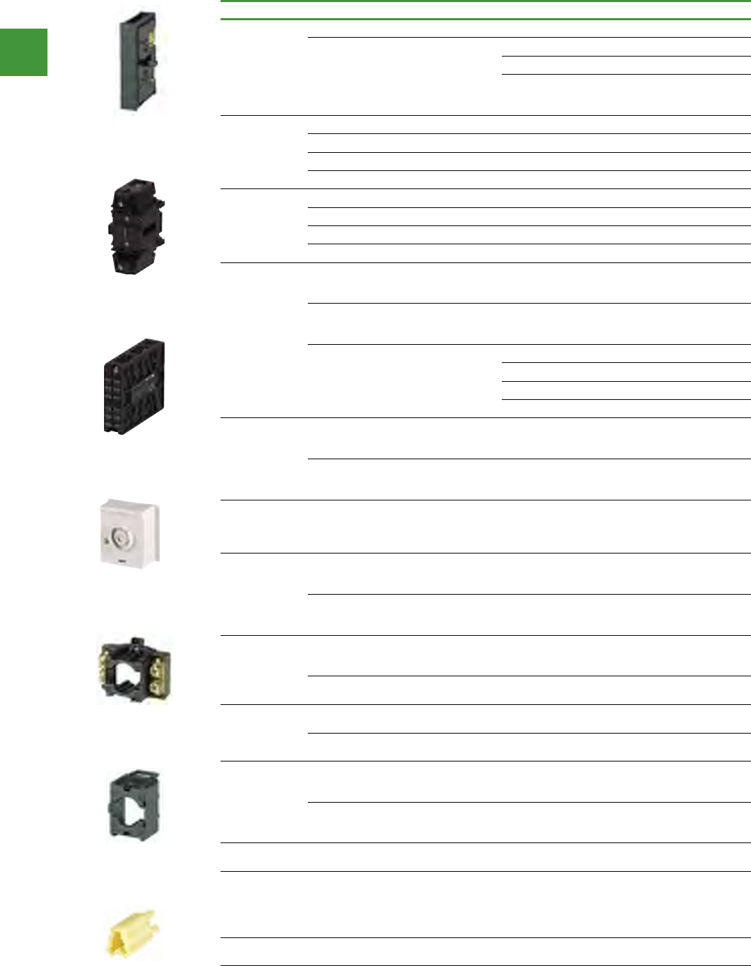
Control and indication
Power control
189 2015/2016 Product guide AUS15_007 - February 2016
Description For use with Item no.
Neutral
conductor
For left or right side mounting P1-…/E, …/EA, …/EZ N-P1E
For P1-…/I2: optionally, N-P1Z or
HI11-P1/P3Z,
can only be fitted on the left
P1-…/Z, …/V, …/I2, …/IVS N-P1Z
P3-…/E, …/EA… N-P3E
P3-…/Z, …/V, …/IVS
P3-63…/Z, …/I4
P3-100…/Z, …/I5
N-P3Z
Neutral terminal
P5-125(160)/E(EA) N-P5-125/160E
P5-125(160)/Z(V) N-P5-125/160Z
P5-250(315)/E(EA) N-P5-250/315E
P5-250(315)/Z(V) N-P5-250/315Z
Ground terminal
P5-125(160)/E(EA) PE-P5-125/160E
P5-125(160)/Z(V) PE-P5-125/160Z
P5-250(315)/E(EA) PE-P5-250/315E
P5-250(315)/Z(V) PE-P5-250/315Z
Auxiliary
contacts
1 normally open (N/O), 1 normally
close contact (N/C) - For left and/or
right side mounting
P1-…/E, …/EA…, …/EZ
P3-…/E, …/EA HI11-P1/P3E
For P1…/I2: optionally, HI11-P1/P3Z or
N-P1Z, can only be fitted on the left
P1-…/Z, …/V, …/I2, …/IVS
P3-63/Z, …/V, …/I4, …/IVS
P3-100/Z, …/V, …/I5, …/IVS
HI11-P1/P3Z
2 normally open (N/O), 1 normally
close contact (N/C) - For left and/or
right side mounting
P5-125(160)/E(EA) HI21-P5-125/160E
P5-125(160)/Z(V) HI21-P5-125/160Z
P5-250(315)/E(EA) HI21-P5-250/315E
P5-250(315)/Z(V) HI21-P5-250/315Z
Center
mounting
accessories
For cam switches with existing front
plate - quick installation with snap
fitting system
T0-…/E
T3-…/E EZ-T0
Mounting diameter 22.3 mm, one
man mounting with screw fixing
T0-…/E
T3-…/E
P1-…/E
EZ-P1
Service
distribution
board mounting
accessories
For retrofitting in service distribution
board mounting T0-…/IVS design. Use
the basic switch's front plate.
0-…/XZ IVS-T0
Coupling drive
For the retrofitting of switch
T0(T3)-.../XZ as rear mounting,
spare part for T0(T3)/(P1)-.../Z
DE-T0
For the conversion of T5(B)-.../E flush
mounting switch to rear mounting,
spare part for T5(B)/(P3)-...Z
DE-P3
Interlock
sections
T0-…/E, …EZ, …Z
T3-…/E, …EZ, …Z
P1-…/E, …EZ, …Z
UV-T0
T5(B)-…/E, …Z
P3-…/E, …Z UV-P3
Interlock
extensions
Use only with T0/T3-… and P3-…/Z
designs UV-T0 ZVV-T0
Use only with T5(B)-…/Z and P3-…/Z
designs UV-P3 ZVV-P3
Shaft
extensions
T0-…/Z, T0-…/V
T3-…/Z, T3-…/V
P1-…/Z, P1-…/V
ZAV-T0
T5(B)-…/Z
P3-…/Z
P3-…/V
ZAV-P3
Shaft Aluminum, length: 480 mm P5-…/V…
P5-…/Z ZAV-P5
Interlock
extensions und
shaft
extensions,
complete
Extension to 25 mm
When ordering with basic unit
+ZAV(X1)+ZV-
V(X1)-T0/P3
Control cable
terminal P5-250/315 ST-P5-250/315
Cam switches
N-P1E
PE-P5-125/160Z
HI21-P5-125/160Z
IVS-T0
UV-T0
ZVV-T0
SAV-T0
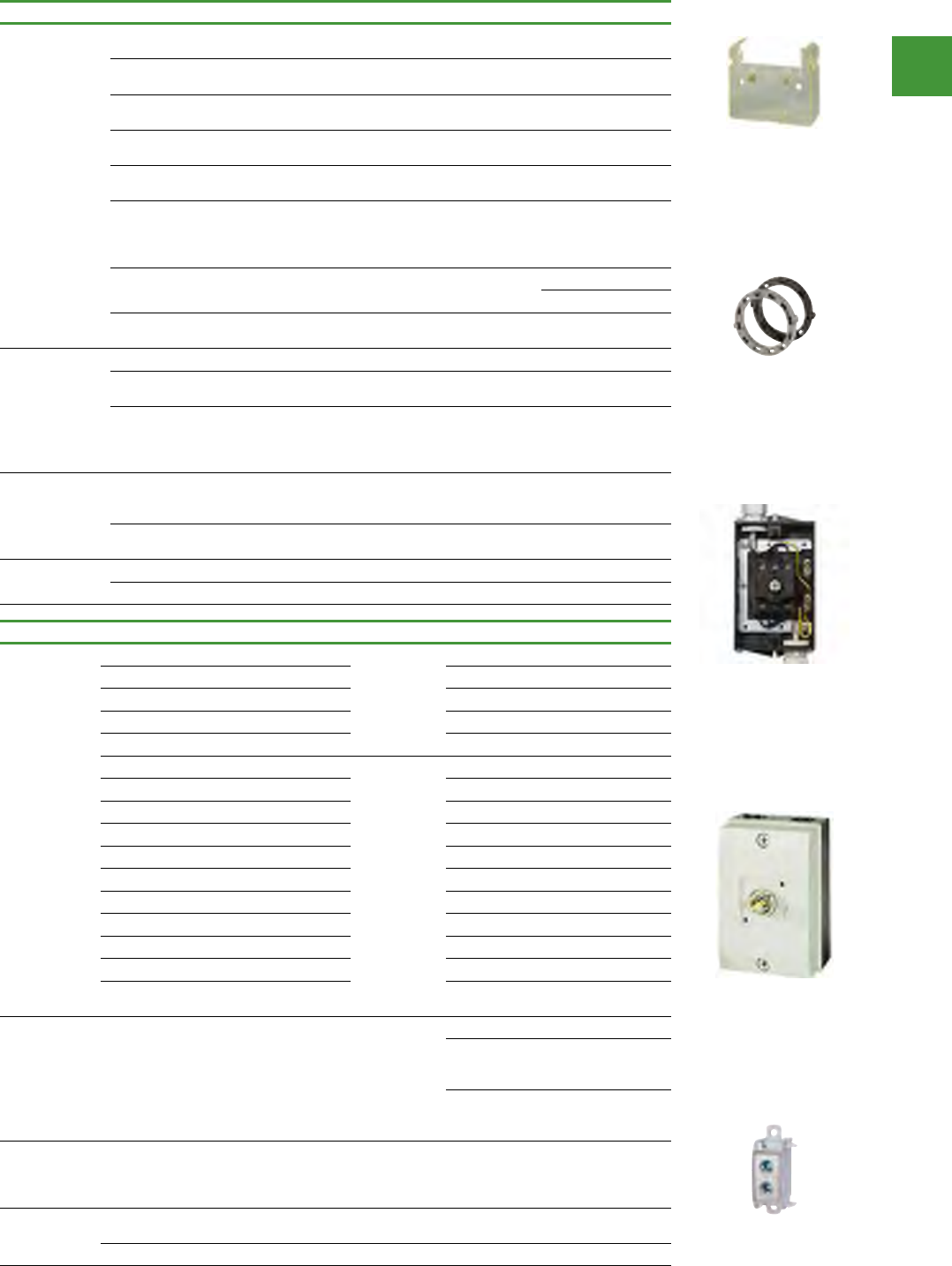
Control and indication
Power control
190
2015/2016 Product guide AUS15_007 - February 2016
Description For use with Item no.
Shrouds
For flush mounting switches with up
to 4 contact units
T0-…/E
T3-…/E H3-T0
For covering the connection terminals
of up to 2 contact units T5(B)-…/E, …/Z H1-T5
Extension for H1-T5 protective shroud
on 3 - 8 contact units H1-T5 HZ-T5
For covering the connection terminals
on 3 pole switch-disconnectors
P1-…/E, …/EZ, …/Z, …/EA,
…/V H-P1
For covering the connection terminals
on 4 pole switch-disconnectors
P1-…N, …HI11,
…N…HI11 H-P14
For covering the connection terminals
on 3 pole open switchdisconnectors
with N neutral conductor and/or HI11
auxiliary contact
P3-…/E, …/Z, …/EA, …/V
P3-…N, …HI11,
…N…HI11
H-P3
For covering the terminals P5 H-P5-125/160
H-P5-250/315
Set (6 units) for covering the connec-
tion terminals T8-3-8342/… H-T8
Key
For KMS 1 individual lock mechanism ES-KMS1-T0
For KMS 2 - 10 or KMS 201 - 400
individual lock mechanism ES-KMS(*)-T0
Individual key, stainless, for master
key system and stored individual lock
mechanisms, state lock plan no. and
key.
HS-SA(*)-T0
Locking cams (2
cams per set)
For later change of key
withdrawability in the engagement
positions
S-T0 for all switching
angles VR-T0
For changing the blocked positions/
ranges
SVA-T3
SVC-T3 VR-T3
Mounting plate
shield
To connect the shielding CI-K2 MBS-I2
To connect the shielding CI-K4 MBS-I4
Description For use with Item no.
IP65 insulated
enclosures
1 - 2 contact units
With
pushthrough
cable entry
diaphragm.
T0-…/Z CI-K1-T0-2
3 - 4 contact units T0-…/Z CI-K1-T0-4
1 - 2 contact units T3-…/Z CI-K2-T3-2
3 - 4 contact units T3-…/Z CI-K2-T3-4
5 contact units T3-…/Z CI-K2-T3-5
1 - 2 contact units
With metric
knockouts
T0-…/Z CI-K1H-T0-2
3 - 4 contact units T0-…/Z CI-K1H-T0-4
1 - 2 contact units T3-…/Z CI-K2H-T3-2
3 - 4 contact units T3-…/Z CI-K2H-T3-4
5 contact units T3-…/Z CI-K2H-T3-5
1 - 2 contact units T5B-…/E CI-K4-T5B-2
3 - 4 contact units T5B-…/E CI-K4-T5B-4
1 - 2 contact units T5-…/Z CI-K5-T5-2
3 - 4 contact units T5-…/Z CI-K5-T5-4
Only available together with basic unit T0-…/I1 +I1H
Only available together with basic unit T3-…/I2
P1-…/I2 +I2H
Neutral terminals
CI-K2-PKZ0-... K-CI-K1/2
T5B-…/I4,
Cl-K4-T5B-…
P3-…/I4, CI-K4
K-CI-K4
T5-…/I5,
CI-K5-T5-…
P3-…/I5, CI-K5
K-CI-K5
Set of external fixing brackets
T5B-…/I4,
T5-…/I5,
P3-63/I4,
P3-100/I5
AB-CI-K4/5
Set of
extension
terminals
For the bottom contact unit T5B-…/I4
T5-…/I5 AW-T5-1/2
For the second contact unit from the bottom T5-…/I5 AW-T5-3/4
Cam switches
C1-K1-T0-2
K-C1-K5
MBS-12
VR-T0
H1-t5
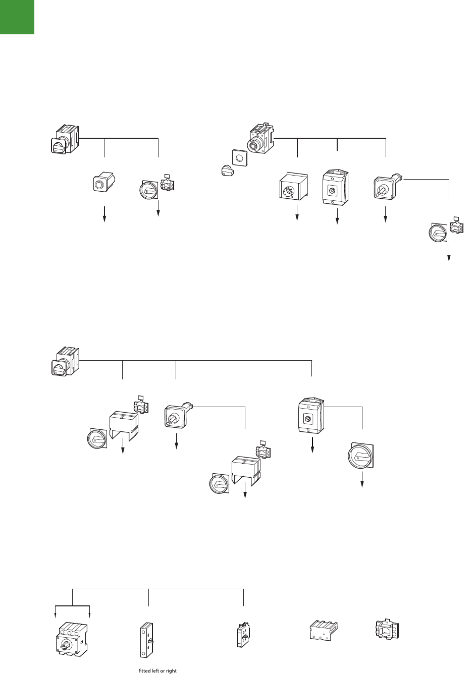
Control and indication
Power control
191 2015/2016 Product guide AUS15_007 - February 2016
Cam switches
4/8 Cam switches, switch-disconnectors
Description
Cam switches can be used for many switching and
control applications. For example as ON-OFF
switches, main switches, main/control switches,
instrument switches.
The switches consist of a hand actuator, the switch
unit and the mounting accessories.
The contact chamber (contact unit = BE) contains
1 or 2 contacts.
Our "T Cam Switches" catalog has over 800 popular
standard contact sequences (please request under
K115D/F/GB, article no. 077643).
The following pages feature a selection of our
standard contact sequences.
T cam switches and P switch-disconnectors are
manufactured without PCB, CFC, asbestos and
silicon.The contacts are cadmium free.
The CI-K... insulated enclosures are silicon and halogen
free.
Cam switches T0 and T3
T . . . . . . . . . . . . - . . . . . . . . . . . . . . . . . . . . . . . . . . . . - . . . . . . . . . . . . . . . . . . . . . . . / . . . . . . . . . . . . . . . . . . . .
Switch size
T0 or T3
Number of contact chambers
= contact units
Contact sequence
number
Mounting form
CI-K1-T0
CI-K2-T3
T0-.../I1
T3-.../I2
T0.../IVS
1)
T0(3).../E
T0(3).../EZ
0T-ED0T-SVIZX/...)3(0T0T-BVS/AE/V0T-ZE
T0(3).../Z
1)
V/EA/SVB-T0
T0-1-(T3-1-).../V/SVB
.
.
.
T0-4-(T3-6-).../V/SVB
T0-1-(T3-1-).../EA/SVB
.
.
.
T0-4-(T3-6-).../EA/SVB
T0, T3, T5, T5B
↑↑↑↑
CI-K4-T5B
CI-K5-T5
DE-P3V/EA/SVB-T5T5(B)...E
T5(B).../EA/SVB T5(B).../Z
V/EA/SVB-T5
T5(B).../V/SVB
T5B-.../I4
T5-.../I5
SVB-P3
T5B-.../I4/SVB
T5-.../I5/SVB
T . . . . . . . . . . . . - . . . . . . . . . . . . . . . . . . . . . . . . . . . . - . . . . . . . . . . . . . . . . . . . . . . . / . . . . . . . . . . . . . . . . . . . .
Switch size
T5(B)
Number of contact chambers
= contact units
Contact sequence
number
Mounting form
↑↑↑↑
↑↑↑↑↑
P. . . . . . . . . . . . - . . . . . . . . . . . . . . . . . . . . . . . . . . . . / . . . . . . . . . . . . . . . . . . . . - . . . . . . . . . . . . . . . . . . / . . . . . . . . . . . . . . . . . . . . .
Switch size
P1 or P3
Rated uninterrupted current Mounting form Part no. suffix
(if required)
Accessories
H-P... UV-P...
N-P...Z HI 11-P1/P3Z
N-P...E HI 11-P1/P3E
3-pole basic unit
.../E or .../Z
Switched neutral can be
(for P1.../I: left only)
Auxiliary contact can be
fitted left or right
(for P1.../I: left only)
Terminal shroud
can be fitted at
top or bottom
N + PE terminals,
also as cover interlock
on .../Z-switches.
or or
Cam switches can be used for many switching and control
applications. For example as ON-OFF switches, main switches,
main/control switches, instrument switches. The switches consist
of a hand actuator, the switch unit and the mounting accessories.
The contact chamber (contact unit = BE) contains 1 or 2 contacts.
Our "T Cam Switches" catalog has over 800 popular standard
contact sequences.The following pages feature a selection of
our standard contact sequences. T cam switches and P switch-
disconnectors are manufactured without PCB, CFC, asbestos
and silicon.The contacts are cadmium free. The CI-K... insulated
enclosures are silicon and halogen free.
Cam switches T0 and T3
Key to part numbers
Cam switches TB5
Key to part numbers
Switch-disconnectors P1 and P3
Key to part numbers
Using the modular sustem to convert the mounting form
Using the modular sustem to convert the mounting form T5B
Add-on functions due to modular systems
Control and indication
Power control
192
2015/2016 Product guide AUS15_007 - February 2016
Cam switches
The TM mini cam switch is a particularly small switch with a small space requirement. It is ideally suited for small voltages and currents
such as electronic controls. For greater safety the contacts are gold plated.
TM switches have consecutive terminal markings starting with 1.
Switch-disconnectors P1 and P3
Key to part numbers
Key to part numbers
Cam switches, switch-disconnectors
2010 CA08103002Z-EN www.eaton.com
4/9
Switch-disconnectors P1 and P3
Key to part numbers
P. . . . . . . . . . . . - . . . . . . . . . . . . . . . . . . . . . . . . . . . . / . . . . . . . . . . . . . . . . . . . . - . . . . . . . . . . . . . . . . . . / . . . . . . . . . . . . . . . . . . . . .
Switch size
P1 or P3
Rated uninterrupted current Mounting form Part no. sux
(if required)
Accessories
Add-on functions due to modular system
TM mini cam switches
The TM mini cam switch is a particularly small switch
with a small space requirement. It is ideally suited for
small voltages and currents such as electronic
controls. For greater safety the contacts are gold
plated.
TM switches have consecutive terminal markings
starting with 1.
Selection pages: Starting on �Page7/54
Key to part numbers
TM-. . . . . . . . . . . . . . . . . . . . . . . . . - . . . . . . . . . . . . . . . . . . . . . . . / . . . . . . . . . . . . . . . . . . . . + . . . . . . . . . . . . . . . . . .
Number of contact chambers
= contact units
Contact sequence
number
Mounting formAccessories
Circuit representation
(see also ordering example in the electronic
catalogue)
Switch from 0 to 1
Contact 1 – 2 open,
Contact 3 – 4 open,
Contact 5 – 6 open,
Contact 7 – 8 closed
Switch from 1 to START
with automatic return to 1
Contact 1 – 2 open,
Contact 3 – 4 closed,
Contact 5 – 6 open,
Contact 7 – 8 remains closed
Switch from 1 to 0
Contact 1 – 2 open,
Contact 3 – 4 open,
Contact 5 – 6 open,
Contact 7 – 8 open
Switch from 0 to 2
Contact 1 – 2 closed,
Contact 3 – 4 open,
Contact 5 – 6 open,
Contact 7 – 8 closed
Switch from 2 to START
with automatic return to 2
Contact 1 – 2 open,
Contact 3 – 4 open,
Contact 5 – 6 closes with early make,
Contact 7 – 8 opens with late break
Switch from 2 to 0
Contact 1 – 2 open,
Contact 3 – 4 open,
Contact 5 – 6 open,
Contact 7 – 8 open
H-P... UV-P...
N-P...Z HI 11-P1/P3Z
N-P...E HI 11-P1/P3E
3-pole basic unit
.../E or .../Z
Switched neutral
Can be tted left
or right
(for P1.../I: left only)
Auxiliary contact
Can be tted left
or right
(for P1.../I: left only)
Terminal shroud
can be tted at
top or bottom
N + PE terminals,
also as cover interlock
on .../Z-switches.
or or
1
2
3
4
5
6
7
8
START
1
0
2
START
Links
Terminal markings
Front plate labeling
P1, P3, TM
Cam switches, switch-disconnectors
2010 CA08103002Z-EN www.eaton.com
4/9
Switch-disconnectors P1 and P3
Key to part numbers
P. . . . . . . . . . . . - . . . . . . . . . . . . . . . . . . . . . . . . . . . . / . . . . . . . . . . . . . . . . . . . . - . . . . . . . . . . . . . . . . . . / . . . . . . . . . . . . . . . . . . . . .
Switch size
P1 or P3
Rated uninterrupted current Mounting form Part no. sux
(if required)
Accessories
Add-on functions due to modular system
TM mini cam switches
The TM mini cam switch is a particularly small switch
with a small space requirement. It is ideally suited for
small voltages and currents such as electronic
controls. For greater safety the contacts are gold
plated.
TM switches have consecutive terminal markings
starting with 1.
Selection pages: Starting on �Page7/54
Key to part numbers
TM-. . . . . . . . . . . . . . . . . . . . . . . . . - . . . . . . . . . . . . . . . . . . . . . . . / . . . . . . . . . . . . . . . . . . . . + . . . . . . . . . . . . . . . . . .
Number of contact chambers
= contact units
Contact sequence
number
Mounting formAccessories
Circuit representation
(see also ordering example in the electronic
catalogue)
Switch from 0 to 1
Contact 1 – 2 open,
Contact 3 – 4 open,
Contact 5 – 6 open,
Contact 7 – 8 closed
Switch from 1 to START
with automatic return to 1
Contact 1 – 2 open,
Contact 3 – 4 closed,
Contact 5 – 6 open,
Contact 7 – 8 remains closed
Switch from 1 to 0
Contact 1 – 2 open,
Contact 3 – 4 open,
Contact 5 – 6 open,
Contact 7 – 8 open
Switch from 0 to 2
Contact 1 – 2 closed,
Contact 3 – 4 open,
Contact 5 – 6 open,
Contact 7 – 8 closed
Switch from 2 to START
with automatic return to 2
Contact 1 – 2 open,
Contact 3 – 4 open,
Contact 5 – 6 closes with early make,
Contact 7 – 8 opens with late break
Switch from 2 to 0
Contact 1 – 2 open,
Contact 3 – 4 open,
Contact 5 – 6 open,
Contact 7 – 8 open
H-P... UV-P...
N-P...Z HI 11-P1/P3Z
N-P...E HI 11-P1/P3E
3-pole basic unit
.../E or .../Z
Switched neutral
Can be tted left
or right
(for P1.../I: left only)
Auxiliary contact
Can be tted left
or right
(for P1.../I: left only)
Terminal shroud
can be tted at
top or bottom
N + PE terminals,
also as cover interlock
on .../Z-switches.
or or
1
2
3
4
5
6
7
8
START
1
0
2
START
Links
Terminal markings
F
ront plate labeling
P1, P3, TM
TM mini cam switches
Motor failure has the potential
to cause production downtime,
costly repair bills and numerous
safety concerns for plant
personnel. For these reasons,
motor protection should be a
key element in protecting your
organization’s most valuable
assets. Selecting accurate
and reliable motor overload
protection is the best way to
manage your costs and maintain
system integrity.
Reliable, accurate, intelligent
motor protection.
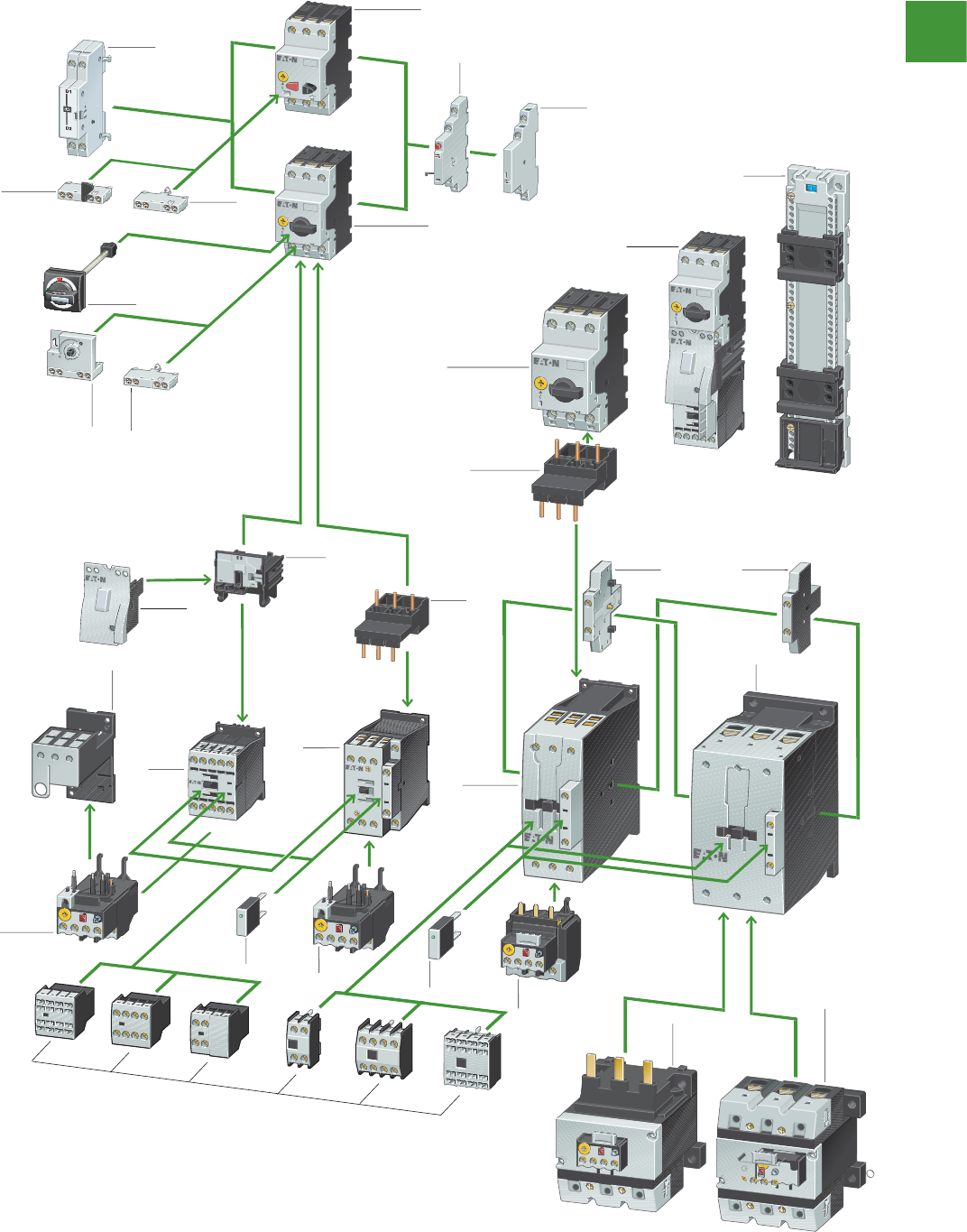
Motor control
Shunt and
undervoltage
release
Manual Motor Protector with
pushbutton actuation up to 25A
Trip-indicating
auxiliary contact
Side mounting
auxiliary contact
Top-hat rail
adapter
Manual Motor
Controller
Manual Motor Protector
with rotary actuation
up to 65A
Manual Motor Protector
with rotary actuation
up to 32A
Front mounting
auxiliary contact
Front mounting
auxiliary contact
Door coupling rotary
handle and axis extension
Early-make
auxiliary contact
Early-make
auxiliary
contact
Electrical
connector
Contactor
up to
65A
Contactor
up to 150A
Side mounting
auxillary contact
Electrical
connector
Contactor
up to 32A
Contactor
up to 15A
Overload
relay up to 15A Overload
relay up
to 32A
Overload
relay up
to 65A
Overload
relay up
to 150A
Overload
relay up
to 150A
seperate
mounting
Suppressor
Suppressor
Top mounting
auxiliary contact
Overload relay
seperate
mounting adapter
up to 65A
Tool-less
plug connector
Mechanical
connector
up to 15A
Xstart IEC Motor control
Power control
194
2015/2016 Product guide AUS15_007 - February 2016
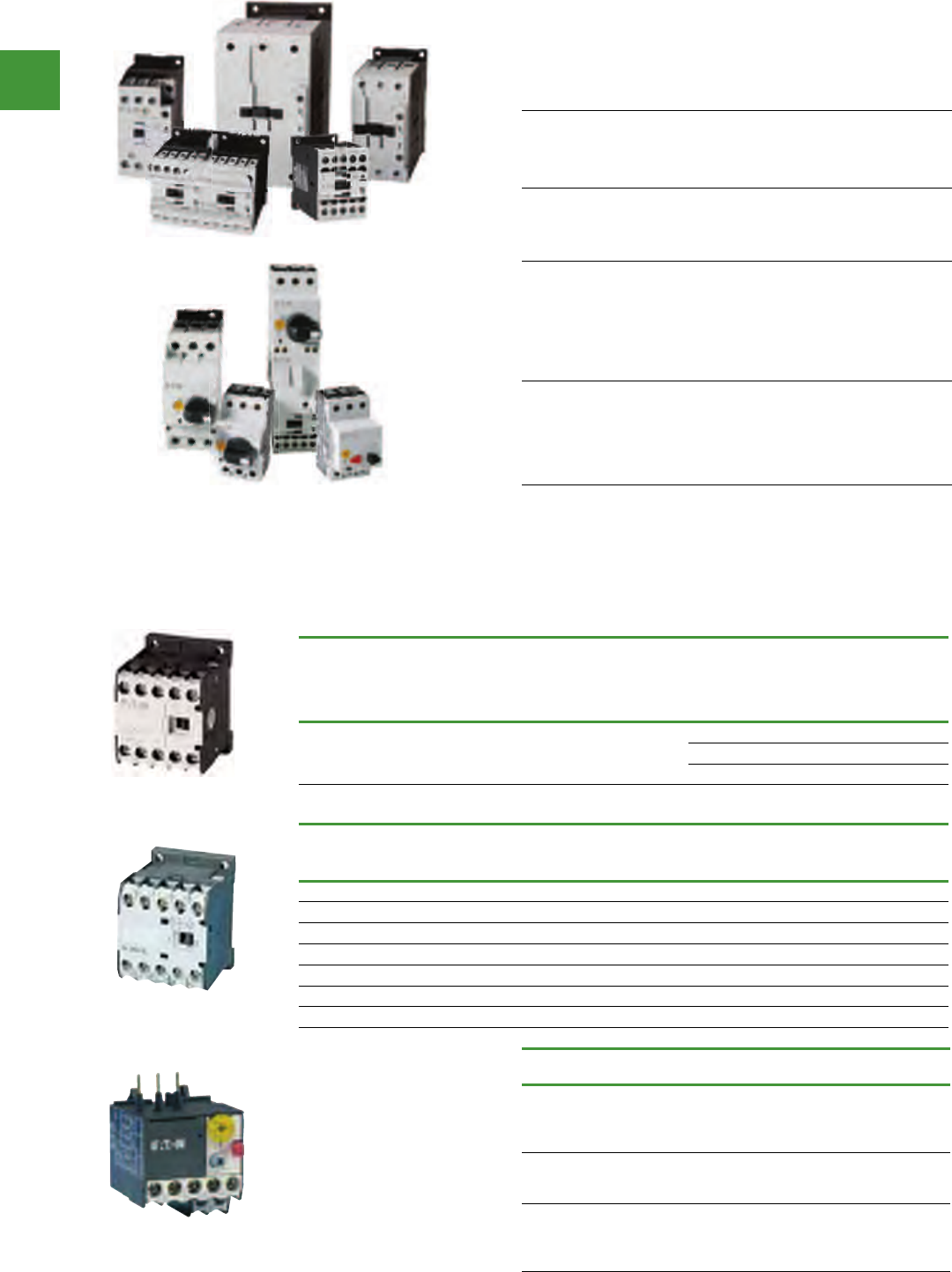
Motor control
Power control
195 2015/2016 Product guide AUS15_007 - February 2016
Xstart IEC Motor control
The XStart range of contactors, overloads & manual motor
protectors is a complete range of IEC Motor control. XStart is an
efficient & effective solution for applications from 7-2600A.
Feature Benefit
AC & DC devices with the
same dimensions achieved
with an electronically
controlled coil system.
Space savings, reduced
engineering design time.
Twin terminals with separate
sockets in contactors up to
400A.
Offers installation & application
flexibility when using different size
wires. The improved integrity of the
connections reduces cabling faults.
Reduced sealing power
consumption for DC
contactors due to an
electronic coil controller that
uses less power.
With sealing wattage as low as
0.5W, XStart contactors reduce
power consumption & generate
less heat. This results in lower
cooling requirements,
& the ability to mount more
contactors per cabinet.
Integrated suppressors in DC
controlled contactors from
7–1000A. Integrated surge
suppressors in all contactors
from 115A & above.
Offers reductions in total logistics
& inventory costs by limiting the
number of products ordered &
stocked. Increased installation &
maintenance efficiency,
as wiring is not required.
IEC Miniature controls
Operational
current AC-3
Amp rating
Thermal
current
AC-1
Maximum kW ratings AC-3,
3-Phase Motors, 50 – 60 Hz
No. of
power
poles
Aux.
contacts
Item no.
240V 415V
6.6 20 1.5 3 3 1NO DILEEM-10(...)
6.6 20 1.5 3 3 1NC DILEEM-01(...)
9 20 2.2 4 3 1NO DILEM-10(…)
9 20 2.2 4 3 1NC DILEM-01(…)
12 20 3.5 5.5 3 1NO DILEM12-10(...)
12 20 3.5 5.5 3 1NC DILEM12-01(...)
9 20 2.2 4 4 - DILEM4(…)
Motor full load
current (FLC) Trip class Contact
configuration Item no.
0.1 – 0.16A
0.16 – 0.24A
0.24 – 0.4A
0.4 – 0.6A
10A 1NO-1NC
ZE-0,16
ZE-0,24
ZE-0,4
ZE-0,6
0.6 – 1A
1 – 1.6A
1.6 – 2.4A
10A 1NO-1NC
ZE-1,0
ZE-1,6
ZE-2,4
2.4 – 4A
4 – 6A
6 – 9A
9 – 12A
10A 1NO-1NC
ZE-4
ZE-6
ZE-9
ZE-12
IEC Miniature overload relays
• Trip Class 10A
• Ambient temperature
compensated -5° to 50°C
• Selectable manual /
automatic reset
• 1NO-1NC auxiliary contact
as standard
• Direct mount with DILEM
contactors
Xstart IEC Mini contactors
Mini contactor relays
Rated operational current AC-15 Conventional free
air thermal current Aux. contact Item no.
220 V, 230 V, 240 V
Ie
A
380 V, 400 V, 415 V
Ie
A
Ith
A
6 3 10
4 N/O -DILER-40(...)
3 N/O 1 NC DILER-31(...)
2 N/O 2 NC DILER-22(...)
Due to its compact size, this line of mini controls is best suited to be applied in light duty loads such as
hoisting, packaging, material handling, heating, lighting & automation systems. These mini contactors
are a particularly compact, economic & environmentally friendly solution wherever control of small
motors or loads is required.
DILER-40
DILEEM-10
ZE-0,16
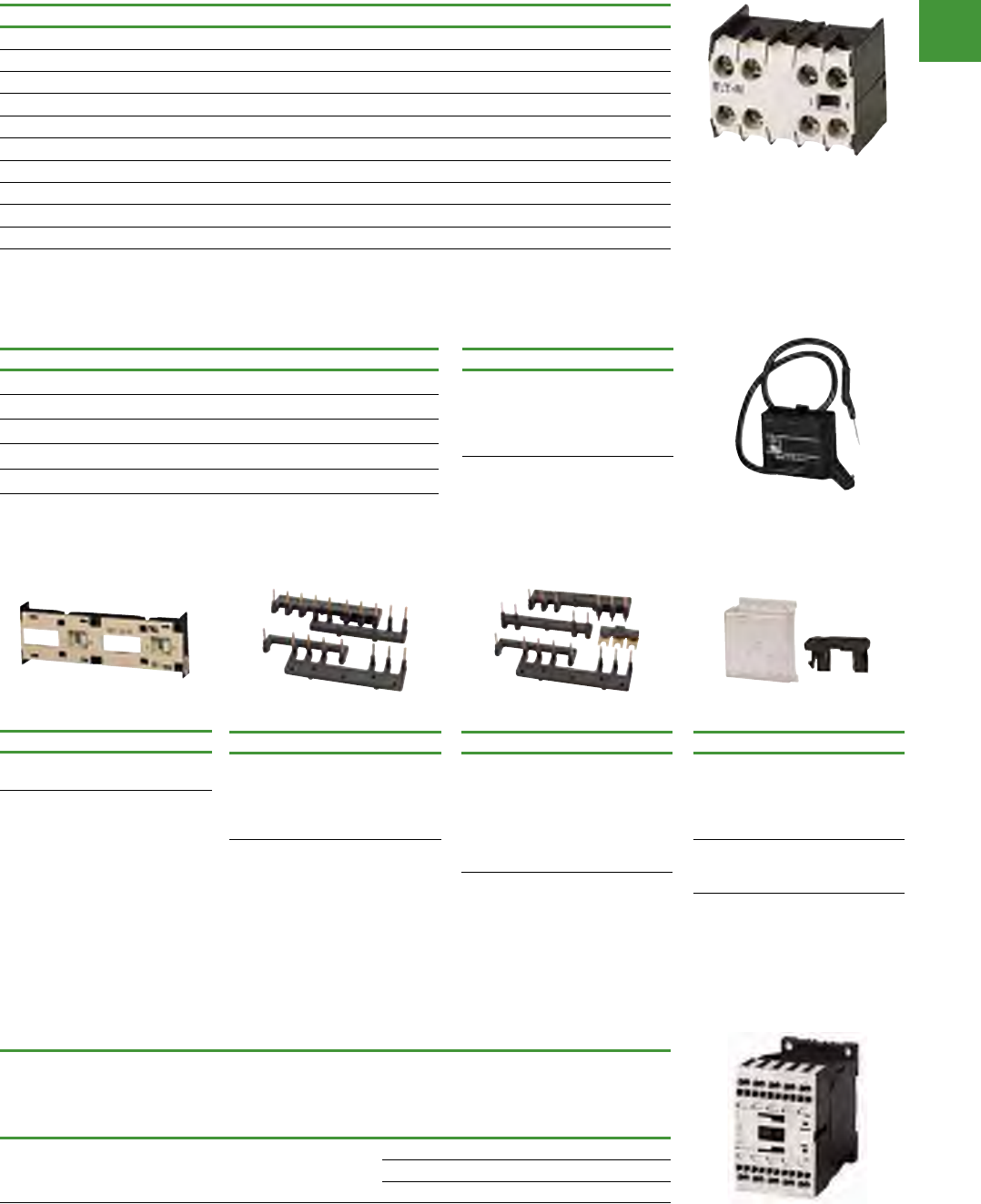
Motor control
Power control
196
2015/2016 Product guide AUS15_007 - February 2016
IEC Miniature controls accessories
(auxiliary contacts for mini contactors, front (top) mounted)
Contact configuration Poles Item no.
1NO/1NC 2 11DILE
2NO 2 20DILE
2NC 2 02DILE
2NO2NC 4 22DILE
1NO/3NC 4 13DILE
3NO1NC 4 31DILE
4NO 4 40DILE
4NC 4 04DILE
1ECNO/1LONC 2 11DDILE
2ECNO/2LONC 2 22DDILE
Note: Auxiliary contacts are rated for 10A AC-1.
Xstart IEC Mini contactors
Xstart IEC control relays
Mechanical interlock
Description Item no.
Mechanical
Interlock MVDILE
Note: For two contactors with AC or DC
operated coils that are horizontally or
vertically mounted, the distance between
contactors is 0 mm
Star-delta link kit
Description Item no.
Main current
wiring for
star-delta
combinations.
Includes the
Star-Delta
Bridge.
MVS-SB-EM
Reversing link kit
Description Item no.
Main current
wiring for
reversing
contactors &
starters.
MVS-WB-EM
Note: Reversing Link Kit does not include
mechanical interlock. Order part No.
MVDILE for Mechanical Interlock.
Other accessories
Description Item no.
Connector for
mechanically
arranging
contactors in
combinations.
V0DILE
Shroud IP40
Sealable Shroud,
snap fit
HDILE
Note: 0 mm distance between contactors
with connector.
Basic devices with positively driven contacts
Rated operational current AC-15 Conventional free
air thermal current Aux. contact Item no.
240 V
Ie
A
415 V
Ie
A
Ith
A
4 4 16
4 N/O -DILA-40(...)
3 N/O 1 NC DILA-31(...)
2 N/O 2 NC DILA-22(...)
Coil selection chart
Coil Voltage (50Hz) Suffix code
415 AC (415V50HZ, 480V60HZ)
230-240 AC (240V50HZ)
110 AC (110V50HZ/120V60HZ)
24 AC (24V50HZ)
24 DC (415V50HZ, 480V60HZ)
Note: Mini Contactor Coils are not interchangeable.
For additional coil voltages contact Eaton.
RC-suppressor
Description Item no.
Mini contactor
relay.
110-250 AC.
For use with
DILE...
RCDILE250
Note: For AC operated contactors 50-60 Hz.
DC operated contactor relays have an
integrated suppressor. RCDILE250
11DILE
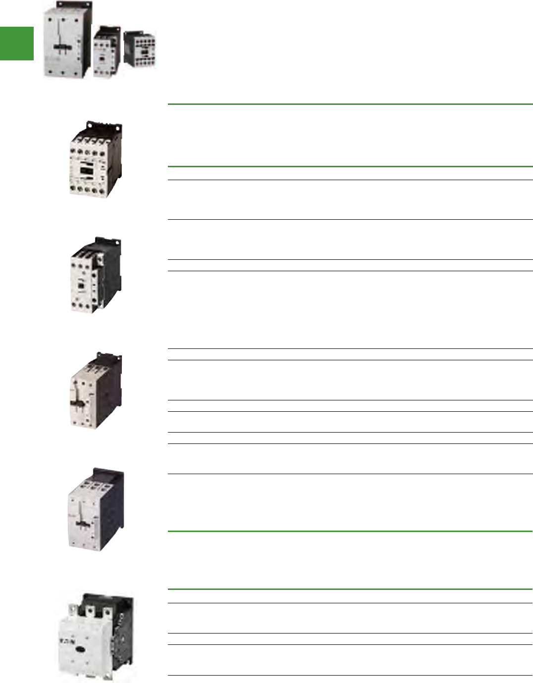
Motor control
Power control
197 2015/2016 Product guide AUS15_007 - February 2016
Full voltage non-reversing 3-pole contactors
IEC ratings
Aux.
contacts Item no.
AC-3
Ie (A)
AC-1
(60°C)
Ie = Ith (A)
Maximum kW ratings AC-3
3-Phase Motors 50 – 60 Hz
400V 660/
690V
Frame B
7
7
9
9
20
20
20
20
3
3
4
4
3.5
3.5
4.5
4.5
1NO
1NC
1NO
1NC
DILM7-10(…)
DILM7-01(…)
DILM9-10(…)
DILM9-01(…)
12
12
15.5
15.5
20
20
20
20
5.5
5.5
7.5
7.5
6.5
6.5
7
7
1NO
1NC
1NO
1NC
DILM12-10(…)
DILM12-01(…)
DILM15-10(…)
DILM15-01(…)
Frame C
18
18
25
25
32
32
38
38
35
35
40
40
40
40
40
40
7.5
7.5
11
11
15
15
18.5
18.5
11
11
14
14
17
17
21
21
1NO
1NC
1NO
1NC
1NO
1NC
1NO
1NC
DILM17-10(…)
DILM17-01(…)
DILM25-10(…)
DILM25-01(…)
DILM32-10(…)
DILM32-10(…)
DILM38-10(...)
DILM38-01(...)
Frame D
40
50
65
72
50
65
80
80
18.5
22
30
37
23
30
35
35
—
—
—
—
DILM40(…)
DILM50(…)
DILM65(…)
DILM72(...)
Frame F
80
95
90
110
37
45
63
75
—
—
DILM80(…)
DILM95(…)
Frame G
115
150
170
130
160
185
55
75
90
90
96
96
—
—
—
DILM115(…)
DILM150(…)
DILM170(...)
Note: The 7 – 38A contactors have positively driven contacts between the integrated auxiliary contact & the auxiliary contact
module as well as within the auxiliary contact modules.
The 40 – 72A contactors have positively driven contacts within the auxiliary contact module. 6 auxiliary contacts are possible
with a combination of side mounted & front mount auxiliary contacts.
DC operated contactors (Frames B – G, 7 – 170A) have a built-in suppressor circuit. Frame B – C contactors with 1NC built-in
auxiliary are mirror contacts.
Xstart IEC Contactors
IEC Contactors
• AC-3 contactor ratings to 1600A & AC-1
contactor ratings
to 2600A
• Panel or DIN-Rail mounting to 72A
• IP20 finger & back-of-hand proof
• Built-in NO or NC auxiliary contacts to 38A
• Built-in surge suppression on DC coils Frame
B-G & AC or DC coils on Frame L-R
• Can be used with ZB or ZEB overload relays
• Can be used with PKZM or PKE for manual
Motor controllers
IEC ratings
Aux.
contacts Item no.
AC-3
Ie (A)
AC-1
(60°C)
Ie = Ith (A)
Maximum kW ratings AC-3
3-Phase Motors 50 – 60 Hz
400V 660/
690V 1000V
Frame L — Electronic Coil
185
225
250
275
315
330
90
110
132
140
150
195
108
108
108
2NO-2NC
2NO-2NC
2NO-2NC
DILM185A/22(…)
DILM225A/22(…)
DILM250/22(…)
Frame M — Electronic Coil
300
400
500
350
500
700
160
200
250
195
344
344
132
132
132
2NO-2NC
2NO-2NC
2NO-2NC
DILM300A/22(…)
DILM400/22(...)
DILM500/22(…)
Contactors Frame L - R; Electronic Coil: Wide range of control voltages, Can be controlled by a PLC output, Can be controlled by a low
power command device, like a limit switch or sensor.
Frame B
Frame C
Frame D
Frame L
Frame F & G
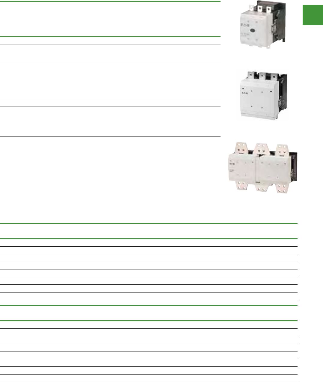
Motor control
Power control
198
2015/2016 Product guide AUS15_007 - February 2016
Full voltage non-reversing 3-pole contactors
IEC ratings
Aux.
contacts Item no.
AC-3
Ie (A)
AC-1
(60°C)
Ie = Ith (A)
Maximum kW ratings AC-3
3-Phase Motors 50 – 60 Hz
400V 660/
690V 1000V
Frame M — Standard coil (110/120V, 230/240V AC coil only)
300
400
500
430
612
857
160
200
250
195
344
344
-
-
-
2NO-2NC
2NO-2NC
2NO-2NC
DILM300A-S/22(…)
DILM400-S/22(…)
DILM500-S/22(…)
Frame N — Electronic coil
580
650
750
820
1000
800
850
900
1000
1000
315
355
400
450
560
560
630
720
750
1000
600
600
800
800
1100
2NO-2NC
2NO-2NC
2NO-2NC
2NO-2NC
2NO-2NC
DILM580/22(…)
DILM650/22(…)
DILM750/22(…)
DILM820/22(…)
DILM1000/22(…)
Frame R — Electronic coil
1600
-
-
-
-
1800
1400
2000
2200
2600
900
-
-
-
-
1600
-
-
-
-
1770
-
-
-
-
2NO-2NC
-
-
-
-
DILM1600/22(...)
DILH1400/22(...)
DILH2000/22(...)
DILH2200/22(...)
DILH2600/22(...)
Note: AC & DC operated contactors have a built-in suppressor circuit.
(Frames L – R, 185 – 2600A).
Coil suffix tables
Coil voltage
(suffix) DILM7-15 DILM17-65,
DILM80-95 DILM72 DILM115-225A
24V AC 24V50HZ 24V50HZ 24V50/60HZ RAC24
110V AC 110V50HZ,120V60HZ 110V50HZ,120V60HZ 110V50HZ,120V60HZ RAC120
240V AC 240V50HZ 240V50HZ 240V50HZ RAC240
415VAC 415V50HZ,480V60HZ 415V50HZ,480V60HZ 400V50HZ,440V60HZ RAC440
24V DC 24VDC RDC24 RDC24 RDC24
48V DC 48VDC RDC60 - RDC60
110V DC 110VDC RDC130 - RDC130
230V DC 220VDC RDC240 RDC240 RDC240
Coil voltage
(suffix) DILM250-500 DILM580-820 DILM1000 DILM1600
24V AC ----
110V AC RA110 RA110 - -
240V AC RA250 RA250 RA250 RAW250
415VAC RAC500 RAC500 - -
24V DC RDC48 - - -
48V DC RDC48 - - -
110V DC RA110 RA110 - -
230V DC RA250 RA250 RA250 RAW250
Xstart IEC Contactors
Frame M
Frame N
Frame R
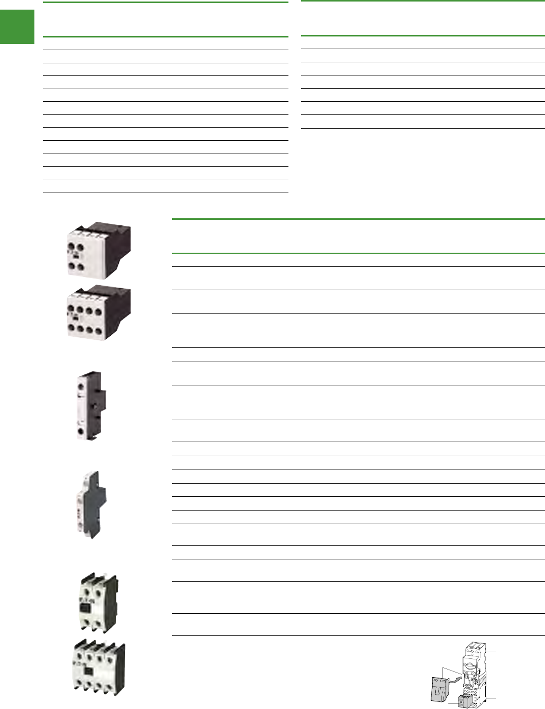
Motor control
Power control
199 2015/2016 Product guide AUS15_007 - February 2016
Xstart IEC Contactors
IEC 4-Pole Contactors, frame B – frame G
Ie (A)
AC-3
Ie = Ith (A)
(40°C)
AC-1
Maximum kW ratings AC-3
Item no.
3 Ph Motors 50 – 60 Hz
400V, kW
Frame B
12 20 5.5 DILMP20(...)
Frame C
18 32 7.5 DILMP32-10(…)
25 45 11 DILMP45-10(…)
Frame D
40 63 18.5 DILMP63(…)
50 80 22 DILMP80(…)
Frame G
80 125 37 DILMP125(…)
95 160 45 DILMP160(…)
115 200 55 DILMP200(…)
Accessories - Auxiliary contacts
Conventional thermal current,
Open at 60°C
Ith = Ie, AC-1 in Amps
Poles Contact
configuration Item no.
Frame B – C — Front (Top) Mount
16
16
2
2
2NO
2NC
DILA-XHI20
DILA-XHI02
16
16
2
2
1NO-1NC
1ECNO-1LONC
DILA-XHI11
DILA-XHIV11
16
16
16
2
2
2
2NO
1NO-1NC
2NC
DILA-XHIT20
DILA-XHIT11
DILA-XHIT02
16 4 2NO-2NC DILA-XHIT22
16
16
4
4
4NO
4NC
DILA-XHI40
DILA-XHI04
16
16
16
4
4
4
2NO-2NC
3NO-1NO
1NO-3NC
DILA-XHI22
DILA-XHI31
DILA-XHI13
16 4 1NO-1NC,
1ECNO-1LONC DILA-XHIV22
Frame B — Side mount
16 1 1NO DILA-XHI10-S
16 1 1NC DILA-XHI01-S
Frame C — Side mount
10 2 1NO-1NC DILM32-XHI11-S
Frame D — G Front (top) mount
16
16
2
2
2NO
2NC
DILM150-XHI20
DILM150-XHI02
16 2 1NO-1NC DILM150-XHI11
16
16
4
4
4NO
4 NC
DILM150-XHI40
DILM150-XHI04
16
16
16
4
4
4
2NO-2NC
3NO-1NC
1NO-3NC
DILM150-XHI22
DILM150-XHI31
DILM150-XHI13
16 4 1NO-1NC,
1ECNO-ILONC DILM150-XHIV22
IEC Capacitor contactors, frame C – Frame D
Switching duty in kvar -
Group compensation, without reactor Item no.
230V 400V 525V 690V
Frame C
7.5 12.5 16.7 20 DILK12-11(...)
11 20 25 33.3 DILK20-11(...)
15 25 33.3 40 DILK25-11(...)
Frame D
20 33.3 40 55 DILK33-10(...)
25 50 65 85 DILK50-10(...)
Note: Weld resistant contactors for capacitors, with inrush current peaks up to 180 In
Fram B - side mount: can be mounted to the left side of contactor only. Cannot be used in
combination with front (top) mount auxiliary contacts or mechanical interlocks.
Note: Interlocked opposing contacts, to IEC/EN 60947-5-1 Annex L (positively driven),
within the auxiliary contact modules (not NO (early make) & NC (late break) contacts) &
for the built-in auxiliary contacts of the DILM7 - DILM38... Auxiliary break contact can be
used as mirror contact to IEC/EN 60947-4-1 Annex F (not NC (late break) contact). No
auxiliary contacts can be fitted between two contactors.
Suitable for the combination with electrical wiringlinks in tool-less plug connection
usable with: DILM12-XSL, DILM12-XRL,
DILM12-XS1, PKZM0-XDM12, PKZM0-XRM12, PKZM0-XSM12
5/40 Contactors
Auxiliary contact module
2010 CA08103002Z-EN www.eaton.com
Auxiliary contact module
Connection
type
Pole conventional
thermal
current
Ith = Ie
AC-1 at 60 °C
Contact
configuration
N/O = normally
open contact
SF = N/O early
make
NC = normally
closed contact
ÖS = NC late-
break
Circuit
symbol
For use with Part no.
Article no. Price
See
price
list
Std. pack Notes
Open
Ith = Ie
A
Auxiliary contact modules
With interlocked opposing contacts
Top mounting auxiliary contacts
Screw
terminals
2 pole 16 2 N/O – DILM40…
DILM50…
DILM65…
DILM72…
DILM80…
DILM95…
DILM115…
DILM150…
DILM170…
DILMP63…
DILMP80…
DILMP125…
DILMP160…
DILMP200…
DILM150-XHI20
277945
5 off
Interlocked
opposing contacts
according to
IEC/EN 60947-5-1
Annex L, inside the
auxiliary contact
modules
Auxiliary NC
usable as mirror
contact according
to IEC/EN 60947-4-1
,
Annex F
1 N/O 1 NC DILM150-XHI11
277946
1 N/O 1 NC DILM150-XHIA11
283463
– 2 NC DILM150-XHI02
277947
Screw
terminals
4 pole 16 4 N/O – DILM150-XHI40
277948
3 N/O 1 NC DILM150-XHI31
277949
2 N/O 2 NC DILM150-XHI22
277950
2 N/O 2 NC DILM150-XHIA22
283464
1 N/O 3 NC DILM150-XHI13
277951
– 4 NC DILM150-XHI04
277952
1 N/O
1 SF
1 NC
1 ÖS
DILM150-XHIV22
277953
–
High version1)
Screw
terminals
2 pole 16 2 N/O – DILM7…
DILM9…
DILM12…
DILM15…
DILL…
DILA-XHIT20
101042
5 off
Interlocked
opposing contacts
according to
IEC/EN 60947-5-1
Annex L, inside the
auxiliary contact
modules
Auxiliary NC
usable as mirror
contact according
to IEC/EN 60947-4-1
,
Annex F
1 N/O 1 NC DILA-XHIT11
101043
– 2 NC DILA-XHIT02
101041
4 pole 2 N/O 2 NC DILA-XHIT22
101044
Notes 1) Suitable for the combination with electrical wiringlinks
in tool-less plug connection usable with:
DILM12-XSL
DILM12-XRL
DILM12-XS1
PKZM0-XDM12
PKZM0-XRM12
PKZM0-XSM12
1 PKZM0
2 DILM7 - DILM15
3 DILA-XHIT
4 PKZM0-XDM12
Information relevant for export to North
America
Product Standards IEC/EN 60947-4-1;
UL 508; CSA-C22.2
No. 14-05; CE mark-
ing
UL File No. E29184
UL CCN NKCR
CSA File No. 012528
CSA Class No. 3211-03
NA Certification UL Listed,
CSA certified
14 24
13 23
14
13 21
22
54
53 61
62
12
11 21
22
14
13 23
24
33
34
43
44
14
13 21
22
33
34
43
44
14
13 21
22
31
32
43
44
54
53 61
62
71
72
83
84
14
13 21
22
31
32
41
42
12
11 21
22
31
32
41
42
14
13 21
22
35
36
47
48
54
63
64
53
54
53 61
62
51
52
61
62
54
53 61
62
71
72
83
84
1
2
3
4
DILM HPL05040EN
Frame B-C
Frame D-G
Frame B
Frame C
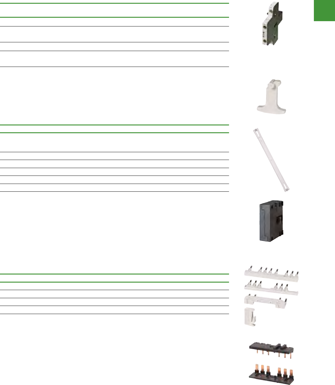
Motor control
Power control
200
2015/2016 Product guide AUS15_007 - February 2016
Xstart IEC Contactors
Accessories
Side mount auxiliary contacts for frame D – R, 40 – 2600A
Conventional free air thermal current,
Ith = Ie, AC-1 in Amps Poles Contact
configuration Item no.
Frame D – L (40 - 225A)
10
10
2
2
1NO-1NC
IECNO-ILONC
DILM1000-XHI11-SI
DILM1000-XHIV11-SI
Frame L – R (250 - 2600A)
10
10
2
2
1NO-1NC
IECNO-ILONC
DILM820-XHI11-SI
DILM820-XHI11V-SI
Note: For Frames B – C, cannot use both a side & a top mount auxiliary contact at the same time. For Frame D, 6 auxiliary contacts
maximum (can be a combination of side & top mount units). For Frames F – R, 8 auxiliary contacts maximum (can be a combination of
side & top mount units).
Mechanical interlock
For use with... Pkg. qty. Item no.
DILM7 - 15
DILMP20
DILA
5DILM12-XMV
DILM17 - 38 1DILM32-XMV
DILM40 - 72 1DILM65-XMV
DILM80 - 170 1DILM150-XMV
DILM185A - 500 1DILM500-XMV
DILM580 - 1000 1DILM820-XMV
Reversing link kits
For use with... Pkg. qty. Item no.
DILM7 - 12 1DILM12-XRL
DILM17 - 32 1DILM32-XRL
DILM40 - 65 1DILM65-XRL
DILM80 - 150 1DILM150-XRL
For two contactors with AC or DC operated magnet system which are horizontally or vertically mounted. For B – G frames,
mechanical lifespan is 2.5 x 10⁶ operations & the distance between contactors is 0 mm. For L – N frames, mechanical lifespan is 5
x 106 operations & no auxiliary contact can be mounted between the mechanical interlock & the contactor — the distance between
contactors is 15 mm.
DILM150-XMV and DILM820-XMV consist of an interlock element & mounting plate.
Also includes Interlocking Bridge (DILM12-XEV).
DILM12-XMV
DILM12-XRL
DILM32-XRL
DILM32-XMV
DILM500-XMV
DILM1000-XHI11-SI
Motor control
Power control
201 2015/2016 Product guide AUS15_007 - February 2016
Accessories
Suppressor circuit
Voltage
Us V For use with Item no.
RC suppressors
24 - 48 AC DILM7 - DILM15
DILMP20
DILA
DILM12-XSPR48
110 - 240 AC DILM12-XSPR240
240 - 500 AC DILM12-XSPR500
24 - 48 AC DILM17 - DILM32
DILK12 - DILK25
DILL..
DILMP32 - DILMP45
DILM32-XSPR48
110 - 240 AC DILM32-XSPR240
240 - 500 AC DILM32-XSPR500
24 - 48 AC DILM40 - DILM95
DILK33 - DILK50
DILMP63 - DILMP200
DILM95-XSPR48
110 - 240 AC DILM95-XSPR240
240 - 500 AC DILM95-XSPR500
Varistor suppressors
24 - 48 AC
DILM7 - DILM15
DILMP20
DILA
DILM12-XSPV48
48 - 130 AC DILM12-XSPV130
130 - 240 AC DILM12-XSPV240
240 - 500 AC DILM12-XSPV500
24 - 48 AC DILM17 - DILM32
DILK12 - DILK25
DILL..
DILMP32 - DILMP45
DILM32-XSPV48
48 - 130 AC DILM32-XSPV130
130 - 240 AC DILM32-XSPV240
240 - 500 AC DILM32-XSPV500
24 - 48 AC
DILM40 - DILM95
DILK33 - DILK50
DILMP63 - DILMP200
DILM95-XSPV48
48 - 130 AC DILM95-XSPV130
130 - 240 AC DILM95-XSPV240
240 - 500 AC DILM95-XSPV500
Varistor suppressors with integrated LED
24 - 48 AC DILM7 - DILM15
DILMP20
DILA
DILM12-XSPVL48
130 - 240 AC DILM12-XSPVL240
24 - 48 AC DILM17 - DILM32
DILK12 - DILK25
DILL..
DILMP32 - DILMP45
DILM32-XSPVL48
130 - 240 AC DILM32-XSPVL240
24 - 48 AC DILM40 - DILM95
DILK33 - DILK50
DILMP63 - DILMP200
DILM95-XSPVL48
130 - 240 AC DILM95-XSPVL240
Diode suppressor
12 - 250 DC
DILM7 - DILM15
DILMP20
DILA
DILM12-XSPD
DILM12-XSPR48
DILM12-XSPV48
DILM12-XSPVL48
DILM12-XSPD
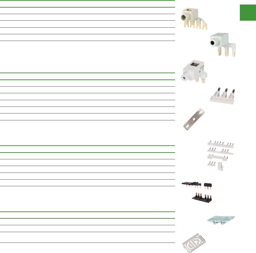
Motor control
Power control
202
2015/2016 Product guide AUS15_007 - February 2016
Accessories
Paralleling links for main contacts*
For use with Item no.
DILM7 - DILM15 DILM12-XP1
DILM17 - DILM32 DILM32-XP1
DILM40 -DILM72 DILM65-XP1
DILM80 - DILM72 DILM150-XP1
DILM185A DILM185-XP1
* Consisting of 2 paralleling links
Star-delta wiring kit
For use with Item no.
DILM7, DILM9, DILM12, DILM15 DILM12-XSL
DILM17, DILM25, DILM32 DILM32-XSL
DILM40, DILM50, DILM65 DILM65-XSL
DILM80, DILM95 DILM95-XSL
DILM115, DILM150 DILM150-XSL
Star-point bridges
For use with Item no.
DILM7 - DILM15 DILM12-XS1
DILM17 - DILM32 DILM32-XS1
DILM40 - DILM72 DILM65-XS1
DILM80 - DILM170 DILM150-XS1
DILM185A - DILM400 DILM400-XS1
DILM500 DILM500-XS1
IP2X cover set
For use with Item no.
DILM17, DILM25, DILM32, DILM38, DILMP32, DILMP45 DILM32-XIP2X
DILM40, DILM50, DILM65, DILM72, DILMP63, DILMP80 DILM65-XIP2X
DILM80, DILM95, DILM115, DILM150, DILM170, DILMP125, DILMP160,
DILMP200, ZB150 DILM150-XIP2X
DILM12-XP1
DILM150-XP1
DILM32-XP1
DILM12-XS1
DILM400-XS1
DILM12-XSL
DILM32-XSL
DILM32-XIP2X
DILM65-XIP2X
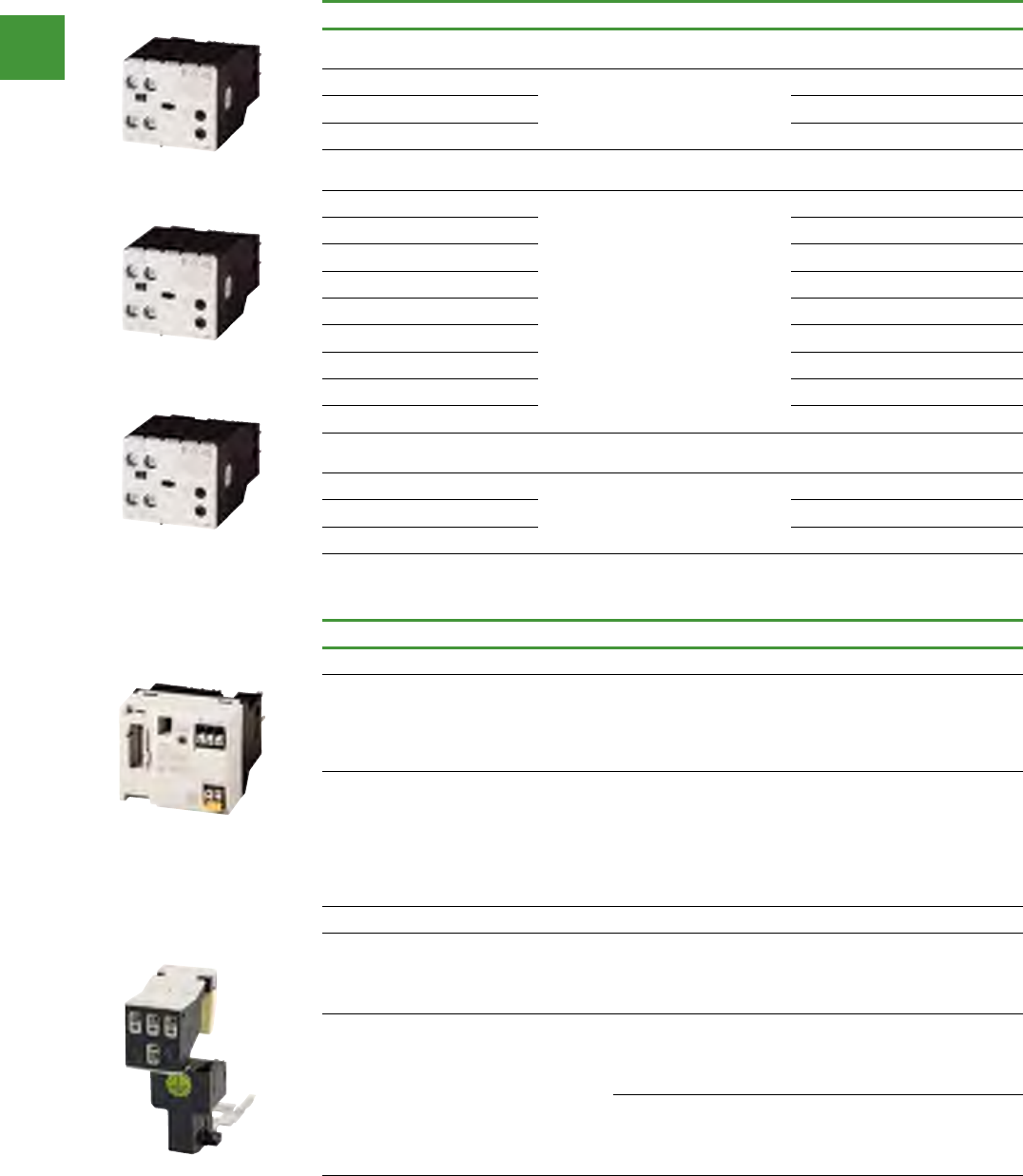
Motor control
Power control
203 2015/2016 Product guide AUS15_007 - February 2016
Accessories
Electronic timer modules
Description For use with Item no.
On-delayed
Cannot be combined with top mounting auxiliary contacts. Incl. suppressor circuits
24V AC/DC DILM7 - DILM32
DILMP20
DILMP32 - DILMP45
DILA
DILM32-XTEE11(RA24)
100 ... 130 V AC DILM32-XTEE11(RA130)
200 ... 240 V AC DILM32-XTEE11(RAC240)
Off-delayed, auxiliary voltage-free
Cannot be combined with top mounting auxiliary contacts. Incl. suppressor circuits
24V AC/DC
DILM7 - DILM32
DILMP20
DILMP32 - DILMP45
DILA
DILM32-XTED11-1(RA24)
DILM32-XTED11-10(RA24)
DILM32-XTED11-100(RA24)
100 ... 130 V AC DILM32-XTED11-1(RAC130)
DILM32-XTED11-10(RAC130)
DILM32-XTED11-100(RAC130)
200 ... 240 V AC DILM32-XTED11-1(RAC240)
DILM32-XTED11-10(RAC240)
DILM32-XTED11-100(RAC240)
For star-delta applications
Cannot be combined with top mounting auxiliary contacts. Incl. suppressor circuits
24V AC/DC DILM7 - DILM32
DILMP20
DILMP32 - DILMP45
DILA
DILM32-XTEY20(RA24)
100 ... 130 V AC DILM32-XTEY20(RAC130)
200 ... 240 V AC DILM32-XTEY20(RAC240)
Accessories
Description For use with Item no.
SmartWire-Darwin module for installation on contactors. One module per contactor
Two digital inputs for potential-free
contacts. 1 electrical interlock for the
surface mounting of reversing starters.
Messages: Contactor switch status,
status of the digital inputs 1 and 2.
DILM7… - DILM32
DILM38
DILA
DIL-SWD-32-001
Two digital inputs for potential-free
contacts. 1 electrical interlock for the
surface mounting of reversing starters.
1-0-A switch for manual or automatic
operation. Messages: contactor
switching position, status of the digital
inputs 1 and 2, 1-0-A switch position.
DILM7… - DILM32
DILM38
DILA
DIL-SWD-32-002
Wiring set for motor feeder plug
PE module with contact plate
DILM7
DILM9
DILM12
DILM15
DILM12-XMCE
Motor plate with PE module and
contact plate
DILM7
DILM9
DILM12
DILM15
DILM12-XMCP/E
PKZM0/PKE + DILM7
PKZM0/PKE + DILM9
PKZM0/PKE + DILM12
PKZM0/PKE + DILM15
DILM12-XMCP/T
DILM32-XTEE11(RA24)
DILM32-XTED11-1(RA24)
DILM32-XTEY20(RA24)
DILM12-XMCP/E
DIL-SWD-32-001
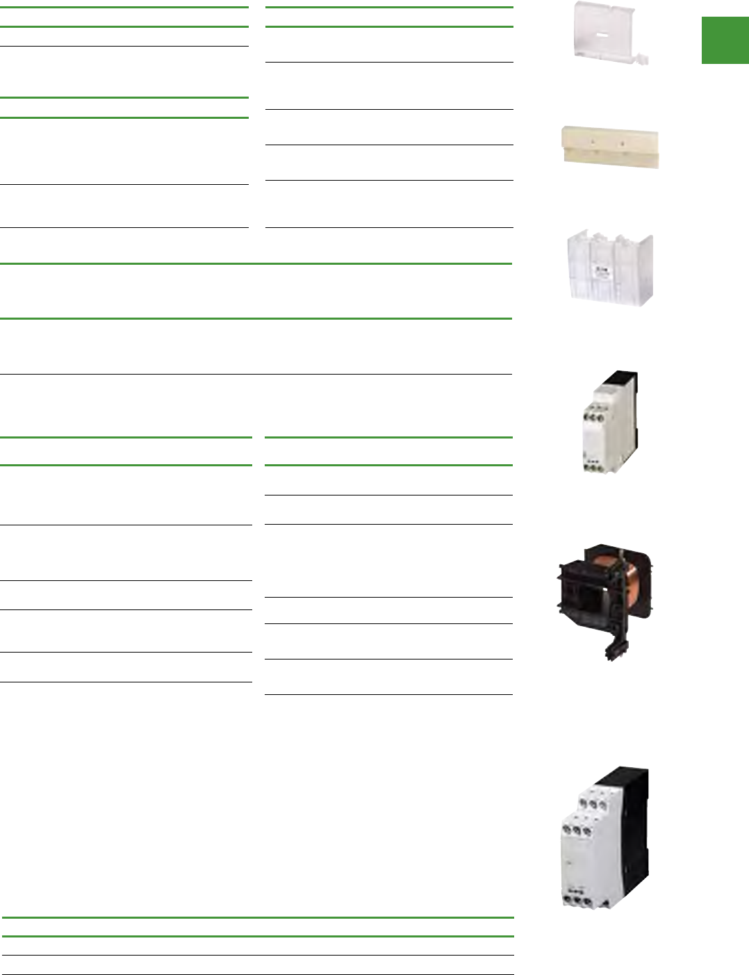
Motor control
Power control
204
2015/2016 Product guide AUS15_007 - February 2016
Accessories
Sealable shrouds - Transparent
For use with Item no.
DILM32-XTE... DILM32-XTEPLH
Suppressor circuits for vacuum contactors
(on load side)
For use with Item no.
DILM580
DILM650
DILM750
DILM820
DILM1000
DILM1000-XSM
DILH2000
DILH2200
DILH2600
DILH2600-XSM
Terminal Cover
For use with Item no.
DILM185A
DILM225A DILM225A-XHB
DILM250
DILM300A
DILM400
DILM400-XHB
DILM500 DILM500-XHB
DILM580
DILM650 DILM650-XHB
DILM750
DILM820
DILM1000
DILM820-XHB
Amplifier module for separate mounting
Rated operational current AC-15 Actuating
voltage For use with Item no.
AC-15
230V
Ie A
400V
Ie A
DC
220V
Ie AUs A DC
2 2 0.03 24
...DILM
DILMP...
DILL...
DILK...
ETS4-VS3
Notes: Contactor coils with rated operational current > 2 A must be actuated via the DILER-G mini contactor relay.
Rated operational current DC: Making and breaking conditions DC-13, time L/R 300ms
For use with DC voltage
Item no.
AC voltage
Item no.
DILM17
DILM25
DILM32
DILM38
DILM32-XSP
(RDC24) * DILM32-XSP
(240V50HZ)
DILM40
DILM50
DILM65
DILM72
DILM65-XSP
(RDC24) *
DILM65-XSP
(240V50HZ)
DILM80
DILM95
DILM95-XSP
(RDC24) *
DILM95-XSP
(240V50HZ)
DILM115
DILM150
DILM170
DILM150-XSP
(RDC24) *
DILM150-XSP
(RAC240)
DILM185A
DILM225A
DILM225A-XSP
(RDC24) *
DILM225A-XSP
(RAC240)
* (Includes electronic module)
For use with DC voltage
Item no.
AC voltage
Item no.
DILM250
DILM300A
DILM250-XSP/E
(RA250)
DILM250-XSP/E
(RA250)
DILM400
DILM500
DILM500-XSP/E
(RA250)
DILM500-XSP/E
(RA250)
DILM580
DILM650
DILM750
DILM820
DILM1000
DILM1000-XSP/E
(RA250)
DILM1000-XSP/E
(RA250)
DILH1400 -DILH1400-XSP/E
(RAW250)
DILM250-S
DILM300A-S -DILM250-S-XSP/E
(220-240V50/60HZ)
DILM400-S
DILM500-S -DILM500-S-XSP/E
(220-240V50/60HZ)
Replacement coils for DILM contactors
Application
The function of the CMD is to monitor the main
contacts of a contactor against welding. For this
the control voltage of the contactor is compared
with the state of the main contacts which is
reliably monitored using a mirror contact
(IEC EN60947-4-1 Annex F). If the coil is
deenergized and the contactor does not drop out
the CMD trips the upstream circuit-breaker/motor
protective circuit breaker/switch-disconnector via
a shunt release.
Safety
The CMD has a safety-compliant design so that in
safety combinations with a circuit-breaker/motor
protective circuit breaker/switch disconnector
the reliable switch off in the case of a "welded
contactor" can be guaranteed. In this application
it replaces the series connection of a second
contactor. As a component it conforms to safety
category 3 according to EN 954-1 and
EN ISO 13849.
Contactor monitoring device
CMD
Description Item no.
Contactor monitoring device CMD(24VDC)
Contactor monitoring device CMD(220-240VAC)
DILM32-XTEPLH
DILM1000-XSM
DILM225A-XHB
ETS4-VS3
DILM32-XSP(RDC24)
CMD(24VDC)
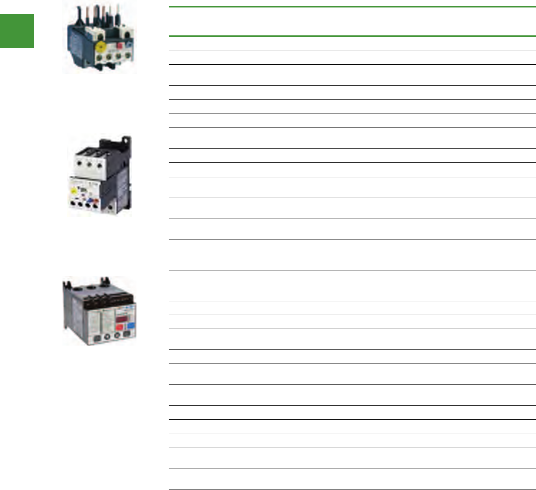
Motor control
Power control
205 2015/2016 Product guide AUS15_007 - February 2016
Overload relays
Product overview
Description Thermal
overload relays
Electronic
overload relays
Motor insight
overload and motor
protection relays
Type ZB ZEB C441
Relay type Thermal Bi-Metallic Electronic Electronic
Direct connect to
contactor Yes, (DILM) Yes, (DILM) —
Separate mount Yes, Adapter Yes Yes
FLC Range 0.1 – 630A 0.1 – 1500A 1 – 540A (with CTs)
FLC max.:min. ratio Approx. 1.5:1 5:1 —
Motor overload
protection Yes Yes Yes
Underload protection — — Yes
Supply protection — — Yes
Enhanced phase
loss protection — Yes Yes
Enhanced phase
imbalance protection — Yes Yes
Trip class 10A Selectable
10 / 20 / 30 5 – 30
Reset type Selectable manual /
automatic
Selectable manual /
automatic
Selectable manual
/ automatic /
programmable / remote
Communications
with I/O — Yes
Yes (Modbus,
ETHERNET/IP,
DeviceNet, PROFIBUS)
Remote display — — Yes
Ground fault — Yes Yes
Alarm no trip ——Yes
(voltage & ground faults)
Jam — Yes Yes
Programmable
reset timers — — Yes
Progammable
reset attempts — — Yes
Current monitoring — Yes Yes
Voltage monitoring — — Yes
Power monitoring — — Yes
Thermal capacity
monitoring — Yes Yes
Motor run
hours monitoring — — Yes
Thermal overload relays
Motor insight overload
and motor protection relays
Electronic overload relays

Motor control
Power control
206
2015/2016 Product guide AUS15_007 - February 2016
Setting range
overload release, Ir
Aux contact
configuration
For use with
contactor Ampere range Item no.
Frame B — Direct mount to contactor (DILM7-15)
0.1 – 0.16
0.16 – 0.24
0.24 – 0.4
0.4 – 0.6
1NO-1NC
1NO-1NC
1NO-1NC
1NO-1NC
7 – 15A
7 – 15A
7 – 15A
7 – 15A
ZB12-0,16
ZB12-0,24
ZB12-0,4
ZB12-0,6
0.6 – 1
1 – 1.6
1.6 – 2.4
2.4 – 4
1NO-1NC
1NO-1NC
1NO-1NC
1NO-1NC
7 – 15A
7 – 15A
7 – 15A
7 – 15A
ZB12-1
ZB12-1,6
ZB12-2,4
ZB12-4
4 – 6
6 – 10
9 – 12
12 – 16
1NO-1NC
1NO-1NC
1NO-1NC
1NO-1NC
7 – 15A
7 – 15A
9 – 15A
12 – 15A
ZB12-6
ZB12-10
ZB12-12
ZB12-16
Frame C — Direct mount to contactor (DILM17-38)
0.1 – 0.16
0.16 – 0.24
0.24 – 0.4
0.4 – 0.6
1NO-1NC
1NO-1NC
1NO-1NC
1NO-1NC
17 – 38A
17 – 38A
17 – 38A
17 – 38A
ZB32-0,16
ZB32-0,24
ZB32-0,4
ZB32-0,6
0.6 – 1
1 – 1.6
1.6 – 2.4
2.4 – 4
1NO-1NC
1NO-1NC
1NO-1NC
1NO-1NC
17 – 38A
17 – 38A
17 – 38A
17 – 38A
ZB32-1
ZB32-1,6
ZB32-2,4
ZB32-4
4 – 6
6 – 10
10 – 16
16 – 24
24 – 32
32 - 38
1NO-1NC
1NO-1NC
1NO-1NC
1NO-1NC
1NO-1NC
1NO-1NC
17 – 38A
17 – 38A
17 – 38A
17 – 38A
17 – 38A
17 – 38A
ZB32-6
ZB32-10
ZB32-16
ZB32-24
ZB32-32
ZB32-38
Frame D — Direct mount to contactor (DILM40-72)
6 – 10
10 – 16
16 – 24
1NO-1NC
1NO-1NC
1NO-1NC
40 – 72A
40 – 72A
40 – 72A
ZB65-10
ZB65-16
ZB65-24
24 – 40
40 – 57
50 – 65
65 – 75
1NO-1NC
1NO-1NC
1NO-1NC
1NO-1NC
40 – 72A
40 - 72 A
40 – 72A
40 - 72 A
ZB65-40
ZB65-57
ZB65-65
ZB65-75
Frame F – G — Direct mount to contactor (DILM80-170)
35 – 50
50 – 70
70 – 100
1NO-1NC
1NO-1NC
1NO-1NC
80 – 170A
80 – 170A
80 – 170A
ZB150-50
ZB150-70
ZB150-100
95 – 125
120 – 150
145 – 175
1NO-1NC
1NO-1NC
1NO-1NC
80 – 170A
80 – 170A
80 – 170A
ZB150-125
ZB150-150
ZB150-175
Frame F – G — Separate mount to contactor (DILM80-170)
35 – 50
50 – 70
70 – 100
1NO-1NC
1NO-1NC
1NO-1NC
80 – 170A
80 – 170A
80 – 170A
ZB150-50/KK
ZB150-70/KK
ZB150-100/KK
95 – 125
120 – 150
145 – 175
1NO-1NC
1NO-1NC
1NO-1NC
80 – 170A
80 – 170A
80 – 170A
ZB150-125/KK
ZB150-150/KK
ZB150-175/KK
Overload relays
ZB bi-metallic overload relays
• Direct mount to DILM contactors or
separate mount
• Class 10A, up to 630A motors
• Ambient - compensated bi-metallic
• Test/off pushbutton
• Reset pushbutton mannual/auto
• Tripfree release
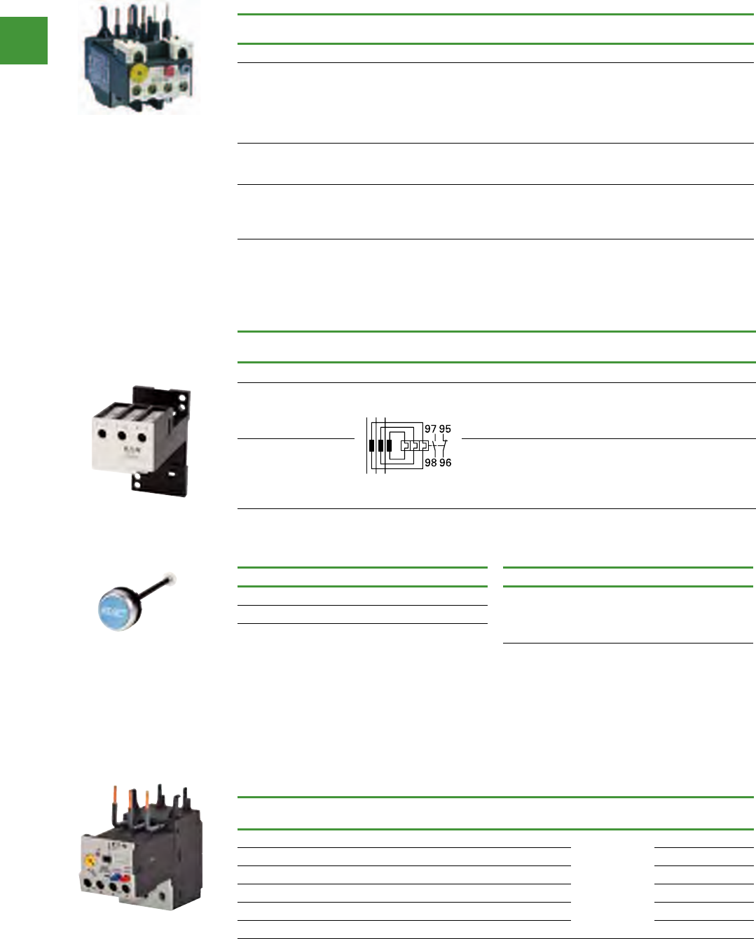
Motor control
Power control
207 2015/2016 Product guide AUS15_007 - February 2016
Current transformer operated overload relay
Setting range
Overload release, Ir Contact Sequence Aux contact
configuration
For use with contactor
Ampere range Item no.
Frame L – N — Separate Mount
42 - 63
60 - 90
85 - 125
110 - 160
1NO-1NC
1NO-1NC
1NO-1NC
1NO-1NC
185 - 650A
185 - 650A
185 - 650A
185 - 650A
ZW7-63
ZW7-90
ZW7-125
ZW7-160
160 – 240
190 – 290
270 – 400
360 – 540
420 – 630
1NO-1NC
1NO-1NC
1NO-1NC
1NO-1NC
1NO-1NC
185 - 650A
185 - 650A
185 - 650A
185 - 650A
185 - 650A
ZW7-240
ZW7-290
ZW7-400
ZW7-540
ZW7-630
DIN-Rail or panel-mount adapter, frame C – D
Accessories
For use with... Item no.
ZB32 ZB32-XEZ
ZB65 ZB65-XEZ
Can be snap fitted on a top hat rail (DIN-Rail) or can be
screw fitted.
External reset button, IP65
For use with... Item no.
ZW7...
ZE, Z5
ZB12, ZB32
ZB65, ZB150
M22-DZ-B-GB14
ZEB12 direct mounting
Ground fault
detection
Setting range of
overload releases Ir A
Auxiliary
contact
For use
with... Item no.
Without 0.33 - 1.65 1NO - 1NC
DILM7
DILM9
DILM12
DILM15
ZEB12-1,65
Without 1 - 5 1NO - 1NC ZEB12-5
Without 4 - 20 1NO - 1NC ZEB12-20
With 0.33 - 1.65 1NO - 1NC ZEB12-1,65-GF
With 1 - 5 1NO - 1NC ZEB12-5-GF
With 4 - 20 1NO - 1NC ZEB12-20-GF
ZEB12 electronic overload relay
• Phase-failure sensitivity
• Test/off pushbutton
• Reset button
• Manual/Auto reset selectable
• Protection with heavy starting duty (Class
5-30)
Setting range
Overload release, Ir
Aux contact
configuration
For use with
contactor Ampere range Item no.
Frame L — Direct mount or separate mount (DILM185A-300A)
50 – 70
70 – 100
95 – 125
120 – 160
160 – 220
200 – 250
1NO-1NC
1NO-1NC
1NO-1NC
1NO-1NC
1NO-1NC
1NO-1NC
185 - 225A
185 - 225A
185 - 225A
185 - 225A
185 - 225A
185 - 225A
Z5-70/FF225A
Z5-100/FF225A
Z5-125/FF225A
Z5-160/FF225A
Z5-220/FF225A
Z5-250/FF225A
50 – 70
70 – 100
95 – 125
1NO-1NC
1NO-1NC
1NO-1NC
250A
250A
250A
Z5-70/FF250
Z5-100/FF250
Z5-125/FF250
120 – 160
160 – 220
200 – 250
250 - 300
1NO-1NC
1NO-1NC
1NO-1NC
1NO-1NC
250A
250A
250A
300A
Z5-160/FF250
Z5-220/FF250
Z5-250/FF250
Z5-300/FF250
Note: Short circuit protection: Observe the maximum permissible fuse of the contactor with direct device mounting.
Trip Class: 10A. Suitable for protection of EEx e-motors.
Overload Relays
ZB bi-metallic Overload Relays
M22-DZ-B-GB14
ZB32-XEZ
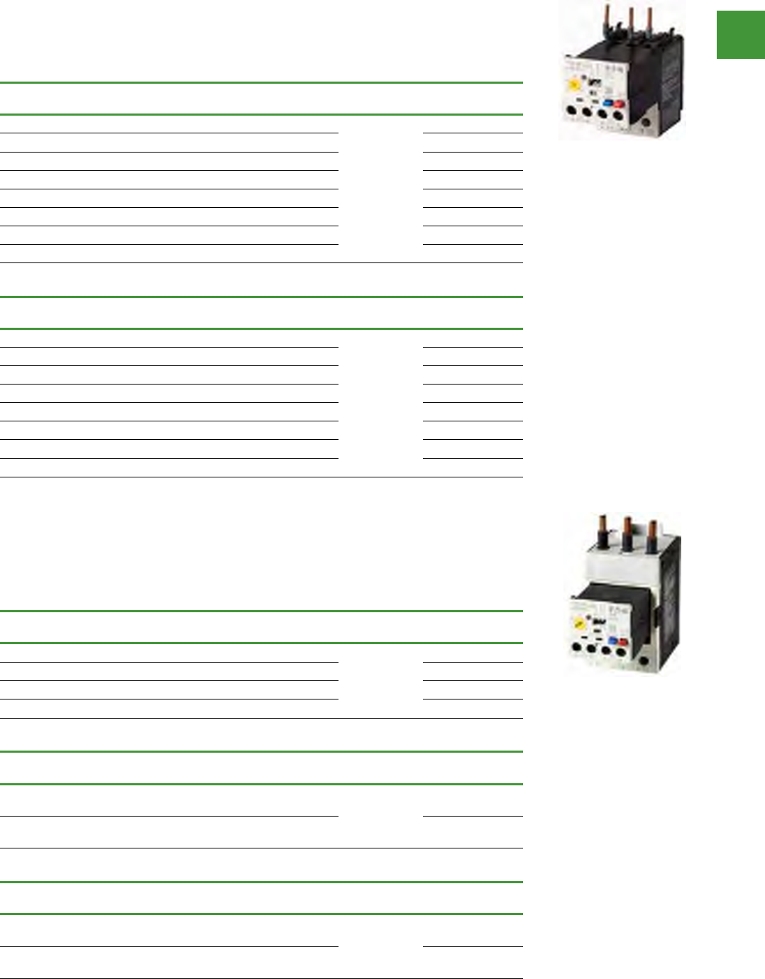
Motor control
Power control
208
2015/2016 Product guide AUS15_007 - February 2016
Overload relays
ZEB32 direct mounting
Ground fault
detection
Setting range of
overload releases Ir A
Auxiliary
contact
For use
with... Item no.
Without 0.33 - 1.65 1NO - 1NC
DILM17
DILM25
DILM32
DILM38
ZEB32-1,65
Without 1 - 5 1NO - 1NC ZEB32-5
Without 4 - 20 1NO - 1NC ZEB32-20
Without 9 - 45 1NO - 1NC ZEB32-45
With 0.33 - 1.65 1NO - 1NC ZEB32-1,65-GF
With 1 - 5 1NO - 1NC ZEB32-5-GF
With 4 - 20 1NO - 1NC ZEB32-20-GF
With 9 - 45 1NO - 1NC ZEB32-45-GF
ZEB32 separate mounting
Ground fault
detection
Setting range of
overload releases Ir A
Auxiliary
contact
For use
with... Item no.
Without 0.33 - 1.65 1NO - 1NC
DILM17
DILM25
DILM32
DILM38
ZEB32-1,65/KK
Without 1 - 5 1NO - 1NC ZEB32-5/KK
Without 4 - 20 1NO - 1NC ZEB32-20/KK
Without 9 - 45 1NO - 1NC ZEB32-45/KK
With 0.33 - 1.65 1NO - 1NC ZEB32-1,65-GF/KK
With 1 - 5 1NO - 1NC ZEB32-5-GF/KK
With 4 - 20 1NO - 1NC ZEB32-20-GF/KK
With 9 - 45 1NO - 1NC ZEB32-45-GF/KK
ZEB32 electronic overload relay
• Phase-failure sensitivity
• Test/off pushbutton
• Reset button
• Manual/Auto reset selectable
• Protection with heavy starting duty (Class
5-30)
ZEB65 direct mounting
Ground fault
detection
Setting range of
overload releases Ir A
Auxiliary
contact
For use
with... Item no.
Without 9 - 45 1NO - 1NC DILM40
DILM50
DILM65
DILM72
ZEB65-45
With 9 - 45 1NO - 1NC ZEB65-45-GF
Without 20 - 100 1NO - 1NC ZEB65-100
With 20 - 100 1NO - 1NC ZEB65-100-GF
ZEB150 direct mounting
Ground fault
detection
Setting range of
overload releases Ir A
Auxiliary
contact
For use
with... Item no.
Without 20 - 100 1NO - 1NC DILM80
DILM95
DILM115
DILM150
ZEB150-100
With 20 - 100 1NO - 1NC ZEB150-100-GF
ZEB150 separate mounting
Ground fault
detection
Setting range of
overload releases Ir A
Auxiliary
contact
For use
with... Item no.
Without 20 - 100 1NO - 1NC DILM80
DILM95
DILM115
DILM150
ZEB150-100/KK
With 20 - 100 1NO - 1NC ZEB150-100-GF/KK
ZEB65 and ZEB150 electronic overload relay
• Phase-failure sensitivity
• Test/off pushbutton
• Reset button
• Manual/Auto reset selectable
• Protection with heavy starting duty (Class
5-30)
Motor control
Power control
209 2015/2016 Product guide AUS15_007 - February 2016
Thermistor overload relays for machine protection
• 3 A rated operational current for
AC-15, 240 V
Description Rated control voltage
Us, V Item no.
Without automatic reset
Mains & fault LED display
24 – 240 V 50/60 Hz,
24 – 240 V DC EMT6
Without automatic reset
Mains & fault LED display
With 2 sensor circuits
EMT62
Without automatic reset Mains & fault LED display
Trip with short-circuit in the sensor cable
24 – 240 V 50/60 Hz,
24 – 240 V DC EMT6-K
Without automatic reset
Mains & fault LED display 230 V 50/60 Hz EMT6(230V)
Selector switch with/without automatic reset
For manual or remote resetting
Test button
Mains & fault LED display
24 – 240 V 50/60 Hz,
24 – 240 V DC EMT6-DB
Selector switch with/without automatic reset
For manual or remote resetting
Test button
Mains & fault LED display
With 2 sensor circuits
EMT62-DB
Selector switch with/without automatic reset
For manual or remote resetting
Test button
Mains & fault LED display
Trip with short-circuit in the sensor cable
24 – 240 V 50/60 Hz,
24 – 240 V DC EMT6-KDB
Selector switch with/without automatic reset
For manual or remote resetting Test button
Mains & fault LED display
230 V 50/60 Hz EMT6-DB(230V)
Multifunction device
Selector switch with/without automatic reset
Trip with short-circuit in the sensor cable
Zero-voltage safe
For manual or remote resetting
Test button
Short-circuit detection and retention can
be deactivated
Mains & fault LED display
24 – 240 V 50/60 Hz,
24 – 240 V DC EMT6-DBK
Accessories - screw adapter
For screw fixing – CS-TE
Provide additional short-circuit protection in the sensor circuit with a current monitoring relay.
ZEB accessories
Current sensors
Setting range of overload releases
Ir A For use with... Item no.
60 - 300
ZEB32-5-GF/KK
ZEB32-5/KK
ZEB-XCT300
120 - 600 ZEB-XCT600
200 - 1000 ZEB-XCT1000
300 - 1500 ZEB-XCT1500
Overload relays
EMT6
EMT6-DB
EMT6-DBK
CS-TE
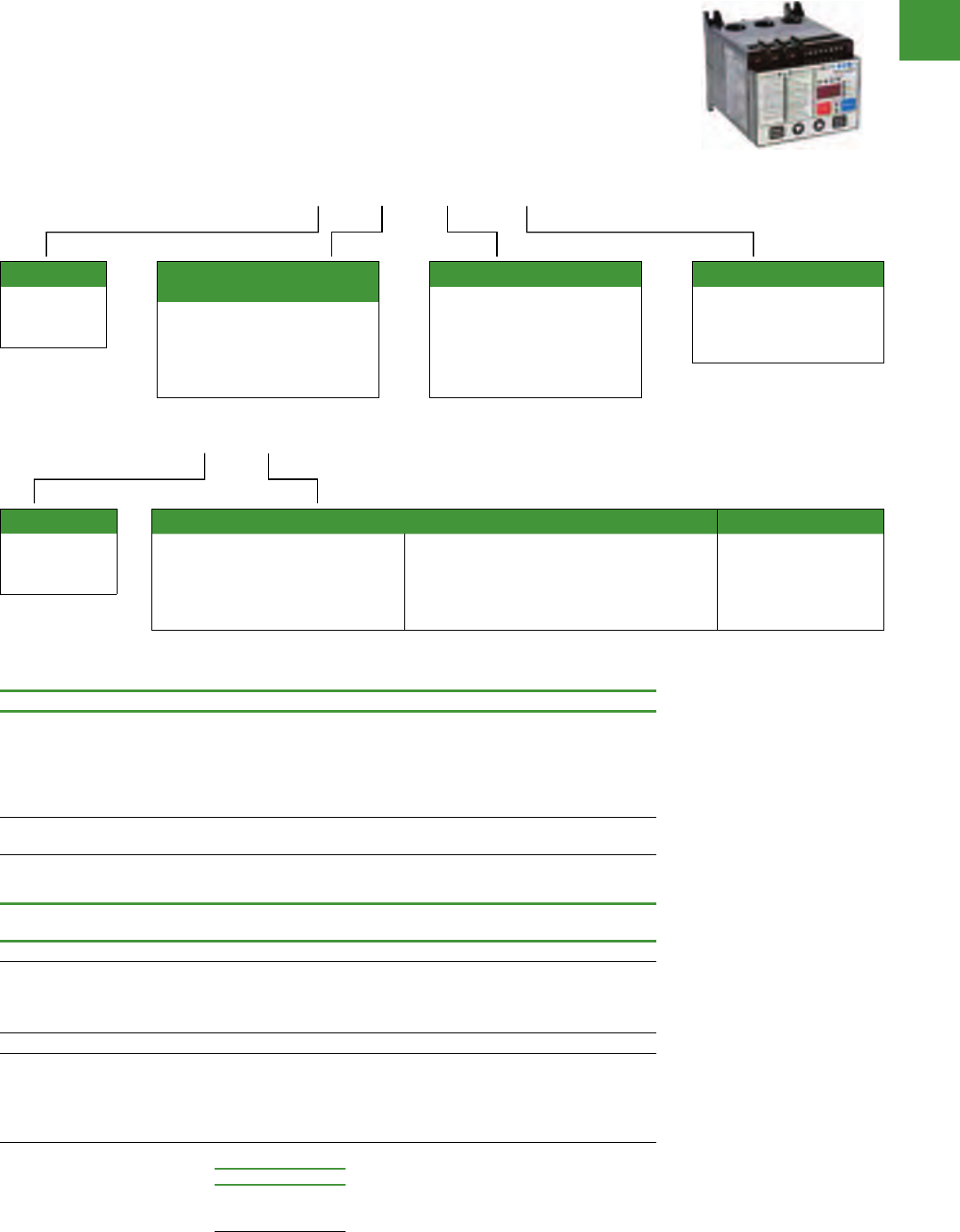
Motor control
Power control
210
2015/2016 Product guide AUS15_007 - February 2016
Motor insight motor protection relays
• Power, voltage & current monitoring, ground
fault, flexible communications, motor, load &
line protection in a single package
• Enhanced surge / sag withstand capacity
ensures reliable operation
• Finger proof IP20 rated terminals provide
extra safety by reducing shock hazard
• Adjustments to overload settings can be
made without disconnecting power
• User Interface
• Bright LED display
• Intuitive & highly customisable parameter
configuration
• Remote display allows for configuration
without opening the panel, providing
additional operator safety
Overload relays
Internal user interface
Blank = With user interface
(line powered models)
NOUI = Without user interface
(120 Vac control models)
C441 B A NOUI
Device type
C441
Motor Insight
overload relay
Overload relay power
source voltage
B = 240 Vac (170-254 Vac)
C = 480 Vac (323-528 Vac)
D = 600 Vac (487-660 Vac)
Blank = 120 Vac control power
(170-660 Vac)
Overload relay current rating
A = 1-9A (1-50A)
B = 5-90A (5-90A)
0109 = 120 Vac control power
(0-660 Vac, 1-9A)
0590 = 120 Vac control power
(0-660 Vac, 5-90A)
Motor Insight relays
Voltage Current range Item no.
240V ac (170 – 264)
240V ac (170 – 264)
415V ac (323 – 528)
415V ac (323 – 528)
600V ac (489 – 660)
600V ac (489 – 660)
1 – 9 Amps
5 – 90 Amps
1 – 9 Amps
5 – 90 Amps
1 – 9 Amps
5 – 90 Amps
C441BA
C441BB
C441CA
C441CB
C441DA
C441DB
120V ac (170-660)
120V ac (170-660
1 – 9 Amps
5 – 90 Amps
C4410109NOUI
C4410590NOUI
Motor Insight CT multiplier and wire wrap schedule
Motor FLC Number of
loops
Number of conductors,
through CT primary
CT multiplier,
setting
External CT kit
Catalogue no. Item no.
Current Range: 5 – 90A
5 – 22.5
6.67 – 30
10 – 45
20 – 90
3
2
1
0
4
3
2
1
4
3
2
1
-
-
-
-
C441_B
and
C4410590NOUI
Current Range: 1 – 9A
1 – 5
2 – 9
60 – 135
120 – 270
240 – 540
1
0
0
0
0
2
1
1
1
1
2
1
150 – (150:5)
300 – (300:5)
600 – (600:5)
-
-
C441CTKIT150
C441CTKIT300
C441CTKIT600
C441_A
and
C4410190NOUI
Underscore indicates operating
voltage code required.
Any manufacturer’s CT’s
may be used
Operating Voltage Codes:
Code Voltage
B
C
D
240V ac
415V ac
600V ac
Device type
C441
Motor Insight
overload relay
Communication module Accessory type
K = DeviceNet module 4in/2out 120 Vac
L = DeviceNet module 4in/2out 24 Vdc
M = Modbus RTU module
N = Modbus RTU module 4in/2out 120 Vac
P = Modbus RTU module 4in/2out 24 Vdc
Q = PROFIBUS module 4in/2out 120 Vac
R = Modbus TCP/EtherNet/IP module 4in/2out 120Vac
S = PROFIBUS module 4in/2out 24 Vdc
T = Modbus TCP/EtherNet/IP module 4in/2out 24 Vdc
1 = Type 1 and 12
remote mounted display
3 = type 3R kit for
remote display
CMP1 = Conversion plate
C441 K
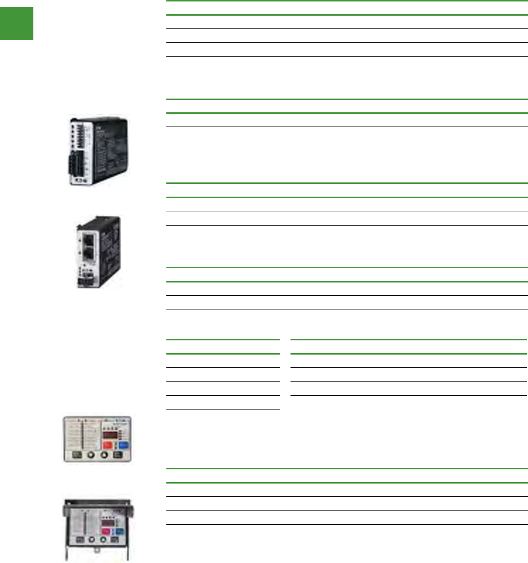
Motor control
Power control
211 2015/2016 Product guide AUS15_007 - February 2016
Overload relays
Modbus RTU communication modules
Description I/O Item no.
Modbus communication module None C441M
Modbus communication module 4IN / 2OUT 120V ac C441N
Modbus communication module 4IN / 2OUT 24Vdc C441P
DeviceNet communication modules
Description I/O Item no.
DeviceNet communication module 120V ac C441K
DeviceNet communication module 24V dc C441L
PROFIBUS communication modules
Description I/O Item no.
PROFIBUS module 4in/2out 120V ac C441S
PROFIBUS module 4in/2out 24V dc C441Q
Ethernet communication modules
Description I/O Item no.
Modbus TCP/EtherNet/IP module 4in/2out 120V ac C441R
Modbus TCP/EtherNet/IP module 4in/2out 24V dc C441T
Motor insight — accessories
Description Item no.
Remote display IP54 C4411
NEMA 3R Kit for remote display (remote display not included) C4413
Conversion plate C441CMP1
Communication cables
The remote display requires a
communication cable to connect
to the Motor Insight overload
relay
Communication cable lengths
Length Item no.
0.25 m D77E-QPIP25
1 m D77E-QPIP100
2 m D77E-QPIP200
3 m D77E-QPIP300
Current transformer kits
Description Item no.
Three 150:5 CTs to be used with Motor Insight C441CTKIT150
Three 300:5 CTs to be used with Motor Insight C441CTKIT300
Three 600:5 CTs to be used with Motor Insight C441CTKIT600
C4411
C4413
C441R
C441S
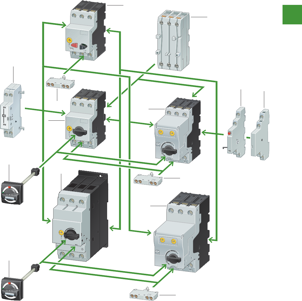
Power control
212
2015/2016 Product guide AUS15_007 - February 2016
Motor control
IEC Manual motor protectors
2010 CA08103002Z-EN www.eaton.com
7/2 Motor-protective circuit-breakers PKZM01, PKZM0, PKZM4, PKE
Motor-protective circuit-breaker
Motor-protective circuit-breaker
System overview
6
5
4
77
7
1
3
3
2
7
7
8
5
Basic devices
Motor-protective circuit-
breaker PKZM01
1
� Page 7/3
Motor-protective circuit-
breaker PKZM0
2
� Page 7/4
Motor-protective circuit-
breakerwith wide-range
overload protection
3
� Page 7/8
Motor-protective circuit-
breaker PKZM4
4
� Page 7/4
Add-on functions
Standard auxiliary contacts7
� Page 7/10
Shunt release6
� Page 7/29
Current limiters 8
� Page 7/12
Mounting accessories
Door coupling handles IP65 5
� Page 7/20
Insulated enclosure
� Page 7/16
Mounting/wiring
� Page 7/22
1. Motor-protective circuit-
breaker PKZM01
2. Motor-protective circuit-
breaker PKZM0
3. Motor-protective circuit-
breaker with wide-range
overload protection PKE
4. Motor-protective circuit-
breaker PKZM4
5. Door coupling handles IP65
6. Shunt release
7. Standard auxiliary contacts
8. Current limiters
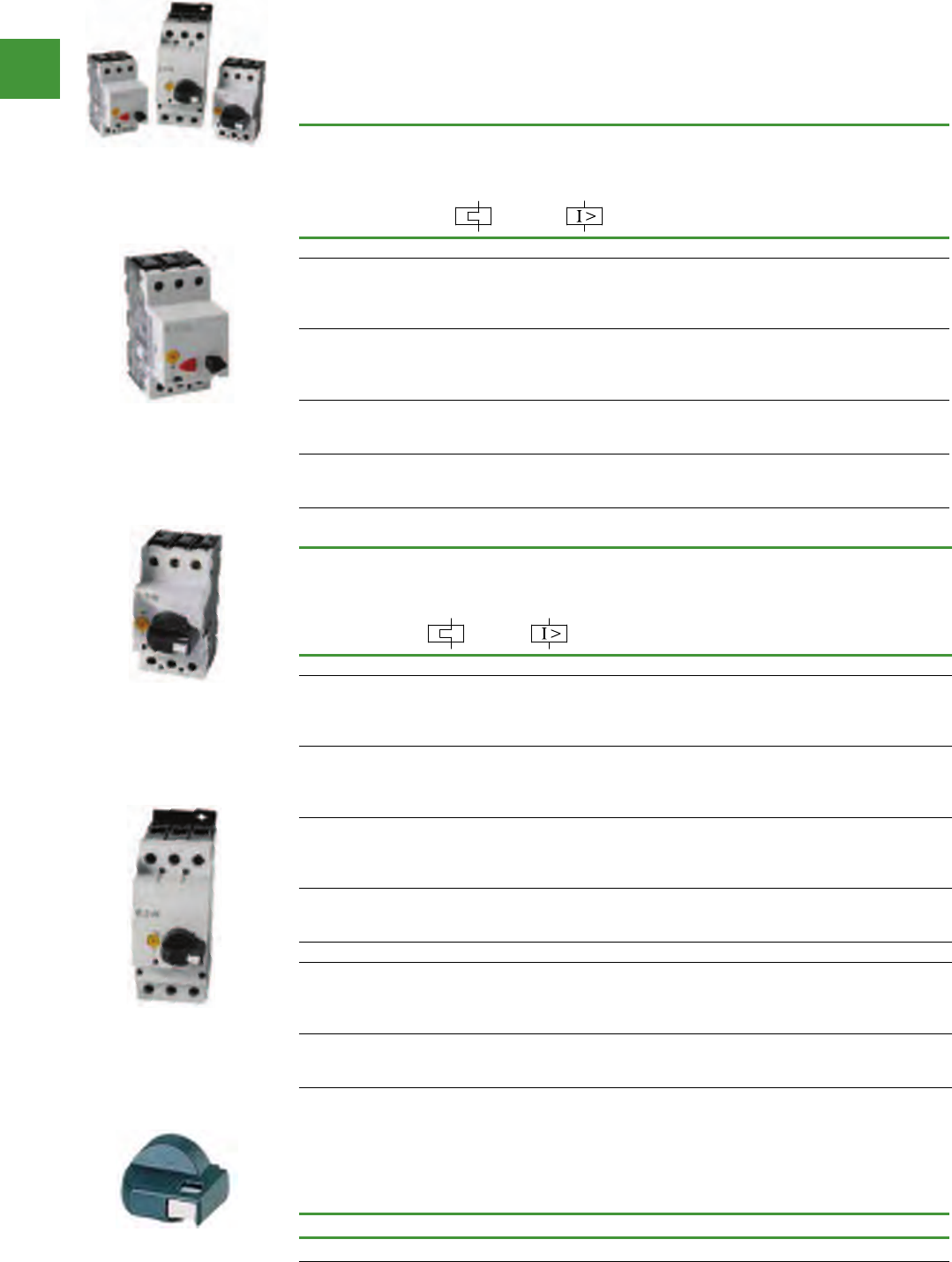
Motor control
Power control
213 2015/2016 Product guide AUS15_007 - February 2016
Pushbutton manual motor protectors
Rated
Uninterrupted
Current —
Iu = Ie (Amps)
FLC adjustment
range/overload
release —
Ir (Amps)
Short circuit
release —
Irm (Amps)
Maximum Motor Ratings
Maximum kW Rating AC-3
— P (kW)
3-Phase Item no.
220 -
240V
380 -
415V 440V
Frame B (Type 1 & Type 2 Coordination)
0.16
0.25
0.4
0.63
0.1 – 0.16
0.16 – 0.25
0.25 – 0.4
0.4 – 0.63
2.2
3.5
5.6
8.8
—
—
0.06
0.09
—
0.06
0.09
0.12
—
0.06
0.12
0.18
PKZM01-0,16
PKZM01-0,25
PKZM01-0,4
PKZM01-0,63
1
1.6
2.5
4
0.63 – 1
1 – 1.6
1.6 – 2.5
2.5 – 4
14
22
35
56
0.12
0.25
0.37
0.75
0.25
0.55
0.75
1.5
0.25
0.55
1.1
1.5
PKZM01-1
PKZM01-1,6
PKZM01-2,5
PKZM01-4
6.3
10
12
4 – 6.3
6.3 – 10
8 – 12
88
140
168
1.1
2.2
3
2.2
4
5.5
3
4
5.5
PKZM01-6,3
PKZM01-10
PKZM01-12
16
20
25
10 – 16
16 – 20
20 – 25
224
280
350
4
5.5
5.5
7.5
9
12.5
9
11
12.5
PKZM01-16
PKZM01-20
PKZM01-25
IEC Manual motor protectors
• Class 10 overload protection
• Motor applications from 0.1A to 63A
• Built-in heater & magnetic trip elements to protect the motor
• Adjustment dial for setting motor FLC
Lockable rotary handle for MMPs
For use with Item no.
PKZM0 & PKZM4 AK-PKZ0
Rotary manual motor protectors
Rated
Uninterrupted
Current —
Iu = Ie (Amps)
FLC adjustment
range/overload
release —
Ir (Amps)
Short Circuit
Release —
Irm (Amps)
Maximum Motor Ratings
Maximum kW Rating AC-3 — P (kW)
3-Phase Item no.
220 –
240V
380 –
415V 440V 500V 660 –
690V
B (Type 1 & Type 2 Coordination)
0.16
0.25
0.4
0.63
0.1 – 0.16
0.16 – 0.25
0.25 – 0.4
0.4 – 0.63
2.2
3.5
5.6
8.8
—
—
0.06
0.09
—
0.06
0.09
0.12
—
0.06
0.12
0.18
—
0.06
0.12
0.25
0.06
0.12
0.18
0.25
PKZM0-0,16
PKZM0-0,25
PKZM0-0,4
PKZM0-0,63
1
1.6
2.5
4
0.63 – 1
1 – 1.6
1.6 – 2.5
2.5 – 4
14
22
35
56
0.12
0.25
0.37
0.75
0.25
0.55
0.75
1.5
0.25
0.55
1.1
1.5
0.37
0.75
1.1
2.2
0.55
1.1
1.5
3
PKZM0-1
PKZM0-1,6
PKZM0-2,5
PKZM0-4
6.3
10
12
16
4 – 6.3
6.3 – 10
8 – 12
10 – 16
88
140
168
224
1.1
2.2
3
4
2.2
4
5.5
7.5
3
4
5.5
9
3
4
5.5
9
4
7.5
11
12.5
PKZM0-6,3
PKZM0-10
PKZM0-12
PKZM0-16
20
25
32
16 – 20
20 – 25
25 – 32
280
350
448
5.5
5.5
7.5
9
12.5
15
11
12.5
15
12.5
15
22
15
22
30
PKZM0-20
PKZM0-25
PKZM0-32
Frame D (Type 1 & Type 2 Coordination)
16
25
32
40
10 – 16
16 – 25
25 – 32
32 – 40
224
350
448
560
4
5.5
7.5
11
7.5
12.5
15
20
9
12.5
17.5
22
9
15
22
24
12.5
22
22
30
PKZM4-16
PKZM4-25
PKZM4-32
PKZM4-40
50
58
65
40 – 50
50 – 58
55 – 65
700
812
882
14
17
18.5
25
30
34
30
37
37
30
37
45
45
55
55
PKZM4-50
PKZM4-58
PKZM4-63
Select manual motor protectors by full load amperes. Maximum motor ratings (kW) are for reference only.
Note: Service Factor (SF) — Setting Ir of current scale in dependence of load factor:
SF = 1.15 -> Ir = 1 x In mot
SF = 1 -> Ir = 0.9 x In mot
Eaton PKZM0 & PKZM4 handles are not padlockable. Order part no. AK-PKZ0 handle if a lockable handle is required.
PKZM4-16
PKZM0-1
PKZM01-1
AK-PKZ0
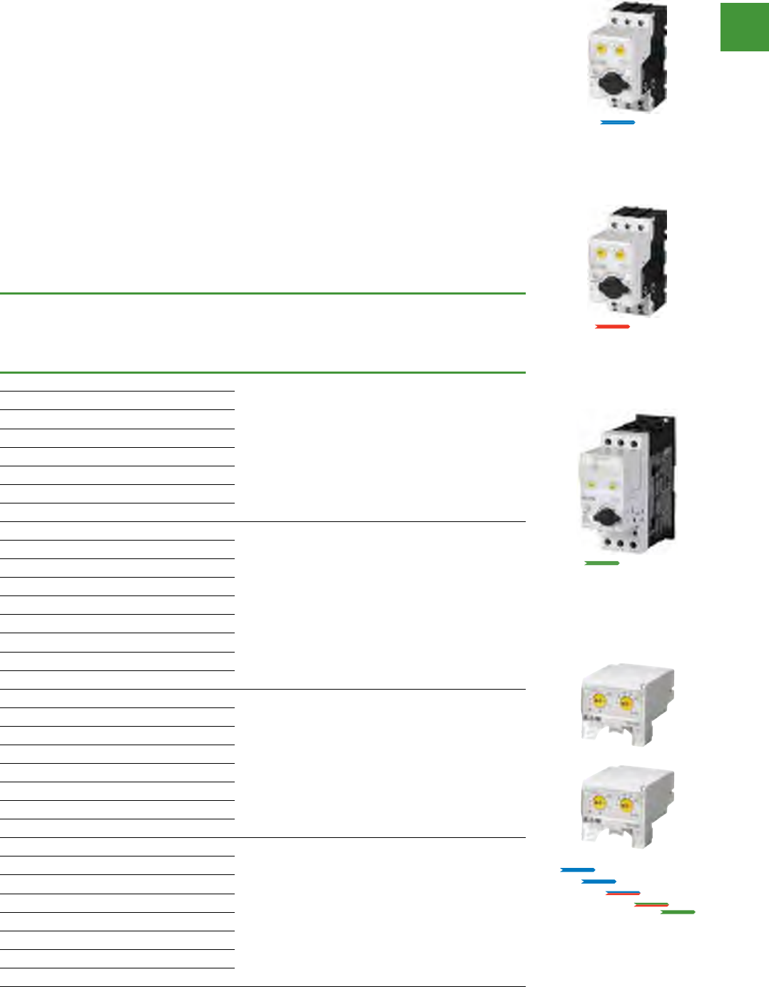
Motor control
Power control
214
2015/2016 Product guide AUS15_007 - February 2016
Electronic Motor-protective circuit-breaker PKE
Switch & protect motors up to 65 A with electronic wide-range overload protection. Modular design.
Highest level of flexibility. Highest level of performance.
The selection of a suitable motor-protective circuit-breaker is decisive for the functional safety &
service life of a motor. Motor-protective circuit-breakers PKE with electronic overload protection offer
an interesting alternative to the bimetal solution here & complement the intelligent PKZ series from
Eaton. The motor-protective circuit-breaker PKE provides the highest level of flexibility featuring a
compact & modular design with plug-in control unit for motor currents up to 65 A.
The large current setting ranges decisively reduce the number of variants & minimise the engineering
work & costs accordingly.
PKE features & benefits:
• Autonomous supply via current transformer
• Large electronically controlled setting range
• Exchangeable control units
• Tripping classes greater than CLASS 10
• Precise & extremely long-time stable tripping
characteristic curves
• Minimum heat losses
• Protection suited to individual starting
conditions
• Motor starter design with standard
components
• Common range of accessories from system
PKZ0
• Parameter data read out options
• Very service friendly
• Reduction of engineering time & costs
• Advanced control unit includes a COM
interface for SmartWire
Motor
rating
Rated motor current AC-3 Overload
release
setting
range
Base unit Control unit
Standard
Control unit
Advanced
(with COM
interface)
240V 415V 660 V
690 V
kW A A A
Motor-protective circuit-breaker, Coordination
type “1” & “2”
0.06 0.37 - -0.3 ... 1.2 A PKE12 PKE-XTU-1,2 PKE-XTUA-1,2
0.09 0.54 0.31 -
0.12 0.72 0.41 -
0.18 1.04 0.6 0.35
0.25 - 0.8 0.5
0.37 - 1.1 0.7
0.55 0.9
0.75 1.1
0.18 1.04 - -1 ... 4 A
PKE12 PKE-XTU-4 PKE-XTUA-4
0.25 1.4 - -
0.37 2 1.1 -
0.55 2.7 1.5 -
0.75 3.2 1.9 1.1
1.1 - 2.6 1.5
1.5 - 3.6 2.1
2.2 2.9
33.8
0.75 3.2 - -3 ... 12 A PKE12
PKE32
PKE-XTU-12 PKE-XTUA-12
1.1 4.6 - -
1.5 6.3 3.6 -
2.2 8.7 5 -
3 11.5 6.6 3.8
4 - 8.5 4.9
5.5 - 11.3 6.5
7.5 8.8
2.2 8.7 - -8 ... 32 A PKE32 PKE-XTU-32 PKE-XTUA-32
3 11.5 - -
4 14.8 8.5 -
5.5 19.6 11.3 -
7.5 26.4 15.2 8.8
11 - 21.7 12.6
15 - 29.3 17
18.5 20.9
5 plug-in control units up to
65 A in 2 versions.
Standard
Extended
0.3A 1.2A
1A 4A
3A 12A
8A 32A
16A 65A
PKE 12, 12A (45 mm)
0.3A 12A
0.09 - 5.5 kW (400 V)
PKE 32, 32A (45 mm)
3A 32A
1.5 - 15 kWa (400 V)
PKE 65, 65A (55 mm)
8A 65A
4 - 34 kW (400 V)
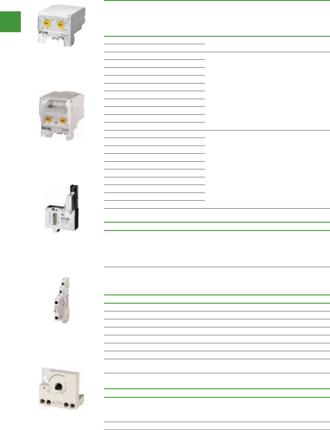
Motor control
Power control
215 2015/2016 Product guide AUS15_007 - February 2016
IEC manual motor protectors accessories
Auxiliary contacts
Contact configuration Item no.
Side-Mount
1NO-1NC NHI11-PKZ0
2NO-1NC NHI21-PKZ0
1NO-2NC NHI12-PKZ0
Front-Mount
1NO-1NC NHI-E-11-PKZ0
1NO NHI-E-10-PKZ0
Trip indicating aux. contact AGM2-10-PKZ0
AGM2-01-PKZ0
Smartwire-DT module for connecting PKE-XTUA trip block to Smartwire-DT
Description Item no.
Messages
Contactor state PKS
Motor current and thermal motor image in %
Trip indicators
Set value overload releases
Remote disconnection of motor-protective curicuit breakers
PKE-SWD-SP
Early-make auxiliary contacts
Contact configuration For use with.. Item no.
2N/O
PKZM0
PKZM0-T
PKM0
PKZM4
VHI20-PKZ0
2N/O PKZM01 VHI20-PKZ01
Motor
rating
Rated motor current AC-3
Overload
release
setting
range
Base unit Control unit
Standard
Control unit
Advanced
(with COM
interface)
240V 415V 660 V
690 V
kW A A A
Motor-protective circuit-breaker, Coordination
type “1” & “2”
22 - - 23.8 8 ... 32 A PKE32 PKE-XTU-32 PKE-XTUA-32
30 - - 32
5.5 19.6 - - 16...65 A PKE65 PKE-XTU-65 PKE-XTUA-65
7.5 26.4 - -
11 38 21.7 -
15 51 29.3 17
18.5 63 36 20.9
22 - 41 23.8
30 - 55 32
37 - - 39
45 - - 47
55 - - 58
2.2 8.7 - - 8...32 A PKE65 PKE-XTUW-32 PKE-XTUWA-32
3 11.5 - -
4 14.8 8.5 -
5.5 19.6 11.3 -
7.5 26.4 15.2 8.8
11 - 21.7 12.6
15 - 29.3 17
18.5 - - 20.9
22 - - 23.8
30 - - 58
Electronic motor-protective circuit-breaker PKE
PKE-XTUA-32
PKE-XTUWA-32
PKE-SWD-SP
NHI21-PKZ0
VHI20-PKZ0
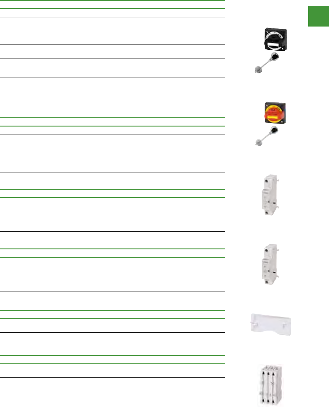
Motor control
Power control
216
2015/2016 Product guide AUS15_007 - February 2016
Electronic motor-protective circuit-breaker PKE
IP65 rotary handle mechanism - PKZM0
Description Item no.
Complete Kits — Includes Handle, Shaft & Required Hardware
Rotary Handle Mechanism IP65 Black — For use on main switches to
IEC / EN 60204. PKZ0-XH
Rotary Handle Mechanism IP65 Red / Yellow — For use on main switch with
Emergency-Stop function to IEC / EN 60204. PKZ0-XRH
Rotary Handle Mechanism IP65 Black — For use on main switches to
IEC / EN 60204 where PKZ0 is mounted 90° from vertical. PKZ0-XH-MCC
Rotary Handle Mechanism IP65 Red / Yellow — For use on main switch with
Emergency-Stop function to IEC / EN 60204 where PKZ0 is mounted 90°
from vertical.
PKZ0-XRH-MCC
With ON/OFF switch position & “+” (tripped), lockable with 3 padlocks, 4 – 8 mm hasp. Can be locked in the OFF
position, if required.
Rotary handle mechanisms ship with door interlock disabled. See instruction publication with product for how to
enable door interlock.
Not for use with VHI20-PKZ0 early-make front-mount auxiliary contact.
Shunt release
Voltage Item no.
24 vac
110 vac
240 vac
415 vac
24 vdc
A-PKZ0(24V50HZ)
A-PKZ0(110V50HZ)
A-PKZ0(240V50HZ)
A-PKZ0(415V50HZ)
A-PKZ0(24VDC)
Undervoltage release
Voltage Item no.
24 vac
110 vac
240 vac
415 vac
24 vdc
U-PKZ0(24V50HZ)
U-PKZ0(110V50HZ)
U-PKZ0(240V50HZ)
U-PKZ0(415V50HZ)
U-PKZ0(24VDC)
Sealing facility
Description Item no.
To prevent tampering with the overload release & the test
function (For use with PKZMO & PKZM4) PL-PKZ0
IP65 rotary handle mechanism - PKE
Description Item no.
For use as main switch to IEC/EN 60204 black PKE-XH
For use as main switch with Emergency-Stop function to
IEC/EN 60204 red-yellow PKE-XRH
For use as a main switch to EN 60204 in MCC power
distribution systems and with PKE installed when rotated by 90° black PKE-XH-MCC
For use as a main switch to EN 60204 in MCC power
distribution systems and with PKE installed when rotated by 90° red-yellow PKE-XRH-MCC
Current limiters
Description Item no.
For increasing switching capacity of motor-protective circuit-
breakers without auto-protection CL-PKZ0
PKZ0-XH
PKZ0-XRH-MCC
A-PKZ0(110V50HZ)
U-PKZ0(24VDC)
PL-PKZ0
CL-PKZ0
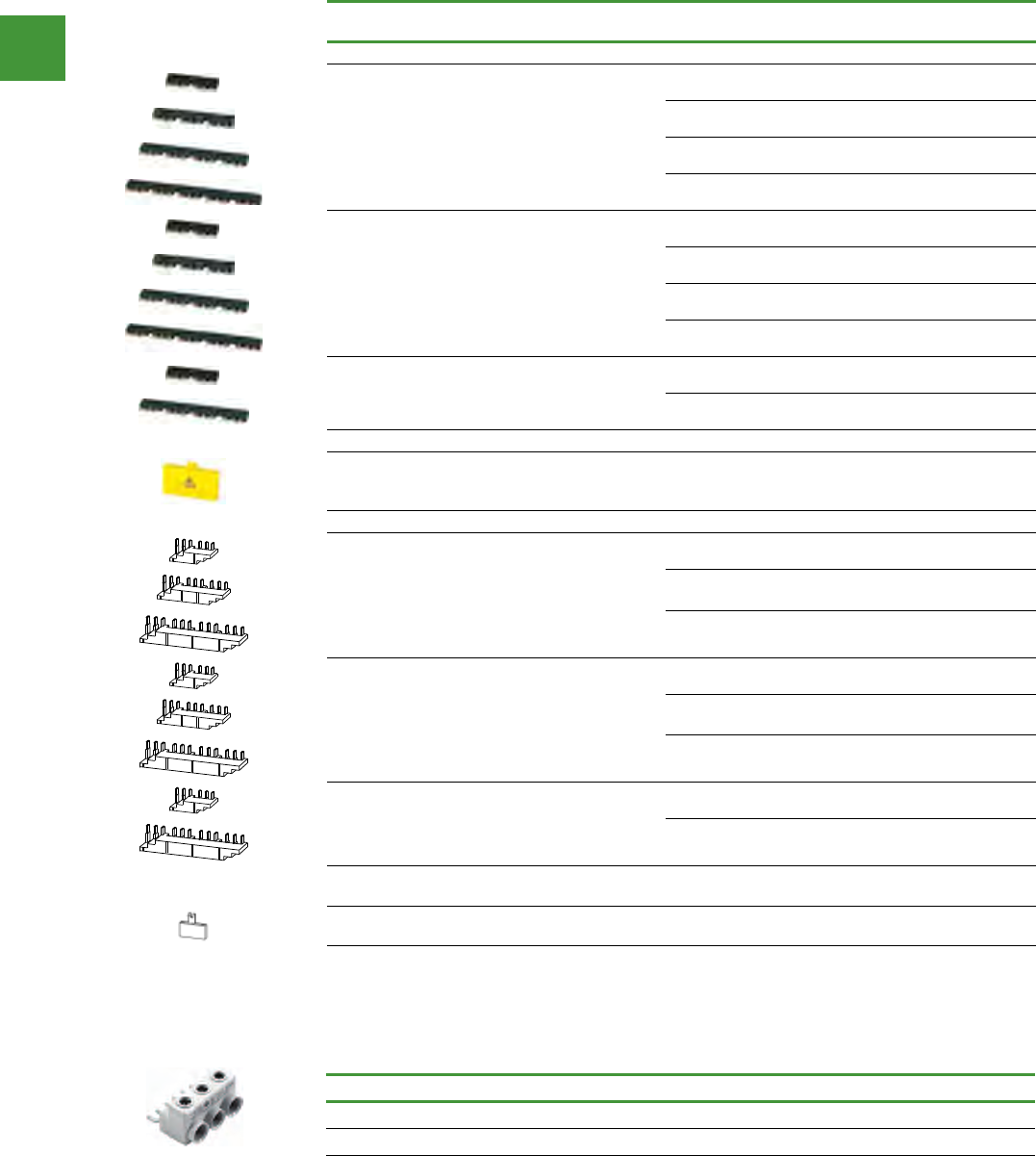
Motor control
Power control
217 2015/2016 Product guide AUS15_007 - February 2016
IEC Manual motor protectors accessories
Three-phase commoning links
For Use with... Qty.
MMP
Length of
link (mm)
Unit width
(mm) Item no.
Frame B
MMP With No Side-Mounted Auxiliaries or
Voltage Releases
2 90 45 B3.0/2-PKZ0
3 135 45 B3.0/3-PKZ0
4 180 45 B3.0/4-PKZ0
5 225 45 B3.0/5-PKZ0
For motor-protective circuit-breaker each with
an auxiliary contact or trip-indicating auxiliary
contact fitted on the right
2 99 45 + 9 B3.1/2-PKZ0
3 153 45 + 9 B3.1/3-PKZ0
4 207 45 + 9 B3.1/4-PKZ0
5 261 45 + 9 B3.1/5-PKZ0
For PKZM0-... with one auxiliary contact each &
a trip-indicating auxiliary contact fitted on right
or a voltage release fitted on left
2 108 45 + 18 B3.2/2-PKZ0
4 234 45 + 18 B3.2/4-PKZ0
Shroud for unused terminals.
Protection against direct contact.
For closing off non-used connections on the
three phase commoning link. B3...-PKZ0
---H-B3-PKZ0
Frame D
MMP With No Side-Mounted Auxiliaries or
Voltage Releases
2 110 55 B3.0/2-PKZ4
3 165 55 B3.0/3-PKZ4
4 220 55 B3.0/4-PKZ4
For motor-protective
circuit-breakers/starters each
with an auxiliary contact or
trip-indicating auxiliary contact fitted on the
right & with
a DIL1(A)M contactor
2--B3.1/2-PKZ4
3--B3.1/3-PKZ4
4--B3.1/4-PKZ4
For PKZM4 with one auxiliary contact each or
trip-indicating auxiliary contact fitted on right or
a voltage release fitted on left
2--B3.2/2-PKZ4
4--B3.2/4-PKZ4
Shroud for unused terminals. Protection against direct contact. To cover unused terminals on three-
phase commoning link
- - - - H-B3-PKZ4
Protected against accidental contact. B-Frame short circuit proof Ue = 690V, Iu = 63A; D-Frame short circuit proof
Ue = 690V, Iu = 128A. Frame B links can be combined by rotating mounting. Frame D links cannot be combined. +
MMP w/1 aux. (2, 3, 4, 5 module) + trip indicating etc. for frames B & D.
Incoming terminal for three-phase commoning link
For use with... Item no.
B-Frame PKZM0/PKE BK25/3-PKZ0
PKZM4 BK50/3-PKZ4-E
For three-phase commoning link, protected against accidental contact, Ue = 690V, Iu = 63A; for conductor cross-
sections: 2.5 – 25 mm2 stranded; 2.5 – 16 mm2 flexible with ferrules, AWG 14-6.
Motor control
Power control
218
2015/2016 Product guide AUS15_007 - February 2016
IEC Manual motor protectors accessories
Combination connection kits for connection of rotary MMP with IEC contactor
For use with... Description Item no.
Non-Reversing Starters
PKE/PKZMO + DILM7-15
DS7 (4-12A)
Comprised of:
Mechanical connection element for PKZM0 & contactor
Main current wiring between PKZM0 & contactor
in tool-less plug connection
Cable guidance
Use contactor auxiliary switch DILA-XHIT...
Control cable guidance: max. 6 cables up to 2.5 mm2
external diameter or 4 cables up to 3.5 mm2 external
diameter.
PKZM0-XDM12
PKZMO + DILM17-32 Comprised of:
DIN-Rail adapter plate
Main current wiring between PKZM0 & contactor
PKZM0-XDM32
PKZM4 + DILM40-65 PKZM4-XDM65
Reversing starters
PKZM0, PKE + DILM7-01
DILM9-01
DILM12-01
Consists of:
Mechanical connection element for PKZM0 and contactor
Reversing starters main supply wiring with tool-less plug
connection
PKZM0-XRM12
PKZM0, PKE + DILM17
DILM25
DILM32
Consists of:
Top-hat rail adapter plates
Reversing starters supply wiring
PKZM0-XRM32
Wiring kit
PKZM0, PKE + DILM17
DILM25
DILM32
DS7-34…SX016…
DS7-34…SX024…
SX032…
Main supply wiring between PKZM0 and contactor
Use only in combination with busbar adapter or mounting
rail adapter plate
PKZM0-XM32DE
PKZM4 + DILM40
DILM50
DILM65
Main current supply between PKZM4 and contactor PKZM4-XM65DE
Insulated enclosures for surface mounting
Degree of
protection For use with... Description Item no.
PKZM01 Pushbutton Manual Motor Protectors
IP65
PKZM01
With operating membrane CI-PKZ01-G
IP65 With Emergency-Stop (E-Stop)
pushbutton actuator, Red-Yellow CI-PKZ01-PVT
D-Frame (10 – 65A) PKZM0/PKZM4 Rotary Manual Motor Protectors
IP65 PKZM4 With black/grey rotary handle CI-K4-PKZ4-G
IP65 PKZM0
With black/grey rotary handle CI-K2-PKZ0-G
With red/yellow rotary handle
for use as Emergency-Stop
switches to IEC/ EN 60204
CI-K2-PKZ0-GR
IP65 PKZM4
With red/yellow rotary handle
for use as Emergency-Stop
switches to IEC / EN 60204
CI-K4-PKZ4-GR
Integrated terminal for PE(N) connection.
% Metric knockouts: Top ÷ bottom: M25/M32. In backplate: M25/M32. Control cable entry: M20.
MMP enclosure accessories (padlock attachment)
For use with... Description Item no.
CI-K2-PKZ0-GR &
CI-K2-PKZ0-G Padlocking feature. Up to 3 padlocks with 3 – 6 mm hasp
thickness. For use as main switch to IEC/EN 60204.
SVB-PKZ0-CI
CI-K4-PKZ4-GR &
CI-K4-PKZ4-G SVB-PKZ4-CI
More enclosures are available. Contact your local sales office for more information.
Lockable in the 0-position of the XTPR manual motor protector.
PKZM0-XDM12
PKZM4-XDM65
PKZM0-XM32DE
CI-PKZ01-PVT
CI-K2-PKZ0-G
SVB-PKZ0-CI
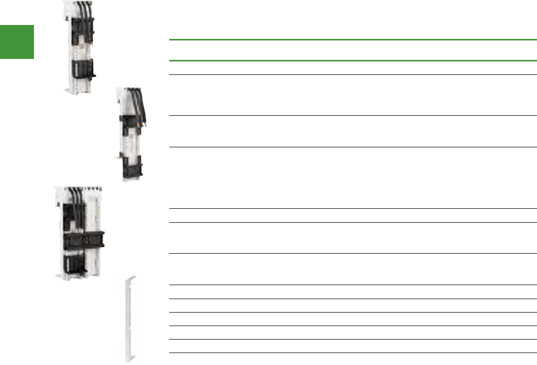
Motor control
Power control
219 2015/2016 Product guide AUS15_007 - February 2016
IEC Motor control busbar adapters
Busbar adapter, 3 pole
Rated operational voltage Ue = 690 V. For mounting on CU flat busbars with 60 mm interval between
busbar centres, suitable for 5 mm & 10 mm busbar thickness.
Rated operational
current, Ie, A
Width
(mm)
Length
(mm) For use with... Item no.
For direct-on-line starters
25 45 200
PKE/ PKZM0 + DILM7
PKE/ PKZM0 + DILM9
PKE/ PKZM0 + DILM12
PKE/ PKZM0 + DILM15
BBA0-25
32 45 200
PKE/ PKZM0 + DILM17
PKE/ PKZM0 + DILM25
PKE/ PKZM0 + DILM32
BBA0-32
63 55 260
PKZM4 + DILM17
PKZM4 + DILM25
PKZM4 + DILM32
PKZM4 + DILM40
PKZM4 + DILM50
PKZM4 + DILM65
BBA4L-63
For reversing starters
25 90 200
PKE/ PKZM0 + 2 x DILM7-01
PKE/ PKZM0 + 2 x DILM9-01
PKE/ PKZM0 + 2 x DILM12-01
BBA0R-25
32 90 200
PKE/ PKZM0 + 2 x DILM17-01
PKE/ PKZM0 + 2 x DILM25-01
PKE/ PKZM0 + 2 x DILM32-01
BBA0R-32
Empty module, without electrical contacts
– 45 200 – BBA0/2TS-L
– 54 200 – BBA4/2TS-L
Side mounted module, can be plugged into both sides
– 9 200 – BBA-XSM
BBA0-25
BBA0R-32
BBA4L-63
BBA-XSM
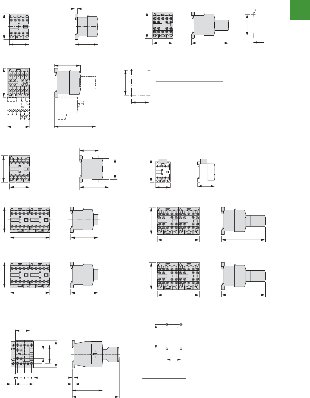
Motor control
Power control
220
2015/2016 Product guide AUS15_007 - February 2016
5/134 Contactors
Minicontactor relay, contactor combination
Minicontactor relay, contactor combination
Dimensions
Mini contactor relays
DILER-...(-C)
DILER-...-G(-C)
DILER-...(-C) + ...DILE(-C)
DILER-...-G(-C) + ...DILE(-C)
DILEEM-..., DILEM-...(-C), DILEM-12-...
DILEEM-...-G, DILEM-...-G(-C), DILEM-12-...-G
Suppressor circuit
RCDILE...
VGDILE
2DILE-... + MVDILE
2DILE-...-G + MVDILE
2DILE-... + MVDILE + ...DILE
2DILE-...-G + MVDILE + ...DILE
Ssrotcatnoc gnisreveR tar-delta contactors
DIULEM SDAINLEM
DILER-... + TDDILE24 Parallel connector
P1DILEM
45
58
52 (54)
5.5
45 83 (86)
58
50
35
M4
35
58
c1
c
50
M4
45
Part no. c c1
DILE(E)M-...(-G) 52 83
DILE(E)M-...-G(-C) 54 86
45
58
65,3
43
45
52
45
62.5
90 63
58
90
58
94
61
108
90 94
61
108
180 83
45
75
67
4,7
~125
40
65.5
83.5
DILER..., DILE(E)M..., DIULEM, SDAINLEM
DILER-... + HDILE
DILER-...-...G + HDILE
Mini contactor relays
5/134 Contactors
Minicontactor relay, contactor combination
Minicontactor relay, contactor combination
Dimensions
Mini contactor relays
DILER-...(-C)
DILER-...-G(-C)
DILER-...(-C) + ...DILE(-C)
DILER-...-G(-C) + ...DILE(-C)
DILEEM-..., DILEM-...(-C), DILEM-12-...
DILEEM-...-G, DILEM-...-G(-C), DILEM-12-...-G
Suppressor circuit
RCDILE...
VGDILE
2DILE-... + MVDILE
2DILE-...-G + MVDILE
2DILE-... + MVDILE + ...DILE
2DILE-...-G + MVDILE + ...DILE
Ssrotcatnoc gnisreveR tar-delta contactors
DIULEM SDAINLEM
DILER-... + TDDILE24 Parallel connector
P1DILEM
45
58
52 (54)
5.5
45 83 (86)
58
50
35
M4
35
58
c1
c
50
M4
45
Part no. c c1
DILE(E)M-...(-G) 52 83
DILE(E)M-...-G(-C) 54 86
45
58
65,3
43
45
52
45
62.5
90 63
58
90
58
94
61
108
90 94
61
108
180 83
45
75
67
4,7
~125
40
65.5
83.5
DILER..., DILE(E)M..., DIULEM, SDAINLEM
DILER-... + HDILE
DILER-...-...G + HDILE
Suppressor circuit
Basic devices up to 170 A, contactor relay
Contactor with auxiliary contact module
DILM7...DILM15
DILA...
DILMC7...DILMC15
DILAC...
DILA-XHIC...
DILM17...DILM38
DILMC17...DILMC32
DILMF8...DILMF32
Clearance at side to grounded
parts: 6 mm
6.5
75
c
3.2
18
45
68
45
36
8.78.78.7 8.7 (5.1)
10.2
35
2 x M4
60
Part no. c
DILM32-XHI 117
DILA-XHI 117
DILA-XHI...T 125
68
6.5
3.2
75
125
26.4
52.3
45
8.7 8.7 8.7 8.7(5.1)
1.8
1.8
10.2
35
2 x M4
60
11.611.6
4.5
17.7
10.6
6.4
38
71
60.4
85
45
11 4.8
138
6.5
97.4
4.5 35
2 x M4
75
Contactor with auxilary contact module
Dimensions
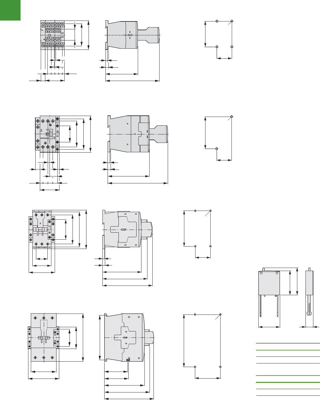
Motor control
Power control
221 2015/2016 Product guide AUS15_007 - February 2016
5/136 Contactors
Basic devices up to 170 A, suppressor circuit
2010 CA08103002Z-EN www.eaton.com
Basic devices up to 170 A, sup pressor circuit
Contactors
DILM40...DILM72
Clearance at side to
grounded parts: 6 mm
DILM80...DILM170
Clearance at side to
grounded parts: 10 mm
Suppressor circuits
DILM...XSP...
34.4
55
77
57
86.4
104
115
6.9
4.7
114
132.1
147
45
2 x M4
105
90
111
82.5
85.5
142
175
160
76.5
57
170
156
70
4 x M6
156
c
a
b
b1
Part no. a b
DILM12-XSP... 25 28
DILM32-XSP... 25 28
DILM95-XSP... 25 28
Part no. b1 c
DILM12-XSP... ≈32 9
DILM32-XSP... ≈32 9
DILM95-XSP... ≈32 9
DILM..., DILMF..., DILM...XSP...
5/136 Contactors
Basic devices up to 170 A, suppressor circuit
2010 CA08103002Z-EN www.eaton.com
Basic devices up to 170 A, suppressor circuit
Contactors
DILM40...DILM72
Clearance at side to
grounded parts: 6 mm
DILM80...DILM170
Clearance at side to
grounded parts: 10 mm
Suppressor circuits
DILM...XSP...
34.4
55
77
57
86.4
104
115
6.9
4.7
114
132.1
147
45
2 x M4
105
90
111
82.5
85.5
142
175
160
76.5
57
170
156
70
4 x M6
156
c
a
b
b1
Part no. a b
DILM12-XSP... 25 28
DILM32-XSP... 25 28
DILM95-XSP... 25 28
Part no. b1 c
DILM12-XSP... ≈32 9
DILM32-XSP... ≈32 9
DILM95-XSP... ≈32 9
DILM..., DILMF..., DILM...XSP...
Contactors
Dimensions
Suppressor circuit
Basic devices up to 170 A, contactor relay
Contactor with auxiliary contact module
DILM7...DILM15
DILA...
DILMC7...DILMC15
DILAC...
DILA-XHIC...
DILM17...DILM38
DILMC17...DILMC32
DILMF8...DILMF32
Clearance at side to grounded
parts: 6 mm
6.5
75
c
3.2
18
45
68
45
36
8.78.78.7 8.7 (5.1)
10.2
35
2 x M4
60
Part no. c
DILM32-XHI 117
DILA-XHI 117
DILA-XHI...T 125
68
6.5
3.2
75
125
26.4
52.3
45
8.7 8.7 8.7 8.7(5.1)
1.8
1.8
10.2
35
2 x M4
60
11.611.6
4.5
17.7
10.6
6.4
38
71
60.4
85
45
11 4.8
138
6.5
97.4
4.5 35
2 x M4
75
Basic devices up to 170 A, contactor relay
Contactor with auxiliary contact module
DILM7...DILM15
DILA...
DILMC7...DILMC15
DILAC...
DILA-XHIC...
DILM17...DILM38
DILMC17...DILMC32
DILMF8...DILMF32
Clearance at side to grounded
parts: 6 mm
6.5
75
c
3.2
18
45
68
45
36
8.78.78.7 8.7 (5.1)
10.2
35
2 x M4
60
Part no. c
DILM32-XHI 117
DILA-XHI 117
DILA-XHI...T 125
68
6.5
3.2
75
125
26.4
52.3
45
8.7 8.7 8.7 8.7(5.1)
1.8
1.8
10.2
35
2 x M4
60
11.611.6
4.5
17.7
10.6
6.4
38
71
60.4
85
45
11 4.8
138
6.5
97.4
4.5 35
2 x M4
75
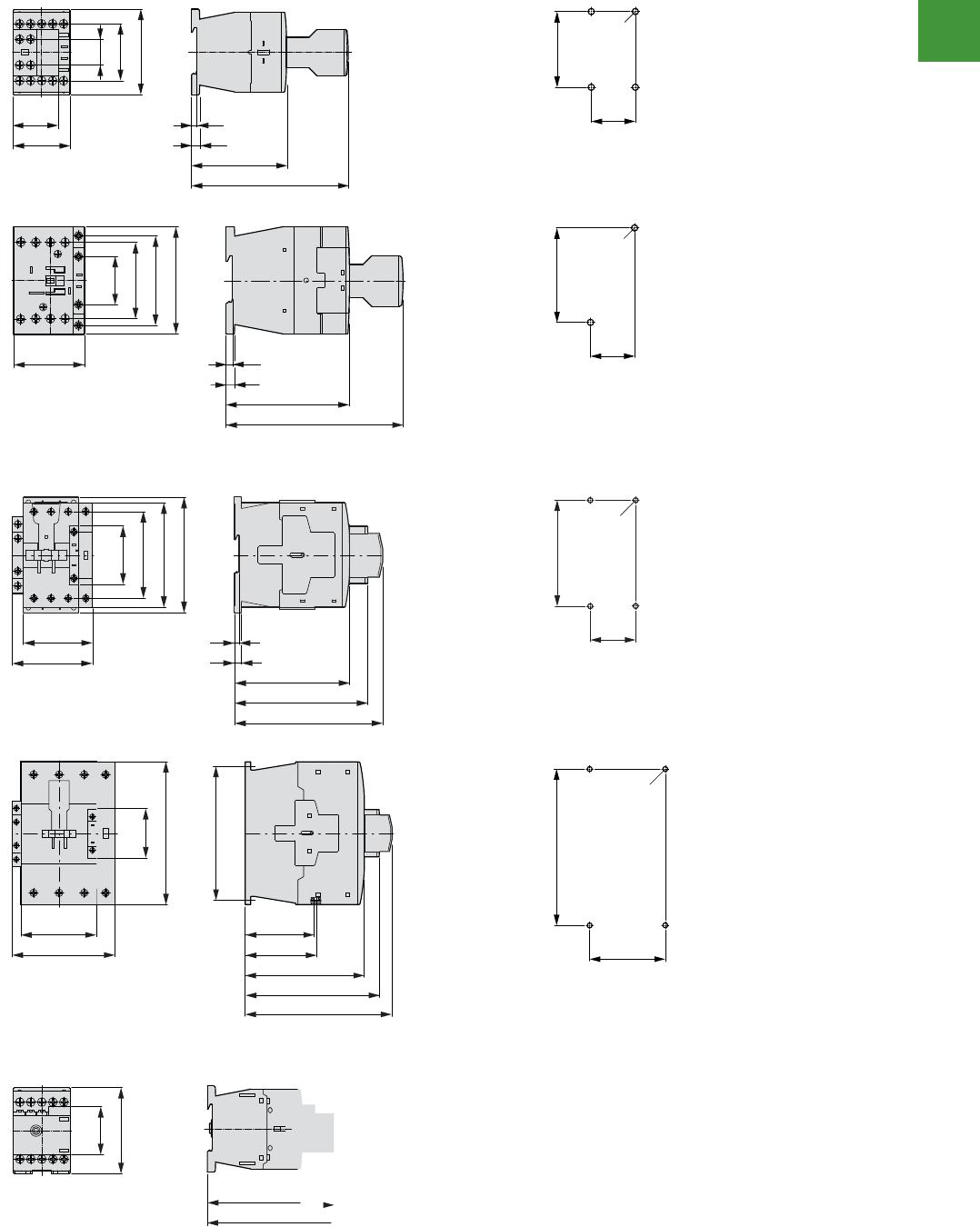
Motor control
Power control
222
2015/2016 Product guide AUS15_007 - February 2016
Contactors
Basic devices up to 200 A
2010 CA08103002Z-EN www.eaton.com
5/137
Basic devices up to 200 A
Complete units for currents greater than 170 A
Contactor with auxiliary contact module
DILMP20
Clearance at side to earthed
parts: 10 mm
18
45
68
45
36
6.5
75
117
3.2
35
2 x M4
60
DILMP32 DILMP45
Distance at side to
grounded parts: 6 mm
38
71
60.4
85
58
138
6.5
97.4
4.5
35
2 x M4
75
Contactors
DILMP63 DILMP80
Distance at side to
grounded parts: 6 mm
6.9
4.7
114
132.1
147
74
85
57
86.4
104
115
45
2 x M4
105
DILMP125 DILMP160 DILMP200
122
133
82.5
85.5
142
175
160
57
170
156
70
4 x M6
156
Motor suppressor module
DILM12-XMSM
38.3
68
75
101.2
DILMP...
Contactor with auxilary contact module
Contactors
Motor suppressor module
Dimensions
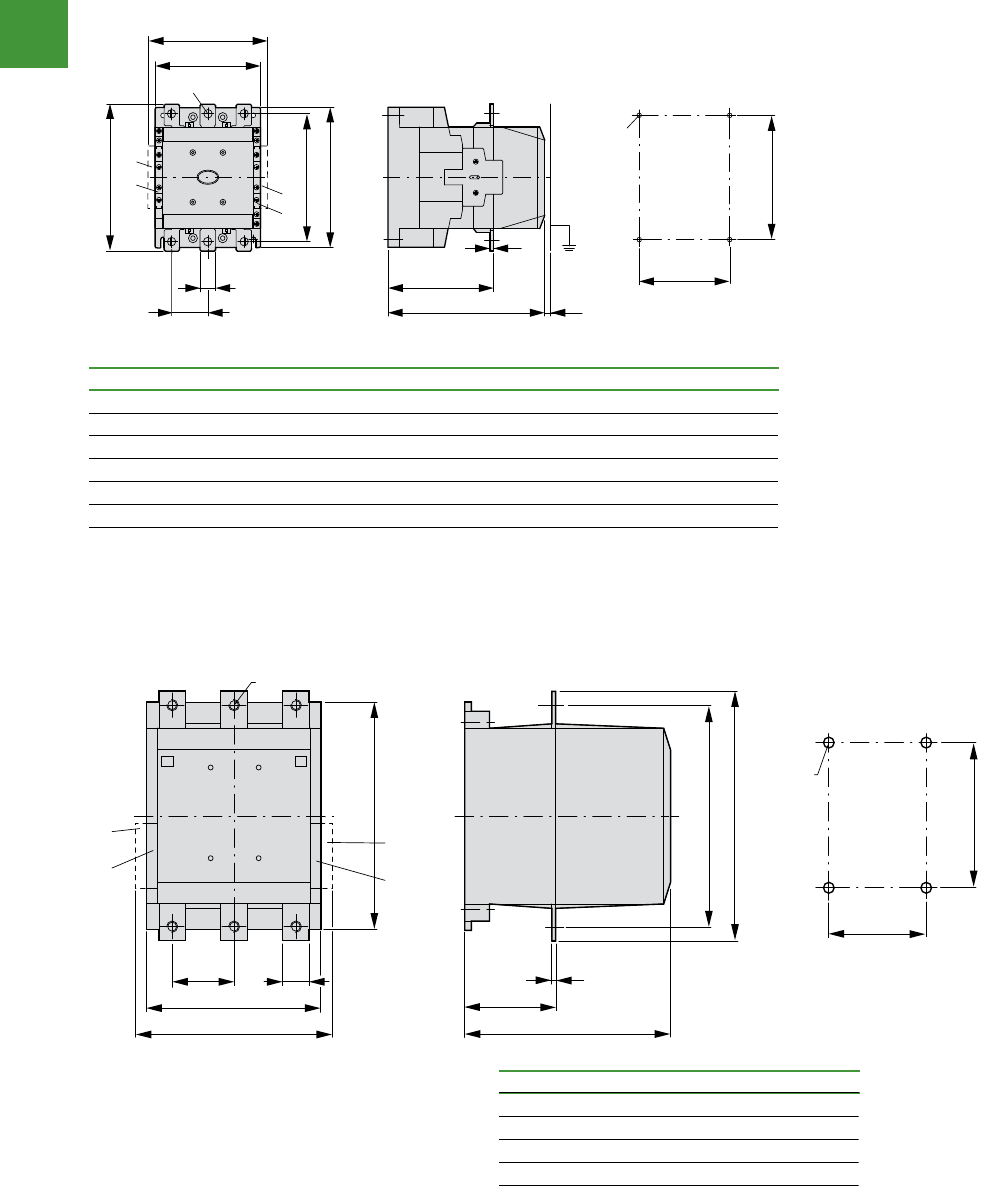
Motor control
Power control
223 2015/2016 Product guide AUS15_007 - February 2016
5/138 Contactors
Complete units for currents greater than 170 A
2010 CA08103002Z-EN www.eaton.com
Complete units
DILM185A...DILM500
DILM250-S...DILM570-S
a DILM1000-XHI...-SI
b DILM1000-XHI11-SA
DILM580...DILM1000
a DILM820-XHI...-SI
b DILM820-XHI11-SA
c8
f
b1
a1
M6
e
d1
b2
b3
b
d2
a
o11
a2
a
b
a
b
Part no. a a1 a2 b b1 b2 b3 d1 d2 e c f
DILM185A 140 120 160 180 160 165 190 20 41 5 158 83
DILM225A 140 120 160 180 160 165 190 20 41 5 158 83
DILM250 140 120 160 180 160 164 189 25 48 5 208 140
DILM300A 140 120 160 180 160 164 189 25 48 5 208 140
DILM400 160 130 180 200 180 184 209 25 48 6 216 140
DILM500 160 130 180 200 180 189 219 38 57 6 216 140
DILM570 160 130 180 200 180 189 219 38 57 6 216 140
250
80 d1
232
232
b3
140
b2
270
e
165
215
M6
a
a
b
b
f
Part no. b2 b3 d1 e f
DILM580 256 296 45 6 13.5
DILM650 256 296 45 6 13.5
DILM750 256 296 45 6 13.5
DILM820 256 296 45 6 13.5
DILM1000 256 296 45 10 13.5
...DILM
Complete units
Dimensions
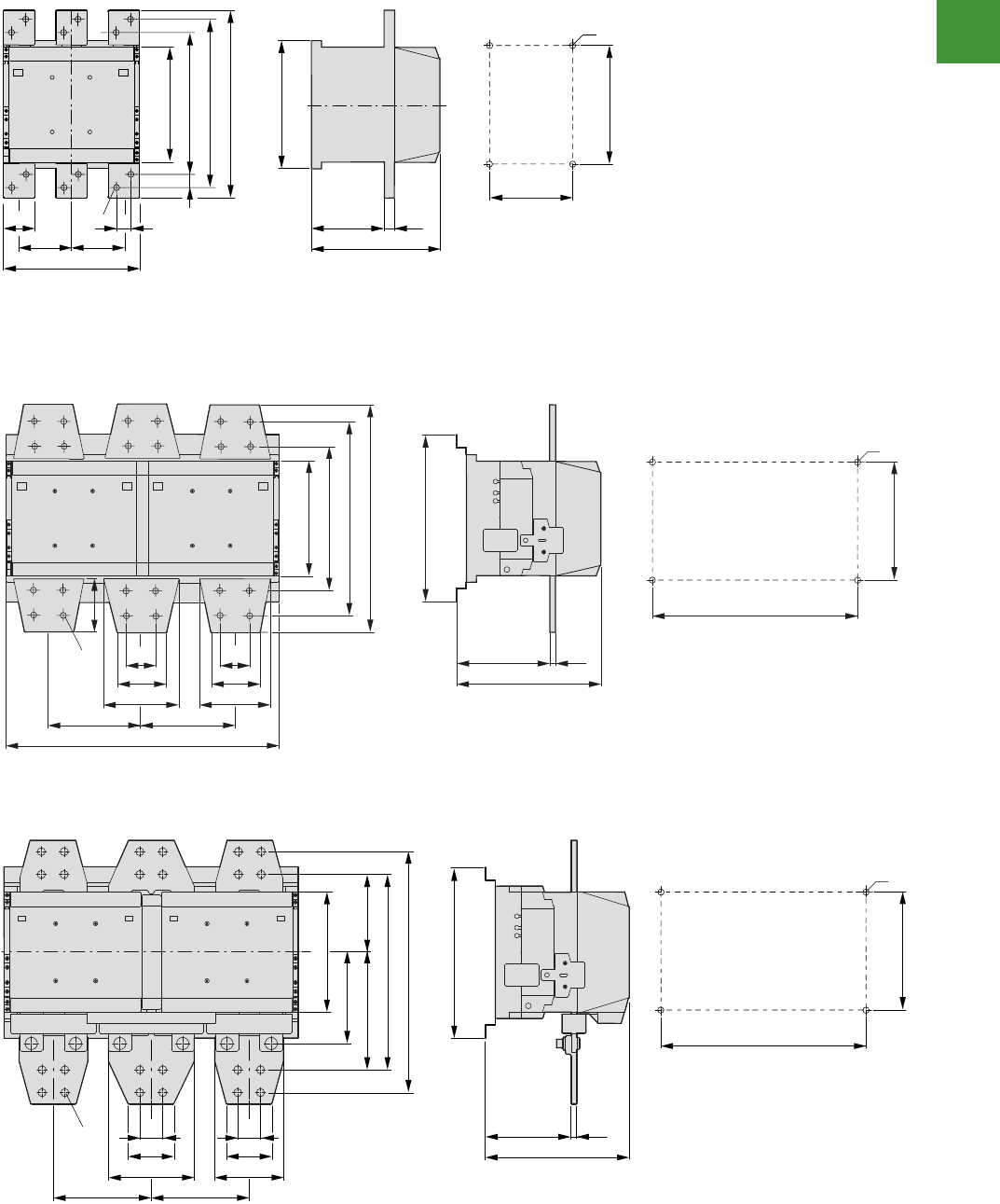
Motor control
Power control
224
2015/2016 Product guide AUS15_007 - February 2016
Contactors
Contactors greater than 1000 A
2010 CA08103002Z-EN www.eaton.com
5/139
Contactors greater than 1000 A
AC -1 contactors greater than 1000 A
DILH1400
DILM1600
DILH2000
DILH2200
DILH2600
100
60 35
100
210
232
25635
342
308
260
o 14
165
215
M6
232
130 10
40
80
125
172.5172.5
210
272
352
392
o 14
300
252
150 10
40
80
150
515
430
270
M6
96
300
252
150 10
430
270
M6
210
160
206 136
422
(342)
o 14
172.5172.5
125
40
80
150
40
80
DILH..., DILM...
AC-1 contactors greater than 1000A
Dimensions

Motor control
Power control
225 2015/2016 Product guide AUS15_007 - February 2016
5/140 Contactors
Capacitor contactors, lamp contactors, contactor monitoring devices, SWD contactor modules
2010 CA08103002Z-EN www.eaton.com
Capacitor contactors, lamp con tactors, contactor monitoring devices, SWD contactor modules
Contactor for capacitors
DILK…
Illumination contactors
DILL…
Clearance at side to grounded parts: 6 mm
Contactor monitoring devices
CMD(...)
SWD contactor modules
DIL-SWD-32-...
b
ca
a1
b1
d
Part no. a b c a1 b1 d
DILK12 45 135 138 35 75 2 x M4
DILK20 45 135 138 35 75 2 x M4
DILK25 45 135 138 35 75 2 x M4
DILK33 55 190 147 45 105 2 x M4
DILK50 55 190 147 45 105 2 x M4
11.6 11.6
4.5
17.7
10.6
(6.4)
38
60.4
85
45
4.8
138
6.5
97.4
4.5
35
2 x M4
75
103
98
78
22.5
82.5
38
45 53.1
72.3
DILK..., DILL..., CMD, DIL-SWD
Dimensions
Contactor for capacitors
5/140 Contactors
Capacitor contactors, lamp contactors, contactor monitoring devices, SWD contactor modules
2010 CA08103002Z-EN www.eaton.com
Capacitor contactors, lamp con tactors, contactor monitoring devices, SWD contactor modules
Contactor for capacitors
DILK…
Illumination contactors
DILL…
Clearance at side to grounded parts: 6 mm
Contactor monitoring devices
CMD(...)
SWD contactor modules
DIL-SWD-32-...
b
ca
a1
b1
d
Part no. a b c a1 b1 d
DILK12 45 135 138 35 75 2 x M4
DILK20 45 135 138 35 75 2 x M4
DILK25 45 135 138 35 75 2 x M4
DILK33 55 190 147 45 105 2 x M4
DILK50 55 190 147 45 105 2 x M4
11.6 11.6
4.5
17.7
10.6
(6.4)
38
60.4
85
45
4.8
138
6.5
97.4
4.5
35
2 x M4
75
103
98
78
22.5
82.5
38
45 53.1
72.3
DILK..., DILL..., CMD, DIL-SWD
Contactor monitoring decives
5/140 Contactors
Capacitor contactors, lamp contactors, contactor monitoring devices, SWD contactor modules
2010 CA08103002Z-EN www.eaton.com
Capacitor contactors, lamp con tactors, contactor monitoring devices, SWD contactor modules
Contactor for capacitors
DILK…
Illumination contactors
DILL…
Clearance at side to grounded parts: 6 mm
Contactor monitoring devices
CMD(...)
SWD contactor modules
DIL-SWD-32-...
b
ca
a1
b1
d
Part no. a b c a1 b1 d
DILK12 45 135 138 35 75 2 x M4
DILK20 45 135 138 35 75 2 x M4
DILK25 45 135 138 35 75 2 x M4
DILK33 55 190 147 45 105 2 x M4
DILK50 55 190 147 45 105 2 x M4
11.6 11.6
4.5
17.7
10.6
(6.4)
38
60.4
85
45
4.8
138
6.5
97.4
4.5
35
2 x M4
75
103
98
78
22.5
82.5
38
45 53.1
72.3
DILK..., DILL..., CMD, DIL-SWD
SWD contactor modules
5/142 Contactors
Accessories
2010 CA08103002Z-EN www.eaton.com
Accessories
Three-phase commoning links
DILM12-XDSB...
Electronic timer modules
Amplier module
3SV-4STE
ETX…MLID
Wiring set for motor feeder plug
T/PCMX-21MLIDECMX-21MLID
DILM12-XMCP/E
13.1
a
18.1
12.5
Part no. a
DILM12-XDSB0/3 112
DILM12-XDSB0/4 157
DILM12-XDSB0/5 202
38
25
70
45
103
98
78
22.5
82.5
25 45
80
20
45
30 27 12
25 20
45
50
6
37
30
25 45
80
27 12
20
45
50
6
37
30
DILM...XDSB..., ETS4-VS3, DILM...XTE, DILM12-XMC...
Amplifier module
5/142 Contactors
Accessories
2010 CA08103002Z-EN www.eaton.com
Accessories
Three-phase commoning links
DILM12-XDSB...
Electronic timer modules
Amplier module
3SV-4STE
ETX…MLID
Wiring set for motor feeder plug
T/PCMX-21MLIDECMX-21MLID
DILM12-XMCP/E
13.1
a
18.1
12.5
Part no. a
DILM12-XDSB0/3 112
DILM12-XDSB0/4 157
DILM12-XDSB0/5 202
38
25
70
45
103
98
78
22.5
82.5
25 45
80
20
45
30 27 12
25 20
45
50
6
37
30
25 45
80
27 12
20
45
50
6
37
30
DILM...XDSB..., ETS4-VS3, DILM...XTE, DILM12-XMC...
Electronic timer modules
5/142 Contactors
Accessories
2010 CA08103002Z-EN www.eaton.com
Accessories
Three-phase commoning links
DILM12-XDSB...
Electronic timer modules Amplier module
3SV-4STEETX…MLID
Wiring set for motor feeder plug
T/PCMX-21MLID
ECMX-21MLID
DILM12-XMCP/E
13.1
a
18.1
12.5
Part no. a
DILM12-XDSB0/3 112
DILM12-XDSB0/4 157
DILM12-XDSB0/5 202
38
25
70
45
103
98
78
22.5
82.5
25 45
80
20
45
30
27 12
25 20
45
50
6
37
30
25 45
80
27 12
20
45
50
6
37
30
DILM...XDSB..., ETS4-VS3, DILM...XTE, DILM12-XMC...
5/142 Contactors
Accessories
2010 CA08103002Z-EN www.eaton.com
Accessories
Three-phase commoning links
DILM12-XDSB...
Electronic timer modules Amplier module
3SV-4STEETX…MLID
Wiring set for motor feeder plug
T/PCMX-21MLIDECMX-21MLID
DILM12-XMCP/E
13.1
a
18.1
12.5
Part no. a
DILM12-XDSB0/3 112
DILM12-XDSB0/4 157
DILM12-XDSB0/5 202
38
25
70
45
103
98
78
22.5
82.5
25 45
80
20
45
30 27 12
25 20
45
50
6
37
30
25 45
80
27 12
20
45
50
6
37
30
DILM...XDSB..., ETS4-VS3, DILM...XTE, DILM12-XMC...
5/142 Contactors
Accessories
2010 CA08103002Z-EN www.eaton.com
Accessories
Three-phase commoning links
DILM12-XDSB...
Electronic timer modules Amplier module
3SV-4STEETX…MLID
Wiring set for motor feeder plug
T/PCMX-21MLID
ECMX-21MLID
DILM12-XMCP/E
13.1
a
18.1
12.5
Part no. a
DILM12-XDSB0/3 112
DILM12-XDSB0/4 157
DILM12-XDSB0/5 202
38
25
70
45
103
98
78
22.5
82.5
25 45
80
20
45
30
27 12
25 20
45
50
6
37
30
25 45
80
27 12
20
45
50
6
37
30
DILM...XDSB..., ETS4-VS3, DILM...XTE, DILM12-XMC...
Wiring set for motor feeder plug
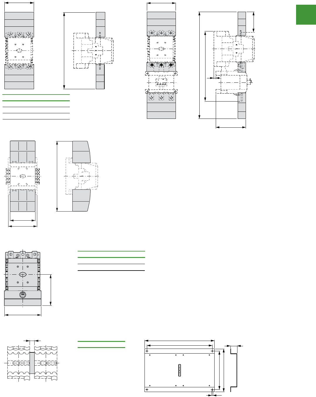
Motor control
Power control
226
2015/2016 Product guide AUS15_007 - February 2016
Contactors 5/143
Power contactors with terminal shro ud, mechanic al interloc k
Contactors with terminal shrouds
052FF/...-5Z + 052MLIDBHX-...MLID + 0001MLID...052MLID
DILM185A...DILM225A + DILM225A-XHB
Contactor with star-point bridge and terminal shroud
DILM...XS1
Mechanical interlock
VMX-028MLIDVMX-005MLID
a
b
150
34
523
110
328
~144
for part no. a b
DILM250, DILM300A 150 384
DILM400 150 404
DILM500 174 426
DILM580...1000 236 506
325
124
140
a
b
for part no. a b
DILM185...250 150 127
DILM300...400 150 137
DILM500 176 146
a
for part no. a
DILM185...500 15
9
515
430
270
300
20
...DILM
Contactors with terminal shrouds
Contactors with star-point bridge and terminal shrouds
Dimensions
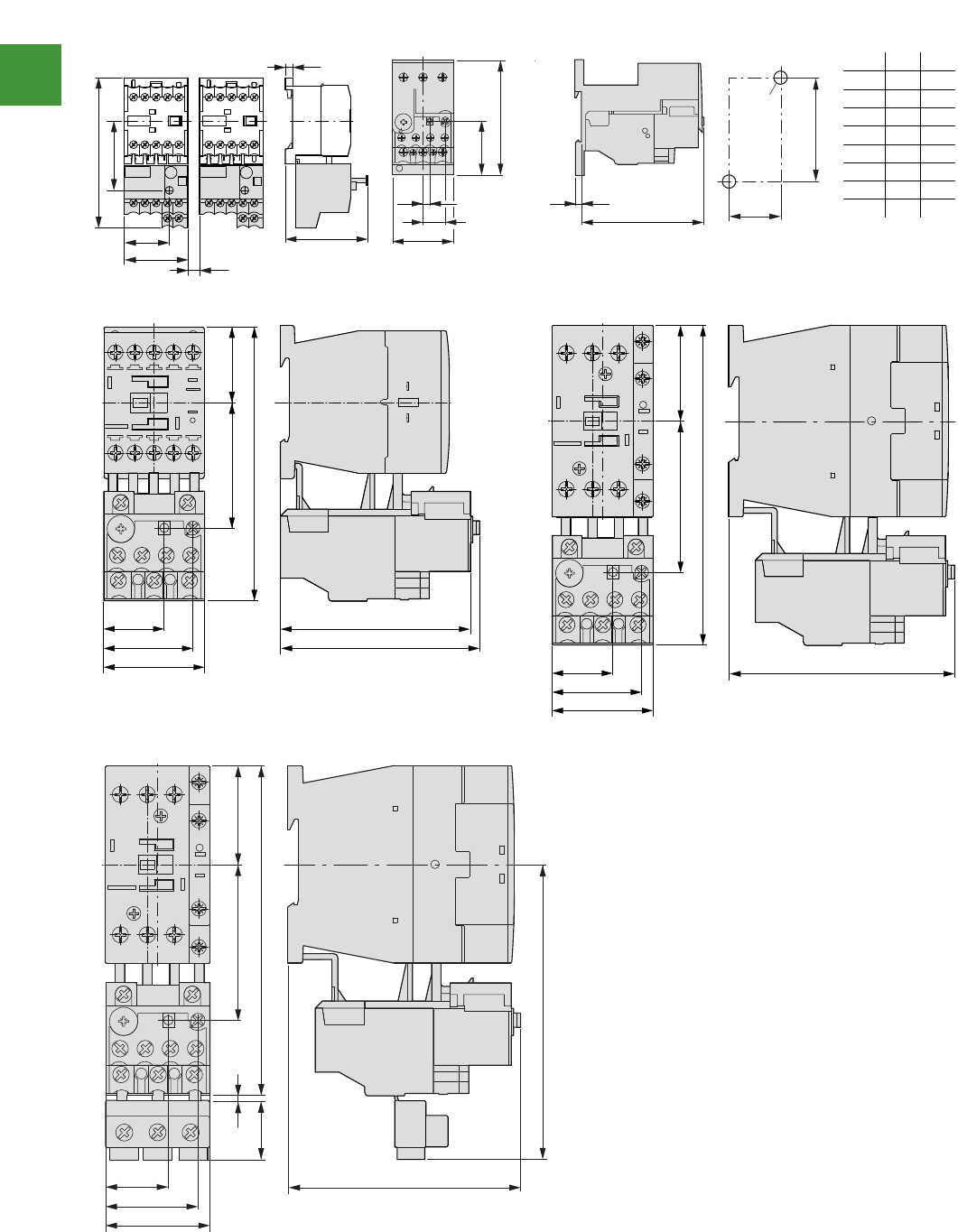
Motor control
Power control
227 2015/2016 Product guide AUS15_007 - February 2016
Overload relays
Overload relays
2010 CA08103002Z-EN www.eaton.com
6/37
Dimensions
Overload relays esaBsyaler daolrevO
Z
EX-56BZZEX-23BZ…-EZ
ZB12 ZB32
① OFF
② Reset/ON
ZB32-38
① OFF
② Reset/ON
5.5
58
= 5
45
32
49
106
>
5
b2
16.5
c2
b
a
c
b1
a1
2 x d
ZB32 ZB65
a 45 60
b 85 86
c90.5 112
c2 3.8 4.7
a1 35 50
b1 75 75
b2 40.5 47
d M4 M5
45
27.5
39 88
84
53 34
120
a
b
45
27.5
39
102
2426
136
a
b
45
27.5
39
102
622
25
42
136
120
a
b
ZE, ZB
Overload relays
Overload relays
2010 CA08103002Z-EN www.eaton.com
6/37
Dimensions
Overload relays esaBsyaler daolrevO
ZEX-56BZ
ZEX-23BZ…-EZ
ZB12
ZB32
① OFF
② Reset/ON
ZB32-38
① OFF
② Reset/ON
5.5
58
= 5
45
32
49
106
>
5
b2
16.5
c2
b
a
c
b1
a1
2 x d
ZB32 ZB65
a 45 60
b 85 86
c90.5 112
c2 3.8 4.7
a1 35 50
b1 75 75
b2 40.5 47
d M4 M5
45
27.5
39 88
84
53 34
120
a
b
45
27.5
39
102
2426
136
a
b
45
27.5
39
102
622
25
42
136
120
a
b
ZE, ZB
Overload relays
Dimensions
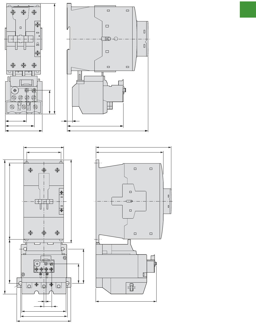
Motor control
Power control
228
2015/2016 Product guide AUS15_007 - February 2016
6/38Overload relays
Overload relays
2010 CA08103002Z-EN www.eaton.com
Overload relays
Overload relays
ZB65 ① OFF
② Reset/ON
① OFF
② Reset/ON
172
40
60
46.5
35 7.5
132
96.5
a
b
a
b
100
134
44
74
118
95
5
16.5
91
90
150
170
156
160
277
70
o7
ZB
ZB150
Overload relays
Dimensions
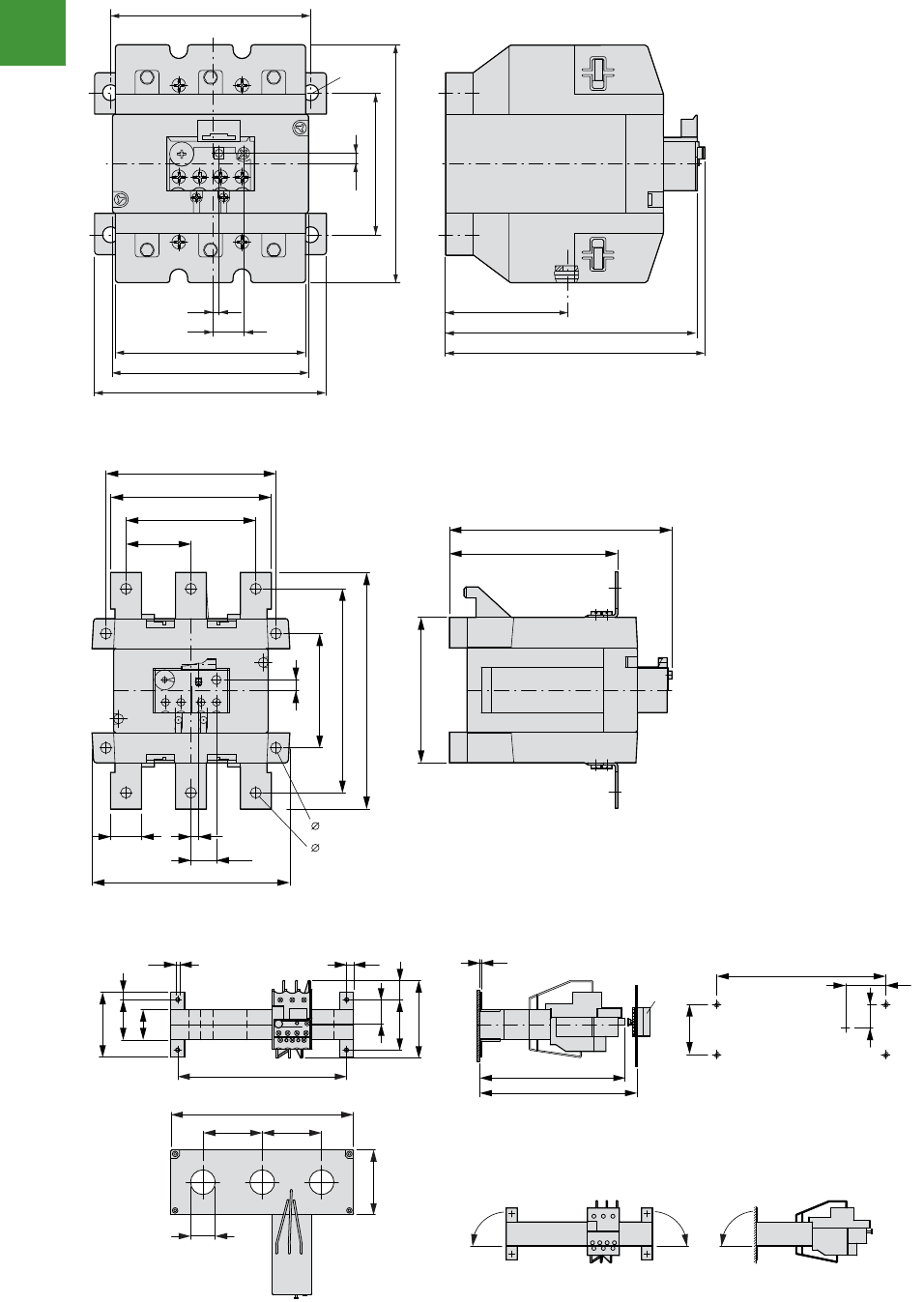
Motor control
Power control
229 2015/2016 Product guide AUS15_007 - February 2016
Overload relays
Dimensions
Overload relays
Overload relays, CT-operated overload relays
6/39
Overload relays, CT-operated overload relays
Overload relays
ZB150-50/KK
① OFF
② Reset/ON
Z5 overload relays greater than 150A
Z5-.../FF250
① OFF
② Reset/ON
Current transformer-operated overload relays
ZW7-…
① Reset/ON
121
74
7
5
16.5
63
129
134
100
118
99
95
o 7
a
b
121
110
96
128
74
144
169
48
25 5
16.5
144
111
94
7
7
11
a b
a
b
200
185
65
65
71
27
7.5
26
55 21
85
71
44
33
8
4.3
185
M4
44
26
55
a
a
1.5
159
172 – 250
90° 90°90°
Z5, ZW7
Z5 overload replays greater than 150A
Current transformer-operated overload relays
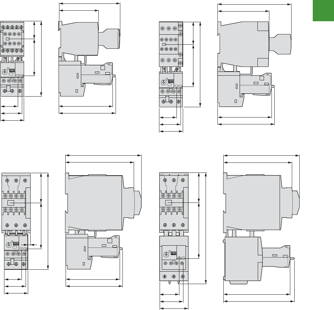
Motor control
Power control
230
2015/2016 Product guide AUS15_007 - February 2016
6/40 Overload relays
Electronic overload relays
2010 CA08103002Z-EN www.eaton.com
Electronic overload relays
Electronic overload relays
ZEB12
ZEB32
ZEB65-45
ZEB65-100
76
117
34
143
70
103
108
33.2
40.5
45
97.5
139.5
103
108
43
161
79
33.2
40.5
45
132.5
146.1
57.5
184
87
5
103
108
33.2
40.5
45
38.6
46.2
55
128.2
136.3
57.5
213.6
107
132.5
146.1
ZEB
Electronic overload relays
Dimensions
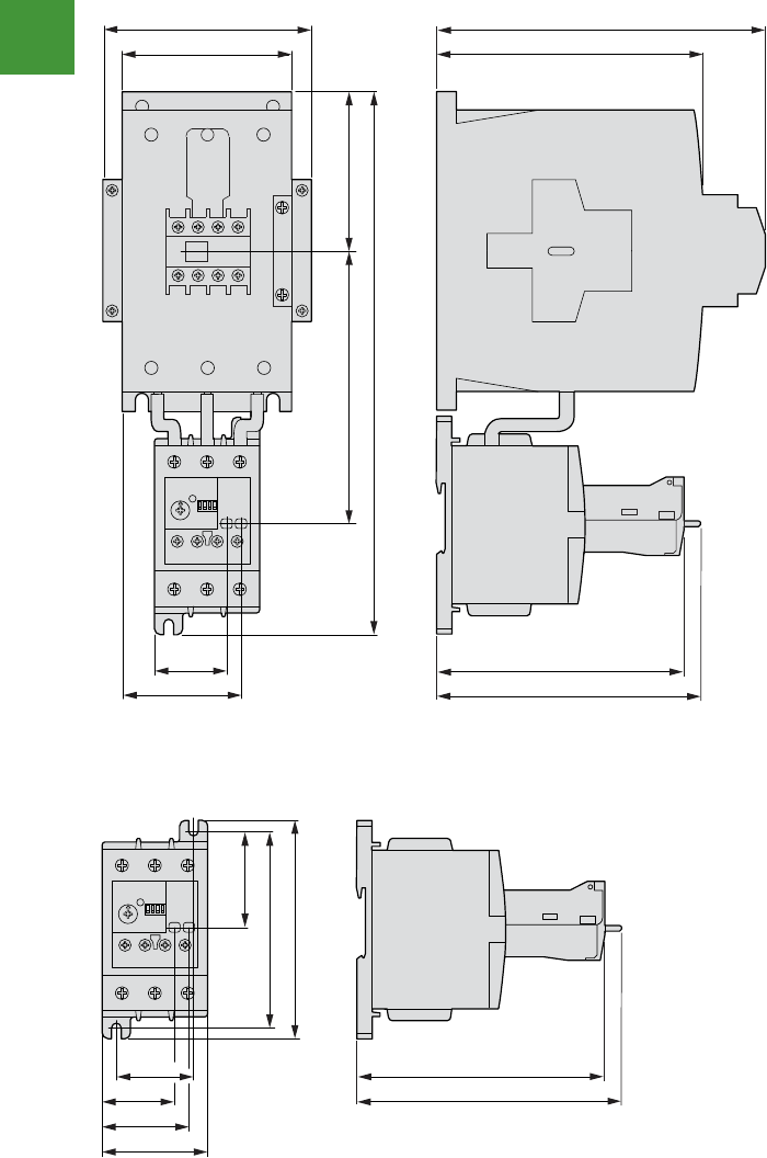
Motor control
Power control
231 2015/2016 Product guide AUS15_007 - February 2016
Overload relays
Electronic overload relays
2010 CA08103002Z-EN www.eaton.com
6/41
Electronic overload relays
Electronic overload relays
Electronic overload relays
ZEB150-100
ZEB150-100/KK
132.4
140.5
85
289.1
145.4
38.6
63.2
90
111.8 175
160
38.6
41
46.1
56
51.7
104.8
116
132.4
140.5
ZEB
Electronic overload relays
Dimensions
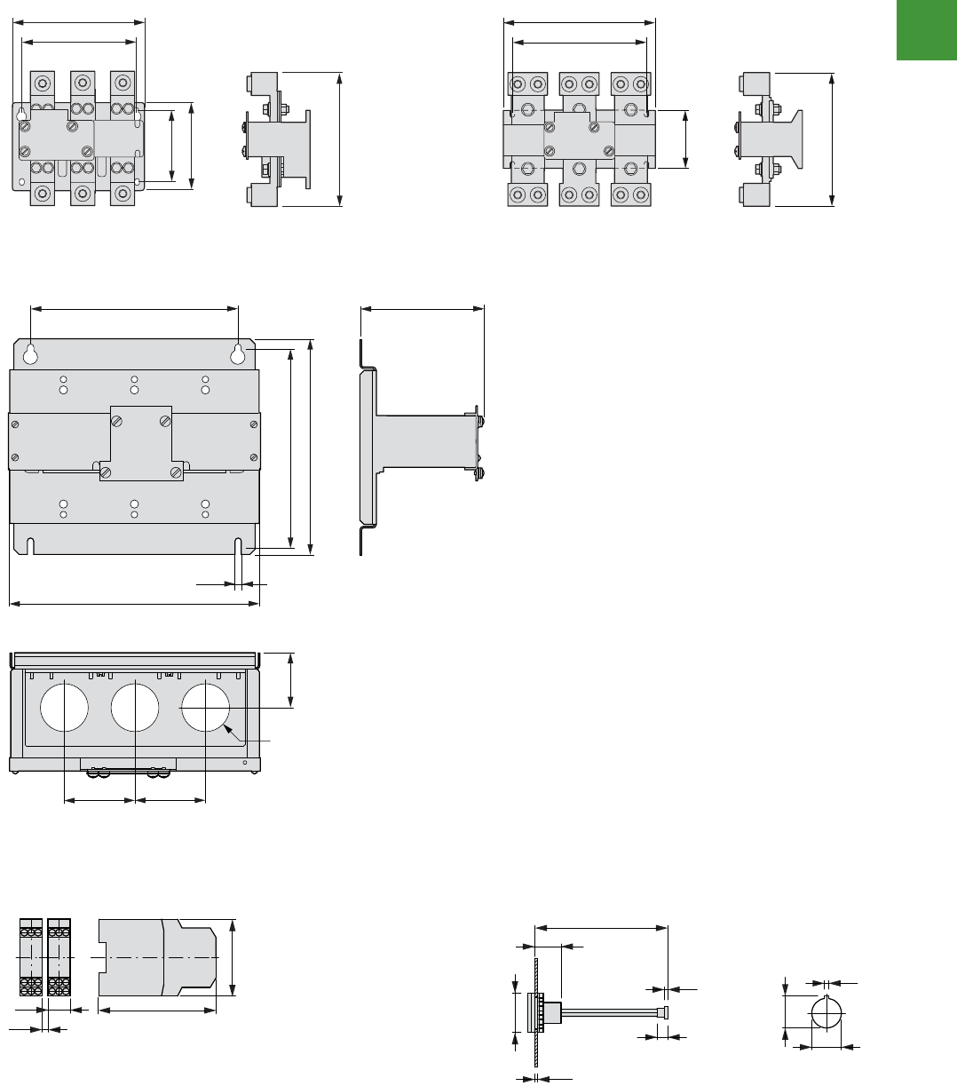
Motor control
Power control
232
2015/2016 Product guide AUS15_007 - February 2016
6/42Overload relays
Thermistor overload relays for machine protection, electronic overload relays
2010 CA08103002Z-EN www.eaton.com
Thermistor overload relays for machine protection, electronic overload rel ays
Current sensors
ZEB-XCT300 ZEB-XCT600
ZEB-XCT1000
ZEB-XCT1500
EMT6 thermistor overload relays for nottub teser lanretxEnoitcetorp enihcam
EMT6… M22-DZ-B
M22-DZ-X
190.5
165.1
106.1
127
193.5
234.2
206
89.2
205.4
304.6
330.2
317 188.9
10.1
383.5
108108
83.5
o 73.2
102
78
22.5
3
_>
100
19
2 – 5
8
2.5
24.1
22.3
3.2
o 29.5
ZEB, EMT6
Current sensors
EMT6 thermistor overload relays for machine protection External reset button
Dimensions
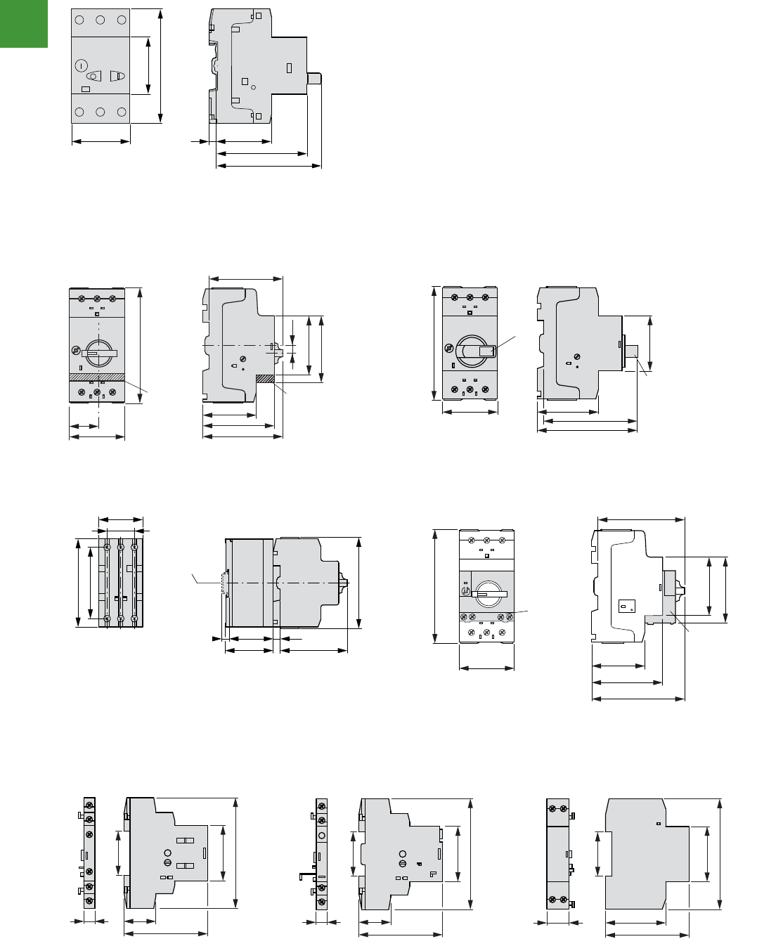
Motor control
Power control
233 2015/2016 Product guide AUS15_007 - February 2016
Motor-protective circuit-breakers PKZM01, PKZM0, PKZM4, PKE
Motor-protective circuit-breaker
2010 CA08103002Z-EN www.eaton.com
7/39
Motor-protective circuit-breaker
Dimensions
Motor-protective circuit-breaker
PKZM01…
seldnah yrator elbakcol htiw srekaerb-tiucric evitcetorp-rotoMrekaerb-tiucric evitcetorp-rotoM
Transformer-protective circuit-breakers
Motor-protective circuit-breaker with
standard auxiliary contacts
PKZM0-…(+NHI-E-…-PKZ0)
PKZM0-…-T(+NHI-E-…-PKZ0)
PKM0-…(+NHI-E-…-PKZ0)
PKZM0-…+AK-PKZ0
stcatnoc yrailixua ekam-ylrae htiw srekaerb-tiucric evitcetorp-rotoMsretimil tnerruC
CL-PKZ… PKZM0-…+VHI-…-PKZ0
① Top-hat rail IEC/EN 60715
esaeler tnuhSsrotaci dni pirTstcatnoc yrailixua dradnatS Undervoltage release
…0ZKP-A0ZKP-…2MGA0ZKP-…IHN
U-PKZ0…
5.545
45
93
44
74
85
NHI-E-..-PKZ0
NHI-E-..-PKZ0
70
55
45
25
93
50
76
68
45
4.5
45
AK-PKZ 0
AK-PKZ 0
93
50
88
94
45
70
7.5
49.5
44
7.5
45
28
90
73
93
a
VHI...-PKZ0
80
55
45
93
50
86
68
45
VHI...-PKZ0
926
68
45
90
36
9 26
68
45
90
36
18 49
68
36
45
90
PKZM01, PKZM0
Motor-protective circuit breaker
Motor-protective circuit breaker with
lockable rotary handles
Motor-protective circuit breaker with
early-make auxilary contacts
Current limiters
Stabdard auxiliary contacts Trip indicators Shunt release - undervoltage release
Motor-protective circuit breaker
Transformer-protective circuit breakers
Motor-protective circuit breaker with auxiliary contacts
Dimensions
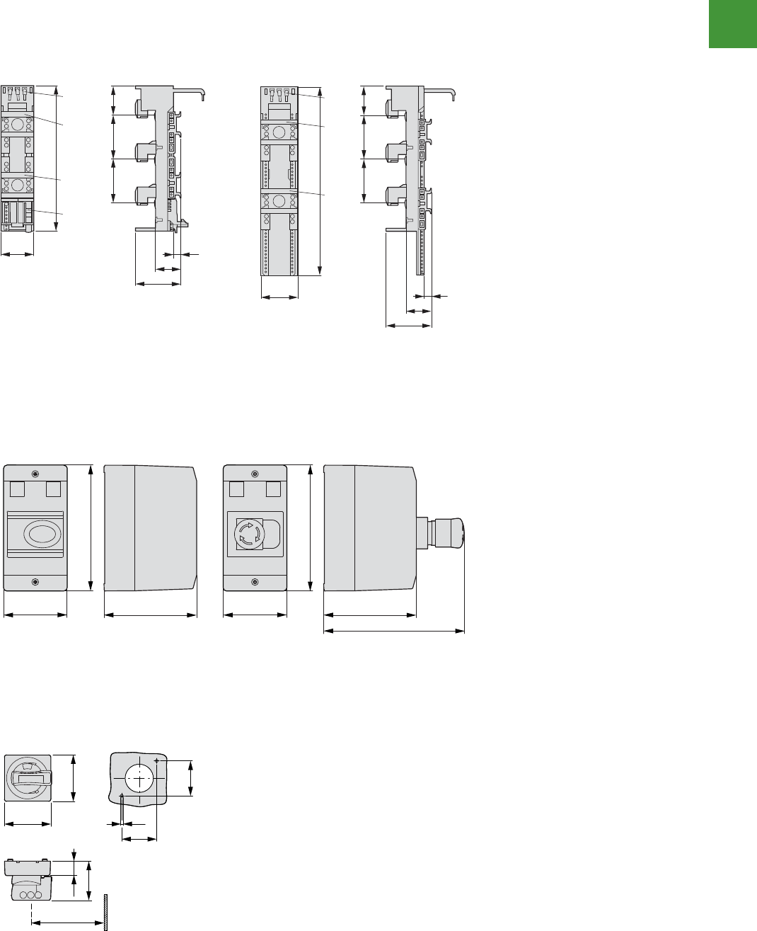
Motor control
Power control
234
2015/2016 Product guide AUS15_007 - February 2016
7/40 Motor-protective circuit-breakers PKZM01, PKZM0, PKZM4, PKE
Busbar adapters
2010 CA08103002Z-EN www.eaton.com
Busbar adapters
L-ST2/4ABB36-2ABB
52-0ABB
36-L4ABBST2/36-2ABB
ST2/52-0ABB
BBA0/2TS-L
BBA0-32
BBA0-32/2TS-C
BBA0C-16
36-L2ABBS-ST2/08-2ABB36-4ABB
L54CX-0MZKP23-K0ABB52-L0ABB
BBA0L-32 PKZM0-XC45L-2
200
45
35
63
10
40
6060
a b c
e f
a b c
d e f
a c d
a b
e f
a BBA0-32/2TS-C
b BBA0-25/2TS
c BBA0C-16
d BBA0/2TS-L
e BBA0-25
f BBA0-32
200
72
35
63
10
40
6060
a
a BBA2-63/2TS
b BBA2-63
a b
35
63
10
40
6060
260
55
a
a b
a b
a BBA4L-63
b BBA4/2TS-L
35
63
10
40
6060
200
55
214
72
40
6060
35
63
10
260
72
35
63
10
40
6060
260
45
a b
b
a BBA0L-25
b BBA0L-32
35
63
10
40
6060
161
45
20
6060
35
63
10
283
45
20
40
10
a b
b
a PKZM0-XC45L
b PKZM0-XC45L-2
BBA
7/40 Motor-protective circuit-breakers PKZM01, PKZM0, PKZM4, PKE
Busbar adapters
2010 CA08103002Z-EN www.eaton.com
Busbar adapters
L-ST2/4ABB
36-2ABB52-0ABB
36-L4ABB
ST2/36-2ABBST2/52-0ABB
BBA0/2TS-L
BBA0-32
BBA0-32/2TS-C
BBA0C-16
36-L2ABBS-ST2/08-2ABB36-4ABB
L54CX-0MZKP23-K0ABB52-L0ABB
BBA0L-32 PKZM0-XC45L-2
200
45
35
63
10
40
6060
a b c
e f
a b c
d e f
a c d
a b
e f
a BBA0-32/2TS-C
b BBA0-25/2TS
c BBA0C-16
d BBA0/2TS-L
e BBA0-25
f BBA0-32
200
72
35
63
10
40
6060
a
a BBA2-63/2TS
b BBA2-63
a b
35
63
10
40
6060
260
55
a
a b
a b
a BBA4L-63
b BBA4/2TS-L
35
63
10
40
6060
200
55
214
72
40
6060
35
63
10
260
72
35
63
10
40
6060
260
45
a b
b
a BBA0L-25
b BBA0L-32
35
63
10
40
6060
161
45
20
6060
35
63
10
283
45
20
40
10
a b
b
a PKZM0-XC45L
b PKZM0-XC45L-2
BBA
7/42 Motor-protective circuit-breakers PKZM01, PKZM0, PKZM4, PKE
Accessories
2010 CA08103002Z-EN www.eaton.com
Accessories
Door coupling handles
PKZ0-X(R)H…
Mounting depth: 100 to 240 mm
from the top edge of the top-hat rail
to the front edge of the cabinet
door/cover
Distance between switch axis and
cover hinge: at least 100 mm
①
At least 100 mm from cover hinge
Insulated enclosures for flush mounting Mounting aperture E-PKZ0…
E-PKZ0 E-PKZ0-G…
E-PKZ0-G… + SVB-PKZ0-E
Insulated enclosures for surface mounting Mounting plates
CI23E… M3-CI23
54
20
64
64
48
48
7.5
a
69
85
129
96
80
124
55
R4
70–72
116 – 118
98
30
58
55
80
96
124
85
129
30
28
21
98
30
58
55
80
96
124
3
3
25
25
187.5
250
162
200
215
225
262
278
56
114
144
147
177
35
60
90
147
177
7knockout
8 x PG 16
2 x PG 21/29
142.5
205
62.5
125
14
27
84.5
114.5
92
14
27
84.5
114.5
92
6 × PG 16
1 × PG 21/29
BBA
Busbar adaptors
Motor-protective circuit-breakers PKZM01, PKZM0, PKZM4, PKE
Accessories
2010 CA08103002Z-EN www.eaton.com
7/43
Accessories
Accessories
Accessories
Insulated enclosures for surface mounting
CI-PKZ01 CI-PKZ01-PVT CI-PKZ01-SVB
CI-PKZ01-G CI-PKZ01-PVS CI-PKZ01-SVB-V
Insulated enclosures for flush mounting
E-PKZ01 E-PKZ01-PVT
E-PKZ01-G E-PKZ01-PVS
E-PKZ01-SVB
E-PKZ01-SVB-V
80
158
116.5 80
158
116.5
177.2
80
158
116.5
129.5
69
90.2 93
115.2
129
69
90.2 93
115.2
175.9
129
69
90.2 93
115.2
128.2
129
PKZM01
Insulated enclosures for surface mounting
Door coupling handles
Dimensions
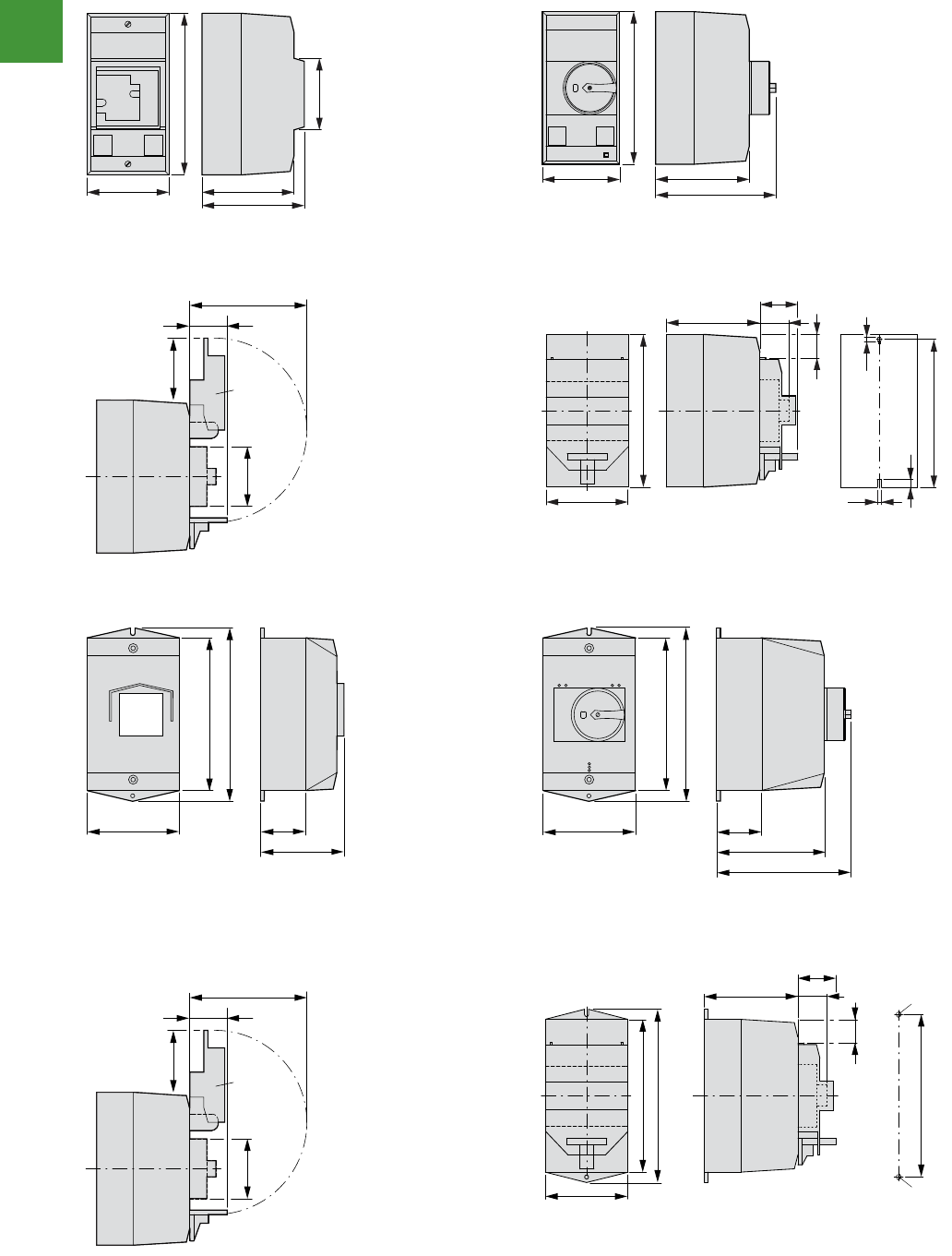
Motor control
Power control
235 2015/2016 Product guide AUS15_007 - February 2016
Motor-protective circuit-breakers PKZM01, PKZM0, PKZM4, PKE
Accessories
2010 CA08103002Z-EN www.eaton.com
7/41
Accessories
Insulated enclosures for surface mounting
M...G01ZKP-ICM-0ZKP-IC
80
158
90
100
70
80
158
97.5
125.5
CI-PKZ0-…M
+ SVB-PKZ0-CI
98
30
44
55
SVB-PKZ0-CI
Drilling dimensions
CI-PKZ0-…M
80
158
28
33
97.5
4.5
153
8
30
4.5
)V()R(G0ZKP-2K-IC0ZKP-2K-IC
100
160
47.5
104
181
100
160
47.5
103
130
181
CI-K2-PKZ0-G(R)(V)
+ SVB-PKZ0-CI
98
30
44
55
SVB-PKZ0-CI
Drilling dimensions
CI-K2-PKZ0…
97
181
28
33
114
171
M4
M4
30
160
PKZM01, PKZM0
Insulated enclosures for surface mounting
Drilling dimensions
Drilling dimensions
Dimensions
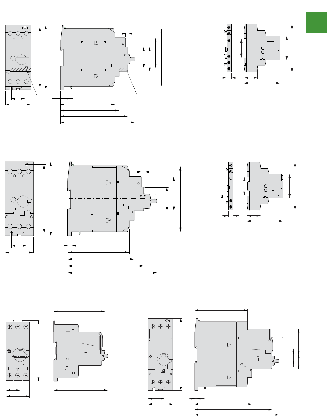
Motor control
Power control
236
2015/2016 Product guide AUS15_007 - February 2016
7/44 Motor-protective circuit-breakers PKZM01, PKZM0, PKZM4, PKE
Accessories
2010 CA08103002Z-EN www.eaton.com
Motor-protective circuit-br ixua dradnatSrekae liary contacts
PKZM4-… NHI…-PKZ…
NHI…-PKZ0
30 NHI-E... 7.5
118
127
145
160
55
130
140
125
65
53
45
4
NHI-E...
926
68
45
90
36
Motor-protective circuit-breakers with lockable srotacidni pirTrevoc
PKZM4-… +AK-PKZ0 AGM2…-PKZ…
AGM2…-PKZ0
30 7.5
118
127
145
171
55
130
140
125
65
45
4
AK-PKZ0
9 26
68
45
90
36
PKE Motor-protective circuit-breakers
56EKP23EKP , 21EKP
101
102.5
100.5
25
45
56.5
160
32.5
35 5.5
55 127
118
172
187
14.5
PKZM4, PKE
Motor-protective circuit breakers
Motor-protective circuit breakers with lockable cover
PKE Motor-protective circuit breakers
Standard auxiliary contacts
Trup indicators
Dimensions
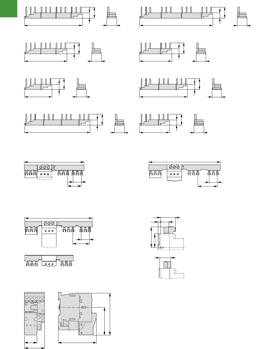
Motor control
Power control
237 2015/2016 Product guide AUS15_007 - February 2016
Motor-protective circuit-breakers PKZM01, PKZM0, PKZM4, PKE
Accessories
2010 CA08103002Z-EN www.eaton.com
7/45
Accessories
Motor plug DILM12-XMCP/T
Three-phase commoning links
4ZKP-4/2.3B4ZKP-4/0.3B
4ZKP-2/2.3B4ZKP-3/0.3B
4ZKP-3/1.3B4ZKP-2/0.3B
4ZKP-2/1.3B4ZKP-4/1.3B
14
205
36
33 33
14
260
36
14
151
36
33
14
115
36
33
14
98
36
33 33
14
170
36
33
14
232
36
33
14
117
36
Accessories sknil gninommoc esahp-eerhTsknil gninommoc esahp-eerhT
B3.0/4-PKZ0 B3.2/4-PKZ0
B3.0/2-PKZ0 B3.2/2-PKZ0
180 (90)
H-B3-
PKZ 0 27
45
234
H-B3-
PKZ0 27
63
slanimret gnimocnIsknil gninommoc esahp-eerhT
0ZKP-3/52KB0ZKP-3/1.3B0ZKP-5/1.3B
B3.1/4-PKZ0 B3.1/2-PKZ0
Overlapping
mounting to
extend the
three-phase
commoning link
H-B3-
PKZ 0 27
261 (207, 153, 99)
54
BK25/3-PKZ0
F 41
73
7.5 31
48
F 56
B3...-PKZ0
45
62
94
27 85
PKZM0, PKZM4
Three-phase commoning links
Incoming terminals
Motor plug DILM12-XMCP/T
Dimensions
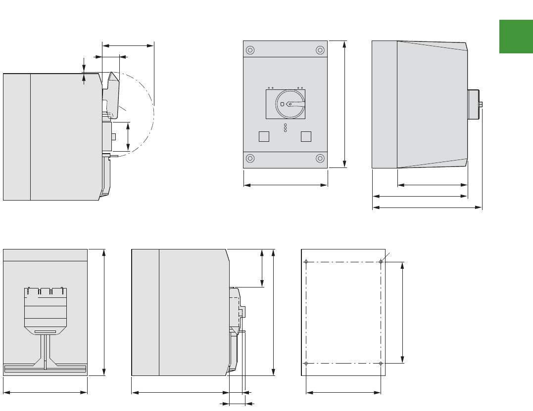
Motor control
Power control
238
2015/2016 Product guide AUS15_007 - February 2016
7/46 Motor-protective circuit-breakers PKZM01, PKZM0, PKZM4, PKE
Accessories
2010 CA08103002Z-EN www.eaton.com
G-4ZKP-4K-IC)R(G-4ZKP-4K-IC
+SVB-PKZ4-CI
Drilling dimensions
CI-K4-PKZ-G(R)
32
98
SVB-PKZ4-CI
72
3
160
240
134
181
197
160 186 28
30
240
240
193
142
o 5.6
72
PKZM4
Insulated enclosures for surface mounting
Dimensions
Reduce cost throughout the
value chain.
SmartWire-DT reduces wiring
time and effort, which in turn
reduces costs. From design
through construction to
commissioning and system
expansion, SmartWire-DT
creates value at every step.
SmartWire-DT works with third-
party PLC controllers and industry
standard networks to connect
motor starters and pilot devices
without conventional
point-to-point wiring.
SmartWire-DT™
Changing the way
panels are wired.
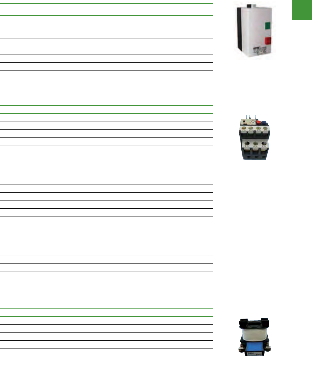
Motor control
Power control
240
2015/2016 Product guide AUS15_007 - February 2016
DOL Starters
DOL starters
IP65 Surface mounting starter, fitted with start & stop/reset pushbuttons.
kW(400 -
415VAC) AC-3 Amps Coil voltage Aux.
contacts
Dimensions
(W x H x D) mm Item no.
4 11 240 1NO 90 x 184 x 113 EDOL40NO240
5.5 12 240 1NO 90 x 184 x 113 EDOL55NO240
7.5 16 240 1NO 90 x 184 x 113 EDOL75NO240
11 22 240 1NO 100 x 194 x 123 EDOL11NO240
4 11 415 1NO 90 x 184 x 113 EDOL40NO415
5.5 12 415 1NO 90 x 184 x 113 EDOL55NO415
7.5 16 415 1NO 90 x 184 x 113 EDOL75NO415
11 22 415 1NO 100 x 194 x 123 EDOL11NO415
Order Overloads Separately.
Overload relays
Full load current (A) Item no.
0.35 - 0.5 EDOL045TOL
0.45 - 0.63 EDOL063TOL
0.55 - 0.8 EDOL08TOL
0.75 - 1.0 EDOL10TOL
0.9 - 1.3 EDOL1P3TOL
1.1 - 1.6 EDOL1P6TOL
1.4 - 2.0 EDOL02TOL
1.8 - 2.5 EDOL25TOL
2.3 - 3.2 EDOL32TOL
2.9 - 4.0 EDOL04TOL
3.5 - 4.8 EDOL48TOL
4.5 - 6.3 EDOL63TOL
5.5 - 7.5 EDOL75TOL
7.2 - 10 EDOL100TOL
9.0 - 12.5 EDOL125TOL
11.3 - 16 EDOL16TOL
15.0 - 20.0 EDOL20TOL
17.5 - 21.5 EDOL215TOL
21.0 - 25.0 EDOL250TOL
24.5 - 30.0 EDOL30TOL
1NO/1NC Electrically Separated Auxiliary Contacts.
Single - phase sensitivity for phase imbalance & phase loss protection.
Temperature Compensated.
Spare coils
Coil voltage (AC) Item no.
24V EDOLCOIL24A
32V EDOLCOIL32A
110V EDOLCOIL110A
240V EDOLCOIL240A
415V EDOLCOIL415A
480V EDOLCOIL480A
12V EDOLCOIL12A
Coils suit all starter sizes.
EDOL4DNO240
EDOL25TOL
EDOLCOIL240A
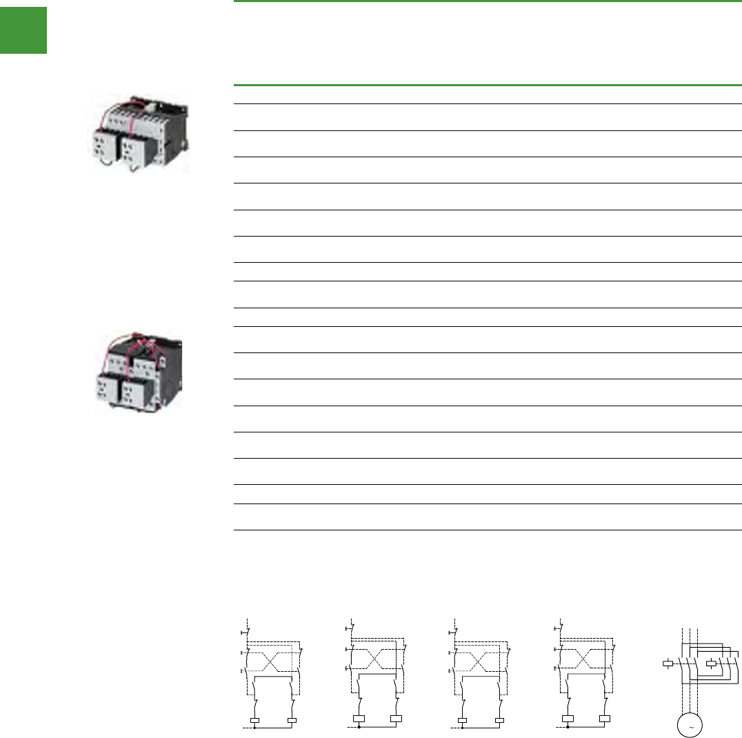
Motor control
Power control
241 2015/2016 Product guide AUS15_007 - February 2016
DOL starters
Reversing DOL starters
Rated
operational
current
Max. rating for
three-phase motors,
50 – 60 Hz
Individual components of the
combination
AC operation
Item no.
AC-3, 415 V
Ie, A
AC-3,
380/415 V
P, kW
AC-4,
380/415 V
P, kW
Contactor Q11
Item no.
Contactor Q12
Item no.
Open units
9 4 2.5 DILM9-01
+ DILA-XHI20
DILM9-01
+ DILA-XHI20 DOLRS4/U(...V50HZ)
12 5.5 3 DILM12-01
+ DILA-XHI20
DILM12-01
+ DILA-XHI20 DOLRS5.5/U(...V50HZ
18 7.5 4.5 DILM17-01
+ DILA-XHI20
DILM17-01
+ DILA-XHI20 DOLRS7.5/U(...V50HZ)
25 11 6 DILM25-01
+ DILA-XHI20
DILM25-01
+ DILA-XHI20 DOLRS11/U(...V50HZ)
32 15 7 DILM32-01
+ DILA-XHI20
DILM32-01
+ DILA-XHI20 DOLRS15/U(...V50HZ)
40 18.5 9 DILM40
+ DILM150-XHI11
DILM40
+ DILM150-XHI11 DOLRS18.5/U(...V50HZ)
50 22 10 - - DOLRS22/U(...V50HZ)
65 30 12 DILM65
+ DILM150-XHI11
DILM65
+ DILM150-XHI11 DOLRS30/U(...V50HZ)
Enclosed units
9 4 2.5 DILM9-01
+ DILA-XHI20
DILM9-01
+ DILA-XHI20 DOLRS4/I(...V50HZ)
12 5.5 3 DILM12-01
+ DILA-XHI20
DILM12-01
+ DILA-XHI20 DOLRS5.5/I(...V50HZ)
18 7.5 4.5 DILM17-01
+ DILA-XHI20
DILM17-01
+ DILA-XHI20 DOLRS7.5/I(...V50HZ)
25 11 6 DILM25-01
+ DILA-XHI20
DILM25-01
+ DILA-XHI20 DOLRS11/I(...V50HZ)
32 15 7 DILM32-01
+ DILA-XHI20
DILM32-01
+ DILA-XHI20 DOLRS15/I(...V50HZ)
40 18.5 9 DILM40
+ DILM150-XHI11
DILM40
+ DILM150-XHI11
DOLRS18.5/I(...V50HZ)
50 22 10 - - DOLRS22/I(...V50HZ)
65 30 12 DILM65
+ DILM150-XHI11
DILM65
+ DILM150-XHI11 DOLRS30/I(...V50HZ)
Specify voltage & frequency when ordering.
Standard voltages: V AC: 24 V, 110 V, 240 V, 415 V at 50 Hz.
Non-standard voltages: V AC: 12 – 600 V at 50 or 60 Hz. V DC: 12 – 250 V.
ForDCvoltageaddsufx“-G”toItemNo.
N.B.additionalchargeapplies.Pleaseenquirefornon-standardcongurations.
Moeller SK0211-1158GB-AUS
5/10
Moeller SK0211-1158GB-AUS
Contactors
Contactors
GST not included
Contactor combinations Contactor combinations
Reversing combinations Reversing combinations
AC operation
Rated
operational
current
Max. rating for three-phase
motors, 50 – 60 Hz
Part no. Price ($)
Product
group 0
Individual components of the combination Spare auxiliary contacts Notes Notes
AC-3 AC-3 AC-4 Contactor Q11 Contactor Q12 Q11 Q12 Mechanical
interlock
415 V 380/415 V 380/415 V
IePP Part no. Part no.
AkW kW
Reversing combinations
Open units 942.5 DOLRS4/U(...V50HZ)1) 500.90 DILM9-01
+ DILA-XHI20
DILM9-01
+ DILA-XHI20
12 5.5 3DOLRS5.5/U(...V50HZ1) 578.80 DILM12-01
+ DILA-XHI20
DILM12-01
+ DILA-XHI20
+
18 7.5 4.5 DOLRS7.5/U(...V50HZ)1) 634.50 DILM17-01
+ DILA-XHI20
DILM17-01
+ DILA-XHI20
+
25 11 6DOLRS11/U(...V50HZ)1) 768.00 DILM25-01
+ DILA-XHI20
DILM25-01
+ DILA-XHI20
+
32 15 7DOLRS15/U(...V50HZ)1) 957.20 DILM32-01
+ DILA-XHI20
DILM32-01
+ DILA-XHI20
+
40 18.5 9 DOLRS18.5/U(...V50HZ)1) 1,035.10 DILM40
+ DILM150-XHI11
DILM40
+ DILM150-XHI11
––+
50 22 10 DOLRS22/U(...V50HZ)1) 1,246.60
65 30 12 DOLRS30/U(...V50HZ)1) 1,446.90 DILM65
+ DILM150-XHI11
DILM65
+ DILM150-XHI11
––+
Enclosed units 942.5 DOLRS4/I(...V50HZ)1) 656.70 DILM9-01
+ DILA-XHI20
DILM9-01
+ DILA-XHI20
+
12 5.5 3DOLRS5.5/I(...V50HZ)1) 667.80 DILM12-01
+ DILA-XHI20
DILM12-01
+ DILA-XHI20
+
18 7.5 4.5 DOLRS7.5/I(...V50HZ)1) 857.10 DILM17-01
+ DILA-XHI20
DILM17-01
+ DILA-XHI20
+
25 11 6DOLRS11/I(...V50HZ)1) 1,090.80 DILM25-01
+ DILA-XHI20
DILM25-01
+ DILA-XHI20
+
32 15 7DOLRS15/I(...V50HZ)1) 1,357.90 DILM32-01
+ DILA-XHI20
DILM32-01
+ DILA-XHI20
40 18.5 9 DOLRS18.5/I(...V50HZ)1) 1,357.90 DILM40
+ DILM150-XHI11
DILM40
+ DILM150-XHI11
––+
50 22 10 DOLRS22/I(...V50HZ)1) 1,736.30
65 30 12 DOLRS30/I(...V50HZ)1) 1,903.30 DILM65
+ DILM150-XHI11
DILM65
+ DILM150-XHI11
––+
Notes 1) Specify voltage and frequency when ordering.
Standard voltages: V AC: 24 V, 110 V, 240 V, 415 V at 50 Hz
Non-standard voltages: V AC: 12 – 600 V at 50 or 60 Hz
V DC: 12 – 250 V
For DC voltage add suffix “-G” to part no.
N.B. additional charge applies.
Please enquire for non-standard configurations.
64
63
64
63
Q12
54
Q11
54
53 53
Q12
22
21
Q11
22
21
Q11
A1
A2
Q12
A1
A2
I
14
13
13
II
21
22
22
21
21
22
0
14
Reversing contactors
UVW
Q11
M
M1
Q12
135
64
2
13 5
6
4
2
3
64
63
64
63
64
63
64
63
64
63
64
63
64
63
64
63
Q12
14
Q11
14
13 13
Q12
22
21
Q11
22
21
Q11
A1
A2
Q12
A1
A2
(-)N
I
14
13
13
II
21
22
22
21
21
22
0
14
64
63
64
63
Q12
54
Q11
54
53 53
Q12
22
21
Q11
22
21
Q11
A1
A2
Q12
A1
A2
I
14
13
13
II
21
22
22
21
21
22
0
14
Reversing contactors
UVW
Q11
M
M1
Q12
135
64
2
13 5
6
4
2
3
64
63
64
63
64
63
64
63
64
63
64
63
64
63
64
63
Q12
14
Q11
14
13 13
Q12
22
21
Q11
22
21
Q11
A1
A2
Q12
A1
A2
(-)N
I
14
13
13
II
21
22
22
21
21
22
0
14
5/11
SK1158AUS_05_008-011.fm Seite 10 Donnerstag, 2. Oktober 2008 3:38 15
Moeller SK0211-1158GB-AUS
5/10
Moeller SK0211-1158GB-AUS
Contactors
Contactors
GST not included
Contactor combinations Contactor combinations
Reversing combinations Reversing combinations
AC operation
Rated
operational
current
Max. rating for three-phase
motors, 50 – 60 Hz
Part no. Price ($)
Product
group 0
Individual components of the combination Spare auxiliary contacts Notes Notes
AC-3 AC-3 AC-4 Contactor Q11 Contactor Q12 Q11 Q12 Mechanical
interlock
415 V 380/415 V 380/415 V
IePP Part no. Part no.
AkW kW
Reversing combinations
Open units 942.5 DOLRS4/U(...V50HZ)1) 500.90 DILM9-01
+ DILA-XHI20
DILM9-01
+ DILA-XHI20
12 5.5 3DOLRS5.5/U(...V50HZ1) 578.80 DILM12-01
+ DILA-XHI20
DILM12-01
+ DILA-XHI20
+
18 7.5 4.5 DOLRS7.5/U(...V50HZ)1) 634.50 DILM17-01
+ DILA-XHI20
DILM17-01
+ DILA-XHI20
+
25 11 6DOLRS11/U(...V50HZ)1) 768.00 DILM25-01
+ DILA-XHI20
DILM25-01
+ DILA-XHI20
+
32 15 7DOLRS15/U(...V50HZ)1) 957.20 DILM32-01
+ DILA-XHI20
DILM32-01
+ DILA-XHI20
+
40 18.5 9 DOLRS18.5/U(...V50HZ)1) 1,035.10 DILM40
+ DILM150-XHI11
DILM40
+ DILM150-XHI11
––+
50 22 10 DOLRS22/U(...V50HZ)1) 1,246.60
65 30 12 DOLRS30/U(...V50HZ)1) 1,446.90 DILM65
+ DILM150-XHI11
DILM65
+ DILM150-XHI11
––+
Enclosed units 942.5 DOLRS4/I(...V50HZ)1) 656.70 DILM9-01
+ DILA-XHI20
DILM9-01
+ DILA-XHI20
+
12 5.5 3DOLRS5.5/I(...V50HZ)1) 667.80 DILM12-01
+ DILA-XHI20
DILM12-01
+ DILA-XHI20
+
18 7.5 4.5 DOLRS7.5/I(...V50HZ)1) 857.10 DILM17-01
+ DILA-XHI20
DILM17-01
+ DILA-XHI20
+
25 11 6DOLRS11/I(...V50HZ)1) 1,090.80 DILM25-01
+ DILA-XHI20
DILM25-01
+ DILA-XHI20
+
32 15 7DOLRS15/I(...V50HZ)1) 1,357.90 DILM32-01
+ DILA-XHI20
DILM32-01
+ DILA-XHI20
40 18.5 9 DOLRS18.5/I(...V50HZ)1) 1,357.90 DILM40
+ DILM150-XHI11
DILM40
+ DILM150-XHI11
––+
50 22 10 DOLRS22/I(...V50HZ)1) 1,736.30
65 30 12 DOLRS30/I(...V50HZ)1) 1,903.30 DILM65
+ DILM150-XHI11
DILM65
+ DILM150-XHI11
––+
Notes 1) Specify voltage and frequency when ordering.
Standard voltages: V AC: 24 V, 110 V, 240 V, 415 V at 50 Hz
Non-standard voltages: V AC: 12 – 600 V at 50 or 60 Hz
V DC: 12 – 250 V
For DC voltage add suffix “-G” to part no.
N.B. additional charge applies.
Please enquire for non-standard configurations.
64
63
64
63
Q12
54
Q11
54
53 53
Q12
22
21
Q11
22
21
Q11
A1
A2
Q12
A1
A2
I
14
13
13
II
21
22
22
21
21
22
0
14
Reversing contactors
UVW
Q11
M
M1
Q12
135
64
2
13 5
6
4
2
3
64
63
64
63
64
63
64
63
64
63
64
63
64
63
64
63
Q12
14
Q11
14
13 13
Q12
22
21
Q11
22
21
Q11
A1
A2
Q12
A1
A2
(-)N
I
14
13
13
II
21
22
22
21
21
22
0
14
64
63
64
63
Q12
54
Q11
54
53 53
Q12
22
21
Q11
22
21
Q11
A1
A2
Q12
A1
A2
I
14
13
13
II
21
22
22
21
21
22
0
14
Reversing contactors
UVW
Q11
M
M1
Q12
135
64
2
13 5
6
4
2
3
64
63
64
63
64
63
64
63
64
63
64
63
64
63
64
63
Q12
14
Q11
14
13 13
Q12
22
21
Q11
22
21
Q11
A1
A2
Q12
A1
A2
(-)N
I
14
13
13
II
21
22
22
21
21
22
0
14
5/11
SK1158AUS_05_008-011.fm Seite 10 Donnerstag, 2. Oktober 2008 3:38 15
Reversing contactors
DOLRS4/u(...V50HZ)
DOLRS4/I(...V50HZ)
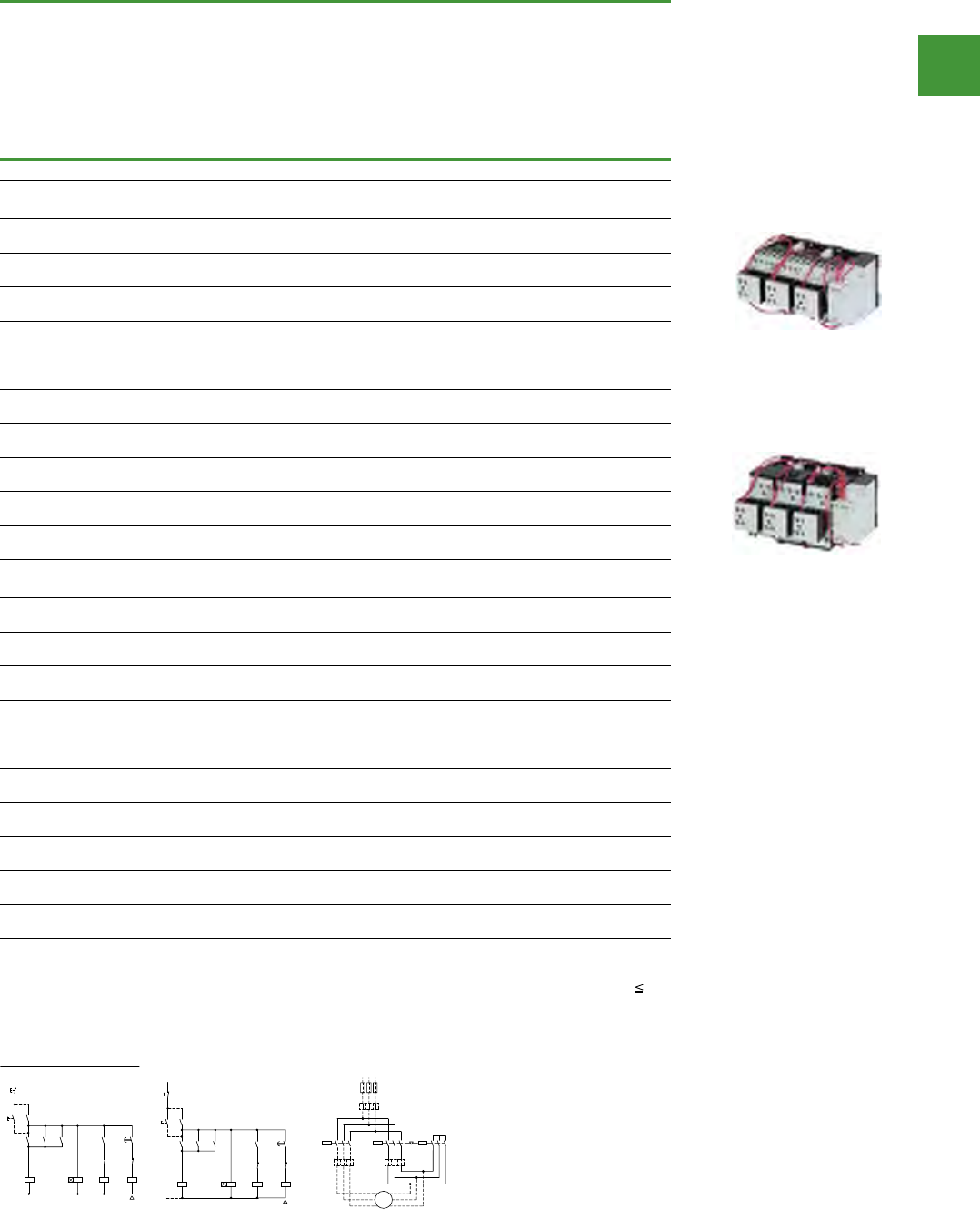
Motor control
Power control
242
2015/2016 Product guide AUS15_007 - February 2016
Star-delta starters
Rated
operational
current
Max. rating for
three-phase
motors,
50 – 60 Hz
Max.
changeover
time
Individual components of the combination Item no.
AC-3,
380/415 V
Ie, A
AC-3,
380/415 V
P, kW
SMains contactor
Q11 Item No.
Delta contactor
Q15 Item No.
Star contactor
Q13 Item No.
Star-delta starter combinations
Open units
Timing relay K1T: ETR4-51, Complete with overload
12 5.5 20 DILM7-10
+ DILA-XHI20
DILM7-01
+ DILA-XHI20
DILM7-01
+ DILA-XHI20 SDES5.5/U(...)
16 7.5 20 DILM9-10
+ DILA-XHI20
DILM9-01
+ DILA-XHI20
DILM7-01
+ DILA-XHI20 SDES7.5/U(...)
22 11 20 DILM12-10
+ DILA-XHI20
DILM12-01
+ DILA-XHI20
DILM7-01
+ DILA-XHI20 SDES11/U(...)
30 15 20 DILM17-10
+ DILA-XHI20
DILM17-01
+ DILA-XHI20
DILM17-01
+ DILA-XHI20 SDES15/U(...)
45 22 20 DILM25-10
+ DILA-XHI20
DILM25-01
+ DILA-XHI20
DILM17-01
+ DILA-XHI20 SDES22/U(...)
55 30 20 DILM32-10
+ DILA-XHI20
DILM32-01
+ DILA-XHI20
DILM25-01
+ DILA-XHI20 SDES30/U(...)
70 37 20 DILM40
+ DILM150-XHI11
DILM40
+ DILM150-XHI31
DILM40
+ DILM150-XHI11 SDES37/U(...)
90 45 20 DILM50
+ DILM150-XHI11
DILM50
+ DILM150-XHI31
DILM40
+ DILM150-XHI11 SDES45/U(...)
115 55 20 DILM65
+ DILM150-XHI11
DILM65
+ DILM150-XHI31
DILM40
+ DILM150-XHI11 SDES55/U(...)
140 75 20 DILM80
+ DILM150-XHI11
DILM80
+ DILM150-XHI31
DILM50
+ DILM150-XHI11 SDES75/U(...)
Enclosed units
Complete with pushbutton & overload, According to IEC 60947
12 5.5 20 DILM7-10
+ DILA-XHI20
DILM7-01
+ DILA-XHI20
DILM7-01
+ DILA-XHI20 SDES5.5/I(...)
16 7.5 20 DILM9-10
+ DILA-XHI20
DILM9-01
+ DILA-XHI20
DILM7-01
+ DILA-XHI20 SDES7.5/I(...)
22 11 20 DILM12-10
+ DILA-XHI20
DILM12-01
+ DILA-XHI20
DILM7-01
+ DILA-XHI20 SDES11/I(...)
30 15 20 DILM17-10
+ DILA-XHI20
DILM17-01
+ DILA-XHI20
DILM17-01
+ DILA-XHI20 SDES15/I(...)
45 22 20 DILM25-10
+ DILA-XHI20
DILM25-01
+ DILA-XHI20
DILM17-01
+ DILA-XHI20 SDES22/I(...)
55 30 20 DILM32-10
+ DILA-XHI20
DILM32-01
+ DILA-XHI20
DILM25-01
+ DILA-XHI20 SDES30/I(...)
70 37 20 DILM40
+ DILM150-XHI11
DILM40
+ DILM150-XHI31
DILM40
+ DILM150-XHI11 SDES37/I(...)
90 45 20 DILM50
+ DILM150-XHI11
DILM50
+ DILM150-XHI31
DILM40
+ DILM150-XHI11 SDES45/I(...)
115 55 20 DILM65
+ DILM150-XHI11
DILM65
+ DILM150-XHI31
DILM40
+ DILM150-XHI11 SDES55/I(...)
140 75 20 DILM80
+ DILM150-XHI11
DILM80
+ DILM150-XHI31
DILM50
+ DILM150-XHI11 SDES75/I(...)
Specify voltage & frequency when ordering.
Standard voltages: V AC: 24 V, 110 V, 240 V, 415 V at 50 Hz
Non-standard voltages: V AC: 12 – 600 V at 50 or 60 Hz, V DC: 12 – 250 V
ForDCvoltageaddsufx“-G”topartno.
N.B.additionalchargeapplies.pleaseenquirefornon-standardcongurations.
Moeller SK0211-1158GB-AUS
5/8
Moeller SK0211-1158GB-AUS
Contactors
Contactors
GST not included
Contactor combinations Contactor combinations
Star-delta combinations Star-delta combinations
Rated
operational
current
Max. rating for
three-phase
motors,
50 – 60 Hz
Max.
changeover
time
Part no. Price ($)
Product
group 0
Spare auxiliary
contacts
Individual components of the combination
SDES5.5 – SDES30
AC-3 AC-3 Q11 Q13 Q15 Mains contactor
Q11
Delta contactor
Q15
Star contactor
Q13
380 V
415 V
380 V
415 V
IePPart no. Part no. Part no.
AkW s
Star-delta starter combinations
Open units
• Timing relay K1T: ETR4-51
• Complete with overload
12 5.51) 20 SDES5.5/U(...)1) 723.50 DILM7-10
+ DILA-XHI20
DILM7-01
+ DILA-XHI20
DILM7-01
+ DILA-XHI20
SDES37 – SDES75
16 7.5 20 SDES7.5/U(...)1) 723.50 DILM9-10
+ DILA-XHI20
DILM9-01
+ DILA-XHI20
DILM7-01
+ DILA-XHI20
22 11 20 SDES11/U(...)1) 768.00 DILM12-10
+ DILA-XHI20
DILM12-01
+ DILA-XHI20
DILM7-01
+ DILA-XHI20
30 15 20 SDES15/U(...)1) 946.10 DILM17-10
+ DILA-XHI20
DILM17-01
+ DILA-XHI20
DILM17-01
+ DILA-XHI20
45 22 20 SDES22/U(...)1) 968.40 DILM25-10
+ DILA-XHI20
DILM25-01
+ DILA-XHI20
DILM17-01
+ DILA-XHI20
55 30 20 SDES30/U(...)1) 1,101.90 DILM32-10
+ DILA-XHI20
DILM32-01
+ DILA-XHI20
DILM25-01
+ DILA-XHI20
70 37 20 SDES37/U(...)1) 1,335.60 –– DILM40
+ DILM150-XHI11
DILM40
+ DILM150-XHI31
DILM40
+ DILM150-XHI11
90 45 20 SDES45/U(...)1) 1,558.20 –– DILM50
+ DILM150-XHI11
DILM50
+ DILM150-XHI31
DILM40
+ DILM150-XHI11
115 55 20 SDES55/U(...)1) 1,669.50 –– DILM65
+ DILM150-XHI11
DILM65
+ DILM150-XHI31
DILM40
+ DILM150-XHI11
140 75 20 SDES75/U(...)1) 3,172.10 –– DILM80
+ DILM150-XHI11
DILM80
+ DILM150-XHI31
DILM50
+ DILM150-XHI11
Enclosed units
• Complete with pushbutton and overload
• According to IEC 60947
12 5.5 20 SDES5.5/I(...)1) 990.60 DILM7-10
+ DILA-XHI20
DILM7-01
+ DILA-XHI20
DILM7-01
+ DILA-XHI20
16 7.5 20 SDES7.5/I(...)1) 990.60 DILM9-10
+ DILA-XHI20
DILM9-01
+ DILA-XHI20
DILM7-01
+ DILA-XHI20
22 11 20 SDES11/I(...)1) 1,046.30 DILM12-10
+ DILA-XHI20
DILM12-01
+ DILA-XHI20
DILM7-01
+ DILA-XHI20
30 15 20 SDES15/I(...)1) 1,224.30 DILM17-10
+ DILA-XHI20
DILM17-01
+ DILA-XHI20
DILM17-01
+ DILA-XHI20
45 22 20 SDES22/I(...)1) 1,335.60 DILM25-10
+ DILA-XHI20
DILM25-01
+ DILA-XHI20
DILM17-01
+ DILA-XHI20
55 30 20 SDES30/I(...)1) 1,613.90 DILM32-10
+ DILA-XHI20
DILM32-01
+ DILA-XHI20
DILM25-01
+ DILA-XHI20
70 37 20 SDES37/I(...)1) 1,881.00 –– DILM40
+ DILM150-XHI11
DILM40
+ DILM150-XHI31
DILM40
+ DILM150-XHI11
90 45 20 SDES45/I(...)1) 2,181.50 –– DILM50
+ DILM150-XHI11
DILM50
+ DILM150-XHI31
DILM40
+ DILM150-XHI11
115 55 20 SDES55/I(...)1) 2,292.80 –– DILM65
+ DILM150-XHI11
DILM65
+ DILM150-XHI31
DILM40
+ DILM150-XHI11
140 75 20 SDES75/I(...)1) 3,661.80 –– DILM80
+ DILM150-XHI11
DILM80
+ DILM150-XHI31
DILM50
+ DILM150-XHI11
Notes 1) Specify voltage and frequency when ordering.
Standard voltages: V AC: 24 V, 110 V, 240 V, 415 V at 50 Hz
Non-standard voltages: V AC: 12 – 600 V at 50 or 60 Hz
V DC: 12 – 250 V
For DC voltage add suffix “-G” to part no.
N.B. additional charge applies.
Please enquire for non-standard configurations.
S11
0
(–)N
Q11
Q13
Q13
Q15
K1
I
Q11
Q11
Q15
Q13
K1
Q15
NY
K1
21
22
13
14
A2
A1
A2
A1
13
14
22
21
28
17
17
18
14
13
13
14
43
44
A2
A1
A2
A1
22
21
64
63
64
63
64
63
S11
0
(–)N
Q11
Q13
Q13
Q15
K1
I
Q11
Q11
Q15
Q13
K1
Q15
NY
K1
21
22
13
14
A2
A1
A2
A1
13
14
22
21
28
17
17
18
14
13
13
14
43
44
A2
A1
A2
A1
22
21
Overload relay settings Starting
A: IN x 0.58
Protection of the motor in Y- and d configuration
F 15 s
B: IN x 1
Only partial motor protection in star position
15 – 40 s
C: IN x 0.58
Motor not protected in star position
> 40 s
Timing relay set to approx. 10 s
Main circuit:
Depending on the coordination type required (i.e. Type “1” or Type “2”) it must be established
whether the fuse protection and the input wiring for the mains contactor and delta contactor are to
be common or separate.
L1 L2 L3
F1
M1
Q13
0.58 x I
n
0.58 x I
n
3~
M
C
A
Q15Q11
V1
U1
W1
U2
W2
V2
135
246
135
246
135
246
B1 x I
n
64
63
64
63
64
63
64
63
64
63
64
63
64
63
64
63
64
63
64
63
64
63
64
63
64
63
64
63
64
63
21
22
33
34
21
22
33
34
21
22
33
34
21
22
33
34
64
63
64
63
64
63
64
63
64
63
64
63
64
63
64
63
64
63
64
63
64
63
64
63
64
63
64
63
64
63
64
63
64
63
64
63
21
22
33
34
21
22
33
34
21
22
33
34
21
22
33
34
5/9
SK1158AUS_05_008-011.fm Seite 8 Donnerstag, 2. Oktober 2008 3:38 15
Moeller SK0211-1158GB-AUS
5/8
Moeller SK0211-1158GB-AUS
Contactors
Contactors
GST not included
Contactor combinations Contactor combinations
Star-delta combinations Star-delta combinations
Rated
operational
current
Max. rating for
three-phase
motors,
50 – 60 Hz
Max.
changeover
time
Part no. Price ($)
Product
group 0
Spare auxiliary
contacts
Individual components of the combination SDES5.5 – SDES30
AC-3 AC-3 Q11 Q13 Q15 Mains contactor
Q11
Delta contactor
Q15
Star contactor
Q13
380 V
415 V
380 V
415 V
IePPart no. Part no. Part no.
AkW s
Star-delta starter combinations
Open units
• Timing relay K1T: ETR4-51
• Complete with overload
12 5.51) 20 SDES5.5/U(...)1) 723.50 DILM7-10
+ DILA-XHI20
DILM7-01
+ DILA-XHI20
DILM7-01
+ DILA-XHI20
SDES37 – SDES75
16 7.5 20 SDES7.5/U(...)1) 723.50 DILM9-10
+ DILA-XHI20
DILM9-01
+ DILA-XHI20
DILM7-01
+ DILA-XHI20
22 11 20 SDES11/U(...)1) 768.00 DILM12-10
+ DILA-XHI20
DILM12-01
+ DILA-XHI20
DILM7-01
+ DILA-XHI20
30 15 20 SDES15/U(...)1) 946.10 DILM17-10
+ DILA-XHI20
DILM17-01
+ DILA-XHI20
DILM17-01
+ DILA-XHI20
45 22 20 SDES22/U(...)1) 968.40 DILM25-10
+ DILA-XHI20
DILM25-01
+ DILA-XHI20
DILM17-01
+ DILA-XHI20
55 30 20 SDES30/U(...)1) 1,101.90 DILM32-10
+ DILA-XHI20
DILM32-01
+ DILA-XHI20
DILM25-01
+ DILA-XHI20
70 37 20 SDES37/U(...)1) 1,335.60 –– DILM40
+ DILM150-XHI11
DILM40
+ DILM150-XHI31
DILM40
+ DILM150-XHI11
90 45 20 SDES45/U(...)1) 1,558.20 –– DILM50
+ DILM150-XHI11
DILM50
+ DILM150-XHI31
DILM40
+ DILM150-XHI11
115 55 20 SDES55/U(...)1) 1,669.50 –– DILM65
+ DILM150-XHI11
DILM65
+ DILM150-XHI31
DILM40
+ DILM150-XHI11
140 75 20 SDES75/U(...)1) 3,172.10 –– DILM80
+ DILM150-XHI11
DILM80
+ DILM150-XHI31
DILM50
+ DILM150-XHI11
Enclosed units
• Complete with pushbutton and overload
• According to IEC 60947
12 5.5 20 SDES5.5/I(...)1) 990.60 DILM7-10
+ DILA-XHI20
DILM7-01
+ DILA-XHI20
DILM7-01
+ DILA-XHI20
16 7.5 20 SDES7.5/I(...)1) 990.60 DILM9-10
+ DILA-XHI20
DILM9-01
+ DILA-XHI20
DILM7-01
+ DILA-XHI20
22 11 20 SDES11/I(...)1) 1,046.30 DILM12-10
+ DILA-XHI20
DILM12-01
+ DILA-XHI20
DILM7-01
+ DILA-XHI20
30 15 20 SDES15/I(...)1) 1,224.30 DILM17-10
+ DILA-XHI20
DILM17-01
+ DILA-XHI20
DILM17-01
+ DILA-XHI20
45 22 20 SDES22/I(...)1) 1,335.60 DILM25-10
+ DILA-XHI20
DILM25-01
+ DILA-XHI20
DILM17-01
+ DILA-XHI20
55 30 20 SDES30/I(...)1) 1,613.90 DILM32-10
+ DILA-XHI20
DILM32-01
+ DILA-XHI20
DILM25-01
+ DILA-XHI20
70 37 20 SDES37/I(...)1) 1,881.00 –– DILM40
+ DILM150-XHI11
DILM40
+ DILM150-XHI31
DILM40
+ DILM150-XHI11
90 45 20 SDES45/I(...)1) 2,181.50 –– DILM50
+ DILM150-XHI11
DILM50
+ DILM150-XHI31
DILM40
+ DILM150-XHI11
115 55 20 SDES55/I(...)1) 2,292.80 –– DILM65
+ DILM150-XHI11
DILM65
+ DILM150-XHI31
DILM40
+ DILM150-XHI11
140 75 20 SDES75/I(...)1) 3,661.80 –– DILM80
+ DILM150-XHI11
DILM80
+ DILM150-XHI31
DILM50
+ DILM150-XHI11
Notes 1) Specify voltage and frequency when ordering.
Standard voltages: V AC: 24 V, 110 V, 240 V, 415 V at 50 Hz
Non-standard voltages: V AC: 12 – 600 V at 50 or 60 Hz
V DC: 12 – 250 V
For DC voltage add suffix “-G” to part no.
N.B. additional charge applies.
Please enquire for non-standard configurations.
S11
0
(–)N
Q11
Q13
Q13
Q15
K1
I
Q11
Q11
Q15
Q13
K1
Q15
NY
K1
21
22
13
14
A2
A1
A2
A1
13
14
22
21
28
17
17
18
14
13
13
14
43
44
A2
A1
A2
A1
22
21
64
63
64
63
64
63
S11
0
(–)N
Q11
Q13
Q13
Q15
K1
I
Q11
Q11
Q15
Q13
K1
Q15
NY
K1
21
22
13
14
A2
A1
A2
A1
13
14
22
21
28
17
17
18
14
13
13
14
43
44
A2
A1
A2
A1
22
21
Overload relay settings Starting
A: IN x 0.58
Protection of the motor in Y- and d configuration
F 15 s
B: IN x 1
Only partial motor protection in star position
15 – 40 s
C: IN x 0.58
Motor not protected in star position
> 40 s
Timing relay set to approx. 10 s
Main circuit:
Depending on the coordination type required (i.e. Type “1” or Type “2”) it must be established
whether the fuse protection and the input wiring for the mains contactor and delta contactor are to
be common or separate.
L1 L2 L3
F1
M1
Q13
0.58 x I
n
0.58 x I
n
3~
M
C
A
Q15Q11
V1
U1
W1
U2
W2
V2
1
35
246
135
246
135
246
B1 x I
n
64
63
64
63
64
63
64
63
64
63
64
63
64
63
64
63
64
63
64
63
64
63
64
63
64
63
64
63
64
63
21
22
33
34
21
22
33
34
21
22
33
34
21
22
33
34
64
63
64
63
64
63
64
63
64
63
64
63
64
63
64
63
64
63
64
63
64
63
64
63
64
63
64
63
64
63
64
63
64
63
64
63
21
22
33
34
21
22
33
34
21
22
33
34
21
22
33
34
5/9
SK1158AUS_05_008-011.fm Seite 8 Donnerstag, 2. Oktober 2008 3:38 15
Overload relay settings Starting
A: IN x 0.58 15 s
Protection of the motor in
Y- anddconguration
B: IN x 1 15 – 40 s
Only partial motor protection in
star position
C: IN x 0.58 > 40 s
Motor not protected in star position.
Timing relay set to approx. 10 s.
Main circuit:
Depending on the coordination type
required (i.e. Type “1” or Type “2”) it must
be established whether the fuse protection
and the input wiring for the mains contactor
and delta contactor are to be common or
separate.
SDES5.5-U
SDES15-U
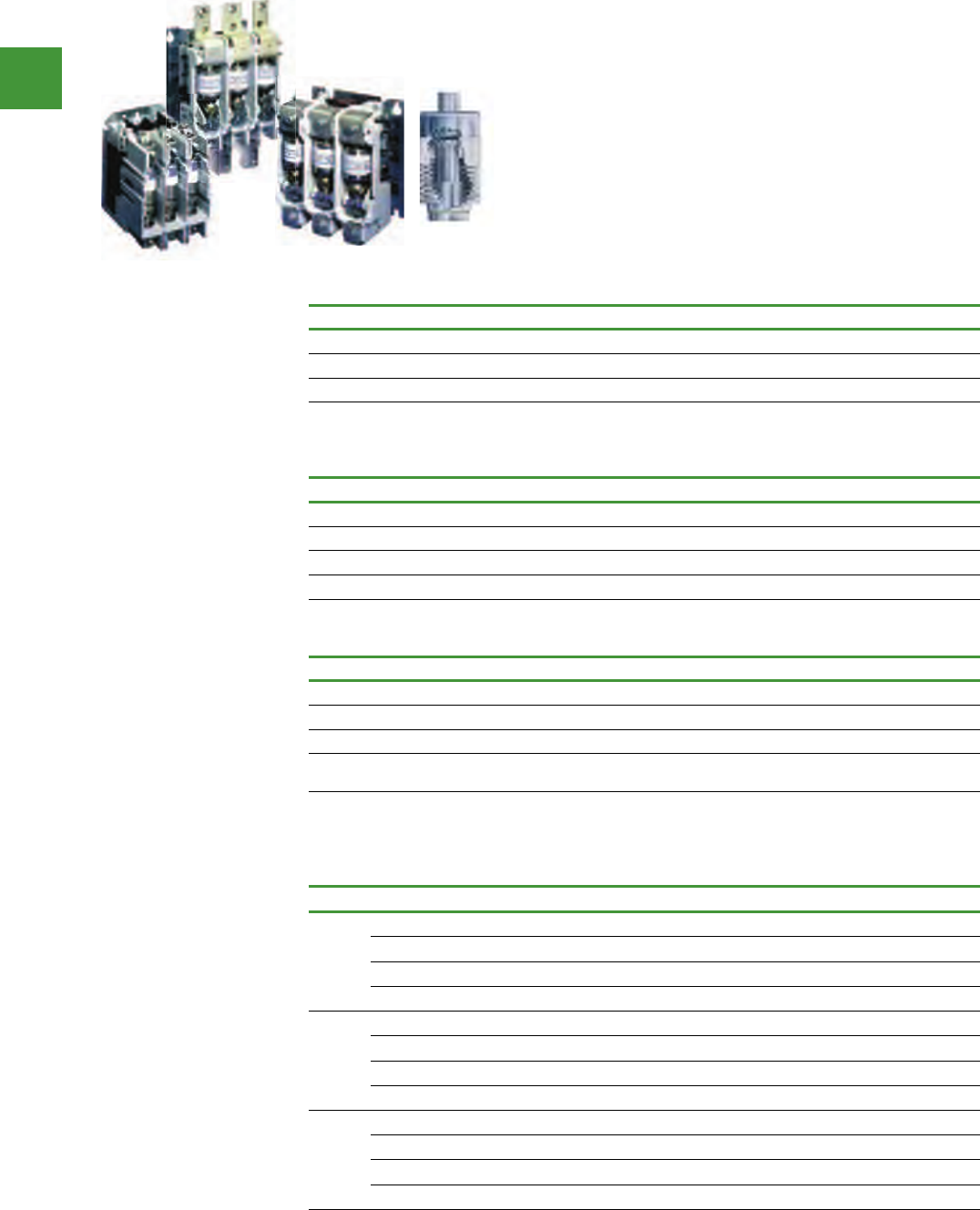
Power control
243 2015/2016 Product guide AUS15_007 - February 2016
Motor control
1000V Mining contactors
Eaton V201 vacuum contactor
Eaton’s V201 Vacuum Contactors are known for quality & proven
performance. They are ideally suited for heavy-duty applications in
harsh environments. These contactors are most commonly used
for mining applications.
Vacuum contactors
Description Item no.
160A V201KRCJZ1
320A V201KTCJZ1
540A V201KVCJZ1
110V AC Coil as standard. Vacuum Contactor Amp Ratings are AC3. Vacuum switch tubes cannot be replaced.
Auxiliary contacts for V201 vacuum contactors & DPCK air break contactors
Description Item no.
1NO/1NC J-11
2NO J-20
2NC J-02
1NO/1NC delay – 160A only J-1CV
Accessories
Description Item no.
For mechanically interlocking two 160A Vacuum Contactors 180C113G04
For mechanically interlocking two 320A Vacuum Contactors 180C113G16
For mechanically interlocking two 540A Vacuum Contactors 180C113G17
Interphase barriers for 160A Vacuum contactor.
Contains a set of two interphase barriers. IPB1
A set is suitable for line OR load side of the contactor. For line AND load side interphase barriers, order two sets.
• Rated for up to 1500V
• Small physical size
• Long life
• Reduced maintenance
• No atmospheric
contamination of the
contacts
• No noise, no arc flash
• Derating is not required at
higher voltages
• Mounting in any position
Replacement parts
Description Suffix Item no.
Size 4
110/120 Vac, 50/60 Hz J 9085A57G01
220/240 Vac, 50/60 Hz K 9085A57G02
380/415 Vac, 50/60 Hz H ID89221G07
440/480 Vac, 50/60 Hz U 9085A57G03
Size 5
110/120 Vac, 50/60 H z J7874A09G01
220/240 Vac, 50/60 Hz K 7874A09G04
380/415 Vac, 50/60 Hz H 7874A09G10
440/480 Vac, 50/60 Hz U 7874A09G05
Size 6
110/120 Vac, 50/60 H z J7874A24G01
220/240 Vac, 50/60 Hz K 7874A24G02
380/415 Vac, 50/60 Hz H 7874A24G07
440/480 Vac, 50/60 Hz U 7874A24G03
125 Vdc can be directly applied to the Size 5 and 6 coil rated for 120 Vac/60 Hz (cannot be applied to Size 4).
250 Vdc can be directly applied to the Size 5 and 6 coil rated for 240 Vac/60 Hz (cannot be applied to Size 4).
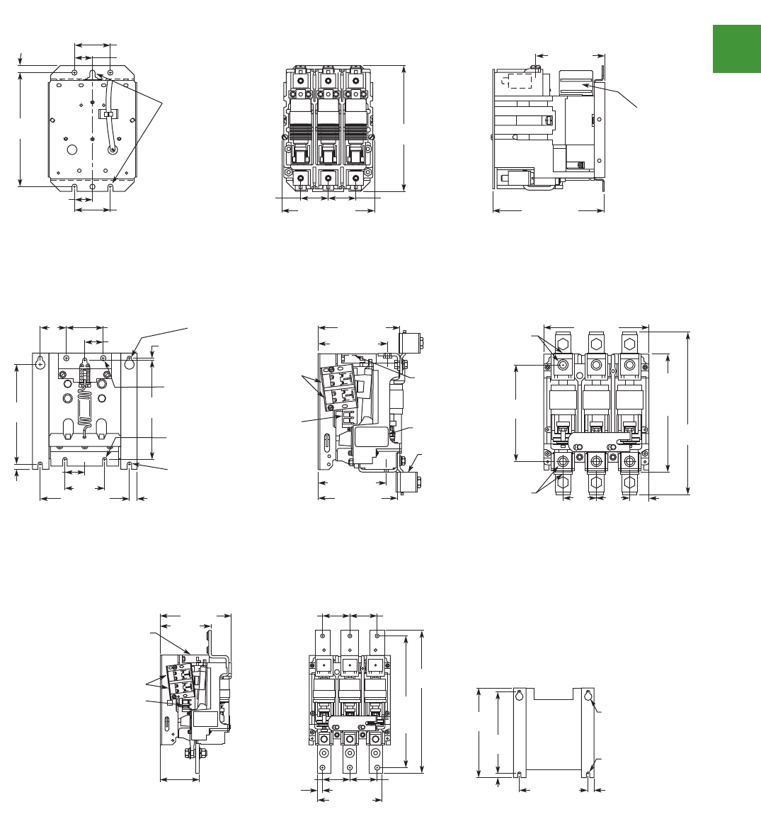
V5-T7-10 Volume 5—Motor Control and Protection CA08100006E—June 2014 www.eaton.com
7
7
7
7
7
7
7
7
7
7
7
7
7
7
7
7
7
7
7
7
7
7
7
7
7
7
7
7
7
7
7.1
Vacuum Contactors and Starters
NEMA, Special Purpose and Mining Rating
Dimensions
Approximate Dimensions in Inches (mm)
Open Type Contactors and Starters—Size 4 and 160A
Size and 160A Non-Reversing Contactor
Size 4 and 160A Reversing Contactor
Size 4 Non-Reversing Starter
Rear View — Drilling Plan Front View Side View
6.63
(168.4)
6
(152.4)
.38 (9.7)
5.96 (151.4)4.83 (122.7)
1.44 (36.6)
1.88 (47.8)
1.88 (47.8)
3.6 (91.4)
.94 (23.9)
.94 (23.9)
.28 (7.1) Dia.
3 Mtg. Slots
Front View Shown
without Cover Plate
and Overtravel
Gauge.
1.44 (36.6)
Recess for
Auxiliary
Interlock
1.88 (47.8) 1.88 (47.8)
6
(152.4)
.28 (7.1)
3 Mtg.
Slots
3.5 (88.9)
2
(50.8)
.44 (11.2) 5.13 (130.3)
2.56 (65)
4.88 (124)
7.0 (177.8)
Rear View — Drilling Plan Front View Side Vew
8.5
(215.9)
Max.
6.88
(174.8)
9.96 (253)
1.44 (36.6)
1.13 (28.7)
1.44 (36.6) 6.54
(166.1)
4.2 (106.7)
Mechanical
Interlock
Recess for
Auxiliary
Interlock
Reset
Front View Shown
without Cover Plate
and Overtravel Gauge.
Recess for
Auxiliary Interlock
1.44
(36.6)
.28 (7.1) Dia.
3 Mtg. Holes
1.44 (36.6)
1.44 (36.6) 3.60
(91.4)
4.83 (122.7) 5.94 (150.9)
6.11 (155.2)
Max. to Reset
6.34 (161.0)
Hand Reset
.46
(11.7)
.58
(14.7)
1.31 (33.3) 1.31 (33.3)
.65 (16.5)
.46 (11.7)
.38 (9.7)
.94 (23.9)
1.88 (47.8)
9.25
(235)
9.97
(253.2)
Rear View — Drilling Plan Front View Side Vew
2.88 (73.2)
Volume 5—Motor Control and Protection CA08100006E—June 2014 www.eaton.com V5-T7-11
7
7
7
7
7
7
7
7
7
7
7
7
7
7
7
7
7
7
7
7
7
7
7
7
7
7
7
7
7
7
7.1
Vacuum Contactors and Starters
NEMA, Special Purpose and Mining Rating
Approximate Dimensions in Inches (mm)
Open Type Contactors and Starters—Size 4 and 160A, continued
Size 4 Reversing Starter
Open Type Contactors and Starters—Size 5 and 320A
Size 5 and 320A Non-Reversing Contactor
Size 5 and 320A Reversing Contactor
Mechanical
Interlock
Recess for
Auxiliary Interlock
10.12
(257)
.281 (7.14) Dia.
3 Mtg. Holes
Reset
8.00 (203.2)
9.25
(235)
.44
(11.2) 4.00
(101.6)
.47 (11.9) 6.61 (168)
Max. to Reset
6.86 (174.2)
Hand Reset
.66 (16.8)
.47
(11.9)
1.03
(26.2)
1.13 (28.7) 4.10
(104.1)
1.44 (36.6)
1.44 (36.6)
4.88 (124)
9.96 (253)
6.38 (162.1)
Rear View — Drilling Plan Front View Side Vew
8
(203.2)
.38
(9.7)
7. 5
(190.5)
6.75 (171.5)
Drilling Plan — Rear View
.58 (14.7)
3
(76.2)
1.5
(38.1)
7.28 (184.9)
Term. Holes
12.5
(317.5)
8.94
(227.1)
Term.
to
Term.
.13
(3.3)
A
B
1.38
(35.1)
2.75 (69.9) 6.13 (155.7)
5.22 (132.6)
Line Term.
5.93 (150.6)
7.9 (200.7)
2.5
(63.5)
2.5
(63.5) 1.45
(36.8)
5.09 (129.3)
Load Term.
2
(50.8)
Nameplate
Terminal
Clamps
Are
Optional
Coil Interlock
Location
3/8-16 Tap
Line Terminals
Six (6) Places
3/8-16 Tap
Line Terminals
Six (6) Places
.33 x .75
(8.4 x 19.1)
Key Holes
3 Places
.41 (10.4)
Dia.
2 Holes
.33 (8.4)
Slot
2 Places
.31 (7.9)
Slot
2 Places
A – Two Dual Circuit
Interlocks Located
on Both Sides of
Contactor.
(When Used)
B – Coil Terminals
Located on Both
Sides of Contactor.
3.75
(95.3)
1.75
(44.5)
.62
(15.7)
2.74 (69.6)
.38
(9.7)
4.1
(104.1)
Nameplate
22 (558.8)
5.73
(145.5)
1.5
(38.1)
4.25
(108) 2.5
(63.5)
1.9
(48.3)
1.62 (41.1)
4.21
(106.9) 3.65 (92.7)
2.5
(63.5)
24.24 (615.7) 9.48 (240.8)
6.61 (167.9)
18.24
(463.3)
14
(355.6)
2.12
(53.8)
2.48
(63)
.86
(21.8)
Volume 5—Motor Control and Protection CA08100006E—June 2014 www.eaton.com V5-T7-13
7
7
7
7
7
7
7
7
7
7
7
7
7
7
7
7
7
7
7
7
7
7
7
7
7
7
7
7
7
7
7.1
Vacuum Contactors and Starters
NEMA, Special Purpose and Mining Rating
Approximate Dimensions in Inches (mm)
Open Type Contactors and Starters—Size 6, 540A and 610A
Size 6, 540A and 610A Non-Reversing Contactor
Size 6, 540A and 610A Reversing Contactor
8
(203.2)
.38
(9.7)
8.75
(222.3)
12.9
(327.7)
Term.
Holes
13.99
(355.3)
6.75 (171.5) .58
(14.7)
.33 (8.4)
Slot
2 Places
.33 x .75
(8.4 x 19.1)
Key Holes
5 (127)
2.67 (67.8) 2.67 (67.8)
2.67 (67.8)
2.67 (67.8)
7 (177.8)
3.72 (94.5)
Load 1.28
(32.5) 7.9 (200.7)
A
B
Coil
Interlock
A—Two Dual Circuit Interlocks
Located on Both Sides of
Contactor. (When Used)
B—Coil Terminals Located on
Both Sides of Contactor.
Rear View—Drilling Plan
Front ViewSide Vew
2.73
(69.3)
2.73
(69.3)
4.39
(111.5)
3.75
(95.3)
7.87
(199.9)
4.88
(124)
1.5
(38.1)
14.01
(355.9)
2.09
(53.1)
18.24
(463.3)
4.62
(117.3)
6.5
(165.1)
4.12
(104.6)
17.02
(432.3)
24.24
(615.7)
22
(558.8)
2.67
(67.8)
2.67
(67.8)
4.4
(111.8)
1.64
(41.7)
7.84
(199.1)
Nameplate
Front View Side View
Open type contactors and starters - size 4 and 160A
Size 4 and 160A non-revising contactor
Open type contactors and starters - size 5 and 320A
Size 5 and 320A non-revising contactor
Open type contactors and starters - size 6, 540A and 610A
Size 6, 540 and 610A non-revising contactor
Dimensions
Power control
244
2015/2016 Product guide AUS15_007 - February 2016
Motor control
Looking to run your process
more efficiently and see a
significant return on your
investment? Whether you
application calls for an ultra-
compact solution, requires
harmonic mitigation, or future
configurability is needed,
Eaton's high performance
adjustable frequency drives will
allow you to realise dramatic
energy savings, enabling you
to show positive ROI within 18
months, all while maximising
your process.
For further information about
Eaton's drives please visit
www.eatoncorp.com.au
Solutions you can
depend upon.
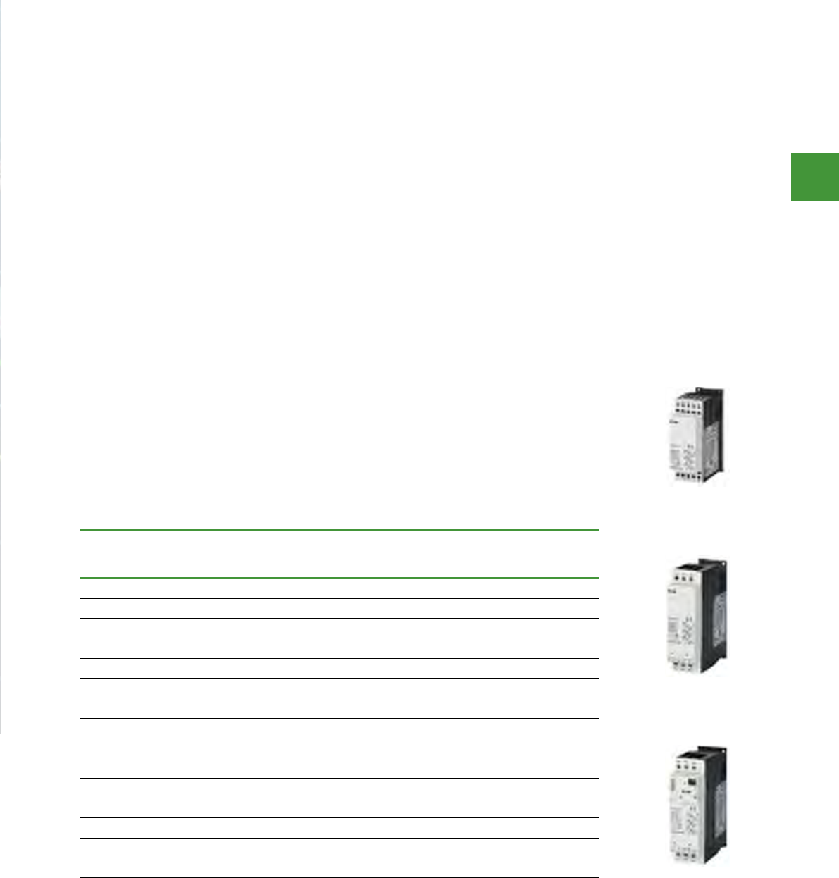
Drives and soft starters
Power control
246
2015/2016 Product guide AUS15_007 - February 2016
Drives and soft starters
Soft starters
Eaton’s variable speed drives are software driven solid-state devices that enable the OEM, contractor
or end user to control the speed of motors used in industrial, mining & HVAC applications. Drives are
an alternative to direct-on-line or star-delta starters as a method to control the motor & offer greatly
enhanced control capability along with energy savings.
From advanced starting & stopping control to integrated motor protection & communications
capabilities, Eaton’s line of soft starters provide a unique combination of soft starting & flexible
protective features. Communications capabilities enable integration into building management systems
for easy monitoring & troubleshooting & the small size permits the use of smaller panels & enclosures,
for significant cost savings.
• Tool-less plug connection, ensuring easy
connection & wiring with other switching
devices such as motor-protective circuit
breakers
• Connection design, handling & the 45 mm
device width match our motor-protective
circuit-breakers & contactors of the device
series exactly
• The DS7 ensures a jerk-free increase in
torque and effective current reduction in the
three-phase motor startup phase
• Furthermore, the DS7 is also available with a
110/230 Vac control voltage input
• Settings & status values can be remotely
transferred via SmartWire-Darwin gateway
regardless of whether Profibus DP or
CANopen control commands are used
DS7 Soft starters
Rated operational
current
Ie, A
Rated power for three-phase
motors at 3 AC 400 V
P, kW
Control supply Item no.
4 1.5 24 V DC DS7-34DSX004N0-D
7 3 24 V DC DS7-34DSX007N0-D
9 4 24 V DC DS7-34DSX009N0-D
12 5.5 24 V DC DS7-34DSX012N0-D
16 7.5 24 V DC DS7-34DSX016N0-D
24 11 24 V DC DS7-34DSX024N0-D
32 15 24 V DC DS7-34DSX032N0-D
41 22 24 V DC DS7-34DSX041N0-D
55 30 24 V DC DS7-34DSX055N0-D
70 37 24 V DC DS7-34DSX070N0-D
81 45 24 V DC DS7-34DSX081N0-D
100 55 24 V DC DS7-34DSX100N0-D
135 75 24 V DC DS7-34DSX135N0-D
160 90 24 V DC DS7-34DSX160N0-D
200 110 24 V DC DS7-34DSX200N0-D
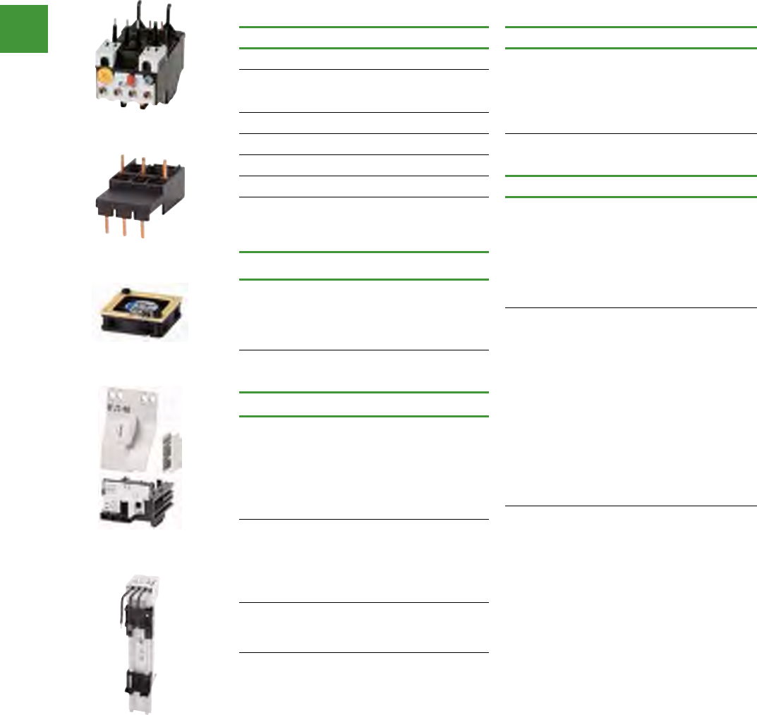
Drives and soft starters
Power control
247 2015/2016 Product guide AUS15_007 - February 2016
Soft starters
Accessories
Overload relays PKZ-DS7 wiring set
For use with... Item no. For use with... Item no.
DS7-34…SX004… ZB12-4 DS7-34…SX004…
PKZM0-XDM12
DS7-34…SX007… ZB12-10 DS7-34…SX007…
DS7-34…SX009… DS7-34…SX009…
DS7-34…SX012… ZB12-12 DS7-34…SX012…
DS7-34…SX016… ZB32-16
DS7-34…SX024… ZB32-24 Busbar adapter
DS7-34…SX032… ZB32-32 For use with... Item no.
PKZM0, PKE +
DS7...004N...
BBA0L-25
Electric contact module PKZM0, PKE +
DS7...007N...
For use with... Item no. PKZM0, PKE +
DS7...009N...
DS7-34…SX016…
PKZM0-XM32DE
PKZM0, PKE +
DS7...012N...
DS7-34…SX024… PKZM0, PKE +
DS7...004N...
PKZM0, PKE +
DS7...007N...
PKZM0, PKE +
DS7...009N...
PKZM0, PKE +
DS7...012N...
PKZM0, PKE +
DS7...016N...
PKZM0, PKE +
DS7...024N...
PKZM0, PKE +
DS7...032N...
BBA0L-32
DS7-34…SX032…
Device fans
For use with... Item no.
DS7-34...SX004...
DS7-34...SX007...
DS7-34...SX009...
DS7-34...SX012...
DS7-34...SX016...
DS7-34...SX024...
DS7-34...SX032...
DS7-FAN-032
DS7-34...SX041...
DS7-34...SX055...
DS7-34...SX070...
DS7-34...SX081...
DS7-34...SX100...
DS7-FAN-100
DS7-34...SX135...
DS7-34...SX160...
DS7-34...SX200...
DS7-FAN-200
ZB12-4
PKZM0-XM32DE
DS7-FAN-032
PKZM0-XDM12
BBA0L-25
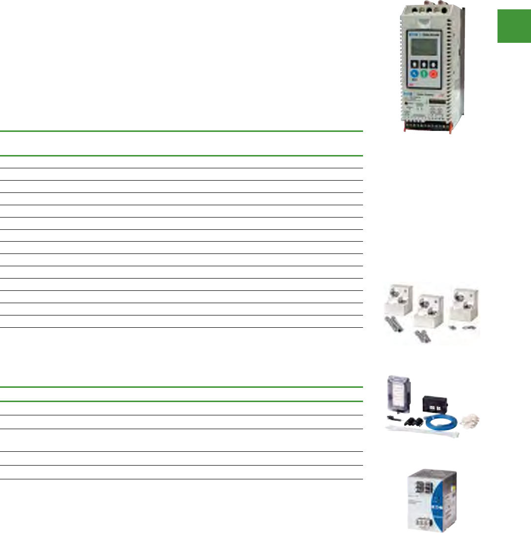
Drives and soft starters
Power control
248
2015/2016 Product guide AUS15_007 - February 2016
Soft starters
Accessories for S811+ soft starters
Description Item no.
Lug kits, 3-phase 2 cable connection, up to 2 x 240mm dia (T/U) EML24
Lug kits, 3-phase 2 cable connection, up to 2 x 240mm dia (V) EML28
Control interface module
panel mounting kits Kit with 2m Cable, remote keypad mount EMA69C
Control wire connectors 12-Pin Connector for Control Wiring EMA75
DC power supply 240Vac in, 24 V DC out PSG240E
For voltages rated 690V to 7.5kV open panel/enclosed type, we have the MV 811 Series medium voltage soft
starters. Please contact your nearest Eaton branch to discuss your application for the medium voltage starters.
• Built-in overload protection
• Built-in run bypass contactor
• Adjustable ramp times
• Adjustable torque control
• Adjustable kick start control
• Programmable overload settings, 31-100%
of rated current
• Digital Interface Module (DIM) to safely
configure, commission, monitor and
troubleshoot
• Soft start and Soft stop control
• Multiple trip class settings (5, 10, 20 and 30)
• Built-in comms. capability for Modbus
(through the DIM or using CH Studio
software)
• Six SCR control, 3 or 6 wire 415V
• Ideal for pump protection and control
• 24V DC power supply required
with soft starter see below
S811+ intelligent technologies (IT)
Max current (amps) kW rating at 415V AC Item no.
Normal duty Severe duty Normal duty* Severe duty**
37 22 18.5 11 S811+N37P3S
66 42 30 22 S811+N66P3S
105 65 55 37 S811+R10P3S
135 80 75 45 S811+R13P3S
180 115 90 55 S811+T18P3S
240 150 132 75 S811+T24P3S
304 192 160 90 S811+T30P3S
360 240 185 132 S811+U36P3S
420 305 220 160 S811+U42P3S
500 365 260 200 S811+V50P3S
650 420 355 220 S811+V65P3S
720 480 400 260 S811+V72P3S
850 525 450 300 S811+V85P3S
1000 575 560 330 S811+V10P3S
Normal duty is 4 starts per hour at ramp current 300% of full load amps. Severe duty is 4 starts per hour at ramp
current 450% of full load amps.
PSG240E
EMA69C
EML24
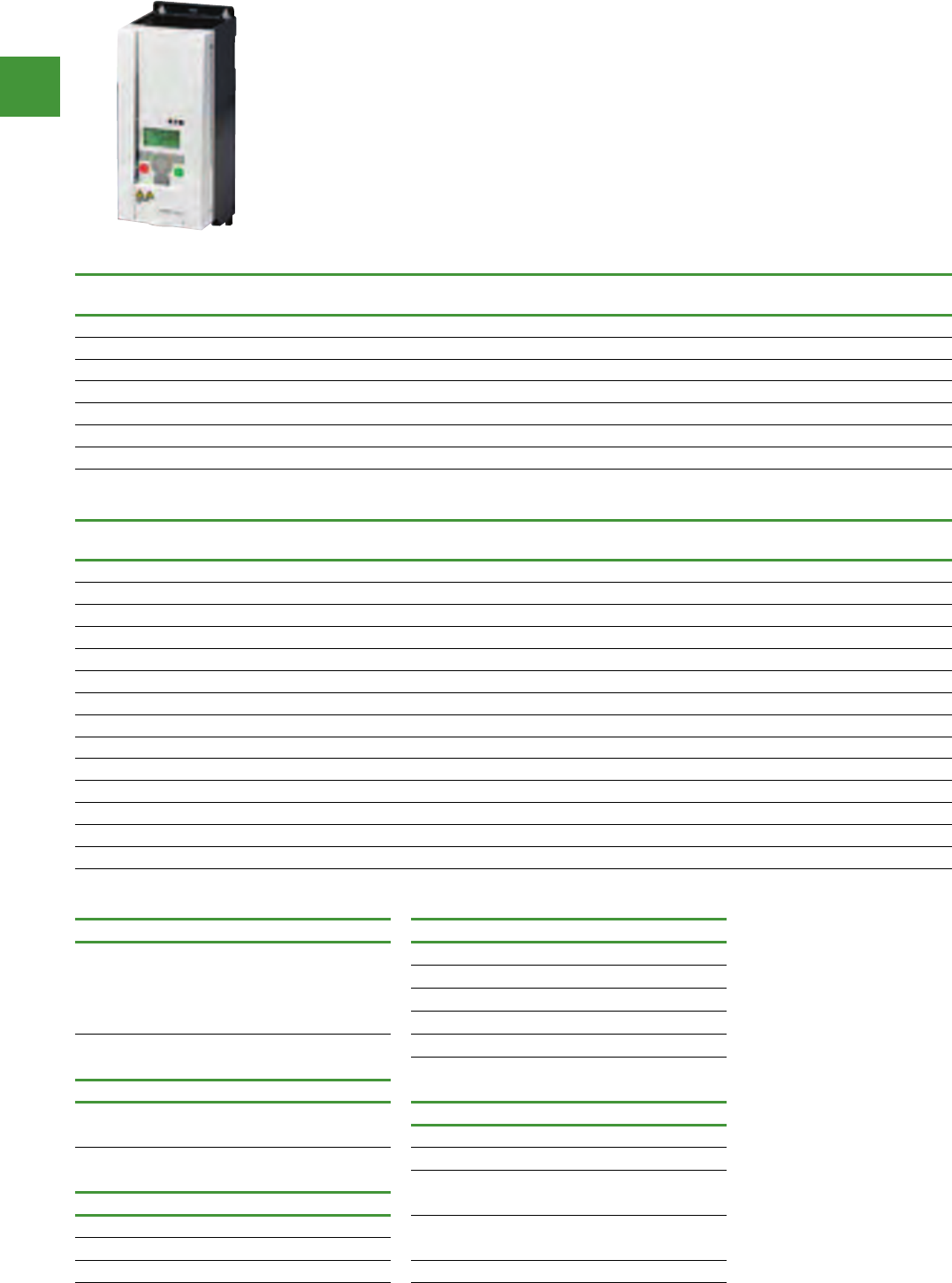
Drives and soft starters
Power control
249 2015/2016 Product guide AUS15_007 - February 2016
NEMA Type 1 kit provides conduit
entry plate.
Additional input and output
reactors are available. Consult Eaton
representative for a complete listing.
All three components are required
for remote keypad operation.
Variable speed drives
1-ph in, 3-ph out, 240V AC
Description H x W x D (mm) High overload Low overload Item no.
P(kW) I(H) P(kW) I(L)
M-Max Drive 240V 0.25 kW CT IP20 157 x 66 x 102 0.25 1.7 0.25 1.7 MMX12AA1D7F0-0
M-Max Drive 240V 0.37 kW CT IP20 157 x 66 x 102 0.37 2.4 0.37 2.4 MMX12AA2D4F0-0
M-Max Drive 240V 0.55 kW CT IP20 157 x 66 x 102 0.55 2.8 0.55 2.8 MMX12AA2D8F0-0
M-Max Drive 240V 0.75 kW CT IP20 157 x 66 x 102 0.75 3.7 0.75 3.7 MMX12AA3D7F0-0
M-Max Drive 240V 1.1 kW CT IP20 195 x 90 x 105 1.1 4.8 1.1 4.8 MMX12AA4D8F0-0
M-Max Drive 240V 1.5 kW CT IP20 195 x 90 x 105 1.5 7 1.5 7 MMX12AA7D0F0-0
M-Max Drive 240V 2.2 kW CT IP20 263 x 100 x 112 2.2 9.6 2.2 9.6 MMX12AA9D6F0-0
3-ph in, 3-ph out, 415V AC
Description H x W x D (mm) High overload Low overload Item no.
P(kW) I(H) P(kW) I(L)
M-Max Drive 415V 0.37 kW CT IP20 160 x 66 x 102 0.37 1.3 0.37 1.3 MMX34AA1D3F0-0
M-Max Drive 415V 0.55 kW CT IP20 160 x 66 x 102 0.55 1.9 0.55 1.9 MMX34AA1D9F0-0
M-Max Drive 415V 0.75 kW CT IP20 160 x 66 x 102 0.75 2.4 0.75 2.4 MMX34AA2D4F0-0
M-Max Drive 415V 1.1 kW CT IP20 195 x 90 x 105 1.1 3.3 1.1 3.3 MMX34AA3D3F0-0
M-Max Drive 415V 1.5 kW CT IP20 195 x 90 x 105 1.5 4.3 1.5 4.3 MMX34AA4D3F0-0
M-Max Drive 415V 2.2 kW CT IP20 195 x 90 x 105 2.2 5.6 2.2 5.6 MMX34AA5D6F0-0
M-Max Drive 415V 3.0 kW CT IP20 253 x 100 x 112 3 7.6 3 7.6 MMX34AA7D6F0-0
M-Max Drive 415V 4.0 kW CT IP20 253 x 100 x 112 4949MMX34AA9D0F0-0
M-Max Drive 415V 5.5 kW CT IP20 253 x 100 x 112 5.5 12 5.5 12 MMX34AA012F0-0
M-Max Drive 415V 7.5 kW CT IP20 253 x 100 x 112 7.5 14 7.5 14 MMX34AA014F0-0
M-Max Drive 415V 7.5 kW CT IP20 370 x 165 x 168 7.5 16 7.5 16 MMX34AA016F0-0
M-Max Drive 415V 11 kW CT IP20 370 x 165 x 168 11 23 11 23 MMX34AA023F0-0
M-Max Drive 415V 15 kW CT IP20 414 x 165 x 205 15 31 15 31 MMX34AA031F0-0
M-Max Drive 415V 18.5 kW CT IP20 414 x 165 x 205 18.5 38 18.5 38 MMX34AA038F0-0
M-Max machinery drives
• Ease of use — plug & play, start-up wizard,
advanced diagnostic capability, copy/paste
parameters without powering drive
• Compact, space-saving design
• RS485/Modbus & PI-controller inbuilt as
standard
• Rugged & reliable — 50°C rating, 150%
overload for 1 min., 200% starting current
for 2 secs. in every 20 sec. period, conformal
coated boards
• Internal EMC filter complying with
IEC61800-3
• RoHS compliance
M-Max copy/paste module NEMA type 1 kit
Description Item no. Description Item no.
Module is plugged onto the
front of the drive to provide
upload/download of all
parameters, direct link to a
PC via USB or via
MaxConnect software.
MMX-COM-PC
NEMA type 1 and IP21 kit for frame 1 MMX-IP21-FS1
NEMA type 1 and IP21 kit for frame 2 MMX-IP21-FS2
NEMA type 1 and IP21 kit for frame 3 MMX-IP21-FS3
NEMA type 1 for frame 4 MMX-CKIT-FS4
NEMA type 1for frame 5 MMX-CKIT-FS5
PC cable
Description Item no. Optional communication modules
Remote download USB to
RJ-45 cable with software driver REM-USB-DOWN Description Item no.
Communication adaptor kit (FS1-FS3) MMX-NET-XA
Communication adaptor kit (FS4-FS5) MMX-NET-XA-45
Remote Keypad PROFIBUS DP network card w.
serial connection XMX-NET-PS-A
Description Item no.
Keypad, bezel and cable OPTRMT-BP-HMAX PROFIBUS DP network card w.
Sub-D connection XMX-NET-PD-A
Romote copy/paste keypad MMX-REMKEY-TEXT
VFD adaptor MMX-ADAPTER-RJ45 DevicerNet network card XMX-NET-DN-A
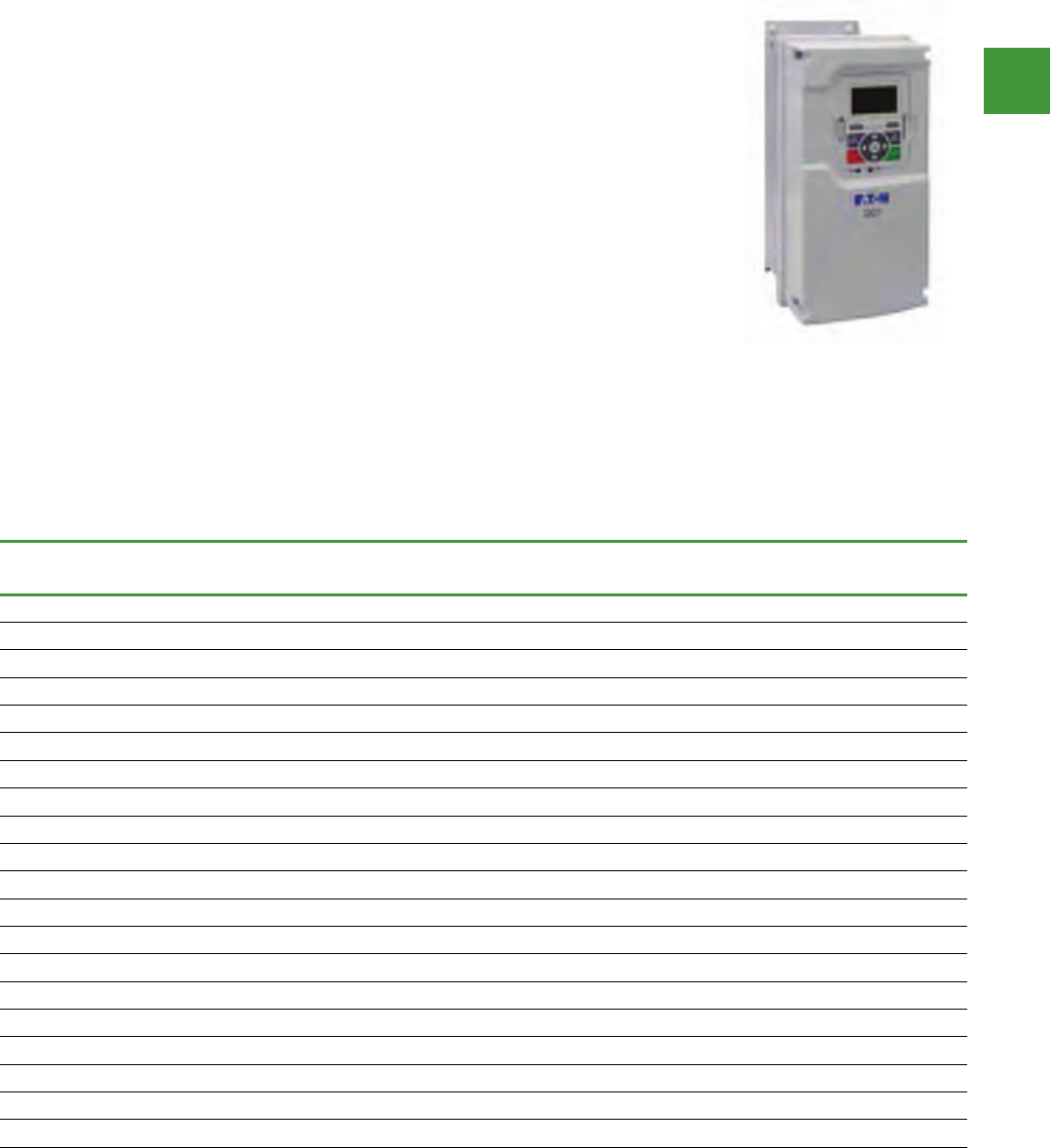
Drives and soft starters
Power control
250
2015/2016 Product guide AUS15_007 - February 2016
DG1 general purpose drives
• High spec sensorless vector open loop
general purpose industrial drive, with inbuilt
5% dc choke
• Suitable for variable torque (fan/pump)
and constant torque (conveyor/crusher)
applications
• Internal RFI filter complying with emc
category 2 & inbuilt brake chopper in frames
1-3
• Available off-the-shelf with IP21 & IP54
protection, suitable for direct wall mounting
• Comms inbuilt onboard - Ethernet/IP,
Modbus/RTU, Modbus/TCP, BacNet MS/TP
• Conformal coated boards, suitable
for tropical & coastal high humidity
environments
• Complies with local C-Tick & RCM mark
& product standards AS/IEC61800, 61000
series
• Real time clock & graphic copy/paste
keypad with local/remote key & onscreen
diagnostics
• Preset speeds, jump frequencies, sleep/
wake modes, 2 PID feedback loops inbuilt
• Patented ‘Active Energy Control’ energy
saving software, added savings over other
drives
380-500V IP21
Description Frame
size
High overload Low overload Item no.
P [kW] I(H) P [kW] I(L)
DG1 drive 415V 1.1kW VT IP21 C/W brake chopper 1 0.75 2.2 1.1 3.3 DG1-342D2FB-C21C
DG1 drive 415V 1.5kW VT IP21 C/W brake chopper 1 1.1 3.3 1.5 4.3 DG1-343D3FB-C21C
DG1 drive 415V 2.2kW VT IP21 C/W brake chopper 1 1.5 4.3 2.2 5.6 DG1-344D3FB-C21C
DG1 drive 415V 3.0kW VT IP21 C/W brake chopper 1 2.2 5.6 3 7.6 DG1-345D6FB-C21C
DG1 drive 415V 4.0kW VT IP21 C/W brake chopper 1 3 7.6 4 9 DG1-347D6FB-C21C
DG1 drive 415V 5.5kW VT IP21 C/W brake chopper 1 4 9 5.5 12 DG1-349D0FB-C21C
DG1 drive 415V 7.5kW VT IP21 C/W brake chopper 2 5.5 12 7.5 16 DG1-34012FB-C21C
DG1 drive 415V 11kW VT IP21 C/W brake chopper 2 7.5 16 11 23 DG1-34016FB-C21C
DG1 drive 415V 15kW VT IP21 C/W brake chopper 2 11 23 15 31 DG1-34023FB-C21C
DG1 drive 415V 18.5kW VT IP21 C/W brake chopper 3 15 31 18.5 38 DG1-34031FB-C21C
DG1 drive 415V 22kW VT IP21 C/W brake chopper 3 18.5 38 22 46 DG1-34038FB-C21C
DG1 drive 415V 30kW VT IP21 C/W brake chopper 3 22 46 30 61 DG1-34046FB-C21C
DG1 drive 415V 37kW VT IP21 4 30 61 37 72 DG1-34061FN-C21C
DG1 drive 415V 45kW VT IP21 4 37 72 45 87 DG1-34072FN-C21C
DG1 drive 415V 55kW VT IP21 4 45 87 55 105 DG1-34087FN-C21C
DG1 drive 415V 75kW VT IP21 5 55 105 75 140 DG1-34105FN-C21C
DG1 drive 415V 90kW VT IP21 5 75 140 90 170 DG1-34140FN-C21C
DG1 drive 415V 110kW VT IP21 5 90 170 110 205 DG1-34170FN-C21C
DG1 drive 415V 132kW VT IP21 6 110 205 132 261 DG1-34205FN-C21C
DG1 drive 415V 160kW VT IP21 6 132 245 160 310 DG1-34261FN-C21C
Drives
DG1
The DG1 general purpose drives are part of Eaton’s next generation PowerXL Series of adjustable
frequency drives specifically engineered for today’s more demanding commercial and industrial
applications. The power unit makes use of the most sophisticated semiconductor technology and a
highly modular construction that can be flexibly adapted to meet the customer’s needs.
The control module was designed to include today’s standard communication protocols and I/O while
still having the modularity to add additional option cards. Eaton’s patented Active Energy Control is also
a standard feature on DG1 drives, offering customers increased efficiency, safety and reliability.
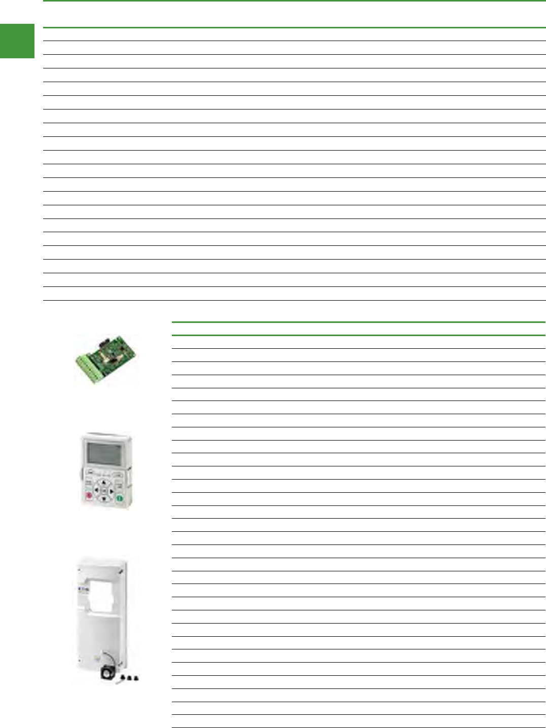
Drives and soft starters
Power control
251 2015/2016 Product guide AUS15_007 - February 2016
380-500V IP54
Description Frame High overload Low overload Item no.
size P [kW] I(H) P [kW] I(L)
DG1 drive 415V 1.1kW VT IP54 C/W brake chopper 1 0.75 2.2 1.1 3.3 DG1-342D2FB-C54C
DG1 drive 415V 1.5kW VT IP54 C/W brake chopper 1 1.1 3.3 1.5 4.3 DG1-343D3FB-C54C
DG1 drive 415V 2.2kW VT IP54 C/W brake chopper 1 1.5 4.3 2.2 5.6 DG1-344D3FB-C54C
DG1 drive 415V 3.0kW VT IP54 C/W brake chopper 1 2.2 5.6 3 7.6 DG1-345D6FB-C54C
DG1 drive 415V 4.0kW VT IP54 C/W brake chopper 1 3 7.6 4 9 DG1-347D6FB-C54C
DG1 drive 415V 5.5kW VT IP54 C/W brake chopper 1 4 9 5.5 12 DG1-349D0FB-C54C
DG1 drive 415V 7.5kW VT IP54 C/W brake chopper 2 5.5 12 7.5 16 DG1-34012FB-C54C
DG1 drive 415V 11kW VT IP54 C/W brake chopper 2 7.5 16 11 23 DG1-34016FB-C54C
DG1 drive 415V 15kW VT IP54 C/W brake chopper 2 11 23 15 31 DG1-34023FB-C54C
DG1 drive 415V 18.5kW VT IP54 C/W brake chopper 3 15 31 18.5 38 DG1-34031FB-C54C
DG1 drive 415V 22kW VT IP54 C/W brake chopper 3 18.5 38 22 46 DG1-34038FB-C54C
DG1 drive 415V 30kW VT IP54 C/W brake chopper 3 22 46 30 61 DG1-34046FB-C54C
DG1 drive 415V 37kW VT IP54 4 30 61 37 72 DG1-34061FN-C54C
DG1 drive 415V 45kW VT IP54 4 37 72 45 87 DG1-34072FN-C54C
DG1 drive 415V 55kW VT IP54 4 45 87 55 105 DG1-34087FN-C54C
DG1 drive 415V 75kW VT IP54 5 55 105 75 140 DG1-34105FN-C54C
DG1 drive 415V 90kW VT IP54 5 75 140 90 170 DG1-34140FN-C54C
DG1 drive 415V 110kW VT IP54 5 90 170 110 205 DG1-34170FN-C54C
DG1 drive 415V 132kW VT IP54 6 110 205 132 261 DG1-34205FN-C54C
DG1 drive 415V 160kW VT IP54 6 132 245 160 310 DG1-34261FN-C54C
Options & accessories
Description Item no.
DG1 Option card 3 DI 3 DO 1 THERMISTOR INPUT DXG-EXT-3DI3DO1T
DG1 Option card 1 AI 2 AO ISOLATED ANALOG DXG-EXT-1AI2AO
DG1 Option card 3 RO (2NO+1CO) OUTPUT DXG-EXT-3RO
DG1 Option card 3 Pt100 RTD INPUT DXG-EXT-THERM1
DG1 Option card 6 DI 240VAC INPUT DXG-EXT-6DI
DG1 Comms card PROFIBUS DP DXG-NET-PROFIBUS
DG1 Comms card CANOPEN DXG-NET-CANOPEN
DG1 Comms card DEVICENET DXG-NET-DEVICENET
DG1 Comms card PROFIBUS DP (DB9 CONN) DXG-MNT-PROFIBUS
DG1 Comms card SMARTWIRE DT DXG-NET-SWD
DG1 Comms card LONWORKS DXG-NET-LONWORKS
DG1 replacement keypad DXG-KEY-LCD
DG1 remote keypad mount kit (0.5M CABLE) DXG-KEY-RMTKIT
DG1 remote keypad cable 1M DXG-CBL-1M0
DG1 remote keypad cable 3M DXG-CBL-3M0
DG1 remote keypad mounting holder DXG-KEY-HOLDER
DG1 IP54 blank keypad hole plug DXG-KEY-N12PLUG
DG1 FRAME 1 IP54 conversion kit DXG-ACC-4FR1N12KIT
DG1 FRAME 2 IP54 conversion kit DXG-ACC-FR2N12KIT
DG1 FRAME 3 IP54 conversion kit DXG-ACC-FR3N12KIT
DG1 FRAME 1 IP54 flange kit DXG-ACC-FR1N12FK
DG1 FRAME 2 IP54 flange kit DXG-ACC-FR2N12FK
DG1 FRAME 3 IP54 flange kit DXG-ACC-FR3N12FK
DG1 FRAME 4 IP54 flange kit DXG-ACC-FR4N12FK
DG1 FRAME 5 IP54 flange kit DXG-ACC-FR5N12FK
DG1 control module demo stand DG1-DEMO1
DG1 full drive demo case DG1-DEMO2
DG1 RS485 programming cable USB-TO-RJ45 DXG-CBL-PCCABLE
DG1 battery for real time clock DXG-ACC-RTBATT
DG1 control module kit with keypad DXG-SPR-CTRLKIT
DXG-EXT-3DI3DO1T
DXG-KEY-LCD
DXG-ACC-FR2N12KIT

Drives and soft starters
Power control
252
2015/2016 Product guide AUS15_007 - February 2016
Volume 6—Solid-State Motor Control CA08100007E—July 2014 www.eaton.com V6-T1-41
1
1
1
1
1
1
1
1
1
1
1
1
1
1
1
1
1
1
1
1
1
1
1
1
1
1
1
1
1
1
1.1
Reduced Voltage Motor Starters
Solid-State Controllers
Frame 3—SmartWire-DT and Standard (Non SmartWire-DT)
Frame 4—SmartWire-DT and Standard (Non SmartWire-DT)
Catalog Numbers
DS7-340SX041N0-N DS7-342SX041N0-N DS7-34DSX041N0-D
DS7-340SX055N0-N DS7-342SX055N0-N DS7-34DSX055N0-D
DS7-340SX070N0-N DS7-342SX070N0-N DS7-34DSX070N0-D
DS7-340SX081N0-N DS7-342SX081N0-N DS7-34DSX081N0-D
DS7-340SX100N0-N DS7-342SX100N0-N DS7-34DSX100N0-D
Catalog Numbers
DS7-342SX135N0-N DS7-340SX135N0-N DS7-34DSX135N0-D
DS7-342SX160N0-N DS7-340SX160N0-N DS7-34DSX160N0-D
DS7-342SX200N0-N DS7-340SX200N0-N DS7-34DSX200N0-D
6.14 (156.0)
DS7-…-D
5.47 (139.0)
1.38 (35.0)
6.89
(175.0)
6.34
(161.0)
5.08
(129.0)
1.58
(40.0)
PE
1.18
(30.0)
0.89
(22.5)
1.18
(30.0)
3.66 (93.0) 0.89
(22.5)
PE
PE
PE
8.46
(215.0)
4.25 (108.0)
0.59
(15.0)
7.68 (195.0)
DS7-…-D
7.01 (178.0)
2.07 (52.5)
7.87
(200.0)
6.22
(158.0)
1.58
(40.0)
1.18
(30.0)
0.89
(22.5)
1.18
(30.0)
Dimensions (approximate dimensions in inched (mm)
Soft starter controllers
V6-T1-40Volume 6—Solid-State Motor Control CA08100007E—July 2014 www.eaton.com
1
1
1
1
1
1
1
1
1
1
1
1
1
1
1
1
1
1
1
1
1
1
1
1
1
1
1
1
1
1
1.1
Reduced Voltage Motor Starters
Solid-State Controllers
Dimensions
Approximate Dimensions in Inches (mm)
Frame 1
Frame 1—SmartWire-DT
Frame 2
Frame 2—SmartWire-DT
Item no.
DS7-340SX004N0-N DS7-342SX004N0-N
DS7-340SX007N0-N DS7-342SX007N0-N
DS7-340SX009N0-N DS7-342SX009N0-N
DS7-340SX012N0-N DS7-342SX012N0-N
Item no.
DS7-34DSX004N0-DDS7-34DSX009N0-D
DS7-34DSX007N0-DDS7-34DSX012N0-D
4.92
(125.0)
3.74
(95.0)
1.77
(45.0)
4 x M4
4.80
(122.0)
5.12
(130.0)
1.38
(35.0)
4.92
(125.0)
4.05 (103.0)
3.74 (95.0)
1.77
(45.0)
4 x M4
1.38
(35.0)
4.80
(122.0)
5.12
(130.0)
Item no.
DS7-340SX016N0-N DS7-342SX016N0-N
DS7-340SX024N0-N DS7-342SX024N0-N
DS7-340SX032N0-N DS7-342SX032N0-N
Item no.
DS7-34DSX016N0-D
DS7-34DSX024N0-D
DS7-34DSX032N0-D
1.77
(45.0)
4 x M4
1.38
(35.0)
5.90
(150.0)
4.65 (118.0)
5.51
(140.0)
4.65 (118.0)
1.77
(45.0)
2 x M4
5.60
(150.0)
1.38
(35.0)
5.51
(140.0)
4.96 (126.0)
Frame 1—SmartWire-DT Frame 2—SmartWire-DT
Frame 1 Frame 2
Frame 3—SmartWire-DT and Standard (Non SmartWire-DT) Frame 4—SmartWire-DT and Standard (Non SmartWire-DT)
Item no.
DS7-340SX041N0-N DS7-342SX041N0-N DS7-34DSX041N0-D
DS7-340SX055N0-N DS7-342SX055N0-N DS7-34DSX055N0-D
DS7-340SX070N0-N DS7-34DSX070N0-D DS7-342SX070N0-N
DS7-340SX081N0-N DS7-342SX081N0-N DS7-34DSX081N0-D
DS7-340SX100N0-N DS7-342SX100N0-N DS7-34DSX100N0-D
Item no.
DS7-342SX135N0-N DS7-340SX135N0-N DS7-34DSX135N0-D
DS7-342SX160N0-N DS7-340SX160N0-N DS7-34DSX160N0-D
DS7-342SX200N0-N DS7-340SX200N0-N DS7-34DSX200N0-D
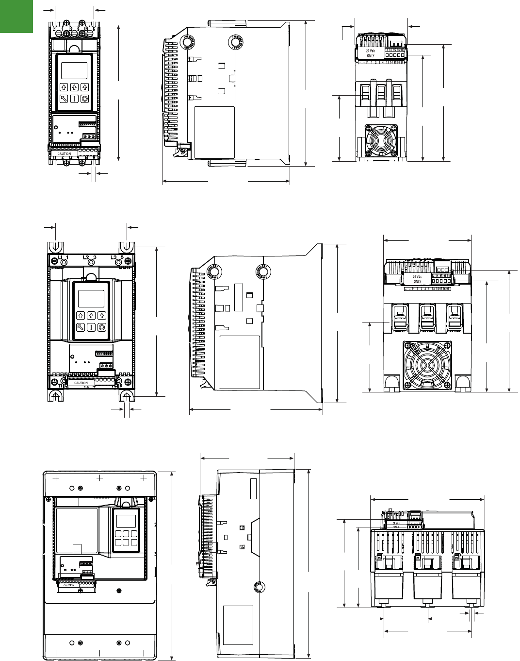
Drives and soft starters
Power control
253 2015/2016 Product guide AUS15_007 - February 2016
Volume 6—Solid-State Motor Control CA08100007E—July 2014 www.eaton.com V6-T1-97
1
1
1
1
1
1
1
1
1
1
1
1
1
1
1
1
1
1
1
1
1
1
1
1
1
1
1
1
1
1
1.2
Reduced Voltage Motor Starters
Solid-State Starters
Approximate Dimensions in Inches (mm)
S811+N_
S811+R_
6.87
(174.5)
1.97 (50.0)
4X Ø
0.22
(5.5)
7.37
(187.2)
6.45 (163.9)
5.35
(135.9)
5.89
(149.7)
3.32
(84.4)
2.66
(67.6)
5.54
(140.7)
4.38 (111.3)
3.54 (90.0)
4X Ø
0.27
(6.8) 6.64 (168.6)
7.92
(201.2)
6.08
(154.5)
7.44
(189.0)
3.49
(88.5)
Dimensions (approximate dimensions in inched (mm)
Solid soft starter
S811+N...
Volume 6—Solid-State Motor Control CA08100007E—July 2014 www.eaton.com V6-T1-97
1
1
1
1
1
1
1
1
1
1
1
1
1
1
1
1
1
1
1
1
1
1
1
1
1
1
1
1
1
1
1.2
Reduced Voltage Motor Starters
Solid-State Starters
Approximate Dimensions in Inches (mm)
S811+N_
S811+R_
6.87
(174.5)
1.97 (50.0)
4X Ø
0.22
(5.5)
7.37
(187.2)
6.45 (163.9)
5.35
(135.9)
5.89
(149.7)
3.32
(84.4)
2.66
(67.6)
5.54
(140.7)
4.38 (111.3)
3.54 (90.0)
4X Ø
0.27
(6.8) 6.64 (168.6)
7.92
(201.2)
6.08
(154.5)
7.44
(189.0)
3.49
(88.5)
S811+R...
S811+T...
V6-T1-98 Volume 6—Solid-State Motor Control CA08100007E—July 2014 www.eaton.com
1
1
1
1
1
1
1
1
1
1
1
1
1
1
1
1
1
1
1
1
1
1
1
1
1
1
1
1
1
1
1.2
Reduced Voltage Motor Starters
Solid-State Starters
Approximate Dimensions in Inches (mm)
S811+T_
S811+U_
11.77
(299.0) 12.71
(322.9)
6.47 (164.4)
7.65 (194.4)
5.40
(137.3)
5.95
(151.1)
5.91 (150.0)
0.28
(7.1)
6X Ø
2.95
(75.0)
7.16 (181.8)
6X Ø
12.72
(323.1)
11.77
(299.0) 6.09
(154.8)
6.64
(168.6)
2.60
(66.0)
0.28
(7.1)
5.20 (132.0)
7.73 (196.3)

Drives and soft starters
Power control
254
2015/2016 Product guide AUS15_007 - February 2016
V6-T1-98 Volume 6—Solid-State Motor Control CA08100007E—July 2014 www.eaton.com
1
1
1
1
1
1
1
1
1
1
1
1
1
1
1
1
1
1
1
1
1
1
1
1
1
1
1
1
1
1
1.2
Reduced Voltage Motor Starters
Solid-State Starters
Approximate Dimensions in Inches (mm)
S811+T_
S811+U_
11.77
(299.0) 12.71
(322.9)
6.47 (164.4)
7.65 (194.4)
5.40
(137.3)
5.95
(151.1)
5.91 (150.0)
0.28
(7.1)
6X Ø
2.95
(75.0)
7.16 (181.8)
6X Ø
12.72
(323.1)
11.77
(299.0) 6.09
(154.8)
6.64
(168.6)
2.60
(66.0)
0.28
(7.1)
5.20 (132.0)
7.73 (196.3)
Volume 6—Solid-State Motor Control CA08100007E—July 2014 www.eaton.com V6-T1-99
1
1
1
1
1
1
1
1
1
1
1
1
1
1
1
1
1
1
1
1
1
1
1
1
1
1
1
1
1
1
1.2
Reduced Voltage Motor Starters
Solid-State Starters
Approximate Dimensions in Inches (mm)
S811+V__
6.79 (172.5)
0.236
(6.00)
3.05
(77.5)
9.84 (250.0)
15.63
(397.0)
4X Ø
0.2650
(6.731)
6.50
(165.1)
7.39
(187.8)
11.05 (280.6)
16.57
(420.8)
Dimensions (approximate dimensions in inched (mm)
Solid soft starter
S811+U...
S811+V...
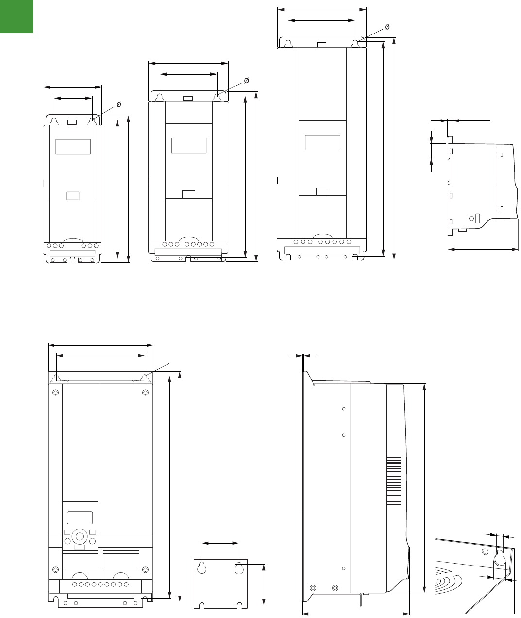
Drives and soft starters
Power control
255 2015/2016 Product guide AUS15_007 - February 2016
V6-T2-26 Volume 6—Solid-State Motor Control CA08100007E—May 2014 www.eaton.com
2
2
2
2
2
2
2
2
2
2
2
2
2
2
2
2
2
2
2
2
2
2
2
2
2
2
2
2
2
2
2.3
Adjustable Frequency Drives
M-Max Series Drives
Dimensions
Approximate Dimensions in Inches (mm)
Dimensions and Frame Sizes, FS1–FS3 (FS = Frame Size)
b1
b
a1
a
b1
b
a1
a
b1
b
a1
a
b2
c
0.28 in
(7 mm)
FS1
FS2
FS3
Volume 6—Solid-State Motor Control CA08100007E—May 2014 www.eaton.com V6-T2-27
2
2
2
2
2
2
2
2
2
2
2
2
2
2
2
2
2
2
2
2
2
2
2
2
2
2
2
2
2
2
2.3
Adjustable Frequency Drives
M-Max Series Drives
Approximate Dimensions in Inches (mm)
Dimensions and Frame Sizes, FS4 and FS5 (FS = Frame Size)
b1
a1
b2
c
b1
b
a1
a
Ø
0.28
(7.0)
Ø1
Ø2
Frame Sizes, FS1–FS3 (FS = Frame Size)
Frame Sizes, FS4 and FS5 (FS = Frame Size)
Dimensions (approximate dimensions in inched (mm)
M-Max series drives
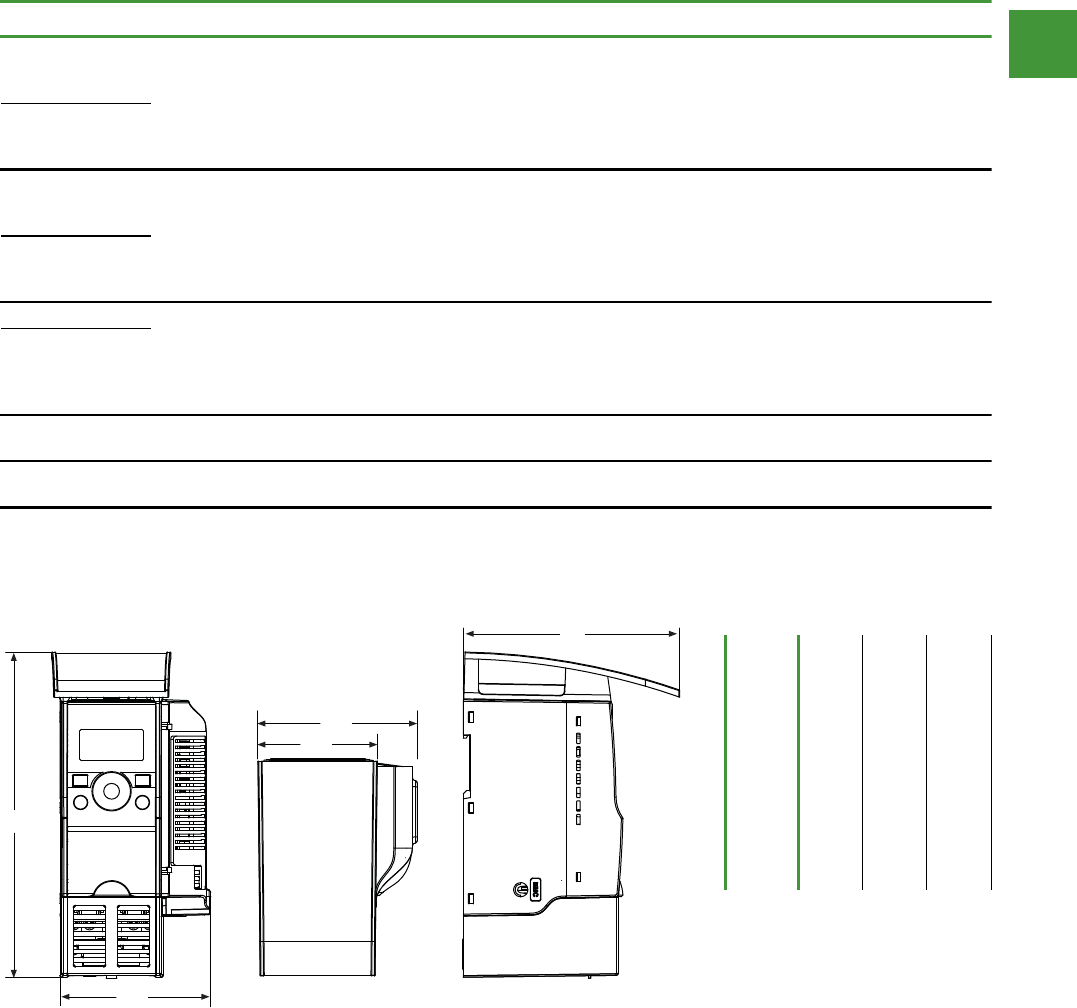
Drives and soft starters
Power control
256
2015/2016 Product guide AUS15_007 - February 2016
Dimensions (approximate dimensions in inched (mm)
M-Max series drives
Volume 6—Solid-State Motor Control CA08100007E—May 2014 www.eaton.com V6-T2-29
2
2
2
2
2
2
2
2
2
2
2
2
2
2
2
2
2
2
2
2
2
2
2
2
2
2
2
2
2
2
2.3
Adjustable Frequency Drives
M-Max Series Drives
Approximate Dimensions in Inches (mm)
NEMA 1/IP21 M-Max Drives and Communication Adapter Kit
Frame Type H W1 W2 W3 D
FS1 8.14 (206.7) 3.77 (95.7) 2.99 (75.9) 3.98 (101.2) 5.41 (137.5)
FS2 9.90 (251.5) 4.72 (120.0) 3.97 (100.8) 4.94 (125.5) 5.68 (144.2)
FS3 12.26 (311.5) 5.12 (130.1) 4.36 (110.8) 5.33 (135.3) 6.32 (160.5)
H
W1
W2
D
W3
V6-T2-28 Volume 6—Solid-State Motor Control CA08100007E—May 2014 www.eaton.com
2
2
2
2
2
2
2
2
2
2
2
2
2
2
2
2
2
2
2.3
Adjustable Frequency Drives
M-Max Series Drives
Dimensions and Frame Sizes
Note 1 in = 25.4 mm, 1 mm = 0.0394 in
Installation
Size
Item no. a a1 b b1 b2 c Ø, Ø1 Ø2
MMX12AA1D7_
MMX12AA2D4_
MMX12AA2D8_ 2.60
(66)
1.50
(38)
6.30
(160)
5.79
(147)
1.26
(32)
4.02
(102)
0.18
(4.5)
— FS1
MMX34AA1D3_
MMX34AA1D9_
MMX34AA2D4_
3.54
(90)
2.46
(62.5)
7.68
(195)
7.17
(182)
1.26
(32)
4.14
(105)
2.17
(5.5)
— FS2
MMX12AA3D7_
MMX12AA4D8_
MMX12AA7D0_
MMX34AA3D3_
MMX34AA4D3_
MMX34AA5D6_
3.94
(100)
2.95
(75)
9.96
(253)
9.53
(242)
1.34
(34)
4.41
(112)
2.17
(5.5)
— FS3
MMX12AA9D6_
MMX34AA7D6_
MMX34AA9D0_
MMX34AA012_
MMX34AA014_
6.50
(165.0)
5.51
(140.0)
14.57
(370.0)
13.82
(351.0)
13.27
(337.0)
6.61
(168.0)
0.28
(7.0)
0.55
(14.0)
FS4
MMX34AA016_
MMX34AA023_
6.50
(165.0)
5.51
(140.0)
14.57
(414.0)
13.82
(398.0)
15.08
(383.0)
8.07
(205.0)
0.28
(7.0)
0.55
(14.0) FS5
MMX34AA031_
MMX34AA038_
Frame
type FS1 FS2 FS3
H8.14
(206.7)
9.90
(215.5)
12.26
(311.5)
W1 3.77
(95.7)
4.72
(120.0)
5.12
(130.1)
W2 2.99
(75.9)
3.97
(100.8)
4.36
(110.8)
W3 3.98
(101.2)
4.94
(125.5)
5.33
(135.3)
D5.41
(137.5)
5.68
(144.2)
6.32
(160.5)
NEMA 1/IP21 M-Max Drives and Communication Adapter Kit
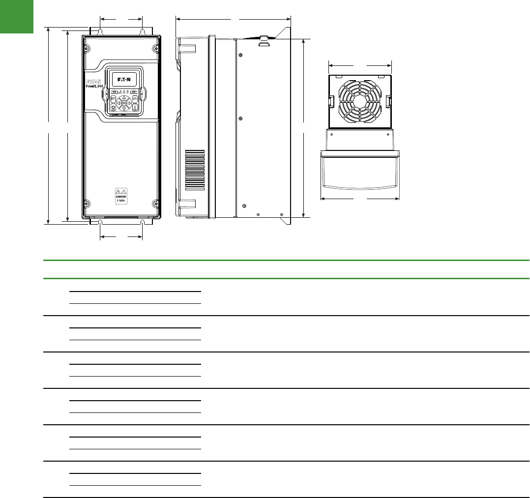
Drives and soft starters
Dimensions (approximate dimensions in inched (mm)
DG1 drive
V6-T2-44Volume 6—Solid-State Motor Control CA08100007E—May 2014 www.eaton.com
2
2
2
2
2
2
2
2
2
2
2
2
2
2
2
2
2
2
2
2
2
2
2
2
2
2
2
2
2
2
2.4
Adjustable Frequency Drives
PowerXL DG1 Series Drives
Dimensions
Approximate Dimensions in Inches (mm)
PowerXL Series—DG1 Dimensions
Note 1FR6 and 575 Vac available in 2015.
Frame
Size Voltage hp (CT/IH) kW
Amperes
(CT/IH)
Weight
Lb (kg)D H1 H2 H3 W1 W2 W3 W4 Ø
FR1 230 Vac 0.75–3 0.55–2.2 3.5–11 7.89
(200.4)
480 Vac 1–5 0.75–3.7 2.3–7.6
575 Vac
12–5 1.5–3.7 3.3–7.5
FR2 230 Vac 5–7.5 3–5.5 12.5–25 9.63
(244.7)
480 Vac 7.5–15 5.5–11 12–23
575 Vac
17.5–15 5.5–11 10–18
FR3 230 Vac 10–15 7.5–11 31–48 10.44
(265.1)
480 Vac 20–30 15–22 31–46
575 Vac
120–30 15–22 22–34
FR4 230 Vac 20–30 15–22 61–88 11.57
(294.0)
480 Vac 40–60 30–45 61–87
575 Vac
140–60 30–45 41–62
FR5 230 Vac 40–60 30–45 114–170 13.41
(340.7)
12.87
(326.9)
16.50
(419.1)
21.97
(558.0)
24.80
(629.9)
34.98
(888.5)
12.28
(311.9)
15.98
(405.9)
21.46
(545.0)
34.31
(617.5)
29.65
(753.1)
11.50
(292.1)
14.96
(380.0)
20.43
(518.9)
23.27
(591.1)
27.83
(706.9)
6.02
(153.0)
6.61
(167.8)
8.06
(204.6)
9.36
(237.7)
11.34
(288.0)
4.80
(121.9)
5.28
(134.1)
7.24
(183.9)
9.13
(231.9)
11.10
(281.9)
3.94
(100.1)
3.54
(90.0)
4.92
(125.0)
8.07
(205.0)
8.66
(220.0)
3.94
(100.1)
3.54
(90.0)
4.92
(125.0)
8.07
(205.0)
8.66
(220.0)
0.28
(7.0)
0.28
(7.0)
0.35
(9.0)
0.35
(9.0)
0.35
(9.0)
14.33
(6.5)
23.37
(10.6)
49.82
(22.6)
77.60
(35.2)
154.32
(70.0)
480 Vac 75–125 55–90 105–170
575 Vac
175–125 55–90 80–125
FR6
1230 Vac 75–100 55–75 211–261
480 Vac 150–200 110–150 205–261
575 Vac
1150–200 110–160 144–208
W3
H2
W4
W1
W2
H1
D
H3
1111111111
PowerXL Series
Power control
257 2015/2016 Product guide AUS15_007 - February 2016
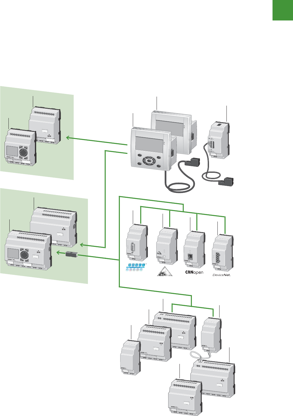
Automation
Power control
258
2015/2016 Product guide AUS15_007 - February 2016
1. Basic device - EASY500
2. Basic device - EASY700
3. Remote text display - Display/operating unit MFD-80(-B)
Power supply unit/communication module MFD(-AC)-CP4-500
4. Ethernet gateway - EASY209-SE
5. Bus modules - EASY204-DP
6. Bus modules - EASY205-ASI
7. Bus modules - EASY221-CO
8. Bus modules - EASY222-DN
9. Output expansion - EASY202-RE
10. I/O expansions - EASY410...
11. I/O expansions - EASY6...
12. Coupling module - EASY200-EASY
easy relay controllers
System overview, easy relays, MFD-titan multi-function display
Control, monitor, protect.
12/4 Control relays
2010 CA08103002Z-EN www.eaton.com
500, 700
System overview
POW
BUS
POWER
COM-ERR
ADR
ERR MS
NS
4
3
3
2
2
1
1
5
6
7
8
12
11
11
9
10
10
Today’s marketplace is all about how you interface
with customers, suppliers & your machinery.
Meeting customers’ needs means creating
products that interface seamlessly. That’s why
Eaton’s complete line of automation & control
products includes everything from sophisticated
logic controllers & operator interfaces to monitoring
relays, timers, limit switches & terminal blocks, all
the latest in technology.
With the ever present need to be connected to
your machinery & processes, communications
are more important than ever. All our controllers,
touchscreens & drives provide Ethernet
connectivity to stay in control of your processes &
machinery wherever you are. Our new & expanded
range, now including Eaton’s industrial automation
products, provides a one-stop shop for all your
automation & control requirements.
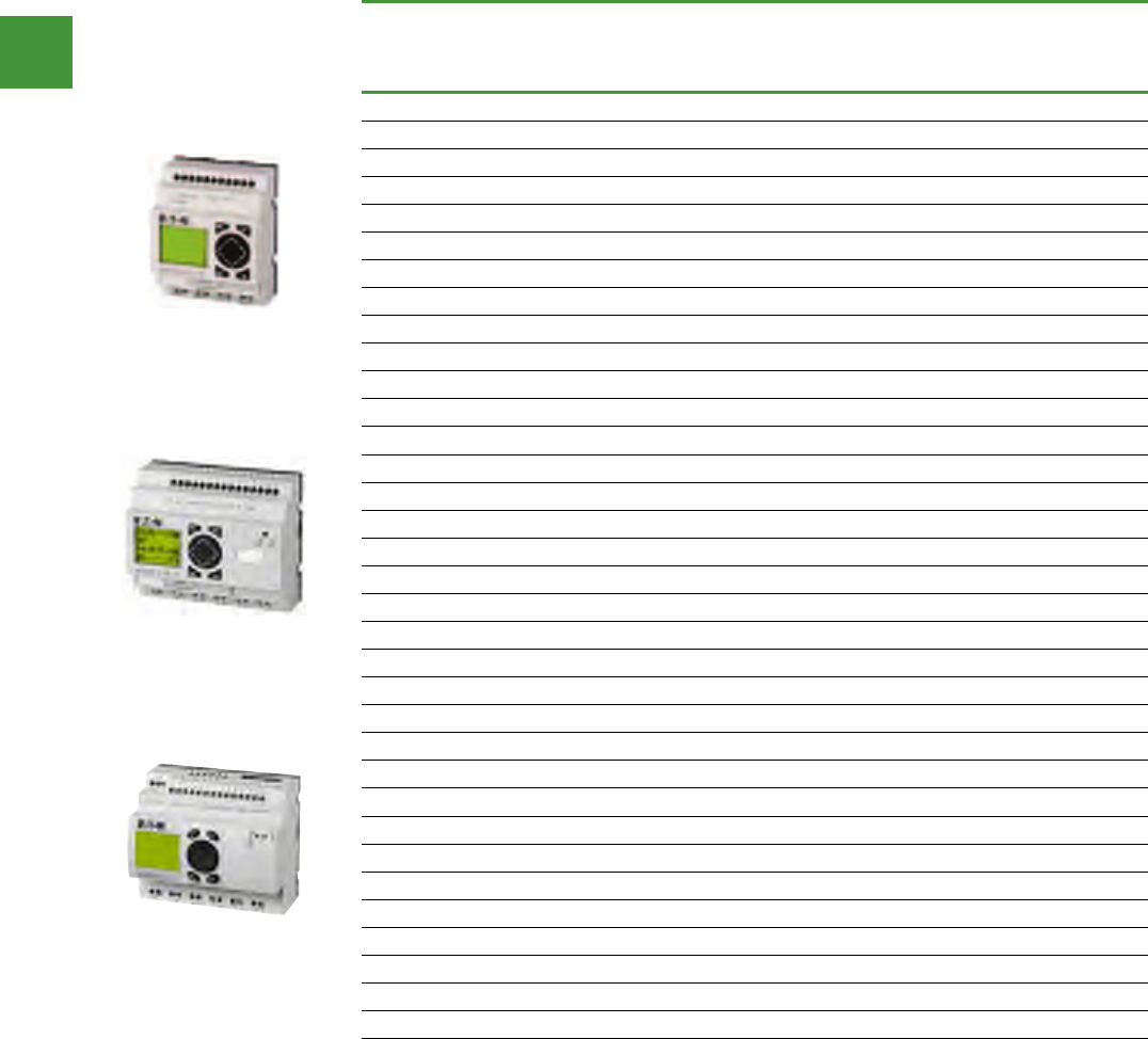
Automation
Power control
259 2015/2016 Product guide AUS15_007 - February 2016
Base units easy500, easy700, easy800
Inputs of which
can be
used as
analogue
Outputs Additional features
Supply
voltage Item no.
Digital Relay 10
A (UL) Transistor Analog Display
& keypad
Real time
clock
8 2 4 – – 24 V AC EASY512-AB-RC
8 2 4 – – – 24 V AC EASY512-AB-RCX
8 – 4 – – –100 - 240 VAC EASY512-AC-R
8 – 4 – – 100 - 240 VAC EASY512-AC-RC
8 – 4 – – – 100 - 240 VAC EASY512-AC-RCX
8 2 4 – – 12 V DC EASY512-DA-RC
8 2 4 – – – 12 V DC EASY512-DA-RCX
8 2 4 – – –24 V DC EASY512-DC-R
8 2 4 – – 24 V DC EASY512-DC-RC
8 2 4 – – – 24 V DC EASY512-DC-RCX
8 2 – 4 – 24 V DC EASY512-DC-TC
8 2 – 4 – – 24 V DC EASY512-DC-TCX
12 4 6 – – 24 V AC EASY719-AB-RC
12 4 6 – – – 24 V AC EASY719-AB-RCX
12 – 6 – – 100 - 240 VAC EASY719-AC-RC
12 – 6 – – – 100 - 240 VAC EASY719-AC-RCX
12 4 6 – – 12 V DC EASY719-DA-RC
12 4 6 – – – 12 V DC EASY719-DA-RCX
12 4 6 – – 24 V DC EASY719-DC-RC
12 4 6 – – – 24 V DC EASY719-DC-RCX
12 4 – 8 – 24 V DC EASY721-DC-TC
12 4 – 8 – – 24 V DC EASY721-DC-TCX
12 – 6 – – 100 - 240 VAC EASY819-AC-RC
12 – 6 – – – 100 - 240 VAC EASY819-AC-RCX
12 4 6 – – 24 V DC EASY819-DC-RC
12 4 6 – – – 24 V DC EASY819-DC-RCX
12 4 6 – 1 24 V DC EASY820-DC-RC
12 4 6 – 1 – 24 V DC EASY820-DC-RCX
12 4 – 8 – 24 V DC EASY821-DC-TC
12 4 – 8 – – 24 V DC EASY821-DC-TCX
12 4 – 8 1 24 V DC EASY822-DC-TC
12 4 – 8 1– 24 V DC EASY822-DC-TCX
easy relay controllers
easy500
easy700
easy800
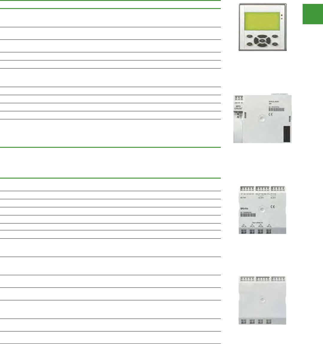
Automation
Power control
260
2015/2016 Product guide AUS15_007 - February 2016
easy relay controllers
MFD-Titan display/keypad, CPU, I/O modules
Voltage Description Item no.
Display/operating unit
Graphics display: 132 x 64 pixels with switchable backlight, freely definable status LED,
IP65, removable titanium front frame
– With keypad & Eaton logotype NEMA 4x in connection with
MFD-XM-80 protective membrane, see accessories MFD-80-B
– With keypad, without Eaton logotype, NEMA 4x in connection
with MFD-XM-80 protective membrane, see accessories MFD-80-B-X
–Without keypad, with Eaton logotype, NEMA 4x MFD-80
–Without keypad, without Eaton logotype, NEMA 4x MFD-80-X
Power supply unit/CPU module
Expandable with MFD-80-.. & I/O module, easy expansions can be connected, Serial interface,
IP20, cage clamp terminals
100/240 V AC Without easy-NET MFD-AC-CP8-ME
100/240 V AC With easy-NET MFD-AC-CP8-NT
24 V DC Without easy-NET MFD-CP8-ME
24 V DC With easy-NET MFD-CP8-NT
MFD-Titan display/keypad, CPU, I/O modules
Inputs Outputs
Range of
temperature Item no.
Digital
of which
can be
used as
analog
Pt 100/
Ni 1000
Relay
10 A
(UL)
Transistor Analog
I/O modules
IP20, cage clamp terminals 24 V DC for MFD-CP8..
12 4 – 4 – – – MFD-R16
12 4 – – 4 – – MFD-T16
12 4 – 4 – 1 – MFD-RA17
12 4 – – 4 1 – MFD-TA17
100/240 V AC for MFD-AC-CP8…
12 – – 4 – – – MFD-AC-R16
I/O modules with temperature measuring
IP20, cage clamp terminals, 24 V DC for MFD-CP8…,
(from device version 08), temperature range can be set
6 2 2 – 4 –
-40…+90 °C
0…+250 °C
0…+400 °C
MFD-TP12-PT-A
6 2 2 – 4 – -200…+200 °C
0…+850 °C MFD-TP12-PT-B
6 2 2 – 4 – -40…+90 °C
0…+250 °C MFD-TP12-NI-A
6 2 2 – 4 1
-40…+90 °C
0…+250 °C
0…+400 °C
MFD-TAP13-PT-A
6 2 2 – 4 1 -200…+200 °C
0…+850 °C MFD-TAP13-PT-B
6 2 2 – 4 1 -40…+90 °C
0…+250 °C MFD-TAP13-NI-A
MFD-80-B
MFD-CP8-ME
MFD-R16
MFD-TP12-PT-A
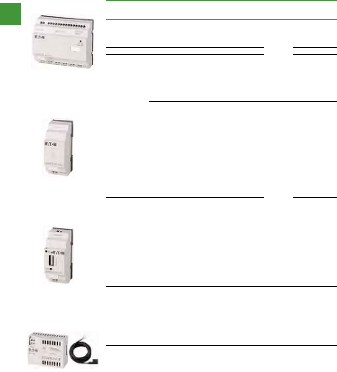
Automation
Power control
261 2015/2016 Product guide AUS15_007 - February 2016
easy relay controllers
Expansions, bus modules, Ethernet gateway
Description
Inputs Outputs Supply
voltage
For use
with... Item no.
Digital/
Analogue
Relay 10
A (UL) Transistor Analogue
I/O expansions
– 12 6 – - 100 - 240
VAC
easy700
easy800
MFD-CP8..
EASY618-AC-RE
– 12 6 – - 24 V DC EASY618-DC-RE
– 12 – 8 - 24 V DC EASY620-DC-TE
Not usable in
combination
with base units
EASY719-DA-...
– 2 – - – EASY202-RE
Can be used
through easyLink
6 4 – - 24 V DC EASY410-DC-RE
6 – 4 - 24 V DC EASY410-DC-TE
1 / 2 –2124 V DC EASY406-DC-ME
1 / 6 –2224 V DC EASY411-DC-ME
Coupling unit
For the
connection
of remote I/O
modules up to
30 m.
– – – - –
easy700
easy800
MFD-CP8..
EASY200-EASY
Expansion units for networking
AS-Interface
connection
slave 4 inputs,
4 outputs,
4parameter
bits Addresses
available: 0 to 31
– – – - –
easy700
easy800
MFD-CP8..
EASY205-ASI
Profibus DP
slave addresses
available: 1 to
126
– – – - – EASY204-DP
CANopen
interface
addresses
available: 1 to
127
– – – - – EASY221-CO
DeviceNet
interface
addresses
available: 0 to 63
– – – - – EASY222-DN
Ethernet gateway
Serial interface
easy to ethernet – – – - –
easy500
easy700
easy800
MFD-CP8..
EASY209-SE
Power supply unit/communication modules
24 V DC – – – - – easy500
easy700 MFD-CP4-500
24 V DC – – – - – easy800
MFD-CP8.. MFD-CP4-800
100/240 V AC – – – - – easy500
easy700 MFD-AC-CP4-500
100/240 V AC – – – - – easy800
MFD-CP8.. MFD-AC-CP4-800
2 × 0 - 10 V, 2 × 0 - 20 mA, 2 × RTD (2/3-wire connection);
any combination Voltage inputs (0–10 V) can optionally be used as digital inputs
2 x 0 - 10 V, 2 x 0 - 20mA, 2 x Pt100 (2/3 wire connection);
Voltage inputs (0 –10 V) can optionally be used as digital inputs
EASY618-AC-RE
EASY200-EASY
EASY209-SE
MFD-CP4-500
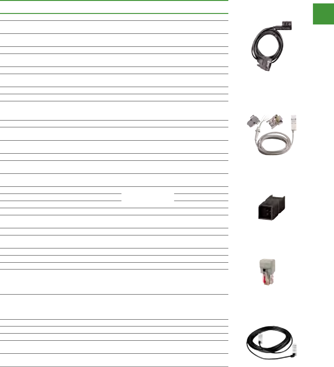
Automation
Power control
262
2015/2016 Product guide AUS15_007 - February 2016
easy relay controllers
easy relays, MFD-Titan multi-function display, accessories
Description For use with Item no.
Programming software
Menu selection in 13 languages. Operating systems:
Windows 2000 SP4, Windows XP SP1 easy400/500/600/700 EASY-SOFT-BASIC
Menu selection in 13 languages. Operating systems:
Windows 2000 SP4, Windows XP SP1
easy400/500/600/700
/800/MFD-..-CP8 EASY-SOFT-PRO
Programming cable
SUB-D 9-pole, serial, 2 m easy500
easy700 EASY-PC-CAB
USB, 2 m EASY-USB-CAB
SUB-D 9-pole, serial, 2 m easy800
MFD-..-CP8 EASY800-PC-CAB
USB, 2 m EASY800-USB-CAB
Modem cable
Configurable modem, printer and programming
cable, possible transfer rate 56 kbaud, 9 pole Sub-D
plug (plug + socket for assembly by user)
EASY800-MO-CAB
Memory cards
32 kB module easy500
easy700 EASY-M-32K
256 kB module easy800
MFD-..-CP8 EASY-M-256K
Coupling piece
Spare link between base unit & expansion units easy700/800/
MFD-..-CP8 EASY-LINK-DS
Network connection cable (remote coupling)
Completely prepared for easy-NET
Length: 0.3 m easy800
MFD-..-CP8-NT
EASY-NT-30
Length: 0.8 m EASY-NT-80
Length: 1.5 m EASY-NT-150
Bus termination resistor
8pole,RJ45,124Ω
Connection to PIN 1 and PIN 2 easyNet EASY-NT-R
Data cable
4 x 0.14 mm², twisted pair, AWG 26
Length: 100 m easyNet EASY-NT-CAB
Bus connector plug
8 pole, RJ45 easyNet EASY-NT-RJ45
Point-to-point connection cable
Serial interface for connecting MFD-..-CP8 to
easy800 or MFD-..-CP8, can be configured as
required with separate plug, 5m can be cut as
required
easy800
MFD-..-CP8 MFD-800-CAB5
Reserve power supply/communications module
For MFD-80… separately mounted display (only
ASCII characters) on easy500/700/800/MFD-…-CP8,
without connection cable, serial interface.
24 V DC, IP20 MFD-80.. MFD-CP4
100/240 V AC, IP20 MFD-80.. MFD-AC-CP4
Spare connection cables
For the connection of MFD-CP4-500 to easy500/
easy700, 5m, can be cut to length
easy500
easy700 MFD-CP4-500-CAB5
For the connection of MFD-CP4-800 to easy800/
MFD-…-CP8, 5m, can be cut to length
easy800
MFD-..-CP8 MFD-CP4-800-CAB5
EASY-PC-CAB
EASY-LINK-DS
MFD-800-CAB5
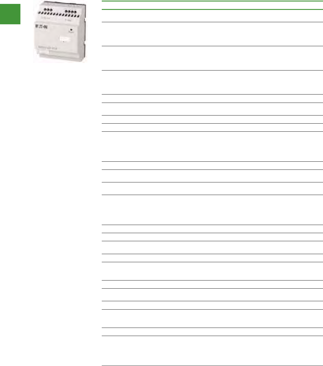
Automation
Power control
263 2015/2016 Product guide AUS15_007 - February 2016
easy relay controllers
easy relays, MFD-Titan multi-function display, accessories
Description For use with Item no.
Switched-mode power supply unit primary-switched mode
Stabilized
Rated input voltage: 50/60 HZ: 100/240 V AC
Rated output voltage (residual ripple): 24 V DC (g 3 %)
Rated output current: 1.25 A
easy500
easy700
easy800
MFD-CP8
EASY400-POW
Rated input voltage: 50/60 Hz: 100/240 V
Rated output voltage: 24 V/12 V DC
Rated output current: 0.35 A/20 mA
easy500
easy700
easy800
MFD-CP8
EASY200-POW
Rated input voltage:
50/60 Hz: 100 - 240 V AC
Rated output voltage (residual ripple): 24 V DC (± 3 %)
Rated output current: 2.5 A
EASY500-POW
PROFIBUS-DP data cable
Twisted pair, without plug, 2-core, 2 x 0.64 mm²
(only suitable for fixed wiring) 100 m ZB4-900-KB1
PROFIBUS-DP bus connector plug
Pins, 9 pole - Cable entry, angled 90° ZB4-209-DS2
Metallised insulated housing Maximum transfer rate 12 MBit/s
Integrated switch (accessible from the outside) for the bus
terminating resistors
Terminal block for two cable entries, with straight or 90° angled
cable entry, as required
ZB4-209-DS3
Upstream device to increase the AC input current
6 channels, cable length up to 100m AC versions of
easy/MFD EASY256-HCI
Mounting accessories
Top-hat rail adapter for hinged inspection window
12 mm x 66 mm x 82 mm Installation on hinged inspection
window, for front fitting of devices. Complete set, consisting of
2 brackets & 4 screws
easy200
easy500
easy700
easy800
MFD-CP8
SKF-HA
Hinged inspection window
94 mm x 77 mm x 25 mm (4 space units) easy500 SKF-FF4
130 mm x 77 mm x 25 mm (6 space units) easy700
easy800 SKF-FF6
Mounting rail to IEC/EN 60715
Mounting rail with cutout specifically for MFD-AC-CP8.../MFD
CP8... for fixing easy expansion units (2 space units) Length:
142.5 mm
easy200 MFD-TS-144
Protective cover
Transparent, protection against accidental actuation. Can be
sealed. Application without front frame MFD-80.. MFD-XS-80
Protective membrane
Transparent version for harsh environmental conditions &
application in the food industry. Increased protection rating to
NEMA 4x for MFD-80-B
MFD-80.. MFD-XM-80
Telescopic clip
With 35mm top-hat rail to IEC/EN 60715 for mounting depth
compensation when rear mounting in CI-K… enclosures and
cabinets.
Stepless adjustment via scale from 75 – 115 mm.
Screw and snap fastening
M22-TA
EASY400-POW
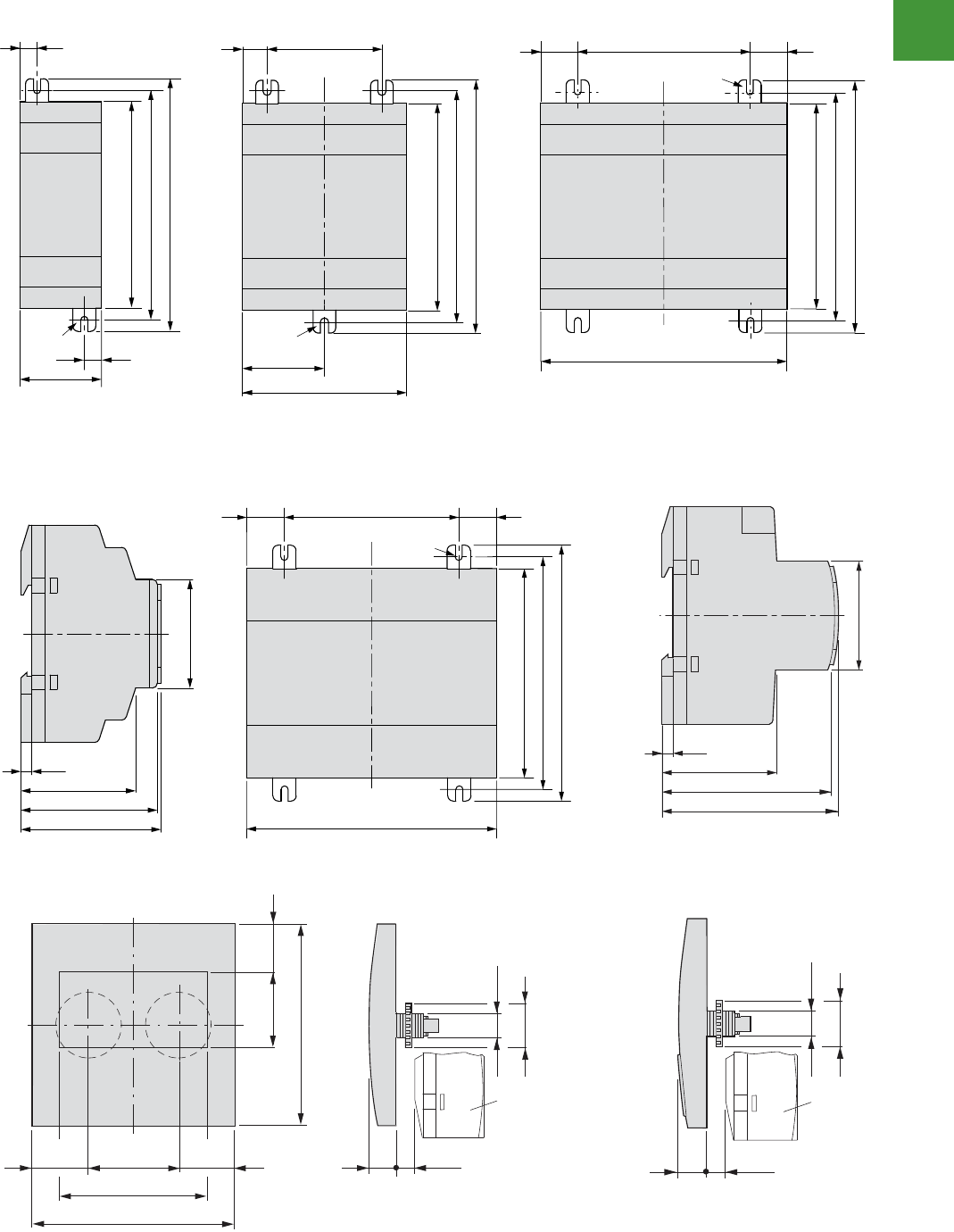
Automation
Power control
264
2015/2016 Product guide AUS15_007 - February 2016
Control relays, multi-function display
Basic devices, expansions, display/operating unit
2010 CA08103002Z-EN www.eaton.com
..., MFD-80...Basic devices, expansions, display/operating unit
Dimensions
006ysae004ysae002ysae
007ysae005ysae
008ysae002ysae
easy400
easy500
easy600
easy700
B-08-DFM08-DFM...08-DFM
M4
7.5
35.5
7.5
90
102
110
90
102
110
71.5
M4
10.75 50
35.75
90
102
110
M4
107.5
75 16.25
16.25
90
102
110
M4
107.5
75 16.2516.25
48.5
45
4.5
70.5
72
45
58
56.5
47.5
4.5
32 17
20 13.7
86.5
30
62
86.5
52.8252.82
MFD-CP...
22.3
30
22.3 +0.4
21.5 13.7
MFD-CP
...
30
Control relays, multi-function display
Basic devices, expansions, display/operating unit
2010 CA08103002Z-EN www.eaton.com
..., MFD-80...Basic devices, expansions, display/operating unit
Dimensions
006ysae004ysae002ysae
007ysae005ysae
008ysae002ysae
easy400
easy500
easy600
easy700
B-08-DFM08-DFM...08-DFM
M4
7.5
35.5
7.5
90
102
110
90
102
110
71.5
M4
10.75
50
35.75
90
102
110
M4
107.5
75 16.25
16.25
90
102
110
M4
107.5
75 16.2516.25
48.5
45
4.5
70.5
72
45
58
56.5
47.5
4.5
32 17
20 13.7
86.5
30
62
86.5
52.8252.82
MFD-CP...
22.3
30
22.3 +0.4
21.5 13.7
MFD-CP...
30
easy relay controllers
Dimension
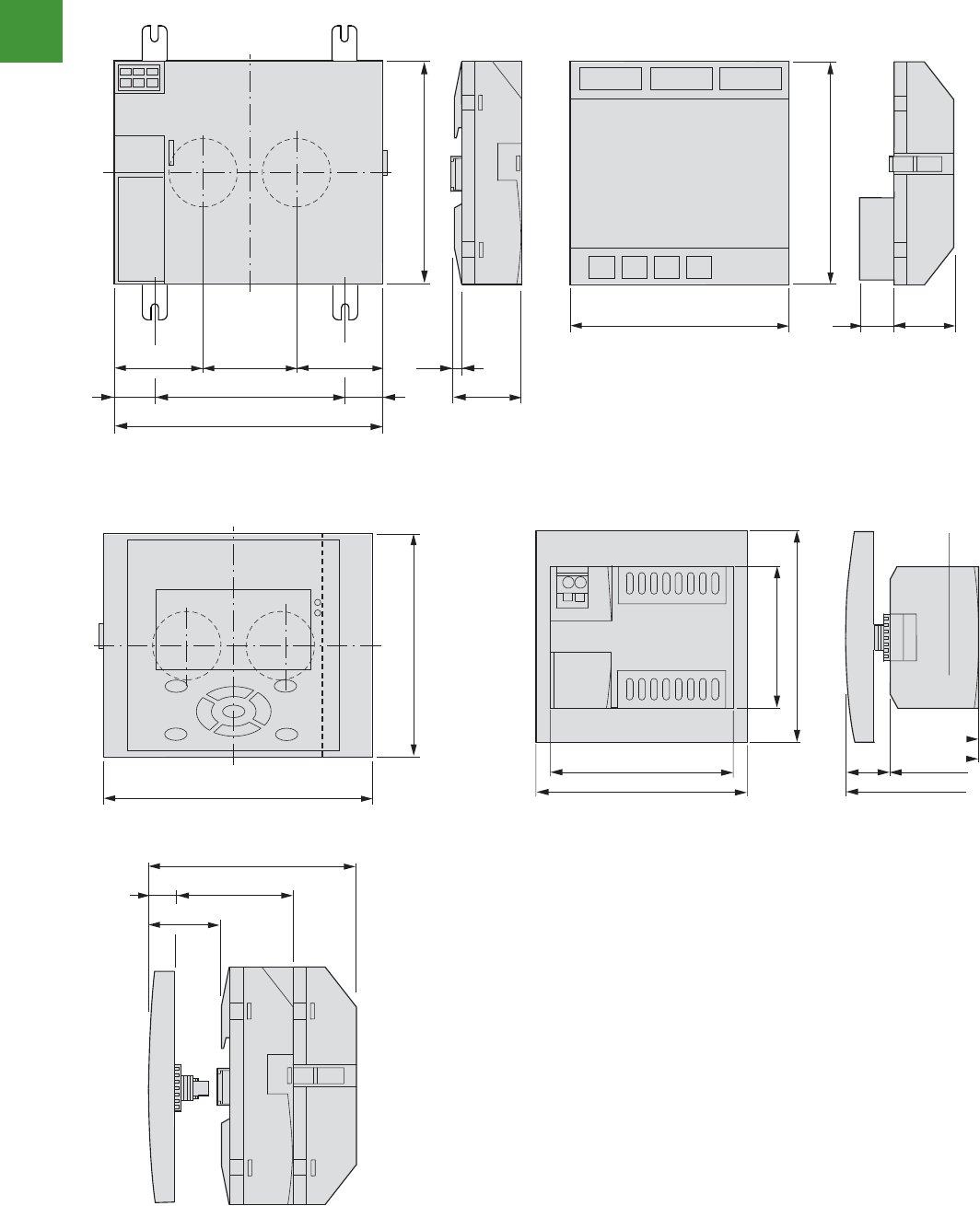
Automation
Power control
265 2015/2016 Product guide AUS15_007 - February 2016
12/52 Control relays, multi-function display
Central processing unit, communication module, inputs/outputs modules
2010 CA08103002Z-EN www.eaton.com
MFD...
MFD...Central processing unit, communication module, inputs/outputs modul es 61R-CA-DFM , ...T-DFM , ...R-DFM...PC-CA-DFM , ...PC-DFM
4PC-DFM + ...08-DFM...T-DFM/...R-DFM + ...PC-DFM + ...08-DFM
MFD-80... + MFD-AC-CP... + MFD-AC-R16
90
57.83 57.83 4.5
29.5
75 52.61 52.61
107.5
30 g0.2
90
88.1 19 25
90
88.2
107.5
20 43.2
33.7
65.5
29.3 36.2
86.5
75
86.5
58
easy relay controllers
Dimension
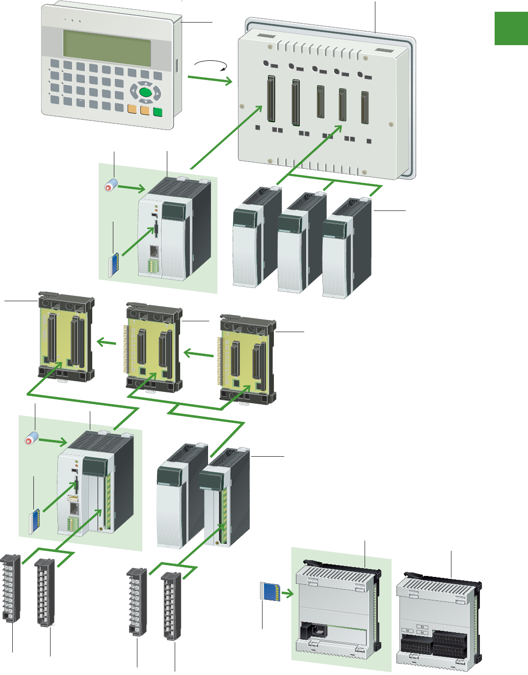
Automation
Power control
266
2015/2016 Product guide AUS15_007 - February 2016
Programmable logic controllers
2010 CA08103002Z-EN www.eaton.com
CLP raludoMstcudorp noitamotuA63/41
Modular PLC
System overview
DC IN PUT
EH-XD16
0
4
8
12
1
5
9
13
2
6
10
14
3
7
11
15
DC IN PUT
EH-XD16
0
4
8
12
1
5
9
13
2
6
10
14
3
7
11
15
XC-CPU201
0
4
0
4
1
5
1
5
2
6
2
14
3
7
3
15
DC IN PUT
EH-XD16
0
4
8
12
1
5
9
13
2
6
10
14
3
7
11
15
DC IN PUT
EH-XD16
0
4
8
12
1
5
9
13
2
6
10
14
3
7
11
15
DC IN PUT
EH-XD16
0
4
8
12
1
5
9
13
2
6
10
14
3
7
11
15
2
5
8
F5
1
4
7
F4
0
,
+/-
F3
F15
F13
F11
F2
F14
F12
F10
F1
3
ESC ENTERCLEAR
SHIFT
6
9
F6 F7 F8 F9
XC-CPU101
0
4
0
4
1
5
1
5
2
6
2
14
3
7
3
15
2
6
7
5
10
6
7
3
4
4
4
1
88
88
7
1
180
9
3
1. XV101 text display
2. XC100
3. XI/OC I/O modules
4. Module backplane
5. XC200
6. Battery
7. Memory card (multi-media card)
8. XI/OC terminal block
9. XC121
10. EXT121-1
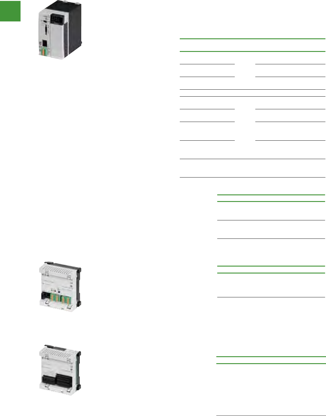
Automation
Power control
267 2015/2016 Product guide AUS15_007 - February 2016
XC100/XC200
• Controller with digital inputs/outputs, locally & remotely expandable
• CANopen interface, 24V power supply
• Locally expandable by up to 15 XI/OC modules
• The following accessory equipment is required: terminal clamps, module rack, battery
Programmable logic controllers
XC-CPU…
Description Std.
pack Item no.
64 kByte
user memory
1 off
XC-CPU101-C64K-8DI-6DO
128 kByte
user memory XC-CPU101-C128K-8DI-6DO
256 kByte
user memory XC-CPU101-C256K-8DI-6DO
256 kByte
user memory
1 off
XC-CPU201-EC256K-8DI-6DO
2 mByte
user memory XC-CPU201-EC512K-8DI-6DO
256 kByte
user memory
Integrated Web server
XC-CPU201-EC256K-8DI-6DO-XV
2 mByte
user memory
Web server
XC-CPU201-EC512K-8DI-6DO-XV
4 mByte
user memory
Integrated Web server
XC-CPU202-EC4M-8DI-6DO-XV
XC100
Controller with 8 digital inputs
(4 interrupt inputs), 6 digital
outputs, RS232 interface for
programming & communication,
CANopen interface; slot
for memory card, optional
expansion with text display,
RUN/STOP switch & LED
indicators.
XC200
Controller with 8 digital inputs
(2 counters, 2 interrupt inputs,
1 incremental input) & 6 digital
outputs, Ethernet & RS232
interface for programming &
communication, CANopen
interface, slot for memory card,
USB interface, RUN/STOP
switch & LED indicators.
Text display for XC100
• Backlit LCD
• Membrane keypad
• 1 slot for XC100
• 3 spare slots for XI/OC modules
• Numerical keypad
• Arrow keys
• Contrast setting adjustable via software
Description Item no.
Operation with XC-CPU101-…-XV
4 lines x 20 characters, resolution
122 x 32 pixels, 9 function keys
XV-101-K42
Operation with XC-CPU101-…-XV
8 lines x 40 characters, resolution
240 x 64 pixels, 15 function keys
XV-101-K84
XC121
• Compact PLC
• 24 V supply
• 2 CANopen interfaces
• RS232 interface for programming and
communication
• Second RS232/RS485 interface
• Slot for MMC memory card
• Connection through spring-cage terminal
blocks
• OPC server
Description Item no.
Can be locally expanded with
I/O module XIO-EXT-121-1
256 kByte program memory,
244 kByte data memory
XC-CPU121-2C256K
I/O expansion for XC121
• Expansion unit with digital and analog
inputs/outputs
• expandable with XI/OC signal modules
(except XIOC-NET-DP-M)
• pluggable spring-cage terminals
Description Item no.
Local I/O expansions for PLC XC121
10 digital inputs 24 V DC, of which
6 interrupt
8 digital inputs/outputs 24 V DC,
0.5 A
2 analog inputs 0 - 10 V
2 analog inputs 0 - 20 mA
2 analog inputs Pt100 RTD
2 analog outputs 0 - 10 V
XIO-EXT121-1
XC-CPU101-C64K-8DI-6DO
XC-CPU121-2C256K
XIO-EXT121-1
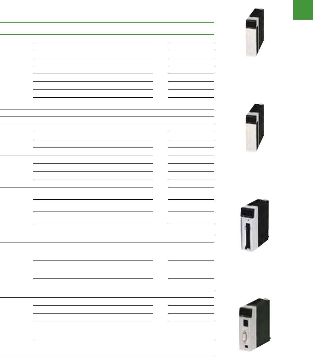
Automation
Power control
268
2015/2016 Product guide AUS15_007 - February 2016
Programmable logic controllers
XIOC
• Compact I/O system for connection to XC100/200 Modular PLCs
• XC100/200 expandable with up to 15 XI/OC modules
• Optionally, screw terminals or spring-loaded terminals for digital/analogue modules
Description Std.
pack Item no.
Digital
modules
8 inputs, 24 V DC
1 off
XIOC-8DI
16 inputs, 24 V DC XIOC-16DI
32 inputs, 24 V DC XIOC-32DI
8 outputs, 24 V DC, 0.3 A XIOC-8DO
12 relay outputs XIOC-12DO-R
16 outputs, 24 V DC, 0.3 A XIOC-16DO XIOC-16DO
16 outputs, 24 V DC, 0.8 A, short-circuit proof XIOC-16DO-S
32 outputs, 24 V DC, 0.2 A XIOC-32DO
16 connections, 4 inputs, 12 freely parameterisable as
inputs/outputs, 24 V DC Outputs 0.5 A XIOC-16DX
Analogue modules
Inputs
8 inputs, 4 – 20 mA
1 off
XIOC-8AI-I2
8 voltage inputs, 0 – 10 V XIOC-8AI-U1
8 voltage inputs, g10 V XIOC-8AI-U2
4 inputs for temperature monitoring, Pt100/1000 XIOC-4T-PT
Outputs
4 inputs for thermocouples, Type K, J, L, B, N, E, R, S, T XIOC-4AI-T
2 outputs, g10 V XIOC-2AO-U2
2 outputs, 0 – 10 V, 2 outputs, 4 – 20 mA XIOC-2AO-U1-2AO-I2
4 outputs, 0 – 10 V XIOC-4AO-U1
Combination
modules
2 inputs & 1 output, 0 – 10 V
1 ms conversion time XIOC-2AI-1AO-U1
2 inputs & 1 output, 0 – 10 V, 0 – 20 mA
1 ms conversion time, individual changeover XIOC-2AI-1AO-U1-I1
4 inputs & 2 outputs, 0 – 10 V
1 ms conversion time XIOC-4AI-2AO-U1
4 inputs & 2 outputs 0 – 10 V, 0 – 20 mA
1 ms conversion time, individual changeover XIOC-4AI-2AO-U1-I1
Counter
modules
1 input up to 100 kHz, 24 V DC, 5 V DC, 2 digital
transistor outputs, opto-isolated, 24 V DC
30-pole connector required for counter module
1 off
XIOC-1CNT-100KHZ
2 inputs up to 100 kHz, (24 V DC or 5 V diff), 4 digital
transistor outputs, opto-coupled, 24 V DC
30-pole connector required for counter module
XIOC-2CNT-100KHZ
2 incremental encoders up to 400 kHz, 5 V DC,
2 analog, outputs, +10 V XIOC-2CNT-2AO-INC
Communication
modules
Profibus DP master module
1 off
XIOC-NET-DP-M
Profibus DP slave module XIOC-NET-DP-S
Suconet K master module XIOC-NET-SK-M
Serial interface RS 232C, RS 485, RS 422. Operating
modes: Transparent mode, Modbus master, slave,
SUCOM A, Suconet-K slave
XIOC-SER
Serial interfaces RS232C, RS485, RS422. Modes of
operation; Transparent mode, Modbus master/slave
SUCOM-A, DNP protocol
XIOC-TC1
XIOC-8DI
XIOC-8AI-I2
XIOC-1CNT-100KHZ
XIOC-NET-DP-M
Automation
Power control
269 2015/2016 Product guide AUS15_007 - February 2016
Programmable logic controllers
Accessories XIOC-…
Description Std.
pack Item no.
Terminals
18-pole plug with spring-loaded terminal
10
off
XIOC-TERM-18T
One 18-pole terminal plug is required for each digital & analogue module. XIOC-TERM-18S
30-pole connector for counter module, with 4 m cable
XIOC-1CNT-100KHZ, XIOC-2CNT-100KHZ XIOC-TERM30-CNT4
40-pole connector for digital module, with 4 m cable
XIOC-32DI, XIOC-32DO XIOC-TERM32
Basic rack for mounting XC100/200
on top-hat rail, expandable Width: 2 slots for controller
1 off
XIOC-BP-XC
Basic rack for mounting XC100/200
on top-hat rail, expandable
Width: 3 slots for controller &
one XI/OCmodule XIOC-BP-XC1
Expander rack for mounting XI/OC
modules on top-hat rail, expandable Width: 2 slots for XI/OC modules XIOC-BP-2
Expander rack for mounting XI/OC
modules on top-hat rail, expandable Width: 3 slots for XI/OC modules XIOC-BP-3
Expander rack for mounting XI/OC
modules on top-hat rail, expandable
Width: 3 slots for XI/OC modules
Note: module carriers for expansion to
maximum 15 modules must be plugged into
the 5th slot
XIOC-BP-EXT
Other accessories
XIOC-…, XTT…
Description Item no.
Multi-media card - for storage of programs, data, recipes
-512 MByte XT-MEM-MM512M
-32 MByte XT-MEM-MM32M
Battery For back-up of real-time clock & retentive data XT-CPU-BAT1
Programming cable
2 m length D-sub, 9-pin, serial XT-SUB-D/RJ45
2 m length Ethernet cross, 2 m XT-CAT5-X-2
5 m length Ethernet cross, 5 m XT-CAT5-X-5
Programming cable for XC, EC4P, EU5C through USB interface EU4A-RJ45-USB-CAB1
Connection cable
Connecting cable for interface switch XC200 Length: 0.3 m EASY-NT-30
Connecting cable for interface switch XC200 Length: 0.8 m EASY-NT-80
Connecting cable for interface switch XC200 Length: 1.5 m EASY-NT-150
CAN cable to
ISO 11898
Recommendation: UNITRONIC bus LD, Messrs.
LAPPKABEL, 2 x 2 x 0.22 mm2
Surge impedance: 100 – 120 W
Effective capacitance: 800 Hz, max. 60 nF/km
-
Empty module Empty module to cover free XI/OC slots XIOC-NOP
Interface switch
Interface adapter to split the combined RS232/Ethernet
interface of the XC200 into RJ45 sockets. Connection
cable EASY-NT-30/80/150 usable for connection to XC200.
XT-RJ45-ETH-RS232
Filter Interference suppression of the external 24 V DC, supply
of the XC100/200, Max. current drawn: 2.2 A XT-FIL-1
Insert labels
Insert labels for free user inscription
For 3 devices: XV-101-K42
For 3 devices: XV-101-K84
XT-BS1
XIOC-TERM-18T
XIOC-BP-XC1
XT-MEM-MM512M
EASY-NT-30
XIOC-NOP
XT-RJ45-ETH-RS232
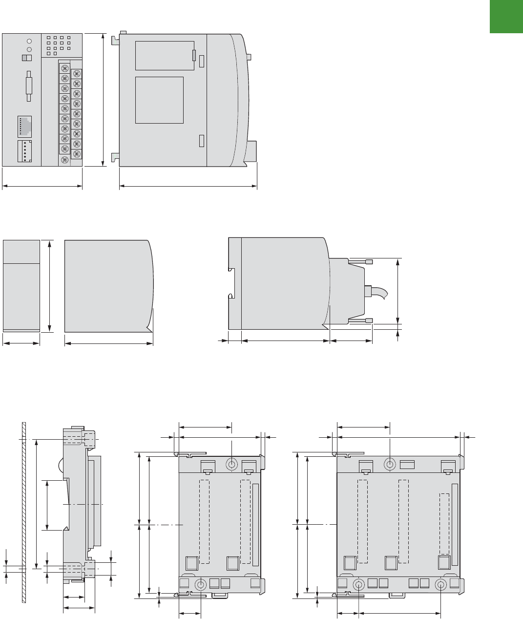
Automation
Power control
270
2015/2016 Product guide AUS15_007 - February 2016
Programmable logic controllers
Automation products
2010 CA08103002Z-EN www.eaton.com
95/41sCLP raludoM
Modular PLCs
Dimensions
XC-CPU101
XC-CPU201
XC-CPU202
XIOC…
Backplanes 3-PB-COIX2-PB-COIX
TXE-PB-COIXCX-PB-COIX
XIOC-BP-XC1
10060
100
95
30
100
95 50
21
735
8.5
4.5 35.5
88
M 4
14
21
53.5 53.5
50
50
1
3.5 3
60
39
16
3.5 3
90
39
5.355.35
50
50
1
16 60
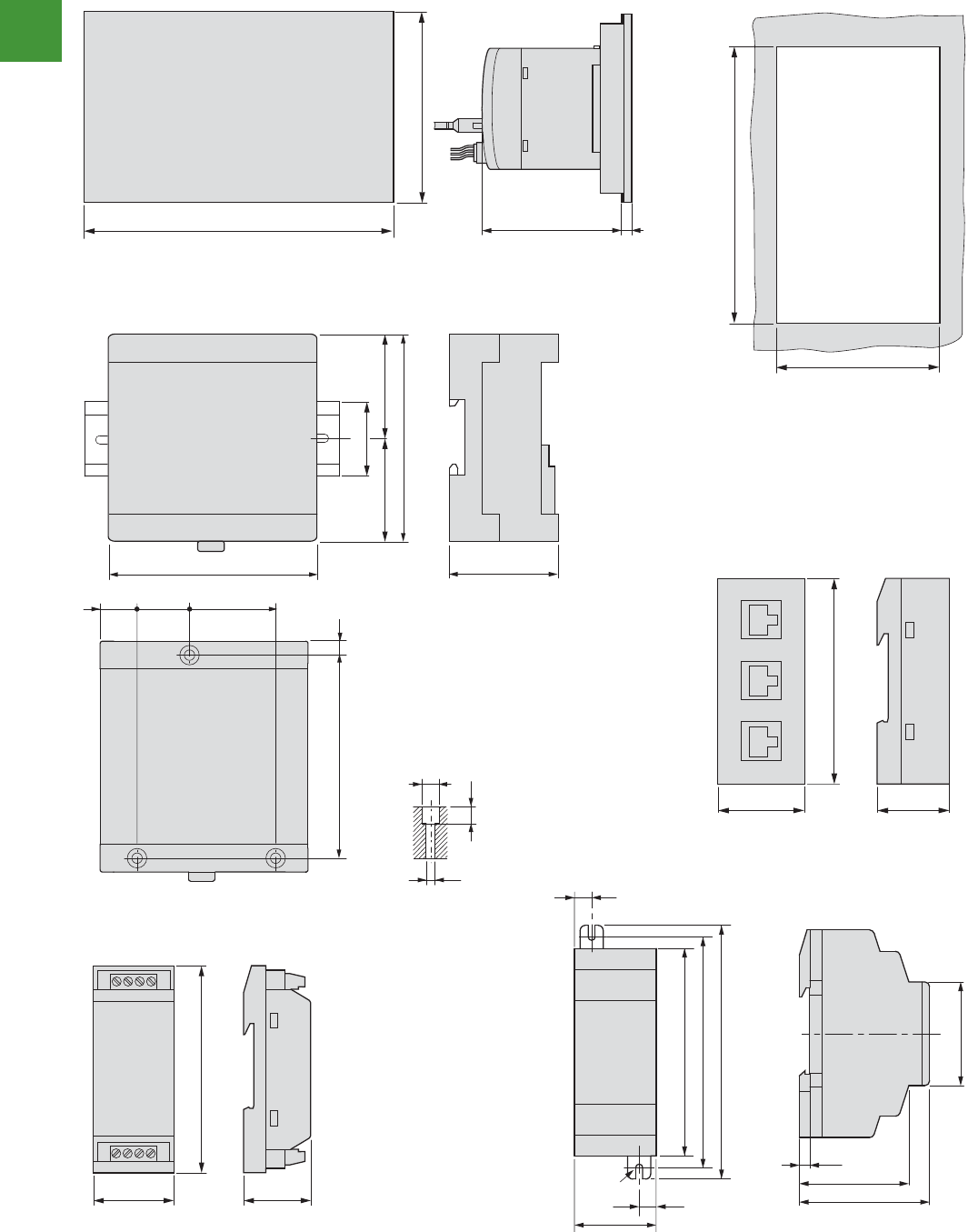
Automation
Power control
271 2015/2016 Product guide AUS15_007 - February 2016
14/60 Automation products
2010 CA08103002Z-EN www.eaton.com
Modular PLCs
XV-101…Mounting dimensions
XC-CPU-121...
XT-RJ45-ETH-RS232
XIO-EXT121-1
212
156
134 6
198
142
100
90 47
35
50 50
90 mm (3.54”)
35 mm
(1.38”)
30 mm
(1.18”)
8.5
4.5
6.8
16 37.25
88 6
22.75
14/60 Automation products
2010 CA08103002Z-EN www.eaton.com
Modular PLCs
XV-101…Mounting dimensions
XC-CPU-121...
XT-RJ45-ETH-RS232
XIO-EXT121-1
212
156
134 6
198
142
100
90 47
35
50 50
90 mm (3.54”)
35 mm
(1.38”)
30 mm
(1.18”)
8.5
4.5
6.8
16 37.25
88 6
22.75
14/60 Automation products
2010 CA08103002Z-EN www.eaton.com
Modular PLCs
XV-101…Mounting dimensions
XC-CPU-121...
XT-RJ45-ETH-RS232
XIO-EXT121-1
212
156
134 6
198
142
100
90 47
35
50 50
90 mm (3.54”)
35 mm
(1.38”)
30 mm
(1.18”)
8.5
4.5
6.8
16 37.25
88 6
22.75
Automation products
2010 CA08103002Z-EN www.eaton.com
16/41sCLP raludoM
XT-FIL-1
XT-FIL-2
90
35 30
M4
7.5
35.5
7.5
90
102
110
47.5
56.5
45
4.5
Automation products
2010 CA08103002Z-EN www.eaton.com
16/41sCLP raludoM
XT-FIL-1
XT-FIL-2
90
35 30
M4
7.5
35.5
7.5
90
102
110
47.5
56.5
45
4.5
Programmable logic controllers
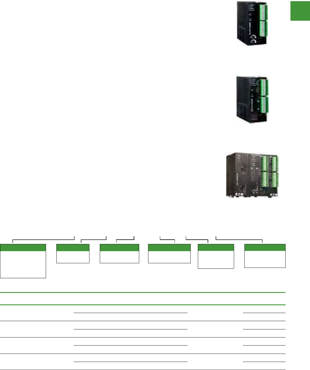
Automation
Power control
272
2015/2016 Product guide AUS15_007 - February 2016
Programmable logic controllers
ELC modular PLCs
Controllers and modules
Description Inputs Outputs Analogue High speed
I/O
Max.
current Item no.
ELC-PB module and 14 I/O built-in (8) 24 Vdc (6) Relay, 1.5A - (2) 20 kHz
inputs 150 mA ELC-PB14NNDR
(8) 24 Vdc 6) Transistor, 100 mA - ELC-PB14NNDT
ELC-PC module and 12 I/O built-in (8) 24 Vdc 4) Relay, 1.5A - (1) 30 kHz
inputs 150 mA ELC-PC12NNDR
(8) 24 Vdc (4) Transistor, 100 mA -ELC-PC12NNDT
ELC-PA module and 10 I/O built-in
Analogue - 2 in, 2 out
(4) 24 Vdc (2) Relay, 1.5A - (1) 30 kHz
inputs 210 mA ELC-PA10AADR
(4) 24 Vdc (2) Relay, 1.5A - ELC-PA10AADT
ELC-PV module and 28 I/O built-in (16) 24 Vdc (12) Relay, 1.5A - (2) 200 kHz
inputs 220 mA ELC-PV28NNDR
(16) 24 Vdc (12) Transistor, 100 mA -ELC-PV28NNDT
ELC PA 10 A A D R
Digital inputs
A = AC
D = DC
(sink or source)
I/O count
xx = Total
number of I/O
Digital outputs
T = Transistor (NPN)
P = Transistor (PNP)
R = Relay
Device type
PB = Base model
PC = Clock/
calendar model
PA = Analogue model
PV = Advanced model
Analogue inputs
A = Analogue
N = None
Analogue outputs
A = Analogue
N = None
PB base model—
• 14 I/O (8i/6o)
• Over 130 instructions
• Two Modbus (ASCII/RTU) serial ports
for master/slave communications
• RS-485 master port with the ability to
communicate to 31 other devices
• The master port can also be configured to
communicate to devices such as ASCII,
bar code readers, and so on
• EEPROM program retention in the event
of power loss
Note: This model does not provide a real-time clock
PH high-speed model
• 12 I/O (8i/4o)
• All the features of the PC model
• High speed pulse capture up to 100 kHz
• Single-axis motion control
PC clock/calendar model
• 12 I/O (8i/4o)
• Same features as the basic model plus
clock/calendar
• Distributed I/O capability with up to 16
devices
• File area for data storage and retrieval
• RAM program memory with battery backup
• Replaceable battery has greater than
a 5-year life
• Two digital potentiometers that vary
the data in internal registers
PA analog model
• 10 I/O (6i/4o)
• Same features as PC model with a
different I/O mix
• Four digital inputs, two digital outputs,
two analog inputs, and two analog outputs
• Analog channels can be set up for either
voltage or current
• Two 7-segment LEDs that can be used
to display unit ID, error codes, process
steps, and so on
PV advanced model
• 28 I/O (16i/12o)
• The PV model has the most extensive
features
• Programs written for the other controllers
can be migrated to a PV model controller
where greater speed or more I/O is required
• 10 times increase in processing speed for
about0.24μseconds/step
• RAM program storage and backed using
a rechargeable lithium-ion battery that
charges with normal use
• Includes 2-axis motion control
• Additional expansion bus to the left
of the controller
• Add high-speed and specialty modules
to the left
• Left side Ethernet master and DeviceNet
master modules are available for use
with the PV model controller ELC-PV
ELC-PA
ELC-PC
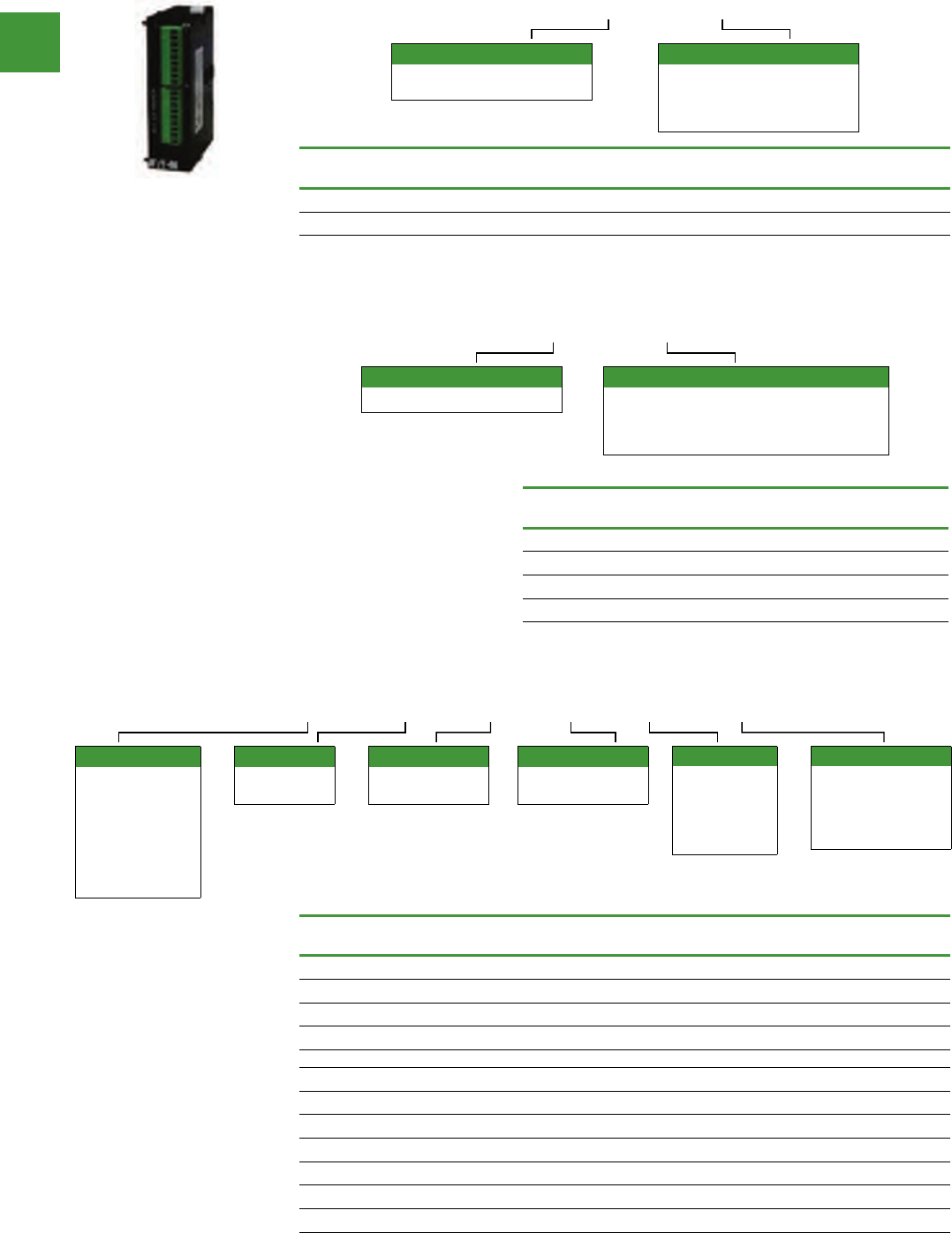
Automation
Power control
273 2015/2016 Product guide AUS15_007 - February 2016
Programmable logic controllers
Description Inputs
points Type Outputs
points Item no.
Ethernet Modbus TCP (master/slave) Modbus TCP ELC-COENETM
DeviceNet Scanner (master/slave) 190 bytes DeviceNet 190 bytes ELC-CODNETM
Left side bus communications module—for use with ELC-PV controllers only.
Master communication modules
ELC CO ENETM
Device type
CO = Communication interface
module
Module type
DNETM = DeviceNet master
module
ENETM = Ethernet master
module
Description Item no.
EtherNet/IP or Modbus TCP I/O adapter ELC-CAENET
Modbus serial RS-485 I/O adapter ELC-CARS485
DeviceNet I/O adapter ELC-CADNET
PROFIBUS-DP I/O adapter ELC-CAPBDP
Distributed I/O adapters
ELC CA ENET
Device type
CA = Distributed I/O adapter
Module type
ENET = EtherNet/IP or Modbus TCP I/O adapter
DNET = DeviceNet I/O adapter
RS485 = Modbus serial RS-485 I/O adapter
PBDP = PROFIBUS-DP I/O adapter
Features
• Combine with ELC
expansion modules to
create distributed I/O racks
for different PLC networks
• Use ELC-CAENET and
ELC-COENETM to create
distributed I/O racks to the
ELC-PV controllers
Description Inputs Outputs Max.
current Item no.
8 DC input module (8) 24 Vdc 50 mA ELC-EX08NNDN
8 AC input module (8) 110 Vac 50 mA ELC-EX08NNAN
8 Transistor output module (8) Transistor (sink), 0.3A 70 mA ELC-EX08NNNT
8 Relay output module (8) Relay, 1.5A 70 mA ELC-EX08NNNR
8 DC input/output module (4) 24 Vdc (4) Transistor (sink), 0.3A 70 mA ELC-EX08NNDT
8 DC input/relay output module (4) 24 Vdc (4) Relay, 1.5A 70 mA ELC-EX08NNDR
6 High current relay output module (6) Relay, 6A 70 mA ELC-EX06NNNI
16 DC input module (16) 24 Vdc 100 mA ELC-EX16NNDN
16 DC input/output module (8) 24 Vdc (8) Transistor (sink), 0.3A 90 mA ELC-EX16NNDT
16 DC input/output module (8) 24 Vdc (8) Transistor (source), 0.3A 100 mA ELC-EX16NNDP
16 DC input/relay output module (8) 24 Vdc (8) Relay, 1.5A 90 mA ELC-EX16NNDR
Digital expansion modules (right side bus)
ELC EX 16 N N D P
Digital inputs
A = AC
D = DC
(sink or source)
S = Switch
N = None
I/O count
xx = Total
number of I/O
Digital outputs
T = Transistor (NPN)
P = Transistor (PNP)
R = Relay
I = Relay - high current
N = None
Device type
AN = Analog
expansion module
EX = Digital
expansion module
PT = Platinum RTD
expansion module
TC = Thermocouple
expansion module
Analogue inputs
A = Analogue
N = None
Analogue outputs
A = Analogue
N = None
Features
• Digital right side expansion
modules can be used with
any ELC controller
• They simply snap together
to allow the ELC backplane
to pass through each
connected module
• Maximum of 14 modules
per controller
ELC-EX16NNDR
Automation
Power control
274
2015/2016 Product guide AUS15_007 - February 2016
Programmable logic controllers
Analogue input and out modules (right side bus)
Description
Input
points
Resolution
Mode
Output
points
Resolution
Mode
Max.
current
Item no.
4 analogue
input module 4V= 12 bit
I = 13 bit
±10V
±20 mA 90mA ELC-AN04ANNN
2 analogue
output module 2 12 bit 0–20 mA; 4–20 mA
0–10V; 2–10V 125mA ELC-AN02NANN
4 analogue
output module 2 12 bit 0–20 mA; 4–20 mA
0–10V; 2–10V 170mA ELC-AN04NANN
6 analogue
input/output
module
4V = 12 bit
I = 11 bit
±10V
±20 mA 2 12 bit 0–20 mA
0–10V 170mA ELC-AN06AANN
Temperature input modules (right side bus)
Thermocouple and Platinum RTD temperature sensor input modules with 14 bit resolution
Description
Input
points
Resolution
Sensor
type
Max.
current
Item no.
4 Thermocouple input module 4 J, K, R, S, T 90 mA ELC-TC04ANNN
4 Platinum RTD input module 4 14 bit PT100 90 mA ELC-PT04ANNN
RS-485 Adapter module (right side bus—end module)
Passive RS-485 connection device module.
RJ12 port for connecting to a drive.
2-pin screw terminal to connect to ELC controller.
Male and female DB9 connectors to connect to other RS-485 devices.
Description Connector type Item no.
RS-485 Connect adapter module RJ12, DB9 (male and female)
2-pin screw terminals ELC-485APTR
Accessories
Power supplies
All ELC controllers, analog and specialty expansion modules operate from 24 Vdc
Description
Input
power
Output
volts
Output
current (A)
Watts
Item no.
24 watt, 1 amp power supply 100–240 Vac 50/60 Hz 24 Vdc 1A 24 ELC-PS01
48 watt, 2 amp power supply 100–240 Vac 50/60 Hz 24 Vdc 2A 48 ELC-PS02
Description Item no.
Cable to connect a PC or an ELC-GP unit to ELC, 3 meters (DB 9-pin female to
8-pin DIN) ELC-CBPCELC3
Cable to connect a PC or an ELC-GP unit to ELC, 1 meter with right angle
connector (DB 9-pin female to 8-pin DIN) ELC-CBPCELC1
Cables
Storage devices
The ELC-ACPGMXFR module is a multifunction device that provides the ability to back up an application
already loaded onto one of the ELC controllers. It will store system settings, passwords and the applica-
tion, including the data registers for pre-loaded recipes
Description Item no.
Program transfer module for ELC controllers ELC-ACPGMXFR
Programming software
ELCSoft programming software configures all ELC controllers. Program in ladder, sequential function
chart or instruction language.
Description Item no.
Programming Software for ELC Controllers ELCSOFT
ELC-PS01
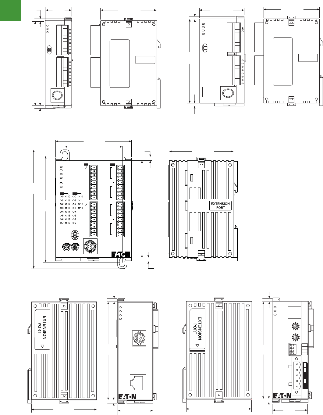
Automation
Power control
275 2015/2016 Product guide AUS15_007 - February 2016
Dimensions (approximate dimensions in inches (mm)
Programmable logic controllers
V7-T4-18 Volume 7—Logic Control, Operator Interface and Connectivity Solutions CA08100008E—February 2014 www.eaton.com
4
4
4
4
4
4
4
4
4
4
4
4
4
4
4
4
4
4
4
4
4
4
4
4
4
4
4
4
4
4
4.1
PLC, I/O and Communications Products
ELC Series Programmable Logic Controllers
Circuit Diagrams
DC Input Sink Mode
DC Transistor Sinking Output
DC Input Source Mode
Relay Outputs
Dimensions
Approximate Dimensions in Inches (mm)
ELC-PB14 Controllers ELC-PC12, ELC-PH12 and ELC-PA10 Controllers
Sink Mode
S/S X0 X1 X2
+24V 0V
DC Power Supply
Y0
LED
C0
<0.5A
Transistor Output
Load
Trigger Circuit
Source Mode
S/S X0 X1 X2
+24V 0V
DC Power Supply
Y0
LED
C0
Load
Power
Relay Output
RY
EXTENSION
PORT
2.36 (60.0)
3.54
(90.0)
0.12
(3.0)
0.12
(3.0)
0.99
(25.2)
POWER
RUN
RUN
STOP
ERROR
BAT.LOW
EXTENSION
PORT
3.54
(90.0)
0.12
(3.0)
1.47 (37.4) 2.36 (60.0)
0.12
(3.0)
ELC-PB14 controllers ELC-PC12, ELC-PH12 and ELC-PA10 controllers
Volume 7—Logic Control, Operator Interface and Connectivity Solutions CA08100008E—February 2014 www.eaton.com V7-T4-19
4
4
4
4
4
4
4
4
4
4
4
4
4
4
4
4
4
4
4
4
4
4
4
4
4
4
4
4
4
4
4.1
PLC, I/O and Communications Products
ELC Series Programmable Logic Controllers
Approximate Dimensions in Inches (mm)
ELC-PV Controller
ELC-COENETM ELC-CODNETM
POWER
RUN
ERROR
BAT. LOW
RS-232
RS-495
IN
OUT
IN
OUT
SS
X0
X1
X2
X3
X4
X5
X6
X7
SS
X10
X 11
X12
X13
X14
X15
X16
X17
Y 11
Y12
Y13
C3
Y0
Y1
Y2
C0
C1
Y3
Y4
Y5
C2
Y6
Y7
Y10
RUN
STOP
01
0.12
(3.0)
3.54
(90.0)
2.75 (70.0)
3.98
(101.0)
4.31
(109.4)
ELC-PV28NNDR
2.09 (53.2)
2.36 (60.0)
0.12
(3.0)
2.36 (59.9)
3.54
(89.9)
0.12
(3.0) 1.29
(32.8)
ELC-COENETM
POWER
RS-232
100M
LAN
RS-232
LINK
0.12
(3.0)
2.36 (59.9)
3.54
(89.9)
0.12
(3.0) 1.29
(32.8)
ELC-CODNETM
POWER
MS
NS
Node Address
x10
x10
0
1
2
3
4
5
6
7
8
9
0
1
2
3
4
5
6
7
8
9
DP On
1234
DR 1
DR 0
IN 1
IN 0
0.12
(3.0)
ELC-COENETM ELC-CODNETM
Volume 7—Logic Control, Operator Interface and Connectivity Solutions CA08100008E—February 2014 www.eaton.com V7-T4-19
4
4
4
4
4
4
4
4
4
4
4
4
4
4
4
4
4
4
4
4
4
4
4
4
4
4
4
4
4
4
4.1
PLC, I/O and Communications Products
ELC Series Programmable Logic Controllers
Approximate Dimensions in Inches (mm)
ELC-PV Controller
ELC-COENETM ELC-CODNETM
POWER
RUN
ERROR
BAT. LOW
RS-232
RS-495
IN
OUT
IN
OUT
SS
X0
X1
X2
X3
X4
X5
X6
X7
SS
X10
X 11
X12
X13
X14
X15
X16
X17
Y 11
Y12
Y13
C3
Y0
Y1
Y2
C0
C1
Y3
Y4
Y5
C2
Y6
Y7
Y10
RUN
STOP
01
0.12
(3.0)
3.54
(90.0)
2.75 (70.0)
3.98
(101.0)
4.31
(109.4)
ELC-PV28NNDR
2.09 (53.2)
2.36 (60.0)
0.12
(3.0)
2.36 (59.9)
3.54
(89.9)
0.12
(3.0) 1.29
(32.8)
ELC-COENETM
POWER
RS-232
100M
LAN
RS-232
LINK
0.12
(3.0)
2.36 (59.9)
3.54
(89.9)
0.12
(3.0) 1.29
(32.8)
ELC-CODNETM
POWER
MS
NS
Node Address
x10
x10
0
1
2
3
4
5
6
7
8
9
0
1
2
3
4
5
6
7
8
9
DP On
1234
DR 1
DR 0
IN 1
IN 0
0.12
(3.0)
ELC-PV controller
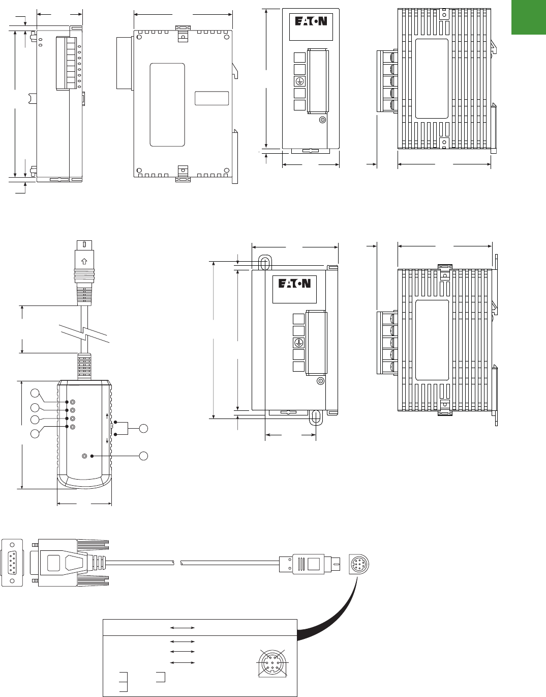
Automation
Power control
276
2015/2016 Product guide AUS15_007 - February 2016
Dimensions (approximate dimensions in inches (mm)
Programmable logic controllers
V7-T4-20 Volume 7—Logic Control, Operator Interface and Connectivity Solutions CA08100008E—February 2014 www.eaton.com
4
4
4
4
4
4
4
4
4
4
4
4
4
4
4
4
4
4
4
4
4
4
4
4
4
4
4
4
4
4
4.1
PLC, I/O and Communications Products
ELC Series Programmable Logic Controllers
Approximate Dimensions in Inches (mm)
Right Side Specialty and Expansion Modules
ELC-ACCOVER Plate Mount for Specialty Modules
EXTENSION
PORT
3.54
(90.0)
0.12
(3.0)
0.12
(3.0)
0.99
(25.2)
2.36
(60.0)
2.51 (63.4)
3.94
(100.0)
3.54
(89.9)
0.27
(6.8)
0.12
(3.0) 0.28
(7.1)
4.20
(106.5)
0.12
(3.0)
Volume 7—Logic Control, Operator Interface and Connectivity Solutions CA08100008E—February 2014 www.eaton.com V7-T4-21
4
4
4
4
4
4
4
4
4
4
4
4
4
4
4
4
4
4
4
4
4
4
4
4
4
4
4
4
4
4
4.1
PLC, I/O and Communications Products
ELC Series Programmable Logic Controllers
Approximate Dimensions in Inches (mm)
ELC-PS01
ELC-PS02
ELC-P S 01
POWER
L
N
24V
0V
1.44
(36.5)
3.54
(90.0)
0.12
(3.0)
2.36
(60.0)
13.30
(0.5)
ELC-PS02
POWER
L
N
24V
0V
3.94
(100.0)
0.12
(3.0)
1.28
(32.5)
3.54
(90.0)
2.17
(55.0)
0.12
(3.0)
2.36
(60.0)
13.30
(0.5)
V7-T4-22 Volume 7—Logic Control, Operator Interface and Connectivity Solutions CA08100008E—February 2014 www.eaton.com
4
4
4
4
4
4
4
4
4
4
4
4
4
4
4
4
4
4
4
4
4
4
4
4
4
4
4
4
4
4
4.1
PLC, I/O and Communications Products
ELC Series Programmable Logic Controllers
Approximate Dimensions in Inches (mm)
ELC-CBPCELC1 Cable (Right Angle Connector not Shown) and ELC-CBPCELC3 Cable (Straight Connector as Shown)
ELC-ACPGMXFER Storage Device
PC/HMI COM Port
9 PIN D-SUB Female PLC COM1 Port
8 PIN MINI DIN
12
3
4
5
6
7
8
Rx 2 5 Tx
Tx 3 4 Rx
GND 5 8 GND
1,2 5V
1
4
6
7
8
POWER
COM
OK
ERR
ERASE
ELC-ACPGMXFR
WR RD
1.29
(32.8)
2.61
(66.3)
1 23 4
11.81
(292.4)
56
Right side specialty and expansion modules ELC-PS01
ELC-PS02ELC-ACPGMXFR storage device
V7-T4-22 Volume 7—Logic Control, Operator Interface and Connectivity Solutions CA08100008E—February 2014 www.eaton.com
4
4
4
4
4
4
4
4
4
4
4
4
4
4
4
4
4
4
4
4
4
4
4
4
4
4
4
4
4
4
4.1
PLC, I/O and Communications Products
ELC Series Programmable Logic Controllers
Approximate Dimensions in Inches (mm)
ELC-CBPCELC1 Cable (Right Angle Connector not Shown) and ELC-CBPCELC3 Cable (Straight Connector as Shown)
ELC-ACPGMXFER Storage Device
PC/HMI COM Port
9 PIN D-SUB Female PLC COM1 Port
8 PIN MINI DIN
12
3
4
5
6
7
8
Rx 2 5 Tx
Tx 3 4 Rx
GND 5 8 GND
1,2 5V
1
4
6
7
8
POWER
COM
OK
ERR
ERASE
ELC-ACPGMXFR
WR RD
1.29
(32.8)
2.61
(66.3)
1 23 4
11.81
(292.4)
56
ELC-CBPCELC1 cable (right angle connector not shown) and ELC-CBPCEL3 cable (straight connector as shown)
Automation
Power control
277 2015/2016 Product guide AUS15_007 - February 2016
Eaton ELC Graphic touch panels
ELC Graphic touch panels
Description Item no.
Graphic touch panels
Touch panel, 160 x 32 pixels, 10 function keys, monochrome ELC-GP02
Touch panel, 128 x 64 pixels, 10 function keys, monochrome ELC-GP04
Programming software
Programming software for ELC graphic touch panels ELCSOFTGP
Power supplies
Power supply, 110-240V AC IN, 24V DC OUT, 24 watts, 1 A ELC-PS01
Power supply, 110-240V AC IN, 24V DC OUT, 48 watts, 2 A ELC-PS02
Programming cable
Cable PC to ELC-GP, 3m (DB9 female to DB9 female) ELC-CBPCGP3
Cable PC or touch panel to PLC, 3 m (DB9 female to 8-pin DIN) ELC-CBPCELC3
Program transfer module
Program transfer module for ELC graphic touch panels ELC-GPXFERMOD
• High-end features in a low-cost operator
interface
• Communication through 2 ports
simultaneously: RS232 & RS485/422
• Connection to all major PLCs with drivers
• Process indication by graphs, alarms, etc
• 10 levels of password protection
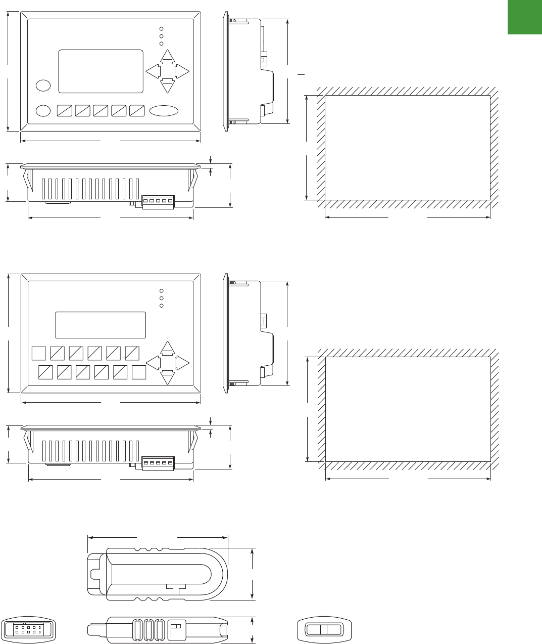
Automation
Power control
278
2015/2016 Product guide AUS15_007 - February 2016
ELC Graphic touch panels
Dimensions (approximate dimensions in inches (mm)
V7-T5-12 Volume 7—Logic Control, Operator Interface and Connectivity Solutions CA08100008E—February 2014 www.eaton.com
5
5
5
5
5
5
5
5
5
5
5
5
5
5
5
5
5
5
5
5
5
5
5
5
5
5
5
5
5
5
5.2
Operator Interface Products
ELC Graphics Panels
Approximate Dimensions in Inches (mm)
ELC-GP02
ELC-GPXFERMOD
3.82
(97.0)
3.35
(85.0)
1.20
(30.5) 0.14
(3.5) 1.40
(35.5)
3.35
(85.0)
5.79
(147.0)
ALARM
RS-232
RS-485
Up
Pg Up
Pg Dn
Down
Left
Esc F0
0
Right
5.31
(135.0)
5.31 ~ 5.37
(135 ~ 136.5)
Cut-Out Dimensions
F1
1
F2
2
F3
3
F4
4
Enter
F5
5
F6
6
F7
7
F8
8 9
F9
0.78 (19.8)
2.00 (50.9)
0.39 (10.0)
ELC-GP02
ELC-GP04
Volume 7—Logic Control, Operator Interface and Connectivity Solutions CA08100008E—February 2014 www.eaton.com V7-T5-11
5
5
5
5
5
5
5
5
5
5
5
5
5
5
5
5
5
5
5
5
5
5
5
5
5
5
5
5
5
5
5.2
Operator Interface Products
ELC Graphics Panels
Dimensions
Approximate Dimensions in Inches (mm)
ELC-GP04
3.82
(97.0)
3.35
(85.0)
1.20
(30.5) 0.14
(3.5) 1.40
(35.5)
3.35
(85.0)
5.79
(147.0)
ALARM
RS-232
RS-485
Up
Pg Up
Pg Dn
Down
Left
Esc
Enter
F0
F5
F1
F6
F2
F7
F3
F8
F4
F9
Shift
Right
5.31
(135.0)
5.31 ~ 5.37
(135 ~ 136.5)
Cut-Out Dimensions
V7-T5-12 Volume 7—Logic Control, Operator Interface and Connectivity Solutions CA08100008E—February 2014 www.eaton.com
5
5
5
5
5
5
5
5
5
5
5
5
5
5
5
5
5
5
5
5
5
5
5
5
5
5
5
5
5
5
5.2
Operator Interface Products
ELC Graphics Panels
Approximate Dimensions in Inches (mm)
ELC-GP02
ELC-GPXFERMOD
3.82
(97.0)
3.35
(85.0)
1.20
(30.5) 0.14
(3.5) 1.40
(35.5)
3.35
(85.0)
5.79
(147.0)
ALARM
RS-232
RS-485
Up
Pg Up
Pg Dn
Down
Left
Esc F0
0
Right
5.31
(135.0)
5.31 ~ 5.37
(135 ~ 136.5)
Cut-Out Dimensions
F1
1
F2
2
F3
3
F4
4
Enter
F5
5
F6
6
F7
7
F8
8 9
F9
0.78 (19.8)
2.00 (50.9)
0.39 (10.0)
ELC-GPXFERMOD
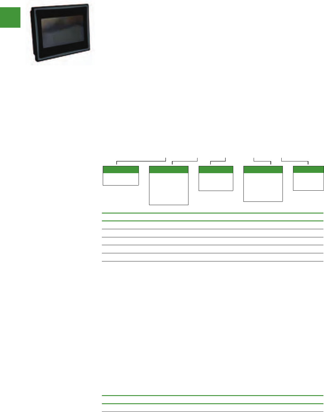
Automation
Power control
279 2015/2016 Product guide AUS15_007 - February 2016
HMi operator interface
Operator interface
Positioned between the ELC graphics panels and the XV series of operator interfaces, HMi is the
workhorse of the industry. Ideal for machinery OEMs, the HMi series provides the most value with
the latest technology and advanced feature set in an economical hardware and software package. All
units offer RS-232, RS-485 and RS-422 communications. The 7-, 8- and 10-inch units also offer Ethernet
communication options.
Features
• Auto-scale application from
10 to 4 inches
• Screen and backlight saver
• Pop-up screens
• Animated graphics
• Conditional visibility
• Application lock for IP
protection
• Data archiving
• Multi-language
• Eight levels of security
• Ethernet communication
drivers
• Ethernet, COMM port and
USB upload/download
• USB ports for data storage
• Three serial ports
• Up to four simultaneous
protocols
• Math and logic functions
• CSV import/export tags
and recipes
• Macro capability
• Alarm/event recording and
viewing
• Real-time and historical
trending
• Online and offline
simulation
HMi VU exclusive features
• VU server
• VU remote
• Multi-link
• Onboard Ethernet on some
models
• Audio and SD on some
models
• Supports USB mouse and
other industrial pointing
devices
HMIVU 07 CU NB E
Options
E = On-board
Ethernet
and audio out
Display
04 = 4.3-inch LCD
06 = 5.6-inch LCD
07 = 7.0-inch LCD
08 = 8.0-inch LCD
10W = 10.
1-inch-wide LCD
Series
HMIVU = HMi
VU Series
Options
CU = Color
TFT without
expansion port
Options
NBx = HMi VU
Firmware Series
NB = HMi VU
Series no
function buttons
Description Item no.
4-inch color TFT, no function buttons, on-board Ethernet HMIVU04CUNBE
6-inch color TFT, no function buttons, no Ethernet HMIVU06CUNB1
7-inch color TFT, no function buttons, on-board Ethernet HMIVU07CUNBE
8-inch color TFT, no function buttons, on-board Ethernet HMIVU08CUNBE
10-inch color TFT, no function buttons, on-board Ethernet HMIVU10WCUNBE
Description Item no.
Programming software for HMi and HMi VU models HMISOFT
HMiSoft programming software
For use with the of HMi and HMi VU series touchscreens. This easy to use Windows based software
can run on Windows XP and Windows 7 32-bit and 64-bit systems.
• Ethernet and serial
communication drivers
• Up to four simultaneous
protocols
• Screen manager
• Over 70 on-screen objects
• Pop-up screens
• Animated graphics
• Conditional visibility
• Built-in picture library
• Create your own picture
library
• Multi-language
• Eight levels of security
• Macro editing with math
and logic functions
• CSV import/export tags
and recipes
• Alarm/event recording and
viewing
• Store archived data,
alarms and events to USB
• Real-time and historical
trending
• Auto-scale application
from 10 to 4 inches
• On and offline simulation
• Upload/download
applications over USB,
serial or Ethernet
• Application lock for IP
protection
• Screen and backlight saver
• Multi-link allows sharing of
PLC data over Ethernet
• VU Server optional
download
• VU Remote optional
download
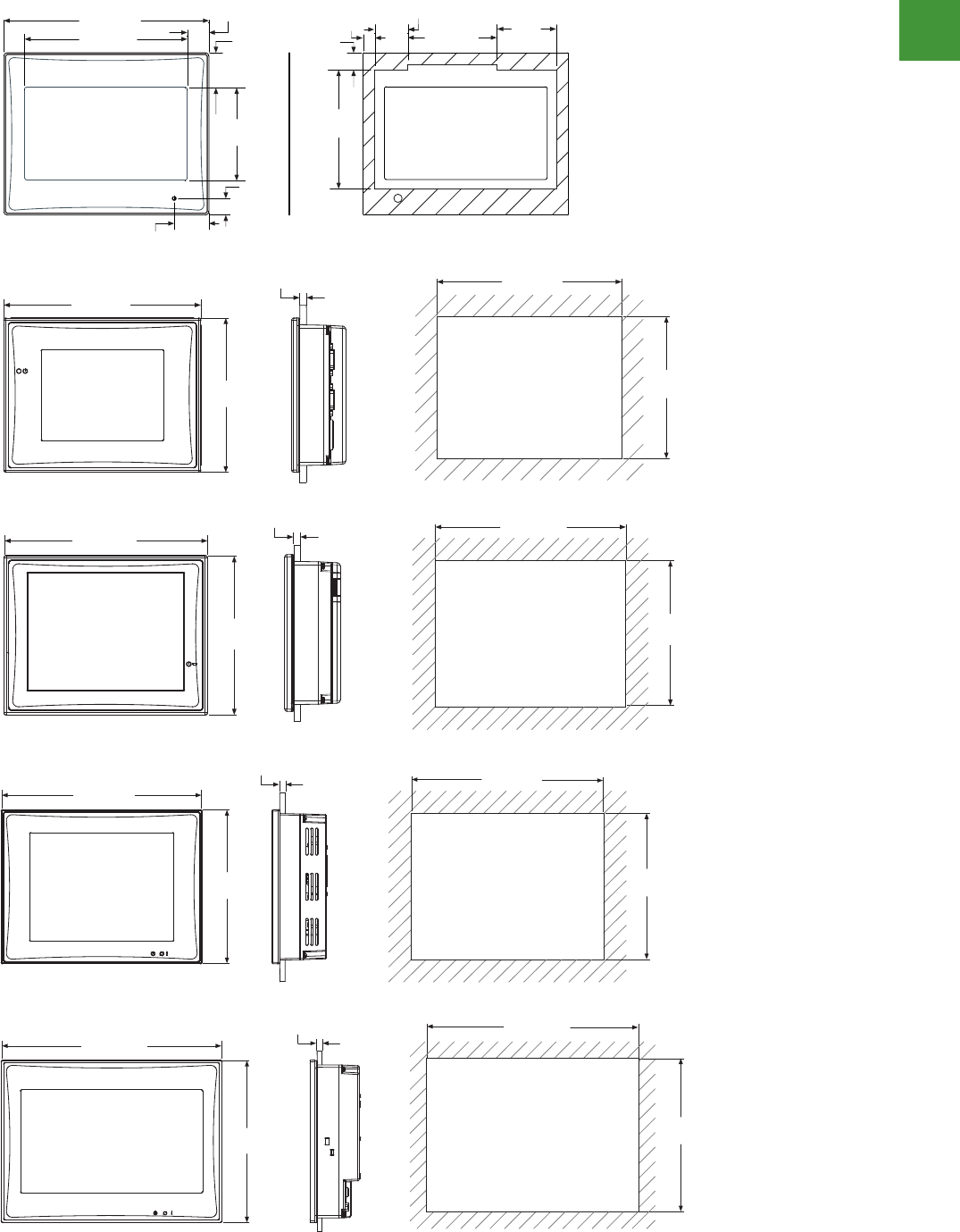
Automation
Power control
280
2015/2016 Product guide AUS15_007 - February 2016
Operator interface
Dimensions (approximate dimensions in inches (mm)
Volume 7—Logic Control, Operator Interface and Connectivity SolutionsCA08100008E—February 2014 www.eaton.com V7-T5-19
5
5
5
5
5
5
5
5
5
5
5
5
5
5
5
5
5
5
5
5
5
5
5
5
5
5
5
5
5
5
5.3
Operator Interface Products
HMi Operator Interface
Dimensions
Approximate Dimensions in Inches (mm)
HMIVU04
HMIVU06
HMIVU07
2.82
(71.7)
2.11 (53.7)
0.79 (20.0)
0.41
(10.4)
Cutout
4.88 (124.0)
3.87 (98.3)
0.52 (13.1)
0.83
(21.2)
2.21
(56.1)
0.83 (21.0)
0.39
(10.0)
0.28
(7.0) 1.43
(36.3)
5.21
(132.4)
6.79 (172.4)
0.063 (1.6) to 0.24 (6.0)
7.24 (184.0)
5.67
(144.0)
5.21
(132.4)
6.79 (172.4)
0.063 (1.6) to 0.24 (6.0)
7.24 (184.0)
5.67
(144.0)
V7-T5-20 Volume 7—Logic Control, Operator Interface and Connectivity Solutions CA08100008E—February 2014 www.eaton.com
5
5
5
5
5
5
5
5
5
5
5
5
5
5
5
5
5
5
5
5
5
5
5
5
5
5
5
5
5
5
5.3
Operator Interface Products
HMi Operator Interface
Approximate Dimensions in Inches (mm)
HMIVU08
HMIVU10
8.64 (219.4)
0.063 (1.6) to 0.24 (6.0)
8.94 (227.1)
6.85
(174.1)
6.56
(166.5)
10.29 (261.3)
0.063 (1.6) to 0.24 (6.0)
10.71 (272.0)
7.88
(200.0)
7.45
(189.3)
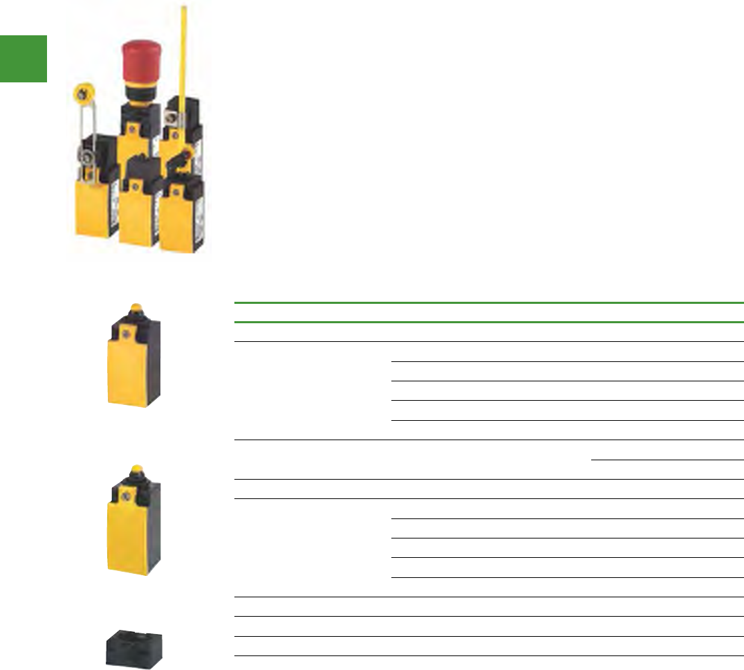
Automation
Power control
281 2015/2016 Product guide AUS15_007 - February 2016
Description Contacts Item no.
Insulated, enclosed units, IP66, rounded plunger
Basic units
Standard action contacts 1 N/O, 1 N/C LS-11
Make-before-break contacts 1 N/O, 1 N/C LS-11D
Snap-action contacts 1 N/O, 1 N/C LS-11S
Standard action contacts 2 N/O LS-20
Standard action contacts 2 N/C LS-02
Basic units with electronically
adjustable operating point Indicator light 1 N/O, 1 N/C LSE-11
2 N/C LSE-02
Metal, enclosed units, IP66, rounded plunger
Basic units
Standard action contacts 1 N/O, 1 N/C LSM-11
Make-before-break contacts 1 N/O, 1 N/C LSM-11D
Snap-action contacts 1 N/O, 1 N/C LSM-11S
Standard action contacts 2 N/O LSM-20
Standard action contacts 2 N/C LSM-02
Accessories
Fixing adapter For operation by RMQ-Titan actuators -M22-LS
To show status (optical status display safety category 3, EN 954-1)
Basic units
LS-Titan position switches are quick & easy to install, highly flexible & safe. Rated to IP66, the LS-Titan
range is available in two versions: For normal operating conditions in corrosive environments, or in
the food industry, the LS versions have a totally insulated housing, whereas the LSM versions in their
robust metal enclosures are suited to mechanically harsher environments.
All devices are actuated mechanically & with their positively opening & interlocked opposing contacts,
are suitable for use in safety circuits. A unique feature is the ability to combine LS-Titan with
pushbutton actuators, selector switches or Emergency-Stop buttons from the RMQ-Titan range. These
can simply be snapped on to act as the operating head of the position switch.
The LSE (limit switch electronic) has a freely programmable operating point that can be easily set. Just
move the plunger from the original position to the new switching position & press the ‘teach-in’ button
with a screwdriver for 1 second. Once the LED flashes at a higher rate, the new position is accepted &
is usable. The switching point is freely adjustable within a range of 0.5 to 5.5 mm.
Features & benefits:
• Conform to EN 50047, so ensuring interchangeability
• Modular range of basic units & operating heads are quickly & easily installed with a bayonet catch,
offering flexibility of application
• Maintenance free & vibration resistant cage clamp terminals
LS-Titan position switches
LS-11
LSM-11
M22-LS
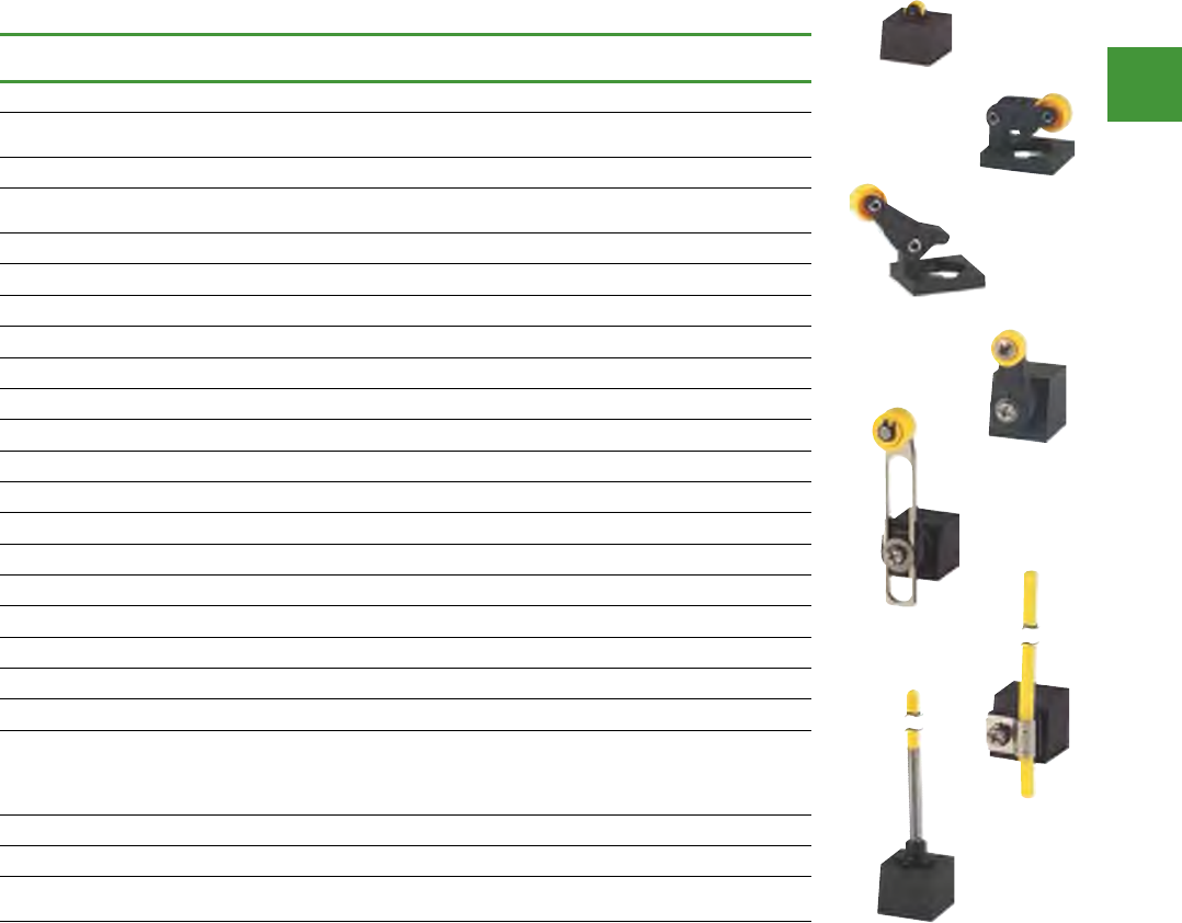
Automation
Power control
282
2015/2016 Product guide AUS15_007 - February 2016
Operating heads
Description Std.
pack
Plastic
Item no.
Std.
pack
Metal
Item no.
Rounded plunger, center fixing
For installation in M18 × 1 enclosure
wall or mounting plate drilling 1 off LS-XZS
Roller plunger, center fixing
For installation in M18 × 1 enclosure
wall or mounting plate drilling 1 off LS-XZRS
Roller plunger 10 off LS-XP 10 off LSM-XP
Roller lever
Large 5 off LS-XLB
Short 1 off LS-XLS
Long 10 off LS-XL 10 off LSM-XL
Angled roller lever 10 off LS-XLA 10 off LSM-XLA
Rotary lever 5 off LS-XRL 5 off LSM-XRL
Adjustable roller lever
D = 18 mm 4 off LS-XRLA 4 off LSM-XRLA
D = 30 mm 5 off LS-XRLA30
D = 40 mm (rubber) 5 off LS-XRLA40R
D = 40 mm 5 off LS-XRLA40
Actuating rod
Rod from insulated material 4 off LS-XRR 4 off LSM-XRR
Metal rod 4 off LS-XRRM 4 off LSM-XRRM
Spring rod
Not to be used as a safety
position switch
Use only in conjunction with
snap-action contact.
5 off LS-XS 5 off LSM-XS
Actuating rod 1 off LS-XOR
Fixing adapters
Actuation through front element
RMQ-Titan® 10/1 off M22-LS
LS-Titan position switches
LS-XP
LS-XLA
LS-XRLA
LS-XS
LS-XL
LS-XRL
LS-XRR
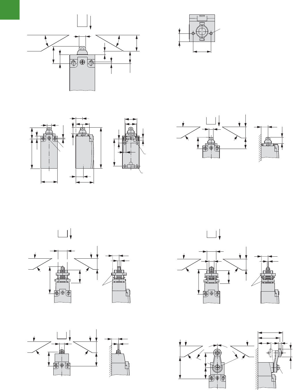
Automation
Power control
283 2015/2016 Product guide AUS15_007 - February 2016
LS-Titan position switches
Position Switches
(Safety) position switches
2010 CA08103002Z-EN www.eaton.com
52/3natiT-SL
Dimensions
Basic units, non expandable (front fixing)
LS(M)-…/F
① Screw-in depth max. 12 mm
Basic units, expandable,
LS-…, LSM-…, LSE-…
① Tightening torque of cover screw: 0.8 Nm ±0.2 Nm
② Only with LS (insulated version)
③ Fixing screw 2 x M4 ≥ 30
MA = 1.5 Nm
Rounded plunger, center fixingRoller plunger, center fixing
SRZX-SLSZX-SL
revel yratoRregnulp relloR
LR/…-)M(SLP/…-)M(SL
10.8
f 15
1.95
4.2
21
8.2
30° 30°
f 20
10.2
22
M3
a
5.3
31
55
8.2
21
a
c
11.7
12.7
14
33.5
76
22
20
25
4.3
4.3
50
7.3
b
o 4
1.95
M20
f 15
30°
11.7
21
8.2 12.7
30°
f 20
51
M18 x 1
13
6
23
f 20
30° 30°
SW 24
46
9
M18 x 1
13
2.5
23
f 20
30° 30°
SW 24
26.5
9
12.7
2.5
25.5 f 20
30° 30°
30°
46.2
40.5
1.6 Nm ±0.2
23.9
27
21
5
o 14
40 f 20
30°
65°
65°
Dimensions
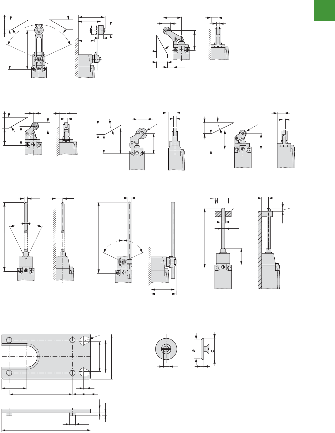
Automation
Power control
284
2015/2016 Product guide AUS15_007 - February 2016
LS-Titan position switches
3/26Position Switches
(Safety) position switches
2010 CA08103002Z-EN www.eaton.com
LS-Titan
(Safety) position switchesLS -Titan
Adjustable roller leve revel rellor delgnAr
ALX-)M(SLALR/…-)M(SL
① Setting range from 54.5 to 97
revel relloR
SL/…-)M(SLBL/…-)M(SLL/…-)M(SL
dor gnitautcAdor gnitautcAdor gnirpS
RO/…-)M(SLRR/…-)M(SLS/…-)M(SL
① Approach direction, vertical
② Guide is done by customer, not included
③ Max. push-through
① LS…/RR 150
LS…/RRM 210
etalp gnitacoLetalp retpadA
TA-SFPAX-SL
54.5
46.4
a
10
32.2
o 18 – 40
f 20
f 44.5
°03°03
65°
65°
1.6 Nm ±0.2
33.2
13
36.3
12.7
5
30°
f 20
f 8
13
3.4
34.4
12.7
5
31 f 20
30°
f 39
52.3
20.35 5.6
12.7
41.3
o 22
30°
f 20
30°
f 20
f 29.7
36.5
5
12.7
30
o 13
126
12.7
o 5.8
26°
26°
46
43
o 6
a
65°
65°
o 6.5
o 4
31
110
12.7
f 6.1
c
b
a
16.8
60
2
o 3.9
3 7.3
42.7
2.5
1.7
20
R 2.2
22
30.5
4.3 2
14
16
≤
≤
Dimensions
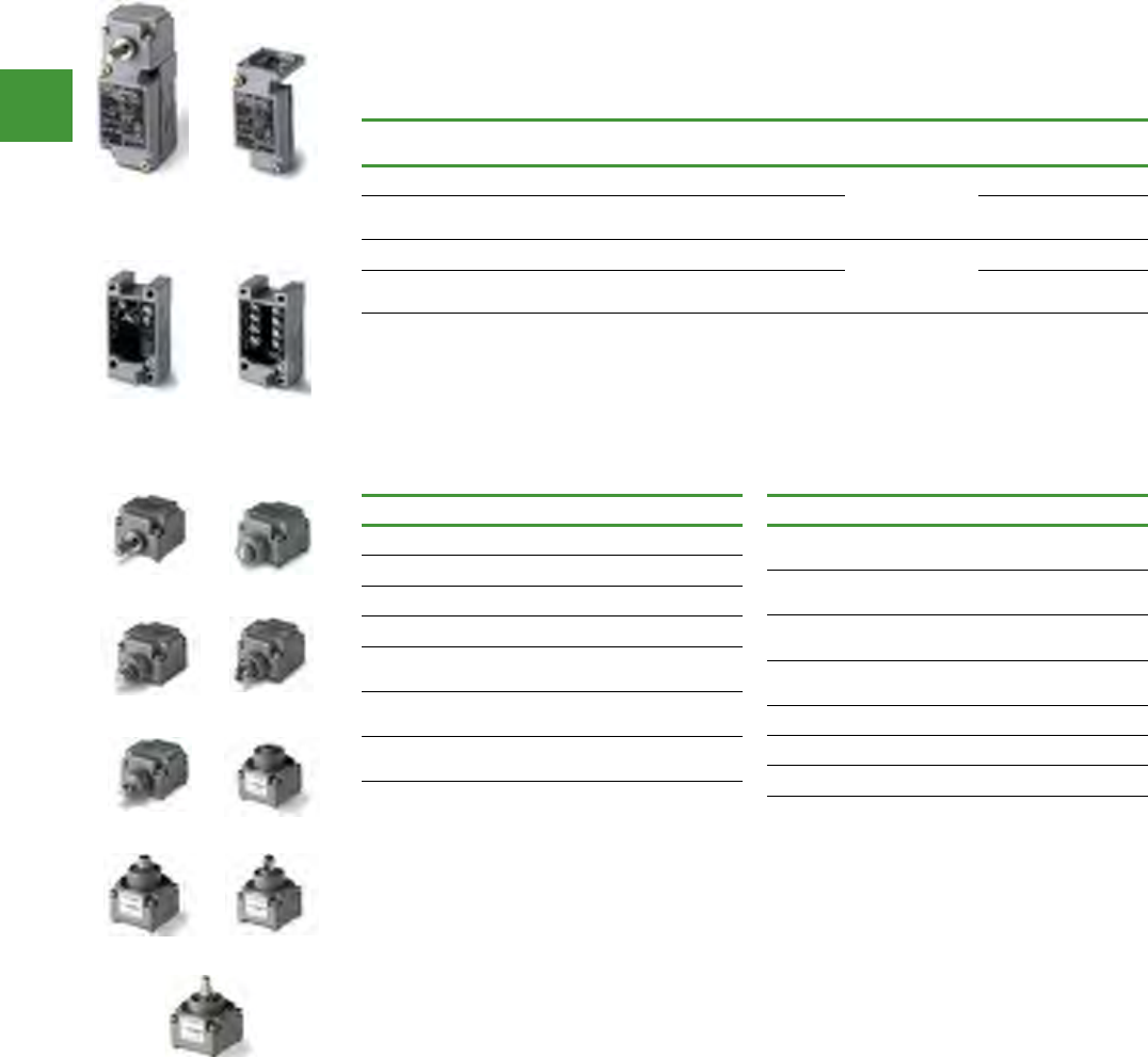
Automation
Power control
285 2015/2016 Product guide AUS15_007 - February 2016
E50 Heavy duty modular limit switches
Eaton E50 Limit Switches are available with or without indicating LED, in single- or 2-pole versions.
Optional manifold mount & submersible versions available.
Complete switch = body + receptacle + Head
Indicating
light
Switch body
Item no.
Receptacle
Item no.
None E50SA, 1N.O.-1N.C. Single Pole
(5 Terminal)
E50RA
LED (24 - 120V
AC/DC) E50SAL, 1N.O.-1N.C. -
None E50SB, 2N.O.-2N.C.
Double pole
(9 Terminal)
E50RB
LED (24 - 120V
AC/DC) E50SBL, 2N.O.-2N.C. -
Operating head type Item no.
Side Rotary
Standard Spring Return E50DR1
Low Force Spring Return E50DL1
Maintained Two position E50DM1
Side Pushbutton,
Spring Return - E50DS1 E50DS1
Side Pushbutton,
Spring Return - E50DS2 E50DS2
Side Push Roller,
Spring Return - E50DS3 E50DS3
Operating head type Item no.
Side Pushbutton,
Maintained - E50DH1 E50DH1
Top Pushbutton,
Spring Return - E50DT1 E50DT1
Top Pushbutton,
Adjustable Spring Return - E50DT2 E50DT2
Top Push Roller,
Spring Return - E50DT3 E50DT3
Wobble Head Spring Return
Standard Duty E50DW1
Heavy-Duty High Strength Steel E50DW2
Assembled
switch
Single
pole
Double
pole
Switch
body
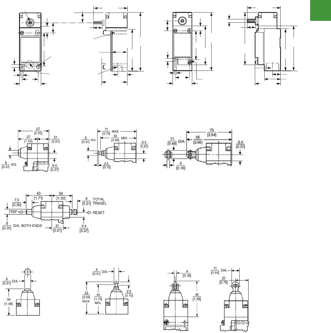
Automation
Power control
286
2015/2016 Product guide AUS15_007 - February 2016
V8-T2-66 Volume 8—Sensing Solutions CA08100010E—May 2013 www.eaton.com
2
2
2
2
2
2
2
2
2
2
2
2
2
2
2
2
2
2
2
2
2
2
2
2
2
2
2.6
Limit Switches
E50 Heavy-Duty Plug-In Switches
Dimensions
Approximate Dime nsions in Inches (mm)
Standard
Side push operators
Approximate dimensions in mm [in]
Pushbutton
Maintained pushbutton
Top push operators
Pushbutton
2.46 (63)
3.13
(79)
4.22
(107)
1.78 (45)
0.50 (13)
Pipe Tap
0.63 (16)
Dia. 0.20 (5)
Front Mtg. Hole
0.75
(19)
[10-32] Tap
0.38 (10) Deep
Rear Mt. Holes (2)
Dia. 0.63 (16)
Hole for
Manifold Mtg.
1.54 (39)
0.20 (5)
0.24
(6)
Shaft Dia. 0.28 (7)
0.38 (10)
1.06
(27)
0.65
(16)
0.70 (18)
1
1
E50SB34
Roller
Roller
Notes
1Can accommodate both U.S., 1.16 (29.4) x 2.34 (59.5) and DIN, 1.18 (30) x 3.26 (60),
mounting dimensions.
2For E50DS4.
3For E50DS3.
2.68 (68)
3.40
(86)
4.22
(107)
3.61
(92)
2.05 (52)
Conduit Entrance
3/4-14 NPT
Pipe Threads
0.63
(16)
0.75
(19)
[10-32] Tap
0.38 (10) Deep
Rear Mt. Holes (2)
1.54 (39)
0.20
(5)
0.24
(6)
Dia. 0.27 (7)
(Over Knurl)
0.38 (10)
3.13
(79)
4.70
(119)
0.65 (16)
1.31 (33)
1
2
3
Adjustable pushbutton
Adjustable pushbutton
Plug-in switches
Dimensions (approximate dimensions in inches (mm)
(approximate dimensions in mm (inches)
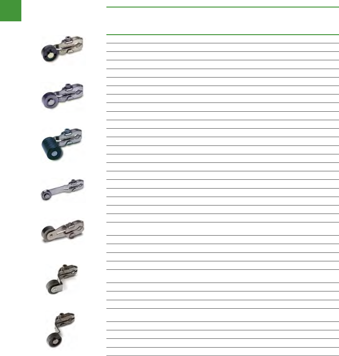
Automation
Power control
287 2015/2016 Product guide AUS15_007 - February 2016
Limit switches
Roller type operators
For rotary head switches: E50 Plug-In, E50 6P+, and 10316.
Roller
type
Minimum
Required
Return
torque
Approximate Dimensions in Inches (mm)
Item no.
A
Lever
length
B
Roller
diameter
C
Roller
width
D E F
Standard roller (stainless steel)
Metal 0.62 in-oz 0.88 (22.2) 0.75 (19.0) 0.32 (8.1) 0.31 (7.9) 0.20 (5.1) 0.24 (6.1) E50KL39
Metal 0.95 in-oz 1.38 (34.9) 0.75 (19.0) 0.32 (8.1) 0.34 (8.6) 0.13 (3.3) 0.17 (4.3) E50KL40
Ball bearing 0.77 in-oz 1.50 (38.1) 0.69 (17.5) 0.25 (6.4) 0.34 (8.6) 0.05 (1.3) 0.11 (2.8) E50KL531
Nylatron 0.53 in-oz 1.50 (38.1) 0.75 (19.0) 0.32 (8.1) 0.34 (8.6) 0.13 (3.3) 0.17 (4.3 E50KL200
Metal 1.10 in-oz 1.50 (38.1) 0.75 (19.0) 0.32 (8.1) 0.34 (8.6) 0.13 (3.3) 0.17 (4.3) E50KL355
Nylatron 0.96 in-oz 1.50 (38.1) 0.75 (19.0) 1.00 (25.4) 0.34 (8.6) 0.83 (21.1) 0.83 (21.1) E50KL377
Without roller 0.32 in-oz 1.50 (38.1) ——0.34 (8.6) — — E50KL32
Ball bearing 1.10 in-oz 2.00 (50.8) 0.69 (17.5) 0.25 (6.4) 0.34 (8.6) 0.05 (1.3) 0.11 (2.8) E50KL552
Nylatron 0.71 in-oz 2.00 (50.8) 0.75 (19.0) 0.32 (8.1) 0.34 (8.6) 0.13 (3.3) 0.17 (4.3) E50KL546
Metal 1.50 in-oz 2.00 (50.8) 0.75 (19.0) 0.32 (8.1) 0.34 (8.6) 0.13 (3.3) 0.17 (4.3) E50KL549
Nylatron 1.45 in-oz 2.00 (50.8) 0.75 (19.0) 1.00 (25.4) 0.34 (8.6) 0.83 (21.1) 0.83 (21.1) E50KL572
Ball bearing 1.50 in-oz 2.50 (63.5) 0.69 (17.5) 0.25 (6.4) 0.34 (8.6) 0.05 (1.3) 0.11 (2.8) E50KL553
Nylatron 1.00 in-oz 2.50 (63.5) 0.75 (19.0) 0.32 (8.1) 0.34 (8.6) 0.13 (3.3) 0.17 (4.3) E50KL547
Metal 2.00 in-oz 2.50 (63.5) 0.75 (19.0) 0.32 (8.1) 0.34 (8.6) 0.13 (3.3) 0.17 (4.3) E50KL550
Nylatron 1.80 in-oz 2.50 (63.5) 0.75 (19.0) 1.00 (25.4) 0.34 (8.6) 0.83 (21.1) 0.83 (21.1) E50KL573
Nylatron 1.40 in-oz 2.50 (63.5) 1.50 (38.1) 0.28 (7.1) 0.34 (8.6) 0.11 (2.8) 0.17 (4.3) E50KL575
Ball bearing 1.80 in-oz 3.00 (76.2) 0.69 (17.5) 0.25 (6.4) 0.34 (8.6) 0.05 (1.3) 0.11 (2.8) E50KL554
Nylatron 1.30 in-oz 3.00 (76.2) 0.75 (19.0) 0.32 (8.1) 0.34 (8.6) 0.13 (3.3) 0.17 (4.3) E50KL548
Metal 2.50 in-oz 3.00 (76.2) 0.75 (19.0) 0.32 (8.1) 0.34 (8.6) 0.13 (3.3) 0.17 (4.3) E50KL551
Nylatron 2.30 in-oz 3.00 (76.2) 0.75 (19.0) 1.00 (25.4) 0.34 (8.6) 0.83 (21.1) 0.83 (21.1) E50KL574
Nylatron 1.80 in-oz 3.00 (76.2) 1.50 (38.1) 0.28 (7.1) 0.34 (8.6) 0.11 (2.8) 0.17 (4.3) E50KL576
Roller on reverse side (stainless steel)
Ball bearing 0.77 in-oz 1.50 (38.1) 0.69 (17.5) 0.25 (6.4) 0.34 (8.6) 0.18 (4.6) 0.24 (6.1) E50KL580
Nylatron 0.53 in-oz 1.50 (38.1) 0.75 (19.0) 0.32 (8.1) 0.34 (8.6) 0.27 (6.9) 0.31 (7.9) E50KL310
Metal 1.10 in-oz 1.50 (38.1) 0.75 (19.0) 0.32 (8.1) 0.34 (8.6) 0.27 (6.9) 0.31 (7.9) E50KL579
Nylatron 0.96 in-oz 1.50 (38.1) 1.50 (38.1) 0.28 (7.1) 0.34 (8.6) 0.23 (5.8) 0.31 (7.9) E50KL536
Offset inboard roller (stainless steel)
Nylatron 0.65 in-oz 1.50 (38.1) 0.75 (19.0) 0.32 (8.1) 0.03 (0.8) — — E50KL24
Metal 1.20 in-oz 1.50 (38.1) 0.75 (19.0) 0.32 (8.1) 0.03 (0.8) — — E50KL25
Ball bearing 0.90 in-oz 1.50 (38.1) 0.69 (17.5) 0.25 (6.4) 0.04 (1.0) — — E50KL26
Offset outboard (stainless steel)
Nylatron 0.65 in-oz 1.50 (38.1) 0.75 (19.0) 0.32 (8.1) 0.03 (0.8) — — E50KL27
Metal 1.20 in-oz 1.50 (38.1) 0.75 (19.0) 0.32 (8.1) 0.03 (0.8) — — E50KL28
Ball bearing 0.90 in-oz 1.50 (38.1) 0.69 (17.5) 0.25 (6.4) 0.04 (1.0) — — E50KL29
Nylatron 1.10 in-oz 1.50 (38.1) 0.75 (19.0) 1.00 (25.4) — — — E50KL30
Volume 8—Sensing Solutions CA08100010E—May 2013 www.eaton.com V8-T2-81
2
2
2
2
2
2
2
2
2
2
2
2
2
2
2
2
2
2
2
2
2
2
2
2
2
2
2
2
2
2
2.8
Limit Switches
Operators
Product Selection
Roller Type Operators
For rotary head switches: E50 Plug-In, E50 6P+, and 10316.
Note: Only operators with Nylatron rods or rollers should be used with explosion-proof limit switches.
Operators—Roller Type
Notes
1 Caution: When selecting lever, the minimum required return torque of lever should not exceed minimum
return force available in operating head as given in operating head specifications.
2 Length from the operating shaft axis to the roller axis (or to the tip for non-roller operators).
Roller Type
Minimum
Required
Return Torque 1
Approximate Dimensions in Inches (mm)
Catalog
Number
A
Lever Length 2
B
Roller Diameter
C
Roller Width D E F
Standard Roller (Stainless Steel)
Metal 0.62 in-oz 0.88 (22.2) 0.75 (19.0) 0.32 (8.1) 0.31 (7.9) 0.20 (5.1) 0.24 (6.1) E50KL39
Metal 0.95 in-oz 1.38 (34.9) 0.75 (19.0) 0.32 (8.1) 0.34 (8.6) 0.13 (3.3) 0.17 (4.3) E50KL40
Ball bearing 0.77 in-oz 1.50 (38.1) 0.69 (17.5) 0.25 (6.4) 0.34 (8.6) 0.05 (1.3) 0.11 (2.8) E50KL531
Nylatron 0.53 in-oz 1.50 (38.1) 0.75 (19.0) 0.32 (8.1) 0.34 (8.6) 0.13 (3.3) 0.17 (4.3) E50KL200
Metal 1.10 in-oz 1.50 (38.1) 0.75 (19.0) 0.32 (8.1) 0.34 (8.6) 0.13 (3.3) 0.17 (4.3) E50KL355
Nylatron 0.96 in-oz 1.50 (38.1) 0.75 (19.0) 1.00 (25.4) 0.34 (8.6) 0.83 (21.1) 0.83 (21.1) E50KL377
Without roller 0.32 in-oz 1.50 (38.1) — —0.34 (8.6) — — E50KL32
Ball bearing 1.10 in-oz 2.00 (50.8) 0.69 (17.5) 0.25 (6.4) 0.34 (8.6) 0.05 (1.3) 0.11 (2.8) E50KL552
Nylatron 0.71 in-oz 2.00 (50.8) 0.75 (19.0) 0.32 (8.1) 0.34 (8.6) 0.13 (3.3) 0.17 (4.3) E50KL546
Metal 1.50 in-oz 2.00 (50.8) 0.75 (19.0) 0.32 (8.1) 0.34 (8.6) 0.13 (3.3) 0.17 (4.3) E50KL549
Nylatron 1.45 in-oz 2.00 (50.8) 0.75 (19.0) 1.00 (25.4) 0.34 (8.6) 0.83 (21.1) 0.83 (21.1) E50KL572
Ball bearing 1.50 in-oz 2.50 (63.5) 0.69 (17.5) 0.25 (6.4) 0.34 (8.6) 0.05 (1.3) 0.11 (2.8) E50KL553
Nylatron 1.00 in-oz 2.50 (63.5) 0.75 (19.0) 0.32 (8.1) 0.34 (8.6) 0.13 (3.3) 0.17 (4.3) E50KL547
Metal 2.00 in-oz 2.50 (63.5) 0.75 (19.0) 0.32 (8.1) 0.34 (8.6) 0.13 (3.3) 0.17 (4.3) E50KL550
Nylatron 1.80 in-oz 2.50 (63.5) 0.75 (19.0) 1.00 (25.4) 0.34 (8.6) 0.83 (21.1) 0.83 (21.1) E50KL573
Nylatron 1.40 in-oz 2.50 (63.5) 1.50 (38.1) 0.28 (7.1) 0.34 (8.6) 0.11 (2.8) 0.17 (4.3) E50KL575
Ball bearing 1.80 in-oz 3.00 (76.2) 0.69 (17.5) 0.25 (6.4) 0.34 (8.6) 0.05 (1.3) 0.11 (2.8) E50KL554
Nylatron 1.30 in-oz 3.00 (76.2) 0.75 (19.0) 0.32 (8.1) 0.34 (8.6) 0.13 (3.3) 0.17 (4.3) E50KL548
Metal 2.50 in-oz 3.00 (76.2) 0.75 (19.0) 0.32 (8.1) 0.34 (8.6) 0.13 (3.3) 0.17 (4.3) E50KL551
Nylatron 2.30 in-oz 3.00 (76.2) 0.75 (19.0) 1.00 (25.4) 0.34 (8.6) 0.83 (21.1) 0.83 (21.1) E50KL574
Nylatron 1.80 in-oz 3.00 (76.2) 1.50 (38.1) 0.28 (7.1) 0.34 (8.6) 0.11 (2.8) 0.17 (4.3) E50KL576
Dimensions, see Page V8-T2-84.
Roller On Reverse Side (Stainless Steel)
Ball bearing 0.77 in-oz 1.50 (38.1) 0.69 (17.5) 0.25 (6.4) 0.34 (8.6) 0.18 (4.6) 0.24 (6.1) E50KL580
Nylatron 0.53 in-oz 1.50 (38.1) 0.75 (19.0) 0.32 (8.1) 0.34 (8.6) 0.27 (6.9) 0.31 (7.9) E50KL310
Metal 1.10 in-oz 1.50 (38.1) 0.75 (19.0) 0.32 (8.1) 0.34 (8.6) 0.27 (6.9) 0.31 (7.9) E50KL579
Nylatron 0.96 in-oz 1.50 (38.1) 1.50 (38.1) 0.28 (7.1) 0.34 (8.6) 0.23 (5.8) 0.31 (7.9) E50KL536
Offset Inboard Roller (Stainless Steel)
Nylatron 0.65 in-oz 1.50 (38.1) 0.75 (19.0) 0.32 (8.1) 0.03 (0.8) — — E50KL24
Metal 1.20 in-oz 1.50 (38.1) 0.75 (19.0) 0.32 (8.1) 0.03 (0.8) — — E50KL25
Ball bearing 0.90 in-oz 1.50 (38.1) 0.69 (17.5) 0.25 (6.4) 0.04 (1.0) — — E50KL26
Offset Outboard Roller (Stainless Steel)
Nylatron 0.65 in-oz 1.50 (38.1) 0.75 (19.0) 0.32 (8.1) 0.03 (0.8) — — E50KL27
Metal 1.20 in-oz 1.50 (38.1) 0.75 (19.0) 0.32 (8.1) 0.03 (0.8) — — E50KL28
Ball bearing 0.90 in-oz 1.50 (38.1) 0.69 (17.5) 0.25 (6.4) 0.04 (1.0) — — E50KL29
Nylatron 1.10 in-oz 1.50 (38.1) 0.75 (19.0) 1.00 (25.4) — — — E50KL30
Dimensions, see Page V8-T2-85.
E50KL200
E50KL355
E50KL377
E50KL554
E50KL580
E50KL24
E50KL27
E50KL200
E50KL355
E50KL377
E50KL554
E50KL580
E50KL24
E50KL27
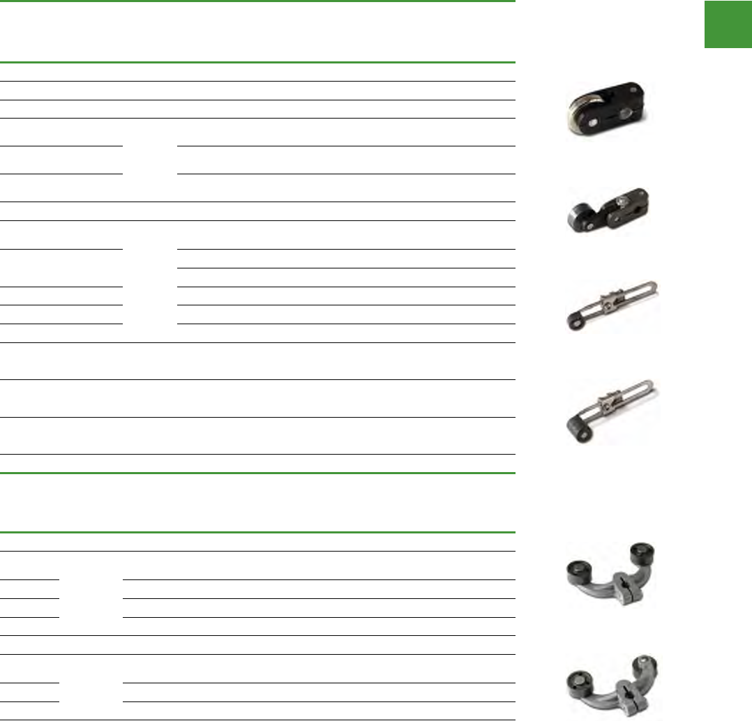
Automation
Power control
288
2015/2016 Product guide AUS15_007 - February 2016
Limit switches
Roller type operators
Roller
type
Minimum
Required
Return
torque
Approximate dimensions in Inches (mm)
Item no.
A
Lever
length
B
Roller
diameter
C
Roller
width
D E F
Bantam lever
Metal 0.45 in-oz 0.69 (17.5) 0.85 (22.0) 0.18 (4.6) — — — E50KL532
Precision adjustment
Nylatron 0.65 in-oz 0.69
(17.5)
Roller
length:
1.50
(38.1)
0.75 (19.0) 0.32 (8.1) 0.48 (12.2) 0.24 (6.1) 0.28 (7.1) E50KL340
Metal 1.20 in-oz 0.75 (19.0) 0.32 (8.1) 0.48 (12.2) 0.24 (6.1) 0.28 (7.1) E50KL465
Ball
bearing 0.90 in-oz 0.69 (17.5) 0.25 (6.4) 0.48 (12.2) 0.16 (4.1) 0.22 (5.6) E50KL535
Adjustable roller (Stainless steel)
Ball
bearing 2.50 in-oz
1.0 (25.4)
to 3.75
(95.2)
0.69 (17.5) 0.25 (6.4) 0.23 (5.8) 0.30 (7.6) — E50KL539
Nylatron 1.90 in-oz
0.75 (19.0) 0.32 (8.1) 0.29 (7.4) 0.33 (8.4) — E50KL201
0.75 (19.0) 0.32 (8.1) 0.29 (7.4) 0.33 (8.4) — E50KL201SPL
Metal 3.40 in-oz 0.75 (19.0) 0.32 (8.1) 0.29 (7.4) 0.33 (8.4) — E50KL538
Nylatron 1.90 in-oz 0.75 (19.0) 0.50 (12.7) 0.46 (11.6) 0.48 (12.2) — E50KL599
Nylatron 3.10 in-oz 0.75 (19.0) 1.00 (25.4) 0.90 (22.9) 0.95 (24.1) — E50KL537
Large
Nylatron 4.50 in-oz
0.5 (12.7)
to 3.25
(82.6)
4.00 (102.0) 0.11 (2.8) 0.11 (2.8) 0.19 (4.8) — E50KL598
Without
roller 1.20 in-oz
0.5 (12.7)
to 3.75
(95.2)
— — — — — E50KL31
Nylatron 2.50 in-oz
1.63 (41.3)
to 3.75
(95.2)
1.50 (38.1) 0.29 (7.4) 0.26 (6.6) 0.32 (8.1) — E50KL443
Roller
type
Approximate dimensions in Inches (mm)
Item no.
A
Lever
length
B
Roller
diameter
C
Roller
width
D E F G
Fork lever—both rollers on one side
Ball
bearing
1.50 (38.1)
0.69 (17.5) 0.25 (6.4) 0.08 (2.0) 0.14 (3.6) — — E50KL545
Nylatron 0.75 (19.0) 0.32 (8.1) 0.16 (4.1) 0,20 (5.1) — — E50KL204
Metal 0.75 (19.0) 0.32 (8.1) 0.16 (4.1) 0,20 (5.1) — — E50KL544
Nylatron 0.75 (19.0) 1.00 (25.4) 0.84 (21.3) 0.88 (22.4) — — E50KL543
Fork lever—one roller outside, one inside
Ball
bearing 1.50
(38.1)
0.69 (17.5) 0.25 (6.4) 0.08 (2.0) 0.14 (3.6) 0.64 (16.3) 0.70 (17.8) E50KL542
Nylatron 0.75 (19.0) 0.32 (8.1) 0.16 (4.1) 0.20 (5.1) 0.73 (18,5) 0.77 (19.6) E50KL203
Metal 0.75 (19.0) 0.32 (8.1) 0.16 (4.1) 0.20 (5.1) 0.73 (18,5) 0.77 (19.6) E50KL541
Caution: When selecting lever, the minimum required return torque of lever should not exceed minimum
return force available in operating head as given in operating head specifications.
Length from the operating shaft axis to the roller axis (or to the tip for non-roller operators).
Maximum length dimension between operating shaft axis to roller axis for comparison.
Precision adjustable to lesser dimensions.
Applies when lever is extended to the maximum dimension.
By reassembling lever, minimum length can be reduced another 0.5 in (12.7 mm).
High-grade stainless steel.
V8-T2-82 Volume 8—Sensing Solutions CA08100010E—May 2013 www.eaton.com
2
2
2
2
2
2
2
2
2
2
2
2
2
2
2
2
2
2
2
2
2
2
2
2
2
2
2
2
2
2
2.8
Limit Switches
Operators
Note: Only operators with Nylatron rods or rollers should be used with explosion-proof limit switches.
Operators—Roller Type, continued
Operators—Roller Type, continued
Notes
1 Caution: When selecting lever, the minimum required return torque of lever should not exceed minimum
return force available in operating head as given in operating head specifications.
2 Length from the operating shaft axis to the roller axis (or to the tip for non-roller operators).
3 Maximum length dimension between operating shaft axis to roller axis for comparison.
Precision adjustable to lesser dimensions.
4 Applies when lever is extended to the maximum dimension.
5 By reassembling lever, minimum length can be reduced another 0.5 in (12.7 mm).
6 High-grade stainless steel.
Roller Type
Minimum
Required
Return Torque 1
Approximate Dimensions in Inches (mm)
Catalog
Number
A
Lever Length 2
B
Roller Diameter
C
Roller Width D E F
Bantam Lever
Metal 0.45 in-oz 0.69 (17.5) 0.85 (22.0) 0.18 (4.6) — — — E50KL532
Precision Adjustment
Nylatron 0.65 in-oz 0.69 (17.5)
Roller length:
1.50 (38.1) 3
0.75 (19.0) 0.32 (8.1) 0.48 (12.2) 0.24 (6.1) 0.28 (7.1) E50KL340
Metal 1.20 in-oz 0.75 (19.0) 0.32 (8.1) 0.48 (12.2) 0.24 (6.1) 0.28 (7.1) E50KL465
Ball bearing 0.90 in-oz 0.69 (17.5) 0.25 (6.4) 0.48 (12.2) 0.16 (4.1) 0.22 (5.6) E50KL535
Dimensions, see Page V8-T2-85.
Adjustable Roller (Stainless Steel)
Ball bearing 2.50 in-oz 41.0 (25.4) to
3.75 (95.2) 5
0.69 (17.5) 0.25 (6.4) 0.23 (5.8) 0.30 (7.6) — E50KL539
Nylatron 1.90 in-oz 40.75 (19.0) 0.32 (8.1) 0.29 (7.4) 0.33 (8.4) — E50KL201
0.75 (19.0) 0.32 (8.1) 0.29 (7.4) 0.33 (8.4) — E50KL201SPL 6
Metal 3.40 in-oz 40.75 (19.0) 0.32 (8.1) 0.29 (7.4) 0.33 (8.4) — E50KL538
Nylatron 1.90 in-oz 40.75 (19.0) 0.50 (12.7) 0.46 (11.6) 0.48 (12.2) — E50KL599
Nylatron 3.10 in-oz 40.75 (19.0) 1.00 (25.4) 0.90 (22.9) 0.95 (24.1) — E50KL537
Large Nylatron 4.50 in-oz 40.5 (12.7) to
3.25 (82.6)
4.00 (102.0) 0.11 (2.8) 0.11 (2.8) 0.19 (4.8) — E50KL598
Without roller 1.20 in-oz 40.5 (12.7) to
3.75 (95.2)
— — ———E50KL31
Nylatron 2.50 in-oz 41.63 (41.3) to
3.75 (95.2) 5
1.50 (38.1) 0.29 (7.4) 0.26 (6.6) 0.32 (8.1) — E50KL443
Dimensions, see Page V8-T2-86.
Roller Type
Minimum
Required
Return
Torque 1
Approximate Dimensions in Inches (mm)
G
Catalog
Number
A
Lever Length 2
B
Roller Diameter
C
Roller Width D E F
Fork Lever—Both Rollers on One Side
Ball bearing — 1.50 (38.1) 0.69 (17.5) 0.25 (6.4) 0.08 (2.0) 0.14 (3.6) — — E50KL545
Nylatron — 0.75 (19.0) 0.32 (8.1) 0.16 (4.1) 0,20 (5.1) — — E50KL204
Metal — 0.75 (19.0) 0.32 (8.1) 0.16 (4.1) 0,20 (5.1) — — E50KL544
Nylatron — 0.75 (19.0) 1.00 (25.4) 0.84 (21.3) 0.88 (22.4) — — E50KL543
Fork Lever—One Roller Outside, One Inside
Ball bearing — 1.50 (38.1) 0.69 (17.5) 0.25 (6.4) 0.08 (2.0) 0.14 (3.6) 0.64 (16.3) 0.70 (17.8) E50KL542
Nylatron — 0.75 (19.0) 0.32 (8.1) 0.16 (4.1) 0.20 (5.1) 0.73 (18,5) 0.77 (19.6) E50KL203
Metal — 0.75 (19.0) 0.32 (8.1) 0.16 (4.1) 0.20 (5.1) 0.73 (18,5) 0.77 (19.6) E50KL541
Dimensions, see Page V8-T2-86.
E50KL532
E50KL340
E50KL201
E50KL537
E50KL545
E50KL542
E50KL532
E50KL340
E50KL201
E50KL537
E50KL545
E50KL542
Automation
Power control
289 2015/2016 Product guide AUS15_007 - February 2016
Limit switches
Rod type operators
For rotary head switches: E50 Plug-In, E50 6P+, and 10316.
Rod type
Minimum
required
return torque
Approximate dimensions in Inches
(mm) Item no.
A
Rod length
B
Rod diameter
Adjustable rod
Nylon 0.40 in-oz 3 5.50 (140.0)
0.19 (4.8) E50KL399
Metal 0.92 in-oz 3 0.12 (3.2) E50KL202
Metal 2.20 in-oz 3 8.75 (222.0)
Rod size (square):
0.12 (3.2) x 0.12
(3.2)
E50KL581
Stainless steel 7.00 in-oz 3 9.00 (229.0) 0.19 (4.8) E50KL220
Bendable steel 5.00 in-oz 3 12.00 (305.0) 0.12 (3.2) E50KL226
Clamps for adjustable rods (rod not included)
clamp for..
0.19 (4.8) diameter rods E50KL35
0.12 (3.2) diameter rods E50KL36
0.25 (6.4) diameter rods E50KL41
Wobble type operators
For E50DW1 and E50DW2 Operator Heads on E50 Plug-In and E50 6P+ Switches.
Wobble type Item no.
Nylon rod E50KW2
Stainless steel rod E50KW3
Coil spring E50KW4
Rod type
Minimum
required
return torque
Approximate dimensions in Inches (mm)
Item no.
A Rod
length
B Rod
diameter C D
Spring rod
Nylon 3.50 in-oz — — — — E50KL556
Stainless
steel 2.80 in-oz — — — — E50KL421
Adjustable wire
Nylon
covered wire 1.50 in-oz — — — — E50KL533
Adjustable wide roller lever
Nylatron 4.50 in-oz — — — — E50KL37
Nylatron loop
Nylatron 0.40 in-oz 6.00 (152.0) 0.158 (4.0) — — E50KL142
Eye bolt
Zinc-plated
steel 0.53 in-oz 150.00
(38.1)
Ǿ 0.1875 (4.8)
Loop ID: 0.375
(9.5)
0.52 (13.1) 0.24 (8.6) E50KL33
Caution: When selecting lever, the minimum required return torque of lever should not exceed minimum return force
available in operating head as given in operating head specifications.
Length from the operating shaft axis to tip.
Applies when lever is extended to the maximum dimension.
Volume 8—Sensing Solutions CA08100010E—May 2013 www.eaton.com V8-T2-83
2
2
2
2
2
2
2
2
2
2
2
2
2
2
2
2
2
2
2
2
2
2
2
2
2
2
2
2
2
2
2.8
Limit Switches
Operators
Rod Type Operators
For rotary head switches: E50 Plug-In, E50 6P+, and 10316.
Note: Only operators with Nylatron rods or rollers should be used with explosion-proof limit switches.
Operators—Rod Type
Operators—Rod Type, continued
Notes
1 Caution: When selecting lever, the minimum required return torque of lever should not exceed minimum
return force available in operating head as given in operating head specifications.
2 Length from the operating shaft axis to tip.
3 Applies when lever is extended to the maximum dimension.
Rod Type
Minimum
Required
Return Torque 1
Approximate Dimensions in Inches (mm)
A
Rod Length
(Maximum) 2
B
Rod Diameter
Catalog
Number
Adjustable Rod
Nylon 0.40 in-oz 35.50 (140.0) 0.19 (4.8) E50KL399
Metal 0.92 in-oz 30.12 (3.2) E50KL202
Metal 2.20 in-oz 38.75 (222.0) Rod size (square):
0.12 (3.2) x 0.12 (3.2)
E50KL581
Stainless steel 7.00 in-oz 39.00 (229.0) 0.19 (4.8) E50KL220
Bendable steel 5.00 in-oz 312.00 (305.0) 0.12 (3.2) E50KL226
Clamps for Adjustable Rods (Rod not included)
Clamp for …
0.19 (4.8) diameter rods E50KL35
0.12 (3.2) diameter rods E50KL36
0.25 (6.4) diameter rods E50KL41
Dimensions, see Page V8-T2-87.
Rod Type
Minimum
Required
Return Torque 1
Approximate Dimensions in Inches (mm)
A
Rod Length 2
B
Rod Diameter C D
Catalog
Number
Spring Rod
Nylon 3.50 in-oz — — — — E50KL556
Stainless steel 2.80 in-oz — — — — E50KL421
Adjustable Wire
Nylon covered wire 1.50 in-oz 3————E50KL533
Adjustable Wide Roller Lever
Nylatron 4.50 in-oz 3————E50KL37
Nylatron Loop
Nylatron 0.40 in-oz 6.00 (152.0) 0.158 (4.0) — —E50KL142
Eye Bolt
Zinc-plated steel 0.53 in-oz 150.00 (38.1) 0.1875 (4.8)
Loop ID: 0.375 (9.5)
0.52 (13.1) 0.24 (8.6) E50KL33
Dimensions, see Page V8-T2-87.
Nylon/Metal
Metal/Steel
Nylon/Steel
Nylon Covered Wire
Nylatron
Nylatron
Zinc-Plated Steel
V8-T2-84 Volume 8—Sensing Solutions CA08100010E—May 2013 www.eaton.com
2
2
2
2
2
2
2
2
2
2
2
2
2
2
2
2
2
2
2
2
2
2
2
2
2
2
2
2
2
2
2.8
Limit Switches
Operators
Wobble Type Operators
For E50DW1 and E50DWZ Operator Heads on E50 Plug-In and E50 6P+ Switches.
Note: Only operators with Nylatron rods or rollers should be used with explosion-proof limit switches.
Operators—Wobble Type
Dimensions
Roller Type Operators
Standard roller
Note
1Length from the operating shaft axis to the roller axis (or to the tip for non-roller operators).
Wobble Type Catalog Number
Nylon Rod
E50KW2
Stainless Steel Rod
E50KW3
Coil Spring
E50KW4
Dimensions , see Page V8-T2-88 .
Item no.
A
Lever Length
1
B
Roller Diameter
C
Roller Width D E F
E50KL39 0.88 (22.2) 0.75 (19.0) 0.32 (8.1) 0.31 (7.9) 0.20 (5.1) 0.24 (6.1)
E50KL40 1.38 (34.9) 0.75 (19.0) 0.32 (8.1) 0.34 (8.6) 0.13 (3.3) 0.17 (4.3)
E50KL531 1.50 (38.1) 0.69 (17.5) 0.25 (6.4) 0.34 (8.6) 0.05 (1.3) 0.11 (2.8)
E50KL200 1.50 (38.1) 0.75 (19.0) 0.32 (8.1) 0.34 (8.6) 0.13 (3.3) 0.17 (4.3)
E50KL355 1.50 (38.1) 0.75 (19.0) 0.32 (8.1) 0.34 (8.6) 0.13 (3.3) 0.17 (4.3)
E50KL377 1.50 (38.1) 0.75 (19.0) 1.00 (25.4) 0.34 (8.6) 0.83 (21.1) 0.83 (21.1)
E50KL32 1.50 (38.1) — — 0.34 (8.6) — —
E50KL552 2.00 (50.8) 0.69 (17.5) 0.25 (6.4) 0.34 (8.6) 0.05 (1.3) 0.11 (2.8)
E50KL546 2.00 (50.8) 0.75 (19.0) 0.32 (8.1) 0.34 (8.6) 0.13 (3.3) 0.17 (4.3)
E50KL549 2.00 (50.8) 0.75 (19.0) 0.32 (8.1) 0.34 (8.6) 0.13 (3.3) 0.17 (4.3)
E50KL572 2.00 (50.8) 0.75 (19.0) 1.00 (25.4) 0.34 (8.6) 0.83 (21.1) 0.83 (21.1)
E50KL553 2.50 (63.5) 0.69 (17.5) 0.25 (6.4) 0.34 (8.6) 0.05 (1.3) 0.11 (2.8)
E50KL547 2.50 (63.5) 0.75 (19.0) 0.32 (8.1) 0.34 (8.6) 0.13 (3.3) 0.17 (4.3)
E50KL550 2.50 (63.5) 0.75 (19.0) 0.32 (8.1) 0.34 (8.6) 0.13 (3.3) 0.17 (4.3)
E50KL573 2.50 (63.5) 0.75 (19.0) 1.00 (25.4) 0.34 (8.6) 0.83 (21.1) 0.83 (21.1)
E50KL575 2.50 (63.5) 1.50 (38.1) 0.28 (7.1) 0.34 (8.6) 0.11 (2.8) 0.17 (4.3)
E50KL554 3.00 (76.2) 0.69 (17.5) 0.25 (6.4) 0.34 (8.6) 0.05 (1.3) 0.11 (2.8)
E50KL548 3.00 (76.2) 0.75 (19.0) 0.32 (8.1) 0.34 (8.6) 0.13 (3.3) 0.17 (4.3)
E50KL551 3.00 (76.2) 0.75 (19.0) 0.32 (8.1) 0.34 (8.6) 0.13 (3.3) 0.17 (4.3)
E50KL574 3.00 (76.2) 0.75 (19.0) 1.00 (25.4) 0.34 (8.6) 0.83 (21.1) 0.83 (21.1)
E50KL576 3.00 (76.2) 1.50 (38.1) 0.28 (7.1) 0.34 (8.6) 0.11 (2.8) 0.17 (4.3)
E5
0KW2
E5
0KW3
E5
0KW4
0.44
(11)
C
A
D
F
E
B
0.67
(17)
Approximate dimensions in inches (mm)
Nylon/metal
Metal/steel
Nylon/steel
Nylon covered wire
Nylatron
Nylatron loop
Zinc-plated steel
E50KW2
E50KW3
E50KW4
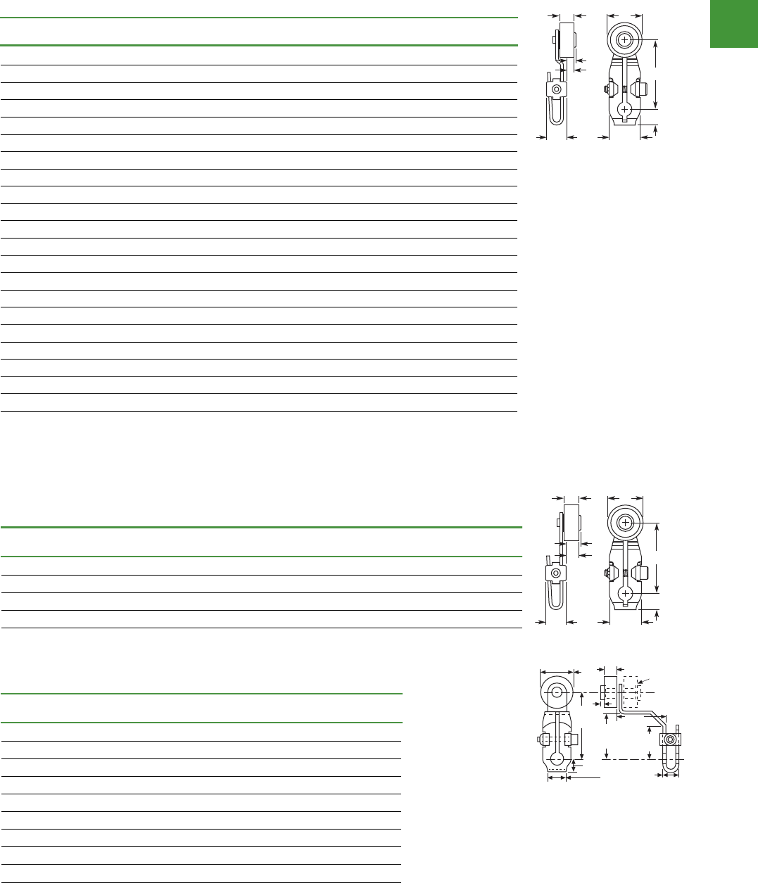
Automation
Power control
290
2015/2016 Product guide AUS15_007 - February 2016
V8-T2-84 Volume 8—Sensing Solutions CA08100010E—May 2013 www.eaton.com
2
2
2
2
2
2
2
2
2
2
2
2
2
2
2
2
2
2
2
2
2
2
2
2
2
2
2
2
2
2
2.8
Limit Switches
Operators
Wobble Type Operators
For E50DW1 and E50DWZ Operator Heads on E50 Plug-In and E50 6P+ Switches.
Note: Only operators with Nylatron rods or rollers should be used with explosion-proof limit switches.
Operators—Wobble Type
Dimensions
Roller Type Operators
Standard roller
Note
1Length from the operating shaft axis to the roller axis (or to the tip for non-roller operators).
Wobble Type Catalog Number
Nylon Rod
E50KW2
Stainless Steel Rod
E50KW3
Coil Spring
E50KW4
Dimensions , see Page V8-T2-88 .
Item no.
A
Lever Length
1
B
Roller Diameter
C
Roller Width D E F
E50KL39 0.88 (22.2) 0.75 (19.0) 0.32 (8.1) 0.31 (7.9) 0.20 (5.1) 0.24 (6.1)
E50KL40 1.38 (34.9) 0.75 (19.0) 0.32 (8.1) 0.34 (8.6) 0.13 (3.3) 0.17 (4.3)
E50KL531 1.50 (38.1) 0.69 (17.5) 0.25 (6.4) 0.34 (8.6) 0.05 (1.3) 0.11 (2.8)
E50KL200 1.50 (38.1) 0.75 (19.0) 0.32 (8.1) 0.34 (8.6) 0.13 (3.3) 0.17 (4.3)
E50KL355 1.50 (38.1) 0.75 (19.0) 0.32 (8.1) 0.34 (8.6) 0.13 (3.3) 0.17 (4.3)
E50KL377 1.50 (38.1) 0.75 (19.0) 1.00 (25.4) 0.34 (8.6) 0.83 (21.1) 0.83 (21.1)
E50KL32 1.50 (38.1) — — 0.34 (8.6) — —
E50KL552 2.00 (50.8) 0.69 (17.5) 0.25 (6.4) 0.34 (8.6) 0.05 (1.3) 0.11 (2.8)
E50KL546 2.00 (50.8) 0.75 (19.0) 0.32 (8.1) 0.34 (8.6) 0.13 (3.3) 0.17 (4.3)
E50KL549 2.00 (50.8) 0.75 (19.0) 0.32 (8.1) 0.34 (8.6) 0.13 (3.3) 0.17 (4.3)
E50KL572 2.00 (50.8) 0.75 (19.0) 1.00 (25.4) 0.34 (8.6) 0.83 (21.1) 0.83 (21.1)
E50KL553 2.50 (63.5) 0.69 (17.5) 0.25 (6.4) 0.34 (8.6) 0.05 (1.3) 0.11 (2.8)
E50KL547 2.50 (63.5) 0.75 (19.0) 0.32 (8.1) 0.34 (8.6) 0.13 (3.3) 0.17 (4.3)
E50KL550 2.50 (63.5) 0.75 (19.0) 0.32 (8.1) 0.34 (8.6) 0.13 (3.3) 0.17 (4.3)
E50KL573 2.50 (63.5) 0.75 (19.0) 1.00 (25.4) 0.34 (8.6) 0.83 (21.1) 0.83 (21.1)
E50KL575 2.50 (63.5) 1.50 (38.1) 0.28 (7.1) 0.34 (8.6) 0.11 (2.8) 0.17 (4.3)
E50KL554 3.00 (76.2) 0.69 (17.5) 0.25 (6.4) 0.34 (8.6) 0.05 (1.3) 0.11 (2.8)
E50KL548 3.00 (76.2) 0.75 (19.0) 0.32 (8.1) 0.34 (8.6) 0.13 (3.3) 0.17 (4.3)
E50KL551 3.00 (76.2) 0.75 (19.0) 0.32 (8.1) 0.34 (8.6) 0.13 (3.3) 0.17 (4.3)
E50KL574 3.00 (76.2) 0.75 (19.0) 1.00 (25.4) 0.34 (8.6) 0.83 (21.1) 0.83 (21.1)
E50KL576 3.00 (76.2) 1.50 (38.1) 0.28 (7.1) 0.34 (8.6) 0.11 (2.8) 0.17 (4.3)
E5
0KW2
E5
0KW3
E5
0KW4
0.44
(11)
C
A
D
F
E
B
0.67
(17)
Approximate dimensions in inches (mm)
Volume 8—Sensing Solutions CA08100010E—May 2013 www.eaton.com V8-T2-85
2
2
2
2
2
2
2
2
2
2
2
2
2
2
2
2
2
2
2
2
2
2
2
2
2
2
2
2
2
2
2.8
Limit Switches
Operators
Roller on reverse side
Approximate dimensions in Inches (mm)
Offset r oller
Approximate dimensions in mm [in]
Bantam lever
Approximate dimensions
in mm [in]
Precision Adjustment
Approximate Dimensions in mm [in]
Notes
1Length from the operating shaft axis to the roller axis (or to the tip for non-roller operators).
2Maximum length dimension between operating shaft axis to the roller axis for comparison. Precision adjustable to lesser dimensions.
Item no.
A
Lever Length
1
B
Roller Diameter
C
Roller Width D E F
E50KL580 1.50 (38.1) 0.69 (17.5) 0.25 (6.4) 0.34 (8.6) 0.18 (4.6) 0.24 (6.1)
E50KL310 1.50 (38.1) 0.75 (19.0) 0.32 (8.1) 0.34 (8.6) 0.27 (6.9) 0.31 (7.9)
E50KL579 1.50 (38.1) 0.75 (19.0) 0.32 (8.1) 0.34 (8.6) 0.27 (6.9) 0.31 (7.9)
E50KL536 1.50 (38.1) 1.50 (38.1) 0.28 (7.1) 0.34 (8.6) 0.23 (5.8) 0.31 (7.9)
Item no.
A
Lever Length
1
B
Roller Diameter
C
Roller Width D
Inboard
E50KL24 38.1 [1.50] 19.0 [0.75] 8.1 [0.32] 0.8 [0.03]
E50KL25 38.1 [1.50] 19.0 [0.75] 8.1 [0.32] 0.8 [0.03]
E50KL26 38.1 [1.50] 17.5 [0.69] 6.4 [0.25] 1.0 [0.04]
Outboard
E50KL27 38.1 [1.50] 19.0 [0.75] 8.1 [0.32] 0.8 [0.03]
E50KL28 38.1 [1.50] 19.0 [0.75] 8.1 [0.32] 0.8 [0.03]
E50KL29 38.1 [1.50] 17.5 [0.69] 6.4 [0.25] 1.0 [0.04]
E50KL30 38.1 [1.50] 19.0 [0.75] 25.4 [1.00] —
0.44
(11)
A
D
C
F
E
B
0.67
(17)
B
Dia
C
8.4
[0.33] 16
[0.64]
7.6
[0.30]
D
38
[1.50] 26
[1.02]
24
[0.94]20
[0.80]
Inboard
Roller
22
[0.85]
16
[0.62]
4.1
[0.16] 4.6
[0.18]
18
[0.69]
12
[0.48]
12.7
[0.50]
Item no.
A
Lever Length
1
B
Roller Diameter
C
Roller Width D E F
E50KL340 17.5 [0.69]
Roller length:
38.1 [1.50]
2
19.0 [0.75] 8.1 [0.32] 12.2 [0.48] 6.1 [0.24] 7.1 [0.28]
E50KL465 19.0 [0.75] 8.1 [0.32] 12.2 [0.48] 6.1 [0.24] 7.1 [0.28]
E50KL535 17.5 [0.69] 6.4 [0.25] 12.2 [0.48] 4.1 [0.16] 5.6 [0.22]
B Dia.
A
E
C
F
D
Max
60º
20R
[0.80]
16
[0.63] 12.7
[0.50]
Precision
Adjustment
Screw
Max
60º
Limit switches
Dimensions
V8-T2-84 Volume 8—Sensing Solutions CA08100010E—May 2013 www.eaton.com
2
2
2
2
2
2
2
2
2
2
2
2
2
2
2
2
2
2
2
2
2
2
2
2
2
2
2
2
2
2
2.8
Limit Switches
Operators
Wobble Type Operators
For E50DW1 and E50DWZ Operator Heads on E50 Plug-In and E50 6P+ Switches.
Note: Only operators with Nylatron rods or rollers should be used with explosion-proof limit switches.
Operators—Wobble Type
Dimensions
Roller Type Operators
Standard roller
Note
1Length from the operating shaft axis to the roller axis (or to the tip for non-roller operators).
Wobble Type Catalog Number
Nylon Rod
E50KW2
Stainless Steel Rod
E50KW3
Coil Spring
E50KW4
Dimensions , see Page V8-T2-88 .
Item no.
A
Lever Length
1
B
Roller Diameter
C
Roller Width D E F
E50KL39 0.88 (22.2) 0.75 (19.0) 0.32 (8.1) 0.31 (7.9) 0.20 (5.1) 0.24 (6.1)
E50KL40 1.38 (34.9) 0.75 (19.0) 0.32 (8.1) 0.34 (8.6) 0.13 (3.3) 0.17 (4.3)
E50KL531 1.50 (38.1) 0.69 (17.5) 0.25 (6.4) 0.34 (8.6) 0.05 (1.3) 0.11 (2.8)
E50KL200 1.50 (38.1) 0.75 (19.0) 0.32 (8.1) 0.34 (8.6) 0.13 (3.3) 0.17 (4.3)
E50KL355 1.50 (38.1) 0.75 (19.0) 0.32 (8.1) 0.34 (8.6) 0.13 (3.3) 0.17 (4.3)
E50KL377 1.50 (38.1) 0.75 (19.0) 1.00 (25.4) 0.34 (8.6) 0.83 (21.1) 0.83 (21.1)
E50KL32 1.50 (38.1) — — 0.34 (8.6) — —
E50KL552 2.00 (50.8) 0.69 (17.5) 0.25 (6.4) 0.34 (8.6) 0.05 (1.3) 0.11 (2.8)
E50KL546 2.00 (50.8) 0.75 (19.0) 0.32 (8.1) 0.34 (8.6) 0.13 (3.3) 0.17 (4.3)
E50KL549 2.00 (50.8) 0.75 (19.0) 0.32 (8.1) 0.34 (8.6) 0.13 (3.3) 0.17 (4.3)
E50KL572 2.00 (50.8) 0.75 (19.0) 1.00 (25.4) 0.34 (8.6) 0.83 (21.1) 0.83 (21.1)
E50KL553 2.50 (63.5) 0.69 (17.5) 0.25 (6.4) 0.34 (8.6) 0.05 (1.3) 0.11 (2.8)
E50KL547 2.50 (63.5) 0.75 (19.0) 0.32 (8.1) 0.34 (8.6) 0.13 (3.3) 0.17 (4.3)
E50KL550 2.50 (63.5) 0.75 (19.0) 0.32 (8.1) 0.34 (8.6) 0.13 (3.3) 0.17 (4.3)
E50KL573 2.50 (63.5) 0.75 (19.0) 1.00 (25.4) 0.34 (8.6) 0.83 (21.1) 0.83 (21.1)
E50KL575 2.50 (63.5) 1.50 (38.1) 0.28 (7.1) 0.34 (8.6) 0.11 (2.8) 0.17 (4.3)
E50KL554 3.00 (76.2) 0.69 (17.5) 0.25 (6.4) 0.34 (8.6) 0.05 (1.3) 0.11 (2.8)
E50KL548 3.00 (76.2) 0.75 (19.0) 0.32 (8.1) 0.34 (8.6) 0.13 (3.3) 0.17 (4.3)
E50KL551 3.00 (76.2) 0.75 (19.0) 0.32 (8.1) 0.34 (8.6) 0.13 (3.3) 0.17 (4.3)
E50KL574 3.00 (76.2) 0.75 (19.0) 1.00 (25.4) 0.34 (8.6) 0.83 (21.1) 0.83 (21.1)
E50KL576 3.00 (76.2) 1.50 (38.1) 0.28 (7.1) 0.34 (8.6) 0.11 (2.8) 0.17 (4.3)
E5
0KW2
E5
0KW3
E5
0KW4
0.44
(11)
C
A
D
F
E
B
0.67
(17)
Approximate dimensions in inches (mm)
Volume 8—Sensing Solutions CA08100010E—May 2013 www.eaton.com V8-T2-85
2
2
2
2
2
2
2
2
2
2
2
2
2
2
2
2
2
2
2
2
2
2
2
2
2
2
2
2
2
2
2.8
Limit Switches
Operators
Roller on reverse side
Approximate dimensions in Inches (mm)
Offset r oller
Approximate dimensions in mm [in]
Bantam lever
Approximate dimensions
in mm [in]
Precision Adjustment
Approximate Dimensions in mm [in]
Notes
1Length from the operating shaft axis to the roller axis (or to the tip for non-roller operators).
2Maximum length dimension between operating shaft axis to the roller axis for comparison. Precision adjustable to lesser dimensions.
Item no.
A
Lever Length
1
B
Roller Diameter
C
Roller Width D E F
E50KL580 1.50 (38.1) 0.69 (17.5) 0.25 (6.4) 0.34 (8.6) 0.18 (4.6) 0.24 (6.1
)
E50KL310 1.50 (38.1) 0.75 (19.0) 0.32 (8.1) 0.34 (8.6) 0.27 (6.9) 0.31 (7.9
)
E50KL579 1.50 (38.1) 0.75 (19.0) 0.32 (8.1) 0.34 (8.6) 0.27 (6.9) 0.31 (7.9
)
E50KL536 1.50 (38.1) 1.50 (38.1) 0.28 (7.1) 0.34 (8.6) 0.23 (5.8) 0.31 (7.9
)
Item no.
A
Lever Length
1
B
Roller Diameter
C
Roller Width D
Inboard
E50KL24 38.1 [1.50] 19.0 [0.75] 8.1 [0.32] 0.8 [0.03]
E50KL25 38.1 [1.50] 19.0 [0.75] 8.1 [0.32] 0.8 [0.03]
E50KL26 38.1 [1.50] 17.5 [0.69] 6.4 [0.25] 1.0 [0.04]
Outboard
E50KL27 38.1 [1.50] 19.0 [0.75] 8.1 [0.32] 0.8 [0.03]
E50KL28 38.1 [1.50] 19.0 [0.75] 8.1 [0.32] 0.8 [0.03]
E50KL29 38.1 [1.50] 17.5 [0.69] 6.4 [0.25] 1.0 [0.04]
E50KL30 38.1 [1.50] 19.0 [0.75] 25.4 [1.00] —
0.44
(11)
A
D
C
F
E
B
0.67
(17)
B
Dia
C
8.4
[0.33] 16
[0.64]
7.6
[0.30]
D
38
[1.50] 26
[1.02]
24
[0.94]20
[0.80]
Inboard
Roller
22
[0.85]
16
[0.62]
4.1
[0.16] 4.6
[0.18]
18
[0.69]
12
[0.48]
12.7
[0.50]
Item no.
A
Lever Length
1
B
Roller Diameter
C
Roller Width D E F
E50KL340 17.5 [0.69]
Roller length:
38.1 [1.50]
2
19.0 [0.75] 8.1 [0.32] 12.2 [0.48] 6.1 [0.24] 7.1 [0.28]
E50KL465 19.0 [0.75] 8.1 [0.32] 12.2 [0.48] 6.1 [0.24] 7.1 [0.28]
E50KL535 17.5 [0.69] 6.4 [0.25] 12.2 [0.48] 4.1 [0.16] 5.6 [0.22]
B Dia.
A
E
C
F
D
Max
60º
20R
[0.80]
16
[0.63] 12.7
[0.50]
Precision
Adjustment
Screw
Max
60º
Volume 8—Sensing Solutions CA08100010E—May 2013 www.eaton.com V8-T2-85
2
2
2
2
2
2
2
2
2
2
2
2
2
2
2
2
2
2
2
2
2
2
2
2
2
2
2
2
2
2
2.8
Limit Switches
Operators
Roller on reverse side
Approximate dimensions in Inches (mm)
Offset r oller
Approximate dimensions in mm [in]
Bantam lever
Approximate dimensions
in mm [in]
Precision Adjustment
Approximate Dimensions in mm [in]
Notes
1Length from the operating shaft axis to the roller axis (or to the tip for non-roller operators).
2Maximum length dimension between operating shaft axis to the roller axis for comparison. Precision adjustable to lesser dimensions.
Item no.
A
Lever Length
1
B
Roller Diameter
C
Roller Width D E F
E50KL580 1.50 (38.1) 0.69 (17.5) 0.25 (6.4) 0.34 (8.6) 0.18 (4.6) 0.24 (6.1)
E50KL310 1.50 (38.1) 0.75 (19.0) 0.32 (8.1) 0.34 (8.6) 0.27 (6.9) 0.31 (7.9)
E50KL579 1.50 (38.1) 0.75 (19.0) 0.32 (8.1) 0.34 (8.6) 0.27 (6.9) 0.31 (7.9)
E50KL536 1.50 (38.1) 1.50 (38.1) 0.28 (7.1) 0.34 (8.6) 0.23 (5.8) 0.31 (7.9)
Item no.
A
Lever Length
1
B
Roller Diameter
C
Roller Width D
Inboard
E50KL24 38.1 [1.50] 19.0 [0.75] 8.1 [0.32] 0.8 [0.03]
E50KL25 38.1 [1.50] 19.0 [0.75] 8.1 [0.32] 0.8 [0.03]
E50KL26 38.1 [1.50] 17.5 [0.69] 6.4 [0.25] 1.0 [0.04]
Outboard
E50KL27 38.1 [1.50] 19.0 [0.75] 8.1 [0.32] 0.8 [0.03]
E50KL28 38.1 [1.50] 19.0 [0.75] 8.1 [0.32] 0.8 [0.03]
E50KL29 38.1 [1.50] 17.5 [0.69] 6.4 [0.25] 1.0 [0.04]
E50KL30 38.1 [1.50] 19.0 [0.75] 25.4 [1.00] —
0.44
(11)
A
D
C
F
E
B
0.67
(17)
B
Dia
C
8.4
[0.33] 16
[0.64]
7.6
[0.30]
D
38
[1.50] 26
[1.02]
24
[0.94]20
[0.80]
Inboard
Roller
22
[0.85]
16
[0.62]
4.1
[0.16] 4.6
[0.18]
18
[0.69]
12
[0.48]
12.7
[0.50]
Item no.
A
Lever Length
1
B
Roller Diameter
C
Roller Width D E F
E50KL340 17.5 [0.69]
Roller length:
38.1 [1.50]
2
19.0 [0.75] 8.1 [0.32] 12.2 [0.48] 6.1 [0.24] 7.1 [0.28]
E50KL465 19.0 [0.75] 8.1 [0.32] 12.2 [0.48] 6.1 [0.24] 7.1 [0.28]
E50KL535 17.5 [0.69] 6.4 [0.25] 12.2 [0.48] 4.1 [0.16] 5.6 [0.22]
B Dia.
A
E
C
F
D
Max
60º
20R
[0.80]
16
[0.63] 12.7
[0.50]
Precision
Adjustment
Screw
Max
60º
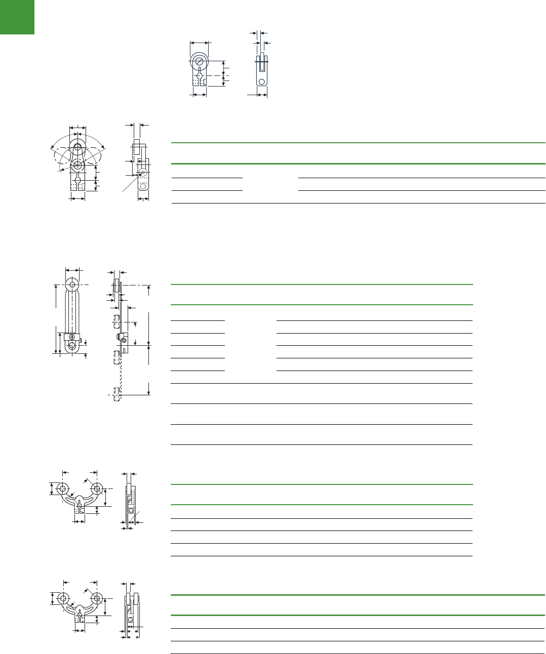
Automation
Power control
291 2015/2016 Product guide AUS15_007 - February 2016
V8-T2-86 Volume 8—Sensing Solutions CA08100010E—May 2013 www.eaton.com
2
2
2
2
2
2
2
2
2
2
2
2
2
2
2
2
2
2
2
2
2
2
2
2
2
2
2
2
2
2
2.8
Limit Switches
Operators
Adjustable roller
Approximate dimensions in mm [in]
Fork lever—Both rollers on one side
Approximate Dimensions in mm [in]
Fork lever— one roller outside, one inside
Approximate dimensions in mm [in]
Notes
1Length from the operating shaft axis to the roller axis (or to the tip for non-roller operators).
2By reassembling lever, minimum length can be reduced another 12.7 mm [0.5 in].
3High-grade stainless steel.
Item no.
A
Lever Length
1
B
Roller Diameter
C
Roller Width D E
E50KL539 25.4 [1.0] to
95.2 [3.75]
2
17.5 [0.69] 6.4 [0.25] 5.8 [0.23] 7.6 [0.30]
E50KL201 19.0 [0.75] 8.1 [0.32] 7.4 [0.29] 8.4 [0.33]
E50KL201SPL
319.0 [0.75] 8.1 [0.32] 7.4 [0.29] 8.4 [0.33]
E50KL538 19.0 [0.75] 8.1 [0.32] 7.4 [0.29] 8.4 [0.33]
E50KL599 19.0 [0.75] 12.7 [0.50] 11.6 [0.46] 12.2 [0.48]
E50KL537 19.0 [0.75] 25.4 [1.00] 22.9 [0.90] 24.1 [0.95]
E50KL598 12.7 [0.50] to
82.6 [3.25]
102.0 [4.00] 2.8 [0.11] 4.8 [0.19] 24.1 [0.95]
E50KL31 12.7 [0.50] to
95.2 [3.75]
— — — —
E50KL443 41.3 [1.63] to
95.2 [3.75]
2
38.1 [1.50] 7.4 [0.29] 6.6 [0.26] 8.1 [0.32]
Item no.
A
Lever Length
1
B
Roller Diameter
C
Roller Width D E
E50KL545 38.1 [1.50] 17.5 [0.69] 6.4 [0.25] 2.0 [0.08] 3.6 [0.14]
E50KL204 38.1 [1.50] 19.0 [0.75] 8.1 [0.32] 4.1 [0.16] 5.1 [0.20]
E50KL544 38.1 [1.50] 19.0 [0.75] 8.1 [0.32] 4.1 [0.16] 5.1 [0.20]
E50KL543 38.1 [1.50] 19.0 [0.75] 25.4 [1.00] 21.3 [0.84] 22.4 [0.88]
Item no.
A
Lever Length
1
B
Roller Diameter
C
Roller Width D E F G
E50KL542
38.1 [1.50] 17.5 [0.69] 6.4 [0.25] 2.0 [0.08] 3.6 [0.14] 16.3 [0.64] 17.8 [0.70]
E50KL203
38.1 [1.50] 19.0 [0.75] 8.1 [0.32] 4.1 [0.16] 5.1 [0.20] 18.5 [0.73] 19.6 [0.77]
E50KL541
38.1 [1.50] 19.0 [0.75] 8.1 [0.32] 4.1 [0.16] 5.1 [0.20] 18.5 [0.73] 19.6 [0.77]
B Dia.
108
[4.24]
27
[1.08]
11
[0.42] 79
[3.12]
25.4R
[1.0]
95R
[3.75]
12.7
[0.50]
E
C
D
54
[2.12]
16
[0.62]
12
[0.48]
27
[1.06] 10
[0.38]
C
E
D
B
Dia.
38
[1.50]
1.0
[0.04]
54
[2.12]
16
[0.62]
12
[0.48]
27
[1.06]
10
[0.38]
C
E
DF
G
B
Dia.
38
[1.50)]
Volume 8—Sensing Solutions CA08100010E—May 2013 www.eaton.com V8-T2-85
2
2
2
2
2
2
2
2
2
2
2
2
2
2
2
2
2
2
2
2
2
2
2
2
2
2
2
2
2
2
2.8
Limit Switches
Operators
Roller on reverse side
Approximate dimensions in Inches (mm)
Offset r oller
Approximate dimensions in mm [in]
Bantam lever
Approximate dimensions
in mm [in]
Precision Adjustment
Approximate Dimensions in mm [in]
Notes
1Length from the operating shaft axis to the roller axis (or to the tip for non-roller operators).
2Maximum length dimension between operating shaft axis to the roller axis for comparison. Precision adjustable to lesser dimensions.
Item no.
A
Lever Length
1
B
Roller Diameter
C
Roller Width D E F
E50KL580 1.50 (38.1) 0.69 (17.5) 0.25 (6.4) 0.34 (8.6) 0.18 (4.6) 0.24 (6.1)
E50KL310 1.50 (38.1) 0.75 (19.0) 0.32 (8.1) 0.34 (8.6) 0.27 (6.9) 0.31 (7.9)
E50KL579 1.50 (38.1) 0.75 (19.0) 0.32 (8.1) 0.34 (8.6) 0.27 (6.9) 0.31 (7.9)
E50KL536 1.50 (38.1) 1.50 (38.1) 0.28 (7.1) 0.34 (8.6) 0.23 (5.8) 0.31 (7.9)
Item no.
A
Lever Length
1
B
Roller Diameter
C
Roller Width D
Inboard
E50KL24 38.1 [1.50] 19.0 [0.75] 8.1 [0.32] 0.8 [0.03]
E50KL25 38.1 [1.50] 19.0 [0.75] 8.1 [0.32] 0.8 [0.03]
E50KL26 38.1 [1.50] 17.5 [0.69] 6.4 [0.25] 1.0 [0.04]
Outboard
E50KL27 38.1 [1.50] 19.0 [0.75] 8.1 [0.32] 0.8 [0.03]
E50KL28 38.1 [1.50] 19.0 [0.75] 8.1 [0.32] 0.8 [0.03]
E50KL29 38.1 [1.50] 17.5 [0.69] 6.4 [0.25] 1.0 [0.04]
E50KL30 38.1 [1.50] 19.0 [0.75] 25.4 [1.00] —
0.44
(11)
A
D
C
F
E
B
0.67
(17)
B
Dia
C
8.4
[0.33] 16
[0.64]
7.6
[0.30]
D
38
[1.50] 26
[1.02]
24
[0.94]20
[0.80]
Inboard
Roller
22
[0.85]
16
[0.62]
4.1
[0.16] 4.6
[0.18]
18
[0.69]
12
[0.48]
12.7
[0.50]
Item no.
A
Lever Length
1
B
Roller Diameter
C
Roller Width D E F
E50KL340 17.5 [0.69]
Roller length:
38.1 [1.50]
2
19.0 [0.75] 8.1 [0.32] 12.2 [0.48] 6.1 [0.24] 7.1 [0.28]
E50KL465 19.0 [0.75] 8.1 [0.32] 12.2 [0.48] 6.1 [0.24] 7.1 [0.28]
E50KL535 17.5 [0.69] 6.4 [0.25] 12.2 [0.48] 4.1 [0.16] 5.6 [0.22]
B Dia.
A
E
C
F
D
Max
60º
20R
[0.80]
16
[0.63] 12.7
[0.50]
Precision
Adjustment
Screw
Max
60º
Limit Switches
Dimensions
Volume 8—Sensing Solutions CA08100010E—May 2013 www.eaton.com V8-T2-85
2
2
2
2
2
2
2
2
2
2
2
2
2
2
2
2
2
2
2
2
2
2
2
2
2
2
2
2
2
2
2.8
Limit Switches
Operators
Roller on reverse side
Approximate dimensions in Inches (mm)
Offset r oller
Approximate dimensions in mm [in]
Bantam lever
Approximate dimensions
in mm [in]
Precision Adjustment
Approximate Dimensions in mm [in]
Notes
1Length from the operating shaft axis to the roller axis (or to the tip for non-roller operators).
2Maximum length dimension between operating shaft axis to the roller axis for comparison. Precision adjustable to lesser dimensions.
Item no.
A
Lever Length
1
B
Roller Diameter
C
Roller Width D E F
E50KL580 1.50 (38.1) 0.69 (17.5) 0.25 (6.4) 0.34 (8.6) 0.18 (4.6) 0.24 (6.1)
E50KL310 1.50 (38.1) 0.75 (19.0) 0.32 (8.1) 0.34 (8.6) 0.27 (6.9) 0.31 (7.9)
E50KL579 1.50 (38.1) 0.75 (19.0) 0.32 (8.1) 0.34 (8.6) 0.27 (6.9) 0.31 (7.9)
E50KL536 1.50 (38.1) 1.50 (38.1) 0.28 (7.1) 0.34 (8.6) 0.23 (5.8) 0.31 (7.9)
Item no.
A
Lever Length
1
B
Roller Diameter
C
Roller Width D
Inboard
E50KL24 38.1 [1.50] 19.0 [0.75] 8.1 [0.32] 0.8 [0.03]
E50KL25 38.1 [1.50] 19.0 [0.75] 8.1 [0.32] 0.8 [0.03]
E50KL26 38.1 [1.50] 17.5 [0.69] 6.4 [0.25] 1.0 [0.04]
Outboard
E50KL27 38.1 [1.50] 19.0 [0.75] 8.1 [0.32] 0.8 [0.03]
E50KL28 38.1 [1.50] 19.0 [0.75] 8.1 [0.32] 0.8 [0.03]
E50KL29 38.1 [1.50] 17.5 [0.69] 6.4 [0.25] 1.0 [0.04]
E50KL30 38.1 [1.50] 19.0 [0.75] 25.4 [1.00] —
0.44
(11)
A
D
C
F
E
B
0.67
(17)
B
Dia
C
8.4
[0.33] 16
[0.64]
7.6
[0.30]
D
38
[1.50] 26
[1.02]
24
[0.94]20
[0.80]
Inboard
Roller
22
[0.85]
16
[0.62]
4.1
[0.16] 4.6
[0.18]
18
[0.69]
12
[0.48]
12.7
[0.50]
Item no.
A
Lever Length
1
B
Roller Diameter
C
Roller Width D E F
E50KL340 17.5 [0.69]
Roller length:
38.1 [1.50]
2
19.0 [0.75] 8.1 [0.32] 12.2 [0.48] 6.1 [0.24] 7.1 [0.28]
E50KL465 19.0 [0.75] 8.1 [0.32] 12.2 [0.48] 6.1 [0.24] 7.1 [0.28]
E50KL535 17.5 [0.69] 6.4 [0.25] 12.2 [0.48] 4.1 [0.16] 5.6 [0.22]
B Dia.
A
E
C
F
D
Max
60º
20R
[0.80]
16
[0.63] 12.7
[0.50]
Precision
Adjustment
Screw
Max
60º
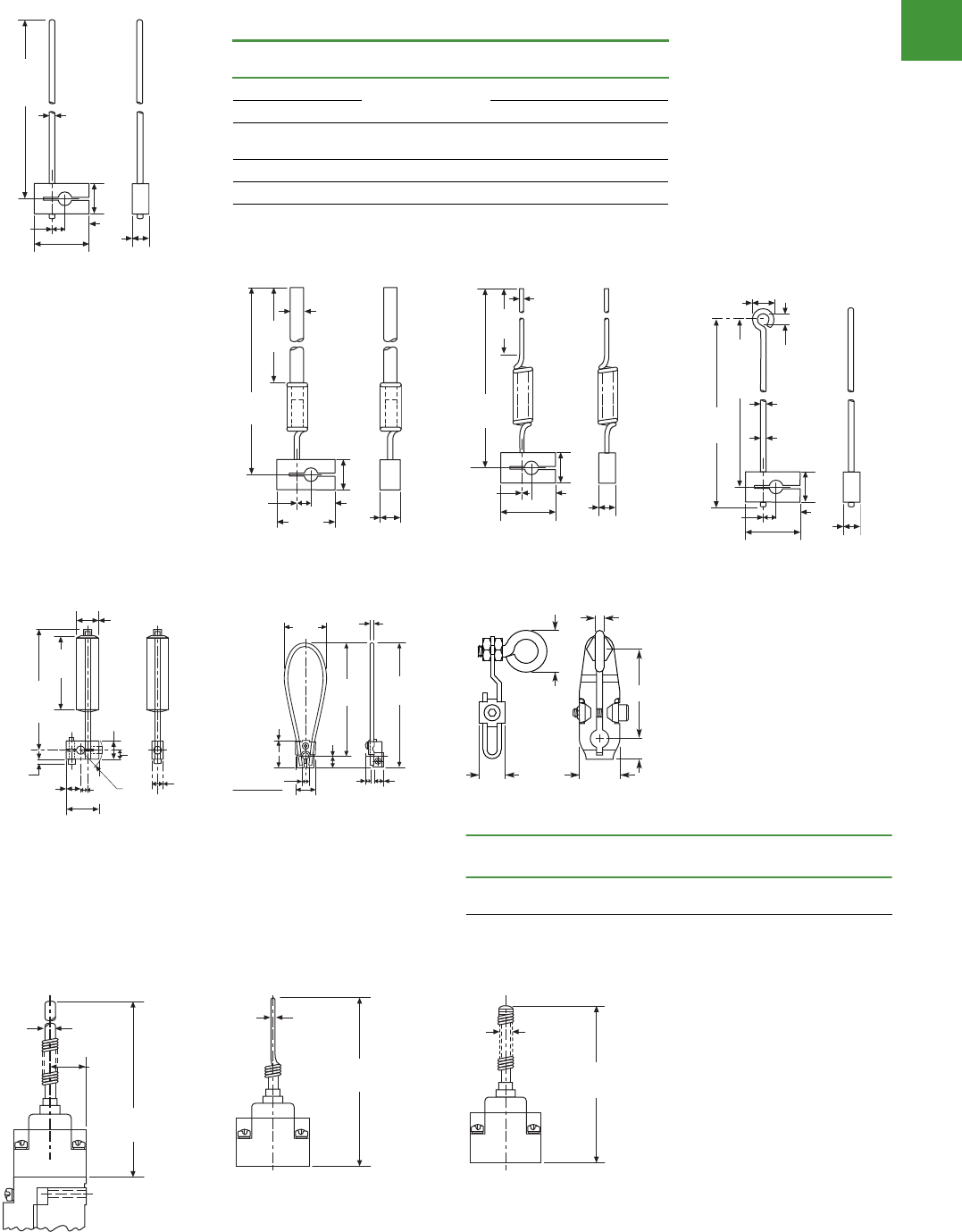
Automation
Power control
292
2015/2016 Product guide AUS15_007 - February 2016
Volume 8—Sensing Solutions CA08100010E—May 2013 www.eaton.com V8-T2-87
2
2
2
2
2
2
2
2
2
2
2
2
2
2
2
2
2
2
2
2
2
2
2
2
2
2
2
2
2
2
2.8
Limit Switches
Operators
Approximate Dimensions in Inches or mm [in]
Rod type operators
Adjustable rod
Spring rod—E50KL556 Spring rod—E50KL421 Adjustable wire
Adjustable wide
roller lever Nylatron loop—E5 0KL142 Eye bolt
Notes
1Applies when lever is extended to the maximum dimension.
2Length from the operating shaft axis to tip.
Item no.
A
Rod Length
1
B
Rod Diameter
E50KL399 140.0 [5.50] 4.8 [0.19]
E50KL202 3.2 [0.12]
E50KL581 222.0 [8.75] Rod size (square):
3.2 [0.12] x 3.2 [0.12]
E50KL220 229.0 [9.00] 4.8 [0.19]
E50KL226 305.0 [12.00] 3.2 [0.12]
6.35
[.25]
16.26
[.64]
9.65
[.38]
12.7
[.50]
28.45
[1.12]
B Dia.
A
Max.
Ext.
6.35
[.25]
247.90
[9.76]
307.85
[12.12]
6.35
[.25]
16.26
[.64]
9.65
[.38]
12.7
[.50]
28.45
[1.12]
Dia.
Nylon
6.35
[.25]
295.15
[11.62]
16.26
[.64]
9.65
[.38]
12.7
[.50]
28.45
[1.12]
228.6
[9.0]
2.29
[0.9] Dia.
Steel
Spring Rod
6.35
[.25]
16.26
[.64]
9.65
[.38]
12.7
[.50]
28.45
[1.12]
12.7
[.50]
6.6
[.26]
3.05
[.12] Dia.
Nylon
1.52
[.06] Dia.
Steelcore
307.85
[12.12]
Max.
Ext.
307.85
[12.12]
19.1
[.75]
63.5
[2.50]
16.3
[.64]
8.1
[.32]
6.4
[.25]
106.4
[4.19]
Max.
4.2
[.164] 12.7
[.50]
28.4
[1.12]
9.7
[.38]
22.9R
[.90]
Dia.
48.3
[1.90]
152.4
[6.00]
12.7
[.50]
9.7
[.38]
5.1
[.20]
22.9
[.90]
31.8
[1.125]
Max.
+.05
7.16 – .00
+.002
.282 – .000
Dia.
139.7
[5.50]
4.0
[.158] Dia.
Max.
0.44
[11]
A
D
C
B
0.67
[17]
Catalog
Number
A
Rod Length
2
B
Rod Diameter
C
Rod Width D
E50KL33 38.1 [1.50] 4.8 [0.1875]
Loop ID: 9.5 [0.375]
13.1 [0.52] 8.6 [0.34]
V8-T2-88Volume 8—Sensing SolutionsCA08100010E—May 2013 www.eaton.com
2
2
2
2
2
2
2
2
2
2
2
2
2
2
2
2
2
2
2
2
2
2
2
2
2
2
2
2
2
2
2.8
Limit Switches
Operators
Wobble Type Operators
gnirpS lioCdoR leetS sselniatSdoR nolyN
6.35
[.250]
124.45
[4.90]
20.60
[.81]
Dia.
1.60
[.063]
346.45
[13.64]
Dia. 8.74
[.344]
146.30
[5.76]
Dia.
Limit Switches
Dimensions
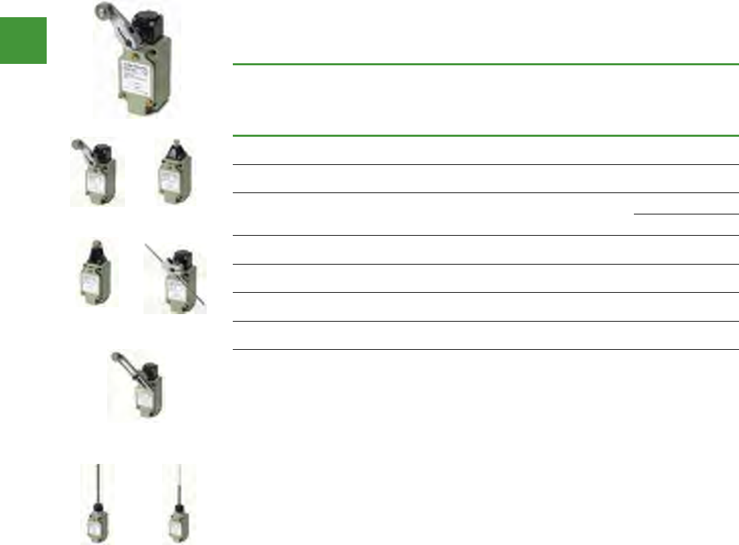
Automation
Power control
293 2015/2016 Product guide AUS15_007 - February 2016
Operating
head type
Specifications Item no.
Travel to
operate
contacts
Travel
to reset
contacts
Total
travel
Force to
operate
contacts
(maximum) (lb)
Minimum
return
force (lb)
Assembled units
(Switch Body &
Head), 1N.O./1N.C.
Contacts
Roller lever 20° 12° 50° 2.99 0.50 E49M11AP1
Top push 0.067 in
(1.7mm)
0.04 in
(1.0mm) - 6.02 2.01 E49M11BP1
Top push
roller
- E49M11CP1
0.067 in
(1.7 mm)
0.04 in
(1.0 mm)
0.25 in
(6.5 mm) 6.02 2.01
E49M11CP1
E49M11CP2*
Rod lever 20° 12° 50° 0.31 0.06 E49M11DP1
Adjustable
roller lever 20° 12° 50° 2.99 0.50 E49M11UP1
Wobble 1.10 in
(28mm) N/A N/A 0.33 N/A E49M11VP1
Cat whisker 1.10 in
(28mm) N/A N/A 0.064 N/A E49M11XM1
* Includes 90° Roller.
E49 metal body compact limit switches
Eaton E49 compact metal limit switches
• Rigid die cast switch housing
• Oil-tight, waterproof & dustproof
construction
• High mechanical strength
• Snap action 1NO/1NC contact provides
flexibility in design
Roller Lever Top Push
Top Push Roller
- E49M11CP1 Rod Lever
Adjustable
Roller Lever
Wobble Cat Whisker
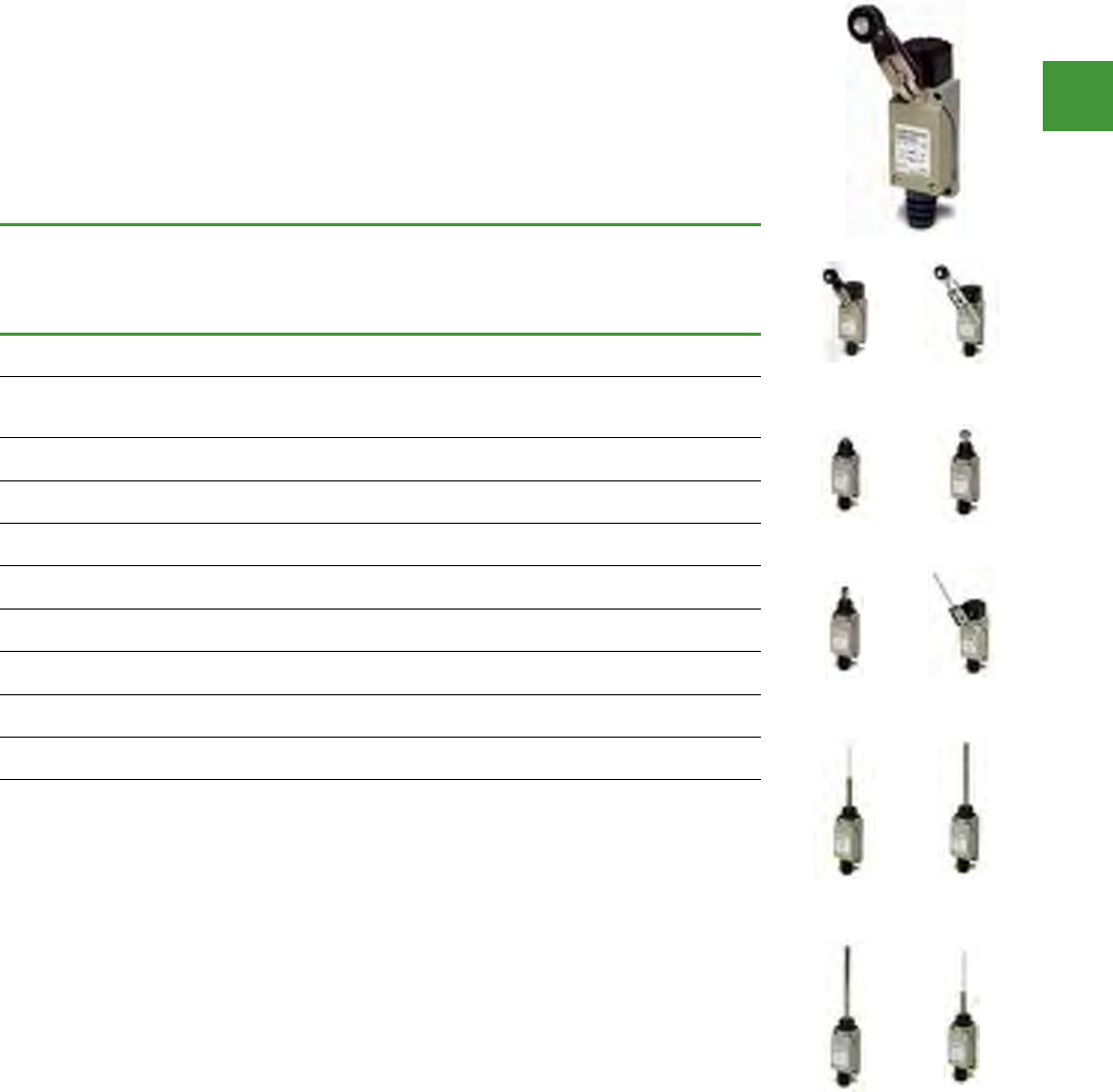
Automation
Power control
294
2015/2016 Product guide AUS15_007 - February 2016
Operating
head type
Specifications Item no.
Travel to
operate
contacts
Travel
to reset
contacts
Total
travel
Force to
operate
contacts
(g)
Minimum
return
force (g)
Assembled Units
(Switch Body &
Head), 1N.O./1N.C.
Contacts
Side rotary
lever 20° 12° 70° 750 100 E49G31AP3
Adjustable
side rotary
lever
20° 12° 70° 750 100 E49G31UP3
Top
pushbutton
0.06 in
(1.5 mm)
0.04 in
(1 mm)
0.22 in
(5.5 mm) 900 150 E49G31BP3
Top push roller 0.06 in
(1.5 mm)
0.04 in
(1 mm)
0.22 in
(5.5 mm) 900 150 E49G31CP3
Top push roller 0.06 in
(1.5 mm)
0.04 in
(1 mm)
0.22 in
(5.5 mm) 900 150 E49G31C1P3*
Adjustable rod
lever 20° 12° 70° 750 100 E49G31DP3
Wobble stick
(Nylon coil)
1.18 in
(30 mm) - - 150 - E49G31NP3
Wobble stick
(metal coil)
1.18 in
(30 mm) - - 150 - E49G31VP3
Wobble stick
(metal rod)
1.18 in
(30 mm) - - 150 - E49G31MP3
Wobble stick
(whisker)
1.18 in
(30 mm) - - 150 - E49G31XM3
* Includes 90° Roller.
E49 metal body compact limit switches
Eaton E49 mini metal limit switches
• Long life - rated for 10 million operations
• Pre-wired units with custom cable lengths
available for high volume customers
• Fingerproof terminals protect against
accidental contact
• Double-spring mechanism for contact
reliability
• Grounding terminal included
• Captive screws on enclosure cover make
wiring hassle-free
• SPDT double break
Side Rotary
Lever
Adjustable Side
Rotary Lever
Top Pushbutton Top Push Roller
Top Push Roller Adjustable Rod
Lever
Wobble Stick
(Nylon Coil)
Wobble Stick
(Metal Coil)
Wobble Stick
(Metal Rod)
Wobble Stick
(Whisker)
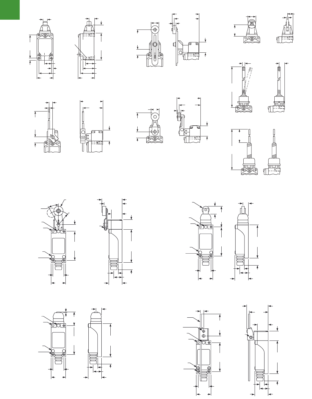
Automation
Power control
295 2015/2016 Product guide AUS15_007 - February 2016
Limit switches
Dimensions
Volume 8—Sensing Solutions CA08100010E—May 2013 www.eaton.com V8-T2-53
2
2
2
2
2
2
2
2
2
2
2
2
2
2
2
2
2
2
2
2
2
2
2
2
2
2
2
2
2
2
2.5
Limit Switches
E49 Compact Metal Switches
Dimensions
Approximate Dimensions in Inches (mm)
Switch Body with E49M11BP1
E49M11CP1/E49M11CP2
E49M11DP1
E49M11AP1
E49M11UP1
E49M11VP1
E49M11XM1
0.35 (9.0)
Dia. 0.50 (12.7)
0.19 (4.9)
1.19 (30.2) 1.38 (35.0)
1.15 (29.2)
1.58
(40.0)
0.59 (15.1)
4-M6
Thread
2.31
(58.7)
0.20
(5.0)
0.85 (21.6)
1.63
(41.5)
2.71
(68.7)
0.78
(19.9)
0.67 (17.0)
Dia. 0.20 (5.0)
0.50 (12.7)
1
.10 (28.0)
0.98 (25.0)
to
5.51 (140.0)
0.58 (14.7)
0.35 (9.0)
1.81
(46.0)
0.12 (3.0)
Dia.
2.17 (55.0)
1.00
(25.4)
1.84
(46.6)
0.58 (14.7)
0.69 (17.5)
Dia. 2.09
(53.0)
0.28
(7.0)
2.32 (59.0)
1.00
(25.4)
0.98 (25.0)
to
3.51 (89.0)
0.69 (17.5)
Dia. 2.36 (60.0)
0.28 (7.0)
2.64 (67.0)
1.00
(25.4)
0.58 (14.7)
5.51
(140.0)
0.26 (6.5)
Dia.
0.52
(13.1)
2.03
(51.5)
5.51
(140.0)
Volume 8—Sensing Solutions CA08100010E—May 2013 www.eaton.com V8-T2-53
2
2
2
2
2
2
2
2
2
2
2
2
2
2
2
2
2
2
2
2
2
2
2
2
2
2
2
2
2
2
2.5
Limit Switches
E49 Compact Metal Switches
Dimensions
Approximate Dimensions in Inches (mm)
Switch Body with E49M11BP1
E49M11CP1/E49M11CP2
E49M11DP1
E49M11AP1
E49M11UP1
E49M11VP1
E49M11XM1
0.35 (9.0)
Dia. 0.50 (12.7)
0.19 (4.9)
1.19 (30.2) 1.38 (35.0)
1.15 (29.2)
1.58
(40.0)
0.59 (15.1)
4-M6
Thread
2.31
(58.7)
0.20
(5.0)
0.85 (21.6)
1.63
(41.5)
2.71
(68.7)
0.78
(19.9)
0.67 (17.0)
Dia. 0.20 (5.0)
0.50 (12.7)
1
.10 (28.0)
0.98 (25.0)
to
5.51 (
140.0)
0.58 (14.7)
0.35 (9.0)
1.81
(46.0)
0.12 (3.0)
Dia.
2.17 (55.0)
1.00
(25.4)
1.84
(46.6)
0.58 (14.7)
0.69 (17.5)
Dia. 2.09
(53.0)
0.28
(7.0)
2.32 (59.0)
1.00
(25.4)
0.98 (25.0)
to
3.51 (89.0)
0.69 (17.5)
Dia. 2.36 (60.0)
0.28 (7.0)
2.64 (67.0)
1.00
(25.4)
0.58 (14.7)
5.51
(140.0)
0.26 (6.5)
Dia.
0.52
(13.1)
2.03
(51.5)
5.51
(140.0)
Volume 8—Sensing Solutions CA08100010E—May 2013 www.eaton.com V8-T2-53
2
2
2
2
2
2
2
2
2
2
2
2
2
2
2
2
2
2
2
2
2
2
2
2
2
2
2
2
2
2
2.5
Limit Switches
E49 Compact Metal Switches
Dimensions
Approximate Dimensions in Inches (mm)
Switch Body with E49M11BP1
E49M11CP1/E49M11CP2
E49M11DP1
E49M11AP1
E49M11UP1
E49M11VP1
E49M11XM1
0.35 (9.0)
Dia. 0.50 (12.7)
0.19 (4.9)
1.19 (30.2) 1.38 (35.0)
1.15 (29.2)
1.58
(40.0)
0.59 (15.1)
4-M6
Thread
2.31
(58.7)
0.20
(5.0)
0.85 (21.6)
1.63
(41.5)
2.71
(68.7)
0.78
(19.9)
0.67 (17.0)
Dia. 0.20 (5.0)
0.50 (12.7)
1.10 (28.0)
0.98 (25.0)
to
5.51 (
140.0)
0.58 (14.7)
0.35 (9.0)
1.81
(46.0)
0.12 (3.0)
Dia.
2.17 (55.0)
1.00
(25.4)
1.84
(46.6)
0.58 (14.7)
0.69 (17.5)
Dia. 2.09
(53.0)
0.28
(7.0)
2.32 (59.0)
1.00
(25.4)
0.98 (25.0)
to
3.51 (89.0)
0.69 (17.5)
Dia. 2.36 (60.0)
0.28 (7.0)
2.64 (67.0)
1.00
(25.4)
0.58 (14.7)
5.51
(140.0)
0.26 (6.5)
Dia.
0.52
(13.1)
2.03
(51.5)
5.51
(140.0)
Volume 8—Sensing Solutions CA08100010E—May 2013 www.eaton.comV8-T2-47
2
2
2
2
2
2
2
2
2
2
2
2
2
2
2
2
2
2
2
2
2
2
2
2
2
2
2
2
2
2
2.4
Limit Switches
E49 Mini Metal Switches
Dimensions
Approximate Dimensions in Inches (mm)
E49G31AP3
E49G31BP3
E49G31C1P3
E49G31CP3
E49G31DP3
E49G31MP3
2.52
(64)
0.73
(18)
0.55 (14)
M4
M3 x 6
0.16 (4.1)
Dia.
M3 x 23
M5
(P=0.8)
0.30
(7) 0.6 (15)
0.98
(25)
0.83
(21)
1.1
(28)
0.8
(20)
1.43 (28)
1.62 (41)
1.18 (30)
R
2.2
(56)
0.49 (12)
0.70 x 0.28
(18 x 7) Dia.
PT 20°
Max.
2.2
(56)
1.06 (27)
0.12 (3)
2.52
(64)
0.55 (14)
0.39
(10)
M3 x 6
0.16 (4.1)
Dia.
M3 x 23
M5
(P=0.8)
0.30
(7) 0.6 (15)
0.98
(25)
0.83
(21)
1.1
(28)
2.2
(56)
1.5
(38)
0.59 (15)
2.52
(64)
0.55 (14)
0.39
(10)
M3 x 6
0.16 (4.1)
Dia.
M3 x 23
M5
(P=0.8)
0.50 x 0.15
(13 x 4)
Dia.
0.30
(7) 0.6 (15)
0.98
(25)
0.83
(21)
1.1
(28)
2.2
(56)
1.5
(38)
0.59 (15)
2.52
(64)
0.55 (14)
0.39
(10)
M3 x 6
0.16 (4.1)
Dia.
M3 x 23
M5
(P=0.8)
0.50 x 0.15
(13 x 4)
Dia.
0.30
(7) 0.6 (15)
0.98
(25)
0.83
(21)
1.1
(28)
2.2
(56)
1.18~4.65
(30~118)
0.49 (12)
2.52
(64)
0.73
(18)
0.55 (14)
0.30
(7)
0.8
(20)
1.41
(36)
1.77 (45)
0.6 (15)
0.98
(25)
0.83
(21)
1.1
(28)
0.22 (6)
M3 x 6
M4
0.16 (4.1)
Dia.
0.10 (3)
Dia.
M3 x 23
M6
M5
(P=0.8)
0.11 (3)
Dia.
0.23 (6)
Dia.
0.40
(10)
2.2
(56)
3.94
(100)
1.65
(42)
2.52
(64)
0.55 (14)
M3 x 6
0.16 (4.1)
Dia.
M3 x 23
M5
(P=0.8)
0.30
(7) 0.6 (15)
0.98
(25)
0.83
(21)
1.1
(28)
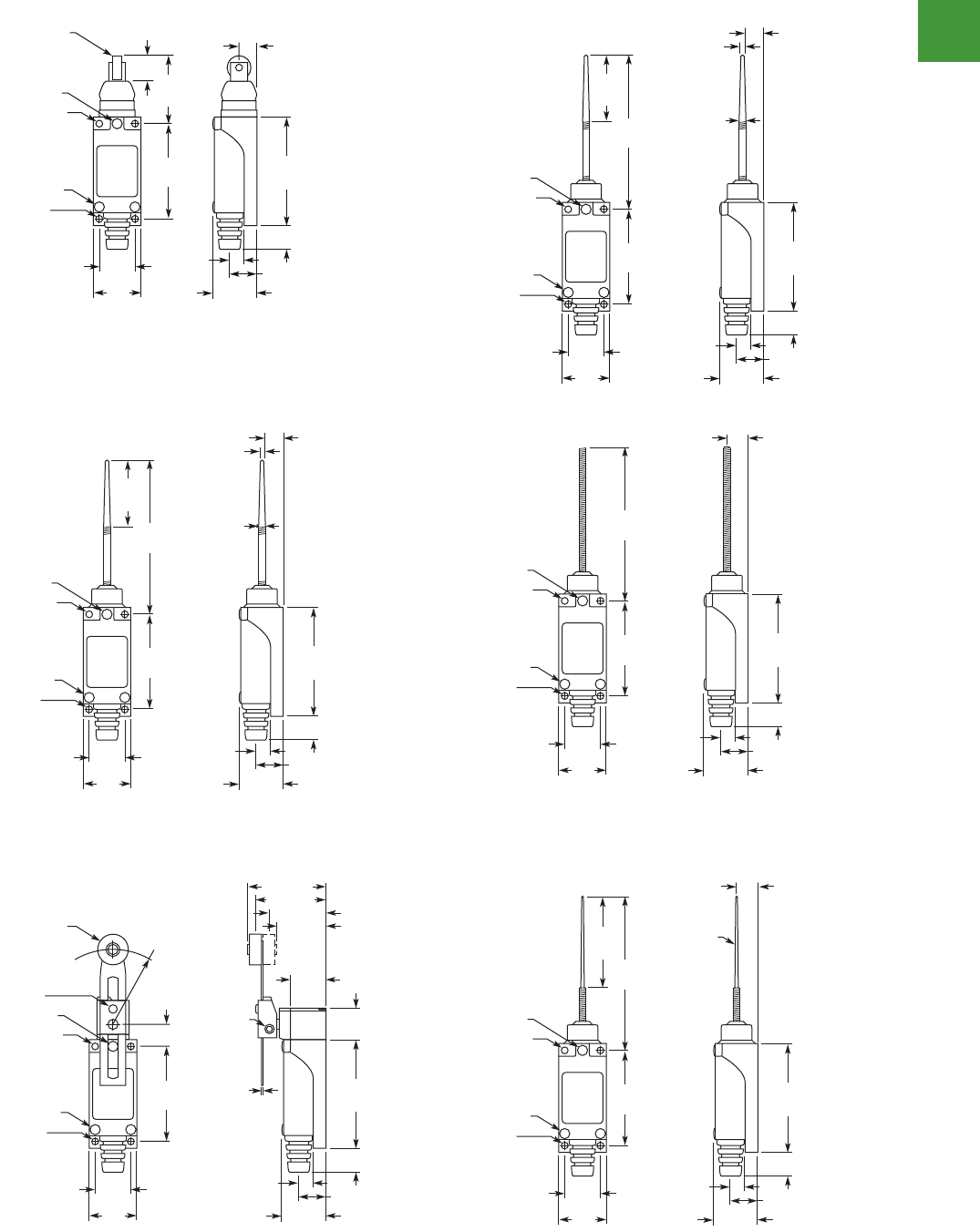
Automation
Power control
296
2015/2016 Product guide AUS15_007 - February 2016
Limit switches
Dimensions
Volume 8—Sensing Solutions CA08100010E—May 2013 www.eaton.comV8-T2-47
2
2
2
2
2
2
2
2
2
2
2
2
2
2
2
2
2
2
2
2
2
2
2
2
2
2
2
2
2
2
2.4
Limit Switches
E49 Mini Metal Switches
Dimensions
Approximate Dimensions in Inches (mm)
E49G31AP3
E49G31BP3
E49G31C1P3
E49G31CP3
E49G31DP3
E49G31MP3
2.52
(64)
0.73
(18)
0.55 (14)
M4
M3 x 6
0.
16 (4.1)
Dia.
M3 x 23
M5
(P=0.8)
0.30
(7) 0.6 (15)
0.98
(25)
0.83
(21)
1.1
(28)
0.8
(20)
1.43 (28)
1.62 (41)
1.18 (30)
R
2.2
(56)
0.49 (12)
0.70 x 0.28
(18 x 7) Dia.
PT 20°
Max.
2.2
(56)
1.06 (27)
0.12 (3)
2.52
(64)
0.55 (14)
0.39
(10)
M3 x 6
0.
16 (4.1)
Dia.
M3 x 23
M5
(P=0.8)
0.30
(7) 0.6 (15)
0.98
(25)
0.83
(21)
1.1
(28)
2.2
(56)
1.5
(38)
0.59 (15)
2.52
(64)
0.55 (14)
0.39
(10)
M3 x 6
0.16 (4.1)
Dia.
M3 x 23
M5
(P=0.8)
0.50 x 0.15
(13 x 4)
Dia.
0.30
(7) 0.6 (15)
0.98
(25)
0.83
(21)
1.1
(28)
2.2
(56)
1.5
(38)
0.59 (15)
2.52
(64)
0.55 (14)
0.39
(10)
M3 x 6
0.16 (4.1)
Dia.
M3 x 23
M5
(P=0.8)
0.50 x 0.15
(13 x 4)
Dia.
0.30
(7) 0.6 (15)
0.98
(25)
0.83
(21)
1.1
(28)
2.2
(56)
1.18~4.65
(30~118)
0.49 (12)
2.52
(64)
0.73
(18)
0.55 (14)
0.30
(7)
0.8
(20)
1.41
(36)
1.77 (45)
0.6 (15)
0.98
(25)
0.83
(21)
1.1
(28)
0.22 (6)
M3 x 6
M4
0.16 (4.1)
Dia.
0.10 (3)
Dia.
M3 x 23
M6
M5
(P=0.8)
0.11 (3)
Dia.
0.23 (6)
Dia.
0.40
(10)
2.2
(56)
3.94
(100)
1.65
(42)
2.52
(64)
0.55 (14)
M3 x 6
0.16 (4.1)
Dia.
M3 x 23
M5
(P=0.8)
0.30
(7) 0.6 (15)
0.98
(25)
0.83
(21)
1.1
(28)
V8-T2-48Volume 8—Sensing SolutionsCA08100010E—May 2013 www.eaton.com
2
2
2
2
2
2
2
2
2
2
2
2
2
2
2
2
2
2
2
2
2
2
2
2
2
2
2
2
2
2
2.4
Limit Switches
E49 Mini Metal Switches
Approximate Dimensions in Inches (mm)
E49G31NP3
E49G31UP3
E49G31VP3
E49G31XM3
0.23 (6)
Dia.
0.11 (3)
Dia.
0.40
(10)
2.2
(56)
3.94
(100)
1.65
(42)
2.52
(64)
0.55 (14)
M3 x 6
0.
16 (4.1)
Dia.
M3 x 23
M5
(P=0.8)
0.30
(7) 0.6 (15)
0.98
(25)
0.83
(21)
1.1
(28)
2.2
(56)
L=
1.18~2.75
(30~70)
0.49 (12)
2.52
(64)
0.73
(18)
0.55 (14)
0.8
(20)
1.10 (28)
1.30 (33)
1.69 (43)
1.89 (48)
0.30
(7) 0.6 (15)
0.98
(25)
0.83
(21)
1.1
(28)
0.08
(2)
M4
M6
M3 x 6
0.16 (4.1)
Dia.
M3 x 23
M5
(P=0.8)
0.70 x 0.28
(18 x 7)
Dia.
0.40
(10)
2.2
(56)
3.94
(100)
2.52
(64)
0.55 (14)
M3 x 6
0.
16 (4.1)
Dia.
M3 x 23
M5
(P=0.8)
0.30
(7) 0.6 (15)
0.98
(25)
0.83
(21)
1.1
(28)
2.2
(56)
3.94
(100)
2.05
(52)
2.52
(64)
0.55 (14)
M3 x 6
0.16 (4.1)
Dia.
M3 x 23
M5
(P=0.8)
0.40
(10)
0.04 (1)
Dia.
0.30
(7) 0.6 (15)
0.98
(25)
0.83
(21)
1.1
(28)
V8-T2-48Volume 8—Sensing SolutionsCA08100010E—May 2013 www.eaton.com
2
2
2
2
2
2
2
2
2
2
2
2
2
2
2
2
2
2
2
2
2
2
2
2
2
2
2
2
2
2
2.4
Limit Switches
E49 Mini Metal Switches
Approximate Dimensions in Inches (mm)
E49G31NP3
E49G31UP3
E49G31VP3
E49G31XM3
0.23 (6)
Dia.
0.11 (3)
Dia.
0.40
(10)
2.2
(56)
3.94
(100)
1.65
(42)
2.52
(64)
0.55 (14)
M3 x 6
0.16 (4.1)
Dia.
M3 x 23
M5
(P=0.8)
0.30
(7) 0.6 (15)
0.98
(25)
0.83
(21)
1.1
(28)
2.2
(56)
L=
1.18~2.75
(30~70)
0.49 (12)
2.52
(64)
0.73
(18)
0.55 (14)
0.8
(20)
1.10 (28)
1.30 (33)
1.69 (43)
1.89 (48)
0.30
(7) 0.6 (15)
0.98
(25)
0.83
(21)
1.1
(28)
0.08
(2)
M4
M6
M3 x 6
0.16 (4.1)
Dia.
M3 x 23
M5
(P=0.8)
0.70 x 0.28
(18 x 7)
Dia.
0.40
(10)
2.2
(56)
3.94
(100)
2.52
(64)
0.55 (14)
M3 x 6
0.16 (4.1)
Dia.
M3 x 23
M5
(P=0.8)
0.30
(7) 0.6 (15)
0.98
(25)
0.83
(21)
1.1
(28)
2.2
(56)
3.94
(100)
2.05
(52)
2.52
(64)
0.55 (14)
M3 x 6
0.
16 (4.1)
Dia.
M3 x 23
M5
(P=0.8)
0.40
(10)
0.04 (1)
Dia.
0.30
(7) 0.6 (15)
0.98
(25)
0.83
(21)
1.1
(28)
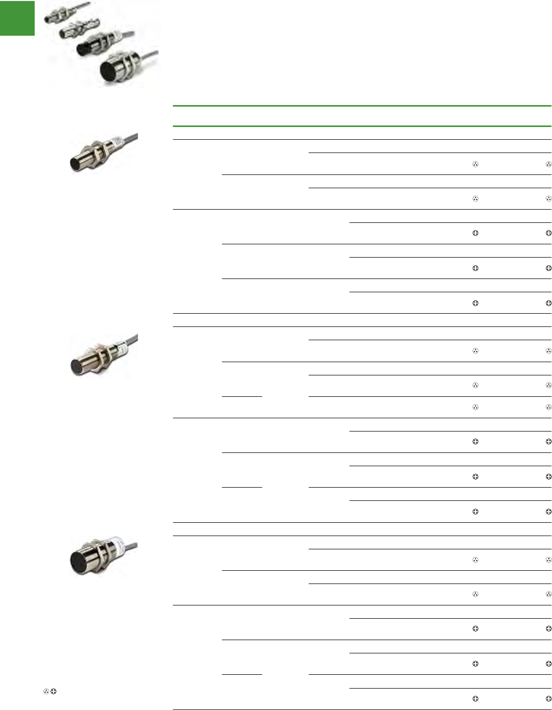
Automation
Power control
297 2015/2016 Product guide AUS15_007 - February 2016
Global proximity sensors
Features
• The Global Proximity Line features solid
performance and a basic feature set for
reliable, cost-effective sensing
• Available in a variety of sizes to fit in all of
your applications: 8 mm, 12 mm, 18 mm and
30 mm diameters
• DC sensors operate on 10–30 Vdc in
two-wire and three-wire (NPN or PNP)
configurations
• AC sensors operate on 20–250 Vac in
two-wire configuration
• Switching frequency of 2 kHz for DC models
• Shielded and unshielded versions available
• Terminations include:
2-meter cable
Micro-connector
Nano-connector
• DC units include short circuit protection
Two-wire sensors
Operating
voltage
Sensing
range Shielding Output
type
Connection
type
NO Output
Item no.
NC Output
Item no.
12 mm Diameter
20–250 Vac
2 mm Shielded
2-meter cable E57-12GS02-A E57-12GS02-A1
3-pin micro AC
connector E57-12GS02-AAB E57-12GS02-A1AB
4 mm Unshielded
2-meter cable E57-12GU04-A E57-12GU04-A1
3-pin micro AC
connector E57-12GU04-AAB E57-12GU04-A1AB
10–30 Vdc
2 mm Shielded NPN/PNP
2-meter cable E57-12GS02-D E57-12GS02-D1
4-pin micro DC
connector E57-12GS02-DDB E57-12GS02-D1DB
4 mm Unshielded NPN/PNP
2-meter cable E57-12GU04-D E57-12GU04-D1
4-pin micro DC
connector E57-12GU04-DDB E57-12GU04-D1DB
8 mm
(extended
range)
NPN/PNP
2-meter cable E57-12GE08-D E57-12GE08-D1
4-pin micro DC
connector E57-12GE08-DDB E57-12GE08-D1DB
18 mm Diameter
20–250 Vac
5 mm Shielded
2-meter cable E57-18GS05-A E57-18GS05-A1
3-pin micro AC
connector E57-18GS05-AAB E57-18GS05-A1AB
8 mm
Unshielded
2-meter cable E57-18GU08-A E57-18GU08-A1
3-pin micro AC
connector E57-18GU08-AAB E57-18GU08-A1AB
16 mm 3-pin micro AC
connector E57-18GE16-AAB E57-18GE16-A1AB
10–30 Vdc
5 mm Shielded NPN/PNP
2-meter cable E57-18GS05-D E57-18GS05-D1
4-pin micro DC
connector E57-18GS05-DDB E57-18GS05-D1DB
8 mm
Unshielded
NPN/PNP
2-meter cable E57-18GU08-D E57-18GU08-D1
4-pin micro DC
connector E57-18GU08-DDB E57-18GU08-D1DB
16 mm
(extended
range)
NPN/PNP
2-meter cable E57-18GE16-D E57-18GE16-D1
4-pin micro DC
connector E57-18GE16-DDB E57-18GE16-D1DB
30 mm Diameter
20–250 Vac
10 mm Shielded
2-meter cable E57-30GS10-A E57-30GS10-A1
3-pin micro AC
connector E57-30GS10-AAB E57-30GS10-A1AB
15 mm Unshielded
2-meter cable E57-30GU15-A E57-30GU15-A1
3-pin micro AC
connector E57-30GU15-AAB E57-30GU15-A1AB
10–30 Vdc
10 mm Shielded NPN/PNP
2-meter cable E57-30GS10-D E57-30GS10-D1
4-pin micro DC
connector E57-30GS10-DDB E57-30GS10-D1DB
15 mm
Unshielded
NPN/PNP
2-meter cable E57-30GU15-D E57-30GU15-D1
4-pin micro DC
connector E57-30GU15-DDB E57-30GU15-D1DB
25 mm
(extended
range)
NPN/PNP
2-meter cable E57-30GE25-D E57-30GE25-D1
4-pin micro DC
connector E57-30GE25-DDB E57-30GE25-D1DB
See listing of compatible
connector cables
V8-T3-36 Volume 8—Sensing Solutions CA08100010E—October 2013 www.eaton.com
3
3
3
3
3
3
3
3
3
3
3
3
3
3
3
3
3
3
3
3
3
3
3
3
3
3
3
3
3
3
For Customer Service in the U.S. call 1-877-ETN CARE (386-2273),
in Canada call 1-800-268-3578.
For Application Assistance in the U.S. and Canada
call 1-800-426-9184.
3.4
Inductive Proximity Sensors
Global Proximity Sensors
Global Proximity Sensors Contents
Description Page
Global Proximity Sensors
Product Selection
Global Proximity Sensors . . . . . . . . . . . . . . V8-T3-37
Compatible Connector Cables . . . . . . . . . . V8-T3-40
Accessories . . . . . . . . . . . . . . . . . . . . . . . . . . . V8-T3-40
Technical Data and Specifications . . . . . . . . . . V8-T3-41
Wiring Diagrams . . . . . . . . . . . . . . . . . . . . . . . V8-T3-42
Dimensions . . . . . . . . . . . . . . . . . . . . . . . . . . . V8-T3-43
Global Proximity Sensors
Product Description
The Global Proximity Sensor
family was created by
Eaton’s Electrical Sector
with the high volume OEM in
mind. It has been optimized
to include only those functions
necessary for basic, reliable
sensing. Why pay for extra
features when you don’t
need them? That’s not to
say these sensors lack the
performance or features
you expect. Our DC units
are short circuit protected
and will sense up to 2000
operations per second. Plus,
all sensors include a bright
LED indicator to show
output status.
There’s no need to design
your machine around these
sensors. The Global family
includes models in a variety
of diameters so they will fit
right where you need them.
Select models from 8 mm
diameter all the way up to
30 mm, for just the size
or
sensing range that you
require. Need
something
smaller? Our standard line
includes inductive proximity
sensors as small as 4 mm
in diameter.
The Global Proximity is
available in AC or DC, two-
wire or three-wire, and NPN
or PNP. You can even choose
between
cable wiring or
quick-disconnect connectors.
For power handling, our DC
units feature a 100 mA load
current rating and AC units
are rated up to 200 mA.
Features
●The Global Proximity Line
features solid performance
and a basic feature set for
reliable, cost-effective
sensing
●Available in a variety of
sizes to fit in all of your
applications: 8 mm,
12 mm, 18 mm and
30 mm diameters
●DC sensors operate on
10–30 Vdc in two-wire and
three-wire (NPN or PNP)
configurations
●AC sensors operate on
20–250 Vac in two-wire
configuration
●Switching frequency of
2 kHz for DC models
●Shielded and unshielded
versions available
●Terminations include:
●2-meter cable
●Micro-connector
●Nano-connector
●DC units include short
circuit protection
Standards and Certifications
●CE (DC models only)
●cCSAus
DANGER
THIS SENSOR IS NOT A
SAFETY DEVICE AND IS NOT
INTENDED TO BE USED AS A
SAFETY DEVICE. This sensor
is designed only to detect
and read certain data in an
electronic manner and
perform no use apart from
that, specifically no safety-
related use. This sensor
product does not include
self-checking redundant
circuitry, and the failure of
this sensor product could
cause either an energized
or de-energized output
condition, which could result
in death, serious bodily
injury, or property damage.
For the most current information
on this product, visit our Web site:
www.eaton.com
Volume 8—Sensing Solutions CA08100010E—October 2013 www.eaton.com V8-T3-37
3
3
3
3
3
3
3
3
3
3
3
3
3
3
3
3
3
3
3
3
3
3
3
3
3
3
3
3
3
3
3.4
Inductive Proximity Sensors
Global Proximity Sensors
Product Selection
Global Proximity Sensors
Two-Wire Sensors
Note
See listing of compatible connector cables on Page V8-T3-40.
Operating
Voltage
Sensing
Range Shielding Output Type Connection Type
NO Output
Catalog Number
NC Output
Catalog Number
12 mm Diameter
20–250 Vac 2 mm Shielded — 2-meter cable E57-12GS02-A E57-12GS02-A1
3-pin micro AC connector E57-12GS02-AAB E57-12GS02-A1AB
4 mm Unshielded — 2-meter cable E57-12GU04-A E57-12GU04-A1
3-pin micro AC connector E57-12GU04-AAB E57-12GU04-A1AB
10–30 Vdc 2 mm Shielded NPN/PNP 2-meter cable E57-12GS02-D E57-12GS02-D1
4-pin micro DC connector E57-12GS02-DDB E57-12GS02-D1DB
4 mm Unshielded NPN/PNP 2-meter cable E57-12GU04-D E57-12GU04-D1
4-pin micro DC connector E57-12GU04-DDB E57-12GU04-D1DB
8 mm
(extended range)
NPN/PNP 2-meter cable E57-12GE08-D E57-12GE08-D1
4-pin micro DC connector E57-12GE08-DDB E57-12GE08-D1DB
18 mm Diameter
20–250 Vac 5 mm Shielded — 2-meter cable E57-18GS05-A E57-18GS05-A1
3-pin micro AC connector E57-18GS05-AAB E57-18GS05-A1AB
8 mm Unshielded — 2-meter cable E57-18GU08-A E57-18GU08-A1
3-pin micro AC connector E57-18GU08-AAB E57-18GU08-A1AB
16 mm 3-pin micro AC connector E57-18GE16-AAB E57-18GE16-A1AB
10–30 Vdc 5 mm Shielded NPN/PNP 2-meter cable E57-18GS05-D E57-18GS05-D1
4-pin micro DC connector E57-18GS05-DDB E57-18GS05-D1DB
8 mm Unshielded NPN/PNP 2-meter cable E57-18GU08-D E57-18GU08-D1
4-pin micro DC connector E57-18GU08-DDB E57-18GU08-D1DB
16 mm
(extended range)
NPN/PNP 2-meter cable E57-18GE16-D E57-18GE16-D1
4-pin micro DC connector E57-18GE16-DDB E57-18GE16-D1DB
30 mm Diameter
20–250 Vac 10 mm Shielded — 2-meter cable E57-30GS10-A E57-30GS10-A1
3-pin micro AC connector E57-30GS10-AAB E57-30GS10-A1AB
15 mm Unshielded — 2-meter cable E57-30GU15-A E57-30GU15-A1
3-pin micro AC connector E57-30GU15-AAB E57-30GU15-A1AB
10–30 Vdc 10 mm Shielded NPN/PNP 2-meter cable E57-30GS10-D E57-30GS10-D1
4-pin micro DC connector E57-30GS10-DDB E57-30GS10-D1DB
15 mm Unshielded NPN/PNP 2-meter cable E57-30GU15-D E57-30GU15-D1
4-pin micro DC connector E57-30GU15-DDB E57-30GU15-D1DB
25 mm
(extended range)
NPN/PNP 2-meter cable E57-30GE25-D E57-30GE25-D1
4-pin micro DC connector E57-30GE25-DDB E57-30GE25-D1DB
12 mm
18 mm
30 mm
12mm diameter
18mm diameter
30mm diameter
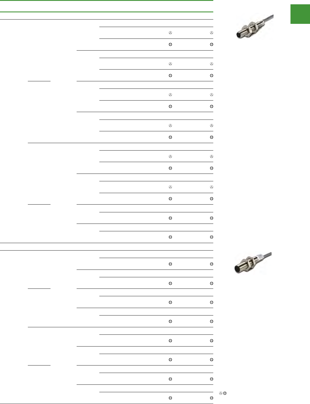
Automation
Power control
298
2015/2016 Product guide AUS15_007 - February 2016
Global proximity sensors
Three-wire sensors
Operating
voltage
Sensing
range Shielding Output
type
Connection
type
NO Output
Item no.
NC Output
Item no.
8 mm Diameter
10–30 Vdc
1 mm
Shielded
NPN
2-meter cable E57-08GS01-C E57-08GS01-C1
3-pin nano-
connector E57-08GS01-CNB E57-08GS01-C1NB
4-pin micro DC
connector E57-08GS01-CDB E57-08GS01-C1DB
PNP
2-meter cable E57-08GS01-G E57-08GS01-G1
3-pin nano-
connector E57-08GS01-GNB E57-08GS01-G1NB
4-pin micro DC
connector E57-08GS01-GDB E57-08GS01-G1DB
3 mm
(extended
range)
NPN
2-meter cable E57-08GE03-C E57-08GE03-C1
3-pin nano-
connector E57-08GE03-CNB E57-08GE03-C1NB
4-pin micro DC
connector E57-08GE03-CDB E57-08GE03-C1DB
PNP
2-meter cable E57-08GE03-G E57-08GE03-G1
3-pin nano-
connector E57-08GE03-GNB E57-08GE03-G1NB
4-pin micro DC
connector E57-08GE03-GDB E57-08GE03-G1DB
2 mm
Unshielded
NPN
2-meter cable E57-08GU02-C E57-08GU02-C1
3-pin nano-
connector E57-08GU02-CNB E57-08GU02-C1NB
4-pin micro DC
connector E57-08GU02-CDB E57-08GU02-C1DB
PNP
2-meter cable E57-08GU02-G E57-08GU02-G1
3-pin nano-
connector E57-08GU02-GNB E57-08GU02-G1NB
4-pin micro DC
connector E57-08GU02-GDB E57-08GU02-G1DB
6 mm
(extended
range)
NPN
2-meter cable E57-08GE06-C E57-08GE06-C1
4-pin micro DC
connector E57-08GE06-CDB E57-08GE06-C1DB
PNP
2-meter cable E57-08GE06-G E57-08GE06-G1
4-pin micro DC
connector E57-08GE06-GDB E57-08GE06-G1DB
12 mm Diameter
10–30 Vdc
2 mm
Shielded
NPN
2-meter cable E57-12GS02-C E57-12GS02-C1
4-pin micro DC
connector E57-12GS02-CDB E57-12GS02-C1DB
PNP
2-meter cable E57-12GS02-G E57-12GS02-G1
4-pin micro DC
connector E57-12GS02-GDB E57-12GS02-G1DB
5 mm
(extended
range)
NPN
2-meter cable E57-12GE05-C E57-12GE05-C1
4-pin micro DC
connector E57-12GE05-CDB E57-12GE05-C1DB
PNP
2-meter cable E57-12GE05-G E57-12GE05-G1
4-pin micro DC
connector E57-12GE05-GDB E57-12GE05-G1DB
4 mm
Unshielded
NPN
2-meter cable E57-12GU04-C E57-12GU04-C1
4-pin micro DC
connector E57-12GU04-CDB E57-12GU04-C1DB
PNP
2-meter cable E57-12GU04-G E57-12GU04-G1
4-pin micro DC
connector E57-12GU04-GDB E57-12GU04-G1DB
10 mm
(extended
range)
NPN
2-meter cable E57-12GE10-C E57-12GE10-C1
4-pin micro DC
connector E57-12GE10-CDB E57-12GE10-C1DB
PNP
2-meter cable E57-12GE10-G E57-12GE10-G1
4-pin micro DC
connector E57-12GE10-GDB E57-12GE10-G1DB
See listing of compatible
connector cables
V8-T3-38 Volume 8—Sensing Solutions CA08100010E—October 2013 www.eaton.com
3
3
3
3
3
3
3
3
3
3
3
3
3
3
3
3
3
3
3
3
3
3
3
3
3
3
3
3
3
3
3.4
Inductive Proximity Sensors
Global Proximity Sensors
Three-Wire Sensors
Note
See listing of compatible connector cables on Page V8-T3-40.
Operating
Voltage
Sensing
Range Shielding Output Type Connection Type
NO Output
Catalog Number
NC Output
Catalog Number
8 mm Diameter
10–30 Vdc 1 mm Shielded NPN 2-meter cable E57-08GS01-C E57-08GS01-C1
3-pin nano-connector E57-08GS01-CNB E57-08GS01-C1NB
4-pin micro DC connector E57-08GS01-CDB E57-08GS01-C1DB
PNP 2-meter cable E57-08GS01-G E57-08GS01-G1
3-pin nano-connector E57-08GS01-GNB E57-08GS01-G1NB
4-pin micro DC connector E57-08GS01-GDB E57-08GS01-G1DB
3 mm
(extended range)
NPN 2-meter cable E57-08GE03-C E57-08GE03-C1
3-pin nano-connector E57-08GE03-CNB E57-08GE03-C1NB
4-pin micro DC connector E57-08GE03-CDB E57-08GE03-C1DB
PNP 2-meter cable E57-08GE03-G E57-08GE03-G1
3-pin nano-connector E57-08GE03-GNB E57-08GE03-G1NB
4-pin micro DC connector E57-08GE03-GDB E57-08GE03-G1DB
2 mm Unshielded NPN 2-meter cable E57-08GU02-C E57-08GU02-C1
3-pin nano-connector E57-08GU02-CNB E57-08GU02-C1NB
4-pin micro DC connector E57-08GU02-CDB E57-08GU02-C1DB
PNP 2-meter cable E57-08GU02-G E57-08GU02-G1
3-pin nano-connector E57-08GU02-GNB E57-08GU02-G1NB
4-pin micro DC connector E57-08GU02-GDB E57-08GU02-G1DB
6 mm
(extended range)
NPN 2-meter cable E57-08GE06-C E57-08GE06-C1
4-pin micro DC connector E57-08GE06-CDB E57-08GE06-C1DB
PNP 2-meter cable E57-08GE06-G E57-08GE06-G1
4-pin micro DC connector E57-08GE06-GDB E57-08GE06-G1DB
12 mm Diameter
10–30 Vdc 2 mm Shielded NPN 2-meter cable E57-12GS02-C E57-12GS02-C1
4-pin micro DC connector E57-12GS02-CDB E57-12GS02-C1DB
PNP 2-meter cable E57-12GS02-G E57-12GS02-G1
4-pin micro DC connector E57-12GS02-GDB E57-12GS02-G1DB
5 mm
(extended range)
NPN 2-meter cable E57-12GE05-C E57-12GE05-C1
4-pin micro DC connector E57-12GE05-CDB E57-12GE05-C1DB
PNP 2-meter cable E57-12GE05-G E57-12GE05-G1
4-pin micro DC connector E57-12GE05-GDB E57-12GE05-G1DB
4 mm Unshielded NPN 2-meter cable E57-12GU04-C E57-12GU04-C1
4-pin micro DC connector E57-12GU04-CDB E57-12GU04-C1DB
PNP 2-meter cable E57-12GU04-G E57-12GU04-G1
4-pin micro DC connector E57-12GU04-GDB E57-12GU04-G1DB
10 mm
(extended range)
NPN 2-meter cable E57-12GE10-C E57-12GE10-C1
4-pin micro DC connector E57-12GE10-CDB E57-12GE10-C1DB
PNP 2-meter cable E57-12GE10-G E57-12GE10-G1
4-pin micro DC connector E57-12GE10-GDB E57-12GE10-G1DB
8 mm
12 mm
12mm diameter
8mm diameter
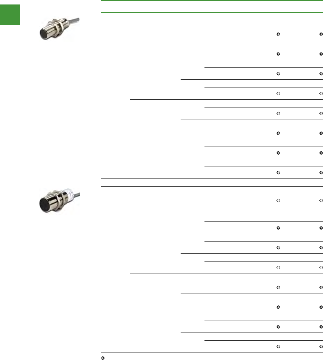
Automation
Power control
299 2015/2016 Product guide AUS15_007 - February 2016
Global proximity sensors
Three-wire sensors
Operating
voltage
Sensing
range Shielding Output
type
Connection
type
NO Output
Item no.
NC Output
Item no.
18 mm Diameter
10–30 Vdc
5 mm
Shielded
NPN
2-meter cable E57-18GS05-C E57-18GS05-C1
4-pin micro DC
connector E57-18GS05-CDB E57-18GS05-C1DB
PNP
2-meter cable E57-18GS05-G E57-18GS05-G1
4-pin micro DC
connector E57-18GS05-GDB E57-18GS05-G1DB
8 mm
(extended
range)
NPN
2-meter cable E57-18GE08-C E57-18GE08-C1
4-pin micro DC
connector E57-18GE08-CDB E57-18GE08-C1DB
PNP
2-meter cable E57-18GE08-G E57-18GE08-G1
4-pin micro DC
connector E57-18GE08-GDB E57-18GE08-G1DB
8 mm
Unshielded
NPN
2-meter cable E57-18GU08-C E57-18GU08-C1
4-pin micro DC
connector E57-18GU08-CDB E57-18GU08-C1DB
PNP
2-meter cable E57-18GU08-G E57-18GU08-G1
4-pin micro DC
connector E57-18GU08-GDB E57-18GU08-G1DB
18 mm
(extended
range)
NPN
2-meter cable E57-18GE18-C E57-18GE18-C1
4-pin micro DC
connector E57-18GE18-CDB E57-18GE18-C1DB
PNP
2-meter cable E57-18GE18-G E57-18GE18-G1
4-pin micro DC
connector E57-18GE18-GDB E57-18GE18-G1DB
30 mm Diameter
10–30 Vdc
10 mm
Shielded
NPN
2-meter cable E57-30GS10-C E57-30GS10-C1
4-pin micro DC
connector E57-30GS10-CDB E57-30GS10-C1DB
PNP
2-meter cable E57-30GS10-G E57-30GS10-G1
5-meter Cable E57-30GS10-G5 —
4-pin micro DC
connector E57-30GS10-GDB E57-30GS10-G1DB
15 mm
(extended
range)
NPN
2-meter cable E57-30GE15-C E57-30GE15-C1
4-pin micro DC
connector E57-30GE15-CDB E57-30GE15-C1DB
PNP
2-meter cable E57-30GE15-G E57-30GE15-G1
4-pin micro DC
connector E57-30GE15-GDB E57-30GE15-G1DB
15 mm
Unshielded
NPN
2-meter cable E57-30GU15-C E57-30GU15-C1
4-pin micro DC
connector E57-30GU15-CDB E57-30GU15-C1DB
PNP
2-meter cable E57-30GU15-G E57-30GU15-G1
4-pin micro DC
connector E57-30GU15-GDB E57-30GU15-G1DB
29 mm
(extended
range)
NPN
2-meter cable E57-30GE29-C E57-30GE29-C1
4-pin micro DC
connector E57-30GE29-CDB E57-30GE29-C1DB
PNP
2-meter cable E57-30GE29-G E57-30GE29-G1
4-pin micro DC
connector E57-30GE29-GDB E57-30GE29-G1DB
See listing of compatible connector cables
Volume 8—Sensing Solutions CA08100010E—October 2013 www.eaton.com V8-T3-39
3
3
3
3
3
3
3
3
3
3
3
3
3
3
3
3
3
3
3
3
3
3
3
3
3
3
3
3
3
3
3.4
Inductive Proximity Sensors
Global Proximity Sensors
Three-Wire Sensors, continued
Note
See listing of compatible connector cables on Page V8-T3-40.
Operating
Voltage
Sensing
Range Shielding Output Type Connection Type
NO Output
Catalog Number
NC Output
Catalog Number
18 mm Diameter
10–30 Vdc 5 mm Shielded NPN 2-meter cable E57-18GS05-C E57-18GS05-C1
4-pin micro DC connector E57-18GS05-CDB E57-18GS05-C1DB
PNP 2-meter cable E57-18GS05-G E57-18GS05-G1
4-pin micro DC connector E57-18GS05-GDB E57-18GS05-G1DB
8 mm
(extended range)
NPN 2-meter cable E57-18GE08-C E57-18GE08-C1
4-pin micro DC connector E57-18GE08-CDB E57-18GE08-C1DB
PNP 2-meter cable E57-18GE08-G E57-18GE08-G1
4-pin micro DC connector E57-18GE08-GDB E57-18GE08-G1DB
8 mm Unshielded NPN 2-meter cable E57-18GU08-C E57-18GU08-C1
4-pin micro DC connector E57-18GU08-CDB E57-18GU08-C1DB
PNP 2-meter cable E57-18GU08-G E57-18GU08-G1
4-pin micro DC connector E57-18GU08-GDB E57-18GU08-G1DB
18 mm
(extended range)
NPN 2-meter cable E57-18GE18-C E57-18GE18-C1
4-pin micro DC connector E57-18GE18-CDB E57-18GE18-C1DB
PNP 2-meter cable E57-18GE18-G E57-18GE18-G1
4-pin micro DC connector E57-18GE18-GDB E57-18GE18-G1DB
30 mm Diameter
10–30 Vdc 10 mm Shielded NPN 2-meter cable E57-30GS10-C E57-30GS10-C1
4-pin micro DC connector E57-30GS10-CDB E57-30GS10-C1DB
PNP 2-meter cable E57-30GS10-G E57-30GS10-G1
5-meter Cable E57-30GS10-G5 —
4-pin micro DC connector E57-30GS10-GDB E57-30GS10-G1DB
15 mm
(extended range)
NPN 2-meter cable E57-30GE15-C E57-30GE15-C1
4-pin micro DC connector E57-30GE15-CDB E57-30GE15-C1DB
PNP 2-meter cable E57-30GE15-G E57-30GE15-G1
4-pin micro DC connector E57-30GE15-GDB E57-30GE15-G1DB
15 mm Unshielded NPN 2-meter cable E57-30GU15-C E57-30GU15-C1
4-pin micro DC connector E57-30GU15-CDB E57-30GU15-C1DB
PNP 2-meter cable E57-30GU15-G E57-30GU15-G1
4-pin micro DC connector E57-30GU15-GDB E57-30GU15-G1DB
29 mm
(extended range)
NPN 2-meter cable E57-30GE29-C E57-30GE29-C1
4-pin micro DC connector E57-30GE29-CDB E57-30GE29-C1DB
PNP 2-meter cable E57-30GE29-G E57-30GE29-G1
4-pin micro DC connector E57-30GE29-GDB E57-30GE29-G1DB
18 mm
30 mm
18mm diameter
30mm diameter
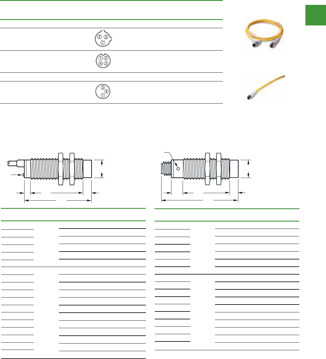
Automation
Power control
300
2015/2016 Product guide AUS15_007 - February 2016
Global proximity sensors
Volume 8—Sensing Solutions CA08100010E—October 2013 www.eaton.com V8-T3-43
3
3
3
3
3
3
3
3
3
3
3
3
3
3
3
3
3
3
3
3
3
3
3
3
3
3
3
3
3
3
3.4
Inductive Proximity Sensors
Global Proximity Sensors
Dimensions
Approximate Dimensions in mm
Cable Models
Two-Wire Sensors
Three-Wire Sensors
Catalog
Number
Operating
Voltage A B C D E
E57-12GS02-A 20–250 Vac M12x1 65 15 50 —
E57-12GU04-A M12x1 60 15 42 8
E57-18GS05-A M18x1 80 20 60 —
E57-18GU08-A M18x1 80 20 48 12
E57-30GS10-A M30x1.5 80 20 60 —
E57-30GU15-A M30x1.5 80 20 45 15
E57-12GS02-D 10–30 Vdc M12x1 50 — 50 —
E57-12GU04-D M12x1 50 — 42 8
E57-12GE08-D M12x1 50 — 42 8
E57-12GE08-D1 M12x1 50 — 42 8
E57-18GS05-D M18x1 55 5 50 —
E57-18GU08-D M18x1 55 5 38 12
E57-18GE16-D M18x1 55 5 38 12
E57-18GE16-D1 M18x1 55 5 38 12
E57-30GS10-D M30x1.5 55 5 50 —
E57-30GU15-D M30x1.5 55 5 35 15
E57-30GE25-D M30x1.5 55 5 35 15
E57-30GE25-D1 M30x1.5 55 5 35 15
“A”
LED
“B”
“C” “D” “E”
Catalog
Number
Operating
Voltage A B C D E
E57-08GE03-C 10–30 Vdc M8x1 46 6 40 —
E57-08GE03-G M8x1 46 6 40 —
E57-08GE06-C M8x1 45 — 41 4
E57-08GE06-G M8x1 45 — 41 4
E57-08GS01-C M8x1 45 — 45 —
E57-08GS01-G M8x1 45 — 45 —
E57-08GU02-C M8x1 45 — 41 4
E57-08GU02-G M8x1 45 — 41 4
E57-12GE05-C M12x1 51 2 49 —
E57-12GE05-G M12x1 51 2 49 —
E57-12GE10-C M12x1 50.5 1.7 41 7.8
E57-12GE10-G M12x1 50.5 1.7 41 7.8
E57-12GS02-C M12x1 50 — 50 —
E57-12GS02-G M12x1 50 — 50 —
E57-12GU04-C M12x1 50 — 42 8
E57-12GU04-G M12x1 50 — 42 8
E57-18GE08-C M18x1 67.5 2.5 65 —
E57-18GE08-G M18x1 65.5 2.5 65 —
E57-18GE18-C M18x1 66 2.5 52 11.5
E57-18GE18-G M18x1 66 2.5 52 11.5
E57-18GS05-C M18x1 55 5 50 —
E57-18GS05-G M18x1 55 5 50 —
E57-18GU08-C M18x1 55 5 38 12
E57-18GU08-G M18x1 55 5 38 12
E57-30GE15-C M30x1.5 69 5 64 —
E57-30GE15-G M30x1.5 69 5 64 —
E57-30GE29-C M30x1.5 83 5 64 15
E57-30GE29-G M30x1.5 83 5 64 15
E57-30GS10-C M30x1.5 55 5 50 —
E57-30GS10-G M30x1.5 55 5 50 —
E57-30GU15-C M30x1.5 55 5 35 15
E57-30GU15-G M30x1.5 55 5 35 15
“A”
LED
“B”
“C” “D” “E”
Dimensions
Two-wire sensors
Cable models Connector modules
V8-T3-44 Volume 8—Sensing Solutions CA08100010E—October 2013 www.eaton.com
3
3
3
3
3
3
3
3
3
3
3
3
3
3
3
3
3
3
3
3
3
3
3
3
3
3
3
3
3
3
3.4
Inductive Proximity Sensors
Global Proximity Sensors
Approximate Dimensions in mm
Connector Models
Two-Wire Sensors
Three-Wire Sensors
Note
1Normally closed models are dimensionally identical to equivalent normally open models.
Catalog
Number
1
Operating
Voltage A B C D E
E57-12GS02-AAB 20–250 Vac M12x1 68 16 42 —
E57-12GU04-AAB M12x1 68 16 34 8
E57-18GS05-AAB M18x1 91 20 60 —
E57-18GU08-AAB M18x1 91 20 48 12
E57-18GE16-AAB M18x1 79.2 15 37 11.5
E57-30GS10-AAB M30x1.5 80 20 60 —
E57-30GU15-AAB M30x1.5 91 20 45 15
E57-12GS02-DDB 10–30 Vdc M12x1 69 16 42 —
E57-12GU04-DDB M12x1 68 16 34 8
E57-12GE08-DDB M12x1 68 10 50 8
E57-12GE08-D1DB M12x1 68 10 50 8
E57-18GS05-DDB M18x1 76 15 61 —
E57-18GU08-DDB M18x1 80 15 49 12
E57-18GE16-DDB M18x1 79 15 52 12
E57-30GS10-DDB M30x1.5 75 15 60 —
E57-30GU15-DDB M30x1.5 79 15 45 15
E57-30GE25-DDB M30x1.5 78 15 48 15
“A”
LED
“B”
“C” “D” “E”
Catalog
Number
1
Operating
Voltage A B C D E
E57-08GE03-CDB 10–30 Vdc M8x1 71 26 36 —
E57-08GE03-CNB M8x1 61 19 42 —
E57-08GE03-GDB M8x1 71 26 36 —
E57-08GE03-GNB M8x1 61 19 42 —
E57-08GE06-CDB M8x1 70 31 35 4
E57-08GE06-GDB M8x1 70 31 35 4
E57-08GS01-CDB M8x1 70 21 49 —
E57-08GS01-CNB M8x1 60 20 40 —
E57-08GS01-GDB M8x1 70 21 49 —
E57-08GS01-GNB M8x1 60 20 40 —
E57-08GU02-CDB M8x1 70 21 45 4
E57-08GU02-CNB M8x1 60 20 36 4
E57-08GU02-GDB M8x1 70 21 45 4
E57-08GU02-GNB M8x1 60 20 36 4
E57-12GE05-CDB M12x1 69 24 45 —
E57-12GE05-GDB M12x1 69 24 45 —
E57-12GE10-CDB M12x1 68.5 10.3 36 7.8
E57-12GE10-GDB M12x1 68.5 10.3 36 7.8
E57-12GS02-CDB M12x1 68 16 52 —
E57-12GS02-GDB M12x1 68 16 52 —
E57-12GU04-CDB M12x1 68 20 31 8
E57-12GU04-GDB M12x1 68 20 31 8
E57-18GE08-CDB M18x1 79 30 49 —
E57-18GE08-GDB M18x1 79 30 49 —
E57-18GE18-CDB M18x1 79.2 15 37 11.5
E57-18GE18-GDB M18x1 79.2 15 37 11.5
E57-18GS05-CDB M18x1 76 15 61 —
E57-18GS05-GDB M18x1 76 15 61 —
E57-18GU08-CDB M18x1 76 15 49 12
E57-18GU08-GDB M18x1 80 15 49 12
E57-30GE29-CDB M30x1.5 79 30 34 15
E57-30GE29-GDB M30x1.5 79 30 34 15
E57-30GS10-CDB M30x1.5 79 15 60 —
E57-30GS10-GDB M30x1.5 75 15 60 —
E57-30GU15-CDB M30x1.5 75 15 45 15
E57-30GU15-GDB M30x1.5 75 15 45 15
“A”
LED
“B”
“C” “D” “E”
Compatible connector cables
Voltage
style
Number
of pins Gauge Length
Pin configuration/
Wire colors
(Face view female shown)
PVC jacket
Item no.
PUR jacket
Item no.
Micro-style, straight female
AC 3-pin,
3-wire 22 AWG 6.0 ft (2m)
1-Green
2-Red/Black
3-Red/White
CSAS3F3CY2202 CSAS3F3RY2202
DC 4-pin,
3-wire 22 AWG 6.0 ft (2m)
1-Brown
2-No Wire
3-Blue
4-Black
CSDS4A3CY2202 CSDS4A3RY2202
Nano-style, straight female
DC 3-pin 24 AWG 6.0 ft (2m)
1-Brown
3-Blue
4-Black
CSNS3A3CY2402 CSNS3A3RY2402
V8-T3-40 Volume 8—Sensing Solutions CA08100010E—October 2013 www.eaton.com
3
3
3
3
3
3
3
3
3
3
3
3
3
3
3
3
3
3
3
3
3
3
3
3
3
3
3
3
3
3
3.4
Inductive Proximity Sensors
Global Proximity Sensors
Compatible Connector Cables
Standard Cables 1
Accessories
Global Proximity Sensors
Note
1 For a full selection of connector cables, see Tab 10, section 10.1.
Voltage
Style
Number
of Pins Gauge Length
Pin Configuration/Wire Colors
(Face View Female Shown)
PVC Jacket
Catalog Number
PUR Jacket
Catalog Number
Micro-Style, Straight Female
AC 3-pin,
3-wire
22 AWG 6.0 ft (2m) CSAS3F3CY2202 CSAS3F3RY2202
DC 4-pin,
3-wire
22 AWG 6.0 ft (2m) CSDS4A3CY2202 CSDS4A3RY2202
Nano-Style, Straight Female
DC 3-pin 24 AWG 6.0 ft (2m) CSNS3A3CY2402 CSNS3A3RY2402
Description Reference
Mounting brackets See Tab 8,
section 8.2
Replacement mounting nuts and other accessories See Tab 8,
section 8.3
Connector cables See Tab 10,
section 10.1
Micro-Style
Straight Female
Nano-Style
Straight Female
1-Green
2-Red/Black
3-Red/White
1-Brown
2-No Wire
3-Blue
4-Black
1-Brown
3-Blue
4-Black
Note: Normally closed models are dimensionally identical to equivalent normally open models
Micro-style
Nano-style
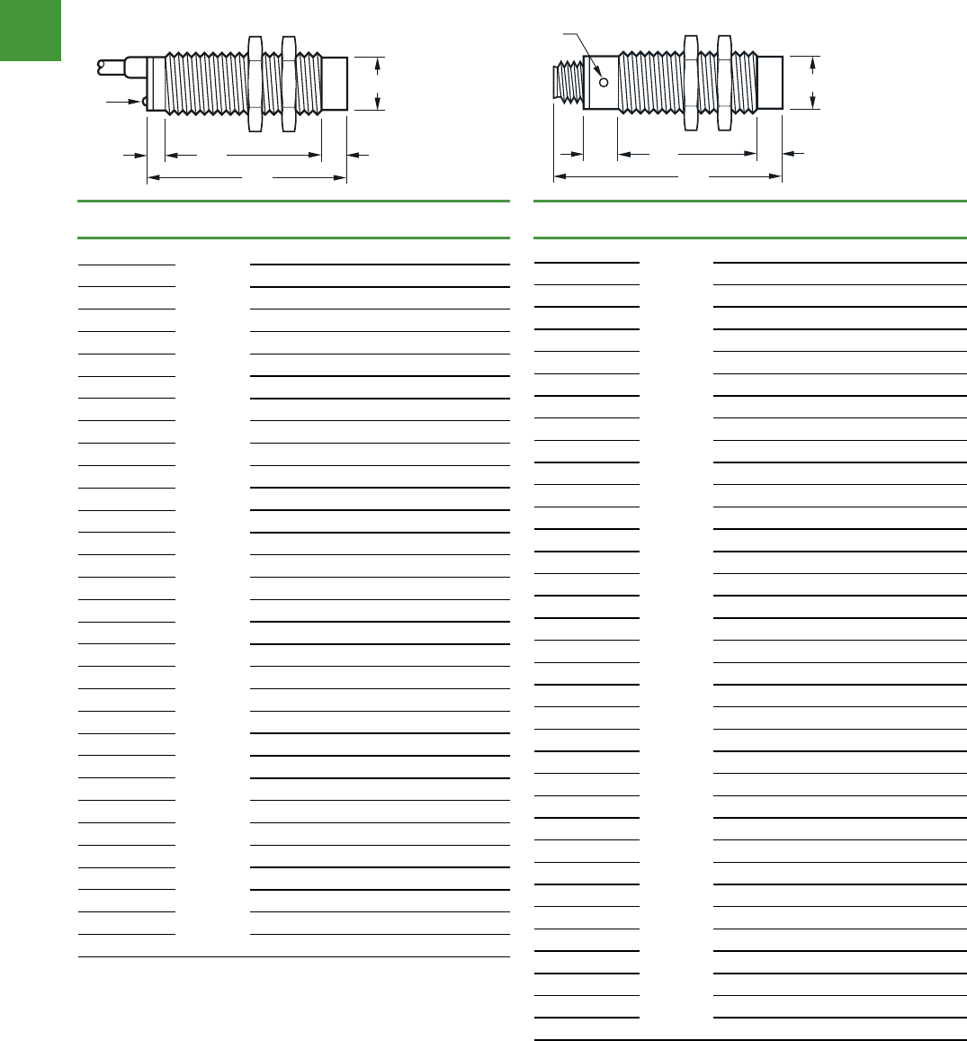
Automation
Power control
301 2015/2016 Product guide AUS15_007 - February 2016
V8-T3-44 Volume 8—Sensing Solutions CA08100010E—October 2013 www.eaton.com
3
3
3
3
3
3
3
3
3
3
3
3
3
3
3
3
3
3
3
3
3
3
3
3
3
3
3
3
3
3
3.4
Inductive Proximity Sensors
Global Proximity Sensors
Approximate Dimensions in mm
Connector Models
Two-Wire Sensors
Three-Wire Sensors
Note
1Normally closed models are dimensionally identical to equivalent normally open models.
Catalog
Number
1
Operating
Voltage A B C D E
E57-12GS02-AAB 20–250 Vac M12x1 68 16 42 —
E57-12GU04-AAB M12x1 68 16 34 8
E57-18GS05-AAB M18x1 91 20 60 —
E57-18GU08-AAB M18x1 91 20 48 12
E57-18GE16-AAB M18x1 79.2 15 37 11.5
E57-30GS10-AAB M30x1.5 80 20 60 —
E57-30GU15-AAB M30x1.5 91 20 45 15
E57-12GS02-DDB 10–30 Vdc M12x1 69 16 42 —
E57-12GU04-DDB M12x1 68 16 34 8
E57-12GE08-DDB M12x1 68 10 50 8
E57-12GE08-D1DB M12x1 68 10 50 8
E57-18GS05-DDB M18x1 76 15 61 —
E57-18GU08-DDB M18x1 80 15 49 12
E57-18GE16-DDB M18x1 79 15 52 12
E57-30GS10-DDB M30x1.5 75 15 60 —
E57-30GU15-DDB M30x1.5 79 15 45 15
E57-30GE25-DDB M30x1.5 78 15 48 15
“A”
LED
“B”
“C” “D” “E”
Catalog
Number
1
Operating
Voltage A B C D E
E57-08GE03-CDB 10–30 Vdc M8x1 71 26 36 —
E57-08GE03-CNB M8x1 61 19 42 —
E57-08GE03-GDB M8x1 71 26 36 —
E57-08GE03-GNB M8x1 61 19 42 —
E57-08GE06-CDB M8x1 70 31 35 4
E57-08GE06-GDB M8x1 70 31 35 4
E57-08GS01-CDB M8x1 70 21 49 —
E57-08GS01-CNB M8x1 60 20 40 —
E57-08GS01-GDB M8x1 70 21 49 —
E57-08GS01-GNB M8x1 60 20 40 —
E57-08GU02-CDB M8x1 70 21 45 4
E57-08GU02-CNB M8x1 60 20 36 4
E57-08GU02-GDB M8x1 70 21 45 4
E57-08GU02-GNB M8x1 60 20 36 4
E57-12GE05-CDB M12x1 69 24 45 —
E57-12GE05-GDB M12x1 69 24 45 —
E57-12GE10-CDB M12x1 68.5 10.3 36 7.8
E57-12GE10-GDB M12x1 68.5 10.3 36 7.8
E57-12GS02-CDB M12x1 68 16 52 —
E57-12GS02-GDB M12x1 68 16 52 —
E57-12GU04-CDB M12x1 68 20 31 8
E57-12GU04-GDB M12x1 68 20 31 8
E57-18GE08-CDB M18x1 79 30 49 —
E57-18GE08-GDB M18x1 79 30 49 —
E57-18GE18-CDB M18x1 79.2 15 37 11.5
E57-18GE18-GDB M18x1 79.2 15 37 11.5
E57-18GS05-CDB M18x1 76 15 61 —
E57-18GS05-GDB M18x1 76 15 61 —
E57-18GU08-CDB M18x1 76 15 49 12
E57-18GU08-GDB M18x1 80 15 49 12
E57-30GE29-CDB M30x1.5 79 30 34 15
E57-30GE29-GDB M30x1.5 79 30 34 15
E57-30GS10-CDB M30x1.5 79 15 60 —
E57-30GS10-GDB M30x1.5 75 15 60 —
E57-30GU15-CDB M30x1.5 75 15 45 15
E57-30GU15-GDB M30x1.5 75 15 45 15
“A”
LED
“B”
“C” “D” “E”
Global proximity sensors
Dimensions
Three-wire sensors
Cable modules Connector modules
Volume 8—Sensing Solutions CA08100010E—October 2013 www.eaton.com V8-T3-43
3
3
3
3
3
3
3
3
3
3
3
3
3
3
3
3
3
3
3
3
3
3
3
3
3
3
3
3
3
3
3.4
Inductive Proximity Sensors
Global Proximity Sensors
Dimensions
Approximate Dimensions in mm
Cable Models
Two-Wire Sensors
Three-Wire Sensors
Catalog
Number
Operating
Voltage A B C D E
E57-12GS02-A 20–250 Vac M12x1 65 15 50 —
E57-12GU04-A M12x1 60 15 42 8
E57-18GS05-A M18x1 80 20 60 —
E57-18GU08-A M18x1 80 20 48 12
E57-30GS10-A M30x1.5 80 20 60 —
E57-30GU15-A M30x1.5 80 20 45 15
E57-12GS02-D 10–30 Vdc M12x1 50 — 50 —
E57-12GU04-D M12x1 50 — 42 8
E57-12GE08-D M12x1 50 — 42 8
E57-12GE08-D1 M12x1 50 — 42 8
E57-18GS05-D M18x1 55 5 50 —
E57-18GU08-D M18x1 55 5 38 12
E57-18GE16-D M18x1 55 5 38 12
E57-18GE16-D1 M18x1 55 5 38 12
E57-30GS10-D M30x1.5 55 5 50 —
E57-30GU15-D M30x1.5 55 5 35 15
E57-30GE25-D M30x1.5 55 5 35 15
E57-30GE25-D1 M30x1.5 55 5 35 15
“A”
LED
“B”
“C” “D” “E”
Catalog
Number
Operating
Voltage A B C D E
E57-08GE03-C 10–30 Vdc M8x1 46 6 40 —
E57-08GE03-G M8x1 46 6 40 —
E57-08GE06-C M8x1 45 — 41 4
E57-08GE06-G M8x1 45 — 41 4
E57-08GS01-C M8x1 45 — 45 —
E57-08GS01-G M8x1 45 — 45 —
E57-08GU02-C M8x1 45 — 41 4
E57-08GU02-G M8x1 45 — 41 4
E57-12GE05-C M12x1 51 2 49 —
E57-12GE05-G M12x1 51 2 49 —
E57-12GE10-C M12x1 50.5 1.7 41 7.8
E57-12GE10-G M12x1 50.5 1.7 41 7.8
E57-12GS02-C M12x1 50 — 50 —
E57-12GS02-G M12x1 50 — 50 —
E57-12GU04-C M12x1 50 — 42 8
E57-12GU04-G M12x1 50 — 42 8
E57-18GE08-C M18x1 67.5 2.5 65 —
E57-18GE08-G M18x1 65.5 2.5 65 —
E57-18GE18-C M18x1 66 2.5 52 11.5
E57-18GE18-G M18x1 66 2.5 52 11.5
E57-18GS05-C M18x1 55 5 50 —
E57-18GS05-G M18x1 55 5 50 —
E57-18GU08-C M18x1 55 5 38 12
E57-18GU08-G M18x1 55 5 38 12
E57-30GE15-C M30x1.5 69 5 64 —
E57-30GE15-G M30x1.5 69 5 64 —
E57-30GE29-C M30x1.5 83 5 64 15
E57-30GE29-G M30x1.5 83 5 64 15
E57-30GS10-C M30x1.5 55 5 50 —
E57-30GS10-G M30x1.5 55 5 50 —
E57-30GU15-C M30x1.5 55 5 35 15
E57-30GU15-G M30x1.5 55 5 35 15
“A”
LED
“B”
“C” “D” “E”
Note: Normally closed models are dimensionally identical to equivalent normally open models

Automation
Power control
302
2015/2016 Product guide AUS15_007 - February 2016
• E58 Sensors are available in 18 mm & 30
mm diameters
• Highly refined optics for long sensing
ranges & to see through high levels of
contamination — unmatched optical
performance
• Perfect Prox® technology provides
exceptional background rejection &
extremely high excess gain
• Resistant to the wide range of chemicals
used in the automotive, food processing &
forest products industries
• Suitable for high temperature, high pressure
washdown (1200 psi)
• Mechanical Viton seals hold up to extreme
temperature variations
• Visible sensing beam on all models lets
you see where the beam is aimed for quick
setup & alignment
• Output status indicator is the brightest
available & is visible from any angle & in any
lighting condition
• The industry’s only background rejection
sensors with a 2-wire circuit design
• Models available with both AC & DC
operation in a single unit
• 4-wire DC sensors offer dual NPN & PNP
outputs
3-Wire & 4-Wire sensors
Model selection Operating
voltage
Sensing
range Field of view Through
beam part
Item no.
Light Operate
Item no.
Dark Operate
30 mm Diameter 20 – 132V AC 250 m 830 mm diameter Source E58-30TS250-GA E58-30TS250-GA
Through-Beam or 15 – 30V DC -at 7.6 metres Detector E58-30TD250-GL E58-30TD250-GD
30 mm Diameter
Reflex
20 – 132V AC
or 15 – 30V DC 18 m 150 mm diameter
at 6 metres -E58-30RS18-GL* E58-30RS18-GD*
30 mm Diameter
Polarized Reflex
20 – 132V AC
or 15 – 30V DC 10 m 150 mm diameter
at 6 metres -E58-30RP10-GL* E58-30RP10-GD*
* Retroreflector not included.
Connection type: 2 metre Cable
2-Wire sensors
Model selection Operating
voltage
Sensing
range Field of view Through
beam part
Item no.
Light Operate
Item no.
Dark Operate
18 mm Diameter
Perfect Prox®
90 – 132V AC
or 18 – 50V DC 50 mm 6 mm diameter
at 50 mm -E58-18DP50-EL E58-18DP50-ED
90 – 132V AC
or 18 – 50V DC 100 mm 10 mm diameter
at 100 mm -E58-18DP100-EL E58-18DP100-ED
30 mm Diameter
Perfect Prox®
90 – 132V AC
or 18 – 50V DC 150 mm 19 mm diameter
at 150 mm
-E58-30DP150-EL E58-30DP150-ED
90 – 132V AC
or 18 – 50V DC 280 mm 26 mm diameter
at 280 mm
-E58-30DPS280-EL E58-30DPS280-ED
Connection type: 2 metre Cable
3-Wire & 4-Wire sensors
Model selection Operating
voltage
Sensing
range Field of view Through
beam part
Item no.
Light Operate
Item no.
Dark Operate
18 mm Diameter
Perfect Prox®
10 – 30V DC 50 mm 6 mm diameter
at 50 mm -E58-18DP50-HL E58-18DP50-HD
10 – 30V DC 100 mm 10 mm diameter
at 100 mm -E58-18DP100-HL E58-18DP100-HD
30 mm Diameter
Perfect Prox®
20 – 132V AC
or 15 – 30V DC 150 mm 19 mm diameter
at 150 mm -E58-30DP150-GL E58-30DP150-GD
20 – 132V AC
or 15 – 30V DC 280 mm 26 mm diameter
at 280 mm -E58-30DPS280-GL E58-30DPS280-GD
Connection type: 2 metre Cable
Photoelectric sensors
Eaton E58 harsh duty series photoelectric sensors
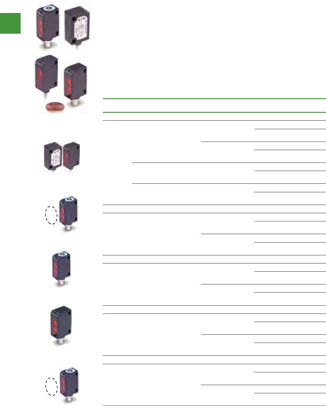
Automation
Power control
303 2015/2016 Product guide AUS15_007 - February 2016
• A Complete Family of Solutions—Models
include an 8.2 ft (2.5m) polarized reflex, a 13
in (35 cm) diffuse reflective, a 4 in (10 cm)
fixed-focus diffuse, a 20 ft (6m) thru-beam;
and a 2.6 ft (80 cm) clear object detector for
sensing plastic bottles, molds, cartons and
films
• Small Size—At less than 1.5 in long and
half an in deep, NanoView can fit into the
smallest of spaces
• Fixed Focus Diffuse Models—Perfect for
sensing very small targets at a 4-in focal
point. A visible red LED beam makes it easy
to set up
• Clear Object Detection Models—Ideal for
sensing plastic bottles, molds, cartons, films
and glass objects
Photoelectric sensors
Nano view series sensors
Voltage
range
Sensing
mode
Sensing
range Output type Connection
type Item no.
Thru-beam
10–30 Vdc
Thru-beam
detector 19 ft (6m)
NPN, light operate or
dark operate (selectable)
6 ft cable E71-TBRN-CA
4-pin nano-
connector E71-TBRN-M8
PNP, light operate or
dark operate (selectable)
6 ft cabl e E71-TBRP-CA
4-pin nano-
connector E71-TBRP-M8
Thru-beam
source 19 ft (6m)
6 ft cabl e E71-TBS-CA
4-pin nano-
connector E71-TBS-M8
Narrow beam
Thru-beam
source
4.9 ft (1.5m )
6 ft cabl e E71-NTBS-CA
4-pin nano-
connector E71-NTBS-M8
Polarized reflex
10–30 Vdc Polarized
reflex 8.2 ft (2.5m)
NPN, light operate or
dark operate (selectable)
6 ft cable E71-PRN-CA
4-pin nano-
connector E71-PRN-M8
PNP, light operate or
dark operate (selectable)
6 ft cable E71-PRP-CA
4-pin nano-
connector E71-PRP-M8
Diffuse reflective
10–30 Vdc Diffuse reflec-
tive
13.8 in (35
cm)
NPN, light operate or
dark operate (selectable)
6 ft cable E71-SDN-CA
4-pin nano-
connector E71-SDN-M8
PNP, light operate or
dark operate (selectable)
6 ft cable E71-SDP-CA
4-pin nano-
connector E71-SDP-M8
Fixed focus diffuse reflective
10–30 Vdc
Fixed-focus
Diffuse reflec-
tive
3.9 in (10 cm)
focal point
NPN, light operate or
dark operate (selectable)
6 ft cable E71-FFDN-CA
4-pin nano-
connector E71-FFDN-M8
PNP, light operate or
dark operate (selectable)
6 ft cable E71-FFDP-CA
4-pin nano-
connector E71-FFDP-M8
Clear object detector
10–30 Vdc
Clear object
detector
31.5 in (80
cm)
NPN, light operate or
dark operate (selectable)
6 ft cable E71-CON-CA
4-pin nano-
connector E71-CON-M8
PNP, light operate or
dark operate (selectable)
6 ft cable E71-COP-CA
4-pin nano-
connector E71-COP-M8
for compatible connector cables, refer to the following page
Volume 8—Sensing Solutions CA08100010E—July 2014 www.eaton.com V8-T5-27
5
5
5
5
5
5
5
5
5
5
5
5
5
5
5
5
5
5
5
5
5
5
5
5
5
5
5
5
5
5
For Customer Service in the U.S. call 1-877-ETN CARE (386-2273),
in Canada call 1-800-268-3578.
For Application Assistance in the U.S. and Canada
call 1-800-426-9184.
5.2
Photoelectric Sensors
NanoView Series Sensors
NanoView Series Sensors
Contents
Description Page
NanoView Series Sensors
Product Selection
NanoView Series Sensors—
Four-Wire Sensors . . . . . . . . . . . . . . . . . . V8-T5-28
Compatible Connector Cables . . . . . . . . . . . V8-T5-29
Accessories . . . . . . . . . . . . . . . . . . . . . . . . . . . V8-T5-29
Technical Data and Specifications . . . . . . . . . . V8-T5-30
Detection Diagrams . . . . . . . . . . . . . . . . . . . . . V8-T5-30
Wiring Diagrams . . . . . . . . . . . . . . . . . . . . . . . . V8-T5-31
Dimensions . . . . . . . . . . . . . . . . . . . . . . . . . . . V8-T5-32
NanoView Series Sensors
Product Description
The NanoView™ Series from
Eaton is a family of miniature
rectangular photoelectric
sensors designed for
optimum value and sensing
performance in a wide range
of applications.
These small sensors are
available in a variety of optical
modes: polarized reflex;
diffuse reflective; fixed-focus
diffuse; thru-beam with
narrow-beam option; and
even a clear object detector.
NanoView sensors are
housed in ABS enclosures
rated IP66 or better. Two top-
mounted indicator LEDs
communicate power and
output status. Each model
includes both light operate
and dark operate modes.
Termination options include a
4-pin M8 connector cable or a
built-in 6 ft (2m) cable.
NanoView is the ultimate
solution to sensing
challenges that require
reduced dimensions and
costs.
Features
●A Complete Family of
Solutions—Models include
an 8.2 ft (2.5m) polarized
reflex, a 13 in (35 cm)
diffuse reflective, a 4 in
(10 cm) fixed-focus diffuse,
a 20 ft (6m) thru-beam;
and a 2.6 ft (80 cm) clear
object detector for sensing
plastic bottles, molds,
cartons and films
●Small Size—At less than
1.5 in long and half an in
deep, NanoView can fit
into the smallest of spaces
●Fixed Focus Diffuse
Models—Perfect for
sensing very small targets
at a 4-in focal point. A
visible red LED beam
makes it easy to set up
●Clear Object Detection
Models—Ideal for sensing
plastic bottles, molds,
cartons, films and glass
objects
Standards and Certifications
●UL Listed
●cUL Listed
●CE Approved
DANGER
THIS SENSOR IS NOT A
SAFETY DEVICE AND IS NOT
INTENDED TO BE USED AS A
SAFETY DEVICE. This sensor
is designed only to detect
and read certain data in an
electronic manner and
perform no use apart from
that, specifically no safety-
related use. This sensor
product does not include
self-checking redundant
circuitry, and the failure of
this sensor product could
cause either an energized
or de-energized output
condition, which could result
in death, serious bodily
injury, or property damage.
For the most current information
on this product, visit our Web site:
www.eaton.com
Volume 8—Sensing Solutions CA08100010E—July 2014 www.eaton.com V8-T5-27
5
5
5
5
5
5
5
5
5
5
5
5
5
5
5
5
5
5
5
5
5
5
5
5
5
5
5
5
5
5
For Customer Service in the U.S. call 1-877-ETN CARE (386-2273),
in Canada call 1-800-268-3578.
For Application Assistance in the U.S. and Canada
call 1-800-426-9184.
5.2
Photoelectric Sensors
NanoView Series Sensors
NanoView Series Sensors Contents
Description Page
NanoView Series Sensors
Product Selection
NanoView Series Sensors—
Four-Wire Sensors . . . . . . . . . . . . . . . . . . V8-T5-28
Compatible Connector Cables . . . . . . . . . . . V8-T5-29
Accessories . . . . . . . . . . . . . . . . . . . . . . . . . . . V8-T5-29
Technical Data and Specifications . . . . . . . . . . V8-T5-30
Detection Diagrams . . . . . . . . . . . . . . . . . . . . . V8-T5-30
Wiring Diagrams . . . . . . . . . . . . . . . . . . . . . . . . V8-T5-31
Dimensions . . . . . . . . . . . . . . . . . . . . . . . . . . . V8-T5-32
NanoView Series Sensors
Product Description
The NanoView™ Series from
Eaton is a family of miniature
rectangular photoelectric
sensors designed for
optimum value and sensing
performance in a wide range
of applications.
These small sensors are
available in a variety of optical
modes: polarized reflex;
diffuse reflective; fixed-focus
diffuse; thru-beam with
narrow-beam option; and
even a clear object detector.
NanoView sensors are
housed in ABS enclosures
rated IP66 or better. Two top-
mounted indicator LEDs
communicate power and
output status. Each model
includes both light operate
and dark operate modes.
Termination options include a
4-pin M8 connector cable or a
built-in 6 ft (2m) cable.
NanoView is the ultimate
solution to sensing
challenges that require
reduced dimensions and
costs.
Features
●A Complete Family of
Solutions—Models include
an 8.2 ft (2.5m) polarized
reflex, a 13 in (35 cm)
diffuse reflective, a 4 in
(10 cm) fixed-focus diffuse,
a 20 ft (6m) thru-beam;
and a 2.6 ft (80 cm) clear
object detector for sensing
plastic bottles, molds,
cartons and films
●Small Size—At less than
1.5 in long and half an in
deep, NanoView can fit
into the smallest of spaces
●Fixed Focus Diffuse
Models—Perfect for
sensing very small targets
at a 4-in focal point. A
visible red LED beam
makes it easy to set up
●Clear Object Detection
Models—Ideal for sensing
plastic bottles, molds,
cartons, films and glass
objects
Standards and Certifications
●UL Listed
●cUL Listed
●CE Approved
DANGER
THIS SENSOR IS NOT A
SAFETY DEVICE AND IS NOT
INTENDED TO BE USED AS A
SAFETY DEVICE. This sensor
is designed only to detect
and read certain data in an
electronic manner and
perform no use apart from
that, specifically no safety-
related use. This sensor
product does not include
self-checking redundant
circuitry, and the failure of
this sensor product could
cause either an energized
or de-energized output
condition, which could result
in death, serious bodily
injury, or property damage.
For the most current information
on this product, visit our Web site:
www.eaton.com
V8-T5-28 Volume 8—Sensing Solutions CA08100010E—July 2014 www.eaton.com
5
5
5
5
5
5
5
5
5
5
5
5
5
5
5
5
5
5
5
5
5
5
5
5
5
5
5
5
5
5
5.2
Photoelectric Sensors
NanoView Series Sensors
Product Selection
NanoView Series Sensors—Four-Wire Sensors
Note
1 For compatible connector cables, see Page V8-T5-29.
Voltage Range Sensing Mode Sensing Range Output Type Connection Type Catalog Number
Thru-Beam
10–30 Vdc Thru-beam detector 19 ft (6m) NPN, light operate or
dark operate (selectable)
6 ft cable E71-TBRN-CA
4-pin nano-connector 1E71-TBRN-M8
PNP, light operate or
dark operate (selectable)
6 ft cable E71-TBRP-CA
4-pin nano-connector 1E71-TBRP-M8
Thru-beam source 19 ft (6m) N/A 6 ft cable E71-TBS-CA
4-pin nano-connector 1E71-TBS-M8
Narrow beam
Thru-beam source
4.9 ft (1.5m) N/A 6 ft cable E71-NTBS-CA
4-pin nano-connector 1E71-NTBS-M8
Polarized Reflex
10–30 Vdc Polarized reflex 8.2 ft (2.5m) NPN, light operate or
dark operate (selectable)
6 ft cable E71-PRN-CA
4-pin nano-connector 1E71-PRN-M8
PNP, light operate or
dark operate (selectable)
6 ft cable E71-PRP-CA
4-pin nano-connector 1E71-PRP-M8
Diffuse Reflective
10–30 Vdc Diffuse reflective 13.8 in (35 cm) NPN, light operate or
dark operate (selectable)
6 ft cable E71-SDN-CA
4-pin nano-connector 1E71-SDN-M8
PNP, light operate or
dark operate (selectable)
6 ft cable E71-SDP-CA
4-pin nano-connector 1E71-SDP-M8
Fixed Focus Diffuse Reflective
10–30 Vdc Fixed-focus
Diffuse reflective
3.9 in (10 cm)
focal point
NPN, light operate or
dark operate (selectable)
6 ft cable E71-FFDN-CA
4-pin nano-connector 1E71-FFDN-M8
PNP, light operate or
dark operate (selectable)
6 ft cable E71-FFDP-CA
4-pin nano-connector 1E71-FFDP-M8
Clear Object Detector
10–30 Vdc Clear object detector 31.5 in (80 cm) NPN, light operate or
dark operate (selectable)
6 ft cable E71-CON-CA
4-pin nano-connector 1E71-CON-M8
PNP, light operate or
dark operate (selectable)
6 ft cable E71-COP-CA
4-pin nano-connector 1E71-COP-M8
Thru-Beam
Polarized Reflex
Diffuse Reflective
Fixed Focus
Diffuse Reflective
Clear Object Detector
Thru-Beam
Polarized Reflex
Diffuse Reflective
Fixed Focus Diffuse Reflective
Clear Object Detector
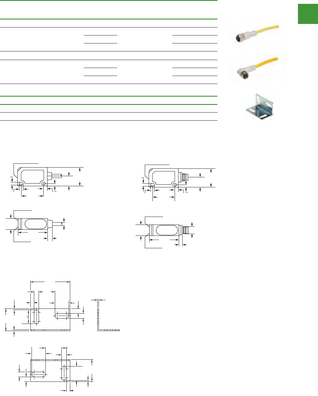
Automation
Power control
304
2015/2016 Product guide AUS15_007 - February 2016
Photoelectric sensors
Standard cables—Nano
Dimensions
Voltage
style
Number of
pins Gauge Length
Pin configuration/
Wire colors
(Face view female shown)
PVC yellow jacket
Item no.
Nano-connector cable, straight female
DC 4-pin,
4-wire 24 AWG
6.0 ft (2m) 1-Brown
2-White
3-Blue
4-Black
CSNS4A4CY2402
16.4 ft (5m) CSNS4A4CY2405
32.8 ft (10m) CSNS4A4CY2410
Nano-connector cable, right angle female
DC 4-pin,
4-wire 24 AWG
6.0 ft (2m) 1-Brown
2-White
3-Blue
4-Black
CSNR4A4CY2402
16.4 ft (5m) CSNR4A4CY2405
32.8 ft (10m) CSNR4A4CY2410
Accessories
Description Item no.
Mounting bracket
L-shaped mounting bracket for NanoView sensors E71-MTB1
V8-T5-32Volume 8—Sensing SolutionsCA08100010E—July 2014 www.eaton.com
5
5
5
5
5
5
5
5
5
5
5
5
5
5
5
5
5
5
5
5
5
5
5
5
5
5
5
5
5
5
5.2
Photoelectric Sensors
NanoView Series Sensors
Dimensions
Approximate Dimensions in Inches (mm)
sledoM rotcennoC-onaN
sledoM elbaC
Accessories
E71-MTB1—Mounting Bracket
Output LED
Adjustment Pot (E71-P/S/C)
Power On LED
Stability LED
0.94
(24.0)
0.17
(4.2)
0.13
(3.2)
0.16
(4.0)
0.10
(2.6)
0.79
(20.0)
0.42
(10.7)
0.47
(12.0)
0.20
(5.0)
ø0.15
(ø3.7)
1.26
(32.0)
0.94
(24.0)
0.17
(4.2)
0.
13
(3.2)
Adjustment Pot (E71-P/S/C)
Power On LED
Stability LED
Output LED
0.16
(4.0)
0.10
(2.6)
0.79
(20.0)
0.42
(10.7)
0.47
(12.0)
1.26
(32.0) 0.15
(3.8)
M8
0.17
(4.2)
0.54
(13.8)
1.34
(34.0)
0.47
(12.0)
0.47
(12.0)
0.04
(1.0)
0.04
(1.0)
0.04
(1.0)
0.17
(4.2)
0.75
(19.0)
0.47
(12.0)
0.54
(13.8) 0.17
(4.2)
0.17
(4.2)
0.75
(19.0)
0.47
(12.0)
0.12
(3.0)
0.12
(3.0)
0.16
(4.0)
0.16
(4.0)
0.04
(1.0)
V8-T5-32Volume 8—Sensing SolutionsCA08100010E—July 2014 www.eaton.com
5
5
5
5
5
5
5
5
5
5
5
5
5
5
5
5
5
5
5
5
5
5
5
5
5
5
5
5
5
5
5.2
Photoelectric Sensors
NanoView Series Sensors
Dimensions
Approximate Dimensions in Inches (mm)
sledoM rotcennoC-onaN
sledoM elbaC
Accessories
E71-MTB1—Mounting Bracket
Output LED
Adjustment Pot (E71-P/S/C)
Power On LED
Stability LED
0.94
(24.0)
0.17
(4.2)
0.
13
(3.2)
0.16
(4.0)
0.10
(2.6)
0.79
(20.0)
0.42
(10.7)
0.47
(12.0)
0.20
(5.0)
ø0.15
(ø3.7)
1.26
(32.0)
0.94
(24.0)
0.17
(4.2)
0.13
(3.2)
Adjustment Pot (E71-P/S/C)
Power On LED
Stability LED
Output LED
0.16
(4.0)
0.10
(2.6)
0.79
(20.0)
0.42
(10.7)
0.47
(12.0)
1.26
(32.0) 0.15
(3.8)
M8
0.17
(4.2)
0.54
(13.8)
1.34
(34.0)
0.47
(12.0)
0.47
(12.0)
0.04
(1.0)
0.04
(1.0)
0.04
(1.0)
0.17
(4.2)
0.75
(
19.0)
0.47
(12.0)
0.54
(13.8) 0.17
(4.2)
0.17
(4.2)
0.75
(19.0)
0.47
(12.0)
0.12
(3.0)
0.12
(3.0)
0.16
(4.0)
0.16
(4.0)
0.04
(1.0)
Volume 8—Sensing Solutions CA08100010E—July 2014 www.eaton.com V8-T5-29
5
5
5
5
5
5
5
5
5
5
5
5
5
5
5
5
5
5
5
5
5
5
5
5
5
5
5
5
5
5
5.2
Photoelectric Sensors
NanoView Series Sensors
Compatible Connector Cables
Standard Cables—Nano 1
Accessories
NanoView Series Sensors
Note
1 For a full selection of connector cables, see Tab 10, section 10.1.
Voltage
Style
Number
of Pins Gauge Length
Pin Configuration/Wire Colors
(Face View Female Shown)
PVC Yellow Jacket
Catalog Number
Nano-Connector Cable, Straight Female
DC 4-pin,
4-wire
24 AWG 6 ft (2m) CSNS4A4CY2402
16.4 ft (5m) CSNS4A4CY2405
32.8 ft (10m) CSNS4A4CY2410
Nano-Connector Cable, Right Angle Female
DC 4-pin,
4-wire
24 AWG 6 ft (2m) CSNR4A4CY2402
16.4 ft (5m) CSNR4A4CY2405
32.8 ft (10m) CSNR4A4CY2410
Description Catalog Number
Mounting Bracket
L-shaped mounting bracket for NanoView sensors E71-MTB1
Dimensions, see Page V8-T5-32.
M8 Nano-Connector,
Straight Female
M8 Nano-Connector,
Right Angle Female
1-Brown
2-White
3-Blue
4-Black
4
31
2
1-Brown
2-White
3-Blue
4-Black
4
31
2
Mounting Bracket
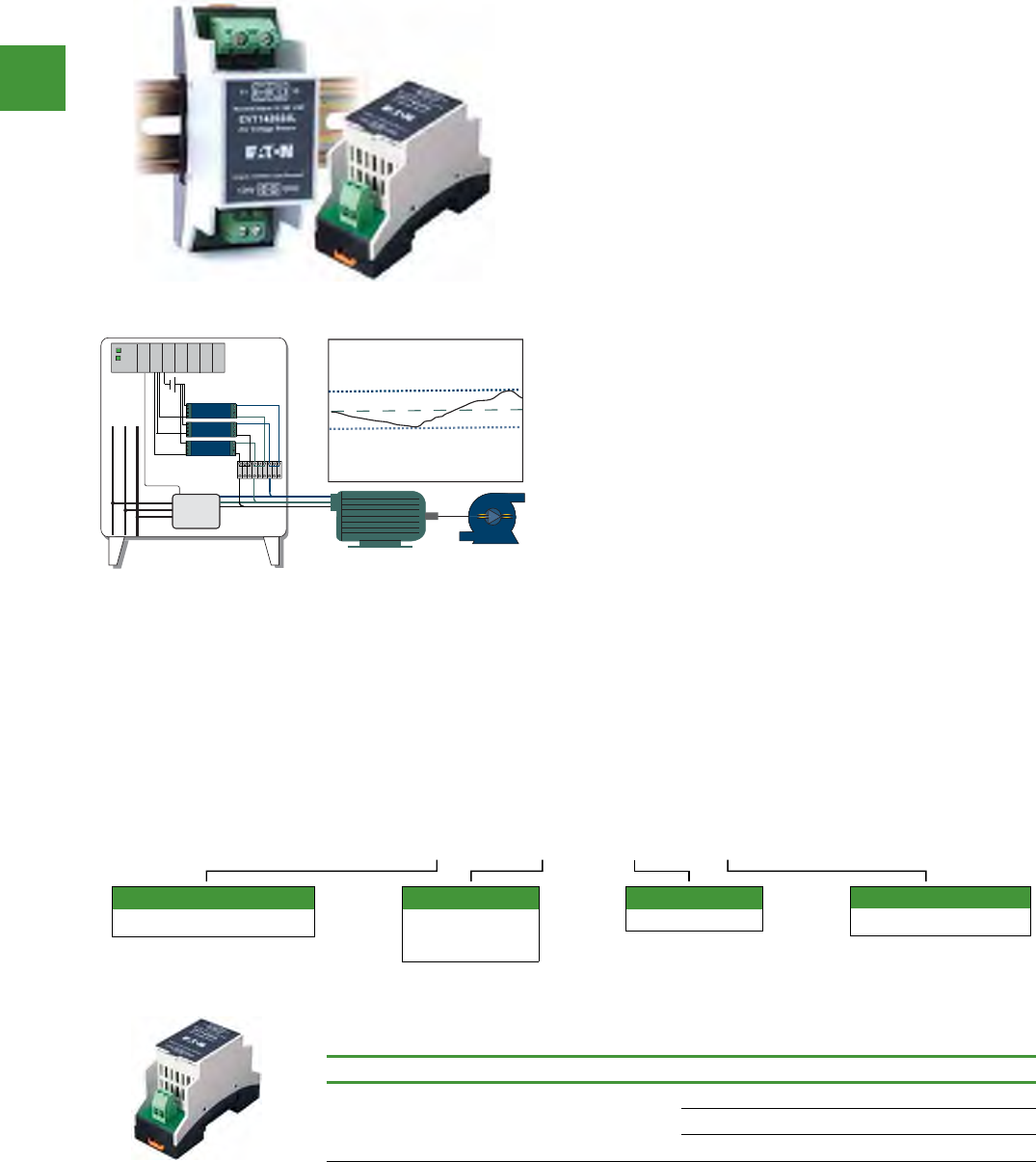
Automation
Power control
305 2015/2016 Product guide AUS15_007 - February 2016
Eaton’s VoltageWatch™ sensor is a high-performance, true RMS
sensor for sensing voltage in single- and threephase installations.
Applicable on nominal circuits of 120V, 240V and 480V, this voltage
sensor provides a fully isolated analog output proportional to rated
nominal voltage in both sinusoidal and non-sinusoidal (variable
frequency) situations. It is housed in a slim, compact, easy-to-install
DIN rail mount enclosure.
Ideal for situations where power quality is of interest or concern,
the VoltageWatch sensor facilitates monitoring of supply voltage
levels, identifying undervoltage or overvoltage conditions, and
helping to protect critical motors and electronics.
Designed with an industry standard 4–20 mA output, VoltageWatch
is easily coupled to a data logger, panel meter or PLC to enable
basic trending of operational status of low voltage circuits up to
real-time monitoring and reporting of supply voltage levels.
Features
• True RMS Output - Allows
for use in situations where
power supplied is non-
sinusoidal, such as VFD
applications, poor power
quality installations or
other electrically harsh/
challenging environments
• Input/Output Isolation -
Input and output circuitry
is electrically isolated for
improved safety
• Standard 4–20 mA Loop
Powered Output - Industry
standard output works
easily and reliably with
existing controllers, data
loggers and SCADA
equipment
• Compact DIN Rail Mount
Enclosure—Space-saving
35 mm wide enclosure
mounts quickly for an
attractive installation
EVT 1 420 24L
Supply voltage
24L = 24V Loop powered
Nominal range
1 = 120V
3 = 240V
4 = 480V
Standard family name
EVT = VoltageWatch sensor
Output type
420 = 4–20 mA
VoltageWatch EVT range
VoltageWatch EVT—top terminal current sensors
Power supply Output signal Nominal voltage Item no.
24 Vdc loop powered 4–20 mA
120 EVT1-420-24L
240 EVT3-420-24L
480 EVT4-420-24L
V8-T7-6 Volume 8—Sensing Solutions CA08100010E—March 2014 www.eaton.com
7
7
7
7
7
7
7
7
7
7
7
7
7
7
7
7
7
7
7
7
7
7
7
7
7
7
7
7
7
7
7.1
Current and Voltage Sensors
VoltageWatch EVT Series
Standards and Certifications
●UL
●CE (Pending)
●RoHS Compliant
DANGER
THIS SENSOR IS NOT A
SAFETY DEVICE AND IS NOT
INTENDED TO BE USED AS A
SAFETY DEVICE. This sensor
is designed only to detect
and read certain data in an
electronic manner and
perform no use apart from
that, specifically no safety-
related use. This sensor
product does not include
self-checking redundant
circuitry, and the failure of
this sensor product could
cause either an energized
or de-energized output
condition, which could result
in death, serious bodily
injury, or property damage.
Catalog Number Selection
VoltageWatch EVT Series—Top Terminal Current Sensors
Product Selection
VoltageWatch EVT Series—Top Terminal Current Sensors
(Pending)
Power Supply Output Signal Nominal Voltage Catalog Number
24 Vdc loop powered 4–20 mA 120 EVT1-420-24L
240 EVT3-420-24L
480 EVT4-420-24L
EVT 1 - 420 - 24L
Standard Family Name
EVT = VoltageWatch sensor
Nominal Range
1 = 120V
3 = 240V
4 = 480V
Output Type
420 = 4–20 mA
Supply Voltage
24L = 24V Loop powered
EVT Series
Volume 8—Sensing Solutions CA08100010E—March 2014 www.eaton.com V8-T7-5
7
7
7
7
7
7
7
7
7
7
7
7
7
7
7
7
7
7
7
7
7
7
7
7
7
7
7
7
7
7
For Customer Service in the U.S. call 1-877-ETN CARE (386-2273),
in Canada call 1-800-268-3578.
For Application Assistance in the U.S. and Canada
call 1-800-426-9184.
7.1
Current and Voltage Sensors
VoltageWatch EVT Series
EVT Series VoltageWatch Voltage Sensors
Contents
Description Page
EVT Series VoltageWatch Voltage Sensors
Standards and Certifications . . . . . . . . . . . . . . V8-T7-6
Catalog Number Selection . . . . . . . . . . . . . . . . V8-T7-6
Product Selection . . . . . . . . . . . . . . . . . . . . . . . V8-T7-6
Technical Data and Specifications . . . . . . . . . . V8-T7-7
Wiring Diagram . . . . . . . . . . . . . . . . . . . . . . . . V8-T7-7
Dimensions . . . . . . . . . . . . . . . . . . . . . . . . . . . V8-T7-7
EVT Series VoltageWatch Voltage Sensors
Product Description
Eaton’s VoltageWatch™
sensor is a high-performance,
true RMS sensor for sensing
voltage in single- and three-
phase installations.
Applicable on nominal circuits
of 120V, 240V and 480V, this
voltage sensor provides a
fully isolated analog output
proportional to rated nominal
voltage in both sinusoidal and
non-sinusoidal (variable
frequency) situations. It is
housed in a slim, compact,
easy-to-install DIN rail mount
enclosure.
Ideal for situations where
power quality is of interest or
concern, the VoltageWatch
sensor facilitates monitoring
of supply voltage levels,
identifying undervoltage or
overvoltage conditions, and
helping to protect critical
motors and electronics.
Designed with an industry-
standard 4–20 mA output,
VoltageWatch is easily
coupled to a data logger,
panel meter or PLC to enable
basic trending of operational
status of low voltage circuits
up to real-time monitoring
and reporting of supply
voltage levels.
Application Description
True RMS Voltage Monitoring
●Detect below normal or
“brown out” voltage
conditions; protect against
possible motor overheating
●Identify phase-loss
conditions by detecting
voltage reduction in one or
more phases of a three-
phase motor
●Monitor overvoltage
conditions associated with
regenerative voltage to
help in diagnosing/avoiding
motor drive issues
●Detect voltage conditions
that may cause stress in or
damage to soft starter
components (SCRs)
For the most current information
on this product, visit our Web site:
www.eaton.com
Example Application—Phase Loss
Features
●True RMS Output—
Allows for use in situations
where power supplied is
non-sinusoidal, such as
VFD applications, poor
power quality installations
or other electrically harsh/
challenging environments
●Standard 4–20 mA Loop
Powered Output—
Industry standard output
works easily and reliably
with existing controllers,
data loggers and SCADA
equipment
●Input/Output Isolation—
Input and output circuitry is
electrically isolated for
improved safety
●Compact DIN Rail Mount
Enclosure—Space-saving
35 mm wide enclosure
mounts quickly for an
attractive installation
PLC
24 Vdc Supply
–+
VTR
VTR
VTR
480 Vac
500 Vac
460 Vac
Zero Vac 4 mA Transducer Output
AC Voltage
Phase to Phase
20 mA Transducer Output
19.36 mA Transducer Output
18.72 mA Transducer Output
Motor
Control
Signal
Motor
Starter
Example application - Phase loop Application description
true RMS voltage monitoring
• Detect below normal
or “brown out” voltage
conditions; protect against
possible motor overheating
• Identify phase-loss
conditions by detecting
voltage reduction in one
or more phases of a
threephase motor
• Monitor overvoltage
conditions associated with
regenerative voltage to
help in diagnosing/avoiding
motor drive issues
• Detect voltage conditions
that may cause stress in
or damage to soft starter
components (SCRs)
Volume 8—Sensing Solutions CA08100010E—March 2014 www.eaton.com V8-T7-5
7
7
7
7
7
7
7
7
7
7
7
7
7
7
7
7
7
7
7
7
7
7
7
7
7
7
7
7
7
7
For Customer Service in the U.S. call 1-877-ETN CARE (386-2273),
in Canada call 1-800-268-3578.
For Application Assistance in the U.S. and Canada
call 1-800-426-9184.
7.1
Current and Voltage Sensors
VoltageWatch EVT Series
EVT Series VoltageWatch Voltage Sensors
Contents
Description Page
EVT Series VoltageWatch Voltage Sensors
Standards and Certifications . . . . . . . . . . . . . . V8-T7-6
Catalog Number Selection . . . . . . . . . . . . . . . . V8-T7-6
Product Selection . . . . . . . . . . . . . . . . . . . . . . . V8-T7-6
Technical Data and Specifications . . . . . . . . . . V8-T7-7
Wiring Diagram . . . . . . . . . . . . . . . . . . . . . . . . V8-T7-7
Dimensions . . . . . . . . . . . . . . . . . . . . . . . . . . . V8-T7-7
EVT Series VoltageWatch Voltage Sensors
Product Description
Eaton’s VoltageWatch™
sensor is a high-performance,
true RMS sensor for sensing
voltage in single- and three-
phase installations.
Applicable on nominal circuits
of 120V, 240V and 480V, this
voltage sensor provides a
fully isolated analog output
proportional to rated nominal
voltage in both sinusoidal and
non-sinusoidal (variable
frequency) situations. It is
housed in a slim, compact,
easy-to-install DIN rail mount
enclosure.
Ideal for situations where
power quality is of interest or
concern, the VoltageWatch
sensor facilitates monitoring
of supply voltage levels,
identifying undervoltage or
overvoltage conditions, and
helping to protect critical
motors and electronics.
Designed with an industry-
standard 4–20 mA output,
VoltageWatch is easily
coupled to a data logger,
panel meter or PLC to enable
basic trending of operational
status of low voltage circuits
up to real-time monitoring
and reporting of supply
voltage levels.
Application Description
True RMS Voltage Monitoring
●Detect below normal or
“brown out” voltage
conditions; protect against
possible motor overheating
●Identify phase-loss
conditions by detecting
voltage reduction in one or
more phases of a three-
phase motor
●Monitor overvoltage
conditions associated with
regenerative voltage to
help in diagnosing/avoiding
motor drive issues
●Detect voltage conditions
that may cause stress in or
damage to soft starter
components (SCRs)
For the most current information
on this product, visit our Web site:
www.eaton.com
Example Application—Phase Loss
Features
●True RMS Output—
Allows for use in situations
where power supplied is
non-sinusoidal, such as
VFD applications, poor
power quality installations
or other electrically harsh/
challenging environments
●Standard 4–20 mA Loop
Powered Output—
Industry standard output
works easily and reliably
with existing controllers,
data loggers and SCADA
equipment
●Input/Output Isolation—
Input and output circuitry is
electrically isolated for
improved safety
●Compact DIN Rail Mount
Enclosure—Space-saving
35 mm wide enclosure
mounts quickly for an
attractive installation
PLC
24 Vdc Supply
–+
VTR
VTR
VTR
480 Vac
500 Vac
460 Vac
Zero Vac 4 mA Transducer Output
AC Voltage
Phase to Phase
20 mA Transducer Output
19.36 mA Transducer Output
18.72 mA Transducer Output
Motor
Control
Signal
Motor
Starter
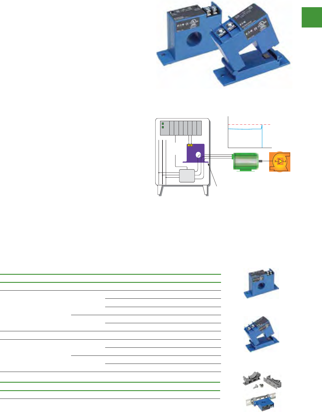
Automation
Power control
306
2015/2016 Product guide AUS15_007 - February 2016
The CurrentWatch™ ECS Series from Eaton’s Electrical Sector is a
family of solidstate adjustable current switches, ideal for providing
status information on electrical equipment. The ECS is excellent for
new installations, where the conductors run through the housing,
requiring no cutting. These switches are also ideal for retrofits, since
split-core models can be opened to fit around existing conductors.
The current switch is accurate, reliable and easy to install.
The ECS can sense continuous currents from 1 to 150A and does
not require any supply voltage, as the power required is induced
from the monitored conductor. The output is a non-polarity-
sensitive solidstate contact for switching AC and DC circuits up
to 240 Vac/dc. This switch also includes an LED indicating two
states: on and below trip point, and above trip point with contacts
energized.
Any change in current can be sensed with the ECS Series. A
change in current may indicate motor failure, belt loss/slippage or
mechanical failure. Any of these events can cause the current to
drop significantly, tripping the switch and notifying the controller.
ECS range CurrentWatch current switches
ECS range CurrentWatch current switches
Power supply Aperture Size Output Signal Setpoint and LED Configuration Item no.
Solid-Core Housing
Self powered
(no external
power needed)
0.74 in (19
mm)
Normally
open
Adjustable 1–150A setpoint with LED ECSNOASC
Fixed 1.0A setpoint no LED ECSNOFSC
Fixed 5.5A setpoint no LED ECSNOFSCY1
Normally
closed
Adjustable 1–150A setpoint with LED ECSNCASC
Fixed 1.0A setpoint no LED ECSNCFSC
Split-Core Housing
Self powered
(no external
power needed)
0.85 in (21.6
mm)
Normally
open
Adjustable 1.75–150A setpoint with LED ECSNOASP
Fixed 1.5A setpoint no LED ECSNOFSP
Normally
closed
Adjustable 1.75–150A setpoint with LED ECSNCASP
Fixed 1.5A setpoint no LED ECSNCFSP
Features
• Universal Outputs - NO or
NC solid-state switch for
control circuits up to 240
Vac/dc, compatible with
most automation systems
• Self-Powered - Cuts
installation and operating
costs
• Easily Adjustable Setpoint
- Increases application
flexibly and speeds start-up
• Solid- or Split-Core
Housings - Versions tailored
for each type of installation
• LED Indication - Provides
quick visual indication of
contact status
• Built-In Mounting Feet -
Simple, two-screw panel
mount or attach with
optional DIN-rail mounting
kit accessory
Application description
typical applications
• Electronic Proof of
Flow - Current operated
switches eliminate the
need for multiple pipe
or duct penetrations
and are more reliable
than electromechanical
pressure or flow switches
• Conveyors - Detect jams
and overloads
• Lighting Circuits - Easier to
install and more accurate
than photocells
• Fans, Pumps and Heating
Elements - Faster
response than temperature
sensors
• Critical Motors
• Ancillary Equipment
Accessories
Description Item no.
DIN rail mounting kit EDINKIT
V8-T7-8 Volume 8—Sensing Solutions CA08100010E—March 2014 www.eaton.com
7
7
7
7
7
7
7
7
7
7
7
7
7
7
7
7
7
7
7
7
7
7
7
7
7
7
7
7
7
7
For Customer Service in the U.S. call 1-877-ETN CARE (386-2273),
in Canada call 1-800-268-3578.
For Application Assistance in the U.S. and Canada
call 1-800-426-9184.
7.2
Current and Voltage Sensors
CurrentWatch ECS Series
ECS Series CurrentWatch Current Switches
Contents
Description Page
ECS Series CurrentWatch Current Switches
Standards and Certifications . . . . . . . . . . . . . . . V8-T7-9
Product Selection . . . . . . . . . . . . . . . . . . . . . . . V8-T7-9
Accessories . . . . . . . . . . . . . . . . . . . . . . . . . . . V8-T7-9
Technical Data and Specifications . . . . . . . . . . V8-T7-10
Wiring Diagram . . . . . . . . . . . . . . . . . . . . . . . . V8-T7-10
Dimensions . . . . . . . . . . . . . . . . . . . . . . . . . . . V8-T7-10
ECS Series CurrentWatch Current Switches
Product Description
The CurrentWatch™ ECS
Series from Eaton’s Electrical
Sector is a family of solid-
state adjustable current
switches, ideal for providing
status information on
electrical equipment. The
ECS is excellent for new
installations, where the
conductors run through the
housing, requiring no cutting.
These switches are also ideal
for retrofits, since split-core
models can be opened to fit
around existing conductors.
The current switch is
accurate, reliable and easy
to install.
The ECS can sense
continuous currents from
1 to 150A and does not
require any supply voltage,
as the power required is
induced from the monitored
conductor. The output is a
non-polarity-sensitive solid-
state contact for switching
AC and DC circuits up to
240 Vac/dc. This switch also
includes an LED indicating
two states: on and below trip
point, and above trip point
with contacts energized. All
ECS Series switches carry an
unconditional five-year
warranty.
Any change in current can be
sensed with the ECS Series.
A change in current may
indicate motor failure, belt
loss/slippage or mechanical
failure. Any of these events
can cause the current to drop
significantly, tripping the
switch and notifying the
controller.
Application Description
Typical Applications
●Electronic Proof of
Flow—Current operated
switches eliminate the
need for multiple pipe or
duct penetrations and are
more reliable than electro-
mechanical pressure or
flow switches
●Conveyors—Detect jams
and overloads
●Lighting Circuits—Easier
to install and more
accurate than photocells
●Fans, Pumps and Heating
Elements—Faster
response than temperature
sensors
●Critical Motors
●Ancillary Equipment
For the most current information
on this product, visit our Web site:
www.eaton.com
Example Application—
Pump Jam and Suction Loss Protection
Features
●Universal Outputs—NO
or NC solid-state switch for
control circuits up to 240
Vac/dc, compatible with
most automation systems
●Self-Powered—Cuts
installation and operating
costs
●Easily Adjustable
Setpoint—Increases
application flexibly and
speeds start-up
●Solid- or Split-Core
Housings—Versions
tailored for each type of
installation
●LED Indication—Provides
quick visual indication of
contact status
●Built-In Mounting Feet—
Simple, two-screw panel
mount or attach with
optional DIN-rail mounting
kit accessory
Jam
AMPS
Overload Setpoint
Current Switch
Motor
Starter
Digital
Input
PLC
B/I Card
Motor
Off
Normal Operation
Time
Motor
Control
Signal
Example application - Pump jam and suction loss protection
Volume 8—Sensing Solutions CA08100010E—March 2014 www.eaton.com V8-T7-9
7
7
7
7
7
7
7
7
7
7
7
7
7
7
7
7
7
7
7
7
7
7
7
7
7
7
7
7
7
7
7.2
Current and Voltage Sensors
CurrentWatch ECS Series
Standards and Certifications
●UL Listed
●cUL Listed
●CE Certified
DANGER
THIS SENSOR IS NOT A
SAFETY DEVICE AND IS NOT
INTENDED TO BE USED AS A
SAFETY DEVICE. This sensor
is designed only to detect
and read certain data in an
electronic manner and
perform no use apart from
that, specifically no safety-
related use. This sensor
product does not include
self-checking redundant
circuitry, and the failure of
this sensor product could
cause either an energized
or de-energized output
condition, which could result
in death, serious bodily
injury, or property damage.
Product Selection
ECS Series CurrentWatch Current Switches
Top Terminal Current Switches
Accessories
ECS Series CurrentWatch
Current Switches
Note
1 Sensor pictured for reference and not included in kit.
Power Supply Aperture Size Output Signal Setpoint and LED Configuration Catalog Number
Solid-Core Housing
Self powered
(no external power needed)
0.74 in (19 mm) Normally open Adjustable 1–150A setpoint with LED ECSNOASC
Fixed 1.0A setpoint no LED ECSNOFSC
Fixed 5.5A setpoint no LED ECSNOFSCY1
Normally closed Adjustable 1–150A setpoint with LED ECSNCASC
Fixed 1.0A setpoint no LED ECSNCFSC
Split-Core Housing
Self powered
(no external power needed)
0.85 in (21.6 mm) Normally open Adjustable 1.75–150A setpoint with LED ECSNOASP
Fixed 1.5A setpoint no LED ECSNOFSP
Normally closed Adjustable 1.75–150A setpoint with LED ECSNCASP
Fixed 1.5A setpoint no LED ECSNCFSP
Description Catalog Number
DIN rail mounting kit 1EDINKIT
Solid-Core Housing
Split-Core Housing
DIN Rail
Mounting Kit
V8-T7-8 Volume 8—Sensing Solutions CA08100010E—March 2014 www.eaton.com
7
7
7
7
7
7
7
7
7
7
7
7
7
7
7
7
7
7
7
7
7
7
7
7
7
7
7
7
7
7
For Customer Service in the U.S. call 1-877-ETN CARE (386-2273),
in Canada call 1-800-268-3578.
For Application Assistance in the U.S. and Canada
call 1-800-426-9184.
7.2
Current and Voltage Sensors
CurrentWatch ECS Series
ECS Series CurrentWatch Current Switches
Contents
Description Page
ECS Series CurrentWatch Current Switches
Standards and Certifications . . . . . . . . . . . . . . . V8-T7-9
Product Selection . . . . . . . . . . . . . . . . . . . . . . . V8-T7-9
Accessories . . . . . . . . . . . . . . . . . . . . . . . . . . . V8-T7-9
Technical Data and Specifications . . . . . . . . . . V8-T7-10
Wiring Diagram . . . . . . . . . . . . . . . . . . . . . . . . V8-T7-10
Dimensions . . . . . . . . . . . . . . . . . . . . . . . . . . . V8-T7-10
ECS Series CurrentWatch Current Switches
Product Description
The CurrentWatch™ ECS
Series from Eaton’s Electrical
Sector is a family of solid-
state adjustable current
switches, ideal for providing
status information on
electrical equipment. The
ECS is excellent for new
installations, where the
conductors run through the
housing, requiring no cutting.
These switches are also ideal
for retrofits, since split-core
models can be opened to fit
around existing conductors.
The current switch is
accurate, reliable and easy
to install.
The ECS can sense
continuous currents from
1 to 150A and does not
require any supply voltage,
as the power required is
induced from the monitored
conductor. The output is a
non-polarity-sensitive solid-
state contact for switching
AC and DC circuits up to
240 Vac/dc. This switch also
includes an LED indicating
two states: on and below trip
point, and above trip point
with contacts energized. All
ECS Series switches carry an
unconditional five-year
warranty.
Any change in current can be
sensed with the ECS Series.
A change in current may
indicate motor failure, belt
loss/slippage or mechanical
failure. Any of these events
can cause the current to drop
significantly, tripping the
switch and notifying the
controller.
Application Description
Typical Applications
●Electronic Proof of
Flow—Current operated
switches eliminate the
need for multiple pipe or
duct penetrations and are
more reliable than electro-
mechanical pressure or
flow switches
●Conveyors—Detect jams
and overloads
●Lighting Circuits—Easier
to install and more
accurate than photocells
●Fans, Pumps and Heating
Elements—Faster
response than temperature
sensors
●Critical Motors
●Ancillary Equipment
For the most current information
on this product, visit our Web site:
www.eaton.com
Example Application—
Pump Jam and Suction Loss Protection
Features
●Universal Outputs—NO
or NC solid-state switch for
control circuits up to 240
Vac/dc, compatible with
most automation systems
●Self-Powered—Cuts
installation and operating
costs
●Easily Adjustable
Setpoint—Increases
application flexibly and
speeds start-up
●Solid- or Split-Core
Housings—Versions
tailored for each type of
installation
●LED Indication—Provides
quick visual indication of
contact status
●Built-In Mounting Feet—
Simple, two-screw panel
mount or attach with
optional DIN-rail mounting
kit accessory
Jam
AMPS
Overload Setpoint
Current Switch
Motor
Starter
Digital
Input
PLC
B/I Card
Motor
Off
Normal Operation
Time
Motor
Control
Signal
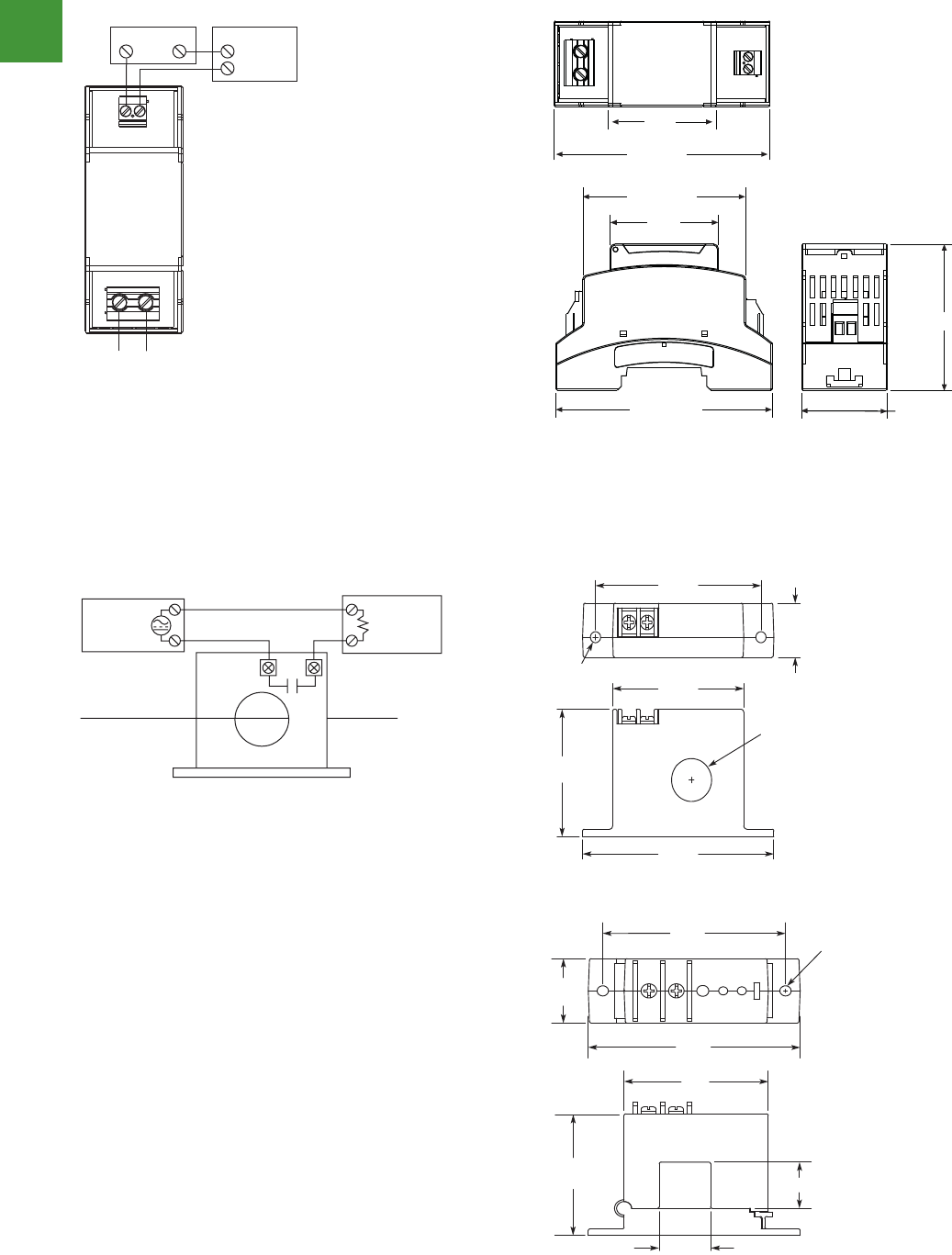
Automation
Power control
307 2015/2016 Product guide AUS15_007 - February 2016
Volume 8—Sensing Solutions CA08100010E—March 2014 www.eaton.com V8-T7-7
7
7
7
7
7
7
7
7
7
7
7
7
7
7
7
7
7
7
7
7
7
7
7
7
7
7
7
7
7
7
7.1
Current and Voltage Sensors
VoltageWatch EVT Series
Technical Da ations
VoltageWatch EVT Series
Wiring Diagram
VoltageWatch EVT
Dimensions
Approximate Dimensions in Inches (mm)
Complete unit
Description Speci cation
Power supply 24 Vdc loop-powered
Input 120V, 240V, 480V
Input over-range +15% of nominal range
Output 4–20 mA proportional; capped at 24 mA maximum
Response time 250 ms (to 90% value)
Accuracy <1%
Linearity <0.5%
Loading <500 ohms
Isolation voltage 2500 Vac
Frequency range 40 Hz–5 kHz
Operating temperature –22° to 140°F (–30° to 60°C)
Mounting DIN rail compatible
Case UL 94 V0 ammability rated; noncorrosive therm
Environmental 14° to 122°F (–10° to 50°C), 0–95% RH noncondens
EMC/immunity EN50081-1, EN50082-2
Ripple <1% (peak to peak)
Listings UL/cUL and CE pending
+
-
(–)(+)
24 Vdc Power
(+)
(–)
Load
Controller
Meter, etc.
Output
Line Voltage
(120, 240, 480)
2.66 (67.6)
3.53 (89.7) 1.40 (35.6)
2.39 (60.7)
1.77
(45.0)
2.66 (67.6)
1.77
(45.0)
Dimensions (approximate dimensions in inches (mm)
Dimensions (approximate dimensions in inches (mm)
Wiring diagram
Wiring diagram
V8-T7-10 Volume 8—Sensing Solutions CA08100010E—March 2014 www.eaton.com
7
7
7
7
7
7
7
7
7
7
7
7
7
7
7
7
7
7
7
7
7
7
7
7
7
7
7
7
7
7.2
Current and Voltage Sensors
CurrentWatch ECS Series
Technical Da ations
ECS Series CurrentWatch Current Switches
Wiring Diagram
ECS CurrentWatch current switches
Normally open (NO) models shown
Dimensions
Approximate Dimensions in Inches (mm)
gnisuoh eroc tilpS
gnisuoh eroc-diloS
Description Speci cation
Power supply Self-powered—no power supply needed
Output Magnetically isolated solid-state switch
Output rating NO version: 0.15A at 240 Vac/dc
NC version: 0.2A at 135 Vac/dc
Models ending Y1: 5.0A, 125 Vac, 30 Vdc
O-state leakage <10 µA
Response time 120 ms
Setpoint range Solid-core housings: 1–150A
Split-core housings: 1.75–150A
Hysteresis 5% of setpoint
Description Speci cation
Overload Fixed setpoint, NO models: 6 sec. at 500A; 1 sec. at 1000A
All other models: 6 sec. at 400A; 1 sec. at 1000A
Maximum continuous Amps: 250A
Isolation voltage UL listed to 1270 Vac, tested to 5000 Vac
Frequency range 6–100 Hz
Sensing aperture Solid-core housings: 0.74 in (19 mm)
Split-core housings: 0.85 in (21.6 mm)
Housing UL94 V0 mmability rated
Environmental Operating temperature: –58° to 122°F (–50° to 50°C)
Humidity: 0–95% RH, non-condensing
AC or DC
Power
AC or DC
Load
Monitored Wire
Current Switch
3.50
(88.9)
3.03
(77.0)
0.93
(23.6)
0.19 Dia.
(4.8) 2.40
(61.0)
2.18
(55.4)
0.74 Dia.
(19)
0.85 (21.6)
0.85 (21.6)
3.53
(89.7)
2.40
(61)
3.04
(77.2)
0.19 Dia.
(4.8)
2.25
(57.2)
1.19
(30.2)
V8-T7-10 Volume 8—Sensing Solutions CA08100010E—March 2014 www.eaton.com
7
7
7
7
7
7
7
7
7
7
7
7
7
7
7
7
7
7
7
7
7
7
7
7
7
7
7
7
7
7.2
Current and Voltage Sensors
CurrentWatch ECS Series
Technical Da ations
ECS Series CurrentWatch Current Switches
Wiring Diagram
ECS CurrentWatch current switches
Normally open (NO) models shown
Dimensions
Approximate Dimensions in Inches (mm)
gnisuoh eroc tilpSgnisuoh eroc-diloS
Description Speci cation
Power supply Self-powered—no power supply needed
Output Magnetically isolated solid-state switch
Output rating NO version: 0.15A at 240 Vac/dc
NC version: 0.2A at 135 Vac/dc
Models ending Y1: 5.0A, 125 Vac, 30 Vdc
O-state leakage <10 µA
Response time 120 ms
Setpoint range Solid-core housings: 1–150A
Split-core housings: 1.75–150A
Hysteresis 5% of setpoint
Description Speci cation
Overload Fixed setpoint, NO models: 6 sec. at 500A; 1 sec. at 1000A
All other models: 6 sec. at 400A; 1 sec. at 1000A
Maximum continuous Amps: 250A
Isolation voltage UL listed to 1270 Vac, tested to 5000 Vac
Frequency range 6–100 Hz
Sensing aperture Solid-core housings: 0.74 in (19 mm)
Split-core housings: 0.85 in (21.6 mm)
Housing UL94 V0 mmability rated
Environmental Operating temperature: –58° to 122°F (–50° to 50°C)
Humidity: 0–95% RH, non-condensing
AC or DC
Power
AC or DC
Load
Monitored Wire
Current Switch
3.50
(88.9)
3.03
(77.0)
0.93
(23.6)
0.19 Dia.
(4.8) 2.40
(61.0)
2.18
(55.4)
0.74 Dia.
(19)
0.85 (21.6)
0.85 (21.6)
3.53
(89.7)
2.40
(61)
3.04
(77.2)
0.19 Dia.
(4.8)
2.25
(57.2)
1.19
(30.2)
VoltageWatch EVT range
ECS range CurrentWatch current switches
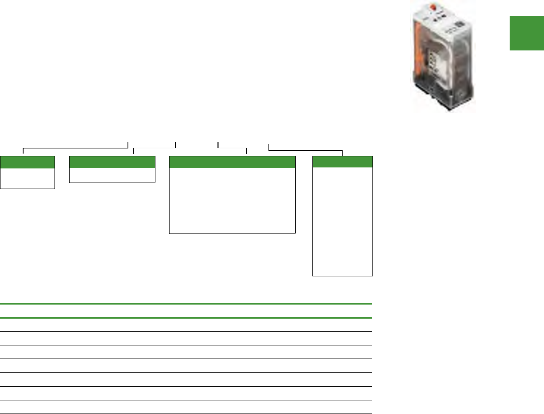
Automation
Power control
308
2015/2016 Product guide AUS15_007 - February 2016
Plug-in relays – D1 range
Eaton D1RF 1-pole relays
• The contact operation can be easily checked
by Push-to-Test button
• Flag indicator shows relay status in manual
or powered condition
• LED status lamp shows coil ON or
OFF status— ideal for use in low light
applications
• Push-to-Test button allows for manual
operation of relay without the need for coil
power
• Lock-down door holds pushbutton and
contacts in the operate position when
activated
• Finger-grip cover allows operator to remove
relays from sockets easily
• ID tag/write label to identify relays in
multiple relay circuits
• Bipolar LED allows for reverse polarity
applications
Eaton D1RF1 1-pole relays
Description Voltage Item no.
Relay 20A 24V DC 1 Pole 24V DC D1RF1T1
Relay 20A 24V AC 1 Pole 24V AC D1RF1T
Relay 20A 240V AC 1 Pole 240V AC D1RF1B
Relay 20A 110V AC 1 Pole 110V AC D1RF1A
Relay 20A 110V DC 1 Pole 110V DC D1RF1A1
1-pole base D1 relay DIN mount D1RAA
Hold down clip PMC-1781
D 1 R F 1 A A
Coil voltage
A = 120 Vac
A1 = 110 Vdc
B = 240 Vac
P = 6 Vac
P1 = 6 Vdc
R= 12Vac
R1 = 12 Vdc
T = 24 Vac
T1 = 24 Vdc
W = 48 Vac
W1 = 48 Vdc
Contact configuration
1 = SPDT
Family type
D1RF
D1AR
Standard features
Blank = Mechanical flag indicator
(only with D1RR)
A = LED test button, flag indicator,
lock-down door, finger-grip cover,
ID tag (only with D1RR)
1 = LED and mechanical flag
indicator
Volume 7—Logic Control, Operator Interface and Connectivity Solutions CA08100008E—February 2014 www.eaton.com V7-T3-53
3
3
3
3
3
3
3
3
3
3
3
3
3
3
3
3
3
3
3
3
3
3
3
3
3
3
3
3
3
3
Volume 7—Logic Control, Operator Interface and Connectivity Solutions CA08100008E—February 2014 www.eaton.com V7-T3-53
3
3
3
3
3
3
3
3
3
3
3
3
3
3
3
3
3
3
3
3
3
3
3
3
3
3
3
3
3
3
3.4
Control Relays and Timers
General Purpose Plug-In Relays
D1 Series Relay
Contents
Description Page
D1PR/D1PF Series
Product Selection . . . . . . . . . . . . . . . . . . . . . . . V7-T3-54
Accessories . . . . . . . . . . . . . . . . . . . . . . . . . . . . V7-T3-55
Technical Data and Specifications . . . . . . . . . . . V7-T3-56
Wiring Diagram . . . . . . . . . . . . . . . . . . . . . . . . . V7-T3-57
Dimensions . . . . . . . . . . . . . . . . . . . . . . . . . . . . V7-T3-57
D2PR/D2PF Series . . . . . . . . . . . . . . . . . . . . . . . . . V7-T3-58
D3PR/D3PF Series . . . . . . . . . . . . . . . . . . . . . . . . . V7-T3-68
D4 Series . . . . . . . . . . . . . . . . . . . . . . . . . . . . . . . . V7-T3-78
D5PR/D5PF Series . . . . . . . . . . . . . . . . . . . . . . . . . V7-T3-82
D7PR/D7PF Series . . . . . . . . . . . . . . . . . . . . . . . . . V7-T3-91
D8 Series . . . . . . . . . . . . . . . . . . . . . . . . . . . . . . . . V7-T3-106
D9 Series . . . . . . . . . . . . . . . . . . . . . . . . . . . . . . . . V7-T3-112
Accessories . . . . . . . . . . . . . . . . . . . . . . . . . . . . . . V7-T3-116
D1PR/D1PF Series
Product Description
The D1 Series of relay
provides a compact single-
pole relay capable of handling
20A. Multiple feature and
voltage options allow for the
perfect fit for any application.
Features
D1PR
●Compact relay capable of
breaking relatively large
load currents
●Panel and DIN rail
mounting
D1PF
●The contact operation
can be easily checked by
Push-to-Test button
●Flag indicator shows relay
status in manual or
powered condition
●LED status lamp shows
coil ON or OFF status—
ideal for use in low light
applications
●Push-to-Test button allows
for manual operation of
relay without the need for
coil power
●Lock-down door holds
pushbutton and contacts in
the operate position when
activated
●Finger-grip cover allows
operator to remove relays
from sockets easily
●ID tag/write label to
identify relays in multiple-
relay circuits
●Bipolar LED allows for
reverse polarity
applications
Standards and Certifications
When used with
accompanying Eaton
screw terminal socket.
Catalog Number Selection
D1PR/D1PF Series
UL Listed
D 1 P F 1 A A
Family Type
D1PF
D1PR
Contact Configuration
1 = SPDT
Standard Features
Blank = Mechanical flag indicator
(only with D1PR)
A = LED test button, flag indicator,
lock-down door, finger-grip cover,
ID tag (only with D1PF)
1 = LED and mechanical flag indicator
Coil Voltage
A = 120 Vac
A1 = 110 Vdc
B = 240 Vac
P = 6 Vac
P1 = 6 Vdc
R = 12 Vac
R1 = 12 Vdc
T = 24 Vac
T1 = 24 Vdc
W = 48 Vac
W1 = 48 Vdc

Automation
Power control
309 2015/2016 Product guide AUS15_007 - February 2016
Description Voltage Item no.
Relay 10A 24V DC 4 Pole 24V DC D2RF4T1
Relay 10A 24V AC 4 Pole 24V AC D2RF4T
Relay 10A 240V AC 4 Pole 240V AC D2RF4B
Relay 10A 110V AC 4 Pole 110V AC D2RF4A
Relay 10A 110V DC 4 Pole 110V DC D2RF4A1
4-pole base D2 relay DIN mount D2PA7
Hold down clip PQC-1782
Eaton D2RF2 2 pole relays
• Flag indicator shows relay status in manual or
powered condition
• Bi-polar LED status lamp allows for reverse
polarity applications
• LED status lamp shows coil “ON” or “OFF”
status — ideal for use in low light applications
• Shows coil ON or OFF status
• Colour coded pushbutton identifies AC coils
with red or DC coils with blue pushbuttons
• Allows for manual operation of relay without
the need for coil power
• Ideal for field service personnel to test control
circuits
• Lock down door, when activated, holds
pushbutton & contacts in the operate position
• Excellent for analysing circuit problems
• Finger-grip cover allows operator to remove
relays from sockets more easily than
conventional relays
• White plastic I.D. tag/write label used for
identification of relays in multi-relay circuits
Plug-in relays – D2 range
Description Voltage Item no.
Relay 10A 24V DC 2 Pole 24V DC D2RF2T1
Relay 10A 24V AC 2 Pole 24V AC D2RF2T
Relay 10A 240V AC 2 Pole 240V AC D2RF2B
Relay 10A 110V AC 2 Pole 110V AC D2RF2A
Relay 10A 110V DC 2 Pole 110V DC D2RF2A1
2-pole base D2 relay DIN mount D2PAL
Hold down clip PQC-1782
Eaton D2RF4 4 pole relays
• Flag indicator shows relay status in manual
or powered condition
• LED status lamp shows coil “ON” or “OFF”
status — ideal for use in low light applications
• Push-to-test button allows for manual
operation of relay without the need for coil
power
• Lock-down door holds pushbutton & contacts
in the operate position when activated
• Finger-grip cover allows operator to remove
relays from sockets easily
• I.D. tag/write label to identify relays in
multiple-relay circuits
• Bi-polar LED allows for reverse polarity
applications
For deciphering Item Numbers. Do not use for ordering as not
all combinations are readily available.
D 2 R F 2 A A
Coil voltage
A = 120V ac
A1 = 110V dc
B = 240V ac
P = 6V ac
P1 = 6V dc
R = 12V ac
R1 = 12V dc
T = 24V ac
T1 = 24V dc
W1 = 48V dc
Contact configuration
2 = DPDT
4 = 4PDT
5 = DPDT latching
Family type
D2RF
D2RR
Standard features
Blank = Plain cover (only with
D2RR)
A = LED test button, flag indicator,
lock-down door, finger-grip cover,
ID tag (only with D2RF)
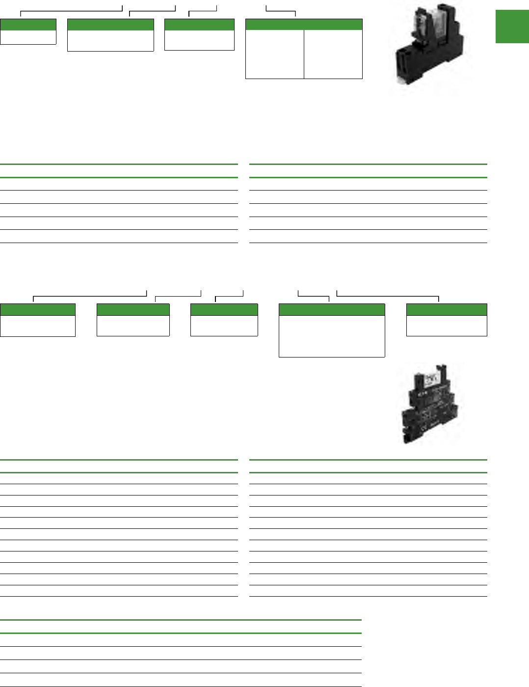
Automation
Power control
310
2015/2016 Product guide AUS15_007 - February 2016
Eaton D4PR1 single pole slimline flat pin relay D4PR2 double pole slimline flat pin relay
Description Voltage Item no. Description Voltage Item no.
Relay 10 Amps 24V DC 1 Pole 24V DC D4PR11T1 Relay 5 Amps 24V DC 2 Pole 24V DC D4PR21T1
Relay 10 Amps 24V AC 1 Pole 24V AC D4PR11T Relay 5 Amps 24V AC 2 Pole 24V AC D4PR21T
Relay 10 Amps 240V AC 1 Pole 240V AC D4PR11B Relay 5 Amps 120V AC 2 Pole 120V AC D4PR21A
Relay 10 Amps 120V AC 1 Pole 120V AC D4PR11A Relay 5 Amps 240V AC 2 Pole 240V AC D4PR21B
Single Pole Base -D4PA1 Double Pole Base -D4PA2
Plug-in relays – D4 range
Interface relays – XR range
For deciphering Item Numbers. Do not use for ordering as not
all combinations are readily available.
D 4 P R 1 1 A
Coil voltage
A = 120Vac
A1 = 110Vdc
B = 240Vac
P = 6Vac
P1 = 6Vdc
R = 12Vac
R1 = 12Vdc
T = 24Vac
T1 = 24Vdc
W1= 48Vdc
Contact configuration
1 = SPDT
2 = DPDT
Family type
D4PR
Options
Blank = Plain cover
1 = Indicating light
D4PR1, D4PR2 single & double pole slimline flat pin relay
• Slim-styled power relay
• Socket has built-in hold-down clip
• Panel or DIN rail mounting
XR U 1 D12 G
Type
XR = XR Terminal
Block Relay
Connection type
U = Screw
P = Spring-Cage
Number of poles
1 = 1 PDT
2 = 2 PDT
Gold plated contacts
G = Yes
Blank = No
Coil voltage
D12 = 12V dc
D120U = 120V ac / 110V dc
D24 = 24V dc
D230U = 23Vac / dc
Description Item no. Description Item no.
XR Relay, 1P, 6A, 12VDC, screw conn XRU1D12 XR Relay, 1P, 6A, 12VDC, spring-cage XRP1D12
XR Relay, 1P, 6A, 120VAC/110VDC, screw conn XRU1D120U XR Relay, 1P, 6A, 120VAC/110VDC, spring-cage XRP1D120U
XR Relay, 1P, 6A, 230VAC/220VDC, screw conn XRU1D230U XR Relay, 1P, 6A, 230VAC/220VDC, spring-cage XRP1D230U
XR Relay, 1P, 6A, 24VDC, screw conn XRU1D24 XR Relay, 1P, 6A, 24VDC, spring-cage XRP1D24
XR Relay, 1P, 6A, 24VAC/DC, screw conn XRU1D24U XR Relay, 1P, 6A, 24VAC/DC, spring-cage XRP1D24U
XR Relay, 2P, 6A, 12VDC, screw conn XRU2D12 XR Relay, 2P, 6A, 230VAC/220VDC, spring-cage XRP2D230U
XR Relay, 2P, 6A, 120VAC/110VDC, screw conn XRU2D120U XR Relay, 1P, 10A, 12VDC, screw conn XRU1H12
XR Relay, 2P, 6A, 230VAC/220VDC, screw conn XRU2D230U XR Relay, 1P, 10A, 120VAC/110VDC, screw conn XRU1H120U
XR Relay, 2P, 6A, 24VDC, screw conn XRU2D24 XR Relay, 1P, 10A, 230VAC/220VDC, screw conn XRU1H230U
XR Relay, 2P, 6A, 24VAC/DC, screw conn XRU2D24U XR Relay, 1P, 10A, 24VDC, screw conn XRU1H24
XR Terminal block interface relays
• 6mm wide (1P), 14mm wide (2P) relay screw
connection or spring-cage
• Plug-in jumpers or bridges available
• SPDT or DPDT contacts rated 6A
• DIN rail mount, LED indication
• Field-replaceable pluggable miniature relay
• 12VDC to 110VDC/120VAC available
• 10A High current series in SPDT
Accessories
Description Item no.
2-position snap-in Jumper, grey XRAFBST2GY
80-position snap-in Jumper, grey XRAFBST500GY
Power Terminal Block XRAPLCESK
End Cover XRAATPBK
Automation
Power control
311 2015/2016 Product guide AUS15_007 - February 2016
EMR measuring & monitoring relays
Current, phase, sequence relays, phase imbalance monitoring
Description
Current
measuring
range, I ~ /I
= A
Circuit symbol Supply
voltage Item no.
Current monitoring relays EMR4-I…, single-phase
• Switching hysteresis
adjustable from 3 - 30 %
• Response delay 0.1 - 30 s
• Monitoring of one upper or
lower limit
• Extension of the
measurement range possible
with current transformers
3 – 30 mA
10 – 100 mA
0.1 – 1 A
24 - 240 V AC,
50/60 Hz
24 - 240 V DC
EMR4-I1-2-A
0.3 – 1.5 A
1 – 5 A
3 – 15 A
24 - 240 V AC,
50/60 Hz
24 - 240 V DC
EMR4-I15-2-A
0.3 – 1.5 A
1 – 5 A
3 – 15 A
24 - 240 V AC,
50/60 Hz
24 - 240 V DC
EMR4-I15-2-B
Description
Monitoring
voltage per
phase,UN
V AC
Circuit symbol Supply
voltage Item no.
EMR4-F… phase sequence relay
• Monitors three-phase
systems for phase sequence
and phase failure (< 0.6 x Ue)
• Supply voltage connection =
monitored voltage
200 - 500 V AC,
50/60 Hz
200 - 500 V AC,
50/60 Hz EMR4-F500-2
Description Threshold
value Circuit symbol Supply
voltage Item no.
EMR5-A... phase imbalance monitoring relays
Power supply from measuring circuit
Three-phase monitoring
• Phase sequence
• Phase failure
• Asymmetry
• Imbalance threshold values
adjustable 2 - 25 % of mean
value of phase voltages
• On-delay: None = 0 or
adjustable from 0.1 to 30 s
Imbalance =
2 - 25 % of
phase voltage
mean value
160 - 300 V
AC,
50/60 Hz
EMR5-A300-1-C
Power supply from measuring circuit
Three-phase monitoring
• Phase sequence
• Phase failure
• Asymmetry
• Imbalance threshold values
adjustable
• On-delay: None = 0 or
adjustable from 0.1 to 30 s
Imbalance =
2 - 25 % of
phase voltage
mean value
300 - 500 V
AC,
50/60 Hz
EMR5-A400-1
Description Response
sensitivity Circuit symbol Supply
voltage Item no.
Liquid level monitoring relays EMR4-N…
• Fill level monitoring of
conductive liquids
• Mixture ratio monitoring of
conductive liquids
• Selectable dry-running or
overflow protection
5kΩ-100kΩ
220 - 240 V
AC,
50/60 Hz
EMR4-N100-1-B
• Fill level monitoring of
conductive liquids
• Mixture ratio monitoring of
conductive liquids
• Selectable on-delay or off-
delay between 0.5 - 10 s
250Ω-500kΩ
24 - 240 V AC,
50/60 Hz
24 - 240 V DC
EMR4-N500-2-A
250Ω-500kΩ
220 - 240 V
AC,
50/60 Hz
EMR5-N80-1-B
Liquid level monitoring relays EMR5N...
• Fill level monitoring of
conductive liquids
• Conductivity (mixture ratio)
monitoring of conductive
liquids
5kΩ-100kΩ
220 - 240 V
AC,
50/60 Hz
EMR5-N80-1-B
11/16 Electronic relays
Measuring and monitoring relays
2010 CA08103002Z-EN www.eaton.com
EMR
EMRMeasuring and monitoring relays
Ordering
Current
measurement
range
Contact sequences Supply voltage
connection Part no.
Article no. Price
See price list
Std. pack
I∼/I=
A
Current monitoring relays EMR4-I…, single-phase
Load limit curves → Page 11/21
Circuit and contact sequence diagrams → Instructional leaflet (AWA) under www.moeller.net/support
• Switching hysteresis adjustable
from 3 - 30 %
• Response delay 0.1 - 30 s
• Monitoring of one upper or lower
limit
• Extension of the measurement
range possible with current
transformers
3 - 30 mA
10 - 100 mA
0.1 - 1 A
24 - 240 V AC,
50/60 Hz
24 - 240 V DC
EMR4-I1-1-A
106942
1 off
0.3 - 1.5 A
1 - 5 A
3 - 15 A
24 - 240 V AC,
50/60 Hz
24 - 240 V DC
EMR4-I15-1-A
106943
1 off
0.3 - 1.5 A
1 - 5 A
3 - 15 A
220 - 240 V AC,
50/60 Hz EMR4-I15-1-B
106944
1 off
Monitoring
voltage per
phase
Contact sequences Supply voltage
connection Part no.
Article no. Price
See price list
Std. pack
UN
V AC
EMR4-F… phase sequence relay
Load limit curves → Page 11/21
Circuit and contact sequence diagrams → Instructional leaflet (AWA) under www.moeller.net/support
• Monitors three-phase systems
for phase sequence and phase
failure (< 0.6 x Ue)
• Supply voltage connection =
monitored voltage
200 - 500 V AC,
50/60 Hz
200 - 500 V AC,
50/60 Hz EMR4-F500-2
221784
1 off
Threshold
value
Contact sequences Supply voltage
connection Part no.
Article no. Price
See price list
Std. pack
EMR5-A... phase imbalance monitoring relays
Load limit curves → Page 11/21
Circuit and contact sequence diagrams → Instructional leaflet (AWA) under www.moeller.net/support
Power supply from measuring circuit
Three-phase monitoring
• Phase sequence
• Phase failure
• Asymmetry
• Imbalance threshold values
adjustable 2 - 25 % of mean value of
phase voltages
• On-delay: None = 0
or adjustable from 0.1 to 30 s
Imbalance =
2 - 25 % of
phase voltage
mean value
160 - 300 V AC,
50/60 Hz EMR5-A300-1-C
134230
1 off
Power supply from measuring circuit
Three-phase monitoring
• Phase sequence
• Phase failure
• Asymmetry
• Imbalance threshold values
adjustable
• On-delay: None = 0
or adjustable from 0.1 to 30 s
Imbalance =
2 - 25 % of
phase voltage
mean value
300 - 500 V AC,
50/60 Hz EMR5-A400-1
134222
1 off
Notes Information relevant for export to North America
Product Standards IEC 255-6; UL 508; CSA-22.2 No. 14-05; CE marking
UL File No. E29184
UL CCN NKCR, NKCR7
CSA File No. UL report valid
CSA Class No. 3211-03
NA Certification UL Listed, Certified by UL for use in Canada
Degree of Protection IEC: IP20, UL/CSA Type: -
C
15 25B1 B2 B3
1816 26 28A1 A2
15
L1 L2 L3 11
16
12
18
14
26
22
28
24
25
21
15
L1 L2 L3 11
16
12
18
14
26
22
28
24
25
21
15
L1 L2 L3 11
16
12
18
14
26
22
28
24
25
21
HPL11016EN
Electronic relays
Measuring and monitoring relays
2010 CA08103002Z-EN www.eaton.com
EMR 11/17
Response sen-
sitivity
Contact sequences Supply voltage
connection Part no.
Article no. Price
See price list
Std. pack
Liquid level monitoring relays EMR4-N…
Load limit curves → Page 11/21
Circuit and contact sequence diagrams → Instructional leaflet (AWA) under www.moeller.net/support
• Fill level monitoring of conductive
liquids
• Mixture ratio monitoring of
conductive liquids
• Selectable dry-running or
overflow protection
5 kΩ - 100 kΩ220 - 240 V AC,
50/60 Hz EMR4-N100-1-B
221789
1 off
• Fill level monitoring of conductive
liquids
• Mixture ratio monitoring of
conductive liquids
• Selectable on-delay or off-delay
between 0.5 - 10 s
250 Ω - 500 kΩ24 - 240 V AC,
50/60 Hz
24 - 240 V DC
EMR4-N500-2-A
221791
1 off
250 Ω - 500 kΩ220 - 240 V AC,
50/60 Hz EMR4-N500-2-B
221790
1 off
Liquid level monitoring relays EMR5N...
Load limit curves → Page 11/21
Circuit and contact sequence diagrams → Instructional leaflet (AWA) under www.moeller.net/support
• Fill level monitoring of conductive
liquids
• Conductivity (mixture ratio)
monitoring of conductive liquids
5 kΩ - 100 kΩ220 - 240 V AC,
50/60 Hz EMR5-N80-1-B
134232
1 off
Notes Information relevant for export to North America
Product Standards IEC 255-6; UL 508; CSA-22.2 No. 14-05; CE marking
UL File No. E29184
UL CCN NKCR, NKCR7
CSA File No. UL report valid
CSA Class No. 3211-03
NA Certification UL Listed, Certified by UL for use in Canada
Degree of Protection IEC: IP20, UL/CSA Type: -
15C
MAX MIN
1816A1 A2
15 25C
1816 26 28A1 A2
MAX MIN
15C
MAX MIN
1816A1 A2
HPL11017EN
EMR5-N80-1-B
EMR4-N500-2-A
EMR5-A300-1-C
EMR4-F500-2
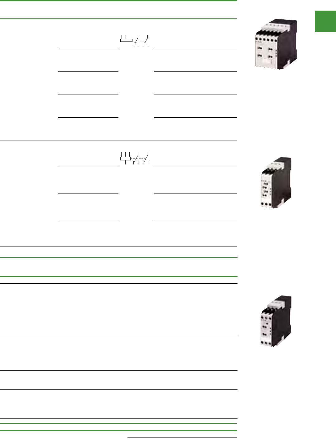
Automation
Power control
312
2015/2016 Product guide AUS15_007 - February 2016
Description
Insulation
resistance
range Ω
Circuit symbol Supply
voltage Item no.
Insulation monitoring relays EMR4-R...
Monitors the insulation resistance
between non-grounded AC supply
systems and the protective ground
conductor. Insulation monitoring in
1- and 3-phase. AC voltage networks
Test via local test button or remote
test operation. Status display via LED
(according to VDE 0413/Part 2)
Tripping function memory
1-110kΩ 0-400V AC
45-65 Hz EMR5-R400-1-A
Monitors the insulation resistance in
non-grounded DC supply systems.
Selector switch for open- or closed-circuit
principle. Test and reset via local test
button or remote test operation. Status
indication via LEDs
10-110kΩ
0-300V DC
or 0-250V AC
15-400Hz EMR5-R250-1-A
The EMR5-R400-2-A serves to monitor insulation resistance in accordance
with IEC 61557-8 in unearthed IT AC systems, IT AC systems with
galvanically connected DC circuits, or unearthed IT DC systems.
0-600 V DC or
0-400 V AC,
15-400 Hz
EMR5-R400-2-A
The coupling module EMR5-RC690 is a passive device not needing any
control supply voltage. It serves to connect the insulation monitoring
relay EMR5-R400-2-A to systems up to 690 V AC and 1000 V DC. Hence
the EMR5-RC690 is connected between the system to be monitored and
the EMR5-R400-2-A
1000V DC or
690V AC EMR5-RC690
Description Width mm Item no.
Sealable shroud EMR4-PH... 22.5 EMR4-PH22
45 EMR4-PH45
Description
Monitoring
voltage per
phase
Threshold
value
Circuit
symbol
Supply
voltage
Width
mm Item no.
Phase monitoring relay EMR5-(A)W...
Power supply from
measuring circuit
Three-phase monitoring
Phase sequence
Phase failure
Overvoltage
Undervoltage
Asymmetry
Adjustable threshold
values for overvoltage/
undervoltage and
imbalance
On-/Off-delay:
None = 0 or adjustable
between 0.1 - 30 s
160 - 300 V
AC, 50/60
Hz
Umax 220 -
300 V AC
Umin 160 -
230 V AC
160 - 300 V
AC, 50/60
Hz
22.5 EMR5-AW300-1-C
300 - 500 V
AC, 50/60
Hz
Umax 420 -
500 V AC
Umin 300 -
380 V AC
300 - 500 V
AC, 50/60
Hz
22.5 EMR5-AW500-1-D
350 - 580 V
AC, 50/60
Hz
Umax 480 -
580 V AC
Umin 350 -
460 V AC
350 - 580 V
AC, 50/60
Hz
45 EMR5-AWM580-2
450 - 720 V
AC; 50/60
Hz
Umax 600 -
720 V AC
Umin 450 -
570 V AC
350 - 720 V
AC, 50/60
Hz
45 EMR5-AWM720-2
530 - 820 V
AC; 50/60
Hz
Umax 690 -
820 V AC
Umin 530 -
660 V AC
530 - 820 V
AC, 50/60
Hz
45 EMR5-AWM820-2
Power supply from
measuring circuit
Three-phase monitoring
Phase sequence
Phase failure
Overvoltage
Undervoltage
Asymmetry
Neutral cable break (not
EMR5-AWN500-1)
Adjustable threshold
values for overvoltage/
undervoltage and
imbalance
On-/Off-delay:
None = 0 or adjustable
between 0.1 - 30 s
90 - 170 V
AC, 50/60
Hz
Umax 120 -
170 V AC
Umin. 90 -
130 V AC
90 - 170 V
AC, 50/60/
400 Hz
22.5 EMR5-AWN170-1-E
180 - 280 V
AC, 50/60
Hz
Umax 240 -
280 V AC
Umin 180 -
220 V AC
180 - 280 V
AC, 50/60/
400 Hz
22.5 EMR5-AWN280-1
180 - 280 V
AC, 50/60
Hz
Umax 240 -
280 V AC
Umin 180 -
220 V AC
180 - 280 V
AC, 50/60
Hz
22.5 EMR5-AWN280-1-F
300 - 500 V
AC, 50/60
Hz
Umax 420 -
500 V AC
Umin 300 -
380 V AC
300 - 500 V
AC, 50/60
Hz
22.5 EMR5-AWN500-1
Imbalance = 2 - 25% of phase voltage mean value
EMR measuring & monitoring relays
11/18 Electronic relays
Measuring and monitoring relays
2010 CA08103002Z-EN www.eaton.com
EMR
EMRMeasuring and monitoring relays
Monitoring
voltage per
phase
Threshold value1) Contact
sequences
Supply
voltage
connection
Width Part no.
Article no. Price
See price
list
Std. pack
mm
Phase monitoring relay EMR5-(A)W...
Multifunctional
Load limit curves → Page 11/21
Connections and contact sequence diagrams → Instructional leaflet (AWA) under www.moeller.net
Power supply from
measuring circuit
Three-phase
monitoring
• Phase sequence
• Phase failure
• Overvoltage
• Undervoltage
• Asymmetry
• Adjustable
threshold values
for overvoltage/
undervoltage and
imbalance
• On-/Off-delay:
None = 0
or adjustable
between 0.1 - 30 s
160 - 300 V
AC, 50/60 Hz Umax 220 - 300 V AC
Umin 160 - 230 V AC
160 - 300 V
AC, 50/60 Hz
22.5 EMR5-AW300-1-C
134223
1 off
300 - 500 V
AC, 50/60 Hz Umax 420 - 500 V AC
Umin 300 - 380 V AC
300 - 500 V
AC, 50/60 Hz
22.5 EMR5-AW500-1-D
134224
350 - 580 V
AC, 50/60 Hz Umax 480 - 580 V AC
Umin 350 - 460 V AC
350 - 580 V
AC, 50/60 Hz
45 EMR5-AWM580-2
134235
450 - 720 V
AC; 50/60 Hz Umax 600 - 720 V AC
Umin 450 - 570 V AC
350 - 720 V
AC, 50/60 Hz
45 EMR5-AWM720-2
134236
530 - 820 V
AC; 50/60 Hz Umax 690 - 820 V AC
Umin 530 - 660 V AC
530 - 820 V
AC, 50/60 Hz
45 EMR5-AWM820-2
134237
1 off
Power supply from
measuring circuit
Three-phase
monitoring
• Phase sequence
• Phase failure
• Overvoltage
• Undervoltage
• Asymmetry
• Neutral cable
break (not
EMR5-AWN500-1)
• Adjustable
threshold values
for overvoltage/
undervoltage and
imbalance
• On-/Off-delay:
None = 0
or adjustable
between 0.1 - 30 s
90 - 170 V
AC, 50/60 Hz Umax 120 - 170 V AC
Umin. 90 - 130 V AC
90 - 170 V
AC, 50/60/
400 Hz
22.5 EMR5-AWN170-1-E
134225
1 off
180 - 280 V
AC, 50/60 Hz Umax 240 - 280 V AC
Umin 180 - 220 V AC
180 - 280 V
AC, 50/60/
400 Hz
22.5 EMR5-AWN280-1
134233
180 - 280 V
AC, 50/60 Hz Umax 240 - 280 V AC
Umin 180 - 220 V AC
180 - 280 V
AC, 50/60 Hz
22.5 EMR5-AWN280-1-F
134226
300 - 500 V
AC, 50/60 Hz Umax 420 - 500 V AC
Umin 300 - 380 V AC
300 - 500 V
AC, 50/60 Hz
22.5 EMR5-AWN500-1
134234
Notes 1) Imbalance = 2 - 25% of phase voltage mean value
Information relevant for export to North America
Product Standards IEC 255-6; UL 508;
CSA-22.2 No. 14-05; CE marking
UL File No. E29184
UL CCN NKCR, NKCR7
CSA File No. UL report valid
CSA Class No. 3211-03
NA Certification UL Listed, Certified by UL for use in Canada
Degree of Protection IEC: IP20, UL/CSA Type: -
15
L1 L2 L3 11
16
12
18
14
26
22
28
24
25
21
15 25L1 L2 L3
1816N 26 28
HPL11018EN
EMR5-AWM720-2
EMR5-AWN500-1
EMR5-R400-1-A

Automation
Power control
313 2015/2016 Product guide AUS15_007 - February 2016
Description
Rated operational
current AC-11 Conventional
thermal current Time
range
Item no.
24 - 240 V AC,
50/60 Hz
24 - 240 V DC
Item no.
400 V AC,
50/60 Hz
230 V 400 V
Ie
A
Ie
A
Ith
A
Star-delta switching
timing functions 3 3 6 3 - 60 s ETR4-51-A ETR4-51-W
On-delayed timing
functions 336
0.05 - 1 s
0.15 - 3 s
0.5 - 10 s
1.5 - 30 s
5 - 100 s
15 - 300 s
1.5 - 30 min
15 - 300 min
1.5 - 30 h
5 - 100 h
ETR4-11-A ETR4-11-W
Multifunctional timing
functions 336 ETR4-69-A ETR4-69-W
Multifunctional
with connection for
potentiometer, and two
changeover contacts
that can be converted
to two timed contacts
or one non-delayed
contact and one
timed contact.
Timing functions
3 - 6 ETR4-70-A -
Description
Rated operational
current AC-11 Conventional
thermal current Time
range
Voltage
range Item no.230 V 400 V
Ie
A
Ie
A
Ith
A
One changeover contact
On-delayed timing functions 3 - 6
0.05 - 1 s
0.5 - 10 s
5 - 100 s
0.5 - 10 min
5 - 100 min
0.5 - 10 h
5 - 100
24 - 240
V AC,
50/60 Hz
24 - 48 V
DC
ETR2-11
Off-delayed timing functions 3 - 6 ETR2-12
Fleeting contact on
energization timing functions 3 - 6 ETR2-21
Flashing, pulse initiating
timing functions 3 - 6 ETR2-42
Flashing, 2 speeds
(ON/OFF times variable)
timing functions
3 - 6 ETR2-44
Multifunction relay timing
functions 3 - 6 ETR2-69
Two changeover contacts
On-delayed timing functions 3 - 6 0.05 - 1 s
0.5 - 10 s
5 - 100 s
0.5 - 10 min
5 - 100 min
0.5 - 10 h
5 - 100 h
24 - 240 V
AC,
50/60 Hz
24 - 48 V
DC
ETR2-11-D
Off-delayed timing functions 3 - 6 ETR2-12-D
Multifunction relay timing
functions 3 0.75 6
12 - 240 V
AC,
50/60 Hz
ETR2-69-D
Timing relays - Electronic ETR4
Timing relays - Electronic ETR2
ETR2-12
ETR2-44
ETR2-11-D
ETR4-11-A
ETR4-70-A
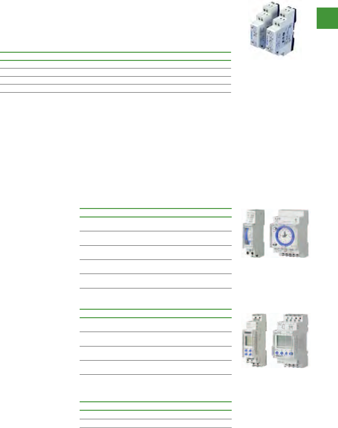
Automation
Power control
314
2015/2016 Product guide AUS15_007 - February 2016
Timeswitches
Timeswitches are applied in any residential or commercial buildings wherever automatic control is
required on predefined times. The Eaton range comprises of a wide variety of different products which
include analogue and digital timeswitches.
Benefits
• Easily programmable on front of device.
• Computer aided programming software
available.
• Compact 18 mm design for restricted space
opportunities.
• High level of accuracy.
• Automatic summer and winter time
adjustment.
• Holiday & Random program settings.
• High power reserve up to 10 years.
Digital timeswitches
• Simplified set-up
Pre-settings only need
confirmation (fewer
manually settings needed)
• TSA MEMKIT software kit
Programming can be
copied from one clock to
another
Pre-programming on PC
• Pulse output
• Memory card for storing
time settings
• Weekly programing, 1 or 2
channels
• Automatic summer/winter
time switching
Analogue timeswitches
• Daily or weekly programing
• Power reserve in case of
loss of supply
• Compact 18mm design for
restricted spaces
• Permanent on/off
• Manual override function
• 1 changeover (or normally
open) rated 16A resistive,
240Vac
• Convenient DIN rail
mounting type.
Analogue range
Description Item no.
Analogue time switch, dial type, 24 hr,
1 channel, no power reserve TSSD1CO
Analogue time switch, 18 mm wide, 24 hr,
1 channel, no power reserve TSSD1NO
Analogue time switch, dial type, 24 hr,
1 channel, 200 hr power reserve TSQD1CO
Analogue time switch, 18 mm wide, 24 hr,
1 channel, 3 yr power reserve TSQD1NO
Analogue time switch, dial type, 7 day,
1 channel, 200 hr power reserve TSQW1CO
Digital range
Description Item no.
Digital time switch, 36 mm wide, 7 day,
1 channel, 10 yr power reserve TSDW1CO
Digital time switch, 18 mm wide, 7 day,
1 channel, 3 yr power reserve TSDW1COMIN
Digital time switch, 36 mm wide, 7 day,
1 channel, 10 yr power reserve, pulse output TSDW1CODG
Digital time switch, 36 mm wide, 7 day,
2 channel, 10 yr power reserve TSDW2CO
Software & memory card
Description Item no.
Programming software, cable & memory card TSAMEMKIT
Memory card TSAMEM
Analogue timeswitches
Digital timeswitches
Description Item no.
18mm DIN Multifunction Timer - 4 modes TRL04
18mm DIN Multifunction Timer - 7 modes TRL07
Compact DIN rail mount, DPDT TRL27
Asymmetrical pulse generator, DPDT TRW27
Timers
Eaton TRL 18mm DIN timers
• Slim 18mm DIN rail mount timers
• Timing range 50 msec to 100 hours
• Changeover output contact rated 8A, 240VAC
• Universal supply voltage
12V-240V AC/DC for TRL07 & TRLPG
24V-240V AC/DC for TRL04
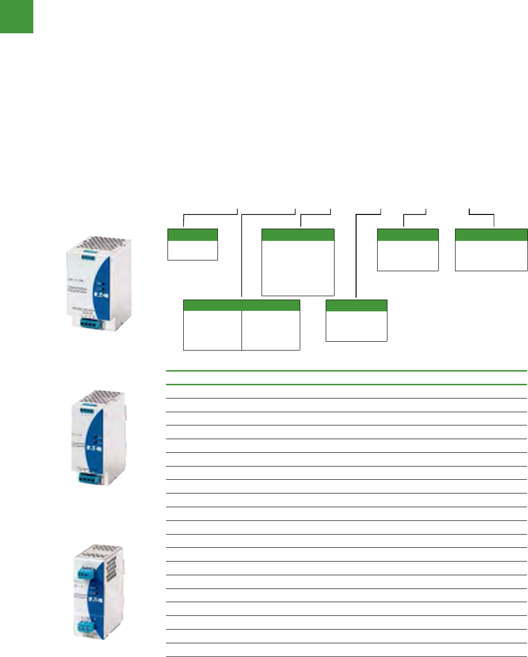
Automation
Power control
315 2015/2016 Product guide AUS15_007 - February 2016
DC power supplies
Eaton’s PSG Series of power supplies is designed to be a high-performance, highquality line of
products covering a majority of 12 Vdc and 24 Vdc control applications.
Features, benefits and functions
• Universal input voltages: 100–240 Vac for
singlephase units, 400–500 Vac for three-
phase units
• General-purpose 12 Vdc and 24 Vdc
adjustable output
• 150% power surge output
• Wide operating temperature range: –25°C to
+80°C
• MTBF up to 1,000,000 hours ensures uptime
and reliability
• Protection from overvoltage, overcurrent and
overtemperature conditions
• Rugged aluminum and plastic housings
provide the durability required to stand up to
harsh environments
• All-metal DIN rail mounting hardware
• Heavy-duty screw and finger-safe terminals
• LED indicating light for DC OK simplifies
troubleshooting
• Conformal coated electronics
• Hazardous Location Class I, Division 2 rated
models
• NEC® Class II rated model
• Redundancy modules keep loads up and
running in the event of a device failure
• Buffer module has the stored power needed
to keep loads running through a short
duration power failure
Output power
15 = 15W
30 = 30W
60 = 60W
100 = 100W
120 = 120W
240 = 240W
480 = 480W
960 = 960W
Model
E = Single-phase
F = Three-phase
R = Redundancy
module
B = Buffer module
N = NEC Class II
Output voltage
24 = 24 Vdc
12 = 12 Vdc
Blank = 24 Vdc
Terminals
S = Screw
R = Finger-safe
Blank = Screw
Housing
M = Aluminum
P = Plastic
Blank = Aluminum
Series
PSG = PSG
power supply
PSG 240 E 24 R M
Description Item no.
Single phase input
Power supply 85-264VAC input 12VDC output 15W plastic housing PSG15E12SP
Power supply 85-264VAC input 12VDC output 30W plastic housing PSG30E12SP
Power supply 85-264VAC input 12VDC output 30W aluminium housing PSG60E12SM
Power supply 85-264VAC input 24VDC output 60W plastic housing PSG60E24SP
Power supply 85-264VAC input 24VDC output 60W aluminium housing PSG60E24RM
Power supply 85-264VAC input 24VDC output 100W aluminium housing PSG100E12SM
Power supply 85-264VAC input 24VDC output 120W aluminium housing PSG120E24RM
Power supply 85-264VAC input 24VDC output 240W aluminium housing PSG240E24RM
Power supply 85-264VAC input 24VDC output 480W aluminium housing PSG480E24RM
Three phase input
Power supply 320-600VAC input 24VDC output 60W aluminium housing PSG60F24RM
Power supply 320-600VAC input 24VDC output 120W aluminium housing PSG120F24RM
Power supply 320-600VAC input 24VDC output 240W aluminium housing PSG240F24RM
Power supply 320-600VAC input 24VDC output 480W aluminium housing PSG480F24RM
Power supply 320-600VAC input 24VDC output 960W aluminium housing PSG960F24RM
Buffer & Redundancy modules
Buffer module 24VDC 20A aluminium housing PSG480B24RM
Power supply redundant module 24VDC 20A aluminium housing PSG480R24RM
Power supply redundant module 24VDC 40A aluminium housing PSG960R24RM
PSG240F24RM
PSG120F24RM
PSG120E24RM
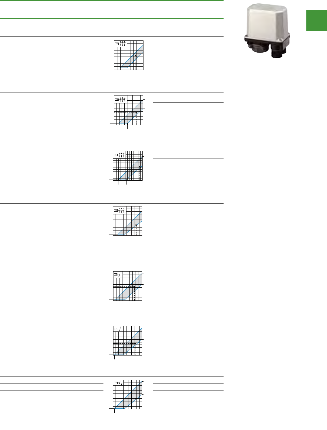
Automation
Power control
316
2015/2016 Product guide AUS15_007 - February 2016
Description
Max.
operating
pressure
Item no.
Pressure switches with main contacts IP65, 3 pole
Preferred setting range
from bar
Preferred setting range
to bar
0.9 4
Pressure Switches
Pressure switches with main contacts
2010 CA08103002Z-EN www.eaton.com
MCSN 3/31
MCSNPressure switches with main contacts
Make and break pressure:
Separately infinitely adjustable.
Pressures can be set to any point within
the area of the pressure diagram for the
appropriate switch.
Max.
operating
pressure
Part no.
Article no. Price
See price
list
Std.
pack Notes
bar
Pressure switches with main contacts IP65, 3 pole
Min. switching differential: 0.6 bar
Example:
Cut-out pressure 3.3 bar
Cut-in pressure 2.2 bar
Variable
switching
differential
7MCSN4
057679
1 off Features:
• With terminal cover as standard
• 1 insulated protective wire terminal
• 1 insulated N terminal
• 2 cable entry knockouts for M20,
without cable gland
• IP65 in conjunction with V-M20
cable gland
• Pressure pipe flange R ½”
• Please enquire: Pressure pipe flange
R ¼”
• Neoprene diaphragm
R ¼” corresponds to G ¼
R ½” corresponds to G ½ to ISO 228-1
For use as a motor load switch to
IEC/EN 60947-4-1 for:
Three-phase current AC-3
Single-phase current
Direct current DC-3
For use as control switch:
Factory setting of cut-in and cut-out
pressure via type suffix: → Page 3/33
With relief
valve
for 6 mm
compres-
sion fitting
7MCSN4-V
062425
Min. switching differential: 1.4 bar
Example:
Cut-out pressure 8.5 bar
Cut-in pressure 4.5 bar
Variable
switching
differential
15 MCSN11
029203
With relief
valve
for 6 mm
compres-
sion fitting
15 MCSN11-V
033949
Min. switching differential: 2.4 bar
Example:
Cut-out pressure 14.5 bar
Cut-in pressure 7.5 bar
Variable
switching
differential
25 MCSN16
038695
With relief
valve
for 6 mm
compres-
sion fitting
25 MCSN16-V
043441
Min. switching differential: 3.0 bar
Example:
Cut-out pressure 17.5 bar
Cut-in pressure 7.8 bar
Variable
switching
differential
25 MCSN22
048187
With relief
valve
for 6 mm
compres-
sion fitting
25 MCSN22-V
052933
0
0,9
0
3,8
0,3
1
2
3
4
1234
2,7
1
P
24
35
6
4,5
4,5
bar
bar
Pmin
P
max
P
N
135
>
246
M
3
>
M
1
13 5
N
P
246
N
>
M
_
P
246
135
>
KH
13 5
246
N
P
0
1,9
011
9,4
0,5
6,0
5,1
246810
2
4
6
8
10
11
1
P
24
35
6
bar
bar
P
min
P
max
16
13.1
8.0
0
0.7
0246810 12 14
2
4
6
8
10
12
14
3.1 7.5
16
1
P
24
35
6
bar
bar
P
min
P
max
22
18.5
0
0.9
0
11.0
246810 12 14 18 20
20
2
4
6
8
10
12
14
16
18
16
3.9 9.1
22 1
P
24
35
6
bar
bar
Pmin
P
max
HPL03031EN
7MCSN4
7MCSN4-V
2 10
Pressure Switches
Pressure switches with main contacts
2010 CA08103002Z-EN www.eaton.com
MCSN 3/31
MCSNPressure switches with main contacts
Make and break pressure:
Separately infinitely adjustable.
Pressures can be set to any point within
the area of the pressure diagram for the
appropriate switch.
Max.
operating
pressure
Part no.
Article no. Price
See price
list
Std.
pack Notes
bar
Pressure switches with main contacts IP65, 3 pole
Min. switching differential: 0.6 bar
Example:
Cut-out pressure 3.3 bar
Cut-in pressure 2.2 bar
Variable
switching
differential
7MCSN4
057679
1 off Features:
• With terminal cover as standard
• 1 insulated protective wire terminal
• 1 insulated N terminal
• 2 cable entry knockouts for M20,
without cable gland
• IP65 in conjunction with V-M20
cable gland
• Pressure pipe flange R ½”
• Please enquire: Pressure pipe flange
R ¼”
• Neoprene diaphragm
R ¼” corresponds to G ¼
R ½” corresponds to G ½ to ISO 228-1
For use as a motor load switch to
IEC/EN 60947-4-1 for:
Three-phase current AC-3
Single-phase current
Direct current DC-3
For use as control switch:
Factory setting of cut-in and cut-out
pressure via type suffix: → Page 3/33
With relief
valve
for 6 mm
compres-
sion fitting
7MCSN4-V
062425
Min. switching differential: 1.4 bar
Example:
Cut-out pressure 8.5 bar
Cut-in pressure 4.5 bar
Variable
switching
differential
15 MCSN11
029203
With relief
valve
for 6 mm
compres-
sion fitting
15 MCSN11-V
033949
Min. switching differential: 2.4 bar
Example:
Cut-out pressure 14.5 bar
Cut-in pressure 7.5 bar
Variable
switching
differential
25 MCSN16
038695
With relief
valve
for 6 mm
compres-
sion fitting
25 MCSN16-V
043441
Min. switching differential: 3.0 bar
Example:
Cut-out pressure 17.5 bar
Cut-in pressure 7.8 bar
Variable
switching
differential
25 MCSN22
048187
With relief
valve
for 6 mm
compres-
sion fitting
25 MCSN22-V
052933
0
0,9
0
3,8
0,3
1
2
3
4
1234
2,7
1
P
24
35
6
4,5
4,5
bar
bar
Pmin
P
max
P
N
135
>
246
M
3
>
M
1
13 5
N
P
246
N
>
M
_
P
246
135
>
KH
13 5
246
N
P
0
1,9
011
9,4
0,5
6,0
5,1
246810
2
4
6
8
10
11
1
P
24
35
6
bar
bar
P
min
P
max
16
13.1
8.0
0
0.7
0246810 12 14
2
4
6
8
10
12
14
3.1 7.5
16
1
P
24
35
6
bar
bar
P
min
P
max
22
18.5
0
0.9
0
11.0
246810 12 14 18 20
20
2
4
6
8
10
12
14
16
18
16
3.9 9.1
22 1
P
24
35
6
bar
bar
Pmin
P
max
HPL03031EN
15 MCSN11
15 MCSN11-V
5 15
Pressure Switches
Pressure switches with main contacts
2010 CA08103002Z-EN www.eaton.com
MCSN 3/31
MCSNPressure switches with main contacts
Make and break pressure:
Separately infinitely adjustable.
Pressures can be set to any point within
the area of the pressure diagram for the
appropriate switch.
Max.
operating
pressure
Part no.
Article no. Price
See price
list
Std.
pack Notes
bar
Pressure switches with main contacts IP65, 3 pole
Min. switching differential: 0.6 bar
Example:
Cut-out pressure 3.3 bar
Cut-in pressure 2.2 bar
Variable
switching
differential
7MCSN4
057679
1 off Features:
• With terminal cover as standard
• 1 insulated protective wire terminal
• 1 insulated N terminal
• 2 cable entry knockouts for M20,
without cable gland
• IP65 in conjunction with V-M20
cable gland
• Pressure pipe flange R ½”
• Please enquire: Pressure pipe flange
R ¼”
• Neoprene diaphragm
R ¼” corresponds to G ¼
R ½” corresponds to G ½ to ISO 228-1
For use as a motor load switch to
IEC/EN 60947-4-1 for:
Three-phase current AC-3
Single-phase current
Direct current DC-3
For use as control switch:
Factory setting of cut-in and cut-out
pressure via type suffix: → Page 3/33
With relief
valve
for 6 mm
compres-
sion fitting
7MCSN4-V
062425
Min. switching differential: 1.4 bar
Example:
Cut-out pressure 8.5 bar
Cut-in pressure 4.5 bar
Variable
switching
differential
15 MCSN11
029203
With relief
valve
for 6 mm
compres-
sion fitting
15 MCSN11-V
033949
Min. switching differential: 2.4 bar
Example:
Cut-out pressure 14.5 bar
Cut-in pressure 7.5 bar
Variable
switching
differential
25 MCSN16
038695
With relief
valve
for 6 mm
compres-
sion fitting
25 MCSN16-V
043441
Min. switching differential: 3.0 bar
Example:
Cut-out pressure 17.5 bar
Cut-in pressure 7.8 bar
Variable
switching
differential
25 MCSN22
048187
With relief
valve
for 6 mm
compres-
sion fitting
25 MCSN22-V
052933
0
0,9
0
3,8
0,3
1
2
3
4
1234
2,7
1
P
24
35
6
4,5
4,5
bar
bar
Pmin
P
max
P
N
135
>
246
M
3
>
M
1
13 5
N
P
246
N
>
M
_
P
246
135
>
KH
13 5
246
N
P
0
1,9
011
9,4
0,5
6,0
5,1
246810
2
4
6
8
10
11
1
P
24
35
6
bar
bar
P
min
P
max
16
13.1
8.0
0
0.7
0246810 12 14
2
4
6
8
10
12
14
3.1 7.5
16
1
P
24
35
6
bar
bar
P
min
P
max
22
18.5
0
0.9
0
11.0
246810 12 14 18 20
20
2
4
6
8
10
12
14
16
18
16
3.9 9.1
22 1
P
24
35
6
bar
bar
Pmin
P
max
HPL03031EN
25 MCSN16
25 MCSN16-V
8 22
Pressure Switches
Pressure switches with main contacts
2010 CA08103002Z-EN www.eaton.com
MCSN 3/31
MCSNPressure switches with main contacts
Make and break pressure:
Separately infinitely adjustable.
Pressures can be set to any point within
the area of the pressure diagram for the
appropriate switch.
Max.
operating
pressure
Part no.
Article no. Price
See price
list
Std.
pack Notes
bar
Pressure switches with main contacts IP65, 3 pole
Min. switching differential: 0.6 bar
Example:
Cut-out pressure 3.3 bar
Cut-in pressure 2.2 bar
Variable
switching
differential
7MCSN4
057679
1 off Features:
• With terminal cover as standard
• 1 insulated protective wire terminal
• 1 insulated N terminal
• 2 cable entry knockouts for M20,
without cable gland
• IP65 in conjunction with V-M20
cable gland
• Pressure pipe flange R ½”
• Please enquire: Pressure pipe flange
R ¼”
• Neoprene diaphragm
R ¼” corresponds to G ¼
R ½” corresponds to G ½ to ISO 228-1
For use as a motor load switch to
IEC/EN 60947-4-1 for:
Three-phase current AC-3
Single-phase current
Direct current DC-3
For use as control switch:
Factory setting of cut-in and cut-out
pressure via type suffix: → Page 3/33
With relief
valve
for 6 mm
compres-
sion fitting
7MCSN4-V
062425
Min. switching differential: 1.4 bar
Example:
Cut-out pressure 8.5 bar
Cut-in pressure 4.5 bar
Variable
switching
differential
15 MCSN11
029203
With relief
valve
for 6 mm
compres-
sion fitting
15 MCSN11-V
033949
Min. switching differential: 2.4 bar
Example:
Cut-out pressure 14.5 bar
Cut-in pressure 7.5 bar
Variable
switching
differential
25 MCSN16
038695
With relief
valve
for 6 mm
compres-
sion fitting
25 MCSN16-V
043441
Min. switching differential: 3.0 bar
Example:
Cut-out pressure 17.5 bar
Cut-in pressure 7.8 bar
Variable
switching
differential
25 MCSN22
048187
With relief
valve
for 6 mm
compres-
sion fitting
25 MCSN22-V
052933
0
0,9
0
3,8
0,3
1
2
3
4
1234
2,7
1
P
24
35
6
4,5
4,5
bar
bar
Pmin
P
max
P
N
135
>
246
M
3
>
M
1
13 5
N
P
246
N
>
M
_
P
246
135
>
KH
13 5
246
N
P
0
1,9
011
9,4
0,5
6,0
5,1
246810
2
4
6
8
10
11
1
P
24
35
6
bar
bar
P
min
P
max
16
13.1
8.0
0
0.7
0246810 12 14
2
4
6
8
10
12
14
3.1 7.5
16
1
P
24
35
6
bar
bar
P
min
P
max
22
18.5
0
0.9
0
11.0
246810 12 14 18 20
20
2
4
6
8
10
12
14
16
18
16
3.9 9.1
22 1
P
24
35
6
bar
bar
Pmin
P
max
HPL03031EN
25 MCSN22
25 MCSN22-V
Pressure switch with auxiliary contacts, IP65
1 changeover contact
3/32 Pressure Switches
Pressure switches with auxiliary contacts
2010 CA08103002Z-EN www.eaton.com
MCS
MCSPressure switches with auxiliary contacts
Variable switching
differential
Contacts Max.
operating
pressure
Make and break pressure:
separately infinitely adjustable.
Pressures can be set to any point within
the area of the pressure diagram for the
appropriate switch.
Part no.
Article no. Price
See price
list
Std. pack Notes
Number bar
Pressure switch with auxiliary contacts, IP65
1 changeover
contact
7
Min. switching differential: 0.2 bar
Example:
Cut-out pressure 3.3 bar
Cut-in pressure 2.2 bar
MCS4
019711
1 off
Features:
• Pressure pipe flange R ¼”
• If required: pressure pipe flange R ½”
• IP65 in conjunction with V-M20 cable gland
• 1 Insulated protective wire terminal
• 2 cable entry knockouts for M20
• Neoprene diaphragm, resistant to aging,
air, engine oil, and water
min. -25 °C, max. +80 °C
Factory setting of cut-in and cut-out pressure
via type suffix: → Page 3/33
R ¼” corresponds to G ¼
R ½” corresponds to G ½ to
ISO 228-1
Auxiliary contact to IEC/EN 60947-1
1) Gold contacts are specially suitable for
switching small voltages and currents from
12 V AC/DC, 0.1 A.
1 changeover
contact with
gold-plated
7MCS4-G1)
058693
2 changeover
contacts with
gold-plated
contacts
7MCS4-SOND910-G1)
087792
1 changeover
contact 15
Min. switching differential: 0.3 bar
Example:
Cut-out pressure 8.5 bar
Cut-in pressure 4.5 bar
MCS11
088527
1 changeover
contact with
gold-plated
15 MCS11-G1)
058692
2 changeover
contact with
gold-plated
contacts
15 MCS11-SOND910-G1)
087793
1 changeover
contact 25
Min. switching differential: 0.7 bar
Example:
Cut-out pressure 17.5 bar
Cut-in pressure 7.8 bar
MCS22
098019
1 changeover
contact with
gold-plated
25 MCS22-G1)
058691
2 changeover
contact with
gold-plated
contacts
25 MCS22-SOND910-G1)
087794
4
3
2
1
0.1 0
0
4.2
2.5
4.5
4
3
2
1
1.8
1
P
24
0.3
4.5
P
bar
bar
min
P
max
PN
1
>
2
KH
4
0
0.5
10.4
6.0
11
246810
0.2 0
2
4
6
8
10
11 1
P
24
bar
bar
Pmin
P
max
0
1.1
0.4 0
9.1
21.0
11.0
2
4
6
8
10
12
14
16
18
20
246810 12 14 16 18 20
22
22
1
P
24
bar
bar
P
min
P
max
HPL03032EN
7MCS4
1 changeover contact with gold-plated 7 MCS4-G
2 changeover contact with gold-plated
contacts 7MCS4-SOND910-G
1 changeover contact
3/32 Pressure Switches
Pressure switches with auxiliary contacts
2010 CA08103002Z-EN www.eaton.com
MCS
MCSPressure switches with auxiliary contacts
Variable switching
differential
Contacts Max.
operating
pressure
Make and break pressure:
separately infinitely adjustable.
Pressures can be set to any point within
the area of the pressure diagram for the
appropriate switch.
Part no.
Article no. Price
See price
list
Std. pack Notes
Number bar
Pressure switch with auxiliary contacts, IP65
1 changeover
contact
7
Min. switching differential: 0.2 bar
Example:
Cut-out pressure 3.3 bar
Cut-in pressure 2.2 bar
MCS4
019711
1 off
Features:
• Pressure pipe flange R ¼”
• If required: pressure pipe flange R ½”
• IP65 in conjunction with V-M20 cable gland
• 1 Insulated protective wire terminal
• 2 cable entry knockouts for M20
• Neoprene diaphragm, resistant to aging,
air, engine oil, and water
min. -25 °C, max. +80 °C
Factory setting of cut-in and cut-out pressure
via type suffix: → Page 3/33
R ¼” corresponds to G ¼
R ½” corresponds to G ½ to
ISO 228-1
Auxiliary contact to IEC/EN 60947-1
1) Gold contacts are specially suitable for
switching small voltages and currents from
12 V AC/DC, 0.1 A.
1 changeover
contact with
gold-plated
7MCS4-G1)
058693
2 changeover
contacts with
gold-plated
contacts
7MCS4-SOND910-G1)
087792
1 changeover
contact 15
Min. switching differential: 0.3 bar
Example:
Cut-out pressure 8.5 bar
Cut-in pressure 4.5 bar
MCS11
088527
1 changeover
contact with
gold-plated
15 MCS11-G1)
058692
2 changeover
contact with
gold-plated
contacts
15 MCS11-SOND910-G1)
087793
1 changeover
contact 25
Min. switching differential: 0.7 bar
Example:
Cut-out pressure 17.5 bar
Cut-in pressure 7.8 bar
MCS22
098019
1 changeover
contact with
gold-plated
25 MCS22-G1)
058691
2 changeover
contact with
gold-plated
contacts
25 MCS22-SOND910-G1)
087794
4
3
2
1
0.1 0
0
4.2
2.5
4.5
4
3
2
1
1.8
1
P
24
0.3
4.5
P
bar
bar
min
P
max
PN
1
>
2
KH
4
0
0.5
10.4
6.0
11
246810
0.2 0
2
4
6
8
10
11 1
P
24
bar
bar
Pmin
P
max
0
1.1
0.4 0
9.1
21.0
11.0
2
4
6
8
10
12
14
16
18
20
246810 12 14 16 18 20
22
22
1
P
24
bar
bar
P
min
P
max
HPL03032EN
15 MCS11
1 changeover contact with gold-plated 15 MCS11-G
2 changeover contact with gold-plated
contacts 15 MCS11-SOND910-G
1 changeover contact
3/32 Pressure Switches
Pressure switches with auxiliary contacts
2010 CA08103002Z-EN www.eaton.com
MCS
MCSPressure switches with auxiliary contacts
Variable switching
differential
Contacts Max.
operating
pressure
Make and break pressure:
separately infinitely adjustable.
Pressures can be set to any point within
the area of the pressure diagram for the
appropriate switch.
Part no.
Article no. Price
See price
list
Std. pack Notes
Number bar
Pressure switch with auxiliary contacts, IP65
1 changeover
contact
7
Min. switching differential: 0.2 bar
Example:
Cut-out pressure 3.3 bar
Cut-in pressure 2.2 bar
MCS4
019711
1 off
Features:
• Pressure pipe flange R ¼”
• If required: pressure pipe flange R ½”
• IP65 in conjunction with V-M20 cable gland
• 1 Insulated protective wire terminal
• 2 cable entry knockouts for M20
• Neoprene diaphragm, resistant to aging,
air, engine oil, and water
min. -25 °C, max. +80 °C
Factory setting of cut-in and cut-out pressure
via type suffix: → Page 3/33
R ¼” corresponds to G ¼
R ½” corresponds to G ½ to
ISO 228-1
Auxiliary contact to IEC/EN 60947-1
1) Gold contacts are specially suitable for
switching small voltages and currents from
12 V AC/DC, 0.1 A.
1 changeover
contact with
gold-plated
7MCS4-G1)
058693
2 changeover
contacts with
gold-plated
contacts
7MCS4-SOND910-G1)
087792
1 changeover
contact 15
Min. switching differential: 0.3 bar
Example:
Cut-out pressure 8.5 bar
Cut-in pressure 4.5 bar
MCS11
088527
1 changeover
contact with
gold-plated
15 MCS11-G1)
058692
2 changeover
contact with
gold-plated
contacts
15 MCS11-SOND910-G1)
087793
1 changeover
contact 25
Min. switching differential: 0.7 bar
Example:
Cut-out pressure 17.5 bar
Cut-in pressure 7.8 bar
MCS22
098019
1 changeover
contact with
gold-plated
25 MCS22-G1)
058691
2 changeover
contact with
gold-plated
contacts
25 MCS22-SOND910-G1)
087794
4
3
2
1
0.1 0
0
4.2
2.5
4.5
4
3
2
1
1.8
1
P
24
0.3
4.5
P
bar
bar
min
P
max
PN
1
>
2
KH
4
0
0.5
10.4
6.0
11
246810
0.2 0
2
4
6
8
10
11 1
P
24
bar
bar
Pmin
P
max
0
1.1
0.4 0
9.1
21.0
11.0
2
4
6
8
10
12
14
16
18
20
246810 12 14 16 18 20
22
22
1
P
24
bar
bar
P
min
P
max
HPL03032EN
25 MCS22
1 changeover contact with gold-plated 25 MCS22-G
2 changeover contact with gold-plated
contacts 25 MCS22-SOND910-G
Pressure switches
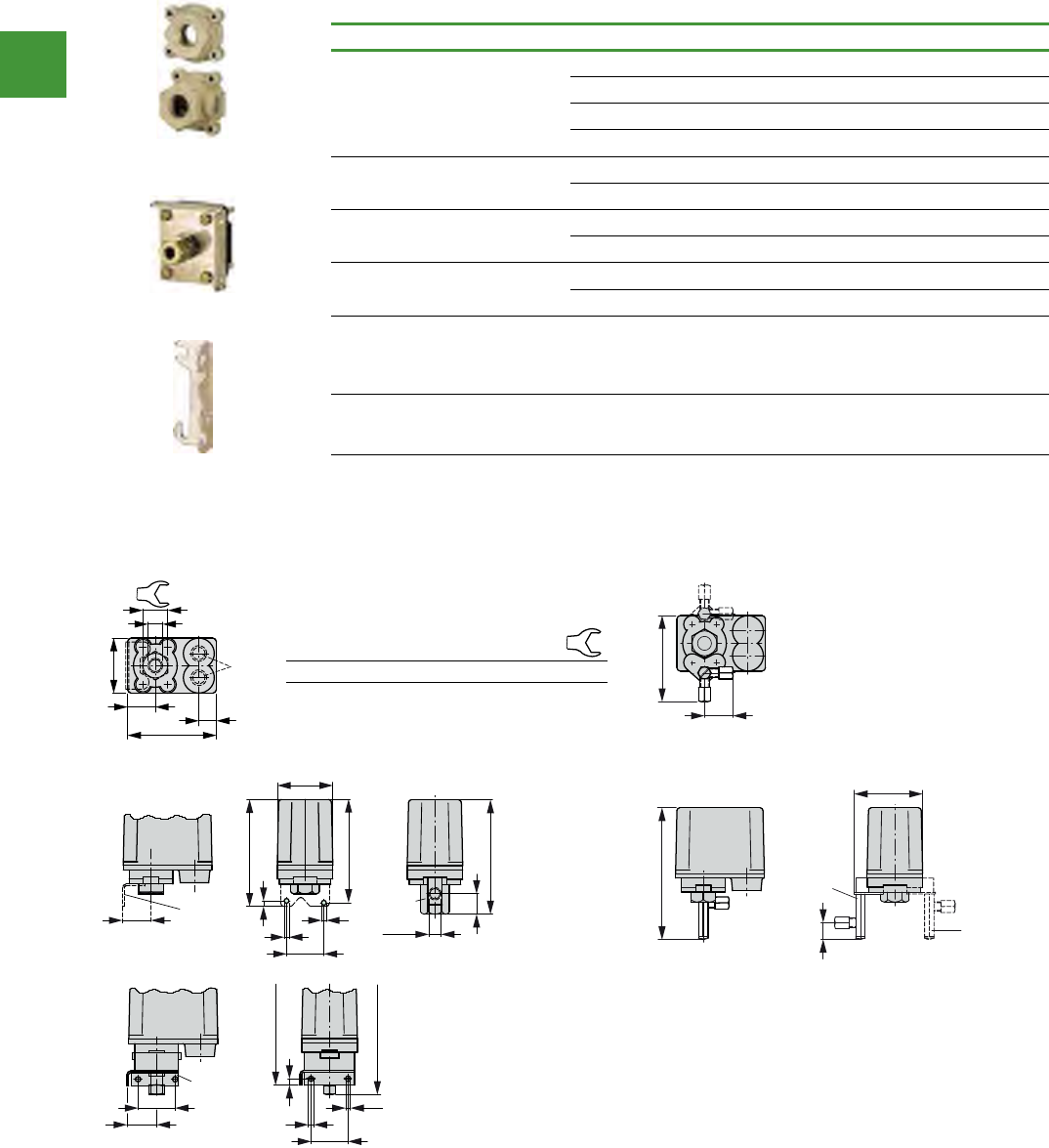
Automation
Power control
317 2015/2016 Product guide AUS15_007 - February 2016
Accessories
Description For use with Item no.
Pressurepipeange
MCS with R ½" +R1/2"-MCS
MCS with R ½" R1/2"-MCS
MCSN(-V) with R ¼" +R1/4"-MCSN
MCSN(-V) with R ¼" R1/4"-MCSN
Pressurepipeangewithpres-
sure gauge connection
MCS, MCSN(-V) +M-MCS
MCS, MCSN(-V) M-MCS
Compressiontting MCS, MCSN +E8-MCS
MCS, MCSN E8-MCS
Wallxingbracket MCS, MCSN +W-MCS
MCS, MCSN W-MCS
External unit plug, IP65
3 poles plus earth for socket
adapters to
DIN 43650-A/ISO 4400
MCS
MCS…-G
Not for use with
MCS…SOND910-G
+S3-MCS
Pressure setting
Standard setting of the cut-in
and cut-out pressures
MCS, MCSN +PMIN(*)/PMAX(*)
Dimensions
Pressure switches
3/34 Pressure Switches
2010 CA08103002Z-EN www.eaton.com
MCS, MCSN
MCS, MCSN
Rating data for
approved types to
UL/CSA 1)
Max.
pressure
Rated
insulation
voltage to
UL/CSA
Maximum motor rating Rated operational
current
Part no.
Article no.
Price
See price
list
Std. pack
HP = PS
115
V
200
V
230
V
460
V
575
V
Ie
psi2) V AC HP HP HP HP HP A
MCS(N) pressure switches, IP55
With transparent hood
1 pole only for
single-phase
motors
4)
65 300 0.25
3) 0.5
3) – – – 10 MCS4FORMCDN
024457
1 o
52.0061 3) 0.5
3) – – – 10 MCS11FORMCDN
093273
52.0513 3) 0.5
3) – – – 10 MCS22FORMCDN
014965
3 pole
4) 65 600 – 3357.5 10 MCSN4FORMCDN
064798
1 o
015.7533–061 MCSN11FORMCDN
036322
015.7533–032 MCSN16FORMCDN
045814
Notes1) Devices for world markets IEC UL/CSA
2) In North America, pressure is stated in pounds/inch (psi) (1 bar = 14.5 psi)
3) Heavy Pilot Duty = High switching duty
4) Selection data and application notes � 3/32
Dimensions
MCS (N)
Pressure switches
MCS…, MCSN… MCSN…V
With relief valve
96
30
60
19
M20
a
Item no. Pipe in-lead a
MSC… 2 x M20 R 1/4“ 27
MSCN… 2 x M20 R 1/2“ 36
93
31
142
74
18
MCSN...-V
MCSN...-VG
115
40
111
60
6
6
5,2
+M-MCS
22
123
R 1/4"
31 ...+W-MCS
40
134
32
40
...+ E8 - MCS
124
6
7
5,2
HPL03034EN
W-MCS
E8-MCS
R1/2-MCS
Motor-protective circuit-breakers PKZ have been manufactured by
Eaton since 1932. Our ideas and developments have decisively
influenced the trends in the protection of motors since then.
The results are progressive concepts and marketable product
innovations that again and again assume the role of international
trendsetting, pioneering products, e.g. such as the motor-protective
circuit-breaker PKE.
Standstill times of machines and installation should be as short
as possible. The fuseless motor-protective circuit-breakers PKZ
combine short-circuit protection and overload protection in a single
device. This enables a short recovery time. PKZM0, PKZM01,
PKZM4 and PKE feature the same range of accessories. They can
be easily combined with contactors DILM and soft starters DS7.
Switching technology can be this easy.
Simple, intelligent,
pluggable, versatile.
