Manual Installation Directions
2016-09-04
: Pdf 141463-Installationsheet 141463-InstallationSheet B4 unilog
Open the PDF directly: View PDF ![]() .
.
Page Count: 62
- Table of Contents
- 1 Declaration of Conformity
- 2 General Information
- 3 Safety
- 4 Product Description
- 5 Installation
- 6 Commissioning
- 7 Operation with the PROFIBUS
- 7.1 General information on the PROFIBUS
- 7.2 PROFIBUS-DP
- 7.2.1 PROFIBUS DP communication parameters
- 7.2.2 PROFIBUS DP functions
- 7.2.3 Device identification/software version message for PROFIBUS DP
- 7.2.4 Definition of PROFIBUS DP modules
- 7.2.5 Communication direction: PROFIBUS DP fi control interface unit
- 7.2.6 Communication direction: control interface unit fi PROFIBUS DP
- 7.2.7 PROFIBUS DP command sequence, example
- 8 Fault Diagnostics
- 9 Technical Data
- 10 Appendix
FACTORY AUTOMATION
M
MM
MA
AA
AN
NN
NU
UU
UA
AA
AL
LL
L
IVI-KHD2-4HB6, IVI-KHA6-4HB6
CONTROL INTERFACE UNIT FOR
PROFIBUS-DP
With regard to the supply of products, the current issue of the following document is applicable:
The General Terms of Delivery for Products and Services of the Electrical Industry, as published by
the Central Association of the 'Elektrotechnik und Elektroindustrie (ZVEI) e.V.',
including the supplementary clause "Extended reservation of title"
We at Pepperl+Fuchs recognise a duty to make a contribution to the future.
For this reason, this printed matter is produced on paper bleached without the use of chlorine.

IDENT-I • IVI-KHD2-4HB6, IVI-KHA6-4HB6
Table of Contents
Zumutbare Änderungen aufgrund technischer Verbesserungen vorbehalten. Copyright Pepperl+Fuchs, Printed in Germany
Pepperl+Fuchs GmbH · 68301 Mannheim · Telefon (06 21) 7 76-11 11 · Telefax (06 21) 7 76-10 00 · Internet http://www.pepperl-fuchs.com
Ausgabedatum 30.7.01
1
Table of Contents
1 Declaration of Conformity........................................................................3
2 General Information..................................................................................5
3 Safety .........................................................................................................7
3.1 Intended Use............................................................................................................ 7
3.2 General safety information ..................................................................................... 7
3.3 Functional safety/monitoring ................................................................................. 7
4 Product Description..................................................................................9
4.1 Scope of delivery..................................................................................................... 9
4.2 Range of application ............................................................................................... 9
4.3 System description.................................................................................................. 9
4.4 Indicators and operators....................................................................................... 13
4.5 Structure and functioning..................................................................................... 14
4.6 System variants..................................................................................................... 14
4.7 Accessories/product family.................................................................................. 15
5 Installation ...............................................................................................17
5.1 Storage and transport........................................................................................... 17
5.2 Unpacking .............................................................................................................. 17
5.3 Mounting................................................................................................................. 18
5.3.1 Mounting to a top-hat rail......................................................................................... 18
5.3.2 Wall mounting.......................................................................................................... 19
5.4 Electrical connection............................................................................................. 19
5.4.1 Equipment connection ............................................................................................. 20
5.4.2 Information for connecting the read/write head cable.............................................. 23
5.4.3 Special connection information for the PROFIBUS cable........................................ 24
5.5 Disassembly, packing and disposal .................................................................... 26
6 Commissioning .......................................................................................27
6.1 Preparation............................................................................................................. 27
6.2 Main procedure......................................................................................................28
7 Operation with the PROFIBUS...............................................................31
7.1 General information on the PROFIBUS ............................................................... 31
7.2 PROFIBUS-DP........................................................................................................ 32
7.2.1 PROFIBUS DP communication parameters............................................................ 32
7.2.2 PROFIBUS DP functions......................................................................................... 32
7.2.3 Device identification/software version message for PROFIBUS DP ....................... 32
7.2.4 Definition of PROFIBUS DP modules...................................................................... 33
7.2.5 Communication direction: PROFIBUS DP Þ control interface unit......................... 34
7.2.6 Communication direction: control interface unit Þ PROFIBUS DP......................... 38
7.2.7 PROFIBUS DP command sequence, example ....................................................... 41

IDENT-I • IVI-KHD2-4HB6, IVI-KHRX-4HRX
Table of Contents
Zumutbare Änderungen aufgrund technischer Verbesserungen vorbehalten. Copyright Pepperl+Fuchs, Printed in Germany
Pepperl+Fuchs GmbH · 68301 Mannheim · Telefon (06 21) 7 76-11 11 · Telefax (06 21) 7 76-10 00 · Internet http://www.pepperl-fuchs.com
Ausgabedatum 30.7.01
2
8 Fault Diagnostics.................................................................................... 43
9 Technical Data ........................................................................................ 45
9.1 General specifications...........................................................................................45
9.2 Electrical data.........................................................................................................45
9.3 Mechanical data .....................................................................................................46
9.4 Indicating/operating means ..................................................................................46
9.5 Software..................................................................................................................46
10 Appendix ................................................................................................. 47
10.1 List of abbreviations..............................................................................................47
10.2 Example of commissioning ..................................................................................48
10.2.1 Brief description .......................................................................................................48
10.2.2 Components used....................................................................................................48
10.2.3 Parameter assignment of the IM308C with COM PROFIBUS .................................49
10.2.4 Program ...................................................................................................................55
10.2.5 Examples .................................................................................................................57

IDENT-I • IVI-KHD2-4HB6, IVI-KHA6-4HB6
Declaration of Conformity
Subject to reasonable modifications due to technical advances. Copyright Pepperl+Fuchs, Printed in Germany
P
epperl+Fuchs Group • Tel.: Germany (06 21) 7 76-0 • USA (330) 4 25 35 55 • Singapore 7 79 90 91 • Internet http://www.pepperl-fuchs.com
Date of issue 19.07.2001
3
1 Declaration of Conformity
The control interfaces IVI-KHD2-4HB6 and IVI-KHA6-4HB6 have been developed
and produced in accordance with the applicable European standards and directives.
The manufacturer of the product, Pepperl+Fuchs GmbH in D-68301 Mannheim, pos-
sesses a certified quality assurance system in accordance with ISO 9001.
A corresponding declaration of conformity can be requested from the
manufacturer.
ISO9001

IDENT-I • IVI-KHD2-4HB6, IVI-KHA6-4HB6
Declaration of Conformity
Subject to reasonable modifications due to technical advances. Copyright Pepperl+Fuchs, Printed in Germany
P
epperl+Fuchs Group • Tel.: Germany (06 21) 7 76-0 • USA (330) 4 25 35 55 • Singapore 7 79 90 91 • Internet http://www.pepperl-fuchs.com
Date of issue 19.07.2001
4

IDENT-I • IVI-KHD2-4HB6, IVI-KHA6-4HB6
General Information
Subject to reasonable modifications due to technical advances. Copyright Pepperl+Fuchs, Printed in Germany
P
epperl+Fuchs Group • Tel.: Germany (06 21) 7 76-0 • USA (330) 4 25 35 55 • Singapore 7 79 90 91 • Internet http://www.pepperl-fuchs.com
Date of issue 19.07.2001
5
2 General Information
This symbol warns the user of possible danger. Failure to heed this
warning can lead to personal injury or death and/or damage to equip-
ment.
This symbol warns the user of a possible failure. Failure to heed this
warning can lead to total failure of the equipment or any other connec-
ted equipment.
This symbol gives the user important hints.

IDENT-I • IVI-KHD2-4HB6, IVI-KHA6-4HB6
General Information
Subject to reasonable modifications due to technical advances. Copyright Pepperl+Fuchs, Printed in Germany
P
epperl+Fuchs Group • Tel.: Germany (06 21) 7 76-0 • USA (330) 4 25 35 55 • Singapore 7 79 90 91 • Internet http://www.pepperl-fuchs.com
Date of issue 19.07.2001
6

IDENT-I • IVI-KHD2-4HB6, IVI-KHA6-4HB6
Safety
Subject to reasonable modifications due to technical advances. Copyright Pepperl+Fuchs, Printed in Germany
P
epperl+Fuchs Group • Tel.: Germany (06 21) 7 76-0 • USA (330) 4 25 35 55 • Singapore 7 79 90 91 • Internet http://www.pepperl-fuchs.com
Date of issue 19.07.2001
7
3Safety
3.1 Intended Use
The control interface units IVI-KHD2-4HB6/IVI-KHA6-4HB6 serve as part of the in-
ductive identification system IDENT-I from Pepperl+Fuchs to connect to a high order
computer (PLC, PC) with the PROFIBUS-DP interface (DIN 19245 T1 + T2,
EN 50170).The control interface units are only to be used with the read/write heads
and the code/data carriers from Pepperl+Fuchs.
3.2 General safety information
3.3 Functional safety/monitoring
The control interface units IVI-KHD2-4HB6/IVI-KHA6-4HB6 operate on a micropro-
cessor basis. Functional disturbances and equipment errors/faults are signalled with
the LED "Run/Error" on the front of the device.
In addition function control via the PROFIBUS is possible by interrogating the diagno-
sis/status information. Device failure or breakdown of a read/write head can be detec-
ted and indicated by the master unit.
The protection of operating personnel and the system against possible
danger is not guaranteed if the control interface unit is not operated in
accordance with its intended use.
The devices IVI-KHD2-4HB6/IVI-KHA6-4HB6 may only be operated by
appropriately qualified personnel in accordance with this operating
manual.
Safety and correct functioning of the device cannot be guaranteed if any
operation other than that described in this operating manual is perfor-
med.
The connection of the equipment and any maintenance work to be car-
ried out with voltage applied to the equipment must only be performed
by appropriately qualified electro-technical personnel.
In the case that a failure cannot be repaired, the device must be taken
out of operation and protected against inadvertently being put back into
operation.
Repair work may only be carried out by the manufacturer. Additions or
modifications to the equipment are not allowed and void the warranty.
The responsibility for the observance to local safety standards lies with
the operator.
More detailed information can be found in chapter 8 "Fault Diagnostics".

IDENT-I • IVI-KHD2-4HB6, IVI-KHA6-4HB6
Safety
Subject to reasonable modifications due to technical advances. Copyright Pepperl+Fuchs, Printed in Germany
P
epperl+Fuchs Group • Tel.: Germany (06 21) 7 76-0 • USA (330) 4 25 35 55 • Singapore 7 79 90 91 • Internet http://www.pepperl-fuchs.com
Date of issue 19.07.2001
8
IDENT-I • IVI-KHD2-4HB6, IVI-KHA6-4HB6
Product Description
Subject to reasonable modifications due to technical advances. Copyright Pepperl+Fuchs, Printed in Germany
P
epperl+Fuchs Group • Tel.: Germany (06 21) 7 76-0 • USA (330) 4 25 35 55 • Singapore 7 79 90 91 • Internet http://www.pepperl-fuchs.com
Date of issue 30.07.2001
9
4 Product Description
4.1 Scope of delivery
The following is included with the delivery of the device:
• 1 device IVI-KHD2-4HB6/IVI-KHA6-4HB6
• 1 terminal block
• 1 CD ROM including the manuals as PDF-file (german, english) and the GSD-file
4.2 Range of application
Bus systems, especially the PROFIBUS, make the reduction of interconnection ca-
bling possible and allow large data exchange over long distances. The control inter-
face units IVI-KHD2-4HB6/IVI-KHA6-4HB6 with a PROFIBUS connection are
unsurpassed when applied in large systems with many distant and distributed reading
stations. Typical areas of application are:
• high-bay storage systems
• driverless transport systems
• interlinked production lines
• automatic container-identification
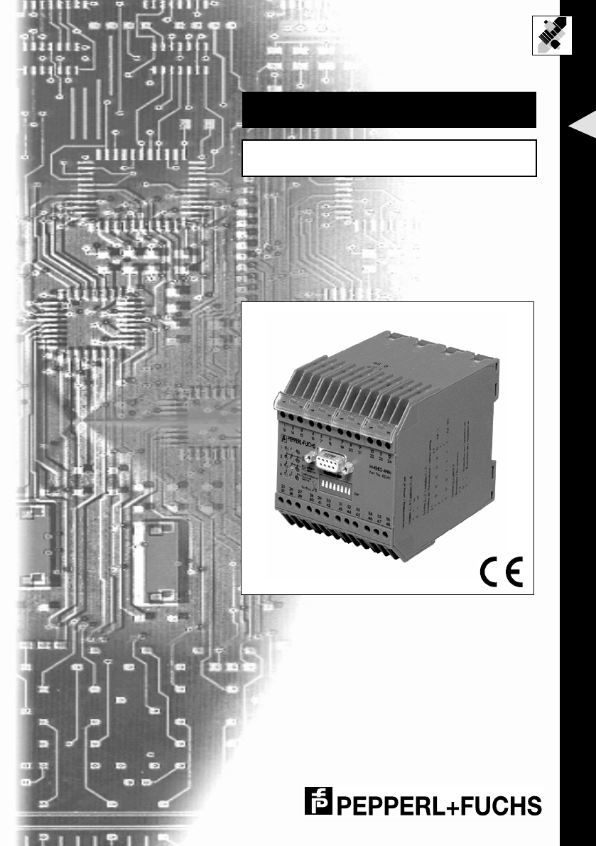
4.3 System description
Figure 4.1 Function of the control interface unit IRI-KHD2-4HB6/IRI-KHA6-4HB6 in the Inductive
Identification System R

IDENT-I • IVI-KHD2-4HB6, IVI-KHA6-4HB6
Product Description
Subject to reasonable modifications due to technical advances. Copyright Pepperl+Fuchs, Printed in Germany
P
epperl+Fuchs Group • Tel.: Germany (06 21) 7 76-0 • USA (330) 4 25 35 55 • Singapore 7 79 90 91 • Internet http://www.pepperl-fuchs.com
Date of issue 30.07.2001
10
The control interface unit IVI-KHD2-4HB6/IVI-KHA6-4HB6 takes over the control of
the connected read/write heads that implement the data transmission with the code
or data carriers, prepares the read/write information and controls the communication
and data transmission with a PROFIBUS master unit.
It is possible to connect up to 4 read/write heads to a single IVI-KHD2-4HB6/IVI-
KHA6-4HB6 unit.
With the PROFIBUS, the complete read/write functionality is available. The control in-
terface unit operates as a passive subscriber of the system bus (slave).

IDENT-I • IVI-KHD2-4HB6, IVI-KHA6-4HB6
Product Description
Subject to reasonable modifications due to technical advances. Copyright Pepperl+Fuchs, Printed in Germany
P
epperl+Fuchs Group • Tel.: Germany (06 21) 7 76-0 • USA (330) 4 25 35 55 • Singapore 7 79 90 91 • Internet http://www.pepperl-fuchs.com
Date of issue 30.07.2001
11
Overview of commands
The following commands for the reading and writing of data are available with the con-
trol interface unit IVI-KHD2-4HB6/IVI-KHA6-4HB6:
1. Reading fixcode carriers
2. Reading data carriers
Command Function Description
SF Single Read Fixcode All active parameterised read/write
heads or read heads will be activated
once. If multiple heads could
successfully read the data, then all
read data are transmitted.
AF Auto Read Fixcode All active parameterised read/write
heads or read heads are activated for
such a time until one fixcode carrier is
read.
BF Buffered Read Fixcode All active parameterised read/write
heads or read heads are activated
continuously.
EF Enhanced Buffered Read
Fixcode
All active parameterised read/write
heads or read heads are activated
continuously. If the code/data carrier
leaves the reading area, Status 5 is
transmitted.
Command Function Description
SR Single Read All active parameterised read/write
heads will be activated once. If multiple
heads could successfully read the
data, all read data is transmitted.
AR Auto Read All active parameterised read/write
heads will be activated, until the data of
one data carrier could be read.
BR Buffered Read All active parameterised read/write
heads will be continually activated.
ER Enhanced Buffered Read All active parameterised read/write
heads will be continually activated. If
the code/data carrier leaves the rea-
ding area, Status 5 is transmitted.

IDENT-I • IVI-KHD2-4HB6, IVI-KHA6-4HB6
Product Description
Subject to reasonable modifications due to technical advances. Copyright Pepperl+Fuchs, Printed in Germany
P
epperl+Fuchs Group • Tel.: Germany (06 21) 7 76-0 • USA (330) 4 25 35 55 • Singapore 7 79 90 91 • Internet http://www.pepperl-fuchs.com
Date of issue 30.07.2001
12
3. Blockwise reading of data carriers
The functions for blockwise reading SB/AB/BB are obtained by analogy with SR/AR/
BR, but only for 1k data carriers. The four blocks, each with 16 words, are read block-
wise "in one piece", which considerably increases the reading speed in comparison
with that for individual words.
Addressing:
4. Writing data carriers
Command Function Description
SB Single Read Block All active parameterised read/write
heads will be activated once. If multiple
heads could successfully read the
data, all read data is transmitted.
AB Auto Read Block All active parameterised read/write
heads will be activated, until the data of
one data carrier could be read.
BB Buffered Auto Read Block All active parameterised read/write
heads will be continually activated.
Block Word
0 0 ... 15
1 16 ... 31
2 32 ... 47
3 48 ... 63
Command Function Description
SW Single Write All active parameterised read/write
heads are activated in succession for
such a time until one head has suc-
cessfully written or all heads have been
activated once.
AW Auto Write All active parameterised read/write
heads are activated for such a time
until one data carrier could be written.
BW Buffered Write All active parameterised read/write
heads will be continually activated.
EW Enhanced Buffered Write All active parameterised read/write
heads will be continually activated. If
the code/data carrier leaves the rea-
ding area, Status 5 is transmitted.
IDENT-I • IVI-KHD2-4HB6, IVI-KHA6-4HB6
Product Description
Subject to reasonable modifications due to technical advances. Copyright Pepperl+Fuchs, Printed in Germany
P
epperl+Fuchs Group • Tel.: Germany (06 21) 7 76-0 • USA (330) 4 25 35 55 • Singapore 7 79 90 91 • Internet http://www.pepperl-fuchs.com
Date of issue 30.07.2001
13
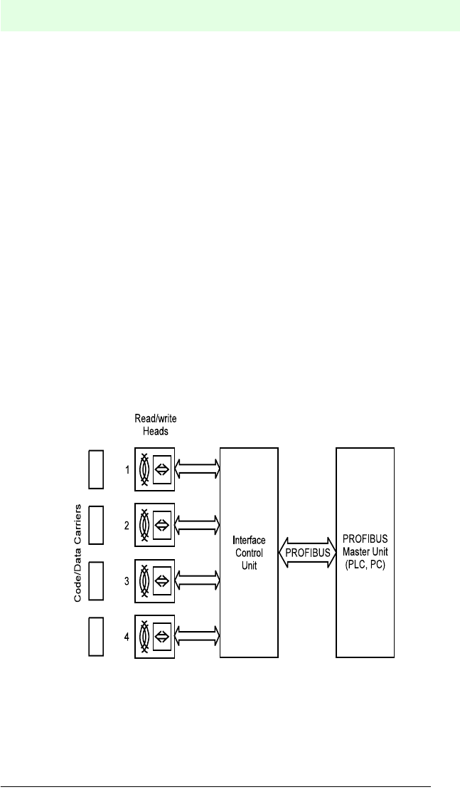
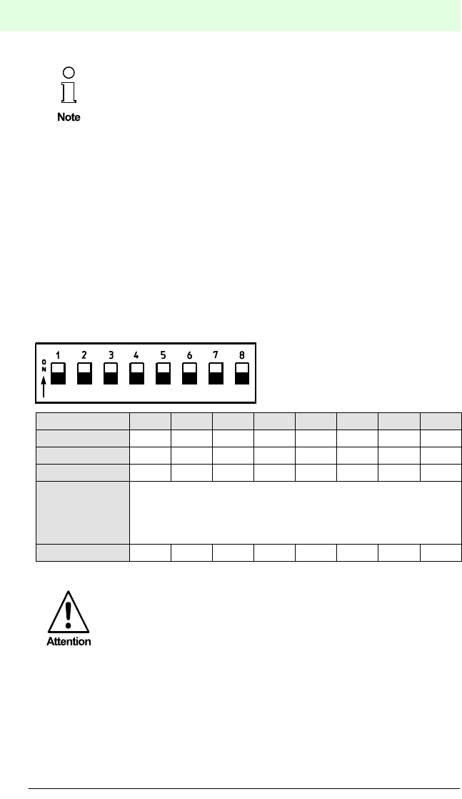
4.4 Indicators and operators
Structure and functioning
DIP-switch
(on the front side)
Switches 1 ... 7:
Switch 8:
subscriber address
no function
LED-indication
(on the front side)
Indicators Description
Ident 3 LEDs per read head status
LED green Read/write head active (4 LEDs, 1 per head)
LED yellow Code carrier detected (4 LEDs, 1 per head)
LED red Functional reserved (4 LEDs, 1 per head)
Bus 1 LED system status (two-coloured)
Run/Error LED green device ready for operation/communication active
Run/Error LED red device error
red-green blinking device ready for operation/communication faulty
Bus termination
(on the top side)
Switch S9:
(Bus termination)
0 = OFF
1 = ON
IVH aktiv/
IVH active
IDC erkannt/
IDC detected
reserviert/
reserved
PROFIBUS-DP
Run/Error
1
2
3
45
sw
plug
Sub-D
MSBLSB
IVH aktiv/
IVH active
IDC erkannt/
IDC detected
reserviert/
reserved
1
2
3
4
1
0
S9
DIP-Switch
LED-Indication
IDENT-I • IVI-KHD2-4HB6, IVI-KHA6-4HB6
Product Description
Subject to reasonable modifications due to technical advances. Copyright Pepperl+Fuchs, Printed in Germany
P
epperl+Fuchs Group • Tel.: Germany (06 21) 7 76-0 • USA (330) 4 25 35 55 • Singapore 7 79 90 91 • Internet http://www.pepperl-fuchs.com
Date of issue 30.07.2001
14
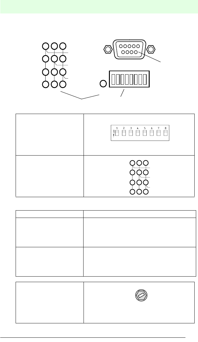
4.5 Structure and functioning
The control interface unit IVI-KHD2-4HB6/IVI-KHA6-4HB6 is the link between the
read heads and the PROFIBUS master (PLC, PC, etc.). Two independently operating
microprocessors, which are connected to each other via an interface, take over the
data exchange between the read heads and the PROFIBUS master.
Figure 4.2 Block diagram of the control interface unit IVI-KHD2-4HB6/IVI-KHA6-4HB6
Both the supply voltage and the RS 485 interface of the PROFIBUS are galvanically
isolated within the system.
Up to 14 words (DP) of user data can be transmitted in a single telegram.
4.6 System variants
The control interface unit IVI-KHD2-4HB6/IVI-KHA6-4HB6 comes in two versions
which vary only in their supply voltage.
Variant Supply Voltage
IVI-KHD2-4HB6 18 V DC ... 32 V DC
IVI-KHA6-4HB6 85 V AC ... 253 V AC, 50 Hz ... 60 Hz
IDENT-I • IVI-KHD2-4HB6, IVI-KHA6-4HB6
Product Description
Subject to reasonable modifications due to technical advances. Copyright Pepperl+Fuchs, Printed in Germany
P
epperl+Fuchs Group • Tel.: Germany (06 21) 7 76-0 • USA (330) 4 25 35 55 • Singapore 7 79 90 91 • Internet http://www.pepperl-fuchs.com
Date of issue 30.07.2001
15
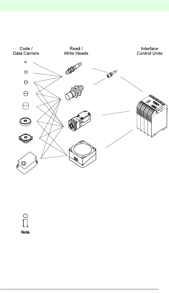
4.7 Accessories/product family
The inductive identification system IDENT-I from Pepperl+Fuchs offers many different
possibilities to combine single components.
Figure 4.3 Overview of the inductive identification system structure
According to installation requirements, read/write distance, environmental conditions
and memory requirements, one can select appropriate code/data carriers and read/
write heads.
Further information on the inductive identification system with read/write
functioning (System V) can be found in the Sensor Systems 1 cata-
logue.

IDENT-I • IVI-KHD2-4HB6, IVI-KHA6-4HB6
Product Description
Subject to reasonable modifications due to technical advances. Copyright Pepperl+Fuchs, Printed in Germany
P
epperl+Fuchs Group • Tel.: Germany (06 21) 7 76-0 • USA (330) 4 25 35 55 • Singapore 7 79 90 91 • Internet http://www.pepperl-fuchs.com
Date of issue 30.07.2001
16

IDENT-I • IVI-KHD2-4HB6, IVI-KHA6-4HB6
Installation
Subject to reasonable modifications due to technical advances. Copyright Pepperl+Fuchs, Printed in Germany
P
epperl+Fuchs Group • Tel.: Germany (06 21) 7 76-0 • USA (330) 4 25 35 55 • Singapore 7 79 90 91 • Internet http://www.pepperl-fuchs.com
Date of issue 30.07.2001
17
5 Installation
5.1 Storage and transport
The device must be packed for storage and transport so that it is shock-resistant and
protected against humidity. The original packaging offers optimal protection.
The necessary environmental conditions also must be satisfied (see chap. 9 "Techni-
cal Data").
5.2 Unpacking
Check that the contents are not damaged. In case of damage, notify the postal service
or the forwarding agent and inform the deliverer.
Check the contents of delivery with respect to your order and the delivery papers for:
•correct number of parts
•device type and version according to the name plate
•accessories
•manual(s)
Keep the original packaging in case the device must be repacked and stored or re-
shipped.
For any further questions please contact Pepperl+Fuchs GmbH.
IDENT-I • IVI-KHD2-4HB6, IVI-KHA6-4HB6
Installation
Subject to reasonable modifications due to technical advances. Copyright Pepperl+Fuchs, Printed in Germany
P
epperl+Fuchs Group • Tel.: Germany (06 21) 7 76-0 • USA (330) 4 25 35 55 • Singapore 7 79 90 91 • Internet http://www.pepperl-fuchs.com
Date of issue 30.07.2001
18
5.3 Mounting
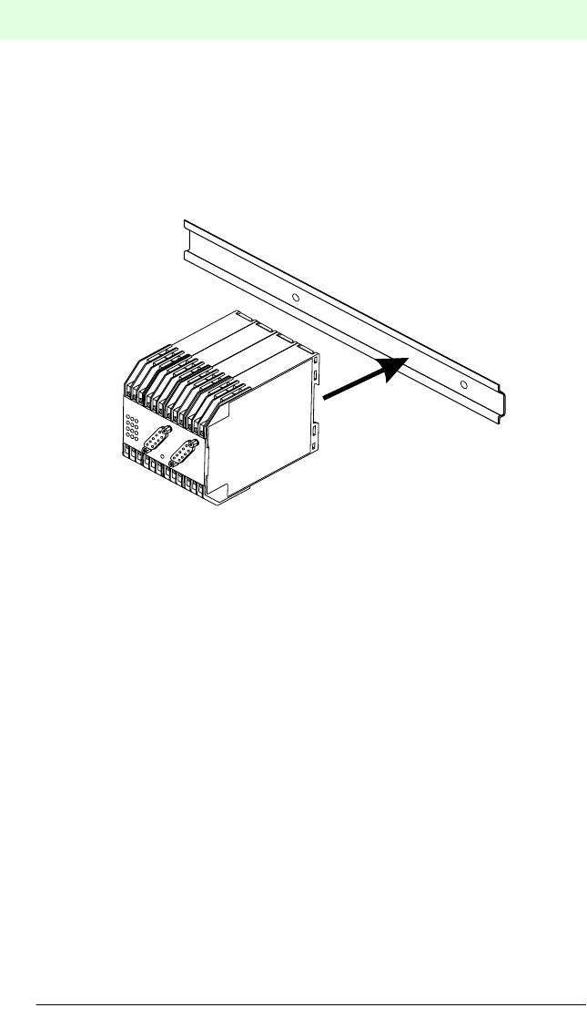
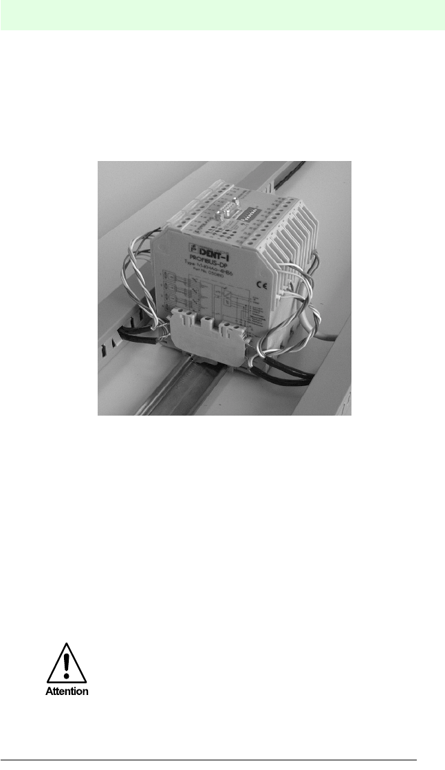
5.3.1 Mounting to a top-hat rail
As with all systems in K-system housings from Pepperl+Fuchs, the control interface
unit IVI-KHD2-4HB6/IVI-KHA6-4HB6 can be snapped onto the 35 mm standard top-
hat rail according to DIN EN 50022
.
Figure 5.1 Mounting to the top-hat rail according to DIN EN 50022
Hang the unit over the top part of the top-hat rail and press the bottom part of the hou-
sing against the rail until it snaps onto the railing. Check that the unit sits firmly on the
railing.
IDENT-I • IVI-KHD2-4HB6, IVI-KHA6-4HB6
Installation
Subject to reasonable modifications due to technical advances. Copyright Pepperl+Fuchs, Printed in Germany
P
epperl+Fuchs Group • Tel.: Germany (06 21) 7 76-0 • USA (330) 4 25 35 55 • Singapore 7 79 90 91 • Internet http://www.pepperl-fuchs.com
Date of issue 30.07.2001
19
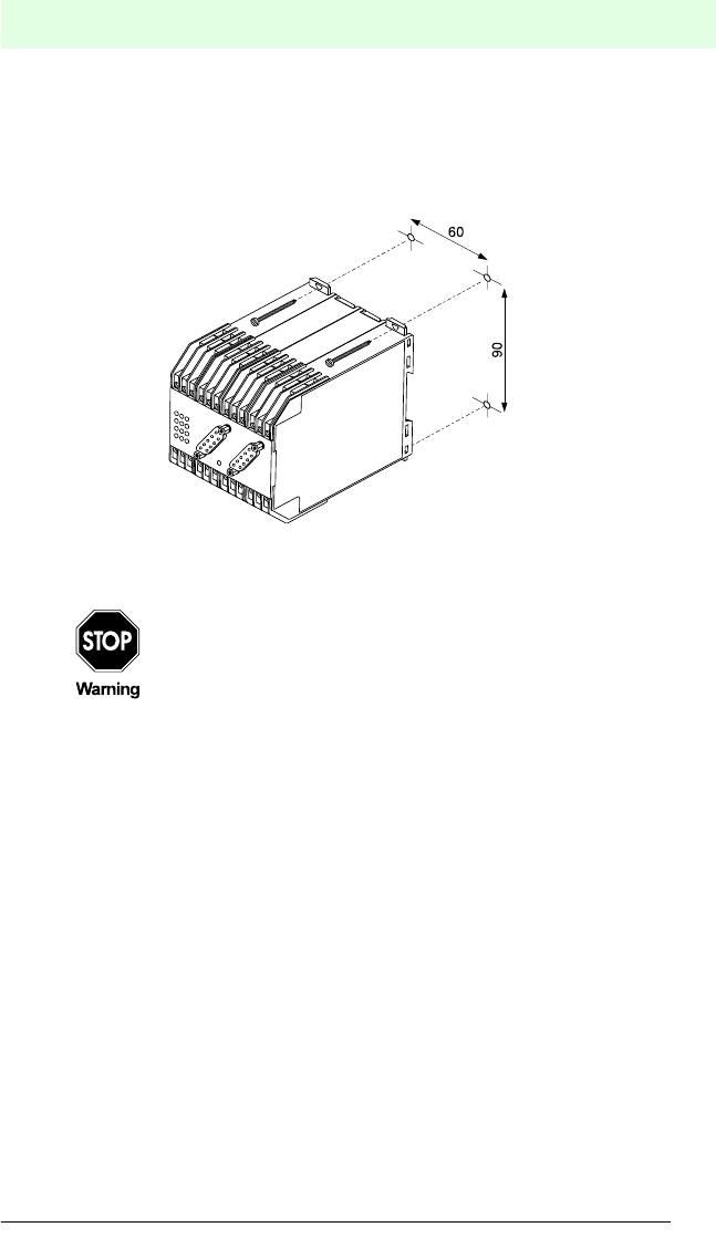
5.3.2 Wall mounting
The control interface unit can also be mounted on the wall using four screws. Simply
pull out the four outer brackets on the back side of the unit. The unit can be easily
screwed onto the wall through the holes in the brackets. The screw pair spacing is 90
mm (max. screw diameter M5).
Figure 5.2 Wall mounting
5.4 Electrical connection
Only qualified personnel are permitted to carry out work under voltage
and make electrical connection to the mains.
Ensure that the correct voltage is applied according to the name plate of
the unit.
A mains isolating device must be installed close to the device and label-
led as such for the IVI-KHD2-4HB6/IVI-KHA6-4HB6.
IDENT-I • IVI-KHD2-4HB6, IVI-KHA6-4HB6
Installation
Subject to reasonable modifications due to technical advances. Copyright Pepperl+Fuchs, Printed in Germany
P
epperl+Fuchs Group • Tel.: Germany (06 21) 7 76-0 • USA (330) 4 25 35 55 • Singapore 7 79 90 91 • Internet http://www.pepperl-fuchs.com
Date of issue 30.07.2001
20
5.4.1 Equipment connection
The electrical connection of the control interface unit is made with the self-opening
screw terminals on the top and bottom of the unit, max. cross section 2 x 2.5 mm2.
The PROFIBUS connection must be carried out according to the PROFIBUS specifi-
cation via the 9-pole Sub-D sockets on the front of the device. Additionally, the bus
connections (RxD/TxD - P, RxD/TxD-N, shield) are also available on the screw termi-
nals.
Connect the read heads and the supply voltage according to the connection diagram
and the labelled configuration of the terminals.
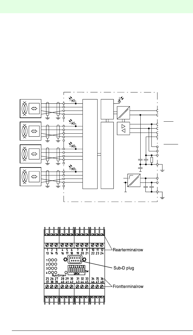
Figure 5.3 Connection diagram for the control interface unit IVI-KHD2-4HB6/IVI-KHA6-4HB6
Location of the connection terminals
Figure 5.4 Assignment of connection terminals
1 Screen
30 Screen
Sub-D
Terminals
+
Reset
Data
-
reserved
+
Reset
Data
-
reserved
+
Reset
Data
-
reserved
+
Reset
Data
-
reserved
+
_U
U
5
1.1
2.1
3.1
4.1
µP1
µP2
1
2
3
4
5
13
14
15
16
17
25
26
27
28
29
37
38
39
40
41
1
2
3
4
1
2
3
4
1
2
3
4
1
2
3
4
1
2
3
4
6VP
5 DGND
3 RxD/TxD-P
8 RxD/TxD-N
6 RxD/TxD-P
18 RxD/TxD-N
4 CNTR-P
42
46
48 ~ / -
47 ~ / +

IDENT-I • IVI-KHD2-4HB6, IVI-KHA6-4HB6
Installation
Subject to reasonable modifications due to technical advances. Copyright Pepperl+Fuchs, Printed in Germany
P
epperl+Fuchs Group • Tel.: Germany (06 21) 7 76-0 • USA (330) 4 25 35 55 • Singapore 7 79 90 91 • Internet http://www.pepperl-fuchs.com
Date of issue 30.07.2001
21
List of terminal assignments
Terminal Function
1supply voltage read/write head 1 positive
2"direction" read/write head 1
3"data" read/write head 1
4supply voltage read/write head 1 negative
5reserved
6 PROFIBUS RxD/TxD-P
7reserved
8reserved
9reserved
10 reserved
11 reserved
12 reserved
13 supply voltage read/write head 2 positive
14 "direction" read/write head 2
15 "data" read/write head 2
16 supply voltage read/write head 2 negative
17 reserved
18 PROFIBUS RxD/TxD-N
19 reserved
20 reserved
21 reserved
22 reserved
23 reserved
24 reserved
25 supply voltage read/write head 3 positive
26 "direction" read/write head 3
27 "data" read/write head 3
28 supply voltage read/write head 3 negative
29 reserved
30 reserved
31 reserved
32 reserved
33 reserved
34 reserved
35 reserved
36 reserved
37 supply voltage read/write head 4 positive
38 "direction" read/write head 4
IDENT-I • IVI-KHD2-4HB6, IVI-KHA6-4HB6
Installation
Subject to reasonable modifications due to technical advances. Copyright Pepperl+Fuchs, Printed in Germany
P
epperl+Fuchs Group • Tel.: Germany (06 21) 7 76-0 • USA (330) 4 25 35 55 • Singapore 7 79 90 91 • Internet http://www.pepperl-fuchs.com
Date of issue 30.07.2001
22
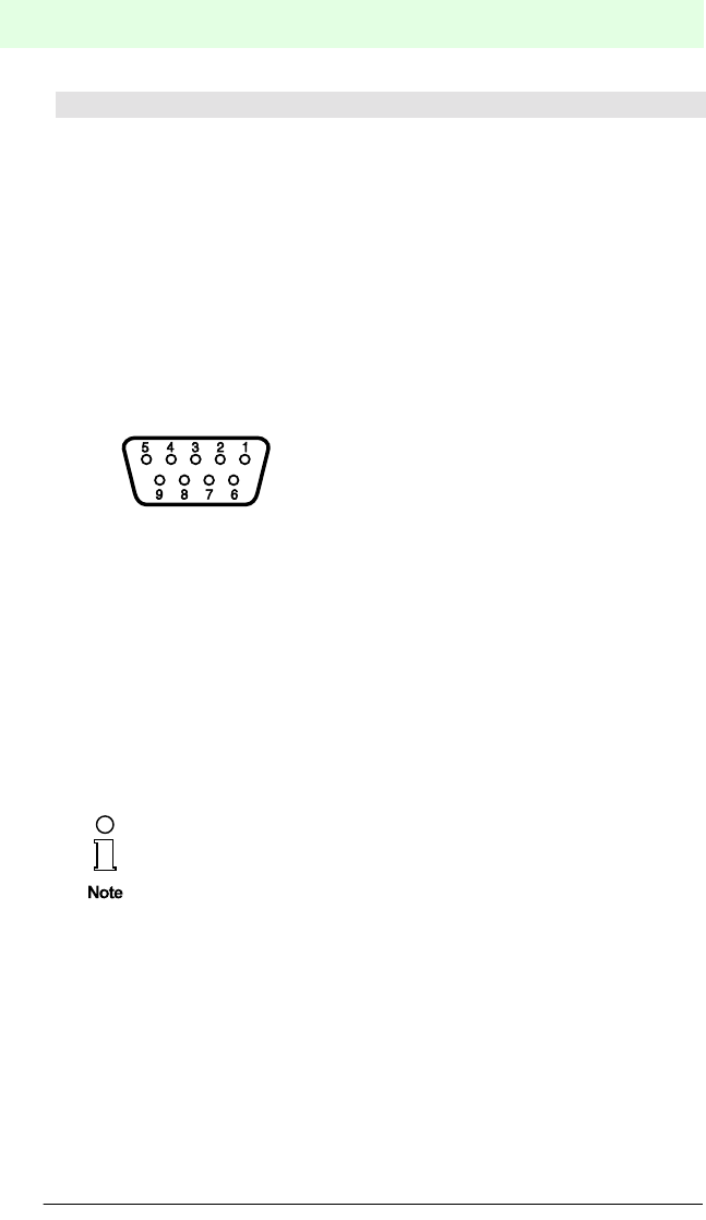
Assignment of the 9-pole Sub-D socket
39 "data" read/write head 4
40 supply voltage read/write head 4 negative
41 reserved
42 ground bus/identification system
43 reserved
44 reserved
45 reserved
46 ground power supply
47 L+ (IVI-KHD2-4HB6) or L (IVI-KHA6-4HB6)
48 L- (IVI-KHD2-4HB6) or N (IVI-KHA6-4HB6)
PIN Function
1 shield PROFIBUS cable (connect to metal casing of Sub-D connector)
2 reserved
3 PROFIBUS RxD/TxD-P
4 CNTR-P
5DGND
6VP
7 reserved
8 PROFIBUS RxD/TxD-N
9 reserved
If leads with double shielding are used, e.g. metallic wire mesh and
metallic foil, they must be connected to each other using a low impe-
dance connection at one end of the cable.
Many noise impulses come from the supply cables, e.g. switch-on cur-
rent of a motor. For this reason, running the supply cables in parallel
with the data/signal cables, especially in the same cable duct, should be
avoided.
Terminal Function
IDENT-I • IVI-KHD2-4HB6, IVI-KHA6-4HB6
Installation
Subject to reasonable modifications due to technical advances. Copyright Pepperl+Fuchs, Printed in Germany
P
epperl+Fuchs Group • Tel.: Germany (06 21) 7 76-0 • USA (330) 4 25 35 55 • Singapore 7 79 90 91 • Internet http://www.pepperl-fuchs.com
Date of issue 30.07.2001
23
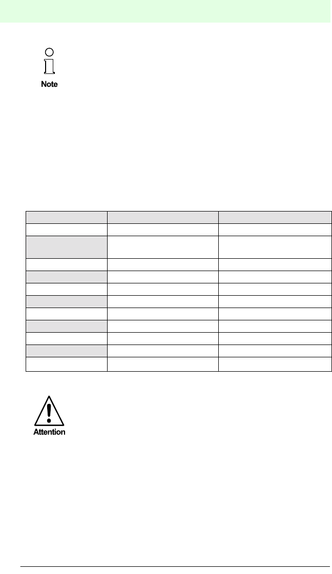
5.4.2 Information for connecting the read/write head cable
The connecting cables to the read/write heads must be shielded. The cross section
of the cables must be at least 0.14 mm2.
The screen of the read head lead is connected on both sides to earth (PE) with low
resistence and low induction. For that the attached terminal block can be used (see
figure 5.5.). Please make sure that the screen is kept as small as possible.
Figure 5.5 Terminal block with connecting cables
Read head cable lengths up to 50 m or 100 m are possible if the following conditions
are satisfied:
up to 50 m read head cable: cross sectional area of at least 4 x 0.25 mm2
maximum resistance 78 Ohm/km
maximum capacitance 90 pF/m
(e.g. LIYC11C, Mukkenhaut & Nusselt MUNFLEX
C11Y)
up to 100 m read head
cable:
cross sectional area of at least 4 x 0.5 mm2
maximum resistance 37 Ohm/km
maximum capacitance 90 pF/m
With a cable length of 100 m, a series resistor of 82 Ohm must be fitted
in the cable connected to the 'Reset' terminal of the read heads.
Since more EM interference can result with longer cable lengths, the
maximum cable lengths given above might not be possible for some
applications.
IDENT-I • IVI-KHD2-4HB6, IVI-KHA6-4HB6
Installation
Subject to reasonable modifications due to technical advances. Copyright Pepperl+Fuchs, Printed in Germany
P
epperl+Fuchs Group • Tel.: Germany (06 21) 7 76-0 • USA (330) 4 25 35 55 • Singapore 7 79 90 91 • Internet http://www.pepperl-fuchs.com
Date of issue 30.07.2001
24
5.4.3 Special connection information for the PROFIBUS cable
The connecting lead for the bus is specified in the EN 50170 as type A cable and can
be used in accordance with the following table. Line parameters and lengths for a type
B cable are also included in the following tables for the sake of completeness. Only
cable of type A should be used in new designs because of the longer overall length
of leads in systems.
Line parameters as follows:
Line B*) not to be used in future, if possible.
Transmission rates
The following transmission rates are supported:
9.6 kbit/s, 19.2 kbit/s, 44.44 kbit/s, 93.75 kbit/s, 187.5 kbit/s, 500 kbit/s and 1.5 Mbit/s.
The setting of the transmission rate required is self-synchronising.
If leads with double shielding are used, e.g. metallic wire mesh and
metallic foil, they must be connected to each other using a low impe-
dance connection at one end of the cable.
Many noise impulses come from the supply cables, e.g. switch-on cur-
rent of a motor. For this reason, running the supply cables in parallel
with the data/signal cables, especially in the same cable duct, should be
avoided.
Parameter Line A Line B*
cable design two-wire twisted, shielded two-wire twisted, shielded
capacitance per unit
length
(pF/m) < 30 < 60
surge impedance
(W) 135 ... 165 100 ... 130
loop resistance
(W) 110 -*)
lead diameter
(mm) 0.64 > 0.53
cross sectional area
(mm2)> 0.34 > 0.22
Use only twisted pair, shielded cable. In this case, the noise immunity
will be optimised.
IDENT-I • IVI-KHD2-4HB6, IVI-KHA6-4HB6
Installation
Subject to reasonable modifications due to technical advances. Copyright Pepperl+Fuchs, Printed in Germany
P
epperl+Fuchs Group • Tel.: Germany (06 21) 7 76-0 • USA (330) 4 25 35 55 • Singapore 7 79 90 91 • Internet http://www.pepperl-fuchs.com
Date of issue 30.07.2001
25
Length of leads
The reliable lengths of the transmission leads in a bus segment are determined from
the following:
•type of bus cables used
•influence of external noise
•transmission rate
•number of bus subscribers
The maximum total lead length of a bus segment as a function of the transmission rate
for maximum number of subscribers (32) is:
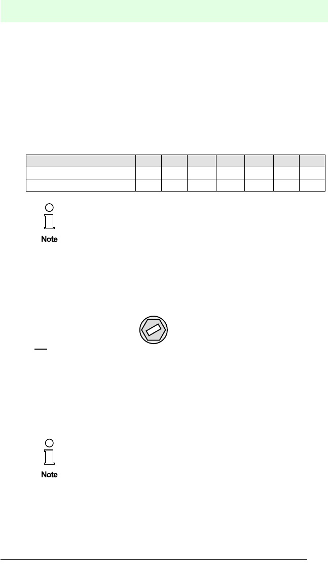
Bus termination
With the PROFIBUS, every bus segment must be terminated via terminating resis-
tances at both ends of the bus leads.
Figure 5.6 Rotating switch S9 for the termination of the bus
The control interface unit IVI-KHD2-4HB6/IVI-KHA6-4HB6 has built-in, switchable
bus termination. The bus termination can be activated by turning the rotating switch
S9 on the left hand side of the unit housing with an appropriate screwdriver.
Transmission rate in kbit/s 9.6 19.2 44.44 93.75 187.5 500 1500
Line type A (in m) 1200 1200 1200 1200 1000 400 200
Line type B (in m) 1200 1200 1200 1200 600 200 •••
By breaking into multiple bus segments and the application of repea-
ters, the transmission length can be increased. A maximum of three
repeaters between two communicating bus subscribers can be used.
If leads with double shielding are used, e.g. metallic wire mesh and
metallic foil, they must be connected to each other using a low impe-
dance connection at one end of the cable.
Many noise impulses come from the supply cables, e.g. switch-on cur-
rent of a motor. For this reason, running the supply cables in parallel
with the data/signal cables, especially in the same cable duct, should be
avoided.
Bus termination
aktiv
Bus termination
not aktiv
Rotation switch “S9“ for the
Bus termination of the
system on top side.
Adjust with an appropriate
screwdriver.
1
0
S9

IDENT-I • IVI-KHD2-4HB6, IVI-KHA6-4HB6
Installation
Subject to reasonable modifications due to technical advances. Copyright Pepperl+Fuchs, Printed in Germany
P
epperl+Fuchs Group • Tel.: Germany (06 21) 7 76-0 • USA (330) 4 25 35 55 • Singapore 7 79 90 91 • Internet http://www.pepperl-fuchs.com
Date of issue 30.07.2001
26
5.5 Disassembly, packing and disposal
Repacking
The unit must be protected against humidity and shock when packing for later use.
The original packaging offers optimal protection.
Disposal
Electronic waste can be hazardous. Pay attention to local regulations
when disposing of this unit.
The control interface unit IVI-KHD2-4HB6/IVI-KHA6-4HB6 does not
contain internal batteries which must be removed before disposal.

IDENT-I • IVI-KHD2-4HB6, IVI-KHA6-4HB6
Commissioning
Subject to reasonable modifications due to technical advances. Copyright Pepperl+Fuchs, Printed in Germany
P
epperl+Fuchs Group • Tel.: Germany (06 21) 7 76-0 • USA (330) 4 25 35 55 • Singapore 7 79 90 91 • Internet http://www.pepperl-fuchs.com
Date of issue 30.07.2001
27
6 Commissioning
6.1 Preparation
Due to the complexity of field bus programming with the PROFIBUS, it is, unfortuna-
tely, difficult to give a valid general description on how to perform the commissioning.
A very important aspect for the operation of an inductive identification system using
the control interface unit IVI-KHD2-4HB6/IVI-KHA6-4HB6 on the PROFIBUS is the re-
sponse time of the total system. The question "How much time is required for data to
be available in my computer once the code carrier is positioned in front of the read
head?" cannot be correctly answered in general.
The important factors in respect to response time are:
•type of high order host system, e.g. PLC or PC
•type of PROFIBUS master, e.g. pre-defined transmission rate
•communication between the PROFIBUS master and the host system
•the number of PROFIBUS subscribers
•the number of control interface units on the PROFIBUS
•the number and type of read/write heads connected
•type of code or data carriers used
•type of access of the communications objects of the control interface unit
•type of commands on the identification system
•structure of the user program
For this reason, you should construct a test system for your particular application and
check the transmission to the PROFIBUS master or host system if you have little ex-
perience with the design of a PROFIBUS system.
Before proceeding with the commissioning, make sure that no danger
to the system can arise from the device, e.g. due to uncontrolled control
processes.
Check again all connections before proceeding with the commissioning.
Prepare for the commissioning by familiarising yourself with the com-
munication between the PROFIBUS master and the control interface
unit (see chap. 7). The commissioning requires a good knowledge of
the PROFIBUS and the programming of the master unit.
IDENT-I • IVI-KHD2-4HB6, IVI-KHA6-4HB6
Commissioning
Subject to reasonable modifications due to technical advances. Copyright Pepperl+Fuchs, Printed in Germany
P
epperl+Fuchs Group • Tel.: Germany (06 21) 7 76-0 • USA (330) 4 25 35 55 • Singapore 7 79 90 91 • Internet http://www.pepperl-fuchs.com
Date of issue 30.07.2001
28
6.2 Main procedure
Before the commissioning, the system address of the control interface unit and, if ne-
cessary, of the bus termination (chapter 5.4.3 "Special connection information for the
PROFIBUS cable") must be set.
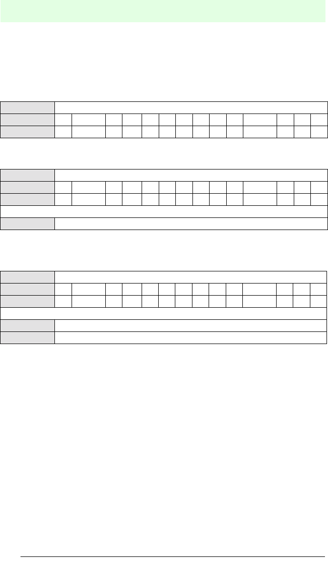
Setting of the unit address
Select a device address not already occupied by another bus subscriber (between 0
and 126) and set this address using the DIP switch on the front of the device.
Figure 6.1 Setting the device address
A complete series of design tools exist that allow a PROFIBUS user to
plan and commission a network, even if he/she has no knowledge of
the fundamental communication sequences.
There are PC programs and PROFIBUS PC connector cards which
help determine the communication relationships and your parameters,
and can clearly display bus telegrams on the screen.
The system software of programmable logic controllers (PLC) with a
PROFIBUS communication processor often offer network configuration
and management possibilities.
Device address S1 S2 S3 S4 S5 S6 S7 S8
0OFF OFF OFF OFF OFF OFF OFF OFF
1ON OFF OFF OFF OFF OFF OFF OFF
2OFF ON OFF OFF OFF OFF OFF OFF
•
••
•
•
•
•
•
•
•
•
•
•
•
•
•
•
•
•
••
•
•
•
•
•
•
•
•
•
•
•
•
•
•
•
126 OFFONONONONONONOFF
The device address 127 is reserved for a special PROFIBUS service. If
the address 127 is set on a slave unit, it will not function.
DIP-Switch "SW" on the
front side of the unit to adjust
the PROFIBUS device

IDENT-I • IVI-KHD2-4HB6, IVI-KHA6-4HB6
Commissioning
Subject to reasonable modifications due to technical advances. Copyright Pepperl+Fuchs, Printed in Germany
P
epperl+Fuchs Group • Tel.: Germany (06 21) 7 76-0 • USA (330) 4 25 35 55 • Singapore 7 79 90 91 • Internet http://www.pepperl-fuchs.com
Date of issue 30.07.2001
29
After connecting to voltage, the control interface unit automatically adjusts its trans-
mission rate to that of the master. The supported rates are:
Configuration of the network master(s) for DP operation
The configuration data required for the control interface unit IVI-KHD2-4HB6/IVI-
KHA6-4HB6 can be found in the GSD file supplied and the network master is confi-
gured accordingly. If you have a configuration tool, then the network master is confi-
gured automatically by using the configuration tool to read the GSD file.
The device address must be entered to do this.
Self test
After switching on the supply voltage, the control interface unit checks the internal me-
mory area with a self test. If a device error or transmission error occurs, or if an incor-
rect device address is set, communication will not be activated. The error is indicated
with the LED "Run/Error" (see chap. 8 "Fault Diagnostics").
Interconnection structure
The interconnection structure is established automatically in DP mode
It is now possible to communicate with the control interface unit IVI-KHD2-4HB6/IVI-
KHA6-4HB6 using the PROFIBUS master.
• 9.6 kbit/s • 19.2 kbit/s
• 44.44 kbit/s • 93.75 kbit/s
• 187.5 kbit/s • 500 kbit/s
• 1.5 Mbit/s
If the logic connection to the control interface unit is made, the LED
"Run/Error" will be green and permanently illuminated.

IDENT-I • IVI-KHD2-4HB6, IVI-KHA6-4HB6
Commissioning
Subject to reasonable modifications due to technical advances. Copyright Pepperl+Fuchs, Printed in Germany
P
epperl+Fuchs Group • Tel.: Germany (06 21) 7 76-0 • USA (330) 4 25 35 55 • Singapore 7 79 90 91 • Internet http://www.pepperl-fuchs.com
Date of issue 30.07.2001
30

IDENT-I • IVI-KHD2-4HB6, IVI-KHA6-4HB6
Operation with the PROFIBUS
Subject to reasonable modifications due to technical advances. Copyright Pepperl+Fuchs, Printed in Germany
P
epperl+Fuchs Group • Tel.: Germany (06 21) 7 76-0 • USA (330) 4 25 35 55 • Singapore 7 79 90 91 • Internet http://www.pepperl-fuchs.com
Date of issue 31.07.2001
31
7 Operation with the PROFIBUS
7.1 General information on the PROFIBUS
The INTERBUS is a standardized field bus that can exchange data between PLCs,
PCs, operating and monitoring systems as well as sensors and actuators.
The framework of this operating manual can not be considered as an extensive intro-
duction to the PROFIBUS. For substantial information, one is referred to the PROFI-
BUS standard DIN 19245 or EN 50170 and the relevant literature.
Performance features PROFIBUS-DP
The important PROFIBUS-DP performance features of the control interface unit
IVI-KHD2-4HB6/IVI-KHA6-4HB6 are as follows:
•full DP slave functionality with the functions Data_Exchange, RD_Inp, RD_Outp,
Slave_Diag, Set_Prm, Chk_Cfg, Get_Cfg, Global_Control, Set_Slave_Add
•modular DP slave device with one module each for read and write data
•transmission rates 9.6 kbit/s, 19.2 kbit/s, 44.44 kbits/s, 93.75 kbit/s, 187.5 kbit/s,
500 kbit/s and 1.5 Mbit/s self-synchronising
•switchable bus termination
•adjustable system address 0 ... 126
Information brochures and a PROFIBUS product catalogue is available
from the PROFIBUS User Organisation e.V. (PNO), Karlsruhe .

IDENT-I • IVI-KHD2-4HB6, IVI-KHA6-4HB6
Operation with the PROFIBUS
Subject to reasonable modifications due to technical advances. Copyright Pepperl+Fuchs, Printed in Germany
P
epperl+Fuchs Group • Tel.: Germany (06 21) 7 76-0 • USA (330) 4 25 35 55 • Singapore 7 79 90 91 • Internet http://www.pepperl-fuchs.com
Date of issue 31.07.2001
32
7.2 PROFIBUS-DP
7.2.1 PROFIBUS DP communication parameters
The communication parameters can be found in the master data file (GSD) for the de-
vice. The name of the GSD-file is p&f_0840.gsd.
7.2.2 PROFIBUS DP functions
7.2.3 Device identification/software version message for PROFIBUS DP
Transmission of device identification and the software version is by the DP function
"device-specific diagnosis"
Function Description Master
Set_Slave_Add Change the address of a DP slave Class 2
Set_Prm Transfer parameterisation data to a DP slave Class 1
Chk_Cfg Transfer configuration data to a DP slave to check Class 1
Get_Cfg Read configuration data from a DP slave Class 2
Data_Exchange Send output data to a DP slave device and request
input data from a DP slave
Class 1
RD_Inp Read input data from a DP slave Class 2
RD_Outp Read output data from a DP slave Class 2
Global_Control Send special commands to one or more DP slaves Class 1
Slave_Diag Read diagnostic information from a DP slave Class 1
Byte Description
0 Station status 1
1 Station status 2
2 Station status 3
3 Model station number
4 Manufactoring designation (high Byte)
5 Manufactoring designation (low Byte)
from 6 Other specific diagnostic data (header byte, data length)
7 ... 12 "IVI-B6"
13 blank
14 Identification of the bus software
15 Index for the bus software
16 blank
17 Identification of the identification system software
18 Index for the identification system software

IDENT-I • IVI-KHD2-4HB6, IVI-KHA6-4HB6
Operation with the PROFIBUS
Subject to reasonable modifications due to technical advances. Copyright Pepperl+Fuchs, Printed in Germany
P
epperl+Fuchs Group • Tel.: Germany (06 21) 7 76-0 • USA (330) 4 25 35 55 • Singapore 7 79 90 91 • Internet http://www.pepperl-fuchs.com
Date of issue 31.07.2001
33
7.2.4 Definition of PROFIBUS DP modules
For the transmission of the entry data (read, data from slave to DP-master) and output
data (write, data from DP-master to slave) are an input and output module defined.
The size of the input module and output module is variable. At this way, the quantity
(from Firmware-Version 1801K017 from the 22nd June 1998) of the data is optimized
for the actual application. This avoided an unnecessary load of the bus through not-
used data.
For using the variable length of the module, you need the master data file P&F_0840.GSD
Revision 1.2 from the 10th July 1998. In this file, the input module with a word length from
2 to 16 and the output module with a word length up to 16 are predefined.
The size of the module you need is dependent from the application. The output mo-
dule (data from DP-master to slave) contains one or two commands and up to 14
words data.
The input module (data from slave to DP-master) always contains two words status
and up to 14 words data.
Examples:
Command "Single/Auto/Buffered Read Fixcode"
Only one word commands and command parameters are transmitted. A data carrier
word address or write data are not used. Here you can still use the "1 Word Output"
module.
The length of the fixcode-data which reads the code carrier amounts to 4 words. Be-
cause always two words status are additional transmitted, the minimum size of the in-
put module must be 6 words. You must choose the "6 Words Input" module.
Command "Single/Auto/Buffered Write", write data-length 14 words
Here are two words for the commands (command, parameter and data carrier
word address) required. Together with the 14 words write data the maximum output
module length results in 16 words (16 words output).
For valid read commands, the control interface unit responds only with the status
command, so the input module size of two words is enough (2 Words Input).
Command "Single/Auto/Buffered Read", read data-length 8 words
For the transmission of the read commands are two words necessary (commands,
command parameters and data carrier word address), so module "2 Words Output"
is enough.
For the transmission of the read commands and the two words status commands are
totally 10 words necessary, so modul "10 Words Input" is fit.
The structure of the 16 data words for the communication direction from DP master
to control interface unit and from control interface unit to DP master is described in
the following two chapters.
At projecting, select only one input module and one output module from
the table.
IDENT-I • IVI-KHD2-4HB6, IVI-KHA6-4HB6
Operation with the PROFIBUS
Subject to reasonable modifications due to technical advances. Copyright Pepperl+Fuchs, Printed in Germany
P
epperl+Fuchs Group • Tel.: Germany (06 21) 7 76-0 • USA (330) 4 25 35 55 • Singapore 7 79 90 91 • Internet http://www.pepperl-fuchs.com
Date of issue 31.07.2001
34
7.2.5 Communication direction: PROFIBUS DP Þ control interface unit
The transmitted data are depending from the length of the chosen output mode.
In the following, only the structure of the necessary words are shown. If, depending
from the module size, further words are generated, these words contain no valid data.
Reading Fixcode
Commands and command parameters are transmitted in word 0.
Reading data
Commands and command parameters are transmitted in word 0. Word 1 contains the
starting memory address for the data carrier, as of which the data are read or written.
Writing data
Depending from the chosen modul size is n maximum 16.
Commands and command parameters are transmitted in word 0. Word 1 contains the
starting memory address for the data carrier, as of which the data are read or written.
The words 2 ... 15 include the data to be written for write commands. For read com-
mands, the words 2 ... 15 do not contain valid data.
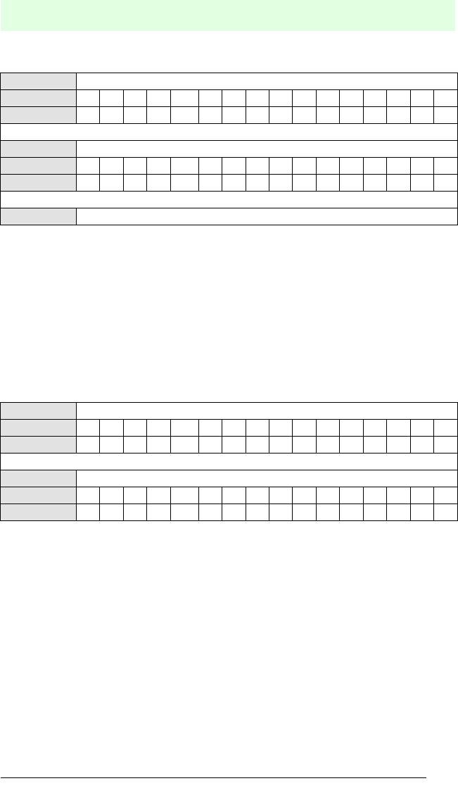
Word 0 Commands and parameters
Bit No. 15 14 13 12 11 10 9 8 7 6 5 4 3 2 1 0
Description B4B3 B2B1DS 0 T2T1N4N3N2N1K3K2K1 T
Word 0 Commands and parameters
Bit No. 15 14 13 12 11 10 9 8 7 6 5 4 3 2 1 0
Description B4B3 B2B1DS 0 T2T1N4N3N2N1K3K2K1 T
Word 1 Word address/Block address (Block commands SB/AB/BB)
Word 0 Commands and parameters
Bit No. 15 14 13 12 11 10 9 8 7 6 5 4 3 2 1 0
Description B4B3 B2B1DS 0 T2T1N4N3N2N1K3K2K1 T
Word 1 Word address/Block address (Block commands SB/AB/BB)
Words 2 ... n Write data
IDENT-I • IVI-KHD2-4HB6, IVI-KHA6-4HB6
Operation with the PROFIBUS
Subject to reasonable modifications due to technical advances. Copyright Pepperl+Fuchs, Printed in Germany
P
epperl+Fuchs Group • Tel.: Germany (06 21) 7 76-0 • USA (330) 4 25 35 55 • Singapore 7 79 90 91 • Internet http://www.pepperl-fuchs.com
Date of issue 31.07.2001
35
Toggle flag (T)
The toggle flag serves to unambiguously identify a new command which is valid. A
new command is only then accepted by the control interface unit and executed provi-
ded this flag does not have the same status as the preceding command, i.e. when it
is toggled.
In the acknowledgment from the control interface unit to the DP master, the toggle flag
does not change and serves to indicate to the user that the command was received
by the control interface and has been processed.
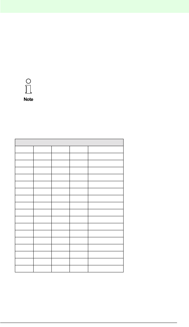
Command identification (B4 ... B1)
The desired command is defined by the command parameters B4 ... B1.
A detailed description of these commands is given in chapter 4.3 "System descripti-
on".
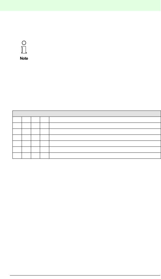
Execution of the command is finished, when the execution counter
became ¹ 0.
Command identification B4 ... B1
15 14 13 12 Bit No.
B4 B3 B2 B1 Designation
0000No command
0001 SF
0010 AF
0011 BF
0100 SR
0101 AR
0110 BR
0111 SW
1000 AW
1001 BW
1010 SB
1011 AB
1100 BB
1101 EF
1110 ER
1111 EW
IDENT-I • IVI-KHD2-4HB6, IVI-KHA6-4HB6
Operation with the PROFIBUS
Subject to reasonable modifications due to technical advances. Copyright Pepperl+Fuchs, Printed in Germany
P
epperl+Fuchs Group • Tel.: Germany (06 21) 7 76-0 • USA (330) 4 25 35 55 • Singapore 7 79 90 91 • Internet http://www.pepperl-fuchs.com
Date of issue 31.07.2001
36
Double-side mode (DS)
This function enables double-side reading/writing.
If this bit is set (DS = 1), code/data carriers of the types ICC-50, IDC-50 and IDC-
CARD can be read and written from both sides.
Otherwise code/data carriers are only read from the inscribed side.
Data carrier type (T2, T1)
The data carrier type is defined by the parameters T1 and T2
.
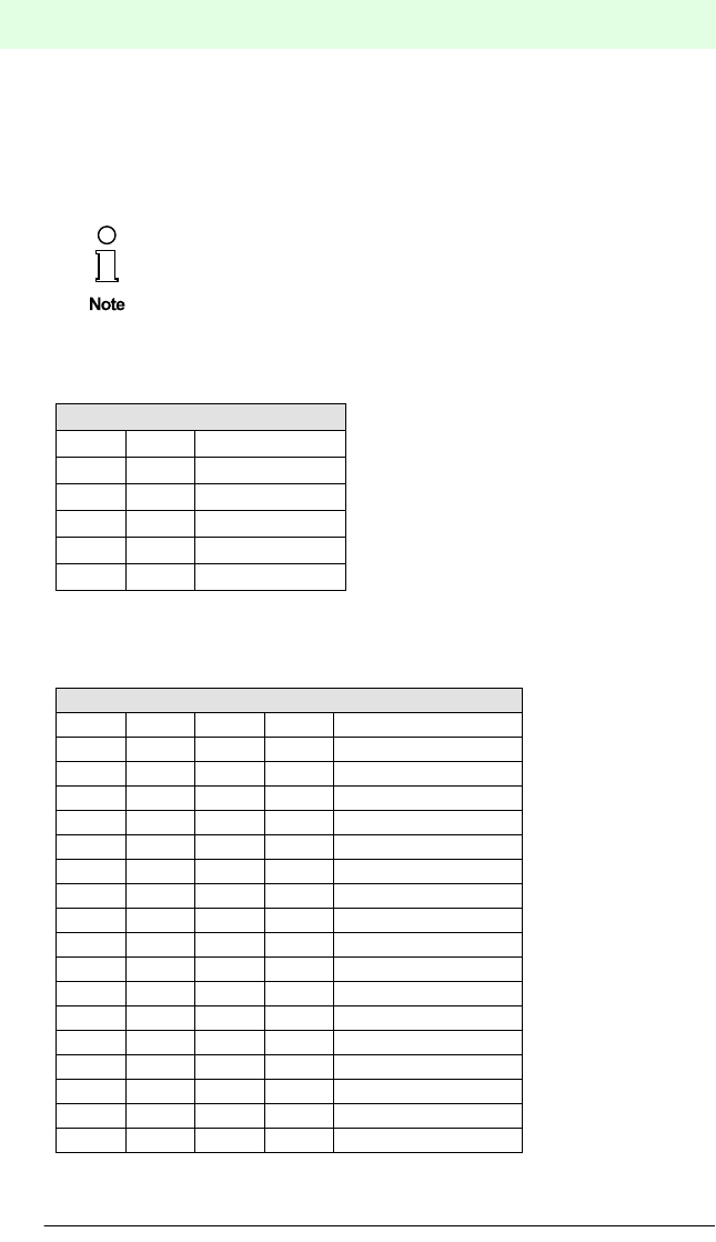
Number of words (N4 ... N1)
The number of words to be read or written is defined by the parameters N4 ... N1
(max. 14 words).
In the double-side mode the operating time for reading/writing will be
longer as in the normal mode.
Type of data carrier T1, T2
98 Bit No.
T2 T1 Type
0 0 IDC-1k
0 1 IMC40-64k
1 0 IMC40-256k
1 1 not defined
Number of words N4 - N1
7654 Bit No.
N4 N3 N2 N1 Number of words
0 0 0 0 not defined
0001 1
0010 2
0011 3
0100 4
0101 5
0110 6
0111 7
1000 8
1001 9
1010 10
1011 11
1100 12
1101 13
1110 14
1 1 1 1 not defined

IDENT-I • IVI-KHD2-4HB6, IVI-KHA6-4HB6
Operation with the PROFIBUS
Subject to reasonable modifications due to technical advances. Copyright Pepperl+Fuchs, Printed in Germany
P
epperl+Fuchs Group • Tel.: Germany (06 21) 7 76-0 • USA (330) 4 25 35 55 • Singapore 7 79 90 91 • Internet http://www.pepperl-fuchs.com
Date of issue 31.07.2001
37
Head number (K3 ... K1)
The parameters K3 ... K1 define which read/write head(s) shall be activated
.
Word address (word 1)
The starting memory address of the data to be read or written in the data carrier is
given in this word.
Head number K3 ... K1
321 Bit No.
K3 K2 K1 Head
000 1
001 2
010 3
011 4
100 all
101 all
110 all
111 all
Type of data carrier Address range (hex)
Word address Block address
(SB(AB/BB)
IDC-1k 0000 ... 003F 0000 ... 003F
IMC40-64k 0000 ... 0FFF 0000 ... 0FFF
IMC40-256k 0000 ... 3FFF 0000 ... 3FFF

IDENT-I • IVI-KHD2-4HB6, IVI-KHA6-4HB6
Operation with the PROFIBUS
Subject to reasonable modifications due to technical advances. Copyright Pepperl+Fuchs, Printed in Germany
P
epperl+Fuchs Group • Tel.: Germany (06 21) 7 76-0 • USA (330) 4 25 35 55 • Singapore 7 79 90 91 • Internet http://www.pepperl-fuchs.com
Date of issue 31.07.2001
38
7.2.6 Communication direction: control interface unit Þ PROFIBUS DP
The transmitted data are depending from the length of the chosen output mode.
In the following, only the structure of the necessary words are shown. If, depending
from the module size, further words are generated, these words contain no valid data.
Reading Fixcode
Commands and command parameters already sent are repeated in word 0 as an ack-
nowledgment.
Word 1 includes status information, the execution counter and the assigned head
number. The bits H4 ... H1 are only use for the command EF in the "Enhanced Buffe-
red Read Fixcode" mode.
Hi=1 means, that the read head is activ
Hi=0 means, that the read head is not activ.
The words 2 ... 15 contain the data read for the read commands. For write commands,
the words 2 ... 15 do not contain valid data.
Word 0 Command, parameter and toggle flag mirrored
Bit No. 15 14 13 12 11 10 9 8 7 6 5 4 3 2 1 0
Designation B4B3B2B1DS 0 T2T1N4N3N2N1K3K2K1 T
Word 1 Status/execution counter/head number
Bit No. 15 14 13 12 11 10 9 8 7 6 5 4 3 2 1 0
Designation - K3K2K1 A4 A3A2A1H4H3H2H1S4S3S2S1
Word 2 ... 15 Read data
IDENT-I • IVI-KHD2-4HB6, IVI-KHA6-4HB6
Operation with the PROFIBUS
Subject to reasonable modifications due to technical advances. Copyright Pepperl+Fuchs, Printed in Germany
P
epperl+Fuchs Group • Tel.: Germany (06 21) 7 76-0 • USA (330) 4 25 35 55 • Singapore 7 79 90 91 • Internet http://www.pepperl-fuchs.com
Date of issue 31.07.2001
39
Reading data
Depending from the chosen modul size is n maximum 15.
Commands and command parameters already sent are repeated in word 0 as an ack-
nowledgment.
Word 1 includes status information, the execution counter and the assigned head
number. The bits H4 ... H1 are only use for the command ER in the "Enhanced Buf-
fered Read " mode.
Hi=1 means, that the read head is activ
Hi=0 means, that the read head is not activ.
The words 2 ... 15 contain read commands.
Writing data
Commands and command parameters already sent are repeated in word 0 as an ack-
nowledgment.
Word 1 includes status information, the execution counter and the assigned head
number.
Head number (K3 ... K1)
000b = head 1
001b = head 2
010b = head 3
011b = head 4
Should "all" heads respond, then the heads are successively read out or written in the
sequence 1, 2, 3 and 4.
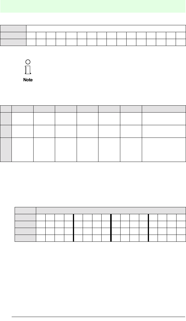
Word 0 Command, parameter and toggle flag mirrored
Bit No. 15 14 13 12 11 10 9 8 7 6 5 4 3 2 1 0
Designation B4 B3 B2 B1 DS 0 T2 T1 N4 N3 N2 N1 K3 K2 K1 T
Word 1 Status/execution counter/head number
Bit No. 15 14 13 12 11 10 9 8 7 6 5 4 3 2 1 0
Designation - K3K2K1 A4 A3A2A1H4H3H2H1S4S3S2S1
Word 2 ... n Read data
Word 0 Command, parameter and toggle flag mirrored
Bit No. 15 14 13 12 11 10 9 8 7 6 5 4 3 2 1 0
Designation B4 B3 B2 B1 DS 0 T2 T1 N4 N3 N2 N1 K3 K2 K1 T
Word 1 Status/execution counter/head number
Bit No. 15 14 13 12 11 10 9 8 7 6 5 4 3 2 1 0
Designation - K3K2K1 A4 A3A2A1H4H3H2H1S4S3S2S1
IDENT-I • IVI-KHD2-4HB6, IVI-KHA6-4HB6
Operation with the PROFIBUS
Subject to reasonable modifications due to technical advances. Copyright Pepperl+Fuchs, Printed in Germany
P
epperl+Fuchs Group • Tel.: Germany (06 21) 7 76-0 • USA (330) 4 25 35 55 • Singapore 7 79 90 91 • Internet http://www.pepperl-fuchs.com
Date of issue 31.07.2001
40
Execution counter (A4 ... A1)
The execution counter is reset for command start and incremented each time as soon
as new status values or data are available.
Haed activity (H4 ... H1)
The bits H4 ... H1 are only use for the command EW in the "Enhanced Buffered Write"
mode.
Hi=1 means, that the read head is activ
Hi=0 means, that the read head is not activ.
Status indicator (S4 ... S1)
General status and error messages are defined by the parameters S4 ... S1.
The fields, head number, status and the words 2 to 15 do not contain
valid data as long as the counter remains at 0.
Status Indicator S4 ... S1
3210bit No.
S4 S3 S2 S1 status
0 0 0 0 error-free execution of command
0 0 0 1 battery weak (IMC-40 only), correct execution of command
0 1 0 0 incorrect command, invalid parameter or timeout
0 1 0 1 read or write error
0 1 1 0 hardware fault (read head defective)

IDENT-I • IVI-KHD2-4HB6, IVI-KHA6-4HB6
Operation with the PROFIBUS
Subject to reasonable modifications due to technical advances. Copyright Pepperl+Fuchs, Printed in Germany
P
epperl+Fuchs Group • Tel.: Germany (06 21) 7 76-0 • USA (330) 4 25 35 55 • Singapore 7 79 90 91 • Internet http://www.pepperl-fuchs.com
Date of issue 31.07.2001
41
7.2.7 PROFIBUS DP command sequence, example
The execution of the command commences as soon as a valid command has been
written in the register with a toggled flag "T". After reception of the command, this flag,
together with the remaining fields of the word 0, are passed back to the master as ack-
nowledgement.
The execution counter is incremented on each command from the IDENT system. All
the same time, the fields head number, status, read error flag, read numbers and fix-
code data are set in accordance with the IDENT system message. The handling of
the read error flag also depends on the command.
The read numbers are incremented when read data has been received from the
IDENT system (Status 0). Only the read number of the data field is incremented, that
is assigned to the head number sent by the IDENT system. The read number is not
incremented if the IDENT system reports an error (Status 4, 5, 6).
The read error flag is not operated for the commands SF, AF und BF and always re-
mains at 0.
The following applies to the command EF: The read error flag is reset (=0) as soon as
read data has been received from the IDENT system (Status 0). The read error flag
is set as soon as the IDENT system reports a read error (Status 5), and remains un-
changed for other error messages (Status 4, 6).
A command sequence is shown in the following example.
Command: "Single Read Fixcode" with Head 2, without doubleside mode
Command from the DP master
Anfangszustand:
Head number (K3...1) 0
Execution counter (N4...1) 0
Status (S4...1) 0
4 x read error flags (ERR) 0 for SF, AF, BF; 1 for EF
4 x read numbers (L3...1) 0
4 x fixcode data (C28...1) 0
Command (B4 ... B1) 0001bSF (Single Read Fixcode)
Doubleside (DS) 0bdoubleside mode OFF
Data carrier type (T2, T1) 00bIDC-1k
Number of words (N4 ... N1) 0100b4 words = 8 bytes (the 8th byte is of no
significance as the fixcode comprises 7
bytes)
Head number (K3 ... K1) 001bhead number 2 responds
Toggle flag (T) 1b(or 0, depending on the previous status, for
first command or when switched on = 1)
IDENT-I • IVI-KHD2-4HB6, IVI-KHA6-4HB6
Operation with the PROFIBUS
Subject to reasonable modifications due to technical advances. Copyright Pepperl+Fuchs, Printed in Germany
P
epperl+Fuchs Group • Tel.: Germany (06 21) 7 76-0 • USA (330) 4 25 35 55 • Singapore 7 79 90 91 • Internet http://www.pepperl-fuchs.com
Date of issue 31.07.2001
42
= 1043hex
Response from the control interface unit to the DP master
Single commands are executed once and the result (success or error) is output.
Word 0: command and parameters mirror-imaged
Word 1: status/execution counter/head number (see below)
Words 2 ... 5: for successful reading, the corresponding data from the code carrier
are given here.
Words 6 ... 15: no valid data
Word 0 Commands and parameters
B4B3B2B1DS 0 T2T1N4N3N2N1K3K2K1 T
0001000001000011
The words 1 ... 15 do not contain valid data. This only applies however
for fixcode carriers. For data carriers, the word 1 would contain the star-
ting memory address and the words 2 ... 15 (for write commands) the
data to be written.
Word 0 Word 1 Word 2 Word 3 Word 4 Word 5
1043
(hex)
1105
(hex)
xxxx xxxx xxxx xxxx if no code carrier in
front of head
or 1043
(hex)
1106
(hex)
xxxx xxxx xxxx xxxx if head not connec-
ted or is defective
or 1043
(hex)
1100
(hex)
4235
(hex)
3433
(hex)
3634
(hex)
32xx
(hex)
if code carrier inclu-
des "B543642"
(ASCII) in front of
head
Word 1 Status/execution counterhead number
- K3K2K1A4A3A2A1 - - - - S4S3S2S1
0001000100000101
or 0001000100000110
or 0001000100000000
Head number (K3 ... K1) 001bread by head 2
Execution counter (A4 ... A1) 0001bexecuted once
Status (S4 ... S1) 0101bread or write error
or 0110bhardware fault
or 0000berror-free execution of command

IDENT-I • IVI-KHD2-4HB6, IVI-KHA6-4HB6
Fault Diagnostics
Subject to reasonable modifications due to technical advances. Copyright Pepperl+Fuchs, Printed in Germany
P
epperl+Fuchs Group • Tel.: Germany (06 21) 7 76-0 • USA (330) 4 25 35 55 • Singapore 7 79 90 91 • Internet http://www.pepperl-fuchs.com
Date of issue 19.07.2001
43
8 Fault Diagnostics
The "Run/Error" LED indicates the status of the control interface unit IVI-KHD2-4HB6/
IVI-KHA6-4HB6:
Status of the "Run/Error" LED Description
permanently green device ready for operation/communication active
5 s red, 0,5 s green blinking device ready for operation/communication faulty
permanently red device error

IDENT-I • IVI-KHD2-4HB6, IVI-KHA6-4HB6
Fault Diagnostics
Subject to reasonable modifications due to technical advances. Copyright Pepperl+Fuchs, Printed in Germany
P
epperl+Fuchs Group • Tel.: Germany (06 21) 7 76-0 • USA (330) 4 25 35 55 • Singapore 7 79 90 91 • Internet http://www.pepperl-fuchs.com
Date of issue 19.07.2001
44

IDENT-I • IVI-KHD2-4HB6, IVI-KHA6-4HB6
Technical Data
Subject to reasonable modifications due to technical advances. Copyright Pepperl+Fuchs, Printed in Germany
P
epperl+Fuchs Group • Tel.: Germany (06 21) 7 76-0 • USA (330) 4 25 35 55 • Singapore 7 79 90 91 • Internet http://www.pepperl-fuchs.com
Date of issue 19.07.2001
45
9 Technical Data
9.1 General specifications
The control interface unit is operated as a slave on the PROFIBUS-DP. The device
makes available the complete read/write functionality. Up to 32 bytes are transmitted
per cycle. Of these, up to 14 words for data, each with 16 bits , plus 2 words for com-
mand are available to the user. The size of the input and output modules is variable.
As a result, it is possible, by means of appropriate selections in the GSD file, to opti-
mize the quantity of transmitted data for the given application.
Up to 4 read heads can be connected to the control interface unit.
The address is set via DIP switches, and the terminating resistor for the bus is con-
nected via a rotary switch.
9.2 Electrical data
Number of read/write heads max. 4
Interface RS 485
Protocol PROFIBUS-DP accord. to DIN EN 50170
Transmission rate 9.6, 19.2, 4.44, 93.75, 187.5, 500, 1500 kBit/s
self-synchronising
Address adjustment DIP switches
Order code IVI-KHD2-4HB6 IVI-KHA6-4HB6
Power supply
Supply voltage 18 V DC ... 32 V DC 85 V AC ... 253 V AC,
50 Hz ... 60 Hz
Ripple £ 10 %
Current 250 mA 60 mA
Quiescent current 120 mA (type.) 35 mA (type.)
with activ heads 190 mA 45 mA
Power consumption 6 W 12 W
IDENT-I • IVI-KHD2-4HB6, IVI-KHA6-4HB6
Technical Data
Subject to reasonable modifications due to technical advances. Copyright Pepperl+Fuchs, Printed in Germany
P
epperl+Fuchs Group • Tel.: Germany (06 21) 7 76-0 • USA (330) 4 25 35 55 • Singapore 7 79 90 91 • Internet http://www.pepperl-fuchs.com
Date of issue 19.07.2001
46
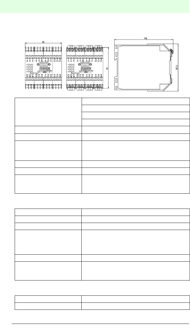
9.3 Mechanical data
9.4 Indicating/operating means
9.5 Software
Ambient conditions
Operating temperature -25 °C ... +70 °C (248 Kelvin ... 343 Kelvin
Storage temperature -25 °C ... +85 °C (248 Kelvin ... 358 Kelvin)
Humidity max. 75 % rel. humidity
Mechanical specifications
Protection degree IP20 acc. EN 60529
Connection possibilities self-opening apparatus terminals,
max. cross sectional area 2 x 2.5 mm2
9-pin Sub-D built-in connector
Housing material Makrolon 6485
Construction type K-System, 80 mm (4 TE)
Mounting snaps onto 35 mm standard rail according to
DIN EN 50022 or screw-mountable with 2 screws
through pull-out brackets in 90 mm spacing
LED green Read/write head active (4 LEDs, 1 per head)
LED yellow Code carrier detected (4 LEDs, 1 per head)
LED red Functional reserved (4 LEDs, 1 per head)
LED red/green
permanently green
red-green blinking
permanently red
device status
device ready for operation/communication active
device ready for operation/communication faulty
device error
DIP-switches setting the station address
Rotary switch (S9) Bus termination
0 = not activ (OFF)
1 = aktiv (ON)
Software The GSD file is included in the scope of delivery.
Terminal block is included in the scope of delivery

IDENT-I • IVI-KHD2-4HB6, IVI-KHA6-4HB6
Appendix
Subject to reasonable modifications due to technical advances. Copyright Pepperl+Fuchs, Printed in Germany
P
epperl+Fuchs Group • Tel.: Germany (06 21) 7 76-0 • USA (330) 4 25 35 55 • Singapore 7 79 90 91 • Internet http://www.pepperl-fuchs.com
Date of issue 27.08.2001
47
10 Appendix
10.1 List of abbreviations
ACI -acyclic control interval
ALI -application layer interface
BRCT -PROFIBUS connection type: broadcast
CRC -cyclic redundancy check
DIP -dual in-line package, housing type
EEPROM -electronically erasable and programmable ROM
FMS -fieldbus message specification
HEX -hexadecimal
LED -light emitting diode
MIN_TSDR -minimal station delay time
MSAZ -PROFIBUS connection type: master-slave acyclic
MSZY -PROFIBUS connection type: master-slave cyclic
MULT -PROFIBUS connection type: multicast
PC -personal computer
PDU -protocol data unit
PLC -programmable logic controller
PNO -PROFIBUS User Organisation
RAC -read acknowledge request counter
RAM -random access memory
RCC -read confirmed request counter
ROM -read only memory
SAC -send acknowledge request counter
SAP -service access point
SCC -send confirmed request counter

IDENT-I • IVI-KHD2-4HB6, IVI-KHA6-4HB6
Appendix
Subject to reasonable modifications due to technical advances. Copyright Pepperl+Fuchs, Printed in Germany
P
epperl+Fuchs Group • Tel.: Germany (06 21) 7 76-0 • USA (330) 4 25 35 55 • Singapore 7 79 90 91 • Internet http://www.pepperl-fuchs.com
Date of issue 27.08.2001
48
10.2 Example of commissioning
In this chapter is shown a commissionig of an SPS SIMATIC S5 135 with an IM308C
assembly module.
10.2.1 Brief description
The Pepperl+Fuchs IVI-KH❏❏-4HB6 interface unit (bus address 3) is connected to
the S5 via the IM308C PROFIBUS master (bus address 1). The interface is used to
exchange 16 words input data and 16 words output data via the PROFIBUS. Parame-
ter assignment of the IM308C is carried out with the COM PROFIBUS program.
The 16 words input data and 16 words output data are read from the interface unit into
the DB830 data module, using the FB192 function module and written to the interface
unit from the DB31 data module.
10.2.2 Components used
•S5 135U SIEMENS
•CPU 928B SIEMENS
•IM308C SIEMENS
•IVI-KH❏❏-4HB6 Pepperl+Fuchs GmbH
•PG 740 SIEMENS
•FB 192 SIEMENS
•COM Profibus program SIEMENS
PROFIBUS-DP address 3 settings on the IVI-KH❏❏-4HB6, using
DIP switches 1 ... 8:
•Switch 1 ON
•Switch 2 ON
•Switch 3 OFF
•Switch 4 OFF
•Switch 5 OFF
•Switch 6 OFF
•Switch 7 OFF
•Switch 8 OFF
In the display driver blocks BB1 and BB2, the data modules DB30 and
DB31 can be inspected under ‘Variables control’.
IDENT-I • IVI-KHD2-4HB6, IVI-KHA6-4HB6
Appendix
Subject to reasonable modifications due to technical advances. Copyright Pepperl+Fuchs, Printed in Germany
P
epperl+Fuchs Group • Tel.: Germany (06 21) 7 76-0 • USA (330) 4 25 35 55 • Singapore 7 79 90 91 • Internet http://www.pepperl-fuchs.com
Date of issue 27.08.2001
49
10.2.3 Parameter assignment of the IM308C with COM PROFIBUS
After starting the COM PROFIBUS program, the GSD file provided with it must now
be read-in via the menu item 'File', unless this has already been carried out. The pro-
gram interface unit is referenced under ‘other’ devices. Parameter assignment of the
IM308C can now be started for a new project. The individual steps required are sum-
marised briefly in the following. To start a new project, select 'File -> New’ from the
menu.
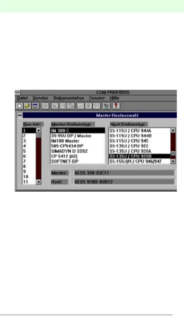
First the PROFIBUS master is defined. In the example, the IM308C card is used as
the master, with bus address 1 and an S5-135U with a CPU928B is used as the S5
station. The appropriate selection is accepted by pressing the OK button.
Figure 10.1
IDENT-I • IVI-KHD2-4HB6, IVI-KHA6-4HB6
Appendix
Subject to reasonable modifications due to technical advances. Copyright Pepperl+Fuchs, Printed in Germany
P
epperl+Fuchs Group • Tel.: Germany (06 21) 7 76-0 • USA (330) 4 25 35 55 • Singapore 7 79 90 91 • Internet http://www.pepperl-fuchs.com
Date of issue 27.08.2001
50
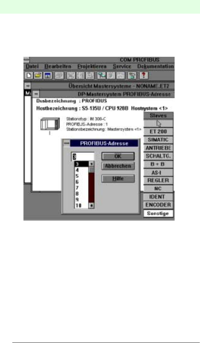
By double-clicking on master system a window is opened, on the right side of which
a PROFIBUS slave selection table appears. The interface unit can now be inserted
as 'another' slave. In the example, address 3 is set as the bus address.
As before, the settings are accepted by pressing the OK button.
Figure 10.2
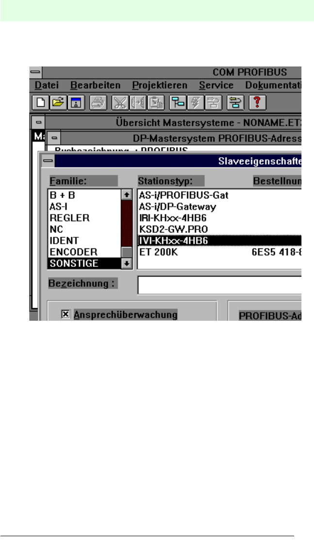
IDENT-I • IVI-KHD2-4HB6, IVI-KHA6-4HB6
Appendix
Subject to reasonable modifications due to technical advances. Copyright Pepperl+Fuchs, Printed in Germany
P
epperl+Fuchs Group • Tel.: Germany (06 21) 7 76-0 • USA (330) 4 25 35 55 • Singapore 7 79 90 91 • Internet http://www.pepperl-fuchs.com
Date of issue 27.08.2001
51
The IVI-KH❏❏-4HB6 interface unit must now be selected from the list of alternative
slaves in the window which has now appeared.
Figure 10.3
On successful selection, the DP-Master system window appears in which the PRO-
FIBUS string is represented.
If the previous settings have been made correctly, the identification of the interface
unit appears in the rectangle with bus address 3.
Data transfer with the interface unit can now be configured by double-clicking on this
rectangle.
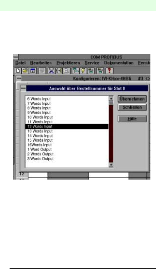
IDENT-I • IVI-KHD2-4HB6, IVI-KHA6-4HB6
Appendix
Subject to reasonable modifications due to technical advances. Copyright Pepperl+Fuchs, Printed in Germany
P
epperl+Fuchs Group • Tel.: Germany (06 21) 7 76-0 • USA (330) 4 25 35 55 • Singapore 7 79 90 91 • Internet http://www.pepperl-fuchs.com
Date of issue 27.08.2001
52
On selecting the Order Number button, a window opens in which the fixed input/out-
put data are presented. This information relates to the COM PROFIBUS program
from the GSD file.
A 16 words input (see Figure 10.4) and a 16 words output (see Figure 10.5) have to
be selected for the configuration and accepted by actuating the appropriate button.
The window can then be closed.
Figure 10.4
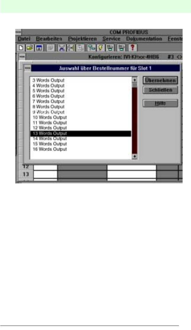
IDENT-I • IVI-KHD2-4HB6, IVI-KHA6-4HB6
Appendix
Subject to reasonable modifications due to technical advances. Copyright Pepperl+Fuchs, Printed in Germany
P
epperl+Fuchs Group • Tel.: Germany (06 21) 7 76-0 • USA (330) 4 25 35 55 • Singapore 7 79 90 91 • Internet http://www.pepperl-fuchs.com
Date of issue 27.08.2001
53
Figure 10.5
The numbers 223 and 239 should now be entered under the term 'Code'. These two
numbers represent the transfer parameters shown in figure 10.6 and figure 10.7.
16 words of input data are transferred from the interface unit and 16 words of output
data are transferred to the interface unit via the PROFIBUS. This transfer must take
place consistent with the assembly module. As a consequence of this, the data can-
not be accessed directly via the input/output address range. The function module
FB192 must be used for the transfer, in conjunction with data modules for acceptance
of the data.
The FB192 provides data communication between the S5CPU and the IM308C.
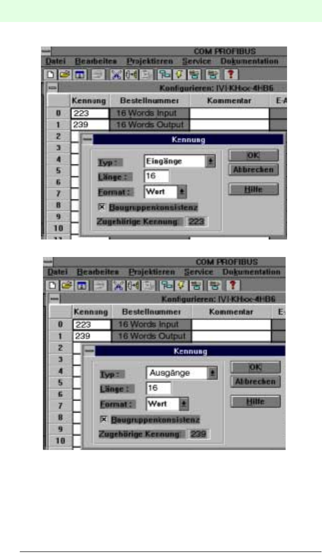
IDENT-I • IVI-KHD2-4HB6, IVI-KHA6-4HB6
Appendix
Subject to reasonable modifications due to technical advances. Copyright Pepperl+Fuchs, Printed in Germany
P
epperl+Fuchs Group • Tel.: Germany (06 21) 7 76-0 • USA (330) 4 25 35 55 • Singapore 7 79 90 91 • Internet http://www.pepperl-fuchs.com
Date of issue 27.08.2001
54
Figure 10.6
Figure 10.7
This concludes the configuration for the PROFIBUS system with the interface unit. It
can now be transferred to the IM308C memory card.
After successful storage on the memory card, this can be inserted in the IM308C.
As soon as the interface unit is correctly connected to the IM308C, the green LED
lights.

IDENT-I • IVI-KHD2-4HB6, IVI-KHA6-4HB6
Appendix
Subject to reasonable modifications due to technical advances. Copyright Pepperl+Fuchs, Printed in Germany
P
epperl+Fuchs Group • Tel.: Germany (06 21) 7 76-0 • USA (330) 4 25 35 55 • Singapore 7 79 90 91 • Internet http://www.pepperl-fuchs.com
Date of issue 27.08.2001
55
10.2.4 Program
OB 1
FB 3
FB 4
SPA FB 3
NAME: IVI-DP
SPA FB 4
NAME: IVI-DP
BE
NAME: IVI-DP
ADB 30
SPA FB 192
NAME: IM308C
DPAD: KH F800
IMST: KY 0,3 Slave adresse 3
FCT: KC RI RI Read Data command
GCGR: KM 00000000 00000000
TYP: KY 0,30 Number of data module DB 30
STAD: KF +0 Offset for first data word, here 0
LENG: KF -1
ERR: MW 200 Marker for FB 192 messages
BE
NAME: IVI-DP
ADB 31
SPA FB 192
NAME: IM308C
DPAD: KH F800
IMST: KY 0,3 Slave Adresse 3
FCT: KC WO WO Write Date command
GCGR: KM 00000000 00000000
TYP: KY 0,31 Number of data module DB 31
STAD: KF +0 Offset for first data word, here 0
LENG: KF -1
ERR: MW 202 Merker for FB 192 messages
BE

IDENT-I • IVI-KHD2-4HB6, IVI-KHA6-4HB6
Appendix
Subject to reasonable modifications due to technical advances. Copyright Pepperl+Fuchs, Printed in Germany
P
epperl+Fuchs Group • Tel.: Germany (06 21) 7 76-0 • USA (330) 4 25 35 55 • Singapore 7 79 90 91 • Internet http://www.pepperl-fuchs.com
Date of issue 27.08.2001
56
DB 30
DB 31
0: KH 3045
1: KH 2004
2: KH 0000
3: KH 0000
4: KH 0000
5: KH 0000
6: KH 0000
7: KH 0000
8: KH 0000
9: KH 0000
10: KH 0000
11: KH 0000
12: KH 0000
13: KH 0000
14: KH 0000
15: KH 0000
0: KH 3045
1: KH 0000
2: KH 0000
3: KH 0000
4: KH 0000
5: KH 0000
6: KH 0000
7: KH 0000
8: KH 0000
9: KH 0000
10: KH 0000
11: KH 0000
12: KH 0000
13: KH 0000
14: KH 0000
15: KH 0000
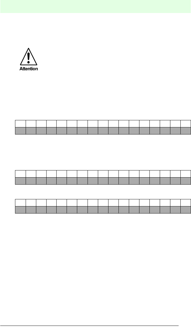
IDENT-I • IVI-KHD2-4HB6, IVI-KHA6-4HB6
Appendix
Subject to reasonable modifications due to technical advances. Copyright Pepperl+Fuchs, Printed in Germany
P
epperl+Fuchs Group • Tel.: Germany (06 21) 7 76-0 • USA (330) 4 25 35 55 • Singapore 7 79 90 91 • Internet http://www.pepperl-fuchs.com
Date of issue 27.08.2001
57
10.2.5 Examples
Commands can be sent to the interface unit by changing the data word DW0 of the
DB31.
Continuous read-in of a fixcode with read head No. 3 (Buffered-Auto-Read Fix-
code)
Output data:
DB31 DW 0 PROFIBUS master command to the interface uni
t
DB31 DW 1 ... 15 are not considered.
Input data:
DB30 DW 0 Mirror imaging of the command from the interface unit to the PROFIBUS
master
DB30 DW 1 Status/execution counter/head number
K3 ... 1: Read head number
N4 ... 1: 4 bit execution counter
S4 ... 1: Status/error message
DB30 DW 2 ... DW5: Read data
When sending commands, care should be taken that bit 0 of the data
word DW0 is always toggled, in order to give the card validity.
T = 0, if previously 1
T = 1, if previously 0
For the 1st command the toggle bit (T) must be 1.
Bit1514131211109876543210
001100000100010T
Bit1514131211109876543210
001100000100010T
Bit1514131211109876543210
-K3 K2 K1 N4 N3 N2 N1 ----S4 S3 S2 S1

IDENT-I • IVI-KHD2-4HB6, IVI-KHA6-4HB6
Appendix
Subject to reasonable modifications due to technical advances. Copyright Pepperl+Fuchs, Printed in Germany
P
epperl+Fuchs Group • Tel.: Germany (06 21) 7 76-0 • USA (330) 4 25 35 55 • Singapore 7 79 90 91 • Internet http://www.pepperl-fuchs.com
Date of issue 27.08.2001
58
Continuous reading of a type IDC-1k data carrier at address 0000h, 2 words,
with read head No. 2 (Buffered-Auto-Read)
Output data:
DB31 DW 0 PROFIBUS master command to the interface unit
DB31 DW 1
DB31 DW 1-15 are not considered.
Input data:
DB30 DW 0 Mirror image of the command from the interface unit to the PROFIBUS
master
DB30 DW 1 Status/execution counter/head number
K3 ... 1: Read head number
N4 ... 1: 4 bit execution counter
S4 ... 1: Status/error message
DB30 DW 2 ... DW3: Read data
Bit1514131211109876543210
011000000010001T
Bit1514131211109876543210
0000000000000000
Bit1514131211109876543210
011000000010001T
Bit1514131211109876543210
-K3 K2 K1 N4 N3 N2 N1 ----S4 S3 S2 S1
With regard to the supply of products, the current issue of the following document is applicable:
The General Terms of Delivery for Products and Services of the Electrical Industry, as published by
the Central Association of the 'Elektrotechnik und Elektroindustrie (ZVEI) e.V.',
including the supplementary clause "Extended reservation of title"
We at Pepperl+Fuchs recognise a duty to make a contribution to the future.
For this reason, this printed matter is produced on paper bleached without the use of chlorine.

43 297 07/01 02
