11646 Woodhead AeroMotive 142413 Catalog
2016-10-06
: Pdf 142413-Catalog 142413-Catalog B5 unilog
Open the PDF directly: View PDF ![]() .
.
Page Count: 48
AERO-MOTIVE®
PRODUCTS
CABLE REELS
CABLE REELS

HAND WIND REELS
Page 4
Hand Wind
Reels
Description:
Manually operated reels
for storage and
retrieval of extension
cords, power cables,
ropes or hoses. Three models to
choose from.
Applications: Power source
for portable tools, lights, fans, or
pumps.
■Portable or fixed-mount
■Up to 100 feet of 3-conductor
#12, #14 or #16 AWG cable
■Optional power receptacle or
slip ring
■Indoor or outdoor applications
CORD REELS & LAMPS
Pages 5-7
Cord Reels
Description: Cord Reels
arespring retractable,industri-
al reels that are used to keep
handlamps andpower outlets
accessible and out of the way.
Applications: Portable
power supplies, mobile material
handling equipment, portable
lighting, and machining.
■Available with a variety of
optional hand lamps
■Up to 50 feet of cord - up to
250 volt duty
■Swinging or rigid mount
■Adjustable tension
■Built in ratchet locks
■UL Listed and CSA Certified
■3Conductor 16 AWG cable
(4 Conductor 18 AWG cable
model available)
Aero-Motive®Products:
Mobile connectivity
solutions for a full range of
industrial applications
Get the power to perform with the most advanced
cable reels in the industry. Made with precision electri-
cal and mechanical components, Aero-Motive reels are
designed to provide top performance, long service life
and ease of maintenance. With a huge selection of
sizes, styles and related accessories, you get the
mobile connectivity solutions you need.
For more information check us out on the web at:
www.woodhead.com
ACCESSORIES
Pages 33-35
Accessories
Pivot and
Swivel Base
for directional
flexibility.
Cable Guides,
Connectors
andGrips to
extend cable
life.
SPECIALTY
Pages 28-32
Specialty Reels
Automatic
Switches and
Junction Boxes
for safety and
convenience.
Service options for
Mill Duty, Marine,
Hazardous locations.
Welding
Reels payout
and retract
arc welding
cable.
PAGE 3
POW-R-MITE REELS
Pages 8-9
Pow-R-Mite®Cable Reels
Description: Easy to order Pow-R-Mites® are spring-powered
cable reels that come equipped with cable installed. Two frame sizes
are available with cable capacity of up to 70 feet.
Applications: Use where a movable power supply is required
including mobile electrical equipment, portable lighting or power
tools. The fixed mount units are suitable for indoor or outdoor use.
■Containerized mainspring for easy replacement
■Available with up to 12 conductors
■Modular collector ring
■Adjustable built in cable guides
■Corrosion resistant surface
POW-R-MATIC REELS
Pages 10-27
Pow-R-Matic®Cable Reels
Description: “Assembled-to-Order” Pow-R-Matic®Reels can be fitted with the exact
amountand type of cable you require. Frames can accommodate up to 320 feet of #16 AWG
cable or up to 180 feet of#1 cable.Precision Collector Rings can be specified for up to 36 con-
ductors. Single or dual main springs are containerized for quick change and easy adjustment.
Applications: Use for power and/or control to mobile
industrial equipment such as cranes, hoists,
transfer devices, etc.
■Containerized main spring
■External tension adjustment
■Quick change spring motor
■NEMA-4 enclosures for indoor or outdoor use
■Anti-lock-out ratchet system
Pages 35-47
Tech Info
Cable Selection:
Aero-Motive provides information and charts to
helps you select the right cable for the job.
Details such as cable diameter, weight, operat-
ing conditions, AC & DC motor current loads
and magnet sizes aretaken into consideration.
Reel Dimensions:
Complete dimensional information is detailed
for all Pow-R-Matic Reels.
StaticDischarge
andGroundFault
Reels for in plant
andelectricutility
vehicle safety.
Retractors,
Balancers and
Torque Reels keep
pendantstations,
connectors and
lights up and out
oftheway.
HAND WIND REELS
PAGE 4
■Heavy duty design for storage of extension cords,
power cables, rope or hoses
■Center cavity access to the end of conductor
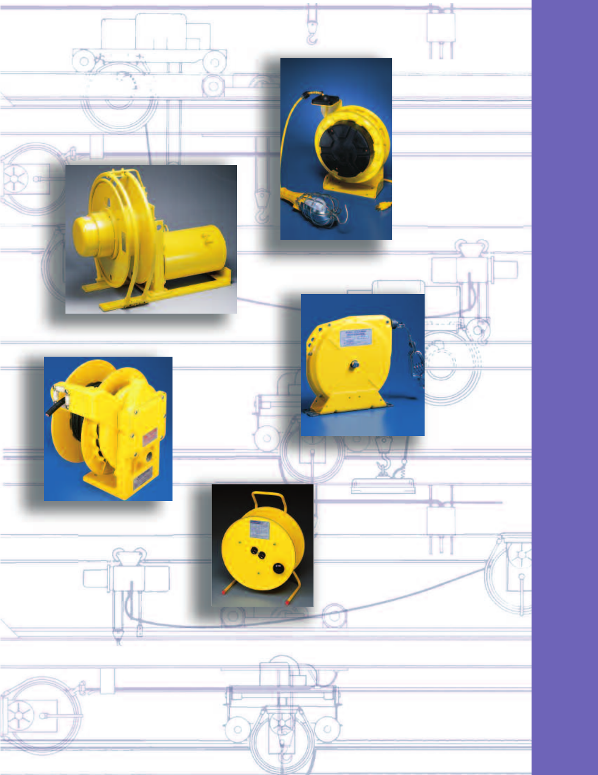
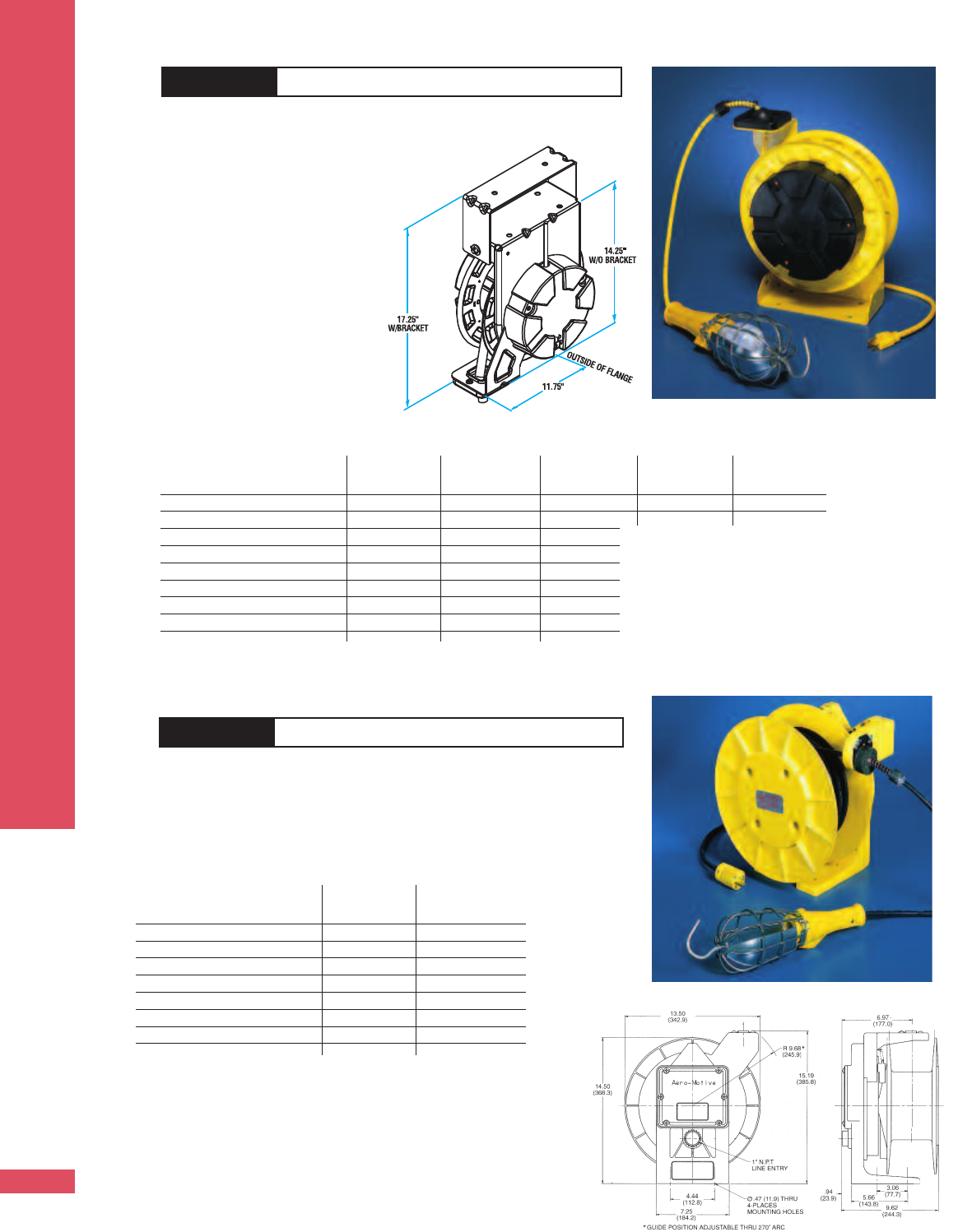
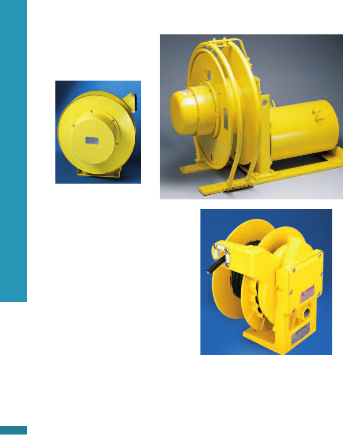
HW100 HAND WIND REEL
Hand Wind Reels
Hand wind reels are designed for heavy duty
industrial storage applications. Perfect for storing
extension cords, or continuous power service.
■15 Amp duplex receptacle on reel and plug on
free end of cable
■Point of use
■Disconnecting electrical device is required to
windor unwind cable
■Equipped with slip ring, power cable, and plug
■Payout cable has receptacle
■Ideal for continuous service
Maximum capacity- all models
3cond. #16 AWG SO (.430 in. dia.) 200 Ft.
3cond. #14 AWG SO (.560 in. dia.) 125 ft.
3cond. #12 AWG SO (.640 in. dia.) 100 ft.
usable spool vol. 500 cu. in.
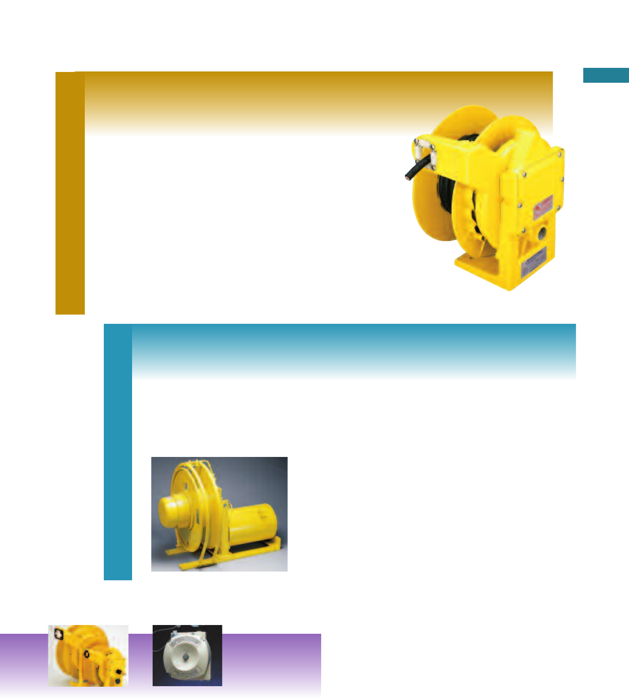
HW200 HAND WIND REEL
HW300 HAND WIND REEL
3 cond. Type SO Cable Amperage Series-UL listed/CSA certified
Size length ft. mcord off reel HW100 HW200 HW300
#16 AWG 50 15.24 10 HW122 HW222 HW322
#16 AWG 100 30.48 10 HW124 HW224 HW324
#14 AWG 50 15.24 15 HW132 HW232 HW332
#14 AWG 100 30.48 15 HW134 HW234 HW334
#12 AWG 50 15.24 15 HW142 HW242 HW342
#12 AWG 100 30.48 15 HW144 HW244 HW344
Cable Not Supplied 15 HW100 HW200 HW300
All rated at 125 volts.
HW100
HW200
HW300
HW200 Series Shown
35 ft. of Cable
Accessories
3c/#16 AWG 7a / 120v
No Accessories RI453
Type M Lamp RI453-M
Type H Lamp RI453-H
Type FE Lamp RI453-FE
Type 13S Lamp RI453-13S
Type 13G Lamp RI453-13G
Type 13W Lamp RI453-13W
5-15R Receptacle RI453-R
Quad Tap Box RI453-Q
GFCI Dual Outlet Box RI453-D
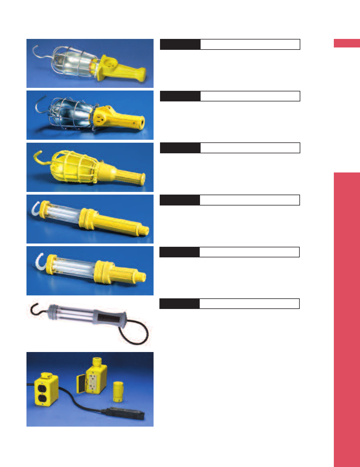
CORD REELS
PAGE 5
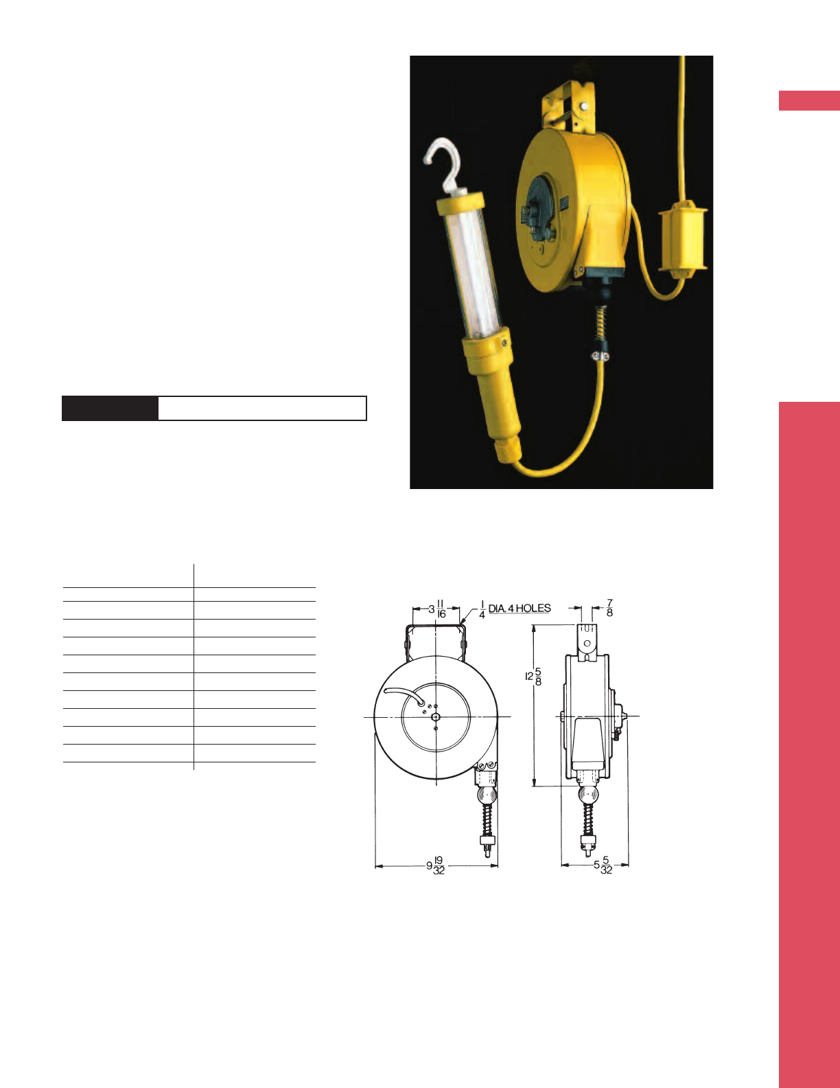
Cord Reels
Cord reels are designed for
indoor maintenance, repair,
power supply to hoists and
close-up work. Ideal for ready
access to hand lamps and
power outlets.
Swing mount standard on all
RI45 models.
■35 feet travel ■For Hand Lamp, add
■Swinging mount suffix M, H, 13W,13G,
■Adjustable tension 13S or FE (see page 7)
■3conductor,16 AWG ■UL listed and CSA certified
RI45 CORD REEL
CORD REEL SELECTOR CHART RI45
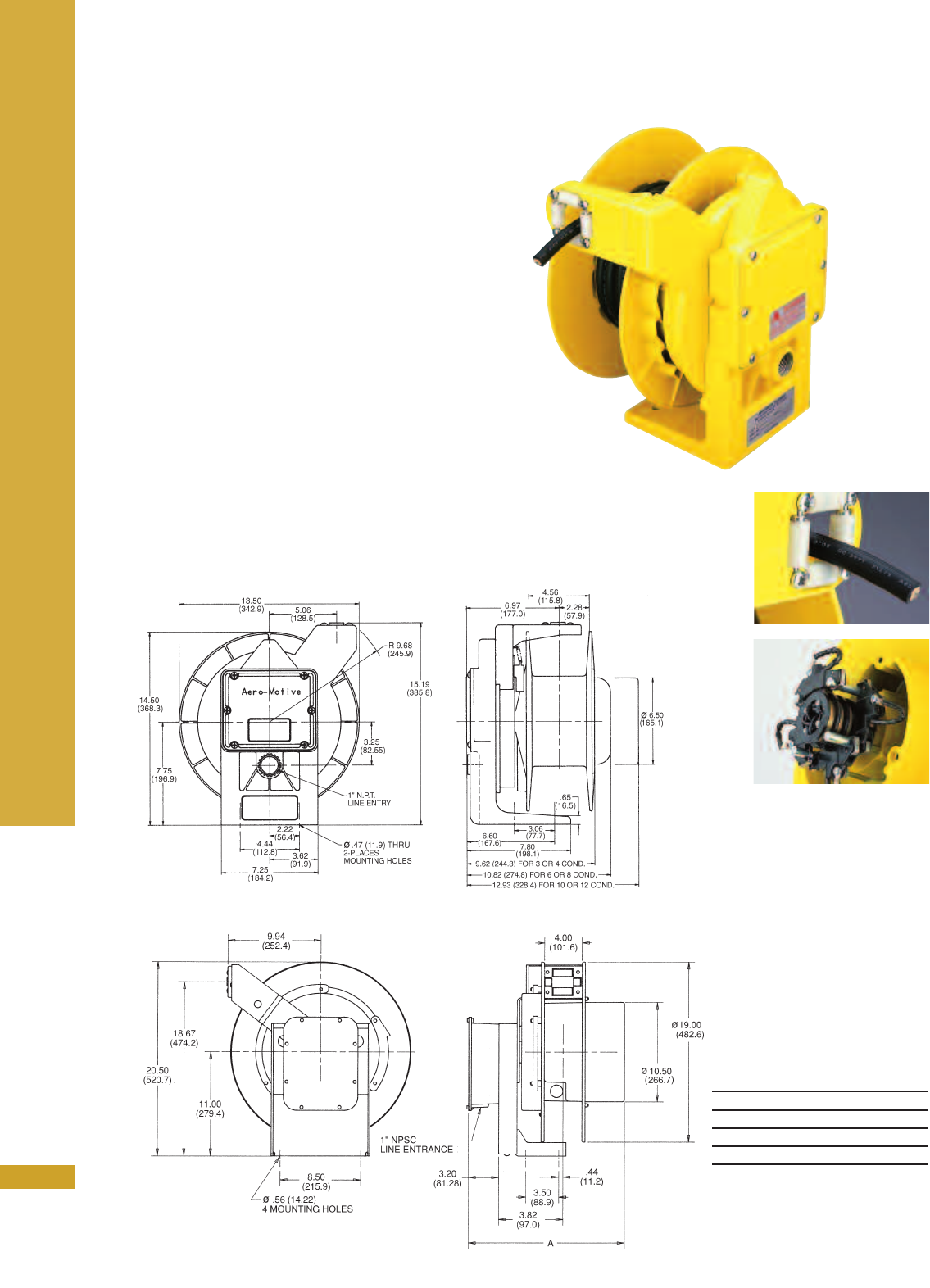
CORD REELS
PAGE 6
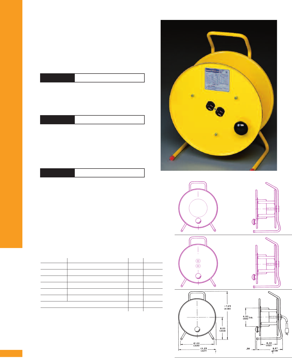
RI50 CORD REEL
Industrial strength reel has all the convenience,
endurance and reliability feature you need at an
easy-to-buy price.
■Fewer moving parts for long working
life
■Removable hub covers for easy
maintenance
■Easy tension adjustment
■Ratchet lock with engage and
disengage capability
■Corrosion resistant
steel housing
■Rigid or swinging mounts
available
■UL listed
■Indoor use only
■50 feet travel ■Rigid Mount
■Adjustable tension ■UL listed and CSA certified
■3conductor, ■For Hand Lamp, add suffix FE, M, or G
16 AWG SO (see page 7)
228B CORD REEL
50 ft. of Cable 45 ft. of Cable 35 ft. of Cable 50 ft. of Cable 30 ft. of Cable
Accessories
3c/#16 AWG 3c/#14 AWG 3c/#12 AWG 4c/#16 AWG 4c/#14 AWG
8a / 120v 11a / 120v 15a / 120v 5.5a / 120v 7.5a / 120v
No Accessories RI51 RI53 RI55 RI52 RI54
Type M Lamp RI51-M RI53-M
Type FE Lamp RI51-FE RI53-FE
Type 13G Lamp RI51-13G RI53-13G
5-15R Receptacle RI51-R RI53-R RI55-R
Triplex Outlet Strip RI51-T
Quad Tap Box (4) 5-15R RI51-Q RI53-Q RI55-Q
GFCI Dual Outlet Box (2) 5-15R RI51-D RI53-D RI55-D
RI50 reels comestandard with rigid mount and no hand
lamps. To select swinging mount add suffix “S” to part
number. To add hand lamp option add the suffix for the
type of hand lamp required. Add the suffix “AS” for the
auto switch option. Example: RI51S-FE-AS. To add a pivot
base option order item# PB10YE. All 3 conductor reel
include 2.5 ft. of lead-in cable with plug. 4 conductor
reels come without plug.
50 ft. of Cable 45 ft. of Cable
Accessories
3c/#16 AWG 3c/#14 AWG
Type M Lamp 228B-M
Type FE Lamp 228B-FE
Type 13S Lamp 228B-13S
Type 13G Lamp 228B-13G
5-15R Receptacle 228B-R 358C-R
Quad Tap Box (4) 5-15R 228B-Q 358C-Q
GFCI Dual Outlet Box (2) 5-15R 228B-D 358C-D
All 228B and 358C reels come standard with rigid mount.
Swinging mount option is not available. Auto switch
option is not available. To add a pivot base option order
item# PB2A. 228BH, 228BM, and 228B13S reels include 3
ft. of lead-in cable with plug and a cable stop.
HAND LAMPS
PAGE 7
Type H HAND LAMP DANIEL WOODHEAD®
■Fluorescent hand lamp
■Low temperature 13-watt lamp
■Use with remote or optional auto switch
■Built-in ballast
Type 13G
■Fluorescent hand lamp
■Built-in ballast
■Low temperature 13 watt lamp
Type 13S HAND LAMP DANIEL WOODHEAD®
■Guard with reflector for 100W bulb
■Replaceable lamp switch
■NEMA 5-15R outlet
■Snap open guard
Type M HAND LAMP DANIEL WOODHEAD®
■Steel guard with reflector for 100W bulb
■Replaceable lamp switch
■NEMA 5-15R outlet
■Rubber handle
■Snap-open guard
Optional Cord Reel Lamps
Other Cord Reel Accessories
RECEPTACLE
One NEMA 5-15R outlet (add suffix -R)
TRIPLEX OUTLET
Three NEMA 5-15R outlets (add suffix -T)
DUAL OUTLET
Two 15A GFCI outlets, snap door cover (add suffix -D)
QUAD OUTLET
Four NEMA 5-15R outlets (add suffix -Q)
PIVOT BASE
(see page 9) 330° pivot - order PB10YE for RI50
series reels and PB2A for 228B
AUTOMATIC ON/OFF SWITCH
Turns light off when cable is
fully retracted (Available on RI50 cable reels only)
Type FE HAND LAMP DANIEL WOODHEAD®
■Fluorescent hand lamp
■Low temperature13-watt lamp
■Use with remote or optional auto switch
■Ballast on cord / inlet side
Type 13W HAND LAMP DANIEL WOODHEAD®
■Insulated guard without reflector
■Use with remote or optional auto switch
■Complies with NEC S11-3F
HAND LAMP DANIEL WOODHEAD®
-
-D
D
-
-R
R
-
-T
T
-
-Q
Q
POW-R-MITE CABLE REELS
PAGE 8
Pow-R-Mite®Cable Reels
Cable reels are designed for top performance, long service
life and easy maintenance. Ideal for hoists, electric tools
and moving equipment.
■Factory assembled with Type SO or W cable
■Reels constructed with spring tension
to lift or stretch cable with no more than 10% sag
■Containerized main-spring for safe, easy handling
■Modular collector ring
■30 Amp collector ring on 200, 300, & 400 models
■35 or 75 Amp collector ring on 5000 models
■Adjustable cable guide with anti cable “lock-out”
■UL listed and CSA Certified
Selecting Pow-R-Mite Reels
■Determine cable size (AWG), number of conductors
required and travel distance
■Locate model number in chart on page 9
■Consider accessories needed
■Order model number
Compact 30, 35 or 75
amp modular collector
rings can accommodate
up to 16 conductors. All
brushes are spring loaded
copper/ graphite for posi-
tive electrical contact.
Cable is included on all
Pow-R-Mite models. Specify
by number of conductors,
AWG size and length.
Aero-Motive reels
feature corrosion
resistant powder-
polyester surface
construction.
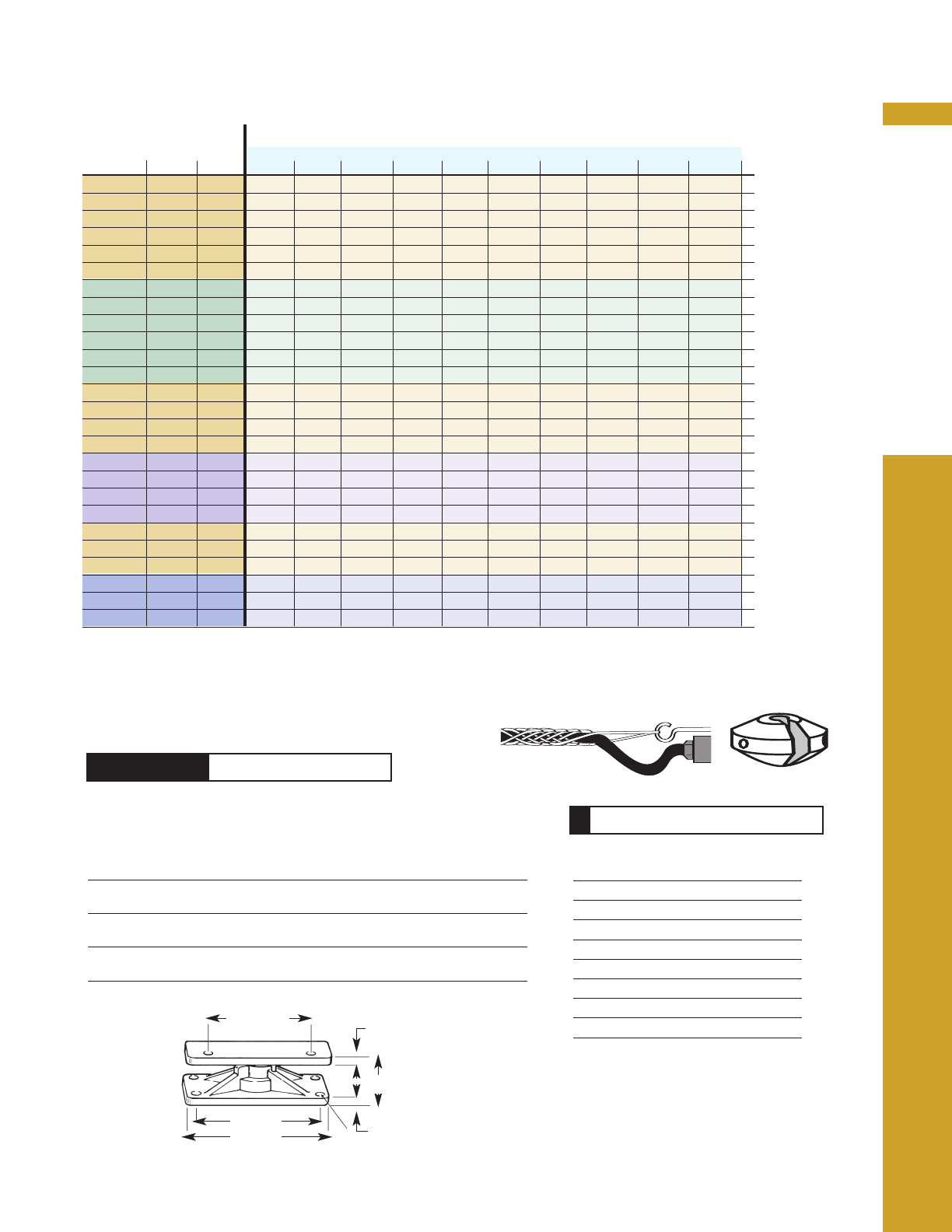
Series 200, 300, 400
Series 5000M
Dim.
Models A (in)
#16 - 10 AWG (2 - 6 Cond.) 16.67
#16 - 10 AWG (8 - 12 Cond.) 18.84
#8 - 6 AWG (2 - 3 Cond.) 16.67
#8 - 6 AWG (4 Cond.) 18.84
Cable Length Feet/Meters
Rated AWG No.
Amps. Size Cond. 20 /6.1 25/ 7.6 30/9.1 35 /10.7 38/ 11.6 40/12.2 45/13.7 50 /15.2 60/18.3 70/ 21.3
9 16 3 232B* 224B* 231B* 228B* 5137BL*
7 16 4 242B 234B 244B 238B 5147BL
7 16 6 206B 5167BL
6 16 8 208B 485B 5187BL
5 16 10 403B 5105BL 5207BL
5 16 12 413B 5115BL 5217BL
13 14 3 332C** 253C** 233C** 334C** 358C** 5137CL**
11 14 4 342C 363C 343C 344C 367C 345C 5147CL
11 14 6 306C 5165CL 5267CL
8 14 8 308C 483C 5286CL
7 14 10 402C 5205C
6 14 12 5112CL 5214CL
18 12 3 332D 383D 333D 385D 434D 435D 5137DL
14 12 4 342D 394D 444D 445D 5146DL
14 12 6 463D 5266DL
12 12 8 482D 5285DL
22 10 3 242E 433E 434E 5135EL 5237EL
16 10 4 452E 443E 5144EL 5245EL 5247EL
14 10 6462E 5365EL
14 10 85283EL
40 8 2 5123FL 5225FL
35 8 3 5133FL 5235FL
32 8 4 5142FL 5344FL
55 6 2 5223GL 5325GL
45 6 3 5333GL
44 6 4 5342GL
POW-R-MITE CABLE REELS
PAGE 9
■Allows cable and cord reels to rotate 330˚
POW-R-MITE SELECTOR
PB Series PIVOT BASE
Pow-R-Mite Accessories
Dim.A Dim.B Dim.C Dim.D Dim.E Dim.F
Reel in. in. in. in. in. in.
Model Series mm mm mm mm mm mm
PB10YE RI50 3 4 2.69 0.50 0.438 1.25
76 102 68.3 13 11.13 31.8
PB2A 200/300 3 4 1.44 0.50 0.438 0.25
400 76 102 36.6 13 11.13 6.4
PBM7A 5000 10 11.5 3.76 0.75 0.531 0.63
254 292 95.5 19.1 13.49 15.9
Cable Size Cable Grip Cable Stop
OD, ins. Model Model
0.30-0.41 36562 ST1
0.41-0.56 36564 ST1
0.57-0.70 36567 ST1
0.70-0.75 36569 ST1
0.75-0.82 36569 ST2
0.82-0.875 36571 ST2
0.875-1.00 36571 ST3
1.06-1.25 36574 ST3
CABLE GRIPS AND STOPS
For easy selection, choose amperage, cable size, number of conductors
and cable length from shaded area below.
matched to
reel mounting
A square
C
F
D
B square E- dia. (4) mounting holes
End of Cable options (see page 7)
*Q, R, D, M, H, 13S
**Q, R, D
POW-R-MATIC CABLE REELS
PAGE 10
Pow-R-Matic®Cable Reels
Cable reels are designed for top performance, long
service life and easy maintenance. Ideal for hoists,
electric tools and moving equipment.
■Custom assembled with modular components
■Order without cable or fitted with exact cable
length needed
■Containerized main spring for safe and easy
handling
■Self-contained collector ring for simple
installation and service
■Driving and declutching spring hub protects
springs from damage when cable is installed or
in the event of broken cable.
■External tension adjustment allows tension
adjustment to be completed in minutes.
Available on series 2000 through 2800.
See page 28.
■Quick change spring motor reduces down time.
Standard on all Series 2000 reels.
■NEMA-4 electrical enclosures
■Anti-lock-out ratchet system available on series
0900 & 1000M prevents reel lock out when cable
is fully extended
■Cable reel accessories available on pages 33-35.
POW-R-MATIC CABLE REELS
PAGE 11
Frame Size
Pow-R-Matic Reels are available in over 10 frame styles, defined as
“Series” in this catalog. Within each series are dozens of size varia-
tions that accommodate various cable lengths and diameters. The
charts on the following pages make it easy to order the right reel for
the job. All frames are engineered for long-term, trouble-free service.
Optional components can be added to the frame for mill duty, haz-
ardous locations or marine service. Four roller guides are standard on
Series 0900 and 1000M. Larger reels feature guide rails that can
accommodate optional guides.
Main Spring
All Aero-Motive reels are powered by individual or dual flat spring steel
mainsprings. The unique self-contained precision springs are lubed for
life. Maintenance is easier and safer with the external tension adjust-
ment feature and the declutching spring hub. An interchangeable
quick-change spring motor is standard on all Series 2000 - 2800 reels.
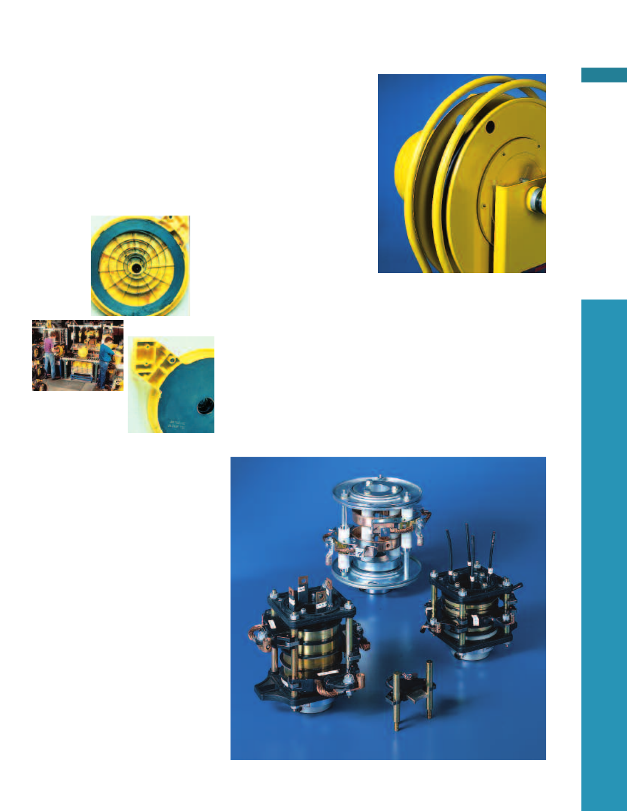
Collector Ring
The heart of every Pow-R-Matic Reel
is the collector or slip ring. All
Aero-Motive collector rings are
engineered to more than meet the
electrical requirements of the cable.
Four styles handle from 30 to 200
amps, 3 to 36 conductors.
Modular brush holder assembly is
made with non-conductive phenolic
holders that are mounted at two
points for assured alignment.
Stainless steel compression springs
provide constant contact for the
copper graphite brushes and copper
alloy rings. Silver components can
be ordered for low level communi-
cation signals.
Self -contained main
springs are lubricat-
ed for life at the
factory.
POW-R-MATIC CABLE REELS
PAGE 12
Selecting Pow-R-Matic Reels
Pow-R-Matic Reels are assembled from modular components to your specific application
requirements. Follow these four simple steps to order the reel that fits your needs.
Step 1
Select Conductor Size
Cable must be capable of handling the full operating
load of all equipment which can be operated
concurrently (total connected horsepower). Turn to
the page spread that features your size selection.
SPECIAL CABLES: Pow-R-Matic Cable Reels can be
used with stainless steel braided, silicone, or refrasil
insulated cables. For cables designed for extreme
temperatures, consult the factory for reel recommen-
dations.
Step 2
Determine Your Application
Reels within each page are grouped by application.
See the explanation below and match it with the
application grouping on the selector chart.
Step 3
Select The Number of Conductors and
Type of Cables
Determine the number of control or power functions
required. Extra conductors should be considered for
future use.
Reels are cataloged based on Type SO for control
cables and Type W and G for power. Refer to page 36
for further cable information.
Step 4
Determine Length of Active Cable
Finally, select the desired length of active cable by
feet (in black type) or meters (in blue). Actual cable
must be ordered separately.
Active cable longer than 50 ft. will have too much
tension to be pulled out manually.
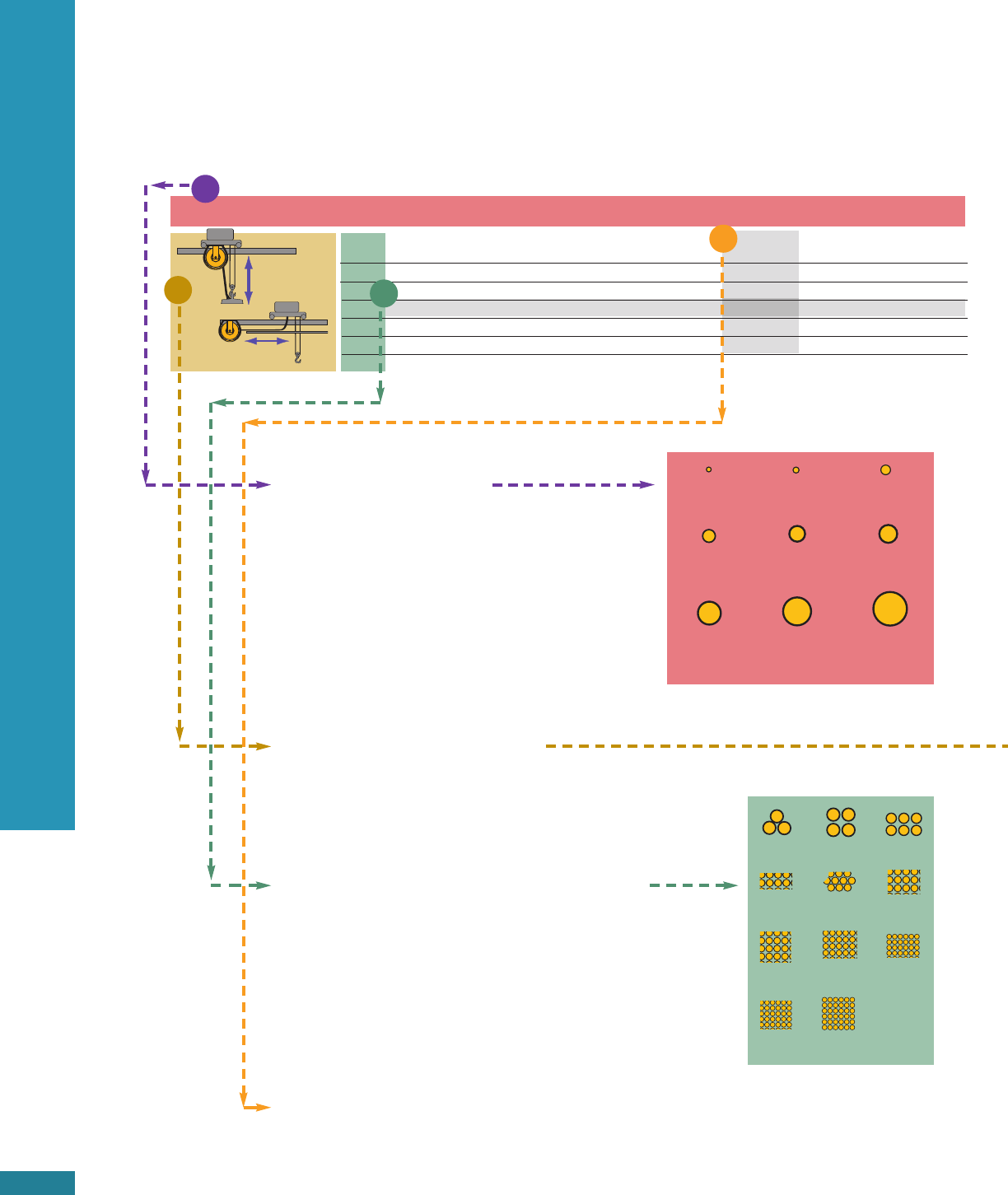
16AWG 14AWG 12AWG
Pages 14-15 Pages 16-17 Pages 18-19
346
8 10 12
16 20 24
30 36
No. of 20 ft 30 ft. 40 ft. 50 ft. 60 ft. 70 ft. 80 ft.
Cond. 6.1 m 9.15 m 12.2 m 15.25 m 18.3 m 21.35 m 24.4 m
3 0951-05-203 0951-05-203 0951-05-203 0951-05-203 1051-01-303 1051-01-303 1051-01-303
4 0951-05-204 0951-05-204 0951-04-204 0951-04-204 1051-01-304 1051-01-304 1051-01-304
6 0951-05-206 0951-05-206 0951-04-206 1051-01-306 1051-02-306 1051-02-306 1143-16-306
8 0951-05-208 0951-04-208 1051-02-308 1051-02-308 1051-02-308 1143-16-308 1164-05-308
10 0951-04-210 1051-01-310 1051-02-310 1051-02-310 1163-16-310 1253-05-310 1253-05-310
No. Cable
Vertical
Lift
Drag
14
1
23
4
POW-R-MATIC CABLE REELS
PAGE 13
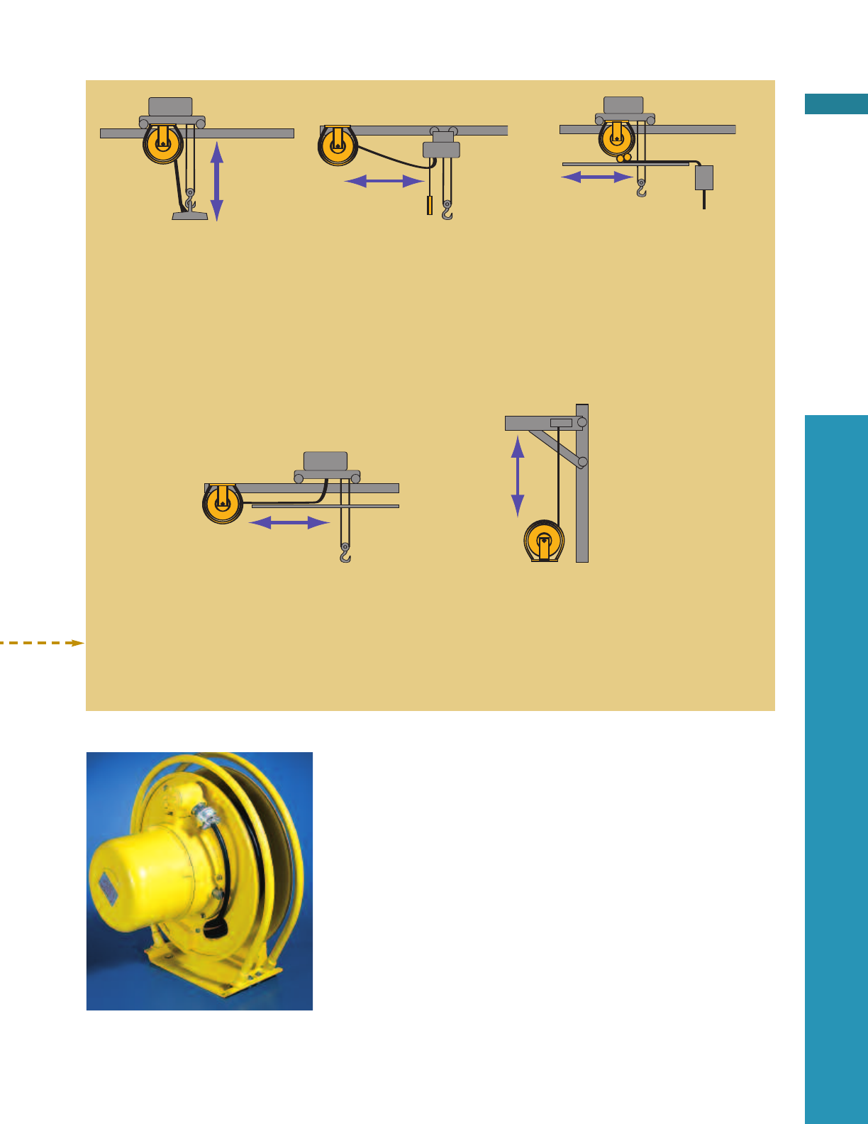
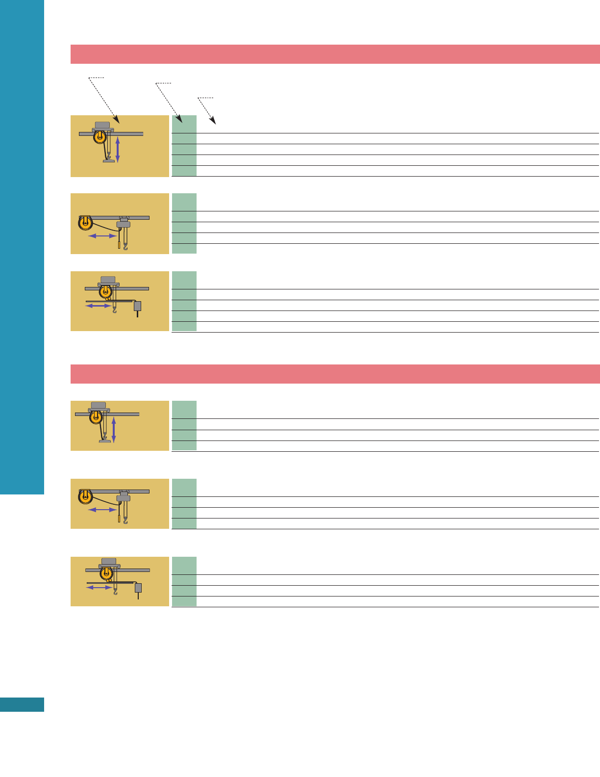
Example
In the example illustrated above, a job called for a reel with
#14 AWG wire(1) used in a lift application(2). Six conductors
were required (3) and the active travel was between 50 and
60 feet (4). The best reel for the job is model 1051-01-303.
Optional features can be ordered by including the
appropriate suffix to the model number:
-L for a ratchet lock (models 1100M through 1400M),
-MD for mill duty service option (models 2000 through
2800),see page 28.
-X for hazardous location (models 1100M through 2800)
See pages 33-35 for more information on these and other
accessories.
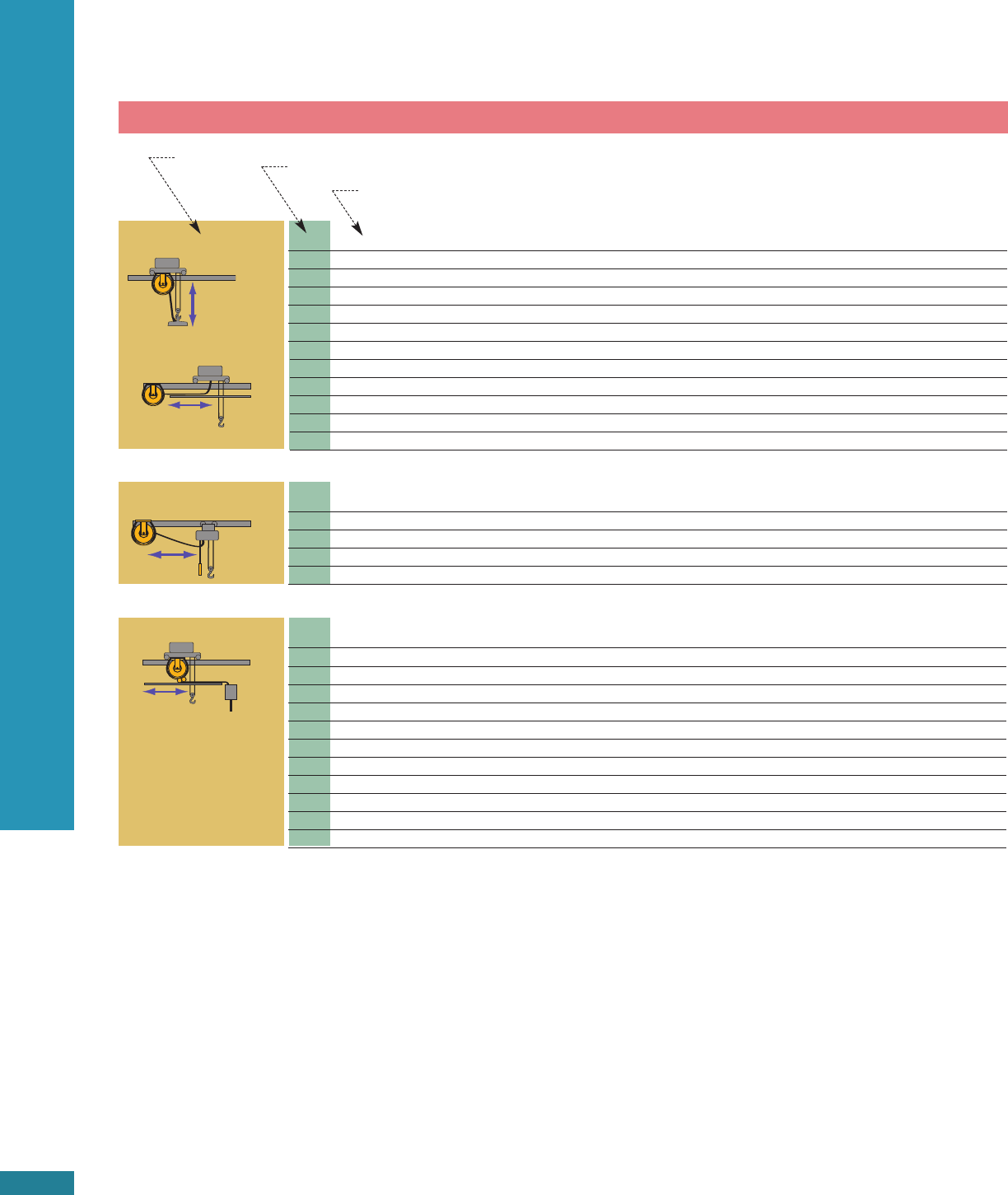
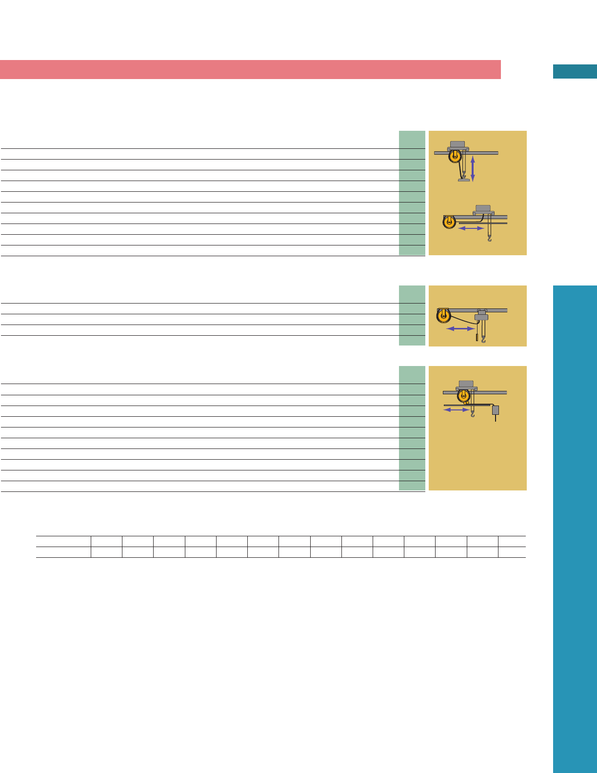
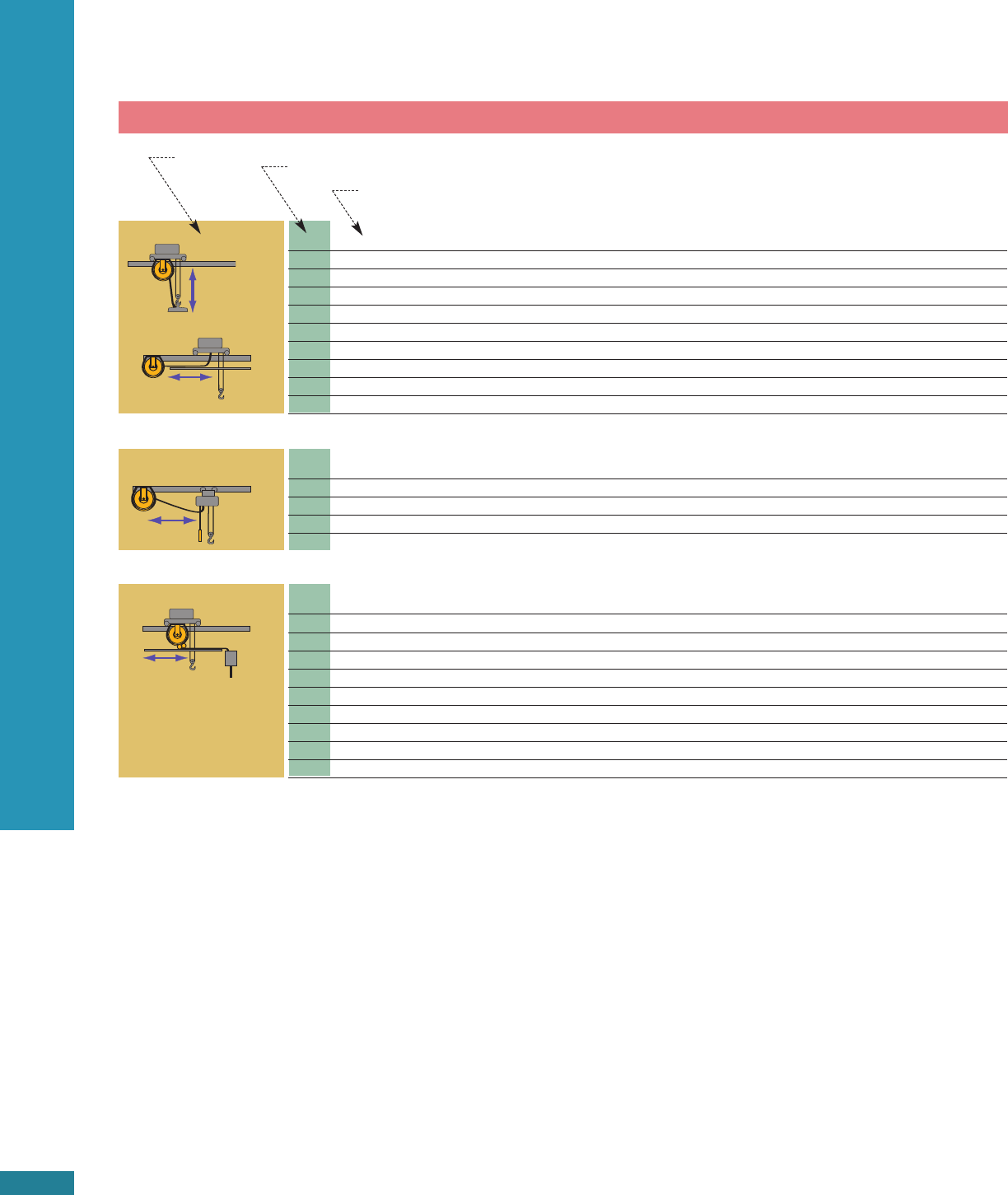
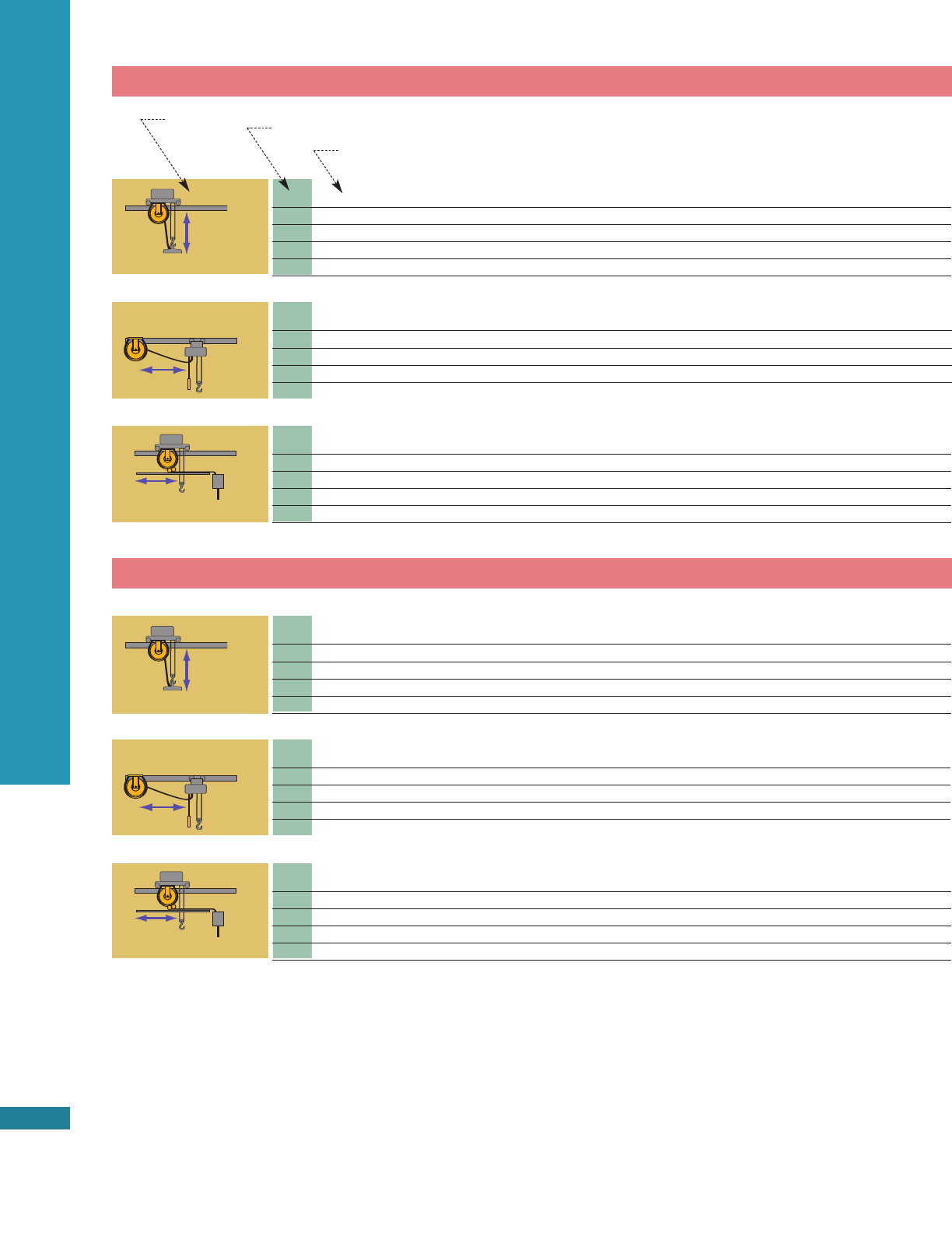
Vertical Lift:
Reel is mounted overhead. Cable
pays out downward and is retract-
ed up via spring power. Reel must
have enough tension to lift the
total weight of the cable and any
additional weight attached to it,
e.g., pendent station, cable over-
hang. The exact weight of added
equipment must be known, as
standard reels are designed to
lift weight of specified length of
cable only.
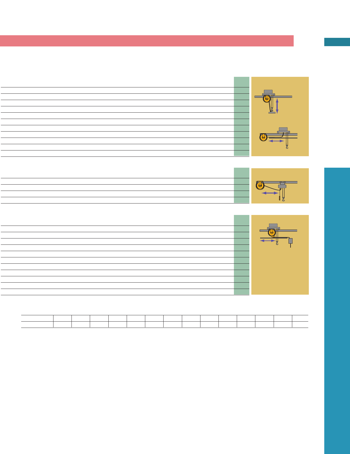
Horizontal Stretch:
Cable is suspended in the air, sup-
ported at both ends. The tension
must accommodate about twice the
total weight of the cable to main-
tain an acceptable 6% sag. The
greater the allowable sag, the less
tension required, allowing dollar
savings to the user.
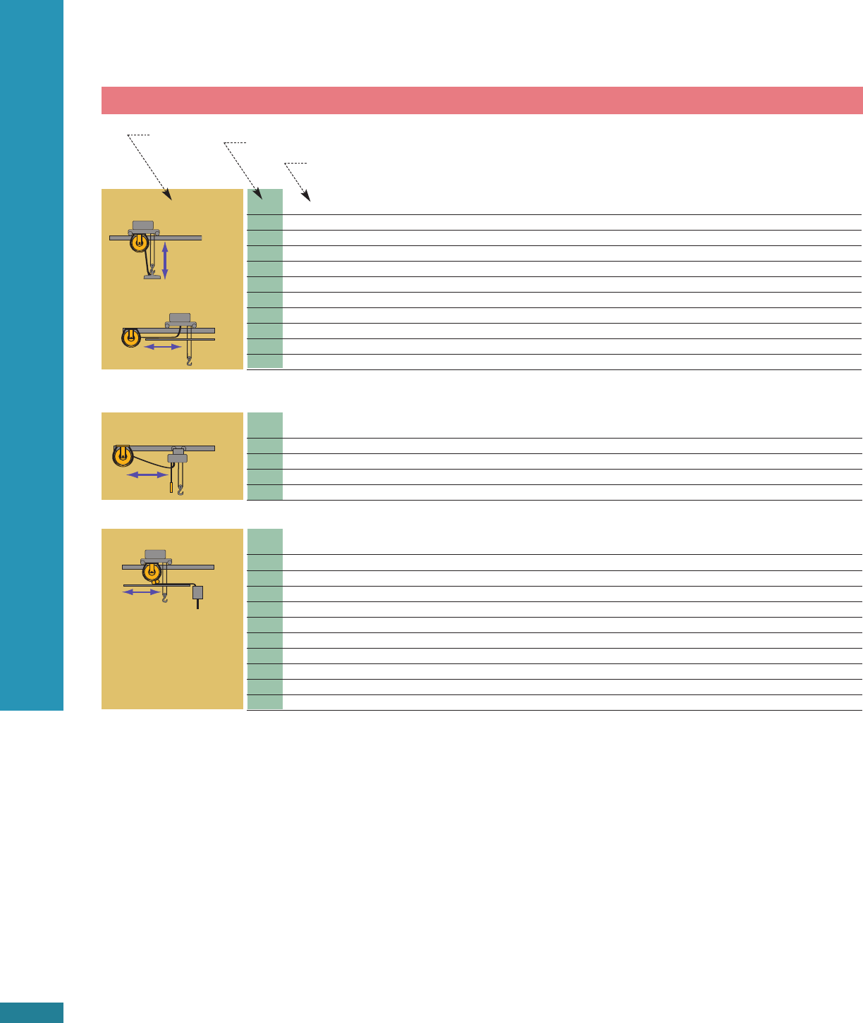
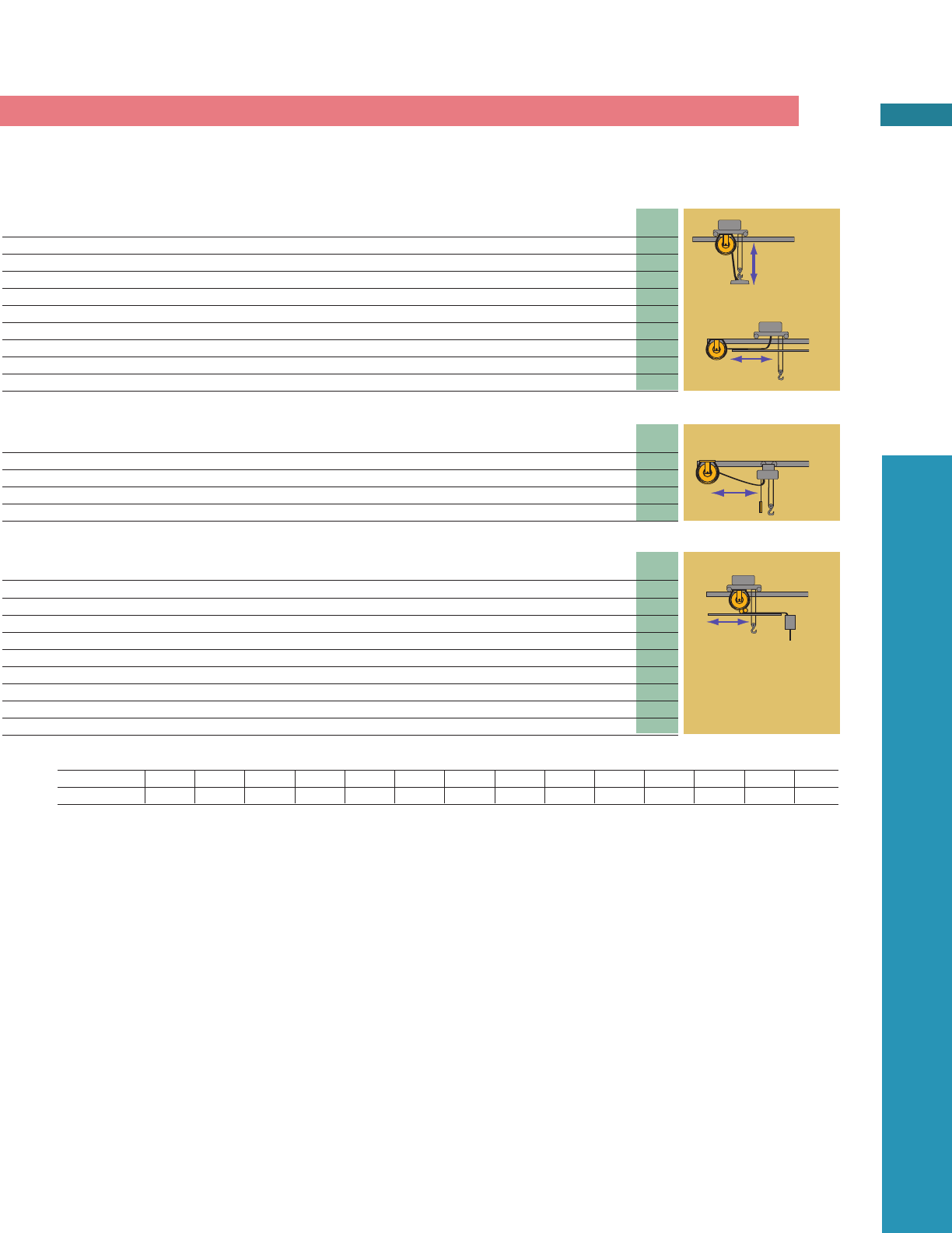
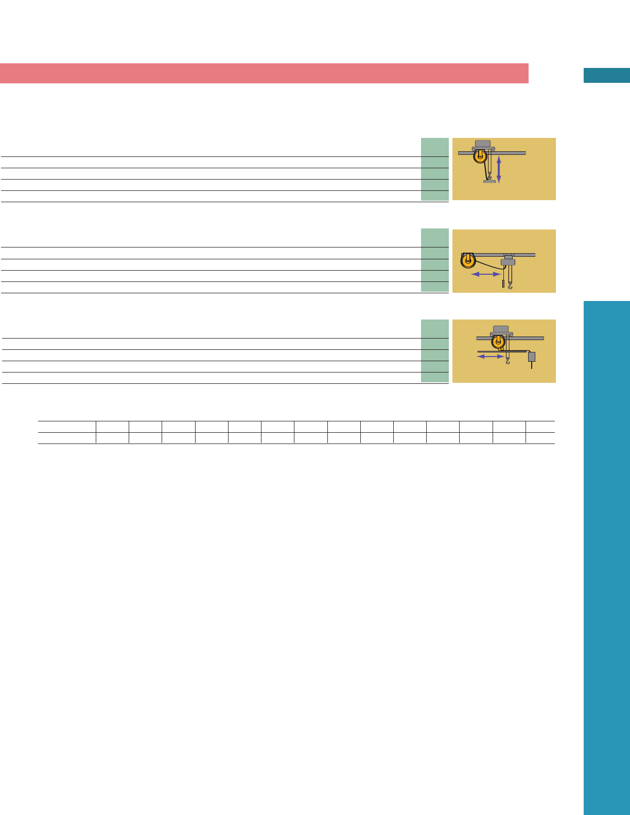
Recovery:
Mounted on a moving carrier,
reel picks up cable from station-
ary base. The closer the reel is
to the recovery surface, the less
tension is required.
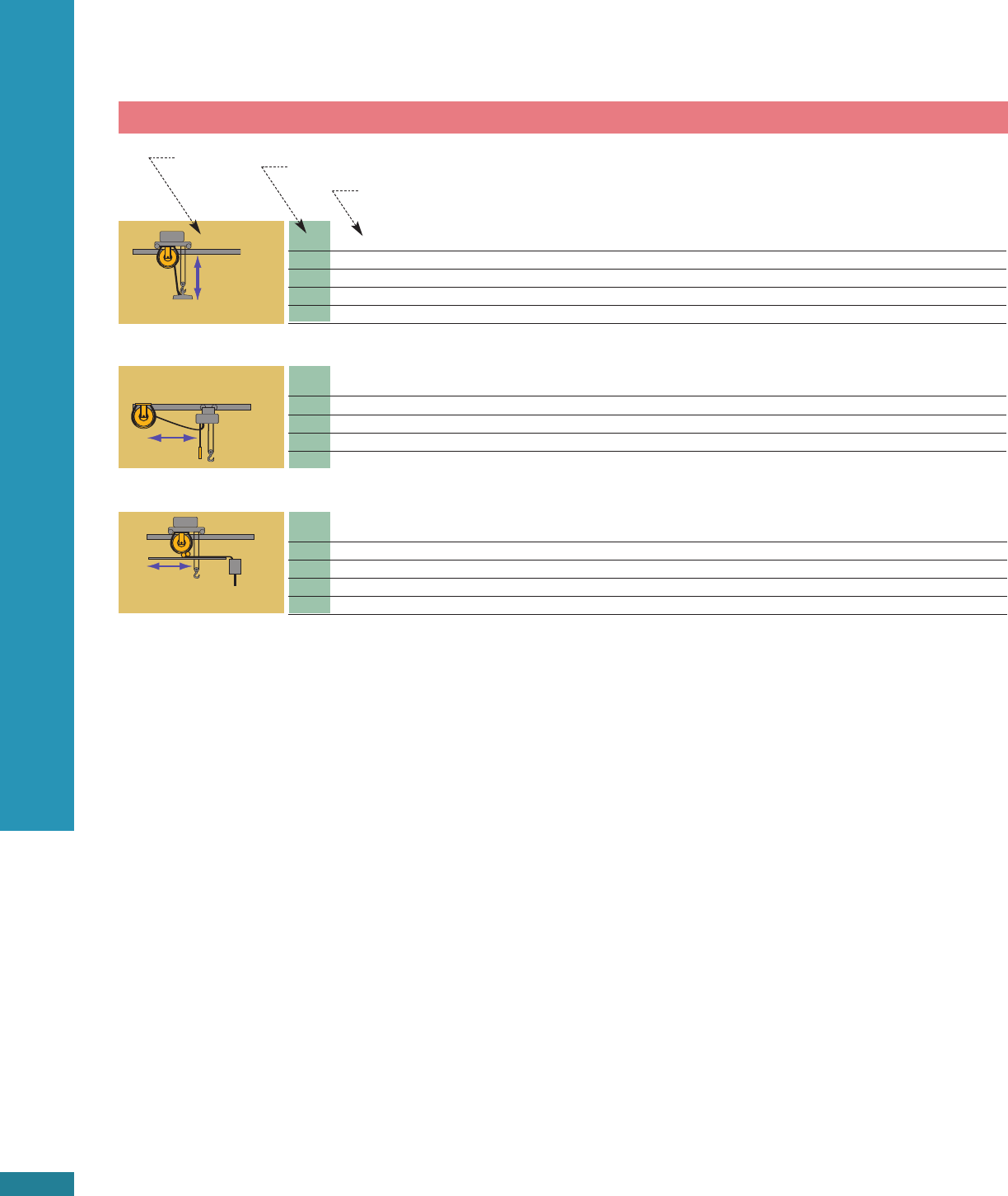
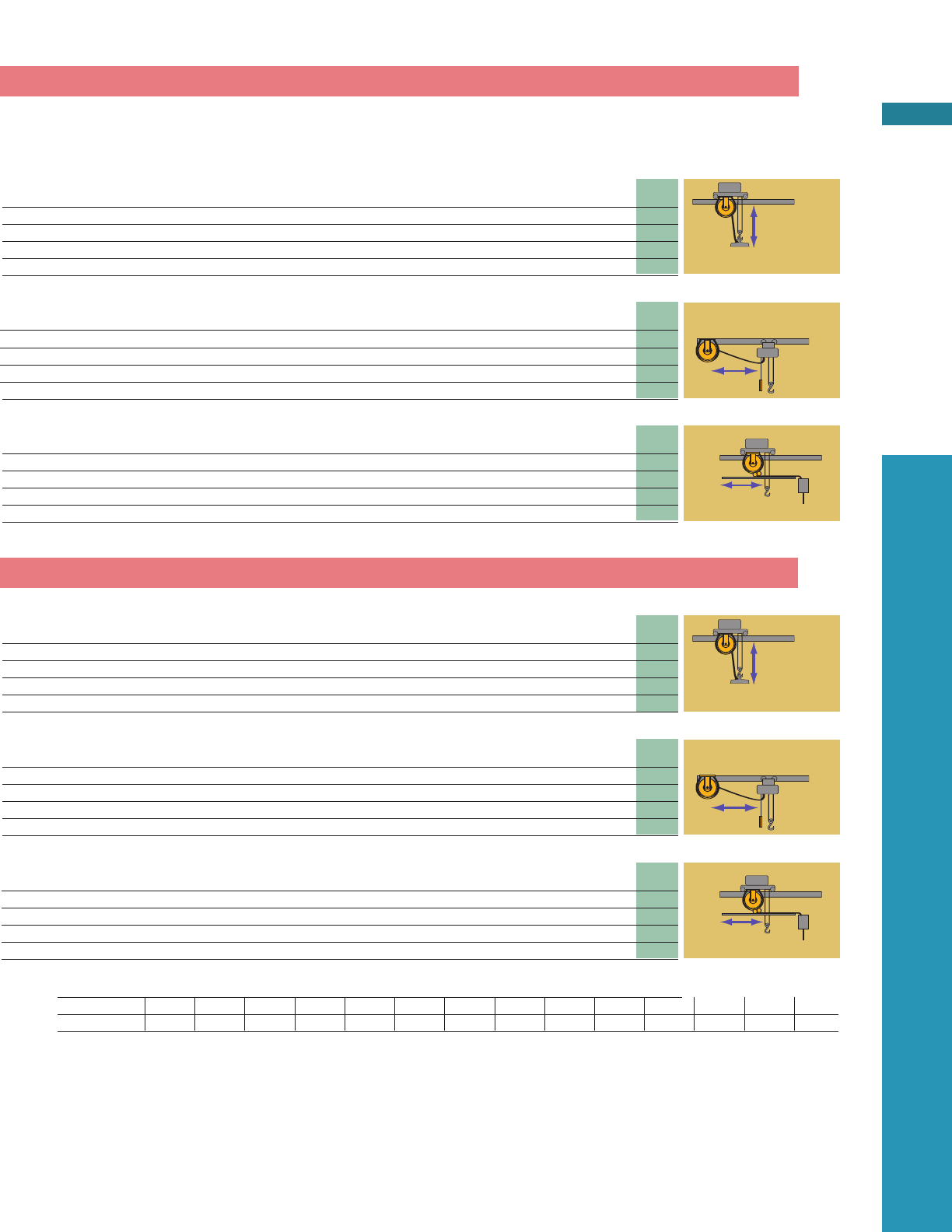
Vertical Recovery:
Base mounted reel pays out
cable upward. The reel is
required only to recover the
cable on the spool, as the
cable moves downward.
Minimal tension is needed to
recover cable into the reel.
Drag:
The reel is mounted in a permanent
location. Cable is dragged over sur-
face to and from fixed mounted
reel. The tension required is about
the same as the lift application.

POW-R-MATIC CABLE REELS
20 ft. 30 ft. 40 ft. 50 ft. 60 ft. 70 ft. 80 ft.
6.1 m 9.15 m 12.2 m 15.25 m 18.3 m 21.35 m 24.4 m
3 0951-05-203 0951-05-203 0951-05-203 0951-05-203 1051-01-303 1051-01-303 1142-10-303
4 0951-05-204 0951-05-204 0951-05-204 0951-05-204 1051-01-304 1051-01-304 1051-01-304
6 0951-05-206 0951-05-206 0951-05-206 0951-05-206 1051-01-306 1051-01-306 1051-01-306
8 0951-05-208 0951-05-208 0951-04-208 0951-04-208 1051-01-308 1051-01-308 1051-01-308
10 0951-04-210 0951-04-210 0951-04-210 1051-01-310 1051-02-310 1051-02-310 1143-16-310
12 0951-04-212 0951-04-212 0951-04-212 1051-01-312 1142-16-312 1143-16-312 1143-16-312
16 1142-10-316 1142-10-316 1142-10-316 1142-16-316 1143-16-316 1163-05-316 1163-05-316
20 1142-10-320 1142-10-320 1142-16-320 1142-16-320 1163-05-320 1163-05-320 1164-17-320
24 1142-10-324 1142-10-324 1142-16-324 1253-05-324 1253-05-324 1253-17-324 1544-16-324
30 1142-10-330 1142-16-330 1142-16-330 1253-05-330 1253-17-330 1354-16-330 1544-16-330
36 1142-10-336 1142-16-336 1163-05-336 1253-17-336 1354-16-336 1544-05-336 1546-05-336
No. Cable Cable rated at 600 volts
Vertical
Lift
Drag
No. of 20 ft 30 ft. 40 ft. 50 ft. 60 ft. 70 ft. 80 ft.
Cond. 6.1 m 9.15 m 12.2 m 15.25 m 18.3 m 21.35 m 24.4 m
3 0951-05-203 0951-05-203 0951-05-203 0951-05-203 1051-01-303 1051-01-303 1142-10-303
4 0951-05-204 0951-05-204 0951-05-204 0951-04-204 1051-01-304 1051-01-304 1051-01-304
6 0951-05-206 0951-05-206 0951-04-206 0951-04-206 1051-01-306 1142-10-306 1142-10-306
8 0951-05-208 0951-04-208 0951-08-208 1051-01-308 1051-02-308 1143-16-308 1143-05-308
Stretch
No.of 50 ft 60 ft 70 ft 80 ft 90 ft 100 ft 120 ft
Cond. 15.2 m 18.3 m 21.35 m 24.4 m 27.45 m 30.5 m 36.6 m
3 0951-05-203 1051-01-303 1051-01-303 1142-10-303 1143-10-303 1143-10-303 1143-10-303
4 0951-05-204 1051-01-304 1051-01-304 1051-01-304 1143-10-304 1143-10-304 1143-10-304
6 0951-05-206 1051-01-306 1051-01-306 1051-01-306 1143-10-306 1143-10-306 1143-10-306
8 0951-04-208 1051-01-308 1051-01-308 1051-01-308 1143-10-308 1143-10-308 1143-10-308
10 1051-01-310 1051-01-310 1051-01-310 1143-10-310 1143-10-310 1163-10-310 1253-10-310
12 1051-01-312 1051-01-312 1051-01-312 1143-10-312 1163-10-312 1163-10-312 1253-10-312
16 1142-10-316 1142-10-316 1163-10-316 1163-10-316 1253-10-316 1253-10-316 1253-10-316
20 1142-10-320 1163-10-320 1163-10-320 1163-10-320 1253-10-320 1253-10-320 1443-10-320
24 1253-10-324 1253-10-324 1253-10-324 1443-10-324 1443-10-324 1443-16-324 1475-16-324
30 1253-10-330 1253-10-330 1253-10-330 1443-05-330 1445-05-330 1443-05-330 1475-05-330
36 1253-10-336 1253-10-336 1443-05-336 1443-05-336 1445-05-336 1475-05-336 1475-05-336
Recovery
(Pickup, Retrieve)
PAGE 14
APPLICATION NOTES
See page 12 for application details.
Vertical Lift Loads in addition to cable weight are not included. Lift
reels will also drag cables over supporting surface, or stretch cables
with 10% sag.
Horizontal Stretch (unsupported) Maximum sag is 6% of total
cable length. If 10% sag can be allowed, use LIFT chart.
Recovery (Pickup, Retrieve) Reel is mounted on moving equipment.
Pay-out and recovery can be two-way with power source at mid-
point. Typical mounting is 3 ft. from surface to lower reel flange.
Speeds to 200 fpm. For other conditions, contact factory. I
If
f s
sl
lo
ow
w
m
mo
ov
vi
in
ng
g r
re
ec
co
ov
ve
er
ry
y a
ap
pp
pl
li
ic
ca
at
ti
io
on
n (
(5
50
0f
fp
pm
m o
or
r l
le
es
ss
s)
) m
mo
or
re
e t
te
en
ns
si
io
on
n m
ma
ay
y b
be
e
r
re
eq
qu
ui
ir
re
ed
d.
. P
Pl
le
ea
as
se
e c
co
on
nt
ta
ac
ct
t f
fa
ac
ct
to
or
ry
y f
fo
or
r a
ap
pp
pl
li
ic
ca
at
ti
io
on
n a
as
ss
si
is
st
ta
an
nc
ce
e.
.
When ordering, specify cable size and type. Maximum operating
speed: 200 fpm.; for other conditions, consult factory. Ratchet lock
standard on Series 0900 and 1000M reels. Optional ratchet lock
available on Series 1100M through 1400M; Specify by adding “-L” to
model number. Junction box data, see page 38; junction boxes are
required to comply with CSA specifications. Cable grips are recom-
mended for all applications. See page 37.
ALL MODELS ARE LESS CABLE
Application Number of Conductors
Length of Active Cable (feet, meters)
16

90 ft. 100 ft. 120 ft. 140 ft. 160 ft. 180 ft. 200 ft. No. of
27.45 m 30.5 m 36.6 m 42.7 m 48.8 m 54.9 m 61 m Cond.
1143-10-303 1143-10-303 1143-10-303 1164-10-303 1164-10-303 1255-10-303 1255-10-303 3
1143-10-304 1143-10-304 1143-10-304 1164-10-304 1164-10-304 1255-16-304 Use No.12/4 4
1143-10-306 1143-10-306 1143-10-306 1255-16-306 1255-05-306 1255-05-306 Use No.12/6 6
1143-16-308 1164-16-308 1164-16-308 1255-05-308 1255-05-308 1255-17-308 2058-53-308 8
1163-16-310 1164-05-310 1255-05-310 1255-17-310 2056-53-310 2347-55-310 2348-56-310 10
1163-05-312 1164-05-312 1255-05-312 1255-17-312 2346-55-312 2348-56-312 2348-56-312 12
1253-05-316 1255-17-316 1356-16-316 2346-55-316 2348-60-316 2349-60-316 2477-53-316 16
1255-17-320 1356-16-320 2346-56-320 2347-60-320 2349-63-320 2370-63-320 2477-53-320 20
1546-16-324 1546-05-324 2377-60-324 2379-63-324 2370-65-324 2477-55-324 2478-56-324 24
1546-05-330 1546-05-330 2378-63-330 2370-66-330 2476-55-330 2476-56-330 2479-60-330 30
1546-05-336 2377-63-336 2379-66-336 2476-56-336 2478-60-336 2679-60-336 2670-63-336 36
90 ft. 100 ft. 110 ft. 120 ft. 130 ft. 140 ft. 150 ft. No. of
27.45 m 30.5 m 33.55 m 36.6 m 39.65 m 42.7 m 45.75 m Cond.
1143-10-303 1143-10-303 1143-10-303 1143-10-303 1143-10-303 1255-16-303 1255-16-303 3
1143-10-304 1143-10-304 1143-10-304 1164-16-304 1164-16-304 1255-05-304 1255-05-304 4
1143-16-306 1164-16-306 1164-05-306 1164-05-306 1255-05-306 1255-05-306 1255-17-306 6
1164-05-308 1164-05-308 1164-05-308 1255-17-308 1255-17-308 2056-53-308 2056-53-308 8
140 ft. 160 ft. 180 ft. 200 ft. 240 ft. 280 ft. 320 ft. No.of
42.7 m 48.8 m 54.9 m 61 m 73.2 m 85.4 m 97.6 m Cond.
1164-10-303 1164-10-303 1255-10-303 1255-10-303 3
1164-10-304 1164-10-304 1255-10-304 1255-10-304 4
1164-10-306 1165-10-306 1255-10-306 6
1255-10-308 1255-10-308 1255-10-308 8
1255-10-310 1255-10-310 1445-10-310 10
1255-10-312 1443-10-312 1445-10-312 12
1443-10-316 1443-10-316 1445-10-316 16
1443-10-320 1445-10-320 1475-10-320 20
1475-16-324 1475-16-324 1475-16-324 24
1475-05-330 1475-05-330 1475-05-330 30
1475-05-336 1475-05-336 2576-50-336 36
No. 16 Cable
POW-R-MATIC CABLE REELS
PAGE 15
DIMENSIONS
SERIES 0900 1000M 1100M 1200M 1300M 1400M 1500M 2000 2300 2400 2500 2600 2700 2800
PAGE NO. 38 38 39 40 40 41 41 42 43-44 45 46 46 47 47
Vertical
Lift
Drag
Stretch
Recovery
(Pickup, Retrieve)
If cable reel is not found in selection charts, please consult factory.
POW-R-MATIC CABLE REELS
20 ft. 30 ft. 40 ft. 50 ft. 60 ft. 70 ft. 80 ft.
6.1 m 9.15 m 12.2 m 15.25 m 18.3 m 21.35 m 24.4 m
3 0951-05-203 0951-05-203 0951-05-203 0951-05-203 1051-01-303 1051-01-303 1051-01-303
4 0951-05-204 0951-05-204 0951-04-204 0951-04-204 1051-01-304 1051-01-304 1051-01-304
6 0951-05-206 0951-05-206 0951-04-206 1051-01-306 1051-02-306 1051-02-306 1143-16-306
8 0951-05-208 0951-04-208 1051-02-308 1051-02-308 1051-02-308 1143-16-308 1164-05-308
10 0951-04-210 1051-01-310 1051-02-310 1051-02-310 1163-16-310 1253-05-310 1253-05-310
12 1051-01-312 1051-01-312 1051-02-312 1163-16-312 1164-16-312 1253-05-312 1253-17-312
16 1142-10-316 1142-16-316 1163-05-316 1253-05-316 1253-17-316 1354-16-316 1544-16-316
20 1142-10-320 1163-16-320 1253-05-320 1253-17-320 1354-16-320 1544-16-320 1546-05-320
24 1142-16-324 1163-05-324 1253-05-324 1544-16-324 1544-05-324 1546-05-324 1546-17-324
30 1142-16-330 1253-05-330 1544-16-330 1544-05-330 1574-05-330 1576-17-330 2376-65-330
36 1163-05-336 1253-17-336 1544-16-336 1544-05-336 1576-17-336 2376-66-336 2378-70-336
No. Cable Cable rated at 600 volts
Vertical
Lift
Drag
No. of 20 ft. 30 ft. 40 ft. 50 ft. 60 ft. 70 ft. 80 ft.
Cond. 6.1 m 9.15 m 12.2 m 15.25 m 18.3 m 21.35 m 24.4 m
3 0951-05-203 0951-05-203 0951-04-203 1051-01-303 1051-01-303 1051-02-303 1142-10-303
4 0951-05-204 0951-05-204 0951-04-204 1051-01-304 1051-02-304 1051-02-304 1143-16-304
6 0951-04-206 0951-08-206 0951-08-206 1051-02-306 1143-16-306 1143-05-306 1143-05-306
80951-04-208 0951-08-208 1051-02-308 1051-03-308 1143-05-308 1143-17-308 1164-17-308
Stretch
No.of 50 ft. 60 ft. 70 ft. 80 ft. 90 ft. 100 ft. 120 ft.
Cond. 15.2 m 18.3 m 21.35 m 24.4 m 27.45 m 30.5 m 36.6 m
3 0951-05-203 1051-01-303 1051-01-303 1051-01-303 1143-10-303 1143-10-303 1143-10-303
4 0951-06-204 1051-01-304 1051-01-304 1143-10-304 1143-10-304 1143-10-304 1143-10-304
6 1051-01-306 1051-01-306 1051-01-306 1143-10-306 1163-10-306 1163-10-306 1253-10-306
8 1051-01-308 1051-01-308 1143-10-308 1164-10-308 1253-10-308 1253-10-308 1443-10-308
10 1051-01-310 1163-10-310 1253-10-310 1253-10-310 1253-10-310 1253-10-310 1443-10-310
12 1163-10-312 1164-10-312 1253-10-312 1253-10-312 1253-10-312 1253-10-312 1443-10-312
16 1253-10-316 1253-10-316 1253-10-316 1443-05-316 1443-05-316 1445-05-316 1475-05-316
20 1253-10-320 1253-10-320 1443-05-320 1443-05-320 1445-05-320 1475-05-320 1475-05-320
24 1443-05-324 1443-05-324 1445-05-324 1445-05-324 1445-05-324 1475-05-324 1475-05-324
30 1443-05-330 1475-05-330 1475-05-330 1475-05-330 1475-05-330 1475-05-330 2576-55-330
36 1544-16-336 1574-16-336 1574-16-336 1576-16-336 1576-16-336 2577-60-336 2578-60-336
Recovery
(Pickup, Retrieve)
APPLICATION NOTES
See page 12 for application details.
Vertical Lift Loads in addition to cable weight are not included. Lift
reels will also drag cables over supporting surface, or stretch cables
with 10% sag.
Horizontal Stretch (unsupported) Maximum sag is 6% of total
cable length. If 10% sag can be allowed, use LIFT chart.
Recovery (Pickup, Retrieve) Reel is mounted on moving equipment.
Pay-out and recovery can be two-way with power source at mid-
point. Typical mounting is 3 ft. from surface to lower reel flange.
Speeds to 200 fpm. For other conditions, contact factory. I
If
f s
sl
lo
ow
w
m
mo
ov
vi
in
ng
g r
re
ec
co
ov
ve
er
ry
y a
ap
pp
pl
li
ic
ca
at
ti
io
on
n (
(5
50
0f
fp
pm
m o
or
r l
le
es
ss
s)
) m
mo
or
re
e t
te
en
ns
si
io
on
n m
ma
ay
y b
be
e
r
re
eq
qu
ui
ir
re
ed
d.
. P
Pl
le
ea
as
se
e c
co
on
nt
ta
ac
ct
t f
fa
ac
ct
to
or
ry
y f
fo
or
r a
ap
pp
pl
li
ic
ca
at
ti
io
on
n a
as
ss
si
is
st
ta
an
nc
ce
e.
.
When ordering, specify cable size and type. Maximum operating
speed: 200 fpm.; for other conditions, consult factory. Ratchet lock
standard on Series 0900 and 1000M reels. Optional ratchet lock
available on Series 1100M through 1400M; Specify by adding “-L” to
model number. Junction box data, see page 38; junction boxes are
required to comply with CSA specifications. Cable grips are recom-
mended for all applications. See page 37.
PAGE 16
ALL MODELS ARE LESS CABLE
Application Number of Conductors
Length of Active Cable (feet, meters)
14
90 ft. 100 ft. 120 ft. 140 ft. 160 ft. 180 ft. 200 ft. No. of
27.45 m 30.5 m 36.6 m 42.7 m 48.8 m 54.9 m 61 m Cond.
1143-10-303 1143-10-303 1164-16-303 1255-16-303 1255-05-303 1255-05-303 Use No. 12/3 3
1143-10-304 1164-16-304 1164-16-304 1255-05-304 1255-05-304 1255-05-304 Use No. 12/4 4
1163-16-306 1164-05-306 1255-05-306 1255-17-306 2346-55-306 2348-56-306 2348-56-306 6
1253-05-308 1255-05-308 1546-16-308 2346-55-308 2347-56-308 2349-60-308 2370-60-308 8
1255-17-310 1356-16-310 1546-16-310 2347-60-310 2348-60-310 2370-63-310 2477-53-310 10
1356-16-312 1356-16-312 2346-56-312 2347-60-312 2349-63-312 2476-53-312 2476-53-312 12
1546-16-316 1546-05-316 2378-63-316 2370-66-316 2476-55-316 2477-56-316 2679-60-316 16
1546-05-320 2377-63-320 2379-66-320 2476-56-320 2678-60-320 2678-60-320 2670-63-320 20
2347-65-324 2378-66-324 2476-56-324 2677-60-324 2679-63-324 2870-63-324 2870-65-324 24
2378-70-330 2370-76-330 2676-60-330 2678-63-330 2879-65-330 30
2370-76-336 2676-60-336 2677-63-336 2878-66-336 36
90 ft. 100 ft. 110 ft. 120 ft. 130 ft. 140 ft. 150 ft. No. of
27.45 m 30.5 m 33.55 m 36.6 m 39.65 m 42.7 m 45.75 m Cond.
1143-16-303 1164-16-303 1164-05-303 1164-05-303 1255-05-303 1255-05-303 1255-17-303 3
1143-16-304 1164-05-304 1164-05-304 1255-05-304 1255-17-304 1255-17-304 2056-53-304 4
1164-17-306 1356-16-306 2056-55-306 2056-56-306 2058-60-306 2058-60-306 2059-60-306 6
1356-16-308 2056-56-308 2057-60-308 2347-60-308 2347-60-308 2349-63-308 2349-63-308 8
140 ft. 160 ft. 180 ft. 200 ft. 240 ft. 280 ft. 320 ft. No. of
42.7 m 48.8 m 54.9 m 61 m 73.2 m 85.4 m 97.6 m Cond.
1164-10-303 1255-10-303 1255-10-303 1255-10-303 3
1164-10-304 1255-10-304 1255-10-304 1255-10-304 4
1255-10-306 1443-10-306 6
1443-10-308 1443-10-308 8
1443-10-310 1445-10-310 10
1443-10-312 1445-10-312 12
1475-05-316 1475-05-316 16
1475-05-320 2576-50-320 20
2576-50-324 2576-50-324 24
2576-55-330 2770-60-330 30
2779-60-336 2770-60-336 36
No. 14 Cable
POW-R-MATIC CABLE REELS
PAGE 17
DIMENSIONS
SERIES 0900 1000M 1100M 1200M 1300M 1400M 1500M 2000 2300 2400 2500 2600 2700 2800
PAGE NO. 38 38 39 40 40 41 41 42 43-44 45 46 46 47 47
Vertical
Lift
Drag
Stretch
Recovery
(Pickup, Retrieve)
If cable reel is not found in selection charts, please consult factory.
POW-R-MATIC CABLE REELS
20 ft. 30 ft. 40 ft. 50 ft. 60 ft. 70 ft. 80 ft.
6.1 m 9.15 m 12.2 m 15.25 m 18.3 m 21.35 m 24.4 m
3 0951-05-203 0951-05-203 0951-05-203 0951-04-203 1051-01-303 1051-01-303 1143-10-303
4 0951-05-204 0951-05-204 0951-04-204 1051-01-304 1051-01-304 1142-10-304 1143-16-304
6 0951-05-206 0951-04-206 1051-02-306 1051-02-306 1051-02-306 1143-16-306 1163-05-306
8 0951-05-208 1051-02-308 1051-02-308 1051-02-308 1164-05-308 1253-05-308 1253-17-308
10 1051-01-310 1051-02-310 1142-16-310 1253-05-310 1253-05-310 1253-17-310 1544-16-310
12 1051-01-312 1051-02-312 1142-16-312 1253-05-312 1253-17-312 1354-16-312 1544-16-312
16 1142-10-316 1142-16-316 1163-05-316 1253-17-316 1354-16-316 1546-05-316 1546-05-316
20 1142-16-320 1163-05-320 1253-17-320 1544-16-320 1544-05-320 1546-05-320 2346-63-320
24 1163-16-324 1253-17-324 1544-16-324 1544-05-324 1576-17-324 2378-65-324 2378-70-324
30 1163-05-330 1354-16-330 1544-05-330 1544-17-330 2375-65-330 2377-70-330 2379-76-330
No. Cable Cable rated at 600 volts
Vertical
Lift
Drag
No. of 20 ft. 30 ft. 40 ft. 50 ft. 60 ft. 70 ft. 80 ft.
Cond. 6.1 m 9.15 m 12.2 m 15.25 m 18.3 m 21.35 m 24.4 m
3 0951-05-203 0951-04-203 0951-08-203 1051-02-303 1051-02-303 1051-02-303 1143-05-303
4 0951-05-204 0951-04-204 0951-08-204 1051-02-304 1051-02-304 1143-05-304 1143-05-304
6 0951-04-206 0951-08-206 1051-02-306 1051-03-306 1143-05-306 1143-17-306 1164-17-306
8 0951-08-208 1051-02-308 1051-03-308 1143-05-308 1164-17-308 1354-16-308 1356-05-308
Stretch
No.of 50 ft. 60 ft. 70 ft. 80 ft. 90 ft. 100 ft. 120 ft.
Cond. 15.2 m 18.3 m 21.35 m 24.4 m 27.45 m 30.5 m 36.6 m
3 0951-04-203 1051-01-303 1051-01-303 1051-01-303 1143-10-303 1143-10-303 1163-10-303
4 1051-01-304 1051-01-304 1051-01-304 1143-10-304 1143-10-304 1143-10-304 1164-10-304
6 1051-01-306 1051-01-306 1143-10-306 1163-10-306 1164-10-306 1253-10-306 1253-10-306
8 1051-01-308 1164-10-308 1253-10-308 1253-10-308 1253-10-308 1253-10-308 1443-10-308
10 1253-10-310 1253-10-310 1253-10-310 1443-10-310 1443-10-310 1443-10-310 1475-10-310
12 1253-10-312 1253-10-312 1253-10-312 1443-05-312 1443-05-312 1443-05-312 1475-05-312
16 1253-10-316 1253-10-316 1443-05-316 1443-05-316 1445-05-316 1475-05-316 1475-05-316
20 1443-05-320 1443-05-320 1443-05-320 1445-05-320 1145-05-320 1475-05-320 1475-05-320
24 1445-05-324 1475-05-324 1475-05-324 1475-05-324 1476-05-324 2577-60-324 2578-60-324
30 1544-05-330 1576-05-330 1576-05-330 1576-05-330 2377-60-330 2577-60-330 2578-60-330
Recovery
(Pickup, Retrieve)
APPLICATION NOTES
See page 12 for application details.
Vertical Lift Loads in addition to cable weight are not included. Lift
reels will also drag cables over supporting surface, or stretch cables
with 10% sag.
Horizontal Stretch (unsupported) Maximum sag is 6% of total cable
length. If 10% sag can be allowed, use LIFT chart.
Recovery (Pickup, Retrieve) Reel is mounted on moving equipment.
Pay-out and recovery can be two-way with power source at midpoint.
Typical mounting is 3 ft. from surface to lower reel flange. Speeds to
200 fpm. For other conditions, contact factory. I
If
f s
sl
lo
ow
w m
mo
ov
vi
in
ng
g r
re
ec
co
ov
ve
er
ry
y
a
ap
pp
pl
li
ic
ca
at
ti
io
on
n (
(5
50
0f
fp
pm
m o
or
r l
le
es
ss
s)
) m
mo
or
re
e t
te
en
ns
si
io
on
n m
ma
ay
y b
be
e r
re
eq
qu
ui
ir
re
ed
d.
. P
Pl
le
ea
as
se
e
c
co
on
nt
ta
ac
ct
t f
fa
ac
ct
to
or
ry
y f
fo
or
r a
ap
pp
pl
li
ic
ca
at
ti
io
on
n a
as
ss
si
is
st
ta
an
nc
ce
e.
.
When ordering, specify cable size and type. Maximum operating speed:
200 fpm.; for other conditions, consult factory. Ratchet lock standard
on Series 0900 and 1000M reels. Optional ratchet lock available on
Series 1100M through 1400M; Specify by adding “-L” to model number.
Junction box data, see page 38; junction boxes are required to comply
with CSA specifications. Cable grips are recommended for all applica-
tions. See page 37.
90 ft. 100 ft. 120 ft. 140 ft. 160 ft. 180 ft. 200 ft. No. of
27.45 m 30.5 m 36.6 m 42.7 m 48.8 m 54.9 m 61 m Cond.
1143-16-303 1164-16-303 1164-05-303 1255-05-303 1255-05-303 2058-53-303 2058-53-303 3
1143-16-304 1164-16-304 1164-05-304 1255-17-304 2056-53-304 2057-53-304 2058-55-304 4
1164-05-306 1255-05-306 1356-16-306 2057-55-306 2347-56-306 2340-60-306 2340-60-306 6
1255-17-308 1356-16-308 1546-16-308 2346-56-308 2348-60-308 2370-63-308 2476-53-308 8
1544-16-310 2345-56-310 2377-60-310 2379-63-310 2370-65-310 2477-55-310 2478-56-310 10
1546-05-312 2346-60-312 2378-62-312 2379-65-312 2476-55-312 2477-56-312 2479-60-312 12
2347-63-316 2377-63-316 2370-70-316 2476-56-316 2478-60-316 2670-63-316 2670-63-316 16
2347-65-320 2379-70-320 2476-56-320 2677-60-320 2679-63-320 2870-65-320 2870-66-320 20
2370-76-324 2570-76-324 2677-63-324 2878-65-324 2870-70-324 24
2370-76-330 2676-60-330 2678-65-330 2870-70-330 30
90 ft. 100 ft. 110 ft. 120 ft. 130 ft. 140 ft. 150 ft. No. of
27.45 m 30.5 m 33.55 m 36.6 m 39.65 m 42.7 m 45.75 m Cond.
1164-05-303 1164-05-303 1255-17-303 1255-17-303 2056-53-303 2056-53-303 2057-55-303 3
1164-05-304 1164-17-304 1255-17-304 2056-55-304 2056-55-304 2057-56-304 2058-60-304 4
1356-16-306 1356-16-306 2056-56-306 2058-60-306 2058-60-306 2050-63-306 2340-63-306 6
1356-05-308 2057-60-308 2348-63-308 2348-63-308 2340-66-308 2340-66-308 2446-55-308 8
140 ft. 160 ft. 180 ft. 200 ft. 240 ft. 280 ft. 320 ft. No.of
42.7 m 48.8 m 54.9 m 61 m 73.2 m 85.4 m 97.6 m Cond.
1255-10-303 1255-10-303 1255-10-303 1255-10-303 3
1255-10-304 1255-10-304 1255-10-304 1255-10-304 4
1255-10-306 1443-10-306 6
1443-10-308 1445-10-308 8
1475-10-310 1475-10-310 10
1475-05-312 1475-05-312 12
1475-05-316 1475-05-316 16
2577-55-320 2577-55-320 20
2779-60-324 2770-60-324 24
2770-60-330 2876-60-330 30
PAGE 18
ALL MODELS ARE LESS CABLE
Application Number of Conductors
Length of Active Cable (feet, meters)
12
90 ft. 100 ft. 120 ft. 140 ft. 160 ft. 180 ft. 200 ft. No. of
27.45 m 30.5 m 36.6 m 42.7 m 48.8 m 54.9 m 61 m Cond.
1143-16-303 1164-16-303 1164-05-303 1255-05-303 1255-05-303 2058-53-303 2058-53-303 3
1143-16-304 1164-16-304 1164-05-304 1255-17-304 2056-53-304 2057-53-304 2058-55-304 4
1164-05-306 1255-05-306 1356-16-306 2057-55-306 2347-56-306 2340-60-306 2340-60-306 6
1255-17-308 1356-16-308 1546-16-308 2346-56-308 2348-60-308 2370-63-308 2476-53-308 8
1544-16-310 2345-56-310 2377-60-310 2379-63-310 2370-65-310 2477-55-310 2478-56-310 10
1546-05-312 2346-60-312 2378-62-312 2379-65-312 2476-55-312 2477-56-312 2479-60-312 12
2347-63-316 2377-63-316 2370-70-316 2476-56-316 2478-60-316 2670-63-316 2670-63-316 16
2347-65-320 2379-70-320 2476-56-320 2677-60-320 2679-63-320 2870-65-320 2870-66-320 20
2370-76-324 2570-76-324 2677-63-324 2878-65-324 2870-70-324 24
2370-76-330 2676-60-330 2678-65-330 2870-70-330 30
90 ft. 100 ft. 110 ft. 120 ft. 130 ft. 140 ft. 150 ft. No. of
27.45 m 30.5 m 33.55 m 36.6 m 39.65 m 42.7 m 45.75 m Cond.
1164-05-303 1164-05-303 1255-17-303 1255-17-303 2056-53-303 2056-53-303 2057-55-303 3
1164-05-304 1164-17-304 1255-17-304 2056-55-304 2056-55-304 2057-56-304 2058-60-304 4
1356-16-306 1356-16-306 2056-56-306 2058-60-306 2058-60-306 2050-63-306 2340-63-306 6
1356-05-308 2057-60-308 2348-63-308 2348-63-308 2340-66-308 2340-66-308 2446-55-308 8
140 ft. 160 ft. 180 ft. 200 ft. 240 ft. 280 ft. 320 ft. No.of
42.7 m 48.8 m 54.9 m 61 m 73.2 m 85.4 m 97.6 m Cond.
1255-10-303 1255-10-303 1255-10-303 1255-10-303 3
1255-10-304 1255-10-304 1255-10-304 1255-10-304 4
1255-10-306 1443-10-306 6
1443-10-308 1445-10-308 8
1475-10-310 1475-10-310 10
1475-05-312 1475-05-312 12
1475-05-316 1475-05-316 16
2577-55-320 2577-55-320 20
2779-60-324 2770-60-324 24
2770-60-330 2876-60-330 30
No. 12 Cable
POW-R-MATIC CABLE REELS
PAGE 19
DIMENSIONS
SERIES 0900 1000M 1100M 1200M 1300M 1400M 1500M 2000 2300 2400 2500 2600 2700 2800
PAGE NO. 38 38 39 40 40 41 41 42 43-44 45 46 46 47 47
Vertical
Lift
Drag
Stretch
Recovery
(Pickup, Retrieve)
If cable reel is not found in selection charts, please consult factory.
POW-R-MATIC CABLE REELS
20 ft. 30 ft. 40 ft. 50 ft. 60 ft. 70 ft. 80 ft.
6.1 m 9.15 m 12.2 m 15.25 m 18.3 m 21.35 m 24.4 m
3 0951-05-203 0951-05-203 0951-04-203 1051-01-303 1051-02-303 1051-02-303 1143-16-303
4 0951-05-204 0951-04-204 1051-01-304 1051-02-304 1051-02-304 1051-02-304 1143-16-304
6 0951-06-206 0951-08-206 1051-02-306 1051-02-306 1143-05-306 1163-05-306 1164-17-306
8 1051-01-308 1051-02-308 1142-16-308 1253-05-308 1253-17-308 1354-16-308 1544-16-308
10 1142-10-310 1142-16-310 1163-05-310 1253-17-310 1354-16-310 1544-16-310 1544-05-310
12 1142-10-312 1142-16-312 1163-05-312 1253-17-312 1354-16-312 1544-05-312 1546-05-312
16 1142-16-316 1163-05-316 1354-16-316 1544-05-316 1544-05-316 1546-17-316 2346-65-316
20 1163-05-320 1253-17-320 1544-05-320 1544-05-320 2375-65-320 2376-66-320 2379-76-320
24 1253-05-324 2053-53-324 1544-05-324 1574-17-324 2376-65-324 2378-76-324 2370-80-324
No. Cable Cable rated at 600 volts
Vertical
Lift
Drag
No. of 20 ft. 30 ft. 40 ft. 50 ft. 60 ft. 70 ft. 80 ft.
Cond. 6.1 m 9.15 m 12.2 m 15.25 m 18.3 m 21.35 m 24.4 m
3 0951-05-203 0951-08-203 0951-08-203 1051-02-303 1143-16-303 1143-05-303 1143-05-303
40951-04-204 0951-08-204 1051-02-304 1051-03-304 1143-05-304 1143-05-304 1143-17-304
6 0951-08-206 1051-02-306 1051-03-306 1143-05-306 1143-17-306 1354-16-306 1356-05-306
81051-02-308 1051-03-308 1142-17-308 1354-16-308 1354-05-308 1356-05-308 1546-17-308
Stretch
No. of 50 ft. 60 ft. 70 ft. 80 ft. 90 ft. 100 ft. 120 ft.
Cond. 15.2 m 18.3 m 21.35 m 24.4 m 27.45 m 30.5 m 36.6 m
3 1051-01-303 1051-01-303 1051-01-303 1051-01-303 1143-10-303 1163-10-303 1164-10-303
4 1051-01-304 1051-01-304 1051-01-304 1143-10-304 1163-10-304 1163-10-304 1253-10-304
61051-01-306 1142-10-306 1143-10-306 1163-10-306 1253-10-306 1253-10-306 1443-10-306
8 1253-10-308 1253-10-308 1253-10-308 1443-05-308 1443-05-308 1443-05-308 1475-05-308
10 1253-10-310 1253-10-310 1443-05-310 1443-05-310 1443-05-310 1475-05-310 1475-05-310
12 1253-10-312 1253-10-312 1443-05-312 1443-05-312 1443-05-312 1475-05-312 1475-05-312
16 1443-05-316 1445-05-316 1445-05-316 1445-05-316 1445-05-316 1475-05-316 1476-05-316
20 1544-16-320 1576-16-320 1576-16-320 1576-16-320 1576-16-320 2577-60-320 2578-60-320
24 1576-05-324 1576-05-324 1576-05-324 1576-05-324 2577-60-324 2578-60-324 2876-55-324
Recovery
(Pickup, Retrieve)
APPLICATION NOTES
See page 12 for application details.
Vertical Lift Loads in addition to cable weight are not included. Lift
reels will also drag cables over supportingsurface,or stretch cables
with 10% sag.
Horizontal Stretch (unsupported) Maximum sag is 6% of total
cable length. If 10% sag can be allowed,use LIFT chart.
Recovery (Pickup, Retrieve) Reel is mounted on moving equipment.
Pay-out and recovery can be two-way with power source at mid-
point. Typical mounting is 3 ft. from surface to lower reel flange.
Speeds to 200 fpm. For other conditions, contact factory. I
If
f s
sl
lo
ow
w
m
mo
ov
vi
in
ng
g r
re
ec
co
ov
ve
er
ry
y a
ap
pp
pl
li
ic
ca
at
ti
io
on
n (
(5
50
0f
fp
pm
m o
or
r l
le
es
ss
s)
) m
mo
or
re
e t
te
en
ns
si
io
on
n m
ma
ay
y b
be
e
r
re
eq
qu
ui
ir
re
ed
d.
. P
Pl
le
ea
as
se
e c
co
on
nt
ta
ac
ct
t f
fa
ac
ct
to
or
ry
y f
fo
or
r a
ap
pp
pl
li
ic
ca
at
ti
io
on
n a
as
ss
si
is
st
ta
an
nc
ce
e.
.
When ordering, specify cable size and type. Maximum operating
speed: 200 fpm.; for other conditions, consult factory. Ratchet lock
standard on Series 0900 and 1000M reels. Optional ratchet lock
available on Series 1100M through 1400M; Specify by adding “-L” to
model number. Junction box data, see page 38; junction boxes are
required to comply with CSA specifications. Cable grips are recom-
mended for all applications. See page 37.
PAGE 20
ALL MODELS ARE LESS CABLE
Application Number of Conductors
Length of Active Cable (feet, meters)
10
90 ft. 100 ft. 120 ft. 140 ft. 160 ft. 180 ft. 200 ft. No. of
27.45 m 30.5 m 36.6 m 42.7 m 48.8 m 54.9 m 61 m Cond.
1143-16-303 1164-05-303 1164-05-303 1255-17-303 2056-53-303 2058-55-303 2058-55-303 3
1164-05-304 1164-05-304 1255-17-304 2056-53-304 2346-55-304 2347-56-304 2349-60-304 4
1255-17-306 1356-16-306 2346-56-306 2347-60-306 2349-63-306 2370-63-306 2477-53-306 6
1546-05-308 1546-05-308 2378-63-308 2379-65-308 2476-55-308 2477-56-308 2479-60-308 8
1546-05-310 2377-63-310 2378-65-310 2476-55-310 2477-56-310 2479-60-310 2679-60-310 10
2347-63-312 2377-63-312 2370-70-312 2476-56-312 2478-60-312 2670-63-312 2670-63-312 12
2348-70-316 2370-76-316 2477-60-316 2678-63-316 2679-65-316 2870-66-316 16
2370-76-320 2676-60-320 2677-63-320 2879-66-320 20
2676-66-324 2677-63-324 2879-70-324 24
90 ft. 100 ft. 110 ft. 120 ft. 130 ft. 140 ft. 150 ft. No. of
27.45 m 30.5 m 33.55 m 36.6 m 39.65 m 42.7 m 45.75 m Cond.
1164-17-303 1164-17-303 2055-53-303 2056-55-303 2056-55-303 2057-56-303 2059-60-303 3
1356-16-304 1356-16-304 2056-56-304 2058-60-304 2058-60-304 2058-60-304 2349-63-304 4
1356-05-306 2057-60-306 2058-63-306 2348-63-306 2349-66-306 2446-55-306 2446-55-306 6
2347-63-308 2348-66-308 2349-70-308 2476-56-308 2477-60-308 2477-60-308 2478-60-308 8
140 ft. 160 ft. 180 ft. 200 ft. 240 ft. 280 ft. 320 ft. No. of
42.7 m 48.8 m 54.9 m 61 m 73.2 m 85.4 m 97.6 m Cond.
1255-10-303 1255-10-303 1255-10-303 1255-10-303 3
1255-10-304 1443-10-304 1445-10-304 1445-10-304 4
1443-10-306 1445-10-306 6
1475-05-308 1475-05-308 8
1475-05-310 1475-05-310 10
1475-05-312 1475-05-312 12
2577-55-316 2577-55-316 16
2770-60-320 2876-50-320 20
2876-55-324 24
No. 10 Cable
POW-R-MATIC CABLE REELS
DIMENSIONS
SERIES 0900 1000M 1100M 1200M 1300M 1400M 1500M 2000 2300 2400 2500 2600 2700 2800
PAGE NO. 38 38 39 40 40 41 41 42 43-44 45 46 46 47 47
Vertical
Lift
Drag
Stretch
Recovery
(Pickup, Retrieve)
If cable reel is not found in selection charts, please consult factory.
PAGE 21
POW-R-MATIC CABLE REELS
20 ft. 30 ft. 40 ft. 50 ft. 60 ft. 70 ft. 80 ft.
6.1 m 9.15 m 12.2 m 15.25 m 18.3 m 21.35 m 24.4 m
2W* 1051-01-402 1051-01-402 1051-01-402 1051-02-402 1143-16-402 1163-16-402 1163-05-402
3W 1051-01-403 1051-01-403 1051-02-403 1051-02-403 1163-05-403 1163-05-403 1164-17-403
3G 1051-01-404 1051-01-404 1051-02-404 1051-03-404 1163-05-404 1163-05-404 1164-17-404
4W 1051-01-404 1051-02-404 1051-03-404 1163-05-404 1253-17-404 1354-16-404 1354-16-404
*For Magnet Reel applications substitute SR-902 Slip Ring.
No. Cable Cable rated at 600 volts
No. of 20 ft. 30 ft. 40 ft. 50 ft. 60 ft. 70 ft. 80 ft.
Cond. 6.1 m 9.15 m 12.2 m 15.25 m 18.3 m 21.35 m 24.4 m
2W 1051-01-402 1051-02-402 1051-02-402 1051-03-402 1143-05-402 1163-17-402 1164-17-402
3W 1051-01-403 1051-02-403 1051-03-403 1143-05-403 1163-17-403 1354-16-403 1356-05-403
3G 1051-01-404 1051-03-404 1051-03-404 1143-17-404 1354-16-404 1354-16-404 1356-05-404
4W 1051-02-404 1051-03-404 1143-17-404 1354-16-404 1354-05-404 1356-05-404 2057-63-404
Stretch
No. of 50 ft. 60 ft. 70 ft. 80 ft. 90 ft. 100 ft. 120 ft.
Cond. 15.2 m 18.3 m 21.35 m 24.4 m 27.45 m 30.5 m 36.6 m
2W 1051-01-402 1142-10-402 1163-10-402 1163-10-402 1253-10-402 1253-10-402 1253-10-402
3W 1051-01-403 1163-10-403 1163-10-403 1163-10-403 1253-10-403 1253-10-403 1443-10-403
3G 1051-01-404 1163-10-404 1163-10-404 1163-10-404 1253-10-404 1253-10-404 1443-10-404
4W 1163-10-404 1253-10-404 1253-10-404 1253-10-404 1253-10-404 1443-05-404 1445-05-404
Recovery
Vertical
Lift
(or drag)
APPLICATION NOTES
See page 12 for application details.
Vertical Lift Loads in addition to cable weight are not included. Lift
reels will also drag cables over supporting surface, or stretch cables
with 10% sag.
Horizontal Stretch (unsupported) Maximum sag is 6% of total
cable length. If 10% sag can be allowed, use LIFT chart.
Recovery (Pickup, Retrieve) Reel is mounted on moving equipment.
Pay-out and recovery can be two-way with power source at mid-
point. Typical mounting is 3 ft. from surface to lower reel flange.
Speeds to 200 fpm. For other conditions, contact factory. I
If
f s
sl
lo
ow
w
m
mo
ov
vi
in
ng
g r
re
ec
co
ov
ve
er
ry
y a
ap
pp
pl
li
ic
ca
at
ti
io
on
n (
(5
50
0f
fp
pm
m o
or
r l
le
es
ss
s)
) m
mo
or
re
e t
te
en
ns
si
io
on
n m
ma
ay
y b
be
e
r
re
eq
qu
ui
ir
re
ed
d.
. P
Pl
le
ea
as
se
e c
co
on
nt
ta
ac
ct
t f
fa
ac
ct
to
or
ry
y f
fo
or
r a
ap
pp
pl
li
ic
ca
at
ti
io
on
n a
as
ss
si
is
st
ta
an
nc
ce
e.
.
When ordering, specify cable size and type. Maximum operating
speed: 200 fpm.; for other conditions, consult factory. Ratchet lock
standard on Series 0900 and 1000M reels. Optional ratchet lock
available on Series 1100M through 1400M; Specify by adding “-L” to
model number. Junction box data, see page 38; junction boxes are
required to comply with CSA specifications. Cable grips are recom-
mended for all applications. See page 37.
PAGE 22
ALL MODELS ARE LESS CABLE
Application Number of Conductors
Length of Active Cable (feet, meters)
8
90 ft. 100 ft. 120 ft. 140 ft. 160 ft. 180 ft. 200 ft. No. of
27.45 m 30.5 m 36.6 m 42.7 m 48.8 m 54.9 m 61 m Cond.
1253-05-402 1255-05-402 2055-53-402 2346-55-402 2347-56-402 2349-60-402 2349-60-402 2W
1255-17-403 1356-16-403 2346-56-403 2347-60-403 2349-63-403 2370-63-403 2477-53-403 3W
1354-16-404 1356-16-404 2346-56-404 2347-60-404 2349-63-404 2476-53-404 2477-55-404 3G
1356-05-404 2346-60-404 2348-63-404 2349-66-404 2476-55-404 2477-56-404 2470-60-404 4W
90 ft. 100 ft. 110 ft. 120 ft. 130 ft. 140 ft. 150 ft. No. of
27.45 m 30.5 m 33.55 m 36.6 m 39.65 m 42.7 m 45.75 m Cond.
1356-16-402 2056-56-402 2056-56-402 2058-60-402 2058-60-402 2349-63-402 2349-63-402 2W
1356-05-403 2057-60-403 2058-63-403 2348-63-403 2349-66-403 2446-55-403 2446-55-403 3W
1356-05-404 2058-63-404 2058-63-404 2349-66-404 2340-70-404 2446-55-404 2446-56-404 3G
2058-66-404 2349-70-404 2340-70-404 2446-56-404 2447-60-404 2447-60-404 2448-60-404 4W
140 ft. 160 ft. 180 ft. 200 ft. 240 ft. 280 ft. 320 ft. No. of
42.7 m 48.8 m 54.9 m 61 m 73.2 m 85.4 m 97.6 m Cond.
1443-10-402 1445-10-402 2W
1443-10-403 1445-10-403 3W
1445-10-404 1445-10-404 3G
1445-05-404 1475-05-404 4W
No. 8 Cable
POW-R-MATIC CABLE REELS
PAGE 23
DIMENSIONS
SERIES 0900 1000M 1100M 1200M 1300M 1400M 1500M 2000 2300 2400 2500 2600 2700 2800
PAGE NO. 38 38 39 40 40 41 41 42 43-44 45 46 46 47 47
Vertical
Lift
(or drag)
Stretch
Recovery
If cable reel is not found in selection charts, please consult factory.
POW-R-MATIC CABLE REELS
No. Cable Cable rated at 600 volts
PAGE 24
ALL MODELS ARE LESS CABLE
Application Number of Conductors
Length of Active Cable (feet, meters)
6
No. Cable Cable rated at 600 volts
4
20 ft. 30 ft. 40 ft. 50 ft. 60 ft. 70 ft. 80 ft.
6.1 m 9.15 m 12.2 m 15.25 m 18.3 m 21.35 m 24.4 m
2W* 1051-01-402 1051-02-402 1051-02-402 1051-03-402 1164-05-402 1253-05-402 1253-17-402
3W 1051-02-403 1051-03-403 1142-05-403 1163-05-403 1253-17-403 1354-16-403 1354-16-403
3G 1051-02-404 1051-03-404 1142-05-404 1163-17-404 1354-16-404 1354-16-404 1356-05-404
4W 1051-02-404 1051-03-404 1163-05-404 1253-17-404 1354-16-404 1354-05-404 1546-05-404
*For Magnet Reel applications substitute SR-902 Slip Ring.
No. of 20 ft. 30 ft. 40 ft. 50 ft. 60 ft. 70 ft. 80 ft.
Cond. 6.1 m 9.15 m 12.2 m 15.25 m 18.3 m 21.35 m 24.4 m
2W 1051-02-402 1051-03-402 1051-03-402 1163-17-402 1354-16-402 1354-16-402 1356-05-402
3W 1051-02-403 1051-03-403 1143-17-403 1354-16-403 1356-05-403 1356-05-403 2057-63-403
3G 1051-03-404 1142-05-404 1354-16-404 1354-05-404 1356-05-404 1356-17-404 2058-66-404
4W 1051-03-404 1142-17-404 1354-16-404 1354-05-404 1356-17-404 2057-66-404 2348-70-404
Stretch
No. of 50 ft. 60 ft. 70 ft. 80 ft. 90 ft. 100 ft. 120 ft.
Cond. 15.2 m 18.3 m 21.35 m 24.4 m 27.45 m 30.5 m 36.6 m
2W 1051-01-402 1164-10-402 1253-10-402 1253-10-402 1253-10-402 1253-10-402 1443-10-402
3W 1163-10-403 1253-10-403 1253-10-403 1253-10-403 1253-10-403 1445-05-403 1445-05-403
3G 1163-10-404 1253-10-404 1253-10-404 1253-10-404 1253-10-404 1445-05-404 1445-05-404
4W 1253-10-404 1253-10-404 1253-10-404 1443-05-404 1445-05-404 1445-05-404 1475-05-404
Recovery
Vertical
Lift
(or drag)
No. of 20 ft. 30 ft. 40 ft. 50 ft. 60 ft. 70 ft. 80 ft.
Cond. 6.1 m 9.15 m 12.2 m 15.25 m 18.3 m 21.35 m 24.4 m
2W* 1051-02-402 1051-03-402 1163-05-402 1253-17-402 1354-16-402 1354-16-402 1544-05-402
3W 1142-16-403 1163-05-403 1253-17-403 1354-16-403 1354-16-403 1546-05-403 1546-17-403
3G 1142-16-404 1163-05-404 1354-16-404 1354-16-404 1356-05-404 1546-17-404 2346-65-404
4W 1142-16-404 1164-17-404 1354-16-404 1544-05-404 1544-17-404 2346-65-404 2347-66-404
*For Magnet Reel applications substitute SR-902 Slip Ring.
No. of 20 ft. 30 ft. 40 ft. 50 ft. 60 ft. 70 ft. 80 ft.
Cond. 6.1 m 9.15 m 12.2 m 15.25 m 18.3 m 21.35 m 24.4 m
2W 1051-03-402 1142-05-402 1354-16-402 1354-16-402 1356-05-402 1356-17-402 2347-66-402
3W 1142-05-403 1354-16-403 1354-16-403 1356-17-403 2056-66-403 2347-70-403 2349-76-403
3G 1142-05-404 1354-16-404 1354-05-404 1356-17-404 2057-70-404 2349-76-404 2340-80-404
4W 1142-17-404 1354-05-404 1354-17-404 2345-66-404 2348-76-404 2349-76-404 2446-63-404
Stretch
No. of 50 ft. 60 ft. 70 ft. 80 ft. 90 ft. 100 ft. 120 ft.
Cond. 15.2 m 18.3 m 21.35 m 24.4 m 27.45 m 30.5 m 36.6 m
2W 1253-10-402 1253-10-402 1253-10-402 1443-05-402 1445-05-402 1445-05-402 1475-05-402
3W 1253-05-403 1253-05-403 1445-05-403 1445-05-403 1445-05-403 1475-05-403 1475-05-403
3G 1253-05-404 1253-05-404 1445-05-404 1445-05-404 1445-05-404 1475-05-404 1476-05-404
4W 1445-05-404 1445-05-404 1445-05-404 1445-05-404 1476-05-404 1476-05-404 1476-05-404
Recovery
Vertical
Lift
(or drag)
140 ft. 160 ft. 180 ft. 200 ft. 240 ft. 280 ft. 320 ft. No. of
42.7 m 48.8 m 54.9 m 61 m 73.2 m 85.4 m 97.6 m Cond.
1475-05-402 1475-05-402 2W
1475-05-403 2577-55-403 3W
1476-05-404 2577-55-404 3G
2579-60-404 2579-60-404 4W
APPLICATION NOTES
See page 12 for application details.
Vertical Lift Loads in addition to cable weight are not included. Lift
reels will also drag cables over supporting surface, or stretch cables
with 10% sag.
Horizontal Stretch (unsupported) Maximum sag is 6% of total
cable length. If 10% sag can be allowed, use LIFT chart.
Recovery (Pickup, Retrieve) Reel is mounted on moving equipment.
Pay-out and recovery can be two-way with power source at mid-
point. Typical mounting is 3 ft. from surface to lower reel flange.
Speeds to 200 fpm. For other conditions, contact factory. I
If
f s
sl
lo
ow
w
m
mo
ov
vi
in
ng
g r
re
ec
co
ov
ve
er
ry
y a
ap
pp
pl
li
ic
ca
at
ti
io
on
n (
(5
50
0f
fp
pm
m o
or
r l
le
es
ss
s)
) m
mo
or
re
e t
te
en
ns
si
io
on
n m
ma
ay
y b
be
e
r
re
eq
qu
ui
ir
re
ed
d.
. P
Pl
le
ea
as
se
e c
co
on
nt
ta
ac
ct
t f
fa
ac
ct
to
or
ry
y f
fo
or
r a
ap
pp
pl
li
ic
ca
at
ti
io
on
n a
as
ss
si
is
st
ta
an
nc
ce
e.
.
When ordering, specify cable size and type. Maximum operating
speed: 200 fpm.; for other conditions, consult factory. Ratchet lock
standard on Series 0900 and 1000M reels. Optional ratchet lock
available on Series 1100M through 1400M; Specify by adding “-L” to
model number. Junction box data, see page 38; junction boxes are
required to comply with CSA specifications. Cable grips are recom-
mended for all applications. See page 37.
POW-R-MATIC CABLE REELS
PAGE 25
DIMENSIONS
SERIES 0900 1000M 1100M 1200M 1300M 1400M 1500M 2000 2300 2400 2500 2600 2700 2800
PAGE NO. 38 38 39 40 40 41 41 42 43-44 45 46 46 47 47
90 ft. 100 ft. 120 ft. 140 ft. 160 ft. 180 ft. 200 ft. No. of
27.45 m 30.5 m 36.6 m 42.7 m 48.8 m 54.9 m 61 m Cond.
1354-16-402 1356-16-402 2346-56-402 2347-60-402 2349-63-402 2476-53-402 2476-53-402 2W
1356-05-403 1546-05-403 2348-63-403 2349-66-403 2476-55-403 2477-56-403 2470-60-403 3W
1356-05-404 1546-05-404 2348-65-404 2340-70-404 2477-56-404 2479-60-404 2470-60-404 3G
1546-05-404 2347-63-404 2379-66-404 2476-56-404 2478-60-404 2470-62-404 4W
90 ft. 100 ft. 110 ft. 120 ft. 130 ft. 140 ft. 150 ft. No. of
27.45 m 30.5 m 33.55 m 36.6 m 39.65 m 42.7 m 45.75 m Cond.
1356-05-402 2058-63-402 2348-63-402 2349-66-402 2340-70-402 2446-55-402 2446-56-402 2W
2058-66-403 2349-70-403 2445-56-403 2447-60-403 2447-60-403 2447-60-403 2448-62-403 3W
2059-70-404 2340-76-404 2445-56-404 2447-60-404 2447-60-404 2448-63-404 2449-63-404 3G
2340-76-404 2340-76-404 2476-60-404 2478-63-404 2478-63-404 2479-65-404 4W
140 ft. 160 ft. 180 ft. 200 ft. 240 ft. 280 ft. 320 ft. No. of
42.7 m 48.8 m 54.9 m 61 m 73.2 m 85.4 m 97.6 m Cond.
1443-10-402 1445-10-402 2W
1445-05-403 1475-05-403 3W
1445-05-404 1475-05-404 3G
1475-05-404 1475-05-404 4W
No. 6 Cable
No. 4 Cable
Vertical
Lift
(or drag)
Stretch
Recovery
90 ft. 100 ft. 120 ft. 140 ft. 160 ft. 180 ft. 200 ft. No. of
27.45 m 30.5 m 36.6 m 42.7 m 48.8 m 54.9 m 61 m Cond.
1546-05-402 1546-05-402 2378-65-402 2476-55-402 2477-56-402 2479-60-402 2W
2346-65-403 2379-70-403 2476-56-403 2477-60-403 2679-63-403 2670-65-403 3W
2347-66-404 2379-70-404 2477-60-404 2479-63-404 2670-65-404 2670-65-404 3G
2378-70-404 2370-76-404 2477-60-404 2679-65-404 2670-66-404 4W
90 ft. 100 ft. 110 ft. 120 ft. 130 ft. 140 ft. 150 ft. No. of
27.45 m 30.5 m 33.55 m 36.6 m 39.65 m 42.7 m 45.75 m Cond.
2348-70-402 2340-76-402 2476-56-402 2477-60-402 2477-60-402 2479-63-402 2479-63-402 2W
2340-80-403 2477-63-403 2477-63-403 2478-65-403 2470-70-403 2470-70-403 3W
2447-63-404 2477-63-404 2478-65-404 2470-70-404 2470-70-404 3G
2477-63-404 2478-66-404 2470-70-404 4W
140 ft. 160 ft. 180 ft. 200 ft. 240 ft. 280 ft. 320 ft. No. of
42.7 m 48.8 m 54.9 m 61 m 73.2 m 85.4 m 97.6 m Cond.
1475-05-402 1475-05-402 2W
1475-05-403 2577-55-403 3W
1476-05-404 2577-55-404 3G
2579-60-404 2579-60-404 4W
Vertical
Lift
(or drag)
Stretch
Recovery
If cable reel is not found in selection charts, please consult factory.
POW-R-MATIC CABLE REELS
PAGE 26
No. Cable Cable rated at 600 volts
ALL MODELS ARE LESS CABLE
Application Number of Conductors
Length of Active Cable (feet, meters)
2
No. Cable Cable rated at 600 volts
1
20 ft. 30 ft. 40 ft. 50 ft. 60 ft. 70 ft. 80 ft.
6.1 m 9.15 m 12.2 m 15.25 m 18.3 m 21.35 m 24.4 m
2W 1142-16-902 1163-05-902 1253-17-902 1544-16-902 1544-05-902 1546-05-902 1546-17-902
3W 1142-16-903 1164-17-903 1354-16-903 1544-05-903 1544-05-903 2346-65-903 2347-66-903
3G 1142-05-904 1164-17-904 1354-05-904 1544-05-904 1546-17-904 2346-66-904 2378-70-904
4W 1163-05-904 1354-16-904 1544-05-904 1544-17-904 2376-66-904 2378-76-904 2379-76-904
No. of 20 ft. 30 ft. 40 ft. 50 ft. 60 ft. 70 ft. 80 ft.
Cond. 6.1 m 9.15 m 12.2 m 15.25 m 18.3 m 21.35 m 24.4 m
2W 1142-05-902 1163-17-902 1354-05-902 1544-17-902 2346-66-902 2347-70-902 2349-76-902
3W 1142-17-903 1354-05-903 1354-17-903 2345-66-903 2348-76-903 2349-76-903 2446-63-903
3G 1142-17-904 1354-05-904 2055-66-904 2346-70-904 2348-80-904 2340-85-904 2476-65-904
4W 1354-16-904 1354-17-904 2345-70-904 2347-76-904 2370-85-904 2476-65-904 2478-70-904
Stretch
No. of 50 ft. 60 ft. 70 ft. 80 ft. 90 ft. 100 ft. 120 ft.
Cond. 15.2 m 18.3 m 21.35 m 24.4 m 27.45 m 30.5 m 36.6 m
2W 1443-05-902 1443-05-902 1443-05-902 1445-05-902 1445-05-902 1475-05-902 1475-05-902
3W 1445-05-903 1445-05-903 1445-05-903 1475-05-903 1476-05-903 1476-05-903 1476-05-903
3G 1546-05-904 1546-05-904 1546-05-904 1576-05-904 2377-60-904 2377-60-904 2378-60-904
4W 1546-05-904 1576-05-904 1576-05-904 1576-05-904 2377-60-904 2378-60-904 2579-60-904
Recovery
Vertical
Lift
(or drag)
No. of 20 ft. 30 ft. 40 ft. 50 ft. 60 ft. 70 ft. 80 ft.
Cond. 6.1 m 9.15 m 12.2 m 15.25 m 18.3 m 21.35 m 24.4 m
2W 1163-16-902 1253-17-902 1544-16-902 1544-05-902 1576-17-902 2376-65-902 2378-70-902
3W 1163-05-903 1354-16-903 1544-05-903 1544-17-903 2376-66-903 2378-76-903 2379-76-903
3G 1163-17-904 1354-05-904 1544-05-904 2345-65-904 2377-70-904 2378-76-904 2476-63-904
No.of 20 ft. 30 ft. 40 ft. 50 ft. 60 ft. 70 ft. 80 ft.
Cond. 6.1 m 9.15 m 12.2 m 15.25 m 18.3 m 21.35 m 24.4 m
2W 1163-17-902 1354-05-902 1544-17-902 2346-70-902 2378-76-902 2379-80-902 2476-63-902
3W 1354-16-903 1354-17-903 2345-70-903 2347-76-903 2370-85-903 2476-65-903 2478-70-903
3G 1354-05-904 2054-65-904 2346-76-904 2348-80-904 2476-65-904 2477-70-904 2479-76-904
Stretch
No. of 50 ft. 60 ft. 70 ft. 80 ft. 90 ft. 100 ft. 120 ft.
Cond. 15.2 m 18.3 m 21.35 m 24.4 m 27.45 m 30.5 m 36.6 m
2W 1544-16-902 1574-16-902 1576-16-902 1576-16-902 1576-16-902 2577-60-902 2578-60-902
3W 1546-05-903 1576-05-903 1576-05-903 1576-05-903 2377-60-903 2578-60-903 2579-60-903
3G 1546-05-904 1576-05-904 1576-05-904 2377-60-904 2378-60-904 2579-60-904 2570-60-904
Recovery
Vertical
Lift
(or drag)
APPLICATION NOTES
See page 12 for application details.
Vertical Lift Loads in addition to cable weight are not included. Lift
reels will also drag cables over supporting surface, or stretch cables
with 10% sag.
Horizontal Stretch (unsupported) Maximum sag is 6% of total
cable length. If 10% sag can be allowed, use LIFT chart.
Recovery (Pickup, Retrieve) Reel is mounted on moving equipment.
Pay-out and recovery can be two-way with power source at mid-
point. Typical mounting is 3 ft. from surface to lower reel flange.
Speeds to 200 fpm. For other conditions, contact factory. I
If
f s
sl
lo
ow
w
m
mo
ov
vi
in
ng
g r
re
ec
co
ov
ve
er
ry
y a
ap
pp
pl
li
ic
ca
at
ti
io
on
n (
(5
50
0f
fp
pm
m o
or
r l
le
es
ss
s)
) m
mo
or
re
e t
te
en
ns
si
io
on
n m
ma
ay
y b
be
e
r
re
eq
qu
ui
ir
re
ed
d.
. P
Pl
le
ea
as
se
e c
co
on
nt
ta
ac
ct
t f
fa
ac
ct
to
or
ry
y f
fo
or
r a
ap
pp
pl
li
ic
ca
at
ti
io
on
n a
as
ss
si
is
st
ta
an
nc
ce
e.
.
When ordering, specify cable size and type. Maximum operating
speed: 200 fpm.; for other conditions, consult factory. Ratchet lock
standard on Series 0900 and 1000M reels. Optional ratchet lock
available on Series 1100M through 1400M; Specify by adding “-L” to
model number. Junction box data, see page 38; junction boxes are
required to comply with CSA specifications. Cable grips are recom-
mended for all applications. See page 37.

DIMENSIONS
SERIES 0900 1000M 1100M 1200M 1300M 1400M 1500M 2000 2300 2400 2500 2600 2700 2800
PAGE NO. 38 38 39 40 40 41 41 42 43-44 45 46 46 47 47
90 ft. 100 ft. 120 ft. 140 ft. 160 ft. 180 ft. 200 ft. No. of
27.45 m 30.5 m 36.6 m 42.7 m 48.8 m 54.9 m 61 m Cond.
2347-66-902 2378-66-902 2476-56-902 2677-60-902 2679-63-902 2670-65-902 2W
2378-70-903 2370-76-903 2477-60-903 2679-65-903 2670-66-903 3W
2370-76-904 2476-60-904 2478-63-904 2679-66-904 3G
2370-80-904 2677-63-904 2678-66-904 2870-70-904 4W
90 ft. 100 ft. 110 ft. 120 ft. 130 ft. 140 ft. 150 ft. No. of
27.45 m 30.5 m 33.55 m 36.6 m 39.65 m 42.7 m 45.75 m Cond.
2340-80-902 2477-63-902 2477-63-902 2478-65-902 2479-66-902 2670-70-902 2W
2477-63-903 2478-66-903 2470-70-903 3W
2477-66-904 2479-70-904 3G
2478-70-904 2670-76-904 4W
140 ft. 160 ft. 180 ft. 200 ft. 240 ft. 280 ft. 320 ft. No. of
42.7 m 48.8 m 54.9 m 61 m 73.2 m 85.4 m 97.6 m Cond.
2576-50-902 2576-50-902 2W
2579-60-903 2579-60-903 3W
2579-60-904 2579-60-904 3G
2876-55-904 2877-55-904 4W
No. 2 Cable
No. 1 Cable
Vertical
Lift
(or drag)
Stretch
Recovery
90 ft. 100 ft. 120 ft. 140 ft. 160 ft. 180 ft. 200 ft. No. of
27.45 m 30.5 m 36.6 m 42.7 m 48.8 m 54.9 m 61 m Cond.
2370-76-902 2570-76-902 2677-63-902 2878-65-902 2870-70-902 2W
2370-80-903 2677-63-903 2678-66-903 2870-70-903 3W
2477-65-904 2677-66-904 2679-70-904 3G
90 ft. 100 ft. 110 ft. 120 ft. 130 ft. 140 ft. 150 ft. No. of
27.45 m 30.5 m 33.55 m 36.6 m 39.65 m 42.7 m 45.75 m Cond.
2477-65-902 2677-66-902 2679-70-902 2W
2478-70-903 2670-76-903 3W
2470-76-904 3G
140 ft. 160 ft. 180 ft. 200 ft. 240 ft. 280 ft. 320 ft. No.of
42.7 m 48.8 m 54.9 m 61 m 73.2 m 85.4 m 97.6 m Cond.
2875-50-902 2875-50-902 2W
2876-55-903 2877-55-903 3W
2877-55-904 2878-55-904 3G
Vertical
Lift
(or drag)
Stretch
Recovery
POW-R-MATIC CABLE REELS
PAGE 27
If cable reel is not found in selection charts, please consult factory.

Mill Duty Service Option
The Mill Duty Service option is available on all reels
with external spring drive motors. This includes
2000 through 2800 Series reels.
■This option is recommended for reels used in
critical processes, where downtime must be held to
an absolute minimum, or where high labor costs
make it necessary to minimize installation time.
■To order the service option add the suffix -MD to
the model number of any 2000 through 2800 Series
Reel.
■The features of the Mill Duty Service option are
designed to make installation and service of Aero-
Motive Cable Reels faster and easier than any other
brand available.
Easy Cable
Connections
All Mill Duty Reels fea-
ture two junction boxes
which provide quick,
easy access for all work-
ing and lead-in cable
connections.
The working cable con-
nection is made at a
junction box attached to the slip ring chamber.
Cable passes through a watertight connector at the
junction box.
High temperature lead wires are
installed at the factory, con-
necting the slip ring to the
junction box. Working cable can
be installed without disturbing
the slip ring or removing the
slip ring cover.
Power supply “lead-in” is made
at a junction box (up to 2” NPT
hole size for conduit). Internal
wiring is provided by high tem-
perature leads from the slip
ring through the stationary
mainshaft to the junction box.
PAGE 28
Fast Tensioning
End Plate
The fast-tensioning end
plate is designed so
that set-up and ten-
sioning of a reel can be
completed in a matter of seconds, reducing critical
downtime. Tension is set after the cable has been
installed and final electrical connections are made. No
special tools are required to set tension. This is done
using a bar or wrench rotating an external nut clock-
wise, as one 360˚ turn of the nut puts one setup turn
on the spring. A second external nut is used for
decreasing the tension.
Quick Change Spring Motor
A quick-change spring motor is provided on all 2000
through 2800 Series Cable Reels. A drive pin engages
the motor shaft with the drive shaft allowing the spring
motor change to be completed in moments, reducing
critical downtime. Resetting the tension is done with-
out unhooking the cable, with the fast-tension end
plate on the spring motor. All spring motors are lubri-
cated for life and are inter-
changeable between reels with-
in the 2000 through 2800
group. ONE size spring is used
in ALL spring motors to reduce
the number of replacement
parts maintained for critical
applications.
■Service option available on all Series
2000 - 2800 models
■Use option when downtime is critical
■Two junction boxes provide quick access for
all working and lead-in cable connections
■Quick change spring motor is standard on all
Series 2000 - 2800
■To order, add suffix “-MD” to model number on
any Series 2000 - 2800
■A full line of Mill Duty Reels is available. Just ask
your representative for the Mill Duty Catalog.
Self-contained slip ring
assembly can be
removed in one piece
for service and a
replacement installed
in a matter of minutes.
SPECIALTY CABLE REELS
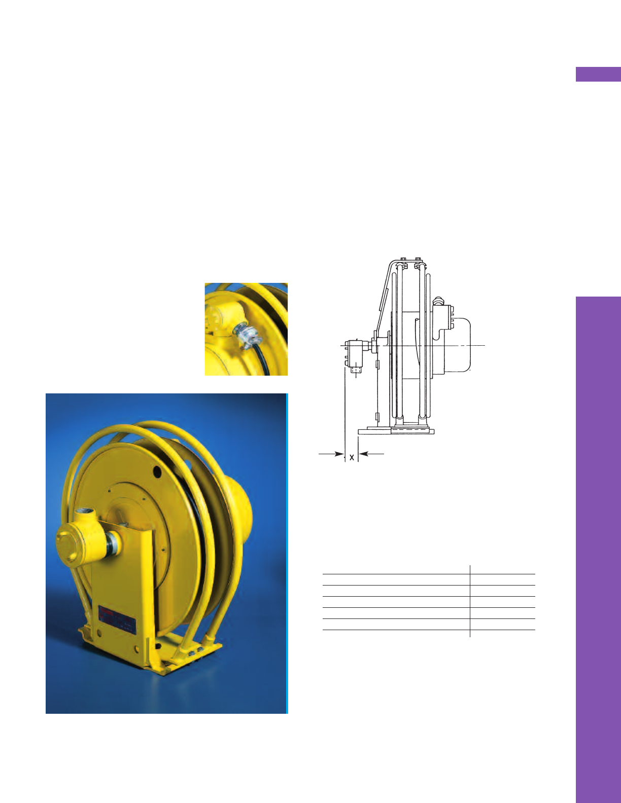
PAGE 29
■Available on all Series 1100 - 2800 models
■Class I, Division I, Group C & D
■Dust-ignition proof for Class II, Division I,
Group E, F, and G
■Suitable for Class III, Division I, Outdoor
Hazardous locations
■Fully enclosed junction boxes with connecting
leads
■Oversized, rugged construction slip rings
■To order, add suffix “-X” to model number on
any Series 1100 - 2800
Reels for Hazardous Locations
All series 1100M-2800 reels are available with enclosures
which are designed to comply with requirements for the
following locations as defined by the National Electric Code:
- Class I, Division I, Group C and D
- Dust-ignition proof for Class II, Division I, Group E, F and G
- Suitable for Class III, Division I, Outdoor Hazardous
locations
Fully enclosed junction boxes have connecting leads which
are sealed at both ends with a sealing compound. Slip rings
are oversized, and constructed of extra heavy material.
These Pow-R-Matic Reels (Models 1100M through 2800) are
available with 3 to 10 conductors (35 Amp slip rings). Nos.
18 to 10 AWG; or 3 or 4 conductors (75 Amp. slip rings),
Nos. 8 to 4 AWG.
TO ORDER: add suffix “-X” to catalog number to designate
the above construction.
Note: Ground wire is connected through
slip ring and to frame of reel on ALL
models.
SPECIALTY CABLE REELS
On Series 1100M-1500M, the junction box will
increase the width of the reel as follows:
X Dimension
Reel Series in. mm
1100M 6.25 158.8
1200M 4.13 104.9
1300M 4.13 104.9
1400M 4.13 104.9
1500M 4.13 104.9
The junction box does not affect width on Series
2000-2800.
*NOTE: The slip ring cover on hazardous location
reels will extend .50 inch (12.7mm) farther than on
standard models.
If dimensions are critical, consult factory for
certified prints.
Junction box included on Hazardous Location
models. Line entrance tapped as required by the
National Electric Code.
Factory Mutual
Listed
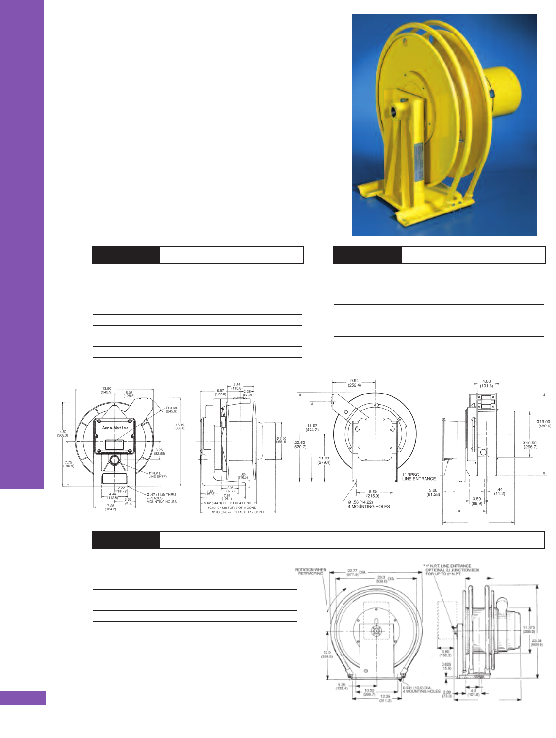
SPECIALTY CABLE REELS
PAGE 30
Dimensions similar to Series 1000M (Page 38)
AWG Cable Amp
Catalog No. Wire Size. Length (ft) Rating
ERL51000 Less Cable — 375*
ERL51280 2 80 150
ERL51180 1 80 200
ERL51075 1/0 75 250
ERL51960 2/0 60 300
Cable included on all models except ERL51000.
5000 SERIES WELDING REELS
■Dimensions similar to Series 1100M (Page 39)
AWG Cable Amp
Catalog No. Wire Size. Length (ft) Rating
ERM60000 Less Cable — 450*
ERM61100 1 100 150
ERM60110 1/0 110 200
ERM69090 2/0 90 250
Cable included on all models except ERM60000.
6000 SERIES WELDING REELS
■Containerized mainspring for safe and
easy handling
■Weathertight design
■Safety declutching drive hub
■Rugged four-roller guide on 4000 & 5000 series
■Adjustable guide arm on 4000 & 5000 series
■Permanent lubrication
■Ratchet lock
When cable is installed, lengths shown in selec-
tion charts are maximum allowed when used with
corresponding wire size.
*Rating is established for slip ring only. The proper wire
size must be used to obtain this rating.
Welding Reels
Aero-Motive’s Electric Welding Reels are built to high
quality standards. Standard models cover the four
most desirable wire sizes.
Dimensions similar to Series 0900 (Page 38)
AWG Cable Amp
Catalog No. Wire Size. Length (ft) Rating
ERA4000 Less Cable — 375*
ERA4450 4 50 145
ERA4250 2 50 250
ERA4150 1 50 250
ERA4040 1/0 40 350
ERA4940 2/0 40 375
Cable included on all models except ERA4000.
4000 SERIES WELDING REELS
6.82
(173.23)
18.84
(478.54)
16.38
(416.05)
6.44
(163.58)
3.31
(84.07)
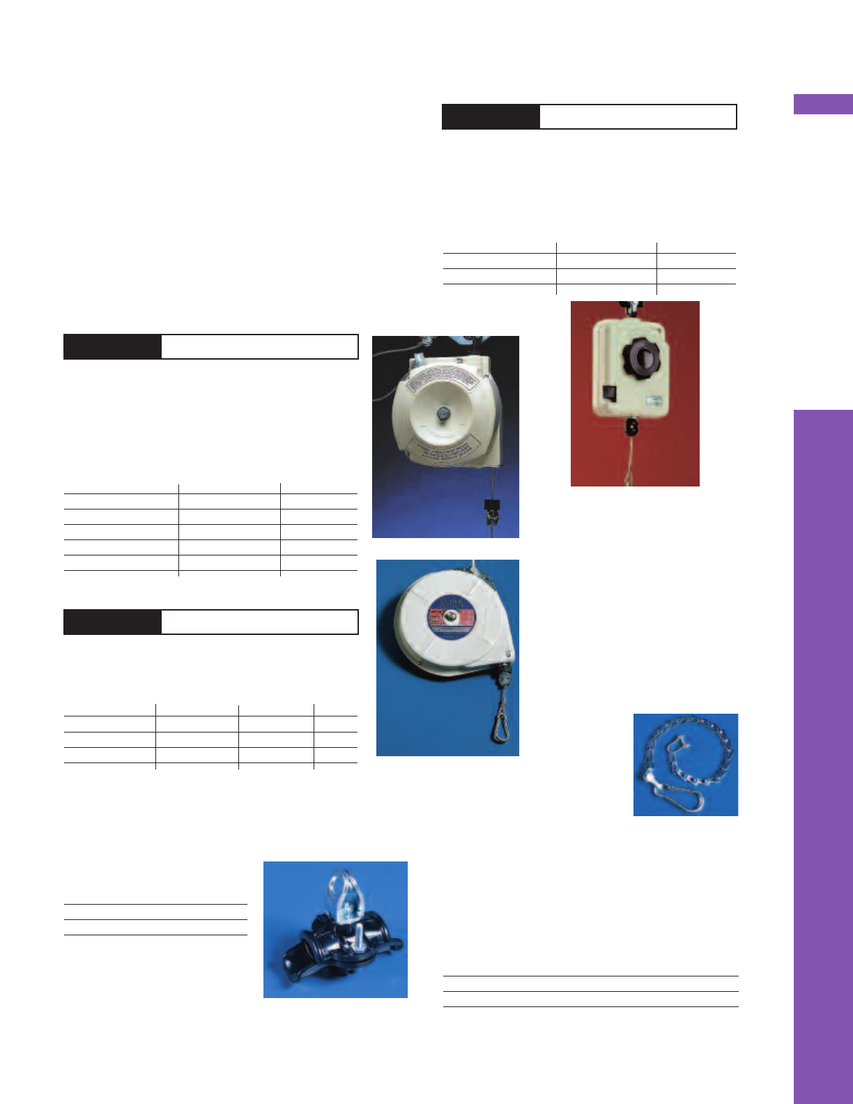
SPECIALTY CABLE REELS
PAGE 31
Pendent Station Retractors
Spring powered retractors provide a simple, inexpen-
sive means of lifting pendent stations, connectors,
lights, and more out of the way when not in use. A
simple tug on the cable returns the pendent to its
original position.
To select a retractor, add the total weight of the
pendent, the cable between the pendent and the
cable clamp, and half the cable hanging in the loop.
Select a retractor that has sufficient weight capacity
and travel distance to fit your requirements.
■Easy tension adjustment without tools
■Full range of motion with 360˚swivel hanger
■Nylon-covered steel cable
■Ratchet lock
Weight Cable Travel
Model lbs. kg ft. m
RFL6 4-6 1.8-2.7 6.6 2
RFL8 6-8 2.7-3.6 6.6 2
RFL 4-8 LB. RETRACTOR
■Heavy duty, containerized spring
■Full range of motion with 360˚swivel hanger
■High-impact composite housing
■Ratchet lock
■Shackle design for secure mounting
Weight Cable Travel
Model lbs. kg ft. m
BFL6 3-6 1.4-2.7 6.6 2
BFL9 6-9 2.7-4.1 6.6 2
BFL13 9-13 4.1-5.9 6.6 2
BFL18 13-18 5.9-8.2 6.6 2
BFL24 18-24 8.2-10.9 6.6 2
BFL 6-24 LB. BALANCERS
■Easy external tension adjustment
■Series T offers automatic drum lock
Weight Active Travel Tension Build Up
Model lb. kg ft. mlb. kg
0515T 5 2.3 15 4.58
1015T 10 4.5 15 4.58
1515T 15 6.8 15 4.58 19 8.64
1515 1-30 LB. TORQUE REELS
Balancer Secondary Support Chains
Model Description Max. Length
H13760001 Support for RFL 20”
H13760000 Support for BF 20”
Hose and Cable Support
Model Cable/Hose Dia.
61020 0.49”-0.91”
61021 0.91”-1.25”
Secondary
Support Cable
A secondary support cable or chain should be
attached to equipment mounted overhead to ensure
against injury in the event of a failure of the hang-
er or supporting structure.
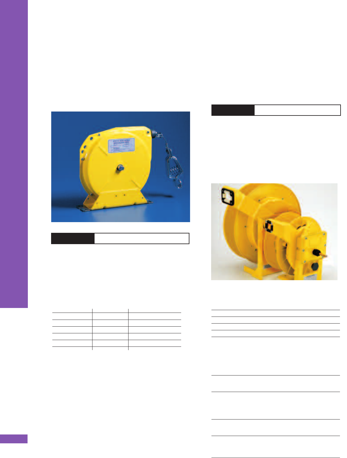
SPECIALTY CABLE REELS
PAGE 32
Static Discharge
Grounding Reels
Eliminates static build-up. Spring-operated, automatic
retrieve reels.
The 2050-Y Reel with a “Y” bridle allows two ground
connections at the same time, providing maximum
efficiency.
■Spring operated, automatic retrieve reel
■Stranded steel aircraft cable is 3/32”.
■Provides light, constant spring tension on the
cable
■100 ampere ground clamp
■Rubber cable stop
Cable length Net weight Resistance
Catalog no. ft. mlbs. Kg ohms
2050 50 15.24 12 5.44 2.0
2050-Y* 50 15.24 12 5.44 2.0
2050NC 50 15.24 12 5.44 2.0
2050CT 50 15.24 12 5.44 2.0
2050NCCT 50 15.24 12 5.44 2.0
“NC” = nylon coated cable 3/32”
“CT” = constant tension models.
*2050 Reel with “Y” Bridle (30 ft. payout then 20 ft. bridle for each
branch, with clamps) allows simultaneous grounding at two
points.
2050 STATIC DISCHARGE REELS
■Retracts temporary ground cable for portable
equipment
■Ground cable protection when not in use.
■Compact design provides more efficient use of
vehicle storage space.
■Easy field cable termination
■No bonding required as ground cable connected
directly to collector ring.
Capacity
Cable AWG Length (ft.,meters)
Model
#2 40 12.2 GR900
1/0 40 12.2 GR900
2/0 40 12.2 GR900
2/0 60 18.3 GR1000L
4/0 50 15.2 GR1000L
Qualification Tests
Certified testing 2/0 AWG sample with cable fully
extended:
GR GROUND FAULT REELS
Amp- Resistance
Scenario/Result Duration litude Before After
one shot/ rotated
freely same resistance 8 cycles 18.4 kA 0.548mΩ 0.610mΩ
after rotating
reclose sequence/ 8 cycles 18.7 kA 0.541mΩ
rotated freely same (2 sec)
resistance after rotating 8 cycles 18.6 kA
(15 sec)
9 cycles 18.2 kA 0.639mΩ
breaker failure/
rotating freely 0.646m 100 cyc. 15.6 kA 0.594m Ω 0.638mΩ
resistance after rotating
to failure/ 2.0 cable
lead fused open 6 in.
from reel. No damage 101 cyc. 15.5 kA n/a
to collector ring.
Ground Fault
Cable Retractor
Models GR900 and GR1000 are sturdy compact spring-
powered cable reels that provide a convenient and
efficient method of retracting and storing equipment
ground cables on electric utility service trucks requir-
ing a minimum of maintenance.

Accessory
Accessories and Options
Use this selection chart for all standard
accessories and options available
on Pow-R-Matic Reels.
Catalog No
0900
1000M-2000M
1100M
1200M &1400M
1300M &1500M
2000
2300
2400
2500-2600-2700-2800
ACCESSORIES
PAGE 33
Incl Incl NA NA NA NA NA NA NA
Four-Roller Guide 2FM NA NA Opt Opt Opt Opt NA NA NA
3FM NA NA Opt Opt Opt Opt Opt Opt Opt*
Junction Box Incl Incl Opt Opt Opt Opt Opt Opt Opt
Pivot Base (330˚) Opt Opt Opt Opt Opt Opt Opt Opt NA
Guide Arm Incl Incl NA NA NA NA NA NA NA
Guide Rails NA NA Incl Incl Incl Incl Incl Incl NA
Ratchet Lock (-L) Incl Incl Opt Opt NA NA NA NA NA
Hazardous Locations (-X) NA NA Lim Lim Lim Lim Lim Lim Lim
Marine Service NA NA Spcl Spcl Spcl Spcl Spcl Spcl Spcl
Silver Ring/Brush Opt Opt Opt Opt Opt Opt Opt Opt Opt
Service Package (-MD) NA NA NA NA NA Opt Opt Opt Opt
KEY: Opt = Optional NA = Not Available *Must be mounted separately
Incl = Included Lim = Limited **Not normally used
Spcl = Special - Consult factory for current availability of specials.
Cable Grips, see below
Four-Roller Guide
A four-roller guide is standard on Series 0900 and
1000M reels. 2FMYE guide is used for cable up to
1.5 in./38.1 mm in diameter. 3FMYE guide is used
for cable up to 2.0 in./50.8 mm in diameter. See
page 34 for details.
Junction Box
Included as part of reel stand on Series 0900 and
1000M reels. 2JM junction box has up to 2” NPT.
See page 35 for further details.
Pivot Base
Allows for 330˚ pivot. See page 34 for details.
Always give complete model number of reel when
ordering pivot base.
Marine Service
No exposed aluminum parts, Powder paint, all
exposed fasteners up to 5
/8” stainless steel.
Special order.
Hazardous Locations
See page 29 for details
Silver Plated Rings and Silver
Brush Contacts
Available on 30 and 35 ampere slip rings only.
Service Package
Includes external fast tension end plate, 2-J
Junction Box for input connection, and second
junction box for easy connection of working cable
without opening slip ring housing and disturbing
brush-holder and brush alignment. Internal lead
wires are also supplied. See page 28.
Ordering
To order a reel with the Ratchet Lock, Hazardous
Locations, or Service Package options, add the
proper suffix -L, -X, or -MD to the model number.
To order any other accessory, order it by name.
Example: 2053-50-902, complete with number
3FMYE cable guide.
Cable Size Cable Grip Cable Stop
OD, ins. Model Model
0.30-0.41 37121-11 ST1
0.41-0.56 37121-12 ST1
0.57-0.70 37121-16 ST1
0.70-0.75 37121-18 ST1
0.75-0.82 37121-18 ST2
0.82-0.875 37121-20 ST2
0.875-1.00 37121-20 ST3
1.06-1.25 37121-22 ST3
Cable Grips & Stops
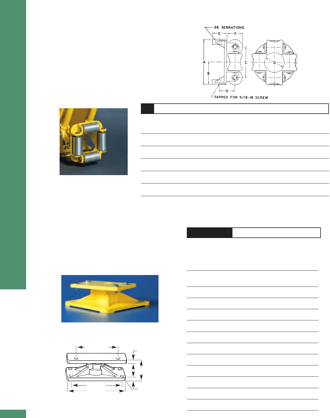
■Allows cable and cord reels to rotate 330˚
■ Heavy duty ball bearing models
PB SERIES PIVOT BASE
Dim.A Dim.B Dim.C Dim.D Dim.E Dim.F
Reel in. in. in. in. in. in.
Series Model mm mm mm mm mm mm
0951, PB2A 3 4 1.44 0.50 0.438 0.25
200,300, 76 102 36.6 13 11.13 6.4
400
RI50 PB10YE 3 4 2.69 0.50 0.438 1.25
76 102 68.3 13 11.13 31.8
1051 PBM7A 10 11.5 3.76 0.75 0.531 0.63
5000 254 292 95.5 19.1 13.49 15.9
1120 PBM3A 10 11.5 3.76 0.75 0.531 0.63
254 292 95.5 19.1 13.49 15.9
1140 PBM3B 10 11.5 3.76 0.75 0.531 0.63
254 292 95.5 19.1 13.49 15.9
1160 PBM3C 10 11.5 3.76 0.75 0.531 0.63
254 292 95.5 19.1 13.49 15.9
1200M PBM4A 10 11.5 3.76 0.75 0.531 0.63
1300M 254 292 95.5 19.1 13.49 15.9
1440 PBM5A 10 11.5 3.76 0.75 0.531 0.63
1540 254 292 95.5 19.1 13.49 15.9
1470 PBM5B 10 11.5 3.76 0.75 0.531 0.63
1570 254 292 95.5 19.1 13.49 15.9
2000 PB6AX 12 14 5.79 0.63 0.563 0.188
305 356 147 16 14.3 4.7
2300 PB6BX 12 14 5.79 0.63 0.563 0.188
305 356 147 16 14.3 4.7
2400 PB6XX 12 14 5.79 0.63 0.563 0.188
305 356 147 16 14.3 4.7
matched to
reel mounting
A square
C
F
D
B square E- dia. (4) mounting holes
*Specify reel model when ordering
HEAVY DUTY BALL BEARING MODELS
NOTE: A four-roller guide is required when a pivot base is used. Cable
grips are recommended also. See page 33 & 34
ACCESSORIES
PAGE 34
Provides
330˚
pivot
Cable Guides
Four-roller cable guides are standard on Series 0900
and 1000M. Series 1100M through 2400 reels are
equipped with guide rails only. Roller guides are
optional on these reels and mount on the guide rails.
Ratchet locks are optional on models 1100M through
1400M, and must be ordered with the reel (indicate
with “-L” added to model number). NOTE: Roller
guides are to be used only to assist in guiding cable
onto the reel, and are NOT to be used as a sheave to
change direction of payout.
CABLE GUIDE DIMENSIONS
Type Maximum Dim.A Dim.B Dim.C Dim.D Dim.E Dim.F Dim.G
of Cable Recommended in. in. in. in. in. in. in.
Model Guide Cable Dia.. mm mm mm mm mm mm mm
2FMYE Cable 1.5 4 2 2.69 1.75 1.25 1.31 1.38
2FMYE7* Guide 38.1 101.6 50.8 68.3 44.5 31.8 33.8 35.1
3FMYE Cable 2 4 2 3.88 2.63 1.69 1.25 1.81
3FMYE7* Guide 50.8 101.6 50.8 98.5 66.8 42.9 31.8 46
1R Guide ___ ___ 11.72 12 21 ___ ___ ___
Rails 298 305 533.4
2R Guide ___ ___ 14.19 14.25 25 ___ ___ ___
Rails 360 362 635
3R Guide ___ ___ 18.19 18.25 33 ___ ___ ___
Rails 462 464 838.2
* 2FMYE7 and 3FMYE7 are for 237X and 247X model cable reels
FOUR-ROLLER CABLE GUIDES
2FMYE: For cables up to
1.5”/38.1 mm diameter
3FMYE: For cables up to
2”/50.8 mm diameter (Series
1100M, 2400)
Pivot Bases
ROTATION OF 330˚ OR LESS (NO COLLECTOR RINGS)
Pivot base allows reel to payout cable in any
direction up to 330˚ where a complete continuous
circle is not required.

TECHNICAL DATA
PAGE 35
Important Cable Selection Data
An important point to remember is that the sole function of Pow-R-
Matic Cable Reel is to handle a given cable in a predetermined,
specific manner. This re-emphasizes the importance of selecting
the right cable for the job it is intended to do.
Important Factors in Cable Selection
■Electrical - Cable must be capable of handling the full operating
load of all equipment which can be operated concurrently (total
connected horsepower). See horsepower conversion chart on the
following page and the chart below for intermittent service ratings.
■Mechanical - Cable must be flexible, portable, and generally neo-
prene jacketed. Individual conductor stranding should not be less than the number of strands per conductor as
listed in the table at left.
■Special cables - Pow-R-Matic Cable Reels can be used with special cables such as stainless steel braided, sili-
cone, or refrasil insulated, etc. Consult the factory for recommended reels for use with cables designed for use in
extremely hot or cold temperatures.
Slip Ring Ratings
Ratings refer to the Pow-R-Matic Cable Reel Slip Ring
only and may be referred to where cable is being
derated for short time (intermittent) service. Ratings
are based on two conductor assemblies and must be
derated for multiconductor service. Ratings are
established for slip rings only, operating in approved
enclosures. The proper wire size must be used to
obtain these ratings. Consult the factory for specific
requirements not covered here.
The first number of the last three digits indicates
Slip Ring rating.
Example: 2053-50-902 (9 is the Slip Ring rating). See chart above.
Junction Boxes (Weathertight)
Junction boxes are used to connect conduit leading from the power source
to the internal wiring of the reel, especially when the lead-in conduit is
larger than the threaded connection provided on the reel. The NPT line
entrance of the junction box provided with the reel will be equal to or
greater than National Electric Code requirements. The chart below lists the
junction box line entrance with the proper slip ring designation for reel
series 1100M and larger. (See page 38 for NPT size on series 0900 and
1000M). Unless otherwise specified, junction boxes will be threaded to
match the chart. In Canada, a junction box is required on all reels to meet
CSA approval. Slip Ring designation of model number (last three digits)
determine the entrance (NPT) of junction box.
Example: 2053-50-902 (902 is the Slip Ring designation)
To order, specify 2J-A, 2J-B, 2J-C, or 2J-D. See page 33 for more information.
Size (AWG) Minimum Stranding
18 16 strands of #30
16 26 strands of #30
14 41 strands of #30
12 65 strands of #30
10 104 strands of #30
8 through 4 133 strands of #30
2 through 2/0 259 strands of #30*
3/0 through 4/0 427 strands of #30*
*Recommended minimum stranding for best performance and
long cable life. If coarser stranding must be used, we suggest
you advise the factory so allowance can be made.
Catalog No. Ampere Rating Maximum
Name- Maximum Continuous Operating
Code plate Load (30 Duty Cycle Temperature
minutes)*
2 30 30 30 248° F, 120° C
3 35 50 35 248° F, 120° C
4 75 100 75 248° F, 120° C
9 200 250 200 392° F, 200° C
*Maximum running time at full load per hour
Slip Ring Line Entrance Slip Ring Line Entrance Slip Ring Line Entrance
Designation NPT Designation NPT Designation NPT
303 1” 316 11/2”403 1”
304 1” 320 2” 404 1”
306 1” 324 2” 406 11/2”
308 11/4” 330 2” 902 11/2”
310 11/4”336 2” 903 11/2”
312 11/4” 402 1” 904 2”
Model No. N.P.T.
2J-A 1”
2J-B 11/4”
2J-C 11/2”
2J-D 2”
Junction boxes should be used when
lead-in conduit is larger than threaded
connection provided on the reel.

TECHNICAL DATA
PAGE 36
Selecting the Proper Cable
Due to the great variety of electrical applications, types
(and manufacturers) of controls, and available currents,
it is impossible for the reel manufacturer to select elec-
trical cable for any specific requirement. Because the
user, or specifying engineers, are closest to all details
involved in any particular requirement, the responsibility
for selecting cable must be left in their hands. To assist
in the selection of cable, the charts shown on this page
and the following procedure are offered as a guide.
For more complete data or specific details, please refer
to the National Electric Code.
To select cable:
(a) Determine motor horsepower. (HP)
(b) Using Chart A for alternating current (AC) or Chart B
for Direct Current (DC), find the proper horsepower in the
left hand column.
(c) On the line showing proper horsepower, move to the
right until reaching the column headed by the operating
voltage to be used.
(d) At this intersection the maximum ampere load is list-
ed. For example, a 100 HP motor operating at 460 volts
three-phase current draws 124 amperes.
(e) Once maximum ampere load is known, we can deter-
mine the size of electrical cable (AWG) required by using
Chart C. In the above example, 124 amperes calls for
#1/0 cable at 60˚C; #1 at 75˚C, etc.
(f) To comply with CSA requirements, Types SOW or WOW
must be used on outdoor applications.
(g) Caution: Voltage drop and power factor corrections
frequently require an increase in size of conductors
required.
Use the 75˚ column for standard cables. Contact the
cable manufacturer or Aero-Motive if higher temperature
ratings are required.
Temperature Rating of Conductor
Size 60˚C 75˚C 85˚-90˚C 110˚C 125˚C 200˚C
AWG 140˚F 167˚F 185˚F 230˚F 257˚F 392˚F
14 15 15 25 30 30 30
12 20 20 30 35 40 40
10 30 30 40 45 50 55
8 40 45 50 60 65 70
6 55 65 70 80 85 95
4 70 85 90 105 115 120
3 80 100 105 120 130 145
2 95 115 120 135 145 165
1 110 130 140 160 170 190
1/0 125 150 155 190 200 225
2/0 145 175 185 215 230 250
3/0 165 200 210 245 265 285
4/0 195 230 235 275 310 340
250 215 255 270 315 335 ...
300 240 285 300 345 380 ...
350 240 310 325 390 420 ...
400 280 335 360 420 450 ...
500 320 380 405 470 500 ...
HP 115V 230V 460V 575V 2300V
.5 4 2 1 .8
.75 5.6 2.8 1.4 1.1
17.2 3.6 1.8 1.4
1.5 10.4 5.2 2.6 2.1
2 13.6 6.8 3.4 2.7
3 9.6 4.8 3.9
5 15.2 7.6 6.1
7.5 22 11 9
10 28 14 11
15 42 21 17
20 54 27 22
25 68 34 27
30 80 40 32
40 104 52 41
50 130 65 52
60 154 77 62 16
75 192 96 77 20
100 248 124 99 26
125 312 156 125 31
150 360 180 144 37
200 480 240 192 49
HP 120V 240V
.25 2.9 1.5
.33 3.6 1.5
.5 5.2 2.6
.75 7.4 3.7
1 9.4 4.7
1.5 13.2 6.6
2 17 8.5
3 25 12.2
5 40 20
7.5 58 29
10 76 38
HP 120V 240V
15 55
20 72
25 89
30 106
40 140
50 173
60 206
75 255
100 341
125 425
150 506
200 675
Nominal Cold Cable
Magnet Current Size*
Diam.(in.) (Amps.) (AWG)
39 31 #8
47 43 #6
58 67 #4
58 73 #4
Nominal Cold Cable
Magnet Current Size*
Diam.(in.) (Amps.) (AWG)
67 86 #2
68 96 #2
68 100 #2
84 134 #1/0
For full-load currents of
208- and 200-volt motors,
increase the corresponding
220-volt motor full-load
current by 6 and 10 per-
cent, respectively.
These values of full-load
current are for motors run-
ning at speeds usual for
belted motors and motors
with normal torque charac-
teristics. Motors built for
especially low speeds or
high torques may require
more running current, and
multispeed motors will
vary full-load current
according to speed, in
which case the nameplate
current rating should be
used.
Chart A AMPERAGES FOR AC MOTORS
Chart B AMPERAGES FOR DC MOTORS
Chart C CABLE SELECTOR
Chart D MAGNET SIZE TO CABLE SIZE
*Recommended cable size for estimating purposes. For exact cable recommendations contact the
magnet manufacturer. Use for cable lengths of 125 feet or less.
Motors running at full speed — Full load current listed in amps
Based on three-conductor cables
Induction type — Full load currents listed in amps
Notes:
1. Use the highest available voltage to keep wire size to a minimum.
2. If cable is to stand idle ON reel for long periods at full electric load, contact
Aero-Motive, as derating may be required.
3. Always specify maximum available cable stranding to ensure flexibility and
long life of the cable.
4. For short time cable ratings, refer to the National Electric Code.
5. If fourth conductor is to be a ground wire, use the three-conductor rating.

TECHNICAL DATA
PAGE 37
Cable Diameters and Net Weights
All Pow-R-Matic Reels listed in
this catalog have capacities
based on thefigures shown here.
Due to the importance of cable
weight and diameter in figuring
reel capacities, the listings
below are conservative to
compensate for manufacturing
variations in cable O.D. and
weight. Should you intend using
acable of larger diameter or
greater weight than shown,
please advise thefactory.
Ampere ratings are based on
75˚C insulation. Higher ratings
may be obtained with other
insulations. Refer to the National
Electric Code for details.
Please note: A cable’s amperage
rating is affected by many fac-
tors including ambient tempera-
ture, amount of cable stacked on
spool, and number of conductors
carryingload. Cable ratings here
are based on a 360°C ambient
and cable in free air not wound
on spool.
No.of Diam. Weight
Cond. Amps (in.) lbs./ft.
27.0 .390 .0814
3 7.0 .405 .0968
4 5.6 .435 .1168
5 5.6 .495 .1408
65.6 .525 .1606
7.565 .1815
8.600 .2024
9 .640 .2200
10 .640 .2288
12 .660 .2508
14 .715 .3058
16 .760 .3454
18 .800 .3817
20 .835 .4158
22 .870 .4499
24 .910 .4774
26 .910 .5027
28 .995 .5957
30 .995 .5962
32 1.035 .6380
34 1.070 .6765
36 1.070 .6930
40 1.140 .7733
44 1.180 .8184
48 1.200 .8668
52 1.230 .9306
56 1.230 .9955
60 1.305 1.0549
No.of Diam. Weight
Cond. Amps (in.) lbs./ft.
210.0 .405 .0913
3 10.0 .430 .1122
4 8.0 .485 .1495
5 8.0 .525 .1683
68.0 .565 .1947
7.605 .2222
8.645 .2431
9 .720 .2926
10 .720 .3058
12 .740 .3355
14 .775 .3828
16 .825 .4246
18 .860 .4730
20 .900 .5126
22 .940 .5588
24 1.015 .6303
26 1.015 .6644
28 1.070 .7194
30 1.070 .7447
32 1.115 .7854
34 1.155 .8591
36 1.155 .8877
40 1.235 .9823
44 1.275 1.0208
48 1.295 1.1000
52 1.365 1.2287
56 1.410 1.3079
No.of Diam. Weight
Cond. Amps (in.) lbs./ft.
215.0 .530 .1507
3 15.0 .560 .1859
4 12.0 .605 .2209
5 12.0 .685 .2882
612.0 .740 .3322
7.795 .3619
8.845 .4073
9 .905 .4554
10 .905 .4774
12 .930 .5291
14 .980 .6116
16 1.075 .7227
18 1.125 .7854
20 1.180 .8646
22 1.230 .9427
24 1.290 1.0120
26 1.290 1.0846
28 1.400 1.2078
30 1.400 1.2518
32 1.460 1.3420
34 1.510 1.4300
36 1.510 1.4718
No.of Diam. Weight
Cond. Amps (in.) lbs./ft.
220.0 .605 .2068
3 20.0 .640 .2530
4 16.0 .670 .2970
5 16.0 .730 .3509
616.0 .800 .4092
7.860 .4719
8.915 .5192
9 1.015 .6028
10 1.015 .6347
12 1.045 .7062
14 1.100 .8140
16 1.155 .9207
18 1.225 1.0153
20 1.285 1.1022
22 1.375 1.2584
24 1.445 1.3530
26 1.445 1.4245
28 1.525 1.5455
30 1.525 1.6038
No.of Diam. Weight
Cond. Amps (in.) lbs./ft.
225.0 .645 .2431
3 25.0 .695 .3113
4 20.0 .750 .3850
5 20.0 .815 .4609
620.0 .880 .5324
7.980 .6490
81.050 .7172
9 1.125 .7942
10 1.125 .8382
12 1.155 .9383
16 1.290 1.2331
20 1.460 1.5510
24 1.600 1.8095
26 1.600 1.9228
Wire Size No. of Current Diameter, Weight
AWG Cond. Cap.,Amps. inches lbs./Ft.
2 45 .81 .407
83 45 .90 .528
4 36 .99 .693
6 36 1.19 .865
2 65 .93 .583
63 65 .99 .781
452 1.10 .957
652 1.36 1.138
285 1.08 .841
4385 1.20 1.155
468 1.32 1.424
2100 1.22 .946
33100 1.27 1.265
480 1.40 1.551
2115 1.27 1.067
23115 1.34 1.402
492 1.55 1.848
2130 1.44 1.430
13130 1.51 1.842
4104 1.75 2.332
2150 1.50 1.573
1/0 3150 1.65 2.145
4120 1.88 2.646
2175 1.65 1.908
2/0 3175 1.75 2.299
4140 2.02 4.059
2200 1.77 2.442
3/0 3200 1.97 3.630
4160 2.15 4.697
2230 1.92 3.740
4/0 3230 2.10 4.455
4184 2.34 5.764
Wire Size No. of Current Diameter Weight
AWG Cond. Cap.,Amps. inches lbs./Ft.
2 45 .81 .440
83 45 .91 .572
4 34 .99 .742
2 65 .93 .654
63 65 1.01 .841
4 52 1.10 1.034
2 85 1.08 .957
43 85 1.20 1.265
4 68 1.30 1.540
2 100 1.16 1.089
33 100 1.26 1.364
4 80 1.36 1.771
2 115 1.27 1.265
23 115 1.34 1.573
4 92 1.55 2.007
2 130 1.44 1.688
13 130 1.51 2.112
4 104 1.75 2.607
2 150 1.52 1.870
1/0 3 150 1.65 2.431
4 120 1.87 2.959
2 175 1.65 2.255
2/0 3 175 1.75 2.838
4 140 2.02 3.630
2 200 1.80 2.860
3/0 3 200 1.97 3.608
4 160 2.15 4.631
2230 2.00 3.245
4/0 3230 2.10 4.191
4184 2.34 5.610
AWG AWG AWG AWG AWG
18 16 14 12 10
Type Cable Volts
W600 Type Cable Volts
G600
Note: The current capacity of each conductor in Type
SO cable with 4 or more conductors is as follows:
4to 6 conductors - 80% of values shown
7to 24 conductors - 70% of values shown
25 to 42 conductors - 60% of values shown
43 or more conductors - 50% of values shown
Type Cable Volts
SO 600
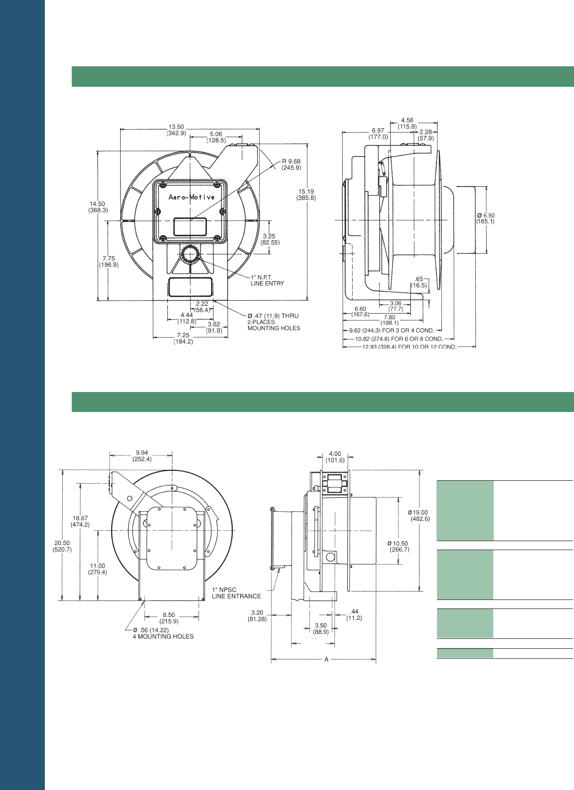
TECHNICAL DATA
PAGE 38
Dimensions
Series Reels
900
Chart shows dimensional variables within a reel series – “xx”
in the catalog number listing represents the drive system and
does not affect reel dimensions.
See page 35 for slip ring rating and junction box detail.
Series Reels
1000
ELECTRIFICATION LISTINGS
Pow-R-Mite Cable Reels are
constructed to standards
published by NEC, UL, and
CSA. All reels shipped in
Canada are CSA approved.
ERA4000 Series Welding Reels are dimensioned the same as the 4 Conductor Model Above.
Dim. A Weight
Model in. mm Lbs.
1051-xx-302 81
1051-xx-303 81
1051-xx-304 16.67 423 81
1051-xx-306 82
1051-xx-402 81
1051-xx-403 81
1051-xx-308 82
1051-xx-310 83
1051-xx-312 18.84 479 83
1051-xx-404 82
1051-xx-405 83
1051-xx-314 84
1051-xx-316 21.65 500 84
1051-xx-902 82
1051-xx-320 25.00 635 86
6.82
(173.23)
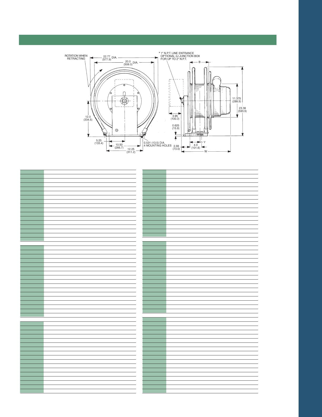
TECHNICAL DATA
PAGE 39
Dimensions
Series Reels
1100M
Dim. B Dim. Y Dim. W Weight
Model in. mmin. mmin. mm lbs. Kg
1122-xx-303 2.25 57.2 1.25 31.8 14.25 362.0 114 51.8
304 2.25 57.2 1.25 31.8 14.25 362.0 114 51.8
306 2.25 57.2 1.25 31.8 16.25 412.8 115 52.2
308 2.25 57.2 1.25 31.8 16.25 412.8 116 52.7
310 2.25 57.2 1.25 31.8 18.25 463.6 117 53.1
312 2.25 57.2 1.25 31.8 18.25 463.6 118 53.6
316 2.25 57.2 1.25 31.8 20.25 514.4 120 54.5
320 2.25 57.2 1.25 31.8 22.25 565.2 123 55.8
324 2.25 57.2 1.25 31.8 24.25 616.0 125 56.8
330 2.25 57.2 1.25 31.8 28.25 717.6 128 58.1
336 2.25 57.2 1.25 31.8 30.25 768.4 131 59.5
402 2.25 57.2 1.25 31.8 16.25 412.8 115 52.2
403 2.25 57.2 1.25 31.8 16.25 412.8 115 52.2
404 2.25 57.2 1.25 31.8 16.25 412.8 116 52.7
902 2.25 57.2 1.25 31.8 18.25 463.6 116 52.7
903 2.25 57.2 1.25 31.8 18.25 463.6 117 53.1
904 2.25 57.2 1.25 31.8 20.25 514.4 119 54.0
1142-xx-303 4.25 108 2.25 57.2 14.25 362.0 114 51.8
304 4.25 108 2.25 57.2 14.25 362.0 114 51.8
306 4.25 108 2.25 57.2 16.25 412.8 115 52.2
308 4.25 108 2.25 57.2 16.25 412.8 116 52.7
310 4.25 108 2.25 57.2 18.25 463.6 117 53.1
312 4.25 108 2.25 57.2 18.25 463.6 118 53.6
316 4.25 108 2.25 57.2 20.25 514.4 120 54.5
320 4.25 108 2.25 57.2 22.25 565.2 123 55.8
324 4.25 108 2.25 57.2 24.25 616.0 125 56.8
330 4.25 108 2.25 57.2 28.25 717.6 128 58.1
336 4.25 108 2.25 57.2 30.25 768.4 131 59.5
402 4.25 108 2.25 57.2 16.25 412.8 115 52.2
403 4.25 108 2.25 57.2 16.25 412.8 115 52.2
404 4.25 108 2.25 57.2 16.25 412.8 116 52.7
902 4.25 108 2.25 57.2 18.25 463.6 116 52.7
903 4.25 108 2.25 57.2 18.25 463.6 117 53.1
904 4.25 108 2.25 57.2 20.25 514.4 119 54.0
1143-xx-303 4.44 112.8 2.31 58.7 16.38 416.1 138 62.7
304 4.44 112.8 2.31 58.7 16.38 416.1 138 62.7
306 4.44 112.8 2.31 58.7 18.38 466.9 139 63.1
308 4.44 112.8 2.31 58.7 18.38 466.9 140 63.6
310 4.44 112.8 2.31 58.7 20.38 517.7 141 64.0
312 4.44 112.8 2.31 58.7 20.38 517.7 142 64.5
316 4.44 112.8 2.31 58.7 22.38 568.5 144 65.4
320 4.44 112.8 2.31 58.7 24.38 619.3 147 66.7
324 4.44 112.8 2.31 58.7 26.38 670.1 149 67.6
330 4.44 112.8 2.31 58.7 30.38 771.7 152 69.0
336 4.44 112.8 2.31 58.7 32.38 822.5 155 70.4
402 4.44 112.8 2.31 58.7 18.38 466.9 139 63.1
403 4.44 112.8 2.31 58.7 18.38 466.9 139 63.1
404 4.44 112.8 2.31 58.7 18.38 466.9 140 63.6
902 4.44 112.8 2.31 58.7 20.38 517.7 140 63.6
903 4.44 112.8 2.31 58.7 20.38 517.7 141 64.0
904 4.44 112.8 2.31 58.7 22.38 568.5 143 64.9
Dim. B Dim. Y Dim. W Weight
Model in. mm in. mm in. mm lbs. Kg
1163-xx-303 6.44 163.6 3.31 84.1 16.38 416.1 138 62.7
304 6.44 163.6 3.31 84.1 16.38 416.1 138 62.7
306 6.44 163.6 3.31 84.1 18.38 466.9 139 63.1
308 6.44 163.6 3.31 84.1 18.38 466.9 140 63.6
310 6.44 163.6 3.31 84.1 20.38 517.7 141 64.0
312 6.44 163.6 3.31 84.1 20.38 517.7 142 64.5
316 6.44 163.6 3.31 84.1 22.38 568.5 144 65.4
320 6.44 163.6 3.31 84.1 24.38 619.3 149 67.6
324 6.44 163.6 3.31 84.1 26.38 670.1 149 67.6
330 6.44 163.6 3.31 84.1 32.38 822.5 155 70.4
402 6.44 163.6 3.31 84.1 18.38 466.9 139 63.1
403 6.44 163.6 3.31 84.1 18.38 466.9 139 63.1
404 6.44 163.6 3.31 84.1 18.38 466.9 140 63.6
902 6.44 163.6 3.31 84.1 20.38 517.7 140 63.6
903 6.44 163.6 3.31 84.1 20.38 517.7 141 64.0
904 6.44 163.6 3.31 84.1 22.38 568.5 143 64.9
1164-xx-303 6.63 168.4 3.44 87.4 18.63 473.2 163 74.0
304 6.63 168.4 3.44 87.4 18.63 473.2 163 74.0
306 6.63 168.4 3.44 87.4 20.63 524.0 164 74.5
308 6.63 168.4 3.44 87.4 20.63 524.0 165 74.9
310 6.63 168.4 3.44 87.4 2.63 574.8 166 75.4
312 6.63 168.4 3.44 87.4 22.63 574.8 167 75.8
316 6.63 168.4 3.44 87.4 24.63 625.6 169 76.7
320 6.63 168.4 3.44 87.4 26.63 676.4 172 78.1
324 6.63 168.4 3.44 87.4 28.63 727.2 174 79.0
330 6.63 168.4 3.44 87.4 32.63 828.0 177 80.4
336 6.63 168.4 3.44 87.4 34.63 879.6 180 81.7
402 6.63 168.4 3.44 87.4 20.63 524.0 164 74.5
403 6.63 168.4 3.44 87.4 20.63 524.0 164 74.5
404 6.63 168.4 3.44 87.4 20.63 524.0 165 74.9
902 6.63 168.4 3.44 87.4 22.63 574.8 165 74.9
903 6.63 168.4 3.44 87.4 22.63 574.8 166 75.4
904 6.63 168.4 3.44 87.4 24.63 625.6 168 76.3
1165-xx-303 6.63 168.4 3.44 87.4 20.75 527.1 188 85.4
304 6.63 168.4 3.44 87.4 20.75 527.1 188 85.4
306 6.63 168.4 3.44 87.4 22.75 577.9 189 85.8
308 6.63 168.4 3.44 87.4 22.75 577.9 190 86.3
310 6.63 168.4 3.44 87.4 24.75 628.9 191 86.7
312 6.63 168.4 3.44 87.4 24.75 628.9 192 87.2
316 6.63 168.4 3.44 87.4 26.75 679.5 194 88.1
320 6.63 168.4 3.44 87.4 28.75 730.3 197 89.4
324 6.63 168.4 3.44 87.4 30.75 781.1 199 90.3
330 6.63 168.4 3.44 87.4 34.75 882.7 202 91.7
336 6.63 168.4 3.44 87.4 36.75 933.5 205 93.1
402 6.63 168.4 3.44 87.4 22.75 577.9 189 85.8
403 6.63 168.4 3.44 87.4 22.75 577.9 198 85.8
404 6.63 168.4 3.44 87.4 22.75 577.9 190 86.3
902 6.63 168.4 3.44 87.4 24.75 628.7 190 86.3
903 6.63 168.4 3.44 87.4 24.75 628.7 191 86.7
904 6.63 168.4 3.44 87.4 26.75 679.5 193 87.6
ER61000 6.44 163.6 3.31 84.1 16.38 416.1 138 62.7
Chart shows dimensional vari-
ables within a reel series – “xx”
in the catalog number listing
represents the drive system and
does not affect reel dimensions.
See page 38 for slip ring rating
and junction box detail.
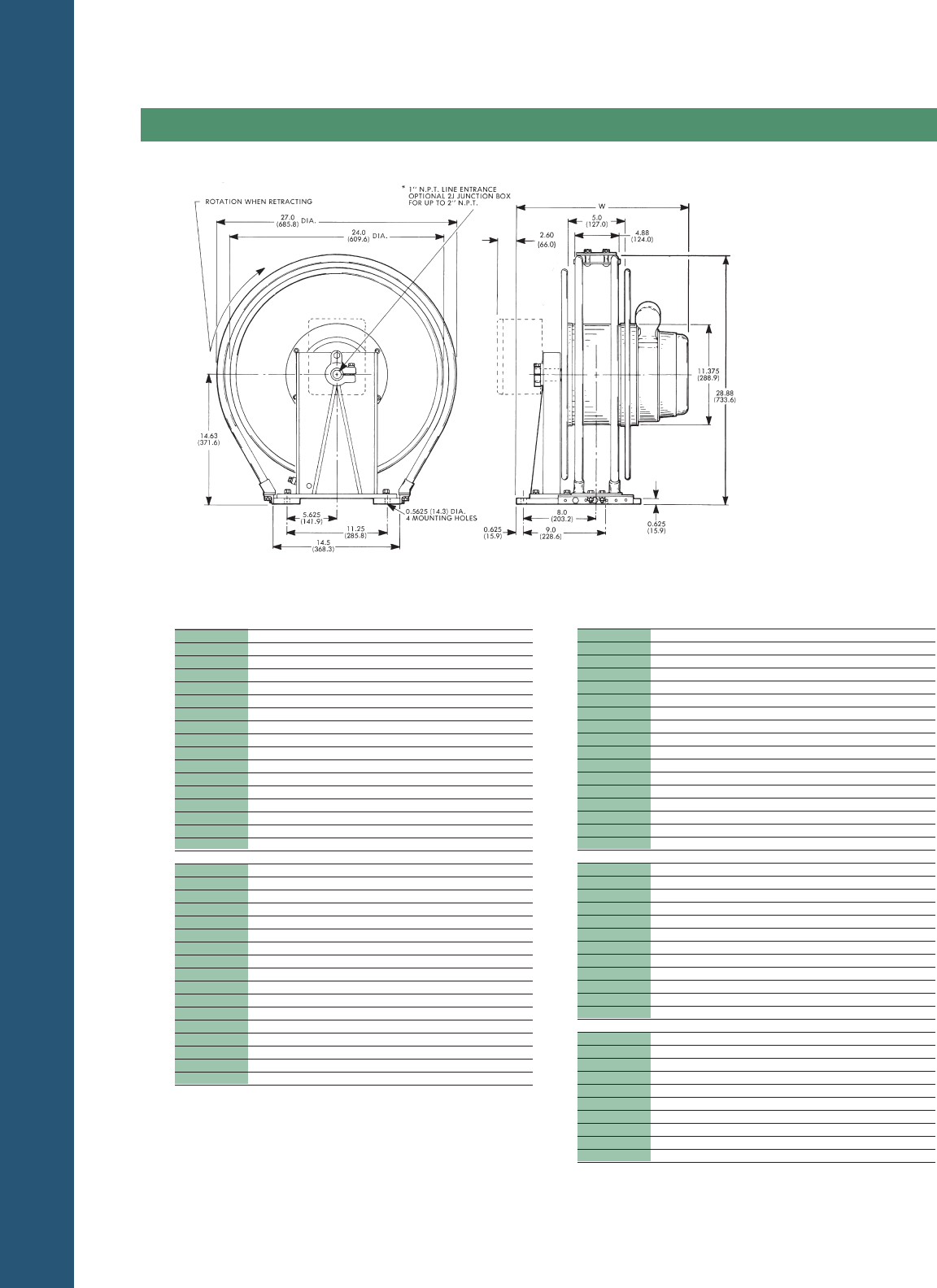
TECHNICAL DATA
PAGE 40
Dimensions
Series Reels
1200M&1300M
Dim. W Weight
Model in. mm lbs. Kg
1253-xx-303 19.38 492.3 172 78.1
304 19.38 492.3 172 78.1
306 21.38 543.1 173 78.5
308 21.38 543.1 174 79.0
310 23.38 593.9 175 79.5
312 23.38 593.9 176 79.9
316 25.38 644.7 178 80.8
320 27.38 695.5 181 82.2
324 29.38 746.3 183 83.1
330 33.38 847.9 186 84.4
336 35.38 898.7 189 85.8
402 21.38 543.1 173 78.5
403 21.38 543.1 173 78.5
404 21.38 543.1 174 79.0
902 23.38 593.9 174 79.0
903 23.38 593.9 175 79.5
904 25.38 644.7 177 80.4
1255-xx-303 23.75 603.3 221 100.3
304 23.75 603.3 221 100.3
306 25.75 654.1 222 100.9
308 25.75 654.1 223 101.2
310 27.75 704.9 224 101.7
312 27.75 704.9 225 102.2
316 29.75 755.6 227 103.1
312 27.75 806.5 230 104.4
324 33.75 857.3 232 105.3
330 37.75 958.9 235 106.7
336 39.75 1009.7 238 108.0
402 25.75 654.1 222 100.8
403 25.75 654.1 222 100.8
404 25.75 654.1 223 101.2
902 27.75 704.9 223 101.2
903 27.75 704.9 224 101.7
904 29.75 755.6 226 102.6
Dim. W Weight
Model in. mm lbs. Kg
1257-xx-303 28.12 714.3 271 123.0
304 28.12 714.3 271 123.0
306 30.12 765.1 272 123.5
308 30.12 765.1 273 123.9
310 32.12 815.9 274 124.4
312 32.12 815.9 275 124.9
316 34.12 866.7 277 125.8
320 36.12 917.5 280 127.1
324 38.12 968.3 282 128.0
330 42.12 1069.9 285 129.4
336 44.12 1120.7 288 130.8
402 30.12 765.1 272 123.5
403 30.12 765.1 272 123.5
404 30.12 765.1 273 123.9
902 32.12 815.9 273 123.9
903 32.12 815.9 274 124.4
904 34.12 866.7 276 125.3
1354-xx-306 23.56 547 198 90.0
308 23.56 547 199 90.5
310 25.56 649 200 90.9
312 25.56 649 201 91.3
316 27.56 700 203 92.2
320 29.56 751 206 93.6
324 31.56 802 208 94.5
330 35.56 903 198 90.0
404 23.56 547 199 90.5
902 25.56 649 199 90.5
903 25.56 649 200 90.9
904 27.56 700 202 91.8
1356-xx-304 25.93 659 246 111.8
306 27.93 709 247 112.3
308 27.93 709 248 112.7
310 29.93 760 249 113.2
312 29.93 760 250 113.6
316 31.93 811 252 114.5
320 33.93 862 254 115.5
402 27.93 709 247 112.3
403 27.93 709 247 112.3
404 27.93 709 248 112.4
Chart shows dimensional vari-
ables within a reel series – “xx”
inthe catalog number listing
represents the drive system and
does not affect reel dimensions.
See page 35 for slip ring rating
and junction box detail.
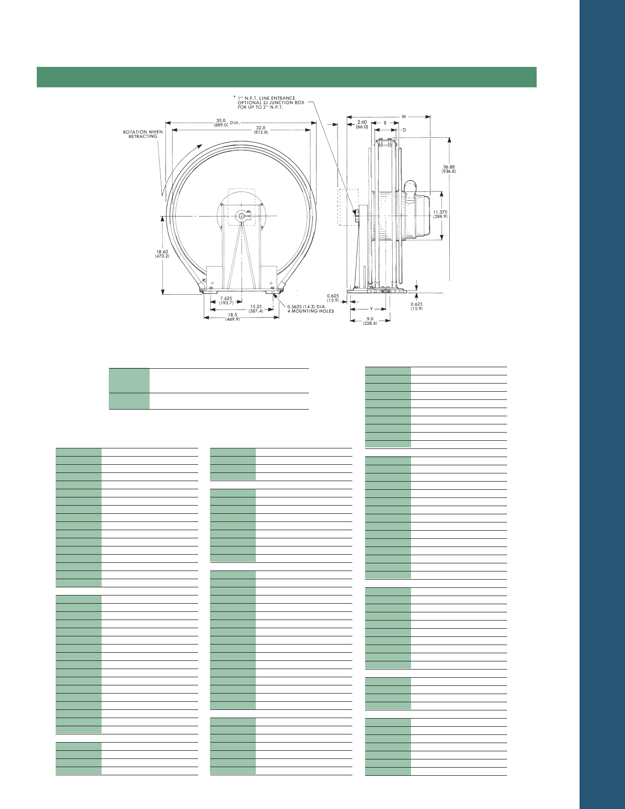
TECHNICAL DATA
PAGE 41
Dimensions
Series Reels
1400M&1500M
Dim. W Weight
Model in. mm lbs. Kg
1443-xx-303 19.56 496.8 229 104.0
304 19.56 496.8 229 104.0
306 21.56 547.6 230 104.4
308 21.56 547.6 231 104.9
310 23.56 598.4 232 105.3
312 23.56 598.4 233 105.8
316 25.56 649.2 235 106.7
320 27.56 700.0 238 108.1
324 29.56 750.8 240 109.0
330 33.56 852.4 243 110.3
336 35.56 903.2 246 111.7
402 21.56 547.6 230 104.4
403 21.56 547.6 230 104.4
404 21.56 547.6 231 104.9
902 23.56 598.4 231 104.9
903 23.56 598.4 232 105.3
904 25.56 649.2 234 106.2
1445-xx-303 23.88 606.5 279 126.7
304 2388 606.5 279 126.7
306 25.88 657.4 280 127.1
308 25.88 657.4 281 127.6
310 27.88 708.2 282 128.0
312 27.88 708.2 283 128.5
316 29.88 759.0 285 129.4
320 31.88 809.8 288 130.8
324 33.88 860.6 290 131.7
330 37.88 962.2 293 133.0
336 39.88 1013.0 296 134.4
402 25.88 657.4 280 127.1
403 25.88 657.4 280 127.1
404 25.88 657.4 281 127.6
902 27.88 708.2 281 127.6
903 27.88 708.2 282 128.0
904 29.88 759.0 284 128.9
1446-xx-303 26.06 661.9 304 138.0
304 26.06 661.9 304 138.0
306 28.06 712.7 305 138.5
308 28.06 712.7 306 138.9
Dim. W Weight
Model in. mm lbs. Kg
1446-xx-310 30.06 763.5 307 139.4
312 30.06 763.5 308 139.8
316 32.06 814.3 310 140.7
320 34.06 865.1 313 142.1
1446-xx-324 36.06 915.9 315 143.0
330 40.06 1017.5 318 144.4
336 42.06 1068.3 321 145.7
402 28.06 712.7 305 138.5
403 28.06 712.7 305 138.5
404 28.06 712.7 306 138.9
902 30.06 763.5 306 138.9
903 30.06 763.5 307 139.4
904 32.06 814.3 309 140.3
1475-xx-303 23.88 606.5 279 126.7
304 23.88 606.5 279 126.7
306 25.88 657.4 280 127.1
308 25.88 657.4 281 127.6
310 27.88 708.2 282 128.0
312 27.88 708.2 283 128.5
316 29.88 759.0 285 129.4
320 31.88 809.8 288 130.8
324 33.88 860.6 290 131.7
330 37.88 962.2 293 133.0
336 39.88 1013.0 296 134.4
402 25.88 657.4 280 127.1
403 25.88 657.4 280 127.1
404 25.88 657.4 281 127.6
902 27.88 708.2 281 127.6
903 27.88 708.2 282 128.0
904 29.88 759.0 284 128.9
1476-xx-303 26.06 661.9 304 138.0
304 26.06 661.9 304 138.0
306 28.06 712.7 305 138.5
308 28.06 712.7 306 138.9
310 30.06 763.5 307 139.4
312 30.06 763.5 308 139.8
316 32.06 814.3 310 140.7
Dim. W Weight
Model in. mm lbs. Kg
1476-xx-320 34.06 865.1 313 142.1
324 36.06 915.9 315 143.0
330 40.06 1017.5 318 144.4
336 42.06 1068.3 321 145.7
402 28.06 712.7 305 138.5
403 28.06 712.7 305 138.5
404 28.06 712.7 306 138.9
902 30.06 763.5 306 138.9
903 30.06 763.5 307 139.4
904 32.06 814.3 309 140.3
1544-xx-306 23.74 603.0 255 115.9
308 23.74 603.0 256 116.4
310 25.74 653.8 257 116.8
312 25.74 653.8 258 117.3
316 27.74 704.6 260 118.2
320 29.74 755.4 263 119.5
324 31.74 806.2 265 120.5
330 35.74 907.8 268 121.8
336 37.74 958.6 271 123.2
402 23.74 603.0 255 115.9
403 23.74 603.0 255 115.9
404 23.74 603.0 256 116.4
902 25.74 653.8 256 116.4
903 25.74 653.8 257 116.8
904 27.74 704.6 259 117.7
1546-xx-304 26.06 661.9 304 138.0
306 28.06 712.7 305 138.5
308 28.06 712.7 306 138.9
310 30.06 763.5 307 139.4
312 30.06 763.5 308 139.8
316 32.06 814.3 310 140.7
320 34.06 865.1 313 142.1
402 28.06 712.7 305 138.5
403 28.06 712.7 305 138.5
404 28.06 712.7 306 138.9
1574-xx-324 31.74 806.2 265 120.5
330 35.74 907.8 268 121.8
336 37.74 958.6 271 123.2
902 25.74 907.8 256 116.4
1576-xx-320 34.06 865.1 313 142.1
324 36.06 915.9 315 143.0
330 40.06 1017.5 318 144.4
336 42.06 1068.3 321 145.7
902 30.06 763.5 306 138.9
903 30.06 763.5 307 139.4
904 32.06 814.3 309 1404
Chart shows dimensional vari-
ables within a reel series – “xx”
in the catalog number listing
represents the drive system and
does not affect reel dimensions.
See page 35 for slip ring rating
and junction box detail.
Dim. B Dim. D Dim. Y
Series No. in. mm in. mm in. mm
1443, 1445
&1446 4.0 101.6 4.88 124.0 7.63 193.8
1544&1546
1475&1476 7.0 177.8 6.19 157.2 9.13 231.9
1574&1576
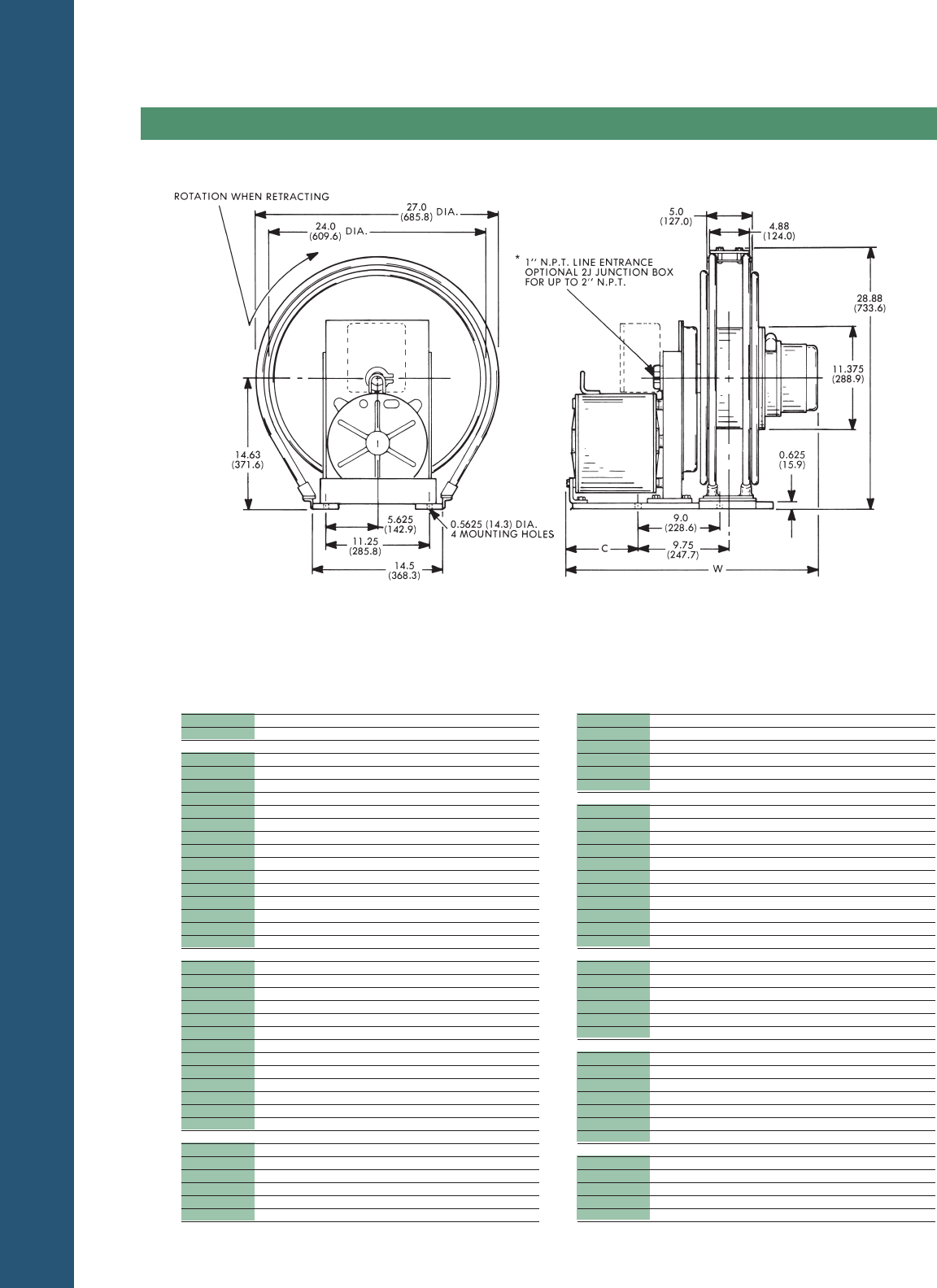
TECHNICAL DATA
PAGE 42
Dimensions
Series Reels
2000
Dim. C Dim. W Weight
Model in. mm in. mm lbs. Kg
316 11.12 282.5 37.00 939.8 260 118.0
320 11.12 282.5 39.00 990.6 264 119.9
402 11.12 282.5 33.00 838.2 255 115.8
403 11.12 282.5 33.00 838.2 256 116.2
404 11.12 282.5 33.00 838.2 256 116.2
904 11.12 282.5 37.00 939.8 259 117.6
2056-xx-303 13.25 336.6 33.25 844.6 275 124.9
304 13.25 336.6 33.25 844.6 276 125.3
306 13.25 336.6 35.25 895.4 277 125.8
308 13.25 336.6 35.25 895.4 278 126.2
310 13.25 336.6 37.25 946.2 278 126.2
312 13.25 336.6 37.25 946.2 279 126.7
316 13.25 336.6 39.25 997.0 280 127.1
320 13.25 336.6 41.25 1047.8 281 127.6
402 13.25 336.6 35.25 895.4 276 125.3
403 13.25 336.6 35.25 895.4 277 125.8
404 13.25 336.6 35.25 895.4 288 130.8
2057-xx-303 15.38 390.7 35.38 898.7 296 134.4
304 15.38 390.7 35.38 898.7 297 134.8
306 15.38 390.7 37.38 949.5 297 134.8
308 15.38 390.7 37.38 949.5 298 135.3
403 15.38 390.7 37.38 949.5 297 134.8
404 15.38 390.7 37.38 949.5 298 135.3
2058-xx-303 17.63 447.8 37.50 952.5 317 143.9
304 17.63 447.8 37.50 952.5 317 143.9
306 17.63 447.8 39.50 1003.3 318 144.4
308 17.63 447.8 39.50 1003.3 319 144.8
402 17.63 447.8 39.50 1003.3 318 144.4
403 17.63 447.8 39.50 1003.3 318 144.4
404 17.63 447.8 39.50 1003.3 319 144.8
2059-xx-303 19.75 501.7 39.75 1009.7 338 153.5
304 19.75 501.7 39.75 1009.7 338 153.5
306 19.75 501.7 41.75 1060.5 339 153.9
308 19.75 501.7 41.75 1060.5 341 154.8
404 19.75 501.7 41.75 1060.5 340 154.4
Chart shows dimensional variables within a reel series – “xx”
in the catalog number listing represents the drive system and
does not affect reel dimensions.
See page 38 for slip ring rating and junction box detail.
MILL DUTY SERVICE OPTION (Page 28)
will increase Dimensions C and W by 2.86 inches (73 mm)
Dim. C Dim. W Weight
Model in. mm in. mm lbs. Kg
2050-xx-303 21.88 555.8 41.88 1063.8 358 162.5
306 21.88 555.8 43.88 1114.6 360 163.4
2053-xx-306 6.75 171.5 27.38 695.5 214 97.2
308 6.75 171.5 27.38 695.5 215 97.6
310 6.75 171.5 29.38 746.3 216 98.1
312 6.75 171.5 29.38 746.3 217 98.5
316 6.75 171.5 31.38 797.1 218 99.0
320 6.75 171.5 33.38 847.9 222 100.8
324 6.75 171.5 35.38 898.7 224 101.7
330 6.75 171.5 39.38 1002.5 227 103.1
336 6.75 171.5 41.38 1051.1 229 104.0
402 6.75 171.5 27.38 695.5 213 96.7
403 6.75 171.5 27.38 695.5 214 97.2
404 6.75 171.5 27.38 695.5 214 97.2
902 6.75 171.5 29.38 746.3 215 97.6
903 6.75 171.5 29.38 746.3 216 98.1
904 6.75 171.5 31.38 797.1 217 98.5
2054-xx-306 8.88 225.6 30.88 784.4 235 106.7
308 8.88 225.6 30.88 784.4 236 107.2
310 8.88 225.6 32.88 835.2 237 107.6
312 8.88 225.6 32.88 835.2 237 107.6
316 8.88 225.6 34.88 886.0 239 108.5
330 8.88 225.6 42.88 1089.2 247 112.1
336 8.88 225.6 44.88 1140.0 250 113.5
402 8.88 225.6 30.88 784.4 234 106.2
403 8.88 225.6 30.88 784.4 235 106.7
404 8.88 225.6 30.88 784.4 235 106.7
902 8.88 225.6 32.88 835.2 235 106.7
903 8.88 225.6 32.88 835.2 237 107.6
904 8.88 225.6 34.88 886.0 238 108.1
2055-xx-303 11.12 282.5 31.00 787.4 254 115.3
304 11.12 282.5 31.00 787.4 255 115.8
306 11.12 282.5 33.00 838.2 256 116.2
308 11.12 282.5 33.00 838.2 257 116.7
310 11.12 282.5 35.00 889.0 257 116.7
312 11.12 282.5 35.00 889.0 258 117.1
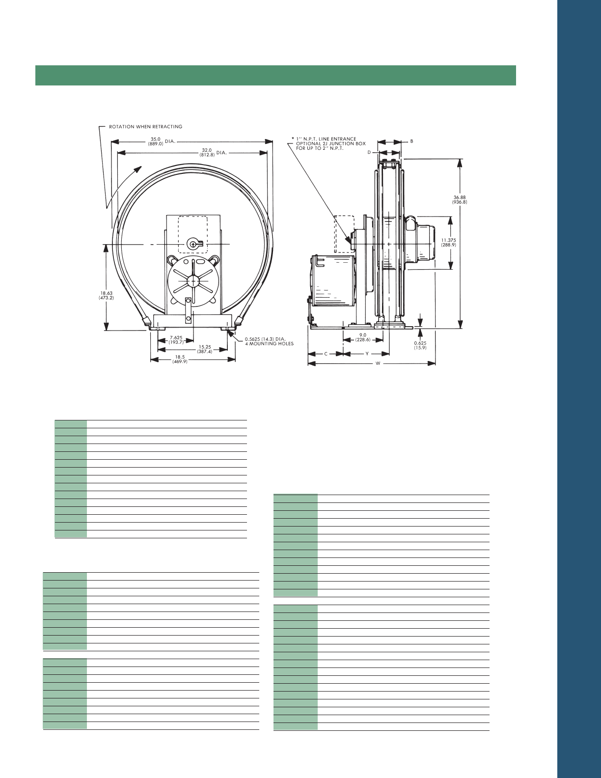
TECHNICAL DATA
PAGE 43
Dimensions
Series Reels
2300
Dim. B Dim. D Dim. Y
Series No. in. mm in. mm in. mm
2340 4.00 101.6 4.88 124.0 9.25 235.0
2343 4.00 101.6 4.88 124.0 9.25 235.0
2344 4.00 101.6 4.88 124.0 9.25 235.0
2345 4.00 101.6 4.88 124.0 9.25 235.0
2346 4.00 101.6 4.88 124.0 9.25 235.0
2347 4.00 101.6 4.88 124.0 9.25 235.0
2348 4.00 101.6 4.88 124.0 9.25 235.0
2349 4.00 101.6 4.88 124.0 9.25 235.0
2370 7.00 177.8 6.19 157.2 10.75 273.1
2374 7.00 177.8 6.19 157.2 10.75 273.1
2375 7.00 177.8 6.19 157.2 10.75 273.1
2376 7.00 177.8 6.19 157.2 10.75 273.1
2377 7.00 177.8 6.19 157.2 10.75 273.1
2378 7.00 177.8 6.19 157.2 10.75 273.1
2379 7.00 177.8 6.19 157.2 10.75 273.1
Chart shows dimensional variables within a reel series – “xx”
in the catalog number listing represents the drive system and
does not affect reel dimensions.
See page 35 for slip ring rating and junction box detail.
MILL DUTY SERVICE OPTION (Page 28)
will increase Dimensions C and W by 2.86 inches (73 mm)
Dim. C Dim. W Weight
Model in. mm in. mm lbs. Kg
2340-xx-304 21.88 555.8 40.38 1025.7 417 189.3
306 21.88 555.8 42.38 1076.5 418 189.3
308 21.88 555.8 42.38 1076.5 419 190.2
310 21.88 555.8 44.38 1127.3 420 190.7
312 21.88 555.8 44.38 1127.3 422 191.6
402 21.88 555.8 42.38 1076.5 418 189.8
403 21.88 555.8 42.38 1076.5 418 189.8
404 21.88 555.8 42.38 1076.5 419 190.2
902 21.88 555.8 44.38 1127.3 419 190.2
904 21.88 555.8 46.38 1178.1 422 191.6
2343-xx-316 6.75 171.5 31.12 790.5 276 125.3
320 6.75 171.5 33.12 841.3 280 127.1
324 6.75 171.5 35.12 892.1 282 128.0
330 6.75 171.5 39.12 993.7 284 128.9
336 6.75 171.5 41.12 1044.5 287 130.3
404 6.75 171.5 27.12 688.9 272 123.5
902 6.75 171.5 29.12 739.7 272 123.5
903 6.75 171.5 29.12 739.7 274 124.4
904 6.75 171.5 31.12 790.5 275 124.9
Dim. C Dim. W Weight
Model in. mm in. mm lbs. Kg
2344-xx-308 8.88 225.6 29.38 746.3 294 133.5
310 8.88 225.6 31.38 797.1 295 133.9
312 8.88 225.6 31.38 797.1 295 133.9
316 8.88 225.6 33.38 847.9 297 134.8
320 8.88 225.6 35.38 898.7 301 136.7
324 8.88 225.6 37.38 949.5 303 137.6
330 8.88 225.6 41.38 1051.1 305 138.5
336 8.88 225.6 43.38 1101.9 308 139.8
402 8.88 225.6 29.38 746.3 292 132.6
404 8.88 225.6 29.38 746.3 293 133.0
902 8.88 225.6 31.38 797.1 293 133.0
903 8.88 225.6 31.38 797.1 295 133.9
904 8.88 225.6 33.38 847.9 296 134.4
2345-xx-304 11.12 282.5 29.50 749.3 313 142.1
306 11.12 282.5 31.50 800.1 314 142.6
308 11.12 282.5 31.50 800.1 315 143.0
310 11.12 282.5 33.50 850.9 315 143.0
312 11.12 282.5 33.50 850.9 316 143.5
316 11.12 282.5 35.50 901.7 318 144.4
320 11.12 282.5 37.50 952.5 322 146.2
324 11.12 282.5 39.50 1003.3 324 147.1
330 11.12 282.5 43.50 1104.9 326 148.0
336 11.12 282.5 45.50 1155.7 329 149.4
402 11.12 282.5 31.50 800.1 313 142.1
403 11.12 282.5 31.50 800.1 314 142.6
404 11.12 282.5 31.50 800.1 314 142.6
902 11.12 282.5 33.50 850.9 314 142.6
903 11.12 282.5 33.50 850.9 316 143.5
904 11.12 282.5 35.50 901.7 317 143.9
Continued on next page
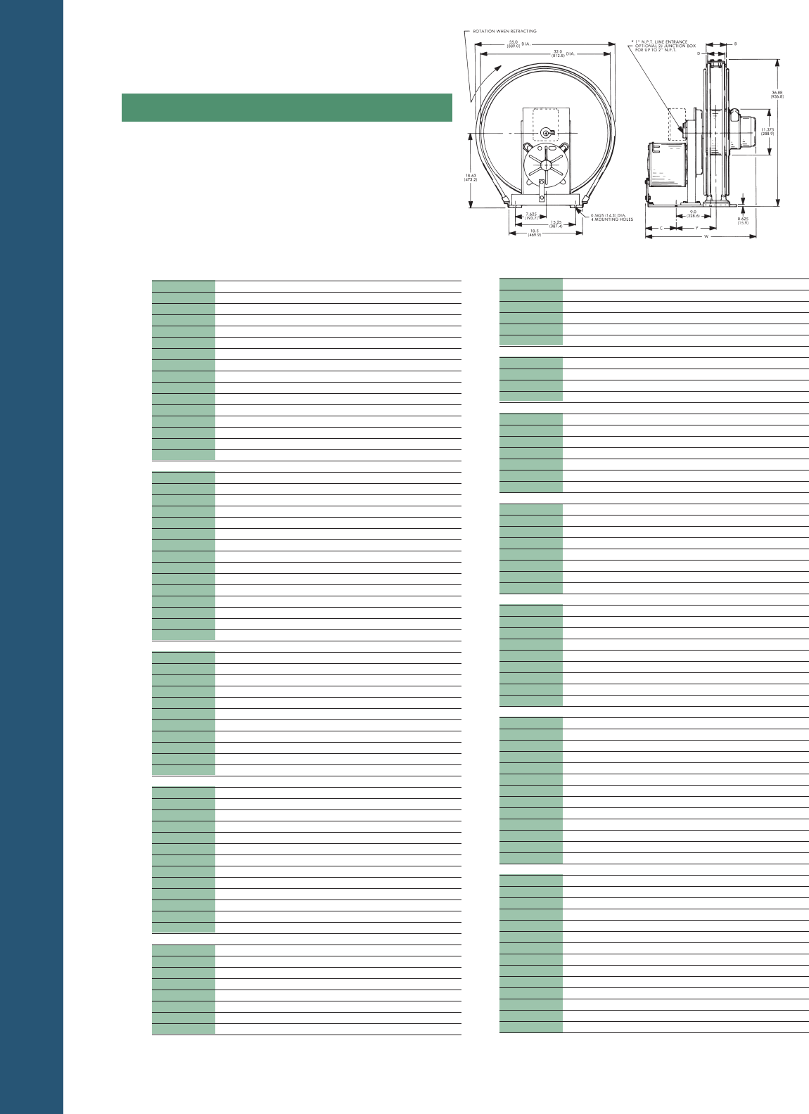
TECHNICAL DATA
PAGE 44
Dimensions
Series Reels
2300
Dim. C Dim. W Weight
Model in. mm in. mm lbs. Kg
2370-xx- 336 21.88 555.8 59.38 1508.3 438 198.9
403 21.88 555.8 45.38 1152.7 423 192.0
404 21.88 555.8 45.38 1152.7 424 192.5
902 21.88 555.8 47.38 1203.4 424 192.5
903 21.88 555.8 47.38 1203.4 425 193.0
904 21.88 555.8 49.38 1254.3 427 193.9
2374-xx-324 8.88 225.6 40.38 1025.7 308 139.8
330 8.88 225.6 44.38 1127.3 310 140.7
336 8.88 225.6 46.38 1178.1 313 142.1
902 8.88 225.6 34.38 873.3 298 135.3
2375-xx-320 11.12 282.5 40.50 1028.7 327 148.5
324 11.12 282.5 42.50 1079.5 329 149.4
330 11.12 282.5 46.50 1181.1 331 150.3
336 11.12 282.5 48.50 1231.9 334 151.6
902 11.12 282.5 36.50 927.1 319 144.8
903 11.12 282.5 36.50 927.1 321 145.7
904 11.12 282.5 38.50 977.9 322 146.2
2376-xx-316 13.25 336.6 40.62 1031.8 346 157.1
320 13.25 336.6 42.62 1082.6 348 158.0
324 13.25 336.6 44.62 1133.4 349 158.4
330 13.25 336.6 48.62 1235.0 352 159.8
336 13.25 336.6 50.62 1285.8 355 161.2
902 13.25 336.6 38.62 981.0 340 154.4
903 13.25 336.6 38.62 981.0 342 155.3
904 13.25 366.6 40.62 1031.8 343 155.7
2377-xx-310 15.38 390.7 40.88 1038.4 362 164.3
312 15.38 390.7 40.88 1038.4 363 164.8
316 15.38 390.7 42.88 1089.2 365 165.7
320 15.38 390.7 44.88 1140.2 369 167.5
324 15.38 390.7 46.88 1190.8 370 168.0
330 15.38 390.7 50.88 1292.4 373 169.3
336 15.38 390.7 52.88 1343.2 376 170.7
903 15.38 390.7 40.88 1038.4 363 164.8
904 15.38 390.7 42.88 1089.2 364 165.3
2378-xx-308 17.63 447.8 41.00 1041.4 382 173.4
310 17.63 447.8 43.00 1092.2 383 179.9
312 17.63 447.8 43.00 1092.2 385 174.8
316 17.63 447.8 45.00 1143.0 386 175.2
320 17.63 447.8 47.00 1193.8 389 176.6
324 17.63 447.8 49.00 1244.6 391 177.5
330 17.63 447.8 53.00 1346.2 394 178.9
336 17.63 447.8 55.00 1397.0 396 179.8
402 17.63 447.8 41.00 1041.4 381 173.0
404 17.63 447.8 41.00 1041.4 382 173.4
902 17.63 447.8 43.00 1092.2 382 173.4
903 17.63 447.8 43.00 1092.2 383 173.9
904 17.63 447.8 45.00 1143.0 385 174.8
2379-xx-308 19.75 495.7 43.12 1095.3 403 183.0
310 19.75 495.7 45.12 1146.1 404 183.4
312 19.75 495.7 45.12 1146.1 405 183.9
316 19.75 495.7 47.12 1196.9 408 185.2
320 19.75 495.7 49.12 1247.7 410 186.1
324 19.75 495.7 51.12 1298.5 412 187.0
330 19.75 495.7 55.12 1400.1 415 188.4
336 19.75 495.7 57.12 1450.9 418 189.8
402 19.75 495.7 41.12 1044.5 402 182.5
403 19.75 495.7 41.12 1044.5 402 182.5
404 19.75 495.7 41.12 1044.5 403 183.0
902 19.75 495.7 43.12 1095.3 403 183.0
903 19.75 495.7 43.12 1095.3 404 183.5
904 19.75 495.7 45.12 1146.1 406 184.3
Dim. C Dim. W Weight
Model in. mm in. mm lbs. Kg
2346-xx-304 13.25 336.6 31.62 803.2 334 151.6
306 13.25 336.6 33.62 854.0 335 152.1
308 13.25 336.6 33.62 854.0 335 152.1
310 13.25 336.6 35.62 904.8 336 152.5
312 13.25 336.6 35.62 904.8 337 153.0
316 13.25 336.6 37.62 955.6 339 153.9
320 13.25 336.6 39.62 1006.4 343 155.7
324 13.25 336.6 41.62 1057.2 344 156.2
330 13.25 336.6 45.62 1158.8 347 157.5
336 13.25 336.6 47.62 1209.6 350 158.9
402 13.25 336.6 31.62 803.2 334 151.6
403 13.25 336.6 31.62 803.2 334 151.6
404 13.25 336.6 31.62 803.2 335 152.1
902 13.25 336.6 33.62 854.0 335 152.1
903 13.25 366.6 33.62 854.0 337 153.0
904 13.25 336.6 35.62 904.8 338 153.5
2347-xx-304 15.38 390.7 33.88 860.6 355 161.2
306 15.38 390.7 35.88 911.4 355 161.2
308 15.38 390.7 35.88 911.4 356 161.6
310 15.38 390.7 37.88 962.2 357 162.1
312 15.38 390.7 37.88 962.2 358 162.5
316 15.38 390.7 39.88 1013.0 360 163.4
320 15.38 390.7 41.88 1063.8 364 165.3
324 15.38 390.7 43.88 1114.6 365 165.7
330 15.38 390.7 47.88 1216.2 370 168.0
402 15.38 390.7 35.88 911.4 355 161.2
403 15.38 390.7 35.88 911.4 355 161.2
404 15.38 390.7 35.88 911.4 356 161.6
902 15.38 390.7 37.88 962.2 356 161.6
903 15.38 390.7 37.88 962.2 358 162.5
904 15.38 390.7 39.88 1013.0 359 163.0
2348-xx-306 17.63 447.8 38.00 965.2 376 170.7
308 17.63 447.8 38.00 965.2 377 171.2
310 17.63 447.8 40.00 1016.0 378 171.6
312 17.63 447.8 40.00 1016.0 379 172.1
316 17.63 447.8 42.00 1066.8 381 173.0
320 17.63 447.8 44.00 1117.6 382 173.4
402 17.63 447.8 38.00 965.2 376 170.7
403 17.63 447.8 38.00 965.2 376 170.7
404 17.63 447.8 38.00 965.2 377 171.2
903 17.63 447.8 40.00 1016.0 379 172.1
904 17.63 447.8 42.00 1066.8 380 172.5
2349-xx-303 19.75 495.7 38.12 968.2 395 179.3
304 19.75 495.7 38.12 968.2 396 179.8
306 19.75 495.7 40.12 1019.1 397 180.2
308 19.75 495.7 40.12 1019.1 398 180.7
310 19.75 495.7 42.12 1069.9 399 181.1
312 19.75 495.7 42.12 1069.9 400 181.6
316 19.75 495.7 44.12 1120.7 402 182.5
320 19.75 495.7 46.12 1171.5 405 183.9
402 19.75 495.7 38.12 968.2 397 180.2
403 19.75 495.7 38.12 968.2 397 180.2
404 19.75 495.7 38.12 968.2 398 180.7
902 19.75 495.7 40.12 1019.1 398 180.7
903 19.75 495.7 40.12 1019.1 404 183.4
2370-xx-306 21.88 555.8 45.38 1152.7 423 192.0
308 21.88 555.8 45.38 1152.7 424 192.5
310 21.88 555.8 47.38 1203.4 425 193.0
312 21.88 555.8 47.38 1203.4 426 193.4
316 21.88 555.8 49.38 1254.3 428 194.3
320 21.88 555.8 51.38 1305.1 431 195.7
324 21.88 555.8 53.38 1355.9 433 196.6
330 21.88 555.8 57.38 1457.5 436 197.9
(CONTINUED)
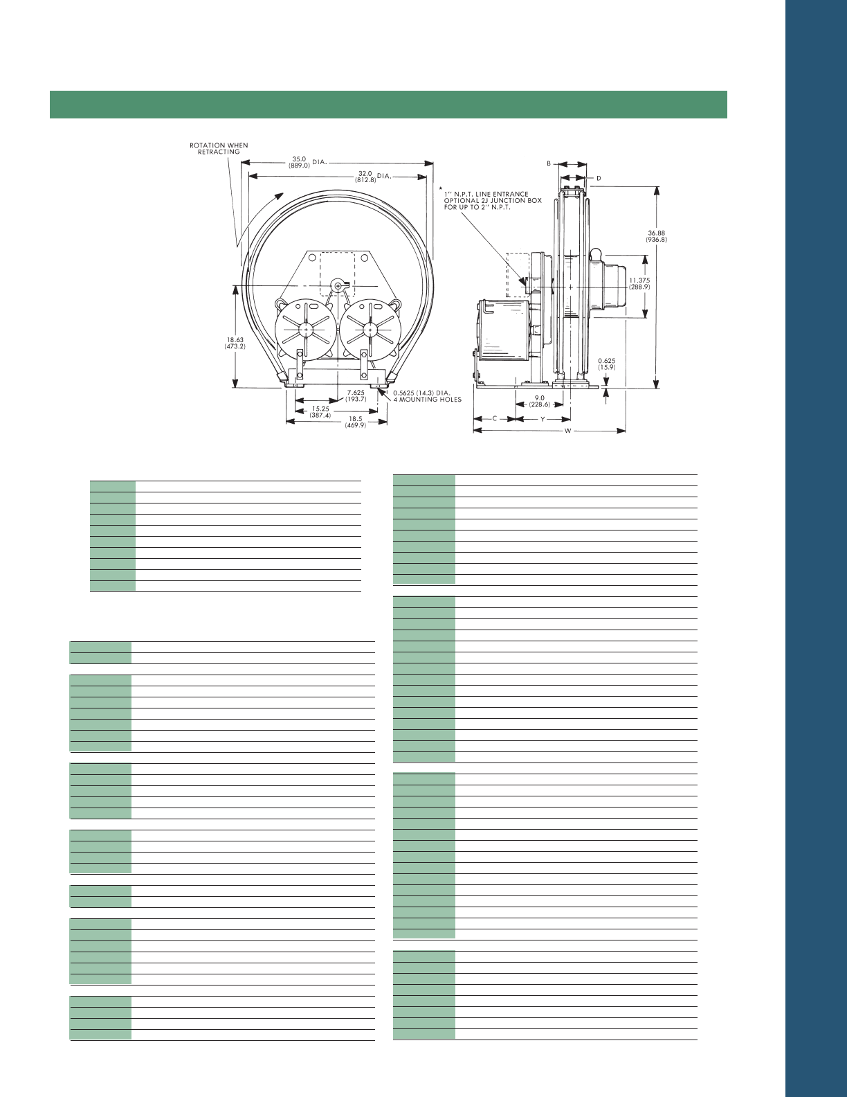
TECHNICAL DATA
PAGE 45
Dimensions
Dim. C Dim. W Weight
Model in. mm in. mm lbs. Kg
2476-xx-320 13.25 336.6 42.62 1082.6 503 228.4
324 13.25 336.6 44.62 1133.4 505 229.3
330 13.25 336.6 48.62 1235.0 508 230.6
336 13.25 336.6 50.62 1285.8 510 231.5
402 13.25 336.6 36.62 930.2 494 224.3
403 13.25 336.6 36.62 930.2 495 224.7
404 13.25 336.6 36.62 930.2 495 224.7
902 13.25 336.6 38.62 981.0 496 225.2
903 13.25 336.6 38.62 981.0 497 225.6
904 13.25 336.6 38.62 981.0 499 226.5
2477-xx-306 15.38 390.7 38.88 987.6 537 243.8
308 15.38 390.7 38.88 987.6 538 244.3
310 15.38 390.7 40.88 1038.4 539 244.7
312 15.38 390.7 40.88 1038.4 540 245.2
316 15.38 390.7 42.88 1089.2 541 245.6
320 15.38 390.7 44.88 1140.0 545 247.4
324 15.38 390.7 46.88 1190.8 547 248.3
330 15.38 390.7 50.88 1292.4 550 249.7
336 15.38 390.7 52.88 1343.2 555 252.0
402 15.38 390.7 38.88 987.6 536 243.3
403 15.38 390.7 38.88 987.6 537 243.8
404 15.38 390.7 38.88 987.6 537 243.8
902 15.38 390.7 40.88 1038.4 537 243.8
903 15.38 390.7 40.88 1038.4 539 244.7
904 15.38 390.7 40.88 1038.4 540 137.2
2478-xx-306 17.63 447.8 41.00 1041.4 578 262.4
308 17.63 447.8 41.00 1041.4 580 263.3
310 17.63 447.8 43.00 1092.2 580 263.3
312 17.63 447.8 43.00 1092.2 581 263.8
316 17.63 447.8 45.00 1143.0 583 264.7
320 17.63 447.8 47.00 1193.8 586 266.0
324 17.63 447.8 49.00 1244.6 589 267.4
330 17.63 447.8 53.00 1346.2 591 268.3
336 17.63 447.8 55.00 1397.0 594 269.7
402 17.63 447.8 41.00 1041.4 578 262.4
403 17.63 447.8 41.00 1041.4 579 262.9
404 17.63 447.8 41.00 1041.4 579 262.9
902 17.63 447.8 43.00 1092.2 579 262.9
903 17.63 447.8 43.00 1092.2 581 263.8
904 17.63 447.8 45.00 1143.0 582 264.2
2479-xx-308 19.75 495.7 43.12 1095.3 621 281.9
310 19.75 495.7 45.12 1146.1 622 282.4
312 19.75 495.7 45.12 1146.1 623 282.8
330 19.75 495.7 55.12 1400.1 623 282.8
402 19.75 495.7 43.12 1095.3 620 281.5
404 19.75 495.7 43.12 1095.3 621 281.9
902 19.75 495.7 45.12 1146.1 621 281.9
904 19.75 495.7 47.12 1196.9 624 283.3
Series Reels
2400
Dim. B Dim. D Dim. Y
Series No. in. mm in. mm in. mm
2445 4.00 101.6 4.88 124.0 9.25 235.0
2446 4.00 101.6 4.88 124.0 9.25 235.0
2447 4.00 101.6 4.88 124.0 9.25 235.0
2448 4.00 101.6 4.88 124.0 9.25 235.0
2449 4.00 101.6 4.88 124.0 9.25 235.0
2470 7.00 177.8 6.19 157.2 10.75 273.1
2476 7.00 177.8 6.19 157.2 10.75 273.1
2477 7.00 177.8 6.19 157.2 10.75 273.1
2478 7.00 177.8 6.19 157.2 10.75 273.1
2479 7.00 177.8 6.19 157.2 10.75 273.1
Dim. C Dim. W Weight
Model in. mm in. mm lbs. Kg
2445-xx-403 11.12 282.5 31.50 800.1 448 203.4
404 11.12 282.5 31.50 800.1 449 203.8
2446-xx-303 13.25 336.6 31.62 803.2 488 221.6
306 13.25 336.6 33.62 854.0 490 222.5
308 13.25 336.6 35.63 905.0 491 222.9
402 13.25 336.6 33.62 854.0 489 222.0
403 13.25 336.6 33.62 854.0 490 222.5
404 13.25 336.6 33.62 854.0 490 222.5
903 13.25 336.6 35.62 905.0 491 222.9
2447-xx-304 15.38 390.7 33.88 860.6 530 240.1
306 15.38 390.7 35.88 911.4 530 240.1
402 15.38 390.7 35.88 911.4 532 241.5
403 15.38 390.7 35.88 911.4 532 241.5
404 15.38 390.7 35.88 911.4 532 241.5
2448-xx-308 17.63 447.8 38.00 965.2 574 260.6
402 17.63 447.8 38.00 965.2 574 260.6
403 17.63 447.8 38.00 965.2 574 260.6
404 17.63 447.8 38.00 965.2 574 260.6
2449-xx-402 19.75 495.7 40.12 1019.1 615 279.2
404 19.75 495.7 40.12 1019.1 616 279.7
2470-xx-308 21.88 555.8 45.38 1152.7 663 301.0
402 21.88 555.8 45.38 1152.7 662 300.5
403 21.88 555.8 45.38 1152.7 662 300.5
404 21.88 555.8 45.38 1152.7 663 301.0
903 21.88 555.8 47.38 1203.5 664 301.5
904 21.88 555.8 49.38 1254.3 666 302.4
2476-xx-308 13.25 336.6 36.62 930.2 496 225.2
310 13.25 336.6 38.62 981.0 497 225.6
312 13.25 336.6 38.62 981.0 498 226.1
316 13.25 336.6 40.62 1031.8 500 227.0
Chart shows dimensional vari-
ables within a reel series – “xx”
in the catalog number listing
represents the drive system and
does not affect reel dimensions.
See page 35 for slip ring rating
and junction box detail.
MILL DUTY SERVICE OPTION
(Page 28)
will increase Dimensions C
and W by 2.86 inches (73 mm)
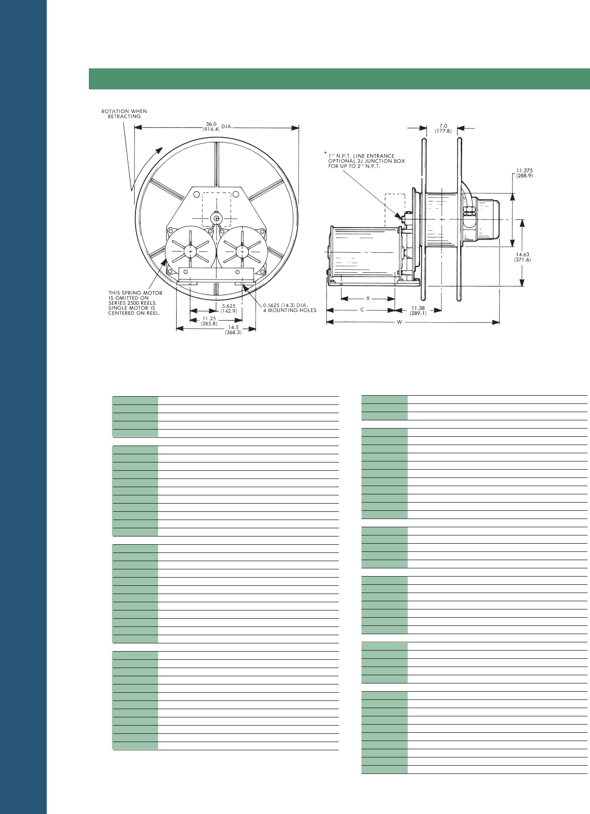
TECHNICAL DATA
PAGE 46
Dimensions
Series Reels
2500&2600
Dim. X Dim. C Dim. W Weight
Model in. mm in. mm in. mm lbs. Kg
2570-xx-324 16.94 430.3 21.96 557.8 54.88 1394.0 429 194.8
404 16.94 430.3 21.96 557.8 46.88 1191.0 422 191.6
902 16.94 430.3 21.96 557.8 48.88 1241.6 419 190.2
903 16.94 430.3 21.96 557.8 48.88 1241.6 420 190.7
904 16.94 430.3 21.96 557.8 50.88 1292.4 422 191.6
2576-xx-308 8.25 209.6 13.27 337.1 38.13 968.5 336 152.5
310 8.25 209.6 13.27 337.1 40.13 1019.3 337 153.0
312 8.25 209.6 13.27 337.1 40.13 1019.3 338 153.5
316 8.25 209.6 13.27 337.1 42.13 1070.1 340 154.4
320 8.25 209.6 13.27 337.1 44.13 1120.9 343 155.7
324 8.25 209.6 13.27 337.1 46.13 1171.7 345 156.7
330 8.25 209.6 13.27 337.1 50.13 1273.3 348 158.0
336 8.25 209.6 13.27 337.1 52.13 1324.1 350 158.9
402 8.25 209.6 13.27 337.1 38.13 968.5 334 151.6
403 8.25 209.6 13.27 337.1 38.13 968.5 335 152.1
902 8.25 209.6 13.27 337.1 40.13 1019.3 336 152.5
2577-xx-308 10.44 265.2 15.62 396.8 40.50 1028.7 357 162.1
310 10.44 265.2 15.62 396.8 42.50 1079.5 358 162.5
312 10.44 265.2 15.62 396.8 42.50 1079.5 359 163.0
316 10.44 265.2 15.62 396.8 44.50 1130.3 360 163.4
320 10.44 265.2 15.62 396.8 46.50 1181.1 364 165.3
324 10.44 265.2 15.62 396.8 48.50 1231.9 366 166.2
330 10.44 265.2 15.62 396.8 52.50 1333.5 396 167.5
336 10.44 265.2 15.62 396.8 54.50 1384.3 371 168.4
402 10.44 265.2 15.62 396.8 40.50 1028.7 355 161.2
403 10.44 265.2 15.62 396.8 40.50 1028.7 356 161.6
404 10.44 265.2 15.62 396.8 40.50 1028.7 356 161.6
902 10.44 265.2 15.62 396.8 42.50 1079.5 357 162.1
2578-xx-306 12.56 319.0 17.62 447.5 42.50 1079.5 377 171.2
310 12.56 319.0 17.62 447.5 44.50 1130.3 379 172.1
312 12.56 319.0 17.62 447.5 44.50 1130.3 380 172.5
320 12.56 319.0 17.62 447.5 48.50 1231.9 385 174.8
324 12.56 319.0 17.62 447.5 50.50 1282.7 387 175.7
330 12.56 319.0 17.62 447.5 54.50 1384.3 389 176.6
336 12.56 319.0 17.62 447.5 56.50 1435.1 392 178.0
403 12.56 319.0 17.62 447.5 42.50 1079.5 377 171.2
404 12.56 319.0 17.62 447.5 42.50 1079.5 377 171.2
902 12.56 319.0 17.62 447.5 44.50 1130.3 377 171.2
903 12.56 319.0 17.62 447.5 44.50 1130.3 379 172.1
904 12.56 319.0 17.62 447.5 46.50 1181.1 380 172.5
Dim. X Dim. C Dim. W Weight
Model in. mm in. mm in. mm lbs. Kg
2579-xx-404 14.75 374.7 19.79 502.7 44.63 1133.6 398 180.7
903 14.75 374.7 19.79 502.7 46.63 1184.4 400 181.6
904 14.75 374.7 19.79 502.7 48.63 1235.2 401 182.1
2670-xx-310 16.94 430.3 21.96 557.8 48.88 1241.6 660 299.6
312 16.94 430.3 21.96 557.8 48.88 1241.6 660 299.6
316 16.94 430.3 21.96 557.8 50.88 1292.4 662 300.5
320 16.94 430.3 21.96 557.8 52.88 1343.2 666 302.4
324 16.94 430.3 21.96 557.8 54.88 1394.0 668 303.2
336 16.94 430.3 21.96 557.8 60.88 1546.4 673 305.5
403 16.94 430.3 21.96 557.8 46.88 1190.8 658 298.7
404 16.94 430.3 21.96 557.8 46.88 1190.8 658 298.7
902 16.94 430.3 21.96 557.8 48.88 1241.6 658 298.7
903 16.94 430.3 21.96 557.8 48.88 1241.6 660 299.6
904 16.94 430.3 21.96 557.8 50.88 1292.4 661 300.1
2676-xx-320 8.25 209.6 13.27 337.1 44.13 1120.9 499 226.5
324 8.25 209.6 13.27 337.1 46.13 1171.7 500 227.0
330 8.25 209.6 13.27 337.1 50.13 1273.3 503 228.4
336 8.25 209.6 13.27 337.1 52.13 1324.1 506 229.7
902 8.25 209.6 13.27 337.1 40.13 1019.3 491 222.9
2677-xx-320 10.44 265.2 15.62 396.8 46.50 1181.1 540 245.2
324 10.44 265.2 15.62 396.8 48.50 1231.9 542 246.1
330 10.44 265.2 15.62 396.8 52.50 1333.5 545 247.3
336 10.44 265.2 15.62 396.8 54.50 1384.3 548 248.8
902 10.44 265.2 15.62 396.8 42.50 1079.5 533 242.0
903 10.44 265.2 15.62 396.8 42.50 1079.5 534 242.4
904 10.44 265.2 15.62 396.8 44.50 1130.3 536 243.3
2678-xx-316 12.56 319.0 17.62 447.5 46.50 1181.1 579 262.9
320 12.56 319.0 17.62 447.5 48.50 1231.9 584 265.1
330 12.56 319.0 17.62 447.5 54.50 1384.3 587 266.5
903 12.56 319.0 17.62 447.5 44.50 1130.3 576 261.5
904 12.56 319.0 17.62 447.5 46.50 1181.1 578 262.4
2679-xx-310 14.75 374.7 19.79 502.7 46.63 1184.4 618 280.6
316 14.75 374.7 19.79 502.7 48.63 1235.2 620 281.5
320 14.75 374.7 19.79 502.7 50.63 1286.0 624 283.3
324 14.75 374.7 19.79 502.7 52.63 1336.8 626 284.2
336 14.75 374.7 19.79 502.7 58.63 1489.2 631 286.5
403 14.75 374.7 19.79 502.7 44.63 1133.6 616 279.7
404 14.75 374.7 19.79 502.7 44.63 1133.6 616 279.7
902 14.75 374.7 19.79 502.7 46.63 1184.4 617 280.1
903 14.75 374.7 19.79 502.7 46.63 1184.4 618 280.6
904 14.75 374.7 19.79 502.7 48.63 1235.2 620 281.5
Chart shows dimensional vari-
ables within a reel series – “xx”
inthe catalog number listing rep-
resents the drive system and
does not affect reel dimensions.
See page 35 for slip ring rating
and junction box detail.
MILL DUTY SERVICE OPTION
(Page 28) will increase Dims. C
and W by 2.86 inches (73 mm)
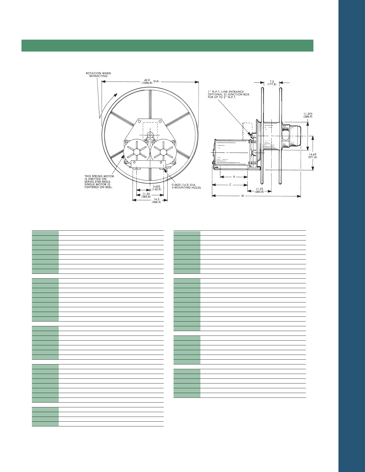
TECHNICAL DATA
PAGE 47
Dimensions
Series Reels
2700&2800
Dim. X Dim. C Dim. W Weight
Model in. mm in. mm in. mm lbs. Kg
2876-xx-316 8.25 209.6 13.27 337.6 42.13 1070.1 522 237.0
320 8.25 209.6 13.27 337.6 44.13 1120.9 526 238.8
324 8.25 209.6 13.27 337.6 46.13 1171.7 527 239.3
330 8.25 209.6 13.27 337.6 50.13 1273.3 530 240.6
403 8.25 209.6 13.27 337.6 38.13 968.5 517 234.7
404 8.25 209.6 13.27 337.6 38.13 968.5 518 235.2
902 8.25 209.6 13.27 337.6 40.13 1019.3 518 235.2
903 8.25 209.6 13.27 337.6 40.13 1019.3 520 236.1
904 8.25 209.6 13.27 337.6 42.13 1070.1 521 236.5
2877-xx-312 10.44 265.2 15.62 396.8 42.50 1079.5 562 255.1
316 10.44 265.2 15.62 396.8 44.50 1130.3 564 256.1
324 10.44 265.2 15.62 396.8 48.50 1231.9 568 257.9
330 10.44 265.2 15.62 396.8 52.50 1333.5 572 259.7
336 10.44 265.2 15.62 396.8 54.50 1384.3 575 261.1
402 10.44 265.2 15.62 396.8 40.50 1028.7 559 253.8
403 10.44 265.2 15.62 396.8 40.50 1028.7 559 253.8
404 10.44 265.2 15.62 396.8 40.50 1028.7 560 254.2
902 10.44 265.2 15.62 396.8 42.50 1079.5 560 254.2
903 10.44 265.2 15.62 396.8 42.50 1079.5 561 254.7
904 10.44 265.2 15.62 396.8 44.50 1130.3 563 255.6
2878-xx-320 12.56 319.0 17.62 447.5 48.50 1231.9 609 276.5
324 12.56 319.0 17.62 447.5 50.50 1282.7 611 277.4
330 12.56 319.0 17.62 447.5 54.50 1384.3 612 277.8
336 12.56 319.0 17.62 447.5 56.50 1435.1 616 279.7
902 12.56 319.0 17.62 447.5 44.50 1130.3 602 273.3
904 12.56 319.0 17.62 447.5 46.50 1181.1 605 274.7
2879-xx-320 14.75 374.7 19.79 502.7 50.63 1286.0 651 295.6
324 14.75 374.7 19.79 502.7 52.63 1336.8 653 296.5
330 14.75 374.7 19.79 502.7 56.63 1438.4 656 297.8
902 14.75 374.7 19.79 502.7 46.63 1184.4 644 292.4
903 14.75 374.7 19.79 502.7 46.63 1184.4 646 293.3
904 14.75 374.7 19.79 502.7 48.63 1235.2 648 294.2
Dim. X Dim. C Dim. W Weight
Model in. mm in. mm in. mm lbs. Kg
2770-xx-312 16.94 430.3 21.96 557.8 48.88 1241.6 448 203.4
316 16.94 430.3 21.96 557.8 50.88 1292.4 450 204.3
320 16.94 430.3 21.96 557.8 52.88 1343.2 454 206.1
324 16.94 430.3 21.96 557.8 54.88 1394.0 456 207.0
330 16.94 430.3 21.96 557.8 58.88 1495.6 458 207.9
336 16.94 430.3 21.96 557.8 60.88 1546.4 461 209.3
402 16.94 430.3 21.96 557.8 46.88 1190.8 445 202.0
404 16.94 430.3 21.96 557.8 46.88 1190.8 446 202.5
902 16.94 430.3 21.96 557.8 48.88 1241.6 448 203.4
2777-xx-310 10.44 265.2 15.62 396.8 42.50 1079.5 385 174.8
324 10.44 265.2 15.62 396.8 48.50 1231.9 393 178.4
2778-xx-308 12.56 319.0 17.62 447.5 42.50 1079.5 405 183.9
310 12.56 319.0 17.62 447.5 44.50 1130.3 406 184.3
312 12.56 319.0 17.62 447.5 44.50 1130.3 407 184.8
316 12.56 319.0 17.62 447.5 46.50 1181.1 408 185.2
320 12.56 319.0 17.62 447.5 48.50 1231.9 412 187.0
324 12.56 319.0 17.62 447.5 50.50 1282.7 414 188.0
330 12.56 319.0 17.62 447.5 54.50 1384.3 416 188.9
2779-xx-308 14.75 374.7 19.79 502.7 44.63 1133.6 426 193.4
310 14.75 374.7 19.79 502.7 46.63 1184.4 427 193.9
312 14.75 374.7 19.79 502.7 46.63 1184.4 427 193.9
316 14.75 374.7 19.79 502.7 48.63 1235.2 429 194.8
320 14.75 374.7 19.79 502.7 50.63 1286.0 433 196.6
324 14.75 374.7 19.79 502.7 52.63 1336.8 435 197.5
336 14.75 374.7 19.79 502.7 58.63 1489.2 440 199.8
2870-xx-316 16.94 430.3 21.96 557.8 50.88 1292.4 689 312.8
320 16.94 430.3 21.96 557.8 52.88 1343.2 693 314.6
324 16.94 430.3 21.96 557.8 54.88 1394.0 695 315.5
330 16.94 430.3 21.96 557.8 58.88 1495.6 697 316.4
336 16.94 430.3 21.96 557.8 60.88 1546.4 700 317.8
902 16.94 430.3 21.96 557.8 48.88 1241.6 685 311.0
903 16.94 430.3 21.96 557.8 48.88 1241.6 687 311.9
904 16.94 430.3 21.96 557.8 50.88 1292.4 688 312.4
2875-xx-324 6.06 153.9 11.10 281.9 44.00 1117.6 486 220.6
330 6.06 153.9 11.10 281.9 48.00 1219.2 488 221.6
404 6.06 153.9 11.10 281.9 36.00 914.4 476 216.1
902 6.06 153.9 11.10 281.9 38.00 965.2 476 216.1
Chart shows dimensional
variables within a reel
series – “xx” in the catalog
number listing represents
the drive system and does
not affect reel dimensions.
See page 35 for slip ring
rating and junction box
detail.
MILL DUTY SERVICE
OPTION (Page 28)
will increase Dimensions
Cand W by 2.86 inches
(73 mm)

© 2005 Woodhead L.P.
DWCR LCP 105 5M
Aero-Motive, Pow-R-Mite, and Pow-R-Matic are trademarks of Woodhead Industries Inc.
AERO-MOTIVE®
AERO-MOTIVE®
United States/Mexico
Woodhead L.P.
3411 Woodhead Drive
Northbrook, IL 60062
1-800-999-8559
FAX: 1-800-333-6119
woodhead.com
Canada
Woodhead Canada Limited
1090 Brevik Place
Mississauga, Ontario L4W 3Y5
1-905-624-6518
FAX: 1-905-624-9151
www.woodhead.ca
Europe
Woodhead Connectivity Ltd.
Factory No. 9
Rassau Industrial Estate
Ebbw Vale, Gwent, Wales
United Kingdom NP23 5SD
011-44-1495-350436
FAX: 011-44-1495-350877
sales@wdhd.co.uk
Asia
Woodhead Asia Pte. Ltd.
No. 4 Toh Tuck Link
Level 3, Mezzanine
Markono Logistics Bldg.
Singapore 596 226
+(65)-6261-6533
FAX: 65-62-261-3588
sales.asia@woodhead.com
Japan
Woodhead Japan Corp.
3G Kawashima No. 5 Bldg.
29-16 Imaike-Minami
Chikusa-ku
Nagoya 464-0851 Japan
011-81-52-745-7621
