TB02603002E 148242 Catalog
2016-10-06
: Pdf 148242-Catalog 148242-Catalog B5 unilog
Open the PDF directly: View PDF ![]() .
.
Page Count: 46

CA08104001E For more information, visit: www.eaton.com/consultants
April 2016
Contents
Power Management Connectivity & Monitoring 2.0-1
i
ii
1
2
3
4
5
6
7
8
9
10
11
12
13
14
15
16
17
18
19
20
21
Sheet 02001
Power Management
Connectivity & Monitoring
Power Management Connectivity & Monitoring
Introduction
Designing a Power Monitoring and Control System for the
Entire Power Distribution and Motor Control System. . . . . . . . . . . . . 2.0-2
Copper and Fiber Optic Cable Wiring Guidelines for Ethernet Networks
. . 2.0-5
Power Monitoring and Control for Power Distribution and Control Assemblies
Medium Voltage Switchgear . . . . . . . . . . . . . . . . . . . . . . . . . . . . . . . . . . 2.1-1
Low Voltage Switchgear . . . . . . . . . . . . . . . . . . . . . . . . . . . . . . . . . . . . . . 2.1-3
Medium Voltage Motor Control . . . . . . . . . . . . . . . . . . . . . . . . . . . . . . . . 2.1-4
Low Voltage Motor Control . . . . . . . . . . . . . . . . . . . . . . . . . . . . . . . . . . . 2.1-5
Low Voltage Commercial Power Distribution . . . . . . . . . . . . . . . . . . . . . 2.1-6
Low Voltage Switchgear . . . . . . . . . . . . . . . . . . . . . . . . . . . . . . . . . . . 2.1-7
Low Voltage Panelboard . . . . . . . . . . . . . . . . . . . . . . . . . . . . . . . . . . . 2.1-8
Connectivity and Software Products
Power Xpert Ethernet Switches . . . . . . . . . . . . . . . . . . . . . . . . . . . . . . . . 2.2-1
Power Xpert Gateway 900 . . . . . . . . . . . . . . . . . . . . . . . . . . . . . . . . . . . . 2.2-2
Power Xpert Dashboard . . . . . . . . . . . . . . . . . . . . . . . . . . . . . . . . . . . . . . 2.2-9
Power Xpert Insight Software . . . . . . . . . . . . . . . . . . . . . . . . . . . . . . . . . 2.2-14
Foreseer Services . . . . . . . . . . . . . . . . . . . . . . . . . . . . . . . . . . . . . . . . . . . 2.2-20
Power Management Systems & Products for Third-Party Integration
MINTII RS-232 Converter . . . . . . . . . . . . . . . . . . . . . . . . . . . . . . . . . . . . . 2.3-1
mMINT . . . . . . . . . . . . . . . . . . . . . . . . . . . . . . . . . . . . . . . . . . . . . . . . . . . . 2.3-2
PMINT. . . . . . . . . . . . . . . . . . . . . . . . . . . . . . . . . . . . . . . . . . . . . . . . . . . . . 2.3-3
Specifications
See Eaton’s Product Specification Guide, available on CD or on the Web.
CSI Format . . . . . . . . . . . . . . . . . . . . . . 1995 2010
Section 16901 & Section 26 27 13.11 &
Section 16911 Section 26 09 13.13

2.0-2
For more information, visit: www.eaton.com/consultants CA08104001E
April 2016
Power Management Connectivity & Monitoring
i
ii
1
2
3
4
5
6
7
8
9
10
11
12
13
14
15
16
17
18
19
20
21
Sheet 02
Introduction
002
Designing a Power
Monitoring and Control
System for the Entire Power
Distribution and Motor
Control System
Introduction
The main objective of system design
is to produce a cost-effective, high-
quality product. Several things stand
in the way—unexpected equipment
downtime, energy costs, reduced
maintenance personnel and budgets,
and limited capital. Downtime or
power outage costs range from a few
thousand to hundreds of thousands of
dollars per hour in the lost production
and related costs. In many facilities,
the electrical energy consumption
contributes significantly to overall
cost of energy. Having the ability to
monitor and control every aspect of
the electrical use throughout the entire
facility, provides the mechanism for
turning off noncritical loads during
times of high peak usage and during
power outages to keep critical loads
operational with limited electrical
supply from a standby generator.
Consider These Facts
■Energy costs are growing at an
average of 8 percent to 10 percent
per year and any increase in power
demand is dramatically more
expensive (up to $40/kW)
■Engineering and maintenance staffs
are being asked to do more with
fewer personnel
■Product quality is very dependent on
the consistency of the power supply
at a time when the utilities are being
pushed to deliver more with no
increase in generating capacity
■With the rise in energy costs and
the shrinking energy availability,
increasingly complex energy
reporting and cost saving programs
require elaborate monitoring and
reporting systems
Power monitoring and control principles
can be applied to the entire power
distribution and control system.
Ranging from medium voltage to low
voltage equipment, solid-state devices
equipped with communication interface
modules make up the backbone of the
power monitoring and control system
network. The recommended approach
to building the system is to use best-
of-breed components that individually
and together provide the best possible
solution at the lowest cost.
What is Needed in this
Environment?
By obtaining information and making
it available in real time to the people
who need to have it...provide energy
consumption and performance informa-
tion for the electrical distribution and
control system effectively in a simple
format that each person can understand
and utilize. This information can be
obtained from a power monitoring and
control system (PMCS). The PMCS is a
complete family of solid-state products
including protective relays, meters and
control relays designed to provide
superior protection and metering from
the utility incoming line down to a 15 A
breaker or fractional horsepower motor.
When connected together over a high-
speed Ethernet network, it provides
the necessary information to the right
person in real time to ensure the plant
and facility operates efficiently. It is
also “open” to communicate with
other communications systems used
in a facility.
During the initial design of the power
monitoring and control system, the
designer will need to consider the type
of information required for the right
person in the facility.
Design Considerations
The following checklist provides
a good set of guidelines to follow
when designing a Power Monitoring
and Control System (PMCS) for
the electrical distribution and
control system.
1. Consider solid-state overcurrent
protection devices (OCPDs) such
as: protection relays, circuit
breaker trip units and overload
relays, on all circuits greater than
100 A. This provides the founda-
tion to add: remote I/O, shunt trip
release, motor operator, remote
racking device, and communica-
tions for remote monitoring,
configuration and control of
the OCPD.
2. Add Power Quality Metering
(PQM) to monitor and record
electrical information such as:
■Voltage
■Current
■Power
■Demand
■Energy
■Power factor
■Frequency
■THD
■Alarms
■Waveform capture
Critical or key points in the
electrical distribution and control
system such as:
■Incoming main breakers on
distribution equipment
■Large feeders on distribution
equipment 225 A and greater
■Main breaker or Main Lug Only
(MLO) panels
■Main breaker on motor control
centers
■Starters with large loads such
as 100 hp and above
■Bus duct feeder runs
■Large loads; 100 A bus plugs
and above
3. Coordinate with other divisions
(mechanical systems, control
systems, network infrastructure)
for making OCPD information
accessible on the company
network or control networks.
4. Take into consideration which
personnel need access to certain
levels of control of the OCPD or
other communicating devices
such as: meters, relays and
communications gateways.
5. Plan for the installation and
routing of necessary communica-
tion cables, conduits and trays
to connect equipment together to
form a network or to connect to an
existing network.
6. Work closely with the customer
or building owner to discuss
the long-term ownership of the
power monitoring system and the
maintenance associated with it.
Items to discuss are: firmware
updates to all electronic equip-
ment, long-term data storage of
monitored trend data, and security
passwords for key personnel to
access the equipment.

CA08104001E For more information, visit: www.eaton.com/consultants
2.0-3
April 2016
Power Management Connectivity & Monitoring
i
ii
1
2
3
4
5
6
7
8
9
10
11
12
13
14
15
16
17
18
19
20
21
Sheet 02
Introduction
003
Safety Considerations
Safety is a concern anytime mainte-
nance personnel are required to be
near or perform service on energized
electrical equipment. Eaton has taken
this concern very seriously and has
designed a system to make safety the
number one focus. The design goal of
the system is to limit the interaction
with energized electrical equipment
to the absolute minimum. The biggest
area of concern pertains to opening and
closing switches and circuit breakers
while equipment is energized.
Security Considerations
Every day, cyber-attacks against
government and commercial computer
networks number in the millions.
According to U.S. Cyber Command,
pentagon systems are probed 250,000
times per hour. Similar attacks are
becoming more prevalent on other
kinds of information-based smart
networks as well, such as those that
operate buildings and utility systems.
Whether the objective is to steal
intellectual property or halt operations,
the tools and the techniques used for
unauthorized network access are
increasingly sophisticated.
Connectivity—why do we need to
address cybersecurity for power moni-
toring and control systems (PMCS)?
There is increasing concern regarding
cybersecurity across industries where
companies are steadily integrating field
devices into enterprise-wide informa-
tion systems. This occurs in discrete
manufacturing and process industrial
environments, a wide range of general
and specific purpose commercial
buildings, and even utility networks.
Traditionally, electrical systems were
controlled through serial devices
connected to computers via dedicated
transceivers with proprietary protocols.
In contrast, today’s control systems
are increasingly connected to larger
enterprise networks, which can expose
these systems to similar vulnerabilities
that are typically found in computer
systems.
The differences between information
technology (IT) and networks can be
summarized as follows:
■The main focus of the IT network is
to ensure the confidentiality and the
integrity of the data using rigorous
access control and data encryption
■The main focus of the ICs network
is safety, availability, and integrity
of data
■Enterprise security protects the
servers’ data from attack
■Control system security protects
the facility’s ability to safely and
securely operate, regardless of what
may befall the rest of the network
Cybersecurity threat vectors are paths
or tools that an entity can use to gain
access to a device or a control network
in order to deliver a malicious attack.
Potential threats include:
■External users accessing the
network through the Internet
misconfigured firewalls
■Unsecure wireless routers and
wired modems
■Infected laptops located elsewhere
that can access the network behind
the firewall
■Infected USB keys and PLC
logic programs
■Unsecure RS-232 serial links
The most common malicious attacks
come in the following forms:
■Virus—a software program that
spreads from one device to another,
affecting operation
■Trojan horse—a malicious device
program that hides inside other
programs and provides access to
that device
■Worm—a device program that
spreads without user interaction and
affects the stability and performance
of the ICs network
■Spyware—a device program that
changes the configuration of a
device
Controlling access to the power
monitoring system is an excellent step
toward securing it. Many regulatory
agencies and standards organizations
now recommend/require Role-Based
Access Control (RBAC) as part of any
access control effort. To support this,
the power monitoring system compo-
nents have a robust set of tools to
create the set of users and role-based
permissions needed to comply with
security policies in effect at your site.
As a good rule of thumb, it is a good
idea to have the customer review their
policies and have a good understand-
ing of the access control requirements
for their site.
By default, most power monitoring
systems are provided with two user
types:
Admin: has access to all functions and
can edit anything (admin role). The
password for the admin account is
also admin.
User: can view any information on the
tabs, but can’t access Settings or edit
anything. The password is “user.”
Before doing anything else, change the
default account names and logins. Not
only are these users not compliant
with RBAC, keeping them is a security
hazard. Keep in mind that this manual,
along with the login names and pass-
words, is published on the Internet.
Anyone with either physical access to
the PXG or to your ICS network could
know how to login as the admin user.
You'll need to replace these accounts
with RBAC compliant ones to meet the
needs of your security policy. While
the Admin user is useful for commis-
sioning, it’s a security risk to maintain
a single account with all permissions.
2.0-4
For more information, visit: www.eaton.com/consultants CA08104001E
April 2016
Power Management Connectivity & Monitoring
i
ii
1
2
3
4
5
6
7
8
9
10
11
12
13
14
15
16
17
18
19
20
21
Sheet 02
Introduction
004
Design Considerations for
Interoperability with Open Systems
Eaton has chosen to use Ethernet
communication networks both internal
and external to the switchgear. The use
of Ethernet technology has become
more accepted and prevalent for indus-
trial applications. Ethernet networks are
faster and have become much more
deterministic over the years.
The Eaton Power Xpert Gateway /
Dashboard Server is typically installed
inside the switchgear assembly to
consolidate all of the device data into
a single point of access.
The gateway function of this device
provides a source of data to third-party
systems e.g.: Building Management
System (BMS) using common data
protocols such as: BACnet/IP and
Modbus TCP/IP. These protocols
provide the means to request and
receive metering and breaker status
information for visualization, data
trending and status within the BMS
software graphics screens.
Eaton provides data reference tables
for Modbus TCP/IP in the form of
printed “register maps” that are
available in PDF format on the Eaton
website. These register maps will
assist the BMS integrator personnel
when building their data tables.
Alternatively, if the BMS integrator
personnel choose to use the BACnet/IP
data path, all that needs to be done is
discover the entire device tree shown
below as a new BACnet object. This
method eliminates the need to
manually create the device tables
and simply drag and drop elements
on the BMS graphic screens.
Benefits of the Power Monitoring
and Control System
Improved Energy Management
■Historical trending functions used
to develop daily or seasonal load
profiles
■Rapid reaction to utility load
shedding requirements
■Accurate allocation of energy
costs within a facility
■Reduce a peak demand
■Equalize loads to reduce potential
downtime
Scheduled Maintenance Reduces Costs
■Preventive maintenance schedules
can be developed from the
database of real time mechanical
and electrical equipment usage
■Alerts are provided to remind when
preventive maintenance is required
on monitored equipment
■Costs can be reduced through
elimination of unnecessary
maintenance dictated only by
time instead of actual use
■Emergency maintenance problems
are dramatically reduced
Early Warning Alerts to Potential Problems
■The operator is alerted to problems
before they occur such as a breaker
beginning to time out or a load
about to be exceeded
■Problems can be corrected by
shedding or equalizing loads while
the cause is identified and corrected
■Isolation and correction of problems
help ensure that a process or facility
will not shut down
Instantaneous Troubleshooting Information
■Information on with breaker
tripped, the cause and magnitude
is available instantaneously
■Alarms which time stamping
provide an indication of which
event occurred first, second and
so forth. This narrows the potential
cause of a given trip
■Maintenance personnel are
provided with information to
identify the problem and have
the system up and operating in
minutes instead of hours
Increased Personnel Productivity
■Time-consuming data collection by
dedicated personnel is unnecessary
■Maintenance personnel are free
to perform actual maintenance
functions to keep the equipment
and facility operating
■Scheduled maintenance based on
real time eliminates unnecessary
maintenance
■Time-consuming troubleshooting to
determine overload or fault source
is eliminated

CA08104001E For more information, visit: www.eaton.com/consultants
2.0-5
April 2016
Power Management Connectivity & Monitoring
i
ii
1
2
3
4
5
6
7
8
9
10
11
12
13
14
15
16
17
18
19
20
21
Sheet 02
Introduction
Copper and FIber Optic Cable Wiring Guidelines for Ethernet Networks
005
Copper Ethernet Cable
Wiring Guidelines
The following information can be used
as a guide when designing an Ethernet
system using copper Ethernet cable.
■Cables should not be routed near
equipment that generates strong
electric or magnetic fields such
as motors, drive controllers, arc
welders and conduit
■Ethernet cable insulation has a
voltage rating of 300 Vac. Use of
barriers, cable trays or high voltage
sheathing with STP Ethernet cable
may be required in installations
with cables carrying voltages greater
than 300 Vac. This may also be
necessary in order to comply with
UL requirements. In installations
where the cable cannot be physically
separated from the power cables
(where a physical barrier is not
practical) fiber optic cable should
be used
■When crossing power conductors
with Ethernet cable, cross at right
angles
■Shielded twisted pair (STP) Ethernet
cable should be specified for use in
high noise environments. Shielded
shrouded connectors must be used
and the shield must be connected at
both ends of the wire. The mating
plug must have a shielded shroud
that is terminated to ground at both
ends. Where there is a possibility of
a difference in ground potential
(common mode) voltages between
the two terminated ends, fiber optic
cable is recommended
■When using conduit or a metal
cable tray, each section of the
conduit or tray must be bonded
to each adjacent section and the
conduit or tray needs to be bonded
to earth ground. Do not allow the
shields to touch the conduit or metal
tray at any point
■Only shielded (STP) Ethernet cables
should be placed into metal conduit.
Some UTP cables may not function
properly when installed in conduit,
as the metal conduit can affect the
electrical properties of an unshielded
cable. Consult the cable manufac-
turer when installing UTP cables
in conduit
■As a general rule for noise protection,
Ethernet Cable should maintain a
minimum distance of 3 inches
(8 cm) from electric power conductors
for up to 100 V and 1 inch (3 cm) for
each additional 100 V up to 400 V.
STP cable is recommended
■For Ethernet cable run within
conduit but near conductors with
potentially noisy power conductors
carrying currents of greater than
20 A or voltages greater than 400 V,
maintain the following distances.
STP cable is required
❑Conductors of less than
20 A = 3 inches
❑Conductors of 20 A or more
and up to 100 kVA = 6 inches
❑Conductors greater than
100 kVA = 12 inches
■For Ethernet cable run near
conductors with potentially noisy
power conductors carrying currents
of greater than 20 A or voltages
greater than 400 V, maintain the
following distances. STP cable is
recommended
❑Conductors of less than
20 A = 6 inches
❑Conductors of 20 A or more
and up to 100 kVA = 12 inches
❑Conductors greater than
100 kVA = 24 inches
■Route Ethernet cable at least 5 ft
(1.5 m) from sources of rf/microwave
radiation. STP cable is required
■Do not cascade more than four
Ethernet repeaters (router, switch or
hub) within a network segment
■Environmentally sealed connectors
should be specified for cables used
in outdoor installations
■Avoid pinching the cable when using
cable ties
■Total distance between an Ethernet
transmitter and receiver at the end
points of the network should not
exceed 328 ft (100 m)
■Total distance from a patch panel to
a wall jack (using solid cable) shall
not exceed 295 ft (90 m). Splices are
not permitted
■Patch cords used as cross-connect
jumpers in a patch panel should not
exceed 20 ft (6 m)
■Patch cords from a wall jack to the
work area PC (or device) shall not
exceed 16 ft (5 m)
■Ethernet cable used in harsh
environments must be selected to
withstand the following conditions:
vibration, air born contaminants,
chemicals, temperature, electro-
magnetic interference, combustible
atmospheres and local regulatory
standards such as UL and NEMA
■Ethernet connectors used in harsh
environments must be robust
enough to withstand vibration,
multiple connection cycles, tempera-
ture changes, and provide a proper
seal to protect against moisture,
dust/dirt and chemical attack
■Different cable media support
different bandwidth capabilities.
When installing cable in a network,
care should be taken to install the
cable that will fill current network
loading requirements and future
expansion needs. In general, fiber
optic cable can support the greatest
bandwidth (upward of 25,000 giga-
bits) and UTP has the lowest. CAT5e
cabling is designed to operate a bit
rates up to 1000 Mb and CAT6 cable
up to 2000 Mb
■Operating your cable at maximum
speed reduces the distance between
network segments. Check with your
cable supplier for specifications
regarding segment distance vs. speed
■Cable with 5% impedance mismatch
or return loss of 27 to 32 dB is
recommended. Ethernet cable
impedance can vary by as much
as 15% (85 to 115 ohms). Average
Ethernet cable with 15% impedance
variation can have up to 10 dB addi-
tional return loss. This discontinuity
is referred to as return loss, since
it causes some of the signal to be
reflected back down the cable
instead of propagating forward. It
is measured in decibels or ratio of
transmitted versus reflected signal

2.0-6
For more information, visit: www.eaton.com/consultants CA08104001E
April 2016
Power Management Connectivity & Monitoring
i
ii
1
2
3
4
5
6
7
8
9
10
11
12
13
14
15
16
17
18
19
20
21
Sheet 02
Introduction
Copper and FIber Optic Cable Wiring Guidelines for Ethernet Networks
006
Fiber Optic Technology
The use of fiber optics in telecommuni-
cations and wide area networking
has been common for many years,
but more recently fiber optics have
become increasingly prevalent in
industrial data communications
systems as well. High data rate
capabilities, noise rejection and
electrical isolation are just a few of
the important characteristics that make
fiber optic technology ideal for use in
industrial and commercial systems.
Although often used for point-to-point
connections, fiber optic links are being
used to extend the distance limitations
of RS-232, RS-422/485 and Ethernet
systems while ensuring high data
rates and minimizing electrical
interference.
Conventional electrical data signals
are converted into a modulated light
beam, introduced into the fiber and
transported via a very small diameter
glass or plastic fiber to a receiver that
converts the light back into electrical
signals.
Optical fibers allow data signals to
propagate through them by ensuring
that the light signal enters the fiber at
an angle greater than the critical angle
of the interface between two types of
glass. Optical fiber is actually made
up of three parts. The center core is
composed of very pure glass. Core
dimensions are usually in the range
of 50–125 um for multi-mode cables
and 8–9 um for single-mode cables.
The surrounding glass, called clad-
ding, is a slightly less pure glass.
The diameter of the core and cladding
together is in the range of 125–440 um.
Surrounding the cladding is a protec-
tive layer of flexible silicone called
the sheath.
Fiber Optic Cable
Wiring Guidelines
The following information can be used
as a guide when designing an Ethernet
system using fiber optic Ethernet
cable:
■Select a fiber cable that is suited for
the application, e.g., outdoor, aerial,
duct, intra-building, risers, general
building and plenum applications
■Fiber optic cable is useful in
applications where the environment
is combustible, electrically noisy,
the cable must be bundles with high
voltage wires or where common
mode voltages may exist between
the earth ground points of the
terminating connectors
■Fiber optic cable is available in
various operating temperature
ranges. Care should be taken to
match the temperature rating of
the fiber to the environment it will
be exposed to. The temperature
specification for fiber may be
narrower than copper cable. Consult
the cable manufacturer for tempera-
ture specifications of your cable type
■Sealed fiber connectors are available
for use in harsh environments to
prevent contamination from enter-
ing the connector and fiber. The type
of seal required will be application
dependant and can vary from dust-
and moisture-proof to water-tight
■Mixing fiber cable types is not
permitted. The same core
dimensions and mode must be
used within cable segments
■Care should be taken when
purchasing connectors to include
strain relief, which reduces
mechanical strain (vibration) within
the cable, as well as the connector.
Strain relief also provides support
to the cable to ensure proper bend
radius at the connector
■Single-mode fiber is used for
long distance transmission of
up to 120 km. Distance may vary
depending on speed and type of
converter used
■Multi-mode graded-index fiber cable
is used for communication over
shorter distances of up to 2 km
■Fiber cable is composed of glass
and is not well suited for applica-
tions requiring tight bend radiuses.
Cable radius dimensions vary per
manufacturer. If the manufacturer
does not provide a bend radius, a
typical rule of thumb is a radius not
less than 15x the cable diameter
■Fiber cable to connector termina-
tions can be performed in the field
using special equipment. This
method is not recommended
❑Tier One testing is recommended
when diagnosing system irregu-
larities and should be performed
in all new installations
❑Tier Two testing is recommended
to certify that a system complies
with standards set forth by the
owner/installer
CA08104001E For more information, visit: www.eaton.com/consultants
2.1-1
March 2016
Power Management Systems & Products
i
ii
1
2
3
4
5
6
7
8
9
10
11
12
13
14
15
16
17
18
19
20
21
Sheet 02
Power Monitoring and Control
Medium Voltage Switchgear
007
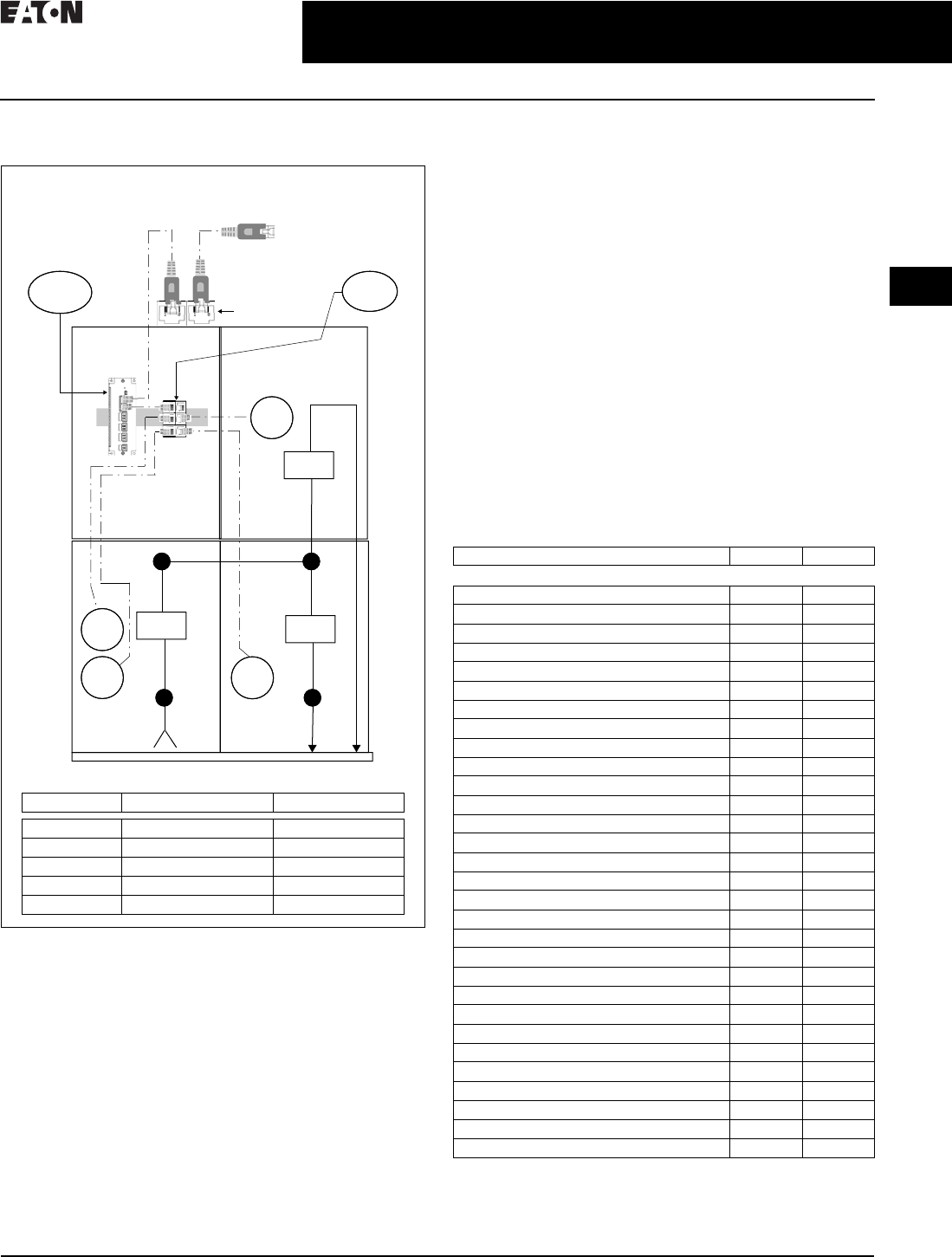
Medium Voltage Switchgear
Figure 2.1-1. Two Section Medium Voltage Lineup
General Description
Device Selection
The devices shown in Figure 2.1-1 have been chosen to
provide the best feature/benefit to the end user. Typically the
specifying consulting engineer or end user will have device
preference; however, for the purpose of illustration, all Eaton
devices have been selected. If there are no significant
differences between the switchgear manufacturer’s devices
and those of a recommended third party, there are distinct
advantages to allow the switchgear manufacturer to provide
them. This allows the switchgear manufacturer to test to
internal standards and minimize variation to aid in providing
a high-quality and cost-effective product to the customer.
Protective Relay Selection
Eaton’s medium voltage switchgear is supplied with both
standard and advanced protective relays and meters. Depend-
ing upon the level of functionality required at each point in the
switchgear, Eaton offers a choice in device selection.
Protection Functions
All of Eaton’s E-Series protective relays are fully equipped
with a standard set of protection functions and additional
optional features.
The EDR-3000 is Eaton’s standard protective relay typically
selected for feeder protection. This relay monitors phase and
ground current. The EDR-5000 is Eaton’s advanced protective
relay typically selected for main breakers. This relay monitors
the line side voltage and bus voltage, as well as bus current.
This provides the needed level of protection for the primary
switchgear bus.
Features
Depending upon the specific requirements for local access
to metering information at the switchgear, using the protec-
tive relay for metering as opposed to adding an additional
set of current transformers and meters, may be acceptable.
Table 2.1-1. Metering Feature Comparison
M1
R1 R2
R2
1200
1200
1200
Main
Feeder 2
Feeder 1
ES
PXG
Network Coupler
to be Provided
by Electrical
Contractor
Connect to Local
Area Network Building
Management System (BMS)
Legend
Designation Product Make/Model Description
M1 Eaton PXM6000 Power Quality Meter
R1 Eaton EDR-5000 Advanced Relay
R2 Eaton EDR-3000 Standard Relay
PXG Eaton PXG900 Ethernet Gateway
ES Eaton ES6P 6 Port Switch
Description EDR-3000 EDR-5000
Metering and Monitoring Features
Current (pos., neg. and zero seq.) ■■
Current unbalance % (I2/I1) ■■
Differential current — —
Voltage (L–L, L–N, pos., neg. and zero seq.) — ■
Voltage unbalance % (V2/V1) — ■
Phase angles ■■
Volt-amps, watts, volt-amps reactive — ■
kWh (forward, reverse and net) — ■
kVArh (lead, lag and net) — ■
Power factor — ■
Frequency — ■
Volts/Hz — —
2nd harmonic current % (H2/fund.) — —
3rd harmonic voltage — —
THD current (% and magnitude) ■■
THD voltage (% and magnitude) — ■
Minimum/maximum recording ■■
Sync values — ■
Temperature with remote URTD module — —
Trip circuit monitoring ■■
Breaker wear and general counters ■■
CT supervision ■■
VT supervision — ■
Waveform recorder (7200 cycles total storage) ■■
Fault recorder (20 events) ■■
Sequence of events recorder (300 events) ■■
Trend recorder ■■
Motor history, start trending, thermal capacity — —
Generator hours of operation — —
Programmable logic equations (up to 80) ■■
2.1-2
For more information, visit: www.eaton.com/consultants CA08104001E
March 2016
Power Management Systems & Products
i
ii
1
2
3
4
5
6
7
8
9
10
11
12
13
14
15
16
17
18
19
20
21
Sheet 02
Power Monitoring and Control
Medium Voltage Switchgear
008
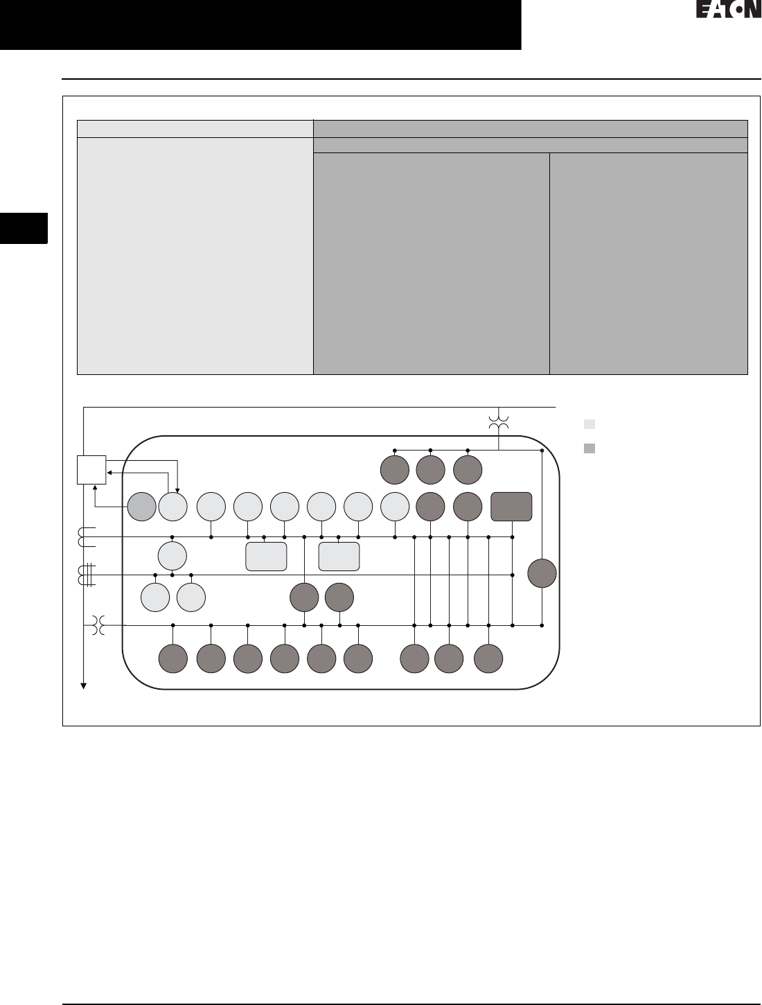
Figure 2.1-2. Protection Feature Comparison
Model Comparison Guide–Protective Functions
Typical One-Line Example—ANSI Protective Elements Guide
EDR-3000 EDR-5000
Protection Functions
46 —Current unbalance elements
50BF —Breaker failure
50P —Phase instantaneous overcurrent
elements
50R —Calculated ground or neutral
instantaneous overcurrent elements
50X —Measured ground or neutral
instantaneous overcurrent elements
51P —Phase overcurrent protection per
time-current curve elements
51R —Calculated ground fault protection
per time-current curve elements
51X —Measured ground or neutral fault
protection per time-current curve
elements
CLPU —Cold load pickup
SOTF —Switch on to fault
CTS —Current transformer supervision
74TCM —Trip coil monitor (option)
ZI —Zone selective interlocking (option)
The EDR-5000 has all of the same protection functions as the EDR-3000 with additional features.
Enhanced protection functions
27A/M —Auxiliary and main three-phase
undervoltage elements
47 —Voltage unbalance elements
55A/D —Apparent and displacement power
factor elements
59A/M —Auxiliary and main three-phase
overvoltage elements
59N —Ground fault overvoltage elements
67P —Directional overcurrent elements
67X —Calculated directional overcurrent
elements
78V —Vector surge element
81U/O/R —Under and over and rate of change
frequency elements
LOP —Loss of potential
25 —Sync check
32 —Forward and reverse watts elements
32V —Forward and reverse VARs elements
51V —Voltage restraint elements
79 —Auto-reclosing
27T —Low voltage ride-through (LVRT)
27Q —Reactive power and undervoltage
LOP
1
59A59N27A
52
3
1
3
67R67P4651R50R
50
BF
74
TCM 51P50P79
CTS
51X50X 55
A/D 67X
81
U/O 81R47 78V 27M 59M 51V 32 32V
SOTF
25
CLPU
Protective Elements Key
= Elements available on
EDR-3000 and EDR-5000
= Elements available
on EDR-5000
See Page 1 for metering features.
152—circuit breaker.
1


2.1-4
For more information, visit: www.eaton.com/consultants CA08104001E
March 2016
Power Management Systems & Products
i
ii
1
2
3
4
5
6
7
8
9
10
11
12
13
14
15
16
17
18
19
20
21
Sheet 02
Power Monitoring and Control
Medium Voltage Motor Control
010
Medium Voltage
Motor Control
TO COME
General Description
COPY TO COME.

CA08104001E For more information, visit: www.eaton.com/consultants
2.1-5
March 2016
Power Management Systems & Products
i
ii
1
2
3
4
5
6
7
8
9
10
11
12
13
14
15
16
17
18
19
20
21
Sheet 02
Power Monitoring and Control
Low Voltage Motor Control
011
Low Voltage Motor Control
TO COME
General Description
COPY TO COME.

2.1-6
For more information, visit: www.eaton.com/consultants CA08104001E
March 2016
Power Management Systems & Products
i
ii
1
2
3
4
5
6
7
8
9
10
11
12
13
14
15
16
17
18
19
20
21
Sheet 02
Power Monitoring and Control
Low Voltage Commercial Power Distribution
012
Low Voltage Commercial
Power Distribution
TO COME
General Description
COPY TO COME.

CA08104001E For more information, visit: www.eaton.com/consultants
2.1-7
March 2016
Power Management Systems & Products
i
ii
1
2
3
4
5
6
7
8
9
10
11
12
13
14
15
16
17
18
19
20
21
Sheet 02
Power Monitoring and Control
Low Voltage Commercial Power Distribution
013
Low Voltage Switchboard
TO COME
General Description
COPY TO COME.

2.1-8
For more information, visit: www.eaton.com/consultants CA08104001E
March 2016
Power Management Systems & Products
i
ii
1
2
3
4
5
6
7
8
9
10
11
12
13
14
15
16
17
18
19
20
21
Sheet 02
Power Monitoring and Control
Low Voltage Commercial Power Distribution
014
Low Voltage Panelboard
TO COME
General Description
COPY TO COME.
CA08104001E For more information, visit: www.eaton.com/consultants
2.2-1
March 2016
Power Management Systems & Products
i
ii
1
2
3
4
5
6
7
8
9
10
11
12
13
14
15
16
17
18
19
20
21
Sheet 02
Connectivity and Software Products
015
Power Xpert Ethernet
Switches
Convenient Network Expansion
General Description
Eaton’s Power Xpert Ethernet switches
are ideal for extending Ethernet
networks via CAT5 wiring or fiber
in harsh, industrial environments.
Built with high-grade components
and constructed using special thermal
techniques, PXE switches can with-
stand the unpredictable conditions
of such environments.
Features
■Simultaneous, full-duplex, high-
speed communication on all ports—
no network performance bottlenecks
■Hardened for factory floor—ideal
for both industrial or data center
applications
■Unmanaged, plug-and-play
implementation—no software or
additional hardware required for
configuration
■Seamlessly integrates into Eaton’s
Power Xpert Architecture—quality
and reliability of Eaton guaranteed
■Mounting options include stand-
alone panel-mounting, DIN rail
mounting, or 19-inch standard
rack mounting
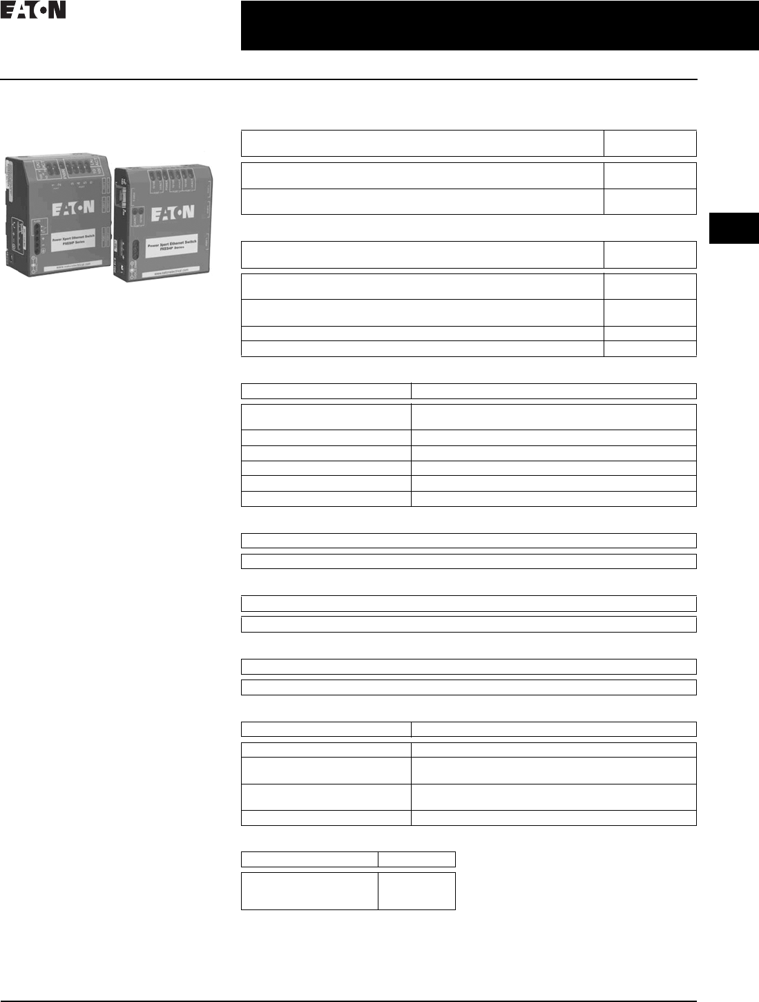
PXE 6-Port Switch—10/100 Mb with
Optional 100 Mb Fiber
This compact switch provides
six Ethernet ports, with flexible
configurations. The base models
have one of three options:
■Two 100 Mb fiber and four 10/100
copper ports
■One fiber and five copper ports
■Six copper ports
PXE 4-Port Switch—10/100 Mb
For smaller applications requiring
fewer connection points and no fiber,
the 4-port Power Xpert Ethernet switch
is a versatile option. It provides edge
access Ethernet ports in a convenient
and compact package.
Technical Data and Specifications
Table 2.2-1. Power Xpert Ethernet Switches
Table 2.2-2. Accessories
Table 2.2-3. Operating Environment
Table 2.2-4. Network Standards
Table 2.2-5. Agency Approvals and Standards Compliance
Table 2.2-6. Power Consumption
Table 2.2-7. Packaging
Table 2.2-8. Mounting Note: These specifications are subject to
change without notice and represent the
maximum capabilities of the product with
all options installed. This is not a complete
feature list. Features and functionality
may vary depending on selected options
and product model. Please refer to the
technical data sheet and user manual
for detailed specifications. Please see
www.eaton.com/powerxpert for latest
information.
Description Catalog
Number
4 port Ethernet switch—copper only
6 port Ethernet switch—copper only
PXES4P24V
PXES6P24V
6 port Ethernet switch—5 copper/1 fiber (ST connector)
6 port Ethernet switch—4 copper/2 fiber (ST connector)
PXES6P24V1ST
PXES6P24V2ST
Description Catalog
Number
Power supply (preferred)—100–240 Vac input
DIN rail mount with screw—24 Vdc output terminals
ELC-PS02
Power supply (alternate)—120 Vac input
Wall plug-in type with 6 ft. cord—12 Vdc output
PXESPS12V
DIN rail mounting bracket PXESDINRL
19-inch rack mount tray PXESTRAY
Description Specifications
Ambient temperature ratings –25 ° to 60 °C long-term per independent agency tests (UL),
or –40 ° to 85 °C short-term per IEC type tests
Storage temperature –40 ° to 185 °F (–40 °C to 85 °C)
Cold start to –20 °C
Ambient relative humidity 5%–95% (noncondensing)
Altitude –200 to 50,000 ft (–60 to 15,000 m)
MTBF > 15 years
Description
Ethernet IEEE 802.3, IEEE 802.3u; IEEE 802.1p, 100Base-TX, 10Base-T, 100Base-FX
Description
UL listed (UL60950), cUL, CE, emissions meet FCC Part 15, Class A
Description
7.0 watts typical—9 watts maximum
Description Specifications
Enclosure Robust sheet metal (steel)
Dimensions of PXES4P series
Weight of PXES4P series
3.50 in H x 3.00 in W x 1.00 in D (8.9 cm x 7.6 cm x 2.5 cm)
8.6 oz. (243g)
Dimensions of PXES6P series
Weight of PXES6P series
3.60 in H x 3.00 in W x 1.70 in D (9.2 cm x 7.6 cm x 4.3 cm)
13 oz. (370g)
Cooling method Case used as a heat sink
Description Specifications
Metal panel mounting clips
DIN rail mounting
19-inch rack mount
Included
Optional
Optional

2.2-2
For more information, visit: www.eaton.com/consultants CA08104001E
March 2016
Power Management Systems & Products
i
ii
1
2
3
4
5
6
7
8
9
10
11
12
13
14
15
16
17
18
19
20
21
Sheet 02
Connectivity and Software Products
Power Xpert Gateway 900
016
Power Xpert Gateway 900
Delivers real-time, Web-enabled
monitoring of electrical distribution
and control equipment
General Description
The Power Xpert Gateway 900
(PXG 900) has been designed to be
installed in electrical assemblies or
systems—low and medium voltage
switchgear, switchboards, panelboards,
transfer switches, and motor control
centers to acquire and consolidate data
available from components such as trip
units, meters, relays, drives, and I/O.
Product Overview
■Open communication architecture
❑Connects to both Eaton and
third-party electrical equipment;
communicates to INCOME,
Modbus® TCP, and Modbus
RTU devices
❑Modbus TCP and BACnet/IP
support facilitates integration with
third-party monitoring solutions
❑Ethernet/Web-based support
uses your existing network infra-
structure, reducing costs
■Flexible and expandable solutions
❑Stand-alone or small systems
benefit from comprehensive, on-
board Web pages; no additional
programming or software is
necessary for virtually out-of-the-
box, plug-and-play functionality
❑Larger systems, such as campus
installations or power systems
with remote locations can view
multiple PXGs via Power Xpert
Insight® or a third-party
monitoring system
❑Existing equipment can be
connected to the PXG to reap
the benefits of Power Xpert
Architecture at minimal cost,
without the need to upgrade
■Information at a glance
❑Private Network mode on the
Net 2 port will allow for the
ability to establish a private
subnet to attach Modbus TCP
communication devices
❑Using a standard Web browser,
view the PXG’s Web interfaces
that include a Network tab,
Alarms tab, individual device
detail pop-outs, and One Line
graphics tab
❑Comprehensive, well-organized
device Web pages present
measured parameters such as
current, voltage, power, energy,
frequency, power factor, and
voltage THD, just to name a few
❑Combine with Power Xpert
Insight for viewing multiple
gateways and other power
system equipment for more
extensive energy monitoring
and capacity analysis
Monitoring Power and Energy
in a Networked World
Through standard on-board Web
pages, Power Xpert Insight, or third-
party software, Eaton’s Power Xpert
Gateway (PXG) 900 allows you to
closely monitor the performance
of your power and energy efficiency
with easily accessed, real-time,
Web-enabled data. Eaton’s PXG 900
provides a central point to connect
devices to an Ethernet network. The
gateway may be used as a standalone
device to view one system or location,
or it can be easily integrated into a
large, multi-location system.
The PXG is our configurable data
acquisition solution for facility equip-
ment like switchgear, switchboards,
motor control centers, etc. Power and
energy data from the downstream
devices are time stamped and stored
in non-volatile memory. This interval
data can be stored or updated to a
destination of the user’s choice
through CSV. Data can also be
accessed through any Web browser
directly on the PXG. Users can move
data into Power Xpert Insight v. 3.2
or higher, BMS, BAS, building dash-
boards, custom software applications,
or virtually any Web interface.
Features and Benefits
Rugged, Industrial Design
■Designed specifically for industrial
environments, the PXG has a
compact design that only requires
convection cooling
■Stringent EMI design requirements
ensure that the PXG will function in
the most difficult EMI situations to
deliver high reliability
■Mounting options are provided for
panel mounting or DIN rail, allowing
for installation flexibility
Smart Configuration and User Interface
■As an out-of-the-box, plug-and-play
device, there is no additional
software required to configure
and view downstream devices
■All configuration menus are
straightforward and easy to follow
■Upon configuring the PXG and
associated devices, the data will
automatically appear in the Web UI
when you point your browser to the
IP address of the PXG
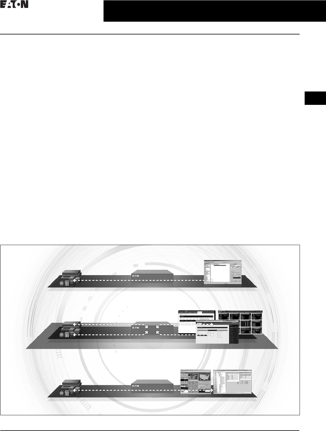
Three operational modes
The Power Xpert Gateway can operate
in three modes, simultaneously if
required, providing flexibility for
varying protocols, devices, and
systems. For further details of each
operational mode, see user manual.
For a graphical representation of each
mode, see Figure 2.2-1.
1. INCOM Pass-Through mode
allows data from INCOM serial
devices to flow directly through
the gateway to be viewed in
PowerNet™ software for logging
and consolidation with other
connected devices.
– Expansion of an existing
PowerNet system with addi-
tional equipment can be easily
achieved by adding a PXG 900
to the system to bring the
INCOM communicating
devices online in INCOM
pass-through mode.
Note: INCOM serial communication can
either be cached or EMINT/pass-through,
not both at the same time.
CA08104001E For more information, visit: www.eaton.com/consultants
2.2-3
March 2016
Power Management Systems & Products
i
ii
1
2
3
4
5
6
7
8
9
10
11
12
13
14
15
16
17
18
19
20
21
Sheet 02
Connectivity and Software Products
Power Xpert Gateway 900
017
2. The Modbus RTU-Modbus TCP
Pass-Through mode allows
information from Modbus serial
devices to pass directly through
the gateway to be viewed by a (or
multiple) Modbus TCP monitoring
software, i.e., an existing Building
Management System.
– The PXG allows users to do
simple protocol translation,
with minimal configuration in
the PXG for those applications
where they need Modbus TCP
to bring devices into their
existing system.
– The flexibility of the PXG for
simple Modbus protocol
translation in conjunction
with other mode’s makes
the PXG more than a simple
Modbus protocol translator.
3. Cache mode allows data from
INCOM serial devices and Modbus
RTU and TCP devices into the
gateway, creating real-time
viewing status through a Web
browser as well as logging for
historical reference and trending.
Cached data from the connected
devices can be shared with other
client software similar to pass
through.
– The PXG in Cache mode serves
as an acquisition tool and
provides the ability for users to
view their devices on the ports
connected to the PXG through
a Web browser. This allows
users to bring power infrastruc-
ture equipment online to
monitor operation and record
power and energy usage.
Secure Cyber Communication
Controlling access to the PXG 900
is a vital component in any effort to
secure it. Many regulatory agencies
and standards organizations now
recommend/require Role-Based
Access Control (RBAC) as part of any
access control effort. To support this,
the PXG 900 has a robust set of tools
you can use to create the set of users
and role-based permissions you need
to comply with security policies in
effect at your site.
■Password protection
Role-Based Access Control (RBAC)
as part of any access control effort.
To support this, the PXG 900 has a
robust set of tools you can use to
create the set of users and role-
based permissions you need to
comply with security policies in
effect at your site
■Secure Web browsing
SSL Encryption option ensures
that information and passwords
exchanged with the PXG’s Web
server cannot be intercepted on
the LAN
■Access control / trusted host list
Provides an additional method of
security by limiting access to the
communication ports by authorized
trusted hosts’ IP addresses
Figure 2.2-1. Three Operational Modes
INCOM Serial Devices INCOM Mode
PowerNet
Pass-through EMINT
Web Browser
INCOM Serial Devices
Modbus Serial Devices
Modbus TCP Devices Cached Data Mode
Modbus Masters
Modbus Serial Devices
Modbus TCP Devices Modbus Mode
PowerPort-E
Cashed Data
Pass-Through Modbus RTU-TCP

2.2-4
For more information, visit: www.eaton.com/consultants CA08104001E
March 2016
Power Management Systems & Products
i
ii
1
2
3
4
5
6
7
8
9
10
11
12
13
14
15
16
17
18
19
20
21
Sheet 02
Connectivity and Software Products
Power Xpert Gateway 900
018
Time Synchronization
The PXG supports synchronization of
clocks on INCOM devices that support
the set time and date command.
Additionally, the PXG can be
combined with a network time server
for accurate time stamping via NTP.
Real-time trending and viewing
The PXG 900 allows the user to enable
pre-selected parameters to be trended
for each supported device. This feature
is user-selectable on the device
configuration page. A trend symbol
is displayed next to the trended
parameter on the device page.
Selecting the trend symbol will
generate a real-time graph via the
Web UI for that parameter and can be
viewed for the past 24 hours, 7 days,
30 days or all past history.
Trend and alarm logging and analysis
The PXG 900 stores both historical
data and alarms that can be down-
loaded into a comma separated value
(CSV) file format. Using Excel® will
allow you to perform analysis to
discover potential system issues or
proactively perform maintenance.
Waveforms capture and downloads
The PXG 900 supports waveform
acquisition for INCOM supported
devices capable of generating wave-
forms. This feature is user-selectable
on the device configuration page.
The waveform files are converted and
stored as a COMTRADE file format
in the PXG 900. The files can then
be downloaded and viewed using a
standard COMTRADE waveform
viewer of your choice.
Table 2.2-1. Summary of PXG 900 features
Note: The Eaton Power Xpert Gateway 900 includes the Power Xpert Gateway Module,
USB A to Mini-B USB cable, and DIN rail adapter with mounting screws.
Features PXG 900
Protocols supported on downstream devices: INCOM, Modbus TCP, and Modbus RTU Yes
Number of downstream communication ports 3
Number of downstream protocols supported simultaneously 2
USB port for configuration Yes
Two RJ-45 Ethernet ports—10/100/1000Base-T Yes
Modbus TCP/IP protocol supported Yes
BACnet/IP protocol supported Yes
INCOM date and time settings supported Yes
Network tab, alarm tab, one line tab, device and alarm detail sidebar, and pop-out Yes
Device waveform access and storage—COMTRADE file format Yes
Set user-defined alarms Yes
Real-time trending Yes
Trend graphs displayed in Web browser Yes
Alarm notification via the Web interface Yes
Alarm logs—csv file format, downloadable to Excel Yes
Trend logs—csv file format, downloadable to Excel Yes
Email notification on alarms and daily updates if requested Yes
Secure Ethernet communication—SSL encryption Yes
Secure communication ports via access control/trusted host list Yes
IPv4 support Yes
Save and restore configuration settings Yes
Audit logs Yes
CA08104001E For more information, visit: www.eaton.com/consultants
2.2-5
March 2016
Power Management Systems & Products
i
ii
1
2
3
4
5
6
7
8
9
10
11
12
13
14
15
16
17
18
19
20
21
Sheet 02
Connectivity and Software Products
Power Xpert Gateway 900
019
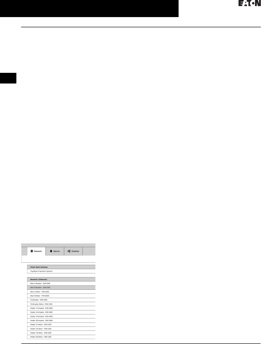
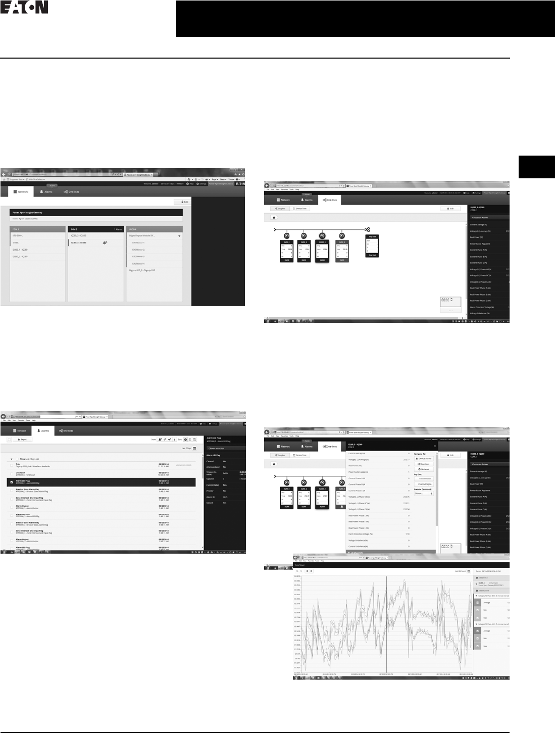
Power Xpert Insight Gateway user interface
Network Tab
Default log-in screen that provides general configuration of
the gateway, serial communication ports, and devices. The
Network tab provides a simple view of the serial devices
and their current status of operation by color changes and
symbols. Additional detail and functionality is accessible
from the Network tab sidebar for all communicating devices.
Alarms Tab
Provides a single screen that provides details on all alarms
associated with the device communicating in cache
mode through the gateway. Alarms can be reviewed and
acknowledged, as well as sorted and filtered based on
status. Additional information regarding the alarm can be
found by selecting the alarm and specifics on the alarm will
be displayed in the sidebar.
One-Lines Tab
Allows users the ability to create a graphical representation
of a one-line diagram based on the user’s desired represen-
tation. Through the device tree, a user can select devices
and group them in locations and generate a multiple level
one-line representing the devices connected to the gateway.
The one-line graphic will provide device status graphically,
and additional detail can be found on the device and its
supported channels in the sidebar of a selected device on
the one-line or device tree.
Device Details and Trend Viewer
Selected devices on the Network tab and One-Lines tab
provide a device sidebar. From that sidebar, a user can
get additional detail about the device and its monitored
channels, by selecting the choose an action menu on the
sidebar. This will allow users to see the device details
pop-out as well as gain access to historical trend data and
other available information regarding the selected device.
2.2-6
For more information, visit: www.eaton.com/consultants CA08104001E
March 2016
Power Management Systems & Products
i
ii
1
2
3
4
5
6
7
8
9
10
11
12
13
14
15
16
17
18
19
20
21
Sheet 02
Connectivity and Software Products
Power Xpert Gateway 900
020
User-Defined Alarms
The PXG 900 supports the setting of
user-defined alarms on an individual
device and channel basis. This feature
is set for enabled channels via the
Setting button in the header under the
alarms setting tab. An example of a
user-defined alarm would be a low
and high limit on the phase A current
channel for a device. The alarm limit
values and the alarm names can be
chosen by the user.
Email Notification
A user has the ability to customize and
direct email to notifications to up to
10 users in their organization. Select
from alarm notifications, trend log,
alarm log, and daily emails. This
function provides yet one more way
to effectively and proactively manage
your monitored system.
Save and Restore Configuration Settings
The PXG provides the ability to
save the PXG device and network
configuration settings to an XML
file format. It can be used to restore
settings to any PXG to facilitate
configuration of similar systems.
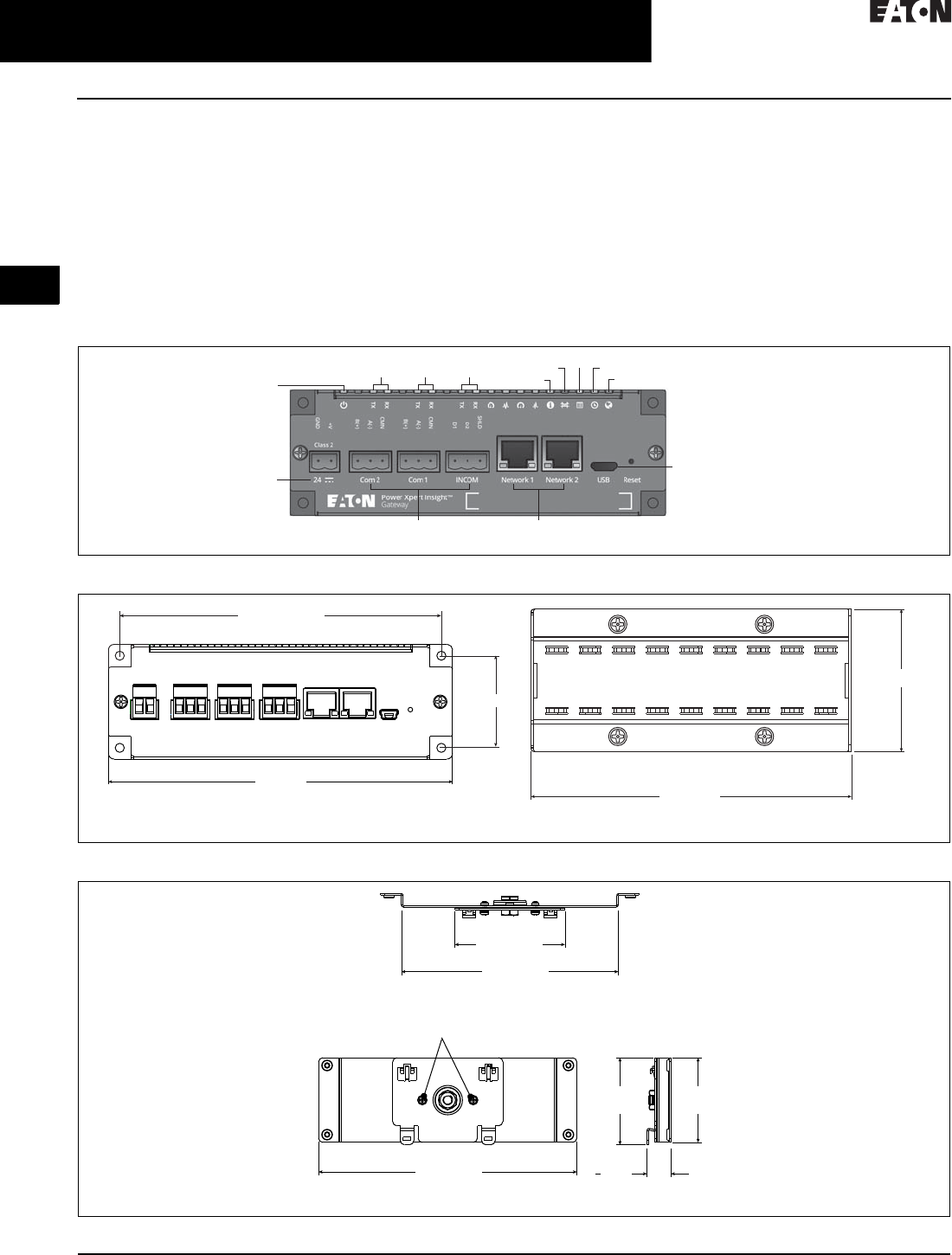
Figure 2.2-2. Power Xpert Gateway 900
Figure 2.2-3. Power Xpert Gateway 900 with Standard Panel Mounting
Figure 2.2-4. Power Xpert Gateway 900 with DIN Rail Mounting (Brackets Included)
Power
Com2 Com1 INCOM Status
Bridge DHCP NTP
Web
24 Vcd
Input Power
USB Connection for Local
Configuration Capability
RJ-45 Connections with Link
Speed and Activity Indicators
RJ-485 Connections
6 (152.4)
Front View 4.5 (114.3)
Side View
2 (50.8)
5.625 (142.875)
1.625 (41.275)
5.04 (128)
2.56 (65)
Top View
6 (152.4)
Front View
Remove and then reattach these
screws to rotate for vertical mounting
1.97
(50)
2.023
(51.402)
0.556
(14.12)
Side View
CA08104001E For more information, visit: www.eaton.com/consultants
2.2-7
March 2016
Power Management Systems & Products
i
ii
1
2
3
4
5
6
7
8
9
10
11
12
13
14
15
16
17
18
19
20
21
Sheet 02
Connectivity and Software Products
Power Xpert Gateway 900
021
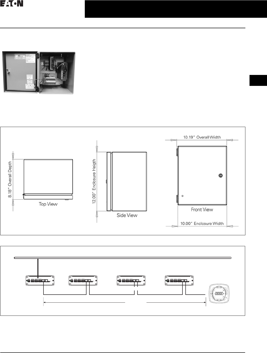
Power Xpert Gateway
Enclosed Version
Enclosed Version
■Cost-effective solution to add
communications to new or existing
equipment that has no physical
space to install the PXG in the
equipment structure
■NEMA 12 enclosure rating
■Prewired with a PSG60N24RP power
supply and terminal blocks for ease
of wiring of incoming power and
connected devices
PXG Daisy Chain Application
in Bridge Mode
The PXG allows for units to be con-
nected together through two RJ-45
10/100/1000 connectors on the front of
the PXG series of products. Default is
bridged mode for the daisy chain
application. This arrangement is a
pass-through of Ethernet communica-
tions, allowing a single network
drop to connect up to five Ethernet
communicating devices. The maxi-
mum length of a copper cable run
should not exceed 295 ft (90 m) total.
Note: In this configuration, if any of the
PXG units go offline or lose power, the
communication to the downstream Ethernet
devices will lose connection to the LAN.
Figure 2.2-5. Power Xpert Gateway Enclosure Dimensions
Figure 2.2-6. PXG Daisy Chain Application
Ethernet LAN
LAN Connection
295 ft (90 m)
Cat-5 Patch Cables
PXM2000

2.2-8
For more information, visit: www.eaton.com/consultants CA08104001E
March 2016
Power Management Systems & Products
i
ii
1
2
3
4
5
6
7
8
9
10
11
12
13
14
15
16
17
18
19
20
21
Sheet 02
Connectivity and Software Products
Power Xpert Gateway 900
022
Technical Specifications
Table 2.2-2. PXG Part Numbers
Memory
■Flash: 2 GB
■RAM: 1 GB
Communication Ports
■Network ports: Two 10/100/1000Base-T RJ-45 connectors
■Serial ports
❑Two RS-485 ports for connection to Modbus RTU
devices
❑One dedicated RS-485 port for INCOM devices
■Configuration port: One USB port
Network Protocols Supported
■Modbus TCP/IP: Supports data access from
Modbus TCP clients
■Web server: Supports data access from Web browsers
(HTTP and HTTPS)
■DHCP: Supports automatic IP address assignments,
if enabled
■NTP: Supports time synchronization via a network time
server for PXG synchronization
■SMTP: Supports mail server for email notification
■BACnet/IP: Supports data access from BACnet clients
Serial Protocols Supported
■INCOM
■Modbus RTU
Web Browsers Recommended
■Internet Explorer versions 10 and 11
■Google Chrome
Power Input
■Input voltage, nominal: 24 Vdc; 0.3 A minimum
■Input voltage range: ±10% nominal
Power Consumption
■8 W maximum
Operating Temperature
■+32 to +140 °F (0 to +60 °C)
Ambient Storage Temperature
■–40 to +185 °F (–40 to +85 °C)
Relative Humidity
■5 to 95% noncondensing at 122 °F (50 °C)
Size (H x D x L) in Inches
■2.00 x 4.50 x 6.00
Weight
■1.7 pounds
Supported Devices and Performance
PXG performance will vary depending upon the number and
type of connected devices. This is driven by the following:
■Each supported device has a distinct number of channels
to report back to the PXG, ranging from as few as 4 to
over 900
■The channels are prioritized
■Device protocol, Modbus or INCOM
■Baud rate setting
For this reason, a PXG modeling tool has been developed
to assist in understanding the expected performance for a
given application since all systems are unique. This tool
can be found at www.eaton.com/pxg. For a high level perfor-
mance comparison, see the table below for three examples.
Regulatory and Standards Compliance
■UL 508, Standard for Programmable Controller Equipment
■FCC, Class A, Part 15, Subpart B, Sections 15.107b
and 15.109b
■EN55022:2010/A1:2011 Class A and EN55024:2010
Information Technology Equipment
■EN 61326-1:2006 and EN 61326-2-2:2006 Electromagnetic
Compatibility (EMC) in Industrial Environments
Note: Features and specifications listed in this document are subject
to change without notice and represent the maximum capabilities
of the product with all options installed. Although every attempt
has been made to ensure the accuracy of information contained
within, Eaton makes no representation about the completeness,
correctness, or accuracy and assumes no responsibility for any
errors or omissions. Features and functionality may vary depending
on selected options.
Description Eaton
Style Number
Eaton
Catalog Number
Power Xpert Gateway 900 66D2325G01 PXG900
Power supply—24 Vdc PSG60N24RP-A1 PSG60N24RP
Enclosed Power Xpert Gateway PXG900-2A
How long does it take For this combination of devices
(all times in seconds)
64 INCOM /
32 Modbus
15 INCOM /
15 Modbus
5
INCOM
Between value change in the UI
(INCOM 9600)—Priority 1
21.9 3.7 1.4
Between value change in the UI
(Modbus 57600)—Priority 1
3.5 1.6 —
Between value change in the UI
(INCOM 9600)—Priority 2
44.3 7.4 2.6
Between value change in the UI
(Modbus 57600)—Priority 2
7. 0 3 . 1 —
Modbus server pass-through
response time (57600)
(local connection)
0.061 0.059 —
For the UI to show an alarm
(INCOM device)
17.0 3.0 3.0
To boot up (all devices
communicating)
399.0 85.0 51.0
CA08104001E For more information, visit: www.eaton.com/consultants
2.2-9
March 2016
Power Management Systems & Products
i
ii
1
2
3
4
5
6
7
8
9
10
11
12
13
14
15
16
17
18
19
20
21
Sheet 02
Connectivity and Software Products
Power Xpert Dashboard
023
Power Xpert Dashboard
General Description
The Power Xpert® Dashboard allows users to monitor
and control Eaton electronic devices installed in an Eaton
Magnum DS® low voltage or VacClad medium voltage
switchgear assemblies and transformers as part of a unit
substation. These devices include Eaton E-Series protective
relays, Digitrip™ 1150 and 520MC trip units, Power Xpert
meters, and Eaton diagnostic devices. The Power Xpert
Dashboard can be mounted on the switchgear, on the wall in
an enclosure, or in a kiosk. The wallmount enclosure or kiosk
can be placed near the switchgear but outside the arc flash
boundary to provide safe access to control and monitoring
of the equipment.
It provides features such as:
■Open/close circuit breakers through Control Mode
■Enable Arcflash Reduction Maintenance Mode and
see status
■Monitor or initiate a transfer scheme in a Main/Tie/Main
switchgear and adjust timer settings and sequence details
■Ability to configure/monitor alarms for various devices
■Rich interface to monitor parameters of all devices and
study the trends of those parameters
Elevation View
Timeline View
Oneline View
Docs
2.2-10
For more information, visit: www.eaton.com/consultants CA08104001E
March 2016
Power Management Systems & Products
i
ii
1
2
3
4
5
6
7
8
9
10
11
12
13
14
15
16
17
18
19
20
21
Sheet 02
Connectivity and Software Products
Power Xpert Dashboard
024
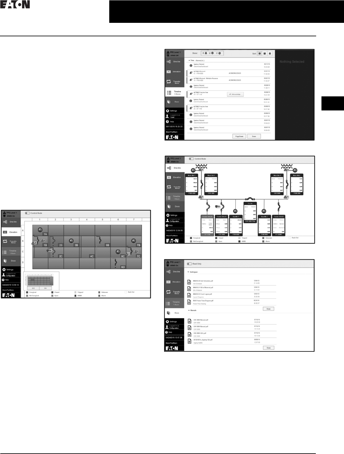
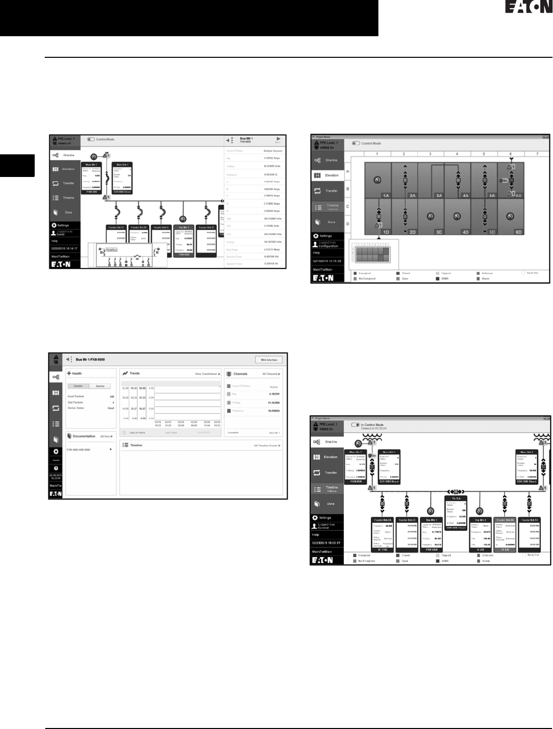
One-Line View
■The one-line view shows the lineup of all the configured
devices with their top 5 parameters in the widget. It
graphically represents the power flow between the
configured devices
■Clicking on a widget provides the top 16 parameters
of the device
■Clicking on the More button in the top parameters
sidebar opens the Device Details page
■The Device Details page allows the user to customize
top parameters, alarms, trends, etc.
■The navigator at the bottom can be used to move
between various sections of the lineup
■The timeline is highlighted if any alarm is active
Elevation View
■Elevation view shows the front view of the switchgear
lineup with the status of breakers and buses
■Any alarm or fault causes the corresponding compartment
to be highlighted
■The navigator shows the visible portion of the lineup.
Clicking on a widget provides the top 16 parameters
of the device
Control Feature
■Control Mode allows an authorized user to open/close
breakers remotely. Control Mode can be entered from
the one-line or elevation view
■Trip units and protective relays may be placed in the
Arcflash Reduction Maintenance Mode and this is
indicated by blue dashed bus lines
CA08104001E For more information, visit: www.eaton.com/consultants
2.2-11
March 2016
Power Management Systems & Products
i
ii
1
2
3
4
5
6
7
8
9
10
11
12
13
14
15
16
17
18
19
20
21
Sheet 02
Connectivity and Software Products
Power Xpert Dashboard
025
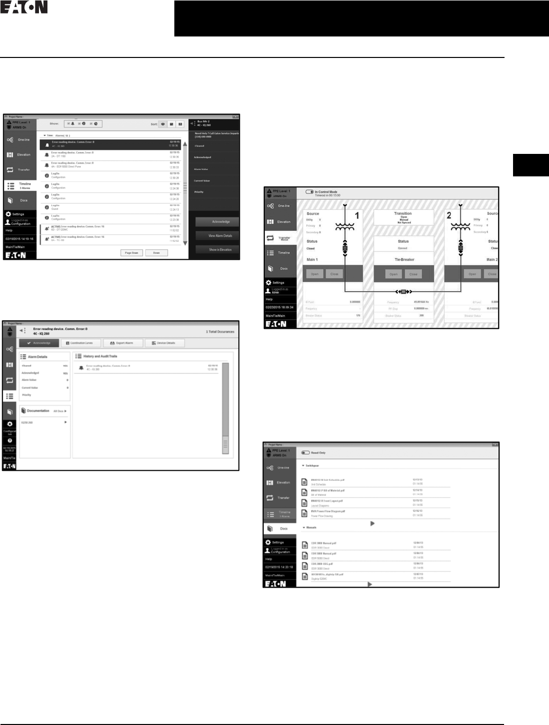
Timeline
■Clicking on an alarm opens the sidebar as follows.
The alarm can be acknowledged by clicking the tab
■Clicking on View Alarm Details opens the Alarm Details
page. This page lists the alarm information such as time
of occurrence, value at occurrence, and all the instances
of the same alarm
Transfer
■The Power Xpert Dashboard allows the user to monitor
the transfer state and see a visual indication of the
transfer process
■Various standard transfer schemes are supported
using a switchgear installed programmable controller
■The user can set the transfer to be automatic or manual.
The type of transition can be configured as Open/Closed
■Timing for various parameters can also be adjusted
through the dashboard interface
Docs
■Docs from the menu lists the support documents provided
with the switchgear. One can navigate between various
documents, including mechanical drawings, electrical
schematics, component instruction books, and spare
parts information using the right arrow at the bottom
■On entering the Edit Mode, more documents can be added
under switchgear or manual
CA08104001E For more information, visit: www.eaton.com/consultants
2.2-12
March 2016
Power Management Systems & Products
i
ii
1
2
3
4
5
6
7
8
9
10
11
12
13
14
15
16
17
18
19
20
21
Sheet 02
Connectivity and Software Products
Power Xpert Dashboard
026
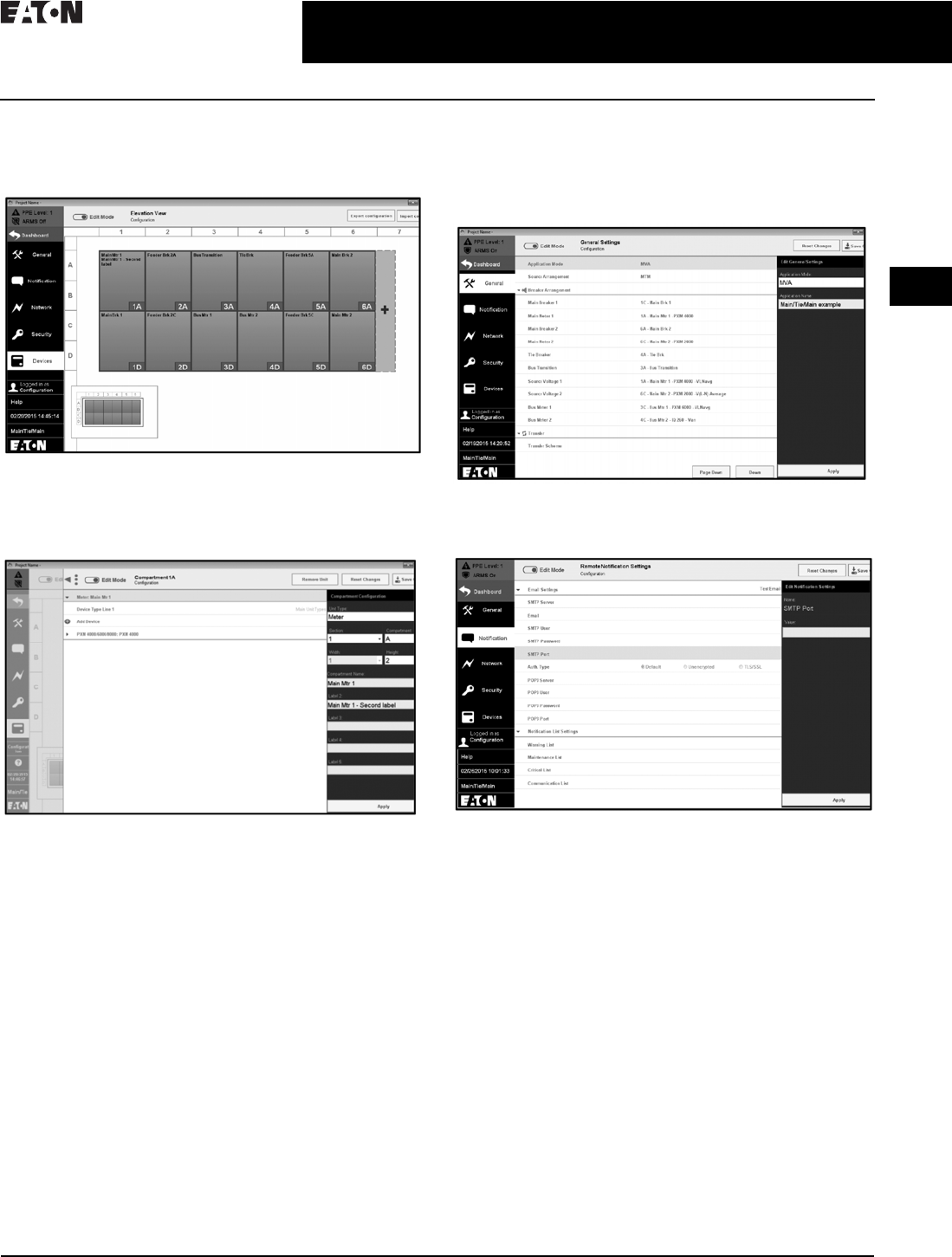
Device Configuration Using Settings Tab
■Add compartments and devices to switchgear
using Settings tab
■In Edit Mode, click on a compartment (under Devices)
to add a unit
■Under Add Devices, add the device that is to be monitored
with its IP address
■Import a configuration that is already provided or save
your custom configuration
■Under Settings>General, select the Application Mode
(MVA/LVA)
■Select the source arrangement and breaker arrangement
■Provision for transfer schemes settings
■Eaton Logic Controller settings provided for
source transfer

CA08104001E For more information, visit: www.eaton.com/consultants
2.2-13
March 2016
Power Management Systems & Products
i
ii
1
2
3
4
5
6
7
8
9
10
11
12
13
14
15
16
17
18
19
20
21
Sheet 02
Connectivity and Software Products
Power Xpert Dashboard
027
■The Notification tab allows the user to set up a mailing
functionality. Any alarms, warnings, or alerts that are
generated will be mailed to the configured mail ID
■Monitor the configured devices on the network
(red: healthy, green: failed)
■The number of passed and failed packets is recorded
■Error message displayed for devices with failed
communication
■Export the network information for later reference
■The Security tab allows users to have a secured login
■A user can set a password for their account
■Complex password and password expiry feature
■A user with admin rights can add/remove users and
change the passwords of all users
System Requirements
Compatible Devices
Eaton low and medium voltage switchgear with:
■Eaton Power Xpert meters
■Eaton Magnum DS circuit breakers with Digitrip 520MC
or Digitrip 1150 trip units (Digitrip 1150 trip units required
for remote breaker and Arcflash Reduction Maintenance
Mode control)
■Eaton E-Series protective relays
■Eaton TC-50/TC-100 transformer temperature controllers
■Eaton InsulGard™ medium voltage insulation monitor
■Eaton Logic Controller (ELC)
Software Specifications
Server side:
■Visual Designer software version 7.1, Service Pack 3,
Patch 3
■SQL Server 2008
■Microsoft® Access Database Engine 2010
Client side:
■Microsoft Internet Explorer® (IE) 9, 10, or 11
Hardware Specifications
■HMI module (XP503 WXGA, 1366 x 768 pixel resolution)
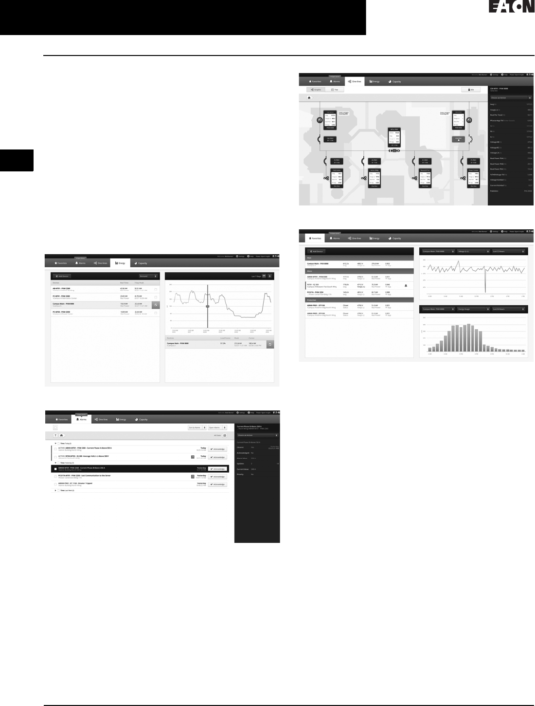
2.2-14
For more information, visit: www.eaton.com/consultants CA08104001E
March 2016
Power Management Systems & Products
i
ii
1
2
3
4
5
6
7
8
9
10
11
12
13
14
15
16
17
18
19
20
21
Sheet 02
Connectivity and Software Products
Power Xpert Insight
028
Power Xpert Insight
General Description
Eaton’s Power Xpert Insight® is a power and energy
monitoring system that is designed to be easy to install,
easy to update and easy to use. It provides you with the
energy and power information you need to:
■Keep the lights on with real-time, actionable alarms
across desktop and mobile
■Save money and energy with easy to use and share
energy reports
■Stay up to speed on your most critical devices with
adjustable dashboards
■Drill into problems quickly with powerful graphics and
detailed data
■Understand current issues and plan for future investments
using trends and visualizations
Energy
Alarms
One-Lines
Favorites
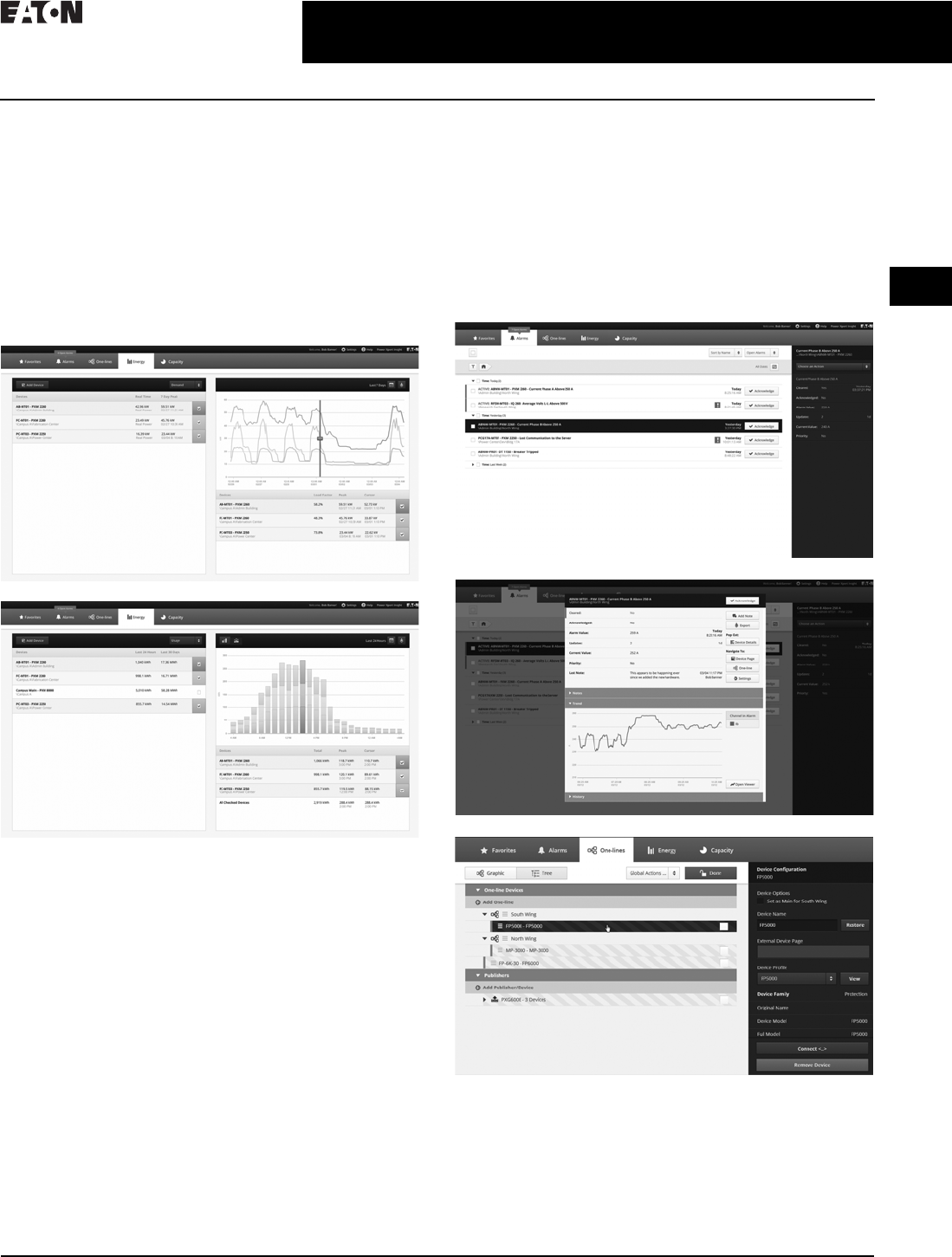
CA08104001E For more information, visit: www.eaton.com/consultants
2.2-15
March 2016
Power Management Systems & Products
i
ii
1
2
3
4
5
6
7
8
9
10
11
12
13
14
15
16
17
18
19
20
21
Sheet 02
Connectivity and Software Products
Power Xpert Insight
029
Energy
■View energy usage and demand
■Select the desired devices and time range, 24 hours to a
custom range
■Choose the type of graph that best suits; line or stacked
bar chart
■Move the cursor over the graph to view detailed data
■Export data to a CSV-format file
■Expand to the Trend Viewer for additional information
■Energy usage is automatically added up for the devices
shown in the table
Alarms
■View color-coded alarms on one page (Black = Normal,
Red = Alarm, Orange = Loss of Communication)
■Sort alarms by Time, Device or Priority for a specified time
range, view by Alarm Status
■Acknowledge Alarms by individual device or group
together
■Open the Alarm Pop Out to view additional data and
add notes
■Export alarm history to a CSV-format file
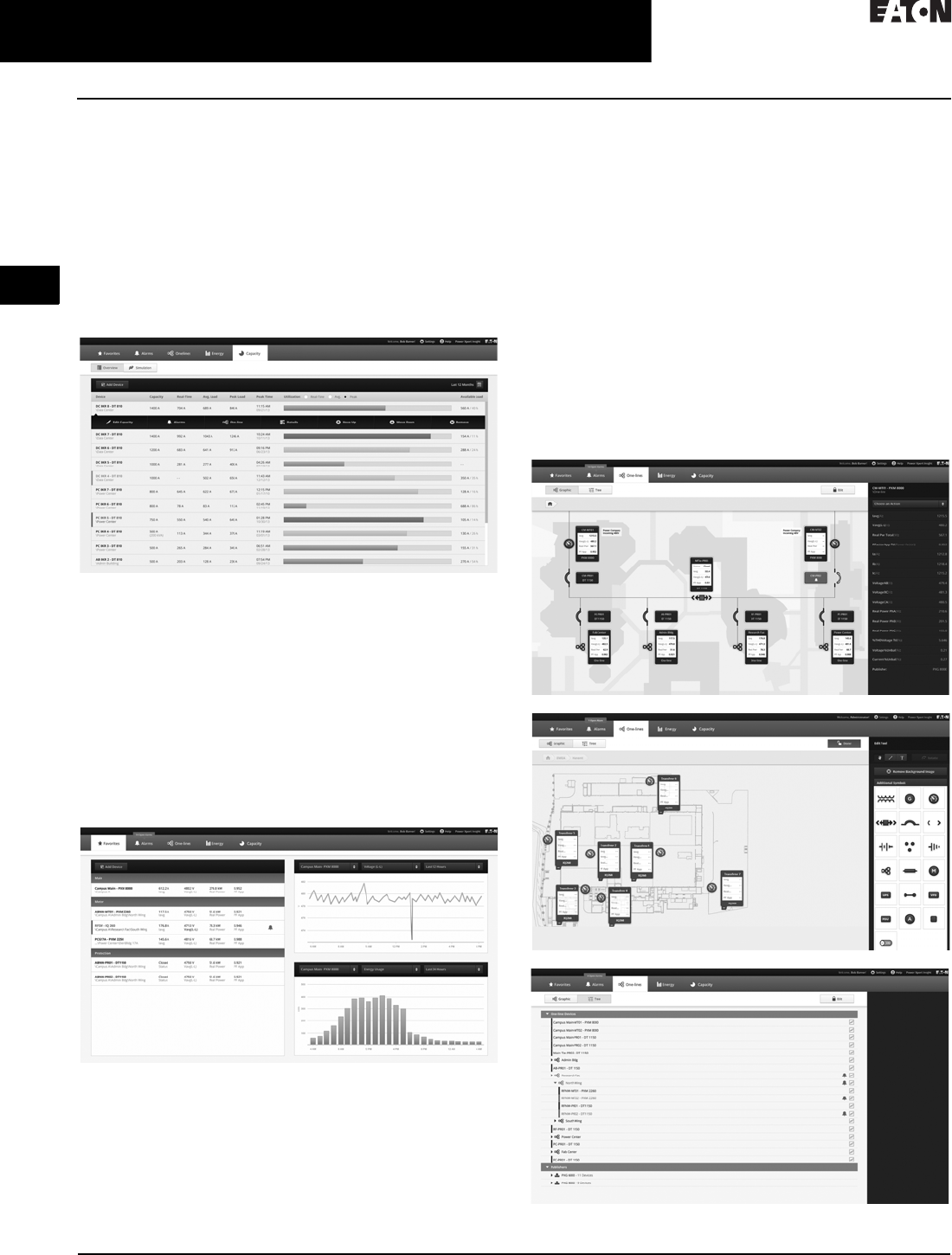
2.2-16
For more information, visit: www.eaton.com/consultants CA08104001E
March 2016
Power Management Systems & Products
i
ii
1
2
3
4
5
6
7
8
9
10
11
12
13
14
15
16
17
18
19
20
21
Sheet 02
Connectivity and Software Products
Power Xpert Insight
030
Capacity
■Benchmark capacity usage in real-time to determine
tripping points and avoid downtime
■Custom trigger thresholds for cautionary and critical
levels support all type of electrical environments and
changing needs
■Simulate and trend with line graphics load additions prior
to device installation to avoid tripping and downtime
■Forecast, budget and plan capacity requirements
■Proactively predict overall electrical system performance
by modeling capabilities
Favorites Dashboard
■Each user can create a unique dashboard to focus on the
devices or systems that they are interested in
■Devices are displayed by device type (Main, Meter,
Protection) and populate the top 4 channels for that device
■Alarm color-coding is automatically propagated
across pages
■A quick Trend Graph and Energy Graph are also displayed
for a selected device and channel over a time range up
to 24 hours
■Quickly add or remove devices from the Favorites
dashboard
Modbus Protocol Adapter
The Protocol Adapter provides a Modbus server that regularly
updates values for a specific set of Power Xpert Insight
channels and makes these available as Modbus registers.
You can specify the Power Xpert Insight channels you want
and set the update characteristics of the Modbus server.
One-Lines
■Build an electrical one-line representation of the system
with device widgets and the symbols library
■Drag-and-drop devices, lines, symbols where needed, add
text boxes. Easily updated when devices are removed or
added to service
■The top 4 device channels are automatically populated on
the device widgets and alarm color-coding carries through
on the one-lines
■Upload a unique background image
■Use the Device Tree to set up the one-line structure
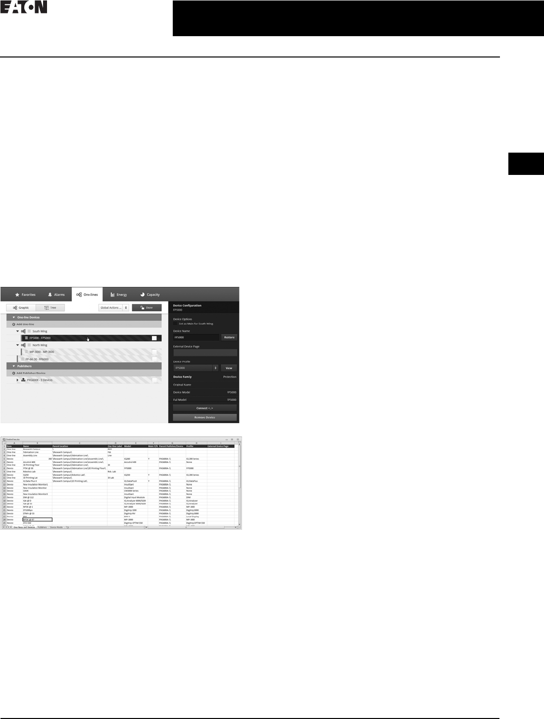
CA08104001E For more information, visit: www.eaton.com/consultants
2.2-17
March 2016
Power Management Systems & Products
i
ii
1
2
3
4
5
6
7
8
9
10
11
12
13
14
15
16
17
18
19
20
21
Sheet 02
Connectivity and Software Products
Power Xpert Insight
031
Event Notification
Power Xpert Notify will send out emails to selected
recipients when alarms occur. The user can select the
devices, recipients and frequency of notifications.
Offline Configuration
Power Xpert Insight provides the ability to completely
configure a system in advance. The more you know about
the final system, the more complete the offline configuration
process will be.
■Configure Power Xpert Insight in advance using an Excel®
spreadsheet (template available at Eaton.com/pxi)
■Upload the spreadsheet to an offline Power Xpert
Insight system
■Set up one-line graphics in the offline Power Xpert
Insight system
■Extract that entire system configuration
Upload the configuration into the target system when ready
and connect when the devices are online.
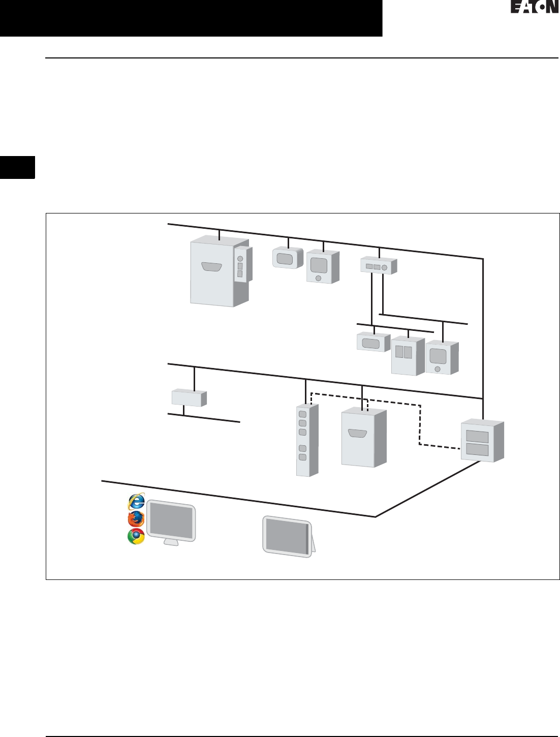
2.2-18
For more information, visit: www.eaton.com/consultants CA08104001E
March 2016
Power Management Systems & Products
i
ii
1
2
3
4
5
6
7
8
9
10
11
12
13
14
15
16
17
18
19
20
21
Sheet 02
Connectivity and Software Products
Power Xpert Insight
032
System Architecture Diagram
Power Xpert Insight (PXI) seamlessly communicates over
Ethernet with other Power Xpert-enabled products and
third-party products via the Power Xpert bridge and Power
Xpert Gateways.
Power Xpert Insight can be accessed via personal computer
or Windows® Surface Pro tablet computer. It supports
multiple Web browsers including Windows Internet
Explorer®, Google Chrome™ and Mozilla® Firefox®.
For a complete list of supported devices, see the Hardware
Compatibility List at Eaton.com/pxi.
Figure 2.2-7. System Architecture Diagram
Ethernet
PXGX Meters
Trip Units
UPS, PDUs
PXG
Ethernet
UPS
ePDU
ModBus
INCOM
Server
PXI
PXb
햲
SNMP
Serial
MOXA
• Over 600 facility-centric drivers
• Contact Eaton's Power Systems
Automation group for delivery options
Windows Surface Pro
Computer
Meters
Relays
Trip Units
Drives
CA08104001E For more information, visit: www.eaton.com/consultants
2.2-19
March 2016
Power Management Systems & Products
i
ii
1
2
3
4
5
6
7
8
9
10
11
12
13
14
15
16
17
18
19
20
21
Sheet 02
Connectivity and Software Products
Power Xpert Insight
033
System Requirements
Table 2.2-3. Hardware Requirements
Power Xpert Insight requires a server-class machine with the
following minimum hardware specifications:
Table 2.2-4. Software Requirements
Table 2.2-5. Ordering Information
Table 2.2-6. Power Xpert Software General Features
Hardware Specification
Processor Quad Core
Memory 16 GB
Hard disk drive 100 GB—5 years estimated data storage
Video resolution 1920 x 1080
Description Specification
Supported Operating Systems
Server Windows Server 2008 R2, Standard and Enterprise, SP1
Windows Server 2012 Standard and Datacenter
Client Windows 7 Professional, Ultimate or Enterprise, x64, SP1
Windows 8 Professional/Enterprise X86 and X64
Supported
versions of
Microsoft
SQL Server
SQL Server 2008 R2 Standard
(and Standard for Small Business) SP2
SQL Server 2008 R2 Enterprise
SQL Server 2012 Express with Advanced Services,
Standard, Enterprise, Enterprise Core and
Business Intelligence
If you do not have one of the above versions installed, Power Xpert Insight
will install SQL Server 2012 Express with Advanced Services.
Supported Web Browsers
Microsoft Internet Explorer (IE) 9, 10 or 11
Google Chrome
Firefox
Other browsers (such as Opera and Safari) that support Silverlight may
also work, but are not officially supported by Eaton.
Description Catalog Number
Power Xpert Insight
PXI for up to 10 device connections PXI-A
PXI for up to 25 device connections PXI-B
PXI for up to 50 device connections PXI-C
PXI for up to 100 device connections PXI-D
PXI for up to 200 device connections PXI-E
Power Xpert Insight Upgrades
PXI 10 to 25 upgrade PXI-A2B
PXI 10 to 50 upgrade PXI-A2C
PXI 10 to 100 upgrade PXI-A2D
PXI 10 to 200 upgrade PXI-A2E
PXI 25 to 50 upgrade PXI-B2C
PXI 25 to 100 upgrade PXI-B2D
PXI 25 to 200 upgrade PXI-B2E
PXI 50 to 100 upgrade PXI-C2D
PXI 50 to 200 upgrade PXI-C2E
PXI 100 to 200 upgrade PXI-D2E
Service Packs
Power Xpert 1-day startup Service Pack PX-1S
Power Xpert 2-day startup Service Pack PX-2S
Power Xpert 5-day startup Service Pack PX-5S
Features
General
Web browser user interface
Web-based monitoring capabilities
Downloadable software version updates
Event Notification
Event notification via e-mail notification
Event Notification via pagers, text message or third-party interfaces
Alarm state management
Event indicator displayed without Web page active
Alarm/event searching and filtering
Waveform attached to applicable power event
Web browser based waveform viewing
Alarm capabilities based on device driven events
Analysis and Trending
Graphic trend viewer
Chart or data option selection
Multiple trends display
Multiple axis support
View multiple variables (i.e., Ia, Ib, Ic, Vab, Vbc, etc.) for a single waveform
Standard COMTRADE file format support
Customizable trend viewer look and feel
Fixed or custom time frames
Trend analysis capabilities
Data export
Custom Graphics and Layouts
Custom graphics development via Web browser
Four user view example templates included as standard
iFrame capability
Browser portal widget support
Streaming media support
Graphic object library included as standard
ISO standard electrical picture objects available
Graphic files import capability
Graphic object animation capability
Gauge object library support
External Web Links support
Alarm bubble-up support through several page layers
Trend object support
UPS Shutdown
File saving during shutdown
Automatic, orderly and sequential shutdown
Parallel redundant UPS shutdown capability
Security and Administration
Windows authentication security
Two tier secure system access support
SSL
Secure Web browser access (support for HTTPS)
Time Synchronization
Time synchronization support for connected devices with 1 millisecond
time resolution
Export and Integration
Extended Excel spreadsheet support
SQL database query support
Logs
System log
Error log
Service
Eaton help desk services (1-877-ETN-CARE)
Turnkey startup service
System Backup
Power Xpert Software system backup
Documentation and Training Videos
System Administrator’s Guide
Power Xpert Software User’s Guide
Layout Manager Guide
Quick Start Guide
Power Xpert Software introduction and training video
Power Xpert Reporting introduction and training video
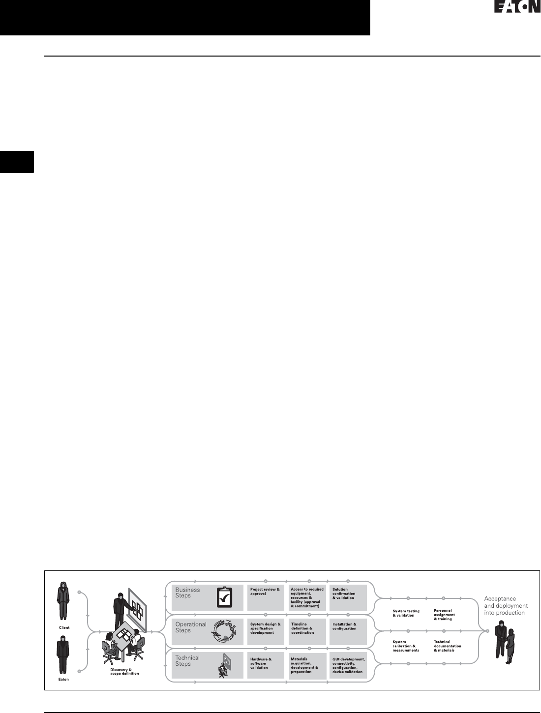
2.2-20
For more information, visit: www.eaton.com/consultants CA08104001E
March 2016
Power Management Systems & Products
i
ii
1
2
3
4
5
6
7
8
9
10
11
12
13
14
15
16
17
18
19
20
21
Sheet 02
Connectivity and Software Products
Foreseer Services
034
Foreseer® Services
Foreseer Software and Engineering
Services (Foreseer Services) provide
vendor independent, power and
energy infrastructure integration
solutions that help companies reduce
energy consumption and unplanned
downtime due to the failure of critical
power, environmental, safety or
security systems.
Turnkey software and connectivity
solutions are coupled with state-of-
the-art project management, systems
design, third-party device integration,
testing and custom application devel-
opment to develop a comprehensive
monitoring solution to meet your
custom needs.
Foreseer Services is delivered in four
categories, each offering a multitude
of unique value-add services that
you can discuss with your Eaton
sales professional.
■Design services
■Installation services
■Commissioning services
■Follow-up services
■Hardware services
■Software services
Foreseer services is fully distributable
to allow different monitoring capabili-
ties to be deployed at different sites
allowing you to purchase only what is
needed. Many competitive systems
offer a one-size-fits all type approach
where you end up paying for more
capacity than is needed. With Foreseer
Services, you pay only for what you
need, when you need it.
Foreseer Services Categories
Foreseer Services has three
general categories:
■Foreseer Software Services
■Foreseer Project Management
Services
■Foreseer Engineering Services
Foreseer Software Services–
Unique Features
Completely Scalable Solution
Several classes, capable of handing up
to 512,000 data streams (channels)
while available to start with a low point
of entry.
■Foreseer A-Class server software
(up to 5,000 channels)
■Foreseer C-Class server software
(up to 15,000 channels)
■Foreseer M-Class server software
(up to 25,000 channels)
■Foreseer R-Class server software
(up to 100,000 channels)
■Foreseer S-Class server software
(up to 256,000 channels)
■Foreseer X-Class server software
(up to 512,000 channels)
Redundant, Worldwide Coverage
The inclusion of one or more extra
Foreseer servers provides the highest
possible levels of system reliability. In
the unlikely event that one Foreseer
server fails then the remaining servers
can carry the load of the power
monitoring system.
With the Manager of Managers (MOM)
software option, data from one server
can be monitored alongside data
from other servers, enabling you to
aggregate multiple Foreseer sites into
a single system.
Data Gathering, 24/7
A proactive algorithm gathers data
24/7, enabling you to sample data
points from thousands of devices,
every second.
User-Defined Formulas
Information from multiple sources
and systems can be inserted into user
defined formulas, providing knowl-
edge for informed decision making.
Extensive Device Driver Library
Foreseer Software Services enables
the full-scale integration of third-party
products. A device library of over
600 drivers has been developed. For a
full list of compatible devices, see the
Foreseer services/hardware compati-
bility list at www.eaton.com/foreseer.
Trend Analysis
High performance analysis and
forecasting tools assess equipment
performance specifications including
cause analysis, impact analysis,
capacity planning, preventive mainte-
nance assessments and trending.
Custom User Interfaces
Mimic graphics, dynamic one-line
views, dashboards, 3D renderings
and virtually any custom view to help
operators manage their facility.
Web Browser Access—Unlimited Seats
Web browser access enables easy
system access. Multiple users can
access Foreseer software without the
need for additional client seat licenses.
Alarm Notifications
For each channel being monitored, you
can assign up to four alarm thresh-
olds—from routine maintenance alerts
to system failure—plus handling
instructions and escalation procedures
for each.
Foreseer Project Management Services
Each Foreseer integration project can
be customized. See Figure 2.2-8 for an
overview of project flow.
Figure 2.2-8. Foreseer Project Management Services
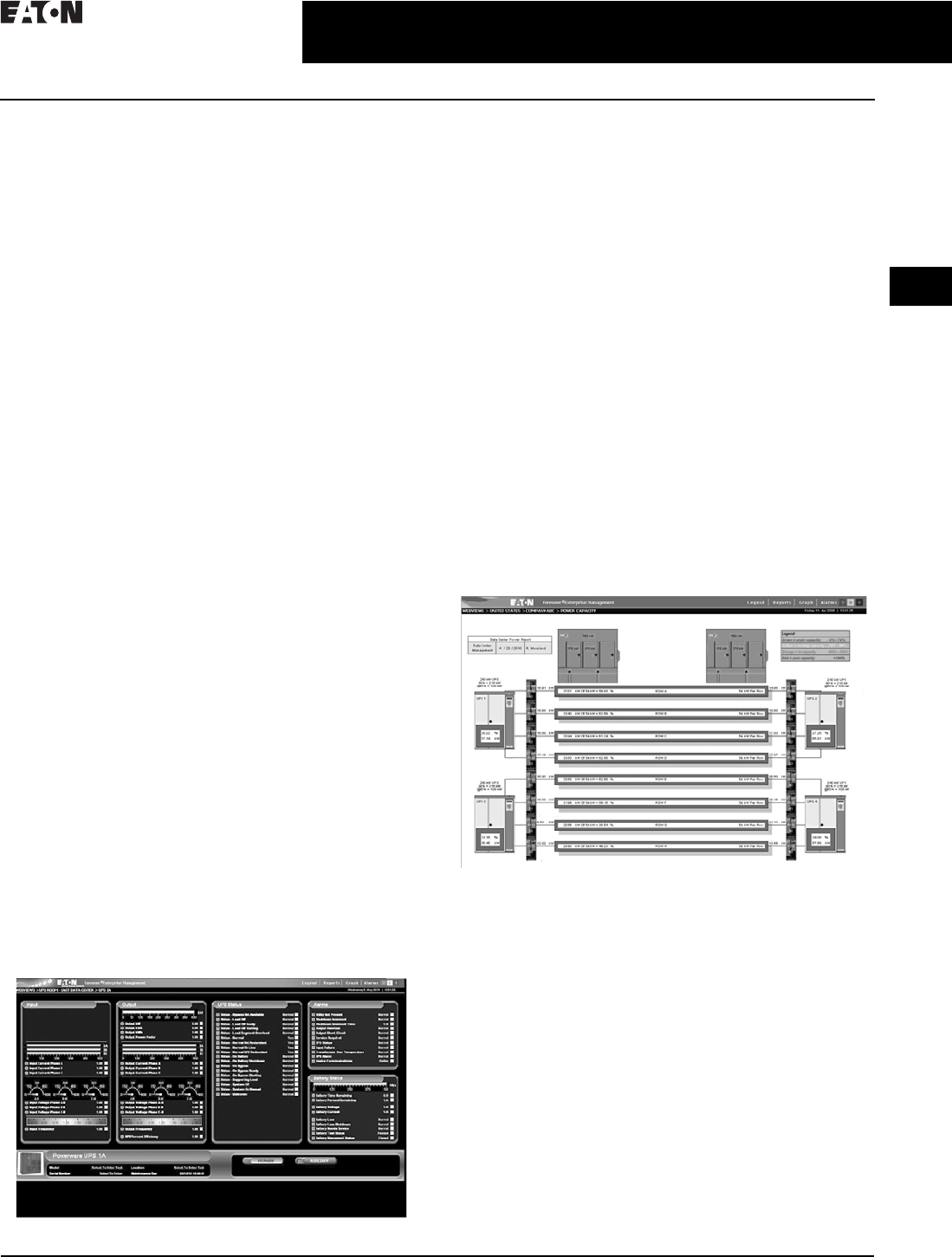
CA08104001E For more information, visit: www.eaton.com/consultants
2.2-21
March 2016
Power Management Systems & Products
i
ii
1
2
3
4
5
6
7
8
9
10
11
12
13
14
15
16
17
18
19
20
21
Sheet 02
Connectivity and Software Products
Foreseer Services
035
Foreseer Engineering Services
Design Services
After extensive assessment of your requirements and the
existing device and facility infrastructure, the Foreseer
design services team configures your system, complete with
a bill of materials and recommendations unique to your
needs. Specification development, drawings and detailed
documentation for your project is part of this step. Third-
party device support and communication interface planning
is critical, including driver development and enhancement, if
necessary. User interfaces are designed with default views
to meet your specifications.
Installation Services
Installation services team members are with you from proj-
ect initiation to handing over the Foreseer system when
work is complete. Tasks include:
■Startup needs, testing and customization
■Drawings and custom graphic layout development
■Customized device gauge graphics and status indicators
■Third-party software integration
■Custom software and application development
■Setup and configuration of reporting packages and basic
Foreseer training
Commissioning Services
Commissioning services consist of overall and tiered systems
testing and full point-to-point system commissioning options.
Post Project Services
Once your system is successfully deployed, the Foreseer
Service team is available to provide ongoing services such
as system expansion, upgrades, troubleshooting and
support, and advanced Foreseer training. Customized
support contracts are available to tailor toward customer
needs and requirements.
Custom Foreseer Services Applications
Management Dashboards
Standard with all new deployments, Foreseer’s management
dashboards provide high-level facility information for one-
stop overview management. Utilizing Foreseer’s powerful
derived equations, measurables like utility power availability,
emergency power availability, facility efficiency, environmental
impact, facility environment, facility cooling, outside weather
conditions, security system(s) status, fire system(s) status,
monitoring system status, and others are available to provide
quick glance management of a facility.
Eaton Powerware UPS-Primary View
Calculates DCiE and PUE
Use Foreseer Software Services Power Xpert Reporting
option to automatically calculate Data Center Infrastructure
Efficiency (DCiE) and Power Usage Effectiveness (PUE).
These industry-standard efficiency metrics help IT managers
to understand and to track how efficiently their data center is
running and how effective improvement efforts have been.
Energy Cost Allocation
Fair Share Utility Cost Distribution
Foreseer Software provides energy usage by individual
circuit so each device can be a part of the energy manage-
ment strategy. It even allocates electrical cost to individual
and branch circuits, which can then be assigned to individual
users of a department or device.
Power Density
Pinpoint Hot Spots in Your Data Center
Power density is a critical measurement as racks proliferate
and expand from TCP/IP networks and servers and other
elements of the infrastructure are placed into smaller areas.
Foreseer Software manages power density by device, for a
single rack, floor or an entire building, allowing identification
of overloaded racks and incorrect power drains due to
device failure.
Growth Planning
Power Capacity View
The Power Capacity View provides an at-a-glance simple
analysis of the data center’s electrical capacity. Normal,
cautionary and alarm events are triggered automatically,
both online and remotely once a threshold has been
reached. Mapping the data center’s capacity is critical for
power, cooling and redundancy planning. With Foreseer
Software projection graphing capability, data center manag-
ers can easily predict when they are going to hit a capacity
threshold going into the future and can prepare accordingly.
Plan with the Electrical Capacity Planning Tool
Demand on devices grows as organizations expand.
While average demand may not be a concern, peak
demand is. Foreseer software tracks the kW and kVA over
time, immediately informs of peak levels, and projects future
demands based on past usage. Assisting in planning for
electrical upgrades and/or changes to the power system to
support changing load patterns.
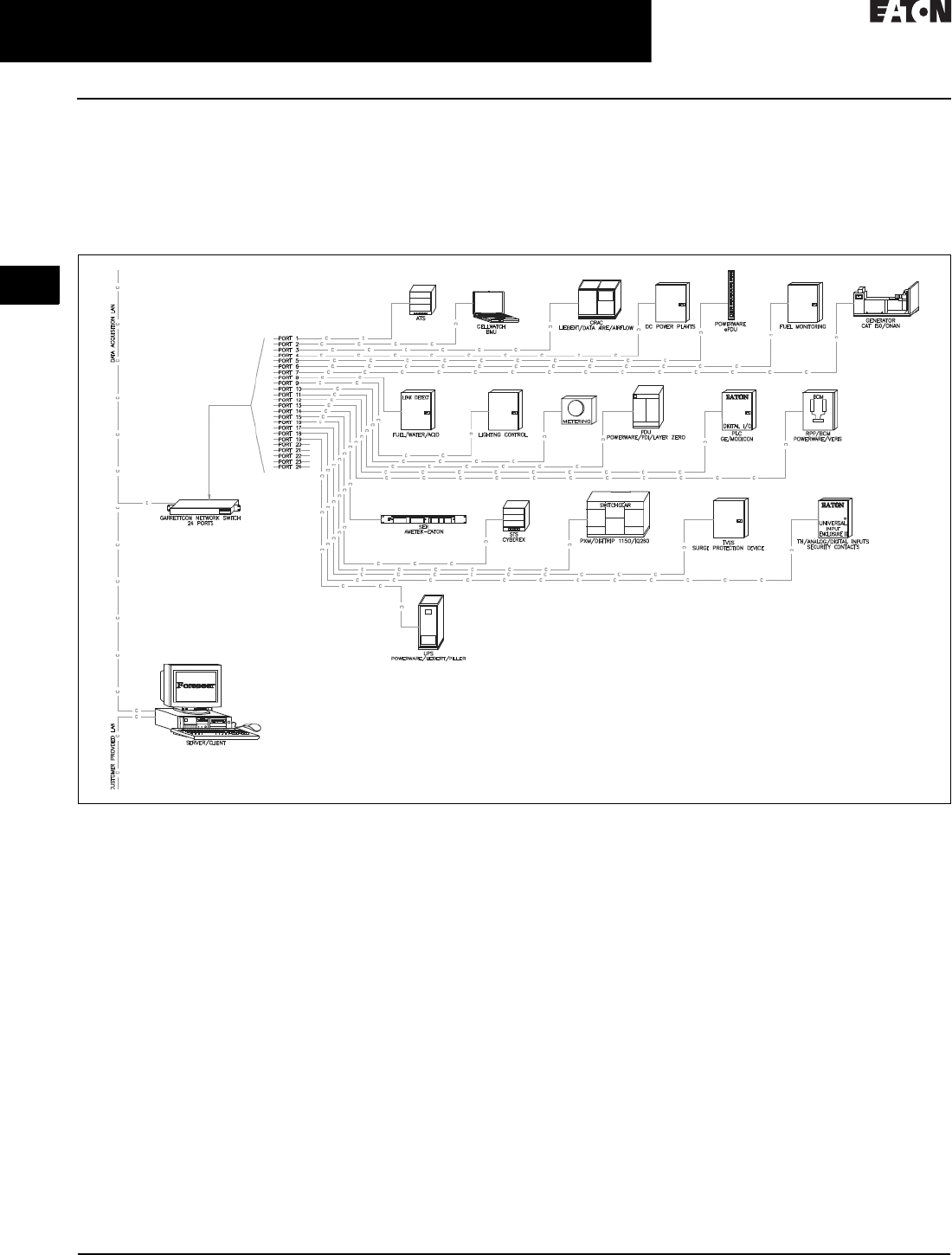
2.2-22
For more information, visit: www.eaton.com/consultants CA08104001E
March 2016
Power Management Systems & Products
i
ii
1
2
3
4
5
6
7
8
9
10
11
12
13
14
15
16
17
18
19
20
21
Sheet 02
Connectivity and Software Products
Foreseer Services
036
Load Balancing
Prevent Unbalanced Loads
Improper load balancing contributes to harmonic distortion.
Foreseer software tracks load levels by phase, giving instant
notification when extreme imbalances begin to occur, and
providing the knowledge to take the necessary steps to
re-distribute the load. Foreseer software visually illustrates
the load balance of a device or system in real-time, while
showing what the balanced model should be. You see the
current state, the worst-case scenario and the proper load.
Figure 2.2-9. Data Center/Co-Location Device—The typical Data Center/Co-Location device mixture includes a large variety of power distribution,
cooling, environmental monitoring, lighting, safety and security, backup and emergency power systems that have been purchased over a long
period of time. Foreseer Services integrates all of these systems into a simple, single software monitoring package. Support for metering and
energy measurement, including greenhouse gas monitoring, are requirements that need to be taken into consideration as well as, for example,
Building Management System integration.
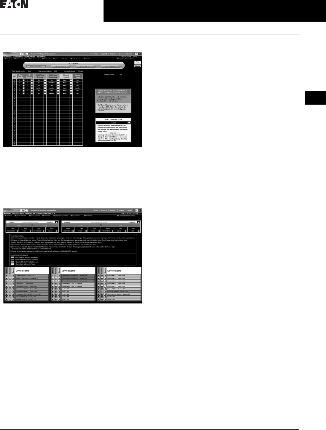
CA08104001E For more information, visit: www.eaton.com/consultants
2.2-23
March 2016
Power Management Systems & Products
i
ii
1
2
3
4
5
6
7
8
9
10
11
12
13
14
15
16
17
18
19
20
21
Sheet 02
Connectivity and Software Products
Foreseer Services
037
A/C Control Client Software
AC Control-Zone Assignment
Take Control of Your Environment
The Foreseer software A/C interface offers comprehensive
monitoring and optional lead/lag control for Air Flow, Data
Aire and Liebert System 3 air conditioning units. Lead/lag
control and scheduling is viewable via a Web-browser and is
controllable with the proper user authority.
Maintenance Scheduler
Maintenance Scheduler
Eliminate the Hassles
The Foreseer software maintenance scheduler offers the
ability to preset scheduled (weekly or periodic) maintenance
windows within the system to disarm selected devices
on which maintenance will be performed. Disarming the
devices allows continued monitoring and archiving
during the maintenance period while disabling alarms
and preventing unnecessary notification of personnel.
Foreseer Services Available Options
Power Xpert Reporting
Eaton’s Power Xpert Reporting works in conjunction with
Foreseer Software allowing a view past individual measure-
ments, trend graphs and events. It consolidates complex data
from a multitude of devices from around the globe into easy-
to-understand graphical reports. It provides a standard set of
reports for the most common report requests. Simply choose
from 10 ready-to-go report templates. Power Xpert Reporting
can be set to run the report automatically and send you new,
updated reports via e-mail at predefined intervals.
Manager of Managers (MOM)
Provides a powerful means to integrate data from multiple
locations where each location is running its own Foreseer
software server. This unique feature provides a scalable
system where the total number of integrated points on the
centralized MOM server can be as large as 256,000 points.
Sequence of Events Recorder
Enables breaker status monitoring capability at a time
stamping resolution of 1 millisecond. During a critical
or catastrophic event, sequence of event information is
captured by the recorder for retrospective analysis and
root cause issue mitigation.
Secure Web Server (https)
Provides an encrypted means to protect all data that is
viewed via a standard Web browser on the Internet or
intranet. Using the OpenSSL package from the Internet,
Foreseer software is able to provide 128 bit encryption
between the Foreseer Software and the Web browser. Both
registered certificates from a third-party provider or self-
signed certificates are allowed to be used with this option.
Foreseer Gateway
Most facilities utilize multiple systems to help manage
a facility including power monitoring systems, building
management or automation systems, data center infra-
structure management systems, control systems, etc.
Successful and efficient management of a facility may
depend on interaction of some of these systems. Foreseer’s
gateway interface makes this interaction with other systems
simple and reliable, utilizing data availability through open
protocols such as Modbus, SNMP, BACnet and OPC. Every
data channel in the Foreseer server can be made available
to another system at intervals up to once per second for
processing or analysis.
Redundancy
Safeguards valuable information. The inclusion of one or
more extra Foreseer software servers provides the highest
levels of system reliability. In the event that one Foreseer
software server fails, the remaining servers carry the load
of the power monitoring system.

2.2-24
For more information, visit: www.eaton.com/consultants CA08104001E
March 2016
Power Management Systems & Products
i
ii
1
2
3
4
5
6
7
8
9
10
11
12
13
14
15
16
17
18
19
20
21
Sheet 02
Connectivity and Software Products
Foreseer Services
038
Data Acquisition Engine (DAE)
Designed specifically for geographically
or physically removed sites where
local IT expertise may not exist.
The data acquisition engine (see
Page 2.2-25 for details) automatically
collects and sends data from critical
infrastructure devices, and communi-
cates that data back to the Foreseer
software server. Using local processing
and the shared bandwidth of an IP
network, the DAE reduces the cost
required to transmit data to the central
server. The DAE also continues to
operate independently and generate
alarms even if the connection to
the central server is unavailable,
increasing the overall availability of
the management system.
Data Acquisition Terminal (DAT)
Easily integrates monitored
equipment and sensors located in
small, networked remote sites. The
DAT (see Page 2.2-25 for details)
employs standard Modbus communi-
cations to relay information to either
a Foreseer software server or a data
acquisition engine over a TCP/IP
network. Data is packaged in
sequential Modbus registers to
enable optimum scan times without
impacting network bandwidth.
Universal Input Enclosure
(UIE2, UIE2+)
Provides network connectivity for
analog and contact input information
along with device server capability.
Each enclosure contains from one to
five input modules with pluggable
connectors used for power and
input wiring, enabling cost-efficient
monitoring of equipment in small,
remote facilities.
The universal input enclosure provides
network connectivity for analog and
contact input information along with
the option for concentration of a
variety of monitored points via
several communication means at
a single point. Each UIE2 contains up
to five input modules with pluggable
connectors used for power and
input wiring, enabling cost-efficient
monitoring of equipment in small,
remote facilities. Serial-to-Ethernet
conversion hardware and network
switch may be added to give a single
point of monitoring connection for
all analog/digital contacts, serial-
based devices and Ethernet-based
devices, making the UIE2 an
extremely flexible building block
of a monitoring infrastructure.
To further expand the reach of
Foreseer Services, several hardware
options are offered.
The Foreseer data acquisition engine is
designed specifically for geographically
or physically removed Foreseer class
sites where local IT expertise may
not exist.
The Foreseer data acquisition
terminal easily integrates monitored
equipment and sensors located in
small, networked remote sites.
The Foreseer universal input enclosure
is designed for small remote sites
containing equipment with several
connectivity types.
Designed for small remote sites
containing equipment with several
connectivity types. The universal input
enclosure provides modular termina-
tions for analog contacts, such as flow
metering and temperature/humidity
sensors, and digital contacts, such as
summary alarms and door open/close
contacts, based on quantity and
type for flexible integration into the
Foreseer monitoring system. In situa-
tions where space is at a premium, the
UIE2+ can be utilized to concentrate
serial communicating wiring and
Ethernet communication wiring and
provide a single Ethernet connection
out to the Foreseer system. Housed
inside a NEMA 12 enclosure with all
modules mounted and internal power
connected, the UIE2 is a very contrac-
tor-friendly communication center of
the Foreseer monitoring architecture.

CA08104001E For more information, visit: www.eaton.com/consultants
2.2-25
March 2016
Power Management Systems & Products
i
ii
1
2
3
4
5
6
7
8
9
10
11
12
13
14
15
16
17
18
19
20
21
Sheet 02
Connectivity and Software Products
Foreseer Services
039
Data Acquisition Engine (DAE)
Data Acquisition Engine (DAE)
Designed specifically for geographi-
cally or physically removed sites
where local IT expertise may not exist.
The data acquisition engine automati-
cally collects and sends data from
critical infrastructure devices, such as
UPS, generator and power distribution
units, and communicates that data, as
well as status and alarms, back to the
centrally located Foreseer server.
Using local processing and using the
shared bandwidth of an IP network,
the DAE reduces the cost required to
transmit data to the central server.
The DAE can also continues to operate
independently and generate alarms
even if the connection to the central
server is unavailable, increasing
the overall availability of the
management system.
DAE Technical Specifications
■External power input: 115/230 Vac in,
5 Vdc 8 A out, optional—48 Vdc
■Ethernet: dual 10/100Base-T
Ethernet ports
■Communications ports: four RS-232/
422/485 and four USB ports
■Dimensions in inches (H x W x D):
3.50 x 17.00 x 11.00, 19.00-inch rack-
mount with removable flanges
■Environment: 32 ° to 104 °F
(0 ° to 40 °C), 0% to 90%
noncondensing RH
■Monitoring: 3072 channels,
maximum of 1536 analog
Data Acquisition Terminal (DAT)
Data Acquisition Terminal (DAT)
Easily integrates monitored
equipment and sensors located in
small, networked remote sites. The
DAT employs standard Modbus
communications to relay information
to either a Foreseer server or a data
acquisition engine over a TCP/IP
network. Data is packaged in
sequential Modbus registers to
enable optimum scan times without
impacting network bandwidth.
DAT Technical Specifications
■External power input: 100/240 Vac,
47/63 Hz,1 A (0.5 A at 240) optional
–48 Vdc
■Ethernet: 10Base-T, status and
activity LEDs
■Communications: Modbus RTU
via UDP using TCP/IP Port 7010
or Modbus TCP
■Dimensions in inches (H x W x D):
1.75 x 19.00 x 4.63
■Weight: 3 lbs
■Environment: –4 ° to 185 °F
(–20 ° to 85 °C), 0% to 90%
noncondensing RH
■Discrete inputs: 16 channels
configure as dry contact
■Relay outputs: 16 channels, SPDT
configuration, contacts rated at
500 mA, 125 Vac
■Analog inputs: eight channels of
12-bit A/D up to 16 digital inputs
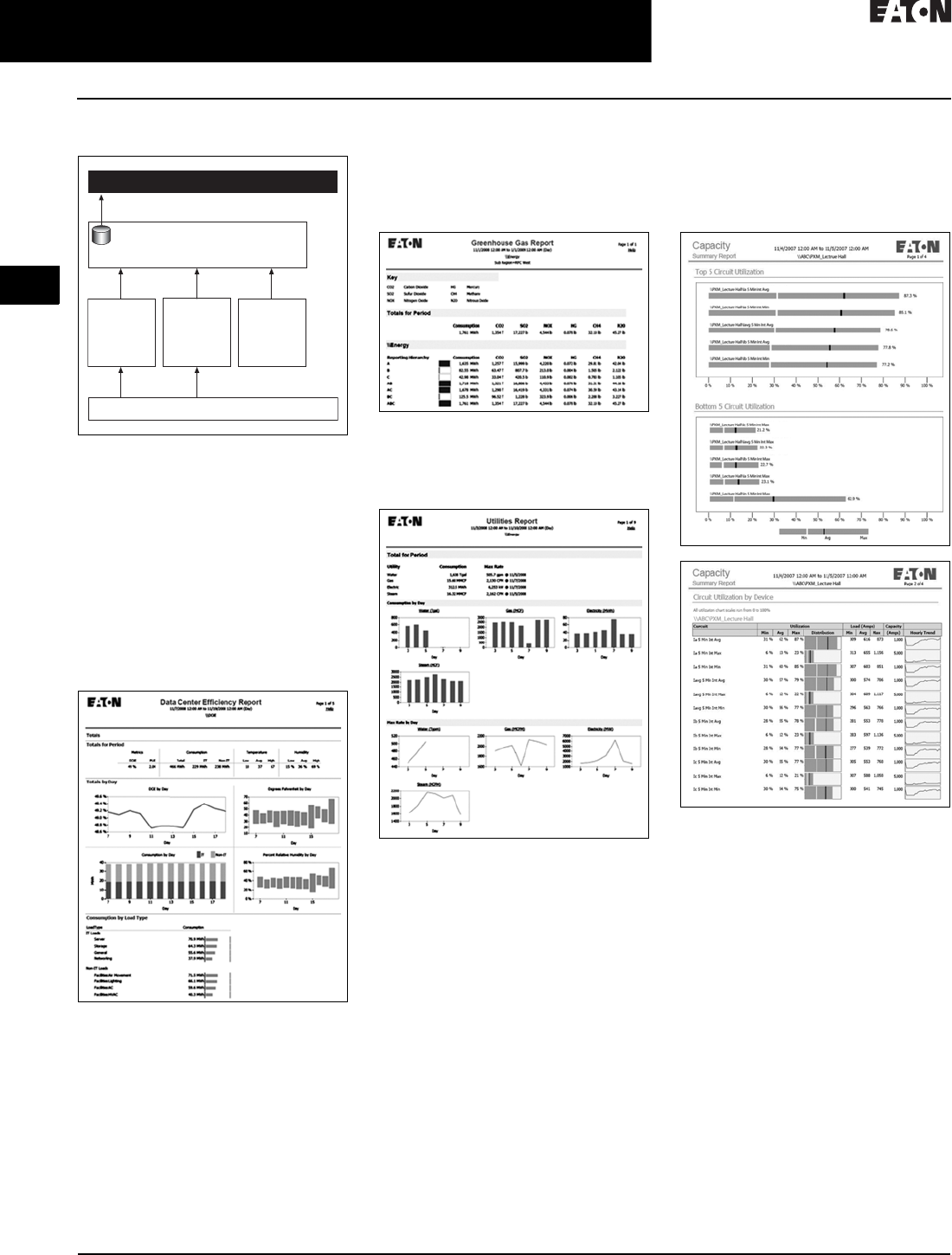
2.2-26
For more information, visit: www.eaton.com/consultants CA08104001E
March 2016
Power Management Systems & Products
i
ii
1
2
3
4
5
6
7
8
9
10
11
12
13
14
15
16
17
18
19
20
21
Sheet 02
Connectivity and Software Products
Power Xpert Reporting Software
040
Power Xpert Reporting Software
Figure 2.2-10. Power Xpert Reporting
Architectural Overview
Power Xpert Reporting brings the
power system information together
to compare and contrast. Power Xpert
Reporting provides a standard set
of reports, including:
■Data Center Efficiency Report:
A summary of data center
infrastructure efficiency and power
usage effectiveness, including such
information as temperature and
humidity, and energy consumption
Data Center Efficiency Report
■Greenhouse Gas Report: Captures
the six offensive greenhouse gasses:
carbon dioxide, sulfur dioxide,
nitrogen oxide, mercury, methane
and nitrous oxide broken down by
selected locations within a facility
Greenhouse Gas Report
■Utilities Report: Captures
consumption of water, air, gas,
electricity and steam (WAGES)
Utilities Report
■Capacity Summary Report: The
summary of top- and bottom-loaded
circuits, as well as loading details
for each circuit according to user-
defined date/time range and facility
hierarchy location
Capacity Summary Report
Foreseer Software
(one or more instances)
Power Xpert Reporting
Third-Party Devices, Non-Power Xpert Devices
Device
Aggregators
(PowerNet,
Gateways)
Power Xpert
Devices
(Meters,
Gateways,
Other)
4CR Data
Acquisition
Engine
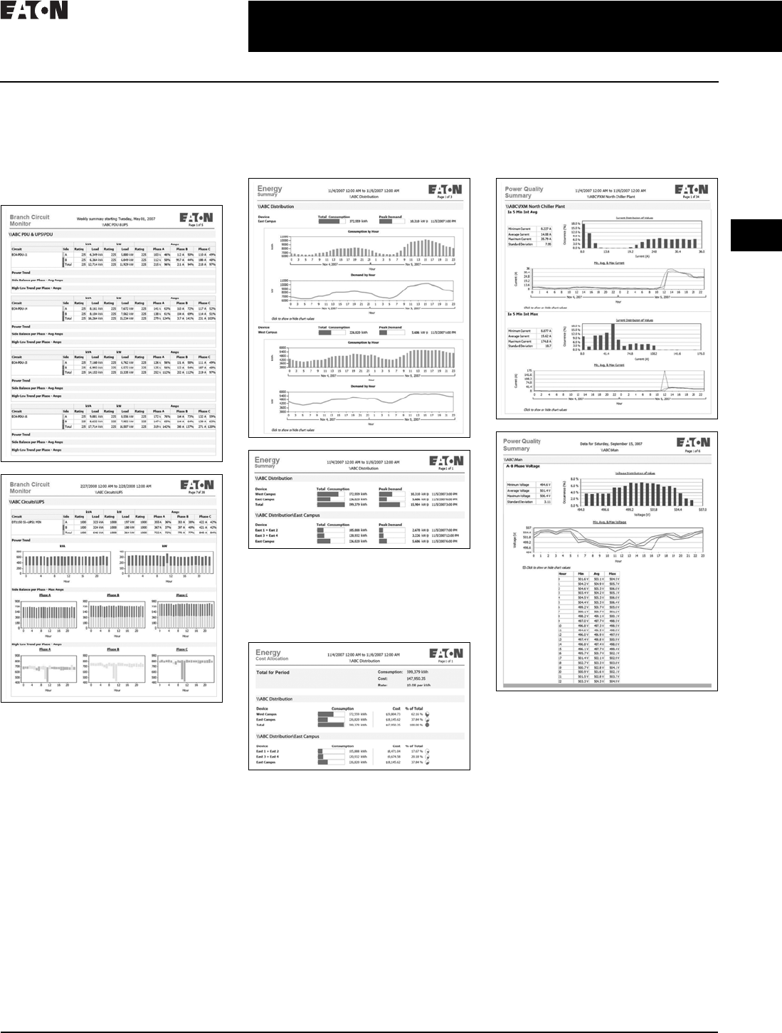
CA08104001E For more information, visit: www.eaton.com/consultants
2.2-27
March 2016
Power Management Systems & Products
i
ii
1
2
3
4
5
6
7
8
9
10
11
12
13
14
15
16
17
18
19
20
21
Sheet 02
Connectivity and Software Products
Power Xpert Reporting Software
041
■Branch Circuit Monitoring Report:
Determine branch circuit loading
levels at a glance with color-coded
graphics indicating loading status
against capacity. Redundant sources
can be reviewed, as well as single
source loads
Branch Circuit Monitoring Report
■Energy Summary Report: The
summary of consumption (kWh)
and demand (kW) for a user-
defined date/time range and
facility hierarchy location
Energy Summary Report
■Energy Cost Allocation Report: The
total energy bill dollar value or a cost
per kWh across a facility hierarchy
for a user-defined date/time range
Energy Cost Allocation Report
■Power Quality Report: The
distribution and trend for amps,
volts and THD according to user-
defined date/time ranges and
facility hierarchy location
Power Quality Report

2.2-28
For more information, visit: www.eaton.com/consultants CA08104001E
March 2016
Power Management Systems & Products
i
ii
1
2
3
4
5
6
7
8
9
10
11
12
13
14
15
16
17
18
19
20
21
Sheet 02
Connectivity and Software Products
Power Xpert Reporting Software
042
■Event Summary Report: Provides a
Pareto chart of events according to
user-defined date/time ranges and
facility hierarchy location
Event Summary Report
■Joint Commission Report: Standard
Joint Commission Compliant Report
supports hospital power test require-
ments. It checks events, key metrics
of generators and automatic transfer
switches (ATS) during generator
testing at user-defined date/time
ranges and facility hierarchy location
Joint Commission Report
Table 2.2-7. Power Xpert Reporting Software
Description Catalog
Number
Power Xpert Reporting
Power Xpert Reporting—single source DB connection
Power Xpert Reporting—up to 2 source DB connections
Power Xpert Reporting—up to 5 source DB connections
PXR
PXR-2DB
PXR-5DB
Power Xpert Reporting—up to 10 source DB connections
Power Xpert Reporting—up to 25 source DB connections
Power Xpert Reporting—up to 50 source DB connections
PXR-10DB
PXR-25DB
PXR-50DB
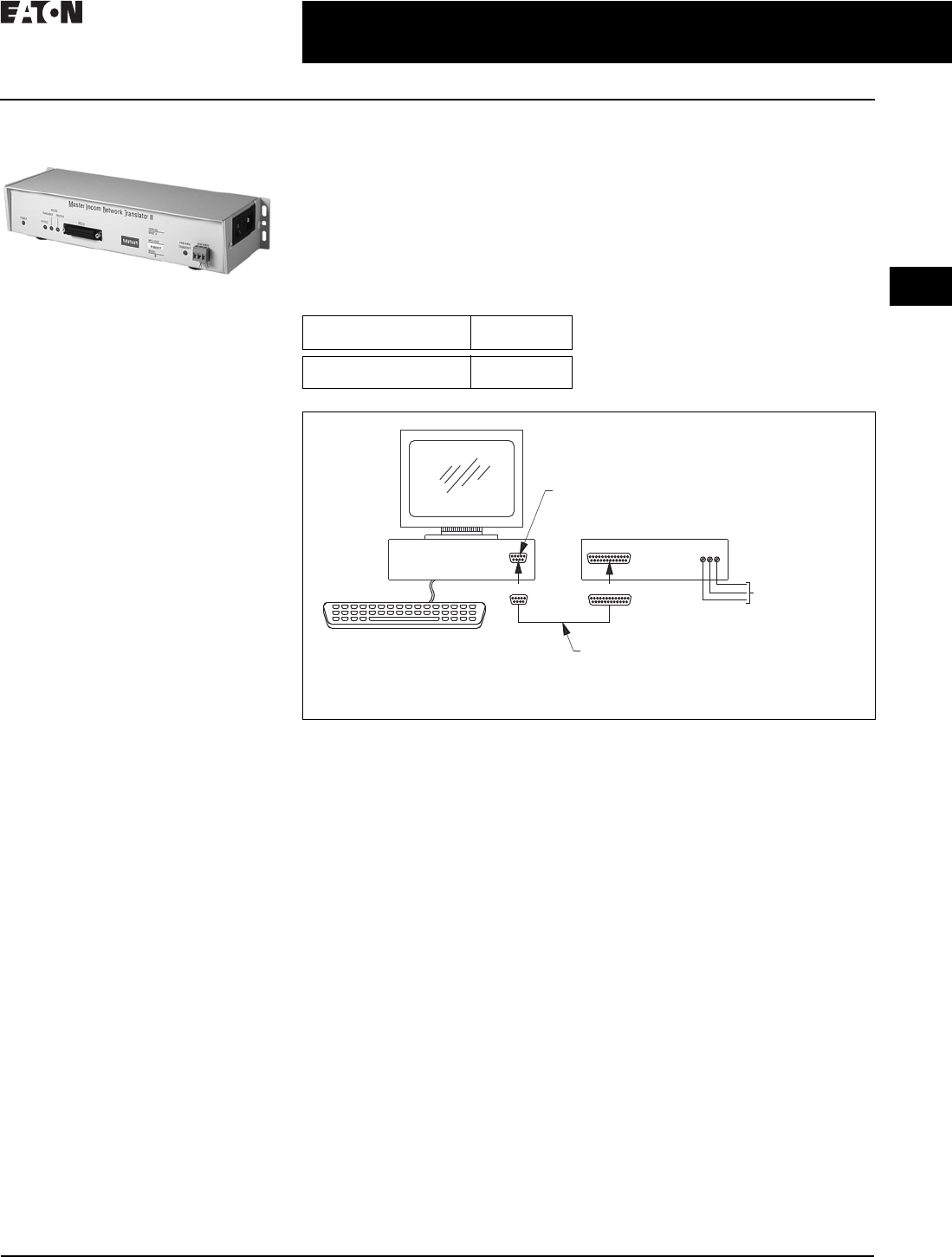
CA08104001E For more information, visit: www.eaton.com/consultants
2.3-1
April 2016
Power Management Systems & Products
i
ii
1
2
3
4
5
6
7
8
9
10
11
12
13
14
15
16
17
18
19
20
21
Sheet 02
for Third-Party Integration
MINTII RS-232 Converter
043
MINTII RS-232 Converter
MINTII RS-232 Converter
General Description
Applications
Converts a network of power manage-
ment software devices to ASCII RS-232
format for access through a serial port
of a PC, laptop, or Programmable
Logic Controller (PLC).
Displayed Parameters
■Eaton’s MINTII provides access to
all parameters monitored over a
system monitoring system such as
Power Xpert Software or Foreseer
Services
■Supports INCOM networks up to
8500 ft (2590 m) in distance and
device counts up to 1000
Physical Characteristics
■Suitable for panel mounting or
desktop use
■120 Vac power cord included for
plug-in to standard duplex receptacle
■Height: 2.25 inches (57.2 mm)
■Width: 11.50 inches (292.1 mm)
■Depth: 4.25 inches (108.0 mm)
Technical Data and Specifications
■Temperature: 0° to 60°C
■Humidity: 0–95%
■Power: 120 V
■Speed: 1200, 2400 and 9600 baud
(INCOM), 19.2K baud (RS-232)
■Communications: INCOM, RS-232
Product Selection
Table 2.3-1. MINTII RS-232 Converter
Master INCOM Network Translator II
The Master INCOM Network
Translator II (MINTII) converts the
twisted shielded pair network of
INCOM devices to an RS-232 signal.
This signal can be accessed by PLCs,
computer serial ports and building
management system serial interface
cards. The MINTII is also often
applied as an interface to standard
line drivers and converters to allow
communication through dedicated
telephone lines, dial-up modems,
fiber-optic line drivers, radio
frequency or wireless modems.
Figure 2.3-1. MINTII Connection Diagram for Use with a PC
Description Catalog
Number
Master INCOM
Network Translator II
MINTII
Twisted Pair
INCOM Network
9-Pin Female to
25-Pin Male
Straight-Through
RS-232 Cable
9-Pin
PC Comport
PC MINTII
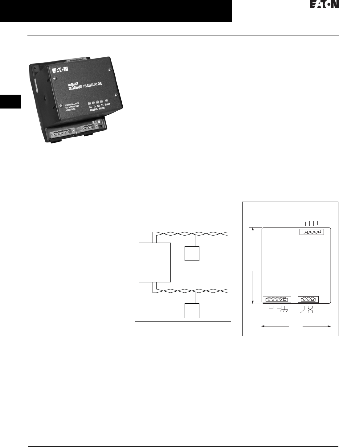
2.3-2
For more information, visit: www.eaton.com/consultants CA08104001E
April 2016
Power Management Systems & Products
i
ii
1
2
3
4
5
6
7
8
9
10
11
12
13
14
15
16
17
18
19
20
21
Sheet 02
for Third-Party Integration
mMINT
044
mMINT
mMINT Module
General Description
The mMINT (Modbus Master INCOM
Network Translator) Module is an
Eaton accessory product that will
provide communication between a
Modbus RTU network and an INCOM
(INdustrial COMmunications) network
(see Figure 2.3-2). This module is
transparent to the Modbus network.
It communicates to a master on the
Modbus network using the Modbus
RTU (Remote Terminal Unit) protocol.
It communicates to slave devices on
the INCOM network using the IMPACC
(Integrated Monitoring, Protection,
and Control Communication) protocol.
The catalog number of this product
is mMINT.
Features
The mMINT module is a slave
device on the Modbus network and
as such requires a master that will
exchange register objects with the
mMINT module.
■Handles generic pass-through com-
mands (Modbus/INCOM/Modbus)
■Capable of passing Modbus register
objects from Eaton’s existing prod-
ucts
and newer PnP (Plug-‘n-Play)
products
to a Modbus RTU master
■Data in IEEE Floating Point format
and fixed point
■Modbus RTU communications
data transfer rates of 1200, 9600
or 19200 baud with one start bit,
eight data bits, no parity, and either
one or two stop bits
■Up to 32 products connected to
INCOM network port (246 unique
addresses maximum)
■Flashing Status LED to indicate an
active module
■LED indicators for INCOM transmit
and receive communications
exchanges
■LED indicators for Modbus RS-485
transmit and receive communica-
tions exchanges
■Input power for the module from
either 120 Vac or 24–125 Vdc
■DIN rail mount package
■0° to 60°C ambient operation
Module Mounting
When mounting the mMINT, verify
that an 11 mm H x 28 mm W DIN rail
is used and that it is within an
enclosed space.
Simplified Wiring Rules
INCOM Network
The following simplified rules apply
to a given system consisting of a
single daisy-chained main cable link
between master and slave devices
(see Figure 2.3-2). For more complex
considerations including star configu-
rations, please refer to the IMPACC
wiring specification T.D. 17513.
Figure 2.3-2. mMINT in a Communications
Network
■Recommended INCOM cable styles
are Belden 9463 or C-H style
2A957805G01
■The maximum system capacity is
10,000 feet of communications cable
and 32 slave devices on the INCOM
network under the mMINT
■Non-terminated taps, up to 200 feet in
length, off the main link are permitted,
but add to the total cable length
■Make sure that there is twisted-pair
wire that is recommended for
IMPACC network use. Use shielded
twisted-pair wire to connect each
slave to the INCOM network,
daisy-chain style. The polarity of
the twisted pair is not important
Modbus RS-485 Network
The following simplified rules apply to
a given system consisting of a cable
link between master and slave devices
(see Figure 2.3-3). For more complex
configurations, please refer to standard
Modbus RTU wiring specification
rules for the RS-485 network.
■The recommended Modbus cable
has twisted-pair wires (24 AWG
stranded 7x32 conductors with PVC
insulation) having an aluminum/
mylar foil shield with drain wire
■The maximum system capacity
is 4000 feet of communications
cable and 247 devices on the
Modbus RTU network
■Make sure that there is twisted-
pair wire that is recommended
for Modbus RTU network use.
Use shielded twisted-pair wire to
connect each slave to the Modbus
RTU network, daisy-chain style.
The polarity of the twisted pair is
critically important
Figure 2.3-3. mMINT Module Dimensions
Burden
■24 Vac/dc 3 VA
Safety Standards
■UL
■CSA
■CE mark
Communications Speed
■INCOM: 1200, 9600 baud
■N2 Bus: 9600 baud
Modbus RTU Serial Network
(Slave)
Modbus
mMINT
(Master)
Modbus
Master
INCOM Network
INCOM
Slaves
J1 J2
J3
4.25
(108.0)
RS-485
Modbus
3.54
(89.9)
24–125 Vdc
120 Vac
Shield INCOM
A B COM SHD

CA08104001E For more information, visit: www.eaton.com/consultants
2.3-3
April 2016
Power Management Systems & Products
i
ii
1
2
3
4
5
6
7
8
9
10
11
12
13
14
15
16
17
18
19
20
21
Sheet 02
for Third-Party Integration
PMINR
045
PMINT
PMINT Module
General Description
The PMINT (PROFIBUS DP—Master
INCOM network translator) module is
an Eaton accessory product that will
provide communications between a
PROFIBUS DP network master and an
INCOM (INdustrial COMmunications)
based Digitrip™ Magnum® 520MC
or 1150 trip unit. The module is
transparent to the PROFIBUS network
master. It communicates to a master
on the PROFIBUS network using
the PROFIBUS-DP-V0 protocol. It
communicates to a slave Magnum
trip unit device on INCOM.
Features
The PMINT module is a slave device
on the PROFIBUS network and as such
requires a PROFIBUS master that will
interrogate the PMINT module.
■The PMINT uses the VPC3+C Pro-
fiChip integrated circuit, providing
PROFIBUS communications support
with automatic recognition of data
transfer rates up to 12 Mbits/s
■Flashing Status LED to indicate an
active module
■LED indicators for PROFIBUS
SYSFAULT and BUSFAULT
■LED indicators for INCOM transmit
and receive communications
exchanges
■Input power for the module from
either 100–240 Vac or 24–150 Vdc
■DIN rail mount package
■–40° to 85 °C ambient operation
INCOM Connection
INCOM communications is based on
a master-slave protocol. The PMINT
is a master on the INCOM connection
and continually obtains data from the
attached trip unit. Reference material
pertaining to INCOM can be obtained
from http://www.eaton.com, then
search on 17384.
■IL17384—Part A: INCOM
Communications Standard
■IL17384—Part C: Protective Relays
and Trip Units
The following simplified rules apply
to a given system consisting of an
INCOM master and the slave trip unit.
■Recommended INCOM cable styles
are Belden 3073F or Eaton style
2A957805G01
■A 100 ohm terminating resistor is
required across the INCOM carrier
signal pair at the trip unit
■The maximum system capacity
is 8000 feet of communications
cable on an INCOM network under
the PMINT
Make sure that there is twisted pair
wire that is recommended for INCOM
network use. Use shielded twisted pair
wire to connect between the PMINT
and the INCOM communications
based trip unit. The polarity of the
twisted pair is not important.
PROFIBUS DP RS-485 Network
Reference material pertaining to
PROFIBUS can be obtained from the
http://wwwPROFIBUS.com Web site.
Refer to the PROFIBUS DP standard for
transmission using copper cables
(RS-485). A 9-pin D-SUB connector
interface is provided.

2.3-4
For more information, visit: www.eaton.com/consultants CA08104001E
April 2016
Power Management Systems & Products
i
ii
1
2
3
4
5
6
7
8
9
10
11
12
13
14
15
16
17
18
19
20
21
Sheet 02 046
This page intentionally left blank.
