Volume 7 Tab 4 148525 Catalog
1000497921-Catalog 1000497921-Catalog 1000497921-Catalog B5 unilog cesco-content
2016-09-04
: Pdf 148525-Catalog 148525-Catalog B4 unilog
Open the PDF directly: View PDF ![]() .
.
Page Count: 116 [warning: Documents this large are best viewed by clicking the View PDF Link!]
Volume 7—Logic Control, Operator Interface and Connectivity Solutions CA08100008E—May 2016 www.eaton.com V7-T4-1
4
4
4
4
4
4
4
4
4
4
4
4
4
4
4
4
4
4
4
4
4
4
4
4
4
4
4
4
4
4
PLC, I/O and Communications Products
XN300 Series Remote I/O
ELC Series PLCs
XC Series PLCs
XI/ON Series Distributed I/O
XV Series HMI-PLC
XC152 Series PLCs
4.1 ELC Series Programmable Logic Controllers
Product Overview . . . . . . . . . . . . . . . . . . . . . . . . . . . . . . . . . . . . . . . . V7-T4-2
Product Selection Guide . . . . . . . . . . . . . . . . . . . . . . . . . . . . . . . . . . . V7-T4-3
Product Selection . . . . . . . . . . . . . . . . . . . . . . . . . . . . . . . . . . . . . . . . . V7-T4-4
Technical Data and Specifications . . . . . . . . . . . . . . . . . . . . . . . . . . . . V7-T4-19
Dimensions . . . . . . . . . . . . . . . . . . . . . . . . . . . . . . . . . . . . . . . . . . . . . V7-T4-25
4.2 XC Series Programmable Logic Controllers
Product Overview . . . . . . . . . . . . . . . . . . . . . . . . . . . . . . . . . . . . . . . . V7-T4-29
Product Selection Guide . . . . . . . . . . . . . . . . . . . . . . . . . . . . . . . . . . . V7-T4-30
System Overview . . . . . . . . . . . . . . . . . . . . . . . . . . . . . . . . . . . . . . . . V7-T4-31
Product Selection . . . . . . . . . . . . . . . . . . . . . . . . . . . . . . . . . . . . . . . . . V7-T4-33
Technical Data and Specifications . . . . . . . . . . . . . . . . . . . . . . . . . . . . V7-T4-39
Dimensions . . . . . . . . . . . . . . . . . . . . . . . . . . . . . . . . . . . . . . . . . . . . . V7-T4-55
4.3 XC152 Series Programmable Logic Controllers
Product Description . . . . . . . . . . . . . . . . . . . . . . . . . . . . . . . . . . . . . . . V7-T4-57
Product Selection . . . . . . . . . . . . . . . . . . . . . . . . . . . . . . . . . . . . . . . . . V7-T4-58
Technical Data and Specifications . . . . . . . . . . . . . . . . . . . . . . . . . . . . V7-T4-59
Dimensions. . . . . . . . . . . . . . . . . . . . . . . . . . . . . . . . . . . . . . . . . . . . . . V7-T4-60
4.4 XV-100 Series HMI-PLCs
Product Description . . . . . . . . . . . . . . . . . . . . . . . . . . . . . . . . . . . . . . . V7-T4-61
Catalog Number Selection . . . . . . . . . . . . . . . . . . . . . . . . . . . . . . . . . . V7-T4-61
Product Selection . . . . . . . . . . . . . . . . . . . . . . . . . . . . . . . . . . . . . . . . . V7-T4-62
4.5 XV-300 Series HMI-PLCs
Product Description . . . . . . . . . . . . . . . . . . . . . . . . . . . . . . . . . . . . . . . V7-T4-63
Catalog Number Selection . . . . . . . . . . . . . . . . . . . . . . . . . . . . . . . . . . V7-T4-65
Product Selection . . . . . . . . . . . . . . . . . . . . . . . . . . . . . . . . . . . . . . . . . V7-T4-65
Accessories . . . . . . . . . . . . . . . . . . . . . . . . . . . . . . . . . . . . . . . . . . . . . V7-T4-66
Technical Data and Specifications . . . . . . . . . . . . . . . . . . . . . . . . . . . . V7-T4-67
4.6 XN300 Series Remote I/O
Product Description . . . . . . . . . . . . . . . . . . . . . . . . . . . . . . . . . . . . . . . V7-T4-68
Features . . . . . . . . . . . . . . . . . . . . . . . . . . . . . . . . . . . . . . . . . . . . . . . . V7-T4-68
Standards and Certifications . . . . . . . . . . . . . . . . . . . . . . . . . . . . . . . . V7-T4-68
Product Selection . . . . . . . . . . . . . . . . . . . . . . . . . . . . . . . . . . . . . . . . . V7-T4-69
4.7 XI/ON Series Remote I/O
Product Overview . . . . . . . . . . . . . . . . . . . . . . . . . . . . . . . . . . . . . . . . V7-T4-70
Product Selection Guide . . . . . . . . . . . . . . . . . . . . . . . . . . . . . . . . . . . V7-T4-71
System Overview . . . . . . . . . . . . . . . . . . . . . . . . . . . . . . . . . . . . . . . . V7-T4-74
Product Selection . . . . . . . . . . . . . . . . . . . . . . . . . . . . . . . . . . . . . . . . . V7-T4-78
Technical Data and Specifications . . . . . . . . . . . . . . . . . . . . . . . . . . . . V7-T4-88
Dimensions . . . . . . . . . . . . . . . . . . . . . . . . . . . . . . . . . . . . . . . . . . . . . V7-T4-113
Note: For EASY Programmable Relays, see Tab 3 in this volume.
V7-T4-2 Volume 7—Logic Control, Operator Interface and Connectivity Solutions CA08100008E—May 2016 www.eaton.com
4
4
4
4
4
4
4
4
4
4
4
4
4
4
4
4
4
4
4
4
4
4
4
4
4
4
4
4
4
4
4.1
PLC, I/O and Communications Products
ELC Series Programmable Logic Controllers
ELC Series Programmable Logic Controllers
Contents
Description Page
ELC Series Programmable Logic Controllers
Product Selection Guide . . . . . . . . . . . . . . . . . V7-T4-3
Product Selection
ELCM Modular Brick PLCs . . . . . . . . . . . . . V7-T4-4
ELC/ELC2 Modular PLCs . . . . . . . . . . . . . . V7-T4-6
ELC System Overview . . . . . . . . . . . . . . . . V7-T4-8
ELC Communication Modules . . . . . . . . . . V7-T4-12
ELC Remote I/O Adapters . . . . . . . . . . . . . V7-T4-13
ELC Expansion Modules . . . . . . . . . . . . . . . V7-T4-14
Programming Software . . . . . . . . . . . . . . . . V7-T4-16
Accessories . . . . . . . . . . . . . . . . . . . . . . . . . . . V7-T4-17
Technical Data and Specifications . . . . . . . . . . V7-T4-19
Circuit Diagrams . . . . . . . . . . . . . . . . . . . . . . . . V7-T4-24
Dimensions . . . . . . . . . . . . . . . . . . . . . . . . . . . V7-T4-25
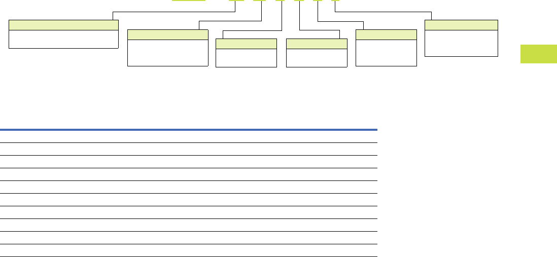
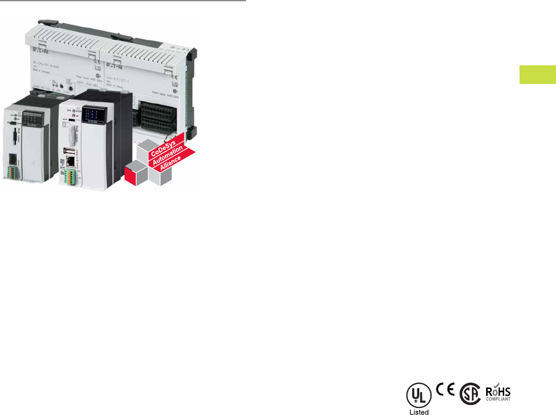
Product Overview
Controllers
ELC2 Modular Controllers
The ELC lineup is focused
on compact size, powerful
features, and affordability.
Whether your needs involve
discrete standalone control,
necessitate distributed
control networks, or even
a control system using
centralized control with
distributed I/O, ELCs provide
the solution your application
demands.
While the ELCs are perfectly
suited for small applications
of <40 I/O with a diverse mix
of I/O, they can also expand
to hundreds of I/O points
when needed. These
controllers are modular,
with a wide range of digital,
analog, thermocouple, RTD,
and even motion expansion
modules. Despite a world-
class small footprint—with
controllers as small as 1.00-
inch wide, these controllers
perform like much larger PLCs.
With online editing, high-
speed processing (basic
instructions
as fast as 0.24
microseconds),
multiple high-
speed inputs/outputs (up to
200 kHz), and multiple
independent master
communication channels,
these controllers excel where
only the largest PLCs could
go only a few years ago.
ELCM Modular Brick-Style
Controllers
The next member of the ELC
portfolio of controllers is the
ELCM. This midrange family
comprises “brick-style”
controllers, with expansion
I/O modules. These all-in-one
controllers combine inputs,
outputs, logic processing, and
an integrated AC power
supply into a compact
package—but also provide
the means to expand as
applications change or grow.
The controller also provides
24 Vdc power for sensors,
eliminating the space, wiring,
and expense of an additional
power supply. And with three
communication ports, the
ELCM is able to interface into
a local operator interface,
connect to other controllers
or supervisory computers,
and still maintain an open port
for programming.
Electrical/EMC
●ESD Immunity
●8 kV air discharge
●EFT Immunity
●
Power Line: 2 kV
●
Digital I/O: 1 kV
●
Analog and
Communication
I/O: 250V
●Damped-Oscillatory Wave
●
Power Line: 1 kV
●Digital I/O: 1 kV
●RS Immunity
●26 MHz–1 GHz, 10 V/m
Standards and Certifications
●cULus
●CE
●C-Tick
●RoHS
Volume 7—Logic Control, Operator Interface and Connectivity Solutions CA08100008E—May 2016 www.eaton.com V7-T4-3
4
4
4
4
4
4
4
4
4
4
4
4
4
4
4
4
4
4
4
4
4
4
4
4
4
4
4
4
4
4
4.1
PLC, I/O and Communications Products
ELC Series Programmable Logic Controllers
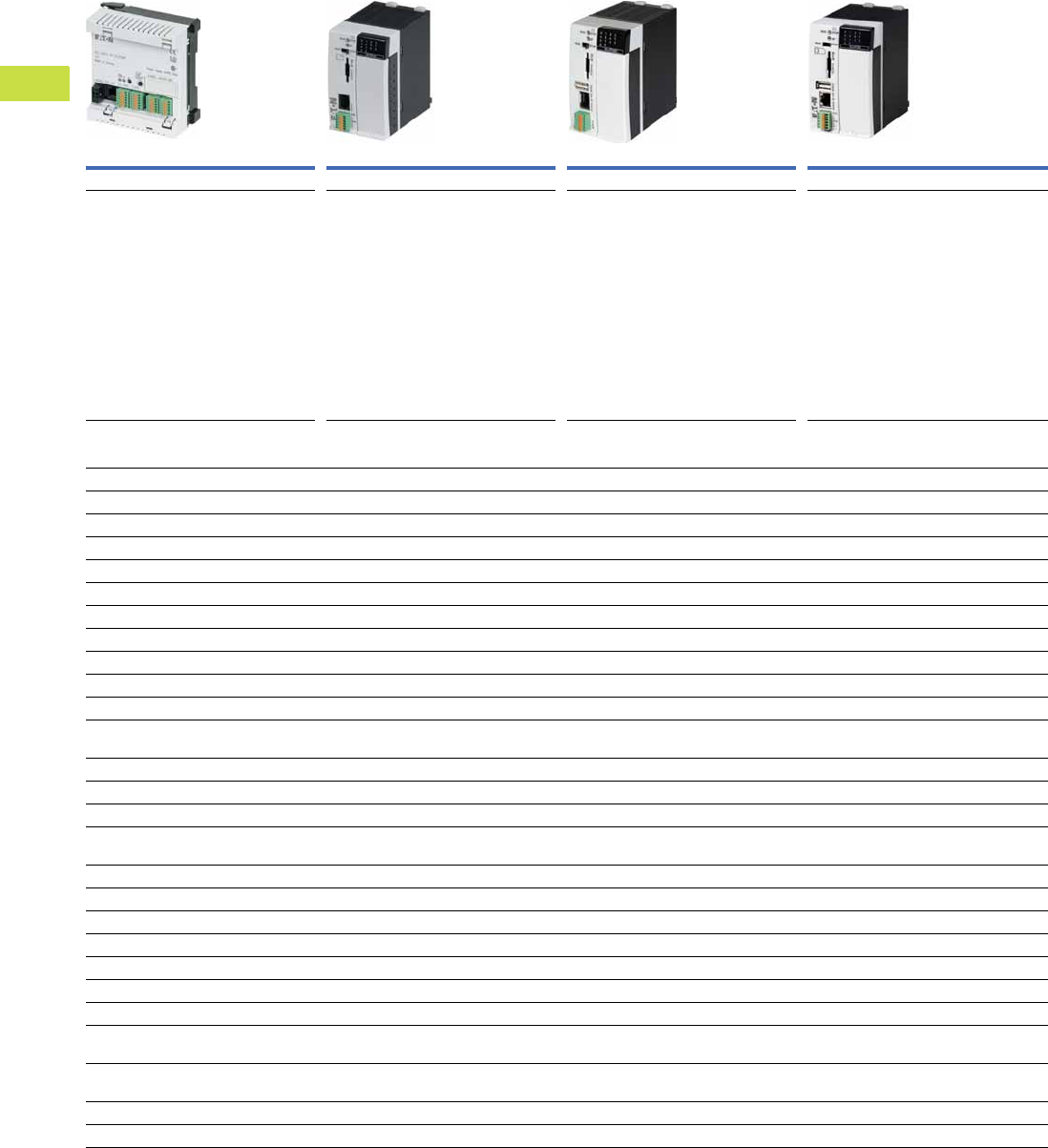
Product Selection Guide
ELC Series Programmable Logic Controllers
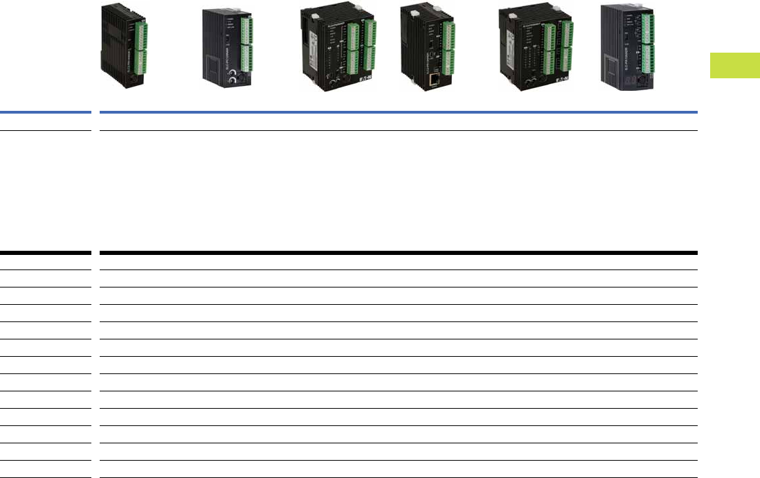
Model ELCM Modular Brick PLCs ELC/ELC2 Modular PLCs
Page V7-T4-4 Page V7-T4-6
Product Description Expandable brick PLCs
●Digital and analog I/O
●16, 20, 24, 32 or 40 I/O base controllers
●8 and 16 digital I/O expansion modules
●24 Vdc inputs
●Relay or transistor outputs
●Built-in 110 Vac power supply
●On board 400 mA 24 Vdc sensor power
●RS-232 programming port
●Two RS-485 Modbus serial ports
●DIN rail or panel mount
Modular and expandable PLCs with distributed I/O capability
●Digital, analog, thermocouple and RTDI/O
●10, 12, 14 and 28 I/O base controllers
●6, 8 or 16 digital I/O expansion modules
●2, 4 and 6 analog I/O expansion modules
●24 Vdc and 110 Vac inputs
●Relay or transistor outputs
●High current relay output module
●High speed pulse capture and high speed pulse output up to 200 kHz
●Up to 2 RS-485 Modbus serial ports
●DIN rail mounting only
●Distributed I/O adapters for EtherNet/IP, Modbus TCP, DeviceNet,
PROFIBUS-DP and RS-485
Features
Input voltage 120 Vac 24 Vdc
Maximum local I/O points 40 264
Built-in power supply Yes No
Built-in 24 Vdc sensor power supply Yes No
DC inputs Yes Yes
AC inputs No Yes
Transistor outputs Yes Yes
Relay outputs Yes Yes
High current relay outputs No Yes
Clock/calendar No Yes
Expandable Yes Yes
Removable terminal blocks Yes Yes
RS-232 communication ports 1 1
RS-458 communication ports 2 1 or 2 depending on model
High-speed counters Yes Yes
Analog I/O Yes Yes
Thermocouple module No Yes
Platinum RTD module No Yes
Single axis motion control module No Yes
DeviceNet master No Yes
Ethernet (Modbus TCP) master No Yes
Distributed I/O adapters No Yes
V7-T4-4 Volume 7—Logic Control, Operator Interface and Connectivity Solutions CA08100008E—May 2016 www.eaton.com
4
4
4
4
4
4
4
4
4
4
4
4
4
4
4
4
4
4
4
4
4
4
4
4
4
4
4
4
4
4
4.1
PLC, I/O and Communications Products
ELC Series Programmable Logic Controllers
Product Selection
ELCM Modular Brick PLCs
Features
●Midrange brick style
controller with digital,
analog, thermocouple and
RTD expansion capability
●Expansion modules can
optionally be used to
increase the total number
of I/O, to provide a mix of
different types of I/O, or both
●These controllers include
an embedded AC power
supply and provide up to
400 mA of DC sensor
power
●Each controller supports
two RS-485 Modbus serial
(master/node) and one
RS-232 programming port
Controllers
Controllers
Inputs Outputs
Description AC DC Analog Relay
NPN Sinking
Transistor Analog Catalog Number
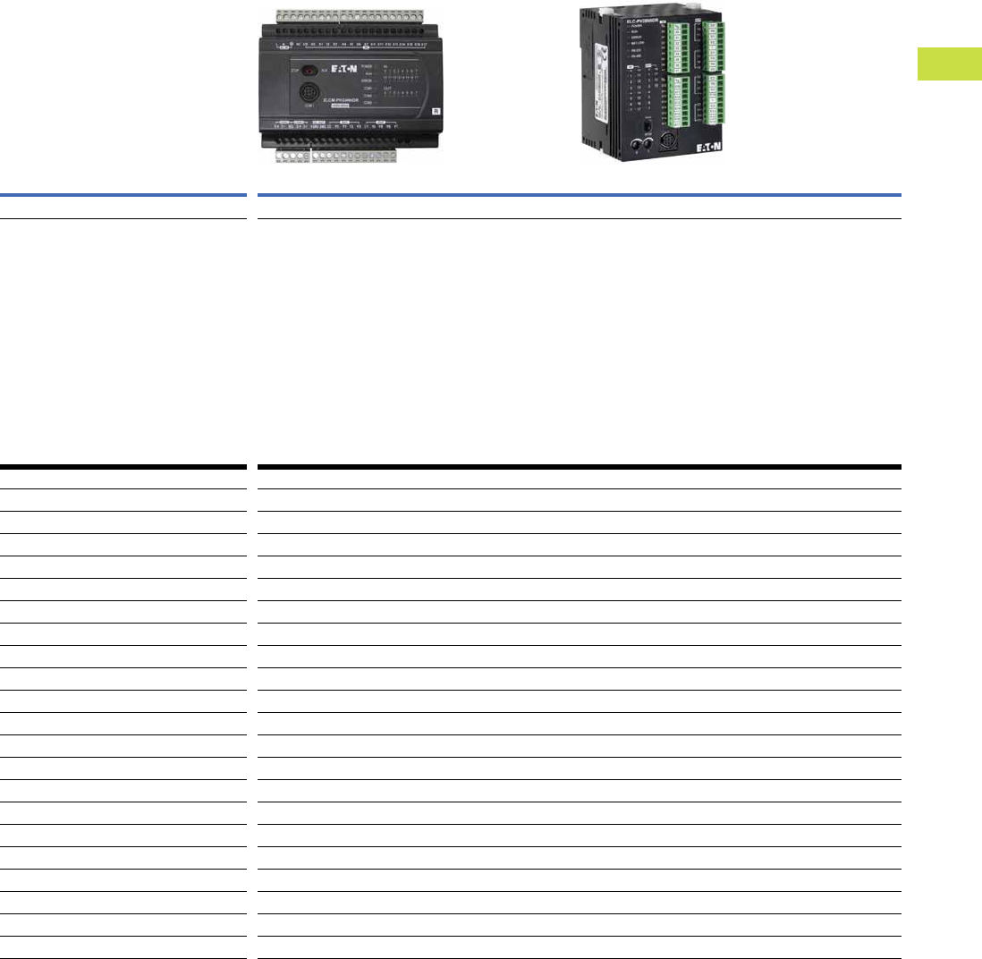
16 I/O PH model — 8 — 8 — — ELCM-PH16NNDR
—8 ——8 —ELCM-PH16NNDT
24 I/O PH model — 16 — 8 — — ELCM-PH24NNDR
—16——8 —ELCM-PH24NNDT
32 I/O PH model — 16 — 16 — — ELCM-PH32NNDR
—16——16 —ELCM-PH32NNDT
40 I/O PH model — 24 — 16 — — ELCM-PH40NNDR
—24——16 —ELCM-PH40NNDT
20 I/O PH model —846— 2ELCM-PA20AADR
—84—6 2ELCM-PA20AADT
Device Type
PH = High-speed model
PA = Analog model
ELCM - PA 16 A A D R
Digital Inputs
A =AC
D =DC
N = None
Analog Inputs
A =Analog
N = None
I/O Count
xx = Total number of I/O
(16, 24, 32, 40 digital;
20 analog and digital)
Analog Outputs
A = Analog
N = None
Digital Outputs
R = Transistor
T =Relay
N =None
ELCM-PH16NNDR
Volume 7—Logic Control, Operator Interface and Connectivity Solutions CA08100008E—May 2016 www.eaton.com V7-T4-5
4
4
4
4
4
4
4
4
4
4
4
4
4
4
4
4
4
4
4
4
4
4
4
4
4
4
4
4
4
4
4.1
PLC, I/O and Communications Products
ELC Series Programmable Logic Controllers
Expanded and Specialty Modules
Right Side Digital Expansion Modules
Inputs Outputs
Description AC
DC
Sink/Source Relay
NPN Sinking
Transistor Catalog Number
8 DC input module — 8 — — ELCM-EX08NNDN
16 DC input module — 16 — — ELCM-EX16NNDN
8 Relay output module — — 8 — ELCM-EX08NNNR
16 Relay output module — — 16 — ELCM-EX16NNNR
8 Transistor output module — — 8 — ELCM-EX08NNNT
16 Transistor output module — — 16 — ELCM-EX16NNNT
8 DC input/relay output module — 4 4 — ELCM-EX08NNDR
16 DC input/relay output module — 8 8 — ELCM-EX16NNDR
8 DC input/output module — 4 — 4 ELCM-EX08NNDT
16 DC input/output module — 8 — 8 ELCM-EX16NNDT
Device Type
AN = Analog expansion module
EX = Digital expansion module
ELCM - EX 16 N N D R
Digital Inputs
A =AC
D =DC
N = None
Analog Inputs
A =Analog
N = None
I/O Count
xx = Total number of I/O
(16, 24, 32, 40 digital;
20 analog and digital)
Analog Outputs
A = Analog
N = None
Digital Outputs
R = Transistor
T =Relay
N =None

V7-T4-6 Volume 7—Logic Control, Operator Interface and Connectivity Solutions CA08100008E—May 2016 www.eaton.com
4
4
4
4
4
4
4
4
4
4
4
4
4
4
4
4
4
4
4
4
4
4
4
4
4
4
4
4
4
4
4.1
PLC, I/O and Communications Products
ELC Series Programmable Logic Controllers
ELC2 Modular PLCs
Features
●PB Base Model—
●
14 I/O (8I+6O)
●
Over 130 instructions
●
RS-485 master port
with the ability to
communicate to 31
other devices
●
The master port can
also be configured to
communicate to devices
such as ASCII, bar code
readers, and so on
●Retentive flash memory
●PC Clock/Calendar Model
●
12 I/O (8I+4O)
●
Same features as the basic
model plus clock/calendar
●
Distributed I/O capability
with up to 14 devices
●
File area for data storage
and retrieval
●
Two digital potentiometers
that vary the data in
internal registers
●
Compatible with left side
Ethernet and DeviceNet
master communication
modules
●PE Ethernet Model
●
12 I/O (8I+4O)
●
All the features of the
PC model
●
Built-in Ethernet client/
server
●
EtherNet/IP server
●PA20 Analog Model
●
20 I/O (12I+8O)
●
Same features as PC
model with analog I/O
●
Analog channels can be
set up for either voltage
or current
●PV Advanced Model
●
28 I/O (16I+12O)
●
The PV model has the
most extensive features
●
Programs written for the
other controllers can be
migrated to a PV model
controller where greater
speed or more I/O
is required
●
Flash ROM and SRAM
program storage and
backed using a
rechargeable lithium-ion
battery that charges with
normal use
●
Includes 2-axis motion
control
●
Additional expansion bus
to the left of the controller
●
Add high-speed and
specialty modules to
the left
●
Compatible with left side
Ethernet and DeviceNet
master communication
modules
ELC Modular PLCs
Features
●PA10 Analog Model
●
10 I/O (6I+4O)
●
Same features as PC
model with a different
I/O mix
●
Four digital inputs, two
digital outputs, two
analog inputs, and two
analog outputs
●
Analog channels can be
set up for either voltage or
current
●
Two 7-segment LEDs that
can be used to display
unit ID, error codes,
process steps, and so on
Volume 7—Logic Control, Operator Interface and Connectivity Solutions CA08100008E—May 2016 www.eaton.com V7-T4-7
4
4
4
4
4
4
4
4
4
4
4
4
4
4
4
4
4
4
4
4
4
4
4
4
4
4
4
4
4
4
4.1
PLC, I/O and Communications Products
ELC Series Programmable Logic Controllers
ELC Series Programmable Logic Controllers
ELC2 ELC
Model PB–Basic PC–Clock/calendar PA–Analog PE–Ethernet PV–Advanced function PA–Analog
Page V7-T4-11 Page V7-T4-11 Page V7-T4-10 Page V7-T4-10 Page V7-T4-10 Page V7-T4-10
Product Description ●Most popular, best
value PLC
●Smallest footprint
●Relay, NPN or PNP
outputs
●No clock/calendar
function
●No battery required
●Clock/calendar functions
●Built-in potentiometers
●Relay or NPN outputs
●No battery required
●Analog I/O for voltage
or current
●Clock/calendar functions
●Built-in potentiometers
●Relay, NPN or PNP
outputs
●No battery required
●Built-in Ethernet
●EtherNet/IP server
●Clock/calendar functions
●Relay or NPN outputs
●No battery required
●Fastest CPU
●Clock/calendar functions
●Built-in potentiometers
●Relay, NPN or PNP
outputs
●Battery backup
●Built-in LED displays
●Analog I/O for voltage or
current
●Clock/calendar functions
●Relay or NPN outputs
●Replaceable battery
Features
On-board I/O 12/14 12 20 12 28 10
Analog I/O — — 4I + 2O — — 2I + 2O
CPU 32-bit 32-bit 32-bit 32-bit 32-bit 16-bit
Program capacity 8 k 16 k 16 k 16 k 30 k 8 k
RS-232111111
RS-485121111
USB——11——
Clock/calendar No Yes Yes Yes Yes Yes
BatteryNoNoNoNoYesYes
Right side bus Yes Yes Yes Yes Yes Yes
Left side bus No Yes Yes Yes Yes No
Potentiometers—22—2—
LED displays———-——2
V7-T4-8 Volume 7—Logic Control, Operator Interface and Connectivity Solutions CA08100008E—May 2016 www.eaton.com
4
4
4
4
4
4
4
4
4
4
4
4
4
4
4
4
4
4
4
4
4
4
4
4
4
4
4
4
4
4
4.1
PLC, I/O and Communications Products
ELC Series Programmable Logic Controllers
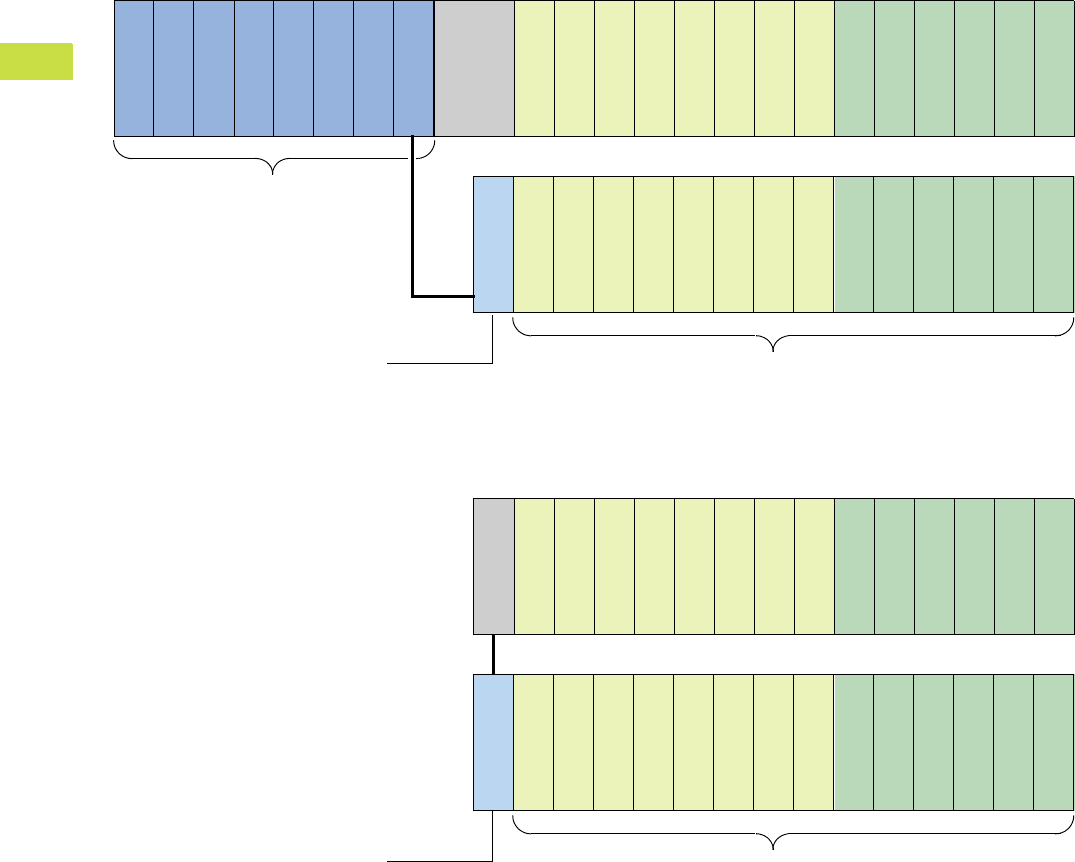
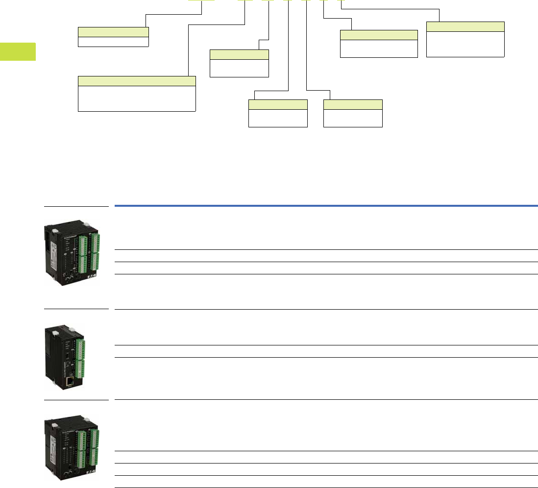
ELC System Overview
Configuration and Layout
123456789101112131487654321
ANALOG
ANALOG
ANALOG
ANALOG
ANALOG
ANALOG
ANALOG
ANALOG
ANALOG
ANALOG
ANALOG
ANALOG
ANALOG
ANALOG
ANALOG
ANALOG
DIGITALDIGITAL
DIGITALDIGITAL
DIGITALDIGITAL
DIGITALDIGITAL
DIGITALDIGITAL
DIGITALDIGITAL
ELC-CAENET
ELC-COENETM
ELC-COENETM
ELC-COENETM
ELC-COENETM
ELC-COENETM
ELC-COENETM
ELC-COENETM
ELC-COENETM
ELC2-PC,
ELC2-PA,
ELC2-PV
Right Side Bus Modules
— Up to 8 analog modules
— Up to 14 digital modules
Left Side Bus Modules
—Up to 8 modules
Ethernet I/O Adapters
— Up to 4 adapter modules per master
1234567891011121314
ANALOG
ANALOG
ANALOG
ANALOG
ANALOG
ANALOG
ANALOG
ANALOG
ANALOG
ANALOG
ANALOG
ANALOG
ANALOG
ANALOG
ANALOG
ANALOG
DIGITALDIGITAL
DIGITALDIGITAL
DIGITALDIGITAL
DIGITALDIGITAL
DIGITALDIGITAL
DIGITALDIGITAL
ELC-CAENET ELC2-PE
Right Side Bus Modules
— Up to 8 analog modules
— Up to 14 digital modules
Ethernet I/O Adapters
— Up to 4 adapter modules
Volume 7—Logic Control, Operator Interface and Connectivity Solutions CA08100008E—May 2016 www.eaton.com V7-T4-9
4
4
4
4
4
4
4
4
4
4
4
4
4
4
4
4
4
4
4
4
4
4
4
4
4
4
4
4
4
4
4.1
PLC, I/O and Communications Products
ELC Series Programmable Logic Controllers
Controllers—Basic
Controllers—Basic
All models include RS-232 and RS-485 programming/communication ports and can be expanded with up to
14 extension modules on the right-hand side bus.
On-
Board
I/O
Program
Memory
Steps
Inputs Outputs Analog High Speed Inputs High Speed Outputs
24 Vdc
Relay
1.5 A
NPN
0.5 A
PNP
0.5 A Inputs Outputs 10 kHz 20 kHz 100 kHz 200 kHz 10 kHz 100 kHz 200 kHz
Catalog
Number
ELC2-PB Basic Controllers
• Smallest size and footprint
• Retentive flash memory
148 k 8 6 ————4 4 —————ELC2-PB14NNDR
148 k 8 —6 ———4 4 ——4 ——ELC2-PB14NNDT
128 k 8 ——4 ——4 4 ——4 ——ELC2-PB12NNDP
ELC2-PC Basic Clock Controllers
• Suitable for larger capacity and RTC applications
• Expandable with left side communication modules
• 2 RS-485 ports
• 2 built-in potentiometers
• Retentive flash memory
1216 k8 4 ————4 —4 ————ELC2-PC12NNDR
1216 k8 —4 ———4 —4 —2 2 —ELC2-PC12NNDT
ELC-PA Basic Analog Controllers
• Built-in 2 analog inputs and 2 analog outputs
• 2-digit, 7-segment display
• SRAM and replaceable battery
• Retentive flash memory (style -3 and above)
108 k 4 2 ——2 2 2 2 —————ELC-PA10AADR
108 k 4 —2 —2 2 2 2 ——2 ——ELC-PA10AADT
Device Type
PA = Analog model
PB = Base model
PC = Clock/calendar model
ELC2 - PB 14 N N D R
Digital Inputs
A =AC
D = DC (sink or source)
Analog Inputs
A = Analog
N = None
I/O Count
xx = Total number
of I/O
Analog Outputs
A = Analog
N =None
Digital Outputs
R =Relay
T = Transistor (NPN)
P = Transistor (PNP)
Controller Type
ELC2
ELC
ELC2-PB_
ELC2-PC _
ELC-PA10_
V7-T4-10 Volume 7—Logic Control, Operator Interface and Connectivity Solutions CA08100008E—May 2016 www.eaton.com
4
4
4
4
4
4
4
4
4
4
4
4
4
4
4
4
4
4
4
4
4
4
4
4
4
4
4
4
4
4
4.1
PLC, I/O and Communications Products
ELC Series Programmable Logic Controllers
Controllers—Advanced
Controllers—Advanced
All models (except ELC2-PE) include RS-232 and RS-485 programming/communication ports and can be expanded
with up to 14 extension modules on the right-hand side bus.
Note
1 PNP transistor outputs are only 0.3 A.
On-
Board
I/O
Program
Memory
Steps
Inputs Outputs Analog High Speed Inputs High Speed Outputs
24 Vdc
Relay
1.5 A
NPN
0.5 A
PNP
0.5 A Inputs Outputs 10 kHz 20 kHz 100 kHz 200 kHz 10 kHz 100 kHz 200 kHz
Catalog
Number
ELC2-PA Advanced Analog Controllers
• Built-in 4 analog inputs and 2 analog outputs
• Expandable with left side communication modules
• 2 built-in potentiometers
• Retentive flash memory
2016 k8 6 ——4 2 6 —2 ————ELC2-PA20AADR
2016 k8 —6 —4 2 6 —2 —2 2 —ELC2-PA20AADT
20 16 k 8 — — 6 1426—2—22—ELC2-PA20AADP
ELC2-PE Ethernet Controllers
• Built-in Ethernet and USB port
• Expandable with left side communication modules
• Retentive flash memory
1216 k8 4 ————6 —2 ————ELC2-PE12NNDR
1216 k8 —4 ———6 —2 - 2 2 —ELC2-PE12NNDT
ELC2-PV Large Capacity Advanced Controllers
• 4, 200 kHz inputs and 4, 200 kHz outputs
• Extendable with left side communication modules
• 2 built-in potentiometers
• Self-charging lithium-ion battery
• Retentive flash memory and SRAM
2830 k1612————12——4 ———ELC2-PV28NNDR
2830 k16—12———12——4 ——4 ELC2-PV28NNDT
2830 k16——12——12——4 ——4 ELC2-PV28NNDP
Device Type
PA = Analog model
PE = Ethernet model
PV = Advanced model
ELC2 - PV 28 N N D R
Digital Inputs
A =AC
D = DC (sink or source)
Analog Inputs
A = Analog
N = None
I/O Count
xx = Total number
of I/O
Analog Outputs
A = Analog
N =None
Digital Outputs
R =Relay
T = Transistor (NPN)
P = Transistor (PNP)
Controller Type
ELC2
ELC2-PA20_
ELC2-PE_
ELC2-PV_
Volume 7—Logic Control, Operator Interface and Connectivity Solutions CA08100008E—May 2016 www.eaton.com V7-T4-11
4
4
4
4
4
4
4
4
4
4
4
4
4
4
4
4
4
4
4
4
4
4
4
4
4
4
4
4
4
4
4.1
PLC, I/O and Communications Products
ELC Series Programmable Logic Controllers
Controllers—Superseded
Controllers—Superseded
For Replacement Only
Description Inputs Outputs Analog
High
Speed I/O
Max. Current
Consumption
(at 24 Vdc)
Catalog
Number
ELC-PB model and 14 I/O built-in (8) 24 Vdc (6) Relay, 1.5 A — (2) 20 kHz inputs 150 mA ELC-PB14NNDR
(8) 24 Vdc (6) Transistor, 100 mA — (2) 20 kHz inputs 150 mA ELC-PB14NNDT
ELC-PC model and 12 I/O built-in (8) 24 Vdc (4) Relay, 1.5 A — (1) 30 kHz inputs 150 mA ELC-PC12NNDR
(8) 24 Vdc (4) Transistor, 100 mA — (1) 30 kHz inputs 150 mA ELC-PC12NNDT
(8) 110 Vac (4) Relay, 1.5 A — (1) 30 kHz inputs 150 mA ELC-PC12NNAR
ELC-PH model and 12 I/O built-in (8) 24 Vdc (4) Transistor, 100 mA — (1) 100 kHz inputs 170 mA ELC-PH12NNDT
Device Type
PB = Base model
PC = Clock/calendar model
PH = High-speed model
Digital Inputs
A =AC
D = DC (sink or source)
Analog Inputs
N = None
I/O Count
xx = Total number
of I/O
Analog Outputs
N = None
Digital Outputs
R =Relay
T = Transistor (NPN)
P = Transistor (PNP)
ELC - PB 12 N N D R
ELC2-PB_
V7-T4-12 Volume 7—Logic Control, Operator Interface and Connectivity Solutions CA08100008E—May 2016 www.eaton.com
4
4
4
4
4
4
4
4
4
4
4
4
4
4
4
4
4
4
4
4
4
4
4
4
4
4
4
4
4
4
4.1
PLC, I/O and Communications Products
ELC Series Programmable Logic Controllers
ELC Communication Modules
ELC Communication Modules
Ethernet Master Communication Module (Left Side Bus)
Features
●Ethernet communication
module
●Enables the ELC2-PC,
EL2C-PA and ELC2-PV
controllers to connect to
Modbus TCP networks
auto detecting 10/100 MB
connections
●Enables the uploading and
downloading of programs
in addition to program
monitoring
●Use ELCSoft to search for
all the Ethernet modules
attached to the network
and manage them
remotely
●Share data in a peer-to-peer
network to reduce long I/O
wiring
●Send e-mails for alerts and
notifications. For example,
advise personnel of alarm
condition or send daily
production yield summaries
●Keep accurate time with
the NTP (Network Time
Protocol) feature, which
synchronizes your
controller with an NTP
server
●The Ethernet module will
automatically detect and
use the type of patch or
crossover cable attached
●IP addresses may be
filtered to manage module
traffic in order to maximize
communication
performance.
Ethernet Master Communication Module (Left Side Bus)
DeviceNet Master Communication Module (Left Side Bus)
Features
●DeviceNet master module
maps up to 380 bytes of
data directly into the PV
model controller for quick
and easy access
●Use polled, bit-strobe and
change of state/cyclic
DeviceNet commands, or
send explicit messages
●Configuration of DeviceNet
components in ELCSoft is
easy with the drag-and-
drop interface
●Use the pre-populated EDS
files within ELCSoft and
add others to simplify the
configuration
DeviceNet Master Communication Module (Left Side Bus)
Note
1Left side bus communications module—for use with ELC-PV, ELC2-PC, ELC2-PA, ELC2-PE and ELC2-PV controllers only.
Module Type
DNETM = DeviceNet master module 1
ENETM = Ethernet master module 1
Device Type
CO = Communication interface module
ELC - CO ENETM
Description
Inputs
Points Type
Outputs
Points
Catalog
Number
Ethernet Modbus TCP (client/server) N/A Modbus TCP N/A ELC-COENETM
ELC-COENETM
Description
Inputs
Points Type
Outputs
Points
Catalog
Number
DeviceNet Scanner (client/server) 190 bytes DeviceNet 190 bytes ELC-CODNETM
ELC-CODNETM
Volume 7—Logic Control, Operator Interface and Connectivity Solutions CA08100008E—May 2016 www.eaton.com V7-T4-13
4
4
4
4
4
4
4
4
4
4
4
4
4
4
4
4
4
4
4
4
4
4
4
4
4
4
4
4
4
4
4.1
PLC, I/O and Communications Products
ELC Series Programmable Logic Controllers
ELC Remote I/O Adapters
Features
●Combine with ELC
expansion modules to
create remote I/O racks for
different PLC networks
●Use ELC-CAENET and
ELC-COENETM to create
remote I/O racks to the
ELC-PV controllers
●Connect cost effective ELC
expansion modules to
third-party PLCs using
standard networks
●EtherNet/IP, Modbus TCP,
DeviceNet, PROFIBUS-DP
and Modbus serial RS-485
remote I/O adapters
●Connect up to 8 analog
expansion modules or 14
digital expansion modules
ELC Remote I/O Adapters
Remote I/O Adapter Modules
Description Catalog Number
EtherNet/IP or Modbus TCP I/O adapter ELC-CAENET
Modbus serial RS-485 I/O adapter ELC-CARS485
DeviceNet I/O adapter ELC-CADNET
PROFIBUS-DP I/O adapter ELC-CAPBDP
Device Type
CA = Remote I/O adapter
Module Type
ENET = EtherNet/IP or Modbus TCP I/O adapter
DNET = DeviceNet I/O adapter
RS485 = Modbus serial RS-485 I/O adapter
PBDP = PROFIBUS-DP I/O adapter
ELC – CA ENET
ELC-CAENET
V7-T4-14 Volume 7—Logic Control, Operator Interface and Connectivity Solutions CA08100008E—May 2016 www.eaton.com
4
4
4
4
4
4
4
4
4
4
4
4
4
4
4
4
4
4
4
4
4
4
4
4
4
4
4
4
4
4
4.1
PLC, I/O and Communications Products
ELC Series Programmable Logic Controllers
ELC Expansion Modules
Right Side Bus
Expansion Modules
Features
●Digital right side expansion
modules can be used with
any ELC controller
●They simply snap together
to allow the ELC backplane
to pass through each
connected module
●Add only the amount of I/O
you need
●Choose I/O counts as small
as 6 points and as large as
14 points per module
●I/O modules are available in
a broad selection of AC/DC
inputs, relay/transistor and
high current outputs that
may be used together in
any combination
●Maximum of 14 modules
per controller
Digital Expansion Modules (Right Side Bus) 8-Point
Digital Expansion Modules (Right Side Bus) 16-Point
Device Type
AN = Analog expansion module
EX = Digital expansion module
PT = Platinum RTD expansion module
TC = Thermocouple expansion module
ELC - EX 16 N N D P
Digital Inputs
A =AC
D = DC (sink or source)
S =Switch
N =None
Analog Inputs
A = Analog
N = None
I/O Count
xx = Total number
of I/O
Analog Outputs
A = Analog
N = None
Digital Outputs
T = Transistor (NPN)
P = Transistor (PNP)
R =Relay
I = Relay—high current
N =None
Description Inputs Outputs
Max. Current
Consumption
(at 24 Vdc)
Catalog
Number
8 DC input module (8) 24 Vdc — 50 mA ELC-EX08NNDN
8 AC input module (8) 110 Vac — 50 mA ELC-EX08NNAN
8 Transistor output module — (8) Transistor (sink), 0.3 A 70 mA ELC-EX08NNNT
8 Relay output module — (8) Relay, 1.5 A 70 mA ELC-EX08NNNR
Description Inputs Outputs
Max. Current
Consumption
(at 24 Vdc)
Catalog
Number
8 DC input/output module (4) 24 Vdc (4) Transistor (sink), 0.3 A 70 mA ELC-EX08NNDT
8 DC input/relay output module (4) 24 Vdc (4) Relay, 1.5 A 70 mA ELC-EX08NNDR
6 High current relay output module — (6) Relay, 6 A 70 mA ELC-EX06NNNI
16 DC input module (16) 24 Vdc — 100 mA ELC-EX16NNDN
16 DC input/output module (8) 24 Vdc (8) Transistor (sink), 0.3 A 90 mA ELC-EX16NNDT
16 DC input/output module (8) 24 Vdc (8) Transistor (source), 0.3 A 100 mA ELC-EX16NNDP
16 DC input/relay output module (8) 24 Vdc (8) Relay, 1.5 A 90 mA ELC-EX16NNDR
ELC-EX08NNDN
ELC-EX08NNDT
Volume 7—Logic Control, Operator Interface and Connectivity Solutions CA08100008E—May 2016 www.eaton.com V7-T4-15
4
4
4
4
4
4
4
4
4
4
4
4
4
4
4
4
4
4
4
4
4
4
4
4
4
4
4
4
4
4
4.1
PLC, I/O and Communications Products
ELC Series Programmable Logic Controllers
Analog Input and Output Modules (Right Side Bus)
Analog input/output modules uses voltage or current mode for any channel—see table
for resolution based on type and mode.
Temperature Input Modules (Right Side Bus)
Thermocouple and Platinum RTD temperature sensor input modules with 14 bit resolution.
Motion Control Module (Right Side Bus)
Single axis motion control module.
If used with ELC2-PC controllers, it can provide a second axis because these controllers
have a single axis built-in.
If used with the ELC2-PV controllers, it can provide a third axis because these controllers
incorporate two axis of motion control and are capable of output pulses up to 200 kHz.
RS-485 Adapter Module (Right Side Bus—End Module)
Passive RS-485 connection device module.
RJ12 port for connecting to a drive.
2-pin screw terminal to connect to ELC controller.
Male and female DB9 connectors to connect to other RS-485 devices.
Toggle Switch Input Module (Right Side Bus)
8 input switch module for manual switch inputs to
the ELC controllers—used for debugging applications
or product training demonstrations
Description
Input
Points Resolution Mode
Output
Points Resolution Mode
Maximum
Current
Consumption
(at 24 Vdc)
Catalog
Number
4 Analog input module 4 V = 14 bit
I = 13 bit
±10 V
±20 mA
—— — 90 mA ELC-AN04ANNN
2 Analog output module — — — 2 12 bit 0–20 mA; 4–20 mA
0–10 V; 2–10 V
125 mA ELC-AN02NANN
4 Analog output module — — — 4 12 bit 0–20 mA; 4–20 mA
0–10 V; 2–10 V
170 mA ELC-AN04NANN
6 Analog input/output
module
4 V = 12 bit
I = 11 bit
±10 V
±20 mA
2 12 bit 0–20 mA
0–10 V
170 mA ELC-AN06AANN
Description
Input
Points Resolution
Sensor
Type
Maximum Current
Consumption
(at 24 Vdc)
Catalog
Number
4 Thermocouple input module 4 — J, K, R, S, T 90 mA ELC-TC04ANNN
4 Platinum RTD input module 4 14 bit PT100 90 mA ELC-PT04ANNN
Description
Input
Type
Output
Type
Catalog
Number
Single axis motion control module Phase in, start, stop, and so on Phase, pulse, direction ELC-MC01
Description
Connector
Types
Catalog
Number
RS-485 Connect adapter module RJ12, DB9 (male and female), 2-pin screw terminals ELC-485APTR
Description
Maximum Current
Consumption
(at 24 Vdc)
Catalog
Number
8 Toggle switch input module 20 mA ELC-EX08NNSN
ELC-AN04ANNN
ELC-PT04ANNN
ELC-MC01
ELC-485APTR
ELC-EX08NNSN
V7-T4-16 Volume 7—Logic Control, Operator Interface and Connectivity Solutions CA08100008E—May 2016 www.eaton.com
4
4
4
4
4
4
4
4
4
4
4
4
4
4
4
4
4
4
4
4
4
4
4
4
4
4
4
4
4
4
4.1
PLC, I/O and Communications Products
ELC Series Programmable Logic Controllers
Programming Software
ELCSoft programming
software configures all ELC
controllers. With ELCSoft,
applications can be created,
edited and monitored. Move
programs from one controller
to another with ease.
Program in ladder, sequential
function chart or instruction
language. ELCSoft is the
single program to develop
ELC controller applications.
ELCSoft is also used to
configure the DeviceNet
master and Modbus TCP
Ethernet modules.
New program simulation
capabilities are available in
ELCSoft Version 2.
Requirements
Operating Systems
●Windows® 2000
●Windows XP
●Windows Vista
●Windows 7
Hard Drive
●At least 100 Mbytes
RAM
●At least 512 Mbytes
ELC Software
Description Catalog Number
Programming Software for ELC Controllers ELCSOFT
Configuration Software for ELC Ethernet networks ECISOFT
ELCSoft Editor
Volume 7—Logic Control, Operator Interface and Connectivity Solutions CA08100008E—May 2016 www.eaton.com V7-T4-17
4
4
4
4
4
4
4
4
4
4
4
4
4
4
4
4
4
4
4
4
4
4
4
4
4
4
4
4
4
4
4.1
PLC, I/O and Communications Products
ELC Series Programmable Logic Controllers
Accessories
Power Supplies
All ELC controllers, analog
and specialty expansion
modules operate from
24 Vdc.
These power supplies
provide a convenient way to
provide robust DC voltage for
ELC and other products.
Power Supplies
Cables
Use these cables to connect
your PC’s RS-232 serial
port to your ELC controller
to download, upload and
monitor your ELC controllers,
or to connect any ELC-GP
to an ELC controller. The
ELC-CBPCELC1 cable is
1 meter long and has a
right angle connector to
the ELC controller to help
reduce depth when cable
is attached. The ELC-
CBPCELC3 is 3 meters long
with a straight connector.
Cables
Storage/Transfer Module
The ELC-ACPGMXFR module
is a multifunction device that
provides the ability to back up
an application already loaded
onto one of the ELC or ELC2
controllers. The transfer
module can be used for
copying the same application
to multiple controllers and to
transfer an existing
application to a new controller
in the event of a failure. It will
store system settings,
passwords and the
application, including the data
registers for pre-loaded
recipes. Once stored in the
module, the application, data
registers and settings can be
transferred to another ELC/
ELC2 controller of the same
model number.
Storage/Transfer Module
Description Input Power
Output
Volts
Output
Current (A) Watts
Catalog
Number
24 watt, 1 amp power supply 100–240 Vac 50/60 Hz 24 Vdc 1 A 24 ELC-PS01
48 watt, 2 amp power supply 100–240 Vac 50/60 Hz 24 Vdc 2 A 48 ELC-PS02
ELC-PS01
Description
Catalog
Number
Cable to connect a PC or an ELC-GP unit to ELC, 1 meter with right angle connector (DB 9-pin female to 8-pin DIN) ELC-CBPCELC1
Cable to connect a PC or an ELC-GP unit to ELC, 3 meters (DB 9-pin female to 8-pin DIN) ELC-CBPCELC3
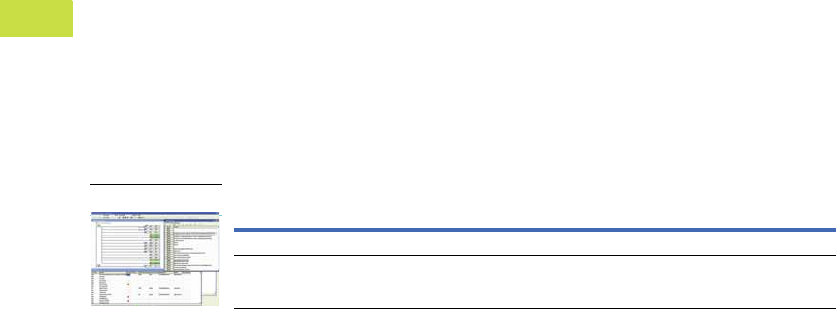
PC/HMI COM Port
9 PIN D-SUB Female PLC COM1 Port
8 PIN MINI DIN
12
3
4
5
6
7
8
Rx 2 5 Tx
Tx 3 4 Rx
GND 5 8 GND
1,2 5V
1
4
6
7
8
Description
Catalog
Number
Program transfer module for ELC and ELC2 controllers
(Not compatible with ELC2-PE controllers)
ELC-ACPGMXFR
ELC-ACPGMXFR
V7-T4-18 Volume 7—Logic Control, Operator Interface and Connectivity Solutions CA08100008E—May 2016 www.eaton.com
4
4
4
4
4
4
4
4
4
4
4
4
4
4
4
4
4
4
4
4
4
4
4
4
4
4
4
4
4
4
4.1
PLC, I/O and Communications Products
ELC Series Programmable Logic Controllers
Plate Mount
Use the ELC-ACCOVER
surface mount stand-alone
modules instead of mounting
to a DIN rail.
This may be used to mount
analog, temperature or the
RS-485 adapters remotely.
Plate Mount
Spare Parts
ELC Spare Parts
Description Catalog Number
Plate mount for specialty modules, qty. 10 ELC-ACCOVER
Description Catalog Number
Kit consists of: ELC-SPKIT
Module to module locking clips (white) 4
Module DIN rail clip (white) 2
3-pin power plug and cable assembly (white) 4
2-pin RS-485 communications connector (green—for latest version PA, PB, PC and PH) 4
3-pin RS-485 communications connector (green—PV controllers only) 2
Left side expansion port cover (PV controllers and left side communications modules) 2
Right side I/O expansion port cover (all controllers and I/O modules) 2
Battery cover door (for PA, PC and PH controllers) 2
Metal mounting clips (only for PV controllers) 2
Kit consists of: ELC-IOBLOCK
9-pin replacement I/O blocks (green) 4
Battery with pigtail and connector (for ELC-PA, PC and PH controllers only) ELC-BAT
ELC-BAT

Volume 7—Logic Control, Operator Interface and Connectivity Solutions CA08100008E—May 2016 www.eaton.com V7-T4-19
4
4
4
4
4
4
4
4
4
4
4
4
4
4
4
4
4
4
4
4
4
4
4
4
4
4
4
4
4
4
4.1
PLC, I/O and Communications Products
ELC Series Programmable Logic Controllers
Technical Data and Specifications
ELC2 Controllers
Note
1High-speed counter inputs can be used for different types of 32-bit counting, such as single-ended, single-phase two inputs, and quadrature.
Therefore, all high-speed counters may not be used at the same time. Please refer to the ELC Programming Manual, MN05003003E, for details.
Description ELC2-PB14NNDR/T ELC2-PB12NNDP ELC2-PC12NNDR/T
Dimensions W x H x D
in inches (mm)
0.99 x 3.54 x 2.36
(25.2 x 90.0 x 60.0)
0.99 x 3.54 x 2.36
(25.2 x 90.0 x 60.0)
1.47 x 3.54 x 2.36
(37.4 x 90.0 x 60.0)
I/O type—embedded 14 (8DI/6DO) 12 (8DI/4DO) 12 (8DI/4DO)
Maximum additional I/O points Up to 14 expansion modules (maximum of 8
analog/specialty modules)
Up to 14 expansion modules (maximum of 8
analog/specialty modules)
Up to 14 expansion modules (maximum of 8
analog/specialty modules)
DC in sink/source Yes Yes Yes
Execution speed (basic instructions) 0.54 s 0.54 s 0.54 s
Program language Instructions + Ladder Logic + SFC Instructions + Ladder Logic + SFC Instructions + Ladder Logic + SFC
Program capacity (steps) 7,920 7,920 15,872
Data memory capacity
(M device—bits)
4096 4096 4096
Data memory capacity
(D register—words)
5000 5000 10,000
Index registers 16 16 16
File memory capacity (words) 0 0 5000
Retentive storage Flash ROM Flash ROM Flash ROM
Commands Basic/Advanced
Floating point Support Support Support
SFC commands (steps) 1024 1024 1024
Timers quantity 256 256 256
Timers resolution 1 ms, 10 ms, 100 ms 1 ms, 10 ms, 100 ms 1 ms, 10 ms, 100 ms
Counters quantity 256 256 256
High-speed counters 122 22 22
Max. high-speed counting 120 kHz 20 kHz 100 kHz
Pulse output 4*10 kHz 4*10 kHz 2*10 kHz+2*100 kHz
PID Support Support Support
Master control 8 8 8
Subroutines 256 256 256
For/next loops Max. 6 loops Max. 6 loops Max. 6 loops
Max. interrupts quantity 21 21 22
Real-time clock/calendar No No Built-in
Password security Yes Yes Yes
Diagnostic relays Yes Yes Yes
Diagnostic word registers Yes Yes Yes
Specialty expansion modules Up to a maximum of 8 (Analog in/analog out/TC/
RTD/PT) modules
Up to a maximum of 8 (Analog in/analog out/TC/
RTD/PT) modules
Up to a maximum of 8 (Analog in/analog out/TC/
RTD/PT) modules
Serial ports 2 Modbus* (ASCII/RTU) 1=server
(RS-232)/1=client/server (RS-485)
2 Modbus* (ASCII/RTU) 1=server
(RS-232)/1=client/server (RS-485)
2 Modbus* (ASCII/RTU) 1=server
(RS-232)/1=client/server (RS-485)
Max. digital I/O 494 492 492
On-line editing Yes Yes Yes
Run/stop switch Yes Yes Yes
Removable terminal strips Yes Yes Yes
Special features — — 2 potentiometers, high-speed,
left-side bus

V7-T4-20 Volume 7—Logic Control, Operator Interface and Connectivity Solutions CA08100008E—May 2016 www.eaton.com
4
4
4
4
4
4
4
4
4
4
4
4
4
4
4
4
4
4
4
4
4
4
4
4
4
4
4
4
4
4
4.1
PLC, I/O and Communications Products
ELC Series Programmable Logic Controllers
ELC2 Controllers, continued
Note
1High-speed counter inputs can be used for different types of 32-bit counting, such as single-ended, single-phase two inputs, and quadrature.
Therefore, all high-speed counters may not be used at the same time. Please refer to the ELC Programming Manual, MN05003003E, for details.
Description ELC2-PA20AADR/T/P ELC2-PE12NNDR/T ELC2-PV28NNDR/T
Dimensions W x H x D
in inches (mm)
2.76 x 3.54 x 2.36
(70.0 x 90.0 x 60.0)
1.47 x 3.54 x 2.36
(37.4 x 90.0 x 60.0)
2.76 x 3.54 x 2.36
(70.0 x 90.0 x 60.0)
I/O type—embedded 20 (8DI/6DO/4AI/2AO) 12 (8DI/4DO) 28 (16DI/12DO)
Maximum additional I/O points Up to 14 expansion modules (maximum of 8
analog/specialty modules)
Up to 14 expansion modules (maximum of 8
analog/specialty modules)
Up to 14 expansion modules (maximum of 8
analog/specialty modules)
DC in sink/source Yes Yes Yes
Execution speed (basic instructions) 0.54 s 0.54 s 0.24 s
Program language Instructions + Ladder Logic + SFC Instructions + Ladder Logic + SFC Instructions + Ladder Logic + SFC
Program capacity (steps) 15,872 15,872 30,000
Data memory capacity
(M device—bits)
4096 4096 4096
Data memory capacity
(D register—words)
10,000 10,000 12,000
Index registers 16 16 16
File memory capacity (words) 5000 5000 50,000
Retentive storage Flash ROM Flash ROM Flash ROM+SRAM with rechargeable battery
Commands Basic/Advanced
Floating point Support Support Support
SFC commands (steps) 1024 1024 1024
Timers quantity 256 256 256
Timers resolution 1 ms, 10 ms, 100 ms 1 ms, 10 ms, 100 ms 1 ms, 10 ms, 100 ms
Counters quantity 256 256 256
High-speed counters 122 22 18
Max. high-speed counting 1100 kHz 100 kHz 200 kHz
Pulse output 2*10 kHz+2*100 kHz 2*10 kHz+2*100 kHz 4*200 kHz
PID Support Support Support
Master control 8 8 8
Subroutines 256 256 256
For/next loops Max. 6 loops Max. 6 loops Max. 6 loops
Max. interrupts quantity 22 22 36
Real-time clock/calendar Built-in Built-in Built-in
Password security Yes Yes Yes
Diagnostic relays Yes Yes Yes
Diagnostic word registers Yes Yes Yes
Specialty expansion modules Up to a maximum of 8 (Analog in/analog out/TC/
RTD/PT) modules
Up to a maximum of 8 (Analog in/analog out/TC/
RTD/PT) modules
Up to a maximum of 8 (Analog in/analog out/TC/
RTD/PT) modules
Serial ports 2 Modbus* (ASCII/RTU) 1=server
(RS-232)/1=client/server (RS-485)
2 Modbus* (ASCII/RTU) 1=server
(RS-232)/1=client/server (RS-485)
2 Modbus* (ASCII/RTU) 1=server
(RS-232)/1=client/server (RS-485)
Max. digital I/O 494 492 508
On-line editing Yes Yes Yes
Run/stop switch Yes Yes Yes
Removable terminal strips Yes Yes Yes
Special features 2 potentiometers, high-speed,
left-side bus
2 potentiometers, high-speed, left-side bus, Built-in
Ethernet & USB port
2 potentiometers, high-speed,
left-side bus

Volume 7—Logic Control, Operator Interface and Connectivity Solutions CA08100008E—May 2016 www.eaton.com V7-T4-21
4
4
4
4
4
4
4
4
4
4
4
4
4
4
4
4
4
4
4
4
4
4
4
4
4
4
4
4
4
4
4.1
PLC, I/O and Communications Products
ELC Series Programmable Logic Controllers
ELC Controllers
Note
1High-speed counter inputs can be used for different types of 32-bit counting, such as single-ended, single-phase two inputs, and quadrature.
Therefore, all high-speed counters may not be used at the same time. Please refer to the ELC Programming Manual, MN05003003E, for details.
Description ELC-PB14NNDR/DT ELC-PC12NNAR/DR/DT ELC-PH12NNDT ELC-PA10AADR/DT ELC-PV28NNDR/DT
Dimensions W x H x D
in inches (mm)
0.99 x 3.54 x 2.36
(25.2 x 90.0 x 60.0)
1.47 x 3.54 x 2.36
(37.4 x 90.0 x 60.0)
1.47 x 3.54 x 2.36
(37.4 x 90.0 x 60.0)
1.47 x 3.54 x 2.36
(37.4 x 90.0 x 60.0)
2.76 x 3.54 x 2.36
(70.0 x 90.0 x 60.0)
I/O type—embedded 14 (8DI/6DO) 12 (8DI/4DO) 12 (8DI/4DO) 10 (4DI/2DO/2AI/2AO) 28 (16DI/12DO)
Maximum additional I/O points Up to 14 expansion modules
(maximum of 8 analog/
specialty modules)
Up to 14 expansion modules
(maximum of 8 analog/
specialty modules)
Up to 14 expansion modules
(maximum of 8 analog/
specialty modules)
Up to 14 expansion modules
(maximum of 8 analog/
specialty modules)
Up to 14 expansion modules
(maximum of 8 analog/
specialty modules)
DC in sink/source Yes Yes Yes Yes Yes
Execution speed (basic instructions) 2 µs 2 µs 2 µs 2 µs 0.24 µs
Program language Instructions + Ladder Logic + Sequential Function Chart
Program capacity (steps) 3792 7920 7920 7920 15,872
Data memory capacity (bits) 1280 4096 4096 4096 4096
Data memory capacity (words) 744 5000 5000 5000 10,000
Index registers 288816
File memory capacity (words) None 1600 words 1600 words 1600 words 10,000 words
Retentive storage Yes Yes Yes Yes Yes
Commands basic/advanced 32/107 32/168 32/168 32/168 32/193
Floating point Yes Yes Yes Yes Yes
SFC commands (steps) 128 1024 1024 1024 1024
Timers qty. 128 244 Standard with additional timers for subroutine and retentive applications
Timers resolution 1–100 ms 1–100 ms 1–100 ms 1–100 ms 1–100 ms
Counters qty. 128 250 250 250 253
High-speed counters 1Up to 4 Up to 6 Up to 8 Up to 6 Up to 8
Max. high-speed counting 12 at 20 kHz 1 at 30 kHz 1 at 100 kHz 1 at 30 kHz 2 at 200 kHz
Pulse output 2 channels, 10 kHz max. 2 channels, 50 kHz max. 100 kHz 2 channels, 50 kHz max. 200 kHz
PID Yes Yes Yes Yes Yes
Master control loop 8 loops 8 loops 8 loops 8 loops 8 loops
Subroutines 64 subroutines 256 subroutines 256 subroutines 256 subroutines 256 subroutines
For/next loops Yes Yes Yes Yes Yes
Interrupts 6 15 15 15 22
Real-time clock/calendar No Built-in Built-in Built-in Built-in
Password security Yes Yes Yes Yes Yes
Diagnostic relays Yes Yes Yes Yes Yes
Diagnostic word registers Yes Yes Yes Yes Yes
Specialty expansion modules Up to a maximum of 8 (Analog In/Analog Out/TC/RTD/PT) Modules
Serial ports 2 Modbus (ASCII/RTU) 1 = Slave (RS-232)/11 = Master-Slave (RS-485)
Remote I/O No With 16 other devices With 16 other devices With 16 other devices With 32 other devices
Runtime editing No Yes Yes Yes Yes
Run/stop switch Yes Yes Yes Yes Yes
Removable terminal strips Yes Yes Yes Yes Yes
Special features — 2 potentiometers 2 potentiometers 2, 7-segment displays 2 potentiometers high-
speed, left side bus

V7-T4-22 Volume 7—Logic Control, Operator Interface and Connectivity Solutions CA08100008E—May 2016 www.eaton.com
4
4
4
4
4
4
4
4
4
4
4
4
4
4
4
4
4
4
4
4
4
4
4
4
4
4
4
4
4
4
4.1
PLC, I/O and Communications Products
ELC Series Programmable Logic Controllers
Environmental Ratings
DC Input Point Electrical Specifications
Output Point Electrical Specifications
Description Specification
Transportation and Storage
Temperature –13 to +158 °F (–25 to +70 °C)
Humidity 5–95%
Operating
Temperature 32 to 131 °F (0 to 55 °C)
Humidity 50–95%
Power supply voltage ELC: 24 Vdc (–15%–20%) (with DC input reverse polarity protection)
Power consumption 3–6 W
Insulation resistance >5 M ohms at 500 Vdc (between all inputs/outputs and earth)
Grounding The diameter of grounding wire cannot be smaller than the wire diameter of terminals L and N (All ELC units should be grounded directly to the ground pole)
Vibration / shock resistance IEC1131-2, IEC 68-2-6 (TEST Fc)/IEC1131-2 and IEC 68-2-27 (TEST Ea)
Description Specification
Input type DC (SINK or SOURCE)
Input current 24 Vdc 5 mA
Active level OFF ➔ ON, above 16 Vdc
ON ➔ OFF, below 14.4 Vdc
Response time About 10 ms (an adjustment range of 0–10,000 ms could be selected through D1020 and D1021)
Output Type Relay–R Transistor–T
Current specification 1.5 A / 1 point (5 A / COM) 0.5 A / 1 point @ 40 °C; When the output of Y0 and Y1 is high-speed pulse, Y0 and Y1 = 30 mA
Voltage specification Below 250 Vac, 30 Vdc 30 Vdc
Maximum loading 75 VA (inductive) 9 W / 1 point; When the output of Y0 and Y1 is high-speed pulse, Y0 and Y1 = 0.9 W
(Y0 = 32 kHz, Y1 = 10 kHz), Y0 can be 50 kHz using D registers
90 W (resistive)
Response time Adjustable 0–15 ms,
default is 10 ms
OFF ➔ ON 20 µs Y0 and Y1 are specified points for high-speed pulse
ON ➔ OFF 30 µs Y0 and Y1 are specified points for high-speed pulse

Volume 7—Logic Control, Operator Interface and Connectivity Solutions CA08100008E—May 2016 www.eaton.com V7-T4-23
4
4
4
4
4
4
4
4
4
4
4
4
4
4
4
4
4
4
4
4
4
4
4
4
4
4
4
4
4
4
4.1
PLC, I/O and Communications Products
ELC Series Programmable Logic Controllers
ELC vs. ELC2 Memory Maps
The ELC2 memory map is different from the ELC memory map—except the ELC2-PV,
which is the same as the ELC-PV; the differences are listed below.
Non-Latched Area Latched Area
Device ELC-PB ELC2-PB ELC-PB ELC2-PB
S None S128~S911 S0~S127 S0~S127,
S912~S1023
M M0~M511 M0~M511,
M768~M999
M2000~M2047
M512~M767 M512~M767,
M2048~M4095
D D0~D407 D0~D407,
D600~D999,
D3920~D4999
D408~D599 D408~D599
D2000~D3919
Non-Latched Area Latched Area
Device ELC-PB ELC2-PB ELC-PB ELC2-PB
T
(ms)
100 T0~T63 T0~T126
T128~T199
T250~T255
None None
10 T64~T126 T200~T245 None None
1 T127 T127, T246~T249 None None
C
(Bit)
16 C0~C111 C0~C111
C128~C199
C112~C127 C112~C127
32 None C200~C223 C235~C255 C224~C255
Non-Latched Area Latched Area
Device ELC-PA/PC/PH ELC2-PA/PC ELC-PA/PC/PH ELC2-PA/PC
S S0~S511 S128~S911 S512~S1023 S0~S127,
S912~S1023
M M0~M511 M0~M511,
M768~M999
M2000~M2047
M512~M999
M2000~M4095
M512~M767,
M2048~M4095
D D0~D199 D0~D407,
D600~D999,
D3920~D9999
D200~D999
D2000~D4999
D408~D599
D2000~D3919
T
(ms)
100 T0~T199,
T250~T255
T0~T126
T128~T199
T250~T255
None None
10 T200~T245 T200~T245 None None
1 T246~T249 T127, T246~T249 None None
C
(Bit)
16 C0~C95 C0~C111
C128~C199
C96~C199 C112~C127
32 C200~C215 C200~C223 C216~C255 C224~C255
V7-T4-24 Volume 7—Logic Control, Operator Interface and Connectivity Solutions CA08100008E—May 2016 www.eaton.com
4
4
4
4
4
4
4
4
4
4
4
4
4
4
4
4
4
4
4
4
4
4
4
4
4
4
4
4
4
4
4.1
PLC, I/O and Communications Products
ELC Series Programmable Logic Controllers
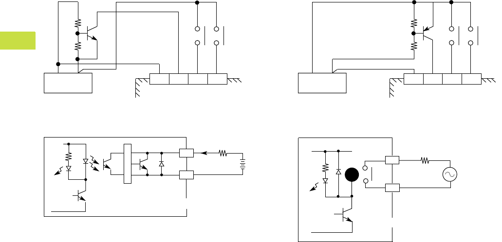
Circuit Diagrams
DC Input Sink Mode
DC Transistor Sinking Output
DC Input Source Mode
Relay Outputs
Sink Mode
S/S X0 X1 X2
+24V 0V
DC Power Supply
Y0
LED
C0
<0.5 A
Transistor Output
Load
Trigger Circuit
Source Mode
S/S X0 X1 X2
+24V 0V
DC Power Supply
Y0
LED
C0
Load
Power
Relay Output
RY
Volume 7—Logic Control, Operator Interface and Connectivity Solutions CA08100008E—May 2016 www.eaton.com V7-T4-25
4
4
4
4
4
4
4
4
4
4
4
4
4
4
4
4
4
4
4
4
4
4
4
4
4
4
4
4
4
4
4.1
PLC, I/O and Communications Products
ELC Series Programmable Logic Controllers
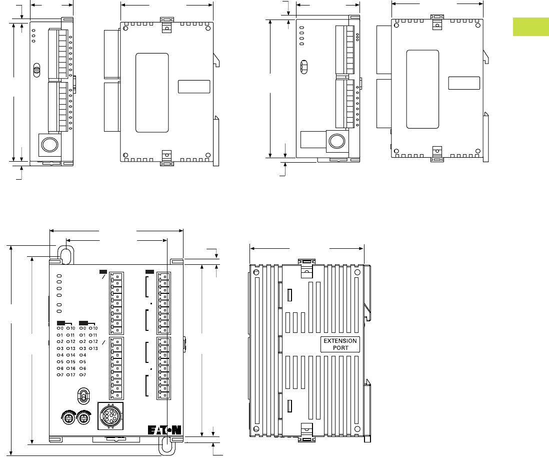
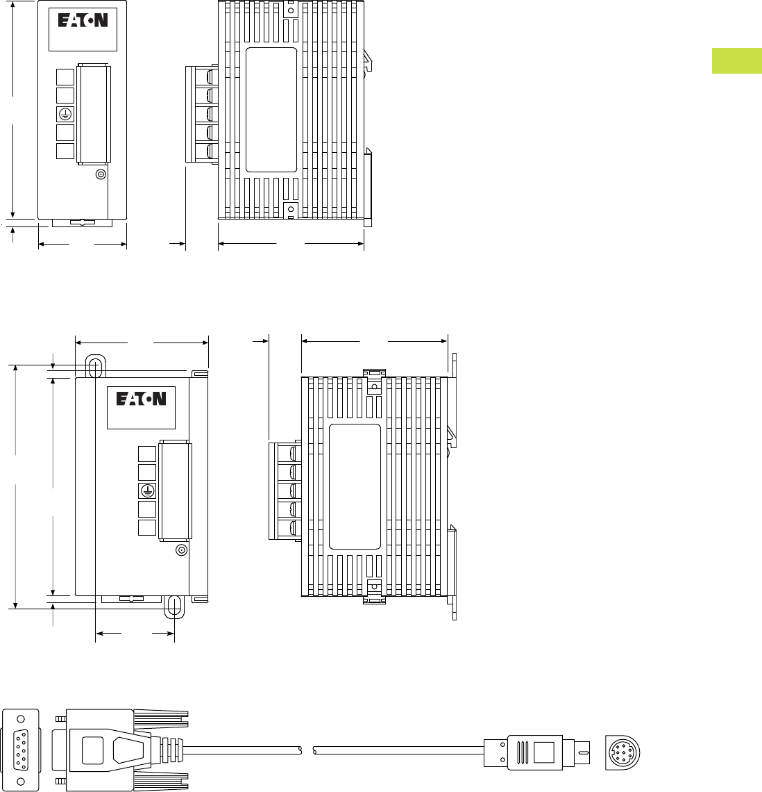
Dimensions
Approximate Dimensions in Inches (mm)
ELC-PB and ELC2-PB Controllers
ELC-PC, ELC-PH, ELC-PA10, ELC2-PC and ELC2-PE Controllers
ELC-PV, ELC2-PV and ELC2-PA20 Controllers
EXTENSION
PORT
2.36 (60.0)
3.54
(90.0)
0.12
(3.0)
0.12
(3.0)
0.99
(25.2)
POWER
RUN
RUN
STOP
ERROR
BAT.LOW
EXTENSION
PORT
3.54
(90.0)
0.12
(3.0)
1.47 (37.4) 2.36 (60.0)
0.12
(3.0)
POWER
RUN
ERROR
BAT. LOW
RS-232
RS-495
IN
OUT
IN
OUT
SS
X0
X1
X2
X3
X4
X5
X6
X7
SS
X10
X11
X12
X13
X14
X15
X16
X17
Y11
Y12
Y13
C3
Y0
Y1
Y2
C0
C1
Y3
Y4
Y5
C2
Y6
Y7
Y10
RUN
STOP
01
0.12
(3.0)
3.54
(90.0)
2.75 (70.0)
3.98
(101.0)
4.31
(109.4)
ELC-PV28NNDR
2.09 (53.2)
2.36 (60.0)
0.12
(3.0)
V7-T4-26 Volume 7—Logic Control, Operator Interface and Connectivity Solutions CA08100008E—May 2016 www.eaton.com
4
4
4
4
4
4
4
4
4
4
4
4
4
4
4
4
4
4
4
4
4
4
4
4
4
4
4
4
4
4
4.1
PLC, I/O and Communications Products
ELC Series Programmable Logic Controllers
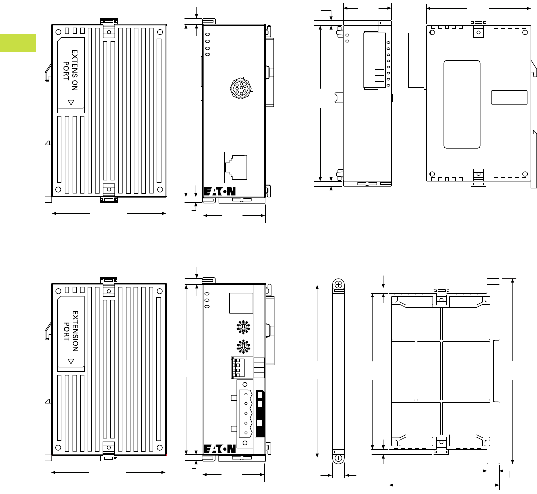
Approximate Dimensions in Inches (mm)
ELC-COENETM Communication Module
ELC-CODNETM Communication Module
Right Side Expansion and Specialty Modules
ELC-ACCOVER Plate Mount for Specialty Modules
2.36 (59.9)
3.54
(89.9)
0.12
(3.0) 1.29
(32.8)
ELC-COENETM
POWER
RS-232
100M
LAN
RS-232
LINK
0.12
(3.0)
2.36 (59.9)
3.54
(89.9)
0.12
(3.0) 1.29
(32.8)
ELC-CODNETM
POWER
MS
NS
Node Address
x10
x10
0
1
2
3
4
5
6
7
8
9
0
1
2
3
4
5
6
7
8
9
DP On
1234
DR 1
DR 0
IN 1
IN 0
0.12
(3.0)
EXTENSION
PORT
3.54
(90.0)
0.12
(3.0)
0.12
(3.0)
0.99
(25.2)
2.36
(60.0)
2.51 (63.4)
3.94
(100.0)
3.54
(89.9)
0.27
(6.8)
0.12
(3.0) 0.28
(7.1)
4.20
(106.5)
0.12
(3.0)
Volume 7—Logic Control, Operator Interface and Connectivity Solutions CA08100008E—May 2016 www.eaton.com V7-T4-27
4
4
4
4
4
4
4
4
4
4
4
4
4
4
4
4
4
4
4
4
4
4
4
4
4
4
4
4
4
4
4.1
PLC, I/O and Communications Products
ELC Series Programmable Logic Controllers
Approximate Dimensions in Inches (mm)
ELC-PS01 Power Supply
ELC-PS02 Power Supply
ELC-CBPCELC1 Cable (Right Angle Connector not Shown) and ELC-CBPCELC3 Cable (Straight Connector as Shown)
ELC-PS01
POWER
L
N
24V
0V
1.44
(36.5)
3.54
(90.0)
0.12
(3.0)
2.36
(60.0)
13.30
(0.5)
ELC-PS02
POWER
L
N
24V
0V
3.94
(100.0)
0.12
(3.0)
1.28
(32.5)
3.54
(90.0)
2.17
(55.0)
0.12
(3.0)
2.36
(60.0)
13.30
(0.5)
V7-T4-28 Volume 7—Logic Control, Operator Interface and Connectivity Solutions CA08100008E—May 2016 www.eaton.com
4
4
4
4
4
4
4
4
4
4
4
4
4
4
4
4
4
4
4
4
4
4
4
4
4
4
4
4
4
4
4.1
PLC, I/O and Communications Products
ELC Series Programmable Logic Controllers
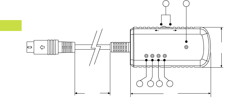
Approximate Dimensions in Inches (mm)
ELC-ACPGMXFER Storage/Transfer Module
POWER
COM
OK
ERR
ERASE
ELC-ACPGMXFR
WR RD
1.29
(32.8)
2.61
(66.3)
1234
11.81
(292.4)
56
Volume 7—Logic Control, Operator Interface and Connectivity Solutions CA08100008E—May 2016 www.eaton.com V7-T4-29
4
4
4
4
4
4
4
4
4
4
4
4
4
4
4
4
4
4
4
4
4
4
4
4
4
4
4
4
4
4
4.2
PLC, I/O and Communications Products
XC Series Programmable Logic Controllers
XC Series Programmable Logic Controllers
Contents
Description Page
XC Series Programmable Logic Controllers
Product Selection Guide . . . . . . . . . . . . . . . . . . V7-T4-30
Catalog Number Selection . . . . . . . . . . . . . . . . V7-T4-31
System Overview . . . . . . . . . . . . . . . . . . . . . . . V7-T4-31
Product Selection . . . . . . . . . . . . . . . . . . . . . . . V7-T4-33
Accessories . . . . . . . . . . . . . . . . . . . . . . . . . . . V7-T4-36
Technical Data and Specifications . . . . . . . . . . V7-T4-39
Dimensions . . . . . . . . . . . . . . . . . . . . . . . . . . . V7-T4-55
Product Overview
The XC100 and XC200 series
modular PLCs stand out on
account of their highly
scalable design. Different
CPU performance classes
and a wide range of
expansion modules are
available. An important
feature is their ability to be
integrated in modern
communication systems.
Innovative solutions can be
created thanks to the
possibility of exchanging data
with OPC clients via the
Ethernet interface and the
integrated web server.
Features and Benefits
Flexible Range
●Compact and modular CPU
versions to suit the needs
of the application
●With or without on-board
Ethernet and/or built-in
web server
●
Range of CPU performance
●Integrated CANopen
interface for easy
integration with XI/ON
remote I/O
High Performance
●Parallel backplane bus for
faster processing speed
●Fiber optic CANopen
interface for environments
with severe electromagnetic
interference
●High performance XC202
CPU with
●10/100 Mbit Ethernet
●XSoft-CoDeSys
programming software
Standards and
Certifications
●IEC—UL508; CSA C22.2
No. 0-
M;
CSA C22.2
No. 142-M; CE marking
●UL File No.—E135462
●UL CCN—NRAQ
●CSA File No. 012528
●CSA Class No. 2252-01
●NA Certification—
●UL Listed
●CSA certified/cUL
●RoHS
V7-T4-30 Volume 7—Logic Control, Operator Interface and Connectivity Solutions CA08100008E—May 2016 www.eaton.com
4
4
4
4
4
4
4
4
4
4
4
4
4
4
4
4
4
4
4
4
4
4
4
4
4
4
4
4
4
4
4.2
PLC, I/O and Communications Products
XC Series Programmable Logic Controllers
Product Selection Guide
XC Series Programmable Logic Controllers
XC121 Compact PLC XC101 Modular PLCs XC201 Modular PLCs XC202 Modular PLCs
Page V7-T4-33 Page V7-T4-33 Page V7-T4-34 Page V7-T4-34
This PLC is particularly suitable for
applications where space is at premium and
with high communication requirements.
●Two serial and two CAN interfaces enable:
– the coupling of two CAN networks
– Modbus master/slave coupling
(RS-232 or RS-485)—CAN
– RS-232—CAN coupling
●I/O expansion with 18 digital and 8 analog
inputs/outputs
●6 interrupt inputs
●Expandable with standard XIOC modules
The modular PLCs of the XC101 series are
universal automation devices for small and
medium-sized applications.
●Locally expandable with up to 15
XIOC modules
●Data storage on SD card
●CAN interface
The modular PLCs of the XC201 series offer a
high CPU performance, a high speed and a
wide range of communication options.
●Locally expandable with up to 15
XIOC modules
●Ethernet interface for communication
and programming
●CAN interface
●Data storage on SD card or USB stick
●Web server enables visualization via
CoDeSys
●Operating system update SD card or USB
The modular PLCs of the XC202 series offer
higher CPU performance and memory than the
XC201 PLCs.
●Locally expandable with up to 15
XIOC modules
●Ethernet interface for communication
and programming
●CAN interface
●Data storage on SD card or USB stick
●Operating system update via Ethernet,
SD card or USB
●Up to three IP addresses can be configured
●29-bit CAN identifier
Features XC121 XC101 XC201 XC202
Input voltage 24 Vdc 24 Vdc 24 Vdc 24 Vdc
Memory size 256 kB 64, 128 or 256 kB 256 kB or 2 MB 4 MB
Microprocessor Infineon CC161 Infineon C164 MIPS RISC ARM11
Processor speed 36 MHz 24 MHz 131 MHz 532 MHz
Cycle time per 1k instructions <0.3 ms <0.5 ms <0.15 ms <0.025 ms
SD card slot Yes Yes Yes Yes
USB interface No No Yes Yes
Real time clock Yes Yes Yes Yes
On-board digital inputs — 8 8 8
On-board digital outputs — 6 6 6
Interrupt inputs 6422
Expandability XIO-EXT base module +
Up to 15 XIOC modules
Up to 15 XIOC modules Up to 15 XIOC modules Up to 15 XIOC modules
Removable terminal blocks Yes Yes Yes Yes
Screw terminal option No Yes Yes Yes
Spring-cage terminal option Yes Yes Yes Yes
Serial interface 1, RS-232
1, RS-232/RS-485
1, RS-232 1, RS-232 1, RS-232
Ethernet port No No Yes Yes
CANopen interface2111
On-board high speed counters No No Yes Yes
On-board encoder inputs No No Yes Yes
OPC server Yes Yes Yes Yes
Integrated web server No No On suffix “-XV” models Yes
FTP server No No On suffix “-XV” models Yes
Networks master CANopen/easyNet CANopen/PROFIBUS-DP/easyNet Ethernet/CANopen/PROFIBUS-DP/
easyNet
Ethernet/CANopen/PROFIBUS-DP/
easyNet
Networks node/device CANopen/PROFIBUS-DP®/
easyNet
CANopen/PROFIBUS-DP/
easyNet
Ethernet/CANopen/PROFIBUS-DP/
easyNet
Ethernet/CANopen/PROFIBUS-DP/
easyNet
Operating system Proprietary Proprietary Windows CE Windows CE
X-Soft-CoDeSys version V2.3 V2.3 V2.3 V2.3 and 3.0
Volume 7—Logic Control, Operator Interface and Connectivity Solutions CA08100008E—May 2016 www.eaton.com V7-T4-31
4
4
4
4
4
4
4
4
4
4
4
4
4
4
4
4
4
4
4
4
4
4
4
4
4
4
4
4
4
4
4.2
PLC, I/O and Communications Products
XC Series Programmable Logic Controllers
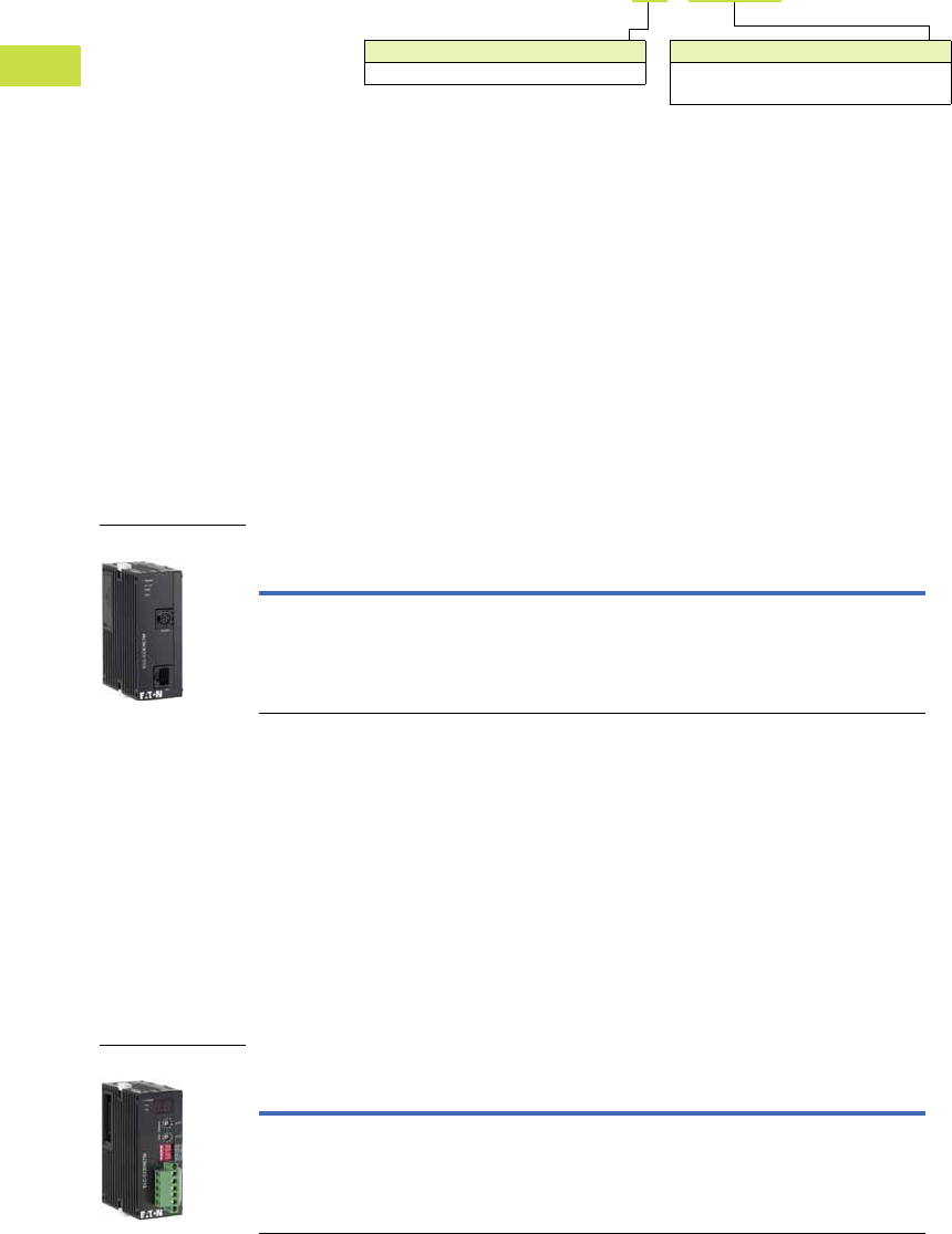
Catalog Number Selection
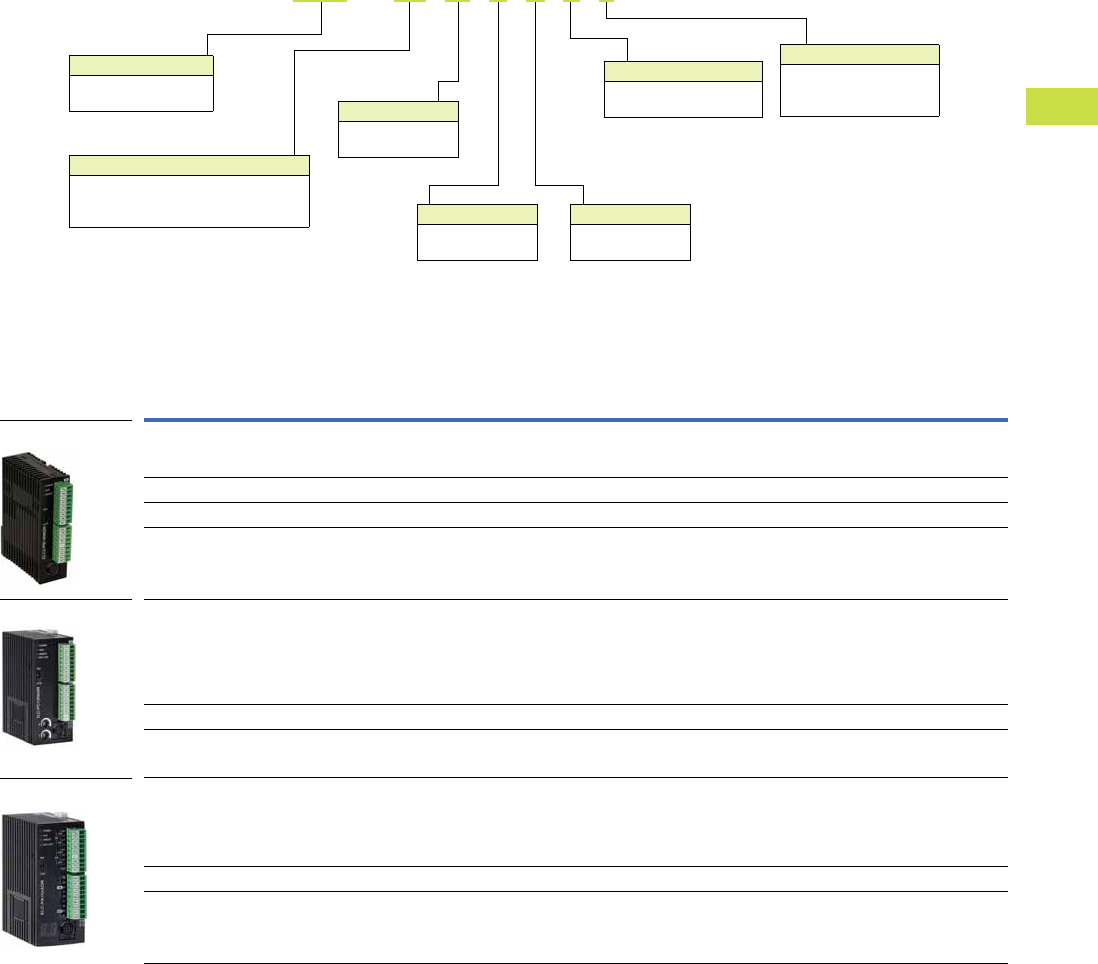
Controllers
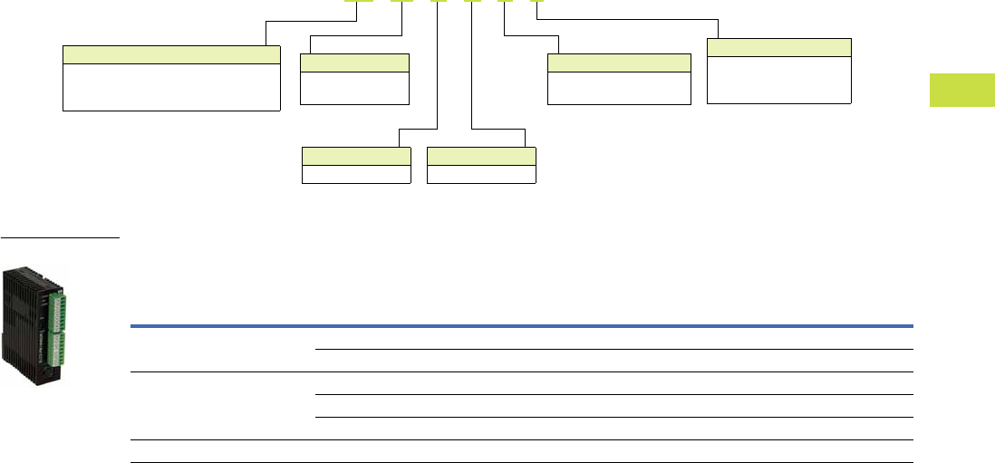
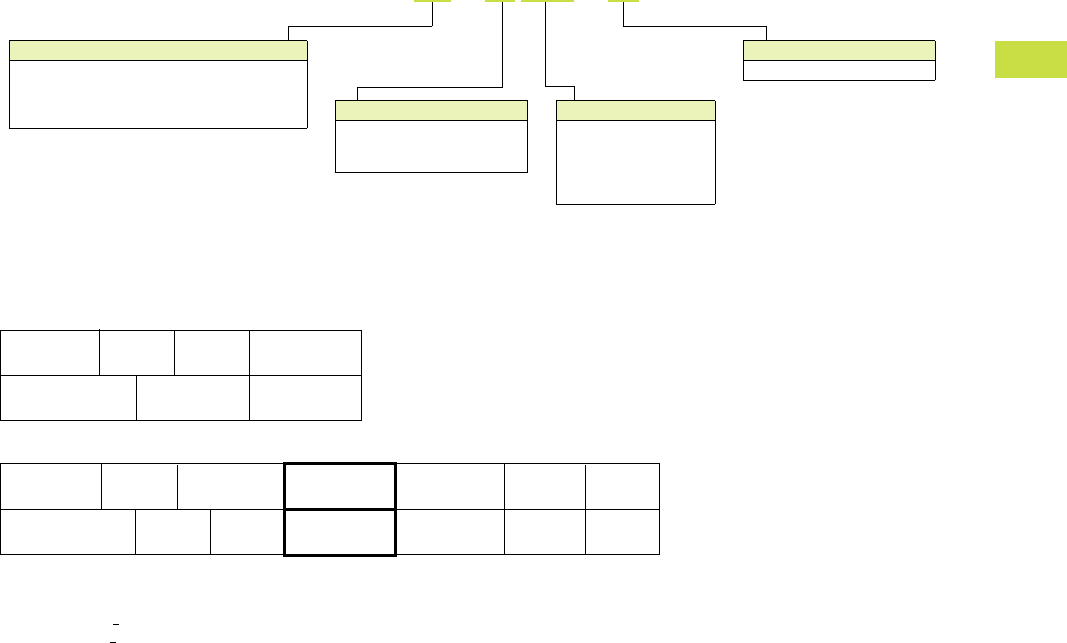
System Overview
System Configuration
Notes
1Maximum basic version, <7 signal modules.
2Maximum total version, <15 signal modules.
Model Number
101 = Modular (Infineon C164—16 bit at 24 MHz)
121 = Compact (Infineon XC161—16 bit at 36 MHz)
201 = Modular (MIPS RISC—32 bit at 131 MHz)
202 = Modular (ARM 11—32 bit at 532 MHz)
XC - CPU 201 - EC 512K - XV
User Memory
64K = 64 kB
128K = 128 kB
256K = 256 kB
512K =2 MB
4M =4 MB
Communication Ports
C = 1 CANopen
2C = 2 CANopen
EC = Ethernet and CANopen
Visualization Option
XV = Web server
CPU 2 4 713 65
CPU 2 4 713 6511109812131415
XIOC-BP-XC XIOC-BP-2 XIOC-BP-2 XIOC-BP-3
XIOC-BP-3XIOC-BP-3XIOC-BP-XC1
XIOC-BP-XC XIOC-BP-2
XIOC-BP-2 XIOC-BP-2
XIOC-BP-3 XIOC-BP-3
XIOC-BP-3
XIOC-BP-2
XIOC-BP-2
XIOC-BP-2
XIOC-BP-2XIOC-BP-XC1
XIOC-BP-EXT
XIOC-BP-EXT
1
2
V7-T4-32 Volume 7—Logic Control, Operator Interface and Connectivity Solutions CA08100008E—May 2016 www.eaton.com
4
4
4
4
4
4
4
4
4
4
4
4
4
4
4
4
4
4
4
4
4
4
4
4
4
4
4
4
4
4
4.2
PLC, I/O and Communications Products
XC Series Programmable Logic Controllers
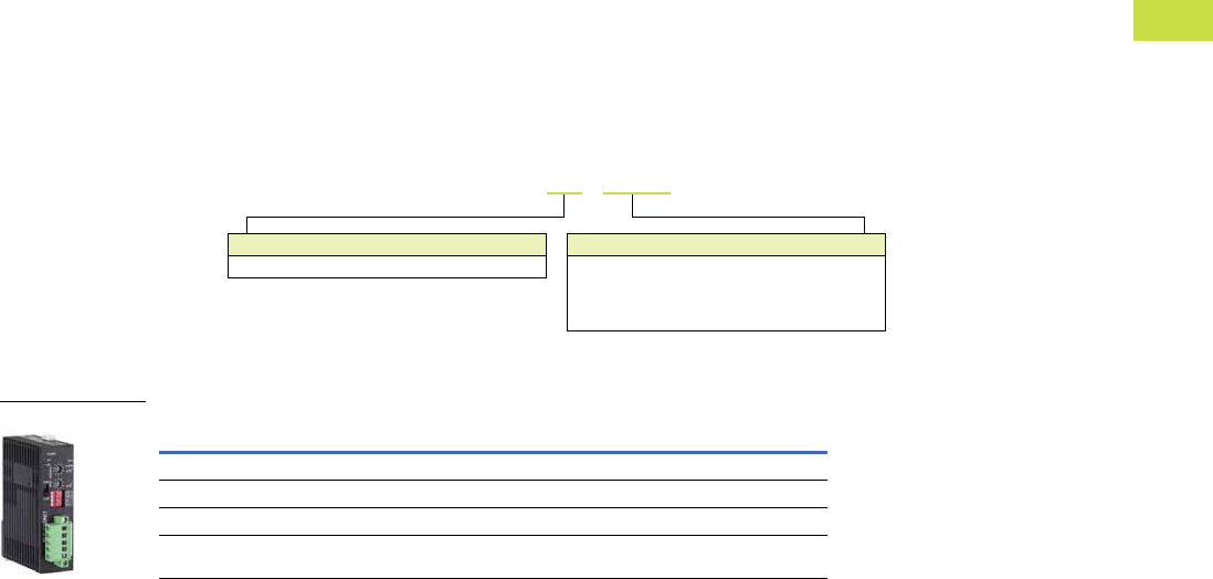
Product Identification
Item
Number Description
Item
Number Description
1XC121 Compact PLC CPU 6Battery
2XC121 I.O Expansion module 7SD Memory card
3XC100/XC200 Modular PLC 8XIOC Terminal block, screw terminals
4XIOC I/O modules 9XIOC Terminal block, spring-cage terminals
5XIOC Module backplane
7
12
5
5
5
36
4
7
89 89
Volume 7—Logic Control, Operator Interface and Connectivity Solutions CA08100008E—May 2016 www.eaton.com V7-T4-33
4
4
4
4
4
4
4
4
4
4
4
4
4
4
4
4
4
4
4
4
4
4
4
4
4
4
4
4
4
4
4.2
PLC, I/O and Communications Products
XC Series Programmable Logic Controllers
Product Selection
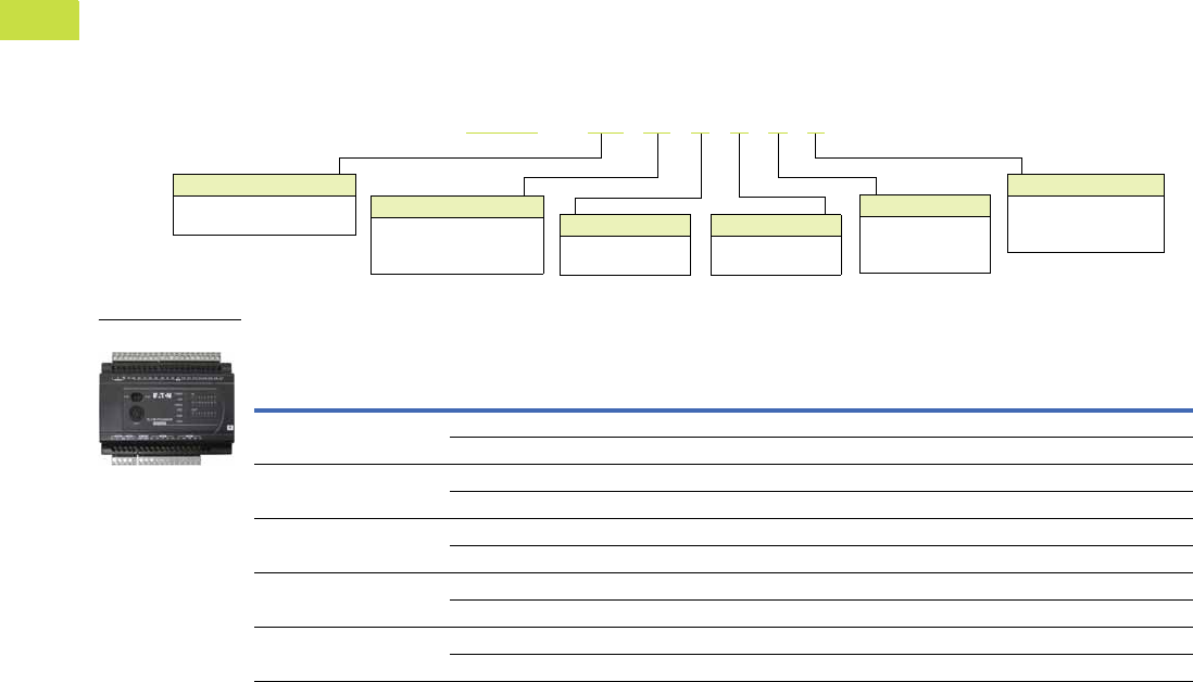
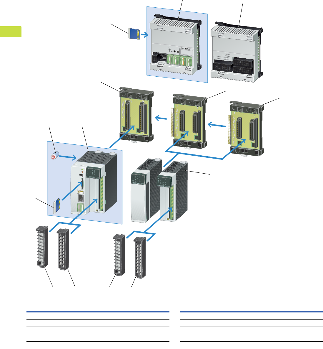
XC121 Compact PLC CPU
Can be locally expanded with I/O module XIO-EXT-121-1.
●24 Vdc input supply
●Real time clock
●2 CANopen interfaces
(500 kB)
●RS-232 interface for
programming and
communication
●Second RS-232/RS-485
interface
●Slot for SD memory card
●Spring-cage terminal
blocks
●OPC server
●RUN/STOP switch
XC121 Compact PLC
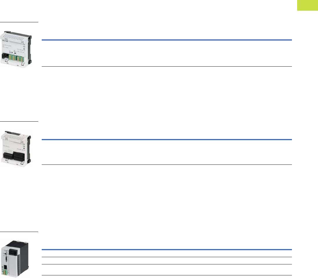
XC121 I/O Expansion Module
Base I/O module for the XC121.
●10 digital inputs 24 Vdc
●6 interrupt inputs
●8 digital inputs/outputs
24 Vdc 0.5A
●2 analog inputs 0–10V
●2 analog inputs 0–20 mA
●2 analog inputs PT100 RTD
●2 analog outputs 0–10V
●Removable spring-cage
terminals
●Expandable with 15 XIOC
modules 2
XC121 I/O Expansion Module
XC101 Modular PLCs
Order backplane, terminals and battery separately.
●24 Vdc input supply
●Real time clock
●Expandable with 15 XIOC
modules
●8 digital inputs
●4 interrupt inputs
●6 digital outputs
●RS-232 interface for
programming and
communication
●CANopen interface
(500 kB)
●Slot for SD memory card
●RUN/STOP switch and
LED indicators
XC101 Modular PLCs
Notes
1Cycle time per 1k of instructions.
2Except the XIOC-NET-DP-M module.
Program
Memory Size
Cycle
Time 1Ethernet CAN
Serial
Interface
Web
Server
Pkg.
Qty.
Style
Number
Catalog
Number
256 kB <0.3 ms — 2 1, RS-232
1, RS-232/RS-485
— 1 290446 XC-CPU121-2C256K
XC121
Digital
Inputs
Digital
Inputs/Outputs
Analog
Inputs
Analog
Outputs
Pkg.
Qty.
Style
Number
Catalog
Number
10, 24 Vdc 8, 24 Vdc 0.5A 2, 0–10V
2, 0–20 mA
2, PT100 RTD
2, 0–10V 1 290450 XIO-EXT121-1
XC121 I/O Module
Program
Memory Size
Cycle
Time 1Ethernet CANOpen
Serial
Interface
Web
Server
Pkg.
Qty.
Style
Number
Catalog
Number
64 kB <0.5 ms — 1 1, RS-232 typ. — 1 262152 XC-CPU101-C64K
128 kB <0.5 ms — 1 1, RS-232 typ. — 1 262146 XC-CPU101-C128K
256 kB <0.5 ms — 1 1, RS-232 typ. — 1 274399 XC-CPU101-C256K
XC101
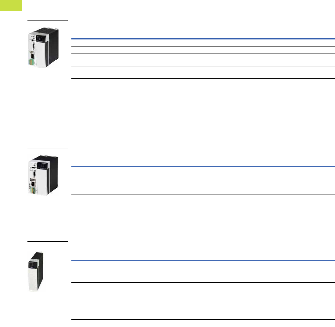
V7-T4-34 Volume 7—Logic Control, Operator Interface and Connectivity Solutions CA08100008E—May 2016 www.eaton.com
4
4
4
4
4
4
4
4
4
4
4
4
4
4
4
4
4
4
4
4
4
4
4
4
4
4
4
4
4
4
4.2
PLC, I/O and Communications Products
XC Series Programmable Logic Controllers
XC201 Modular PLCs
Order backplane, terminals and battery accessories separately.
●24 Vdc input supply
●Real time clock
●Expandable with 15 XIOC
modules
●8 digital inputs
●2 interrupt inputs
●Incremental encoder
inputs
●High speed counter
(50 kHz) inputs
●6 digital outputs
●Ethernet and RS-232
interface for programming
and communication
●CANopen interface (1 MB)
●
Slot for SD memory card
●USB interface
●RUN/STOP switch and LED
indicators
●Built-in Web server on
XV models
XC201 Modular PLCs
XC202 Modular PLCs
Order backplane, terminals and battery accessories separately.
●24 Vdc input supply
●Real time clock
●Expandable with 15 XIOC
modules
●8 digital inputs
●2 interrupt inputs
●Incremental encoder
inputs
●High speed counter
(50 kHz) inputs
●6 digital outputs
●Ethernet and RS-232
interface for programming
and communication
●CANopen interface (1 MB)
●
Slot for SD memory card
●USB interface
●RUN/STOP switch and LED
indicators
●Built-in Web server
XC202 Modular PLCs
XIOC Expansion Modules
Order screw, spring-cage terminals or 40-pin connector cable for 32 I/O modules separately.
●8, 16 and 32 input modules
●8, 16 and 32 output
modules
●User configurable input/
output module
●Isolated relay output
module
XIOC Digital Expansion Modules
Note
1Cycle time per 1k of instructions.
Program
Memory Size
Cycle
Time 1Ethernet CANOpen
Serial
Interface
Web
Server
Pkg.
Qty.
Style
Number
Catalog
Number
256 kB <0.15 ms ✓1 1, RS-232 — 1 262155 XC-CPU201-EC256K
2 MB <0.15 ms ✓1 1, RS-232 — 1 262157 XC-CPU201-EC512K
256 kB
Integrated web server
<0.15 ms ✓11, RS-232✓1 262156 XC-CPU201-EC256K-XV
2 MB
Integrated web server
<0.15 ms ✓11, RS-232✓1 262158 XC-CPU201-EC512K-XV
XC201
Program
Memory Size
Cycle
Time 1Ethernet CANOpen
Serial
Interface
Web
Server
Pkg.
Qty.
Style
Number
Catalog
Number
4 MB
Integrated web server
<0.025 ms ✓11, RS-232✓1 134238 XC-CPU202-EC4M-XV
XC202
Description
Pkg.
Qty.
Style
Number
Catalog
Number
8 inputs, 24 Vdc 1 257891 XIOC-8DI
16 inputs, 24 Vdc 1 257892 XIOC-16DI
32 inputs, 24 Vdc 1 267411 XIOC-32DI
8 outputs, 24 Vdc, 0.3A 1 257894 XIOC-8DO
16 outputs, 24 Vdc, 0.3A 1 257896 XIOC-16DO
16 outputs, 24 Vdc, 0.8A, short-circuit protected 1 257895 XIOC-16DO-S
16 terminals, 4 inputs, 12 configurable as inputs/outputs, 24 Vdc—outputs 0.5A 1 262322 XIOC-16DX
32 outputs, 24 Vdc, 0.2A 1 267413 XIOC-32DO
12 relay outputs, isolated 1 257897 XIOC-12DO-R
XIOC—Digital
Volume 7—Logic Control, Operator Interface and Connectivity Solutions CA08100008E—May 2016 www.eaton.com V7-T4-35
4
4
4
4
4
4
4
4
4
4
4
4
4
4
4
4
4
4
4
4
4
4
4
4
4
4
4
4
4
4
4.2
PLC, I/O and Communications Products
XC Series Programmable Logic Controllers
XIOC Analog Modules
Counter Modules
Communication Modules
Description
Pkg.
Qty.
Style
Number
Catalog
Number
Inputs: 8 inputs 4–20 mA 1 262549 XIOC-8AI-I2
Inputs: 8 voltage inputs 0–10V 1 257899 XIOC-8AI-U1
Inputs: 8 voltage inputs, ±10V 1 257900 XIOC-8AI-U2
Inputs: 4 inputs for temperature monitoring, PT100/1000 1 257901 XIOC-4T-PT
Inputs: 4 inputs for thermocouples Type K, J, L, B, N, E, R, S, T 1 289933 XIOC-4AI-T
Outputs: 2 outputs, ±10V 1 257904 XIOC-2AO-U2
Outputs: 2 outputs 0–10V, 2 outputs 4–20 mA 1 257902 XIOC-2AO-U1-2AO-I2
Outputs: 4 outputs 0–10 V 1 257903 XIOC-4AO-U1
Combination modules: 2 inputs and 1 output 0–10V/1 ms conversion time 1 262409 XIOC-2AI-1AO-U1
Combination modules: 2 inputs and 1 output 0–10V, 0–20 mA/1 ms conversion time, individual changeover 1 281545 XIOC-2AI-1AO-U1-I1
Combination modules: 4 inputs and 2 outputs 0–10V/1 ms conversion time 1 262405 XIOC-4AI-2AO-U1
Combination modules: 4 inputs and 2 outputs 0–10V, 0–20 mA/1 ms conversion time, individual changeover 1 281544 XIOC-4AI-2AO-U1-I1
Description
Pkg.
Qty.
Style
Number
Catalog
Number
1 input up to 100 kHz, 24 Vdc, 5 Vdc, 2 digital transistor outputs, opto-isolated, 24 Vdc
30-pin connector required for counter module
1 257906 XIOC-1CNT-100KHZ
2 inputs up to 100 kHz, (24 Vdc or 5V diff), 4 digital transistor outputs, opto-isolated, 24 Vdc
30-pin connector required for counter module
1 257907 XIOC-2CNT-100KHZ
2 incremental encoders up to 400 kHz, 5 Vdc, 2 analog outputs ±10V 1 262417 XIOC-2CNT-2AO-INC
Description
Pkg.
Qty.
Style
Number
Catalog
Number
PROFIBUS-DP master module 1 257908 XIOC-NET-DP-M
PROFIBUS-DP node module 1 286419 XIOC-NET-DP-S
Serial interfaces: RS-232C, RS-485, RS-422 (for XC101, XC201 and XC202)
Modes of operation: Transparent mode, Modbus master/node
1 267191 XIOC-SER
Serial interfaces: RS-232C, RS-485, RS-422 (for XC201 and XC202 only)
Modes of operation: Transparent mode, Modbus master/node
1 135265 XIOC-TC1
XIOC—Analog
XIOC—Counter
XIOC—Communication
Card
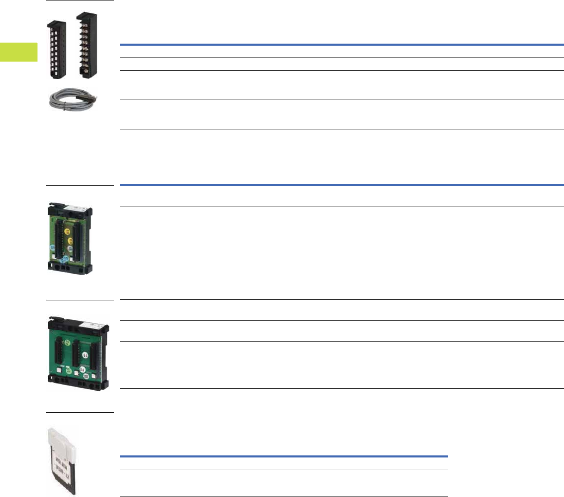
V7-T4-36 Volume 7—Logic Control, Operator Interface and Connectivity Solutions CA08100008E—May 2016 www.eaton.com
4
4
4
4
4
4
4
4
4
4
4
4
4
4
4
4
4
4
4
4
4
4
4
4
4
4
4
4
4
4
4.2
PLC, I/O and Communications Products
XC Series Programmable Logic Controllers
Accessories
Te rm i n a l s
One 18 pole terminal plug is required for each digital and analog module.
Module Backplane
Memory Card
For storage of programs, data, recipes for XC100, XC121, XC200.
Note
1 Module backplane for expansion with up to 15 modules, must be plugged into the 6th slot.
Description
Pkg.
Qty.
Style
Number
Catalog
Number
18-pin connector with screw terminals for digital or analog I/O 10 258102 XIOC-TERM-18S
18-pin connector with spring-cage terminal for digital or analog I/O 10 258104 XIOC-TERM-18T
40-pin connector for digital module, with 4 m cable
XIOC-32DI
XIOC-32DO
1 267414 XIOC-TERM32
30-pin connector for counter module, with 4 m cable
XIOC-1CNT-100KHZ
XIOC-2CNT-100KHZ
1 262248 XIOC-TERM30-CNT4
Description
Pkg.
Qty.
Style
Number
Catalog
Number
Basic backplane for mounting XC100/200 on top-hat rail, can be expanded
Width: 2 slots for controller
1 260792 XIOC-BP-XC
Expansion backplane for mounting XIOC modules on top-hat rail, can be expanded
Width: 2 slots for XIOC modules
1 260794 XIOC-BP-2
Basic backplane for mounting XC100/200 on DIN rail, can be expanded
Width: 3 slots for controller and one XIOC module
1 260793 XIOC-BP-XC1
Expansion backplane for mounting XIOC modules on DIN rail, can be expanded
Width: 3 slots for XIOC modules
1 260795 XIOC-BP-3
Expansion backplane for mounting XIOC modules on DIN rail, can be expanded
Width: 3 slots for XIOC modules 1
1 274291 XIOC-BP-EXT
Description
Pkg.
Qty.
Style
Number
Catalog
Number
512 MB 1 138257 XT-MEM-MM512M
32 MB 1 262731 XT-MEM-MM32M
Terminals
Backplane
Backplane
Memory Card
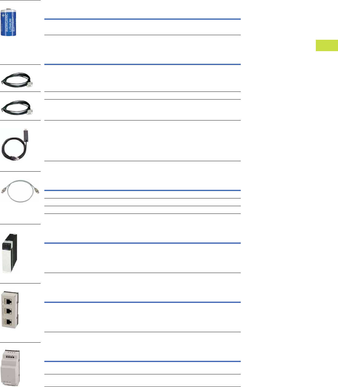
Volume 7—Logic Control, Operator Interface and Connectivity Solutions CA08100008E—May 2016 www.eaton.com V7-T4-37
4
4
4
4
4
4
4
4
4
4
4
4
4
4
4
4
4
4
4
4
4
4
4
4
4
4
4
4
4
4
4.2
PLC, I/O and Communications Products
XC Series Programmable Logic Controllers
Battery
Programming Cables
Connection Cables
Empty Module
Interface Switch
Filter
Description
Pkg.
Qty.
Style
Number
Catalog
Number
Lithium 1/2 AA 3.6V battery for backup of real-time clock 1 256209 XT-CPU-BAT1
Description
Pkg.
Qty.
Style
Number
Catalog
Number
2m, D-sub 9-pin, serial 1 262186 XT-SUB-D/RJ45
2m, Ethernet cross 1 256487 XT-CAT5-X-2
5m, Ethernet cross 1 256488 XT-CAT5-X-5
Programming cable for XC through USB interface 1 115735 EU4A-RJ45-USB-CAB1
Description
Pkg.
Qty.
Style
Number
Catalog
Number
0.3m: Connection cable for XC200 to interface switch 1 256283 EASY-NT-30
0.8m: Connection cable for XC200 to interface switch 1 256284 EASY-NT-80
1.5m: Connection cable for XC200 to interface switch 1 256285 EASY-NT-150
Description
Pkg.
Qty.
Style
Number
Catalog
Number
Empty module to cover open XIOC slots 1 288894 XIOC-NOP
Description
Pkg.
Qty.
Style
Number
Catalog
Number
Interface adapter to split the combined RS-232/Ethernet
interface of the XC200 into RJ45 sockets. Connection cable
EASY-NT-30/80/150 usable for connection to XC200
1 289170 XT-RJ45-ETH-RS232
Description
Pkg.
Qty.
Style
Number
Catalog
Number
Interference suppression of the external 24 Vdc supply of the
XC100/200. Maximum current consumption: 2.2A
1 285316 XT-FIL-1
Power supply interference suppression of I/O modules of
XC100/200. Maximum current consumption: 12A
1 118980 XT-FIL-2
Battery
D-Sub 9-Pin
Ethernet Cross
Programming
Connection Cable
Empty Module
Interface Switch
Filter
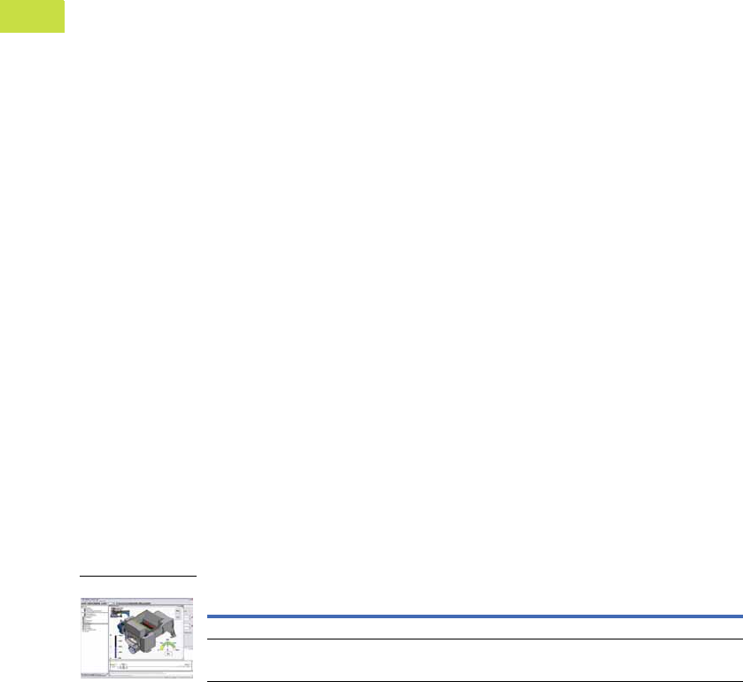
V7-T4-38 Volume 7—Logic Control, Operator Interface and Connectivity Solutions CA08100008E—May 2016 www.eaton.com
4
4
4
4
4
4
4
4
4
4
4
4
4
4
4
4
4
4
4
4
4
4
4
4
4
4
4
4
4
4
4.2
PLC, I/O and Communications Products
XC Series Programmable Logic Controllers
XSoft-CoDeSys-2 Software
Combined Logic and Visualization Development for XC Series PLCs and XV-100 Series HMI-PLCs
IEC 61131-3 Programming Languages
●Ladder Diagram
●Structured Text
●Sequential function chart
●Function block diagram
●Freely definable function block chart/continuous function chart
●Instruction List
Project Development
●Automatic variable
declaration
●On-line editing
●Pop-up variable and
function search/pick tools
●Automatic formatting and
color coding of logic/
declaration text
●Re-usable Visual-Logic
Function Blocks
Debugging and
commissioning
XSoft-CoDeSys-2 offers you
a number of important
functions for debugging,
testing and commissioning
your applications quickly and
efficiently.
All these features are
available as soon as you log
on to the XV HMI-PLC or
XC200 PLC (online mode)
over an Ethernet connection.
Target Visualization
Integrated design of Operator
Interface screens for the XV
HMI-PLC series. Visualization
and logic developed as part of
the same project. Simplifies
screen design and always
keeps the Logic and
visualization in synch.
Web Visualization
Optionally XSoft-CoDeSys-2
can automatically generate
XML-based runtime screens
to make the screens from the
XV HMI-PLC accessible
remotely using a web
browser with a JavaScript
plug-in such as Internet
Explorer®, Firefox®
and others.
Simulation
Users can also test the
application when the XV HMI-
PLC is not connected to the
process. This is possible
thanks to the integrated
online simulation feature.
Simulation supports both the
screens and logic that have
been designed using XSoft-
CoDeSys.
Advanced Features
●Up to 16 time and/or event
driven tasks per project
●Each task can include
multiple logic programs or
subroutines
●Programs and screen
designs can be exported
and imported to support
reuse
●Powerful, built-in function
block libraries
●Ability to create user-
defined function blocks
●Fieldbus Configurator
for CANopen, PROFIBUS-
DP and SmartWire-DT®
device I/O
●Ethernet and serial
communication function
blocks (OPC server, UDP,
TCP/IP, FTP client/ server,
Modbus Master/Node,
email, SMS, and more)
●8 level password
protection
●Web access selectable
per screen
●System function libraries
(OS Storage Card, and
more)
●On-line and historical
alarms
●On-line and historical
trends
System Requirements
Windows XP and Windows 7
32-bit systems
XSoft-CoDeSys-2 Software
Description Catalog Number
Single Seat License SW-XSOFT-CODESYS-2-S
Multiple Seat License (3) SW-XSOFT-CODESYS-2-M
XSoft-CoDeSys-2

Volume 7—Logic Control, Operator Interface and Connectivity Solutions CA08100008E—May 2016 www.eaton.com V7-T4-39
4
4
4
4
4
4
4
4
4
4
4
4
4
4
4
4
4
4
4
4
4
4
4
4
4
4
4
4
4
4
4.2
PLC, I/O and Communications Products
XC Series Programmable Logic Controllers
Technical Data and Specifications
XC121 Compact PLC
Description Unit XC-CPU121-2C256K
General
Standards IEC/EN 61131-2; EN 50178
Ambient temperature °F (°C) 32° to 131° (0° to 55°)
Storage °F (°C) –13° to 158° (–25° to 70°)
Mounting position Horizontal
Relative humidity, noncondensing (IEC/EN 60068-2-30) % 10–95
Air pressure (in operation) hPa 795–1080
Vibration resistance Frequency 5–9 Hz; 3.5 mm amplitude
9–150 Hz; 1.0g constant acceleration
Mechanical shock resistance 15g/11 ms
Overvoltage category II
Pollution degree 2
Degree of protection IP20
Rated insulation voltage (Ui)V500
Emitted interference EN 61000-6-4
Interference immunity EN 61000-6-2
Backup time At least 72 hours
Weight kg 0.15
Electromagnetic Compatibility (EMC) Refer to Page V7-T4-54
Connections
Supply voltage
Connection type —
Terminal capacity mm20.14–1 (AWG28-18)
COM1 interface
Connection type RJ45
COM2, CAN1, CAN2 interfaces
Connection type Spring-loaded terminal block, 6-pole
Terminal capacity mm² 0.14–0.5 (AWG28-20)
Power Supply
Input voltage Vdc 24
Permissible range Vdc 20.4–28.8
Input power W Max. 1.44
Input current mA 60
Ripple % <5
Maximum heat dissipation (without local I/O) (Pv)W6
Overvoltage protection Yes
Protection against polarity reversal Yes
Inrush current x InNo limitation
(limited only by upstream 24 Vdc power supply unit)
Supply failure bridging
Duration of power failure ms 10
Repetition rate s 1
External supply filter Part No.: XT-FIL-1, Refer to Page V7-T4-37
Memory
Program code/program data kByte 256/244
Marker/input/output/retain data kByte 16/4/4/8
Cycle time for 1k of instructions (bits, bytes) ms <0.3

V7-T4-40 Volume 7—Logic Control, Operator Interface and Connectivity Solutions CA08100008E—May 2016 www.eaton.com
4
4
4
4
4
4
4
4
4
4
4
4
4
4
4
4
4
4
4
4
4
4
4
4
4
4
4
4
4
4
4.2
PLC, I/O and Communications Products
XC Series Programmable Logic Controllers
XC121 Compact PLC, continued
Description Unit XC-CPU121-2C256K
Interfaces
Serial interface (RS-232) without handshake lines
Baud rate kbit/s Programming (character format: 8 data bits,
No parity, 1 stop bit) 19.2, 38.4 (default), 57.6
Connector type RJ45
Potential isolation No
In transparent mode
Baud rate kbit/s 0.3, 0.6, 1.2, 2.4, 4.8, 9.6, 19.2, 38.4, 57.6, 115.2
Character formats 8E1, 8O1, 8N1, 8N2, 7E2, 7O2, 7N2, 7E1
Number of send bytes for block 190
Number of receive bytes for block 190
COM2 (RS-232/RS-485) without handshake lines
Baud rate kbit/s Transparent mode (setting through function blocks)
0.3, 0.6, 1.2, 2.4, 4.8, 9.6, 19.2, 38.4, 57.6
Character formats 8E1, 8O1, 8N1, 8N2, 7E2, 7O2, 7N2, 7E1
(setting through function blocks)
Potential isolation No
Bus termination External, for RS-485
CAN1/CAN2 interface
Baud rate kbit/s 10 – 500
Potential isolation No
Stations 126
Bus termination Adjustable for each interface (CAN1/CAN2)
PDO type Asyn., cyc., acyc.
Power Supply of Local Inputs/Outputs (24 VQ/0 VQ)
Input voltage Vdc 24
Voltage range Vdc 19.2–30, observe polarity
Potential isolation
Between power supply and CPU voltage Yes
Overvoltage protection Yes

Volume 7—Logic Control, Operator Interface and Connectivity Solutions CA08100008E—May 2016 www.eaton.com V7-T4-41
4
4
4
4
4
4
4
4
4
4
4
4
4
4
4
4
4
4
4
4
4
4
4
4
4
4
4
4
4
4
4.2
PLC, I/O and Communications Products
XC Series Programmable Logic Controllers
XC121 Expansion Module
Description Unit XIO-EXT121-1
General
Standards IEC/EN 61131-2; EN 50178
Ambient temperature °F (°C) 32° to 131° (0° to 55°)
Storage °F (°C) –13° to 158° (–25° to 70°)
Mounting position Horizontal
Relative humidity, noncondensing (IEC/EN 60068-2-30) % 10–95
Air pressure (in operation) hPa 795–1080
Vibration resistance Frequency 5–9 Hz; 3.5 mm amplitude
9–150 Hz; 1.0g constant acceleration
Mechanical shock resistance 15g/11 ms
Overvoltage category II
Pollution degree 2
Degree of protection IP20
Rated insulation voltage (Ui)V500
Emitted interference EN 61000-6-4
Interference immunity EN 61000-6-2
Backup time At least 72 hours
Weight kg 0.15
Electromagnetic Compatibility (EMC) Refer to Page V7-T4-54
Connections
X1 connector
Connector type Spring-loaded terminal block, 20 pole, B2L 3.5
Terminal capacity (solid) mm20.5–1
X2/X3 connector
Connector type Spring-loaded terminal block, 10-pole, BLZF 3.5/180 or
BLI/O 3.5/10F with LEDs
Terminal capacity (solid) mm² 0.5–1
Power Supply
Supply failure bridging
Duration of power failure ms 10
Repetition rate s 1
Input voltage Vdc 24
Permissible range Vdc 20.4 – 28.8
Input power W Max.1.68
Input current mA 70
Ripple % <5
Overvoltage protection Yes
Protection against polarity reversal Yes
Inrush current x InMax. 1A
Output voltage for signal modules
Max. field current (IL)A2
Digital Inputs
Number X2: 9 with plug BLI/O 3.5/10F or 10 with plug BLZF 3.5/
180 X3: 8 (can also be used as outputs)
Rated voltage (Ue) Vdc 24
At state “0” (Ue) Vdc <5
At state “1” (Ue) Vdc >15
Rated operational current
At state “1” (Ie)mA3.3
Delay time
X2: DI0–DI3 µs 20
X2: DI4–DI9 µs 250
X2: DX0–DX7 ms 20
Potential isolation No

V7-T4-42 Volume 7—Logic Control, Operator Interface and Connectivity Solutions CA08100008E—May 2016 www.eaton.com
4
4
4
4
4
4
4
4
4
4
4
4
4
4
4
4
4
4
4
4
4
4
4
4
4
4
4
4
4
4
4.2
PLC, I/O and Communications Products
XC Series Programmable Logic Controllers
XC121 Expansion Module, continued
Description Unit XIO-EXT121-1
Digital Outputs
Number At X3: 8 (can also be used as inputs)
Rated voltage
Rated voltage (Ue) Vdc 24
Permissible range 20.4–28.8 Vdc
Ripple % <5
Rated operational current
At state “1” (Ie) A 0.5 at 24 Vac
Utilization factor (%) g 1
Maximum duty factor ms 100%
Lamp load without (Rv)W5
Potential isolation No
Residual current at state “0” per channel mA <0.1
Max. output voltage
At state “0” with external load <10M ohms V 2.5
At state “1” at Ie = 0.5A V U = Ue–1V
Short-circuit tripping current
Short-circuit tripping current for Ra <10M ohms A 0.7 < Ie <2 for output
Total short-circuit current A 16
Peak short-circuit current A 32
Max. operating frequency ops/h 40,000
Parallel connection capability Yes
Analog Inputs 0–10V
Number of channels 2
Primary voltage range V 0–10
Resolution bit 10
Conversion time ms <5
Overall accuracy < ± 1% (of full-scale value)
Input resistance kohm 200
Analog Inputs 0–20 mA
Number of channels 2
Primary voltage range mA 0–20
Resolution bit 10
Conversion time ms <5
Overall accuracy < ± 1% (of full-scale value)
Input resistance ohm 50
PT100 RTD
Number of channels 2
Temperature range °F (°C) –348° to 392° (–200° to 200°)
Resistance range ohm 18.5–175.8
Resolution bit 10
Overall accuracy < ± 2%
Analog Outputs
Number of channels 2
Secondary voltage range V 0–10
Resolution bit 12
Conversion time ms <5
Overall accuracy < ± 1% (of full-scale value)
External load resistance (R) kohm 10

Volume 7—Logic Control, Operator Interface and Connectivity Solutions CA08100008E—May 2016 www.eaton.com V7-T4-43
4
4
4
4
4
4
4
4
4
4
4
4
4
4
4
4
4
4
4
4
4
4
4
4
4
4
4
4
4
4
4.2
PLC, I/O and Communications Products
XC Series Programmable Logic Controllers
XC101 Modular PLCs
Description Unit XC-CPU101-C64K-8DI-6DO XC-CPU101-C128K-8DI-6DO XC-CPU101-FC128K-8DI-6DO XC-CPU101-C256K-8DI-6DO
General
Standards IEC/EN 61131-2; EN 50178 IEC/EN 61131-2; EN 50178 IEC/EN 61131-2; EN 50178 IEC/EN 61131-2; EN 50178
Ambient temperature °F (°C) 32° to 131° (0° to 55°) 32° to 131° (0° to 55°) 32° to 131° (0° to 55°) 32° to 131° (0° to 55°)
Storage °F (°C) –13° to 158° (–25° to 70°) –13° to 158° (–25° to 70°) –13° to 158° (–25° to 70°) –13° to 158° (–25° to 70°)
Mounting position Horizontal Horizontal Horizontal Horizontal
Relative humidity, noncondensing
(IEC/EN 60068-2-30)
% 10–95 10–95 10–95 10–95
Air pressure (in operation) hPa 795–1080 795–1080 795–1080 795–1080
Vibration resistance 10–57 Hz ±0.075 mm/57–150 Hz ±1.0g
Mechanical shock resistance 15g/11 ms 15g/11 ms 15g/11 ms 15g/11 ms
Overvoltage category II II II II
Pollution degree 2 2 2 2
Degree of protection IP20 IP20 IP20 IP20
Rated insulation voltage (Ui) V 500 500 500 500
Emitted interference UiEN 61000-6-4, Class A EN 61000-6-4, Class A EN 61000-6-4, Class A EN 61000-6-4, Class A
Interference immunity EN 61000-6-2 EN 61000-6-2 EN 61000-6-2 EN 61000-6-2
Battery (lifespan) Normally 5 years Normally 5 years Normally 5 years Normally 5 years
Weight kg 0.23 0.23 0.23 0.23
Terminals Plug-in terminal block Plug-in terminal block Plug-in terminal block Plug-in terminal block
Terminal capacity
Screw terminals
Flexible with ferrule mm20.5–1.5 0.5–1.5 0.5–1.5 0.5–1.5
Solid mm20.5–2.5 0.5–2.5 0.5–2.5 0.5–2.5
Spring-cage terminal
Flexible mm20.34–1.0 0.34–1.0 0.34–1.0 0.34–1.0
Solid mm20.14–1.0 0.14–1.0 0.14–1.0 0.14–1.0
Electromagnetic Compatibility (EMC) Refer to Page V7-T4-54
Power Supply
Mains failure duration ms 10 10 10 10
Repetition rate s 1 1 1 1
Input voltage Vdc 24 24 24 24
Permissible range Vdc 20.4–28.8 20.4–28.8 20.4–28.8 20.4–28.8
Input power W Max. 26 Max. 26 Max. 26 Max. 26
Ripple % <5<5<5<5
Maximum heat dissipation
(without local I/O) (Pv)
W6666
Overvoltage protection Yes Yes Yes Yes
Protection against polarity reversal Yes Yes Yes Yes
Mains filter (external) Yes Yes Yes Yes
Inrush current x InNot limited, (limiting only by a supply-side 24 Vdc PSU)
Output voltage for signal modules
Rated value Vdc 5 5 5 5
Output current A 3.2 3.2 3.2 3.2
Short-circuit rating Yes Yes Yes Yes
Isolated from supply voltage No No No No
CPU
Microprocessor Infineon C164 Infineon C164 Infineon C164 Infineon C164
Memory
Program code/program data kByte 64/64 128/128 128/128 256/256
Marker/retain data kByte 4/4 8/8 8/8 8/8
Cycle time for 1k of instructions
(bits, bytes)
ms <0.5 <0.5 <0.5 <0.5

V7-T4-44 Volume 7—Logic Control, Operator Interface and Connectivity Solutions CA08100008E—May 2016 www.eaton.com
4
4
4
4
4
4
4
4
4
4
4
4
4
4
4
4
4
4
4
4
4
4
4
4
4
4
4
4
4
4
4.2
PLC, I/O and Communications Products
XC Series Programmable Logic Controllers
XC101 Modular PLCs, continued
Description Unit XC-CPU101-C64K-8DI-6DO XC-CPU101-C128K-8DI-6DO XC-CPU101-FC128K-8DI-6DO XC-CPU101- C256K-8DI-6DO
Interfaces
Serial interface (RS-232)
without handshake lines
Baud rate kbit/s Max. 57.6 Max. 57.6 Max. 57.6 Max. 57.6
Connections RJ45 RJ45 RJ45 RJ45
Potential isolation No No No No
CANopen
Maximum data transfer rate bit/s 500,000 500,000 500,000 500,000
Potential isolation Yes Yes Yes Yes
Device profile To DS 301 V4 To DS 301 V4 To DS 301 V4 To DS 301 V4
PDO type Asyn., cyc., acyc. Asyn., cyc., acyc. Asyn., cyc., acyc. Asyn., cyc., acyc.
Connection Plug-in terminal block Plug-in terminal block Optical fiber interface, wavelength
660 mm, plug for example
HFBR-4516 Agilent Technologies
Plug-in terminal block
Bus terminating resistors External External External External
Stations Number Max. 126 Max. 126 Max. 126 Max. 126
Watchdog Yes Yes Yes Yes
RTC (real-time clock) Yes Yes Yes Yes
Power Supply of Local Inputs/Outputs (24 VQ/0 VQ)
Input voltage Vdc 24 24 24 24
Voltage range Vdc 19.2–30, observe polarity 19.2–30, observe polarity 19.2–30, observe polarity 19.2–30, observe polarity
Potential isolation
Between power supply and
CPU voltage
Yes Yes Yes Yes
Overvoltage protection Yes Yes Yes Yes
Protection against polarity reversal Yes Yes Yes Yes
Digital Inputs
Input current for channel at rated
voltage
mA Normally 3.5 Normally 3.5 Normally 3.5 Normally 3.5
Heat dissipation for channel mW Normally 85 Normally 85 Normally 85 Normally 85
Voltage level to IEC/EN 61131-2
Limit value type 1 Low <5 Vdc/High >15 Vdc Low <5 Vdc,/High >15 Vdc Low <5 Vdc/High >15 Vdc Low <5 Vdc/High >15 Vdc
Input delay
OFF ON ms Normally 0.1 Normally 0.1 Normally 0.1 Normally 0.1
ON OFF ms Normally 0.1 Normally 0.1 Normally 0.1 Normally 0.1
Inputs Number 8 (of which 4 interrupt inputs) 8 (of which 4 interrupt inputs) 8 (of which 4 interrupt inputs) 8 (of which 4 interrupt inputs)
Channels with the same reference
potential
Number8888
Status indication LED LED LED LED
Digital Outputs
Channels Number 6 6 6 6
Heat dissipation for channel W 0.08 0.08 0.08 0.08
Load circuits A 0.5 0.5 0.5 0.5
Output delay
OFF ON Normally 0.1 ms Normally 0.1 ms Normally 0.1 ms Normally 0.1 ms
ON OFF Normally 0.1 ms Normally 0.1 ms Normally 0.1 ms Normally 0.1 ms
Channels with the same reference
potential
Number6666
Status indication LED LED LED LED
Switching capacity IEC/EN 60947-5-1,
utilization category DC-13
IEC/EN 60947-5-1,
utilization category DC-13
IEC/EN 60947-5-1,
utilization category DC-13
IEC/EN 60947-5-1,
utilization category DC-13
Duty factor % DF 100 100 100 100
Utilization factor g 1 1 1 1

Volume 7—Logic Control, Operator Interface and Connectivity Solutions CA08100008E—May 2016 www.eaton.com V7-T4-45
4
4
4
4
4
4
4
4
4
4
4
4
4
4
4
4
4
4
4
4
4
4
4
4
4
4
4
4
4
4
4.2
PLC, I/O and Communications Products
XC Series Programmable Logic Controllers
XC200 Series Modular PLCs
Description Unit XC-CPU201-EC256K-8DI-6DO(-XV) XC-CPU201-EC512K-8DI-6DO(-XV) XC-CPU202-EC4M-8DI-6DO-XV
General
Standards IEC/EN 61131-2; EN 50178 IEC/EN 61131-2; EN 50178 IEC/EN 61131-2; EN 50178
Ambient temperature °F (°C) 32° to 131° (0° to 55°) 32° to 131° (0° to 55°) 32° to 131° (0° to 55°)
Storage °F (°C) –13° to 158° (–25° to 70°) –13° to 158° (–25° to 70°) –13° to 158° (–25° to 70°)
Mounting position Horizontal Horizontal Horizontal
Relative humidity, noncondensing (IEC/EN 60068-2-30) % 10–95 10–95 10–95
Air pressure (in operation) hPa 795–1080 795–1080 795–1080
Vibration resistance 10–57 Hz ±0.075 mm
57–150 Hz ±1.0g
10–57 Hz ±0.075 mm
57–150 Hz ±1.0g
10–57 Hz ±0.075 mm
57–150 Hz ±1.0g
Mechanical shock resistance 15g/11 ms 15g/11 ms 15g/11 ms
Overvoltage category II II II
Pollution degree 2 2 2
Degree of protection IP20 IP20 IP20
Rated impulse withstand voltage (Uimp) V 850 850 850
Emitted interference EN 61000-6-4, Class A EN 61000-6-4, Class A EN 61000-6-4, Class A
Interference immunity EN 61000-6-2 EN 61000-6-2 EN 61000-6-2
Battery (lifespan) Normally 5 years Normally 5 years Normally 5 years
Weight kg 0.23 0.23 0.23
Terminals Plug-in terminal block Plug-in terminal block Plug-in terminal block
Terminal capacity
Screw terminals
Flexible with ferrule mm20.5–1.5 0.5–1.5 0.5–1.5
Solid mm20.5–2.5 0.5–2.5 0.5–2.5
Spring-cage terminal
Flexible mm20.34–1.0 0.34–1.0 0.34–1.0
Solid mm20.14–1.0 0.14–1.0 0.14–1.0
Electromagnetic Compatibility (EMC) Refer to Page V7-T4-54
Power Supply
Duration of mains failure ms 10 10 10
Repetition rate s 1 1 1
Input voltage Vdc 24 24 24
Permissible range Vdc 20.4–28.8 20.4–28.8 20.4–28.8
Input power W Max. 33 Max. 33 Max. 33
Ripple % <5<5<5
Maximum heat dissipation (Pv)W666
Overvoltage protection Yes Yes Yes
Protection against polarity reversal Yes Yes Yes
Line filter Yes Yes Yes
Inrush current x InNot limited (limiting only by a supply-side 24 Vdc PSU)
Output voltage for signal modules
Rated value Vdc 5 5 5
Output current A 3.2 3.2 3.2
Short-circuit rating Yes Yes Yes
Isolated from supply voltage No No No
CPU
Microprocessor NEC VR4181 A MIPS NEC VR4181 A MIPS ARM 532 MHz
Memory
Program code/program data 256 kByte/256 kByte 2 Mbyte/512 kByte 4 Mbyte/512 kByte
Marker/retain data kByte 16/32 16/32 16/64
Cycle time for 1k of instructions (bits, bytes) ms <0.15 <0.15 <0.025

V7-T4-46 Volume 7—Logic Control, Operator Interface and Connectivity Solutions CA08100008E—May 2016 www.eaton.com
4
4
4
4
4
4
4
4
4
4
4
4
4
4
4
4
4
4
4
4
4
4
4
4
4
4
4
4
4
4
4.2
PLC, I/O and Communications Products
XC Series Programmable Logic Controllers
XC200 Series Modular PLCs, continued
Description Unit XC-CPU201-EC256K-8DI-6DO(-XV) XC-CPU201-EC512K-8DI-6DO(-XV) XC-CPU202-EC4M-8DI-6DO-XV
Interfaces
Ethernet
Baud rate Mbit/s 10/100–Autodetect 10/100–Autodetect 10/100–Autodetect
Connector type RJ45 RJ45 RJ45
Potential isolation No No No
Serial interface (RS-232) without handshake lines
Baud rate kbit/s Max. 115.2 Max. 115.2 Max. 115.2
Connector type RJ45 RJ45 RJ45
Potential isolation No No No
USB interface 1.0 1.0 2.0
CANopen
Maximum data transfer rate Mbit/s 1 1 1
Potential isolation Yes Yes Yes
Device profile To DS 301 V4 To DS 301 V4 To DS 301 V4
PDO type Asyn., cyc., acyc. Asyn., cyc., acyc. Asyn., cyc., acyc.
Connection Plug-in terminal block Plug-in terminal block Plug-in terminal block
Bus terminating resistors External External Internal
Stations Number Max. 126 Max. 126 Max. 126
Watchdog Yes Yes Yes
RTC (real-time clock) Yes Yes Yes
Power Supply of Local Inputs/Outputs (24 VQ/0 VQ)
Input voltage Vdc 24 24 24
Voltage range Vdc 19.2–30, observe polarity 19.2–30, observe polarity 19.2–30, observe polarity
Potential isolation
Between power supply and CPU voltage Yes Yes Yes
Between power supply and inputs/outputs No No No
Status indication LED LED LED
Terminals Plug-in terminal block Plug-in terminal block Plug-in terminal block
Overvoltage protection Yes Yes Yes
Protection against polarity reversal Yes Yes Yes
Digital Inputs
Input current per channel at rated voltage mA Normally 3.5 Normally 3.5 Normally 3.5
Heat dissipation per channel Normally 85m W Normally 85m W Normally 85m W
Voltage level to IEC/EN 61131-2
Limit value type 1 Low <5 Vdc/High >15 Vdc Low <5 Vdc/High >15 Vdc Low <5 Vdc/High >15 Vdc
Input delay
OFF ON ms Type 0.1 Type 0.1 Type 0.1
ON OFF ms Type 0.1 Type 0.1 Type 0.1
Inputs Number 8, of which parameterizable: 2 counters, 50 kHz, 2 interrupt inputs, 1 incremental input
Channels with the same reference potential Number 8 8 8
Status indication LED LED LED
Digital Outputs
Channels Number 6 6 6
Heat dissipation per channel W 0.08 0.08 0.08
Load circuits A 0.5 0.5 0.5
Output delay
OFF ON Normally 0.1 ms Normally 0.1 ms Normally 0.1 ms
ON OFF Normally 0.1 ms Normally 0.1 ms Normally 0.1 ms
Channels with the same reference potential Number 6 6 6
Status indication LED LED LED
Switching capacity IEC/EN 60947-5-1, utilization category DC-13
Duty factor % DF 100 100 100
Utilization factor g 1 1 1
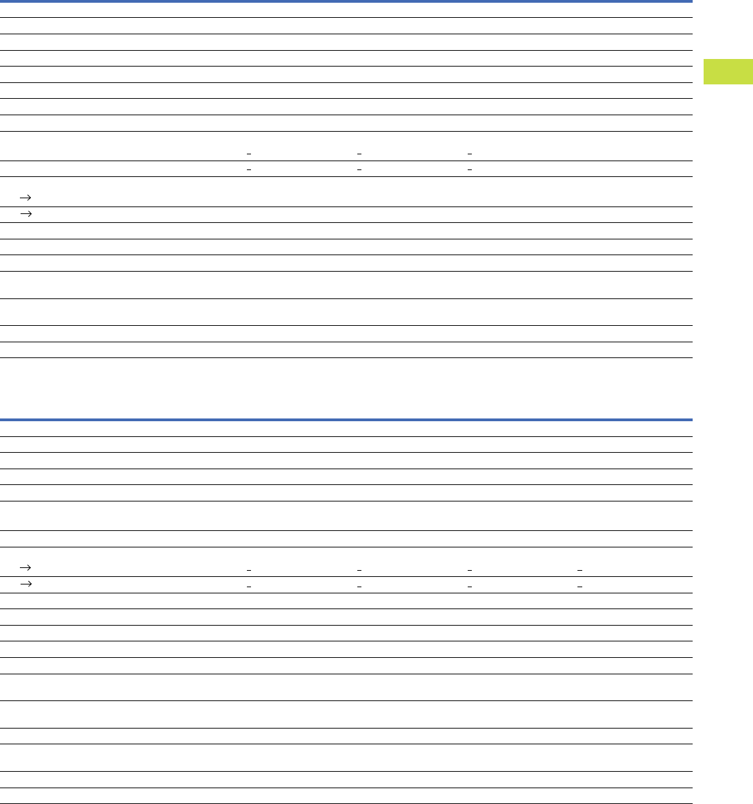
Volume 7—Logic Control, Operator Interface and Connectivity Solutions CA08100008E—May 2016 www.eaton.com V7-T4-47
4
4
4
4
4
4
4
4
4
4
4
4
4
4
4
4
4
4
4
4
4
4
4
4
4
4
4
4
4
4
4.2
PLC, I/O and Communications Products
XC Series Programmable Logic Controllers
XIOC Digital Input Modules
XIOC Digital Output Modules
Description Unit XIOC-8DI XIOC-16DI XIOC-32DI
Modules
Input type DC input DC input DC input
Input voltage Vdc 24 24 24
Permissible range Vdc 20.4–28.8 20.4–28.8 20.4–28.8
Input voltage Vac — — —
Permissible range Vac — — —
Input resistance Normally 3.5 kohm Normally 5.9 kohm Normally 5.6 kohm
Input current mA Normally 6.9 Normally 4.0 Normally 4.3
Voltage level to IEC 61131-2, limit value type 1
ON Vdc >15 >15 >15
OFF Vdc <5<5<5
Input delay
OFF ON ms 5 (normally 4) 5 (normally 4) 5 (normally 4)
OFF ON ms 5 (normally 4) 5 (normally 4) 5 (normally 4)
Input channels Number 8 16 32
Channels with the same reference potential Number 8 16 32
Potential isolation With optocouplers With optocouplers With optocouplers
Indication LED (green) LED (green) 16 LEDs (green),
switchable: 0–15, 16–31
Terminals Plug-in terminal block Plug-in terminal block XIOC-TERM32
(connector and cable)
Internal current consumption (5 Vdc) mA Normally 26 Normally 51 Normally 100
Weight kg 0.16 0.16 0.16
Description Unit XIOC-8DO XIOC-16DO XIOC-16DO-S XIOC-32DO
Modules
Output type Transistor (source type) Transistor (source type) Transistor (source type) Transistor (source type)
Output voltage Vdc 24 (–15 to +20%) 24 (–15 to +20%) 24 (–15 to +20%) 24 (–15 to +20%)
Switching current, minimummA1111
Leakage current mA 0.1 0.1 0.1 0.1
Maximum load current
Per circuit A 0.3 0.3 0.8 0.2
Per common potential terminal A 2.4 4 5 3.2
Output delay
OFF ON ms <0.3 <0.3 <0.3 <0.3
OFF ON ms <1<1<1<1
Output channels Number 8 16 16 32
Channels with the same reference potential Number 8 16 16 32
Overvoltage protection Diode Diode Integrated Diode
Fuse rating A 4 8 None 8
Potential isolation With optocouplers With optocouplers With optocouplers With optocouplers
Indication LED (green) LED (green) LED (green) 16 LEDs (green)
switchable: 0–15, 16–31
Terminals Plug-in terminal block Plug-in terminal block Plug-in terminal block XIOC-TERM32
(connector and cable)
Internal current consumption (5 Vdc) mA Normally 30 Normally 50 Normally 50 Normally 250
External voltage for outputs/module
(30 mA for module supply) (Us)
Vdc 24 (–15 to +20%) 24 (–15 to +20%) 24 (–15 to +20%) 24 (–15 to +20%)
Short-circuit protection — — Yes —
Weight kg 0.16 0.16 0.16 0.16

V7-T4-48 Volume 7—Logic Control, Operator Interface and Connectivity Solutions CA08100008E—May 2016 www.eaton.com
4
4
4
4
4
4
4
4
4
4
4
4
4
4
4
4
4
4
4
4
4
4
4
4
4
4
4
4
4
4
4.2
PLC, I/O and Communications Products
XC Series Programmable Logic Controllers
XIOC Relay Output Module
Description Unit XIOC-12DO-R
Modules
Output type Relays
Output voltage Vdc 24
Output voltage Vac 100/240
Switching current, minimum mA 1
Maximum load current
Per circuit A 2
Per common potential terminal A 5
Output delay
OFF ON ms <10
OFF ON ms <10
Output channels Number 12
Channels with the same reference potential Number 12
Overvoltage protection External
Fuse rating A External
Potential isolation With optocouplers
Indication LED (green)
Terminals Plug-in terminal block
Internal current consumption (5 Vdc) mA Normally 40
External voltage for operating the relay 24 Vdc (–15 to +20%, max. 70 mA)
Weight kg 0.2

Volume 7—Logic Control, Operator Interface and Connectivity Solutions CA08100008E—May 2016 www.eaton.com V7-T4-49
4
4
4
4
4
4
4
4
4
4
4
4
4
4
4
4
4
4
4
4
4
4
4
4
4
4
4
4
4
4
4.2
PLC, I/O and Communications Products
XC Series Programmable Logic Controllers
XIOC Digital Input/Output Module
Description Unit XIOC-16DX
Power Supply
Supply voltage 24 Vdc (–15 to +20%)
Ripple % <5
Overvoltage protection Yes
Protection against polarity reversal Yes
Potential isolation
Between power supply and I/O bus Yes
Between power supply and I/O No
Internal current consumption (5 Vdc) mA Normally 80
Channels Number 16
Terminals Plug-in terminal block
Status indication LED
Inputs
Input type DC input
Input voltage Vdc 24
Inputs Number 4, 12, configurable
Input current mA Normally 4
Voltage level to IEC 61131-2, limit value type 1
ON Vdc >15
OFF Vdc <5
Input delay
OFF ON ms Normally 0.1
OFF ON ms Normally 0.1
Outputs
Output type Transistor (source type)
Output voltage Vdc 12/24 –15 to +20%)
Output current A Normally 0.5
Outputs Number Max. 12, configurable
Short-circuit tripping current A Max. 1.2 over 3 ms for output
Lamp load W Max. 3
Drop-out delay (High Low) µs Normally 100
Switching capacity IEC/EN 60947-5-1, utilization category DC-13
Short-circuit rating Yes
Parallel connection of outputs In groups 0 – 3, 4 – 7, 8 – 11; Actuation of the outputs
within a group only in the same program cycle
Number of outputs that can be switched in parallel Max. 3
Total maximum current A 2 for group
Weight kg 0.16

V7-T4-50 Volume 7—Logic Control, Operator Interface and Connectivity Solutions CA08100008E—May 2016 www.eaton.com
4
4
4
4
4
4
4
4
4
4
4
4
4
4
4
4
4
4
4
4
4
4
4
4
4
4
4
4
4
4
4.2
PLC, I/O and Communications Products
XC Series Programmable Logic Controllers
XIOC Analog Modules
XIOC Thermocouple Module
Description Unit XIOC-8AI-I2 XIOC-8AI-U1 XIOC-8AI-U2 XIOC-4T-PT
Modules
Input voltage Vdc — 0 to 10 –10 to +10 —
Input current mA 4–20 — — —
Resolution, digital bit 12 12 12 15 bit with sign
Conversion time <5 ms <5 ms <5 ms —
Total errors % < ± 1 (of full-scale value) < ± 1 (of full-scale value) < ± 1 (of full-scale value) < ± 1 (of full-scale value)
Input resistance kohm — 100 100 —
Potential isolation
Circuit within each channel With optocouplers With optocouplers With optocouplers With optocouplers
Between the input channels No No No No
Input channels Number 8 8 8 4
Terminals Plug-in terminal block Plug-in terminal block Plug-in terminal block Plug-in terminal block
External power supply 24 Vdc (–15 to +20%),
approx. 150 mA
24 Vdc (–15 to +20%),
approx. 150 mA
24 Vdc (–15 to +20%),
approx. 150 mA
24 Vdc (–15 to +20%),
100 mA
External resistance (R) kohm — — — Max. 0.4, 4 channels
Connection type 2-core shielded cable (<20m) 2-core shielded cable (<20m) 2-core shielded cable (<20m) Shielded cable
Platinum RTD — — — PT100 (IEC 751), PT1000
Accuracy
–20° to 40°C (PT100) °C — — — ±0.5
–50° to 400°C (PT100) °C — — — ±3
–50° to 400°C (PT1000) °C — — — ±6
Temperature measuring range — — — –20 to 40°/–50 to 400°
(uninterrupted current: 2 mA)
Internal current consumption (5 Vdc) mA Normally 100 Normally 100 Normally 100 Max. 200
Additional function — — — Linearization
Fault detection
–20° to 40°C —— — < –25°C or > +45°C = resistance
value 7FFFFhex
–50° to 400°C — — — < –60°C or > +410°C =
resistance value 7FFFFhex
Response to cable break or unused inputs — — — In these cases, the resistance
value is 7FFFhex
Weight kg 0.18 0.18 0.18 0.18
Description Unit XIOC-4AI-T
Channels
Number 4
Temperature measuring range °C Type K: –270 to 1370
Type J: –210 to 1200
Type B: 100 to 1800
Type N: –270 to 1300
Type E: –270 to 1000
Type R: –50 to 1760
Type T: –200 to 400
Voltage measurement mV –50 to 50
–100 to 100
–500 to 500
–1000 to 1000
Cold-junction compensation Yes, built-in
Interference suppression 50 Hz, 60 Hz
Unit 0.1°C, 0.1 F
Resolution bit 16
Total errors % ±0.5 of measurement range
Conversion time <1s
Temperature coefficient <200 ppm/°C of measurement range

Volume 7—Logic Control, Operator Interface and Connectivity Solutions CA08100008E—May 2016 www.eaton.com V7-T4-51
4
4
4
4
4
4
4
4
4
4
4
4
4
4
4
4
4
4
4
4
4
4
4
4
4
4
4
4
4
4
4.2
PLC, I/O and Communications Products
XC Series Programmable Logic Controllers
XIOC Analog Modules
XIOC Analog Modules
Description Unit XIOC-2AO-U1-2AO-I2 XIOC-4AO-U1 XIOC-2AO-U2
Modules
Output voltage Vdc 0–10 0–10 –10 to 10
Output current mA 4–20 — —
Resolution bit121212
Conversion time <5 ms <5 ms <5 ms
Total errors % < ±1 (of full-scale value) < ±1 (of full-scale value) < ±1 (of full-scale value)
External load resistance
Voltage output >10 kohm >10 kohm >10 kohm
Current output ohm 0 to 500 ohm — —
Potential isolation
Circuit within each channel With optocouplers
Between channels No No No
Number of outputs
Output voltage 2 (channels 0 and 1) 4 2
Output current 2 (channels 2 and 3) — —
Terminals Plug-in terminal block Plug-in terminal block Plug-in terminal block
Internal current consumption (5 Vdc) mA Normally 100 Normally 100 Normally 100
External power supply 24 Vdc (–15/+20%), approx. 150 mA 24 Vdc (–15/+20%), approx. 150 mA 24 Vdc (–15/+20%), approx. 150 mA
Connection type 2-core shielded cable (<20m) 2-core shielded cable (<20m) 2-core shielded cable (<20m)
Description Unit XIOC-2AI-1AO-U1 XIOC-2AI-1AO-U1-I1 XIOC-4AI-2AO-U1 XIOC-4AI-2AO-U1-I1
Inputs
Input voltage Vdc 0–10 0–10 0–10 0–10
Input current mA — 0–20 — 0–20
Resolution bit14141414
Conversion time <1 ms <1 ms <1 ms <1 ms
Total errors % Normally 0.4 Normally 0.4 Normally 0.4 Normally 0.4
Potential isolation
Circuit within each channel No No No No
Between the input channels No No No No
Between input/output channels No No No No
Channels Number 2244
Input resistance kohm 40 40 40 40
Outputs
Output voltage Vdc 0–10 0–10 0–10 0–10
Output current mA — 0–20 — 0–20
Resolution bit12121212
Errors Normally 0.4% Normally 0.4% Normally 0.4% Normally 0.4%
Potential isolation
Circuit within each channel No No No No
Between the output channels No No No No
Number of channels 1122
External load resistance >2 kohm >2 kohm >2 kohm >2 kohm
Short-circuit rating Yes Yes Yes Yes
Terminal Connection
Terminals Plug-in terminal block Plug-in terminal block Plug-in terminal block Plug-in terminal block
Internal current consumption (5 Vdc) mA Normally 200 Normally 200 Normally 200 Normally 200
Weight kg 0.16 0.16 0.16 0.16

V7-T4-52 Volume 7—Logic Control, Operator Interface and Connectivity Solutions CA08100008E—May 2016 www.eaton.com
4
4
4
4
4
4
4
4
4
4
4
4
4
4
4
4
4
4
4
4
4
4
4
4
4
4
4
4
4
4
4.2
PLC, I/O and Communications Products
XC Series Programmable Logic Controllers
XIOC Communication Modules
Description Unit XIOC-NET-DP-M XIOC-NET-DP-S XIOC-SER XIOC-TC1
Interfaces
Interfaces PROFIBUS-DP, RS-485, EN 50170 PROFIBUS-DP, RS-485, EN 50170 RS-232(C), RS-422, RS-485 RS-232(C), RS-422, RS-485
Protocol PROFIBUS-DP master (class 1) PROFIBUS-DP slave Transparent mode, Modbus
master/slave
Transparent mode, Modbus
master/slave, DNP3 protocol
Character formats — — 8E1, 8O1, 8N1, 8N2, 7E2, 7O2,
7N2, 7E1
8E1, 8O1, 8N1, 8N2, 7E2, 7O2,
7N2, 7E1
Control and signal cables — — RTS, CTS, DTR, DSR, DCD RTS, CTS, DTR, DSR, DCD
Transfer rate kbit/s 9.6 to 12,000 9.6 to 12,000 0.3 –57.6 0.3–57.6
Potential isolation Yes Yes Yes (RS-485, RS-422) Yes (RS-485, RS-422)
Number of slaves 124 — — —
Send/receive data 3500 Byte each Max. 244 Byte 250 Byte per slave
120 Byte per slave
250/500
Bus terminating resistors Switchable Switchable Switchable for RS-485, RS-422 Switchable for RS-485, RS-422
Connector type D-sub 9-pin socket D-sub 9-pin socket RS-232: D-sub 9-pin
RS-485, 422: plug-in
terminal block
RS-232: D-sub 9-pin
RS-485, 422: plug-in
terminal block
Current consumption mA <300 <300 <275 <275
Weight kg Approx. 0.2 Approx. 0.2 Approx. 0.2 Approx. 0.2
Number of modules XC100: 1/XC200: 3 XC100: 1/XC200: 3 XC100: 2/XC200: 4 XC200: 4
Slots 1, 2, 3 1, 2, 3 Any Any

Volume 7—Logic Control, Operator Interface and Connectivity Solutions CA08100008E—May 2016 www.eaton.com V7-T4-53
4
4
4
4
4
4
4
4
4
4
4
4
4
4
4
4
4
4
4
4
4
4
4
4
4
4
4
4
4
4
4.2
PLC, I/O and Communications Products
XC Series Programmable Logic Controllers
XIOC Counter Modules
Description Unit XIOC-1CNT-100KHZ XIOC-2CNT-100KHZ XIOC-2CNT-2AO-INC
Inputs
Counter limits 0–4294967295 (32 bit) 0–4294967295 (32 bit) 0–4294967295 (32 bit)
Internal current consumption mA 200 200 450
Frequency kHz 100 (25 with four times resolution) 100 (25 with four times resolution) 400 (100 with four times resolution)
Number of channels 1 2 2
Input voltage Vdc 12–24 12–24 —
Voltage for ON Vdc >10 >10 —
Voltage for OFF VA/W <4 <4 —
Input current mA > 4> 4—
Differential input voltage Vdc ±5 ±5 ±5
Voltage for ON Vdc 2–5 2–5 0.2–5
Voltage for OFF Vdc –5 to 8 –5 to 8 –5 to –0.2
Differential input current mA 35 35 5
Minimum pulse width µs ON >4/OFF >4ON
>4/OFF >4—
Potential isolation With optocouplers With optocouplers —
Connection for external cabling 30-pin plug: XIOC-TERM30-CNT4 30-pin plug: XIOC-TERM30-CNT4 Plug-in terminal block
External cabling Shielded, twisted pair cable Shielded, twisted pair cable Shielded, twisted pair cable
Outputs
Output type Transistor (open collector) Transistor (open collector) Analog
External power supply 12/24 Vdc (30 max.) 12/24 Vdc (30 max.) —
Minimum load current mA 1 1 —
Maximum load current (Ie)mA2020—
Max. leakage current mA 0.5 0.5 —
Max. voltage drop at ON V 1.5 1.5 —
Debounce OFF
OFF ON ms <1<1—
OFF ON ms <1<1—
Output channels Number 2 4 2
Potential isolation With optocouplers With optocouplers —
Output voltage Vdc — — –10 to 10
Resolution bit——12
Conversion time — — <1 ms
Total errors % — — Normally 0.4
Load resistance — — >1 kohm
Connection for external cabling 30-pin plug: XIOC-TERM30-CNT4 30-pin plug: XIOC-TERM30-CNT4 Plug-in terminal block
External cabling Shielded, twisted pair cable Shielded, twisted pair cable Shielded 2-core cable
Current per channel mA — — <300
Power supply of encoders — — 5 Vdc
Current consumption mA 200 200 Max. 450
Weight kg 0.16 0.16 0.18

V7-T4-54 Volume 7—Logic Control, Operator Interface and Connectivity Solutions CA08100008E—May 2016 www.eaton.com
4
4
4
4
4
4
4
4
4
4
4
4
4
4
4
4
4
4
4
4
4
4
4
4
4
4
4
4
4
4
4.2
PLC, I/O and Communications Products
XC Series Programmable Logic Controllers
Power Supply Suppression Filters
General Information on Electromagnetic Compatibility (EMC) of Automation Systems
Description Unit XT-FIL-1 XT-FIL-2
General
Standards IEC/EN 61131-2; EN 50178 IEC/EN 61131-2; EN 50178
Ambient temperature °F (°C) 32° to 131° (0° to 55°) 32° to 131° (0° to 55°)
Storage °F (°C) –13° to 158° (–25° to 70°) –13° to 158° (–25° to 70°)
Mounting position Vertical or horizontal Vertical or horizontal
Vibration resistance 10–57 Hz ± 0.075 mm
57–150 Hz ± 1.0g
10–57 Hz ± 0.075 mm
57–150 Hz ± 1.0g
Mechanical shock resistance 15g/11 ms 15g/11 ms
Impact strength 500g /50 mm ±25g 500g/50 mm ±25g
Overvoltage category II II
Pollution degree 2 2
Protection type IP20 IP20
Rated impulse withstand voltage (Uimp)V850 850
Interference immunity EN 61000-6-2 EN 61000-6-2
Weight kg 0.1 0.1
Dimensions (W x H x D) mm 35 x 90 x 30 35 x 90 x 57
Terminals Screw terminals Screw terminals
Terminal capacity
Screw terminals
Flexible with ferrule mm20.2–2.5 (AWG22–12) 0.2–2.5 (AWG22–12)
Solid mm20.2–2.5 (AWG22–12) 0.2–2.5 (AWG22–12)
Power Supply
Input voltage Vdc 24 24
Permissible range Vdc 20.4–28.8 20.4–28.8
Ripple % < 5< 5
Mains overvoltage protection Yes Yes
Potential isolation
Between input voltage and PE Yes Yes
Between input voltage and output voltage No No
Between output voltage and PE Yes Yes
Rated value Vdc 24 24
Output current A 2.2 12
Description Specification
Emitted interference EN 55011/22 Class A (VDE 0875, Part 11)
Interference immunity
ESD IEC/EN 61000-4-2 Contact discharge: 4 kV
Air discharge 8 kV
RFI IEC/EN 61000-4-3 AM (80%) 80–1000 MHz 10V/m
Mobile phones/cellphones IEC/EN 61000-4-3 PM 800–960 MHz 10V/m
Burst IEC/EN 61000-4-4 Mains/digital I/O (direct): 2 kV
Analog I/O, fieldbus (capacitive coupling): 1 kV
Surge IEC/EN 61000-4-5 Digital I/O, asymmetric, analog I/O, asymmetric, connection to shielding: 0.5 kV
Mains DC, asymmetric: 1 kV
Mains DC, symmetric: 1 kV
Mains AC, asymmetric: 0.5 kV
Mains AC, symmetric: 2 kV
Conducted interference, induced by
high-frequency fields
IEC/EN 61000-4-6; 2003 AM (80%) 150 kHz–80 MHz 3V
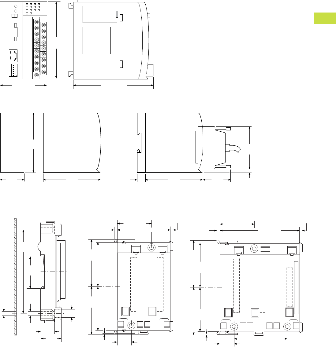
Volume 7—Logic Control, Operator Interface and Connectivity Solutions CA08100008E—May 2016 www.eaton.com V7-T4-55
4
4
4
4
4
4
4
4
4
4
4
4
4
4
4
4
4
4
4
4
4
4
4
4
4
4
4
4
4
4
4.2
PLC, I/O and Communications Products
XC Series Programmable Logic Controllers
Dimensions
Approximate Dimensions in Inches (mm)
XC-CPU101, XC-CPU201, XC-CPU202
XIOC_
Backplates
XIOC-BP-2 XIOC-BP-3 XIOC-BP-XC1
XIOC-BP-XC XIOC-BP-EXT
3.94 (100.0)
3.94
(100.0)
2.36 (60.0)
3.94
(100.0)
1.18
(30.0)
3.74
(95.0)
2.87
(73.0)
0.19
(5.0)
1.97
(50.0)
3.74
(95.0)
0.83
(21.0)
M4
3.46
(88.0)
1.40
(35.5)
0.18
(4.5) 0.33
(8.5)
0.55
(14.0) 0.83
(21.0)
1.54 (39.0)
2.11
(53.5)
1.97
(50.0)
2.11
(53.5)
1.97
(50.0)
0.04
(1.0) 0.63
(16.0)
2.36 (60.0)
0.14
(3.5)
0.12 (3.0)
1.54 (39.0)
3.54 (90.0)
0.14
(3.5)
0.12 (3.0)
2.11
(53.5)
1.97
(50.0)
2.11
(53.5)
1.97
(50.0)
0.04
(1.0) 0.63 (16.0)
2.36 (60.0)
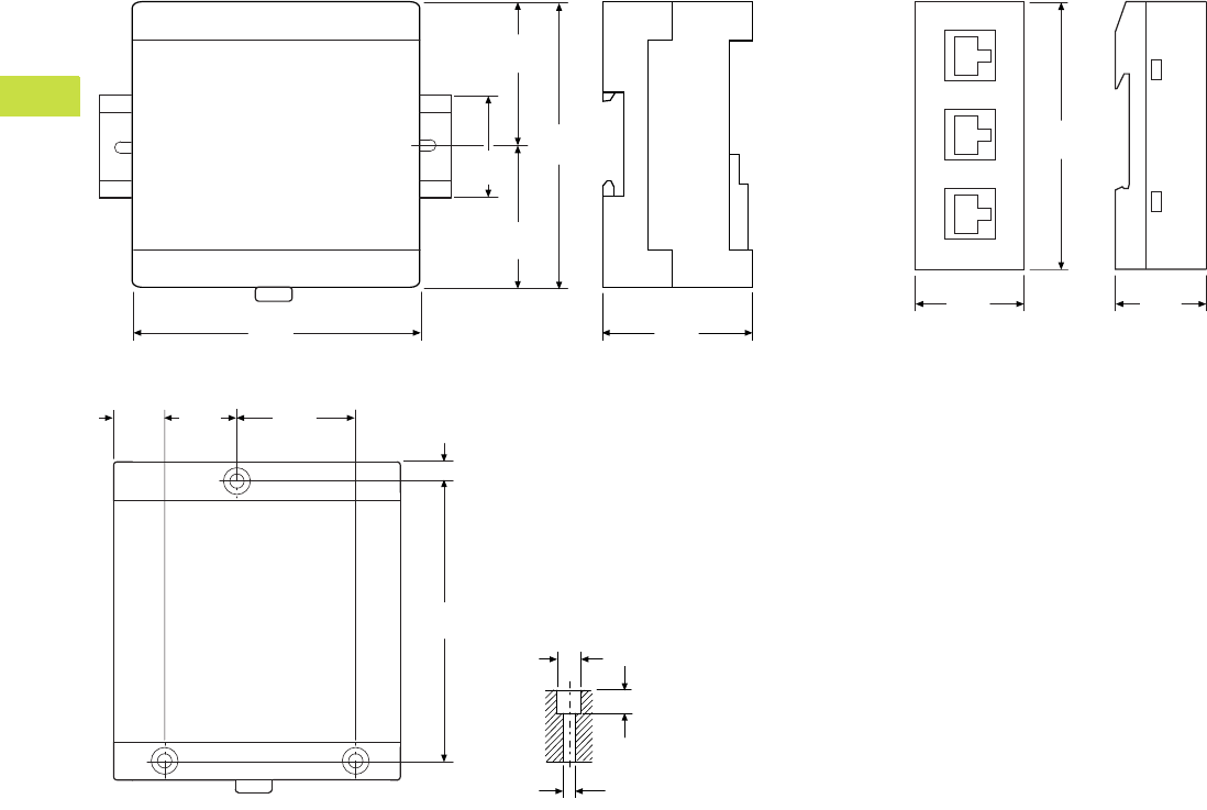
V7-T4-56 Volume 7—Logic Control, Operator Interface and Connectivity Solutions CA08100008E—May 2016 www.eaton.com
4
4
4
4
4
4
4
4
4
4
4
4
4
4
4
4
4
4
4
4
4
4
4
4
4
4
4
4
4
4
4.2
PLC, I/O and Communications Products
XC Series Programmable Logic Controllers
Approximate Dimensions in Inches (mm)
XC-CPU-121_, XIO-EXT121-1 XT-RJ45-ETH-RS232
3.54
(90.0)
1.97
(50.0)
1.97
(50.0)
1.38
(35.0)
3.94
(100.0)
1.85
(47.0)
3.54
(90.0)
1.38
(35.0)
1.18
(30.0)
3.46
(88.0)
0.34
(8.5)
0.27
(6.8)
0.18
(4.5)
1.47
(37.3)
0.90
(22.8)
0.63
(16.0) 0.24
(6.0)
Volume 7—Logic Control, Operator Interface and Connectivity Solutions CA08100008E—May 2016 www.eaton.com V7-T4-57
4
4
4
4
4
4
4
4
4
4
4
4
4
4
4
4
4
4
4
4
4
4
4
4
4
4
4
4
4
4
4.3
PLC, I/O and Communications Products
XC152 Series Programmable Logic Controllers
XC152 Series Programmable Logic Controllers
Contents
Description Page
XC152 Series Programmable Logic Controllers
Catalog Number Selection . . . . . . . . . . . . . . . . V7-T4-58
Product Selection . . . . . . . . . . . . . . . . . . . . . . . V7-T4-58
Accessories . . . . . . . . . . . . . . . . . . . . . . . . . . . V7-T4-58
Technical Data and Specifications . . . . . . . . . . V7-T4-59
Dimensions . . . . . . . . . . . . . . . . . . . . . . . . . . . V7-T4-60
Product Description
The XC152 compact
PLC combines plenty of
processing power with a
large number of
communication interfaces.
This makes the device
particularly well-suited to
standardized automation
solutions in modular machine
building applications.
The XC152 not only provides
machine segment control
functions that can be
programmed with CoDeSys,
but it can store module-
specific visualizations.
These visualizations can be
retrieved and displayed on
a central HMI or a computer
as needed.
In addition, the XC152
connects SmartWire-DT
systems to standard fieldbus
systems via its interfaces.
This enables the XC152 PLC
to support Eaton’s Lean
Automation strategy while
enabling users to design
automation systems in a
flexible manner and run them
cost-effectively.
Application Description
Flexible Solutions for
Modular Machine Units
In the field of automation,
complex processes are
subdivided into easily
manageable functional units
to make programming,
production and installation
easier. For example, a
packaging machine can be
subdivided into infeed,
positioning (erector), filling
and sealing (gluing) modules.
Other systems and machines
can also be effectively
subdivided to create a wide
variety of different models or
to delimit various expansion
stages.
With the XC152, a powerful
PLC controls individual
system modules while
making it possible to directly
connect SmartWire-DT
system devices and standard
fieldbus components. Data
transfers via the Ethernet
interface to OPC clients,
together with the available
remote visualization system,
support a connection to a
central control and
visualization system.
SmartWire-DT
The XC152 relies on Eaton’s
tried-and-true SmartWire-DT
connection system,
eliminating the need for
control current wiring in
every single machine
module and simplifying the
commissioning process by
means of better diagnostic
options. This results in
significant design,
commissioning and
maintenance cost reductions.
Standard CAN and
PROFIBUS Fieldbus
Systems
Servo drives, frequency
inverters and hydraulic
components can all be easily
connected using the large
number of fieldbus interfaces
available on the XC152.
Visualization
The integrated Web
visualization function offers a
key advantage, as machine
module diagnostic and
visualization information can
be displayed on a central HMI
or a terminal.
Features and Benefits
●CoDeSys PLC and Web
visualization
●Galileo/CoDeSys remote
visualization
●Ethernet port on all models
●Windows® CE 5 operating
system
●32-bit RISC CPU at
400 MHz
●64 MB internal memory
●SD card slot for external
memory
●Run/Stop switch
●Optional: Integrated
SmartWire-DT master
for 99 nodes
●Optional: RS-232, RS-485,
PROFIBUS-DP/MPI,
CANopen/easyNet
Standards and
Certifications
●IEC/EN 61131-2, EN 50178
●
EN 61000-6-2, EN 61000-6-4
●cULus
●CE
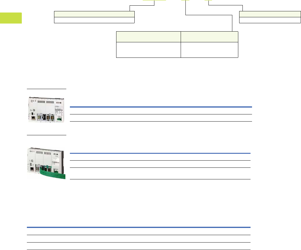
V7-T4-58 Volume 7—Logic Control, Operator Interface and Connectivity Solutions CA08100008E—May 2016 www.eaton.com
4
4
4
4
4
4
4
4
4
4
4
4
4
4
4
4
4
4
4
4
4
4
4
4
4
4
4
4
4
4
4.3
PLC, I/O and Communications Products
XC152 Series Programmable Logic Controllers
Catalog Number Selection
XC152 PLCs with and without SmartWire-DT
Product Selection
XC152 PLC
XC152 PLC SmartWire-DT
Accessories
XC PLC Accessories
CoDeSys
Firmware
Fieldbus
Type RS-232 RS-485 Ethernet
Catalog
Number
Yes CANopen Yes Yes Yes XC-152-D6-11
Yes PROFIBUS-DP Yes Yes Yes XC-152-D8-11
CoDeSys
Firmware
Fieldbus
Type RS-232 RS-485 Ethernet SmartWire-DT
Catalog
Number
Yes None Y None Yes Yes XC-152-E3-11
Yes CANopen None Yes Yes Yes XC-152-E6-11
Yes PROFIBUS-DP None Yes Yes Yes XC-152-E8-11
Description
Catalog
Number
PLC programming software, single seat license SW-XSOFT-CODESYS-2-S
PLC programming software, multiple seat license SW-XSOFT-CODESYS-2-M
SD memory card MEMORY-SD-A1-S
Family
XC-152 = Windows CE OS CoDeSys firmware
Mounting
11 = DIN rail or panel mount
Features
Base Unit Variant
Features
Additional COMM Options
D = Ethernet, RS-485 and USB host
E = SmartWire-DT, Ethernet and
USB host
3 =None
6 = 1-CANopen
8 = 1-PROFIBUS-DP
XC-152 – E6 – 11
XC152 PLC
XC152 PLC
SmartWire-DT

Volume 7—Logic Control, Operator Interface and Connectivity Solutions CA08100008E—May 2016 www.eaton.com V7-T4-59
4
4
4
4
4
4
4
4
4
4
4
4
4
4
4
4
4
4
4
4
4
4
4
4
4
4
4
4
4
4
4.3
PLC, I/O and Communications Products
XC152 Series Programmable Logic Controllers
Technical Data and Specifications
XC152 Series Programmable Logic Controllers
Note
1Interface not galvanically isolated.
Description Unit XC-152-D6-11 XC-152-D8-11 XC-152-E3-11 XC-152-E6-11 XC-152-E8-11
System
Processor RISC, 32 bit at 400 MHz RISC, 32 bit at 400 MHz RISC, 32 bit at 400 MHz RISC, 32 bit at 400 MHz RISC, 32 bit at 400 MHz
Internal memory
DRAM
(OS-, program and data memory)
Mbyte6464646464
NAND FLASH
(can be used for data security)
Mbyte Approx. 128 available Approx. 128 available Approx. 128 available Approx. 128 available Approx. 128 available
NVRAM (retain) kByte Approx. 32 available Approx. 32 available Approx. 32 available Approx. 32 available Approx. 32 available
External memory
SD memory card slot SDA Specification 1.00 SDA Specification 1.00 SDA Specification 1.00 SDA Specification 1.00 SDA Specification 1.00
Real-time clock (battery backup)
Battery (not rechargeable) Zero maintenance Zero maintenance Zero maintenance Zero maintenance Zero maintenance
Backup time at zero voltage Normally 10 years Normally 10 years Normally 10 years Normally 10 years Normally 10 years
Operating system Windows CE 5 Windows CE 5 Windows CE 5 Windows CE 5 Windows CE 5
Engineering
PLC-Programming software CoDeSys 2/3 CoDeSys 2/3 CoDeSys 2/3 CoDeSys 2/3 CoDeSys 2/3
Visualization
WEB-VISU CoDeSys CoDeSys CoDeSys CoDeSys CoDeSys
Remote Client Galileo/CoDeSys Galileo/CoDeSys Galileo/CoDeSys Galileo/CoDeSys Galileo/CoDeSys
Communication Interfaces
Ethernet 100Base-TX/10Base-T 100Base-TX/10Base-T 100Base-TX/10Base-T 100Base-TX/10Base-T 100Base-TX/10Base-T
USB host 1—————
USB device 1USB 2.0 USB 2.0 USB 2.0 USB 2.0 USB 2.0
System port (RS-232) 1■■■——
SmartWire-DT 1——■■■
CAN 1■——■—
PROFIBUS/MP 1—■——■
RS-485 1■■—■■
General
Rated operating voltage 24 Vdc SELV 24 Vdc SELV 24 Vdc SELV 24 Vdc SELV 24 Vdc SELV
Power consumption W Max. 5 Max. 5 Max. 5 Max. 5 Max. 5
Protect against polarity reversal Yes Yes Yes Yes Yes
Approvals CE, cULus CE, cULus CE, cULus CE, cULus CE, cULus
Ambient air temperature °C 0 to 55 0 to 55 0 to 55 0 to 55 0 to 55
Storage temperature °C –40 to +70 –40 to +70 –40 to +70 –40 to +70 –40 to +70
Protection type IP20 IP20 IP20 IP20 IP20
Flush mounting DIN rail EN 60715, 35 mm DIN rail EN 60715, 35 mm DIN rail EN 60715, 35 mm DIN rail EN 60715, 35 mm DIN rail EN 60715, 35 mm
Dimensions (H x W x D) mm 105 x 155 x 40 105 x 155 x 40 105 x 155 x 40 105 x 155 x 40 105 x 155 x 40
Weight (approximate) kg 0.3 0.3 0.3 0.3 0.3
Applied standards and directives
Product standard
IEC/EN 61131-2, EN50178 IEC/EN 61131-2, EN50178 IEC/EN 61131-2, EN50178 IEC/EN 61131-2, EN50178 IEC/EN 61131-2, EN50178
EMC
EN 61000-6-2, EN 61000-6-4 EN 61000-6-2, EN 61000-6-4 EN 61000-6-2, EN 61000-6-4 EN 61000-6-2, EN 61000-6-4 EN 61000-6-2, EN 61000-6-4
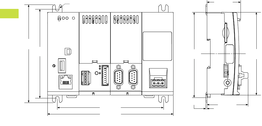
V7-T4-60 Volume 7—Logic Control, Operator Interface and Connectivity Solutions CA08100008E—May 2016 www.eaton.com
4
4
4
4
4
4
4
4
4
4
4
4
4
4
4
4
4
4
4
4
4
4
4
4
4
4
4
4
4
4
4.3
PLC, I/O and Communications Products
XC152 Series Programmable Logic Controllers
Dimensions
Approximate Dimensions in Inches (mm)
XC152 Series Programmable Logic Controllers
4.77
(121.2)
1.99 (50.6)
0.06 (1.5)
Ø 0.18 (4.5)
5.15 (130.8)
6.11 (155.1)
4.34
(110.2)
1.63 (41.5)
4.04
(102.6)
4.16
(105.6)
With Fixing Brackets Without Fixing Brackets
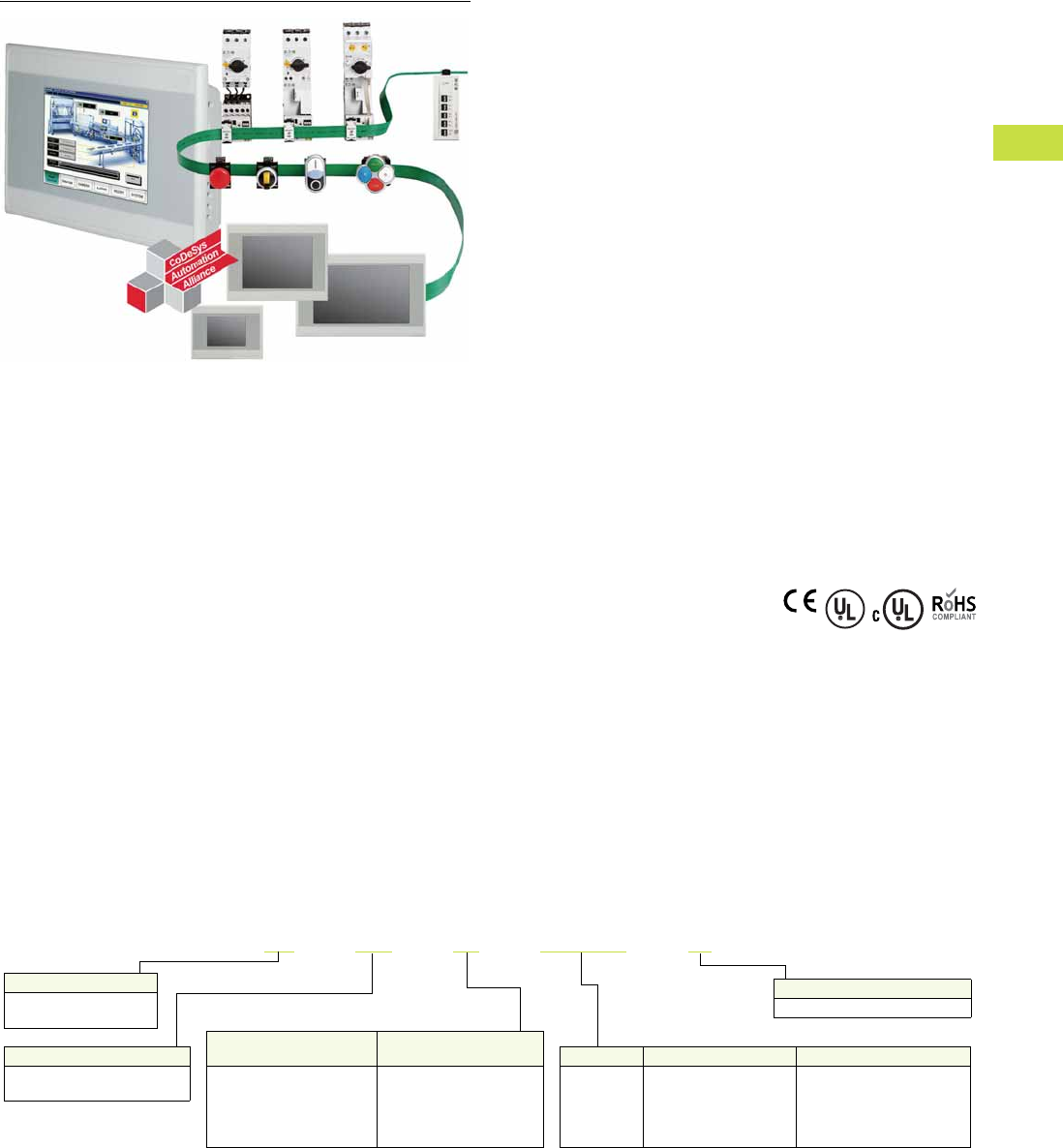
Volume 7—Logic Control, Operator Interface and Connectivity Solutions CA08100008E—May 2016 www.eaton.com V7-T4-61
4
4
4
4
4
4
4
4
4
4
4
4
4
4
4
4
4
4
4
4
4
4
4
4
4
4
4
4
4
4
4.4
PLC, I/O and Communications Products
XV-100 Series HMI-PLCs
XV-100 Series HMI-PLC
Contents
Description Page
XV-100 Series HMI-PLC
Product Selection . . . . . . . . . . . . . . . . . . . . . . . V7-T4-62
Accessories . . . . . . . . . . . . . . . . . . . . . . . . . . . V7-T4-62
Product Description
The XV-100 HMI-PLC is a
powerful combination of logic
and visualization based on the
open CoDeSys programming
platform. It is ideal for small
to mid-range PLC applications
where integrated logic and
visualization is advantageous
and/or where remote
administration is critical.
The XV-100 HMI-PLC is also
available with an integrated
SmartWire-DT master. This
combination of visualization,
control and SmartWire-DT
connectivity is the ultimate
lean automation solution.
Features
●Built-in SmartWire-DT
master for 99 nodes
●Brilliant image display with
65,536 colors
●High resolution resistive
touch TFT displays
●3.5 in, 5.7 in or 7 in
widescreen displays in a
robust plastic housings
and bezels, or
●5.7 in, 8.4 in or 10.4 in
displays in high-end
aluminum front bezels
and metal housings
●Ethernet on all models
●RS-232 or RS-485 serial
ports available
●PROFIBUS-DP or
CANopen master on all
models larger than 3.5 in
●Programmable with
IEC 61131-3 compliant
XSoft-CoDeSys software
●Easy connection direct to
motor control components
or I/O modules on the
SmartWire-DT flat cable
Standards and
Certifications
●CE
●UL
●cUL
●RoHS
Catalog Number Selection
XV-100 HMI-PLC
XV –102–E6–35TQRG–10
Family
XV = Windows® CE
operating system
Bezel
10 = Standard blank front bezel
Display Size Display Technology OS Build
35 = 3.5 in
57 = 5.7 in
70 = 7.0 in
84 = 8.4 in
10 = 10.4 in
TQR = TFT (QVGA) resistive
TVR = TFT (VGA) resistive
TWR = TFT (WGA) resistive
C = XSoft-CoDeSys
Features
Base Unit Variant
Features
Additional COMM Options
B = Retentive memory
D = Retentive memory, USB
host, RS-232
E = SmartWire-DT, retentive
memory, USB host, RS-232
6 = 1-CANopen
8 = 1-PROFIBUS-DP
E = SmartWire-DT
Housing
102 = Plastic housing
152 = Metal housing
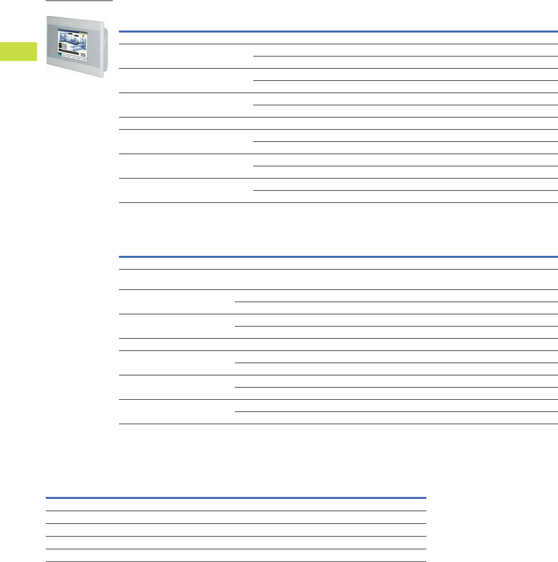
V7-T4-62 Volume 7—Logic Control, Operator Interface and Connectivity Solutions CA08100008E—May 2016 www.eaton.com
4
4
4
4
4
4
4
4
4
4
4
4
4
4
4
4
4
4
4
4
4
4
4
4
4
4
4
4
4
4
4.4
PLC, I/O and Communications Products
XV-100 Series HMI-PLCs
Product Selection
XV-100 HMI-PLC
XV-100 HMI-PLC SmartWire-DT
Accessories
XV-100 HMI-PLC Accessories
Note
1For details on SW-XSoft-CoDeSys software, see Page V7-T4-38.
Display Size/Type
Display
Resolution
CoDeSys
Firmware Fieldbus Type RS485 Ethernet Catalog Number
Plastic Housing
3.5 in TFT
Resistive
QVGA
320x240
Y CANopen Y Y XV-102-B6-35TQRC-10
Y PROFIBUS-DP Y Y XV-102-B8-35TQRC-10
5.7 in TFT
Resistive
VGA
640x480
Y CANopen Y Y XV-102-D6-57TVRC-10
Y PROFIBUS-DP Y Y XV-102-D8-57TVRC-10
7.0 in TFT
Resistive
WGA
800x480
Y CANopen Y Y XV-102-D6-70TWRC-10
Y PROFIBUS-DP Y Y XV-102-D8-70TWRC-10
Metal Housing
5.7 in TFT
Resistive
VGA
640x480
Y CANopen Y Y XV-152-D6-57TVRC-10
Y PROFIBUS-DP Y Y XV-152-D8-57TVRC-10
8.4 in TFT
Resistive
VGA
640x480
Y CANopen Y Y XV-152-D6-84TVRC-10
Y PROFIBUS-DP Y Y XV-152-D8-84TVRC-10
10.4 in TFT
Resistive
VGA
640x480
Y CANopen Y Y XV-152-D6-10TVRC-10
Y PROFIBUS-DP Y Y XV-152-D8-10TVRC-10
Display
Size/Type
Display
Resolution
CoDeSys
Firmware Fieldbus Type RS485 Ethernet SmartWire-DT Catalog Number
Plastic Housing
3.5 in TFT QVGA
320x240
Y None None Y Y XV-102-BE-35TQRC-10
5.7 in TFT VGA
640x480
Y CANopen Y Y Y XV-102-E6-57TVRC-10
Y PROFIBUS-DP Y Y Y XV-102-E8-57TVRC-10
7.0 in TFT WGA
800x480
Y CANopen Y Y Y XV-102-E6-70TWRC-10
Y PROFIBUS-DP Y Y Y XV-102-E8-70TWRC-10
Metal Housing
5.7 in TFT VGA
640x480
Y CANopen Y Y Y XV-152-E6-57TVRC-10
Y PROFIBUS-DP Y Y Y XV-152-E8-57TVRC-10
8.4 in TFT VGA
640x480
Y CANopen Y Y Y XV-152-E6-84TVRC-10
Y PROFIBUS-DP Y Y Y XV-152-E8-84TVRC-10
10.4 in TFT VGA
640x480
Y CANopen Y Y Y XV-152-E6-10TVRC-10
Y PROFIBUS-DP Y Y Y XV-152-E8-10TVRC-10
Description Catalog Number
HMI-PLC programming software, single seat license SW-XSOFT-CODESYS-2-S 1
HMI-PLC programming software, multiple seat license SW-XSOFT-CODESYS-2-M 1
SD memory card MEMORY-SD-A1-S
XV-102 parts kit (1 power conductor, 8 mounting brackets, 1 sealing strip, 1 touch pen) ACC-TP-57-KG-1
XV-152 parts kit (1 power conductor, 8 mounting brackets, 1 sealing strip, 1 touch pen) ACC-TP-10-12-RES-1
XV-100 HMI-PLC
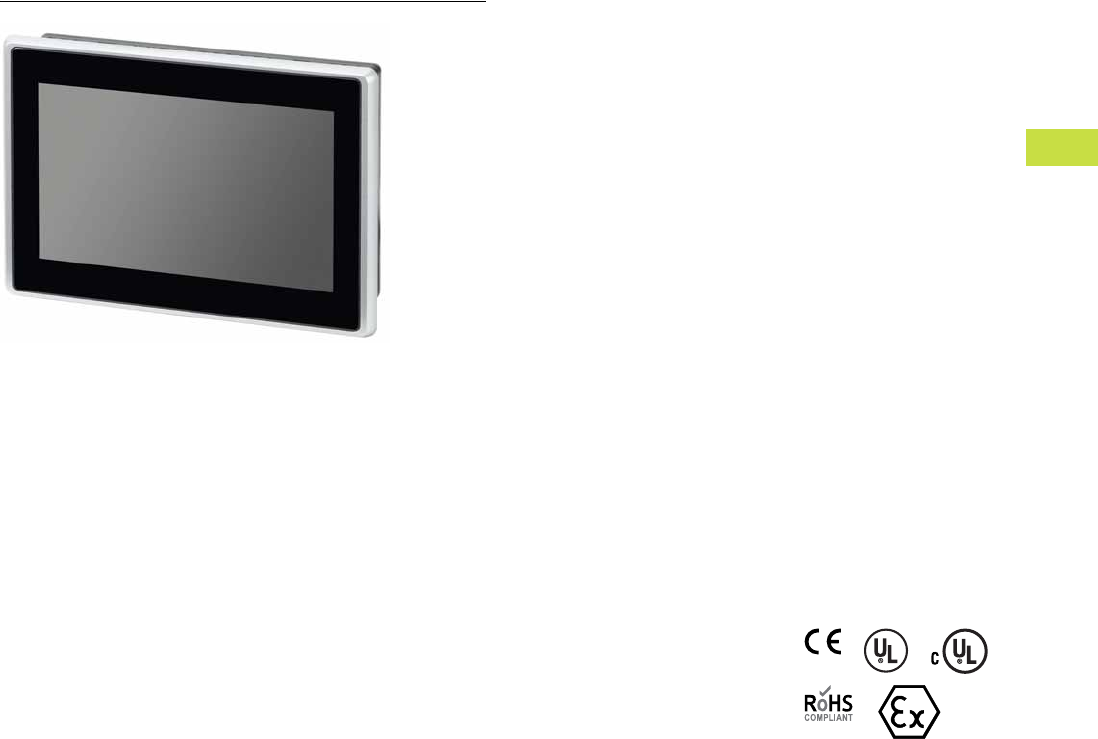
Volume 7—Logic Control, Operator Interface and Connectivity Solutions CA08100008E—May 2016 www.eaton.com V7-T4-63
4
4
4
4
4
4
4
4
4
4
4
4
4
4
4
4
4
4
4
4
4
4
4
4
4
4
4
4
4
4
4.5
PLC, I/O and Communications Products
XV-300 Series HMI-PLCs
XV-300 Series HMI-PLC
Contents
Description Page
XV-300 Series HMI-PLC
Product Selection Guide . . . . . . . . . . . . . . . . . . V7-T4-64
Catalog Number Selection . . . . . . . . . . . . . . . . V7-T4-65
Product Selection . . . . . . . . . . . . . . . . . . . . . . . V7-T4-65
Accessories . . . . . . . . . . . . . . . . . . . . . . . . . . . V7-T4-66
Technical Data and Specifications . . . . . . . . . . V7-T4-67
Product Description
The XV-300 HMI-PLC is the
most powerful combination
of logic and visualization
available today. The XV-300’s
logic software CoDeSys is
based on the open IEC 61131
programming platform. And
because it has by far the
highest adoption rate with
hundreds of automation
vendors offering products
based on CoDeSys, it has
become the de-facto
standard for IEC 61131 logic
software. It has all the
features of a high end full
featured logic development
tool but is well suited for
small and mid-range PLC
applications. Because so
many automation vendors
offer CoDeSys-based
products, you will never have
to learn another development
software package. Plus you
will be able to create projects
that utilize hardware from
multiple different vendors
all in one integrated
environment where data can
be easily shared between all
devices on a network. While
CoDeSys had its own set of
visualization tools for creating
a graphical user interface, on
the XV-300 platform you can
combine CoDeSys logic
development with the full
Visual Designer HMI-SCADA
development suite for the
most advanced user interface
available anywhere. With an
HMI-PLC-SCADA solution,
you can meet virtually any
application need you can
think of. So whether using
models with just the
CoDeSys software bundle
or the CoDeSys + Visual
Designer software bundle,
you know you can meet the
needs of your application.
Features
●Built-in master for
CANopen, EtherNet/IP,
Modbus TCP, PROFINET
EtherCAT and Modbus
serial I/O networks
●Optional SmartWire-DT
master for 99 nodes of I/O
●Optional PROFIBUS-DP
master
●Single high-speed Ethernet
standard with optional
second high-speed
independent Ethernet for
multiple subnet
connectivity, e.g., Machine
network + Plant network,
or Machine network +
Wireless cellular modem
●High resolution,
widescreen, multi-touch
projected capacitive
touchscreen (PCT)
●Brilliant image display
with 65,536 colors and
1024x600 pixel resolution
in both 7-inch and 10.1-inch
screen sizes
●Software bundles for
XSoft-CoDeSys 3 PLC logic
and visualization and/or
Visual Designer HMI-
SCADA graphical user
interface
Standards and
Certifications
●CE Mark
●UL
●cUL
●RoHS
●ATEX

V7-T4-64 Volume 7—Logic Control, Operator Interface and Connectivity Solutions CA08100008E—May 2016 www.eaton.com
4
4
4
4
4
4
4
4
4
4
4
4
4
4
4
4
4
4
4
4
4
4
4
4
4
4
4
4
4
4
4.5
PLC, I/O and Communications Products
XV-300 Series HMI-PLCs
Product Selection Guide
PLC, I/O and Communications Products
XV-300 Series HMI-PLCs
Model XV-102 XV-152 XV-300
Screen Size 3.5, 5.7, 7.0 5.7, 8.4, 10.4 7.0, 10.1
Housing material Plastic Metal Plastic
Operating system Windows CE 5.0 Professional Windows CE 7.0 Professional
Touchscreen technology Resistive PCT, ruggedized glass
Communication ports 1 Ethernet, 1 or 2 serial, 0 or 1 USB 1 Ethernet, 2 serial,
1 USB, CAN
Optional field buses PROFIBUS, CANopen, SmartWire-DT Optional Communication Ports—
2nd Ethernet, SmartWire-DT,
PROFIBUS-DP
Development software Visual Designer (VISUALDCE or VISUALDXP) Visual Designer
Pre-licensed tags, driver and Web session
and field upgrade options
1500 tags, 3 drivers, 1 Web session
4000 tags, 3 drivers, 1, 2, 4 or 8
simultaneous Web sessions
1500 tags, 3 drivers,
1 Web session
Optional upgrade to 4000 tags,
3 drivers, 1, 2, 4 or 8 simultaneous
Web sessions
Alarm online/history Yes Yes
Trend online/history Yes Yes
Scripting Yes (VB Script) Yes (VB Script)
Scheduler Yes Yes
Recipe Yes Yes
Reports Yes Yes
OPC, TCP/IP, and communication drivers Yes Yes
Web Server and Web Thin Client support Yes Yes
Full remote access Yes Yes
Local/remote database interface Yes Yes
Ability to run third-party software Yes Limited
ActiveX and .NET controls No No
Full document viewing No Yes (PDF and HTML)
Media player No Yes
Vision system interfaces No No
Network camera monitoring No No
Volume 7—Logic Control, Operator Interface and Connectivity Solutions CA08100008E—May 2016 www.eaton.com V7-T4-65
4
4
4
4
4
4
4
4
4
4
4
4
4
4
4
4
4
4
4
4
4
4
4
4
4
4
4
4
4
4
4.5
PLC, I/O and Communications Products
XV-300 Series HMI-PLCs
Catalog Number Selection
XV-300 HMI-PLC
Product Selection
XV-300 HMI-PLC—All models have Ethernet, CANopen, RS-232, RS-485, SD card slot,
USB host, and 24 Vdc power input. All have 1024 x 600 pixel resolution with 65 K colors and
projected capacitive multi-touch touchscreen with hardened glass front, aluminum bezel and
plastic housing. All meet IP65 and NEMA 4X enclosure ratings and all have CE Mark, UL,
cUL, RoHS, and ATEX certifications.
XV-300 HMI-PLC
Display Size/Type
Single or Dual
Ethernet
Optional
Fieldbus
CoDeSys
Runtime
Visual Designer
Runtime Catalog Number
7.0-inch wide screen TFT Single None No No XV-303-70-B00-A00-1B
7.0-inch wide screen TFT Dual None No No XV-303-70-C00-A00-1B
7.0-inch wide screen TFT Dual None No Yes XV-303-70-C00-A00-1D
7.0-inch wide screen TFT Single None Yes No XV-303-70-B00-A00-1C
7.0-inch wide screen TFT Dual None Yes No XV-303-70-C00-A00-1C
7.0-inch wide screen TFT Single PROBIFUS Yes No XV-303-70-B02-A00-1C
7.0-inch wide screen TFT Dual PROBIFUS Yes No XV-303-70-C02-A00-1C
7.0-inch wide screen TFT Single SmartWire-DT Yes No XV-303-70-BE0-A00-1C
7.0-inch wide screen TFT Dual SmartWire-DT Yes No XV-303-70-CE0-A00-1C
7.0-inch wide screen TFT Dual None Yes Yes XV-303-70-C00-A00-1E
7.0-inch wide screen TFT Dual SmartWire-DT Yes Yes XV-303-70-CE0-A00-1E
10.1-inch wide screen TFT Single None No No XV-303-10-B00-A00-1B
10.1-inch wide screen TFT Dual None No No XV-303-10-C00-A00-1B
10.1-inch wide screen TFT Dual None No Yes XV-303-10-C00-A00-1D
10.1-inch wide screen TFT Single None Yes No XV-303-10-B00-A00-1C
10.1-inch wide screen TFT Dual None Yes No XV-303-10-C00-A00-1C
10.1-inch wide screen TFT Single PROBIFUS Yes No XV-303-10-B02-A00-1C
10.1-inch wide screen TFT Dual PROBIFUS Yes No XV-303-10-C02-A00-1C
10.1-inch wide screen TFT Single SmartWire-DT Yes No XV-303-10-BE0-A00-1C
10.1-inch wide screen TFT Dual SmartWire-DT Yes No XV-303-10-CE0-A00-1C
10.1-inch wide screen TFT Dual None Yes Yes XV-303-10-C00-A00-1E
10.1-inch wide screen TFT Dual SmartWire-DT Yes Yes XV-303-10-CE0-A00-1E
XV-303 –70–B00– A00 –1C
Family
XV-303 = Windows CE
operating system
Software License Options
1B= Galileo only
1C= CoDeSys and Galileo
1D= Visual Designer (no PLC)
1E= CoDeSys + Visual Designer
Future Options
A00 = Base HW/SW
Hardware Options
B = Single Ethernet
C = Dual Ethernet
0 = No SmartWire-DT
E = SmartWire-DT
0 = No PROFIBUS-DP
E = PROFIBUS-DP
Display Size
70 = 7.0-inch
10 = 10.0-inch
XV-300 HMI-PLC

V7-T4-66 Volume 7—Logic Control, Operator Interface and Connectivity Solutions CA08100008E—May 2016 www.eaton.com
4
4
4
4
4
4
4
4
4
4
4
4
4
4
4
4
4
4
4
4
4
4
4
4
4
4
4
4
4
4
4.5
PLC, I/O and Communications Products
XV-300 Series HMI-PLCs
Accessories
XV Family Accessories
XV Family Software Options
Description Catalog Number
SD memory card with 1 GB storage for all XV-100 and XV-300 models MEMORY-SD-A2-S
Accessory set for XV-303 (10 mounting brackets and 1 power plug) ACCESSORIES-TP-10-KG
Description Catalog Number
Product license for 40 points for use with Galileo or XSoft-CoDeSys units LIC-OPT-1ST-LEVEL
Product license for 80 points for use with Galileo or XSoft-CoDeSys units LIC-OPT-2ND-LEVEL
License product Paper PLC with license sticker for XSoft-CoDeSys-2/-3 for XV-300 LIC-PLC-A
License product Paper Visual Designer with license sticker for XV-300 LIC-VISD-A

Volume 7—Logic Control, Operator Interface and Connectivity Solutions CA08100008E—May 2016 www.eaton.com V7-T4-67
4
4
4
4
4
4
4
4
4
4
4
4
4
4
4
4
4
4
4
4
4
4
4
4
4
4
4
4
4
4
4.5
PLC, I/O and Communications Products
XV-300 Series HMI-PLCs
Technical Data and Specifications
XV Operator Interface
Series
Model XV-303
Screen Size 7.0-Inch 10.0-Inch
Operating system WinCE7.0 Professional
Touchscreen technology Projected Capacitive Multi-touch
Display colors 16 million
Pixel resolution (landscape) portrait mode also available WSVGA 1024 x 600
Brightness (cd/m2) 400
Backlight LED, selectable dimming
Lifespan of backlight (half-life) 50,000 hrs
Processor 800 MHz Cortex A8 CPU with graphics co-processor
Volatile memory 512 MB DRAM
Non-volatile memory 128 KB NVRAM (PLC), 1 GB SLC, 1 SD card slot
Real time clock Yes
Communication ports Ethernet 10/100, RS-232, RS-485, CAN, USB Host, USB Device
Optional communication ports Second Ethernet 10/100, PROFIBUS DP, SmartWire-DT
Power supply rated voltage 24 Vdc nominal (–20%/+25%) with polarity protection
Continuous current consumption (max. amps) 0.6 (7.0-inch) 0.75 (10.1-inch)
Starting current inrush (A2s) 1.0 (7.0-inch) 1.0 (10.1-inch)
Ambient conditions
Operation-relative humidity, noncondensing 0 to 50 °C, 10 to 95%
Storage/transport-relative humidity, noncondensing –20 to +60 °C, 10 to 95%
Shock IEC 60068-2-27 15 g for 11 ms duration
Vibration IEC 60068-2-6
5–9 Hz: 3.5 mm displacement
9–60 Hz: 0.15 mm displacement
60–150 Hz: 2 g acceleration
Agency certifications and standards CE, UL/cUL, RoHS2, UL/cUL Class I Div 2 groups A, B, C, D (pending)
ATEX Zone 22 (pending)
Protection type
Front IP65, NEMA 12 and NEMA 4X (indoor)
Rear IP20, NEMA 1
Housing material Plastic
Dimensions W x H x D (mm) 196 x 135 x 51 269 x 174 x 58
Mounting cutout W x H (mm) 182 x 121 254 x 160
Approximate weight lbs (kg) 1.6 (0.74) 2.5 (1.13)
Ability to run third-party software Limited
Visual Designer development software VISUALDCE or VISUALDXP
Pre-licensed tags, drivers, Web 1500 tags, 3 drivers, 1 Web session
Field upgradeable max. tags, drivers, Web sessions (VisD) 4000 tags, 5 drivers, 1, 2, 4 or 8 simultaneous Web sessions
XSoft-CoDeSys-3 development software SW-XSOFT-CODESYS-3-S
(seat)
SW-XSOFT-CODESYS-3-M
(multi-seat)
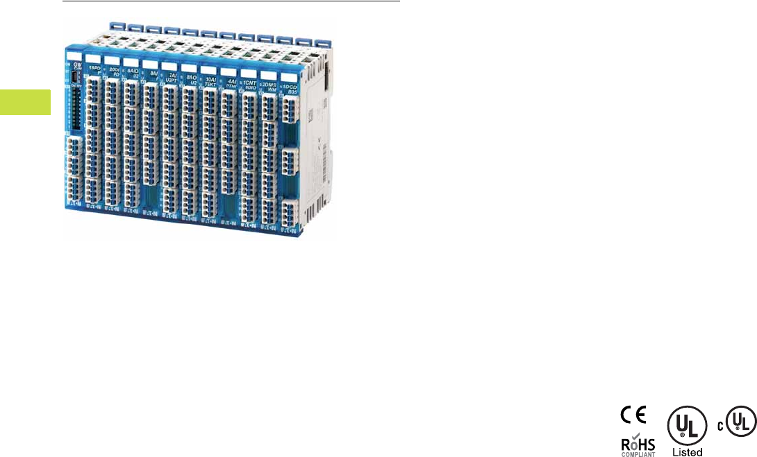
V7-T4-68 Volume 7—Logic Control, Operator Interface and Connectivity Solutions CA08100008E—May 2016 www.eaton.com
4
4
4
4
4
4
4
4
4
4
4
4
4
4
4
4
4
4
4
4
4
4
4
4
4
4
4
4
4
4
4.6
PLC, I/O and Communications Products
XN300 Series Remote I/O
XN300 Series Remote I/O
Contents
Description Page
XN300 Series Remote I/O
Product Selection . . . . . . . . . . . . . . . . . . . . . . . V7-T4-69
Product Description
The XN300 family of slice I/O
modules offers the highest
density I/O available on the
market today. With a very
cost-effective price per I/O
point, it meets the needs of
machinery OEMs for high-
speed, low-cost and compact
I/O systems. The CANopen
Gateway provides a remote
I/O connection that can
connect to all Eaton XC PLCs
and XV HMI-PLCs as well as
many third-party PLCs. The
tool-less assembly saves
time in connecting modules
on a DIN rail and the PUSH-IN
technology makes wiring up
the I/O a breeze. Status
LEDs on all I/O points make
it easy to quickly identify
any wiring errors and to
determine current signal
conditions. The free XN300
Assist programming tool
helps you to generate and
check the I/O configuration
and produce both electronic
documentation and EDS files
to simplify PLC configuration
of XN300 I/O.
Coupled with the new XV-300
HMI-PLC, the XN300 I/O
products provide a high-
powered low-cost system
solution for MOEMs. Bundled
with Visual Designer and
CoDeSys 3 on an XV-300
HMI-PLC, you get the
smallest, most cost-effective
and powerful HMI-PLC and
SCADA system available on
the market. This industry-
leading combination of
compact I/O solutions and
HMI-PLCs can significantly
reduce the overall control
panel size, helping MOEMs in
the never-ending quest to
reduce the size and cost of
their machinery.
Features
●Efficient—a wide range of
discrete and analog input
and output modules along
with specialty modules
focused on solving
application needs
●Compact—up to 20
channels per slice (12.5 x
102 mm) helps reduce
installation space and cost
●Simple—tool-free
assembly with PUSH-IN &
plug connection, with
simple dismounting of plug
connectors
●Fast identification of errors
and signal conditions via
LED status displays for all
points
●Application specific, free,
programmable module
status LED
●CANopen Gateway
connects up to 32 slices
per block to connect I/O
to both Eaton PLCs and
HMI-PLCs and many third-
party PLCs. Mini USB port
to connect to XN300 Assist
●XN300 Assist software tool
to generate electronic
documentation and EDS
files for PLC configuration
Standards and
Certifications
●CE Mark
●UL/cUL
●RoHS
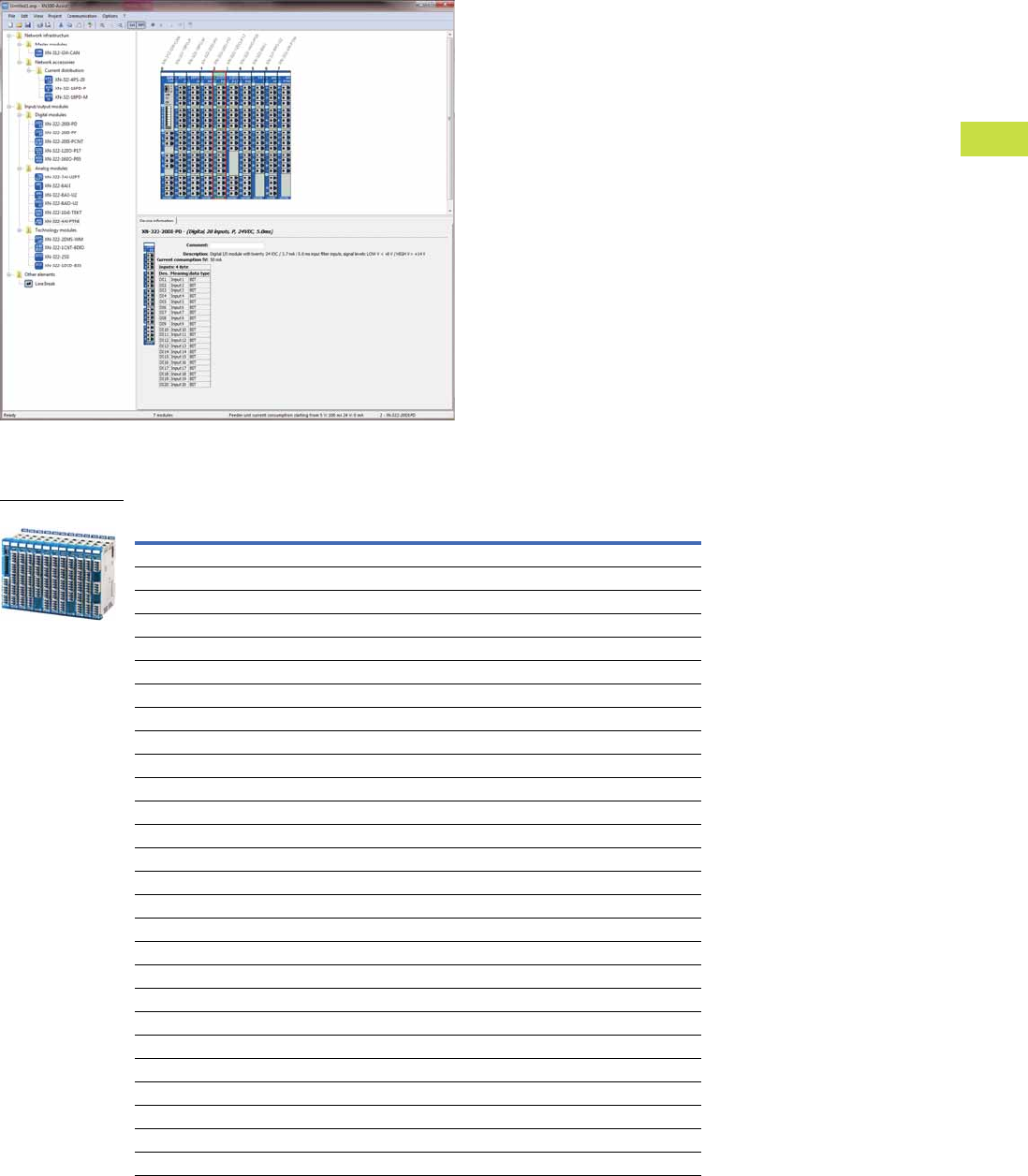
Volume 7—Logic Control, Operator Interface and Connectivity Solutions CA08100008E—May 2016 www.eaton.com V7-T4-69
4
4
4
4
4
4
4
4
4
4
4
4
4
4
4
4
4
4
4
4
4
4
4
4
4
4
4
4
4
4
4.6
PLC, I/O and Communications Products
XN300 Series Remote I/O
Product Selection
XN300 Series Remote I/O
Description Style Number Catalog Number
Digital Inputs
Digital, 20 input, P, 24 Vdc, 5.0 ms 178786 XN-322-20DI-PD
Digital, 20 input, P, 24 Vdc, 0.5 ms 178768 XN-322-20DI-PF
Digital, 20 input, P, 24 Vdc, 2/4 cnt, 25 kHz 178767 XN-322-20DI-PCNT
Counters
Counter, 1 cnt, 125 kHz, 16 bit, 4 DO, 4 DI 178795 XN-322-1CNT-8DIO
Digital Outputs
Digital,16 output, P, 24 Vdc, 0.5 A, sp 178787 XN-322-16DO-P05
Digital,12 output, P, 24 Vdc, 1.7 A, sp 178788 XN-322-12DO-P17
Analog
Analog, 6 input, ±10 V, 1 PT/KTY, Uref 178789 XN-322-7AI-U2PT
Analog, 8 input, 0/4–20 mA 179288 XN-322-8AI-I
Analog, 8 input, thermo element, 2 KTY 178792 XN-322-10AI-TEKT
Analog, 4 input, PT/NI/KTY/R, 2/3 wire 178772 XN-322-4AI-PTNI
Analog, 8 output, ±10 V 178790 XN-322-8AO-U2
Analog, 4 In-/4 output, ±10 V, Uref 178791 XN-322-8AIO-U2
Specialty
Weigh module, 2 DMS, 24 bit 178793 XN-322-2DMS-WM
DC-motor driver, 12–30 V, brush, 3.5 A 178794 XN-322-1DCD-B35
Power
Power supply, 4 x 24 Vdc / 2 A, sp 178796 XN-322-4PS-20
Power distribution, 18 channel, GND 178769 XN-322-18PD-M
Power distribution, 18 channel, VCC 178770 XN-322-18PD-P
Serial and SSI
Serial, 2 SSI, RS-422, 32 bit 178773 XN-322-2SSI
Gateways
CANopen Gateway module (supports 32 slices) 178782 XN-312-GW-CAN
XN-322_
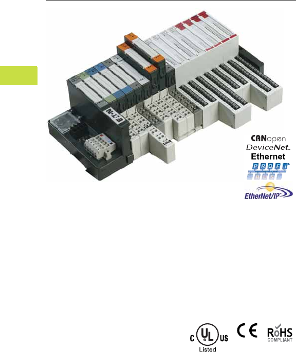
V7-T4-70 Volume 7—Logic Control, Operator Interface and Connectivity Solutions CA08100008E—May 2016 www.eaton.com
4
4
4
4
4
4
4
4
4
4
4
4
4
4
4
4
4
4
4
4
4
4
4
4
4
4
4
4
4
4
4.7
PLC, I/O and Communications Products
XI/ON Series Remote I/O
XI/ON Series Remote I/O
Contents
Description Page
XI/ON Series Remote I/O
Product Selection Guide . . . . . . . . . . . . . . . . . V7-T4-71
Catalog Number Selection . . . . . . . . . . . . . . . . V7-T4-72
System Overview . . . . . . . . . . . . . . . . . . . . . . . V7-T4-74
Product Selection . . . . . . . . . . . . . . . . . . . . . . . V7-T4-78
Accessories . . . . . . . . . . . . . . . . . . . . . . . . . . . V7-T4-87
Technical Data and Specifications . . . . . . . . . . V7-T4-88
Connection Diagrams . . . . . . . . . . . . . . . . . . . . V7-T4-101
Dimensions . . . . . . . . . . . . . . . . . . . . . . . . . . . V7-T4-113
Product Overview
Whether for controlling
movements, measuring
temperature or speed, or
logging currents and
voltages, the application
ranges for remote I/Os
are as extensive as the
different applications
involved. They are used
wherever decentralized
signal processing is the
essential element of the
automation concept.
Thanks to the high modularity
of the XI/ON system and
the wide range of functions,
Eaton is able to offer the
right I/O solution for every
application. XI/ON: A modular
concept with simple handling—
adaptable to any application,
intelligent and ready for
future developments.
Standards and
Certifications
●UL File No. E205091
●UL CCN—NRAQ, NRAQ7
●cULus
●CE
●RoHS
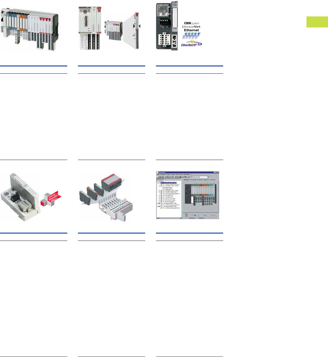
Volume 7—Logic Control, Operator Interface and Connectivity Solutions CA08100008E—May 2016 www.eaton.com V7-T4-71
4
4
4
4
4
4
4
4
4
4
4
4
4
4
4
4
4
4
4
4
4
4
4
4
4
4
4
4
4
4
4.7
PLC, I/O and Communications Products
XI/ON Series Remote I/O
Product Selection Guide
XI/ON Series Remote I/O
XI/ON
XNE Gateways and
Integrated Modules
XN Standard Gateways and
Plug-in Modules
Page V7-T4-78 Page V7-T4-80
As many as needed, as few as possible—
this is the principle on which the XI/ON
modular I/O system was built. An extensive
range of digital and analog I/Os as well as
technology modules are available.
●High level of modularity
●Fieldbuses: CANopen, PROFIBUS-DP,
DeviceNet and Ethernet
●Bus-independent, pluggable modules
●Low wiring requirement
●Precise diagnostics
●Space and cost saving with XNE
modules
●Programmable CANopen gateway
●Standard and XNE modules can be
mixed
XI/ON XNE completes the XI/ON I/O
system with price and space optimized I/O
modules and gateways. The XNE gateways
use the EtherNet/IP, Modbus TCP Ethernet,
CANopen and PROFIBUS-DP bus systems.
●XNE gateways with integrated bus
terminating resistors
●Full compatibility with the standard
XI/ON system
●No base module required
●High channel density (up to 16 DI/DO
on 12.5 mm width)
●“Push-In” spring-loaded terminals
●Multi-functional slices
●Diagnostics interface
The standard gateways use the Modbus
TCP, DeviceNet, Ethernet, CANopen and
PROFIBUS-DP bus systems.
●The use of pluggable I/O modules is
independent on the fieldbus used
●Wiring is implemented on the base
module, fixed wiring
●Fast module exchange under power
(hot swapping)
●Generation of diagnostics information
to higher-level controller
●Up to 74 slice modules can be
connected per gateway
●Mechanical coding of modules
●Diagnostics interface
Programmable CANopen Gateway Base Modules for Every Requirement
I/Oassistant—the Universal
Configuration and Diagnostics Tool
Page V7-T4-80 Page V7-T4-84
The programmable CANopen gateway
brings the power of the PLC directly to the
fieldbus terminal. The device is ideal for
handling decentralized automation tasks
and thus for relieving the load of a higher-
level PLC.
The serial onboard interface is used for
local programming access and as an
interface for the I/Oassistant configuration
and diagnostics tool. Alternatively, this
interface can also be used as a free user
interface. The gateway is programmed with
XSoft-CoDeSys-2.
The base modules are used to connect
the field wiring for the standard XI/ON
modules. They are available for 2-, 3- and
4-wire connections, as block or slice
modules, with either spring-loaded
terminals or screw terminals—the right
format for every application.
The I/Oassistant provides you with a
universal tool that offers interactive
support with the entire planning and
implementation of your XI/ON installation.
The I/Oassistant is integrated in
XSoft-CoDeSys-2.
A project is first of all created and
structured on the screen. For this you
choose gateways, electronic and base
modules as well as the appropriate
accessories. The individual stations are
then configured offline or online. Once
everything is set to your satisfaction, you
simply put your installation into operation.
The I/Oassistant also automatically
generates a parts list for your order.
I/Oassistant checks the station, reads the
process data, outputs values and visualizes
the diagnostics data of the channel. This
enables you to commission your station
without a higher-level PLC and ensure that
a section of the system is functioning
correctly.
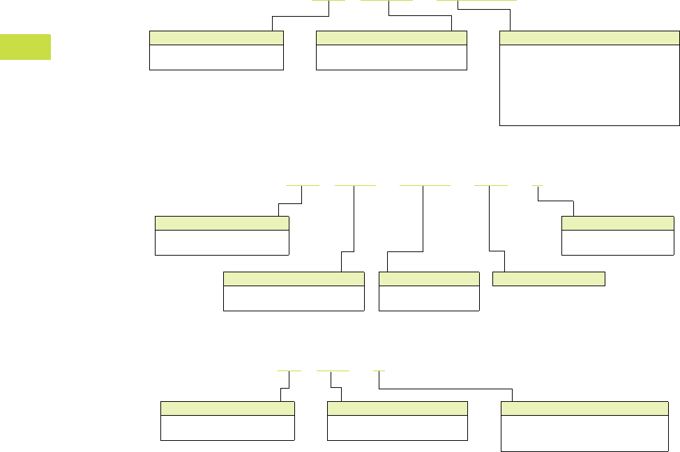
V7-T4-72 Volume 7—Logic Control, Operator Interface and Connectivity Solutions CA08100008E—May 2016 www.eaton.com
4
4
4
4
4
4
4
4
4
4
4
4
4
4
4
4
4
4
4
4
4
4
4
4
4
4
4
4
4
4
4.7
PLC, I/O and Communications Products
XI/ON Series Remote I/O
Catalog Number Selection
Gateway Modules
Digital I/O Modules
Analog I/O Modules
Module Type
XNE = Integrated I/O Modules
XN = Plug-in I/O Modules
XNE -GWBR - 2ETH - IP
Fieldbus Type
2ETH-IP = EtherNet/IP
2ETH-MB = Modbus TCP/Ethernet
MODBUS-TCP = Modbus TCP/Ethernet
DVP1 = PROFIBUS-DP (DVP1)
PBDP = PROFIBUS-DP (DVP0)
CANOPEN = CANopen
DNET = DeviceNet
Gateway Type
GWBR = Standard Gateway
PLC = Programmable Gateway
XNE -16DO - 24VDC - 0.5A - P
Number of Digital I/O
DI = Number of digital inputs
DO = Number of digital outputs
Rated Voltage
VDC =24 Vdc
VAC = 120/230 Vac
Switching
P = Positive switching
N = Negative switching
Module Type
XNE = Integrated I/O Modules
XN = Plug-in I/O Modules
Current Rating
XN -2AO - U - (–10/0 … +10 Vdc)
Input/Output Range
I = 0/4 to 20 mA
U = –10/0 to +10 Vdc
U/I = 0/4 to 20 mA or –10/0 to +10 Vdc
Number of Analog I/O
AI = Number of analog inputs
AO = Number of analog outputs
Module Type
XNE = Integrated I/O Modules
XN = Plug-in I/O Modules
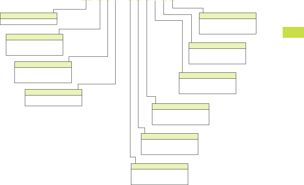
Volume 7—Logic Control, Operator Interface and Connectivity Solutions CA08100008E—May 2016 www.eaton.com V7-T4-73
4
4
4
4
4
4
4
4
4
4
4
4
4
4
4
4
4
4
4
4
4
4
4
4
4
4
4
4
4
4
4.7
PLC, I/O and Communications Products
XI/ON Series Remote I/O
Base Modules
Module Type
B = Block module (white)
P = Power module (gray)
S = Slice module (white)
Module Type
XN = Plug-in I/O modules
XN -S 6 T - S B C S B C
Terminal Connections
S = Screw terminals
T = Spring-cage terminals
Connection Levels
3 = 3 levels
4 = 4 levels
6 = 6 levels
Terminals 16 and 26
B = Bridged terminals
C = Common bus terminals
S = Signal terminals
Terminals 15 and 25
B = Bridged terminals
C = Common bus terminals
S = Signal terminals
Terminals 14 and 24
B = Bridged terminals
C = Common bus terminals
S = Signal terminals
Terminals 13 and 23
B = Bridged terminals
C = Common bus terminals
S = Signal terminals
Terminals 12 and 22
B = Bridged terminals
C = Common bus terminals
S = Signal terminals
Terminals 11 and 21
B = Bridged terminals
C = Common bus terminals
S = Signal terminals

V7-T4-74 Volume 7—Logic Control, Operator Interface and Connectivity Solutions CA08100008E—May 2016 www.eaton.com
4
4
4
4
4
4
4
4
4
4
4
4
4
4
4
4
4
4
4
4
4
4
4
4
4
4
4
4
4
4
4.7
PLC, I/O and Communications Products
XI/ON Series Remote I/O
System Overview
System Configuration
XN Module and Base Compatibility Chart
Notes
1Base module for gateway supply.
2Base module for bus refreshing within the station.
Base Modules
XN-S3S-SBB
XN-S3T-SBB
XN-S3S-SBC
XN-S3T-SBC
XN-S4S-SBBC
XN-S4T-SBBC
XN-S4S-SBBS
XN-S4T-SBBS
XN-S4S-SBCS
XN-S4T-SBCS
XN-S4S-SBBS-CJ
XN-S4T-SBBS-CJ
XN-S6S-SBBSBB
XN-S6T-SBBSBB
XN-S6S-SBCSBC
XN-S6T-SBCSBC
XN-B3S-SBB
XN-B3T-SBB
XN-B3S-SBC
XN-B3T-SBC
XN-B4S-SBBC
XN-B4T-SBBC
XN-B6S-SBBSBB
XN-B6T-SBBSBB
XN-B6S-SBCSBC
XN-B6T-SBCSBC
XN-P3S-SBB
XN-P3T-SBB
XN-P3S-SBB-B
XN-P3T.-SBB-B
XN-P4S-SBBC
XN-P4T-SBBC
XN-P4S-SBBC-B
XN-P4T-SBBC-B
Electronics Modules
Digital Input Modules
XN-2DI-24VDC-P ✓—✓——————————————
XN-2DI-24VDC-N ✓—✓——————————————
XN-2DI-120/230VAC ✓—✓——————————————
XN-4DI-24VDC-P — — — ✓—— ✓——————————
XN-4DI-24VDC-N — — — ✓—— ✓——————————
XN-16DI-24VDC-P ———————— ✓—✓——————
XN-32DI-24VDC-P ——————————— ✓—————
Digital Output Modules
XN-2DO-24VDC-0.5A-P — ✓—— ✓————————————
XN-2DO-24VDC-0.5A-N — ✓—— ✓————————————
XN-2DO-24VDC-2A-P — ✓—— ✓————————————
XN-2DO-120/230VAC-0.5A — ✓—— ✓————————————
XN-4DO-24VDC-0.5A-P ———— ✓—— ✓—————————
XN-16DO-24VDC-0.5A-P ————————— ✓———————
XN-32DO-24VDC-0.5A-P ———————————— ✓————
Relay Modules
XN-2DO-R-NC — — — ✓✓
————————————
XN-2DO-R-NO — — — ✓✓
————————————
XN-2DO-R-CO — — — ✓—————————————
Analog Input Modules
XN-1AI-I(0/4…20MA) ✓—— ✓—————————————
XN-2AI-I(0/4…20MA) ✓—— ✓—————————————
XN-1AI-U(-10/0…+10VDC) ✓—— ✓—————————————
XN-2AI-U(-10/0…+10VDC) ✓—— ✓—————————————
XN-2AI-PT/NI-2/3 ✓—— ✓—————————————
XN-2AI-THERMO-PI ————— ✓———————————
XN-4AI-U/I ——————— ✓—————————
Analog Output Modules
XN-1AO-I(0/4…20MA) ✓————————————————
XN-2AO-I(0/4…20MA) ✓————————————————
XN-2AO-U(-10/0…+10VDC) ✓————————————————
Technology Modules
XN-1CNT-24VDC — — — ✓—————————————
XN-1RS232 ——— ✓—————————————
XN-1RS485/422 — — — ✓—————————————
XN-1SSI ——— ✓—————————————
Supply Modules
XN-BR-24VDC-D —————————————
✓ 1✓ 2✓ 1✓ 2
XN-PF-24VDC-D ————————————— ✓—✓—
XN-PF-120/230VAC-D ————————————— ✓—✓—
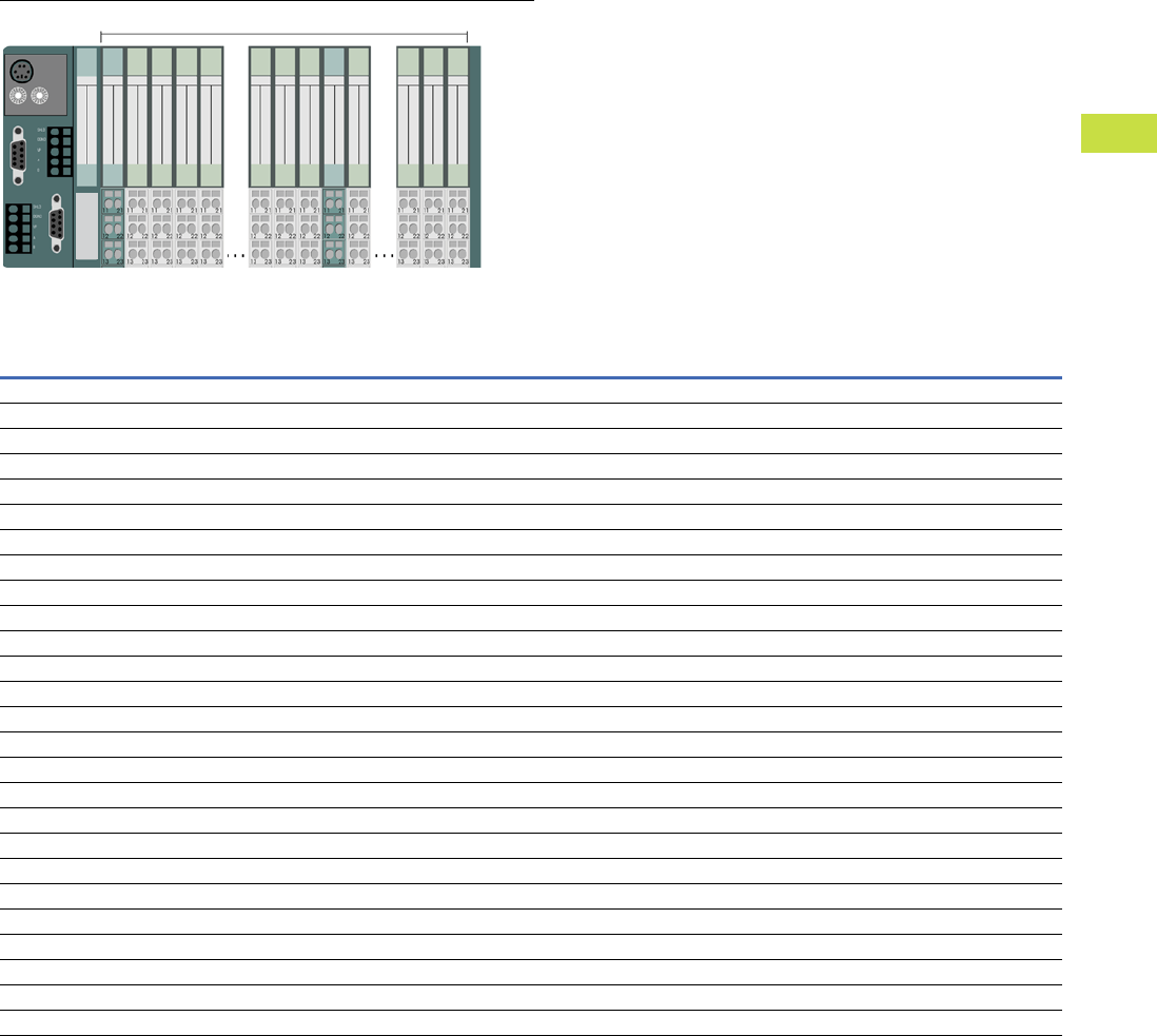
Volume 7—Logic Control, Operator Interface and Connectivity Solutions CA08100008E—May 2016 www.eaton.com V7-T4-75
4
4
4
4
4
4
4
4
4
4
4
4
4
4
4
4
4
4
4
4
4
4
4
4
4
4
4
4
4
4
4.7
PLC, I/O and Communications Products
XI/ON Series Remote I/O
Maximum System Configuration
Plan your XI/ON station with the software “I/Oassistant”.
Advantage 1:
Automatically generates a full parts list for your order.
Advantage 2:
Generates an error message as soon as the system limits are
exceeded.
IMPORTANT:
When extending your system, make sure that you have a
sufficient number of bus refresh or power feed modules.
Note
Numeric values in parentheses. Maximum number when diagnostic alarm disabled.
The supply module XN-BR-24VDC-D must be mounted immediately next to the gateway XN-GW-_ to provide power for the gateways.
Style Number: 140045 140044 140047 152279
Catalog Number: XNE-GWBR-PBDP XNE-GWBR-CANOPEN XNE-GWBR-2ETH-IP XNE-GWBR-2ETH-MB
Channels Modules Channels Modules Channels Modules Channels Modules
Modules
XN-4DI-24VDC-P 136 34 244 61 288 72 288 72
XN-4DI-24VDC-N 136 34 244 61 288 72 288 72
XN-16DI-24VDC-P 128 8 128 8 128 8 128 8
XN-32DI-24VDC-P 256 8 256 8 256 8 256 8
XNE-8DI-24VDC-P 384 48 512 64 512 64 512 64
XNE-16DI-24VDC-P 768 48 512 32 512 32 512 32
XN-4DO-24VDC-0.5A-P 132 33 244 61 288 72 288 72
XN-16DO-24VDC-0.5A-P 128 8 128 8 128 8 128 8
XN-32DO-24VDC-0.5A-P 256 8 256 8 256 8 256 8
XNE-8DO-24VDC-0.5A-P 384 48 488 61 512 64 512 64
XNE-16DO-24VDC-0.5A-P 640 40 512 32 512 32 512 32
XN-2DO-R-_ 70 35 122 61 144 72 144 72
XN-2AI-I(0/4…20MA) 56 28 100 50 126 63 126 63
XN-2AI-U(-10/0…+10VDC) 56 28 100 50 126 63 126 63
XN-2AI-PT/NI2/3 44 22 98 49 126 63 126 63
XN-2AI-THERMO-PI 44 22 98 49 126 63 126 63
XN-4AI-U/I 64 (132) 16 (33) 108 27 124 31 124 31
XNE-8AI-U/I-4PT/NI 72 (120) 9 (15) 144 18 128 16 128 16
XN-2AO-I(0/4…20MA) 50 25 70 35 126 63 126 63
XN-2AO-U(-10/0…+10VDC) 46 23 70 35 126 63 126 63
XNE-4AO-U/I 64 (76) 16 (19) 108 27 64 16 64 16
XN-1CNT-24VDC 13 13 27 27 31 31 31 31
XN-1RS232 7 7 272731313131
XN-1RS485/422 1616272731313131
XN-1SSI 2020272731313131
Maximum 74 XI/ON Modules in Slice Design
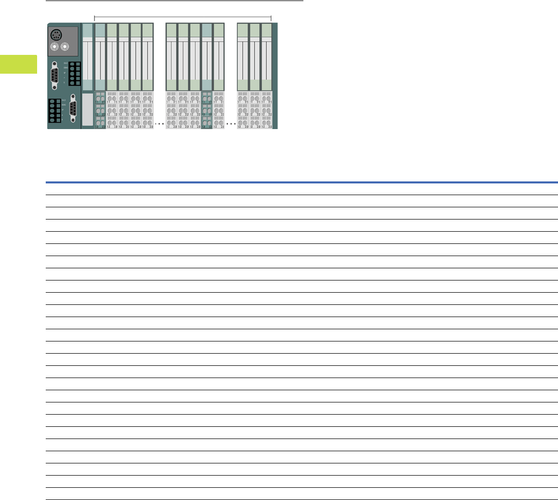
V7-T4-76 Volume 7—Logic Control, Operator Interface and Connectivity Solutions CA08100008E—May 2016 www.eaton.com
4
4
4
4
4
4
4
4
4
4
4
4
4
4
4
4
4
4
4
4
4
4
4
4
4
4
4
4
4
4
4.7
PLC, I/O and Communications Products
XI/ON Series Remote I/O
Maximum System Configuration, continued
Plan your XI/ON station with the software “I/Oassistant”.
Advantage 1:
Automatically generates a full parts list for your order.
Advantage 2:
Generates an error message as soon as the system limits are
exceeded.
IMPORTANT:
When extending your system, make sure that you have a
sufficient number of bus refresh or power feed modules.
Note
Numeric values in parentheses. Maximum number when diagnostic alarm disabled.
Style Number: 140154 140055 140156 140162
Catalog Number: XN-GWBR-PBDP XN-GWBR-CANOPEN XN-GWBR-DNET XN-GWBR-MODBUS-TCP
Channels Modules Channels Modules Channels Modules Channels Modules
Modules
XN-4DI-24VDC-P 288 72 288 72 288 72 288 72
XN-4DI-24VDC-N 288 72 288 72 288 72 288 72
XN-16DI-24VDC-P 128 8 128 8 128 8 128 8
XN-32DI-24VDC-P 256 8 256 8 256 8 256 8
XNE-8DI-24VDC-P 592 74 512 64 576 72 512 64
XNE-16DI-24VDC-P 1184 74 512 32 1152 72 512 32
XN-4DO-24VDC-0.5A-P 288 72 288 72 128 32 288 72
XN-16DO-24VDC-0.5A-P 128 8 128 8 128 8 128 8
XN-32DO-24VDC-0.5A-P 256 8 256 8 256 8 256 8
XNE-8DO-24VDC-0.5A-P 592 74 512 64 256 32 512 64
XNE-16DO-24VDC-0.5A-P 1168 73 512 32 512 32 512 32
XN-2DO-R-_ 144 72 144 72 64 32 144 72
XN-2AI-I(0/4…20MA) 78 39 144 72 32 16 144 72
XN-2AI-U(-10/0…+10VDC) 78 39 144 72 32 16 144 72
XN-2AI-PT/NI-2/3 46 23 144 72 32 16 144 72
XN-2AI-THERMO-PI 58 (76) 29 (38) 144 72 32 16 144 72
XN-4AI-U/I 112 28 144 36 64 16 144 36
XNE-8AI-U/I-4PT/NI 88 11 144 18 128 16 144 18
XN-2AO-I(0/4…20MA) 38 19 144 72 32 16 144 72
XN-2AO-U(-10/0…+10VDC) 38 19 144 72 32 16 144 72
XNE-4AO-U/I 36 9 144 36 64 16 124 31
XN-1CNT-24VDC 7 7 727216167272
XN-1RS232 222268688 8 6868
XN-1RS485/422 222272728 8 7272
XN-1SSI 222272728 8 7272
Maximum 74 XI/ON Modules in Slice Design
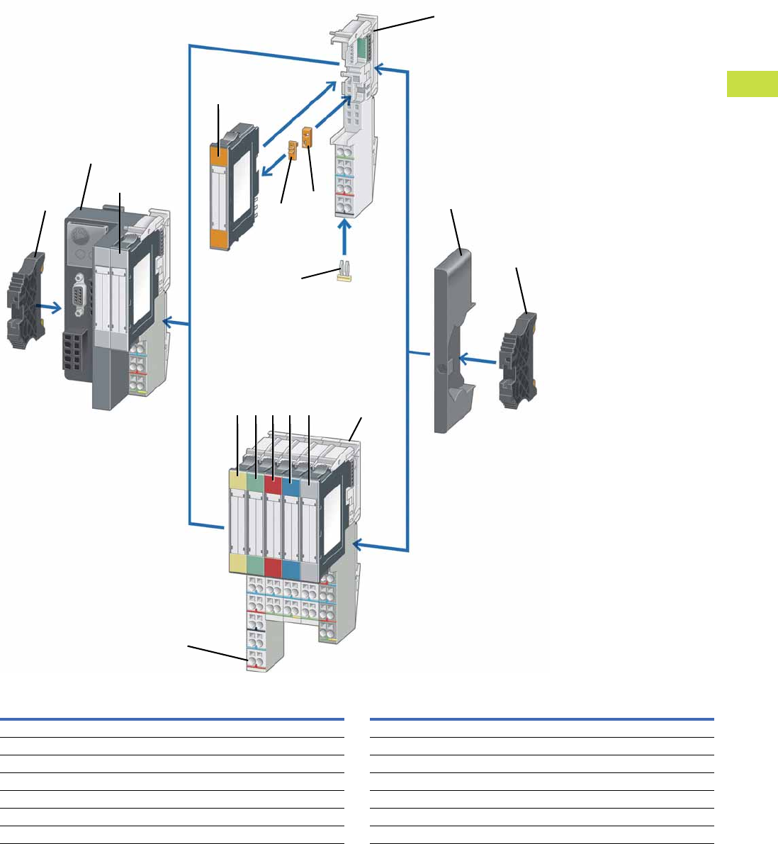
Volume 7—Logic Control, Operator Interface and Connectivity Solutions CA08100008E—May 2016 www.eaton.com V7-T4-77
4
4
4
4
4
4
4
4
4
4
4
4
4
4
4
4
4
4
4
4
4
4
4
4
4
4
4
4
4
4
4.7
PLC, I/O and Communications Products
XI/ON Series Remote I/O
System Overview
Item
Number Description
Item
Number Description
1Gateway 8End bracket
2Digital input module 9Power supply module
3Relay module 10 Analog input module
4Coding element 11 Digital output module
5Base module 12 Analog output module
6Relay jumper 13 Technology module
7End plate 14 Marker
1
2
3
4
5
7
8
910111213
14
4
8
6
5

V7-T4-78 Volume 7—Logic Control, Operator Interface and Connectivity Solutions CA08100008E—May 2016 www.eaton.com
4
4
4
4
4
4
4
4
4
4
4
4
4
4
4
4
4
4
4
4
4
4
4
4
4
4
4
4
4
4
4.7
PLC, I/O and Communications Products
XI/ON Series Remote I/O
Product Selection
XNE Series
The following are included as standard with all gateways:
2 x End bracket XN-WEW-32/2-SW,
1 x End plate XN-ABPL.
XNE Gateway with Integrated Supply
Description
Fieldbus
Connection
Terminal Capacity
(Fieldbus/Supply
Voltage)
Servicing
Interface
Transfer
Rate
Style
Number Catalog Number
Ethernet
Supports up to 74 disc type modules (XN, XNE)
2xRJ45 socket
Address set with decimal rotary coding switches,
BootP, DHCP or I/Oassistant
Address range: 1–254 (dec.)
Ethernet
(EtherNet/IP
protocol)
Push-in spring-cage
terminals
Mini USB 10/100
MBit/s
140047 XNE-GWBR-2ETH-IP
Supports up to 74 disc type modules (XN, XNE)
RJ45 Ethernet switch
Address set with decimal rotary coding switches,
BootP, DHCP or I/Oassistant
Address range: 1–254 (dec.)
Ethernet
(Modbus TCP)
Push-in spring-cage
terminals
Mini USB 10/100
MBit/s
152279 XNE-GWBR-2ETH-MB
PROFIBUS-DP
Supports up to 48 slice type modules (XN, XNE)
Address setting through DIP switch
Address range: 1–125 (dec.)
PROFIBUS-DP
(DPV0/DPV1
protocol)
Push-in spring-cage
terminals
PS/2 socket 9.6 kbit/s to
12 Mbit/s
140045 XNE-GWBR-PBDP
CANopen
Supports up to 62 disc type modules (XN, XNE)
Address set with DIP switch
Address range: 1–63 (dec.)
CANopen Push-in spring-cage
terminals
PS/2 socket 1000 kbit/s
800 kbit/s
500 kbit/s
250 kbit/s
125 kbit/s
50 kbit/s
20 kbit/s
140044 XNE-GWBR-CANOPEN
XNE Gateways

Volume 7—Logic Control, Operator Interface and Connectivity Solutions CA08100008E—May 2016 www.eaton.com V7-T4-79
4
4
4
4
4
4
4
4
4
4
4
4
4
4
4
4
4
4
4
4
4
4
4
4
4
4
4
4
4
4
4.7
PLC, I/O and Communications Products
XI/ON Series Remote I/O
XNE Digital Input Modules
Positive switching.
XNE Digital Output Modules
Resistive inductive and lamp load connectable.
XNE Analog Input and RTD Module
Rated voltage via power supply terminal: 24 Vdc.
XNE Analog Output Module
Rated voltage via power supply terminal: 24 Vdc.
XNE Counter Module
Rated voltage via power supply terminal: 24 Vdc.
Signal evaluation A, B: Pulse and direction, rotary encoder single/double/quadruple.
Note
1 cUL pending.
Channels
Rated Voltage via
Power Supply Terminal
Input Delay
tRise/tFall
Input Voltage
High Signal
Style
Number Catalog Number
8 24 Vdc <100/<200 µs 11 V-UL140035 XNE-8DI-24VDC-P
16 24 Vdc <150/<300 µs 11 V-UL140040 XNE-16DI-24VDC-P
Channels
Rated Voltage via
Power Supply Terminal
Switching Frequency with
Resistive Load in Hz
Utilization Factor
g in %
Style
Number Catalog Number
8 24 Vdc <100 100 140036 XNE-8DO-24VDC-0.5A-P
16 24 Vdc <100 50%, maximum 4A 140039 XNE-16DO-24VDC-0.5A-P
Channels Measured Variables Measuring Ranges Value Representation
Limit
Frequency
in Hz
Style
Number Catalog Number
8 (U/I)/
4 (PT/NI/R)
Voltage, current
temperature (PT, NI),
resistance R
–10 to 10 Vdc/0 to 10 Vdc
PT100, 200, 500, 1000,
NI100, 1000 2-, 3-wire
Standard:
16-bit/12-bit (flush-left)
1.5 140037 XNE-8AI-U/I-4PT/NI
Extended range:
16-bit/12-bit (flush-left) PA (NE43),
16-bit/12-bit (flush-left)
Channels Measured Variables Output Variables Value Representation
Style
Number Catalog Number
4 Voltage, current –10 to 10 Vdc/0 to 10 Vdc
0 to 20 mA
4 to 20 mA
Standard:
16-bit/12-bit (flush-left)
140034 XNE-4AO-U/I 1
Channels Operating Modes Pulse Duration
PWM
Module Resolution
Style
Number Catalog Number
2 Continuous, once only and
periodic counting
32-bit/maximum 120s ✓32-bit 140038 XNE-2CNT-2PWM
XNE Digital Input
XNE Digital Output
XNE Analog Input
XNE Analog Output
XNE Counter
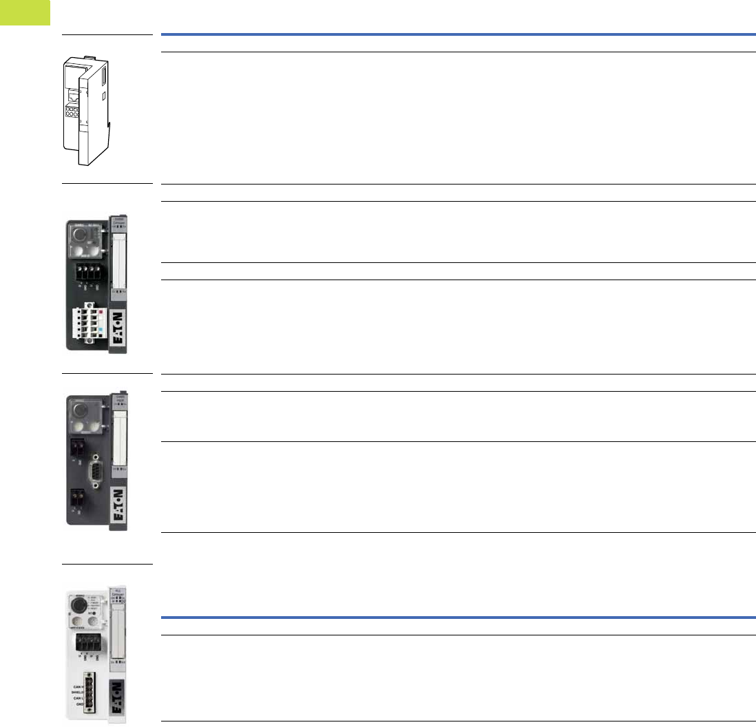
V7-T4-80 Volume 7—Logic Control, Operator Interface and Connectivity Solutions CA08100008E—May 2016 www.eaton.com
4
4
4
4
4
4
4
4
4
4
4
4
4
4
4
4
4
4
4
4
4
4
4
4
4
4
4
4
4
4
4.7
PLC, I/O and Communications Products
XI/ON Series Remote I/O
XN Series
The following are included as standard with all gateways:
2 x End bracket XN-WEW-32/2-SW,
1 x End plate XN-ABPL.
XN Gateway with Integrated Supply
XN Programmable Gateway with Integrated Supply
Description
Fieldbus
Connection
Terminal Capacity
(Fieldbus/Supply
Voltage)
Servicing
Interface
Transfer
Rate
Style
Number Catalog Number
Ethernet
Supports up to 74 slice type modules (XN, XNE)
1 x RJ45 socket
Address set with decimal rotary coding switches,
BootP, DHCP or I/Oassistant
Address range: 1–254 (dec.)
Ethernet
(Modbus TCP
protocol)
Screw terminals PS/2 socket 10/100 Mbit/s 140162 XN-GWBR-MODBUS-TCP
DeviceNet
Supports up to 74 disc type modules (XN, XNE)
1 x open-style connector
Address set with two decimal rotary coding
switches
Address range: 1–63 (dec.)
DeviceNet Screw terminals PS/2 socket 500 kbit/s
250 kbit/s
125 kbit/s
140156 XN-GWBR-DNET
CANopen
Supports up to 74 disc type modules (XN, XNE)
1 x open-style connector
Address set with two decimal rotary coding
switches
Address range: 1–99 (dec.)
CANopen Screw terminals PS/2 socket 1000 kbit/s
800 kbit/s
500 kbit/s
250 kbit/s
125 kbit/s
50 kbit/s
20 kbit/s
10 kbit/s
140155 XN-GWBR-CANOPEN
PROFIBUS-DP
Supports up to 74 disc type modules (XN, XNE)
1 x D-sub 9-pin socket
Address set with decimal rotary coding switches
Address range: 1–99 (dec.)
PROFIBUS-DP
(DVP1 protocol)
Screw terminals PS/2 socket 9.6 kbit/s to
12 Mbit/s
148561 XN-GWBR-DVP1
Supports up to 74 disc type modules (XN, XNE)
1 x D-sub 9-pin socket
Address set with decimal rotary coding switches
Address range: 1–99 (dec.)
PROFIBUS-DP
(DVP0 protocol)
Screw terminals PS/2 socket 9.6 kbit/s to
12 Mbit/s
140154 XN-GWBR-PBDP
Description
Fieldbus
Connection
Terminal Capacity
(Fieldbus/Supply
Voltage)
Servicing
Interface
Transfer
Rate
Style
Number Catalog Number
CANopen
Supports up to 74 disc type modules
(XN, XNE to limited extent)
1 x open-style connector
Operating mode and address setting with two
hexadecimal rotary coding switches
Address range: 1–99 (dec.)
CANOpen Screw terminals PS/2 socket Adjustable up
to 1 Mbit/s
140157 XN-PLC-CANOPEN
XN-GWBR-D_,
XN-GWBR-C_
XN-GWBR-DVP1
XN-GWBR-MODBUS_
XN-PLC-CANOPEN
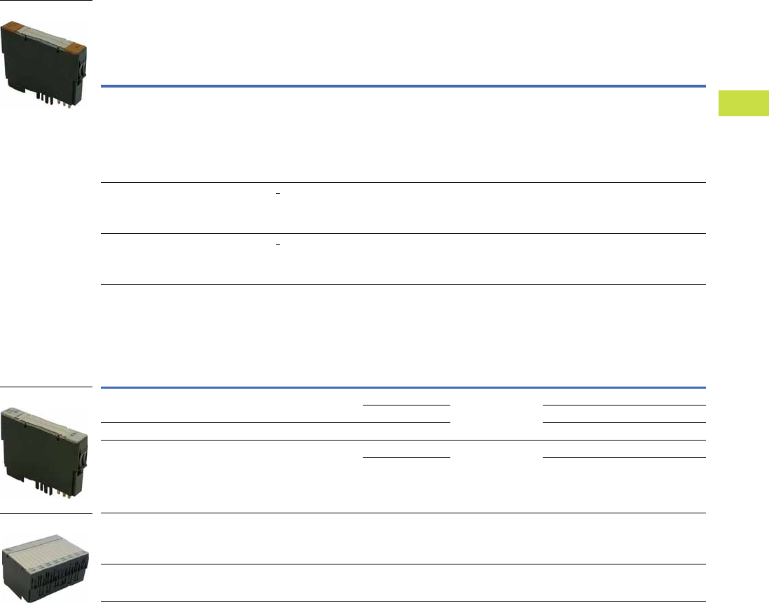
Volume 7—Logic Control, Operator Interface and Connectivity Solutions CA08100008E—May 2016 www.eaton.com V7-T4-81
4
4
4
4
4
4
4
4
4
4
4
4
4
4
4
4
4
4
4
4
4
4
4
4
4
4
4
4
4
4
4.7
PLC, I/O and Communications Products
XI/ON Series Remote I/O
XN Power Supply Modules
Number of diagnostic bits: 4.
Ripple <5% (to EN 61131-2).
XN Digital Input Modules
Base module required.
Operating and
Field Voltage
System
Power Supply
Rated Current
Consumption
from Modbus
Maximum
System Supply
Current
For Use
With …
Style
Number Catalog Number
24 Vdc 24 Vdc — 1.5A XN-P3T-SBB
XN-P3S-SBB
XN-P4T-SBBC
XN-P4S-SBBC
XN-P3T-SBB-B
XN-P3S-SBB-B
XN-P4T-SBBC-B
XN-P4S-SBBC-B
140071 XN-BR-24VDC-D
24 Vdc — <28 mA — XN-P3T-SBB
XN-P3S-SBB
XN-P4T-SBBC
XN-P4S-SBBC
140070 XN-PF-24VDC-D
120/230 Vac — <25 mA — XN-P3T-SBB
XN-P3S-SBB
XN-P4T-SBBC
XN-P4S-SBBC
140072 XN-PF-120/230VAC-D
Channels
Rated Voltage via
Power Supply
Terminal
Input Delay
tRise/tFall
Input Voltage
High Signal
For Use
With …
Style
Number Catalog Number
2 24 Vdc <200/<200 µs 11–30 Vdc XN-S3T-SBB
XN-S3S-SBB
XN-S4T-SBBC
XN-S4S-SBBC
140056 XN-2DI-24VDC-P
0–5 Vdc 140057 XN-2DI-24VDC-N
2 120/230 Vac <20,000/<20,000 µs 79–265 Vac 140058 XN-2DI-120/230VAC
4 24 Vdc <200/<200 µs 15–30 Vdc XN-S4T-SBBS
XN-S4S-SBBS
XN-S6T-SBBSBB
XN-S6S-SBBSBB
140052 XN-4DI-24VDC-P
0–5 Vdc 140059 XN-4DI-24VDC-N
16 24 Vdc <200/<200 µs 15–30 Vdc XN-B3T-SBB
XN-B3S-SBB
XN-B4T-SBBC
XN-B4S-SBBC
140142 XN-16DI-24VDC-P
32 24 Vdc <200/<200 µs 15–30 Vdc XN-B6T-SBBSBB
XN-B6S-SBBSBB
140147 XN-32DI-24VDC-P
Slice Module
Slice Module
Block Module
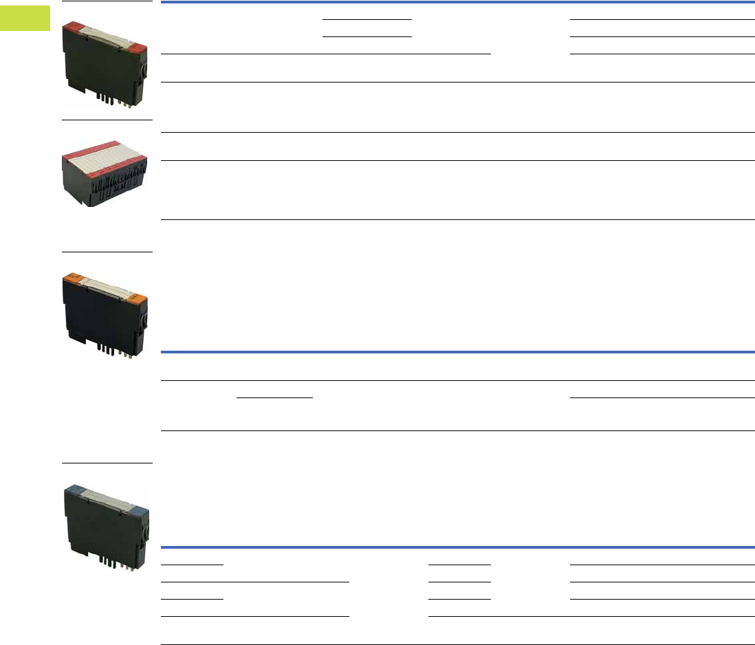
V7-T4-82 Volume 7—Logic Control, Operator Interface and Connectivity Solutions CA08100008E—May 2016 www.eaton.com
4
4
4
4
4
4
4
4
4
4
4
4
4
4
4
4
4
4
4
4
4
4
4
4
4
4
4
4
4
4
4.7
PLC, I/O and Communications Products
XI/ON Series Remote I/O
XN Digital Output Modules
Base module required.
Resistive inductive and lamp load connectable.
XN Relay Modules
Base module required.
Rated voltage via power supply terminal: 24 Vdc.
Resistive inductive and lamp load connectable.
XN Analog Input Modules
Base module required.
Rated voltage via power supply terminal: 24 Vdc.
Channels
Rated Voltage via
Power Supply
Terminal
Switching Frequency
with Resistive
Load in Hz
Utilization
Factor g in %
For Use
With …
Style
Number Catalog Number
2 24 Vdc <5000 (RLO <1 kohm) 100 XN-S3T-SBC
XN-S3S-SBC
XN-S4T-SBCS
XN-S4S-SBCS
140053 XN-2DO-24VDC-0.5A-P
<100 (RLO <1 kohm) 140060 XN-2DO-24VDC-0.5A-N
<5000 (RLO <1 kohm) 140055 XN-2DO-24VDC-2A-P
2 120–230 Vac
(45–65 Hz)
— 100 (observe derating
requirements)
140150 XN-2DO-120/230VAC-0.5A
4 24 Vdc <1000 (RLO <1 kohm) 100 XN-S4T-SBCS
XN-S4S-SBCS
XN-S6T-SBCSBC
XN-S6S-SBCSBC
140148 XN-4DO-24VDC-0.5A-P
16 24 Vdc <100 (RLO <1 kohm) 100 XN-B3T-SBC
XN-B3S-SBC
140141 XN-16DO-24VDC-0.5A-P
32 24 Vdc <100 (RLO <1 kohm) See total
module current
XN-B6T-SBCSBC
XN-B6S-SBCSBC
140161 XN-32DO-24VDC-0.5A-P
Channels Contact Type
Rated Load
Voltage
Maximum Continuous
Current per Channel/
230 Vac Resistive Load
For Use
With …
Style
Number Catalog Number
2 Changeover
Contacts
230 Vac, 30 Vdc 5A XN-S4T-SBBS
XN-S4S-SBBS
140054 XN-2DO-R-CO
2 NC 230 Vac, 30 Vdc 5A XN-S4T-SBBS
XN-S4S-SBBS
XN-S4T-SBCS
XN-S4S-SBCS
140061 XN-2DO-R-NC
NO 140062 XN-2DO-R-NO
Channels
Measured
Variables
Measuring
Range
Value
Representation
Limit
Frequency
in Hz
For Use
With …
Style
Number Catalog Number
1 Current 0–20 mA,
4–20 mA
Standard
16-bit/12-bit
(flush left)
— XN-S3T-SBB
XN-S3S-SBB
XN-S4T-SBBS
XN-S4S-SBBS
140063 XN-1AI-I
2 — 140144 XN-2AI-I
1 Voltage –10…10 Vdc,
0…10 Vdc
200 140064 XN-1AI-U
2 50 140145 XN-2AI-U
4 Voltage/Current –10…10 Vdc,
0…10 Vdc
20 XN-S6T-SBCSBC
XN-S6S-SBCSBC
140158 XN-4AI-U/I
Slice Module
Block Module
Slice Module
Slice Module
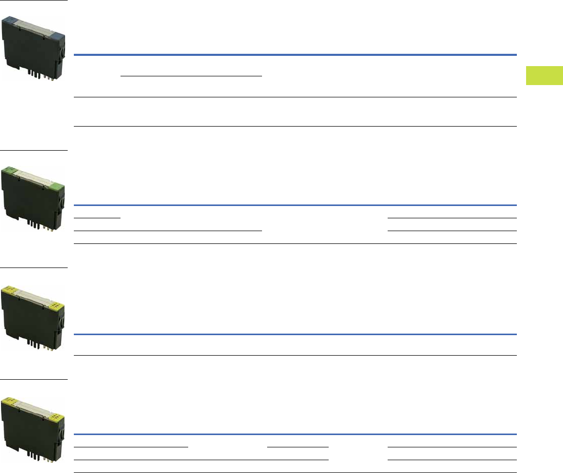
Volume 7—Logic Control, Operator Interface and Connectivity Solutions CA08100008E—May 2016 www.eaton.com V7-T4-83
4
4
4
4
4
4
4
4
4
4
4
4
4
4
4
4
4
4
4
4
4
4
4
4
4
4
4
4
4
4
4.7
PLC, I/O and Communications Products
XI/ON Series Remote I/O
XN Temperature Modules
Base module required.
Rated voltage via power supply terminal: 24 Vdc.
XN Analog Output Modules
Base module required.
Rated voltage via power supply terminal: 24 Vdc.
XN Counter Modules
Base module required.
Rated voltage via power supply terminal: 24 Vdc.
Signal evaluation A, B: Pulse and direction, rotary encoder single/double/quadruple.
XN Serial Interfaces
Base module required.
Rated voltage via power supply terminal: 24 Vdc.
Note
1 cUL pending.
Channels
Connectable
Sensors
Measuring
Range (°C)
Value
Representation
For Use
With …
Style
Number Catalog Number
2 PT100. 200. 500, 1000 Platinum sensors:
–200…850/–200…150
Standard
16-bit/12-bit
(flush left)
XN-S3T-SBB
XN-S3S-SBB
XN-S4T-SBBS
XN-S4S-SBBS
140067 XN-2AI-PT/NI-2/3
Ni100, Ni1000 Nickel sensors:
–60…250/–60…150
2 Type B, E, J, K, N, R,
S, T Thermocouples
See user manual Standard
16-bit/12-bit
(flush left)
XN-S4T-SBBS-CJ
XN-S4S-SBBS-CJ
140068 XN-2AI-THERMO-PI 1
Channels
Measured
Variables
Output
Variables
Value
Representation
For Use
With …
Style
Number Catalog Number
1 Current 0–20 mA/4–20 mA Standard
16-bit/12-bit
(flush left)
XN-S3T-SBB
XN-S3S-SBB
140065 XN-1AO-I
2140146 XN-2AO-I
2 Voltage –10…10 Vdc/0…10 Vdc 140066 XN-2AO-U
Channels
Operating
Modes
Pulse
Duration Resolution
For Use
With …
Style
Number Catalog Number
1 Continuous, once only and
periodic counting
8-bit
max. 0.51s
32-bit XN-S4T-SBBS
XN-S4S-SBBS
140069 XN-1CNT-24VDC
Typ e
Transfer
Channels
Bit Transfer
Rate Cable Length
For Use
With …
Style
Number Catalog Number
RS-232 RxD, TxD, RTS, CTS Max. 115,200 bits/s
(adjustable)
Max. 15m XN-S4T-SBBS
XN-S4S-SBBS
140151 XN-1RS232
RS-485/RS-422 RxD, TxD Max. 30m 140152 XN-1RS485/422
SS1 CL, D Max. 1 MHz (adjustable) Max. 30m 140153 XN-1SSI
Slice Module
Slice Module
Slice Module
Slice Module
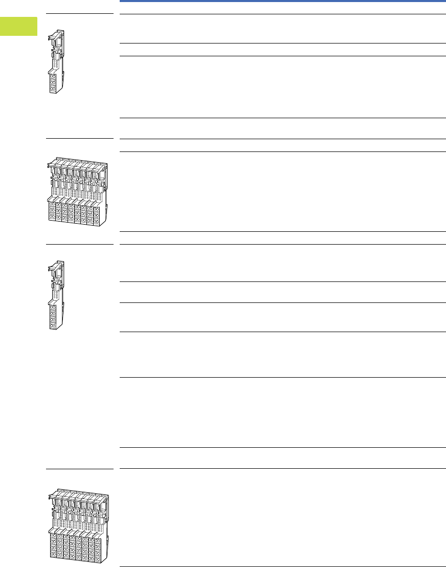
V7-T4-84 Volume 7—Logic Control, Operator Interface and Connectivity Solutions CA08100008E—May 2016 www.eaton.com
4
4
4
4
4
4
4
4
4
4
4
4
4
4
4
4
4
4
4
4
4
4
4
4
4
4
4
4
4
4
4.7
PLC, I/O and Communications Products
XI/ON Series Remote I/O
Base Modules
Spring-Cage Terminals
Description For Use With …
Style
Number Catalog Number
Three Connection Levels
Base module for field power supply
Base module for the gateway supply
(with XN-BR-24VDC-D)
XN-BR-24VDC-D
XN-PF-24VDC-D
XN-PF-120/230VAC-D
140074 XN-P3T-SBB
Base module for bus refresh within the station XN-BR-24VDC-D 140073 XN-P3T-SBB-B
—XN-2DI-_
XN-1AI-_
XN-2AI-I(0/4…20MA)
XN-2AI-U(-10/0…+10VDC)
XN-2AI-PT/NI-2/3
XN-1AO-I(0/4…20MA)
XN-2AO-_
140077 XN-S3T-SBB
Connection to C rail XN-2DO-24VDC-_
XN-2DO-120/230VAC-0.5A
140079 XN-S3T-SBC
— XN-16DI-24VDC-P 140133 XN-B3T-SBB
Connection to C rail XN-16DO-24VDC-0.5-P 140134 XN-B3T-SBC
Four Connection Levels
Base module for field power supply
Base module for the gateway supply
(with XN-BR-24VDC-D)
Connection to C rail
XN-BR-24VDC-D
XN-PF-24VDC-D
XN-PF-120/230VAC-D
140076 XN-P4T-SBBC
Base module for bus refresh within the station
Connection to C rail
XN-BR-24VDC-D 140075 XN-P4T-SBBC-B
Connection to C rail XN-2DI-24VDC-P
XN-2DI-24VDC-N
XN-2DI-120/230VAC
140078 XN-S4T-SBBC
Connection to C rail XN-2DO-24VDC-_
XN-2DO-120/230VAC-0.5A
XN-4DO-24VDC-0.5A-P
XN-2DO-R-NO
XN-2DO-R-NC
140080 XN-S4T-SBCS
—XN-4DI-_
XN-2DO-R-_
XN-1AI-_
XN-2AI-I(0/4…20MA)
XN-2AI-U(-10/0…+10VDC)
XN-2AI-PT/NI-2/3
XN-1CNT-24VDC
XN-1RS_
140081 XN-S4T-SBBS
Base module with temperature sensors for
cold-junction compensation
XN-2AI-THERMO-PI 140084 XN-S4T-SBBS-CJ
Connection to C rail XN-16DI-24VDC-P 140135 XN-B4T-SBBC
Slice Module
Block Module
Slice Module
Block Module
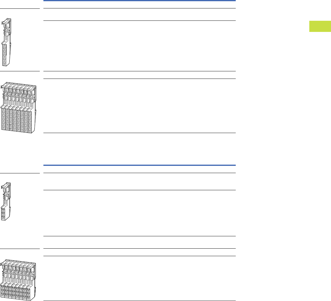
Volume 7—Logic Control, Operator Interface and Connectivity Solutions CA08100008E—May 2016 www.eaton.com V7-T4-85
4
4
4
4
4
4
4
4
4
4
4
4
4
4
4
4
4
4
4
4
4
4
4
4
4
4
4
4
4
4
4.7
PLC, I/O and Communications Products
XI/ON Series Remote I/O
Spring-Cage Terminals, continued
Screw Terminals
Description For Use With …
Style
Number Catalog Number
Six Connection Levels
— XN-4DI-24VDC-P
XN-4DI-24VDC-N
140082 XN-S6T-SBBSBB
Connection to C rail XN-4DO-24VDC-0.5A-P
XN-4AI-U/I
140083 XN-S6T-SBCSBC
— XN-32DI-24VDC-P 140136 XN-B6T-SBBSBB
Connection to C rail XN-32DO-24VDC-0.5A-P 140159 XN-B6T-SBCSBC
Description For Use With …
Style
Number Catalog Number
Three Connection Levels
Base module for field power supply
Base module for the gateway supply
(with XN-BR-24VDC-D)
XN-BR-24VDC-D
XN-PF-24VDC-D
XN-PF-120/230VAC-D
140085 XN-P3S-SBB
— XN-2DI-24VDC-P
XN-2DI-24VDC-N
XN-2DI-120/230VAC
XN-1AI-_
XN-2AI-I(0/4…20MA)
XN-2AI-U(-10/0…+10VDC)
XN-2AI-PT/NI-2/3
XN-1AO-I(0/4…20MA)
XN-2AO-_
140088 XN-S3S-SBB
Connection to C rail XN-2DO-24VDC-_
XN-2DO-120/230VAC-0.5A
140090 XN-S3S-SBC
— XN-16DI-24VDC-P 140137 XN-B3S-SBB
Connection to C rail XN-16DO-24VDC-0.5A-P 140138 XN-B3S-SBC
Slice Module
Block Module
Slice Module
Block Module
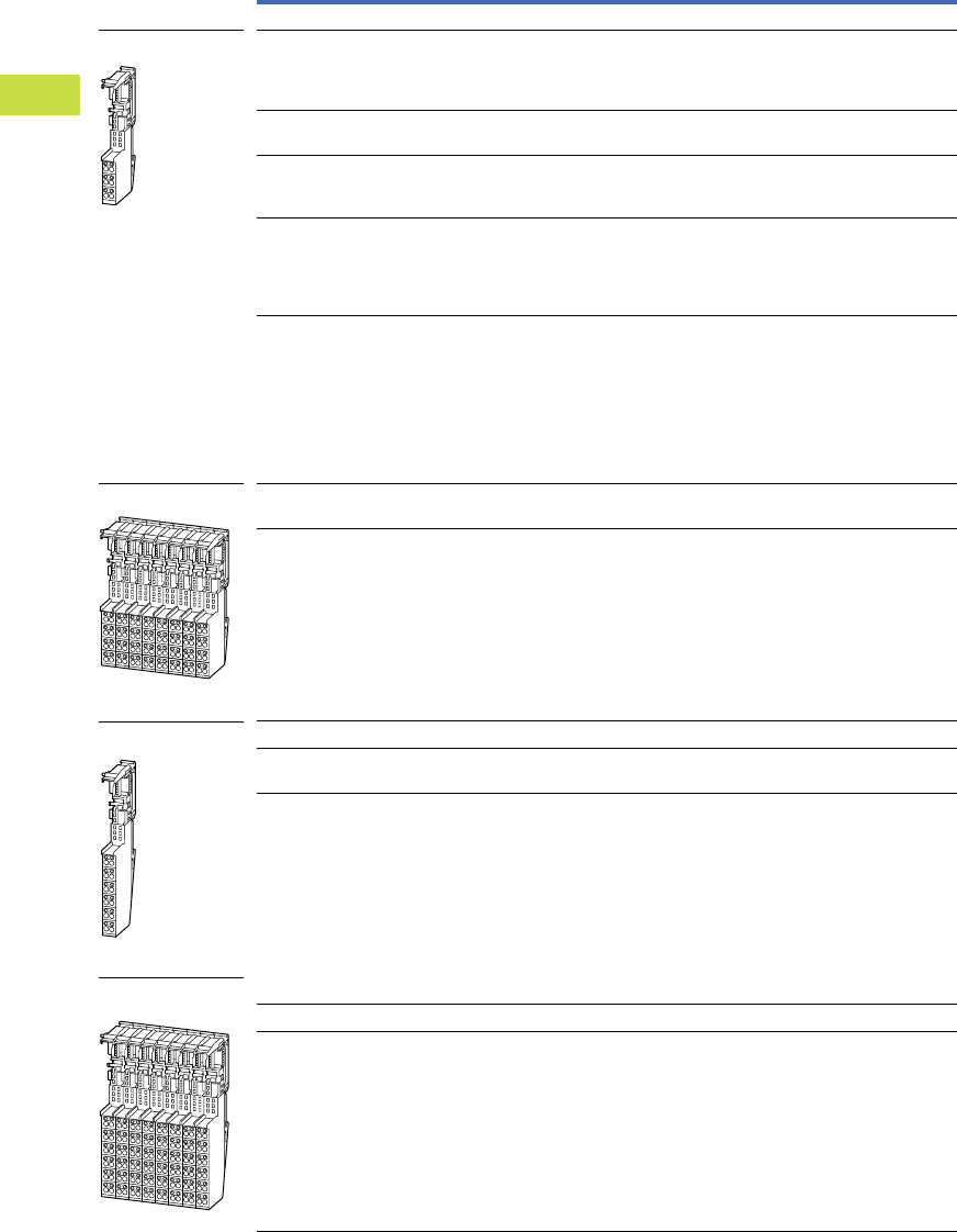
V7-T4-86 Volume 7—Logic Control, Operator Interface and Connectivity Solutions CA08100008E—May 2016 www.eaton.com
4
4
4
4
4
4
4
4
4
4
4
4
4
4
4
4
4
4
4
4
4
4
4
4
4
4
4
4
4
4
4.7
PLC, I/O and Communications Products
XI/ON Series Remote I/O
Screw Terminals, continued
Description For Use With …
Style
Number Catalog Number
Four Connection Levels
Base module for field power supply
Base module for the gateway supply
(with XN-BR-24VDC-D)
Connection to C rail
XN-BR-24VDC-D
XN-PF-24VDC-D
XN-PF-120/230VAC-D
140087 XN-P4S-SBBC
Base module for bus refresh within the station
Connection to C rail
XN-BR-24VDC-D 140086 XN-P4S-SBBC-B
Connection to C rail XN-2DI-24VDC-P
XN-2DI-24VDC-N
XN-2DI-120/230VAC
140089 XN-S4S-SBBC
Connection to C rail XN-2DO-24VDC-_
XN-2DO-120/230VAC-0.5A
XN-4DO-24VDC-0.5A-P
XN-2DO-R-NO
XN-2DO-R-NC
140091 XN-S4S-SBCS
—XN-4DI-_
XN-2DO-R-_
XN-1AI-_
XN-2AI-I(0/4…20MA)
XN-2AI-U(-10/0…+10VDC)
XN-2AI-PT/NI-2/3
XN-1CNT-24VDC
XN-1RS_
XN-1SSI
140092 XN-S4S-SBBS
Base module with temperature sensors for
cold-junction compensation
XN-2AI-THERMO-PI 140095 XN-S4S-SBBS-CJ
Connection to C rail XN-16DI-24VDC-P 140139 XN-B4S-SBBC
Six Connection Levels
— XN-4DI-24VDC-P
XN-4DI-24VDC-N
140093 XN-S6S-SBBSBB
Connection to C rail XN-4DO-24VDC-0.5A-P
XN-4AI-U/I
140094 XN-S6S-SBCSBC
— XN-32DI-24VDC-P 140140 XN-B6S-SBBSBB
Connection to C rail XN-32DO-24VDC-0.5A-P 140160 XN-B6S-SBCSBC
Slice Module
Block Module
Slice Module
Block Module
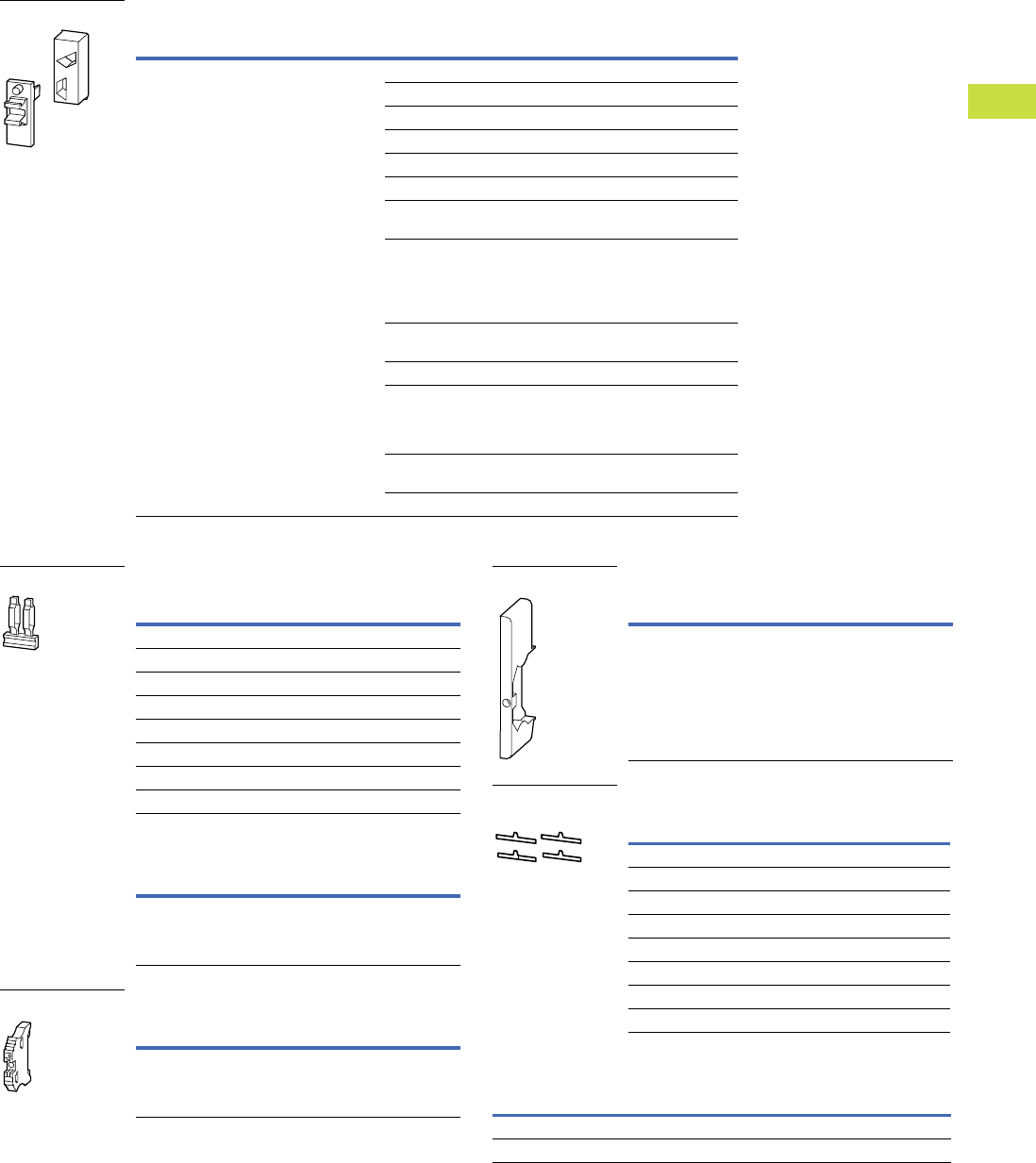
Volume 7—Logic Control, Operator Interface and Connectivity Solutions CA08100008E—May 2016 www.eaton.com V7-T4-87
4
4
4
4
4
4
4
4
4
4
4
4
4
4
4
4
4
4
4
4
4
4
4
4
4
4
4
4
4
4
4.7
PLC, I/O and Communications Products
XI/ON Series Remote I/O
Accessories
Coding Elements
Relay Jumpers
Servicing Cable
End Bracket
End Cover
Connection Level Labels
Labels
Description For Use With …
Style
Number Catalog Number
Included as standard with every electronics
module. Prevents incorrect connection of the
electronics modules
XN-…DI-24VDC_ 140114 XN-KO/2
XN-2DI-120/230VAC 140117 XN-KO/5
XN-xDO-24VDC_ 140118 XN-KO/6
XN-2DO-R-NO 140119 XN-KO/8
XN-2DO-R-NC 140120 XN-KO/9
XN-2DO-R-CO 140121 XN-KO/10
XN-1AI-I(0/4…20MA)
XN-2AI-I(0/4…20MA)
140122 XN-KO/11
XN-1AI-U(-10/0…+10VDC)
XN-2AI-U(-10/0…+10VDC)
XN-2AI-PT/NI-2/3
XN-2AI-THERMO-PI
XN-4AI-U/I
140123 XN-KO/12
XN-1AO-I(0/4…20MA)
XN-2AO-I(0/4…20MA)
140124 XN-KO/13
XN-2AO-U(-10/0…+10VDC) 140125 XN-KO/14
XN-1CNT-24VDC
XN-1RS232
XN-1RS485/422
XN-1SSI
140126 XN-KO/15
XN-BR-24VDC-D
XN-PF-24VDC-D
140127 XN-KO/16
XN-PF-120/230VAC-D 140128 XN-KO/17
Coding Elements
Description
Style
Number
Catalog
Number
1-grid 140097 XN-QV/1
2-grid 140098 XN-QV/2
3-grid 140099 XN-QV/3
4-grid 140100 XN-QV/4
5-grid 140101 XN-QV/5
6-grid 140102 XN-QV/6
7-grid 140103 XN-QV/7
8-grid 140104 XN-QV/8
Description
Style
Number Catalog Number
Establishes the connection
between I/O assistant and the
service interface at the
gateway
140096 XN-PS2-CABLE
Description
Style
Number Catalog Number
For fixing the XI/ON station on
the top-hat rail. Two end
brackets are supplied as
standard with the gateways
140130 XN-WEW-35/2-SW
Relay Jumper
End Bracket
Description
Style
Number Catalog Number
For covering an XI/ON station.
An end cover is supplied with
the gateway as standard
140129 XN-ABPL
Description
Style
Number Catalog Number
Blue 140105 XN-ANBZ-BL
Red 140106 XN-ANBZ-RT
Green 140107 XN-ANBZ-GN
Black 140108 XN-ANBZ-SW
Brown 140109 XN-ANBZ-BR
Red/blue 140110 XN-ANBZ-RT/BL-BED
Yellow/green 140111 XN-ANBZ-GN/GE-BED
White 140112 XN-ANBZ-WS
Description
Style
Number Catalog Number
A5 sheet, perforated, 1 x 57 labels 140131 XN-LABEL/SCHEIBE
A5 sheet, perforated, 1 x 6 labels 140132 XN-LABEL/BLOCK
End Cover
Connection
Level Labels

V7-T4-88 Volume 7—Logic Control, Operator Interface and Connectivity Solutions CA08100008E—May 2016 www.eaton.com
4
4
4
4
4
4
4
4
4
4
4
4
4
4
4
4
4
4
4
4
4
4
4
4
4
4
4
4
4
4
4.7
PLC, I/O and Communications Products
XI/ON Series Remote I/O
Technical Data and Specifications
XI/ON General
Te r m i n a l s
Description Unit Specification
Standards EN 61000-6-2, EN 61000-6-4, EN 61131-2
Supported fieldbus systems PROFIBUS-DP, CANopen, DeviceNet, Modbus TCP, EtherNet/IP (depending
on gateway)
Potential isolation Yes, through optocoupler
Ambient temperature °F (°C) 32° to 131° (0° to 55°)
Ambient temperature, storage °F (°C) –13° to 185° (–25° to 85°)
Relative humidity % 5–95 (indoor), Level RH-2, noncondensing (for storage at 45°C)
Harmful gases
SO2ppm 10 (relative humidity <75%, noncondensing)
H2S ppm 1.0 (relative humidity <75%, noncondensing)
Vibration resistance, operating conditions According to IEC 60068-2-6
Mechanical shock resistance According to IEC 60068-2-27
Repetitive shock resistance According to IEC 60068-2-29
Drop and free fall According to IEC 60068-2-31, free fall to IEC 60068-2-32
Protection type IP20
Electromagnetic compatibility (EMC)
ESD EN 61000-4-2
Electromagnetic fields EN 61000-4-3
Burst EN 61000-4-4
Surge EN 61000-4-5
HF, asymmetric EN 61000-4-6
Radiated interference (RFI) EN 55016-2-3
Voltage fluctuations EN 61131-2
Type test To EN 61131-2
Approvals CE, cUL
Description Unit
XN Gateways and
XN Basic Modules
XNE Gateways and
Integrated XNE Modules
Dimensional data To VDE 0611 Part 1/8.92/
IEC/EN 60947-7-1
To VDE 0611 Part 1/8.92/
IEC/EN 60947-7-1
Connection from above Spring-loaded/screw terminals Push-in spring-cage terminals
Cable stripped length mm 8 8
Max. terminal capacity mm20.5–2.5 0.14–1.5
Connectable conductors
“e” solid H07V-U mm20.5–2.5 0.25–1.5
“f” flexible H 07V-K mm20.5–1.5 0.25–1.5
“f” with ferrule without plastic collar
to DIN 46228-1 (ferrules gas-tight)
mm20.5–1.5 0.25–1.5
“f” with ferrule with plastic collar
to DIN 46228-1 (ferrules gas-tight)
mm20.5–1.5 0.25–0.75
Gauge pin IEC/EN 60947-1 A1 A1

Volume 7—Logic Control, Operator Interface and Connectivity Solutions CA08100008E—May 2016 www.eaton.com V7-T4-89
4
4
4
4
4
4
4
4
4
4
4
4
4
4
4
4
4
4
4
4
4
4
4
4
4
4
4
4
4
4
4.7
PLC, I/O and Communications Products
XI/ON Series Remote I/O
XNE Gateways
XN Gateways with Built-In Supply Module
Description Unit XNE-GWBR-PBDP XNE-GWBR-CANOPEN XNE-GWBR-2ETH-IP
Fieldbus PROFIBUS-DP CANopen Ethernet
Protocol PROFIBUS-DPV0 and PROFIBUS-DPV1 CANopen EtherNet/IP
Maximum number of stations 48 modules (XN, XNE) of slice design or
max. length of station: 1m
62 modules (XN, XNE) of slice design or
max. length of station: 1m
74 modules (XN, XNE) of slice design or
max. length of station: 1m
System supply (USYS) Vdc 24/5 24/5 24/5
Permissible range, 5 Vdc (USYS) Vdc 4.7–5.3 4.7–5.3 4.7–5.3
Permissible range, 24 Vdc (USYS) Vdc 18–30 18–30 18–30
Field voltage (UL) Vdc 24 24 24
Permissible range (UL) Vdc 18–30 18–30 18–30
Ripple % <5 (to EN 61131-2) <5 (to EN 61131-2) <5 (to EN 61131-2)
Servicing interface PS/2 socket PS/2 socket Mini USB
Fieldbus terminals Push-in spring-cage terminals Push-in spring-cage terminals 2x RJ45 socket
Transfer rate kBit/s 9.6–12,000 20, 50, 125, 250, 500, 800, 1000 10,000, 100,000
Data transfer rate setting Automatic Through DIP switch or automatically Automatic
Address assignment Through DIP switch Through DIP switch Through DIP switch, BootP, DHCP or PGM
Fieldbus termination Through DIP switch Through DIP switch —
Number of parameter bytes 2 — —
Number of diagnosis bytes 2 — —
Address range 1–125 decimal 1–63 decimal 1–254 decimal
Description Unit XN-GWBR-PBDP XN-GWBR-CANOPEN XN-GWBR-DNET XN-GWBR-MODBUS-TCP XN-PLC-CANOPEN
Fieldbus PROFIBUS-DP CANopen DeviceNet Ethernet CANopen
Protocol PROFIBUS-DPV0 CANopen DeviceNet Modbus-TCP CANopen
Maximum number of stations 74 modules (XN, XNE) of
slice design or max. length
of station: 1m
74 modules (XN, XNE) of
slice design or max. length
of station: 1m
74 modules (XN) of slice
design or max. length of
station: 1m
74 modules (XN, XNE) of slice
design or max. length of station:
1m
74 modules (XN, XNE with
limitations) of slice design or
max. length of station: 1m
System supply (USYS) Vdc 24/5 24/5 24/5 24/5 24/5
Permissible range, 5 Vdc (USYS) Vdc 4.7–5.3 4.7–5.3 4.7–5.3 4.7–5.3 4.7–5.3
Permissible range, 24 Vdc (USYS) Vdc 18–30 18–30 18–30 18–30 18–30
Field voltage (UL) 24 24 24 24 24
Permissible range (UL) Vdc 18–30 18–30 18–30 18–30 18–30
Ripple % <5 (to EN 61131-2) <5 (to EN 61131-2) <5 (to EN 61131-2) <5 (to EN 61131-2) <5 (to EN 61131-2)
Servicing interface PS/2 socket PS/2 socket PS/2 socket PS/2 socket PS/2 socket
Fieldbus terminals 1 x D-sub 9-pin socket Open style connector Open style connector RJ45 bus Open style connector
Transfer rate kBit/s 9.6–12,000 10, 20, 50, 125, 250, 500,
800, 1000
125, 250, 500 10,000, 100,000 10, 20, 50, 125, 250, 500, 800,
1000
Data transfer rate setting — Through DIP switch Through DIP switch Automatic Software
Address assignment 2 decimal rotary coding
switches
2 decimal rotary coding
switches
2 decimal rotary coding
switches
Decimal rotary coding switch,
BootP, DHCP or I/Oassistant
Software
Fieldbus termination External External External — External
Number of parameter bytes 5 — — — —
Number of diagnosis bytes 3 — — — —
Address range 1–99 decimal 1–99 decimal 1–63 decimal 1–254 decimal 1–127 decimal
Program data kByte — — — — 128
Program code kByte — — — — 128
Cycle time for 1k of instructions
(bits, bytes)
ms———— 0.5
Real-time clock — — — — Yes

V7-T4-90 Volume 7—Logic Control, Operator Interface and Connectivity Solutions CA08100008E—May 2016 www.eaton.com
4
4
4
4
4
4
4
4
4
4
4
4
4
4
4
4
4
4
4
4
4
4
4
4
4
4
4
4
4
4
4.7
PLC, I/O and Communications Products
XI/ON Series Remote I/O
Supply Modules
Digital Input Modules
Notes
1Permissible range for system supply: for USYS = 24 Vdc: 18 to 30 Vdc (to EN 61131-2).
2Permissible range for field voltage UL: to EN 61131-2 (18 to 30 Vdc).
3Permissible range for rated voltage and field voltage UL: to EN 61131-2.
4The supply terminal (UL) provides power for the module electronics and for the sensors at the inputs. The total current required for each module consists of the sum of all partial currents.
5Part of the XI/ON module’s electronics is supplied with module bus voltage (5 Vdc), the other part through the supply terminal (UL).
6Maximum permissible capacity: 141 nF at 79 Vac/50 Hz; 23 nF at 265 Vac/50 Hz.
Description Unit XN-BR-24VDC-D XN-PF-24VDC-D XN-PF-120/230VAC-D
Operating voltage 24 Vdc 24 Vdc 120/230 Vac
System supply (USYS) Vdc 24 — —
Permissible range, 24 Vdc (USYS) Vdc 18–30 1——
Permissible range, 5 Vdc (UMB
[built into system]
) Vdc 4.7–5.3 — —
Field voltage (UL) 24 Vdc 24 Vdc 120/230 Vac
Permissible range (UL) 18–30 Vdc 18–30 Vdc 2102–132 Vac (120 Vac)
195.5–253 Vac (230 Vac) 3
Rated current drawn from module bus (IMB)mA — <28 <25
Insulation test (Ui) Vac 500 500 1500
Ripple % <5 (to EN 61131-2) <5 (to EN 61131-2) <5 (to EN 61131-2)
Maximum operating current (IL) A 10 10 10
Maximum system supply current (IMB)A 1.5 — —
Number of diagnostic bits 4 4 4
Base module without gateway power supply
Without C connection XN-P3…-SBB/XN-P3…-SBB-B XN-P3…-SBB XN-P3…-SBB
With C connection XN-P4…-SBBC/XN-P4…-SBBC-B XN-P4…-SBBC XN-P4…-SBBC
Description Unit XN-2DI-24VDC-P XN-2DI-24VDC-N XN-2DI-120/230VAC XN-4DI-24VDC-P XN-4DI-24VDC-N
Channels Number 2 2 2 4 4
Rated voltage at supply
terminal (UL)
24 Vdc 24 Vdc 120/230 Vac 24 Vdc 24 Vdc
Rated current drawn from
supply terminal (IL) 45
mA <20 <20 <20 <40 <40
Rated current drawn from
module bus (IMB) 5
mA <28 <28 <28 <29 <28
Insulation test (Ui) Vac 500 500 1500 500 500
Heat dissipation W 0.7 0.7 1 1 1
Input voltage
Input voltage, rated value 24 Vdc 24 Vdc 120/230 Vac 24 Vdc 24 Vdc
Low level –30V to 5V 30V (UL–11V) 0–20 Vac –30V to 5V 30V (UL–11V)
High level 11–30V 0–5V 79 Vac–265 Vac 615 V–30V 0–5V
Frequency range Hz — — 48–63 — —
Input current
Low level/active level 0 mA–1.5 mA 0 mA–1.7 mA 0 mA–1 mA 0 mA–1.5 mA 0 mA–1.2 mA
High level/active level 2 mA–10 mA 1.8 mA–10 mA 3 mA–10 mA 2 mA–10 mA 1.3 mA–6 mA
Input delay
trising edge µs <200 <200 <20,000 <200 <200
tfalling edge µs <200 <200 <20,000 <200 <200
Basic modules
Without C connection XN-S3…-SBB 2-conductor proximity switches (Bero®)
can be connected, with a permissible quiescent
current of up to 1.5 mA
XN-S3…-SBB XN-S4…-SBBS
XN-S6…-SBBSBB
XN-S4…-SBBS
XN-S6…-SBBSBB
With C connection XN-S4…-SBBC XN-S4…-SBBC XN-S4…-SBBC — —

Volume 7—Logic Control, Operator Interface and Connectivity Solutions CA08100008E—May 2016 www.eaton.com V7-T4-91
4
4
4
4
4
4
4
4
4
4
4
4
4
4
4
4
4
4
4
4
4
4
4
4
4
4
4
4
4
4
4.7
PLC, I/O and Communications Products
XI/ON Series Remote I/O
Digital Input Modules, continued
Notes
1The supply terminal (UL) provides power for the module electronics and for the sensors at the inputs. The total current required for each module consists of the sum of all partial currents.
2Part of the XI/ON module’s electronics is supplied with module bus voltage (5 Vdc), the other part through the supply terminal (UL).
Description Unit XN-16DI-24VDC-P XN-32DI-24VDC-P XNE-8DI-24VDC-P XNE-16DI-24VDC-P
Channels Number 16 32 8 16
Rated voltage at supply terminal (UL) Vdc242424 24
Rated current drawn from supply terminal (IL) 12 mA <40 <30 <1.5 <3
Rated current drawn from module bus (IMB) 2mA <45 <30 <15 <15
Insulation test (Ui) Vac 500 500 500 500
Heat dissipation W 2.5 4.2 <1.5 <2.5
Input voltage
Input voltage, rated value Vdc 24 24 24 24
Low level –30V to 5V –30V to 5V –ULto 5V –UL to 5V
High level 15V–30V 15V–30V 11V–UL11V–UL
Frequency range Hz ————
Input current
Low level/active level 0 mA–1.5 mA 0 mA–1.5 mA –1 mA–1.5 mA –1 mA–1.5 mA
High level/active level 2 mA–10 mA 2 mA–10 mA 2 mA–5 mA 2 mA–5 mA
Input delay
trising edge µs <200 <200 <100 <150
tfalling edge µs <200 <200 <200 <300
Basic modules
Without C connection XN-B3…-SBB XN-B6…-SBBSBB Already built in Already built in
With C connection XN-B4…-SBBC — — —

V7-T4-92 Volume 7—Logic Control, Operator Interface and Connectivity Solutions CA08100008E—May 2016 www.eaton.com
4
4
4
4
4
4
4
4
4
4
4
4
4
4
4
4
4
4
4
4
4
4
4
4
4
4
4
4
4
4
4.7
PLC, I/O and Communications Products
XI/ON Series Remote I/O
Digital Output Modules
Notes
1The supply terminal (UL) provides power for the module electronics and for the consumers at the outputs. The total current required for each module consists of the sum of all partial currents.
2Part of the XI/ON module’s electronics is supplied with module bus voltage (5 Vdc), the other part through the supply terminal (UL).
3To increase the maximum output current to up to 1A, two outputs can be connected in parallel.
Description Unit XN-2DO-24VDC-0.5A-P XN-2DO-24VDC-0.5A-N XN-2DO-120/230VAC-0.5A XN-2DO-24VDC-2A-P XN-4DO-24VDC-0.5A-P
Channels Number 2 2 2 2 4
Rated voltage at supply terminal (UL) 24 Vdc 24 Vdc 120/230 Vac (45–65 Hz) 24 Vdc 24 Vdc
Rated current drawn from supply
terminal (for 0 mA load current) (IL) 1
mA <20 <20 <20 <50 <25
Rated current drawn from module
bus (IMB) 2
mA <32 <32 <35 <33 <30
Insulation test (Ui) Vac 500 500 1500 500 500
Heat dissipation W Normally 1 Normally 1 Normally 1 Normally 1 Normally 1
Output voltage
High level >UL–1 Vdc <GNDL +1 Vdc >UL–2 Vac,
(zero-point switching triac)
>UL–1 Vdc >UL–1 Vdc
Output current
High level (rated) A 0.5 0.5 0.5 320.5
High level (permissible range) A <0.6 <0.6 0.02–0.5 <2.4 <0.6
Low level mA — — <1.5 — —
Back-up fuse — — 500 mA FF — —
Surge current (IS) A — — 8 (1 period at 60 Hz) — —
Number of parallel-switchable
outputs (maximum)
——— —4
Total module current A 1 1 1 4 2
Delay for signal changeover,
resistive load
From Low to High level µs <100 <100 <T/2 +1 ms <100 <250
From High to Low level µs <100 <100 <T/2 +1 ms <100 <250
Load resistance range >48 ohm >48 ohm At 120 Vac:
240 ohm to 6 kohm
At 230 Vac:
460 ohm to 11.5 kohm
<12 ohm >48 ohm
Utilization factor (%) g 100 100 100 (observe derating) 100 100
The following can be connected: Resistive loads/Inductive loads/Lamp loads
Resistive load ohm >48 >48 — >12 >48
Inductive load H <1.2 <1.2 — <1.2 <1.2
Lamp load (RLL) W <3 <12 — <6 <6
Switching frequency
For resistive load (f) Hz <5000 (RLO <1 kohm) <100 (RLO <1 kohm) — <5000 (RLO <1 kohm) <1000 (RLO <1 kohm)
For inductive load Hz <2 <2 — <2 <2
For lamps Hz <10 <10 — <10 <10
Number of diagnostic bits 2 2 — 2 1
Diagnostics Yes Yes No Yes Yes
Outputs to EN 61131-1 Protected Protected — Protected Short-circuit proof
Retriggering after elimination of short
circuit (Ii)
Self-acting Self-acting — Self-acting Self-acting
Basic modules
With C connection XN-S3…-SBC
XN-S4…-SBCS
XN-S3…-SBC
XN-S4…-SBCS
XN-S3…-SBC
XN-S4…-SBCS
XN-S3…-SBC
XN-S4…-SBCS
XN-S4…-SBCS
XN-S4…-SBCSBC

Volume 7—Logic Control, Operator Interface and Connectivity Solutions CA08100008E—May 2016 www.eaton.com V7-T4-93
4
4
4
4
4
4
4
4
4
4
4
4
4
4
4
4
4
4
4
4
4
4
4
4
4
4
4
4
4
4
4.7
PLC, I/O and Communications Products
XI/ON Series Remote I/O
Digital Output Modules, continued
Notes
1The supply terminal (UL) provides power for the module electronics and for the consumers at the outputs. The total current required for each module consists of the sum of all partial currents.
2Part of the XI/ON module’s electronics is supplied with module bus voltage (5 Vdc), the other part through the supply terminal (UL).
3To increase the maximum output current to up to 1A, two outputs can be connected in parallel.
Description Unit XN-16DO-24VDC-0.5A-P XN-32DO-24VDC-0.5A-P XNE-8DO-24VDC-0.5A-P XNE-16DO-24VDC-0.5A-P
Channels Number 16 32 8 16
Rated voltage at supply terminal (UL) Vdc 24 24 24 24
Rated current drawn from supply terminal (for
0 mA load current) (IL) 1
mA <30 <50 <3 (all outputs OFF) <3 (all outputs OFF)
Rated current drawn from module bus (IMB) 2mA <120 <30 <15 <25
Insulation test (Ui) Vac 500 500 500 500
Heat dissipation W Normally 4 Normally 5 Normally 1.5 Normally 2.5
Output voltage
High level Vdc >UL–1 >UL–1 >UL–1 >UL–1
Output current
High level (rated) A 0.5 0.5 0.5 30.5 3
High level (permissible range) A <0.6 <1.0 <1.0 <1.0
Low level mA————
Back-up fuse ————
Surge current (IS)A————
Number of parallel-switchable outputs
(maximum)
—2 ——
Total module current A 8 10 4 4
Delay for signal changeover, resistive load
From Low to High level µs <100 <300 <300 <300
From High to Low level µs <100 <300 <300 <300
Load resistance range >48 ohm >48 ohm >48 ohm >48 ohm
Utilization factor (%) g 100 See total module current 100 50%, max. 4A
The following can be connected: Resistive loads/Inductive loads/Lamp loads
Resistive load ohm >48 >48 >48 >48
Inductive load H <1.2 <1.2 As for DC13 to IEC 60947-5-1 As for DC13 to IEC 60947-5-1
Lamp load (RLL) W <3 <6 <6 <6
Switching frequency
For resistive load (f) Hz <100 (RLO <1 kohm) <100 (RLO <1 kohm) <100 <100
For inductive load Hz — — As for DC13 to IEC 60947-5-1 As for DC13 to IEC 60947-5-1
For lamps Hz——<10<10
Number of diagnostic bits 4 8 — —
Diagnostics Yes Yes — —
Outputs to EN 61131-1 Short-circuit proof Short-circuit proof Short-circuit proof Short-circuit proof
Retriggering after elimination of
short circuit (Ii)
Self-acting Self-acting Self-acting Self-acting
Basic modules
With C connection XN-B3…-SBC XN-B6…-SBCSBC Already built in Already built in

V7-T4-94 Volume 7—Logic Control, Operator Interface and Connectivity Solutions CA08100008E—May 2016 www.eaton.com
4
4
4
4
4
4
4
4
4
4
4
4
4
4
4
4
4
4
4
4
4
4
4
4
4
4
4
4
4
4
4.7
PLC, I/O and Communications Products
XI/ON Series Remote I/O
Analog Input Modules
Notes
1The supply terminal (UL) provides power for the module electronics and for the analog transmitters at the inputs. The total current required for each module consists of the sum of all partial currents.
2Part of the XI/ON module’s electronics is supplied with module bus voltage (5 Vdc), the other part through the supply terminal (UL).
Description Unit XN-1AI-I(0/4…20MA) XN-2AI-I(0/4…20MA) XN-1AI-U(-10/0…+10VDC) XN-2AI-U(-10/0…+10VDC)
Measured variables Current Current Voltage Voltage
Channels Number 1212
Rated voltage at supply terminal (UL) Vdc 24 24 24 24
Rated current drawn from supply
terminal (IL) 12
mA <50 <12 <50 <12
Rated current drawn from module
bus (IMB) 2
mA <41 <35 <41 <35
Heat dissipation W <1 <1 <1 <1
Sensor/transmitter supply Bridged with UL and GNDL of
incoming unit; not protected
<250 mA; bridged with UL and
GNDL of incoming unit; not
protected
Bridged with UL and GNDL of
incoming unit; not protected
<250 mA; bridged with UL and
GNDL of incoming unit; not
protected
Voltage measurement
Measurement ranges — — –10 to 10 Vdc/0 to 10 Vdc –10 to 10 Vdc/0 to 10 Vdc
Value representation — — Standard, 16-bit/12-bit
left-aligned
Standard, 16-bit/12-bit
left-aligned
The following can be connected: — — 2-/3-/4-conductor + shield 2-/3-conductor + shield
Maximum input voltage (Umax.)Vdc——3535
Input resistance (RL) kohm — — >98.5 >98.5
Limiting frequency (fG)Hz——20050
Basic error limit at 23°C % — — <0.2 <0.2
Temperature coefficient — — <300 ppm/°C of full-scale value <150 ppm/°C of full-scale value
Current measurement
Measurement ranges mA 0–20/4–20 0–20/4–20 — —
Value representation Standard, 16-bit/12-bit
(left-aligned)
Standard, 16-bit/12-bit
(left-aligned)
——
The following can be connected: 2-/3-/4-conductor + shield 2-/3-conductor + shield — —
Maximum input current (Imax.)mA50 50 — —
Input resistance (RL) ohm <125 ohm <125 ohm — —
Limiting frequency (fG)Hz200 50 — —
Basic error limit at 23°C % <0.2 <0.2 — —
Temperature coefficient <300 ppm/°C of full-scale value <300 ppm/°C of full-scale value — —
Temperature measurement
Connectable sensors ————
Measurement ranges ————
Value representation ————
The following can be connected:————
Measuring current (Imess) ————
Destruction limit (Umax.)Vdc————
Basic error limit at 23°C%————
Temperature coefficient ————
R (resistance measurement)
Measurement ranges ————
Value representation ————
The following can be connected:————
Destruction limit (Umax.)Vdc————
Limiting frequency (fG)Hz————
Basic error limit at 23°C%————
Temperature coefficient ————
Basic modules
Without C connection XN-S3…-SBB XN-S3…-SBB XN-S3…-SBB XN-S3…-SBB
Without C connection, for sensor supply XN-S4…-SBBS XN-S4…-SBBS XN-S4…-SBBS XN-S4…-SBBS

Volume 7—Logic Control, Operator Interface and Connectivity Solutions CA08100008E—May 2016 www.eaton.com V7-T4-95
4
4
4
4
4
4
4
4
4
4
4
4
4
4
4
4
4
4
4
4
4
4
4
4
4
4
4
4
4
4
4.7
PLC, I/O and Communications Products
XI/ON Series Remote I/O
Analog Input Modules, continued
Notes
1The supply terminal (UL) provides power for the module electronics and for the analog transmitters at the inputs. The total current required for each module consists of the sum of all partial currents.
2Part of the XI/ON module’s electronics is supplied with module bus voltage (5 Vdc), the other part through the supply terminal (UL).
Description Unit XN-4AI-U/I XN-2AI-THERMO-PI XN-2AI-PT/NI-2/3 XNE-8AI-U/I-4PT/NI
Measured variables Voltage, current Temperature (thermocouples) Temperature PT, NI resistance R Voltage, current, temperature PT,
NI resistance R
Channels Number 4228 (U/I)/4 (PT/NI/R)
Rated voltage at supply terminal (UL) Vdc 24 24 24 24
Rated current drawn from supply
terminal (IL) 12
mA <20 <30 <30 Normally 35
Rated current drawn from module
bus (IMB) 2
mA <50 <45 <45 <30
Heat dissipation W <1 <1 <1 <1.5
Sensor/transmitter supply ————
Voltage measurement
Measurement ranges –10 to 10 Vdc/0 to 10 Vdc –50 to 50 mV, –100 to 100 mV
–500 to 500 mV,
–1,000 to 1,000 mV
— –10 to 10 Vdc/0 to 10 Vdc
Value representation Standard, 16-bit/12-bit
(left-aligned)
Standard, 16-bit/12-bit
(left-aligned)
— Standard, 16-bit/12-bit
(left-aligned)
Extended range, 16-bit/12-bit
(left-aligned)
PA (NE43), 16-bit/12-bit
(left-aligned)
The following can be connected: 2-conductor + shield 2-conductor — 2-conductor
Maximum input voltage (Umax.) Vdc 30 10 — ±20
Input resistance (RL) kohm >98.5 — — >200
Limiting frequency (fG)Hz20 ——1.5
Basic error limit at 23°C % <0.3 <0.2 (normally) — <0.2
Temperature coefficient <300 ppm/°C of full-scale value <300 ppm/°C of full-scale value — <200 ppm/°C of full-scale value
Current measurement
Measurement ranges mA 0–20/4–20 — — 0–20/4–20
Value representation Standard, 16-bit/12-bit
(left-aligned)
— — Standard, 16-bit/12-bit
(left-aligned)
Extended range, 16-bit/12-bit
(left-aligned)
PA (NE43), 16-bit/12-bit
(left-aligned)
The following can be connected: 2-conductor + shield — — 2-conductor
Maximum input current (Imax.) mA 50 — — 40 (Max. input voltage: <17V)
Input resistance (RL) ohm <62 — — <52
Limiting frequency (fG)Hz20 ——1.5
Basic error limit at 23°C % <0.3 — — <0.2
Temperature coefficient <300 ppm/°C of full-scale value — — <200 ppm/°C of full-scale value
Temperature measurement
Connectable sensors — Thermocouple type B, E, J, K, N,
R, S, T to IEC 584, Class 1, 2, 3
PT100 RTD, PT200, PT500, PT100
RTD0 (EN 60751)
NI100, NI1000 (DIN 43760)
PT100 RTD, PT200, PT500, PT100
RTD0 (all: EN 60751)
NI100, NI1000 (DIN 43760),
NI1000TK5000
Measurement ranges — Type B: 100 to 1820 °C
Type E: –270 to 1000 °C
Type J: –210 to 1200 °C
Type K: –270 to 1370 °C
Type N: –270 to 1300 °C
Type R: –50 to 1760 °C
Type S: –50 to 1540 °C
Type T: –270 to 400 °C
Platinum RTDs:
–200 to 850°C/–200 to 150°C
Nickel RTDs:
–60 to 250°C/–60 to 150°C
Platinum RTDs:
–200 to 850°C/–200 to 150°C
Nickel RTDs:
–60 to 250°C/–60 to 150°C

V7-T4-96 Volume 7—Logic Control, Operator Interface and Connectivity Solutions CA08100008E—May 2016 www.eaton.com
4
4
4
4
4
4
4
4
4
4
4
4
4
4
4
4
4
4
4
4
4
4
4
4
4
4
4
4
4
4
4.7
PLC, I/O and Communications Products
XI/ON Series Remote I/O
Analog Input Modules, continued
Description Unit XN-4AI-U/I XN-2AI-THERMO-PI XN-2AI-PT/NI-2/3 XNE-8AI-U/I-4PT/NI
Temperature measurement, continued
Value representation — Standard, 16-bit/12-bit left-aligned
The following can be connected: — 2-conductor (cold-junction
compensation in base module)
2-conductor/3-conductor 2-conductor/3-conductor
Measuring current (Imess)——<1 mA<0.5 mA
Destruction limit (Umax.) Vdc — — >30 >30
Basic error limit at 23°C % — <0.2 (type T, –200 to 0°C: 0.6%) <0.2 PT100 RTD, NI100: 0.35%,
PT200, PT500, PT100 RTD0,
NI1000, NI1000TK5000: 0.2%
Temperature coefficient — <300 ppm/°C of full-scale value <300 ppm/°C of full-scale value <200 ppm/°C of full-scale value
R (resistance measurement)
Measurement ranges — — 0–100 ohm, 0–200 ohm,
0–400 ohm, 0–1000 ohm
0–250 ohm, 0–400 ohm,
0–800 ohm, 0–2000 ohm,
0–4000 ohm
Value representation — — Standard, 16-bit/
12-bit left-aligned
Standard, 16-bit/
12-bit left-aligned
The following can be connected: — — 2-conductor/3-conductor 2-conductor/3-conductor
Destruction limit (Umax.) Vdc — — >30 >30
Limiting frequency (fG)Hz— — — 1.5
Basic error limit at 23°C % — — <0.2 <0.2
Temperature coefficient — — <300 ppm/°C of full-scale value <200 ppm/°C of full-scale value
Basic modules
Without C connection XN-S6…-SBCSBC — XN-S3…-SBB Already built in
Without C connection, for sensor supply — With integrated cold-junction
compensation XN-S4…-SBBS-CJ
XN-S4…-SBBS —

Volume 7—Logic Control, Operator Interface and Connectivity Solutions CA08100008E—May 2016 www.eaton.com V7-T4-97
4
4
4
4
4
4
4
4
4
4
4
4
4
4
4
4
4
4
4
4
4
4
4
4
4
4
4
4
4
4
4.7
PLC, I/O and Communications Products
XI/ON Series Remote I/O
Analog Output Modules
Note
1Part of the XI/ON module’s electronics is supplied with module bus voltage (5 Vdc), the other part through the supply terminal (UL).
Description Unit XN-1AO-I(0/4…20MA) XN-2AO-I(0/4…20MA) XN-2AO-U(-10/0…+10VDC) XNE-4AO-U/I
Measured variables Current Current Voltage Voltage, current
Channels Number 1 2 2 4
Rated voltage at supply terminal (UL) Vdc 24 24 24 24
Rated current drawn from supply
terminal (IL) 1
mA <50 <50 <50 <150
Rated current drawn from module
bus (IMB) 1
mA <39 <40 <43 <40
Heat dissipation W Normally 1 Normally 1 Normally 1 <3
Output Value, Voltage
Output voltage Vdc — — –10 to 10 Vdc/0 to 10 Vdc –10 to 10 Vdc/0 to 10 Vdc
Value representation — — Standard, 16-bit/12-bit
(left-aligned)
Standard, 16-bit/12-bit (left-aligned)
Extended range, 16-bit/12-bit (left-aligned)
PA (NE43), 16-bit/12-bit (left-aligned)
The following can be connected: — — 2-conductor + shield 2-conductor
Load resistor
Resistive load ohm — — >1000 >1000
Capacitive load µF — — <1 <1
Transfer frequency Hz — — <100 <20
Recovery time — —
Resistive load ms — — <0.1 <1
Inductive load ms — — <0.5 <2
Capacitive load ms — — <0.5 <2
Short-circuit current mA — — <40 <40
Basic error limit at 23°C % — — <0.2 <0.2
Temperature coefficient — — <300 ppm/°C of full-scale value <200 ppm/°C of full-scale value
Output Value, Current
Output current mA 0–20/4–20 0–20/4–20 — 0–20/4–20
Value representation Standard, 16-bit/12-bit
(left-aligned)
Standard, 16-bit/12-bit
(left-aligned)
— Standard, 16-bit/12-bit (left-aligned)
Extended range, 16-bit/12-bit (left-aligned)
PA (NE43), 16-bit/12-bit (left-aligned)
The following can be connected: 2-conductor + shield 2-conductor + shield — 2-conductor
Load resistor
Resistive load ohm <550 <450 — <450
Inductive load H <1 <1 — <1
Transfer frequency Hz <200 <200 — <20
Recovery time
Resistive load ms <0.1 <2 — <1
Inductive load ms <0.5 <2 — <2
Capacitive load ms <0.5 — — <2
Short-circuit current mA — — — <40
Basic error limit at 23°C % <0.2 <0.2 — <0.2
Temperature coefficient <300 ppm/°C of
full-scale value
<300 ppm/°C of
full-scale value
—<200 ppm/°C of
full-scale value
Basic modules
Without C connection XN-S3…-SBB XN-S3…-SBB XN-S3…-SBB Already built in

V7-T4-98 Volume 7—Logic Control, Operator Interface and Connectivity Solutions CA08100008E—May 2016 www.eaton.com
4
4
4
4
4
4
4
4
4
4
4
4
4
4
4
4
4
4
4
4
4
4
4
4
4
4
4
4
4
4
4.7
PLC, I/O and Communications Products
XI/ON Series Remote I/O
Relay Modules
Description Unit XN-2DO-R-NC XN-2DO-R-NO XN-2DO-R-CO
Contact type 2 NC 2 N/O 2 change-over contacts
Rated voltage at supply terminal (UL) Vdc 24 24 24
Rated current drawn from supply terminal (IL)mA <20 <20 <20
Rated current drawn from module bus (IMB)mA <28 <28 <28
Insulation test (Ui) Vac 1500, 500 1500, 500 1500, 500
Heat dissipation W Normally 1 Normally 1 Normally 1
The following can be connected: Resistive loads/Inductive loads/Lamp loads
Nominal load voltage 230 Vac, 30 Vdc 230 Vac, 30 Vdc 230 Vac, 30 Vdc
Output current for channel/230 Vac
Maximum continuous current A 2 2 2
Maximum continuous current, resistive load 5A, load-dependent 5A, load-dependent 5A, load-dependent
Minimum load current mA 100 at 12 Vdc 100 at 12 Vdc 100 at 12 Vdc
Output current for DC voltage (resistive) Load limit curve, see Page V7-T4-111
Utilization factor (g) % 100 100 100
Lifespan at 230 Vac
At 5A (Operations) x 106>0.1 >0.1 >0.1
At 0.5A (Operations) x 106>1 >1 >1
Basic modules
Without C connection XN-S4…-SBBS XN-S4…-SBBS XN-S4…-SBBS
With C connection XN-S4…-SBCS XN-S4…-SBCS —

Volume 7—Logic Control, Operator Interface and Connectivity Solutions CA08100008E—May 2016 www.eaton.com V7-T4-99
4
4
4
4
4
4
4
4
4
4
4
4
4
4
4
4
4
4
4
4
4
4
4
4
4
4
4
4
4
4
4.7
PLC, I/O and Communications Products
XI/ON Series Remote I/O
Technology Modules
Note
1The figures for rated operational current from the supply terminal apply for load current = 0 mA.
Description Unit XN-1CNT-24VDC XNE-2CNT-2PWM
Rated voltage at supply terminal (UL) Vdc 24 24
Rated current drawn from supply terminal (IL)mA <50 1<20
Rated current drawn from module bus (IMB)mA <40 <50
Heat dissipation W <1.3 <3
Power supply of encoders Output voltage UL (–0.8V)
Output current <0.5A, short-circuit proof
Output voltage UL, GNDL
Output current 0.5A, not protected
Digital Inputs
Input voltage
Input voltage, rated value Vdc 24 24
Low level Vdc –30 to 5 –30 to 5
High level Vdc 11 to 30 11 to 30
Input current
Low level mA –8 to 1.5 –1 to 1.5
High level mA 2 to 10 2 to 10
Minimum pulse width µs Filter on: >25 (20 kHz)
Filter off: <2.5 (200 kHz)
Filter on: >25 (20 kHz)
Filter off: <2.5 (200 kHz)
Counter Modules
Channels Number 1 2
Resolution bit 32 32
Measurement Ranges
Frequency 0.1 Hz–200 kHz 0.01 Hz–200 kHz (scaleable)
Rotational speed 1–25,000 rpm Scaleable
Period duration 5 ms to 120s 5 ms to 120s (scaleable)
Counter Modes
Signal evaluation A, B Pulse and direction, rotary encoder: single/double/quadruple Pulse and direction, rotary encoder: single/double/quadruple
Operating mode Endless count, count once, count periodically Endless count, count once, count periodically
Hysteresis bit 8 32
Pulse duration 8-bit/max. 0.51s 32-bit/max. 120s
Synchronization Once/periodic Once/periodic
Counter limits Upper count limit: 0–7FFF FFFF
Lower count limit: 8000 0000–FFFF FFFF
Upper count limit: 0–7FFF FFFF
Lower count limit: 8000 0000–FFFF FFFF
Measurement Modes
Signal evaluation A, B Pulse and direction, single rotary encoder Pulse and direction, single rotary encoder
Digital Outputs
Output voltage
Output voltage, nominal value Vdc 24 24
Low level Vdc <3 <3
High level >UL (–1V) >UL (–1V)
Output current
High level (permissible range) 5 mA to 2A 5 mA to 0.6A
High level (nominal) <0.5A (55°C) 0.5A (55°C)
Switching frequency
For resistive load Hz 100 20,000/100
For inductive load Hz 2 —
For lamps Hz <10 —
Lamp load (RLL)W
<10 —
Output delay s 100 (resistive load) 25 (resistive load)
Short-circuit rating Yes Yes

V7-T4-100 Volume 7—Logic Control, Operator Interface and Connectivity Solutions CA08100008E—May 2016 www.eaton.com
4
4
4
4
4
4
4
4
4
4
4
4
4
4
4
4
4
4
4
4
4
4
4
4
4
4
4
4
4
4
4.7
PLC, I/O and Communications Products
XI/ON Series Remote I/O
Technology Modules, continued
Interfaces
Note
1The figures for rated operational current from the supply terminal apply when there is no sensor/transmitter current.
Description Unit XN-1CNT-24VDC XNE-2CNT-2PWM
PWM Module
Channels Number — 2
PWM — 0.01Hz–20 kHz
Period duration/duty cycle — 32-bit at 41.6 ns/bit
Pulse duration — 32-bit at 41.6 ns/bit
Pause time — 32-bit at 41.6 ns/bit
Output, number of pulses — 32-bit counter
Pulse output modes — Once, endless
General Data
Diagnostics 1 bit 4 Byte
Parameters 15 bit 16 Byte
Basic Modules
No C-connection for sensor/transmitter supply XN-S4…-SBBS Already built in
Description Unit XN-1RS232 XN-1RS485/422 XN-1SSI
Type RS-232 RS-485/RS-422 SSI
Rated voltage at supply terminal (UL) Vdc 24 24 24
Rated current drawn from supply terminal (IL)mA 0 <25 <25 1
Rated current drawn from module bus (IMB)mA <140 <60 <50
Heat dissipation W Normally 1 Normally 1 Normally 1
Transfer channels RxD, TxD, RTS, CTS RxD, TxD CL, D
Data buffer
Receive Byte 128 128 —
Send Byte 64 64 —
Connection type
RS-232 Full-duplex — —
RS-485 — 2-wire, half-duplex —
RS-422 — 2-conductor, half-duplex or
4-conductor, full-duplex
4-conductor, full-duplex
(clock output/signal input)
Bit transfer rate Max. 115200 bits/s (parameterizable),
Standard: 9600 bits/s, 7 data bits,
odd parity and 2 stop bits
Max. 115200 bits/s (parameterizable),
Standard: 9600 bits/s, 7 data bits,
odd parity and 2 stop bits
Max. 1 MHz (parameterizable),
default settings: 500 kBit/s
Insulation test (Ui)
Between interface and module bus⁄
system voltage
Veff 500 500 500
Between interface and field voltage Veff 500 500 500
Common-mode range Vdc –7 to 12 — —
Cable impedance ohm — 120 120
Bus termination ohm — 120 (external) Internal
Cable length m Max. 15 Max. 30 Max. 30
Number of diagnosis bytes 1 1 1
Number of parameter bytes 4 4 4
Basic modules
No C-connection for sensor/transmitter supply XN-S4…-SBBS XN-S4…-SBBS XN-S4…-SBBS
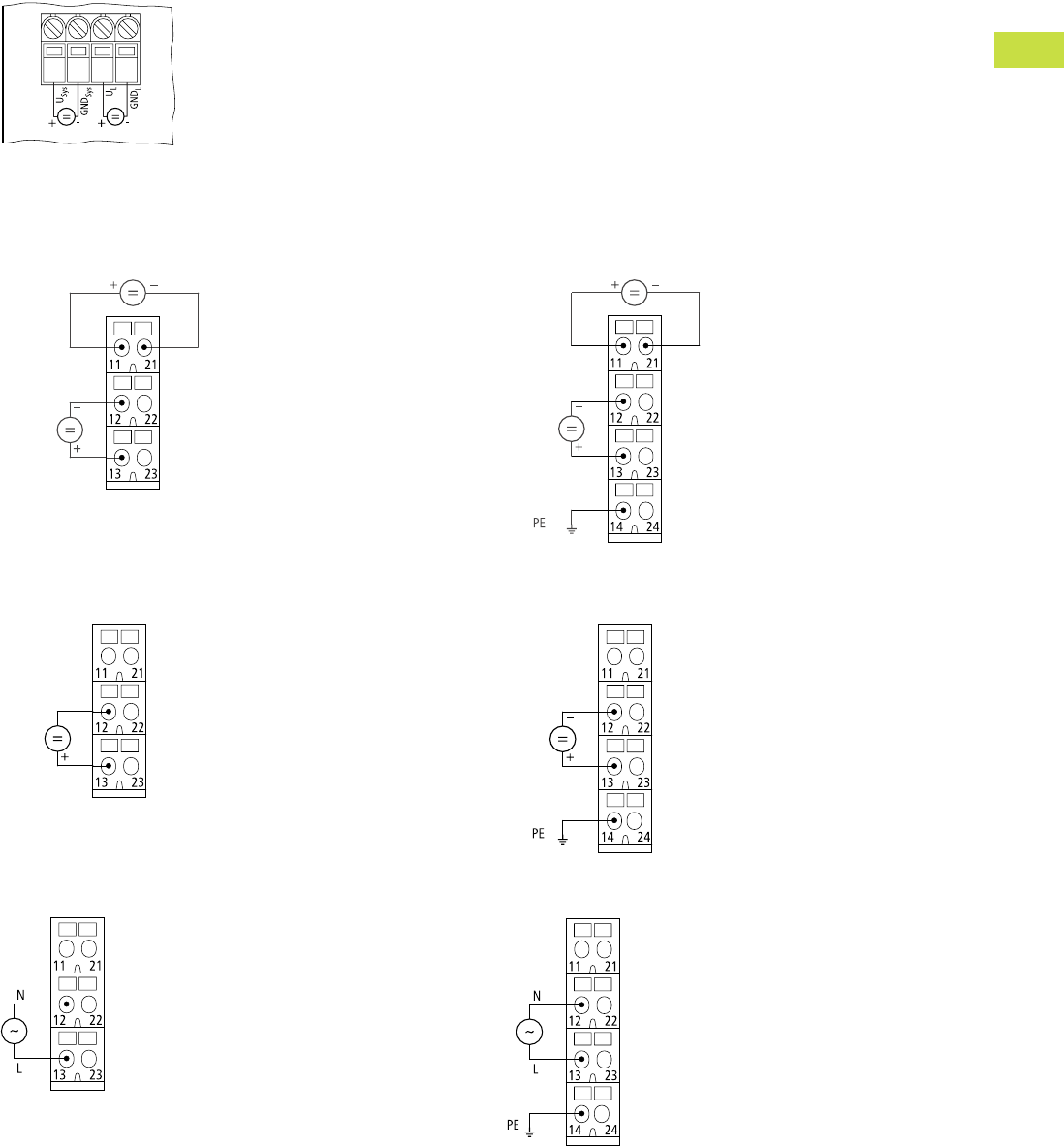
Volume 7—Logic Control, Operator Interface and Connectivity Solutions CA08100008E—May 2016 www.eaton.com V7-T4-101
4
4
4
4
4
4
4
4
4
4
4
4
4
4
4
4
4
4
4
4
4
4
4
4
4
4
4
4
4
4
4.7
PLC, I/O and Communications Products
XI/ON Series Remote I/O
Connection Diagrams
Gateway XN…GWBR_
24V Supply from Gateway (UL) and System Bus (Usys)
Bus Refreshing Modules
XN-P3x-SBB with Gateway Power Supply
XN-P3…-SBB-B without Gateway Power Supply
XN-P4…-SBBC with Gateway Power Supply
XN-P4…-SBBC-B without Gateway Power Supply
Power Feeding Modules
XN-P3…-SBB for XN-PF-24VDC-D
XN-P3…-SBB for XN-PF-120/230VAC-D
XN-P4…-SBBC for XN-PF-24VDC-D
XN-P4…-SBB for XN-PF-120/230VAC-D
24V
24V
24V
Module Bus Supply
Fieldbus
Supply
24V
24V
Module Bus Supply
Fieldbus
Supply
24V
24V
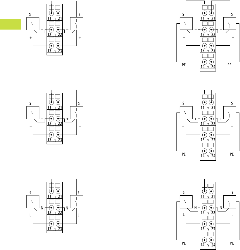
V7-T4-102 Volume 7—Logic Control, Operator Interface and Connectivity Solutions CA08100008E—May 2016 www.eaton.com
4
4
4
4
4
4
4
4
4
4
4
4
4
4
4
4
4
4
4
4
4
4
4
4
4
4
4
4
4
4
4.7
PLC, I/O and Communications Products
XI/ON Series Remote I/O
Digital Input Modules
XN-S3…-SBB for XN-2DI-24VDC-P
XN-S3…-SBB for XN-2DI-24VDC-N
XN-S3…-SBB for XN-2DI-120/230VAC
XN-S4…-SBBC for XN-2DI-24VDC-P
XN-S4…-SBBC for XN-2DI-24VDC-N
XN-S4…-SBBC for XN-2DI-120/230VAC
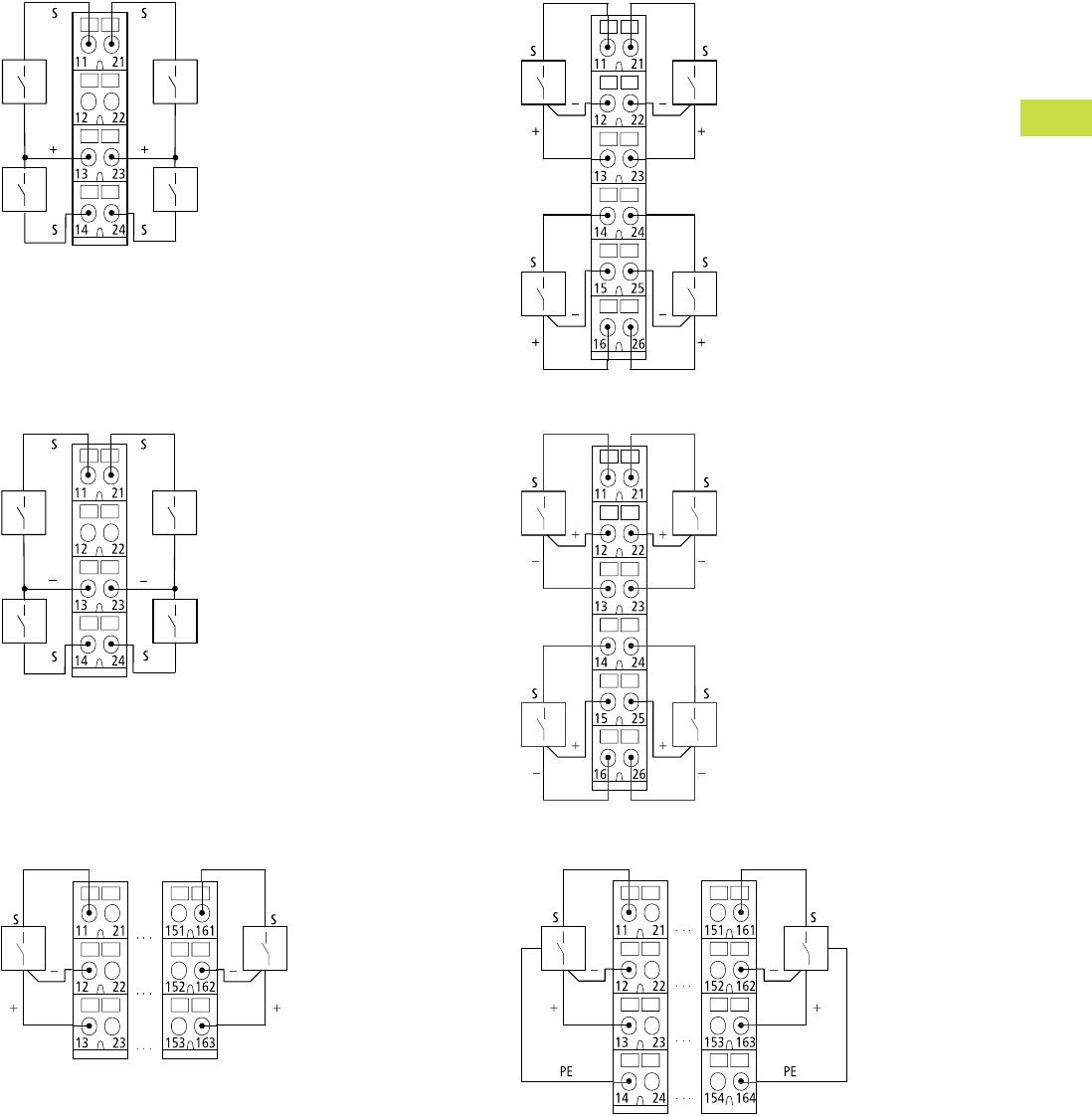
Volume 7—Logic Control, Operator Interface and Connectivity Solutions CA08100008E—May 2016 www.eaton.com V7-T4-103
4
4
4
4
4
4
4
4
4
4
4
4
4
4
4
4
4
4
4
4
4
4
4
4
4
4
4
4
4
4
4.7
PLC, I/O and Communications Products
XI/ON Series Remote I/O
XN-S4…-SBBS for XN-4DI-24VDC-P
XN-S4…-SBBS for XN-4DI-24VDC-N
XN-B3…-SBB for XN-16DI-24VDC-P
XN-S6…-SBBSBB for XN-4DI-24VDC-P
XN-S6…-SBBSBB for XN-4DI-24VDC-N
XN-B4…-SBBC for XN-16DI-24VDC-P
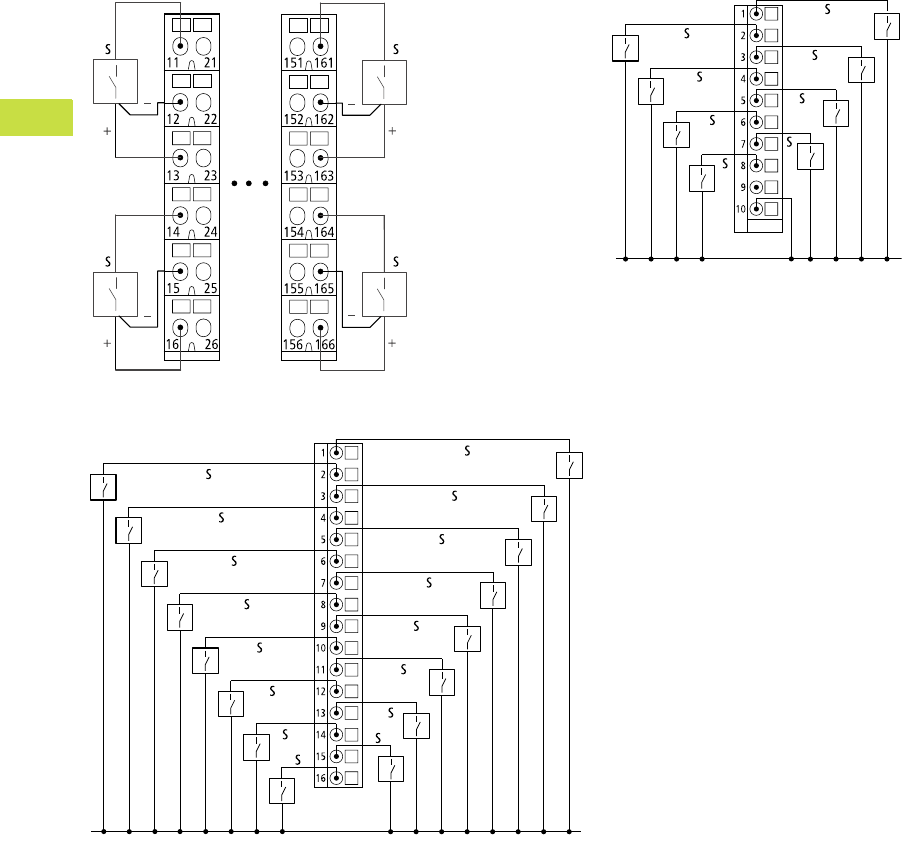
V7-T4-104 Volume 7—Logic Control, Operator Interface and Connectivity Solutions CA08100008E—May 2016 www.eaton.com
4
4
4
4
4
4
4
4
4
4
4
4
4
4
4
4
4
4
4
4
4
4
4
4
4
4
4
4
4
4
4.7
PLC, I/O and Communications Products
XI/ON Series Remote I/O
XN-B6…-SBBSBB for XN-32DI-24VDC-P XNE-8DI-24VDC-P
XNE-16DI-24VDC-P
24V
24V
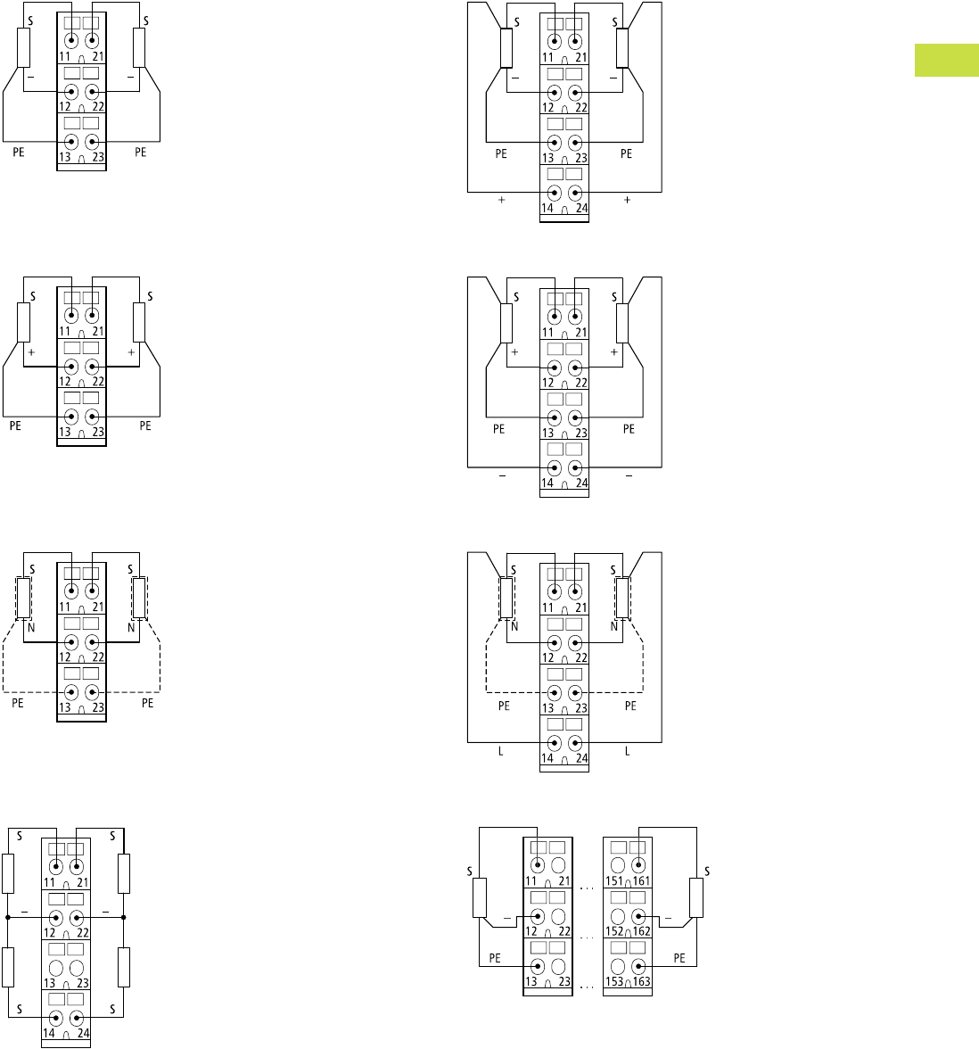
Volume 7—Logic Control, Operator Interface and Connectivity Solutions CA08100008E—May 2016 www.eaton.com V7-T4-105
4
4
4
4
4
4
4
4
4
4
4
4
4
4
4
4
4
4
4
4
4
4
4
4
4
4
4
4
4
4
4.7
PLC, I/O and Communications Products
XI/ON Series Remote I/O
Digital Output Modules
XN-S3…-SBC for XN-2DO-24VDC-0.5A-P and
XN-2DO-24VDC-2A-P
XN-S3…-SBC for XN-2DO-24VDC-0.5A-N
XN-S3…-SBC for XN-2DO-120/230VAC-0.5A
XN-S4…-SBCS for XN-4DO-24VDC-0.5A-P
XN-S4…-SBCS for XN-2DO-24VDC-0.5A-P and
XN-2DO-24VDC-2A-P
XN-S4…-SBCS for XN-2DO-24VDC-0.5A-N
XN-S4…-SBCS for XN-2DO-120/230VAC-0.5A
XN-B3…-SBC for XN-16DO-24VDC-0.5A-P
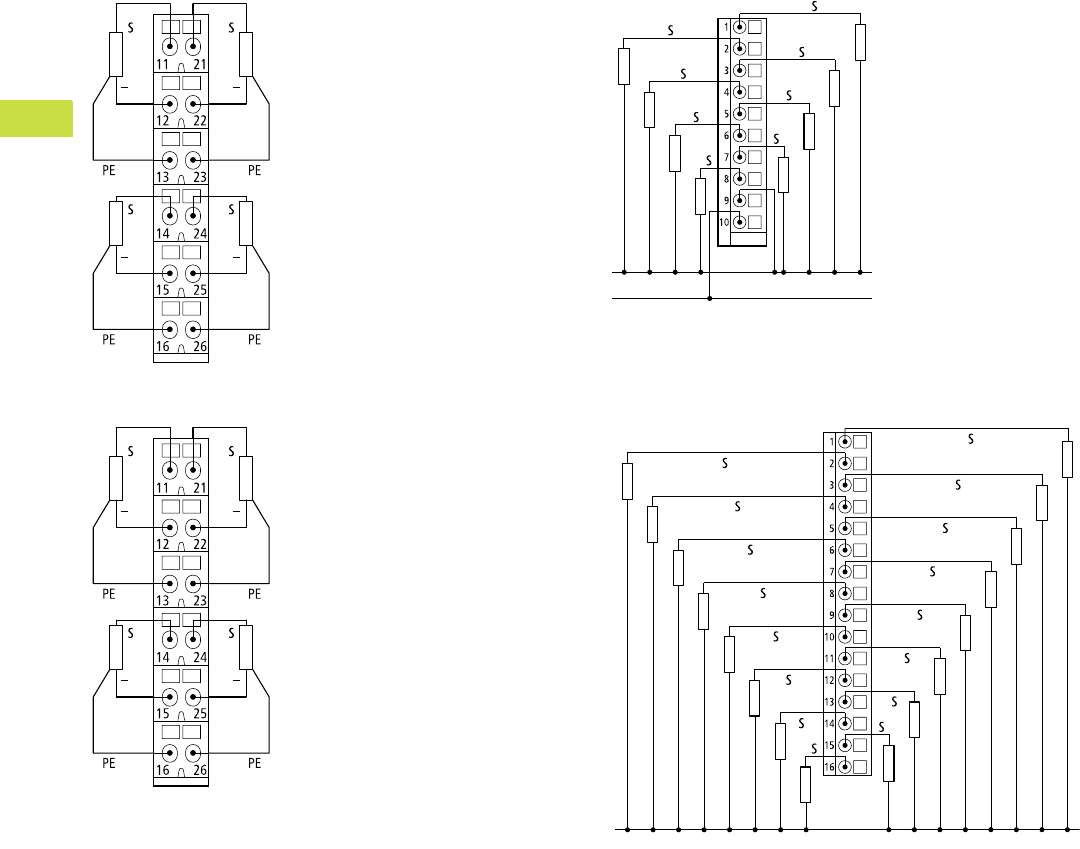
V7-T4-106 Volume 7—Logic Control, Operator Interface and Connectivity Solutions CA08100008E—May 2016 www.eaton.com
4
4
4
4
4
4
4
4
4
4
4
4
4
4
4
4
4
4
4
4
4
4
4
4
4
4
4
4
4
4
4.7
PLC, I/O and Communications Products
XI/ON Series Remote I/O
XN-S6…-SBCSBC for XN-4DO-24VDC-0.5A-P
XN-B6…-SBCSBC for XN-32DO-24VDC-0.5A-P
XNE-8DO-24VDC-0.5A-P
XNE-16DO-24VDC-0.5A-P
24V
GND
GND
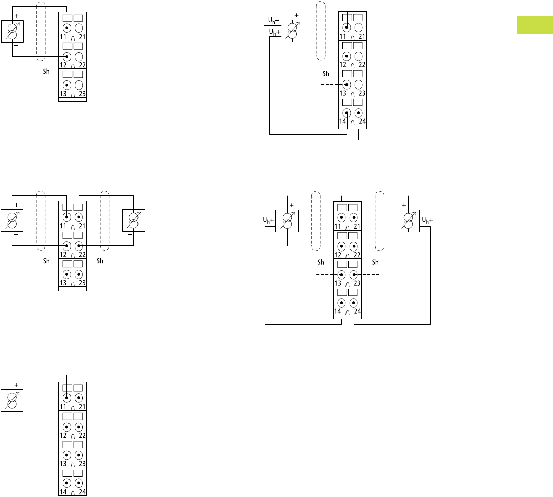
Volume 7—Logic Control, Operator Interface and Connectivity Solutions CA08100008E—May 2016 www.eaton.com V7-T4-107
4
4
4
4
4
4
4
4
4
4
4
4
4
4
4
4
4
4
4
4
4
4
4
4
4
4
4
4
4
4
4.7
PLC, I/O and Communications Products
XI/ON Series Remote I/O
Analog Input Modules
XN-S3…-SBB for XN-1AI-I(0/4…20MA)
XN-S3…-SBB for XN-1AI-U(-10/0…+10VDC)
Analog Sensor/Transmitter, without Transmitter Supply
XN-S3…-SBB for XN-2AI-I(0/4…20MA),
XN-2AI-U(-10/0…+10VDC)
Analog Sensor/Transmitter, without Transmitter Supply
XN-S4…-SBBS for XN-2AI-I(0/4…20MA)
Two-Conductor Connection without
External Transmitter Supply
XN-S4…-SBBS for XN-1AI-I(0/4…20MA)
XN-S4…-SBBS for XN-1AI-U(-10/0…+10VDC)
Analog Transmitter with Non-Isolated Transmitter Supply
XN-S4…-SBBS for XN-2AI-I(0/4…20MA),
XN-2AI-U(-10/0…+10VDC)
Analog Transmitter with Non-Isolated Transmitter Supply
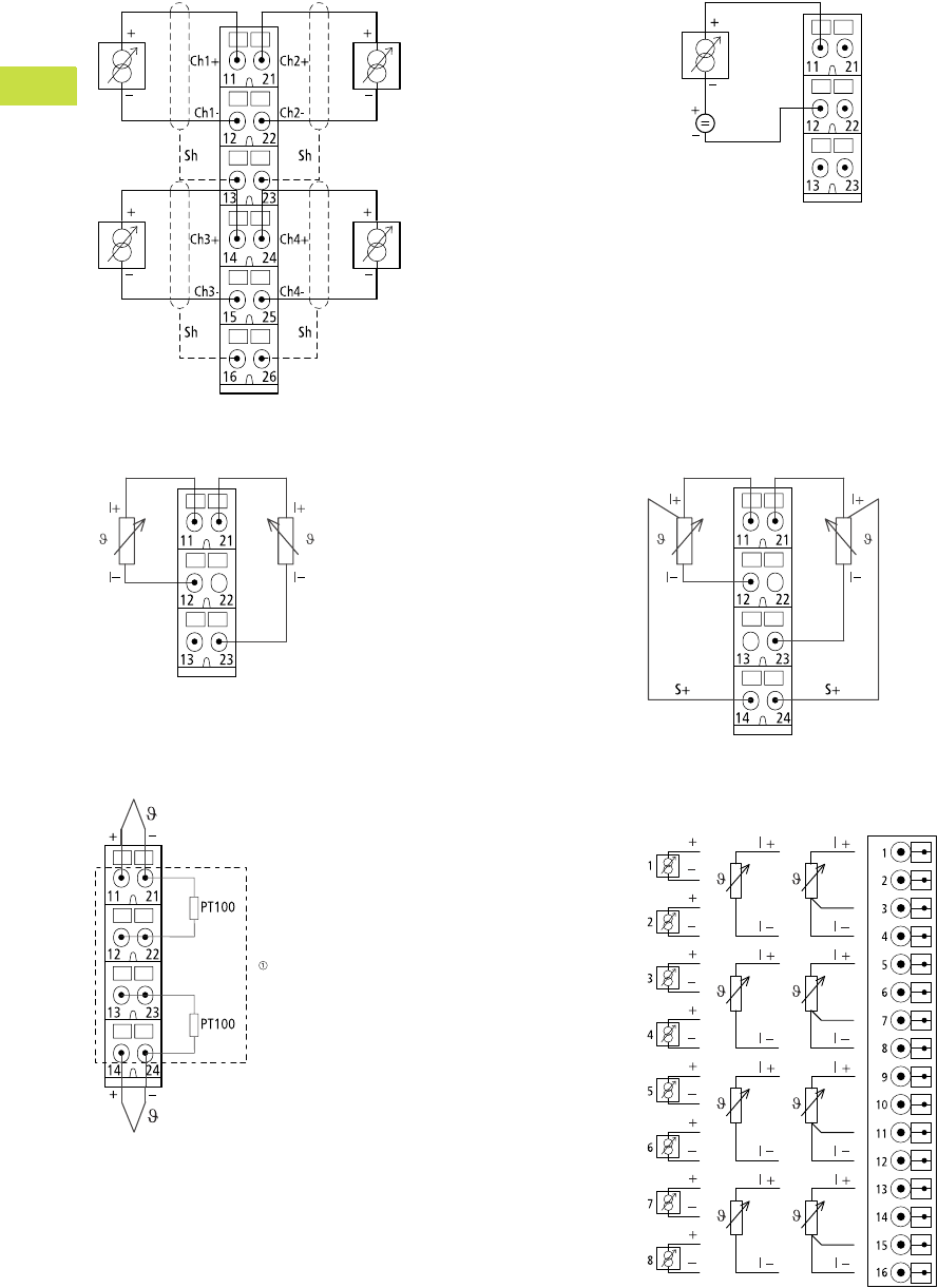
V7-T4-108 Volume 7—Logic Control, Operator Interface and Connectivity Solutions CA08100008E—May 2016 www.eaton.com
4
4
4
4
4
4
4
4
4
4
4
4
4
4
4
4
4
4
4
4
4
4
4
4
4
4
4
4
4
4
4.7
PLC, I/O and Communications Products
XI/ON Series Remote I/O
XN-S6…-SBCSBC for XN-4AI-U/I
Analog Sensor/Transmitter,
without Transmitter Supply
XN-S3…-SBB for XN-2AI-PT/NI-2/3
Two-Conductor Connection
XN-S4…-SBBS-CJ for XN-2AI-THERMO-PI
Note
1Cold-junction compensation in base module.
XN-S3…-SSB for XN-AI-U/I
Two-Conductor Connection without
External Transmitter Supply
XN-S4…-SBBS for XN-2AI-PT/NI-2/3
Three-Conductor Connection
XNE-8AI-U/I-4PT/NI
24V
U/I PT/NI
2-Conductor 2-Conductor 3-Conductor
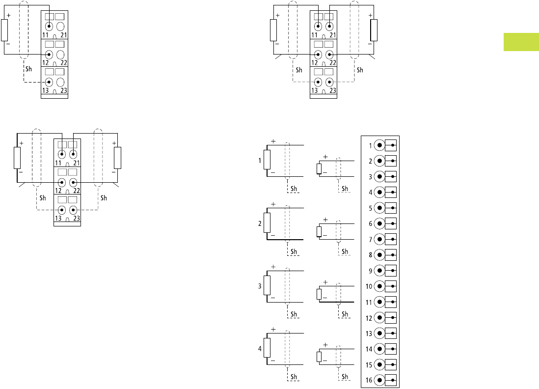
Volume 7—Logic Control, Operator Interface and Connectivity Solutions CA08100008E—May 2016 www.eaton.com V7-T4-109
4
4
4
4
4
4
4
4
4
4
4
4
4
4
4
4
4
4
4
4
4
4
4
4
4
4
4
4
4
4
4.7
PLC, I/O and Communications Products
XI/ON Series Remote I/O
Analog Output Modules
XN-S3…-SSB for XN-1AO-I(0/4…20MA)
XN-S3…-SBB for XN-2AO-U(-10/0…+10VDC)
XN-S3…-SBB for XN-2AO-I(0/4…20MA)
XNE-4AO-U/I
Channel 1 Channel 2
Channel 1 Channel 2
UI
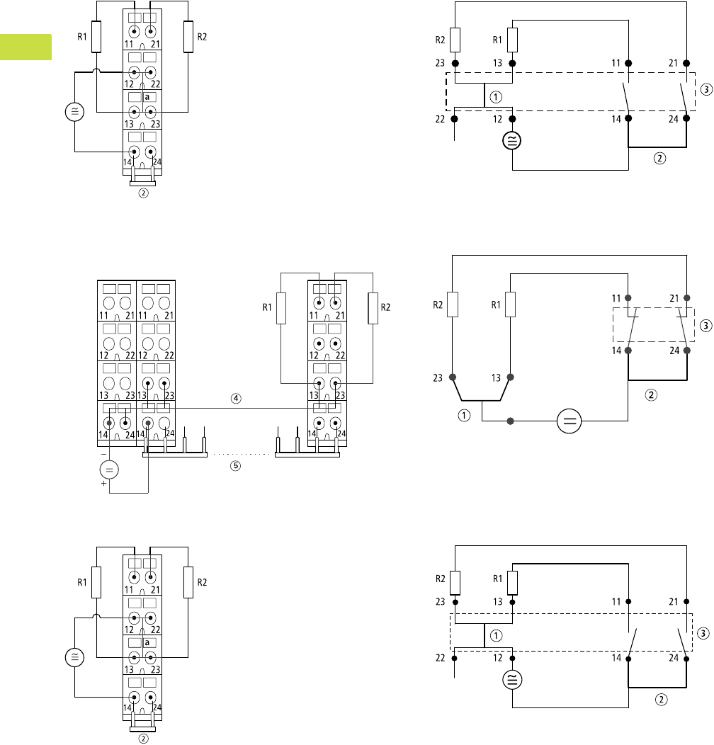
V7-T4-110 Volume 7—Logic Control, Operator Interface and Connectivity Solutions CA08100008E—May 2016 www.eaton.com
4
4
4
4
4
4
4
4
4
4
4
4
4
4
4
4
4
4
4
4
4
4
4
4
4
4
4
4
4
4
4.7
PLC, I/O and Communications Products
XI/ON Series Remote I/O
Relay Modules
XN-S4x…-SBBS with Externally Applied Supply and
Common Potential Link for XN-2DO-R-NC
XN-S4x…-SBCS Supply via C-Rail and Common Potential
Link for XN-2DO-R-NC
XN-S4x…-SBBS with Externally Applied Supply and
Common Potential Link for XN-2DO-R-NO
Module Circuit XN-S4x…SBBS for XN-2DO-R-NC
Module Circuit XN-S4x…-SBCS for XN-2DO-R-NC
Module Circuit XN-S4x…-SBBS for XN-2DO-R-NO
Notes
1Linked in the electronics.
2Cross-link via QVR in the base module.
3Electronics module.
4Supply via C-rail.
5Maximum eight relay modules.
24V
Power
Feeding
Relais 1 Relais n
24V

Volume 7—Logic Control, Operator Interface and Connectivity Solutions CA08100008E—May 2016 www.eaton.com V7-T4-111
4
4
4
4
4
4
4
4
4
4
4
4
4
4
4
4
4
4
4
4
4
4
4
4
4
4
4
4
4
4
4.7
PLC, I/O and Communications Products
XI/ON Series Remote I/O
XN-S4x…-SBCS Supply via C-rail and Common
Potential Link for XN-2DO-R-NO
XN-S4x…-SBBS for XN-2DO-R-CO
Load Limit Curve
Module Circuit XN-S4x…SBCS for XN-2DO-R-NO
Module Circuit XN-S4x…-SBBS for XN-2DO-R-CO
Notes
1Supply via C-rail.
2Maximum eight relay modules.
3Top-hat rail.
4Cross-link via QVR in the base module.
5Electronics module.
6Electronics module—
Definition: At 1000 operations, no arc with a duration >10 ms must occur.
24V
Power
Feeding
Relais 1 Relais n
24V
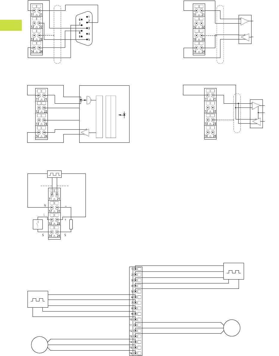
V7-T4-112 Volume 7—Logic Control, Operator Interface and Connectivity Solutions CA08100008E—May 2016 www.eaton.com
4
4
4
4
4
4
4
4
4
4
4
4
4
4
4
4
4
4
4
4
4
4
4
4
4
4
4
4
4
4
4.7
PLC, I/O and Communications Products
XI/ON Series Remote I/O
Serial Interfaces
XN-S4x…-SBBS for XN-1RS232 and D-Sub Plug
XN-S4x…-SBBS for XN-1SSI on an SSI Rotary Encoder
XN-S4x…SBBS for XN-1RS485/422 in RS422 Mode
XN-S4…-SBBS for XN-1RS485/422 in RS485 Mode
Technology Modules/Counter
XN-S4…-SBBS for XN-1CNT-24VDC
XNE-2CNT-2PWM
SHLD
RTS
CTS
GND
TxD
RxD
CL+ CL-
GND GND GND
UL UL UL
D+ D-
SSI Device
Parallel-Serial-Converter
Opto Array
Analog Array
Data Out
Clock
TxD-TxD+
GND GND
SHLD
RxD+ RxD-
Data In
Data Out
SHLD
SHLD
TxD-/RxD-/NTxD+/RxD+/P
GND GND Data In
Data Out
TxEnable
SHLD
SHLD SHLD
Counter Input A
or
Pulse Input
Counter Input B
or
Direction Input
M
M
Counter Input A, Pulse Input Counter 1
Synchronization Z
Counter Input B, Directional Input
Supply 24 Vdc
Supply GND
Output PWM
Output Direction
GND
Drive 1
Counter Input A, Pulse Input
Counter 2
Synchronization Z
Counter Input B, Directional Input
Supply 24 Vdc
Supply GND
Output PWM
Output Direction
GND
Drive 2
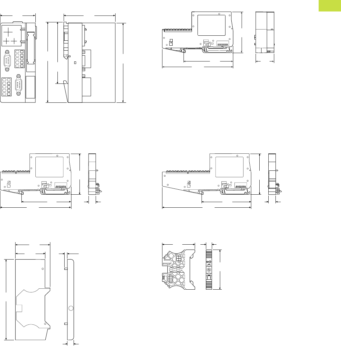
Volume 7—Logic Control, Operator Interface and Connectivity Solutions CA08100008E—May 2016 www.eaton.com V7-T4-113
4
4
4
4
4
4
4
4
4
4
4
4
4
4
4
4
4
4
4
4
4
4
4
4
4
4
4
4
4
4
4.7
PLC, I/O and Communications Products
XI/ON Series Remote I/O
Dimensions
Approximate Dimensions in Inches (mm)
XN Gateways XNE Gateways
Note: The plugs/connectors used depends on the version.
XNE Electronics Modules
End Cover
XN-ABPL
End Bracket
XN-WEW-35/2-SW
XN-GWBR-PBDP XN-GWBR-MODBUS-TCP
XN-GWBR-CANOPEN XN-PLC-CANOPEN
XN-GWBR-DNET
1.99
(50.6)
2.93
(74.4)
4.46
(113.3)
4.52
(114.8)
3.35
(85.0)
XNE-GWBR-PBDP
XNE-GWBR-CANOPEN
XNE-GWBR-2ETH-IP
5.08
(129.0)
3.54
(90.0)
2.95
(75.0)
1.32
(33.5)
XNE-8DO-24VDC-0.5A-P
XNE-8DI-24VDC-P
5.10
(129.5)
3.54
(90.0)
0.51
(13.0)
2.93
(74.5)
4.50
(114.4)
0.36
(9.2)
0.18
(4.5)
1.63
(41.3)
1.91
(48.4)
XNE-16DI-24VDC-P XNE-4AO-U/I
XNE-16DO-24VDC-0.5A-P XNE-2CNT-2PWM
XNE-8AI-U/I/4PT/NI
6.36
(161.5)
3.54
(90.0)
2.93
(74.5)
0.51
(13.0)
1.85
(47.0)
0.31
(8.0)
2.20
(56.0)
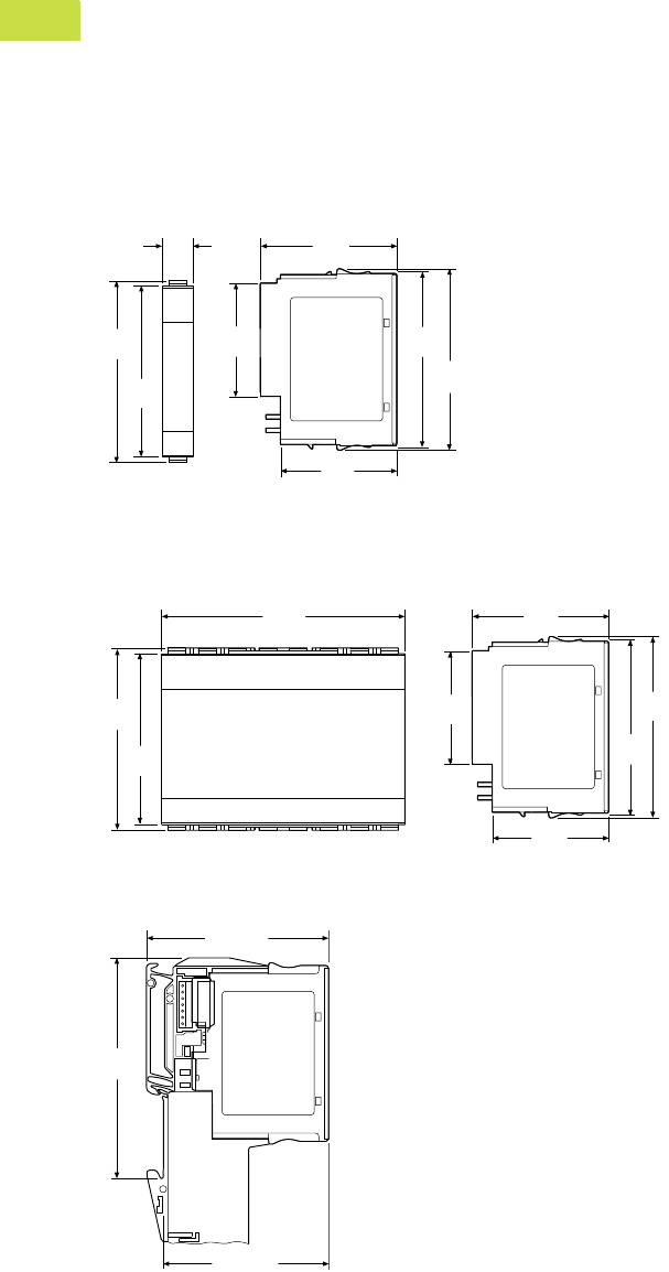
V7-T4-114 Volume 7—Logic Control, Operator Interface and Connectivity Solutions CA08100008E—May 2016 www.eaton.com
4
4
4
4
4
4
4
4
4
4
4
4
4
4
4
4
4
4
4
4
4
4
4
4
4
4
4
4
4
4
4.7
PLC, I/O and Communications Products
XI/ON Series Remote I/O
Approximate Dimensions in Inches (mm)
XN Electronics Modules in Slice Design
XN Electronics Modules in Block Design
XN Electronics Modules Completed with Base Module
All Types
XN-BR-24VDC-D XN-2DI-24VDC-P XN-1AI-I(0/4…20MA) XN-1CNT-24VDC
XN-PF-24VDC-D XN-2DI-24VDC-N XN-2AI-I(0/4…20MA) XN-1RS232
XN-PF-120/230VAC-D XN-2DI-120/230VAC XN-1AI-U(-10/0…+10VDC) XN-1RS485/422
XN-4DI-24VDC-P XN-2AI-U(-10/0…+10VDC) XN-1SSI
XN-4DI-24VDC-N XN-2AI-PT/NI-2/3
XN-2DO-24VDC-2A-P XN-2AI-THERMO-PI
XN-2DO-24VDC-0.5A-P XN-4AI-U/I
XN-2DO-24VDC-0.5A-N XN-1AO-I(0/4…20MA)
XN-2DO-120/230VAC-0.5A XN-2AO-I(0/4…20MA)
XN-4DO-24VDC-0.5A-P XN-2AO-U(-10/0…+10VDC)
XN-2DO-R-CO
XN-2DO-R-NC
XN-2DO-R-NO
XN-16DI-24VDC-P XN-16DO-24VDC-0.5A-P
XN-32DI-24VDC-P XN-32DO-24VDC-0.5A-P
2.92
(74.1)
2.84
(72.1)
0.50
(12.6)
1.81
(46.1)
1.86
(47.3)
2.18
(55.4)
2.84
(72.1)
2.92
(74.1)
3.97
(100.8)
2.92
(74.1)
2.84
(72.1)
1.81
(46.1)
2.18
(55.4)
1.86
(47.3)
2.84
(72.1)
2.92
(74.1)
2.93 (74.5)
2.67 (67.8)
3.54
(90.0)
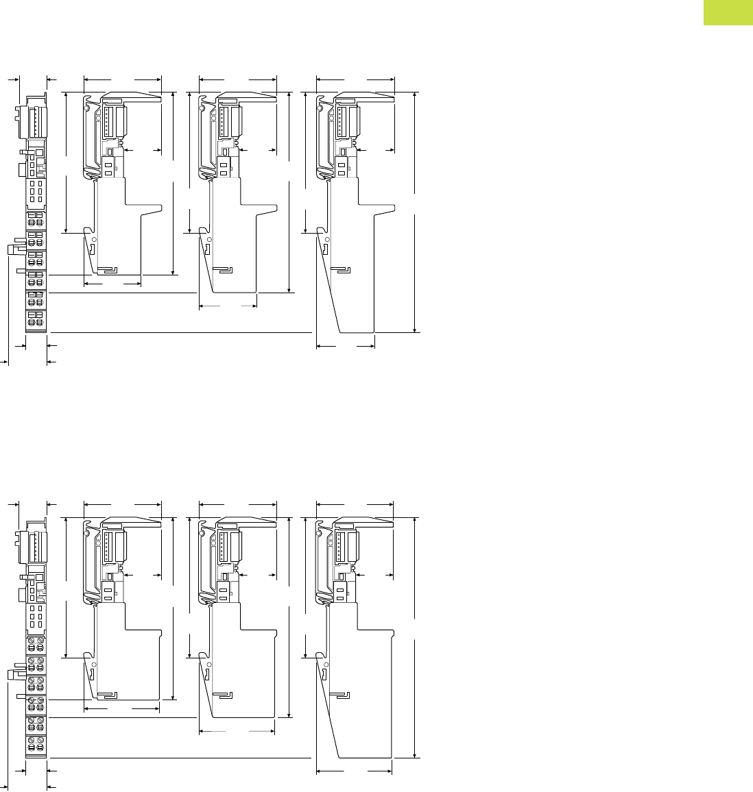
Volume 7—Logic Control, Operator Interface and Connectivity Solutions CA08100008E—May 2016 www.eaton.com V7-T4-115
4
4
4
4
4
4
4
4
4
4
4
4
4
4
4
4
4
4
4
4
4
4
4
4
4
4
4
4
4
4
4.7
PLC, I/O and Communications Products
XI/ON Series Remote I/O
Approximate Dimensions in Inches (mm)
Base Modules in Slice Design
Spring-Cage Terminals
Screw Terminals
3 Connection Levels 4 Connection Levels 6 Connection Levels
XN-S3T-SBB XN-S4T-SBBC XN-S6T-SBBSBB
XN-S3T-SBC XN-S4T-SBBS XN-S6T-SBCSBC
XN-P3T-SBB XN-S4T-SBBS-CJ
XN-P3T-SBB-B XN-S4T-SBCS
XN-P4T-SBBC
XN-P4T-SBBC-B
0.69
(17.6)
1.96
(49.9)
1.96
(49.9)
1.96
(49.9)
3.54
(90.0)
0.95
(24.1)
0.95
(24.1)
0.95
(24.1)
4.63
(117.6)
5.07
(128.9)
6.08
(154.5)
1.64
(41.6)
1.64
(41.6)
1.64
(41.6)
3.54
(90.0)
3.54
(90.0)
0.50 (12.6)
0.93 (23.5)
3 Connection Levels 4 Connection Levels 6 Connection Levels
XN-S3S-SBB XN-S4S-SBBC XN-S6S-SBBSBB
XN-S3S-SBC XN-S4S-SBBS XN-S6S-SBCSBC
XN-P3S-SBB XN-S4S-SBBS-CJ
XN-P3S-SBB-B XN-S4S-SBCS
XN-P4S-SBBC
XN-P4S-SBBC-B
0.69
(17.6)
1.96
(49.9)
1.96
(49.9)
1.96
(49.9)
3.54
(90.0)
0.95
(24.1)
0.95
(24.1)
0.95
(24.1)
4.63
(117.6)
5.07
(128.9)
6.08
(154.5)
1.90
(48.3)
1.90
(48.3)
1.90
(48.3)
3.54
(90.0)
3.54
(90.0)
0.50 (12.6)
0.93 (23.5)
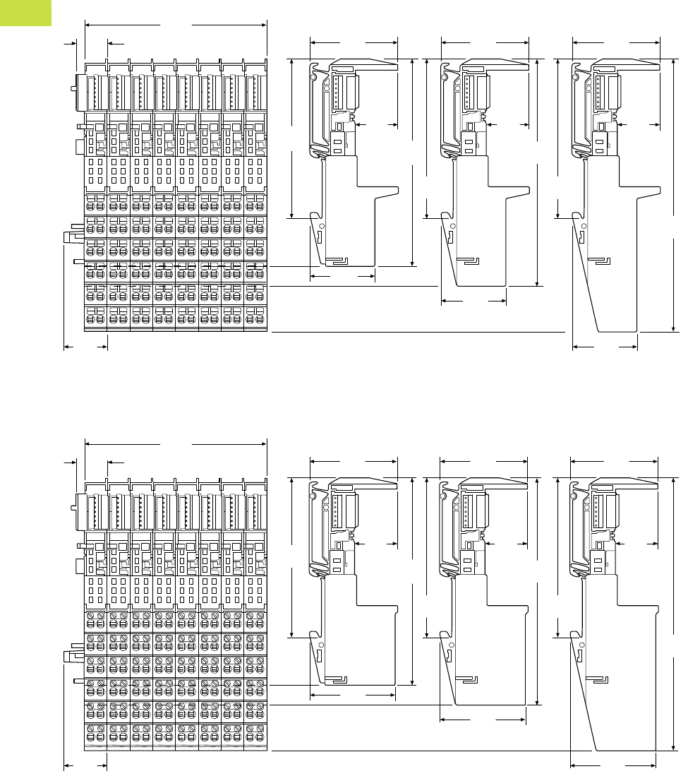
V7-T4-116 Volume 7—Logic Control, Operator Interface and Connectivity Solutions CA08100008E—May 2016 www.eaton.com
4
4
4
4
4
4
4
4
4
4
4
4
4
4
4
4
4
4
4
4
4
4
4
4
4
4
4
4
4
4
4.7
PLC, I/O and Communications Products
XI/ON Series Remote I/O
Approximate Dimensions in Inches (mm)
Base Modules in Block Design
Spring-Cage Terminals
Screw Terminals
3 Connection Levels 4 Connection Levels 6 Connection Levels
XN-B3T-SBB XN-B4T-SBBC XN-B6T-SBBSBB
XN-B3T-SBC XN-B6T-SBCSBC
3.97
(100.8) 1.96
(49.9)
1.96
(49.9)
1.96
(49.9)
0.69
(17.6)
0.93
(23.5)
0.95
(24.1)
0.95
(24.1)
0.95
(24.1)
3.54
(90.0)
1.64
(41.6)
1.64
(41.6)
1.64
(41.6)
4.63
(117.6)
3.54
(90.0)
5.07
(128.9)
3.54
(90.0)
6.08
(154.5)
3 Connection Levels 4 Connection Levels 6 Connection Levels
XN-B3S-SBB XN-B4S-SBBC XN-B6S-SBBSBB
XN-B3S-SBC XN-B6S-SBCSBC
3.97
(100.8) 1.96
(49.9)
1.96
(49.9)
1.96
(49.9)
0.69
(17.6)
0.93
(23.5)
0.95
(24.1)
0.95
(24.1)
0.95
(24.1)
3.54
(90.0)
1.90
(48.3)
1.90
(48.3)
1.90
(48.3)
4.63
(117.6)
3.54
(90.0)
5.07
(128.9)
3.54
(90.0)
6.08
(154.5)
