M5k 03 ORCA/VEHICLE KIT/SERVICE MANUAL/1 5 1
User Manual: Pdf ORCA/VEHICLE KIT/SERVICE MANUAL/1-5
Open the PDF directly: View PDF ![]() .
.
Page Count: 5

09/01 IPN: M5000-00-102 Tait Orca Vehicle Kit F - 11
Tait Orca Vehicle Kit
The Tait Orca vehicle kit provides a secure
environment for a Tait Orca handportable
used in a vehicle. The vehicle kit allows the
radio to be connected to the vehicle’s external
antenna and also acts as a fast charger for the
radio’s NiCd battery.
Note that NiMH batteries are not charged by
the vehicle kit, and that the desktop fast charg-
er should still be used to short condition NiCd
batteries each week.
This section outlines the vehicle kit operation,
specifications and servicing. A detailed circuit
and interface description is also provided, to
allow customised modification of the vehicle
kit.
Product Codes
Table F-3 gives the product codes of available
vehicle kit options and accessories.
The vehicle kits in Group A include selected
mounting options and accessories. These
accessories and other installation options are
available separately as items in Group B.
Table F-3: Vehicle kit product codes
Installing a Vehicle Kit
Detailed installation instructions are provided
in the Tait Orca vehicle kit installation guide
(IPN 429-40000-xx). This guide is included
with each vehicle kit.
Vehicle Kit Operation
Inserting the Radio
Remove the accessory connector cover from
the radio.
Ensure the vehicle kit release button is down
and insert the radio into the radio cavity.
Push the radio firmly into place against the
locating pegs and radio interface. You should
hear the radio snap into place and the release
button will pop up.
Locking a Radio in the Vehicle Kit
You can use the supplied key to lock the radio
into the vehicle kit when you leave the vehicle
unattended.
To lock the radio in the vehicle kit, insert the
supplied key in the lock and turn it clockwise.
Product
code Description
TOPA-VK-002 Vehicle kit, no installation accessories
Group A
TOPA-VK-006 Vehicle kit with mobile microphone &
mounting hardware
TOPA-VK-007 Vehicle kit with mobile microphone,
speaker & mounting hardware
TOPA-VK-008 Vehicle kit with heavy duty mobile
microphone & mounting hardware
TOPA-VK-009 Vehicle kit with heavy duty mobile
microphone, speaker & mounting
hardware
TOPA-VK-011 Vehicle kit with heavy duty micro-
phone & speaker (no additional
mounting hardware)
TOPA -VK-010 Vehicle kit mounting adaptor
Group B
TOPA-VK-020 Vehicle kit single height U bracket
TOPA-VK-030 Vehicle kit double height U bracket
TOPA-VK-040 Vehicle kit triple height U bracket
TOPA-VK-050 Vehicle kit mounting plate
TOPA-VK-060 Vehicle kit charger disable kit
TOPA-VK-100 Vehicle kit mobile microphone
TOPA-VK-200 Vehicle kit external speaker
TOPA-VK-300 Vehicle kit visor microphone
TOPA-VK-400 Vehicle kit remote PTT
TOPA-VK-500 Vehicle kit heavy duty mobile mic.
Product
code Description
F - 12 Tait Orca Vehicle Kit 09/01 IPN: M5000-00-102
To unlock the radio from the vehicle kit, turn
the key counterclockwise.
Removing the Radio
To remove the radio from the vehicle kit, push
the release button down. The radio can now be
removed from the radio cavity.
Charging the Battery
Once the radio is inserted into the radio cavity,
the charger status LED will glow amber for
three seconds, then red. When the LED glows
green, the battery is charged to a minimum of
70% capacity.
If the battery is too hot or too cold, the LED
will glow amber until the battery temperature
is within the safe range for recharging (0ºC to
50ºC). If the indicator remains amber, consid-
er turning on your air conditioning. Optimum
battery charging performance is obtained
between 15ºC and 25ºC.
Charge times when the radio is turned off are:
■up to 1½ hours for the 1100 mAh NiCd
battery; and
■up to 2 hours for the 1500 mAh NiCd.
battery.
You can still use the radio while the battery is
being charged, but the charge times will vary,
depending on how much the radio is being used.
The vehicle charger functional indicators are
summarised in Table F-4.
Table F-4: Charger status LED indicators
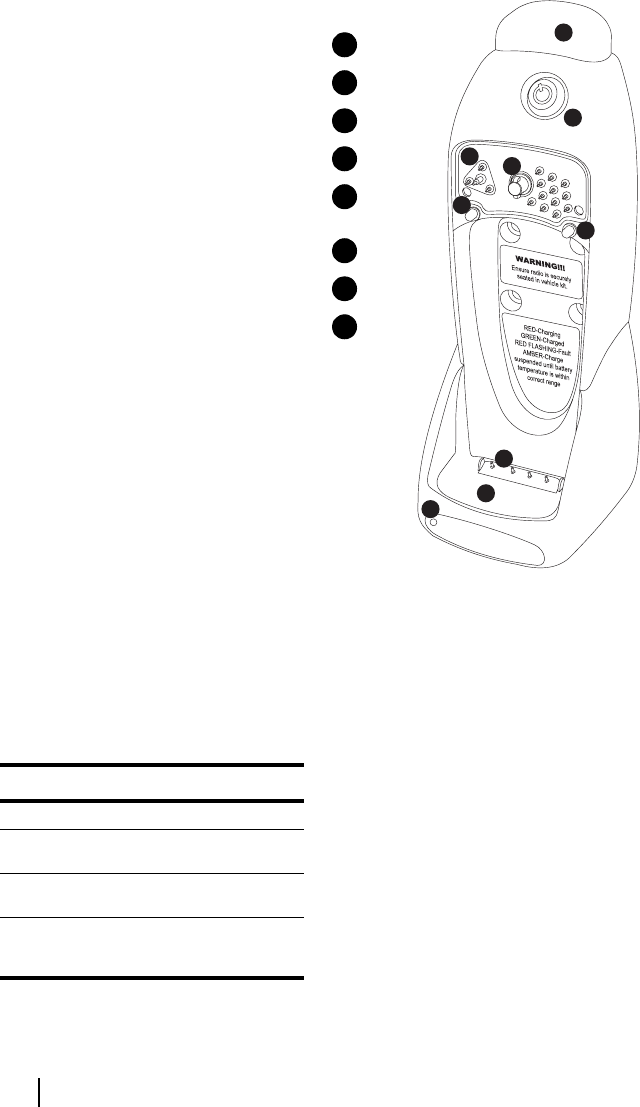
Figure F-7: Vehicle kit assembly
Using the Radio while in the Vehicle Kit
While the radio is seated in the vehicle kit,
operation remains the same, except:
■the radio’s microphone will be inoperative
and an external microphone such as a
mobile microphone must be used; and
■the radio’s speaker will be inoperative
when an external speaker has been
installed. Volume can be adjusted from
the radio’s volume control.
The standard installation results in the charger
and external speaker being turned off when the
ignition is off.
If the vehicle kit determines that the vehicle’s
battery is too low (less than 11 V), the vehicle
kit will turn off.
Indicator Meaning
steady green battery charging
steady green battery charged to a minimum of 70%
capacity
steady amber charge suspended until battery tem-
perature is within correct range
flashing red battery not seated properly in the
charger, contacts dirty, battery faulty
or NiMH battery inserted
8
7
65
4
4
3
2
1
charger status LED
radio cavity
charger pins
locating pegs
locking
mechanism
radio interface
lock
release button
1
2
3
4
5
6
7
8

09/01 IPN: M5000-00-102 Tait Orca Vehicle Kit F - 13
WARNING:
WARNING:WARNING:
WARNING: The vehicle kit uses less than 30
mA from the vehicle’s battery when the
ignition is off. For this reason, if you are
leaving your vehicle unattended for an extend-
ed period of time (for example, more than one
month), the positive fuse should be removed.
Basic Care and Safety
■It is essential to short condition your
battery weekly using the desktop fast
charger.
■Wipe the radio contacts and accessory
interface with a dry, lint-free cloth to
remove any dirt, oil or grease.
■Do not allow the vehicle kit to come into
contact with detergents, alcohols, aerosol
sprays or petroleum-based products, as
they may permanently damage the case.
Vehicle Kit Specifications
The following table outlines the vehicle kit
specifications. Details of test methods can be
obtained from Tait Electronics Ltd.
Table F-5: General specifications
Supply voltage
range
protection
13.8 VDC (nominal)
11 to 16 V range
3 A fuses in power lead
Ambient temperature
range
-10 to +60°C
Battery charger tempera-
ture range
0 to +50°C
Weight 375 g
Size W x H x D 80 mm x 230 mm x 95 mm
(2 in x 5.8 in x 2.4 in)
Product supported • all Tait Orca handportables
(frequency bands up to
530 MHz supported)
• all Tait Orca belt clips
• all Tait Orca NiCd batteries
Note that NiMH batteries are not charged.
Technical compliance complies with FCC part 15,
CISPR 14 and CISPR 14-2
Fast charger charge cur-
rent
0.8 A
Charger control the charger uses voltage, tem-
perature and temperature
change to safely charge and
maintain battery capacity

F - 14 Tait Orca Vehicle Kit 09/01 IPN: M5000-00-102
Servicing the Vehicle Kit
The vehicle kit contains four PCBs, and the
following servicing instructions outline the
disassembly of the vehicle kit to allow replace-
ment of these PCBs.
Servicing Warnings: Screw Head Types
There are four different types of Torx screws
used in the vehicle kit: KC22x6, KC25x6,
KC30x8 and KC30x10. All these screws require
a Torx head screwdriver. When tightening any
screws, be careful not to strip the threads in the
plastic mouldings by exerting too much force.
The following table explains the torque
settings required for the different Torx screw
types.
Figure F-8: Vehicle kit torque specifications
Removing the Vehicle Kit Back Cover
The back cover is held to the front moulding by
two plastic clips at the base of the unit. Insert
the tip of a round screwdriver into the two
holes at the bottom of the rear panel. Lever the
tip upwards towards the top of the unit.
Hold the unit in such a way that your forefin-
ger and thumb exert a slight pressure to
separate the rear panel away from the front
moulding, while you lever the clips with the
screwdriver.
Replacing the Accessory Probe PCB
Remove the back cover and unplug the acces-
sory loom at the top of the options PCB.
Unscrew the two KC30x10 screws holding the
trigger assembly together. The trigger assem-
bly can now be lifted out.
Note that the trigger assembly must be pressed
downwards
downwardsdownwards
downwards while undoing these screws, as
there are springs underneath.
Unplug the loom from the accessory probe
PCB. Carefully use narrow nose pliers to
unplug the MCX connector from the accessory
probe PCB. Now remove the two KC22x6
screws on the front of the vehicle kit holding
the accessory probe PCB into the front mould-
ing. The accessory probe PCB can now be tilted
upwards and removed from the moulding.
Fit the seal onto the new accessory probe PCB
and reassemble the vehicle kit. Read the
assembly instructions for more information.
Replacing the Charger Probe PCB
Remove the back cover and unplug the acces-
sory loom at the top of the options PCB. Lift
the options/charger PCB assembly out of the
front moulding, until the charger loom is
accessible.
Unplug the charger loom and remove both
PCBs from the front moulding. Note that these
PCBs are still attached via the RF cable.
Unscrew the two KC30x8 screws holding the
charger probe moulding into the front mould-
ing, and slide out the probe moulding.
Unscrew the three KC25x6 screws holding the
probe PCB to the probe moulding. Fit the seal
onto the new charger probe PCB and reassem-
ble the vehicle kit.
Removing the Options or Charger PCBs
Remove the two DB25 fasteners holding the
back panel to the accessory/options connec-
tor. Remove the two KC30x10 screws holding
the back plate to the audio PA. Unclip the
backplate from the options PCB. The PCBs can
now be unplugged and replaced.
When putting the options/charger assembly
back into the front moulding, make sure that
the charger PCB is running in its tracks. Be
careful that you do not bump the LED at the
bottom of the charger PCB; the PCB does not
require any force to insert.
Screw Type IPN Quantity Torque
(in.lb)
KC22x6 346-10022-06 2 2
KC25x6 346-10025-06 3 2
KC30x8 346-10030-08 2 6
KC30x10 346-10030-10 4 6

09/01 IPN: M5000-00-102 Tait Orca Vehicle Kit F - 15
Reassembling the Vehicle Kit
To assemble the vehicle kit, reverse the disas-
sembly process.
Note that when doing up the KC30x10 screws
the threads in the plastic PA moulding must
not
notnot
not be stripped. It is important that the audio
PA is held firmly against the backplate, as the
backplate serves as a heatsink.
Trigger Reassembly
When reassembling the trigger assembly,
insert the peg moulding into the front panel.
Insert the quarter turn moulding and rotate it
until the peg moulding prevents it from
turning. Drop the two springs into the peg
moulding. While pressing in the trigger cap,
replace the trigger assembly.
While holding the trigger assembly cover togeth-
er (before doing up the screws) check that the
locking mechanism works correctly. To do this,
press in the locating pegs and check that the
trigger cap pops up. Press the trigger cap down
and check that the locating pegs pop out. If the
trigger assembly does not work correctly, check
that the quarter turn moulding is in the correct
position and repeat the assembly process.
Tighten the two KC30x10 trigger assembly
screws, while holding the trigger assembly in
place.
Rear Cover Reassembly
Locate the top of the rear cover into the back of
the trigger assembly. Press the bottom of the
rear cover to click/lock the cover into the front
moulding.
Spares Kits
The following table shows a list of spares kits
which are currently available for servicing Tait
Orca vehicle kits. These can be ordered from
you local Tait dealer.
Table F-6: Vehicle kit spares kits
The contents of these kits are shown in Tables
F-6 and F-7.
Note that the ‘IPN’ column is the ten digit
‘internal part number’ which uniquely identi-
fies any component used in a Tait product.
The numbers in the ‘Legend’ column refer to
Figure numbers in which the spares item is
shown. The numbers in brackets refer to the
numbered legend within the figure, where
appropriate.
Product code Description
TOPA-SP-301 Vehicle kit spares kit
TOPA-SP-302 Vehicle kit reskinning kit
