0686020 15126 Catalog
2014-09-04
: Pdf 15126-Catalog 15126-Catalog 074983 Batch7 unilog
Open the PDF directly: View PDF ![]() .
.
Page Count: 192 [warning: Documents this large are best viewed by clicking the View PDF Link!]

1
Cable Ties and Installation Tooling
Available Styles
PAN-TY® Locking Cable Ties, Locking Lashing Ties, Releasable Ties, Releasable Lashing Ties,
Clamp Ties, Marker and Flag Ties, Winged Push Mount Ties, Push Mount Ties,
Weather Resistant Ties, Polypropylene Ties, Flame Retardant Ties, Nylon 12 Ties, HALAR* Ties,
TEFZEL** Ties, Fluorescent Ties . . . . . . . . . . . . . . . . . . . . . . . . . . . . . . . . . . . . . . . . . . . . . . . . . . . . . . 6-26
DOM E-TOP ®
Barb Ty Cable Ties, Clamp Ties, Marker Ties, DURA-TY™ WR Cable Ties,
Heat Stabilized Ties, Winged Push Mount Ties. . . . . . . . . . . . . . . . . . . . . . . . . . . . . . . . . . . . . . . . . . 27-35
Parallel Entry (CO NTOU R-TY®
Cable Ties,
BELT-TY™ IN-LINE Cable Ties, IN-LINE Cable Ties) . . . . . . . 36-39
Hook & Loop Cable Ties (TAK -TY®
Hook & Loop Cable Ties, Hook & Loop Strips/Rolls) . . . . . . . . . . . . 40-42
STA-STRAP ® Clamp Ties, Cable Ties, Chassis/Panel Mount Ties . . . . . . . . . . . . . . . . . . . . . . . . . . . . . 43-45
Specialty Ties (Stud Mounted Heat Stabilized, Releaseable Stud Mounted “Ladder” Cable Ties,
Multiple Loop, Double Hose Clamp, Polyethylene Marker Strap) . . . . . . . . . . . . . . . . . . . . . . . . . . . . . 46-50
PAN-POUCH ™ Telephone Cable Identification Kit . . . . . . . . . . . . . . . . . . . . . . . . . . . . . . . . . . . . . . . . . . . . . . 53
Cable Tie Kits . . . . . . . . . . . . . . . . . . . . . . . . . . . . . . . . . . . . . . . . . . . . . . . . . . . . . . . . . . . . . . . . . . . . . . . . .54
Cable Tie Installation Tools (manual/pneumatic/automatic) . . . . . . . . . . . . . . . . . . . . . . . . . . . . . . . . . . . 55-61
Available Materials
Nylon 6.6 Cable Ties . . . . . . . . . . . . . . . . . . . . . . . . . . . . . . . . . . . . . . . . . . . . . . 6-13, 28, 30-33, 36-38, 43, 47
Heat Stabilized Nylon 6.6 Cable Ties . . . . . . . . . . . . . . . . . . . . . . . . . . . . . . . . . . . . . . . . . . . . . .12, 30, 44, 46
Weather Resistant Nylon 6.6 Cable Ties. . . . . . . . . . . . . . . . . . . . . . . . . . . . . . . . 14-18, 29, 31, 36, 38, 47, 48
Polypropylene Cable Ties . . . . . . . . . . . . . . . . . . . . . . . . . . . . . . . . . . . . . . . . . . . . . . . . . . . . . . . . . . . . . 18-19
Flame Retardant Nylon 6.6 Cable Ties . . . . . . . . . . . . . . . . . . . . . . . . . . . . . . . . . . . . . . . . . . . . . . . . . . . . . .20
Weather Resistant Nylon 12 Cable Ties . . . . . . . . . . . . . . . . . . . . . . . . . . . . . . . . . . . . . . . . . . . . . . . . . . . . .21
HALAR* and TEFZEL** Cable Ties . . . . . . . . . . . . . . . . . . . . . . . . . . . . . . . . . . . . . . . . . . . . . . . . . . . . . . . . .22
Fluorescent Ties . . . . . . . . . . . . . . . . . . . . . . . . . . . . . . . . . . . . . . . . . . . . . . . . . . . . . . . . . . . . . . . . . . . . . .23
Weather Resistant Acetal Cable Ties . . . . . . . . . . . . . . . . . . . . . . . . . . . . . . . . . . . . . . . . . . . . . . . . . . . . . . .33
Hook & Loop Cable Ties . . . . . . . . . . . . . . . . . . . . . . . . . . . . . . . . . . . . . . . . . . . . . . . . . . . . . . . . . . . . . . 40-42
Polyethylene Marker Straps . . . . . . . . . . . . . . . . . . . . . . . . . . . . . . . . . . . . . . . . . . . . . . . . . . . . . . . . . . . . . .49
Additional Information
Lashing Ties . . . . . . . . . . . . . . . . . . . . . . . . . . . . . . . . . . . . . . . . . . . . . . . . . . . . . . . . . . . . . . . . . . . . . . . . . 7, 8, 15, 16
Military Cross Reference Aerospace Standard Information . . . . . . . . . . . . . . . . . . . . . . . . . . . . . . . . . . . . . .51
Custom Hot Stamping . . . . . . . . . . . . . . . . . . . . . . . . . . . . . . . . . . . . . . . . . . . . . . . . . . . . . . . . . . . . . . . . . .52
Selecting the Proper Cable Tie Material for Your Application . . . . . . . . . . . . . . . . . . . . . . . . . . . . . . . . . . . . .62
Material Selection Guide . . . . . . . . . . . . . . . . . . . . . . . . . . . . . . . . . . . . . . . . . . . . . . . . . . . . . . . . . . . . . . . .63
Weathering . . . . . . . . . . . . . . . . . . . . . . . . . . . . . . . . . . . . . . . . . . . . . . . . . . . . . . . . . . . . . . . . . . . . . . . . 64-65
Flammability . . . . . . . . . . . . . . . . . . . . . . . . . . . . . . . . . . . . . . . . . . . . . . . . . . . . . . . . . . . . . . . . . . . . . . . 66-67
Radiation/Moisture/Temperature/Tensile Strength . . . . . . . . . . . . . . . . . . . . . . . . . . . . . . . . . . . . . . . . . . . . .68
Physical Characteristics of Cable Tie Materials . . . . . . . . . . . . . . . . . . . . . . . . . . . . . . . . . . . . . . . . . . . . . . .69
Chemical Resistance. . . . . . . . . . . . . . . . . . . . . . . . . . . . . . . . . . . . . . . . . . . . . . . . . . . . . . . . . . . . . . . . . 70-74
Quality . . . . . . . . . . . . . . . . . . . . . . . . . . . . . . . . . . . . . . . . . . . . . . . . . . . . . . . . . . . . . . . . . . . . . . . . . . . . 75-76
Stainless Steel Tie Products
PAN-STEEL ® Stainless Steel Tie . . . . . . . . . . . . . . . . . . . . . . . . . . . . . . . . . . . . . . . . . . . . . . . . . . . . . . . . . . .77
WAVE-TY™ Superior Grip Standard Steel Tie. . . . . . . . . . . . . . . . . . . . . . . . . . . . . . . . . . . . . . . . . . . . . . . . . .77
Stainless Steel Tie Installation Tools . . . . . . . . . . . . . . . . . . . . . . . . . . . . . . . . . . . . . . . . . . . . . . . . . . . . . . .78
Metal Marker Plates/Tags/Marking Devices . . . . . . . . . . . . . . . . . . . . . . . . . . . . . . . . . . . . . . . . . . . . . . . . .78
Stainless Steel Strapping . . . . . . . . . . . . . . . . . . . . . . . . . . . . . . . . . . . . . . . . . . . . . . . . . . . . . . . . . . . . . . . .80
Wiring Accessories
Cable Tie Accessories . . . . . . . . . . . . . . . . . . . . . . . . . . . . . . . . . . . . . . . . . . . . . . . . . . . . . . . . . . . . . . 85-107
Wiring Accessories — used without cable ties . . . . . . . . . . . . . . . . . . . . . . . . . . . . . . . . . . . . . . . . . . . 108-123
Harness Board Accessories . . . . . . . . . . . . . . . . . . . . . . . . . . . . . . . . . . . . . . . . . . . . . . . . . . . . . . . . . 124-129
Communication Cable Management. . . . . . . . . . . . . . . . . . . . . . . . . . . . . . . . . . . . . . . . . . . . . . . . . . . 130-133
Selection and Use of Adhesive Mounts . . . . . . . . . . . . . . . . . . . . . . . . . . . . . . . . . . . . . . . . . . . . . . . . 134-136
Abrasion Protection Products (Heat Shrink, Non-Shrink PVC Tubing,
Spiral Wrap, Grommet Edging and Braided Expandable Sleeving) . . . . . . . . . . . . . . . . . . . . . . . . . 139-181
*HALAR is a registered trademark of Solvay Solexis, Inc.
** TEFZEL is a registered trademark of E.I. DuPont de Nemours Co.
All reference dimensions in this catalog are shown in inches (and millimeters).
Cable Ties/Wiring Accessories Catalog—WW-CTCB03
(replaces SA-101N275C-WC)
Table of Contents
2Most commonly used parts appear in BOLD.
World Leader in Cable Ties and Wiring Accessories
PANDUIT ®
is a leading global producer of cable ties and wiring accessories, offering the
most complete selection of sizes, styles and materials. We continually provide new cable
tie and wiring accessory designs to meet the changing application challenges encountered
by our customers while providing lowest installed costs.
PANDUIT ®
also offers the largest selection of ergonomic cable tie installation tools —
from high speed automatic systems to hand operated tools. So, whatever the need,
PANDUIT ®
has the tool to help lower your total installed cost.
Assured Quality To help assure optimum quality, PANDUIT ®
products are designed
and manufactured to meet applicable international, UL, military and customer standards:
ISO 9001 The International Standards Organization (ISO) establishes worldwide standards for products and
services in recognition of increasing globalization of markets. The ISO program sets up the requirements
for quality assurance systems of these worldwide standards. PANDUIT ®
is registered to ISO 9001, the
most comprehensive model in the standard, meant for companies who design, manufacture, install and
service the products they sell. Registration has been awarded by Underwriters Laboratories (Certificate
No. A2269) after extensive audit of QA systems employed at PANDUIT ®
.
Underwriters Laboratories, Inc. (File E56854)
Most PANDUIT ®
miniature, intermediate, standard, light-heavy and heavy cross-section ties are
Recognized (ZODZ(8)) or Listed in the US and Canada by Underwriters Laboratories (ZODZ(7)) in their
Directory under the category “Wire Positioning Devices.” Natural, pigmented and weather resistant
cable ties are recognized for indoor use at temperatures up to 85 °C (185°F). Weather resistant cable
ties are also UL Listed for outdoor applications. Heat stabilized ties are UL Recognized and Listed for
indoor use at temperatures up to 115°C (239°F).
Aerospace Standard SAE spec AS23190 covers the actual test requirements on cable ties. PANDUIT ®
cable ties, when tested, either meet or exceed the requirements of this specification.
Nuclear Regulatory
Commission
The NRC developed rules and regulations concerning Quality Assurance Criteria for Nuclear Power
Plants or Title 10, Chapter 10, Part 50, Appendix B (10CFR50). PANDUIT ®
Corp. Quality Assurance
program is designed to satisfy the 18 criteria set forth in NRC 10CFR50, Appendix B, Military
Specification AS23190.
Ford Motor Company
PANDUIT ®
has received Q1 certification status from Ford Motor Company. Q1 certification enables all
PANDUIT ®
cable tie manufacturing facilities to approve all initial samples and production shipments of
the parts destined for Ford operations throughout the world.
German (VG)
Military
Lloyd’s Register of
Shipping
RINA Germanischer
Lloyd
Nippon Kaiji
Kyokai
Bureau VeritasDet Norske
Veritas
International Approvals Independent Testing Facilities
K R
QS-9000 is the shorthand name for “Quality System Requirements QS-9000.” It is the common
supplier quality standard for the automotive industry. QS-9000 is based on the 1994 edition of
ISO 9001, but it contains additional requirements that are particular to the automotive industry.
These additions are considered automotive “interpretations” by the ISO community of accreditation
bodies and registrars. Registration has been awarded by Underwriters Laboratories Inc.
(Certificate No. A2269) for PANDUIT ®
cable ties.
QS-9000
Korean Register
of Shipping
ISO14001 is a voluntary standard for Environmental Management Systems established by the
International Organization for Standardization. The international standard provides a benchmark for
continual improvement in environmental performance. Business partners can be confident that the
PANDUIT ® manufacturing facilities around the globe are engaged in an on-going process to maximize
value while minimizing impact on global natural resources.
ISO14001
Aerospace Standard AS23190
3
Most commonly used parts appear in BOLD.
Selection Guide
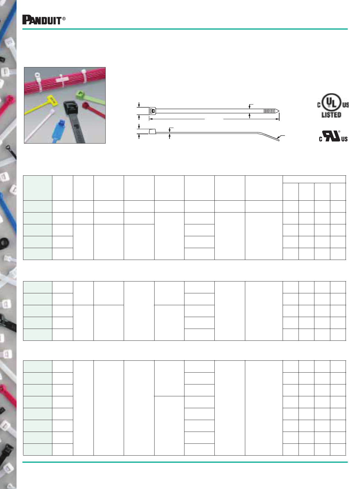
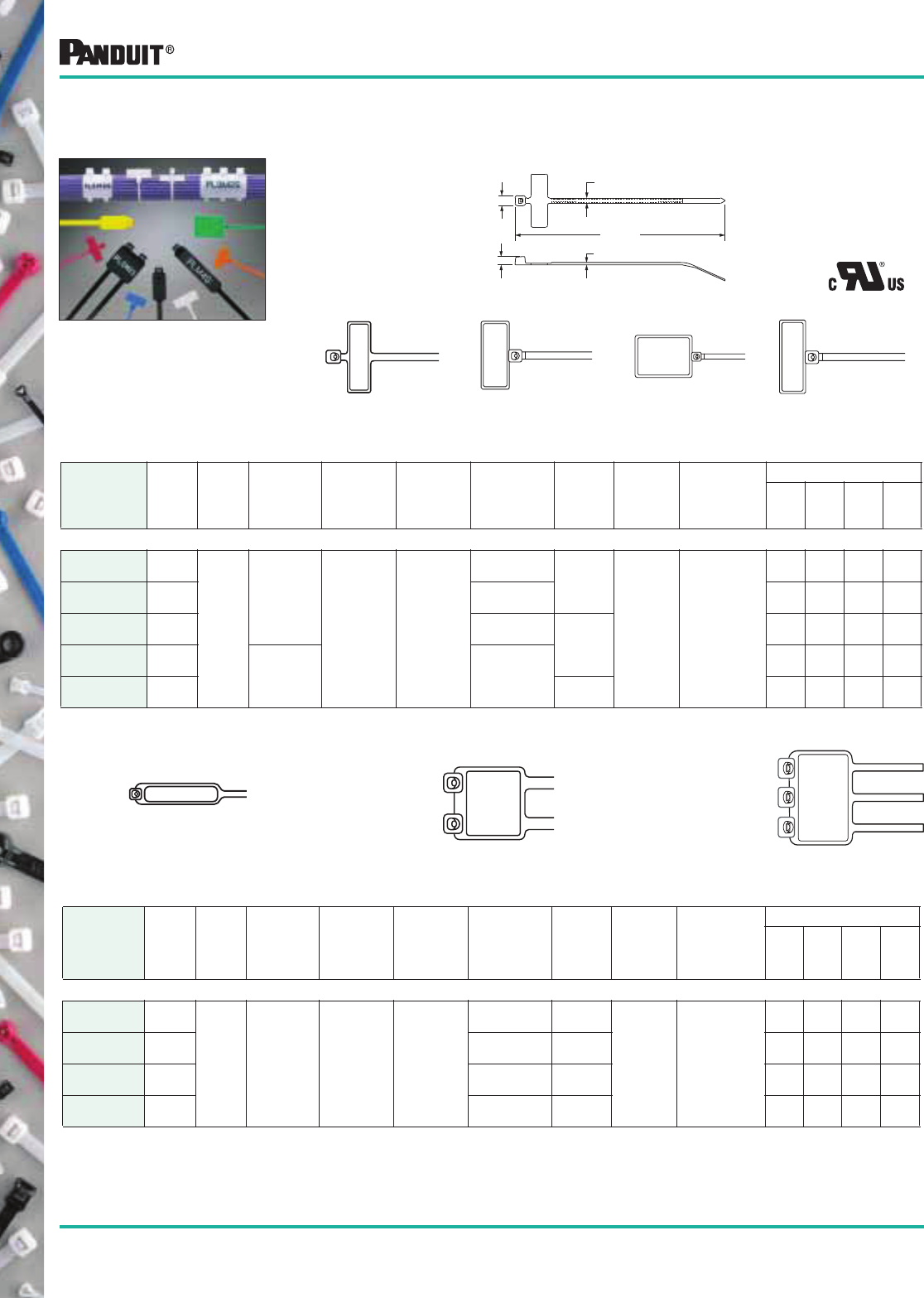
PAN-TY® Cable Ties
This line offers the largest selection of styles,
materials, and sizes. The ties are available in
nylon 6.6, nylon 12, polypropylene, HALAR*
and TEFZEL** material. Available in sizes from
.60" (15mm) maximum bundle diameter up to
13" (330mm) maximum bundle diameter.
All are self-locking and many sizes are
available in both releasable and non-releasable
types. PAN-TY®
Cable Ties are quickly installed
by hand or with PANDUIT ®
installation tools.
These cable ties provide consistent performance
and reliability for those users who prefer a cable tie
with a stainless steel locking barb. They are infinitely
adjustable through their entire bundle range. On
selected popular sizes, the additional length of
DOME-TOP ® Barb Ty Cable Ties provides an
average of 30% more bundle area than other metal
barb cable ties. Available in sizes from .90" (23mm)
maximum bundle diameter up to 9.0" (229mm)
maximum bundle diameter and may be installed by
hand or with PANDUIT ®
installation tools.
*HALAR is a registered trademark of Solvay Solexis, Inc.
** TEFZEL is a registered trademark of E.I. DuPont de Nemours Co.
Styles of Cable Ties
Parallel Entry Cable Ties
Parallel Entry Ties are comprised of the
CONTOUR-TY®
, BELT-TY™ and IN-LINE Cable Tie
families. CONTOUR-TY
®Cable Tie’s fully enclosed
locking wedge insures consistent strength, lasting
performance and it is available in a new heavy-
standard cross section. BELT-TY™
Cable Ties have
low profile heads which help avoid snags and
reduce overall bundle size. IN-LINE Cable Ties are
exceptional for applications that require conformity
to large bundles. Unique IN-LINE design forms
completely around the bundle, increasing the
contact area. Serrations on the side of the head
assure positive grip during threading of the tie and
increases installation speed.
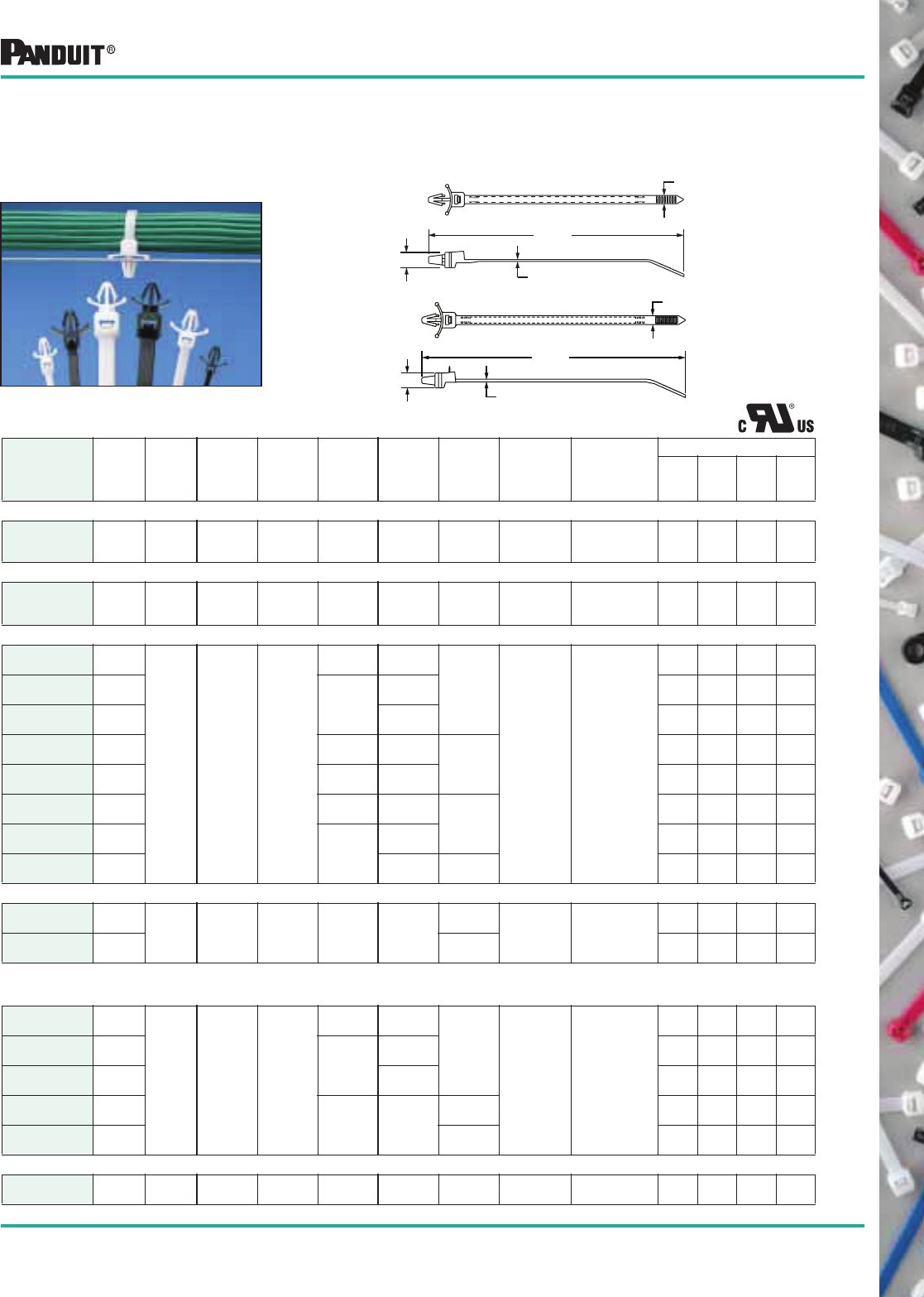
DOME-TOP ® Barb Ty Cable Ties
DURA-TY™
is a heavy-duty cable tie that is
ideal for all outdoor applications requiring
high strength and longer life. The acetal
strap and head provides excellent UV
light resistance and high tensile strength.
The smooth, rounded edges on the head
and body do not irritate the hands. The
ties are easy to install. Available in
standard lengths or dispenser rolls for
easy, cut to length convenience in custom
applications.
DURA-TY™
Cable Ties
4
Most commonly used parts appear in BOLD.
Styles of Cable Ties
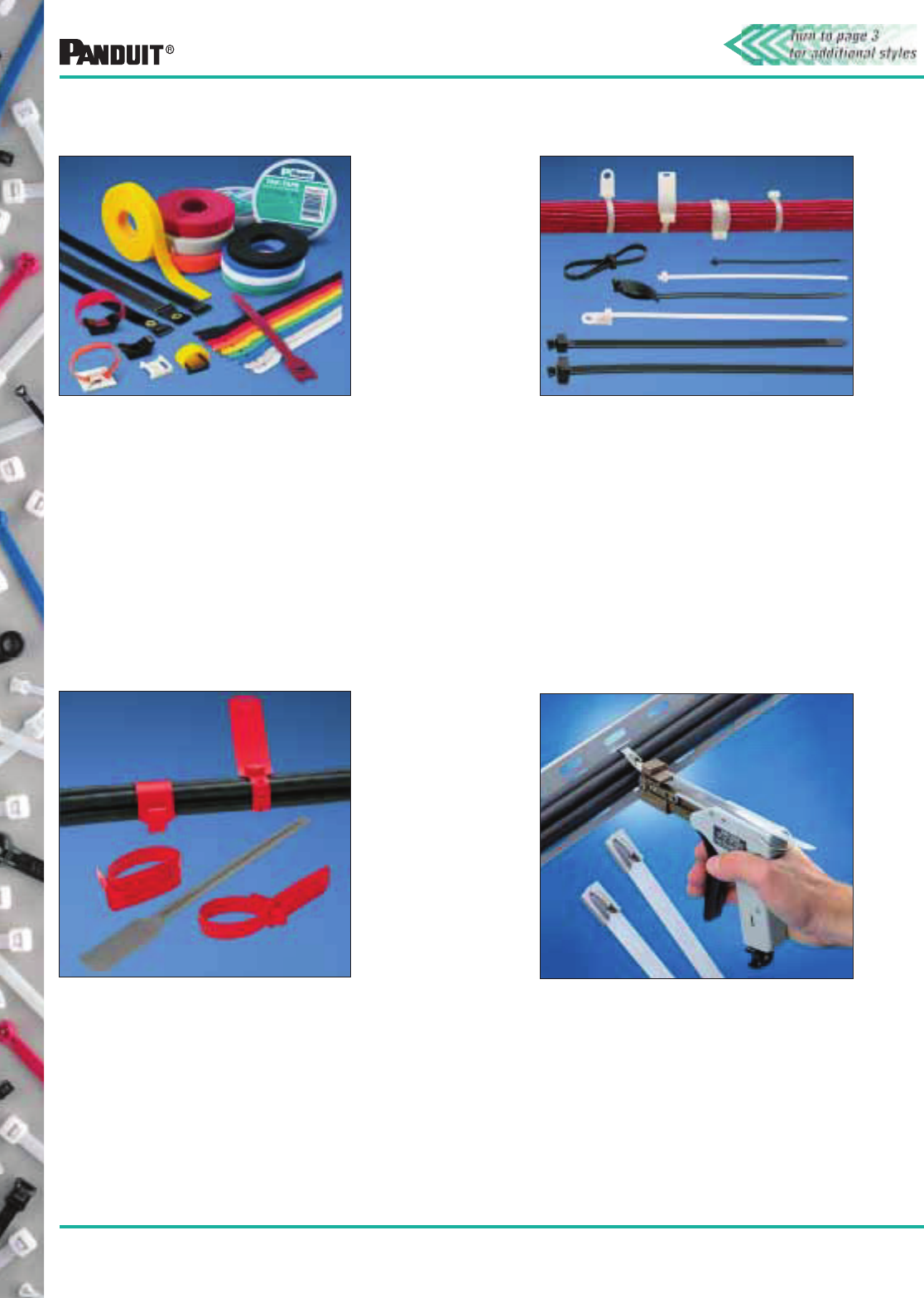
Specialty Ties
PANDUIT ®
continually develops new
products to help solve the unique
application problems of our customers.
One of these products is the polyethylene
cable marker strap that is used for
identifying telephone and fiber optic cable,
which typifies the design/manufacturing
capability of PANDUIT ®
to respond to
these special needs.
Stainless Steel Ties and Strapping
Underground, underwater, indoors,
outdoors — however hostile the
environment — PANDUIT ®
Stainless Steel
Ties and Strapping fasten and identify
components and cables quickly and easily.
Stainless steel ties stand up to most
chemicals, to nuclear and ultraviolet
radiation, to seawater and direct burial in
any soil, and to temperature extremes from
-112°F to 1700°F (-80°C to 925°C).
TAK-TY® Hook & Loop Cable Ties
PANDUIT ®
TAK-TY®
Hook & Loop Cable Ties
are ideal for applications that require
frequent cabling moves, adds and changes.
They can be used to secure a wide variety
of various sizes of cable bundles. Wide color
choice allows for quick and easy color
coding of separate cable bundles.
Selection Guide (cont.)
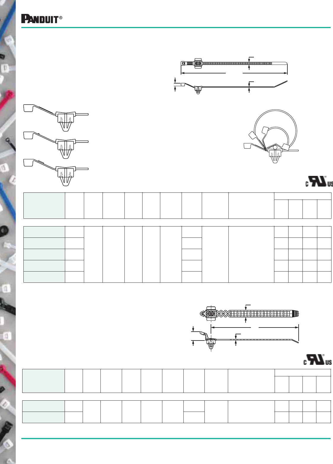
STA-STRAP ® Cable Ties
STA-STRAP ®
Cable Ties offer several unique
features. Harness modifications during
assembly are made easy as the two-piece
design affords releasability prior to final
tensioning and cut-off. The ties are extremely
flexible and lightweight. They also provide
the lowest thread force in the industry which
reduces operator fatigue. The unique design
allows this cable tie to secure a bundle
directly to a panel without the need for
additional fasteners or mounting devices and
reduces installation costs.
5
Most commonly used parts appear in BOLD.
PAN-TY®
Cable Tie Features/Benefits:
1. One Piece Construction 2. Smooth, Round Edges 3. Tensile Strength
4. Curved Tip 5. Finger Tip Grip 6. More Teeth Per Inch
7. Low Threading Force 8. One Piece Locking Design 9. Material Availability
• Consistent performance
and reliability
• Available in lengths from 2.8"
(71mm) up to 43.3"
(1100mm) to meet a variety
of application requirements
• Orients tip toward head to
speed installation — lowers
installed cost
• Faster initial threading
• Easier to pick up from
flat surfaces
• Lowest threading force of
any one piece cable tie in
the industry
• Reduces operator fatigue
• Thin tapered tip facilitates
threading, easier
initial insertion
• No irritation to installer’s hands,
increases productivity
• Prevents damage to
wire insulation
• Finger tip grip on selected
sizes assures positive grip
during threading of the tie
• Grip prevents tip from
slipping out of cable tie head
during threading
• Multiple locking tooth design
provides greater strength
and reliability
• Available in self locking or
releasable styles for use in
applications where changes
are anticipated
• Exceeds Industry and
Aerospace Standards
SAE (AS23190) standards
• Available in seven loop tensile
strengths from 8 lbs. (36N) up
to 250 lbs. (1112N) to provide
an economical selection
• Greater number of small
uniform teeth provides
tighter bundles
• Because they are flush with
surface they provide proper
wire bundle grip without wire
insulation damage
• Available in a variety of
materials to meet the needs
of special environments
• Properly selected ties can be
used indoors or outdoors
with assurance of long
lasting performance
PAN-TY®
Cable Ties
6
Most commonly used parts appear in BOLD.
STANDARD CROSS SECTION
PLT1S-C 4.8
(122)
.190
(4.8)
.052
(1.3)
.220
(5.6)
.316
(8.0)
1.00
(25)
50
(222)
GTS, GS2B, GTH,
GS4H, PTS,
PPTS, STS2
or STH2
100 1000 1000 25000
PLT1.5S-C 6.2
(157)
1.50
(38)
100 1000 1000 25000
PLT2S-C 7.4
(188)
1.88
(48)
100 1000 1000 10000
PLT2.5S-C 9.8
(249)
.337
(8.6)
2.50
(64)
100 1000 1000 10000
PLT3S-C 11.5
(292)
3.00
(76)
100 1000 1000 10000
PLT4S-C 14.5
(368)
4.00
(102)
100 1000 1000 5000
PLT4.5S-C 15.5
(394)
4.50
(114)
100 1000 1000 5000
PLT5S-C 17.5
(445)
5.00
(127)
100 500 1000 5000
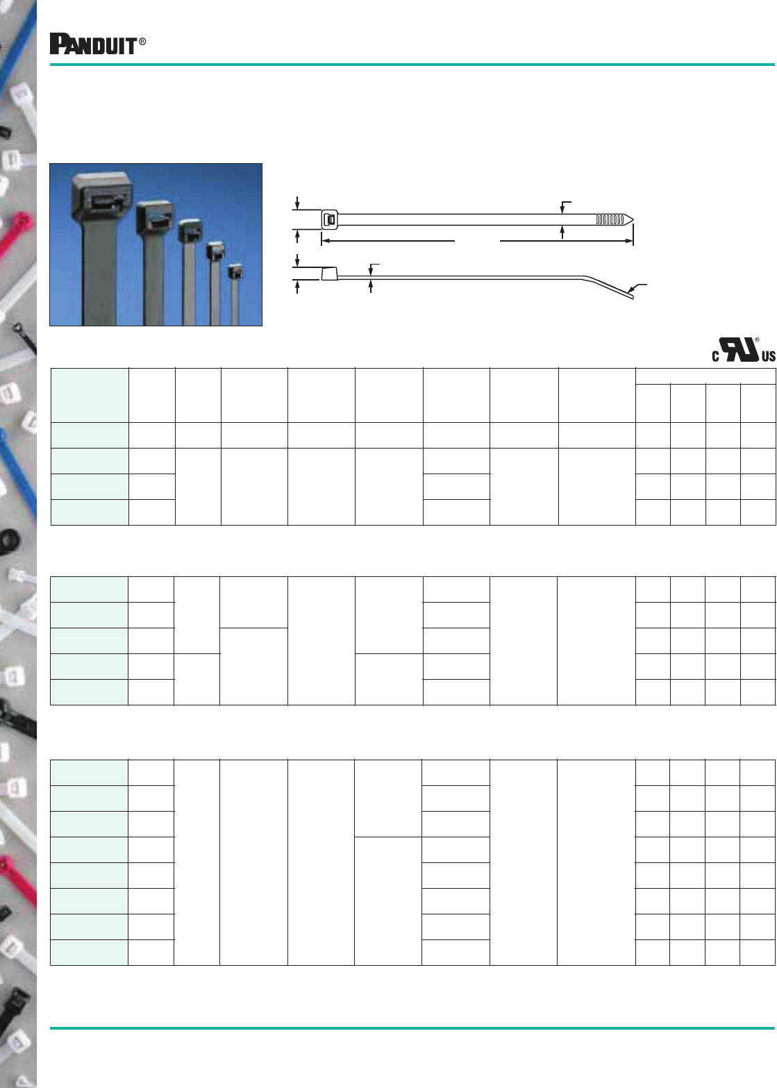
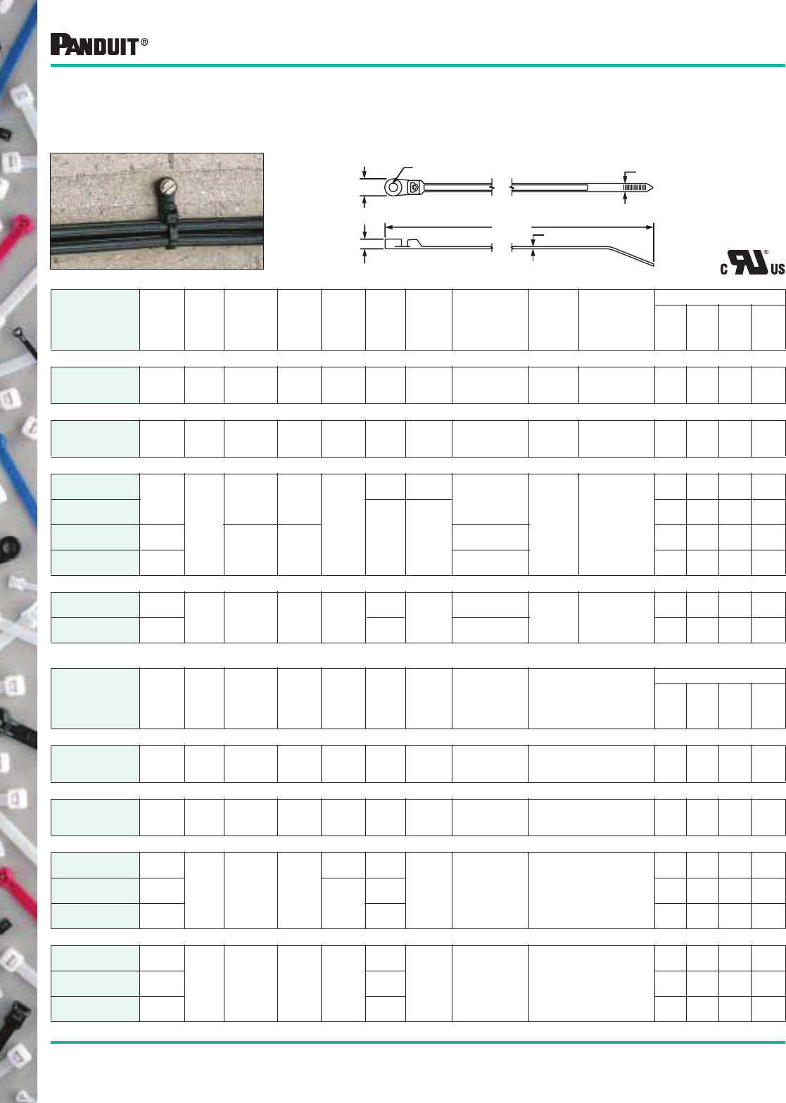
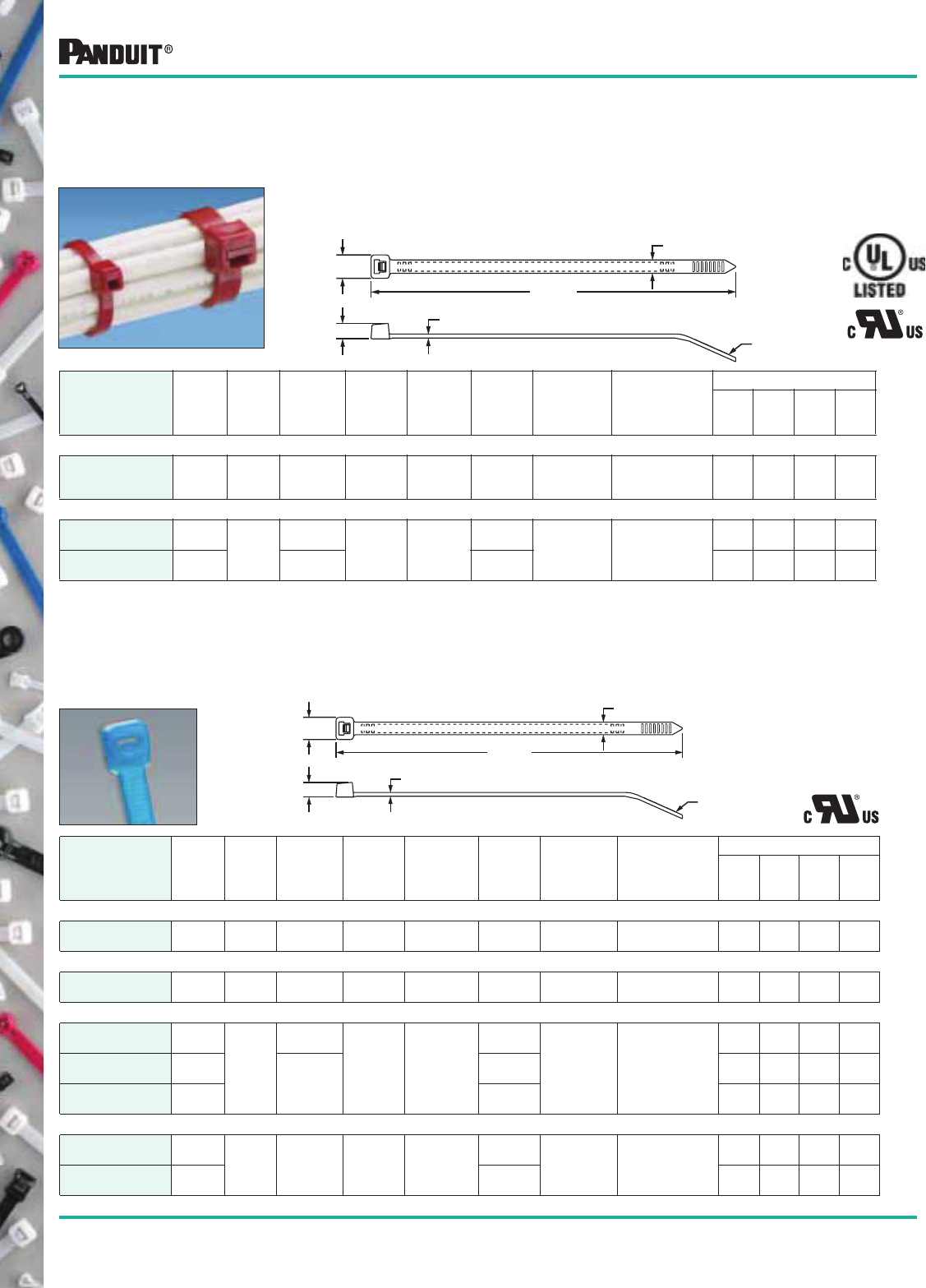
PAN-TY® Nylon 6.6
Locking Cable Ties —
Curved Tip
These versatile fasteners can be used in countless applications
wherever you need to bundle wire, cable, or hose. They tie bundle
diameters up to 13" (330mm), they also can be joined together for
even larger diameters. They have a minimum loop tensile strength
from 8 lbs. (36N) to 250 lbs. (1112N). Colors are available for
specific color-coding applications (see pages 24-26).
SUBMINIATURE AND MINIATURE CROSS SECTION
Part
Number
Length
A
in. (mm)
Width
B
in. (mm)
Thickness
C
in. (mm)
Head
Height
D
in. (mm)
Head
Width
E
in. (mm)
Max.
Bundle
Dia.
in. (mm)
Min. Loop
Tensile
Strength
Lbs. (N)
Recommended
PANDUIT ®
Installation Tool
Part No.
Packaging*
Std.
Pkg.
Qty.
Std.
Ctn.
Qty.
Bulk
Pkg.
Qty.
Bulk
Ctn.
Qty.
PLT.6SM-C 2.8
(71)
.070
(1.8)
.030
(.8)
.095
(2.4)
.125
(3.2)
.60
(15)
8
(36)
GTS, PTS 100 1000 1000 50000
PLT.7M-C 3.1
(79)
.090
(2.3)
.032
(.8)
.115
(2.9)
.180
(4.6)
.68
(17)
18
(80)
GTS, GS2B, PTS,
PPTS or STS2
100 1000 1000 50000
PLT1M-C 3.9
(99)
.098
(2.5)
.043
(1.1)
.154
(3.9)
.87
(22)
100 1000 1000 50000
PLT1.5M-C 5.6
(142)
1.25
(32)
100 1000 1000 50000
PLT2M-C 8.0
(203)
2.00
(51)
100 1000 1000 25000
INTERMEDIATE CROSS SECTION
PLT1.5I-C 5.6
(142) .142
(3.6)
.045
(1.1)
.180
(4.6)
.240
(6.1)
1.38
(35)
40
(178)
GTS, GS2B, PTS,
PPTS or STS2
100 1000 1000 25000
PLT2I-C 8.0
(203)
2.00
(51)
100 1000 1000 25000
PLT2.5I-C 9.7
(246)
.145
(3.7)
.052
(1.3)
.260
(6.6)
2.50
(64)
100 1000 1000 10000
PLT3I-C 11.4
(290)
3.00
(76)
100 1000 1000 10000
PLT4I-C 14.5
(368)
4.00
(102)
100 1000 1000 10000
Nylon 6.6 Locking Cable Ties (PLT Series)
CURVED TIP
E
D
A REF.
B
C
*Order the number of pieces required in multiples of package quantities.
For colors and other materials, see pages 24-26.
All part numbers shown in standard package quantities unless denoted by ‡.
Cable Ties for Automatic
Tools See Page 61.
Except PLT.6SM-C
7
Most commonly used parts appear in BOLD.
PAN-TY
® Locking
Lashing Ties
Part Number
Length
A
in. (mm)
Width
B
in. (mm)
Thickness
C
in. (mm)
Head
Height
D
in. (mm)
Head
Width
E
in. (mm)
Max.
Bundle
Dia.
in. (mm)
Min. Loop
Tensile
Strength
Lbs. (N)
Recommended
PANDUIT ®
Installation Tool
Part No.
Packaging*
Std.
Pkg.
Qty.
Std.
Ctn.
Qty.
Bulk
Pkg.
Qty.
Bulk
Ctn.
Qty.
EXTRA-HEAVY CROSS SECTION
PLT2EH-C‡ 9.0
(229)
.500
(12.7)
.075
(1.9)
.40
(10.2)
.80
(20.3)
2.00
(51)
250
(1112)
GS4EH, PPTEH
or ST2EH
— — 100 1000
PLT5EH-Q!20.1
(511)
5.00
(127)
25 250 100 1000
PLT6EH-Q!22.2
(564)
6.00
(152)
25 250 100 1000
PLT8EH-C‡ 28.3
(719)
.085
(2.2)
8.00
(203)
— — 100 1000
PLT10EH-C‡ 34.2
(869)
10.00
(254)
— — 100 500
PLT12EH-C‡ 40.1
(1019)
12.00
(305)
— — 100 500
Nylon 6.6 Locking Cable Ties (PLT Series)
Part
Number
Length
A
in. (mm)
Width
B
in. (mm)
Thickness
C
in. (mm)
Head
Height
D
in. (mm)
Head
Width
E
in. (mm)
Max.
Bundle
Dia.
in. (mm)
Min. Loop
Tensile
Strength
Lbs. (N)
Recommended
PANDUIT ®
Installation Tool
Part No.
Packaging*
Std.
Pkg.
Qty.
Std.
Ctn.
Qty.
Bulk
Pkg.
Qty.
Bulk
Ctn.
Qty.
LIGHT-HEAVY CROSS SECTION
PLT6LH-L 21.9
(556)
.300
(7.6)
.075
(1.9)
.325
(8.3)
.480
(12.2)
6.00
(152)
120
(534)
GTH, GS4H,
GS4EH
PPTEH, ST2EH
or STH2
50 500 100 2000
PLT7LH-L 24.7
(627)
7.00
(178)
50 500 100 2000
PLT8LH-L 27.6
(701)
8.00
(203)
50 500 100 2000
PLT9LH-L 30.5
(775)
9.00
(229)
50 500 100 1000
PLT10LH-L 34.3
(871)
10.31
(262)
50 1000 100 1000
HEAVY CROSS SECTION
PLT2H-L 8.1
(206)
.300
(7.6)
.075
(1.9)
.290
(7.4)
.480
(12.2)
2.00
(51)
120
(534)
GTH, GS4H,
GS4EH
PPTEH, ST2EH
or STH2
50 500 250 2500
PLT2.5H-L 9.8
(251)
2.50
(64)
50 500 250 2500
PLT3H-L 11.4
(290)
3.00
(76)
50 500 250 2500
PLT4H-L 14.5
(368)
4.00
(102)
50 500 250 2500
PLT5H-L 17.7
(450)
.350
(8.9)
.078
(2.0)
.340
(8.6)
.560
(14.2)
5.00
(127)
175
(778)
50 500 100 2500
PLT6H-L 20.9
(530)
6.00
(152)
50 500 100 2000
PLT8H-L 30.6
(779)
9.00
(229)
50 500 100 1000
PLT13H-Q 43.3
(1100)
13.00
(330)
25 500 100 500
Lashing Ties typically are used on heavy duty jobs such as
securing conduit or large cable bundles to permanent structures,
indoors or out. Can be used with MCEH mounting clip
(see page 16).
*Order the number of pieces required in multiples of package quantities.
For colors and other materials, see pages 24-26.
All part numbers shown in standard package quantities unless denoted by ‡.
!Available without buckle for applications that do not require mounting.
B
E
A REF.
PANDUIT
C
D
STRAIGHT TIP
E
D
A REF.
B
C
Light-Heavy and
Heavy Cross Section
Except PLT5H, 6H,
8H and 13H
8Most commonly used parts appear in BOLD.
Part Number
Length
A
in. (mm)
Width
B
in. (mm)
Thickness
C
in. (mm)
Head
Height
D
in. (mm)
Head
Width
E
in. (mm)
Max.
Bundle
Dia.
in. (mm)
Min. Loop
Tensile
Strength
Lbs. (N)
Recommended
PANDUIT ®
Installation Tool
Part No.
Packaging*
Std.
Pkg.
Qty.
Std.
Ctn.
Qty.
Bulk
Pkg.
Qty.
Bulk
Ctn.
Qty.
STANDARD CROSS SECTION
PRT1S-C 4.8
(122)
.190
(4.8)
.052
(1.3)
.219
(5.6)
.316
(8.0)
1.00
(25)
50
(222)
Hand Installed
Only
100 1000 1000 10000
PRT1.5S-C 6.3
(160)
1.50
(38)
100 1000 1000 10000
PRT2S-C 7.4
(188)
1.88
(48)
100 1000 1000 10000
PRT3S-C 11.5
(292) .337
(8.6)
3.00
(76)
100 1000 1000 10000
PRT4S-C 14.5
(368)
4.00
(102)
100 1000 1000 5000
HEAVY CROSS SECTION
PRT2H-L 8.4
(213)
.300
(7.6)
.075
(1.9)
.300
(7.6)
.480
(12.2)
2.00
(51)
80
(356)
Hand Installed
Only
50 500 250 2500
PRT3H-L 11.4
(290)
3.00
(76)
50 500 250 2500
PRT4H-L 14.5
(368)
4.00
(102)
50 500 250 2500
PAN-TY®
Releasable Lashing Ties — Nylon 6.6
Part Number
Length
A
in. (mm)
Width
B
in. (mm)
Thickness
C
in. (mm)
Head
Height
D
in. (mm)
Head
Width
E
in. (mm)
Max.
Bundle
Dia.
in. (mm)
Min. Loop
Tensile
Strength
Lbs. (N)
Recommended
PANDUIT ®
Installation Tool
Part No.
Packaging*
Std.
Pkg.
Qty.
Std.
Ctn.
Qty.
Bulk
Pkg.
Qty.
Bulk
Ctn.
Qty.
EXTRA-HEAVY CROSS SECTION
PRT2EH-C‡ 9.0
(229)
.500
(12.7)
.075
(1.9)
.40
(10.2)
.80
(20.3)
2.00
(51)
250
(1112)
Hand Installed
Only
— — 100 1000
PRT5EH-Q 20.1
(510)
5.00
(127)
25 250 100 1000
PRT6EH-Q 22.2
(564)
6.00
(152)
25 250 100 1000
PRT8EH-C‡ 28.3
(719)
.085
(2.2)
8.00
(203)
— — 100 1000
PRT10EH-C‡ 34.2
(869)
10.00
(254)
— — 100 500
PRT12EH-C‡ 40.1
(1019)
12.00
(305)
— — 100 500
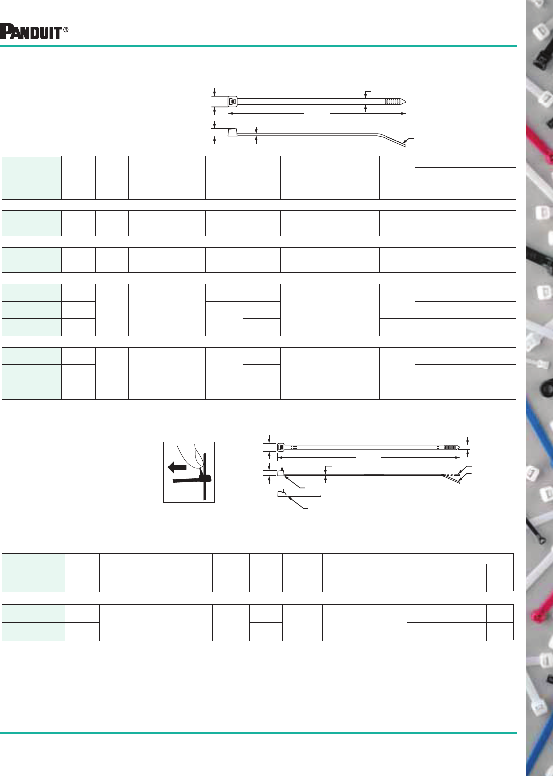
PAN-TY®
Releasable
Nylon 6.6 Cable Ties
The extended tab end of releasable cable ties permits easy release and
re-use even after the tie has been pulled up snug by hand. Releasable
ties are particularly useful in applications where changes are anticipated
during development, production or servicing in the field.
Nylon 6.6 Releasable Cable Ties (PRT Series)
B
E
A REF.
PANDUIT
C
D
To release, grasp the head of the cable tie,
deflect release tab and pull the cable tie
away from the bundle.
E
D
B
A REF.
C
Head design for Standard Cross Section Ties
Head design for Heavy Cross Section Ties
STRAIGHT TIP
CURVED TIP
Except Heavy Ties
*Order the number of pieces required in multiples of package quantities.
For colors and other materials, see pages 24-26.
All part numbers shown in standard package quantities unless denoted by ‡.
9
Most commonly used parts appear in BOLD.
Nylon 6.6 Locking Clamp Ties (PLC Series)
PAN-TY®
Nylon 6.6
Clamp Ties
Part Number
Length
A
in. (mm)
Width
B
in. (mm)
Thickness
C
in. (mm)
Boss
Height
D
in. (mm)
Boss
Width
E
in. (mm)
Hole
Dia.
F
in. (mm)
Screw
Size
(Metric)
Max.
Bundle
Dia.
in. (mm)
Min. Loop
Tensile
Strength
Lbs. (N)
Recommended
PANDUIT ®
Installation Tool
Part No.
Packaging*
Std.
Pkg.
Qty.
Std.
Ctn.
Qty.
Bulk
Pkg.
Qty.
Bulk
Ctn.
Qty.
MINIATURE CROSS SECTION
PLC1M-S4-C 4.3
(110)
.100
(2.5)
.045
(1.2)
.153
(3.9)
.239
(6.1)
.118
(3.0)
#4
(M2.5)
.75
(20)
18
(80)
GTS, GS2B,
PTS, PPTS
or STS2
100 1000 1000 50000
INTERMEDIATE CROSS SECTION
PLC1.5I-S8-C 6.1
(156)
.135
(3.4)
.045
(1.2)
.166
(4.2)
.335
(8.5)
.172
(4.4)
#8
(M4)
1.25
(32)
40
(178)
GTS, GS2B,
PTS, PPTS
or STS2
100 1000 1000 25000
STANDARD CROSS SECTION
PLC2S-S6-C 7.9
(201)
.190
(4.8)
.047
(1.2)
.160
(4.1)
.373
(9.5)
.145
(3.7)
#6
(M3) 1.84
(47)
50
(222)
GTS, GS2B, GTH,
GS4H, PTS,
PPTS, STS2
or STH2
100 1000 1000 10000
PLC2S-S10-C 7.9
(201)
.206
(5.2)
#10
(M5)
100 1000 1000 10000
PLC3S-S10-C 12.0
(305) .052
(1.3)
.220
(5.6)
#10
(M5)
3.00
(76)
100 1000 1000 5000
PLC4S-S10-C 15.0
(381)
#10
(M5)
4.00
(102)
100 1000 1000 5000
HEAVY CROSS SECTION
PLC2H-S25-L 9.0
(228) .300
(7.6)
.075
(1.9)
.265
(6.7)
.500
(12.7)
.260
(6.6)
1/4
(M6)
2.00
(51) 120
(534)
GTH, GS4H,
GS4EH,PPTEH
STH2 or ST2EH
50 500 250 2500
PLC4H-S25-L 15.1
(384)
4.00
(102)
50 500 250 2500
F
E
B
C
A REF.
D
Clamp ties are used to attach a bundle to another surface
such as a control panel, wall or ceiling using another fastener.
The design allows for bundling before or after screwing clamp
in place.
*Order the number of pieces required in multiples of package quantities.
For colors and other materials, see pages 24-26.
All part numbers shown in standard package quantities unless denoted by ‡.
10
Most commonly used parts appear in BOLD.
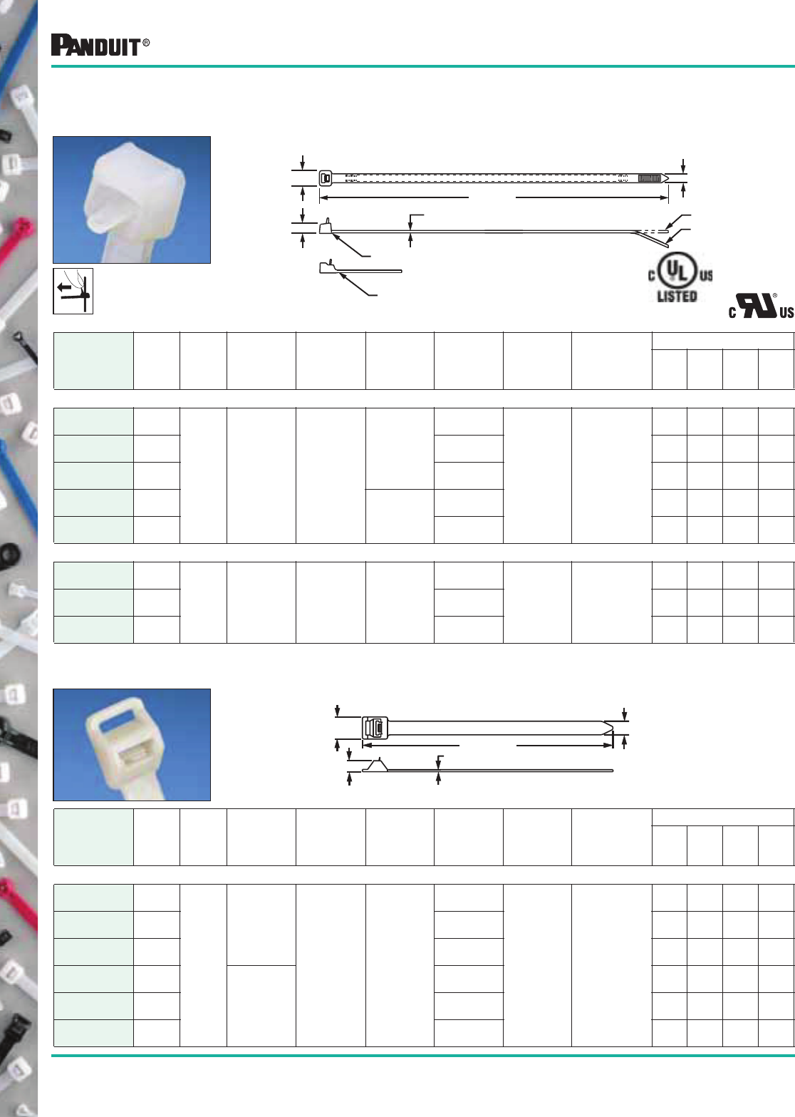
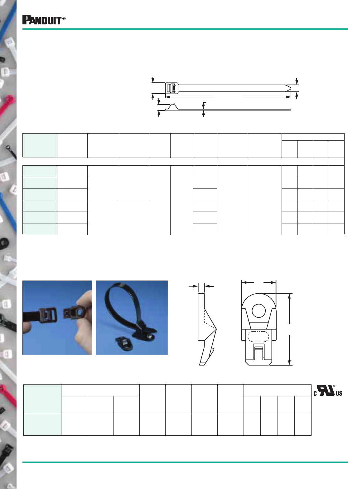
PAN-TY®
Nylon 6.6
Marker and Flag Ties
Marker and Flag Ties fasten and identify bundles at the same time.
They can be marked with PANDUIT ®
Marker Pens or you can use
PANDUIT ®
Custom Hot Stamping Service.
Part Number
Length
A
in. (mm)
Width
B
in. (mm)
Thickness
C
in. (mm)
Head
Height
D
in. (mm)
Head
Width
E
in. (mm)
Write-on
Area
in. (mm)
Max.
Bundle
Dia.
in. (mm)
Min. Loop
Tensile
Strength
Lbs. (N)
Recommended
PANDUIT ®
Installation
Tool Part No.
Packaging*
Std.
Pkg.
Qty.*
Std.
Ctn.
Qty.
Bulk
Pkg.
Qty.
Bulk
Ctn.
Qty.
MINIATURE CROSS SECTION
PLF1M-C 4.3
(109)
.098
(2.5)
.045
(1.1)
.154
(3.9)
.180
(4.6)
.31 X .75
(7.9 X 19.1) .87
(22)
18
(80)
GTS, GS2B,
PTS, PPTS
or STS2
100 1000 1000 25000
PLF1MA-C 5.1
(130)
.76 X 1.04
(19.1 X 26.4)
100 1000 1000 25000
PLF1MB-C 4.0
(101)
.31 X .92
(7.9 X 23.4) .75
(19)
100 1000 1000 25000
PLM1M-C 3.9
(99) .035
(.9)
.26 X .95
(6.6 X 24.1)
100 1000 1000 10000
PLM2M-C 8.0
(203)
2.00
(51)
100 1000 1000 10000
PLM2S
PLM4S
PL2M2S
Marker Ties are also available in weather resistant black nylon for outdoor use. May be marked with PANDUIT ® PX-10 White Marking Pen found on page 105.
Part Number
Length
A
in. (mm)
Width
B
in. (mm)
Thickness
C
in. (mm)
Head
Height
D
in. (mm)
Head
Width
E
in. (mm)
Write-on
Area
in. (mm)
Max.
Bundle
Dia.
in. (mm)
Min. Loop
Tensile
Strength
Lbs. (N)
Recommended
PANDUIT ®
Installation
Tool Part No.
Packaging*
Std.
Pkg.
Qty.*
Std.
Ctn.
Qty.
Bulk
Pkg.
Qty.
Bulk
Ctn.
Qty.
STANDARD CROSS SECTION
PLM2S-C 7.4
(188)
.185
(4.7)
.052
(1.3)
.220
(5.6)
.320
(8.1)
.44 x .87
(11.1 x 22.1)
1.75
(45)
50
(222)
GTS, GS2B,
GTH, GS4H,
PTS, PPTS,
STS2
or STH2
100 1000 500 10000
PLM4S-C 14.6
(371)
.44 x 2.00
(11.1 x 50.8)
4.00
(102)
100 1000 500 5000
PL2M2S-L 7.4
(188)
.87 x 1.07
(22.1 x 27.2)
1.75
(45)
50 500 500 2500
PL3M2S-L 7.4
(188)
.87 x 1.79
(22.1 x 45.5)
1.75
(45)
50 500 500 2500
Custom Hot Stamping Available; See page 52.
Nylon 6.6 Marker and Flag Ties (PLF/PLM Series)
*Order the number of pieces required in multiples of package quantities.
For colors and other materials, see pages 24-26.
All part numbers shown in standard package quantities unless denoted by ‡.
E
DC
A REF.
B
PLM1M
PLM1M
PLM2M
PLF1M PLF1MB
PLF1MA
PL3M2S
11
Most commonly used parts appear in BOLD.
Winged Nylon 6.6 Push Mount Ties — Locking Style (PLWP)
Part Number
Length
A
in. (mm)
Width
B
in. (mm)
Thickness
C
in. (mm)
Head
Height
D
in. (mm)
Nominal
Hole
Dia.
in. (mm)
Max.
Panel
Thickness
in. (mm)
Max.
Bundle
Dia.
in. (mm)
Min. Loop
Tensile
Strength
Lbs. (N)
Recommended
PANDUIT ®
Installation
Tool Part No.
Packaging*
Std.
Pkg.
Qty.
Std.
Ctn.
Qty.
Bulk
Pkg.
Qty.
Bulk
Ctn.
Qty.
MINIATURE CROSS SECTION
PLWP1M-C 4.3
(109)
.098
(2.5)
.044
(1.1)
.220
(5.6)
.187
(4.7)
.093
(2.4)
.87
(22)
18
(80)
GTS, GS2B,
PTS, PPTS
or STS2
100 1000 500 5000
INTERMEDIATE CROSS SECTION
PLWP1.5I-C 6.0
(152)
.135
(3.4)
.045
(1.2)
.280
(7.1)
.187
(4.7)
.093
(2.4)
1.25
(32)
40
(178)
GTS, GS2B,
PTS, PPTS
or STS2
100 1000 500 5000
STANDARD CROSS SECTION
PLWP1S-C 5.2
(132)
.190
(4.8)
.052
(1.3)
.370
(9.4)
.252
(6.4)
.105
(2.7)
1.00
(25)
50
(222)
GTS, GS2B,
GTH, GS4H,
PTS, PPTS,
STS2 or
STH2
100 1000 500 5000
PLWP1SA-D‡ 5.1
(130) .187
(4.7)
.093
(2.4)
— — 500 5000
PLWP1SB-D‡ 5.2
(132)
.157
(4.0)
— — 500 5000
PLWP1.5S-D‡ 6.8
(173)
.252
(6.4)
.105
(2.7) 1.50
(38)
— — 500 5000
PLWP1.5SA-D‡ 6.7
(170)
.187
(4.7)
.093
(2.4)
— — 500 5000
PLWP2S-C 7.8
(198)
.252
(6.4)
.105
(2.7) 1.75
(45)
100 1000 500 5000
PLWP2SA-D‡ 7.7
(196) .187
(4.7)
.093
(2.4)
— — 500 5000
PLWP2SB-D‡ 7.8
(198)
.157
(4.0)
1.75
(45)
— — 500 5000
HEAVY CROSS SECTION
PLWP2H-TL‡ 8.9
(226) .300
(7.6)
.075
(1.9)
.370
(9.4)
.266
(6.8)
.105
(2.7)
2.00
(51) 120
(534)
GTH, GS4H,
STH2 or
PPTEH
— — 250 2500
PLWP3H-TL‡ 12.0
(305)
3.00
(76)
— — 250 2500
Winged Nylon 6.6 Push Mount Ties — Releasable Style (PRWP)
STANDARD CROSS SECTION
PRWP1S-C 5.2
(132)
.190
(4.8)
.052
(1.3)
.370
(9.4)
.266
(6.8)
.105
(2.7)
1.00
(25)
50
(222)
Hand Installed
Only
100 1000 500 5000
PRWP1SA-C 5.1
(130) .187
(4.7)
.093
(2.4)
100 1000 500 5000
PRWP1SB-D‡ 5.2
(132)
.157
(4.0)
— — 500 5000
PRWP1.5S-D‡ 6.8
(173) .252
(6.4)
.105
(2.7)
1.50
(38)
— — 500 5000
PRWP2S-D‡ 7.8
(198)
1.75
(45)
— — 500 5000
HEAVY CROSS SECTION
PRWP2H-TL ‡ 8.9
(226)
.300
(7.6)
.075
(1.9)
.370
(9.4)
.266
(6.8)
.105
(2.7)
2.00
(51)
120
(534)
Hand Installed
Only
— — 250 2500
Nylon 6.6 Winged Push Mount Ties (PLWP/PRWP Series)
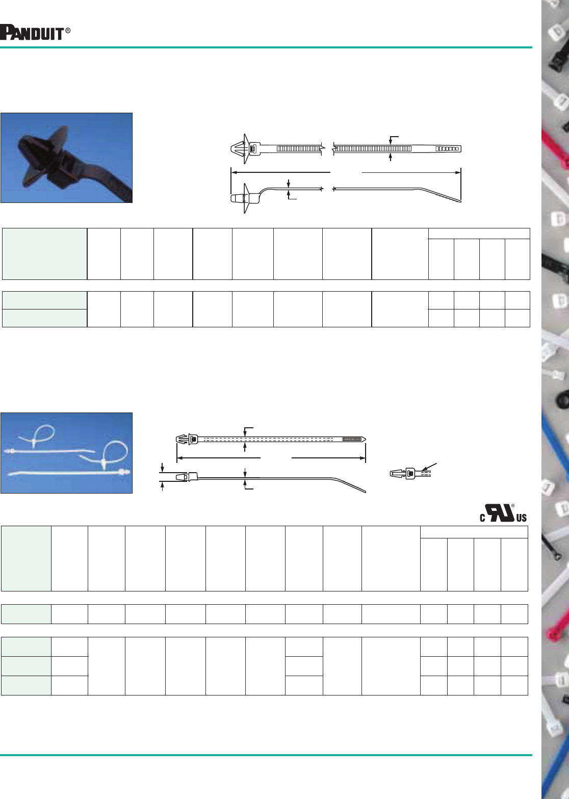
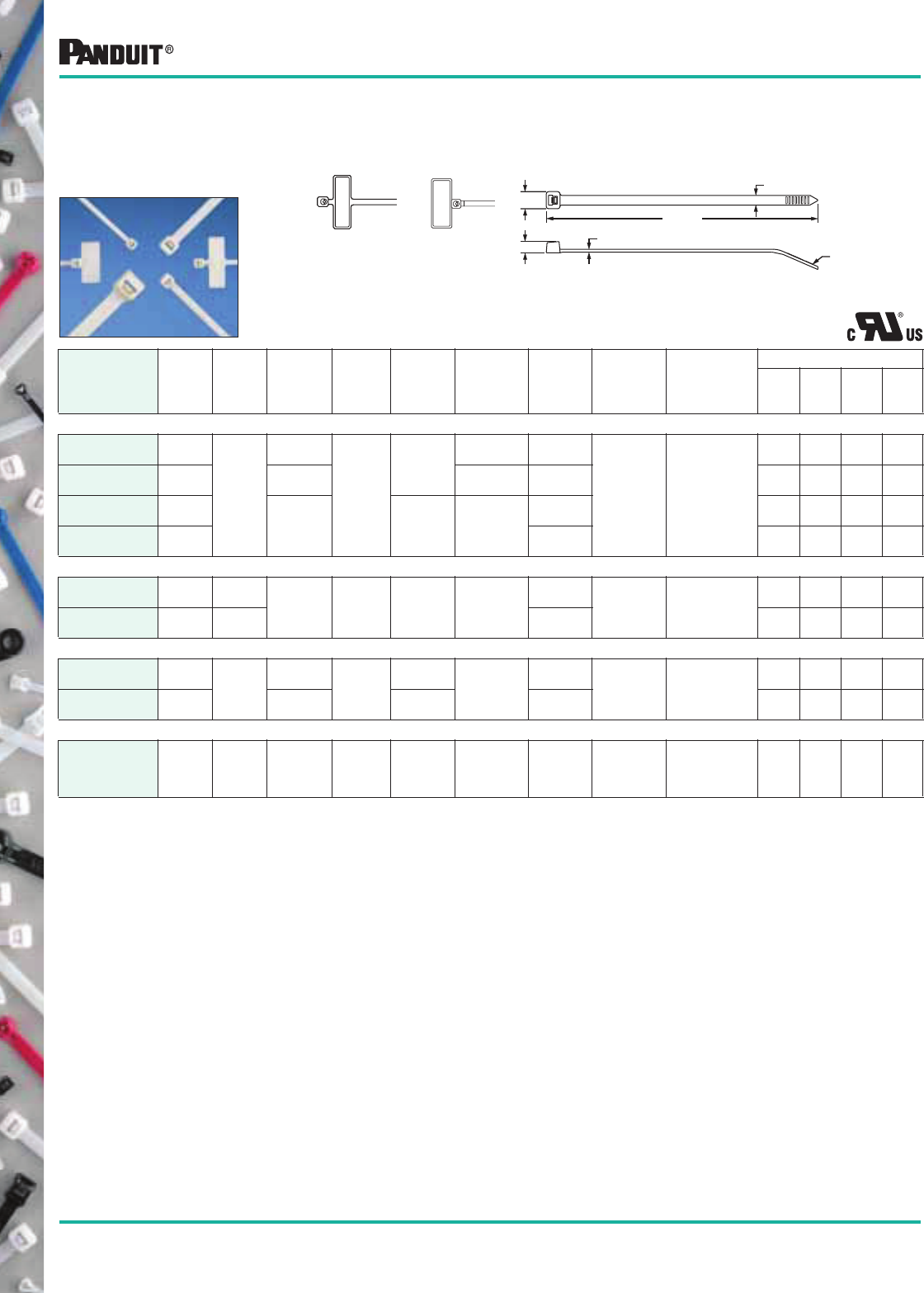
PAN-TY® Nylon 6.6
Winged Push
Mount Ties
Push mount ties are used to attach a cable bundle to a surface such as a
flat panel. The anchor is easily pressed into a pre-drilled hole and locks in
place. The wings provide constant tension when installed, creating a
stable, secure fixture and rattle-free installation.
D
C
A REF.
B
*Order the number of pieces required in multiples of package quantities.
For colors and other materials, see pages 24-26.
All part numbers shown in standard package quantities unless denoted by ‡.
D
C
A REF.
B
PLWP
PRWP
12
Most commonly used parts appear in BOLD.
Part Number
Length
A
in. (mm)
Width
B
in. (mm)
Thickness
C
in. (mm)
Head
Height
D
in. (mm)
Nominal
Hole
Dia.
in. (mm)
Max.
Panel
Thickness
in. (mm)
Max.
Bundle
Dia.
in. (mm)
Min. Loop
Tensile
Strength
Lbs. (N)
Recommended
PANDUIT ®
Installation Tool
Part No.
Packaging*
Std.
Pkg.
Qty.
Std.
Ctn.
Qty.
Bulk
Pkg.
Qty.
Bulk
Ctn.
Qty.
STANDARD CROSS SECTION
PLWP30SC-D30‡ 5.8
(147)
.190
(4.8)
.050
(1.3)
.220
(5.6)
.266
(6.8)
.118
(3.0)
1.18
(30)
50
(222)
GTS, GS2B, GTH,
GS4H, PTS, PPTS,
STS2 or STH2
— — 500 5000
PLWP40SC-D30‡ 7.0
(178)
1.58
(40)
— — 500 5000
PLWP50SC-D30‡ 8.2
(208)
1.97
(50)
— — 500 5000
PLWP40SD-D30‡ 7.0
(178)
1.58
(40)
— — 500 5000
PLWP50SE-D30‡ 8.2
(208)
1.97
(50)
— — 500 5000
PAN-TY®
Center Mounted
Heat Stabilized Nylon 6.6
Winged Push Mount Ties
Center mounted winged push mount cable ties center the
bundle on all bundle diameters.
PLWP30, 40, 50SC winged push mount
cable ties are for normal wire bundles.
PLWP40SD winged push mount cable ties
with convoluted tubing bump that prevents
lateral and axial movement on
convoluted tubing.
PLWP50SE winged push mount cable ties
with convoluted tubing bump that prevents
lateral movement on convoluted tubing.
BUNDLE DIAMETERS
from .12" to 1.97"
(3mm to 50mm)
Heat Stabilized Nylon 6.6 Push Mount Ties (PLWP/PRLWP Series)
B
A REF.
C
D
Ladder Style Heat Stabilized
Nylon 6.6 Winged Push Mount Ties
Unique releasable ladder design eliminates
the need for multiple clamp sizes.
Part Number
Length
A
in. (mm)
Width
B
in. (mm)
Thickness
C
in. (mm)
Head
Height
D
in. (mm)
Nominal
Hole
Dia.
in. (mm)
Max.
Panel
Thickness
in. (mm)
Max.
Bundle
Dia.
in. (mm)
Min. Loop
Tensile
Strength
Lbs. (N)
Recommended
PANDUIT ®
Installation Tool
Part No.
Packaging*
Std.
Pkg.
Qty.
Std.
Ctn.
Qty.
Bulk
Pkg.
Qty.
Bulk
Ctn.
Qty.
STANDARD CROSS SECTION
PRLWP30S-D30‡ 4.7
(119) .380
(9.7)
.050
(1.3)
.470
(12)
.256
(6.5)
.118
(3.0)
1.43
(36) 35
(156) Hand Installed Only
— — 500 5000
PRLWP50S-D30‡ 7.1
(180)
2.18
(55)
— — 500 5000
*Order the number of pieces required in multiples of package quantities.
For colors and other materials, see pages 24-26.
All part numbers shown in standard package quantities unless denoted by ‡.
B
D
A
C
13
Most commonly used parts appear in BOLD.
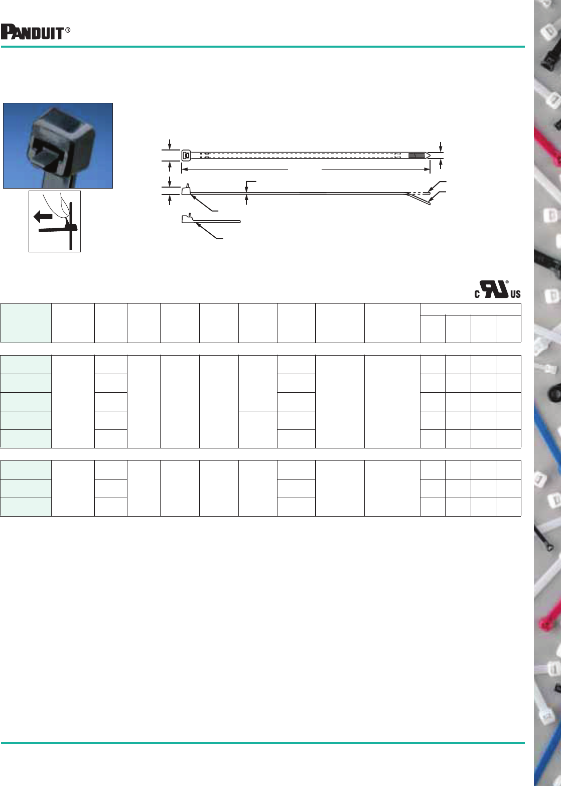
PANDUIT ® Umbrella
Winged Push Mount
Cable Ties
The anchor snaps into a hole in a light gauge metal or plastic panel.
No screws or other fasteners required. The umbrella shaped disc
stabilizes the anchor and insures a tight, rattle-free fit. In addition, the
umbrella disc provides a dust-tight and semi-liquid tight seal against the
panel surface. The material is heat stabilized, black Nylon 6.6.
•For use with Corrugated Loom Tubing.
Part Number
A
Length
in. (mm)
B
Width
in. (mm)
C
Thickness
in. (mm)
Nominal
Hole
Diameter
in. (mm)
Max.
Panel
Thickness
in. (mm)
Max.
Bundle
Diameter
in. (mm)
Min. Loop
Tensile
Strength
Lbs. (N)
Recommended
PANDUIT ®
Installation
Tool
Part No.
Packaging*
Std.
Pkg.
Qty.
Std.
Ctn.
Qty.
Bulk
Pkg.
Qty.
Bulk
Ctn.
Qty.
STANDARD CROSS SECTION
PLUP40S-D30‡
7.0
(177)
.190
(4.8)
.047
(1.2)
.266
(6.8)
.050
(1.3)
1.57
(40)
49
(218)
GTS, GS2B,
GTH, GS4H,
PTH or PPTS
— — 500 5000
•PLUP40SE-D30‡ — — 500 5000
A REF.
B
C
Economical Push Mount Tie Style
Part Number
A
Length
in. (mm)
B
Width
in. (mm)
C
Thickness
in. (mm)
D
Head
Height
in. (mm)
Nominal
Hole
Diameter
in. (mm)
Max.
Panel
Thickness
in. (mm)
Maximum
Bundle
Diameter
in. (mm)
Min. Loop
Tensile
Strength
Lbs. (N)
Recommended
PANDUIT ®
Installation
Tool
Part No.
Packaging*
Std.
Pkg.
Qty.
Std.
Ctn.
Qty.
Bulk
Pkg.
Qty.
Bulk
Ctn.
Qty.
INTERMEDIATE CROSS SECTION
PLP1.5I-M‡ 6.1
(156)
.135
(3.4)
.045
(1.1)
.236
(6.0)
.187
(4.7)
.090
(2.4)
1.25
(31.8)
40
(178)
GTS, GS2B, PTS,
PPTS or STS2
— — 1000 25000
STANDARD CROSS SECTION
PLP1S-C 5.3
(134)
.180
(4.6)
.50
(1.3)
.354
(9.0)
.250
(6.4)
.130
(3.2)
1.00
(25)
50
(222)
GTS, GS2B,
GTH,
GS4H, PTS,
PPTS, STS2 or
STH2
100 1000 1000 10000
PLP1.5S-M‡ 6.7
(170)
1.50
(38)
— — 1000 10000
PLP2S-C 7.9
(200)
1.75
(45)
100 1000 1000 10000
PAN-TY®
Nylon 6.6
Push Mount
Ties (Style PLP)
*Order the number of pieces required in multiples of package quantities.
For colors and other materials, see pages 24-26.
All part numbers shown in standard package quantities unless denoted by ‡.
B
C
D
A REF.
Head design for standard cross section ties
Head design for
intermediate
cross section ties
Nylon 6.6 Push Mount Ties (PLUP/PLP Series)
14
Most commonly used parts appear in BOLD.
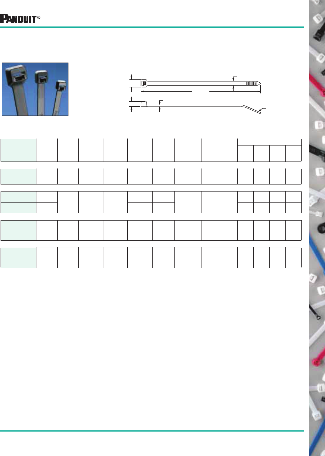
PAN-TY®
Weather
Resistant Nylon
Cable Ties
SUBMINIATURE AND MINIATURE CROSS SECTION
Part Number
Length
A
in. (mm)
Width
B
in. (mm)
Thickness
C
in. (mm)
Head
Height
D
in. (mm)
Head
Width
E
in. (mm)
Max.
Bundle
Dia.
in. (mm)
Min. Loop
Tensile
Strength
Lbs. (N)
Recommended
PANDUIT ®
Installation
Tool Part No.
Packaging*
Std.
Pkg.
Qty.
Std.
Ctn.
Qty.
Bulk
Pkg.
Qty.
Bulk
Ctn.
Qty.
PLT.6SM-C0 2.8
(71)
.070
(1.8)
.030
(.8)
.095
(2.4)
.125
(3.2)
.60
(15)
8
(36)
GTS, PTS or
STS2
100 1000 1000 50000
PLT1M-C0 3.9
(99)
.098
(2.5)
.043
(1.1)
.154
(3.9)
.180
(4.6)
.87
(22)
18
(80)
GTS, GS2B,
PTS, PPTS
or STS2
100 1000 1000 50000
PLT1.5M-C0 5.6
(142)
1.25
(32)
100 1000 1000 50000
PLT2M-C0 8.0
(203)
2.00
(51)
100 1000 1000 25000
INTERMEDIATE CROSS SECTION
PLT1.5I-C0 5.6
(142)
.142
(3.6)
.045
(1.1)
.180
(4.6)
.240
(6.1)
1.38
(35)
40
(178)
GTS, GS2B,
PTS, PPTS
or STS2
100 1000 1000 25000
PLT2I-C0 8.0
(203)
2.00
(51)
100 1000 1000 25000
PLT2.5I-C0 9.7
(246)
.052
(1.3)
2.50
(64)
100 1000 1000 10000
PLT3I-C0 11.4
(290) .145
(3.7)
.280
(6.6)
3.00
(76)
100 1000 1000 10000
PLT4I-C0 14.5
(368)
4.00
(102)
100 1000 1000 10000
Weather Resistant Nylon 6.6 Cable Ties (PLT Series)
STANDARD CROSS SECTION
PLT1S-C0 4.8
(122)
.190
(4.8)
.052
(1.3)
.220
(5.6)
.316
(8.0)
1.00
(25)
50
(222)
GTS, GS2B,
GTH, GS4H,
PTS, PPTS,
STS2 or STH2
100 1000 1000 10000
PLT1.5S-C0 6.2
(157)
1.50
(38)
100 1000 1000 10000
PLT2S-C0 7.4
(188)
1.88
(48)
100 1000 1000 10000
PLT2.5S-C0 9.8
(249)
.337
(8.6)
2.50
(64)
100 1000 1000 10000
PLT3S-C0 11.5
(292)
3.00
(76)
100 1000 1000 10000
PLT4S-C0 14.5
(368)
4.00
(102)
100 1000 1000 5000
PLT4.5S-C0 15.5
(394)
4.50
(114)
100 1000 1000 5000
PLT5S-C0 17.5
(445)
5.00
(127)
100 500 1000 5000
*Order the number of pieces required in multiples of package quantities.
For colors and other materials, see pages 24-26.
All part numbers shown in standard package quantities unless denoted by ‡.
Weather resistant nylon has greater resistance to ultraviolet light
which damages natural nylon. Where adverse outdoor conditions
exist, see technical/application data section (pages 64-65) to select
proper cable tie material for specific applications.
CURVED TIP
E
D
A REF.
B
C
15
Most commonly used parts appear in BOLD.
Part Number
Length
A
in. (mm)
Width
B
in. (mm)
Thickness
C
in. (mm)
Head
Height
D
in. (mm)
Head
Width
E
in. (mm)
Max.
Bundle
Dia.
in. (mm)
Min. Loop
Tensile
Strength
Lbs. (N)
Recommended
PAN DUIT ®
Installation
Tool Part No.
Packaging*
Std.
Pkg.
Qty.
Std.
Ctn.
Qty.
Bulk
Pkg.
Qty.
Bulk
Ctn.
Qty.
LIGHT-HEAVY CROSS SECTION
PLT6LH-L0 21.9
(556)
.300
(7.6)
.075
(1.9)
.325
(8.3)
.480
(12.2)
6.00
(152)
120
(534)
GTH, GS4H,
GS4EH
PPTEH or
STH2
50 500 100 2000
PLT7LH-L0 24.7
(627)
7.00
(178)
50 500 100 2000
PLT8LH-L0 27.6
(701)
8.00
(203)
50 500 100 2000
PLT9LH-L0 30.5
(775)
9.00
(229)
50 500 100 2000
HEAVY CROSS SECTION
PLT2H-LO 8.1
(206)
.300
(7.6)
.075
(1.9)
.290
(7.4)
.480
(12.2)
2.00
(51)
120
(534)
GTH, GS4H,
GS4EH
PPTEH or
STH2
50 500 100 1000
PLT2.5H-L0 9.8
(251)
2.50
(64)
50 500 250 2500
PLT3H-L0 11.4
(290)
3.00
(76)
50 500 250 2500
PLT4H-L0 14.5
(368)
4.00
(102)
50 500 250 2500
PLT5H-L0 17.7
(450)
.350
(8.9)
.078
(2.0)
.340
(8.6)
.560
(14.2)
5.00
(127)
175
(778)
50 500 250 2500
PLT6H-L0 20.9
(530)
6.00
(152)
50 500 250 2000
PLT8H-L0 30.6
(779)
9.00
(229)
50 500 100 1000
PLT13H-Q0 43.3
(1100)
13.00
(330)
25 500 100 500
PAN-TY® Locking
Weather Resistant
Nylon Lashing Ties
Part Number
Length
A
in. (mm)
Width
B
in. (mm)
Thickness
C
in. (mm)
Head
Height
D
in. (mm)
Head
Width
E
in. (mm)
Max.
Bundle
Dia.
in. (mm)
Min. Loop
Tensile
Strength
Lbs. (N)
Recommended
PANDUIT ®
Installation
Tool Part No.
Packaging*
Std.
Pkg.
Qty.
Std.
Ctn.
Qty.
Bulk
Pkg.
Qty.
Bulk
Ctn.
Qty.
EXTRA-HEAVY CROSS SECTION
PLT2EH-Q0 9.0
(229)
.500
(12.7)
.075
(1.9)
.400
(10.2)
.800
(20.3)
2.00
(51)
250
(1112)
GS4EH
PPTEH or
STH2
25 250 100 1000
PLT5EH-Q0 20.1
(511)
5.00
(127)
25 250 100 1000
PLT6EH-Q0 22.2
(564)
6.00
(152)
25 250 100 1000
PLT8EH-Q0 28.3
(719)
.085
(2.2)
8.00
(203)
25 250 100 1000
PLT10EH-Q0 34.2
(869)
10.00
(254)
25 250 100 500
PLT12EH-Q0 40.1
(1019)
12.00
(305)
25 250 100 500
*Order the number of pieces required in multiples of package quantities.
For colors and other materials, see pages 24-26.
All part numbers shown in standard package quantities unless denoted by ‡
B
E
A REF.
PANDUIT
C
D
Weather Resistant Cable Ties (PLT Series)
STRAIGHT TIP
E
D
A REF.
B
C
PAN-TY®
Weather
Resistant Nylon
Cable Ties
16
Most commonly used parts appear in BOLD.
Part Number
Length
A
in. (mm)
Width
B
in. (mm)
Thickness
C
in. (mm)
Head
Height
D
in. (mm)
Head
Width
E
in. (mm)
Max.
Bundle
Dia.
in. (mm)
Min. Loop
Tensile
Strength
Lbs. (N)
Recommended
PANDUIT ®
Installation
Tool Part No.
Packaging*
Std.
Pkg.
Qty.
Std.
Ctn.
Qty.
Bulk
Pkg.
Qty.
Bulk
Ctn.
Qty.
EXTRA-HEAVY CROSS SECTION
PRT2EH-Q0 9.0
(229)
.500
(12.7)
.075
(1.9)
.400
(10.2)
.800
(20.3)
2.00
(51)
250
(1112)
Hand Installed
Only
25 250 100 1000
PRT5EH-Q0 20.1
(510)
5.00
(127)
25 250 100 1000
PRT6EH-Q0 22.2
(564)
6.00
(152)
25 250 100 1000
PRT8EH-Q0 28.3
(719)
.085
(2.2)
8.00
(203)
25 250 100 1000
PRT10EH-Q0 34.2
(869)
10.00
(254)
25 250 100 500
PRT12EH-Q0 40.1
(1019)
12.00
(305)
25 250 100 500
B
E
A REF.
PANDUIT
C
D
*Order the number of pieces required in multiples of package quantities.
For colors and other materials, see pages 24-26.
All part numbers shown in standard package quantities unless denoted by ‡
Weather Resistant Cable Ties (PRT Series)
The extended tab end of releasable cable ties permits easy release
and reuse even after tie has been pulled up snug by hand. Releasable
ties are particularly useful where changes are anticipated during
development, production or servicing in the field.
PAN-TY®
Releasable
Weather Resistant
Nylon Lashing Ties
Part Number
Dimensions
in. (mm)
Material Color
Where
Used
Mounting
Method
Packaging*
Height
A
in. (mm)
Width
B
in. (mm)
Length
C
in. (mm)
Std.
Pkg.
Qty.
Std.
Ctn.
Qty.
Bulk
Pkg.
Qty.
Bulk
Ctn.
Qty.
MCEH-S25-C0 .13
(3.3)
.67
(17.0)
1.38
(35)
Weather
Resistant
Nylon 6.6
Black Outdoors or
Indoors
1/4" (M6)
screw
(except
flathead)
— — 100 1000
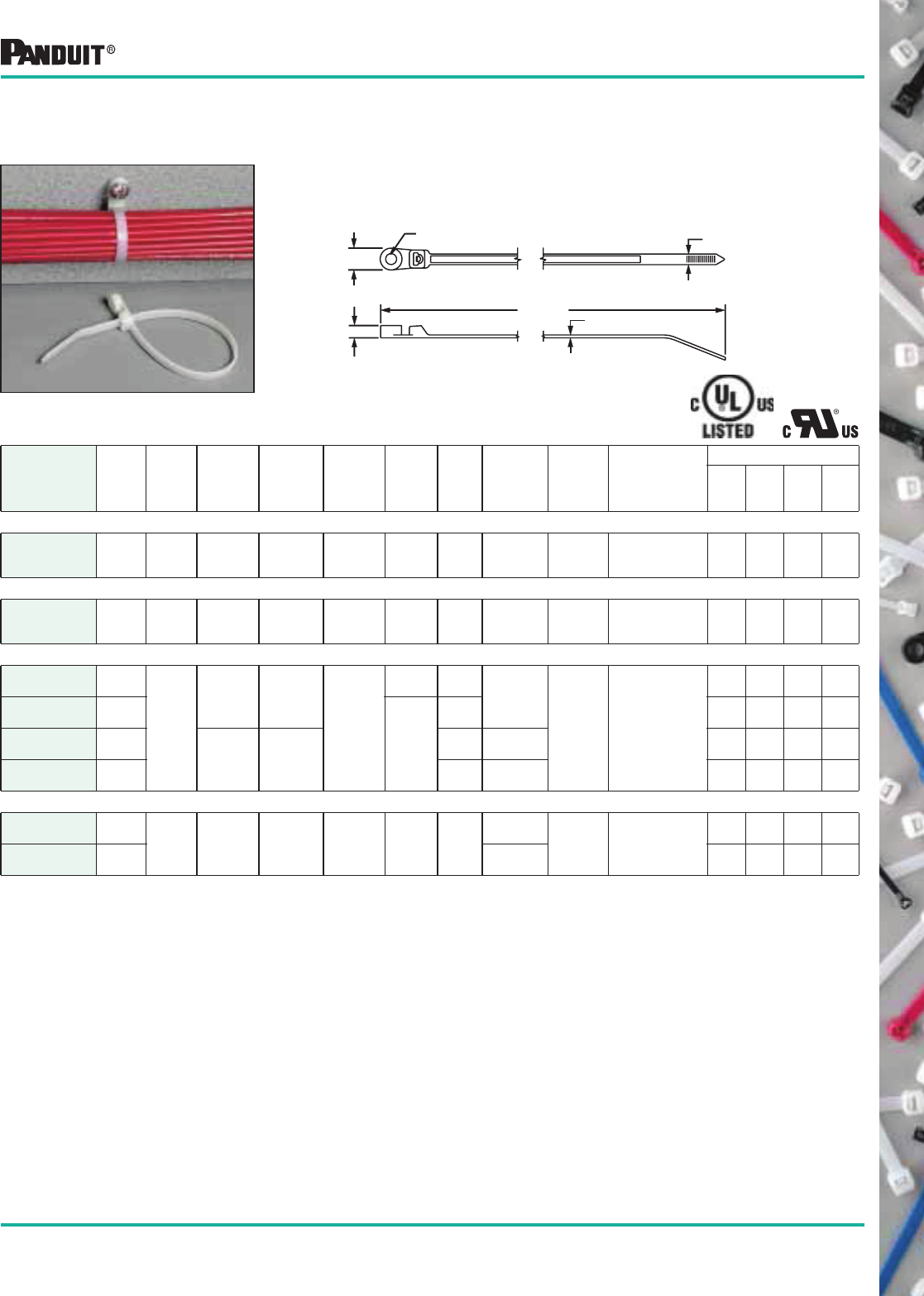
Lashing Tie
Mounting Clip
Converts PANDUIT ®
PAN-TY® Lashing Ties into clamps. Easily snaps
in place for a secure clamp. Used with Lashing Ties
(see pages 7, 8, 15 and above).
AB
C
17
Most commonly used parts appear in BOLD.
Releasable Cable Ties
(PRT Series)
The extended tab end of releasable cable ties permits easy release and
reuse even after tie has been pulled up snug by hand. Releasable ties
are particularly useful where changes are anticipated during
development, production or servicing in the field.
Part Number
Cross
Section
Length
A
in. (mm)
Width
B
in. (mm)
Thickness
C
in. (mm)
Head
Height
D
in. (mm)
Head
Width
E
in. (mm)
Max.
Bundle
Dia.
in. (mm)
Min. Loop
Tensile
Strength
Lbs. (N)
Recommended
PANDUIT ®
Installation
Tool Part No.
Packaging*
Std.
Pkg.
Qty.
Std.
Ctn.
Qty.
Bulk
Pkg.
Qty.
Bulk
Ctn.
Qty.
STANDARD CROSS SECTION
PRT1S-C0
Std.
4.8
(122)
.190
(4.8)
.052
(1.3)
.219
(5.6)
.316
(8.0)
1.00
(25)
50
(222)
Hand Installed
Only
100 1000 100 10000
PRT1.5S-C0 6.3
(160)
1.50
(38)
100 1000 100 10000
PRT2S-C0 7.4
(188)
1.88
(48)
100 1000 100 10000
PRT3S-C0 11.5
(292) .337
(8.6)
3.00
(76)
100 1000 100 10000
PRT4S-C0 14.5
(368)
4.00
(102)
100 1000 100 5000
HEAVY CROSS SECTION
PRT2H-L0
Hvy.
8.4
(213)
.300
(7.6)
.075
(1.9)
.300
(7.6)
.480
(12.2)
2.00
(51)
80
(356)
Hand Installed
Only
50 500 250 2500
PRT3H-L0 11.4
(290)
3.00
(76)
50 500 250 2500
PRT4H-L0 14.5
(368)
4.00
(102)
50 500 250 2500
E
D
B
A REF.
C
Head design for Standard Cross Section Ties
Head design for Heavy Cross Section Ties
STRAIGHT TIP
CURVED TIP
To release, grasp the head of
the cable tie, deflect release
tab and pull the cable tie away
from the bundle.
*Order the number of pieces required in multiples of package quantities.
For colors and other materials, see pages 24-26.
All part numbers shown in standard package quantities unless denoted by ‡
Weather Resistant Cable Ties (PRT Series)
18
Most commonly used parts appear in BOLD.
PAN-TY®
Weather
Resistant Nylon
Clamp Ties
Clamps are used to attach a bundle to another surface such as a control
panel, wall or ceiling using another fastener. The design allows for
bundling before or after screwing clamp in place.
NOTE 1: For best results, use tool tensions at the low end of the adjustment range, i.e. Std. Cable Ties installed at tool setting 5 to arrive at optimum installation tension.
Part Number
Length
A
in.
(mm)
Width
B
in.
(mm)
Thickness
C
in.
(mm)
Boss
Height
D
in.
(mm)
Boss
Width
E
in.
(mm)
Nominal
Hole
Dia.
F
in. (mm)
Screw
Size
Max.
Bundle
Dia.
in. (mm)
Min.
Loop
Tensile
Strength
Lbs. (N)
Recommended
PANDUIT ®
Installation
Tool Part No.
Packaging*
Std.
Pkg.
Qty.
Std.
Ctn.
Qty.
Bulk
Pkg.
Qty.
Bulk
Ctn.
Qty.
MINIATURE CROSS SECTION
PLC1M-S4-C0 4.3
(110)
.100
(2.5)
.045
(1.2)
.153
(3.9)
.239
(6.1)
.118
(3.0)
#4
(M2.5)
.75
(20)
18
(80)
GTS, GS2B,
PTS, PPTS
or STS2
100 1000 1000 50000
INTERMEDIATE CROSS SECTION
PLC1.5I-S8-C0 6.1
(156)
.135
(3.4)
.045
(1.2)
.166
(4.2)
.335
(8.5)
.172
(4.4)
#8
(M4)
1.25
(32)
40
(178)
GTS, GS2B,
PTS, PPTS
or STS2
100 1000 1000 25000
STANDARD CROSS SECTION
PLC2S-S6-C0
7.9
(201)
.190
(4.8)
.047
(1.2)
.160
(4.1)
.390
(9.5)
.145
(3.7)
#6
(M3) 1.84
(47)
50
(222)
GTS, GS2B,
GTH, GS4H,
PTS, PPTS,
STS2 or STH2
100 1000 1000 10000
PLC2S-S10-C0
.206
(5.2)
#10
(M5)
100 1000 1000 10000
PLC3S-S10-C0 12.0
(305) .052
(1.3)
.220
(5.6)
3.00
(76)
100 1000 1000 5000
PLC4S-S10-C0 15.0
(381)
4.00
(102)
100 1000 1000 5000
HEAVY CROSS SECTION
PLC2H-S25-TL0‡ 9.0
(228) .300
(7.6)
.075
(1.9)
.265
(6.7)
.500
(12.7)
.260
(6.6)
.262
(6.7)
1/4
(M6)
2.00
(51) 120
(534)
GTH, GS4H,
GS4EH, PPTEH
or STH2
— — 250 2500
PLC4H-S25-L0 15.1
(384)
4.00
(102)
50 500 250 2500
NATURAL POLYPROPYLENE CABLE TIES (Refer to drawing on page 19)
Part Number
Length
A
in.
(mm)
Width
B
in.
(mm)
Thickness
C
in. (mm)
Head
Height
D
in. (mm)
Head
Width
E
in. (mm)
Max.
Bundle
Dia.
in.
(mm)
Min.
Loop
Tensile
Strength
Lbs. (N)
Recommended
PANDUIT ®
Installation
Tool Part No.
Tool
Setting1
(except STS2/STH2)
Packaging*
Std.
Pkg.
Qty.
Std.
Ctn.
Qty.
Bulk
Pkg.
Qty.
Bulk
Ctn.
Qty.
MINIATURE CROSS SECTION
PLT1M-M109 3.9
(99)
.098
(2.5)
.043
(1.1)
.154
(3.9)
.180
(4.6)
.87
(22)
11
(49)
GTS, GS2B,
PTS, PPTS
or STS2
2 — — 1000 50000
INTERMEDIATE CROSS SECTION
PLT1.5I-M109 5.6
(142)
.142
(3.6)
.045
(1.2)
.180
(4.6)
.240
(6.1)
1.38
(35)
18
(80)
GTS, GS2B,
PTS, PPTS
or STS2
3 — — 1000 25000
STANDARD CROSS SECTION
PLT2S-M109 7.4
(188)
.190
(4.8)
.052
(1.3)
.220
(5.6)
.316
(8.0)
1.88
(48)
30
(133)
GTS, GS2B,
GTH, GS4H,
PTS, PPTS,
STS2 or STH2
5 (GTS, GS2B, PTS, PPTS)
2 (GTH, GS4H)
— — 1000 10000
PLT3S-M109 11.5
(292) .337
(8.6)
3.00
(76)
— — 1000 10000
PLT4S-M109 14.5
(368)
4.00
(102)
— — 1000 5000
HEAVY CROSS SECTION
PLT2H-TL109 8.1
(206)
.300
(7.6)
.075
(1.9)
.290
(7.4)
.480
(12.2)
2.00
(51)
50
(222)
GTH, GS4H,
PPTEH or STH2 5
— — 250 2500
PLT3H-TL109 11.4
(290)
3.00
(76)
— — 250 2500
PLT4H-TL109 14.5
(368)
4.00
(102)
— — 250 2500
F
E
B
C
A REF.
D
Weather Resistant Nylon 6.6 Clamp Ties (PLC Series)
*Order the number of pieces required in multiples of package quantities.
For colors and other materials, see pages 24-26.
All part numbers shown in standard package quantities unless denoted by ‡
19
Most commonly used parts appear in BOLD.
Polypropylene Cable Ties (PLT / PRT Series)
PAN-TY® Weather
Resistant
Polypropylene
Cable Ties
For chemical resistance in outdoor applications that are unsuitable for
nylon and that do not require high loop tensile strengths. Color is black.
*Order the number of pieces required in multiples of package quantities.
All part numbers shown in standard package quantities unless denoted by ‡
Part Number
Length
A
in. (mm)
Width
B
in. (mm)
Thickness
C
in. (mm)
Head
Height
D
in. (mm)
Head
Width
E
in. (mm)
Max.
Bundle
Dia.
in. (mm)
Min. Loop
Tensile
Strength
Lbs. (N)
Recommended
PANDUIT ®
Installation
Tool Part. No.
Packaging*
Std.
Pkg.
Qty.
Std.
Ctn.
Qty.
Bulk
Pkg.
Qty.
Bulk
Ctn.
Qty.
EXTRA-HEAVY CROSS SECTION — WEATHER RESISTANT POLYPROPYLENE
PRT5EH-C100 20.1
(510) .500
(12.7)
.075
(1.9)
.400
(10.2)
.800
(20.3)
5.00
(127) 90
(400) Hand Installed
100 1000 — —
PRT6EH-C100 22.2
(564)
6.00
(152)
100 1000 — —
PAN-TY® Releasable
Polypropylene
Cable Ties
To release, grasp the head of the cable
tie, deflect release tab and pull the
cable tie away from the bundle.
CURVED TIP
E
D
A REF.
B
C
NOTE 1: For best results, use tool tensions at the low end of the adjustment range, i.e. Std. Cable Ties installed at tool setting 5 to arrive at optimum installation tension.
Part Number
Length
A
in. (mm)
Width
B
in. (mm)
Thickness
C
in. (mm)
Head
Height
D
in. (mm)
Head
Width
E
in. (mm)
Max.
Bundle
Dia.
in. (mm)
Min. Loop
Tensile
Strength
Lbs. (N)
Recommended
PANDUIT ®
Installation Tool
Part No.
Tool
Setting1
(except
STS2/
STH2)
Packaging*
Std.
Pkg.
Qty.
Std.
Ctn.
Qty.
Bulk
Pkg.
Qty.
Bulk
Ctn.
Qty.
MINIATURE CROSS SECTION
PLT1M-M100 3.9
(99)
.098
(2.5)
.043
(1.1)
.154
(3.9)
.180
(4.6)
.87
(22)
11
(49)
GTS, GS2B,
PTS, PPTS
or STS2
2 — — 1000 50000
INTERMEDIATE CROSS SECTION
PLT1.5I-M100 5.6
(142)
.142
(3.6)
.045
(1.1)
.180
(4.6)
.240
(6.1)
1.38
(35)
18
(80)
GTS, GS2B,
PTS, PPTS
or STS2
3 — — 1000 25000
STANDARD CROSS SECTION
PLT2S-M100 7.4
(188)
.190
(4.8)
.052
(1.3)
.220
(5.6)
.316
(8.0)
1.88
(48)
30
(133)
GTS, GS2B,
GTH, GS4H,
PTS, PPTS,
STS2
or STH2
5 (GTS,
GS2B,
PTS,
PPTS)
2 (GTH,
GS4H)
— — 1000 10000
PLT3S-M100 11.5
(292) .337
(8.6)
3.00
(76)
— — 1000 10000
PLT4S-M100 14.5
(368)
4.00
(102)
— — 1000 5000
HEAVY CROSS SECTION
PLT2H-TL100 8.1
(206)
.300
(7.6)
.075
(1.9)
.290
(7.4)
.480
(12.2)
2.00
(51)
50
(222)
GTH, GS4H,
PPTEH
or STH2
5
— — 250 2500
PLT3H-TL100 11.4
(290)
3.00
(76)
— — 250 2500
PLT4H-TL100 14.5
(368)
4.00
(102)
— — 250 2500
E
D
B
A REF.
C
Head design for Standard Cross Section Ties
Head design for Heavy Cross Section Ties
STRAIGHT TIP
CURVED TIP
20
Most commonly used parts appear in BOLD.
Flame Retardant Nylon 6.6 Cable Ties
CURVED TIP
E
D
A REF.
B
C
PAN-TY®
Flame
Retardant Nylon 6.6
Cable Ties and
Marker Ties
• Flame Retardant Nylon 6.6 meets the requirements of UL94V-0
• Can be used with flame retardant cable tie mounts (see pages 86 and 89)
Part Number
Length
A
in. (mm)
Width
B
in. (mm)
Thickness
C
in. (mm)
Head
Height
D
in. (mm)
Head
Width
E
in. (mm)
Marker
Write-on
Area
in. (mm)
Max.
Bundle
Dia.
in. (mm)
Min. Loop
Tensile
Strength
Lbs. (N)
Recommended
PANDUIT ®
Installation
Tool Part No.
Packaging*
Std.
Pkg.
Qty.
Std.
Ctn.
Qty.
Bulk
Pkg.
Qty.
Bulk
Ctn.
Qty.
MINIATURE CROSS SECTION
PLF1M-M69‡ 4.3
(109)
.098
(2.5)
.045
(1.1)
.154
(3.9)
.180
(4.6)
.31 x .75
(7.9 x 19.1)
.87
(22)
18
(80)
GTS, GS2B,
PTS. PPTS
or STS2
— — 1000 25000
PLM1M-M69‡ 3.9
(99)
.035
(.9)
.26 x .95
(6.6 x 24.1)
.75
(20)
— — 1000 25000
PLT1M-M69‡ 4.0
(102) .043
(1.1)
.188
(4.8) —
.87
(22)
— — 1000 25000
PLT2M-M69‡ 8.0
(203)
2.00
(51)
— — 1000 25000
INTERMEDIATE CROSS SECTION
PLT1.5I-M69‡ 5.6
(142)
.142
(3.6) .044
(1.1)
.177
(4.5)
.239
(6.1) —
1.38
(35) 40
(178)
GTS, GS2B,
PTS, PPTS
or STS2
— — 1000 25000
PLT2I-M69‡ 8.0
(203)
.142
(3.6)
2.00
(51)
— — 1000 25000
STANDARD CROSS SECTION
PLT2S-M69‡ 7.4
(188) .190
(4.8)
.052
(1.3) .220
(5.6)
.320
(8.1) —
1.88
(48) 50
(222)
GTS, GS2B,
GTH, GS4H,
PTS, PPTS,
STS2 or STH2
— — 1000 10000
PLT4S-M69‡ 14.5
(368)
.052
(1.3)
.337
(8.6)
4.00
(102)
— — 1000 5000
HEAVY CROSS SECTION
PLT4H-TL69‡ 14.6
(371)
.300
(7.6)
.075
(1.9)
.290
(7.4)
.480
(12.2)
— 4.00
(102)
120
(534)
GTH, GS4H,
GS4EH,
PPTEH or
STH2
— — 250 2500
*Order the number of pieces required in multiples of package quantities.
All part numbers shown in standard package quantities unless denoted by ‡
PLTPLM1M PLF1M
21
Most commonly used parts appear in BOLD.
• For high moisture, corrosive environments and
low temperatures
• For indoor use or weather resistant applications
Part Number
Length
A
in. (mm)
Width
B
in. (mm)
Thickness
C
in. (mm)
Head
Height
D
in. (mm)
Head
Width
E
in. (mm)
Max.
Bundle
Dia.
in. (mm)
Min. Loop
Tensile
Strength
Lbs. (N)
Recommended
PANDUIT ®
Installation Tool
Part No.
Packaging*
Std.
Pkg.
Qty.
Std.
Ctn.
Qty.
Bulk
Pkg.
Qty.
Bulk
Ctn.
Qty.
INTERMEDIATE CROSS SECTION
PLT1.5I-M120‡ 5.6
(142)
.142
(3.6)
.045
(1.1)
.180
(4.6)
.240
(6.1)
1.38
(35)
25
(111)
GTS, GS2B,
PTS, PPTS or
STS2
— — 1000 25000
STANDARD CROSS SECTION
PLT2S-M120‡ 7.4
(188) .190
(4.8)
.052
(1.3)
.220
(5.6)
.316
(8.0)
1.88
(48) 40
(178)
GTS, GS2B,
GTH, GS4H,
PTS, PPTS,
STS2 or STH2
— — 1000 10000
PLT4S-M120‡ 14.5
(368)
.337
(8.6)
4.00
(102)
— — 1000 5000
LIGHT-HEAVY CROSS SECTION
PLT8LH-C120‡ 27.6
(701)
.300
(7.6)
.075
(1.9)
.290
(7.4)
.480
(12.2)
8.00
(203)
90
(400)
GTH, GS4H,
GS4EH,
PPTEH or
STH2
— — 100 2000
HEAVY CROSS SECTION
PLT4H-TL120‡ 14.5
(368)
.300
(7.6)
.075
(1.9)
.290
(7.4)
.480
(12.2)
4.00
(102)
90
(400)
GTH, GS4H,
GS4EH,
PPTEH or
STH2
— — 250 2500
CURVED TIP
E
D
A REF.
B
C
Weather Resistant Nylon 12 Cable Ties
*Order the number of pieces required in multiples of packaging quantities.
All part numbers shown in standard package quantities unless denoted by ‡.
P
AN
-T
Y
®
Weather Resistant
Nylon 12 Cable Ties
22
Most commonly used parts appear in BOLD.
HALAR** and TEFZEL*** Cable Ties
**HALAR is a registered trademark of Solvay Solexis, Inc.
Part Number
Length
A
in. (mm)
Width
B
in. (mm)
Thickness
C
in. (mm)
Head
Height
D
in. (mm)
Head
Width
E
in. (mm)
Max.
Bundle
Dia.
in. (mm)
Min. Loop
Tensile
Strength
Lbs. (N)
Recommended
PANDUIT ®
Installation Tool
Part No.
Packaging*
Std.
Pkg.
Qty.
Std.
Ctn.
Qty.
Bulk
Pkg.
Qty.
Bulk
Ctn.
Qty.
MINIATURE CROSS SECTION
PLT1M-C702 4.0
(102)
.098
(2.5)
.043
(1.1)
.186
(4.7)
.188
(4.8)
.87
(22)
18
(80)
GTS, GS2B,
PTS, PPTS
or STS2
100 1000 1000 25000
STANDARD CROSS SECTION
PLT2S-C702 7.4
(188) .190
(4.8)
.055
(1.4) .240
(6.1)
.320
(8.1)
1.88
(48) 50
(222)
GTS, GS2B,
GTH, GS4H,
PTS, PPTS,
STS2 or STH2
100 1000 1000 10000
PLT3S-C702 11.6
(295)
.059
(1.5)
3.00
(76)
100 1000 1000 5000
***TEFZEL is a registered trademark of E. I. DuPont de Nemours Co.
Part Number
Length
A
in. (mm)
Width
B
in. (mm)
Thickness
C
in. (mm)
Head
Height
D
in. (mm)
Head
Width
E
in. (mm)
Max.
Bundle
Dia.
in. (mm)
Min. Loop
Tensile
Strength
Lbs. (N)
Recommended
PANDUIT ®
Installation Tool
Part No.
Packaging*
Std.
Pkg.
Qty.
Std.
Ctn.
Qty.
Bulk
Pkg.
Qty.
Bulk
Ctn.
Qty.
MINIATURE CROSS SECTION
PLT1M-C76 4.0
(102)
.098
(2.5)
.043
(1.1)
.186
(4.7)
.188
(4.8)
.87
(22)
18
(80)
GTS, GS2B, PTS,
PPTS or STS2
100 1000 1000 25000
INTERMEDIATE CROSS SECTION
PLT2I-C76 8.0
(203)
.135
(3.4)
.045
(1.1)
.180
(4.6)
.240
(6.1)
2.00
(51)
25
(111)
GTS, GS2B, PTS,
PPTS or STS2
100 1000 1000 10000
STANDARD CROSS SECTION
PLT2S-C76 7.4
(188)
.190
(4.8)
.055
(1.4)
.240
(6.1)
.320
(8.1)
1.88
(48)
50
(222)
GTS, GS2B,
GTH, GS4H,
PTS, PPTS,
STS2 or STH2
100 1000 1000 10000
PLT3S-C76 11.6
(295) .055
(1.4)
3.00
76)
100 1000 1000 5000
PLT4S-C76 14.6
(371)
4.00
(102)
100 1000 1000 5000
HEAVY CROSS SECTION
PLT3H-L76 11.5
(292) .300
(7.6)
.075
(1.9)
.360
(9.1)
.480
(12.2)
3.00
(78) 120
(534)
GTH, GS4H,
GS4EH
PPTEH or
STH2
50 500 250 2500
PLT4H-L76 14.6
(371)
4.00
(102)
50 500 250 2500
PAN-TY®
HALAR**
Fluoropolymer
Cable Ties
HALAR** Cable Ties are UL Listed and UL Recognized as: Suitable for
use in Air Handling Spaces per NEC, Section 300-22 (c) and (d). Many
inspectors look for the distinctive maroon color. HALAR** cable ties have
a low smoke density rating and an excellent flammability rating of
UL94V-0. Other applications include nuclear plants, chemical
environments, telecommunications equipment, aerospace, high and low
temperature environments.
PAN-TY®
TEFZEL***
Fluoropolymer
Cable Ties
TEFZEL*** cable ties are ideal for applications requiring resistance to
environmental stresses such as chemical attack, gamma radiation, ultraviolet
radiation and extreme temperatures. In addition, TEFZEL*** has a UL
Flammability rating of UL94V-0. TEFZEL*** ties have a distinctive aqua blue color.
*Order the number of pieces required in multiples of package quantities.
All part numbers shown in standard package quantities unless denoted by ‡.
CURVED TIP
E
D
A REF.
B
C
CURVED TIP
E
D
A REF.
B
C

23
Most commonly used parts appear in BOLD.
PAN-TY ® Nylon 6.6
Fluorescent Ties
Designed for packaging and color-coding applications. Ties are
offered in four “hot” colors: Orange, Yellow, Green and Pink.
Part Number Color
Length
A
in.
(mm)
Width
B
in.
(mm)
Thickness
C
in. (mm)
Head
Height
D
in. (mm)
Head
Width
E
in. (mm)
Max.
Bundle
Dia.
in. (mm)
Min. Loop
Tensile
Strength
Lbs. (N)
Recommended
PAN DUIT ®
Installation Tool
Part No.
Packaging*
Std.
Pkg.
Qty.
Std.
Ctn.
Qty.
Bulk
Pkg.
Qty.
Bulk
Ctn.
Qty.
MINIATURE CROSS SECTION
PLT1M-M53 Orange
3.9
(99)
.098
(2.5)
.043
(1.1)
.154
(3.9)
.180
(4.6)
.87
(22)
18
(80)
GTS, GTH, GS2B,
PTS, PPTS
or STS2
— — 1000 50000
PLT1M-M54 Yellow — — 1000 50000
PLT1M-M55 Green — — 1000 50000
PLT1M-M59 Pink — — 1000 50000
INTERMEDIATE CROSS SECTION
PLT2I-M53 Orange
8.0
(203)
.142
(3.6)
.045
(1.1)
.180
(4.6)
.240
(6.1)
2.00
(51)
30
(133)
GTS, GTH, GS2B,
PTS, PPTS
or STS2
— — 1000 25000
PLT2I-M54 Yellow — — 1000 25000
PLT2I-M55 Green — — 1000 25000
PLT2I-M59 Pink — — 1000 25000
STANDARD CROSS SECTION
PLT2S-M53 Orange
7.4
(188)
.190
(4.8)
.052
(1.3)
.220
(5.6)
.316
(8.0)
1.88
(48)
50
(222)
GTS, GS2B,
GTH, GS4H, PTS,
PPTS, STS2
or STH2
— — 1000 10000
PLT2S-M54 Yellow — — 1000 10000
PLT2S-M55 Green — — 1000 10000
PLT2S-M59 Pink — — 1000 10000
PLT3S-M53 Orange
11.5
(292)
.337
(8.6)
3.00
(76)
— — 1000 10000
PLT3S-M54 Yellow — — 1000 10000
PLT3S-M55 Green — — 1000 10000
PLT3S-M59 Pink — — 1000 10000
*Order the number of pieces required in multiples of package quantities.
All part numbers shown in standard package quantities unless denoted by ‡.
Fluorescent Cable Ties
CURVED TIP
E
D
A REF.
B
C
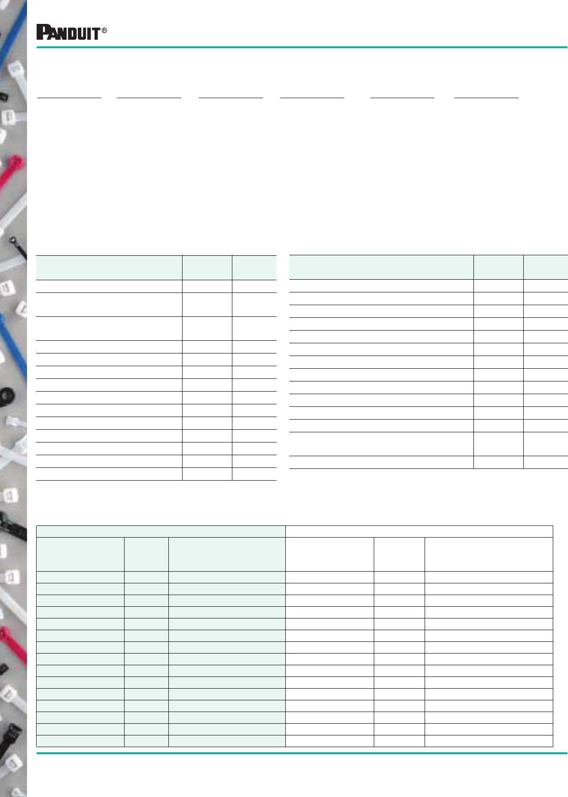
24
Most commonly used parts appear in BOLD.
Part Number Suffix Codes for All PAN-TY® Cable Ties
Part Description:
P = PANDUIT ®
(at beginning of P/N)
L = Locking
T = Tie
C = Clamp
F = Flag
M = Marker
R = Releasable
W = Wing
P = Push Mount
U = Umbrella
Size:
Approximate
Maximum Bundle
Diameter in Inches
Cross Section:
SM = Subminiature
M = Miniature
I = Intermediate
S = Standard
LH = Light-Heavy
H = Heavy
EH = Extra-Heavy
Screw Hole Size:
(Clamp Ties Only)
-S4 = #4 (M2.5)
-S6 = #6 (M3)
-S8 = #8 (M4)
-S10 = #10 (M5)
-S25 = 1/4 (M6)
Package Size:
Q = 25
L = 50
C = 100
TL = 250
D = 500
M = 1000
XMR = 2 reels/5000 ea.
Color:
See Material/Color
chart. Not all ties
available in all colors.
—
Part Number System (Example of PLT2S-C)
Material/Color
PANDUIT ®
Suffix*
Mil Spec
Suffix**
Nylon 6.6 — Natural (See Note) ✔9
Weather Resistant Nylon 6.6 —
Black
0 N/A
Weather Resistant Nylon 6.6 —
Black (meets MIL Spec.)
00 0
Nylon 6.6 — Brown 1 1
Nylon 6.6 — Red 2 2
Nylon 6.6 — Orange 3 3
Nylon 6.6 — Yellow 4 4
Nylon 6.6 — Green 5 5
Nylon 6.6 — Blue 6 6
Nylon 6.6 — Purple 7 7
Nylon 6.6 — Gray 8 8
Nylon 6.6 — White 10 N/A
Nylon 6.6 — Telephone Gray 14 N/A
Nylon 6.6 — Black 20 N/A
Material/Color Chart
Material/Color
PANDUIT ®
Suffix*
Mil Spec
Suffix**
Heat Stabilized Nylon 6.6 — Black 30 N/A
Heat Stabilized Nylon 6.6 — Natural 39 N/A
Nylon 6.6 — Fluorescent Orange 53 N/A
Nylon 6.6 — Fluorescent Yellow 54 N/A
Nylon 6.6 — Fluorescent Green 55 N/A
Nylon 6.6 — Fluorescent Pink 59 N/A
Flame Retardant Nylon 6.6 — Black 60 N/A
Flame Retardant Nylon 6.6 — Ivory 69 N/A
TEFZEL***— Aqua Blue 76 N/A
Weather Resistant Polypropylene — Black 100 N/A
Natural Polypropylene — Green 109 N/A
Nylon 12 — Black 120 N/A
Heat Stabilized Weather Resistant
Nylon 6.6 — Black
300 N/A
HALAR****— Maroon 702 N/A
*NOTE: ✔designates PANDUIT ® standard Natural Nylon 6.6 color/material. No suffix required in part number.
**NOTE: MIL SPEC Color (suffix) per AS33671 (Formerly MS3367) and SAE AS33681 (Formerly MS3368).
***TEFZEL is a registered trademark of E.I. DuPont de Nemours Co.
****HALAR is a registered trademark of Solvay Solexis, Inc.
Standard Packaging Bulk Packaging
Part Number
Natural
Nylon
6.6
Available Color/
Material (Suffix) Part Number
Natural
Nylon 6.6
Available Color/
Material (Suffix)
PLC1M-S4-C ✔0PLC1M-S4-M ✔0, 30
PLC1.5I-S8-C ✔0PLC1.5I-S8-M ✔0, 30
PLC2S-S6-C ✔0PLC2S-S6-M ✔0
PLC2S-S10-C ✔0, 14 PLC2S-S10-M ✔0, 20, 30
PLC3S-S10-C ✔0PLC3S-S10-M ✔0
PLC4S-S10-C ✔0PLC4S-S10-M ✔0, 30
PLC2H-S25-L ✔PLC2H-S25-TL ✔0, 30
PLC4H-S25-L ✔0PLC4H-S25-TL ✔0, 30
PLF1M-C ✔0PLF1M-M ✔0, 2, 3, 4, 6, 10, 69
PLF1MA-C ✔3, 4 PLF1MA-M ✔0, 2, 3, 4, 5, 6, 10
PLF1MB-C ✔PLF1MB-M ✔
PLM1M-C ✔0PLMIM-M ✔0, 1, 2, 3, 4, 5, 6, 7, 8, 10, 69
PLM2M-C ✔PLM2M-M ✔0, 4, 6
PLM2S-C ✔0, 4 PLM2S-D ✔0, 2, 3, 4, 5, 6, 8
PLM4S-C ✔PLM4S-D ✔0, 2, 4, 6
25
Most commonly used parts appear in BOLD.
Part Number Suffix Codes for All PAN-TY® Cable Ties
Standard Packaging Bulk Packaging
Part Number
Natural
Nylon
6.6
Available Color/
Material (Suffix) Part Number
Natural
Nylon 6.6
Available Color/
Material (Suffix)
PL2M2S-L ✔0PL2M2S-D ✔0, 4, 10
PL3M2S-L ✔PL3M2S-D ✔0, 4
PLP1.5I-C ✔PLP1.5I-M ✔0, 30
PLP1S-M ✔0, 30
PLP1.5S-M ✔
PLP2S-C ✔PLP2S-M ✔0, 30
PLT.6SM-C ✔0PLT.6SM-M ✔0, 30
PLT.7M-C ✔PLT.7M-M ✔0, 30
PLT1M-C ✔0, 00, 1, 2, 3, 4, 5, 6, 7,
8, 10, 14, 30, 76, 702
PLT1M-M ✔0, 00, 1, 2, 3, 4, 5, 6, 7, 8, 10, 14,
20, 30, 53, 54, 55, 59, 60, 69, 76,
100, 109, 300, 702
PLT1M-XMR ✔0, 1, 2, 3, 4, 5, 6, 7, 8, 10, 30
PLT1.5M-C ✔0PLT1.5M-M ✔0, 00, 1, 2, 3, 4, 5, 6, 7, 8, 10, 14,
20, 30
PLT1.5M-XMR ✔0, 00, 30
PLT2M-C ✔0PLT2M-M ✔0, 1, 2, 3, 4, 5, 6, 7, 8, 10, 20, 30,
69
PLT1.5I-C ✔0, 1, 2, 3, 4, 5, 6, 7, 8,
10, 20, 30
PLT1.5I-M ✔0, 00, 1, 2, 3, 4, 5, 6, 7, 8, 10, 20,
30, 69, 100, 109, 120, 300
PLT2I-C ✔0, 14, 30, 76 PLT2I-M ✔0, 1, 2, 3, 4, 5, 6, 7, 8, 10, 14, 20,
30, 53, 54, 55, 59, 69, 76, 300
PLT2.5I-C ✔0PLT2.5I-M ✔0, 20
PLT3I-C ✔0, 14 PLT3I-M ✔0, 2, 3, 4, 5, 6, 8, 10, 14, 20, 30
PLT4I-C ✔0, 14 PLT4I-M ✔0, 2, 5, 6, 14, 20, 30
PLT1S-C ✔0PLT1S-M ✔0, 30, 38, 300
PLT1.5S-C ✔0PLT1.5S-M ✔0, 30
PLT2S-C ✔0, 00, 1, 2, 3, 4, 5, 6, 7,
8, 10, 20, 30, 76, 702
PLT2S-M ✔0, 00, 1, 2, 3, 4, 5, 6, 7, 8, 10, 20,
30, 38, 39, 53, 54, 55, 59, 60, 69,
76, 100, 109, 120, 300, 702
PLT2.5S-C ✔0PLT2.5S-M ✔0, 30
PLT3S-C ✔0, 00, 2, 20, 30, 76, 702 PLT3S-M ✔0, 00, 1, 2, 3, 4, 5, 6, 7, 8, 10, 20,
30, 53, 54, 55, 59, 76, 100, 109,
702
PLT4S-C ✔0, 00, 2, 3, 4, 5, 6, 8, 20,
30, 76
PLT4S-M ✔0, 00, 1, 2, 3, 4, 5, 6, 7, 8, 10, 14,
20, 30, 69, 76, 100, 109, 120, 300
PLT4.5S-C ✔0PLT4.5S-M ✔0
PLT5S-C ✔0PLT5S-M ✔0, 2, 3, 4, 5, 6, 8, 30
PLT6LH-L ✔0PLT6LH-C ✔0
PLT7LH-L ✔0PLT7LH-C ✔0, 30
PLT8LH-L ✔0PLT8LH-C ✔0, 120
PLT8LH-Q 0
PLT9LH-L ✔0PLT9LH-C ✔0, 30
PLT10LH-L ✔PLT10LH-C ✔
PLT2H-L ✔0PLT2H-TL ✔0, 2, 4, 6, 30, 100, 109, 300
PLT2.5H-L ✔0PLT2.5H-TL ✔0
PLT3H-L ✔0, 76 PLT3H-TL ✔0, 30, 76, 100, 109
PLT4H-L ✔0, 00, 76 PLT4H-TL ✔0, 00, 1, 2, 3, 4, 5, 6, 10, 20, 30,
69, 76, 100, 109, 120, 300
PLT4H-C ✔0
PLT5H-L ✔0PLT5H-C ✔0, 30
PLT6H-L ✔0PLT6H-C ✔0, 30
PLT8H-Q 0PLT8H-C ✔0, 00, 30
PLT8H-L ✔0
PLT13H-Q ✔0PLT13H-C ✔0, 3
PLT2EH-Q 0PLT2EH-C ✔0
26
Most commonly used parts appear in BOLD.
Part Number Suffix Codes for All PAN-TY® Cable Ties
Standard Packaging Bulk Packaging
Part Number
Natural
Nylon
6.6
Available Color/
Material (Suffix) Part Number
Natural
Nylon 6.6
Available Color/
Material (Suffix)
PLT3EH-NB-C 0
PLT5EH-Q ✔0PLT5EH-C ✔0
PLT5EH-NB-C 0
PLT6EH-Q ✔0PLT6EH-C ✔0
PLT6EH-NB-C 0
PLT8EH-Q 0PLT8EH-C ✔0
PLT10EH-Q 0PLT10EH-C ✔0
PLT12EH-Q 0PLT12EH-C ✔0
PLUP40S-D 30
PLUP40SE-D ✔30
PLWP1M-C ✔PLWP1M-D ✔0, 30
PLWP1.5I-C ✔PLWP1.5I-D ✔30
PLWP1S-C ✔0PLWP1S-D ✔0, 20, 30
PLWP1SA-D ✔
PLWP1SB-D ✔
PLWP1.5S-D ✔30
PLWP1.5SA-D ✔
PLWP2S-C ✔0PLWP2S-D ✔0, 30
PLWP2SA-D ✔
PLWP2SB-D ✔
PLWP2H-TL ✔0, 30
PLWP3H-TL ✔0
PLWP30SC-D 30
PLWP40SC-D 30
PLWP40SD-D 30
PLWP50SC-D 30
PLWP50SE-D 30
PRLWP30S-D 30
PRLWP50S-D 30
PRT1S-C ✔0PRT1S-M ✔0
PRT1.5S-C ✔0PRT1.5S-M ✔0, 30
PRT2S-C ✔0PRT2S-M ✔0, 2, 3, 4, 6, 7
PRT3S-C ✔0PRT3S-M ✔0
PRT4S-C ✔0PRT4S-M ✔0, 2, 3, 4, 6
PRT2H-L ✔0PRT2H-TL ✔0
PRT3H-L ✔0PRT3H-TL ✔0
PRT4H-L ✔0PRT4H-TL ✔0
PRT2EH-Q 0PRT2EH-C ✔0, 100
PRT5EH-Q ✔0PRT5EH-C ✔0, 100
PRT6EH-Q ✔0PRT6EH-C ✔0, 100
PRT8EH-Q 0PRT8EH-C ✔0, 100
PRT10EH-Q 0PRT10EH-C ✔0
PRT12EH-Q 0PRT12EH-C ✔0
PRWP1S-C ✔PRWP1S-D ✔0
PRWP1SA-D ✔
PRWP1SB-D ✔
PRWP1.5S-D ✔0, 20, 30
PRWP2S-D ✔0
PRWP2H-TL ✔
PRST30S-S14-M 30
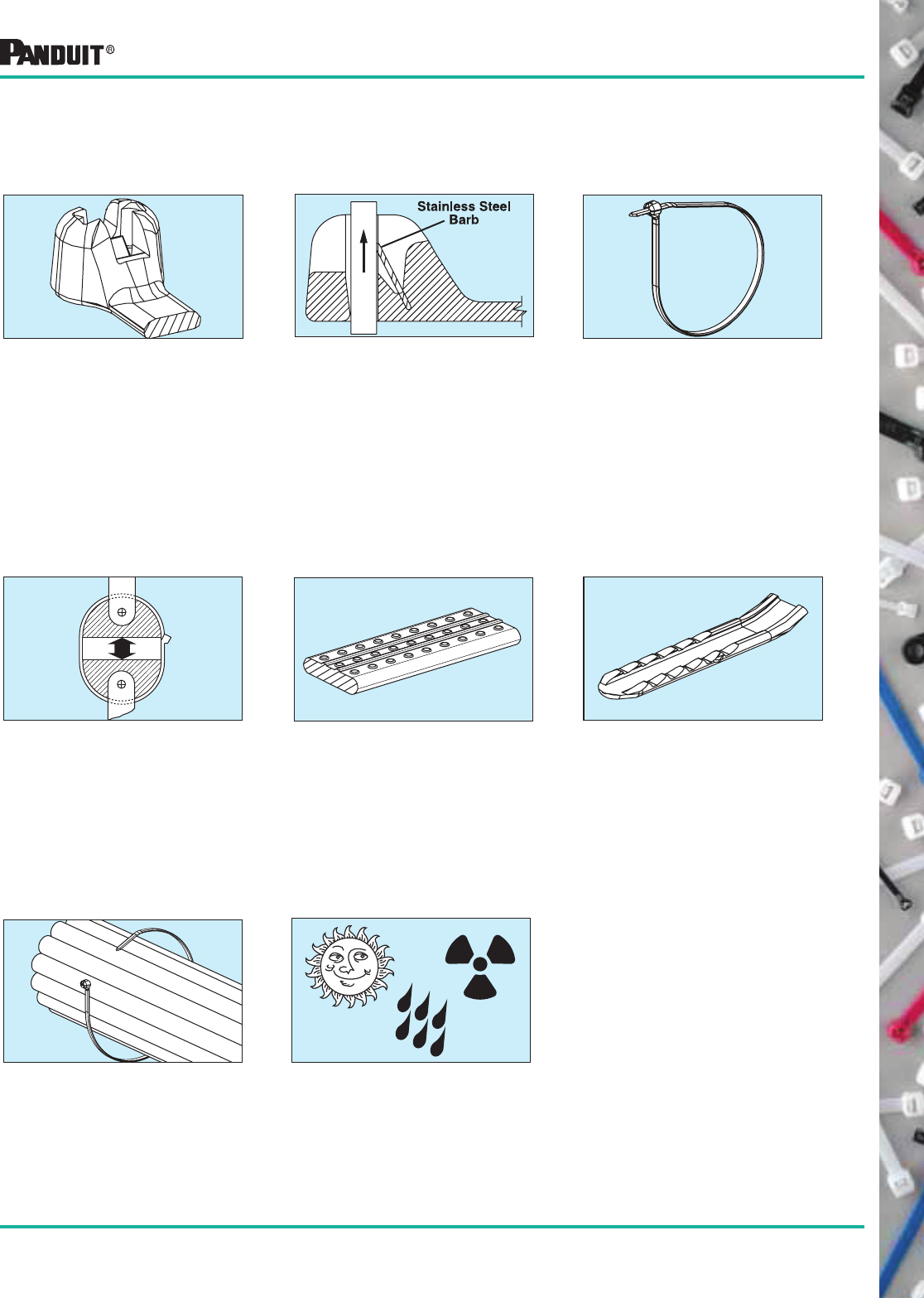
27
Most commonly used parts appear in BOLD.
DOME-TOP ® Barb Ty Cable Ties
DOME-TOP ® Barb Ty Cable Tie Features/Benefits
2. Stainless Steel Barb 3. Low Threading Force
4. High Tensile Strength
• Unique patented design
• Round smooth edges
• No irritation to installer’s hands
• Reduces installer fatigue
• Increases productivity
• Exceeds industry and
Aerospace Standard
SAE (AS23190) standards
• Available in four loop tensile
strengths from 18 lbs. (80N) to
120 lbs. (534N) to provide a
wide selection
5. Anti-Slip Strap Body 6. Finger Tip Grip
• Ribbed and stippled strap
body prevents axial and
lateral movement
• Exclusively designed finger
grip is available on all sizes
of DOM E-TOP ® Barb Ty Cable
Ties to assure positive grip
during threading of the tie
• Orients tip toward head to speed
installation; lowers installed cost
• Faster initial threading
• Easier to pick up from flat surfaces
8. Material/Size Availability
• Available in lengths from 4.0"
(102mm) to 30.7" (780mm) to
meet a variety of applications
• Several materials available for
special environments: Natural 6.6
nylon, weather resistant black 6.6
nylon, heat stabilized 6.6 nylon
and 11 different colors
7. Curved Tip
• Made of 316 corrosion resistant
stainless steel
• Provides consistent
performance and reliability for
users who prefer a cable tie
with a metal barb
• Infinitely adjustable for tight
bundles through its entire
bundle range
1. DO ME-TOP ® Head
28
Most commonly used parts appear in BOLD.
DOME-TOP ® Barb Ty
Nylon 6.6 Locking
Cable Ties
Part Number
Length
A
in. (mm)
Width
B
in. (mm)
Thickness
C
in. (mm)
Head
Height
D
in. (mm)
Head
Width
E
in. (mm)
Max.
Bundle
Dia.
in. (mm)
Min. Loop
Tensile
Strength
Lbs. (N)
Recommended
PANDUIT ®
Installation
Tool Part No.
Packaging*
Std.
Pkg.
Qty.*
Std.
Ctn.
Qty.
Bulk
Pkg.
Qty.
Bulk
Ctn.
Qty.
MINIATURE CROSS SECTION
BT1M-C 4.0
(102)
.095
(2.4)
.036
(0.9)
.156
(4.0)
.172
(4.4)
.90
(23)
18
(80)
GTS, GS2B,
PTS, PPTS
or STS2
100 1000 1000 50000
BT1.5M-C 6.3
(160)
.046
(1.2)
.182
(4.6)
1.50
(38)
100 1000 1000 25000
BT2M-C 7.9
(201)
2.00
(51)
100 1000 1000 25000
BT4M-C 14.2
(361)
4.00
(102)
100 1000 1000 10000
• Available in Miniature, Intermediate, Standard and
Light-Heavy cross sections
• Bundle diameters up to 9.00" (229mm)
• Available in natural, weather resistant and heat stabilized
nylon and 11 different colors
• Tool or hand installed
INTERMEDIATE CROSS SECTION
BT1.5I-C 6.1
(155)
.141
(3.6)
.041
(1.0)
.185
(4.7)
.248
(6.3)
1.50
(38)
40
(178)
GTS, GS2B,
PTS, PPTS
or STS2
100 1000 1000 25000
BT2I-C 8.0
(203)
2.00
(51)
100 1000 1000 25000
BT3I-C 11.3
(287) .049
(1.2)
3.00
(76)
100 1000 1000 10000
BT4I-C 14.3
(363)
4.00
(102)
100 1000 1000 10000
LIGHT-HEAVY CROSS SECTION (STRAIGHT TIP)
BT2LH-L 8.7
(221)
.275
(7.0)
.065
(1.7)
.320
(8.1)
.520
(13.2)
2.00
(51)
120
(534)
GTH, GS4H,
GS4EH,
PPTEH, STH2
or ST2EH
50 500 250 2500
BT3LH-L 11.8
(300)
3.00
(76)
50 500 250 2500
BT4LH-L 14.9
(378)
4.00
(102)
50 500 250 2500
BT5LH-L 18.1
(460)
5.00
(127)
50 500 100 2000
BT6LH-L 21.2
(538)
6.00
(152)
50 500 100 2000
BT7LH-L 24.4
(620)
7.00
(178)
50 500 100 2000
BT8LH-L 27.5
(699)
8.00
(203)
50 500 100 1000
BT9LH-L 30.7
(780)
9.00
(229)
50 500 100 1000
STANDARD CROSS SECTION
BT2S-C 8.0
(203)
.185
(4.7)
.045
(1.2)
.220
(5.6)
.320
(8.1)
2.00
(51)
50
(222)
GTS, GS2B,
GTH, GS4H,
PTS, PPTS,
STS2 or STH2
100 1000 1000 10000
BT3S-C 12.0
(305) .052
(1.3)
3.00
(76)
100 1000 1000 10000
BT4S-C 15.1
(384)
4.00
(102)
100 1000 1000 10000
Side View Front View
DOME-TOP ® Barb Ty Cable Ties (BT Series)
*Order the number of pieces required in multiples of package quantities.
For colors and other materials, see pages 34-35.
All part numbers shown in standard package quantities unless denoted by ‡.
E
A REF.
DSTRAIGHT TIP
CURVED TIP
C
B
29
Most commonly used parts appear in BOLD.
LIGHT-HEAVY CROSS SECTION (STRAIGHT TIP)
BT2LH-L0 8.7
(221)
.275
(7.0)
.065
(1.7)
.320
(8.1)
.520
(13.2)
2.00
(51)
120
(534)
GTH, GS4H,
GS4EH,
PPTEH, STH2,
or ST2EH
50 500 250 2500
BT3LH-L0 11.8
(300)
3.00
(76)
50 500 250 2500
BT4LH-L0 14.9
(378)
4.00
(102)
50 500 250 2500
BT5LH-L0 18.1
(460)
5.00
(127)
50 500 100 2000
BT6LH-L0 21.2
(538)
6.00
(152)
50 500 100 2000
BT7LH-L0 24.4
(620)
7.00
(178)
50 500 100 2000
BT8LH-L0 27.5
(699)
8.00
(203)
50 500 100 1000
BT9LH-L0 30.7
(780)
9.00
(229)
50 500 100 1000
Part
Number
Length
A
in. (mm)
Width
B
in.
(mm)
Thickness
C
in. (mm)
Head
Height
D
in. (mm)
Head
Width
E
in. (mm)
Max.
Bundle
Dia.
in. (mm)
Min. Loop
Tensile
Strength
Lbs. (N)
Recommended
PANDUIT ®
Installation Tool
Part No.
Packaging*
Std.
Pkg.
Qty.
Std.
Ctn.
Qty.
Bulk
Pkg.
Qty.
Bulk
Ctn.
Qty.
MINIATURE CROSS SECTION
BT1M-C0 4.0
(102)
.095
(2.4)
.036
(0.9)
.156
(4.0)
.172
(4.4)
.90
(23)
18
(80)
GTS, GS2B, PTS,
PPTS or STS2
100 1000 1000 50000
BT1.5M-C0 6.3
(160)
.046
(1.2)
.182
(4.6)
1.50
(38)
100 1000 1000 25000
BT2M-C0 7.9
(201)
2.00
(51)
100 1000 1000 25000
BT4M-C0 14.2
(361)
4.00
(102)
100 1000 1000 10000
STANDARD CROSS SECTION
BT2S-C0 8.0
(203)
.185
(4.7)
.045
(1.2)
.220
(5.6)
.320
(8.1)
2.00
(51)
50
(222)
GTS, GS2B
GTH, GS4H,
PTS, PPTS,
STS2 or STH2
100 1000 1000 10000
BT3S-C0 12.0
(305) .052
(1.3)
3.00
(76)
100 1000 1000 10000
BT4S-C0 15.1
(384)
4.00
(102)
100 1000 1000 5000
INTERMEDIATE CROSS SECTION
BT1.5I-C0 6.1
(155)
.141
(3.6)
.041
(1.0)
.185
(4.7)
.248
(6.3)
1.50
(38)
40
(178)
GTS, GS2B, PTS,
PPTS or STS2
100 1000 1000 25000
BT2I-C0 8.0
(203)
2.00
(51)
100 1000 1000 25000
BT3I-C0 11.3
(287) .049
(1.2)
3.00
(76)
100 1000 1000 10000
BT4I-C0 14.3
(363)
4.00
(102)
100 1000 1000 10000
Weather Resistant DOME-TOP ®
Barb Ty Cable Ties (BT Series)
DOME-TOP ® Barb Ty
Weather Resistant Nylon
6.6 Locking Cable Ties
• Available in Miniature, Intermediate, Standard and
Light-Heavy cross sections
• Bundle diameters up to 9.00" (229mm)
• Weather resistant nylon has greater resistance to ultraviolet
light which damages natural nylon
• Tool or hand installed
Side View Front View
*Order the number of pieces required in multiples of package quantities.
For colors and other materials, see pages 34-35.
All part numbers shown in standard package quantities unless denoted by ‡
E
A REF.
DSTRAIGHT TIP
CURVED TIP
C
B
Except LH -0 Ties
Except LH -0 Ties
30 Most commonly used parts appear in BOLD.
Part Number
Length
A
in. (mm)
Width
B
in. (mm)
Thickness
C
in. (mm)
Head
Height
D
in. (mm)
Head
Width
E
in. (mm)
Max.
Bundle
Dia.
in. (mm)
Min. Loop
Tensile
Strength
Lbs. (N)
Recommended
PANDUIT ®
Installation Tool
Part No.
Packaging*
Std.
Pkg.
Qty.
Std.
Ctn.
Qty.
Bulk
Pkg.
Qty.
Bulk
Ctn.
Qty.
MINIATURE CROSS SECTION
BT1M-M39‡ 4.0
(102)
.095
(2.4)
.036
(0.9)
.156
(4.0)
.172
(4.4)
.90
(23)
18
(80)
GTS, GS2B, PTS,
PPTS or STS2
— — 1000 50000
INTERMEDIATE CROSS SECTION
BT1.5I-M39‡ 6.1
(155)
.141
(3.6)
.041
(1.0)
.185
(4.7)
.248
(6.3)
1.50
(38)
40
(178)
GTS, GS2B, PTS,
PPTS or STS2
— — 1000 25000
STANDARD CROSS SECTION
BT2S-M39‡ 8.0
(203) .185
(4.7)
.045
(1.2)
.220
(5.6)
.320
(8.1)
2.00
(51)
50
(222)
GTS, GS2B
GTH, GS4H, PTS,
PPTS, STS2
or STH2
— — 1000 10000
BT3S-M39‡ 12.0
(305) .052
(1.3)
3.00
(76)
— — 1000 10000
BT4S-M39‡ 15.1
(384)
4.00
(102)
— — 1000 5000
LIGHT-HEAVY CROSS SECTION (STRAIGHT TIP)
BT4LH-TL39‡ 14.9
(378)
.275
(7.0)
.065
(1.7)
.320
(8.1)
.520
(13.2)
4.00
(102)
120
(534)
GTH,GS4H,
GS4EH, PPTEH,
STH2 or ST2EH
— — 250 2500
DOME-TOP ® Barb Ty
Heat Stabilized
Nylon 6.6 —
Natural Color
• Available in Miniature, Intermediate, Standard and
Light-Heavy cross sections
• Bundle diameters up to 4.00" (102mm)
• Temperature rating: -40°F (-40°C) to 239°F (115°C)
Side View Front View
DOME-TOP ® Barb Ty Heat Stabilized Cable Ties (BT Series)
Part Number
Length
A
in.
(mm)
Width
B
in.
(mm)
Thickness
C
in. (mm)
Head
Height
D
in. (mm)
Nominal
Hole Dia.
in. (mm)
Max. Panel
Thickness
in. (mm)
Max.
Bundle
Dia.
in. (mm)
Min. Loop
Tensile
Strength
Lbs. (N)
Recommended
PANDUIT ®
Installation
Tool Part No.
Packaging*
Std.
Pkg.
Qty.
Std.
Ctn.
Qty.
Bulk
Pkg.
Qty.
Bulk
Ctn.
Qty.
INTERMEDIATE CROSS SECTION
BW1.5I-D 6.6
(168)
.141
(3.6)
.041
(1.0)
.280
(7.1)
.187
(4.7)
.093
(2.4)
1.50
(38)
40
(178)
GTS, GS2B,
PTS, PPTS
or STS2
— — 500 5000
STANDARD CROSS SECTION
BW2S-D 8.5
(216)
.185
(4.7)
.052
(1.3)
.370
(9.4)
.250
(6.4)
.156
(4.0)
2.00
(51)
50
(222)
GTS, GS2B
GTH, GS4H,
PTS, PPTS,
STS2 or STH2
— — 500 5000
DOME-TOP ® Barb Ty
Nylon 6.6 Winged Push
Mount Ties
Push mount ties are used to attach a cable bundle to a surface
such as a flat panel. The anchor is easily pressed into a
pre-drilled hole and locks in place. The wings provide constant
tension when installed, creating a stable, secure fixture and
rattle-free installation.
A REF.
D
C
B
*Order the number of pieces required in multiples of package quantities.
For colors and other materials, see pages 34-35.
All part numbers shown in standard package quantities unless denoted by ‡
E
A REF.
DSTRAIGHT TIP
CURVED TIP
C
B
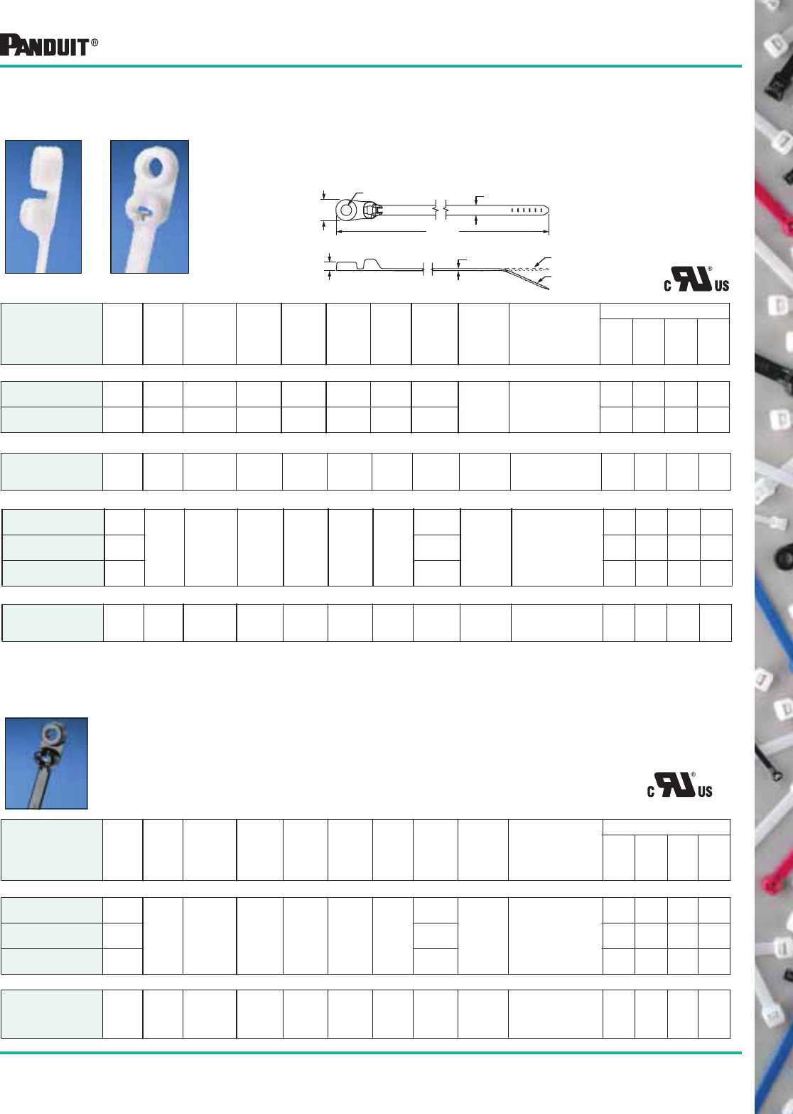
31
Most commonly used parts appear in BOLD.
Part Number
Length
A
in.
(mm)
Width
B
in.
(mm)
Thickness
C
in. (mm)
Boss
Height
D
in. (mm)
Boss
Width
E
in. (mm)
Nominal
Hole
Dia.
F
in.(mm)
Screw
Size
(Metric)
Max.
Bundle
Dia.
in. (mm)
Min. Loop
Tensile
Strength
Lbs. (N)
Recommended
PANDUIT ®
Installation Tool
Part No.
Packaging*
Std.
Pkg.
Qty.
Std.
Ctn.
Qty.
Bulk
Pkg.
Qty.
Bulk
Ctn.
Qty.
MINIATURE CROSS SECTION
BC1MS4-M‡ 4.6
(117)
.095
(2.4)
.046
(1.2)
.156
(4.0)
.234
(5.9)
.124
(3.15)
#4
(M2.5)
.90
(23) 18
(80)
GTS, GS2B,
PTS, PPTS
or STS2
100 1000 1000 50000
BC2M-S4-M‡ 8.3
(211)
.095
(2.4)
.046
(1.2)
.156
(4.0)
.234
(5.9)
.124
(3.15)
#4
(M2.5)
2.0
(51)
100 1000 1000 25000
STANDARD CROSS SECTION
BC2S-S10-C 8.5
(216)
.185
(4.7)
.052
(1.3)
.160
(4.1)
.400
(10.2)
.206
(5.2)
#10
(M5)
2.00
(51)
50
(222)
GTS, GS2B,
GTH, GS4H, PTS,
PPTS, STS2
or STH2
100 1000 500 10000
BC3S-S10-D 12.5
(318)
3.00
(76)
— — 500 10000
BC4S-S10-C 15.6
(396)
4.00
(102)
100 1000 500 5000
LIGHT-HEAVY CROSS SECTION (STRAIGHT TIP)
BC4LH-S25-L 15.5
(394)
.275
(7.0)
.065
(1.7)
.265
(6.7)
.520
(13.2)
.260
(6.6)
1/4
(M6)
4.00
(102)
120
(534)
GTH, GS4H,
GS4EH, PPTEH,
STH2 or ST2EH
50 500 250 2500
*Order the number of pieces required in multiples of package quantities.
For colors and other materials, see pages 34-35.
All part numbers shown in standard package quantities unless denoted by ‡.
DOME-TOP ®
Barb Ty Weather Resistant Nylon Clamp Ties
Part Number
Length
A
in.
(mm)
Width
B
in.
(mm)
Thickness
C
in. (mm)
Boss
Height
D
in. (mm)
Boss
Width
E
in. (mm)
Nominal
Hole
Dia.
F
in. (mm)
Screw
Size
(Metric)
Max.
Bundle
Dia.
in. (mm)
Min.
Loop
Tensile
Strength
Lbs. (N)
Recommended
PANDUIT ®
Installation
Tool Part No.
Packaging*
Std.
Pkg.
Qty.
Std.
Ctn.
Qty.
Bulk
Pkg.
Qty.
Bulk
Ctn.
Qty.
STANDARD CROSS SECTION
BC2S-S10-C0 8.5
(216)
.185
(4.7)
.052
(1.3)
.160
(4.1)
.400
(10.2)
.206
(5.2)
#10
(M5)
2.00
(51)
50
(222)
GTS, GS2B,
GTH, GS4H, PTS,
PPTS, STS2
or STH2
100 500 1000 10000
BC3S-S10-D0 12.5
(318)
3.00
(76)
— — 1000 10000
BC4S-S10-C0 15.6
(396)
4.00
(102)
100 500 1000 5000
LIGHT-HEAVY CROSS SECTION
BC4LH-S25-L0 15.5
(394)
.275
(7.0)
.065
(1.7)
.265
(6.7)
.520
(13.2)
.260
(6.6)
1/4
(M6)
4.00
(102)
120
(534)
GTH, GS4H,
GS4EH,
PPTEH, STH2
or ST2EH
50 500 250 2500
DOME-TOP ® Barb Ty
Nylon 6.6 Clamp Ties
E
F
A REF.
B
CSTRAIGHT TIP
CURVED TIP
D
Front View
Side View
INTERMEDIATE CROSS SECTION
BC1.5I-S8-M‡ 6.6
(168)
.141
(3.6)
.041
(1.0)
.166
(4.2)
.330
(8.4)
.180
(4.57)
#8
(M4)
1.5
(38)
40
(178)
GTS, GS2B,
PTS, PPTS
or STS2
100 1000 1000 25000
• Used to secure a bundle to another surface
• The design allows for bundling before or after screwing clamp in place
• Available in Miniature, Intermediate, Standard and
Light-Heavy cross sections
• Bundle diameters up to 4.00" (102mm)
• Available in natural, weather resistant and heat stabilized black nylon
DOME-TOP ® Barb Ty Clamp Ties
Except Light Heavy
32
Most commonly used parts appear in BOLD.
DOME-TOP ®
Barb Ty Marker and Flag Ties (BM/BF Series)
DOME-TOP ® Barb Ty
Nylon 6.6 Marker
and Flag Ties
• Used to fasten and identify bundles at the same time
• They can be marked with PANDUIT ® Marker Pens, Custom Hot
Stamping Service on page 52 or Computer Printable Labels
• Available in Miniature and Standard Cross Section
• Bundle diameters up to 4.00" (102mm)
• Available in natural and weather resistant nylon
Part Number
Length
A
in. (mm)
Width
B
in. (mm)
Thickness
C
in. (mm)
Head
Height
D
in. (mm)
Head
Width
E
in. (mm)
Marker
Write-on
Area
in. (mm)
Max.
Bundle
Dia.
in. (mm)
Min. Loop
Tensile
Strength
Lbs. (N)
Recommended
PANDUIT ®
Installation Tool
Part No.
Packaging*
Std.
Pkg.
Qty.*
Std.
Ctn.
Qty.
Bulk
Pkg.
Qty.
Bulk
Ctn.
Qty.
MINIATURE CROSS SECTION
BF1M-C 4.6
(117) .095
(2.4)
.046
(1.2)
.156
(4.0)
.182
(4.6)
.36 x .81
(9.1) x (20.6)
.90
(23) 18
(80)
GTS, GS2B,
PTS, PPTS
or STS2
100 1000 1000 25000
BF2M-C 8.3
(211)
2.00
(51)
100 1000 1000 25000
Part Number
Length
A
in. (mm)
Width
B
in. (mm)
Thickness
C
in. (mm)
Head
Height
D
in. (mm)
Head
Width
E
in. (mm)
Marker
Write-on
Area
in. (mm)
Max.
Bundle
Dia.
in. (mm)
Min. Loop
Tensile
Strength
Lbs. (N)
Recommended
PANDUIT ®
Installation Tool
Part No.
Packaging*
Std.
Pkg.
Qty.
Std.
Ctn.
Qty.
Bulk
Pkg.
Qty.
Bulk
Ctn.
Qty.
STANDARD CROSS SECTION
BM2S-C 8.0
(203) .185
(4.7)
.045
(1.2) .220
(5.6)
.320
(8.1)
.49 x .91
(12.4) x (23.1)
2.00
(51) 50
(222)
GTS, GS2B
GTH, GS4H, PTS,
PPTS or STH2
100 1000 500 10000
BM4S-C 15.1
(384)
.052
(1.3)
.50 x 2.13
(12.7) x (54.1)
4.00
(102)
100 1000 500 10000
*Order the number of pieces required in multiples of package quantities.
For colors and other materials, see pages 34-35.
All part numbers shown in standard package quantities unless denoted by ‡
Part Number
Length
A
in. (mm)
Width
B
in. (mm)
Thickness
C
in. (mm)
Head
Height
D
in. (mm)
Head
Width
E
in. (mm)
Marker
Write-on
Area
in. (mm)
Max.
Bundle
Dia.
in. (mm)
Min. Loop
Tensile
Strength
Lbs. (N)
Recommended
PANDUIT ®
Installation Tool
Part No.
Packaging*
Std.
Pkg.
Qty.
Std.
Ctn.
Qty.
Bulk
Pkg.
Qty.
Bulk
Ctn.
Qty.
MINIATURE CROSS SECTION
BM1M-C 4.2
(107) .095
(2.4)
.046
(1.2)
.156
(4.0)
.182
(4.6)
.29 x 1.09
(7.4) x (27.7)
.90
(23) 18
(80)
GTS, GS2B
PTS, PPTS
or STS2
100 1000 1000 25000
BM2M-C 7.9
(201)
2.00
(51)
100 1000 1000 25000
BM1M BM2M
BF1M BF2M
BM2S BM4S
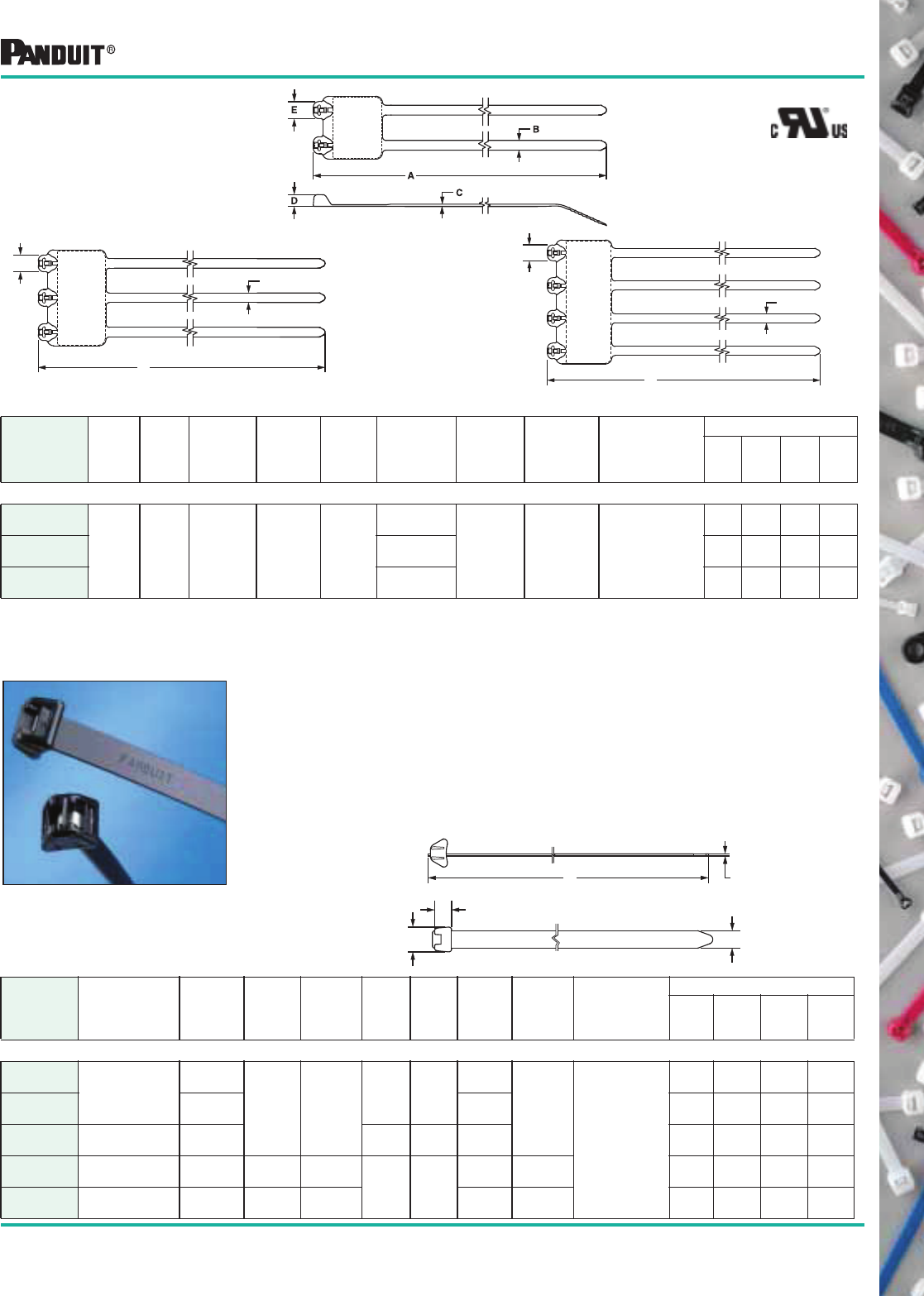
33
Most commonly used parts appear in BOLD.
DOME-TOP ® Barb Ty
Nylon 6.6 Marker
Ties (con’t)
Part Number
Length
A
in. (mm)
Width
B
in.
(mm)
Thickness
C
in. (mm)
Head
Height
D
in. (mm)
Head
Width
E
in. (mm)
Marker
Write-On
Area
in. (mm)
Max.
Bundle
Dia.
in. (mm)
Min. Loop
Tensile
Strength
Lbs. (N)
Recommended
PANDUIT ®
Installation Tool
Part No.
Packaging*
Std.
Pkg.
Qty.*
Std.
Ctn.
Qty.
Bulk
Pkg.
Qty.
Bulk
Ctn.
Qty.
STANDARD CROSS SECTION
B2M2S-D‡
8.0
(203)
.185
(4.7)
.045
(1.2)
.220
(5.6)
.320
(8.1)
11.5 x .91
(29.2) x (23.1)
2.00
(51)
50
(222)
GTS, GS2B,
GTH, GS4H, PTS,
PPTS, STS2
or STH2
50 500 500 2500
B3M2S-TL‡ 1.81 x .91
(46.0) x (23.1)
50 500 250 2500
B4M2S-TL‡ 2.47 x .91
(62.7) x (23.1)
50 500 250 2500
DOME-TOP ®
Barb Ty Marker Ties/DURA-TY ™ Cable Ties
*Order the number of pieces required in multiples of package quantities.
For colors and other materials, see pages 34-35.
All part numbers shown in standard package quantities unless denoted by ‡
DURA-TY™ Weather
Resistant Cable Ties
Part
Number Description
Length
(A)
in. (mm)
Strap
Width
(B)
in. (mm)
Thickness
(C)
in. (mm)
Head
Height
in.
(mm)
Head
Width
in.
(mm)
Max
Bundle
Dia.
in. (mm)
Min. Loop
Tensile
Strength
N (Lbs.)
Recommended
PANDUIT ®
Installation Tool
Part No.
Packaging*
Std.
Pkg.
Qty.
Std.
Ctn.
Qty.
Bulk
Pkg.
Qty.
Bulk
Ctn.
Qty.
EXTRA-HEAVY CROSS SECTION
DT4EH-L0
Cable
Tie
13.5
(343)
.500
(12.7)
.059
(1.5)
.490
(12.4)
.718
(18.2)
3.87
(98)
250
(1112)
GTH, GS4H,
ST2EH
or GS4EH
50 1000 — —
DT8EH-Q0 27.0
(686)
8.00
(203)
25 500 — —
DTREH-LR0 50' Reel of
Strapping
600.0
(15,240)
— — As
Needed
1 20 — —
DTHEH-Q0 Bag of 25 Cable
Tie Heads
— — —
.490
(12.4)
.718
(18.2)
— — 25 500 — —
DTKEH-0 DU RA -TY™
Kit 50 ft.
Reel of Strapping
600.0
(15,240)
.500
(12.7)
.059
(1.5)
As
Needed
250
(1112)
1 20 — —
A
B
D
E
C
• Ideal for all outdoor messenger strand applications including
telephone, cable TV, traffic signals and outside plant
power services
• Weather Resistant Acetal strap body and head
• Double stainless steel Type 302 locking barbs
• High tensile strength and high impact resistance
• Excellent chemical and moisture resistance
• 250 lbs. Minimum loop tensile strength
• Meets Telcordia TR-TSY-000789
• May be used with Stackable Cable Spacers SACS50-T100
(see page 107)
B2M2S
B3M2S B4M2S
A
B
E
E
A
B
34 Most commonly used parts appear in BOLD.
Part Number Suffix Codes for all DOME-TOP ®
Barb Ty and DURA-TY™
Cable Ties
Part Description:
BT = Barb Ty
BC = Barb Clamp
BF = Barb Flag
BM = Barb Marker
BW = Barb Wing
DT = DU RA-TY™
Size:
Approximate
Maximum Bundle
Diameter in Inches
Cross Section:
M = Miniature
I = Intermediate
S = Standard
LH = Light-Heavy
EH = Extra-Heavy
Screw Hole Size:
(Clamp Ties Only)
-S4 = #4 (M2.5)
-S6 = #6 (M3)
-S8 = #8 (M4)
-S10 = #10 (M5)
-S25 = 1/4 (M6)
Package Size:
Q = 25
L = 50
C = 100
TL = 250
D = 500
M = 1000
LR = 50' Reel
0 = DT Kit
Color:
See Material/Color
chart. Not all ties
available in all colors.
—
Part Number System (Example of BT1M-C)
Material/Color
PANDUIT ®
Suffix*
Mil Spec
Suffix**
Nylon 6.6 — Natural (See Note) ✔9
Weather Resistant Nylon 6.6 —
Black
0 N/A
Nylon 6.6 — Brown 1 1
Nylon 6.6 — Red 2 2
Nylon 6.6 — Orange 3 3
Nylon 6.6 — Yellow 4 4
Nylon 6.6 — Green 5 5
Material/Color Chart
Material/Color
PANDUIT ®
Suffix*
Mil Spec
Suffix**
Nylon 6.6 — Blue 6 6
Nylon 6.6 — Purple 7 7
Nylon 6.6 — Gray 8 8
Nylon 6.6 — White 10 N/A
Nylon 6.6 — Telephone Gray 14 N/A
Nylon 6.6 — Black 20 N/A
Heat Stabilized Nylon 6.6 — Black 30 N/A
Heat Stabilized Nylon 6.6 — Natural 39 N/A
* NOTE: ✔designates PANDUIT ® standard Natural Nylon 6.6 color/material. No suffix required in part number.
** NOTE: MIL SPEC Color (suffix) per AS33671 (Formerly MS3367) and SAE AS33681 (Formerly MS3368).
Standard Packaging Bulk Packaging
Part
Number
Natural
Nylon
6.6
Available Color/
Material (Suffix)
Part
Number
Natural
Nylon
6.6
Available Color/
Material (Suffix)
BC1M-S4-M ✔0
BC2M-S4-M ✔0
BC1.5I-S8-M ✔0
BC2S-S10-C ✔0 BC2S-S10-D ✔0
BC3S-S10-D ✔0
BC4S-S10-C ✔0 BC4S-S10-D ✔0, 30
BC4LH-S25-L ✔0 BC4LH-S25-TL ✔0
BF1M-C ✔ BF1M-M ✔0
BF2M-C ✔ BF2M-M ✔0
BM1M-C ✔ BM1M-M ✔0
BM2M-C ✔ BM2M-M ✔0
BM2S-C ✔ BM2S-D ✔0
BM4S-C ✔ BM4S-D ✔0
BT1M-C ✔0, 30 BT1M-M ✔0, 1, 2, 3, 4, 5, 6, 7, 8, 10, 30, 39
BT1.5M-C ✔0 BT1.5M-M ✔0, 30
BT2M-C ✔0 BT2M-M ✔0, 2, 3, 4, 5, 6, 8, 30
BT4M-C ✔0 BT4M-M ✔0
BT1.5I-C ✔0 BT1.5I-M ✔0, 1, 2, 3, 4, 5, 6, 7, 8, 10, 30, 39
BT2I-C ✔0 BT2I-M ✔0, 30
BT3I-C ✔0 BT3I-M ✔0, 30
BT4I-C ✔0 BT4I-M ✔0, 14
35
Most commonly used parts appear in BOLD.
NOTE 1: DURA-TY™
Weather Resistant Acetal Strap Body and Head.
Standard Packaging Bulk Packaging
Part
Number
Natural
Nylon 6.6
Available Color/
Material (Suffix)
Part
Number
Natural
Nylon 6.6
Available Color/
Material (Suffix)
BT2S-C ✔0
BT2S-M
✔0, 1, 2, 3, 4, 5, 6, 7, 8, 10, 20,
30, 39
BT3S-C ✔0, 2 BT3S-M ✔0, 30, 39
BT4S-C ✔0 BT4S-M ✔0, 2, 3, 4, 5, 6, 7, 8, 10, 30, 39
BT2LH-L ✔0 BT2LH-TL ✔0
BT3LH-L ✔0 BT3LH-TL ✔0
BT4LH-L ✔0 BT4LH-TL ✔0, 30, 39
BT5LH-L ✔0 BT5LH-C ✔0
BT6LH-L ✔0 BT6LH-C ✔0
BT7LH-L ✔0 BT7LH-C ✔0
BT8LH-L ✔0 BT8LH-C ✔0
BT9LH-L ✔0 BT9LH-C ✔0
BW1.5I-D ✔
BW2S-D ✔0
B2M2S-D ✔0
B3M2S-TL ✔0
B4M2S-TL ✔0
1DTHEH-Q 0
1DTKEH 0
1DTREH-LR 0
1DT4EH-L 0
1DT8EH-Q 0
Part Number Suffix Codes for all DOME-TOP ® Barb Ty and DURA-TY™ Cable Ties
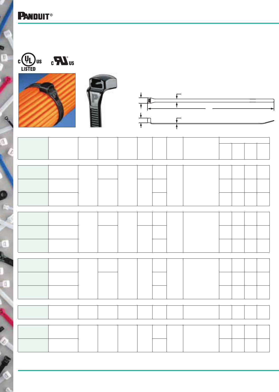
36
Most commonly used parts appear in BOLD.
Part Number
Length
A
in. (mm)
Width
B
in. (mm)
Thickness
C
in. (mm)
Head
Height
D
in. (mm)
Head
Width
E
in. (mm)
Max.
Bundle
Dia.
in.
(mm)
Min.
Loop
Tensile
Strength
Lbs. (N)
Recommended
PANDUIT ®
Installation Tool
Part No.
Packaging*
Std.
Pkg.
Qty.
Std.
Ctn.
Qty.
Bulk
Pkg.
Qty.
Bulk
Ctn.
Qty.
MINIATURE CROSS SECTION
CBR1M-M‡
CBR1M-M0‡
4.1
(104)
.098
(2.5)
.038
(1.0)
.208
(5.3)
.195
(5.0)
1.00
(25)
18
(80)
GTS, GS2B, PTS
or PPTS
— — 1000 50000
CBR1.5M-M‡
CBR1.5M-M0‡
5.6
(142) .042
(1.1)
.209
(5.3)
1.50
(38) — — 1000 50000
CBR2M-M‡
CBR2M-M0‡
7.2
(183)
2.00
(51) — — 1000 25000
INTERMEDIATE CROSS SECTION
CBR1.5I-M‡
CBR1.5I-M0‡
5.9
(150)
.140
(3.6)
.040
(1.0)
.250
(6.4)
.250
(6.4)
1.50
(38)
40
(178)
GTS, GS2B, PTS
or PPTS
— — 1000 25000
CBR3I-M‡
CBR3I-M0‡
10.4
(264) .052
(1.3)
.262
(6.7)
3.00
(76) — — 1000 10000
CBR4I-M‡
CBR4I-M0‡
13.6
(345)
4.00
(102) — — 1000 10000
STANDARD CROSS SECTION
CBR2S-M‡
CBR2S-M0‡
7.6
(193)
.190
(4.8)
.044
(1.1)
.290
(7.1)
.332
(8.4)
2.00
(51)
50
(222)
GTS, GS2B, PTS
or PPTS
— — 1000 10000
CBR3S-M‡
CBR3S-M0‡
10.8
(274) .052
(1.3)
3.00
(76) — — 1000 5000
CBR4S-M‡
CBR4S-M0‡
14.0
(356)
4.00
(102) — — 1000 5000
HEAVY-STANDARD CROSS SECTION
CBR2HS-D‡
CBR2HS-D0‡
8.0
(203)
.250
(6.4)
.058
(1.4)
.326
(8.2)
.388
(9.9)
2.00
(51)
85
(378) GTH or GS4H — — 500 5000
LIGHT-HEAVY CROSS SECTION
CBR4LH-TL‡
CBR4LH-TL0‡
14.6
(371) .300
(7.6)
.070
(1.8)
.400
(10.2)
.490
(12.4)
4.00
(102) 120
(534)
GTH, GS4H
or PPTEH
— — 250 2500
CBR6LH-C‡
CBR6LH-C0‡
20.9
(531)
6.00
(152) — — 100 2000
CONTOUR-TY® Cable Ties
CONTOUR-TY® Cable Ties
Nylon 6.6 and Weather
Resistant Nylon 6.6
• Head designed for no protrusion of cut-off tie
• Tie configuration limits exposure to sharp edges to protect
adjacent cables and installers arms and hands
• Low profile head reduces overall bundle size
• Locking wedge is fully enclosed to insure consistent
strength and lasting performance
• Fully rounded edges on head and strap protect cable
insulation/jacket
• Rounded tip and aggressive grip for faster initial threading
E
A
C
B
D
*Order the number of pieces required in multiples of package quantities.
For colors and other materials, see page 39.
All part numbers shown in standard package quantities unless denoted by ‡.
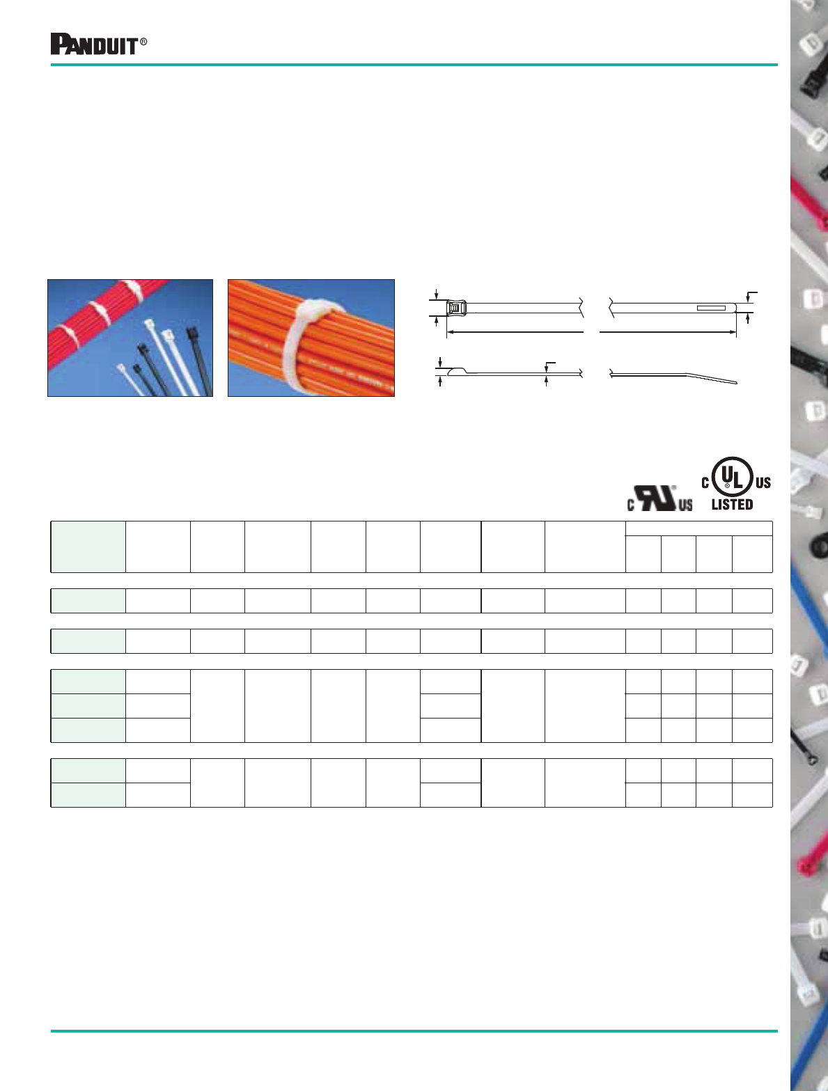
37
Most commonly used parts appear in BOLD.
E
D
C
B
A
*Order the number of pieces required in multiples of package quantities.
For colors and other materials, see page 39.
All part numbers shown in standard package quantities unless denoted by ‡.
.
Part Number
Length
A
in. (mm)
Width
B
in. (mm)
Thickness
C
in. (mm)
Head
Height
D
in. (mm)
Head
Width
E
in. (mm)
Max.
Bundle
Dia.
in. (mm)
Min. Loop
Tensile
Strength
Lbs. (N)
Recommended
PANDUIT ®
Installation
Tool Part No.
Packaging*
Std.
Pkg.
Qty.
Std.
Ctn.
Qty.
Bulk
Pkg.
Qty.
Bulk
Ctn.
Qty.
MINIATURE CROSS SECTION
ILT1M-M‡ 4.8
(122)
.098
(2.5)
.044
(1.1)
.110
(2.8)
.190
(4.8)
1.10
(28)
18
(80)
GTS, GS2B,
PTS or PPTS
— — 1000 50,000
INTERMEDIATE CROSS SECTION
ILT1.5I-M‡ 5.4
(137)
.142
(3.6)
.052
(1.3)
.130
(3.3)
.260
(6.6)
1.38
(35)
30
(133)
GTS, GS2B,
PTS or PPTS
— — 1000 25,000
STANDARD CROSS SECTION
ILT2S-M‡ 8.3
(211)
.190
(4.8)
.052
(1.3)
.140
(3.6)
.316
(8.0)
1.88
(48)
50
(222)
GTS, GS2B,
GTH, GS4H,
PTS or PPTS
— — 1000 10,000
ILT3S-M‡ 11.5
(292)
3.00
(76)
— — 1000 5000
ILT4S-M‡ 14.7
(373)
4.00
(102)
— — 1000 5000
LIGHT-HEAVY CROSS SECTION
ILT4LH-TL‡ 14.8
(376) .300
(7.6)
.075
(1.9)
.250
(6.4)
.475
(12.1)
4.00
(102) 120
(534) GTH, GS4H
or PPTEH
— — 250 2500
ILT6LH-C‡ 21.2
(538)
6.00
(152)
— — 100 500
BELT-TY™ In-Line Cable Ties
• Head designed for no protrusion of cut-off tie
• Low profile head (35% lower than conventional
90° entry cable ties)
• Fully rounded edges on head and strap
• Rounded tip and aggressive grip
• Finger grip shaped head
• Curved tip
• Protects adjacent cables and protects
workers arms and hands
• Avoids snags and reduces overall bundle size
• No sharp edges in contact with cable insulation
• Easy to grip for assembly
• Positive grip when threading tie
• Material: Nylon 6.6
• Parallel-entry cable ties that thread like a belt (at 180°) with the same
performance of conventional (90° entry) cable ties
• The BE LT-TY™ In-Line Cable Tie design reduces the long cut-off
danger of an incorrectly applied conventional cable tie
BELT-TY™
In-Line Cable Ties Nylon 6.6
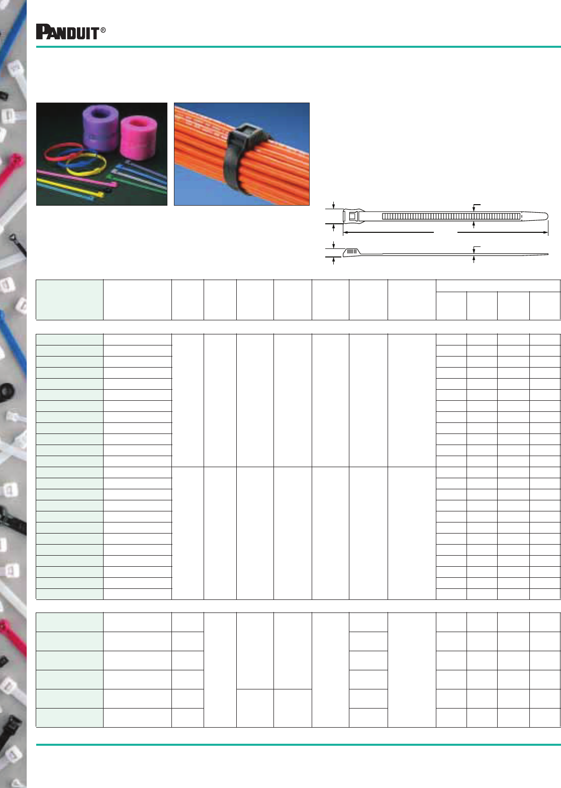
38
Most commonly used parts appear in BOLD.
IN-LINE Weather Resistant
Nylon 6.6 Cable Ties
• Wide tie body and high tensile strength are
ideal for any application including
playground equipment
• For playground installations, the head is
inverted and the body is captured between the
tie and foam for safety
• Flexible, easy to handle and easily installed
without special tools
• Available in 13 UV weather resistant colors for
color coordination and UV stability
*Order the number of pieces required in multiples of package quantities.
For colors and other materials, see page 39.
All part numbers shown in standard package quantities unless denoted by ‡.
IN-LINE Nylon 6.6 Cable Ties
E
D
A REF.
C
B
Part Number Description
Length
A
in. (mm)
Width
B
in. (mm)
Thickness
C
in. (mm)
Head
Height
D
in. (mm)
Head
Width
E
in. (mm)
Max.
Bundle
Dia.
in. (mm)
Min. Loop
Tensile
Strength
Lbs. (N)
Packaging*
Std.
Pkg.
Qty.
Std.
Ctn.
Qty.
Bulk
Pkg.
Qty.*
Bulk
Ctn.
Qty.*
Cable Tie Colors
IT9100-CUV2‡ UV Red
14.1
(358)
.350
(8.9)
.065
(1.7)
.300
(7.6)
.556
(14.1)
3.94
(100)
124
(550)
— — 100 1000
IT9100-CUV4‡ UV Yellow — — 100 1000
IT9100-CUV4A‡ UV Butterscotch — — 100 1000
IT9100-CUV5A‡ UV Green — — 100 1000
IT9100-CUV5B‡ UV Hunter Green — — 100 1000
IT9100-CUV6‡ UV Dark Blue — — 100 1000
IT9100-CUV6A‡ UV Light Blue — — 100 1000
IT9100-CUV6B ‡ UV Cobalt Blue — — 100 1000
IT9100-CUV7A‡ UV Purple — — 100 1000
IT9100-CUV8‡ UV Silver — — 100 1000
IT9100-CUV11‡ UV Teal — — 100 1000
IT9100-CUV16B ‡ UV Pink — — 100 1000
IT9115-CUV2‡ UV Red
15.3
(389)
.350
(8.9)
.065
(1.7)
.300
(7.6)
.556
(14.1)
4.53
(115)
124
(550)
— — 100 1000
IT9115-CUV4‡ UV Yellow — — 100 1000
IT9115-CUV4A ‡ UV Butterscotch — — 100 1000
IT9115-CUV5A‡ UV Green — — 100 1000
IT9115-CUV5B‡ UV Hunter Green — — 100 1000
IT9115-CUV6‡ UV Dark Blue — — 100 1000
IT9115-CUV6A‡ UV Light Blue — — 100 1000
IT9115-CUV6B‡ UV Cobalt Blue — — 100 1000
IT9115-CUV7A‡ UV Purple — — 100 1000
IT9115-CUV8‡ UV Silver — — 100 1000
IT9115-CUV11‡ UV Teal — — 100 1000
IT9115-CUV16B‡ UV Pink — — 100 1000
Black Cable Ties
IT940-C0‡ UV Black 6.8
(173)
.350
(8.9)
.065
(1.7)
.300
(7.6)
.556
(14.1)
1.57
(40)
124
(550)
— — 100 1000
IT965-C0‡ UV Black 10.1
(257)
2.58
(65)
— — 100 1000
IT9100-C0‡ UV Black 14.1
(358)
3.94
(100)
— — 100 1000
IT9115-C0‡ UV Black 15.3
(388)
4.53
(115)
— — 100 1000
IT9150-C0‡ UV Black 20.1
(511) .075
(1.9)
.320
(8.1)
5.91
(150)
— — 100 1000
IT9250-C0‡ UV Black 33.0
(838)
9.84
(250)
— — 100 1000
Colors can be used to install foam
padding for playground applications.
UV Black can be used in any
outdoor application.
39
Most commonly used parts appear in BOLD.
Part Number Suffix Code for All Parallel Entry Cable Ties
Part Description:
CBR = CON TOU R-TY®
ILT = BE LT-TY™
In-Line Tie
IT = In-Line Tie
Size:
Approximate
Maximum Bundle
Diameter in
Inches
Package Size:
C = 100
TL = 250
D = 500
M = 1000
Color:
See Material/Color
chart. Not all ties
available in all colors.
—
Part Number System (Example of ILT1M-M)
Material/Color PANDUIT ®
Suffix*
Mil Spec
Suffix**
Nylon 6.6 — Natural (See Note) ✔9
Weather Resistant Nylon 6.6 —
Black
0 N/A
Ultraviolet Red UV2 N/A
Ultraviolet Yellow UV4 N/A
Ultraviolet Butterscotch UV4A N/A
Ultraviolet Green UV5A N/A
Ultraviolet Hunter Green UV5B N/A
Material/Color Chart
Material/Color PANDUIT ®
Suffix*
Mil Spec
Suffix**
Ultraviolet Dark Blue UV6 N/A
Ultraviolet Light Blue UV6A N/A
Ultraviolet Cobalt Blue UV6B N/A
Ultraviolet Purple UV7A N/A
Ultraviolet Silver UV8 N/A
Ultraviolet Teal UV11 N/A
Ultraviolet Pink UV16B N/A
Ultraviolet Tan UV18 N/A
* NOTE: ✔designates PANDUIT ® standard Natural Nylon 6.6 color.material. No suffix required in part number.
** NOTE: MIL SPEC Color (suffix) per AS33671 (Formerly MS3367) and SAE AS33681 (Formerly MS3368).
Standard Packaging Bulk Packaging
Part
Number
Natural
Nylon 6.6
Available Color/
Material (Suffix)
Part
Number
Natural
Nylon 6.6
Available Color/
Material (Suffix)
CBR1M-M ✔0
CBR1.5M-M ✔0
CBR2M-M ✔0
CBR1.5I-M ✔0
CBR3I-M ✔0
CBR4I-M ✔0
CBR2S-M ✔0, 39
CBR3S-M ✔0
CBR4S-M ✔0
CBR2HS-D ✔0
CBR4LH-TL ✔0
CBR6LH-C ✔0
ILT1M-M ✔0
ILT1.5I-M ✔0
ILT2S-C ✔0ILT2S-M ✔0
ILT3S-C ✔0ILT3S-M ✔0
ILT4S-C ✔0ILT4S-M ✔0
ILT4LH-TL ✔0
ILT6LH-C ✔0
IT940-C 0
IT965-C 0
IT9100-C 0, UV2, UV4, UV6, UV6A,
UV7A, UV8, UV16B
IT9115-C 0, UV2, UV4, UV4A, UV5A,
UV5B, UV6, UV6A, UV6B,
UV7A, UV8, UV11, UV16B,
UV18
IT9150-C 0
IT9250-C 0
Cross Section:
M = Miniature
I = Intermediate
S = Standard
HS = Heavy-Standard
LH = Light-Heavy
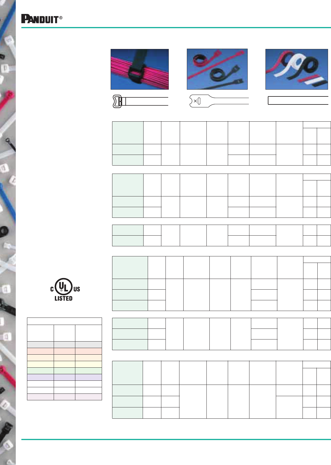
40
Most commonly used parts appear in BOLD.
TAK-TY® Hook & Loop
Cable Ties
CINCH TIES — CINCH RING PROVIDES EXTRA STRENGTH AND BUNDLE TIGHTNESS
Part Number
Length
in. (mm)
Width
in. (mm)
Thickness
in. (mm)
Head
Width
in. (mm)
Min.
Bundle
Dia.
in. (mm)
Max.
Bundle
Dia.
in. (mm)
Min. Loop
Tensile
Strength*
Lbs. (N)
Packaging**
Std.
Pkg.
Qty.
Std.
Ctn.
Qty.
HLC3S-X0 12.0
(305) .750
(19.1)
.10
(2.5)
1.10
(27.9)
2.00
(51)
3.00
(76) 50
(222)
10 100
HLC5S-X0 18.0
(457)
3.00
(76)
5.00
(127) 10 100
LOOP TIES — SLOT ALLOWS FOR PRE-WRAPPING OF BUNDLES
Part Number
Length
in. (mm)
Width
in. (mm)
Thickness
in. (mm)
Head
Width
in. (mm)
Min.
Bundle
Dia.
in. (mm)
Max.
Bundle
Dia.
in. (mm)
Min. Loop
Tensile
Strength*
Lbs. (N)
Packaging**
Std.
Pkg.
Qty.
Std.
Ctn.
Qty.
HLT2I-X0 8.0
(203) .50
(12.7)
.10
(2.5)
1.00
(25.4)
.25
(6)
1.91
(49) 40
(178)
10 100
HLT3I-X0 12.0
(305)
.25
(6)
3.18
(81)
10 100
UL LISTED LOOP TIES ** — LARGER
HLTP2I-X12 8.0
(203) .50
(12.7)
.10
(2.5)
1.00
(25.4)
.25
(6)
1.91
(49) 40
(178)
10 100
HLTP3I-X12 12.0
(305)
.25
(6)
3.18
(81)
10 100
Color Chart
Color
Part
Number
Suffix Example
Black 0 HLT2I-X0
Red 2 HLT2I-X2
Orange 3 HLT2I-X3
Yellow 4 HLT2I-X4
Green 5 HLT2I-X5
Blue 6 HLT2I-X6
Gray 8 HLT2I-X8
White 10 HLT2I-X10
Maroon 12 HLTP2I-X12
**Order the number of pieces required in multiples of package quantities.
For colors and other materials, see page 42.
All part numbers shown in standard package quantities unless denoted by ‡.
STRIP TIES — ROLLS PERFORATED IN CONVENIENT 6", 12" AND 18" STRIPS
Part Number
Length
in.
(mm)
Width
in.
(mm)
Thickness
in. (mm)
Head
Width
in. (mm)
Min.
Bundle
Dia.
in. (mm)
Max.
Bundle
Dia.
in. (mm)
Min. Loop
Tensile
Strength*
Lbs. (N)
Packaging**
Std.
Pkg.
Qty.
Std.
Ctn.
Qty.
HLS1.5S-X0 6.0
(152)
.750
(19.1)
.10
(2.5) —.25
(6)
1.50
(38)
50
(222)
10 100
HLS3S-X0 12.0
(305)
3.20
(81)
10 100
HLS5S-X0 18.0
(457)
5.00
(127)
10 100
UL LISTED STRIP TIES ** — LARGER
HLSP1.5S-X12 6.0
(152)
.750
(19.1)
.10
(2.5) —.25
(6)
1.50
(38)
50
(222)
10 100
HLSP3S-X12 12.0
(305)
3.20
(81)
10 100
HLSP5S-X12 18.0
(457)
5.00
(127)
10 100
HLT/HLTP SeriesHLC Series HLS/HLSP/HLM Series
HLTP/HLSP Only
• Releasable and reusable
hundreds of times
• No risk of over tensioning
and damaging high
performance cabling
• No installation tool needed
• No waste — excess can be
wrapped around bundle
• Cinch ties — Pass hook
portion through plastic cinch
ring. Pull end of tie against
ring to tension. Secure hook
portion against loop portion
of tie body to fasten
• Loop and Strip ties have
hooks on one side and
loops on the other, so it
adheres to itself; wrap
around bundle and secure
end of tie on the body
• HLM-15R can be used with
ABM3H-A-L, ABM4H-A-L,
TM3S8-C, TM3S10-C and
TM3S25-C mounts
• Loop and Strip ties (in black
and maroon) are UL Listed
for use in air handling
spaces per NEC section
300-22 (c) and (d) and are
UL94V-2 flame rated
TAK-TY® Hook & Loop Cable Ties
15' & 75' ROLLS — CAN BE CUT TO DESIRED LENGTH, ELIMINATING WASTE
*Minimum 2" overlap required to achieve loop tensile rating (HLC, HLT, HLS, HLM series).
**Available in -0 (Black) rated 18lbs. (80N).
Part Number
Length
in. (mm)
Width
in. (mm)
Thickness
in. (mm)
Head
Width
in. (mm)
Min.
Bundle
Dia.
in. (mm)
Max.
Bundle
Dia.
in. (mm)
Min. Loop
Tensile
Strength*
Lbs. (N)
Packaging**
Std.
Pkg.
Qty.
Std.
Ctn.
Qty.
HLM-15R0 180.0
(4572) .33
(8.4)
.10
(2.5) —.25
(6) Various
18
(80)
1 10
HLS-15R0 180.0
(4572)
.750
(19.1) 50
(222)
1 10
HLS-75R0 900.0
(22,860)
.750
(19.1)
1 10
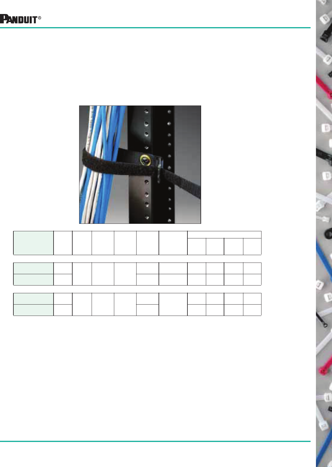
41
Most commonly used parts appear in BOLD.
TAK-TY®
Hook & Loop Grommet Cinch Ties
TAK-TY® Hook & Loop
Grommet Cinch Ties
• Sturdy brass grommet and washer provides strength and high
visibility for mounting in poor lighting conditions
• 1/4" (M6) diameter mounting hole fits drywall screws up to
#12 screw size
• Grommet allows for mounting of the cinch ties prior to cable
installation for easier handling of cable bundles with tie
pre-positioned and anchored
• No sharp edges to damage cables
• Releasable and Reusable
*Tensile Strength achieved with 2" overlap.
Part Number
Length
in. (mm)
Width
in. (mm)
Thickness
in. (mm)
Head
Width
in. (mm)
Max.
Bundle
Dia.
in. (mm)
Min. Loop
Tensile
Strength
Lbs. (N)*
Packaging**
Std.
Pkg.
Qty.**
Std.
Ctn.
Qty.**
Bulk
Pkg.
Qty.
Bulk
Ctn.
Qty.
GCTC SERIES — GROMMET CINCH TIE CENTER MOUNT (Centers bundle over mounting point)
GCTC3S-X0 12.0
(305) .750
(19.1)
.10
(2.5)
1.10
(27.9)
3.00
(76.2)
30
(133)
10 100 — —
GCTC5S-X0 18.0
(457)
5.00
(127)
50
(222)
10 100 — —
GCTE SERIES — GROMMET CINCH TIE END MOUNT (Offsets bundle next to mounting point)
GCTE2S-X0 10.5
(267) .750
(19.1)
.10
(2.5)
1.10
(27.9)
2.20
(55.8) 50
(222)
10 100 — —
GCTE4S-X0 16.5
(419)
4.10
(104.1)
10 100 — —
**Order the number of pieces required in multiples of package quantities.
All part numbers shown in standard package quantities unless denoted by ‡.
42
Most commonly used parts appear in BOLD.
Part Number Suffix Codes for All Hook & Loop Cable Ties
Part Description:
HL = Hook & Loop
HLC = H&L Cinch Tie
HLT = H&L Tie
HLTP* = H&L Tie Plenum
HLS = H&L Strip
HLSP* = H&L Strip Plenum
HLM = H&L Strip Miniature
GCT = Grommet Cinch Tie
Size:
Approximate
Maximum
Bundle
Diameter in
Inches
Cross Section:
I = Intermediate
S = Standard
Package Size:
X = 10
15R = 15' Roll
75R = 75' Roll
—
Part Number System (Example of HLC3S-X0)
Color
PANDUIT ®
Suffix
Black 0
Red 2
Orange 3
Yellow 4
Green 5
Material/Color Chart
Color
PANDUIT ®
Suffix
Blue 6
Gray 8
White 10
Maroon 12
*HLSP and HLTP are unique Hook & Loop style ties that are UL Listed for use in air-handling spaces
per NEC section 300-22 (c) and (d) and are UL94V-2 flame rated. Available in Black (-X0) and
Maroon (-X12).
Standard Packaging
Part
Number
Available Color/
Material (Suffix)
GCTC3S-X 0
GCTC5S-X 0
GCTE2S-X 0
GCTE4S-X 0
HLC3S-X 0
HLC5S-X 0
HLM-15R 0, 2, 3, 4, 5, 6, 8, 10
HLS-15R 0, 2, 3, 4, 5, 6, 8, 10
HLS-75R 0, 2, 3, 4, 5, 6, 8, 10
HLS1.5S-X 0, 2, 3, 4, 5, 6, 8, 10
HLS3S-X 0, 2, 3, 4, 5, 6, 8, 10
HLS5S-X 0, 2, 3, 4, 5, 6, 8, 10
HLT2I-X 0, 2, 3, 4, 5, 6, 8, 10
HLT3I-X 0, 2, 3, 4, 5, 6, 8, 10
*HLSP1.5S-X 0,12
*HLSP3S-X 0,12
*HLSP5S-X 0,12
*HLTP2I-X 0,12
*HLTP3I-X 0,12
Color:
See Material/
Color chart. Not
all ties available in
all colors.
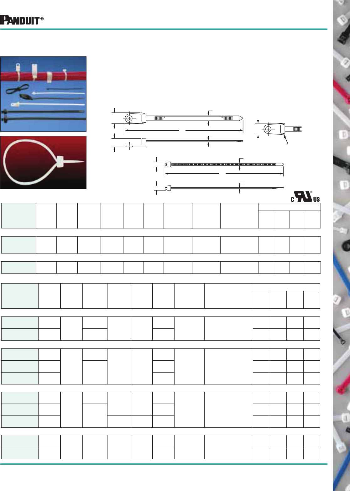
43
Most commonly used parts appear in BOLD.
STA-STRAP ® Nylon 6.6
Cable Ties
STA-STRAP ® Cable Ties (SSC/SST Series)
• STA-STRAP ® Cable Ties — Use for normal bundling and
through-panel applications
•
STA-STRAP ® Clamp Ties — Only clamp that can be pre-mounted
before tying bundle
• Low profile head for use in compact areas
• Two piece design provides low thread force to reduce installer fatigue
• Lower weight than comparable one-piece ties
• Releasable (prior to final tensioning and cut-off) —
Helpful in assembly
STA-STRAP ® Clamp Head Cable Ties — SSC Series
Part Number
Length
A
in. (mm)
Width
B
in. (mm)
Thickness
C
in. (mm)
Boss
Height
D
in. (mm)
Boss
Width
E
in. (mm)
Max.
Bundle
Dia.
in. (mm)
Min. Loop
Tensile
Strength
Lbs. (N)
Screw
Size
Recommended
PAN DUIT ®
Installation
Tool Part No.
Packaging*
Std.
Pkg.
Qty.
Std.
Ctn.
Qty.
Bulk
Pkg.
Qty.
Bulk
Ctn.
Qty.
STANDARD CROSS SECTION
SSC2S-S10-C 7.4
(187)
.180
(4.6)
.045
(1.2)
.310
(7.9)
.430
(10.9)
1.75
(45)
50
(222)
#10
(M5)
GTS, GS2B, GTH,
GS4H, PTS
or PPTS
100 100 1000 1000
HEAVY CROSS SECTION
SSC4H-S25-L 15.6
(395)
.300
(7.6)
.065
(1.5)
.460
(11.7)
.53
(13.5)
4.00
(102)
120
(534)
1/4
(M6)
GTH, GS4H,
GS4EH or PPTEH
50 500 500 2500
E
A
C
B
D
STA-STRAP ® Cable Ties — SST Series
Part Number
Length
A
in. (mm)
Width
B
in. (mm)
Thickness
C
in. (mm)
Head
Height
D
in. (mm)
Head
Width
E
in. (mm)
Max.
Bundle
Dia.
in. (mm)
Min. Loop
Tensile
Strength
Lbs. (N)
Recommended
PANDUIT ®
Installation
Tool Part No.
Packaging*
Std.
Pkg.
Qty.
Std.
Ctn.
Qty.
Bulk
Pkg.
Qty.
Bulk
Ctn.
Qty.
MINIATURE CROSS SECTION
SST1M-C 4.0
(102) .095
(2.4)
.035
(.9) .150
(3.8)
.175
(4.5)
.78
(20) 18
(80)
GTS, GS2B,
PTS or PPTS
100 1000 1000 50000
SST1.5M-C 5.5
(140)
.037
(.9)
1.25
(32)
100 1000 1000 50000
INTERMEDIATE CROSS SECTION
SST1.5I-C 5.3
(137)
.135
(3.4)
.037
(.9)
.210
(5.3)
.240
(6.1)
1.25
(32)
40
(178)
GTS, GS2B,
PTS or PPTS
100 1000 1000 25000
SST2I-C 8.1
(206) .040
(1.0)
2.00
(50)
100 1000 1000 25000
SST3I-C 11.0
(279)
3.00
(76)
100 1000 1000 10000
STANDARD CROSS SECTION
SST2S-C 6.7
(172)
.180
(4.6)
.045
(1.2) .250
(6.4)
.310
(7.9)
1.75
(45)
50
(222)
GTS, GS2B, GTH,
GS4H, PTS, PPTS,
STS2 or STH2
100 1000 1000 15000
SST3S-C 11.0
(279) .048
(1.2)
3.00
(76)
100 1000 1000 10000
SST4S-C 15.0
(381)
.253
(6.4)
.350
(8.9)
4.00
(102)
100 1000 1000 5000
HEAVY CROSS SECTION
SST4H-D‡ 14.8
(376) .300
(7.6)
.067
(1.7)
.325
(8.3)
.460
(11.7)
4.00
(102) 120
(534)
GTH, GS4H,
GS4EH or PPTEH
— — 500 2500
SST8H-D‡ 27.5
(699)
8.00
(203)
— — 500 2000
*Order the number of pieces required in multiples of package quantities.
For colors and other materials, see page 45.
All part numbers shown in standard package quantities unless denoted by ‡.
E
A
C
B
D
E
ALTERNATE HEAD
DESIGN - SSC2S ONLY
SSC Series
SST Series
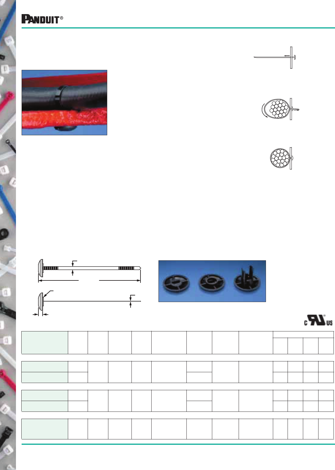
44
Most commonly used parts appear in BOLD.
STA-STRAP ® Cable Ties (SSPM Series)
*Order the number of pieces required in multiples of package quantities.
All part numbers shown in standard package quantities unless denoted by ‡.
STA-STRAP ® Chassis/Panel Mount Tie —
Weather Resistant Heat Stabilized Nylon 6.6
HEAVY CROSS SECTION
Part Number
A
Length
in. (mm)
B
Width
in. (mm)
C
Thickness
in. (mm)
D
Head
Height
in. (mm)
Recommended
Panel Hole
Dia.
in. (mm)
Maximum
Bundle
Diameter
in. (mm)
Min. Loop
Tensile
Strength
Lbs. (N)
Recommended
PAN DUIT ®
Installation Tool
Part No.
Packaging*
Std.
Pkg.
Qty.
Std.
Ctn.
Qty.
Bulk
Pkg.
Qty.
Bulk
Ctn.
Qty.
WITHOUT PILOT
SSPM2.5H-L300 10.1
(257) .30
(7.6)
.062
(1.6)
.248
(6.3)
.316 to.820
(8.0 to 21)
2.76
(70) 120
(534)
GTH, GS4H,
GS4EH, PPTEH,
STH2
or ST2EH
50 2500 250 2500
SSPM4H-L300 14.8
(376)
4.00
(102)
50 2500 250 2500
WITH PILOT
SSPM2.5HP-L300 10.1
(257) .30
(7.6)
.062
(1.6)
.248
(6.3)
.440 to.820
(11.2 to 21)
2.76
(70) 120
(534)
GTH, GS4H,
GS4EH, PPTEH,
STH2
or ST2EH
50 2500 250 2500
SSPM4HP-L300 14.8
(376)
4.00
(102)
50 2500 250 2500
WITH LONG CENTERING PILOT
SSPM4HLP-TL300‡ 14.8
(376)
.30
(7.6)
.062
(1.6)
.248
(6.3)
.440 to.820
(11.2 to 21)
4.00
(102)
120
(534)
GTH, GS4H,
GS4EH,
PPTEH, STH2
or ST2EH
— — 250 2500
Without Pilot With Pilot With Long
Centering Pilot
• Optional Long
Centering Pilot
• Pilot ears protect
strap body
from clearance
hole edges
Applications:
• Run cable and hose along
truck frame rails
• Secure a bundle under a
chassis assembly
• Manage wire harnesses in
the cab and sleeper
• Use a through-hole in
frame/chassis to mount
Solution:
PANDUIT ® STA-STRAP ® Chassis Mount Ties are uniquely de-
signed to secure a bundle directly to a chassis or panel utilizing
a through-hole.
Features:
• Eliminates the need for separate fasteners to reduce costs
and decrease installation time
• Remains adjustable and releasable until tie is tensioned
and cut-off
• Installs easily with PANDUIT ® hand-operated tools
• Engages clearance hole with optional centering pilot
(2 designs) to prevent tie from shifting or abrading during
vehicle operation
Three Easy Steps...
Insert tip end of STA-STRAP ® cable tie
through the correct size pre-drilled hole
in the panel.
1
Wrap cable tie around the bundle
and insert the tip end back through
the hole and head of the cable tie.
2
Pull tip end until STA-STR AP ® cable tie
is snug on bundle. Tension and cut off
excess portion with PANDUIT ® cable
tie installation tool.
3
A REF.
C
B
D
OPTICAL CENTERING PILOT
To ensure coverage of hole up to .70" (18mm)
45
Most commonly used parts appear in BOLD.
Part Number Suffix Codes for All STA-STRAP ® Cable Ties
Part Description:
SST = STA-STRA P ® Tie
SSC = STA-STRAP ® Clamp
SSPM = STA-STRAP ® Panel Mount
SSB = STA-STRAP ® Bow-Ty
SSM = STA-STRAP ® Marker
Size:
Approximate
Maximum Bundle
Diameter in
Inches
Cross Section:
M = Miniature
I = Intermediate
S = Standard
LH = Light-Heavy
H = Heavy
HH = Heavy Head
Screw Hole Size:
(Clamp Ties Only)
-S6 = #6 (M3)
-S10 = #10 (M5)
-S25 = 1/4 (M6)
Package Size:
L = 50
C =100
TL = 250
D = 500
M = 1000
Color:
See
Material/
Color chart.
Not all ties
available in
all colors.
—
Part Number System (Example of SST1M-C)
Material/Color
PANDUIT ®
Suffix*
Mil Spec
Suffix**
Nylon 6.6 — Natural (see note) ✔9
Weather Resistant Nylon 6.6 —
Black
0 N/A
Nylon 6.6 — Black 20 N/A
Material/Color Chart
Material/Color
PANDUIT ®
Suffix*
Mil Spec
Suffix**
Heat Stabilized Nylon 6.6 — Black 30 N/A
Heat Stabilized Weather Resistant
Nylon 6.6 — Black
300 N/A
*NOTE: ✔designates PANDUIT ® standard Natural Nylon 6.6 color.material. No suffix required in part number.
**NOTE: MIL SPEC Color (suffix) per AS33671 (Formerly MS3367) and SAE AS33681 (Formerly MS3368).
Standard Packaging Bulk Packaging
Part
Number
Natural
Nylon
6.6
Available Color/
Material (Suffix)
Part
Number
Natural
Nylon 6.6
Available Color/
Material (Suffix)
SSPM2.5H-L 300 SSPM2.5H-TL 300
SSPM2.5HP-L 300 SSPM2.5HP-TL 300
SSPM4H-L 300 SSPM4H-TL 300
SSPM4HP-L 300 SSPM4HP-TL 300
SSPM4HLP-TL 300
SSC2S-S10-C ✔SSC2S-S10-M ✔0, 30
SSC2S-S6-C ✔SSC2S-S6-M ✔0
SSC4S-S10-C ✔SSC4S-S10-M ✔0
SSC4H-S25-L ✔SSC4H-S25-D ✔0
SSM2S-C ✔SSM2S-D ✔0
SSM4S-D ✔
SST1M-C ✔0SST1M-M ✔0, 20, 30
SST1.5M-C ✔SST1.5M-M ✔0, 20, 30
SST1.5I-C ✔SST1.5I-M ✔0
SST2I-C ✔SST2I-M ✔0, 20
SST3I-C ✔0SST3I-M ✔0
SST4I-C ✔SST4I-M ✔0
SST1.5S-M ✔0
SST2S-C ✔0SST2S-M ✔0, 20, 30
SST3S-C ✔0SST3S-M ✔0, 20, 30
SST4S-C ✔0SST4S-M ✔0, 2, 30
SST2H-D ✔0
SST4H-L ✔0SST4H-D ✔0, 30
SST4HH-D 30
SST8H-L ✔0SST8H-D ✔0, 30
SSB2S-C ✔SSB2S-M ✔0, 30
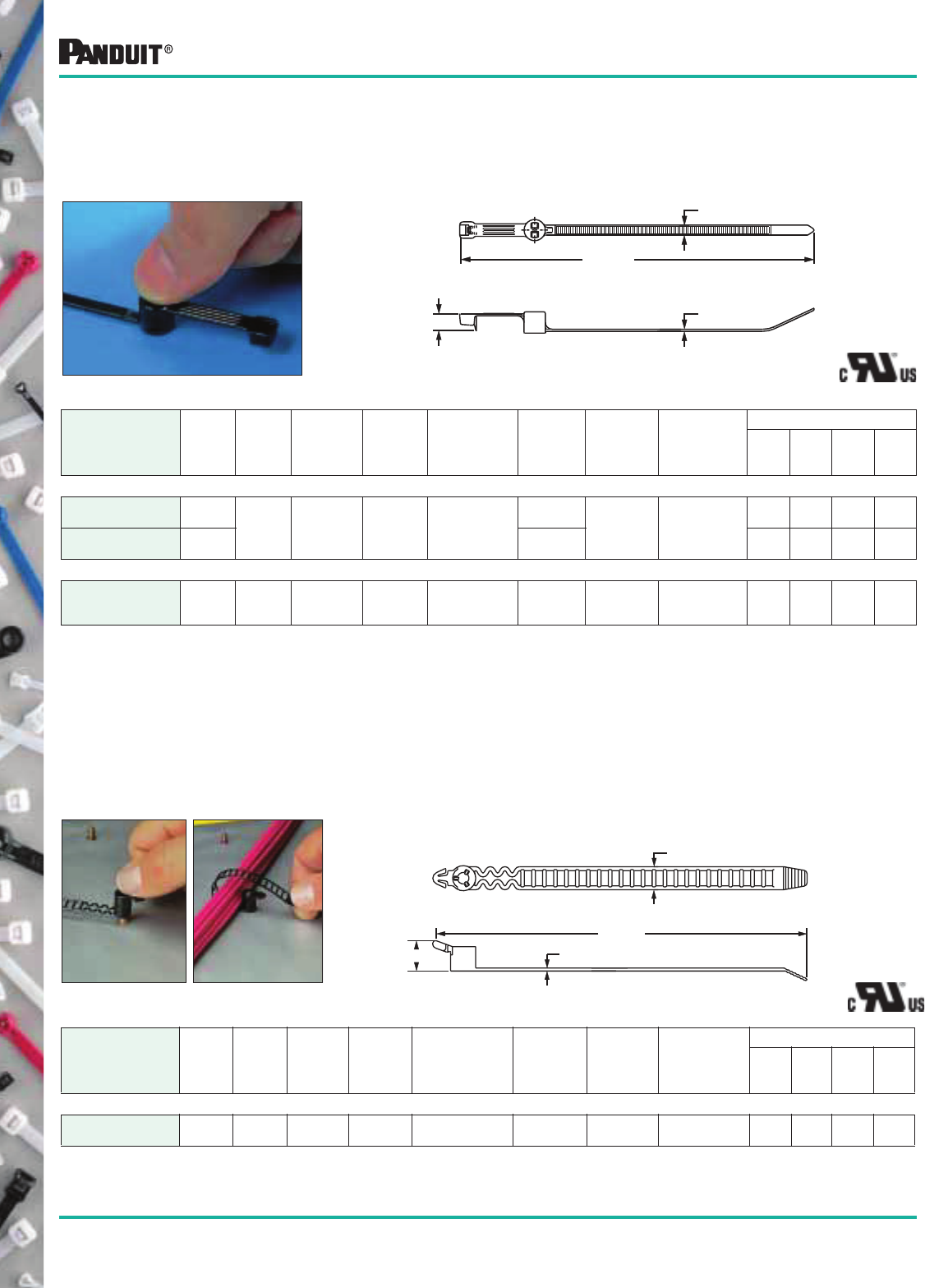
46
Most commonly used parts appear in BOLD.
B
D
A REF.
C
PANDUIT ® Stud
Mounted Heat
Stabilized Nylon 6.6
Cable Ties
Base portion pushes onto a threaded stud and the tie portion wraps
around the bundle. The wire bundle is centered over the stud.
Part Number
Length
A
in. (mm)
Width
B
in. (mm)
Thickness
C
in. (mm)
Head
Height
D
in. (mm)
Recommended
Stud Size
in. (mm)
Max.
Bundle
Dia.
in. (mm)
Min. Loop
Tensile
Strength
Lbs. (N)
Recommended
PANDUIT ®
Installation
Tool Part No.
Packaging*
Std.
Pkg.
Qty.
Std.
Ctn.
Qty.
Bulk
Pkg.
Qty.
Bulk
Ctn.
Qty.
STANDARD CROSS SECTION
PLST30SC-D30‡ 5.74
(146) .19
(4.8)
.050
(1.3)
.41
(10.5)
10-24
(5)
1.18
(30) 50
(222)
GTS, GS2B
GTH, GS4H,
PTS, PPTS,
STS2 or STH2
— — 500 5000
PLST50SC-D30‡ 8.14
(207)
1.97
(50)
— — 500 5000
HEAVY CROSS SECTION
PLST4HS25-TL300‡ 15.3
(389)
.300
(7.6)
.075
(1.9)
.265
(6.7)
1/4-20
(6)
4.00
(102.1)
120
(534)
GTH, GS4H,
GS4EH or
PPTEH
— — 250 2500
Ladder Style Stud
Mounted Cable Tie
Heat Stabilized
Nylon 6.6
The ties can be removed from the stud by turning counterclockwise.
Adjustable and releasable.
Part Number
Length
A
in. (mm)
Width
B
in. (mm)
Thickness
C
in. (mm)
Head
Height
D
in. (mm)
Recommended
Stud Size
in. (mm)
Max.
Bundle
Dia.
in. (mm)
Min. Loop
Tensile
Strength
Lbs. (N)
Recommended
PANDUIT ®
Installation
Tool Part No.
Packaging*
Std.
Pkg.
Qty.
Std.
Ctn.
Qty.
Bulk
Pkg.
Qty.
Bulk
Ctn.
Qty.
STANDARD CROSS SECTION
PRST30S-S14-M30‡ 5.2
(132)
.38
(9.7)
.050
(1.3)
.59
(15)
10-24
(5)
1.18
(30)
35
(156)
Hand Installed
Only
— — 1000 10000
*Order the number of pieces required in multiples of package quantities.
For colors and other materials, see page 50.
All part numbers shown in standard package quantities unless denoted by ‡.
B
D
A REF.
C
Specialty Ties
Except PLST4H
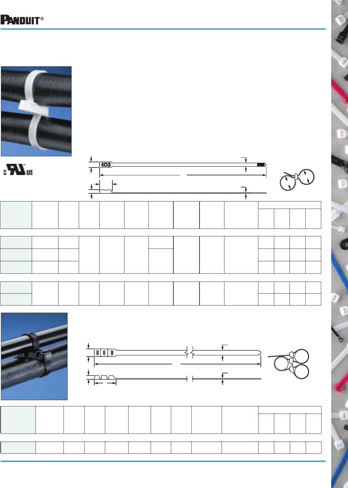
47
Most commonly used parts appear in BOLD.
Part Number
Max.
Combined
Bundle Dia.
D1, D2 & D3
in. (mm)
Length
A
in. (mm)
Width
B
in. (mm)
Thickness
C
in. (mm)
Head
Height
D
in. (mm)
Head
Width
E
in. (mm)
Head
Length
F
in. (mm)
Min. Loop
Tensile
Strength
Lbs.
(N)
Recommended
PANDUIT ®
Installation
Tool Part No.
Packaging*
Std.
Pkg.
Qty.
Std.
Ctn.
Qty.
Bulk
Pkg.
Qty.
Bulk
Ctn.
Qty.
EXTRA-HEAVY CROSS SECTION
PL3B5EH-C0‡ 5.0
(127)
20.0
(508)
.500
(12.7)
.075
(1.9)
.400
(10.2)
.800
(20.3)
1.8
(45.7)
125
(556)
GS4EH or
PPTEH
— — 100 1000
Part Number
Max.
Combined
Bundle dia.
D1 & D2
in. (mm)
Length
A
in. (mm)
Width
B
in. (mm)
Thickness
C
in. (mm)
Head
Height
D
in. (mm)
Head
Width
E
in. (mm)
Head
Length
F
in. (mm)
Min. Loop
Tensile
Strength
Lbs. (N)
Recommended
PANDUIT ®
Installation
Tool Part No.
Packaging*
Std.
Pkg.
Qty.
Std.
Ctn.
Qty.
Bulk
Pkg.
Qty.
Bulk
Ctn.
Qty.
STANDARD CROSS SECTION
PLB2S-C 1.8
(46)
7.6
(193)
.19
(4.8)
.052
(1.3)
.220
(5.6)
.320
(8.1)
.465
(11.8)
50
(222)
GTS, GS2B.
GTH, GS4H,
PTS, PPTS,
STS2 or STH2
100 1000 1000 10000
PLB3S-C 3.0
(76)
11.8
(300) .337
(8.6)
100 1000 1000 10000
PLB4S-C 4.1
(104)
14.8
(376)
100 1000 1000 5000
HEAVY CROSS SECTION
PLB4H-TL‡
3.6
(91)
14.7
(373)
.300
(7.6)
.075
(1.9)
.322
(8.2)
.490
(12.4)
1.1
(27.9)
120
(534)
GTH, GS4H,
GS4EH,
or PPTEH
— — 250 2500
PLB4H-TL0‡ — — 250 2500
PANDUIT ® Multiple
Loop Cable Ties —
Nylon 6.6
*Order the number of pieces required in multiples of package quantities.
For colors and other materials, see page 50.
All part numbers shown in standard package quantities unless denoted by ‡.
E
A
B
C
D
F
Specialty Ties
E
D
F
A
B
C
Except PLB4H-0
PANDUIT ®
Multiple Loop Cable Ties —
Weather Resistant Nylon 6.6
Applications:
• Underhood hose and harness routing
• Areas where bundles must be secured parallel to each other or
another element
Solution
Looking for a labor saving alternative to cushioned clamps when securing hoses
and wire bundles? PANDUIT ® Multiple Loop Cable Ties are the perfect solution.
Features and Benefits:
• Offers multiple loop capability
• Prevents bundle damage with a wire strap body that spreads the
clamping forces
• Provides high tensile strength to route bundles securely
• Installs easily by hand — use PANDUIT ® tooling for repeatable tension
and cut-off
• Reduces part number inventory with a single product to cover multiple
bundle sizes
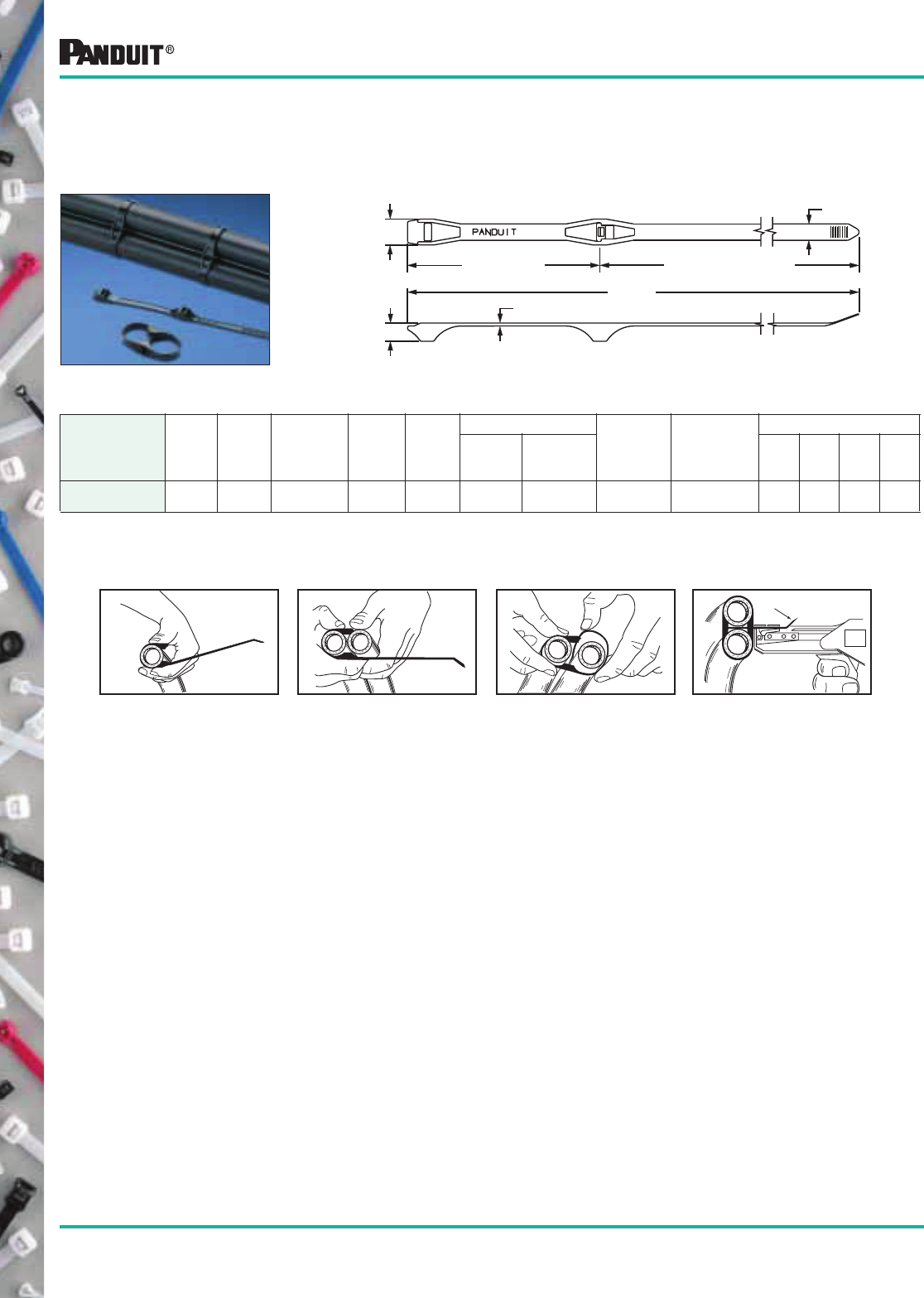
48
Most commonly used parts appear in BOLD.
Double Hose Clamp
Weather Resistant
Nylon 6.6
The Double Hose Clamp can be used on gasoline, hydraulic or
pneumatic hoses. It holds each hose individually to prevent abrasion
and holds them together to prevent twisting.
Part Number
Length
A
in. (mm)
Width
B
in. (mm)
Thickness
C
in. (mm)
Head
Height
D
in. (mm)
Head
Width
E
in. (mm)
Loop Diameters Min. Loop
Tensile
Strength
Lbs. (N)
Recommended
PANDUIT ®
Installation
Tool Part No.
Packaging*
Fixed
Loop
in. (mm)
Adjustable
Loop
in. (mm)
Std.
Pkg.
Qty.
Std.
Ctn.
Qty.
Bulk
Pkg.
Qty.
Bulk
Ctn.
Qty.
DHC1.12x1.75-D0 11.0
(279)
.28
(7.1)
.050
(1.3)
.31
(7.9)
.44
(11.2)
1.12
(28.4)
1.0 to 1.75
(25 to 44)
100
(445)
GTH, GS4H,
STH2 or ST2EH
— — 500 2500
1. Wrap clamp around hose. 2. Position second hose in clamp. 3. Loop tail around second hose
and thread tail through both
spacer heads.
E
A REF.
B
C
D
FIXED LOOP ADJUSTABLE LOOP
Curved tip up
GS4H
Specialty Ties
4. Tension and cut off with
PANDUIT ® tool.
Curved tip up
GS4H
*Order the number of pieces required in multiples of package quantities.
For colors and other materials, see page 50.
All part numbers shown in standard package quantities unless denoted by ‡.
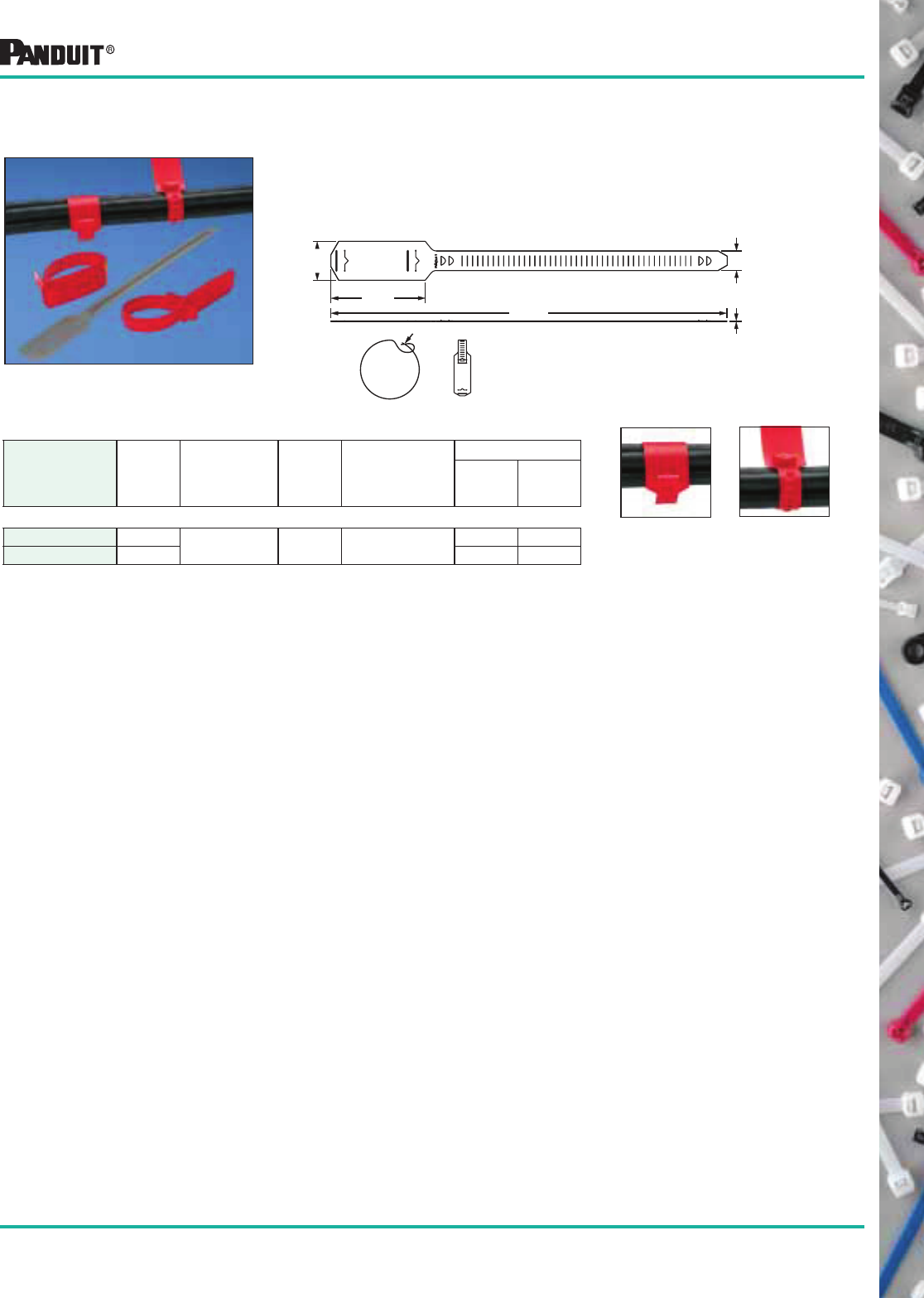
49
Most commonly used parts appear in BOLD.
Polyethylene
Cable Marker Strap
For identifying telephone and fiber optic cable. Replaces costly and
cumbersome lead marking tags. Lightweight and easy-to-install.
Can be used as wrap-around or “flag” marker. Can also be used in
underground identification applications. Custom hot stamping is
available (see page 52).
Part Number Color
Marking
Area
in. (mm,)
Max.
Bundle
Dia.
in. (mm)
Recommended
PANDUIT ®
Installation
Tool Part No.
Packaging*
Std.
Pkg.
Qty.
Std.
Ctn.
Qty.
STANDARD CROSS SECTION
CM4S-L2 Red 1.50 x 2.62
(38.1 x 66.5)
4.38
(111) Hand Installed Only 50 500
CM4S-L8 Gray 50 500
WRAP-AROUND
MARKER
(Min. Dia.: 1.27")
“FLAG” MARKER
(Min. Dia.: 25")
Specialty Ties
*Order the number of pieces required in multiples of package quantities.
For colors and other materials, see page 50.
All part numbers shown in standard package quantities unless denoted by ‡.
Loop Excess
Thru Slot
1.50
(38.1)
3.88
(98.5)
.75
(19.1)
.033
(.84)
15.25
(387.4)
Unique design allows
strap to be used as:
50
Most commonly used parts appear in BOLD.
Part Number Suffix Codes for All PANDUIT ® Specialty Cable Ties
Part Description:
CM4S = Cable Marker Strap
DHC = Double Hose Clamp
PLST = Lock. Stud Mounted
PLB = Locking Bow Tie
PRST = Releas. Stud Mounted
(Ladder Style)
Size:
Approximate
Maximum Bundle
Diameter in Inches
Cross Section:
S = Standard
H = Heavy
EH = Extra-Heavy
Stud Size:
-S25 = 1/4" (M6)
-SC = .20" (5mm)
Package Size:
L = 50
C = 100
TL = 250
D = 500
Color:
See Material/
Color chart. Not
all ties available
in all colors.
—
Part Number System (Example of PLST4HS25-TL)
Material/Color
PANDUIT ®
Suffix*
Mil Spec
Suffix**
Natural Nylon 6.6 (See Note) ✔9
Weather Resistant Nylon 6.6 0 N/A
Nylon 6.6 — Red 2 2
Material/Color Chart
Material/Color
PANDUIT ®
Suffix*
Mil Spec
Suffix**
Nylon 6.6 — Gray 8 8
Heat Stabilized Black Nylon 6.6 30 N/A
Heat Stabilized Weather Resistant
Nylon 6.6
300 N/A
Standard Packaging Bulk Packaging
Part
Number
Natural
Nylon 6.6
Available Color/
Material (Suffix)
Part
Number
Natural
Nylon 6.6
Available Color/
Material (Suffix)
CM4S-L 2, 8
DHC1.12X1.75-D 0
PLB2S-C ✔0PLB2S-M ✔0, 30
PLB3S-C ✔0PLB3S-M ✔0, 30
PLB4S-C ✔PLB4S-M ✔0, 30
PLB4H-TL ✔0, 30
PL3B5EH-C 0
PLST4HS25-TL 300
PLST30SC-D 30
PLST50SC-D 30
PRST40SC-D 30
*NOTE: ✔designates PANDUIT ®
standard Natural Nylon 6.6 color/material. No suffix required in part number.
**NOTE: MIL SPEC Color (suffix) per AS33671 (Formerly MS3367) and SAE AS33681 (Formerly MS3368).
51
Most commonly used parts appear in BOLD.
Cable Ties
Current MIL Std.
Part Number*
PAN-TY®
Cable Tie
Part Number
DOM E-TOP ®
Barb Ty Cable Tie
Part Number
STA-STRAP ®
Cable Tie
Part Number
BELT-TY™
In-Line Cable Tie
Part Number
MS3367-1-*
MS3367-2-*
MS3367-3-*
MS3367-4-*
MS3367-4-*
MS3367-5-*
MS3367-6-*
MS3367-6-*
MS3367-7-*
MS3367-23-*
MS3367-24-*
MS3367-25-*
MS3367-26-*
MS3367-27-*
MS3367-29-*
PLT2S
PLT4S
PLT4H
PLT.7M
PLT1M
PLT1.5I
PLT8LH
—
PLT3S
—
—
—
—
—
—
BT2S
BT4S
BT4LH
—
BT1M
BT1.5I
BT8LH
BT9LH
BT3S
—
—
—
—
—
—
SST2S
SST4S
SST4H
—
SST1M
SST1.5I
SST8H
—
SST3S
—
—
—
—
—
—
—
—
—
—
—
—
—
—
—
ILT2S
ILT4S
ILT4LH
ILT1M
ILT1.5I
ILT3S
Marker Ties
Current MIL Std.
Part Number*
PAN-TY®
Cable Tie
Part Number
DOM E-TOP ®
Barb Ty Cable Tie
Part Number
MS3368-1-*A
MS3368-2-*A
MS3368-3-*C
MS3368-4-*D
MS3368-5-*E
PLM2S
PLM4S
PL2M2S
PL3M2S
PLM1M
BM2S
BM4S
B2M2S
B3M2S
BM1M
Installation Tools
Current MIL Std.
Part Number*
Tool
Part Number
MS90387-1
MS90387-2
MS90387-3
GTS, GS2B
GS4H
GS4MT
* Color Code (See Material/Color Chart located in the back of each product line section).
Aerospace and Military Standard cross reference to PANDUIT ® part numbers
Military Cross Reference
The PANDUIT ® Cable Ties and Marker Ties listed in the table below meet all the testing requirements of
Aerospace Standard SAE-AS23190A (formerly MIL-S-23190E) and the dimensional requirements of
Aerospace Standards SAE-AS33671 (formerly MS3367) and SAE-AS33681 (formerly MS3368).
The PANDUIT ® Installation Tools listed in the table below
meet all the testing requirements of MIL-T-81306 and the
dimensional requirements of MS90387.
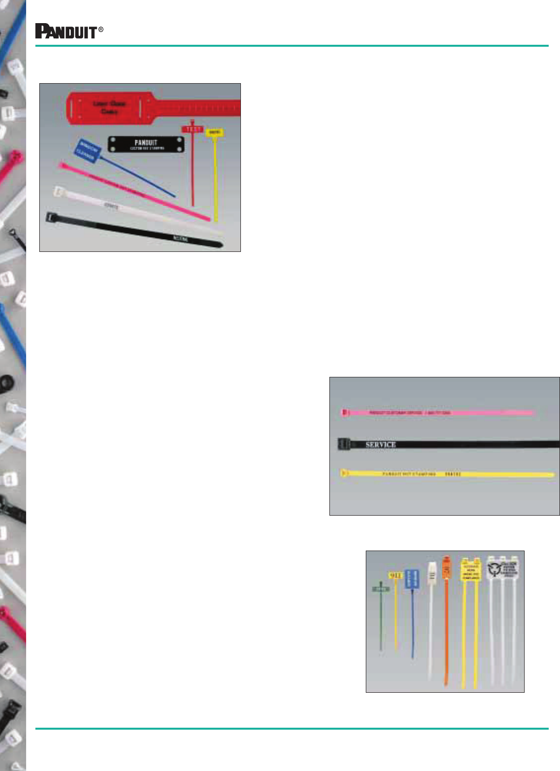
52
Most commonly used parts appear in BOLD.
Custom Hot Stamping
• Economical
• Convenient
• 1/8" (3mm), 3/16" (4.8mm), 5/64" (2mm) and 7/64"
(2.8mm) characters are available
• Standard Type Style: News Gothic
• Character sizes can be mixed from line-to-line
• Alphanumeric and sequential numbering for
serialization are available
• Sequential numbering available in 3/32" (2.4mm), 9/64"
(3.6mm), and 1/8" (3mm) characters
• Seven colors of hot stamping to make your message
stand out — Black, Blue, Green, Red, Yellow, Orange
and White
• Special logos, type styles and sizes can be provided
(when camera ready artwork is supplied)
• Minimum order: 5,000 pieces per part number and
message
Contact Your Local PANDUIT ® Distributor for Details
A custom program to mark
nylon cable ties, marker ties
and marker plates to suit
your application
requirements . . .
PANDUIT ® Custom Hot Stamping Program
Cable Tie Cross Sections
INTERMEDIATE
(Locking)
STANDARD
(Locking and Releasable)
LIGHT-HEAVY AND HEAVY
(Locking and Releasable)
EXTRA-HEAVY
(Locking and Releasable)
Marker Tie Cross Sections
MINIATURE
(Locking)
STANDARD
(Locking)
NOTE: Most cable ties and marker ties are available in colors
(See information at the back of each tie section).
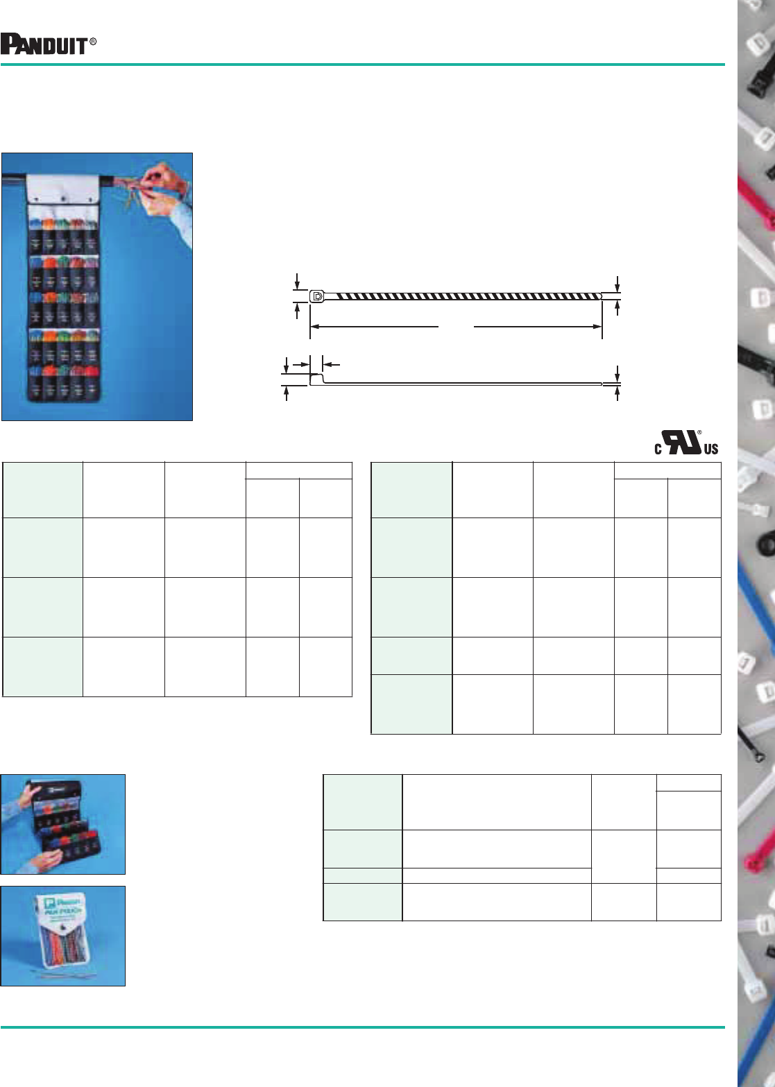
53
Most commonly used parts appear in BOLD.
•Not included in filled PA N-PO UCH ™.
Part Number
Cable Tie
Color
Color
Stripe
Packaging*
Std.
Pkg.
Qty.
Std.
Ctn.
Qty.
PLT1M-L6-4
PLT1M-L3-4
PLT1M-L5-4
PLT1M-L1-4
PLT1M-L8-4
Blue
Orange
Green
Brown
Slate
Yellow
50
50
50
50
50
1000
1000
1000
1000
1000
PLT1M-L6-7
PLT1M-L3-7
PLT1M-L5-7
PLT1M-L1-7
PLT1M-L8-7
Blue
Orange
Green
Brown
Slate•
Violet
50
50
50
50
50
1000
1000
1000
1000
1000
PLT1M-L2
PLT1M-L0
PLT1M-L4
Red
Black•
Yellow•
—
50
50
50
1000
1000
1000
PLT1M-L6
PLT1M-L3
PLT1M-L5
PLT1M-L1
PLT1M-L8
Blue•
Orange•
Green•
Brown•
Slate•
—
50
50
50
50
50
1000
1000
1000
1000
1000
The PAN-POUCH ™ system provides a fast, convenient method of
identifying binder groups on both sides of a splice in PIC cable.
It consists of striped PAN-TY® Cable Ties in 25 color combinations
which match the universally accepted Even-Count Color Code.
In addition, solid color ties are available for identification of
“Super Groups” in cable containing more than 600 pairs. Cable
ties have maximum bundle diameter of .82" (21mm). Each 50 pc.
package fits into PAN-POUCH ™ over Pocket Pouch.
Cable ties in other solid colors (sold in 100 pc. packages) see pages 24-26.
Part Number
Cable Tie
Color
Color
Stripe
Packaging*
Std.
Pkg.
Qty.
Std.
Ctn.
Qty.
PLT1M-L6-10
PLT1M-L3-10
PLT1M-L5-10
PLT1M-L1-10
PLT1M-L8-10
Blue
Orange
Green
Brown
Slate
White
50
50
50
50
50
1000
1000
1000
1000
1000
PLT1M-L6-2
PLT1M-L3-2
PLT1M-L5-2
PLT1M-L1-2
PLT1M-L8-2
Blue
Orange
Green
Brown
Slate
Red
50
50
50
50
50
1000
1000
1000
1000
1000
PLT1M-L6-0
PLT1M-L3-0
PLT1M-L5-0
PLT1M-L1-0
PLT1M-L8-0
Blue
Orange
Green
Brown
Slate
Black
50
50
50
50
50
1000
1000
1000
1000
1000
Nylon 6.6 Cable Ties
Pouches
Part Number Description
Pouch
Material
Packaging*
Std.
Pkg.
Qty.
PPC25x50F PAN-POUCH ™ filled with 1250 cable ties.
50 each of all 24 striped ties plus
solid red.
2 ply
Laminated
Black Nylon/
Vinyl
1
PPC25x50 Empty PAN-POUCH ™ 1
PP5x50F Pocket Pouch filled with 250 cable ties.
50 each: blue, orange, green, brown and
slate all with white stripe.
Vinyl 1
PAN-POUCH ™ is 10 1/2" x 38"
(267mm x 965mm) made of
2 ply laminated black nylon/
vinyl and folds to 10 1/2" x 6"
(266m x 152mm) for easy
storage. The pouch can be
easily hung from cable by
using Hook & Loop fasteners.
Pocket Pouch holds
five (50 pc.) packages.
*Order by the number of pieces required in multiples of package quantities.
All part numbers shown in standard package quantities unless denoted by ‡.
PAN-POUCH ™ Telephone Cable Identification Kit
PANDUIT ® PAN-POUCH ™
Telephone Cable
Identification Kit
.185
(4.7)
.100
(2.5)
3.8
(95)
.036
(.9)
.154
(3.9)
.175
(4.4)
54 Most commonly used parts appear in BOLD.
Cable Tie Kits in
Plastic Boxes —
KP-506A/KP-506A-0
Cable Ties and
Accessories Kit
Part Number Description
Std.
Pkg.
Qty.*
KP-506A Contains natural nylon ties for indoor use:
(100) PLT1M-C Cable Ties
(100) PLT1.5I-C Cable Ties
(100) PLT2S-C Cable Ties
(50) ABM2S-A Mounts
(1) Plastic Kit Box
1
KP-506A-0 Contains weather resistant cable ties and mounts for outdoor use:
(100) PLT1M-C0 Black Weather Resistant Cable Ties
(100) PLT1.5I-C0 Black Weather Resistant Cable Ties
(100) PLT2S-C0 Black Weather Resistant Cable Ties
(50) ABM2S-AT-0 Black Weather Resistant Mounts
(1) Plastic Kit Box
1
KP-509 A special collection of cable ties and wiring accessories for prototyping and new
product development.
Contains (over 600 pieces):
Including PAN-TY® Cable Ties (in different styles, sizes, colors and materials);
25 different cable tie mounts; 30 different wiring accessories;
(1) Plastic Kit Box
1
KB-550 Assortment Pack contains natural and weather resistant PAN-TY® nylon cable ties:
(15) PLT1M Cable Ties
(10) PLT1M Black Weather Resistant Cable Ties
(15) PLT1.5I Cable Ties
(10) PLT1.5I Black Weather Resistant Cable Ties
(15) PLT2S Cable Ties
(10) PLT2S Black Weather Resistant Cable Ties
(15) PLT3S Cable Ties
(10) PLT3S Black Weather Resistant Cable Ties
1
KB-551 Assortment Pack contains natural and weather resistant DOME-TOP ® Barb Ty nylon
cable ties:
(15) BT1M Cable Ties
(10) BT1M Black Weather Resistant Cable Ties
(15) BT1.5I Cable Ties
(10) BT1.5I Black Weather Resistant Cable Ties
(15) BT2S Cable Ties
(10) BT2S Black Weather Resistant Cable Ties
(15) BT3S Cable Ties
(10) BT3S Black Weather Resistant Cable Ties
1
K-504 Contains cable ties, adhesive backed mounts and cable tie installation tool:
(100) PLT1M-C Cable Ties
(100) PLT1.5I-C Cable Ties
(100) PLT2S-C Cable Ties
(100) PLC2S-S10-C Clamp Ties
(100) TM2S8-C Mounts
(100) ABM2S-A-C Mounts
(1) STS2 Tool
(1) Steel Kit Box
1
SR2 2-Drawer Slide Rack to hold K-504 Kit or K-1100 Series Terminal Kits.
See PANDUIT ® Terminal Catalog, SA101N21B-NL. 1
K-205 Contains 300 cable ties, 600 terminals and 2 installation tools:
(100) PLT1M-C Cable Ties
(100) PLT1.5I-C Cable Ties
(100) PLT2S-C Cable Ties
(1) GTS Cable Tie Installation Tool
(100) PV18-6LF-C Terminals
(100) PV14-8LF-C Terminals
(100) PV14-10LF-C Terminals
(50) PV10-10LF-L Terminals
(100) BSV18X-C Splices
(100) BSV14X-C Splices
(50) BSV10X-L Splices
(1) CT-100 Crimping Tool
(1) Steel Kit Box
1
KP-509 Designer’s Kit
Cable Tie Kits in
Steel Boxes —
K-504 Cable Ties and
Accessories Kit
K-205 Cable Ties and
Terminal Kit
*Order the number of kits required in multiples of package quantities.
All part numbers shown in standard package quantities unless denoted by ‡.
Cable Tie Kits
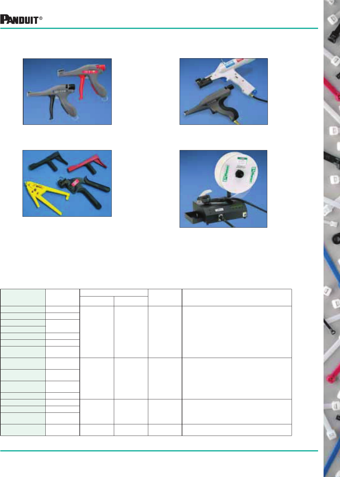
55
Most commonly used parts appear in BOLD.
Cable Tie Installation Tools
The PANDUIT ® Selection. . . PANDUIT ® offers the greatest selection of job-matched tools:
Cable Tie Installation Tools
PAT1M/PAT1.5M Automatic Cable Tie
Installation Systems
Pneumatic Tool Controlled
Tension and Cutoff Tools
Tool Controlled Tension
and Cutoff Tools
Operator Controlled Tension and
Cutoff Tools
Choosing the right tool increases productivity. . .
Whatever the need; Original Equipment Manufacturer (high, medium, low volume), maintenance/repair or
construction; PANDUIT ® has the tool to help lower your total installed cost. The following chart can be
used as a guide for tool selection:
Tool
Cable Tie
Cross
Section
Cable Tie Usage
Operation Typical Application(s)Per Minute Per Year
GTS SM, M, I or S
4-6 Under
50,000 Hand Low to Medium Volume OEM tie usage, maintenance/
repair or construction
GS2B M, I, or S
GTH S, HS, LH
or H
GS4H
GS4H/B S, HS, LH or H
GS4H121W S, HS, LH or H
GS4EH LH, H
or EH
STS2 M, I
or S
1-4 Under
10,000 Hand Maintenance/repair or construction
STH2 S, LH
or H
ST2EH LH, H
or EH
STHV LH or H
PTS SM, M, I or S
5-8 Up To
250,000 Pneumatic Medium to High Volume OEM tie usage where a variety
of tie sizes are needed.
PPTS M, I, or S
PPTEH LH, H
or EH
PAT1M/PAT1.5M
Systems (Automatic)
M 30-40 250,000
and above
Pneumatic/
Electric
High Volume OEM tie usage
56
Most commonly used parts appear in BOLD.
Hand-Operated Tools —
Tool-Controlled Tension
and Cut-Off
The most preferred hand-operated cable tie tools in the industry.
These tools are versatile and can be used for production,
maintenance or construction applications. These tools will tension
and cut off excess tie material flush to the head by squeezing
trigger handle.
For PANDUIT ® Cable Ties up to 1/2" (12.7mm) wide
• Lightweight and balanced
• Requires no special maintenance
• Easy to change tension adjustment and easy to operate
• Proven features to help lower installed costs; a combination of
design, operating and construction features provide a long
service life
• Replacement blades available
Part Number Description
Std.
Pkg.
Qty.*
GTS Installs PANDUIT ® Subminiature, Miniature, Intermediate and Standard cross
section cable ties. Qualified Product Listed per Mil. Std. MS90387-1 and
Mil. Spec. MIL-T-81306A. Plastic molded housing. Ergonomic design.
Color Identification:
Trigger Handle: Black
Selector Knob: Black
Weight: 8.8 oz. (249g)
1
GS2B Installs PANDUIT ® Miniature, Intermediate and Standard cross section
cable ties. Qualified Product Listed per Mil. Std. MS90387-1 and
Mil. Spec. MIL-T-81306A.
Color Identification:
Trigger Handle: Black
Selector Knob: Black
Weight: 11.5 oz. (327g)
1
GTH Installs PANDUIT ® Standard, Heavy-Standard, Light-Heavy and Heavy cross
section cable ties. Plastic molded housing. Ergonomic design.
Color Identification:
Trigger Handle: Red
Selector Knob: Red
Weight: 11.2 oz. (318g)
1
GS4H Installs PANDUIT ® Standard, Heavy-Standard, Light-Heavy and Heavy cross
section cable ties. Durable powder coat finish. Qualified Product Listed per
Mil. Std. MS90387-2 and Mil. Spec. MIL-T-81306A.
Color Identification:
Trigger Handle: Red
Selector Knob: Red
Weight: 16 oz. (454g)
1
GS4H/B
Installs PANDUIT ® Standard, Heavy-Standard, Light-Heavy and Heavy cross
section cable ties. Durable powder coat finish. High tension, factory set,
non-adjustable.
Color Identification:
Trigger Handle: Blue
Weight: 16 oz. (454g)
1
GS4H121W Installs PANDUIT ® Standard, Heavy-Standard, Light-Heavy and Heavy cross
section cable ties. This tool provides greater tension, especially on 175 lb.
strength ties, which results in tighter bundles. Durable powder coat finish.
Color Identification:
Trigger Handle: Green
Selector Knob: Green
Weight: 16 oz. (454g)
1
GS4EH Installs
PANDUIT ® Light-Heavy, Heavy and Extra-Heavy cross section cable ties.
Durable powder coat finish.
Color Identification:
Trigger Handle: Blue
Selector Knob: Blue
Weight: 15 oz. (426g)
1
Hand-Operated Tools
*Order the number of pieces required in multiples of package quantities.
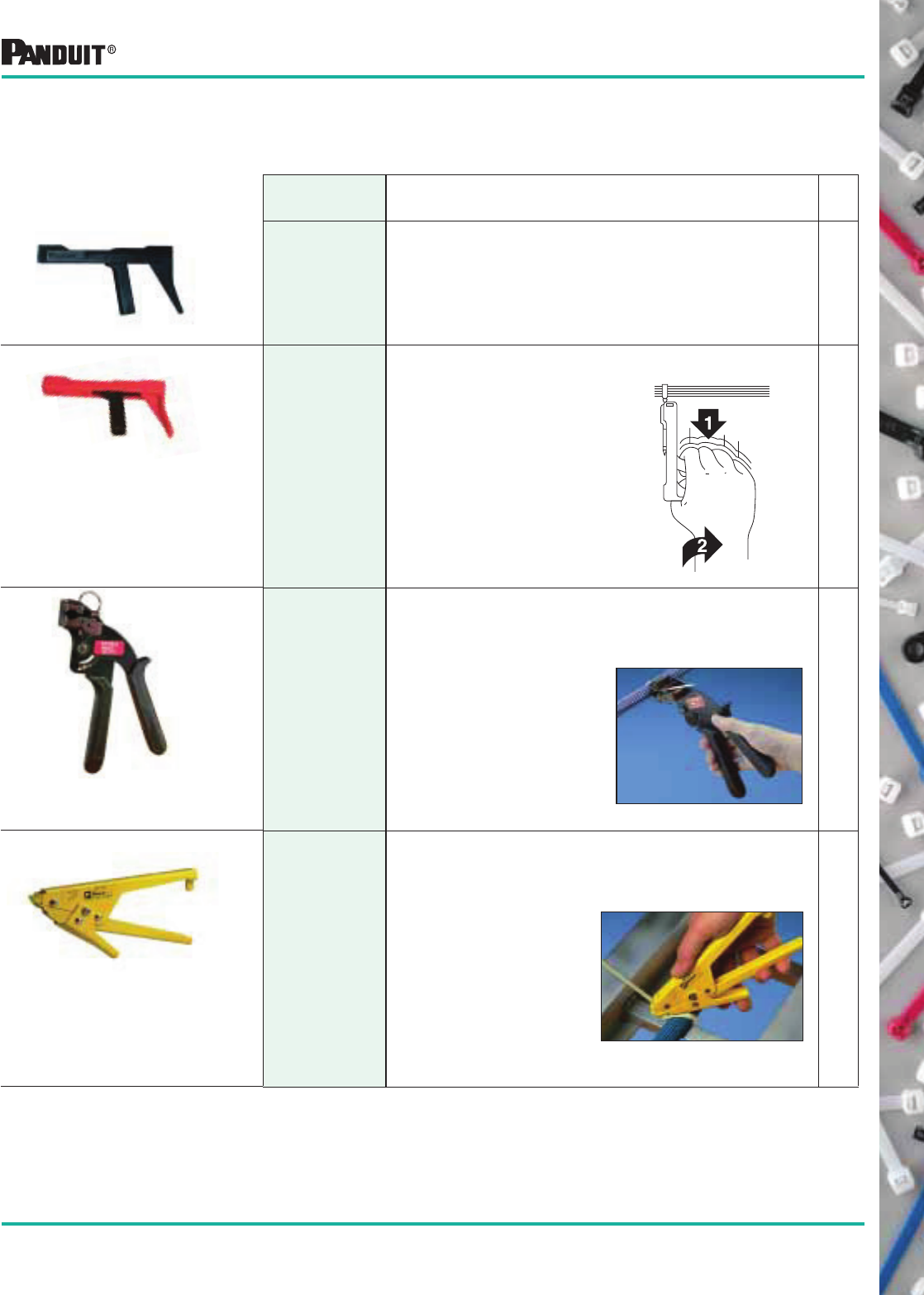
57
Most commonly used parts appear in BOLD.
Part Number Description
Std.
Pkg.
Qty.*
STS2
Installs PANDUIT ®
Miniature, Intermediate or Standard cross section cable ties.
See STH2 operation below.
Color Identification: Black
Weight: 2 1/2 oz. (71g) 1
STH2 Installs PANDUIT®
Standard, Heavy-Standard, Light-Heavy or Heavy cross section
cable ties.
Color Identification: Red
Weight: 2 1/2 oz. (71g)
INSTALLATION PROCEDURE FOR
STS2 AND STH2 TOOLS
1. Install cable tie around bundle.
Tension tie by squeezing tool handle.
2. Reduce tension slightly and twist tool
1/4 turn either direction for cut-off of
cable tie.
1
ST2EH Installs PANDUIT ®
Light-Heavy, Heavy or Extra-Heavy cross section cable ties.
Color Identification: Black Handles
Weight: 16 oz. (454g)
1
STHV Installs PANDUIT ®
Light-Heavy and Heavy cross section cable ties.
Color Identification: All Yellow
Weight: 14 oz. (399g)
1
• Inexpensive, maintenance-
free, all purpose tools
• Ergonomic handle design
and short handle span
• Top loading feature for right
or left-handed users
After installing tie around bundle
and tensioning, tool is twisted a 1/4 turn
“in either direction” to cut off excess tie.
After installing tie around bundle, the
handles are squeezed to provide
tension. A separate lever cuts
excess tie.
• Durable all steel construction
• Comfortable rubber handles
• Durable all steel
construction
• “Travel stop” helps prevent
pinched fingers
Hand-Operated Tools
*Order the number of pieces required in multiples of packaging quantities.
Hand Operated
Tools—
Installer-Controlled
Tension and Cut-Off
PANDUIT ® offers an economical series of tools for maintenance or
construction applications — the user determines the required cable tie
tension and the tools provide a cut-off. Used with the full line of PANDUIT ®
Cable Ties.
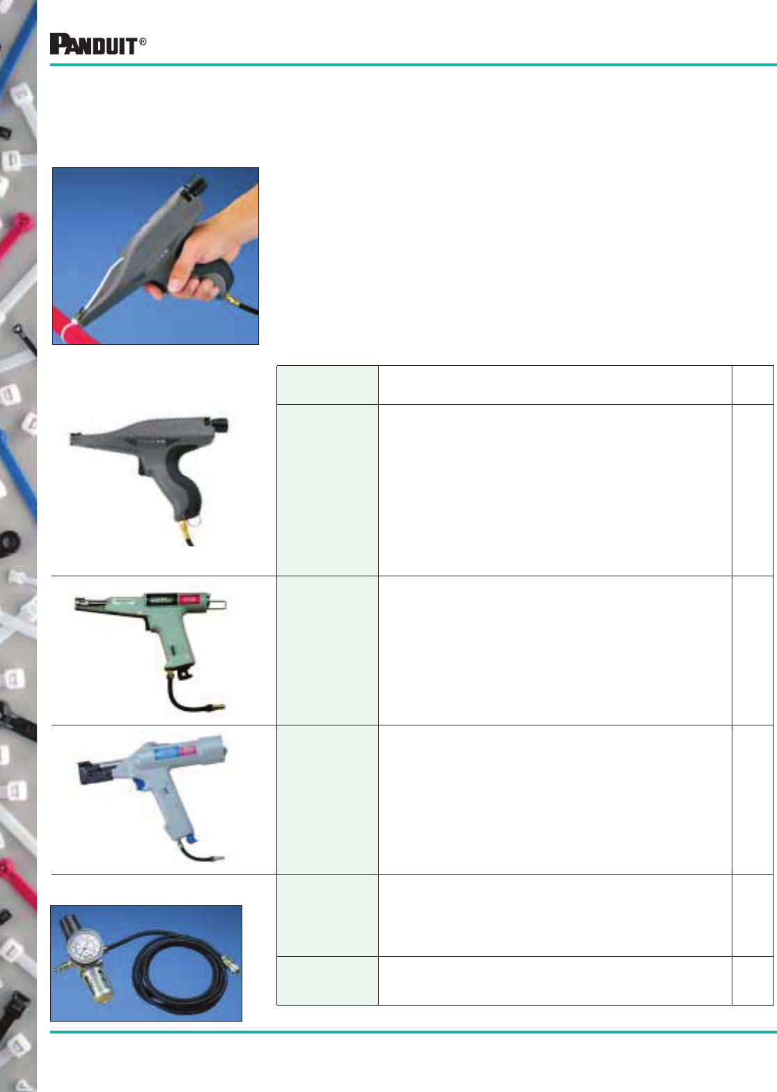
58
Most commonly used parts appear in BOLD.
*Order the number of pieces required in multiples of package quantities.
For PANDUIT ®
Cable Ties up to 1/2" (12.7mm) wide
• Easy to change tension adjustment
• Requires no special training to use
• Durable, lightweight, easy to operate and designed to reduce
operator fatigue
• Tensions and cuts off excess tie in a fraction of a second
• Operates on non-lubricated air, without special maintenance
Pneumatic Hand Tools
Tool-Controlled Tension
and Cut-Off
Note: PTS, PPTS and PPTEH tools require the PPH10 hose and PL289N1 Filter/Regulator for proper operation.
Part Number Description
Std.
Pkg.
Qty.*
PTS Installs Subminiature, Miniature, Intermediate or Standard cross section
cable ties.
Color identification: (Knob) Black
Weight: 17.3 oz. (490g)
Replacement parts can be par t of a scheduled maintenance program
Plastic molded housing
Ergonomic design 1
PPTS Installs Miniature, Intermediate or Standard cross section cable ties.
Color identification: (Knob) Black
Weight: 18 oz. (510g)
Replacement parts can be par t of a scheduled maintenance program
Powder coat finish 1
PPTEH
Installs Light-Heavy, Heavy and Extra-Heavy cross section cable ties.
Color Identification: (Knob) Blue
Weight: 52 oz. (1476g)
Replacement parts can be par t of a scheduled maintenance program
Powder coat finish
1
PPH10 10' (3m) Hose Assembly (regulator to tool). Includes a 1/8" NPT male
connector (to regulator) and 1/8" female quick disconnect fitting (to tool).
1
PL289N1 Filter/Regulator .5 micron (max.) element, regulated range 3-100 PSIG,
1/8" ports. 1
Filter Regulator and Hose
Pneumatic Hand Tools
PANDUIT ® pneumatic tools tension and cut off excess tie after it
is hand-installed around the bundle, minimizing operator fatigue.
Tools are rugged, yet lightweight.
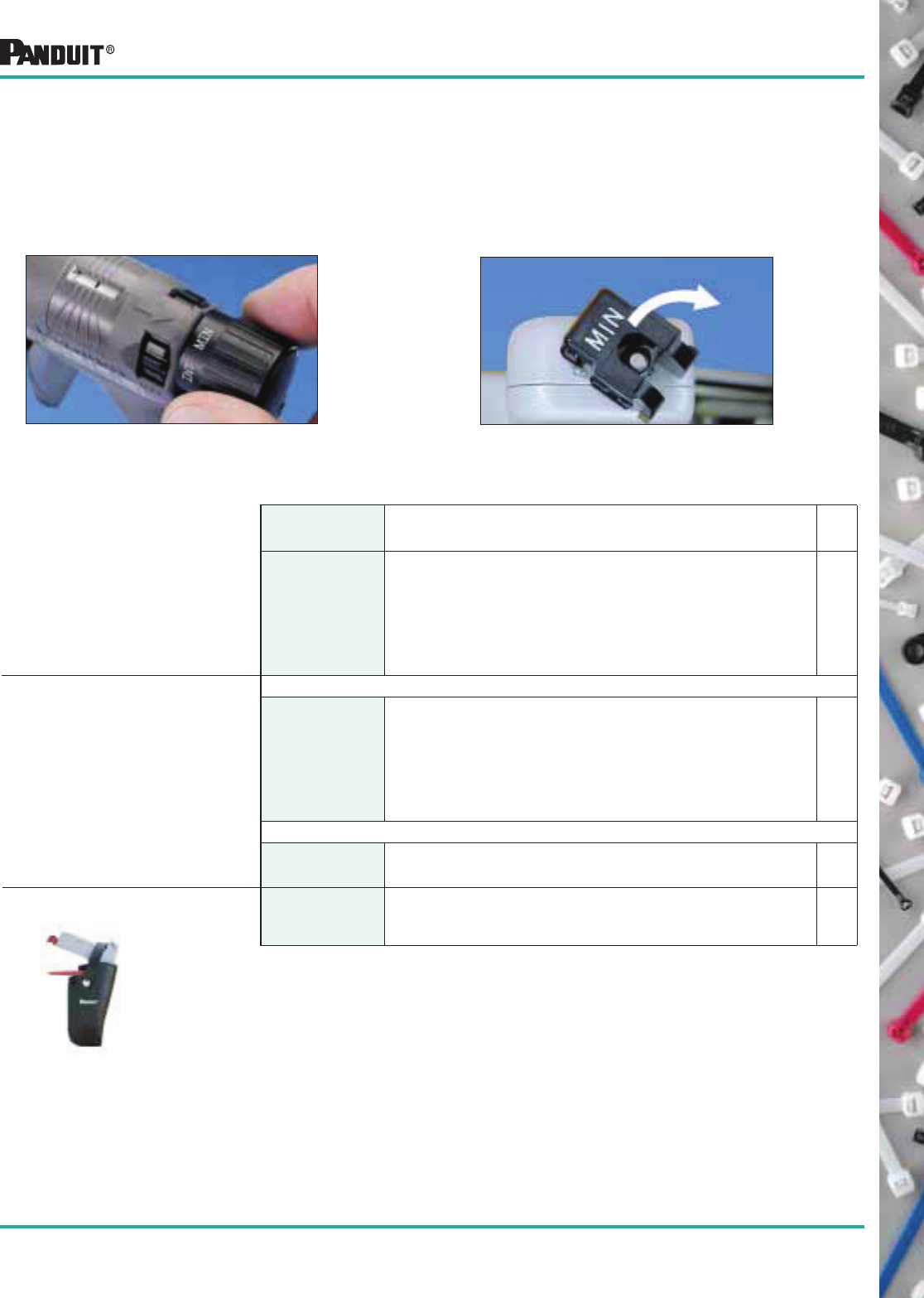
59
Most commonly used parts appear in BOLD.
Hand-Operated Tool Accessories
Fast and Easy Selection
GTS Tool — Tension Setting Dial
Part Number Description
Std.
Pkg.
Qty.*
KGTSTL
KGTHTL
KPTSTL
TTLK3
Tension Locking Kit for GTS.
Tension Locking Kit for GTH.
Tension Locking Kit for PTS.
Tool Tension Lock Kit.
Each kit contains (1) #4-40 selection locking screw (with head), (1) selection locking
clip, and (1) #4-40 tension locking screw (headless). For use with GS-Family Tools.
10
Blade Replacement Kits
KGTSBLD
KGTHBLD
K2-BLD2
K4H-BLD
KPPTEHB
Blade Replacement Kit for GTS, PTS.
Blade Replacement Kit for GTH.
Blade Replacement Kit for GS2B and PPTS (all versions).
Blade Replacement Kit for GS4H series (3-screw blade guard only).
Blade Replacement Kit for PPTEH series.
1
Gripper Replacement Kits
KPPTEHG
KPTSG
KST2EHG
Gripper Replacement Kit for PPTEH series.
Gripper Replacement Kit for PPTS.
Gripper Replacement Kit for ST2EH.
1
GHH Specifically designed to hold GTS, and GS (series) or PPTS tools.
Used wherever the hand tools are used—construction sites to assembly lines for
a convenient and handy place for the tool.
1
Tool Tension Lock Kits
Certain applications require a locking
device on the selector knob
(one cross-section size and tension only).
Repair Parts
Hand Tool Accessory
GHH — Holster
Adjustment Features
Each cross section of cable ties can be installed with a variety of tensions to meet the application.
The proper tension range is marked on each package of cable ties.
GS2B Tool — Tension Setting Knob
Can be part of a scheduled
maintenance plan or use only when
cutoffs are not clean and crisp.
*Order the number of pieces required in multiples of package quantities.
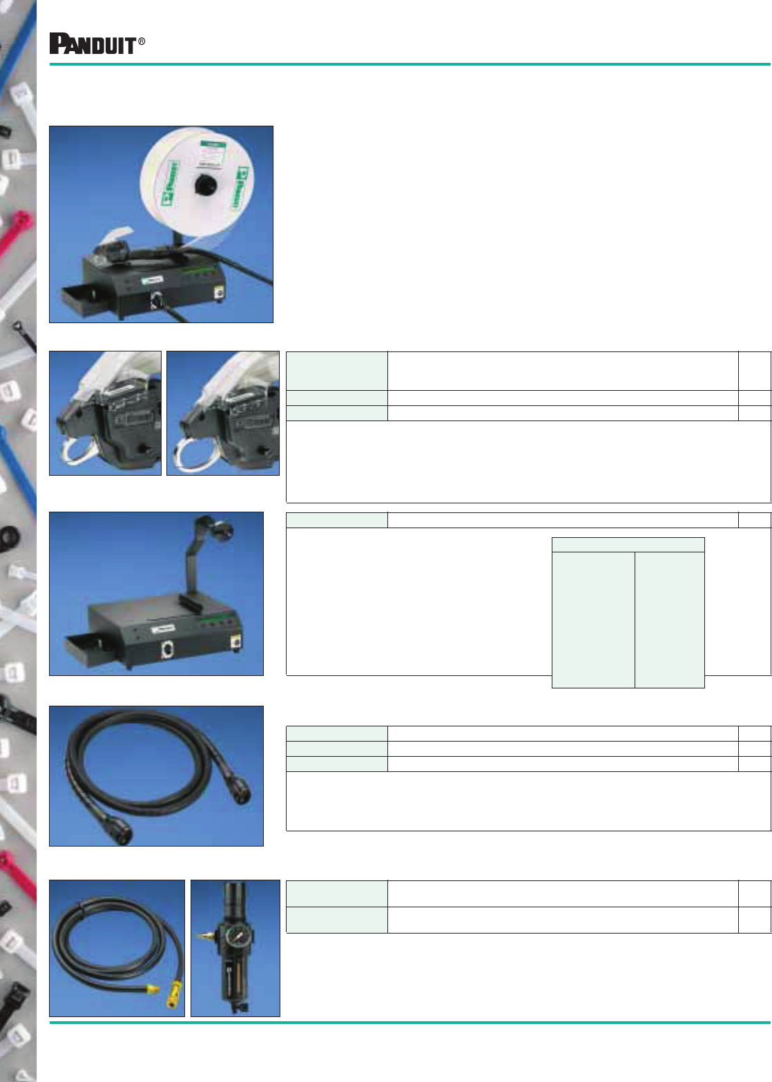
60
Most commonly used parts appear in BOLD.
PAT1M/PAT1.5M Reel-Fed Systems for Miniature Cross Section Cable Ties
(18 lb. (80N) minimum loop tensile)
• The system consists of the tool head, dispenser, feeder hose and
continuously molded, reel-fed cable ties (5000 ties per reel). Each system
will install a cable tie in less than one second
• Choice of two tool head sizes for bundle diameters up to .82" (21mm) or up
to 1.3" (33mm)
• The dispenser and hose are designed to operate with either tool head for
maximum versatility and economy
• The system design permits complete mobility in the use of the tool and
location of the dispenser
• The system operates on 65 psig (minimum) non-lubricated, filtered air and
100-240 VAC 150 or 60 Hz—Automatically adjusts within this range
• Optional bench mount shown on page 61
• Choice of 3 materials
Tool Heads
Part Number Description
Std.
Pkg.
Qty.*
PAT1M Tool Head for cable ties up to .82" (21mm) bundle diameter (PLT1M-XMR). 1
PAT1.5M Tool Head for cable ties up to 1.3" (33mm) bundle diameter (PLT1.5M-XMR). 1
• Lightweight, no counter-balance required
• Slim, ergonomically designed handle for operator comfort and greater productivity. Reduces
potential for repetitive motion injuries
• Right or left hand operation
• Durable, one-piece cable tie tip collector (for cut-off tips)
• Includes tension adjustment
• Built-in safety interlock prevents false triggering if anything obstructs jaw path
PDM Stationary dispenser for 100 VAC, 120 VAC and 230 VAC. 1
• LCD display monitors performance.
If an error occurs an alarm is sounded
• On-line HELP menu
• Multi-language capability via LCD
display (English, Spanish, German,
Italian or French)
• Cable tie reels are easily loaded into
the dispenser, reducing downtime
• Audible reload signal when reel is empty
• Minimum maintenance required
• Power cord included
Dispenser
PHM1 3.2' (1m) Feeder Hose. 1
PHM2 6.5' (2m) Feeder Hose. 1
PHM3 9.8' (3m) Feeder Hose. 1
• Transfers cable ties and signal from dispenser to tool head
• Available in three lengths for either tool head
• Reversible
• Large electrical connectors for quick, easy and secure connections
Choose one:
Feeder Hose
Other Components
PDH10-37 Air hose from filter/regulator to dispenser/. 9.8' (3m).
Includes standard air fittings.
1
PL283N1 Filter/regulator 25 micron (max.) element, 3/8 " ports. 1
Specifications
Pneumatic
• Operates at
65 psig
minimum
• 7 scfm flow
minimum
• Operates on
non-lubricated
air
Electrical
• 100-240
VAC
• 50 or 60 Hz.
• Less than
1 amp
• Approx.
20 watts
(AVG)
Fully Automatic Cable Tie Installation Systems
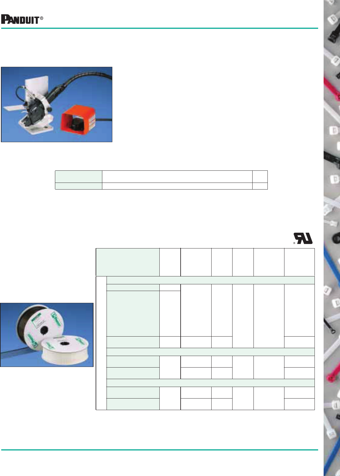
61
Most commonly used parts appear in BOLD.
Cable Ties for Automatic Installation Systems
Flammability Rating: UL 94V-2, ATB < sec. per ASTM-D635.
Nylon 6.6 (for indoor use) up to 185°F (85°C)
PLT1M-XMR Natural
.82
(21)
4.0
(102) .100
(2.5)
18
(80)
PAT1M
PLT1M-XMR1
PLT1M-XMR2
PLT1M-XMR3
PLT1M-XMR4
PLT1M-XMR5
PLT1M-XMR6
PLT1M-XMR7
PLT1M-XMR8
PLT1M-XMR10
Brown
Red
Orange
Yellow
Green
Blue
Purple
Gray
White
PLT1.5M-XMR Natural 1.31
(33)
5.6
(142)
PAT1.5M
Weather Resistant Nylon (for outdoor use) up to 185°F (85°C)
PLT1M-XMR0
Black
.82
(21)
4.0
(102) .100
(2.5)
18
(80)
PAT1M
PLT1.5M-XMR0 1.31
(33)
5.6
(142)
PAT1.5M
Heat Stabilized Nylon (for indoor use) up to 238°F (115°C)
PLT1M-XMR30
Black
.82
(21)
4.0
(102) .100
(2.5)
18
(80)
PAT1M
PLT1.5M-XMR30 1.31
(33)
5.6
(142)
PAT1.5M
Cable Ties for PAT1M/PAT1.5M Systems
Cable Ties on Reels
• Miniature cross section
cable ties
• Self-locking
• UL Recognized
• 5000 ties/reel
Continuously molded cable ties in sizes, color and
material options to meet the application.
Part Number Color
Max. Bundle
Diameter
in. (mm)
Length
in.
(mm)
Width
in.
(mm)
Min. Loop
Tensile
Strength Lbs.
(N)
Use with
PA NDUIT ®
Installation
System
Reels of 5,000 — 2 Reels/Carton
Part Number Description
Pkg.
Qty.
PATMBM Bench mount and foot pedal for PAT1M/PAT1.5M system, four-hole base plate. 1
PATMBM Bench Mount used with PAT1M/PAT1.5M Automatic Systems for
Miniature Cross Section Cable Ties (18 lb., 80N minimum loop tensile)
For Operations Where the Application is Brought to the Tool
• Used with either PAT1M or PAT1.5M tool head
• Supplied with a foot-actuated pedal to allow operator to work
with both hands
• A tool can be installed in the mount in seconds
• Supplied with a four-hole base plate
• The bench mount operates on 65 psi non-lubricated, filtered
air which pilots off of the dispenser
In addition to tool head, dispenser, feeder hose and cable ties on reels;
order the following:
62
Most commonly used parts appear in BOLD.
Design Criteria
Part Number Suffix
Material Designation
-0 -30 -39 -300 -60 -69 -120 -109 -100 -76 -702 N/A
Loop Tensile Strength 7 7 7 7 7 7 7 6 5 5 7 5 9 10
Low Temperature Service 6 6 6 6 6 5 5 6 6 6 7 7 6 10
High Temperature Service 5 5 6 6 6 5 5] 5 5 5 8 7 3 10
Flammability 6 6 6 6 6 8 8 3 2 2 9 9 2 10
Ultraviolet Resistance 1 6 4 1 6 1 1 7 1 6 9 9 9 10
Radiation Resistance 3 3 3 3 3 3 3 4 5 5 9 9 3 10
Overall Chemical Resistance
–Hydrocarbons
–Chlorinated Hydrocarbons
–Acids
–Bases
–Salts
6
9
7
2
7
3
6
9
7
2
7
3
6
9
7
2
7
3
6
9
7
2
7
3
6
9
7
2
7
3
6
9
7
2
7
3
6
9
7
2
7
3
8
9
8
6
7
8
8
6
5
9
9
10
8
6
5
9
9
10
10
10
10
10
10
10
10
10
10
10
10
10
5
9
8
2
2
4
9
10
10
10
8
9
Relative Price Low Low Low Low Med. Med. Med. Med. Low Low High High Med. High
Selecting the Proper Cable Tie Material for Your Application
By using this information as a guide, the user will be better equipped to select the best suited cable tie
and material to perform its intended function over a long period of time.
For long life and dependable service, there are many factors to consider when selecting the proper cable
tie for each application. Since it is impossible for PANDUIT ®
to provide data on all the various
combinations of conditions which may arise, it is suggested that this data be used as a guide. Sample
cable ties should be tested under actual end-use conditions to determine the correct cable tie for
the application.
To select the optimum cable tie for a specific application, the following table can be used as a quick
reference. First, determine the most critical design criteria and then read across the table to find which
material is most suitable to meet this need (10 = Most Suitable and 1 = Least Suitable). Next, review the
other criteria by scanning in a vertical direction on the chart and then make your final selection.
Example No. 1:
Application Selection
If the application requires high radiation (2 x 10⁸ rads) resistance, excellent
resistance to hydrocarbons and the price is not critical.
The best choice is TEFZEL*** or stainless steel. The price is higher than other
materials, but both have high ratings in resistance to radiation and hydrocarbons.
Example No. 2:
Application Selection
If the application requires a low cost material, good ultraviolet resistance and good
resistance to acid rains.
The best choice is weather resistant polypropylene. Cost is low; it has a rating of 6
in ultraviolet resistance and a rating of 9 in resistance to acids.
*See page 70 (Table C) for chemical resistance of 304 & 316 stainless steel.
** HALAR is a registered trademark of Solvay Solexis, Inc.
*** TEFZEL is a registered trademar k of E. I. DuPont de Nemours Co.
Cable Tie Selection and Specification Guidelines
Natural
6.6 Nylon
Weather Resistant
6.6 Nylon
Heat Stabilized Black
6.6 Nylon
Heat Stabilized
Natural 6.6 Nylon
Heat Stabilized
Weather Resistant
6.6 Nylon
Flame Retardant
Black 6.6 Nylon
Flame Retardant
6.6 Nylon
Weather Resistant
Nylon 12
Weather Resistant
Polypropylene
TEFZEL***
HALAR**
Weather Resistant
Acetal
Stainless Steel*
Natural
Polypropylene
63
Most commonly used parts appear in BOLD.
Material Selection Guide
To select the proper cable tie for your application, start at the
left of the chart and answer the “Yes” and “No” questions until
you arrive at the correct material to use.
Suggested Material to use
START
No
Yes
No
Yes
No
No
Yes
No
Yes
No — Nylon 6.6
Yes — Flame Retardant Nylon 6.6 (-69)
No — Heat Stabilized Nylon 6.6 (-30)
Yes —Stainless Steel
No — Natural Polypropylene (-109)
Yes — Stainless Steel
No — Stainless Steel
Yes — Stainless Steel
No — Weather Resistant
Nylon 6.6 (-0) (-00)
Weather Resistant Acetal
Yes — Stainless Steel
No — Weather Resistant Heat
Stabilized Nylon 6.6 (-300)
Yes — Stainless Steel
No — Weather Resistant
Polypropylene (-100)
or Nylon 12 (-120)
Yes — Stainless Steel
No — Stainless Steel
Yes — Stainless Steel
or TEFZEL** (-76)
or HALAR* (-702)
Yes
No
Yes
Material must
resist high
heat?
No
Yes
**HALAR is a registered trademark of Solvay Solexis, Inc.
*** TEFZEL is a registered trademark of E. I. DuPont de Nemours Co.
Material must
be flame
retardant?
Material must
be flame
retardant?
Material must
be flame
retardant?
Material must
be flame
retardant?
Material must
be flame
retardant?
Material must
be flame
retardant?
Material must
be flame
retardant?
Material must
be flame
retardant?
Material must
resist high
heat?
Material must
be resistant to
chemicals
(salt/acids)?
Material must
resist high
heat?
Does material
need to be
UV resistant?
Material must
resist high
heat?
Material must
be resistant
to chemicals
(salt/acids)?
64
Most commonly used parts appear in BOLD.
Weathering
Ultraviolet light (which is a component of sunlight) attacks, over a period of
time, most plastic materials and reduces their properties by breaking the
molecular chain. The material breakdown is accompanied by reductions in
tensile strength and elongation, increased brittleness, color changes and
loss of surface gloss.
Carbon black, which is used in PANDUIT ®
nylon and polypropylene cable
ties, is one of the most effective stabilizers known today. A uniform
dispersion of carbon black provides good ultraviolet light resistance without
adversely affecting physical properties. The addition of carbon black, or any
other ultraviolet light stabilizer, prolongs the useful life of plastic products
used outdoors, but it does not totally eliminate the destructive effects of the
light. Some plastics, such as TEFZEL** or HALAR*, are intrinsically very
resistant to ultraviolet light and do not require stabilizing additives.
Weathering Test Methods
In order to monitor the effects of ultraviolet light and the effectiveness of ultraviolet stabilizers, PANDUIT ®,
in conformance with industry standards, adopted two methods of weatherability testing: Outdoor Aging and
Accelerated Weather Aging.
Outdoor Aging
The Outdoor Aging method is probably the best and most realistic method of the two. It is conducted in
accordance with ASTM D1435 Standard Practice for Outdoor Weathering of Plastics, and allows the
material to be affected by not only ultraviolet light, but by all other outdoor elements as well. Although this
may more closely approximate an actual application, two drawbacks do exist. The period of time required
to produce property decay and material failure may be quite long, and varying adverse chemical
environments cannot be tested.
Accelerated Weather Aging
Accelerated weathering tests are conducted to estimate the rate of degradation due to a combination
of ultraviolet light, temperature and moisture. The methods used are in accordance with the
following standards:
• ASTM D1499, Operating Light and Water Exposure Apparatus (Carbon-Arc type) for exposure
to plastics
• ASTM G53, Operating Light and Water Exposure (Fluorescent U.V. Condensation type) for exposure of
non-metallic materials
The condition specified in ASTM D1499 utilizes a carbon arc to simulate natural sunshine and a water
spray. The test chamber is operated 20 hrs/day with a two hour cycle of 108 minutes of simulated sunshine
and 12 minutes of sunshine and water spray. The temperature of a black body inside the chamber is
approximately 63°C (145°F) during the “Sunshine Only” portion of the cycle. Humidity is not controlled
inside the chamber.
The test chamber per ASTM G53 uses fluorescent sun lamps to generate ultraviolet light only. A heated
water pan produces condensation during a portion of the cycle.The daily cycle is composed of 20 hours of
light followed by 4 hours of condensation. Black body temperatures during the light cycle are 50°C (122°F)
and 40°C (104°F) during the condensation cycle.
PANDUIT ® has also designed a special chamber which is used to simulate the effect of acid rain and
ultraviolet light on cable tie materials. The effect of other common chemicals, such as road salt, are also
evaluated in this chamber.
These methods are effective in quickly determining the ultraviolet light resistance of the various cable tie
materials, but it must be emphasized that there are no exact correlations between accelerated aging and
actual outdoor exposure.
*HALAR is a registered trademark of Solvay Solexis, Inc.
**TEFZEL is a registered trademark of E. I. DuPont de Nemours Co.
Weathering
65
Most commonly used parts appear in BOLD.
Material Failure Testing
Property decay can lead to three different modes of failure: loss of strength, loss of toughness or change
in appearance. The critical mode for any given application would depend upon the application and the
requirements it places upon the material itself.
Loss of strength is monitored by tensile testing samples of the material before and after it has been
weathered. This test will reveal the decreasing strength accompanied by extended weathering.
Loss of toughness can be monitored by measuring changes in elongation and impact strength. As
ultraviolet light exposure time increases and the material becomes brittle, its elongation and impact
strength are greatly reduced. It is important to note that brittle failures can occur even when the tensile
strength shows no change.
Although change in appearance is normally not a failure mode for cable ties, the plastic does tend to
discolor and lose its surface gloss as exposure increases. These changes can be measured by color
difference using Adams units which are similar to National Bureau of Standard units.
PANDUIT ® has its own weathering test program to determine estimated life of various cable tie
materials.This includes examining many previously aged samples obtained throughout the world.
In all cases, the amount of property decay increased with increasing exposure to ultraviolet light. The
principal signs of degradation were found to be brittleness, cracking and loss of surface gloss. It was also
determined that the time for failure to occur was shorter than indicated from industry tests performed on
material samples. This discrepancy is in part due to the fact that cable ties were tested in an end use,
stressed condition, while most plastic resin suppliers conduct weathering tests using unstressed
test bars.
Four cable tie materials (TEFZEL**, HALAR*, Weather Resistant ACETAL and Stainless Steel) have
superior ultraviolet light resistance. In tests conducted to date, all have shown no significant signs
of degradation.
Determining the outdoor life expectancy of any material is difficult since there are other factors, besides
ultraviolet light stability, which have to be considered. These factors are listed below and should be
considered before specifying a cable tie material.
FACTORS DECREASED LIFE
Chemicals Applications which have chemicals present can reduce the life. This is
the most detrimental factor to the life of a tie.
Bundle
Diameter
As the bundle diameter is reduced, the tie has more bending stress.
A thick strap on small diameter has more stress.
Loading If the tie is under high loading, this will add additional stress on the
tie body.
Thickness A thinner tie will have a decreased life since surface cracks will
penetrate the thickness of the tie faster.
Vibration Applications with high vibrations will cause impact which will
propagate any surface cracks.
Degree of
Exposure
No shield or shade, southern exposure, higher altitudes and high
temperatures decrease the life of the cable tie.
Moisture Dry environments cause nylon 6.6 ties to become more brittle. High
humidity plus high temperatures can result in degradation due to
hydrolysis in nylon.
Galvanized
Metals
Acid rain and acid moisture acting on galvanized metals release
chemicals known to attack nylon 6.6.
*Based on assumption of minimum loading, no chemical attack and
impact-free conditions.
WEATHERING LIFE EXPECTANCY
Materials (P/N Suffix) Years*
Natural Polypropylene (-109) 1
Natural Nylon 6.6 1-2
Flame Retardant Black Nylon 6.6 (-60) 1-2
Flame Retardant Nylon 6.6 (-69) 1-2
Heat Stabilized Nylon 6.6 (-30) 4-5
Heat Stabilized Natural Nylon 6.6 (-39) 1-2
Weather Resistant Nylon 6.6 (-0 & -00) 7-9
Heat Stabilized Weather Resistant Nylon 6.6 (-300) 7-9
Weather Resistant Polypropylene (-100) 7-9
Weather Resistant Nylon 12 (-120) 12-15
TEFZEL** (-76) >15
HALAR* (-702) >15
Acetal >20
Stainless Steel (MLT prefix) >30
Weathering
TABLE A — External Factors Which Affect the Life of a Cable Tie
*HALAR is a registered trademark of Solvay Solexis, Inc.
**TEFZEL is a registered trademark of E. I. DuPont de Nemours Co.
66
Most commonly used parts appear in BOLD.
Flammability
A number of test procedures have been developed which can be used for the evaluation
and comparison of various materials to support combustion.
UL94 Vertical Burning Test
Samples of a material, with dimensions 127mm by 12.7mm and the thickness of the
intended end use product, are tested in an unaged “as manufactured” state and in an
aged state (7 days at 158 °F, 70°C). The test requires the placement of a precisely
controlled flame under a vertically supported specimen for a 10 second period. The
flame is removed and the duration of flaming is recorded. If the flame extinguishes, the
specimen is immediately subjected to a second 10 second ignition period. Duration of
flaming is again recorded. A piece of surgical cotton is placed under the specimen. If
drips ignite the cotton, this fact is also recorded.
Materials Classed 94V-0
Materials classed 94V-0 shall:
• Not have any specimens which burn with flaming combustion for more than 10 seconds after either
application of the test flame
• Not have a total flaming combustion time exceeding 50 seconds for the 10 flame applications for each
set of five specimens
• Not have any specimens which burn with flaming or glowing combustion up to the holding clamp
• Not have any specimens which drip flaming particles that ignite the dry absorbent surgical cotton
located 12" (305mm) below the test specimen
• Not have any specimens with glowing combustion which persists for more than 30 seconds after the
second removal of the test flame
Materials Classed 94V-1
Materials classed 94V-1 shall:
• Not have any specimens which burn with flaming combustion for more than 30 seconds after either
application of the test flame
• Not have a total flaming combustion time exceeding 250 seconds for the 10 flame applications for each
set of five specimens
• Not have any specimens which burn with flaming or glowing combustion up to the holding clamp
• Not have any specimens which drip flaming particles that ignite the dry absorbent surgical cotton
located 12" (305mm) below the test specimen
• Not have any specimens with glowing combustion which persists for more than 60 seconds after the
second removal of the test flame
Materials Classed 94V-2
• Not have any specimens which burn with flaming combustion for more than 30 seconds after either
application of the test flame
• Not have a total flaming combustion time exceeding 250 seconds for the 10 flame applications for each
set of five specimens
• Not have any specimens which burn with flaming or glowing combustion up to the holding clamp
• Be permitted to have specimens that drip flaming particles which burn only briefly, some of which ignite
the dry absorbent surgical cotton placed 12" (305mm) below the test specimen
• Not have any specimens with glowing combustion which persists for more than 60 seconds after the
second removal of the test flame
Flammability
67
Most commonly used parts appear in BOLD.
ASTM D 635
Samples of a material, with dimensions 125mm by 12.5mm and the thickness of the intended end use
product, are tested in an unaged “as manufactured” state. A precisely controlled flame is applied to the
specimen and a stopwatch is started. The flame is applied for 30 seconds. The stopwatch is stopped
when burning or glowing combustion ceases or when the flame has proceeded to a mark 100mm from
the free end. Ten specimens are tested.
• Burning Rate
• If two or more specimens have burned to the 100mm mark then Average Burning Rate (cm/min.) shall be reported
as the average of the burning rates of all specimens which have burned to the 100mm mark
• Average Time of Burning and Average Extent of Burning
• Average time of burning and average extent of burning of the sample shall be reported if none of ten samples or
no more than one of twenty specimens have burned to the 100mm mark
• Average Time of Burning (ATB): • Average Extent of Burning (AEB):
Rating based on 1/8" thick test samples
Materials UL94 ASTM D635
Natural Nylon 6.6 94V-2 (1/16") AEB = 20mm
ATB = 5 seconds
Weather Resistant Nylon 6.6 (-00) 94V-2 (1/16") AEB = 20mm
ATB = 5 seconds
Weather Resistant Nylon 6.6 (-0) 94V-2 (1/16") AEB = 20mm
ATB = 5 seconds
Heat Stabilized Nylon 6.6 (-30) 94V-2 (1/16") AEB = 20mm
ATB = 5 seconds
Heat Stabilized Natural Nylon 6.6 (-39) 94V-2 (1/16") AEB = 20mm
ATB = 5 seconds
Heat Stabilized Weather Resistant Nylon 6.6 (-300) 94V-2 (1/16") AEB = 20mm
ATB = 5 seconds
Flame Retardant Black Nylon 6.6 (-60) 94V-0 (1/64") AEB =15mm
ATB < 5 seconds
Flame Retardant Nylon 6.6 (-69) 94V-0 (1/64") AEB = 15mm
ATB < 5 seconds
Weather Resistant Nylon 12 (-120) Not Recognized Ave. Burning Rate
1.6cm/min.
Natural Polypropylene (-109) Not Recognized Ave. Burning Rate
2 cm/min.
Weather Resistant Polypropylene (-100) 94 HB (.94mm) Ave. Burning Rate
2 cm/min.
TEFZEL** (-76) 94V-0(1/16") AEB < 15mm
ATB < 5 seconds
HALAR* (-702) 94V-0(1/16") AEB = 15 min.
ATB < 5 seconds*
Weather Resistant ACETAL (DT Series) 94 HB (1.5mm) Ave. Burning Rate
2.8 cm/min.
Stainless (MLT prefix) Not Applicable Not Applicable
Flammability Ratings
t 30s–! "
0
10
#
Number of Specimens
ATB,s =
Rounded to the nearest 5 sec.
Number of Specimens
AEB,mm =
Rounded to the nearest 5mm
kjf dsjfs
0
10
#(100 – unburned length)
*HALAR is a registered trademark of Solvay Solexis, Inc.
**TEFZEL is a registered trademark of E. I. DuPont de Nemours Co.
Flammability
68
Most commonly used parts appear in BOLD.
Radiation
Installed cable ties of various materials have been exposed to different amounts of
radiation to determine the maximum acceptable limit. These tests were conducted by
PANDUIT ® mainly to determine the acceptability for use in various areas of nuclear power
plants (accumulated over 40 year life). See Table B (page 69) for radiation resistance rating.
Moisture
Many plastics when exposed to high relative humidity absorb water and, as such, the tensile
strength of the material can change dramatically. Nylon 6.6 when exposed to 100% relative
humidity, will absorb as much as 8.5% water which will reduce tensile strength by 50% when
compared to a dry cable tie. Polypropylene, HALAR*, Type 12 Nylon, TEFZEL** and ACETAL
are low water absorbing materials and, as such, the effect of water is minimal.
See Table B (page 69) for moisture absorption.
Temperature
Plastic materials normally undergo property loss during exposure to high temperature due to
oxidation. The Maximum Continuous Use Temperature for cable tie materials depends upon the time
at the elevated temperature as well as other environmental conditions. Initially, plastics become
more flexible and weaker when exposed to high temperatures. After a period of time, oxidation may
occur which will cause embrittlement, making plastic cable ties more susceptible to failure from
impact and vibration.
The Maximum Continuous Use Temperature, otherwise known as the Relative Thermal Index
(mechanical without impact) is determined per UL746B. It is one indicator of a materials ability
to retain a particular physical property when exposed to elevated temperatures over an extended
period of time. It is based on the assumption that there is no loading, no chemical attack and impact free condition.
The Maximum Continuous Use Temperatures for cable tie materials are listed in Table B (see page 69).
Low temperature exposure will also make most plastics more brittle during the exposure, but little property loss
occurs when the material is returned to room temperatures. The Minimum Continuous Use Temperatures for cable tie
materials are listed in Table B (see page 69).
Tensile Strength
Most cable ties are selected based on material, length and minimum loop tensile strength. Minimum loop tensile
strength was established under SAE Aerospace Standard AS23190. Each cross section cable tie (Miniature-M,
Intermediate-I, Standard-S, Heavy-H and Extra Heavy-EH) has a different loop tensile strength when tested
per AS23190.
The cable tie is first conditioned at 49°C (120°F), 20% relative humidity for 24 hours, then
the cable tie is installed on a split mandrel and the halves of the mandrel separated at a rate
of 1" (25.4mm) per minute (Fig.1). The separating force required to unlock or break the
cable tie is the loop tensile strength. Loop tensile strength is dependent both on the locking
design and the tensile strength (psi) of the material. As an example, the tensile strength of
polypropylene material is approximately 1/2 to 1/3 of nylon 6.6; thus the loop tensile
strength of a given cross section tie made of polypropylene would be much less than a tie
made of nylon 6.6. This is another property to be considered when selecting a cable tie.
The various representative loop tensile strengths are listed in Table B (page 69).
*HALAR is a registered trademark of Solvay Solexis, Inc.
**TEFZEL is a registered trademark of E. I. DuPont de Nemours Co.
Fig. 1
Radiation/Moisture/Temperature/Tensile Strength
69
Most commonly used parts appear in BOLD.
NOTE 1: ASTM D638
NOTE 2: Telcordia TR-TSY-000789
NOTE 3: ASTM E8
NOTE 4: See page 68 — Temperature
NOTE 5:Estimated
NOTE 6: (-321) goes to 1700° (923°C)
NOTE 7: After installation
Design Criteria
Part Number Suffix/
Material Designation
None -0 and
-00
-30 -39 -300 -60 -69 -120 -109 -100 -76 -702 N/A N/A
Tensile Strength
73°F (psi)
12,000
(Note 1)
12,000
(Note 1)
12,000
(Note 1)
12,000
(Note 1)
12,000
(Note 1)
12,000
(Note 1)
12,000
(Note 1)
8,100
(Note 1)
4,100
(Note 1)
4,100
(Note 1)
7,500
(Note 1)
7,000
(Note 1)
6,500
(Note 2)
90,000
(Note 3)
Color Natural Black Black Natural Black Black Ivory Black Green Black Aqua Maroon Black Stain-
less
UL Flammability See Page 66
Oxygen Index 28 28 26 26 26 34 34 NA NA NA 30 60 NA NA
Radiation Resistance 1 x 10⁵
Rads
1 x 10⁵
Rads
1 x 10⁵
Rads
1 x 10⁵
Rads
1 x 10⁵
Rads
1 x 10⁵
Rads
1 x 10⁵
Rads
3.5 x 10⁶
Rads
1 x 10⁶
Rads
1 x 10⁶
Rads
2 x 10⁸
Rads
2 x 10⁸
Rads
6 x 10⁵
Rads
2 x 10⁸
Rads
Water Absorption
(24 hours)
1.2% 1.2% 1.2% 1.2% 1.2% 1.1% 1.1% 0.3% 0.1% 0.1% <0.03% <0.05% <0.45% None
Ultraviolet Light
Resistance
Poor Good Fair Poor Good Poor Poor Good Poor Good Very
Good
Very
Good
Excellent Excellent
Max. Continuous Use
Temperature (Note 4)
185°F
85°C
185°F
85°C
239°F
115°C
239°F
115°C
212°F
100 °C
(Note 5)
212°F
100 °C
212°F
100 °C
194°F
90°C
238°F
115°C
238°F
115°C
338°F
170°C
302°F
150°C
185°F
85°C
1000 °F
537°C
(Note 6)
Min. Continuous Use
Temperature (Note 7)
-40 °F
-40°C
-40 °F
-40°C
-40 °F
-40°C
-40 °F
-40°C
-40 °F
-40°C
-40 °F
-40°C
-40 °F
-40°C
-40°F
-40°C
-40°F
-40°C
-40°F
-40°C
-50°F
-46°C
-50°F
-46°C
-40°F
-40°C
-112°F
-80 °C
Minimum
Loop Tensile
Strength
@120 °F
20% RH
Submin.
Min.
Int.
Std.
Hvy.-Std.
Hvy.
EH
DH
12 lb.
18 lb.
40 lb.
50 lb.
85 lb.
120/
175 lb.
250 lb.
12 lb.
18 lb.
40 lb.
50 lb.
85 lb.
120/
175 lb.
250 lb.
N/A
18 lb.
40 lb.
50 lb.
N/A
120/
175 lb.
250 lb.
N/A
18 lb.
40 lb.
50 lb.
N/A
120/
175 lb.
250 lb.
N/A
18 lb.
30 lb.
50 lb.
N/A
120 lb.
N/A
N/A
18 lb.
30 lb.
50 lb.
N/A
120 lb.
N/A
N/A
18 lb.
40 lb.
50 lb.
N/A
120 lb.
N/A
N/A
N/A
25 lb.
40 lb.
N/A
90 lb.
N/A
N/A
12 lb.
N/A
30 lb.
N/A
50 lb.
90 lb.
N/A
12 lb.
N/A
30 lb.
N/A
50 lb.
90 lb.
N/A
18 lb.
25 lb.
50 lb.
N/A
120 lb.
N/A
N/A
18 lb.
N/A
50 lb.
N/A
N/A
N/A
N/A
N/A
N/A
N/A
N/A
N/A
250 lb.
N/A
N/A
N/A
100 lb.
N/A
250 lb.
N/A
600 lb.
Tool Installed
GTS
GTH
GS4H
GS4EH
STS2
STH2
ST2EH
STHV
PTS
PPTS
PPTEH
GTS
GTH
GS4H
GS4EH
STS2
STH2
ST2EH
STHV
PTS
PPTS
PPTEH
GTS
GTH
GS4H
STS2
STH2
ST2EH
STHV
PTS
PPTS
PPTEH
GTS
GTH
GS4H
STS2
STH2
ST2EH
STHV
PTS
PPTS
PPTEH
GTS
GTH
GS4H
STS2
STH2
ST2EH
STHV
PTS
PPTS
PPTEH
GTS
GTH
GS4H
STS2
STH2
ST2EH
STHV
PTS
PPTS
PPTEH
GTS
GTH
GS4H
STS2
STH2
ST2EH
STHV
PTS
PPTS
PPTEH
GTS
GTH
GS4H
STS2
STH2
STHV
PTS
PPTS
GTS
GTH
GS4H
STS2
STH2
PTS
PPTS
GTS
GTH
GS4H
STS2
STH2
PTS
PPTS
GTS
GTH
GS4H
STS2
STH2
PTS
PPTS
GTS
GTH
GS4H
STS2
STH2
PTS
PPTS
GTH
GS4H
GS4EH
ST2EH
GS4MT
ST2MT
PPTMT
HTMT
*HALAR is a registered trademark of Solvay Solexis, Inc.
**TEFZEL is a registered trademark of E. I. DuPont de Nemours Co.
Physical Characteristics of Cable Tie Materials
Weather Resistant
Polypropylene
Natural
6.6 Nylon
Weather Resistant
6.6 Nylon
Heat Stabilized Black
6.6 Nylon
Heat Stabilized Natural
6.6 Nylon
Heat Stabilized
Weather Resistant
6.6 Nylon
Flame Retardant Black
6.6 Nylon
Flame Retardant
6.6 Nylon
Weather Resistant
Nylon 12
Natural
Polypropylene
TEFZEL**
HALAR*
Stainless Steel
TABLE B
Weather Resistant
Acetal
70
Most commonly used parts appear in BOLD.
TABLE C
Chemical Resistance
Many factors combine to determine the useful life of a cable tie material and none
is as important as chemical exposure. Various chemicals will have different
effects on plastics depending on such things as chemical concentrations,
temperature, stress and ultraviolet light. Table C is an excellent guideline for the
selection of the best cable tie material. It should be noted that the exposure
temperature for this chemical resistance chart is 70°F.
Resistance of PANDUIT ® Cable Tie Materials to Chemical Attack at 70°F
— = Not Tested
E = Excellent
S = Satisfactory
B = Slight Attack
U = Attacked
1 (NOTE 1) = Pitting occurs under some conditions
2 (NOTE 2) = Attack may occur if sulfuric acid present
Aq. = Aqueous
C.S. = Cold Saturated
Agent
Percent
Concen-
tration
*
Nylon
6.6
Nylon
12 Polypropylene TEFZEL*** HALAR**
304
Stainless
Steel
316
Stainless
Steel
Acetaldehyde 90 S — B E E — —
Acetic Acid 97 U U E E E E E
Acentic Acid 10 B S E E E E E
Acetic Anyhdride 90 — S E E E E E
Acetone 100 E E E E E E E
Acetophenone 100 — — S E E E E
Acetylene 100 — — E E E E E
Aluminum Chloride 10 S E E E E U B
Aluminum Fluoride 10 S E E E E U B
Aluminum Hydroxide Aq. C.S. — E E E E E E
Aluminum Potassium Sulfate 10 S E E E E E1E
Ammonia All — E E E E E E
Ammonium Carbonate 1 to 5 — E — E E E E
Ammonium Chloride 10 to 25 U E E E E E1E
Ammonium Hydroxide 10 E — — E E — —
Ammonium Nitrate 100 — E E E E E E
Ammonium Sulfate 10 — E E E E E1E1
Amyl Acetate 100 — — B E E E E
Aniline 100 — S E E E E E
Antimony Trichloride All U — E E E E E
Arsenic Acid 1 to 80 — — E E E E E
Barium Carbonate All — E E E E E E
Barium Chloride All — E E E E E1E
Barium Sulfate All — E E E E E E
Barium Sulfide All — E E E E E E
Benzene 100 E E B E E E E
Benzoic Acid 100 U E E E E E E
Benzoyl Chloride 100 — — B E E — —
Benzyl Alcohol 100 — — E E E — —
Boric Acid All U E E E E S —
Bromine 100 U U U E E U U
Butadiene 100 — — B E E E E
Butane 100 — E E E E E E
Butanediol 100 — — E E E — —
Butyl Acetate 100 — E B E E — —
N. Butyl Alcohol 100 — E E E E E E
Butyl Phthalate 100 — — E E E — —
Butyraldehyde 100 — — E E E — —
Butyric Acid 10 to 100 U — E E E E E
Calcium Carbonate Aq. C.S. — — E E E E E
Calcium Chlorate Aq. C.S. — — E E E E E
Calcium Chloride 5 B E E E E E1E1
Chemical Resistance
*Includes all 6.6 Nylons (such as Weather Resistant, Heat Stabilized and Flame Retardant).
**HALAR is a registered trademark of Solvay Solexis, Inc.
***TEFZEL is a registered trademark of E. I. DuPont de Nemours Co.
71
Most commonly used parts appear in BOLD.
Table C — (cont.)
Agent
Percent
Concen-
tration
*
Nylon
6.6
Nylon
12
Polypro-
pylene TEFZEL*** HALAR**
304
Stainless
Steel
316
Stainless
Steel
Calcium Hydroxide 50 — — E E E E E
Calcium Hypochlorite 2 U — E E E E1E1
Calcium Nitrate 50 — E E E E — —
Calcium Sulfate 2 B — E E E E E
Carbon Tetrachloride 100 E E U E E E E
Carbon Tetrachloride Aq. 10 — — — — E B1E1
Chlorine Dry — U U E E B B
Chlorine Wet — U B E E U U
Chloroacetic Acid 10 to 50 U — E E E U B
Chlorobenzene 100 — B E E E — —
Chloroform 100 E B B E E E E
Chlorosulphonic Acid 10 to 100 U U U S E U U
Chromic Acid 10 to 50 U U E E E B B
Citric Acid 10 to 50 S S E — E E E
Copper Chloride 1 to 10 U — E E E E1 to U E1 to B1
Copper Cyanide Aq. C.S. — — E E E E E
Copper Nitrate 50 — — E E E E E
Cresol 100 U U — E E E E
Crotonaldehyde 100 — — E E E — —
Cyclohexane 100 — E B E E E —
Cyclohexanol 100 — E E E E E —
Cyclohexanone 100 — E B E E E —
Dibutyl Phthalate 100 — — E E E — —
Dichloroethane 100 — — E — E E E
Dichloroethylene 100 — — B E E — —
Diesel Fuel 100 — E B E E E E
Diethyl Ether 100 — E E E E E E
Diglycolic Acid Aq.C.S. — — E E E — —
Disobutyl Ketone 100 — — E E E — —
Dimethyl Amine 100 — — E E E — —
Dimethyl Formamide 100 — E E E E E —
Dimethyl Sulfate 100 — — B E E — —
Dioctyl Phthalate 100 — — E E E E —
1, 4-Dioxane 100 — S B E E E —
Ethyl Acetate 100 E E S E E E E
Ethyl Alcohol 100 E E E E E E E
Ethyl Chroride 100 — — B E E E E
Ethylene Chloride 100 E B B E E E E
Ethylene Glycol 100 E E E E E E E
Ethylene Oxide 100 — — B E E — —
Fatty Acids 100 — — E E E — —
Ferric Chloride 50 U — E E E U U
Ferric Hydroxide All — — E E E E E
Ferric Nitrate All — — E E E E E
Ferrous Chloride Aq. C.S. U — E E E U B
Ferrous Sulfate 10 — — E E E E1E
Fluorine (Dry) 100 — — U E — U U
Formaldehyde 40 E S E E E E1E
Formic Acid All U U E E E E E
Freons 100 E — — E E — —
Fuel Oil 100 — E — E E E E
Furfural 100 E — — E E E E
Gallic Acid Aq. C.S. — — — E E E E
Gasoline 100 E — B E E E E
Glycerin 100 — E E — E E E
Chemical Resistance
Resistance of PANDUIT ® Cable Tie Materials to Chemical Attack at 70°F
*Includes all 6.6 Nylons (such as Weather Resistant, Heat Stabilized and Flame Retardant).
**HALAR is a registered trademark of Solvay Solexis, Inc.
***TEFZEL is a registered trademark of E. I. DuPont de Nemours Co.
72
Most commonly used parts appear in BOLD.
Table C — (cont.)
Agent
Percent
Concen-
tration
*
Nylon
6.6
Nylon
12
Polypro-
pylene TEFZEL*** HALAR**
304
Stainless
Steel
316
Stainless
Steel
Glycolic Acidb 40 U — E E E — —
Heptane 100 — E E E E E E
Hexane 100 — E E E E E E
Hydrobromic Acid All U U E E E U U
Hydrochloric Acid All U U E E E U U
Hydrocyanic Acid All — U E E E B B
Hydrofluoric Acid All U U E E E U U
Hydrofluorosiliac Acid 30 — U E E E U U
Hydrogen Peroxide 30 U S S E E S E
Hydrogen Sulfide Dry — — E E E E E
Hydrogen Sulfide Wet U — E E E B2E2
Hydroquinone 100 — — E E E — —
Iodine 100 — — E E E U U
Iodoform 100 — — — E E E E
Isopropyl Alcohol 100 E E E E E E E
Jet Fuel 100 E — E E E E E
Lactic Acid 10 E S E E E E E
Lanolin 10 E E E E E E E
Lead Acetate Aq. C.S. — — E E E E E
Linseed Oil 100 E E E E E E E
Magnesium Carbonate Aq. C.S. — E E E E E E
Magnesium Chloride Aq. C.S. B E E E E E1E1
Magnesium Nitrate Aq. C.S. — E E E E E E
Maleic Acid 100 — — E E E — —
Malic Acid Aq. C.S. — — E E E E E
Mercuric Chloride Dilute — E E E E U U
Mercury 100 — E E E E E E
Methyl Alcohol 100 E E E E E E E
Methyl Bromide 100 — — U E E — —
Methyl Chloride 100 — — B E E — E
Methyl Chloroform 100 E — B E E — —
Methyl Ethyl Ketone 100 — E B E E E E
Methyl Isobutyl Ketone 100 E — B E E E E
Methylene Chloride 100 B U B E E E E
Naptha 100 — — E E E E E
Naphthalene 100 — S E E E E E
Nickel Chloride Aq. C.S. — E E E E E1E1
Nickel Sulfate Aq. C.S. — E E E E E1E1
Nitric Acid 10 to 30 U U E E E E E
Nitric Acid 30 to 68 U U U S E E E
Nitro Benzene 100 — B B E E E E
Nitro Methane 100 E — — E E — —
Nitrous Acid 5 — — — E E E E
Oleic Acid 100 — B E E E E E
Oxalic Acid 10 — B E E E E E
Oxygen All — — E E E — —
Paraffin 100 E E E E E E E
Perchlorethylene 100 — — B E E E E
Petroleum Ether 100 — E E E E E E
Phenol 90 U U E E E E E
Phosphoric Acid 10 U U E E E E E
Phosphorus Pentoxide 100 — U E E E — —
Phosphorus Trichloride 100 — U B E E E E
Phthalic Acid 50 — — B E E E E
Pictic Acid 1 — — E E E E E
Chemical Resistance
Resistance of PANDUIT ® Cable Tie Materials to Chemical Attack at 70°F
*Includes all 6.6 Nylons (such as Weather Resistant, Heat Stabilized and Flame Retardant).
**HALAR is a registered trademark of Solvay Solexis, Inc.
***TEFZEL is a registered trademark of E. I. DuPont de Nemours Co.
73
Most commonly used parts appear in BOLD.
Table C — (cont.)
Agent
Percent
Concen-
tration
*
Nylon
6.6
Nylon
12
Polypro-
pylene TEFZEL*** HALAR**
304
Stainless
Steel
316
Stainless
Steel
Potassium Borate 1 — — E E E — —
Potassium Bromide Aq. C.S. — — E E E E1E1
Potassium Carbonate Aq. C.S. — B E E E E E
Potassium Chlorate Aq. C.S. — S E E E E E
Potassium Chloride 5 — E E E E E1E1
Potassium Dichromate Aq. C.S. — U E E E E E
Potassium Ferrocyanide 25 — — E E E E E
Potassium Hydroxide 30 B — E E E B B
Potassium Iodide Aq. C.S. — E E — E E E
Potassium Nitrate Aq. C.S. — E E E E E E
Potassium Perchlorate 1 — — E E E — —
Potassium Permanganate 5 U U E E E E E
Potassium Persulfate All — — E E E — —
Potassium Sulfate Aq. C.S. — E E E E E E
Potassium Sulfide Aq. C.S. — — E E E E E
Propionic Acid 50 — — E E E — —
Propyl Alcohol 100 E — E E E E E
Pyridine 100 — E B E E B B
Sea Water 100 — E E E E E1E
Silver Chloride Aq. C.S. — E E E E U U
Silver Nitrate 10 — E E E E E E
Sodium Acetate Aq. C.S. E — E E E E1E
Sodium Benzoate Aq. C.S. — — E E E — —
Sodium Bicarbonate Aq. C. S. E E E E E E E
Sodium Bisulfate 10 — — E E E E E
Sodium Bisulfite Aq. C.S. — S E E E E E
Sodium Borate Aq. C.S. — — E E E E E
Sodium Carbonate 2 E E E E E E E
Sodium Chlorate 25 — B E E E E E
Sodium Chloride 10 E E E E E E1E1
Sodium Chromate Aq. C.S. U — E E E E E
Sodium Fluoride 5 — — E E E E1E1
Sodium Hydroxide 10 E E E E E E E
Sodium Hypochlorite 5 S B E E E B1E1
Sodium Hyposulfite Aq. C.S. — — — E E E E
Sodium Nitrate 5 E E E E E E E
Sodium Nitrite Aq. C.S. — B E E E E E
Sodium Perborate Aq. C.S. — S E E E — B
Sodium Perchlorate 10 — — — E E E E
Sodium Phosphate 5 — E E E E E E
Sodium Sulfate 5 — E E E E E E
Sodium Sulfide 5 — E E E E E1E
Sodium Thiosulfate 25 — E E E E E2E2
Stannic Chloride Aq. C.S. U — E E E U B
Stannous Chloride Aq. C.S. — E E E E B S
Stearic Acid 100 — B E E E E E
Succinic Acid 100 — S E E E — —
Sulfur 100 — E E E E S B
Sulfer Dioxide All U — B E E E E
Sulfuric Acid 5 U B E E E B E
Sulfuric Acid 50 U U E E E U B
Sulfuric Acid Concentrate U U B E E B B
Chemical Resistance
Resistance of PANDUIT ® Cable Tie Materials to Chemical Attack at 70°F
*Includes all 6.6 Nylons (such as Weather Resistant, Heat Stabilized and Flame Retardant).
**HALAR is a registered trademark of Solvay Solexis, Inc.
***TEFZEL is a registered trademark of E. I. DuPont de Nemours Co.
74
Most commonly used parts appear in BOLD.
Table C — (cont.)
Agent
Percent
Concen-
tration
*
Nylon
6.6
Nylon
12
Polypro-
pylene TEFZEL*** HALAR**
304
Stainless
Steel
316
Stainless
Steel
Sulfurous Acid 10 E — E E E B1E1
Tannic Acid 10 — E E E E E E
Tartaric Acid 50 — S E E E E E
Tetrahydrofuran 100 — B B E E E E
Toluene 100 E E B E E E E
Trichloroacetic Acid 10 U — S E E U U
Trichloroethylene 100 — U B E E E1E1
Turpentine 100 — S U E E E E
Urea 50 — E E E E — —
Vinyl Acetate 100 — — E E E — —
Xylene 100 E — U E E E E
Zinc Chloride 70 U E E E E E E
Zinc Nitrate Aq. C.S. — E E E E E E
Zinc Sulfate Aq. C.S. — E E E E E E
*Includes all 6.6 Nylons (such as Weather Resistant, Heat Stabilized and Flame Retardant).
**HALAR is a registered trademark of Solvay Solexis, Inc.
***TEFZEL is a registered trademark of E. I. DuPont de Nemours Co.
Chemical Resistance
Resistance of PANDUIT ® Cable Tie Materials to Chemical Attack at 70°F

75
Most commonly used parts appear in BOLD.
Quality
PANDUIT ® Total Quality
Assurance (TQA) initiative
spans more than two
decades. During that time we
have furnished quality training
to all levels of our employees,
enabling them to participate
in our Excellence Through
Quality (ETQ) program
of continuous
quality improvement.
Our quality policies and major
improvement projects are
chosen and monitored by the
Corporate Process
Improvement Committee. This
group is comprised of the top
management representatives
from each of PANDUIT ®
business segments.
PANDUIT ® Engineering and
Manufacturing groups work
together to design quality into
the products and the
production processess.
Service quality is equally
important and our customer
service group takes the lead
in assuring superior
performance from the
supporting departments.
Our high degree of product and
service quality is due in part to
heavy investment in technology
by PANDUIT ®. However, people
are really the foundation for our
quality achievements. We believe
in Quality at the Source.
By introducing Quality at the
Source throughout the company,
we have provided the training,
supplied the necessary
equipment and moved the
responsibility for performance to
the employees doing the work.
Their pride in product and service
is demonstrated every day in how
we serve our customers.
PANDUIT ® ISO 9001 and
QS-9000 registrations serve
notice to our customers that we
support their business through
our reliable quality systems.
When necessary to meet the
needs of specific industries, we
incorporate additional quality
requirements in our systems.
At PANDUIT ®, our commitment is
Total Quality Assurance.
The owner-operator concept makes
employees responsible for their
areas of the manufacturing process.
Operator inspection is an important
PANDUIT ® TQA procedure.
Members of ETQ Teams search for
ways to improve product quality.
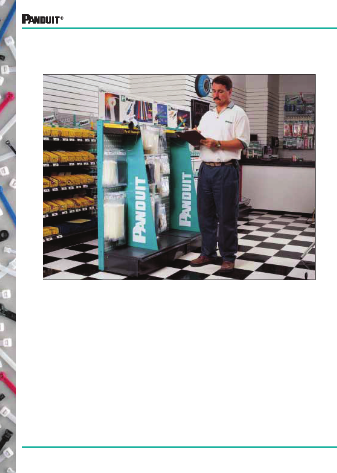
76
Most commonly used parts appear in BOLD.
Your local PANDUIT ® Distributor carries top quality PANDUIT ® products and
offers many advantages and services to help lower your transaction costs:
• Local stock for fast
delivery and “Just-In-
Time” requirements.
Reduces your
inventory costs.
• One stop for all your
electrical needs because
he stocks products from
many manufacturers.
One purchase order, less
administrative and
freight costs.
• Well trained personnel to
answer any questions
and to make sure you
have the right product for
the right job.
PANDUIT ® Products are on Display at Your
Local PANDUIT ® Distributor
Merchandising
77
Most commonly used parts appear in BOLD.
• Loop tensile strength
of 450 lbs. Provides
superior strength for
increased performance
and reliability
• Available in 304 and
316 stainless steel
• The unique wave-form spring maintains a high
tension grip on non-resilient objects; provides the
strength of steel and the high tension of a
steel spring
Standard,
Light Heavy
and Heavy
• For applications
that require
bundling various
bundle diameters
• Provides versatility on
job sites for any
diameter with
minimum inventory
• 304 Stainless Steel
(316 available)
WAVE-TY™
Superior Grip Steel Ties
Part Number
Max. Bundle
Dia.
In. (mm)
Length
In. (mm)
Width
In. (mm)
Min. Loop
Tensile
Strength
Lbs. (N)
Std.
Pkg.
Qty.*
Std.
Ctn.
Qty.
MLT1S-CP 1.00 (25) 5.0 (127)
.18
(4.6)
200
(890)
100 500
MLT2S-CP 2.00 (51) 7.9 (201) 100 500
MLT2.7S-CP 2.70 (69) 10.2 (259) 100 500
MLT4S-CP 4.00 (102) 14.3 (362) 100 500
MLT6S-CP 6.00 (152) 20.5 (521) 100 500
MLT8S-CP 8.00 (203) 26.8 (679) 100 500
MLT2LH-LP 2.00 (51) 7.9 (201)
.25
(6.4)
250
(1112)
50 250
MLT4LH-LP 4.00 (102) 14.3 (362) 50 250
MLT6LH-LP 6.00 (152) 20.5 (521) 50 250
MLT8LH-LP 8.00 (203) 26.8 (679) 50 250
MLT2H-LP 2.00 (51) 7.9 (201)
.31
(7.9)
450
(2000)
50 250
MLT4H-LP 4.00 (102) 14.3 (362) 50 250
MLT6H-LP 6.00 (152) 20.5 (521) 50 250
MLT8H-LP 8.00 (203) 26.8 (679) 50 250
MLT10H-LP 10.00 (254) 33.0 (838) 50 250
MLT12H-Q 12.00 (305) 42.0 (1067) 25 125
CUSTOM LENGTH BANDING SYSTEM
MBS-TLR Any 250' (76m) .18
(4.6)
100
(445)
1 n/a
MBS-MR 1000' (305m) 1 n/a
MBH-TLR Any 250' (76m) .31
(7.9)
250
(1112)
1 n/a
MBH-MR 1000' (305m) 1 n/a
BANDING HEADS
MTHS-C n/a n/a .18 (4.6) 100 (445) 100 1000
MTHH-C n/a n/a .31 (7.9) 250 (1112) 100 1000
*Order the number of reels required in multiples of standard package quantities.
WAVE-TY™
MLT2.7WH-LP 2.70
(69)
10.2
(259)
.31
(7.9)
450
(2000)
50 250
MLT4WH-LP 4.00
(102)
14.2
(360)
50 250
MLT6WH-LP 6.00
(152)
20.4
(520)
50 250
MLT8WH-LP 8.00
(203)
26.8
(679)
50 250
MLT10WH-LP 10.00
(254)
33.0
(838)
50 250
*Order the number of ties required in multiples of standard package quantities.
NYLON 11 COATED 316 STAINLESS STEEL
MLTC2H-LP316 2.00 (50) 7.9 (201)
.31
(7.9)
250
(1112)
50 250
MLTC4H-LP316 4.00 (102) 14.2 (360) 50 250
MLTC6H-LP316 6.00 (152) 20.4 (520) 50 250
MLTC8H-LP316 8.00 (203) 26.8 (679) 50 250
MLTC10H-LP316 10.00 (254) 33.0 (838) 50 250
Ties —
Standard Sizes
• Fully rounded edge
design eliminates sharp
edges for added protection
and safety
• Available in a loop tensile
strength of 200 lbs. for
standard cross-section
ties, 250 lbs. for light
heavy cross section ties
and 450 lbs. for heavy
cross section ties
• Superior strength for most
bundling applications
• Available in type 304 and
316 stainless steel which
provides excellent
resistance to temperature
extremes, corrosion,
weather and UV radiation
Coated Stainless Steel Ties
• For communication and
electrical cable
• The strength of steel, the
protection of nylon; the
nylon coating provides
fully rounded plastic edges to protect cables
• Available with a loop tensile strength of 250 lbs.
• Base metal is 316 grade stainless steel for
excellent resistance to temperature extremes,
corrosion, weather, chemicals, salt sprays and
UV radiation
Stainless Steel Cable Ties and Accessories
For more complete information on Stainless Steel Products, see PANDUIT ® Brochure SA-SSCB01.
PANDUIT ® NO-SLIP ™ line of Stainless Steel Self-Locking Ties have a unique low-insertion force
head design that keeps the tie locked, before or after tightening, regardless of its orientation or
how tightly it is installed. With features like high strength, corrosion resistance, extreme
temperature tolerance, fully rounded edges and special styles, these stainless steel ties are an
excellent choice for a wide variety of applications and are designed to install easily for long
service life under adverse conditions. All ties can be installed using PANDUIT ® standard
installation tools, or simply installed by hand.
PAN-STEEL® Self-Locking Stainless Steel Ties
Banding System
78 Most commonly used parts appear in BOLD.
*Order the number of tools required in multiples of standard package quantities.
Part Number Description
Std.
Pkg.
Qty.*
PPTMT Pneumatic-operated, tool controlled tension and cut-off
for production applications.
1
GS4MT MIL approved. Hand-operated, tool controlled tension
and cut-off.
1
K4M-BLD Replacement cutter blade for GS4MT. 1
K4MTG Replacement tension gripper for GS4MT. 1
ST2MT Hand-operated, installer controlled tension and cut-off. 1
KT2MG Replacement tension gripper for ST2MT. 1
HTMT Used to tension and coil the tail of tie. 1
Bulk Pkg. -CR = 100' reel
*Order the number of reels required in multiples of standard package quantities.
Part Number
For Clamp
Width
In. mm
Sleeve
Width
In. (mm)
Std.
Pkg.
Qty.*
Std.
Ctn.
Qty.
PCSS-B-CR .18 (4.6) .33 (8.4) 1 —
PCSH-B-CR .31 (7.9) .47 (12) 1 —
PAN-STEEL® Accessories
Cushion Sleeve
• Makes rigid bundles
resilient, provides
tighter tensioning
• Non-conductive
insulator between
clamp and bundle
• Material: black, neoprene
Stainless Steel Mounts
Part Number
For MLT
Tie Width
In (mm)
Mounting
Method
Hole
Diameter
In. (mm)
Std.
Pkg.
Qty.*
Std.
Ctn.
Qty.
MTM1H-C .18 (4.6)
thru
.31 (7.9)
#8 (4) Screw .18 (4.6) 100 1000
MTM1H10-C #10 (5) Screw .21 (5.4) 100 1000
MTM1H25-C 1/4” (6) Screw .28 (7.1) 100 1000
Material: 304 Stainless Steel
*Order the number of pieces required in multiples of standard package quantities.
Part Number
For MLT
Tie Width
In. (mm)
Mounting
Method
In. (mm)
Panel
Thickness
In. (mm)
Std.
Pkg.
Qty.*
Std.
Ctn.
Qty.
MPWM-H56 .18 (4.6)
thru
.31 (7.9)
Inserted into
pre-drilled hole
5/16 (8)
.031 (.8)-
.094 (2.4)
25 250
MBM-H25-Q .18
(4.6)
Inserted
into pre-drilled
hole .250 (6.4)
.031 (.8)-
.125 (3.2)
25 250
MTM2H-Q .18 (4.6) thru
.31 (7.9)
#8 (4) Screw — 25 250
MTMBH-Q .18 (4.6)
thru
.31 (7.9)
Pre-drill hole size
Max. size
.625 (15.9)
Up to .500 max.
(12.7)
25 250
Mount
• Low profile
• Utilizes only one hole
for mounting
• Material: 304
Stainless Steel
Push-Wing Mount
MPWM-H56-Q
Push-Button Mount
MBM-H25-Q
Two-Way Mount
MTM2H-Q
Bulkhead Mount
MTMBH-Q
Stainless Steel Marking Products
Use PAN-STEEL ® Ties or Stainless Steel Strapping to provide identification in harsh environments. The ties and
strapping can be stamped with available tooling or custom stamped upon request. Marker plates and metal embossed
tape are also available.
Marker Plates
and Tags
• Attached with PAN-STEEL ® T ies
• 304, 316 stainless steel, brass and
aluminum available
• Can be used as a flag or wrap
• Various sizes and shapes available;
round, square, rectangular, etc.
Part numbers available upon request
• Can be custom marked by
PANDUIT ®. See page 79 for details *Order the number of pieces required in multiples of standard package quantities.
Part Number
Used with
Clamp/Tie
Width
In. (mm)
Size - In. (mm)
Std.
Pkg.
Qty.*
Std.
Ctn.
Qty.Width Length
MMP350-C .18 (4.6) .75 (19) 3.50 (89) 100 1000
MMP350W38-C .18 (4.6) .38 (10) 3.50 (89) 100 1000
MMP350H-C .18 (4.6) thru
.31 (7.9)
.75
(19)
3.50
(89)
100 1000
Stainless Steel Mounts and Marking Products
For more complete information on Stainless Steel Products, see PANDUIT ® Brochure SA-SSCB01.
Installation Tools
• Complete line of
manual and pneumatic
installation tools
speeds installation
• Side-entry of cable ties
into the tools, makes for
quick and easy
installation
• Automatic tension and
cut-off capabilities
available on
select models
• High reliability, low
maintenance, long life
Stainless Mount
MTM1H-C
79
Most commonly used parts appear in BOLD.
Laser Marking System:
• Used on all stainless steel cable ties, strapping,
metal marker plates/tags and anodized
aluminum locks
• Graphics capability and BOLD block letters
• Upper and lower case character capability
• Alphanumeric and sequential numbering ability
Metal Embossed Tape System
• Hand operated embosser
with 3/16" height characters
(approx. 6 characters/inch)
• Hole punch (3/16" dia.)
allows tape to be used as a
wrap or flag marker, held on
with PAN-STEEL®Ties
*Order the number of pieces required in multiples of standard package quantities.
Part Number Description
Std.
Pkg.
Qty.*
Std.
Ctn.
Qty.
MEHT Embosser, carrying case, (1) roll each of
META and METS4 tape.
1 —
TAPE
META-X 1/2” x 16'. roll Aluminum tape. 10 50
METS3-X 1/2" x 21' roll Stainless Steel (316 Grade). 10 50
METS4-X 1/2" x 21' roll Stainless Steel (304 Grade). 10 50
*Order the number of pieces required in multiples of standard package quantities.
Part Number Description
Std.
Pkg.
Qty.*
IMP094
IMP125
IMP187
Press with 3/32" character wheel.
Press with 1/8" character wheel.
Press with 3/16" character wheel.
1
1
1
MWK094
MWK125
MWK187
3/32" character wheel kit.
1/8" character wheel kit.
3/16" character wheel kit.
1
1
1
IMP-FIX Interchangeable fixture for MMP172 series.
MT series and the aluminum marker plates.
1
• For medium volume marking
of ties, strapping or plates
• Manual operation with
automatic indexing
• Interchangeable character
wheel makes the press
versatile and economical
• Press includes fixturing
device to
provide high quality marking
Characters include:
3/8" height (approx. 6 characters per inch).
A B C D E F G H I J K L M
N O P Q R S T U V W X Y Z
2 3 4 5 6 7 8 9 . / -
Characters include:
A B C D E F G H I J K L M N
O P Q R S T U V W X Y Z
& 1 2 3 4 5 6 7 8 9 0 . / -
For more complete information on Stainless Steel Products, see PANDUIT® Brochure SA-SSCB01.
Custom Marking Capabilities on PANDUIT ® PAN-STEEL® Stainless Steel
Cable Ties, Strapping, Metal Marker Plates/Tags Anodized Aluminum Locks.*
Embossing System:
• Used on metal marker plates and tags which
are a maximum of .020" (0.5mm) thick
• Excellent for applications that are exposed
to occasional painting and excessive dirt
• Upper case “raised” character
capability only
• Alphanumeric and sequential
numbering ability
PANDUIT ® stainless steel cable ties, strapping, stainless steel, brass and aluminum
marker plates/tags and anodized aluminum locks can be custom marked for
identification of equipment, cables, hoses, pipes, conduit, etc. in petrochemical
plants, power plants, pulp and paper mills, breweries, and many other applications.
PANDUIT ® in-house computer controlled custom marking systems provide sharp,
crisp, high quality legends. Sequential numbering for serialization is available.
*Anodized aluminum locks can only be marked by the laser system.
Indenter Press
Stainless Steel Marking Products
Character Sizes ** Available:
• 1/8" (3.18mm)
• 1/4" (6.35mm)
• 3/16" (4.77mm)
• 5/16" (7.94mm)
• 1/2" (12.7mm)
Character Sizes ** Available:
• 1/8" (3.18mm)
• 3/16" (4.77mm)
**Other character sizes available. For complete product information, specification or character information, contact 866-405-6659.
80
Most commonly used parts appear in BOLD.
Stainless Steel Strapping System
*Order the number of pieces required in multiples of standard package quantities.
Part Number Description
Std.
Pkg.
Qty.*
BT1HT Installation tool. Used for all widths of PANDUIT ® PAN-STEEL®
strapping. Tensions, cuts strapping, and secures the buckle tab.
Ratchet-type tool provides mechanical advantage for tensioning.
Easy to operate.
1
Installation Tools
Hand operated tool. Adjustable
tension control and lever
actuated cut-off.
For more complete information on Stainless Steel Products, see PANDUIT ® Brochure SA-SSCB01.
Stainless Steel
Strapping
• Reduces installation time and leaves no sharp edges
• Burr-free sides
• 304 Stainless Steel
• Designed for use in critical applications where radiation, weathering, corrosion
and temperature extremes are a concern
• Temperature range: -112°F (-80°C) to 1000°F (538°C)
• Fast and reliable alternative to wing seals
Custom Length Strapping System
• Provides job-site
versatility with
minimum inventory
• Gives custom
capability on larger
diameters
• 304 stainless steel
• Buckle is easy to
install—just slip onto
strapping and turn
strapping back
on bundle *Order the number of strapping, and buckles required in multiples of standard package quantities.
Part Number
Thickness
In. (mm)
Approx.
Width
In. (mm)
Used
With
Buckle
Std.
Pkg.
Qty.*
Std.
Ctn.
Qty.
STRAPPING
MSW38T15-CR4 .015 (.38) .38 (9.5) MSBW38-C4 1* —
MSW50T15-CR4 .015 (.38) .50 (12.7) MSBW50-C4 1* —
MSW63T15-CR4 .015 (.38) .63 (15.9) MSBW63-C4 1* —
BUCKLES
MSBW38-C4 Used with .38" width strapping. 100 1000
MSBW50-C4 Used with .50” width strapping. 100 1000
MSBW63-C4 Used with .63" width strapping. 100 1000
*Order the number of strapping, and buckles required in multiples of standard package quantities.
Part Number
Thickness
in. (mm)
Width
in. (mm)
Min. Loop
Tensile
Strength
lbs. (N)
Max.
Bundle
Dia.
in. (mm)
Length
in. (mm)
Recommended
PANDUIT ®
Installation
Tool Part No.
Std.
Pkg.
Qty.*
Std.
Ctn.
Qty.
MS2W38T15-L4
MS4W38T15-L4
MS6W38T15-L4
MS8W38T15-L4
MS10W38T15-L4
.015
(.38)
.38
(9.5)
500
(2225)
2.00 (51)
4.00 (102)
6.00 (152)
8.00 (203)
10.00 (254)
11.8 (300)
18.0 (457)
24.4 (620)
30.7 (780)
37.0 (940)
BT1HT or
BT2MS75
50
50
50
50
50
250
250
250
250
250
MS4W50T15-L4
MS6W50T15-L4
MS8W50T15-L4
MS10W50T15-L4
.015
(.38)
.50
(12.7)
700
(3115)
4.00 (102)
6.00 (152)
8.00 (203)
10.00 (254)
18.0 (457)
24.4 (620)
30.7 (780)
37.0 (940)
BT1HT or
BT2MS75
50
50
50
50
250
250
250
250
MS4W63T15-L4
MS6W63T15-L4
MSW63T15-L4
MS10W63T15-L4
.015
(.38)
.63
(15.9)
800
(3560)
4.00 (102)
6.00 (152)
8.00 (203)
10.00 (254)
18.0 (457)
24.4 (620)
30.7 (780)
37.0 (940)
BT1HT or
BT2MS75
50
50
50
50
250
250
250
250
The PANDUIT ® Method Reduces Installation Time:
1. Place strap around the
material, insert tail of strap
through buckle. Pull
strapping tight and bend up
to hold in place. Insert tail
of strapping into tool nose
section. Squeeze handles
to tension.
2. Once proper tension is
reached, maintain tension
and raise tool 90°-120°
over buckle and pull
down on cutter lever,
cutting strap.
3. Remove tool, press cut
end down and toward
retaining tab.
4. Using the closure level on the handle of the tool, bend
retaining tab down and over cut end. Provides finished,
safe, low profile closure.
81
Push Mounts Cord Clips Abrasion Protection Products
Snap-In Clips Heat Shrink Harness Board Accessories
Wiring Accessories
Smart Ways to Lower Your Installed Cost
PANDUIT ®
Wiring Accessories offer you a broad range of products designed to speed installation and
lower your installed costs—whatever your requirements. Plus, PANDUIT ® provides experienced technical
support to assure you get not only the best product for your application, but maximum benefit from its use.
For more information, in the U.S.A. call toll-free:
Technical Support: 866-405-6657 or Customer Service: 800-777-3300
Adhesive Backed Mounts
Wire Management Communication Cable Management

82
Most commonly used parts appear in BOLD.
Contents
(See back of catalog for alphabetical index of part numbers referencing specific page numbers.)
Selection of Styles . . . . . . . . . . . . . . . . . . . . . . . . . . . . . . . . . . . . . . . . . . . . . . .83
Cable Tie Accessories . . . . . . . . . . . . . . . . . . . . . . . . . . . . . . . . . . . . . . . . 85-107
4-Way Adhesive Backed Mounts . . . . . . . . . . . . . . . . . . . . . . . . . . . . . . . . . . . . . . . . . . 85-86
4-Way Mounts Without Adhesive . . . . . . . . . . . . . . . . . . . . . . . . . . . . . . . . . . . . . . . . . . . . .86
Combination Adhesive Mount/Cable Tie . . . . . . . . . . . . . . . . . . . . . . . . . . . . . . . . . . . . . . .87
Adhesive Applied Mounts . . . . . . . . . . . . . . . . . . . . . . . . . . . . . . . . . . . . . . . . . . . . . . . . . . .88
Tie Mounts . . . . . . . . . . . . . . . . . . . . . . . . . . . . . . . . . . . . . . . . . . . . . . . . . . . . . . . . . . . 89-92
Tie Anchor Mounts . . . . . . . . . . . . . . . . . . . . . . . . . . . . . . . . . . . . . . . . . . . . . . . . . . . . . 93-94
Tie Plates . . . . . . . . . . . . . . . . . . . . . . . . . . . . . . . . . . . . . . . . . . . . . . . . . . . . . . . . . . . . . . .95
Right Angle Mounts/Lightening Hole Mounts . . . . . . . . . . . . . . . . . . . . . . . . . . . . . . . . . . . .96
Clip-On Mounts . . . . . . . . . . . . . . . . . . . . . . . . . . . . . . . . . . . . . . . . . . . . . . . . . . . . . . . . . .97
Push Mounts and Specialty Mounts . . . . . . . . . . . . . . . . . . . . . . . . . . . . . . . . . . . . . . . 98-105
Tie Harness Mount System . . . . . . . . . . . . . . . . . . . . . . . . . . . . . . . . . . . . . . . . . . . . 100-101
Flat Cable Mount System . . . . . . . . . . . . . . . . . . . . . . . . . . . . . . . . . . . . . . . . . . . . . . . . . .103
Marker Plates and Rolls/Marking Pens . . . . . . . . . . . . . . . . . . . . . . . . . . . . . . . . . . . 105-106
TELCO Installation Products . . . . . . . . . . . . . . . . . . . . . . . . . . . . . . . . . . . . . . . . . . . . . . .107
Wiring Accessories — used without cable ties . . . . . . . . . . . . . . . . . . . 108-123
Adjustable Releasable Clamp . . . . . . . . . . . . . . . . . . . . . . . . . . . . . . . . . . . . . . . . . . . . . .108
Cord Clips . . . . . . . . . . . . . . . . . . . . . . . . . . . . . . . . . . . . . . . . . . . . . . . . . . . . . . . . . . 109-113
Flat Cable Mounts . . . . . . . . . . . . . . . . . . . . . . . . . . . . . . . . . . . . . . . . . . . . . . . . . . . 114-115
Fixed Diameter “C” Clamps . . . . . . . . . . . . . . . . . . . . . . . . . . . . . . . . . . . . . . . . . . . . 116-117
Siding Clips . . . . . . . . . . . . . . . . . . . . . . . . . . . . . . . . . . . . . . . . . . . . . . . . . . . . . . . . . . . .119
Snap-in Mounts/Clips . . . . . . . . . . . . . . . . . . . . . . . . . . . . . . . . . . . . . . . . . . . . . . . . . 120-121
Circuit Board Posts and Locking Supports . . . . . . . . . . . . . . . . . . . . . . . . . . . . . . . . . 122-123
Harness Board Accessories . . . . . . . . . . . . . . . . . . . . . . . . . . . . . . . . . . 124-129
Communication Cable Management . . . . . . . . . . . . . . . . . . . . . . . . . . . . 130-133
Selection and Use of PANDUIT ® Adhesive Mounts . . . . . . . . . . . . . . . 134-136
Cable Management Bulk Package Part Numbers . . . . . . . . . . . . . . . . . 137-138
Abrasion Protection Products . . . . . . . . . . . . . . . . . . . . . . . . . . . . . . . . . 139-180
Heat Shrink . . . . . . . . . . . . . . . . . . . . . . . . . . . . . . . . . . . . . . . . . . . . . . . . . . . . . . . . . 140-161
Non-Shrink PVC Tubing . . . . . . . . . . . . . . . . . . . . . . . . . . . . . . . . . . . . . . . . . . . . . . . 162-163
Spiral Wrap . . . . . . . . . . . . . . . . . . . . . . . . . . . . . . . . . . . . . . . . . . . . . . . . . . . . . . . . . 164-167
Split Harness Wrap . . . . . . . . . . . . . . . . . . . . . . . . . . . . . . . . . . . . . . . . . . . . . . . . . . . . . . .168
Grommet Edging . . . . . . . . . . . . . . . . . . . . . . . . . . . . . . . . . . . . . . . . . . . . . . . . . . . . 169-171
Corrugated Loom Tubing . . . . . . . . . . . . . . . . . . . . . . . . . . . . . . . . . . . . . . . . . . . . . . 172-174
Braided Expandable Sleeving . . . . . . . . . . . . . . . . . . . . . . . . . . . . . . . . . . . . . . . . . . 175-176
Flammability Tests, Classifications, Technical Data . . . . . . . . . . . . . . . . . . . . . . . . . 177-180
Abrasion Protection Bulk Package Part Numbers. . . . . . . . . . . . . . . . . . . . . . . . . . . . . . . .181
Wiring Accessories
83
Most commonly used parts appear in BOLD.
Wiring Accessories are an integral part of PANDUIT ® comprehensive selection of wire management
products. These accessories help provide the lowest installed solution to routing, mounting, protecting
wire, cable and optical fiber. These products are manufactured in an environment committed to design
innovation, high quality and knowledgeable service to our customers. The key benefits of this
commitment are:
• The highest quality manufacturing environment,
including statistical process control to meet
applicable international and domestic standards
• PANDUIT ® teams up with a global network
of Distributors to provide you with Just In
Time shipping to eliminate your need for
large inventories
• Fully staffed engineering and tool and die
departments to assist in designing solutions
to specific industry applications
• Continuous research on materials,
adhesives and new technologies to provide
you the latest product innovations
Selection of Styles
Cable Tie Accessories
These products are used with PANDUIT ® Cable Ties to speed and simplify
the mounting of wires, cables and tubing. Installation methods include
adhesive-backed, user applied adhesive, screws, rivets or through-panel
mount designs.
Wiring Accessories
These products, including fixed and adjustable diameter accessories, are
used without cable ties. Mounting methods include adhesive-backed, user
applied adhesive, screws, rivets or through-panel designs.
Harness Board Accessories
PANDUIT ® unique selection of harness board accessories speeds the routing
and forming of wire in harness fabrication. They hold wires at a uniform height
above the board and are ideal for use with PANDUIT ® manual and automatic
cable tie tooling.
Abrasion Protection Products
PANDUIT ® offers a wide variety of abrasion protection products to protect wires,
cables, hoses and tubing from abrasion. Heat shrink tubing, non-shrink PVC
tubing, spiral wrap, grommet edging, corrugated loom tubing and braided
expandable sleeving are available in a variety of sizes and materials to meet
a broad range of indoor and outdoor applications.
Wiring Accessories
84 Most commonly used parts appear in BOLD.
Wiring Accessories Part Number System and Technical Data
X = 10
Q = 25
L = 50
C = 100
T = 200
D = 500
M = 1000
For Part Description and
Mounting Method, refer to
specific product tables
in catalog.
Blank = Natural
0 = Weather Resistant Black
8 = Gray
15 = Ivory
20 = Pigmented Black
30 = Heat Stabilized Nylon (Black)
69 = Flame Retardant Nylon (Natural)
76 = TEFZEL* (Blue)
100 = Polypropylene Weather Resistant (Black)
109 = Polypropylene (Green)
120 = Weather Resistant Nylon 12 (Black)
630 = Heat Stabilized Nylon 6 (Black)
639 = Heat Stabilized Nylon 6 (Natural)
702 = HALAR** (Maroon)
—
Part Number System Example
Part Description Package Quantity Color/Material
Physical Properties and Colors of Wiring Accessory Materials
Design Criteria
General Purpose
Nylon 6.6
Weather
Resistant
Nylon 6.6
Impact
Modified
Weather
Resistant
Nylon 6.6
Heat
Stabilized
Nylon 6.6
Flame Retardant
Nylon 6.6
Glass Filled
Flame
Retardant
Nylon 6.6
Color Natural Black Black Black Black Black Natural Black
Par t Number Suffix None 20 0 0 30 60 69 None
UL Flammability — UL94 V-2 V-2 V-2 HB V-2 V-0 V-0 V-0
Gamma Radiation Resistance 1 x 10⁵ Rads 1 x 10⁵ Rads 1 x 10⁵
Rads N/A 1 x 10⁵ Rads 1 x 10⁵ Rads 1 x 10⁵ Rads N/A
Water Absorption 1.2%
(24 hrs)
1.2%
(24 hrs)
1.2%
(24 hrs)
1.2%
(24 hrs)
1.2%
(24 hrs)
1.1%
(24hrs)
1.1%
(24hrs)
0.7%
(24hrs)
UV Resistance Poor Fair Good Good Good Poor Poor Poor
Maximum Continuous
Use Temperature 185°F (85°C) 185°F (85°C) 185°F (85°C) 185°F (85°C) 257°F (125°C) 230°F (110°C) 230°F (110°C) 230°F (110°C)
Minimum Continuous
Use Temperature
-40°F
(-40°C)
-40°F
(-40°C)
-40°F
(-40°C)
-40°F
(-40°C)
-40°F
(-40°C)
-40°F
(-40°C)
-40°F
(-40°C)
-40°F
(-40°C)
Physical Properties and Colors of Wiring Accessory Materials
Based on assumption of minimal loading, chemical attack and impact free conditions.
Design
Criteria
Heat Stabilized
Nylon 6.6 TEFZEL*
General
Purpose
Polypropylene
Weather
Resistant
Polypropylene
Polyproplyene
(Green) HALAR**
General Purpose
ABS
Weather
Resistant
ABS
Flame
Retardant
Polycarbonate Acetal PVC
Color Black Natural Blue White Black Green Maroon White Black Black Black Black Gray, White
Part Number
Suffix
630 639 76 None 100 109 702 None 20 0 None None 8, 10
UL
Flammability
— UL94
HB HB V-0 HB HB HB V-0 HB HB HB V-0 HB V-0
Gamma
Radiation
Resistance
N/A N/A 2 x 10⁸
Rads
1 x 10⁶
Rads
1 x 10⁶
Rads
N/A 2 x 10⁸
Rads
N/A N/A N/A N/A N/A N/A
Water
Absorption
(24 hours)
1.5%
(24 hrs)
1.5%
(24hrs)
<0.03%
(24hrs)
0.1%
(24 hrs)
0.1%
(24hrs)
0.1%
(24hrs)
<0.05%
(24hrs)
0.3%
(24hrs)
0.3%
(24hrs)
0.3%
(24hrs)
0.15%
(24hrs)
0.43%
(24 hrs)
0.3%
(30 days)
UV
Resistance
Fair Poor Excellent Poor Good Poor Excellent Poor Fair Good Good Fair Poor
Maximum
Continuous
Use
Temperature
250°F
(121°C)
250°F
(121°C)
302°F
(150°C)
221°F
(105°C)
221°F
(105°C)
221°F
(105°C)
284°F
(140°C)
150°F
(65°C)
150°F
(65°C)
150°F
(65°C)
257°F
(125°C)
194°F
(90°C)
122°F
(50°C)
Minimum
Continuous
Use
Temperature
-40°F
(-40°C)
-40°F
(-40°C)
-50°F
(-46°C)
-40°F
(-40°C)
-40°F
(-40°C)
-40°F
(-40°C)
-50°F
(-46°C)
-40°F
(-40°C)
-40°F
(-40°C)
-40°F
(-40°C)
-40°F
(-40°C)
-40°F
(-40°C)
-40°F
(-40°C)
*TEFZEL is a registered trademark of E. I. DuPont de Nemours Co.
**HALAR is a registered trademark of Solvay Solexis, Inc.
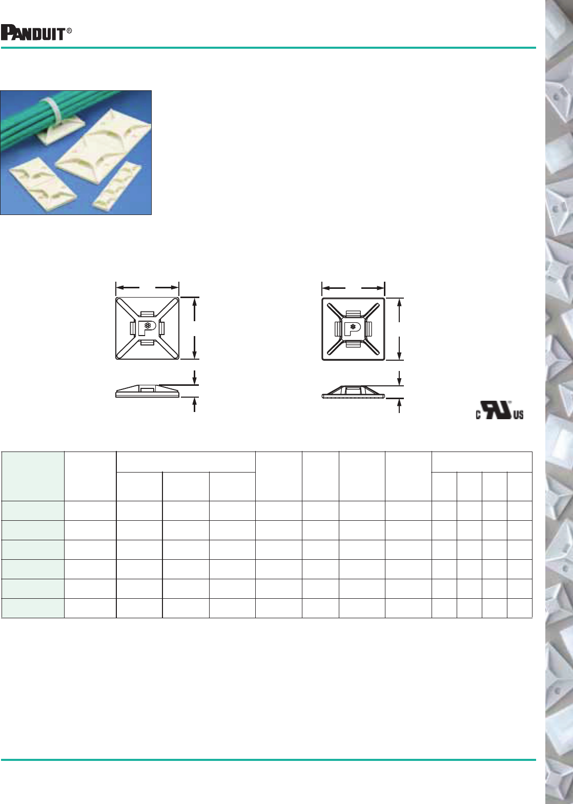
85
Most commonly used parts appear in BOLD.
*Parts shown for Std. Pkg. Qtys. Order number of mounts required in multiples of package quantities.
‡Part Numbers listed are for Standard Materials in Standard Package Quantity.
For Bulk package part numbers, see page 137-138.
Cable tie cross section sizes: M = Miniature and I = Intermediate.
Adhesive Backed Cable Tie Mounts
Lower your installed costs with fast, easy-to-install PANDUIT ®
adhesive-backed cable tie mounts. Four-way tie entry for easy
orientation of wires or cables. PANDUIT ® mounts are produced
2-up, 4-up, and with tear tabs for fast and easy liner removal to
speed installation. For additional holding strength use #6 (M3)
screws in the mounting hole(s). For specific information on
adhesive properties and technical data on mount selection,
see page 134-136.
Part Number‡
Used With
Cable Ties**
Dimensions
in. (mm)
Material Color
Where
Used
Adhesive
Type/Static
Load lbs. (g)
Packaging*
A B C
Std.
Pkg.
Qty.
Std.
Ctn.
Qty.
Bulk
Pkg.
Qty.
Bulk
Ctn.
Qty.
ABM1M-A-C M .50
(12.7)
.50
(12.7)
.16
(4.0)
Nylon 6.6 White Indoors Rubber
.13 (59)
100 500 1000 5000
ABM1M-AT-C M .50
(12.7)
.50
(12.7)
.16
(4.0)
Nylon 6.6 White Indoors/
High Temp.
Acrylic
.13 (59)
100 500 1000 5000
ABMM-A-C M, I .75
(19.1)
.75
(19.1)
.18
(4.6)
ABS White Indoors Rubber
.30 (136)
100 500 500 5000
ABMM-A-C20 M, I .75
(19.1)
.75
(19.1)
.18
(4.6)
ABS Black Indoors Rubber
.30 (136)
100 500 — —
ABMM-AT-C M, I .75
(19.1)
.75
(19.1)
.18
(4.6)
ABS White Indoors/
High Temp.
Acrylic
.30 (136)
100 500 500 5000
ABMM-AT-C0 M, I .75
(19.1)
.75
(19.1)
.18
(4.6)
ABS Black Outdoors/
High Temp.
Acrylic
.30 (136)
100 500 500 5000
4-Way Adhesive Backed Mounts
ABM1M ABMM
C
B
A
C
B
A
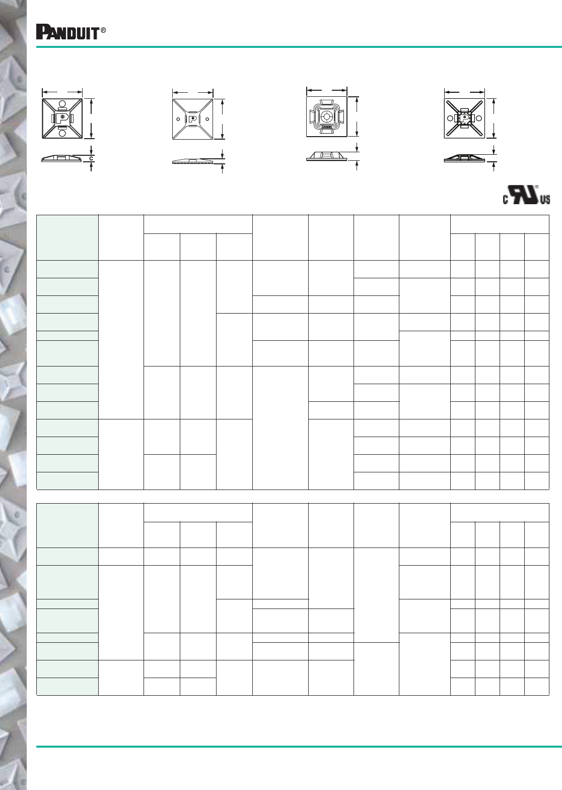
86 Most commonly used parts appear in BOLD.
!Used with PANDUIT ® HLM series Hook & Loop Cable Ties found on page 40.
Part Number‡
Used With
Cable Ties**
Dimensions
in. (mm)
Material Color
Where
Used
Adhesive
Type/Static
Load lbs. (g)
Packaging*
A B C
Std.
Pkg.
Qty.
Std.
Ctn.
Qty.
Bulk
Pkg.
Qty.
Bulk
Ctn.
Qty.
ABM2S-A-C
M, I, S
1.00
(25.4)
1.00
(25.4)
.16
(4.2)
ABS White
Indoors Rubber
.50 (227)
100 500 500 5000
ABM2S-AT-C Indoors/
High Temp. Acrylic
.50 (227)
100 500 500 5000
ABM2S-AT-C0 Weather
Resistant ABS
Black Outdoors/
High Temp.
100 500 500 5000
ABM100-A-C
.23
(5.8)
Nylon 6.6 White Indoors
Rubber
.50 (227)
100 500 500 5000
ABM100-AT-C
Acrylic
.50 (227)
100 500 500 5000
ABM100-AT-C0 Weather
Resistant
Nylon 6.6
Black Outdoors/
High Temp.
100 500 500 5000
ABM112-A-C
1.12
(28.6)
1.12
(28.6)
.14
(4.1)
Nylon 6.6
White
Indoors Rubber
.63 (286)
100 500 500 5000
ABM112-AT-C Indoors/
High Temp. Acrylic
.63 (286)
100 1000 500 5000
ABM112-AT-C0 Black Outdoors/
High Temp.
100 1000 500 5000
ABM3H-A-L
M, I, S, HS,
LH, H,
HLM !
1.50
(38.1)
1.50
(38.1)
.25
(6.4) White
Indoors Rubber
1.12 (513)
50 500 200 1000
ABM3H-AT-L Indoors
High Temp.
Acrylic
1.12 (513)
50 500 200 1000
ABM4H-A-L
2.00
(50.8)
2.00
(50.8)
Indoors Rubber
2.0 (907)
50 500 200 1000
ABM4H-AT-L Indoors/
High Temp.
Acrylic
2.0 (907)
50 500 200 1000
4-WAY MOUNTS WITHOUT ADHESIVE
Part Number‡
Used With
Cable Ties**
Dimensions
in. (mm)
Material Color
Where
Used
Adhesive
Type/Static
Load lbs. (g)
Packaging*
A B C
Std.
Pkg.
Qty.
Std.
Ctn.
Qty.
Bulk
Pkg.
Qty.
Bulk
Ctn.
Qty.
ABMM-D M, I .75
(19.1)
.75
(19.1)
.14
(3.6)
ABS White
Indoors
User supplied
adhesive
— — 500 5000
ABM2S-S6-D
M,I,S
1.00
(25.4)
1.00
(25.4)
.16
(4.2)
User supplied
adhesive
and/or (2)
#6 (M3) Screws
— — 500 5000
ABM100-S6-C
.20
(5.1)
Nylon 6.6 User supplied
adhesive
and/or #6 (M3)
Screw
100 1000 500 5000
ABM100-S6-C69 Flame Retard.
Nylon 6.6
Natural 100 1000 500 5000
ABM112-S6-C 1.12
(28.6)
1.12
(28.6)
.14
(4.1)
Nylon 6.6 White
User supplied
adhesive
and/or (2) #6
(M3) Screws
100 1000 500 5000
ABM112-S6-C69 Flame Retard.
Nylon 6.6
Natural
Indoors
100 500 500 5000
ABM3H-S6-T M, I, S, HS,
LH, H,
HLM !
1.50
(38.1)
1.50
(38.1) .21
(5.2) Nylon 6.6 White
— — 200 1000
ABM4H-S6-T 2.00
(50.8)
2.00
(50.8)
— — 200 1000
ABM2S ABM3H/ABM4H ABM100 ABM112
4-Way Adhesive Backed Mounts
Adhesive Backed Cable Tie Mounts
B
A
C
B
A
C
B
A
C
B
A
*Order the number of mounts required in multiples of package quantities.
‡Part Numbers listed are for Standard Materials in Standard Package Quantity. For Bulk package part numbers, see page 137-138.
**Cable Tie Cross Section Sizes: M = Miniature, I = Intermediate, S = Standard, HS= Heavy Standard, LH = Light-Heavy and H = Heavy.

87
Most commonly used parts appear in BOLD.
Snap-In Cable Tie Mounts Integral retaining notch holds cable tie head in place
below bundle; eliminates protruding tie head and
facilitates one hand tie threading.
Part Number‡
Used
With
Cable
Ties**
Dimensions
in. (mm)
Material Color
Where
Used
Mounting
Method
Packaging*
ABC
Std.
Pkg.
Qty.*
Std.
Ctn.
Qty.
Bulk
Pkg.
Qty.
Bulk
Ctn.
Qty.
ADHESIVE BACKED
SMS-A-C S 2.00
(50.8)
1.00
(25.4)
.31
(7.9)
ABS White Indoors Rubber
Adhesive
Static Load
1.0 lbs.
(454g)
100 500 500 5000
SCREW MOUNT
SMS-S6-D S 2.00
(50.8)
1.00
(25.4)
.31
(7.9)
ABS White Indoors (2) #6
(M3) Screws
— — 500 5000
Adhesive Backed Cable Tie Mounts
Adhesive mount and cable tie molded as one piece help reduce
inventory costs. Mount portion features ramp to guide tip into tie head
and holes to install two (2) optional #6 screws for added mounting
strength. Available with locking or releasable tie. Extended adhesive
liner release tab on mount for fast liner removal.
Combination Adhesive Mount/Cable Tie
Part Number‡
Cable Tie Specifications
Recommended
PANDUIT ®
Installation Tool Material Color
Adhesive
Type/Static
Load lbs. (g)
Packaging*
Length
A
in. (mm)
Width
B
in. (mm)
Max.
Bundle Dia.
in. (mm)
Min. Loop
Tensile
Strength
Lbs. (N)
Std.
Pkg.
Qty.
Std.
Ctn.
Qty.
Bulk
Pkg.
Qty.
Bulk
Ctn.
Qty.
Locking
PLA2S-A-Q
7.4
(188)
.19
(4.8)
1.85
(47)
50
(222)
GTS, GS2B,
PPTS, PTS,
STS2 or STH2
Nylon 6.6 White Rubber
.45
(204)
25 250 100 1000
Releasable
PRA2S-A-Q
Hand Installed
Only
25 250 100 1000
.90
(22.9)
.30
(7.6)
1.0
(25.4)
A REF.
B
.148 (3.76)
C
A
1.12
(28.4)
B
.145
(3.7)
*Order the number of mounts required in multiples of package quantities.
‡Part Numbers listed are for Standard Materials in Standard Package Quantity. For Bulk package part numbers, see page 137-138.
**Recommended cable ties: PLT1S, PLT1.5S, PLT2S, PRT1.5S, PRT2S. Cable Tie Cross Section: S = Standard.
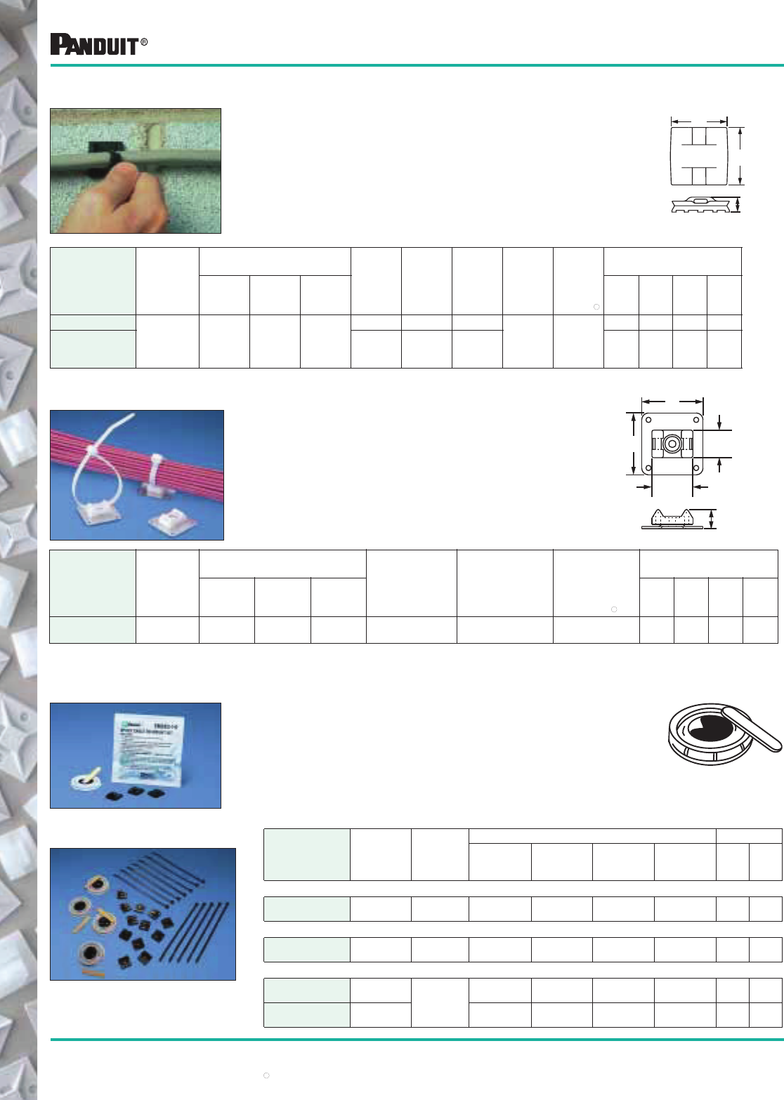
88
Most commonly used parts appear in BOLD.
*Order the number of mounts required in multiplies of package quantities.
‡Part numbers listed are for standard Materials in Standard Package Quantity. For Bulk package part numbers, see page 137-138.
**Cable Tie Cross Section Sizes: M = Miniature, I = Intermediate and S = Standard.
"Max. static load rating, following full cure period, when applied with PANDUIT ® EMA Epoxy Adhesive according to installation instructions.
EMA Epoxy supplied in convenient two-compartment mixer
cup with a mixer stick for each cup. Each cup contains
adhesive for three (3) EMS or ASMS mounts.
Epoxy hardens in about five (5) minutes. Supports about 5 lbs.
after first 15 minutes. After full 24-hour curing time, bonding
strength will exceed 50 lbs. on clean, grease-free surface.
Note: Not recommended for polyethylene and polypropylene.
Part Number‡
Used
With
Cable
Ties**
Where
Used
Contents of Each Kit Packaging*
Epoxy
Cups
Mixer
Sticks
EMS
Mounts
Cable
Ties
Std.
Pkg.
Qty.
Bulk
Pkg.
Qty.
EPOXY ADHESIVE ONLY
EMA-X — Indoor/
Outdoor
10 10 None None 10
Kits
—
EPOXY MOUNTING KIT WITH EMS MOUNTS
EMSK3-1-X0 M, I, S Indoor/
Outdoor
1 1 3 None 10
Kits
100
Kits
EPOXY MOUNTING KIT WITH EMS MOUNTS AND CABLE TIES
EMSK3-1-3-0 M, I, S
Indoor/
Outdoor
1 1 3 3 ea.
PLT2S-0
1
Kit
10
Kits
EMSK12-4-12-X0 M, I, S 4 4 12 12 ea.
PLT2S-0
10
Kits
100
Kits
Cable Tie Mounts
These mounts are designed for application with PANDUIT ®
EMA Epoxy. Provides a fast, strong, economical method to
secure wire or cable to steel, aluminum, glass, wood and
most other surfaces. Especially well suited to construction
and maintenance applications. Eliminates the need to
drill holes.
Part Number‡
Used
With
Cable
Ties**
Dimensions
in. (mm)
Material Color
Where
Used
Mounting
Method
Max.
Static
Load
lbs. (g)"
Packaging*
ABC
Std.
Pkg.
Qty.
Std.
Ctn.
Qty.
Bulk
Pkg.
Qty.
Bulk
Ctn.
Qty.
EMS-A-C
M, I, S .98
(24.9)
.98
(24.9)
.26
(6.6)
Nylon 6.6 Natural Indoors
EMA
Epoxy 10 (4540)
100 500 500 1000
EMS-A-C0 Weather
Resistant
Nylon 6.6
Black Outdoors 100 500 500 5000
A
B
C
Epoxy Applied Mounts
B
0.75"
(19)
C
0.50"
(12.7)
A
Part Number‡
Used
With
Cable
Ties
Dimensions
in. (mm)
Where
Used
Mounting
Method
Max. Static
Load
lbs. (g)"
Packaging*
ABC
Std.
Pkg.
Qty.
Std.
Ctn.
Qty.
Bulk
Pkg.
Qty.
Bulk
Ctn.
Qty.
ASMS-A-X M, I, S 1.125
(28.6)
1.125
(28.6)
.35
(8.9)
Indoors EMA
Epoxy
10 (4540) 10 50 200 1000
Epoxy Applied Swivel Mounts
Mount swivels 360° to assure proper orientation
with harness. Four inspection holes to check
adhesive coverage.
Material:
Base and Rivet: Aluminum
Mount: Natural Nylon 6.6 — Indoors
Epoxy Adhesive and Mount Kits
EMA EPOXY
EMSK3-1-X0 Epoxy Kit with mounts.
Packed in sturdy foil pouch
EMSK-12-4-12-X0 Epoxy Kit with
mounts and cable ties
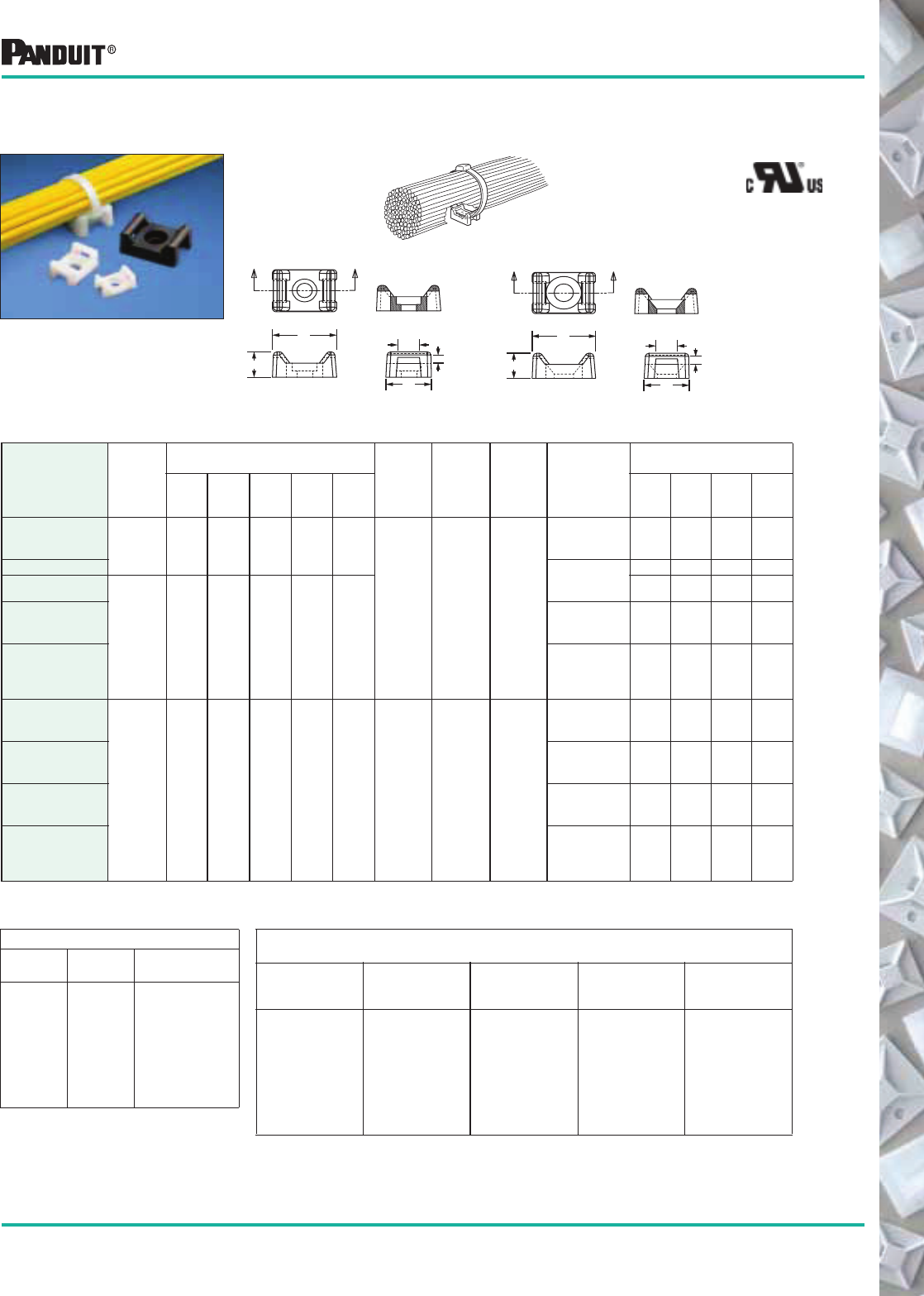
89
Most commonly used parts appear in BOLD.
*Order the number of mounts required in multiples of package quantities.
‡Part Numbers listed are for Standard Materials in Standard Package Quantity.
For Bulk package part numb ers, see page 137-138.
**Cable Tie Cross Section Sizes: M = Miniature, I = Intermediate, S = Standard, HS = Heavy Standard and LH = Light-Heavy.
Unique cradle design provides maximum stability and rigidity to
the wire bundle. Screw or rivet installed.
Except
TM1S4-M69
TM2S8-C100
TM3S8-C69
TM3S8-C100
Part Number‡
Used
With
Cable
Ties**
Dimensions
in. (mm)
Material Color
Where
Used
Mounting
Method
Packaging*
A B C D E
Std.
Pkg.
Qty.
Std.
Ctn.
Qty.
Bulk
Pkg.
Qty.
Bulk
Ctn.
Qty.
TM1S4-C
M.513
(13.0)
.316
(8.0)
.230
(5.8)
.130
(3.3)
.067
(1.7)
Nylon 6.6 Natural Indoors
#4 (M2.5)
Screw or
Tapered Rivet
100 500 1000 5000
TM1S6-C #6 (M3)
Screw or
Tapered Rivet
100 500 1000 5000
TM2S6-C
M, I, S .630
(16.0)
.425
(10.8)
.275
(7.0)
.215
(5.5)
.060
(1.5)
100 500 1000 5000
TM2S8-C #8 (M4)
Screw or
Tapered Rivet
100 500 1000 5000
TM2R6-C #6 (M3) Screw
or
Countersunk
Rivet
100 500 1000 5000
TM3S8-C
M, I, S,
HS, LH
.858
(21.8)
.610
(15.5)
.375
(9.5)
.320
(8.1)
.080
(2.0) Nylon 6.6 Natural Indoors
#8 (M4) Screw
or Tapered
Rivet
100 500 1000 5000
TM3S10-C #10 (M5)
Screw or
Tapered Rivet
100 500 1000 5000
TM3S25-C 1/4 (M6)
Screw or
Tapered Rivet
100 500 1000 5000
TM3R6-C #6 (M3) Screw
or
Countersunk
Rivet
100 500 1000 5000
Hole Diameter — in. (mm)
Part
Number Hole Dia.
Counterbore
Dia.
TM1S4
TM1S6
TM2S6
TM2S8
TM2R6
TM3S8
TM3S10
TM3S25
TM3R6
.120 (3.0)
.150 (3.8)
.150 (3.8)
.180 (4.6)
.190 (4.8)
.180 (4.6)
.200 (5.1)
.260 (6.6)
.190 (4.8)
.230 (5.8)
.280 (7.1)
.280 (7.1)
.320 (8.1)
Countersunk
.320 (8.1)
.390 (9.9)
.510 (12.9)
Countersunk
***TEFZEL is a registered trademark of E.I. DuPont de Nemours Co.
####
Additional Tie Mount Part Numbers Available in specified materials.
All are available as standard PANDUIT ® parts
Heat
Stabilized
Nylon
Flame
Retardant
Nylon
Weather
Resistant
Nylon
Weather
Resistant
Polypropylene TEFZEL***
TM1S4-M30
TM1S6-M30
TM2R6-M30
TM2S6-M30
TM2S8-M30
TM3S8-M30
TM3S10-M30
TM3S25-M30
TM1S4-M69
TM1S6-M69
TM2S6-M69
TM2S8-M69
TM3S8-C69
TM3S10-M69
TM1S6-M0
TM2R6-M0
TM2S6-M0
TM2S8-M0
TM3R6-M0
TM3S10-Q0
TM3S10-M0
TM3S25-M0
TM2S8-C100
TM3S8-C100
TM3S8-M100
TM3S10-C76
TM3S8-C76
TM2S8-C76
Cable Tie Mounts
TM-S- TM-R-
Tie Mounts —
Mechanically Applied
A
B
C
AA
SECTION A-A
D
E
A
C
AA
SECTION A-A
B
D
E
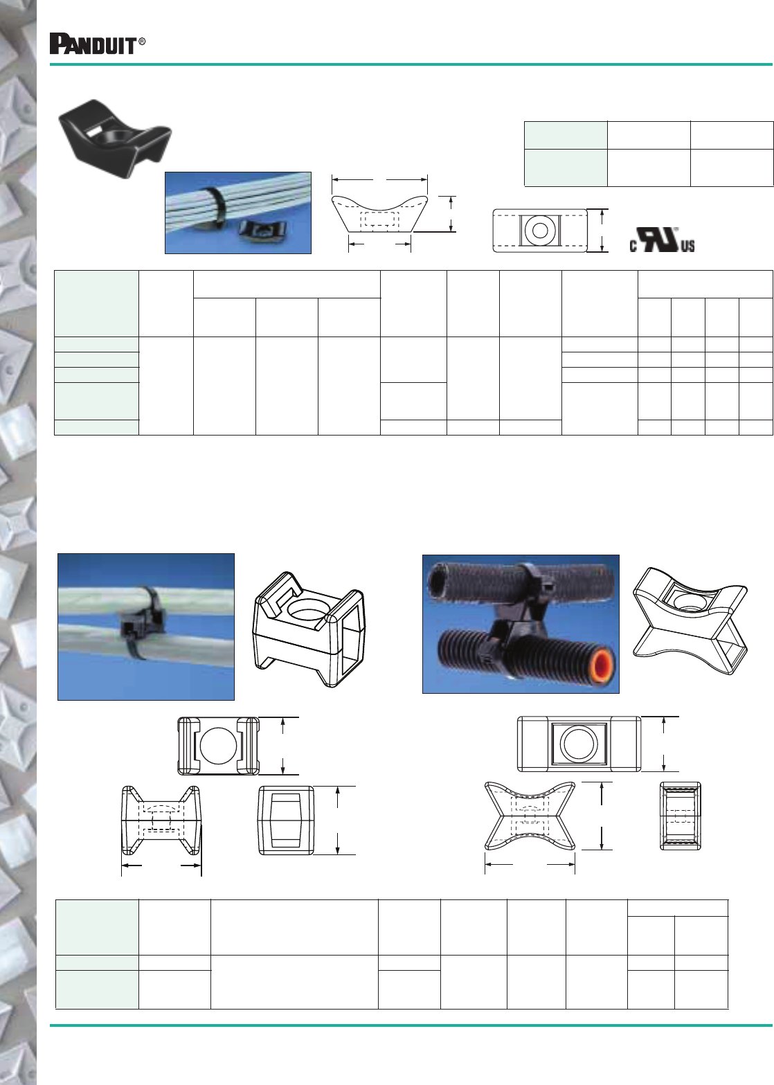
90 Most commonly used parts appear in BOLD.
Mounts designed especially for use with PANDUIT ®
Extra-Heavy cross-section ties for mounting cable, large wire
bundles or tubular shapes.
Except
TMEH-S10-C100
TMEH-S10-C109
Part Number‡
Used
With
Cable
Ties**
Dimensions
in. (mm)
Material Color
Where
Used
Mounting
Method
Packaging*
ABC
Std.
Pkg.
Qty.
Std.
Ctn.
Qty.
Bulk
Pkg.
Qty.
Bulk
Ctn.
Qty.
TMEH-S8-Q0
M, I, S, HS,
LH, EH,
HLM !
1.65
(42)
.74
(19)
.61
(15.5)
Weather
Resistant
Nylon 6.6 Black Outdoors
#8 (M4) Screw 25 250 100 500
TMEH-S10-Q0 #10 (M5) Screw 25 250 100 500
TMEH-S25-Q0 1/4 (M6) Screw 25 250 100 500
TMEH-S10-C100 Weather
Resistant
Polypropylene #10 (M5) Screw
— — 100 500
TMEH-S10-C109 Polypropylene Green Indoors — — 100 500
B
1.05"
(26.7)
C
A
Cable Tie Mounts
Part
Number Hole Diameter
Counterbore
Diameter
TMEHS8
TMEHS10
TMEH25
.18" (4.3 mm)
.20" (5.1 mm)
.26" (6.6 mm)
.51" (13.0)
.51" (13.0)
.51" (13.0)
Extra-Heavy Tie Mounts
Swivel Cable Tie Mounts
The two TM style mounts are securely fastened together with a rivet that allow both mounts to swivel.
The Swivel Mount can join bundles of cable, tubing or hoses that may need to move or are not parallel.
This mount is also a great way to separate bundles to avoid abrasion.
Part Number
Used
With
Cable
Ties**
Dimensions
in. (mm)
Pull Apart
Force Material Color
Where
Used
Packaging*
Std.
Pkg.
Qty.
Std.
Ctn.
Qty.
TM3-X2-C0 M, I, S, HS, LH
See Drawing
120 lbs. Weather
Resistant
Nylon 6.6
Black Outdoors/
Indoors
100 1000
TMEH-X2-L0 M, I, S, HS, LH,
EH,
HLM!
250 lbs. 50 500
TM3 TMEH
.87
(22.10)
.75
(19.05)
1.64
(41.70)
1.23
(31.34)
0.73
(18.54)
0.62
(15.75)
**Cable Tie Cross Section Sizes: M = Miniature, I = Intermediate, S = Standard, HS = Heavy Standard, LH = Light-Heavy and EH = Extra-Heavy.
*Order the number of mounts required in multiples of packaging quantities.
‡Part numbers listed are for Standard Materials in Standard Package Quantity. For Bulk package part numbers, see page 137-138.
!Used with PANDUIT ® HLM series Hook & Loop Cable Ties found on page 40.
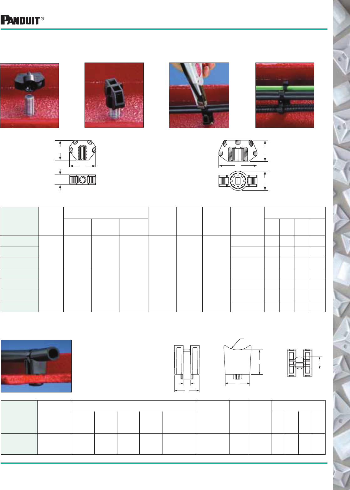
91
Most commonly used parts appear in BOLD.
Cable Tie Mounts
Stud Tie Mounts Easily applied to bolts or studs with a light hammer blow or turning of the
mount. The mounts are designed for use with cable ties to mount wire
bundles, air, water and hydraulic lines.
Part Number‡
Used
With
Cable
Ties**
Dimensions
in. (mm)
Material Color
Where
Used
Mounting
Method
Packaging*
A B C
Std.
Pkg.
Qty.
Std.
Ctn.
Qty.
Bulk
Pkg.
Qty.
Bulk
Ctn.
Qty.
TMSTLHS5-M0
M, I, S,
HS, LH
1.25
(31.8)
.48
(12.2)
.95
(24.1)
Impact
Modified
Weather
Resistant
Nylon 6.6
Black Outdoors
#12 Stud Dia.
(5 mm)
100 1000 1000 5000
TMSTLHS6-M0 1/4" Stud Dia.
(6 mm)
100 1000 1000 5000
TMSTLHS8-M0 5/16" Stud Dia.
(8 mm)
100 1000 1000 5000
TMSTHS10-D0
M, I, S, HS,
LH, H
1.99
(50.6)
1.01
(25.6)
1.10
(27.9)
3/8" Stud Dia.
(10 mm)
100 1000 500 500
TMSTHS13-D0 1/2" Stud Dia.
(13 mm)
100 1000 500 500
TMSTHS16-D0 5/8" Stud Dia.
(16 mm)
100 1000 500 500
TMSTHS19-D0 3/4" Stud. Dia.
(19 mm)
100 1000 500 500
TMSTLHS Type
B
C
A
B
C
A
TMSTHS Type
Spacer Mount
Part Number‡
Used
With
Cable
Ties
Dimensions
in. (mm)
Material Color
Minimum
Panel
Thickness
Packaging*
A
Cable Tie
Channel
in. (mm)
B
Width
in. (mm)
C
Standoff
Height
in. (mm)
D
Base
Depth
in. (mm)
E
Recommended
Panel Hole Dia.
in. (mm)
Std.
Pkg.
Qty.
Std.
Ctn.
Qty.
Bulk
Pkg.
Qty.
Bulk
Ctn.
Qty.
TMSH50-T300 SSPM2.5H-L300
SSPM4H-L300
.310
(7.875)
1.00
(25.4)
1.00
(25.4)
1.00
(25.4)
.50
(12.7)
Weather
Resistant Heat
Stabilized
Nylon 6.6
Black 0.188
(4.78)
100 1000 200 1000
Maintain a standoff from the
frame rail in Chassis Tie
applications. Ideal for
applications where bundles
must be secured away from
the frame to avoid abrasion.
B
C
A
E
D
0.75 R
(19.05)
*Order the number of mounts required in multiples of package quantities.
‡Part Numbers listed are for Standard Materials in Standard Package Quantity. For Bulk package part numbers, see page 137-138.
**Cable Tie Cross Section Sizes: M = Miniature, I = Intermediate, S = Standard, HS= Heavy Standard, LH = Light-Heavy and H = Heavy.
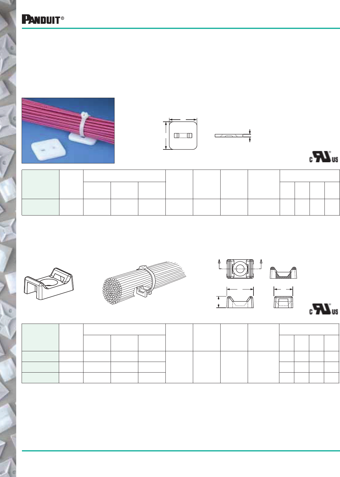
92
Most commonly used parts appear in BOLD.
Cable Tie Mounts
Part Number‡
Used
With
Cable
Ties**
Dimensions
in. (mm)
Material Color
Where
Used
Mounting
Method
Packaging*
ABC
Std.
Pkg.
Qty.
Std.
Ctn.
Qty.
Bulk
Pkg.
Qty.
Bulk
Ctn.
Qty.
AM2-C M, I, S 1.22
(31.2)
1.22
(31.2)
.125
(3.2)
Nylon 6.6 Natural Indoors User
Supplied
Adhesive
100 500 1000 5000
Tie Mounts — Applied with User Supplied Adhesives
Apply cyanoacrylic or another type adhesive to mount surface. Any adhesive selected should be
user-tested to assure suitability for the actual application. Mounts should be installed on a clean,
dry and grease-free surface. Bond strength depends on adhesive used.
Low Profile Mount — AM2 Low profile design keeps bundle close to mounting surface
where overhead space is limited.
TM1A, TM2A, TM3A Solid flat bottom surface provides maximum adhesive area.
Part Number‡
Used
With
Cable
Ties**
Dimensions
in. (mm)
Material Color
Where
Used
Mounting
Method
Packaging*
ABC
Std.
Pkg.
Qty.
Std.
Ctn.
Qty.
Bulk
Pkg.
Qty.
Bulk
Ctn.
Qty.
TM1A-C M .513
(13.0)
.316
(8.0)
.230
(5.8)
Nylon 6.6 Natural Indoors
User
Supplied
Adhesive
100 1000 1000 10000
TM2A-C M, I, S .630
(16.0)
.425
(10.8)
.275
(7.0)
100 500 1000 5000
TM3A-C M, I, S, HS,
LH
.875
(22.2)
.620
(15.8)
.375
(9.5)
100 500 1000 5000
B
A
C
AA
C
A B
SECTION A-A
*Order the number of mounts required in multiples of package quantities.
‡Part Numbers listed are for Standard Materials in Standard Package Quantity. For Bulk package part number s, see page 137-138.
*Cable Tie Cross Section Sizes: M = Miniature, I = Intermediate, S = Standard, HS = Heavy Standard and LH = Light-Heavy.
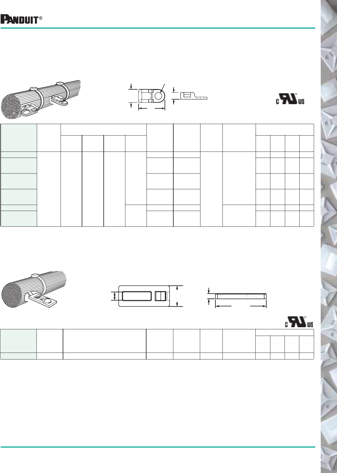
93
Most commonly used parts appear in BOLD.
*Order the number of mounts required in multiples of package quantities.
‡Part Numbers listed are for Standard Materials in Standard Package Quantity.
For Bulk package part numbers, see page 137-138.
**Cable Tie Cross Section Sizes: M = Miniature, I = Intermediate and S = Standard.
Low profile and versatile, these screw-installed mounts can be ideal for
applications where space is limited. Designed for four-way cable tie
insertion, this mount can be mounted in-line or perpendicular to the
wire bundle.
TA1 Anchor
Part Number‡
Used
With
Cable
Ties**
Dimensions
in. (mm)
Material Color
Where
Used
Mounting
Method
Packaging*
ABCD
Std.
Pkg.
Qty.
Std.
Ctn.
Qty.
Bulk
Pkg.
Qty.
Bulk
Ctn.
Qty.
TA1S8-C
M, I, S .75
(19.0)
.38
(9.5)
.20
(5.1)
.17
(4.3)
Nylon 6.6 Natural
Indoors
#8 (M4) Screw
100 500 1000 5000
TA1S8-M0 Weather
Resistant
Nylon 6.6
Black — — 1000 5000
TA1S8-M30 Heat
Stabilized
Nylon
Black — — 1000 5000
TA1S8-M69 Flame
Retardant
Nylon 6.6
Natural
— — 1000 5000
TA1S10-C
.20
(5.1)
Nylon 6.6 Natural
#10 (M5) Screw
100 500 1000 5000
TA1S10-M0 Weather
Resistant
Nylon 6.6
Black — — 1000 5000
TA2 Anchor This mount is installed perpendicular to the wire bundle. Elongated slot
permits installing the screw and adjusting mount position with the
bundle attached.
Part Number‡
Used
With
Cable Ties**
Dimensions
in. (mm) Material Color
Where
Used
Mounting
Method
Packaging*
Std.
Pkg.
Qty.
Std.
Ctn.
Qty.
Bulk
Pkg.
Qty.
Bulk
Ctn.
Qty.
TA2-C M, I, S See Drawing Nylon 6.6 Natural Indoors #10 (M5) Screw 100 500 1000 5000
Except
TA1S8-M69
.195"
(5.0)
.50"
(12.7) .125"
(3.2)
1.225"
(31.1)
Cable Tie Mounts
Screw Applied Tie
Anchor Mounts
B
A
C
D (Dia) = Hole Diameter
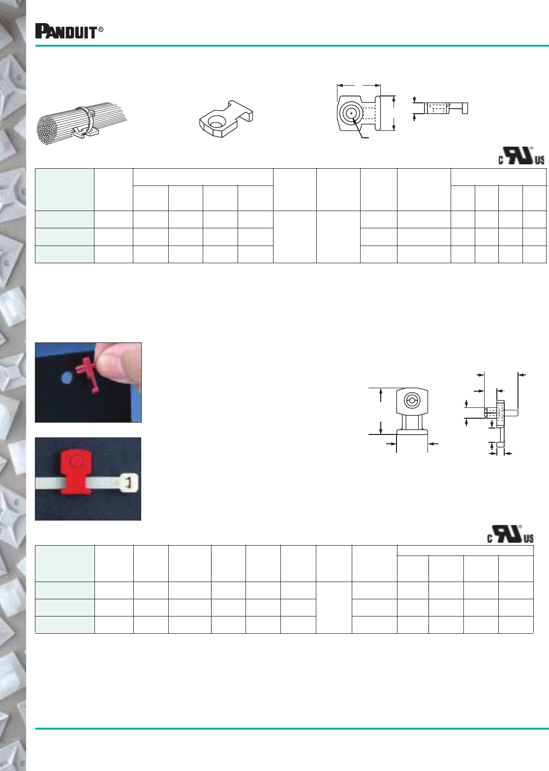
94 Most commonly used parts appear in BOLD.
*Order the number of mounts required in multiples of package quantities.
‡Part Numbers listed are for Standard Materials in Standard Package Quantity.
For Bulk package part numbers, see page 137-138.
**Cable Tie Cross Section Sizes: M = Miniature, I = Intermediate and S = Standard.
Cable Tie Mounts
Screw Applied
Low Profile Mounts
Designed to secure wire bundles where space is limited.
NOTE 1: Combination Counterbore and Countersunk Hole (.088" (2.2) Dia. rivet can also be used).
NOTE 2: Countersunk Hole
Part Number‡
Used
With
Cable
Ties**
Dimensions
in. (mm)
Material Color
Where
Used
Mounting
Method
Packaging*
A B C D
Std.
Pkg
Qty.
Std.
Ctn.
Qty.
Bulk
Pkg.
Qty.
Bulk
Ctn.
Qty.
LPMM-S2-C M .40
(10.2)
.32
(8.1)
.10
(2.5)
.0951
(2.4)
Nylon 6.6 Natural
Indoors #2 (M2)
Flathead Screw
100 1000 1000 10,000
LPMM-S5-C M .40
(10.2)
.32
(8.1)
.10
(2.5)
.1302
(3.3)
Indoors #5 (M3)
Flathead Screw
100 1000 1000 10,000
LPMS-S8-C M, I, S .75
(19.1)
.50
(12.7)
.12
(3.0)
.1702
(4.3)
Indoors #8 (M4)
Flathead Screw
100 1000 1000 5000
Part Number‡
Used With
Cable
Ties** A
Dimensions
in. (mm)
Hole
Size Material Color
Where
Used
Mounting
Method
Packaging*
Std.
Pkg.
Qty.
Std.
Ctn.
Qty.
Bulk
Pkg.
Qty.
Bulk
Ctn.
Qty.
KIMS-H366-C2 M, I, S .155
(3.9)
See Drawing .144
(3.7)
Nylon 6.6 Red
Indoors
Integral
Push Rivet
100 500 1000 5000
KIMS-H430-C6 M, I, S .180
(4.6)
See Drawing .169
(4.3)
Nylon 6.6 Blue Integral
Push Rivet
100 1000 1000 5000
KIMS-H500-C4 M, I, S .202
(5.1)
See Drawing .196
(5.0)
Nylon 6.6 Yellow Integral
Push Rivet
100 500 1000 5000
Knock-In Low
Profile Mounts
Secures wires to any pre-drilled panel. Can be installed in any panel
thickness. Eliminates screws.
Easy to Install:
1. Push rivet in pre-drilled panel hole.
2. Use PANDUIT ® Rivet Installation
Tool (TNR) or hammer to drive the pin
flush to the base. This drives the rivet
into the hole and secures the mount.
3. Attach wires to the mount with
cable tie.
.735
(18.670)
.490
(12.445)
A
.230
(5.840)
.120
.190
(4.825)
.53 REF.
(13.46)
A
D (Dia)
BC
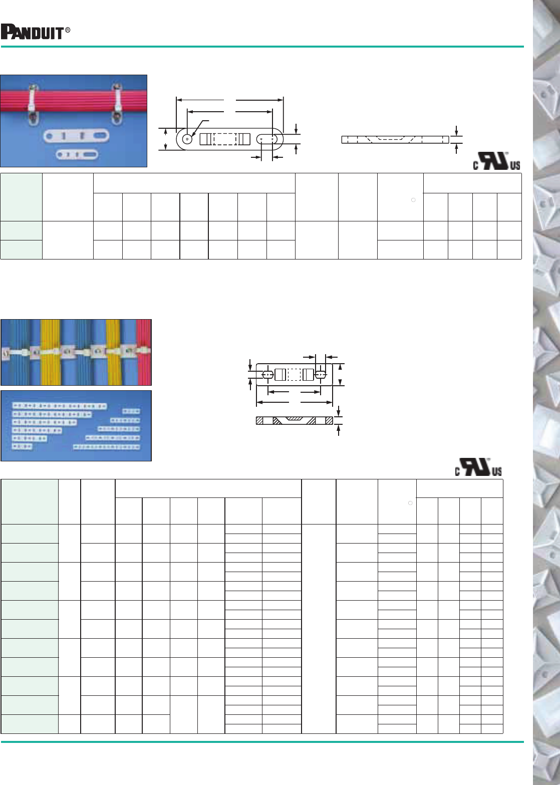
95
Most commonly used parts appear in BOLD.
*Order the number of mounts required in multiples of package quantities.
‡Part Numbers listed are for Standard Materials in Standard Package Quantity. For Bulk package part numbers, see page 137-138.
**Cable Tie Cross Section Sizes: M = Miniature, I = Intermediate, S = Standard, HS = Heavy Standard, LH = Light-Heavy and H = Heavy.
"For use with most common screw types except flat head.
Cable Tie Plates
Screw applied. Each tie plate has a slotted mounting hole to
accommodate various fastener spacings.
Part
Number‡
Used
With
Cable
Ties**
Dimensions
in. (mm)
Color &
Material
Where
Used
Mounting
Method "
Screw
Size
Packaging*
A B C D E F G
Std.
Pkg.
Qty.
Std.
Ctn.
Qty.
Bulk
Pkg.
Qty.
Bulk
Ctn.
Qty.
TP2-C
M, I, S, HS
1.98
(50.3)
.50
(12.7)
.125
(3.2)
.200
(5.1)
.40
(10.2)
.200
(5.1)
1.60
(40.6) Natural
Nylon 6.6 Indoors
#10 (M5) 100 1000 1000 5000
TP4H-C 3.08
(78.2)
.62
(15.7)
.203
(5.2)
.270
(6.9)
.31
(7.9)
.270
(6.9)
2.50
(63.5)
1/4 (M6) 100 1000 500 2500
Multiple Tie Plates Screw applied. Used to secure closely spaced wire bundles.
B
D (Dia)
G
E
F
A
C
C
F
E
B
A
D
Tie Plates
Part Number‡
No.
of
Bdls.
Used
With
Cable
Ties**
Dimensions
in. (mm) Material
&
Where
Used
Mil. Std.
Part No.
Mounting
Method "
Screw
Size
Packaging*
A B C D E F
Std.
Pkg.
Qty.
Std.
Ctn.
Qty.
Bulk
Pkg.
Qty.
Bulk
Ctn.
Qty.
MTP1S-E6-C
MTP1S-E10-C
1
M, I, S 1.75
(44.5)
.50
(12.7)
.125
(3.2)
1.25
(31.8)
.220 (5.58) .147 (3.73)
Natural
Nylon 6.6,
Indoors
MS3339-1
—
#6 (M3) — — 100 1000
.330 (7.62) .200 (5.08) #10 (M5) 100 1000
MTP1H-E6-C
MTP1H-E10-C
M, I, S,
HS, LH, H
2.09
(53.1)
.62
(15.7)
.203
(5.2)
1.50
(38.1)
.220 (5.58) .147 (3.73) MS3339-6
—
#6 (M3) — — 100 1000
.300 (7.62) .200 (5.08) #10 (M5) 100 1000
MTP2S-E6-C
MTP2S-E10-C
2
M, I, S 3.00
(76.2)
.50
(12.7)
.125
(3.2)
1.25
(31.8)
.220 (5.58) .147 (3.73) MS3339-2
—
#6 (M3) — — 100 1000
.300 (7.62) .200 (5.08) #10 (M5) 100 1000
MTP2H-E6-C
MTP2H-E10-C
M, I, S,
HS, LH, H
3.59
(91.2)
.62
(15.7)
.203
(5.2)
1.50
(38.1)
.220 (5.58) .147(3.73) MS3339-7
—
#6 (M3) — — 100 1000
.300 (7.62) .200 (5.08) #10 (M5) 100 1000
MTP3S-E6-C
MTP3S-E10-C
3
M, I, S 4.25
(108.0)
.50
(12.7)
.125
(3.2)
1.25
(31.8)
.220 (5.58) .147 (3.73) MS3339-3
—
#6 (M3) — — 100 1000
.300 (7.62) .200 (5.08) #10 (M5) 100 1000
MTP3H-E6-C
MTP3H-E10-C
M, I, S,
HS, LH, H
5.09
(129.3)
.62
(15.7)
.203
(5.2)
1.50
(38.1)
.220 (5.58) .147 (3.73) MS3339-8
—
#6 (M3) — — 100 1000
.300 (7.62) .200 (5.08) #10 (M5) 100 1000
MTP4S-E6-C
MTP4S-E10-C
4
M, I, S 5.50
(139.7)
.50
(12.7)
.125
(3.2)
1.25
(31.8)
.220 (5.58) .147 (3.73) MS3339-4
—
#6 (M3) — — 100 1000
.300 (7.62) .200 (5.08) #10 (M5) 100 1000
MTP4H-E6-C
MTP4H-E10-C
M, I, S,
HS, LH, H
6.59
(167.4)
.62
(15.7)
.203
(5.2)
1.50
(38.1)
.220 (5.58) .147 (3.73) MS3339-9
—
#6 (M3) — — 100 1000
.300 (7.62) .200 (5.08) #10 (M5) 100 1000
MTP5S-E6-C
MTP5S-E10-C
5
M, I, S 6.75
(171.5)
.50
(12.7)
.125
(3.2)
1.25
(31.8)
.220 (5.58) .147 (3.73) MS3339-5
—
#6 (M3) — — 100 1000
.300 (7.62) .200 (5.08) #10 (M5) 100 1000
MTP5H-E6-C
MTP5H-E10-C
M, I, S,
HS, LH, H
8.09
(205.5)
.62
(15.7) .203
(5.2)
1.50
(38.1)
.220 (5.58) .147 (3.73) MS3339-10
—
#6 (M3) — — 100 1000
.300 (7.62) .200 (5.08) #10 (M5) 100 1000
MTP6H-E6-C
MTP6H-E10-C 6M, I, S,
HS, LH, H
9.59
(243.6)
.62
(15.7)
.220 (5.58) .147 (3.73) MS3339-11
—
#6 (M3) — — 100 1000
.300 (7.62) .200 (5.08) #10 (M5) 100 1000
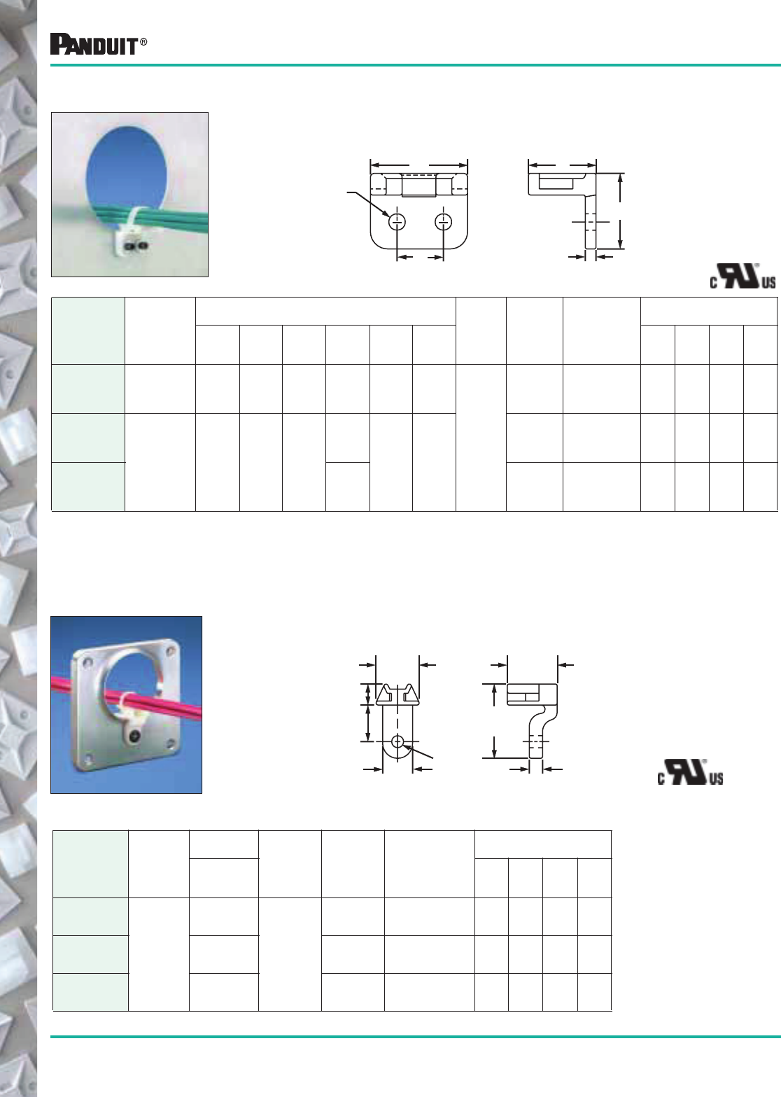
96 Most commonly used parts appear in BOLD.
*Order the number of mounts required in multiples of package quantities.
**Cable Tie Cross Section Sizes: M = Miniature, I = Intermediate, S = Standard, HS = Heavy Standard, LH = Light-Heavy and H = Heavy.
Secure wire bundles that run through bulkheads or cabinet holes,
holding them away from sharp edges. Can also be used to mount
wire bundles adjacent to any surface. Screw or rivet applied.
Part Number
Used
With
Cable
Ties**
Dimensions
in. (mm) Color,
Material
&
Where
Used
Mil. Std.
Part No.
Mounting
Method
in. (mm)
Packaging*
ABCDEF
Std.
Pkg.
Qty.
Std.
Ctn.
Qty.
Bulk
Pkg.
Qty.
Bulk
Ctn.
Qty.
RAMS-S3-M M, I, S .56
(14.2)
.39
(9.9)
.44
(11.2)
.095
(2.4)
.06
(1.5)
.281
(7.1)
Natural
Nylon 6.6,
Indoors
MS3341-2 #3 (M2.5) Screw
or 3/32 (2.4)
Round Head
Rivet
— — 1000 5000
RAMH-S6-D
M, I, S, HS,
LH and H
1.00
(25.4)
.75
(19.1)
1.00
(25.4)
.125
(3.2)
.18
(4.6)
.500
(12.7)
MS3341-1 #6 (M3) Screw
or 1/8 (3.2)
Round Head
Rivet
— — 500 5000
RAMH-S10-D .200
(5.1)
— #10 (M5) Screw
or 3/16 (4.7)
Round Head
Rivet
— — 500 5000
Used to secure wire bundles which run through bulkhead lightening
holes (.87" (22.1mm) diameter or larger) and keep bundles away from
sharp edges. Only one screw or rivet needed.
Part Number
Used
With
Cable
Ties**
Dimensions
in. (mm) Color,
Material
&
Where
Used
Mil. Std.
Part No.
Mounting
Method
in. (mm)
Packaging*
D
Std.
Pkg.
Qty.
Std.
Ctn.
Qty.
Bulk
Pkg.
Qty.*
Bulk
Ctn.
Qty.
LHMS-S5-D
M, I, S
.127
(3.2)
Natural
Nylon 6.6,
Indoors
— #5 (M3) Screw
or 1/8 (3.2)
Rivet
— — 500 2500
LHMS-S6-D .145
(3.7)
MS3340-1 #6 (M3) Screw
or 9/64 (3.5)
Rivet
— — 500 2500
LHMS-S10-D .192
(4.9)
— #10 (M5) Screw
or 3/16 (4.7)
Rivet
— — 500 2500
D (Dia)
F
A
E
C
B
.45"
(11.4)
D (Dia)
.30"
(7.6)
.55"
(14.0)
.70"
(17.8)
1.10"
(27.9)
.20"
(5.1)
.75"
(19.1)
Cable Tie Mounts
Right Angle Mounts
Lightening Hole
Mounts
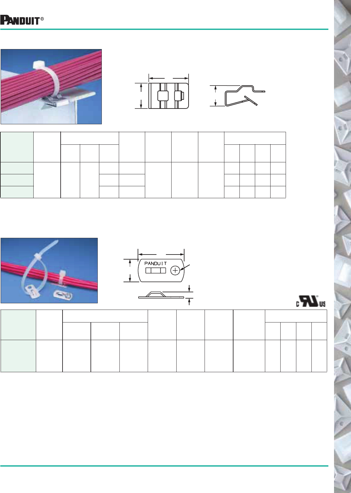
97
Most commonly used parts appear in BOLD.
*Order the number of mounts required in multiples of packaging quantities.
‡Part Numbers listed are for Standard Materials in Standard Package Quantity.
For Bulk package part numbers, see page 137-138.
**Cable Tie Cross Section Sizes: M = Miniature, I = Intermediate and S = Standard.
Cable Tie Mounts
The mount clips on sheet metal edges for fast mounting of
harnesses with cable ties. Ties may be inserted from any of the four
sides for easy harness orientation.
Part Number
Used
With
Cable
Ties**
Dimensions
in. (mm)
Max.
Panel
Thickness Material
Mounting
Method
Packaging*
A B C
Where
Used
Std.
Pkg.
Qty.
Std.
Ctn.
Qty.
Bulk
Pkg.
Qty.
Bulk
Ctn.
Qty.
MCMS12-P-C
M, I, S .88
(22.4)
.56
(14.2)
.31
(8.0)
.13
(3.2)
Zinc Plated
Steel
Indoors or
Outdoors Clip-On
— — 100 500
MCMS25-P-C .46
(11.5)
.24
(6.1)
— — 100 500
MCMS30-P-C .55
(14.0)
.27
(6.9)
— — 100 500
Metal Mount Screw applied aluminum mounting base for a secure support in
demanding applications.
• NOTE: Mount can
also be installed
with a user
supplied adhesive
Part Number‡
Used
With
Cable
Ties**
Dimensions
in. (mm)
Material
Where
Used
Mounting
Method
Max. Static
Load
lbs. (g)
Packaging*
A B C
Std.
Pkg.
Qty.
Std.
Ctn.
Qty.
Bulk
Pkg.
Qty.
Bulk
Ctn.
Qty.
MBMS-S10-C M, I, S 1.00
(25.4)
.50
(12.7)
.14
(3.6)
Aluminum
(Chromate
Coated) MIL
C. 5541 D
Class 3
Coating
Indoors
or Outdoors
#10 (M5)
Screw
10 (4540) 100 1000 1000 10000
B
A
C
Metal Clip-On Mounts
B
A
.200" Dia.
(For #10
Screw)
C
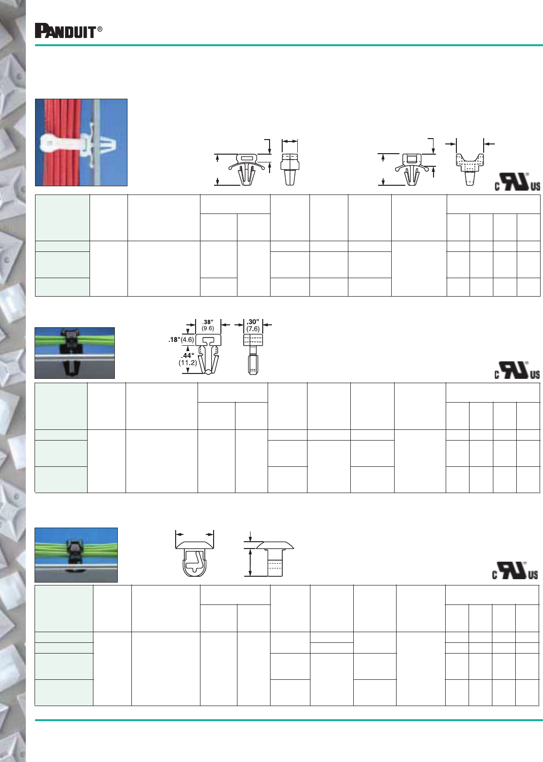
98 Most commonly used parts appear in BOLD.
*Order the number of mounts required in multiples of package quantities.
‡For Bulk package part numbers, See page 137-138.
**Cable Tie Cross Section Sizes: M = Miniature, I = Intermediate and S = Standard.
Part number shown for PM2H25-C is standard package quantity.
Part Number‡
Used
With
Cable
Ties**
Dimensions
in. (mm)
Panel Dimensions
in. (mm)
Material Color
Where
Used
Mounting
Method
Packaging*
Thickness
Max.
Hole
Diameter
Std.
Pkg.
Qty.
Std.
Ctn.
Qty.
Bulk
Pkg.
Qty.
Bulk
Ctn.
Qty.
PM2H25-C
M, I, S See Drawing .125
(3.2)
.250
(6.4)
Nylon 6.6 Natural Indoors
Inserted
into Pre-Drilled
Hole
100 500 1000 5000
PM2H25-M0 Weather
Resistant
Nylon 6.6 Black
Outdoors — — 1000 5000
PM2H25-M30 Heat
Stabilized
Nylon 6.6
Indoors — — 1000 5000
Push mounts require no adhesive or additional mounting hardware.
They are inserted into pre-drilled holes. The winged base applies
pressure on the panel wall to provide a more secure mount in high
vibration applications. Can be used where only one side of the panel
is accessible.
Part number shown for PWMS-H25-C and TM2PWH25-C is standard package quantity.
Part Number‡
Used
With
Cable
Ties**
Dimensions
in. (mm)
Panel Dimensions
in. (mm)
Material Color
Where
Used
Mounting
Method
Packaging*
Thickness
Max.
Hole
Diameter
Std.
Pkg.
Qty.
Std.
Ctn.
Qty.
Bulk
Pkg.
Qty.
Bulk
Ctn.
Qty.
PWMS-H25-C
M, I, S See Drawing
.105
(2.7) .250
(6.4)
Nylon 6.6 Natural Indoors
Inserted
into Pre-Drilled
Hole
100 1000 1000 5000
PWMS-H25-M0 Weather
Resistant
Nylon 6.6
Black Outdoors — — 1000 5000
TM2PWH25-C .094
(2.3)
Nylon 6.6 Natural Indoors 100 500 1000 5000
Push Mounts
Push Button Mounts Designed for use where both sides of the panel
are accessible.
Part number shown for PBMS-H25-C and PBMS-H25-C14 is Standard Package Quantity.
Part Number‡
Used
With
Cable
Ties**
Dimensions
in. (mm)
Panel Dimensions
in. (mm)
Material Color
Where
Used
Mounting
Method
Packaging*
Thickness
Max.
Hole
Diameter
Std.
Pkg.
Qty.
Std.
Ctn.
Qty.
Bulk
Pkg.
Qty.
Bulk
Ctn.
Qty.
PBMS-H25-C
M, I, S See Drawing .125
(3.2)
.25
(6.4)
Nylon 6.6 Natural Indoors
Inserted into
Pre-Drilled
Hole
100 500 1000 5000
PBMS-H25-C14 Gray 100 500 1000 5000
PBMS-H25-M0 Weather
Resistant
Nylon 6.6 Black
Outdoors — — 1000 5000
PBMS-H25-M30 Heat
Stabilized
Nylon 6.6
Indoors — — 1000 5000
.17
(4.4)
.610
(15.5)
.303
(7.7)
PWMS-H25
.72
(18.2)
.24
(6.1) .61
(15.4)
TM2PWH25
Cable Tie Mounts
.445" Dia.
(11.3)
.080" (2.0)
.325"
(8.3)
Push Mounts —
Winged Push Mounts
This part is a version of the mount shown above,
but without tensioning wings.
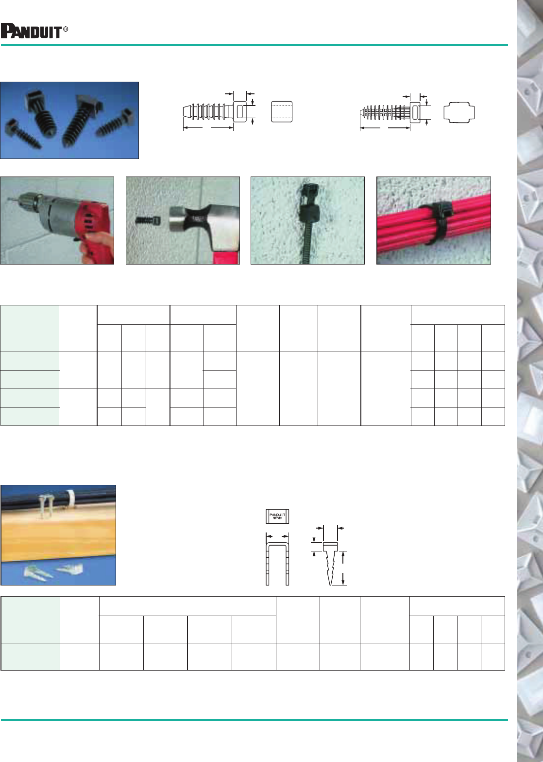
99
Most commonly used parts appear in BOLD.
*Order the number of mounts required in multiples of package quantities.
‡Part Numbers listed are for Standard Materials in Standard Package Quantity. For Bulk package part numbers, see page 137-138.
!Used with PANDUIT ® HLM series Hook & Loop Cable Ties found on page 40.
**Cable Tie Cross Section Sizes: M = Miniature, I = Intermediate, S = Standard, HS = Heavy Standard, LH = Light-Heavy and H = Heavy.
Used to secure wire, cable or tubing to masonry surfaces.
Installed quickly into pre-drilled holes. Holds bundle securely.
1. Drill hole using correct size bit. 2. Hammer mount into hole. 3. Place cable tie through mount. 4. Install wires or cable.
Part Number‡
Used
With
Cable
Ties**
Dimensions
in. (mm)
Hole Dimensions
in. (mm)
Material Color
Where
Used
Mounting
Method
Packaging*
ABC
Drill
Depth
Hole
Diameter
Std.
Pkg.
Qty.
Std.
Ctn.
Qty.
Bulk
Pkg.
Qty.
Bulk
Ctn.
Qty.
MPMS19-C0
M, I, S .97
(24.6)
.25
(6.4)
.22
(5.6)
1.25
(31.8)
.188
(5)
Impact
Modified
Weather-
Resistant
Nylon 6.6
Black Outdoors or
Indoors
Inserted into
Pre-Drilled Hole
100 500 1000 5000
MPMS25-C0 .25
(6)
100 500 1000 5000
MPMH38-L0 M, I, S, HS,
LH, H, and
HLM !
1.25
(31.8)
.30
(7.5) .38
(9.6)
1.50
(38.1)
.375
(10)
50 500 500 5000
MPMWH32-L0 1.41
(35.8)
.28
(7.1)
1.75
(44.5)
.313
(8)
50 500 500 5000
Wood Push Mount Used to secure wire, cable, or tubing to wood surfaces. Driven
into wood with hammer, barbed design holds mount in place —
rated for 60 lb. pullout.
Part Number
Used
With
Cable
Ties**
Dimensions
in. (mm)
Material
Where
Used
Mounting
Method
Packaging*
ABCD
Std.
Pkg.
Qty.
Std.
Ctn.
Qty.
Bulk
Pkg.
Qty.
Bulk
Ctn.
Qty.
WPMH-C M, I, S, HS,
LH, H, and
HLM !
.75
(19.1)
.31
(7.9)
.50
(12.7)
.19
(4.8)
16 gauge
steel zinc
plated
Outdoors
or Indoors
Hammer
into Wood
100 500 — —
Cable Tie Mounts
Masonry Push Mounts
MPMS19-C0
MPMS25-C0
MPMH38-L0
MPMWH32-L0
A
C
B
D
C
B
A
C
B
A
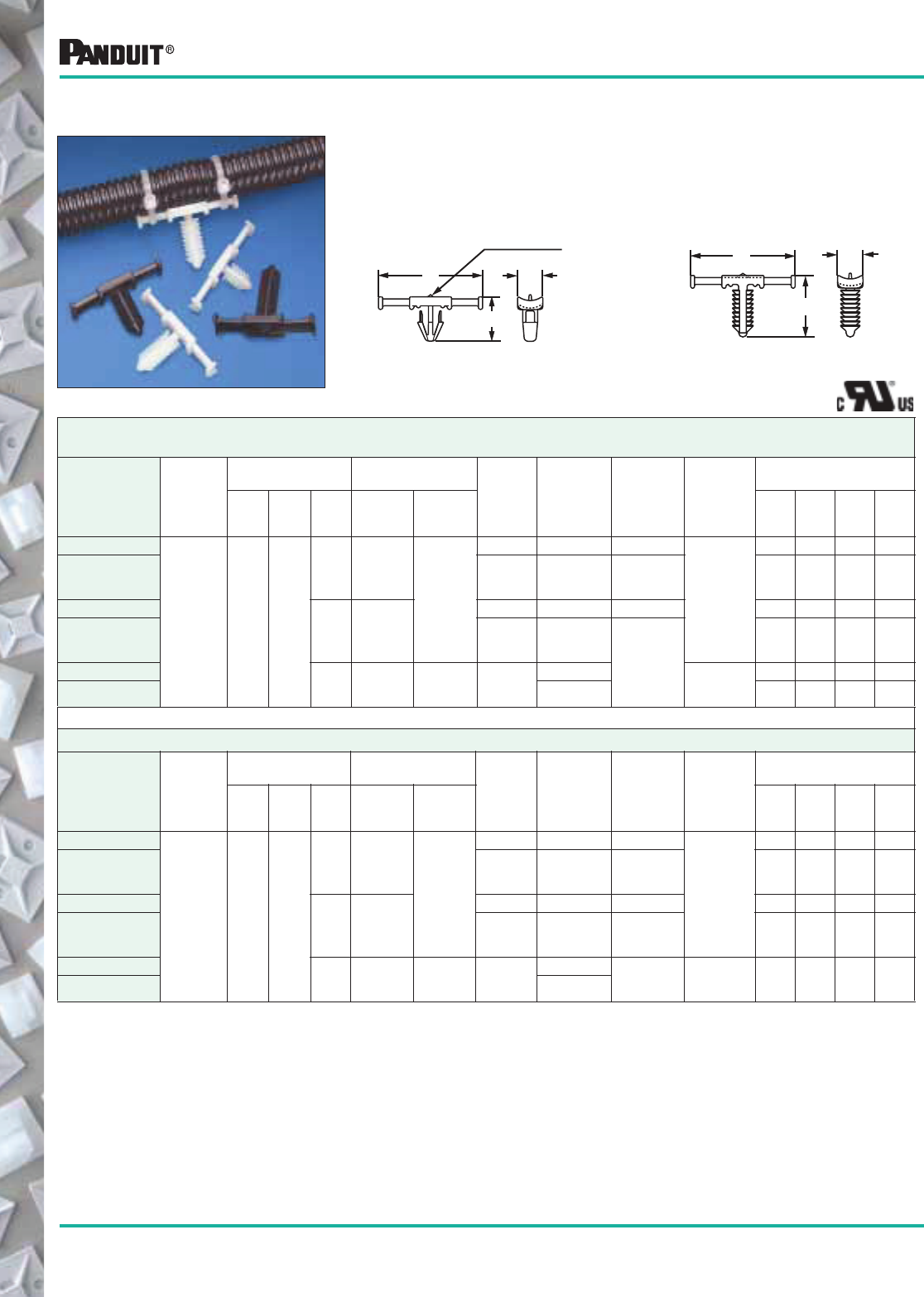
100
Most commonly used parts appear in BOLD.
Tie Harness Mounts used with Corrugated Loom Tubing
Tie Harness Mounts are designed to be attached to the wire harness
during assembly with 2 cable ties. Ties can be installed by hand or,
more efficiently, with PANDUIT ® PAT Automatic Cable Tie Tooling
(see page 60). Use with Harness Board Standoff Post (page 129).
Available with or without corrugated loom tubing location tab.
FOR CORRUGATED TUBING — A specially designed location tab on the mount shelf aligns with grooves in corrugated tubing
ensuring proper mount location during assembly.
Part Number‡
Used
With
Cable
Ties**
Dimensions
in. (mm)
Panel Dimensions
in. (mm)
Material Color
Where
Used
Mounting
Method
Packaging*
ABC
Thickness
Max.
Hole
Diameter
Std.
Pkg.
Qty.
Std.
Ctn.
Qty.
Bulk
Pkg.
Qty.
Bulk
Ctn.
Qty.
THMSP20-C
M, I, S 1.54
(39.1)
.37
(9.5)
.47
(11.9)
.16
(4.1)
.244-.283
(6.2-7.2)
Nylon 6.6 Natural Indoors
Push Barb
100 1000 — —
Heat
Stabilized
Nylon 6.6
Black Indoors/
High Temp.
100 1000 — —
THMSP20-C30
THMSP25-C
.54
(13.7)
.23
(5.8)
Nylon 6.6 Natural Indoors 100 1000 1000 5000
Heat
Stabilized
Nylon 6.6
Black
Indoors/
High Temp.
100 1000 1000 5000
THMSP25-C30
THMSC35-C639 .46
(11.7)
.25
(6.4)
.244-.268
(6.2-6.8)
Heat
Stabilized
Nylon 6
Natural
Tree Barb
100 1000 1000 5000
Black 100 1000 1000 5000
THMSC35-C630
FOR DISCRETE WIRING — There is no location tab for applications not requiring the use of corrugated tubing.
Part Number‡
Used
With
Cable
Ties**
Dimensions
in. (mm)
Panel Dimensions
in. (mm)
Material Color
Where
Used
Mounting
Method
Packaging*
A B C
Thickness
Max.
Hole
Diameter
Std.
Pkg.
Qty.
Std.
Ctn.
Qty.
Bulk
Pkg.
Qty.
Bulk
Ctn.
Qty.
THMSP20F-C
M, I, S 1.54
(39.1)
.37
(9.5)
.47
(11.9)
.16
(4.1)
.244-.283
(6.2-7.2)
Nylon 6.6 Natural Indoors
Push Barb
100 1000 — —
Heat
Stabilized
Nylon 6.6
Black Indoors/
High Temp.
100 1000 — —
THMSP20F-C30
THMSP25F-C
.54
(13.7)
.23
(5.8)
Nylon 6.6 Natural Indoors 100 1000 — —
Heat
Stabilized
Nylon 6.6
Black Indoors/
High Temp.
100 1000 1000 5000
THMSP25F-C30
THMSC35F-C639 .46
(11.7)
.25
(6.4)
.244-.268
(6.2-6.8)
Heat
Stabilized
Nylon 6
Natural Indoors/
High Temp. Tree Barb
100 1000 1000 5000
THMSC35F-C630 Black
THMSP — Push Barb Style THMSC — Tree Barb Style
A
C
B
Location tab
appears
on parts
used with
corrugated
tubing.
A
C
B
Tie Harness Mounts
*Order the number of pieces required in multiples of package quantities.
‡Part numbers listed are for standard materials in standard package quantity. For Bulk package part numbers, see page 137-138.
**Cable Tie Cross Section Sizes: M = Miniature, I = Intermediate, and S = Standard.
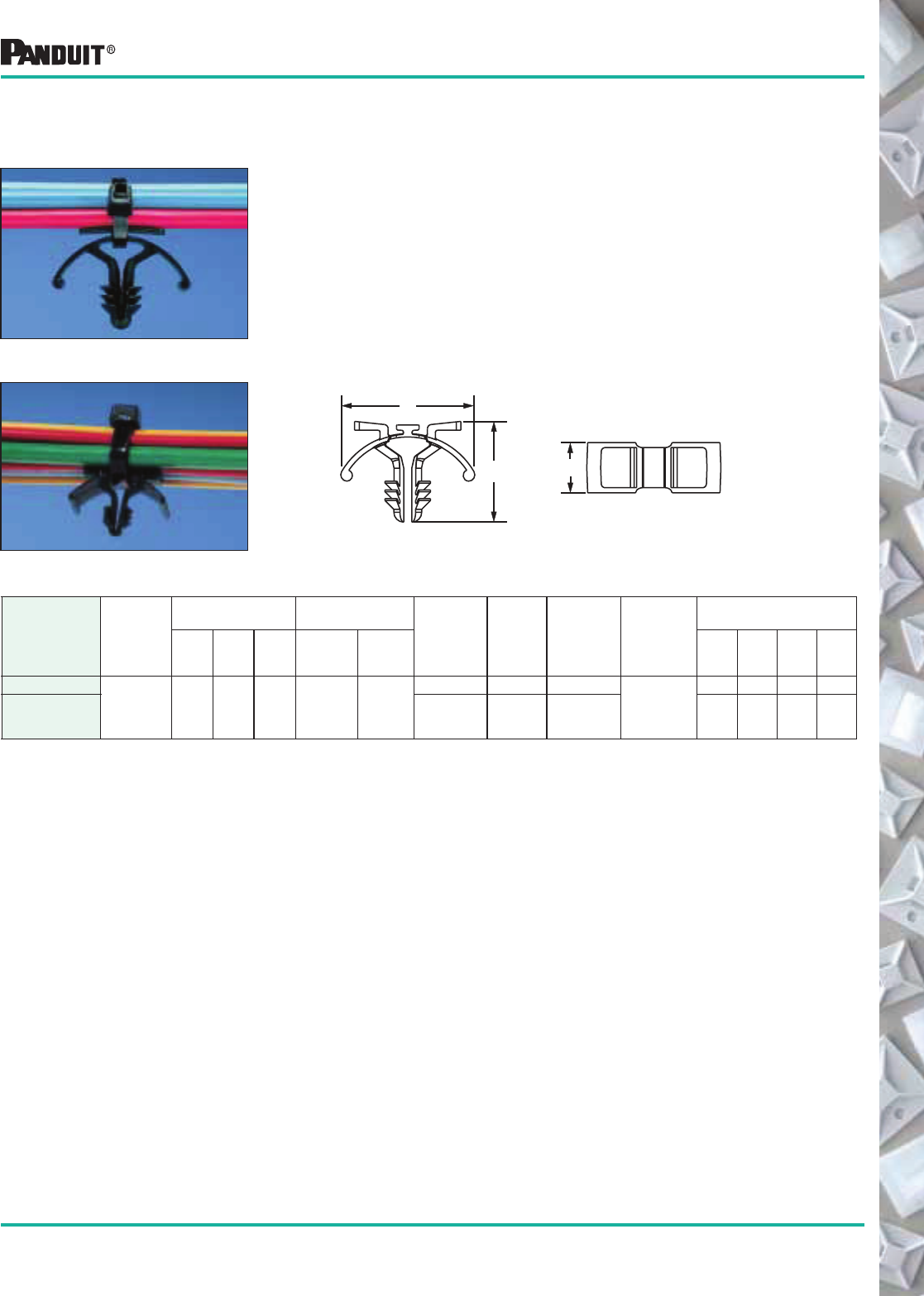
101
Most commonly used parts appear in BOLD.
*Order the number of pieces required in multiples of package quantities.
‡Part Numbers listed are for Standard Materials in Standard Package Quantity. For Bulk package part numbers, see page 137-138.
**Cable Tie Cross Section Sizes: M = Miniature, I = Intermediate and S = Standard.
Tie Harness Mount for Single Tie
• Secured with only 1 cable tie
• Can be used with auto-fed or loose piece cable ties
• Cable ties can be installed by hand with PANDUIT ® Automatic
Cable Tie Tooling Installation Systems (see page 60) or
pneumatic tool (page 58) or hand operated cable tie
tools (page 56)
• Winged design prevents vibration
• Barb design is easy to insert into pre-drilled hole
• 50 lb. vertical extraction force from .250" hole
Part Number‡
Used
With
Cable
Ties**
Dimensions
in. (mm)
Panel Dimensions
in. (mm)
Material Color
Where
Used
Mounting
Method
Packaging*
ABC
Thickness
Max.
Hole
Diameter
Std.
Pkg.
Qty.
Std.
Ctn.
Qty.
Bulk
Pkg.
Qty.
Bulk
Ctn.
Qty.
THM1SC-C
M, I, S .98
(24.8)
.38
(9.5)
.75
(19.1)
.187
(4.7)
.250
(6.5)
Nylon 6.6 Natural Indoors
Tree
Barb
100 1000 1000 5000
THM1SC-C30 Heat
Stabilized
Nylon 6.6
Black Indoors/
High Temp.
100 1000 1000 5000
A
CB
THM1SC Tie Harness Mount for Single Cable Tie —
Unique Mount is Attached to Harness Automatically as Tie is Installed
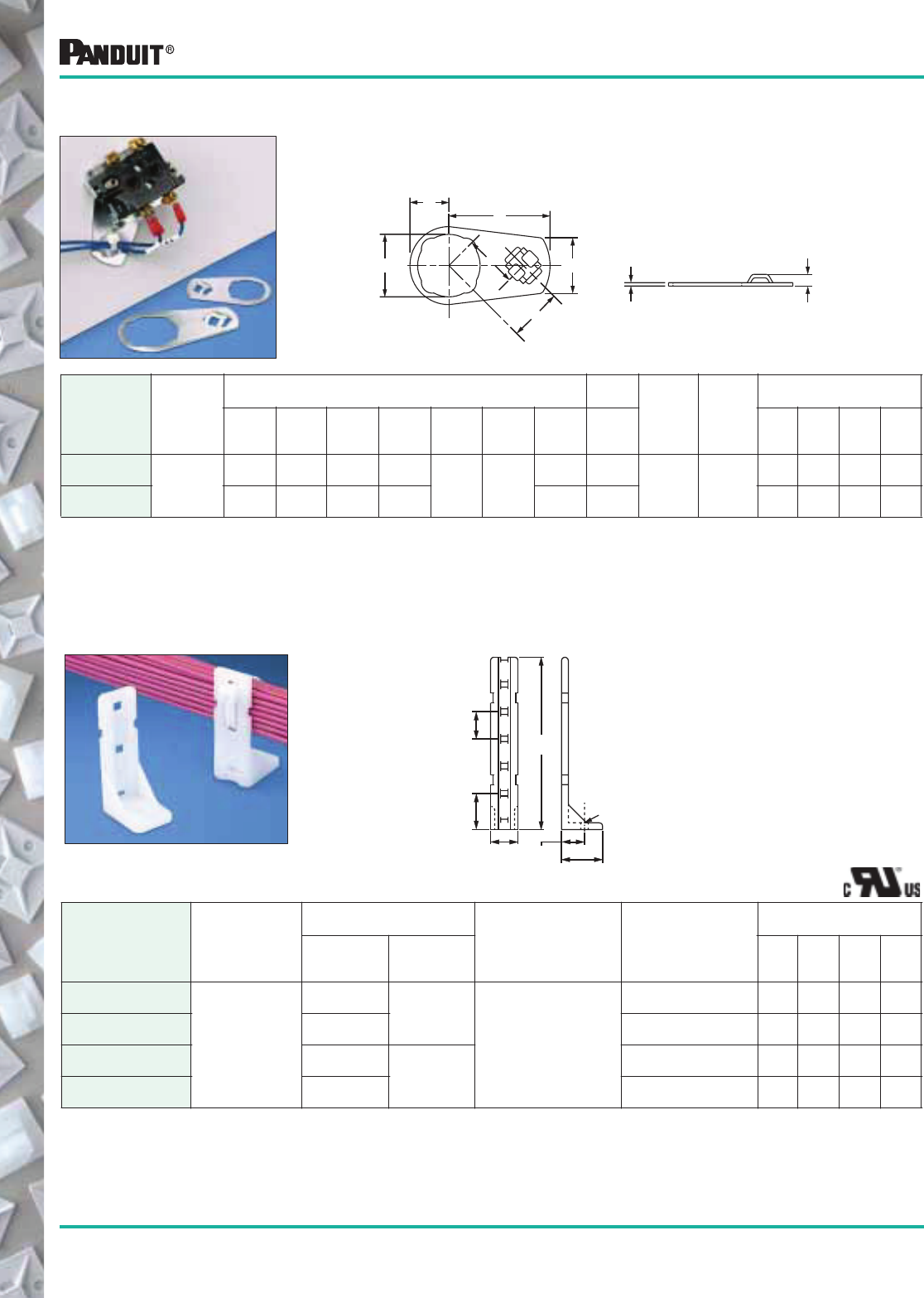
102
Most commonly used parts appear in BOLD.
*Order the number of pieces required in multiples of package quantities.
‡Part Numbers listed are for Standard Materials in Standard Package Quantity. For Bulk package part numbers,
see page 137-138.
**Cable Tie Cross Section Sizes: M = Miniature, I = Intermediate and S = Standard.
Part Number‡
Used
With
Cable
Ties**
Dimensions
in. (mm)
Color
&
Material
Mounting
Method
Packaging*
A B
Std.
Pkg.
Qty.
Std.
Ctn.
Qty.
Bulk
Pkg.
Qty.
Bulk
Ctn.
Qty.
PP1S-S10-X
M, I, S
.200
(5.1) 2.00
(50.8)
Natural
Nylon 6.6
#10 (M5)
Screw
10 50 100 1000
PP1S-S12-X .228
(5.8)
#12 (M5.5)
Screw
10 50 100 1000
PP2S-S10-X .200
(5.1) 4.60
(116.8)
#10 (M5)
Screw
10 50 100 1000
PP2S-S12-X .228
(5.8)
#12 (M5.5)
Screw
10 50 100 1000
Installed behind control panel switch. Ideal for high strain areas where cable
is routed from panel door to panel. Compatible with most control panel
switch designs.
Part Number
Used
With
Cable
Ties**
Dimensions
in. (mm)
Material
Mounting
Method
Packaging*
A B C D E F G H
Std.
Pkg.
Qty.
Std.
Ctn.
Qty.
Bulk
Pkg.
Qty.
Bulk
Ctn.
Qty.
CPM87S-C
M, I, S
.89
(22.6)
.57
(14.5)
1.44
(36.6)
.75
(19.1) .048
(1.2)
.17
(4.3)
.76
(19.3)
.75
(19.1) Zinc
Plated
Steel
Control
Panel
Switch
— — 100 1000
CPM122S-C 1.22
(31.0)
.75
(19.1)
2.07
(52.6)
1.12
(28.4)
.82
(20.8)
1.12
(28.4)
— — 100 1000
PAN-POST ™ Standoff
B
1.00"
(25.4)
.72"
Typ.
(18.3)
A (Hole Dia.)
.75"
(19.1)
.62"
(15.9) 1.10"
(27.9)
Cable Tie Mounts
Supports wire bundles above or away from surface.
Control Panel Mount
A
B
C
G
D
H
E
F
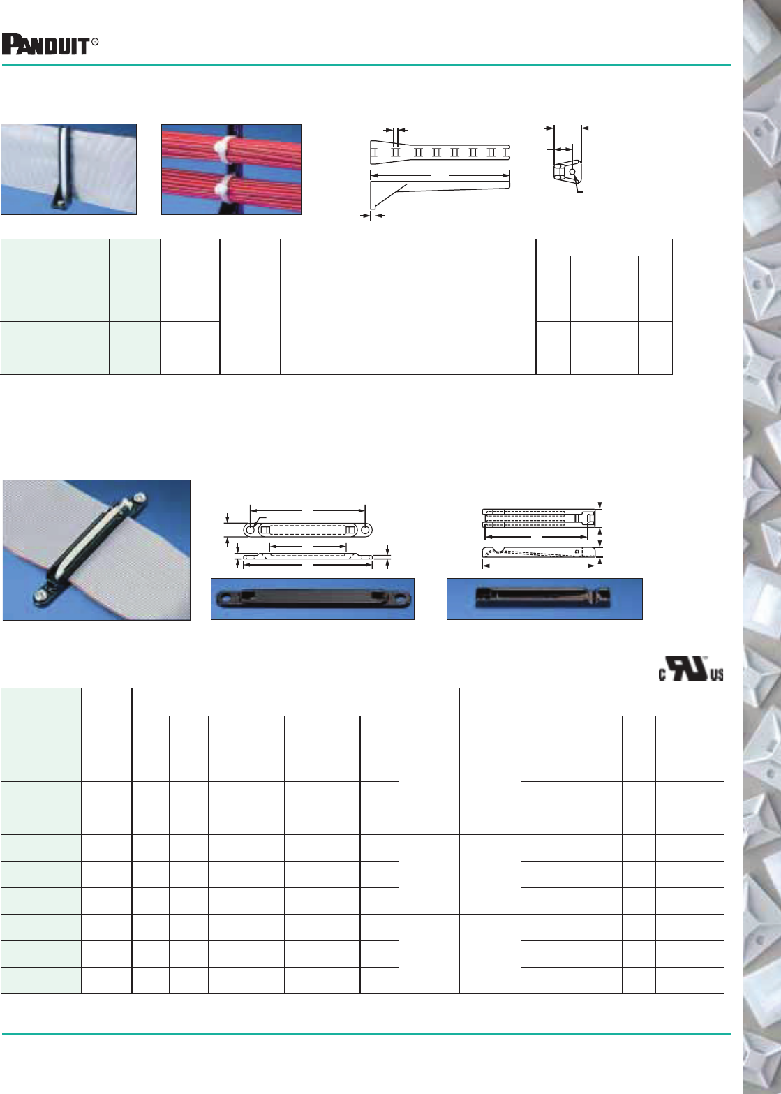
103
Most commonly used parts appear in BOLD.
*Order the number of mounts required in multiples of package quantities.
‡Part Numbers listed are for Standard Materials in Standard Package Quantity. For Bulk package part numbers, see page 137-138.
Right Angle Base RAFCB
Part Number‡
For Flat
Cable
Widths
(Up to)
A
in. (mm)
B
in. (mm)
C
in. (mm)
Color
&
Material
Where
Used
Mounting
Method
Packaging*
Std.
Pkg.
Qty.
Std.
Ctn.
Qty.
Bulk
Pkg.
Qty.
Bulk
Ctn.
Qty.
RAFCBI1-S6-C20 1.00
(25.4)
1.75
(44.4)
.125
(3.2)
.125
(3.2)
Black
Nylon 6.6 Indoors #6 (M3)
Screw
100 500 1000 5000
RAFCBI2-S6-C20 2.00
(50.8)
2.78
(70.6)
100 500 1000 4000
RAFCBI3-S6-C20 3.00
(76.2)
3.81
(96.8)
100 500 1000 4000
Cable Tie Mounts
Secures stacked cables, folds and breakouts as well as
laminated and molded bus bars.
Base FCB Plate FCP
Mounting Application
Use one base, one corresponding size
plate and one intermediate cable tie.
Bundling Application
Use two plates (same size) and
one intermediate cable tie.
Part Number‡
For Flat
Cable
Widths
(Up to)
Dimensions
in. (mm)
Color &
Material
Where
Used
Mounting
Method
Packaging*
A B C D E F G
Std.
Pkg.
Qty.
Std.
Ctn.
Qty.
Bulk
Pkg.
Qty.
Bulk
Ctn.
Qty.
FCBI1-S10-C20 1.00
(25.4)
3.29
(83.5)
1.04
(26.4)
2.08
(52.8)
.150
(3.8)
.375
(9.5)
.200
(5.1)
.095
(2.4)
Black
Nylon 6.6 Indoors
#10 (M5)
Screw
100 1000 1000 5000
FCBI2-S10-C20 2.00
(50.8)
3.50
(88.9)
2.04
(51.8)
3.10
(78.7)
.150
(3.8)
.375
(9.5)
.200
(5.1)
.095
(2.4)
#10 (M5)
Screw
100 1000 1000 5000
FCBI3-S10-C20 3.00
(76.2)
4.52
(114.8)
3.04
(77.2)
4.12
(104.6)
.150
(3.8)
.375
(9.5)
.200
(5.1)
.095
(2.4)
#10 (M5)
Screw
100 1000 1000 5000
FCBI1-A-C20 1.00
(25.4)
3.29
(83.5)
1.04
(26.4)
2.08
(52.8)
.150
(3.8)
.375
(9.5)
.200
(5.1)
.095
(2.4)
Black
Nylon 6.6 Indoors
Adhesive
Backed
100 1000 1000 5000
FCBI2-A-C20 2.00
(50.8)
3.50
(88.9)
2.04
(51.8)
3.10
(78.7)
.150
(3.8)
.375
(9.5)
.200
(5.1)
.095
(2.4)
Adhesive
Backed
100 1000 1000 5000
FCBI3-A-C20 3.00
(76.2)
4.52
(114.8)
3.04
(77.2)
4.12
(104.6)
.150
(3.8)
.375
(9.5)
.200
(5.1)
.095
(2.4)
Adhesive
Backed
100 1000 1000 5000
FCPI1-C20 1.00
(25.4)
1.29
(32.8)
1.04
(26.4)
.375
(9.5)
— — .200
(5.1)
—
Black
Nylon 6.6 Indoors
Cable Ties 100 1000 1000 5000
FCPI2-C20 2.00
(50.8)
2.31
(58.7)
2.04
(51.8)
.375
(9.5)
— — .200
(5.1)
— Cable Ties 100 1000 1000 5000
FCPI3-C20 3.00
(76.2)
3.32
(84.3)
3.04
(77.2)
.375
(9.5)
— — .200
(5.1)
— Cable Ties 100 1000 1000 5000
G
F
A
B
E
D (Dia) C
Flat Cable Mounting System
For use in perpendicular applications. Supports cable
above the mount surface.
C
A
B
.75"
(19.1)
.50"
(12.7)
.145" Dia
(3.7)
A
B
F
C
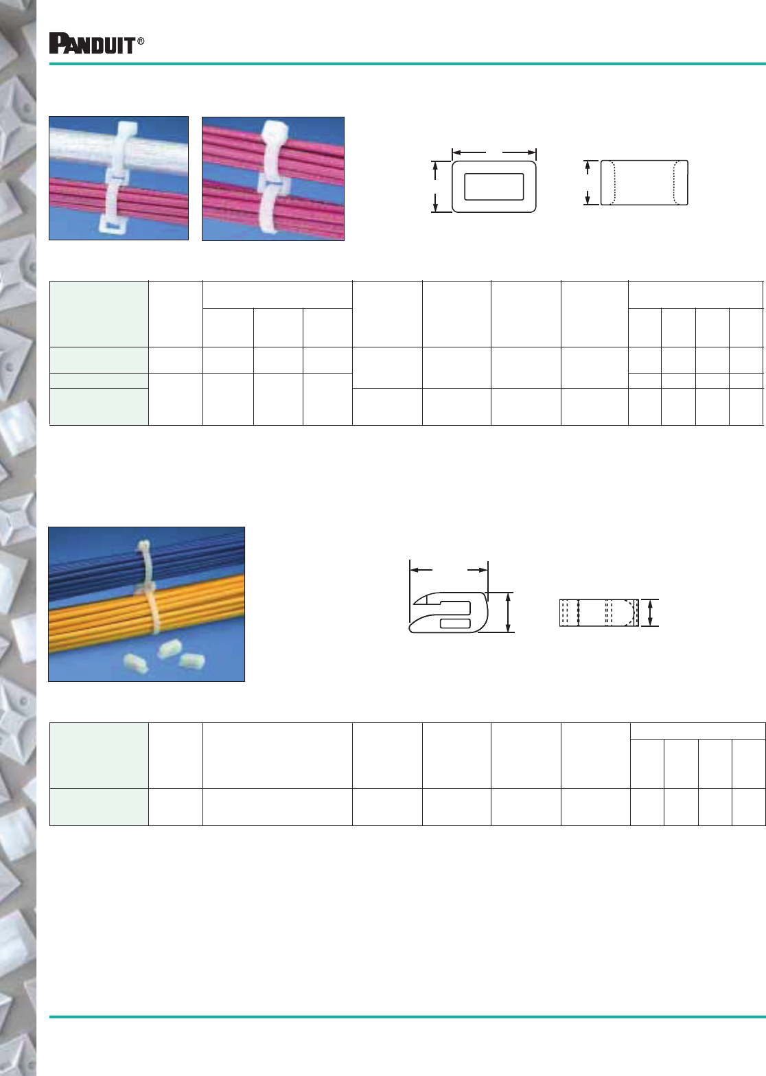
104 Most commonly used parts appear in BOLD.
*Order the number of pieces required in multiples of packaging quantities.
**Cable Tie Cross Section Sizes: M = Miniature, I = Intermediate, S = Standard, HS = Heavy Standard and LH = Light-Heavy.
Connect multiple wire bundles or hang bundles from
conduit, eliminating the need for saddle clamps.
Part Number
Used
With
Cable
Ties**
Dimensions
in. (mm)
Material Color
Where
Used
Mounting
Method
Packaging*
A B C
Std.
Pkg.
Qty.
Std.
Ctn.
Qty.
Bulk
Pkg.
Qty.
Bulk
Ctn
Qty.
CR2-M M, I, S .33
(8.4)
.24
(6.1)
.20
(5.1) Nylon 6.6 Natural Indoors Cable Ties — — 1000 10000
CR4H-M
M, I, S,
HS, LH
.57
(14.5)
.36
(9.1)
.30
(7.6)
— — 1000 10000
CR4H-M0 Weather
Resistant Nylon
6.6
Black Indoors/
Outdoors
Cable Ties — — 1000 10000
Open Connector Ring
Cable Tie Mounts — Connector Rings
Designed to “add on” wire bundles without changing cable ties.
Closed Connector Rings
Part Number
Used
With
Cable
Ties**
Dimensions
in. (mm) Material Color
Where
Used
Mounting
Method
Packaging*
Std.
Pkg.
Qty.
Std.
Ctn.
Qty.
Bulk
Pkg.
Qty.
Bulk
Ctn.
Qty.
CROS-M M, I, S See Drawing Nylon 6.6 Natural Indoors Connects
to M, I, S
Cable Ties
— — 1000 5000
A
BC
.52"
(13.2)
.26"
(6.6)
.18"
(4.6)
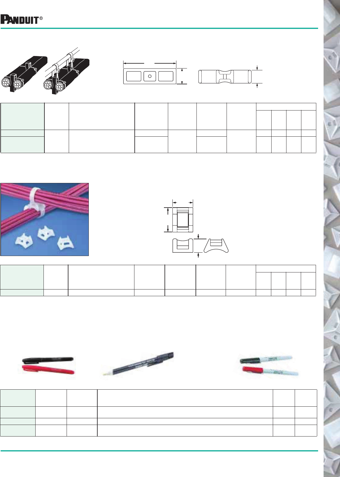
105
Most commonly used parts appear in BOLD.
*Order the number of pieces required in multiples of packaging quantities.
**Cable Tie Cross Section Sizes: M = Miniature, I = Intermediate, S = Standard, HS = Heavy Standard, LH = Light-Heavy and H = Heavy.
Part Number
Used
With
Cable
Ties**
Dimensions
in. (mm) Material Color
Where
Used
Mounting
Method
Packaging*
Std.
Pkg.
Qty.
Std.
Ctn.
Qty.
Bulk
Pkg.
Qty.
Bulk
Ctn.
Qty.
CSH-D20
M, I, S, HS,
LH, H See Drawing
Nylon 6.6
Black
Indoors
Cable Ties
— — 500 2500
CSH-D0 Weather
Resistant
Nylon 6.6
Outdoors
or Indoors
— — 500 2500
Cable Spacers Used to separate and/or hang wires, cable and hoses.
Cable Spacer — Cross Connects two bundles at 90°. Provides .19" (4.8mm) space
between bundles. Dual cradle design. Recommended max.
bundle diameter (each) is .625" (15.9mm).
Part Number
Used
With
Cable
Ties**
DImensions
in. (mm) Material Color
Where
Used
Mounting
Method
Packaging*
Std.
Pkg.
Qty.
Std.
Ctn.
Qty.
Bulk
Pkg.
Qty.
Bulk
Ctn.
Qty.
CSCS-M M, I, S See Drawing Nylon 6.6 Natural Indoors Cable Ties — — 1000 10000
Cable Tie Mounts
2.12
(53.8)
.50
(12.7)
.62
(15.7)
.45
(11.4)
.37
(9.4)
.25
(6.3)
Provide fast drying, permanent, legible identification on nylon —
where ordinary marking pens will not work.
Part Number Tip Color Description
Std.
Pkg.
Qty.*
Std.
Ctn.
Qty.
PX-0
PX-2
Regular
Regular
Black
Red
Color of ink is color of pen. Reversible tip to extend life of pen. 12
12
144
144
PX-10 Regular White For marking black or other dark-colored parts. Color of tip denotes color. 12 300
PFX-0
PFX-2
Fine
Fine
Black
Red
For detailed marking on nylon surfaces. Color of cap and tip is color of ink. 12
12
144
144
PX-0
PX-2 PX-10 PFX-0
PFX-2
Marking Pens
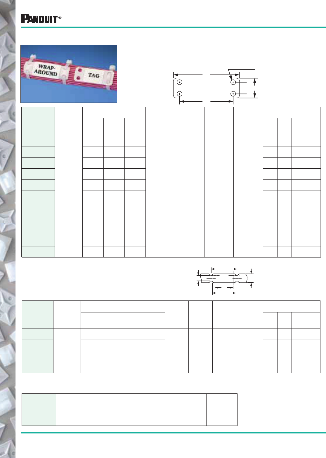
106 Most commonly used parts appear in BOLD.
PANDUIT ® Marker Plates can be mounted in any direction, either
vertically or horizontally as flags, tags, or wrap-around identification
plates. They can be marked with nylon marking pens or hot stamped.
See page 105 for marker pen information.
Marker Plates on Rolls
Part Number
Used
With
Cable
Ties
Dimensions
in. (mm)
Material Color
Where
Used
Mounting
Method
Packaging*
A B C D
Std.
Pkg.
Qty.
Std.
Ctn.
Qty.
Bulk
Pkg.
Qty.
Bulk
Ctn.
Qty.
MP150-R
M, I, S
1.50
(38.1)
.75
(19.0)
1.03
(26.2)
1.69
(42.9)
Nylon 6.6 White Indoors Cable Ties
— — 1000 5000
MP175-R 1.75
(44.5)
.75
(19.0)
1.28
(32.5)
1.94
(49.3)
— — 1000 5000
MP200-R 2.00
(50.8)
.75
(19.0)
1.53
(38.9)
2.19
(55.6)
— — 1000 5000
MP250-R 2.50
(63.5)
.75
(19.0)
2.03
(51.6)
2.69
(68.3)
— — 1000 5000
Part Number Description
Std.
Pkg.
Qty.*
MP150KIT-Q
MP250KIT-Q
MP350KIT-Q
Kit contains 25 MP150 marker plates, 1 PFX-0 marking pen.
Kit contains 25 MP250 marker plates, 1 PFX-0 marking pen.
Kit contains 25 MP350 marker plates, 1 PFX-0 marking pen.
1
1
1
.44"
(11.2)
Typ.
Nom.
Dia.
.195"
(5.0)
B
THICKNESS: .015" (0.4mm)
A
C
Cable Tie Mounts
Marker Plate Kits
Part Number‡
Used
With
Cable
Ties
Dimensions
in. (mm)
Material Color
Where
Used
Mounting
Method
Packaging*
A B C
Std.
Pkg.
Qty.
Std.
Ctn.
Qty.
Bulk
Pkg.
Qty.
Bulk
Ctn.
Qty.
MP150-C
M, I, S
1.50
(38.1)
.75
(19.0)
1.03
(26.2)
Nylon 6.6 White Indoors Cable Ties
100 500 1000 5000
MP175-C 1.75
(44.5)
.75
(19.0)
1.28
(32.5)
100 500 1000 5000
MP200-C 2.00
(50.8)
.75
(19.0)
1.53
(38.4)
100 500 1000 5000
MP250-C 2.50
(63.5)
.75
(19.0)
2.03
(51.6)
100 500 1000 5000
MP350-C 3.50
(88.9)
.75
(19.0)
3.03
(77.0)
100 500 1000 5000
MP250W175-C 2.50
(63.5)
1.75
(44.5)
2.03
(51.6)
100 500 1000 5000
MP150-C0
M, I, S
1.50
(38.1)
.75
(19.0)
1.03
(26.2)
Weather
Resistant
Nylon 6.6
Black Outdoors
Weather
Resistant
Cable Ties
100 500 1000 5000
MP175-C0 1.75
(44.5)
.75
(19.0)
1.28
(32.5)
100 500 1000 5000
MP200-C0 2.00
(50.8)
.75
(19.0)
1.53
(38.4)
100 500 1000 5000
MP250-C0 2.50
(63.5)
.75
(19.0)
2.03
(51.6)
100 500 1000 5000
MP350-C0 3.50
(88.9)
.75
(19.0)
3.03
(77.0)
100 500 1000 5000
*Order the number required in multiples of packaging quantities.
‡Part Numbers listed are for Standard Materials in Standard Package Quantity.
For Bulk package part numbers, see page 137-138.
**Cable Tie Cross Section Sizes: M = Miniature, I = Intermediate, and S = Standard.
Marker Plates
D
A
C
B
.44
(11.2)
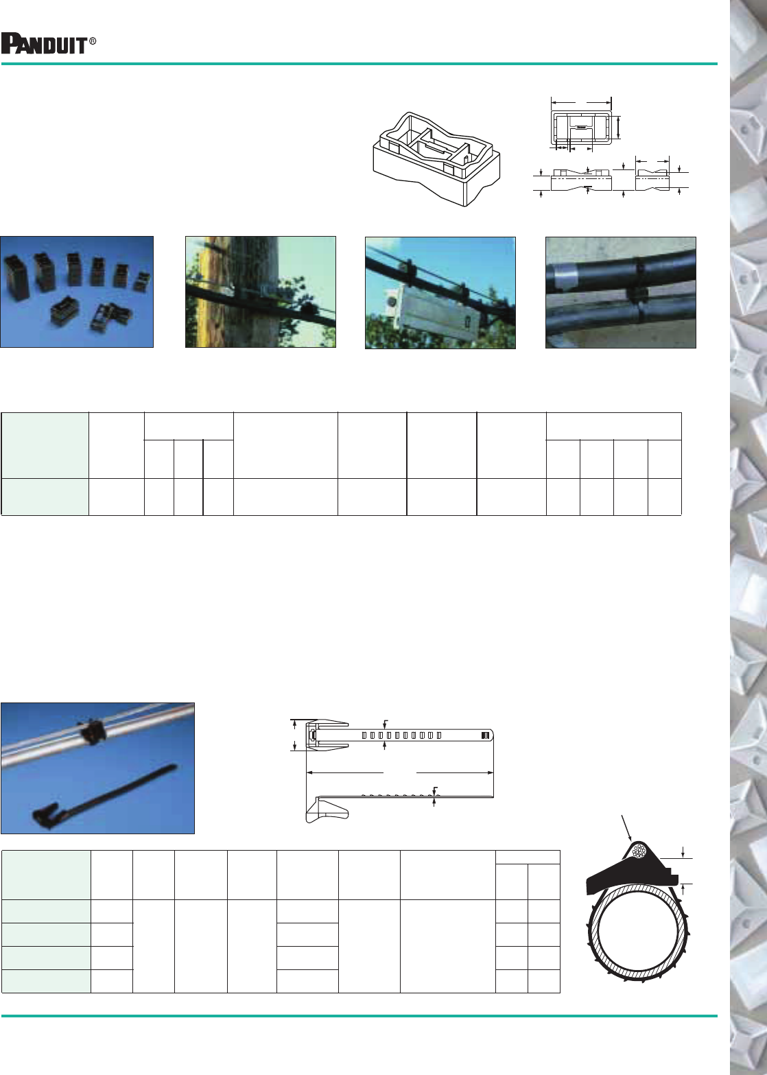
107
Most commonly used parts appear in BOLD.
Stackable Cable Spacer
Just one part to inventory. Each spacer snaps by hand into
another— increases spacer height by 1/2" increments.
Because there is only one part, on-site sorting is
eliminated. Can be used with up to 3/4" width lashed cable
supports in parallel or perpendicular applications.
Stackable Spacers may be installed using Weather-Resistant Lashing Ties (see page 15). Weather- Resistant Extra-Heavy and Light-Heavy Cable Ties (see page 15), and Stainless Steel
Ties (see page 77).
Part Number
Used
With
Cable
Ties
Dimensions
in. (mm)
Material Color
Where
Used
Mounting
Method
Packaging*
A B C
Std.
Pkg.
Qty.
Std.
Ctn.
Qty.
Bulk
Pkg.
Qty.
Bulk
Ctn.
Qty.
SACS50-T100 See
Footnote
2.08
(52.8)
1.16
(29.5)
.50
(12.7)
Weather
Resistant
Polypropylene
Black Outdoors Cable Ties — — 200 2000
Used perpendicular to strand
and cable
Used parallel to strand and cable Underground application
*Order the number of pieces required in multiples of package quantities.
B
.77
(19.6)
A
.40
(10.2)
.79
(20.1)
.71
(18.0)
.51
(13.0)
.45
(11.4)
C
Weather Resistant
Polypropylene Aerial
Support Tie —
With integral 1/2"
(12.7mm) spacer
Designed to attach coax or telephone cable to the support strand 1/4" (6.4mm) or
5/16" (7.9mm) to form the expansion loop and keep equipment and cables clear of
pole hardware. One-piece construction with integral spacer reduces inventory
costs of separate spacer and bands and installs faster to lower the installed cost.
Releasable and reusable.
B
D
A REF.
C
Support Strand
Max. Dia.:
.32 (8.1 mm)
Min. Dia:
.22 (5.6 mm)
Spacer Height
.50 (12.7 mm)
Nom.
Assembled View
CABLE
(or Cable
Bundle)
Part Number
Length
A
in. (mm)
Width
B
in. (mm)
Thickness
C
in. (mm)
Head
Width
D
in. (mm)
Max.
Bundle
Dia.
in. (mm)
Min. Loop
Tensile
Strength
lbs. (N)
Recommended
PANDUIT ®
Installation Tool
Part Number
Packaging*
Std.
Pkg.
Qty.
Std.
Ctn.
Qty.
AST10-5-C100 5.6
(142)
.448
(11.4)
.055
(1.4)
1.16
(29.5)
1.0
(25)
75
(334) Hand Installed Only
100 1000
AST15-5-C100 6.9
(175)
1.5
(38)
100 1000
AST20-5-C100 8.4
(214)
2.0
(51)
100 1000
AST25-5-C100 10.0
(254)
2.5
(64)
100 1000
Outside Plant Products
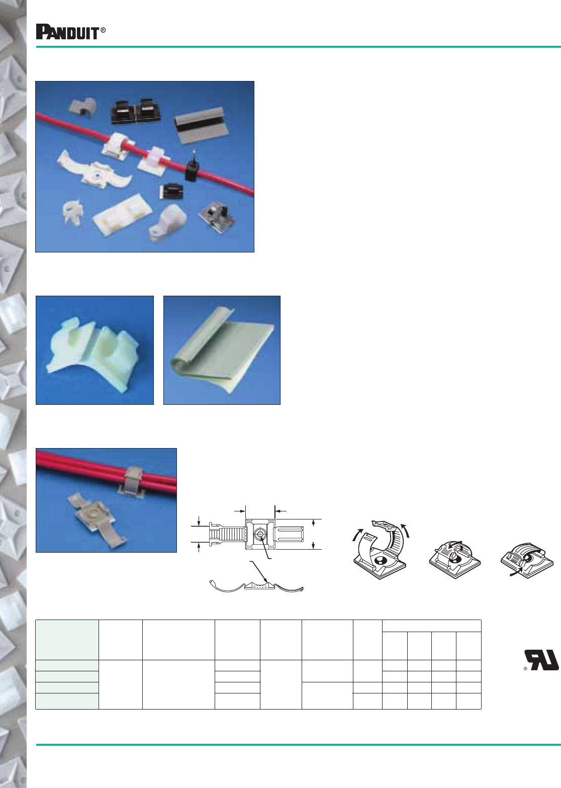
108
Most commonly used parts appear in BOLD.
Cable and Wire Mounting Devices (used without cable ties)
Adhesive Backed Mounting Devices
Faster Liner Removal Speeds Installation and
Lowers Installed Cost
• The adhesive backed mounts are offered either as
one or two mounts per liner
• The two-up mounts are easily removed by bending
the mounts away from the liner
• The individual mounts have a convenient tear tab
for quick removal
CLINCHER ™ Adjustable Releasable Clamp
This clamp provides a fast and convenient method of securing bundles from
.19" (4.8mm) up to .69" (17.5mm) diameter. It is available with adhesive
backing or screw applied with one #6 (M3) screw.
Part Number‡
Bundle
Dia.
in. (mm) Material Color
Where
Used
Mounting
Method
Max.
Static
Load
lbs. (g)
Packaging*
Std.
Pkg.
Qty.
Std.
Ctn.
Qty.
Bulk
Pkg.
Qty.
Bulk
Ctn.
Qty.
ARC.68-A-Q
.19-.69
(4.8-17.5) Polypropylene
White
Indoors
Rubber
Adhesive
.50
(227)
25 250 100 1000
ARC.68-A-Q14 Gray 25 250 100 1000
ARC.68-S6-Q White #6 (M3)
Pan Head
Screw
— 25 250 100 1000
ARC.68-S6-Q14 Gray — 25 250 100 1000
.15 Dia
(3.9)
.38 Rad
(9.5)
1.00
(25.4)
1.00
(25.4)
.50
(12.7)
The CLINCHER™ clamp is fast and easy to use. . .
Lift tab to release
*Order the number of mounts required in multiples of packaging quantities.
‡Part Numbers listed are for Standard Materials in Standard Package Quantity. For Bulk package part numbers, see page 137-138.
Wiring Accessories are an integral part of the
PANDUIT ® comprehensive selection of wire
management products.
These accessories are one piece solutions that help
provide the lowest installed cost for controlling,
mounting and protecting wire and cable.
Mounting methods include:
• Adhesive-Backed
• Screw applied
• Rivet applied
• Push Mounts
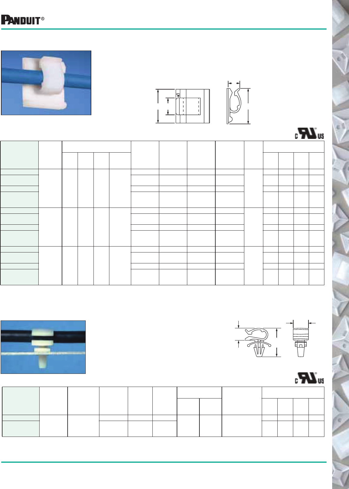
109
Most commonly used parts appear in BOLD.
*Order the number of mounts requried in multiples of packaging quantities.
‡Part Numbers listed are for Standard Materials in Standard Package Quantity.
For Bulk package part numbers, see page 137-138.
Cable and Wire Mounting Devices
Adhesive Backed Cord Clips — ACC Type
Three sizes of clips to hold cords, tubing, cable, or wire
bundles up to .62" (15.7mm) diameter. Bundles are easily
snapped into or out of the clips.
Part Number‡
Max.
Bundle
Dia.
in. (mm)
Dimensions
in. (mm)
Material Color
Where
Used
Adhesive
Type
Max.
Static
Load
lbs. (g)
Packaging*
A B C D
Std.
Pkg.
Qty.
Std.
Ctn.
Qty.
Bulk
Pkg.
Qty.
Bulk
Ctn.
Qty.
ACC19-A-C
.19
(4.8)
.62
(15.9)
.76
(19.3)
.25
(6.5)
.39
(9.9)
Nylon 6.6 Natural Indoors Rubber
.20
(91)
100 500 1000 5000
ACC19-AT-C Nylon 6.6 Natural Indoors/
High Temp.
Acrylic 100 500 1000 5000
ACC19-A-C20 Nylon 6.6 Black Indoors Rubber 100 500 1000 5000
ACC19-AT-C0 Weather
Resistant
Nylon 6.6
Black Outdoors/
High Temp.
Acrylic 100 500 1000 5000
ACC38-A-C
.38
(9.6)
1.00
(25.4)
1.00
(25.4)
.27
(6.9)
.49
(12.4)
Nylon 6.6 Natural Indoors Rubber
.50
(227)
100 500 1000 5000
ACC38-AT-C Nylon 6.6 Natural Indoors/
High Temp.
Acrylic 100 500 1000 5000
ACC38-A-C20 Nylon 6.6 Black Indoors Rubber 100 500 1000 5000
ACC38-AT-C0 Weather
Resistant
Nylon 6.6
Black Outdoors/
High Temp.
Acrylic 100 500 1000 5000
ACC62-A-C
.62
(15.7)
1.24
(31.4)
1.12
(28.6)
.63
(16.1)
.74
(18.8)
Nylon 6.6 Natural Indoors Rubber
.70
(318)
100 500 500 5000
ACC62-AT-C Nylon 6.6 Natural Indoors/
High Temp.
Acrylic 100 500 500 5000
ACC62-A-C20 Nylon 6.6 Black Indoors Rubber 100 500 500 5000
ACC62-AT-C0 Weather
Resistant
Nylon 6.6
Black Outdoors/
High Temp.
Acrylic 100 500 500 5000
C
A
D
B
Push Mount Cord Clip
Mounts snap easily into pre-drilled
holes. Integral mounting device
eliminates the need for additional
mounting hardware. The winged design
holds mount in place in applications
where vibration is present.
.38"
(9.6)
.90"
(22.9)
.50"
(12.7)
Part Number
Max.
Bundle
Dia.
in. (mm) Dimensions Material Color
Where
Used
Panel Dimensions
in. (mm)
Mounting
Method
Packaging*
Max.
Thickness
Hole
Diameter
Std.
Pkg.
Qty.
Std.
Ctn.
Qty.
Bulk
Pkg.
Qty.
Bulk
Ctn.
Qty.
PMCC38H25-C
.38
(9.6) See drawing
Nylon Natural Indoors
.105
(2.7)
.250
(6.4)
Inserted into a
Pre-Drilled Hole
100 1000 1000 5000
PMCC38H25-M0 Weather
Resistant
Nylon 6.6
Black Outdoors — — 1000 5000
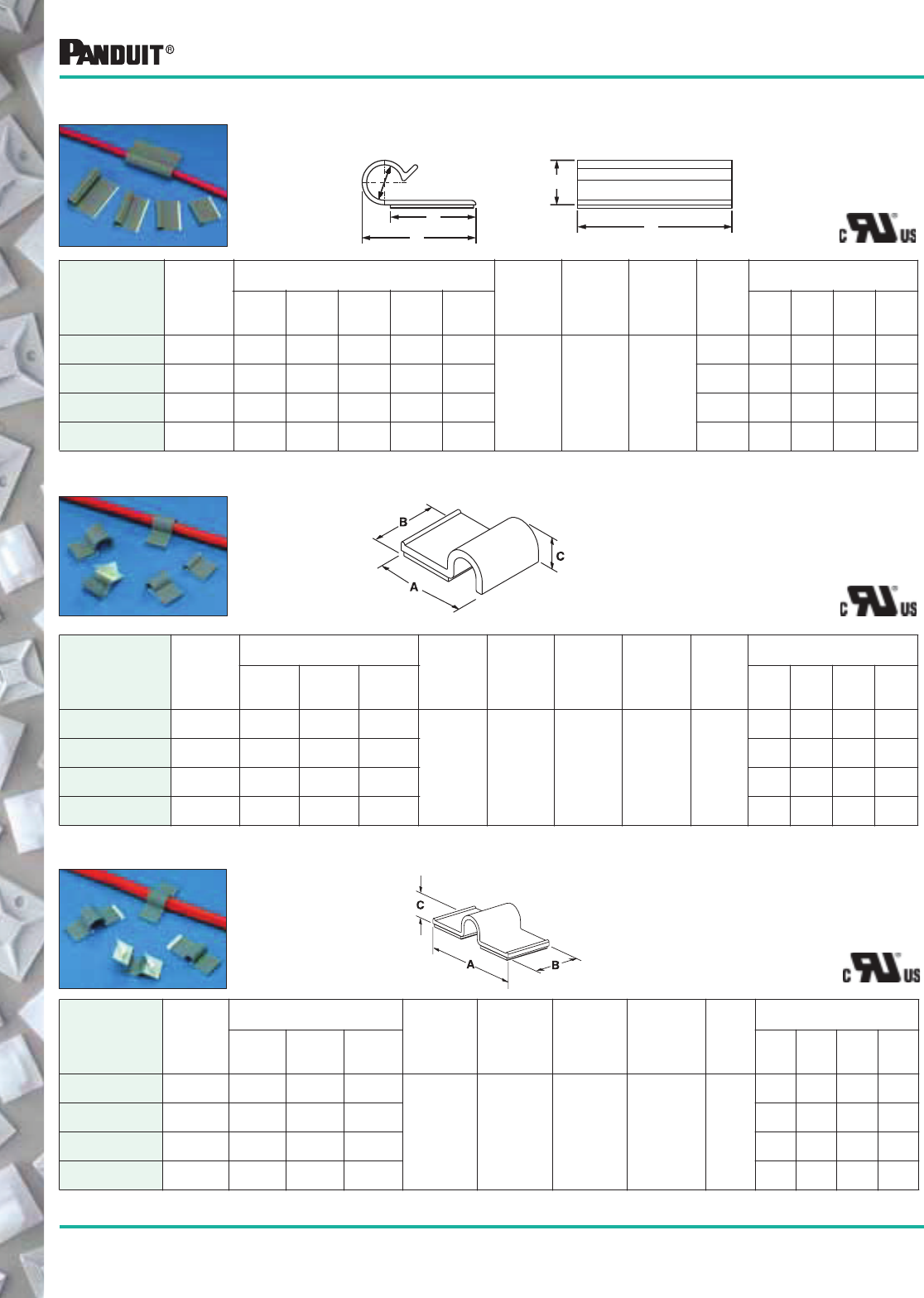
110 Most commonly used parts appear in BOLD.
Cable and Wire Mounting Devices
*Order the number of mounts required in multiples of package quantities.
Holds cords, cables and tubing. Single adhesive pad for confined areas.
Part Number
Max.
Bundle
Dia.
in. (mm)
Dimensions
in. (mm)
Material Color
Where
Used
Mounting
Method
Max.
Static
Load
lbs. (g)
Packaging*
ABC
Std.
Pkg.
Qty.
Std.
Ctn.
Qty.
Bulk
Pkg.
Qty.
Bulk
Ctn.
Qty.
A1C12-A-C8 .12
(3.0)
.77
(19.6)
.63
(16)
.23
(5.8)
PVC Gray Indoors Rubber
Adhesive
.14
(64)
— — 100 1000
A1C25-A-C8 .25
(6.4)
.91
(23.1)
.63
(16)
.38
(9.7)
— — 100 1000
A1C38-A-C8 .38
(9.5)
1.04
(26.4)
.63
(16)
.51
(13)
— — 100 1000
A1C50-A-C8 .50
(12.7)
1.17
(29.7)
.63
(16)
.64
(16.3)
— — 100 1000
Part Number
Max.
Bundle
Dia.
in. (mm)
Dimensions
in. (mm)
Material Color
Where
Used
Mounting
Method
Max.
Static
Load
lbs. (g)
Packaging*
A B C
Std.
Pkg.
Qty.
Std.
Ctn.
Qty.
Bulk
Pkg.
Qty.
Bulk
Ctn.
Qty.
A2C12-A-C8 .12
(3.0)
1.30
(33)
.63
(16)
.23
(5.8)
PVC Gray Indoors Rubber
Adhesive
.37
(169)
— — 100 1000
A2C25-A-C8 .25
(6.4)
1.43
(36.3)
.63
(16)
.36
(9.1)
— — 100 1000
A2C38-A-C8 .38
(9.5)
1.56
(39.6)
.63
(16)
.49
(12.4)
— — 100 1000
A2C50-A-C8 .50
(12.7)
1.72
(43.7)
.63
(16)
.61
(15.5)
— — 100 1000
A2C Type Holds cords, cables and tubing. Two adhesive pads for added strength.
A1C Type
AJC Type These low profile “J” clips retain cords, wires, or tubing and are available in four
sizes. Their flexible design allows for easy cord insertion yet holds bundles tightly.
Part Number
Max.
Bundle
Dia.
in. (mm)
Dimensions
in. (mm)
Color
&
Material
Where
Used
Mounting
Method
Max.
Static
Load
lbs. (g)
Packaging*
A B C D E
Std.
Pkg.
Qty.
Std.
Ctn.
Qty.
Bulk
Pkg.
Qty.
Bulk
Ctn.
Qty.
AJC19-A-C .19
(4.8)
.89
(22.6)
1.25
(31.8)
.30
(7.6)
.19
(4.8)
.77
(19.6)
Gray,
PVC Indoors Rubber
Adhesive
.50
(227)
— — 100 1000
AJC25-A-C .25
(6.4)
.92
(23.4)
1.50
(38.1)
.34
(8.6)
.25
(5.8)
.77
(19.6)
.60
(272)
— — 100 1000
AJC31-A-C .31
(7.9)
1.23
(31.2)
1.75
(44.5)
.44
(11.2)
.31
(7.9)
1.03
(26.2)
.90
(408)
— — 100 1000
AJC38-A-C .38
(9.6)
1.28
(32.5)
2.00
(50.8)
.53
(13.5)
.38
(10.2)
1.03
(26.2)
1.0
(454)
— — 100 1000
A
E
DDia.
B
C
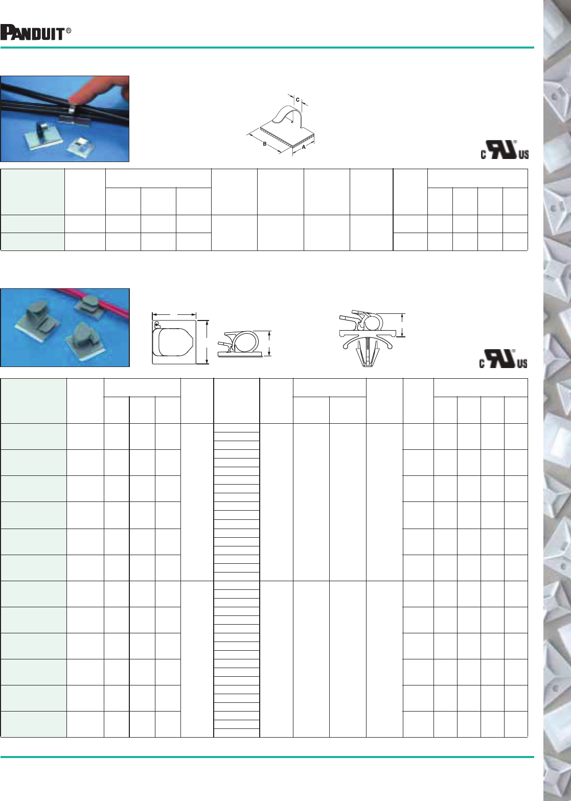
111
Most commonly used parts appear in BOLD.
*Order the number of mounts required in multiples of package quantities.
‡Part numbers listed are for standard materials in standard package quantity. For Bulk package part numbers, see page 137-138.
Cable and Wire Mounting Devices
Part Number
Max.
Bundle
Dia.
in. (mm)
Dimensions
in. (mm)
Material Color
Where
Used
Mounting
Method
Max.
Static
Load
lbs. (g)
Packaging*
ABC
Std.
Pkg.
Qty.
Std.
Ctn.
Qty.
Bulk
Pkg.
Qty.
Bulk
Ctn.
Qty.
MACC25-A-C .25
(6.4)
.53
(13.5)
.79
(20)
.28
(7.1) Zinc
Plated
Steel
— Indoors
Rubber
Adhesive
.21
(95)
100 1000 — —
MACC62-A-C .62
(15.7)
.75
(19.1)
1.18
(30)
.28
(7.1)
.44
(200)
100 1000 — —
MACC Type Metal adhesive backed cord clip can be opened and closed without
damage to the clip, to remove or add wires quickly and easily.
Holds wires, cable and tubing and is available in 6 sizes, with releasable
latch. Adhesive backed and push mount styles available. Large mounting
base for high bonding strength.
Adhesive
Version
Push Mount
Version
Part Number‡
Max.
Bundle
Dia.
in. (mm)
Dimensions
in. (mm)
Material Color
Where
Used
Panel Thickness
in. (mm)
Mounting
Method
Max.
Static
Load
lbs. (g)
Packaging*
ABC
Max.
Thickness
Hole
Diameter
Std.
Pkg.
Qty.
Std.
Ctn.
Qty.
Bulk
Pkg.
Qty.
Bulk
Ctn.
Qty.
LWC19-A-C
LWC19-A-C14
LWC19-A-C20
.19
(4.8)
.61
(15.5)
.85
(21.6)
.39
(9.9)
Nylon
6.6
Natural
Indoors — — Rubber
Adhesive
.25
(113)
100
100
100
1000
1000
1000
—
500
—
—
5000
—
Gray
Black
LWC25-A-C
LWC25-A-C14
LWC25-A-C20
.25
(6.4)
1.0
(25.4)
.88
(22.2)
.45
(11.4)
Natural .45
(204)
100
100
100
1000
1000
1000
500
500
—
5000
5000
—
Gray
Black
LWC38-A-C
LWC38-A-C14
LWC38-A-C20
.37
(9.5)
1.0
(25.4)
1.0
(25.4)
.56
(14.2)
Natural .50
(227)
100
100
100
1000
1000
1000
500
500
—
5000
5000
—
Gray
Black
LWC50-A-L
LWC50-A-L14
LWC50-A-L20
.50
(12.7)
1.0
(25.4)
1.26
(32.0)
.67
(17.0)
Natural .63
(284)
50
50
50
500
500
500
200
200
—
2000
2000
—
Gray
Black
LWC75-A-L
LWC75-A-L14
LWC75-A-L20
.75
(19.1)
1.24
(31.5)
1.48
(37.6)
.90
(22.9)
Natural .94
(425)
50
50
50
500
500
500
100
100
—
1000
1000
—
Gray
Black
LWC100-A-L
LWC100-A-L14
LWC100-A-L20
1.0
(25.4)
1.97
(50.0)
2.21
(56.1)
1.26
(32.0)
Natural 2.25
(1020)
50
50
50
500
500
500
100
100
—
1000
1000
—
Gray
Black
LWC19-H25-C
LWC19-H25-C14
LWC19-H25-C20
.19
(4.8)
.51
(12.8)
.85
(21.6)
.41
(10.4)
Nylon
6.6
Natural
Indoors .102
(2.6)
.220
(5.6)
Inserted
into
Pre-Drilled
Hole
—
100
100
100
1000
1000
1000
500
500
500
5000
5000
5000
Gray
Black
LWC25-H25-C
LWC25-H25-C14
LWC25-H25-C20
.25
(6.4)
.58
(14.7)
.86
(21.8)
.47
(11.9)
Natural
—
100
100
100
1000
1000
1000
500
500
—
5000
5000
—
Gray
Black
LWC38-H25-C
LWC38-H25-C14
LWC38-H25-C20
.37
(9.5)
.58
(14.7)
.94
(23.9)
.57
(14.5)
Natural
—
100
100
100
1000
1000
1000
500
500
—
5000
5000
—
Gray
Black
LWC50-H25-L
LWC50-H25-L14
LWC50-H25-L20
.50
(12.7)
.76
(19.3)
1.25
(31.8)
.78
(19.8)
Natural
—
50
50
50
500
500
500
200
200
—
2000
2000
—
Gray
Black
LWC75-H25-L
LWC75-H25-L14
LWC75-H25-L20
.75
(19.1)
.87
(22.1)
1.45
(36.8)
.97
(24.7)
Natural
—
50
50
50
500
500
500
100
100
—
1000
1000
—
Gray
Black
LWC100-H25-L
LWC100-H25-L14
LWC100-H25-L20
1.0
(25.4)
.99
(25.1)
1.89
(47.9)
1.30
(33.0)
Natural
—
50
50
50
500
500
500
100
100
—
1000
1000
—
Gray
Black
LWC Type
C
A
B
C
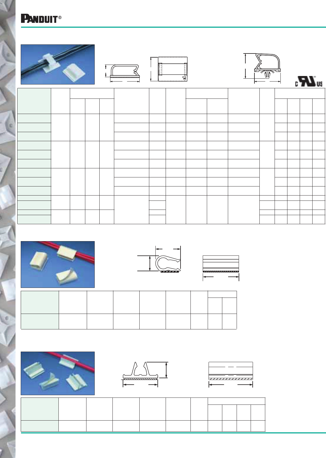
112 Most commonly used parts appear in BOLD.
*Order the number of mounts required in multiples of package quantities.
‡Part numbers listed are for standard materials in standard package quantity. For Bulk package part numbers, see page 137-138.
Cable and Wire Mounting Devices
Part Number‡
Max.
Bundle
Dia.
in. (mm)
Dimensions
in. (mm)
Material Color
Where
Used
Panel Dimensions
in. (mm)
Mounting
Method
in. (mm)
Max.
Static
Load
lbs. (g)
Packaging*
A B C
Max.
Thickness
Hole
Diameter
Std.
Pkg.
Qty.
Std.
Ctn.
Qty.
Bulk
Pkg.
Qty.
Bulk
Ctn.
Qty.
BEC38-A-L
.38
(9.6) 1.46
(37.1) 1.24
(31.5) .52
(13.2)
Nylon 6.6 Natural Indoors — — Rubber
Adhesive
.91
(411)
50 500 200 1000
BEC38-A-L20 Nylon 6.6 Black Indoors — — Rubber
Adhesive 50 500 200 1000
BEC38-AT-L0 Weather
Resist. Nylon 6.6 Black Outdoors — — Acrylic
Adhesive 50 500 200 1000
BEC62-A-L
.62
(15.7) 1.46
(37.1) 1.24
(31.5) .79
(20.1)
Nylon 6.6 Natural Indoors — — Rubber
Adhesive
.91
(411)
50 500 200 1000
BEC62-A-L20 Nylon 6.6 Black Indoors — — Rubber
Adhesive 50 500 200 1000
BEC62-AT-L0 Weather
Resist. Nylon 6.6 Black Outdoors — — Acrylic
Adhesive 50 500 200 1000
BEC75-A-L
.75
(19) 1.46
(37.1) 1.49
(37.8) .89
(22.6)
Nylon 6.6 Natural Indoors — — Rubber
Adhesive
1.09
(493)
50 500 200 1000
BEC75-A-L20 Nylon 6.6 Black Indoors — — Rubber
Adhesive 50 500 200 1000
BEC75-AT-L0 Weather
Resist. Nylon 6.6 Black Outdoors — — Acrylic
Adhesive 50 500 200 1000
BECP38H25-L .38
(9.6) 1.46
(37.1) .73
(18.5) 1.0
(25.4)
Nylon 6.6
Natural
Indoors .08
(1.9) .250
(6.4) Inser ted into
Pre-Drilled Hole
— 50 500 200 1000
BECP38H25-
L20 Black — 50 500 200 1000
BECP75H25-L .75
(9.6) 1.47
(37.3) .73
(18.5) 1.35
(34.3)
Natural — 50 500 200 1000
BECP75H25-
L20 Black — 50 500 200 1000
Bevel Entry Clips are available in 3 sizes to hold tubing, cable or wire bundles.
The beveled entry makes it easy to snap in the bundle. The clips are available
in push barb or adhesive backed styles.
Adhesive
Version
Push Mount
Version
BEC Type
B
A
C
C
A
Holds two cables in high temperature applications both indoors and outdoors.
*NORYL is a registered trademark of General Electric Company.
Part Number‡
Max.
Bundle
Dia.
in. (mm) Material Color
Where
Used
Mounting
Method
Max.
Static
Load
lbs. (g)
Packaging*
Std.
Pkg.
Qty.
Std.
Ctn.
Qty.
ADCC31-AT-C10 2 bundles
.20-.31
(5.1-7.9)
NORYL* White Indoors/
Outdoors
Acrylic
Adhesive
.25
(113)
100 500
AMC Type Holds a single cable and can be mounted on any flat smooth surface both
indoors and outdoors.
.36
(9.14)
.81
(20.6)
1.00
(25.4)
Part Number
Max.
Bundle
Dia.
in. (mm) Material Color
Where
Used
Mounting
Method
Max.
Static
Load
lbs. (g)
Packaging*
Std.
Pkg.
Qty.
Std.
Ctn.
Qty.
Bulk
Pkg.
Qty.
Bulk
Ctn.
Qty.
AMC25-AT-C10 .22-.28
(6 -7)
PVC White Indoors/
Outdoors
Acrylic
Adhesive
.40
(182)
— — 1000 1000
ADCC Type
.44
(11.2)
.681
(17.3)
1.00
(25.4)
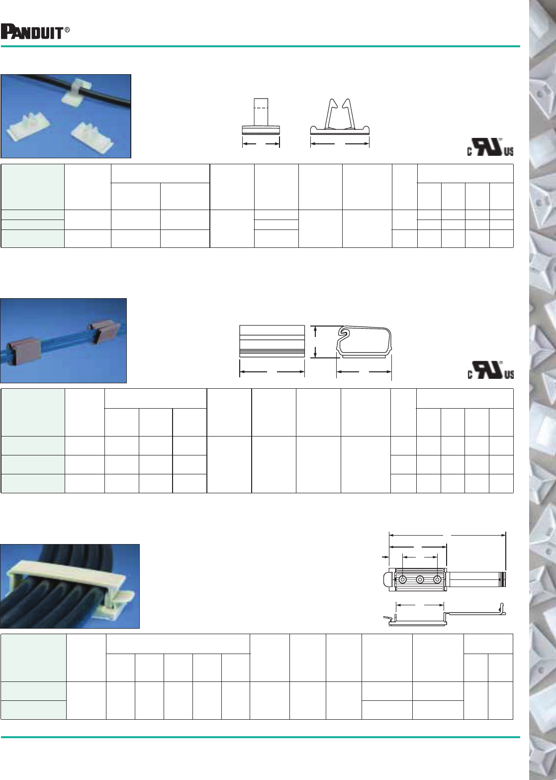
113
Most commonly used parts appear in BOLD.
Part Number‡
Max.
Bundle
Dia.
in. (mm)
Dimensions
in. (mm)
Material Color
Where
Used
Mounting
Method
Max.
Static
Load
lbs. (g)
Packaging*
A B
Std.
Pkg.
Qty.
Std.
Ctn.
Qty.
Bulk
Pkg.
Qty.
Bulk
Ctn.
Qty.
VCC25-A-C .25
(6.4)
.50
(12.7)
1.00
(25.4) Nylon 6.6
Natural
Indoors Rubber
Adhesive
.25
(113)
100 500 1000 5000
VCC25-A-C20 Black 100 500 1000 5000
VCC50-A-C .50
(12.7)
1.00
(25.4)
1.56
(39.7)
Natural .78
(354)
100 500 200 1000
Part Number
Max.
Bundle
Dia.
in. (mm)
Dimensions
in. (mm)
Material Color
Where
Used
Mounting
Method
Max.
Static
Load
lbs. (g)
Packaging*
ABC
Std.
Pkg.
Qty.
Std.
Ctn.
Qty.
Bulk
Pkg.
Qty.
Bulk
Ctn.
Qty.
LC3-A-C8 .20
(5.0)
.75
(19)
.78
(19.8)
.47
(11.9)
PVC Gray Indoors Rubber
Adhesive
.22
(100)
— — 100 1000
LC5-A-C8 .36
(9.1)
1.00
(25.4)
1.01
(25.7)
.61
(15.5)
.44
(200)
— — 100 1000
LC10-A-L8 .93
(23.6)
1.00
(25.4)
1.51
(38.4)
.84
(21.3)
.60
(272)
— — 50 500
VCC Type Funnel entry design of this vertical cord clip allows for easy insertion of
wires, cables and cords. Top loading for fast production operations.
Latching Clip This versatile clip retains and supports wire for a variety of applications.
Provides a quickly installed mount with a locked cover which withstands
vibration yet allows easy access.
B
A
C
B
A
Cable and Wire Mounting Devices
Part Number
Cable
Width
in. (mm)
Dimensions
in. (mm)
Material Color
Where
Used
Mounting
Method
Max. Static
Load
lbs. (g)
Packaging*
ABCDE
Std.
Pkg.
Qty.
Std.
Ctn.
Qty.
CH105-A-C14
2.00
(50.8)
5.04
(128.0)
2.48
(63.0)
2.06
(52.3)
.59
(15.0)
1.50
(38.1) Nylon 6.6 Gray Indoors
Rubber
Adhesive
1.28
(582) 100 200
CH105-S6-C14 (2) #6 (M3)
Screws —
Cable Holder Holds wires, cables and tubing and has a
releasable latch. Adhesive backed and
screw mount styles available. Large
mounting base for high bonding strength.
B
E
A
C
D
*Order the number of mounts required in multiples of package quantities.
‡Part numbers listed are standard materials in standard package quantity. For Bulk package part numbers, see page 137-138.
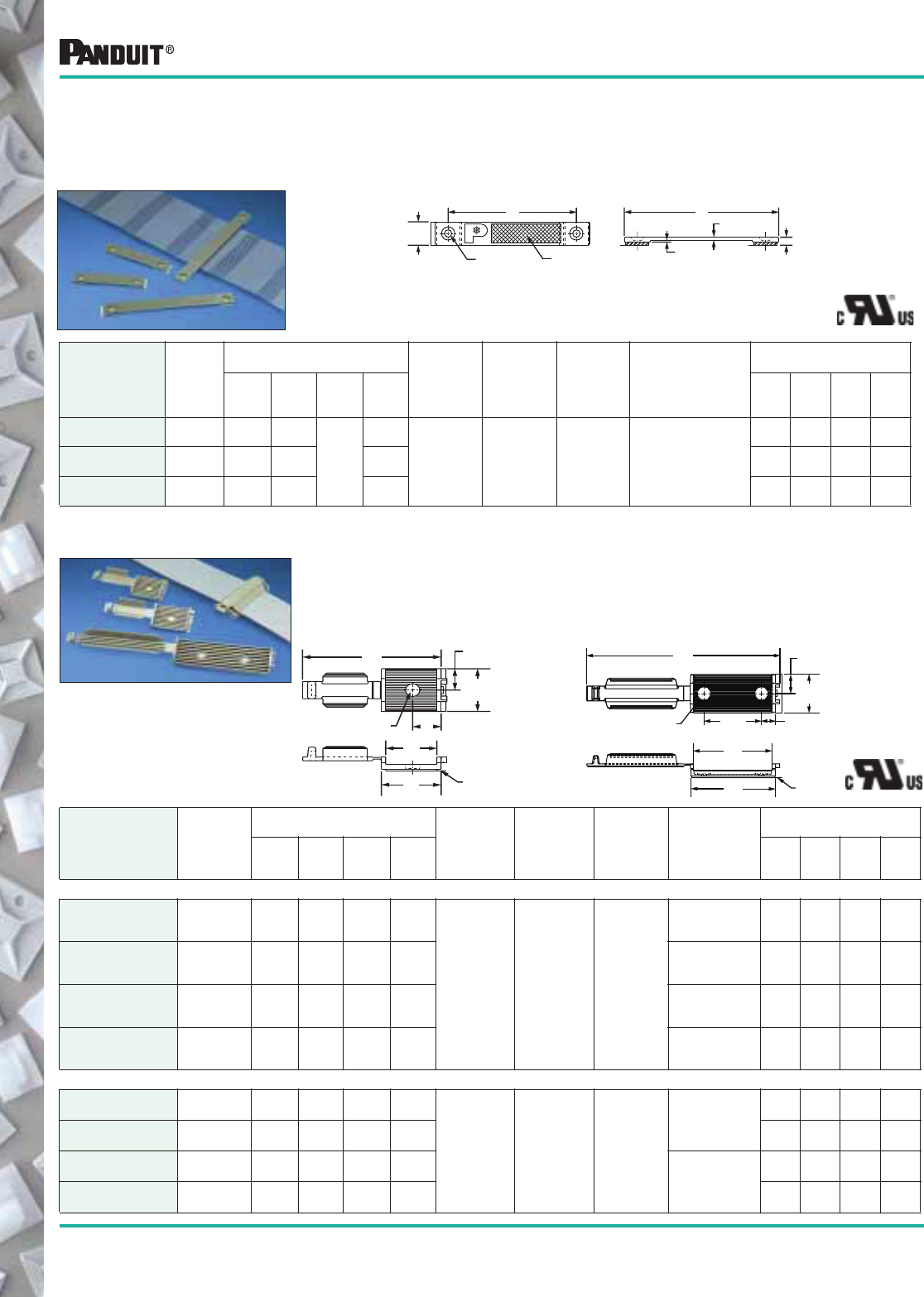
114 Most commonly used parts appear in BOLD.
Cable and Wire Mounting Devices
Part Number‡
Cable
Width
in. (mm)
Dimensions
in. (mm)
Material Color
Where
Used
Mounting
Method
Packaging*
A B C D
Std.
Pkg.
Qty.
Std.
Ctn.
Qty.
Bulk
Pkg.
Qty.
Bulk
Ctn.
Qty.
LPFCM14-A-C14 1.44
(37)
2.56
(65)
2.00
(50.8)
.134
(3.4)
2.00
(50.8)
Nylon 6.6 Gray Indoors
Rubber Adhesive/
Static Load
.25 lbs (113g)
or (2) #6 (M3) Screws
100 500 500 5000
LPFCM22-A-C14 2.19
(56)
3.31
(84)
2.75
(69.9)
2.75
(69.9)
100 500 500 5000
LPFCM34-A-C14 3.44
(87)
4.56
(115.8)
4.00
(101.6)
4.00
(101.6)
100 500 500 5000
Part Number‡
Cable
Width
in. (mm)
Dimensions
in. (mm)
Material Color
Where
Used
Mounting
Method
Packaging*
A B C D
Std.
Pkg.
Qty.
Std.
Ctn.
Qty.
Bulk
Pkg.
Qty.
Bulk
Ctn.
Qty
ADHESIVE BACKED
FCM1-A-C14 1.00
(25.4)
2.90
(73.7)
1.21
(30.7)
1.05
(26.7)
.61
(15.5)
Nylon 6.6 Gray Indoors
Rubber Adhe-
sive/Static Load
.5 lbs. (227g)
100 500 200 1000
FCM1.2-A-C14 1.20
(30.5)
3.16
(80.3)
1.37
(34.8)
1.20
(30.5)
.69
(17.5)
Rubber Adhe-
sive/Static Load
.62 lbs. (281g)
100 500 200 1000
FCM2-A-C14 2.00
(50.8)
5.06
(128.5)
2.22
(56.4)
2.05
(52.1)
.37
(9.4)
Rubber Adhe-
sive/Static Load
1.0 lbs. (454g)
100 500 200 1000
FCM3.25-A-L14 3.25
(82.5)
7.30
(185.4)
3.38
(85.9)
3.23
(82.0)
.94
(23.9)
Rubber Adhe-
sive/Static Load
1.5 lbs. (681g)
50 500 200 1000
SCREW MOUNTED
FCM1-S6-C14 1.00
(25.4)
2.90
(73.7)
1.21
(30.7)
1.05
(26.7)
.61
(15.5)
Nylon 6.6 Gray Indoors
#6 (M3)
Screw
100 500 200 1000
FCM1.2-S6-C14 1.20
(30.5)
3.16
(80.3)
1.37
(34.8)
1.20
(30.5)
.69
(17.5)
100 500 200 1000
FCM2-S6-C14 2.00
(50.8)
5.06
(128.5)
2.22
(56.4)
2.05
(52.1)
.37
(9.4) (2) #6
(M3) Screws
100 500 200 1000
FCM3.25-S6-L14 3.25
(82.5)
7.30
(185.4)
3.38
(85.9)
3.23
(82.0)
.94
(23.9)
50 500 200 1000
Adhesive Backed Flat Cable Mounts — FCM Type
Adhesive Backed
Flat Cable Mounts
LPFCM Type —
Low Profile
.500
(12.7)
0.138 Dia.
(
3.5
)
BA
C
.045
(1.1)
.060
(1.5)
Identification
Area
The FCM will hold flat cable securely without damaging the cable’s
jacket or conductors. The four available sizes will accommodate cable
up to 3.25" wide and allow cable stacking up to .17" (4.3mm). All sizes
are available with or without adhesive backing.
This low profile mount is available in 3 sizes and provides cost effective
cable containment and identification for stack heights up to .105"
(2.67mm). It features a matte, textured surface for either hand written
identification or application of computer labels.
1.00
(25.4)
0.50
(12.7)
A
D
0.14
(3.6) DIA THRU
C
TEAR-TAB
B
*Order the number of pieces required in multiples of package quantities.
‡Part numbers listed are for standard materials in standard package quantities. For Bulk package part numbers, see page 137-138.
FCM1 & FCM1.2
A
D
C
B
0.14 (3.6) DIA. THRU
TEAR-TAB
1.00
(25.4)
0.50
(12.7)
1.5
(38.1)
FCM2 & FCM3.25
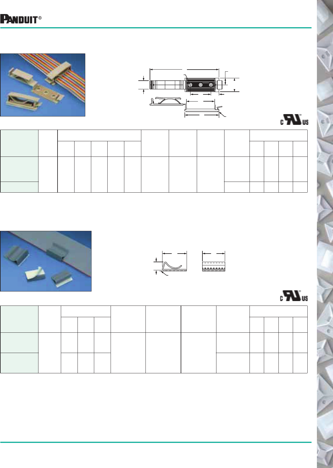
115
Most commonly used parts appear in BOLD.
Cable and Wire Mounting Devices
Part Number‡
Cable
Width
in. (mm)
Dimensions
in. (mm)
Material Color
Where
Used
Mounting
Method
Packaging*
A B C
Std.
Pkg.
Qty.
Std.
Ctn.
Qty.
Bulk
Pkg.
Qty.
Bulk
Ctn.
Qty.
FCC5-A-C8
Any
width
flat
cable
1.00
(25.4)
.56
(14.1)
.29
(7.4)
PVC Gray Indoors
Rubber
Adhesive/Static
Load .25 lbs.
(113g)
100 1000 500 5000
FCC-A-C8 1.00
(25.4)
1.09
(27.7)
.38
(9.7)
Rubber
Adhesive/Static
Load .50 lbs.
(227g)
100 1000 500 5000
Adhesive Backed Flat Cable
Mounts — FCC Type
Used with any width flat cable for a maximum stack
height of .17" (4.3mm).
Adhesive Backed Flat Cable
Mounts — FCH Type
The FCH part is designed for flat cable up to a stack height of
.25" (6.3mm) or discrete wire. It is available with adhesive
backing or can be screw applied.
Part Number‡
Cable
Width
in. (mm)
Dimensions
in. (mm)
Material Color
Where
Used
Mounting
Method
Packaging*
A B C D E
Std.
Pkg.
Qty.
Std.
Ctn.
Qty.
Bulk
Pkg.
Qty.
Bulk
Ctn.
Qty.
FCH2-A-C14
2.00
(50.8)
5.00
(128.1)
2.50
(63.0)
2.10
(52.2)
.59
(15.0)
1.50
(38.1) Nylon 6.6 Gray Indoors
Rubber
Adhesive/
Static Load
1.0 lbs.
(454g)
100 500 200 1000
FCH2-S6-C14 (2) #6 (M3)
Screws
100 500 — —
C
BA
TEAR-TAB
B
ED
.63
(16.00)
1.03
(26.16)
A
0.14
(3.6)
DIA THRU
0.50
(12.7)
C
TEAR-TAB
*Order the number of pieces required in multiples of package quantities.
‡Part numbers listed are for standard materials in standard package quantities. For Bulk package part numbers, see page 137-138.
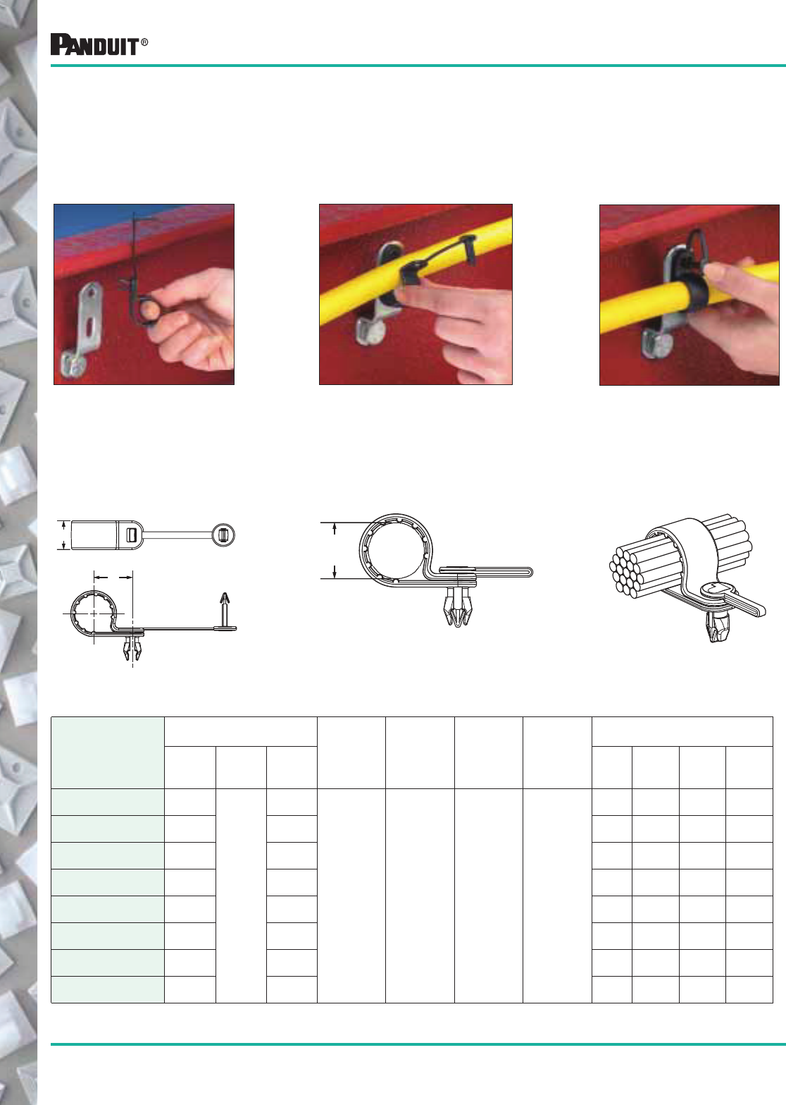
116 Most commonly used parts appear in BOLD.
*Order the number of pieces required in multiples of package quantities.
‡Part numbers listed are for standard materials in standard package quantity. For Bulk package part numbers, see page 137-138.
PAN-CLAMP ™
Heavy Duty Fixed
Diameter Clamp with
Integrated Fastener
PANDUIT ® PAN-CLAMP ™
Heavy Duty Fixed Diameter Clamps offer easy
installation and economical assembly for a wide variety of applications.
• Integrated fastener replaces up to a five piece assembly
• Anchors with 70 lbs. (31.8kg) of pull out force and supports
125 lbs. (56.7kg) of shear
Part Number‡
Dimensions
in. (mm)
Material Color
Panel Hole
Size
in. (mm)
Panel
Thickness
in. (mm)
Packaging*
ABC
Std.
Pkg.
Qty.
Std.
Ctn.
Qty.
Bulk
Pkg.
Qty.
Bulk
Ctn.
Qty.
PC038-H25D-C0 3/8
(9.5)
.62
(15.7)
.65
(16.5)
Impact
Modified
Weather
Resistant
Nylon 6.6
Black .275
(7.0)
.126
(3.2)
100 500 500 1000
PC050-H25D-C0 1/2
(12.7)
.71
(18.0)
100 500 500 1000
PC062-H25D-C0 5/8
(15.8)
.77
(19.6)
100 1000 500 1000
PC075-H25D-C0 3/4
(19.1)
.84
(21.3)
100 1000 500 1000
PC087-H25D-C0 7/8
(22.1)
.90
(22.9)
100 1000 500 1000
PC100-H25D-C0 1
(25.4)
.96
(24.3)
100 1000 200 1000
PC112-H25D-C0 1 1/8
(28.5)
1.02
(25.9)
100 1000 200 1000
PC125-H25D-C0 1 1/4
(31.8)
1.08
(27.4)
100 1000 200 1000
Cable and Wire Mounting Devices
A
Bundle
Diameter
2. Molded barbs keep the clamp
secured in the hole during assembly.
3. Rivet installs easily by hand. No
special tools required.
B
C
1. Install into 1/8" (3.2mm) thick
panel or bracket with a hole
diameter of 0.281" (7.1mm) typical
clearance hole for 1/4" (6mm) bolts.
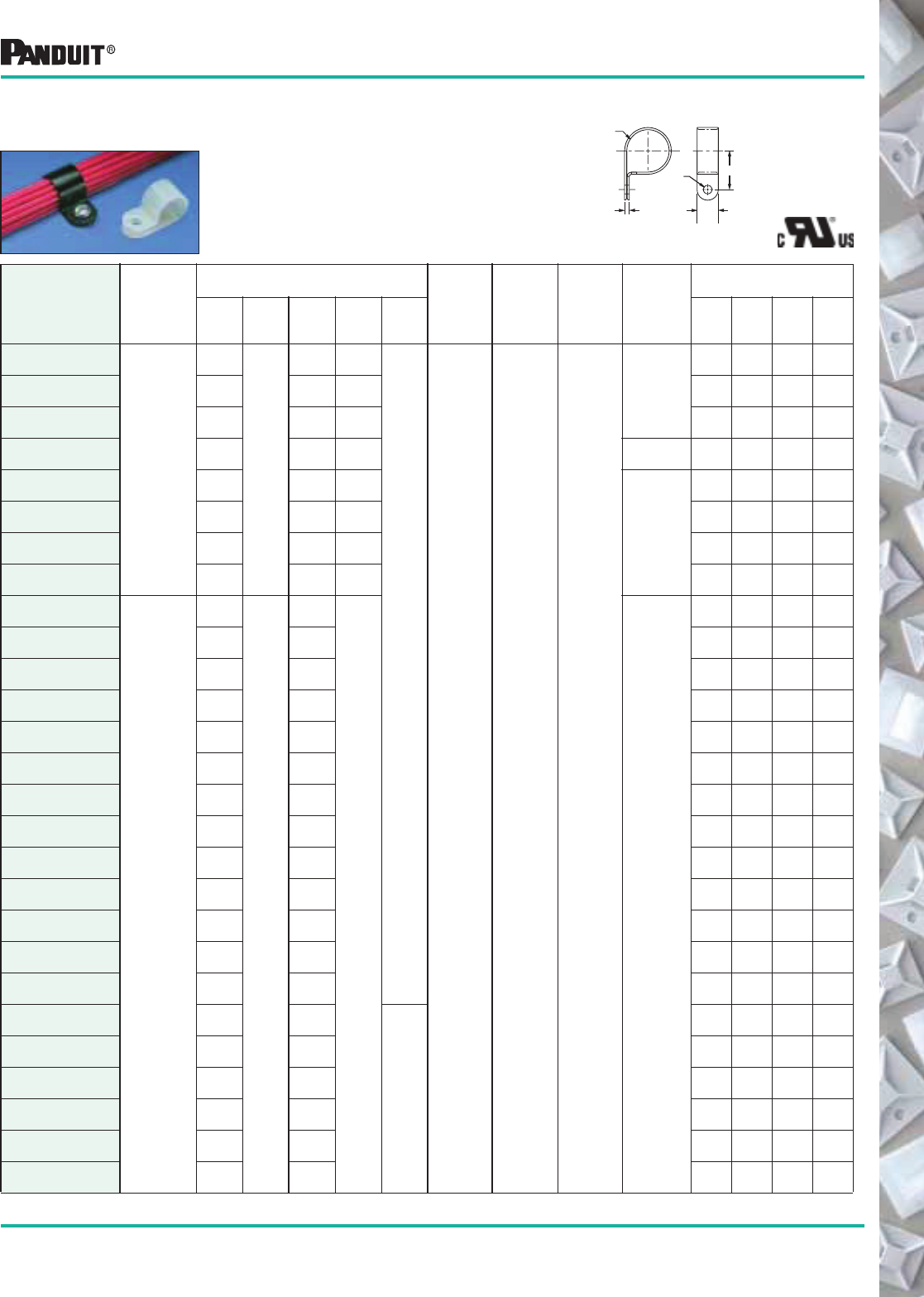
117
Most commonly used parts appear in BOLD.
*Order the number of pieces required in multiples of package quantities.
‡Part numbers listed are for standard materials in standard package quantity (except CCH112 through CCH150).
For Bulk package part numbers, see page 137-138.
Part Number‡
Type of
Application
Dimensions
in. (mm)
Material Color
Where
Used
Mounting
Method
Packaging*
ABCDE
Std.
Pkg.
Qty
Std.
Ctn.
Qty.
Bulk
Pkg.
Qty.
Bulk
Ctn.
Qty.
CCS12-S8-C
Standard
.13
(3.1)
.38
(9.5)
.33
(8.4)
.17
(4.2)
.11
(2.6)
Nylon 6.6 Natural Indoors
#8 (M4)
Screw
100 500 1000 5000
CCS19-S8-C .19
(4.8)
.43
(10.9)
.17
(4.2)
100 500 1000 5000
CCS25-S8-C .25
(6.4)
.41
(10.4)
.17
(4.2)
100 500 1000 5000
CCS25-S10-C .25
(6.4)
.41
(10.4)
.20
(5.1)
#10 (M5)
Screw
100 500 1000 5000
CCS31-S8-C .31
(7.9)
.49
(12.4)
.17
(4.2)
#8 (M4)
Screw
100 500 1000 5000
CCS38-S8-C .38
(9.5)
.57
(14.5)
.17
(4.2)
100 500 1000 5000
CCS44-S8-C .44
(11.1)
.59
(15.0)
.17
(4.2)
100 500 1000 5000
CCS50-S8-C .50
(12.7)
.60
(15.2)
.17
(4.2)
100 500 1000 5000
CCH12-S10-C
Heavy
Duty
.13
(3.1)
.50
(12.7)
.36
(9.1)
.20
(5.1)
#10 (M5)
Screw
100 500 1000 5000
CCH19-S10-C .19
(4.8)
.43
(10.8)
100 500 1000 5000
CCH25-S10-C .25
(6.4)
.46
(11.7)
100 500 1000 5000
CCH31-S10-C .31
(7.9)
.50
(12.7)
100 500 1000 5000
CCH38-S10-C .38
(9.5)
.53
(13.5)
100 500 1000 5000
CCH44-S10-C .44
(11.1)
.56
(14.2)
100 500 1000 5000
CCH50-S10-C .50
(12.7)
.60
(15.1)
100 500 1000 5000
CCH56-S10-C .56
(14.3)
.63
(15.9)
100 500 1000 5000
CCH62-S10-C .63
(15.9)
.66
(16.8)
100 500 1000 5000
CCH69-S10-C .69
(17.5)
.76
(19.2)
100 500 500 5000
CCH75-S10-C .75
(19.1)
.79
(19.9)
100 500 500 5000
CCH81-S10-C .81
(20.7)
.81
(20.7)
100 500 500 5000
CCH87-S10-C .87
(22.2)
.85
(21.5)
100 500 500 5000
CCH100-S10-C 1.00
(25.4)
.91
(23.1)
.13
(3.1)
100 500 500 5000
CCH112-S10-C 1.13
(28.6)
.97
(24.6)
— — 100 500
CCH119-S10-C 1.19
(30.2)
1.00
(25.4)
— — 100 500
CCH125-S10-C 1.25
(31.8)
1.06
(26.9)
— — 100 500
CCH138-S10-C 1.38
(34.9)
1.13
(28.6)
— — 100 500
CCH150-S10-C 1.50
(38.1)
1.19
(30.2)
— — 100 500
Durable nylon cable clamps are available
in two widths: 3/8" wide for standard use
and 1/2" wide for heavy duty use.
NOTE: All parts listed also available in black
weather resistant material (-0). Bulk package only.
E
A
(Dia.)
D
(Dia.)
B
C
Cable and Wire Mounting Devices
Fixed Diameter
Cable Clamps
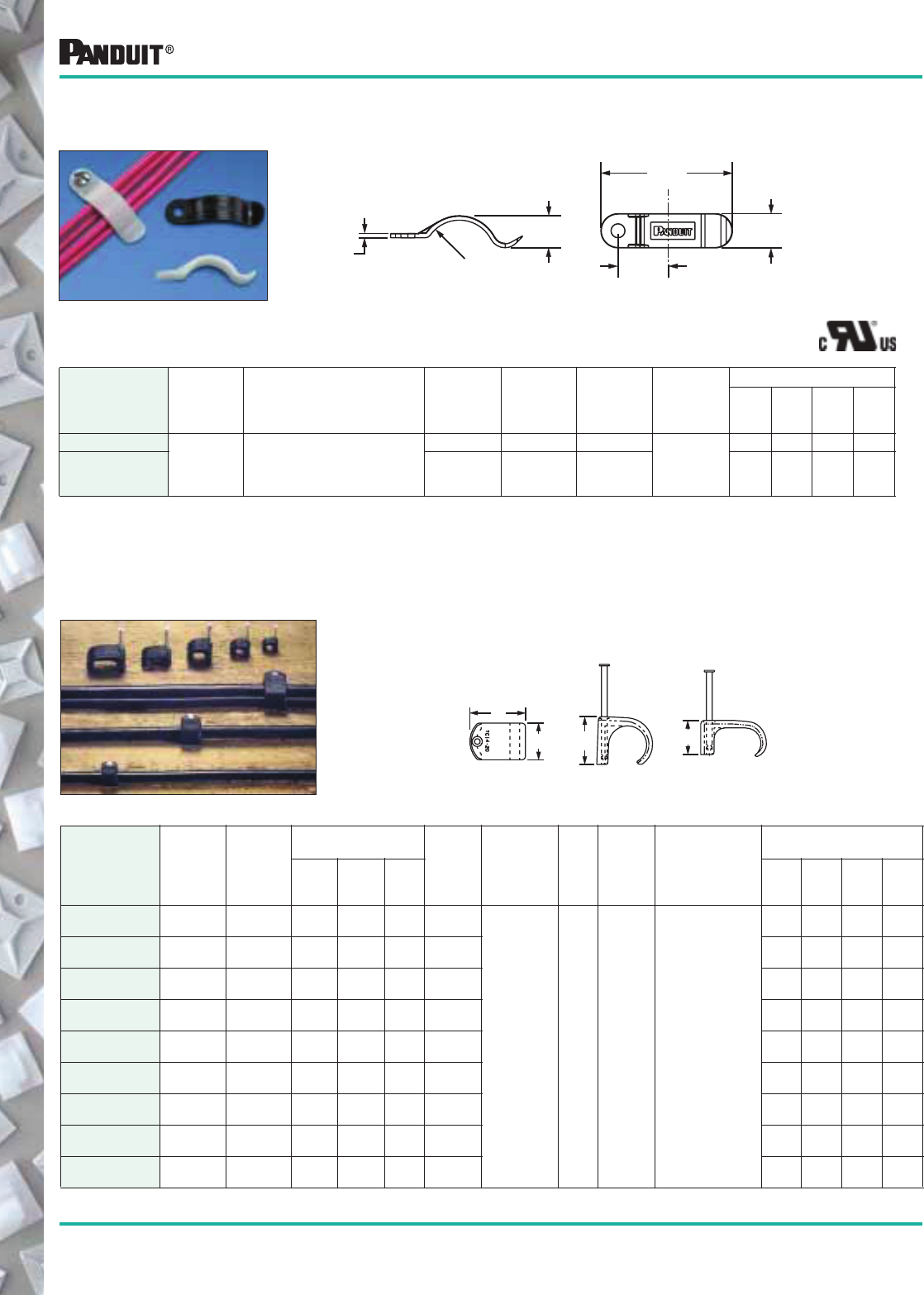
118 Most commonly used parts appear in BOLD.
*Order the number of pieces required in multiples of package quantities.
‡Part numbers listed are for standard materials in standard package quantity. For Bulk package part numbers, see page 137-138.
Cable and Wire Mounting Devices
Tension
Wire Retainers
Wires slide into the clip and are held in place by tension.
Part Number‡
Bundle
Diameter
in. (mm)
Dimensions
in. (mm) Material Color
Where
Used
Mounting
Method
Packaging*
Std.
Pkg.
Qty.
Std.
Ctn.
Qty.
Bulk
Pkg.
Qty.
Bulk
Ctn.
Qty.
TWR-C
.38
(9.5) See Drawing
Nylon 6.6 Natural Indoors
#6 (M3)
Screw
100 1000 1000 5000
TWR-C0 Weather
Resistant
Nylon 6.6
Black Indoors/
Outdoors
100 1000 — —
Tack Clips Used for securing wire, cable and tubing to nailable surfaces. The
clips are furnished with a single integral zinc plated, hardened steel
nail to help speed installation.
Part Number Type
Bundle
Capacity
in. (mm)
Dimensions
in. (mm)
Coaxial
Cross
RG# Material Color
Where
Used
Mounting
Method
Packaging*
A B C
Std.
Pkg.
Qty.
Std.
Ctn.
Qty.
Bulk
Pkg.
Qty.
Bulk
Ctn.
Qty.
TC3-5-C100 S .13 dia.
(3.5)
.20
(5.1)
.29
(7.4)
.23
(5.8)
187
Weather
Resistant
Polypropylene
Black Indoors/
Outdoors
Nail is
hammered
into a nailable
surface such as
wood or
mortar joints.
Do not use on
concrete or brick.
— — 100 1000
TC5-7-C100 S .21 dia.
(5)
.31
(7.9)
.39
(9.9)
.23
(5.8)
58 — — 100 1000
TC7-10-C100 S .26 dia.
(6.5)
.38
(9.7)
.49
(12.5)
.35
(8.9)
59 — — 100 1000
TC10-14-C100 S .36 dia.
(9.2)
.51
(13)
.59
(14.9)
.45
(11.4)
6A — — 100 1000
TC14-20-C100 S .49 dia.
(12)
.67
(17)
.79
(20.6)
.54
(13.7)
8A, 9B, 11 — — 100 1000
TC5x8-C100 D .20 x .30
(5 x 8)
.30
(8.8)
.54
(13.7)
.27
(6.8)
— — — 100 1000
TC6x10-C100 D .23 x .37
(6 x 9.5)
.34
(8.6)
.62
(15.7)
.34
(8.6)
— — — 100 1000
TC7x14-C100 D .26 x .46
(7 x 12)
.36
(9.1)
.70
(17.8)
.43
(10.9)
— — — 100 1000
TC9x18-C100 D .38 x .65
(10 x 17)
.50
(12.7)
.89
(22.6)
.52
(13.2)
— — — 100 1000
.38"
(9.5)
1.44"
(36.5)
.56"
(14.2)
.36"
(9.1)
.06"
(1.5) .38 RAD
(9.5)
TYPE S
(SINGLE)
TYPE D
(DOUBLE)
A
A
C
B
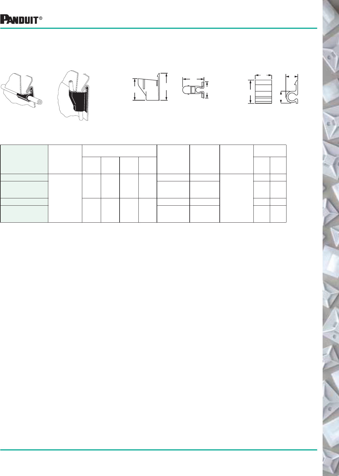
119
Most commonly used parts appear in BOLD.
Cable and Wire Mounting Devices
Part Number‡
Max.
Cable
Dia.
in. (mm)
Dimensions
in. (mm)
Material Color
Mounting
Method
Packaging*
A B C D
Std.
Pkg.
Qty.
Std.
Ctn.
Qty.
HSC.25-L
.25
(6.4)
.50
(12.7)
.71
(18.0)
.34
(8.6)
.37
(9.4)
Nylon 6.6 White
Attach
to
Siding
50 500
HSC.25-L100 Weather
Resistant
Polypropylene
Black
50 500
VSC.25-L
1.26
(31.8)
.98
(25.0)
1.00
(25.4)
.70
(17.8)
Nylon 6.6 White 50 500
VSC.25-L100 Weather
Resistant
Polypropylene
Black
50 500
Siding Clips Attaches coax cable to buildings having “Pittsburgh Interlok” type aluminum
or steel siding. Will not corrode or stain siding. Low profile, installs without
drilling or nailing.
C
D
A
B
HSC Horizontal Clip
Horizontal Siding Clip Vertical Siding Clip
C
D
A
B
VSC Vertical Clip
*Order the number of pieces required in multiples of package quantities.
‡Part numbers listed are for standard materials in standard package quantity. For Bulk package part numbers, see page 137-138.
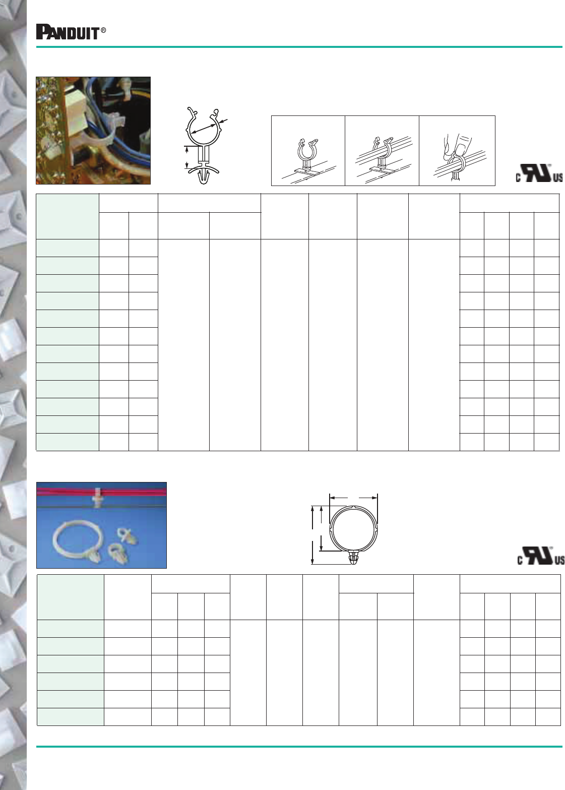
120
Most commonly used parts appear in BOLD.
*Order the number of pieces required in multiples of package quantities.
‡Part numbers listed are for standard materials in standard package quantity. For Bulk package part numbers, see page 137-138.
Cable and Wire Mounting Devices
Snap-In Clips
C
A
B
The clips hold wire bundles securely. Clips are placed on the bundle then
attached to the panel. Designed for pre-drilled holes.
Part Number‡
Max.
Bundle
Dia.
in. (mm)
Dimensions
in. (mm)
Material Color
Where
Used
Panel Dimensions
in. (mm)
Mounting
Method
Packaging*
ABC
Maximum
Thickness
Hole
Diameter
Std.
Pkg.
Qty.
Std.
Ctn.
Qty.
Bulk
Pkg.
Qty.
Bulk
Ctn.
Qty.
SICH25-C .25
(6.4)
.82
(20.9)
.34
(8.6)
.40
(10.2)
Nylon 6.6 Natural Indoors .10
(2.5)
.25
(6.4)
Inserted into
Pre-Drilled
Hole
100 1000 1000 5000
SICH38-C .38
(9.6)
.98
(24.6)
.50
(12.8)
.54
(13.7)
100 1000 1000 5000
SICH50-C .50
(12.7)
1.11
(26.2)
.62
(15.7)
.67
(17.0)
100 1000 1000 5000
SICH75-C .75
(19)
1.40
(35.6)
1.0
(25.4)
.96
(24.4)
100 1000 1000 5000
SICH100-C 1.00
(25.4)
1.65
(41.9)
1.25
(31.8)
1.21
(30.7)
100 1000 — —
SICH150-C 1.5
(38)
2.15
(54.6)
1.75
(44.5)
1.71
(43.4)
100 1000 — —
For retaining wires, cable, components or tubing away from panel or
conductive chassis. Finger grip flanges can be easily locked or unlocked for
revisions. Hand installed in pre-drilled hole.
Press wire standoff
through pre-drilled hole
in panel.
Load wires, cables, etc. Press top flanges
together to lock.
1. 2. 3.
Easy to install and use.
A
Max. Dia.
(when closed)
B
Part Number‡
Dimensions
in. (mm)
Panel Dimensions
in. (mm)
Material Color
Where
Used
Mounting
Method
Packaging*
A B
Panel
Thickness
Hole
Diameter
Std.
Pkg.
Qty.
Std.
Ctn.
Qty.
Bulk
Pkg.
Qty.
Bulk
Ctn.
Qty.
WS25-25-C .25
(6.4)
.25
(6.4)
.03 to .08
(0.7 to 2.0)
.19 to .20
(4.7 to 4.9) Nylon 6.6 Natural Indoors
Inserted into
Pre-Drilled
Hole
100 1000 — —
WS25-50-C .25
(6.4)
.50
(12.7)
100 1000 — —
WS25-75-C .25
(6.4)
.75
(19.1)
100 1000 — —
WS35-25-C .35
(8.9)
.25
(6.4)
100 1000 — —
WS35-50-C .35
(8.9)
.50
(12.7)
100 1000 — —
WS35-75-C .35
(8.9)
.75
(19.1)
100 1000 — —
WS50-25-C .47
(11.9)
.25
(6.4)
100 1000 — —
WS50-50-C .47
(11.9)
.49
(12.7)
100 1000 — —
WS50-75-C .47
(11.9)
.75
(19.1)
100 1000 — —
WS75-25-C .78
(19.8)
.25
(6.4)
100 1000 1000 5000
WS75-50-C .78
(19.8)
.50
(12.7)
100 1000 1000 5000
WS75-75-C .78
(19.8)
.75
(19.1)
100 1000 1000 5000
Wire Standoffs
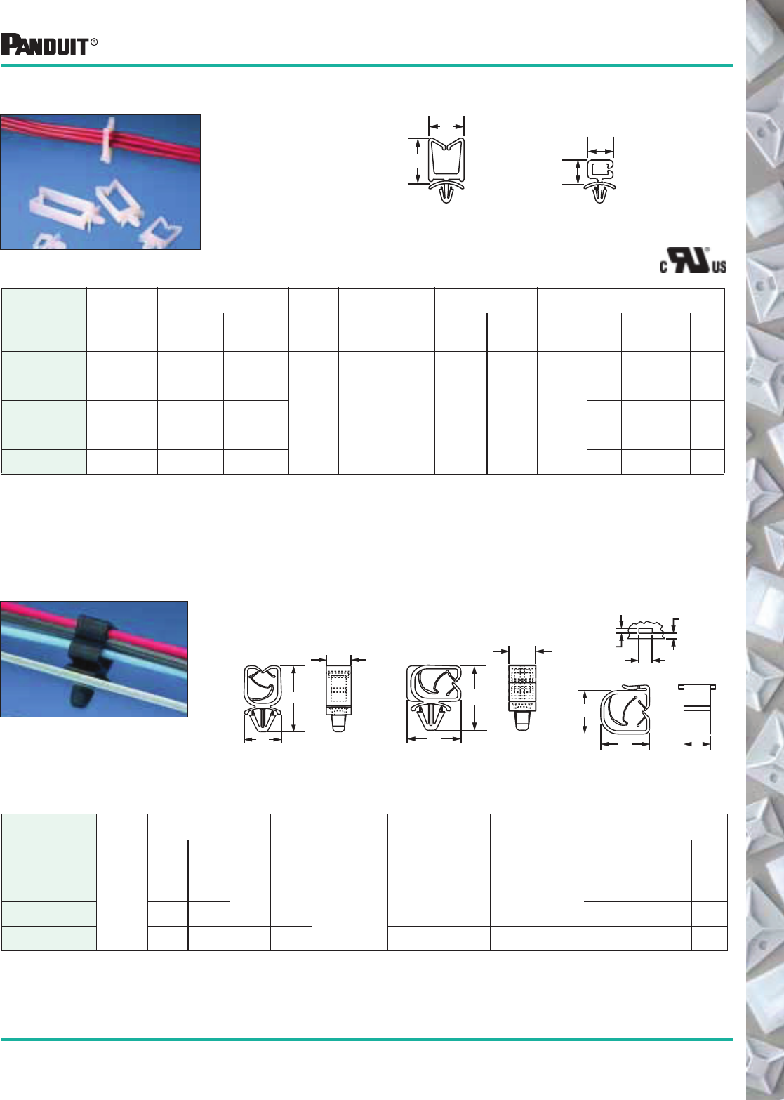
121
Most commonly used parts appear in BOLD.
Cable and Wire Mounting Devices
Wire Saddles Funnel entry design for
fast insertion of wires
and cables. Used in
pre-drilled holes.
Part Number‡
Max.
Bundle
Capacity
in. (mm)
Dimensions
in. (mm)
Material Color
Where
Used
Panel Dimensions
in. (mm)
Mounting
Method
Packaging*
A B
Panel
Thickness
Hole
Diameter
Std.
Pkg.
Qty.
Std.
Ctn.
Qty.
Bulk
Pkg.
Qty.
Bulk
Ctn.
Qty.
VWS4218-C .18 x .42
(5 x 11)
.58
(14.7)
.60
(15.2)
Nylon 6.6 Natural Indoors .03-.08
(.79 - 2.0)
.19
(4.7)
Inserted
into
Pre-Drilled
Hole
100 500 1000 5000
VWS4238-C .40 x .42
(10 x 11)
.78
(19.8)
.60
(15.2)
100 500 1000 5000
VWS4274-C .74 x .42
(19 x 11)
1.14
(29.0)
.60
(15.2)
100 500 1000 5000
VWS42105-C 1.05 x .42
(27 x 11)
1.45
(36.8)
.60
(15.2)
100 500 1000 5000
HWS2819-C .19 x .28
(5 x 7)
.42
(10.7)
.44
(11.2)
100 500 1000 5000
VWS
Vertical
HWS
Horizontal
*Order the number of pieces required in multiples of package quantities.
‡Part numbers listed are for standard materials in standard package quantity. For Bulk package part numbers, see page 137-138.
A
B
A
B
Integral “spring” holds wire bundles tightly. Used in pre-drilled holes.
Vertical, horizontal, and edge mount versions available.
Vertical
HCMP06B12
Horizontal
HCMP06C12
B
A
C
A
B
C
Edge Mount
HCME06A12
Harness Clips
A
B C
0.157
(4) 0.433
(11)
0.17
(4.4)
Part Number‡
Max.
Bundle
Dia.
Range
in. (mm)
Dimensions
in. (mm)
Material Color
Where
Used
Panel Dimensions
in. (mm)
Mounting
Method
in. (mm)
Packaging*
A B C
Maximum
Thickness
Hole
Diameter
Std.
Pkg.
Qty.
Std.
Ctn.
Qty.
Bulk
Pkg.
Qty.
Bulk
Ctn.
Qty.
HCMP06B12-C20
.24-.47
(5.9-2.5)
1.25
(31.8)
.74
(18.8) .39
(10)
Nylon
6.6 Black Indoors
.11
(2.7)
.25
(6.4)
Inserted into
Pre-Drilled Hole
100 500 1000 5000
HCMP06C12-C20 1.10
(27.9)
.80
(20.2)
100 500 1000 5000
HCME06A12-C130 .59
(15.0)
.74
(18.7)
.39
(9.9)
Acetal — — See Drawing 100 500 5000 10000
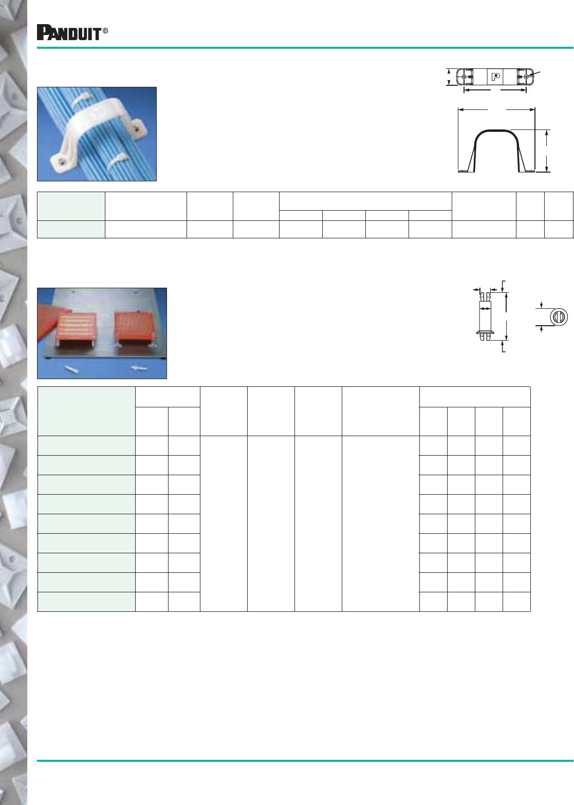
122 Most commonly used parts appear in BOLD.
Wire Bundle Strap
Part Number
Bundle Retaining Area
in2Material Color
Dimensions
in. (mm) Mounting
Method
Std.
Pkg.
Qty.*
Std.
Ctn.
Qty.A B C D
WBS6-Q 6 ABS Natural 1.00
(25.4)
3.92
(99.6)
2.54
(64.5)
.25
(6.35) 1/4 (M6) Screw 25 125
Wire Bundle Strap provides a quick, durable and
inexpensive way to contain wire, cable and tubing.
It can be installed on wood, plywood, masonry
and other surfaces using standard fasteners.
B
A
C
4.82
(122.56)
REF.
D (Dia)
Cable and Wire Mounting Devices
*Order the number of pieces required in multiples of package quantities.
Part numbers listed are for standard materials in standard package quantity. For Bulk package part numbers, see page 137-138.
For board-to-board or board-to-chassis mounting.
Posts snap into pre-drilled holes.
Bell flange on bottom end provides greater stability.
Part Number‡
Dimensions
in. (mm)
Material Color
Where
Used
Mounting
Method
in. (mm)
Packaging*
Standoff
Height A
Std.
Pkg.
Qty.
Std.
Ctn.
Qty.
Bulk
Pkg.
Qty.
Bulk
Ctn.
Qty.
CBP12-C .125
(3.2)
.405
(10.3)
Nylon 6.6 Natural Indoors
For Circuit Boards
or Chassis:
.062 (1.5) thick
with .158 (4.0)
diameter
mounting holes
100 1000 1000 5000
CBP25-C .250
(6.4)
.530
(13.5)
100 1000 1000 5000
CBP31-C .312
(7.9)
.592
(15.0)
100 1000 1000 5000
CBP37-C .375
(9.5)
.655
(16.6)
100 1000 1000 5000
CBP50-C .500
(12.7)
.780
(19.8)
100 1000 1000 5000
CBP62-C .625
(15.9)
.905
(23.0)
100 1000 1000 5000
CBP75-C .750
(19.1)
1.030
(26.2)
100 1000 1000 5000
CBP87-C .875
(22.2)
1.155
(29.3)
100 1000 1000 5000
CBP100-C 1.00
(25.4)
1.280
(32.5)
100 1000 1000 5000
Circuit Board Posts
A
.140
(3.6)
.140
(3.6)
.170
(4.3)
.187 Dia.
(4.7) .282
(7.2)
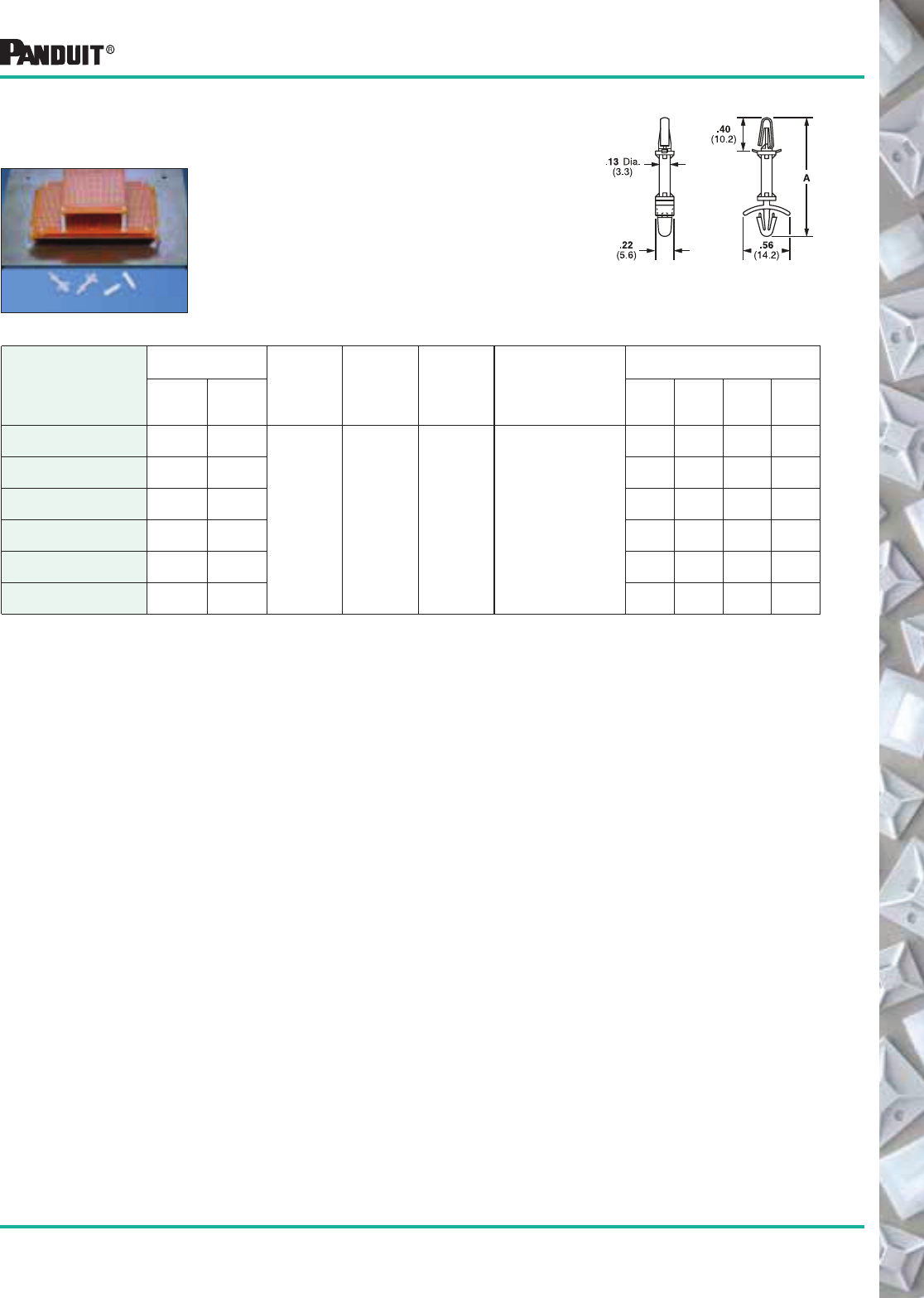
123
Most commonly used parts appear in BOLD.
Circuit Board
Locking Supports
For board-to-chassis support. Snap-in
design for fast assembly. Wing design on
chassis mounting provides constant tension
and stability.
Part Number‡
Dimensions
in. (mm)
Material Color
Where
Used
Mounting
Method
in. (mm)
Packaging*
Standoff
Height A
Std.
Pkg.
Qty.
Std.
Ctn.
Qty.
Bulk
Pkg.
Qty.
Bulk
Ctn.
Qty.
CBLS18-C .187
(4.7)
.92
(23.4)
Nylon 6.6 Natural Indoors
For Circuit Boards:
.062 (1.5) thick
with .158 (4.0)
diameter
mounting holes
For Chassis:
.03 (.79) to .08 (2.0)
thick with
.185 (4.7) to
.193 (4.9)
diameter
mounting holes
100 500 1000 5000
CBLS25-C .250
(6.4)
.98
(24.9)
100 1000 1000 5000
CBLS37-C .375
(9.5)
1.11
(28.2)
100 1000 1000 5000
CBLS50-C .500
(12.7)
1.23
(31.2)
100 1000 1000 5000
CBLS62-C .625
(15.9)
1.35
(34.3)
100 1000 1000 5000
CBLS75-C .750
(19.1)
1.48
(37.5)
100 1000 1000 5000
Circuit Board Posts/Supports
*Order the number of pieces required in multiples of packaging quantities.
‡Part numbers listed are for standard materials in standard package quantity.
For Bulk package part numbers, see page 137-138.
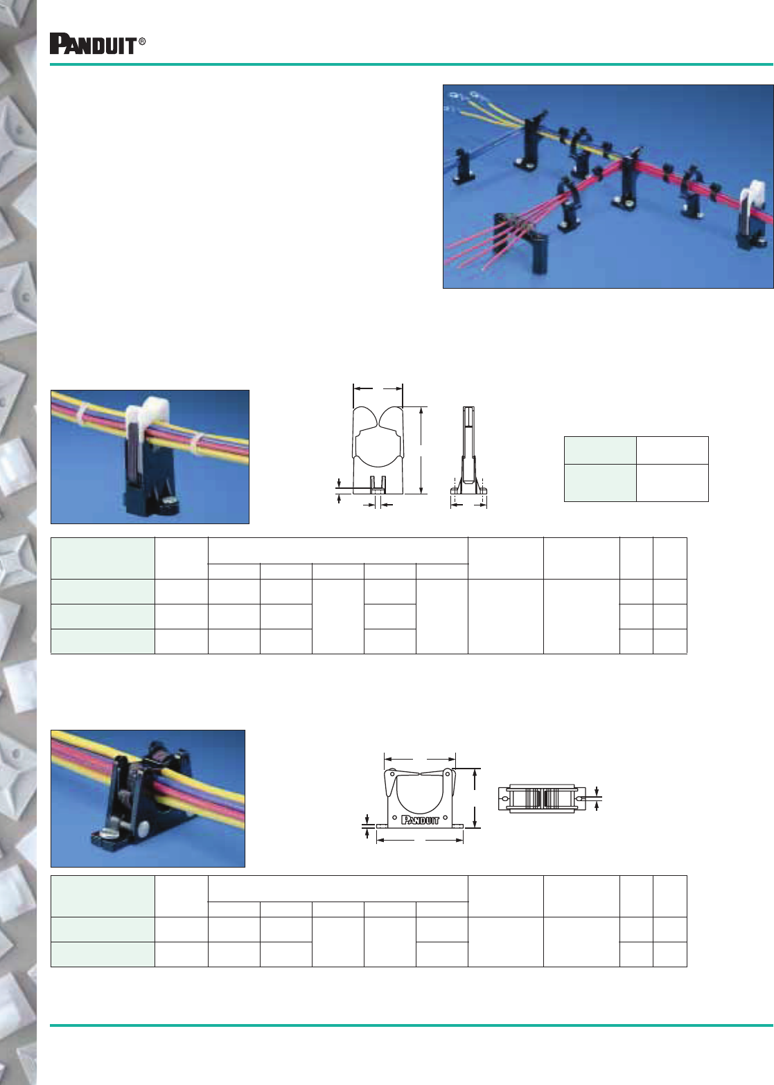
124
Most commonly used parts appear in BOLD.
Wire Retainers —
RER Type Replaceable
Elastic Retainers
As wires are individually inserted, the bundle is formed. When harness
is complete, it can be easily snapped out. Three sizes available for
1/2" (12.7mm), 3/4" (19.0mm) and 2 1/4" (31.8mm) bundles.
PANDUIT ® harness board accessories provide fast routing
and forming of wires in harness fabrication. They hold the
wires off the harness board at a uniform height for easy
application of cable ties. The accessories are designed for use
with various PANDUIT ® cable tie installation tools. The Low
accessories are used with hand-operated tools. The High
accessories are used with the automatic tools. To maintain the
harness at a uniform height of approx. 1.33" (33.8mm) (at the
center of the harness) above the board, use RER Elastic
Retainers, BR.75-E6 (or BR.5-E6), CPH.75-S8, TJF and
SHH1-S8 or SHH3-S8 harness board accessories. This
height is suitable for use with the PAT1M Fully Automatic
Cable Tie Installation system (page 60).
Part Number
Max.
Dia.
in. (mm)
Dimensions
in. (mm) Color
&
Material
Mounting
Method
Std.
Pkg.
Qty.*
Std.
Ctn.
Qty.A B C D E
ER.5-E4-X .50
(12.7)
1.00
(25.4)
1.00
(25.4) .13
(3.2)
.12
(3.0)
1.96
(49.8) Black
Nylon 6.6
and ABS
#4 (M2.5)
Screws
10 100
ER1.25-E4-X 1.25
(31.8)
2.00
(50.8)
2.40
(61.0)
2.90
(73.7)
10 100
Replacement Elastic
For economy, the elastic band can be
replaced in the RER Elastic Retainers
without removing the RER base.
Part
Number
Pkg.
Qty.
RER.5E-X
RER.75E-X
RER1.25E-X
10
10
10
Part Number
Max.
Dia.
in. (mm)
Dimensions
in. (mm) Color
&
Material
Mounting
Method
Std.
Pkg.
Qty.*
Std.
Ctn.
Qty.A B C D E
RER.5-S6-X .50
(12.7)
1.89
(48.0)
.84
(21.3)
.18
(4.7)
.14
(3.6)
1.18
(30.0)
Black Nylon 6.6
and
White Acetal
#6 (M3)
Screw
10 50
RER.75-S6-X .75
(19.0)
2.21
(56.1)
1.12
(28.4)
.14
(3.6)
10 50
RER1.25-S6-X 1.25
(31.8)
2.86
(72.6)
1.64
(41.7)
.14
(3.6)
10 50
ER Type retainers form wire bundles as wires are inserted. Completed
bundles then snap out. Two sizes available for 1/2" (12.7) and
1 1/4" (31.7) bundles.
B
A
D
C
E
B
A
C
E
D
Harness Board Accessories
Harness Board Accessories
ER Type
Elastic Retainers
*Order the number of pieces required in multiples of package quantities.
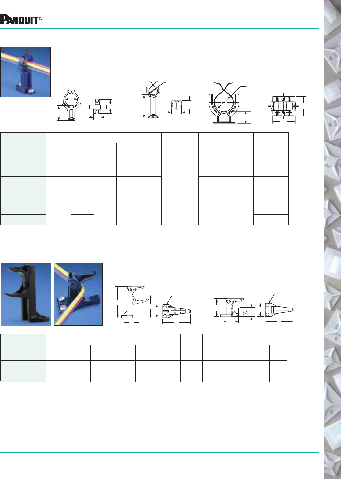
125
Most commonly used parts appear in BOLD.
Part Number
Max.
Dia.
in. (mm)
Dimensions
in. (mm)
Color
&
Material Mounting Method
Packaging*
A B C D E
Std.
Pkg.
Qty*
Std.
Ctn.
Qty.
CPH.75-S8-X
.75
(19.0)
1.88
(47.8)
1.60
(40.8)
1.35
(34.4)
.90
(22.9)
1.18
(30.0) Black
Nylon 6.6
(2) #8 (M4) Screws
10 100
CPL.75-S8-X 1.08
(27.4)
1.52
(38.6)
.56
(14.2)
.88
(22.4)
1.11
(28.2)
10 100
Spring fingers with large lead in facilitate fast routing of wires and easy removal of
completed harness. Overlapping feet on the BR.5 and BR.75 allow the retainers
to be butted together for wire breakouts. Three sizes available for 1/2" (12.7mm),
3/4" (19.0mm) and 2.00" (50.8mm) bundles.
Part Number
Max.
Dia.
in. (mm)
Dimensions
in. (mm) Color
&
Material
Mounting
Method
Packaging*
Std.
Pkg.
Qty
Std.
Ctn.
Qty.A B C D
BR.5-E6-C .50
(12.7)
1.07
(27.2) .44
(11.2)
.78
(19.8)
.55
(14.0)
Black
Acetal
(2) #6 (M3) Screws
100 500
BR.75-E6-C .75
(19.0)
.95
(24.1)
.76
(19.4)
100 500
BR2-1.3-X
2.00
(50.8)
1.32
(33.5)
2.25
(57.2)
2.50
(63.5
2.12
(54.0)
(2) 1/4 (M6) Screws 10 100
BR2-1.3-A-X Rubber Adhesive 2.0 lbs
(907g) Static Load
10 100
BR2-1.5-X 1.59
(40.4)
2.18
(55.4)
2.56
(65.0) (2) 1/4 (M6) Screws
10 100
BR2-4-X 4.00
(101.6)
10 100
BR2-6-X 6.00
(152.4)
10 100
Corner Posts Designed to pre-form tight bundles at harness corners and breakouts.
The top arm pivots for easy removal of completed harness.
CPH Corner Post, High CPL Corner Post, Low
A
E
C
D
B
.172" Dia. Hole
(4.4)
E
CD
B
.172" Dia. Hole
(4.4)
A
Harness Board Accessories
Bundle Retainers
*Order the number of pieces required in multiples of package quantities.
A
D
C
B
A
D
B
C
AB
D
C
BR2-1.3
BR2
BR.5 and BR.75
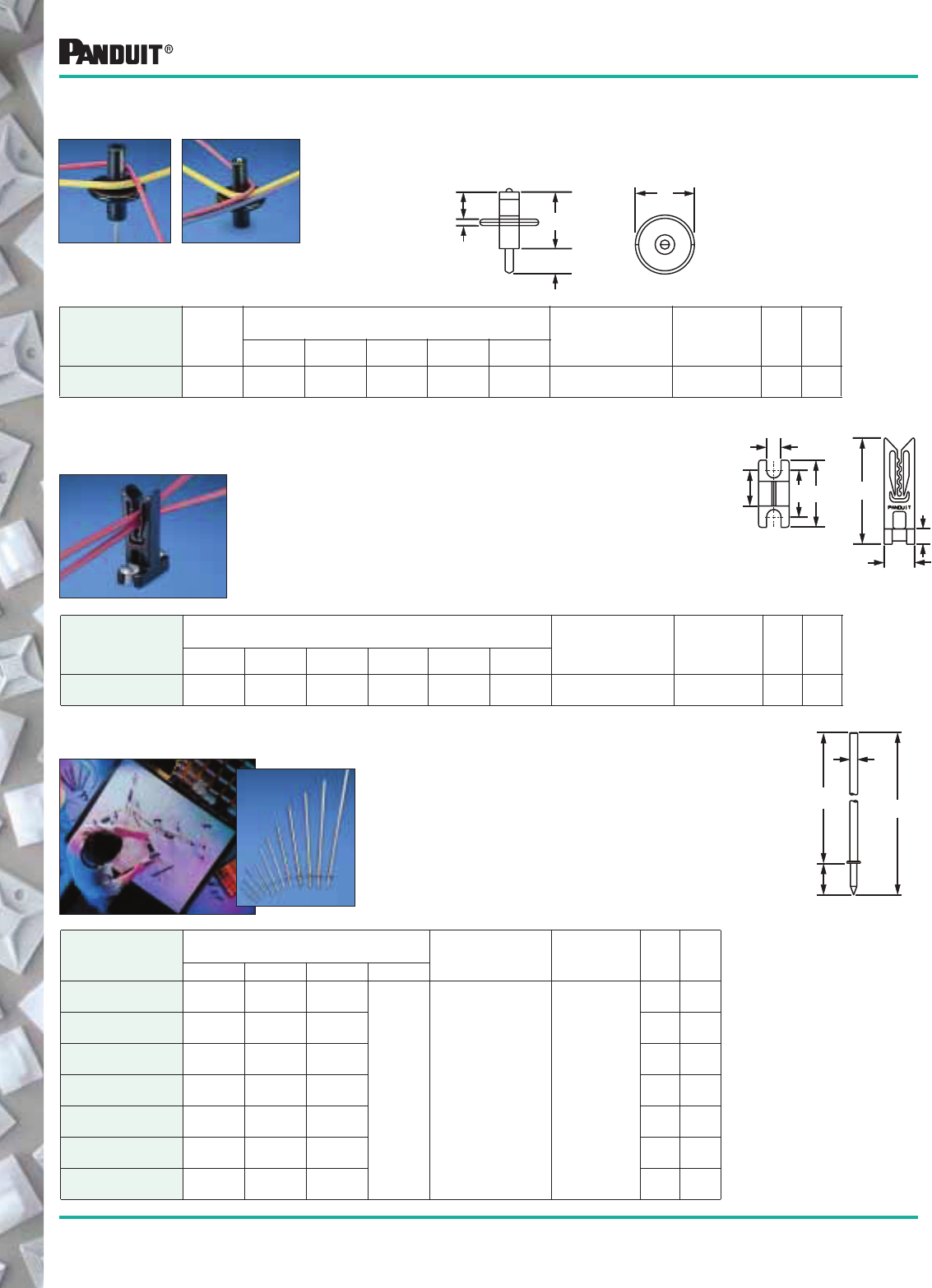
126
Most commonly used parts appear in BOLD.
Part Number
Dimensions
in. (mm) Color
&
Material
Mounting
Method
Std.
Pkg.
Qty.*
Std.
Ctn.
Qty.A B C D E F
WEH-E8-C 1.22
(31.0)
.37
(9.4)
.77
(20.0)
.53
(13.5)
.29
(7.4)
.18
(4.6)
Black
Acetal
(2) #8 (M4)
Screws
100 1000
Wire End Holder Secures wire ends with or without terminations
while harness is being fabricated. Wires can be
easily added or removed from the top, but will
hold the wire from axial movement. Used with
#28 through #16 AWG wires.
Part Number
Dimensions
in. (mm)
Material
Mounting
Method
Std.
Pkg.
Qty.*
Std.
Ctn.
Qty.A B C D
HBN.75-T 1.40
(35.6)
.75
(19.0)
.075
(1.9)
.62
(15.8)
Nickel Plated
Steel
Hammered
into
harness
board
200 1000
HBN1-T 1.65
(41.9)
1.00
(25.4)
.075
(1.9)
200 1000
HBN1.5-T 2.15
(54.6)
1.50
(38.1)
.084
(2.1)
200 1000
HBN2-T 2.65
(67.3)
2.00
(50.8)
.093
(2.4)
200 1000
HBN2.5-T 3.17
(80.5)
2.50
(63.5)
.107
(2.7)
200 1000
HBN3-T 3.67
(93.2)
3.00
(76.2)
.122
(3.1)
200 1000
HBN4-T 4.67
(118.6)
4.00
(101.6)
.142
(3.6)
200 1000
Harness Board Nails Speeds routing of wires. All of the nails have a
uniform driving depth insured by a collar stop.
Smooth finish on the nails, will not abrade
wire jackets.
D
C
A
B
F
E
.16
(4.1)
Harness Board Accessories
D
B
C
Dia.
A
*Order the number of pieces required in multiples of package quantities.
Using an integrated harness board nail, the T-Junction Fixture moves to
form harnesses. When the harness is complete, the fixture can be
pushed down for easy harness removal.
In the “up” position
to form harness.
In the “down”
position to tie and
remove harness.
Part Number
Max.
Bundle
Dia.
in. (mm)
Dimensions
in. (mm) Color
&
Material
Mounting
Method
Std.
Pkg.
Qty.*
Std.
Ctn.
Qty.A B C D E
TJF-X 1.34
(34.0)
.75
(19.0)
.12
(3.0)
1.39
(35.1)
.70
(17.8)
1.12
(28.4)
Black Nylon 6.6 and
Nickel Plated Steel
Integral
Nail
10 100
T-Junction Fixture
A
BC
D
E
(Dia)
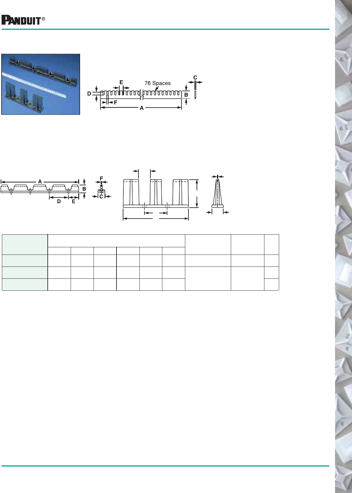
127
Most commonly used parts appear in BOLD.
Assures that wires are held in a particular orientation in sophisticated
wiring harnesses. Consists of fanning strip and fanning strip holder.
Contains evenly spaced “snap slots” to hold wires
in place. No sharp edges to damage wire
insulation. Becomes part of the wiring harness. Will
accept wires up to 18 AWG. Used with FSH40 or
FSHH holders.
Fanning Strip Holders
High Holder (FSHH-X)
Used in conjunction with RER.75-S6,
BR.75-E6 (BR.5-E6) and CPH.75-S8.
Ideal for use with PAT cable tie tool.
Part Number
Dimensions
in. (mm) Color
&
Material
Mounting
Method
Std.
Pkg.
Qty.*A B C D E F
FS156-C 12.1
(307.3)
.31
(7.9)
.04
(1.0)
.12
(3.0)
.156
(4.0)
.06
(1.5)
Natural
Nylon 6.6
Fanning
Strip Holder
100
FSH40-X 6.0
(152.4)
.62
(15.7)
.56
(14.2)
1.50
(38.1)
.75
(19.0)
.04
(1.0) Black
ABS
#8 (M4)
Screws
10
FSHH-X 3.2
(81.3)
1.4
(36.0)
.60
(15.2)
1.10
(28.0)
.53
(13.5)
.04
(1.0)
10
Harness Board Accessories
E
D
A
B
F
C
Fanning Strip System
Low Holder (FSH40-X)
*Order the number of pieces required in multiples of packaging quantities.
Fanning Strip (FS156)
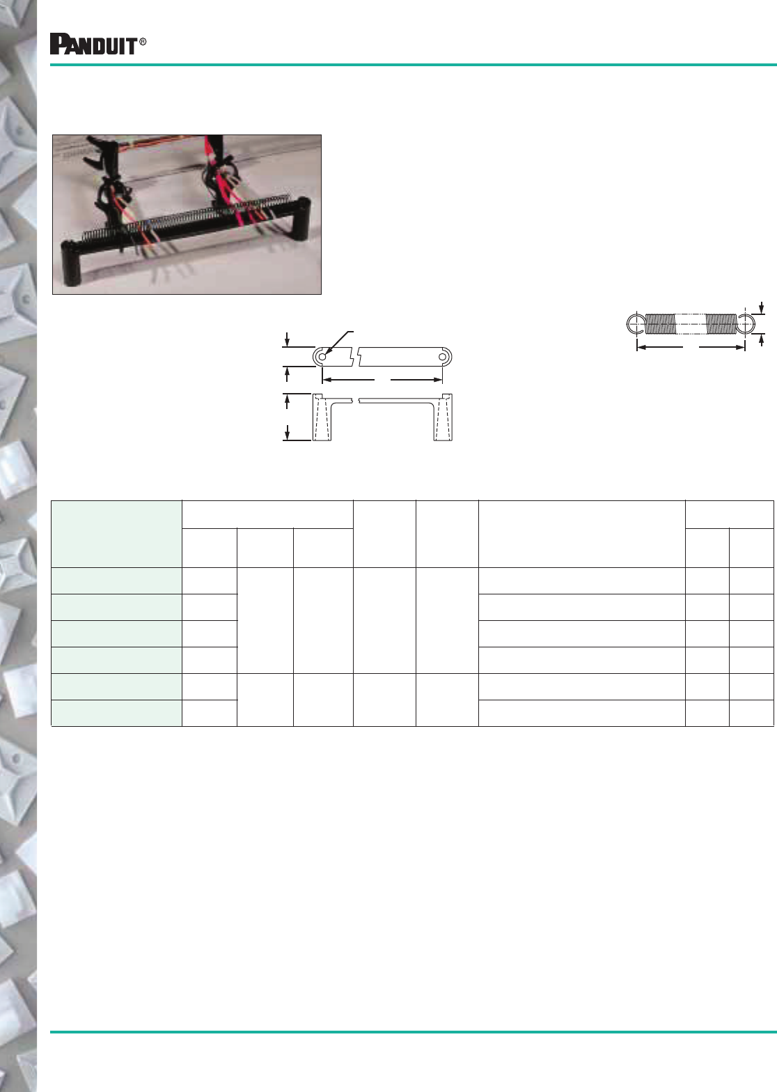
128
Most commonly used parts appear in BOLD.
Separates and holds wires in a harness while the rest of the
harness is being formed. The wires simply pull out from the
spring when the harness is complete.
Part Number
Dimensions
in. (mm)
Material
in. (mm) Color
Mounting
Method
Packaging*
A B C
Std.
Pkg.
Qty.
Std.
Ctn.
Qty.
PBSC1-X 1.00
(25.4)
.44
(11.2) —
.035 (.9)
Thick
Steel
—
Used with SHH1 Spring Holder 10 100
PBSC3-X 3.00
(76.2)
(2) #8 (M4) Screws 10 100
PBSC6-X 6.00
(152.4)
Used with SHH3 Spring Holder 10 100
PBSC12-X 12.00
(304.8)
(2) #8 (M4) Screws 10 100
SHH1-S8-X 1.85
(47.0) 1.30
(33)
.53
(13.4) Nylon 6.6 Black
(2) #8 (M4)
Screws used with PBSC1
10 100
SHH3-S8-X 6.85
(174.0)
(2) #8 (M4)
Screws used with PBSC3 or PBSC6
10 100
Harness Board Accessories
PBSC Spring
Wire Breakout
SHH Spring Holder
Each SHH Spring Holder is supplied
with (1) rigid wire piece to hold the
spring laterally and two #8 (M4) 2"
(50.8) hex head wood screws. Two
sizes available for use with PBSC1
and PBSC6.
A
B
C
B
.188" Dia.
(4.8)
A
Spring Wire
Breakout System
*Order the number of pieces required in multiples of packaging quantities.
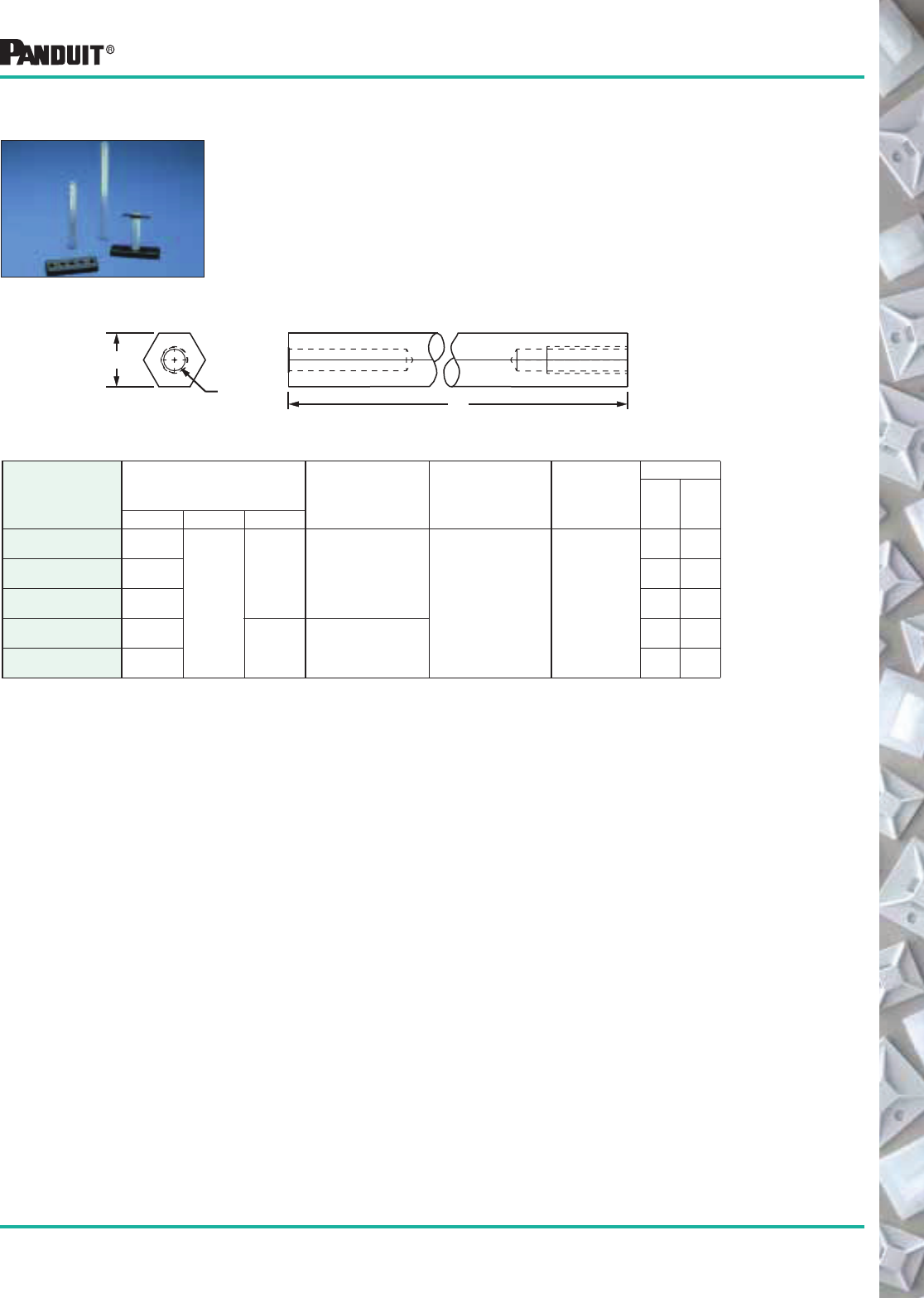
129
Most commonly used parts appear in BOLD.
Part Number
Used With
Part Numbers Material
Mounting
Method
Packaging*
Dimensions
in. (mm) Std.
Pkg.
Qty.
Std.
Ctn.
Qty.A B C
HB2SP19-X 2.00
(50.8)
.50
(12.7)
.20
(5.2)
PLWP, PRWP, WS,
VWS, HWS, TPM
Aluminum 1/4 (M6)
Screw
10 100
HB4SP19-X 4.00
(101.6)
10 100
HB6SP19-X 6.00
(152.4)
10 100
HB2SP25-X 2.00
(51) .295
(7.5)
PLWP, PRWP, PLP,
THMS, HCMP, PMCC
10 100
HB4SP25-X 4.00
(101.6)
10 100
Harness Board Accessories
Harness Board Standoff Posts
Used to hold a push mount accessories or a push mount cable tie at a
specific location on a harness board. The Standoff Post is placed over a hole
in the harness board, a bolt is then threaded into the bottom of the standoff
from the backside of the board and tightened. Push mount accessories are
inserted into the top of the Standoff Post prior to assembly. When the
assembly is complete, the harness and the attached push mount are
removed from the Standoff Post.
*Order the number of mounts required in multiples of package quantities.
B
A
C
(Dia)
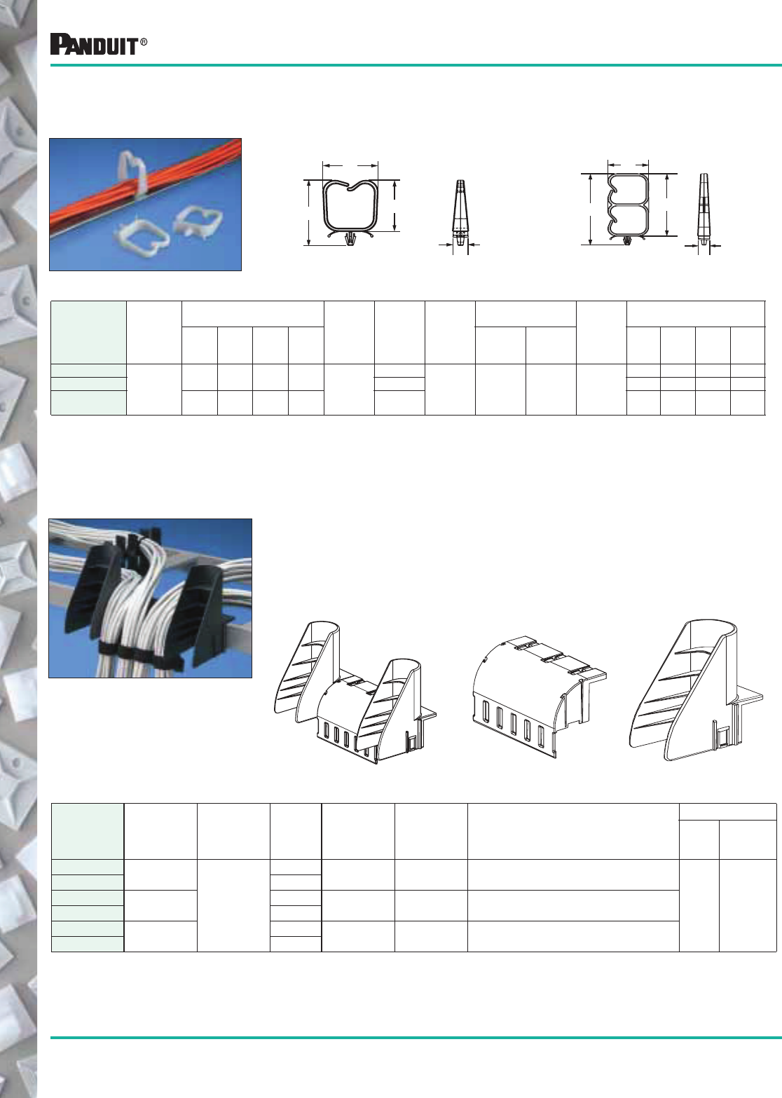
130
Most commonly used parts appear in BOLD.
Communication Cable Management
Part Number‡
Max.
Bundle
Dia.
in. (mm)
Dimensions
in. (mm)
Material Color
Where
Used
Panel Dimensions
in. (mm)
Mounting
Method
in. (mm)
Packaging*
A B C D
Maximum
Thickness
Hole
Diameter
Std.
Pkg.
Qty.
Std.
Ctn.
Qty.
Bulk
Pkg.
Qty.
Bulk
Ctn.
Qty.
VWS106-C
1.06
(26.9)
1.65
(41.7)
1.18
(29.9)
1.30
(31.8)
.34
(8.6) Nylon 6.6
Natural
Indoors .09
(2.3)
.187
(4.7)
Inserted
into
Pre-Drilled
Hole
100 500 1000 5000
VWS106-C20 Black 100 500 1000 5000
VWSDC-C 2.64
(66.8)
1.26
(32.0)
2.36
(59.9)
.39
(9.9)
Natural 100 1000 500 2500
Optical Fiber
Network Saddles
The product is designed with rounded edges for routing fiber optic cables.
This feature provides a very smooth surface to eliminate the potential for
snagging and putting stress on the fiber optic cable.
VWS Push Mount Type
B
AC
D
VWSDC Dual Capacity Type
CMWB-Waterfall Base
Part Number
Bend Radius
Limit
in. (mm) Material Color
Width
in. (mm)
Height
in. (mm) Included in Package
Packaging*
Std.
Pkg.
Qty.*
Std.
Ctn.
Qty.
CMW-KIT —
Glass Filled
Flame
Retardant
Nylon 6.6
Black 9.60
(243.8)
6.07
(154.18) One Base, Two Wings, and Three Cable Ties.
1 10
CMW-KIT10 White
CMWB 1.75
(44.45)
Black 5.24
(133.1)
3.07
(77.98) One Base and Three Cable Ties.
CMWB10 White
CMWW 1.0
(25.4)
Black 2.00
(50.6)
4.87
(123.7) One Bend Radius Control Wing.
CMWW10 White
Waterfall Accessories PANDUIT ® Waterfall Accessory provides bend radius control in both
vertical and horizontal directions when transferring cables from
standard ladder rack. Installs easily to the rung or a stringer of the
ladder rack with PANDUIT ® PLT series cable ties, provided in every
package. PANDUIT ® Waterfall Accessories are part of a complete
cable management system.
CMW-Kit CMWW-Waterfall Wing
D
A
B
C
*Order the number of pieces required in multiples of package quantities.
‡Part numbers listed are for standard materials in standard package quantity. For Bulk package part numbers, see page 137-138.
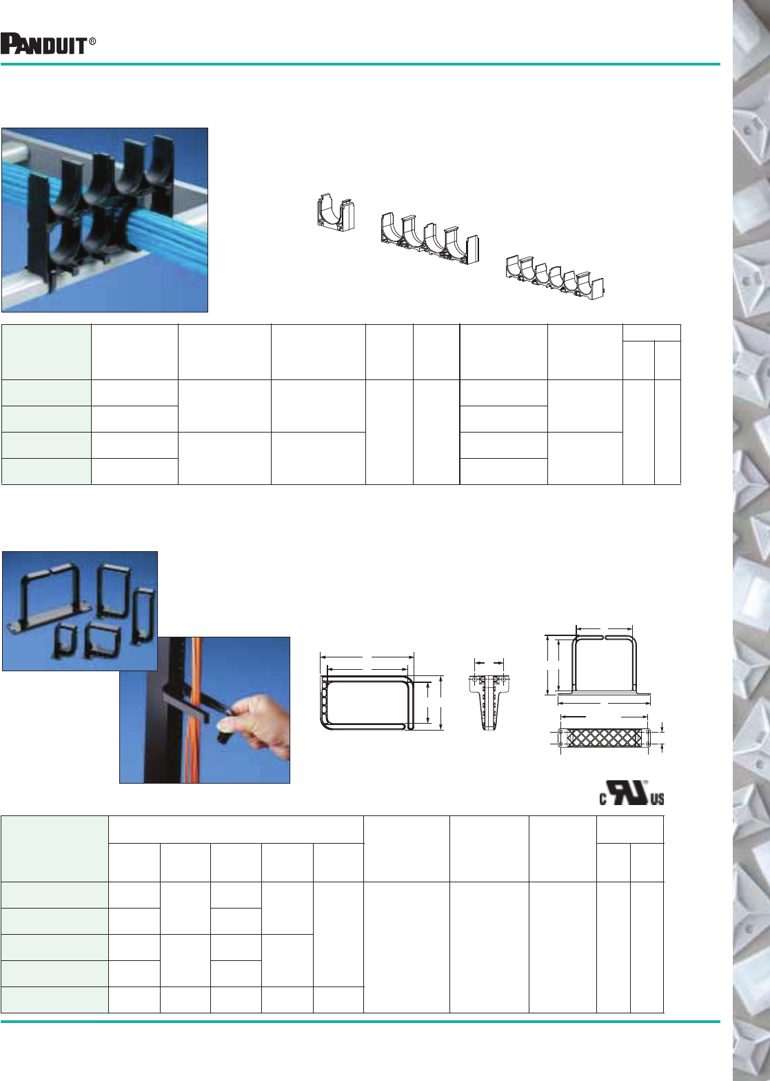
131
Most commonly used parts appear in BOLD.
Communication Cable Management
Part Number
Cable
Bundles
Bundle Diameter
in. (mm) Material Color
Mounting
Method
Width
in. (mm)
Stack
Height
in. (mm)
Packaging*
Std.
Pkg.
Qty.
Std.
Ctn.
Qty.
CRS4-125-X 4
1.25
(31.75)
Glass Filled Flame
Retardant
Nylon 6.6
Black
Standard
Cross
Section
Cable
Ties
5.24
(133.1) 1.42
(36.07)
10 100
CRS1-125-X 1 1.55
(39.4)
CRS6-X 6
0.8
(20.32)
Polycarbonate/ABS
Blend
5.25
(133.35) 1.00
(25.4)
CRS1-X 1 1.13
(28.58)
Stackable Cable
Rack Spacers
PANDUIT ® Stackable Cable Rack Spacers separate and support
cable on standard ladder racks. This product prevents pinch points
between the bottom row of cable and the ladder rack rung as a result
of the weight of multiple cable layers applied on top of each other.
Maximize rack space by stacking products for maximum
cable capacity.
Vertical D-Rings The PANDUIT ® Vertical D-Ring provides open access
cable management. The front arm of the D-Ring rotates
90° to allow entire cable bundles to be inserted. Screw
holes are spaced according to EIA standards and allow
for installation on standard equipment racks.
Part Number
Dimensions
in. (mm)
Material Color
Mounting
Method
Packaging*
A B C D E
Std.
Pkg.
Qty.
Std.
Ctn.
Qty.
CMVDR1 4.80
(121.9) 1.18
(30.0)
5.72
(145.2) 2.05
(52.07)
1.75
(44.45) Flame Retardant
Polycarbonate Black (2) 1/4 (M6)
Screws 1 10
CMVDR1S 2.4
(60.9)
3.26
(82.8)
CMVDR2 4.80
(121.9) 2.40
(60.9)
5.72
(145.2) 3.30
(83.82)
CMVDR2S 2.40
(60.9)
3.26
(82.8)
CMVDRC 4.72
(119.88)
5.09
(129.29)
5.66
(143.64)
8.75
(222.25)
1.12
(28.58)
B
A
C
D
E
A
B
D
C
8.25 (REF)
E
*Order the number of pieces required in multiples of package quantities.
CRS4-125
CRS1 & CRS1-125
CMVDR1, CMVDR1S
CMVDR2, CMVDR2S CMVDRC
CRS6
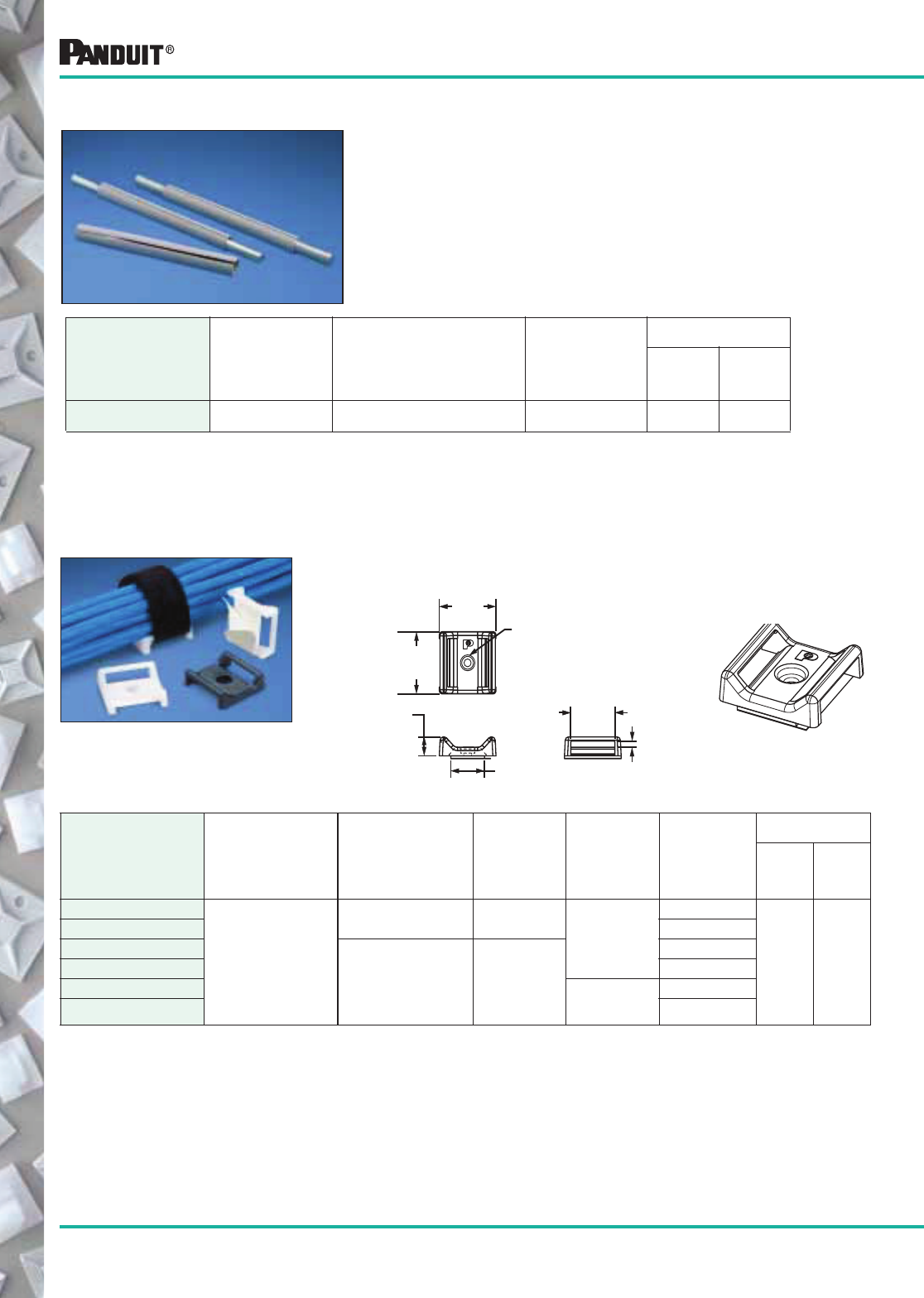
132 Most commonly used parts appear in BOLD.
*Order the number of pieces required in multiples of package quantities.
‡Part numbers listed are for standard materials in standard package quantities. For Bulk package part numbers,
see page 137-138.
.11
(2.79)
.87
(22.10)
.68
(17.27)
.34
(8.64)
1.10
(27.94)
1.10
(27.94) .142
Communication Cable Management
Threaded Rod Cover PANDUIT ® Threaded Rod Cover protects cables from abrasion
caused by contact with threaded rod.
• Manufactured from material that meets UL94V-0 specifications
• Soft material for easy installation
• Available in 18" lengths
Part Number
For Threaded
Rod Size
in. (mm) Material Color
Packaging*
Std.
Pkg.
Qty.
Std.
Ctn.
Qty.
TRC18FR-X8 1/2 to 5/8
(12.7) to (15.88)
Flame Retardant Polyethylene Gray 10 100
TAK-TY
® Hook & Loop
Cable Tie Mounts
Mounting base for use with 3/4" TAK-TY® Hook & Loop
Cable Ties
• For indoor use only
!Used with all PANDUIT ® HLC/HLT/HLS and HLM TAK-TY® options found on page 40.
Part Number‡ Used with Cable Ties Mounting Method
Maximum
Static Load
lbs. (g) Material Color
Packaging*
Std.
Pkg.
Qty.
Std.
Ctn.
Qty.
ABMT-A-C
TAK-TY®!
Hook & Loop
Cable Ties
Rubber Adhesive .38 (172)
Nylon 6.6
Natural
100 1000
ABMT-A-C20 Black
ABMT-S6-C
#6 (M3) Screw —
Natural
ABMT-S6-C20 Black
ABMT-S6-C60 Flame
Retardant
Nylon 6.6
Black
ABMT-S6-C69 Natural
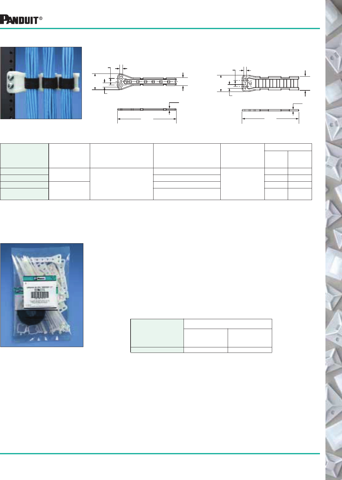
133
Most commonly used parts appear in BOLD.
!Used with all PANDUIT ®Hook & Loop Cable Ties found on page 40.
Part Number
Used
With
Cable
Ties**
Dimensions
in. (mm)
Color
&
Material
Mounting
Method
Packaging*
Std.
Pkg.
Qty.
Std.
Ctn.
Qty.
PPF2S-S25-V M, I, S
See
Drawing
Natural Nylon 6.6
(2) 1/4 (M6)
Screws
5 50
PPF2S-S25-V69 Natural Flame Retardant Nylon 6.6 5 50
PPF2SV-S25-V M, I, S, HS, LH, H,
HLM!
Natural Nylon 6.6 5 50
PPF2SV-S25-V69 Natural Flame Retardant
Nylon 6.6
5 50
Flat PAN-POST ™ Standoff
PPF2S PPF2SV
Used to secure cable in vertical or horizontal configurations.
Mounting hole configuration meets EIA/TIA specifications for
use on racks or in enclosures.
.75
(19.0)
.28
(7.2)
.40
(10.2)
TYP
.61
(15.5)
1.50
(38.1)
REF
5.50
(139.7)
.19
(4.8)
REF
1.38
(34.9)
.26
(6.6)
.37
(9.4)
TYP
.61
(15.5)
REF
1.62
(41.3)
REF
5.60
(142.2)
.19
(4.8)
REF
Communication Cable Management
Communication Cable
Management Kit for Cabinets
Kit of wire management accessories specifically designed
for use in a network cabinet or enclosure.
Part Number
Packaging*
Std.
Pkg.
Qty.
Std.
Ctn.
Qty.
CCMKIT1 1 100
Kit includes the following:
• TAK-TY® Hook & Loop cable tie (HLM-15R0)/1 roll
• Nylon Cable tie (ILT3S)/24 pieces
• Adhesive backed mounts (ABM3H-A and ABM112-A)
6 pieces each
• Flat Post Standoff (PPF2S-S25)/8 pieces
• Push mount (PWMS-H25)/6 pieces
• Vertical wire saddle (VWS106)/4 pieces
*Order the number of pieces required in multiples of package quantities.
‡Part numbers listed are for standard materials in standard package quantities. For Bulk package part numbers, see page 137-138.
**Cable Tie Cross Section Sizes: M = Miniature, I = Intermediate, S = Standard, HS = Heavy Standard, LH = Light-Heavy and H = Heavy.
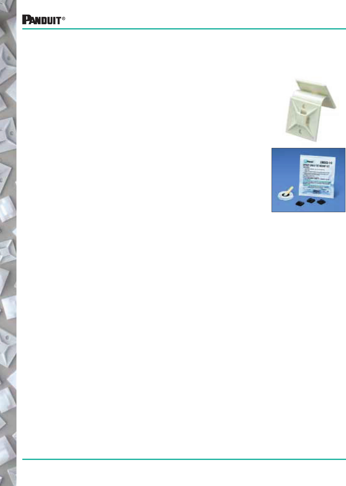
134
Most commonly used parts appear in BOLD.
PANDUIT ®adhesive mounts provide a quick, economical and dependable method of supporting, routing
and protecting wires or cables. Some are used with PANDUIT ® cable ties and others can be used without
cable ties. Adhesive backed mounts adhere to a variety of surfaces. This alternative to mechanical fasteners
offers the advantage of lower installed cost with safe, easy to use, quality products.
• To route wires in control panels and switchboards
• To support bundles of wires away from moving mechanical devices
• Routing and harnessing cables, both indoors and out, to prevent safety hazards
• To organize flat cables in many locations with low profile construction
• Ideal for supporting wire bundles where holes cannot be put into the substrate
• To separate groups of wires for identification
• Original Equipment Manufacturers (OEM)
• Construction Industry
• Telecommunication Systems
• CATV
• Aerospace Industry
General Mount Guidelines
PANDUIT ®pressure sensitive adhesive (foam tape) mounts are intended to secure wire bundles or other
light objects to smooth surfaces. These mounts are not designed to support excessive loads and should not
be used when the maximum expected load exceeds the rated capacity of the mount.
PANDUIT ®offers two standard pressure sensitive foam tapes which are available on most adhesive backed
wiring accessories products. The general purpose tape is produced with a rubber based adhesive and is
identified by an “-A” in the part number. This tape develops its strength extremely fast and can be used
in environments with temperatures ranging from -20°F to +120°F. It is recommended that rubber based
adhesive mounts dwell 2 hours after installation, prior to loading. Rubber based adhesive tape is the best
choice for most adhesive mount applications, including powder coated surfaces.
Acrylic based adhesive tape is also available and is identified by an “-AT” in the part number. This tape is for
use in environments where continuous exposure to temperatures as high as 180°F is possible. Acrylic
based adhesive develops its maximum strength over a longer period of time than rubber based adhesive.
It is recommended that acrylic adhesive mounts dwell 8 hours after installation, prior to loading. Acrylic
based adhesive tape is a good choice for environments with prolonged exposure to UV rays or
temperatures above 120°F.
PANDUIT ®also offers a two-part epoxy for use in applications where excessive loading is required, or
where the surface to which the mount must be applied is porous rather than smooth. This adhesive is
formulated specifically for use on PANDUIT ® mounts, and is packaged in pre-measured cups to insure the
proper ratio of resin and hardener are mixed, eliminating wasted epoxy.
• Utilities
• Electronic Components
• Transportation Industry
• Appliance Manufacturers
• Maintenance and Repair
Operations (MRO)
Selection and Use of Adhesive Mounts
General Introduction
Applications
Markets
Choosing the Right Adhesive
135
Most commonly used parts appear in BOLD.
For specific applications we recommend individual testing prior to production use.
For best results, PANDUIT ®adhesive mounts should be applied to clean, dry, grease-free surfaces. We
recommend that the surface be cleaned prior to mount installation. For rubber and acrylic based foam tape
adhesives, a blend of isopropyl alcohol and water 50/50 may be used to clean most surfaces.
For epoxy type adhesives, especially masonry surfaces, be sure to clean all loose particles away before
mount installation. Some surface abrasion is recommended to achieve maximum strength. A light rubbing
with medium grit emery cloth or sandpaper is best. Wash after abrading.
For proper installation of adhesive mounts with foam tape, simply remove the release liner and place the
mount in the desired location. Avoid touching the adhesive prior to positioning the mount. Apply firm
pressure to the mount for 5 seconds to insure proper adhesion.
Selection and Use of Adhesive Mounts
Allow surface to air dry. Remove the release liner,
being careful not to touch
the adhesive.
Apply full thumb pressure
for at least 5 seconds.
Allow mount to
properly dwell.
Clean surface with a clean
cloth and isopropyl alcohol.
Epoxy Adhesive Mounts
PANDUIT
®EMA adhesive is a two-part epoxy cement which is packaged in convenient mixer cups
containing an equal amount of resin and hardener. Peel the protective covering off and pop the center of the
cup in to form a mixing bowl. Each cup is supplied with a mixer stick and contains enough epoxy to properly
apply three EMS mounts. The resin and hardener should be thoroughly mixed together until the epoxy is a
consistent and uniform color. The mixer stick can then be used to apply the adhesive to the mount. The
epoxy should be forced into the grooves on the bottom of the mount to obtain optimum bond performance.
The mount should be applied to the surface with light pressure and a back-and-forth twisting motion.
Hardening of the epoxy begins five minutes after mixing at room temperature.
1. Not recommended for use on copper or brass.
2. Mounts manufactured from outdoor material only. For specific applications, individual testing prior to extensive
use is suggested.
3. Depends on concentration, exposure time and chemical composition.
Surfaces
Rubber Based
Foam Tape Mounts
Acrylic Based
Foam Tape Mounts
Epoxy Applied
Adhesive Mounts
Plastics
Wood
Glass
Painted Surfaces
Powder Coating
Metal
Paper
Concrete, Stone, Masonry
Good
Good
Fair
Good
Good
Good1
Good
Not Recommended
Good
Good
Good
Good
Fair
Good1
Good
Not Recommended
Good
Good
Good
Fair
Good
Good
Fair
Good
Chemical Resistance
Water
Oil
Gasoline
Dilute Acids
Dilute Alkalis
Organic Solvents
Outdoor Exposure
Good
Poor
Poor
Poor
Good
Poor
Not Recommended
Good
Fair3
Fair3
Fair3
Fair3
Fair3
Good
Poor
Good
Fair
Fair
Fair
Not Recommended
Good2
Since PANDUIT
®manufactures adhesive
backed mounts with a variety of adhesive
types, this chart should be used as a
guideline for choosing the best adhesive
for often-encountered conditions. Each
type of adhesive is rated good, fair or
poor for some specific mounting surfaces
and/or chemical environments.
To determine the number of mounts to
use in a given application, the following
formula can be used as a guideline:
Cable or weight (lbs./ft.)
Static Load rating of Mount (lbs/mt.) = Spacing Mounts
Ft.
Application Chart
Mount Spacing
Surface Preparation
Proper Installation Techniques For Pressure Sensitive Adhesive Mounts
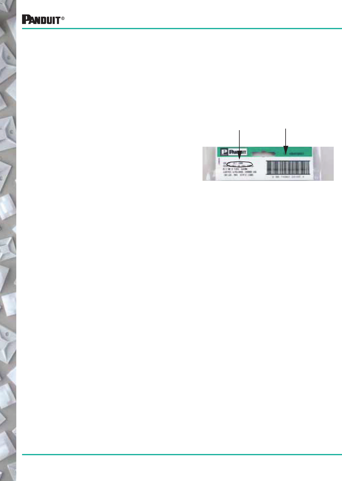
136
Most commonly used parts appear in BOLD.
All PANDUIT ®adhesive products have an expiration date printed on the package label. Use the following
storage guidelines:
1. For rubber and acrylic based foam tape adhesives, store in temperatures of 70°F (21°C) and 45%
Relative Humidity (R.H.).
2. For epoxy type adhesives, store in temperatures of 40°F (4°C) to 75°F (25°C) and relative humidity not in excess of
45%. Storage in opened containers is not recommended. Using the guidelines above, the shelf life of foam tape is 3
years. Shelf life of epoxy is 1 year. Deviation from the recommended storage conditions may reduce the shelf life or
adhesive strength. In any case, adhesive products should never be stored near heating vents or other heat sources,
and storage in lower temperatures than those recommended may increase the shelf life.
There is no simple or easy method for removing PANDUIT ® adhesives. A thin wire or razor blade can be moved in
between the surfaces when removing foam tape mounts; however, the adhesive residue will remain on the surface.
Epoxy adhesives may be removed with a commercial paint stripping solution.
Selection and Use of Adhesive Mounts
Best-If-Used-By Date Quality Control Number
Adhesive mount inventory should be rotated in order to insure
the quality of the adhesive foam tape. Each package of
PANDUIT ® adhesive backed mounts has a Quality Control
Number and a best-if-used-by date on the package label. The
best-if-used-by date provides the customer with an accurate
way to control the rotation of inventory, and, as is the case with
all PANDUIT ® products, the Quality Control Number provides
complete traceability for all components that go into a specific
production run of product.
Proper Storage Conditions
Stock Rotation
Mount Removal
137
Most commonly used parts appear in BOLD.
Wiring Accessories Bulk Package Part Numbers
Bulk Package Part Numbers
The following is an alpha-numeric cross reference of Standard Package Wiring Accessories parts with the corresponding Bulk Package part numbers.
Standard Part No. Bulk Part No.
A
ABMM-A-C ABMM-A-D
ABMM-AT-C ABMM-AT-D
ABMM-AT-C0 ABMM-AT-D0
ABMS-A-C ABMS-A-D
ABM1M-A-C ABM1M-A-M
ABM1M-AT-C ABM1M-AT-M
ABM100-A-C ABM100-A-D
ABM100-AT-C ABM100-AT-D
ABM100-AT-C0 ABM100-AT-D0
ABM100-S6-C ABM100-S6-D
ABM100-S6-C69 ABM100-S6-D69
ABM112-A-C ABM112-A-D
ABM112-AT-C ABM112-AT-D
ABM112-AT-C0 ABM112-AT-D0
ABM112-S6-C ABM112-S6-D
ABM112-S6-C69 ABM112-S6-D69
ABM2S-A-C ABM2S-A-D
ABM2S-AT-C ABM2S-AT-D
ABM2S-AT-C0 ABM2S-AT-D0
ABM3H-A-L ABM3H-A-T
ABM3H-AT-L ABM3H-AT-T
ABM4H-A-L ABM4H-A-T
ABM4H-AT-L ABM4H-AT-T
ACC19-A-C ACC19-A-M
ACC19-A-C20 ACC19-A-M20
ACC19-AT-C ACC19-AT-M
ACC19-AT-C0 ACC19-AT-M0
ACC38-A-C ACC38-A-M
ACC38-A-C20 ACC38-A-M20
ACC38-AT-C ACC38-AT-M
ACC38-AT-C0 ACC38-AT-M0
ACC62-A-C ACC62-A-M
ACC62-A-C0 ACC62-A-M0
ACC62-A-C20 ACC62-A-D20
ACC62-AT-C0 ACC62-AT-M0
AM2-C AM2-M
ARC.68-A-Q ARC.68-A-C
ARC.68-A-Q14 ARC.68-A-C14
ARC.68-S6-Q ARC.68-S6-C
ARC.68-S6-Q14 ARC.68-S6-C14
ASMS-A-X ASMS-A-T
ASMS-A-X0 ASMS-A-T0
B
BCS-L100 BCS-D100
BCS-C115 BCS-D115
BEC38-A-L BEC38-A-T
BEC38-A-L20 BEC38-A-T20
BEC38-A-L0 BEC38-A-T0
BEC62-A-L BEC62-A-T
BEC62-A-L20 BEC62-A-T20
BEC62-A-L0 BEC62-A-T0
BEC75-A-L BEC75-A-T
BEC75-A-L20 BEC75-A-T20
BEC75-A-L0 BEC75-A-T0
BECP38H25-L BECP38H25-T
BECP38H25-L20 BECP38H25-T20
BECP75H25-L BECP75H25-T
BECP75H25-L20 BECP75H25-T20
C
CBLS18-C CBLS18-M
CBLS25-C CBLS25-M
CBLS37-C CBLS37-M
CBLS50-C CBLS50-M
CBLS62-C CBLS62-M
CBLS75-C CBLS75-M
CBP12-C CBP12-M
CBP25-C CBP25-M
CBP31-C CBP31-M
CBP37-C CBP37-M
CBP50-C CBP50-M
CBP62-C CBP62-M
CBP75-C CBP75-M
CBP87-C CBP87-M
CBP100-C CBP100-M
CCS12-S8-C CCS12-S8-M
CCS12-S8-C0 CCS12-S8-M0
CCS19-S8-C CCS19-S8-M
CCS19-S8-C0 CCS19-S8-M0
CCS25-S8-C CCS25-S8-M
CCS25-S8-C0 CCS25-S8-M0
CCS25-S10-C CCS25-S10-M
CCS25-S10-C0 CCS25-S10-M0
CCS31-S8-C CCS31-S8-M
CCS31-S8-C0 CCS31-S8-M0
CCS38-S8-C CCS38-S8-M
CCS38-S8-C0 CCS38-S8-M0
CCS44-S8-C CCS44-S8-M
CCS44-S8-C0 CCS44-S8-M0
CCS50-S8-C CCS50-S8-M
CCS50-S8-C0 CCS50-S8-M0
CCH12-S10-C CCH12-S10-M
CCH12-S10-C0 CCH12-S10-M0
CCH19-S10-C CCH19-S10-M
CCH19-S10-C0 CCH19-S10-M0
CCH25-S10-C CCH25-S10-M
CCH25-S10-C0 CCH25-S10-M0
CCH31-S10-C CCH31-S10-M
CCH31-S10-C0 CCH31-S10-M0
CCH38-S10-C CCH38-S10-M
CCH38-S10-C0 CCH38-S10-M0
CCH44-S10-C CCH44-S10-M
CCH44-S10-C0 CCH44-S10-M0
CCH50-S10-C CCH50-S10-M
CCH50-S10-C0 CCH50-S10-M0
CCH56-S10-C CCH56-S10-M
CCH56-S10-C0 CCH56-S10-M0
CCH62-S10-C CCH62-S10-M
CCH62-S10-C0 CCH62-S10-M0
CCH69-S10-C CCH69-S10-D
CCH69-S10-C0 CCH69-S10-D0
CCH75-S10-C CCH75-S10-M
CCH75-S10-C0 CCH75-S10-M0
CCH81-S10-C CCH81-S10-M
CCH81-S10-C0 CCH81-S10-M0
CCH87-S10-C CCH87-S10-M
CCH87-S10-C0 CCH87-S10-M0
CCH100-S10-C CCH100-S10-M
CCH100-S10-C0 CCH100-S10-M0
Standard Part No. Bulk Part No.
E
EMA-X STD. ONLY
EMS-A-C EMS-A-D
EMS-A-C0 EMS-A-D0
EMSK3-1-3-0 EMSK3-1-3-X
EMSK3-1-X0 EMSK3-1-C0
EMSK12-4-12-X0 EMSK12-4-12-C0
F
FCBI1-S10-C20 FCBI1-S10-M20
FCBI2-S10-C20 FCBI2-S10-M20
FCBI3-S10-C20 FCBI3-S10-M20
FCC5-A-C8 FCC5-A-D8
FCC-A-C8 FCC-A-D8
FCH2-A-C14 FCH2-A-T14
FCM1-A-C14 FCM1-A-T14
FCM1-S6-C14 FCM1-S6-T14
FCM2-A-C14 FCM2-A-T14
FCM2-S6-C14 FCM2-S6-T14
FCM1.2-A-C14 FCM1.2-A-T14
FCM1.2-S6-C14 FCM1.2-S6-T14
FCM3.25-A-L14 FCM3.25-A-T14
FCM3.25-S6-L14 FCM3.25-S6-T14
FCPI1-C20 FCPI1-M20
FCPI2-C20 FCPI2-M20
FCPI3-C20 FCPI3-M20
H
HCME06A12-C130 HCME06A12-M130
HCMP06B12-C20 HCMP06B12-M20
HCMP06C12-C20 HCMP06C12-M20
HWS2819-C HWS2819-M
K
KIMS-H366-C2 KIMS-H366-M2
KIMS-H430-C6 KIMS-H430-M6
KIMS-H500-C4 KIMS-H500-M4
L
LPFCM14-A-C14 LPFCM14-A-D14
LPFCM22-A-C14 LPFCM22-A-D14
LPFCM34-A-C14 LPFCM34-A-D14
LPMM-S2-C LPMM-S2-M
LPMM-S5-C LPMM-S5-M
LPMS-S8-C LPMS-S8-M
LWC19-A-C LWC19-A-M
LWC19-A-C14 LWC19-A-M14
LWC19-H25-C LWC19-H25-M
LWC19-H25-C14 LWC19-H25-M14
LWC25-A-C LWC25-A-D
LWC25-A-C14 LWC25-A-D14
LWC25-H25-C LWC25-H25-D
LWC25-H25-C14 LWC25-H25-D14
LWC38-A-C LWC38-A-D
LWC38-A-C14 LWC38-A-D14
LWC38-H25-C LWC38-H25-D
LWC38-H25-C14 LWC38-H25-D14
LWC50-A-L LWC50-A-T
LWC50-A-L14 LWC50-A-T14
LWC50-H25-L LWC50-H25-T
LWC50-H25-L14 LWC50-H25-T14
LWC75-A-L LWC75-A-C
LWC75-A-L14 LWC75-A-C14
Standard Part No. Bulk Part No.
138
Most commonly used parts appear in BOLD.
LWC75-H25-L LWC75-H25-C
LWC75-H25-L14 LWC75-H25-C14
LWC100-A-L LWC100-A-C
LWC100-A-L14 LWC100-A-C14
LWC100-H25-L LWC100-H25-C
LWC100-H25-L14 LWC100-H25-C14
M
MBMS-S10-C MBMS-S10-M
MMS8 STD. ONLY
MP150-C MP150-M
THRU THRU
MP350-C MP350-M
MP150-C0 MP150-M0
THRU THRU
MP350-C0 MP350-M0
BULK ONLY MP150R
THRU
MP250R
MPMS19-C0 MPMS19-M0
MPMH38-L0 MPMH38-D0
MPMS25-C0 MPMS25-M0
MPMWH32-L0 MPMWH32-D0
P
PBMS-H25-C PBMS-H25-M
PBMS-H25-C14 PBMS-H25-M14
PC038-H25D-C0 PC038-H25D-D0
PC050-H25D-C0 PC050-H25D-D0
PC062-H25D-C0 PC062-H25D-D0
PC075-H25D-C0 PC075-H25D-D0
PC087-H25D-C0 PC087-H25D-D0
PC100-H25D-C0 PC100-H25D-T0
PC112-H25D-C0 PC112-H25D-T0
PC125-H25D-C0 PC125-H25D-T0
PLA2S-A-Q PLA2S-A-C
PMCC38H25-C PMCC38H25-M
PM2H25-C PM2H25-M
PP1S-S10-X PP1S-S10-C
PP2S-S10-X PP2S-S10-C
PP2S-S12-X PP2S-S12-C
PRA2S-A-Q PRA2S-A-C
PWMS-H25-C PWMS-H25-M
R
RAFCBI1-S6-C20 RAFCBI1-S6-M20
RAFCBI2-S6-C20 RAFCBI2-S6-M20
RAFCBI3-S6-C20 RAFCBI3-S6-M20
S
SICH25-C SICH25-M
SICH38-C SICH38-M
SICH50-C SICH50-M
SICH75-C SICH75-M
SMS-A-C SMS-A-D
Standard Part No. Bulk Part No.
T
TA1S8-C TA1S8-M
TA1S10-C TA1S10-M
TA2-C TA2-M
THASS8-C THASS8-M
THASS8-C30 THASS-M30
THASS10-C THASS10-M
THASS10F-C30 THASS10F-M30
THASS25-C THASS25-M
THASS25-C30 THASS25-M30
THASS8F-C THASS8F-M
THASS8F-C30 THASS8F-M30
THASS10F-C THASS10F-M
THASS10F-C30 THASS10F-M30
THASS25F-C THASS25F-M
THASS25F-C30 THASS25F-M30
THAUF4-X THAUF4-C
THM1SC-C THM1SC-M
THM1SC-C30 THM1SC-M30
THMSC35-C30 THMSC35-M30
THMSC35-C639 THMSC35-M639
THMSC35-C630 THMSC35-M630
THMSC35F-C630 THMSC35F-M630
THMSC35F-C39 THMSC35-M39
THMSC35F-C639 THMSC35-M639
THMSC60-C30 THMSC60-M30
THMSC60-C39. THMSC60-M39
THMSC60F-C30 THMSC60F-M30
THMSC60F-C39 THMSC60F-M39
THMSC85-C30 THMSC85-M30
THMSC85-C39 THMSC85-M39
THMSP25-C THMSP25-M
THMSP25-C30 THMSP25-M30
THMSP25F-C30 THMSP25F-M30
TMEH-S8-Q0 TMEH-S8-C0
TMEH-S10-Q0 TMEH-S10-C0
TMEH-S25-Q0 TMEH-S25-C0
TMSH50-C300 TMSH50-T300
TMSTHS10-C0 TMSTHS10-D0
TMSTHS13-C0 TMSTHS13-D0
TMSTHS16-C0 TMSTHS16-D0
TMSTHS19-C0 TMSTHS16-D0
TMSTLHS5-C0 TMSTLHS5-M0
TMSTLHS6-C0 TMSTLHS6-M0
TMSTLHS8-C0 TMSTLHS8-M0
TM1A-C TM1A-M
TM1S4-C TM1S4-M
TM1S6-C TM1S6-M
TM2A-C TM2A-M
TM2PWH25-C TM2PWH25-M
TM2R6-C TM2R6-M
TM2S6-C TM2S6-M
Standard Part No. Bulk Part No.
TM2S8-C TM2S8-M
TM2S8-C100 TM2S8-M100
TM3A-C TM3A-M
TM3R6-C TM3R6-M
TM3S10-C TM3S10-M
TM3S25-C TM3S25-M
TM3S8-C TM3S8-M
TM3S8-C100 TM3S8-M100
TP2-C TP2-M
TP4H-C TP4H-D
TWR-C TWR-M
V
VCC25-A-C VCC25-A-M
VCC50-A-C VCC50-A-T
VCS-25-L VCS-25-D
VCS-25-L100 VCS-25-D100
VWS106-C VWS106-M
VWS106-C20 VWS106-M20
VWS4218-C VWS4218-M
VWS4238-C VWS4238-M
VWS4274-C VWS4274-M
VWS42105-C VWS42105-M
VWSDC-C VWSDC-D
W
WS75-25-C WS75-25-M
WS75-50-C WS75-50-M
WS75-75-C WS75-75-M
Standard Part No. Bulk Part No.
Bulk Package Part Numbers (continued)
The following is an alpha-numeric cross reference of Standard Package Wiring Accessories parts with the corresponding Bulk Package part numbers.
Wiring Accessories Bulk Package Part Numbers
139
Most commonly used parts appear in BOLD.
Abrasion Protection Products
Heat Shrink PVC Non-Shrink Tubing
Spiral Wrap
Abrasion Protection for Wire, Cable, Hydraulic and Pneumatic Tubing
Grommet Edging
Corrugated Loom Tubing Braided Sleeving
Split Harness Wrap
140
Most commonly used parts appear in BOLD.
For standard packages containing 6" lengths, refer to individual pages for complete part number offering.
Note: The above information is to be used as a guide. For specific part number offerings review individual pages for verification.
▲KYNAR is a registered trademark of Atofiina Chemicals, Inc.
TEFLON is a registered trademark of E.I. DuPont de Nemours Co.
CHARACTERISTICS
See page 160 for IP Technical information.
U.L. Listed X
UL Recognized X‡ X X X
CSA Certified X‡✓X✓X✓X**
VW-1 Rated X X X
Very Flexible X X
Flexible X X X X
Semi-Rigid X X X X
Thin Wall X X X X X X X X X
Thick Wall X
Cross-Linked Material X X X X X X X X X
Colors Available X X X*
High Shrink Ratio 2.5:1 3:1 3:1
Flame Retardant X‡ X X X X X X X X X
Adhesive Lined (Dual Wall) X X X X
Meets Military Specification X X X X X X X X X
Below Ground Application X
High Temp Applications(>250ºF) X X
Highly Chemical Resistant X X
Low Coefficient of Friction X
Custom Cut Lengths X X X X X X X X X X
Standard 6" pieces X X X X
Standard 4' lengths X X X X X X X X
Small 25' Reels X X X X
Large Reels X X X X
IP Rating 62 62 62 62 — 62 66 66 66 68
Found on Page. . . 141-
144
145-
146
148 150 149 147 151 153 152 154
HSTT
HSTTV
HSTTN
HSTTK
HSTTT
HSTTP
HSTTVA
HSTTRA
HSTTA
HST
*Black/Red
**Except red
‡Except clear
✓Except sizes over 1"
Type
HSTT = Thin Wall
HSTTV = Thin Wall VW-1
HSTTN = Thin Wall Neoprene
HSTTK = Thin Wall KYNAR
HSTTT = Thin Wall TFE TEFLON
HSTTP = Thin Wall PVC
HSTTVA = Flexible Adhesive Lined
HSTTRA = Semi-Rigid Adhesive Lined
HSTTA = Thin Wall Adhesive Lined
Expanded Diameter
05 = 3/64" (1.2mm)
06 = 1/16" (1.6mm)
09 = 3/32" (2.4mm)
12 = 1/8" (3.2mm)
19 = 3/16" (4.8mm)
25 = 1/4" (6.4mm)
38 = 3/8" (9.5mm)
50 = 1/2" (12.7mm)
75 = 3/4" (19.0mm)
100 = 1" (25.4mm)
150 = 1-1/2" (38.1mm)
200 = 2" (50.5mm)
300 = 3" (76.2mm)
400 = 4" (101.6mm)
Tube Length
48" = (1.2m)
NONE = Reel
Package Quantity
(If Tube Length Specified)
Reels (If No Tube Length Specified)
Q = 25' (7.6m)
L = 50' (15.2m)
C = 100' (30.5m)
T = 200' (61.0m)
D = 500' (152.4m)
M = 1000' (304.8m)
Color
NONE = Black
C = Clear
2 = Red
4 = Yellow
5 = Green
6 = Blue
10 = White
45 = Yellow/
Green
Thin Wall Heat Shrink Part Number System
HSTT 12 - 48 - Q 10
PANDUIT ® Heat Shrink Tubing — Heat Shrink Tubing Quick Selection Guide
Quick reference for PANDUIT ® Heat Shrinking for specific location applications
2 = 2 Pcs.
5 = 5 Pcs.
Q = 25 Pcs.
LQ = 75 Pcs.
CQ = 125 Pcs.
T = 200 Pcs.
TL = 250 Pcs.
Y= 6" Pcs.
141
Most commonly used parts appear in BOLD.
HSTT Heat Shrink in 4' (1.2m) Pieces
and Reels
• General purpose heat shrink tubing for dry locations
• Applications include insulating, protecting, harnessing
and identifying wires
HSTT in Bulk Packages — Large Reels and 4' (1.2m) Pcs. (3/64" to 3/16" Expanded I.D.)
Part Number
(Black✓)
Nominal
Diameter
in.
Minimum
Expanded
I.D.
in. (mm)
Maximum
Recovered
I.D.
in. (mm)
Nominal
Recovered
Wall
Thickness
in. (mm)
Length
Feet (m)
Bulk
Pkg.
Qty.*
Bulk
Ctn.
Qty.
HSTT05-48-Q
HSTT05-48-TL
HSTT05-C
HSTT05-M
3/64 .046 (1.2) .023 (0.6) .016 (0.4)
4 (1.2)
4 (1.2)
100 (30.5)
1000 (304.8)
25 Pcs.
250 Pcs.
1 Reel
1 Reel
—
—
10 Reels
2 Reels
HSTT06-48-Q
HSTT06-48-TL
HSTT06-C
HSTT06-M
1/16 .063 (1.6) .031 (0.8) .017 (0.4)
4 (1.2)
4 (1.2)
100 (30.5)
1000 (304.8)
25 Pcs.
250 Pcs.
1 Reel
1 Reel
—
—
10 Reels
2 Reels
HSTT09-48-Q
HSTT09-48-TL
HSTT09-C
HSTT09-M
3/32 .093 (2.4) .046 (1.2) .020 (0.5)
4 (1.2)
4 (1.2)
100 (30.5)
1000 (304.8)
25 Pcs.
250 Pcs.
1 Reel
1 Reel
—
—
10 Reels
2 Reels
HSTT12-48-Q
HSTT12-48-TL
HSTT12-C
HSTT12-M
1/8 .125 (3.2) .062 (1.6) .020 (0.5)
4 (1.2)
4 (1.2)
100 (30.5)
1000 (304.8)
25 Pcs.
250 Pcs.
1 Reel
1 Reel
—
—
10 Reels
2 Reels
HSTT19-48-Q
HSTT19-48-TL
HSTT19-C
HSTT19-M
3/16 .187 (4.8) .093 (2.4) .020 (0.5)
4 (1.2)
4 (1.2)
100 (30.5)
1000 (304.8)
25 Pcs.
250 Pcs.
1 Reel
1 Reel
—
—
10 Reels
2 Reels
(Except Clear) (Except Clear)
Flexible Polyolefin DRY-SHRINK ™ Heat Shrink Tubing
HSTT Polyolefin Cross-Linked
600V
-67°F to 275°F
(-55°C to 135°C‡) AMS-DTL-23053/5
Class 1 or Class 2
Flexible
Shrink Ratio: ▲
2:1
Flame Retardant
(Except Clear) Variety of Colors
(Except Clear)
Type Materials
‡Maximum UL temperature range is 125°C
*Order in multiples of bulk pkg. qty.
See page 160 for IP Technical Information.
✓For additional color information, contact PANDUIT ® Technical Assistance 866-405-6657.
▲Shrink ratios are approximations; please refer to above ordering information for the exact min. Expanded and max. recovered I.D.’s.
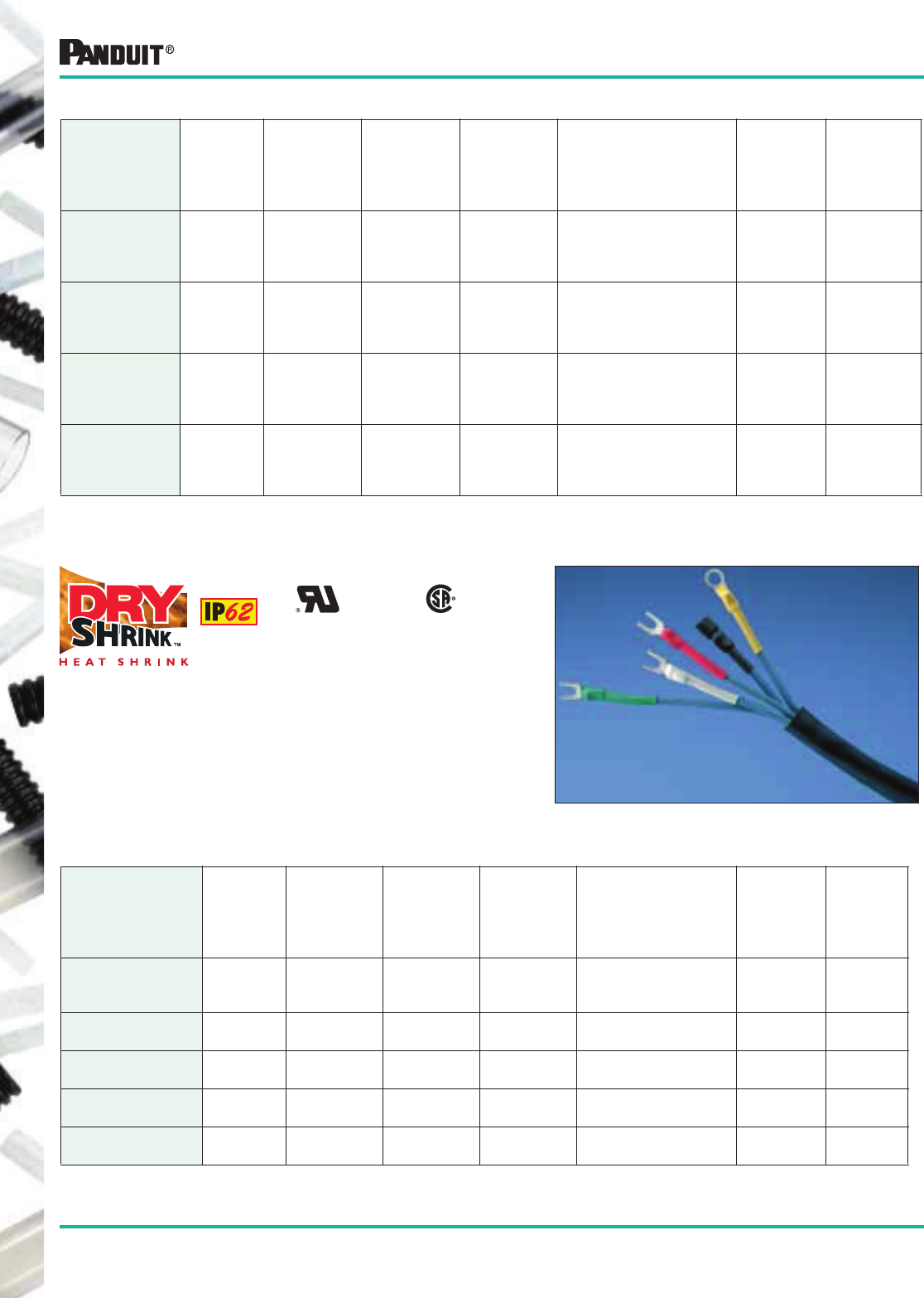
142
Most commonly used parts appear in BOLD.
*Order in multiples of bulk pkg. qty.
✓For additional color information, contact PANDUIT ® Technical Assistance 866-405-6657.
▲Shrink ratios are approximations; please refer to above ordering information for the exact min. Expanded and max. Recovered I.D.’s.
Flexible Polyolefin DRY-SHRINK ™ Heat Shrink Tubing
HSTT in Bulk Packages — Large Reels and 4' (1.2m) Pcs. (1" to 4" Expanded I.D.)
Part Number
(Black✓)
Nominal
Diameter
in.
Minimum
Expanded
I.D.
in. (mm)
Maximum
Recovered
I.D.
in. (mm)
Nominal
Recovered
Wall
Thickness
in. (mm)
Length
Feet (m)
Bulk
Pkg.
Qty.*
Bulk
Ctn.
Qty.
HSTT100-48-5
HSTT100-48-LQ
HSTT100-C
1 1.00 (25.4) .500 (12.7) .035 (0.9)
4 (1.2)
4 (1.2)
100 (30.5)
5 Pcs.
75 Pcs.
1 Reel
—
—
2 Reels
HSTT150-48-5
HSTT150-C 1 1/2 1.50 (38.1) .750 (19.0) .040 (1.0) 4 (1.2)
100 (30.5)
5 Pcs.
1 Reel
—
2 Reels
HSTT200-48-5
HSTT200-L 2 2.00 (50.8) 1.00 (25.4) .045 (1.1) 4 (1.2)
50 (15.2)
5 Pcs.
1 Reel
—
2 Reels
HSTT300-48-2
HSTT300-L 3 3.00 (76.2) 1.50 (38.1) .050 (1.3) 4 (1.2)
50 (15.2)
2 Pcs.
1 Reel
—
—
HSTT400-48-2
HSTT400-L 4 4.00 (101.6) 2.00 (50.8) .055 (1.4) 4 (1.2)
50 (15.2)
2 Pcs.
1 Reel
—
—
HSTT in Bulk Packages (cont.) — Large Reels and 4'(1.2m) Pcs. (1/4" to 3/4" Expanded I.D.)
Part Number
(Black✓)
Nominal
Diameter
in.
Minimum
Expanded
I.D.
in. (mm)
Maximum
Recovered
I.D.
in. (mm)
Nominal
Recovered
Wall
Thickness
in. (mm)
Length
Feet (m)
Bulk
Pkg.
Qty.*
Bulk
Ctn.
Qty.
HSTT25-48-Q
HSTT25-48-TL
HSTT25-C
HSTT25-D
1/4 .250 (6.4) .125 (3.2) .025 (0.6)
4 (1.2)
4 (1.2)
100 (30.5)
500 (152.4)
25 Pcs.
250 Pcs.
1 Reel
1 Reel
—
—
10 Reels
2 Reels
HSTT38-48-Q
HSTT38-48-TL
HSTT38-C
HSTT38-T
3/8 .375 (9.5) .187 (4.8) .025 (0.6)
4 (1.2)
4 (1.2)
100 (30.5)
200 (61.0)
25 Pcs.
250 Pcs.
1 Reel
1 Reel
—
—
10 Reels
2 Reels
HSTT50-48-Q
HSTT50-48-T
HSTT50-C
HSTT50-T
1/2 .500 (12.7) .250 (6.4) .025 (0.6)
4 (1.2)
4 (1.2)
100 (30.5)
200 (61.0)
25 Pcs.
200 Pcs.
1 Reel
1 Reel
—
—
10 Reels
2 Reels
HSTT75-48-5
HSTT75-48-CQ
HSTT75-C
HSTT75-T
3/4 .750 (19.0) .375 (9.5) .030 (0.8)
4 (1.2)
4 (1.2)
100 (30.5)
200 (61.0)
5 Pcs.
125 Pcs.
1 Reel
1 Reel
—
—
10 Reels
2 Reels
(Except Clear) (Except Clear)
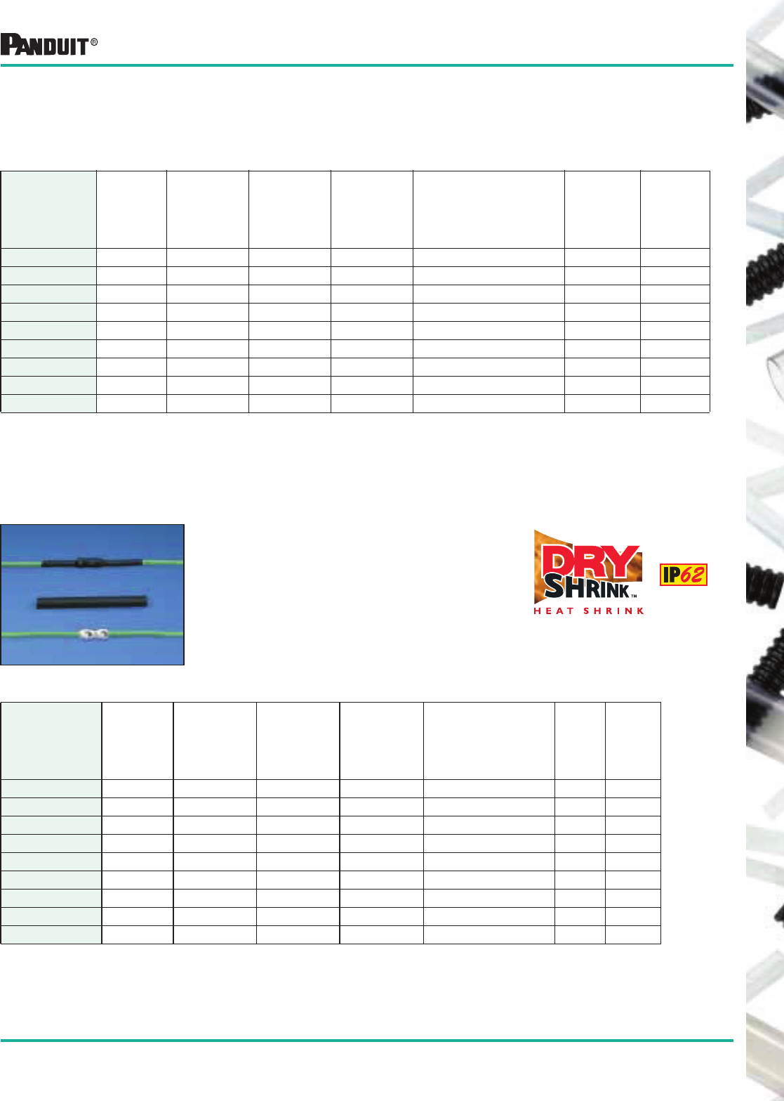
143
Most commonly used parts appear in BOLD.
*Order in multiples of std. pkg. qty.
✓For additional color information, contact PANDUIT ® Technical Assistance 866-405-6657.
▲Shrink ratios are approximations; please refer to above ordering information for the exact min. expanded and
max. recovered I.D.’s.
Flexible Polyolefin DRY-SHRINK ™ Heat Shrink Tubing
HSTT in Standard Packages
Part Number
(Black✓)
Nominal
Diameter
in.
Minimum
Expanded
I.D.
in. (mm)
Maximum
Recovered
I.D.
in. (mm)
Nominal
Recovered
Wall
Thickness
in. (mm)
Length
Feet (m)
Std.
Pkg.
Qty.*
Std.
Ctn.
Qty.
HSTT05-Q 3/64 .046 (1.2) 0.23 (0.6) .016 (0.4) 25 (7.6) 1 Reel 10 Reels
HSTT06-Q 1/16 .063 (1.6) .031 (0.8) .017 (0.4) 25 (7.6) 1 Reel 10 Reels
HSTT09-Q 3/32 .093 (2.4) .046 (1.2) .020 (0.5) 25 (7.6) 1 Reel 10 Reels
HSTT12-Q 1/8 .125 (3.2) .062 (1.6) .020 (0.5) 25 (7.6) 1 Reel 10 Reels
HSTT19-Q 3/16 .187 (4.8) .093 (2.4) .020 (0.5) 25 (7.6) 1 Reel 10 Reels
HSTT25-Q 1/4 .250 (6.4) .125 (3.2) .025 (0.6) 25 (7.6) 1 Reel 10 Reels
HSTT38-Q 3/8 .375 (9.5) .187 (4.8) .025 (0.6) 25 (7.6) 1 Reel 10 Reels
HSTT50-Q 1/2 .500 (12.7) .250 (6.4) .025 (0.6) 25 (7.6) 1 Reel 10 Reels
HSTT75-Q 3/4 .750 (19.0) .375 (9.5) .030 (0.8) 25 (7.6) 1 Reel 10 Reels
HSTT Heat Shrink on 25' (7.6m) Reels
• General purpose heat shrink tubing for dry locations
• Featuring unique self dispensing Q-Box 25’ (7.5m)
HSTT Heat Shrink
Standard Packs of Heat Shrink — 6" (152.4mm) Pieces
HSTT in Standard Packages
Part Number
(Black✓)
Nominal
Diameter
in.
Minimum
Expanded
I.D.
in. (mm)
Maximum
Recovered
I.D.
in. (mm)
Nominal
Recovered
Wall
Thickness
in. (mm)
Length
in. (mm)
Std.
Pkg.
Qty.*
Std.
Ctn.
Qty.
HSTT06-Y 1/16 .063 (1.6) .031 (0.8) .017 (0.4) 6 (152.4) 26 pcs. 10 Pkgs.
HSTT09-Y 3/32 .093 (2.4) .046 (1.2) .020 (0.5) 6 (152.4) 24 pcs. 10 Pkgs.
HSTT12-Y 1/8 .125 (3.2) .062 (1.6) .020 (0.5) 6 (152.4) 20 pcs. 10 Pkgs.
HSTT19-Y 3/16 .187 (4.8) .093 (2.4) .020 (0.5) 6 (152.4) 18 pcs. 10 Pkgs.
HSTT25-Y 1/4 .250 (6.4) .125 (3.2) .025 (0.6) 6 (152.4) 14 pcs. 10 Pkgs.
HSTT38-Y 3/8 .375 (9.5) .187 (4.8) .025 (0.6) 6 (152.4) 12 pcs. 10 Pkgs.
HSTT50-Y 1/2 .500 (12.7) .250 (6.4) .025 (0.6) 6 (152.4) 10 pcs. 10 Pkgs.
HSTT75-Y 3/4 .750 (19.0) .375 (9.5) .030 (0.8) 6 (152.4) 8 pcs. 10 Pkgs.
HSTT100-Y 1 1.00 (25.4) .500 (12.7) .035 (0.9) 6 (152.4) 6 pcs. 10 Pkgs.
Small package holds unused tube and fits
easily in a tool box
• General purpose heat shrink tubing for
dry locations
• Applications include insulating, protecting,
harnessing and identifying wires
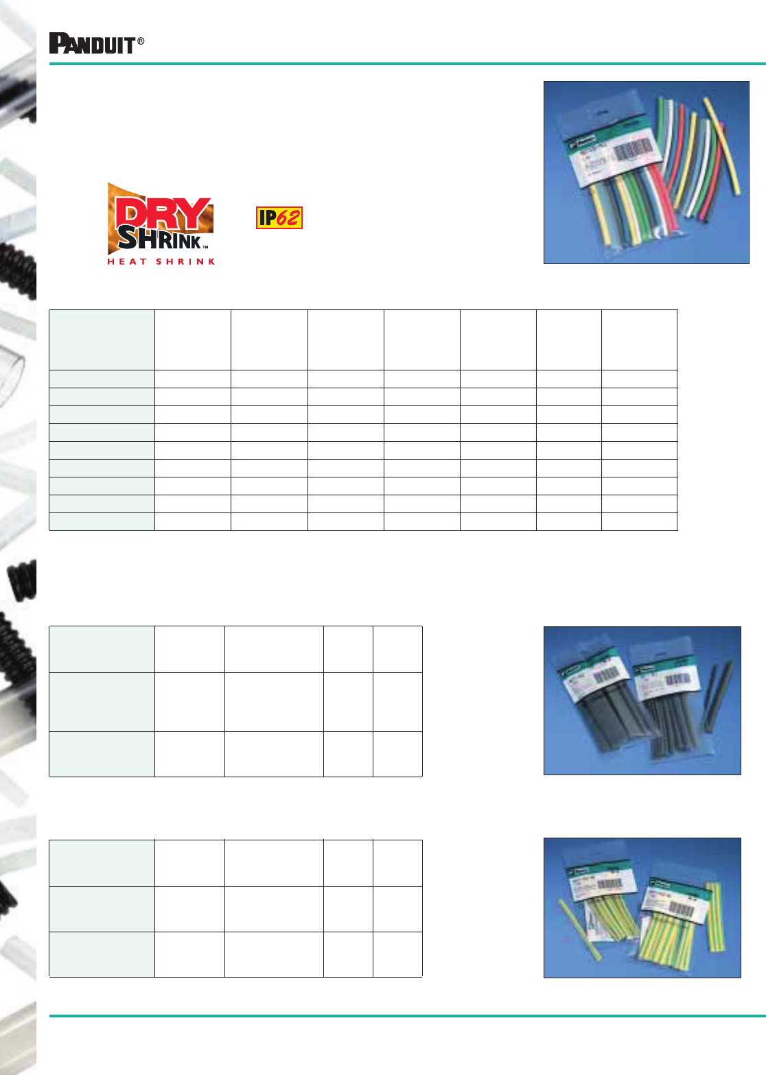
144
Most commonly used parts appear in BOLD.
Flexible Polyolefin DRY-SHRINK ™ Heat Shrink Tubing
Standard Packs of Heat Shrink —
6" (152.4mm) Pieces
Small package holds unused tube and fits easily in a tool box
• Assorted colors and diameters available
HSTT — Combination: Black and Colors — Single Diameter
NOTE: Colors include clear, red, yellow, green, blue and white. For additional color information, contact PANDUIT ® Technical Assistance 866-405-6657.
Part Number
Nominal
Diameter
in.
Minimum
Expanded
I.D.
in. (mm)
Maximum
Recovered
I.D.
in. (mm)
Black
No. Pcs.
Each
Color No.
Pcs.
Std.
Pkg.
Qty.*
Std.
Ctn.
Qty.
HSTT06-YK1 1/16 .063 (1.6) .031 (0.8) 8 3 26 pcs. 10 Pkgs.
HSTT09-YK1 3/32 .093 (2.4) .046 (1.2) 6 3 24 pcs. 10 Pkgs.
HSTT12-YK1 1/8 .125 (3.2) .062 (1.6) 2 3 20 pcs. 10 Pkgs.
HSTT19-YK1 3/16 .187 (4.8) .093 (2.4) 6 2 18 pcs. 10 Pkgs.
HSTT25-YK1 1/4 .250 (6.4) .125 (3.2) 2 2 14 pcs. 10 Pkgs.
HSTT38-YK1 3/8 .375 (9.5) .187 (4.8) 6 1 12 pcs. 10 Pkgs.
HSTT50-YK1 1/2 .500 (12.7) .250 (6.4) 4 1 10 pcs. 10 Pkgs.
HSTT75-YK1 3/4 .750 (19.0) .375 (9.5) 2 1 8 pcs. 10 Pkgs.
HSTT100-YK1 1 1.00 (25.4) .500 (12.7) 1 1 7 pcs. 10 Pkgs.
HSTT — Black Only — Multiple Diameters
Part Number
Nominal
Diameter
Black Number
of Pieces by
Diameter
Std.
Pkg.
Qty.*
Std.
Ctn.
Qty.
HSTT-YK1 Various;
Smaller
Range
(2) pcs. each
1/8", 1/16", 3/16",
3/32", 1/4",
1/2", 3/8"
14 pcs. 10 Pkgs.
HSTT-YK2 Various;
Larger
Range
(2) pcs. each
3/8", 1/2",
3/4", 1"
8 pcs. 10 Pkgs.
HSTT — Yellow/Green Stripe — Multiple Diameters
Part Number
Nominal
Diameter
Number
of Pieces by
Diameter
Std.
Pkg.
Qty.*
Std.
Ctn.
Qty.
HSTT-YK1-45 Various;
Smaller
Range
(2) pcs. each
1/8", 3/16",
1/4", 3/8"
8 pcs. 10 Pkgs.
HSTT-YK2-45 Various;
Larger
Range
(2) pcs. each
3/8",
1/2", 3/4"
6 pcs. 10 Pkgs.
*Order in multiples of std. pkg. qty.
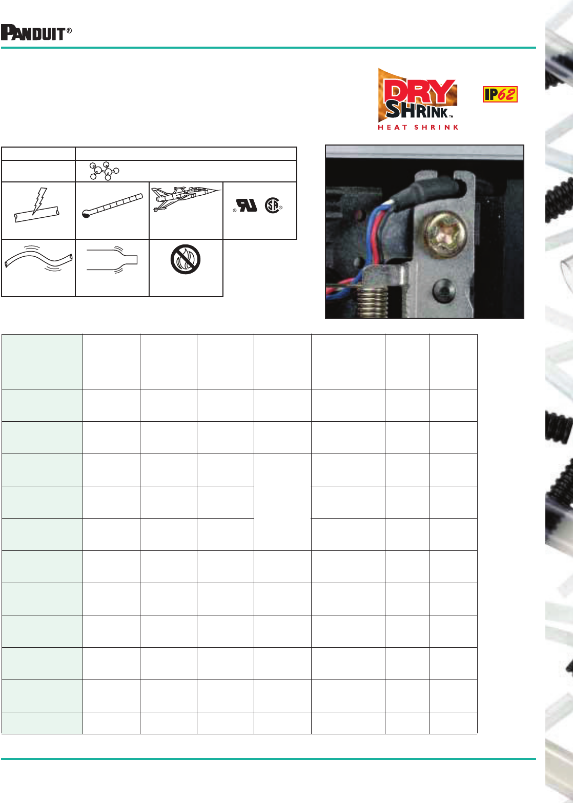
145
Most commonly used parts appear in BOLD.
*Order in multiples of bulk pkg. qty.
✓For additional color information, contact PANDUIT ® Technical Assistance 866-405-6657.
▲Shrink ratios are approximations; please refer to above ordering information for the exact min. expanded and max.
recovered I.D.’s.
Flexible Polyolefin VW-1 DRY-SHRINK™ Heat Shrink Tubing
HSTTV Heat Shrink in Small Reels and 4' (1.2m) Pieces
• For dry locations
• Highly flame retardant
• Meets UL VW-1 rating
• Fast Shrink Time
-67°F to 257°F
(-55°C to 125°C‡)
600V AMS-DTL-23053/5
Class 3
Flexible Shrink Ratio:▲
2:1 Highly Flame
Retardant VW-1
HSTTV Polyolefin Cross-Linked
Type Materials
VW-1 OFT
HSTTV in Bulk Packages — Small Reels & 4' (1.2m) Pcs.
Part Number
(Black✓)
Nominal
Diameter
in.
Minimum
Expanded I.D.
in. (mm)
Maximum
Recovered
I.D.
in. (mm)
Nominal
Recovered
Wall
Thickness
in. (mm)
Length
Feet (m)
Bulk
Pkg.
Qty.*
Bulk
Ctn.
Qty.
HSTTV05-48-Q
HSTTV05-48-TL
HSTTV05-C
3/64 .046 (1.2) .023 (0.6) .016 (0.4)
4 (1.2)
4 (1.2)
100 (30.5)
25 Pcs.
250 Pcs.
1 Reel
—
—
10 Reels
HSTTV06-48-Q
HSTTV06-48-TL
HSTTV06-C
1/16 .063 (1.6) .031 (0.8) .017 (0.4)
4 (1.2)
4 (1.2)
100 (30.5)
25 Pcs.
250 Pcs.
1 Reel
—
—
10 Reels
HSTTV09-48-Q
HSTTV09-48-TL
HSTTV09-C
3/32 .093 (2.4) .046 (1.2)
.020 (0.5)
4 (1.2)
4 (1.2)
100 (30.5)
25 Pcs.
250 Pcs.
1 Reel
—
—
10 Reels
HSTTV12-48-Q
HSTTV12-48-TL
HSTTV12-C
1/8 .125 (3.2) .062 (1.6)
4 (1.2)
4 (1.2)
100 (30.5)
25 Pcs.
250 Pcs.
1 Reel
—
—
10 Reels
HSTTV19-48-Q
HSTTV19-48-TL
HSTTV19-C
3/16 .187 (4.8) .093 (2.4)
4 (1.2)
4 (1.2)
100 (30.5)
25 Pcs.
250 Pcs.
1 Reel
—
—
10 Reels
HSTTV25-48-Q
HSTTV25-48-TL
HSTTV25-C
1/4 .250 (6.4) .125 (3.2) .025 (0.6)
4 (1.2)
4 (1.2)
100 (30.5)
25 Pcs.
250 Pcs.
1 Reel
—
—
10 Reels
HSTTV38-48-Q
HSTTV38-48-TL
HSTTV38-C
3/8 .375 (9.5) .187 (4.8) .025 (0.6)
4 (1.2)
4 (1.2)
100 (30.5)
25 Pcs.
250 Pcs.
1 Reel
—
—
10 Reels
HSTTV50-48-Q
HSTTV50-48-T
HSTTV50-C
1/2 .500 (12.7) .250 (6.4) .025 (0.6)
4 (1.2)
4 (1.2)
100 (30.5)
25 Pcs.
200 Pcs.
1 Reel
—
—
10 Reels
HSTTV75-48-5
HSTTV75-48-CQ
HSTTV75-C
3/4 .750 (19.0) .375 (9.5) .030 (0.8)
4 (1.2)
4 (1.2)
100 (30.5)
5 Pcs.
125 Pcs.
1 Reel
—
—
10 Reels
HSTTV100-48-5
HSTTV100-48-LQ
HSTTV100-C
1 1.00 (25.4) .500 (12.7) .035 (0.9)
4 (1.2)
4 (1.2)
100 (30.5)
5 Pcs.
75 Pcs.
1 Reel
—
—
2 Reels
HSTTV150-48-5
HSTTV150-C 1 1/2 1.50 (38.1) .750 (19.0) .040 (1.0) 4 (1.2)
100 (30.5)
5 Pcs.
1 Reel
—
2 Reels
‡Maximum UL temperature range is 125° C.
146
Most commonly used parts appear in BOLD.
Flexible Polyolefin VW-1 DRY-SHRINK™ Heat Shrink Tubing
HSTTV in Bulk Packages — Large Reels
* Order in multiples of bulk pkg. qty.
Nominal
Diameter
in.
Length
Feet (m)
Part Number Bulk
Pkg.
Qty.*
Bulk
Ctn.
Qty.
Black Red Yellow Blue
3/64 1000 (304.8) HSTTV05-M HSTTV05-M2 HSTTV05-M4 HSTTV05-M6 1 Reel 2 Reels
1/16 1000 (304.8) HSTTV06-M HSTTV06-M2 HSTTV06-M4 HSTTV06-M6 1 Reel 2 Reels
3/32 1000 (304.8) HSTTV09-M HSTTV09-M2 HSTTV09-M4 HSTTV09-M6 1 Reel 2 Reels
1/8 1000 (304.8) HSTTV12-M HSTTV12-M2 HSTTV12-M4 HSTTV12-M6 1 Reel 2 Reels
3/16 1000 (304.8) HSTTV19-M HSTTV19-M2 HSTTV19-M4 HSTTV19-M6 1 Reel 2 Reels
1/4 500 (152.4) HSTTV25-D HSTTV25-D2 HSTTV25-D4 HSTTV25-D6 1 Reel 2 Reels
3/8 200 (61.0) HSTTV38-T HSTTV38-T2 HSTTV38-T4 HSTTV38-T6 1 Reel 2 Reels
1/2 200 (61.0) HSTTV50-T HSTTV50-T2 HSTTV50-T4 HSTTV50-T6 1 Reel 2 Reels
3/4 200 (61.0) HSTTV75-T HSTTV75-T2 HSTTV75-T4 HSTTV75-T6 1 Reel 2 Reels
HSTTV in Standard Packages of 25' (7.5m) Reels — Black Only
* Order in multiples of std. pkg. qty.
Part Number
Nominal
Diameter
in.
Minimum
Expanded I.D.
in. (mm)
Maximum
Recovered I.D.
in. (mm)
Nominal
Recovered Wall
Thickness
in. (mm)
Length
Feet (m)
Std.
Pkg.
Qty.*
Std.
Ctn.
Qty.
HSTTV05-Q 3/64 .046 (1.2) .023 (0.6) .020 (0.5) 25 (7.5) 1 Reel 10 Reels
HSTTV06-Q 1/16 .063 (1.6) .031 (0.8) .020 (0.5) 25 (7.5) 1 Reel 10 Reels
HSTTV09-Q 3/32 .093 (2.4) .046 (1.2) .020 (0.5) 25 (7.5) 1 Reel 10 Reels
HSTTV12-Q 1/8 .125 (3.2) .062 (1.6) .020 (0.5) 25 (7.5) 1 Reel 10 Reels
HSTTV19-Q 3/16 .187 (4.8) .093 (2.4) .020 (0.5) 25 (7.5) 1 Reel 10 Reels
HSTTV25-Q 1/4 .250 (6.4) .125 (3.2) .025 (0.6) 25 (7.5) 1 Reel 10 Reels
HSTTV38-Q 3/8 .375 (9.5) .187 (4.8) .025 (0.6) 25 (7.5) 1 Reel 10 Reels
HSTTV50-Q 1/2 .500 (12.7) .250 (6.4) .025 (0.6) 25 (7.5) 1 Reel 10 Reels
HSTTV75-Q 3/4 .750 (19.0) .375 (9.5) .030 (0.8) 25 (7.5) 1 Reel 10 Reels
HSTTV100-Q 1 1.00 (25.4) .500 (12.7) .035 (0.9) 25 (7.5) 1 Reel 2 Reels
HSTTV — Single Diameter — Black Only
* Order in multiples of std. pkg. qty.
Part Number
Nominal
Diameter
in.
Minimum
Expanded
I.D.
in. (mm)
Maximum
Recovered
I.D.
in. (mm)
Std.
Pkg.
Qty.*
Std.
Ctn.
Qty.
HSTTV05-Y 3/64 .046 (1.2) .023 (0.6) 26 pcs. 10 Pkgs.
HSTTV06-Y 1/16 .063 (1.6) .031 (0.8) 26 pcs. 10 Pkgs.
HSTTV09-Y 3/32 .093 (2.4) .046 (1.2) 24 pcs. 10 Pkgs.
HSTTV12-Y 1/8 .125 (3.2) .062 (1.6) 20 pcs. 10 Pkgs.
HSTTV19-Y 3/16 .187 (4.8) .093 (2.4) 18 pcs. 10 Pkgs.
HSTTV25-Y 1/4 .250 (6.4) .125 (3.2) 14 pcs. 10 Pkgs.
HSTTV38-Y 3/8 .375 (9.5) .187 (4.8) 12 pcs. 10 Pkgs.
HSTTV50-Y 1/2 .500 (12.7) .250 (6.4) 10 pcs. 10 Pkgs.
HSTTV75-Y 3/4 .750 (19.0) .375 (9.5) 8 pcs. 10 Pkgs.
HSTTV100-Y 1 1.00 (25.4) .500 (12.7) 6 pcs. 10 Pkgs.
Standard Packs of Heat Shrink — 6" (152.4mm) Pieces
HSTTV Heat Shrink in 1000' (304.8m), 500' (152.4m) and 200' (61.0m) Reels
HSTTV Heat Shrink in
25' (7.5m) Reels
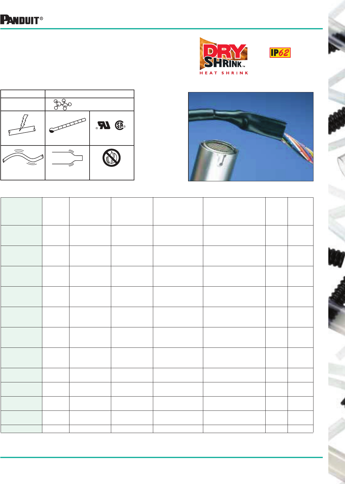
147
Most commonly used parts appear in BOLD.
PVC DRY-SHRINK ™ Heat Shrink Tubing
HSTTP Heat Shrink
• For dry locations
• Flexible, highly flame retardant tubing
• Good resistance to most fuels and oils
• Good cut through and solder resistance
• Material is UV Resistant
-4°F to 221°F
(-20°C to 105°C)
Highly Flame
Retardant VW-1
Flexible
600V
Polyvinyl Chloride
Cross-Linked
HSTTP
Type Materials
HSTTP in Standard Packages — Reels — Black Only
Part Number
Nominal
Diameter
in.
Minimum
Expanded I.D.
in. (mm)
Maximum
Recovered I.D.
in. (mm)
Nominal
Recovered Wall
Thickness
in. (mm)
Length
Feet (m)
Std.
Pkg.
Qty.*
Std.
Ctn.
Qty.
HSTTP05-Q
HSTTP05-C
HSTTP05-M
3/64 .046 (1.2) .023 (0.6) .020 (0.5)
25 (7.5)
100 (30.5)
1000 (304.8)
1 Reel
1 Reel
1 Reel
10 Reels
2 Reels
2 Reels
HSTTP06-Q
HSTTP06-C
HSTTP06-M
1/16 .063 (1.6) .031 (0.8) .020 (0.5)
25 (7.5)
100 (30.5)
1000 (304.8)
1 Reel
1 Reel
1 Reel
10 Reels
2 Reels
2 Reels
HSTTP09-Q
HSTTP09-C
HSTTP09-M
3/32 .093 (2.4) .046 (1.2) .025 (0.6)
25 (7.5)
100 (30.5)
1000 (304.8)
1 Reel
1 Reel
1 Reel
10 Reels
2 Reels
2 Reels
HSTTP12-Q
HSTTP12-C
HSTTP12-M
1/8 .125 (3.2) .062 (1.6) .025 (0.6)
25 (7.5)
100 (30.5)
1000 (304.8)
1 Reel
1 Reel
1 Reel
10 Reels
2 Reels
2 Reels
HSTTP19-Q
HSTTP19-C
HSTTP19-M
3/16 .187 (4.8) .093 (2.4) .025 (0.6)
25 (7.5)
100 (30.5)
1000 (304.8)
1 Reel
1 Reel
1 Reel
10 Reels
2 Reels
2 Reels
HSTTP25-Q
HSTTP25-C
HSTTP25-D
1/4 .250 (6.4) .125 (3.2) .025 (0.6)
25 (7.5)
100 (30.5)
500 (152.4)
1 Reel
1 Reel
1 Reel
10 Reels
2 Reels
2 Reels
HSTTP38-Q
HSTTP38-C
HSTTP38-T
3/8 .375 (9.5) .187 (4.8) .030 (0.8)
25 (7.5)
100 (30.5)
200 (61.0)
1 Reel
1 Reel
1 Reel
10 Reels
2 Reels
2 Reels
HSTTP50-Q
HSTTP50-C 1/2 .500 (12.7) .250 (6.4) .030 (0.8) 25 (7.5)
100 (30.5)
1 Reel
1 Reel
10 Reels
2 Reels
HSTTP75-Q
HSTTP75-C 3/4 .750 (19.0) .375 (9.5) .035 (0.9) 25 (7.5)
100 (30.5))
1 Reel
1 Reel
10 Reels
2 Reels
HSTTP100-Q
HSTTP100-C 1 1.00 (25.4) .500 (12.7) .040 (1.0) 25 (7.5)
100 (30.5)
1 Reel
1 Reel
2 Reels
2 Reels
HSTTP150-Q
HSTTP150-C 1 1/2 1.50 (38.1) .750 (19.0) .045 (1.1) 25 (7.5)
100 (30.5)
1 Reel
1 Reel
2 Reels
2 Reels
HSTTP200-Q 2 2.00 (50.8) 1.00 (25.4) .050 (1.3) 25 (7.5) 1 Reel 2 Reels
Shrink Ratio:▲
2:1
*Order in multiples of std. pkg. qty.
▲Shrink ratios are approximations; please refer to above ordering information for the exact min. expanded
and max. recovered I.D.’s.
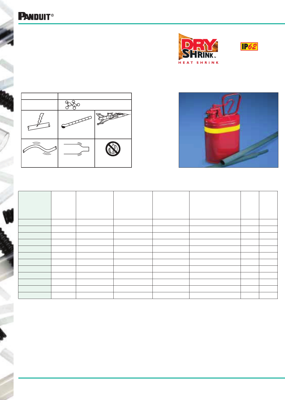
148
Most commonly used parts appear in BOLD.
Neoprene DRY-SHRINK™ Heat Shrink Tubing
HSTTN Heat Shrink
• For dry locations
• Highly flexible tubing
• Offers excellent chemical resistance, especially
to fuels and oils
• Highly flame retardant
-94°F to 250°F
(-70°C to 121°C)
Highly Flame
Retardant
Shrink Ratio:▲
2:1
Highly Flexible
600V
Elastomer Neoprene
Cross-Linked
HSTTN
AMS-DTL-23053/1
Class 2
Type Materials
HSTTN in Standard Packages — 25' (7.5m) and 100' (30.5m) Reels — Black Only
Part Number
Nominal
Diameter
in.
Minimum
Expanded I.D.
in. (mm)
Maximum
Recovered I.D.
in. (mm)
Nominal
Recovered
Wall
Thickness
in. (mm)
Length
Feet (m)
Std.
Pkg.
Qty.*
Std.
Ctn.
Qty.
HSTTN25-C 1/4 .250 (6.4) .143 (3.6) .035 (0.9) 100 (30.5) 1 Reel 2 Reels
HSTTN38-C 3/8 .375 (9.5) .211 (5.4) .040 (1.0) 100 (30.5) 1 Reel 2 Reels
HSTTN50-C 1/2 .500 (12.7) .286 (7.3) .048 (1.2) 100 (30.5) 1 Reel 2 Reels
HSTTN63-C 5/8 .625 (15.9) .357 (9.1) .052 (1.3) 100 (30.5) 1 Reel 2 Reels
HSTTN75-C 3/4 .750 (19.0) .428 (10.9) .057 (1.5) 100 (30.5) 1 Reel 2 Reels
HSTTN88-C 7/8 .875 (22.2) .500 (12.7) .065 (1.7) 100 (30.5) 1 Reel 2 Reels
HSTTN100-C 1 1.00 (25.4) .570 (14.5) .070 (1.8) 100 (30.5) 1 Reel 2 Reels
HSTTN125-C 1 1/4 1.25 (31.8) .714 (18.1) .087 (2.2) 100 (30.5) 1 Reel 2 Reels
HSTTN150-C 1 1/2 1.50 (38.1) .857 (21.8) .095 (2.4) 100 (30.5) 1 Reel 2 Reels
HSTTN175-C 1 3/4 1.75 (44.5) 1.00 (25.4) .107 (2.7) 100 (30.5) 1 Reel 2 Reels
HSTTN200-Q 2 2.00 (50.8) 1.140 (29.0) .110 (2.8) 25 (7.5) 1 Reel 2 Reels
HSTTN300-Q 3 3.00 (76.2) 1.710 (43.4) .125 (3.8) 25 (7.5) 1 Reel 2 Reels
*Order in multiples of std. pkg. qty.
▲Shrink ratios are approximations; please refer to above ordering information for the exact min. expanded and max. recovered I.D.’s.
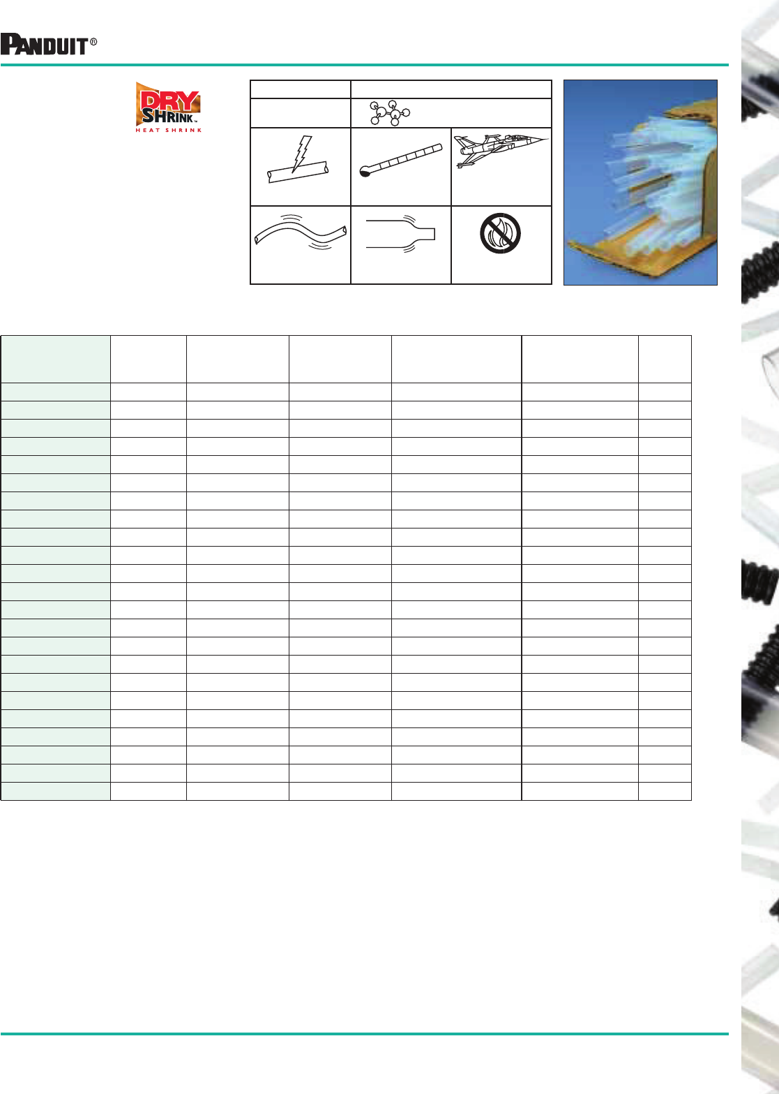
149
Most commonly used parts appear in BOLD.
*Order in multiples of std. pkg. qty.
▲Shrink ratios are approximations; please refer to above ordering information for the exact min. expanded
and max. recovered I.D.’s.
‡TEFLON is a registered trademark of E.I. Dupont de Nemours Co.
TFE TEFLON‡ DRY-SHRINK ™ Heat Shrink Tubing
HSTTT (TFE)
Heat Shrink
• For dry locations
• Semi-rigid, highly heat resistant
• Offers the widest temperature
range of any plastic material
• Color is milky clear
NOTE: Special instructions on page 158.
-88°F to 482°F
(-67°C to 250°C)
Non-Flammable
Shrink Ratio:▲
2:1
Semi-Rigid
600V
PolytetrafluoroethyleneHSTTT
AMS-DTL-23053/
12, Class 3
Type Materials
2:1 Shrink Ratio (Class 3) — HSTTT in Standard Packages — 4' (1.2m) Pcs.
Part Number
Nominal
Diameter
Minimum
Expanded I.D.
in. (mm)
Maximum
Recovered I.D.
in. (mm)
Nominal Recovered
Wall Thickness
in. (mm)
Length
Feet (m)
Std.
Pkg.
Qty.*
HSTTT03-48-Q 30 AWG .034 (0.9) .015 (0.4) .009 (0.2) 4 (1.2) 25 Pcs.
HSTTT04-48-Q 28 AWG .038 (1.0) .018 (0.5) .009 (0.2) 4 (1.2) 25 Pcs.
HSTTT046-48-Q 26 AWG .046 (1.2) .022 (0.5) .010 (0.3) 4 (1.2) 25 Pcs.
HSTTT05-48-Q 24 AWG .050 (1.3) .027 (0.7) .010 (0.3) 4 (1.2) 25 Pcs.
HSTTT055-48-Q 22 AWG .055 (1.4) .032 (0.8) .012 (0.3) 4 (1.2) 25 Pcs.
HSTTT06-48-Q 20 AWG .060 (1.5) .039 (1.0) .012 (0.3) 4 (1.2) 25 Pcs.
HSTTT08-48-Q 18 AWG .076 (1.9) .049 (1.2) .012 (0.3) 4 (1.2) 25 Pcs.
HSTTT09-48-Q 16 AWG .093 (2.3) .061 (1.6) .012 (0.3) 4 (1.2) 25 Pcs.
HSTTT12-48-Q 14 AWG .120 (3.0) .072 (1.8) .012 (0.3) 4 (1.2) 25 Pcs.
HSTTT15-48-Q 12 AWG .150 (3.8) .089 (2.3) .012 (0.3) 4 (1.2) 25 Pcs.
HSTTT19-48-Q 10 AWG .191 (4.9) .112 (2.8) .012 (0.3) 4 (1.2) 25 Pcs.
HSTTT24-48-Q 8 AWG .240 (6.0) .141 (3.6) .015 (0.4) 4 (1.2) 25 Pcs.
HSTTT30-48-Q 6 AWG .302 (7.7) .178 (4.5) .015 (0.4) 4 (1.2) 25 Pcs.
HSTTT37-48-Q 4 AWG .370 (9.4) .224 (5.7) .015 (0.4) 4 (1.2) 25 Pcs.
HSTTT43-48-Q 2 AWG .430 (10.9) .278 (7.0) .015 (0.4) 4 (1.2) 25 Pcs.
HSTTT47-48-Q 0 AWG .470 (11.9) .347 (8.8) .015 (0.4) 4 (1.2) 25 Pcs.
HSTTT56-48-5 9/16 .560 (14.2) .399 (10.1) .015 (0.4) 4 (1.2) 5 Pcs.
HSTTT66-48-5 5/8 .655 (16.6) .462 (11.7) .018 (0.5) 4 (1.2) 5 Pcs.
HSTTT75-48-5 3/4 .750 (19.0) .524 (13.3) .018 (0.5) 4 (1.2) 5 Pcs.
HSTTT93-48-5 15/16 .930 (23.6) .655 (16.6) .020 (0.5) 4 (1.2) 5 Pcs.
HSTTT112-48-5 1 1/8 1.125 (28.6) .786 (20.0) .025 (0.6) 4 (1.2) 5 Pcs.
HSTTT131-48-2 1 5/16 1.310 (33.3) .911 (23.1) .030 (0.8) 4 (1.2) 2 Pcs.
HSTTT150-48-2 1 1/2 1.500 (38.1) 1.036 (26.3) .030 (0.8) 4 (1.2) 2 Pcs.
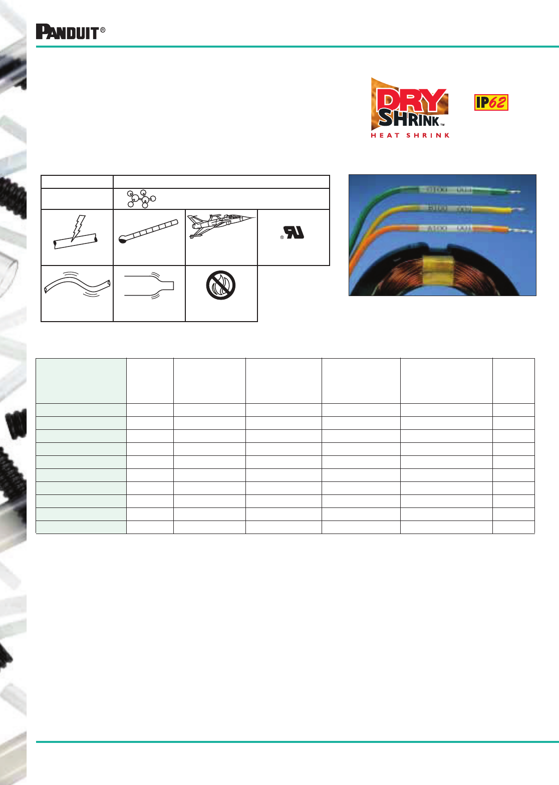
150
Most commonly used parts appear in BOLD.
*Order in multiples of std. pkg. qty.
▲Shrink ratios are approximations; please refer to above ordering information for the exact min. expanded and max. recovered I.D.’s.
■KYNAR is a registered trademark of Atofina Chemicals, Inc.
HSTTK KYNAR■ Heat Shrink
• For dry locations
• Semi-rigid, highly heat resistant
• Offers excellent chemical and abrasion resistance
• Use in high temperature or solvent rich environment
• Color is milky clear
-67°F to 347°F
(-55°C to 175°C)
Highly Flame
Retardant VW-1
Shrink Ratio:▲
2:1
Semi-Rigid
600V
Polyvinylidene Fluoride
HSTTK
AMS-DTL-23053/8
Type Material
VW-1
HSTTK in Standard Packages — 4' (1.2m) Pieces
Part Number
Nominal
Diameter
in.
Minimum
Expanded I.D.
in. (mm)
Maximum
Recovered I.D.
in. (mm)
Nominal
Recovered
Wall Thickness
in. (mm)
Length
Feet (m)
Std.
Pkg.
Qty.*
HSTTK05-48-Q 3/64 .046 (1.2) .023 (0.6) .010 (0.3) 4 (1.2) 25 Pcs.
HSTTK06-48-Q 1/16 .063 (1.6) .031 (0.8) .010 (0.3) 4 (1.2) 25 Pcs.
HSTTK09-48-Q 3/32 .093 (2.4) .046 (1.2) .010 (0.3) 4 (1.2) 25 Pcs.
HSTTK12-48-Q 1/8 .125 (3.2) .062(1.6) .010 (0.3) 4 (1.2) 25 Pcs.
HSTTK19-48-Q 3/16 .187 (4.8) .093 (2.4) .010 (0.3) 4 (1.2) 25 Pcs.
HSTTK25-48-Q 1/4 .250 (6.4) .125(3.2) .010 (0.3) 4 (1.2) 25 Pcs.
HSTTK38-48-Q 3/8 .375 (9.5) .187 (4.8) .012 (0.3) 4 (1.2) 25 Pcs.
HSTTK50-48-5 1/2 .500 (12.7) .250 (6.4) .012 (0.3) 4 (1.2) 5 Pcs.
HSTTK75-48-5 3/4 .750 (19.0) .375 (9.5) .017 (0.4) 4 (1.2) 5 Pcs.
HSTTK100-48-5 1 1.00 (25.4) .500 (12.7) .019 (0.5) 4 (1.2) 5 Pcs.
KYNAR■ DRY-SHRINK ™ Heat Shrink Tubing
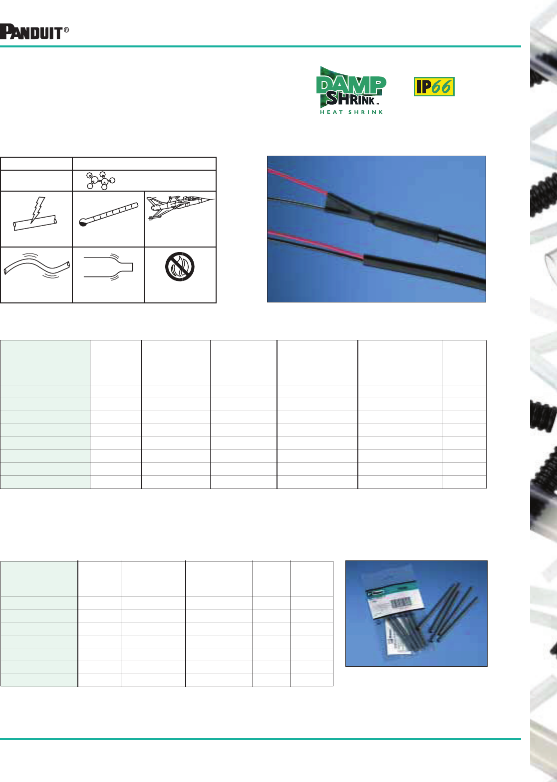
151
Most commonly used parts appear in BOLD.
*Order in multiples of std. pkg. qty.
▲Shrink ratios are approximations; please refer to above ordering information for the exact min. expanded
and max. recovered I.D.’s.
HSTTVA Heat Shrink
• For damp locations
• Flexible tubing with an adhesive inner wall which seals
and protects components from moisture and corrosion
-67°F to 230°F
(-55°C to 110°C)
600V AMS-DTL-23053/4
Class 2
Flexible Shrink Ratio:▲
2:1
HSTTVA Polyolefin Cross-Linked
with Adhesive
Outer Wall
Flame Retardant
Type Materials
HSTTVA in Standard Packages — 4' (1.2m) Pieces — Black Only
Part Number
Nominal
Diameter
in.
Minimum
Expanded I.D.
in. (mm)
Maximum
Recovered I.D.
in. (mm)
Nominal
Recovered Wall
Thickness
in. (mm)
Length
Feet (m)
Std.
Pkg.
Qty.*
HSTTVA12-48-Q 1/8 .125 (3.2) .062 (1.6) .020 (0.5) 4 (1.2) 25 Pcs.
HSTTVA19-48-Q 3/16 .187 (4.8) .093 (2.4) .022 (0.6) 4 (1.2) 25 Pcs.
HSTTVA25-48-Q 1/4 .250 (6.4) .125 (3.2) .030 (0.8) 4 (1.2) 25 Pcs.
HSTTVA38-48-Q 3/8 .375 (9.5) .187 (4.8) .031 (0.8) 4 (1.2) 25 Pcs.
HSTTVA50-48-5 1/2 .500 (12.7) .250 (6.4) .032 (0.8) 4 (1.2) 5 Pcs.
HSTTVA75-48-5 3/4 .750 (19.0) .375 (9.5) .037 (0.9) 4 (1.2) 5 Pcs.
HSTTVA100-48-5 1 1.00 (25.4) .500 (12.7) .046 (1.2) 4 (1.2) 5 Pcs.
HSTTVA150-48-5 1 1/2 1.50 (38.1) .750 (19.0) .049 (1.2) 4 (1.2) 5 Pcs.
Standard Packs of HSTTVA Heat Shrink — 6" (152.4mm) Pieces
HSTTVA — Black Only — Single Diameter
Part Number
Nominal
Diameter
in.
Minimum
Expanded I.D.
in. (mm)
Maximum
Recovered I.D.
in. (mm)
Std.
Pkg.
Qty.*
Std.
Ctn.
Qty.
HSTTVA12-Y 1/8 .125 (3.2) .062 (1.6) 7 pcs. 10 Pkgs.
HSTTVA19-Y 3/16 .187 (4.8) .093 (2.4) 7 pcs. 10 Pkgs.
HSTTVA25-Y 1/4 .250 (6.4) .125 (3.2) 5 pcs. 10 Pkgs.
HSTTVA38-Y 3/8 .375 (9.5) .187 (4.8) 4 pcs. 10 Pkgs.
HSTTVA50-Y 1/2 .500 (12.7) .250 (6.4) 4 pcs. 10 Pkgs.
HSTTVA75-Y 3/4 .750 (19.0) .375 (9.5) 3 pcs. 10 Pkgs.
HSTTVA100-Y 1 1.00 (25.4) .500 (12.7) 2 pcs. 10 Pkgs.
Dual Wall Polyolefin DAMP-SHRINK™Heat Shrink Tubing
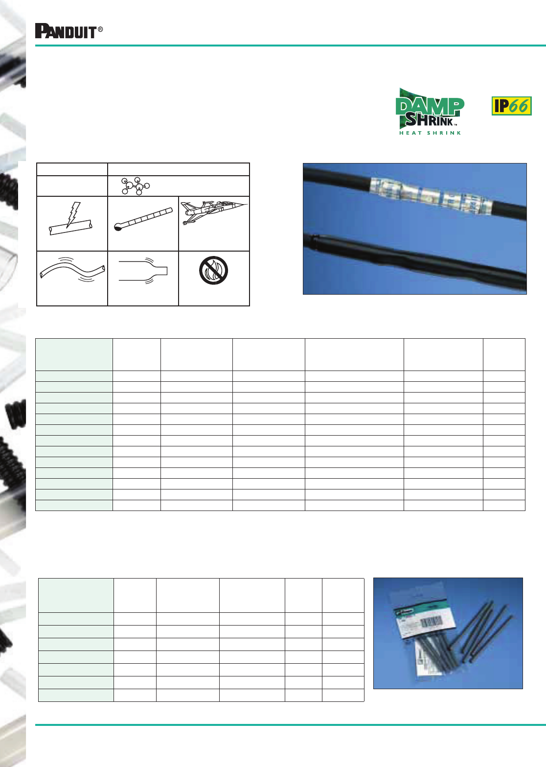
152
Most commonly used parts appear in BOLD.
*Order in multiples of std. pkg. qty.
▲Shrink ratios are approximations; please refer to above ordering information for the exact min. expanded
and max. recovered I.D.’s
HSTTA Heat Shrink
• For damp locations
• Flexible tubing with adhesive inner wall, seals and protects
components from moisture and corrosion
• The 3:1 shrink ratio is a benefit when working with connector to
cable transitions
-67°F to 230°F
(-55°C to 110°C)
600V AMS-DTL-23053/4
Class 3
Flexible Shrink Ratio:▲
3:1
HSTTA Polyolefin Cross-
Linked with Adhesive
Outer Wall
Flame Retardant
Type Materials
HSTTA in Standard and Bulk Packages — 4' (1.2m) Pieces — Black Only
Part Number
Nominal
Diameter
in.
Minimum
Expanded I.D.
in. (mm)
Maximum
Recovered I.D.
in. (mm)
Nominal Recovered
Wall Thickness
in. (mm)
Length
Feet (m)
Std.
Pkg.
Qty.*
HSTTA19-48-Q 3/16 .187 (4.8) .062 (1.6) .040 (1.0) 4 (1.2) 25 Pcs.
HSTTA25-48-Q 1/4 .250 (6.4) .080 (2.0) .040 (1.0) 4 (1.2) 25 Pcs.
HSTTA25-48-TL 1/4 .250 (6.4) .080 (2.0) .040 (1.0) 4 (1.2) 250 Pcs.
HSTTA38-48-Q 3/8 .375 (9.5) .120 (3.0) .055 (1.4) 4 (1.2) 25 Pcs.
HSTTA38-48-TL 3/8 .375 (9.5) .120 (3.0) .055 (1.4) 4 (1.2) 250 Pcs.
HSTTA50-48-5 1/2 .500 (12.7) .160 (4.1) .070 (1.8) 4 (1.2) 5 Pcs.
HSTTA50-48-T 1/2 .500 (12.7) .160 (4.1) .070 (1.8) 4 (1.2) 200 Pcs.
HSTTA75-48-5 3/4 .750 (19.0) .250 (6.4) .085 (2.2) 4 (1.2) 5 Pcs.
HSTTA75-48-C 3/4 .750 (19.0) .250 (6.4) .085 (2.2) 4 (1.2) 100 Pcs.
HSTTA100-48-5 1 1.00 (25.4) .320 (8.1) .100 (2.5) 4 (1.2) 5 Pcs.
HSTTA100-48-L 1 1.00 (25.4) .320 (8.1) .100 (2.5) 4 (1.2) 50 Pcs.
HSTTA150-48-5 1 1/2 1.50 (38.1) .510 (12.9) .100 (2.5) 4 (1.2) 5 Pcs.
HSTTA150-48-Q 1 1/2 1.50 (38.1) .510 (12.9) .100 (2.5) 4 (1.2) 25 Pcs.
Dual Wall Polyolefin DAMP-SHRINK™Heat Shrink Tubing
Standard Packs of HSTTA Heat Shrink — 6" (152.4mm) Pieces
HSTTA — Black Only — Single Diameter
Part Number
Nominal
Diameter
in.
Minimum
Expanded I.D.
in. (mm)
Maximum
Recovered I.D.
in. (mm)
Std.
Pkg.
Qty.*
Std.
Ctn.
Qty.
HSTTA19-Y 3/16 .187 (4.8) .062 (1.6) 6 pcs. 10 Pkgs.
HSTTA25-Y 1/4 .250 (6.4) .080 (2.0) 4 pcs. 10 Pkgs.
HSTTA38-Y 3/8 .375 (9.5) .120 (3.0) 3 pcs. 10 Pkgs.
HSTTA50-Y 1/2 .500 (12.7) .160 (4.1) 3 pcs. 10 Pkgs.
HSTTA75-Y 3/4 .750 (19.0) .250 (6.4) 2 pcs. 10 Pkgs.
HSTTA100-Y 1 1.00 (25.4) .320 (8.1) 2 pcs. 10 Pkgs.
HSTTA150-Y 1 1/2 1.50 (38.1) .510 (12.9) 1 pcs. 10 Pkgs.
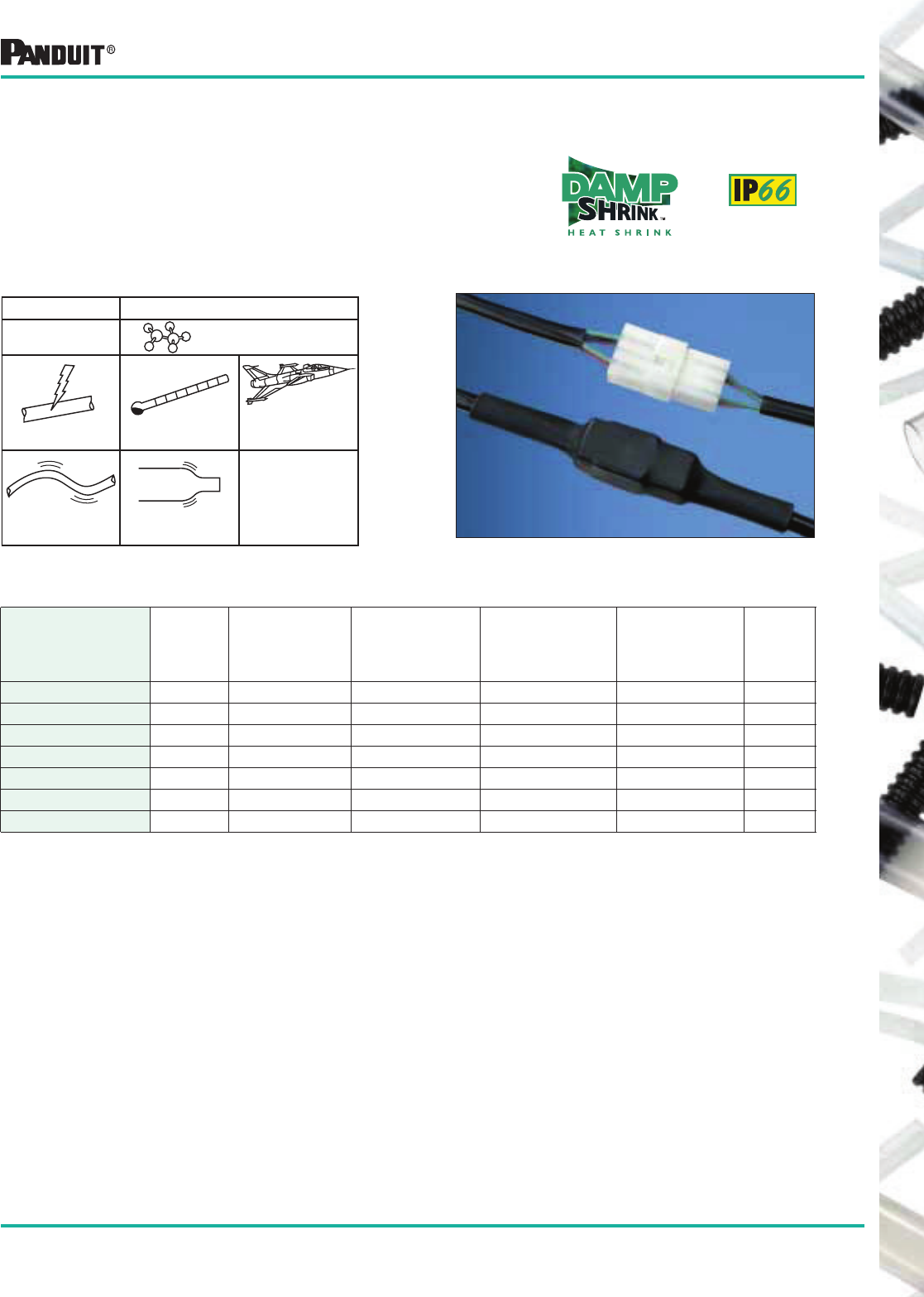
153
Most commonly used parts appear in BOLD.
Dual Wall Polyolefin DAMP-SHRINK ™ Heat Shrink Tubing
HSTTRA Heat Shrink
• For damp locations
• Semi-rigid tubing
• Adhesive inner wall which seals and protects
components from moisture and corrosion
• Provides a rugged seal from the elements
HSTTRA Polyolefin Cross-Linked
with Adhesive
600V -67°F to 230°F
(-55°C to 110°C) AMS-DTL-23053/4
Class 1
Semi-Rigid Shrink Ratio:▲
2.5:1
Type Materials
HSTTRA in Standard Packages — 4' (1.2m) Pieces — Black Only
Part Number
Nominal
Diameter
in.
Minimum
Expanded I.D.
in. (mm)
Maximum
Recovered I.D.
in. (mm)
Nominal
Recovered Wall
Thickness
in. (mm)
Length
Feet (m)
Std.
Pkg.
Qty.*
HSTTRA12-48-Q 1/8 .125 (3.2) .023 (0.6) .038 (1.0) 4 (1.2) 25 Pcs.
HSTTRA19-48-Q 3/16 .187 (4.8) .060 (1.5) .043 (1.1) 4 (1.2) 25 Pcs.
HSTTRA25-48-Q 1/4 .250 (6.4) .080 (2.0) .047 (1.2) 4 (1.2) 25 Pcs.
HSTTRA38-48-Q 3/8 .375 (9.5) .135 (3.4) .050 (1.3) 4 (1.2) 25 Pcs.
HSTTRA50-48-5 1/2 .500 (12.7) .195 (5.0) .059 (1.5) 4 (1.2) 5 Pcs.
HSTTRA75-48-5 3/4 .750 (19.0) .313 (8.0) .065 (1.7) 4 (1.2) 5 Pcs.
HSTTRA100-48-5 1 1.00 (25.4) .400 (10.6) .075 (1.9) 4 (1.2) 5 Pcs.
*Order in multiples of std. pkg. qty.
▲Shrink ratios are approximations; please refer to above ordering information for the exact min. expanded
and max. recovered I.D.’s.
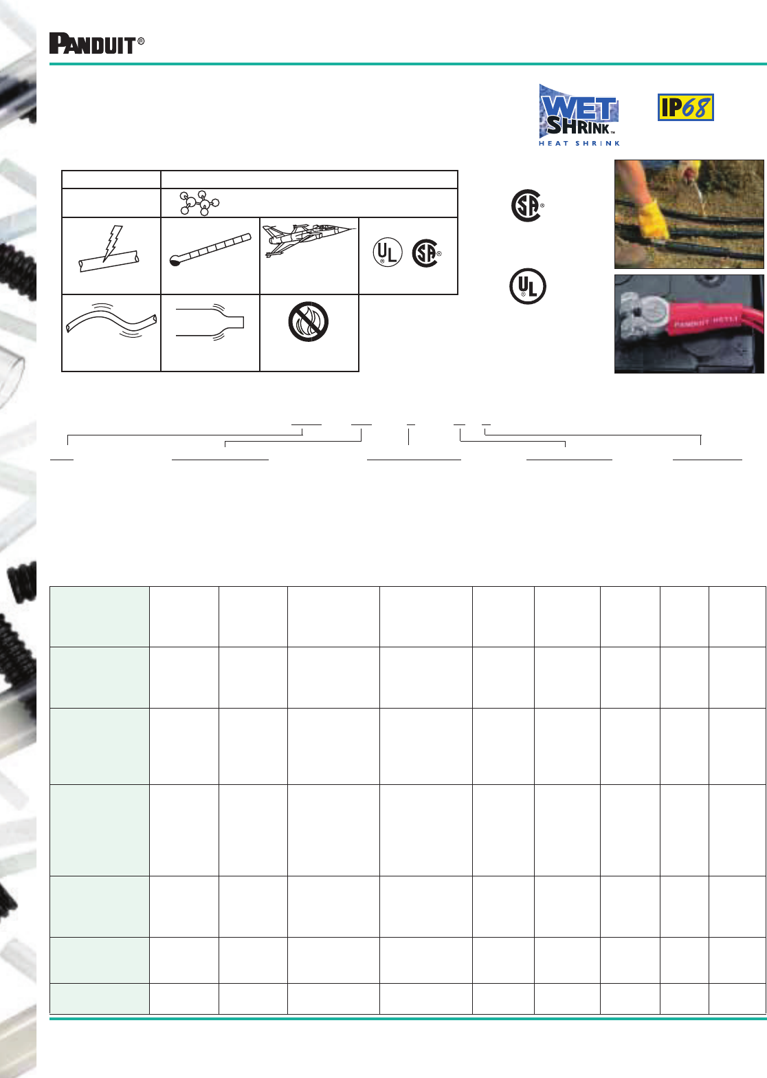
154
Most commonly used parts appear in BOLD.
*Order in multiples of std pkg. qty.
‡For red, add 2 to end of part number package suffix (example HST0.4-3-Q2).
▲Shrink ratios are approximations; please refer to above ordering information for the exact min. expanded and max. recovered I.D.’s.
Thick Wall Polyolefin WET-SHRINK ™ Heat Shrink Tubing
-85°F to 230°F
(-65°C to 110°C)
Flame RetardantShrink Ratio:▲
3:1
Rigid
600V
Polyolefin Cross-Linked
with Adhesive
HST
AMS-DTL-23053/15
(HST only)
HST Thick Wall Heat Shrink
• Suitable for wet locations and direct burial according to UL 486D
• Provides excellent protection above or below ground level
• Adhesive lined inner wall seals and protects against moisture
HST in Standard Packages
Part
Number
(Black)
Minimum
Expanded
I.D.
in. (mm)
Maximum
Recovered
I.D.
in. (mm)
Nominal
Recovered
Wall Thickness
in. (mm)
Conductor
Size Range
AWG/kcmil
(mm2)
Minimum
Cable
O.D. in.
(mm)
Maximum
Connector
O.D.
in. (mm)
Tube
Length
in. (mm)
Std.
Pkg.
Qty.*
Std. Ctn.
Qty.
HST0.4-3-Q‡
HST0.4-6-3
HST0.4-6-X‡
HST0.4-48-5‡
.40 (10.1) .15 (3.8) .09 (2.3) #12-#6
(4-16)
.170
(4.3)
.350
(8.9)
3 (76.2)
6 (152.4)
6 (152.4)
4' (1.2M)
25 PCS.
3 PCS.
10 PCS.
5 PCS.
4 Pkgs.
10 Pkgs.
10 Pkgs.
4 Pkgs.
HST0.8-6-3
HST0.8-6-X‡
HST0.8-9-X‡
HST0.8-12-5‡
HST0.8-48-5‡
.80 (20.3) .25 (6.4) .11 (2.8) #8-#1/0
(10-55)
.240
(6.1)
.650
(16.5)
6 (152.4)
6 (152.4)
9 (228.6)
12 (304.8)
4' (1.2M)
3 PCS.
10 PCS.
10 PCS.
5 PCS.
5 PCS.
10 Pkgs.
10 Pkgs.
10 Pkgs.
10 Pkgs.
4 Pkgs.
HST1.1-6-3
HST1.1-6-X‡
HST1.1-9-2
HST1.1-9-X‡
HST1.1-12-5‡
HST1.1-48-5‡
1.10 (27.9) .37 (9.4) .12 (3.0) #2-#4/0
(35-120)
.400
(10.1)
.875
(22.2)
6 (152.4)
6 (152.4)
9 (228.6)
9 (228.6)
12 (304.8)
4' (1.2M)
3 PCS.
10 PCS.
2 PCS.
10 PCS.
5 PCS.
5 PCS.
10 Pkgs.
10 Pkgs.
10 Pkgs.
10 Pkgs.
10 Pkgs.
4 Pkgs.
HST1.5-9-X
HST1.5-12-1
HST1.5-12-5
HST1.5-48-5
1.50 (38.1) .50 (12.7) .17 (4.3) #3/0-400 kcmil
(95-185)
.600
(15.2)
1.190
(30.2)
9 (228.6)
12 (304.8)
12 (304.8)
4' (1.2M)
10 PCS.
1 PC.
5 PCS.
5 PCS.
10 Pkgs.
10 Pkgs.
10 Pkgs.
4 Pkgs.
HST2.0-9-5
HST2.0-12-2
HST2.0-48-2
2.00 (50.8) .67 (16.9) .17 (4.3) 250-600 kcmil
(125-300)
.750
(19.1)
1.600
(40.6)
9 (228.6)
12 (304.8)
4' (1.2M)
5 PCS.
2 PCS.
2 PCS.
10 Pkgs.
10 Pkgs.
4 Pkgs.
HST3.0-12-2
HST3.0-48-2 3.00(76.2) 1.00 (25.4) .17 (4.3) 600-1250 kcmil
(300-625)
1.20
(30.5)
2.250
(57.2)
12 (304.8)
4' (1.2M)
2 PCS.
2 PCS.
10 Pkgs.
4 Pkgs.
Thick Wall Heat Shrink Part Number System
HST 0.4 - 3 - Q 2
Type
HST
Tube Length
3 = 3" (76.2mm)
6 = 6" (152.4mm)
9 = 9" (228.6mm)
12 = 12" (304.8mm)
48 = 4' (1.2m)
Package Quantity
1 = 1 Pc.
2 = 2 Pcs.
3 = 3 Pcs.
5 = 5 Pcs.
X = 10 Pcs.
Q = 25 Pcs.
Color
None = Black
2 = Red
Expanded Diameter
0.4 = .40" (10.2mm)
0.8 = .80" (20.3mm)
1.1 = 1.10" (27.9mm)
1.5 = 1.50" (38.1mm)
2.0 = 2.00" (50.8mm)
3.0 = 3.00" (76.2mm)
Listed 6R72
(except HST3.0)
(Black Only)
Including HST3.0
Type Material
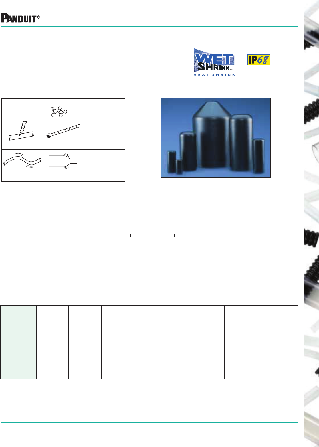
155
Most commonly used parts appear in BOLD.
*Order in multiples of std. pkg. qty.
▲Shrink ratios are approximations; please refer to above ordering information for the exact min. expanded
and max. recovered I.D.’s.
Polyolefin WET-SHRINK ™ Thick Wall End Caps
• For wet locations
• Provides excellent protection for sealing ends of wire or cable
• Adhesive lined inner wall seals and protects against moisture
Thick Wall End Caps in Standard Packages — Black Only
Part
Number
Minimum
Expanded
I.D.
in. (mm)
Maximum
Recovered
I.D. in. (mm)
Nominal
Recovered
Wall
Thickness
in. (mm)
Conductor
Size
Cap Length
in. (mm)
Std.
Pkg.
Qty.*
Std.
Ctn.
Qty.
HSEC0.5-X
HSEC0.8-X
.47 (11.9)
.79 (20.1)
.18 (4.6)
.30 (7.6)
.10 (2.5)
.10 (2.5)
#8 TO #4 AWG (10 TO 25mm2)
#4 TO 3/0 AWG (25 TO 95mm2)
1.38 (35.1)
2.13 (54.1)
10 PCS.
10 PCS.
10 Pkgs.
10 Pkgs.
HSEC1.0-X
HSEC1.5-5
1.02 (25.9)
1.58 (40.1)
.45 (11.4)
.68 (17.3)
.10 (2.5)
.11 (2.8)
#2 TO 4/0 AWG (35 TO 95mm2)
250 TO 500 kcmil (120 TO 240mm2)
3.23 (82.0)
3.86 (98.0)
10 PCS.
5 PCS.
10 Pkgs.
10 Pkgs.
HSEC2.0-5
HSEC4.0-2
2.25 (57.2)
4.14 (105.2)
.87 (22.1)
1.78 (45.2)
.15 (3.8)
.15 (3.8)
600 TO 1000 kcmil (300 TO 500mm2)
1500 TO 2000 kcmil (720 TO 1000mm2)
5.52 (140.2)
6.90 (175.3)
5 PCS.
2 PCS.
10 Pkgs.
5 Pkgs.
HSEC Thick Wall End Caps
Thick Wall End Caps Part Number System
HSEC 0.5 - X
Type
HSEC
Expanded Diameter
0.5 = .47" (11.9mm)
0.8 = .79" (20.1mm)
1.0 = 1.02" (25.9mm)
1.5 = 1.58" (40.1mm)
2.0 = 2.25" (57.2mm)
4.0 = 4.14" (105.2mm)
Package Quantity
2 = 2 Pcs.
5 = 5 Pcs.
X = 10 Pcs.
-67°F to 221°F
(-55°C to 105°C)
Shrink Ratio:▲
3:1
Rigid
600V
HSEC Polyolefin Cross-Linked
with Adhesive
Type Materials
-
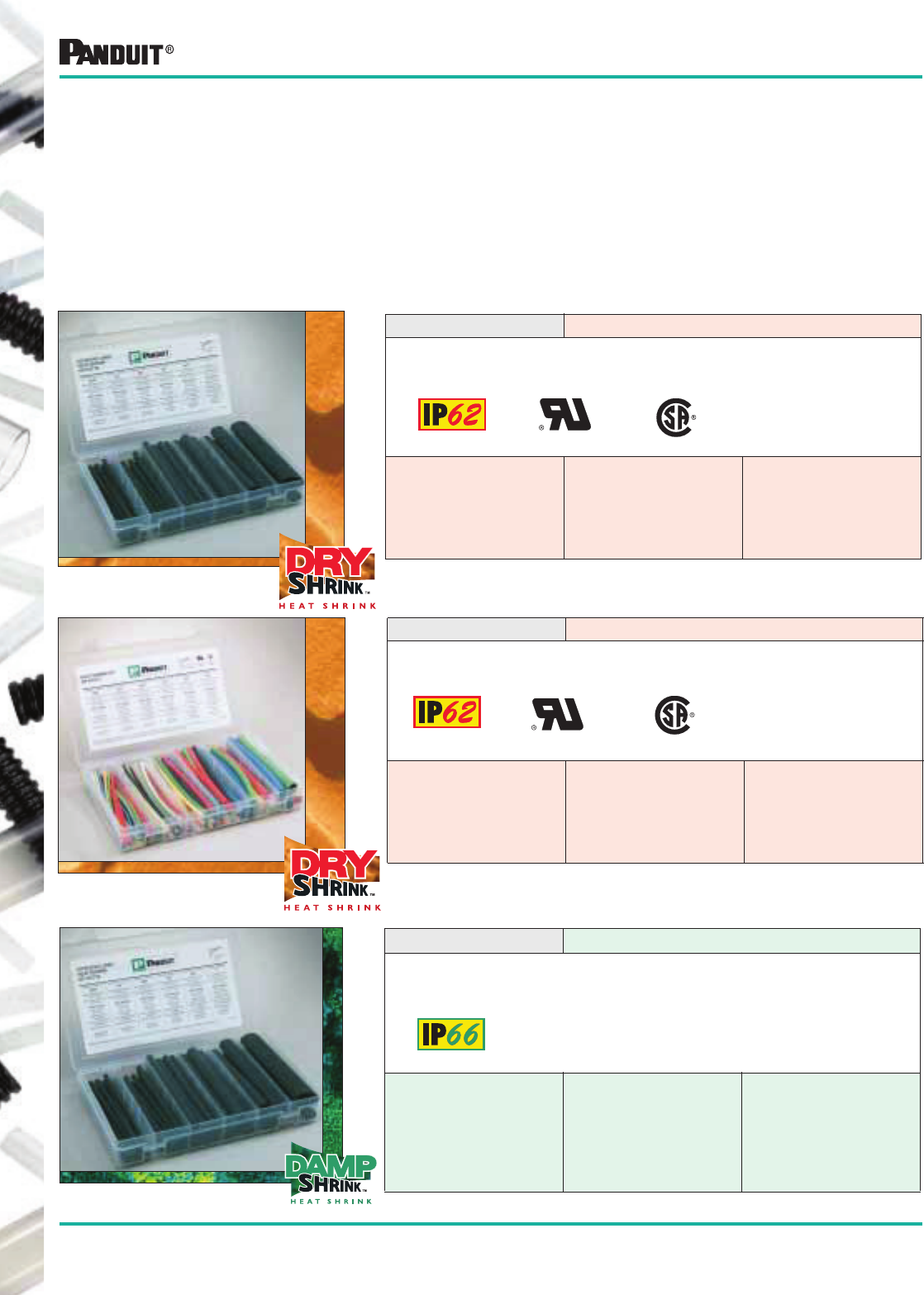
156
Most commonly used parts appear in BOLD.
Order number of kits required.
KP-HSTTA Contents For Damp Locations
ADHESIVE LINED BLACK POLYOL EFIN DAMP-SH RI NK ™ HEAT SHRINK TUBING (TY PE HSTTA)
IN 6" (152.4mm) LENGTHS
3:1 SHRINK RATIO
AMS-DTL-23053/4
CLASS 3
14 EACH
HSTTA19 3/16" (4.8mm) I.D.
12 EACH
HSTTA25 1/4" (6.4mm) I.D.
10 EACH
HSTTA38 3/8" (9.5mm) I.D.
6 EACH
HSTTA50 1/2" (12.7mm) I.D.
3 EACH
HSTTA75 3/4" (19.0mm) I.D.
2 EACH
HSTTA100 1" (25.4mm) I.D.
Note: Colors include: Red, Yellow, Green, Blue, White, Clear and Black.
KP-HSTT2 Contents For Dry Locations
MULTIPLE COLOR POLYOL EFIN DRY-SHR INK ™ HEAT SHRINK TUBING (TYPE HSTT)
IN 6" (152.4mm) LENGTHS
2:1 SHRINK RA TIO
AMS-DTL-23053/5
CLASS 1 & 2
35 EACH
HSTT09 3/32" (2.4mm) I.D.
- 7 COLOR S
HSTT12 1/8" (3.2mm) I.D.
- 7 COLOR S
21 EACH
HSTT19 3/16" (4.8mm) I.D.
- 7 COLOR S
HSTT25 1/4" (6.4mm) I.D.
- 7 COLOR S
7 EACH
HSTT38 3/8" (9.5mm) I.D.
- 7 COLOR S
HSTT50 1/2" (12.7mm) I.D.
- 7 COLOR S
Plastic Kit Boxes
Heat Shrink Tubing Kits
• Provides organized storage for a wide variety of parts in one convenient location
• Informative label eliminates guess work:
— Specifies correct heat shrink usage based on wire range and connector size
— Provides reorder part number information
• Once top is closed, loose pieces remain in their 6 compartments
• Available with non-adhesive or adhesive lined heat shrink tubing for dry and damp locations
(Except Clear) (Except Clear)
KP-HSTT1 Contents For Dry Locations
BLACK POLYOLEFIN DR Y-SH RINK ™HEAT SHRINK TUB ING (TYPE HSTT)
IN 6" (152.4mm) LEN GTH S
2:1 SHRINK RATIO
AMS-DTL-23053/5
CLASS 1
35 E AC H
HSTT09 3/32" (2.4mm) I.D.
HSTT12 1/8" (3.2mm) I.D.
21 E AC H
HSTT19 3/16" (4.8mm) I.D.
HSTT25 1/4" (6.4mm) I.D.
7 EACH
HSTT38 3/8" (9.5mm) I.D.
HSTT50 1/2" (12.7mm) I.D.
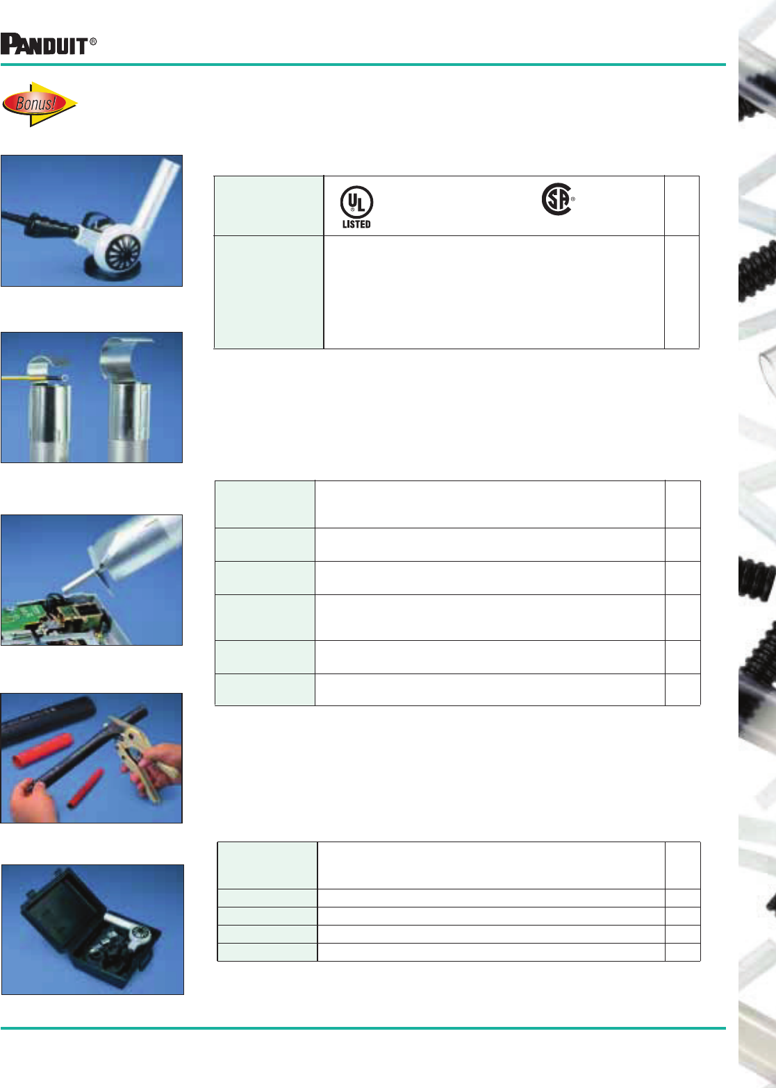
157
Most commonly used parts appear in BOLD.
Heat Shrink Tools and Accessories
Heat Tools
Part
Number Description
Std.
Pkg.
Qty
HSG-115V-650 • High temperature tool — For use on PANDUIT ® HSTT,
HSTTA, HSTTF, HSTTR, HSTTK, HSTTRA, HST
and HSEC
• Air intake regulator varies temperature from 650°F
(344°C) to 900°F (482°C) 115 Volt, 10 AMP
• Neoprene jacketed cord with molded strain relief
• Adjustable stand included
• Replaceable bearings, brushes and heating elements
1
Listed 826N
(Heat Tools only)
(Heat Tools
only)
Accessories
Part
Number Description
Std.
Pkg.
Qty
HSG-A1 • Shrink tube reflector for tubing up to 3/4" inside diameter
• Directs heat around the tubing to reduce shrink time
1
HSG-A2 • Shrink tube reflector for tubing up to 1 1/2" inside diameter
• Directs heat around the tubing to reduce shrink time
1
HSG-A3 • Shrink tube concentrator
• Directs heat toward tubing and away from heat
sensitive items
1
HSG-A4 • Black polyethylene carrying case
• Stores heat tool, stand and all three accessories
1
DCT • Cutting tool for use with HST Thick Wall Heat Shrink
Tubing only
1
Replacement Parts
Order number of heat tools, accessories and replacement parts required.
Part
Number Description
Std.
Pkg.
Qty
HSG-P1 • Brush/Spring Kit 1
HSG-P2 • Switch 20 Amp 1
HSG-P3 • Bearing Kit 1
HSG-P7 • Heat Element 650°F 1
HSG Heat tool with stand
Heat Reflector Accessory slips onto
heat tools
Heat Concentrator Accessory directs
heat to reduce shrink time
Carrying Case
Mica insulation in the
heat element provides
extended life to HSG
Heat Tools.
DCT — Cutting Tool
158
Most commonly used parts appear in BOLD.
General Instructions
Position heat shrink over the object to be covered. Using a heat gun, soft yellow flame torch, infrared heat
source or oven, evenly heat the tubing until it has fully recovered and conforms to the object. Use caution
not to char or burn the tubing.
Special Instructions for HSTTT
TFE tubing is the most difficult to shrink due to its high shrink temperature. TFE shrink tubing must be
heated to the gel state 621°F (327°C) to completely recover. This can be recognized when the tubing
changes from milky white to clear color. It can be shrunk with a heat gun or torch, however, it is very difficult
to use these methods since they have a tendency to overheat the tube in one area while other areas remain
too cool. The most reliable way to shrink TFE is in an oven. Position the heat shrink over the object to be
covered and place it in an oven set at 800°F (427°C) until the tubing turns clear. Once clear, remove
assembly from oven to prevent over heating and allow it to cool at room temperature. Do not quench in cold
air or water. Large objects, particularly metal tubing or rods, must be preheated to get a uniform shrink.
Heat Shrink Installation Instructions
DRY-SHRINK™, DAMP-SHRINK ™ and WET-SHRINK ™ Heat Shrink Tubing Technical Data
Size Selection for Heat Shrink Tubing
Generally, the largest tube that shrinks down tightly onto an object should be chosen. This allows the heat
shrink tubing maximum stress relief and this will yield the longest service life.
Example:
A multi-conductor cable needs to be covered with HSTT Type DR Y-SHRINK ™ Heat Shrink. The area to be
covered has a measured outside diameter of .700" (17.8mm). The two possibilities are HSTT75-48-5
and HSTT100-48-5.
The proper choice is HSTT100-48-5 since the tube will recover more than HSTT75-48-5. The HSTT75-48-5
will fit over the .700" (17.8mm) outside diameter; however, this is not the proper choice since it is smaller
than the HSTT100-48-5. In general, heat shrink should recover at least 10-20% to reduce stress and yield
Part Number
Expanded I.D.
in. (mm)
Recovered I.D.
in. (mm)
HSTT75-48-5 .750 (19.0) .375 (9.5)
HSTT100-48-5 1.00 (25.4) .500 (12.7)

159
Heat Shrink Selection Guide
Recommended Tubing Size for Common Wire Types Based on Location
For Insulated Wire, Non-insulated Wire and Insulated Wire With Copper Connectors
Instructions for tube selection:
1) Determine Location Type.
LOCATION:
DRY — IP62: A location not normally subject to dampness or wetness. A location classified as dry may be temporarily subject to dampness or
wetness, as in the case of a building under construction.
DAMP — IP66: Partially protected locations under canopies, marquees, roofed open porches, and like locations, and interior locations subject to
moderate degrees of moisture, such as some basements, some barns and some cold-storage warehouses.
WET — IP68: Installations underground or in concrete slabs or masonry in direct contact with the earth, and locations subject to saturation with
water or other liquids, such as vehicle washing areas, and locations exposed to weather and unprotected.
2) Match wire size to location type under required application — insulated wire, non-insulated wire, or insulated wire with copper connectors.
3) Read corresponding part number.
4) Part numbers with “-Y” are packages containing 6" pieces. Part numbers with “-48” are 48" pieces.
5) Part numbers shown below are for black heat shrink. Consult relevant catalog section for color options.
Sizing information is based on the following wire types: MTW, THHN, THWN, TFN, THW, TW, TF, RHW, RH, RHH AND UL1015.
THHN is the most common wire type.
Portions reprinted with permission from NFPA, the National Electrical Code ® Handbook, Copyright© 1996, National Fire Protection Association,
Quincy, MA 02269.
All rights reserved. National Electrical Code ® and NEC ® are registered trademarks of the National Fire Protection Association, Inc.,
Quincy, MA 02269.
Wire
Size Insulated Wire Uninsulated Wire
Insulated Wire with Copper Connector
DR Y -SHRINK ™DAMP-SHR IN K ™WET-SH RINK ™DR Y-SHRINK ™DAMP-SHRINK™WET-SHRINK ™DRY-SHR IN K ™DAMP-
SHRINK ™
WET-SHR IN K ™
24 HSTT12-Y HSTTA19-Y — — — — HSTT12-Y — —
22 HSTT12-Y HSTTA19-Y — — — — HSTT12-Y — —
20 HSTT12-Y HSTTA19-Y — HSTT06-Y — — HSTT19-Y HSTTA19-Y —
18 HSTT19-Y HSTTA19-Y — HSTT06-Y — — HSTT19-Y HSTTA19-Y —
16 HSTT19-Y HSTTA25-Y — HSTT06-Y — — HSTT19-Y HSTTA25-Y —
14 HSTT19-Y HSTTA25-Y — HSTT12-Y HSTTA19-Y — HSTT19-Y HSTTA25-Y —
12 HSTT25-Y HSTTA38-Y HST0.4-48-5 HSTT12-Y HSTTA19-Y — HSTT25-Y HSTTA38-Y HST0.4-48-5
10 HSTT25-Y HSTTA38-Y HST0.4-48-5 HSTT19-Y HSTTA25-Y — HSTT25-Y HSTTA38-Y HST0.4-48-5
8HSTT38-Y HSTTA50-Y HST0.4-48-5 HSTT25-Y HSTTA25-Y — HSTT38-Y HSTTA50-Y HST0.4-48-5
6HSTT50-Y HSTTA50-Y HST0.8-48-5 HSTT25-Y HSTTA38-Y HST0.4-48-5 HSTT50-Y HSTTA50-Y HST0.8-48-5
4HSTT50-Y HSTTA75-Y HST0.8-48-5 HSTT38-Y HSTTA38-Y HST0.4-48-5 HSTT50-Y HSTTA75-Y HST0.8-48-5
3HSTT50-Y HSTTA75-Y HST0.8-48-5 HSTT38-Y HSTTA50-Y HST0.4-48-5 HSTT50-Y HSTTA75-Y HST0.8-48-5
2HSTT75-Y HSTTA100-Y HST0.8-48-5 HSTT50-Y HSTTA50-Y HST0.8-48-5 HSTT75-Y HSTTA100-Y HST0.8-48-5
1HSTT75-Y HSTTA100-Y HST0.8-48-5 HSTT50-Y HSTTA50-Y HST0.8-48-5 HSTT75-Y HSTTA100-Y HST1.1-48-5
1/0 HSTT75-Y HSTTA100-Y HST1.1-48-5 HSTT50-Y HSTTA75-Y HST0.8-48-5 HSTT75-Y HSTTA100-Y HST1.1-48-5
2/0 HSTT100-Y HSTTA100-Y HST1.1-48-5 HSTT50-Y HSTTA75-Y HST0.8-48-5 HSTT100-Y HSTTA100-Y HST1.1-48-5
3/0 HSTT100-Y HSTTA150-Y HST1.1-48-5 HSTT75-Y HSTTA100-Y HST0.8-48-5 HSTT100-Y HSTTA150-Y HST1.5-48-5
4/0 HSTT100-Y HSTTA150-Y HST1.5-48-5 HSTT75-Y HSTTA100-Y HST1.1-48-5 HSTT100-Y HSTTA150-Y HST1.5-48-5
250 HSTT100-Y HSTTA150-Y HST1.5-48-5 HSTT100-Y HSTTA100-Y HST1.1-48-5 HSTT100-Y HSTTA150-Y HST1.5-48-5
300 HSTT150-48-5 HSTTA150-Y HST1.5-48-5 HSTT100-Y HSTTA100-Y HST1.1-48-5 HSTT150-Y HSTTA150-Y HST1.5-48-5
350 HSTT150-48-5 HSTTA150-Y HST1.5-48-5 HSTT100-Y HSTTA150-Y HST1.5-48-5 HSTT150-48-5 HSTTA150-Y HST2.0-48-2
400 HSTT150-48-5 HSTTA150-Y HST2.0-48-2 HSTT100-Y HSTTA150-Y HST1.5-48-5 HSTT150-48-5 HSTTA150-Y HST2.0-48-2
500 HSTT150-48-5 HSTTA150-Y HST2.0-48-2 HSTT100-Y HSTTA150-Y HST1.5-48-5 HSTT150-48-5 HSTTA150-Y HST2.0-48-2
600 HSTT150-48-5 HSTTA150-Y HST2.0-48-2 HSTT150-48-5 HSTTA150-Y HST2.0-48-2 HSTT150-48-5 HSTTA150-Y HST2.0-48-2
700 HSTT200-48-5 HSTTA150-Y HST2.0-48-2 HSTT150-48-5 HSTTA150-Y HST2.0-48-2 HSTT200-48-5 — HST2.0-48-2
750 HSTT200-48-5 HSTTA150-Y HST3.0-48-2 HSTT150-48-5 HSTTA150-Y HST2.0-48-2 HSTT200-48-5 — HST3.0-48-2
800 HSTT200-48-5 — HST3.0-48-2 HSTT150-48-5 HSTTA150-Y HST2.0-48-2 HSTT200-48-5 — HST3.0-48-2
900 HSTT200-48-5 — HST3.0-48-2 HSTT150-48-5 HSTTA150-Y HST2.0-48-2 HSTT200-48-5 — HST3.0-48-2
1000 HSTT200-48-5 — HST3.0-48-2 HSTT200-48-5 HSTTA150-Y HST2.0-48-2 HSTT200-48-5 — HST3.0-48-2
1250 HSTT300-48-2 — HST3.0-48-2 HSTT200-48-5 HSTTA150-Y HST2.0-48-2 — — HST3.0-48-2
1500 HSTT300-48-2 — HST3.0-48-2 HSTT200-48-5 — HST3.0-48-2 — — —
1750 HSTT300-48-2 — HST3.0-48-2 HSTT200-48-5 — HST3.0-48-2 — — —
2000 HSTT300-48-2 — HST3.0-48-2 HSTT200-48-5 — HST3.0-48-2 — — —
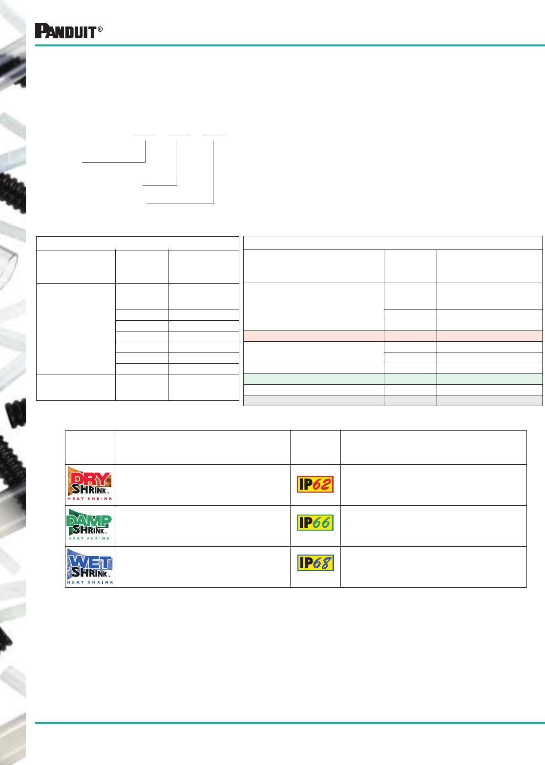
160
Most commonly used parts appear in BOLD.
Does not include PANDUIT ® DR Y-SHR INK ™ HSTTT (TEFLON —TFE)
Intended Application Location:
Ingress
Protection
Rating: Description:
DRY Locations not normally subject to moisture Protected against the ingress of dust but not
protected against the ingress of water.
DAMP Locations subjected to moderate
degrees of water and moisture
Protected against the ingress of dust and protected
against the ingress of a power jet of water.
WET Locations are defined as underground
burial or immersion in water
Protected against the ingress of dust and protected
against the ingress of water to a depth of 10 meters.
IP (Ingress Protection) as defined by the International Standard IEC 529
IP x x
Ingress
Protection
1st Characteristic Numeral
2nd Characteristic Numeral
DR Y-SHRINK ™ Heat Shrink has been tested in accordance with EN 60529 paragraph 13.4 thereby providing
PANDUIT ® DRY-SHR INK ™ Heat Shrink with an ingress protection rating of IP62.
DAMP-SHRINK ™ Heat Shrink has been tested in accordance with EN 60529 paragraph 13.4 and with
paragraph 14.2.6 thereby providing PANDUIT ® DAMP-SHRINK ™ with an ingress protection rating of IP66.
WET-SHRINK ™ Heat Shrink has been tested in accordance with EN 60529 paragraph 13.4, paragraph 14.2.6
and with paragraph 14.2.7 thereby providing WET-SHRINK ™ Heat Shrink with an ingress protection rating of
IP68. PANDUIT ® WET-SHRINK ™ Heat Shrink has passed EN 60529 paragraph 14.2.7 at depth of 10 meters.
The first characteristic numeral indicates the level of
protection against the ingress of solid foreign objects.
The second characteristic numeral indicates the level of
protection against the ingress of water.
The IEC 529 international standard describes a system for classifying the degrees of protection provided by
the enclosures of electrical equipment and is a recognized standard around the world. An independent test
laboratory has tested PANDUIT ® Heat Shrink Tubing to the IEC 529 standard. The following information
exhibits the IP ratings for PANDUIT ® Heat Shrink tubing and how each of the IP ratings relates to the USA.
1st Characteristic Numeral
PANDUIT ®
Heat Shrink
Ingress
Protection
(IP)
Meaning for
Protection
Against
ingress of
solid object
0 Non-Protected
1 50mm diameter
2 12.5mm diameter
3 2.5mm diameter
4 1.0mm diameter
5 Dust Protected
DR Y -SHRINK ™
,
DA M P-SHR IN K ™
and
WE T-SHRINK ™
6 Dust Tight
2nd Characteristic Numeral
PANDUIT ®
Heat Shrink
Ingress
Protection
(IP)
Meaning for
Protection
Against
ingress of
water
0 Non-Protected
1 Vertically Dripping
DR Y-SH RINK ™
Heat Shrink Tubing 2 Dripping (15° tilted)
3 Spraying
4 Splashing
5 Jetting
DAMP -SHRINK ™
Heat Shrink Tubing 6 Powerful Jetting
7 Temporary Immersion
WET-SH RI NK ™
Heat Shrink Tubing 8 Continuous Immersion
161
Most commonly used parts appear in BOLD.
General Information
Product
Type Typical Applications
Specific
Gravity Flammability
Water
Absorption
Dielectric
Strength
Page
No.
HSTT Economical and easy way to insulate, protect,
harness and identify electrical and electronic
components in a wide variety of applications.
Black is U.V. Resistant.
Class 1,
1.35
Class 2,
1.0
ASTM
D792
Class 1 Self
Extinguishing
Class 2 N/A
ASTM D2671
Procedure B
0.5% MAX.
ASTM
D570
500 V/MIL.
(19.7 Kv/mm) min.
ASTM D2671
141-
144
HSTTV Use where UL recognition with VW-1 rating is
required. Use where the wire component
cannot tolerate higher shrink temperatures,
reduces application time to insulate, protect,
identify, etc. Black is U.V. Resistant.
1.50
ASTM
D792
Self
Extinguishing
ASTM D2671
Procedure C
0.5% MAX.
ASTM
D570
500 V/MIL.
(19.7 Kv/mm) min.
ASTM D2671
145-
146
HSTTVA Seals and protects components from
moisture and corrosion. Use where a flexible
tubing is needed. Suitable for damp locations.
N/A Self
Extinguishing
ASTM D2671
Procedure B
0.5% MAX.
ASTM
D570
500 V/MIL.
(19.7 Kv/mm) min.
ASTM D2671
151
HSTTRA Environmentally seals and protects
components forming a rugged and heavy duty
covering. The 2.5:1 shrink ratio is a benefit
when working with connector to cable
transitions. Suitable for damp locations.
N/A N/A 0.5% MAX.
ASTM
D570
500 V/MIL.
(19.7 Kv/mm) min.
ASTM D2671
153
HSTTA Environmentally seals and protects
components. The 3:1 shrink ratio is a benefit
when working with connector to cable
transitions. Suitable for damp locations.
N/A Self
Extinguishing
ASTM D2671
Procedure B
1.0% MAX.
ASTM
D570
300 V/MIL.
(11.8 Kv/mm) min.
ASTM D2671
152
HST Seals and protects electrical connections and
splices above or below ground, 3:1 shrink
ratio. Suitable for outdoor and wet locations.
1.2 MAX. Self
Extinguishing
ASTM D2671
Procedure C
0.5% MAX.
ASTM
D570
200 V/MIL.
(7.9 Kv/mm) min.
ASTM D2671
154
HSTTP Ripple free conformance around sharp bends
as in appliance handles and bus bars. Good
cut through and solder-iron resistance.
Black is U.V. Resistant.
1.35
MAX.
Self
Extinguishing
ASTM D876
1.0% MAX.
ASTM
D570
400 V/MIL.
(15.8 Kv/mm) min.
ASTM D2671
147
HSTTN Insulation and abrasion resistance, extensive
military uses on vehicles and ship-board.
Excellent chemical resistance especially to
fuels and oils. Black is U.V. Resistant.
1.30
ASTM
D792
Self
Extinguishing
ASTM D876
1.0% MAX.
ASTM
D570
300V/MIL.
(11.8 Kv/mm) min.
ASTM D2671
148
HSTTK Protection and strain relief for wires or
connectors in a high temperature or solvent
rich environment. Insulation of heater leads.
1.8 MAX.
ASTM
D792
Pass
MIL-DTL-
23053/8B
4.6.15.3
0.5% MAX.
ASTM
D570
Size to .500"
(12.7mm)
800V/MIL.
(31.5 Kv/mm)min.
Over .500" (12.7mm)
600 V/MIL
(23.6 Kv/mm) min.
ASTM D2671
150
HSTTT High insulation and abrasion resistance. High
temperature, strain relief, resists corrosive
atmospheres, self lubrication and non-
wetting. Can be used with fiber optics and as
a strain relief for high density connectors.
It is U.V. Resistant
2.2 MAX.
ASTM
D792
N/A
Non-
flammable
0.01%
MAX.
ASTM
D570
800 V/MIL.
(31.5 Kv/mm) min.
ASTM D2671
149
D
RY
-S
HRINK
™
, D
AMP
-S
HRINK
™
and W
ET
-S
HRINK
™
Heat Shrink Tubing
Technical Data
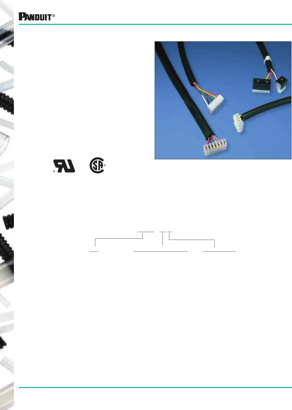
162
Most commonly used parts appear in BOLD.
PVC Tubing
• Provides insulation and protection for lead
wires, wire harness assemblies, soldered joints
and components in electrical and
electronic equipment
• Material: Polyvinyl chloride (PVC)
• Voltage Rating: 300V and 600V
• All purpose, flexible, non-shrinkable
• Resistant to heat and moisture
• Applicable Specifications:
UL224 VW-1
CSA C22.2 No. 198.1 (OFT)
ASTM D-922, Grade CFR
MIL-I-631, Type F, Form U, Grade C
Class 1, Category 1
Non-Shrink PVC Tubing
The Functional Part Number System Makes Ordering Easy
Type
Polyvinyl
Chloride
Tubing
Nominal Size
22 = 22 AWG
20 = 20 AWG
19 = 19 AWG
18 = 18 AWG
16 = 16 AWG
15 = 15 AWG
14 = 14 AWG
12 = 12 AWG
10 = 10 AWG
9 = 9 AWG
8 = 8 AWG
7 = 7 AWG
6 = 6 AWG
5 = 5 AWG
Package Quantity
L = 50' (15.2m)
C = 100' (30.5m)
TL = 250' (76.2m)
D = 500' (152.4m)
M = 1000' (304.8m)
2.5M = 2500' (762m)
VW-1 OFT
Non-Shrink PVC Tubing Part Number System
TV105 - 19 M
4 = 4 AWG
3 = 3 AWG
2 = 2 AWG
1 = 1 AWG
0 = 0 AWG
.25 = 1/4"
.31 = 5/16"
.38 = 3/8"
.44 = 6/16"
.50 = 1/2"
.56 = 9/16"
.63 = 5/8"
.75 = 3/4"
1.0 = 1"
163
Most commonly used parts appear in BOLD.
Part Number
Clear
Part Number
Black
Nominal
Size/
Trade
Name
Inside Diameter — in. (mm)
Wall
Thickness
in. (mm)
Max.
Volt
Rating**
Std.
Pkg.
Qty.*
Std.
Ctn.
Qty.Maximum Minimum
TV105-242.5M TV105-242.5M20 24 AWG .027 (0.68) .020 (0.51) .012 (.30)
300V
2500 (762m) 2 Reels
TV105-222.5M TV105-222.5M20 22 AWG .032 (0.81) .025 (0.69) 2500 (762m) 2 Reels
TV105-20M TV105-20M20 20 AWG .039 (0.99) .032 (0.81)
.016 (.41)
1000 (304.8m) 2 Reels
TV105-19M TV105-19M20 19 AWG .042 (1.06) .036 (0.91) 1000 (304.8m) 2 Reels
TV105-18M TV105-18M20 18 AWG .049 (1.24) .040 (1.02) 1000 (304.8m) 2 Reels
TV105-17M TV105-17M20 17 AWG .053 (1.34) .045 (1.14) 1000 (304.8m) 2 Reels
TV105-16M TV105-16M20 16 AWG .061 (1.54) .051 (1.30) 1000 (304.8m) 2 Reels
TV105-15M TV105-15M20 15 AWG .066 (1.67) .057 (1.45) 1000 (304.8m) 2 Reels
TV105-14M TV105-14M20 14 AWG .072 (1.82) .064 (1.63) 1000 (304.8m) 2 Reels
TV105-13M TV105-13M20 13 AWG .080 (2.03) .072 (1.83) 1000 (304.8m) 2 Reels
TV105-12D TV105-12D20 12 AWG .089 (2.26) .081 (2.06) 500 (152.4m) 2 Reels
TV105-11D TV105-11D20 11 AWG .101 (2.56) .091 (2.31) 500 (152.4m) 2 Reels
TV105-10D TV105-10D20 10 AWG .112 (2.84) .102 (2.59) 500 (152.4m) 2 Reels
TV105-9D TV105-9D20 9 AWG .124 (3.14) .114 (2.90)
.020 (.51)
500 (152.4m) 2 Reels
TV105-8D TV105-8D20 8 AWG .141 (3.58) .129 (3.28) 500 (152.4m) 2 Reels
TV105-7D TV105-7D20 7 AWG .158 (4.01) .144 (3.66) 500 (152.4m) 2 Reels
TV105-6TL TV105-6TL20 6 AWG .178 (4.52) .162 (4.11) 250 (76.2m) 2 Reels
TV105-5TL TV105-5TL20 5 AWG .198 (5.02) .182 (4.62) 250 (76.2m) 2 Reels
TV105-4TL TV105-4TL20 4 AWG .224 (5.68) .204 (5.18) 250 (76.2m) 2 Reels
TV105-3TL TV105-3TL20 3 AWG .249 (6.32) .229 (5.82) 250 (76.2m) 2 Reels
TV105-2TL TV105-2TL20 2 AWG .278 (7.06) .258 (6.55) 250 (76.2m) 2 Reels
TV105-1TL TV105-1TL20 1 AWG .311 (7.89) .289 (7.34) 250 (76.2m) 2 Reels
TV105-0TL TV105-0TL20 0 AWG .347 (8.81) .325 (8.26) 250 (76.2m) 2 Reels
TV105-.25TL TV105-.25TL20 1/4 .265 (6.73) .245 (6.22) 250 (76.2m) 2 Reels
TV105-.31TL TV105-.31TL20 5/16 .334 (8.48) .313 (7.95)
.025 (.64)
600V
250 (76.2m) 2 Reels
TV105-.38TL TV105-.38TL20 3/8 .399 (10.13) .375 (9.53) 250 (76.2m) 2 Reels
TV105-.44TL TV105-.44TL20 7/16 .462 (11.73) .438 (11.13) 250 (76.2m) 2 Reels
TV105-.50TL TV105-.50TL20 1/2 .524 (13.30) .500 (12.70) 250 (76.2m) 2 Reels
TV105-.56C TV105-.56C20 9/16 .585 (14.85) .563 (14.30) .030 (.76) 100 (30.5m) 2 Reels
TV105-.63C TV105-.63C20 5/8 .655 (16.63) .625 (15.88) 100 (30.5m) 2 Reels
TV105-.75C TV105-.75C20 3/4 .786 (19.96) .750 (19.05)
.035 (.89)
100 (30.5m) 2 Reels
TV105-.88C TV105-.88C20 7/8 .911 (23.13) .875 (22.23) 100 (30.5m) 2 Reels
TV105-1.0L TV105-1.0L20 1 1.036 (26.31) 1.000 (25.40) 50 (15.2m) 2 Reels
TV105-1.25L TV105-1.25L20 1 1/4 1.290 (32.76) 1.250 (31.75) .040 (1.02) 50 (15.2m) 2 Reels
TV105-1.50L TV105-1.50L20 1 1/2 1.550 (39.37) 1.500 (38.10) .045 (1.14) 50 (15.2m) 2 Reels
Non-Shrink PVC Tubing
PVC Tubing
-4°F to 221°F
(-20°C to 105°C)
Highly Flame
Retardant VW-1
Oil ResistantHighly Flexible
300V/600V**
Polyvinyl Chloride
TV105
MIL-I-631,Type F,
Form U Grade C
Class 1, Cat 1
Type Materials
VW-1 OFT
*Order in multiples of std. pkg. qty.
**UL voltage rating is a function of wall thickness.
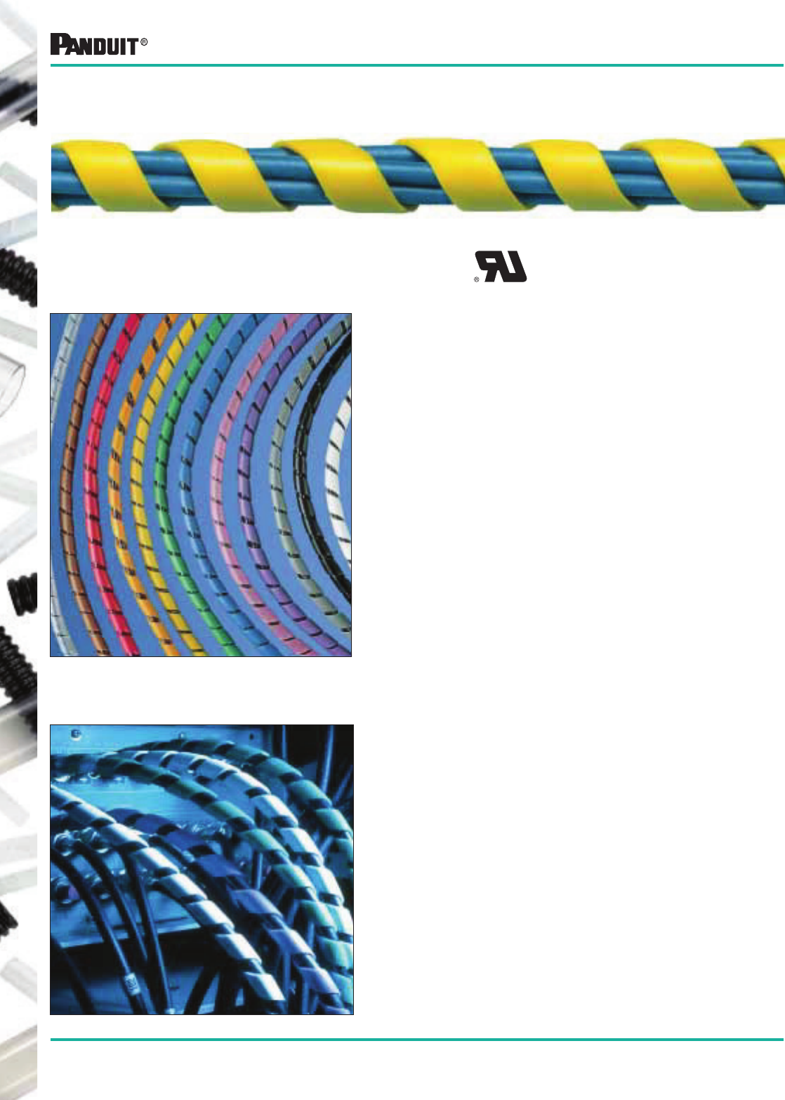
164
Most commonly used parts appear in BOLD.
• Large variety of colors, materials and sizes
• Available in seven different materials and twelve
different colors
• Can be used to color code wire bundles
• Flexible, neat, fast
• Allows breakouts of single/multiple wires and
rerouting of replacement wires
• Harness multiple cables into a single
manageable bundle
• Abrasion protection for wires, cables, hoses and tubing
• Reusable
• Tool supplied in each package
Suggested Applications
• Organize wires for communication and computer
equipment where access to the wires is required
• In OEM applications for protecting tubes
and harnesses
• Abrasion protection for control panel wiring
• Personal computer and printer wire organization
• Protect glass tubes from abrasion and breakage
• Kink-proofing for all kinds of tubing... ideal
for laboratories
• Eliminates lacing cord and tie-offs
• Use orange or yellow spiral wrap for protecting and
identifying fiber optic cables
U.L. Recognized
Spiral Wrap
Spiral Wrap
165
Most commonly used parts appear in BOLD.
The Functional Part Number System Makes Ordering Easy
Spiral Wrap Part Number Description
T 25 F - C 16
Type
T = Spiral Wrap
Outside Diameter
12 = 1/8"
25 = 1/4"
38 = 3/8"
50 = 1/2"
62 = 5/8"
75 = 3/4"
100 = 1"
Package Quantity
X = 10'
Q = 25'
L = 50'
C = 100'
T = 200'
TL = 250'
D = 500'
M = 1000'
Material
F = Polyethylene and Weather
Resistant Polyethylene
R = Fire Resistant - UL94V-2
FR = Flame Retardant - UL94V-0
N = Nylon
T = TEFLON‡
Color Suffix
See Table Below
Spiral Wrap
Blank = Not applicable
*Colors are stocked for 1/4" and 1/2" polyethylene. Other sizes available, contact PANDUIT ® Technical Assistance 866-405-6657.
‡TEFLON or equivalent fluorocarbon PTFE material is used. TEFLON is a registered trademark of E.I. DuPont de Nemours Co.
Material Availability
Color
Color
Suffix* Polyethylene
Weather
Resistant
Polyethylene
Fire Resistant
Polyethylene
Flame
Retardant
Polyethylene Nylon
Weather
Resistant
Nylon TEFLON‡
Natural
(Opaque to
Translucent)
No Suffix
will be
listed
✔
✔ (Natural
color is white)
✔ (Natural
color is white) ✔ ✔
Weather Resistant
Black 0 ✔ ✔
Brown 1 ✔
Red 2 ✔
Orange 3 ✔
Yellow 4 ✔
Green 5 ✔
Blue 6 ✔
Purple 7 ✔
Gray 8 ✔
White 10 ✔
Pink 16 ✔
Black 20 ✔ ✔
166
Most commonly used parts appear in BOLD.
U.L. Recognized
Part
Number Material Color
A
Outside Dia.
in. (mm)
B
in. (mm)
T
in. (mm)
Bundle Size
in. (mm)
Std.
Pkg.
Qty.*
Ft. (m)
T12F-C
Polyethylene
Natural
.125 (3.2) .218 (5.5) .03 (.76) .064 (1.6) – .50 (12.7) 100 (30.5)
T19F-C .188 (4.8) .250 (6.4) .035 (.89) .125 (3.2) – 1.00 (25.4)
T25F-X
.25 (6.4) .375 (9.5) .04 (1.02) .188 (4.8) – 2.00 (50.8)
10 (3.0)
T25F-C
100 (30.5)
T25F-C1 Brown
T25F-C10 White
T25F-C16 Pink
T25F-C2 Red
T25F-C3 Orange
T25F-C4 Yellow
T25F-C5 Green
T25F-C6 Blue
T25F-C7 Purple
T25F-C8 Gray
T38F-C
Natural
.375 (9.5) .437 (11.1) .055 (1.4) .316 (7.9) – 3.00 (76.2)
T50F-X
.50 (12.7) .50 (12.7) .06 (1.5) .38 (9.5) – 4.00 (101.6)
10 (3.0)
T50F-C
100 (30.5)
T50F-C1 Brown
T50F-C10 White
T50F-C16 Pink
T50F-C2 Red
T50F-C3 Orange
T50F-C4 Yellow
T50F-C5 Green
T50F-C6 Blue
T50F-C7 Purple
T50F-C8 Gray
T62F-C
Natural
.625 (15.9) .625 (15.9) .062 (1.57) .50 (12.7) – 4.50 (114.3)
T75F-C .75 (19.1) .875 (22.2) .065 (1.65) .625 (15.9) – 5.00 (127.0)
T100F-C 1 (25.4) 1.125 (28.6) .07 (1.78) .875 (22.2) – 6.00 (152.4)
T12F-C0
Weather
Resistant
Polyethylene Black
.125 (3.2) .218 (5.5) .03 (.760) .064 (1.6) – .50 (12.7)
T19F-C0 .188 (4.8) .250 (6.4) .035 (0.89) .125 (3.2) – 1.00 (25.4)
T25F-X0 .25 (6.4) .375 (9.5) .04 (1.02) .188 (4.8) – 2.00 (50.8) 10 (3.0)
T25F-C0 100 (30.5)
T38F-C0 .375 (9.5) .437 (11.1) .055 (1.4) .316 (7.9) – 3.00 (76.2)
T50F-X0 .5 (12.7) .5 (12.7) .06 (1.5) .375 (9.5) – 4.00 (101.6) 10 (3.0)
T50F-C0
100 (30.5)
T62F-C0 .625 (15.9) .625 (15.9) .062 (1.57) .50 (12.7) – 4.50 (114.3)
T75F-C0 .75 (19.1) .875 (22.2) .065 (1.65) .625 (15.9) – 5.00 (127.0)
T100F-C0 1 (25.4) 1.125 (28.6) .07 (1.78) .875 (22.2) – 6.00 (152.4)
Spiral Wrap
B
T
A
*Order in multiples of standard package quantity.
Note: Custom cut-to-length sizes are available upon request. Contact PANDUIT ® Technical Assistance 866-405-6657 for details.
167
Most commonly used parts appear in BOLD.
Part
Number Material Color
A
Outside Dia.
in. (mm)
B
in. (mm)
T
in. (mm)
Bundle Size
in. (mm)
Std.
Pkg.
Qty.*
Ft. (m)
T12R-C
T19R-C
T25R-C
T25R-C20
T38R-C
T50R-C
T62R-C
T75R-C
T100R-C
Fire
Resistant
Polyethylene
UL94V-2
Natural
Natural
Natural
Black
Natural
Natural
Natural
Natural
Natural
.125 (3.2)
.188 (4.8)
.25 (6.4)
.25 (6.4)
.375 (9.5)
.50 (12.7)
.625 (15.9)
.75 (19.1)
1.00 (25.4)
.218 (5.5)
.250 (6.4)
.375 (9.5)
.375 (9.5)
.437 (11.1)
.50 (12.7)
.625 (15.9)
.875 (22.2)
1.125 (28.6)
.03 (.76)
.035 (.89)
.04 (1.02)
.04 (1.02)
.055 (1.4)
.06 (1.5)
.062 (1.57)
.065 (1.65)
.07 (1.78)
.064 (1.6) – .50 (12.7)
.125 (3.2) – 1.00 (25.4)
.188 (4.8) – 2.00 (50.8)
.188 (4.8) – 2.00 (50.8)
.316 (7.9) – 3.00 (76.2)
.375 (9.5) – 4.00 (101.6)
.50 (12.7) – 4.50 (114.3)
.625 (15.9) – 5.00 (127.0)
.875 (22.2) – 6.00 (152.4)
100 (30.5)
100 (30.5)
100 (30.5)
100 (30.5)
100 (30.5)
100 (30.5)
100 (30.5)
100 (30.5)
100 (30.5)
T12FR-C
T12FR-C20
T19FR-C
T19FR-C20
T25FR-C
T25FR-C20
T38FR-C
T38FR-C20
T50FR-C
T50FR-C20
T62FR-C
T62FR-C20
T75FR-C
T75FR-C20
T100FR-C
T100FR-C20
Flame
Retardant
Polyethylene
UL94V-0
Natural
Black
Natural
Black
Natural
Black
Natural
Black
Natural
Black
Natural
Black
Natural
Black
Natural
Black
.125 (3.2)
.125 (3.2)
.188 (4.8)
.188 (4.8)
.25 (6.4)
.25 (6.4)
.375 (9.5)
.375 (9.5)
.50 (12.7)
.50 (12.7)
.625 (15.9)
.625 (15.9)
.75 (19.1)
.75 (19.1)
1.00 (25.4)
1.00 (25.4)
.218 (5.5)
.218 (5.5)
.250 (6.4)
.250 (6.4)
.375 (9.5)
.375 (9.5)
.437 (11.1)
.437 (11.1)
.50 (12.7)
.50 (12.7)
.625 (15.9)
.625 (15.9)
.875 (22.2)
.875 (22.2)
1.125 (28.6)
1.125 (28.6)
.03 (.76)
.03 (.76)
.032 (.81)
.032 (.81)
.04 (1.02)
.04 (1.02)
.055 (1.4)
.055 (1.4)
.06 (1.5)
.06 (1.5)
.062 (1.57)
.062 (1.57)
.065 (1.65)
.065 (1.65)
.07 (1.78)
.07 (1.78)
.064 (1.6) – .50 (12.7)
.064 (1.6) – .50 (12.7)
.125 (3.2) – 1.00 (25.4)
.125 (3.2) – 1.00 (25.4)
.188 (4.8) – 2.00 (50.8)
.188 (4.8) – 2.00 (50.8)
.316 (7.9) – 3.00 (76.2)
.316 (7.9) – 3.00 (76.2)
.375 (9.5) – 4.00 (101.6)
.375 (9.5) – 4.00 (101.6)
.50 (12.7) – 4.50 (114.3)
.50 (12.7) – 4.50 (114.3)
.625 (15.9) – 5.00 (127.0)
.625 (15.9) – 5.00 (127.0)
.875 (22.2) – 6.00 (152.4)
.875 (22.2) – 6.00 (152.4)
100 (30.5)
100 (30.5)
100 (30.5)
100 (30.5)
100 (30.5)
100 (30.5)
100 (30.5)
100 (30.5)
100 (30.5)
100 (30.5)
100 (30.5)
100 (30.5)
100 (30.5)
100 (30.5)
100 (30.5)
100 (30.5)
T12N-C
T12N-C0
T19N-C
T19N-C0
T25N-C
T25N-C0
T38N-C
T38N-C0
T50N-C
T50N-C0
T62N-C
T62N-C0
T75N-C
T75N-C0
T100N-C
T100N-C0
Nylon (Black
is Weather
Resistant
Nylon)
Natural
Black
Natural
Black
Natural
Black
Natural
Black
Natural
Black
Natural
Black
Natural
Black
Natural
Black
.125 (3.2)
.125 (3.2)
.188 (4.8)
.188 (4.8)
.25 (6.4)
.25 (6.4)
.375 (9.5)
.375 (9.5)
.50 (12.7)
.50 (12.7)
.625 (15.9)
.625 (15.9)
.75 (19.1)
.75 (19.1)
1.00 (25.4)
1.00 (25.4)
.218 (5.5)
.218 (5.5)
.250 (6.4)
.250 (6.4)
.375 (9.5)
.375 (9.5)
.437 (11.1)
.437 (11.1)
.50 (12.7)
.50 (12.7)
.625 (15.9)
.625 (15.9)
.875 (22.2)
.875 (22.2)
1.125 (28.6)
1.125 (28.6)
.015 (.38)
.015 (.38)
.020 (.51)
.020 (.51)
.023 (.58)
.023 (.58)
.03 (.76)
.03 (.76)
.032 (.81)
.032 (.81)
.035 (.89)
.03 (.89)
.04 (1.02)
.04 (1.02)
.045 (1.1)
.045 (1.1)
.064 (1.6) – .50 (12.7)
.064 (1.6) – .50 (12.7)
.125 (3.2) – 1.00 (25.4)
.125 (3.2) – 1.00 (25.4)
.188 (4.8) – 2.00 (50.8)
.188 (4.8) – 2.00 (50.8)
.316 (7.9) – 3.00 (76.2)
.316 (7.9) – 3.00 (76.2)
.375 (9.5) – 4.00 (101.6)
.375 (9.5) – 4.00 (101.6)
.50 (12.7) – 4.50 (114.3)
.50 (12.7) – 4.50 (114.3)
.625 (15.9) – 5.00 (127.0)
.625 (15.9) – 5.00 (127.0)
.875 (22.2) – 6.00 (152.4)
.875 (22.2) – 6.00 (152.4)
100 (30.5)
100 (30.5)
100 (30.5)
100 (30.5)
100 (30.5)
100 (30.5)
100 (30.5)
100 (30.5)
100 (30.5)
100 (30.5)
100 (30.5)
100 (30.5)
100 (30.5)
100 (30.5)
100 (30.5)
100 (30.5)
T12T-C
T19T-C
T25T-L
T50T-Q
T62T-Q
T75T-X
T100T-X
TEFLON‡
Natural
Natural
Natural
Natural
Natural
Natural
Natural
.125 (3.2)
.188 (4.8)
.25 (6.4)
.50 (12.7)
.625 (15.9)
.75 (19.1)
1.00 (25.4)
.218 (5.5)
.250 (6.4)
.375 (9.5)
.50 (12.7)
.625 (15.9)
.875 (22.2)
1.125 (28.6)
.02 (.5)
.03 (.76)
.03 (.76)
.03 (.76)
.03 (.76)
.03 (.76)
.04 (1.02)
.064 (1.6) – .50 (12.7)
.125 (3.2) – 1.00 (25.4)
.188 (4.8) – 2.00 (50.8)
.375 (9.5) – 4.00 (101.6)
.50 (12.7) – 4.50 (114.3)
.625 (15.9) – 5.00 (127.0)
.875 (22.2) – 6.00 (152.4)
100 (30.5)
100 (30.5)
50 (15.2)
25 (7.6)
25 (7.6)
10 (3.0)
10 (3.0)
Spiral Wrap
U.L. Recognized
B
T
A
*Order in multiples of std. pkg. qty.
‡TEFLON or equivalent fluorocarbon PTFE mater ial is used. TEFLON is a registered trademark of E.I. DuPont de Nemours Co.
Note: Custom cut-to-length sizes are available upon request. Contact PANDUIT ® Technical Assistance 866-405-6657 for details.
168
Most commonly used parts appear in BOLD.
Split Harness Wrap
PAN-WRAP ™ Split Harness Wrap
PAN-WRAP ™ Split Harness Wrap is an innovative addition to the
PANDUIT ® Abrasion Protection Line. Engineered for wire harness
protection, PAN-WRAP ™bundles and protects wire, cable and hoses.
The PAN-WRAP ™design provides full 360° coverage with pre-cut slots
for break-outs to maximize reliability and reduce installation time.
PAN-WRAP ™tools are available for easy installation.
Split Harness Wrap
Part
Number
Size
I.D.
In. (mm)
Maximum
Bundle
Diameter
In. (mm) Material Color
Length
Ft. (M)
Std.
Pkg.
Qty.*
PW50F-T .50 (12.7) .55 (13.97) Polyethylene Natural 200 (61.05) 1
PW75F-C .75 (19.05) .80 (20.32) Polyethylene Natural 100 (30.48) 1
PW50F-T20 .50 (12.7) .55 (13.97) Polyethylene Black 200 (61.05) 1
PW75F-C20 .75 (19.05) .80 (20.32) Polyethylene Black 100 (30.48) 1
Tool
Part
Number Material Color Size
Std.
Pkg.
Qty.*
PWT50 ABS White .50" 1
PWT75 ABS White .75" 1
Open PAN-WRAP ™ Tool to
enable the wire bundle to be
inserted inside the tool.
Insert wire bundle inside tool.
Close tool to secure the wire
bundle and prepare to insert
bundle into the PAN-WRA P ™
Split Harness Wrap.
Insert end of tool into the end
of Split Harness Wrap. Begin
pulling the tool making
certain that the Split Harness
Wrap is feeding over the
wire bundle.
Hold end of Split Harness
Wrap and wire bundle while
continuing to pull the tool,
inserting the wire bundle into
the length of the Split
Harness Wrap.
• Slotted walls allow wire break-outs to speed installation
• Flexible design allows maneuverability and protects wire and cables during movement
• New installation tool reduces installation time and lowers installed cost
• 360° abrasion protection improves product reliability
Features and Benefits
• Wire Harness Assemblers
• Transportation
• Commercial Appliances
• Industrial Robotics
Applications
*Order in multiples of std. pkg. qty.
169
Most commonly used parts appear in BOLD.
Example: GEE 36 F -A- C 0
• Nylon grommet edging strips conform
to the Military Standard MS21266
• Slotted or solid wall construction
• Available with pressure
sensitive adhesive
• No liner to remove from adhesive
The Functional Part Number System Makes Ordering Easy
Grommet Edging Part Number Description
Grommet Edging
Part Description
Grommet Edging
Strips = GE
Slotted Grommet
Edging = GEE
Solid Grommet
Edging = GES
Package Size
Q = 25'
L = 50'
C = 100'
Color Suffix
0 = Weather
Resistant Black
Leave Blank = Natural
Material
F = Polyethylene
N = Nylon 6.6
FR = Flame Retardant
Polyethylene
Adhesive
A = Adhesive
Lined
Leave Blank =
Non-Adhesive
Max. Panel Thickness
36 = .036" thickness
62 = .062" thickness
99 = .099" thickness
144 = .144" thickness
189 = .189" thickness
• Use the solid wall product on
straight edges
• Use to prevent abrasion against
the sharp edges of panel walls
and knockouts
Suggested Applications:Features:
170
Most commonly used parts appear in BOLD.
Protects wires and cables from sharp edges
Choose from five materials:
Nylon 6.6
• Self extinguishing
• For indoor use up to 149°F (65°C)
• Available with slotted wall only‘
Polyethylene
• General purpose material for indoor use up to 122°F (50°C)
• Style GEE and GES provided in .030" (0.8mm) thick material,
makes them highly flexible
• Available with slotted or solid wall construction
Weather Resistant Polyethylene
• For outdoor use up to 122°F (50°C)
• Excellent resistance to ultra-violet light
Flame Retardant Polyethylene
• Will not support a flame
• Available with slotted or solid wall construction
Grommet Edging
Adhesive Lined Polyethylene
• Base is lined with a pressure sensitive adhesive
• Available in natural and weather resistant
• Adhesive ensures that the product will stay where it is installed
Adhesive Lined
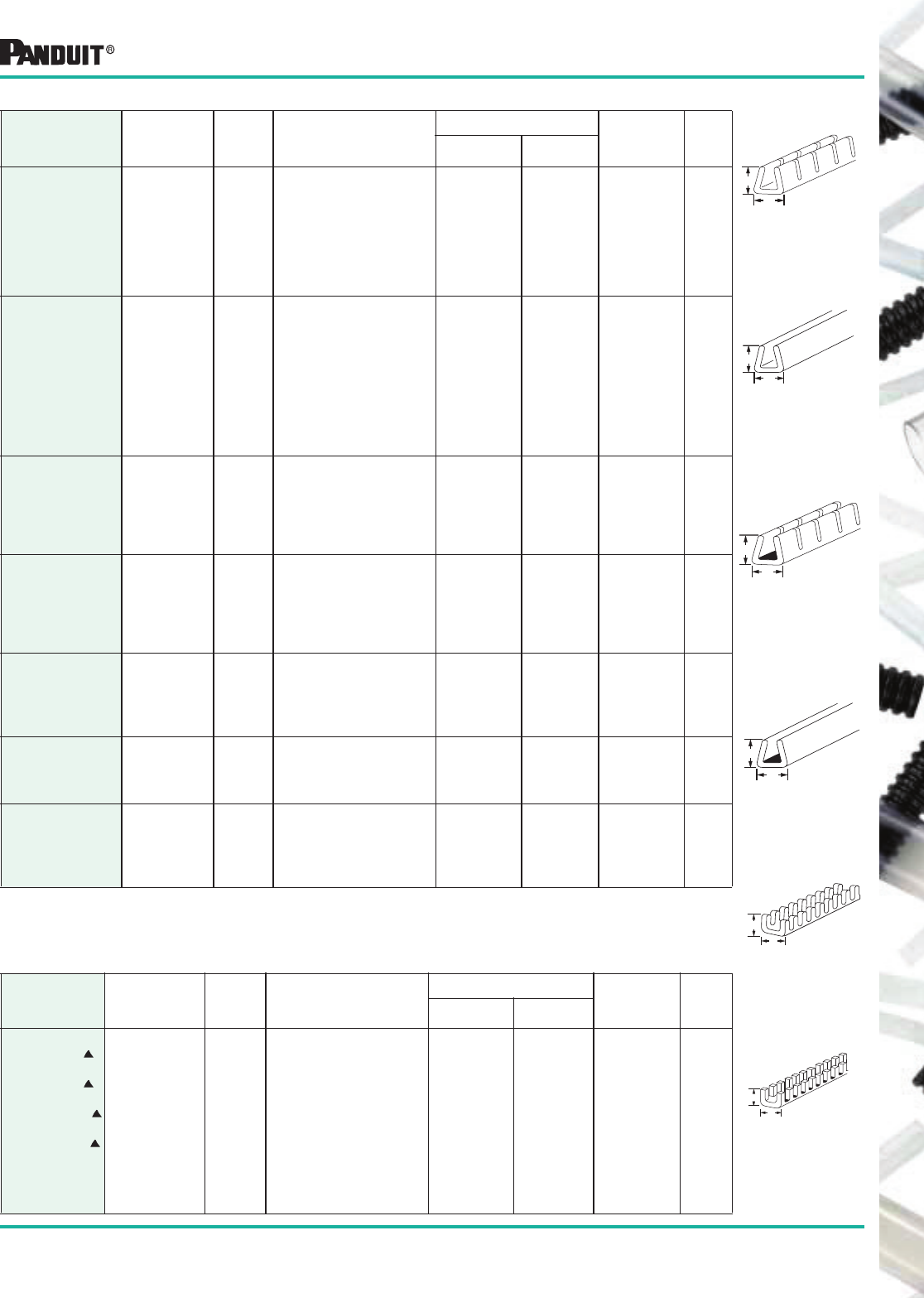
171
Most commonly used parts appear in BOLD.
B
A
*Order the number of reels required in multiples of standard package quantities.
Part Number Material Color
Panel Thickness
in. (mm)
Dimensions—in. (mm)
Ft. (m)
Per Roll
Std.
Pkg.
Qty.*A B
GEE36F-C
GEE36F-C0
GEE62F-C
GEE62F-C0
GEE99F-C
GEE99F-C0
GEE144F-C
GEE144F-C0
Continuous
Polyethylene
(Slotted
Wall)
Natural
Black
Natural
Black
Natural
Black
Natural
Black
.026 (.7) – .036 (.9)
.026 (.7) – .036 (.9)
.036 (.9) – .062 (1.6)
.036 (.9) – .062 (1.6)
.062 (1.6) – .099 (2.5)
.062 (1.6) – .099 (2.5)
.099 (2.5) – .144 (3.7)
.099 (2.5) – .144 (3.7)
.106 (2.7)
.106 (2.7)
.131 (3.3)
.131 (3.3)
.169 (4.3)
.169 (4.3)
.213 (5.4)
.213 (5.4)
.117 (3.0)
.117 (3.0)
.160 (4.1)
.160 (4.1)
.186 (4.7)
.186 (4.7)
.222 (5.6)
.222 (5.6)
100 (30.5)
100 (30.5)
100 (30.5)
100 (30.5)
100 (30.5)
100 (30.5)
100 (30.5)
100 (30.5)
1 Roll
1 Roll
1 Roll
1 Roll
1 Roll
1 Roll
1 Roll
1 Roll
GES36F-C
GES36F-C0
GES62F-C
GES62F-C0
GES99F-C
GES99F-C0
GES144F-C
GES144F-C0
GES189F-C
GES189F-C0
Continuous
Polyethylene
(Solid Wall)
Natural
Black
Natural
Black
Natural
Black
Natural
Black
Natural
Black
.026 (.7) – .036 (.9)
.026 (.7) – .036 (.9)
.036 (.9) – .062 (1.6)
.036 (.9) – .062 (1.6)
.062 (1.6) – .099 (2.5)
.062 (1.6) – .099 (2.5)
.099 (2.5) – .144 (3.7)
.099 (2.5) – .144 (3.7)
.144 (3.7) – .189 (4.8)
.144 (3.7) – .189 (4.8)
.106 (2.7)
.106 (2.7)
.131 (3.3)
.131 (3.3)
.169 (4.3)
.169 (4.3)
.213 (5.4)
.213 (5.4)
.297 (7.6)
.297 (7.6)
.117 (3.0)
.117 (3.0)
.160 (4.1)
.160 (4.1)
.186 (4.7)
.186 (4.7)
.222 (5.6)
.222 (5.6)
.301 (7.7)
.301 (7.7)
100 (30.5)
100 (30.5)
100 (30.5)
100 (30.5)
100 (30.5)
100 (30.5)
100 (30.5)
100 (30.5)
100 (30.5)
100 (30.5)
1 Roll
1 Roll
1 Roll
1 Roll
1 Roll
1 Roll
1 Roll
1 Roll
1 Roll
1 Roll
GEE62F-A-C
GEE62F-A-C0
GEE99F-A-C
GEE99F-A-C0
GEE144F-A-C
GEE144F-A-C0
Continuous
Polyethylene
With
Adhesive
(Slotted
Wall)
Natural
Black
Natural
Black
Natural
Black
036 (.9) – .062 (1.6)
.036 (.9) – .062 (1.6)
.062 (1.6) – .099 (2.5)
.062 (1.6) – .099 (2.5)
.099 (2.5) – .144 (3.7)
.099 (2.5) – .144 (3.7)
.131 (3.3)
.131 (3.3)
.169 (4.3)
.169 (4.3)
.213 (5.4)
.213 (5.4)
.160 (4.1)
.160 (4.1)
.186 (4.7)
.186 (4.7)
.222 (5.6)
.222 (5.6)
100 (30.5)
100 (30.5)
100 (30.5)
100 (30.5)
100 (30.5)
100 (30.5)
1 Roll
1 Roll
1 Roll
1 Roll
1 Roll
1 Roll
GES62F-A-C
GES62F-A-C0
GES99F-A-C
GES99F-A-C0
GES144F-A-C
GES144F-A-C0
Continuous
Polyethylene
With
Adhesive
(Solid Wall)
Natural
Black
Natural
Black
Natural
Black
036 (.9) – .062 (1.6)
.036 (.9) – .062 (1.6)
.062 (1.6) – .099 (2.5)
.062 (1.6) – .099 (2.5)
.099 (2.5) – .144 (3.7)
.099 (2.5) – .144 (3.7)
.131 (3.3)
.131 (3.3)
.169 (4.3)
.169 (4.3)
.213 (5.4)
.213 (5.4)
.160 (4.1)
.160 (4.1)
.186 (4.7)
.186 (4.7)
.222 (5.6)
.222 (5.6)
100 (30.5)
100 (30.5)
100 (30.5)
100 (30.5)
100 (30.5)
100 (30.5)
1 Roll
1 Roll
1 Roll
1 Roll
1 Roll
1 Roll
GEE36FR-C
GEE62FR-C
GEE99FR-C
GEE144FR-C
Flame
Retardant
Polyethylene
(Slotted
Wall)
Natural
Natural
Natural
Natural
.026 (.7) – .036 (.9)
.036 (.9) – .062 (1.6)
.062 (1.6) – .099 (2.5)
.099 (2.5) – .144 (3.7)
.106 (2.7)
.131 (3.3)
.169 (4.3)
.213 (5.4)
.117 (3.0)
.160 (4.1)
.155 (3.9)
.232 (5.9)
100 (30.5)
100 (30.5)
100 (30.5)
100 (30.5)
1 Roll
1 Roll
1 Roll
1 Roll
GES36FR-C
GES62FR-C
GES99FR-C
GES144FR-C
Flame
Retardant
Polyethylene
(Solid Wall)
Natural
Natural
Natural
Natural
.026 (.7) – .036 (.9)
.036 (.9) – .062 (1.6)
.062 (1.6) – .099 (2.5)
.099 (2.5) – .144 (3.7)
.106 (2.7)
.131 (3.3)
.169 (4.3)
.213 (5.4)
.117 (3.0)
.160 (4.1)
.155 (3.9)
.232 (5.9)
100 (30.5)
100 (30.5)
100 (30.5)
100 (30.5)
1 Roll
1 Roll
1 Roll
1 Roll
GEE47N-C
GEE55N-C
GEE71N-C
GEE98N-C
GEE134N-C
Continuous
Nylon 6.6
(Slotted
Wall)
Natural
Natural
Natural
Natural
Natural
.039 (1.0) – .055 (1.4)
.047 (1.2) – .063 (1.6)
.063 (1.6) – .079 (2.0)
.091 (2.3) – .106 (2.7)
.126 (3.2) – .142 (3.6)
.130 (3.3)
.133 (3.4)
.150 (3.8)
.180 (4.6)
.210 (5.3)
.140 (3.5)
.140 (3.5)
.140 (3.5)
.140 (3.5)
.140 (3.5)
100 (30.5)
100 (30.5)
100 (30.5)
100 (30.5)
100 (30.5)
1 Roll
1 Roll
1 Roll
1 Roll
1 Roll
Grommet Edging
Polyethylene
Style GES
Solid Wall
Continuous
(100') Rolls
Adhesive Lined
Polyethylene
Style GEE-A
Slotted Wall
Continuous
(100') Rolls
Adhesive Lined
Polyethylene
Style GES-A
Solid Wall
Continuous
(100') Rolls
Nylon 6.6
Style GE
Slotted Wall
12 3/4" strips
Style GEE
Slotted Wall
Continuous
(100') Rolls
Polyethylene
Style GEE
Slotted Wall
Continuous
(100') Rolls
Part Number Material Color
Panel Thickness
in. (mm)
Dimensions—in. (mm) Pieces
Per
Pkg.
Std.
Pkg.
Qty.*A B
GE52-C
GE52-C69
GE85-C
GE85-C69
GE128-C
GE128-C69
GE192-L
GE192-L69
GE255-L
GE318-L
GE380-Q
GE510-Q
Military
Standard
MS21266
12.75
(323.85mm)
Nylon 6.6
Strips -69
designates
Flame
Retardant)
Natural
Natural
Natural
Natural
Natural
Natural
Natural
Natural
Natural
Natural
Natural
Natural
.015 (.4) – .052 (1.3)
.015 (.4) – .052 (1.3)
.052 (1.3) – .085 (2.2)
.05 (1.3) – .085 (2.2)
.085 (2.2) – .128 (3.3)
.085 (2.2) – .128 (3.3)
.128 (3.3) – .192 (4.9)
.128 (3.3) – .192 (4.9)
.192 (4.9) – .255 (6.5)
.255 (6.5) – .318 (8.1)
.318 (8.1) – .380 (9.7)
.380 (9.7) – .510 (13.0)
.150 (3.8)
.150 (3.8)
.175 (4.5)
.175 (4.5)
.220 (5.6)
.220 (5.6)
.325 (8.3)
.325 (8.3)
.385 (9.8)
.455 (11.3)
.515 (13.1)
.640 (16.3)
.155 (3.9)
.155 (3.9)
.155 (3.9)
.155 (3.9)
.155 (3.9)
.155 (3.9)
.230 (5.8)
.230 (5.8)
.240 (6.1)
.255 (6.5)
.255 (6.5)
.255 (6.5)
100
100
100
100
100
100
50
50
50
50
25
25
Strips
Strips
Strips
Strips
Strips
Strips
Strips
Strips
Strips
Strips
Strips
Strips
B
A
B
A
B
A
B
A
B
A
Nylon 6.6
*Order the number of pieces required in multiples of standard package quantities.
This material is not listed under military standard MS21266.
Grommet edging is to be used for odd shaped holes in addition to circular panel holes. Circular hole installation cut lengths
can be found by: cut lengths = (dia. of hole) x 3.14.
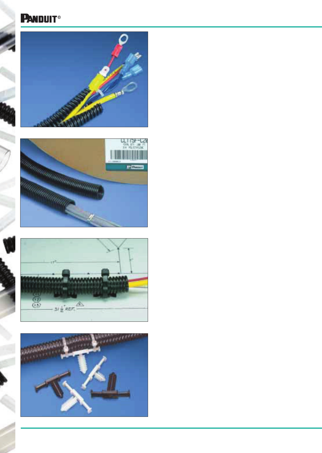
172
Most commonly used parts appear in BOLD.
Features and Benefits
• Protects and reduces the risk of damage to wiring
• Crush, impact and abrasion resistant
• Slit wall design for ease of installation
• Available in easy to handle 100' lengths
• Available in black, orange and yellow polyethylene and
black heat stabilized nylon
• Secure with push type cable ties, adhesive or push
type mounts
Corrugated Loom Tubing
Suggested Applications
• Bundle wires in control panels
• Contain and organize loose and bundled
wiring harnesses
• Route wires in automotive, truck, trailer, bus,
conversion van, emergency service and recreational
vehicle applications
• Protect wires in off road/mobile equipment
• Use in mining equipment
• Marine applications for protecting wires on boats
and ships
• PANDUIT ® Corrugated Loom Tubing is offered for
applications where spiral wrap or braided expandable
sleeving may be difficult to install or where they do not
offer the amount of protection required
• Available in Heat Stabilized Nylon or Polyethylene, this
product features a lengthwise slit which makes it easy
to install onto a bundle of wires or a pre-assembled
harness assembly
Wiring Accessories for Corrugated Loom Tubing
• Tie Harness Mounts have a specially designed
location tab on the mount that aligns with grooves in
corrugated loom tubing to ensure proper mount location
during assembly
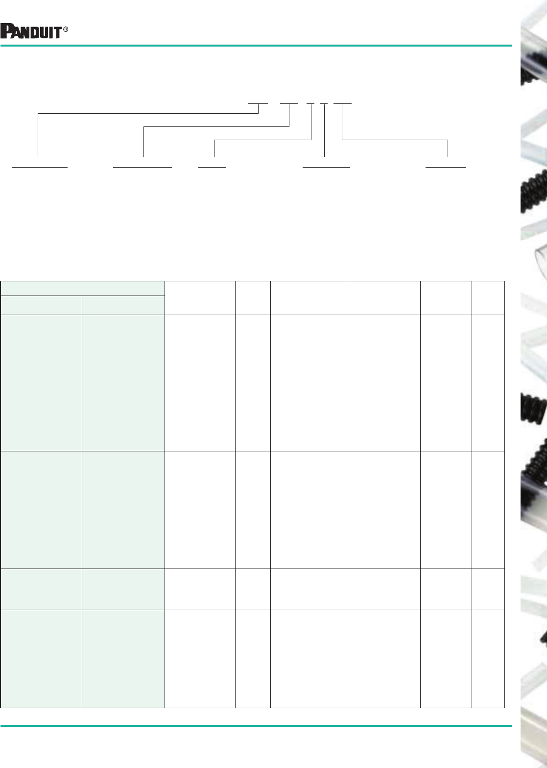
173
Most commonly used parts appear in BOLD.
The Functional Part Number System Makes Ordering Easy
Corrugated Loom Tubing Part Number Description
Example: CLT 100 N -C 630
Part Description
Corrugated Loom
Tubing
CLT= Slit Wall
CLTS= Solid Wall
Bundle Diameter
25 = 1/4"
35 = 5/16"
38 = 3/8"
50 = 1/2"
62 = 5/8"
75 = 3/4"
100 = 1"
125 = 1 1/4"
150 = 1 1/2"
188 = 1 7/8"
Material
N = Heat Stabilized Nylon
F = Polyethylene
Package Size
X = 10'
L = 50'
C = 100'
T = 200'
D = 500'
6C = 600’
Color Suffix
630 = Heat Stabilized
Black Nylon 6
20 = Black Polyethylene
3= Orange
4= Yellow
Part Number
Material Color
Inside
Diameter
in. (mm)
Outside
Diameter
in. (mm)
Length
Ft. (m)
Std.
Pkg.
Qty.*
Slit Solid
CLT25F-C20
CLT35F-C20
CLT38F-C20
CLT50F-C20
CLT62F-C20
CLT75F-C20
CLT100F-C20
CLT125F-L20
CLT150F-X20
CLT150F-T20
CLT150F-D20
CLT188F-X20
CLT188F-C20
CLT188F-6C20
CLTS25F-C
CLTS35F-C
CLTS38F-C
CLTS50F-C
CLTS62F-C
CLTS75F-C
CLTS100F-C
CLTS125F-L
**
**
CLTS150F-D
**
**
**
Polyethylene Black
.265 (6.7)
.350 (8.9)
.414 (10.5)
.505 (12.8)
.665 (16.9)
.760 (19.3)
.915 (23.2)
1.290 (32.8)
1.550 (39.1)
1.550 (39.1)
1.550 (39.1)
1.881 (47.8)
1.881 (47.8)
1.881 (47.8)
.390 (9.9)
.500 (12.7)
.556 (14.1)
.670 (17.0)
.830 (21.1)
.935 (23.7)
1.090 (27.7)
1.500 (38.1)
1.860 (47.2)
1.860 (47.2)
1.860 (47.2)
2.169 (55.1)
2.169 (55.1)
2.169 (55.1)
100 (30.5)
100 (30.5)
100 (30.5)
100 (30.5)
100 (30.5)
100 (30.5)
100 (30.5)
50 (15.2)
10 (3.0)
200 (61.0)
500 (152.4)
10 (3.0)
100 (30.5)
600 (182.9)
1 Roll
CLT25F-C3
CLT35F-C3
CLT38F-C3
CLT50F-C3
CLT62F-C3
CLT75F-C3
CLT100F-C3
CLT125F-L3
CLT150F-X3
CLT150F-D3
CLT188F-X3
CLT188F-C3
CLTS25F-C3
CLTS35F-C3
CLTS38F-C3
CLTS50F-C3
CLTS62F-C3
CLTS75F-C3
CLTS100F-C3
CLTS125F-L3
**
CLTS150F-D3
**
**
Polyethylene Orange
.265 (6.7)
.350 (8.9)
.414 (10.5)
.505 (12.8)
.665 (16.9)
.760 (19.3)
.915 (23.2)
1.290 (32.8)
1.550 (39.1)
1.550 (39.1)
1.881 (47.8)
1.881 (47.8)
.390 (9.9)
.500 (12.7)
.556 (14.1)
.670 (17.0)
.830 (21.1)
.935 (23.7)
1.090 (27.7)
1.500 (38.1)
1.860 (47.2)
1.860 (47.2)
2.169 (55.1)
2.169 (55.1)
100 (30.5)
100 (30.5)
100 (30.5)
100 (30.5)
100 (30.5)
100 (30.5)
100 (30.5)
50 (15.2)
10 (3.0)
500 (152.4)
10 (3.0)
100 (30.5)
1 Roll
CLT150F-X4
CLT150F-D4
CLT188F-X4
CLT188F-C4
**
**
**
**
Polyethylene Yellow
1.550 (39.1)
1.550 (39.1)
1.881 (47.8)
1.881 (47.8)
1.860 (47.2)
1.860 (47.2)
2.169 (55.1)
2.169 (55.1)
10 (3.0)
500 (152.4)
10 (3.0)
100 (30.5)
1 Roll
CLT25N-C630
CLT35N-C630
CLT38N-C630
CLT50N-C630
CLT62N-C630
CLT75N-C630
CLT100N-C630
CLT125N-L630
CLT150N-D630
CLT188N-6C630
CLTS25N-C
CLTS35N-C
CLTS38N-C
CLTS50N-C
CLTS62N-C
CLTS75N-C
CLTS100N-C
CLTS125N-L
**
**
Heat Stabilized
Black Nylon 6 Black
.265 (6.7)
.350 (8.9)
.414 (10.5)
.505 (12.8)
.665 (16.9)
.760 (19.3)
.915 (23.2)
1.290 (32.8)
1.550 (39.1)
1.881 (47.8)
.390 (9.9)
.500 (12.7)
.556 (14.1)
.670 (17.0)
.830 (21.1)
.935 (23.7)
1.090 (27.7)
1.500 (38.1)
1.860 (47.2)
2.169 (55.1)
100 (30.5)
100 (30.5)
100 (30.5)
100 (30.5)
100 (30.5)
100 (30.5)
100 (30.5)
50 (15.2)
500 (152.4)
600 (182.9)
1 Roll
Corrugated Loom Tubing
*Order number of rolls required.
**Contact PANDUIT ® Technical Assistance 866-405-6657 for additional sizes, materials, colors, and bulk packaging.
NOTE: Custom cut-to-length sizes are available upon request. Contact PANDUIT ® Technical Assistance 866-405-6657 for details.
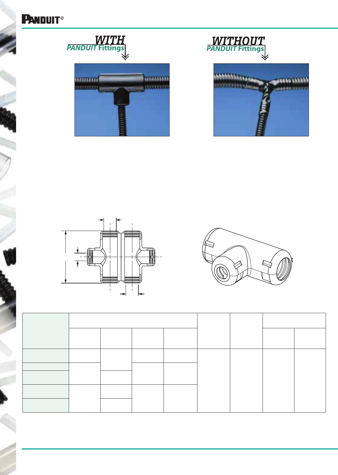
174
Most commonly used parts appear in BOLD.
Corrugated Loom Tubing Fittings
Features: Benefits:
• Fast assembly . . . . . . . . . . . . . . . . . Reduces production time
• Virtually eliminates taping . . . . . . . . Improves system appearance
• Easy to assemble . . . . . . . . . . . . . . Reduces operator fatigue
• Locking latch design . . . . . . . . . . . . Secures fittings firmly in place
• Durable polyethylene shell. . . . . . . . Protects wires
• Works with most popular sizes . . . . Provides easy selection of
of Corrugated Loom Tubing fittings for application needs
Part Number
Dimensions
in. (mm)
Material Color
Packaging*
A B C D
Std.
Pkg
Qty.
Std.
Ctn.
Qty.
CF382538F-Q .38
(9.53) .25
(6.35)
.38
(9.53)
2.06
(52.32)
Polyethylene Black 25 100
CF502550F-Q .50
(12.70)
.50
(12.70)
2.30
(58.42)
CF503850F-Q .38
(9.53)
CF752575F-Q
.75
(19.05)
.25
(6.35) .75
(19.05)
3.06
(77.72)
CF753875F-Q .38
(9.53)
C
A
B
D
*Order the number of pieces required in multiplies of package quantities.
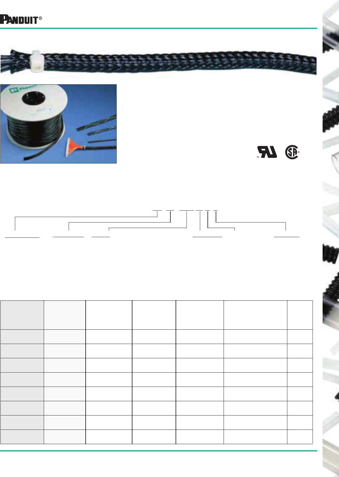
175
Most commonly used parts appear in BOLD.
• Provides continuous abrasion resistance for wires,
cables and tubing
• Lightweight, durable protection
• Highly flexible open weave will not trap heat or humidity
• Rated for use up to 257°F (125°C)
• Allows for use with irregular shapes
• Stock colors: Black, gray and white
• See page 176 for cutting tools
The Functional Part Number System Makes Ordering Easy
Braided Expandable Sleeving Part Number Description
Part Number
Black
Part Number
Gray
Part Number
White
Nominal
I.D.
in.
Nominal
Diameter Range
in. (mm)
Std.
Pkg.
Qty.*
Feet (m)
Std.
Ctn.
Qty.
SE12P-TR0
SE12P-MR0
SE12P-TR8
SE12P-MR8
—
SE12P-MR10
1/8 .094 to .250
(2.4) to (6.4)
200 (61.0)
1000 (304.8)
4 Reels
2 Reels
SE25P-TR0
SE25P-MR0
SE25P-TR8
SE25P-MR8
—
SE25P-MR10
1/4 .125 to .375
(3.2) to (9.5)
200 (61.0)
1000 (304.8)
4 Reels
2 Reels
SE38P-TR0
SE38P-MR0
SE38P-TR8
SE38P-MR8
—
SE38P-MR10
3/8 .188 to .562
(4.7) to (14.3)
200 (61.0)
1000 (304.8)
4 Reels
2 Reels
SE50P-CR0
SE50P-DR0
SE50P-CR8
SE50P-DR8
—
SE50P-DR10
1/2 .250 to .750
(6.4) to (19.1)
100 (30.5)
500 (152.4)
4 Reels
2 Reels
SE75P-CR0
SE75P-DR0
SE75P-CR8
SE75P-DR8
—
SE75P-DR10
3/4 .500 to 1.25
(12.7) to (31.8)
100 (30.5)
500 (152.4)
4 Reels
2 Reels
SE125P-LR0
SE125P-TR0
SE125P-LR8
SE125P-TR8
—
SE125P-TR10
1 1/4 .750 to 1.50
(19.1) to (38.1)
50 (15.2)
200 (61.0)
4 Reels
2 Reels
SE150P-LR0
SE150P-TR0
SE150P-LR8
SE150P-TR8
—
SE150P-TR10
1 1/2 1.00 to 2.25
(25.4) to (57.2)
50 (15.2)
200 (61.0)
4 Reels
2 Reels
SE175P-TR0 — — 1 3/4 1.25 to 2.75
(31.8) to (69.8)
200 (61.0) 2 Reels
Braided Expandable Sleeving
Example: SE 25 PFR - M R 0
Part Description
SE = Sleeving
Expandable
Nom. I.D. Size
12 = 1/8" (3.2)
25 = 1/4" (6.4)
38 = 3/8" (9.5)
50 = 1/2" (12.7)
75 = 3/4" (19.1)
125 = 11/4" (31.8)
150 = 11/2" (38.1)
175 = 13/4" (44.5)
Material
P = Polyethylene Terephthalate (PET)
PFR = Polyethylene Terephthalate (PET)
Flame Retardant
Package Size
L = 50' (15.2m)
C = 100' (30.5m)
T = 200' (61.0m)
D = 500' (152.4m)
M = 1000' (304.8m)
Color Suffix
0 = Black
8 = Gray
10 = White
R = Reel
*Order number of reels required.
Braided Expandable Sleeving — Polyethylene Terephthalate — PET
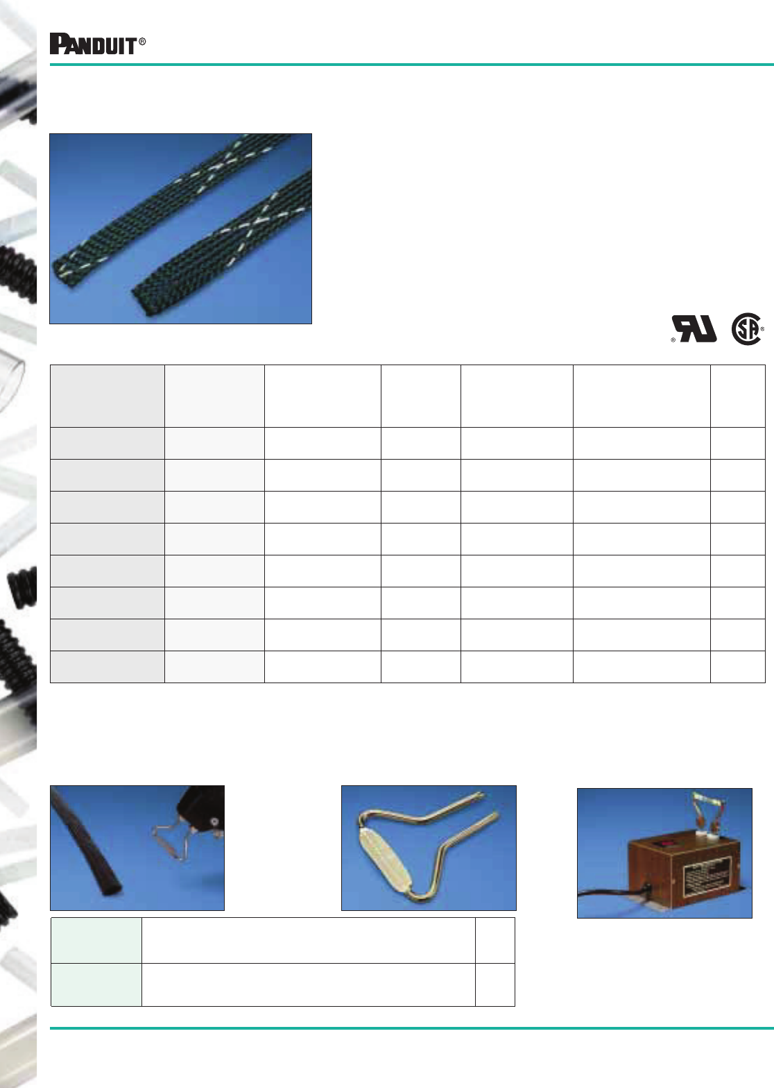
176
Most commonly used parts appear in BOLD.
Flame Retardant Braided Expandable Sleeving
• Provides continuous abrasion resistance for wires, cables
and tubing
• Lightweight, durable protection
• Highly flexible open weave will not trap heat or humidity
• Rated for use up to 257°F (125°C)
• Allows for use with irregular shapes
• Self extinguishing, meets UL VW-1
• Stock colors: Black or gray with white tracer, or in white with
black tracer to identify flame retardant material
• See bottom of this page for cutting tools
Flame Retardant
*Order number of reels required.
Part Number
Black
Part Number
Gray
Part Number
White
Nominal
I.D.
in. (mm)
Nominal
Diameter Range
in. (mm)
Std.
Pkg.
Qty.
Feet (m)
Std.
Ctn.
Qty.
SE12PFR-TR0
SE12PFR-MR0
SE12PFR-TR8
SE12PFR-MR8
—
SE12PFR-MR10
1/8 .094 to .250
(2.4) to (6.4)
200 (61.0)
1000 (304.8)
4 Reels
2 Reels
SE25PFR-TR0
SE25PFR-MR0
SE25PFR-TR8
SE25PFR-MR8
—
SE25PFR-MR10
1/4 .125 to .375
(3.2) to (9.5)
200 (61.0)
1000 (304.8)
4 Reels
2 Reels
SE38PFR-TR0
SE38PFR-MR0
SE38PFR-TR8
SE38PFR-MR8
—
SE38PFR-MR10
3/8 .188 to .625
(4.7) to (15.9)
200 (61.0)
1000 (304.8)
4 Reels
2 Reels
SE50PFR-CR0
SE50PFR-DR0
SE50PFR-CR8
SE50PFR-DR8
—
SE50PFR-DR10
1/2 .250 to .750
(6.4) to (19.1)
100 (30.5)
500 (152.4)
4 Reels
2 Reels
SE75PFR-CR0
SE75PFR-DR0
SE75PFR-CR8
SE75PFR-DR8
—
SE75PFR-DR10
3/4 .500 to 1.25
(12.7) to (31.8)
100 (30.5)
500 (152.4)
4 Reels
2 Reels
SE125PFR-LR0
SE125PFR-TR0
SE125PFR-LR8
SE125PFR-TR8
—
SE125PFR-TR10
1 1/4 .750 to 1.50
(19.1) to (38.1)
50 (15.2)
200 (61.0)
4 Reels
2 Reels
SE150PFR-LR0
SE150PFR-TR0
SE150PFR-LR8
SE150PFR-TR8
—
SE150PFR-TR10
1 1/2 1.00 to 2.25
(25.4) to (57.2)
50 (15.2)
200 (61.0)
4 Reels
2 Reels
SE175PFR-TR0 — — 1 3/4 1.25 to 2.75
(31.8) to (69.8)
200 (61.0) 2 Reels
Tooling Head (HKBS)
Sleeving Cutter/End Sealer Blade —
Used with popular soldering guns to cut and seal sleeving.
Pearson Industries
P.O. Box 36
Prattville, AL 36067
(334) 365-5416
Bench Mount Cutter/
End Sealer
Available Directly from
Manufacturer
*Order number of blades required.
Part Number Description
Std.
Pkg.
Qty*
HKBS For dual straight shank soldering guns with .500" spacing
Typical Guns: WELLER straight shank Model 8200; WEN
Model 199 or 100
1
Braided Expandable Sleeving —
Flame Retardant Polyethylene Terephthalate — PET
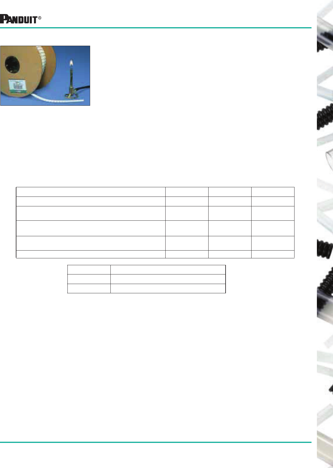
177
Most commonly used parts appear in BOLD.
MATERIALS CLASSIFIED UL-94 HB
• Specimens shall have a maximum burn rate of <1.5"/min over 3" of thickness of 0.120" to 0.5"
• Specimens shall have a maximum burn rate of <3.0"/min over 3" for a thickness less than 0.120"
UL224 VERTICAL WIRE FLAME TEST
Samples of fully recovered tubing are placed over a length of fine spring steel music wire. The test
requires the precise placement of a controlled flame that contacts the heat shrink tubing. The flame is
applied in five fifteen second intervals with a time period between applications. If the flame extinguishes
immediately after the first flame removal, subsequent flame applications are made to the tubing. Duration
of specimen flaming is noted. A piece of surgical cotton is placed under the specimen. If a flaming or
glowing piece of tubing drips and ignites the cotton, this is also noted.
MATERIALS CLASSIFIED AS VW-1 SHALL:
• Not flame or glow longer than 60 seconds following any of the five applications of the flame
• Not ignite or damage more than 25% of kraft paper flag that is placed around the top of the tubing
• Not have any specimens which drip flaming particles and ignite the surgical cotton located 9 1/2" below
the test specimen.
Abrasion Protection Products Flammability Tests and Classifications
• A number of test procedures have been developed which can be
used for the evaluation and comparison of various materials to
support combustion
• Review the following classifications to find which category is
designed to suit your abrasion and protection applications
Flammability Tests and Classifications
UL94 VERTICAL BURNING TEST
Test samples of material, with dimension 125 ± 5mm by 13.0 ± 5mm and provided in the minimum and
maximum thickness of the intended end use product, are tested in an unconditioned (as manufactured)
state and in a conditioned state (7 days at 168F°, 75°C). The test requires the placement of a precisely
controlled flame under a vertically supported specimen for a 10 second period. The flame is removed and
the duration of flaming is recorded. If the flame extinguishes, the specimen is immediately subjected to a
second 10 second ignition period. Duration of flaming is again recorded. A piece of 100% cotton is placed
under the specimen. Also observed and documented is if the sample drips flaming particles that ignite the
cotton indicator below.
Criteria Conditions V-0 V-1 V-2
Afterflame time for each individual specimen t1 or t2!10s !30s !30s
Total afterflame time for any condition set (t1 plus t2 for the
5 specimens)
!50s !250s !250s
Afterflame plus afterglow time for each individual specimen
after the second flame application (t2+t3)
!30s !60s !60s
Afterflame or afterglow of any specimen up to the
holding clamp
No No No
Cotton indicator ignited by flaming particles or drops No No Yes
Materials Classification
t1Afterflame time after first flame application
t2Afterflame time after flame application
t3 Afterglow time after second flame application
178
Most commonly used parts appear in BOLD.
NOTE: Typical operating temperature ranges are extended based on end use application and specific environmental tests.
‡TEFLON or equivalent fluorocarbon PTFE is used. Teflon is the registered trademark of E. I. DuPont de Nemours Co.
Abrasion
Protection
Materials
Technical Data
Ratings and Approvals Physical Properties Chemical Resistance
UL
Temperature
Index
Flammability
(UL94)
Melting
Temperature
Abrasion
Resistance
(Lower number
is better)
Specific
Gravity
(D792)
Minimum Tensile
@ 23°C (psi)
Water Absorption
(Max. 24 hrs.)
Organic
Solvents
Alkalies
Acids
Petro-Chemicals
Natural Polyethylene
Lowest cost material for indoor use up to
122°F. Natural is available in all sizes.
Colors are available in 1/4" and 1/2".
-40°F
(-40°C)
to
122°F
(50°C)
HB 239°F
(115°C)
22 mg .91-
.93
1400
(D638)
.01% Resistant
below 140°F
(60°C) except
to chlorinated
solvents
Resistant Resistant
except to
oxidizing
acids
Some
Discoloration
Weather Resistant Polyethylene
This material has the same
properties as natural polyethylene, and
also has additives which allow it to resist
the effects of ultraviolet light and acid
rain in an outdoor environment. This
product is available in black only.
-40°F
(-40°C)
to
122°F
(50°C)
HB 239°F
(115°C)
20 mg .93-
1.09
2000
(D638)
.03% Resistant
below 140°F
(60°C) except
to chlorinated
solvents
Resistant Resistant
except to
oxidizing
acids
No
Discoloration
Fire Resistant Polyethylene
UL94-V2 Rating
This material is self extinguishing and
passes the UL94 flame
retardant test with a V2 rating.
-40°F
(-40°C)
to
122°F
(50°C)
V-2 239°F
(115°C)
27 mg 1.00-
1.30
1400
(D638)
.02% Resistant
below 140°F
(60°C) except
to chlorinated
solvents
Resistant Resistant
except to
oxidizing
acids
Some
Discoloration
Flame Retardant Polyethylene
UL94-V0 Rating
This material is self extinguishing and
passes the UL94 flame
retardant test with a V0 rating.
-40°F
(-40°C)
to
194°F
(90°C)
UL94
V-0
270°F
(132°C)
22 mg 1.15 1,500
(D638)
.02% Resistant
except to
halogenated
hydrocarbons
Resistant Resistant Resistant
Some
Discoloration
Nylon 6.6
Nylon is strong, durable, self-
extinguishing material for indoor use up
to 149°F. It offers a combination of
lightweight, wide temperature range,
and high abrasion resistance. This
material is suitable for applications
where heavy vibration or stress exists
on the wiring or tubing.
-40°F
(-40°C)
to
149°F
(65°C)
UL94
V-2
505°F
(263°C)
7 mg 1.13-
1.15
12,400
(D638)
1.2% Resistant
except to
halogenated
hydrocarbons
Resistant Not
recom-
mended
Resistant
No
Discoloration
Weather Resistant Nylon
This material has the same
properties as natural Nylon and also has
additives which allow it to resist the
effects of ultraviolet light in an outdoor
environment. This product is available in
black only.
-40°F
(-40°C)
to
149°F
(65°C)
UL94
V-2
505°F
(263°C)
7 mg 1.13-
1.15
12,000
(D638)
1.2% Resistant
except to
halogenated
hydrocarbons
Resistant Not
recom-
mended
Resistant
No
Discoloration
TEFLON‡
This material is a non-flammable,
fluorocarbon resin material.
Suitable for use in any application
(including nuclear containment). It is
rated up to 356°F.
Color: Opaque to Translucent
-400°F
(-240°C)
to
500°F
(260°C)
UL94
V-0
648°F
(342°C)
7 mg 2.13-
2.22
3000
(D876)
.01% Resistant Resistant Resistant Resistant
No
Discoloration
Polyethylene Terephthalate (PET)
This material is a thermoplastic polyester
material designed for indoor applications.
It is rated for use up to 257°F and will
tolerate short-term exposure up to 446°F.
Colors: Black, White and Gray
-94°F
(-70°C)
to
257°F
(125°C)
UL94
HB
500°F
(260°C)
— 1.31 100,00
0
(D876)
.08% Resistant to
some solvents
Resistant to
most weak
bases
Resistant Resistant
No
Discoloration
Flame Ret. Polyethylene
Terephthalate (PET)
This material is a self-extinguishing
thermoplastic polyester that can be used
indoors. It is also rated for use up to
257°F and will tolerate short-term
exposure up to 446°F. It is provided
with tracers to identify the flame
retardant material.
-94°F
(-70°C)
to
257°F
(125°C)
UL
224
VW-1
608°F
(320°C)
— 1.39 100,00
0
(D876)
.08% Resistant to
some solvents
Resistant to
most weak
bases
Resistant Resistant
No
Discoloration
Abrasion Protection Materials Technical Data
SPIRAL WRAP
BRAIDED EXPANDABLE SLEEVING
179
Most commonly used parts appear in BOLD.
Abrasion Protection Materials Technical Data
NOTE: Typical operating temperature ranges are extended based on end use application and specific environmental tests.
Abrasion
Protection
Materials
Technical Data
Ratings and Approvals Physical Properties Chemical Resistance
UL
Temperature
Index
Flammability
(UL94)
Melting
Temperature
Abrasion
Resistance
(Lower number
is better)
Specific
Gravity
(D792)
Minimum Tensile
@ 23°C (psi)
Water Absorption
(Max. 24 hrs.)
Organic
Solvents
Alkalies
Acids
Petro-Chemicals
Black Polyethylene
Lowest cost material is for
use up to 122°F. Other colors may be
available.
-40°F (-
40°C) to
122°F
(50°C)
UL94
HB
— — .926-
.940
1500
(D638)
— Resistant
except to
halogenated
hydrocarbons
Resistant Resistant Resistant
No
Discoloration
Nylon 6
Nylon is a strong, impact modified,
heat stabilized, durable high abrasion
resistant material.
-40°F (-
40°C) to
230°F
(110°C)
UL94
HB
410°F
(211°C)
— 1.06-
1.16
8000
(D638)
1.3% Resistant
except to
halogenated
hydrocarbons
Resistant Not recom-
mended
Resistant
No
Discoloration
PVC Non-Shrink Tubing
This material provides insulation and
protection for continuous use at
temperatures -4°F (-20°C) to
221°F(105°C).
-4°F
(-20°C)
to
221°F
(105°C)
UL
224
VW-1
— — 1.35 2500
(D876)
— Resistant
except to
aromatic
hydrocarbons,
ketones and
esters
Resistant Resistant Resistant
No
Discoloration
Natural Polyethylene
Lowest cost material for indoor use up
to 122°F. Natural is available in all
sizes.
-40°F
(-40°C)
to
122°F
(50°C)
HB 239°F
(115°C)
22 mg .91-
.93
1400
(D638)
.01% Resistant
below 140°F
(60°C) except
to chlorinated
solvents
Resistant Resistant
except to
oxidizing
acids
Some
Discoloration
Weather Resistant Polyethylene
This material has the same
properties as natural polyethylene, and
also has additives which allow it to
resist the effects of ultraviolet light and
acid rain in an outdoor environment.
This product is available in black only.
-40°F
(-40°C)
to
122°F
(50°C)
HB 239°F
(115°C)
20 mg .93-
1.09
2000
(D638)
.03% Resistant
below 140°F
(60°C) except
to chlorinated
solvents
Resistant Resistant
except to
oxidizing
acids
No
Discoloration
Flame Retardant Polyethylene
UL94-V0 Rating
This material is self extinguishing and
passes the UL94 flame
retardant test with a V0 rating
-40°F
(-40°C)
to
140°F
(60°C)
V-0 270°F
(132°C)
22 mg 1.38 1200 .02% Resistant
below 140°F
(60°C) except
to chlorinated
solvents
Resistant Resistant
except to
oxidizing
acids
Some
Discoloration
Nylon
Nylon is strong, durable, self-
extinguishing material for indoor use up
to 149°F. It offers a combination of
lightweight, wide temperature range,
and high abrasion resistance. This
material is suitable for applications
where heavy vibration or stress exists
on the wiring or tubing.
-40°F
(-40°C)
to
149°F
(65°C)
V-2 491°F
(255°C)
7 mg 1.03-
1.15
12,400
(D638)
1.5% Resistant
except to
phenols and
formic acid
Resistant Resistant
to most
weak
acids
No
Discoloration
GROMMET EDGING
PVC TUBINGCORRUGATED LOOM TUBING
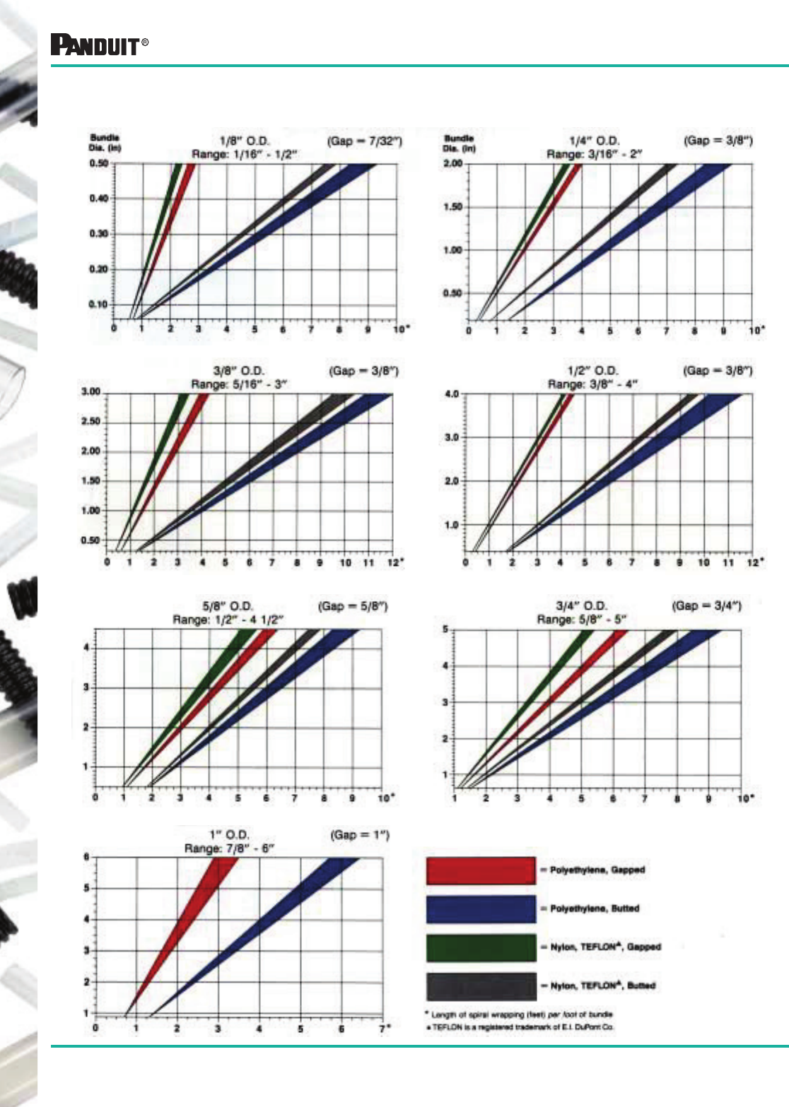
180
Most commonly used parts appear in BOLD.
Abrasion Protection Products Technical Data
The approximate required length of spiral wrap based on the bundle diameter can be determined by using
the graphs below; they show length required (in feet) per foot of bundle:
181
Most commonly used parts appear in BOLD.
Abrasion Protection Bulk Packaging
Standard Part No. Bulk Part No.
C
CLT25N-C630 CLT25N-10M630
CLT35F-2C0 CLT35F-7M20
CLT38F-C20 CLT38F-5M20
CLT38N-C630 CLT38N-5M630
CLT50F-C20 CLT50F-4M20
CLT50N-C630 CLT50N-4M630
CLT62F-C20 CLT62F-2.5M20
CLT62N-C630 CLT62N-2.5M630
CLT75F-C20 CLT75F-2M20
CLT75N-C630 CLT75N-2M630
CLT100F-C20 CLT100F-125M20
CLT100N-C630 CLT100N-125M630
CLT125F-L20 CLT125F-.75M20
CLT125N-L630 CLT125N-.75M630
T
T12F-C T12F-D
T12N-C T12N-D
T19N-C T19N-M
T25F-C T25F-M
T25F-C0 T25F-M0
T25FR-C T25FR-M
T25FR-C20 T25FR-M20
T25N-C T25N-M
T25N-C0 T25N-M0
T25R-C T25R-M
T25R-C20 T25R-M20
T38F-C T38F-TL
T38F-C0 T38F-TL0
T38FR-C T38FR-TL
T38N-C T38N-TL
T38R-C T38R-TL
T50F-C T50F-TL
T50F-C0 T50F-TL0
T50F-C4 T50F-TL4
T50FR-C T50FR-TL
T50N-C T50N-TL
T50N-C0. T50N-TL0
T50R-C T50R-TL
T62F-C T62F-TL
T62F-C0 T62F-TL0
T75F-C T75F-T
T75F-C0 T75F-T0
T75FR-C T75FR-T
T75N-C T75N-T
Standard Part No. Bulk Part No.
Bulk Package Part Numbers
The following is an alpha-numeric cross reference of Standard Package Wiring Abrasion Protection parts
with the corresponding Bulk Package part numbers:
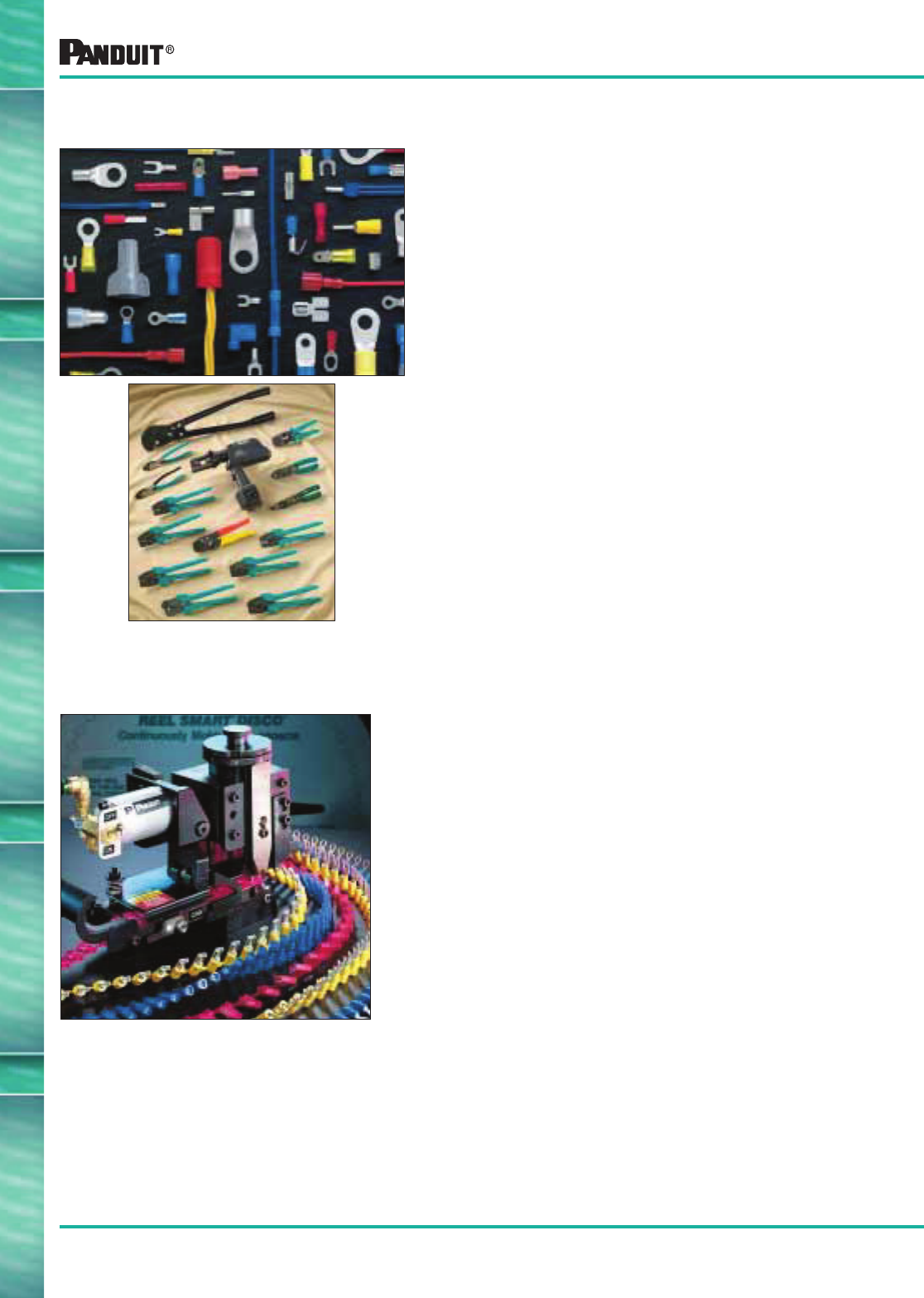
182
Everywhere you need us!
Designed and manufactured for fast assembly,
long, reliable performance...
• Funnel entry available on vinyl and nylon insulated
terminals and disconnects
• Made of electrolytically refined copper to provide
optimum combination of crimp forming properties and
low resistance, high conductivity terminations
• Offered in various types including rings, forks, locking
forks and short locking forks
• Available sizes from 26 to 2 AWG and stud diameters
from #2 to 1/2"
• Disconnects are available in many styles including
fully insulated. Splices and wire joints provide
permanent, reliable connections
• Wide assortment of manual, controlled cycle, battery
operated and pneumatic crimping tools which give
you reliable connections at a lower installed cost
R
EEL
S
MART
™
Continuously Molded Reel-Fed Terminals, Disconnects and Splices
• ONE TECHNOLOGY, one solution for
continuously molded Terminals, Butt Splices and
Disconnects, including Fully Insulated Right Angle
Female Disconnects and Pre-Assembled
Locking Disconnects
• The REEL SMART ™ Termination System for
installing PANDUIT ® continuously molded products
provides the best solution for quality, reliable,
high volume terminations
• This patented system offers an array of technical
enhancements designed to dramatically reduce
set-up time and the amount of downtime traditionally
incurred with alternate systems
• Single, patented application terminates entire
product line
• Applicators compatible with automatic wire
processing machines and other
manufacturer’s presses
“Reel” productivity assures high volume pro-
duction at significant savings...
Ask for PAN-TERM ® Terminal, Disconnects and Splices/
REEL SMART ™ Termination Catalog — SA-TM09CB01A
Ask for PAN-TERM ® Terminal, Disconnects and Splices/
REEL SMART ™ Termination Catalog — SA-TM09CB01A
Complementary Wiring Products
PAN-TERM ® Terminals,
Disconnects and Splices
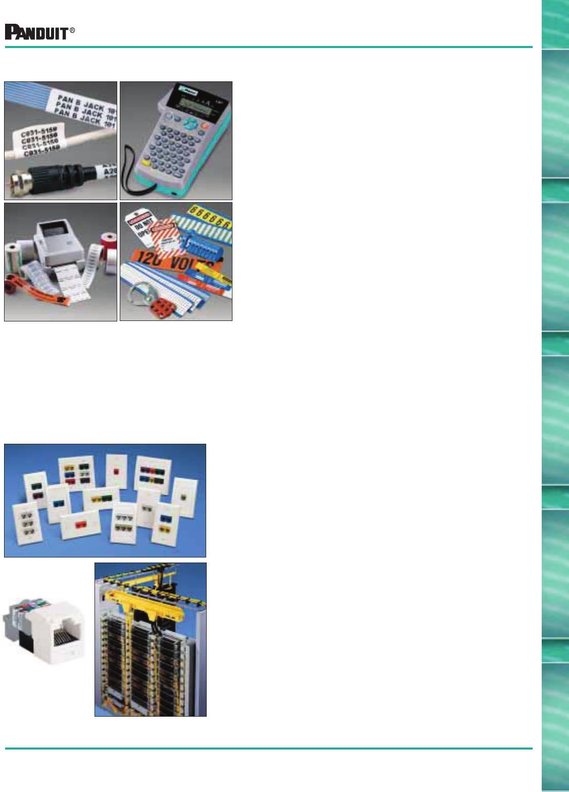
183
Everywhere you need us!
Identification and Labeling Solutions
• Computer Printable Labels
Thermal transfer, laser, ink jet and dot-matrix
labels available in a wide variety of sizes and
industrial materials
• Printers
Versatile hand-held printers for on-site labeling and
desktop thermal transfer printers for medium to high
volume applications
• Labeling Software
Labeling programs available for wire marking,
component identification and safety markers and tags
• Preprinted Markers
Available in books, cards, tape, slip-on and clip-on
formats for fast, convenient identification of wires,
cables and other industrial applications
• Lockout/Tagout and Safety
Lockout devices, training materials, tags and safety
markers for OSHA safety standard compliance
PANDUIT ® offers a complete line of
industrial Identification Solutions...
Complementary Wiring Products
• Breadth of Product Offering
PANDUIT ® supplies copper and fiber optic connectivity
for reliable data, video and voice transmissions,
end-to-end cable management for maximum protection
and system integrity as well as standards compliance
pathway and outlet products for maximum performance
• Modular
All PANDUIT ® MINI-COM ® copper and fiber optic
modules snap in and out of all MINI-COM ® faceplates,
surface mount boxes, patch panels and multimedia
adapter panels
Ask for Network Connectivity Catalog SA-NC10CB01A
Network Connectivity Systems
Ask for Identification Solutions Catalog SA101N315C-ID
The unique PAN-NET ® Network Connectivity
System provides high performance solutions
with FUTURE READY features for system
upgradability. Lowest installed cost solutions are
available for both the enterprise and service
provider markets...
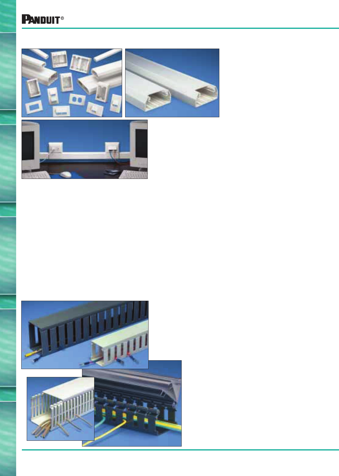
184
Everywhere you need us!
• Advanced Designs
Among other features, all PANDUIT ® cable routing
pathways are designed to maintain the proper bend radius
control for high performance copper and fiber optic cabling
• Aesthetics
Unlike raceway systems of the past, PANDUIT ® perimeter
raceway has been designed with as much regard to form
as function
• Superior Termination Solutions
PANDUIT ® cable routing solutions provide you freedom of
choice when selecting your data and electrical outlets. Most
PANDUIT ® raceway systems accept both NEMA Standard
“Screw-On” faceplates as well as superior PANDUIT ®
Snap-On faceplates for PANDUIT ® Connectivity
• Complete Systems
All PANDUIT ® systems include a full complement of fittings
and accessories that allow a complete installation of a
single system or allow different PANDUIT ®
raceway systems
to be used together
PAN-WAY ®
Surface Raceway System
Ask for PAN-WAY ® Surface Raceway Catalog SA101N60B-LP
Complementary Wiring Products
PANDUCT ®
Wiring Duct — The Original Wiring Duct
Ask for PANDU CT ® Wiring Duct Catalog SA-WDCB05
The superior PAN-WAY ® Surface
Raceway System offers the
flexibility of accepting
PANDUIT ® communication and
power devices in addition to
devices offered from a wide
range of manufacturers. The
PAN-WAY ® system has become
the preferred routing system for
communication and electrical
specifiers and contractors...
PANDUIT ® offers the most comprehensive and
complete line of wiring duct for use in control panels
and other OEM and MRO applications. PANDUIT ®
provides a large selection of sizes, colors, styles and
materials so our customers can meet their specific
application requirements...
• PANDUIT ® Exclusive rounded edges will not cut
installers’ hands or wiring insulation
• Non-slip cover will not slip when installed on
duct base
• Flush cover design holds 10–12% more wires
than traditional duct designs
• Double scoreline saves installation time and
ultimately lowers installed cost
• Restricted slot design retains wire in slot for fast,
easy wire installation or removal
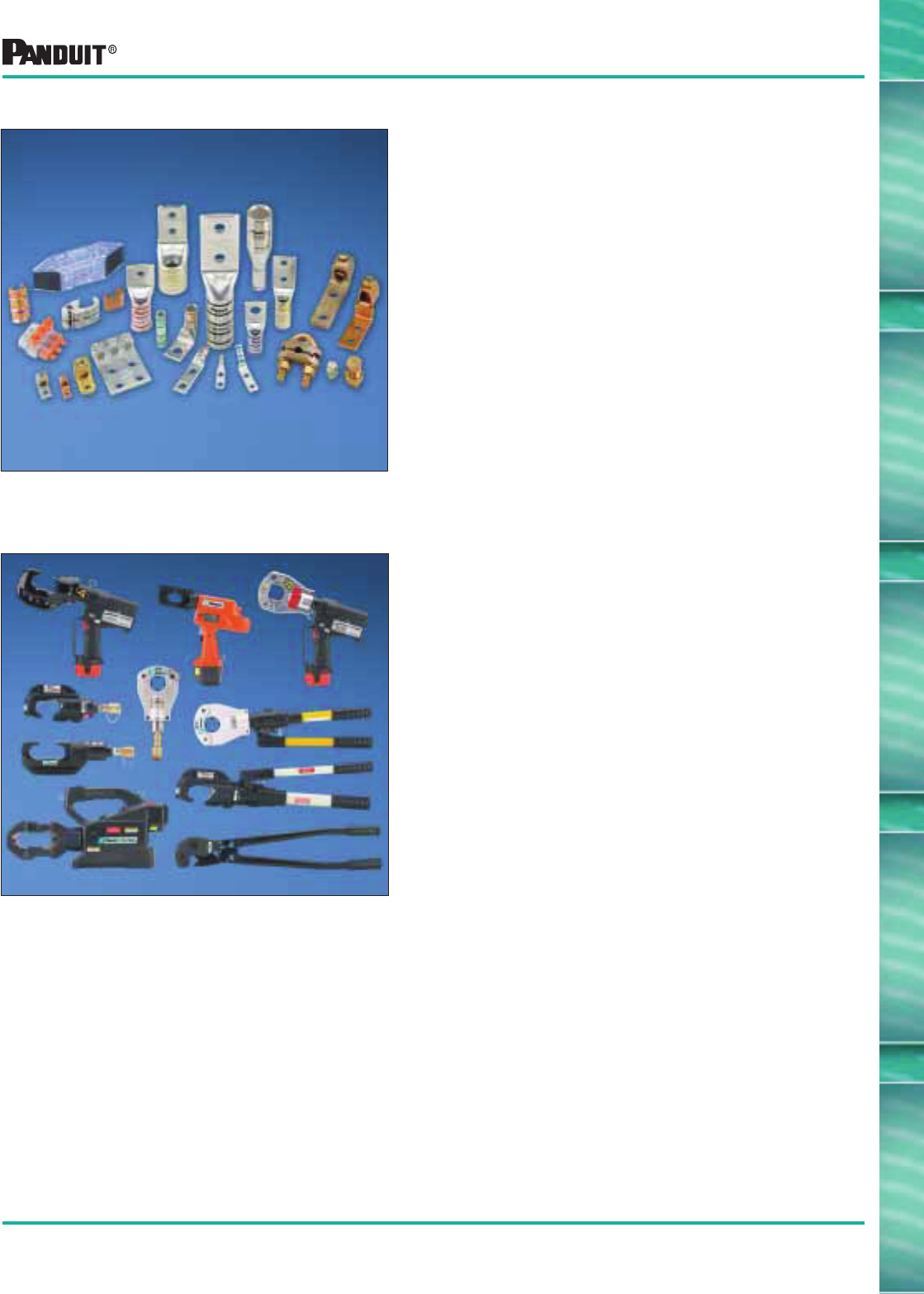
185
Everywhere you need us!
Complementary Wiring Products
Power Connectors
For applications in sizes #14 AWG through
1000 kcmil...
• Compression Connectors
Provide reliable permanently crimped connections in
sizes matched for each conductor size. They are
easy to install and provide a simplified means of
inspection of a proper crimp
• Custom Lugs
PANDUIT ® offers a wide variety of dimensional
choices for #8 AWG to 250 kcmil copper
compression lugs
• Mechanical Connectors
Economical, reusable connectors in many styles in
both copper and dual rated aluminum types
• Power Connector Tooling
Includes hand operated controlled-cycle, mechanical
and hydraulic crimping tools. Also available are the
UNI-DIE ™
CT-980 dieless tool and revolutionary
CT-2001 battery operated crimping tool
Ask for the Termination Solutions Catalog SA-TMCB02
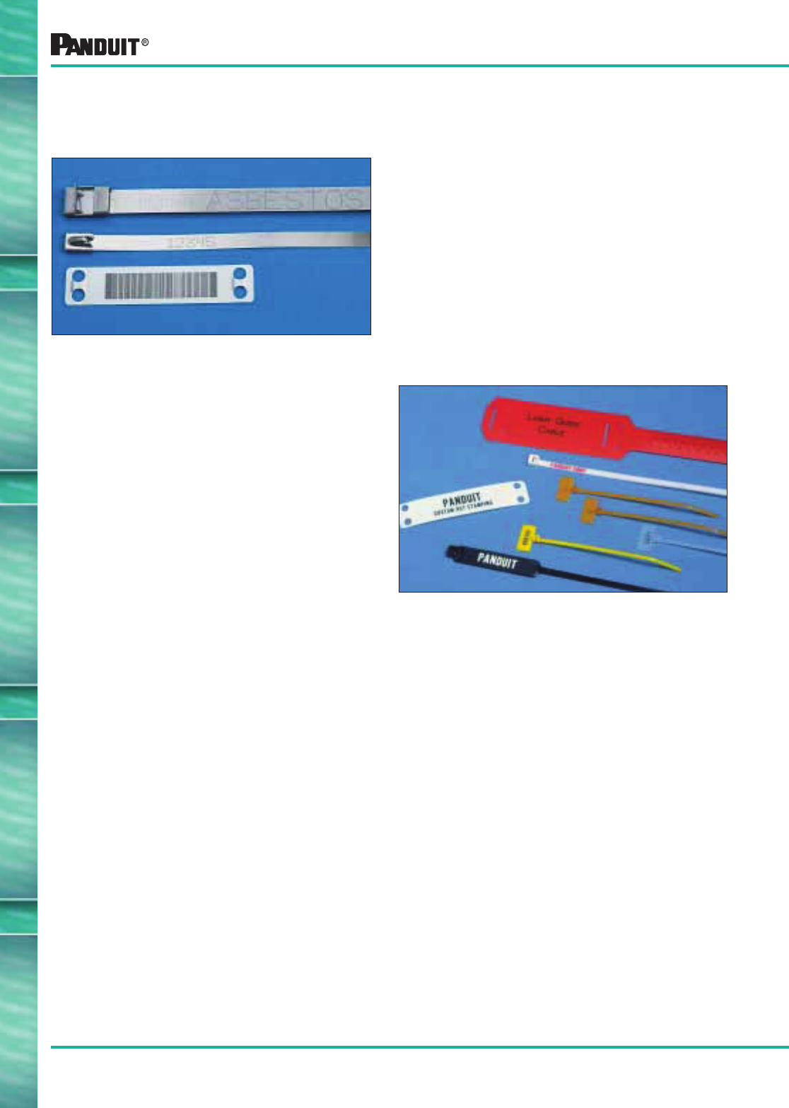
186
Everywhere you need us!
Complementary Wiring Products
PANDUIT ® offers a variety of custom programs designed to permanently
identify PANDUIT ® products for your specific application...
• Custom Marking
All PANDUIT ® stainless steel and brass products
(ties, strapping, marker plates and tags) can be
custom marked by one of two precise computer
controlled systems (Laser or Embosser)
These systems provide sharp, crisp, high quality
legends. A variety of marking device accessories
is also available for permanent identification of
PANDUIT ® stainless steel and brass products
For more information call 866-405-6659
• Hot Stamping
PANDUIT ®nylon cable ties, marker ties and
marker plates can be custom identified to
meet your specific requirements, including
sequential numbering and specialized
company logos (see page 52).
For more information call 866-405-6660

187
Most commonly used parts appear in BOLD.
Alphanumeric Part Number Index
Part Number
Page
Number Part Number
Page
Number
Part Number
Page
Number
A
A1C12-A-C8 . . . . . . . . . . . . . . . . . . . . . . . . . . 110
A1C25-A-C8 . . . . . . . . . . . . . . . . . . . . . . . . . . 110
A1C38-A-C8 . . . . . . . . . . . . . . . . . . . . . . . . . . 110
A1C50-A-C8 . . . . . . . . . . . . . . . . . . . . . . . . . . 110
A2C12-A-C8 . . . . . . . . . . . . . . . . . . . . . . . . . . 110
A2C25-A-C8 . . . . . . . . . . . . . . . . . . . . . . . . . . 110
A2C38-A-C8 . . . . . . . . . . . . . . . . . . . . . . . . . . 110
A2C50-A-C8 . . . . . . . . . . . . . . . . . . . . . . . . . . 110
ABM1M-A-C. . . . . . . . . . . . . . . . . . . . . . . . . . . 85
ABM1M-AT-C . . . . . . . . . . . . . . . . . . . . . . . . . . 85
ABM2S-A-C . . . . . . . . . . . . . . . . . . . . . . . . . . . 86
ABM2S-AT-C . . . . . . . . . . . . . . . . . . . . . . . . . . 86
ABM2S-AT-C0 . . . . . . . . . . . . . . . . . . . . . . . . . 86
ABM2S-S6-D . . . . . . . . . . . . . . . . . . . . . . . . . . . 86
ABM3H-A-L . . . . . . . . . . . . . . . . . . . . . . . . . . . 86
ABM3H-AT-L . . . . . . . . . . . . . . . . . . . . . . . . . . . 86
ABM3H-S6-T . . . . . . . . . . . . . . . . . . . . . . . . . . . 86
ABM4H-A-L . . . . . . . . . . . . . . . . . . . . . . . . . . . 86
ABM4H-AT-L . . . . . . . . . . . . . . . . . . . . . . . . . . . 86
ABM4H-S6-T . . . . . . . . . . . . . . . . . . . . . . . . . . . 86
ABM100-A-C . . . . . . . . . . . . . . . . . . . . . . . . . . 86
ABM100-AT-C . . . . . . . . . . . . . . . . . . . . . . . . . . 86
ABM100-AT-C0 . . . . . . . . . . . . . . . . . . . . . . . . . 86
ABM100-S6-C . . . . . . . . . . . . . . . . . . . . . . . . . . 86
ABM100-S6-C69 . . . . . . . . . . . . . . . . . . . . . . . . 86
ABM112-A-C . . . . . . . . . . . . . . . . . . . . . . . . . . 86
ABM112-AT-C . . . . . . . . . . . . . . . . . . . . . . . . . . 86
ABM112-AT-C0 . . . . . . . . . . . . . . . . . . . . . . . . . 86
ABM112-S6-C . . . . . . . . . . . . . . . . . . . . . . . . . . 86
ABM112-S6-C69 . . . . . . . . . . . . . . . . . . . . . . . . 86
ABMM-A-C. . . . . . . . . . . . . . . . . . . . . . . . . . . . 85
ABMM-AT-C . . . . . . . . . . . . . . . . . . . . . . . . . . . 85
ABMM-AT-C0 . . . . . . . . . . . . . . . . . . . . . . . . . . 85
ABMM-D . . . . . . . . . . . . . . . . . . . . . . . . . . . . . . 86
ABMT-A-C . . . . . . . . . . . . . . . . . . . . . . . . . . . . 132
ABMT-A-C20 . . . . . . . . . . . . . . . . . . . . . . . . . . 132
ABMT-S6-C . . . . . . . . . . . . . . . . . . . . . . . . . . . 132
ABMT-S6-C20 . . . . . . . . . . . . . . . . . . . . . . . . . 132
ABMT-S6-C60 . . . . . . . . . . . . . . . . . . . . . . . . . 132
ABMT-S6-C69 . . . . . . . . . . . . . . . . . . . . . . . . . 132
ACC19-A-C . . . . . . . . . . . . . . . . . . . . . . . . . . . 109
ACC19-A-C20 . . . . . . . . . . . . . . . . . . . . . . . . . 109
ACC19-AT-C . . . . . . . . . . . . . . . . . . . . . . . . . . 109
ACC19-AT-C0 . . . . . . . . . . . . . . . . . . . . . . . . . 109
ACC38-A-C . . . . . . . . . . . . . . . . . . . . . . . . . . 109
ACC38-A-C20 . . . . . . . . . . . . . . . . . . . . . . . . . 109
ACC38-AT-C . . . . . . . . . . . . . . . . . . . . . . . . . . 109
ACC38-AT-C0 . . . . . . . . . . . . . . . . . . . . . . . . . 109
ACC62-A-C . . . . . . . . . . . . . . . . . . . . . . . . . . . 109
ACC62-A-C20 . . . . . . . . . . . . . . . . . . . . . . . . . 109
ACC62-AT-C . . . . . . . . . . . . . . . . . . . . . . . . . . 109
ACC62-AT-C0 . . . . . . . . . . . . . . . . . . . . . . . . . 109
ADCC31-AT-C10 . . . . . . . . . . . . . . . . . . . . . . . 112
AJC19-A-C . . . . . . . . . . . . . . . . . . . . . . . . . . . 110
AJC25-A-C . . . . . . . . . . . . . . . . . . . . . . . . . . . 110
AJC31-A-C . . . . . . . . . . . . . . . . . . . . . . . . . . . 110
AJC38-A-C . . . . . . . . . . . . . . . . . . . . . . . . . . . 110
AM2-C . . . . . . . . . . . . . . . . . . . . . . . . . . . . . . . . 92
AMC25-AT-C10 . . . . . . . . . . . . . . . . . . . . . . . . 112
ARC.68-A-Q . . . . . . . . . . . . . . . . . . . . . . . . . . 108
ARC.68-A-Q14 . . . . . . . . . . . . . . . . . . . . . . . . 108
ARC.68-S6-Q . . . . . . . . . . . . . . . . . . . . . . . . . 108
ARC.68-S6-Q14 . . . . . . . . . . . . . . . . . . . . . . . 108
ASMS-A-X . . . . . . . . . . . . . . . . . . . . . . . . . . . . . 88
AST10-5-C100. . . . . . . . . . . . . . . . . . . . . . . . . 107
AST15-5-C100. . . . . . . . . . . . . . . . . . . . . . . . . 107
AST20-5-C100. . . . . . . . . . . . . . . . . . . . . . . . . 107
AST25-5-C100. . . . . . . . . . . . . . . . . . . . . . . . . 107
B
B2M2S-D . . . . . . . . . . . . . . . . . . . . . . . . . . . . . . 33
B3M2S-TL . . . . . . . . . . . . . . . . . . . . . . . . . . . . 33
B4M2S-TL . . . . . . . . . . . . . . . . . . . . . . . . . . . . 33
BC1M-S4-M . . . . . . . . . . . . . . . . . . . . . . . . . . . . 31
BC1.5I-S8-M . . . . . . . . . . . . . . . . . . . . . . . . . . . 31
BC2M-S4-M . . . . . . . . . . . . . . . . . . . . . . . . . . . . 31
BC2S-S10-C . . . . . . . . . . . . . . . . . . . . . . . . . . . 31
BC2S-S10-C0 . . . . . . . . . . . . . . . . . . . . . . . . . . 31
BC3S-S10-C . . . . . . . . . . . . . . . . . . . . . . . . . . . 31
BC3S-S10-D0 . . . . . . . . . . . . . . . . . . . . . . . . . . 31
BC4LH-S25-L . . . . . . . . . . . . . . . . . . . . . . . . . . 31
BC4LH-S25-L0 . . . . . . . . . . . . . . . . . . . . . . . . . 31
BC4S-S10-C . . . . . . . . . . . . . . . . . . . . . . . . . . . 31
BC4S-S10-C0 . . . . . . . . . . . . . . . . . . . . . . . . . . 31
BEC38-A-L . . . . . . . . . . . . . . . . . . . . . . . . . . . 112
BEC38-A-L20 . . . . . . . . . . . . . . . . . . . . . . . . . 112
BEC38-AT-L0 . . . . . . . . . . . . . . . . . . . . . . . . . 112
BEC62-A-L . . . . . . . . . . . . . . . . . . . . . . . . . . . 112
BEC62-A-L20 . . . . . . . . . . . . . . . . . . . . . . . . . 112
BEC62-AT-L0 . . . . . . . . . . . . . . . . . . . . . . . . . 112
BEC75-A-L . . . . . . . . . . . . . . . . . . . . . . . . . . . 112
BEC75-A-L20 . . . . . . . . . . . . . . . . . . . . . . . . . 112
BEC75-AT-L0 . . . . . . . . . . . . . . . . . . . . . . . . . 112
BECP38H25-L. . . . . . . . . . . . . . . . . . . . . . . . . 112
BECP38H25-L20. . . . . . . . . . . . . . . . . . . . . . . 112
BECP75H25-L. . . . . . . . . . . . . . . . . . . . . . . . . 112
BECP75H25-L20. . . . . . . . . . . . . . . . . . . . . . . 112
BF1M-C . . . . . . . . . . . . . . . . . . . . . . . . . . . . . . . 32
BF2M-C . . . . . . . . . . . . . . . . . . . . . . . . . . . . . .32
BM1M-C . . . . . . . . . . . . . . . . . . . . . . . . . . . . . . 32
BM2M-C . . . . . . . . . . . . . . . . . . . . . . . . . . . . . .32
BM2S-C. . . . . . . . . . . . . . . . . . . . . . . . . . . . . . . 32
BM4S-C . . . . . . . . . . . . . . . . . . . . . . . . . . . . . .32
BR.5-E6-C . . . . . . . . . . . . . . . . . . . . . . . . . . . . 125
BR.75-E6-C . . . . . . . . . . . . . . . . . . . . . . . . . . . 125
BR2-1.3-A-X . . . . . . . . . . . . . . . . . . . . . . . . . . 125
BR2-1.3-X . . . . . . . . . . . . . . . . . . . . . . . . . . . . 125
BR2-1.5-X . . . . . . . . . . . . . . . . . . . . . . . . . . . . 125
BR2-4-X. . . . . . . . . . . . . . . . . . . . . . . . . . . . . . 125
BR2-6-X. . . . . . . . . . . . . . . . . . . . . . . . . . . . . . 125
BT1HT . . . . . . . . . . . . . . . . . . . . . . . . . . . . . . . . 80
BT1M-C . . . . . . . . . . . . . . . . . . . . . . . . . . . . . .28
BT1M-C0 . . . . . . . . . . . . . . . . . . . . . . . . . . . . .29
BT1M-M39. . . . . . . . . . . . . . . . . . . . . . . . . . . . . 30
BT1.5I-C . . . . . . . . . . . . . . . . . . . . . . . . . . . . . .28
BT1.5I-C0 . . . . . . . . . . . . . . . . . . . . . . . . . . . . . 29
BT1.5I-M39 . . . . . . . . . . . . . . . . . . . . . . . . . . . . 30
BT1.5M-C . . . . . . . . . . . . . . . . . . . . . . . . . . . . .28
BT1.5M-C0 . . . . . . . . . . . . . . . . . . . . . . . . . . . .29
BT2I-C . . . . . . . . . . . . . . . . . . . . . . . . . . . . . . .28
BT2I-C0 . . . . . . . . . . . . . . . . . . . . . . . . . . . . . .29
BT2LH-L . . . . . . . . . . . . . . . . . . . . . . . . . . . . . . 28
BT2LH-L0 . . . . . . . . . . . . . . . . . . . . . . . . . . . . . 29
BT2M-C . . . . . . . . . . . . . . . . . . . . . . . . . . . . . .28
BT2M-C0 . . . . . . . . . . . . . . . . . . . . . . . . . . . . .29
BT2S-C. . . . . . . . . . . . . . . . . . . . . . . . . . . . . . .28
BT2S-C0. . . . . . . . . . . . . . . . . . . . . . . . . . . . . .29
BT2S-M39 . . . . . . . . . . . . . . . . . . . . . . . . . . . . . 30
BT3I-C . . . . . . . . . . . . . . . . . . . . . . . . . . . . . . .28
BT3I-C0 . . . . . . . . . . . . . . . . . . . . . . . . . . . . . .29
BT3LH-L . . . . . . . . . . . . . . . . . . . . . . . . . . . . . . 28
BT3LH-L0 . . . . . . . . . . . . . . . . . . . . . . . . . . . . . 29
BT3S-C. . . . . . . . . . . . . . . . . . . . . . . . . . . . . . .28
BT3S-C0. . . . . . . . . . . . . . . . . . . . . . . . . . . . . .29
BT3S-M39 . . . . . . . . . . . . . . . . . . . . . . . . . . . . . 30
BT4I-C . . . . . . . . . . . . . . . . . . . . . . . . . . . . . . .28
BT4I-C0 . . . . . . . . . . . . . . . . . . . . . . . . . . . . . .29
BT4LH-L. . . . . . . . . . . . . . . . . . . . . . . . . . . . . .28
BT4LH-L0. . . . . . . . . . . . . . . . . . . . . . . . . . . . .29
BT4LH-TL39 . . . . . . . . . . . . . . . . . . . . . . . . . . . 30
BT4M-C . . . . . . . . . . . . . . . . . . . . . . . . . . . . . .28
BT4M-C0 . . . . . . . . . . . . . . . . . . . . . . . . . . . . .29
BT4S-C. . . . . . . . . . . . . . . . . . . . . . . . . . . . . . .28
BT4S-C0. . . . . . . . . . . . . . . . . . . . . . . . . . . . . .29
BT4S-M39 . . . . . . . . . . . . . . . . . . . . . . . . . . . . . 30
BT5LH-L . . . . . . . . . . . . . . . . . . . . . . . . . . . . . . 28
BT5LH-L0 . . . . . . . . . . . . . . . . . . . . . . . . . . . . . 29
BT6LH-L . . . . . . . . . . . . . . . . . . . . . . . . . . . . . . 28
BT6LH-L0 . . . . . . . . . . . . . . . . . . . . . . . . . . . . . 29
BT7LH-L . . . . . . . . . . . . . . . . . . . . . . . . . . . . . . 28
BT7LH-L0 . . . . . . . . . . . . . . . . . . . . . . . . . . . . . 29
BT8LH-L . . . . . . . . . . . . . . . . . . . . . . . . . . . . . . 28
BT8LH-L0 . . . . . . . . . . . . . . . . . . . . . . . . . . . . . 29
BT9LH-L. . . . . . . . . . . . . . . . . . . . . . . . . . . . . .28
BT9LH-L0. . . . . . . . . . . . . . . . . . . . . . . . . . . . .29
BW1.5I-D . . . . . . . . . . . . . . . . . . . . . . . . . . . . .30
BW2S-D . . . . . . . . . . . . . . . . . . . . . . . . . . . . . .30
C
CBLS18-C . . . . . . . . . . . . . . . . . . . . . . . . . . . . 123
CBLS25-C . . . . . . . . . . . . . . . . . . . . . . . . . . . . 123
CBLS37-C . . . . . . . . . . . . . . . . . . . . . . . . . . . . 123
CBLS50-C . . . . . . . . . . . . . . . . . . . . . . . . . . . . 123
CBLS62-C . . . . . . . . . . . . . . . . . . . . . . . . . . . . 123
CBLS75-C . . . . . . . . . . . . . . . . . . . . . . . . . . . . 123
CBP12-C . . . . . . . . . . . . . . . . . . . . . . . . . . . . . 122
CBP25-C . . . . . . . . . . . . . . . . . . . . . . . . . . . . . 122
CBP31-C . . . . . . . . . . . . . . . . . . . . . . . . . . . . . 122
CBP37-C . . . . . . . . . . . . . . . . . . . . . . . . . . . . . 122
CBP50-C . . . . . . . . . . . . . . . . . . . . . . . . . . . . . 122
CBP62-C . . . . . . . . . . . . . . . . . . . . . . . . . . . . . 122
CBP75-C . . . . . . . . . . . . . . . . . . . . . . . . . . . . . 122
CBP87-C . . . . . . . . . . . . . . . . . . . . . . . . . . . . . 122
CBP100-C . . . . . . . . . . . . . . . . . . . . . . . . . . . . 122
CBR1M-M. . . . . . . . . . . . . . . . . . . . . . . . . . . . .36
CBR1M-M0. . . . . . . . . . . . . . . . . . . . . . . . . . . .36
CBR1.5I-M . . . . . . . . . . . . . . . . . . . . . . . . . . . .36
CBR1.5I-M0 . . . . . . . . . . . . . . . . . . . . . . . . . . .36
CBR1.5M-M . . . . . . . . . . . . . . . . . . . . . . . . . . .36
CBR1.5M-M0 . . . . . . . . . . . . . . . . . . . . . . . . . .36
CBR2HS-D . . . . . . . . . . . . . . . . . . . . . . . . . . . .36
CBR2HS-D0 . . . . . . . . . . . . . . . . . . . . . . . . . . .36
CBR2M-M. . . . . . . . . . . . . . . . . . . . . . . . . . . . .36
CBR2M-M0. . . . . . . . . . . . . . . . . . . . . . . . . . . .36
CBR2S-M . . . . . . . . . . . . . . . . . . . . . . . . . . . . .36
CBR2S-M0 . . . . . . . . . . . . . . . . . . . . . . . . . . . .36
CBR3I-M . . . . . . . . . . . . . . . . . . . . . . . . . . . . . 36
CBR3I-M0 . . . . . . . . . . . . . . . . . . . . . . . . . . . . 36
CBR3S-M . . . . . . . . . . . . . . . . . . . . . . . . . . . . 36
CBR3S-M0 . . . . . . . . . . . . . . . . . . . . . . . . . . . 36
CBR4I-M . . . . . . . . . . . . . . . . . . . . . . . . . . . . . 36
CBR4I-M0 . . . . . . . . . . . . . . . . . . . . . . . . . . . . 36
CBR4LH-TL . . . . . . . . . . . . . . . . . . . . . . . . . . 36
CBR4LH-TL0 . . . . . . . . . . . . . . . . . . . . . . . . . 36
CBR4S-M . . . . . . . . . . . . . . . . . . . . . . . . . . . . 36
CBR4S-M0 . . . . . . . . . . . . . . . . . . . . . . . . . . . 36
CBR6LH-C . . . . . . . . . . . . . . . . . . . . . . . . . . . 36
CBR6LH-C0 . . . . . . . . . . . . . . . . . . . . . . . . . . 36
CCH12-S10-C. . . . . . . . . . . . . . . . . . . . . . . . . 117
CCH19-S10-C. . . . . . . . . . . . . . . . . . . . . . . . . 117
CCH25-S10-C. . . . . . . . . . . . . . . . . . . . . . . . 117
CCH31-S10-C. . . . . . . . . . . . . . . . . . . . . . . . . 117
CCH38-S10-C. . . . . . . . . . . . . . . . . . . . . . . . 117
CCH44-S10-C. . . . . . . . . . . . . . . . . . . . . . . . . 117
CCH50-S10-C. . . . . . . . . . . . . . . . . . . . . . . . 117
CCH56-S10-C. . . . . . . . . . . . . . . . . . . . . . . . . 117
CCH62-S10-C. . . . . . . . . . . . . . . . . . . . . . . . . 117
CCH69-S10-C. . . . . . . . . . . . . . . . . . . . . . . . . 117
CCH75-S10-C. . . . . . . . . . . . . . . . . . . . . . . . . 117
CCH81-S10-C. . . . . . . . . . . . . . . . . . . . . . . . . 117
CCH87-S10-C. . . . . . . . . . . . . . . . . . . . . . . . . 117
CCH100-S10-C . . . . . . . . . . . . . . . . . . . . . . . . 117
CCH112-S10-C . . . . . . . . . . . . . . . . . . . . . . . . 117
CCH119-S10-C . . . . . . . . . . . . . . . . . . . . . . . . 117
CCH125-S10-C . . . . . . . . . . . . . . . . . . . . . . . . 117
CCH138-S10-C . . . . . . . . . . . . . . . . . . . . . . . . 117
CCH150-S10-C . . . . . . . . . . . . . . . . . . . . . . . . 117
CCMKIT1 . . . . . . . . . . . . . . . . . . . . . . . . . . . . 133
CCS12-S8-C . . . . . . . . . . . . . . . . . . . . . . . . . . 117
CCS19-S8-C . . . . . . . . . . . . . . . . . . . . . . . . . . 117
CCS25-S8-C . . . . . . . . . . . . . . . . . . . . . . . . . 117
CCS25-S10-C . . . . . . . . . . . . . . . . . . . . . . . . . 117
CCS31-S8-C . . . . . . . . . . . . . . . . . . . . . . . . . . 117
CCS38-S8-C . . . . . . . . . . . . . . . . . . . . . . . . . . 117
CCS44-S8-C . . . . . . . . . . . . . . . . . . . . . . . . . . 117
CCS50-S8-C . . . . . . . . . . . . . . . . . . . . . . . . . . 117
CF382538F-Q . . . . . . . . . . . . . . . . . . . . . . . . . 174
CF502550F-Q . . . . . . . . . . . . . . . . . . . . . . . . . 174
CF503850F-Q . . . . . . . . . . . . . . . . . . . . . . . . . 174
CF752575F-Q . . . . . . . . . . . . . . . . . . . . . . . . . 174
CF753875F-Q . . . . . . . . . . . . . . . . . . . . . . . . . 174
CH105-A-C14 . . . . . . . . . . . . . . . . . . . . . . . . . 113
CH105-S6-C14 . . . . . . . . . . . . . . . . . . . . . . . . 113
CLT25F-C3 . . . . . . . . . . . . . . . . . . . . . . . . . . . 173
CLT25F-C20 . . . . . . . . . . . . . . . . . . . . . . . . . . 173
CLT25N-C630. . . . . . . . . . . . . . . . . . . . . . . . . 173
CLT35F-C3 . . . . . . . . . . . . . . . . . . . . . . . . . . . 173
CLT35F-C20 . . . . . . . . . . . . . . . . . . . . . . . . . . 173
CLT35N-C630. . . . . . . . . . . . . . . . . . . . . . . . . 173
CLT38F-C3 . . . . . . . . . . . . . . . . . . . . . . . . . . . 173
CLT38F-C20 . . . . . . . . . . . . . . . . . . . . . . . . . . 173
CLT38N-C630. . . . . . . . . . . . . . . . . . . . . . . . . 173
CLT50F-C3 . . . . . . . . . . . . . . . . . . . . . . . . . . . 173
CLT50F-C20 . . . . . . . . . . . . . . . . . . . . . . . . . . 173
CLT50N-C630. . . . . . . . . . . . . . . . . . . . . . . . . 173
CLT62F-C3 . . . . . . . . . . . . . . . . . . . . . . . . . . . 173
CLT62F-C20 . . . . . . . . . . . . . . . . . . . . . . . . . . 173
CLT62N-C630. . . . . . . . . . . . . . . . . . . . . . . . . 173
CLT75F-C3 . . . . . . . . . . . . . . . . . . . . . . . . . . . 173
CLT75F-C20 . . . . . . . . . . . . . . . . . . . . . . . . . . 173
CLT75N-C630. . . . . . . . . . . . . . . . . . . . . . . . . 173
CLT100F-C3 . . . . . . . . . . . . . . . . . . . . . . . . . . 173
CLT100F-C20 . . . . . . . . . . . . . . . . . . . . . . . . . 173
CLT100N-C630. . . . . . . . . . . . . . . . . . . . . . . . 173
CLT125F-L3 . . . . . . . . . . . . . . . . . . . . . . . . . . 173
CLT125F-L20 . . . . . . . . . . . . . . . . . . . . . . . . . 173
CLT125N-L630 . . . . . . . . . . . . . . . . . . . . . . . . 173
CLT150F-D3 . . . . . . . . . . . . . . . . . . . . . . . . . . 173
CLT150F-D4 . . . . . . . . . . . . . . . . . . . . . . . . . . 173
CLT150F-D20 . . . . . . . . . . . . . . . . . . . . . . . . . 173
CLT150F-T20 . . . . . . . . . . . . . . . . . . . . . . . . . 173
CLT150F-X3 . . . . . . . . . . . . . . . . . . . . . . . . . . 173
CLT150F-X4 . . . . . . . . . . . . . . . . . . . . . . . . . . 173
CLT150F-X20 . . . . . . . . . . . . . . . . . . . . . . . . . 173
CLT150N-D630. . . . . . . . . . . . . . . . . . . . . . . . 173
CLT188F-6C20 . . . . . . . . . . . . . . . . . . . . . . . . 173
CLT188F-C3 . . . . . . . . . . . . . . . . . . . . . . . . . . 173
CLT188F-C4 . . . . . . . . . . . . . . . . . . . . . . . . . . 173
CLT188F-C20 . . . . . . . . . . . . . . . . . . . . . . . . . 173
CLT188F-X3 . . . . . . . . . . . . . . . . . . . . . . . . . . 173
CLT188F-X4 . . . . . . . . . . . . . . . . . . . . . . . . . . 173
CLT188F-X20 . . . . . . . . . . . . . . . . . . . . . . . . . 173
CLT188N-6C630 . . . . . . . . . . . . . . . . . . . . . . . 173
CLTS25F-C. . . . . . . . . . . . . . . . . . . . . . . . . . . 173
CLTS25F-C3. . . . . . . . . . . . . . . . . . . . . . . . . . 173
CLTS25N-C . . . . . . . . . . . . . . . . . . . . . . . . . . 173
CLTS35F-C. . . . . . . . . . . . . . . . . . . . . . . . . . . 173
CLTS35F-C3. . . . . . . . . . . . . . . . . . . . . . . . . . 173
CLTS35N-C . . . . . . . . . . . . . . . . . . . . . . . . . . 173

188
Most commonly used parts appear in BOLD.
Alphanumeric Part Number Index
Part Number
Page
Number Part Number
Page
NumberPart Number
Page
Number
CLTS38F-C . . . . . . . . . . . . . . . . . . . . . . . . . . .173
CLTS38F-C3 . . . . . . . . . . . . . . . . . . . . . . . . . . 173
CLTS38N-C . . . . . . . . . . . . . . . . . . . . . . . . . . .173
CLTS50F-C . . . . . . . . . . . . . . . . . . . . . . . . . . .173
CLTS50F-C3 . . . . . . . . . . . . . . . . . . . . . . . . . . 173
CLTS50N-C . . . . . . . . . . . . . . . . . . . . . . . . . . .173
CLTS62F-C . . . . . . . . . . . . . . . . . . . . . . . . . . .173
CLTS62F-C3 . . . . . . . . . . . . . . . . . . . . . . . . . . 173
CLTS62N-C . . . . . . . . . . . . . . . . . . . . . . . . . . .173
CLTS75F-C . . . . . . . . . . . . . . . . . . . . . . . . . . .173
CLTS75F-C3 . . . . . . . . . . . . . . . . . . . . . . . . . . 173
CLTS75N-C . . . . . . . . . . . . . . . . . . . . . . . . . . .173
CLTS100F-C . . . . . . . . . . . . . . . . . . . . . . . . . . 173
CLTS100F-C3 . . . . . . . . . . . . . . . . . . . . . . . . . 173
CLTS100N-C . . . . . . . . . . . . . . . . . . . . . . . . . . 173
CLTS125F-L. . . . . . . . . . . . . . . . . . . . . . . . . . . 173
CLTS125F-L3. . . . . . . . . . . . . . . . . . . . . . . . . . 173
CLTS125N-L. . . . . . . . . . . . . . . . . . . . . . . . . . . 173
CLTS150F-D . . . . . . . . . . . . . . . . . . . . . . . . . . 173
CLTS150F-D3 . . . . . . . . . . . . . . . . . . . . . . . . . 173
CM4S-L2 . . . . . . . . . . . . . . . . . . . . . . . . . . . . . . 49
CM4S-L8 . . . . . . . . . . . . . . . . . . . . . . . . . . . . . . 49
CMVDR1 . . . . . . . . . . . . . . . . . . . . . . . . . . . . . 131
CMVDR1S . . . . . . . . . . . . . . . . . . . . . . . . . . . . 131
CMVDR2 . . . . . . . . . . . . . . . . . . . . . . . . . . . . . 131
CMVDR2S . . . . . . . . . . . . . . . . . . . . . . . . . . . . 131
CMVDRC . . . . . . . . . . . . . . . . . . . . . . . . . . . . . 131
CMWB . . . . . . . . . . . . . . . . . . . . . . . . . . . . . . . 130
CMWB10 . . . . . . . . . . . . . . . . . . . . . . . . . . . . . 130
CMW-KIT . . . . . . . . . . . . . . . . . . . . . . . . . . . . . 130
CMW-KIT10 . . . . . . . . . . . . . . . . . . . . . . . . . . .130
CMWW . . . . . . . . . . . . . . . . . . . . . . . . . . . . . . . 130
CMWW10 . . . . . . . . . . . . . . . . . . . . . . . . . . . . . 130
CPH.75-S8-X . . . . . . . . . . . . . . . . . . . . . . . . . . 125
CPL.75-S8-X . . . . . . . . . . . . . . . . . . . . . . . . . . 125
CPM87S-C . . . . . . . . . . . . . . . . . . . . . . . . . . . .102
CPM122S-C . . . . . . . . . . . . . . . . . . . . . . . . . . . 102
CR2-M . . . . . . . . . . . . . . . . . . . . . . . . . . . . . . . 104
CR4H-M . . . . . . . . . . . . . . . . . . . . . . . . . . . . . . 104
CR4H-M0 . . . . . . . . . . . . . . . . . . . . . . . . . . . . . 104
CROS-M. . . . . . . . . . . . . . . . . . . . . . . . . . . . . . 104
CRS1-125-X . . . . . . . . . . . . . . . . . . . . . . . . . . . 131
CRS1-X . . . . . . . . . . . . . . . . . . . . . . . . . . . . . . 131
CRS4-125-X . . . . . . . . . . . . . . . . . . . . . . . . . . . 131
CRS6-X . . . . . . . . . . . . . . . . . . . . . . . . . . . . . . 131
CSCS-M . . . . . . . . . . . . . . . . . . . . . . . . . . . . . . 105
CSH-D0 . . . . . . . . . . . . . . . . . . . . . . . . . . . . . . 105
CSH-D20 . . . . . . . . . . . . . . . . . . . . . . . . . . . . . 105
D
DCT . . . . . . . . . . . . . . . . . . . . . . . . . . . . . . . . . 157
DHC1.12x1.75-D0 . . . . . . . . . . . . . . . . . . . . . . . 48
DT4EH-L0, DT8EH-Q0, DTREH-LR0,
DTHEH-Q0, DTKEH-0 . . . . . . . . . . . . . . . . . . . .33
E
EMA-X . . . . . . . . . . . . . . . . . . . . . . . . . . . . . . . . 88
EMS-A-C . . . . . . . . . . . . . . . . . . . . . . . . . . . . . . 88
EMS-A-C0 . . . . . . . . . . . . . . . . . . . . . . . . . . . . . 88
EMSK3-1-3-0 . . . . . . . . . . . . . . . . . . . . . . . . . . . 88
EMSK3-1-X0. . . . . . . . . . . . . . . . . . . . . . . . . . . . 88
EMSK12-4-12-X0 . . . . . . . . . . . . . . . . . . . . . . . .88
ER.5-E4-X . . . . . . . . . . . . . . . . . . . . . . . . . . . . 124
ER1.25-E4-X . . . . . . . . . . . . . . . . . . . . . . . . . . 124
F
FCBI1-A-C20 . . . . . . . . . . . . . . . . . . . . . . . . . . 103
FCBI1-S10-C20 . . . . . . . . . . . . . . . . . . . . . . . . 103
FCBI2-A-C20 . . . . . . . . . . . . . . . . . . . . . . . . . . 103
FCBI2-S10-C20 . . . . . . . . . . . . . . . . . . . . . . . . 103
FCBI3-A-C20 . . . . . . . . . . . . . . . . . . . . . . . . . . 103
FCBI3-S10-C20 . . . . . . . . . . . . . . . . . . . . . . . . 103
FCC5-A-C8. . . . . . . . . . . . . . . . . . . . . . . . . . . .115
FCC-A-C8. . . . . . . . . . . . . . . . . . . . . . . . . . . . . 115
FCH2-A-C14. . . . . . . . . . . . . . . . . . . . . . . . . . . 115
FCH2-S6-C14 . . . . . . . . . . . . . . . . . . . . . . . . . . 115
FCM1-A-C14 . . . . . . . . . . . . . . . . . . . . . . . . . . 114
FCM1-S6-C14 . . . . . . . . . . . . . . . . . . . . . . . . . 114
FCM1.2-A-C14 . . . . . . . . . . . . . . . . . . . . . . . . . 114
FCM1.2-S6-C14 . . . . . . . . . . . . . . . . . . . . . . . .114
FCM2-A-C14 . . . . . . . . . . . . . . . . . . . . . . . . . . 114
FCM2-S6-C14 . . . . . . . . . . . . . . . . . . . . . . . . . 114
FCM3.25-A-L14 . . . . . . . . . . . . . . . . . . . . . . . . 114
FCM3.25-S6-L14 . . . . . . . . . . . . . . . . . . . . . . .114
FCPI1-C20 . . . . . . . . . . . . . . . . . . . . . . . . . . . . 103
FCPI2-C20 . . . . . . . . . . . . . . . . . . . . . . . . . . . . 103
FCPI3-C20 . . . . . . . . . . . . . . . . . . . . . . . . . . . . 103
FS156-C . . . . . . . . . . . . . . . . . . . . . . . . . . . . . . 127
FSH40-X. . . . . . . . . . . . . . . . . . . . . . . . . . . . . . 127
FSHH-X . . . . . . . . . . . . . . . . . . . . . . . . . . . . . . 127
G
GCTC3S-X0 . . . . . . . . . . . . . . . . . . . . . . . . . . . . 41
GCTC5S-X0 . . . . . . . . . . . . . . . . . . . . . . . . . . . . 41
GCTE2S-X0 . . . . . . . . . . . . . . . . . . . . . . . . . . . .41
GCTE4S-X0 . . . . . . . . . . . . . . . . . . . . . . . . . . . .41
GE52-C . . . . . . . . . . . . . . . . . . . . . . . . . . . . . . 171
GE52-C69 . . . . . . . . . . . . . . . . . . . . . . . . . . . . 171
GE85-C . . . . . . . . . . . . . . . . . . . . . . . . . . . . . . 171
GE85-C69 . . . . . . . . . . . . . . . . . . . . . . . . . . . . 171
GE128-C . . . . . . . . . . . . . . . . . . . . . . . . . . . . . 171
GE128-C69 . . . . . . . . . . . . . . . . . . . . . . . . . . . 171
GE192-L. . . . . . . . . . . . . . . . . . . . . . . . . . . . . . 171
GE192-L69. . . . . . . . . . . . . . . . . . . . . . . . . . . . 171
GE255-L. . . . . . . . . . . . . . . . . . . . . . . . . . . . . . 171
GE318-L. . . . . . . . . . . . . . . . . . . . . . . . . . . . . . 171
GE380-Q . . . . . . . . . . . . . . . . . . . . . . . . . . . . . 171
GE510-Q . . . . . . . . . . . . . . . . . . . . . . . . . . . . . 171
GEE36F-C . . . . . . . . . . . . . . . . . . . . . . . . . . . . 171
GEE36F-C0 . . . . . . . . . . . . . . . . . . . . . . . . . . . 171
GEE36FR-C. . . . . . . . . . . . . . . . . . . . . . . . . . . 171
GEE47N-C . . . . . . . . . . . . . . . . . . . . . . . . . . . . 171
GEE55N-C . . . . . . . . . . . . . . . . . . . . . . . . . . . . 171
GEE62F-A-C . . . . . . . . . . . . . . . . . . . . . . . . . . 171
GEE62F-A-C0 . . . . . . . . . . . . . . . . . . . . . . . . . . . . . . . .171
GEE62F-C . . . . . . . . . . . . . . . . . . . . . . . . . . . . 171
GEE62F-C0 . . . . . . . . . . . . . . . . . . . . . . . . . . . 171
GEE62FR-C. . . . . . . . . . . . . . . . . . . . . . . . . . . 171
GEE71N-C . . . . . . . . . . . . . . . . . . . . . . . . . . . . 171
GEE98N-C . . . . . . . . . . . . . . . . . . . . . . . . . . . . 171
GEE99F-A-C . . . . . . . . . . . . . . . . . . . . . . . . . . 171
GEE99F-A-C0 . . . . . . . . . . . . . . . . . . . . . . . . . 171
GEE99F-C . . . . . . . . . . . . . . . . . . . . . . . . . . . . 171
GEE99F-C0 . . . . . . . . . . . . . . . . . . . . . . . . . . . 171
GEE99FR-C. . . . . . . . . . . . . . . . . . . . . . . . . . . 171
GEE134N-C . . . . . . . . . . . . . . . . . . . . . . . . . . . 171
GEE144F-A-C . . . . . . . . . . . . . . . . . . . . . . . . . 171
GEE144F-A-C0 . . . . . . . . . . . . . . . . . . . . . . . . 171
GEE144F-C . . . . . . . . . . . . . . . . . . . . . . . . . . . 171
GEE144F-C0 . . . . . . . . . . . . . . . . . . . . . . . . . . 171
GEE144FR-C. . . . . . . . . . . . . . . . . . . . . . . . . . 171
GES36F-C . . . . . . . . . . . . . . . . . . . . . . . . . . . . 171
GES36F-C0 . . . . . . . . . . . . . . . . . . . . . . . . . . . 171
GES36FR-C. . . . . . . . . . . . . . . . . . . . . . . . . . . 171
GES62F-A-C . . . . . . . . . . . . . . . . . . . . . . . . . . 171
GES62F-A-C0 . . . . . . . . . . . . . . . . . . . . . . . . . 171
GES62F-C . . . . . . . . . . . . . . . . . . . . . . . . . . . . 171
GES62F-C0 . . . . . . . . . . . . . . . . . . . . . . . . . . . 171
GES62FR-C. . . . . . . . . . . . . . . . . . . . . . . . . . . 171
GES99F-A-C . . . . . . . . . . . . . . . . . . . . . . . . . . 171
GES99F-A-C0 . . . . . . . . . . . . . . . . . . . . . . . . . 171
GES99F-C . . . . . . . . . . . . . . . . . . . . . . . . . . . . 171
GES99F-C0 . . . . . . . . . . . . . . . . . . . . . . . . . . . 171
GES99FR-C. . . . . . . . . . . . . . . . . . . . . . . . . . . 171
GES144F-A-C . . . . . . . . . . . . . . . . . . . . . . . . . 171
GES144F-A-C0 . . . . . . . . . . . . . . . . . . . . . . . . 171
GES144F-C . . . . . . . . . . . . . . . . . . . . . . . . . . . 171
GES144F-C0 . . . . . . . . . . . . . . . . . . . . . . . . . . 171
GES144FR-C. . . . . . . . . . . . . . . . . . . . . . . . . . 171
GES189F-C . . . . . . . . . . . . . . . . . . . . . . . . . . . 171
GES189F-C0 . . . . . . . . . . . . . . . . . . . . . . . . . . 171
GHH . . . . . . . . . . . . . . . . . . . . . . . . . . . . . . . . . . 59
GS2B . . . . . . . . . . . . . . . . . . . . . . . . . . . . . . 55-56
GS4EH. . . . . . . . . . . . . . . . . . . . . . . . . . . . . 55-56
GS4H . . . . . . . . . . . . . . . . . . . . . . . . . . . . . . 55-56
GS4H121W . . . . . . . . . . . . . . . . . . . . . . . . . 55-56
GS4H/B . . . . . . . . . . . . . . . . . . . . . . . . . . . . 55-56
GS4MT . . . . . . . . . . . . . . . . . . . . . . . . . . . . . . 78
GTH . . . . . . . . . . . . . . . . . . . . . . . . . . . . . . . 55-56
GTS . . . . . . . . . . . . . . . . . . . . . . . . . . . . . . . 55-56
H
HB2SP19-X . . . . . . . . . . . . . . . . . . . . . . . . . . . 129
HB2SP25-X . . . . . . . . . . . . . . . . . . . . . . . . . . . 129
HB4SP19-X . . . . . . . . . . . . . . . . . . . . . . . . . . . 129
HB4SP25-X . . . . . . . . . . . . . . . . . . . . . . . . . . . 129
HB6SP19-X . . . . . . . . . . . . . . . . . . . . . . . . . . . 129
HBN.75-T. . . . . . . . . . . . . . . . . . . . . . . . . . . . . 126
HBN1-T . . . . . . . . . . . . . . . . . . . . . . . . . . . . . . 126
HBN1.5-T. . . . . . . . . . . . . . . . . . . . . . . . . . . . . 126
HBN2-T . . . . . . . . . . . . . . . . . . . . . . . . . . . . . . 126
HBN2.5-T. . . . . . . . . . . . . . . . . . . . . . . . . . . . . 126
HBN3-T . . . . . . . . . . . . . . . . . . . . . . . . . . . . . . 126
HBN4-T . . . . . . . . . . . . . . . . . . . . . . . . . . . . . . 126
HCME06A12-C130 . . . . . . . . . . . . . . . . . . . . . 121
HCMP06B12-C20 . . . . . . . . . . . . . . . . . . . . . . 121
HCMP06C12-C20 . . . . . . . . . . . . . . . . . . . . . . 121
HKBS . . . . . . . . . . . . . . . . . . . . . . . . . . . . . . . . 176
HLC3S-X0. . . . . . . . . . . . . . . . . . . . . . . . . . . . 40
HLC5S-X0 . . . . . . . . . . . . . . . . . . . . . . . . . . . . . 40
HLM-15R0 . . . . . . . . . . . . . . . . . . . . . . . . . . . . . 40
HLS1.5S-X0 . . . . . . . . . . . . . . . . . . . . . . . . . . . . 40
HLS-15R0 . . . . . . . . . . . . . . . . . . . . . . . . . . . . 40
HLS3S-X0 . . . . . . . . . . . . . . . . . . . . . . . . . . . . . 40
HLS5S-X0 . . . . . . . . . . . . . . . . . . . . . . . . . . . . . 40
HLS-75R0 . . . . . . . . . . . . . . . . . . . . . . . . . . . . . 40
HLSP1.5S-X12 . . . . . . . . . . . . . . . . . . . . . . . . 40
HLSP3S-X12. . . . . . . . . . . . . . . . . . . . . . . . . . 40
HLSP5S-X12. . . . . . . . . . . . . . . . . . . . . . . . . . 40
HLT2I-X0. . . . . . . . . . . . . . . . . . . . . . . . . . . . . 40
HLT3I-X0 . . . . . . . . . . . . . . . . . . . . . . . . . . . . . 40
HLTP2I-X12. . . . . . . . . . . . . . . . . . . . . . . . . . . 40
HLTP3I-X12. . . . . . . . . . . . . . . . . . . . . . . . . . . 40
HSC.25-L. . . . . . . . . . . . . . . . . . . . . . . . . . . . . 119
HSC.25-L100. . . . . . . . . . . . . . . . . . . . . . . . . . 119
HSEC0.5-X, HSEC0.8-X . . . . . . . . . . . . . . . . 155
HSEC1.0-X, HSEC1.5-5 . . . . . . . . . . . . . . . . 155
HSEC2.0-5, HSEC4.0-2 . . . . . . . . . . . . . . . . 155
HSG-115V-650 . . . . . . . . . . . . . . . . . . . . . . . . 157
HSG-A1 . . . . . . . . . . . . . . . . . . . . . . . . . . . . . . 157
HSG-A2 . . . . . . . . . . . . . . . . . . . . . . . . . . . . . . 157
HSG-A3 . . . . . . . . . . . . . . . . . . . . . . . . . . . . . . 157
HSG-A4 . . . . . . . . . . . . . . . . . . . . . . . . . . . . . . 157
HSG-P1 . . . . . . . . . . . . . . . . . . . . . . . . . . . . . . 157
HSG-P2 . . . . . . . . . . . . . . . . . . . . . . . . . . . . . . 157
HSG-P3 . . . . . . . . . . . . . . . . . . . . . . . . . . . . . . 157
HSG-P7 . . . . . . . . . . . . . . . . . . . . . . . . . . . . . . 157
HST0.4-3-Q, HST0.4-48-5 . . . . . . . . . . . . . . 154
HST0.4-6-3 . . . . . . . . . . . . . . . . . . . . . . . . . . 154
HST0.4-6-X . . . . . . . . . . . . . . . . . . . . . . . . . . 154
HST0.8-6-3, HST0.8-6-X, HST0.8-9-X,
HST0.8-12-5, HST0.8-48-5 . . . . . . . . . . . . . . 154
HST1.1-6-3, HST1.1-6-X, HST1.1-9-2,
HST1.1-9-X, HST1.1-12-5, HST1.1-48-5 . . . 154
HST1.5-9-X, HST1.5-12-1, HST1.5-12-5,
HST1.5-48-5 . . . . . . . . . . . . . . . . . . . . . . . . . 154
HST2.0-9-5, HST2.0-12-2, HST2.0-48-2. . . . 154
HST3.0-12-2 . . . . . . . . . . . . . . . . . . . . . . . . . . 154
HST3.0-48-2 . . . . . . . . . . . . . . . . . . . . . . . . . 154
HSTT05-48-Q . . . . . . . . . . . . . . . . . . . . . . . . . 141
HSTT05-48-TL. . . . . . . . . . . . . . . . . . . . . . . . . 141
HSTT05-C . . . . . . . . . . . . . . . . . . . . . . . . . . . . 141
HSTT05-M . . . . . . . . . . . . . . . . . . . . . . . . . . . . 141
HSTT05-Q . . . . . . . . . . . . . . . . . . . . . . . . . . . . 143
HSTT06-48-Q . . . . . . . . . . . . . . . . . . . . . . . . . 141
HSTT06-48-TL. . . . . . . . . . . . . . . . . . . . . . . . . 141
HSTT06-C . . . . . . . . . . . . . . . . . . . . . . . . . . . . 141
HSTT06-M . . . . . . . . . . . . . . . . . . . . . . . . . . . . 141
HSTT06-Q . . . . . . . . . . . . . . . . . . . . . . . . . . . . 143
HSTT06-Y . . . . . . . . . . . . . . . . . . . . . . . . . . . . 143
HSTT06-YK1 . . . . . . . . . . . . . . . . . . . . . . . . . . 144
HSTT09-48-Q . . . . . . . . . . . . . . . . . . . . . . . . . 141
HSTT09-48-TL. . . . . . . . . . . . . . . . . . . . . . . . . 141
HSTT09-C . . . . . . . . . . . . . . . . . . . . . . . . . . . . 141
HSTT09-M . . . . . . . . . . . . . . . . . . . . . . . . . . . . 141
HSTT09-Q . . . . . . . . . . . . . . . . . . . . . . . . . . . . 143
HSTT09-Y . . . . . . . . . . . . . . . . . . . . . . . . . . . . 143
HSTT09-YK1 . . . . . . . . . . . . . . . . . . . . . . . . . . 144
HSTT12-48-Q . . . . . . . . . . . . . . . . . . . . . . . . . 141
HSTT12-48-TL. . . . . . . . . . . . . . . . . . . . . . . . . 141
HSTT12-C . . . . . . . . . . . . . . . . . . . . . . . . . . . . 141
HSTT12-M . . . . . . . . . . . . . . . . . . . . . . . . . . . . 141
HSTT12-Q . . . . . . . . . . . . . . . . . . . . . . . . . . . . 143
HSTT12-Y . . . . . . . . . . . . . . . . . . . . . . . . . . . . 143
HSTT12-YK1 . . . . . . . . . . . . . . . . . . . . . . . . . . 144
HSTT19-48-Q . . . . . . . . . . . . . . . . . . . . . . . . . 141
HSTT19-48-TL. . . . . . . . . . . . . . . . . . . . . . . . . 141
HSTT19-C . . . . . . . . . . . . . . . . . . . . . . . . . . . . 141
HSTT19-M . . . . . . . . . . . . . . . . . . . . . . . . . . . . 141
HSTT19-Q . . . . . . . . . . . . . . . . . . . . . . . . . . . . 143
HSTT19-Y . . . . . . . . . . . . . . . . . . . . . . . . . . . . 143
HSTT19-YK1 . . . . . . . . . . . . . . . . . . . . . . . . . . 144
HSTT25-48-Q . . . . . . . . . . . . . . . . . . . . . . . . . 142
HSTT25-48-TL. . . . . . . . . . . . . . . . . . . . . . . . . 142
HSTT25-C . . . . . . . . . . . . . . . . . . . . . . . . . . . . 142
HSTT25-D . . . . . . . . . . . . . . . . . . . . . . . . . . . . 142
HSTT25-Q . . . . . . . . . . . . . . . . . . . . . . . . . . . . 143
HSTT25-Y . . . . . . . . . . . . . . . . . . . . . . . . . . . . 143
HSTT25-YK1 . . . . . . . . . . . . . . . . . . . . . . . . . . 144
HSTT38-48-Q . . . . . . . . . . . . . . . . . . . . . . . . . 142
HSTT38-48-TL. . . . . . . . . . . . . . . . . . . . . . . . . 142
HSTT38-C . . . . . . . . . . . . . . . . . . . . . . . . . . . . 142
HSTT38-Q . . . . . . . . . . . . . . . . . . . . . . . . . . . . 143
HSTT38-T . . . . . . . . . . . . . . . . . . . . . . . . . . . . 142
HSTT38-Y . . . . . . . . . . . . . . . . . . . . . . . . . . . . 143
HSTT38-YK1 . . . . . . . . . . . . . . . . . . . . . . . . . . 144
HSTT50-48-Q . . . . . . . . . . . . . . . . . . . . . . . . . 142
HSTT50-48-T. . . . . . . . . . . . . . . . . . . . . . . . . . 142
HSTT50-C . . . . . . . . . . . . . . . . . . . . . . . . . . . . 142
HSTT50-Q . . . . . . . . . . . . . . . . . . . . . . . . . . . . 143
HSTT50-T . . . . . . . . . . . . . . . . . . . . . . . . . . . . 142
HSTT50-Y . . . . . . . . . . . . . . . . . . . . . . . . . . . . 143
HSTT50-YK1 . . . . . . . . . . . . . . . . . . . . . . . . . . 144
HSTT75-48-5. . . . . . . . . . . . . . . . . . . . . . . . . . 142
HSTT75-48-CQ . . . . . . . . . . . . . . . . . . . . . . . . 142
HSTT75-C . . . . . . . . . . . . . . . . . . . . . . . . . . . . 142
HSTT75-Q . . . . . . . . . . . . . . . . . . . . . . . . . . . . 143
HSTT75-T . . . . . . . . . . . . . . . . . . . . . . . . . . . . 142
HSTT75-Y . . . . . . . . . . . . . . . . . . . . . . . . . . . . 143
HSTT75-YK1 . . . . . . . . . . . . . . . . . . . . . . . . . . 144
HSTT100-48-5. . . . . . . . . . . . . . . . . . . . . . . . . 142
HSTT100-48-LQ . . . . . . . . . . . . . . . . . . . . . . . 142
HSTT100-C . . . . . . . . . . . . . . . . . . . . . . . . . . . 142

189
Most commonly used parts appear in BOLD.
Alphanumeric Part Number Index
Part Number
Page
Number Part Number
Page
Number
Part Number
Page
Number
HSTT100-Y . . . . . . . . . . . . . . . . . . . . . . . . . . . 143
HSTT100-YK1 . . . . . . . . . . . . . . . . . . . . . . . . . 144
HSTT150-48-5. . . . . . . . . . . . . . . . . . . . . . . . . 142
HSTT150-C . . . . . . . . . . . . . . . . . . . . . . . . . . . 142
HSTT200-48-5. . . . . . . . . . . . . . . . . . . . . . . . . 142
HSTT200-L . . . . . . . . . . . . . . . . . . . . . . . . . . . 142
HSTT300-48-2. . . . . . . . . . . . . . . . . . . . . . . . . 142
HSTT300-L . . . . . . . . . . . . . . . . . . . . . . . . . . . 142
HSTT400-48-2. . . . . . . . . . . . . . . . . . . . . . . . . 142
HSTT400-L . . . . . . . . . . . . . . . . . . . . . . . . . . . 142
HSTTA19-48-Q . . . . . . . . . . . . . . . . . . . . . . . . 152
HSTTA19-Y . . . . . . . . . . . . . . . . . . . . . . . . . . . 152
HSTTA25-48-Q . . . . . . . . . . . . . . . . . . . . . . . . 152
HSTTA25-48-TL . . . . . . . . . . . . . . . . . . . . . . . 152
HSTTA25-Y . . . . . . . . . . . . . . . . . . . . . . . . . . . 152
HSTTA38-48-Q . . . . . . . . . . . . . . . . . . . . . . . . 152
HSTTA38-48-TL . . . . . . . . . . . . . . . . . . . . . . . 152
HSTTA38-Y . . . . . . . . . . . . . . . . . . . . . . . . . . . 152
HSTTA50-48-5 . . . . . . . . . . . . . . . . . . . . . . . . 152
HSTTA50-48-T . . . . . . . . . . . . . . . . . . . . . . . . 152
HSTTA50-Y . . . . . . . . . . . . . . . . . . . . . . . . . . . 152
HSTTA75-48-5 . . . . . . . . . . . . . . . . . . . . . . . . 152
HSTTA75-48-C . . . . . . . . . . . . . . . . . . . . . . . . 152
HSTTA75-Y . . . . . . . . . . . . . . . . . . . . . . . . . . . 152
HSTTA100-48-5 . . . . . . . . . . . . . . . . . . . . . . . 152
HSTTA100-48-L . . . . . . . . . . . . . . . . . . . . . . . 152
HSTTA100-Y . . . . . . . . . . . . . . . . . . . . . . . . . . 152
HSTTA150-48-5 . . . . . . . . . . . . . . . . . . . . . . . 152
HSTTA150-48-Q . . . . . . . . . . . . . . . . . . . . . . . 152
HSTTA150-Y . . . . . . . . . . . . . . . . . . . . . . . . . . 152
HSTTK05-48-Q . . . . . . . . . . . . . . . . . . . . . . . . 150
HSTTK06-48-Q . . . . . . . . . . . . . . . . . . . . . . . . 150
HSTTK09-48-Q . . . . . . . . . . . . . . . . . . . . . . . . 150
HSTTK12-48-Q . . . . . . . . . . . . . . . . . . . . . . . . 150
HSTTK19-48-Q . . . . . . . . . . . . . . . . . . . . . . . . 150
HSTTK25-48-Q . . . . . . . . . . . . . . . . . . . . . . . . 150
HSTTK38-48-Q . . . . . . . . . . . . . . . . . . . . . . . . 150
HSTTK50-48-5 . . . . . . . . . . . . . . . . . . . . . . . . 150
HSTTK75-48-5 . . . . . . . . . . . . . . . . . . . . . . . . 150
HSTTK100-48-5 . . . . . . . . . . . . . . . . . . . . . . . 150
HSTTN25-C . . . . . . . . . . . . . . . . . . . . . . . . . . . 148
HSTTN38-C . . . . . . . . . . . . . . . . . . . . . . . . . . . 148
HSTTN50-C . . . . . . . . . . . . . . . . . . . . . . . . . . . 148
HSTTN63-C . . . . . . . . . . . . . . . . . . . . . . . . . . . 148
HSTTN75-C . . . . . . . . . . . . . . . . . . . . . . . . . . . 148
HSTTN88-C . . . . . . . . . . . . . . . . . . . . . . . . . . . 148
HSTTN100-C. . . . . . . . . . . . . . . . . . . . . . . . . . 148
HSTTN125-C. . . . . . . . . . . . . . . . . . . . . . . . . . 148
HSTTN150-C. . . . . . . . . . . . . . . . . . . . . . . . . . 148
HSTTN175-C. . . . . . . . . . . . . . . . . . . . . . . . . . 148
HSTTN200-Q. . . . . . . . . . . . . . . . . . . . . . . . . . 148
HSTTN300-Q. . . . . . . . . . . . . . . . . . . . . . . . . . 148
HSTTP05-C . . . . . . . . . . . . . . . . . . . . . . . . . . . 147
HSTTP05-M. . . . . . . . . . . . . . . . . . . . . . . . . . . 147
HSTTP05-Q . . . . . . . . . . . . . . . . . . . . . . . . . . . 147
HSTTP06-C . . . . . . . . . . . . . . . . . . . . . . . . . . . 147
HSTTP06-M. . . . . . . . . . . . . . . . . . . . . . . . . . . 147
HSTTP06-Q . . . . . . . . . . . . . . . . . . . . . . . . . . . 147
HSTTP09-C . . . . . . . . . . . . . . . . . . . . . . . . . . . 147
HSTTP09-M. . . . . . . . . . . . . . . . . . . . . . . . . . . 147
HSTTP09-Q . . . . . . . . . . . . . . . . . . . . . . . . . . . 147
HSTTP12-C . . . . . . . . . . . . . . . . . . . . . . . . . . . 147
HSTTP12-M. . . . . . . . . . . . . . . . . . . . . . . . . . . 147
HSTTP12-Q . . . . . . . . . . . . . . . . . . . . . . . . . . . 147
HSTTP19-C . . . . . . . . . . . . . . . . . . . . . . . . . . . 147
HSTTP19-M. . . . . . . . . . . . . . . . . . . . . . . . . . . 147
HSTTP19-Q . . . . . . . . . . . . . . . . . . . . . . . . . . . 147
HSTTP25-C . . . . . . . . . . . . . . . . . . . . . . . . . . . 147
HSTTP25-D . . . . . . . . . . . . . . . . . . . . . . . . . . . 147
HSTTP25-Q . . . . . . . . . . . . . . . . . . . . . . . . . . . 147
HSTTP38-C . . . . . . . . . . . . . . . . . . . . . . . . . . . 147
HSTTP38-Q . . . . . . . . . . . . . . . . . . . . . . . . . . . 147
HSTTP38-T . . . . . . . . . . . . . . . . . . . . . . . . . . . 147
HSTTP50-C . . . . . . . . . . . . . . . . . . . . . . . . . . . 147
HSTTP50-Q . . . . . . . . . . . . . . . . . . . . . . . . . . . 147
HSTTP75-C . . . . . . . . . . . . . . . . . . . . . . . . . . . 147
HSTTP75-Q . . . . . . . . . . . . . . . . . . . . . . . . . . . 147
HSTTP100-C . . . . . . . . . . . . . . . . . . . . . . . . . . 147
HSTTP100-Q. . . . . . . . . . . . . . . . . . . . . . . . . . 147
HSTTP150-C . . . . . . . . . . . . . . . . . . . . . . . . . . 147
HSTTP150-Q. . . . . . . . . . . . . . . . . . . . . . . . . . 147
HSTTP200-Q. . . . . . . . . . . . . . . . . . . . . . . . . . 147
HSTTRA12-48-Q . . . . . . . . . . . . . . . . . . . . . . . 153
HSTTRA19-48-Q . . . . . . . . . . . . . . . . . . . . . . . 153
HSTTRA25-48-Q . . . . . . . . . . . . . . . . . . . . . . . 153
HSTTRA38-48-Q . . . . . . . . . . . . . . . . . . . . . . . 153
HSTTRA50-48-5 . . . . . . . . . . . . . . . . . . . . . . . 153
HSTTRA75-48-5 . . . . . . . . . . . . . . . . . . . . . . . 153
HSTTRA100-48-5 . . . . . . . . . . . . . . . . . . . . . . 153
HSTTT03-48-Q . . . . . . . . . . . . . . . . . . . . . . . . 149
HSTTT04-48-Q . . . . . . . . . . . . . . . . . . . . . . . . 149
HSTTT05-48-Q . . . . . . . . . . . . . . . . . . . . . . . . 149
HSTTT06-48-Q . . . . . . . . . . . . . . . . . . . . . . . . 149
HSTTT08-48-Q . . . . . . . . . . . . . . . . . . . . . . . . 149
HSTTT09-48-Q . . . . . . . . . . . . . . . . . . . . . . . . 149
HSTTT046-48-Q . . . . . . . . . . . . . . . . . . . . . . . 149
HSTTT055-48-Q . . . . . . . . . . . . . . . . . . . . . . . 149
HSTTT12-48-Q . . . . . . . . . . . . . . . . . . . . . . . . 149
HSTTT15-48-Q . . . . . . . . . . . . . . . . . . . . . . . . 149
HSTTT19-48-Q . . . . . . . . . . . . . . . . . . . . . . . . 149
HSTTT24-48-Q . . . . . . . . . . . . . . . . . . . . . . . . 149
HSTTT30-48-Q . . . . . . . . . . . . . . . . . . . . . . . . 149
HSTTT37-48-Q . . . . . . . . . . . . . . . . . . . . . . . . 149
HSTTT43-48-Q . . . . . . . . . . . . . . . . . . . . . . . . 149
HSTTT47-48-Q . . . . . . . . . . . . . . . . . . . . . . . . 149
HSTTT56-48-5 . . . . . . . . . . . . . . . . . . . . . . . . 149
HSTTT66-48-5 . . . . . . . . . . . . . . . . . . . . . . . . 149
HSTTT75-48-5 . . . . . . . . . . . . . . . . . . . . . . . . 149
HSTTT93-48-5 . . . . . . . . . . . . . . . . . . . . . . . . 149
HSTTT112-48-5 . . . . . . . . . . . . . . . . . . . . . . . 149
HSTTT131-48-2 . . . . . . . . . . . . . . . . . . . . . . . 149
HSTTT150-48-2 . . . . . . . . . . . . . . . . . . . . . . . 149
HSTTV05-48-Q . . . . . . . . . . . . . . . . . . . . . . . . 145
HSTTV05-48-TL . . . . . . . . . . . . . . . . . . . . . . . 145
HSTTV05-C. . . . . . . . . . . . . . . . . . . . . . . . . . . 145
HSTTV05-M . . . . . . . . . . . . . . . . . . . . . . . . . . 146
HSTTV05-M2 . . . . . . . . . . . . . . . . . . . . . . . . . 146
HSTTV05-M4 . . . . . . . . . . . . . . . . . . . . . . . . . 146
HSTTV05-M6 . . . . . . . . . . . . . . . . . . . . . . . . . 146
HSTTV05-Q. . . . . . . . . . . . . . . . . . . . . . . . . . . 146
HSTTV05-Y . . . . . . . . . . . . . . . . . . . . . . . . . . . 146
HSTTV06-48-Q . . . . . . . . . . . . . . . . . . . . . . . . 145
HSTTV06-48-TL . . . . . . . . . . . . . . . . . . . . . . . 145
HSTTV06-C. . . . . . . . . . . . . . . . . . . . . . . . . . . 145
HSTTV06-M . . . . . . . . . . . . . . . . . . . . . . . . . . 146
HSTTV06-M2 . . . . . . . . . . . . . . . . . . . . . . . . . 146
HSTTV06-M4 . . . . . . . . . . . . . . . . . . . . . . . . . 146
HSTTV06-M6 . . . . . . . . . . . . . . . . . . . . . . . . . 146
HSTTV06-Q. . . . . . . . . . . . . . . . . . . . . . . . . . . 146
HSTTV06-Y . . . . . . . . . . . . . . . . . . . . . . . . . . . 146
HSTTV09-48-Q . . . . . . . . . . . . . . . . . . . . . . . . 145
HSTTV09-48-TL . . . . . . . . . . . . . . . . . . . . . . . 145
HSTTV09-C. . . . . . . . . . . . . . . . . . . . . . . . . . . 145
HSTTV09-M . . . . . . . . . . . . . . . . . . . . . . . . . . 146
HSTTV09-M2 . . . . . . . . . . . . . . . . . . . . . . . . . 146
HSTTV09-M4 . . . . . . . . . . . . . . . . . . . . . . . . . 146
HSTTV09-M6 . . . . . . . . . . . . . . . . . . . . . . . . . 146
HSTTV09-Q. . . . . . . . . . . . . . . . . . . . . . . . . . . 146
HSTTV09-Y . . . . . . . . . . . . . . . . . . . . . . . . . . . 146
HSTTV12-48-Q . . . . . . . . . . . . . . . . . . . . . . . . 145
HSTTV12-48-TL . . . . . . . . . . . . . . . . . . . . . . . 145
HSTTV12-C. . . . . . . . . . . . . . . . . . . . . . . . . . . 145
HSTTV12-M . . . . . . . . . . . . . . . . . . . . . . . . . . 146
HSTTV12-M2 . . . . . . . . . . . . . . . . . . . . . . . . . 146
HSTTV12-M4 . . . . . . . . . . . . . . . . . . . . . . . . . 146
HSTTV12-M6 . . . . . . . . . . . . . . . . . . . . . . . . . 146
HSTTV12-Q. . . . . . . . . . . . . . . . . . . . . . . . . . . 146
HSTTV12-Y . . . . . . . . . . . . . . . . . . . . . . . . . . . 146
HSTTV19-48-Q . . . . . . . . . . . . . . . . . . . . . . . . 145
HSTTV19-48-TL . . . . . . . . . . . . . . . . . . . . . . . 145
HSTTV19-C. . . . . . . . . . . . . . . . . . . . . . . . . . . 145
HSTTV19-M . . . . . . . . . . . . . . . . . . . . . . . . . . 146
HSTTV19-M2 . . . . . . . . . . . . . . . . . . . . . . . . . 146
HSTTV19-M4 . . . . . . . . . . . . . . . . . . . . . . . . . 146
HSTTV19-M6 . . . . . . . . . . . . . . . . . . . . . . . . . 146
HSTTV19-Q. . . . . . . . . . . . . . . . . . . . . . . . . . . 146
HSTTV19-Y . . . . . . . . . . . . . . . . . . . . . . . . . . . 146
HSTTV25-48-Q . . . . . . . . . . . . . . . . . . . . . . . . 145
HSTTV25-48-TL . . . . . . . . . . . . . . . . . . . . . . . 145
HSTTV25-C. . . . . . . . . . . . . . . . . . . . . . . . . . . 145
HSTTV25-D. . . . . . . . . . . . . . . . . . . . . . . . . . . 146
HSTTV25-D2. . . . . . . . . . . . . . . . . . . . . . . . . . 146
HSTTV25-D4. . . . . . . . . . . . . . . . . . . . . . . . . . 146
HSTTV25-D6. . . . . . . . . . . . . . . . . . . . . . . . . . 146
HSTTV25-Q. . . . . . . . . . . . . . . . . . . . . . . . . . . 146
HSTTV25-Y . . . . . . . . . . . . . . . . . . . . . . . . . . . 146
HSTTV38-48-Q . . . . . . . . . . . . . . . . . . . . . . . . 145
HSTTV38-48-TL . . . . . . . . . . . . . . . . . . . . . . . 145
HSTTV38-C. . . . . . . . . . . . . . . . . . . . . . . . . . . 145
HSTTV38-Q. . . . . . . . . . . . . . . . . . . . . . . . . . . 146
HSTTV38-T . . . . . . . . . . . . . . . . . . . . . . . . . . . 146
HSTTV38-T2 . . . . . . . . . . . . . . . . . . . . . . . . . . 146
HSTTV38-T4 . . . . . . . . . . . . . . . . . . . . . . . . . . 146
HSTTV38-T6 . . . . . . . . . . . . . . . . . . . . . . . . . . 146
HSTTV38-Y . . . . . . . . . . . . . . . . . . . . . . . . . . . 146
HSTTV50-48-Q . . . . . . . . . . . . . . . . . . . . . . . . 145
HSTTV50-48-T . . . . . . . . . . . . . . . . . . . . . . . . 145
HSTTV50-C. . . . . . . . . . . . . . . . . . . . . . . . . . . 145
HSTTV50-Q. . . . . . . . . . . . . . . . . . . . . . . . . . . 146
HSTTV50-T . . . . . . . . . . . . . . . . . . . . . . . . . . . 146
HSTTV50-T2 . . . . . . . . . . . . . . . . . . . . . . . . . . 146
HSTTV50-T4 . . . . . . . . . . . . . . . . . . . . . . . . . . 146
HSTTV50-T6 . . . . . . . . . . . . . . . . . . . . . . . . . . 146
HSTTV50-Y . . . . . . . . . . . . . . . . . . . . . . . . . . . 146
HSTTV75-48-5 . . . . . . . . . . . . . . . . . . . . . . . . 145
HSTTV75-48-CQ. . . . . . . . . . . . . . . . . . . . . . . 145
HSTTV75-C. . . . . . . . . . . . . . . . . . . . . . . . . . . 145
HSTTV75-Q. . . . . . . . . . . . . . . . . . . . . . . . . . . 146
HSTTV75-T. . . . . . . . . . . . . . . . . . . . . . . . . . . 146
HSTTV75-T2. . . . . . . . . . . . . . . . . . . . . . . . . . 146
HSTTV75-T4. . . . . . . . . . . . . . . . . . . . . . . . . . 146
HSTTV75-T6. . . . . . . . . . . . . . . . . . . . . . . . . . 146
HSTTV75-Y. . . . . . . . . . . . . . . . . . . . . . . . . . . 146
HSTTV100-48-5 . . . . . . . . . . . . . . . . . . . . . . . 145
HSTTV100-48-LQ . . . . . . . . . . . . . . . . . . . . . . 145
HSTTV100-C . . . . . . . . . . . . . . . . . . . . . . . . . 145
HSTTV100-Q . . . . . . . . . . . . . . . . . . . . . . . . . 146
HSTTV100-Y. . . . . . . . . . . . . . . . . . . . . . . . . . 146
HSTTV150-48-5 . . . . . . . . . . . . . . . . . . . . . . . 145
HSTTV150-C . . . . . . . . . . . . . . . . . . . . . . . . . 145
HSTTVA12-48-Q. . . . . . . . . . . . . . . . . . . . . . . 151
HSTTVA12-Y . . . . . . . . . . . . . . . . . . . . . . . . . 151
HSTTVA19-48-Q. . . . . . . . . . . . . . . . . . . . . . . 151
HSTTVA19-Y . . . . . . . . . . . . . . . . . . . . . . . . . 151
HSTTVA25-48-Q. . . . . . . . . . . . . . . . . . . . . . . 151
HSTTVA25-Y . . . . . . . . . . . . . . . . . . . . . . . . . 151
HSTTVA38-48-Q. . . . . . . . . . . . . . . . . . . . . . . 151
HSTTVA38-Y . . . . . . . . . . . . . . . . . . . . . . . . . 151
HSTTVA50-48-5 . . . . . . . . . . . . . . . . . . . . . . . 151
HSTTVA50-Y . . . . . . . . . . . . . . . . . . . . . . . . . 151
HSTTVA75-48-5 . . . . . . . . . . . . . . . . . . . . . . . 151
HSTTVA75-Y . . . . . . . . . . . . . . . . . . . . . . . . . 151
HSTTVA100-48-5 . . . . . . . . . . . . . . . . . . . . . . 151
HSTTVA100-Y . . . . . . . . . . . . . . . . . . . . . . . . 151
HSTTVA150-48-5 . . . . . . . . . . . . . . . . . . . . . . 151
HSTT-YK1. . . . . . . . . . . . . . . . . . . . . . . . . . . . 144
HSTT-YK1-45 . . . . . . . . . . . . . . . . . . . . . . . . . 144
HSTT-YK2. . . . . . . . . . . . . . . . . . . . . . . . . . . . 144
HSTT-YK2-45 . . . . . . . . . . . . . . . . . . . . . . . . . 144
HTMT . . . . . . . . . . . . . . . . . . . . . . . . . . . . . . . . 78
HWS2819-C . . . . . . . . . . . . . . . . . . . . . . . . . . 121
I
ILT1M-M . . . . . . . . . . . . . . . . . . . . . . . . . . . . . . 37
ILT1.5I-M. . . . . . . . . . . . . . . . . . . . . . . . . . . . . . 37
ILT2S-M . . . . . . . . . . . . . . . . . . . . . . . . . . . . . . 37
ILT3S-M . . . . . . . . . . . . . . . . . . . . . . . . . . . . . . 37
ILT4LH-TL. . . . . . . . . . . . . . . . . . . . . . . . . . . . . 37
ILT4S-M . . . . . . . . . . . . . . . . . . . . . . . . . . . . . . 37
ILT6LH-C . . . . . . . . . . . . . . . . . . . . . . . . . . . . . 37
IMP094 . . . . . . . . . . . . . . . . . . . . . . . . . . . . . . . 79
IMP125 . . . . . . . . . . . . . . . . . . . . . . . . . . . . . . . 79
IMP187 . . . . . . . . . . . . . . . . . . . . . . . . . . . . . . . 79
IMP-FIX. . . . . . . . . . . . . . . . . . . . . . . . . . . . . . . 79
IT9100-C0 . . . . . . . . . . . . . . . . . . . . . . . . . . . . . 38
IT9100-CUV2 . . . . . . . . . . . . . . . . . . . . . . . . . . 38
IT9100-CUV4 . . . . . . . . . . . . . . . . . . . . . . . . . . 38
IT9100-CUV4A . . . . . . . . . . . . . . . . . . . . . . . . . 38
IT9100-CUV5A . . . . . . . . . . . . . . . . . . . . . . . . . 38
IT9100-CUV5B . . . . . . . . . . . . . . . . . . . . . . . . . 38
IT9100-CUV6 . . . . . . . . . . . . . . . . . . . . . . . . . . 38
IT9100-CUV6A . . . . . . . . . . . . . . . . . . . . . . . . . 38
IT9100-CUV6B . . . . . . . . . . . . . . . . . . . . . . . . . 38
IT9100-CUV7A . . . . . . . . . . . . . . . . . . . . . . . . . 38
IT9100-CUV8 . . . . . . . . . . . . . . . . . . . . . . . . . . 38
IT9100-CUV11 . . . . . . . . . . . . . . . . . . . . . . . . . 38
IT9100-CUV16B . . . . . . . . . . . . . . . . . . . . . . . . 38
IT9115-C0 . . . . . . . . . . . . . . . . . . . . . . . . . . . . . 38
IT9115-CUV2 . . . . . . . . . . . . . . . . . . . . . . . . . . 38
IT9115-CUV4 . . . . . . . . . . . . . . . . . . . . . . . . . . 38
IT9115-CUV4A . . . . . . . . . . . . . . . . . . . . . . . . . 38
IT9115-CUV5A . . . . . . . . . . . . . . . . . . . . . . . . . 38
IT9115-CUV5B . . . . . . . . . . . . . . . . . . . . . . . . . 38
IT9115-CUV6 . . . . . . . . . . . . . . . . . . . . . . . . . . 38
IT9115-CUV6A . . . . . . . . . . . . . . . . . . . . . . . . . 38
IT9115-CUV6B . . . . . . . . . . . . . . . . . . . . . . . . . 38
IT9115-CUV7A . . . . . . . . . . . . . . . . . . . . . . . . . 38
IT9115-CUV8 . . . . . . . . . . . . . . . . . . . . . . . . . . 38
IT9115-CUV11 . . . . . . . . . . . . . . . . . . . . . . . . . 38
IT9115-CUV16B . . . . . . . . . . . . . . . . . . . . . . . . 38
IT9150-C0 . . . . . . . . . . . . . . . . . . . . . . . . . . . . . 38
IT9250-C0 . . . . . . . . . . . . . . . . . . . . . . . . . . . . . 38
IT940-C0 . . . . . . . . . . . . . . . . . . . . . . . . . . . . . . 38
IT965-C0 . . . . . . . . . . . . . . . . . . . . . . . . . . . . . . 38
K
K-205 . . . . . . . . . . . . . . . . . . . . . . . . . . . . . . . . 54
K2-BLD2 . . . . . . . . . . . . . . . . . . . . . . . . . . . . . . 59
K4H-BLD. . . . . . . . . . . . . . . . . . . . . . . . . . . . . . 59
K4M-BLD . . . . . . . . . . . . . . . . . . . . . . . . . . . . . 78
K4MTG . . . . . . . . . . . . . . . . . . . . . . . . . . . . . . . 78
K-504 . . . . . . . . . . . . . . . . . . . . . . . . . . . . . . . . 54
KB-550 . . . . . . . . . . . . . . . . . . . . . . . . . . . . . . . 54
KB-551 . . . . . . . . . . . . . . . . . . . . . . . . . . . . . . . 54
KGTHBLD . . . . . . . . . . . . . . . . . . . . . . . . . . . . . 59
KGTHTL . . . . . . . . . . . . . . . . . . . . . . . . . . . . . . 59
KGTSBLD . . . . . . . . . . . . . . . . . . . . . . . . . . . . . 59
KGTSTL . . . . . . . . . . . . . . . . . . . . . . . . . . . . . . 59
KIMS-H366-C2 . . . . . . . . . . . . . . . . . . . . . . . . . 94
KIMS-H430-C6 . . . . . . . . . . . . . . . . . . . . . . . . . 94
KIMS-H500-C4 . . . . . . . . . . . . . . . . . . . . . . . . . 94
KP-506A . . . . . . . . . . . . . . . . . . . . . . . . . . . . . . 54
KP-506A-0 . . . . . . . . . . . . . . . . . . . . . . . . . . . . 54

190
Most commonly used parts appear in BOLD.
Alphanumeric Part Number Index
Part Number
Page
Number Part Number
Page
NumberPart Number
Page
Number
KP-509 . . . . . . . . . . . . . . . . . . . . . . . . . . . . . . . . 54
KPPTEHB. . . . . . . . . . . . . . . . . . . . . . . . . . . . . . 59
KPPTEHG . . . . . . . . . . . . . . . . . . . . . . . . . . . . . 59
KPTSG . . . . . . . . . . . . . . . . . . . . . . . . . . . . . . . . 59
KPTSTL . . . . . . . . . . . . . . . . . . . . . . . . . . . . . . . 59
KST2EHG. . . . . . . . . . . . . . . . . . . . . . . . . . . . . . 59
KT2MG . . . . . . . . . . . . . . . . . . . . . . . . . . . . . . . . 78
L
LC3-A-C8 . . . . . . . . . . . . . . . . . . . . . . . . . . . . . 113
LC5-A-C8 . . . . . . . . . . . . . . . . . . . . . . . . . . . . . 113
LC10-A-L8 . . . . . . . . . . . . . . . . . . . . . . . . . . . . 113
LHMS-S10-D . . . . . . . . . . . . . . . . . . . . . . . . . . . 96
LHMS-S5-D . . . . . . . . . . . . . . . . . . . . . . . . . . . .96
LHMS-S6-D . . . . . . . . . . . . . . . . . . . . . . . . . . . .96
LPFCM14-A-C14 . . . . . . . . . . . . . . . . . . . . . . .114
LPFCM22-A-C14 . . . . . . . . . . . . . . . . . . . . . . .114
LPFCM34-A-C14 . . . . . . . . . . . . . . . . . . . . . . .114
LPMM-S2-C . . . . . . . . . . . . . . . . . . . . . . . . . . . .94
LPMM-S5-C . . . . . . . . . . . . . . . . . . . . . . . . . . . .94
LPMS-S8-C. . . . . . . . . . . . . . . . . . . . . . . . . . . 94
LWC19-A-C . . . . . . . . . . . . . . . . . . . . . . . . . . .111
LWC19-A-C14 . . . . . . . . . . . . . . . . . . . . . . . . . 111
LWC19-A-C20 . . . . . . . . . . . . . . . . . . . . . . . . . 111
LWC19-H25-C . . . . . . . . . . . . . . . . . . . . . . . . . 111
LWC19-H25-C14 . . . . . . . . . . . . . . . . . . . . . . .111
LWC19-H25-C20 . . . . . . . . . . . . . . . . . . . . . . .111
LWC25-A-C . . . . . . . . . . . . . . . . . . . . . . . . . . .111
LWC25-A-C14 . . . . . . . . . . . . . . . . . . . . . . . . . 111
LWC25-A-C20 . . . . . . . . . . . . . . . . . . . . . . . . . 111
LWC25-H25-C . . . . . . . . . . . . . . . . . . . . . . . . . 111
LWC25-H25-C14 . . . . . . . . . . . . . . . . . . . . . . .111
LWC25-H25-C20 . . . . . . . . . . . . . . . . . . . . . . .111
LWC38-A-C . . . . . . . . . . . . . . . . . . . . . . . . . . .111
LWC38-A-C14 . . . . . . . . . . . . . . . . . . . . . . . . . 111
LWC38-A-C20 . . . . . . . . . . . . . . . . . . . . . . . . . 111
LWC38-H25-C . . . . . . . . . . . . . . . . . . . . . . . . . 111
LWC38-H25-C14 . . . . . . . . . . . . . . . . . . . . . . .111
LWC38-H25-C20 . . . . . . . . . . . . . . . . . . . . . . .111
LWC50-A-L. . . . . . . . . . . . . . . . . . . . . . . . . . . .111
LWC50-A-L14. . . . . . . . . . . . . . . . . . . . . . . . . . 111
LWC50-A-L20. . . . . . . . . . . . . . . . . . . . . . . . . . 111
LWC50-H25-L. . . . . . . . . . . . . . . . . . . . . . . . . . 111
LWC50-H25-L14. . . . . . . . . . . . . . . . . . . . . . . .111
LWC50-H25-L20. . . . . . . . . . . . . . . . . . . . . . . .111
LWC75-A-L. . . . . . . . . . . . . . . . . . . . . . . . . . . .111
LWC75-A-L14. . . . . . . . . . . . . . . . . . . . . . . . . . 111
LWC75-A-L20. . . . . . . . . . . . . . . . . . . . . . . . . . 111
LWC75-H25-L. . . . . . . . . . . . . . . . . . . . . . . . . . 111
LWC75-H25-L14. . . . . . . . . . . . . . . . . . . . . . . .111
LWC75-H25-L20. . . . . . . . . . . . . . . . . . . . . . . .111
LWC100-A-L. . . . . . . . . . . . . . . . . . . . . . . . . . . 111
LWC100-A-L14. . . . . . . . . . . . . . . . . . . . . . . . . 111
LWC100-A-L20. . . . . . . . . . . . . . . . . . . . . . . . . 111
LWC100-H25-L. . . . . . . . . . . . . . . . . . . . . . . . . 111
LWC100-H25-L14. . . . . . . . . . . . . . . . . . . . . . .111
LWC100-H25-L20. . . . . . . . . . . . . . . . . . . . . . .111
M
MACC25-A-C . . . . . . . . . . . . . . . . . . . . . . . . . . 111
MACC62-A-C . . . . . . . . . . . . . . . . . . . . . . . . . . 111
MBH-MR . . . . . . . . . . . . . . . . . . . . . . . . . . . . . 77
MBH-TLR . . . . . . . . . . . . . . . . . . . . . . . . . . . . 77
MBM-H25-Q . . . . . . . . . . . . . . . . . . . . . . . . . . . . 78
MBMS-S10-C . . . . . . . . . . . . . . . . . . . . . . . . . . . 97
MBS-MR. . . . . . . . . . . . . . . . . . . . . . . . . . . . . . . 77
MBS-TLR . . . . . . . . . . . . . . . . . . . . . . . . . . . . 77
MCEH-S25-C0 . . . . . . . . . . . . . . . . . . . . . . . . . . 16
MCMS12-P-C . . . . . . . . . . . . . . . . . . . . . . . . . . . 97
MCMS25-P-C . . . . . . . . . . . . . . . . . . . . . . . . . . . 97
MCMS30-P-C . . . . . . . . . . . . . . . . . . . . . . . . . . . 97
MEHT . . . . . . . . . . . . . . . . . . . . . . . . . . . . . . . . .79
META-X . . . . . . . . . . . . . . . . . . . . . . . . . . . . . . . 79
METS3-X . . . . . . . . . . . . . . . . . . . . . . . . . . . . . . 79
METS4-X . . . . . . . . . . . . . . . . . . . . . . . . . . . . . . 79
MLT1S-CP . . . . . . . . . . . . . . . . . . . . . . . . . . . 77
MLT2H-LP. . . . . . . . . . . . . . . . . . . . . . . . . . . . 77
MLT2LH-LP . . . . . . . . . . . . . . . . . . . . . . . . . . . .77
MLT2S-CP . . . . . . . . . . . . . . . . . . . . . . . . . . . 77
MLT2.7S-CP . . . . . . . . . . . . . . . . . . . . . . . . . . 77
MLT2.7WH-LP . . . . . . . . . . . . . . . . . . . . . . . . . . 77
MLT4H-LP. . . . . . . . . . . . . . . . . . . . . . . . . . . . 77
MLT4LH-LP . . . . . . . . . . . . . . . . . . . . . . . . . . . .77
MLT4S-CP . . . . . . . . . . . . . . . . . . . . . . . . . . . 77
MLT4WH-LP. . . . . . . . . . . . . . . . . . . . . . . . . . . . 77
MLT6H-LP. . . . . . . . . . . . . . . . . . . . . . . . . . . . 77
MLT6LH-LP . . . . . . . . . . . . . . . . . . . . . . . . . . . .77
MLT6S-CP . . . . . . . . . . . . . . . . . . . . . . . . . . . 77
MLT6WH-LP. . . . . . . . . . . . . . . . . . . . . . . . . . . . 77
MLT8H-LP. . . . . . . . . . . . . . . . . . . . . . . . . . . . 77
MLT8LH-LP . . . . . . . . . . . . . . . . . . . . . . . . . . . .77
MLT8S-CP . . . . . . . . . . . . . . . . . . . . . . . . . . . 77
MLT8WH-LP. . . . . . . . . . . . . . . . . . . . . . . . . . . . 77
MLT10H-LP. . . . . . . . . . . . . . . . . . . . . . . . . . . 77
MLT10WH-LP . . . . . . . . . . . . . . . . . . . . . . . . . . 77
MLT12H-Q . . . . . . . . . . . . . . . . . . . . . . . . . . . . . 77
MLTC2H-LP316. . . . . . . . . . . . . . . . . . . . . . . . . 77
MLTC4H-LP316 . . . . . . . . . . . . . . . . . . . . . . . 77
MLTC6H-LP316. . . . . . . . . . . . . . . . . . . . . . . . . 77
MLTC8H-LP316. . . . . . . . . . . . . . . . . . . . . . . . . 77
MLTC10H-LP316 . . . . . . . . . . . . . . . . . . . . . . . . 77
MMP350-C. . . . . . . . . . . . . . . . . . . . . . . . . . . . . 78
MMP350H-C . . . . . . . . . . . . . . . . . . . . . . . . . . . 78
MMP350W38-C . . . . . . . . . . . . . . . . . . . . . . . . . 78
MP150-C . . . . . . . . . . . . . . . . . . . . . . . . . . . . . 106
MP150-C0 . . . . . . . . . . . . . . . . . . . . . . . . . . . . 106
MP150KIT-Q . . . . . . . . . . . . . . . . . . . . . . . . . . 106
MP150-R . . . . . . . . . . . . . . . . . . . . . . . . . . . . . 106
MP175-C . . . . . . . . . . . . . . . . . . . . . . . . . . . . . 106
MP175-C0 . . . . . . . . . . . . . . . . . . . . . . . . . . . . 106
MP175-R . . . . . . . . . . . . . . . . . . . . . . . . . . . . . 106
MP200-C . . . . . . . . . . . . . . . . . . . . . . . . . . . . . 106
MP200-C0 . . . . . . . . . . . . . . . . . . . . . . . . . . . . 106
MP200-R . . . . . . . . . . . . . . . . . . . . . . . . . . . . . 106
MP250-C . . . . . . . . . . . . . . . . . . . . . . . . . . . . . 106
MP250-C0 . . . . . . . . . . . . . . . . . . . . . . . . . . . . 106
MP250-R . . . . . . . . . . . . . . . . . . . . . . . . . . . . . 106
MP250KIT-Q . . . . . . . . . . . . . . . . . . . . . . . . . . 106
MP250W175-C. . . . . . . . . . . . . . . . . . . . . . . . . 106
MP350-C . . . . . . . . . . . . . . . . . . . . . . . . . . . . . 106
MP350-C0 . . . . . . . . . . . . . . . . . . . . . . . . . . . . 106
MP350KIT-Q . . . . . . . . . . . . . . . . . . . . . . . . . . 106
MPMH38-L0. . . . . . . . . . . . . . . . . . . . . . . . . . . . 99
MPMS19-C0. . . . . . . . . . . . . . . . . . . . . . . . . . . . 99
MPMS25-C0. . . . . . . . . . . . . . . . . . . . . . . . . . . . 99
MPMWH32-L0 . . . . . . . . . . . . . . . . . . . . . . . . . . 99
MPWM-H56 . . . . . . . . . . . . . . . . . . . . . . . . . . . . 78
MS2W38T15-L4. . . . . . . . . . . . . . . . . . . . . . . . . 80
MS4W38T15-L4. . . . . . . . . . . . . . . . . . . . . . . . . 80
MS4W50T15-L4. . . . . . . . . . . . . . . . . . . . . . . . . 80
MS4W63T15-L4. . . . . . . . . . . . . . . . . . . . . . . . . 80
MS6W38T15-L4. . . . . . . . . . . . . . . . . . . . . . . . . 80
MS6W50T15-L4. . . . . . . . . . . . . . . . . . . . . . . . . 80
MS6W63T15-L4. . . . . . . . . . . . . . . . . . . . . . . . . 80
MS8W38T15-L4. . . . . . . . . . . . . . . . . . . . . . . . . 80
MS8W50T15-L4. . . . . . . . . . . . . . . . . . . . . . . . . 80
MS8W63T15-L4. . . . . . . . . . . . . . . . . . . . . . . . . 80
MS10W38T15-L4. . . . . . . . . . . . . . . . . . . . . . . . 80
MS10W50T15-L4. . . . . . . . . . . . . . . . . . . . . . . . 80
MS10W63T15-L4. . . . . . . . . . . . . . . . . . . . . . . . 80
MSBW38-C4 . . . . . . . . . . . . . . . . . . . . . . . . . . . 80
MSBW50-C4 . . . . . . . . . . . . . . . . . . . . . . . . . . . 80
MSBW63-C4 . . . . . . . . . . . . . . . . . . . . . . . . . . . 80
MSW38T15-CR4 . . . . . . . . . . . . . . . . . . . . . . . . 80
MSW50T15-CR4 . . . . . . . . . . . . . . . . . . . . . . . . 80
MSW63T15-CR4 . . . . . . . . . . . . . . . . . . . . . . . . 80
MTHH-C . . . . . . . . . . . . . . . . . . . . . . . . . . . . . 77
MTHS-C . . . . . . . . . . . . . . . . . . . . . . . . . . . . . 77
MTM1H10-C . . . . . . . . . . . . . . . . . . . . . . . . . . 78
MTM1H25-C. . . . . . . . . . . . . . . . . . . . . . . . . . . . 78
MTM1H-C . . . . . . . . . . . . . . . . . . . . . . . . . . . . 78
MTM2H-Q . . . . . . . . . . . . . . . . . . . . . . . . . . . . . 78
MTMBH-Q . . . . . . . . . . . . . . . . . . . . . . . . . . . . . 78
MTP1H-E6-C . . . . . . . . . . . . . . . . . . . . . . . . . . . 95
MTP1H-E10-C . . . . . . . . . . . . . . . . . . . . . . . . . . 95
MTP1S-E6-C . . . . . . . . . . . . . . . . . . . . . . . . . . . 95
MTP1S-E10-C . . . . . . . . . . . . . . . . . . . . . . . . . . 95
MTP2H-E6-C . . . . . . . . . . . . . . . . . . . . . . . . . . . 95
MTP2H-E10-C . . . . . . . . . . . . . . . . . . . . . . . . . . 95
MTP2S-E6-C . . . . . . . . . . . . . . . . . . . . . . . . . . . 95
MTP2S-E10-C . . . . . . . . . . . . . . . . . . . . . . . . . . 95
MTP3H-E6-C . . . . . . . . . . . . . . . . . . . . . . . . . . . 95
MTP3H-E10-C . . . . . . . . . . . . . . . . . . . . . . . . . . 95
MTP3S-E6-C . . . . . . . . . . . . . . . . . . . . . . . . . . . 95
MTP3S-E10-C . . . . . . . . . . . . . . . . . . . . . . . . . . 95
MTP4H-E6-C . . . . . . . . . . . . . . . . . . . . . . . . . . . 95
MTP4H-E10-C . . . . . . . . . . . . . . . . . . . . . . . . . . 95
MTP4S-E6-C . . . . . . . . . . . . . . . . . . . . . . . . . . . 95
MTP4S-E10-C . . . . . . . . . . . . . . . . . . . . . . . . . . 95
MTP5H-E6-C . . . . . . . . . . . . . . . . . . . . . . . . . . . 95
MTP5H-E10-C . . . . . . . . . . . . . . . . . . . . . . . . . . 95
MTP5S-E6-C . . . . . . . . . . . . . . . . . . . . . . . . . . . 95
MTP5S-E10-C . . . . . . . . . . . . . . . . . . . . . . . . . . 95
MTP6H-E6-C . . . . . . . . . . . . . . . . . . . . . . . . . . . 95
MTP6H-E10-C . . . . . . . . . . . . . . . . . . . . . . . . . . 95
MWK094 . . . . . . . . . . . . . . . . . . . . . . . . . . . . . . 79
MWK125 . . . . . . . . . . . . . . . . . . . . . . . . . . . . . . 79
MWK187 . . . . . . . . . . . . . . . . . . . . . . . . . . . . . . 79
P
PAT1M . . . . . . . . . . . . . . . . . . . . . . . . . . . . . 55, 60
PAT1.5M . . . . . . . . . . . . . . . . . . . . . . . . . . . 55, 60
PATMBM . . . . . . . . . . . . . . . . . . . . . . . . . . . . . . 61
PBMS-H25-C . . . . . . . . . . . . . . . . . . . . . . . . . . . 98
PBMS-H25-C14 . . . . . . . . . . . . . . . . . . . . . . . . . 98
PBMS-H25-M0. . . . . . . . . . . . . . . . . . . . . . . . . . 98
PBMS-H25-M30. . . . . . . . . . . . . . . . . . . . . . . . . 98
PBSC1-X . . . . . . . . . . . . . . . . . . . . . . . . . . . . . 128
PBSC3-X . . . . . . . . . . . . . . . . . . . . . . . . . . . . . 128
PBSC6-X . . . . . . . . . . . . . . . . . . . . . . . . . . . . . 128
PBSC12-X . . . . . . . . . . . . . . . . . . . . . . . . . . . . 128
PC038-H25D-C0 . . . . . . . . . . . . . . . . . . . . . . . 116
PC050-H25D-C0 . . . . . . . . . . . . . . . . . . . . . . . 116
PC062-H25D-C0 . . . . . . . . . . . . . . . . . . . . . . . 116
PC075-H25D-C0 . . . . . . . . . . . . . . . . . . . . . . . 116
PC087-H25D-C0 . . . . . . . . . . . . . . . . . . . . . . . 116
PC100-H25D-C0 . . . . . . . . . . . . . . . . . . . . . . . 116
PC112-H25D-C0 . . . . . . . . . . . . . . . . . . . . . . . 116
PC125-H25D-C0 . . . . . . . . . . . . . . . . . . . . . . . 116
PCSH-B-CR. . . . . . . . . . . . . . . . . . . . . . . . . . . . 78
PCSS-B-CR. . . . . . . . . . . . . . . . . . . . . . . . . . . . 78
PDH10-37 . . . . . . . . . . . . . . . . . . . . . . . . . . . . . 60
PDM. . . . . . . . . . . . . . . . . . . . . . . . . . . . . . . . . . 60
PFX-0. . . . . . . . . . . . . . . . . . . . . . . . . . . . . . . . 105
PFX-2. . . . . . . . . . . . . . . . . . . . . . . . . . . . . . . . 105
PHM1. . . . . . . . . . . . . . . . . . . . . . . . . . . . . . . . . 60
PHM2. . . . . . . . . . . . . . . . . . . . . . . . . . . . . . . . . 60
PHM3. . . . . . . . . . . . . . . . . . . . . . . . . . . . . . . . . 60
PL283N1 . . . . . . . . . . . . . . . . . . . . . . . . . . . . . . 60
PL289N1 . . . . . . . . . . . . . . . . . . . . . . . . . . . . . . 58
PL2M2S-L . . . . . . . . . . . . . . . . . . . . . . . . . . . . . 10
PL3B5EH-C0 . . . . . . . . . . . . . . . . . . . . . . . . . . . 47
PL3M2S-L . . . . . . . . . . . . . . . . . . . . . . . . . . . . . 10
PLA2S-A-Q . . . . . . . . . . . . . . . . . . . . . . . . . . . . 87
PLB2S-C . . . . . . . . . . . . . . . . . . . . . . . . . . . . . 47
PLB3S-C . . . . . . . . . . . . . . . . . . . . . . . . . . . . . . 47
PLB4H-TL. . . . . . . . . . . . . . . . . . . . . . . . . . . . 47
PLB4H-TL0. . . . . . . . . . . . . . . . . . . . . . . . . . . 47
PLB4S-C . . . . . . . . . . . . . . . . . . . . . . . . . . . . . 47
PLC1M-S4-C. . . . . . . . . . . . . . . . . . . . . . . . . . . 9
PLC1M-S4-C0. . . . . . . . . . . . . . . . . . . . . . . . . 18
PLC1.5I-S8-C . . . . . . . . . . . . . . . . . . . . . . . . . . 9
PLC1.5I-S8-C0 . . . . . . . . . . . . . . . . . . . . . . . . 18
PLC2H-S25-L . . . . . . . . . . . . . . . . . . . . . . . . . . . 9
PLC2H-S25-TL0 . . . . . . . . . . . . . . . . . . . . . . . . 18
PLC2S-S10-C . . . . . . . . . . . . . . . . . . . . . . . . . . 9
PLC2S-S10-C0 . . . . . . . . . . . . . . . . . . . . . . . . 18
PLC2S-S6-C . . . . . . . . . . . . . . . . . . . . . . . . . . . . 9
PLC2S-S6-C0 . . . . . . . . . . . . . . . . . . . . . . . . . . 18
PLC3S-S10-C . . . . . . . . . . . . . . . . . . . . . . . . . . . 9
PLC3S-S10-C0 . . . . . . . . . . . . . . . . . . . . . . . . . 18
PLC4H-S25-L . . . . . . . . . . . . . . . . . . . . . . . . . . 9
PLC4H-S25-L0 . . . . . . . . . . . . . . . . . . . . . . . . 18
PLC4S-S10-C . . . . . . . . . . . . . . . . . . . . . . . . . . 9
PLC4S-S10-C0 . . . . . . . . . . . . . . . . . . . . . . . . 18
PLF1M-C. . . . . . . . . . . . . . . . . . . . . . . . . . . . . 10
PLF1MA-C . . . . . . . . . . . . . . . . . . . . . . . . . . . 10
PLF1MB-C. . . . . . . . . . . . . . . . . . . . . . . . . . . . . 10
PLF1M-M69. . . . . . . . . . . . . . . . . . . . . . . . . . . . 20
PLM1M-C . . . . . . . . . . . . . . . . . . . . . . . . . . . . 10
PLM1M-M69 . . . . . . . . . . . . . . . . . . . . . . . . . . 20
PLM2M-C. . . . . . . . . . . . . . . . . . . . . . . . . . . . . . 10
PLM2S-C . . . . . . . . . . . . . . . . . . . . . . . . . . . . . . 10
PLM4S-C . . . . . . . . . . . . . . . . . . . . . . . . . . . . . . 10
PLP1S-C . . . . . . . . . . . . . . . . . . . . . . . . . . . . . . 13
PLP1.5I-M . . . . . . . . . . . . . . . . . . . . . . . . . . . . 13
PLP1.5S-M . . . . . . . . . . . . . . . . . . . . . . . . . . . . 13
PLP2S-C . . . . . . . . . . . . . . . . . . . . . . . . . . . . . 13
PLST4HS25-TL300 . . . . . . . . . . . . . . . . . . . . . . 46
PLST30SC-D30. . . . . . . . . . . . . . . . . . . . . . . . . 46
PLST50SC-D30. . . . . . . . . . . . . . . . . . . . . . . . . 46
PLT.6SM-C . . . . . . . . . . . . . . . . . . . . . . . . . . . . . 6
PLT.6SM-C0 . . . . . . . . . . . . . . . . . . . . . . . . . . . 14
PLT.7M-C . . . . . . . . . . . . . . . . . . . . . . . . . . . . . 6
PLT1M-C . . . . . . . . . . . . . . . . . . . . . . . . . . . . . . 6
PLT1M-C0 . . . . . . . . . . . . . . . . . . . . . . . . . . . . 14
PLT1M-C702 . . . . . . . . . . . . . . . . . . . . . . . . . . . 22
PLT1M-C76 . . . . . . . . . . . . . . . . . . . . . . . . . . . 22
PLT1M-L0 . . . . . . . . . . . . . . . . . . . . . . . . . . . . . 53
PLT1M-L1 . . . . . . . . . . . . . . . . . . . . . . . . . . . . . 53
PLT1M-L1-0. . . . . . . . . . . . . . . . . . . . . . . . . . . . 53
PLT1M-L1-2. . . . . . . . . . . . . . . . . . . . . . . . . . . . 53
PLT1M-L1-4. . . . . . . . . . . . . . . . . . . . . . . . . . . . 53
PLT1M-L1-7. . . . . . . . . . . . . . . . . . . . . . . . . . . . 53
PLT1M-L1-10. . . . . . . . . . . . . . . . . . . . . . . . . . . 53
PLT1M-L2 . . . . . . . . . . . . . . . . . . . . . . . . . . . . . 53
PLT1M-L3 . . . . . . . . . . . . . . . . . . . . . . . . . . . . . 53
PLT1M-L3-0. . . . . . . . . . . . . . . . . . . . . . . . . . . . 53
PLT1M-L3-2. . . . . . . . . . . . . . . . . . . . . . . . . . . . 53
PLT1M-L3-4. . . . . . . . . . . . . . . . . . . . . . . . . . . . 53
PLT1M-L3-7. . . . . . . . . . . . . . . . . . . . . . . . . . . . 53
PLT1M-L3-10. . . . . . . . . . . . . . . . . . . . . . . . . . . 61
PLT1M-L4 . . . . . . . . . . . . . . . . . . . . . . . . . . . . . 53
PLT1M-L5 . . . . . . . . . . . . . . . . . . . . . . . . . . . . . 53
PLT1M-L5-0. . . . . . . . . . . . . . . . . . . . . . . . . . . . 53
PLT1M-L5-2. . . . . . . . . . . . . . . . . . . . . . . . . . . . 53
PLT1M-L5-4. . . . . . . . . . . . . . . . . . . . . . . . . . . . 53
PLT1M-L5-7. . . . . . . . . . . . . . . . . . . . . . . . . . . . 53
PLT1M-L5-10. . . . . . . . . . . . . . . . . . . . . . . . . . . 61
PLT1M-L6 . . . . . . . . . . . . . . . . . . . . . . . . . . . . . 53
PLT1M-L6-0. . . . . . . . . . . . . . . . . . . . . . . . . . . . 53

191
Most commonly used parts appear in BOLD.
Alphanumeric Part Number Index
Part Number
Page
Number Part Number
Page
Number
Part Number
Page
Number
PLT1M-L6-2. . . . . . . . . . . . . . . . . . . . . . . . . . . . 53
PLT1M-L6-4. . . . . . . . . . . . . . . . . . . . . . . . . . . . 53
PLT1M-L6-7. . . . . . . . . . . . . . . . . . . . . . . . . . . . 53
PLT1M-L6-10. . . . . . . . . . . . . . . . . . . . . . . . . . . 61
PLT1M-L8 . . . . . . . . . . . . . . . . . . . . . . . . . . . . . 53
PLT1M-L8-0. . . . . . . . . . . . . . . . . . . . . . . . . . . . 53
PLT1M-L8-2. . . . . . . . . . . . . . . . . . . . . . . . . . . . 53
PLT1M-L8-4. . . . . . . . . . . . . . . . . . . . . . . . . . . . 53
PLT1M-L8-7. . . . . . . . . . . . . . . . . . . . . . . . . . . . 53
PLT1M-L8-10. . . . . . . . . . . . . . . . . . . . . . . . . . . 53
PLT1M-M53 . . . . . . . . . . . . . . . . . . . . . . . . . . . . 23
PLT1M-M54 . . . . . . . . . . . . . . . . . . . . . . . . . . . . 23
PLT1M-M55 . . . . . . . . . . . . . . . . . . . . . . . . . . . . 23
PLT1M-M59 . . . . . . . . . . . . . . . . . . . . . . . . . . . . 23
PLT1M-M69 . . . . . . . . . . . . . . . . . . . . . . . . . . . 20
PLT1M-M100. . . . . . . . . . . . . . . . . . . . . . . . . . . 19
PLT1M-M109. . . . . . . . . . . . . . . . . . . . . . . . . . . 18
PLT1M-XMR . . . . . . . . . . . . . . . . . . . . . . . . . . . 61
PLT1M-XMR0 . . . . . . . . . . . . . . . . . . . . . . . . . . 61
PLT1M-XMR1 . . . . . . . . . . . . . . . . . . . . . . . . . . 61
PLT1M-XMR2 . . . . . . . . . . . . . . . . . . . . . . . . . . 61
PLT1M-XMR3 . . . . . . . . . . . . . . . . . . . . . . . . . . 61
PLT1M-XMR4 . . . . . . . . . . . . . . . . . . . . . . . . . . 61
PLT1M-XMR5 . . . . . . . . . . . . . . . . . . . . . . . . . . 61
PLT1M-XMR6 . . . . . . . . . . . . . . . . . . . . . . . . . . 61
PLT1M-XMR7 . . . . . . . . . . . . . . . . . . . . . . . . . . 61
PLT1M-XMR8 . . . . . . . . . . . . . . . . . . . . . . . . . . 61
PLT1M-XMR10 . . . . . . . . . . . . . . . . . . . . . . . . . 61
PLT1M-XMR30 . . . . . . . . . . . . . . . . . . . . . . . . . 61
PLT1S-C . . . . . . . . . . . . . . . . . . . . . . . . . . . . . . . 6
PLT1S-C0 . . . . . . . . . . . . . . . . . . . . . . . . . . . . . 14
PLT1.5I-C . . . . . . . . . . . . . . . . . . . . . . . . . . . . . . 6
PLT1.5I-C0 . . . . . . . . . . . . . . . . . . . . . . . . . . . . 14
PLT1.5I-M100 . . . . . . . . . . . . . . . . . . . . . . . . . . 19
PLT1.5I-M109 . . . . . . . . . . . . . . . . . . . . . . . . . . 18
PLT1.5I-M120 . . . . . . . . . . . . . . . . . . . . . . . . . . 21
PLT1.5I-M69 . . . . . . . . . . . . . . . . . . . . . . . . . . . 20
PLT1.5M-C . . . . . . . . . . . . . . . . . . . . . . . . . . . . . 6
PLT1.5M-C0 . . . . . . . . . . . . . . . . . . . . . . . . . . . 14
PLT1.5M-XMR. . . . . . . . . . . . . . . . . . . . . . . . . . 61
PLT1.5M-XMR0 . . . . . . . . . . . . . . . . . . . . . . . . . 61
PLT1.5M-XMR30 . . . . . . . . . . . . . . . . . . . . . . . . 61
PLT1.5S-C . . . . . . . . . . . . . . . . . . . . . . . . . . . . . 6
PLT1.5S-C0 . . . . . . . . . . . . . . . . . . . . . . . . . . . 14
PLT2EH-C . . . . . . . . . . . . . . . . . . . . . . . . . . . . . . 7
PLT2EH-Q0 . . . . . . . . . . . . . . . . . . . . . . . . . . . 15
PLT2H-L . . . . . . . . . . . . . . . . . . . . . . . . . . . . . . . 7
PLT2H-LO . . . . . . . . . . . . . . . . . . . . . . . . . . . . 15
PLT2H-TL100 . . . . . . . . . . . . . . . . . . . . . . . . . . 19
PLT2H-TL109 . . . . . . . . . . . . . . . . . . . . . . . . . . 18
PLT2I-C . . . . . . . . . . . . . . . . . . . . . . . . . . . . . . . 6
PLT2I-C0 . . . . . . . . . . . . . . . . . . . . . . . . . . . . . 14
PLT2I-C76 . . . . . . . . . . . . . . . . . . . . . . . . . . . . . 22
PLT2I-M53 . . . . . . . . . . . . . . . . . . . . . . . . . . . . . 23
PLT2I-M54 . . . . . . . . . . . . . . . . . . . . . . . . . . . . . 23
PLT2I-M55 . . . . . . . . . . . . . . . . . . . . . . . . . . . . . 23
PLT2I-M59 . . . . . . . . . . . . . . . . . . . . . . . . . . . . . 23
PLT2I-M69 . . . . . . . . . . . . . . . . . . . . . . . . . . . . . 20
PLT2M-C . . . . . . . . . . . . . . . . . . . . . . . . . . . . . . 6
PLT2M-C0 . . . . . . . . . . . . . . . . . . . . . . . . . . . . 14
PLT2M-M69 . . . . . . . . . . . . . . . . . . . . . . . . . . . 20
PLT2S-C . . . . . . . . . . . . . . . . . . . . . . . . . . . . . . . 6
PLT2S-C0 . . . . . . . . . . . . . . . . . . . . . . . . . . . . . 14
PLT2S-C702 . . . . . . . . . . . . . . . . . . . . . . . . . . . 22
PLT2S-C76 . . . . . . . . . . . . . . . . . . . . . . . . . . . . 22
PLT2S-M53 . . . . . . . . . . . . . . . . . . . . . . . . . . . . 23
PLT2S-M54 . . . . . . . . . . . . . . . . . . . . . . . . . . . . 23
PLT2S-M55 . . . . . . . . . . . . . . . . . . . . . . . . . . . . 23
PLT2S-M59 . . . . . . . . . . . . . . . . . . . . . . . . . . . . 23
PLT2S-M69 . . . . . . . . . . . . . . . . . . . . . . . . . . . 20
PLT2S-M100 . . . . . . . . . . . . . . . . . . . . . . . . . . 19
PLT2S-M109 . . . . . . . . . . . . . . . . . . . . . . . . . . 18
PLT2S-M120 . . . . . . . . . . . . . . . . . . . . . . . . . . 21
PLT2.5H-L . . . . . . . . . . . . . . . . . . . . . . . . . . . . . . 7
PLT2.5H-L0 . . . . . . . . . . . . . . . . . . . . . . . . . . . . 15
PLT2.5I-C . . . . . . . . . . . . . . . . . . . . . . . . . . . . . . 6
PLT2.5I-C0 . . . . . . . . . . . . . . . . . . . . . . . . . . . . 14
PLT2.5S-C . . . . . . . . . . . . . . . . . . . . . . . . . . . . . . 6
PLT2.5S-C0 . . . . . . . . . . . . . . . . . . . . . . . . . . . . 14
PLT3H-L . . . . . . . . . . . . . . . . . . . . . . . . . . . . . . . 7
PLT3H-L0 . . . . . . . . . . . . . . . . . . . . . . . . . . . . . 15
PLT3H-L76 . . . . . . . . . . . . . . . . . . . . . . . . . . . . 22
PLT3H-TL100 . . . . . . . . . . . . . . . . . . . . . . . . . . 19
PLT3H-TL109 . . . . . . . . . . . . . . . . . . . . . . . . . . 18
PLT3I-C . . . . . . . . . . . . . . . . . . . . . . . . . . . . . . . 6
PLT3I-C0 . . . . . . . . . . . . . . . . . . . . . . . . . . . . . 14
PLT3S-C . . . . . . . . . . . . . . . . . . . . . . . . . . . . . . . 6
PLT3S-C0 . . . . . . . . . . . . . . . . . . . . . . . . . . . . . 14
PLT3S-C76 . . . . . . . . . . . . . . . . . . . . . . . . . . . . 22
PLT3S-C702 . . . . . . . . . . . . . . . . . . . . . . . . . . . 22
PLT3S-M53 . . . . . . . . . . . . . . . . . . . . . . . . . . . . 23
PLT3S-M54 . . . . . . . . . . . . . . . . . . . . . . . . . . . . 23
PLT3S-M55 . . . . . . . . . . . . . . . . . . . . . . . . . . . . 23
PLT3S-M59 . . . . . . . . . . . . . . . . . . . . . . . . . . . . 23
PLT3S-M100. . . . . . . . . . . . . . . . . . . . . . . . . . .19
PLT3S-M109 . . . . . . . . . . . . . . . . . . . . . . . . . . . 18
PLT4H-L . . . . . . . . . . . . . . . . . . . . . . . . . . . . . . .7
PLT4H-L0 . . . . . . . . . . . . . . . . . . . . . . . . . . . . .15
PLT4H-L76 . . . . . . . . . . . . . . . . . . . . . . . . . . . .22
PLT4H-TL69 . . . . . . . . . . . . . . . . . . . . . . . . . . . 20
PLT4H-TL100 . . . . . . . . . . . . . . . . . . . . . . . . . .19
PLT4H-TL109 . . . . . . . . . . . . . . . . . . . . . . . . . . 18
PLT4H-TL120 . . . . . . . . . . . . . . . . . . . . . . . . . . 21
PLT4I-C . . . . . . . . . . . . . . . . . . . . . . . . . . . . . . .6
PLT4I-C0 . . . . . . . . . . . . . . . . . . . . . . . . . . . . .14
PLT4S-C . . . . . . . . . . . . . . . . . . . . . . . . . . . . . . .6
PLT4S-C0 . . . . . . . . . . . . . . . . . . . . . . . . . . . . .14
PLT4S-C76 . . . . . . . . . . . . . . . . . . . . . . . . . . . .22
PLT4S-M69. . . . . . . . . . . . . . . . . . . . . . . . . . . .20
PLT4S-M100 . . . . . . . . . . . . . . . . . . . . . . . . . . . 19
PLT4S-M109 . . . . . . . . . . . . . . . . . . . . . . . . . . . 18
PLT4S-M120 . . . . . . . . . . . . . . . . . . . . . . . . . . . 21
PLT4.5S-C. . . . . . . . . . . . . . . . . . . . . . . . . . . . . . 6
PLT4.5S-C0. . . . . . . . . . . . . . . . . . . . . . . . . . . . 14
PLT5H-L . . . . . . . . . . . . . . . . . . . . . . . . . . . . . . .7
PLT5H-L0 . . . . . . . . . . . . . . . . . . . . . . . . . . . . .15
PLT5EH-Q . . . . . . . . . . . . . . . . . . . . . . . . . . . . .7
PLT5EH-Q0 . . . . . . . . . . . . . . . . . . . . . . . . . . .15
PLT5S-C . . . . . . . . . . . . . . . . . . . . . . . . . . . . . . . 6
PLT5S-C0 . . . . . . . . . . . . . . . . . . . . . . . . . . . . . 14
PLT6H-L . . . . . . . . . . . . . . . . . . . . . . . . . . . . . . .7
PLT6H-L0 . . . . . . . . . . . . . . . . . . . . . . . . . . . . .15
PLT6EH-Q . . . . . . . . . . . . . . . . . . . . . . . . . . . . .7
PLT6EH-Q0 . . . . . . . . . . . . . . . . . . . . . . . . . . .15
PLT6LH-L. . . . . . . . . . . . . . . . . . . . . . . . . . . . . .7
PLT6LH-L0 . . . . . . . . . . . . . . . . . . . . . . . . . . . . 15
PLT7LH-L. . . . . . . . . . . . . . . . . . . . . . . . . . . . . .7
PLT7LH-L0 . . . . . . . . . . . . . . . . . . . . . . . . . . . . 15
PLT8EH-C. . . . . . . . . . . . . . . . . . . . . . . . . . . . . . 7
PLT8EH-Q0. . . . . . . . . . . . . . . . . . . . . . . . . . . . 15
PLT8H-L . . . . . . . . . . . . . . . . . . . . . . . . . . . . . . .7
PLT8H-L0 . . . . . . . . . . . . . . . . . . . . . . . . . . . . .15
PLT8LH-C120 . . . . . . . . . . . . . . . . . . . . . . . . . . 21
PLT8LH-L . . . . . . . . . . . . . . . . . . . . . . . . . . . . . . 7
PLT8LH-L0 . . . . . . . . . . . . . . . . . . . . . . . . . . . . 15
PLT9LH-L. . . . . . . . . . . . . . . . . . . . . . . . . . . . . .7
PLT9LH-L0 . . . . . . . . . . . . . . . . . . . . . . . . . . . .15
PLT10EH-C . . . . . . . . . . . . . . . . . . . . . . . . . . . .7
PLT10EH-Q0 . . . . . . . . . . . . . . . . . . . . . . . . . .15
PLT10LH-L . . . . . . . . . . . . . . . . . . . . . . . . . . . . .7
PLT12EH-C . . . . . . . . . . . . . . . . . . . . . . . . . . . . . 7
PLT12EH-Q0. . . . . . . . . . . . . . . . . . . . . . . . . . . 15
PLT13H-Q. . . . . . . . . . . . . . . . . . . . . . . . . . . . . .7
PLT13H-Q0 . . . . . . . . . . . . . . . . . . . . . . . . . . . . 15
PLUP40S-D30 . . . . . . . . . . . . . . . . . . . . . . . . .13
PLUP40SE-D30 . . . . . . . . . . . . . . . . . . . . . . . .13
PLWP1M-C. . . . . . . . . . . . . . . . . . . . . . . . . . . .11
PLWP1S-C . . . . . . . . . . . . . . . . . . . . . . . . . . . .11
PLWP1SA-D . . . . . . . . . . . . . . . . . . . . . . . . . . . 11
PLWP1SB-D . . . . . . . . . . . . . . . . . . . . . . . . . . . 11
PLWP1.5I-C . . . . . . . . . . . . . . . . . . . . . . . . . . .11
PLWP1.5S-D . . . . . . . . . . . . . . . . . . . . . . . . . . . 11
PLWP1.5SA-D. . . . . . . . . . . . . . . . . . . . . . . . . . 11
PLWP2H-TL . . . . . . . . . . . . . . . . . . . . . . . . . . . 11
PLWP2S-C . . . . . . . . . . . . . . . . . . . . . . . . . . . .11
PLWP2SA-D . . . . . . . . . . . . . . . . . . . . . . . . . . . 11
PLWP2SB-D . . . . . . . . . . . . . . . . . . . . . . . . . . . 11
PLWP3H-TL . . . . . . . . . . . . . . . . . . . . . . . . . . .11
PLWP30SC-D30. . . . . . . . . . . . . . . . . . . . . . . .12
PLWP40SC-D30 . . . . . . . . . . . . . . . . . . . . . . . . 12
PLWP40SD-D30. . . . . . . . . . . . . . . . . . . . . . . .12
PLWP50SC-D30. . . . . . . . . . . . . . . . . . . . . . . .12
PLWP50SE-D30 . . . . . . . . . . . . . . . . . . . . . . . . 12
PM2H25-C. . . . . . . . . . . . . . . . . . . . . . . . . . . . . 98
PM2H25-M0 . . . . . . . . . . . . . . . . . . . . . . . . . . . 98
PM2H25-M30 . . . . . . . . . . . . . . . . . . . . . . . . . . 98
PMCC38H25-C . . . . . . . . . . . . . . . . . . . . . . . . 109
PMCC38H25-M0 . . . . . . . . . . . . . . . . . . . . . . . 109
PP1S-S10-X . . . . . . . . . . . . . . . . . . . . . . . . . . 102
PP1S-S12-X . . . . . . . . . . . . . . . . . . . . . . . . . . 102
PP2S-S10-X . . . . . . . . . . . . . . . . . . . . . . . . . . 102
PP2S-S12-X . . . . . . . . . . . . . . . . . . . . . . . . . . 102
PP5x50F . . . . . . . . . . . . . . . . . . . . . . . . . . . . . . 53
PPC25x50 . . . . . . . . . . . . . . . . . . . . . . . . . . . . . 53
PPC25x50F . . . . . . . . . . . . . . . . . . . . . . . . . . . . 53
PPF2S-S25-V . . . . . . . . . . . . . . . . . . . . . . . . . 133
PPF2S-S25-V69 . . . . . . . . . . . . . . . . . . . . . . . 133
PPF2SV-S25-V . . . . . . . . . . . . . . . . . . . . . . . . 133
PPF2SV-S25-V69 . . . . . . . . . . . . . . . . . . . . . . 133
PPH10 . . . . . . . . . . . . . . . . . . . . . . . . . . . . . . . . 58
PPTEH . . . . . . . . . . . . . . . . . . . . . . . . . . . . 55, 58
PPTMT . . . . . . . . . . . . . . . . . . . . . . . . . . . . . . .78
PPTS . . . . . . . . . . . . . . . . . . . . . . . . . . . . . . 55, 58
PRA2S-A-Q . . . . . . . . . . . . . . . . . . . . . . . . . . . . 87
PRLWP30S-D30 . . . . . . . . . . . . . . . . . . . . . . . . 12
PRLWP50S-D30 . . . . . . . . . . . . . . . . . . . . . . . . 12
PRST30S-S14-M30 . . . . . . . . . . . . . . . . . . . . . 46
PRT1S-C. . . . . . . . . . . . . . . . . . . . . . . . . . . . . . . 8
PRT1S-C0. . . . . . . . . . . . . . . . . . . . . . . . . . . . . 17
PRT1.5S-C . . . . . . . . . . . . . . . . . . . . . . . . . . . . . 8
PRT1.5S-C0 . . . . . . . . . . . . . . . . . . . . . . . . . . . 17
PRT2EH-C . . . . . . . . . . . . . . . . . . . . . . . . . . . . . 8
PRT2EH-Q0 . . . . . . . . . . . . . . . . . . . . . . . . . . . 16
PRT2H-L . . . . . . . . . . . . . . . . . . . . . . . . . . . . . . . 8
PRT2H-L0 . . . . . . . . . . . . . . . . . . . . . . . . . . . . . 17
PRT2S-C. . . . . . . . . . . . . . . . . . . . . . . . . . . . . . 8
PRT2S-C0. . . . . . . . . . . . . . . . . . . . . . . . . . . . . 17
PRT3H-L . . . . . . . . . . . . . . . . . . . . . . . . . . . . . . . 8
PRT3H-L0 . . . . . . . . . . . . . . . . . . . . . . . . . . . . . 17
PRT3S-C. . . . . . . . . . . . . . . . . . . . . . . . . . . . . . 8
PRT3S-C0. . . . . . . . . . . . . . . . . . . . . . . . . . . . . 17
PRT4H-L . . . . . . . . . . . . . . . . . . . . . . . . . . . . . . 8
PRT4H-L0 . . . . . . . . . . . . . . . . . . . . . . . . . . . . . 17
PRT4S-C. . . . . . . . . . . . . . . . . . . . . . . . . . . . . . 8
PRT4S-C0. . . . . . . . . . . . . . . . . . . . . . . . . . . . . 17
PRT5EH-C100 . . . . . . . . . . . . . . . . . . . . . . . . . 19
PRT5EH-Q . . . . . . . . . . . . . . . . . . . . . . . . . . . . 8
PRT5EH-Q0 . . . . . . . . . . . . . . . . . . . . . . . . . . 16
PRT6EH-C100 . . . . . . . . . . . . . . . . . . . . . . . . . 19
PRT6EH-Q . . . . . . . . . . . . . . . . . . . . . . . . . . . . 8
PRT6EH-Q0 . . . . . . . . . . . . . . . . . . . . . . . . . . 16
PRT8EH-C . . . . . . . . . . . . . . . . . . . . . . . . . . . . . 8
PRT8EH-Q0 . . . . . . . . . . . . . . . . . . . . . . . . . . . 16
PRT10EH-C . . . . . . . . . . . . . . . . . . . . . . . . . . . . 8
PRT10EH-Q0 . . . . . . . . . . . . . . . . . . . . . . . . . . 16
PRT12EH-C . . . . . . . . . . . . . . . . . . . . . . . . . . . . 8
PRT12EH-Q0 . . . . . . . . . . . . . . . . . . . . . . . . . . 16
PRWP1S-C. . . . . . . . . . . . . . . . . . . . . . . . . . . . 11
PRWP1SA-C. . . . . . . . . . . . . . . . . . . . . . . . . . . 11
PRWP1SB-D. . . . . . . . . . . . . . . . . . . . . . . . . . . 11
PRWP1.5S-D . . . . . . . . . . . . . . . . . . . . . . . . . 11
PRWP2H-TL . . . . . . . . . . . . . . . . . . . . . . . . . . . 11
PRWP2S-D . . . . . . . . . . . . . . . . . . . . . . . . . . . 11
PTS . . . . . . . . . . . . . . . . . . . . . . . . . . . . . . . 55, 58
PW50F-T. . . . . . . . . . . . . . . . . . . . . . . . . . . . . 168
PW50F-T20. . . . . . . . . . . . . . . . . . . . . . . . . . . 168
PW75F-C . . . . . . . . . . . . . . . . . . . . . . . . . . . . 168
PW75F-C20 . . . . . . . . . . . . . . . . . . . . . . . . . . 168
PWMS-H25-C . . . . . . . . . . . . . . . . . . . . . . . . . . 98
PWMS-H25-M0. . . . . . . . . . . . . . . . . . . . . . . . . 98
PWT50 . . . . . . . . . . . . . . . . . . . . . . . . . . . . . . 168
PWT75 . . . . . . . . . . . . . . . . . . . . . . . . . . . . . . 168
PX-0 . . . . . . . . . . . . . . . . . . . . . . . . . . . . . . . . 105
PX-2 . . . . . . . . . . . . . . . . . . . . . . . . . . . . . . . . 105
PX-10 . . . . . . . . . . . . . . . . . . . . . . . . . . . . . . . 105
R
RAFCBI1-S6-C20 . . . . . . . . . . . . . . . . . . . . . . 103
RAFCBI2-S6-C20 . . . . . . . . . . . . . . . . . . . . . . 103
RAFCBI3-S6-C20 . . . . . . . . . . . . . . . . . . . . . . 103
RAMH-S10-D . . . . . . . . . . . . . . . . . . . . . . . . . . 96
RAMH-S6-D . . . . . . . . . . . . . . . . . . . . . . . . . . . 96
RAMS-S3-M . . . . . . . . . . . . . . . . . . . . . . . . . . . 96
RER.5E-X . . . . . . . . . . . . . . . . . . . . . . . . . . . . 124
RER.5-S6-X . . . . . . . . . . . . . . . . . . . . . . . . . . 124
RER.75E-X . . . . . . . . . . . . . . . . . . . . . . . . . . . 124
RER.75-S6-X . . . . . . . . . . . . . . . . . . . . . . . . . 124
RER1.25E-X . . . . . . . . . . . . . . . . . . . . . . . . . . 124
RER1.25-S6-X . . . . . . . . . . . . . . . . . . . . . . . . 124
S
SACS50-T100. . . . . . . . . . . . . . . . . . . . . . . . . 107
SE125PFR-LR0 . . . . . . . . . . . . . . . . . . . . . . . 176
SE125PFR-TR0 . . . . . . . . . . . . . . . . . . . . . . . 176
SE125PFR-LR8 . . . . . . . . . . . . . . . . . . . . . . . 176
SE125PFR-TR8 . . . . . . . . . . . . . . . . . . . . . . . 176
SE125P-LR0 . . . . . . . . . . . . . . . . . . . . . . . . . . 175
SE125P-TR0. . . . . . . . . . . . . . . . . . . . . . . . . . 175
SE125P-LR8 . . . . . . . . . . . . . . . . . . . . . . . . . . 175
SE125P-TR8. . . . . . . . . . . . . . . . . . . . . . . . . . 175
SE125P-TR10. . . . . . . . . . . . . . . . . . . . . . . . . 175
SE12PFR-TR0 . . . . . . . . . . . . . . . . . . . . . . . . 176
SE12PFR-MR0 . . . . . . . . . . . . . . . . . . . . . . . . 176
SE12PFR-TR8 . . . . . . . . . . . . . . . . . . . . . . . . 176
SE12PFR-MR8 . . . . . . . . . . . . . . . . . . . . . . . . 176
SE12P-MR10 . . . . . . . . . . . . . . . . . . . . . . . . . 175
SE12P-TR0. . . . . . . . . . . . . . . . . . . . . . . . . . . 175
SE12P-MR0 . . . . . . . . . . . . . . . . . . . . . . . . . . 175
SE12P-TR8. . . . . . . . . . . . . . . . . . . . . . . . . . . 175
SE12P-MR8 . . . . . . . . . . . . . . . . . . . . . . . . . . 175
SE25PFRLD-MR0. . . . . . . . . . . . . . . . . . . . . . 176
SE25PFR-MR0 . . . . . . . . . . . . . . . . . . . . . . . . 176
SE25PFR-MR8 . . . . . . . . . . . . . . . . . . . . . . . . 176
SE25PFR-TR0 . . . . . . . . . . . . . . . . . . . . . . . . 176
SE25PFR-TR8 . . . . . . . . . . . . . . . . . . . . . . . . 176
SE25PLD-MR0 . . . . . . . . . . . . . . . . . . . . . . . . 175
SE25P-MR0 . . . . . . . . . . . . . . . . . . . . . . . . . . 175
SE25P-MR8 . . . . . . . . . . . . . . . . . . . . . . . . . . 175
SE25P-MR10 . . . . . . . . . . . . . . . . . . . . . . . . . 175
SE25P-TR0. . . . . . . . . . . . . . . . . . . . . . . . . . . 175
SE25P-TR8. . . . . . . . . . . . . . . . . . . . . . . . . . . 175

192
Most commonly used parts appear in BOLD.
Alphanumeric Part Number Index
Part Number
Page
Number Part Number
Page
NumberPart Number
Page
Number
SE38PFR-MR0. . . . . . . . . . . . . . . . . . . . . . . . . 176
SE38PFR-MR8. . . . . . . . . . . . . . . . . . . . . . . . . 176
SE38PFR-TR0 . . . . . . . . . . . . . . . . . . . . . . . . . 176
SE38PFR-TR8 . . . . . . . . . . . . . . . . . . . . . . . . . 176
SE38P-MR0 . . . . . . . . . . . . . . . . . . . . . . . . . . .175
SE38P-MR8 . . . . . . . . . . . . . . . . . . . . . . . . . . .175
SE38P-MR10 . . . . . . . . . . . . . . . . . . . . . . . . . . 175
SE38P-TR0 . . . . . . . . . . . . . . . . . . . . . . . . . . .175
SE38P-TR8 . . . . . . . . . . . . . . . . . . . . . . . . . . .175
SE50P-CR0 . . . . . . . . . . . . . . . . . . . . . . . . . . .175
SE50P-CR8 . . . . . . . . . . . . . . . . . . . . . . . . . . .175
SE50P-DR0 . . . . . . . . . . . . . . . . . . . . . . . . . . .175
SE50P-DR8 . . . . . . . . . . . . . . . . . . . . . . . . . . .175
SE50P-DR10 . . . . . . . . . . . . . . . . . . . . . . . . . . 175
SE50PFR-CR0 . . . . . . . . . . . . . . . . . . . . . . . . . 176
SE50PFR-CR8 . . . . . . . . . . . . . . . . . . . . . . . . . 176
SE50PFR-DR0 . . . . . . . . . . . . . . . . . . . . . . . . . 176
SE50PFR-DR8 . . . . . . . . . . . . . . . . . . . . . . . . . 176
SE75P-CR0 . . . . . . . . . . . . . . . . . . . . . . . . . . .175
SE75P-CR8 . . . . . . . . . . . . . . . . . . . . . . . . . . .175
SE75P-DR0 . . . . . . . . . . . . . . . . . . . . . . . . . . .175
SE75P-DR8 . . . . . . . . . . . . . . . . . . . . . . . . . . .175
SE75P-DR10 . . . . . . . . . . . . . . . . . . . . . . . . . . 175
SE75PFR-CR0 . . . . . . . . . . . . . . . . . . . . . . . . . 176
SE75PFR-CR8 . . . . . . . . . . . . . . . . . . . . . . . . . 176
SE75PFR-DR0 . . . . . . . . . . . . . . . . . . . . . . . . . 176
SE75PFR-DR8 . . . . . . . . . . . . . . . . . . . . . . . . . 176
SE150PFR-LR0 . . . . . . . . . . . . . . . . . . . . . . . . 176
SE150PFR-LR8 . . . . . . . . . . . . . . . . . . . . . . . . 176
SE150PFR-TR0 . . . . . . . . . . . . . . . . . . . . . . . . 176
SE150PFR-TR8 . . . . . . . . . . . . . . . . . . . . . . . . 176
SE150P-LR0 . . . . . . . . . . . . . . . . . . . . . . . . . . 175
SE150P-LR8 . . . . . . . . . . . . . . . . . . . . . . . . . . 175
SE150P-TR0 . . . . . . . . . . . . . . . . . . . . . . . . . . 175
SE150P-TR8 . . . . . . . . . . . . . . . . . . . . . . . . . . 175
SE150P-TR10 . . . . . . . . . . . . . . . . . . . . . . . . . 175
SE175PFR-TR0 . . . . . . . . . . . . . . . . . . . . . . . . 176
SE175P-TR0 . . . . . . . . . . . . . . . . . . . . . . . . . . 175
SHH1-S8-X. . . . . . . . . . . . . . . . . . . . . . . . . . . .128
SHH3-S8-X. . . . . . . . . . . . . . . . . . . . . . . . . . . .128
SICH25-C . . . . . . . . . . . . . . . . . . . . . . . . . . . . . 120
SICH38-C . . . . . . . . . . . . . . . . . . . . . . . . . . . . . 120
SICH50-C . . . . . . . . . . . . . . . . . . . . . . . . . . . . . 120
SICH75-C . . . . . . . . . . . . . . . . . . . . . . . . . . . . . 120
SICH100-C . . . . . . . . . . . . . . . . . . . . . . . . . . . .120
SICH150-C . . . . . . . . . . . . . . . . . . . . . . . . . . . .120
SMS-A-C . . . . . . . . . . . . . . . . . . . . . . . . . . . . . . 87
SMS-S6-D . . . . . . . . . . . . . . . . . . . . . . . . . . . . . 87
SR2 . . . . . . . . . . . . . . . . . . . . . . . . . . . . . . . . . . 54
SSC2S-S10-C . . . . . . . . . . . . . . . . . . . . . . . . . . 43
SSC4H-S25-L. . . . . . . . . . . . . . . . . . . . . . . . . . . 43
SSPM2.5H-L300 . . . . . . . . . . . . . . . . . . . . . . . 44
SSPM2.5HP-L300 . . . . . . . . . . . . . . . . . . . . . . . 44
SSPM4H-L300 . . . . . . . . . . . . . . . . . . . . . . . . 44
SSPM4HLP-TL300. . . . . . . . . . . . . . . . . . . . . . . 44
SSPM4HP-L300 . . . . . . . . . . . . . . . . . . . . . . . 44
SST1M-C . . . . . . . . . . . . . . . . . . . . . . . . . . . . . . 43
SST1.5I-C. . . . . . . . . . . . . . . . . . . . . . . . . . . . . . 43
SST1.5M-C. . . . . . . . . . . . . . . . . . . . . . . . . . . . .43
SST2I-C . . . . . . . . . . . . . . . . . . . . . . . . . . . . . . . 43
SST2S-C . . . . . . . . . . . . . . . . . . . . . . . . . . . . . . 43
SST3I-C . . . . . . . . . . . . . . . . . . . . . . . . . . . . . . . 43
SST3S-C . . . . . . . . . . . . . . . . . . . . . . . . . . . . . . 43
SST4H-D . . . . . . . . . . . . . . . . . . . . . . . . . . . . . . 43
SST4S-C . . . . . . . . . . . . . . . . . . . . . . . . . . . . . . 43
SST8H-D . . . . . . . . . . . . . . . . . . . . . . . . . . . . . . 43
ST2EH . . . . . . . . . . . . . . . . . . . . . . . . . . . . .55, 57
ST2MT . . . . . . . . . . . . . . . . . . . . . . . . . . . . . . 78
STH2 . . . . . . . . . . . . . . . . . . . . . . . . . . . . . .55, 57
STHV . . . . . . . . . . . . . . . . . . . . . . . . . . . . . .55, 57
STS2 . . . . . . . . . . . . . . . . . . . . . . . . . . . . . .55, 57
T
T100F-C . . . . . . . . . . . . . . . . . . . . . . . . . . . . . . 166
T100F-C0 . . . . . . . . . . . . . . . . . . . . . . . . . . . . . 166
T12F-C . . . . . . . . . . . . . . . . . . . . . . . . . . . . . . . 166
T12F-C0 . . . . . . . . . . . . . . . . . . . . . . . . . . . . . . 166
T12FR-C. . . . . . . . . . . . . . . . . . . . . . . . . . . . . . 167
T12FR-C20. . . . . . . . . . . . . . . . . . . . . . . . . . . .167
T19FR-C. . . . . . . . . . . . . . . . . . . . . . . . . . . . . . 167
T19FR-C20. . . . . . . . . . . . . . . . . . . . . . . . . . . .167
T25FR-C. . . . . . . . . . . . . . . . . . . . . . . . . . . . . . 167
T25FR-C20. . . . . . . . . . . . . . . . . . . . . . . . . . . .167
T38FR-C. . . . . . . . . . . . . . . . . . . . . . . . . . . . . . 167
T38FR-C20. . . . . . . . . . . . . . . . . . . . . . . . . . . .167
T50FR-C. . . . . . . . . . . . . . . . . . . . . . . . . . . . . . 167
T50FR-C20. . . . . . . . . . . . . . . . . . . . . . . . . . . .167
T62FR-C. . . . . . . . . . . . . . . . . . . . . . . . . . . . . . 167
T62FR-C20. . . . . . . . . . . . . . . . . . . . . . . . . . . .167
T75FR-C. . . . . . . . . . . . . . . . . . . . . . . . . . . . . . 167
T75FR-C20. . . . . . . . . . . . . . . . . . . . . . . . . . . .167
T100FR-C. . . . . . . . . . . . . . . . . . . . . . . . . . . . . 167
T100FR-C20. . . . . . . . . . . . . . . . . . . . . . . . . . . 167
T12N-C . . . . . . . . . . . . . . . . . . . . . . . . . . . . . . . 167
T12N-C0. . . . . . . . . . . . . . . . . . . . . . . . . . . . . . 167
T12R-C. . . . . . . . . . . . . . . . . . . . . . . . . . . . . . . 167
T19F-C. . . . . . . . . . . . . . . . . . . . . . . . . . . . . . . 166
T19F-X0 . . . . . . . . . . . . . . . . . . . . . . . . . . . . . . 166
T19N-C. . . . . . . . . . . . . . . . . . . . . . . . . . . . . . . 167
T19N-C0. . . . . . . . . . . . . . . . . . . . . . . . . . . . . . 167
T19R-C. . . . . . . . . . . . . . . . . . . . . . . . . . . . . . . 167
T19T-C. . . . . . . . . . . . . . . . . . . . . . . . . . . . . . . 167
T12T-C. . . . . . . . . . . . . . . . . . . . . . . . . . . . . . . 167
T25F-C. . . . . . . . . . . . . . . . . . . . . . . . . . . . . . . 166
T25F-C0. . . . . . . . . . . . . . . . . . . . . . . . . . . . . . 166
T25F-C1. . . . . . . . . . . . . . . . . . . . . . . . . . . . . . 166
T25F-C2. . . . . . . . . . . . . . . . . . . . . . . . . . . . . . 166
T25F-C3. . . . . . . . . . . . . . . . . . . . . . . . . . . . . . 166
T25F-C4. . . . . . . . . . . . . . . . . . . . . . . . . . . . . . 166
T25F-C5. . . . . . . . . . . . . . . . . . . . . . . . . . . . . . 166
T25F-C6. . . . . . . . . . . . . . . . . . . . . . . . . . . . . . 166
T25F-C7. . . . . . . . . . . . . . . . . . . . . . . . . . . . . . 166
T25F-C8. . . . . . . . . . . . . . . . . . . . . . . . . . . . . . 166
T25F-C10. . . . . . . . . . . . . . . . . . . . . . . . . . . . . 166
T25F-C16. . . . . . . . . . . . . . . . . . . . . . . . . . . . . 166
T25F-X. . . . . . . . . . . . . . . . . . . . . . . . . . . . . . . 166
T25F-X0 . . . . . . . . . . . . . . . . . . . . . . . . . . . . . . 166
T25N-C. . . . . . . . . . . . . . . . . . . . . . . . . . . . . . . 167
T25N-C0. . . . . . . . . . . . . . . . . . . . . . . . . . . . . . 167
T25R-C. . . . . . . . . . . . . . . . . . . . . . . . . . . . . . . 167
T25R-C20. . . . . . . . . . . . . . . . . . . . . . . . . . . . . 167
T25T-L . . . . . . . . . . . . . . . . . . . . . . . . . . . . . . . 167
T38F-C. . . . . . . . . . . . . . . . . . . . . . . . . . . . . . . 166
T38F-C0. . . . . . . . . . . . . . . . . . . . . . . . . . . . . . 166
T38N-C. . . . . . . . . . . . . . . . . . . . . . . . . . . . . . . 167
T38N-C0. . . . . . . . . . . . . . . . . . . . . . . . . . . . . . 167
T38R-C. . . . . . . . . . . . . . . . . . . . . . . . . . . . . . . 167
T50F-C. . . . . . . . . . . . . . . . . . . . . . . . . . . . . . . 166
T50F-C0. . . . . . . . . . . . . . . . . . . . . . . . . . . . . . 166
T50F-C1. . . . . . . . . . . . . . . . . . . . . . . . . . . . . . 166
T50F-C2. . . . . . . . . . . . . . . . . . . . . . . . . . . . . . 166
T50F-C3. . . . . . . . . . . . . . . . . . . . . . . . . . . . . . 166
T50F-C4. . . . . . . . . . . . . . . . . . . . . . . . . . . . . . 166
T50F-C5. . . . . . . . . . . . . . . . . . . . . . . . . . . . . . 166
T50F-C6. . . . . . . . . . . . . . . . . . . . . . . . . . . . . . 166
T50F-C7. . . . . . . . . . . . . . . . . . . . . . . . . . . . . . 166
T50F-C8. . . . . . . . . . . . . . . . . . . . . . . . . . . . . . 166
T50F-C10. . . . . . . . . . . . . . . . . . . . . . . . . . . . . 166
T50F-C16. . . . . . . . . . . . . . . . . . . . . . . . . . . . . 166
T50F-X. . . . . . . . . . . . . . . . . . . . . . . . . . . . . . . 166
T50F-X0 . . . . . . . . . . . . . . . . . . . . . . . . . . . . . . 166
T50N-C. . . . . . . . . . . . . . . . . . . . . . . . . . . . . . . 167
T50N-C0. . . . . . . . . . . . . . . . . . . . . . . . . . . . . . 167
T50R-C. . . . . . . . . . . . . . . . . . . . . . . . . . . . . . . 167
T50T-Q. . . . . . . . . . . . . . . . . . . . . . . . . . . . . . . 167
T62F-C. . . . . . . . . . . . . . . . . . . . . . . . . . . . . . . 166
T62F-C0. . . . . . . . . . . . . . . . . . . . . . . . . . . . . . 166
T62N-C. . . . . . . . . . . . . . . . . . . . . . . . . . . . . . . 167
T62N-C0. . . . . . . . . . . . . . . . . . . . . . . . . . . . . . 167
T62R-C. . . . . . . . . . . . . . . . . . . . . . . . . . . . . . . 167
T62T-Q. . . . . . . . . . . . . . . . . . . . . . . . . . . . . . . 167
T75F-C. . . . . . . . . . . . . . . . . . . . . . . . . . . . . . . 166
T75F-C0. . . . . . . . . . . . . . . . . . . . . . . . . . . . . . 166
T75N-C. . . . . . . . . . . . . . . . . . . . . . . . . . . . . . . 167
T75N-C0. . . . . . . . . . . . . . . . . . . . . . . . . . . . . . 167
T75R-C. . . . . . . . . . . . . . . . . . . . . . . . . . . . . . . 167
T75T-X. . . . . . . . . . . . . . . . . . . . . . . . . . . . . . . 167
T100N-C. . . . . . . . . . . . . . . . . . . . . . . . . . . . . . 167
T100N-C0. . . . . . . . . . . . . . . . . . . . . . . . . . . . . 167
T100R-C. . . . . . . . . . . . . . . . . . . . . . . . . . . . . . 167
T100T-X. . . . . . . . . . . . . . . . . . . . . . . . . . . . . . 167
TA1S8-C . . . . . . . . . . . . . . . . . . . . . . . . . . . . . 93
TA1S8-M0 . . . . . . . . . . . . . . . . . . . . . . . . . . . . . 93
TA1S8-M30 . . . . . . . . . . . . . . . . . . . . . . . . . . . . 93
TA1S8-M69 . . . . . . . . . . . . . . . . . . . . . . . . . . . . 93
TA1S10-C . . . . . . . . . . . . . . . . . . . . . . . . . . . . . 93
TA1S10-M0 . . . . . . . . . . . . . . . . . . . . . . . . . . . . 93
TA2-C. . . . . . . . . . . . . . . . . . . . . . . . . . . . . . . . . 93
TC3-5-C100 . . . . . . . . . . . . . . . . . . . . . . . . . . . 118
TC5-7-C100 . . . . . . . . . . . . . . . . . . . . . . . . . . . 118
TC5x8-C100. . . . . . . . . . . . . . . . . . . . . . . . . . . 118
TC6x10-C100. . . . . . . . . . . . . . . . . . . . . . . . . . 118
TC7-10-C100 . . . . . . . . . . . . . . . . . . . . . . . . . . 118
TC7x14-C100. . . . . . . . . . . . . . . . . . . . . . . . . . 118
TC9x18-C100. . . . . . . . . . . . . . . . . . . . . . . . . . 118
TC10-14-C100 . . . . . . . . . . . . . . . . . . . . . . . . . 118
TC14-20-C100 . . . . . . . . . . . . . . . . . . . . . . . . . 118
THM1SC-C. . . . . . . . . . . . . . . . . . . . . . . . . . . . 101
THM1SC-C30. . . . . . . . . . . . . . . . . . . . . . . . . . 101
THMSC35-C630. . . . . . . . . . . . . . . . . . . . . . . . 100
THMSC35-C639. . . . . . . . . . . . . . . . . . . . . . . . 100
THMSC35F-C630 . . . . . . . . . . . . . . . . . . . . . . 100
THMSC35F-C639 . . . . . . . . . . . . . . . . . . . . . . 100
THMSP20-C. . . . . . . . . . . . . . . . . . . . . . . . . . . 100
THMSP20F-C. . . . . . . . . . . . . . . . . . . . . . . . . . 100
THMSP20F-C30. . . . . . . . . . . . . . . . . . . . . . . . 100
THMSP25-C. . . . . . . . . . . . . . . . . . . . . . . . . . . 100
THMSP25F-C. . . . . . . . . . . . . . . . . . . . . . . . . . 100
TJF-X . . . . . . . . . . . . . . . . . . . . . . . . . . . . . . . . 126
TM1A-C . . . . . . . . . . . . . . . . . . . . . . . . . . . . . . . 92
TM1S4-C . . . . . . . . . . . . . . . . . . . . . . . . . . . . . . 89
TM1S6-C . . . . . . . . . . . . . . . . . . . . . . . . . . . . . . 89
TM2A-C . . . . . . . . . . . . . . . . . . . . . . . . . . . . . . . 92
TM2PWH25-C . . . . . . . . . . . . . . . . . . . . . . . . . . 98
TM2R6-C . . . . . . . . . . . . . . . . . . . . . . . . . . . . . . 89
TM2S6-C . . . . . . . . . . . . . . . . . . . . . . . . . . . . . 89
TM2S8-C . . . . . . . . . . . . . . . . . . . . . . . . . . . . . 89
TM3A-C . . . . . . . . . . . . . . . . . . . . . . . . . . . . . . . 92
TM3R6-C . . . . . . . . . . . . . . . . . . . . . . . . . . . . . . 89
TM3S8-C . . . . . . . . . . . . . . . . . . . . . . . . . . . . . 89
TM3S10-C . . . . . . . . . . . . . . . . . . . . . . . . . . . . 89
TM3S25-C . . . . . . . . . . . . . . . . . . . . . . . . . . . . . 89
TM3-X2-C0 . . . . . . . . . . . . . . . . . . . . . . . . . . . . 90
TMEH25. . . . . . . . . . . . . . . . . . . . . . . . . . . . . . . 90
TMEHS8 . . . . . . . . . . . . . . . . . . . . . . . . . . . . . . 90
TMEH-S8-Q0. . . . . . . . . . . . . . . . . . . . . . . . . . . 90
TMEHS10 . . . . . . . . . . . . . . . . . . . . . . . . . . . . . 90
TMEH-S10-C100. . . . . . . . . . . . . . . . . . . . . . . . 90
TMEH-S10-C109. . . . . . . . . . . . . . . . . . . . . . . . 90
TMEH-S10-Q0. . . . . . . . . . . . . . . . . . . . . . . . . . 90
TMEH-S25-Q0. . . . . . . . . . . . . . . . . . . . . . . . . . 90
TMEH-X2-L0 . . . . . . . . . . . . . . . . . . . . . . . . . . . 90
TMSH50-T300, TMSTHS10-D0, TMSTHS13-D0,
TMSTHS16-D0, TMSTHS19-D0, TMSTLHS5-M0,
TMSTLHS6-M0, TMSTLHS8-M0. . . . . . . . . . . . 91
TP2-C . . . . . . . . . . . . . . . . . . . . . . . . . . . . . . . . 95
TP4H-C . . . . . . . . . . . . . . . . . . . . . . . . . . . . . . . 95
TRC18FR-X8. . . . . . . . . . . . . . . . . . . . . . . . . . 132
TTLK3 . . . . . . . . . . . . . . . . . . . . . . . . . . . . . . . . 59
TV105-.25TL, TV105-.25TL20, TV105-.31TL,
TV105-.31TL20, TV105-.38TL, TV105-.38TL20,
TV105-.44TL, TV105-.44TL20, TV105-.50TL,
TV105-.50TL20, TV105-.56C, TV105-.56C20,
TV105-.63C, TV105-.63C20, TV105-.75C,
TV105-.75C20, TV105-.88C, TV105-.88C20,
TV105-0TL, TV105-0TL20, TV105-1.0L,
TV105-1.0L20, TV105-1.25L, TV105-1.25L20,
TV105-1.50L, TV105-1.50L20, TV105-10D,
TV105-10D20, TV105-11D, TV105-11D20,
TV105-12D, TV105-12D20, TV105-13M,
TV105-13M20, TV105-14M, TV105-14M20,
TV105-15M, TV105-15M20, TV105-16M,
TV105-16M20, TV105-17M, TV105-17M20,
TV105-18M, TV105-18M20, TV105-19M,
TV105-19M20, TV105-1TL, TV105-1TL20,
TV105-20M, TV105-20M20, TV105-222.5M,
TV105-222.5M20, TV105-242.5M,
TV105-242.5M20, TV105-2TL, TV105-2TL20,
TV105-3TL, TV105-3TL20, TV105-4TL,
TV105-4TL20, TV105-5TL, TV105-5TL20,
TV105-6TL, TV105-6TL20, TV105-7D,
TV105-7D20, TV105-8D, TV105-8D20, TV105-9D,
TV105-9D20 . . . . . . . . . . . . . . . . . . . . . . . . . . 163
TWR-C. . . . . . . . . . . . . . . . . . . . . . . . . . . . . . . 118
TWR-C0. . . . . . . . . . . . . . . . . . . . . . . . . . . . . . 118
V
VCC25-A-C, VCC25-A-C20, VCC50-A-C . . . . 113
VSC.25-L . . . . . . . . . . . . . . . . . . . . . . . . . . . . . 119
VSC.25-L100 . . . . . . . . . . . . . . . . . . . . . . . . . . 119
VWS106-C. . . . . . . . . . . . . . . . . . . . . . . . . . . . 130
VWS106-C20. . . . . . . . . . . . . . . . . . . . . . . . . . 130
VWS42105-C, VWS4218-C, VWS4238-C,
VWS4274-C. . . . . . . . . . . . . . . . . . . . . . . . . . . 121
VWSDC-C . . . . . . . . . . . . . . . . . . . . . . . . . . . . 130
W
WBS6-Q. . . . . . . . . . . . . . . . . . . . . . . . . . . . . . 122
WEH-E8-C . . . . . . . . . . . . . . . . . . . . . . . . . . . . 126
WPMH-C . . . . . . . . . . . . . . . . . . . . . . . . . . . . . . 99
WS25-25-C, WS25-50-C, WS25-75-C,
WS35-25-C, WS35-50-CFB, WS35-75-C,
WS50-25-C, WS50-50-C, WS50-75-C,
WS75-25-C, WS75-50-C, WS75-75-C . . . . . . 120
