Eaton Rccb 152183 Catalog 1
2016-10-06
: Pdf 152183-Catalog 1 152183-Catalog_1 B5 unilog
Open the PDF directly: View PDF ![]() .
.
Page Count: 12
Volume 4—Circuit Protection CA08100005E—August 2013 www.eaton.com V4-T1-87
1
1
1
1
1
1
1
1
1
1
1
1
1
1
1
1
1
1
1
1
1
1
1
1
1
1
1
1
1
1
1.4
Miniature Circuit Breakers and Supplementary Protectors
UL 1053 DIN Rail RCCB
UL 1053 DIN Rail RCCB
Contents
Description Page
UL 1053 DIN Rail RCCB 480/277 Vac
Product Selection . . . . . . . . . . . . . . . . . . . . . . . V4-T1-88
Accessories . . . . . . . . . . . . . . . . . . . . . . . . . . . V4-T1-89
Technical Data and Specifications . . . . . . . . . . V4-T1-90
Dimensions . . . . . . . . . . . . . . . . . . . . . . . . . . . V4-T1-91
UL 1053 DIN Rail RCCB 208Y/120 Vac. . . . . . . . . . . . . V4-T1-93
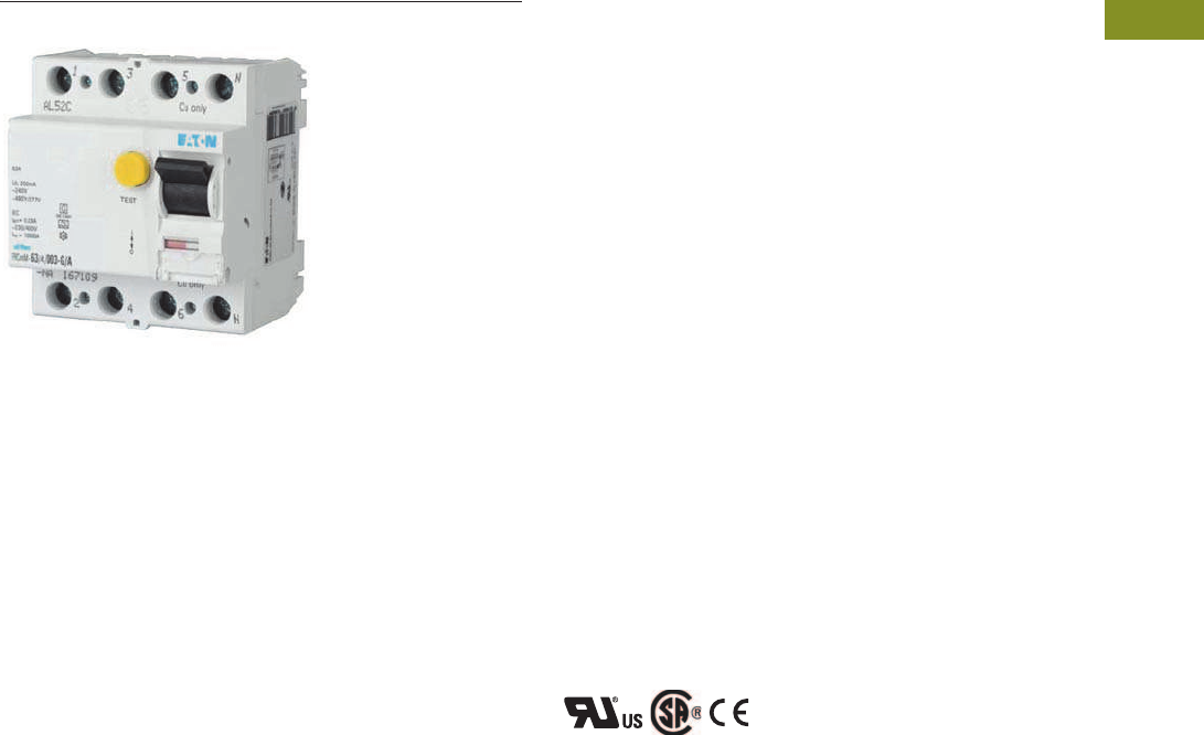
UL 1053 DIN Rail RCCB 480/277 Vac
Product Overview
Optimum product quality,
tested reliability and safety
stand for best protection of
installations and plant.
Eaton’s UL 1053 Residual
Current Circuit Breaker
(RCCB) is designed for use in
residual current applications.
Application Description
●Motor control circuits
●HVAC internal/external
equipment
●PLCs
●HMIs
●Equipment protection
●European housing
Features
●Wide range of compact
RCCB types serving as
fault-current and additional
protection according to
UL 1053 and IEC/EN 61008
standards, suitable for
worldwide use
●Type A or Type G/A (with
delay) protection available
●Comprehensive range of
accessories
●Real contact position
indicator
●Fault current tripping
indicator
●Transparent designation
plate
●Trip-free design—RCCB
can not be defeated by
holding the handle in the
ON position
●Captive screws cannot
be lost
Standards and Certifications
●UL 1053
●IEC/EN 61008
●CSA
●ÖVE
●CE Marked
Courtesy of CMA/Flodyne/Hydradyne Motion Control Hydraulic Pneumatic Electrical Mechanical (800) 426-5480 www.cmafh.com
V4-T1-88 Volume 4—Circuit Protection CA08100005E—August 2013 www.eaton.com
1
1
1
1
1
1
1
1
1
1
1
1
1
1
1
1
1
1
1
1
1
1
1
1
1
1
1
1
1
1
1.4
Miniature Circuit Breakers and Supplementary Protectors
UL 1053 DIN Rail RCCB
Product Selection
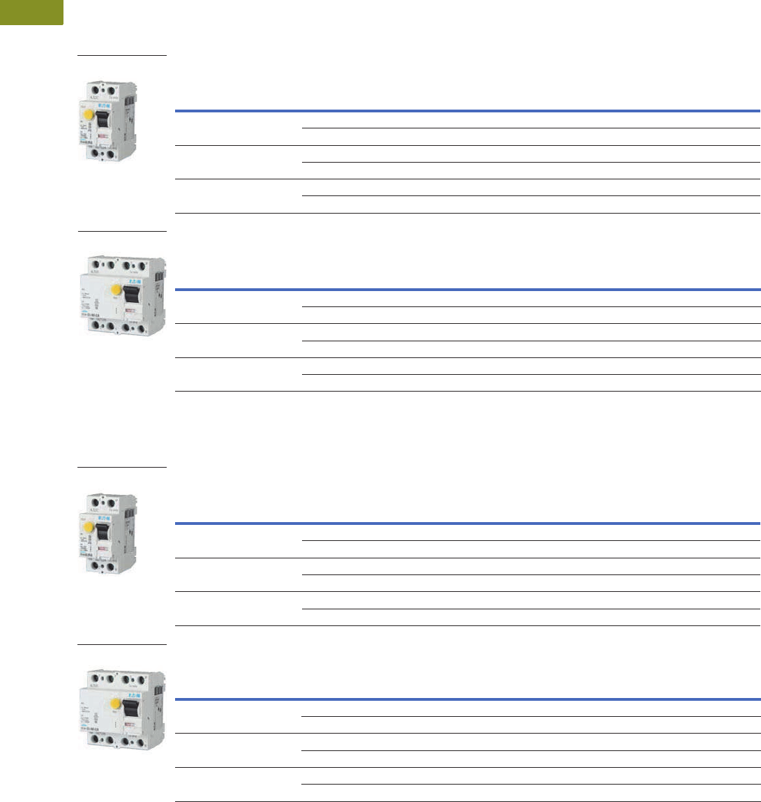
UL 1053 RCCB 480Y/277V Type A
Conditionally Surge Current–Proof 250A, Sensitive to Residual Pulsating DC, Type A
Conditionally Surge Current–Proof 250A, Sensitive to Residual Pulsating DC, Type A
UL 1053 RCCB 480Y/277V Type G/A
Type G/A has a 10 ms delay.
Surge Current–Proof 3 kA, Sensitive to Residual Pulsating DC, Type G/A (ÖVE E 8601)
Surge Current–Proof 3 kA, Sensitive to Residual Pulsating DC, Type G/A (ÖVE E 8601)
Note
1 Has no thermal element; must be paired with FAZ-NA or FAZ per application.
Two-Pole
Amperes
GF Sensitivity
(mA)
Catalog
Number 1Designation
25 30 167113 FRCmM-25/2/003-A-NA
300 167116 FRCmM-25/2/03-A-NA
40 30 167114 FRCmM-40/2/003-A-NA
300 167117 FRCmM-40/2/03-A-NA
63 30 167115 FRCmM-63/2/003-A-NA
300 167118 FRCmM-63/2/03-A-NA
Four-Pole
Amperes
GF Sensitivity
(mA)
Catalog
Number 1Designation
25 30 167125 FRCmM-25/4/003-A-NA
300 167104 FRCmM-25/4/03-A-NA
40 30 167102 FRCmM-40/4/003-A-NA
300 167105 FRCmM-40/4/03-A-NA
63 30 167103 FRCmM-63/4/003-A-NA
300 167106 FRCmM-63/4/03-A-NA
Two-Pole
Four-Pole
Two-Pole
Amperes
GF Sensitivity
(mA)
Catalog
Number 1Designation
25 30 167119 FRCmM-25/2/003-G/A-NA
300 167122 FRCmM-25/2/03-G/A-NA
40 30 167120 FRCmM-40/2/003-G/A-NA
300 167123 FRCmM-40/2/03-G/A-NA
63 30 167121 FRCmM-63/2/003-G/A-NA
300 167124 FRCmM-63/2/03-G/A-NA
Four-Pole
Amperes
GF Sensitivity
(mA)
Catalog
Number 1Designation
25 30 167107 FRCmM-25/4/003-G/A-NA
300 167110 FRCmM-25/4/03-G/A-NA
40 30 167108 FRCmM-40/4/003-G/A-NA
300 167111 FRCmM-40/4/03-G/A-NA
63 30 167109 FRCmM-63/4/003-G/A-NA
300 167112 FRCmM-63/4/03-G/A-NA
Two-Pole
Four-Pole
Courtesy of CMA/Flodyne/Hydradyne Motion Control Hydraulic Pneumatic Electrical Mechanical (800) 426-5480 www.cmafh.com

Volume 4—Circuit Protection CA08100005E—August 2013 www.eaton.com V4-T1-89
1
1
1
1
1
1
1
1
1
1
1
1
1
1
1
1
1
1
1
1
1
1
1
1
1
1
1
1
1
1
1.4
Miniature Circuit Breakers and Supplementary Protectors
UL 1053 DIN Rail RCCB
Accessories
UL 1053 DIN Rail RCCB 480/277 Vac
Note
1Voltage of FAZ-NA circuit breaker is limited to 300V with this auxiliary contact installed.
Description Catalog Number
Two-pole contact or auxiliary
contact / trip indicating contact
Z-NHK 1
Contact
Description Catalog Number
Padlock hasp IS/SPE-1TE
Padlock Hasp
Courtesy of CMA/Flodyne/Hydradyne Motion Control Hydraulic Pneumatic Electrical Mechanical (800) 426-5480 www.cmafh.com

V4-T1-90 Volume 4—Circuit Protection CA08100005E—August 2013 www.eaton.com
1
1
1
1
1
1
1
1
1
1
1
1
1
1
1
1
1
1
1
1
1
1
1
1
1
1
1
1
1
1
1.4
Miniature Circuit Breakers and Supplementary Protectors
UL 1053 DIN Rail RCCB
Technical Data and Specifications
●Residual current devices
●Has no thermal protection; must be paired with FAZ-NA
or FAZ per application
●Captive screw terminals
●Universal tripping signal switch, also suitable for Z-A; can be
mounted subsequently
●Auxiliary switch Z-HK can be mounted subsequently
●Red-green contact position indicator
●White-blue tripping indicator
●Delayed types recommended for use with standard
fluorescent tubes with or without electronical ballast
(30mA-RCD: 30 units per phase conductor,
100mA-RCD: 90 units per phase conductor)
●The device functions irrespective of the position of installation
●Tripping is line voltage-independent. Consequently, the RCD is
suitable for “fault current/residual current protection” and
“additional protection” within the meaning of the applicable
installation rules
●Reverse-feed permitted
●The four-pole device can also be used for two-pole
connection. For this purpose, use terminals 5-6 and N-N
●The test key “T” must be pressed every month. The system
operator must be informed of this obligation and responsibility
in a way that can be proven (self-adhesive RCD-label enclosed)
●Pressing the test key “T” serves the only purpose of function
testing the residual current device (RCD). This test does not
make earthing resistance measurement (RE) or proper
checking of the earth conductor condition redundant, which
must be performed separately
●Type -A: Protects against special forms of residual pulsating
DC that have not been smoothed
●Type -G/A: Additionally protects against special forms of
residual pulsating DC that have not been smoothed
UL 1053 DIN Rail RCCB Technical Data
UL 1053 DIN Rail RCCB Technical Data, continued
Description Specification
Electrical According to IEC/EN 61008
Design according to IEC/EN 61008
ÖVE E 8601
Current test marks as printed onto the device
Tripping Type G 10 ms delay
Rated voltage Un 230/400V, 50 Hz
Rated tripping current I'n 30, 300 mA
Sensitivity AC and pulsating DC
Rated insulation voltage Ui440V
Rated impulse withstand voltage Uimp 4 kV
Rated short-circuit capacity Inc 10 kA
Maximum backup fuse Overload protection Short-circuit protection
In = 25–40A 25A gG/gL 63A gG/gL
In = 63A 40A gG/gL 63A gG/gL
Rated breaking capacity Im bzw.
Rated fault breaking capacity I'm
In = 25–40A 500A
In = 63A 630A
Voltage range of test button Two-pole 184–250V~
Four-pole 184–440V~
Endurance Electrical >4000 operating cycles
Mechanical >20,000 operating cycles
Overvoltage category III
Description Specification
Electrical According to UL 1053
Design according to UL 1053
Current test marks as printed onto the device
Tripping Type G 8 ms delay
Rated voltage Un 480Y/277V, 60 Hz
Pickup current 22, 200 mA
Sensitivity AC and pulsating DC
Overvoltage tested 530V
Rated impulse withstand voltage Uimp 4 kV
Rated short-circuit capacity Inc 5 kA according to CSA
Maximum backup fuse Overload protection Short-circuit protection
In = 25–40A 25A gG/gL 63A gG/gL
In = 63A 40A gG/gL 63A gG/gL
Rated breaking capacity Im or
Rated fault breaking capacity I'm
In = 25–40A 500A
In = 63A 630A
Voltage range of test button Two-pole 184–305V~
Four-pole 184–528V~
Endurance Electrical >4000 operating cycles
Mechanical >20,000 operating cycles
Mechanical
Frame size 45.0 mm
Device height 80.0 mm
Device width 35 mm (2TE), 70 mm (4TE)
Device width Quick fastening with two
lock-in positions on DIN
rail IEC/EN 60715
Degree of protection, built-in IP40
Degree of protection in moisture-proof
enclosure
IP54
Upper and lower terminals Lift terminals
Terminal protection Finger and hand touch
safe BGV A3, ÖVE-EN 6
Terminal capacity 1.5–35 mm2 single-wire
2 x 16 mm2 multi-wire
Busbar material thickness 0.8–2 mm
Tripping temperature –25°C to +60°C
Resistance to climatic conditions According to IEC 61008
Humidity 5–95%
Courtesy of CMA/Flodyne/Hydradyne Motion Control Hydraulic Pneumatic Electrical Mechanical (800) 426-5480 www.cmafh.com

Volume 4—Circuit Protection CA08100005E—August 2013 www.eaton.com V4-T1-91
1
1
1
1
1
1
1
1
1
1
1
1
1
1
1
1
1
1
1
1
1
1
1
1
1
1
1
1
1
1
1.4
Miniature Circuit Breakers and Supplementary Protectors
UL 1053 DIN Rail RCCB
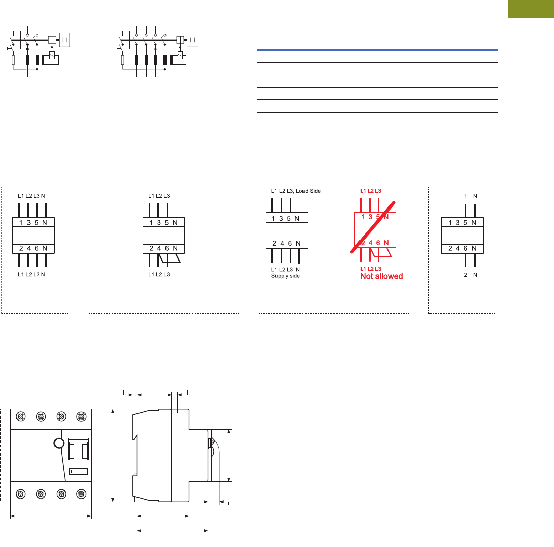
Connection Diagram Impact of Ambient Temperature on the Maximum
Permanent Current Allowed (A)
Notes
1Do not use.
Please make sure that these values are not exceeded and that any upstream overload protection
switches off in time.
Correct Connection
Dimensions
Approximate Dimensions in Inches (mm)
UL 1053 DIN Rail RCCB
1
2
T
N
N
1 5
2 6
T
3 N
4 N
Two-Pole Four-Pole
16A 25A 40A 63A
Tripping
Temperature
Two-
Pole
Four-
Pole
Two-
Pole
Four-
Pole
Two-
Pole
Four-
Pole
Two-
Pole
Four-
Pole
40°C 16 16 25 25 40 40 63 63
45°C 14 14 21 22 37 37 59 59
50°C 11 11 18 19 33 34 55 55
55°C 9 9 14 16 30 31 50 50
60°C 1— — — 26 27 45 45
3+N
(230/400V) IEC
(277/480V) UL
(184–254 Vac Phase-Phase) IEC
(184–277 Vac Phase-Phase) UL
1+N
(230V) IEC
(277V) UL
Three-phase load without NThree-phase load without N
(400 Vac Phase-Phase) IEC
(480 Vac Phase-Phase) UL
Four-Pole
2.76
(70.0)
3.15
(80.0)
1.20
(30.5)
0.22
(5.5)
0.18
(4.5)
1.77
(45.0)
0.41
(10.5)
1.73
(44.0)
2.36
(60.0)
Courtesy of CMA/Flodyne/Hydradyne Motion Control Hydraulic Pneumatic Electrical Mechanical (800) 426-5480 www.cmafh.com

V4-T1-92 Volume 4—Circuit Protection CA08100005E—August 2013 www.eaton.com
1
1
1
1
1
1
1
1
1
1
1
1
1
1
1
1
1
1
1
1
1
1
1
1
1
1
1
1
1
1
1.4
Miniature Circuit Breakers and Supplementary Protectors
UL 1053 DIN Rail RCCB
Accessories Technical Data
Description Z-NHK
Electrical
Contact function 2CO
Rated voltage 230V
Frequency 50/60 Hz
Rated current 2A
Rated thermal current Ith 2A
Utilization category AC13
Rated operational current Ie 3A/250 Vac
Utilization category AC15
Rated operational current Ie 2A/250 Vac
Utilization category DC12
Rated operational current Ie 0.5A/110 Vdc
Rated insulation voltage UI 250 Vac
Minimum operational voltage per contact Umin 5 Vdc
Minimum operational current Imin 10 mA DC
Rated peak withstand voltage Uimp (1.2/50μ) 2.5 kV
Conditional short-circuit current Ik with backup fuse 6A 1 kA
Maximum backup fuse, overload and short circuit 6A gL
Mechanical
Tripping indicator “electrical tripping” Blue/white
Frame size 45 mm
Device height 80 mm
Device width 8.8 mm (0.5MU)
Mounting Onto switching device
Degree of protection, built-in IP40
Terminal protection Finger and hand touch safe
According to BGV A3, ÖVE-EN 6
Terminals Lift terminals
Terminal capacity 20–14 AWG
Terminal screws M3 (Posidrive Z0)
Fastening torque of terminal screws 7 lb-in maximum
Courtesy of CMA/Flodyne/Hydradyne Motion Control Hydraulic Pneumatic Electrical Mechanical (800) 426-5480 www.cmafh.com
Volume 4—Circuit Protection CA08100005E—August 2013 www.eaton.com V4-T1-93
1
1
1
1
1
1
1
1
1
1
1
1
1
1
1
1
1
1
1
1
1
1
1
1
1
1
1
1
1
1
1.4
Miniature Circuit Breakers and Supplementary Protectors
UL 1053 DIN Rail RCCB
UL 1053 DIN Rail RCCB
Contents
Description Page
UL 1053 DIN Rail RCCB 480/277 Vac . . . . . . . . . . V4-T1-87
UL 1053 DIN Rail RCCB 208Y/120 Vac
Product Selection . . . . . . . . . . . . . . . . . . . . . . . . V4-T1-94
Accessories . . . . . . . . . . . . . . . . . . . . . . . . . . . . V4-T1-95
Technical Data and Specifications. . . . . . . . . . . . V4-T1-96
Dimensions. . . . . . . . . . . . . . . . . . . . . . . . . . . . . V4-T1-97
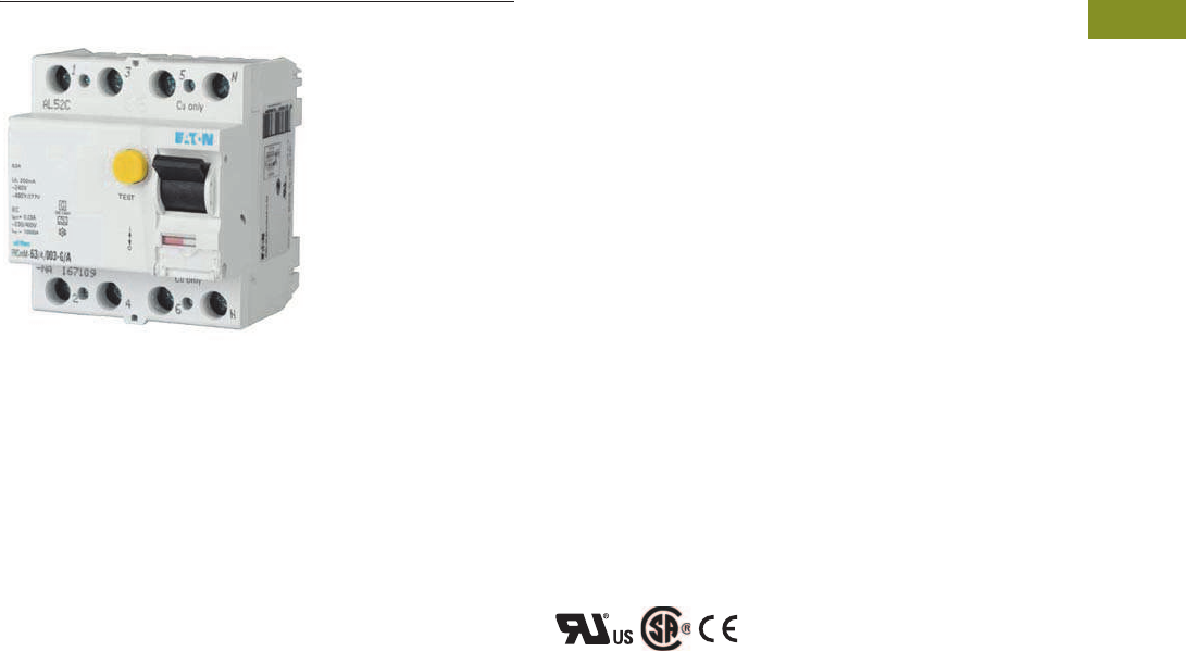
UL 1053 DIN Rail RCCB 208Y/120 Vac
Product Overview
Optimum product quality,
tested reliability and safety
stand for best protection of
installations and plant.
Eaton’s UL 1053 Residual
Current Circuit Breaker
(RCCB) is designed for use in
residual current applications.
Application Description
●Motor control circuits
●HVAC internal/external
equipment
●PLCs
●HMIs
●Equipment protection
Features
●Wide range of compact
RCD type serving as fault-
current and additional
protection according to
UL 1053 and IEC/EN 61008
standards, suitable for
worldwide use in the 110V
range of applications
●Type A or Type G/A (with
delay) protection available
●Comprehensive range of
accessories
●Real contact position
indicator
●Fault current tripping
indicator
●Transparent designation
plate
●Trip-free design—RCCB
can not be defeated by
holding the handle in the
ON position
●Captive screws cannot
be lost
Standards and Certifications
●UL 1053
●IEC/EN 61008
Courtesy of CMA/Flodyne/Hydradyne Motion Control Hydraulic Pneumatic Electrical Mechanical (800) 426-5480 www.cmafh.com
V4-T1-94 Volume 4—Circuit Protection CA08100005E—August 2013 www.eaton.com
1
1
1
1
1
1
1
1
1
1
1
1
1
1
1
1
1
1
1
1
1
1
1
1
1
1
1
1
1
1
1.4
Miniature Circuit Breakers and Supplementary Protectors
UL 1053 DIN Rail RCCB
Product Selection
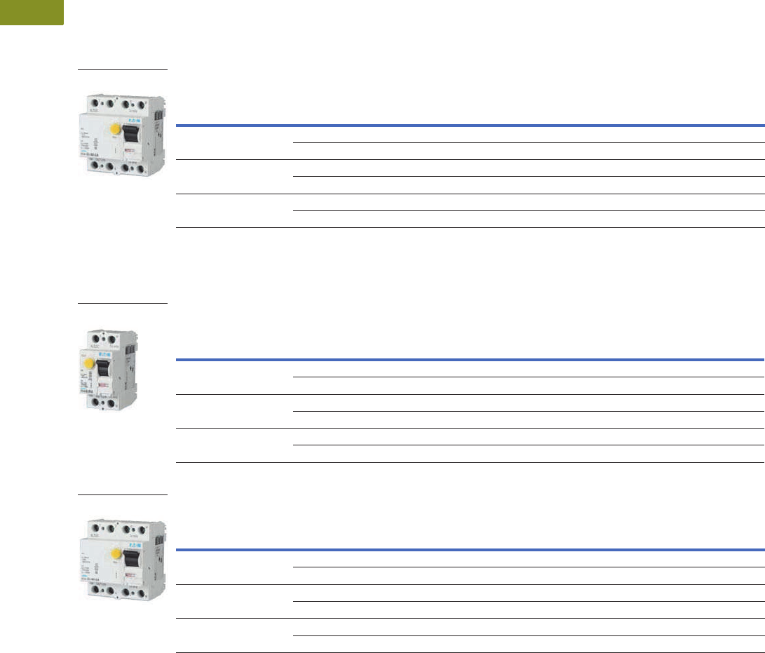
UL 1053 RCCB 208Y/120 Vac Type A
Conditionally Surge Current–Proof 250A, Sensitive to Residual Pulsating DC, Type A
UL 1053 RCCB 208Y/120 Vac Type G/A
Type G/A has a 10 ms delay.
Surge Current–Proof 3 kA, Sensitive to Residual Pulsating DC, Type G/A (ÖVE E 8601)
Surge Current–Proof 3 kA, Sensitive to Residual Pulsating DC, Type G/A (ÖVE E 8601)
Note
1 Has no thermal element; must be paired with FAZ-NA or FAZ per application.
Four-Pole
Amperes
GF Sensitivity
(mA)
Catalog
Number 1Designation
25 30 167699 FRCmM-25/4/003-A-NA-110
300 167702 FRCmM-25/4/03-A-NA-110
40 30 167700 FRCmM-40/4/003-A-NA-110
300 167703 FRCmM-40/4/03-A-NA-110
63 30 167701 FRCmM-63/4/003-A-NA-110
300 167704 FRCmM-63/4/03-A-NA-110
Four-Pole
Two-Pole
Amperes
GF Sensitivity
(mA)
Catalog
Number 1Designation
25 30 167693 FRCmM-25/2/003-G/A-NA-110
300 167696 FRCmM-25/2/03-G/A-NA-110
40 30 167694 FRCmM-40/2/003-G/A-NA-110
300 167697 FRCmM-40/2/03-G/A-NA-110
63 30 167695 FRCmM-63/2/003-G/A-NA-110
300 167698 FRCmM-63/2/03-G/A-NA-110
Four-Pole
Amperes
GF Sensitivity
(mA)
Catalog
Number 1Designation
25 30 167705 FRCmM-25/4/003-G/A-NA-110
300 167708 FRCmM-25/4/03-G/A-NA-110
40 30 167706 FRCmM-40/4/003-G/A-NA-110
300 167709 FRCmM-40/4/03-G/A-NA-110
63 30 167707 FRCmM-63/4/003-G/A-NA-110
300 167710 FRCmM-63/4/03-G/A-NA-110
Two-Pole
Four-Pole
Courtesy of CMA/Flodyne/Hydradyne Motion Control Hydraulic Pneumatic Electrical Mechanical (800) 426-5480 www.cmafh.com

Volume 4—Circuit Protection CA08100005E—August 2013 www.eaton.com V4-T1-95
1
1
1
1
1
1
1
1
1
1
1
1
1
1
1
1
1
1
1
1
1
1
1
1
1
1
1
1
1
1
1.4
Miniature Circuit Breakers and Supplementary Protectors
UL 1053 DIN Rail RCCB
Accessories
UL 1053 DIN Rail RCCB 208Y/120 Vac
Note
1Voltage of FAZ-NA circuit breaker is limited to 300V with this auxiliary contact installed.
Description Catalog Number
Two-pole contact or auxiliary
contact / trip indicating contact
Z-NHK 1
Contact
Description Catalog Number
Padlock hasp IS/SPE-1TE
Padlock Hasp
Courtesy of CMA/Flodyne/Hydradyne Motion Control Hydraulic Pneumatic Electrical Mechanical (800) 426-5480 www.cmafh.com

V4-T1-96 Volume 4—Circuit Protection CA08100005E—August 2013 www.eaton.com
1
1
1
1
1
1
1
1
1
1
1
1
1
1
1
1
1
1
1
1
1
1
1
1
1
1
1
1
1
1
1.4
Miniature Circuit Breakers and Supplementary Protectors
UL 1053 DIN Rail RCCB
Technical Data and Specifications
●Residual current devices
●Has no thermal protection; must be paired with FAZ-NA
or FAZ per application
●Captive screw terminals
●Universal tripping signal switch, also suitable for Z-A; can be
mounted subsequently
●Auxiliary switch Z-HK can be mounted subsequently
●Red-green contact position indicator
●White-blue tripping indicator
●Delayed types recommended for use with standard
fluorescent tubes with or without electronical ballast
(30mA-RCD: 30 units per phase conductor,
100mA-RCD: 90 units per phase conductor)
●The device functions irrespective of the position of installation
●Tripping is line voltage-independent. Consequently, the RCD is
suitable for “fault current/residual current protection” and
“additional protection” within the meaning of the applicable
installation rules
●Reverse-feed permitted
●The four-pole device can also be used for two-pole
connection. For this purpose, use terminals 5-6 and N-N
●The test key “T” must be pressed every month. The system
operator must be informed of this obligation and responsibility
in a way that can be proven (self-adhesive RCD-label enclosed)
●Pressing the test key “T” serves the only purpose of function
testing the residual current device (RCD). This test does not
make earthing resistance measurement (RE) or proper
checking of the earth conductor condition redundant, which
must be performed separately
●Type -A: Protects against special forms of residual pulsating
DC that have not been smoothed
●Type -G/A: Additionally protects against special forms of
residual pulsating DC that have not been smoothed
UL 1053 DIN Rail RCCB Technical Data
UL 1053 DIN Rail RCCB Technical Data, continued
Description Specification
Electrical According to IEC/EN 61008
Design according to IEC/EN 61008
ÖVE E 8601
Current test marks as printed onto the device
Tripping Type G 10 ms delay
Rated voltage Un 230/400V, 50 Hz
Rated tripping current I'n 30, 300 mA
Sensitivity AC and pulsating DC
Rated insulation voltage Ui440V
Rated impulse withstand voltage Uimp 4 kV
Rated short-circuit capacity Inc 10 kA
Maximum backup fuse Overload protection Short-circuit protection
In = 25–40A 25A gG/gL 63A gG/gL
In = 63A 40A gG/gL 63A gG/gL
Rated breaking capacity Im bzw.
Rated fault breaking capacity I'm
In = 25–40A 500A
In = 63A 630A
Voltage range of test button Two-pole 100–132V~
Four-pole 100–230V~
Endurance Electrical >4000 operating cycles
Mechanical >20,000 operating cycles
Overvoltage category III
Description Specification
Electrical According to UL1053
Design according to UL 1053
Current test marks as printed onto the device
Tripping Type G 8 ms delay
Rated voltage Un 208Y/120V, 60 Hz
Pickup current 22, 200 mA
Sensitivity AC and pulsating DC
Overvoltage tested 530V
Rated impulse withstand voltage Uimp 4 kV
Rated short-circuit capacity Inc 5 kA according to CSA
Maximum backup fuse Overload protection Short-circuit protection
In = 25–40A 25A gG/gL 63A gG/gL
In = 63A 40A gG/gL 63A gG/gL
Rated breaking capacity Im or
Rated fault breaking capacity I'm
In = 25–40A 500A
In = 63A 630A
Voltage range of test button Two-pole 100–121V~
Four-pole 100–210V~
Endurance Electrical >4000 operating cycles
Mechanical >20,000 operating cycles
Mechanical
Frame size 45.0 mm
Device height 80.0 mm
Device width 35 mm (2TE), 70 mm (4TE)
Device width Quick fastening with two
lock-in positions on DIN
rail IEC/EN 60715
Degree of protection, built-in IP40
Degree of protection in moisture-proof
enclosure
IP54
Upper and lower terminals Lift terminals
Terminal protection Finger and hand touch
safe BGV A3, ÖVE-EN 6
Terminal capacity 1.5–35 mm2 single-wire
2 x 16 mm2 multi-wire
Busbar material thickness 0.8–2 mm
Tripping temperature –25°C to +60°C
Resistance to climatic conditions According to IEC 61008
Humidity 5–95%
Courtesy of CMA/Flodyne/Hydradyne Motion Control Hydraulic Pneumatic Electrical Mechanical (800) 426-5480 www.cmafh.com
Volume 4—Circuit Protection CA08100005E—August 2013 www.eaton.com V4-T1-97
1
1
1
1
1
1
1
1
1
1
1
1
1
1
1
1
1
1
1
1
1
1
1
1
1
1
1
1
1
1
1.4
Miniature Circuit Breakers and Supplementary Protectors
UL 1053 DIN Rail RCCB
Connection Diagram Impact of Ambient Temperature on the Maximum
Permanent Current Allowed (A)
Notes
1Do not use.
Please make sure that these values are not exceeded and that any upstream overload protection
switches off in time.
Correct Connection
Dimensions
Approximate Dimensions in Inches (mm)
UL 1053 DIN Rail RCCB
1
2
T
N
N
1 5
2 6
T
3 N
4 N
Two-Pole Four-Pole
16A 25A 40A 63A
Tripping
Temperature
Two-
Pole
Four-
Pole
Two-
Pole
Four-
Pole
Two-
Pole
Four-
Pole
Two-
Pole
Four-
Pole
40°C 16 16 25 25 40 40 63 63
45°C 14 14 21 22 37 37 59 59
50°C 11 11 18 19 33 34 55 55
55°C 9 9 14 16 30 31 50 50
60°C 1— — — 26 27 45 45
3+N
(230/400V) IEC
(277/480V) UL
(184–254 Vac Phase-Phase) IEC
(184–277 Vac Phase-Phase) UL
1+N
(230V) IEC
(277V) UL
Three-phase load without NThree-phase load without N
(400 Vac Phase-Phase) IEC
(480 Vac Phase-Phase) UL
Four-Pole
2.76
(70.0)
3.15
(80.0)
1.20
(30.5)
0.22
(5.5)
0.18
(4.5)
1.77
(45.0)
0.41
(10.5)
1.73
(44.0)
2.36
(60.0)
Courtesy of CMA/Flodyne/Hydradyne Motion Control Hydraulic Pneumatic Electrical Mechanical (800) 426-5480 www.cmafh.com

V4-T1-98 Volume 4—Circuit Protection CA08100005E—August 2013 www.eaton.com
1
1
1
1
1
1
1
1
1
1
1
1
1
1
1
1
1
1
1
1
1
1
1
1
1
1
1
1
1
1
1.4
Miniature Circuit Breakers and Supplementary Protectors
UL 1053 DIN Rail RCCB
Accessories Technical Data
Description Z-NHK Z-IHK-NA
Electrical
Contact function 2CO 1NO + 1NC
Rated voltage 230V 250V
Frequency 50/60 Hz 50/60 Hz
Rated current 2A 6A
Rated thermal current Ith 2A 6A
Utilization category AC13
Rated operational current Ie 3A/250 Vac 3A/250 Vac
Utilization category AC15
Rated operational current Ie 2A/250 Vac 2A/250 Vac
Utilization category DC12
Rated operational current Ie 0.5A/110 Vdc 0.5A/110 Vdc
0.25A/220 Vdc
Rated insulation voltage UI 250 Vac 250 Vac
Minimum operational voltage per contact Umin 5 Vdc 5 Vdc
Minimum operational current Imin 10 mA DC 10 mA AC/DC
Rated peak withstand voltage Uimp (1.2/50μ) 2.5 kV 4 kV
Conditional short-circuit current Ik with backup fuse 6A 1 kA 1 kA
Maximum backup fuse, overload and short circuit 6A gL —
Mechanical
Tripping indicator “electrical tripping” Blue/white —
Frame size 45 mm 45 mm
Device height 80 mm 80 mm
Device width 8.8 mm (0.5MU) 8.8 mm (0.5MU)
Mounting Onto switching device —
Degree of protection, built-in IP40 IP40
Terminal protection Finger and hand touch safe
According to BGV A3, ÖVE-EN 6
Finger and hand touch safe
According to BGV A3, ÖVE-EN 6
Terminals Lift terminals Lift terminals
Terminal capacity 20–14 AWG 0.5–2.5 mm2
Terminal screws M3 (Posidrive Z0) M3 (Posidrive Z0)
Fastening torque of terminal screws 7 lb-in maximum 1.2 Nm
Courtesy of CMA/Flodyne/Hydradyne Motion Control Hydraulic Pneumatic Electrical Mechanical (800) 426-5480 www.cmafh.com
