Installation Directions
1000445716-Installationsheet 1000445716-InstallationSheet 1000445716-InstallationSheet B4 unilog cesco-content
1000445716-Installationsheet 1000445716-InstallationSheet 1000445716-InstallationSheet B5 unilog cesco-content
2016-07-29
: Pdf 153433-Installationsheet 153433-InstallationSheet B2 unilog
Open the PDF directly: View PDF ![]() .
.
Page Count: 2
Installation Instructions
Eaton’s Cooper Controls Business
203 Cooper Circle
Peachtree City, Georgia 30269
www.coopercontrol.com
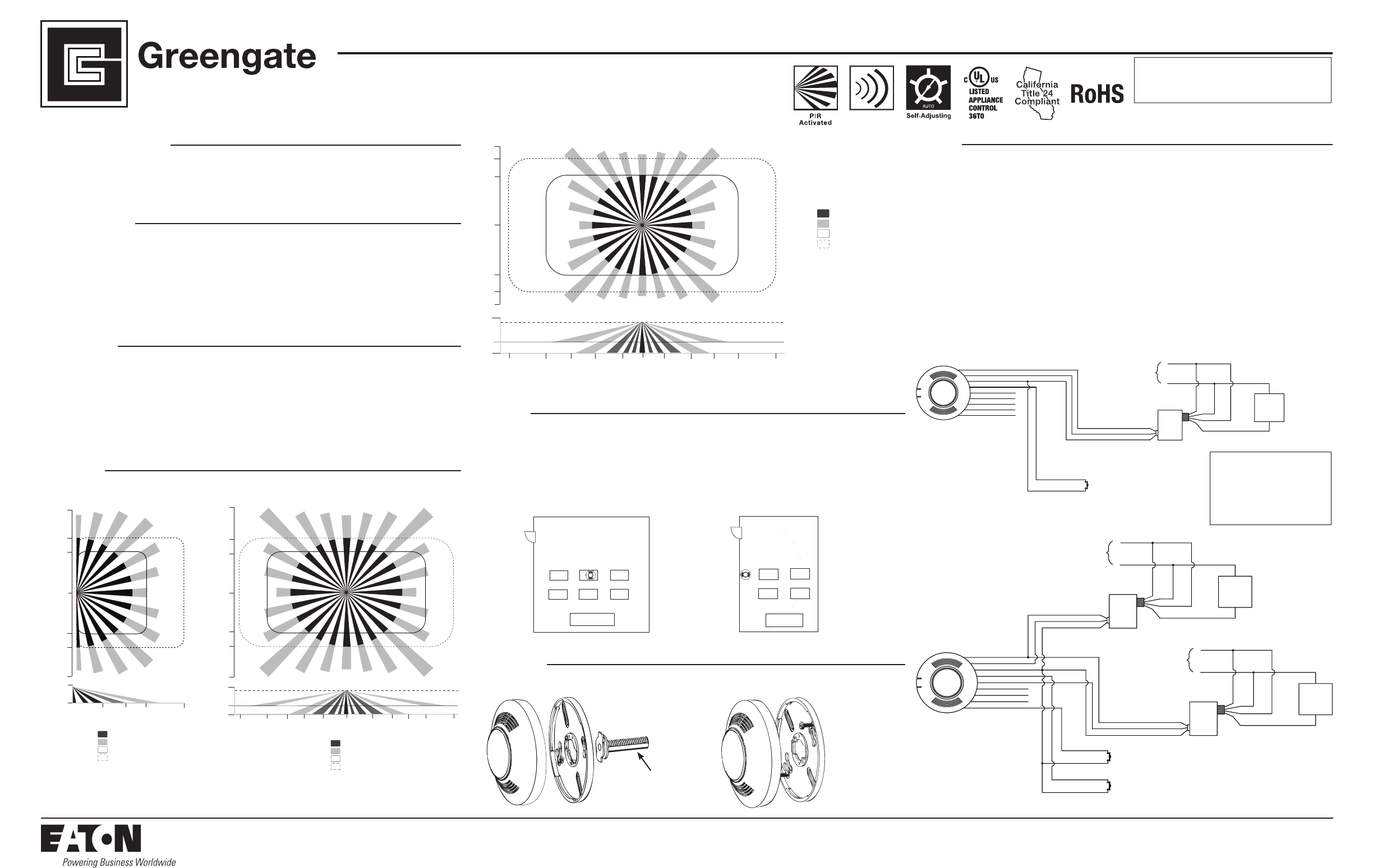
Coverage
Minor Motion, Ultrasonic
Major Motion, Ultrasonic
Maximum coverage area may
vary somewhat according to room
shape and the presence of obstacles.
The NEMA WD 7 Guide and robotic
method were utilized to verify
coverage patterns.
Minor Motion, IR
Major Motion, IR
8.5 ft
(2.59 m)
5 ft
(1.52 m)
10 ft
(3.05 m)
15 ft
(4.57 m)
23 ft
(7.01 m)
0
9 ft
(2.74 m)
9 ft
(2.74 m)
0
12 ft
(3.65 m)
12 ft
(3.65 m)
20 ft
(6.096m)
20 ft
(6.096m)
Model # VAC-DT-0501-R
Model # VAC-DT-1000-R
Model # VAC-DT-2000-R
Dual Technology Ceiling Mounted Low
Voltage Vacancy Sensor
• Readallinstructionsonbothsidesofthis
sheetrst
• InstallinaccordancewithALLlocalcodes
• Forindooruseonly
• ForUsewithGreengateSwitchpacks&
SystemsOnly
• DonotrunanyGreengateLowVoltageWiringin
thesameconduitaspowerconductors
General Information
Power Requirements:
Input:
• 10-30VDCfromGreengateSwitchpackor
Greengatesystem.Maximumcurrentneededis
25mApersensor
Output:
• Opencollectoroutputtoswitchuptoten
GreengateSwitchpacks
• BASwithIsolatedFormCRelay(-Rmodel)
• IsolatedFormCRelayRatings:1A30VDC/VAC
Operating Environment:
• Temperature:32°F–104°F(0°C–40°C)
• RelativeHumidity:upto90%non-condensing
Specifications
Description
Ultrasonic
Activated
TheVAC-DTCeilingMountLowVoltageVacancySensorisaPassiveInfrared(PIR)andUltrasonic(US)motion
sensinglightingcontrol,usedforenergysavingsandconvenience.AmanualswitchisusedtoturnthelightsONand
theneithertechnologyisusedtokeepthelightsON.Whenamanualswitchisusedthebluewireiselectronically
connectedtotheredwire,energizingtherelayintheswitchpacktoturnontheload.Ifvacancyisdetected,the
bluewireisdisconnectedfromthered,causingtherelaytoopenturningOFFtheload.Theredleadis10-30VDC
supply,theblackleadiscommon,andtheblueistherelaycontrol.
Thesensorincludesself-adaptivetechnologythatcontinuallyadjuststoconditionsbyadjustingsensitivityand
timedelayinreal-time.
Location
Themaximumcoverageareamayvarysomewhataccordingtoroomshapeandthepresenceofobstacles.Decrease
totalcoverageareaby15%for“soft”rooms(forexample,heavydraperiesorheavycarpeting).Thesensormusthavea
clearviewoftheareatobecontrolled.Thesensorwillnot“see”throughglass.Mountingheightshouldnotexceed12
feet.Optimummountingheightis8to10feet.Mountthesensorsothegrillesfacetheopenportionoftheroomand
arenotfacinganearbywall,door,windoworotherobstructingobject.Avoidpointingintohallways.Mountingatxture
heightismosteffective.*Topreventfalseactivation,thesensorshouldbemountedawayfromtheairsupplyducta
minimumof4to6feet.
Installation
TheVAC-DTsensorcanbemountedtotheceiling,junctionbox,orroundxturewithraceway.
Wiring
CAUTION: Before installing or performing any service on a Greengate system, the power MUST be turned
OFF at the branch circuit breaker. According to NEC 240-83(d), if the branch circuit breaker is used
as the main switch for a fluorescent lighting circuit, the circuit breaker should be marked “SWD”. All
installations should be in compliance with the National Electric Code and all state and local codes.
NOTE REGARDING COMPACT FLUORESCENT LAMPS: The life of some compact fluorescent lamps (CFLs) is
shortened by frequent automatic or manual switching. Check with CFL and ballast manufacturer to determine the
effects of cycling.
1. MakesurepoweristurnedOFFatthebranchcircuitbreaker.
2.Wireunitsasshowninwiringdiagramsperapplicablevoltagerequirements.(Usetwist-onwireconnectors
forallconnections)CAPALLUNUSEDWIRELEADS.
3.Mountunittoceiling,junctionboxorroundxturewithraceway.
4.TurnpowerbackONatthebranchcircuitbreakerandwait2minutesfortheunittostabilize.
5.Makenecessaryadjustments.(SeeCheckoutandAdjustmentssection)
OAC-STEM Threaded Rod
(sold separately)
Minor Motion, Ultrasonic
Major Motion, Ultrasonic
Maximum coverage area may
vary somewhat according to room
shape and the presence of obstacles.
The NEMA WD 7 Guide and robotic
method were utilized to verify
coverage patterns.
Minor Motion, IR
Major Motion, IR
8.5 ft
(2.59 m)
17 ft
(5.18 m)
10 ft
(3 m)
5 ft
(1.5 m)
0
05 ft
(1.5 m)
10 ft
(3 m)
17 ft
(5.18 m)
23 ft
(7.01 m)
DT1k
9 ft
(2.74 m)
0
12 ft
(3.65 m)
20 ft
(6.096m)
23 ft
(7.01 m)
9 ft
(2.74 m)
12 ft
(3.65 m)
20 ft
(6.096m)
3 ft
(0.91)
15 ft
(4.57 m)
15 ft
(4.57 m)
VAC-DT-1000-R Coverage DiagramVAC-DT-0501-R Coverage Diagram
Minor Motion, Ultrasonic
Major Motion, Ultrasonic
Maximum coverage area may
vary somewhat according to room
shape and the presence of obstacles.
The NEMA WD 7 Guide and robotic
method were utilized to verify
coverage patterns.
Minor Motion, IR
Major Motion, IR
0
23 ft
(7.01 m)
5 ft
(1.52 m)
05 ft
(1.52 m)
32 ft
(9.75 m)
32 ft
(9.75 m)
12 ft
(3.65 m)
16 ft
(4.87 m)
15 ft
(4.57 m)
23 ft
(7.01 m)
15 ft
(4.57 m)
8.5 ft
(2.59 m)
0
12 ft
(3.65 m)
16 ft
(4.87 m)
20 ft
(6.096m)
20 ft
(6.096m)
10 ft
(3 m)
10 ft
(3 m)
3 ft
(0.91)
VAC-DT-2000-R Coverage Diagram
Load 1
Blue
Neutral
Hot
**Use black lead for 120 VAC
Use orange lead for 277 VAC
Cap unused lead.
Line
**Hot
White
Blue
SWITCH-
PACK
Black
Blue
Brown
Yellow
Purple
Gray
Orange
Red
White/Brown
Load 2
Blue
Neutral
Hot
**Use black lead for 120 VAC
Use orange lead for 277 VAC
Cap unused lead.
Line
**Hot
White
Blue
SWITCH-
PACK
Black (Common)
Blue (Control)
Red (15 VDC)
Black (Common)
Blue (Control)
Red (15 VDC)
Model GMDS - Load 2
(Normally Open
Momentary Switch)
Model GMDS - Load 1
(Normally Open
Momentary Switch)
Manual Mode Operation:
Switches are required to
turn corresponding loads ON.
Lights turn OFF when sensor
times out or with the
switch.
If daylight sensor is
enabled and light level is
above setpoint, switchpack
connected to yellow lead
will not turn ON.
Recommended Wire:
18-3 AWG Stranded Wire
non/shielded.
Manual ON Control of
Two Standard Switchpacks
Black
Blue
Brown
Yellow
Purple
Gray
Orange
Red
White/Brown
Load 1
Blue
Neutral
Hot
**Use black lead for 120 VAC
Use orange lead for 277 VAC
Cap unused lead.
Line
**Hot
White
Blue
SWITCH-
PACK
Black (Common)
Blue (Control)
Red (15 VDC)
Model GMDS - Load 1
(Normally Open
Momentary Switch)
Manual Mode Operation:
Switches ar
e required to
tur
n corresponding loads ON.
Lights tur
n OFF when sensor
times out or with the
switch.
If daylight sensor is
enabled and light level is
above setpoint, switchpack
connected to yellow lead
will not tur
n ON.
Recommended Wir
e:
18-3 A
WG Stranded Wire
non/shielded.
One Sensor, One Switchpack
SENSOR WIRE LEAD LEGEND
Black (Common)
Red (10-30 VDC)
Blue (Control - Occupancy)
Yellow (Control - Occupancy and Daylight)
Brown (Switch-Blue Lead Control)
Brown/White (Switch-Yellow Lead Control)
Sensor's Isolated Relay
Orange (Normally Open)
Gray (Common)
Purple (Normally Closed)
30 ft
9.14 m
30 ft
9.14
m
15 ft
4.57 m
30 ft
9.14 m
VAC-DT-1000 & VAC-DT-2000 VAC-DT-0501
P/N 9850-000201-01
Eaton’s Cooper Controls Business
203 Cooper Circle
Peachtree City, Georgia 30269
www.coopercontrol.com
Printed in Malaysia
Warranties and Limitation of Liability
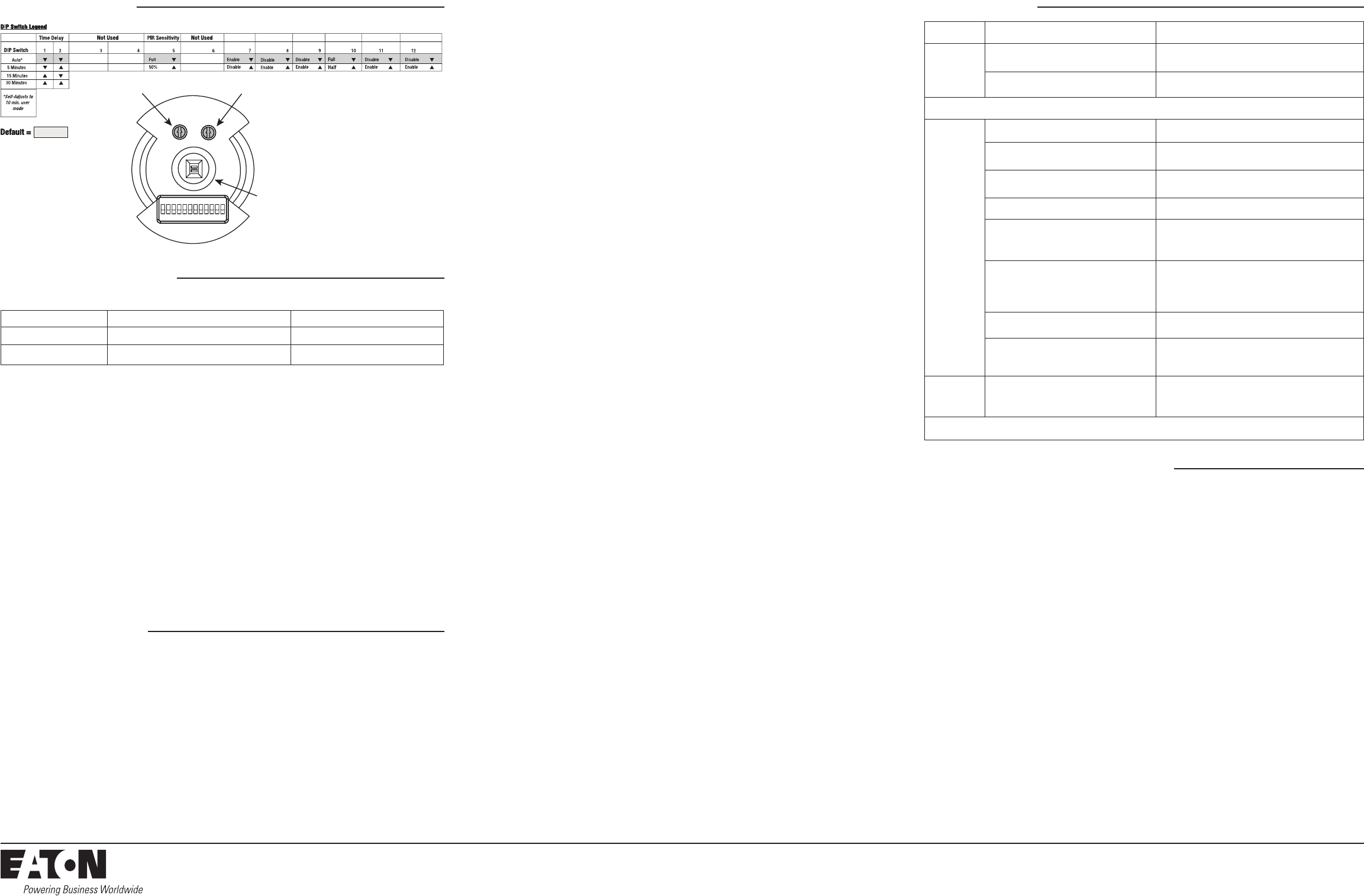
DIP Switch Settings Troubleshooting
Pleaserefertowww.coopercontrol.comundertheLegalsectionforourtermsandconditions.
Checkout and Adjustment
Installer Adjustments
Issue Possible Causes Suggestions
Lights
Will Not
Turn ON
manually
DaylightingFeatureEnabled IfalllightsarerequiredadjustDIPSwitch10
and/ordaylightpotentiometer
Powerinterruption Checkincomingvoltageand/orwiring
If lights will still not turn ON, set sensor to override mode and call Technical Services at 1-800-553-3879
Lights
Will Not
Turn OFF
automatically
Override MakesuresensorisnotinOverrideMode(DIPSwitch8up)
UltrasonicSensitivitysetHigh Lowersensitivitybyturninggreen
potentiometerCCWinsmalldecrements
Sensorinstalledclosetoanairvent Sensorsshouldbeinstalledminimum4-6feetaway
fromanyairventandoutofpathofheavyairow
Sensorinstalledclosetoindirectlighting Sensorsshouldbemountedawayfromindirectlighting.
Self-adjust
Itmaybepossiblefortheunittohaveself-adjusted
thetimedelaytoa30minutedelay.Ifthelightsdo
notturnOFFafter30minutesfollownextstep
30MinuteDelay
Maximumtimedelayis30Minutes.CheckDIP
SwitchestoverifyDIPSwitchsettings.Iflightsdo
notturnOFFatthesettimedelay,checknextstep
PIRactivatedbyheatsourceotherthanoccupant MoveDIPSwitch5up.
Bypass Checkwiringtomakesuresensor
orswitchpackarenotbypassed
Lights Will Not
Turn OFF
manually
Override MakesuresensorisnotinOverrideMode
(DIPSwitch8up)
If lights will still not turn OFF, call Technical Services at 1-800-553-3879
AdjustmentsshouldbemadewiththeHVACsystemON.Useonlyinsulatedtoolstomakeadjustments.
Self-Adjust
SensorisshippedintheSelf-AdjustMode.Thisappliestotimedelay,US,andPIRsensitivity.InpreparationfortheInstallerTest,
thetimedelayissetto15seconds,afterthesensorisinstalled,poweredONandhasstabilized,theunitwilltime-out15seconds
afterthelastmotiondetected.CoverageandsensitivitycanbeconrmedbywatchingtheGreen(US)andRed(PIR)indicatorLEDs
onthefrontofthesensor,whilemovingaroundtheroom.
1. WalkaroundtheroomandmonitorLEDs.LEDsshouldonlyturnONfor¼secondwitheachmotion.(IfLEDsdonotturnON,
gotoInstallerAdjustments–SensitivityAdjustmentsSection)
2. Standstillsixtoeightfeetawayfromthesensorforveseconds.LEDsshouldnotturnON.(IfanyLEDturnsON,noteLED
andgotoInstallerAdjustments–SensitivityAdjustmentsection)
3. Walkoutsidetheroomandwait15secondsforthelightstoturnOFF.(IflightsdonotturnOFFgotoInstallerAdjustments
Section)
4. Re-entertheroomtoactivatesensor.(IflightsdonotturnONgotoTroubleshootingSection)
5. TheunitwillremaininTestModefor10minutesthenautomaticallyexitTestModeandgofor10min.TimeDelayUser
Modesetting.
Note:ToplaceintoTestMode,toggleDIPSwitch10outofitscurrentposition,wait3seconds,andthenbackintoitsoriginalposition.Toforce
into10minUserModemoveDipSwitches1and2down.(IfDIPSwitches1and2arealreadydown,toggleDIPSwitch1outofitscurrentposition,
wait3seconds,andthenbacktoitsoriginalposition)WhileinTestMode,theLEDswillashonceper1/4second.
SweepOverride
LEDs
(-R model only) (-R model only)
Full/Half Logic HVAC/Tracking Zero Time Delay
123456 78 91011 12
ON
Daylight Sensor Adjustment Ultrasonic Sensitivity Adjustment
PIR Detector
LED Indicators Functionality
During Installer/Test Mode While in User Mode
LED Flashing Speed LEDswillashonceper¼second LEDswillashoncepersecond
Duration 10minutes 10to30minutes
Sensitivity Adjustments
Ultrasonic Sensitivity (Green LED)– Usingasmallatheadscrewdriverturnthegreenpotentiometersothatthearrowpointsup.
1. Standindifferentareasoftheroomandwaveyourhands.
2. IftheGreenLEDdoesnotturnON,increasetheUSsensitivitybyturningthegreenpotentiometerclockwiseinsmall
increments.RepeatStep1.
3. Standstillsixtoeightfeetawayfromsensorforveseconds.LEDshouldnotturnON.
4. IfGreenLEDturnsonwithoutmotionorisconstantlyondecreasetheUSsensitivitybyturningthegreenpotentiometer
counter-clock-wiseinsmalldecrements.RepeatStep3.
PIR Sensitivity
1. Standindifferentareasoftheroomandwaveyourhands.
2. IftheRedLEDdoesnotturnON,checkforanyobstructions.
3. Standstillsixtoeightfeetawayfromsensorforveseconds.LEDshouldnotturnON.
4. IfRedLEDturnsONwithoutmotionorisconstantlyONadjustPIRsensitivityto50%bymovingDIPSwitch5up.
Field-of-view outside the space
1. AdjustPIRsensitivityto50%bymovingDIPSwitch5up.
2. AdjustUltrasonicSensitivity.
Daylight Adjustments (-R Model Only 0 to 300 foot-candles)
Ifthisfeatureisnotneeded,leavethelightlevelatmaximum(fullyclockwise).
TheDaylightingfeaturepreventsthelightsfromturningONwhentheroomisadequatelyilluminatedbynaturallight.Ifthereis
enoughlightintheroomregardlessofoccupancy,thesensorwillholdthelightsOFF.Ifthereisnotenoughlightintheroom,thesensor
willallowthelightstoturnONwhenoccupied.
Full and Half Logic Modes(SeeDIPSwitchlegend):
InbothFullandHalfLogicmodes,lightsconnectedtotheyellowcontrolleadwillnotturnONuponoccupancyactivation,should
theambientlightlevelexceedthepresetfoot-candlelevel.
After activation:
FullLogicMode–shouldtheambientlightlevelexceedthepresetfoot-candlelevel,thelightsconnectedtotheyellowcontrol
leadwillturnOFF.ThelightswillremainOFF,untiltheambientlightlevelfallsbelowthesetpoint.
HalfLogicMode–theoutputstateoftheyellowcontrolleadwillnotchangewithambientlightchanges,afteroccupancy
activation.Iftheamountofnaturallightavailablerisesabovethesetpoint,thedaylightsensorwillnotturnthelightsOFFwhile
occupancyisbeingdetected.
Note:Setthelightlevelwhentheambientlightisatthelevelwherenoarticiallightisneeded.Inorderforthisfeaturetofunction,
theyellowcontrolleadmustbewired.
1. WiththeloadON,putthesensorintoTestMode.ToplaceintoTestMode,toggleDIPSwitch10outofitscurrentposition,wait3
secondsandthenbackintoitsoriginalposition.
2. SetDIPSwitch10toFullorHalfLogicMode.
3. Setthelightleveltominimum(fullyCCW).
4. Leavetheroomandletthesensortime-outsolightsareOFF.EnterthespaceandlightsshouldremainOFF.
5. MakesurenottoblockthesensorfromthedaylightsourceandadjustthelightlevelpotentiometerCWinsmallincrementsuntil
thelightsareON.(Pause5secondsbetweeneachadjustment)
6. OncethelightsareON,theloadconnectedtothesensorwillnotturnONiflightlevelsareabovethecurrentillumination.
Time Delay Adjustments
Peoplewhoremainverystillforlongperiodsoftimemayneedalongertimedelaythanthedefaultsettingof10minutes.Aslong
asAutoisenabled,thesensorwillrespondtoeachpairoffalse-OFFswithnonormalOFFinbetween,byalternatelymakingslight
adjustmentstoeithertimedelay(by2minuteincrements)orsensitivity,sothereshouldbenoneedformanualadjustment.Ifmanual
adjustmentisdesired,refertoTimeDelaysettingsinDIPSwitchlegend.
ResetsensorTimeDelaytofactorysettingsbymovingDIPSwitches1and2down.(IfDIPSwitches1and2arealreadydown,toggle
DIPSwitch10outofitscurrentposition,wait3seconds,andthenbacktoitsoriginalposition)
Manual Mode (-R Model Only)
InManualONMode,theoptionalmomentarylowvoltageswitch(es)isrequiredtoturntheload(s)ON.Onceactivatedthesensorwill
maintainthelightsONuntilmotionceasesandthetimedelayexpires.WhiletheroomisoccupiedtheBASrelayremainsactive.After
theTimeDelayexpires,theload(s)willautomaticallybeturnedOFFandtheswitch(es)mustbeusedtoturntheload(s)ONunlessthere
ismotiondetectedwithinthe10secondre-triggerperiod.
Lighting Sweep Option
Ifselected,thisDIPSwitchoptionforcesaninitial60seconddelayupon“power-up”topreventfalseactivationinbuildingswith
computercontrolsystems.
1. MoveDIPSwitch9up.Ifnotselected(DipSwitch9down),uponinitial“power-up”orrestorationofpowerthesensorwillforce
thelightsONnomatterthestateofoccupancy.
HVAC/Tracking Mode (-R model only)
Ifselected,TrackingModeallowstheloadconnectiontotheFormCrelaytofollowthestateofthesensor’sbluelead.HVACMode
allowstheloadconnectedtotheFormCrelaytoremainONwhenthelightsareturnedOFFmanually.Applicationsmayincludekeeping
theroomatadesiredtemperaturewhilegivingapresentationandthelightsareOFF.
Zero Time Delay Mode
InZeroTimeDelayMode,theoutputisactuatedforonesecondtosignalanotherdevicethatthespacebeingmonitoredisoccupied.
Applicationsmayincludetheuseofalightingcontrolsystemtomanagethedelayofthelightingdeactivation.Pleaseseethewiring
diagramsectionforwiringdetails.
WheninZeroTimeDelayModeandTrackingModetheloadconnectedtotheFormCrelayshallfollowthestateofthesensor’sblue
lead(zeroTimeDelayfortheformCrelay)
WheninZeroTimeDelayModeandHVACMode,theloadconnectedtotheFormCrelayremainsONforthestandardTimeDelay.
Override
TheOverridesettingallowsthelightstoremainONintheunlikelyeventofsensorfailure.
1. MoveDIPSwitch8up.
WhileinOverrideMode,theoptionallowvoltagemomentaryswitch(es)willtogglethelightingload(s).
