153622 Catalog
2016-07-29
: Pdf 153622-Catalog 153622-Catalog B2 unilog
Open the PDF directly: View PDF ![]() .
.
Page Count: 40
1
11 ABB | Catalog Electronic relays and controls 2016 | 2CDC 110 004 C0210
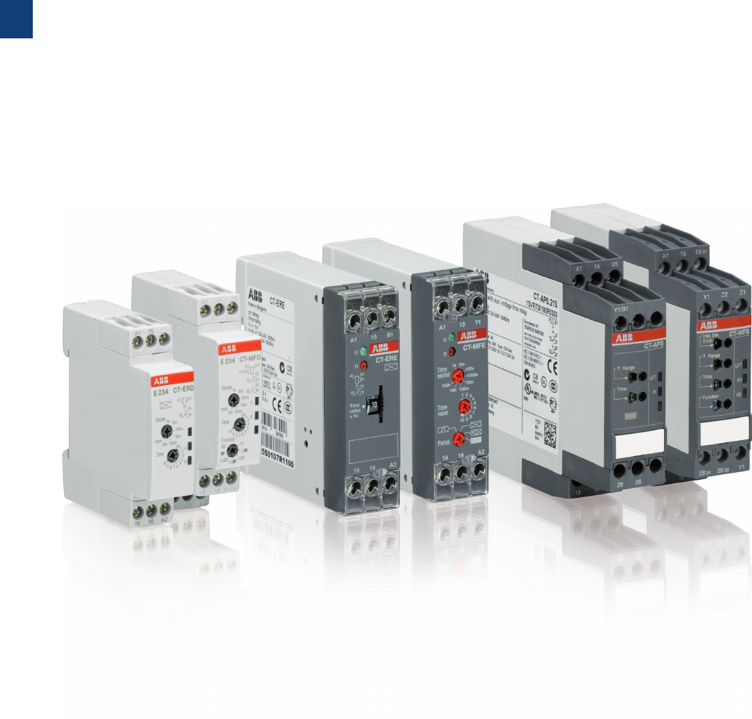
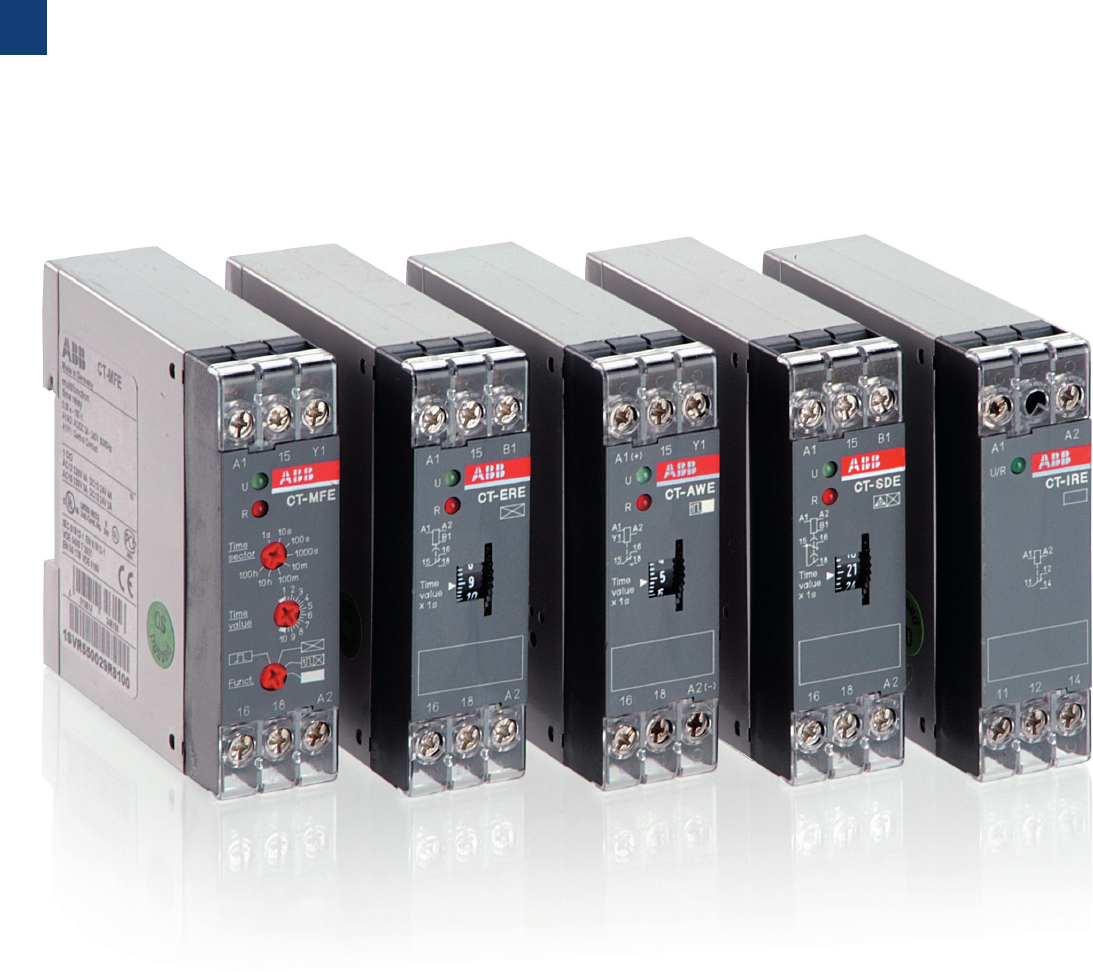
Electronic timers
Product group picture

1
2CDC 110 004 C0210 | Catalog Electronic relays and controls 2016 | ABB 12
Electronic timers
Table of contents
Electronic timers
Electronic timers 12
Type selection 13
Approvals and marks 14
CT-D range 16
Benefits and advantages 17
Ordering details 18
Connection diagrams 19
Technical data 20
Technical diagrams, Wiring notes, Dimensional drawings 22
CT-E range 24
Benefits and advantages 25
Ordering details 26
Connection diagrams 28
Connection diagrams, Technical diagrams 29
Technical data 30
Wiring notes, Dimensional drawings 32
CT-S range 34
Benefits and advantages 35
Ordering details - multifunctional 37
Ordering details - singlefunctional 38
Ordering details - Accessories 39
Connection diagrams 40
Technical data 42
Technical diagrams 45
Wiring notes, Dimensional drawings 46
Electronic timers 47
Timing functions 47
1
13 ABB | Catalog Electronic relays and controls 2016 | 2CDC 110 004 C0210
Electronic timers
Type selection
CT-S the high-performance rangeCT-E the econimic rangeCT-D range in modular DIN rail
housing
multifunctional single-functional multifunctional single-functional multifunctional single-functional
Timing function CT-D CT-E CT-S
A ON-delay CT-MFD CT-ERD CT-MFE,
CT-MKE
CT-ERE, CT-EKE
CT-MVS, CT-MFS,
CT-MBS, CT-WBS
CT-ERS
B OFF-delay CT-MFD CT-AHD CT-MFE CT-AHE,
CT-ARE, CT-AKE
CT-MVS, CT-MFS,
CT-MBS
CT-APS,
CT-AHS, CT-ARS
AB ON- and OFF-delay
CT-MVS, CT-MXS,
CT-MFS, CT-MBS
CA Impulse-ON CT-MFD CT-VWD CT-MFE,
CT-MKE
CT-V WE
CT-MVS, CT-MFS,
CT-MBS, CT-WBS
CB Impulse-OFF CT-MFD CT-AWE
CT-MVS, CT-MFS,
CT-MBS
CE Impulse-ON and OFF
CT-MXS
DA Flasher starting with ON CT-MFD CT-EBD CT-MFE,
CT-MKE
CT-MFS, CT-MBS,
CT-WBS
DB Flasher staring with OFF CT-MFD CT-MFE,
CT-MKE
CT-EBE
CT-MFS, CT-MBS,
CT-WBS
DE Flasher starting with ON or
OFF
CT-MVS
ED Pulse generator starting with
ON or OFF
CT-TGD
CT-MXS
H Pulse former CT-MFD CT-MFE
CT-MVS, CT-MFS,
CT-MBS
F Star-delta change-over CT-SDD,
CT-SAD
CT-SDS
FC Star-delta change-over with
impulse
CT-SDE
CT-MVS.2x,
CT-MFS, CT-MBS
FA Star-delta change-over
twice ON-delayed
CT-YDE
A+ AC BC G
further functions
(depending on device)
CT-MVS, CT-MXS,
CT-MFS, CT-MBS,
CT-WBS
– Time ranges: 7 (0.05 s - 100 h)
– CT-SDD, CT-SAD: (0.05 s - 10 min)
– Wide and multi ranges of control sup-
ply voltage
– 1 or 2 c/o contacts
– CT-SDD, CT-SAD: 2 n/o contacts
– Control inputs: voltage-related trig-
gering, polarized, capable of switch-
ing a parallel load
– Multifunction devices:
8 (0.05 s - 100 h)
Single-function devices:
0.05-1 s, 0.1-10 s, 0.3-30 s, 3-300
s, 0.3-300 min
– Wide, single and dual ranges of con-
trol supply voltage
– 1 c/ o contact
CT-SDE: 1 n/o contact and 1 n/c
contact
CT-MKE, CT-EKE, CT-AKE: 1 thyristor
– voltage-related triggering, polarized
CT-MFE, CT-AHE, CT-AWE:
with auxiliary voltage
– 10 (0.05 s - 300 h)
CT-ARS, CT-SDS: 7 (0.05 s- 10 min)
– Wide, single and multi ranges of con-
trol supply voltage
– 1 or 2 c/o contacts
CT-MVS.21, CT-MFS, CT-MBS:
2nd c/o contact selectable as inst.
contact
CT-SDS: 2 n/o contacts
– voltage-related triggering, non-polar-
ized, capable of switching a parallel
load
CT-MFS, CT-MBS, CT-AHS:
volt-free triggering
A detailed explanation of the different timing functions can be found at “Timing functions” on page 47.

1
2CDC 110 004 C0210 | Catalog Electronic relays and controls 2016 | ABB 14
Electronic timers
Approvals and marks
CT-D CT-E CT-S
AUL508, CAN/CA
C22.2 No. 14
All All All
KCB Scheme All except:
CT-MFD.21, CT-ERD.22, CT-AHD.22,
CT-TGD.22, CT-SDD.22, CT-SAD.22
All except:
CT-MKE, CT-EKE, CT-AKE
All
REAC All All All
ECCC All All except:
CT-MKE, CT-EKE, CT-AKE
All
LRMRS All except:
CT-SDD.22, CT-SAD.22
All All
CGermanischer Lloyd -All All available
Pending for: CT-ARS.11
aCommunauté
Européenne
All All All
bRCM All available
Pending for:
CT-MFD.21, CT-ERD.22, CT-AHD.22,
CT-TGD.22, CT-SDD-22. CT-SAD.22
All All
1
15 ABB | Catalog Electronic relays and controls 2016 | 2CDC 110 004 C0210
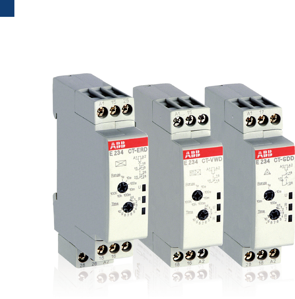
CT-D range
Product group picture

1
17 ABB | Catalog Electronic relays and controls 2016 | 2CDC 110 004 C0210
CT-D range
Benefits and advantages
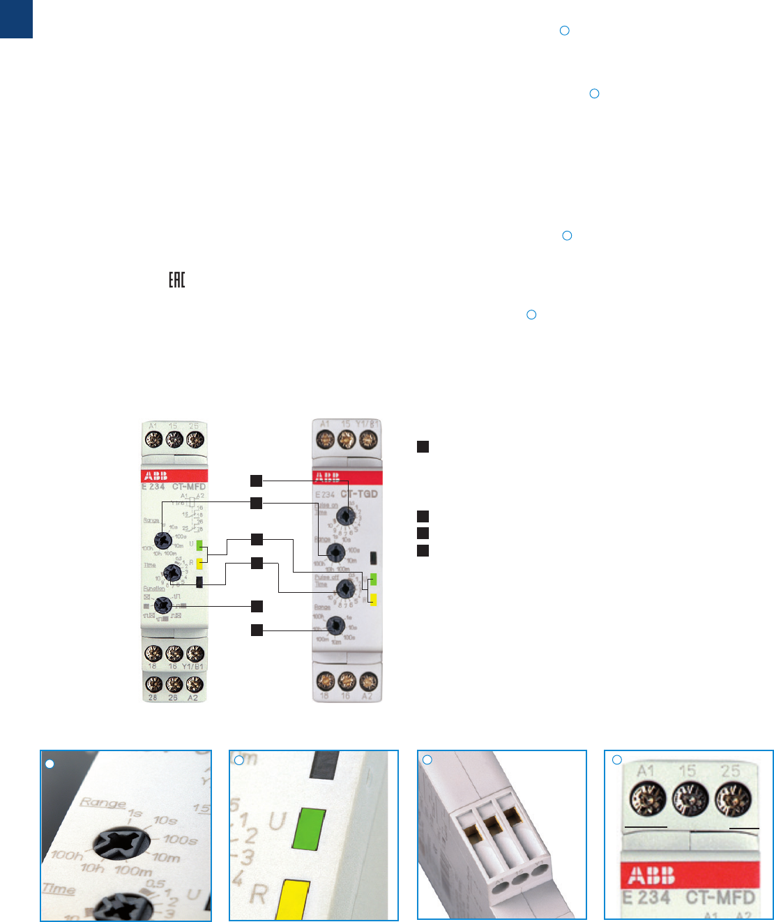
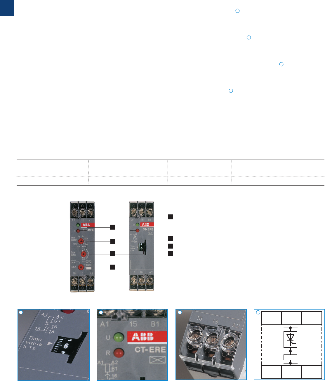
Operating controls
1 LEDs for status indication
U - green LED: V control supply voltage applied
W timing
R, R1, R2 - yellow LED: V output relay energized
2 Time range adjustment
3 Fine adjustment of the time delay
4 Preselection of the timing function
multifunctional single-functional
Direct reading scales
Direct setting of the time delay without any additional
calculation provides accurate time delay adjustment.
LEDs for status indication
All actual operational states are displayed by front-face LEDs,
thus simplifying commissioning and troubleshooting.
Switching currents
The CT-D range timers allow an output load of up to 6 A on
devices with 1 c/o contact and up to 5 A on devices with
2c/o contacts.
Connection terminals
Wide terminal spacing allows connection of wires:
2 x 1.5 mm² (2 x 16 AWG) with wire end ferrules or 2 x 2.5
mm² (2 x 14 AWG) without ferrules.
Width 17.5 mm
With their width of 17.5 mm only, the CT-D range timers are
ideally suited for installation in distribution panels.
17.5 mm
Characteristics
– Diversity:
– 2 multifunction timers
– 10 single-function timers
– Control supply voltages:
– Wide range: 12-240 V AC/DC
– Multi range: 24-48 V DC, 24-240 V AC
– 7 time ranges from 0.05 s to 100 h or
4 time ranges from 0.05 s to 10 min
– Width of only 17.5 mm
– Light-grey housing in RAL 7035
– Devices with:
1 c/o contact (250 V / 6 A) or 2 c/o contacts (250 V / 5 A)
Control input: voltage-related triggering, polarized,
capable of switching parallel loads
– Approvals / Marks (partly pending, details see “Approvals
and marks” on page 14)
– A, K1), E, , L / a, b
1) Only for devices with 1 c/o (SPDT) contact
Benefits
4
2
3
1
2
3
2CDC 253 066 F0006
2CDC 253 132 F0006
2CDC 253 033 F0004
2CDC 253 021 F0004
1
1
2
2
3
3
4
4
1
2CDC 110 004 C0210 | Catalog Electronic relays and controls 2016 | ABB 18
CT-D range
Ordering details
Synonyms
used expression alternative expression(s) used expression alternative expression(s)
1 c/o contact SPDT voltage-related wet / non-floating
2 c/o contacts DPDT volt-free dry / floating
2CDC 251 089 F0006
2CDC 251 091 F0006
CT-MFD.12
CT-ERD.22
Further documentation CT-D
electronic timers on www.abb.com
1) Functions: ON-delay, OFF-delay with auxiliary voltage, Impulse-ON, Impulse-OFF with auxiliary voltage,
Flasher starting with ON, Flasher starting with OFF, Pulse former
2) ON and OFF times adjustable independently: 2 x 7 time ranges 0.05 s - 100 h
3) Transition time 50 ms fixed
4) Transition time adjustable
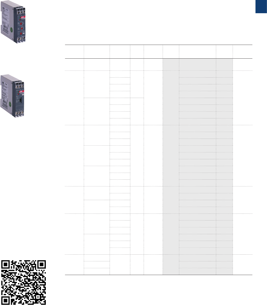
Description
The CT-D range in MDRC design with a width of only 17.5 mm fits into all domestic
installation and distribution panels.
The CT-D range represents a link between industry and the installation types. For maxi-
mum flexibility in operation, 10 single-function as well as 2 multifunction devices with 7
timing functions are available. The devices offer 4 or 7 time ranges from 0.05 seconds up
to 100 hours. Their wide input range allows the use in applications worldwide.
Ordering details
Timing
function
Rated
control
supply
voltage
Time
ranges
Con-
trol
input
Output Type Order code Price
1 pce
Weight
(1 pce)
kg (lb)
Multi1) 24-240 V AC
24-48 V DC
7 (0.05 s -
100 h) M1 c/o CT-M FD.12 1SVR500020R0000 0.060
(0.132)
Multi1) 12-240
VAC/DC
7 (0.05 s -
100 h) M2 c/o CT-MFD.21 1SVR500020R1100 0.065
(0.143 )
ON-delay
24-240 V AC
24-48 V DC
7 (0.05 s -
100 h)
-1 c/o CT-E RD.12 1SVR500100R0000 0.060
(0.132)
-2 c/o CT-ERD.22 1SVR500100R0100 0.065
(0.143 )
OFF-delay
M1 c/o CT-AH D.12 1SVR500110R0000 0.060
(0.132)
M2 c/o CT-AHD.22 1SVR500110R0100 0.065
(0.143 )
Impulse-
ON -
1 c/o
CT-V W D.12 1SVR500130R0000
0.060
(0.132)
Flasher
starting
with ON
-CT-E BD.12 1SVR500150R0000
Pulse
generator
2×7 (0.05
s - 100 h)
M
CT-TGD.12
2) 1SVR500160R0000 0.060
(0.132)
M2 c/o
CT-TGD.22
2) 1SVR500160R0100 0.065
(0.143 )
Star-delta
change-
over
4 (0.05 s -
10min)
-
2 c/o
CT-SDD.22
3) 1SVR500211R0100 0.065
(0.143 )
-
CT-SAD.22
4) 1SVR500210R0100
M Control input with voltage-related triggering
- no triggering
1
19 ABB | Catalog Electronic relays and controls 2016 | 2CDC 110 004 C0210
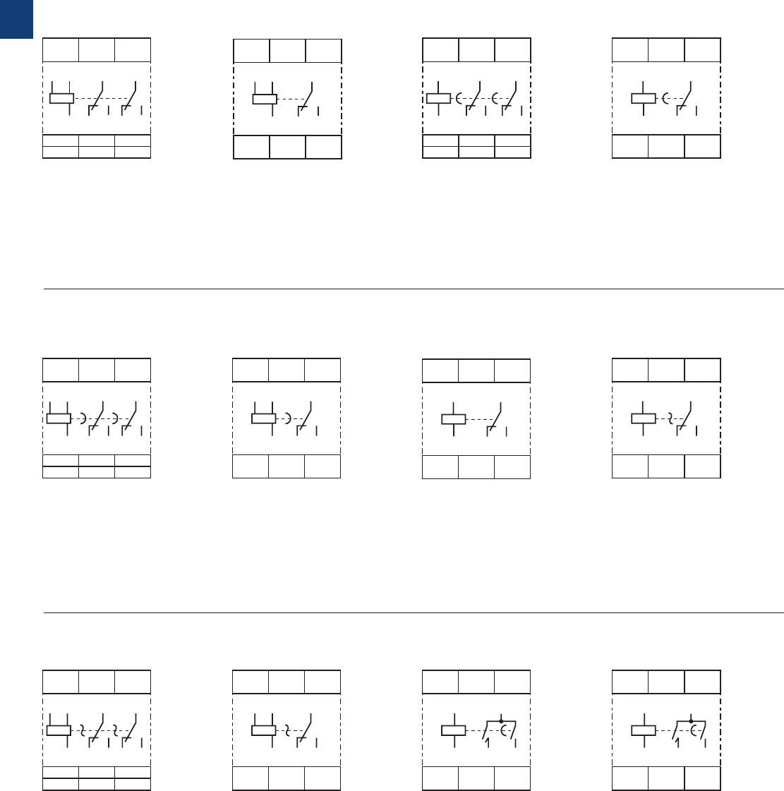
CT-MFD.21 CT-MFD.12 A CT-ERD.12
B CT-AHD.22
A1
A1
28
28
26
26
A2
18 16 Y1/B1
A2
15
25
1816
15
25
Y1/
B1
2CDC 252 113 F0b06
A1
A1
28
28
26
26
A2
18 16 Y1/B1
A2
15
25
1816
15
25
Y1/
B1
2CDC 252 116 F0b06
A1
A1
28
28
26
26
A2
18 16
A2
15 25
25
1816
15
2CDC 252 115 F0b06
A CT-ERD.22
B CT-AHD.12 CA CT-VWD.12 DA CT-EBD.12
ED CT-TGD.22
A1
A1
28
18
26
16
A2
18 16 Y1/B1
A2
15
15
2826
25
25
Y1/
B1
2CDC 252 118 F0b06
A1
A1
A2 18 28
17
17
28 18 A2
2CDC 252 160 F0b06
ED CT-TGD.12 F CT-SDD.22 F CT-SAD.22
A1
A1
18
18
16
16
A2
A2
15
15
Y1/B1
Y1/
B1
2CDC 252 114 F0b06
A1
A1
18
18
16
16
A2
A2
15
15
2CDC 252 177 F0b05
A1
A1
18
18
16
16
A2
A2
15
15
Y1/B1
Y1/
B1
2CDC 252 117 F0b06
A1
A1
18
18
16
16
A2
A2
15
15
2CDC 252 179 F0b05
A1
A1
18
18
16
16
A2
A2
15
15
2CDC 252 180 F0b05
A1
A1
18
18
16
16
A2
A2
15
15
Y1/B1
Y1/
B1
2CDC 252 119 F0b06
A1
A1
A2 18 28
17
17
28 18 A2
2CDC 252 160 F0b06
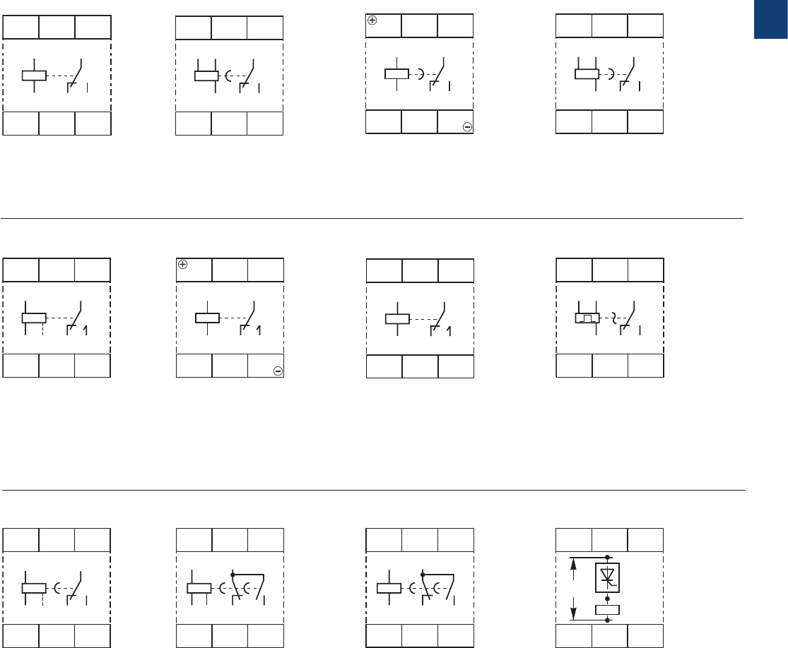
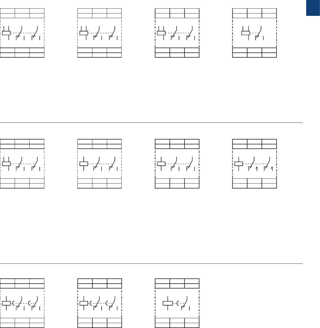
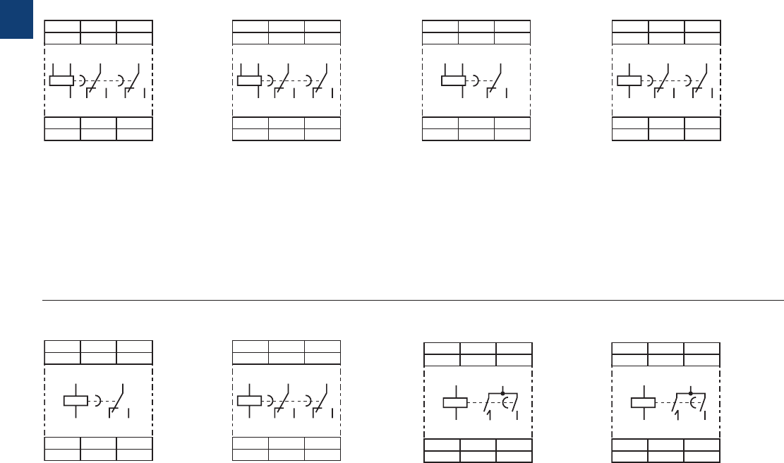
CT-D range
Connection diagrams
A1-A 2 Supply:
12-240 V AC/DC
A1-Y1/B1 Control input
15-16/18 1. c/o contact
25-26/28 2. c/o contact
A1-A 2 Supply:
24-48 V DC or
24-240 V AC
A1-Y1/B1 Control input
15-16/18 1. c/o contact
A1-A 2 Supply:
24-48 V DC or
24-240 V AC
A1-Y1/B1 Control input
15-16/18 1. c/o contact
A1-A 2 Supply:
24-48 V DC or
24-240 V AC
A1-Y1/B1 Control input
15-16/18 1. c/o contact
A1-A 2 Supply:
24-48 V DC or
24-240 V AC
15-16/18 1. c/o contact
25-26/28 2. c/o contact
A1-A 2 Supply:
24-48 V DC or
24-240 V AC
A1-Y1/B1 Control input
15-16/18 1. c/o contact
25-26/28 2. c/o contact
A1-A 2 Supply:
24-48 V DC or
24-240 V AC
A1-Y1/B1 Control input
15-16/18 1. c/o contact
25-26/28 2. c/o contact
A1-A 2 Supply:
24-48 V DC or
24-240 V AC
17-18 1. n/o contact
(star contactor)
17-28 2. n/o contact
(delta contactor)
A1-A 2 Supply:
24-48 V DC or
24-240 V AC
17-18 1. n/o contact
(star contactor)
17-28 2. n/o contact
(delta contactor)
A1-A 2 Supply:
24-48 V DC or
24-240 V AC
15-16/18 1. c/o contact
A1-A 2 Supply:
24-48 V DC or
24-240 V AC
15-16/18 1. c/o contact
A1-A 2 Supply:
24-48 V DC or
24-240 V AC
15-16/18 1. c/o contact
1
2CDC 110 004 C0210 | Catalog Electronic relays and controls 2016 | ABB 20
CT-D range
Technical data
Data at Ta = 25 °C and rated values, unless otherwise indicated
CT-D with 1 c/o
contact
CT-D with 2 c/o
contacts
CT-MFD.21
Input circuit - Supply circuit
Rated control supply voltage Us24-240 V AC / 24-48 V DC 12-240 V AC/DC
Rated control supply voltage US tolerance -15...+10 %
Rated frequency DC or 50/60 Hz
Frequency range AC 47-63 Hz
Typical current / power consumption see data sheet
Power failure buffering time min. 20 ms
Release voltage > 10 % of the minimum rated control supply voltage Us
Input circuit - Control circuit
Control input, control function A1-Y1/B1 start timing external
Kind of triggering voltage-related triggering
Resistance to reverse polarity yes
Parallel load / polarized yes / yes
Maximum cable length to the control inputs 50 m - 100 pF/m
Minimum control pulse length 20 ms
Control voltage potential see rated control supply voltage
Current consumption of the control input see data sheet
Timing circuit
Time ranges 7 time ranges 0.05 s - 100 h 1.) 0.05-1 s 2.) 0.5-10 s 3.) 5-100 s 4.) 0.5-10 min
5.) 5-100 min 6.) 0.5-10 h 7.) 5-100 h
4 time ranges 0.05 s - 10 min (CT-SDD, CT-SAD) 1.) 0.05-1 s 2.) 0.5-10 s 3.) 5-100 s 4.) 0.5-10 min
Recovery time < 50 ms
Accuracy within the rated control supply voltage tolerance it < 0.005 % / V
Accuracy within the temperature range it < 0.06 % / °C
Repeat accuracy (constant parameters) it < ± 0.5 %
Setting accuracy of time delay IEC/EN 61812-1 ± 10% of full-scale value
Star-delta transition time CT-SDD / CT-SAD fixed 50 ms /
adjustable: 20 ms, 30 ms, 40 ms, 50 ms, 60 ms, 80 ms or 100 ms
Star-delta transition time tolerance CT-SDD / CT-SAD ±3 ms
Indication of operational states
Control supply voltage / timing U: green LED V: control supply voltage applied
W: timing
Relay energized (1 c/o contact /
2 c/o contacts or inst. contact)
R: yellow LED V: output relay energized
Operating elements and controls
Adjustment of the time range front-face rotary switch, direct reading scales
Fine adjustment of the time value front-face potentiometer
Preselection of the timing function at multifunction devices front-face rotary switch, direct reading scales
Adjustment of the transition time CT-SAD front-face potentiometer
Output circuit
Kind of output 15-16/18 Relay, 1 c/o contact -
15-16/18; 25-26/28 -Relay, 2 c/o contacts
17-18; 17-28 Relay, 2 n/o contacts (CT-SDD, CT-SAD)
Contact material AgNi alloy, Cd free
Rated operational voltage Ue250 V
Minimum switching voltage / minimum switching current 12 V / 100 mA
Maximum switching voltage / maximum switching current 250 V AC / 6 A 250 V AC / 5 A
Rated operational current Ie
(IEC/EN 60947-5-1 )
AC-12 (resistive) at 230 V 6 A 5 A
AC-15 (inductive) at 230 V 3 A 3 A n/o: 3 A n/c: 0.75 A
DC-12 (resistive) at 24 V 6 A 5 A
DC-13 (inductive) at 24 V 2 A 2 A 1 A
AC rating (UL 508) utilization category (Control Circuit Rating Code) B 300 n/o: B 300 n/c: C 300
max. rated operational voltage 300 V AC
Maximum continuous thermal current at B300 5 A n/o: 5 A
Maximum continuous thermal current at C300 -n/c: 2.5 A
max. making/breaking apparent power at B300 3600 VA / 360 VA n/o: 3600/360 VA
max. making/breaking apparent power at C300 -n/c: 1800/180 VA
Mechanical lifetime 30 x 106 switching cycles
Electrical lifetime 0.1 x 10⁶ switching cycles
Max. fuse rating to achieve short-circuit protection
(IEC/EN 60947-5-1)
n/c contact 6 A fast-acting
n/o contact 10 A fast-acting 6 A fast-acting

1
21 ABB | Catalog Electronic relays and controls 2016 | 2CDC 110 004 C0210
CT-D range
Technical data
CT-D with 1 c/o
contact
CT-D with 2 c/o
contacts
CT-MFD.21
General data
Mean time between failures (MTBF) on request
Duty time 100%
Dimensions (W x H x D) 17.5 x 70 x 58 mm
(0.69 x 2.76 x 2.28 in)
17.5 x 80 x 58 mm
(0.69 x 3.15 x 2.28 in)
Weight see ordering details
Mounting DIN rail (IEC/EN 60715), snap-mounting without any tool
Mounting position any
Minimum distance to other units horizontal / vertical no / no
Degree of protection housing / terminals IP50 / IP20
Electrical connection
Wire size
fine-strand with(out) wire end ferrule
2 x 0.5-1.5 mm2 (2 x 20-16 AWG)
1 x 0.5-2.5 mm2 (1 x 20-14 AWG)
rigid 2 x 0.5-1.5 mm2 (2 x 20-16 AWG)
1 x 0.5-4 mm2 (1 x 20-12 AWG)
Stripping length 7 mm (0.28 in)
Tightening torque 0.5-0.8 Nm (4.43-7.08 lb.in)
Environmental data
Ambient temperature range operation / storage -20 ... +60 °C / -40 ... +85 °C
Climatic class IEC/EN 60068-2-30 3K3
Relative humidity range 25-85%
Shock (half-sine) IEC/EN 60068-2-27 150 m/s2, 11 ms
Isolation data
Rated impulse withstand voltage Uimp
between all isolated circuits
IEC/EN 60664-1 type test: 4 kV; 1.2/50 µs
Pollution category IEC/EN 60664-1 3
Overvoltage category IEC/EN 60664-1 III
Rated insulation voltage Uiinput circuit / output circuit 300 V
output circuit 1 / output circuit 2 not available 300 V 300 V
Basic insulation (IEC/EN 61140) input circuit / output circuit 300 V
Protective separation
(IEC/EN 61140, EN 50178)
input circuit / output circuit 250 V
Power-frequency withstand voltage test
(test voltage)
between all isolated circuits routine test: 2.5 kV; 50 Hz; 1 s
type test: 2.5 kV; 50 Hz; 60 s
Standards
Product standard IEC/EN 61812-1
Low Voltage Directive 2006/95/EC
EMC Directive 2004/108/EC
RoHS Directive 2011/65/EC
Electromagnetic compatibility
Interference immunity to IEC/EN 61000-6-1, IEC/EN 61000-6-2
electrostatic discharge
IEC/EN 61000-4-2
Level 3 (6 kV / 8 kV)
radiated, radio-frequency, electromagnetic field
IEC/EN 61000-4-3
Level 3 (10 V / m)
electrical fast transient / burst
IEC/EN 61000-4-4
Level 3 (2 kV / 5 kHz)
surge
IEC/EN 61000-4-5
Level 4 (2 kV L-L)
conducted disturbances, induced by radio-frequency fields IEC/EN 61000-4-6
Level 3 (10 V)
Interference emission IEC/EN 61000-6-3, IEC/EN 61000-6-4
high-frequency radiated IEC/CISPR 22, EN 55022 Class B
high-frequency conducted IEC/CISPR 22, EN 55022 Class B
Product certifications and declarations see “Approvals and marks” on page 14.
1
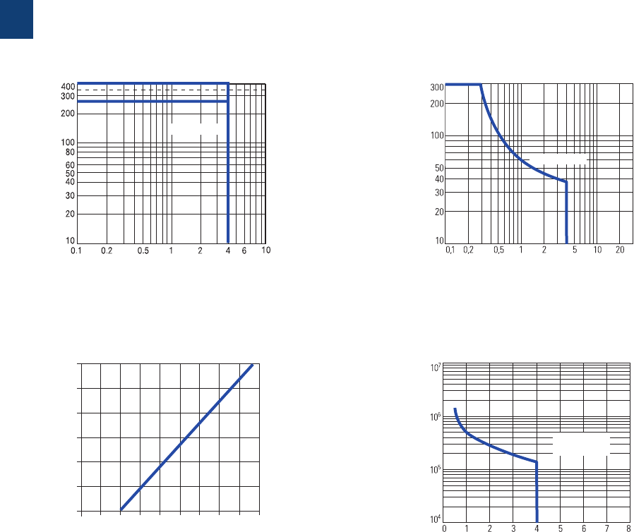
2CDC 110 004 C0210 | Catalog Electronic relays and controls 2016 | ABB 22
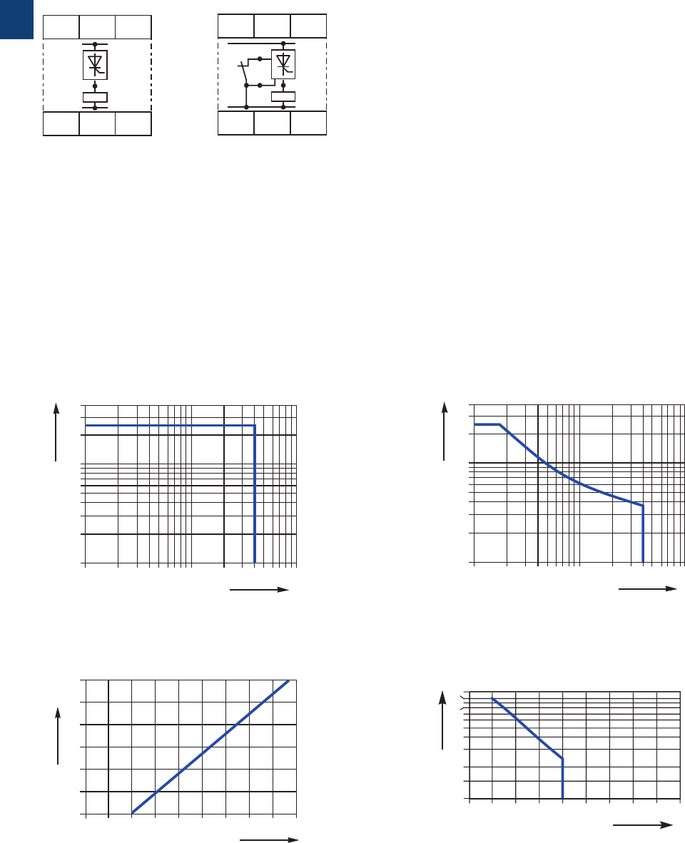
CT-D range
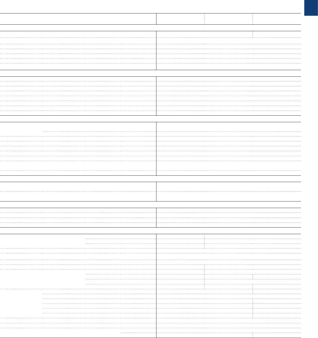
Technical diagrams, Wiring notes, Dimensional drawings
CT-D.2x CT-D.2x
Derating factor F
for inductive AC load
Contact lifetime
DC current [A]
resistive load
DC voltage [V]
2CDC 252 121 F0206
AC current [A]
resistive load
AC voltage [V]
2CDC 252 122 F0206
Switching current [A]
250 V
resistive load
Switching cycles
2CDC 252 123 F0206
cos ϕ
0.5
0.1 0.2 0.3 0.40.5 0.60.7 0.80.9 1.0
0.6
0.7
0.8
0.9
1.0
Derating factor F
2CDC 252 124 F0206
CT-D.1x CT-D.1x
AC load (resistive) DC load (resistive)
Technical diagrams
Load limit curves
DC current [A]
resistive load
DC voltage [V]
2CDC 252 045 F0207
AC current [A]
resistive load
AC voltage [V]
2CDC 252 044 F0207
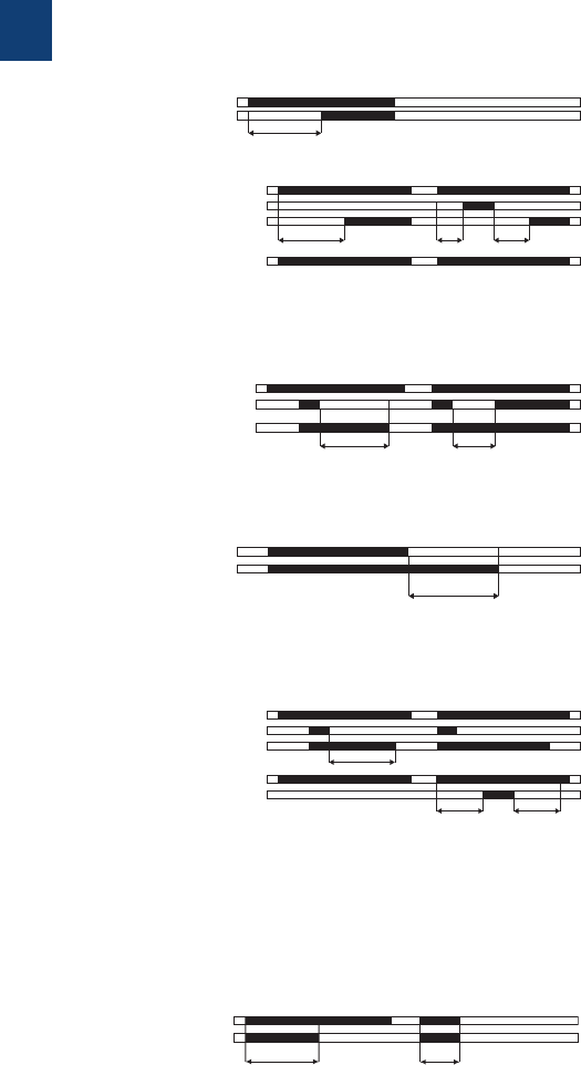
0.69“
2.76“
0.2“
2.28“
1.71“
1.77“
17,5
70
5
58
43,4
45
2CDC 252 131 F0b06
0.69“
17,5
3.15“80
0.2“
5
2.28“
1.71“
58
43,4
1.77“45
2CDC 252 130 F0b06
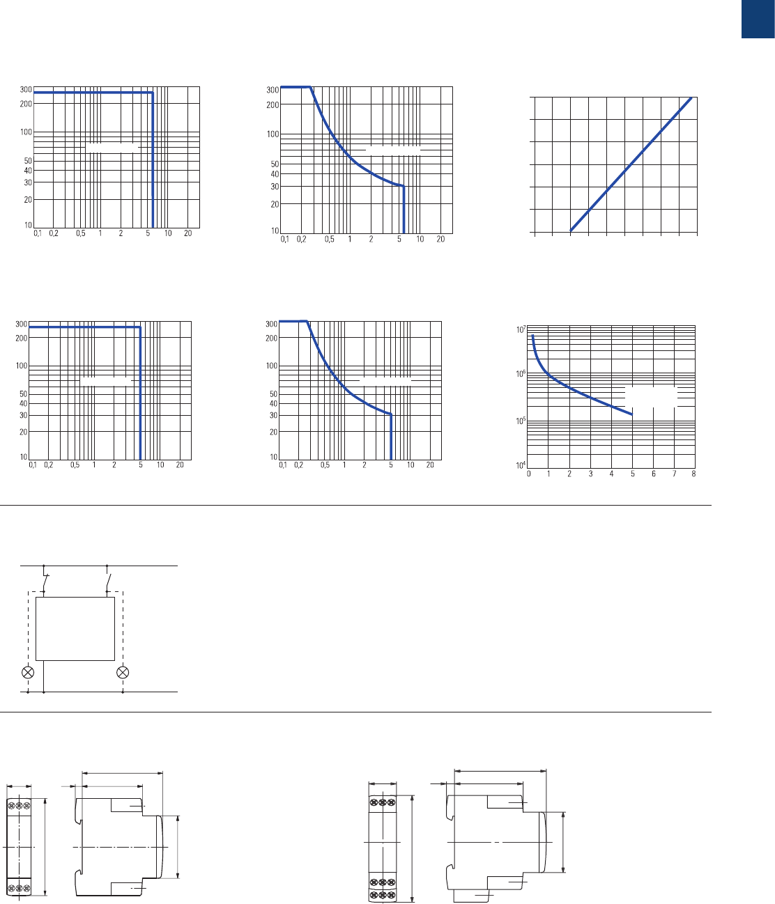
CT-D devices with 1 c/o contact or 2 n/o contacts CT-D devices with 2 c/o contacts
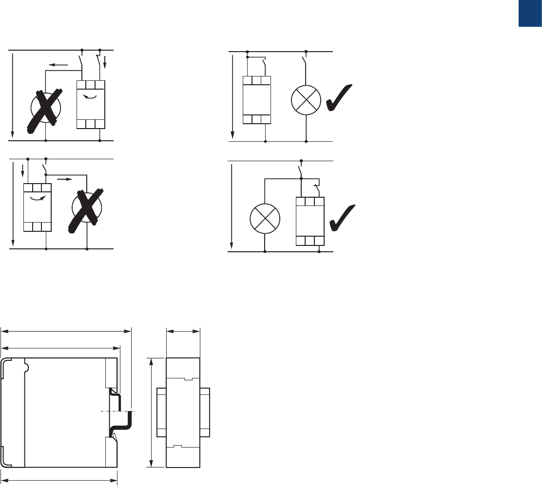
Dimensional drawings
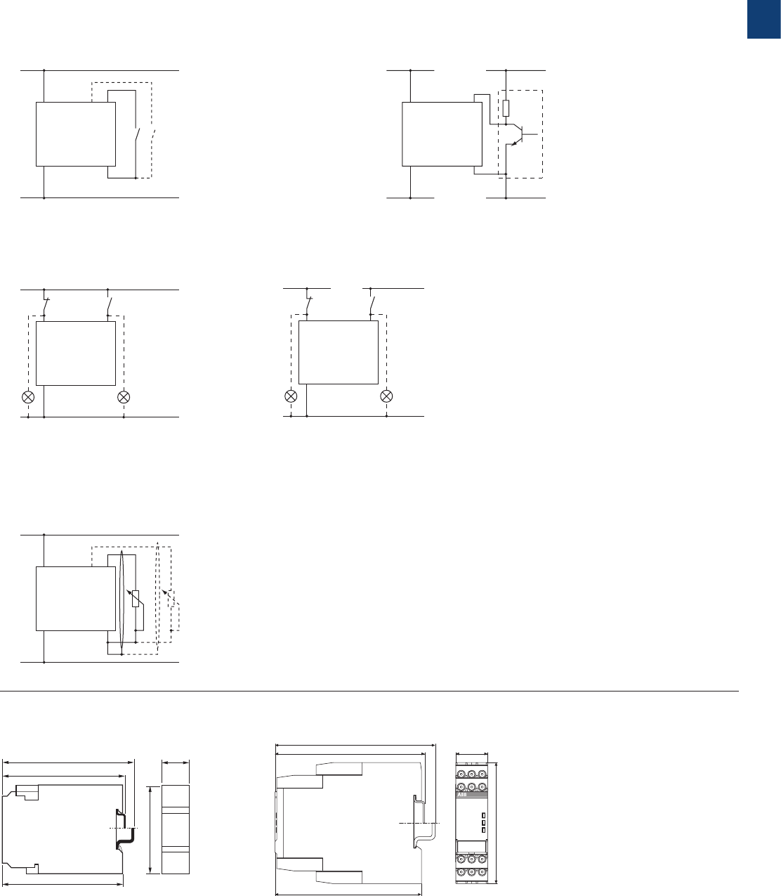
L(+)
N(-)
A1 Y1/B1
A2
2CDC 252 102 F0b06
Wiring notes for devices with control input
A parallel load to the control input is possible
dimensions in mm
1
23 ABB | Catalog Electronic relays and controls 2016 | 2CDC 110 004 C0210
CT-E range
Product group picture

1
25 ABB | Catalog Electronic relays and controls 2016 | 2CDC 110 004 C0210
CT-E range
Benefits and advantages
Characteristics
– Diversity:
– 2 multifunction timers
– 56 single-function timers
– Control supply voltages:
– Dual range: 24 V AC/DC
– Single range: 110-130 V AC, 220-240 V AC
– Wide range: 24-240 V AC/DC (CT-MFE)
– Time ranges
– 5 single ranges: 0.05-1 s, 0.1-10 s, 0.3-30 s, 3-300 s,
0.3-30 min
– 8 time ranges: 0.05 s - 100 h (CT-MFE)
– Devices with 1 c/o (SPDT) contact (250 V / 4 A) or
solid-state output for high switching frequencies (thyristor
0.8 A)
– Approvals / Marks (details see “Approvals and marks” on
page 14)
– A, C, R, K, E, L / a, b
1 LEDs for status indication
U - green LED: V control supply voltage applied
R2: red LED: V output relay energized
2 Time range adjustment (only multifunctional devices)
3 Fine adjustment of the time delay
4 Preselection of the timing function (only multifunctional devices)
Operating controls
Direct reading scales
Direct setting of the time delay without any additional
calculation provides accurate time delay adjustment.
LEDs for status indication
All actual operational states are displayed by front-face LEDs,
thus simplifying commissioning and troubleshooting.
Connection screws in M3 (Pozidrive 1)
Easy and fast tightening and release of the connection screws
with pozidrive, pan- or crosshead screwdriver.
Solid-state output
Devices with solid-state output are the perfect solution for
high operation cycles.
4
1
2
3
Benefits
2CDC 252 166 F0005
ALA1
A1
AL
1SVC 110 000 F0508
1SVC 110 000 F0500
1SVC 110 000 F0506
2CDC 252 166 F0005
1
1
2
2
3 4
4
3
Synonyms
used expression alternative expression(s) used expression alternative expression(s)
1 c/o contact SPDT voltage-related wet / non-floating
2 c/o contacts DPDT volt-free dry / floating
1
2CDC 110 004 C0210 | Catalog Electronic relays and controls 2016 | ABB 26
CT-E range
Ordering details
Further documentation CT-E
electronic timers on www.abb.com
1SVR 550 029 F81001SVR 550 111 F1100
CT-MFE
CT-AHE
1) Functions: ON-delay, OFF-delay with auxiliary voltage, Impulse-ON, Flasher starting with ON, Flasher starting with OFF,
Pulse former
2) without auxiliary voltage, True Off-delay timer
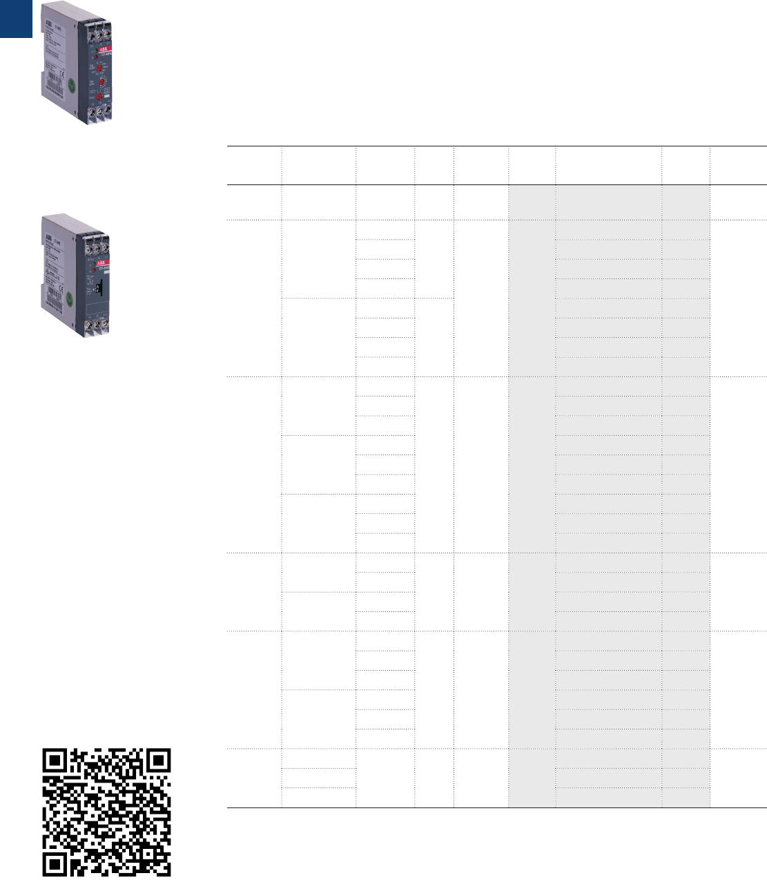
Description
The CT-E range with its excellent price/performance ratio offers an ideal solution for serial
applications. 56 single-function devices with 5 different time ranges as well as 2 multifunction
timers with 6 functions and 8 time ranges offer the highest possible flexibility for almost every
application. For high operating cycles, contact-free CT-E timers with solid-state output are
available.
Ordering details
Timing
function
Rated con-
trol supply
voltage
Time
ranges
Con-
trol
Input
Output Type Order code Price
1 pce
Weight
(1 pce)
kg (lb)
Multi 1) 24-240 VAC/DC 8 (0.05 s -
100 h) M1 c/o CT-MFE 1SVR550029R8100 0.08 (0.18)
ON-delay
24 V AC/DC,
220-240 V AC
0.1-10 s
-
1 c/o CT-ERE
1SVR550107R1100
0.08 (0.18)
0.3-30 s 1SVR550107R4100
3-300 s 1SVR550107R2100
0.3-30 min 1SVR550107R5100
110-130 V AC
0.1-10 s
-
1SVR550100R1100
0.3-30 s 1SVR550100R4100
3-300 s 1SVR550100R2100
0.3-30 min 1SVR550100R5100
OFF-delay
24 VAC/DC
0.1-10 s
M1 c/o CT-AHE
1SV R 55 0118 R110 0
0.08 (0.18)
0.3-30 s 1SVR550118R4100
3-300 s 1SVR550118R2100
110-130 V AC
0.1-10 s 1S V R5 5 0110 R11 0 0
0.3-30 s 1SVR550110R4100
3-300 s 1SVR550110R2100
220-240 V AC
0.1-10 s 1SV R 55 0111R110 0
0.3-30 s 1SV R 55 0111R 410 0
3-300 s 1SV R 55 0111R 210 0
OFF-delay2)
24 V AC/DC,
220-240 V AC
0.1-10 s
-1 c/o CT-ARE
1SVR550127R1100
0.08 (0.18)
0.3-30 s 1SVR550127R4100
110-130 V AC
0.1-10 s 1SVR550120R1100
0.3-30 s 1SVR550120R4100
Impulse-ON
24 V AC/DC,
220-240 V AC
0.1-10 s
-1 c/o CT-V W E
1SVR550137R1100
0.08 (0.18)
0.3-30 s 1SVR550137R4100
3-300 s 1SVR550137R2100
110-130 V AC
0.1-10 s 1SVR550130R1100
0.3-30 s 1SVR550130R4100
3-300 s 1SVR550130R2100
Impulse-
OFF2)
24VAC/DC
0.05 -1 s -1 c/o CT-AWE
1SVR550158R3100
0.08 (0.18)110-130 V AC 1SVR550150R3100
220-240 V AC 1SVR550151R3100
M Control input with voltage-related triggering
- no triggering
1
27 ABB | Catalog Electronic relays and controls 2016 | 2CDC 110 004 C0210
CT-E range
Ordering details
Further documentation CT-E
electronic timers on www.abb.com
1SVR 550 029 F81001SVR 550 111 F1100
CT-MFE
CT-AHE
1) Functions: ON-delay, OFF-delay with auxiliary voltage, Impulse-ON, Flasher starting with ON, Flasher starting with OFF,
Pulse former
2) without auxiliary voltage, True Off-delay timer
Description
The CT-E range with its excellent price/performance ratio offers an ideal solution for serial
applications. 56 single-function devices with 5 different time ranges as well as 2 multifunction
timers with 6 functions and 8 time ranges offer the highest possible flexibility for almost every
application. For high operating cycles, contact-free CT-E timers with solid-state output are
available.
Ordering details
Timing
function
Rated con-
trol supply
voltage
Time
ranges
Con-
trol
Input
Output Type Order code Price
1 pce
Weight
(1 pce)
kg (lb)
Multi 1) 24-240 VAC/DC 8 (0.05 s -
100 h) M1 c/o CT-MFE 1SVR550029R8100 0.08 (0.18)
ON-delay
24 V AC/DC,
220-240 V AC
0.1-10 s
-
1 c/o CT-ERE
1SVR550107R1100
0.08 (0.18)
0.3-30 s 1SVR550107R4100
3-300 s 1SVR550107R2100
0.3-30 min 1SVR550107R5100
110-130 V AC
0.1-10 s
-
1SVR550100R1100
0.3-30 s 1SVR550100R4100
3-300 s 1SVR550100R2100
0.3-30 min 1SVR550100R5100
OFF-delay
24 VAC/DC
0.1-10 s
M1 c/o CT-AHE
1SV R 55 0118 R110 0
0.08 (0.18)
0.3-30 s 1SVR550118R4100
3-300 s 1SVR550118R2100
110-130 V AC
0.1-10 s 1S V R5 5 0110 R11 0 0
0.3-30 s 1SVR550110R4100
3-300 s 1SVR550110R2100
220-240 V AC
0.1-10 s 1SV R 55 0111R110 0
0.3-30 s 1SV R 55 0111R 410 0
3-300 s 1SV R 55 0111R 210 0
OFF-delay2)
24 V AC/DC,
220-240 V AC
0.1-10 s
-1 c/o CT-ARE
1SVR550127R1100
0.08 (0.18)
0.3-30 s 1SVR550127R4100
110-130 V AC
0.1-10 s 1SVR550120R1100
0.3-30 s 1SVR550120R4100
Impulse-ON
24 V AC/DC,
220-240 V AC
0.1-10 s
-1 c/o CT-V W E
1SVR550137R1100
0.08 (0.18)
0.3-30 s 1SVR550137R4100
3-300 s 1SVR550137R2100
110-130 V AC
0.1-10 s 1SVR550130R1100
0.3-30 s 1SVR550130R4100
3-300 s 1SVR550130R2100
Impulse-
OFF2)
24VAC/DC
0.05 -1 s -1 c/o CT-AWE
1SVR550158R3100
0.08 (0.18)110-130 V AC 1SVR550150R3100
220-240 V AC 1SVR550151R3100
M Control input with voltage-related triggering
- no triggering
1
2CDC 110 004 C0210 | Catalog Electronic relays and controls 2016 | ABB 28
2CDC 252 152 F0005
A1
A1
A2
15
15
16
16 18 A2
18
Y1
2CDC 252 153 F0005
A1 B1
16 18 A2
A2 16 18
A1 15
15
B1
2CDC 252 154 F0005
A1
A1
A2 16 18
15
15 Y1
16 18 A2
2CDC 252 155 F0005
A1
A2 16 18
B1 15
15A1 B1
1816 A2
CT-MFE A CT-ERE B CT-ARE
B CT-AHE 1)
15 A1
A1
A2 B1 16 18
15
B1
18 16 A2
2CDC 252 156 F0b05
15 A1
A1
A2 16 18
15
18 16 A2
2CDC 252 157 F0b05
15 Y1 A1
A1
A2 16 18
15
18 16 A2
2CDC 252 158 F0b05
CA CT-VWE CB CT-AWE CB CT-AWE 1)
2CDC 252 159 F0005
15 B1A1
A1 B1 15
1816
A2 16 18
A2
DB CT-EBE
FA CT-YDE FC CT-SDE FC CT-SDE
2CDC 252 160 F0005
15 B1A1
A1
A2 B1 16 18
15
1816 A2
2CDC 252 161 F0005
15 B1A1
A1
A2 B1 16 18
15
1816 A2
2CDC 252 162 F0005
15A1
A1
A2 16 18
15
1816 A2
2CDC 252 165 F0005
X2
A1
A2
U
X1A1
X4X3 A2
CT-MKE
Device without aux. voltage Device with aux. voltage
Device: 1SVR 550 217 R4100 Devices: 1SVR 550 210 R4100,
1SVR 550 212 R4100
CT-E range
Connection diagrams
A1-A 2 Supply:
24-240VAC/DC
A1-Y1 Control input
15-16/18 c/o contact
A1-A 2 Supply: 220-240 V AC
or 110-130 V AC
A1-B1 Supply: 24 V AC/DC
15-16/18 c/o contact
A1-A 2 Supply: 220-240 V AC
A1-B1 Supply: 24 V AC/DC
15-16 n/c contact
15-18 n/o contact
with common contact
A1-A 2 Supply: 110-130 V AC
or 380-415 V AC
15-16 n/c contact
15-18 n/o contact
with common contact
A1-A 2 Supply: 220-240 V AC
or 110-130 V AC
A1-B1 Supply: 24 V AC/DC
15-16/18 c/o contact
A1-A 2 Supply: 220-240 V AC
or 110-130 V AC
A1-B1 Supply: 24 V AC/DC
15-16/18 c/o contact
A1-A 2 Supply: 220-240 V AC
or 110-130 V AC
A1-B1 Supply: 24 V AC/DC
15-16/18 c/o contact
A1-A 2 Supply: 220-240 V AC or
110-130 V AC
A1-B1 Supply: 24 V AC/DC
15-16/18 c/o contact
A1-A 2 Supply: 24-240 V AC/DC
A1-A 2 Thyristor
X1-X4 Timing function adjustment
X2-X4 Timing function adjustment
X3-X4 Time range adjustment
(Details see function diagrams)
A1-A 2 Supply: 24 V AC/DC
or 110-240 V AC or
220-240 VAC
A1-Y1 Control input
15-16/18 c/o contact
A1-A 2 Supply: 24 V AC/DC
or 110-240 V AC or
220-240 VAC
A1-Y1 Control input
15-16/18 c/o contact
A1(+)-A2(-) Supply: 24 V AC/DC
or 110-240 V AC or
220-240 VAC
15-16/18 c/o contact
1) “Wiring notes, Dimensional drawings” on page 32
1
29 ABB | Catalog Electronic relays and controls 2016 | 2CDC 110 004 C0210
2CDC 252 166 F0005
ALA1
A1
AL
2CDC 252 167 F0005
ALA1
A1
Y2
A2 AL
A2Y2
A CT-EKE B CT-AKE
220 V 50 Hz AC1
360 cycles/h
300
200
100
80
60
50
40
30
20
10
1 2 4 6 10
I A
V
U
2CDC 252 193 F0205
0,1 0,2 0,5
cos ϕ
F
2CDC 252 192 F0205
0,5
0,1 0,2 0,3 0,4 0,5 0,6 0,7 0,8 0,9 1,0
0,6
0,7
0,8
0,9
1,0
300
200
100
80
60
50
40
30
20
10
1 2 4 6 10
I A
V
U
2CDC 252 194 F0205
0,1 0,2 0,5
4 3 2 1
105
2
3
4
N
I A
5
8
9
106
5 6 7 8
2CDC 252 034 F0208
AC load (resistive) DC load (resistive)
Technical diagrams
Load limit curves
Derating factor F for inductive AC load Contact lifetime
CT-E range
Connection diagrams, Technical diagrams
A1-AL Supply: 24-240
V AC/DC
A1-AL Thyristor
A1-AL Supply: 24-240 V AC
A1-AL Thyristor
Y2-A2 Control input

1
2CDC 110 004 C0210 | Catalog Electronic relays and controls 2016 | ABB 30
CT-E range
Technical data
Technical data
Data at Ta = 25 °C and rated values, unless otherwise indicated
CT-E (relays) CT-E (solid-state)
Input circuit - Supply circuit
Rated control supply voltage UsA1-A 2, A1-AL 24-240 V AC/DC
A1-A 2, A1-AL 24-240 V AC
A1-A 2 110-130 V AC -
A1-A 2 220-240 V AC -
A1-A 2 380-415 V AC -
A1-B1 24 V AC/DC -
Rated control supply voltage Us tolerance -15...+10 %
Rated frequency AC/DC versions DC or 50/60 Hz
AC versions 50/60 Hz
Typical current / power consumption 24-240 V AC/DC, 24-240 V AC approx. 1.0-2.0 VA/W
110-130 V AC, 220-240 V AC approx. 2.0 VA -
380-415 V AC approx. 3.0 VA -
24 V AC/DC approx. 1.0 VA/W -
Minimum energizing time
CT-ARE, CT-AWE w/o aux. voltage
200 ms -
Current consumption while timing -≤ 2 mA (24-60 V AC/DC)
≤ 8 mA (60-240 V AC/DC)
(CT-AKE only AC)
Input circuit - Control circuit
Kind of triggering voltage-related triggering -
Control input, Control function A1-Y1 start timing external -
Parallel load / polarized no / yes 1) -
Minimum control pulse length 20 ms -
Control voltage potential see rated control supply voltage -
Timing circuit
Time ranges
1 of 5 time ranges per single-function device
0.05-1 s / 0.1-10 s / 0.3-30 s / 3-300 s / 0.3-30 min
8 time ranges 0.05 s - 100 h (CT-MFE) 1.) 0.05-1 s
3.) 5-100 s
5.) 0.5-10 min
7.) 0.5-10 h
2.) 0.5-10 s
4.) 50-1000 s
6.) 5-100 min
8.) 5-100 h
-
2 time ranges 0.1-300 s (CT-MKE) -1.) 0.1-10 s
2.) 3-300 s
Recovery time <50 ms
CT-ARE: <200 ms
CT-AWE, CT-SDE: <400 ms
CT-YDE: <500 ms
CT-EKE: <50 ms
CT-MKE: <100 ms
CT-AKE: <300 ms
Accuracy within the rated control supply voltage tolerance it < 0.5 % / V
Accuracy within the temperature range it < 0.1 % / °C
CT-MFE: it <0.06 % / °C -
Repeat accuracy (constant parameters) it < 1 %
Star-delta transition time CT-YDE / CT-SDE 50 ms / 30 ms -
Output circuit
Kind of output 15-16/18 Relay, 1 c/o contact -
CT-SDE: 15-16, 15-18 1 n/c, 1 n/o contact with common
contact
A1-A 2. A1-AL -Thyristor
Contact material AgCdO -
Rated operational voltage UeIEC/EN 60947-1 250 V
Maximum switching voltage 250 V AC, 250 V DC
Rated operational current Ie
(IEC/EN 60947-5-1)
AC-12 (resistive) at 230 V 4 A -
AC-15 (inductive) at 230 V 3 A -
DC-12 (resistive) at 24 V 4 A -
DC-13 (inductive) at 24 V 2 A -
1) CT-MFE: yes / no

1
31 ABB | Catalog Electronic relays and controls 2016 | 2CDC 110 004 C0210
CT-E (relays) CT-E (solid-state)
AC rating (UL 508) Utilization category (Control Circuit Rating Code) B 300 -
max. rated operational voltage 300 V AC -
Maximum continuous thermal current at B300 5 A -
max. making/breaking apparent power at B300 3600 VA / 360 VA -
Mechanical lifetime 30 x 106 switching cycles -
Electrical lifetime at AC-12, 230 V, 4 A 0.1 x 10⁶ switching cycles -
Max. fuse rating to achieve short-circuit
protection (IEC/EN 60947-5-1)
n/c contact 10 A fast-acting, CT-ARE: 5 A -
n/o contact 10 A fast-acting, CT-ARE: 5 A -
Minimum load current -CT-MKE: 20 mA
CT-EKE, CT-AKE: 10 mA
Maximum load current -CT-MKE: 0.8 A at Ta = 20 °C
CT-EKE, CT-AKE: 0.7 A
Load current reduction / Derating -10 mA/°C
Maximum surge current -CT-MKE: ≤ 20 A for t ≤ 20 ms
CT-EKE, CT-AKE: ≤ 15 A
Voltage drop in connected state -≤ 3 V
Cable length between solid-state timer
and connected load at 50 Hz and a
cable capacity of 100 pF/m :
at 24 V AC -220 m / 22 nF
at 42 V AC -100 m / 10 nF
at 60 V AC -65 m / 6.5 nF
at 110 V AC -50 m / 5 nF
at 240 V AC -22 m / 2.2 nF
General data
Duty time 100%
Dimensions (W x H x D) 22.5 x 78 x 78.5 mm (0.886 x 3.07 x 3.09 in)
Weight approx. 80 g (0.176 lb)
Mounting DIN rail (IEC/EN 60715)
Mounting position any
Minimum distance to other units horizontal / vertical no / no
Degree of protection housing / terminals IP50 / IP20
Electrical connection
Wire size fine-strand with wire end ferrule 2 x 0.75-1.5 mm2 (2 x 18-16 AWG)
fine-strand without wire end ferrule 2 x 1-1.5 mm2 (2 x 18-16 AWG)
rigid 2 x 0.75-1.5 mm2 (2 x 18-16 AWG)
Stripping length 10 mm (0.39 in)
Tightening torque 0.6-0.8 Nm (5.31-7.08 lb.in)
Environmental data
Ambient temperature ranges operation / storage -20...+60 °C / -40...+85 °C
Damp heat IEC/EN 60068-2-30 24 h cycle, 55 °C, 93 % rel., 96 h
Operational reliability IEC/EN 60068-2-6 6 g
Mechanical resistance IEC/EN 60068-2-6 10 g
Isolation data
Rated impulse withstand voltage Uimp
between all isolated circuits
IEC/EN 60664-1 type test: 4 kV; 1.2/50 µs -
Pollution category IEC/EN 60664-1 3
Overvoltage category IEC/EN 60664-1 III
Power-frequency withstand voltage (test
voltage) between all isolated circuits
routine test: 2.5 kV; 50 Hz; 1 s
type test: 2.5 kV; 50 Hz; 60 s
-
Basic insulation (IEC/EN 61140) input circuit / output circuit 300 V -
Rated insulation voltage Uiinput circuit / output circuit 300 V (supply up to 240 V) -
500 V (supply up to 440 V) -
Test voltage between all isolated circuits routine test 2.5 kV, 50 Hz, 1 s -
Standards
Product standard IEC 61812-1, EN 61812-1 + A11, DIN VDE 0435 Teil 2021
Low Voltage Directive 2006/95/EC
EMC Directive 2004/108/EC
Electromagnetic compatibility
Interference immunity to IEC/EN 61000-6-2
electrostatic discharge
IEC/EN 61000-4-2
Level 3 (6 kV / 8 kV)
radiated, radio-frequency
electromagnetic field
IEC/EN 61000-4-3
Level 3 (10 V/m)
electrical fast transient / burst
IEC/EN 61000-4-4
Level 3 (2 kV / 5 kHz)
surge
IEC/EN 61000-4-5
Level 4 (2 kV L-L)
conducted disturbances, induced by radio-
frequency fields
IEC/EN 61000-4-6
Level 3 (10 V)
Interference emission IEC/EN 61000-6-4
Product certifications and declarations see “Approvals and marks” on page 14.
CT-E range
Technical data
1
2CDC 110 004 C0210 | Catalog Electronic relays and controls 2016 | ABB 32
CT-E range
Wiring notes, Dimensional drawings
3.48“
3.19“
3.09“
.886“
3.07“
88,5
81
78,5
78
22,5
2CDC 252 189 F0b05
A1 Y1
A2
I
I
I
2CDC 252 200 F0b05
U
A1
A2
Y1
2CDC 252 199 F0b05
U
Dimensional drawing Dimensions in mm
Wiring notes
for single-function devices with control contact (CT-AHE, CT-AWE with auxiliary voltage)
I
I
A1
A2
Y1
I
2CDC 252 198 F0b05
U A1 Y1
A2
2CDC 252 201 F0b05
U
1
33 ABB | Catalog Electronic relays and controls 2016 | 2CDC 110 004 C0210
CT-S range
Product group picture

1
2CDC 110 004 C0210 | Catalog Electronic relays and controls 2016 | ABB 34
CT-S range
Table of contents
CT-S Range
CT-S range 34
Benefits and advantages 35
Ordering details - multifunctional 37
Ordering details - singlefunctional 38
Ordering details - Accessories 39
Connection diagrams 40
Technical data 42
Technical diagrams 45
Wiring notes, Dimensional drawings 46
Timing functions 47
1
35 ABB | Catalog Electronic relays and controls 2016 | 2CDC 110 004 C0210
CT-S range
Benefits and advantages
Characteristics
– Diversity:
– 8 multifunction timers
– 13 single-function timers
– Control supply voltages:
– Multi range: 24-48 V DC, 24-240 V AC
– Wide range: 24-240 V AC/DC
– Single range: 380-440 V AC
– Innovative connection technology
– Double-chamber cage connection terminals
– Easy Connect Technology
– Devices with:
– 1 or 2 c/o (SPDT) contacts
– 2nd c/o contact can be selected as instantaneous contact 1)
– Remote potentiometer connection 1)
– Control input with volt-free or voltage-related triggering e.g. to start timing, pause timing
– Extended operating temperature range down to -40 °C 1)
– Sealable transparent cover for protection against unauthorized changes of time values
– Integrated marker label
– Approvals / Marks (partly pending, details see “Approvals and marks” on page 14)
– A, C, , E, K, L / a, b
1) selected devices
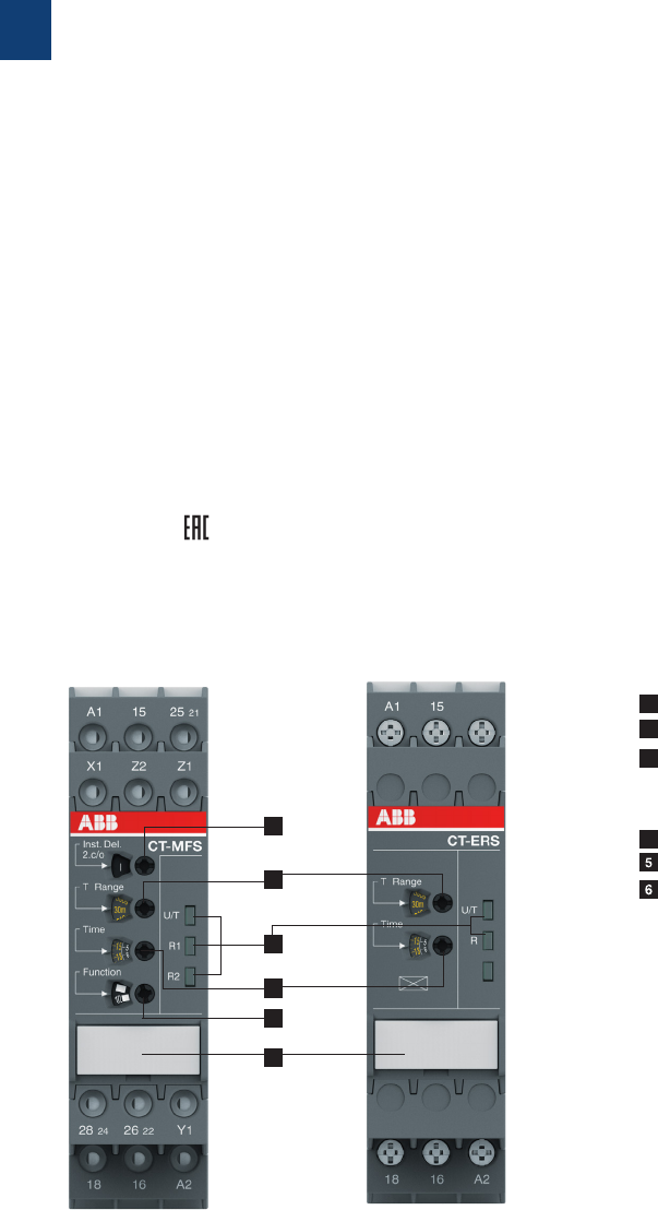
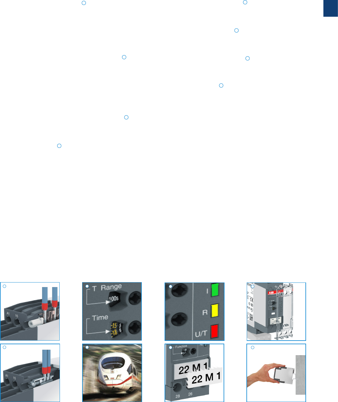
1 2nd contact as an instantaneous contact
2 Preselection of the time range
3 Indication of operational states
U/T: V control supply voltage applied / W timing
R: V Output relay energized
4 Fine adjustment of time delay
4 Preselection of timing function
Marker label
Operating controls
4
1
2
3
5
6
1
2CDC 110 004 C0210 | Catalog Electronic relays and controls 2016 | ABB 36
LEDs for status indication
All actual operational states are displayed by front-face LEDs,
thus simplifying commissioning and troubleshooting.
Integrated marker label
Integrated marker labels allow the product to be marked
quickly and simply. No additional marker labels are required.
Sealable transparent cover
Protection against unauthorized changes of time and
threshold values. Available as an accessory.
Snap-On housing
Tool-free DIN rail installation and deinstallation of the
electronic timer.
CT-S range
Benefits and advantages
Easy Connect Technology
Tool-free wiring and excellent vibration resistance. Push-in
terminals provide connection of wires up to 2 x 0.5 - 1.5 mm²
(2 x 20 -16 AWG), rigid or fine-strand with or without wire
end ferrules. The extended type designators for products with
push-in terminals are indicated by a P following the extended
type designator e.g. CT-xxS.xxP.
Double-chamber cage connection terminals
Double-chamber cage connection terminals provide
connection of wires up to 2 x 0.5-2.5 mm² (2 x 20-14 AWG)
rigid or fine-strand, with or without wire end ferrules. Potential
distribution does not require additional terminals. The
extended type designators for products with double-chamber
cage connection terminals are indicated by a S following the
extended type designator e.g. CT-xxS.xxS.
Time range preselection and fine adjustment
Direct assignment of the preselected time range to the fine
adjustment potentiometer scale by multicolor scales.
Higher utility class
The Easy Connect Technology provides excellent vibra-
tion resistance with gas tight push-in terminals – the right
solution for harsh environment. Selected products of the
electronic timers and measuring and monitoring relays comply
to the latest rail standards NF F 16-101/102, EN 45545, EN
50155 and more standards which are relevant for railway
applications. Find more inforamtion in the rail brochure
2CDC110084B0201.
1
2
3
4
6
5
7
8
4
2CDC 253 035 F0011
2CDC 253 026 F0011
2CDC 253 025 F0011
2CDC 252 006 F0012
2CDC 255 006 S0011
2CDC 253 007 F0012
2CDC 253 013 F0013
2
1 3 7
6 8
5
1
37 ABB | Catalog Electronic relays and controls 2016 | 2CDC 110 004 C0210
CT-S range
Ordering details - multifunctional
2CDC 251 024 V0011
CT-MVS.21P
2CDC 251 023 V0011
CT-MBS.22P
Description
The high-performance CT-S range in ABB’s new S-range housing offers two different types
of connection terminals and is ideally suited for universal use. Two different connection
technologies are available:
– Double-chamber cage connection terminals
– Easy Connect Technology
Accessories:
The CT-S range offers the possibility of using accessories such as a remote potentiometer to
adjust the time delay or a sealable, transparent cover to protect against unauthorized changes.
of time and threshold values.
Ordering details
Timing
function
Rated
control
supply
voltage
Time
ranges
Control
input
Output Type Order code Price
1 pce
Weight
(1 pce)
kg (lb)
Multi 5)
24- 240 VAC/DC
10 (0.05 s -
300 h) M2 c/o
CT-MVS.21S
1) 2) 3) 1SVR730020R0200 0.148
(0.326)
CT-MVS.21P
1) 2) 3) 1SVR740020R0200 0.136
(0.30)
24-48 VDC,
24-240 VAC
CT-MVS.22S 1SVR730020R3300 0.142
(0.313)
CT-MVS.22P 1SVR740020R3300 0.131
(0.289)
380-440 VAC
CT-MVS.23S 1SVR730021R2300 0.14 4
(0.317)
CT-MVS.23P 1SVR740021R2300 0.13 3
(0.293)
Multi 6) 24-48 VDC,
24-240 VAC
10 (0.05 s -
300 h) M1 c/o
CT-M VS .12S 1SVR730020R3100 0.107
(0.236)
CT-M VS .12P 1SVR740020R3100 0.10 2
(0.225)
Multi 7) 24-48 VDC,
24-240 VAC
2×10 (0.05 s -
300 h) M2 c/o
CT- MXS.22S 4)1SVR730030R3300 0.142
(0.313)
CT-MXS.22P 4) 1SVR740030R3300 0.131
(0.289)
Multi 8)
24- 240 VAC/DC 10 (0.05 s -
300 h) n / n2 c/o
CT-MFS.21S
1) 2) 3) 1SVR730010R0200 0.145
(0.32)
CT-MFS.21P
1) 2) 3) 1SVR740010R0200 0.133
(0.293)
24-48 V DC,
24-240 V AC
10 (0.05 s -
300 h) n / n2 c/o
CT-MBS.22S 2) 3) 1SVR730010R3200 0.14
(0.309)
CT-MBS.22P 2) 3) 1SVR740010R3200 0.129
(0.284)
Multi 9) 24-48 V DC,
24-240 V AC
10 (0.05 s -
300 h) -2 c/o
CT-WBS.22S 1SVR730040R3300 0.123
(0.271)
CT-WBS.22P 1SVR740040R3300 0.115
(0.254)
1) Extended temperature range -40 °C
2) Remote potentiometer connection
3) 2nd c/o contact selectable as instantaneous contact
4) 2 remote potentiometer connections
5) Functions: ON-delay, OFF-delay with auxiliary voltage, Impulse-ON, Impulse-OFF with auxiliary voltage, Symmetrical ON- and
OFF-delay, Flasher starting with ON or OFF, Star-delta change-over with impulse, Pulse former, Accumulative ON-delay, ON/
OFF-function
6) Functions: ON-delay, OFF-delay with auxiliary voltage, Impulse-ON, Impulse-OFF with auxiliary voltage, Symmetrical ON- and
OFF-delay, Flasher starting with ON or OFF, Pulse former, Accumulative ON-delay, ON/OFF-function
7) Functions: Select function via DIP switches behind the marker label on the front of the unit, asymmetrical ON- and OFF-delay,
Impulse-ON/OFF, Pulse generator starting with ON or OFF, Single pulse generator, ON/OFF-function
8) Functions: ON-delay, OFF-delay with auxiliary voltage, Impulse-ON, Impulse-OFF with auxiliary voltage, Symmetrical ON- and
OFF-delay, Flasher starting with ON, Flasher starting with OFF, Star-delta change-over with impulse, Pulse former, ON/OFF-
function
9) Functions: Flasher starting with ON, Flasher starting with OFF, Impulse-ON, ON-delay, fixed impulse with adjustable time delay,
Adjustable impulse with fixed time delay, ON/OFF-function
M Control input with voltage-related triggering
m Control input with volt-free triggering
m / m two control input with volt-free triggering
- no triggering
S: screw connection
P: push-in / easy connect
Further documentation CT-S
electronic timers on www.abb.com
1
2CDC 110 004 C0210 | Catalog Electronic relays and controls 2016 | ABB 38
CT-S range
Ordering details - singlefunctional
Timing
function
Rated con-
trol supply
voltage
Time
ranges
Con-
trol
input
Output Type Order code Price
1 pce
Weight
(1 pce)
kg (lb)
ON-delay
24-240 VAC/DC
10 (0.05 s -
300 h)
-2 c/o
CT-ERS.21S1) 1SVR730100R0300 0.13
(0.287)
CT-ERS.21P1) 1SVR740100R0300 0.121
(0.267)
24-48 V DC,
24-240 V AC
CT-ERS.22S 1SVR730100R3300 0.121
(0.267)
CT-ERS.22P 1SVR740100R3300 0.113
(0.249)
24-48 V DC,
24-240 V AC -1 c/o
CT-E RS.12S 1SVR730100R3100 0.10 6
(0.234)
CT-E RS.12P 1SVR740100R3100 0.101
(0.222)
OFF-delay
24-240 V AC/DC
10 (0.05 s -
300 h)
M2 c/o
CT-APS.21S1) 1SVR730180R0300 0.146
(0.322)
CT-APS.21P1) 1SVR740180R0300 0.125
(0.276)
24-48 V DC,
24-240 V AC
CT-APS.22S 1SVR730180R3300 0.13 8
(0.304)
CT-APS.22P 1SV R74 018 0 R3 3 0 0 0.127
(0.28)
M1 c/o
CT-AP S.12S 1SVR730180R3100 0 .109
(0.24)
CT-AP S.12P 1S V R74 018 0 R 310 0 0.103
(0.227)
24-48 V DC,
24-240 V AC
10 (0.05 s -
300 h) M2 c/o
CT-AHS.22S 1SVR730110R3300 0.13 6
(0.30)
CT-AHS.22P 1S V R74 0110 R 3 3 0 0 0.125
(0.276)
OFF-delay5) 24-240
VAC/DC
7 (0.05 s -
10 min)
-1 c/o
CT-AR S.11S 1SVR730120R3100 0.10 6
(0.234)
CT-AR S.11P 1S V R74 012 0 R310 0 0.10
(0.22)
-2 c/o
CT-ARS.21S 1SVR730120R3300 0.124
(0.273)
CT-ARS.21P 1S V R74 012 0R 3 30 0 0.115
(0.254)
Star-delta
change-over6)
24-48 V DC,
24-240 V AC
7 (0.05 s -
10 min) -2 n/o
CT-SDS.22S 1SVR730210R3300 0.114
(0.251)
CT-SDS.22P 1S VR74 0210 R 3 3 0 0 0.10 8
(0.238)
380-440 V AC
CT-SDS.23S 1SVR730211R2300 0.118
(0.26)
CT-SDS.23P 1SVR740211R2300 0.112
(0.247)
2CDC 251 030 V0011
CT-ERS.21P
2CDC 251 033 V0011
CT-AHS.22P
2CDC 251 040 V0011
CT-SDS.23P
1) Extended temperature range -40 °C
2) Remote potentiometer connection
3) 2nd c/o contact selectable as instantaneous contact
4) 2 remote potentiometer connections
5) Without auxiliary voltage
6) 50 ms transition time S: screw connection
P: push-in / easy connect
M Control input with voltage-related triggering
m Control input with volt-free triggering
m / m two control input with volt-free triggering
- no triggering
Further documentation CT-S
electronic timers on www.abb.com
1
39 ABB | Catalog Electronic relays and controls 2016 | 2CDC 110 004 C0210
CT-S range
Ordering details - Accessories
Marker label 29.6 x 44.5 mm
Marker label with scale 0-10
48.5 x 44.5 mm
Sealable transparent cover for
CT-S in new housing
MT-x50B
30 mm adapters
2CDC 252 042 F0009 1SFC 151 139 V0001
2CDC 252 043 F02092CDC 252 044 F0209
2CDC 255 006 S0011
Remote potentiometer
50 kq ±20 % - 0.2 q, degree of protection IP66
Material Diameter
in mm
Type Order code Price
1 piece
Pack.-
unit
pieces
Weight
1piece
g / oz
Plastic, black 22.5 MT-150B 1SFA611410R1506 10.040
Plastic, chrome 22.5 MT-250B 1S FA 611410 R 25 0 6 10.040
Metal, chrome 22.5 MT-350B 1S FA 61141 0 R3 5 0 6 10.048
30 mm adapter for attaching the potentiometer 22 mm in 30 mm mounting hole
Marker label
Material Type Order code Price
1 piece
Pack.-
unit
pieces
Weight
1piece
g / oz
Plastic, black K A1- 80 29 1SFA616920R8029 1
Metal, chrome KA1-8030 1SFA616920R8030 1
Caption Type Order code Price
1 piece
Pack.-
unit
pieces
Weight
1piece
g / oz
Symbol (see illustration) SK 615 562-87
GJD6155620R0087
10.002
Scale 0 - 10 SK 615 562-88
GJD6155620R0088
10.002
Scale 0 - 30 MA16-106 0
1S FA 6119 4 0 R10 6 0
10.002
Accessories for CT-S in new housing (1SVR7...)
Description Type Order code Price
1 piece
Pack.-
unit
pieces
Weight
1piece
g / oz
Adapter for screw mounting A D P. 01 1SVR430029R0100 10.018 (0.040)
Sealable transparent cover COV.11 1SVR730005R0100 10.004 (0.009)
Marker label for devices w/o DIP switches MAR.01 1SVR366017R0100 10 0.001 (0.002)
Marker label for devices with DIP switches M A R.12 1SVR730006R0000 10 0.001 (0.002)
Accessories for CT-S in old housing (1SVR4...)
Description Type Order code Price
1 piece
Pack.-
unit
pieces
Weight
1piece
g / oz
Adapter for screw mounting A D P. 01 1SVR430029R0100 10.018 (0.040)
Sealable transparent cover COV.01 1SVR430005R0100 10.004 (0.009)
Marker label for devices w/o DIP switches MAR.01 1SVR366017R0100 10 0.001 (0.002)
Marker label for devices with DIP switches MAR.02 1SVR430043R0000 10 0.001 (0.002)
Data sheet remote potentiometer
1
2CDC 110 004 C0210 | Catalog Electronic relays and controls 2016 | ABB 40
CT-MVS.21 CT-MVS.22 CT-MVS.12
CT-MXS.22
2CDC 252 002 F0b06
A1
A1
Y1/
B1 15
A2 16 18
15
Z2
18 16 A2
Y1/B1 Z1
25 21
28 24 26 22
21
25
26 28
22 24
A1
A1
Y1/
B1 15 25
A2 16 18 26 28
15
28 26
25
18 16 A2
Y1/B1
2CDC 252 003 F0b06
A1
A1
Y1/
B1 15
A2 16 18
15 Y1/B1
18 16 A2
2CDC 252 004 F0b06
A1
A1
Y1/
B1 15 25
A2 16 18 26 28
15
Z2
28 26 Y1/B1
25
18 16 A2
Z3 Z1
2CDC 252 005 F0b06
A1
A1
Y1/
B1 15 25
A2 16 18 26 28
15
28 26
25
18 16 A2
Y1/B1
2CDC 252 003 F0b06
CT-MVS.23
A1
A1 15 21
25
A2 16 18 26 28
22 24
15
Z2
28 26
24 22 Y1
Z1
18 16 A2
X1
25 21
2CDC 252 006 F0b06
A1
A1 15 21
25
A2 16 18 26 28
22 24
15
Z2
28 26
24 22 Y1
Z1
18 16 A2
25 21
2CDC 252 007 F0b06
A1
A1 15 25
A2 16 18 26 28
15
28 26
25
18 16 A2
2CDC 252 008 F0b06
CT-MFS.21 CT-MBS.22 CT-WBS.22
A CT-ERS.21
A1
A1 15
A2 16 18
15
18 16
28 26
A2
25
25
26 28
2CDC 252 009 F0b06
A1
A1
A2 16 18
15
15
18 16 A2
2CDC 252 010 F0b06
A CT-ERS.22 A CT-ERS.12
A1
A1 15
A2 16 18
15
18 16
28 26
A2
25
25
26 28
2CDC 252 009 F0b06
CT-S range
Connection diagrams
A1-A 2 Supply: 24-240 VAC/DC
A1-Y1/B1 Control input
15-16/18 1. c/o contact
25-26/28 2. c/o contact
21-22/24 2. c/o contact as
instantaneous contact
Z1-Z2 Remote potentiometer
connection
A1-A 2 Supply: 24-240 VAC/DC
15-16/18 1. c/o contact
25-26/28 2. c/o contact
21-22/24 2. c/o contact as
instantaneous contact
Y1-Z2 Control input
X1-Z2 Control input
Z1-Z2 Remote potentiometer
connection
A1-A 2 Supply: 24-48 V DC
or 24-240 V AC
15-16/18 1. c/o contact
25-26/28 2. c/o contact
21-22/24 2. c/o contact as
instantaneous
contact
Y1-Z2 Control input
Z1-Z2 Remote
potentiometer
connection
A1-A 2 Supply: 24-48 V DC
or 24-240 V AC
15-16/18 1. c/o contact
25-26/28 2. c/o contact
A1-A 2 Supply: 24-240 VAC/DC
15-16/18 1. c/o contact
25-26/28 2. c/o contact
A1-A 2 Supply: 24-48 V DC
or 24-240 V AC
15-16/18 1. c/o contact
25-26/28 2. c/o contact
A1-A 2 Supply: 24-48 V DC
or 24-240 V AC
15-16/18 1. c/o contact
A1-A 2 Supply: 24-48 V DC
or 24-240 V AC
A1-Y1/B1 Control input
15-16/18 1. c/o contact
25-26/28 2. c/o contact
Z1-Z2 Remote
potentiometer
connection
Z3-Z2 Remote
potentiometer
connection
A1-A 2 Supply: 224-48 VDC
or 24-240 V AC
A1-Y1/B1 Control input
15-16/18 1. c/o contact
25-26/28 2. c/o contact
A1-A 2 Supply: 380-440VAC
A1-Y1/B1 Control input
15-16/18 1. c/o contact
25-26/28 2. c/o contact
A1-A 2 Supply: 24-48 V DC
or 24-240 V AC
A1-Y1/B1 Control input
15-16/18 1. c/o contact
1
41 ABB | Catalog Electronic relays and controls 2016 | 2CDC 110 004 C0210
B CT-APS.21 B CT-APS.22 B CT-AHS.22
B CT-ARS.11
A1
Y1/
B1 A1 15 25
A2 16 18 26 28
15
Y1/B1
2628
25
18 16 A2
2CDC 252 011 F0b06
A1
A1 15 25
A2 16 18 26 28
15
Z2
2628
25
18 16 A2
Y1
2CDC 252 013 F0b06
15A1
A1
A2 16 18
15
18 16 A2
2CDC 252 014 F0b06
A1
Y1/
B1 A1
A2 16 18
15
15 Y1/B1
18 16 A2
2CDC 252 012 F0b06
B CT-APS.12
A1
A1 15 25
A2 16 18 26 28
15
2628
25
18 16 A2
2CDC 252 015 F0b06
B CT-ARS.21 F CT-SDS.22
A1
A1
A2 18 28
17
17
18 28 A2
2CDC 252 016 F0b06
F CT-SDS.23
A1
Y1/
B1 A1 15 25
A2 16 18 26 28
15
Y1/B1
2628
25
18 16 A2
2CDC 252 011 F0b06
A1
A1
A2 18 28
17
17
18 28 A2
2CDC 252 016 F0b06
CT-S range
Connection diagrams
A1-A 2 Supply: 24-240 V AC/DC
A1-Y1/B1 Control input
15-16/18 1. c/o contact
25-26/28 2. c/o contact
A1-A 2 Supply: 24-240 V AC/DC
15-16/18 1. c/o contact
25-26/28 2. c/o contact
A1-A 2 Supply: 24-48 V DC or
24-240 V AC
17-18 1. n/o contact
17-28 2. n/o contact
A1-A 2 Supply: 380-440 V AC
17-18 1. n/o contact
17-28 2. n/o contact
A1-A 2 Supply: 24-48 V DC or
24-240 V AC
A1-Y1/B1 Control input
15-16/18 1. c/o contact
25-26/28 2. c/o contact
A1-A 2 Supply: 24-48 V DC or
24-240 V AC
A1-Y1/B1 Control input
15-16/18 1. c/o contact
A1-A 2 Supply: 24-240 V AC/DC
15-16/18 1. c/o contact
A1-A 2 Supply: 24-48 V DC or
24-240 V AC
Y1-Z2 Control input
15-16/18 1. c/o contact
25-26/28 2. c/o contact

1
2CDC 110 004 C0210 | Catalog Electronic relays and controls 2016 | ABB 42
Data at Ta = 25 °C and rated values, unless otherwise indicated
CT-S
Input circuit - Supply circuit
Rated control supply voltage UsCT-xxx.x1 24-240 V AC/DC
CT-xxx.x2 24-48 V DC, 24-240 V AC
CT-xxx.x3 380-440 V AC
CT-xxx.x4 110-240 V AC
CT-xxx.x5 220-240 V AC
CT-xxx.x6 24 V AC/DC
CT-xxx.x7 100-127 V AC or 110 V DC
CT-xxx.x8 200-240V AC/DC
Rated control supply voltage US tolerance -15...+10 %
Rated frequency DC or 50/60 Hz
Frequency range AC 47-63 Hz
Typical current / power consumption depending on device, see data sheet
Power failure buffering time 24 V DC min. 15 ms
230/400 V AC min. 20 ms
Minimum energizing time 100 ms (CT-ARS)
Formatting time 1) 5 min (CT-ARS)
Input circuit - Control circuit
Kind of triggering CT-MVS, CT-MXS, CT-APS voltage-related triggering
Control input, Control function A1-Y1/B1 start timing external
Parallel load / polarized yes / no
Maximum cable length to the control input 50 m - 100 pF/m
Minimum control pulse length 20 ms
Control voltage potential see rated control supply voltage
Current consumption of the control input 24 V DC 1.2 mA
230 V AC 8 mA
400 V AC 6 mA
Kind of triggering CT-MFS, CT-MBS, CT-AHS volt-free triggering
Control input, Control function Y1-Z2 start timing external
X1-Z2 pause timing / accumulative functions (CT-MFS)
Maximum switching current in the control circuit 1 mA
Maximum cable length to the control input 50 m - 100 pF/m
Minimum control pulse length 20 ms
No-load voltage at the control inputs 10-40 V DC
Remote potentiometer
Remote potentiometer connections, Resistance value Z1-Z2 50 kΩ (CT-MFS, CT-MBS, CT-MVS.21, CT-MXS)
Z3-Z2 50 kΩ (CT-MXS)
Maximum cable length to remote potentiometer 2 x 25 m, shielded with 100 pF/m
Shield connection Z2
Timing circuit
Time ranges 10 time ranges 0.05 s - 300 h
1.) 0.05-1 s 2.) 0.15-3 s 3.) 0.5-10 s 4.) 1.5-30 s 5.) 5-100 s
6.) 15-300 s 7.) 1.5-30 min 8.) 15-300 min 9.) 1.5-30 h 10.) 15-300 h
7 time ranges 0.05 s - 10 min (CT-SDS,
CT-ARS)
1.) 0.05-1 s 2.) 0.15-3 s 3.) 0.5-10 s
4.) 1.5-30 s 5.) 5-100 s 6.) 15-300 s 7.) 0.5-10 min
Recovery time 24-240 V AC/DC < 50 ms
24-48 V DC, 24-240 V AC < 80 ms
380-440 V AC < 60 ms
Accuracy within the rated control supply voltage tolerance it < 0.004 % / V
Accuracy within the temperature range it < 0.03 % / °C
Repeat accuracy (constant parameters) < ±0.2 %
Star-delta transition time fixed 50 ms (CT-SDS, CT-MBS, CT-MFS, CT-MVS.2x)
Star-delta transition time tolerance ±2 ms
CT-S range
Technical data
1) prior to first commisioning and after a six-month stop in operation

1
43 ABB | Catalog Electronic relays and controls 2016 | 2CDC 110 004 C0210
CT-S range
Technical data
Indication of operational states
Control supply voltage / timing U/T: green LED V: control supply voltage applied / W: timing
Control supply voltage U: green LED V: control supply voltage applied
Relay state R, R1, R2: yellow LED V: output relay energized
Output circuit
Kind of output 15-16/18 relay, 1 c/o contact
15-16/18; 25-26/28 relay, 2 c/o contacts
15-16/18; 25(21)-26(22)/28(24) relay, 2 c/o contacts, 2nd c/o contact selectable as inst. contact
17-18; 17-28 relay, 2 n/o contacts (CT-SDS)
Contact material Cd-free, on request
Rated operational voltage UeIEC/EN 60947-1 250 V
Minimum switching voltage / minimum switching current 12 V / 10 mA
Maximum switching voltage / maximum switching current see load limit curves
Rated operational current Ie
(IEC/EN 60947-5-1 )
AC-12 (resistive) at 230 V 4 A
AC-15 (inductive) at 230 V 3 A
DC-12 (resistive) at 24 V 4 A
DC-13 (inductive) at 24 V 2 A (CT-ARS; 1.5 A)
AC rating (UL 508) Utilization category (Control Circuit Rating Code) B 300
max. rated operational voltage 300 V AC
Maximum continuous thermal current at B300 5 A
max. making/breaking apparent power at B300 3600 VA / 360 VA
Mechanical lifetime 30 x 106 switching cycles
Electrical lifetime at AC-12, 230 V, 4 A 0.1 x 10⁶ switching cycles
Max. fuse rating to achieve short-circuit protection
(IEC/EN 60947-5-1)
n/c contact 6 A fast-acting
n/o contact 10 A fast-acting
General data 2)
MTBF on request
Duty time 100%
Dimensions (W x H x D) product dimensions 22.5 x 85.6 x 103.7 mm (0.89 x 3.37 x 4.08 in)
packaging dimensions 97 x 109 x 30 mm (3.82 x 4.29 x 1.18 in)
Weight depending on device, see ordering details
Mounting DIN rail (IEC/EN 60715), snap-on mounting without any tool
Mounting position any
Minimum distance to other units vertical / horizontal not necessary / not necessary
Material of housing UL 94 V-0
Degree of protection housing / terminals IP50 / IP20
Electrical connection 2)
Screw connection technology Easy Connect Technology
(Push-in)
Wire size fine-strand with(out) wire end
ferrule
1 x 0.5-2.5 mm2 (1 x 20-14 AWG)
2 x 0.5-1.5 mm2 (2 x 20-16 AWG)
2 x 0.5-1.5 mm2 (2 x 20-16 AWG)
rigid 1 x 0.5-4 mm2 (1 x 20-12 AWG)
2 x 0.5-2.5 mm2 (2 x 20-14 AWG)
2 x 0.5-1.5 mm2 (2 x 20-16 AWG)
Stripping length 8 mm (0.32 in)
Tightening torque 0.6-0.8 Nm (5.31-7.08 lb.in) -
2) Data for all references 1SVR 730 xxx xxx and 1SVR 740 xxx xxx. For devices with 1SVR 430 xxx xxx please refer to the data sheet.

1
2CDC 110 004 C0210 | Catalog Electronic relays and controls 2016 | ABB 44
CT-S range
Technical data
Environmental data
Ambient temperature ranges operation / storage -25...+60 °C / -40...+85 °C,
-40...+60 °C / -40...+85 °C (CT-MVS.21, CT-MFS.21, CT-ERS.21,
CT-APS.21)
Damp heat (cyclic) (IEC/EN 60068-2-30) 6 x 24 h cycle, 55 °C, 95 % RH
Vibration, sinusoidal (IEC/EN 60068-2-6) functioning 40 m/s2, 10-58/60-150 Hz
resistance 60 m/s2, 10-58/60-150 Hz, 20 cycles
Vibration, seismic (IEC/EN 60068-3-3) functioning 20 m/s2
Shock, half-sine (IEC/EN 60068-2-27) functioning 100 m/s2, 11 ms, 3 shocks/direction
resistance 300 m/s2 , 11 ms, 3 shocks/direction
Isolation data CT-S with 1 c/o CT-S with 2 c/o
Rated insulation voltage Uiinput circuit / output circuit 500 V
output circuit 1 / output circuit 2 not available 300 V
Rated impulse withstand voltage Uimp between all isolated circuits
(IEC/EN 60664-1)
type test: 4 kV; 1.2/50 µs
Power-frequency withstand voltage (test voltage) between all isolated
circuits
routine test: 2.0 kV; 50 Hz; 1 s
type test: 2.0 kV; 50 Hz; 60 s
Basic insulation (IEC/EN 61140) input circuit / output circuit 500 V
Protective separation
(IEC/EN 61140; EN 50178)
input circuit / output circuit 250 V
Pollution degree IEC/EN 60664-1 3
Overvoltage category IEC/EN 60664-1 III
Standards
Product standard IEC 61812-1, EN 61812-1 + A11, DIN VDE 0435 part 2021
Low Voltage Directive 2006/95/EC
EMC Directive 2004/108/EC
RoHS Directive 2011/65/EC
Electromagnetic compatibility
Interference immunity to IEC/EN 61000-6-1, IEC/EN 61000-6-2
electrostatic discharge IEC/EN 61000-4-2 Level 3, 6 kV / 8 kV
radiated, radio-frequency
electromagnetic field
IEC/EN 61000-4-3 Level 3, 10 V/m (1 GHz) 3 V/m (2 GHz) 1 V/m (2.7 GHz)
electrical fast transient / burst IEC/EN 61000-4-4 Level 3, 2 kV / 5 kHz
surge IEC/EN 61000-4-5 Level 4, 2 kV A1-A2
conducted disturbances, induced by
radio-frequency fields
IEC/EN 61000-4-6 Level 3, 10 V
harmonics and interharmonics IEC/EN 61000-4-13 Class 3
Interference emission IEC/EN 61000-6-3, IEC/EN 61000-6-4
high-frequency radiated IEC/CISPR 22, EN 55022 Class B
high-frequency conducted IEC/CISPR 22, EN 55022 Class B
Product certifications and declarations see “Approvals and marks” on page 14.
1
45 ABB | Catalog Electronic relays and controls 2016 | 2CDC 110 004 C0210
CT-S range
Technical diagrams
AC load (resistive) DC load (resistive)
Technical diagrams
Load limit curves
Derating factor F for inductive AC load Contact lifetime
DC current [A]
resistive load
DC voltage [V]
2CDC 252 150 F0206
cos ϕ
0.5
0.1 0.2 0.3 0.40.5 0.60.7 0.80.9 1.0
0.6
0.7
0.8
0.9
1.0
Derating factor F
2CDC 252 124 F0206
AC current [A]
resistive load
AC voltage [V]
2CDC 252 149 F0206
Switching current [A]
250 V
resistive load
Switching cycles
2CDC 252 148 F0206
1
2CDC 110 004 C0210 | Catalog Electronic relays and controls 2016 | ABB 46
CT-S range
Wiring notes, Dimensional drawings
2CDC 252 188 F0b05
100
102
109,5 4.31“ 22,5
.886“
78 3.07“
4.02“
3.94“
L(+)
N(-)
A1 Y1
Z2
X1
A2
2CDC 252 101 F0b06
L(+)
N(-)
A1 Y1/B1
A2
2CDC 252 102 F0b06
L(+)
L(+)
N(-)
L(-)
A1 Y1/B1
A2
2CDC 252 103 F0b06
L(+)
N(-)
A1 Z1
Z2
Z3
A2
2CDC 252 104 F0b06
L(+)
+V
N(-)
0 V
A1 Y1
Z2A2
2CDC 252 105 F0b06
Wiring notes
Remote potentiometer
Control inputs
(volt-free triggering)
Control inputs
(voltage-related triggering)
Triggering of the control inputs (volt-free)
with a proximity switch (3 wire)
The control input Y1/B1 is triggered with electric potential against A2. It is pos-
sible to use the control supply voltage from terminal A1 or any other voltage
within the rated control supply voltage range.
113.4 4.47”
22.5 0.89”
85.6 3.37”
103.7 4.08”
105.9 4.17”
2CDC 252 009 F0011
1SVR 430 xxx xxx 1SVR 730 xxx xxx, 1SVR 740 xxx xxx
Dimensional drawing Dimensions in mm
1
47 ABB | Catalog Electronic relays and controls 2016 | 2CDC 110 004 C0210
Electronic timers
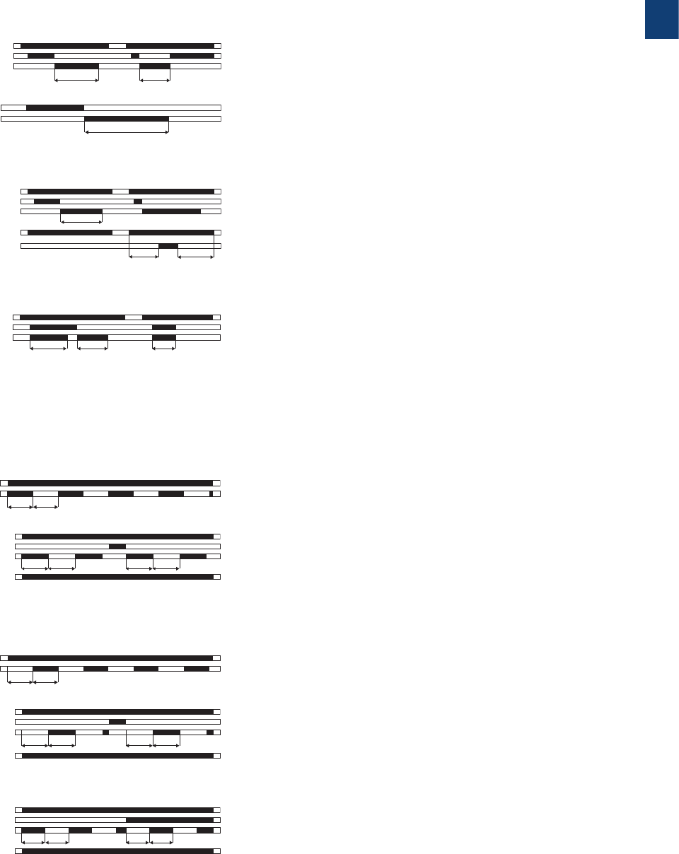
Timing functions
ON-delay
Supply
Output
t
This function requires continuous control supply voltage for timing.
Timing begins when control supply voltage is applied. When the selected
time delay is complete, the output relay energizes. If control supply voltage is
interrupted, the output relay de-energizes and the time delay is reset.
ON-delay
accumulative
Supply
2nd instanteous
contact
Output
Control input
tt2
t1
t1 + t2 = t
This function requires continuous control supply voltage for timing. Timing
begins when control supply voltage is applied. When the selected time delay is
complete, the output relay energizes. Timing can be paused by closing control
input. The elapsed time t1 is stored and continues from this time value when the
control input is re-opened.
If control supply voltage is interrupted, the output relay de-energizes and the
time delay is reset.
OFF-delay
with auxiliary
voltage
Supply
Output
Cont
rol input
tt
<
This function requires continuous control supply voltage for timing. If control
input is closed, the output relay energizes immediately. If control input is opened,
the time delay starts. When the selected time delay is complete, the output relay
de-energizes.
If control input recloses before the time delay is complete, the time delay is reset
and the output relay does not change state. Timing starts again when control
input A1-Y1/B1 re-opens. If control supply voltage is interrupted, the output relay
de-energizes and the time delay is reset.
OFF-delay
without
auxiliary
voltage
Supply
Output
t
The OFF-delay function without auxiliary voltage does not require continuous
control supply voltage for timing.
Applying control supply voltage, energizes the output relay. If control supply
voltage is interrupted, the OFF-delay starts. When timing is complete, the output
relay de-energizes. If control supply voltage is re-applied before the time delay is
complete, the time delay is reset and the output relay remains energized. Control
supply voltage must be applied for the minimum energizing time (200 ms), for
proper operation.
OFF-delay
with auxiliary
voltage (Delay
on break)
Supply
2nd instanteous
contact
Output
Control input
Control input
t1 t2
t1 + t2 = t
t
This function requires continuous control supply voltage for timing. If control
input is closed, the output relay energizes immediately. If control input is opened,
the time delay starts. When the selected time delay is complete, the output relay
de- energizes.
If control input closes before the time delay is complete, the time delay is reset
and the output relay does not change state. Timing starts again when control
input reopens.
Pause timing / Accumulative OFF-delay: Timing can be paused by closing control
input X1-Z2. The elapsed time t1 is stored and continues from this time value
when X1-Z2 is re-opened.
This can be repeated as often as required.
If control supply voltage is interrupted, the output relay de-energizes and the
time delay is reset.
Impulse-ON
(interval)
Supply
Output
t< t
This function requires continuous control supply voltage for timing. The
output relay energizes immediately when control supply voltage is applied and
de-energizes after the set pulse time is complete. If control supply voltage is
interrupted, the output relay de-energizes and the time delay is reset.
On delay functions A
OFF delay functions B
Impulse-ON functions CA
For a detailed overview of product specific timing functions please refer to the corresponding data sheet.
1
2CDC 110 004 C0210 | Catalog Electronic relays and controls 2016 | ABB 48
Electronic timers
Timing functions
Flasher starting
with ON
Supply
Output
t t
Applying control supply voltage starts timing with symmetrical ON & OFF times.
The cycle starts with an ON time first.
If control supply voltage is interrupted, the output relay de-energizes and the
time delay is reset.
Flasher with
reset starting
with ON
Supply
Control input
Output
2nd contact
instantaneous
t t t t
Applying control supply voltage starts timing with symmetrical ON & OFF times.
The cycle starts with an ON time first.
The time delay can be reset by closing control input. Opening control input
starts the timer pulsing again with symmetrical ON & OFF times. If control
supply voltage is interrupted, the output relay de-energizes and the time delay
is reset.
Flasher starting
with OFF
Supply
Output
t t
Applying control supply voltage starts timing with symmetrical ON & OFF times.
The cycle starts with an OFF time first. If control supply voltage is interrupted,
the output relay de-energizes and the time delay is reset.
Flasher with
reset starting
with OFF
Supply
Control input
Output
2nd contact
instantaneous
t t t t
Applying control supply voltage starts timing with symmetrical ON & OFF
times. The cycle starts with an OFF time first. The time delay can be reset by
closing control input. Opening control input starts the timer pulsing again with
symmetrical ON & OFF times. If control supply voltage is interrupted, the output
relay de-energizes and the time delay is reset.
Flasher starting
with ON or OFF
Supply
Control input
Output
2nd contact
instantaneous
t t t t
Applying control supply voltage starts timing with symmetrical ON / OFF times.
If the control input is open during supply voltage is connected the cycle starts
with an ON time first. If the control input is closed during supply voltage is
connected the cycle starts with an OFF time first.
Impulse-OFF
Supply
Output
Cont
rol input
tt
This function requires continuous control supply voltage for timing. The output
relay energizes immediately when the control input is de-energized and the
output de-energizes after the set pulse time is complete. If control supply voltage
is interrupted, the output relay de-energizes and the time delay is reset.
Impulse-OFF
without auxiliary
voltage
Supply
Output
t
This function does not require continuous control supply voltage for timing.
If control supply voltage is interrupted, the output relay energizes and the OFF
time starts. When timing is complete, the output relay de-energizes. If control
supply voltage is re-applied before the time delay is complete, the time delay is
reset and the output relay de-energizes. Control supply voltage must be applied
for the minimum energizing time (200 ms), for proper operation.
Impulse-OFF
with auxiliary
voltage (Trailing
edge interval)
Supply
2nd instanteous
contact
Output
Control input
Control input
t
t1 t2
t1 + t2 = t
This function requires continuous control supply voltage for timing. If control
supply voltage is applied, opening control input energizes the output relay
immediately and starts timing. When the selected pulse time is complete, the
output relay de-energizes.
Closing control input, before the time delay is complete, de-energizes the output
relay and resets the time delay. If control supply voltage is interrupted, the output
relay de-energizes and the time delay is reset.
Impulse-OFF functions CB
Impuls-ON and Impulse-OFF functions CE
Flasher starting with ON functions DA
Flasher starting with OFF functions DB
Flasher starting with ON or OFF functions DE
Impulse-ON
and impulse-
OFF
Supply
Output
Cont
rol input
<t1
t1 t2
This function requires continuous control supply voltage for timing. If control
supply voltage is applied, closing control input energizes the output relay
immediately and starts the pulse time t1. When t1 is complete, the output
relay de-energize. Re-opening control input energizes the output relay
immediately and starts the pulse time t2. When t2 is complete, the output relay
de-energizes. t1 and t2 are independently adjustable. If control input changes
state before the pulse time is complete, the output relay de-energizes and
the pulse time is reset. If control input changes state again, the interrupted
pulse time restarts. If control supply voltage is interrupted, the output relay
de-energizes and the time delay is reset.
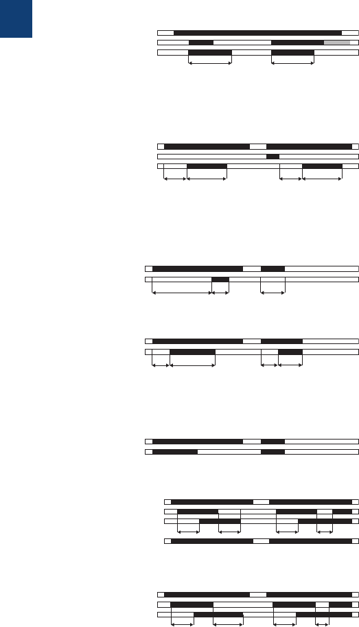
1
49 ABB | Catalog Electronic relays and controls 2016 | 2CDC 110 004 C0210
Pulse former
(single shot)
Supply
Cont
rol input
Output
t t
This function requires continuous control supply voltage for timing. Closing
control input energizes the output relay immediately and starts timing.
Operating the control input during the time delay has no effect. When the
selected ON time is complete, the output relay de-energizes. After the ON
time is complete, it can be restarted by closing control input. If control supply
voltage is interrupted, the output relay de-energizes and the time delay is reset.
ON- and OFF-
delay
Supply
Output
This function requires continuous control supply voltage for timing . Closing the
control input the ON delay starts. After the ON delay time is elapsed the output
energizes. Opening the control input let the OFF delays time start. When the OFF
delay time is elapsed the output de-energizes again. Operating the control input
during timing will reset the respective timing function.
Symmetrical
ON- and OFF-
delay
Supply
2nd instanteous
contact
Output
Control input
t1 t1t2 <t2
This function requires continuous control supply voltage for timing. Closing
control input starts the ON-delay time t1. When timing is complete, the output
relay energizes. Opening control input starts the OFF-delay time t2. When the
OFF-delay t2 is complete, the output relay de-energizes. If control input opens
before the ON-delay t1 is complete, the time delay is reset and the output relay
remains de-energized. If control input closes before the OFF-delay time t2 is
complete, the time delay is reset and the output relay remains energized.
Asymmetrical
ON- and OFF-
delay
Supply
Output
Cont
rol input
t1 t1t2 <t2
This function requires continuous control supply voltage for timing. Closing
control input starts the ON-delay t1. When timing is complete, the output relay
energizes. Opening control input starts the OFF-delay t2. When the OFF-delay
is complete, the output relay de-energizes. The ON-delay and OFF-delay are
independently adjustable.
If control input opens before the ON-delay is complete (<t1), the time delay is
reset and the output relay remains de-energized. If control input closes before
the OFF-delay is complete (<t2), the time delay is reset and the output relay
remains energized. If control supply voltage is interrupted, the output relay
de-energizes and the time delay is reset
Single-pulse
generator,
starting with
OFF
Supply
Cont
rol input
Output
t1 t2 t1 t2
This function requires continuous control supply voltage for timing. Applying
control supply voltage, or, if control supply voltage is already applied, opening
control input energizes the output relay after the OFF time t1 is complete. When
the following ON time t2 is complete, the output relay de-energizes. The ON
& OFF times are independently adjustable. Closing control input with control
supply voltage applied, de-energizes the output relay and resets the time delay.
If control supply voltage is interrupted, the output relay de-energizes and the
time delay is reset.
Fixed
impulse with
adjustable
time delay
Supply
Output
t1 t2 <t1
This function requires continuous control supply voltage for timing. The time
delay t1 starts when control supply voltage is applied. When t1 is complete, the
output relay energizes for the fixed impulse time t2 of 500 ms.
If control supply voltage is interrupted, the time delay is reset. The output relay
does not change state.
Adjustable
impulse with
fixed time
delay
Supply
Output
t1
t2 t2 <t1
This function requires continuous control supply voltage for timing. Applying
control supply voltage starts the fixed time delay t2 of 500 ms. When t2 is
complete, the output relay energizes and the selected pulse time t1 starts.
When t1 is complete, the output relay de-energizes. If control supply voltage is
interrupted, the pulse time is reset. The output relay does not change state.
Pulse former H
Single-pulse former EC
Impulse with delay AC
ON- and OFF-delay AB
Electronic timers
Timing functions
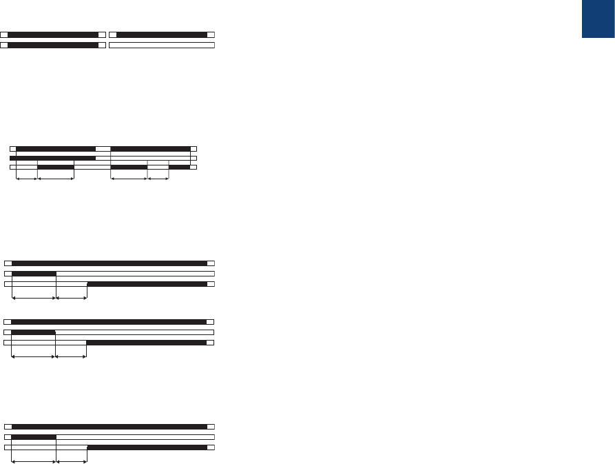
1
2CDC 110 004 C0210 | Catalog Electronic relays and controls 2016 | ABB 50
Electronic timers
Timing functions
FC Star-delta
change-over
with impulse
function
Supply
Output
1
Output
2
t1 t2 t1 = adjusted starting time
t2 = transition time (50 ms)
This function requires continuous control supply voltage for timing
. Applying control supply voltage energizes the star contactor
connected to output 1 and begins the set starting time t1. When
the starting time is complete, the first output de energizes the star
contactor.
Now, the fixed transition time t2 of 50 ms starts.
When the transition time is complete, the second ouput energizes the
delta contactor. The delta contactor remains energized as long as
control supply voltage is applied.
FStar-delta
change-over
(Star-delta
starting)
Supply
Output
1
Output
2
t1 t2 t1 = adjusted starting time
t2 = transition time (50 ms)
This function requires continuous control supply voltage for timing.
Applying control supply voltage, energizes the star contactor and
begins the set starting time t1. When the starting time is complete,
the first output contact de-energizes the star contactor. When the
transition time t2 is complete, the second output contact energizes
the delta contactor. The delta contactor remains energized as long
as control supply voltage is applied.
FStar-delta
change-over
Supply
Output
1
Output
2
t1 t2 t1 = adjusted starting time
t2 = transition time (50 ms)
Applying control supply voltage energizes the star contactor and
begins the set starting time. When the starting time is complete the
star contactor de-energizes. Now, the fix transition time starts. When
the transition time is complete, the delta contactor energizes.
GON/OFF
function
Supply
Output
Time sector ≠ 300 hTime sector = 300 h
This function is used for test purposes during commissioning and
troubleshooting.
If the selected max. value of the time range is smaller than 300 h (front-
face potentiometer “Time sector” ≠ 300 h), applying control supply
voltage energizes the output relay immediately. Interrupting control
supply voltage, de-energizes the output relay.
If the selected max. value of the time range is 300 h (front-face
potentiometer “Time sector” = 300 h) and control supply voltage is
applied the output relay does not energize.
ED Pulse
generator,
starting with
the ON or
OFF time
(Recycling
unequal
times, ON or
OFF first)
Supply
Cont
rol input
Output
t1t1
t2t2
This function requires continuous control supply voltage for timing.
Applying control supply voltage, with open control input, starts timing
with an ON time first. Applying control supply voltage, with closed
control input, starts timing with an OFF time first. If control supply
voltage is interrupted, the output relay de-energizes and the time delay
is reset.
Further functions
