153781 Catalog
131138-Brochure 131138-Brochure 131138-Brochure B5 unilog cesco-content
143736-Catalog 143736-Catalog 143736-Catalog B5 unilog cesco-content
108418-Catalog 108418-Catalog 108418-Catalog 785901 Batch5 unilog cesco-content
2016-09-04
: Pdf 153781-Catalog 153781-Catalog B4 unilog
Open the PDF directly: View PDF ![]() .
.
Page Count: 38
- Table of Contents
- Power Monitoring and Control
- PowerLogic®
- The New PowerLogic System
- The PowerLogic Advantage
- ION Enterprise® Software Ordering Information/Meter Selection
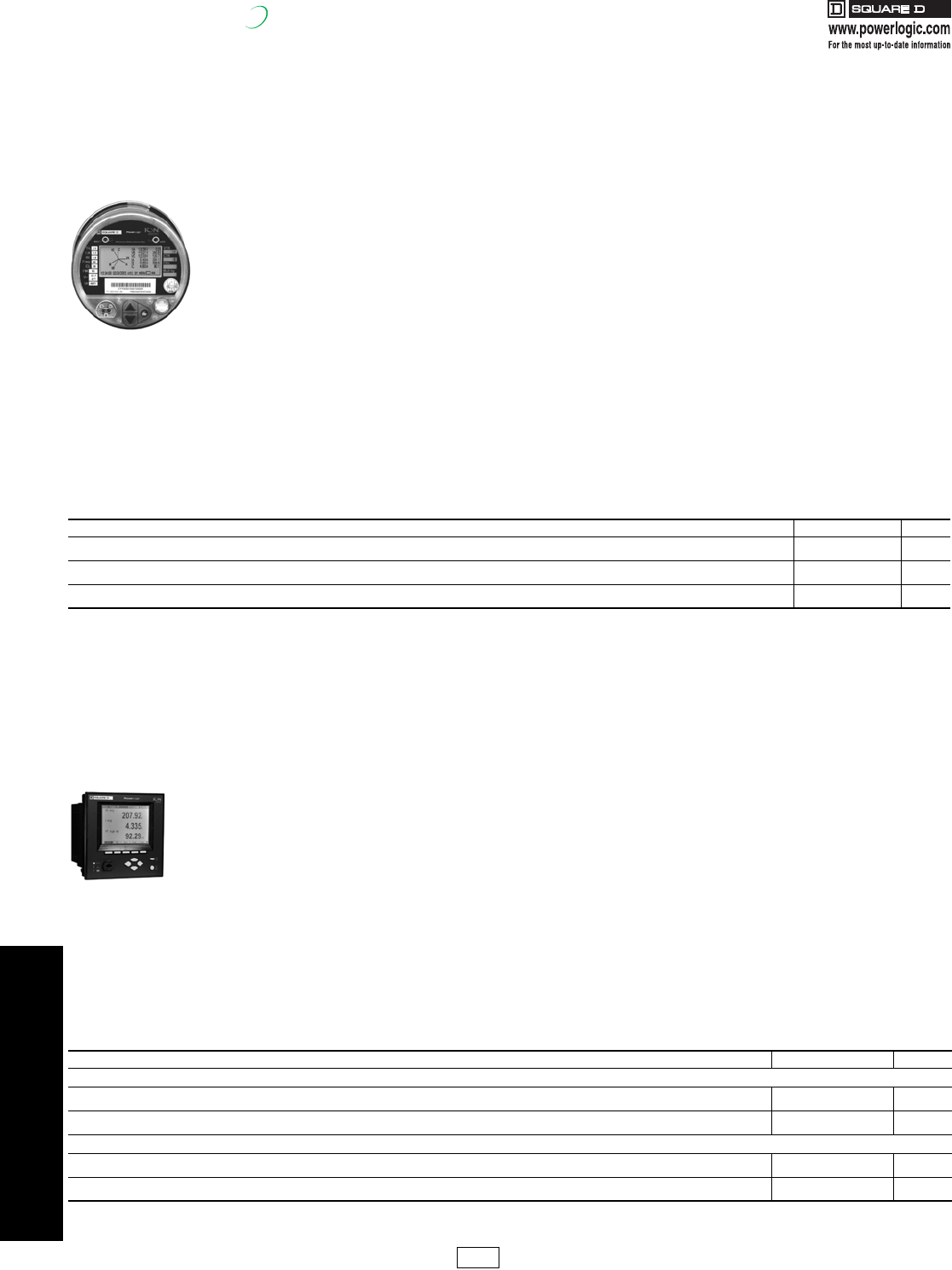
- ION8600/7550/7650 Power and Energy Meters
- SMS Ordering Information/Meter Selection
- Metering
- PowerLogic Series 4000 Circuit Monitor
- PowerLogic Series 4000 Circuit Monitor Optional Displays
- PowerLogic Submetering
- Tenant Metering Software
- Enterprise Energy Management
- PowerLogic High Density Metering
- Features and Benefits
- High Density Meter System includes:
- PowerLogic Energy Meter
- Energy Meter
- PowerLogic Enercept® Meter
- PowerLogic Split Core Current Transformers-Instrument Grade 5 Amp Split-Core Current Transformers
- Submetering
- Solutions for Utilities
- PowerLogic Instrument Transformer Services
- Web-Enabled Network Components
- Consulting & Analysis
- Engineering Services
- Factory Assembled Enclosures
- Engineering Services
- Sepam Series
- PFC Capacitor Banks
- PFC Capacitor Banks
- AccuSine® PCS AHF
- PowerLogic®
4-1
© 2007 Schneider Electric
All Rights Reserved
4POWER MONITORING AND
CONTROL
Download Section 04 PDF Table of Contents
Section 4
Power Monitoring and Control
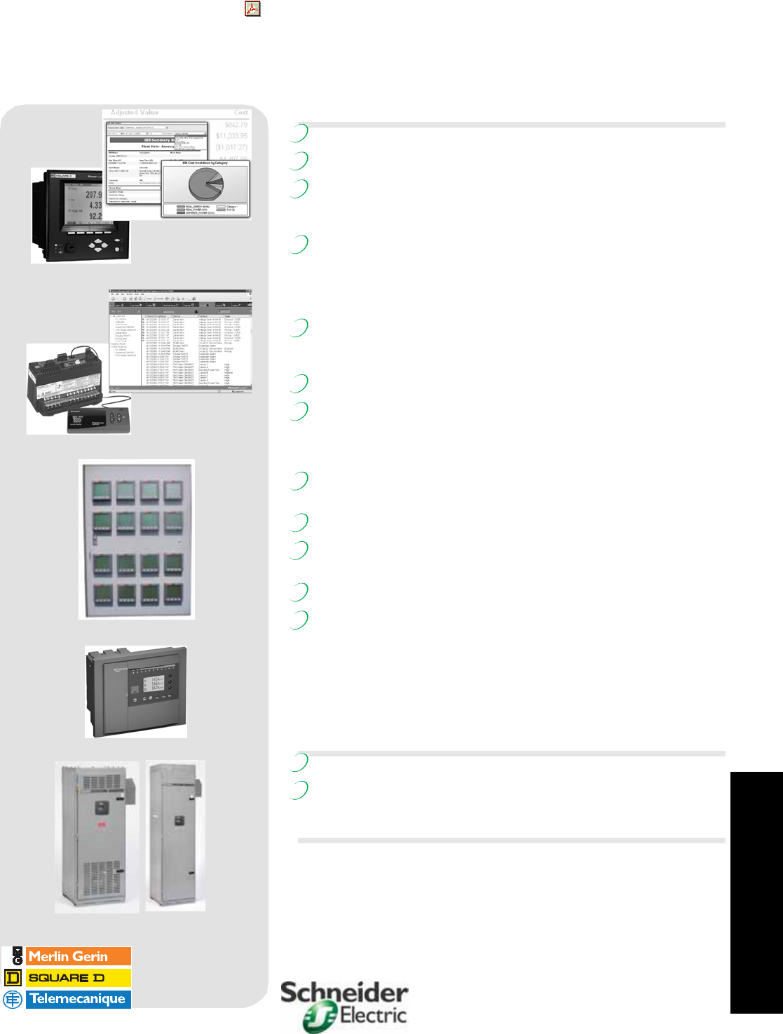
ION Meter and EEM screen cap, page 4-6
CM3000 and Advanced Reports Screen, page 4-10
16 Meter Enclosure, page 4-13
Sepam Series 80, page 4-24
AV4000 & 5000 Automatic Capacitor banks, page 4-30
PowerLogic® Energy and Power Management Systems
Introduction 4-2, 4-3
PowerLogic ION Enterprise Operations Software Overview 4-4
PowerLogic ION Enterprise Software Ordering
Information 4-5
PowerLogic ION Power & Energy Meter Selection 4-5
PowerLogic Power and Energy Meters 4-6
ION8600 4-6
ION7550/7650 4-6
ION7350/7330/7300 4-7
ION6200 4-7
PowerLogic System Manager Software Overview 4-8
SMS Ordering Information 4-9
PowerLogic Circuit Monitor and Power Meter
Selection 4-9
PowerLogic Metering 4-10
Series 700 Power Meter 4-10
Series 800 Power Meter 4-10
Series 3000 Circuit Monitor 4-10
Series 4000 Circuit Monitor 4-11
PowerLogic Submetering
Tenant Metering Software 4-12
High Density Metering 4-13
Energy Meter 4-14
Enercept® Meter 4-14
Split Core Current Transformers 4-14
Branch Current Monitor 4-15
Multi-Circuit Meter 4-15
Submeter Display 4-15
PowerLogic ION EEM Enterprise Energy Management Software 4-16
PowerLogic Solutions for Utilities 4-17
PowerLogic Energy Profiler Online 4-18
PowerLogic ITS 4-18
Web-Enabled Network Components
Ethernet Gateways 4-19
Web Page Generator 4-19
Engineering Services
Consulting & Analysis 4-20
Total Energy Control 4-21
Power System Automation 4-21
System Integration 4-21
Factory Assembled Enclosures 4-22
Technical Support 4-23
Power Management University 4-23
Sepam Digital Protective Relays
Series 80, 40 & 20 Features 4-24
Series 80, 40 & 20 Applications 4-25
Series 80, 40 & 20 Pricing and Accessories 4-26
Selection Example 4-27
ReactiVar® Power Factor Correction Capacitors
Low Voltage Fixed Unfused Capacitor Banks 4-28
Low Voltage Fixed Fused Capacitor Banks 4-29
Automatic Power Factor Capacitor Banks 4-30
Anti-Resonant and Filtering Capacitor Banks 4-31
LV Transient Free Reactive Compensation Banks 4-32
Medium Voltage Fixed and Automatic Capacitor Banks 4-33
CT Selection and Enclosure Dimensions 4-34
AccuSine® Active Harmonic Filter 4-35
Hybrid VAR Compensator (HVC) Overview 4-36
New!
New!
New!
New!
New!
New!
New!
New!
New!
New!
New!
New!
New!
New!
17404.book Page 1 Thursday, October 4, 2007 8:28 AM
4-2 © 2007 Schneider Electric
All Rights Reserved
4POWER MONITORING AND
CONTROL
PowerLogic®
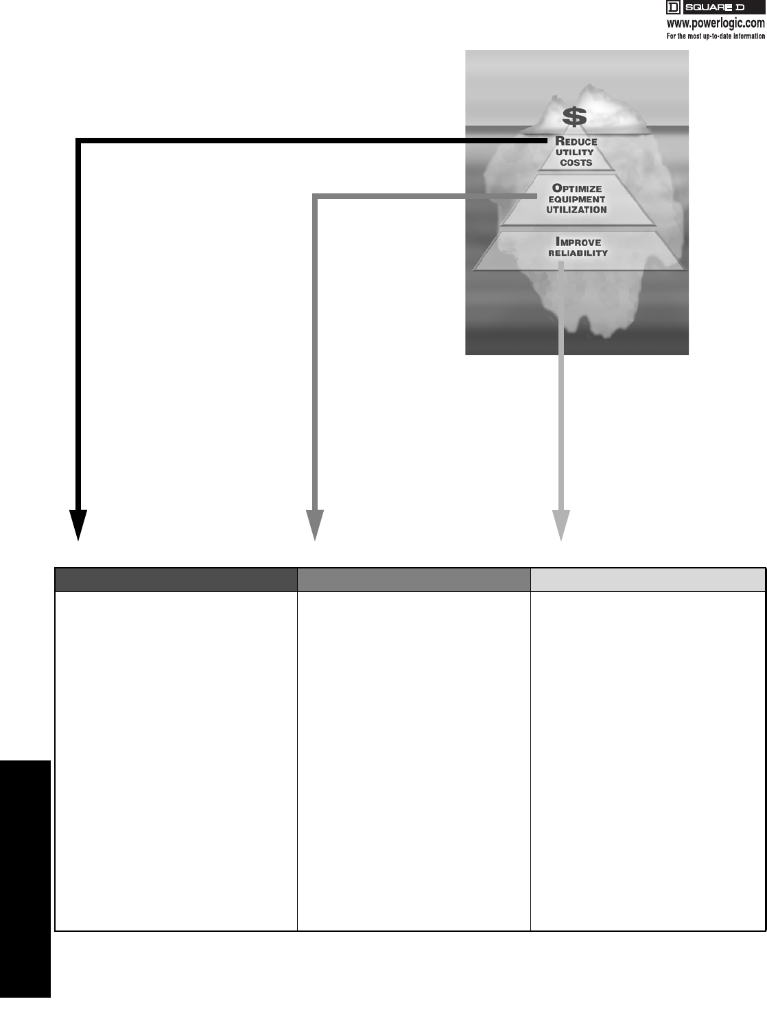
Icebergs. Typically, we think of them as huge peaks rising above the
water. In reality, the majority of an iceberg is actually under the water,
out of view. Utility savings at most facilities can be thought of in much
the same way.
Think of your utility bills as
being the peak, easy to see
every month. By simply
installing a PowerLogic
energy and power
management system, you can
realize a 2–4% savings—but
that’s just the “tip of the
iceberg” in terms of your
potential savings.
The majority of savings,
using a PowerLogic
system, can be derived by
looking beyond a utility
bill—or below the surface.
An additional 2–5% can be
saved through better
equipment utilization and
avoiding unnecessary
capital purchases.
Another 10% can be found in
power system reliability.
PowerLogic systems give you
the power to achieve this kind
of savings, resulting in a quick
return on your investment.
Table 4.1:
Reduce Utility Costs Optimize Equipment Utilization Improve Reliability
Meter Application
•Auto meter reading and energy monitoring
•Revenue Metering
•WAGES pulses
•Tenant Sub-metering
Cost Allocation & Utility Billing
•Interval Benchmarking & Profiling
•Allocate Energy Costs
•Total Load Aggregation
•Utility Bill Reconciliation
Utility Reduction Implementation & Services
•Total Energy Control Services
•Power Factor Correction
•Lighting Control
•Load Shedding/Sequencing
•Peak Shaving/Generator Control
Facility Planning
•Identify Equipment Capacity
•Determine Transformer Stress
•Maximize Equipment Life
Improve Efficiency
•Balance Circuit Loading
•Improve Power Factor
•Balance Generator Efficiency & Usage
•Optimize Chiller & Mechanical
Improve Maintenance Practices
•Equipment Monitoring: transformers,
MCCs, switchgear, switchboards, circuit
breaker status, protective equipment,
capacitors, generators, panelboards,
PDU, UPS, utility meter pulses
System Monitoring & Analysis
•Transient Voltage
•Disturbances
•Power Quality & Harmonics
Power System Automation
•Auto Throw Over (ATO) Systems
•Load preservation
Preventative Maintenance
•Emergency Power Supply System
Documentation
•Remote Alarm Notification
Advanced Diagnostics
•Sequence of Events
•GPS Time Stamping
•Root Cause Analysis
Power System Engineering & Consulting
•Safety & Code Compliance
•Electrical Distribution System Assessment
System Studies
At Square D/Schneider Electric, we pride ourselves on reliable products, innovative systems, expert engineering services, and our ability to provide
single-source energy and power management solutions. It’s not just a concept to us, it’s a legacy and a promise—for companies that seek an edge
in productivity. That’s why leaders turn to Square D/Schneider Electric.
17404.book Page 2 Thursday, October 4, 2007 8:28 AM

4POWER MONITORING AND
CONTROL
© 2007 Schneider Electric
All Rights Reserved 4-3
PowerLogic®
The New PowerLogic System
As the key component of Schneider Electric's
smart energy efficiency offering, the Square D®
PowerLogic system now consists of the most
complete energy and power management
portfolio available.
Backed by experienced power system experts,
and offering the most comprehensive range of
technical support and engineering services, we
are ready to handle your energy efficiency and
reliability challenges. Our recent acquisition of
Power Measurement has both doubled our
resources and increased the breadth of needs
that can be solved by leading-edge Square D PowerLogic solutions. Our total solution approach includes a range of products from simply
configurable to highly flexible with ION® technology options for building and customizing solutions for your business.
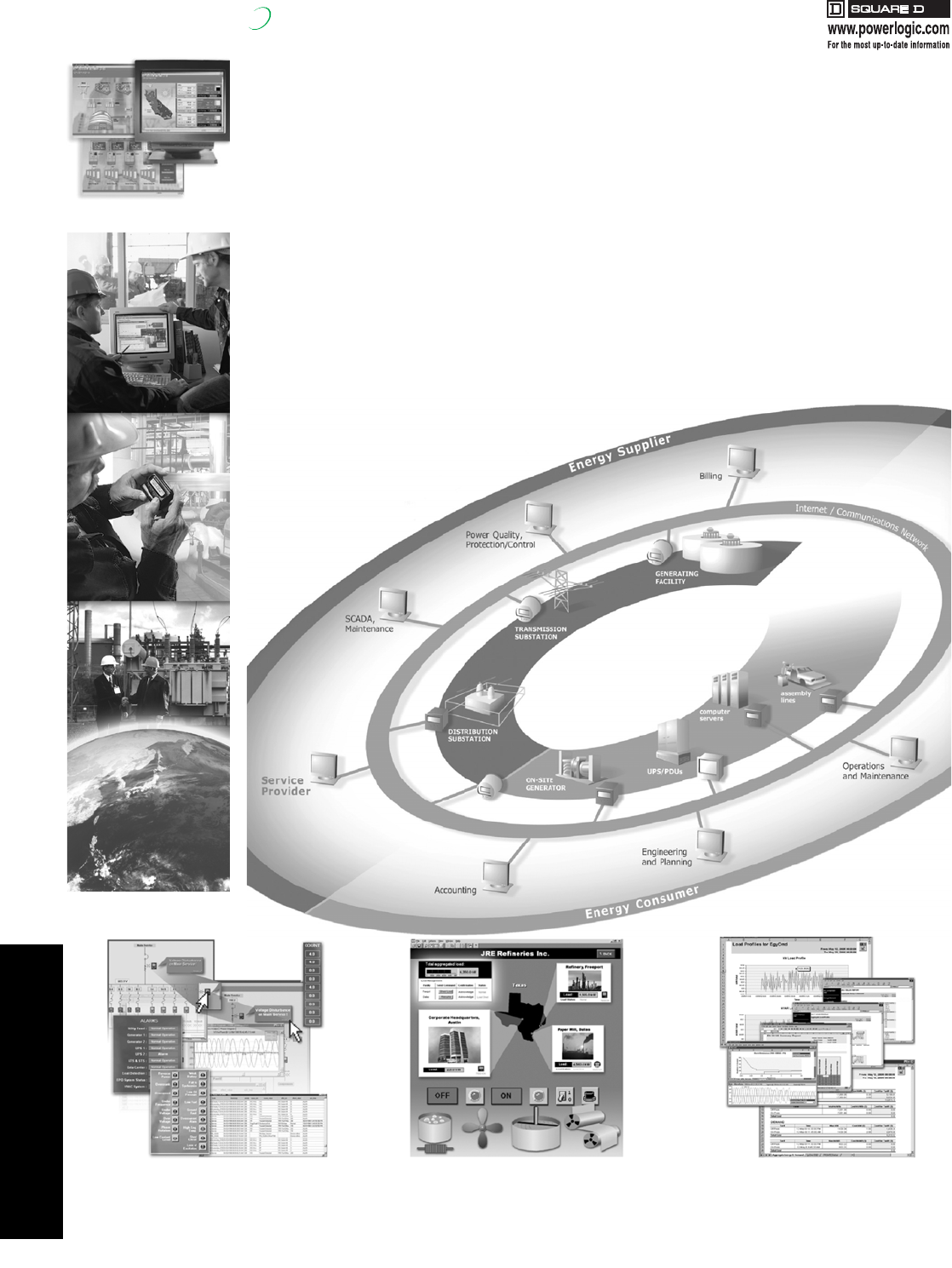
The PowerLogic system acts like a layer of energy and power intelligence across all of your power equipment and piped utility assets, helping you
meter and monitor all types of energy and, in turn, reduce energy costs, optimize equipment utilization and improve system reliability performance.
A tightly integrated network of software and meters can span a single facility or an entire multi-site enterprise. The system monitors key points from
the circuit breaker and equipment throughout the power delivery chain, 24 hours a day, from generators and substations to service entrances,
mains, feeders and individual branch circuits.
At the administrative level, PowerLogic acts as a web portal, delivering timely, relevant information to anyone that needs it, anywhere they are.
Advanced analytic tools enable effective decisions, while coordinated control capabilities help you act on them. Together, this represents a fast and
quantifiable return on investment.
The PowerLogic Advantage
Square D/Schneider Electric has decades of experience in delivering energy and power management solutions to thousands of customers,
including most of the Fortune 500. We are a complete single-source provider that can fully integrate energy and power management with power
distribution and automation solutions.
•PowerLogic is innovative technology featuring enterprise-level features such as energy modeling, web-enabled communications and the world's most advanced line
of energy and power quality instrumentation.
•PowerLogic supports industry standards, including accuracy certifications, power quality compliance standards, and measurement and verification protocols.
•PowerLogic is scalable; take advantage of modular applications and hardware to add or upgrade components easily and affordably.
•PowerLogic fits perfectly with other business, automation, metering or billing systems.
•PowerLogic represents a low cost of installation and ownership; systems are cost-effective, feature-rich, easy to use, and supported by extensive services that
ensure you get the most from your solution.
New!
Reduce Energy Costs Optimize Equipment Improve System Reliability Your ROI Solution Partner
17404.book Page 3 Thursday, October 4, 2007 8:28 AM
4-4 © 2007 Schneider Electric
All Rights Reserved
4POWER MONITORING AND
CONTROL
PowerLogic®PowerLogic ION Enterprise® Operations Software
New!
PowerLogic ION Enterprise Operations Software is an all-in-one package for operational power system monitoring,
analysis and control that helps you reduce energy-related costs. It offers control capabilities, comprehensive power
quality and reliability analysis and helps reduce energy related costs. The software is a suite of applications that
allows you to collect, process, analyze, store, and share data across your entire enterprise. PowerLogic ION
Enterprise software is designed to give you the information and analysis tools you need to make sound decisions. Its
cutting-edge flexibility and compatibility allow you to extend your energy management system at your own pace,
adding newer components as they become available, without interrupting or impacting existing functions. PowerLogic
ION Enterprise collects data through serial, wireless, modem or Ethernet links and can manage a single site or,
through the Internet, connect a global network of devices.
Interface to existing software systems and integrate third-party equipment, leveraging support for a variety of industry-
standard protocols. ION Enterprise also enables you to access information from any desktop, locally or around the
world, in the format you need. Control of your system is always within easy reach. Thanks to patented ION
technology, you get out-of-the box usability, plus you can quickly add or rearrange functions with drag-and-drop icons
and a few clicks of a mouse.
PowerLogic ION Enterprise Operations Software is ideal for energy suppliers and energy consumers and provides
powerful tools for:
•Power quality and reliability analysis
•Load studies and circuit optimization
•Demand and power factor control
•Equipment monitoring and control
•Preventative maintenance
•Cost allocation and billing
Respond to notifications, click an indicator to retrieve
the time, location, and nature of the event. Click again
to study tolerance curves, waveforms, or a report.
Control loads, generation, and power quality
mitigation equipment. Optimize switching with
the latest status and base loading data.
Allocate costs, consolidate billing or negotiate
contract volume pricing. Assure compliance with
PQ standards and verify operational progress.
17404.book Page 4 Thursday, October 4, 2007 8:28 AM
4POWER MONITORING AND
CONTROL
© 2007 Schneider Electric
All Rights Reserved 4-5
PowerLogic®ION Enterprise® Software Ordering Information/Meter Selection
New!
aEvery new system must be ordered with 1 IONE55-Base software and a minimum of 5 IONE55-DL device licenses.
bSpecifications represent maximum capabilities with all options installed. Some options are not available concurrently. This is not a complete feature list,
please refer to detailed product specifications.
Table 4.2: PowerLogic ION Enterprise Software Ordering Information
Description Catalog No. $ Price
Core Software Productsa
ION Enterprise Base software IONE56BASE 719.00
ION Enterprise Device license (For 100+ devices, please call the factory for volume pricing) IONE56DL 251.00
ION Enterprise Client license IONE56CL 719.00
OPC Server support for ION Enterprise IONEOPCV1 3055.00
SQL Server 2005 bundle option (CD and 1-CPU license) IONESQL2005 2440.00
SQL Server 2005 additional CPU license IONESQL2005CPU 1525.00
Upgrades from PowerLogic ION Enterprise 5.5
ION Enterprise Base Upgrade IONE56UPGRADE 359.00
ION Enterprise Device upgrade IONE56DLUPG 125.00
ION Enterprise Client license upgrade IONE56CLUPG 359.00
Related Items
ION Enterprise Replacement CD IONE56REPCD 215.00
ION Enterprise 5.5 Software Documentation Binder DOC-BINDERIE5 143.00
ION Enterprise 5.5 Administrator Guide DOC-UGUIDE204 71.00
ION Enterprise 5.5 Client User Guide DOC-UGUIDE205 35.00
Table 4.3: PowerLogic ION Power and Energy Meter Selection
FeaturesbION8600 ION7650 ION7550 ION7350 ION7330 ION7300 ION6200
ABC
Inputs, outputs and control power
3-phase / single-phase • / • • / • • /• • / • • / • • / • • / • • / • • / •
Digital in and out / analog in and out 16 / 4 16 / 4 16 / 4 20 / 8 20 / 8 8 / 8 8 / 8 4 / 8 2 /
Power supply options AC/DC AC/DC AC/DC AC/DC AC/DC AC/DC AC/DC AC/DC AC/DC
Power and energy measurements
V, I, F, PF • • • • • • •
Power, demand • • • • • • • • •
Energy / time-of-use (energy per shift) • / • • / • • / • • / • • / • • / • • / • • / • • /
ANSI energy accuracy class (% of reading) 0.2 0.2 0.2 0.5 0.5 0.5 0.5
Measurement Canada Approval • ••••
Loss compensation •••••
Power quality analysis
Compliance monitoring (e.g. EN50160) • •
Flicker measurement • •
Transient disturbance capture • •
Sag and swell monitoring ••••••
Harmonics measurement 63 rd 63 rd 31st 63 rd 63 rd 31st 15th 15th THD
Uptime (number of 9's) calculation ••••••••
Waveform capture • •••
Data and event logging
Trend / snapshot • / •• / •• / •• / •• / • • •
Min/max •••••••
Events •••••••
Timestamp resolution (seconds) 0.001 0.001 0.001 0.001 0.001 0.001 0.001
GPS sync •••••
Setpoints, alarms and control
Annunciation / call out on alarm • / • • / • • / • • / • • / • • / • •
Trigger logging •••••••
Trigger relay or digital output control •••••••
Special features
Custom programming: arithmetic, boolean,
object-oriented •••••••
Downloadable firmware •••••••••
Communications
Ethernet port / web / email • / • / • • / • / • • / • / • • / • / • • / • / • • / • / • • / • / • • / • / • / /
Telephone modem port •••••••
Infrared port ••••••••
RS485 / RS232 ports • / • • / • • / • • / • • / • • / • / • / • /
Modbus / DNP / MV-90 protocols • / • / • • / • / • • / • / • • / • / • • / • / • • / • / • • / • / • • / / • / /
PM1 Discount
Schedule Modified
10/4/07
17404.book Page 5 Thursday, October 4, 2007 8:28 AM
4POWER MONITORING AND
CONTROL
4-6 © 2007 Schneider Electric
All Rights Reserved
PowerLogic®ION8600/7550/7650 Power and Energy Meters
New!
ION8600/7550/7650 Power and Energy Meters
The web-enabled PowerLogic ION8600 is used to monitor electric distribution networks, service entrances and substations. It enables businesses
to manage complex energy supply contracts that include power quality guarantees. Low-range current accuracy makes it ideal for independent
power producers and cogeneration applications that require the accurate bi-directional measurement of energy. It is well suited to load curtailment,
equipment monitoring and control and energy pulsing and totalization applications. Integrate it with PowerLogic ION EEM enterprise energy
management software, PowerLogic ION Enterprise operations software or other energy management and SCADA systems.
PowerLogic ION8600 Power and Energy Meter Features
Feature set C includes:
• 9S, 39S, 35S, 36S, 76S socket and switchboard cases
• True RMS 3-phase voltage, current, power and meets stringent ANSI
revenue metering standards including ANSI C12.20 0.2 and Class 2,
10, & 20
• Power quality: sag/swell, individual, even, odd, total harmonics to the
31st and symmetrical components
• 2MB log/event memory, min/max for any parameter, historical logs up
to 32 channels, timestamp resolution to 0.001 seconds and GPS time
synchronization
• Transformer/line loss compensation and Instrument transformer
correction
• Communications: Fiber, Ethernet, Serial, Modem, Internet and
Ethernet to serial gateway and ION, DNP 3.0, Modbus RTU, Modbus
TCP and MV-90 protocols
• Dial-out capability when memory is near full
• Multi-user, multi-level security with control and customized access to
sensitive data for up to 16 users
• Data push capability through SMTP (email)
• 65 setpoints — math, logic, trig, log, linearization formulas
• Password protection and anti-tamper seal protection
• Built-in I/O: 4 KYZ digital outs and 3 form A digital ins, an
optional external I/O expander provides additional I/O
Feature set B adds the following to feature set C:
• Harmonics - individual, total even, total odd up to the 63rd
• 4MB standard memory
• Historical logs up to 320 channels
• Modbus RTU Master on serial ports
• Cycle setpoint minimum response time
Feature set A adds the following to feature sets C and B:
• Waveform capture up to 256 samples/cycle, PQ compliance
monitoring, flicker to EN50160, IEC 6100-4-7/4-15 (also
configurable to IEEE 519-1992, IEEE159, SEMI) CBEMA/ITIC
• Transient detection to 65µs at 60Hz;
• Harmonics: magnitude, phase and inter-harmonics to the 40th
• 10MB standard memory
• Max 96 cycles of waveform logs and 800 channels of historical
logs
Note: Please refer to powerlogic.com for the most complete and up-to-date list of feature availability. Some features are optional.
Table 4.4: Typical PowerLogic ION8600 Power and Energy Meter Ordering Configurations
Description Catalog No. $ Price
ION8600, feature set A, 9S socket base, 5A nominal current inputs, auxiliary power pigtail: 65-120Vac/80-160Vdc, 60 Hz, communications card with: 10baseT Ethernet
— RS-232/485 — Optical, RS-485 S8600A0C0H6E0A0A 6252.00
ION8600, feature set B, 9S socket base, 5A nominal current inputs, auxiliary power pigtail 65-120Vac/80-160Vdc, 60 Hz, communications card with: 10base T Ethernet
— Optical, RS-485 S8600B0C0H6E0A0A 4700.00
ION8600, feature set B, 9S socket base, 5A nominal current inputs, auxiliary power pigtail 65-120Vdc/80-160Vac, 60 Hz, communications card with: RS-232/485.
RS-485, Optical port, standard I/O S8600C0C0H6A0A0A 2609.00
PowerLogic ION7550 and ION7650 Power and Energy Meters
Used at key distribution points and sensitive loads, the web-enabled PowerLogic ION7550 and PowerLogic ION7650 meters combine a wealth of
advanced features from power quality analysis capabilities, revenue accuracy and multiple communications options, through web compatibility,
and control capabilities. Both are compatible with PowerLogic ION EEM enterprise energy management software, PowerLogic ION Enterprise
operations software can be integrated with other energy management or building control systems through multiple communication channels and
protocols.
The meters are ideal for compliance monitoring, disturbance analysis, cost allocation and billing, demand and power factor control and equipment
monitoring and control. The meters have a high visibility, adjustable front panel display that can depict TOU, harmonics, event logs, phasers, and
instantaneous power parameters. They meet stringent ANSI C12.20 0.2, Class 10 & 20 revenue metering standards.
PowerLogic ION7550 and ION7650 Power and Energy Meter Features
The PowerLogic ION7550 includes:
• 3.5” x 4.5” (87 x 112 mm) backlit LCD display
• True RMS 3-phase voltage, current, and power that meets stringent ANSI
C12.20 0.2, Class 2, 10, & 20
• Power quality: sag/swell, harmonics - individual, even, odd, total to the
63rd, waveform capture at 256 samples/cycle
• 5MB log/event memory (10MB optional), waveform logging up to 96
cycles, up to 800 channels historical, min/max, timestamp resolution to
0.001 seconds, GPS time synchronization and historical trends through
front panel
• Communications: fiber, Ethernet, serial, internal modem, optical port, and
a gateway functionality, ION, DNP 3.0, Modbus RTU - master & slave,
Modbus TCP and MV-90
• Dial-out capability when memory is near full
• Data push capability through SMTP (email)
• Multi-user, multi-level security with control and customized
access to sensitive data for up to 16 users
• 65 configurable _ cycle setpoints for single, multi-condition and
dial out on alarm and math, logic, trig, log, linearization formulas
• Password protection and anti-tamper seal protection enhance
meter security
• Extensive standard I/O includes: 8 digital inputs, 4 digital outputs
and 3 onboard relays
The ION7650 has all the features of the ION7550 and adds:
• Waveform capture up to 1024 samples/cycle
• Transient detection to 17µs at 60Hz
• Harmonics: magnitude, phase and inter-harmonics to the 40th
• Flicker to EN50160 and IEC 6100-4-7/4-15 (also configurable for
IEEE 519-1992, IEEE159, SEMI), plus CBEMA/ITIC
• Symmetrical components
Note: Please refer to powerlogic.com for the most complete and up-to-date list of feature availability. Some features are optional.
Table 4.5: Typical PowerLogic ION7550/7650 Power and Energy Meter Ordering Configurations
Description Catalog No. $ Price
Typical PowerLogic ION7550 Power and Energy Meter Ordering Configurations
Integrated display, with 512 samples/cycle, 5 MB logging memory, 5A inputs, standard power supply, standard comms. (1 RS232/RS485 port, 1 RS485, 1 Type 2
optical port) plus Ethernet, standard I/O S7550A0C0B6E0A0A 6318.00
Integrated display, with 512 samples/cycle, 5 MB logging memory, 5A inputs, standard power supply, standard comms. (1 RS232/RS485 port, 1 RS485, 1 Type 2
optical port), standard I/O S7550A0C0B6A0A0A 5589.00
Typical PowerLogic ION7650 Power and Energy Meter Ordering Configurations
Integrated display, with 1024 samples/cycle, 10 MB logging memory, 5A inputs, standard power supply, standard comms. (1 RS232/RS485 port, 1 RS485, 1 Type 2
optical port) plus Ethernet, standard I/O, EN50160 compliance monitoring S7650B1C0B6E0A0E 9279.00
Integrated display, with 512 samples/cycle, 5 MB logging memory, 5A inputs, standard power supply, standard comms. (1 RS232/RS485 port, 1 RS485, 1 Type 2
optical port) plus Ethernet, standard I/O S7650A0C0B6E0A0A 7869.00
PM1 Discount
Schedule
17404.book Page 6 Thursday, October 4, 2007 8:28 AM
4POWER MONITORING AND
CONTROL
© 2007 Schneider Electric
All Rights Reserved 4-7
PowerLogic®ION7350/7330/7300/6200 Power and Energy Meters
New!
Used in diverse applications such as feeder monitoring and sub-metering, the PowerLogic ION7300 series meters are also
suitable for high-accuracy power and energy metering, bill verification, cost allocation and billing, demand and power factor
control, load studies, circuit optimization, equipment monitoring and control and preventative maintenance. They are ideal
replacements for analog meters, with a multitude of power and energy measurements, analog and digital I/O,
communication ports and industry-standard protocols. The ION7330 meter adds on-board data storage, emails of logged
data and an optional modem. The ION7350 meter is further augmented by more sophisticated power quality analysis,
alarms and a call-back-on-alarm feature. They are compatible with PowerLogic ION EEM enterprise energy management
software, PowerLogic ION Enterprise operations software or can be integrated with other energy management or building
control systems through multiple communication channels and protocols.
PowerLogic ION7350, ION7330 and ION7300 Power and Energy Meter Features
The modular PowerLogic ION6200 is a low-cost, ultra-compact meter that offers outstanding versatility and
functionality. It is simple to use, and has a big, bright LED display. It offers four-quadrant power, demand, energy,
power factor and frequency measurements, and is available in a variety of flexible configurations. It is available as a
low-cost base model to which enhanced functionality can be added over the long term. The PowerLogic ION6200 is
ideal for customers who need revenue-accurate and/or certified measurements and want easy integration with power
distribution assemblies and building automation systems. A Megawatt version is available for applications requiring
readings in megawatts and kilovolts. It is well suited for sub-metering, energy cost tracking load profiling, and
substation panel metering and is an ideal replacement for analog meters. It can be used for stand-alone metering in
custom panels, switchboards, switchgear, gensets, motor control centers and UPS systems.
The meter consists of a base unit with options card and a power supply pack, with a remote display being optional.
PowerLogic ION6200 Power and Energy Meter Features
Please refer to powerlogic.com for the most complete and up-to-date list of feature availability. Some features are optional.
The PowerLogic ION7300 includes:
• Multiple form factors: transducer integrated and
remote display models, GE S1 or ABB FT21
switchboard forms
• True RMS 3-phase voltage, current, and power that
meets stringent ANSI C12.16, Class 10
• Power quality: harmonics - individual, even, odd, total
to the 15th, maximum 32 samples/cycle
• Communications: 1 RS-485 port, 1 optional Ethernet
port, 1 ANSI Type 2 infrared optical port, 1 PROFIBUS
DP port (ION7300 only), onboard web server
• Supported protocols include : ION, Modbus RTU slave
on serial, modem, I/R ports, Modbus TCP through
Ethernet
• Extensive standard I/O includes: 4 analog inputs,
4 analog outputs, 4 digital relay outputs
• Minimum/maximum recording
The ION7330 adds the following features:
Time of use - multi-year scheduling, hourly activity profiles
• 4 digital inputs for status monitoring and pulse counting
• Communications: a second RS-485 port, internal modem, DNP 3.0
through serial, modem and I/R ports, EtherGate and ModemGate,
data/alarms via e-mail and MV-90 on serial and Ethernet ports
• 12, one second setpoints for single, multi-condition alarms, plus math,
logic, trig, log, and linearization formulas
• Non-volatile onboard memory capacity of 300kb, min/max logging,
min/max logging, up to 32 channels of historical logs, timestamp
resolution to 0.001 seconds
The ION7350 includes the following additional features:
• Power Quality: sag/swell, individual, even, odd, total harmonics up to
31st , maximum 64 samples/cycle
• Up to 96 channels of logs and up to 48 cycles of waveform logs
• Alarm notifications via e-mail
--
Table 4.6: Typical PowerLogic ION7350/7330/7300 Power and Energy Ordering Configurations
Description Catalog No. $ Price
Typical PowerLogic ION7350 Power and Energy Meter Ordering Configurations
Integrated display with optical port, 5A inputs, standard power supply, standard comms, (two RS-485 ports) plus 10BaseT
Ethernet S7350A0B0B0E0A0A 3567.00
Integrated display with optical port, 5A inputs, standard power supply, standard comms, (two RS-485 ports) S7350A0B0B0A0A0A 2906.00
Typical PowerLogic ION7330 Power and Energy Meter Ordering Configurations
Integrated display with optical port, 5A inputs, standard power supply, standard comms, (two RS-485 ports) plus 10BaseT
Ethernet S7330A0B0B0E0A0A 2800.00
Integrated display with optical port, 5A inputs, standard power supply, standard comms, (two RS-485 ports) S7330A0B0B0A0A0A 2159.00
Typical PowerLogic ION7300 Power and Energy Meter Ordering Configurations
Integrated display with optical port, 5A inputs, standard power supply, standard comms, (one RS-485 port) S7300A0B0B0A0A0A 1436.00
• Only two inches deep, and fits a standard
ANSI four-inch switchboard cutout, or as a
TRAN model with no display and can be
fastened to a flat surface with a 4” (10cm)
ANSI bolt pattern or mounted to a DIN rail.
A remote display module (RMD) can be
ordered for the TRAN and mounted through
an ANSI 4” (10cm) and DIN 96 cutout.
• LED display with twelve 3/4” (19mm) high
digits that display all basic power parameters
• Pulse Outputs: optional kWh, kVARh and/or
kVAh pulsing
• Via two Form A outputs
• Communications: optional RS-485 port with
Modbus RTU and ION compatible
• 64 samples per cycle true RMS
• 3-phase voltage and current inputs
The standard ION6200 is available with the following parameters:
Voltage L-N average and per phase, Voltage L-L average and per phase,
Current average and per phase
Option EP#1, includes the standard measurements and provides the
following additional parameters:
I4, kW/mW total, kWh/mWh total, kW/mW peak, Current demand
average and per phase, Current peak demand average and per phase,
Power factor total
Optional Enhanced Package, includes the standard measurements
and provides the following additional parameters:
kW/mW per phase, kVAR/mVAR total and per phase, kVA/mVA total and
per phase, kWh/mWh and del/rec per phase, kVARh/mVARh total and
del/rec per phase, kVAh/mVAh total and per phase, kW/mW demand,
kVAR/mVAR demand and peak, kVA/mVA demand and peak, Power
Factor per phase, Voltage THD per phase, Current THD per phase
--
Table 4.7: Typical PowerLogic ION6200 Power and Energy Meter Ordering Configurations
Description Catalog No. $ Price
Integrated display, 10A inputs, standard 100-240 Vac power supply, RS485 port (Modbus RTU), Enhanced Package #2 S6200A0A0B0A0A0R 943.00
TRAN Model, with remote display, 10A inputs, standard 100-240 Vac power supply, RS485 port (Modbus RTU), Enhanced
Package #2 S6200R1A0B0A0A0R 977.00
TRAN Model, (no display), 10A inputs, standard 100-240 Vac power supply, RS485 port (Modbus RTU), Enhanced Package #2 S6200T1A0B0A0A0R 753.00
PM1 Discount
Schedule
17404.book Page 7 Thursday, October 4, 2007 8:28 AM
4-8 © 2007 Schneider Electric
All Rights Reserved
4POWER MONITORING AND
CONTROL
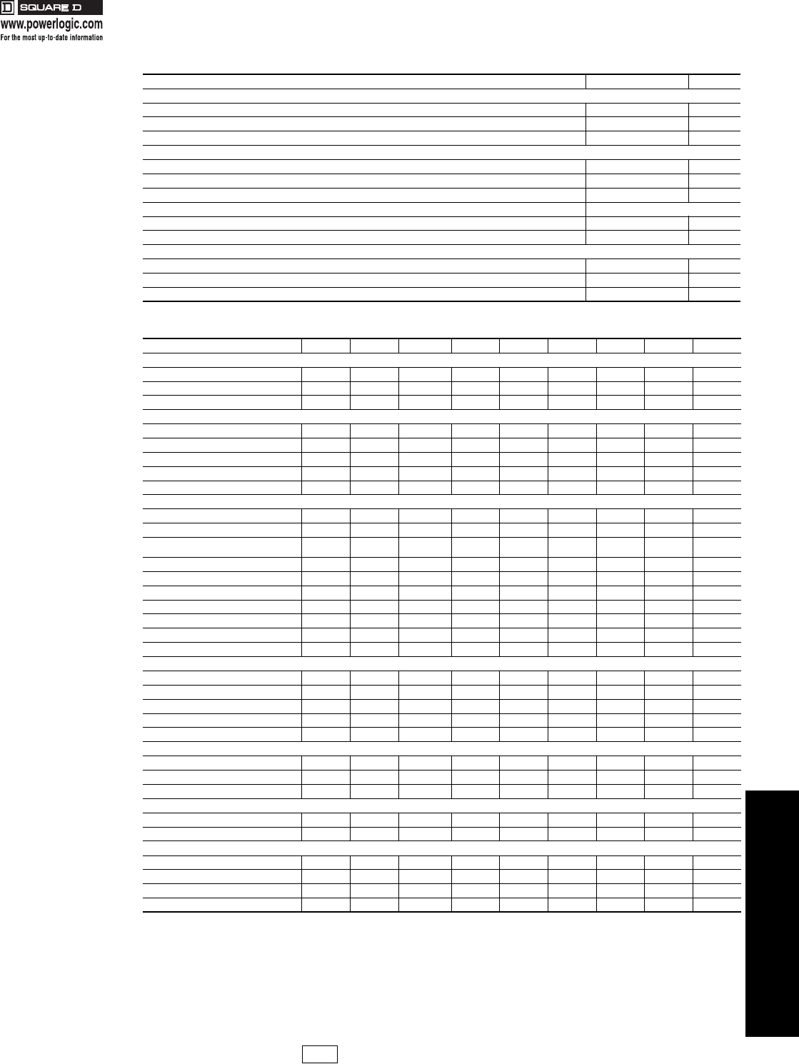
PowerLogic®System Manager Software
PowerLogic System Manager Software is designed to help control the cost, quality and reliability of your electrical and
piped utilities. With a PowerLogic system installed at your facility, you can identify where extra capacity exists,
determine if and where the equipment is being overstressed and balance loads on your power equipment. By
examining and changing the way you use power, you will save money. System Manager gives access to information so
effective decisions can be made concerning utility cost allocation, capital equipment purchases and building
improvements. Plus, System Manager is an essential tool for operations personnel to keep systems running before
problems occur, using graphical data and early alarm notifications.
PowerLogic System Manager Software (SMS) is a full featured web-
enabled product family. With built-in intuitive views, SMS ensures a
consistent power and utility monitoring experience. Upon
installation, the system contains over 50 real time tables, analog
meters and barcharts, an alarm log with waveform links,
pre-engineered power quality and utility cost reports, and more. You
can also tailor SMS to meet your own needs with customized
screens, trends and reports that are automatically incorporated into
the tabbed navigational user interface.
•Distributed monitoring with automatic data collection from device onboard
memory to eliminate nuisance data gaps.
•Open architecture with industry standard protocols.
•Supports a plethora of intelligent power equipment and monitoring
devices.
•Modular add-ons for advanced graphics, reports, billing and customized
functionality enhancements.
•Real time data and report sharing with secure access to information.
•Remote alarm notification to email, pagers and other mobile devices.
•Alarms show active status and alarm history with waveform analysis links
to aid troubleshooting power quality system events.
•Interactive diagrams graphically mimic your system and can provide real
time fault diagnostics indicating whether the direction of the last
disturbance was upstream or downstream of the monitoring point.
17404.book Page 8 Thursday, October 4, 2007 8:28 AM
4POWER MONITORING AND
CONTROL
© 2007 Schneider Electric
All Rights Reserved 4-9
PowerLogic®SMS Ordering Information/Meter Selection
aSpecifications represent maximum capabilities with all options installed. Some options are not available concurrently. This is not a complete feature list.
Please refer to detailed product specifications.
Table 4.8: PowerLogic System Manager Software Ordering Information
Description Catalog No. $ Price
Core Software Products
System Mgr. Device Limited (1 web-enabled client, 16 devices, up to 32 devices with SMSDL32U, Interactive Graphics) SMSDL 4150.00
System Mgr. Standard Ed. (1 web-enabled client, MSDE or SQL Personal Edition with Interactive Graphics) SMSSE 12750.00
System Mgr. Professional Edition (10 web-enabled clients, SQL Server, Advanced Reports, Interactive Graphics) SMSPE 19950.00
Add On Modules
SMS OPC Server Application SMSOPC 2980.00
SQL Server 2005 End User License SMSLIC 1785.00
Active Pager Module - Paging applications with conditional alarms assigned by shift 9789PAGE 3820.00
WAGES Module - Monitoring electrical and piped utilities available with engineered project Available as Engineered Project
SER Module - Sequence of Events software interface for GPS time synch available with engineered project 9789SER 15000.00
EPSS Test Report Module available with engineered project 9789EPSSTSTRPT 4650.00
Extension Products
Enables Standalones (DL & SE) with Remote Web clients (5 pk licenses) SMSWebXTR 2575.00
Extends SMSDL to 32 device limit SMSDL32U 2575.00
Converts SMSDL to SMSSE SMSDL2SE 8755.00
Table 4.9: PowerLogic Circuit Monitor and Power Meter Selection
FeaturesaCM4000T CM4250 CM3350 CM3250 PM870 PM850 PM820 PM750 PM710
Inputs, outputs and control power
3-phase / single-phase • / • • / • • / • • / • • / • • / • • / • • / • •
Digital in and out / analog in and out 24 / 4 24 / 4 9 / 0 9 / 0 18 / 8 18 / 8 18 / 8 3/
Power supply options AC/DC AC/DC AC/DC AC/DC AC/DC AC/DC AC/DC AC/DC AC/DC
Power and energy measurements
V, I, F, PF •• • ••••••
Power, demand •• • ••••••
Energy / energy per shift (time-of-use) • / • • / • • / • • / • • / • • / • • / • • / • /
Energy accuracy (%) 0.2 0.2 0.5 0.5 0.5 0.5 0.5 0.5 1.0
Standards compliance to ANSI / IEC • / • • / • • / • • / • • / • • / • • / • • / • • / •
Power quality analysis
Compliance monitoring (e.g. EN50160) • • • • • •
Flicker measurement •
High-speed transient disturbance capture
(200 ns) •
Transient disturbance capture • • • •
Disturbance direction detection • • •
Sag/swell monitoring • • • •
Harmonics measurement •• • ••••••
Uptime (number of 9's) calculation • • • •
Waveform capture • • • • • •
Waveshape alarm • •
Data and event logging
Trend / billing • / • / • / • / • / • • / • / •
Minimum and maximum •• • ••••••
Events / maintenance • / • • / • • / • / • • / • / • / •/ • /
Timestamp resolution (seconds) 0.001 0.001 0.001 0.001 1 1 1
GPS sync • • • •
Setpoints, alarms and control
Annunciation / call out on alarm • / • • / • • / • • / • • / • / • / •/
Trigger logging • • • • • • •
Trigger relay or digital ouput control • • • • • • •
Special features
Custom programming: arithmetic, boolean • •
Downloadable firmware •• • ••••••
Communications
Ethernet port / web / email • / • / • • / • / • • / • / • • / • / •
Infrared port • • • •
RS485 / RS232 ports • / • • / • • / • / • / • • / • • / • •/ • /
Modbus protocol •• • ••••••
PL1 Discount
Schedule Modified
10/4/07
17404.book Page 9 Thursday, October 4, 2007 8:28 AM
4-10 © 2007 Schneider Electric
All Rights Reserved
4POWER MONITORING AND
CONTROL
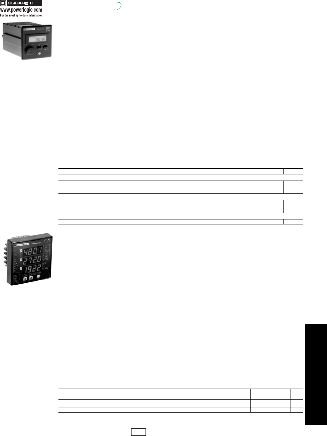
PowerLogic®Metering
New!
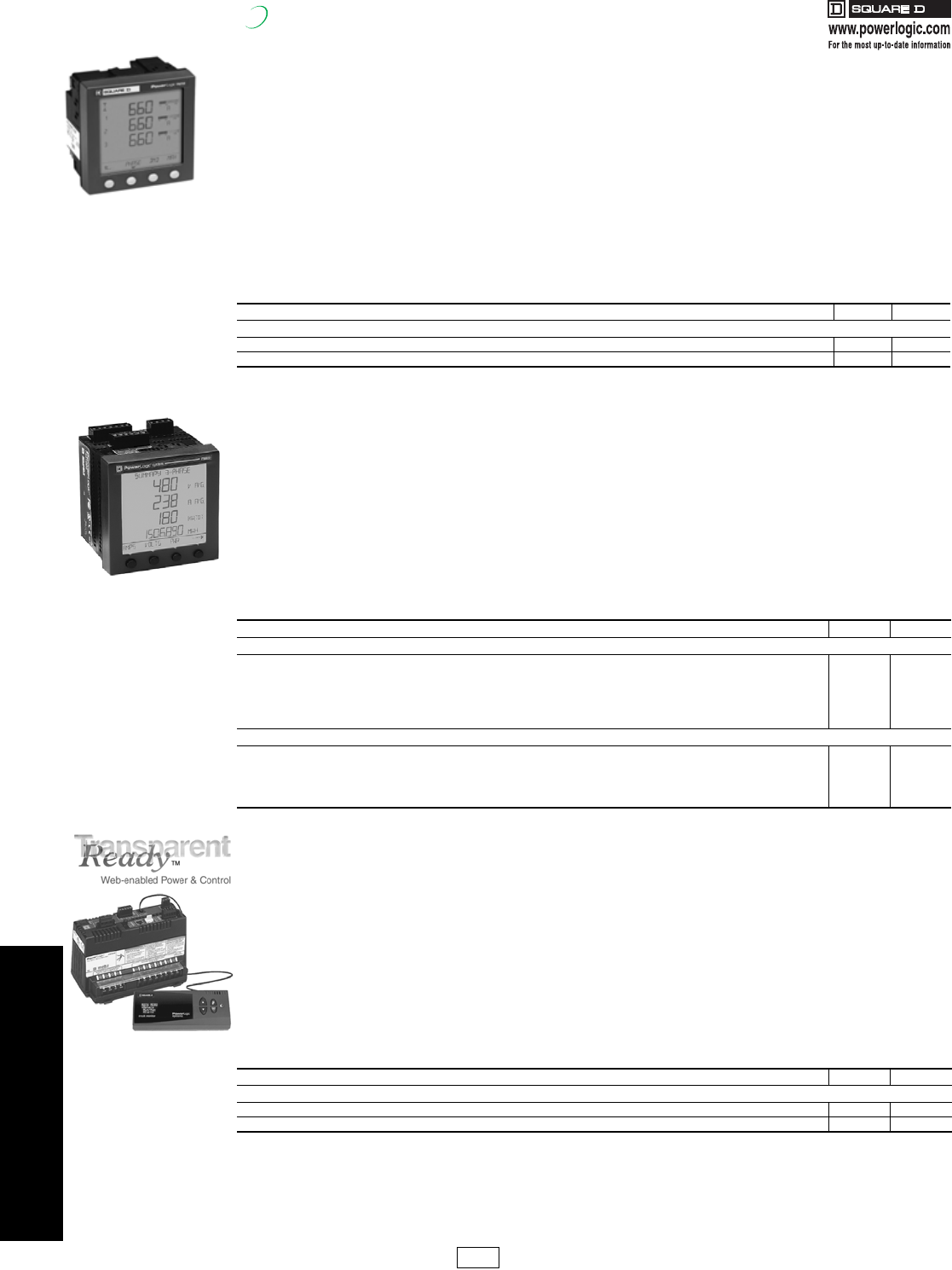
PowerLogic Series 700 Power Meter
The PowerLogic Power Meter 710 offers all of the measurement capabilities required to monitor an electrical
installation in a single 96 x 96 mm unit extending only 50 mm behind the mounting surface (less than 2 inches).
With its large display, you can monitor all three phases and neutral at the same time. The anti-glare display features
large 11 mm high characters and powerful backlighting for easy reading, even in extreme lighting conditions and
viewing angles.
Power and current demand, THD and min/max reading in basic version
A high-performance solution for trouble-free monitoring of your electrical installation.
Energy Class 1 as defined by IEC 62053 (or IEC 61036)
Suitable for sub-billing and cost-allocation applications.
aAvailable 2nd Quarter, 2007
PowerLogic Series 800 Power Meters
The PowerLogic PM800 series Power Meter is a high-performance power-monitoring unit able to provide advanced
power measurement capabilities in a compact 96x96 mm unit. Its large, easy to read display allows you to monitor all
three phases and neutral simultaneously. With its easy to use intuitive interface and self guiding menus, the large anti-
glare and back lit display makes this meter the easiest yet to navigate and use. The modular design allows for flexibility
with an easy upgrade path to grow the meter's capabilities with the addition of Communication and I/O Modules.
PowerLogic Series 3000 Circuit Monitor
The PowerLogic Series 3000 Circuit Monitor is designed for industrial, commercial and OEM users and is the ideal
monitoring device for electrical mains, branch feeders, as well as OEM applications, such as computer power. It
provides instant access to real time web pages without installing or learning special software.
CM3000 can serve up instantaneous readings, energy usage cost, power quality and disturbance analysis or even
customized web pages. Web-access summary data transparently from other devices connected downstream.
NOTE: See page 4-11 for Series 3000 Accessories
•Panel instrumentation (OEMs)
•Sub-billing and cost allocation •Remote monitoring of an electrical installation
•Harmonic monitoring (THD)
Table 4.10:
Description Catalog No. $ Price
Series 700 Power Meters
PM710 Power Meter with integrated display and comms PM710 710.00
aPM750 Power Meter with (2) digital input, (1) digital output PM750 950.00
•Monitor current, voltage, power and energy simultaneously
•Trending/Forecasting Curves functionality (PM850/870)
•128 samples/cycle-zero blind metering
•Waveform capture (PM850), configurable waveform capture (PM870)
•Onboard logging (80k in PM820, 800k in PM850/PM870)
•Detection of voltage sags and swells
•Individual harmonic measurements on current and voltage
•Available with 2 standard Digital I/O
•Field installable Digital and Analog I/O
•THD measurement
•Meets IEC 60687 and ANSI C12.20 Class 0.5S accuracy
•Programmable (logic and mathematical functions)
Table 4.11:
Description Catalog No. $ Price
Series 800 Power Meters
PM820 Power Meter with integrated display, THD, Alarming, 80kb Logging PM820 2390.00
PM850 Power Meter with integrated display, THD, Alarming, 800kb Logging, Waveform Capture PM850 3889.00
PM820 Meter unit only without display PM820U 2050.00
PM850 Meter unit only without display PM850U 3529.00
PM870 Power Meter with integrated display, THD, Alarming, 800 kb Logging, configurable Waveform Capture, Sag/Swell Detection PM870 4799.00
PM870 Meter unit only without display PM870U 4460.00
Series 800 Power Meter Accessories
PM800 Display for integrated meter unit PM8D 443.00
PM800 Module, 2 digital outputs (relays), 6 digital inputs PM8M22 635.00
PM800 Module, 2 digital outputs (relays), 6 digital inputs PM8M26 635.00
PM800 Module, 2 digital out, 2 digital in, 2 analog out, 2 analog in PM8M2222 856.00
PM800 Mounting adapter for CM2000 PM8MA 267.00
•Comes with 8Mb of standard memory allowing for more data
logging than any other meter in its class
•128 samples/cycle allow for zero blind metering
•Sag/Swell disturbance monitoring(CM3350)
•100 ms Event recording(CM3350)
•Harmonic Powerflows to the 40th harmonic
•Sequence of events recording using GPS synchronization
•Built-in Trending and Forecasting functionality allows you to
forecast energy usage up to 4 days in advance
•Custom web pages with optional Ethernet Communications
Card
•Field installable Digital I/O card
•Meets IEC 60687 and ANSI C12.20 Class 0.5S accuracy
Table 4.12:
Description Catalog No. $ Price
Series 3000 Circuit Monitors
Instrumentation, On-board Data Logging Waveform Capture, Disturbance Waveform Capture, Configurable I/O, 0.15% Accuracy CM3250 3944.00
Same as CM3250 plus Sag/Swell Disturbance Detection and 100 ms RMS Event Recording CM3350 5121.00
Series 700 Power Meter
Series 800 Power Meter
Series 3000 Power Meter
PL1 Discount
Schedule
17404.book Page 10 Thursday, October 4, 2007 8:28 AM
4POWER MONITORING AND
CONTROL
© 2007 Schneider Electric
All Rights Reserved 4-11
PowerLogic®Metering
New!
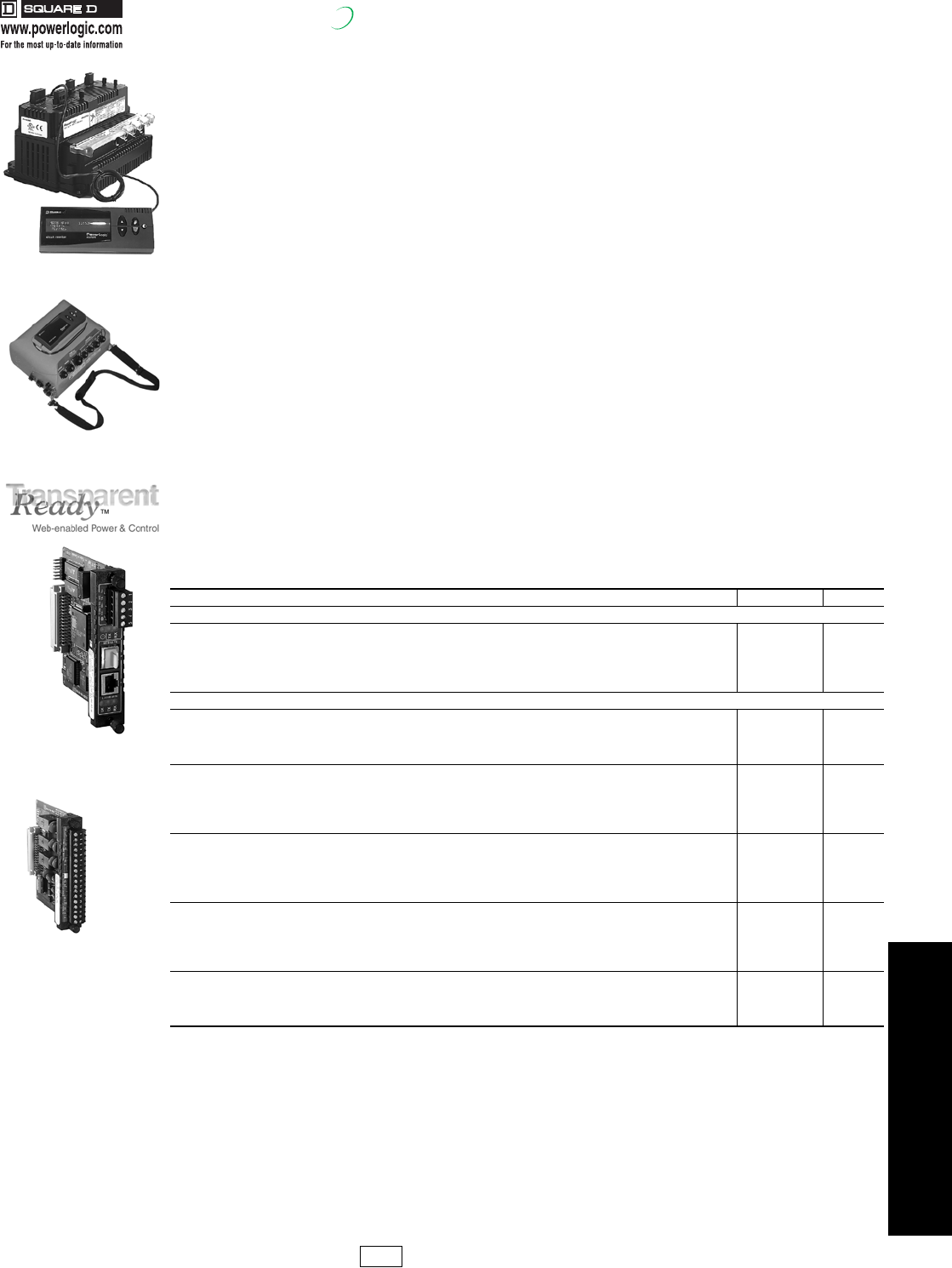
PowerLogic Series 4000 Circuit Monitor
The award winning, Web-enabled PowerLogic Series 4000 Circuit Monitor (CM4250) is the most advanced
permanently mounted circuit monitor in the industry today. Designed for critical power and large energy users who
cannot afford to be shut down, the CM4250 provides the ability to monitor, troubleshoot and preempt power quality
problems. Transients (disturbances lasting less than one cycle) are particularly difficult to detect, due to their short
duration. The CM4000T detects and captures oscillatory and impulsive transients (up to 10,000V peak, line-to-line at 5
MHz per channel) as short as one microsecond in duration. The CM4000T automatically performs a high-speed
transient waveform capture and a longer disturbance capture to show the conditions surrounding an event. The
CM4000T maintains a complete historical record of the number of transients per phase, along with the magnitude,
duration and time of occurrence of each. It also performs a stress calculation to determine the circuits that have
received the greatest stress from transient overvoltages.
PowerLogic Series 4000 Circuit Monitor Optional Displays
•High visibility remote VF (vacuum fluorescence) display with I/R communications port
•Displays metering data, min/max values, alarms, inputs
•Remote LC (liquid crystal) display with backlighting also available
•Optional user configurable display screens
aContact your nearest Square D/Schneider Electric sales office for additional I/O options.
bCM4000 is field upgradeable to provide additional features of specified module.
cAlso available for CM3000
•Waveform capture with up to 512 samples/cycle
•Built-in Trending and Forecasting functionality allows you to
forecast energy usage up to 4 days in advance
•Sag/Swell disturbance monitoring
•Two option card slots for field installable cards
•Optional field installable Ethernet communications card with
standard and custom web pages
•Alarm Setpoint Learning feature allowing optimum threshold setting
(patent pending)
•Multiple alarms including standard, digital, Boolean, high-speed,
and disturbance alarms
•Waveshape alarm monitoring
•High speed transient voltage detection at 5 MHz per channel with
field installable CVMT current/voltage module
•True RMS Metering through the 255th harmonic
•Also available in a rugged sealed case as a Portable Circuit Monitor
•Extended waveform capture (up to 110 seconds)
•Field installable Digital/Analog I/O cards and flexible I/O
extender modules
•Harmonic powerflows up to the 40th harmonic
•Standard KYZ pulse output
•Standard 16 MB of non-volatile memory (field
upgradeable to 32 MB)
•Integrated power quality standards including EN50160,
IEC 61000-4-15 (Flicker)
•Sequence of events recording using GPS synchronization
technology
•Oscillatory transient detection and recording
•Extended range current/voltage module(CVMXR) for
higher inrush currents available, field installable
•UL Listed, CSA Approved, CE Marking, NOM Approved,
FCC compliant
Table 4.13: Series 4000 Circuit Monitors
Description Catalog No. $ Price
Series 4000 Circuit Monitors
Instrumentation, On-board Data Logging, Waveform Capture, Disturbance Recording, Configurable I/O, 0.04% Accuracy CM4250 6386.00
Same as CM4000, Current Overrange of 100A up to 1 Second, 40A Continuous CM4250XR 7124.00
Same as CM4000 plus Impulsive Transient Detection and Flicker (IEC 61000-4-15) CM4000T 8474.00
Portable CM4000 Base Unit, Detachable Vacuum Fluorescent Display, Ride-though Module, Cable Set and Carrying Bag PCM4000 14205.00
Portable CM4000 plus Impulsive Transient Detection and Flicker (IEC 61000-4-15) PCM4000T 17643.00
Series 4000 Circuit Monitor Accessories
Field installable I/O card with 3 relay outputs, 1 pulse output (KYZ) and 4 status inputs IOC44c796.00
I/O Extender module with 4 DC status inputs, 2 DC digital outputs, 1 analog input and 1 analog output IOX2411 1253.00
I/O Extender module with 4 status inputs and 4 analog inputs (4-20 mA) IOX0404 1650.00
I/O Extender module with 8 status inputs IOX08 703.00
I/O Extender module with no pre-installed I/O aIOX 459.00
Ethernet Communications Card; 100 MB Fiber or 10/100 MB UTP Ethernet port and 1 RS-485 master port ECC21c1948.00
Current/Voltage module CVM 1325.00
Current/Voltage module with extended current rangebCVMXR 2949.00
Current/Voltage module with high speed transient detectionbCVMT 5393.00
4-line x 20 - character liquid crystal display with backlighting CMDLCc688.00
4-line x 20 - character vacuum fluorescent display with I/R port and proximity sensor CMDVFc1207.00
I/R communications interface for the vacuum fluorescent display OCIVFc604.00
4 foot display cable CAB4c53.00
12 foot display cable CAB12c89.00
30 foot display cable CAB30c161.00
Portable Circuit Monitor 5A CT 150/300/600A Range (Order 3 for complete set) PLESNS36005 856.00
Portable Circuit Monitor 5A CT 500/1000/1500A Range (Order 3 for complete set) PLESH163155 1359.00
Portable Circuit Monitor 5A CT 1000/2000/3000A Range (Order 3 for complete set) PLESHP32335 1886.00
PowerLogic Satellite Time System, Circuit Monitor and SEPAM GPS Time Synchronization, 100 microsecond accuracy STS3000 5348.00
Satellite Time Reference Module STRM 2827.00
Smart Antenna Module SAM 2292.00
Smart Antenna Module Interface Cable - 200 FT SAIF200 611.00
Power Supply, 24DC/50W, DIN-mountable PS080 558.00
CM4000T with VFD Display
PCM4000
ECC21
IOC44 I/O Card
PL1 Discount
Schedule Modified
10/4/07
17404.book Page 11 Thursday, October 4, 2007 8:28 AM
4POWER MONITORING AND
CONTROL
4-12 © 2007 Schneider Electric
All Rights Reserved
PowerLogic®Submetering
New!
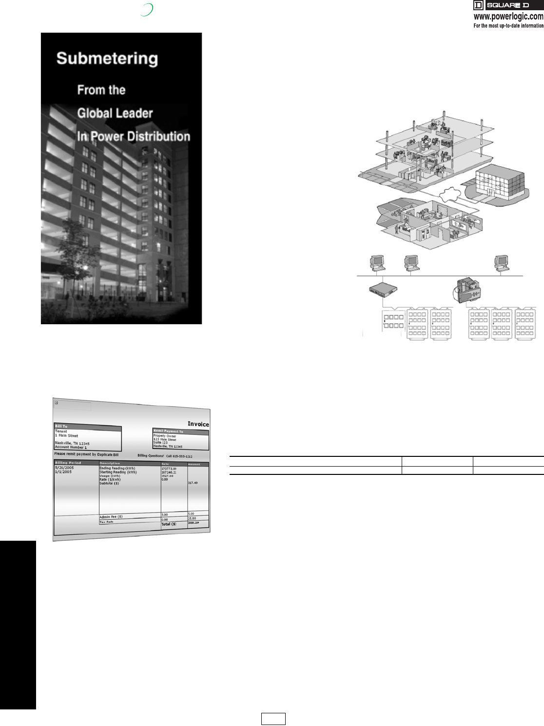
PowerLogic Submetering
In today's increasingly competitive commercial property market, attracting and retaining
high-quality, long-term tenants by offering exceptional value is the primary goal. Balancing
these premium services and reliable infrastructure vs. the financial exposure to volatile
utility costs is the challenge.
Minimizing energy costs requires information on how energy usage translates into money
spent. PowerLogic energy sub-metering systems are specifically engineered to address the
measurement, verification and billing needs of multi-tenant properties.
•Residential high-rise and low-rise
•Campuses
•Shopping centers
•Malls / food courts
•Offices
•Commercial buildings
PowerLogic energy management
and metering systems are ideal
for multi-tenant buildings
providing:
•Metering & Verification tools to
assure compliance to Energy
Policy Act 2005
•Integrated approach from simple
energy allocation requirements to
high-end power quality
•Monitor energy usage and
efficiency to accurately recover
the costs while providing tenants
with energy and a reliable
infrastructure
Square D/Schneider Electric, a
trusted equipment supplier for
over 100 years, can be your
single source for all your energy
management needs — reliable
metering systems, services,
installation, operational costs,
training and maintenance
agreements.
Tenant Metering Software
When PowerLogic submetering is combined with PowerLogic Tenant Metering Software
(TMS), metering data is automatically collected to generate tenant account statements.
Intuitive for even the most novice PC users, TMS offers fully customizable billing periods
and rate structures providing the flexibility necessary to manage a wide range of tenants.
The Tenant Metering Software Export Tool also provides data integration with third party
billing services, to enable complete outsourcing of your utility billing activities.
Enterprise Energy Management
For comprehensive enterprise energy management, PowerLogic ION EEM is a solution that
cleanses and warehouses data from power monitoring and control systems, building and
process automation systems, utility information systems, weather services, spot-market
energy pricing feeds and enterprise business applications. Personalized, browser-based
dashboards and innovative visualization and modeling tools, then make the information
available to whomever needs it, so you can accurately monitor, validate, predict and control
energy-related expenses. For more details see ION EEM page 4-16.
Table 4.14:
Description Catalog No. $ Price
Tenant Metering Software (TMS) TMS 2850.00
PL1 Discount
Schedule
17404.book Page 12 Thursday, October 4, 2007 8:28 AM
4POWER MONITORING AND
CONTROL
© 2007 Schneider Electric
All Rights Reserved 4-13
PowerLogic®Submetering
New!
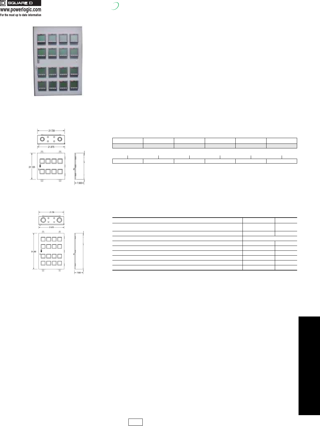
PowerLogic High Density Metering
High Density Metering (HDM) from Square D is engineered to answer the metering and
billing needs of multi-tenant properties:
Features and Benefits
•The HDM comes standard with the PowerLogic PM210 power meter. The PowerLogic PM710 is
available as an upgrade. Please consult the factory to discuss cabinets equipped with the
PowerLogic PM800 series meters.
•Lockable, 16 gauge NEMA Type 1 enclosure provides tamper-resistant security.
•NEMA Type 3R 12, 4 also available. Please consult factory.
•Mounting channel and surface-mount flanges simplify installation.
•Factory installed cover plates are included to cover empty meter spaces.
•Factory installed wiring harness simplifies installation of additional meters and provides future
system expansion.
•Each High Density Metering cabinet is provided with standard RS485 Modbus®, and optional
Modbus Ethernet TCP communications are available. For wireless communications, please consult
factory.
•Available in the following configurations: 120/240 volt single phase, 120/208 volt and 240 volt three
phase, 277/480 volt and 480 volt three phase.
•CTs required. Must select separately.
Note: Complete part #: HDMPM2101211613
High Density Meter System includes:
•Enclosure
•Power Meters, installed
•Installation bulletin for Enclosure
•Wall hanging bracket
•Installation bulletin for Meters
Table 4.15: High Density Metering Cabinet Ordering Example: HDMPM2101211613
Category Meter Series Voltage Phasing Enclosure Size # Meter
HDM PM210 or PM710 12, 48 1, 3 1, 4, 8, 16 0-16
Category Meter Voltage Phase Enclosure # Meters
HDM PM210 12 1 16 13
Table 4.16: Accessories and Options
Description Catalog No. $ Price
Auxiliary Wiring Harness for installation of additional meters (includes connectors and
shorting terminal blocks) HDMPMHKIT27 221.00
Cover plate for empty meter base HDMCVRPLT 5.90
Water and Gas Meters Consult factory for details
PowerLogic Tenant Metering Software (TMS) TMS 2850.00
50 Amp HDM Solid Core Current Transformer, 1.13” window size HDMCT050S1 35.00
100 Amp HDM Solid Core Current Transformer, 1.13” window size HDMCT100S1 35.00
125 Amp HDM Solid Core Current Transformer, 1.13” window size HDMCT125S1 35.00
150 Amp HDM Solid Core Current Transformer, 1.13” window size HDMCT150S1 35.00
200 Amp HDM Solid Core Current Transformer, 1.13” window size HDMCT200S1 52.00
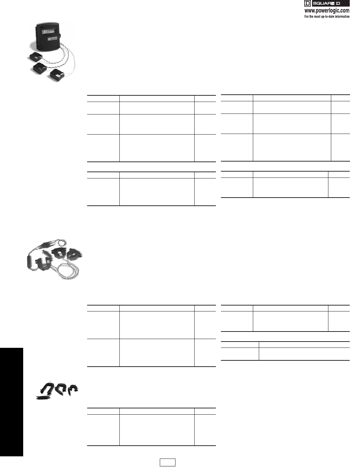
High Density Metering
factory assembled enclosure
for multi-tenant properties
8 meter configuration
16 meter configuration
PL1 Discount
Schedule
17404.book Page 13 Thursday, October 4, 2007 8:28 AM
4POWER MONITORING AND
CONTROL
4-14 © 2007 Schneider Electric
All Rights Reserved
PowerLogic®Submetering
Energy Meter
Note: CT quantity and amperage must match meter model. Total of
combined loads must not exceed rating of meter. All additional CTs
shipped with 6 ft. white and black color-coded wire leads.
aEnergy Meter communication board (EMCB) can be used with all
models of the Energy Meter. Order one EMCB for each Energy Meter
where either kW demand and/or communication is specified.
Note: Max. Voltage without additional insulation 600Vac. Do
not apply 600V Class current transformers to circuits having
a phase-to-phase voltage greater than 600V, unless
adequate additional insulation is applied between the
primary conductor and the current transformers. Square D
assumes no responsibility for damage of equipment or
personal injury caused by transformers operated on circuits
above their published ratings.
PowerLogic Energy Meter
The Energy Meter is ideal for stand-alone and systems-based submetering applications. It is easy to install and provides
exceptional metering accuracy. Available in Basic and Extended Range models. The Basic model is designed for metering
of 120/240 and 208Y/120 volt services. The Extended Range model will meter 120/240 volt up to 480 volt Wye connected
services. Extended Range meters come with pulse output and phase loss output not available on the Basic unit. Optional
Modbus® RS-485 serial communications are provided with the Energy Meter Comms Board, EMCB. Optional kW demand is
also provided by the EMCB.
Meter up to 3 individual services with one Energy Meter. The Energy Meter will allow the addition of up to 3 sets of parallel
CTs for metering multiple electric loads. Additional sets of CTs can be ordered separately. Please refer to the multiple CT
application notes in the Energy Meter instruction bulletin for the proper installation procedures.
Energy Meter Table 4.17: Basic 120/240 Volt, 208 Volt Wye
Catalog No. Description $ Price
EMB1010 Basic 100A, .518"x1.28" ID, 1 CT 426.00
EMB1021 Basic 200A, 0.75” x 1.10” ID, 1 CT 440.00
EMB1032 Basic 300A, .90"x1.90" ID, 1 CT 482.00
EMB2010 Basic 100A, .518"x1.28" ID, 2 CTs 438.00
EMB2021 Basic 200A, 0.75” x 1.10” ID, 2 CTs 464.00
EMB2032 Basic 300A, .90"x1.90" ID, 2 CTs 480.00
EMB2043 Basic 400A, 2.45"x2.89" ID, 2 CTs 505.00
EMB2083 Basic 800A, 2.45"x2.89" ID, 2 CTs 517.00
EMB3010 Basic 100A, .518"x1.28" ID, 3 CTs 750.00
EMB3021 Basic 200A, 0.75” x 1.10” ID, 3 CTs 766.00
EMB3032 Basic 300A, .90"x1.90" ID, 3 CTs 799.00
EMB3043 Basic 400A, 2.45"x2.89" ID, 3 CTs 825.00
EMB3083 Basic 800A, 2.45"x2.89" ID, 3 CTs 855.00
EMB3084 Basic 800A, 2.45"x5.50" ID, 3 CTs 903.00
EMB3164 Basic 1600A, 2.45"x5.50" ID, 3 CTs 903.00
Table 4.18: Additional CT Sets
Catalog No. Description $ Price
EMCT010 100 A, .518” x 1.28” ID, 1 CT 92.00
EMCT021 200 A, 0.75” x 1.10” ID, 1 CT 99.00
EMCT032 300 A, .90” x 1.90” ID, 1 CT 106.00
EMCT043 400 A, 2.45” x 2.89” ID, 1 CT 106.00
EMCT083 800 A, 2.45” x 2.89” ID, 1 CT 123.00
EMCT084 800 A, 2.45” x 5.50” ID, 1 CT 130.00
EMCT164 1600 A, 2.45” x 5.50” ID, 1 CT 130.00
Table 4.19: Extended Range 120-480 Volt Wye
Catalog No. Description $ Price
EME1010 Extended Range 100A, .518"x1.28" ID, 1 CT 471.00
EME1021 Extended Range 200A, 0.75” x 1.10” ID, 1 CT 483.00
EME1032 Extended Range 300A, .90"x1.90" ID, 1 CT 518.00
EME2010 Extended Range 100A,n.518"x1.28" ID, 2 CTs 511.00
EME2021 Extended Range 200A, 0.75” x 1.10” ID, 2 CTs 536.00
EME2032 Extended Range 300A, .90"x1.90" ID, 2 CTs 550.00
EME2043 Extended Range 400A, 2.45"x2.89" ID, 2 CTs 567.00
EME2083 Extended Range 800A, 2.45"x2.89" ID, 2 CTs 585.00
EME3010 Extended Range 100A, .518"x1.28" ID, 3 CTs 811.00
EME3021 Extended Range 200A, 0.75” x 1.10” ID, 3 CTs 829.00
EME3032 Extended Range 300A, .90"x1.90" ID, 3 CTs 864.00
EME3043 Extended Range 400A, 2.45"x2.89" ID, 3 CTs 880.00
EME3083 Extended Range 800A, 2.45"x2.89" ID, 3 CTs 921.00
EME3084 Extended Range 800A, 2.45"x5.50" ID, 3 CTs 971.00
EME3164 Extended Range 1600A, 2.45"x5.50" ID, 3 CTs 971.00
Table 4.20: Energy Meter Accessories
Catalog No. Description $ Price
EMCB Energy Meter Communication Boarda267.00
EMFP1 Energy Meter Fuse Pack, Set of 1 47.00
EMFP2 Energy Meter Fuse Pack, Set of 2 94.00
EMFP3 Energy Meter Fuse Pack, Set of 3 142.00
EMBOND Energy Meter Bonding Kit 117.00
PowerLogic Enercept® Meter
The Enercept Meter is the ideal solution for submetering electric loads where space is at a premium. The compact design
consists of three interconnected split-core CTs with the metering and communication electronics built into the CT housing.
Simply snap on the CTs, connect the voltage inputs, the communication lines, and installation is complete. Both versions
can be connected to either three-phase or single-phase circuits.
Enercept meters employ the Modbus® RTU 2-wire communication protocol, and can utilize the same communication
network and PowerLogic System Manager™ software as other PowerLogic devices. Data from the Enercept meters can be
presented in tabular or graphical format, used for alarming and historical logging and trending, and to produce reports.
Optional Enercept Display Interface acts as a stand-alone operator interface supporting up to 32 meters (63 with a repeater).
In addition, the EDI can act as a network adapter allowing Enercept meters to be incorporated into a 4-wire network. The
Enercept Network Adapter (ENA) is designed to act as a network adapter, allowing the Enercept meters to be integrated into
a PowerLogic 4-wire network. The ENA converts the signals from the 4-wire network to the 2-wire network, as well as
changing the parity between the two networks.
Enercept Meter
Table 4.21: Enercept Meter
Catalog No. Description $ Price
3020B012bBasic 100A, 1.25" x 1.51" ID 776.00
3020B032bBasic 300A, 1.25" x 1.51" ID 800.00
3020B043bBasic 400A, 2.45" x 2.89" ID 823.00
3020B083bBasic 800A, 2.45" x 2.89" ID 847.00
3020B084bBasic 800A, 2.45" x 5.50" ID 869.00
3020B164bBasic 1600A, 2.45" x 5.50" ID 893.00
3020B244bBasic 2400A, 2.45" x 5.50" ID 916.00
3020E012 Enhanced 100A, 1.25" x 1.51" ID 1035.00
3020E032 Enhanced 300A, 1.25" x 1.51" ID 1066.00
3020E043 Enhanced 400A, 2.45" x 2.89" ID 1097.00
3020E083 Enhanced 800A, 2.45" x 2.89" ID 1128.00
3020E084 Enhanced 800A, 2.45" x 5.50" ID 1159.00
3020E164 Enhanced 1600A, 2.45" x 5.50" ID 1190.00
3020E244 Enhanced 2400A, 2.45" x 5.50" ID 1221.00
Table 4.22: Accessories
Catalog No. Description $ Price
ENA485 Enercept Network Adapter 471.00
EDI32 Enercept Display Interface 1338.00
2W485C 2-Wire 232-485 Conv 78.00
EMBK-3 Enercept Mounting Brackets (Set of 3) 75. 00
PS24 24Vdc Power Supply (for use with EDI or ENA) 157.00
Table 4.23: Enercept Metering Quantities
BasicbEnhanced•
kWh, energy usage
kW, real power
kWh, kW per phase and total, min kW, max kW, kWd,
kVAR, kVA, PF per phase and total voltage- V, L-L, L-N
per phase and avg. Current - A, per phase and average
PowerLogic Split Core Current Transformers-Instrument Grade 5 Amp Split-Core Current Transformers
The 3090 SCCT series of split-core current transformers provide secondary amperage proportional to the primary (sensed)
current. For use with Circuit Monitors, Power Meters, data loggers, chart recorders and other instruments the 3090 SCCT
series provides a cost-effective means to transform electrical service amperages to a 0-5A level compatible with monitoring
equipment.
SA Split-Core Current
Transformers
Table 4.24:
Catalog No. Description $ Price
3090SCCT022 Split Core CT - 200A (sz.2): 1.25" x 1.51 120.00
3090SCCT032 Split Core CT - 300A (sz.2): 1.25" x 1.51 120.00
3090SCCT043 Split Core CT - 400A (sz.3): 2.45" x 2.89 129.00
3090SCCT063 Split Core CT - 600A (sz.3): 2.45" x 2.89 129.00
3090SCCT083 Split Core CT - 800A (sz.3): 2.45" x 2.89 129.00
3090SCCT124 Split Core CT - 1200A (sz.4): 2.45" x 5.50 160.00
3090SCCT164 Split Core CT - 1600A (sz.4): 2.45" x 5.50 165.00
3090SCCT204bSplit Core CT - 2000A (sz.4): 2.45" x 5.50 165.00
bSee Handout / Instruction Bulletin for derating properties
PL1 Discount
Schedule Modified
10/4/07
17404.book Page 14 Thursday, October 4, 2007 8:28 AM
4POWER MONITORING AND
CONTROL
© 2007 Schneider Electric
All Rights Reserved 4-15
PowerLogic®Submetering
Class 3030
New!
PowerLogic Branch Current Monitor
The branch current monitoring system provides a cost-effective solution for electrical load management making it
ideally suited for applications where load capacity requirements are dynamic, such as power distribution units (PDUs)
for the data center industry or in any location where monitoring individual electrical loads is critical.
The Branch Current Monitor reports the current level of each of the breakers of a panelboard to provide timely circuit
loading information. In addition, as the circuit load approaches one of two user set levels, an alarm can be generated
back to the monitoring software such as PowerLogic System Manager Software.
Four models of the Branch Current Monitor are available. The BCM42 consists of rail mounted solid-core CTs intended
for mounting inside new panelboards or complete panel retrofits. The BCM42SR is designed to fit into a column width
panel design. The BCMSC model is made up of split-core CTs that are an ideal solution for retrofit applications in
existing panelboards. The BCMSC _ _ H is a 100 Amp version of the split core design.
•Up to 32 BCMs can be daisy chained on one Modbus RS485 string for easy networking capability.
•One BCM42 provides current levels on each circuit of a 42 circuit NQOD panelboard.
•Split-core CTs are perfect for quick installation on critical load applications that can't be powered down.
•Provides Modbus registers for current limit alarms to help prevent overload breaker trips.
•Integrates to an optional network display for local indication.
Note: CT hole size accommodates up to #6 THHN insulated conductors
PowerLogic Multi-Circuit Meter
The MCM8364 is an OEM style multi-circuit meter based on the same functionality as the PowerLogic Enclosed Multi-
Circuit Meter. Designed for OEM style placement in electrical distribution equipment the MCM8364 is configurable to
meter 1 or 3 phases of up to eight individual loads, six loads if neutral monitoring is required. The MCM will monitor up
to 10,000 amps per service using standard 5 Amp CTs. All of the metered circuits must share a common voltage
source. The MCM8364 is a great solution for monitoring critical power distribution equipment and provides 24 different
electrical metering quantities plus an additional nine Modbus register alarms.
With one RS-485 connection, the multi-circuit meter provides Modbus RTU communications output that communicates
to each individual metered circuit. Up to 30 multi-circuit meters can be addressed on the same Modbus network. The
multi-circuit meter can provide warnings to the central monitoring computer via its Modbus output using the MNode
software provided or can be integrated into PowerLogic SMS software. The MCM also works with the submeter display
as shown below.
Electrical Data:
Energy Consumption (kWHr), Real Power (kW), Reactive Power (kVAR), Apparent Power (kVA), Power Factor Total,
Voltage, L-L, avg. of 3 phases, Voltage, L-N, avg. of 3 phases, Current, average of 3 phases, Real Power (kW) phase
A, B, & C, Power Factor, phase A, B,&C, Line to Line Voltage, phase A-B, B-C, A-C, Line to Neutral Voltage, phase A-
N, B-N, C-N, Current, phase A, B, & C, Frequency (measured from phase A) (Hz).
Modbus Alarms:
Over Voltage, Under Voltage, Over Current, Under Current, Over kVA, Under kVA, Phase Loss A, Phase Loss B,
Phase Loss C
PowerLogic Submeter Display
The PowerLogic Submeter Display (SMD) is a comprehensive electrical submetering display that provides a view of
electrical parameters from multiple metering products with one networked LCD. In addition to viewing system data on
the display itself, you can also view data on a remote PC via a network connection. Touch pad buttons provide a
convenient way to view downstream devices on the power-monitoring network. The display is RS-485 Modbus RTU
compatible. It has additional RS-485 and RS-232 Modbus ports for networking to additional displays or to a master PC.
The submeter display is compatible with the following metering devices: BCM, MCM, & Enercept® meters.
Table 4.25:
Catalog No. Description $ Price
BCM42 Branch Circuit Monitor 42 circuits, 3/4” center line CT spacing, 10-50 Amp range, configurable 2350.00
BCM42C1 Branch Circuit Monitor 42 circuits, 1” center line CT spacing, 10-50 Amp range, configurable 2350.00
BCM42SR Branch Circuit Monitor, single row, 3/4” on center CTs 2950.00
BCM42SRC1 Branch Circuit Monitor, single row, 1” on center CTs 2950.00
BCMSC12 Branch Circuit Monitor, split core, 12 CTs 1975.00
BCMSC18 Branch Circuit Monitor, split core, 18 CTs 1975.00
BCMSC24 Branch Circuit Monitor, split core, 24 CTs 2350.00
BCMSC30 Branch Circuit Monitor, split core, 30 CTs 2750.00
BCMSC42 Branch Circuit Monitor, split core, 42 CTs 3250.00
BCMSC12H Branch Circuit Monitor, 100A split core, 12 CTs 2225.00
BCMSC24H Branch Circuit Monitor, 100A split core, 24 CTs 3300.00
BCMSC42H Branch Circuit Monitor, 100 split core, 42 CTs 4950.00
Table 4.26:
Catalog No. Description $ Price
MCM8364 Multi-Circuit Meter 8364 1863.00
Table 4.27:
Catalog No. Description $ Price
SMD Submeter display mounted in enclosure 725.00
SMD OEM OEM style submeter display, no enclosure 595.00
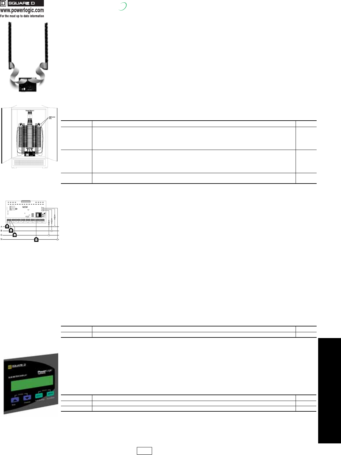
BCM42
3-phase, 4-wire
(with neutral current wiring)
Typical BCMSC
panelboard installation
Submeter Display
PL1 Discount
Schedule
17404.book Page 15 Thursday, October 4, 2007 8:28 AM
4-16 © 2007 Schneider Electric
All Rights Reserved
4POWER MONITORING AND
CONTROL
PowerLogic®ION EEM Enterprise Energy Management Software
New!
PowerLogic ION EEM is a complete enterprise
energy management solution that unites
business and energy strategies across your
entire enterprise by unifying and extending the
benefits of your existing energy-related data
resources. Stakeholders from management to
operations will be empowered by actionable
energy intelligence to reveal opportunities,
isolate problems and drive cost and risk
reduction strategies.
PowerLogic ION EEM automatically acquires
data from power monitoring and control
systems, building and process automation
systems, utility information systems, weather
services, spot-market energy pricing feeds, and
enterprise business applications, cleanses and
warehouses it. Personalized, browser-based
dashboards and innovative visualization and
modeling tools then make the information
available to whomever needs it, so you can
accurately monitor, validate, predict and control
energy-related expenses.
From operational cost reductions to procurement support through cost allocation, benchmarking and budgeting, key
performance indicators and advanced analytics, PowerLogic ION EEM helps you manage energy in financial terms. It
also helps you gain unique insight into the impacts of power quality on your business and all energy assets. From the
service entrance to the boardroom, PowerLogic ION EEM software allows energy to be managed as a variable cost.
Key features
•True enterprise-level software architecture: data quality assurance, data warehouse, web framework
•Web portal: personalized dashboards, key performance indicators, charts, trends, real-time conditions
•Reporting: rich and customized content, support for complex data and graphics, scheduled distribution
•Trending: advanced visualization, dimensional analysis, prediction, statistical rollups
•Modeling: regression analysis, normalization, correlation, integration of all relevant drivers and contextual data
•Billing: built-in rate engine and rate wizard
•Power quality analysis: wide-area event monitoring, classification, filtering, correlation
•Alarms and events: triggering on complex conditions, notification, logging
•Integration: meters and other devices, weather and pricing feeds, other enterprise applications (e.g. BAC, ERP)
Typical applications
•Manage all utilities (electricity, gas, water, etc.) and emissions through a single, unified interface
•Benchmark facility performance across an entire enterprise to identify energy inefficiencies
•Measure and verify savings from energy conservation projects or performance contracts
•Reduce operational costs, improve processes, and prolong asset life
•Meet corporate environmental stewardship goals or mandated impact targets
•Manage demand control schemes, load shedding, peak shaving, base loading or on-site generation
•Enable participation in real-time pricing and load curtailment programs
•Optimize procurement by forecasting and budgeting for energy needs and comparing utility rates
•Identify utility billing errors and validate contract compliance
•Allocate and recover utilities costs from tenants, departments, processes, etc.
•Maximize the use of existing infrastructure capacity and avoid overbuilding
•Identify and reduce risks to uptime
Data presentment tier
Web portal delivers enterprise-wide access
through personalized dashboards, reports,
detailed analytics, and integration of views
from third-party systems. Information and
alerts via cell phone, PDA, pager and more.
Business applications tier
Standard and optional modules tailor
functionality to specific needs. Advanced
analytics and reporting on every driver and
relationship affecting energy cost and
reliability.
Data management tier
Integration of data from many sources: power
monitoring and control systems (PowerLogic or
third party), utility metering systems (water, air,
gas etc.), Internet weather, real-time energy
pricing feeds, manual input, energy assets
(power distribution and reliability equipment,
generators), line-of-business systems (BAC,
DCS, ERP, EAM, accounting). Data quality
module assures complete and reliable data
from all inputs.
For price and ordering information, contact your local PowerLogic Sales Specialist or PowerLogic
Inside Sales at 1-866-466-7627.
Personalized dashboards
help management and
operations personnel
monitor all aspects of
energy use and respond to
opportunities or threats.
Produce aggregate billing,
load profile, cost allocation,
power quality, forecasting or
budget reports to help inform
stakeholders and track
results against goals.
Use advanced billing
functions to support energy
procurement and manage
load or generation assets in
response to curtailment or
pricing signals.
Monitor power quality risk
factors, benchmark
performance, determine
impacts, validate contract
compliance, isolate problem
sources, and confirm your
return-on-investment.
17404.book Page 16 Thursday, October 4, 2007 8:28 AM
4POWER MONITORING AND
CONTROL
© 2007 Schneider Electric
All Rights Reserved 4-17
PowerLogic®Solutions for Utilities
New!
PowerLogic Solutions for Utilities
Square D® PowerLogic delivers complete, cutting-edge web-enabled solutions for many of
the utility industry's most demanding metering, billing and information management
challenges. For many years, regulated utilities, ESCOs and deregulated energy providers
have utilized our proven, scalable meters and software to obtain the accurate, real-time
information they need to meet their organization's business goals.
Cost-effective PowerLogic systems enable energy providers to:
•Maximize competitiveness, increase reliability, streamline operations, and improve service
•Manage wholesale energy transactions across wide geographical areas
•Provide value-added services that enhance customer relationships
•Improve revenue metering, billing accuracy and ensure and report on regulatory compliance
•Provide key personnel with energy information to make analytical and strategic business decisions,
optimize distribution assets, and profit from free market opportunities
PowerLogic's advanced revenue meters are high quality, flexible and scalable devices that
offer a combination of capabilities unmatched in the industry. Whether integrated with third-
party systems or combined with compatible PowerLogic software, Square D can help
utilities address:
•Transmission grid and revenue metering
PowerLogic provides high-accuracy meter information for grid-wide billing applications and offers
MV-90 support and integration into SCADA.
•Substation monitoring
A PowerLogic solution provides the tools to protect valuable equipment from faults, disturbances,
and overloading.
•Power quality analysis
Waveform recording, transient detection, sag/swell, symmetrical components and many more
additional capabilities are available when combined with PowerLogic ION Enterprise software.
•Service entrance metering
The PowerLogic ION8600 billing meter can be used to manage electricity contracts for energy
suppliers and consumers, plus web reporting, sub-metering services, load management and much
more.
•Demand response and load curtailment
PowerLogic meters and software can also be used as part of a demand response/load curtailment
system.
Square D PowerLogic utility solutions resist obsolescence and are engineered to provide
fast payback and easy scalability so you can add metering points and communications
channels as your organization evolves.
With the flexibility of ION technology, multiple form factors,
extensive I/O, and an unmatched feature set, the
PowerLogic ION8600 is a powerful device in substation
automation, SCADA, and billing applications.
Multi-port, (serial, optical, internal modem, Ethernet) plus
multi-protocol communications (Modbus RTU, Master,
Slave, DNP 3.0, Modbus TCP) and a unique gateway
capability provide industry leading integration capability
Analyze data from across your grid
and immediately and share it with
utility personnel, grid operators, or
energy consumers.
17404.book Page 17 Thursday, October 4, 2007 8:28 AM
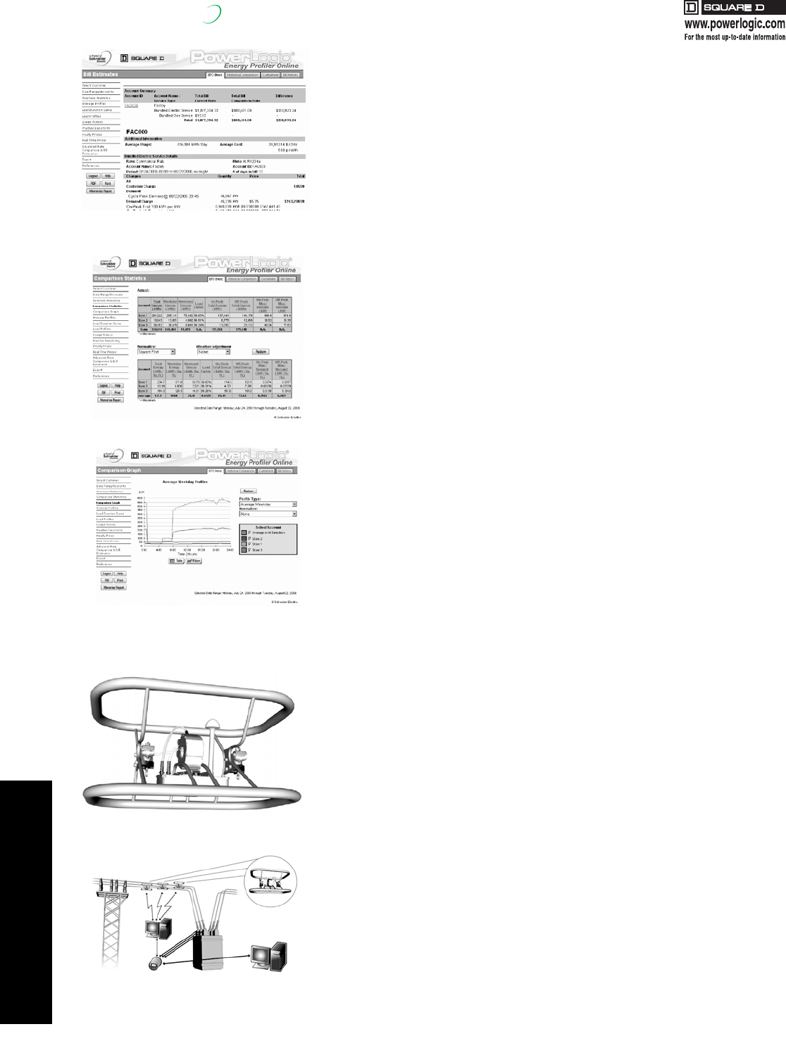
4POWER MONITORING AND
CONTROL
4-18 © 2007 Schneider Electric
All Rights Reserved
PowerLogic®PowerLogic Energy Profiler Online
New!
PowerLogic Energy Profiler Online (EPO) is a web-hosted service that is the industry's
foremost load data visualization and analysis application. This flexible, easy to use system
turns customer usage data into actionable information, freely accessible to all customers
and internal users. For commercial and industrial energy customers, managing energy
costs is the primary objective, but they can’t control what they can’t measure. EPO enables
energy customers to take control of their costs by providing the information they need to
understand how their organization uses energy. They can then take steps to reduce costs
by implementing conservation measures, investing in more efficient equipment, or
participating in new pricing or load curtailment programs.
For the utility, EPO provides an intuitive, easy-to-maintain tool for better understanding
customer usage patterns and meeting customers’ growing need for information. It also
provides a convenient platform from which to administer real-time pricing (RTP) or load
curtailment programs. EPO's instinctive online functionality gives first-time users an
extremely short learning curve, while its powerful configuration options address the needs
of more sophisticated users. The service is available to users at their convenience, 24/7,
and regular updates ensure that customers get the most current information.
For price & ordering information, contact your local PowerLogic Sales Specialist or
PowerLogic Inside Sales at 1-866-466-7627.
PowerLogic Instrument Transformer Services
Current transformer reclassification and verification applications
Accuracy is vital to revenue metering, as large amounts of energy and money flow between
market participants on the power grid. The industry has well established standards in place so
that accurate billing occurs at key interconnection points on the grid. But there's a blind spot in
legacy testing procedures. Current transformers and potential transformers are tested in a lab
prior to installation — but never in the field. The metering industry must ask, “Why do we not
check and verify the accuracy of CTs after they have been installed in the field?”
Our answer: verify CTs live.
The CT Verification service allows a utility to:
•Verify performance of metering class CTs
•Check the end-to-end accuracy of metering systems at key interconnection points
on the grid
•Ensure metering system complies with industry standard accuracy requirements
•Verifies CTs while the system is live, to avoid system interruptions
Interconnections on the power grid require high accuracy revenue metering systems that
include instrument transformers. Industry standards mandate that meters are periodically
verified - this meter is the cash register for all transactions. The PowerLogic Current
Transformer Verification service lets the utility test CTs while the high or medium voltage
system is still operational. Obtain verification that the metering system is in fact meeting
industry standards for accuracy without causing interruption to the system.
Current transformer reclassification and verification services are ideal for:
•Transmission utilities
•Distribution utilities
•Generation plants
•Independent system operators
This CT Verification service lets customers use existing infrastructure with confidence and
documented accuracy, and helps customers assess the need to upgrade their
metering system.
For price and ordering information, contact your local PowerLogic Sales Specialist or
PowerLogic Inside Sales at 1-866-466-7627.
Key features:
•Data access and analysis
•Automated reporting
•Estimated bills and rate comparisons
•Demand response and curtailment programs
•RTP programs
•Alarming
•Administration tool
Applications:
•Energy load analysis
•Energy budgeting and bill forecasting
•Demand response and load curtailment
program management
•Real-time pricing program management
•EPO's Real-Time Pricing module lets users
see interval data for accounts with future
pricing information, and multiply that data
against a price stream.
--
Bill estimates provide valuable information for budgeting
and forecasting
Typical comparison graph showing time of usage
Comparison statistics display
Primary Sensor
ITS application
17404.book Page 18 Thursday, October 4, 2007 8:28 AM
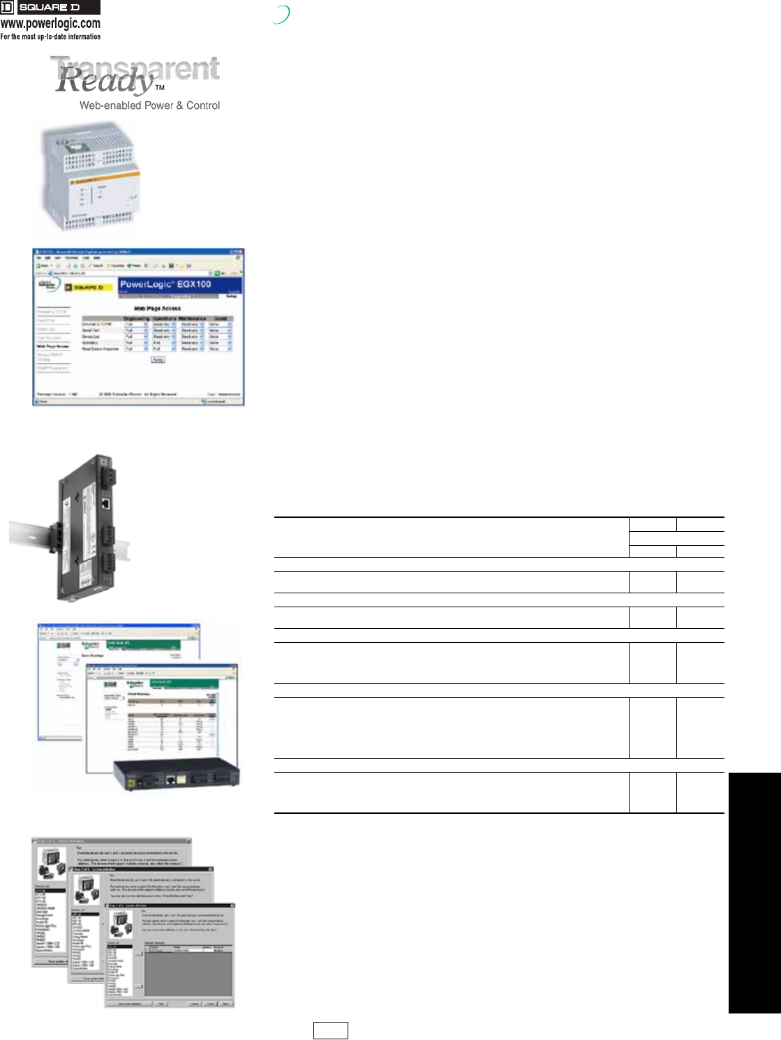
4POWER MONITORING AND
CONTROL
© 2007 Schneider Electric
All Rights Reserved 4-19
PowerLogic®Web-Enabled Network Components
Class 3030
New!
Communications for high-speed access to critical information
From a single building to a multi-site enterprise, PowerLogic Web-Enabled Network
Components provide fast, reliable serial line to Ethernet connectivity in the most demanding
applications:
•Energy management
•Power distribution
•Building automation
•Factory automation
PowerLogic Ethernet Gateways are available in two models-EGX100 and EGX400 -
providing direct connection to Ethernet-Modbus®/TCP networks to make energy and power
monitoring information available over local and wide area networks.
•The EGX100 provides low-cost, reliable, Ethernet to serial-line connectivity in a compact, DIN-rail
mounted package. Enabled by Power over Ethernet (PoE IEEE 802.3af), the EGX100 simplifies
installation by eliminating the need for power supplies plus provides a Web-based interface for
configuration and diagnostics.
•The EGX400 has two serial ports providing Ethernet access to 64 serial devices (more with
repeaters) and includes the ability to e-mail historical data plus provide browser-based access to
real-time and historical interval data logging/trending information allowing electrical distribution
systems to be better managed by utilizing Ethernet and Internet technologies.
Advantages
•Easy to setup—No special software required. Configuration via Microsoft Internet Explorer or
Hyperterminal.
•Easy to troubleshoot—Detailed diagnostics for communication ports through a
Web interface.
•Easy to maintain—Field upgradable firmware lets you add new features while reducing costly
downtime.
•Secure-Customizable, password-protected access to configuration.
•Cost-effective, high-speed communications—Use existing LAN infrastructure to reduce
communications wiring and network management costs.
•Open platform provides broad connectivity—Modbus TCP/IP over Ethernet allows transparent
access via intranet/internet. Each gateway supports up to 32 Modbus or PowerLogic protocol
devices.
•Subnet initiated communications—The gateway supports a slave mode for connecting a serial-line
based system to Ethernet. For example, a building management system with a Modbus serial
interface can route to 16 remote Modbus TCP/IP interfaces supporting up to 128 serial-line devices.
•Extended temperature range— -25 to 70°C enables operation in harsh environments.
PowerLogic Web Page Generator
The PowerLogic Web Page Generator (WPG) creates and downloads application specific
web pages to PowerLogic Ethernet gateways (EGX100 / EGX400, ECC21) with minimal
user intervention. The user simply identifies the serial devices connected to the Ethernet
gateway in this wizard-based software utility. The utility takes care of the rest. This utility is
available for download from www.powerlogic.com.
Table 4.28:
Type
EGX100 EGX400
$ Price
950.00 2460.00
Control Power
24Vdc Power Supply xx
Power Over Ethernet x
Protocols
Ethernet: HTTP, FTP, Modbus TCP/IP, SMTP, SNMP (MIB2), SNTP, TCP, UDP, ICMP, ARP
Serial: Modbus RTU, Modbus ASCII (EGX100 only), JBUS, PowerLogic (SY/MAX)
Ports
Serial: RS485 1
Serial: RS232/485 configurable 1 1
Ethernet UTP (10/100) 11
Fiber (100Mb) 1
Integral web server
Web page generation tool xx
Maintenance/diagnostics xx
Gateway administration setup x x
Comprehensive meter reading x
Interval logging/trends 32 devices
User defined custom pages x
Historical Data Logging
Interval data x
File transfer on scheduled basis email
Export to Excel via web query x
Manual FTP x
EGX100 Ethernet
Gateway
EGX100 lets the Administrator assign access to
setup pages by user groups
Built in tabs provide easy
DIN rail mounting solution.
EGX400 Ethernet Gateway offers you a “window” into your
power equipment
PL1 Discount
Schedule
17404.book Page 19 Thursday, October 4, 2007 8:28 AM
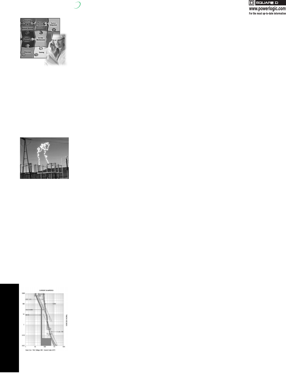
4-20 © 2007 Schneider Electric
All Rights Reserved
4POWER MONITORING AND
CONTROL
PowerLogic®Engineering Services
New!
Consulting & Analysis
Power System Engineering
Square D's Power Systems Engineering team offers a wide range of engineering services to improve the safety,
efficiency and reliability of your power distribution system. The team is comprised of registered, professional engineers,
safety trained and equipped, to perform a variety of engineering functions, such as power system design, testing,
troubleshooting, and analysis.
Arc Flash Analysis
Square D offers on-site services to perform arc flash analysis for a facility, complex, office, or campus. An Arc flash
analysis is used to determine …
Features of Square D's arc flash analysis offerings include…
Power System Studies
The Square D Power System Engineering Team provides expertise for a variety of electrical power system studies.
Some of the more common system studies include…
Power System Assessment
Square D offers engineering services to address a variety of power system needs …
Power Quality Studies
Square D offers onsite power quality engineering studies and solutions to eliminate process disruptions, power system
shutdowns, and equipment damage due to electrical power system disturbances. A power quality study is used to..
Load Studies
Square D offers onsite services to perform loading studies for your electrical distribution system. Load studies are used to...
Power System Design
Square D offers engineering services to address a variety of power system needs …
Square D professional engineers - safety trained and equipped - will listen to your concerns and goals, define the
problem or enhancement, and engineer the solution that best satisfies your needs.
For additional information on power system engineering services and pricing, contact your nearest
Square D/Schneider Electric service district.
•Flash Protection Boundary
•Incident Energy Value
•Hazard/Risk Category
•Appropriate Personal Protective Equipment (PPE)
•Low cost arc flash reduction methods
•Time current coordination analysis showing both existing and recommended over-current device settings
•Short-circuit study to ensure adequacy of equipment
•Onsite verification and documentation of equipment
•Arc flash labels (populated with the results of the arc flash analysis)
•Arc flash label affixation
•NFPA 70E—Safe Workplace Practices Training provided by OSHA authorized outreach instructors
•Recommendations and solutions to reduce potential arc flash hazards
•Short-circuit analysis
•Time-current coordination
•Motor starting/voltage drop
•Motor starting/torque-speed
•Arc flash analysis
•Safe motor re-energization
•Harmonic analysis
•Transient analysis
•Power factor correction analysis
•Other system specific analysis
•Basic codes and standards compliance
•Protective coordination assessment
•Maintenance program review
•Recommendations for power system optimization
•Power quality troubleshooting and analysis
•Power factor and harmonics analysis
•Electrical safety hazards
•Short-circuit withstand overview
•Single-line documentation of power system
•Power monitoring recommendations
•Loading measurements
•Determine compliance with the IEEE 519-Recommended Practices and Requirements for Harmonic Control in Electrical
Power Systems guidelines
•Identify most cost-effective solution to power quality problems
•Solve process disruptions due to power disturbances
•Reduce economic effects of poor power quality
•Identify disturbances originating on electric utility system and improvements to reduce the number and severity
•Evaluate power management and loading levels of electrical circuits
•Determine adequacy of circuit to serve sensitive loads
•Record power measurements on key circuits, including loading, power factor, voltage and current parameters
•New equipment installation
•Existing equipment modification
•Ground Fault Schemes for multiple source distribution systems
•High Resistance Grounding (HRG) Conversion
•Automatic Transfer Control Schemes & Generator Operations
17404.book Page 20 Thursday, October 4, 2007 8:28 AM
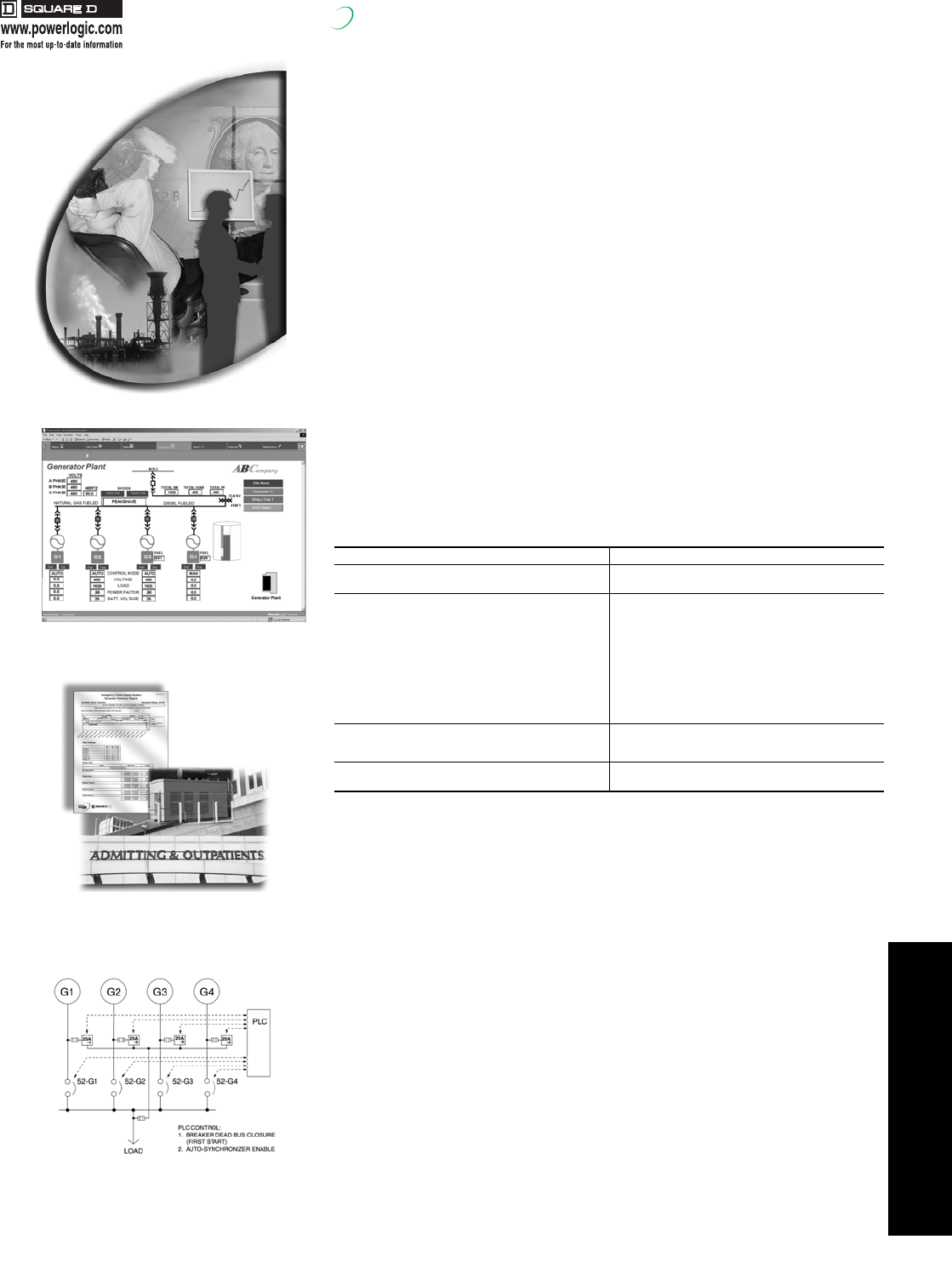
4POWER MONITORING AND
CONTROL
© 2007 Schneider Electric
All Rights Reserved 4-21
PowerLogic®Engineering Services
New!
Total Energy Control
With a comprehensive energy strategy, escalating energy prices don't have to be a
roadblock to industrial growth. As part of Square D / Schneider Electric’s Energy Edge
portfolio that targets improving energy efficiency, Total Energy Control is a consultative
service consisting of our Professional Engineers and Certified Energy Managers who work
with you to ensure the success of your energy strategy. With the development of an Energy
Action Plan tailored for your site, we evaluate your total energy picture addressing:
•Utility Analysis - Evaluating both the commodity supply side and the demand side areas
of the operation
•Supply Management –Forecasting and making adjustments to reflect current conditions
•Demand Side Usage – Profiling facility loads and consumption patterns
•Opportunity Identification / Prioritization - Projects that make sense today and those that should
be considered in the future as energy prices change
•Project Implementation - Client can choose which projects to implement or Square D can provide
turn-key implementation
•On-Going Accountability - Accountable along with you for the ongoing success of your
energy plan
We’re confident that together, we will reduce the total cost of energy at your facility. Take
the logical next step in energy efficiency with the most trusted name in the power industry
for over 100 years.
Power System Automation
Avoid high energy cost associated with peak demands
•Reduce loading requirements to match generator supply
•Shed non-essential loads while maintaining critical processes and lighting requirements
•Retrofit existing generator equipment for peak shaving
•Generate revenue possibilities, export power to the utility during peak periods
•Verify generator performance and ATS status
•Record Sequence of Events to 1 ms for root cause analysis
•Automate existing equipment to seek the utility source, control breakers, and keep the
electrical system operational
For additional information, contact your nearest Square D / Schneider Electric
service district.
System Integration
Power Management Services provides a complete range of design and operational
services including specifying, developing, installing, commissioning, supporting and training
users of power monitoring and control systems and remote power switching systems.
Engineers maintain expertise in many areas such as communications, personal computers,
protective relaying, automatic control systems and programmable controllers.
•System Design and Bill of Material Recommendations
•Power Monitoring and Control
•WAGES (Water, Air, Gas, Electric, Steam)
•Enterprise web-based monitoring
•Specification development, drawings, documentation
•Enclosure panel design and build
•Metering Connection Verification/Testing
•Power distribution automation
•On-Site Installation Assistance, Component Configuration & Startup
•Turn-key project management
•Third Party Device and communication interfaces
•Configured Workstations, User Software Interfaces
•Interactive Graphic Design to mimic facility layout, one-lines, equipment status
•Custom Software, Reports & Applications – Billing and Paging
For additional information, contact your nearest Square D / Schneider Electric
service district.
Table 4.29:
Utility Cost Reduction Power System Reliability
LOAD CONTROL SYSTEMS
Load shedding and sequencing EMERGENCY POWER SUPPLY SYSTEMS (EPSS)
Automatic Generator testing and report generation
GENERATOR CONTROL
Peak shaving
Import/export
•Load following (utility base loading)
•Generator base loading
ATO (Automatic Throw Over) SYSTEMS
Utility to Utility
•Main-Tie-Main
•Main-Main
•Open and closed transition
Utility to Generator
•Basic ATS control with breakers
•Momentary Closed Transition
•Extended Closed Transition (ramped load control)
•Maintained Parallel Operation (Import/Export Control)
ENERGY BILLING & COST ALLOACTION LOAD PRESERVATION SYSTEMS
High speed load shed
Pre-armed load shed schemes
LIGHTING CONTROLS SEQUENCE OF EVENTS RECORDING (SER)
GPS Time synchronization of events
PowerLogic Engineers provide graphic solutions
for realtime monitoring of power systems.
PowerLogic Engineers specialize in the
design and setup of Emergency Power
Supply Systems (EPSS).
PowerLogic Engineers design power
control systems that meet your
operational requirements.
17404.book Page 21 Thursday, October 4, 2007 8:28 AM
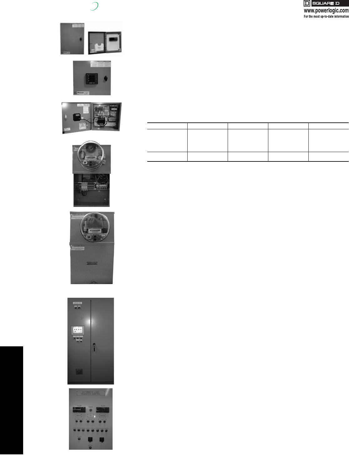
4POWER MONITORING AND
CONTROL
4-22 © 2007 Schneider Electric
All Rights Reserved
PowerLogic®Engineering Services
New!
Factory Assembled Enclosures
PMO Engineering Services provides a variety of factory assembled enclosures designed for
a wide range of power monitoring and control applications. Professional workmanship and
layout offer speed and flexibility during installation. Factory tested, pre-wired enclosures
with well marked terminals help avoid wiring errors and needless troubleshooting during
installation.
•Assemblies include meters & devices wired to terminal blocks, disconnects and shorting blocks
•Tailored to any system voltage :
— 120/208V, 277/480V & 347/600V Wye
— 240V, 480V & 600V Delta
— Utilization of PT's required for higher voltage levels
•Wall mountable and easy to install using concealed holes in the back of the enclosure.
•Complete with necessary documentation and mounting hardware for quick and easy installation
•Carbon steel construction, with industry standard ANSI 61 gray powder coat finish
•Equipped with concealed hinged door, and universal pad-lockable latch.
•Custom engraved nameplates available for all units.
•Supports Single or Multiple Voltage Sources for Indoor (Type 12) & Outdoor (Type 4) applications
•Available with 1 - 4 meters per panel. Serial & Ethernet Communications are options for all units
•EGX & ION RTU Communication Enclosures with 1-4 devices per panel also available
Commercial Enclosure Type 1, UL & CUL 508A Listed
•Available for the following meter types: PM210, PM710, PM820, and ION6200
•Supports Single Voltage Source only for Indoor (Type 1) applications.
•Available with 1 - 12 meters per panel. Serial Communications are standard for all units.
•No Digital or Analog I/O is available for this option.
Industrial/Utility Socket Enclosure Type 3R, UL & CUL 508A Listed
•Available for ION8600 only, with up to 3 Digital Inputs and 4 Digital Outputs
•Supports Single Voltage Source only for Indoor & Outdoor (Type 3R) applications.
•Units are Ring Type with removable cover.
•Available with 1 meter per panel. Serial & Ethernet Communications options available.
•Supports Form 9S, 35S, 36S, 39S and 76S configurations.
•Options available for remote mounted CTs
•Options available for integrated, bar type CTs
•Optional Test Switch.
Additional engineered to order products are available for a wide variety of
custom applications.
•Touch Screen, PC & Server Cabinets
•Generator Control Panels
•PLC Controls & I/O Status Panels
•Retrofit Mechanical Meter Draw Out Cradles with PM and ION Digital Meters
•Communication & Gateway Panels
•Switchgear Automatic Transfer Control Panels
•Water, Air, Gas & Steam (WAGES) Panels
For additional information and pricing please contact your local PowerLogic sales
specialist or PowerLogic Inside Sales Support at 1-866-466-7627. Enclosure pricing
and literature available for download on our website at
www.powerlogic.com/products/enclosures.
To better serve you please have the following information on hand when calling.
•Enclosure type (Indoor or Outdoor) and Environment details (Corrosive or Non-Corrosive)
•Power System Voltage Level and Type (Wye, Delta, or Single Phase)
•Meter Type and Quantity or Device Type and Quantity per enclosure
•Digital & Analog Input and Output requirements
•Ethernet and Serial Communication Requirements
Table 4.30: Industrial Enclosure Types 12, & 4, UL & CUL 508A Listed
Available Meter Types Digital Inputs Digital Outputs Analog Inputs Analog Outputs
PM 210 & 710 N/A N/A N/A N/A
PM 820, 850 & 870 Up to 11 / Meter Up to 7 / Meter Up to 2 / Meter Up to 2 / Meter
CM 3250 & 3350 Up to 4 / Meter Up to 5 / Meter N/A N/A
CM 4250 & 4000T Up to 8 / Meter Up to 7 / Meter Up to 1 / Meter Up to 1 / Meter
ION 6200 N/A Up to 2 / Meter N/A N/A
ION 7300, 7330 & 7350 Up to 4 / Meter Up to 4 / Meter Up to 4 / Meter Up to 4 / Meter
ION 7550 & 7650 Up to 16 / Meter Up to 7 / Meter Up to 4 / Meter Up to 4 / Meter
17404.book Page 22 Thursday, October 4, 2007 8:28 AM
4POWER MONITORING AND
CONTROL
© 2007 Schneider Electric
All Rights Reserved 4-23
PowerLogic®
Engineering Services
New!
Technical Support
There are several ways to receive top quality support on PowerLogic and ION® products:
Priority Support: Excellent Service, Free Software Upgrades, Training
Discounts & More!
Power Management University
Our training centers offer a variety of training courses designed to improve your total energy management skills. Our instructor led courses are 70%
hands-on, with each student having their own lab workstation. We have two main training centers located in Nashville, TN and Victoria, BC and
offer training at a variety of Square D sites across the US and Canada. For more information about how and where we can meet your training
needs please call 1-615-287-3304.
•Latest PowerLogic and ION software upgrades to ensure up-to-date
systems
•Direct access to expertise for quick issue resolution
•More efficient PowerLogic and ION system utilization
•Higher reliability
•Improved productivity and personal efficiency on the job
Premium Support: Priority + Proactive System Checks +
Sr. Technician Assigned to your site
Choose Premium Support when you need to . . .
•Enhance your PowerLogic or ION system's operation with single-sourced
pro-active problem identification, solutions recommendations and change
management skills
•Partner with technical experts who help coordinate support, provide hands-
on assistance, and share knowledge and know-how with you
•Obtain personalized services tailored to your business environment
and objectives
•Take advantage of remote software upgrade capabilities
•Anticipate and communicate necessary change
Remote eServices for PowerLogic and ION
Let expert Square D technicians ensure high-quality performance in
your PowerLogic or ION system by performing remote, online services
through our secure WEB EX Portal. Services include …
•Installations, upgrades, & software patches
•System device setup & configuration along with alarming &
historical trending
•Graphical Screen Development
•Remote, Online System Maintenance
— Software Updates - Patches & Upgrades
— PC Checks - Hard Disk Space, Network & DB Configurations,
Viruses, etc.
— PowerLogic or ION Software Checks - Communications, Data
Logging, & Task Execution
— E-mailing system scorecard & maintenance recommendations
•One-on-one training on system software features
•Power Quality (PQ) & Energy Usage Analysis
For additional information and pricing, contact:
Tech Support Contract Services
295 Tech Park Drive, Suite 100, LaVergne, TN 37086
Phone: 615-287-3332
Fax 615-287-3404
Email: pmo.support@us.schneider-electric.com
Table 4.31:
Course Course No. $ Tuition
PowerLogic Systems
Correspondence Courses
PowerLogic Fundamentals 3000PLUC120CR 350.00
PowerLogic System Installation & Troubleshooting 3000PLUC100CR 750.00
Core Classes
Comprehensive PowerLogic Systems 3000PLUC200 2150.00
Comprehensive PowerLogic Systems Bundle (Includes 3000PLUC120CR) 3000PLUC205 2450.00
PowerLogic System Installation & Troubleshooting 3000PLUC100 1950.00
SMS Administrator 3000PLUC300 2150.00
Target Application Courses
Critical Power and Power Quality 3000PLUC140 1400.00
Energy Management with Advanced Reporting 3000PLUC230 1400.00
Regional SMS Overview 3000PLUC190 1200.00
Regional SMS Overview Bundle (Includes 3000PLUC120CR) 3000PLUC195 1500.00
Customer Site Training 3000PLUCSite By Quote
ION Systems
Core Classes
ION Enterprise Fundamentals 3000PMUFUND 2150.00
ION Enterprise Programmer 3000PMUPROG 2150.00
ION Enterprise Administrator 3000PMUADMIN 2150.00
ION Enterprise Overview 3000PMUCION 1200.00
ION Program Overview 3000PMUCPROG 1600.00
Customer Site Training 3000PMUSITE By Quote
ION Enterprise Refresher 3000PMUREFRESH 1800.00
PL1T Discount
Schedule
17404.book Page 23 Thursday, October 4, 2007 8:28 AM
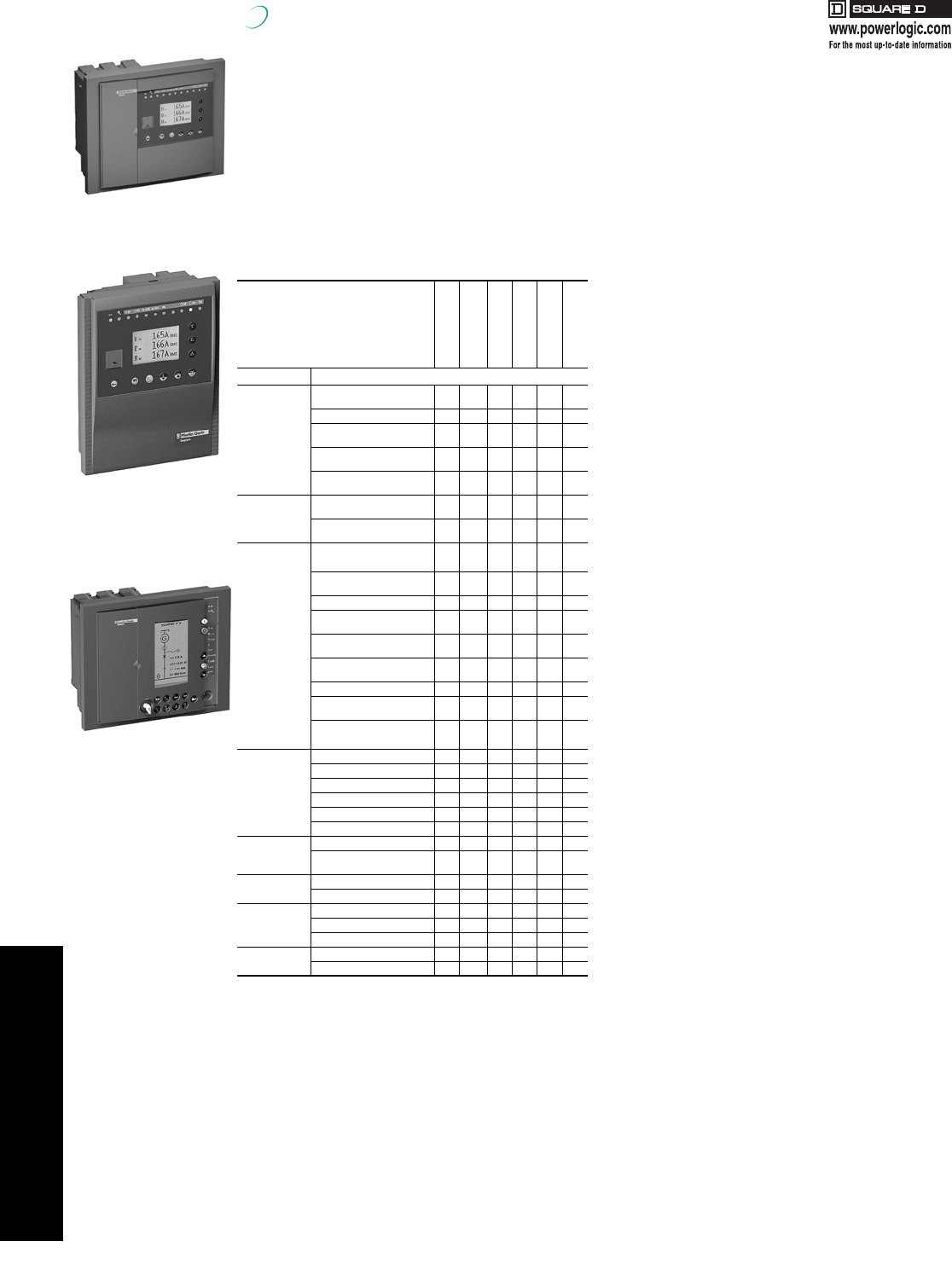
4POWER MONITORING AND
CONTROL
4-24 © 2007 Schneider Electric
All Rights Reserved
Sepam Series Digital Protective Relay
New!
80, 40, and 20 Series
The Sepam family of digital protection units, Series 20, 40
and 80, is the newest generation of Sepam relay, a time
tested product with a 20-year worldwide history. Modular
relay design allows quick and easy future upgrades to
communications, digital I/O, analog output or temperature
acquisition. The 64x128 bit, graphic LCD display and
keypad permit basic relay setting of Series 20 and 40
without a PC. Comprehensive self-testing provides
assurance of readiness to protect. The Sepam family also
has exceptional withstand to environmental
electromagnetic disturbances. An optional 128 x 240 LCD
display can show one-line or electrical vectors.
Note: Units in table depict least complex device types compliant with
criterion.
Sepam Series 80 Relay Features
•Standard footprint for enhanced protection of Mains/Feeders,
Transformer, Motor, Generator, Capacitor, Bus Applications
•Differential protection of transformer or machine transformer
units
•Differential protection of motors and generators
•Protection for mains and ties and important feeders including
pre-programmed transfer schemes
•Increased metering capabilities I, V, E, P, PF, THD, vector
diagram
•Expanded logic equation capabilities (an option for Logipam
PLC ladder logic)
•Setting software with graphical assistance, opt mimic-based
display
•Battery backup for historical and fault waveform data
retention, wide range DC control power
•Two rear communication interfaces
•Includes all Series 20 and Series 40 features
Sepam Series 40 Relay Features
•Compact standard footprint (< 4”deep) for enhanced
protection of Mains/Feeders, Transformer, Motor, Generator
Applications
•Directional overcurrent protection for dual mains and ties and
closed loop feeders
•Current and voltage inputs I, V, E, P, PF
•Setting software with Boolean logic equation assistance
•CT/VT and Trip Circuit supervision
•Sixteen seconds of fault recording, last 5 trip reports, and last
200 time-tagged alarms
•Rear communication port for interface to optional Modbus®
communications modules
•Includes all Series 20 features
Sepam Series 20 Relay Features
•Backlit LCD graphic bitmap display
•Compact standard footprint (< 4”deep) for basic protection of
Mains/Feeders, Transformer, Motor, Bus (Voltage)
Applications
•16 inverse time overcurrent characteristic curves
•Setting software with offline file creation and
download to relay
•Two 86 cycle records of fault recording, last trip fault values,
and last 64 time-tagged alarms retained
•Provides trip diagnostic information for analysis of faults
•Self-test diagnostic ensures correct operation of relay and
integrity of protection
•Wide range of control power inputs
•Display operation minimal training required for operation.
•Application specific design for Main/Feeder, Transformer,
Motor, Bus (Voltage) zones
•Zone selective interlocking (ZSI) improved protection
coordination
•Rear communication port for interface to optional Modbus
communications modules, plus dual port module, opt
protocols DNP3 and IEC60870-5-103, and also F/O
•Modular architecture
•Breaker diagnostics
Table 4.32: Quick Select Guide
Feeder or main
(Substation)
Transformer
Motor
Generator
Bus
Capacitor Bank
Criteria Selection
Network
structure
Radial
(51, 51N, 46) S23 T23 M20 G40 B80 C86
Long feeders (67N) S41 M41
Closed loop
(67N, 67) S42
Parallel mains [transf]
[sources] (67N, 67) S42 T42 G82
Sync-check required
(25)(67N, 67) S82 T82 G82 B80
Grounding
system
Solid or low/high
impedance (51N) S23 T23 M20 G40
Ungrounded or
compensated (67N/NC) S41 T42 M41 G82
Protection
Basic Feeder
[Transf][Motor] S23 T23 M20 G40
Voltage/frequency
(27/59/81) S40 T40 M41 G40 B21
ROCOF (81R) S84 B22
Advanced Fdr/Main[Transf]
[Motor][Gen] S41 T82 M81 G82 B83
Thermal overload (49)-
cable S81
Thermal O/L
(49)- capacitor bank C86
Differential (87T) T87
Machine
differential (87M) M87 G87
Machine-
transformer unit differential M88 G88
Metering
IS23T23M20
V, f B21
I, V, f, P, E S40 T40 M41 G40 B80
I, V, V, f, P, E B83
I, I, V, F, P, E T87 M87 G87
THD-I, THD-V S80 T81 M81 G82 B80
Temperature <8 RTDs of same type T23 M20 G40
> 8 RTDs (< 16) or 2 types
of RTDs T40 M41 G40
I/Os < 10 I / 8 O S23 T23 M20 G40 B21
> 10 I / 8 O and < 42 I / 23 O S80 T81 M81 G82 B80
Program logic
customization
Control matrix S23 T23 M20 G40 B21
Logic equation editor S40 T40 M41 G40 B80
Ladder-logic software S80 T81 M81 G82 B80
Modbus
communication 1 Modbus port S23 T23 M20 G40 B21
2 Modbus ports S80 T81 M81 G82 B80
Series 80
Advanced Display
(A Suffix)
Series 40 or 20
Advanced Display
(A Suffix)
Series 80 Pro
Display
(P Suffix)
17404.book Page 24 Thursday, October 4, 2007 8:28 AM
4POWER MONITORING AND
CONTROL
© 2007 Schneider Electric
All Rights Reserved 4-25
Sepam Series Selection Table
New!
Table 4.33: Series 80 Applications
Protection Application
ANSI Code S80 S81 S82 S84 T81 T82 T87 M81 M87 M88 G82 G87 G88 B80 B83 C86
Phase overcurrenta50/51 8888888888888888
Ground fault / Sensitive ground faulta50N/51N
50G/51G 8888888888888888
Breaker failure 50BF 1111111111111111
Negative sequence / unbalance 46 2222222222222222
Thermal overload for cables 49RMS 2 2 2
Thermal overload for machinesa49RMS 222222222
Thermal overload for capacitors 49RMS 2
Capacitor bank unbalance 51C 8
Restricted ground fault 64REF 222 22
Two-winding transformer differential 87T 111
Machine differential 87M 1 1
Directional phase overcurrenta67 2222 222
Directional ground faulta67N/67NC 2 2 2222222222
Directional active overpower 32P 2 2 2222222222
Directional reactive overpower 32Q 111111
Directional active underpower 37P 2 2
Phase undercurrent 37 111
Excessive starting time, locked rotor 48/51LR 111
Starts per hour 66 111
Field loss (underimpedance) 40 111111
Pole slip 78PS 111111
Overspeed (2 set points)b12 eeeeee
Underspeed (2 set points)b14 eeeeee
Voltage-restrained overcurrent 50V/51V 222
Underimpedance 21B 111
Inadvertent energization 50/27 111
Third harmonic undervoltage/100% stator ground fault 27TN/64G2/64G 222
Overfluxing (V / Hz) 24 2222
Positive sequence undervoltage 27D 2224222222222444
Remanent undervoltage 27R 2222222222222222
Undervoltage (L-L or L-N) 27 4442444444444222
Overvoltage (L-L or L-N) 59 4444444444444444
Neutral voltage displacement 59N 2222222222222222
Negative sequence overvoltage 47 2222222222222222
Overfrequency 81H 2222222222222222
Underfrequency 81L 4444444444444444
Rate of change of frequency 81R 2
Recloser (4 cycles)b79 e e e e
Thermostat / Buchholzb26/63 eeeeee e
Temperature monitoring (16 RTDs)c38/49T eeeeeeeee e
Synchronism-checkd25 e e e eeee eeee e
Table 4.34: Series 40/20 Applications
Protection Application ANSI
Code S23 S40 S41 S42 T23 T40 T42 M20 M41 G40 B21 B22
Phase overcurrenta50/51 4444444444
Voltage-restrained overcurrent 50V/51V 1
Ground fault / Sensitive ground faulta50N/51N
50G/51G 4444444444
Breaker failure 50BF 1111111 11
Negative sequence / unbalance 46 1222122122
Directional phase overcurrenta67 22
Directional ground faulta67N/67NC 2222
Directional active overpower 32P 1 1 11
Directional reactive overpower 32Q/40 11
Thermal overloada49RMS 222222
Phase undercurrent 37 1 1
Excessive starting time, locked rotor 48/51LR/14 1 1
Starts per hour 66 1 1
Positive sequence undervoltage 27D/47 2 2
Positive sequence undervoltage 27D 2
Remanent undervoltage 27R 1 1 1
Phase-to-phase undervoltage 27 2 2
Phase-to-neutral undervoltage 27S 1 1
Undervoltagec27/27S 2 2 22222
Overvoltagec59 2 2 222222 2
Neutral voltage displacement 59N 2 2 222222 2
Negative sequence overvoltage 47 1 1 11111
Overfrequency 81H 2 2 222221 1
Underfrequency 81L 4 4 444442 2
Rate of change of frequency 81R 1
Recloser (4 cycles) 79 e e e e
Temperature monitoring (8 or 16 RTDs) 38/49T eeeeee
Thermostat / Buchholz 26/63 eee
Note: Numerals in table indicate number of protection setpoints
aProtection functions with 2 groups of settings
bRequires MES120 I/O module
cRequires MET1482 RTD Input module
dRequires MCS025 synch check module
eOption
17404.book Page 25 Thursday, October 4, 2007 8:28 AM
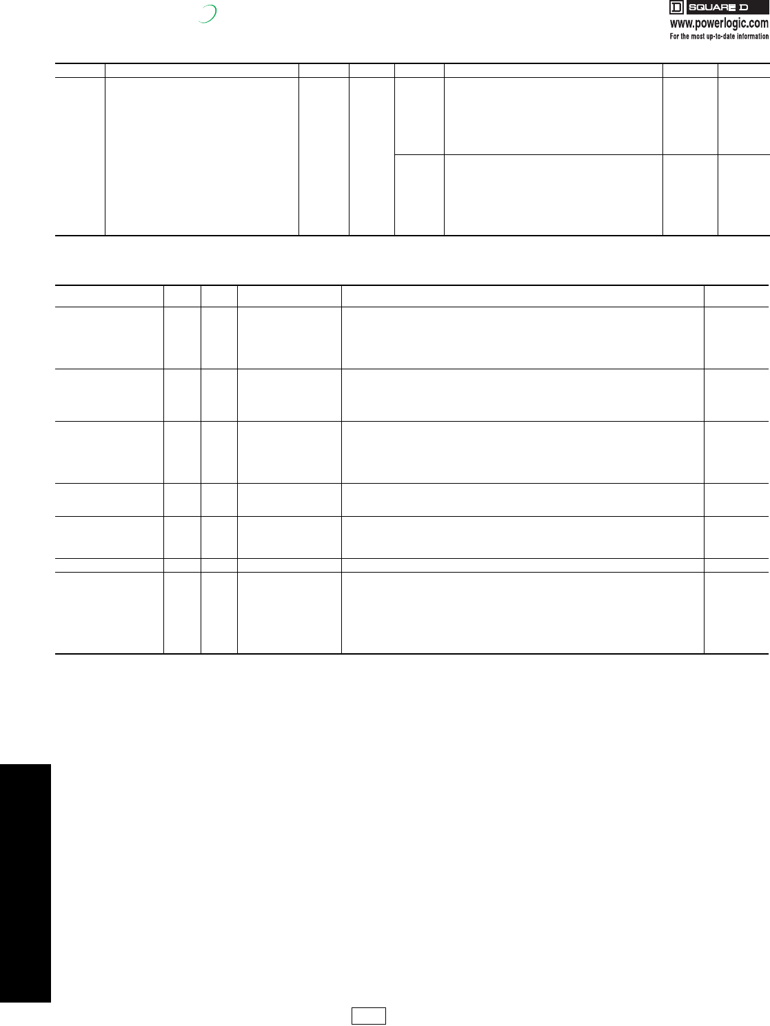
4POWER MONITORING AND
CONTROL
4-26 © 2007 Schneider Electric
All Rights Reserved
Sepam Series Pricing and Accessories
New!
Table 4.35: List Price by Catalog Number
Model Application Catalog No. $ Price Model Application Catalog No. $ Price
Series 80
S80 - Substation/feeder [current & voltage] SQ1S80Aa3870.00
Series 40
S40 - Substation/feeder [current & voltage] SQ1S40A 3023.00
S81 - Substation/feeder [directional grd O/C] SQ1S81A 4060.00 S41 - Substation/feeder [directional grd O/C] SQ1S41A 3439.00
S82 - Substation/feeder [directional ph & grd O/C] SQ1S82A 4180.00 S42 - Substation/feeder [directional ph & grd O/C] SQ1S42A 3870.00
S84 - Substation/main [separation/ load shed] SQ1S84A 4780.00 T40 - Transformer [current & voltage] SQ1T40A 3272.00
T81 - Transformer [current & voltage] SQ1T81A 4130.00 T42 - Transformer [Dir. Ph & Grd O/C] SQ1T42A 4118.00
T82 - Transformer [Dir. Ph & Grd O/C] SQ1T82A 4430.00 M41 - Motor [Dir. Grd O/C] SQ1M41A 3594.00
T87 - Transformer [Diff.-2 wdg) SQ1T87A 4880.00 G40 - Generator [Dir. Real & Reac Power, Volt-Restr O/C] SQ1G40A 3920.00
M81- Motor [Dir. Grd O/C] SQ1M81A 3540.00
M87- Motor [Mach. Diff.] SQ1M87A 3850.00
Series 20
S23 - Substation/feeder [breaker failure] SQ1S23A 1794.00
M88 - Motor [Transf. Diff.] SQ1M88A 4140.00 T23 - Transformer [breaker failure] SQ1T23A 1957.00
G82 - Generator [Dir. Watt & Var, Volt-Restr O/C] SQ1G82A 4170.00 M20 - Motor SQ1M20A 2319.00
G87 - Generator [Mach diff] SQ1G87A 4520.00 B21 - Bus (Voltage/Freq) SQ1B21A 2264.00
G88 - Generator [Transf diff] SQ1G88A 5522.00 B22 - Loss of Mains (Voltage/Freq/ROCOF) SQ1B22A 2576.00
B80 - Bus [Main+1ph volt] SQ1B80A 4050.00
B83 - Bus [Tie +3ph volt] SQ1B83A 4250.00
C86 - Capacitor [4 step 2xWye banks] SQ1C86A 4125.00
aReplace “A” suffix with “P” to select the “Pro” version mimic display. (add $450 to list price)
Table 4.36: Series 80+40+20 Accessory List
Accessory Type Series 80 Series
40/20 Catalog No. Description $ Price
Digital I/O Module
x MES120 14 inputs + 6 outputs / 24-250Vdc 770.00
x MES120G 14 inputs + 6 outputs / 220-250Vdc/hi p.u. 770.00
x MES120H 14 inputs + 6 outputs / 110-125 Vdc/hi p.u. 770.00
x MES114 10 Input / 4 output module 616.00
x MES114E 10 inputs + 4 outputs 110/125V 595.00
x MES114F 10 inputs + 4 outputs 220/250V 785.00
Communication I/Fb Module
x x ACE959 RS485 4-wire Interface Module (requires. ext. 24VDC control pwr) 398.00
x x ACE9492 RS485 2-wire Interface Module (requires. ext. 24VDC control pwr) 398.00
x x ACE937 Fiber optic Interface Module 578.00
x x ACE969TP (2)RS485 2wire I/F 578.00
x x ACE969FO (1) RS485 2wire + (1) F/O I/F 771.00
Analog I/O module
x MCS025 Synch check module (includes cable CCA785) 1410.00
x x MET1482 8 temperature sensor input module 695.00
x x MSA141 Analog output module 637.00
x x DSM303 Remote advanced MMI (requires cable CCA77x see below) 719.00
x SFT080 Logipam plc logic software 750.00
x AMT840 Assembly plate for surface mounting of MCS module 131.00
Analog I/O Cables
x x CCA770 2ft cable from remote display to base unit 36.20
x x CCA772 2m cable from remote display to base unit 51.00
x x CCA774 4m cable from remote display to base unit 78.00
Ground Sensor CTs (mV out)
x x CSH30 Interposing window CT for Residual current input 116.00
x x CSH120 Ground Sensor CT - 120 mm window 235.00
x x CSH200 Ground Sensor CT - 200 mm window 378.00
x x ACE990 Aux. CT for Ground Sensor CT Ratio Adjustment (for retrofit) 709.00
Configure softwarecx x SFT2841KIT Setting/operating software kit (including SFT2826 osc s/w+CCA783 cable) 543.00
Selected sparesd
x x 2640KIT Terminal blocks for MES modules 205.00
x x CCA634 1 or 5 A CT Current Connector 191.00
x x CCT640 Voltage Connector 398.00
x x CCA612 Cable for communication module to relay connection 67.00
x x CCA783 Cable for pc to relay connection 67.00
x CCA785 MCS025 cable 55.00
x CCA670 LPCT Current Connector 430.00
x CCA671 LPCT Current Connector 415.00
bIncludes CCA612 cable to relay rear port
cOne s/w kit required per Series 80 order and recommended per Series 40/20 order
dTo be ordered as spare or replacement
PL1 Discount
Schedule Modified
10/4/07
17404.book Page 26 Thursday, October 4, 2007 8:28 AM
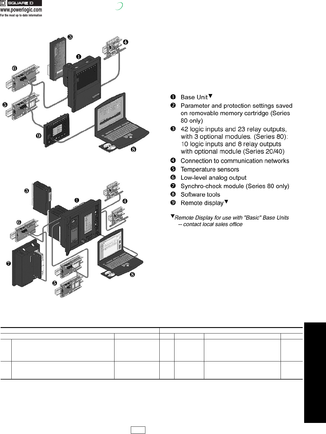
4POWER MONITORING AND
CONTROL
© 2007 Schneider Electric
All Rights Reserved 4-27
Sepam Series Selection Example
New!
Table 4.37: Selection Example
Follow these steps: Example:
Selection Sequence Type Part QTY Catalog No. Description $ Price
[1] Select from Table 4.35 per system, features Table 4.32 & 4.33/4.34 Relay unit 1 SP1T87A T87- Transformer [Diff.-2 wdg) 4880.00
[2] Spare by application Memory module 0 MMS020xxx Spare memory module 0.00
[3] Select from Table 4.36 (as required) Digital I/O 1 MES120 14 inputs + 6 outputs / 24-250Vdc 770.00
[4] Select from Table 4.36 (as required) Communication module 1 ACE959 RS485 4-wire Interface Module l 398.00
[5] Select from Table 4.36 (as required) RTD Input 1 MET1482 8 temperature sensor input module 695.00
[6] Select from Table 4.36 (as required) Analog output 0 MSA141 Analog output module (1 channel) 0.00
[7] Select from Table 4.36 (as required) Sync check (25) module 1 MCS025 Synch check module (includes cable CCA785) 1410.00
[8] Select from Table 4.36 (as required) Config S/W 1 SFT2841KIT Setting / operating software kit 543.00
[9] Select from Table 4.36 (as required) Cable for RTD I/F Modulle 1 CCA772 2m cable from remote display to base unit 51.00
Series 20 and Series 40
Series 80
PL1 Discount
Schedule
17404.book Page 27 Thursday, October 4, 2007 8:28 AM
www.reactivar.com
FOR CURRENT INFORMATION
4POWER MONITORING AND
CONTROL
4-28 © 2007 Schneider Electric
All Rights Reserved
PFC Capacitors
Class 5810
Low Voltage Fixed Capacitors ReactiVar® fixed low voltage capacitors are ideally suited for power
factor correction applications where the load does not change or where
the capacitor is switched with the load, such as the load side of a motor
starter. ReactiVar fixed capacitors are best suited for applications where
there are no harmonic currents or voltages present.
For Fixed Capacitors suitable for use in harmonic-rich environments,
contact your nearest Square D/Schneider Electric sales office.
Features:
•Environmentally Safe: Reactivar capacitors are constructed with a dry type
metalized Polypropylene capacitor element with no liquid dielectrics. There is
no risk of fluid leakage or environmental pollution and no need for a drip pan.
•Multiple Protection System: The patented protection system incorporates
an internal protection device which negates the need for external fuses.
Capacitor elements are encased in a non-flammable vermiculite filler as an
added safety feature.
•Low Loss, Long Life: The design features less than 0.5W/kVAR losses,
including discharge resistors.
•Attractive finish: Capacitor units feature a textured powder paint finish, ASA
49 gray. Units are constructed of 18 gauge steel and are suitable for floor or
wall mounting.
aOrder only. Typical delivery is 1 to 2 weeks.
bWall mounting brackets available for units up to 40 kVAR.
Order catalog # PFCDBR1 ($50.00).
cFor dimensions, see 4-29.
dFor 600 V equipment, change first digit in catalog number from 4 to 6 (e.g. PFCD6004)
and use the same price as above 480 V equipment.
See page 4-33 for Medium Voltage Fixed Banks.
eConsult local Electrical Codes for proper sizing of molded case circuit breaker frame and
disconnect switch rating and cabling.
Fixed
Capacitors are
best suited for
use on
electrical
systems with
no voltage or
current
harmonics.
Application Note: Capacitors are a low impedance path for the harmonic currents
produced by variable frequency drives, motor soft starters, welders, computers,
PLCs, robotics and other electronic equipment. These harmonic currents can be
drawn into the capacitor causing it to overheat, shortening its life. Furthermore, the
resonant circuit formed by shunt capacitors coupled with system inductances
(motors and transformers) can amplify harmonic currents
and voltages in the electrical network. This amplification can cause
nuisance fuse operation and/or damage to electrical equipment
including capacitors and other electronic devices. If power factor
correction in the presence of harmonics is required, please contact
your nearest Square D/Schneider Electric sales office for
assistance.
Table 4.38: Unfused 208 and 240 Volt 3 Phase/60 Hz
kVAR Rating Unfused INDOOR
NEMA Type 1/12aUnfused OUTDOOR
NEMA Type 3RaRated Current
(Amperes) Recommended
Wire Size
Recommended Minimum Size Protection Ratinge
Fuse Circuit Breaker Trip
@ 240 V @208 V Catalog No.b$ Price Encl.cCatalog No.b$ Price Encl.c@240 V @208 V (Qty X AWG) @240 V @208 V @240 V @208 V
2.5 1.88 PFCD2002 612.00 1 PFCD2002R 643.00 1R 6 6 14 10 10 15 15
3.5 2.63 PFCD2003 639.00 1 PFCD2003R 671.00 1R 9 8 14 15 15 15 15
4 3.00 PFCD2004 666.00 1 PFCD2004R 699.00 1R 10 9 14 20 15 15 15
5 3.75 PFCD2005 731.00 1 PFCD2005R 767.00 1R 13 11 12 20 20 20 20
6 4.50 PFCD2006 791.00 1 PFCD2006R 830.00 1R 15 13 12 25 25 25 20
7.5 5.63 PFCD2007 851.00 1 PFCD2007R 893.00 1R 19 16 10 30 30 30 25
10 7.50 PFCD2010 1025.00 1 PFCD2010R 1076.00 1R 25 21 8 40 35 40 35
12.5 9.38 PFCD2012 1218.00 1 PFCD2012R 1279.00 1R 31 27 8 50 45 45 40
15 11.25 PFCD2015 1411.00 1 PFCD2015R 1481.00 1R 37 32 8 60 60 60 50
17.5 13.13 PFCD2017 1584.00 2 PFCD2017R 1662.00 2R 43 37 6 70 60 70 60
20 15.00 PFCD2020 1755.00 2 PFCD2020R 1843.00 2R 49 42 6 80 70 80 70
22.5 16.88 PFCD2022 1923.00 2 PFCD2022R 2049.00 2R 55 47 4 90 80 90 70
25 18.75 PFCD2025 2067.00 3 PFCD2025R 2170.00 3R 61 53 4 100 90 90 80
27.5 20.63 PFCD2027 2715.00 3 PFCD2027R 2851.00 3R 67 58 3 125 00 100 90
30 22.50 PFCD2030 3363.00 3 PFCD2030R 3531.00 3R 73 63 3 125 125 125 00
35 26.25 PFCD2035 3680.00 4 PFCD2035R 3865.00 4R 85 73 2 150 125 150 125
40 30.00 PFCD2040 4162.00 5 PFCD2040R 4370.00 5R 97 84 1/0 175 150 150 125
45 33.75 PFCD2045 5072.00 7 PFCD2045R 5422.00 7R 109 94 1/0 200 175 175 150
50 37.50 PFCD2050 6167.00 7 PFCD2050R 6475.00 7R 121 105 2/0 200 175 200 175
60 45.00 PFCD2060 6656.00 7 PFCD2060R 6989.00 7R 145 126 3/0 250 200 225 200
70 52.50 PFCD2070 6999.00 8 PFCD2070R 7349.00 8R 169 146 4/0 300 250 300 225
75 56.25 PFCD2075 7229.00 10 PFCD2075R 7591.00 10R 181 157 250 kcmil 300 300 300 250
Table 4.39: Unfused 480 Voltd 3 Phase/60 Hz
kVAR
Rating Unfused INDOOR NEMA Type 1/12 Unfused OUTDOOR NEMA Type 3RaRated
Current Recommended
Wire Size
Recommended Minimum Size Protection Ratinge
Fuse Circuit Breaker Trip
@480 V Catalog No.b$ Price Encl.cCatalog No.b$ Price Encl.c@480 V (Qty X AWG) @480 V @480 V
2.5 PFCD4002 558.00 1 PFCD4002R 586.00 1R 3 14 5 15
4 PFCD4004 580.00 1 PFCD4004R 609.00 1R 5 14 10 15
5 PFCD4005 595.00 1 PFCD4005R 625.00 1R 6 14 10 15
6 PFCD4006 619.00a1 PFCD4006R 650.00 1R 7.2 14 15 15
7.5 PFCD4007 642.00 1 PFCD4007R 674.00 1R 9 14 15 15
10 PFCD4010 718.00 1 PFCD4010R 755.00 1R 12 12 20 20
12.5 PFCD4012 810.00 1 PFCD4012R 851.00 1R 15 10 25 25
15 PFCD4015 886.00 1 PFCD4015R 930.00 1R 18 10 30 30
17.5 PFCD4017 937.00a1 PFCD4017R 983.00 1R 21 10 35 35
20 PFCD4020 986.00 1 PFCD4020R 1036.00 1R 24 8 40 40
22.5 PFCD4022 1033.00a1 PFCD4022R 1085.00 1R 27 8 45 45
25 PFCD4025 1103.00 2 PFCD4025R 1158.00 2R 30 8 50 45
27.5 PFCD4027 1169.00a2 PFCD4027R 1228.00 2R 33 8 60 50
30 PFCD4030 1234.00 2 PFCD4030R 1296.00 2R 36 8 60 55
35 PFCD4035 1401.00 3 PFCD4035R 1472.00 3R 42 6 70 65
40 PFCD4040 1572.00 3 PFCD4040R 1651.00 3R 48 6 80 75
45 PFCD4045 1679.00a4 PFCD4045R 1763.00 4R 54 4 90 85
50 PFCD4050 1784.00 4 PFCD4050R 1873.00 4R 60 4 100 90
60 PFCD4060 2650.00 5 PFCD4060R 2782.00 5R 72 3 125 125
70 PFCD4070 2853.00a5 PFCD4070R 2996.00 5R 84 2 150 150
75 PFCD4075 2956.00 5 PFCD4075R 3104.00 5R 90 1 150 150
80 PFCD4080 3130.00a6 PFCD4080R 3286.00 6R 96 1/0 175 150
90 PFCD4090 3478.00a6 PFCD4090R 3651.00 6R 108 1/0 200 175
100 PFCD4100 3825.00 6 PFCD4100R 4017.00 6R 120 2/0 200 200
125 PFCD4125 4765.00a9 PFCD4125R 5003.00 9R 150 4/0 250 225
150 PFCD4150 5704.00a9 PFCD4150R 5990.00 9R 180 250 kcmil 300 300
175 PFCD4175 6374.00a11 PFCD4175R 6692.00 11R 210 300 kcmil 350 350
200 PFCD4200 7043.00a11 PFCD4200R 7395.00 11R 240 (2) 2/0 400 400
225 PFCD4225 7833.00a12 PFCD4225R 8224.00 12R 270 (3) 3/0 500 450
250 PFCD4250 8622.00a13 PFCD4250R 9052.00 13R 300 (2) 4/0 500 450
275 PFCD4275 9410.00a13 PFCD4275R 9881.00 13R 330 (2) 4/0 550 500
300 PFCD4300 10199.00a13 PFCD4300R 10709.00 13R 360 (2) 250 kcmil 600 550
DE2C Discount
Schedule
17404.book Page 28 Thursday, October 4, 2007 8:28 AM
www.reactivar.com
FOR CURRENT INFORMATION
4POWER MONITORING AND
CONTROL
© 2007 Schneider Electric
All Rights Reserved 4-29
PFC Capacitors
Class 5810 / Refer to Catalog 5810HO9701R8/06
LV Fixed Fused Capacitors with Blown Fuse Indicators
aOrder only. Typical delivery is 1 to 2 weeks.
bConsult local Electrical Codes for proper sizing of
molded case circuit breaker frame and disconnect
switch rating and cabling.
cWall mounting brackets available for units up to 40
kVAR,brackets sold in pairs. Order catalog #PFCDBR1
($50.00)
dSee below for dimensions.
eFor 600 V equipment, change first digit from 4 to 6 (e.g.
PFCD6004F) and use the same price as above
f480 V equipment. See page 4-33 for Medium Voltage
Fixed Banks.
gDimensions provided are approximate only. Do not use
for construction purposes. For actual dimensions
contact your nearest Square D/Schneider Electric sales
office.
In addition to the comprehensive Multiple Protection System designed into the New ReactiVar® fixed, low voltage capacitors, fused units feature a
fast acting current limiting fuse in each phase. Blown fuse indicators are included as standard on both indoor (NEMA Type 1/12) and outdoor
(NEMA Type 3R) enclosures. While fuses are not required to protect the capacitor elements, external over current protection may be required by
the local electrical code for protection of the conductors feeding the capacitors. Consult your local electrical code for installation instructions.
Table 4.40: 3 Fuses with Blown Fuse Indicators 208 and 240 Volt 3 Phase/60 Hz
kVAR Rating Fused INDOOR
NEMA Type 1/12aFused OUTDOOR
NEMA Type 3RaRated Current
(Amperes) Recommended
Wire Sizeb
Recommended Minimum Size
Protection Ratingb
Fuse Breaker Trip
@ 240 V @208 V Catalog No.c$ Price Encl.dCatalog No.c$ Price Encl.d@240 V @208 V (Qty. X AWG) @240 V @208 V @240 V @208 V
2.5 1.88 PFCD2002F 893.00 1 PFCD2002RF 938.00 1R 6 6 14 10 10 15 15
3.5 2.63 PFCD2003F 920.00 1 PFCD2003RF 967.00 1R 9 8 14 15 15 15 15
4 3.00 PFCD2004F 947.00 1 PFCD2004RF 995.00 1R 10 9 14 20 15 15 15
5 3.75 PFCD2005F 1012.00 1 PFCD2005RF 1063.00 1R 13 11 12 20 20 20 20
6 4.50 PFCD2006F 1072.00 1 PFCD2006RF 1126.00 1R 15 13 12 25 25 25 20
7.5 5.63 PFCD2007F 1132.00 1 PFCD2007RF 1189.00 1R 19 16 10 30 30 30 25
10 7.50 PFCD2010F 1306.00 1 PFCD2010RF 1371.00 1R 25 21 8 40 35 40 35
12.5 9.38 PFCD2012F 1500.00 1 PFCD2012RF 1574.00 1R 31 27 8 50 45 45 40
15 11.25 PFCD2015F 1692.00 1 PFCD2015RF 1777.00 1R 37 32 8 60 60 60 50
17.5 13.13 PFCD2017F 1865.00 2 PFCD2017RF 1958.00 2R 43 37 6 70 60 70 60
20 15.00 PFCD2020F 2037.00 2 PFCD2020RF 2138.00 2R 49 42 6 80 70 80 70
22.5 16.88 PFCD2022F 2202.00 2 PFCD2022RF 2312.00 2R 55 47 4 90 80 90 70
25 18.75 PFCD2025F 2346.00 3 PFCD2025RF 2463.00 3R 61 53 4 100 90 90 80
27.5 20.63 PFCD2027F 3134.00 3 PFCD2027RF 3290.00 3R 67 58 3 125 100 100 90
30 22.50 PFCD2030F 3922.00 3 PFCD2030RF 4117.00 3R 73 63 3 125 125 125 100
35 26.25 PFCD2035F 4239.00 4 PFCD2035RF 4452.00 4R 85 73 2 150 125 150 125
40 30.00 PFCD2040F 4721.00 5 PFCD2040RF 4957.00 5R 97 84 1/0 175 150 150 125
45 33.75 PFCD2045F 5724.00 7 PFCD2045RF 6009.00 7R 109 94 1/0 200 175 175 150
50 37.50 PFCD2050F 6725.00 7 PFCD2050RF 7062.00 7R 121 105 2/0 200 175 200 175
60 45.00 PFCD2060F 7215.00 7 PFCD2060RF 7576.00 7R 145 126 3/0 250 200 225 200
70 52.50 PFCD2070F 7837.00 8 PFCD2070RF 8229.00 8R 169 146 4/0 300 250 300 225
75 56.25 PFCD2075F 8068.00 10 PFCD2075RF 8471.00 10R 181 157 250 kcmil 300 300 300 250
Table 4.41: 3 Fuses with Blown Fuse Indicators 480 Volte3 Phase/60 Hz
kVAR Rating Fused INDOOR NEMA Type 1/12 Fused OUTDOOR NEMA Type 3RaRated
Current Recommended
Wire Sizeb
Recommended Minimum
Size Protection Ratingb
Fuse Breaker Trip
@480 V Catalog No.c$ Price Encl.dCatalog No.c$ Price Encl.d@480 V (Qty. X AWG) @480 V @480 V
2.5 PFCD4002F 745.00 1 PFCD4002RF 782.00 1R 3.0 14 5 15
4 PFCD4004F 768.00 1 PFCD4004RF 806.00 1R 4.8 14 10 15
5 PFCD4005F 783.00 1 PFCD4005RF 823.00 1R 6.0 14 10 15
6 PFCD4006F 806.00a1 PFCD4006RF 847.00 1R 7.2 14 15 15
7.5 PFCD4007F 829.00 1 PFCD4007RF 871.00 1R 9.0 14 15 15
10 PFCD4010F 907.00 1 PFCD4010RF 952. 1R 12.0 12 20 20
12.5 PFCD4012F 998.00 1 PFCD4012RF 1047.00 1R 15.0 10 25 25
15 PFCD4015F 1074.00 1 PFCD4015RF 1128.00 1R 18.0 10 30 30
17.5 PFCD4017F 1125.00a1 PFCD4017RF 1181.00 1R 21.0 10 35 35
20 PFCD4020F 1175.00 1 PFCD4020RF 1234.00 1R 24.0 8 40 40
22.5 PFCD4022F 1221.a1 PFCD4022RF 1282.00 1R 27.0 8 45 45
25 PFCD4025F 1291.00 2 PFCD4025RF 1355.00 2R 30.0 8 50 45
27.5 PFCD4027F 1356.00a2 PFCD4027RF 1424.00 2R 33.0 8 60 50
30 PFCD4030F 1421.00 2 PFCD4030RF 1492.00 2R 36.0 8 60 55
35 PFCD4035F 1589.00 3 PFCD4035RF 1668.00 3R 42.0 6 70 65
40 PFCD4040F 1761.00 3 PFCD4040RF 1849.00 3R 48.0 6 80 75
45 PFCD4045F 1914.00a4 PFCD4045RF 2009.00 4R 54.0 4 90 85
50 PFCD4050F 2066.00 4 PFCD4050RF 2169.00 4R 60.0 4 100 90
60 PFCD4060F 2931.00 5 PFCD4060RF 3078.00 5R 72.0 3 125 125
70 PFCD4070F 3323.00a5 PFCD4070RF 3489.00 5R 84.0 2 150 150
75 PFCD4075F 3519.00 5 PFCD4075RF 3695.00 5R 90.0 1 150 150
80 PFCD4080F 3693.00a6 PFCD4080RF 3877.00 6R 96.0 1/0 175 150
90 PFCD4090F 4041.00a6 PFCD4090RF 4242.00 6R 108.0 1/0 200 175
100 PFCD4100F 4388.00 6 PFCD4100RF 4608.00 6R 120.0 2/0 200 200
125 PFCD4125F 5328.00a9 PFCD4125RF 5594.00 9R 150.0 4/0 250 225
150 PFCD4150F 6267.00a9 PFCD4150RF 6581.00 9R 180.0 250 kcmil 300 300
175 PFCD4175F 6937.00a11 PFCD4175RF 7283.00 11R 210.0 300 kcmil 350 350
200 PFCD4200F 7606.00a11 PFCD4200RF 7986.00 11R 240.0 (2) 2/0 400 400
225 PFCD4225F 8466.00a12 PFCD4225RF 8889.00 12R 270.0 (3) 3/0 500 450
250 PFCD4250F 9325.00a13 PFCD4250RF 9791.00 13R 300.0 (2) 4/0 500 450
275 PFCD4275F 10184.00a13 PFCD4275RF 10694.00 13R 330.0 (2) 4/0 550 500
300 PFCD4300F 11043.00a13 PFCD4300RF 11596.00 13R 360.0 (2) 250 kcmil 600 550
HH H
WD W W D
W
D
Enclosures
1 to 5 Enclosures
6, 1R to 6R
Enclosures
7 to 13, 7R to 13R
3.00
76
3.75
95 15.25
38722.18
563
13.25
337
C
LC
LC
LC
L
Table 4.42: Type 1 Enclosure
Dimensionsg
Encl. Height (H) Width (W) Depth (D)
IN mm IN mm IN mm
1 16.12 409.45 11.75 298.45 4.81 122.17
2 18.87 479.30 11.75 298.45 4.81 122.17
3 20.06 509.52 11.75 298.45 4.81 122.17
4 22.81 579.37 11.75 298.45 4.81 122.17
5 26.75 679.45 11.75 298.45 4.81 122.17
6 34.00 863.60 19.08 484.63 6.20 157.48
7 22.75 577.85 14.85 377.19 14.78 375.41
8 25.50 647.70 14.85 377.19 14.78 375.41
9 28.88 733.55 14.85 377.19 14.78 375.41
10 29.50 749.30 14.85 377.19 14.78 375.41
11 34.00 863.60 14.85 377.19 14.78 375.41
12 28.88 733.55 21.78 553.21 14.78 375.41
13 34.00 863.60 21.78 553.21 14.78 375.41
Table 4.43: Type 3R Enclosure
Dimensionsg
Encl. Height (H) Width (W) Depth (D)
IN mm IN mm IN mm
1R 16.12 409.45 19.08 484.63 6.20 157.48
2R 18.87 479.30 19.08 484.63 6.20 157.48
3R 20.06 509.52 19.08 484.63 6.20 157.48
4R 22.81 579.37 19.08 484.63 6.20 157.48
5R 26.75 679.45 19.08 484.63 6.20 157.48
6R 34.00 863.60 19.08 484.63 6.20 157.48
7R 22.75 577.85 14.85 377.19 14.78 375.41
8R 25.50 647.70 14.85 377.19 14.78 375.41
9R 28.88 733.55 14.85 377.19 14.78 375.41
10R 29.50 749.30 14.85 377.19 14.78 375.41
11R 34.00 863.60 14.85 377.19 14.78 375.41
12R 28.88 733.55 21.78 553.21 14.78 375.41
13R 34.00 863.60 21.78 553.21 14.78 375.41
DE2C Discount
Schedule
17404.book Page 29 Thursday, October 4, 2007 8:28 AM
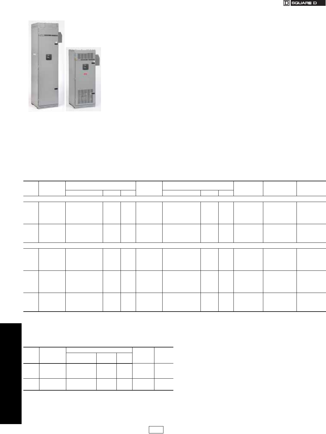
www.reactivar.com
FOR CURRENT INFORMATION
4POWER MONITORING AND
CONTROL
4-30 © 2007 Schneider Electric
All Rights Reserved
PFC Capacitor Banks
Class 5830
AV4000 Series The AV4000 Series performs similarly to the AV5000
series and is more suitable for applications requiring less kVAR
(200 kVAR max., 480 V, main lugs, top entry only).
The Power Factor Table Calculator, available on www.SquareD.com
under Free Software and Online Tools, can be used to determine the
capacitor kVAR required to improve PF of a single load or
entire power system.
aFor 208 Volt applications, the effective kVAR rating at 208 Volts is 0.75 times the kVAR
rating at 240 Volts. See page 4-33 for Medium Voltage Systems.
bA Single remote Current Transformer must be located on the bus/cable at the main service
entrance terminal compartment. CT sold separately. Refer to CT Selection Guide on
page 4-33.
cOrder Only. Typical Delivery—4 to 6 weeks. Contact local sales office for committed
delivery.
dNEMA Type 3R and 12 enclosures available, please contact your nearest Square
D/Schneider Electric sales office for pricing.
eAll trip modules are equipped with dial pick-up settings.
fTop entry is standard. For bottom entry, consult your nearest Square D/Schneider Electric
sales office.
gFor dimensions, see page .
hFor 600 V equipment, additional sizes, ratings or options, please consult your nearest
Square D/Schneider Electric sales office.
iNominal 60 Hz capacitor current draw based on indicated kVAR and voltage ratings.
Consult all applicable electric codes for proper sizing of cables and upstream disconnect.
LV Standard Automatic Capacitor Banks with Main Lugs or Main Breakers
Automatic low voltage capacitor banks are ideally suited for power factor correction at the main service
entrance, in applications where plant loading is constantly changing. A microprocessor-based reactive
power controller measures plant power factor via a single CT located on the bus/cable at the main service
entrance terminal compartment, and switches capacitor stages in and out of service to track a user-
selected target power factor. CT sold separately. Refer to CT Selection Guide on 4-34. The AV4000
and AV5000 Automatic Capacitor Banks are designed for use in networks that contain little or no current
or voltage harmonics.
Features:
Advanced Safety Features: The modularized compact design consists of a microprocessor-based
controller with capacitor switching modules fitted into a cubicle arrangement for top entry. All power and
control wiring is dead front construction. Capacitor modules consist of 3 phase dry metalized
polypropylene elements. Each element has a nonreplaceable 100,000 AIR fuse and pressure sensitive
interrupter. Capacitor modules feature a pre-charge circuit to reduce switching transients to 20% of that
seen with standard capacitor banks. Internal discharge resistors reduce capacitor voltage to 50 Volts or
less within 60 seconds. Dead front fuse holders on AV4000 & AV5000 have integral blown fuse indicators,
standard. Cubicles are constructed with a locking door as standard and are furnished in a textured
powder paint finish, color ASA 49 gray.
State-of-the-art Microprocessor-based Control Module: The solid state control module boasts the
following:
•Automatic C/K ratio selection
•Automatic CT polarity retrieval
•Automatic phase rotation polarity retrieval
•Integral display of target/actual PF, number of steps energized, and more
•Simple, menu-driven programming
•Stage release at voltage dropout
•Alarm relay
•Manual operation with automatic return
•Alarms
The AV4000 and AV5000 are suitable
for use where harmonic generating
loads are less than 15% of the
total connected load.
Table 4.44: AV5000 Series 3 Phase/60 Hz Main Lugs or Main Circuit Breaker – CT sold separately. See page 4-34.b
kVAR
Rating Steps
(Qty x kVAR)
Main Lugsc –
NEMA Type 1dStandard Lugs
Provided
(Qty x AWG)
Main Circuit Breakerc –
NEMA Type 1dStandard Lugs
Provided
(Qty x AWG)
Circuit Breakere
(BV only)
Frame/Sensor
Nominal Current
60 Hzi
(Amps)
Catalog No.f$ Price Encl.gCatalog No.f$ Price Encl.g
240 Volta
50 4 x 12.5 AV005025AV1F6N 15001.00 2
2 x 500 MCM
———
4 x 500 MCM
—120.3
75 3 x 25 AV007525AV2F6N 18392.00 2 BV007525AV2F8N 24535.00 2 1200/600 180.4
100 4 x 25 AV010025AV2F6N 21783.00 2 BV010025AV2F8N 27925.00 2 1200/600 240.6
125 2 x 12.5, 4 x 25 AV012525BV1F6N 25173.00 2 BV012525AV1F8N 31593.00 3 1200/800 300.7
150 6 x 25 AV015025AV2F6N 28564.00 2 BV015025AV2F8N 38607.00 3 1200/1000 360.8
175 1 x 25, 3 x 50 AV017525CV2F6N 31955.00 2 BV017525CV2F8N 41997.00 3 1200/1000 421.0
200 2 x 25, 3 x 50 AV020025BV2F8N 38968.00 3
4 x 500 MCM
BV020025BV2F8N 45388.00 3
4 x 500 MCM
1200/1000 481.1
225 1 x 25, 4 x 50 AV022525CV2F8N 42358.00 3 BV022525CV2F8N 51353.00 3 1200/1000 541.3
250 5 x 50 AV025025AV5F8N 45749.00 3 BV025025AV5F8N 54743.00 3 1200/1000 601.4
275 1 x 25, 5 x 50 AV027525CV2F8N 49140.00 3 BV027525CV2F8N 58134.00 3 1200/1000 661.5
300 6 x 50 AV030025AV5F8N 52530.00 3 BV030025AV5F8N 61525.00 3 1200/1000 721.7
480 Volth
50 2 x 25 AV005045AV2F6N 12422.00 2
2 x 500 MCM
BV005045AV2F8N 13317.00 2
4 x 500 MCM
1200/600 60.1
75 1 x 25, 1 x 50 AV007545CV2F6N 13744.00 2 BV007545CV2F8N 14639.00 2 1200/600 90.2
100 2 x 25, 1 x 50 AV010045BV2F6N 15813.00 2 BV010045BV2F8N 16743.00 2 1200/600 120.3
125 1 x 25, 2 x 50 AV012545CV2F6N 17133.00 2 BV012545CV2F8N 18063.00 2 1200/600 150.4
150 3 x 50 AV015045AV5F6N 18454.00 2 BV015045AV5F8N 24596.00 2 1200/600 180.4
175 1 x 25, 3 x 50 AV017545CV2F6N 20523.00 2 BV017545CV2F8N 26699.00 2 1200/600 210.5
200 4 x 50 AV020045AV5F6N 21845.00 2
2 x 500 MCM
BV020045AV5F8N 28020.00 2
4 x 500 MCM
1200/600 240.6
225 1 x 25, 4 x 50 AV022545CV2F6N 23914.00 2 BV022545CV2F8N 30090.00 2 1200/600 270.6
250 5 x 50 AV025045AV5F6N 25234.00 2 BV025045AV5F8N 31410.00 2 1200/600 300.7
275 1 x 25, 5 x 50 AV027545CV2F6N 27303.00 2 BV027545CV2F8N 37104.00 3 1200/600 330.8
300 6 x 50 AV030045AV5F6N 28624.00 2 BV030045AV5F8N 38668.00 3 1200/800 360.8
350 1 x 50, 3 x 100 AV035045CV5F6N 32015.00 2 BV035045CV5F8N 42057.00 3 1200/1000 421.0
400 2 x 50, 3 x 100 AV040045BV5F8N 39028.00 3
4 x 500 MCM
BV040045BV5F8N 45720.00 3
4 x 500 MCM
1200/1000 481.1
450 1 x 50, 4 x 100 AV045045CV5F8N 42418.00 3 BV045045CV5F8N 51385.00 3 1200/1000 541.3
500 2 x 50, 4 x 100 AV050045BV5F8N 45808.00 3 BV050045BV5F8N 54802.00 3 1200/1000 601.4
550 1 x 50, 5 x 100 AV055045CV5F8N 49199.00 3 BV055045CV5F8N 58193.00 3 1200/1000 661.5
600 6 x 100 AV060045AV8F8N 52588.00 3 BV060045AV8F8N 61583.00 3 1200/1000 721.7
Table 4.45: AV4000 Series 480 Volth 3 Phase/60 Hz
Main Lugs Only – CT sold separately. See page 4-34.b
kVAR
Rating
@ 480 V
Steps
(Qty x kVAR)
Main Lugsc – NEMA Type 1 Standard
Lugs
Provided
(Qty x AWG)
Nominal
Current
60 Hzi
(Amps)
Catalog No.f$ Price Encl.g
50 2 x 25 AV005044AV2F6N 11038.00 1
2 x 500 MCM
48.1
75 1 x 25, 1 x 50 AV007544CV2F6N 12403.00 172.2
100 2 x 25, 1 x 50 AV010044BV2F6N 14276.00 196.2
125 1 x 25, 2 x 50 AV012544CV2F6N 15641.00 1 120.3
150 2 x 25, 2 x 50 AV015044BV2F6N 17513.00 12 x 500 MCM 144.3
175 1 x 25, 3 x 50 AV017544CV2F6N 18880.00 1 168.4
200 4 x 50 AV020044AV5F6N 20246.00 1 192.5
DE2C Discount
Schedule Modified
10/4/07
17404.book Page 30 Thursday, October 4, 2007 8:28 AM
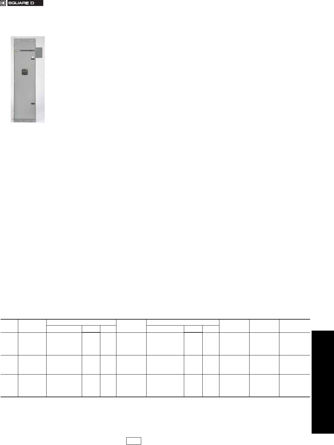
www.reactivar.com
FOR CURRENT INFORMATION
4POWER MONITORING AND
CONTROL
© 2007 Schneider Electric
All Rights Reserved 4-31
PFC Capacitor Banks
Class 5860
Low Voltage Anti-Resonant and Filtering Automatic Capacitor Banks with Main Lugs
and Breaker
ReactiVar® AV6000 anti-resonant and AV7000 harmonic filtering automatic switched capacitor banks are specifically
designed for networks containing harmonic energies which would otherwise damage standard fixed or automatic
capacitor banks.
The problem: Harmonics are a natural by-product of non-linear loads such as variable frequency drives, motor soft
starters, welders, uninterruptable power supplies, robotics, PLCs and other electronic devices. Harmonics introduce
higher-than-60 Hz currents and voltages into the electrical distribution system. Capacitors are a low impedance path for
these higher frequency components and thus will absorb these harmonic energies. Combinations of capacitors and
system inductances (motors and transformers) can form series and parallel tuned circuits which can resonate at certain
frequencies. The harmonics produced by non-linear loads can excite a standard capacitor bank into resonance. The
resonance can magnify currents and voltages, causing system wide damage and equipment failure. This problem is
growing in prevalence.
The solution: Anti-Resonant Automatic Switched Capacitor Banks
The AV6000 anti-resonance capacitor bank’s primary function is power factor correction. Iron core reactors are added
in series with the capacitor modules. The 3 phase reactors are custom designed and manufactured at our factory under
tight tolerance specifically for the AV6000. The reactors tune the bank below the first dominant harmonic (usually the
5th, or 300 Hz). Below the tuning point, the system appears capacitive and thus corrects power factor. Above the tuning
point, the system appears Inductive and thus resonance is minimized. The AV6000 design has the added advantage of
removing up to 50% of the 5th harmonic to reduce overall voltage distortion.
Harmonic Filtering Automatic Switched Capacitor Banks
The need for an AV7000 is usually determined by a power quality specialist. Although the AV7000 looks identical to the
AV6000, its primary function is harmonic mitigation, with power factor correction being a secondary benefit. The
distinction between an AV6000 and an AV7000 is the tuning point. By definition, if the tuning point of the
capacitor/reactor combination is within ±10% of the target harmonic it is intended to absorb, it is referred to as a filter. If
the tuning point is outside the ±10% limit, it is referred to as an anti-resonant system. As the tuning point of the system
approaches the target harmonic, its effectiveness at absorbing increases. Hence, the need to classify its functionality.
The PQc group should always be consulted prior to recommending it to customers.
Application Notes
•A single remote Current Transformer must be located on the bus/cable at the main service entrance terminal compartment. CT sold
separately. Refer to CT Selection Guide on 4-34.
•It is imperative to ensure that no other capacitors (fixed or automatic) are connected to the same network as the AV6000 or AV7000
capacitor banks. The components within these banks are carefully chosen to avoid network resonance between the substation
transformer and the capacitor elements. Additional capacitors on the network will alter the characteristics of the AV6000, possibly
leading to network resonance. The application of this product may warrant special consideration, please supply end customer
telephone number and contact name when placing order.
Application Assistance
The Square D Power Quality Correction Group provides engineering assistance for the application of capacitors in
harmonic rich environments. Specialists at Square D can assess the likelihood of application problems and arrange for
more detailed study if required. Solutions can include computer modeling and system simulation. Depending on the
network, the solution may include de-tuned banks (AV6000) or fully filtered banks (AV7000). Our application engineers
can make all the arrangements for system studies, custom engineering, installation and commissioning, as required by
the application.
Features
•Modularized construction: Units are free standing, modularized “MCC style” in ASA 49 gray. Sections are ganged together as
required with a maximum 300 kVAR per section at 480 V. Key operated latching is standard. Units are NEMA Type 1 standard, with
NEMA Type 3R available upon request (NEMA Type 12 is not available). Top entry, main lugs or main breaker is standard. Bottom
entry is optional.
•Robust design: Capacitor modules are designed with higher than standard voltage and current ratings to provide long life on
systems with high harmonic energies. Reactors are designed to operate at 115°C rise over a maximum 40°C ambient.
•Advanced Safety Features: In addition to the standard safety features designed into the AV4000/5000 systems, the Reactors in
the AV6000 have an embedded thermistor temperature detector. The stage will shut down and annunciate if the reactor should
overheat, usually a result of excessive harmonic energies.
The AV6000 is suitable for
use where less than 50%
of the total connected load
is harmonic generating.
The AV7000 is suitable
where harmonic generating
loads exceed 50% of the
total connected load.
Table 4.46: AV6000 Seriesa480 Volta3 Phase/60 Hz Main Lugs or Main Circuit Breaker – CT sold separately. See page 4-34.b
kVAR
Rating
@ 480 V
Steps
(Qty x kVAR)
Main Lugsc – NEMA Type 1 Standard Lugs
Provided
(Qty x AWG)
Main Circuit Breakerc – NEMA Type 1 Standard Lugs
Provided
(Qty x AWG)
Circuit Breakerf
(BV only)
Frame/Sensor
Nominal Current
60 Hzd
(Amps)
Catalog No.e$ Price Encl. gCatalog No.e$ Price Encl. g
100 2 x 50 AV010046AV2F6N 24467.00 4 2 x 500 MCM BV010046AV2F8N 25444.00 4 4 x 500 MCM 1200/600 132
150 3 x 50 AV015046AV5F6N 31900.00 4 2 x 500 MCM BV015046AV5F8N 38591.00 4 4 x 500 MCM 1200/600 198
200 4 x 50 AV020046AV5F6N 39331.00 4 2 x 500 MCM BV020046AV5F8N 46060.00 4 4 x 500 MCM 1200/600 264
250 1 x 50, 2 x 100 AV025046CV5F6N 41882.00 4 2 x 500 MCM BV025046CV5F8N 53849.00 5 4 x 500 MCM 1200/1000 328
300 2 x 50, 2 x 100 AV030046BV5F6N 49314.00 4 2 x 500 MCM BV030046BV5F8N 61280.00 5 4 x 500 MCM 1200/1000 394
350 1 x 50, 3 x 100 AV035046CV5F8N 59280.00 5 4 x 500 MCM BV035046CV5F8N 69046.00 5 4 x 500 MCM 1200/1000 460
400 4 x 100 AV040046AV8F8N 64270.00 5 4 x 500 MCM BV040046AV8F8N 74068.00 5 4 x 500 MCM 1200/1000 524
450 1 x 50, 4 x 100 AV045046CV5F8N 71702.00 5 4 x 500 MCM BV045046CV5F8N 81499.00 5 4 x 500 MCM 1200/1000 590
500 5 x 100 AV050046AV8F8N 76692.00 5 4 x 500 MCM BV050046AV8F8N 86490.00 5 4 x 500 MCM 1200/1000 655
550 1 x 50, 5 x 100 AV055046CV5F8N 84125.00 5 4 x 500 MCM BV055046CV5FAN 103007.00 6 6 x 500 MCM 1600/1600 721
600 6 x 100 AV060046AV8F8N 89116.00 5 4 x 500 MCM BV060046AV8FAN 107999.00 6 6 x 500 MCM 1600/1600 786
650 1 x 50, 6 x 100 AV065046CV5F8N 100978.00 6 4 x 500 MCM BV065046CV5FAN 114133.00 6 6 x 500 MCM 1600/1600 852
700 7 x 100 AV070046AV8F8N 105939.00 6 4 x 500 MCM BV070046AV8FAN 119125.00 6 6 x 500 MCM 1600/1600 917
750 1 x 50, 7 x 100 AV075046CV5F8N 113371.00 6 4 x 500 MCM BV075046CV5FAN 126557.00 6 6 x 500 MCM 1600/1600 983
800 8 x 100 AV080046AV8F8N 118364.00 6 4 x 500 MCM BV080046AV8FAN 131550.00 6 6 x 500 MCM 1600/1600 1048
850 1 x 50, 8 x 100 AV085046CV5F8N 125795.00 6 4 x 500 MCM BV085046CV5FAN 151047.00 7 6 x 500 MCM 2000/2000 1114
900 9 x 100 AV090046AV8F8N 130788.00 6 4 x 500 MCM BV090046AV8FAN 156040.00 7 6 x 500 MCM 2000/2000 1179
aFor 600 V equipment, AV7000 series, additional sizes, ratings or options, please consult your nearest Square D/Schneider Electric sales office. See page 4-33 for Medium Voltage Systems.
bA Single remote Current Transformer must be located on the bus/cable at the main service entrance terminal compartment. CT sold separately. Refer to CT Selection Guide on page 4-34.
cOrder Only. Typical Delivery—6 to 8 weeks. Contact local sales office for committed delivery.
dNominal 60 Hz capacitor current draw based on indicated kVAR and voltage ratings. Consult all applicable electric codes for proper sizing of cables and upstream disconnect.
eTop entry is standard. For bottom entry, consult your nearest Square D/Schneider Electric sales office.
fAll trip modules are equipped with dial pick-up settings.
gFor dimensions, see page 4-34.
DE2C Discount
Schedule Modified
10/4/07
17404.book Page 31 Thursday, October 4, 2007 8:28 AM
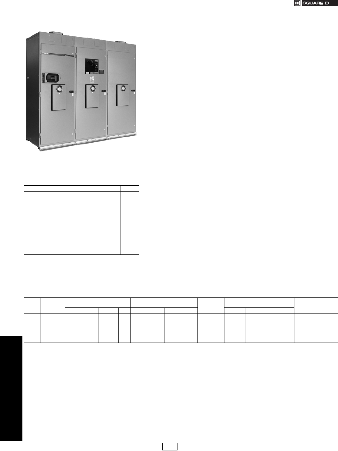
www.reactivar.com
FOR CURRENT INFORMATION
4POWER MONITORING AND
CONTROL
4-32 © 2007 Schneider Electric
All Rights Reserved
PFC Capacitor Banks
Class 5870
LV Transient Free Reactive Compensation Capacitor Banks
Square D ReactiVar® Transient Free Reactive Compensation (TFRC) anti-resonant
(AT6000)Systems are ideally suited for use on electrical systems where connected
equipment is extremely sensitive to variations in the supply voltage.
The problem: Capacitor systems featuring electromechanical contactors generate voltage
transients on the electrical network when switching capacitor stages on/off, even when
current limiting or tuning reactors are employed. Transients can impair the operation of
sensitive equipment, including programmable logic controllers, variable speed drives,
computers and UPS systems. In sensitive networks such as hospitals, data processing
centers, airports and many manufacturing environments, any transient, however slight, may
not be acceptable.
The solution: Transient free reactive compensation systems utilize electronic switching
elements to energize capacitor stages. Switching occurs when the capacitor residual
voltage matches the network voltage. The result is reactive compensation without
generating voltage transients. The Anti-Resonant design allows for installation in harmonic
rich environments which are typical with electronic loads.
Application Notes
1. A remote current transformer for each unit must be located on the bus/cable at the main service
entrance terminal compartment—installed on the “A” phase. CTs are sold separately. To order,
refer to CT Selection Guide on page 34.
2. It is imperative to ensure that no other capacitors (fixed or automatic) are connected to the same
network as the AT6000 TFRC System
3. Additional capacitors on the network can lead to network resonance. Applying capacitors to a
network containing harmonic producing loads warrants special consideration. It is highly
recommended that you contact the Square D Power Quality Correction Group for application
assistance. When calling for assistance, please have the following information available:
.•12 months of utility billing information
•A single line diagram of the network showing the nature of loads
(e.g. 150 hp FVNR starters; 200 hp VFD; etc.)
•Transformer(s) kVA rating and percent impedance (%Z)
•Primary & secondary voltages
•Location of utility metering
•Size, type and location of any existing capacitors
Application Assistance
The Square D Power Quality Correction Group provides engineering assistance for the
application of capacitors in harmonic rich environments. Specialists at Square D can assess
the likelihood of application problems and arrange for more detailed study if required.
Solutions can include computer modeling and system simulation. Our application engineers
can make all the arrangements for system studies, custom engineering, installation and
commissioning, as required by the application.
Table 4.47: Standard Features and
Available Options
AT6000
Silver flashed copper bus X
Copper power and control wiring X
Solid state capacitor switching modules X
Heavy duty capacitor elements X
Iron core tuning reactors X
Forced air ventilation X
Varlogic™ N12 Controller X
Varlogic NRC12 Controller O
Split core CTs for incoming service a
CT shorting blocks X
Incoming section with main lugs X
Incoming section with main circuit breaker O
Top e ntry X
Bottom entry O
Type 1 enclosure (ASA 61 grey) X
Type 3R (ASA 49 grey) O
Other voltages or frequencies O
Note: X=Standard feature
Note: O=Available option–contact your nearest Square D/Schneider
Electric sales office for pricing
aRequired, but must be ordered separately.
Table 4.48: AT6000 Seriesf480 Voltb, 3 Phase, 60 Hz Main Lugs or Main Circuit Breaker—CTs sold separately. See page 4-34 g
KVAR
Ratingb
@480 V
Steps
(Qty x kVAR)
Main Lugs
NEMA Type 1cMain Circuit Breaker
NEMA Type 1cStandard Lugs
Providedb
(Qty x kcmil)
Recommended Minimum Size Protection
Ratingd @480 V Recommended Minimum
Cable Ampacityd 135%
Rated Current
Catalog No.e$ Price Encl. Catalog No.e$ Price Encl. Fuse Breaker/Trip
300 2x150 AT030046AABF8N 58058.00 8 BT030046AABF8N 66183.00 8 4x500 600 800/600 535
375 1x75, 2x150 AT037546CAAF8N 72409.00 8 BT037546CAAF8N 79892.00 8 4x500 800 800/800 668
450 3x150 AT045046AABF8N 81744.00 8 BT045046AABF8N 88022.00 8 4x500 900 1200/900 802
600 4x150 AT060046AABFAN 101601.00 9 BT060046AABFAN 116639.00 9 6x500 1200 1200/1200 1069
750 5x150 AT075046AABFAN 122441.00 9 BT075046AABFAN 134152.00 9 6x500 1500 1600/1500 1337
900 6x150 AT090046AABFAN 141252.00 9 BT090046AABFAN 158676.00 9 6x500 1800 2000/1800 1604
bFor larger sizes or 240 V systems contact your nearest Square D/Schneider Electric sales office. See page 4-33 for Medium Voltage Systems.
cOnly Type 1 Indoor enclosure available. For dimensions, see page 4-34.
dConsult local Electrical Codes for proper sizing of molded case circuit breakers, disconnect switches and cables.
eTop entry is standard. For alternate entry, consult your nearest Square D/Schneider Electric sales office.
fOrder only. Typical delivery is 8-10 weeks. Contact local sales office for committed delivery.
gOne remote current transformer must be located on the bus/cable at the main service entrance terminal compartment, “A” phase. CTs sold separately. See page 4-34.
DE2C Discount
Schedule
17404.book Page 32 Thursday, October 4, 2007 8:28 AM
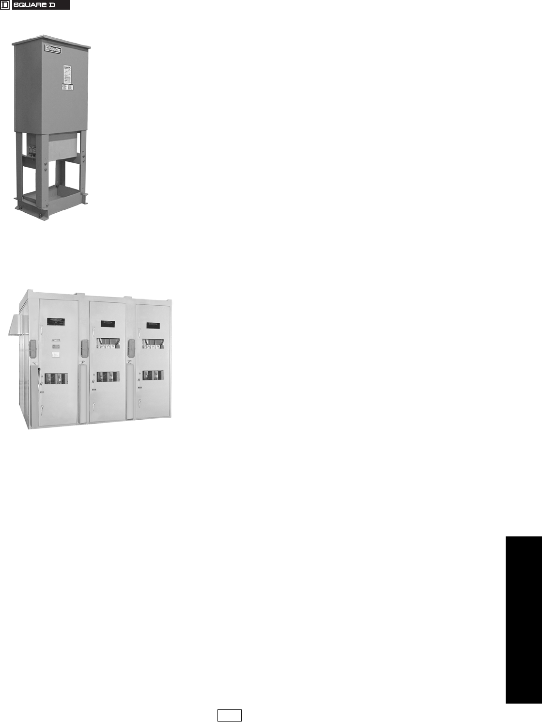
www.reactivar.com
FOR CURRENT INFORMATION
4POWER MONITORING AND
CONTROL
© 2007 Schneider Electric
All Rights Reserved 4-33
ReactiVar Medium Voltage Capacitor Systems
Class 5840, 5841
NOTE: Power factor correction, harmonic mitigation, and voltage support in medium
voltage electrical systems. Custom engineered for steady and rapidly
fluctuating loads.
ReactiVar® Medium Voltage Fixed Power Factor Capacitors
The ReactiVar MVC fixed capacitors are ideally suited for power factor correction in
applications where the load does not change or where the capacitor is switched with the
load, such as the load side of a motor contactor. ReactiVar capacitors are available up to
300 kVAR as individual units, and up to 600 kVAR in banks. Unfused or fused (2 fuses)
assemblies are available. Other ranges available upon request.
Features:
•Fused and unfused applications
•Standard rating up to 600 kVAR, 4800 V (for specials, consult factory)
•Metallized polypropylene film capacitors for low dielectric loss
•Internally mounted discharge resistors
•Operating temperature range of –25°C to +45°C
•Built to applicable NEMA, IEEE, and IEC standards
•Available in indoor (Type 1/12) and outdoor (Type 3R) enclosures
•Painted ASA 61 gray
Lead time: 12–14 weeks typical (consult factory for committed delivery)
Prices & assistance: Call PQc Group at (905) 678-6699 or email
pqc@ca.schneider-electric.com
ReactiVar Medium Voltage Metal Enclosed Automatic Capacitor Banks
(MV5000/MV6000/MV7000)
The ReactiVar medium voltage automatic capacitor banks are ideally suited for centralized
power factor correction and/or harmonic filtering in applications where plant loading is
constantly changing, resulting in the need for varying amounts of reactive power. All MV
capacitor systems are a custom-engineered to meet project specific application and
installation needs.
Features:
•Standard metal enclosures available up to 20,000 kVAR, 5/15 kV, 50/60 Hz
•The Square D HVL load interrupter switch (fused or unfused)
•Externally fused Merlin Gerin PROPIVAR (or equivalent) or Cooper capacitors with excellent life due
to high temperature withstand, small temperature rise, chemical stability, overvoltage and
overcurrent withstand. (Internally fused capacitor available upon request)
•Three-bushing capacitor cells connected in delta available up to 5 kV. Two-bushing capacitor cells
connected in ungrounded wye for higher voltages
•Current limiting capacitor fuses with blown fuse pop-up indicators
•current limiting reactors in multistage-step MV5000 standard systems to limit high capacitor inrush
currents
•Iron core reactors in MV6000 de-tune banks to prevent parallel resonance
•Heavy-duty iron core reactors in MV7000 filtered banks for effective 5th harmonic filtering.
•Available in Type 1 indoor and 3R outdoor enclosure types
•Key interlocking system forces sequential operation of the controls, non-load break switch (or circuit
breaker) and ground switches
•Superior Square D Varlogic™ microprocessor based power factor controller
•The Merlin Gerin SEPAM protective relaying.
Lead time: 12–16 weeks typical (consult factory for committed delivery)
Prices & assistance: Call PQc Group at (905) 678-6699 or email
pqc@ca.schneider-electric.com
MVC systems are suitable for
power factor correction of steady
harmonic-free motor loads.
MV5000 systems are suitable for use where
harmonic generating loads are less than 15% of
the total connected load.
MV6000 systems are suitable for use where
harmonic generating loads are less than 50% of
the total connected load.
MV7000 systems are suitable for use where
harmonic generating loads exceed 50% of the
total connected load.
MVHVC High-Speed compensation systems are
designed for compensation of rapidly
fluctuating loads
DE2C Discount
Schedule
17404.book Page 33 Thursday, October 4, 2007 8:28 AM
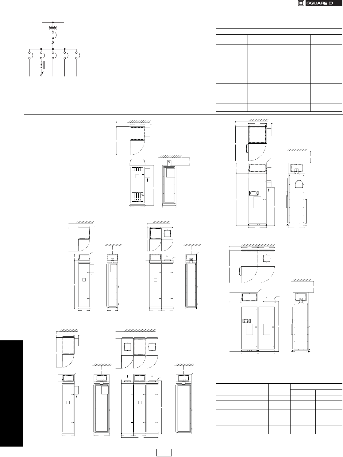
www.reactivar.com
FOR CURRENT INFORMATION
4POWER MONITORING AND
CONTROL
4-34 © 2007 Schneider Electric
All Rights Reserved
PFC Capacitor Banks
Class 5830, 5860, 5870, 5880
CT Selection Guide for Class 5830, 5860, 5870
and 5880
The current transformer is located on a phase A bus or
cable at the main service entrance as illustrated in
Diagram 1. The CT should be sized for the maximum load
current. The CT should be installed upstream of the
capacitor bank and plant loads to measure the combined
current.
CT catalog number: TRAI••••SCc c where •••• is
current rating code of bus/cable and c c is window size
code. Codes are listed in table to the right.
e.g. TRAI1000SC07 is a CT for 1000 A bus with 7"x4"
window.
Unit Price: $673.
Enclosure Dimensions
aDimensions provided are approximate only. Do not use for
construction. For actual dimensions, contact your nearest Square
D/Schneider Electric sales office.
Single Line (Typical)
Diagram 1
Main Transformer
Main Breaker
External Current
Transformer
Ratio XXXX/5
Sub
Feed Sub
Feed Sub
Feed Sub
Feed
600 kVAR
Automatic
Capacitor
Bank
Table 4.49:
Current Rating of Bus/Cable Window Size
Amperes Rating Code
•••• 7" x 4" Size Code
c c 11" x 4" Size Code
c c
300 0300 07 11
400 0400 07 11
500 0500 07 11
600 0600 07 11
750 0750 07 11
800 0800 07 11
1000 1000 07 11
1200 1200 07 11
1500 1500 07 11
1600 1600 07 11
2000 2000 07 11
2500 2500 07 11
3000 3000 07 11
3500 3500 07 11
4000 4000 07 11
5000 5000 N/A 11
6000 6000 N/A 11
Table 4.50: Dimensionsa
Type Encl. Figure Sections Dimensions “B” (Width)
IN mm
AV4000 1 1 1 23.5 597
AV5000 22 1 23.5 597
3 2 2 47.0 1194
AV6000 &
AV7000
43 1 23.5 597
5 3 2 47.0 1194
6 3 3 70.5 1791
7 3 4 94.0 2388
AT6000 84 1 32.0 813
9 5 2 64.0 1626
TOP VIEW
62.42
23.50 21.43
23.50 8.05
AIR
FLOW
REMOVABLE
LIFTING
LUGS
44.28
24 MIN. CLEARANCE
36 MIN. CLEARANCE
Figure 1—AV4000
23.50 21.43
REMOVABLE
LIFTING LUGS
23.50 8.05
91.44
13.00
SUPPLIED BUT
FIELD FITTED
CABLE ENTRY
BOX C/W
REMOVABLE
CABLE ENTRY
PLATE QTY (1)
23.50 23.50
91.44
13.00
AIR FLOW
AIR FLOW
SUPPLIED BU
T
FIELD FITTED
CABLE ENTR
Y
BOX C/W
REMOVABLE
CABLE ENTR
Y
PLATE QTY (1
)
93.44
44.29 44.29
36 MIN. CLEARANCE
24 MIN. CLEARANCE 24 MIN. CLEARANCE
36 MIN. CLEARANCE
Figure 2—AV5000
24 MIN. CLEARANCE 32.00 8.02
AIR
FLOW
REMOVABLE
LIFTING LUGS
TOP VIEW
60.00
32.00
91.50
66.26
36. MIN. CLEARANCE
29.43
SUPPLIED BUT
FIELD FITTED
CABLE ENTRY
BOX C/W
REMOVABLE
CABLE ENTRY
PLATE QTY (1)
18.00
Figure 4—AT6000
24 MIN. CLEARANCE 32.00
REMOVABLE
LIFTING LUGS
60.00
32.00
91.50
36. MIN. CLEARANCE
29.43
SUPPLIED BUT
FIELD FITTED
CABLE ENTRY
BOX C/W
REMOVABLE
CABLE ENTRY
PLATE QTY (1)
18.00
32.00
32.00
AIR FLOW
93.50
Figure 5—AT6000 (2 Section)
8.05
AIR FLOW
23.50
91.44
13.00
SUPPLIED BUT
FIELD FITTED
CABLE ENTRY
BOX C/W
REMOVABLE
CABLE ENTRY
PLATE QTY (1)
REMOVABLE
LIFTING LUGS
AIR FLOWAIR FLOW
23.500 23.500
29.43
SUPPLIED BUT
FIELD FITTED
CABLE ENTRY
BOX C/W
REMOVABLE
CABLE ENTRY
PLATE QTY (1)
52.29 52.29
70.50
93.44
24 MIN. CLEARANCE
36 MIN. CLEARANCE
24 MIN. CLEARANCE
36 MIN. CLEARANCE
Figure 3—AV6000
DE2C Discount
Schedule Modified
10/4/07
17404.book Page 34 Thursday, October 4, 2007 8:28 AM
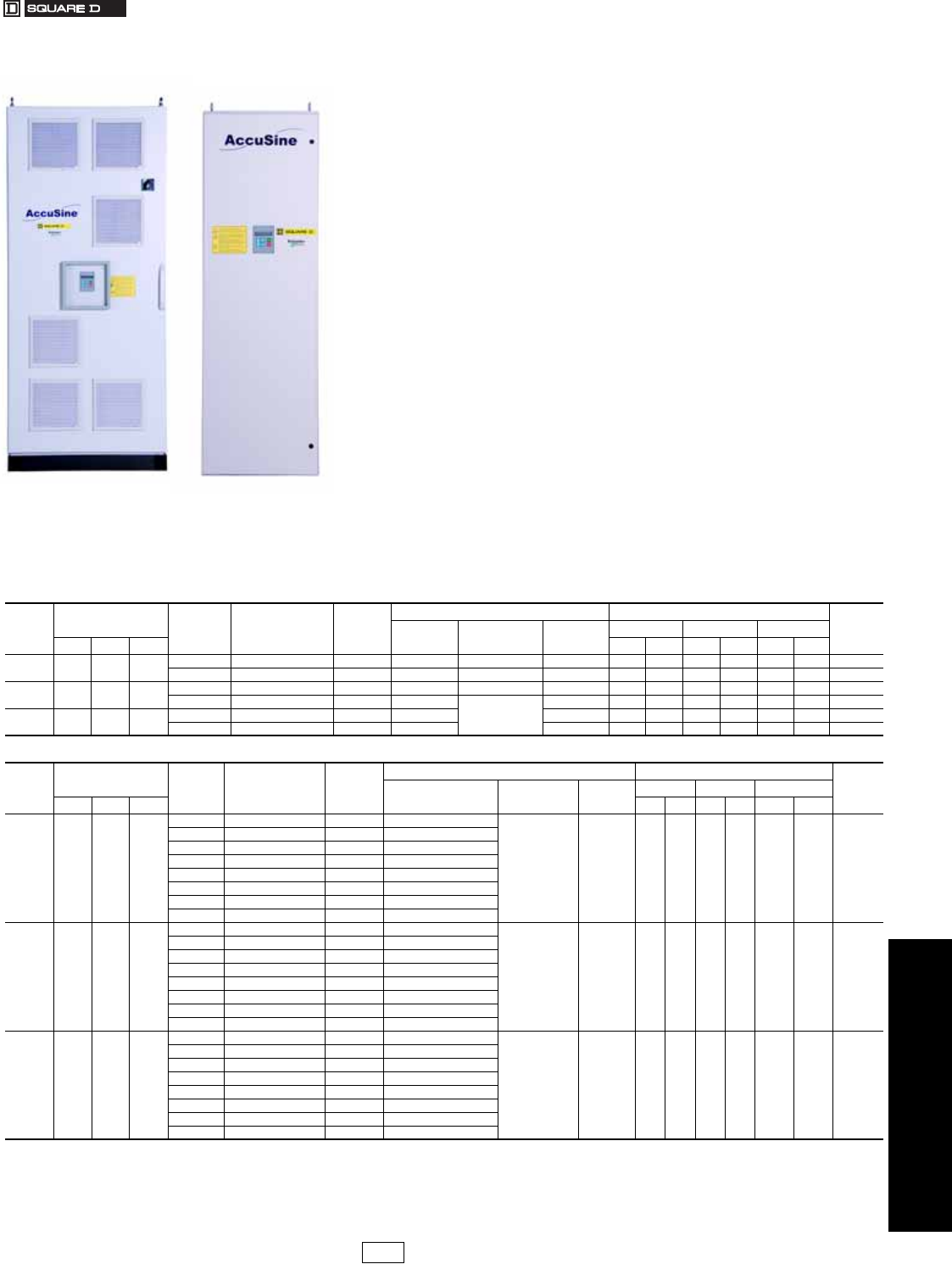
www.reactivar.com
FOR CURRENT INFORMATION
4POWER MONITORING AND
CONTROL
© 2007 Schneider Electric
All Rights Reserved 4-35
AccuSine® PCS AHF
Class 5820
The problem:
High levels of harmonics generated by non-linear loads can have significant negative
impact in the facility electrical system. It can cause malfunction of the equipment, disrupt
plant operation, thus, resulting loss of productivity.
Harmonic filtering:
The AccuSine Power Correction System (PCS) is Active Harmonic Filter (AHF) which
actively injects opposite harmonics current on the source side of the load and it:
•Decreases harmonic related overheating of cables, switchgear and transformers
•Reduces downtime caused by nuisance thermal tripping of protective devices
•Increases electrical network reliability and reduces operating costs
•Corrects to the 50th harmonic, reduce harmonics level to meet IEEE 519, IEC 61000 3-4, and
UK G5/4-1 standards.
•Compensates entire network or specific loads depending on installation point
Power Factor Correction and Dynamic VAR Compensation:
AccuSine PCS features a 100 microsecond response providing for dynamic VAR injection
to reduce voltage sags created by inductive load switching. In addition, AccuSine PCS can
inject peak current at 2.25 times its rms current rating for 3 cycles. AccuSine PCS can also
operate in a dual mode where current is first injected to reduce hamonics and any excess
current capacity is used to improve the power factor.
Other Features:
•Independent phase compensation
•UL, CE, ABS, and CSA approved
•Parallel connection allows for easy retrofit and installation of multiple units for large networks
•Response to load fluctuations begins in 100 microseconds with 1/2 cycle for full response to step
load changes
•50, 100 and 300 A models for 208–480 V. Other voltages available.
Accusine PCS Sizing
For proper sizing of AccuSine units, contact the Square D/Schneider Electric Power Quality
Correction Group at (905) 678-6699. To expedite the product selection process, please
have a single line diagram and/or details of the application including sizes of transformers,
non-linear and linear loads, and any existing filters and capacitors.
Table 4.51: AccuSine—208–480 Va, 50/60 Hzb NEMA rated
Rated
Current
A (rms)
Max. Reactive
Power (kVAR) Frequency
(Hz) Catalog
No. $ Price
Enclosure Exterior Dimensionsc
Weightc
Lbs (kg)
Rating Style Cable Entry HWD
208 V 400V 480 V IN mm IN mm IN mm
50 18 34.6 41.6 50/60 PCS050D5N1 23269.00 NEMA 1 Wall Mount Bottom þ 48 1219 21 526 19 470 250 (114)
50/60 PCS050D5N12 35825.00 NEMA12 Floor StandingeTop/Bottom 75 1900 31 800 24 600 661 (300)
100 36 69.2 83.1 50/60 PCS100D5N1 36754.00 NEMA 1 Wall Mount þ Bottom þ 65 1650 21 526 19 475 350 (159)
50/60 PCS100D5N12 44518.00 NEMA12
Floor Standinge
Top/Bottom 75 1913 31 800 24 600 771 (350)
300 108 207.8 249.4 50/60 PCS300D5N1 73534.00 NEMA 1 Top þ 75 1900 31 800 20 500 775 (352)
50/60 PCS300D5N12 88227.00 NEMA12 Top/Bottom 91 2300 39 1000 32 805 1212 (552)
Table 4.52: AccuSine—208–480 Va, 50/60 Hzb IP ratedd
Rated
Current
A (rms)
Max. Reactive
Power (kVAR) Frequency
(Hz) Catalog
No. $ Price
Enclosure Exterior Dimensionsc
Weightc
Lbs (kg)
Rating Style Cable Entry HW D
208 V 400V 480 V IN mm IN mm IN mm
50 18.0 34.6 41.6
50 PCS050D5IP305 39060.00 IP30
Floor StandingeTop/Bottom 75 1900 31 800 24 600 661 (300)
50 PCS050D5IP545 41229.00 IP54
50 PCS050D5CE305 42538.00 IP30 (CE certified)
50 PCS050D5CE545 44707.00 IP54 (CE certified)
60 PCS050D5IP306 39060.00 IP30
60 PCS050D5IP546 41229.00 IP54
60 PCS050D5CE306 42538.00 IP30 (CE certified)
60 PCS050D5CE546 44707.00 IP54 (CE certified)
100 36 69.2 83.1
50 PCS100D5IP305 47932.00 IP30
Floor StandingeTop/Bottom 75 1900 31 800 24 600 7
50 PCS100D5IP545 50752.00 IP54
50 PCS100D5CE305 52493.00 IP30 (CE certified)
50 PCS100D5CE545 55313.00 IP54 (CE certified)
60 PCS100D5IP306 47932.00 IP30
60 PCS100D5IP546 50752.00 IP54
60 PCS100D5CE306 52493.00 IP30 (CE certified)
60 PCS100D5CE546 55313.00 IP54 (CE certified)
300 108 207.8 249.4
50 PCS300D5IP305 91974.00 IP30
Floor StandingeTop/Bottom 91 2300 39 1000 32 805 1212 (550)
50 PCS300D5IP545 97946.00 IP54
50 PCS300D5CE305 99195.00 IP30 (CE certified)
50 PCS300D5CE545 110217.00 IP54 (CE certified)
60 PCS300D5IP306 91974.00 IP30
60 PCS300D5IP546 97946.00 IP54
60 PCS300D5CE306 99195.00 IP30 (CE certified)
60 PCS300D5CE546 110217.00 IP54 (CE certified)
aOther voltages available. Contact your nearest Square D/Schneider Electric sales office. Multiple units can be connected in parallel.
bTwo remote 400 Hz rated current transformers required for three phase loads. Three remote 400 Hz rated CTs required when single phase loads are present. Select proper CTs per table in
section 4-36.
cDimensions and weights are approximate. Do not use for construction. For actual dimensions, contact your nearest Square D/Schneider Electric sales office.
dAnti-runaway feature included. CE certified unit meets EMC directive 89/336 EEC.
eA main disconnect is included in all floor standing units.
DE2C Discount
Schedule Modified
10/4/07
17404.book Page 35 Thursday, October 4, 2007 8:28 AM
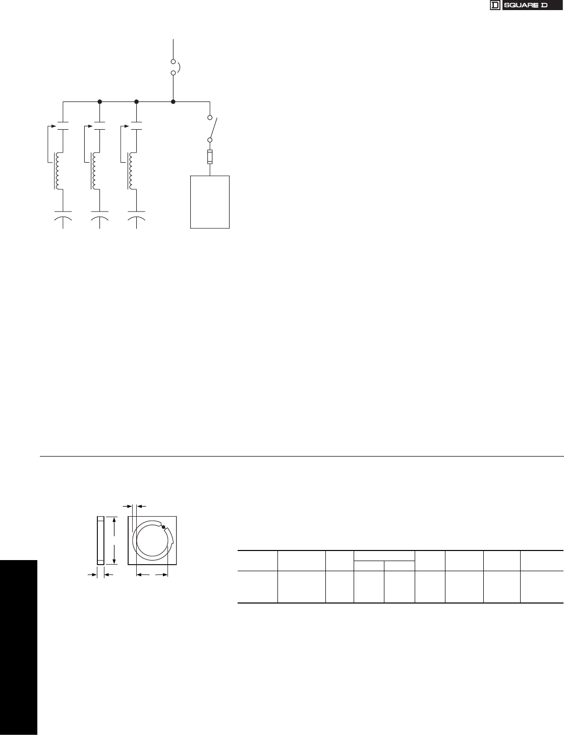
www.reactivar.com
FOR CURRENT INFORMATION
4POWER MONITORING AND
CONTROL
4-36 © 2007 Schneider Electric
All Rights Reserved
AccuSine® PCS AHF Hybrid VAR Compensator (HVC)
Class 5890
The Hybrid VAR Compensator (HVC) is ideally suited for industrial facilities with power
quality or production problems caused by rapidly changing load demands typical of highly
cyclical loads such as welders, mining conveyors and heavy stamping machines.
The problem:
Traditional capacitor systems have a minimum response time of five to ten seconds for load
fluctuations. As a result of this limitation, uncompensated faster loads can produce voltage
instability, voltage flicker, increased losses and poor power factor which reduces the electric
supply capacity. Problems can often be seen inside the facility, on the utility feeder to the
facility or in neighboring facilities. Problems can include:
•Poor weld quality or reduced weld line productivity (due to restrikes or interlock
weld controls)
•Failure to start motor loads (due to voltage sag on startup)
•Undervoltage tripping of sensitive loads (Robots, PLCs, VFDs)
•Lighting flicker and/or HID lighting shutdown
•Overloaded distribution equipment (cyclical current pulses may exceed the rated
current of the distribution equipment)
•Poor power factor and associated utility demand charges
•High harmonic levels
Ultra-Fast Reactive Power Solution:
•The Hybrid VAR Compensator is ideally suited for power factor correction and voltage sag support
in many applications where conventional systems are not suitable:
•One cycle or less for full response
•Infinite VAR resolution
•Compensates for large inductive inrush currents
•Transient free compensation
•Improves voltage regulation
•Reduces flicker
HVC systems can alleviate any of the problems created by cyclical loads that require large
amounts or reactive power for short duration.
Unique, cost-effective construction:
HVC systems couple a detuned capacitor system (fixed, contactor or power electronic
switched) with the AccuSine® Electronic VAR Control (EVC) unit. The Accusine EVC is able
to inject leading or lagging VARs to provide variable compensation over the operating
rating. For example, coupling a 500 kVAR fixed detuned bank with a 300 A Accusine EVC
yields an HVC that can provide reactive compensation between 250 kVAR and 750 kVAR.
Custom Designed Solution:
Sizing of the HVC will often require a site visit by Square D Power Quality Correction Group
technicians to take real-time measurements of the network. Please contact the PQc group
at (905)678-6699 or email pqc@squared.com
Round Split-Core Selection:
Three CT’s required for networks with line-neutral loads. Two remote current transformers
required for three phase loads. For installations requiring parallel connection of multiple
AccuSine for increased correction capacity, special considerations may be required.
Contact the Square D Power Quality Correction Group for details.
Note: Rectangular CTs also available; contact PQC group.
Table 4.53:
Ampacity Catalog No. $ Price Dimensions (IN) Weight
(lbs.) Accuracy Burden
Capacity Secondary
Current
A (ID) D (OD)
500 CT500SC 642.00 4.0 6.5 3.5 2% 3 VA 5 A
1000 CT1000SC 642.00 4.0 6.5 3.5 1% 10 VA 5 A
3000 CT3000SC 800.00 6.0 8.5 4.25 1% 45 VA 5 A
5000 CTFCL500058 1082.00 8.0 10.5 5.5 1% 45 VA 5 A
Main
Breaker
(Optional)
AccuSine
EVC
300 Ampere
ACTIVEPASSIVE
100 kVAR 100 kVAR 100 kVAR
HVC Topology (Typical)
1.25
32
A
1.50
38
D
Modified
10/4/07
17404.book Page 36 Thursday, October 4, 2007 8:28 AM

www.us.schneider-electric.com
FOR CURRENT INFORMATION
© 2007 Schneider Electric
All Rights Reserved 1-1
A
accessories
Sepam series 4-26
AccuSine AHF 4-35– 4-36
dynamic VAR compensation
4-35– 4-36
analysis and consulting 4-20
application
Sepam series 4-25
arc flash analysis 4-20
automation power system 4-21
C
capacitor banks 4-32
capacitor systems medium
voltage 4-33
circuit monitor, PowerLogic 4-11
circuit monitor, PowerLogic 4-10
consulting, analysis 4-20
E
enclosure dimensions
PFC capacitor banks 4-34
energy meters
power meters 4-6
engineering services, PowerLogic
4-21, 4-23
Ethernet-Modbus®/TCP
networks 4-19
F
factory assembled enclosures,
PowerLogic 4-22
H
hybrid VAR compensator (HVC)
4-36
I
ION EEM enterprise energy
management software 4-
16
ION enterprise operations
software, PowerLogic 4-4
ION enterprise software ordering
information
meter selection 4-5
ION power and energy meter,
PowerLogic 4-6– 4-7
M
medium voltage
capacitor systems 4-33
meter comparison chart
SMS ordering information 4-
9
meter selection
ION enterprise software
ordering information
4-5
SMS ordering information 4-
9
metering 4-11
N
network components, Web-
enabled 4-19
P
PFC capacitor banks
anti-resonant and filtering
automatic, main lugs
and circuit breaker 4-
31
automatic, main lugs or main
circuit breakers 4-30
enclosure dimensions 4-34
transient free reactive
compensation 4-32
power meters energy meters 4-6
power meters PowerLogic 4-10
power system automation 4-21
PowerLogic 4-2
circuit monitor 4-10– 4-11
engineering services 4-21,
4-23
factory assembled
enclosures 4-22
instrument
transformer services 4-
18
ION Enterprise operations
software 4-4
ION power and energy meter
4-6– 4-7
power meter 4-10
system integration 4-21
total energy control 4-21
PowerLogic Ethernet Gateways
4-19
pricing
Sepam series 4-26
R
relays
Sepam series digital
protective 4-24
S
selection information
Sepam series 4-27
selection tables
Sepam series 4-25
Sepam series
accessories 4-26
applications 4-25
digital protective relay 4-24
pricing 4-26
selection example 4-27
selection table 4-25
SMS ordering information
meter comparison chart 4-9
meter selection 4-9
solutions, utilities 4-17
submetering 4-15
system integration, PowerLogic
4-21
T
total energy control, PowerLogic
4-21
U
utilities, solutions 4-17
V
VAR compensator (HVC) hybrid
4-36
W
Web-enabled network
components 4-19
17404.book Page 1 Thursday, October 4, 2007 8:28 AM

1-2 © 2007 Schneider Electric
All Rights Reserved
www.us.schneider-electric.com
FOR CURRENT INFORMATION
17404.book Page 2 Thursday, October 4, 2007 8:28 AM
