155071 Catalog
98857-Brochure 98857-Brochure 98857-Brochure B5 unilog cesco-content
2016-07-29
: Pdf 155071-Catalog 155071-Catalog B2 unilog
Open the PDF directly: View PDF ![]() .
.
Page Count: 234 [warning: Documents this large are best viewed by clicking the View PDF Link!]
- General contents
- 1 - Processor modules
- 2 - Modicon X80 I/O platform and Modicon distributed I/O solutions
- Modicon X80 I/O platform
- General Presentation
- Compatibility
- Single-rack configuration
- Multi-rack configuration
- Power supply modules
- Discrete I/O modules
- Analog I/O modules
- BMXEHC0200/0800 counter modules
- BMXEAE0300 SSI encoder interface module
- BMXMSP0200 motion control module
- MFB motion control
- Modicon X80 CRA Ethernet drop adaptors
- Modicon X80 NRP RIO drop optical repeaters
- Peripheral Remote I/O Adaptor
- Time stamping system
- Communication, integrated ports and modules
- Modicon distributed I/O solutions
- Modicon X80 I/O platform
- 3 - Communication
- Communication, integrated ports and modules
- PlantStruxure Ethernet Architectures
- Ethernet Modbus/TCP and EtherNet/IP networks
- Connexium cabling systems for Ethernet and Wi-Fi networks
- Modbus Plus Proxy module
- Profibus DP V1 and Profibus PA buses
- CANopen machine and installation bus
- Modbus and Character mode serial links
- 4 - Software
- 5 - Connection interfaces
- Modicon Telefast ABE7 pre-wired system
- Interface with Modicon X80 I/O modules
- Passive connection sub-bases
- Adaptor sub-bases with fixed relays and removable terminal blocks
- Input/output adaptor sub-bases for or with plug-in relays
- Output adaptor sub-bases for plug-in relays
- Plug-in relays
- Connection sub-bases for analog chanels and application-specific channels
- Accessories for connection sub-bases
- 6 - Ruggedized Modicon M340 modules
- 7 - Services
Modicon M340
automation platform
Catalogue
September 2013
How to find the
“Automation and Control” products
Catalogs
Complete product ranges
Essential guides
Selection of the top selling
products

1
General contents
Processor modules .........................
Modicon X80 I/O platform . . . . . . . . . . . . . . . . . .
Communication .............................
Software ....................................
Connection interfaces . . . . . . . . . . . . . . . . . . . . . .
Ruggedized Modicon M340 modules. . . . . . .
Services .....................................
2
1
3
4
5
6
7
8
9
10
2
1
3
4
5
6
7
8
9
10

1/0
2
1
3
4
5
6
7
8
9
10
2
1
3
4
5
6
7
8
9
10

1/1
1 - Processor modules
1
General presentation ............................................................................. page1/2
Processor modules
Selection guide ............................................. page1/4
Presentation ........................................................................................... page1/6
Description ............................................................................................. page1/7
Memory structure . ................................................................................ page1/8
Memory cards . ........................................................................................ page1/8
Protecting the application ........................................................................ page1/8
Modifying the program in online mode ..................................................... page1/8
References ............................................................................................. page1/9
Ruggedized modules ............................................................................ page6/1
Contents
2
1
3
4
5
6
7
8
9
10
2
1
3
4
5
6
7
8
9
10
1/2
Presentation Modicon M340 automation
platform
Composition
Processor selection guide:
page 1/4
Modicon X80 I/O platform:
page 2/2
Communication:
page 3/2
Software:
page 4/2
Ruggedized Modicon M340:
page 6/2
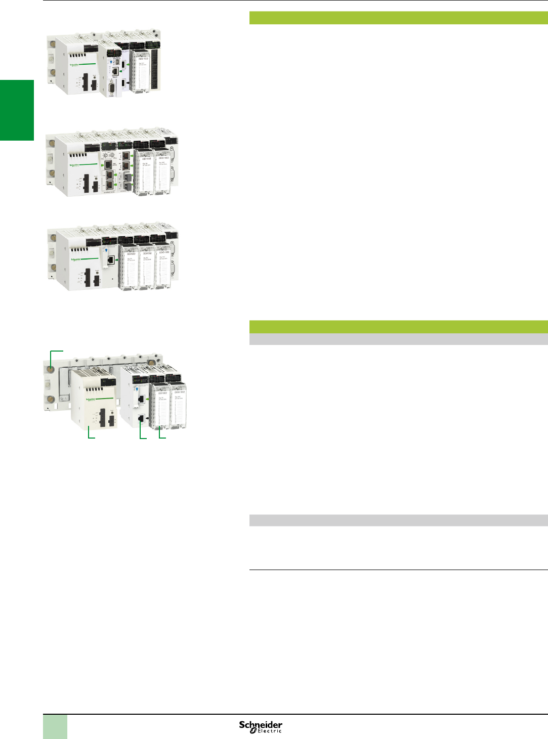
Presentation
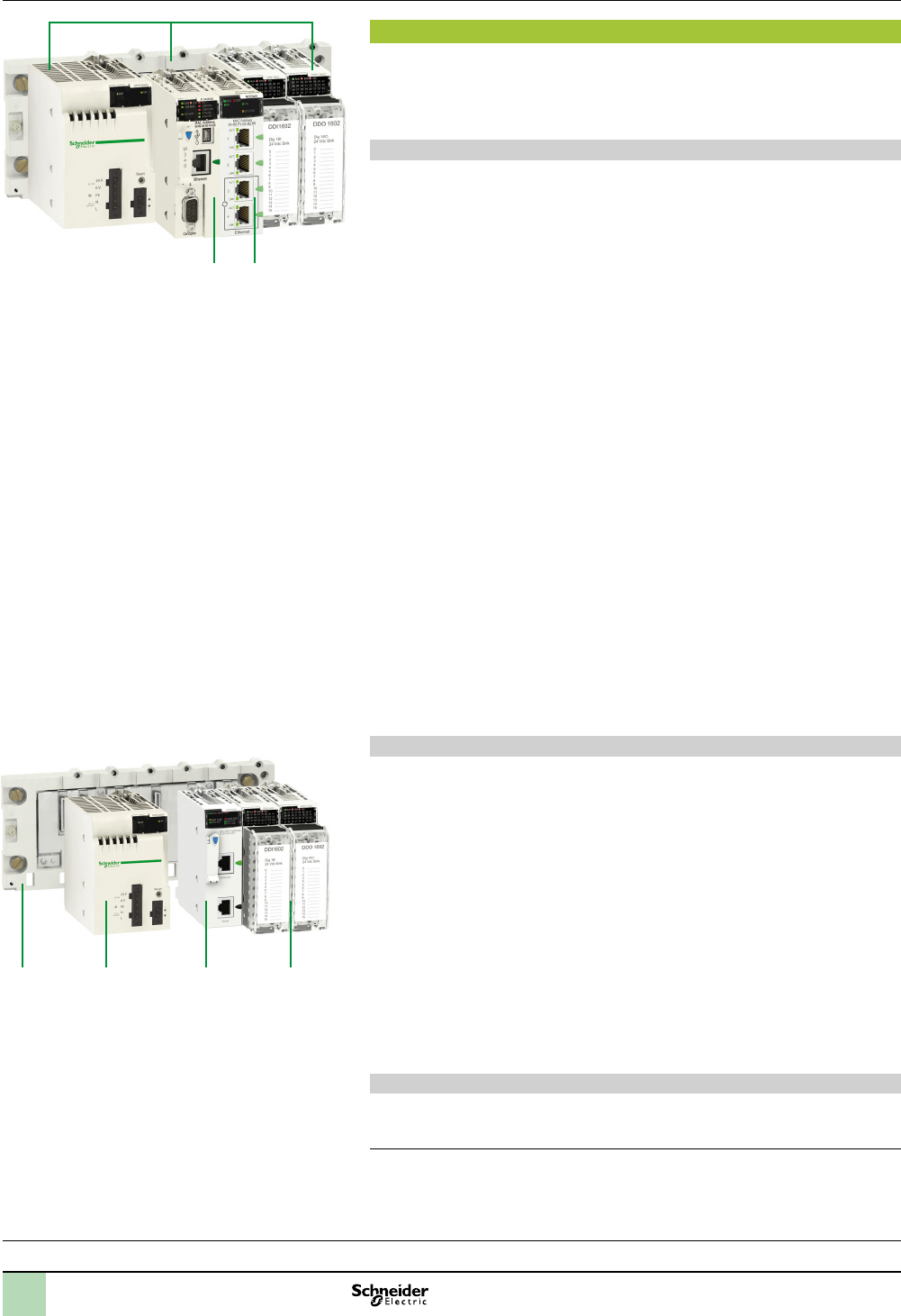
The Modicon M340 automation platform comprises:
1 BMXP34 dedicated processors
2 A Modicon X80 I/O platform, in a single-rack or multi-rack conguration
3 Additional modules for various applications (application-specic, Ethernet
communication, etc.)
Modicon M340 processors
Seven processor models comprising 1 Standard model (BMXP341000) and
6 Performance models (BMXP3420or BMXP3420CL) with different memory
capacities, processing speeds, number of I/O and number and type of
communication ports.
Depending on the model, they offer a maximum (non-cumulative) of:
512 to 1024 discrete I/O
128 to 256 analog I/O
20 to 36 application-specic channels (1)(process counter, motion control and
serial link, or RTU)
0 to 3 Ethernet Modbus/TCP or Ethernet/IP networks (with or without integrated
port and 2 network modules maximum)
4 “Full Extended master” AS-Interface V3 actuator/sensor buses, prole M4.0
Depending on the model, Modicon M340 processors include:
A 10BASE-T/100BASE-TX Ethernet Modbus/TCP port
A CANopen machine and installation bus port
A Modbus or Character mode serial link port
Each processor has a USB TER port (for connecting a programming terminal or a
Magelis GTO, GTW, STU/STO, etc. HMI terminal) (2).
It is supplied with a memory card (3) that enables:
Backing up the application (program, symbols and constants)
Activating a standard Web server for the Transparent Ready class B10 integrated
Ethernet port (depending on the model)
Depending on the model, this memory card can be replaced by another type of
memory card (to be ordered separately) that supports:
Backing up the application and activation of the standard Web server (same as
other card)
An 8 MB or 128 MB storage area, depending on the option card, for storing
additional data organized in a le system (directories and sub-directories)
Modicon X80 I/O platform and additional modules (4)
The “Modicon X80 I/O” platform, which can be used “In Rack” and/or in a remote I/O
(RIO) drop depending on the type of automation platform (Modicon M340, Quantum,
etc.), comprises the following elements:
Racks with 4, 6, 8 or 12 slots (2a)
Power supply modules, or (2b)
Discrete and analog I/O modules (2c)
RTU (RemoteTerminalUnit), serial link, AS-Interface, etc. communication
modules (2d)
Additional dedicated modules for the Modicon M340 automation platform that can be
used on “Modicon X80 I/O” are also available:
Application-specic
Ethernet (Modbus/TCP, Ethernet/IP) communication module
External modules, such as Modbus Plus, Probus DP/PA communication as well as
modules offered as part of CAPP (Collaboration Automation Partner Program), are
also available.
Treatment for severe environments
Using the “ruggedized” modules enables the Modicon M340 automation platform to
be used in severe environments or at operating temperatures from - 25°C to
+ 70°C. See pages 6/2 to 6/9.
(1)Maximumnumberofapplication-specicchannelsperstation.Onlytheapplication-specic
channelsactuallyconguredintheUnityapplicationcount.
(2)FordetailsoftheMagelisofferpleasevisitourwebsitewww.schneider-electric.com.
(3)Withtheexceptionof2modelssuppliedwithoutmemorycard(seepage1/9).
(4)TheX80I/Oplatformisdescribedindetailonpage2/2.
ModiconM340automationplatformcomprising:
-BMXP34typeprocessors,
-Asingle-rackormulti-rackModiconX80I/Oplatform,
-Additionaldedicatedmodules.
2b2a 2d 2c
ModiconX80I/Oplatform
2
1 3
2
1
3
4
5
6
7
8
9
10
2
1
3
4
5
6
7
8
9
10
1/3
Description Modicon M340 automation
platform
Software conguration and multi-rack
conguration
Presentation (continued)
Design and setup of Modicon M340 applications
Setting up of the Modicon M340 automation platform processors requires the use
one of the following software packages:
Unity Pro Small programming software
Unity Pro Medium, Large or Extra Large programming software or identical to that
used to set up Modicon Premium and Modicon Quantum automation platforms
Optionally, depending on requirements, Unity EFB toolkit software for developing
EF and EFB function block libraries in C language
The function block software libraries provide Modicon M340 processors with the
processing capability required to meet the specialized requirements within the mo-
tion control with multiple independent axis functions domain (MFB “MotionFunction
Blocks” library).The axes are controlled by Altivar 312/71 variable speed drives or
Lexium 32 servo drives connected on the CANopen machine bus.
Note:Compatibility of BMXP3420102/20302 processors with the Unity Pro software
version. BMXP3420102/20302processorswithintegratedCANopenbusarecompatiblewith
UnityProversion u 4.1.Boththeseprocessorscanbeusedtocustomizecongurationofthe
deviceBootUpprocedurecompatiblewithallCANopenthird-partyproducts.
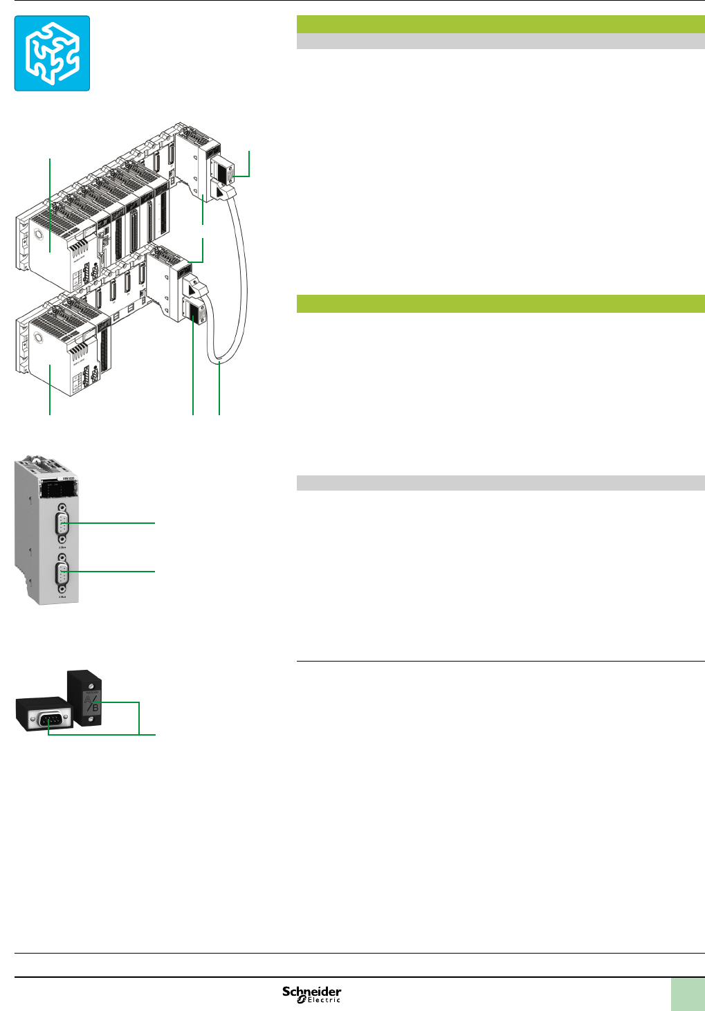
Composition of a multi-rack conguration
Multi-rack congurations are made up of standard BMXXBP00 racks. They
comprise:
2 racks maximum for a station with BMXP341000 processor
4 racks maximum for a station with BMXP3420 or BMXP3420CL
processor
Each rack is equipped with:
1 A BMXCPS power supply
2 A BMXXBE1000 expansion rack module. This module, inserted in the right-hand
end of the rack (XBE slot, see page2/8) does not occupy rack slots 00…11 (4, 6,
8 or 12 slots are still available)
Bus X
The racks, distributed on the Bus X, are connected to each other by Bus X exten-
sion cordsets 3 with a total length of 30 m maximum.
The racks are connected in a daisy chain using BMXXBC0K (1) Bus X exten-
sion cordsets connected to the two 9-way SUB-D connectors 5 and 6 on the front
panels of the BMXXBE1000 rack expansion modules 2.
Line terminators 4
Both expansion modules at the ends of the daisy chain must have a line terminator
4 TSXTLYEX on the unused 9-way SUB-D connector.
Note:Theprocessormoduleisalwayspositionedintherackataddress0.However,inaBusX
daisychain,theorderoftherackshasnoeffectonoperation;theorderofthedaisychaincould
be,forexample0-1-2-3,2-0-3-1,3-1-2-0,etc.
(1)ExtensioncordsetsBMXXBCpp0Kinlengthsof0.8m,1.5m,3m,5mor12mwithelbowed
connectorsorTSXCBYp08K inlengthsof1m,3m,5m,12m,18mor28mwithstraight
connectors.
1
1
4
4 3
2
Rackexpansionmodule
BMXXBE1000
Lineterminator
TSXTLYEX
Unity Pro
Processor selection guide:
pages 1/4 and 1/5
Modicon X80 I/O platform:
pages 2/12 and 2/24
Communication:
page 3/2
Software:
page 4/2
Ruggedized Modicon M340:
page 6/2
5
6
4
2
1
3
4
5
6
7
8
9
10
2
1
3
4
5
6
7
8
9
10

2
1
3
4
5
6
7
8
9
10
2
1
3
4
5
6
7
8
9
10
2
1
3
4
5
6
7
8
9
10
2
1
3
4
5
6
7
8
9
10
Selectionguide Modicon M340 automation
platform
Modicon M340 processors
Type of Modicon M340 processor Standard processor Performance processors with or without
memory card
Performance processors with or without memory card (continued)
Racks Number of racks 2 (with 4, 6, 8 or 12 slots) 4 (with 4, 6, 8 or 12 slots) 4 (with 4, 6, 8 or 12 slots)
Max. number of slots
(excluding power supply module)
24 48 48
I/O In-rack discrete I/O (1) 512 channels (modules with 8, 16, 32 or 64
channels)
1024 channels (modules with 8, 16, 32 or
64 channels)
1024 channels (modules with 8, 16, 32 or 64 channels)
In-rack I/O (1) 128 channels (modules with 2, 4, 6 or 8
channels)
256 channels (modules with 2, 4, 6 or
8 channels)
256 channels (modules with 2, 4, 6 or 8 channels)
Distributed I/O (limited depending on
the type of medium)
- On Ethernet Modbus/TCP via network module (63 devices with I/O Scanning function)
- On Modbus link (32 devices)
- On CANopen bus (63 devices),
- On Ethernet Modbus/TCP via network module (63 devices with I/O Scanning function),
- On Modbus link (32 devices).
In-rack application-
specic channels
No. of channels (counter, motion
control, serial link)
20 max. 36 max. 36 max.
Counter (1) BMXEHC0200 2-channel (60 kHz) or BMXEHC0800 8-channel (10 kHz) modules BMXEHC0200 2-channel (60 kHz) or BMXEHC0800 8-channel (10 kHz) modules
Motion control (1) BMXMSP0200 2-channel (200 kHz) PTO (PulseTrainOutput)modules for servo drives BMXMSP0200 2-channel (200 kHz) PTO (PulseTrainOutput)modules for servo drives
– MFB (Motion Function Blocks) library (for drives or servo
drives on CANopen bus)
– MFB (Motion Function Blocks) library (for drives or servo
drives on CANopen bus)
Serial link (process or RTU) (1) BMXNOM0200 2-channel module or BMXNOR0200H module with 1 RTU serial channel BMXNOM0200 2-channel module or BMXNOR0200H module with 1 RTU serial channel
Process control, programmable loops Process control EFB library Process control EFB library
Integrated
communication ports
Ethernet Modbus/TCP network – – 1 x 10BASE-T/100BASE-TX (Modbus/TCP, BOOTP/DHCP, FDR client, e-mail notication,
class B10 standard web server)
CANopen master bus – 1 (63 slaves, 50…1000 Kbps, class M20) (3) –1 (63 slaves, 50…1000 Kbps, class M20) (3)
Serial link (process or RTU) 1 in RTU/ASCII Modbus master/slave mode or in Character mode (isolated RS232/RS485,
0.3…38.4 Kbps)
1 in RTU/ASCII Modbus master/slave mode or in Character mode (isolated RS232/RS485,
0.3…38.4 Kbps)
–
USB port 1 programming port (PC terminal) or HMI connection port 1 programming port (PC terminal) or HMI connection port
Communication
modules
(1)
Ethernet network Max. no. 2 2
Type of module BMXNOE0100/0110 or BMXNOC0401 network modules or BMXNOR0200H module with
1 Ethernet RTU channel
BMXNOE0100/0110 or BMXNOC0401 network modules or BMXNOR0200H module with 1 Ethernet RTU channel
AS-Interface bus Max. no. 2 4 4
Type of module BMXEIA0100 master module BMXEIA0100 master module
Internal memory
capacity
Internal user RAM 2048 KB 4096 KB 4096 KB
Program, constants and symbols 1792 KB 3584 KB 3584 KB
Located/unlocated data 128 KB 256 KB 256 KB
Memory card
capacity
(on processor)
Backup of program, constants and
symbols
8 MB as standard 8 MB as standard Supplied without card 8 MB as standard Supplied without card
Hosting and display of user Web
pages
(2) (2)
File storage – 8 or 128 MB (according to
BMXRMS8MPF option card)
8 or 128 MB (according to BMXRMS8MPF option card)
Application structure Master task 1 1
Fast task 1 1
Event tasks 32 64 64
No. of K instructions
executed per ms
100% Boolean 5.4 Kinstructions/ms 8.1 Kinstructions/ms 8.1 Kinstructions/ms
65% Boolean + 35% xed arithmetic 4.2 Kinstructions/ms 6.4 Kinstructions/ms 6.4 Kinstructions/ms
Rack power supply 24 V isolated, 24…48 V isolated or 100…240 V power supply module 24 V isolated, 24…48 V isolated or 100…240 V power supply module
References BMXP341000 BMXP342000 BMXP3420102 BMXP3420102CL BMXP342020 BMXP3420302 BMXP3420302CL
Page 1/9 1/9
(1)ThemaximumvaluesforthenumberofdiscreteI/O,analogI/O,counter/motioncontrol/seriallinkchannelsandthenumberofnetworksarenotcumulative
(theyarelimitedbythemaximumnumberofslotsintheconguration,1rack:11,2racks:23,3racks:35and4racks:47.
(2)UserwebpageswithBMXNOE0110EthernetFactoryCastmodule(12MBavailable).
(3)BMXP3420102/20102CL/20302/20302CLprocessorscanbeusedtocustomizecongurationofthedeviceBootUpprocedurecompatiblewithallCANopen
third-partyproducts.RequiresUnityProsoftware,versionuV4.1.
1/4 1/5

1/6
Presentation
Dedicated processor modules BMXP34, which form part of a Modicon M340
automation platform, are available in two types:
Standard type processor modules
Performance type processor modules
The main differences between these 2 types of processor are:
Their number of I/O (512 or 1024)
Their memory capacity (2,048 or 4,096 KB)
The type of communication ports integrated in each model
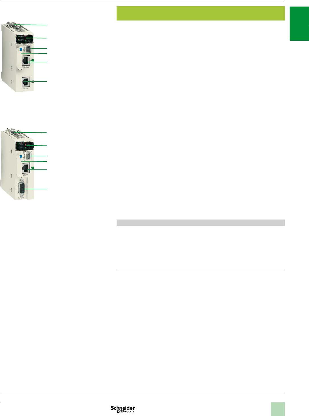
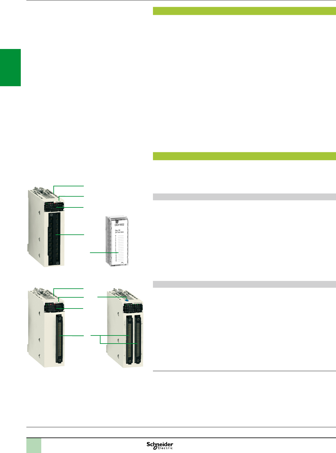
Description of BMXP341000/2000/20102/20102CL processors
BMXP341000/2000/20102/20102CL Standard and Performance single-format
processors have the following on the front panel:
1 Safety screw for locking the module in its slot (marked 0) in the rack.
2 A display block comprising 5 or 7 LEDs, depending on the model:
Run LED (green): processor in operation (program execution)
ERR LED (red): processor or system fault
I/O LED (red): I/O module fault
SER COM LED (yellow): activity on the Modbus serial link
CARD ERR LED (red): memory card missing or faulty
CAN RUN LED (green): integrated CANopen bus operational (BMXP3420102
and BMXP3420102CL models only)
CAN ERR LED (red): integrated CANopen bus fault (BMXP3420102 and
BMXP3420102CL models only)
3 A mini B USB connector for a programming terminal (or Magelis GT/GTO/GK/
GTW and STU/STO HMI terminal (1)).
4 A slot equipped with its Flash memory card (2) for backing up the application
(an LED, located above this slot, indicates recognition of or access to the memory
card).
5 An RJ45 connector for Modbus serial link or Character mode link (RS 232C/RS
485, 2-wire, isolated).
With, in addition, for BMXP3420102 and BMXP3420102CL models:
6 A 9-way SUB-D connector for the integrated CANopen master bus.
(1)MagelisGT/GTO/GK/GTWandSTU/STOgraphicterminalswithUSBportandVijeo
Designercongurationsoftwareversionu4.5.Formoredetailedinformation,pleasereferto
ourwebsitewww.schneider-electric.com.
(2)ExceptformodelBMXP3420102CL,whichissuppliedwithoutmemorycard.
Modicon M340 automation
platform
Processor modules
Presentation,
description
1
2
3
4
5
6
BMXP3420102/BMXP3420102CL
BMXP341000/2000
1
2
3
4
5
Processor selection guide:
pages 1/4 and 1/5
Modicon X80 I/O platform:
pages 2/12 and 2/24
Communication:
page 3/2
Software:
page 4/2
Ruggedized Modicon M340 modules:
page 6/2
2
1
3
4
5
6
7
8
9
10
2
1
3
4
5
6
7
8
9
10
1/7
Modicon M340 automation
platform
Processor modules
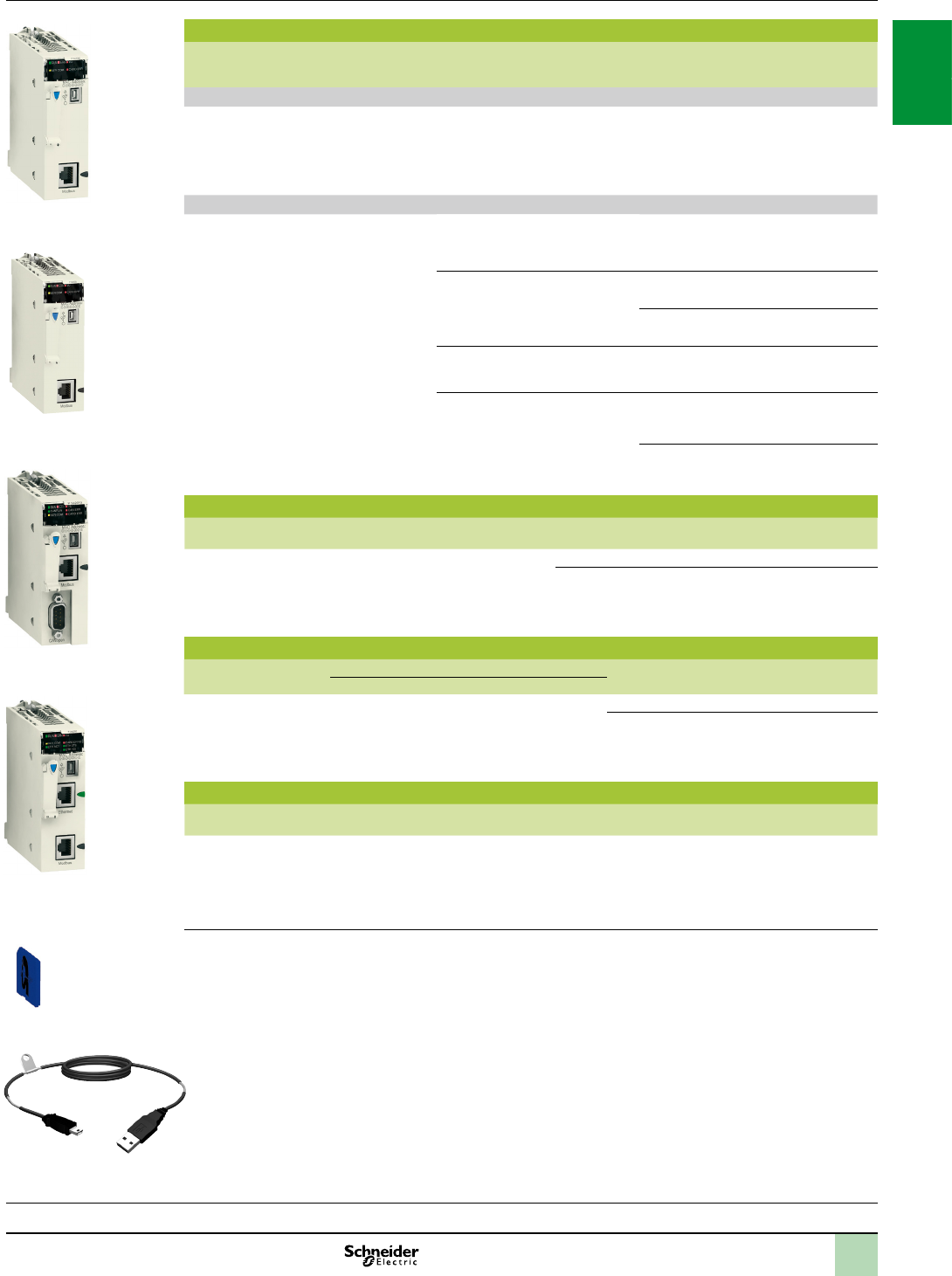
Description of BMXP342020/20302/20302CL processors with
integrated Ethernet Modbus/TCP port
BMXP342020/20302/20302CL Performance single-format processors have the
following on the front panel:
1 Safety screw for locking the module in its slot (marked 0) in the rack.
2 A display block comprising 8 or 10 LEDs, depending on the model:
Run LED (green): processor in operation (program execution)
ERR LED (red): processor or system fault
I/O LED (red): I/O module fault
SER COM LED (yellow): activity on the Modbus serial link
CARD ERR LED (red): memory card missing or faulty
ETH ACT LED (green): activity on the Ethernet Modbus/TCP network
ETH STS LED (green): Ethernet Modbus/TCP network status
ETH 100 (red): Ethernet Modbus/TCP data rate (10 or 100 Mbps)
CAN RUN LED (green): integrated CANopen bus operational (BMXP3420302
and BMXP3420302CL models only)
CAN ERR LED (red): integrated CANopen bus fault (BMXP3420302 and
BMXP3420302CL models only)
3 A mini B USB connector for a programming terminal (or Magelis GT/GTO/GK/
GTW and STU/STO terminal (1)).
4 A slot equipped with its Flash memory card (2) for backing up the application (an
LED, located above this slot, indicates recognition of or access to the memory
card).
5 An RJ45 connector for connection to the 10BASE-T/100BASE-TX Ethernet
Modbus/TCP network.
With, in addition, depending on the model:
6 BMXP342020 processor: an RJ45 connector for the Modbus serial link or
Character mode link (RS 232C/RS 485, 2-wire, isolated).
7 BMXP3420302 and BMXP3420302CL processors: a 9-way SUB-D connector for
the integrated CANopen master bus.
On the back panel: 2 rotary switches for selecting the IP address assignment
method for the module.
USB terminal port
The USB port 3, offering a useful data rate of 12 Mbps, is compatible with Unity Pro
programming software, the OPC Factory Server (OFS),and Magelis GT/GTO/GK/
GTW and STU/STO HMI terminals (1).
All BMXP34 processors can be connected to a USB bus comprising several
peripheral devices. However:
Only one processor can be connected to the USB bus
No device on the USB bus can be controlled by the PLC (modem, printer)
(1)MagelisGT/GTO/GK/GTWandSTU/STOgraphicterminalswithUSBportandVijeo
Designercongurationsoftwareversionu4.5.Formoredetailedinformation,pleasereferto
ourwebsitewww.schneider-electric.com.
(2)ExceptformodelBMXP3420302CL,whichissuppliedwithoutmemorycard.
Description(continued)
BMXP342020
BMXP3420302/BMXP3420302CL
1
2
4
5
6
3
1
2
3
4
5
7
Processor selection guide:
pages 1/4 and 1/5
Modicon X80 I/O platform:
pages 2/12 and 2/24
Communication:
page 3/2
Software:
page 4/2
Ruggedized Modicon M340 modules:
page 6/2
2
1
3
4
5
6
7
8
9
10
2
1
3
4
5
6
7
8
9
10

1/8
Memorystructure
Memory cards
BMXRMS008MP memory card (included as standard)
Modicon M340 processors are supplied as standard (1)with an SD (SecureDigital)
type Flash memory card, referenceBMXRMS008MP. This card is intended for
backing up the two memory areas on the processor module’s internal RAM:
Program, symbols and comments area, which contains the executable binary
code and the IEC source code of the application program for the program part
Constants area, which contains the constant data located by address.
The data is backed up automatically by duplication, when the PLC is turned off.
Likewise, the restoration of the data is transparent for the user, on return of power.
Capacity of the “backup area” on the memory card:
1792 KB for the BMXP341000 Standard processor
3584 KB for the BMXP342pppp Performance processors
BMXP342020/20302/20302CL processors with an integrated Ethernet port have an
additional 2 MB memory area specically for “Standard Web services” (Transparent
Ready B10) (see page 3/16).
The BMXRMS008MP memory card is formatted by Schneider Electric and included
with each processor. It is referenced as a replacement part.
BMXRMS008MPF/128MPF optional memory cards
BMXP342pppp Performance processors can take a BMXRMS008MPF or
BMXRMS128MPF optional memory card, with greater memory capacity, in place of
the standard memory card. These cards also provide a “le storage area” with a
maximum capacity of 8 MB (for the BMXRMS008MPF card) or 128 MB (for the
BMXRMS128MPF card).
This “le storage area” enables:
Any user-dened Word, Excel, PowerPoint or Acrobat Reader document to be
received via FTP (for example, maintenance manuals, diagrams. etc.)
Additional data to be stored via EFB user function blocks (for example: production
data, manufacturing recipes, etc.)
Unity Pro programming software helps the application designer manage the
structure and memory space occupation of the Modicon M340 automation platform.
Protecting the application
If necessary, it is possible to prohibit access to the application (in terms of reading
and modifying the program) by only loading the executable code in the PLC.
Additionally, a memory protection bit, set in conguration mode, is also available to
prevent any program modication (via the programming terminal or downloading).
From Unity Pro V5.0 on, the user has function blocks for protecting know-how by
means of a signature that can be loaded and stored in the M340 processor module’s
Flash memory card (code not executed if the signature is not present).
Program modication in online mode
As with Modicon Premium and Quantum platforms (with Unity Pro software), the
online program modication function is available on the Modicon M340 automation
platform with the option of adding or modifying the program code and data in
different places in the application in a single modication session (thus ensuring
modication is homogenous and consistent with the controlled process).
A dedicated memory area of the application internal RAM authorizes these program
modication or addition sessions while complying with the recommendation to
structure the application program in several, reasonably-sized sections.
(1)Withtheexceptionof2models(seepage1/9).
Modicon M340 automation
platform
Processor modules
Processor selection guide:
pages 1/4 and 1/5
Modicon X80 I/O platform:
pages 2/12 and 2/24
Communication:
page 3/2
Software:
page 4/2
Ruggedized Modicon M340 modules:
page 6/2
2
1
3
4
5
6
7
8
9
10
2
1
3
4
5
6
7
8
9
10
1/9
References
Modicon M340 processors
I/O capacity Max. no. of
network and bus
modules
Integrated
communication
ports
Compatibility
with Unity Pro
software
Memory
card
Reference Weight
kg
Standard BMXP3410, 2 racks
512 discrete I/O
128 analog I/O
20 application-specic
channels
2048 KB integrated
(internal user memory)
2 Ethernet
networks
2 AS-Interface
buses
1 Modbus
serial link
Version 3.0 Included BMXP341000 0.200
Performance BMXP3420, 4 racks
1024 discrete I/O
256 analog I/O
36 application-specic
channels
4096 KB integrated
(internal user memory)
2 Ethernet
networks
4 AS-Interface
buses
1 Modbus
serial link
Version 3.0 Included
BMXP342000
0.200
1 Modbus
serial link
1 CANopen bus
Version 4.1 Included BMXP3420102 (1) 0.210
Not
included (2)
BMXP3420102CL (1) 0.210
1 Modbus
serial link
1 Ethernet network
Version 3.0 BMXP342020 0.205
1 Ethernet network
1 CANopen bus
Version 4.1 Included BMXP3420302 (1)
0.215
Not
included (2)
BMXP3420302CL (1)
0.215
Memory cards
Description Processor compatibility Capacity Reference Weight
kg
Flash Memory
cards (optional)
(3)
BMXP342000
BMXP3420102
BMXP342020
BMXP3420302
BMXP3420102CL
BMXP3420302CL
8 MB + 8 MB le storage BMXRMS008MPF 0.002
8 MB + 128 MB le storage BMXRMS128MPF 0.002
Separate parts
Description Use Length Reference Weight
kg
From To
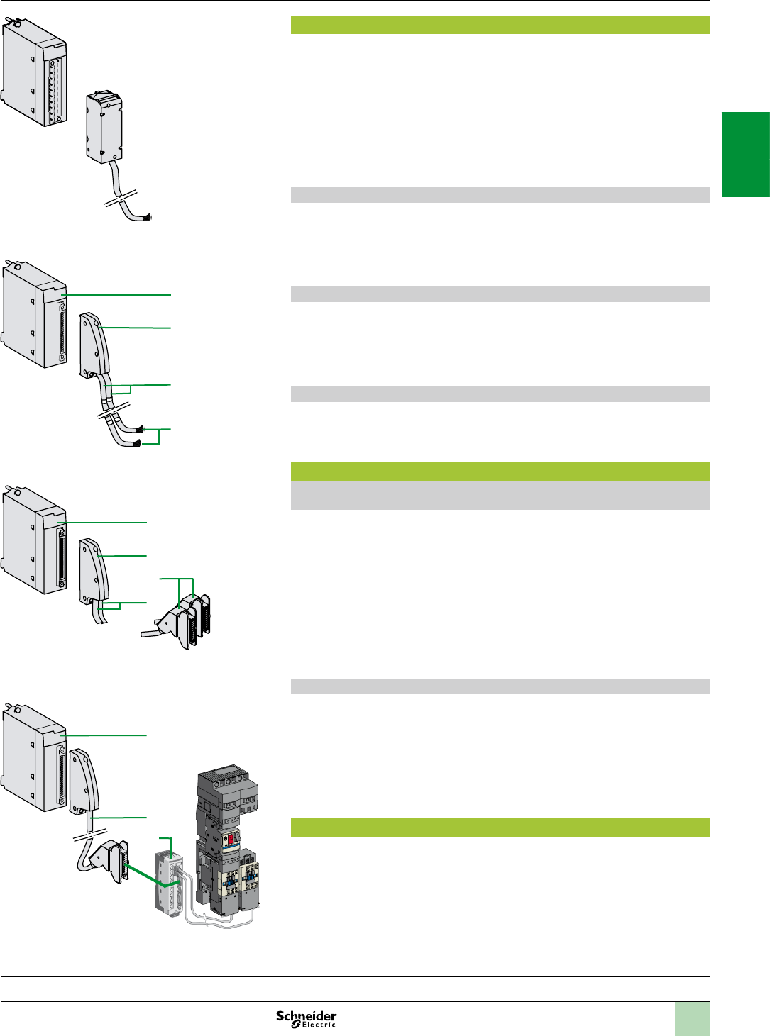
Terminal port/USB
cordsets
Mini B USB port
on the Modicon
M340 processor
Type A USB port on:
- PC terminal,
- Magelis XBT GT/GK/GTW,
HMI GTW, HMI STU/STO HMI
graphic terminal.
1.8 m BMXXCAUSBH018 0.065
4.5 m BMXXCAUSBH045 0.110
Replacement part
Description Use Processor compatibility Reference Weight
kg
8 MB standard Flash
memory card
Included as standard with each
processor. Used for:
- Backing up the program, constants,
symbols and data,
- Activation of class B10 Web server.
BMXP341000
BMXP342000
BMXP342020
BMXP3420102/20302
BMXRMS008MP 0.002
(1)BMXP3420102/20302processors,combinedwithUnityProsoftwareversionu4.1,canbeusedtocustomizecongurationof
thedeviceBootUpprocedurecompatiblewithallCANopenthird-partyproducts.
(2)Theseproductsaresuppliedwithoutintegratedmemorycard.Thememorycardmustbeorderedseparately(seememory
cardsabove).
(3)MemorycardsforBMXP342ppppprocessors, toreplacethestandardmemorycard,usedfor:
- Backinguptheprogram,constants,symbolsanddata
- ActivationofclassB10Webserver
- Filestorage
Modicon M340 automation
platform
Processor modules
BMXP341000
BMXP3420102/20102CL
BMXP3420302/20302CL
BMXP342000
BMXP342020
BMXXCAUSBH0
Processor selection guide:
pages 1/4 and 1/5
Modicon X80 I/O platform:
pages 2/12 and 2/24
Communication:
page 3/2
Software:
page 4/2
Ruggedized Modicon M340 modules:
page 6/2
BMXRMS008/128MPF
2
1
3
4
5
6
7
8
9
10
2
1
3
4
5
6
7
8
9
10

2/0
Contents 2 - Modicon X80 I/O platform and
Modicon distributed I/O solutions
Modicon X80 I/O platform
General Presentation ............................................................................ page2/2
Compatibility ............................................... page2/4
Single-rack conguration
Presentation, description, function ........................................................... page2/6
References .............................................................................................. page2/7
Multi-rack conguration
Presentation, description ......................................................................... page2/8
References .............................................................................................. page2/9
Power supply modules
Presentation, description, function ......................................................... page2/10
References .............................................................................................page2/11
Discrete I/O modules
Selection guide ............................................ page2/12
Presentation, description ....................................................................... page2/18
Connections .......................................................................................... page2/19
Functions ............................................................................................... page2/20
Complementary characteristics ............................................................. page2/21
References ............................................................................................ page 2/22
Analog I/O modules
Selection guide ............................................ page2/24
Presentation .......................................................................................... page2/28
Description ............................................................................................ page2/29
Connections, combinations ................................................................... page2/30
Complementary characteristics ............................................................. page2/31
References ............................................................................................ page2/32
BMXEHC0200/0800 counter modules
Presentation, description ....................................................................... page2/34
Functions ............................................................................................... page2/35
References ............................................................................................ page2/37
BMXEAE0300 SSI encoder interface module
Presentation, description ....................................................................... page2/38
Functions, references ............................................................................ page2/39
BMXMSP0200 motion control module
Presentation, description ....................................................................... page2/40
Operation, references ............................................................................ page2/41
MFB motion control ............................................................................. page2/42
Modicon X80 CRA Ethernet drop adaptors ........................................ page2/44
Modicon X80 NRP RIO drop optical repeaters ................................... page2/45
Peripheral Remote I/O Adaptor ........................................................... page2/46
Time stamping system ........................................................................ page2/48
2
1
3
4
5
6
7
8
9
10
2
1
3
4
5
6
7
8
9
10

2/1
Modicon X80 I/O platform (continued)
Communication, integrated ports and modules
Selection guide ............................................ page2/50
RTU communication systems
- Presentation ..................................................................................... page2/52
- Description, function ......................................................................... page2/54
- References ....................................................................................... page2/55
BMXEIA0100 master module
- Presentation, description .................................................................. page2/56
- References ....................................................................................... page2/57
Modbus and Character mode serial links
- Presentation, description .................................................................. page2/58
- Complementary characteristics, references ..................................... page2/59
PMXNOW0300 Wi-Fi access point
- Presentation, characteristics ............................................................ page2/60
- References ....................................................................................... page2/61
Modicon distributed I/O solutions
Selection guide ............................................ page2/62
2
1
3
4
5
6
7
8
9
10
2
1
3
4
5
6
7
8
9
10
2/2
Presentation,
description Modicon X80 I/O platform 0
Composition
Presentation
The Modicon X80 I/O platform serves as the common base for automation platforms
by simply adding a dedicated processor (1).
It may also:
form part of a Quantum Ethernet I/O architecture as an Ethernet RIO drop with a
CRA bus terminal module
form an Ethernet Modbus/TCP DIO drop with a PRA module
The Modicon X80 I/O platform is available in single-rack or multi-rack conguration.
This platform may also accept automation platform-dedicated modules
(communication, application, etc.).
One Modicon X80 drop may support two racks separated by a cumulative distance
of up to 30 metres.
This platform, common to several automation platforms, can reduce maintenance
and training costs as it comprises:
a single range of spare parts in stock
training common to several PLCs
Based on the latest I/O technology, the Modicon X80 I/O platform offers:
high-quality ruggedness and compactness
compliance with international certications (ATEX, IEC, etc.)
a wide selection of modules: digital or analog I/O, expert modules,
communication modules, etc.
This platform is programmed and congured using Unity Pro software.
Bit forcing simplies simulation and structured data simplies diagnostics.
Description
Modicon X80 I/O platform
The Modicon X80 I/O platform, which can be used in-rack and/or in remote I/O
drops (RIO) and/or distributed I/O drops (DIO) depending on the type of PLC
(M340, Quantum, etc.), offers:
1 racks with 4, 6, 8 or 12 slots
2 AC or DC power supply modules
3 digital and analog I/O modules
4 RTU (Remote Terminal Unit) communication modules, serial link,
AS-Interface, etc.
Ethernet Modbus/TCP communication modules
Character Mode and Modbus serial link modules (on X80 drops with Quantum
Ethernet I/O)
application-specic modules: counting, motion control
modules offered within the framework of the CAPP program (Collaborative
Automation Partner Program)
supplementary modules dedicated to automation platforms (Ethernet modules
for Modicon M340 processors, etc.)
Treatment for harsh environments
With “ruggedized” modules, the Modicon X80 I/O platform may be used in harsh
environments or within a range of operating temperatures from - 25 °C to + 70 °C.
See pages 6/2 to 6/9.
(1)Seethecompatibilityguideonpage2/4.
ModiconX80I/OplatformwithModiconM340processor
ModiconX80EthernetRIOdropwithCRAbusterminal
module
EthernetModbus/TCPDIOdropwithPRAmodule
1
2 4 3
2
1
3
4
5
6
7
8
9
10
2
1
3
4
5
6
7
8
9
10
2/3
Description Modicon X80 I/O platform 0
Architecture, software conguration
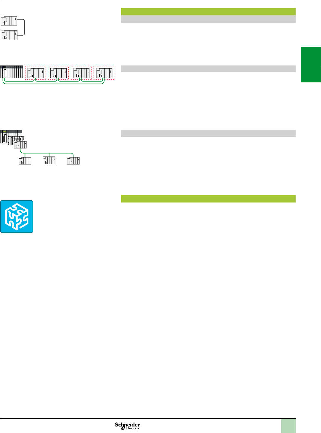
Architectures based on the Modicon X80 I/O platform
Single-rack or multi-rack conguration with M340 processor
This conguration comprises:
a Modicon X80 I/O primary rack with a Modicon M340 processor
a Modicon X80 I/O secondary rack
This conguration may comprise four racks with BMXP342000 processors
separated by a cumulative distance of up to a maximum of 30 metres.
Quantum Ethernet I/O with Modicon X80 Ethernet RIO drop
This architecture comprises:
a Quantum Ethernet I/O platform comprising a processor and dedicated
modules
one or more Modicon X80 Ethernet RIO drops with a standard or high
performance CRA drop adaptor
This conguration may include:
16 drops with 140CPU6p1pp processors
31 drops with 140CPU6p2pp processors
Ethernet Modbus/TCP DIO drop connected to an automation system platform
This architecture comprises:
a Quantum/Premium/M340 automation platform
one or more Ethernet Modbus/TCP DIO drops with a BMXPRA0100 peripheral
remote I/O adaptor, a power supply and I/O
Software conguration
Unity Pro programming software is required to set up the Modicon X80 I/O platform.
The Unity Pro function block software libraries make it possible to meet the needs of
specialist applications in various elds of application such as:
Water and Waste Water (WWW)
Food & Beverage (F&B)
Mining, Minerals, Metals (MMM)
Oil & Gas (O&G)
Multi-rackcongurationwith
M340processor
QuantumEthernetI/OwithModiconX80EthernetRIOdrop
Bus X
Ethernet network
EthernetModbus/TCPDIOdropconnected
toanautomationsystemplatform
Ethernet Modbus/TCP network
Unity Pro
2
1
3
4
5
6
7
8
9
10
2
1
3
4
5
6
7
8
9
10

2/4 2/42/4 2/5
Compatibility Modicon X80 I/O platform
Product compatibility according to the network
architecture
Product type Reference All Modicon M340 processors Ethernet I/O Quantum drop with Modicon X80 RIO drop with CRA drop adaptor,
type
Ethernet Modbus TCP DIO drop with PRA connected
to a Quantum/Premium/M340 platform
Single-rack or multi-rack “standard” BMXCRA31200 “performance” BMXCRA31210 BMXPRA0100
Racks BMXXBE1000/BMXXBE1000H
BMXXBE2005
BMXXBP0400/BMXXBP0400H
BMXXBP0600/BMXXBP0600H
BMXXBP0800/BMXXBP0800H
BMXXBP1200
BMXXEM010
Power supply modules BMXCPS2000
BMXCPS2010
BMXCPS3020/BMXCPS3020H
BMXCPS3500/BMXCPS3500H
BMXCPS3540T
I/O BMXAMI0410/BMXAMI0410H
BMXAMI0800
BMXAMI0810/BMXAMI0810H
BMXAMM0600/BMXAMM0600H
BMXAMO0210/BMXAMO0210H
BMXAMO0410/BMXAMO0410H
BMXAMO0802
BMXART0414/BMXART0414H
BMXART0814/BMXART0814H
BMXDAI0805
BMXDAI1602/BMXDAI1602H
BMXDAI1603/BMXDAI1603H
BMXDAI1604/BMXDAI1604H
BMXDAO1605/BMXDAO1605H
BMXDDI1602/BMXDDI1602H
BMXDDI1603/BMXDDI1603H
BMXDDI1604T
BMXDDI3202K
BMXDDI6402K
BMXDDM16022/BMXDDM16022H
BMXDDM16025/BMXDDM16025H
BMXDDM3202K
BMXDDO1602/BMXDDO1602H
BMXDDO1612/BMXDDO1612H
BMXDDO3202K
BMXDDO6402K
BMXDRA0804T
BMXDRA0805/BMXDRA0805H
BMXDRA1605/BMXDRA1605H
Application-specic
modules
BMXEAE0300/BMXEAE0300H
BMXEHC0200/BMXEHC0200H
BMXEHC0800/BMXEHC0800H
BMXERT1604T
BMXMSP0200
Communication modules BMXNOC0401
BMXNOE0100/BMXNOE0100H
BMXNOE0110/BMXNOE0110H
BMXNOM0200/BMXNOM0200H
BMXNOR0200H
BMXEIA0100
BMXNRP0200
BMXNRP0201
PMXNOW0300
Compatible Not compatible
1 1
2 2
3 3
4 4
5 5
6 6
7 7
8 8
9 9
10 10
2/6
CPS 01 02 03 04 05 06 0700
Modicon X80 I/O platform
Single-rack conguration
Presentation
BMXXBP00 racks are the basic element in Modicon X80 I/O platform single-rack
and multi-rack congurations. They perform the following functions:
Mechanical function: they are used to install all the modules in a PLC station
(power
supply, processor, discrete, analog and application-specic I/O). These racks
can be mounted on a panel, plate or DIN rail:
Inside enclosures
On machine frames, etc.
Electrical function: the racks incorporate a Bus X (proprietary bus). They are used
to:
Distribute the power supplies required for each module in the same rack
Distribute data and service signals for the entire PLC station
Hot swap modules during operation
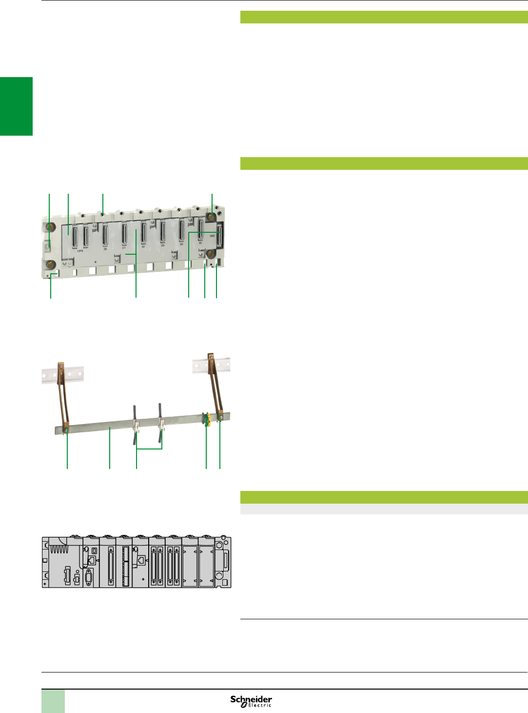
Description
BMXXBP00 racks are available in 4, 6, 8 or 12-slot versions and comprise:
1 A metal frame that performs the following functions:
- Holds the Bus X electronic card and protects it against EMI and ESD type
interference
- Holds the modules
- Gives the rack mechanical rigidity
2 An earth terminal for earthing the rack
3 4 holes (big enough for M6 screws) for mounting the rack on a frame
4 2 xing points for the shielding connection bar
5 Tapped holes to take the locking screw on each module
6 A connector for a rack expansion module, marked XBE
7 40-way female ½ DIN connectors forming the electrical connection between the rack
and each module, marked CPS, 00…11 (the rack is delivered with each connector
protected by a cover, which must be removed before inserting the module)
8 Slots for anchoring the module pins
To be ordered separately:
A BMXXSP00 cable shielding connection kit, used to protect against electrostatic
discharge when connecting the shielding on cordsets for connecting:
Analog, counter and motion control modules
A Magelis XBT operator interface to the processor (via BMXXCAUSBH0
shielded USB cable)
The BMXXSP00 shielding connection kit comprises:
9 A metal bar that takes the clamping rings and the earthing terminal
10 Two sub-bases to be mounted on the rack
11 An earthing terminal
12 Not included in the shielding connection kit, the STBXSP300 clamping rings (sold
in lots of 10, cross-section 1.5…6 mm2 or 5…11 mm2)
Function
Addressing modules in a single-rack conguration (1)
Each rack must contain a power supply module and a processor module.
Installing the modules in the rack:
The power supply module always occupies the CPS slot
The processor module must always be installed in slot 00
I/O modules and application-specic modules are installed from slot 01 to slot:
- 03 for a 4-slot rack
- 05 for a 6-slot rack
- 07 for an 8-slot rack
- 11 for a 12-slot rack
(1)Foramulti-rackcongurationwithaBMXXBE1000rackexpansionmodule(XBEslot),
seepage2/8.
Exampleofinstallationwith8-slotrack
Presentation,
description,
function
XBE
BMXXSP00cableshieldingconnectionkit
10 9 12 11 10
I/O:
pages 2/12 and 2/24
Communication:
page 2/50
Software:
page 4/2
Ruggedized Modicon M340 modules:
page 6/2
8
4 7 4
153
6
BMXXBP0600rackwith6slots
2
2
1
3
4
5
6
7
8
9
10
2
1
3
4
5
6
7
8
9
10
2/7
Modicon X80 I/O platform
Single-rack conguration
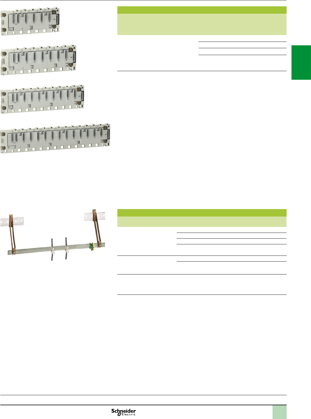
Racks
Description Type of module
to be inserted
No. of
slots
(1)
Power
consump-
tion
(2)
Reference Weight
kg
Racks BMXCPS power supply,
BMXP34 processor,
I/O modules, communication
modules and application-
specic modules (counter,
motion control and serial)
4 1 W BMXXBP0400 0.630
6 1,5 W BMXXBP0600 0.790
8 2 W BMXXBP0800 0.950
12 0 W BMXXBP1200 1.270
(1)Numberofslotstakingtheprocessormodule,I/Omodules,communicationmodulesand
application-specicmodules(excludingpowersupplymodule).
(2)Powerconsumptionofanti-condensationresistor(s).
Accessories
Description For use with Reference Weight
kg
Shielding connection kits
comprising:
- 1 metal bar
- 2 support sub-bases
- 1 earthing terminal
BMXXBP0400 rack BMXXSP0400 0.280
BMXXBP0600 rack BMXXSP0600 0.310
BMXXBP0800 rack BMXXSP0800 0.340
BMXXBP1200 rack BMXXSP1200 0.400
Spring clamping rings
Sold in lots of 10
Cables, cross-section 1.5...6 mm2STBXSP3010 0.050
Cables, cross-section 5...11 mm2STBXSP3020 0.070
Protective covers
(replacement parts)
Sold in lots of 5
Unoccupied slots on
BMXXBP00 rack
BMXXEM010 0.005
References
STBXSP00+STBXP300
I/O:
pages 2/12 and 2/24
Communication:
page 2/50
Software:
page 4/2
Ruggedized Modicon M340 modules:
page 6/2
BMXXBP1200
BMXXBP0400
BMXXBP0800
BMXXBP0600
2
1
3
4
5
6
7
8
9
10
2
1
3
4
5
6
7
8
9
10
2/8
Presentation,
description Modicon X80 I/O platform
Multi-rack conguration
Composition of a multi-rack conguration
Multi-rack congurations are made up of standard BMXXBP00 racks. They
comprise:
2 racks maximum for a station with BMXP341000 processor
4 racks maximum for a station with BMXP3420 or BMXP3420CL
processor
Each rack is equipped with:
1 A BMXCPS power supply
2 A BMXXBE1000 rack expansion module This module, inserted in the right-hand
end of the rack (XBE slot, see page 2/6) does not occupy rack slots 00…11 (4, 6,
8 or 12 slots are still available)
3 The BMXXBE1000 rack expansion modules are connected to each other by Bus
X cordsets
Bus X
The racks, distributed on the Bus X, are connected to each other by Bus X extension
cordsets 3 with a total length of 30 m maximum.
The racks are connected in a daisy chain using BMXXBC0K (1) Bus X extension
cordsets connected to the two 9-way SUB-D connectors 7 and 8 on the front panels
of the BMXXBE1000 rack expansion modules 2.
Line terminators 4
Both expansion modules at the ends of the daisy chain must have a line terminator 4
TSXTLYEX on the unused 9-way SUB-D connector.
Note:Theprocessormoduleisalwayspositionedintherackataddress0.However,inaBusX
daisychain,theorderoftherackshasnoeffectonoperation.Forexample,theorderofthedaisy
chaincanbe0-1-2-3,2-0-3-1or3-1-2-0,etc.
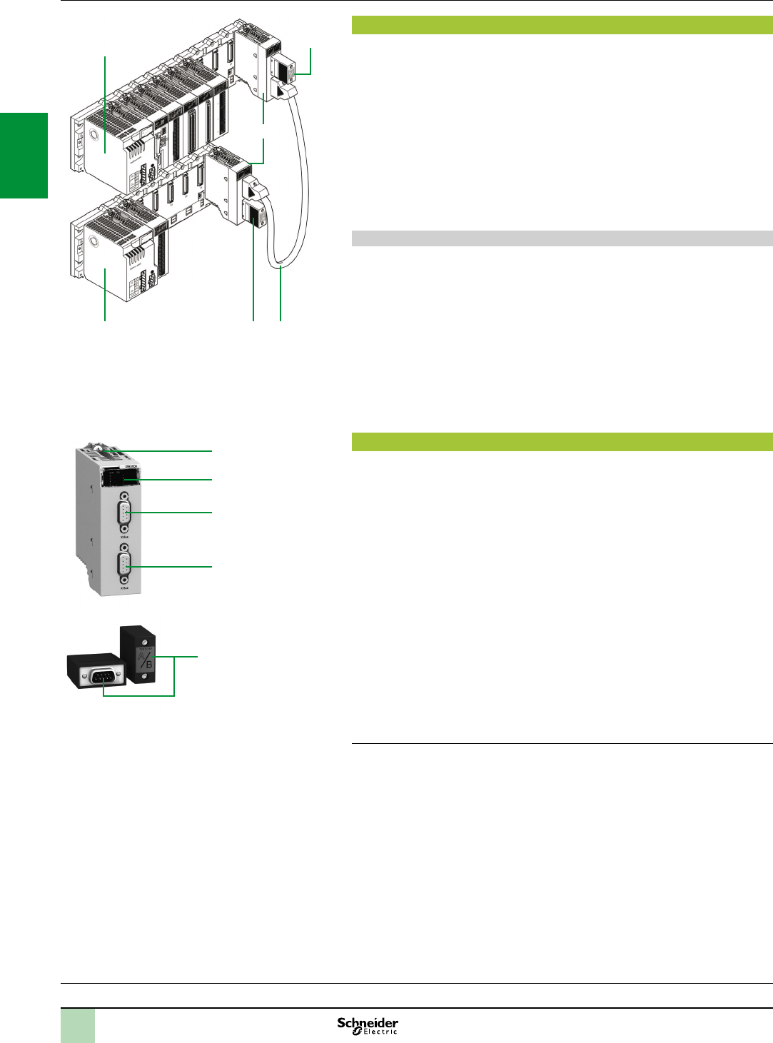
Description
The front panel of the BMXXBE1000 rack expansion module comprises:
5 Safety screw for locking the module in its slot (at the far right-hand end of the rack)
6 A display block with 5 LEDs:
RUN LED (green): module in operation
COL LED (red): several racks have the same address, or rack address 0 does not
contain the BMXP340 processor module
LEDs 0, 1, 2 and 3 (green): rack address 0, 1, 2 or 3
7 A 9-way female SUB-D connector, marked Bus X, for the incoming Bus X cordset
3 connected to the upstream rack, or if it is the rst rack, for the A/ line terminator
included in the TSXTLYEX 4 pack
8 A 9-way female SUB-D connector, marked Bus X, for the outgoing Bus X cordset
3 to the downstream rack, or if it is the last rack, for the /B line terminator included
in the TSXTLYEX 4 pack
On the right-hand side panel
A ap for accessing the 3 rack addressing micro-switches: 0…3.
Installation rules for BMXXBP0 racks
Rules for installing racks in enclosures (see our website
www.schneider-electric.com).
(1)BMXXBCpp0Kextensioncordsets,length0.8m,1.5m,3m,5mor12m,withangled
connectorsorTSXCBYp08K extensioncordsets,length1m,3m,5m,12m,18mor28m,
withstraightconnectors.
I/O:
pages 2/12 and 2/24
Communication:
page 2/50
Software:
page 4/2
Ruggedized Modicon M340 modules:
page 6/2
4
5
6
7
8
1
1
4
4 3
2
2
1
3
4
5
6
7
8
9
10
2
1
3
4
5
6
7
8
9
10

2/9
Rack expansion
Description Use Reference Weight
kg
Modicon X80 I/O
rack expansion
module
Standard module for mounting in each rack
(XBE slot) and used to interconnect:
- Up to 2 racks with BMXP341000 processor module
- Up to 4 racks with BMXP342 processor module
BMXXBE1000 0.178
Modicon X80 I/O
rack expansion kit
Complete kit for 2-rack conguration comprising:
- 2 BMXXBE1000 rack expansion modules
- 1 BMXXBC008K extension cordset, length 0.8 m
- 1 TSXTLYEX line terminator (set of 2)
BMXXBE2005 0.700
Cordsets and connection accessories
Description Use Composition Type of
connector
Length Reference Weight
kg
Bus X extension
cordsets
total length 30 m
max.
Between 2
BMXXBE1000
rack expansion
modules
2 x 9-way SUB-D
connectors
Angled 0.8 m BMXXBC008K 0.165
1.5 m BMXXBC015K 0.250
3 m BMXXBC030K 0.420
5 m BMXXBC050K 0.650
12 m BMXXBC120K 1.440
Straight 1 m TSXCBY010K 0.160
3 m TSXCBY030K 0.260
5 m TSXCBY050K 0.360
12 m TSXCBY120K 1.260
18 m TSXCBY180K 1.860
28 m TSXCBY280K 2.860
Cable reel Length of cable
to be tted with
TSX CBY K9
connectors
Cable with
ends with
ying leads,
2 line testers
– 100 m TSXCBY1000 12.320
Description Use Composition Sold in
lots of
Reference Weight
kg
Line terminators Required on the 2
BMXXBP0
modules located
at either end of
the daisy chain
2 x 9-way SUB-D
connectors marked A/ and /B
2TSXTLYEX 0.050
Bus X
straight
connectors
For TSXCBY1000
cables
2 x 9-way SUB-D
straight connectors
2TSXCBYK9 0.080
Connector
assembly kit
Fitting TSXCBYK9
connectors
2 crimping pliers,
1 pen
(1)
–TSXCBYACC10 –
(1)Tottheconnectorsonthecable,youalsoneedawirestripper,apairofscissorsandadigitalohmmeter.
Modicon X80 I/O platform
Multi-rack conguration
References
Processors:
pages 2/12 and 2/24
Communication:
page 2/50
Software:
page 4/2
Ruggedized Modicon M340 modules:
page 6/2
TSXTLYEX
BMXXBCpppK
BMXXBE1000
2
1
3
4
5
6
7
8
9
10
2
1
3
4
5
6
7
8
9
10
2/10
Presentation,
description,
functions
Presentation
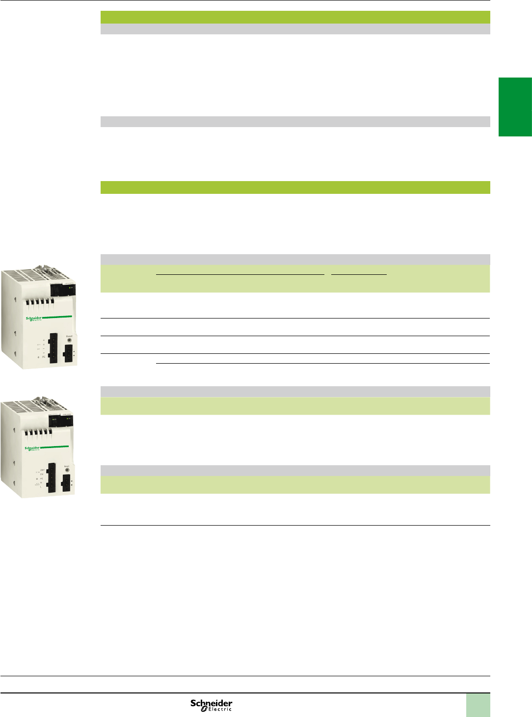
BMXCPS power supply modules provide the power supply for each
BMXXBP00 Modicon X80 I/O rack and the modules installed on it.
The Modicon X80 I/O power supply module offer comprises:
Three power supply modules for DC line supplies:
24 V isolated power supply module, BMXCPS2010
24...48 V isolated power supply module, BMXCPS3020
125 V power supply module, BMXCPS3540T (extended operating temperature
-25° to +70°C)
Two power supply modules for AC line supplies:
100...240 V , 20 W power supply module, BMXCPS2000
100...240 V , 36 W power supply module, BMXCPS3500
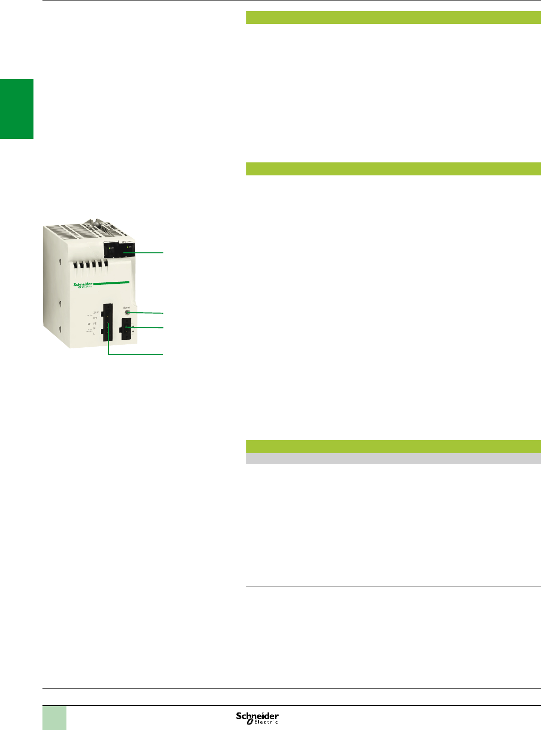
Description
The power supply module is selected according to:
The electrical line supply: 24 V , 48 V , 125 V or 100...240 V
The required power (see the power consumption table on page 7/22)
(1)
BMXCPS power supply modules have the following on the front panel:
1 A display block comprising:
OK LED (green), lit if rack voltages are present and correct
24 V LED (green), lit when the sensor voltage is present
(BMXCPS2000/3500/3540T AC power supply modules only)
2 A pencil-point RESET pushbutton for a cold restart of the application
3 A 2-way connector that can take a removable terminal block (cage clamp
or
spring-type)
for connecting the alarm relay
4 A 5-way connector that can take a removable terminal block (cage clamp
or
spring-type)
for connecting the following:
or line supply
Protective earth
Dedicated 24 V power supply for the input sensors (for
BMXCPS2000/3500/3540T AC power supply modules only)
Included with each power supply module:
Set of two cage clamp removable terminal blocks (5-way and 2-way)
BMXXTSCPS10
To be ordered separately (if necessary):
Set of two spring-type removable terminal blocks (5-way and 2-way)
BMXXTSCPS20
Functions
Alarm relay
The alarm relay incorporated in each power supply module has a volt-free contact
accessible on the front panel, on the 2-way connector.
The operating principle is as follows:
In normal operation, with the PLC in RUN, the alarm relay is energized and its
contact is closed (state 1).
The relay de-energizes and its associated contact opens (state 0) whenever the
application stops, even partially, due to any of the following:
Occurrence of a blocking fault
Incorrect rack output voltages
Loss of supply voltage
(1)ThispowerconsumptioncalculationfortherackcanalsobeperformedbytheUnityPro
programmingsoftware.
Modicon X80 I/O platform 0
Power supply modules
I/O:
pages 2/12 and 2/24
Communication:
page 2/50
Software:
page 4/2
Ruggedized Modicon M340 modules:
page 6/2
1
3
4
2
2
1
3
4
5
6
7
8
9
10
2
1
3
4
5
6
7
8
9
10
2/11
Functions,
references
Functions (continued)
RESET pushbutton
The power supply module in each rack has a RESET button on the front panel which, when pressed, triggers an
initialization sequence on the processor and the modules in the rack it supplies.
Pressing this pushbutton triggers a sequence of service signals, which is the same as that for:
A power break, when the pushbutton is pressed
A power-up, when the pushbutton is released
In terms of the application, these operations represent a cold start (forcing the I/O modules to state 0 and
initializing the processor).
Sensor power supply
BMXCPS2000/3500 AC power supply modules and BMXCPS3540T DC power supply modules have an
integrated 24 V supply for powering the input sensors.
Connection to this 24 V sensor power supply is via the 5-way connector on the front panel.
The available power depends on the power supply module (0.45 A or 0.9 A).
References
Each BMXXBP00 rack must be equipped with a power supply module. These modules are inserted in the rst
two slots of each rack (marked CPS).
The power required to supply each rack depends on the type and number of modules installed in the rack. It is
therefore necessary to draw up a power consumption table for each rack in order to determine which
BMXCPS0 power supply module is the most suitable for each rack (see page 7/22).
Power supply modules (1)
Line supply Available power (2) Nominal current Reference Weight
kg
3.3 V c (3) 24 V c rack
(3)
24 V c
sensors (4)
Total 24 V c rack
(3)
24 V c
isolated
8.3 W 16.8 W – 16.8 W 0.7 A BMXCPS2010 0.290
24...48 V
c isolated
15 W 31.2 W – 31.2 W 1.3 A BMXCPS3020 0.340
100...150 V c 15 W 31.2 W 21.6 W 36 W (5) 1.3 A BMXCPS3540T
(5)
0.340
100...240 V a 8.3 W 16.8 W 10.8 W 20 W 0.7 A BMXCPS2000 0.300
15 W 31.2 W 21.6 W 36 W 1.3 A BMXCPS3500 0.360
Separate part
Description Type Composition Reference Weight
kg
Set of 2 removable
connectors
Spring-type One 5-way terminal block and
one 2-way terminal block
BMXXTSCPS20 0.015
Replacement part
Description Type Composition Reference Weight
kg
Set of 2 removable
connectors
Cage clamp One 5-way terminal block and
one 2-way terminal block
BMXXTSCPS10 0.020
(1)Includeasetof2cageclampremovableconnectors.Spring-typeconnectorsavailableseparatelyunderreference
BMXXTSCPS20.
(2)Thesumofthepowerconsumedoneachvoltage(3.3Vcand24Vc)mustnotexceedthetotalpowerofthemodule.See
thepowerconsumptiontableonpage7/22
.
(3)3.3Vcand24VcrackvoltagesforpoweringmodulesintheModiconX80I/Orack.
(4)24Vcsensorvoltageforpoweringtheinputsensors(voltageavailableviathe2-wayremovableconnectoronthefrontpanel).
(5)Extendedoperatingtemperature-25°to+70°C(withpowerderatingatextremetemperatures:27Wbetween-25°and0°Cand
between60°and70°C).
Modicon X80 I/O platform 0
Power supply modules
I/O:
pages 2/12 and 2/24
Communication:
page 2/50
Software:
page 4/2
Ruggedized Modicon M340 modules:
page 6/2
BMXCPS2010/3020
BMXCPS2000/3500
2
1
3
4
5
6
7
8
9
10
2
1
3
4
5
6
7
8
9
10
2
1
3
4
5
6
7
8
9
10
2
1
3
4
5
6
7
8
9
10
2
1
3
4
5
6
7
8
9
10
2
1
3
4
5
6
7
8
9
10
2/12 2/12
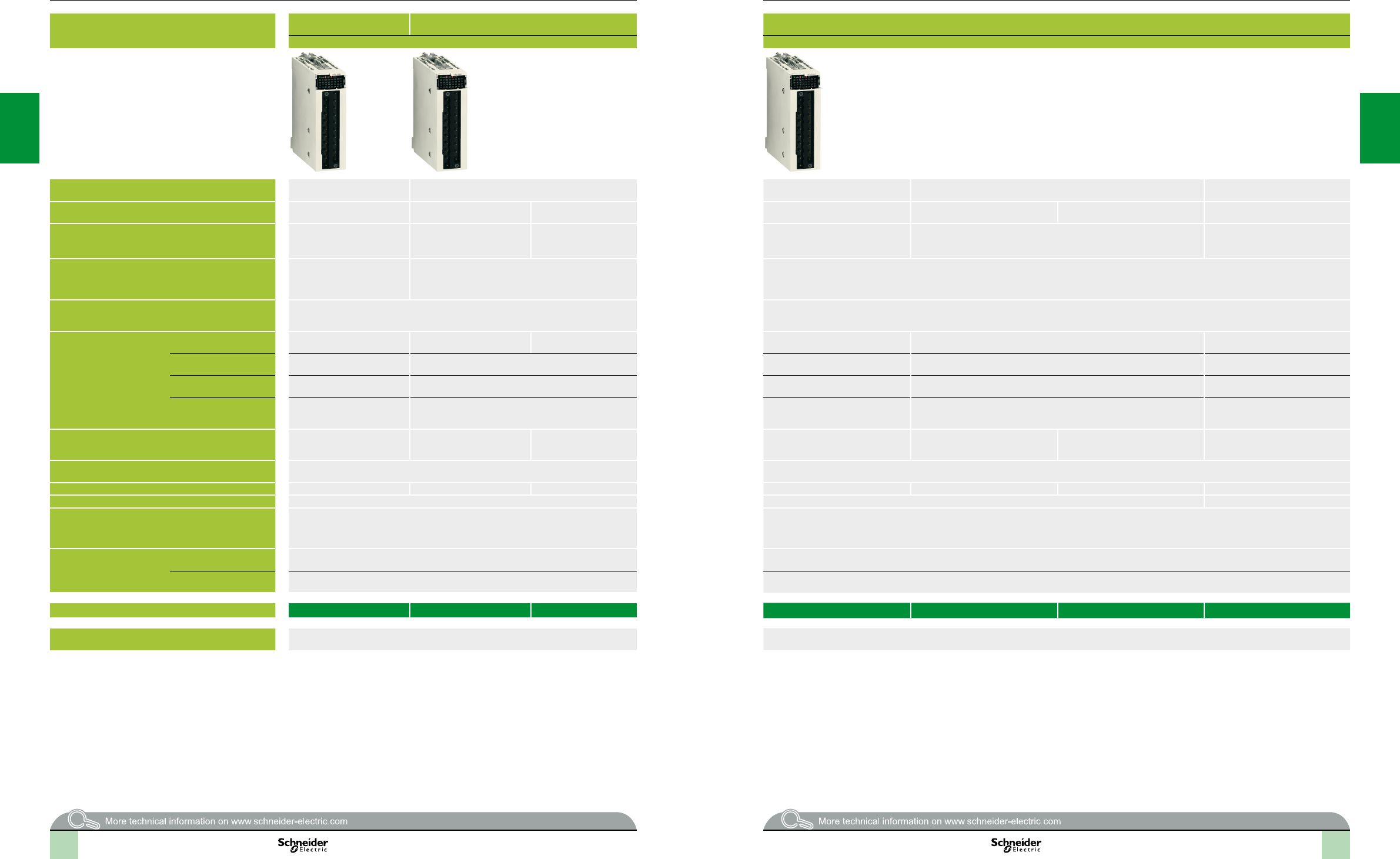
Applications Input module
8 channels
16-channel input modules 16-channel input modules
Connection via cage clamp, screw clamp or spring-type removable block terminal Connection via cage clamp, screw clamp or spring-type removable block terminal
Type or
Voltage 200…240 V 24 V 48 V 24 V ( or ) 48 V 100…120 V 125 V
Current per channel 10.4 mA
(for U = 220 V to 50 Hz)
3.5 mA 2.5 mA 3 mA ( or ) 5 mA 2.4 mA
Modularity
(Number of channels and
commons)
8 isolated inputs and
1 common
16 isolated inputs and
1 common
16 isolated inputs and
1 common
Connection Via 20-way cage clamp, screw clamp or spring-type removable terminal block
BMXFTB2000/2010/2020
Via BMXFTB2000/2010/2020 20-way cage clamp, screw clamp or spring-type removable block terminal
Isolated inputs IEC/EN 61131-2 conformity Type 2 Type 3 Type 1 Type 1 () Type 3 –
Logic – Positive (sink) Negative (source)() – Positive (sink)
Type of input Capacitive Current sink Resistive Capacitive Current sink
Sensor compatibility
IEC/EN 60947-5-2
2-wire 2-wire , 3-wire PNP any type 2-wire /, 3-wire PNP or
NPN any type
2-wire –
Sensor power supply
(ripple included)
170…264 V 19…30 V 38…60 V 19...30 V
20…26 V 40…52 V 85…132 V 88…150 V
Protection of inputs Use one 0.5 A fast-blow fuse per group of channels Use one 0.5 A fast-blow fuse per group of channels
Maximum dissipated power 4.73 W 2.5 W 3.6 W 3 W 4 W 3.8 W 8.5 W (at 40°C)
Operating temperature 0…60°C 0…60°C -25…70°C
Compatibility with
installation help system
TeSys Quickt
– –
Compatibility with
pre-wired system
Modicon
Telefast ABE7
Passive connection
sub-bases
– –
Adaptor sub-bases with
relays
– –
References BMXDAI0805 BMXDDI1602 BMXDDI1603 BMXDAI1602 BMXDAI1603 BMXDAI1604 BMXDDI1604T
Pages 2/22 2/22
Selectionguide Modicon X80 I/O platform 0
Discrete I/O modules
Input modules
2/12 2/13
2
1
3
4
5
6
7
8
9
10
2
1
3
4
5
6
7
8
9
10
2
1
3
4
5
6
7
8
9
10
2
1
3
4
5
6
7
8
9
10
2/13 2/13
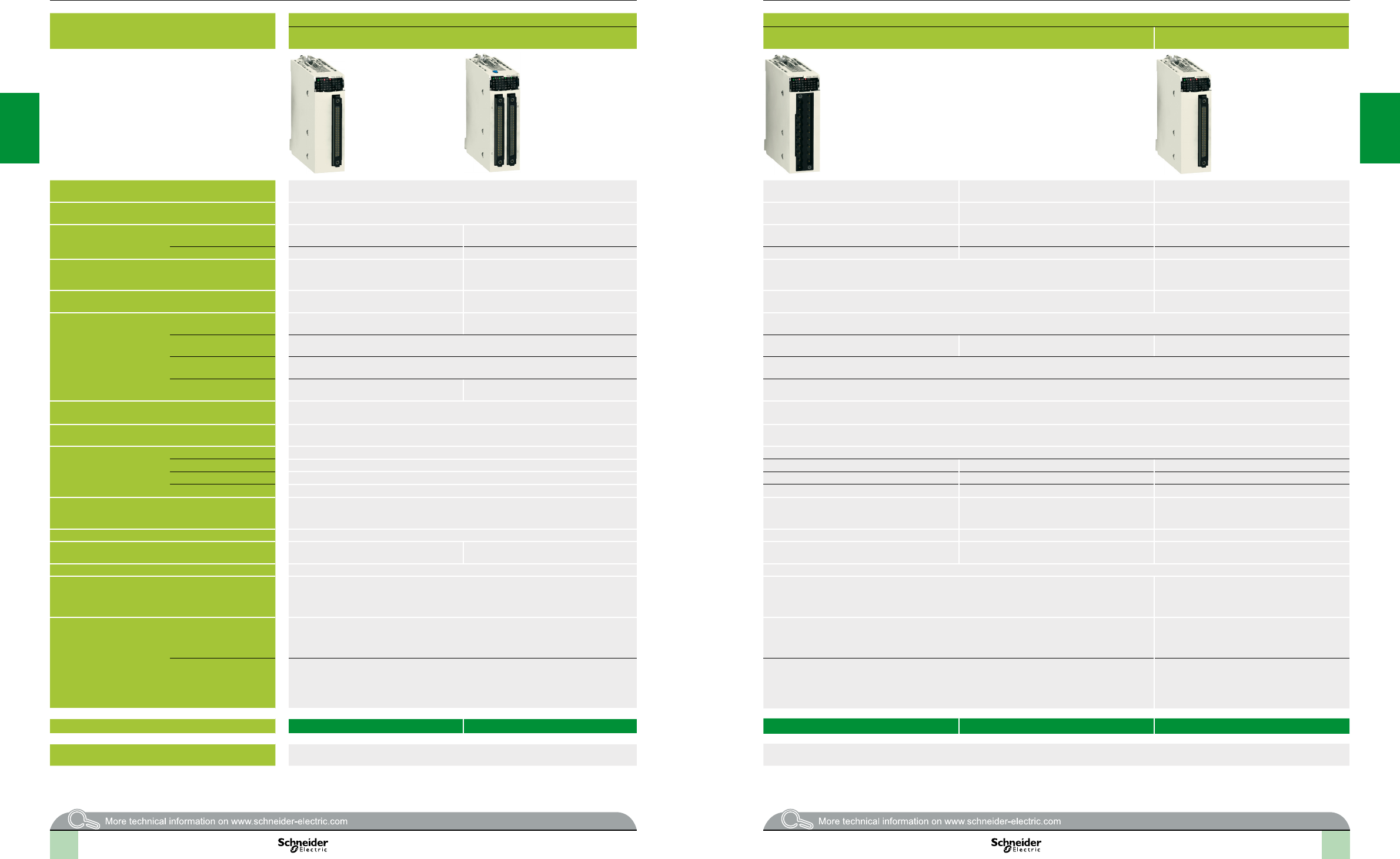
Applications 32 or 64-channel high-density input modules 16 or 32-channel mixed I/O module
Connection via 40-way connectors with preassembled cordsets Connection via cage clamp, screw clamp or spring-type removable block terminal Connection via 40-way connector with
preassembled cordsets
Type and (outputs only)
Voltage 24 V Inputs: 24 V
Solid-state outputs: 24 V
Inputs: 24 V
Relay outputs: 24 V or 24…240 V Inputs: 24 V
Solid-state outputs: 24 V
Current per channel Inputs 2.5 mA 1 mA 3.5 mA 3.5 mA 2.5 mA
Outputs – – 0.5 A 2 A ( or ) 0.1 A
Modularity
(Number of channels and
commons)
32 isolated inputs and
2 commons
64 isolated inputs and
4 commons
8 isolated inputs and 1 common,
8 isolated outputs and 1 common
16 isolated inputs and 1 common,
16 isolated outputs and 1 common
Connection Via one 40-way connector Via two 40-way connectors Via BMXFTB2000/2010/2020
20-way cage clamp, screw clamp or spring-type removable terminal block
Via one 40-way connector
Isolated inputs IEC/EN 61131-2 conformity Type 3 Non-IEC Type 3
Logic Positive (sink) Positive (sink) – Positive (sink)
Type of input Current sink Current sink
Sensor compatibility
IEC/EN 60947-5-2
2-wire , 3-wire PNP any type – 2-wire , 3-wire PNP any type
Sensor power supply
(ripple included)
19…30 V 19…30 V
Protection of inputs Use one 0.5 A fast-blow fuse per group of channels Use one 0.5 A fast-blow fuse per group of channels
Isolated outputs Fallback – Congurable output fallback, continuous monitoring of output control and resetting of outputs in case of internal fault
IEC/EN 61131-2 conformity – Yes
Protection – Protected Not protected Protected
Logic – Positive – Positive
Preactuator power supply
(ripple included)
– 19…30 V 19...30 V
24...240 V
19…30 V
Output fuse protection – Use a 2 A fast-blow fuse Use a 12 A fast-blow fuse Use a 2 A fast-blow fuse
Maximum dissipated power 3.9 W 4.3 W 3.7 W 3.1 W 4 W
Operating temperature 0…60°C 0…60°C
Compatibility with
installation help system
TeSys Quickt
LU9 G02 splitter boxes (8 motor starters) and BMXFCC1/3 preassembled cordsets.
See pages 2/19 and 2/23.
– LU9 G02 splitter boxes (8 motor starters) and
BMXFCC1/3 preassembled cordsets.
See pages 2/19 and 2/23.
Compatibility with pre-wired
system
Modicon Telefast ABE7
Passive connection
sub-bases
Depending on model, 8 or 16-channel passive sub-bases, with or without LED, with common or
2 terminals per channel.
See pages 5/2 and 5/8.
– Depending on model, 8 or 16-channel passive
sub-bases, with or without LED, with common or
2 terminals per channel. See pages 5/2 and 5/8.
Adaptor sub-bases with
relays
Depending on model, active sub-bases with solid state or electromagnetic relays (xed or
removable), 16 channels, with common or 2 terminals per channel (screw or spring-type
connection).
See pages 5/2 and 5/8.
– Depending on model, active sub-bases with solid
state or electromagnetic relays (xed or removable)
16 channels, with common or 2 terminals per
channel (screw or spring-type connection).
See pages 5/2 and 5/8.
References BMXDDI3202K BMXDDI6402K BMXDDM16022 BMXDDM16025 BMXDDM3202K
Pages 2/22 2/23
Selectionguide(continued) Modicon X80 I/O platform 0
Discrete I/O modules
Input modules and mixed I/O modules
2/14 2/15
2
1
3
4
5
6
7
8
9
10
2
1
3
4
5
6
7
8
9
10
2
1
3
4
5
6
7
8
9
10
2
1
3
4
5
6
7
8
9
10
2/14 2/14
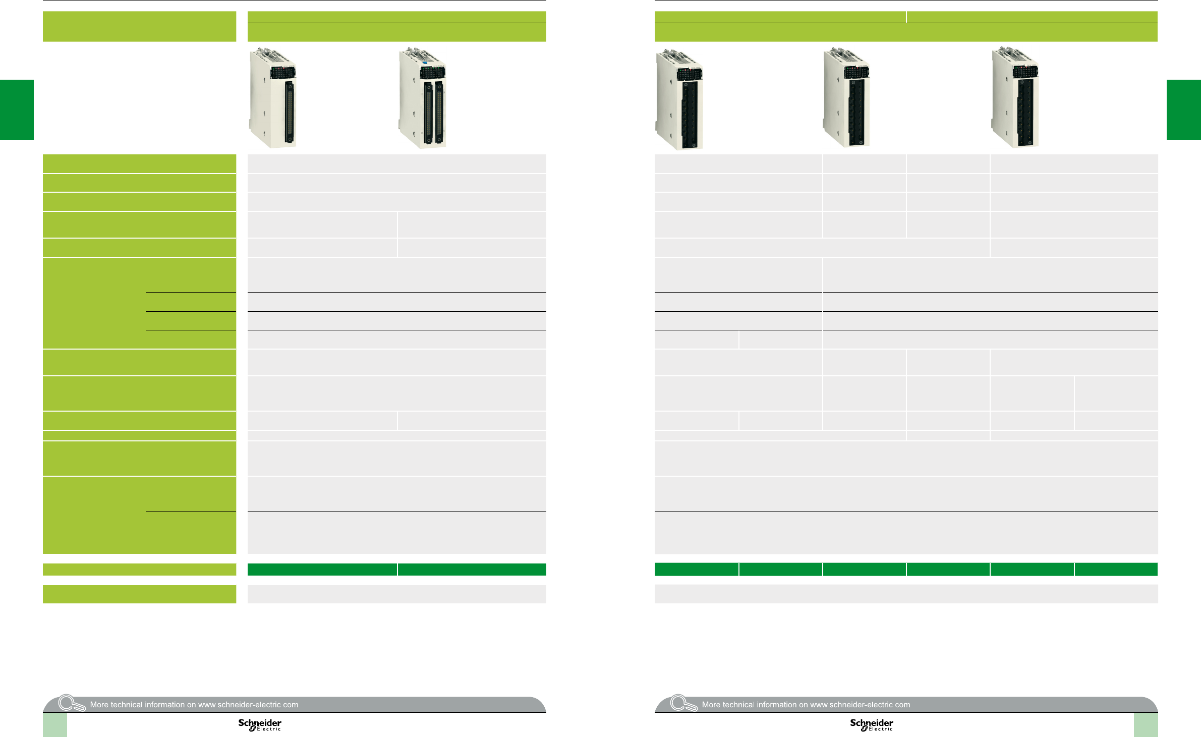
Applications 32 or 64-channel high-density output modules 16-channel output modules 8 or 16-channel output modules
Connection via 40-way connectors with preassembled cordsets Connection via cage clamp, screw clamp or spring-type removable block terminal
Type transistor transistor triac relay / relay
Voltage 24 V 24 V 100…240 V 100…150 V 24 V , 24…240 V a
Current per channel 0.1 A 0.5 A 0.6 A 0.3 A (Ith) 2 A (Ith)
Modularity
(Number of channels and
commons)
32 protected outputs and
2 commons
64 protected outputs and
4 commons
16 protected outputs and
1 common
16 non-protected outputs
and 4 commons
8 non-protected outputs,
without common
16 non-protected outputs and
2 commons
Connection Via one 40-way connector Via two 40-way connectors Via BMXFTB2000/2010/2020 20-way cage clamp, screw clamp or spring-type removable block terminal
Isolated outputs Fallback Congurable output fallback, continuous monitoring of output control and resetting of outputs in
case of internal fault
Congurable output fallback, continuous monitoring
of output control and resetting of outputs in case of
internal fault
Congurable output fallback
IEC/EN 61131-2 conformity Yes Yes Yes
Protection Yes Yes –
Logic Positive Positive(source) Negative (sink) –
Preactuator power supply
(ripple included)
19…30 V 19…30 V 100…240 V 100…150 V 19...30 V
24...240 V
Output fuse protection Use one 2 A fast-blow fuse per group of channels Use one 6.3 A
fast-blow fuse per group of channels
Use one 3 A fast-blow
fuse per group of
channels
Use one 0.5 A, 250 V DC
fast-blow fuse on each
relay
Use one 3 A fast-blow
fuse on each channel
Use one 12 A fast-blow
fuse on each group of
channels
Maximum dissipated power 3.6 W 6.85 W 4 W 2.26 W – 3.17 W 2.7 W 3 W
Operating temperature 0…60°C 0…60°C -25…70°C 0…60°C
Compatibility with
installation help system
TeSys Quickt
LU9 G02 splitter boxes (8 motor starters) and BMXFCC1/3 preassembled cordsets.
See pages 2/19 and 2/23.
–
Compatibility with
pre-wired system
Modicon Telefast ABE7
Passive connection
sub-bases
Depending on model, passive sub-bases with 8 or 16 channels, with or without LED, with
common or with 2 terminals per channel.
See pages 5/2 and 5/8.
–
Adaptor sub-bases with
relays
Depending on model, active sub-bases with solid state or electromagnetic relays (xed or
removable). 16 channels with 1 common or 2 terminals per channel, screw or spring-type
connection.
See pages 5/2 and 5/8
–
References BMXDDO3202K BMXDDO6402K BMXDDO1602 BMXDDO1612 BMXDAO1605 BMXDRA0804T BMXDRA0805 BMXDRA1605
Pages 2/22 2/22
Selectionguide(continued) Modicon X80 I/O platform 0
Discrete I/O modules
Output modules
2/16 2/17
2/18
Presentation,
description Modicon X80 I/O platform
Discrete I/O modules
Presentation
Discrete I/O modules in the Modicon X80 I/O offer are standard modules occupying a
single slot on the rack. These modules are equipped with either of the following:
A connector for a screw or spring-type 20-way removable terminal block
One or two 40-way connectors
This wide range of “discrete” I/O can be used to meet whatever requirements arise in terms
of:
Functions, AC or DC I/O, positive or negative logic
Modularity, 8, 16, 32 or 64 channels per module
The inputs receive signals from the sensors and perform the following functions:
Acquisition
Adaptation
Electrical isolation
Filtering
Protection against interference signals
The outputs memorize commands issued by the processor to enable control of the
preactuators via the decoupling and amplication circuits.
Description
BMXDI/DO/DRA discrete I/O modules are standard format (1 slot). They have a
case, which ensures IP 20 protection of the electronics, and are locked into position
by a captive screw.
I/O modules connected via 20-way removable terminal block
1 Rigid body providing support and protection for the electronic card
2 Module reference marking (a label is also visible on the right-hand side of the
module)
3 Channel status display block
4 Connector taking the 20-way removable terminal block for connecting sensors or
preactuators
To be ordered separately:
5 A BMXFTB200 20-way removable terminal block (identication label supplied
with each I/O module) or a preassembled cordset with a 20-way removable
terminal block at one end and ying leads at the other (see page 2/19).
I/O modules connected via 40-way connector(s)
1 Rigid body providing support and protection for the electronic card
2 Module reference marking (a label is also visible on the right-hand side of the
module)
3 Channel status display block
4 One or two 40-way connectors (32 or 64 channels) (1) for connecting sensors or
preactuators
5 With the 64-channel module, a pushbutton which, with successive presses,
displays the state of channels 0...31 or 32...63 on the display block 3 (see
page 2/20)
To be ordered separately, depending on the type of module:
One or two preassembled cordset(s) with a 40-way connector (see page 2/19)
(1)FujitsuFCN40-wayconnector
Processors:
page 1/4
Communication:
page 2/50
Software:
page 4/2
Ruggedized Modicon M340 modules:
page 6/2
1
3
4
2
32and64-channelmodulesforconnection
viaoneortwo40-wayconnector(s)
5
1
3
4
2
5
Moduleforconnectionvia20-wayremovableterminal
block
2
1
3
4
5
6
7
8
9
10
2
1
3
4
5
6
7
8
9
10
2/19
Connections Modicon X80 I/O platform
Discrete I/O modules
Connecting modules with removable terminal blocks
There are three types of 20-way removable terminal block:
Screw clamp terminal block
Cage clamp terminal block
Spring-type terminal block
Each removable terminal block can take:
Bare wires
Wires equipped with DZ5CE cable ends
A : One version of the removable terminal block is equipped with 3, 5 or 10 m cordsets
with colour-coded ying leads (BMXFTW1). Use limited to voltages of 48 V.
Cage clamp terminal blocks
The capacity of each terminal is:
Minimum: One 0.34 mm2wire (AWG 22)
Maximum: One 1 mm2 wire (AWG 18)
BMXFTB2000 cage clamp connectors are equipped with captive screws
(maximum tightening torque 0.5 N.m).
Screw clamp terminal blocks
The capacity of each terminal is:
Minimum: One or two 0.34 mm2 wires (AWG 22)
Maximum: Two 1.5 mm2 wires (AWG 15)
BMXFTB2010 screw clamp connectors are equipped with captive screws (maximum
tightening torque 0.5 N.m).
Spring terminals
The capacity of each terminal in the BMXFTB2020 spring-type terminal blocks is:
Minimum: One 0.34 mm2 wire (AWG 22)
Maximum: One 1 mm2 wire (AWG 18)
Connecting modules with 40-way connectors
Preassembled cordsets with 40-way connector at one end and ying leads at
the other
B : Preassembled cordsets can be used for easy direct wire-to-wire connection
between the I/O of modules with 40-way connectors1 and the sensors, preactuators
or intermediate terminal blocks.
These preassembled cordsets comprise:
At one end, a 40-way connector 2 with either of the following:
- One sheath containing 20 wires with a cross-section of 0.34 mm
2
(AWG 22)
(BMXFCW1)
- Two sheaths
3
, each containing 20 wires with a cross-section of 0.34 mm
2
(AWG 22) (BMXFCW3)
At the other end, colour-coded ying leads
4
conforming to standard DIN47100.
Preassembled cordsets with 40-way connector and HE 10 connector(s)
C : Two types of cordset can be used for connecting the I/O of modules 1 with
40-way connectors to Modicon Telefast ABE7 rapid wiring connection and adaptation
interfaces, (see page 5/8).
These preassembled cordsets comprise:
At one end, a 40-way connector 2 with either of the following:
- One sheath containing 20 wires (BMXFCC1)
- Two sheaths
3
each containing 20 wires (BMXFCC3)
At the other end, one or two HE 10 connectors 5.
Connection to TeSys Quickt system
D : 1 BMXDDI3202K/6402K input modules, BMXDDO3202K/6402K output
modules and BMXDDM3202K mixed I/O modules with 40-way connectors are
designed, amongst other things, for use in conjunction with the TeSys Quickt
mounting system via the LU9G02 splitter module 6 (for 8 motor starters).
The splitter modules are easily connected using
7
BMXFCC1/3 preassembled
cordsets.
Processors:
page 1/4
Communication:
page 2/50
Software:
page 4/2
Ruggedized Modicon M340 modules:
page 6/2
B
BA
A
Preassembledcordsetwith
40-wayconnectorsandHE10connectorsfor
ModiconTelefastABE7system
B
BA
A
Preassembledcordsetwith
20-wayremovableterminalblockatoneendand
yingleadsattheother
Preassembledcordsetwith
40-wayconnectorandtwoendswithyingleads
ExampleofconnectiontotheTeSysQuicktinstallationhelp
system
A
B
C
D
1
2
5
3
1
2
3
4
1
7
6
2
1
3
4
5
6
7
8
9
10
2
1
3
4
5
6
7
8
9
10
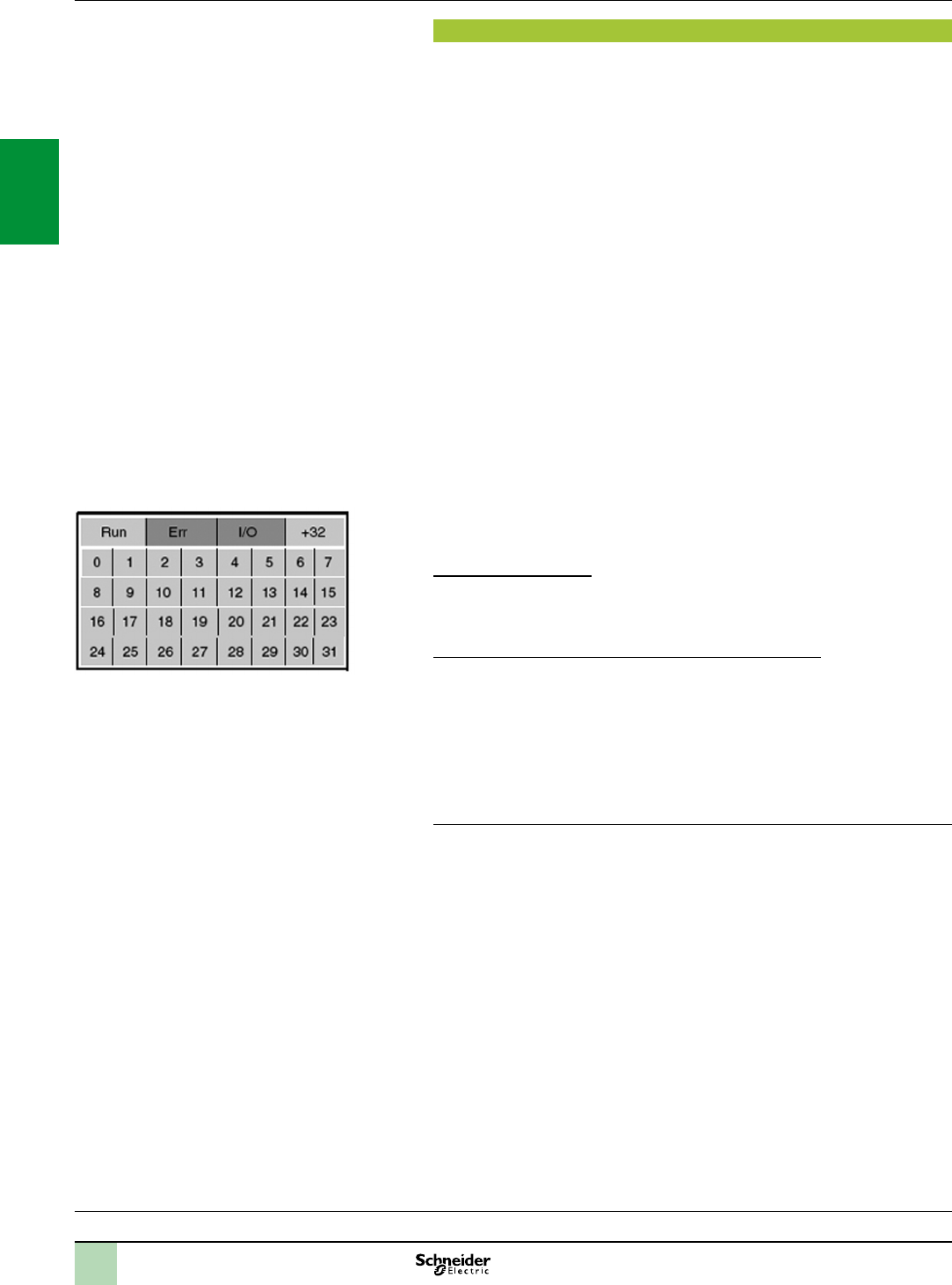
2/20
Functions Modicon X80 I/O platform
Discrete I/O modules
Functions (1)
The discrete I/O modules provide the following functions:
Hot swapping: Due to their special integrated devices, I/O modules (including
application-specic modules) can be removed or added while the power is on.
I/O assignment: The channels of discrete I/O modules are grouped into blocks
of 4, 8 or 16 consecutive channels depending on the type of module. Each group of
channels can be assigned to a specic application task, namely master or fast.
Protection of DC inputs: The 24 V and 48 V inputs are constant-current
type. This characteristic ensures and limits the current consumed at the inputs.
Protection of DC outputs: All active transistor outputs are protected against
overload, short-circuits, reverse polarity and inductive over-voltage.
Reactivation of DC outputs: If a fault has caused an output to trip, the output
can be reactivated using this parameter if no other terminal fault is present.
Reactivation is controlled by means of a group of 8 channels. It can be programmed
or automatic.
RUN/STOP command: An input can be congured to control the RUN/STOP
changeover for the PLC.
Output fallback: This parameter denes the fallback mode used by the DC
transistor outputs when the PLC stops. It can assume the “fallback” value at state 0
or state 1 for the corresponding group of 8 channels or the “maintain” value
representing the state of the outputs before the PLC stops.
I/O module diagnostics: Each discrete I/O module is equipped with a display
block on the front panel centralizing all the information necessary for module control,
diagnostics and maintenance.
Diagnostics via Unity Pro:
Using the integrated diagnostics in Unity Pro, this local diagnostics on the module
front panel is complemented by system diagnostics based on predened screens at
global hardware conguration level, module level and channel level (see page 4/4).
Remote diagnostics using a web browser on a “Thin Client” PC:
In addition, the diagnostics described above can be performed remotely using a
simple web browser thanks to the standard web server integrated in the Modicon
X80 I/O platform (processor with integrated Ethernet port or Ethernet module), using
the “ready-to-use” Rack Viewer function (see page 3/16).
Compatibility with 2-wire and 3-wire sensors: The discrete input modules can
be used in conjunction with OsiSense XS inductive proximity sensors (for
compatibility, see page 7/16) and with OsiSense XU photo-electric sensors (for
compatibility, see page 7/14).
(1)Forfurtherinformation,pleaseconsultourwebsiteatwww.schneider-electric.com.
Processors:
page 1/4
Communication:
page 2/50
Software:
page 4/2
Ruggedized Modicon M340 modules:
page 6/2
DisplayblockformoduleBMXDDO6402K
2
1
3
4
5
6
7
8
9
10
2
1
3
4
5
6
7
8
9
10

2/21
Characteristics Modicon X80 I/O platform
Discrete I/O modules
Complementary characteristics
The following characteristics complement those introduced in the selection guide on
pages 2/12 to 2/17.
DC input modules BMXDDI16pp/1604T/3202K/6402K and BMXDAI1602
Input impedance at nominal voltage: 6.4 to 19.2 kΩ, depending on model
Reverse polarity: Protection for modules BMXDDI1602/1603/3202K
Paralleling of inputs (1): Yes, for modules BMXDDI1602/1603
Dielectric strength between group of channels: 500 V c for modules
BMXDDI3202K/6402K
Temperature derating for module BMXDDI1604T: No derating up to 40°C, a
maximum of 25% of inputs at state 1 at 70°C
AC input modules BMXDAI16pp/0805
Input frequency: 47 to 63 Hz
Current peak on activation at nominal voltage: 5 to 240 mA depending on model
Input impedance at nominal voltage and F = 55 Hz: 6 to 21 kΩ, depending on
model
Triac output modules BMXDAO1605
Current via common: 2.4 A
Current for all 4 commons together: 4.8 A
DC transistor output modules BMXDDO16pp/3202K/6402K
Dielectric strength between groups of channels: 500 V c for modules
BMXDDO3202K/6402K
Relay output modules BMXDRA080pp/1605
Protection against AC inductive overvoltage: Use an RC circuit or ZNO surge
limiter appropriate to the voltage in parallel on each output.
Protection against DC inductive overvoltage: Use a discharge diode on each
output.
Mixed I/O relay module BMXDDM16025
Input impedance at nominal voltage: 6.8 kΩ
Dielectric strength between groups of inputs: 500 V c
DC mixed I/O modules BMXDDM16022/3202K
Input impedance at nominal voltage: 6.8 to 9.6 kΩ, depending on model
Reverse polarity on the inputs: Protection
Paralleling of outputs: Yes, for a maximum of 2 outputs for module BMXDDM16022
and a maximum of 3 outputs for module BMXDDM3202K
(1)Thischaracteristicallowsseveralinputstobewiredinparallelonthesamemoduleoron
differentmodulesforinputredundancy.
Processors:
page 1/4
Communication:
page 2/50
Software:
page 4/2
Ruggedized Modicon M340 modules:
page 6/2
2
1
3
4
5
6
7
8
9
10
2
1
3
4
5
6
7
8
9
10
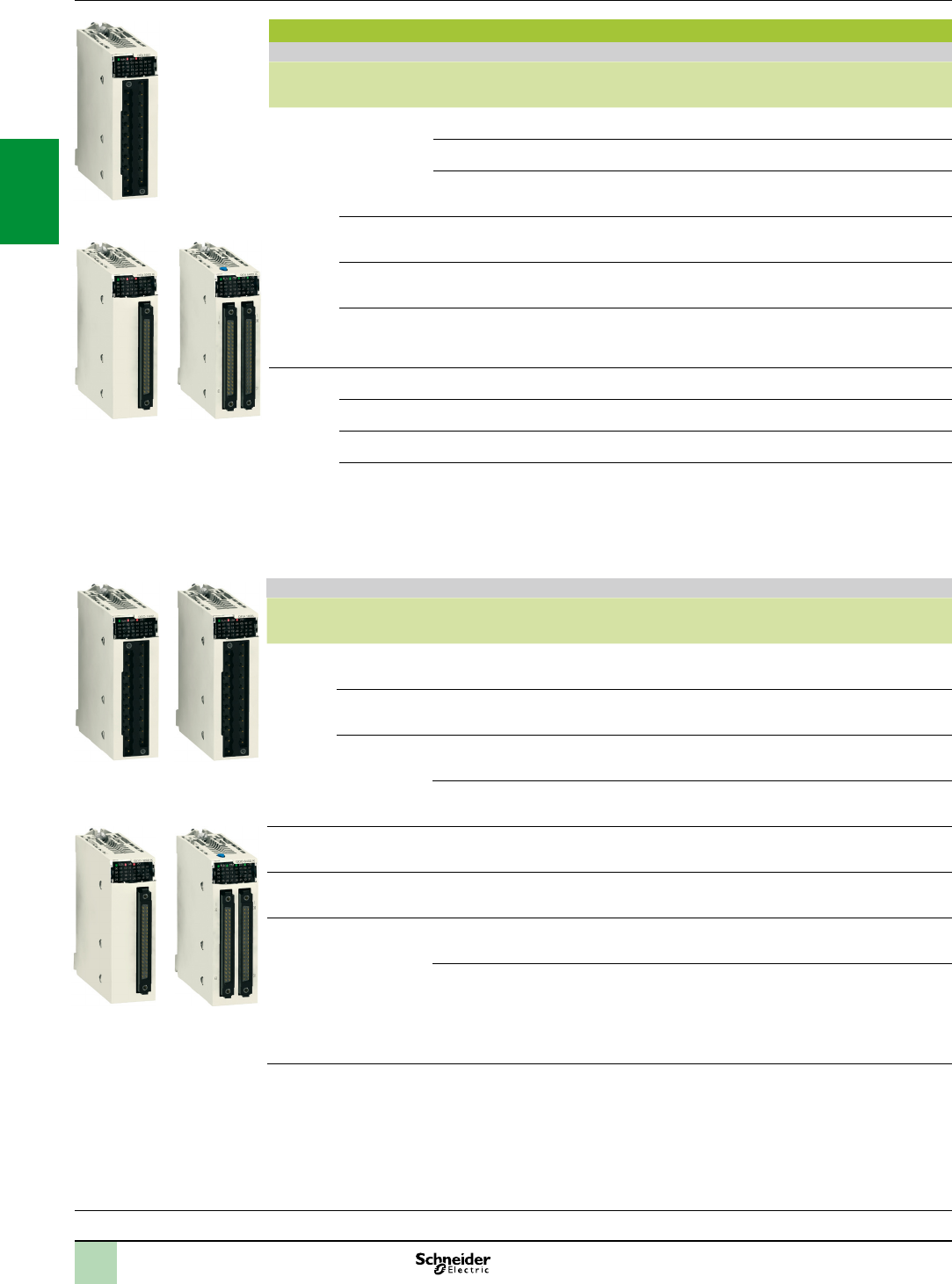
2/22
References Modicon X80 I/O platform
Discrete I/O modules
Input modules and output modules
References
Discrete input modules (1)
Type of
current
Input voltage Connection via
(2)
IEC/EN
61131-2
conformity
No. of channels
(common)
Reference Weight
kg
c24 V (positive
logic)
Screw or spring-type 20-way
removable terminal block
Type 3 16 isolated inputs
(1 x 16)
BMXDDI1602 0.115
One 40-way connector Type 3 32 isolated inputs
(2 x 16)
BMXDDI3202K 0.110
Two 40-way connectors Non-IEC 64 isolated inputs
(4 x 16)
BMXDDI6402K 0.145
24 V (negative
logic)
Screw or spring-type 20-way
removable terminal block
Non-IEC 16 isolated inputs
(1 x 16)
BMXDAI1602 0.115
48 V (positive
logic)
Screw or spring-type 20-way
removable terminal block
Type 1 16 isolated inputs
(1 x 16)
BMXDDI1603 0.115
125 V (positive
logic)
Screw or spring-type 20-way
removable terminal block
16 isolated inputs
(1 x 16)
BMXDDI1604T 0.144
a24 V Screw or spring-type 20-way
removable terminal block
Type 1 16 isolated inputs
(1 x 16)
BMXDAI1602 0.115
48 V Screw or spring-type 20-way
removable terminal block
Type 3 16 isolated inputs
(1 x 16)
BMXDAI1603 0.115
100…120 V Screw or spring-type 20-way
removable terminal block
Type 3 16 isolated inputs
(1 x 16)
BMXDAI1604 0.115
200…240 V Screw or spring-type 20-way
removable terminal block
Type 2 8 isolated inputs
(1 x 8)
BMXDAI0805 0.152
Discrete output modules (1)
Type of
current
Output voltage Connection via
(2)
IEC/EN
61131-2
conformity
No. of channels
(common)
ReferenceWeight
kg
c
transistor
24 V/0.5 A
(positive logic)
20-way removable terminal
block, screw or spring-type
Yes 16 protected
outputs
(1 x 16)
BMXDDO1602 0.120
24 V/0.5 A
(negative logic)
20-way removable terminal
block, screw or spring-type
– 16 protected
outputs
(1 x 16)
BMXDDO1612 0.120
24 V/0.1 A
(positive logic)
One 40-way connector Yes 32 protected
outputs
(2 x 16)
BMXDDO3202K 0.110
Two 40-way connectors Yes 64 protected
outputs
(4 x 16)
BMXDDO6402K 0.150
triac 100…240 20-way removable terminal
block, screw or spring-type
– 16 outputs
(4 x 4)
BMXDAO1605 0.140
c relay 100…150 V/
0.3 A
20-way removable terminal
block, screw or spring-type
Yes 8 non-protected
outputs
BMXDRA0804T 0.178
c or a
relay
24 V /2 A
24…240 V/
2 A
20-way removable terminal
block, screw or spring-type
Yes 8 non-protected
outputs
(without common)
BMXDRA0805 0.145
20-way removable terminal
block, screw or spring-type
Yes 16 non-protected
outputs
(2 x 8)
BMXDRA1605 0.150
(1)Typicalconsumption:Seethepowerconsumptiontableonpage7/22.
(2)64-channelmoduleshave2connectorsandthereforerequire2connectioncables.
Processors:
page 1/4
Communication:
page 2/50
Software:
page 4/2
Ruggedized Modicon M340 modules:
page 6/2
BMXDDO162
BMXDDO3202K BMXDDO6402K
BMXDRA0805/
1605
BMXDDI160
BMXDAI
BMXDDI3202K BMXDDI6402K
2
1
3
4
5
6
7
8
9
10
2
1
3
4
5
6
7
8
9
10
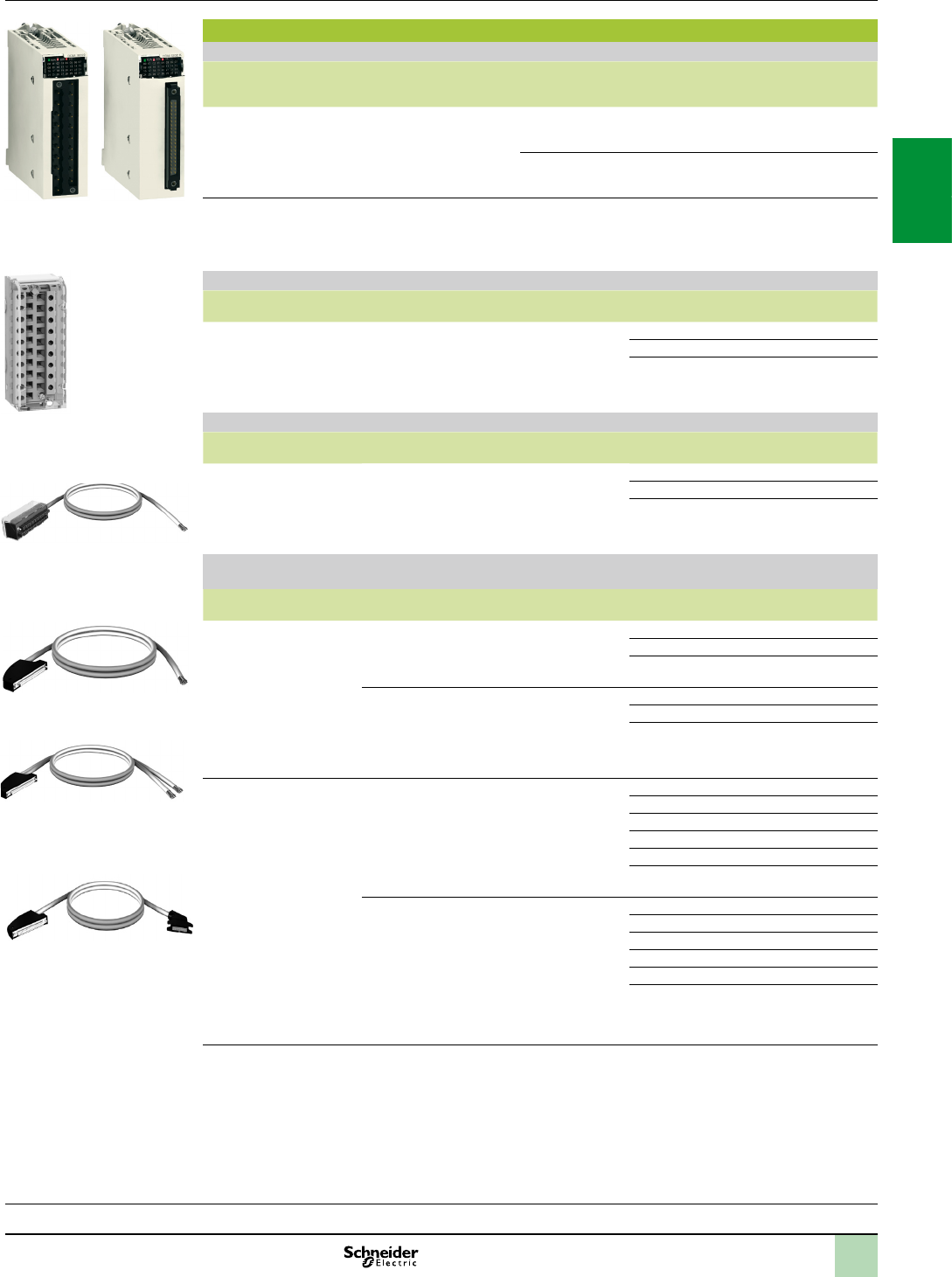
2/23
References (continued)
Discrete mixed I/O modules (1)
Number of
I/O
Connection No. of input channels
(common)
No. of output
channels
(common)
IEC/EN
61131-2
conformity
Reference Weight
kg
16 Screw or
spring-type
20-way
removable
terminal block
8 (positive logic)
(1 x 8)
8, transistor
24 V / 0.5 A
(1 x 8)
Inputs,
type 3
BMXDDM16022 0.115
8, relay 24 V or
24…240 V a
(1 x 8)
Inputs,
type 3
BMXDDM16025 0.135
32 One 40-way
connector
16 (positive logic)
(1 x 16)
16, transistor
24 V / 0.1 A
(1 x 16)
Inputs,
type 3
BMXDDM3202K 0.110
Removable terminal blocks
Description For use with Type Reference Weight
kg
20-way removable terminal
blocks
For module with 20-way removable terminal block Cage clamp BMXFTB2000 0.093
Screw clamp BMXFTB2010 0.075
Spring BMXFTB2020 0.060
Preassembled cordsets for 16-channel I/O modules with removable terminal block
Description Composition Cross-
section
Length Reference Weight
kg
Preassembled cordsets
with one end with ying
leads for 16-channel I/O
modules
Operating voltage 48 V
One 20-way spring-type removable
terminal block (BMXFTB2020) and
one end with colour-coded ying
leads
0.324 mm23 m BMXFTW301 0.850
5 m BMXFTW501 1.400
10 m BMXFTW1001 2.780
Preassembled cordsets for 16, 32 and 64-channel I/O modules with 40-way connectors
Description No. of
sheaths
Composition Cross-
section
Length Reference Weight
kg
Preassembled cordsets
with one end with ying
leads
1 x 20
wires (16
channels)
One 40-way
connector and
one end with colour-
coded ying leads
0.324 mm23 m BMXFCW301 0.820
5 m BMXFCW501 1.370
10 m BMXFCW1001 2.770
2 x 20
wires (32
channels)
(2)
One 40-way
connector and
two ends with colour-
coded ying leads
0.324 mm23 m BMXFCW303 0.900
5 m BMXFCW503 1.490
10 m BMXFCW1003 2.960
Preassembled cordsets for
Modicon Telefast ABE7
sub-bases
1 x 20
wires (16
channels)
One 40-way connector
and one HE 10
connector
0.324 mm20.5 m BMXFCC051 0.140
1 m BMXFCC101 0.195
2 m BMXFCC201 0.560
3 m BMXFCC301 0.840
5 m BMXFCC501 1.390
10 m BMXFCC1001 2.780
2 x 20
wires (32
channels)
(2)
One 40-way connector
and two HE 10 connectors
0.324 mm20.5 m BMXFCC053 0.210
1 m BMXFCC103 0.350
2 m BMXFCC203 0.630
3 m BMXFCC303 0.940
5 m BMXFCC503 1.530
10 m BMXFCC1003 3.000
(1)Typicalconsumption:Seethepowerconsumptiontableonpage7/22.
(2)64-channelmoduleshave2connectorsandthereforerequire2connectioncables.
BMXFTW01
BMXFCW01
BMXFCC01
BMXFCW03
Processors:
page 1/4
Communication:
page 2/50
Software:
page 4/2
Ruggedized Modicon M340 modules:
page 6/2
Modicon X80 I/O platform
Discrete I/O modules
Mixed I/O modules, accessories
References(continued)
BMXFTB2000
BMXDDM1602
BMXDDM3202K
2
1
3
4
5
6
7
8
9
10
2
1
3
4
5
6
7
8
9
10
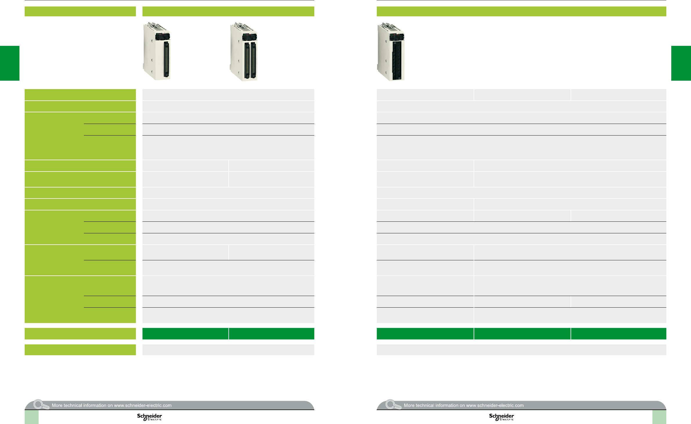
2
1
3
4
5
6
7
8
9
10
2
1
3
4
5
6
7
8
9
10
2
1
3
4
5
6
7
8
9
10
2
1
3
4
5
6
7
8
9
10
2/24 2/24
Selectionguide Modicon X80 I/O platform 0
Analog I/O modules
Input modules
Applications Analog inputs Analog inputs
Type of input Isolated low-level inputs, voltage, thermocouples, temperature probes, resistors Isolated high-level inputs Non-isolated high-level inputs Isolated high-level inputs
Type Multirange Voltage/current
Range Voltage ± 40 mV, ± 80 mV, ± 160 mV, ± 320 mV, ± 640 mV, ± 1.28 V ± 10 V, 0…10 V, 0...5 V, 1..5 V, ± 5 V
Current – 0...20 mA, 4…20 mA, ± 20 mA
Thermocouple
Temperature probe
Resistor
Thermocouples, type B, E, J, K, L, N, R, S, T, U
2, 3 or 4-wire temperature probes, type Pt100, JPt100, Pt1000, JPt1000, Ni100, Ni1000
(in accordance with DIN43760) and Cu 10
2, 3 or 4-wire resistors, 400 Ω or 4000 Ω
–
Modularity 4 inputs 8 inputs 4 inputs 8 inputs
Acquisition period 400 ms for the 4 inputs 400 ms for the 8 inputs Fast: 1 + (1 x no. of declared channels) ms
Default: 5 ms for the 4 channels
Fast: 1 + (1 x no. of declared channels) ms
Default: 9 ms for the 8 channels
Conversion time – –
Resolution 15 bits + sign 16 bits 15 bits + sign
Isolation Between channels 750 V300 V– 300 V
Between channels and bus 1400 V1400 V
Between channels and earth 750 V1400 V
Connection Directly to the module Via 40-way connector Via two 40-way connectors Via 20-way removable terminal block (screw or
spring-type) BMXFTB200
Via 28-way removable terminal block (cage clamp-type) BMXFTB2800 or (spring-type) BMXFTB2820
Via preassembled cordsets Cordsets with one end with colour-coded ying leads
BMXFCW01S (3 or 5 m long)
Cordsets with one end with colour-coded ying leads
BMXFTW01S (3 or 5 m long)
Cordsets with one end with colour-coded ying leads
BMXFTW08S (3 or 5 m long)
Compatibility with pre-wired
system
Modicon Telefast ABE7
Connection sub-base 4-channel sub-base for direct connection of 4 thermocouples plus connection
and provision of cold junction compensation.
See page 5/8
4-channel sub-base for direct connection of 4 inputs,
delivers and distributes 4 protected isolated power
supplies. See page 5/8
8-channel sub-base for direct connection of 8 current/voltage inputs. See page 5/8
Type of connection sub-base ABE7CPA412 ABE7CPA410 ABE7CPA02/03/31/31E ABE7CPA02/31/31E
Type of preassembled
cordsets
BMXFCA2
(1.5, 3 or 5 m long)
BMXFCA0
(1.5, 3 or 5 m long)
BMXFTA0
(1.5 or 3 m long)
References BMXART0414 BMXART0814 BMXAMI0410 BMXAMI0800 BMXAMI0810
Pages 2/32 2/32
2/24 2/25
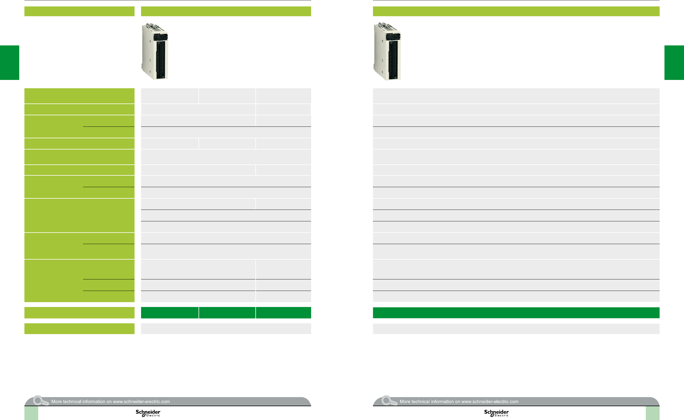
2
1
3
4
5
6
7
8
9
10
2
1
3
4
5
6
7
8
9
10
2
1
3
4
5
6
7
8
9
10
2
1
3
4
5
6
7
8
9
10
2/25 2/25
Selectionguide Modicon X80 I/O platform 0
Analog I/O modules
Output modules and mixed I/O modules
Applications Analog Outputs Mixed analog I/O
Type of I/O Isolated high-level outputs Isolated high-level outputs High-level outputs
non-isolated
Non-isolated high-level inputs and outputs
Type Voltage/current Current Voltage/current
Range Voltage ± 10 V – Inputs: ± 10 V, 0…10 V, 0...5 V, 1..5 V
Outputs: ± 10 V
Current 0...20 mA, 4…20 mA Inputs: 0...20 mA, 4…20 mA
Outputs: 0...20 mA, 4…20 mA
Modularity 2 outputs 4 outputs 8 outputs 4 inputs and 2 outputs
Acquisition period
(inputs)
– Fast: 1 + (1 x no. of declared channels) ms
Default: 5 ms for the 4 channels
Conversion time
(outputs)
1 ms 4 ms 1 ms
Resolution Inputs – 14…12-bit in U range
12-bit in I range
Outputs 15 bits + sign 12-bit in U range
11-bit in I range
Isolation Between channels: 750 V Between groups of input or output channels: 750 V
Between channels and bus: 1400 V Between channels and bus: 1400 V
Between channels and earth: 1400 V Between channels and earth: 1400 V
Connection Directly to the module Via 20-way removable terminal block (screw or spring-type)
BMXFTB200
Via 20-way removable terminal block (screw or spring-type) BMXFTB200
Via preassembled cordsets Cordsets with one end with colour-coded ying leads
BMXFTW01S (3 or 5 m long)
BMXFTW01S cordsets with one end with colour-coded ying leads (3 or 5 m long)
Compatibility with pre-wired
system
Modicon Telefast ABE7
Connection sub-base 4-channel sub-base for direct connection
of 2/4 current/voltage outputs. See page 5/8
8-channel sub-base for direct
connection of
8 current/voltage inputs.
See page 5/8
–
Type of connection sub-base ABE7CPA21 ABE7CPA02 –
Type of preassembled
cordsets
BMXFCA0
(1.5, 3 or 5 m long)
BMXFTA2
(1.5 or 3 m long)
–
References BMXAMO0210 BMXAMO0410 BMXAMO0802 BMXAMM0600
Pages 2/32 2/32
2/26 2/27

2/28
Presentation Modicon X80 I/O platform
Analog I/O modules
Processors:
page 1/4
Communication:
page 2/50
Software:
page 4/2
Ruggedized Modicon M340 modules:
page 6/2
Presentation
The Modicon X80 I/O analog I/O module offer comprises:
5 analog input modules:
2 modules with 4 and 8 isolated channels, low-level voltage, thermocouples, Pt,
JPt, Ni or Cu temperature probes and resistors, 15 bits + sign BMXART0414/0814
1 module with 4 high-speed isolated analog channels, high-level voltage or
current, 16 bits BMXAMI0410
2 modules with 8 high-speed non-isolated analog channels, high-level voltage or
current, 15 bits + sign BMXAMI0800/0810
3 analog output modules:
1 module with 2 isolated analog channels, high-level voltage or current, 15 bits +
sign BMXAMO0210
1 module with 4 isolated analog channels, high-level voltage or current, 15 bits +
sign BMXAMO0410
1 module with 8 non-isolated analog channels, high-level current, 15 bits + sign
BMXAMO0802
1 mixed analog I/O module with 4 input channels and 2 output channels
(non-isolated), voltage or current, 12 to 14 bits according to type of channel and
range BMXAMM0600
Analog I/O modules are equipped with a connector for a 20 or 28-way removable
terminal block, except for BMXART0414/0814 analog input modules for
thermocouples/temperature probes, which are equipped with one or two 40-way
connector(s).
All analog modules occupy a single slot in BMXXBPppp racks. These modules can
be installed in any slot in the rack, except the rst two (PS and 00) which are
reserved for the power supply module and the processor module respectively.
The power supply for the analog functions is supplied by the backplane bus (3.3 V
and 24 V). Analog I/O modules are hot-swappable (see page 2/20).
2
1
3
4
5
6
7
8
9
10
2
1
3
4
5
6
7
8
9
10
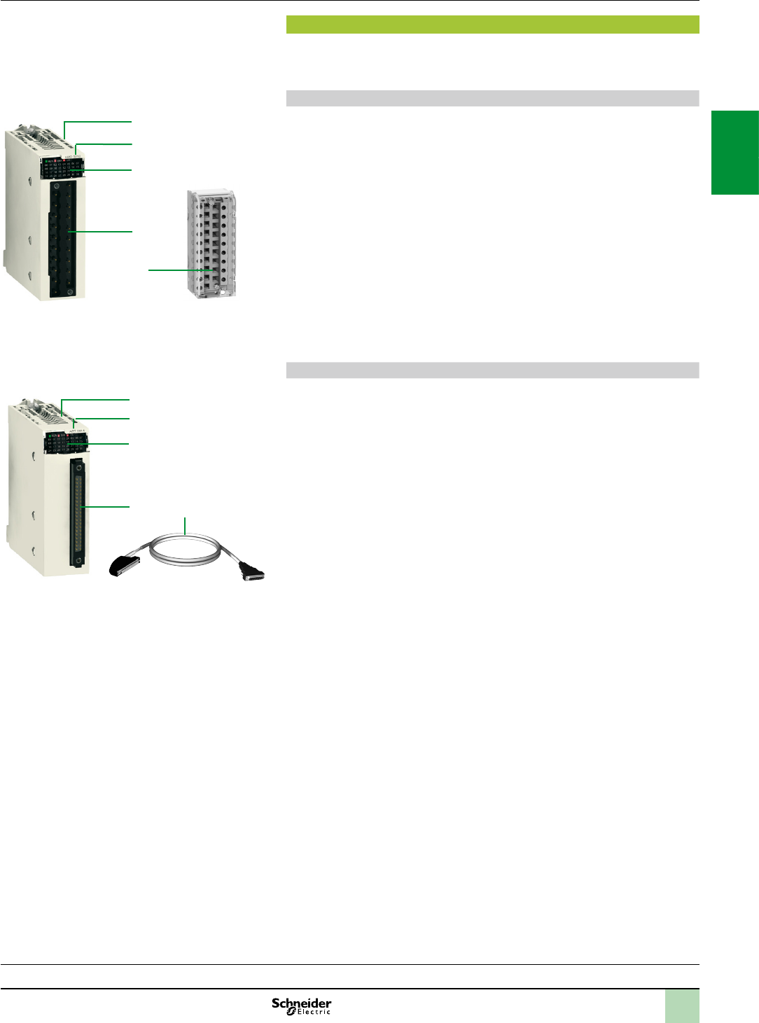
2/29
Description Modicon X80 I/O platform
Analog I/O modules
Processors:
page 1/4
Communication:
page 2/50
Software:
page 4/2
Ruggedized Modicon M340 modules:
page 6/2
Description
BMXAMp/ART analog I/O modules are standard format (1 slot). They have a case,
which ensures IP 20 protection of the electronics, and are locked into position by a
captive screw.
I/O modules connected via 20 or 28-way removable terminal block
BMXAMp analog I/O modules feature the following:
1 A rigid body providing support and protection for the electronic card
2 A module reference marking (a label is also visible on the right-hand side of the
module)
3 A module and channel status display block
4 A connector taking the 20 or 28-way removable screw or spring-type terminal
block for directly connecting the sensors or preactuators to the module.
To be ordered separately:
5 A BMXFTB20p0 or BMXFTB28p0 20 or 28-way removable terminal block
(referencing label supplied with each I/O module) or pre-wired cables with:
- A 20-way terminal block at one end and ying leads at the other
(BMXFTWp01S)
- A 28-way terminal block at one end and ying leads at the other
(BMXFTWp08S)
- A 20 or 28-way terminal block and a 25-way SUB-D connector (BMXFCApp0
or BMXFTApp0), for connection to Modicon Telefast ABE7 sub-bases (see
page 2/33).
I/O modules connected via 40-way connector
BMXART analog input modules have the following on the front panel:
1 A rigid body providing support and protection for the electronic card
2 A module reference marking (a label is also visible on the right-hand side of the
module)
3 A module and channel status display block
4 One (or two) 40-way connector(s) for connecting the sensors
To be ordered separately:
5 Pre-wired cables with:
- A 40-way connector at one end and ying leads at the other BMXFCWp01S
- A 40-way connector and a 25-way SUB-D connector (BMXFCApp2) for direct
connection to the Modicon Telefast ABE7 sub-bases (see page 2/33)
Must be ordered separately:
A shielding connection kit to protect against electrostatic discharge, consisting of
a metal bar and two sub-bases for mounting on the rack supporting the analog
modules
A set of STBXSP3020 clamping rings for the shielding braids of analog signal
cables
1
3
4
2
5
Moduleforconnectionvia20or28-way
removableterminalblock
1
3
4
2
5
Moduleforconnectionfor40-wayconnector
2
1
3
4
5
6
7
8
9
10
2
1
3
4
5
6
7
8
9
10
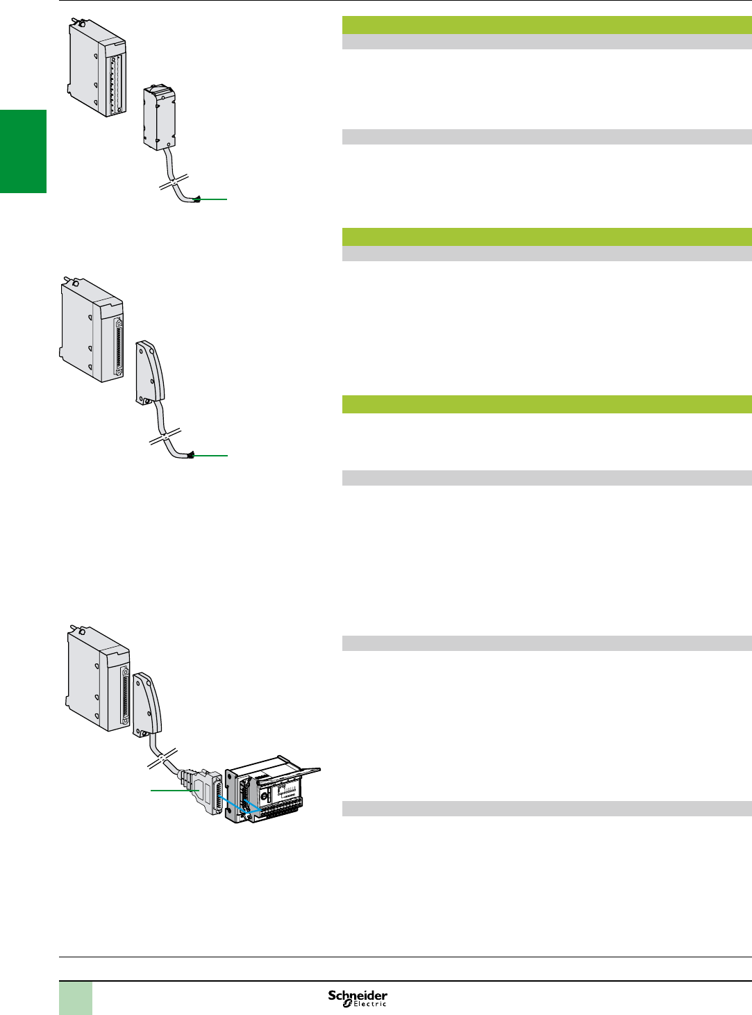
2/30
Connections,
combinations Modicon X80 I/O platform
Analog I/O modules
Processors:
page 1/4
Communication:
page 2/50
Software:
page 4/2
Ruggedized Modicon M340 modules:
page 6/2
Connecting modules with removable terminal blocks
BMXAMI0410, BMXAMO and BMXAMM modules with 20-way terminal block
The 20-way removable terminal blocks (BMXFTB200) are the same as those used
for discrete I/O modules (screw clamp, cage clamp or spring-type) (see page 2/19).
One version of the removable terminal block is equipped with a 3 or 5 m cordset with
colour-coded ying leads (BMXFTW01S). These preassembled cordsets with
reinforced shielding have colour-coded ying leads at the other end
1
.
BMXAMI0800/0810 modules with 28-way terminal block
The 28-way removable terminal blocks are cage clamp-type (BMXFTB2800) or
spring-type (BMXFTB2820).
One version of the removable terminal block is equipped with a 3 or 5 m cordset with
colour-coded ying leads (BMXFTW08S). These preassembled cordsets with
reinforced shielding have colour-coded ying leads at the other end
1
.
Connecting modules with 40-way connectors
BMXART014 modules with 40-way connectors
Two types of cordset are available:
Preassembled cordsets with reinforced shielding (BMXFCW01S) which
have colour-coded ying leads at the other end
2
. Available in 3 or 5 m lengths, they
enable easy direct wire-to-wire connection of the analog sensors via terminal blocks.
Preassembled cordsets with reinforced shielding (BMXFCA02) which have a
25-way SUB-D connector at the other end
3
. Available in 1.5, 3 or 5 m lengths, they
enable direct connection to the Modicon Telefast ABE7CPA412 sub-base (see
below).
Use with Modicon Telefast ABE7 sub-bases
Using the Modicon Telefast ABE7 pre-wired system makes it easier to install
the modules since the inputs (or outputs) can be accessed via screw
terminals. 7 special sub-bases are available:
Modicon Telefast ABE7CPA410 sub-base
The Modicon Telefast ABE7CPA410 sub-base is mainly used in conjunction with
the BMXAMI0410 voltage/current analog 4-input module. This sub-base allows you
to:
Directly connect 4 sensors
Remotely locate the input terminals in voltage mode
Power the 4 to 20 mA conditioning units one channel at a time with a 24 V voltage,
protected and limited to 25 mA, while maintaining isolation between channels
Protect the current impedance matching resistors integrated in the sub-base
against overvoltages
Connection is via the BMXFCA0 cordset (1.5, 3 or 5 m long).
Modicon Telefast ABE7CPA412 sub-base
The Modicon Telefast ABE7CPA412 sub-base is specially designed as a wiring
interface for the BMXART0414 and BMXART0814 thermocouple modules. This
sub-base allows you to:
Connect 4 thermocouple probes
Provide external cold junction compensation with a temperature probe integrated
in the sub-base
Ensure continuity of the shielding
The BMXART0814 module requires two Modicon Telefast ABE7CPA412
sub-bases. The connection with each sub-base is made via a BMXFCA2 cordset
(1.5, 3 or 5 m long).
Modicon Telefast ABE7CPA21 sub-base
The Modicon Telefast ABE7CPA21 sub-base is compatible with the
BMXAMO0210 output module. This sub-base allows you to:
Directly connect 2 current/voltage outputs
Ensure continuity of the shielding
Connection is via the BMXFCA0
3
cordset (1.5, 3 or 5 m long).
1
3
2
BMXFCW01Scordset
(with40-wayconnectoratoneendandyingleadsatthe
other)
BMXFTWp01Scordset
(with20-wayremovableterminalblockatoneendandying
leadsattheother)
BMXART0414
4-channelmodule
ABE7CPA412sub-base
BMXFCA2cordset
2
1
3
4
5
6
7
8
9
10
2
1
3
4
5
6
7
8
9
10

2/31
Use with Modicon Telefast ABE7 sub-bases (continued)
Modicon Telefast ABE7CPA02 sub-base
The Modicon Telefast ABE7CPA02 sub-base can be used in combination with:
The BMXAMI0800/0810 analog current input modules with 8 inputs
The BMXAMO0802 analog current output modules with 8 outputs
This sub-base allows you to:
Connect the 8 analog inputs or outputs point-to-point
Ensure continuity of the shielding
The BMXAMI0800/0810 modules are connected by means of the 1.5 or 3 m long
BMXFTApp0 cables.
The BMXAMO0802 module is connected by means of the 1.5, 3 or 5 m long
BMXFTApp2 cables.
Modicon Telefast ABE7CPA03 sub-base
The Modicon Telefast ABE7CPA03 sub-base can be used in combination with the
BMXAMI0800 voltage/current analog 8-input module.
This sub-base allows you to:
Directly connect 8 analog inputs
Power the current inputs one channel at a time with a voltage of 24 V that is
protected and limited to 25 mA
Ensure continuity of the shielding
The BMXAMI0800 module is connected by means of the 1.5 or 3 m long
BMXFTApp0 cables.
Modicon Telefast ABE7CPA31/31E sub-bases
The Modicon Telefast ABE7CPA31/31E sub-bases can be used in combination with
the BMXAMI0800/0810 voltage/current analog 8-input modules.
This sub-base allows you to:
Directly connect 8 analog inputs
Power the current inputs one channel at a time with 24 V converters
Ensure continuity of the shielding
The BMXAMI0800/0810 modules are connected by means of the 1.5 or 3 m long
BMXFTApp0 cables.
Complementary characteristics
BMXART0414/0814 analog input modules
The BMXART0414/0814 modules are multirange input modules with 4 or 8 low-level
isolated inputs (15 bits + sign) respectively.
Depending on the choice made during conguration, the modules offer, for each of
the inputs, the following ranges:
Temperature probe: Pt100, JPt100, Pt1000, JPt1000, Cu10, Ni100 or Ni1000 (in
accordance with DIN43760), with open-circuit detection
Thermocouple: B, E, J, K, L, N, R, S, T or U with broken wire detection
Resistor: 0…400 or 0…4000 Ω, 2, 3 or 4-wire
Voltage: ± 40 mV, ± 80 mV, ± 160 mV, ± 320 mV, ± 640 mV, ± 1.28 V
BMXAMI0410 analog input modules
The BMXAMI0410 module is a high-level analog input module with 4 isolated inputs
(16 bits).
Used with sensors or transmitters, it performs monitoring, measurement and
process control functions for continuous processes.
The module offers the following ranges for each of the inputs depending on the
choice made during conguration:
Voltage ± 10 V, ± 5 V, 0…10 V, 0…5 V and 1…5 V
Current 0…20 mA, 4…20 mA and ± 20 mA, depending on the choice made during
conguration
BMXAMI0800/0810 analog input modules
The BMXAMI0800/0810 analog input modules are
modules with 8 high-level isolated/non-isolated analog inputs (15 bits + sign).
The modules offer the following ranges for each of the inputs depending on the
choice made during conguration:
Voltage: ± 10 V, 0…10 V, 0…5 V, 1…5 V, ± 5 V
Current: 0…20 mA and 4…20 mA
Combinations(continued),
characteristics Modicon X80 I/O platform
Analog I/O modules
2
1
3
4
5
6
7
8
9
10
2
1
3
4
5
6
7
8
9
10
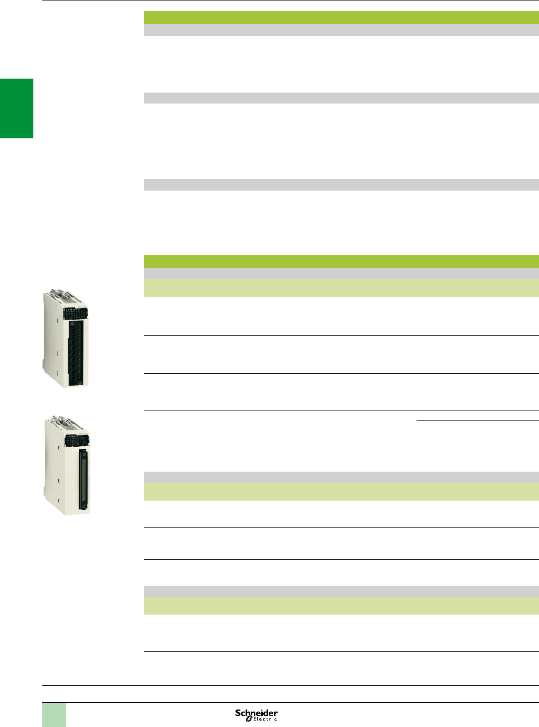
2/32
Characteristics(continued),
references Modicon X80 I/O platform
Analog I/O modules
Input modules, output modules and mixed module
Processors:
page 1/4
Communication:
page 2/50
Software:
page 4/2
Ruggedized Modicon M340 modules:
page 6/2
Complementary characteristics (continued)
BMXAMO0210 analog output module
The BMXAMO0210 module is a module with 2 high-level isolated outputs (15 bits + sign).
The BMXAMO0210 module offers the following ranges for each of the inputs depending on the choice made
during conguration:
Voltage: ± 10 V
Current: 0…20 mA and 4…20 mA
BMXAMO0410/0802 analog output modules
The BMXAMO0410/0802 analog output modules are modules with 4 or 8 high-level isolated/non-isolated analog
outputs (16 bits/15 bits + sign).
The BMXAMO0410 module offers the following ranges for each of the outputs depending on the choice made
during conguration:
Voltage: ± 10 V
Current: 0…20 mA and 4…20 mA
The BMXAMO0802 module offers the current ranges 0…20 mA and 4…20 mA.
BMXAMM0600 analog mixed I/O module
The BMXAMM0600 mixed module is a non-isolated I/O module with 4 inputs (14/12) bits and 2 outputs (12 bits).
The module offers the following ranges for each of the inputs or outputs depending on the choice made during
conguration:
Voltage: ± 10 V, 0…10 V, 0…5 V and 1…5 V
Current: 0…20 mA and 4…20 mA
References
Analog input modules (1)
Type of input Input signal range Resolution Connection No. of
channels
Reference Weight
kg
Isolated high-level
inputs
± 10 V, 0…10 V,
0…5 V, 1…5 V,
± 5 V, 0…20 mA,
4…20 mA, ± 20 mA
16 bits Removable terminal block,
20-way
cage clamp, screw clamp
or spring-type
4 channels
BMXAMI0410
0.143
High-level inputs
non-isolated
± 10 V, 0…10 V,
0…5 V, 1…5 V,
± 5 V, 0…20 mA
15 bits
+ sign
Removable terminal block,
28-way, cage clamp or
spring-type
8 channels
BMXAMI0800
0.175
Isolated high-level
inputs
± 10 V, 0…10 V,
0…5 V, 1…5 V,
± 5 V, 0…20 mA,
15 bits +
sign
Removable terminal block,
28 way, cage clamp or
spring-type
8 channels
BMXAMI0810
0.175
Isolated low-level
inputs
Temperature probe,
thermocouple,
± 40 mV, ± 80 mV,
± 160 mV, ± 320 mV,
± 640 mV, ± 1.28 V
15 bits
+ sign
40-way connector 4 channels
BMXART0414
0.135
8 channels
BMXART0814
0.165
Analog output modules (1)
Type of outputs Output signal
range
Resolution Connection No. of
channels
Reference Weight
kg
Isolated high-level
outputs
± 10 V,
0…20 mA,
4…20 mA
16 bits Removable terminal block,
20-way, cage clamp,
screw clamp or spring-type
2 channels
BMXAMO0210
0.144
High-level outputs
isolated
± 10 V,
0…20 mA,
4…20 mA, ± 20 mA
15 bits
+ sign
Removable terminal block,
20-way, cage clamp,
screw clamp or spring-type
4 channels
BMXAMO0410
0.175
High-level outputs
non-isolated
0…20 mA,
4…20 mA
15 bits
+ sign
Removable terminal block,
20-way, cage clamp,
screw clamp or spring-type
8 channels
BMXAMO0802
0.175
Analog mixed I/O module(1)
Type of I/O Signal range Resolution Connection No. of
channels
Reference Weight
kg
Mixed I/O, non-isolated ± 10 V, 0…10 V,
0…5 V, 1…5 V,
0…20 mA,
4…20 mA
14 bits or
12 bits
depending
on the range
Removable terminal block,
20-way, cage clamp,
screw clamp or spring-type
Inputs:
4 channels
Outputs:
2 channels
BMXAMM0600
0.155
(1)Typicalconsumption:Seethepowerconsumptiontableonpage7/22.
BMXART0414
BMXAM00
2
1
3
4
5
6
7
8
9
10
2
1
3
4
5
6
7
8
9
10
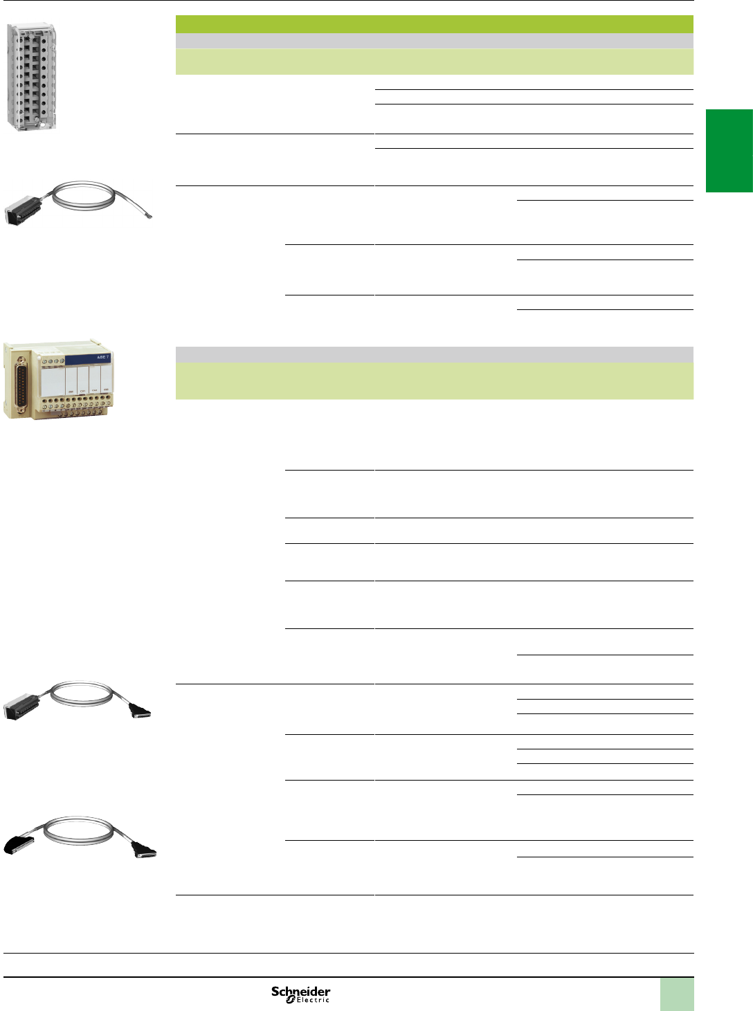
2/33
References(continued) Modicon X80 I/O platform
Analog I/O modules
Accessories
Processors:
page 1/4
Communication:
page 2/50
Software:
page 4/2
Ruggedized Modicon M340 modules:
page 6/2
References (continued)
Connection accessories for analog modules (1)
Description For use with
modules
Type, composition Length Reference Weight
kg
20-way removable
terminal blocks
BMXAMI0410
BMXAMO0210
BMXAMO0410
BMXAMO0802
BMXAMM0600
Cage clamp –
BMXFTB2000
0.093
Screw clamp –
BMXFTB2010
0.075
Spring –
BMXFTB2020
0.060
28-way removable
terminal block
BMXAMI0800
BMXAMI0810
Cage clamp –
BMXFTB2800
0.111
Spring –
BMXFTB2820
0.080
Preassembled
cordsets
BMXAMI0410
BMXAMO0210
BMXAMO0410
BMXAMO0802
BMXAMM0600
One 20-way terminal block
(BMXFTB2020) and one end
with colour-coded ying leads
3 m
BMXFTW301S
0.470
5 m
BMXFTW501S
0.700
BMXAMI0800
BMXAMI0810
1 removable terminal block,
28-way, MX FTB 2820, and
one end with colour-coded ying
leads
3 m
BMXFTW308S
0.435
5 m
BMXFTW508S
0.750
BMXART0414
BMXART0814
One 40-way connector and one
end with colour-coded ying
leads
3 m
BMXFCW301S
0.480
5 m
BMXFCW501S
0.710
Modicon Telefast ABE7 pre-wired system
Description For use with
modules
Type, composition Length or
connection
technology
Reference Weight
kg
Modicon Telefast
ABE7 sub-bases
BMXAMI0410 Distribution of isolated power
supplies
Delivers 4 protected isolated
power supplies for 4…20 mA
inputs.
Direct connection of 4 inputs
Screws
ABE7CPA410
0.180
BMXART0414
BMXART0814 (2)
Connection and provision of
cold-junction compensation for
thermocouples
Direct connection of 4 inputs
Screws
ABE7CPA412
0.180
BMXAMO0210
BMXAMO0410
Direct connection of 2/4 outputs Screws
ABE7CPA21
0.210
BMXAMI0800
BMXAMI0810
BMXAMO0802
Point-to-point connection of 8 I/O Screws
ABE7CPA02
0.317
BMXAMI0800 Direct connection of 8 inputs
Delivers 8x 24 V power
supplies limited to 25 mA to the 8
current inputs
Screws
ABE7CPA03
0.307
BMXAMI0800
BMXAMI0810
Direct connection of 8 inputs
Delivers 8x 24 V power
supplies isolated and limited to
25 mA to the 8 current inputs
Screws
ABE7CPA31
0.498
Spring
ABE7CPA31E
0.508
Preassembled
cordsets for
Modicon Telefast
ABE7 sub-bases
BMXAMI0410
BMXAMO0210
BMXAMO0410
One 20-way removable terminal
block and one 25-way SUB-D
connector for ABE7CPA410/
CPA21 sub-base
1.5 m
BMXFCA150
0.320
3 m
BMXFCA300
0.500
5 m
BMXFCA500
0.730
BMXART0414
BMXART0814 (2)
One 40-way connector and one
25-way SUB-D connector for
ABE7CPA412 sub-base
1.5 m
BMXFCA152
0.330
3 m
BMXFCA302
0.510
5 m
BMXFCA502
0.740
BMXAMI0800
BMXAMI0810
One 28-way removable terminal
block and one 25-way SUB-D
connector for sub-bases
ABE7CPA02/03/31/31E
1.5 m
BMXFTA150
0.374
3 m
BMXFTA300
0.500
BMXAMO0802 One 20-way removable terminal
block and one 25-way SUB-D
connector for ABE7CPA02
sub-bases
1.5 m
BMXFTA152
0.374
3 m
BMXFTA302
0.500
(1)TheshieldingonthecordsetscarryingtheanalogsignalsmustalwaysbeconnectedtotheBMXXSPpp00shielding
connectionkitmountedundertherackholdingtheanalogmodules(seepage2/7).
(2)TheBMXART08148-channelmodulerequirestwoABE7CPA412sub-basesandtwoBMXFCApp2cordsets.
BMXFTB200
BMXFTW01S
BMXFCA0
BMXFCA2
ABE7CPA41/21
2
1
3
4
5
6
7
8
9
10
2
1
3
4
5
6
7
8
9
10
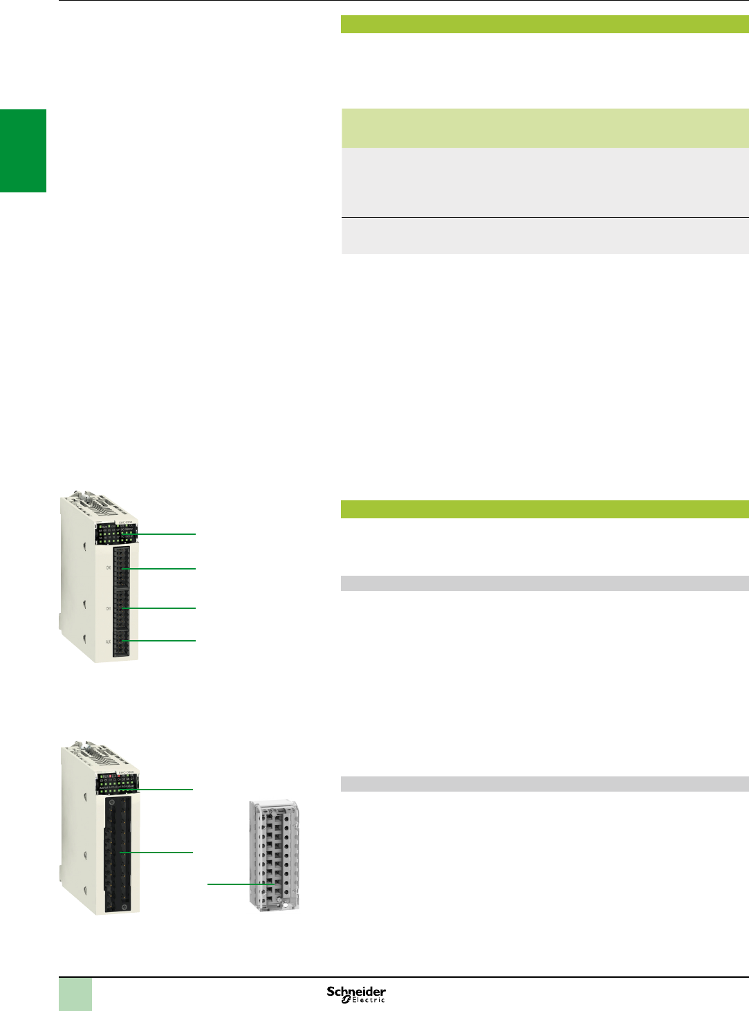
2/34
Presentation,
description Modicon X80 I/O platform
BMXEHC0200/0800 counter modules
Presentation
BMXEHC0200 and BMXEHC0800 counter modules for the Modicon X80 I/O platform
are used to count the pulses generated by a sensor or to process the signals from an
incremental encoder.
The two modules differ in their number of counter channels, maximum input frequencies,
functions and auxiliary input and output interfaces:
Counter
Module
No. of
channels
Maximum
frequency
Integrated
functions
No. of
physical
inputs
No. of
physical
outputs
BMXEHC0200 2 60 KHz Upcounting
Downcounting
Period meter
Frequency meter
Frequency generator
Axis control
6 2
BMXEHC0800 8 10 KHz Upcounting
Downcounting
Measurement
2 –
The sensors used on each channel can be:
2-wire 24 V proximity sensors
3-wire 24 V proximity sensors
10/30 V output signal incremental encoders with push-pull outputs
BMXEHC0200/0800 counter modules can be used to meet the demands of
applications such as:
Alarm generation on empty unwinder status using the ratio
Sorting small parts using the period meter
Single electronic cam using the dynamic setting thresholds
Speed control using the period meter
These standard format modules can be installed in any available slot of a Modicon
X80 I/O PLC. They are hot-swappable.
In a Modicon X80 I/O PLC conguration, the number of BMXEHC0200/0800 counter
modules should be added to the number of application-specic modules
(communication).
The function parameters are set by conguration using the Unity Pro software.
Description
BMXEHC0200/0800 counter modules are standard format. They occupy a single
slot in BMXXBP racks. They come in a plastic case, which ensures IP 20
protection of the electronics, and are locked into position by a captive screw.
BMXEHC0200 module, 2 channels, 60 KHz
The front panel of the BMXEHC0200 counter module features:
1 Module and channel status display block
2 16-way connector for connecting the sensors of counter 0
3 16-way connector for connecting the sensors of counter 1
4 10-way connector for connecting:
- Auxiliary outputs
- Sensor power supplies
To be ordered separately:
A BMXXTSHSC20 kit containing two 16-pin connectors and one 10-pin
connector
A BMXXSP00 shielding connection kit if the rack is not already equipped with
one (see page 2/7).
BMXEHC0800 module, 8 channels, 10 KHz
The front panel of the BMXEHC0800 counter module features:
1 Module and channel status display block
2 Connector taking the 3 BMXFTB200 20-way removable terminal block (same
as that of I/O modules)
To be ordered separately:
A 20-way removable terminal block 3 (cage clamp, screw clamp or spring-type)
BMXFTB200
A BMXXSP00 shielding connection kit if the rack is not already equipped with
one (see page 2/7).
BMXEHC0200
2
1
3
4
BMXEHC0800
2
1
3
BMXFTB20p0
2
1
3
4
5
6
7
8
9
10
2
1
3
4
5
6
7
8
9
10

2/35
Functions Modicon X80 I/O platform
BMXEHC0200/0800 counter modules
Operating modes for module BMXEHC0200
8 congurable modes Frequency meter This mode measures a frequency, speed, data rate or an event stream.
As standard, this mode measures the frequency received on the IN A input.
This frequency is always expressed in Hz (number of pulses/second), with a precision of 1 Hz.
The maximum frequency on the IN A input is 60 kHz.
The maximum cyclic ratio at 60 kHz is 60%.
Event counting This mode is used to determine the number of events received.
In this mode, the counter calculates the number of pulses applied to the IN_A input at time
intervals dened by the user.
The module counts the pulses applied to the IN_A input each time the pulse for this input lasts
longer than 5 μs (without anti-bounce lter).
Period measurement This mode is used to:
Determine the duration of an event
Determine the time between 2 events
Time and measure the execution time of a process
It measures the time elapsed during an event or between 2 events (IN_A input) according to a
selectable time base of 1 μs, 100 μs or 1 ms.
The IN_SYNC input can be used to enable or stop a measurement.
The module can carry out a maximum of 1 measurement every 5 ms.
The shortest measurable pulse is 100 μs, even if the unit dened by the user is 1 μs.
The maximum measurable duration is 4,294,967,295 units (unit to be dened).
Ratio counting Ratio counting mode only uses the IN_A and IN_B inputs. There are 2 possible modes:
Ratio 1: Used to divide 2 frequencies. This is intended for applications such as owmeters,
mixers, etc.
Ratio 2: Used to subtract 2 frequencies. This is intended for the same applications, but for
those requiring more precise regulation (more similar frequencies).
Ratio 1 mode gives the results in thousandths for better accuracy (a display of 2000 corresponds
to a value of 2) and ratio 2 mode gives the results in Hz.
The maximum frequency that the module can measure on the IN_A and IN_B inputs is 60 kHz.
Downcounting This mode is used to list a group of operations. In this mode, activating the synchronization
function starts the counter which, starting from a user-dened preset value, decreases with
each pulse applied to the IN_A input, until it reaches 0. This downcounting is made possible
when the enable function has been activated. The counting register is thus updated at 1 ms
intervals.
One basic use of this mode is to signal, using an output, the end of a group of operations (when
the counter reaches 0).
The shortest pulse applied to the IN_SYNC input is 100 μs.
The maximum frequency applied to the IN_SYNC input is 1 pulse every 5 ms.
The maximum user-dened preset value is 4,294,967,295.
The maximum count value is 4,294,967,295 units.
Loop (modulo) counting This mode is used in packaging and labelling applications where actions are repeated on sets
of moving objects:
In upcounting, the counter increases until it reaches the user-dened “modulo - 1” value. On
the next pulse, the counter is reset to 0 and upcounting restarts.
In downcounting, the counter decreases until it reaches 0. On the next pulse, the counter is
reset to the user-dened “modulo - 1” value. Downcounting can then restart.
The maximum frequency applied to the IN_A and IN_B inputs is 60 kHz.
The maximum frequency of the modulo event is 1 event every 5 ms.
The maximum modulo value is 4,294,967,296 (possible by declaring 0 in the
modulo adjust value).
32-bit counter counting This mode is mainly used in axis following.
The maximum frequency applied simultaneously to the IN_A and IN_B inputs is 60 kHz.
The maximum frequency of the referencing event is 1 event every 5 ms.
The counter value is between - 2,147,483,648 and + 2,147,483,647.
Width modulation In this operating mode, the module uses an internal clock generator to supply a periodic signal
on the module's O0 output. Only the O0 output is affected by this mode, as the O1 output is
independent of it.
The maximum output frequency is 4 kHz.
As O0 is a source output, a load resistor is necessary for the O0 output signal to change to 0 at
the correct frequency.
The cyclic ratio adjustment range varies according to the frequency of the O0 output.
Processors:
page 1/4
Communication:
page 2/50
Software:
page 4/2
Ruggedized Modicon M340 modules:
page 6/2
2
1
3
4
5
6
7
8
9
10
2
1
3
4
5
6
7
8
9
10

2/36
Functions(continued) Modicon X80 I/O platform
BMXEHC0200/0800 counter modules
Operating modes for module BMXEHC0800
5 congurable 16-bit
modes
Frequency meter This mode measures a frequency, speed, rate or data stream control.
As standard, this mode measures the frequency received on the IN A input.
This frequency is always expressed in Hz (number of pulses per second), with a precision of
1 Hz.
The maximum frequency on the IN A input is 10 kHz.
The maximum cyclic ratio at 10 kHz is 60%.
Event counting This mode is used to determine the number of events received.
In this mode, the counter calculates the number of pulses applied to the IN_A input at time
intervals dened by the user.
As an option, it is possible to use the IN_AUX input during a period of time, provided that the
enable bit has been congured.
The module counts the pulses applied to the IN_A input each time the pulse for this input lasts
longer than 50 μs (without anti-bounce lter).
Pulses with less than 100 ms synchronization are lost.
Downcounting This mode is used to list a group of operations. In this mode, when counting is enabled
(software validation via the valid_sync command), a rising or falling edge on the IN_AUX input
causes a value, dened by the user, to be loaded in the counter. The latter decreases with each
pulse applied to the IN_A input until it reaches the value 0. Downcounting is made possible
when the force_enable command is high (software positioning).
The smallest pulse applied to the IN_AUX input varies according to the selected lter level.
The maximum frequency applied to the IN_AUX input is 1 pulse every 25 ms.
Loop (modulo) counting This mode is used in packaging and labelling applications where actions are repeated on sets
of moving objects.
The counter increases with each pulse applied to the IN_A input until it reaches the user-
dened “modulo - 1” value. On the next pulse in the upcounting direction, the counter is reset to
0 and upcounting restarts.
The maximum frequency applied to the IN_A input is 10 kHz.
The smallest pulse applied to the IN_AUX input varies according to the selected lter level.
The maximum frequency of the modulo event is 1 event every 25 ms.
The maximum modulo value is 65,536 units.
Up/down counter This mode is used for an accumulation, upcounting or downcounting operation on a single
input.
Each pulse applied to the IN_A input produces:
Upcounting of pulses if the IN_AUX input is high
Downcounting of pulses if the IN_AUX input is low
The counter values vary between the limits - 65,536 and + 65,535.
The maximum frequency applied to the IN_A input is 10 kHz.
Pulses applied to the IN_A input after a change of direction are only upcounted or downcounted
after a period corresponding to the delay for taking account of the state of the IN_AUX input due
to the programmable lter level on this input.
One 32-bit mode 32-bit counter counting 32-bit counter counting mode is available for channels 0, 2, 4 and 6 (channels 1, 3, 5 and 7 are
now inactive). It behaves in the same way as the up/down counting mode using up to 3 physical
inputs. It enables simultaneous upcounting and downcounting.
The counter values vary between the limits - 2,147,483,648 and + 2,147,483,647 (31 bits +
sign).
The maximum frequency applied to the IN_A and IN_B inputs is 10 kHz.
The smallest pulse applied to the IN_AUX input is dened according to the ltering applied to
this input.
The maximum frequency of loading the preset value is 1 every 25 ms.
Processors:
page 1/4
Communication:
page 2/50
Software:
page 4/2
Ruggedized Modicon M340 modules:
page 6/2
2
1
3
4
5
6
7
8
9
10
2
1
3
4
5
6
7
8
9
10
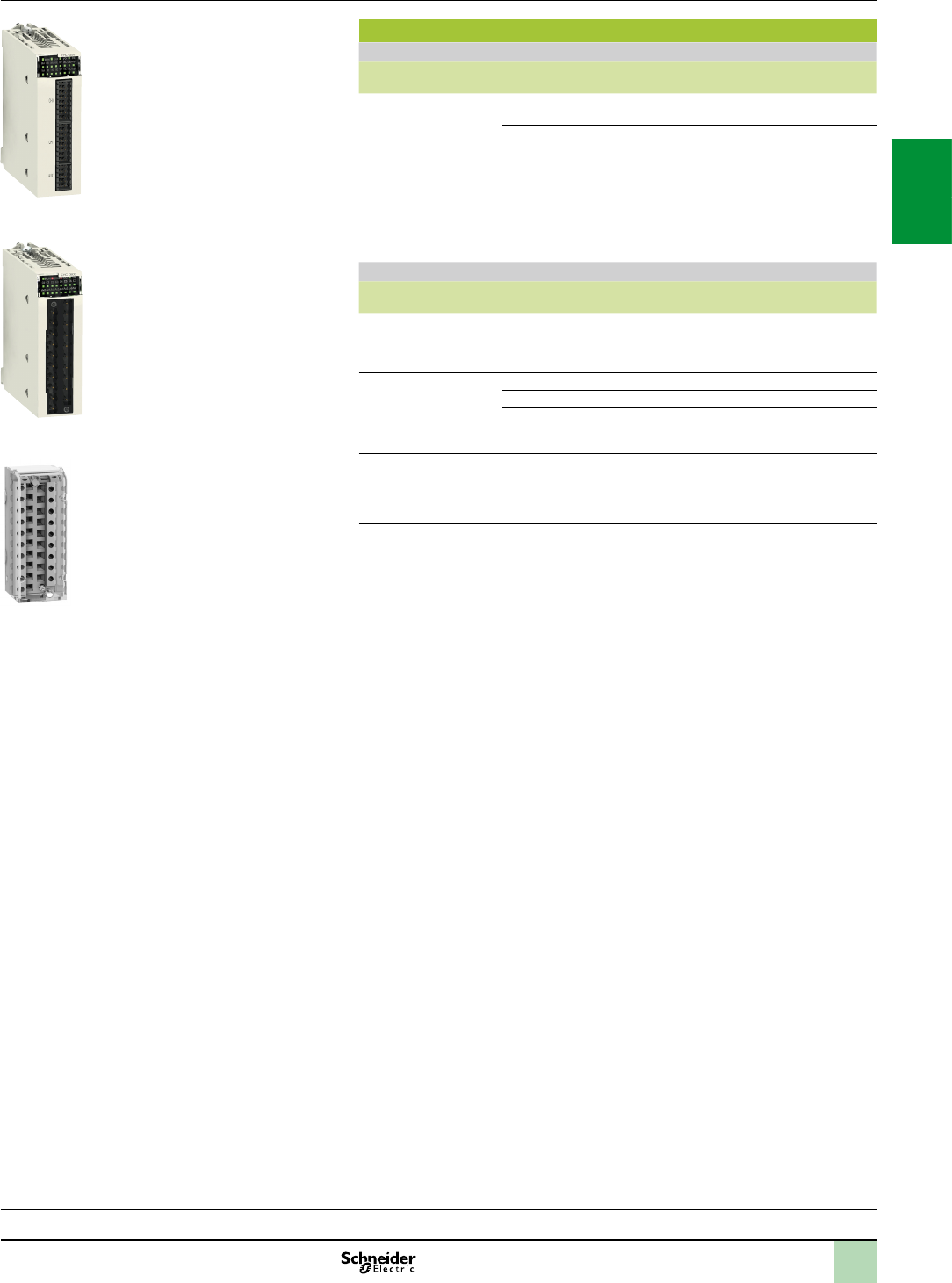
2/37
References Modicon X80 I/O platform
BMXEHC0200/0800 counter modules
References
BMXEHC0200/0800 counter modules(1)
Description No. of
channels
Characteristics
Reference
Weight
kg
Counter modules
for 24 V
2 and 3-wire sensors and
10/30 V incremental
encoders with push-pull
outputs
2 60 kHz counting BMXEHC0200 0.112
8 10 kHz counting
BMXEHC0800 0.113
Connection accessories (2)
Description Composition Unit reference Weight
kg
Pack of connectors
for BMXEHC0200 module
Two 16-way connectors and
one 10-way connector
BMXXTSHSC20 0.021
20-way removable
terminal blocks
for BMXEHC0800 module
Cage clamp BMXFTB2000 0.093
Screw clamp BMXFTB2010 0.075
Spring BMXFTB2020 0.060
Shielding connection kit
for BMXEHC0200/0800
modules
Comprising a metal bar and two
support bases for mounting on rack
See page 2/7 –
(1)Typicalconsumption:Seethepowerconsumptiontableonpage7/22.
(2)Theshieldingonthecordsetscarryingthecountersignalsmustalwaysbeconnectedtothe
BMXXSPpp00shieldingconnectionkitmountedundertherackwhichholdsthe
BMXEHC0200module(seepage2/7).
Processors:
page 1/4
Communication:
page 2/50
Software:
page 4/2
Ruggedized Modicon M340 modules:
page 6/2
BMXFTB20p0
BMXEHC0200
BMXEHC0800
2
1
3
4
5
6
7
8
9
10
2
1
3
4
5
6
7
8
9
10
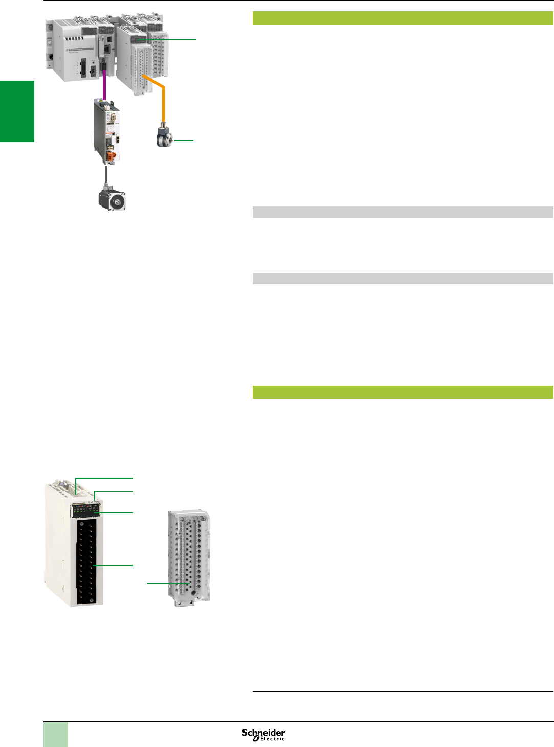
2/38
Presentation
The BMXEAE0300 SSI encoder interface module 1 for the Modicon automation
platform (1) is a 3-channel standard synchronous serial interface module designed
for use with SSI absolute encoders 2.
The BMXEAE0300 module enables SSI encoder values to be processed on PAC
platforms for applications requiring accurate and reliable position/angular control,
such as:
Hydro power, e.g. dam inlet gate position control
Wind power, e.g. wind turbine blade pitch control
Complex motion loop control, e.g. ship elevator, blast furnace, ame cutting, etc.
The BMXEAE0300 module provides a migration path from Premium (with
TSXCTY2C measurement and counter module) to the M340 SSI solution to
compete in the above market segments.
Like any other application-specic module, the BMXEAE0300 module is installed in
the rack slots (01 to 11). The number of modules is limited by the maxiumum number
of application-specic channels, permitted according to the CPU type (consult our
website www.schneider-electric.com).
Dam inlet gate control
Inlet gate control enables the water level in a dam to be monitored and controlled:
The SSI encoder provides the PLC with accurate feedback of the gate position
for precise monitoring of gate opening, adjustment and positioning.
The SSI interface converts the signals from the SSI encoders and transmits them
to the CPU.
Wind turbine blade pitch control
Pitch control is required for adjusting the angle of the wind turbine blades in relation
to the wind direction and strength, in order to achieve optimum energy conversion
efciency.
The SSI absolute encoder is frequently used to feedback the position of the blade
due to its reliability and robustness.
Typically, the position of each of the 3 blades are read by the SSI encoders and
then transmitted to the CPU via the SSI interface for motion loop control.
Sometimes, 3 additional SSI inputs act as backup. Therefore, this new offer is
adequately sized for the channel density.
Description
The BMXEAE0300 SSI encoder interface module is standard format (1 slot). Its
housing provides IP 20 protection of the electronics and it is locked in each slot (01
to 11) by a captive screw.
The front panel of the BMXEAE0300 module features:
1 A rigid housing providing support and protection for the electronic card
2 The module reference marking (a label is also visible on the right-hand side of the
module)
3 A display block indicating:
Module status, 4 LEDs:
- RUN (green): module’s operational status
- ERR (red): internal fault detected in the module or a fault detected between the
module and the rest of the conguration
- I/O (red): external fault detected
- DL (green): rmware download status
Status of the 3 SSI channels, 8 LEDs:
- Sx (green): channel x input (x = 0, 1 or 2)
- Qx (green): reex output for channel x (x = 0, 1 or 2)
- I0/1 (green): capture inputs for the 3 SSI channels
4 A connector for a 28-way terminal block, for connecting to a removable cage
clamp or spring terminal block on sensors and preactuators
To be ordered separately:
5 A 28-way removable cage clamp terminal block BMXFTB2800 or spring terminal
block BMXFTB2820, supplied with a channel identication label
A shielding connection kit to protect against electrostatic discharge, consisting of
a metal bar and two sub-bases for mounting on the rack: BMXXSP00 (reference
dependent on the number of slots in the rack) (see page2/7)
A set of clamping rings STBXSP300 for the connection cable shielding braids
(reference dependent on the cable diameter) (see page2/7)
(1)OnlyfortheModiconautomationplatformscompatiblewithModiconX80I/Oplatform
1
2
Presentation,
description Modicon X80 I/O platform
BMXEAE0300 SSI encoder interface module
BMXFTB28p0
5
BMXEAE0300
1
2
3
4
ModiconX80I/OplatformwithModiconM340processor
2
1
3
4
5
6
7
8
9
10
2
1
3
4
5
6
7
8
9
10
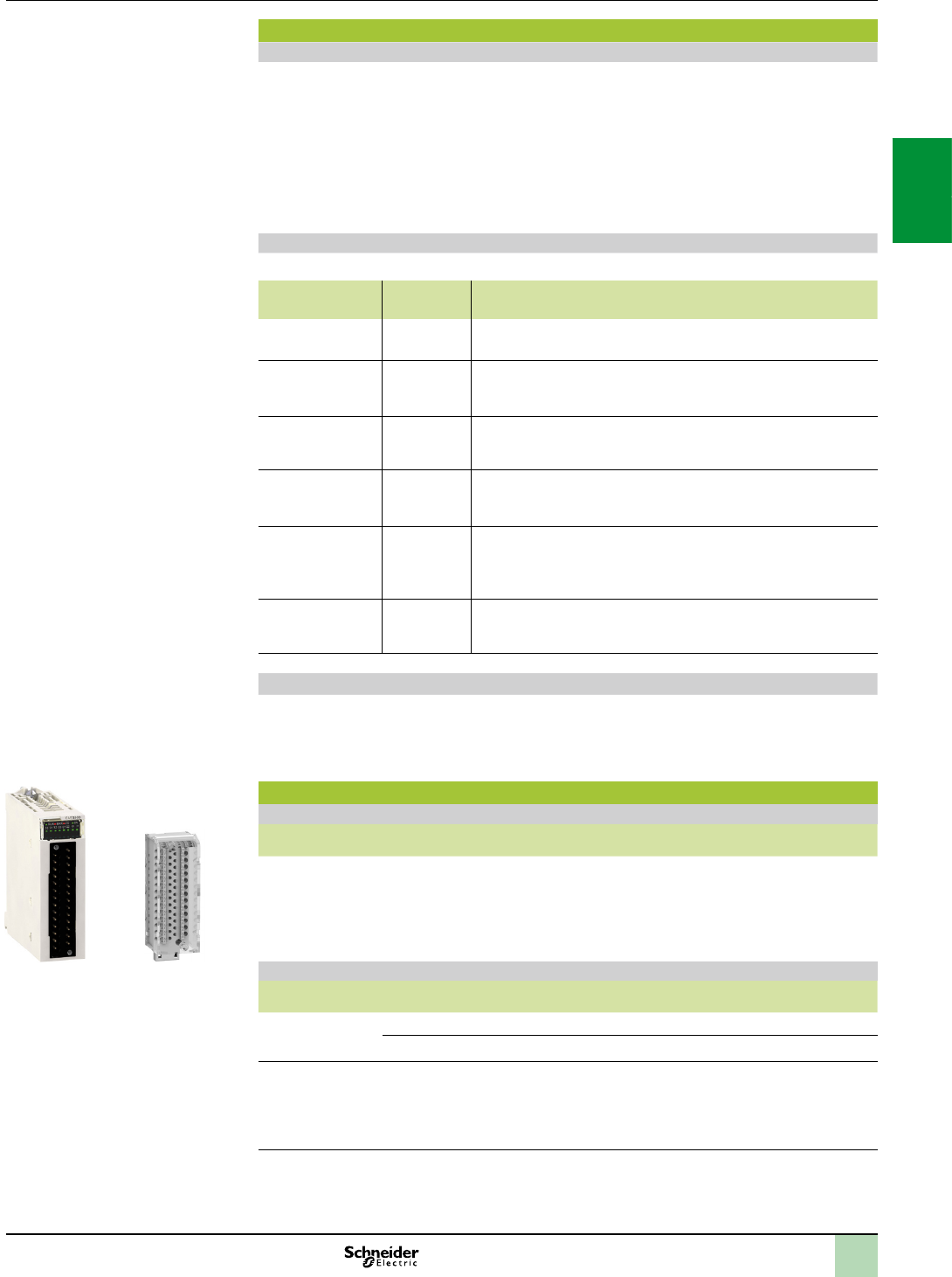
2/39
Module specications and functions
Sepecications
The SSI module BMXEAE0300 is a 3-channel, synchronous serial interface, absolute encoder
interface for Modicon PLCs.
It supports:
3 channels of SSI inputs (DATA pair, CLK pair, 24 VDC eld power supply to encoder)
1 reex output for each SSI channel (Q)
2 capture inputs for the 3 SSI channels (CAP_IN0, CAP_IN1)
8 to 31 bits data width
4 ranks of baud rates (100 kHz, 200 kHz, 500 kHz, 1 MHz)
capture and compare functions
Basic and optional functions
The following table presents the main functionalities of the BMXEAE0300 module:
Function Basic/
optional
Description
Absolute SSI encoder
value acquisition
Basic The position values of the SSI channel are automatically read by the
module within 1 ms, unless the channel is disabled.
Modulo Optional
for motion
The modulo function limits the dynamics of the position value within the
power of 2. An event (if enabled) detects the modulo passing. The reex
output can also be asserted at the passing of modulo (if congured).
Reduction Optional
for motion
This function reduces the intrinsic resolution of the encoder by a value
dened by the “reduction” parameter. This reduction is carried out by a shift
in the bit eld provided by the encoder.
Offset Optional
for motion
The correction function of the encoder offset systematically corrects the
offset produced by the encoder at mechanical position “0”. The user enters
the absolute encoder offset parameter.
Capture Optional
for events
The two capture input registers (per channel) enable the PLC program to
carry out a dynamic measurement function between two points. The
capture action can be triggered by two capture inputs. The event will be
triggered at each occurrence of capture.
Compare Optional
for events
Two independent comparators (per channel), with thresholds that can be
modied by adjustment (explicit exchange), are able to generate an event
or reex output when the threshold is crossed.
Main features
Supported by Unity Pro V6.0 (or higher).
Supports absolute encoder 24 V model with standard SSI interface, including Telemecanique
Sensors OsiSense SSI encoders. For further information, consult the website www.tesensors.com.
Standards and approvals: , UL, CSA, C-Tick, GOST, etc.
References
SSI encoder interface module (1)
Description Number
of channels
Description
per channel
Reference Weight
kg
SSI encoder
interface module
3 SSI
channels
1 reex output for each SSI channel
2 capture inputs for the 3 SSI channels
8 to 31 bits data width
4 ranks of baud rates:100 kHz, 200 kHz,
500 kHz, 1 MHz
Capture and compare functions
BMXEAE0300 0.138
Cabling accessories
Description Description, use Reference Weight
kg
28-way removable
terminal block
Cage clamp BMXFTB2800 0.111
Spring BMXFTB2820 0.080
Shielding
connection kit
for module
BMXEAE0300
(2)
Comprising a metal bar and two support bases
for mounting on rack
See page 2/7 –
(1)Typicalconsumption:Seethepowerconsumptiontableonpage7/22.
(2)Theshieldingonthecablescarryingthesupplytothemodule,eachSSIchannel,thecaptureinputsandthe
reexoutputs(ifanyofthemiswired)mustalwaysbeconnectedtotheBMXXSPpp00shieldingconnectionkit
mountedundertherackholdingtheBMXEAE0300module(seepage2/7).
Functions,
references Modicon X80 I/O platform
BMXEAE0300 SSI encoder interface module
BMXFTB28p0BMXEAE0300
2
1
3
4
5
6
7
8
9
10
2
1
3
4
5
6
7
8
9
10
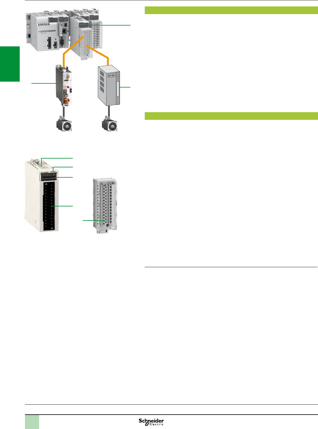
2/40
Presentation,
description Modicon X80 I/O platform
BMXMSP0200 motion control module
Presentation
The 1 BMXMSP0200 motion control pulsetrainoutput (PTO) module for the
Modicon X80 I/O platform is used for controlling third-party variable speed drives 2
which have an integrated position loop and inputs that are compatible with open
collector outputs.
The BMXMSP0200 control module is also directly compatible with the Lexium 32C
and 32M 3 servo drive ranges, which have an integrated pulse control interface.
The BMXMSP0200 motion control PTO module has two independent PTO channels.
Like any other application-specic module, it is installed in the rack slots (labelled 01
to 11). The number of modules is limited by the maximum number of application-
specic channels permitted according to the CPU type:
Standard BMXP341000: Maximum of 20 application-specic channels (1)
Performance BMXP34200: Maximum of 36 application-specic channels (1)
Description
The BMXMSP0200 motion control module is standard format (1 slot). Its housing
provides IP 20 protection of the electronics and it is locked in each slot (01 to 11) by a
captive screw.
The front panel of the BMXMSP0200 motion control module features:
4 A rigid body providing support and protection for the electronic card
5 A module reference marking (a label is also visible on the right-hand side of the
module)
6 A display block indicating:
Module status, 4 LEDs (RUN, ERR, I/O and DL)
Status of the auxiliary inputs, 4 per channel
Status of the PTO outputs, 2 per channel
Status of the auxiliary outputs, 2 per channel
7 A connector for a 28-way terminal block, for connecting to a removable spring
terminal block on sensors and preactuators
To be ordered separately:
8 A 28-way removable cage clamp terminal block BMXFTB2800 or spring terminal
block BMXFTB2820, supplied with a channel identication label
A shielding connection kit to protect against electrostatic discharge, consisting of
a metal bar and two sub-bases for mounting on the rack: BMXXSP00 (reference
dependent on the number of slots in the rack) (see page 2/7)
A set of clamping rings STBXSP300 for the connection cable shielding braids
(reference dependent on the cable diameter) (see page 2/7)
(1)Application-specicchannels:BMXEHC0200 (2-channel)andBMXEHC0800 (8-channel)
countermodules,BMXMSP0200(2-channel)motioncontrolmoduleandBMXNOM0200
(2-channel)andBMXNOR0200H (1-channel) serialcommunicationmodules.
Processors:
page 1/4
Communication:
page 2/50
Software:
page 4/2
Ruggedized Modicon M340 modules:
page 6/2
Servomotors
1
2
3
BMXMSP0200 BMXFTB280
4
5
6
7
8
2
1
3
4
5
6
7
8
9
10
2
1
3
4
5
6
7
8
9
10
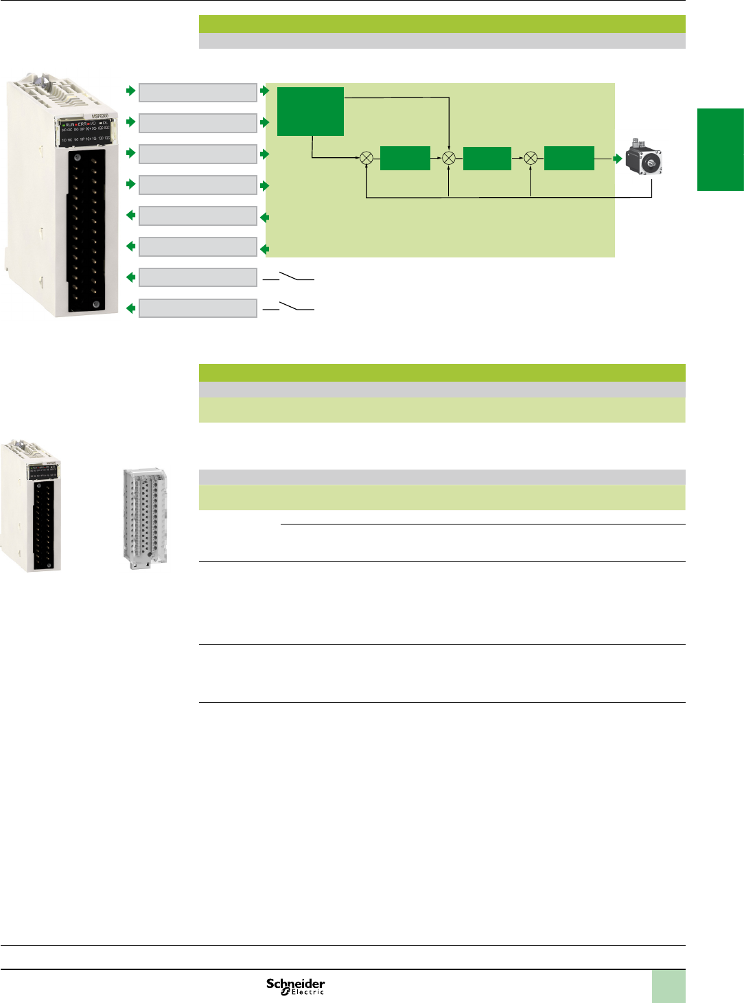
2/41
Operation,
references Modicon X80 I/O platform
BMXMSP0200 motion control module
Operation
Block diagram of a BMXMSP0200 module channel
Integrator
Pulses
PTO output CCW
24 V output D_Enable
24 V output C_Clear
C_Position
D_Ready
Origin
Proximity
Speed
Proximity sensor
Position switch
Homing
Position
loop
Velocity
loop
Torque
loop
Wait position
Servo ready
PTO output CWServo drive
Servo
motor
BMXMSP0200
Inputs/outputs per channel
References
Motion control modules (1)
Description Number of
channels
Description
per channel
Reference Weight
kg
PTO module
(PTO=Pulse
TrainOutput)
2 2 x 200 kHz max. PTO outputs
2 x 24 V /50 mA auxiliary outputs
4 x 24 V auxiliary inputs
BMXMSP0200 0.145
Cabling accessories
Description Description, use Length Reference Weight
kg
28-way
removable
terminal block
Cage clamp – BMXFTB2800 0.111
Spring – BMXFTB2820 0.080
Connection
cable for daisy
chain
or pulse
control(2)
From BMXMSP0200 (screw terminal block)
module to Lexium 32C or 32M (RJ45 connector)
(cablewithyingleadsatoneendandanRJ45
connectorattheother)
3 m VW3M8223R30 –
Shielding
connection kit
for module
BMXMSP0200
Comprising a metal bar and two support bases
for mounting on rack
– See page 2/7 –
(1)Typicalconsumption:Seethepowerconsumptiontableonpage7/22.
(2)Theshieldingonthecordsetscarryingthemotioncontrolsignalsmustalwaysbeconnectedtothe
BMXXSPpp00shieldingconnectionkitmountedundertherackholdingtheBMXMSP0200module(seepage2/7).
Processors:
page 1/4
Communication:
page 2/50
Software:
page 4/2
Ruggedized Modicon M340 modules:
page 6/2
BMXMSP0200 BMXFTB280
2
1
3
4
5
6
7
8
9
10
2
1
3
4
5
6
7
8
9
10
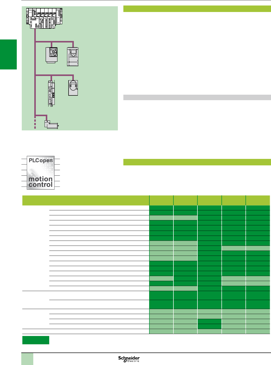
2/42
Presentation
MFB (MotionFunctionBlocks) is a library of function blocks integrated in Unity Pro
used to set up motion control in the architectures of drives and servo drives on
CANopen buses:
Altivar 312: For asynchronous motors from 0.18 to 15 kW
Altivar 71: For synchronous or asynchronous motors from 0.37 to 500 kW
Lexium 32: For servo motors from 0.15 to 7 kW
Lexium ILA/ILE/ILS: Integrated motor drives from 0.10 to 0.35 kW
Lexium SD328A: For 3-phase stepper motors from 0.35 to 0.75 kW.
In compliance with PLCopen specications, the MFB library allows both easy and
exible motion programming with Unity Pro, as well as axis diagnosis.
In maintenance operations, drives can be replaced quickly and safely thanks to drive
parameter download blocks.-
Setting up drives on the CANopen network is facilitated through MotionTree
Manager organization in the Unity Pro browser, making it easy for users to access
the application drives.
Applications
The features of the MotionFunctionBlocks library are particularly suitable for
machines with independent axes. In the case of these modular/special machines,
MFB function blocks are the perfect solution for controlling single axes. The following
are typical applications for this type of architecture:
Automatic storage/removal
Material handling
Palletizers/depalletizers
Conveyors
Packaging, simple label application
Grouping/ungrouping
Adjustment axes in exible machines, etc.
Functions
The table below lists the function blocks of the MFB library and the drives compatible
with them. The prex indicates the block family:
MC: Function block dened by the Motion Function Blocks PLC Open standard
TE: Function block specic to Schneider Electric products
Lxm: Function block specic to Lexium servo drives
Type Function Function block Altivar 312 Altivar 71 Lexium 32 Lexium ILA/
ILE/ILS
Lexium
SD328A
Management
and motion
Read an internal parameter MC_ReadParameter
Write an internal parameter MC_WriteParameter
Read the current position MC_ReadActualPosition
Read the instantaneous speed MC_ReadActualVelocity
Acknowledge error messages MC_Reset
Stop all active movement MC_Stop
Axis coming to standstill MC_Power
Movement to absolute position MC_MoveAbsolute
Relative movement MC_MoveRelative
Additional movement MC_MoveAdditive
Homing MC_Home
Movement at given speed MC_MoveVelocity
Read diagnostic data MC_ReadAxisError
Read servo drive status MC_ReadStatus
Torque control MC_TorqueControl
Read actual torque value MC_ReadActualTorque
Manual control MC_Jog
Save and
restore
parameters
(FDR)
Read all parameters and store
in PLC memory
TE_UploadDriveParam
Write all parameters
from PLC memory
TE_DownloadDriveParam
Advanced
Lexium
functions
Read a motion task Lxm_UploadMTask
Write a motion task Lxm_DownloadMTask
Start a motion task Lxm_StartMTask (1)
Set the reduction ratio, signed Lxm_GearPosS (1)
System Communication with the servo drive TE_CAN_Handler
Compatible (1)TheLxm_StartMTaskandLxm_GearPosSfunctionblocksareonlycompatiblewiththe
MtypeLexium32(LXM32M)servodrives.
MFB:MotioncontroldistributedoverCANopen
Altivar 312
Lexium 32
Lexium ILA/ILE/ILS
Altivar 71
CANopen
Modicon M340
Modicon X80 I/O
Presentation,
functions Modicon X80 I/O platform 0
MFB motion control
Lexium SD328A
2
1
3
4
5
6
7
8
9
10
2
1
3
4
5
6
7
8
9
10
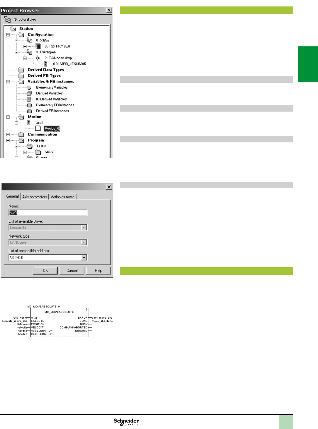
2/43
MotionTreeManagerintegratedintheUnityProbrowser
Generalparameters:Axisnameandaddress
MFB:Programmingamovementinabsolutemode
Setup
Motion Tree Manager
MotionTreeManager is associated with Unity Pro’s MFB library and integrated in its
browser. It provides specic assistance for:
Axis object management
Axis variable denition
Drive parameter management
Motion Tree Manager automatically creates links between the CANopen bus
conguration and the MFB function block data using a limited amount of
conguration data.
General axis parameters
In this tab, the designer is prompted to dene:
The name of the axis that will identify it in the browser for the entire application
The address of the drive on the CANopen bus
Axis parameters
The drop-down lists in this tab are used to determine the exact type of drive: Family,
version.
Variable names
This last tab is used to identify data structures:
Axis_Reference: Used by all the instances of function blocks for the axis in
question
CAN_Handler: Used to manage communication with the drive via the CANopen
network
Recipe denition
The “recipes” attached to the axis are the data structures containing all the
adjustment parameters of a given drive. This data is used when:
Changing the drive with restoration of the context during “FaultyDevice
Replacement” (FDR) maintenance
Changing the manufacturing program of the machine and calling up an
appropriate set of parameters: servo control gains, limitations, etc. adapted to the
weight and size of the moving parts
Saving parameters in the initial values of the PLC application
Programming, diagnostics and maintenance
Communication between the PLC and drive is automatically set up by the system as
soon as a TE_CAN_Handler instance is declared in the Unity Pro task with which the
axis is associated. Movements are then programmed by sequencing function blocks
from the library in the user's chosen Unity Pro editor (LD, ST, FBD).
The two function blocks, MC_ReadStatus, and in some cases MC_ReadAxisError,
are useful for determining the overall status of the axis, as well as the code of active
warnings or errors.
The function blocks TE_UploadDriveParam and TE_DownloadDriveParam allow the
application to save all the parameters of a drive (recipe) and to then quickly reload
them into another drive if the rst one fails.
Modicon X80 I/O platform 0
MFB motion control
2
1
3
4
5
6
7
8
9
10
2
1
3
4
5
6
7
8
9
10
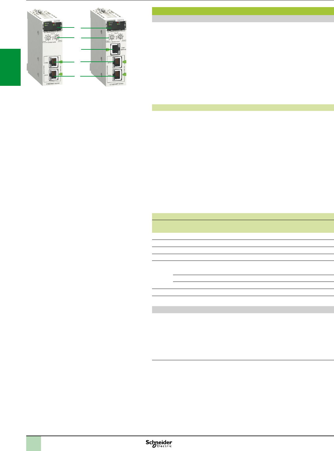
2/44
Modicon X80 CRA Ethernet drop adaptors (1)(2)
Presentation
A Quantum Ethernet I/O architecture with Modicon X80 RIO drops requires the use
of a dedicated CRA drop adaptor in each Modicon X80 drop:
“Standard” drop adaptor BMXCRA31200 (capacity, see below)
“Performance” drop adaptor BMXCRA31210 (capacity, see below)
These drop adaptors are connected by Ethernet cordsets tted with RJ45
connectors. The dual Ethernet network connection port on each drop adaptor allows
DaisyChainLoop connections using the RSTP protocol (RapidSpanningTree
Protocol).
Each module uses one slot in the Modicon X80 rack.
The BMXCRA31210 adaptor is also available in a conformal coating version for
harsh environments.
Capacity of Quantum Ethernet I/O architectures with Modicon X80 Ethernet RIO
1 Quantum CPU drop that can have one primary rack and one secondary rack (3),
equipped with a 140 CPU 6 advanced CPU
With 140 CPU 651standard CPUs and the 140 CPU 67160 HSBY CPU:
Up to 16 Modicon X80 RIO drops, limited to a maximum of 31 RIO drops
(Quantum + Modicon X80)
With the 140 CPU 65260 standard CPU and 140 CPU 6726 HSBY CPUs:
Up to 31 Modicon X80 RIO drops, limited to a maximum of 31 RIO drops
(Ethernet Quantum and Modicon X80)
Each Modicon X80 RIO drop can comprise one primary rack and one secondary
rack (3)
Distance:
100 m between stations (copper medium)
2 km between Modicon X80 drops, with BMXNRP0200 multimode optical bre
repeaters
16 km between Modicon X80 drops, with BMXNRP0201 multimode optical bre
repeaters
Capacity of Modicon X80 CRA drop adaptors
Type of module BMXCRA31200
“standard”
BMXCRA31210
“performance”
Primary racks per drop Up to 2 Up to 2
SERVICE port – 1
Discrete I/O modules Up to 128 Up to 1024
Analog I/O modules Up to 16 Up to 256
Expert modules supported:
serial link – BMXNOM0200
time and date stamping at 1 ms – BMXERT1604T
counting – BMXEHC0200/0800
CCOTF function – Yes
Time and date stamping – 10 ms
Description
1 Display block indicating the module status
2 Rotary switches for addressing Ethernet RIO drops (00…159)
3 On BMXCRA31210 module: dedicated RJ45 SERVICE port for remote service
tools such as a PC, an HMI terminal or Ethernet DIO devices (identical to the
SERVICE port on Quantum CRP/CRA modules, see page 2/8)
4 RJ45 DEVICE NETWORK port for connection to the Ethernet network
5 RJ45 DEVICE NETWORK port for connection to the Ethernet network
(1)Foradditionalcharacteristics,seeourwebsitewww.schneider-electric.com.
(2)RequiresUnityProExtraLargesoftwareu V7.0.
(3)RequirestwoBMXXBE1000rackexpansionmodules(oneintheprimaryrackandoneinthe
secondaryrack)andaBMXXBCKextensioncable(0.8,2or28m)forconnectingthesetwo
modules.SeeourQuantumcatalogueonourwebsitewww.schneider-electric.com.
Description Modicon X80 I/O platform
Modicon X80 CRA Ethernet drop adaptors
1
2
3
4
5
BMXCRA31210BMXCRA31200
2
1
3
4
5
6
7
8
9
10
2
1
3
4
5
6
7
8
9
10
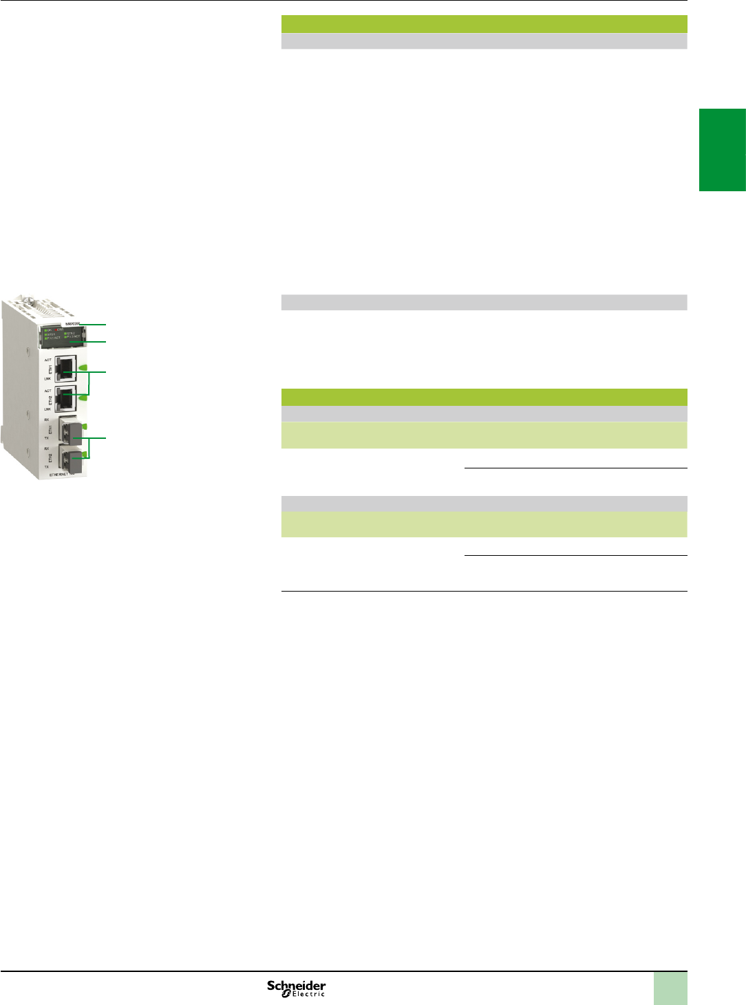
2/45
Presentation,
description,
references
Modicon X80 I/O platform
Modicon X80 NRP RIO drop optical repeaters,
Modicon X80 CRA Ethernet drop adaptors
Modicon X80 Ethernet RIO drop optical repeaters (1)(2)
Presentation
BMXNRP0200/0201 optical bre repeaters are an alternative to the use of
ConneXium managed dual ring switches (DRS), for optical bre communications
over long distances, in Ethernet I/O systems.
When inserted in Modicon X80 RIO drops, BMXNRP0200/0201 optical bre
repeaters make it possible to:
Extend the total distance of the Ethernet I/O network, when Ethernet RIO drops
are located in areas of the factory more than 100 m away
Enhance immunity to noise
Resolve earthing problems, between sites which have different earthing methods
NRP repeaters can be installed on the primary ring or on secondary rings. These
modules cannot however be used to connect secondary rings to the primary ring.
The BMXNRP0200 repeater for multimode optical bre allows remote location up
to 2 km.
The BMXNRP0201 repeater or single mode optical bre allows remote location up to
16 km.
Depending on the conguration, the NRP repeater must be linked to the CRA
adaptor of the drop where it is installed, via one or two Ethernet Interlink cables.
Description
1 Module reference
2 Display block indicating the module status
3 RJ45 Ethernet ports. Two LEDs LNK and ACT indicate the state of each port
4 Optical bre ports with SFP transceiver for LC type connector
References (1)
Modicon X80 Ethernet RIO drop optical repeaters (2)
Description Optical bre Reference Weight
kg
Modicon X80 Ethernet RIO drop
optical repeaters
multimode BMXNRP0200 –
single mode BMXNRP0201 –
Ethernet drop adaptors (2)
Description SERVICE port Reference Weight
kg
Modicon X80 Ethernet RIO drop
adaptor
Provide 1 module per Modicon X80
Ethernet RIO drop
–BMXCRA31200 –
1BMXCRA31210 (3) –
(1)Foradditionalcharacteristics,seeourwebsitewww.schneider-electric.com.
(2)RequiresUnityProExtraLargesoftwareV7.0,seeourwebsite
www.schneider-electric.com.
(3)Conformalcoatingversionforharshenvironments.Inthiscase,addtheletter“C”totheend
ofthereference.
1.0
BMXNRP020p
2
3
4
1
2
1
3
4
5
6
7
8
9
10
2
1
3
4
5
6
7
8
9
10
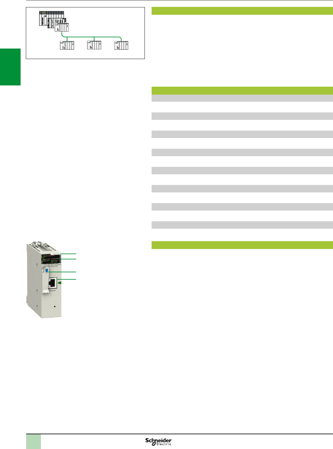
Presentation,
characteristics,
description
Modicon X80 I/O platform 0
Peripheral Remote I/O Adaptor
Presentation
The Peripheral Remote I/O Adaptor (PRA) is specically dedicated for Modicon X80
DIO drops in a Quantum/Premium/M340 I/O architecture using Ethernet Modbus
TCP.
The BMXPRA0100 module manages a remote X80 I/O rack on Ethernet Modbus
TCP which includes:
discrete I/O modules
analog I/O modules
It communicates by I/O scanning with the master PAC (Quantum/ Premium/M340).
In case of a redundant Ethernet link, the use of a BMXNOE0100 Ethernet module is
necessary.
Principal characteristics
Primary racks per drop
Up to 4
Discrete I/O modules
Up to 1024
Analog I/O modules
Up to 256
Intern memory
Up to 448 kBits
Memory card capacity
Up to 96 kBits
Average consumption
95 mA
Dissipated power
2.3 W
Savable real time clock
Yes
Description
1 Module reference
2 Display block indicating the module status
3 Protected memory card port
4 RJ45 Ethernet port
1
2
3
4
Quantum
Premium
M340
Ethernet Modbus TCP
Modicon X80 DIO drops with PRA modules
ModiconX80DIOdropsinaQuantum/Premium/M340I/O
architectureusingEthernetModbusTCP
2/46
2
1
3
4
5
6
7
8
9
10
2
1
3
4
5
6
7
8
9
10


2/48
Modicon X80 I/O platform 3
Time stamping system
Presentation
Presentation
The time stamping system is a complete solution providing a sequence of events
that are time-stamped at source, enabling the user to analyze the source of any
abnormal behaviour in an automated system.
The SOE (system of events) is displayed in the alarm log or in the list of events for a
client such as a SCADA.
Each event in the SOE is a change of value (transition) of a discrete I/O detected by
a time stamping module.
Advantages
Using the time stamping system has the following advantages:
No PLC programming
Direct communication between the time stamping modules and the client. If the
time stamping modules are in a Quantum Ethernet I/O drop, the bandwidth of the
PLC communication is not used
Consistency of the I/O values between the process (time stamping modules) and
the client
Consistency is maintained irrespective of the operating mode
Consistency is based on the following characteristics:
A buffer is available to store events in each time stamping module. Storage of
events is stopped when the buffer is full
Rising and falling edges are stored for each discrete I/O
Advanced diagnostics functions:
- Indication of an unknown SOE on the client
- Information on the time management associated with each time stamping event
No loss of events under normal operating conditions
Management of Hot Standby congurations on the PLC and/or SCADA
redundancy
Composition of a time stamping architecture
BMXCRA312p0 module
This time stamping module can be at the source of any discrete I/O signal located in
the drop with a resolution of 10 ms.
To ensure no event is lost, all events are stored and kept in a buffer located in the
product until OFS takes them.
The synchronization of the CRA module does not use the NTP protocol.
BMXERT1604T module
This module has 16 discrete inputs which carry out the time stamping at source
outputs with a resolution of 1 ms.
To ensure no event is lost, all events are stored and kept in a buffer located in the
product until OFS takes them.
This module can be placed either in an RIO drop, or in a local rack equipped with a
BMXCRA31210 module.
The CRA module is synchronized via the DCF 77 or IRIG-B standards.
OFS V3.40
OFS V3.40 is used to access events stored in the various buffers in the architecture
and to place them in the SCADA via the standard OPC DA protocol. For further
information, consult our website www.schneider-electric.com.
Vijeo Citect V7.30
Vijeo Citect V7.30 receives events transmitted by OFS and displays them in the SOE
or in the list of alarms.
BMXERT1604Tmodule
2
1
3
4
5
6
7
8
9
10
2
1
3
4
5
6
7
8
9
10

2/49
Software 3
OPC data server software
OPC Factory Server
Time stamping system
Performance,
references
Performance
Function Event source
module
Value
Duration of time stamping between
two identical source modules in the
same rack
BMXERT1604T 1.6 < duration of time
stamping < 3.3 ms
BMXCRA312010 ms
Duration of time stamping between
two different inputs in the same
source module
BMXERT1604T 1 ms
BMXCRA31201 scan
Maximum number of events scanned BMXERT1604T 400 events (1)
BMXCRA31202048 events (1)
Maximum number of I/O and memory
available
BMXERT1604T 16 discrete inputs on module
512 events in internal buffer
BMXCRA3120256 discrete I/O congured
4000 events in internal buffer
Maximum number of source modules
in an Ethernet remote I/O drop
BMXCRA31201 per drop
BMXERT 9 per drop
Maximum number of event sources
controlled
BMXERT 500 sources per second (1)
References
Description Input type Reference Weight
kg
Multifunction time stamping input
module
16 discrete inputs BMXERT1604T –
(1)Themaximumvaluedependsontheperformanceoftheoverallsystem.Itisnotanabsolute
valueandmustbeconsistent.
2
1
3
4
5
6
7
8
9
10
2
1
3
4
5
6
7
8
9
10
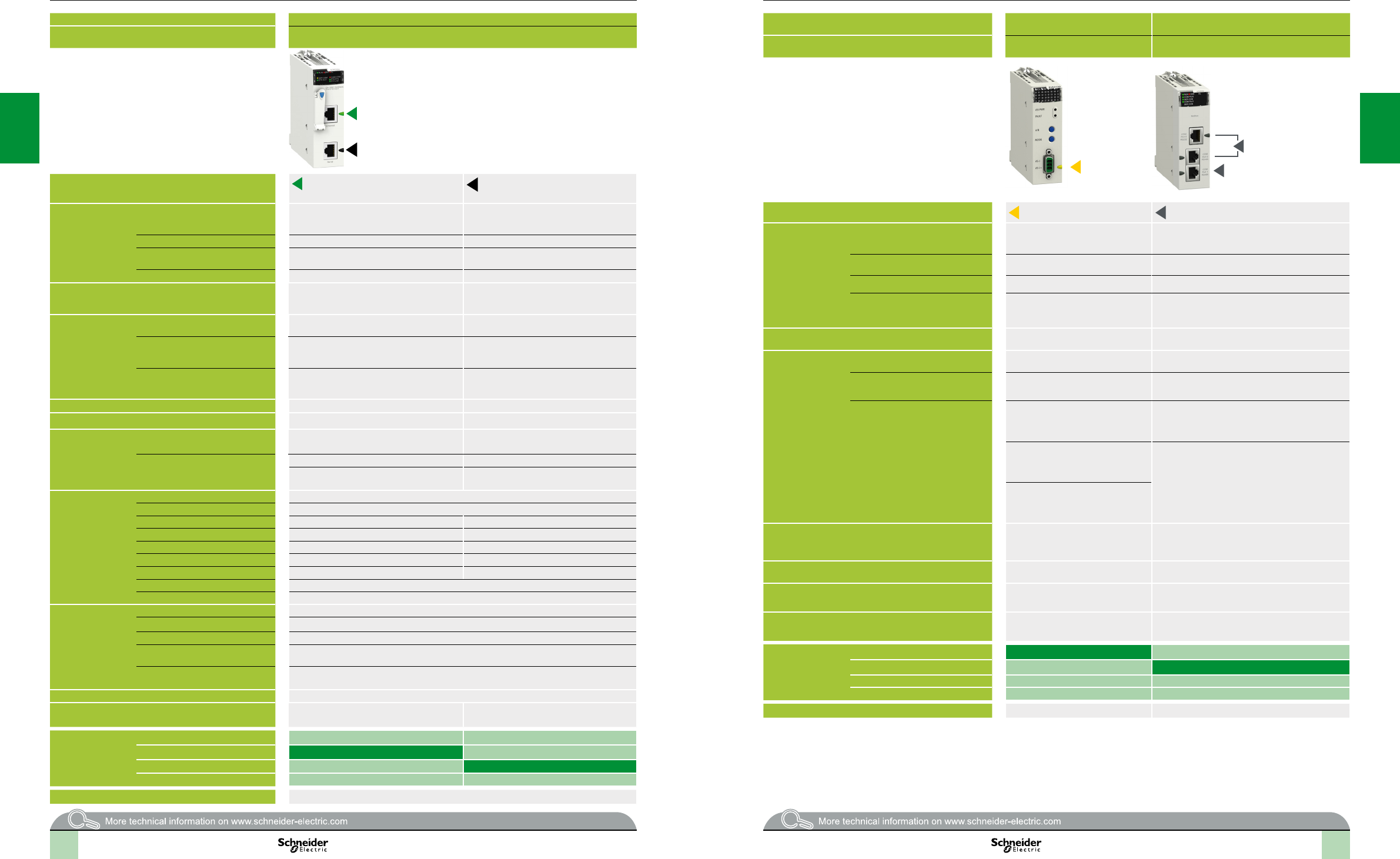
2
1
3
4
5
6
7
8
9
10
2
1
3
4
5
6
7
8
9
10
2
1
3
4
5
6
7
8
9
10
2
1
3
4
5
6
7
8
9
10
2/50 2/50
Selectionguide Modicon X80 I/O platform
Communication, integrated ports and modules
Applications RTU communication
Type of device RTU module
Network protocols Modbus/TCP, IEC 60870-5-104,
DNP3 (subset level 3)
Serial link, External modem link,
IEC 60870-5-101, DNP3 (subset level 3)
Structure Physical interface 10BASE-T/100BASE-TX (Modbus/TCP),
PPPoE (Point-to-Point Protocol over Ethernet)
for ADSL external modem link
Non-isolated RS 232/485 (Serial link),
Non-isolated RS 232 (Radio, PSTN, GSM,
GPRS/3G external modem link)
Type of connector One RJ45 connector One RJ45 connector
Access method CSMA-CD (Modbus/TCP),
Master/slave (IEC 104/DNP3)
Master/slave (IEC101/DNP3)
Data rate 10/100 Mbps (Modbus/TCP) 0.3…38.4 Kbps (Serial link)
Medium Double twisted pair copper cable, category
CAT 5E, optical bre via ConneXium cabling
system
Double shielded twisted pair copper cable,
Crossover serial cable (Serial link),
Direct serial cable (External modem link)
Conguration Maximum number of devices 128 (Modbus/TCP),
64 slaves/servers (IEC 104/DNP3)
32 max.
Max. length 100 m (copper cable), 4000 m (multi-mode
optical bre), 32,500 m (single-mode optical
bre)
1000 m (Serial link with insulating case)
Number of modules of the same type
per station
2 Ethernet or RTU modules per station with any
BMXP34 processor
Depending on application-specic channels
(20/36 application-specic channels with
BMXP341000/P342)
Standard services Modbus/TCP messaging Reading/writing digital and analog I/O, counters
Transparent Ready conformity class C30 –
Embedded Web
server services
Standard services Rack Viewer PLC diagnostics, Data Editor
access to PLC data and variables
–
Congurable services – –
Hosting and display of user Web pages –
Transparent Ready
communication
services
I/O Scanning service –
Global Data service –
NTP time synchronization Yes
FDR service Yes (client) –
SMTP e-mail notication service Yes –
SOAP/XML Web service Server –
SNMP network management service Yes (agent) –
RSTP redundancy service –
QoS (Quality of Service) service –
RTU communication
services
IEC 60870-5-104,
DNP3 IP or
IEC 60870-5-101,
DNP3 serial
Master or Slave conguration Yes, IEC101/104 and DNP3
Time and date stamped data exchange Interrogation via polling and exchanges on change of status (RBE), unsolicited messaging
RTU time synchronization Yes, IEC101/104 and DNP3
Management and buffering of time
and date stamped events
Yes, IEC101/104 and DNP3
Automatic transfer of time and date
stamped events to the Master/SCADA
Yes, IEC101/104 and DNP3
Buffer holding 10,000 events (per connected client, 4 clients max.)
Data Logging service Yes, on SD 128 MB memory card, in CSV les, access via FTP or sent by e-mail
Compatibility with processor Standard and Performance (see page 1/4) –
Processor or module
references depending
on other type of
integrated port
No other integrated port
Serial link BMXNOR0200H
Ethernet Modbus/TCP BMXNOR0200H
CANopen
Page 2/55
Applications AS-Interface
communication
Serial link communication
Type of device AS-Interface
actuator/sensor bus module
2-channel serial link
module
Network protocols AS-Interface Modbus and Character mode
Structure Physical interface AS-Interface V3 standard Non-isolated RS 232, 8-wire
Isolated RS 485, 2-wire
Type of connector 3-way SUB-D 2 RJ45 and 1 RJ45
Access method Master/slave –
Data rate 167 Kbps 0.3...115.2 Kbps in RS 232
0.3...57.6 Kbps in RS 485
Medium Two-wire AS-Interface cable Shielded twisted pair copper cable
Conguration Maximum number of devices 62 slaves 2 per drop, 16 per Ethernet remote I/O (RIO) network
max.
Max. length 100 m,
500 m max. with 2 repeaters
15 m with non-isolated RS 232,
1000 m with non-isolated RS 485
Number of links of the same type per
station
BMXP341000 processor:
2 AS-Interface modules
20/36 application-specic channels with
BMXP341000/P342
(1 application-specic channel = 1 counter, motion
control module or serial link channel)
BMXP34200 processor:
4 AS-Interface modules
36 application specic channels max. per
BMXCRA31210 Ethernet drop adaptor: 2
BMXNOM0200 modules
BMXCRA31210 Ethernet drop adaptor:
2 AS-Interface module
Standard services Transparent exchanges with the
sensors/actuators
Read/write bits and words, diagnostics in Modbus
mode
Send and receive character string in Character mode
Conformity class M4 prole –
SMTP service
notication by e-mail
– –
Compatibility with processor Standard and Performance
(see page 1/4)
Standard and Performance (see page 1/4)
Type of processor or
module depending
on other integrated
port
None BMXEIA0100
Serial link BMXNOM0200
Ethernet Modbus/TCP
CANopen
Page 2/57 2/59
2/50 2/51
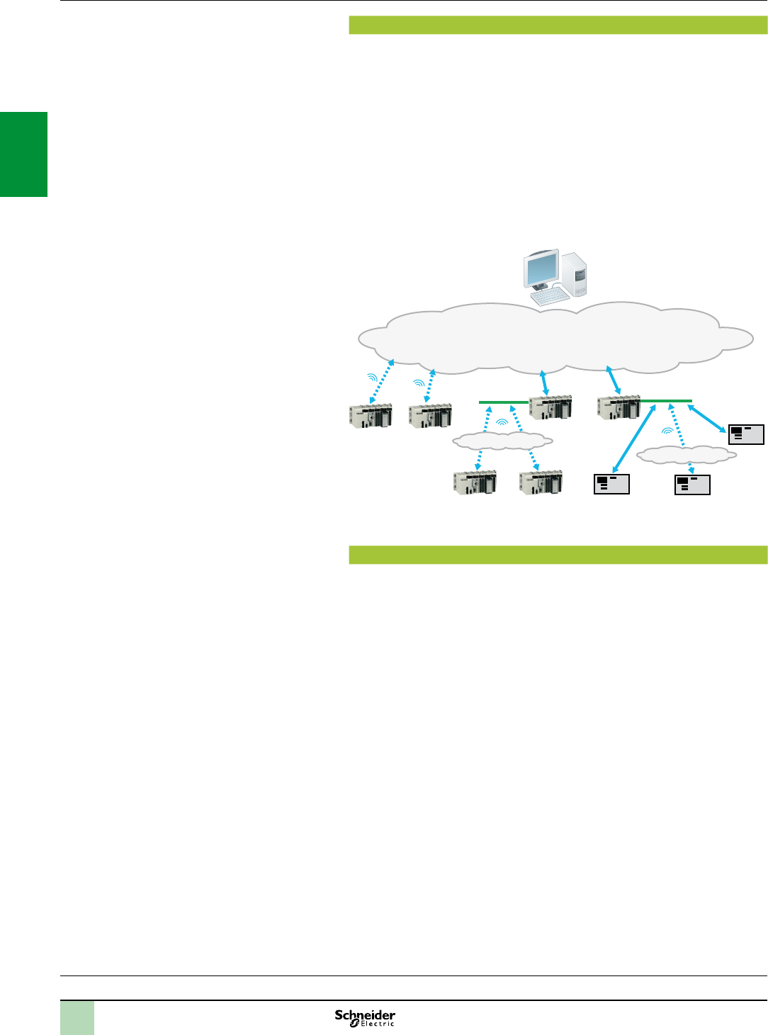
2/52
Presentation Modicon X80 I/O platform
RTU communication systems
Processors:
page 1/4
I/O:
pages 2/12 and 2/24
Software:
page 4/2
Ruggedized Modicon M340 modules:
page 6/2
Presentation
RTU systems are designed to meet the needs of the water industry, the oil and gas
sector and other infrastructures, where remote monitoring and telecontrol are
essential to the good management of sites and substations spread over a wide
geographical area.
RTU protocols and Telemetry systems provide robust, reliable means of communication
which are suitable for the process values, maintenance and remote monitoring needs
of infrastructures disseminated over a vast geographical area which may be difcult
to access.
An RTU system consists of the following elements:
A Telemetry Supervisor (SCADA) in a central control room
A network infrastructure and a variety of suitable communication methods
(LAN, WAN, modems, etc)
A large number of RTU substations geographically distributed throughout the eld
Ethernet 2
Ethernet 1
RTU RTU
RTU RTU
RTURTURTU RTU
RTU
TCP/IP, LAN/WAN, XdSL or Serial networks
PSTN (Public Switched Telephone Network) or GPRS/3G modem connections
Radio modem connections
SCADA master station
Radio network 1
Radio network 2
Main functions
The main RTU system functions are as follows:
Remote communications:
Between remote RTU sites (coordination, synchronization)
With the SCADA host system, controlling the central operator station (monitoring,
alarm reports) and centralized databases (archiving of alarms or events)
With the on-call staff (alarm indication)
With the technical station (diagnostics, maintenance)
Data acquisition, processing and memorization:
Process data sampling using standard or dedicated sensors, validation
Exchange of data with other devices within the station, including controllers and
operator consoles
Use of digital or analog I/O, serial links, eldbuses and LANs
Event detection, time and date stamping, prioritization and logging as required by
the application
Other functions:
IEC 1131-3 programmable control: forcing, access control, load sharing, servo control
Data logging
Alarm and report notication by e-mail/SMS
Web HMI: displaying the process, alarm handling, trend analysis, telecontrol
ExampleofanRTUsystemarchitecture
2
1
3
4
5
6
7
8
9
10
2
1
3
4
5
6
7
8
9
10

2/53
Presentation(continued) Modicon X80 I/O platform
RTU communication protocols
Processors:
page 1/4
I/O:
pages 2/12 and 2/24
Software:
page 4/2
Ruggedized Modicon M340 modules:
page 6/2
Presentation (continued)
Currently, people working in the industrial Telemetry sectors use standard protocols
for communication between control centres (SCADA) and RTU stations.
The most commonly used protocols are as follows:
IEC 60870-5: IEC (International Electrotechnical Commission), in particular
IEC 60870-5-101/104 (commonly known as IEC 101 or 104)
DNP3: Distributed Network Protocol version 3
DNP3 is the predominant protocol in North America, Australia and South Africa
whereas, in certain European countries, the IEC protocol is required by the legislation.
IEC is also commonly used in the Middle East.
The geographical distribution of these protocols is as follows:
DNP3: North America, Australia, New Zealand, UK, Asia, South America, etc
IEC 60870-5: Europe, Middle East, Asia, South America, etc
These protocols offer similar functions.
They are both particularly suited to “transient communications” (modem, radio) and
data exchanges with limited bandwidth for the following reasons:
They transfer data in a very robust and reliable manner between the SCADA
system and the RTU devices
They are essentially “event-triggered” protocols (exchanges on changes of state,
exchanges of time and date stamped events).
They offer the following transmission modes:
Interrogation via polling
Data exchanges on changes of state (RBE:ReportByException)
Unsolicited messaging (a slave station can start an exchange of data with the
master station).
Both protocols offer native data management and time and date stamped events:
Time synchronization between the master station and auxiliary stations via
protocol functions
Time and date stamping of data and events
Automatic transfer of time and date stamped events between the RTU stations
and SCADA (control room).
2
1
3
4
5
6
7
8
9
10
2
1
3
4
5
6
7
8
9
10
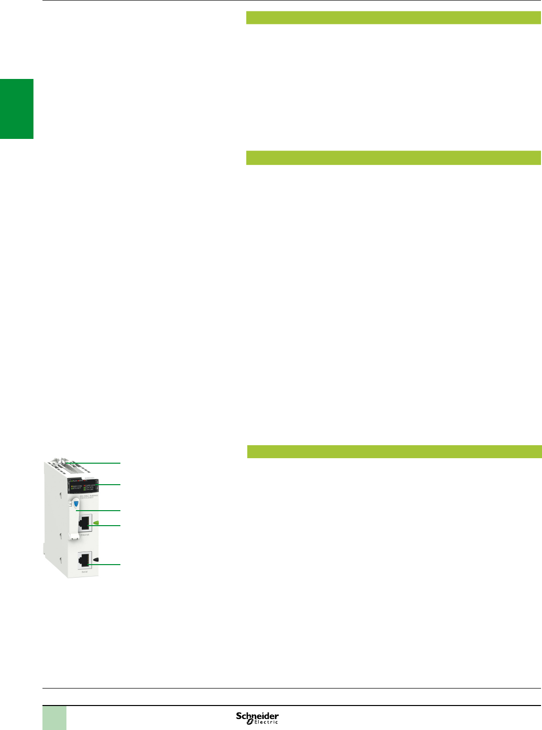
2/54
Le Presentation (continued)
The BMXNOR0200H communication module integrates the RTU (RemoteTerminal
Unit) functions and protocols in the Modicon X80 I/O platform, for industrial
Telemetry applications and other widely distributed infrastructures.
The BMXNOR0200H module can be used to connect an RTU X80 I/O PLC directly
to a Telemetry supervisor or to other RTU stations, via the standard DPN3 protocols
(subset level 3) or IEC 60870-5-101/104 with different connection methods: Ethernet
TCP/IP, LAN, WAN, serial link or modem connections (radio, PSTN, GSM, GPRS/3G,
ADSL).
The BMXNOR0200H module is designed to operate in a harsh environment
(conformal coating), in an extended temperature range (-25 to +70°C).
Functions
The BMXNOR0200H module offers the following functions:
Upstream RTU communication to the SCADA (server or slave mode)
Downstream RTU communication to eld devices (master mode)
RTU protocols: Time synchronization, exchanges of time and date stamped data
via polling (on change of state and unsolicited), management of time and date
stamped events
Application Data Logging with time and date stamping in the module Flash
memory card
Event notications via e-mail or SMS
Embedded Web server for setting the RTU protocol parameters, diagnostics and
monitoring
Communications on Ethernet port:
10BASE-T/100BASE-TX physical interface
Modbus/TCP protocol (client and server)
Integrated RTU protocols for Ethernet communications: DNP3 IP (client or server)
and IEC 60870-5-104 (over IP) (client or server)
Connection of ADSL external modem on the Ethernet port, via the PPPoE
(Point-to-PointProtocoloverEthernet)protocol
Advanced Ethernet functions: NTP client, FTP client or server, HTTP server,
SOAP/XML server, SNMP agent, SMTP agent
Communications on serial port:
Isolated RS232/RS485 point-to-point serial links
Integrated RTU protocols for serial and modem communications: IEC 60870-5-101
(master or slave) and DNP3 serial (master or slave)
Connection of external modems (radio, PSTN, GSM, GPRS/3G) via the PPP
(Point-to-PointProtocol) protocol
Description
The BMXNOR0200H module can be installed in either a standard or “ruggedized”
conguration, equipped with a standard BMXP34ppppp or “ruggedized”
BMXP34pppppH processor.
The front panel of the BMXNOR0200H module features:
1 A safety screw for locking the module in a slot in the rack.
2 A display block with 8 LEDs, 4 of which relate to the serial and Ethernet
communication ports.
3 A slot for a Flash memory card (SD card), with protective cover.
4 An RJ45 connector for the connection to the Ethernet network.
5 An RJ45 connector for connection of the serial link or an external modem.
On the rear panel, 2 rotary switches for selecting the IP address assignment
method for the module.
Modicon X80 I/O platform
RTU communication module
Presentation(continued),
functions,
description
Processors:
page 1/4
I/O:
pages 2/12 and 2/24
Software:
page 4/2
Ruggedized Modicon M340 modules:
page 6/2
5
3
1
2
4
2
1
3
4
5
6
7
8
9
10
2
1
3
4
5
6
7
8
9
10
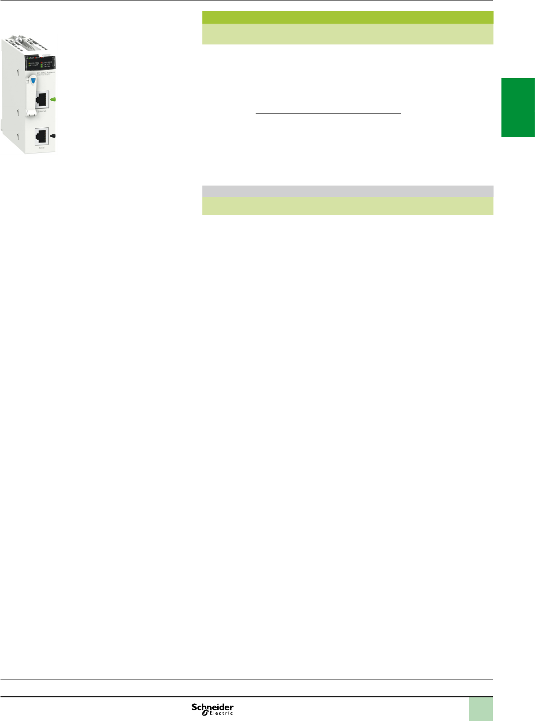
2/55
References
Description Communication
port
Protocol Reference Weight
kg
RTU
communi-
cation module
(1)
Ethernet
10BASE-
100BASE-TX
Modbus/TCP (client or
server), Transparent Ready
class C30
DNP3 IP (client or server)
IEC 60870-5-104 (over IP)
(client or server)
BMXNOR0200H
(2)
0.205
Serial, External
modems
Isolated RS232/RS485
point-to-point serial links
DNP3 serial (master or
slave)
IEC 60870-5-101 (master
or slave)
Spare parts
Description Usage Supplied with module Reference Weight
kg
128 MB Flash
memory card
supplied as
standard with
the module
Web pages,
Storage of
data logging
les (CSV)
BMXNOR0200H BMXRWS128MWF 0.002
(1)Seeruggedizedmodulecharacteristics,pages6/2and6/8.
(2)TheWebDesignersoftwareissuppliedonCD-ROMwiththemodule.Thissoftwarecanbe
usedtocongureanddownloadtheembeddedwebsiteandtocongureadvancedservices:
datalogging,sendingalarmnoticationsviaSMSore-mail,seepage3/18.
Modicon X80 I/O platform
RTU communication module
References
Processors:
page 1/4
I/O:
pages 2/12 and 2/24
Software:
page 4/2
Ruggedized Modicon M340 modules:
page 6/2
BMXNOR0200H
2
1
3
4
5
6
7
8
9
10
2
1
3
4
5
6
7
8
9
10
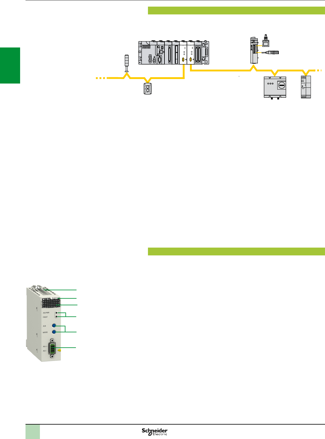
2/56
Presentation
The BMXEIA0100 master module for AS-Interface cabling system provides the
AS-Interface system master function for the Modicon X80 I/O platform.
The AS-Interface cabling system consists of a master station (Modicon X80 I/O
platform) and slave stations. The master supporting the AS-Interface prole
interrogates the devices connected on the AS-Interface line one by one and stores
the information (actuator/sensor status, device operating status) in the PLC memory.
Communication on the AS-Interface line is managed totally transparently in relation
to the application PLC program.
The BMXEIA0100 master module supports the latest management prole for
AS-Interface devices (AS-InterfaceV3) that are able to manage all level V1, V2 and
V3 AS-Interface slaves:
Discrete slave devices (up to 62 devices of 4I/4Q organized in 2 banks (A/B) of
31 addresses each)
Analog devices (up to 31 devices (4 channels) in bank A)
Safety interfaces (up to 31 devices in bank A)
An AS-Interface power supply is essential for powering the various devices on the
line. Ideally it should be placed near stations that consume a great deal of energy.
Please refer to the “Phaseo power supplies and transformers - AS-Interface range”
catalogue.
A Modicon M340 Performance conguration with BMXP34200/2002 processor
can take 4 BMXEIA0100 modules. A Standard conguration with BMXP341000
processor can take 2 BMXEIA0100 modules.
Description
The BMXEIA0100 AS-Interface master module is standard format (1 slot). Its
housing provides IP 20 protection of the electronics and it is locked into each rack
slot 01 ….11) by a captive screw.
The front panel of the BMXEIA0100 AS-Interface master module features:
1 A rigid body providing support and protection for the electronic card.
2 A module reference marking.
3 A display block with 5 LEDs indicating the module operating modes:
RUN (green): Module running
ERR (red): Module faulty
A/B (green): Displays the group of 31 slaves
I/O (red): I/O fault on AS-Interface line
32 LEDs for diagnostics of the AS-Interface line and each slave connected on the
line depending on the A/B pushbutton selection (1).
4 2 LEDs marked ASI POWER and FAULT: AS-Interface external power supply
present and AS-Interface line fault: see diagnostics on page 2/57.
5 Two pushbuttons marked A/B and MODE: see diagnostics on page 2/57.
6 A 3-way male SUB-D connector for the AS-Interface cable (female screw
connector supplied).
___________________________________________________________________________
(1)DependingonwhetherAorBisselected,thisdisplayseithertherst31slaves(standard
addressing)orthelast31slaves(extendedaddressing).
Modicon X80 I/O platform
BMXEIA0100 master module
for AS-Interface cabling system
Presentation,
description
4
1
3
5
2
4
BMXEIA0100
6
T
XAL control station
XVB illuminated
indicator bank
Motor starter Phaseo
AS-Interface
power supply
Sensors via
Advantys interface
AS-Interface
Modicon X80 I/O platform + Modicon M340 processor
2
1
3
4
5
6
7
8
9
10
2
1
3
4
5
6
7
8
9
10
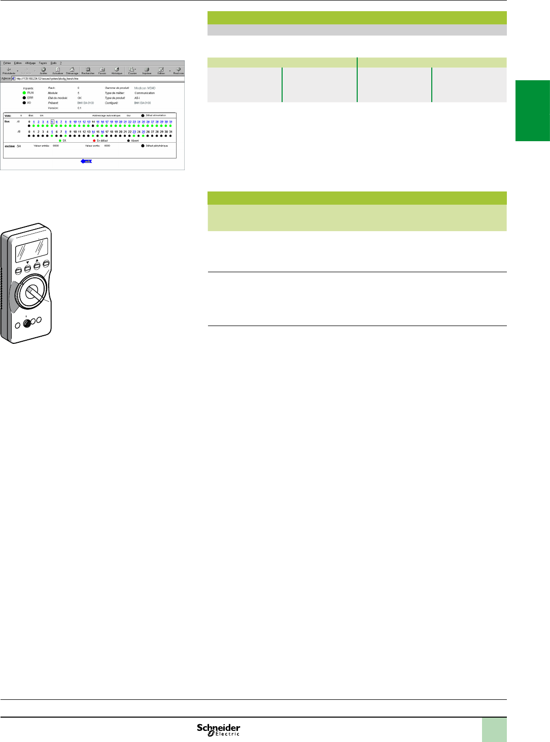
2/57
Modicon X80 I/O platform
BMXEIA0100 master module
for AS-Interface cabling system
Diagnostics
BMXEIA0100 module
The two LEDs 4 on the module front panel are used in conjunction with the two
pushbuttons 5 for module diagnostics:
LEDs Pushbuttons
4 ASI PWR:
AS-Interface
power supply present
4 FAULT: AS-Interface
line fault
5 A/B: Selects the
group of slaves on the
display block 3
5 MODE: Module
Ofine/Online
The display block on the front panel of the BMXEIA0100 master module can be used
to perform simplied local diagnostics by displaying the slave devices present on the
AS-Interface line.
Detailed diagnostics of each of the slave devices is also possible using:
The ASITERV2 adjustment terminal
A web browser using the Rack Viewer function in the standard Web server on the
Modicon X80 I/O platform (see page 3/16)
References
Description Usage Reference Weight
kg
AS-Interface
master module
supplied with 3-way male
SUB-D connector
M4 AS-Interface prole
for level V1, V2 and V3
slaves
BMXEIA0100 0.340
Adjustment terminal For addressing and diagnostics
of AS-Interface level
V1, V2 and V3 interfaces
Powered by LR6 batteries
ASITERV2 1.000
Diagnostics,
references
Processors:
page 1/4
I/O:
pages 2/12 and 2/24
Software:
page 4/2
Ruggedized Modicon M340 modules:
page 6/2
ASITERV2
2
1
3
4
5
6
7
8
9
10
2
1
3
4
5
6
7
8
9
10
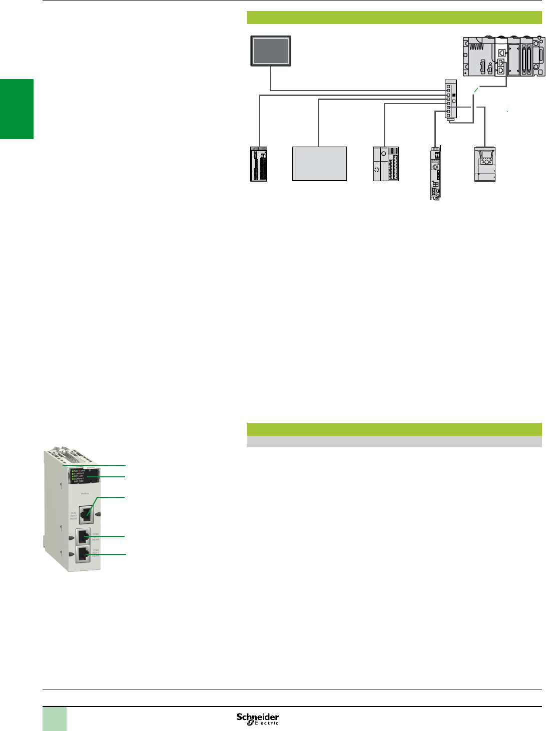
2/58
Presentation
Modicon X80 I/O
Magelis XBT
Preventa
XPSMC
Altivar 71
Twido
Lexium 32
LU9 GC3
Modbus
Third-party Modbus device
The Modbus serial link is used for master/slave architectures (it is necessary,
however, to check that the Modbus services used by the application have been
implemented on all relevant devices).
The bus consists of a master station and slave stations. Only the master station can
initiate the exchange (direct communication between slave stations is not possible).
Two exchange mechanisms are available:
Question/response, where requests from the master are addressed to a given slave.
The master then waits for the response from the slave which has been interrogated.
Broadcasting, where the master broadcasts a message to all slave stations on the
bus. The latter execute the order without transmitting a reply.
It is necessary to use BMXCRA31210 drop adaptors as head of drops. On one
drop it is possible to plug a maximum of two BMXNOM0200 modules.
The following services are not available in the slave stations:
Modbus slave,
Modem services.
Although most types of serial links can support modems, The BMXNOM0200
2-channel serial link module is particularly recommended for this type of use.
Its performance and numerous parameter-setting options make it ideal for any type
of conguration, especially when using radio modems.
Description
BMXNOM0200 serial link module
The front panel of the BMXNOM0200 serial link module features:
1 A safety screw for locking the module in a slot in the rack.
2 A display block with 4 LEDs:
RUN (green) and ERR (red): Module status
For each of the two channels: SER COM (green): Activity on the serial link (lit)/fault
on a device present on the serial link (ashing).
3 Two RJ45 connectors (exclusive use) for connection of channel 0 (with black
indicator):
3a A connector for RS 232C connection, marked COM Port 0 RS232
3b A connector for RS 485 connection, marked COM Port 0 RS485
4 An RJ45 connector for RS 485 connection of channel 1, marked COM Port 1
RS485, with black indicator.
To be ordered separately:
RS 485 cordsets (see page 3/64) or RS 232 cordsets for DCE terminal
(see page 2/59).
Modicon X80 I/O platform
Modbus and Character mode serial links
Presentation,
description
Processors:
page 1/4
I/O:
pages 2/12 and 2/24
Software:
page 4/2
Ruggedized Modicon M340 modules:
page 6/2
BMXNOM0200
2
3b
3a
4
1
2
1
3
4
5
6
7
8
9
10
2
1
3
4
5
6
7
8
9
10
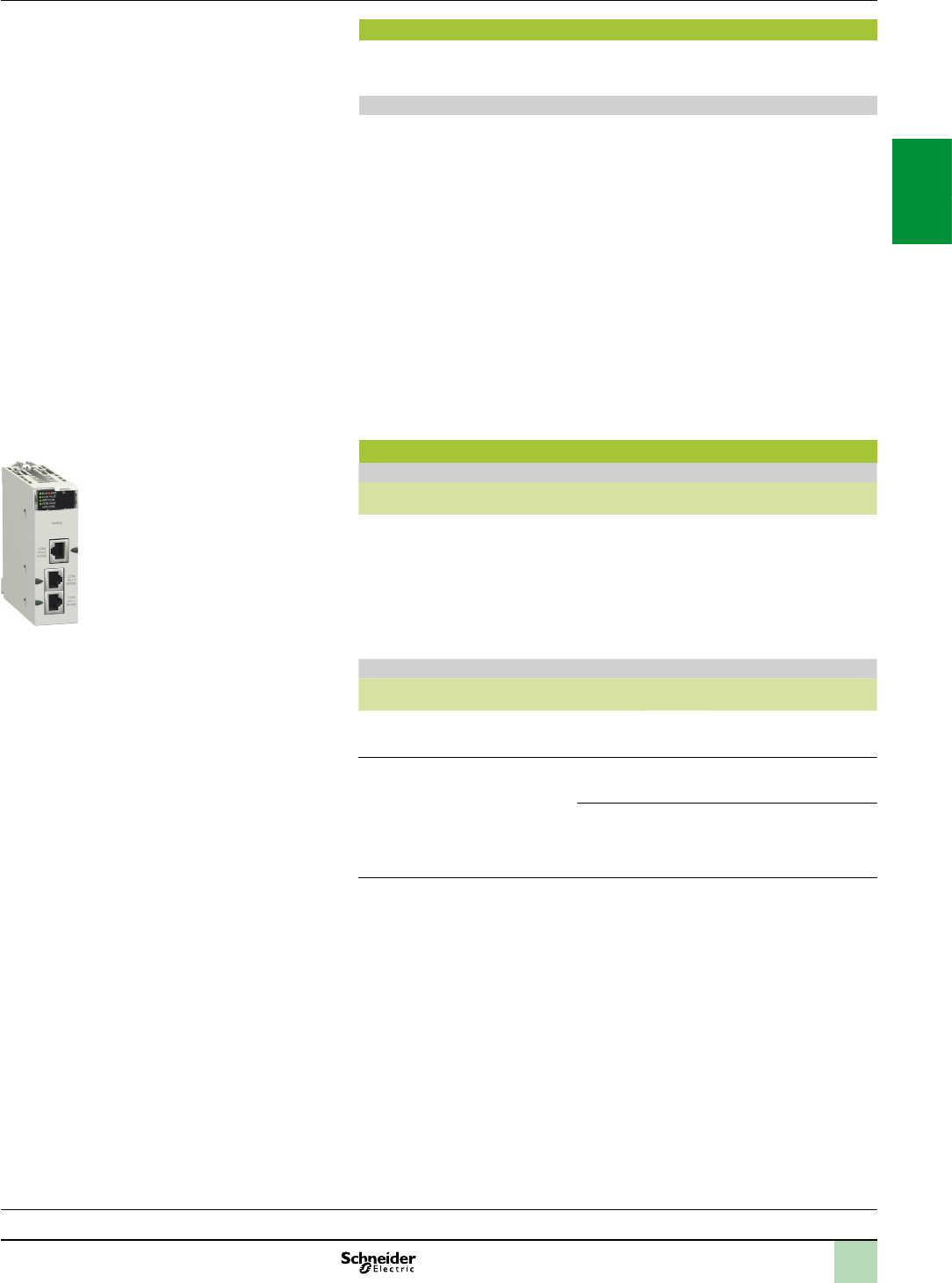
2/59
Processors:
page 1/4
I/O:
pages 2/12 and 2/24
Software:
page 4/2
Ruggedized Modicon M340 modules:
page 6/2
Modicon X80 I/O platform
Modbus and Character mode serial links
Characteristics,
references
Complementary characteristics
The following characteristics complement those indicated in the selection guide on
page 2/51.
BMXNOM0200 module serial links
Physical interface:
RS 232 port 0: RS 232 8-wire, non-isolated
RS 485 port 0 and port 1: RS 485 2-wire, isolated
Frame:
Modbus: RTU/ASCII, full duplex in RS 232, half duplex in RS 485
Character mode: full duplex in RS 232, half duplex in RS 485
Data rate:
RS 232 port 0: 0.3...115 Kbps (Modbus/Character mode)
RS 485 port 0 and port 1: 0.3...57.6 Kbps (Modbus/Character mode)
Line polarization:
Modbus RS 485: automatic
RS 485 character mode: congurable with Unity Pro software
Maximum length of a tap link in RS 485 2-wire:
15 m in a non-isolated link
40 m in an isolated link
Expert mode (from version V1.2 of the module and version V5 of Unity Pro): used
to congure the time out links individually from the application and thus adapt to the
specic characteristics of certain modems.
References (1)
Modbus serial link
Designation Protocol Physical layer Reference Weight
kg
Modbus serial link
2 channels(2)
Modbus
master/slave
RTU/ASCII,
Character
mode,
GSM/GPRS
modem
1 non-isolated RS 232
channel (Port 0)
2 isolated RS 485
channels (Port 0 and
Port 1)
BMXNOM0200 0.230
Cordsets for RS 232 serial link(3)
Designation Description Length Reference Weight
kg
Cordset for Data
Terminal Equipment
(DTE) (printer)
Equipped with an RJ45
connector and a 9-way
female SUB-D connector
3 m TCSMCN3M4F3C2 0.150
Cordset for Data
Communication
Equipment (DCE)
(modem, etc.)
Equipped with
an RJ45
connector and a
9-way male
SUB-D
connector
4-wire
(RX, TX,
RTS, CTS)
3 m TCSMCN3M4M3S2 0.150
8-wire
(excluding
RI signal)
3 m TCSXCN3M4F3S4 0.165
(1)RequiresUnityProsoftwareV1.4.
(2)Fortheruggedizedversion,BMXNOM0200H,seecharacteristicsonpages6/2and6/8.
(3)RS485seriallinkconnection(seepages3/64and3/65).
BMXNOM0200
2
1
3
4
5
6
7
8
9
10
2
1
3
4
5
6
7
8
9
10

2/60
Presentation
The PMXNOW0300 Wi-Fi access point consists of a WLAN wireless connection
combined with a 3-port 10/100 Ethernet switch.
This module is designed to be integrated in the Modicon X80 I/O platform Modicon
processor (1). It retrieves the 24 V voltage from the backplane rack and occupies one slot
in it. An Ethernet cable, supplied with the module, must be used to connect the Wi-Fi
module to the processor or the communication module (BMXNOppppp).
This module offers the following functions:
access point
Ethernet bridge
Wi-Fi repeater
The PMXNOW0300 is compatible with the majority of Ethernet-based protocols, including
Modbus TCP, EtherNet/IP, etc.
It also allows Wi-Fi access to the associated Modicon processor from Vijeo Citect and
Unity Pro software as well as exchange of data between automation platforms.
The PMXNOW0300 module can be removed and replaced while the rack is powered up.
It is compatible with Vijeo Design’ Air and Vijeo Design’ Air Plus, allowing the HMI to be
remotely located on a tablet or smartphone (2).
Main characteristics
Type of device
Wi-Fi access point, client and repeater
Wi-Fi standards
IEEE 802.11 a/b/g/h
Operating frequencies
2.4 GHz and 5 GHz
IP rating
IP 30
Mounting
On the rack
Number of radios
1
Nominal data rate
108 Mbps (Super AG mode, 54 Mbps in standard mode)
Antenna connections
1 x RP-SMA
Ethernet connections
3 x 10/100 BASE TX, MDI-MDIX
Wi-Fi connections
1 x WLAN interface
Range
Up to 300 m in free eld with the antenna supplied as with standard and up to 5 km
with external antenna (frequency range and data rate dependent on antenna type)
Dimensions
97 x 32 x 104 mm
Storage temperature
- 40°C to + 80°C
Humidity
Max. 95% (non-condensing)
Supply voltage
+ 24 V from the Modicon X80 I/O platform rack
Consumption
3.5 W typical
(1)OnlyforprocessorscompatiblewiththeModiconX80I/Oplatform(seepage1/9).
(2)Formoreinformation,pleaseconsultourwebsitewww.schneider-electric.com.
Presentation,
characteristics Modicon X80 I/O platform
Wi-Fi network
PMXNOW0300 Wi-Fi access point
PMXNOW0300Wi-Fiaccesspoint
2
1
3
4
5
6
7
8
9
10
2
1
3
4
5
6
7
8
9
10

2/61
Modicon X80 I/O platform
Wi-Fi network
PMXNOW0300 Wi-Fi access point
References
Wi-Fi access points
Description Number of
radios
Data rate IP rating Reference Weight
Mbps kg
Wi-Fi 802.11a/b/g/h
access point
with antenna and 50 cm
long Ethernet cable
equipped with two RJ45
connectors, plus
CD-ROM
1108
(Super AG
mode,
54 Mbps in
standard
mode)
IP 30 PMXNOW0300 (1) 0.205
(1)Toorderthisproduct,consultourpartnerACKSYS(CollaborativeAutomationPartner
Program):www.acksys.com.
References
2
1
3
4
5
6
7
8
9
10
2
1
3
4
5
6
7
8
9
10
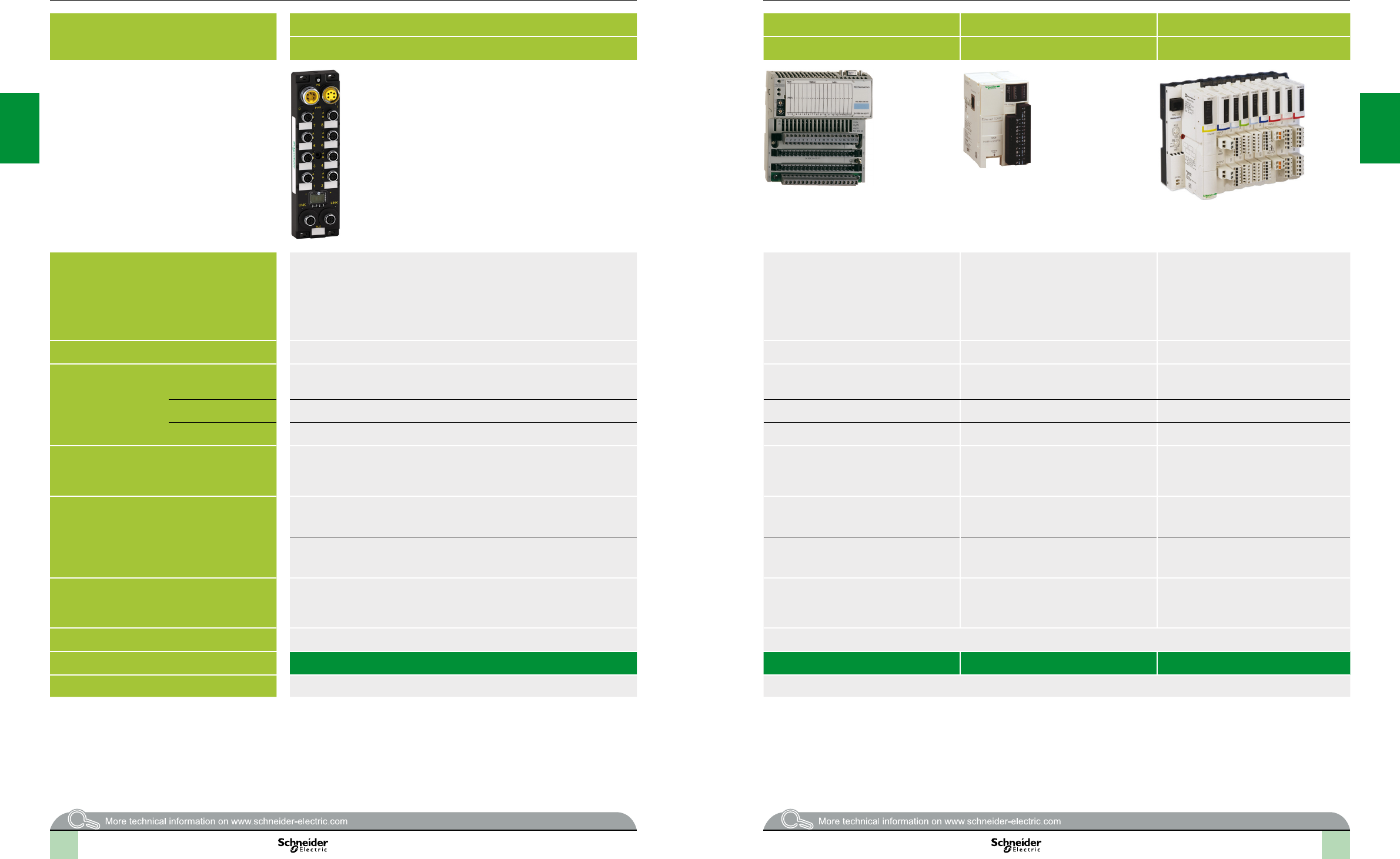
2
1
3
4
5
6
7
8
9
10
2
1
3
4
5
6
7
8
9
10
2
1
3
4
5
6
7
8
9
10
2
1
3
4
5
6
7
8
9
10
Modicon distributed I/O solutions
Selectionguide
Type of splitter box and module Monobloc IP 67 I/O splitter boxes Monobloc IP 20 distributed I/O Optimum IP 20 distributed I/O Modular IP 20 distributed I/O
Modicon ETB Modicon Momentum Modicon OTB Modicon STB
Available buses and
networks
Ethernet Modbus TCP/IP
EtherNet/IP
Ethernet Modbus TCP/IP
Modbus Plus
Fipio
InterBus
Probus DP
DeviceNet
Ethernet Modbus TCP/IP
CANopen
Modbus (RS 485)
Ethernet Modbus TCP/IP
EtherNet/IP
CANopen
Modbus Plus
Fipio
InterBus
Probus DP
DeviceNet
Max. number per connection point 1 I/O base with 1 CPU or 1 communication module 1 interface module + 7 Twido expansion modules 1 NIM (Network Interface Module) + 32 I/O modules
Discrete I/O Modularity Splitter box with 16 congurable I/O, 16 I, 12 I + 4 O, or 8 I +8 O I/O base with 16 I, 32 I, 8 O, 16 O, 32 O, 10 I/8 O,
16 I/8 O, 16 I/12 O and 16 I/16 O
12 I/8 O (interface module)
8 I, 16 I, 32 I, 8 O, 16 O, 32 O, 4 I/4 O and 16 I/8 O
(expansion modules)
Module with 2 I, 4 I, 6 I, 16 I, 2 O, 4 O, 6 O or 16 O
Input voltage 24 V 24 V , 120 V and 230 V 24 V 24 V , 115 V and 230 V
Output voltage 24 V 24 V V, 120 V and 230 V and relay 24 V and relay 24 V , 115/230 V and relay
Analog I/O – 8 I, 16 I or 4 O voltage/current I/O bases
I/O base with 4 thermocouple or probe inputs
2 I, 4 I, 8 I, 1 O, 2 O, 2 I/1 O and 4 I/2 O
(expansion modules)
voltage/current, thermocouple or
temperature probe
Modules with 2, 4 or 8 inputs and 1 or 2 outputs
(voltage/current)
I/O base with 2 thermocouple or probe inputs
Application-specic I/O – 10 kHz/200 kHz 2-channel counter I/O base Integrated in interface module:
- Two 5 kHz/20 kHz channels
- 2 PWM function channels
Counter module with one 40 kHz channel
HART multiplexer module
- 4 HART channels per HART multiplexer module
- Up to 8 HART multiplexer modules per island
– 6 I/3 O 120 V I/O base with 1 Modbus port – Parallel interface modules for TeSys Quickt and
TeSys U motor starters, integrated connection for
third-party CANopen products
I/O connection M12 connectors Screw or spring-type removable terminal blocks Removable screw terminal block (interface module)
Removable screw terminal block, non-removable
spring-type terminal block and HE 10 connector
(expansion modules)
Removable screw or spring-type connectors,
Telefast connectors
Type of housing Plastic Plastic
Type of module ETB1Eppp 170ApOTB1p0DM9LP STBppp
Pages Please consult the catalogue pages on our website www.schneider-electric.com Please consult the catalogue pages on our website www.schneider-electric.com
2/62 2/63

3/0
Contents 3 - Communication
Communication selection guide ............................... page3/2
PlantStruxure Ethernet Architectures
Logical communication architecture ........................................................ page3/8
Physical communication architecture ...................................................... page3/9
Ethernet Modbus/TCP and EtherNet/IP networks
Ethernet Modbus/TCP communication services
Presentation .......................................................................................... page3/10
Functions ................................................................................................page3/11
Web services
Standard Web services ......................................................................... page3/16
FactoryCast Web services .................................................................... page3/17
Web Designer conguration software .................................................... page3/18
SOAP/XML Web services ...................................................................... page3/19
Processors with integrated Ethernet Modbus/TCP port
Presentation, description, references ................................................... page3/20
Ethernet Modbus/TCP network modules
Presentation, description, references ................................................... page3/21
Modbus/TCP and EtherNet/IP network module
Presentation, functions, description ....................................................... page3/22
References ........................................................................................... page3/23
Selection guide for web servers and gateways .................. page3/24
ConneXium cabling systems for Ethernet and Wi-Fi networks
Selection guide for ConneXium hub and
unmanaged switches ....................................... page3/26
Selection guide for ConneXium industrial Firewalls .............. page3/40
Infrastructure ....................................................................................... page3/42
Connection components .................................................................... page3/44
Hub and Transceiver ........................................................................... page3/46
Unmanaged switches .......................................................................... page3/47
Managed switches ............................................................................... page3/49
ConneXium Industrial Ethernet Firewalls .......................................... page3/51
Modbus Plus Proxy module
Presentation ......................................................................................... page3/52
References ........................................................................................... page3/53
Probus DP V1 and Probus PA buses
Presentation ......................................................................................... page3/54
References ........................................................................................... page3/55
2
1
3
4
5
6
7
8
9
10
2
1
3
4
5
6
7
8
9
10

3/1
CANopen machine and installation bus
Presentation ......................................................................................... page3/56
Connectable devices ........................................................................... page3/57
Description, references ....................................................................... page3/58
Connections ......................................................................................... page3/59
Cabling system .................................................................................... page3/60
Modbus and Character mode serial links
Presentation, description ................................................................... page3/62
Complementary characteristics, references ..................................... page3/63
2
1
3
4
5
6
7
8
9
10
2
1
3
4
5
6
7
8
9
10

2
1
3
4
5
6
7
8
9
10
2
1
3
4
5
6
7
8
9
10
2
1
3
4
5
6
7
8
9
10
2
1
3
4
5
6
7
8
9
10
3/2 3/3
Selectionguide Modicon M340 automation
platform
Communication, integrated ports and modules
Applications Ethernet communication Ethernet communication RTU communication
Type of device Processors with integrated
Modbus/TCP port
Ethernet modules Ethernet modules RTU module
Network protocols Ethernet Modbus/TCP EtherNet/IP and Modbus/TCP Modbus/TCP, IEC 60870-5-104,
DNP3 (subset level 3)
Serial link, External modem link,
IEC 60870-5-101, DNP3 (subset level 3)
Structure Physical interface 10BASE-T/100BASE-TX 10BASE-T/100BASE-TX 10BASE-T/100BASE-TX (Modbus/TCP),
PPPoE (Point-to-Point Protocol over Ethernet)
for ADSL external modem link
Non-isolated RS 232/485 (Serial link),
Non-isolated RS 232 (Radio, PSTN, GSM,
GPRS/3G external modem link)
Type of connector RJ45 Four RJ45 connectors (2 connectors for a ring topology) One RJ45 connector One RJ45 connector
Access method CSMA-CD CSMA-CD CSMA-CD (Modbus/TCP),
Master/slave (IEC 104/DNP3)
Master/slave (IEC 101/DNP3)
Data rate 10/100 Mbps 10/100 Mbps 10/100 Mbps (Modbus/TCP) 0.3…38.4 Kbps (Serial link)
Medium Double twisted pair copper cable, category CAT 5E
Optical bre via ConneXium cabling system
Double twisted pair copper cable, category CAT 5E, optical bre via ConneXium cabling system Double shielded twisted pair copper cable,
Crossover serial cable (Serial link),
Direct serial cable (External modem link)
Conguration Maximum number of devices – 128 (EtherNet/IP or Modbus/TCP) 128 (Modbus/TCP),
64 slaves/servers (IEC 104/DNP3)
32 max.
Max. length 100 m (copper cable), 4000 m (multi-mode optical bre), 32,500 m (single-mode optical bre) 100 m (copper cable), 4000 m (multi-mode optical bre), 32,500 m (single-mode optical bre) 1000 m (Serial link with insulating case)
Number of modules of the same type
per station
1 2 Ethernet or RTU modules per station with any BMXP34
processor
2 Ethernet or RTU modules per station with any BMXP34 processor Depending on application-specic channels
(20/36 application-specic channels with
BMXP341000/P342)
Standard services Modbus/TCP messaging EtherNet/IP and Modbus/TCP messaging Modbus/TCP messaging Reading/writing digital and analog I/O, counters
Transparent Ready conformity class B10 B30 C30 B30 C30 –
Embedded Web
server services
Standard services Rack Viewer PLC diagnostics, Data Editor access to PLC data and variables Rack Viewer PLC diagnostics, Data Editor access to PLC data and variables –
Congurable services – Alarm Viewer and
Graphic Data Editor
– – –
Hosting and display of user
Web pages (14 MB)
– Hosting and display of user Web pages –
Transparent Ready
communication
services
I/O Scanning service – Yes Yes –
Global Data service – Yes – –
NTP time synchronization – Yes (module version 2.0) – Yes
FDR service Yes (client) Yes (client/server) Yes (client/server) Yes (client) –
SMTP e-mail notication service Yes, via EF function block
Unity Pro 4.0
– – Yes –
SOAP/XML Web service – – Server – Server –
SNMP network management service Yes Yes Yes Yes (agent) –
RSTP redundancy service – – – Yes –
QoS (Quality of Service) service – – – Yes –
RTU communication
services
IEC 60870-5-104,
DNP3 IP or
IEC 60870-5-101,
DNP3 serial
Master or Slave conguration – – Yes, IEC101/104 and DNP3
Time and date stamped data exchange – – Interrogation via polling and exchanges on change of status (RBE), unsolicited messaging
RTU time synchronization – – Yes, IEC101/104 and DNP3
Management and buffering of time
and date stamped events
– – Yes, IEC101/104 and DNP3
Automatic transfer of time and date
stamped events to the Master/SCADA
– – Yes, IEC101/104 and DNP3
Buffer holding 10,000 events (per connected client, 4 clients max.)
Data Logging service – – – – Yes, on SD 128 MB memory card, in CSV les, access via FTP or sent by e-mail
Compatibility with processor – Standard and Performance (see page 1/4) Standard and Performance (see page 1/4)
Processor or module
references depending
on other type of
integrated port
No other integrated port BMXNOE0100 BMXNOE0110 BMXNOC0401
Serial link BMXP342020 BMXNOR0200H
Ethernet Modbus/TCP BMXNOR0200H
CANopen BMXP3420302/
BMXP3420302CL
Page 3/20 3/21 3/23 2/55

2
1
3
4
5
6
7
8
9
10
2
1
3
4
5
6
7
8
9
10
2
1
3
4
5
6
7
8
9
10
2
1
3
4
5
6
7
8
9
10
Selectionguide(continued) Modicon M340 automation
platform
Communication, integrated ports and modules
Applications CANopen communication AS-Interface
communication
Serial link communication
Type of device Processors
with integrated CANopen port
AS-Interface
actuator/sensor bus module
Processors
with integrated serial link
2-channel serial link
module
Network protocols CANopen AS-Interface Modbus and Character mode
Structure Physical interface ISO 11898 (9-way SUB-D connector) AS-Interface V3 standard Non-isolated RS 232, 4-wire
Non-isolated RS 485, 2-wire
Non-isolated RS 232, 8-wire
Isolated RS 485, 2-wire
Type of connector 9-way SUB-D 3-way SUB-D RJ45 2 RJ45 and 1 RJ45
Access method CSMA/CA (multiple access) Master/slave Master/slave with Modbus link,
Full duplex (RS 232)/Half duplex (RS 485) in Character mode
Data rate 20 Kbps...1 Mbps depending on distance 167 Kbps 0.3...38.4 Kbps 0.3...115.2 Kbps in RS 232
0.3...57.6 Kbps in RS 485
Medium Double shielded twisted pair copper cable Two-wire AS-Interface cable Double shielded twisted pair copper cable Shielded twisted pair copper cable
Conguration Maximum number of devices 63 depending on the devices connected 62 slaves 32 per segment, 247 max. 2 per drop, 16 per Ethernet remote I/O (RIO) network max.
Max. length 20 m (1 Mbps)…2500 m (20 Kbps) 100 m,
500 m max. with 2 repeaters
15 m (non-isolated),
1000 m with insulating case
15 m with non-isolated RS 232,
1000 m with non-isolated RS 485
Number of links of the same type per
station
1 BMXP341000 processor:
2 AS-Interface modules
1 20/36 application-specic channels with BMXP341000/P342
(1 application-specic channel = 1 counter, motion control module or serial link
channel)
BMXP34200 processor:
4 AS-Interface modules
36 application specic channels max. per BMXCRA31210 Ethernet drop
adaptor: 2 BMXNOM0200 modules
BMXCRA31210 Ethernet drop
adaptor:
2 AS-Interface modules
Standard services PDO implicit exchange (application data)
SDO explicit exchange (service data)
Transparent exchanges with
the sensors/actuators
Read/write bits and words, diagnostics in Modbus mode
Send and receive character string in Character mode
Conformity class Class M20 M4 prole –
SMTP service
notication by e-mail
– Yes, via EF function block
Unity Pro 4.0
– –
Compatibility with processor – Standard and Performance
(see page 1/4)
– Standard and Performance (see page 1/4)
Type of processor or
module depending
on other integrated
port
None BMXEIA0100 BMXP341000/2000
Serial link BMXP3420102/
BMXP3420102CL
BMXNOM0200
Ethernet Modbus/TCP BMXP3420302/
BMXP3420302CL
BMXP342020
CANopen BMXP3420102/BMXP3420102CL
Page 3/58 2/57 3/63 2/59
3/4 3/5
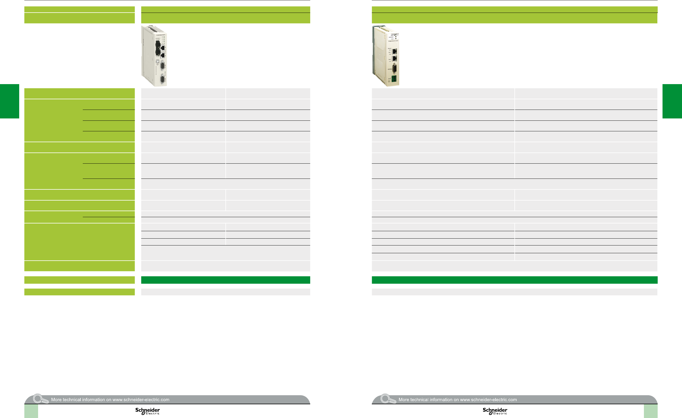
2
1
3
4
5
6
7
8
9
10
2
1
3
4
5
6
7
8
9
10
2
1
3
4
5
6
7
8
9
10
2
1
3
4
5
6
7
8
9
10
Selectionguide(continued) Modicon M340 automation
platform
Communication, integrated ports and modules
Applications Modbus Plus communication Probus DP and Probus PA communication
Type of device M340 Modbus Plus proxy module (external) Probus Remote Master (PRM) module (external)
Network protocols Ethernet Modbus/TCP Modbus Plus Ethernet Modbus/TCP Probus DP V1
Probus PA (via gateway)
Structure Physical interface 10/100BASE-T Modbus Plus standard 10BASE-T/100BASE-TX Isolated RS 485
Type of connector Two RJ45 connectors Two 9-way female SUB-D connectors Two RJ45 connectors (supporting daisy chain topology) One 9-way female SUB-D connector
Access method CSMA-CD Token ring CSMA-CD Master/slave
Data rate 10/100 Mbps 1 Mbps 10/100 Mbps 9.6 Kbps...12 Mbps
Medium Double shielded twisted pair copper cable,
category CAT 5E (direct or crossover)
Twisted pair copper cable Double shielded twisted pair copper cable,
category CAT 5E (direct or crossover)
Shielded twisted pair copper cable
Conguration Maximum number of devices 128 32 per segment
64 for all segments
Several PRMs can be connected to the Ethernet port on the M340, Premium or
Quantum PLC, as long as the I/O scanner capacity is not exceeded
125 slaves
Max. length 100 m 450 m per segment
1800 m with 3 repeaters
100 m (copper) 1200 (9.6 Kbps), 4800 m with 3 repeaters,
100 m (12 Mbps), 400 m with 3 repeaters
Number of links of the same
type per station
1 max. –
Standard services Modbus/TCP messaging Modbus Plus messaging Modbus/TCP messaging Cyclic and acyclic data exchange with slaves
Conformity class – – Transparent Ready Class A20 Class 1 and Class 2
Embedded Web server
service
Standard service Conguration, diagnostics –
Congurable services – –
Communication services Modbus Plus server (scanned by the PLC) Reading/writing variables Modbus server (scanned by the PLC) Master/slave communication
FDR service Global database FDR service Global Control service
SNMP agent network management service Peer Cop service SNMP agent network management service Acyclic communication (read/write) in Class 1 and Class 2
Support for extended diagnostics
Auto-scanning service of slaves on the bus
24 V c external power supply 19.2…31.2 V 18…30 V
Module types TCSEGDB23F24FA TCSEGPA23F14F
Page 3/53 3/55
3/6 3/7
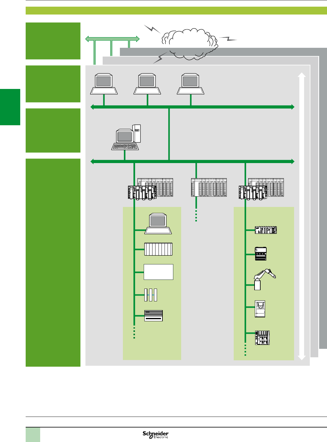
3/8
Premium
Architecture Modicon M340 automation
platform 0
PlantStruxure Ethernet Architectures
Logical communication architecture
Logical communication architecture
Company
Enterprise
Factory
Workshop
MES: Manufacturing Execution System (production management system)
ERP: Enterprise Resource Planning (integrated management software packages)
IHM/SCADA: Human/Machine Interface and Supervision Control And Data Acquisition
Gateway: Gateway to sensor/actuator bus, to installed base network, eldbus, etc.
INPUT
OUTPUT
+
–
INPUT
OUTPUT
+
–
A
B
A
B
Collaborative
Automation
Partner Program
Internet
Site 1
Site 2
Site 3
MES ERP
Unix Windows Linux
HMI + SCADA
Industrial PC
Quantum Quantum
Modicon M340
Quantum
Momentum M1E
Robot
Variable speed
drive
Modicon STB I/O
Workshop 2
Workshop 1
Distributed I/O
Gateway
PLC
Dialogue terminal
Premium
Intranet
Ethernet Modbus/TCP
CPUs:
page 1/4
I/O:
pages 2/12 and 2/24
Software:
page 4/2
Ruggedized Modicon M340
modules: page 6/2
2
1
3
4
5
6
7
8
9
10
2
1
3
4
5
6
7
8
9
10
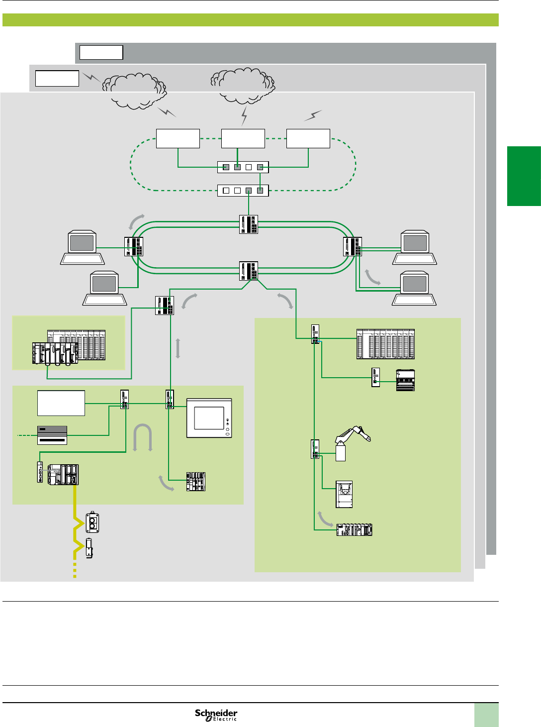
3/9
Architecture(continued) Modicon M340 automation
platform 0
PlantStruxure Ethernet Architectures
Physical communication architecture
Physical communication architecture
(1)Asageneralrule,deningseveralcollisiondomainscanincreasethesizeofthearchitectureandimproveperformance(seepages7/6to7/11).
INPUT
OUTPUT
+
–
INPUT
OUTPUT
+
–
A
B
A
B
Collaborative
Automation
Partner Program
Publictelecommunications
network,ADSL
Site 1
100m
max.
100m
max.
100m
max.
210m
max.
Hub
100m
max.
Switch Redundant optical ring ERP
MES
Specializedlink
FrameRelay
ATM
Switches (VLAN)
or routers
Switch
100m
max.
3100m
max.
Collision domain 2
Hub
Switch
Site 3
Router
Site 2
Router
WAN
Provider
Router Firewall
Quantum Quantum
Premium
Modicon M340
TSX Micro
Hub Hub
Collision domain 3 (1)
AS-Interface bus
Altivar 71
Momentum
M1E
Transceiver
Magelis iPC
Vijeo Designer
Third-party device
Gateway
Modicon STB
Switch
Switch
RAS
(50switchesmax.)
100BASE-FX
Collision domain 1
FullDuplex HalfDuplex
100BASE-TX
Optical
bres
Internet
Provider
Robot
CPUs:
page 1/4
I/O:
pages 2/12 and 2/24
Software:
page 4/2
Ruggedized Modicon M340
modules: page 6/2
2
1
3
4
5
6
7
8
9
10
2
1
3
4
5
6
7
8
9
10

3/10
Presentation
Presentation
BMXP342020/20302/20302CL processors via their integrated Ethernet port,
BMXNOE0100/0110 network modules and the BMXNOR0200H RTU module
provide transparent communication on the Ethernet Modbus/TCP network using
Transparent Ready communication services.
SMTP Modbus
HTTPFTP
TFTP
DHCPRTPS
NTP
SNMP
UDP TCP
Physical
Network
management
FDR Faulty Device Replacement Messaging
Link
Transport
Applications
Services
Ethernet 802.3 and Ethernet II
Time
synchro-
nization
Web
server
Global
Data
E-mail I/O
Scanning
MIB 2 standard
MIB Transparent Ready
IP
The following Transparent Ready communication services are designed for use in
automation applications. They supplement the universal Ethernet services (HTTP,
BOOTP/DHCP, FTP, etc):
Modbus/TCP messaging for class 10 or 30 devices
I/O Scanning service for class 30 devices
FDR (Faulty Device Replacement) for class 10 or 30 devices
SNMP (SimpleNetworkManagementProtocol) network management for class 10
or 30 devices
Global Data, for class 30 devices
Bandwidth management for class 10 or 30 devices
NTP (NetworkTimeProtocol) synchronization for class 30 devices
E-mail alarm notication via SMTP server, via Unity Pro function block
Note:Seeselectionguideonpages3/2and3/3forthecommunicationservicessupportedby
BMXP342020/20302/20302CLprocessors,BMXNOE0100/0110networkmodulesandthe
BMXNOR0200H RTUmoduleontheModiconM340platform.
The following pages (3/11 to 3/15) present the various options available through all
of these services in order to facilitate the optimum choice of solutions when dening
a system integrating Transparent Ready devices.
Modicon M340 automation
platform
Ethernet Modbus/TCP network
Ethernet Modbus/TCP communication services
EthernetcommunicationservicesfortheBMXNOE0100/0110module
Processors:
page 1/4
I/O:
pages 2/12 and 2/24
Software:
page 4/2
Ruggedized Modicon M340 modules:
page 6/2
2
1
3
4
5
6
7
8
9
10
2
1
3
4
5
6
7
8
9
10

3/11
Functions
Functions
Ethernet universal services
The universal Ethernet services used are as follows:
HTTP (HyperText Transfer Protocol):
This protocol is used for transmitting Web pages between a server and a browser.
Web servers embedded in Transparent Ready automation products provide easy
access to products located anywhere in the world from a standard web browser such
as Internet Explorer.
BOOTP/DHCP (RFC1531):
These protocols are used to provide devices with IP parameters automatically.
This avoids having to manage each device address individually by transferring this
management to a dedicated IP address server.
The DHCP protocol (DynamicHostCongurationProtocol) is used to assign
conguration parameters to devices automatically. DHCP is an extension of BOOTP.
Schneider Electric devices can be “BOOTP clients” (used to retrieve the IP
address automatically from a server) or “BOOTP servers” (allowing the device to
distribute IP addresses to the network stations).
Schneider Electric uses standard BOOTP/DHCP protocols for its FDR (Faulty
DeviceReplacement)service.
FTP (File Transfer Protocol) (RFCs 959, 2228, and 2640):
This protocol provides the basic elements for le sharing. Many systems use it to
exchange les between devices.
TFTP (File Transfer Protocol) (RFCs 959, 2228, and 2640):
This network transfer protocol can be used to connect to a device and download
code to it.
For example, it can be used to transfer a boot code to a workstation without a
disk drive or to connect and download updates of network device rmware.
Transparent Ready devices implement FTP and TFTP for transferring certain
information to or from devices, in particular for downloads of rmware or user-dened
Web pages.
SNMP (Simple Network Management Protocol) (RFCs 1155, 1156 and 1157):
The SNMP standard manages the various network components via a single
system.
The network management system can exchange data with SNMP agent devices.
This function allows the manager to display the status of the network and devices,
modify their conguration and feed back alarms in the event of a fault.
Transparent Ready devices are SNMP-compatible and can be integrated
naturally in a network managed via SNMP.
COM/DCOM (Distributed Component Object Model) (RFCs 1155, 1156 and 1157):
COM/DCOM or OLE (ObjectLinkingandEmbedding) protocol is the name of the
technology consisting of Windows objects which enables transparent
communication between Windows applications.
These technologies are used in the OFS (OLEforProcessControlFactoryServer)
data server software.
.Modbus standard communication protocol
Modbus protocol, the industry communication standard since 1979, has been combined
with Ethernet Modbus/TCP, the medium for the Internet revolution, to form Modbus/TCP,
a completely open Ethernet protocol.
The development of a connection to Modbus/TCP does not require any proprietary
component, nor purchase of a license.
This protocol can easily be combined with any product supporting a standard TCP
communication stack. The specications can be obtained free of charge from the
following website: www.modbus-ida.org.
Modicon M340 automation
platform
Ethernet Modbus/TCP network
Ethernet Modbus/TCP communication services
Processors:
page 1/4
I/O:
pages 2/12 and 2/24
Software:
page 4/2
Ruggedized Modicon M340 modules:
page 6/2
2
1
3
4
5
6
7
8
9
10
2
1
3
4
5
6
7
8
9
10
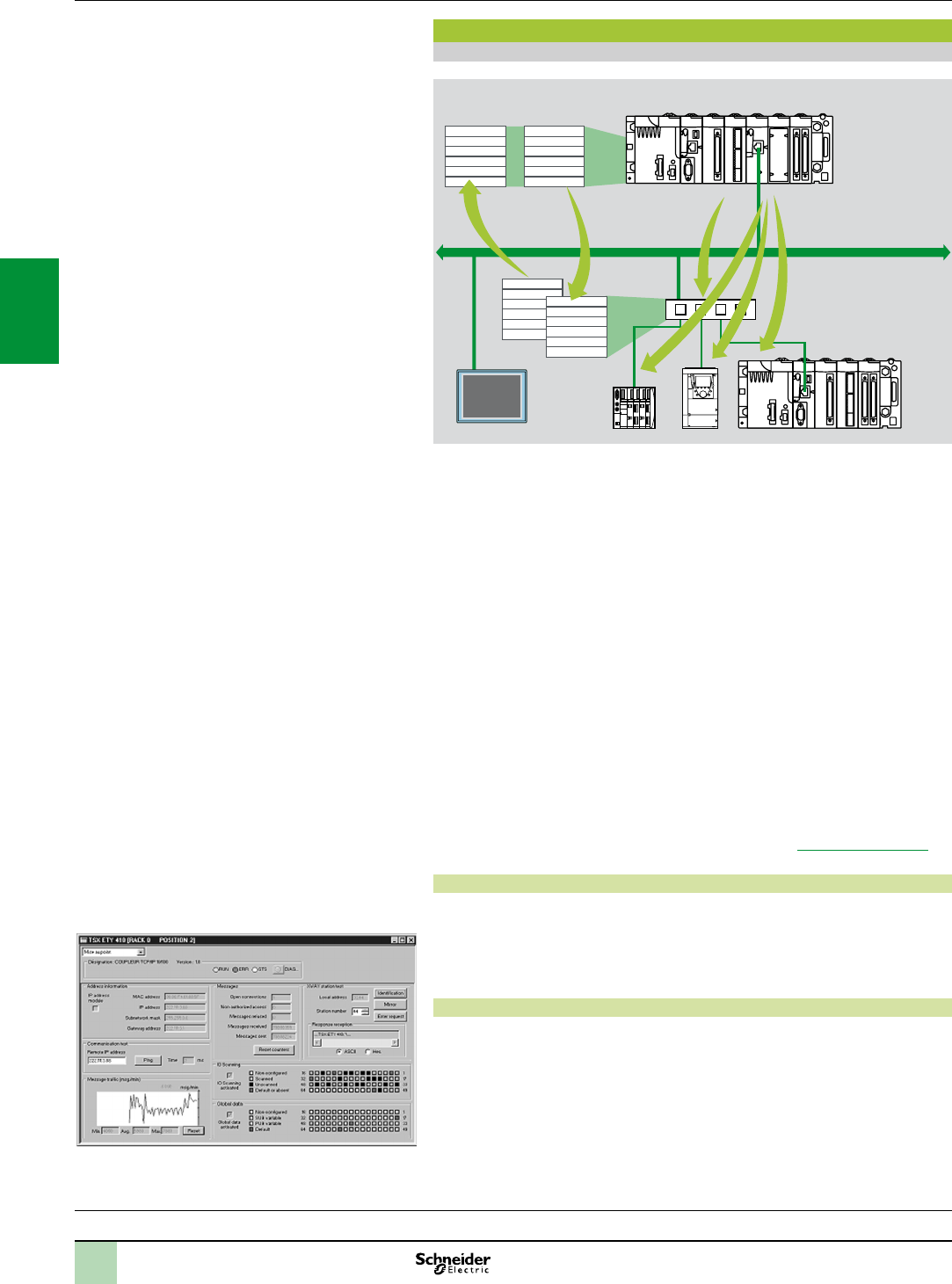
3/12
Functions (continued)
I/O Scanning service
The I/O Scanning Service is used to manage the exchange of remote I/O states on
the Ethernet network after a simple conguration operation, with no need for special
programming.
I/O scanning is performed transparently by means of read/write requests according
to the Modbus client/server protocol on the TCP prole.
This principle of scanning via a standard protocol enables a device with the I/O
Scanning service to communicate with any device supporting Modbus TCP
messaging in server mode.
This service can be used to dene:
A word zone reserved for reading inputs
A word zone reserved for writing outputs
Refresh periods independent of the PLC scan
During operation, the module:
Manages TCP connections with each remote device
Scans devices and copies the I/O to the congured word zone
Feeds back status words used to check that the service is working correctly from
the PLC application
Applies pre-congured fallback values if a communication problem occurs
A range of hardware and software products is available enabling the I/O Scanning
protocol to be implemented on any type of device that can be connected to the
Ethernet network (please consult the Modbus-IDA website: www.modbus-ida.org.
Characteristics
Each Modicon M340 station can exchange a maximum of 100 words for writing
and 125 words for reading.
Maximum size in the Modicon M340 PLC that manages the service (64 stations
max.) with BMXNOE0100/0110 and BMXNOC0401 network modules: 2 Kwords
(input) and 2 Kwords (output).
I/O Scanning service diagnostics
I/O Scanning service diagnostics can be performed in one of ve ways:
Via the application program from a specic PLC data zone
From the setup software debug screen
From the PLC system diagnostic function displayed by means of an internet
browser on a PC station
Using standard SNMP manager software
Functions(continued)
2 Device with Modbus TCP messaging in server mode
Modicon M340 automation
platform
Ethernet Modbus/TCP network
Ethernet Modbus/TCP communication services
Processors:
page 1/4
I/O:
pages 2/12 and 2/24
Software:
page 4/2
Ruggedized Modicon M340 modules:
page 6/2
1 Modicon M340 device with I/O Scanning service
INPUT
OUTPUT
+
–
INPUT
OUTPUT
+
–
A
B
A
B
2
1
2 2
Word table
Read Write
Ethernet Modbus/TCP
Input words
Output words
of devices
2
1
3
4
5
6
7
8
9
10
2
1
3
4
5
6
7
8
9
10
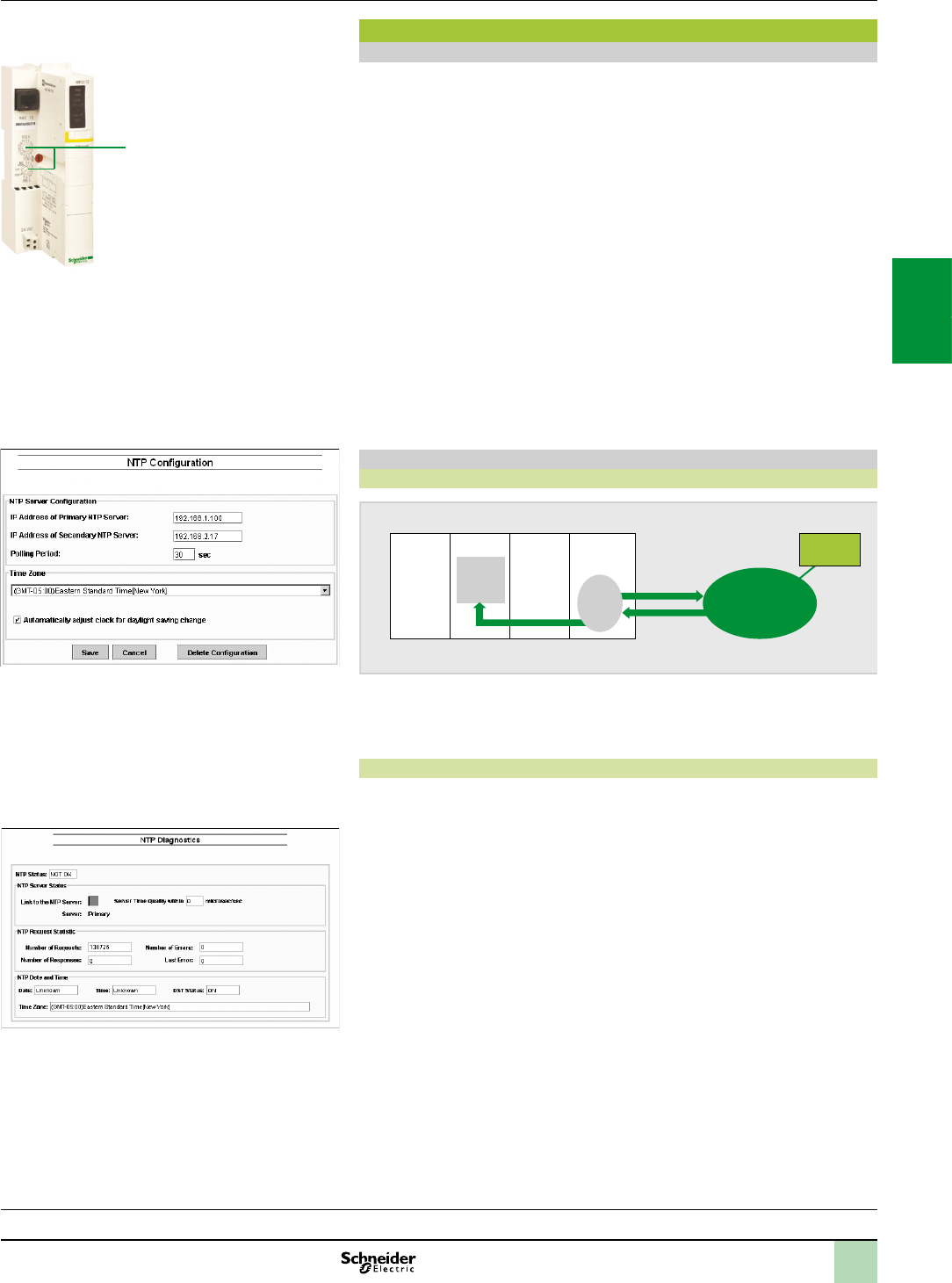
3/13
Functions(continued)
Functions (continued)
FDR (Faulty Device Replacement) service
The Faulty Device Replacement service uses standard address management
technologies (BOOTP, DHCP) and the TFTP (TrivialFileTransferProtocol) le
management service, with the aim of simplifying maintenance of Ethernet devices.
The FDR service is used to replace a faulty device with a new device with the
guarantee that it will be detected, recongured and automatically rebooted by the
system.
The main steps in replacement are:
1 A device using the FDR service malfunctions.
2 Another similar device is taken from the maintenance store, precongured with
the Device name for the faulty device, then reinstalled on the network. Depending
on the device, addressing can be performed using rotary selector switches (as for
Modicon STB distributed I/O a, or Modicon OTB for example) or can be given
using the keypad integrated in the device (as for Altivar variable speed drives for
example).
3 The FDR server detects the new device, allocates it an IP address and transfers
the conguration parameters to it.
4 The substituted device checks that all these parameters are indeed compatible
with its own characteristics and switches to operational mode.
The FDR server can be the BMXNOE0100/0110 Ethernet module or the
BMXNOC0401 module.
NTP time synchronization service
Presentation
BMX CPS
power
supply
Processor BMX NOE
module
Internal
clock
Ethernet network
NTP
server
Modicon M340
NTP response
NTP request
NTP
client
The time synchronization service is based on NTP (NetworkTimeProtocol) which is
used to synchronize the time of a client or a server on Ethernet from a server or another
reference time source (radio, satellite, etc).
Operation
BMXNOE0100/0110, BMXNOC0401 and BMXNOR0200H Ethernet Modbus/TCP
modules have an NTP client component.
These modules connect to an NTP server using a client request (Unicast) in order to
update their local time. The module clock is updated periodically (1 to 120 s) with
typical precision of 5 ms. If the NTP server cannot be reached, the Ethernet TCP/IP
module switches to a standby NTP server.
The PLC processor clock is therefore itself updated with a precision of 5 ms. A
function block is used to read this clock, thus enabling Unity Pro application events
or variables to be time and date stamped.
The Ethernet module is congured by means of a Web page. The time zone can be
congured. A time synchronization service (NTP) diagnostic Web page is also available.
Information on the time synchronization service (NTP) is also available in the
Transparent Ready private MIB, which can be accessed via the SNMP network
management service.
Modicon M340 automation
platform
Ethernet Modbus/TCP network
Ethernet Modbus/TCP communication services
Processors:
page 1/4
I/O:
pages 2/12 and 2/24
Software:
page 4/2
Ruggedized Modicon M340 modules:
page 6/2
NIMnetworkmodulefor
ModiconSTBI/O
a
2
1
3
4
5
6
7
8
9
10
2
1
3
4
5
6
7
8
9
10
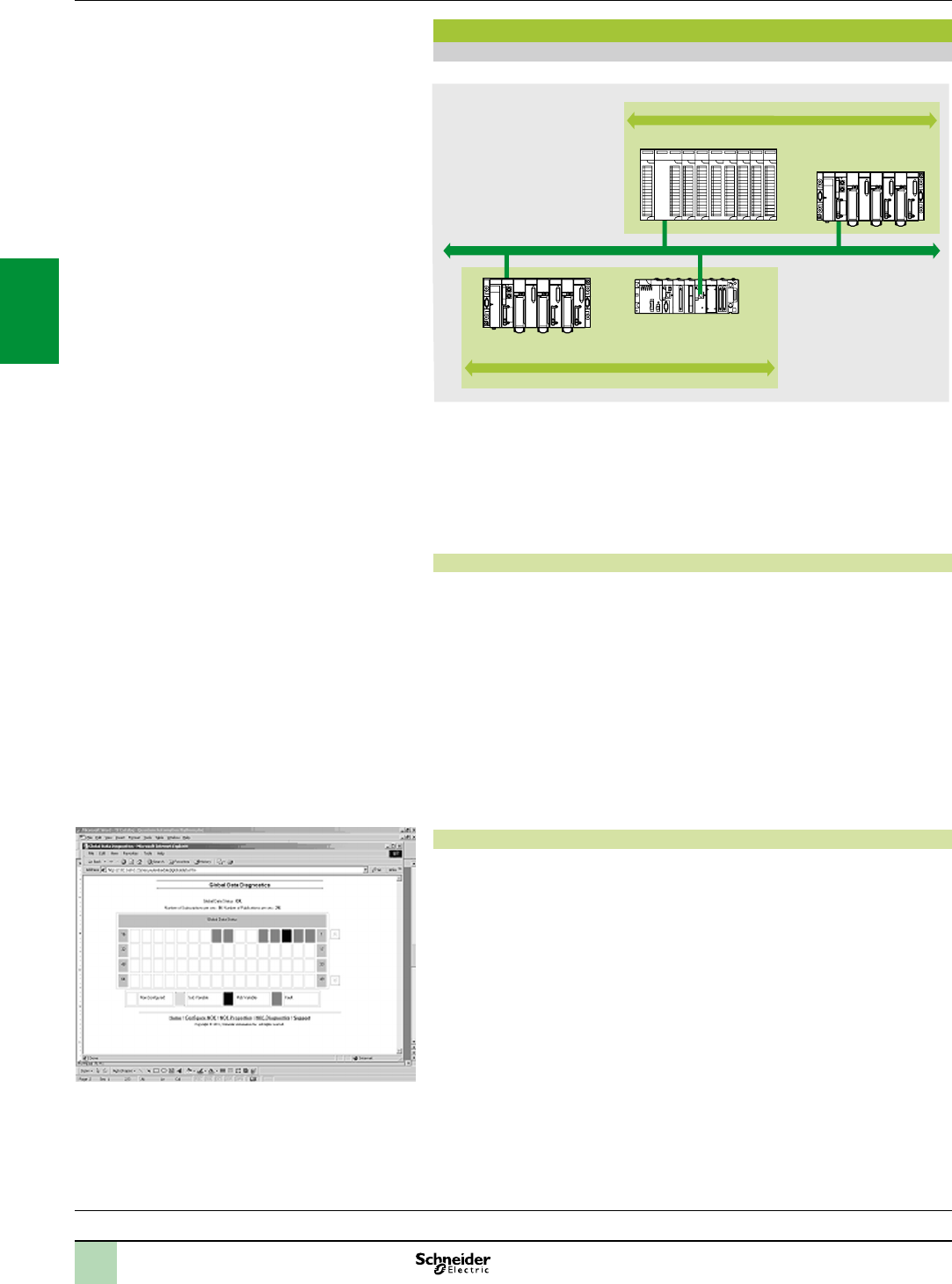
3/14
Functions(continued)
Functions (continued)
Global Data service
The Global Data service performs data exchanges in real time between stations
belonging to the same distribution group. It is used to synchronize remote applications,
or to share a common database between a number of distributed applications.
Exchanges are based on a standard producer/consumer protocol, guaranteeing
optimum performance with a minimum load on the network. This RTPS (RealTime
PublisherSubscriber) protocol is promoted by Modbus-IDA (InterfaceforDistributed
Automation), and is already a standard adopted by several manufacturers.
Characteristics
A maximum of 64 stations can participate in Global Data within a single distribution
group. Each station can:
Publish one 1024-byte variable. The publication period can be congured from
1 to n processor master task (Mast) periods.
Subscribe to between 1 and 64 variables. The validity of each variable is controlled
by status bits (HealthStatusbits) linked to a refresh timeout congurable between
50 ms and 1s. Access to an element of the variable is not possible. The total size of
subscribed variables amounts to 4 K contiguous bytes.
To further optimize the performance of the Ethernet network, Global Data can be
congured with the “multicast ltering” option which, together with switches in the
ConneXium range (see pages 3/26 to 3/37), broadcasts data only to Ethernet ports
where there is a Global Data service subscriber station. If these switches are not
used, Global Data is sent in “multicast” mode to all switch ports.
Global Data service diagnostics
The diagnostic screens use a colour code to show the Global Data status:
Congured/not congured/faulty.
Published/subscribed.
Global Data service diagnostics can be performed in one of ve ways:
Via the application program from a specic PLC data zone.
From the setup software debug screen.
From the PLC system diagnostic function displayed by means of an internet
browser on a PC station.
Using standard SNMP manager software.
Modicon M340 automation
platform
Ethernet Modbus/TCP network
Ethernet Modbus/TCP communication services
Processors:
page 1/4
I/O:
pages 2/12 and 2/24
Software:
page 4/2
Ruggedized Modicon M340 modules:
page 6/2
Modicon Quantum
Modicon Premium
Modicon Premium
Modicon M340
Distributiongroup1
Data exchange 4 KB max.
Data exchange 4 KB max.
Distributiongroup2
IP multicast 239.255.255.251
IP multicast 239.255.255.250
Ethernet Modbus/TCP
2
1
3
4
5
6
7
8
9
10
2
1
3
4
5
6
7
8
9
10
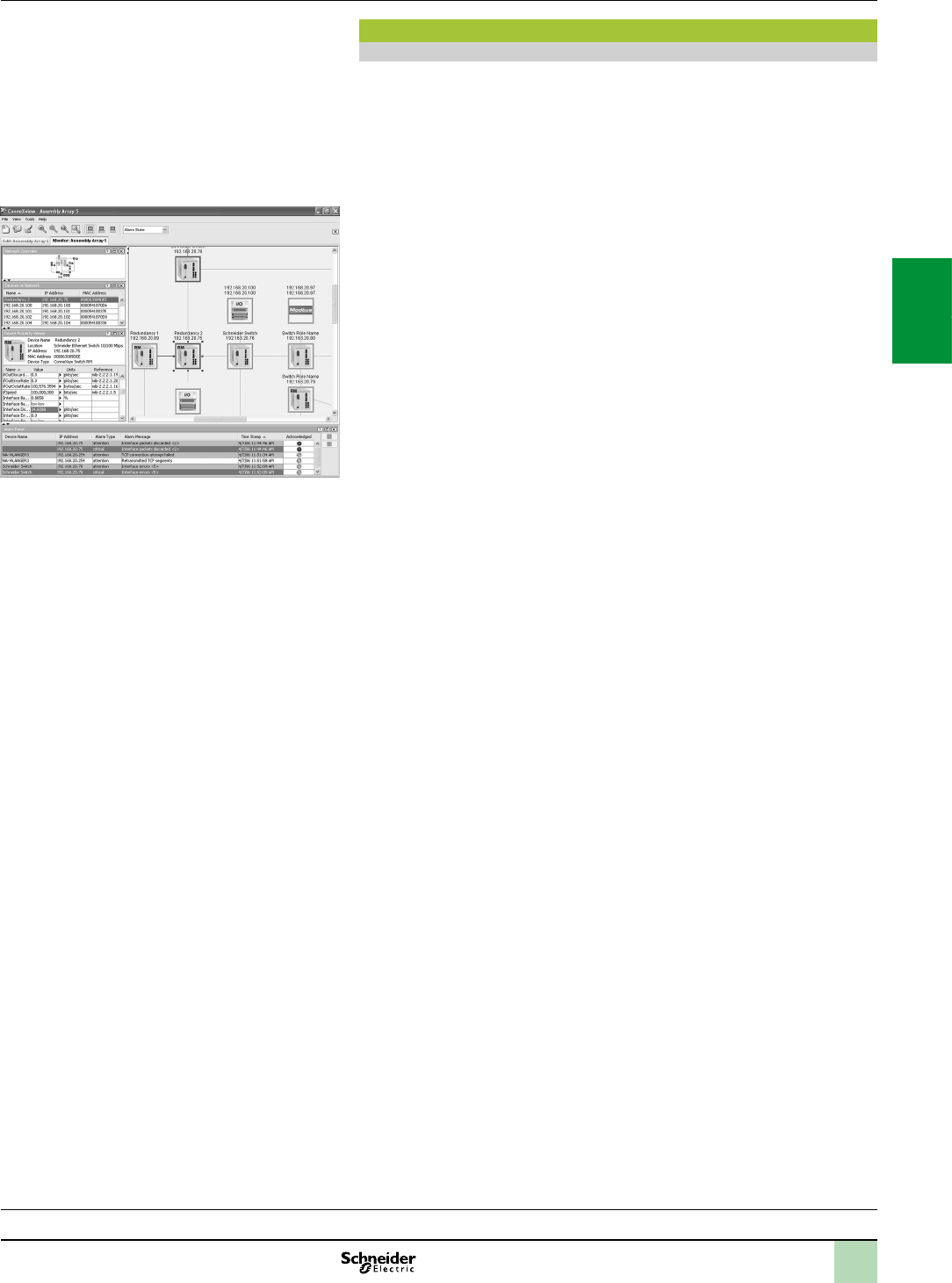
3/15
Functions(continued)
Functions (continued)
SNMP network management service
From a network management station, SNMP (SimpleNetworkManagementProtocol)
monitors and checks all components of the Ethernet architecture and thus ensures
quick diagnostics in the event of a problem.
It is used to:
Interrogate network components such as computer stations, routers, switches,
bridges or terminal devices in order to view their status.
Obtain statistics about the network to which the devices are connected.
This network management software complies with the conventional client/server
model. However, to avoid confusion with other communication protocols that use this
terminology, we talk instead about:
Network manager for the client application that operates on the computer station.
SNMP agent for the network device server application.
Transparent Ready devices can be managed by any SNMP network manager,
including HP Openview and IBM Netview.
Standard SNMP (SimpleNetworkManagementProtocol) is used to access
conguration and management objects contained in the device MIBs (Management
Information Bases). These MIBs must comply with certain standards to be accessed
by any commercially-available manager, but depending on the complexity of products,
manufacturers can add certain objects to private databases.
The Transparent Ready private MIB presents management objects specic to the
Schneider Electric offer. These objects simplify the installation, setup and
maintenance of Transparent Ready devices in an open environment using standard
network management tools.
Transparent Ready devices support 2 levels of SNMP network management:
The Standard MIB II interface: This interface accesses a rst level of network
management. It enables the manager to identify the devices making up the
architecture and retrieve general information about the conguration and operation
of Ethernet Modbus/TCP interfaces.
The Transparent Ready MIB interface: This interface improves the management
of Transparent Ready devices. This MIB has a set of data enabling the network
management system to supervise all the Transparent Ready services.
The Transparent Ready MIB can be downloaded from the FTP server of any
Transparent Ready Ethernet module in a PLC.
Modicon M340 automation
platform
Ethernet Modbus/TCP network
Ethernet Modbus/TCP communication services
Processors:
page 1/4
I/O:
pages 2/12 and 2/24
Software:
page 4/2
Ruggedized Modicon M340 modules:
page 6/2
AutomaticrecognitionofIPdevicesviatheConneXview
diagnosticsoftwareforEthernetindustrialnetworks
2
1
3
4
5
6
7
8
9
10
2
1
3
4
5
6
7
8
9
10
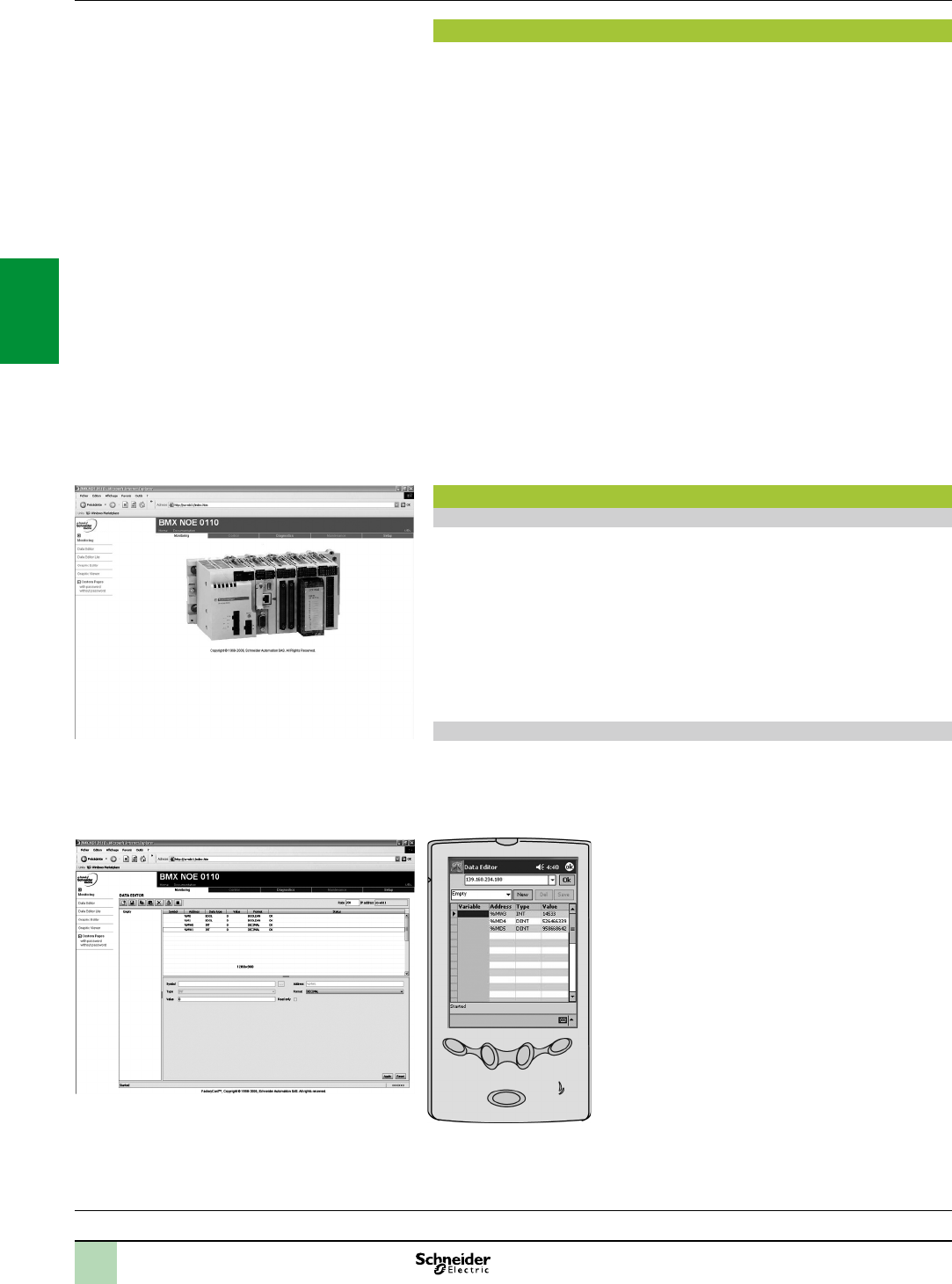
3/16
Modicon M340 automation
platform
Ethernet Modbus/TCP network
Standard Web services
Presentation of Web services
The standard Web server functions are integrated in a wide variety of Schneider Electric
Ethernet products: Modicon automation platform processors and Ethernet modules,
distributed I/O modules, variable speed drives and gateways. These functions are
mainly integrated in BMXP342020/20302/20302CL processors, in
BMXNOE0100/0110 and BMXNOC0401 Ethernet network modules, in the
BMXNOR0200H RTU module, and the TCSEGDB23F24FA Modbus Plus proxy
module on the Modicon M340 platform.
From a simple Internet browser, the standard Web server authorizes the following
“ready-to-use” functions:
Remote diagnostics and maintenance of products
Display and adjustment of products (read/write variables, status)
With the BMXNOE0110 FactoryCast module equipped as standard with the
BMXRWSFC032M card, the Web server also offers the following functions:
Management of PLC system and application alarms with partial or total
acknowledgement (ready-to-use Alarm Viewer function pages)
Hosting and display of Web pages created by the user
The embedded Web server is a real-time data server. All the data can be presented
in the form of standard Web pages in HTML format and can therefore be accessed
using any Web browser that supports the embedded Java code. The standard
functions provided by the Web server are supplied “ready-to-use” and thus do not
require any programming of either the PLC or the client PC device supporting a Web
browser.
Standard Web server on the Modicon M340 platform
Rack Viewer PLC diagnostics function
The Rack Viewer function can be used for PLC system and I/O diagnostics. It
displays the following in real time:
Status of LEDs on the PLC front panel
The PLC type and version
Hardware conguration of the PLC including status of the system bits and words
Detailed diagnostics of:
Each of the I/O module channels or application-specic channels in the conguration
Devices connected to the CANopen bus
Data Editor read/write function for PLC data and variables
The Data Editor function can be used to create tables of animated variables for
real-time read/write access to PLC data in the form of lists.
Various animation tables containing specic application variables to be monitored or
modied can be created by the user and saved in the standard Web server module.
In addition to the functions provided by the standard
Web server, the BMXNOE0110 Ethernet module's
FactoryCast Web server offers the following:
Display of variables: Variables can be entered and
displayed either in their symbolic form (S_Pump 234) or
as their address (%MW99).
Write access to variables: This can be enabled or
disabled for each of the variables using the FactoryCast
module conguration software.
Read/write function: This can be used on tools such
as a pocket PC or PDA terminal.
Presentation,
functions
Processors:
page 1/4
I/O:
pages 2/12 and 2/24
Software:
page 4/2
Ruggedized Modicon M340 modules:
page 6/2
DataEditorvariablestable
ModiconM340hardwareconguration
2
1
3
4
5
6
7
8
9
10
2
1
3
4
5
6
7
8
9
10
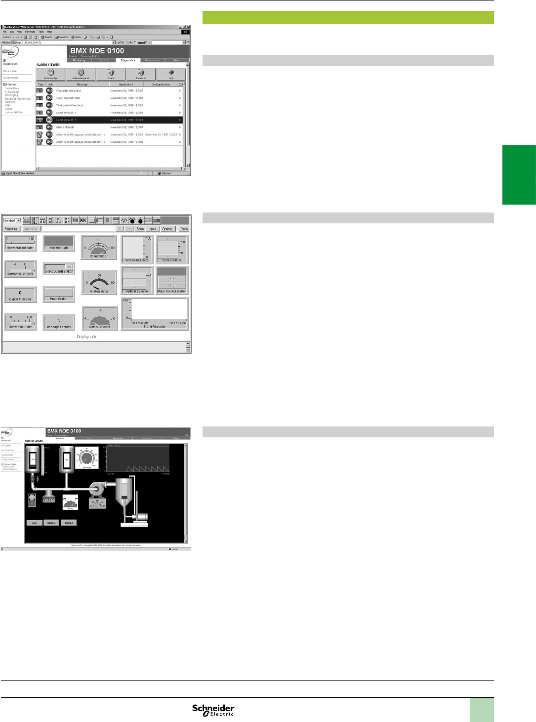
3/17
Modicon M340 automation
platform
Ethernet Modbus/TCP network
FactoryCast Web services
BMXNOE0100 module FactoryCast Web server
In addition to the standard services, the embedded Web server in the BMXNOE0110
FactoryCast module offers the functions described below.
Alarm Viewer function
The alarm viewer is a ready to use, password-protected function. It is used to
process alarms (display, acknowledgement and deletion) managed at PLC level by
the system or using diagnostic function blocks known as DFBs (system-specic
diagnostic function blocks and application-specic diagnostic function blocks
created by the user).
These alarms are stored in the diagnostic buffer managed by the Modicon M340
platform (dedicated memory space for storing all the diagnostic events).
The diagnostic viewer is a Web page comprising a list of messages, which displays
the following information for each alarm:
Dates and times of the occurrence/removal of a fault
Alarm message
Alarm status
Type of associated diagnostic function block (DFB)
Graphic Data Editor function
This function is used to create the graphic views animated by the PLC variables that
can be accessed via their address or via their symbol (access to located data). The
ready-to-use graphic editor is available in online mode when connected to the
BMXNOE0110 module.
These views are created from a library of predened graphic objects by simple
copy/paste operations. The objects are congured to suit the user's requirements
(colour, PLC variables, name, etc).
List of graphic objects available:
Analog and digital indicators
Horizontal and vertical bar charts
Boxes for displaying messages and entering values
Pushbutton boxes
Trend recorders
Vats, valves, motors, etc
Customized graphic objects can be added to this list and can be reused in user Web
pages that have been created using standard software for editing HTML pages. The
views thus created are saved in the BMXNOE0110 module and can be displayed
using any Web browser.
User Web page hosting and display function
The BMXNOE0110 FactoryCast module has a 16 Mbyte non-volatile memory which
is accessed in the same way as a hard drive. This allows hosting of Web pages and
any user-dened Word or Acrobat Reader document (for example, maintenance
manuals, wiring diagrams, etc).
Web pages can be created using any standard tool for creation and editing in HTML
format. They can be enhanced by inserting animated graphic objects linked to PLC
variables. These animated objects are created using the Graphic Data Editor. They
are then downloaded to the BMXNOE0110 module via the FactoryCast Web server
conguration software.
These user Web pages can be used, for example, to:
Display and modify all PLC variables in real time
Create hyperlinks to other external Web servers (documentation, suppliers, etc)
This function is particularly suitable for creating graphic interfaces used for the
following purposes:
Real-time display and supervision
Production monitoring
Diagnostics and help with maintenance
Operator guides
Functions(continued)
Processors:
page 1/4
I/O:
pages 2/12 and 2/24
Software:
page 4/2
Ruggedized Modicon M340 modules:
page 6/2
Real-timesupervisiongraphicinterface
New screen pending
Libraryofpredenedgraphicobjects
Alarmdisplayfromthediagnosticbuffer
2
1
3
4
5
6
7
8
9
10
2
1
3
4
5
6
7
8
9
10

3/18
Modicon M340 automation
platform
Ethernet Modbus/TCP network
Web Designer conguration software
Web Designer conguration software
The Web Designer software is supplied on CD-ROM with the BMXNOE0110
Ethernet network module and the BMXNOR0200H RTU module.
The software is used for the conguration and administration of the Web server
embedded in the modules. It makes it easier to create customized Web human/
machine interfaces (HMIs). It is also used for easy conguration of embedded
advanced processing functions for numerous Web server modules and RTU modules:
FactoryCast Web server modules for Modicon M340, Quantum and Premium PLCs
FactoryCast HMI Web server modules for Modicon Premium and Quantum PLCs
ETG 1000/3000 FactoryCast Gateways for remote access
RTU module for Modicon M340
Web Designer software is compatible with the Windows 2000 SP2, Windows XP
Professional and Windows Vista Professional 32-bit operating systems.
For optimum use, it requires Java Virtual Machine 1.4.2 minimum.
Web Designer software offers the following functions:
Setting the Web Designer function parameters:
Denition of access security, passwords
Importing of PLC symbol databases
Denition of access to write-enabled variables
Management of the Web site:
Management of default site Web pages
Management of user site Web pages
Graphic Data Editor for animating Web pages (BMXNOE0110moduleonly). This
integrated editor can be used for easy customization of graphic objects: bar charts,
gauges, LEDs, curves, cursors, operator input elds, alphanumeric display elds,
buttons, etc.
Downloading of Web pages between the PC and the module
Debugging of Web pages in online mode or in simulation mode (including
animations and Java beans)
Simulation mode:
The application and the Web site (including the Java animations) can be set up in
online mode or in simulation mode.
Simulation mode is used to test the operation of the Web application without a
module (with no physical connection to a PLC) thereby simplifying debugging.
Creation of user Web pages:
User Web pages are created graphically using an external HTML editor
(FrontPage or similar, not supplied).
User Web pages created with the graphic editor are actual animated supervisory
control screens and can be used to monitor the process. Based on Web technologies
(HTML and Java), they provide real-time access to PLC variables using the
FactoryCast library of graphic objects (Java beans) (BMXNOC0401moduleonly)(1).
Data Logging (forBMXNOR0200Hmodule only):
This service is used to archive the application data: events, alarms, process data,
device states, process values, etc.
The data are logged in CSV les in ASCII format, which are stored locally on the
SD memory card in the BMXNOR0200H module.
Sending alarm notications or reports via Email or SMS (BMXNOR0200H
moduleonly):
The BMXNOR0200H module can send e-mails or SMS messages automatically in
real time in order to send alarm notications, maintenance calls, production reports
or factory status updates, etc to specied users.
E-mails or SMS messages are sent when a predened application or process is
triggered.
(1)WebDesignerincludesaplug-inforFrontPage2000.Thisplug-inmakesiteasiertosetup
animationsforreal-timeaccesstothePLCvariablesinHTMLpagescreatedbytheuser.They
arecreatedintheHTMLeditorbysimplyinsertingcustomizedgraphicobjects.
Functions(continued)
Graphic Data Editor
Processors:
page 1/4
I/O:
pages 2/12 and 2/24
Software:
page 4/2
Ruggedized Modicon M340 modules:
page 6/2
ConguringtheData Logging functionfor
BMXNOR0200Hmodule
Web Designer
2
1
3
4
5
6
7
8
9
10
2
1
3
4
5
6
7
8
9
10
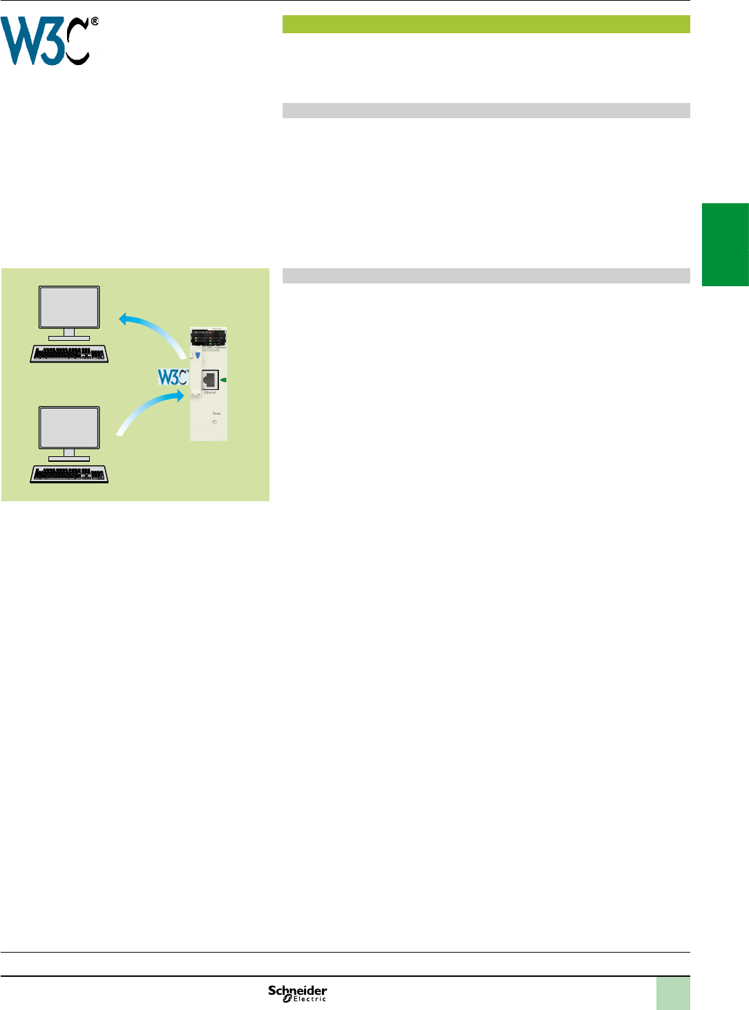
3/19
Modicon M340 automation
platform
Ethernet Modbus/TCP network
SOAP/XML Web services
SOAP/XML Web services
BMXNOE0110,BMXNOC0401 Ethernet network modules and BMXNOR0200H
RTU modules incorporate a standard SOAP/XML data server that provides direct
interoperability between control system devices and computer management
applications (MES, ERP, SAP, Net application, etc).
SOAP/XML Web services embedded in the PLC
These Web services conform to the W3C (WorldWideWebConsortium) Web
service standards. They offer standard open communication resources thanks to
which the control peripherals can interact directly with computer management
applications using a non-proprietary SOAP protocol.
SOAP/XML Web services are based on the following standards:
SOAP (SimpleObjectAccessProtocol), the exchange protocol executed via the
HTTP (HyperTextTransferProtocol) channel
WSDL (WebServicesDescriptionLanguage), in XML format
XML (eXtensibleMarkupLanguage), the universal standard for data exchange
ModbusXMLDa Web services: SOAP server interface
The implementation of ModbusXMLDa (ModbusXMLDataaccess) services in
control system device Web servers means IT engineers can easily create their own
application to access the desired information directly in the PLC, in real time.
Applications such as Microsoft.NET, SQL Server, Microsoft Ofce (Excel), IBM
(WebSphere), SUN (Java, Eclipse), Lotus, Oracle, SAP, MES, ERP, etc can interact
directly with the PLC module Web server.
Exchanges are initiated by the SOAP client application (the server responds to these
requests). Data exchanges are made in XML standard format in response to a request
using the SOAP protocol.
Step 1: Creation of the client application with learning of the Web services.
The development environment (for example, Visual Studio NET) looks in the
FactoryCast server for the list of available services and their WSDL standard
interfaces provided by the module.
Step 2: Development of the client application. The developer integrates the
Web service functions using the code retrieved at step 1 of the learning process.
Step 3: Execution of the client application. The client application
communicates in real time with the FactoryCast Web server module using the SOAP
protocol.
Functions(continued)
1, 2
3
SOAP
request
WSDL
Visual Studio NET
NET Java
FactoryCast
module
BMXNOE0110
SOAP
server
Development tool
Processors:
page 1/4
I/O:
pages 2/12 and 2/24
Software:
page 4/2
Ruggedized Modicon M340 modules:
page 6/2
2
1
3
4
5
6
7
8
9
10
2
1
3
4
5
6
7
8
9
10
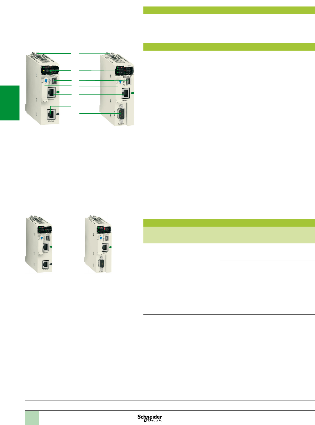
3/20
Presentation,
description,
references
Modicon M340 automation
platform
Processors with integrated Ethernet Modbus/TCP
port
Presentation
BMXP342020, BMXP3420302 and BMXP3420302CL standard format Modicon
M340 processors with integrated Ethernet port occupy a single slot marked “00” in
the rack on the Modicon M340 platform.
Description
The front panel of BMXP342020/20302/20302CL Modicon M340 processors
features:
1 A safety screw for locking the module in a slot in the rack.
2 A display block with 8 LEDs, including 3 relating to the Ethernet port:
ETH ACT LED (green): Activity on the Ethernet network
ETH STS LED (green): Ethernet network status
Depending on processor version:
Version 1: ETH 100 LED (green): data rate on the Ethernet network (10 or
100 Mbps)
Version 2 and later: ETH LNK LED (green): Ethernet link status
3 A mini B USB connector for a programming terminal (or Magelis XBTGT/GK/GTW
HMI terminal).
4 A slot equipped with its Flash memory card for saving the application and
activating the standard Web server (Transparent Ready class B10) (1).
5 An RJ45 connector for the connection to the Ethernet network.
Depending on model:
6 BMXP342020 processor: An RJ45 connector for the Modbus serial link or
Character mode link (RS 232C/RS 485, 2-wire, non-isolated)
7 BMXP3420302/20302CL processor: A 9-way SUB-D connector for the master
CANopen machine and installation bus.
On the rear panel: 2 rotary switches for selecting the IP address using one of
3 assignment methods:
Address set by the position of the two switches
Address set by the application parameters
Address set by the Ethernet network BOOTP server
References
Description I/O capacity
Memory capacity
Other integrated
communication ports
Reference Weight
kg
Processors with
integrated Ethernet
Modbus/TCP link
Transparent Ready
class B10
1024 discrete I/O
256 analog I/O
36 app-specic
channels 4096 KB
integrated
Modbus serial link
or Character mode
BMXP342020 0.205
CANopen bus BMXP3420302 0.215
Processors with
integrated Ethernet
Modbus/TCP link
without memory
card
Transparent Ready
class B10
1024 discrete I/O
256 analog I/O
36 app-specic
channels 4096 KB
integrated
CANopen bus BMXP3420302CL
(1)
0.215
(1)MemorycardmustbeorderedseparatelyfortheBMXP3420302CLprocessor(see
page1/9).
Processors:
page 1/4
I/O:
pages 2/12 and 2/24
Software:
page 4/2
Ruggedized Modicon M340 modules:
page 6/2
6
2
3
5
1
4
7
BMXP342020 BMXP3420302
BMXP3420302CL
2
1
3
4
5
6
7
8
9
10
2
1
3
4
5
6
7
8
9
10
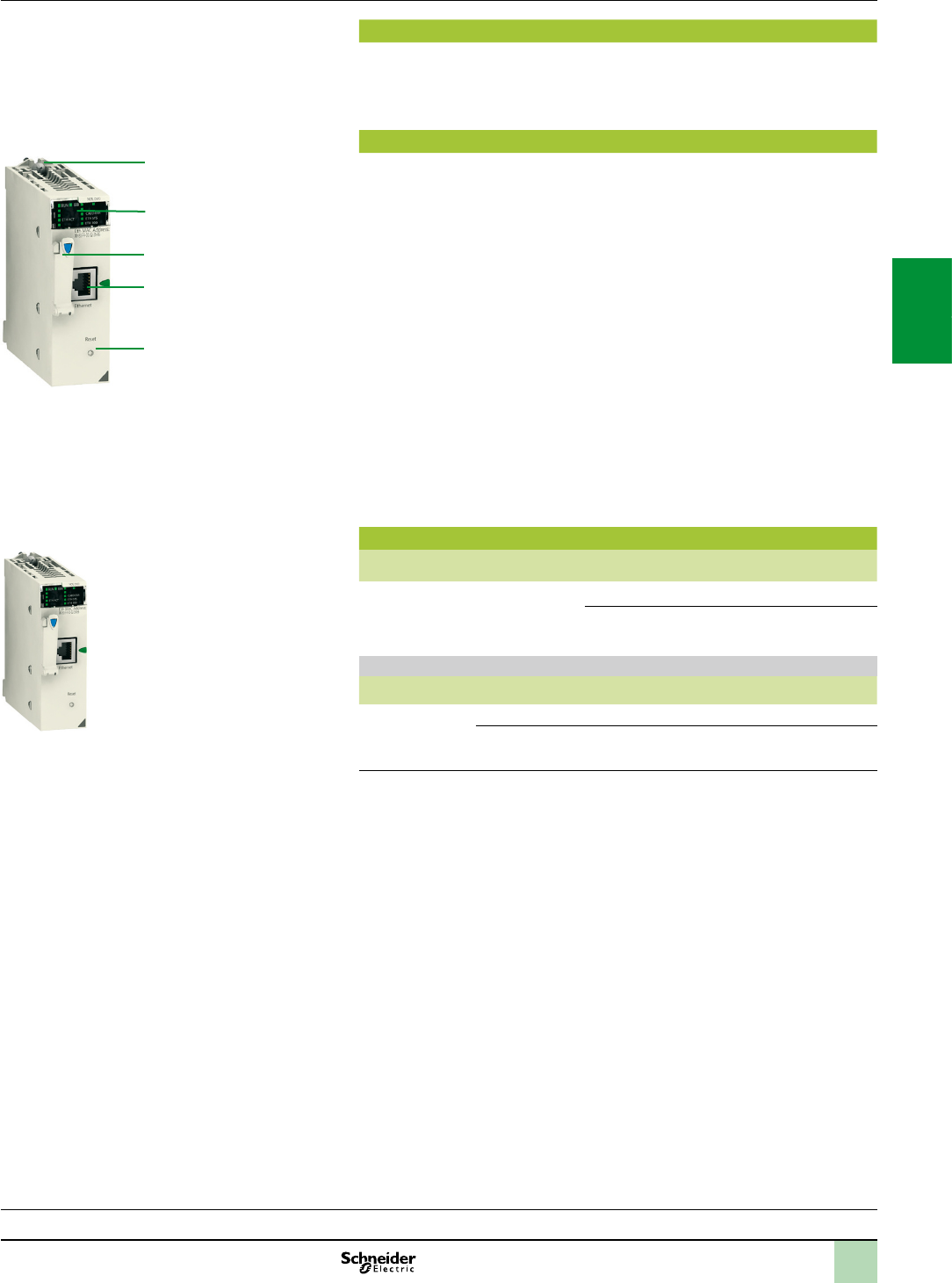
3/21
Presentation,
description,
references
Modicon M340 automation
platform
Ethernet Modbus/TCP network modules
Presentation
BMXNOE0100 and BMXNOE0110 standard format modules occupy a single slot in
the rack on the Modicon M340 platform equipped with a Standard or Performance
processor.
Description
The front panel of BMXNOE0100 and BMXNOE0110 modules features:
1 A safety screw for locking the module in a slot in the rack.
2 A display block with 6 LEDs, including 3 relating to the Ethernet port:
ETH ACT LED (green): Activity on the Ethernet network
ETH STS LED (green): Ethernet network status
Depending on processor version:
Version 1: ETH 100 LED (green): data rate on the Ethernet network (10 or
100 Mbps)
Version 2 and later: ETH LNK LED (green): Ethernet link status
3 A slot equipped with its Flash memory card for saving the application and activating
the Web server (Transparent Ready class B30 or C30 depending on the model).
4 An RJ45 connector for connection to the Ethernet network.
5 A pencil-point RESET pushbutton for a cold restart of the module.
On the rear panel: 2 rotary switches for assigning the IP address in one of three
ways:
Address set by the position of the two switches
Address set by the application parameters
Address set by the Ethernet network BOOTP server
References
Description Data rate Transparent Ready
Class
Reference Weight
kg
Ethernet Modbus/
TCP network
modules
10/100 Mbps B30 BMXNOE0100 0.200
C30 BMXNOE0110 (1) 0.200
Spare parts
Description Size Supplied
as standard with
Reference Weight
kg
Flash memory
cards
8 MB BMXNOE0100 BMXRWSB000M 0.002
32 MB BMXNOE0110 BMXRWSFC032M 0.002
(1)TheWebDesignersoftwareissuppliedonCD-ROMwiththeBMXNOE0110module.
ThissoftwareisusedforthecongurationandadministrationoftheWebserverembeddedin
themodule,seepage3/18.
5
2
4
1
3
BMXNOE0100/0110
Processors:
page 1/4
I/O:
pages 2/12 and 2/24
Software:
page 4/2
Ruggedized Modicon M340 modules:
page 6/2
2
1
3
4
5
6
7
8
9
10
2
1
3
4
5
6
7
8
9
10
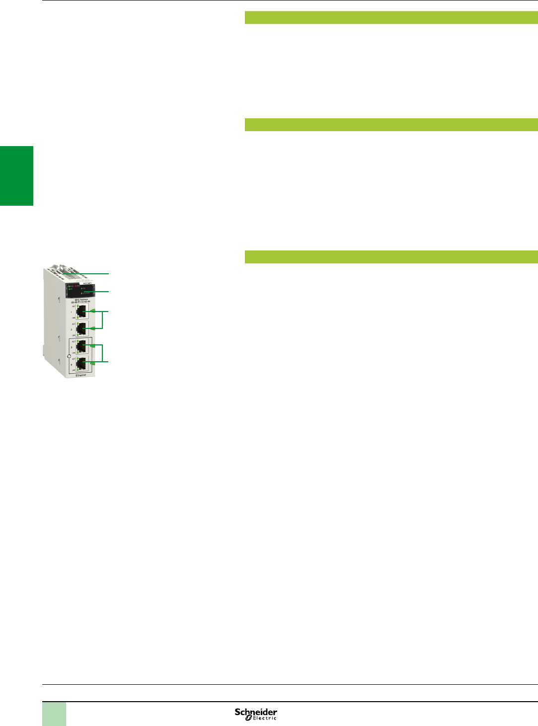
3/22
Presentation,
functions,
description
Modicon M340 automation
platform
Modbus/TCP and EtherNet/IP network module
Presentation
The BMXNOC0401 network module acts as an interface between the M340 PLC
and other Ethernet network devices via the Modbus/TCP and EtherNet/IP
communication protocols.
The standard format BMXNOC0401 network module occupies a single slot in the
rack of the Modicon M340 platform.
This must be equipped with a Standard BMXP341000 or Performance
BMXP342 processor.
Functions
The BMXNOC0401 module offers the following functions:
Modbus/TCP and EtherNet/IP protocols operating simultaneously.
Ring topologies on 2 Ethernet ports using RSTP (RapidSpanningTreeProtocol).
Priority of Ethernet packets using QoS (QualityofService)service.
Automatic module conguration recovery using FDR (FaultyDevice
Replacement)service.
Support for SCADA functions via the OPCprotocol.
Embedded Web server for application monitoring and module diagnostics.
Sharing data between PLCs.
Network management using SNMP (SimpleNetworkManagementProtocol).
Description
The front panel of the BMXNOC0401 module features:
1 A safety screw for locking the module in a slot in the rack.
2 A display block with 5 LEDs:
RUN LED (green): Operating status
ERR LED (red): Error detected
MS LED (green/red): Module status
NS LED (green/red): Network connection status
ETH STS LED (amber): Ethernet link status
3 Four RJ45 connectors for connection to the Ethernet network. The two bottom
connectors 3b support ring topologies (RSTP protocol).
Each RJ45 connector has two associated LEDs:
LNK LED (yellow): Ethernet link established
ACT LED (green): Transmission/reception activity
On the rear panel, 2 rotary switches for selecting the IP address module using one
of 4 assignment methods:
IP address dened by the Ethernet network BootP server
IP address congured by the application parameters
Default IP address
IP address dened by the position of the 2 rotary switches
1
2
3b
3
Processors:
page 1/4
I/O:
pages 2/12 and 2/24
Software:
page 4/2
Ruggedized Modicon M340 modules:
page 6/2
2
1
3
4
5
6
7
8
9
10
2
1
3
4
5
6
7
8
9
10

3/23
References Modicon M340 automation
platform
Modbus/TCP and EtherNet/IP network module
References
Description Data rate Transparent Ready
Class
Reference Weight
kg
EtherNet/IP,
Modbus/TCP
network module
10/100 Mbps B30 BMXNOC0401 (1) 0.345
(1)The“UnityProcongurationtool”softwareissuppliedonCD-ROMwiththemodule.
ThissoftwareisusedtoupdatetheUnityProhardwarecatalogue(additionofthenewmodule
DTMs).
Processors:
page 1/4
I/O:
pages 2/12 and 2/24
Software:
page 4/2
Ruggedized Modicon M340 modules:
page 6/2
BMXNOC0401
2
1
3
4
5
6
7
8
9
10
2
1
3
4
5
6
7
8
9
10
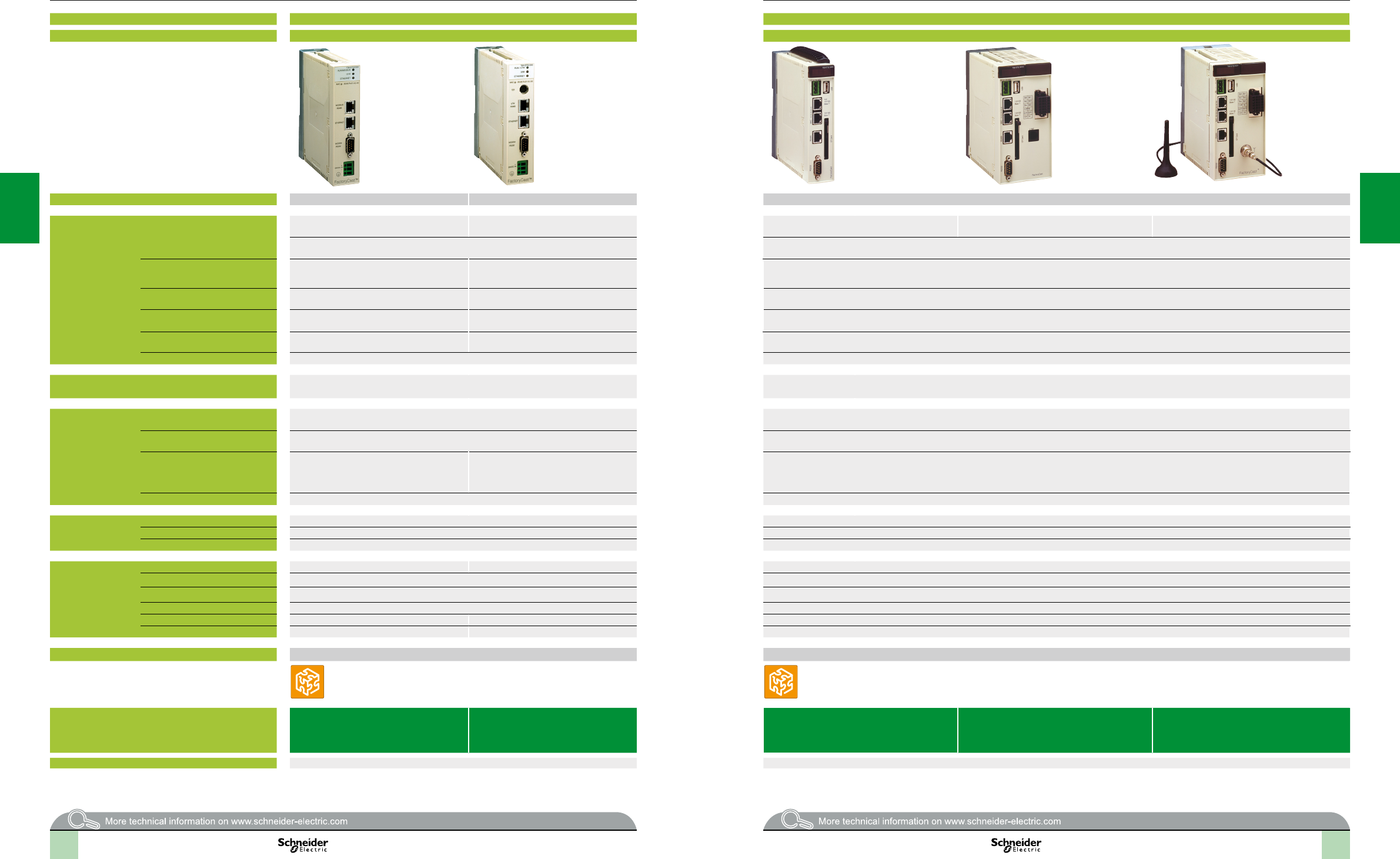
2
1
3
4
5
6
7
8
9
10
2
1
3
4
5
6
7
8
9
10
2
1
3
4
5
6
7
8
9
10
2
1
3
4
5
6
7
8
9
10
3/24 3/24
Web Designer
Selectionguide Modicon M340 automation
platform
Web servers and gateways
Applications Standalone Web Gateway/Server module for remote access Standalone Web Gateway/Server modules for remote access
Type FactoryCast Gateway ETG10p0 FactoryCast HMI Gateway ETG30pp
Target products Type All equipment supporting Modbus All equipment supporting Uni-Telway All Modicon PLCs and third-party equipment supporting Modbus
Network/Remote
access services
Remote access Intranet or via external Modem and integrated
RAS function
Intranet or Modem, External Modem and
integrated RAS function
Intranet or Modem, External Modem and integrated
RAS function
Intranet or Modem
RTC modem and integrated RAS function
Intranet or Modem
GSM modem and integrated RAS function
Remote programming, downloading via FTP, access to Web server via web browser Remote programming, downloading via FTP, access to Web server via web browser
Gateway function Ethernet to Modbus serial
Modem to Modbus serial and Ethernet
Ethernet to Uni-Telway serial
Modem to Uni-Telway and Ethernet
Ethernet to Uni-Telway serial, Modem to Modbus serial and Ethernet
Serial protocols Modbus master Uni-Telway slave Modbus master
Ethernet protocols Modbus/TCP Modbus/TCP
Uni-TE (Premium, Micro)
Modbus/TCP
TCP/IP protocols BootP/DHCP, DNS, SNMP agent, SMTP
client, NTP client (1), FTP
BootP/DHCP, DNS, SNMP agent, SMTP
client, NTP client (1), FTP
DHCP, DNS, SNMP agent, SMTP client, NTP client (1), FTP
Security Protection by IP address ltering and passwords Protection by IP address ltering and passwords
Web server Characteristics HTTP and FTP server, 8 MB memory available for user, hosting of user Web pages and
documents (Doc, Pdf, Excel)
HTTP and FTP server, 32 MB memory available for user Web pages, memory expansion using Compact Flash cards 1 GB max., hosting of user Web pages and
documents (Doc, Pdf, Excel)
Predened services Conguration Via Web Designer software or predened Web pages Via Web Designer software or predened Web pages
Diagnostics Serial device diagnostics via predened Web pages Network diagnostics, serial and Ethernet device diagnostics via predened Web pages
Monitoring Monitoring via animation tables
Display of PLC Unity program in a Web page
Monitoring of devices and application via
animation tables (read/write variables)
Display of PLC Unity program in a Web page
Monitoring of devices and application via animation tables (read/write variables)
Display of PLC Unity program in a Web page
Alarm management – –
Customizable
services
Graphic views Graphic monitoring via animated views (integrated graphic editor) Graphic monitoring via animated views (integrated graphic editor)
Unity Pro operator screen – –
User Web pages Graphic monitoring via animated Web pages created by the user Graphic monitoring via animated Web pages created by the user
Advanced and HMI
services
Calculation scripts – Arithmetic and logical scripts
E-mail service Alarm notication by e-mail Alarm notication by e-mail/SMS
Data logging – Data recorded in the module with date and time stamping (CSV les)
Database connection – Direct recording in an SQL, Oracle or MySQL server
Report service – Dynamic HTML report management
Recipe service – Management of “Recipe” data (storage and review locally or on remote database)
Application development software Web Designer (supplied with each module) Web Designer (supplied with each module)
References TSXETG1000 TSXETG1010 TSXETG3000 TSXETG3010 (PSTN modem) TSXETG3021
(GSM900/1800 MHz band)
TSXETG3022 function
(GSM850/1900 MHz band)
Catalogue or website www.schneider-electric.com www.schneider-electric.com
(1)ExceptwithTSXP57103M/153MModiconPremiumprocessorswhichdonothavetheNTPservice.
Web Designer
3/253/24
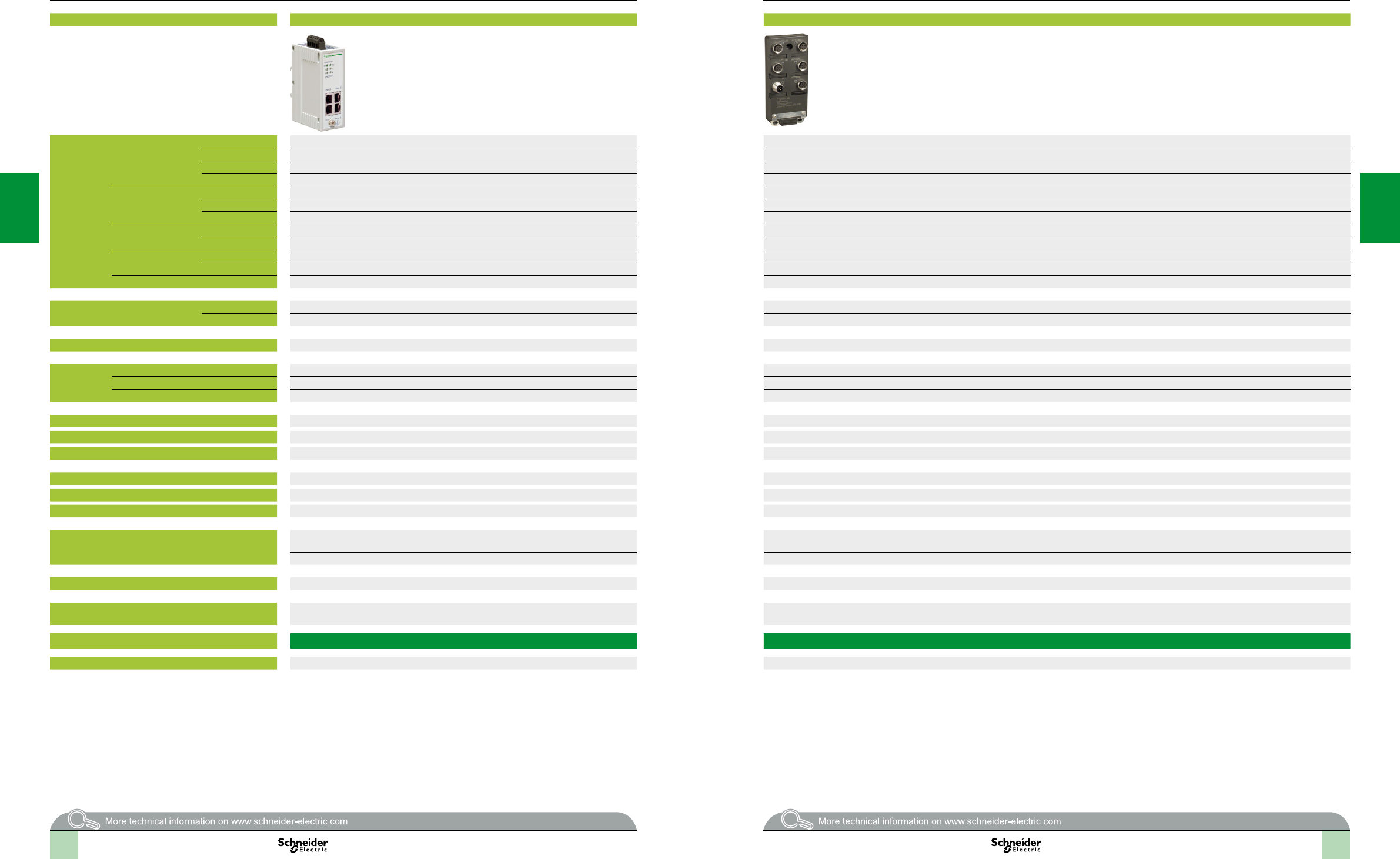
2
1
3
4
5
6
7
8
9
10
2
1
3
4
5
6
7
8
9
10
2
1
3
4
5
6
7
8
9
10
2
1
3
4
5
6
7
8
9
10
Device type Hub Unmanaged switches, copper twisted pair
Interfaces Copper cable ports Number and type 4 x 10BASE-T ports 5 x 10BASE-T/100BASE-TX ports
Shielded connectors RJ45 M12 (type D)
Medium Shielded twisted pair, category CAT 5E Shielded twisted pair, category CAT 5E
Total length of pair 100 m 100 m
Fibre optic ports Number and type – –
Connectors – –
Medium – –
Length of optical bre 50/125 µm – –
62.2/125 µm – –
Optical bre
attenuation analysis
50/125 µm bre – –
62.2/125 µm bre – –
Ethernet services – Storage and re-routing of received data, auto MDI/MDX, automatic negotiation of 10/100 Mbps and duplex mode (on all ports)
Topology Number of hubs or
switches
Cascaded 4 max. Unlimited
In a ring – –
Redundancy P1 and P2 redundant power supplies –
Power supply Voltage 24 V (18…32) safety extra low voltage (SELV) 24 V (18…32) safety extra low voltage (SELV)
Consumption 80 mA (130 max. at 24 V ) 100 mA max.
Removable terminal block 5 terminals 5 terminals, M12 (type A, male)
Operating temperature 0…+ 60°C 0…+ 60°C
Relative humidity 10…95% non-condensing –
Degree of protection IP 30 IP 67
Dimensions W x H x D 40 x 125 x 80 mm 60 x 126 x 31 mm
Mounting On symmetrical DIN rail, 35 mm wide On a at surface
Weight 0.530 kg 0.210 kg
Conforming to standards cUL 60950, UL 508 and CSA 22.2 No. 142, UL 1604 and CSA 22.2 No. 213 class 1 division 2,
, GL, C-Tick
cUL 508 and CSA 22.2 No. 142
FM 3810, FM 3611 class 1 division 2
LED indicators Power supply, activity, link Power supply, link status, data rate
Alarm relay Power supply fault, Ethernet network fault or communication port fault (volt-free contact 1 A
max. at 24 V )
–
Reference 499NEH10410 TCSESU051F0
Pages 3/46 3/47
Selectionguide Ethernet network
Cabling system
ConneXium hub and unmanaged switches
3/26 3/27
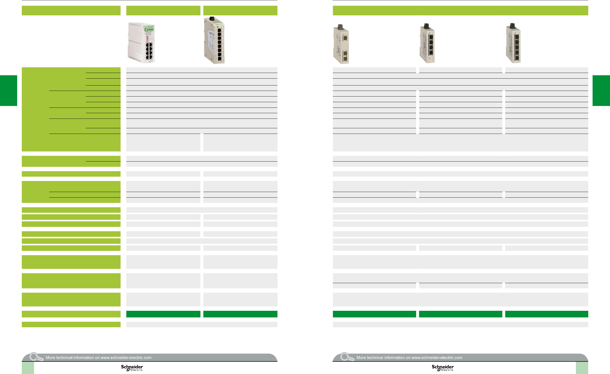
2
1
3
4
5
6
7
8
9
10
2
1
3
4
5
6
7
8
9
10
2
1
3
4
5
6
7
8
9
10
2
1
3
4
5
6
7
8
9
10
Selectionguide(continued) Ethernet network
Cabling system
ConneXium unmanaged switches
Device type Unmanaged switches, copper twisted pair Unmanaged switches (IP 67), copper
twisted pair
Unmanaged switches, 4 and 5 ports, copper twisted pair and bre optic
Interfaces Copper cable ports Number and type 8 x 10BASE-T/100BASE-TX ports 3 x 10BASE-T/100BASE-TX ports 4 x 10BASE-T/100BASE-TX ports 5 x 10BASE-T/100BASE-TX ports
Shielded connectors RJ45 RJ45
Medium Shielded twisted pair, category CAT 5E Shielded twisted pair, category CAT 5E
Total length of pair 100 m 100 m
Fibre optic ports Number and type – – 1 x 100BASE-FX port –
Connectors – – Duplex SC –
Medium – – Multimode optical bre –
Length of optical bre 50/125 µm – – 5000 m(1) –
62.2/125 µm – – 4000 m(1) –
Optical bre
attenuation analysis
50/125 µm bre – – 8 dB –
62.2/125 µm bre – – 11 dB –
Ethernet services – Storage and re-routing of received data, auto
MDI/MDX, automatic negotiation of 10/100
Mbps and duplex mode (on all ports),
automatic change of polarity
Storage and re-routing of received data, auto MDI/MDX, automatic negotiation of 10/100 Mbps and duplex mode (on all ports)
Topology Number of switches Cascaded Unlimited Unlimited
Redundant in a ring – –
Redundancy P1 and P2 redundant power supplies – –
Power supply Voltage 24 V (18…32) safety extra low voltage
(SELV)
24 V (9.6…32) SELV 24 V (9.6…32 V) safety extra low voltage (SELV)
Consumption 125 mA (290 mA max.) 4.1 W max. 2.2 W max. 3.9 W max. 2.2 W max.
Removable terminal block 5 terminals 3 terminals 3-terminal removable screw terminal block
Operating temperature 0…+ 60°C 0…+ 60°C
Relative humidity 10…95% non-condensing 95% max. non-condensing 95% max. non-condensing
Degree of protection IP 20 IP 30 IP 30
Dimensions W x H x D 47 x 135 x 111 mm 35 x 138 x 121 mm 25 x 114 x 79 mm
Mounting On symmetrical DIN rail, 35 mm wide On symmetrical DIN rail, 35 mm wide
Weight 0.230 kg 0.246 kg 0.113 kg 0.120 kg 0.113 kg
Conforming to standards cUL 60950, UL 508 and CSA 22.2 No. 142,
UL 1604 and CSA 22.2 No. 213 class 1
division 2, , GL, C-Tick
UL 508 and CSA 22.2 No.142
IEC/EN 61131-2,
IEC 60825-1 class 1, CISPR 11A
UL 508 and CSA 22.2 No. 142
IEC/EN 61131-2, IEC 60825-1 class 1, CISPR 11A
LED indicators P1 and P2 power supplies, Ethernet link/port
status
Power supply, copper port activity,
10 or 100 Mbps data rate
Power supply, copper port activity, 10 or 100 Mbps data rate
– Fibre port activity and status –
Alarm relay Power supply fault, Ethernet network fault or
communication port fault (volt-free contact 1 A
max. at 24 V )
– –
Reference 499NES18100 TCSESU083FN0 TCSESU033FN0 TCSESU043F1N0 TCSESU053FN0
Pages 3/47 3/48
(1)Lengthdependentontheattenuationanalysisandattenuationoftheopticalbre(typical
value:2000m).
3/28 3/29
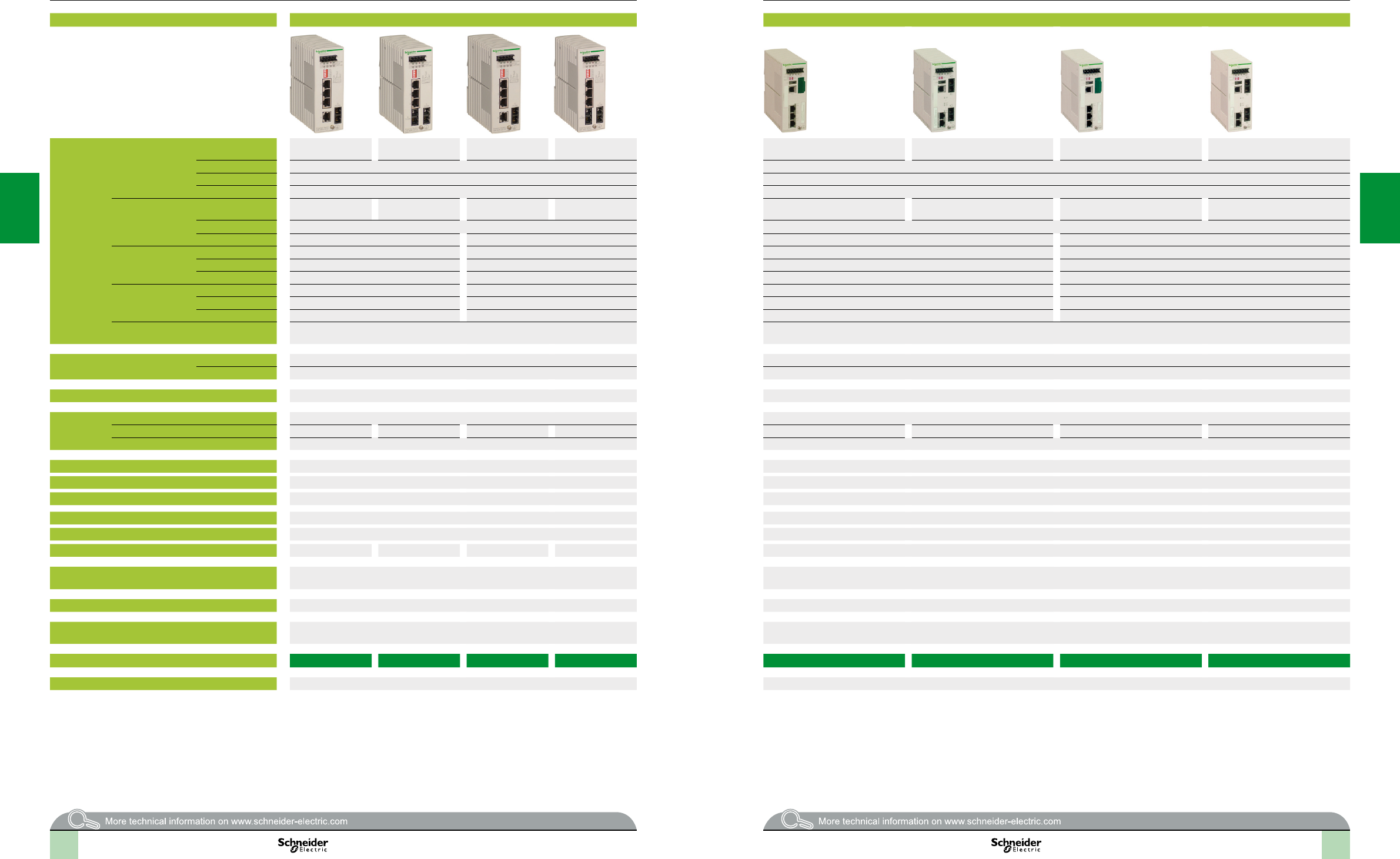
2
1
3
4
5
6
7
8
9
10
2
1
3
4
5
6
7
8
9
10
2
1
3
4
5
6
7
8
9
10
2
1
3
4
5
6
7
8
9
10
Device type Unmanaged switches, 5 ports, copper twisted pair and bre optic Managed switches, 4 ports, copper twisted pair and bre optic
Interfaces Copper cable ports Number and type 4 x 10BASE-T/
100BASE-TX ports
3 x 10BASE-T/
100BASE-TX ports
4 x 10BASE-T/
100BASE-TX ports
3 x 10BASE-T/
100BASE-TX ports
3 x 10/100BASE-TX ports 2 x 10/100BASE-TX ports 3 x 10/100BASE-TX ports 2 x 10/100BASE-TX ports
Shielded connectors RJ45 RJ45
Medium Shielded twisted pair, category CAT 5E Shielded twisted pair, category CAT 5E
Total length of pair 100 m 100 m
Fibre optic ports Number and type 1 x 100BASE-FX
port
2 x 100BASE-FX
ports
1 x 100BASE-FX
port
2 x 100BASE-FX
ports
1 x 100BASE-FX port 2 x 100BASE-FX ports 1 x 100BASE-FX port 2 x 100BASE-FX ports
Connectors SC Duplex SC
Medium Multimode optical bre Single mode optical bre Multimode optical bre Single mode optical bre
Length of optical bre 50/125 µm 5000 m(1) – 5000 m(1) –
62.2/125 µm 4000 m(1) – 4000 m(1) –
9/125 µm bre – 32,500 m(2) – 32,500 m(2)
Optical bre
attenuation analysis
50/125 µm bre 8 dB – 8 dB –
62.2/125 µm bre 11 dB – 11 dB –
9/125 µm bre – 16 dB – 16 dB
Ethernet services – FDR, SMTP V3, SNTP client, multicast ltering for optimization of the Global Data protocol, conguration via Web access,VLAN, IGMP Snooping, RSTP(Rapid
ScanningTreeProtocol), priority port, data stream control, secure port
Topology Number of switches Cascaded Unlimited Unlimited
Redundant in a ring – 50 max.
Redundancy P1 and P2 redundant power supplies Redundant power supplies, redundant single ring, ring coupling
Power supply Voltage 24 V (18…32 V) safety extra low voltage (SELV) 9.6...60 V /18…30 V safety extra low voltage (SELV)
Consumption 200 mA max. 240 mA max. 200 mA max. 240 mA max. 6.5 W 7.3 W 6.5 W 7.3 W
Removable terminal block 5 terminals 6 terminals
Operating temperature - 40...+ 70°C 0…+ 60°C
Relative humidity 10…95% non-condensing 10…90% non-condensing
Degree of protection IP 20 IP 20
Dimensions W x H x D 47 x 135 x 111 mm 47 x 131 x 111 mm
Mounting On symmetrical DIN rail, 35 mm wide On symmetrical DIN rail, 35 mm wide
Weight 0.330 kg 0.335 kg 0.330 kg 0.335 kg 0.400 kg
Conforming to standards cUL 60950, cUL 508 and CSA 22.2 No. 142, UL 1604 and CSA 22.2 No. 213 class 1 division 2,
, GL, C-Tick
IEC 61131-2, UL 508, UL 1604 class 1 division 2, CSA 22.2 No. 142 (cUL), CSA 22.2 No. 213 class 1 division 2 (cUL), , GL, C-Tick
LED indicators P1 and P2 power supplies, Ethernet link status, transmission activity Power supply status, alarm relay status, active redundancy, redundancy management, copper port status and copper port activity
Alarm relay Activity, power supply fault, Ethernet network fault or communication port fault (volt-free contact
1 A max. at 24 V )
Power supply fault, Ethernet network fault, communication port fault, redundancy fault (volt-free contact 1 A max. at 24 V )
Reference 499NMS25101 499NMS25102 499NSS25101 499NSS25102 TCSESM043F1CU0 TCSESM043F2CU0 TCSESM043F1CS0 TCSESM043F2CS0
Pages 3/48 3/49
(1)Lengthdependentontheattenuationanalysisandattenuationoftheopticalbre(typical
value:2000m).
(2)Lengthdependentontheattenuationanalysisandattenuationoftheopticalbre(typical
value:15,000m).
(1)Lengthdependentontheattenuationanalysisandattenuationoftheopticalbre(typicalvalue:2000m).
(2)Lengthdependentontheattenuationanalysisandattenuationoftheopticalbre(typicalvalue:15,000m).
Selectionguide(continued) Ethernet network
Cabling system
Managed and unmanaged ConneXium switches
3/30 3/31
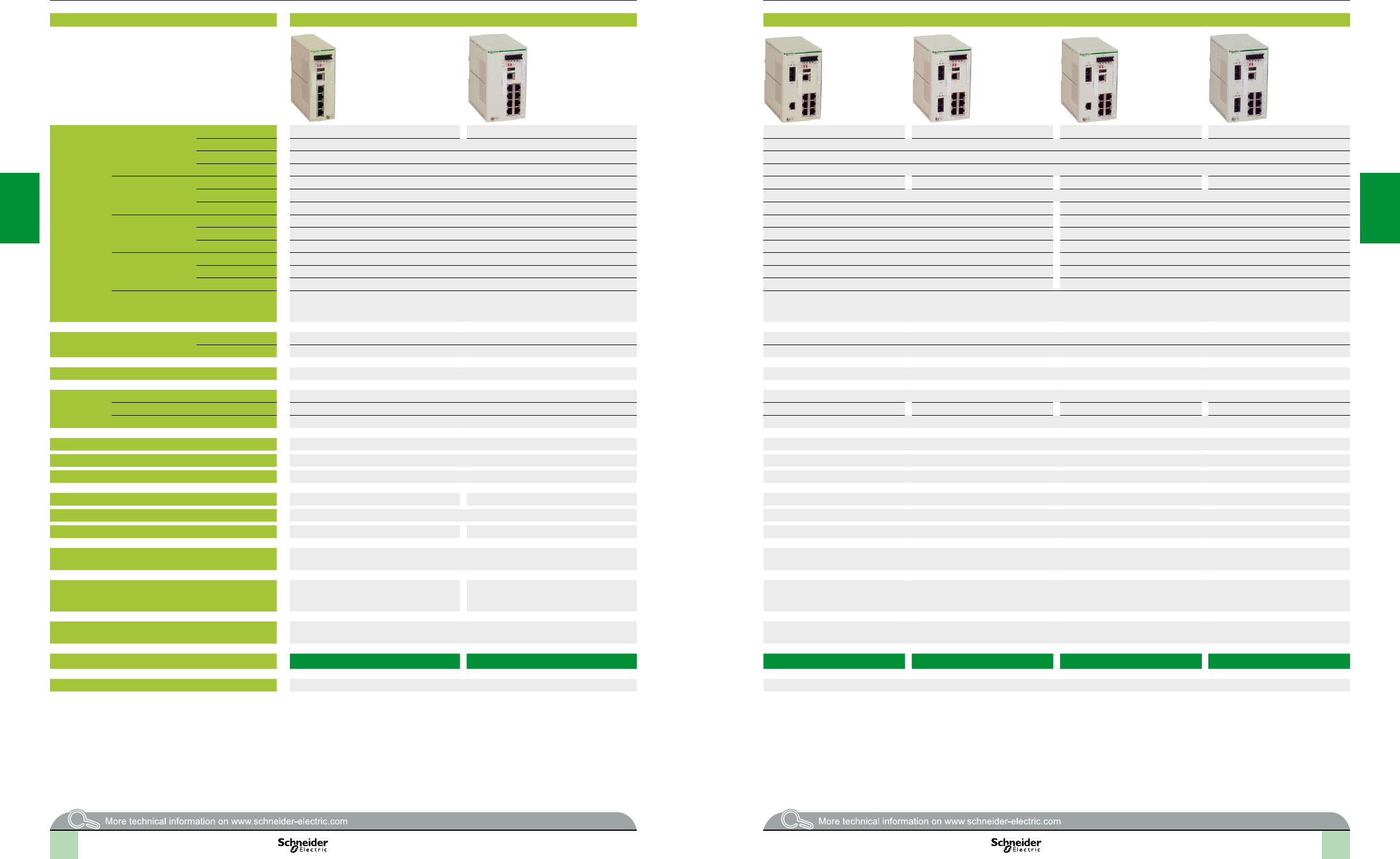
2
1
3
4
5
6
7
8
9
10
2
1
3
4
5
6
7
8
9
10
2
1
3
4
5
6
7
8
9
10
2
1
3
4
5
6
7
8
9
10
Device type Managed switches, 4 and 8 ports, copper twisted pair Managed switches, 8 ports, copper twisted pair and bre optic
Interfaces Copper cable ports Number and type 4 x 10/100BASE-TX ports 8 x 10/100BASE-TX ports 7 x 10/100BASE-TX ports 6 x 10/100BASE-TX ports 7 x 10/100BASE-TX ports 6 x 10/100BASE-T ports
Shielded connectors RJ45 RJ45
Medium Shielded twisted pair, category CAT 5E Shielded twisted pair, category CAT 5E
Total length of pair 100 m 100 m
Fibre optic ports Number and type – 1 x 100BASE-FX port 2 x 100BASE-FX ports 1 x 100BASE-FX port 2 x 100BASE-FX ports
Connectors – Duplex SC
Medium – Multimode optical bre Single mode optical bre
Length of optical bre 50/125 µm – 5000 m (1) –
62.2/125 µm – 4000 m (1) –
9/125 µm bre – – 32,500 m(2)
Attenuation analysis 50/125 µm bre – 8 dB –
62.2/125 µm bre – 11 dB –
9/125 µm bre – – 16 dB
Ethernet services FDR, SMTP V3, SNTP client, multicast ltering for optimization of the Global Data protocol,
conguration via Web access,VLAN, IGMP Snooping, RSTP(RapidScanningTreeProtocol),
priority port, data stream control, secure port
FDR, SMTP V3, SNTP client, multicast ltering for optimization of the Global Data protocol, conguration via Web access,VLAN, IGMP Snooping, RSTP(Rapid
ScanningTreeProtocol), priority port, data stream control, secure port
Topology Number of switches Cascaded Unlimited Unlimited
Redundant in a ring 50 max. 50 max.
Redundancy P1 and P2 redundant power supplies, redundant single ring, ring coupling Redundant power supplies, redundant single ring, ring coupling
Power supply Voltage 9.6...60 V /18…30 V safety extra low voltage (SELV) 9.6...60 V /18…30 V safety extra low voltage (SELV)
Consumption 5.3 W 6.5 W 7.3 W 6.5 W 7.3 W
Removable terminal block 6 terminals 6 terminals
Operating temperature 0...+ 60°C 0…+ 60°C
Relative humidity 10…90% non-condensing 10…90% non-condensing
Degree of protection IP 20 IP 20
Dimensions W x H x D 47 x 131 x 111 mm 74 x 131 x 111 mm 75 x 131 x 111 mm
Mounting On symmetrical DIN rail, 35 mm wide On symmetrical DIN rail, 35 mm wide
Weight 0.400 kg 0.410 kg 0.410 kg
Conforming to standards IEC/EN 61131-2, UL 508, UL 1604 class 1 division 2, CSA 22.2 No. 214 (cUL),
CSA 22.2 No. 213 class 1 division 2 (cUL), , GL, C-Tick
IEC/EN 61131-2, UL 508, UL 1604 class 1 division 2, CSA 22.2 No. 214 (cUL), CSA 22.2 No. 213 class 1 division 2 (cUL), , GL, C-Tick
LED indicators Power supply status, alarm relay status,
active redundancy, redundancy management,
copper port status and copper port activity
Power supply status, alarm relay status,
active redundancy, redundancy management,
bre port status and bre port activity
Power supply status, alarm relay status, active redundancy, redundancy management, bre port status and bre port activity
Alarm relay Power supply fault, Ethernet network fault or communication port fault (volt-free contact 1 A
max. at 24 V )
Power supply fault, Ethernet network fault or communication port fault (volt-free contact 1 A max. at 24 V )
Reference TCSESM043F23F0 TCSESM083F23F0 TCSESM083F1CU0 TCSESM083F2CU0 TCSESM083F1CS0 TCSESM083F2CS0
Pages 3/49 3/50
(1)Lengthdependentontheattenuationanalysisandattenuationoftheopticalbre(typicalvalue:2000m).
(2)Lengthdependentontheattenuationanalysisandattenuationoftheopticalbre(typicalvalue:15,000m).
Selectionguide(continued) Ethernet network
Cabling system
ConneXium managed switches
3/32 3/33
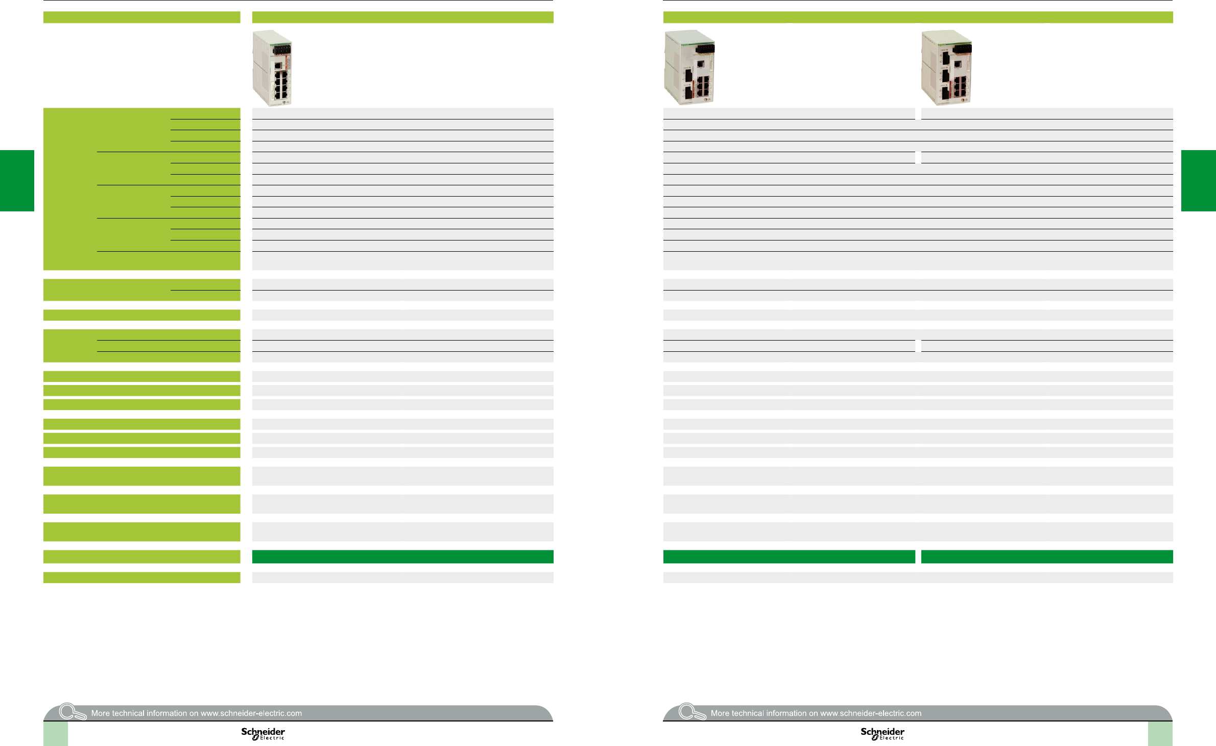
2
1
3
4
5
6
7
8
9
10
2
1
3
4
5
6
7
8
9
10
2
1
3
4
5
6
7
8
9
10
2
1
3
4
5
6
7
8
9
10
Device type Basic managed switch, 8 ports, copper twisted pair Basic managed switches, 8 and 9 ports, copper twisted pair and bre optic
Interfaces Copper cable ports Number and type 8 x 10/100BASE-TX ports 6 x 10/100BASE-TX ports 6 x 10/100BASE-TX ports
Shielded connectors RJ45 RJ45
Medium Shielded twisted pair, category CAT 5E Shielded twisted pair, category CAT 5E
Total length of pair 100 m 100 m
Fibre optic ports Number and type – 2 x 100BASE-FX ports 3 x 100BASE-FX ports
Connectors – Duplex SC
Medium – Multimode optical bre
Length of optical bre 50/125 µm – 5000 m (1)
62.2/125 µm – 4000 m (1)
9/125 µm bre – –
Attenuation analysis 50/125 µm bre – 8 dB+
62.2/125 µm bre – 11 dB
9/125 µm bre – –
Ethernet services FDR, SNTP client, multicast ltering for optimization of the Global Data protocol, conguration
via Web access, IGMP Snooping, RSTP (RapidScanningTreeProtocol), priority port
FDR, SNTP client, multicast ltering for optimization of the Global Data protocol, conguration via Web access, IGMP Snooping, RSTP (RapidScanningTree
Protocol), priority port
Topology Number of switches Cascaded Unlimited Unlimited
Redundant in a ring 50 max. 50 max.
Redundancy P1 and P2 redundant power supplies, redundant single ring, ring coupling P1 and P2 redundant power supplies, redundant single ring, ring coupling
Power supply Voltage 9.6...32 V safety extra low voltage (SELV) 9.6...32 V safety extra low voltage (SELV)
Consumption 6 W 8 W 9 W
Removable terminal block 6 terminals 6 terminals
Operating temperature 0...+ 60°C 0…+ 60°C
Relative humidity 95% max. non-condensing 95% max. non-condensing
Degree of protection IP 20 IP 20
Dimensions W x H x D 47 x 131 x 111 mm 74 x 131 x 111 mm
Mounting On symmetrical DIN rail, 35 mm wide On symmetrical DIN rail, 35 mm wide
Weight 0.400 kg 0.400 kg
Conforming to standards IEC/EN 61131-2, UL 508, UL 1604 class 1 division 2, CSA 22.2 No. 214 (cUL),
CSA 22.2 No. 213 class 1 division 2 (cUL), , GL, C-Tick
IEC/EN 61131-2, UL 508, UL 1604 class 1 division 2, CSA 22.2 No. 214 (cUL), CSA 22.2 No. 213 class 1 division 2 (cUL), , GL, C-Tick
LED indicators Power supply status, alarm relay status, active redundancy, redundancy management,
copper port status and copper port activity
Power supply status, alarm relay status, active redundancy, redundancy management, bre port status and bre port activity
Alarm relay Power supply fault, Ethernet network fault or communication port fault (volt-free contact 1 A
max. at 24 V )
Power supply fault, Ethernet network fault or communication port fault (volt-free contact 1 A max. at 24 V )
Reference TCSESB083F23F0 TCSESB083F2CU0 TCSESB093F2CU0
Pages 3/50 3/50
(1)Lengthdependentontheattenuationanalysisandattenuationoftheopticalbre(typicalvalue:2000m).
(2)Lengthdependentontheattenuationanalysisandattenuationoftheopticalbre(typicalvalue:15,000m).
Selectionguide(continued) Ethernet network
Cabling system
Basic ConneXium managed switches
3/34 3/35
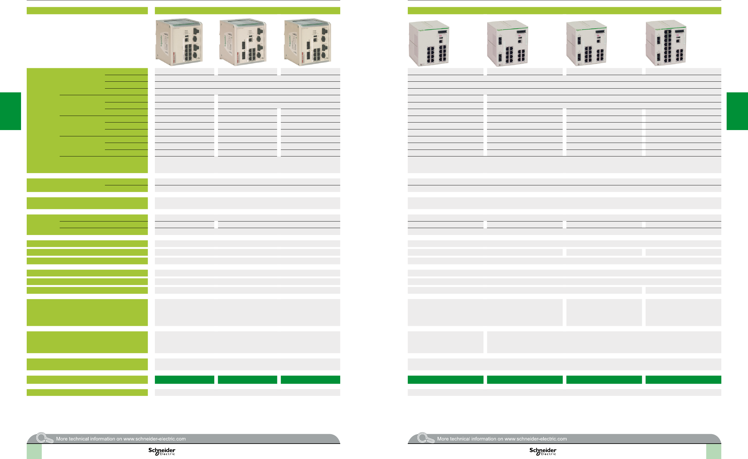
2
1
3
4
5
6
7
8
9
10
2
1
3
4
5
6
7
8
9
10
2
1
3
4
5
6
7
8
9
10
2
1
3
4
5
6
7
8
9
10
Device type Managed switches, 8 extended ports, copper twisted pair and bre optic Managed switches, 16 and 24 ports, copper twisted pair and bre optic
Interfaces Copper cable ports Number and type 8 x 10/100BASE-TX ports 6 x 10/100BASE-TX ports 6 x 10/100BASE-T ports 16 x 10/100BASE-TX ports 14 x 10/100BASE-TX ports 14 x 10/100BASE-TX ports 22 x 10/100BASE-TX ports
Shielded connectors RJ45 RJ45
Medium Shielded twisted pair, category CAT 5E Shielded twisted pair, category CAT 5E
Total length of pair 100 m 100 m
Fibre optic ports Number and type – 2 x 100BASE-FX ports – 2 x 100BASE-FX ports
Connectors – Duplex SC – Duplex SC
Medium – Multimode optical bre Single mode optical bre – Multimode optical bre Single mode optical bre Multimode optical bre
Length of optical bre 50/125 µm – 5000 m (1) – – 5000 m (1) – 5000 m (1)
62.2/125 µm – 4000 m (1) – – 4000 m (1) – 4000 m (1)
9/125 µm bre – – 32,500 m (2) – – 32,500 m (2) –
Attenuation analysis 50/125 µm bre – 8 dB – – 8 dB – 8 dB
62.2/125 µm bre – 11 dB – – 11 dB – 11 dB
9/125 µm bre – – 16 dB – – 16 dB –
Ethernet services FDR, SMTP V3, SNTP client, multicast ltering for optimization of the Global Data protocol,
conguration via Web access,VLAN, IGMP Snooping, RSTP(RapidScanningTreeProtocol),
priority port, data stream control, secure port
FDR, SMTP V3, SNTP client, multicast ltering for optimization of the Global Data protocol, conguration via Web access,VLAN, IGMP Snooping, RSTP(Rapid
ScanningTreeProtocol), priority port, data stream control, secure port
Topology Number of switches Cascaded Unlimited Unlimited
Redundant in a ring 50 max. 50 max.
Redundancy Redundant power supplies, redundant single ring, ring coupling,
rings supporting MRP, Fast HIPER Ring and RSTP
Redundant power supplies, redundant single ring, ring coupling
Power supply Voltage 18...60 V 9.6...60 V /18…30 V safety extra low voltage (SELV)
Consumption 10 W 12 W 9.4 W 11.8 W 11.8 W 15.5 W
Removable terminal block 2 terminal blocks, 2 terminals 6 terminals
Operating temperature 0...+ 60°C 0…+ 60°C
Relative humidity 10…90% non-condensing 10…90% non-condensing 95% max. non-condensing 10…90% non-condensing
Degree of protection IP 30 IP 20
Dimensions W x H x D 120 x 137 x 115 mm 111 x 131 x 111 mm
Mounting On symmetrical DIN rail, 35 mm wide On symmetrical DIN rail, 35 mm wide
Weight 1 kg 0.600 kg 0.650 kg
Conforming to standards IEC/EN 61131-2, IEC 61850-3, UL 508, UL 1604 class 1 division 2, CSA 22.2 No. 214 (cUL),
CSA 22.2 No. 213 class 1 division 2 (cUL), , GL, C-Tick, LR, BV
cUL 60950, UL 508 and CSA 22.2 No. 142, UL 1604 and CSA 22.2 No. 213
class 1 division 2
IEC/EN 61131-2,
UL 508, UL 1604 class 1 division 2,
CSA 22.2 No. 214 (cUL),
CSA 22.2 No. 213 class 1 division 2
(cUL), , GL, C-Tick
cUL 60950, UL 508 and
CSA 22.2 No. 142, UL 1604 and
CSA 22.2 No. 213 class 1 division 2
LED indicators Power supply status, alarm relay status, active redundancy, redundancy management, copper
port status and copper port activity
Power supply status, alarm relay
status, active redundancy,
redundancy management, copper
port status and copper port activity
Power supply status, alarm relay status, active redundancy, redundancy management, bre port status and bre port
activity
Alarm relay Power supply fault, Ethernet network fault or communication port fault (volt-free contact 1 A
max. at 24 V , 2-way)
Power supply fault, Ethernet network fault or communication port fault (volt-free contact 1 A max. at 24 V )
Reference TCSESM083F23F1 TCSESM063F2CU1 TCSESM063F2CS1 TCSESM163F23F0 TCSESM163F2CU0 TCSESM163F2CS0 TCSESM243F2CU0
Pages 3/50 3/51
(1)Lengthdependentontheattenuationanalysisandattenuationoftheopticalbre(typical
value:2000m).
(2)Lengthdependentontheattenuationanalysisandattenuationoftheopticalbre(typical
value:15,000m).
(1)Lengthdependentontheattenuationanalysisandattenuationoftheopticalbre(typicalvalue:2000m).
Selectionguide(continued) Ethernet network
Cabling system
ConneXium managed switches
3/36 3/37
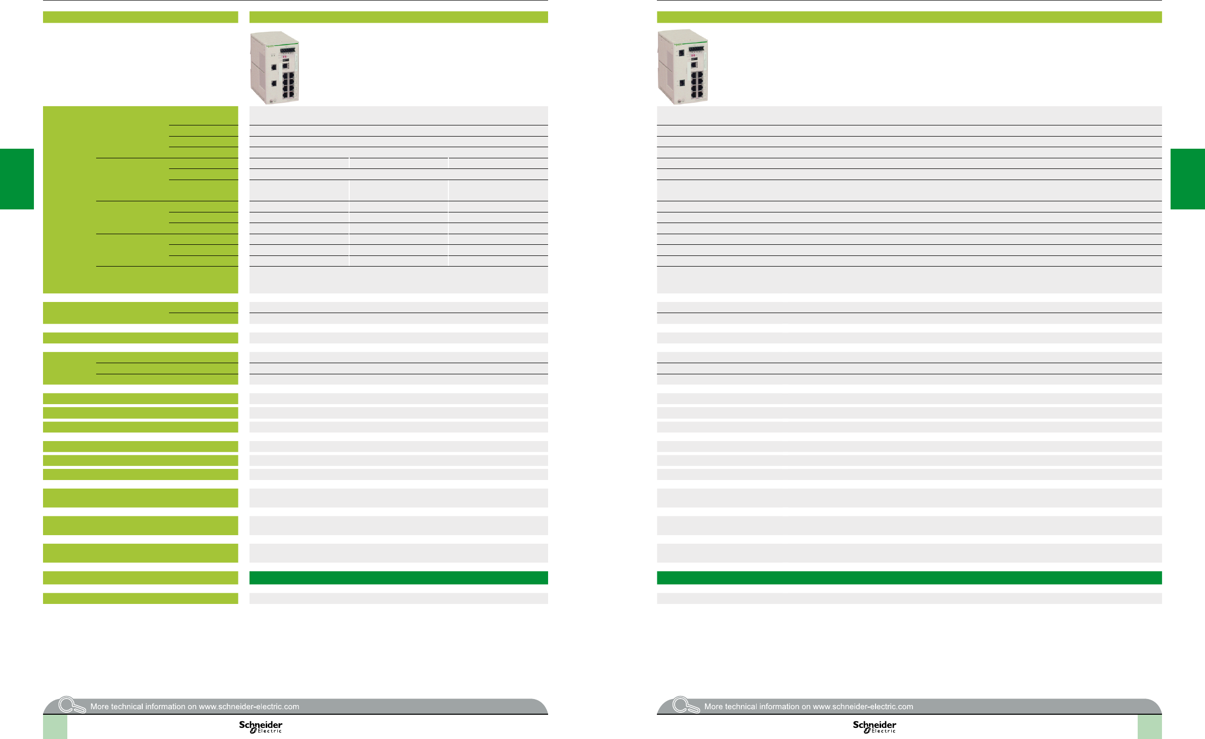
2
1
3
4
5
6
7
8
9
10
2
1
3
4
5
6
7
8
9
10
2
1
3
4
5
6
7
8
9
10
2
1
3
4
5
6
7
8
9
10
Device type Managed switch, 8 ports and 2 Gigabit ports, copper twisted pair and bre optic Managed switch, 8 ports and 2 Gigabit ports, copper twisted pair
Interfaces Copper cable ports Number and type 8 x 10/100BASE-TX ports 8 x 10/100BASE-TX ports and
2 x 10/100/1000BASE-TX ports (Gigabit)
Shielded connectors RJ45 RJ45
Medium Shielded twisted pair, category CAT 5E Shielded twisted pair, category CAT 5E
Total length of pair 100 m 100 m
Fibre optic
Gigabit ports
(with SFP bre optic
module to be mounted
on SFP connector)
Number and type 2 x 1000BASE-SX ports (1) 2 x 1000BASE-LH ports (2) 2 x 1000BASE-LX ports (3) –
Connectors LC LC
Medium Multimode optical bre Single mode optical bre Single mode and multimode
optical bre
–
Length of optical bre 50/125 µm 550 m – 550 m –
62.2/125 µm 275 m – 550 m –
9/125 µm bre – 8 - 72,000 m 20,000 m –
Attenuation analysis 50/125 µm bre 7.5 dB – 11 dB –
62.2/125 µm bre 7.5 dB – 11 dB –
9/125 µm bre – 6 - 22 dB 11 dB –
Ethernet services FDR, SMTP V3, SNTP client, multicast ltering for optimization of the Global Data protocol,
conguration via Web access, VLAN, IGMP Snooping, RSTP(RapidScanningTreeProtocol),
priority port, data stream control, secure port
FDR, SMTP V3, SNTP client, multicast ltering for optimization of the Global Data protocol, conguration via Web access,VLAN, IGMP Snooping, RSTP(Rapid
ScanningTreeProtocol), priority port, data stream control, secure port
Topology Number of switches Cascaded Unlimited Unlimited
Redundant in a ring 50 max. 50 max.
Redundancy Redundant power supplies, redundant single ring, ring coupling Redundant power supplies, redundant single ring, ring coupling
Power supply Voltage 9.6...60 V /18…30 V safety extra low voltage (SELV) 9.6...60 V /18…30 V safety extra low voltage (SELV)
Consumption 8.9 W + 1 W per SFP bre optic module 8.3 W
Removable terminal block 6 terminals 6 terminals
Operating temperature 0...+ 60°C 0...+ 60°C
Relative humidity 10…90% non-condensing 10…90% non-condensing
Degree of protection IP 20 IP 20
Dimensions W x H x D 111 x 131 x 111 mm 111 x 131 x 111 mm
Mounting On symmetrical DIN rail, 35 mm wide On symmetrical DIN rail, 35 mm wide
Weight 0.410 kg 0.410 kg
Conforming to standards cUL 60950, UL 508 and CSA 22.2 No. 142, UL 1604 and CSA 22.2 No. 213 class 1 division 2,
, GL
cUL 60950, UL 508 and CSA 22.2 No. 142, UL 1604 and CSA 22.2 No. 213 class 1 division 2, , GL
LED indicators Power supply status, alarm relay status, active redundancy, redundancy management,
bre port status and bre port activity
Power supply status, alarm relay status, active redundancy, redundancy management, bre port status and bre port activity
Alarm relay Power supply fault, Ethernet network fault or communication port fault (volt-free contact 1 A
max. at 24 V )
Power supply fault, Ethernet network fault or communication port fault (volt-free contact 1 A max. at 24 V )
Reference TCSESM103F2LG0 TCSESM103F23G0
Pages 3/51 3/51
(1)WithTCSEAAF1LFU00breopticmoduletobeorderedseparately(seepage3/45).
(2)WithTCSEAAF1LFH00breopticmoduletobeorderedseparately(seepage3/45).
(3)WithTCSEAAF1LFS00breopticmoduletobeorderedseparately(seepage3/45).
Selectionguide(continued) Ethernet network
Cabling system
ConneXium managed switches
3/38 3/39
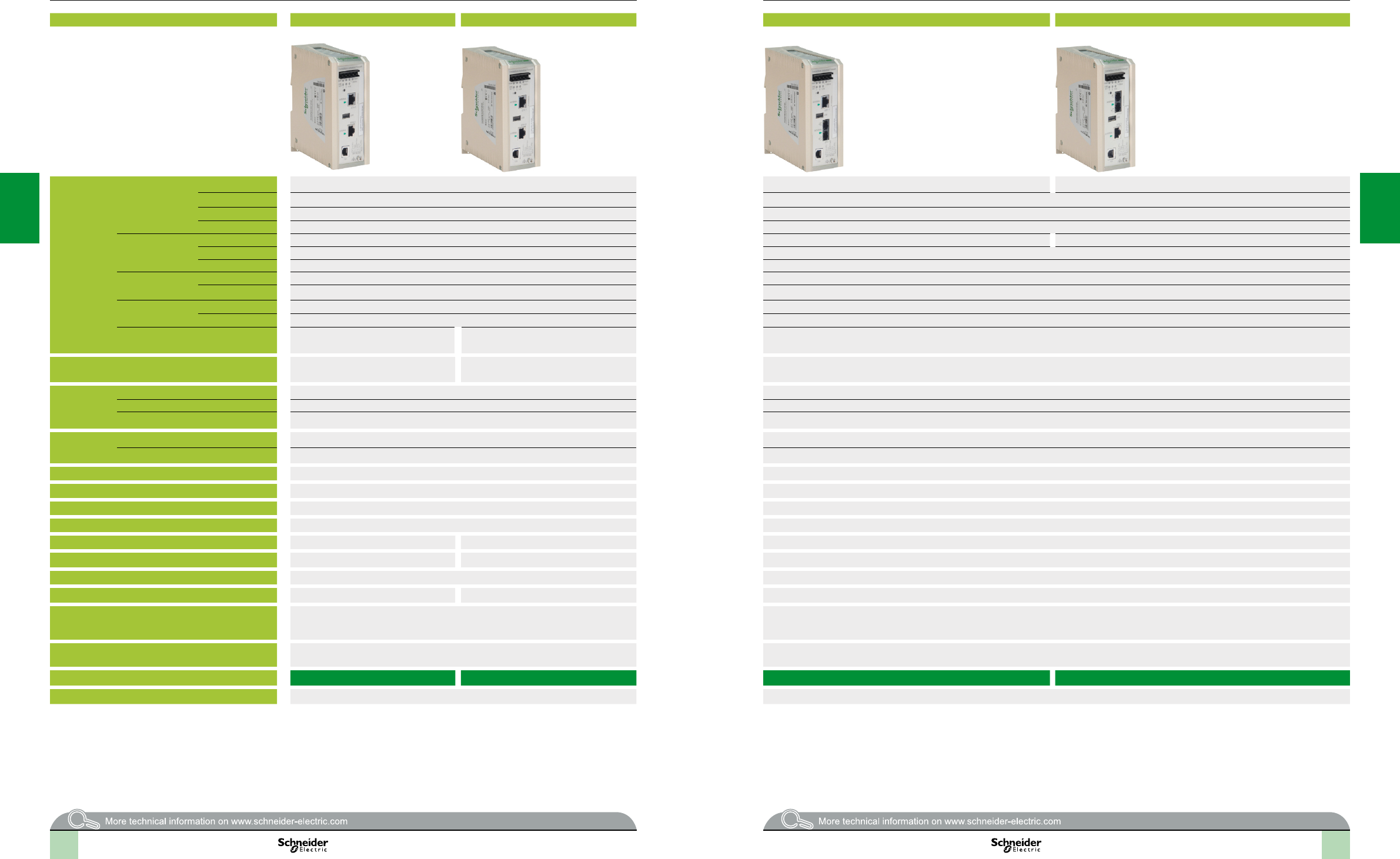
2
1
3
4
5
6
7
8
9
10
2
1
3
4
5
6
7
8
9
10
2
1
3
4
5
6
7
8
9
10
2
1
3
4
5
6
7
8
9
10
3/40 3/40
Selectionguide Ethernet networks
ConneXium industrial Firewalls
Device type TX/TX rewall TX/TX Tono rewall TX/MM rewall MM/TX rewall
Interfaces Copper cable ports Number and type 2 x 10/100 BASE-TX ports for internal and external networks 1 x 10/100BASE-TX port for internal network 1 x 10/100BASE-TX port for external network
Shielded connectors RJ45 type RJ45 type
Medium Shielded twisted pair, category CAT 5E Shielded twisted pair, category CAT 5E
Total length of pair 100 m/328.08 ft 100 m/328.08 ft
Fibre optic ports Number and type – 1 x 100BASE-FX port for external network 1 x 100BASE-FX port for internal network
Connectors – Duplex SC type
Medium – Multimode optical ber
Length of optical bre 50/125 µm – 5000 m (2)
62.2/125 µm – 4000 m (3)
Attenuation analysis 50/125 µm bre – 8 dB
62.2/125 µm bre – 11 dB
Conguration tools Conguration via Web access or command
line interface
Menu based off-line conguration software that
is included with the rewall
Conguration via Web access or command line interface
Security capabilities Packet ltering, network address translation,
VPN, denial of service, routing, redundancy
Built-in security modules that include Firewall,
Modbus/TCP Enforcer and Event Logger
Packet ltering, network address translation, VPN, denial of service, routing, redundancy
Power supply Voltage 12 to 48 V (minimum 9 V to maximum 60 V)or24 V (minimum 18 V to maximum 30 V) 12 to 48 V (minimum 9 V to maximum 60 V) or24 V (minimum 18 V to maximum 30 V)
Consumption 6.9 W max. 8.1 W max.
Hold up time Minimum 20 ms at20.4 V Minimum 20 ms at 20.4 V
Ambiant air
temperature
For operating 0 to 60 °C/32 to 140 °F 0 to 60 °C/32 to 140 °C
For storage - 40 to 70 °C/- 40 to 158 °F - 40 to 70 °C/- 40 to 158 °F
Relative humidity 10 to 95% non-condensing 10 to 95% non-condensing
Maximum operating altitude 2000 m/6560 ft 2000 m/6560 ft
Pollution degree 2 2
Degree of protection IP 20 IP 20
MTBF (mean time between failures) 450 861 hr. at 25 °C/77 °F 240 024 hr. at 25 °C/77 °F 426672 hr. at 25 °C/77 °F
Dimensions W x H x D 60 x 145 x 125 mm/2.36 x 5.71 x 4.92 in 60 x 145 x 123 mm/2.36 x 5.71 x 4.84 in 60 x 145 x 125 mm/2.36 x 5.71 x 4.92 in
Mounting 35 mm/1.38 in DIN rail 35 mm/1.38 in DIN rail
Weight 0.600 kg/21.160 oz 0.615 kg/21.700 oz 0.630 kg/22.220 oz
Standards and certications
IEC 60068-2-6, IEC 60068-2-27, EN 61000-4-2, EN 61000-4-3, EN 61000-4-4,
EN 61000-4-5, EN 61000-4-6, EN 61000-4-9, EN 55022 class A/FCC 47 CFR Part 15 class A
cUL 508:1988, (1)
EN60825-1, IEC 60068-2-6, IEC 60068-2-27, EN 61000-4-2, EN 61000-4-3, EN 61000-4-4, EN 61000-4-5, EN 61000-4-6, EN 61000-4-9,
EN 55022 class A/FCC 47 CFR Part 15 class A
cUL 508:1988,
LED indicators Power Supply 1, Power Supply 2, Fault, Device Status, External Port Status,
Internal Port Status, Serial Port Status
Power Supply 1, Power Supply 2, Fault, Device Status, External Port Status,
Internal Port Status, Serial Port Status
References TCSEFEC23F3F20 TCSEFEA23F3F20 TCSEFEC23FCF20 TCSEFEC2CF3F20
Pages 3/51 3/51
(1)TheConneXiumTonoIndustrialEthernetFirewallTCSEFEA23F3F20isalsocompliantwith
theGermanischerLloydVI-7-3Part1Ed.2003certication.
(2)Lengthdependentontheattenuationanalysisandattenuationoftheopticalbre(typical
value:2000m).
(3)Lengthdependentontheattenuationanalysisandattenuationoftheopticalbre(typical
value:15,000m).
3/41
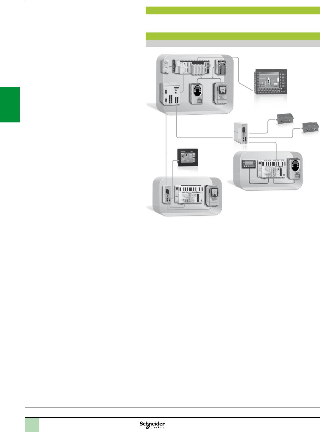
3/42
Presentation
Schneider Electric offers copper and bre optic cables for connecting IP 20 and IP 67
Ethernet devices.
Examples
Mixed IP 20 and IP 67 wiring (copper)
2, 4
2, 4
2, 4
1, 3
1, 3
1, 3
1, 3
1, 3
8
8
1, 3
Key:
1, 3 : Straight-through copper cables
2, 4 : Crossover copper cables
8 : Cables with IP 67 connector (see page 3/45)
Selection guide:
page 3/26
Wiringsystem Ethernet network 0
Infrastructure
2
1
3
4
5
6
7
8
9
10
2
1
3
4
5
6
7
8
9
10
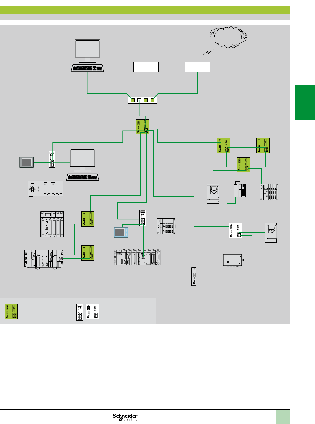
3/43
Examples (continued)
Mixed copper and bre optic wiring
Key:
1, 3: Straight-through copper cables
2, 4 : Crossover copper cables
5, 6, 7 : Fibre optic cables
8 : Cables with IP 67 connector (see pages 3/44 and 3/45)
Wiringsystem(continued) Ethernet network 0
Infrastructure
Selection guide:
page 3/26
Firewall
5, 6, 7
2, 4
8
Magelis XBT
Magelis XBT Modicon STB
Modicon STB
Twido
Altivar 71
Altivar 71
Ositrack
Modbus
Modicon M340
Modicon Quantum
Modicon Premium
1, 3 1, 3
1, 3
1, 3
1, 3
1, 3
1, 3
1, 3
1, 3
1, 3
1, 31, 3
1, 3
1, 3
1, 3
1, 3
2, 4
2, 4
2, 4 2, 4
2, 4 2, 4
2, 4 2, 4
2, 4
Preventa safety PLC
Internet
MES Client
Router
FactoryCast
gateway
Managed
switch
Hub or
unmanaged switch
Fibre optic link
Copper link
Copper link
Server 2
1
3
4
5
6
7
8
9
10
2
1
3
4
5
6
7
8
9
10

3/44
Shielded copper connection cables
ConneXium shielded connection cables are available in two versions to meet the various current standards and
approvals:
EIA/TIA 568 shielded twisted pair cables for market
These cables conform to:
EIA/TIA-568 standard, category CAT 5E
IEC 11801/EN 50173-1 standard, class D
Their re resistance conforms to:
NF C32-070 standard, class C2
IEC 322/1 standards
Low Smoke Zero Halogen (LSZH)
EIA/TIA 568 shielded twisted pair cables for UL market
These cables are:
CEC type FT-1
NEC type CM
A new range of ConneXium fully shielded preassembled cables has been specially designed for use in harsh
industrial environments. These cables combine a category 5E shielded cable and RJ45 connectors reinforced
with a metal prole.
EIA/TIA 568 shielded twisted pair cables for market
Description With connectors
at both ends
No. Type Length Reference Weight
kg
Straight-through
copper cables
compatible
2 x RJ45 connectors
For connection to
terminal equipment
(DTE)
1Standard 2 m 490NTW00002 –
5 m 490NTW00005 –
12 m 490NTW00012 –
40 m 490NTW00040 –
80 m 490NTW00080 –
Ruggedized 1 m TCSECE3M3M1S4 –
2 m TCSECE3M3M2S4 –
3 m TCSECE3M3M3S4 –
5 m TCSECE3M3M5S4 –
10 m TCSECE3M3M10S4 –
Crossover copper
cables
compatible
2 x RJ45 connectors
For connection between
hubs, switches and
transceivers
2Standard 5 m 490NTC00005 –
15 m 490NTC00015 –
40 m 490NTC00040 –
80 m 490NTC00080 –
Shielded twisted pair cables for UL market
Description With connectors
at both ends
No. Type Length Reference Weight
kg
Straight-through
copper cables
UL compatible
2 x RJ45 connectors
For connection to
terminal equipment
(DTE)
3Standard 2 m 490NTW00002U –
5 m 490NTW00005U –
12 m 490NTW00012U –
40 m 490NTW00040U –
80 m 490NTW00080U –
Ruggedized 1 m TCSECU3M3M1S4 –
2 m TCSECU3M3M2S4 –
3 m TCSECU3M3M3S4 –
5 m TCSECU3M3M5S4 –
10 m TCSECU3M3M10S4 –
Crossover copper
cables
UL compatible
2 x RJ45 connectors
For connection between
hubs, switches and
transceivers
4Standard 5 m 490NTC00005U –
40 m 490NTC00040U –
80 m 490NTC00080U –
Do it Yourself copper cable and connectors
The ConneXium Do it Yourself offer consists of 2 references for connectors (M12 and RJ45) and 1 cable
reference (300 m coil), enabling Ethernet 10/100 Mbps networks to be cabled in the eld.
The maximum length of cables created in this way is 80 m.
They are quick to assemble using a knife and simple wire cutters (no special tools are required).
Description Characteristics Length Reference Weight
kg
Ethernet copper cable
2 shielded twisted pairs
24 AWG
Conforms to the standards
and approvals listed above
300 m TCSECN300R2 –
RJ45 connector Conforms to EIA/TIA-568-D – TCSEK3MDS –
M12 connector Conforms to IEC 60176-2-101 – TCSEK1MDRS –
References Ethernet network
Wiring system
ConneXium connection components
TCSECp3M3MppS4
2
1
3
4
5
6
7
8
9
10
2
1
3
4
5
6
7
8
9
10

3/45
Selection guide:
page 3/26
Glass bre optic cables
Glass bre optic cables are intended for connection:
To terminal devices (DTE)
Between hubs, transceivers and switches
Description With connectors
at both ends
No. Length Reference Weight
kg
Glass bre optic cables 1 SC connector
1 MT-RJ connector
55 m 490NOC00005 –
1 ST (BFOC) connector
1 MT-RJ connector
65 m 490NOT00005 –
2 MT-RJ connectors 73 m 490NOR00003 –
5 m 490NOR00005 –
Separate parts for TCS ESM and TCS ESB switches
Description Optical bre Type Reference Weight
kg
Fibre optic modules for
Gigabit ports
with LC connector (1)
Multimode 50/125 µm or 62.5/125 µm 1000BASE
-SX
TCSEAAF1LFU00 0.040
Single mode 9/125 µm 1000BASE
-LH
TCSEAAF1LFH00 0.040
Multimode 50/125 µm or 62.5/125 µm
Single mode 62.5/125 µm
1000BASE
-LX
TCSEAAF1LFS00 0.040
Description Use Port Reference Weight
kg
Conguration backup key
for TCS ESM switches
Connected on the front
of the switch, used to:
- Save and retrieve the switch conguration
- Update the internal software
USB TCSEAM0100 –
Conguration backup key
for TCS ESB switches
RJ45 (V24) TCSEAM0200 –
Connection components for IP 67 switch
Description With connectors
at both ends
No. Length Reference Weight
kg
Straight-through copper
cables
1 x IP 67 4-way M12 connector
and 1 x RJ45 connector
81 m TCSECL1M3M1S2 –
3 m TCSECL1M3M3S2 –
10 m TCSECL1M3M10S2 –
25 m TCSECL1M3M25S2 –
40 m TCSECL1M3M40S2 –
2 x IP 67 4-way M12
connectors
–1 m TCSECL1M1M1S2 –
3 m TCSECL1M1M3S2 –
10 m TCSECL1M1M10S2 –
25 m TCSECL1M1M25S2 –
40 m TCSECL1M1M40S2 –
Power supply cables 2 female M12
straight connectors
–2 m XZCP1164L2 –
5 m XZCP1164L5 –
2 female M12
elbowed connectors
–2.5 m XZCP1264L2 –
5 m XZCP1264L5 –
2 female M12
straight connectors
––XZCC12FDM50B –
2 female M12
elbowed connectors
––XZCC12FCM50B –
M12/RJ45 adaptor IP 67 4-way female M12 connector
and female RJ45 connector
––TCSEAAF11F13F00 –
Reinforced connectors and ConneXium Ethernet cables
Description Characteristics Length Reference Weight
kg
Ethernet cable
4 pairs
Conforms to the CE standards 300 m TCSECE300R2 –
Conforms to the UL standards 300 m TCSECU300R2 –
RJ45 reinforced
connectors
Set of 2 connectors – TCSEK3MR2 –
Set of 10 connectors – TCSEK3MR10 –
(1)Dimensions:WxHxD=20x18x50mm
490NOT00005
490NOR00005
490NOC00005
References(continued) Ethernet network
Wiring system
ConneXium connection components
2
1
3
4
5
6
7
8
9
10
2
1
3
4
5
6
7
8
9
10
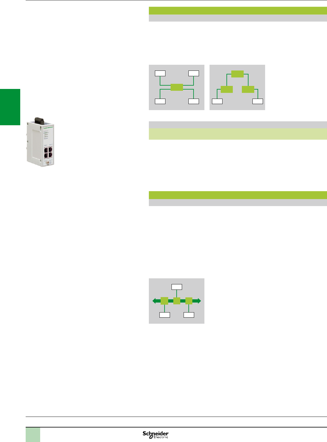
3/46
ConneXium hub
Presentation
Hubs(concentrators) are used for transmitting signals between several media
(ports). Hubs are plug and play devices that do not need to be congured by the
user.
The use of hubs makes it possible to create the following topologies:
Star topology
Tree topology
DTE DTE
DTE DTE
DTE DTE
Star topology Tree topology
Hub
Hub
HubHub
Reference
Description Interfaces Reference Weight
kg
ConneXium hub 4 x 10BASE-T ports (copper
cable), RJ45 shielded
connectors
499NEH10410 0.530
ConneXium transceiver
Presentation
ConneXium transceivers are used to:
Create bre optic linear bus topologies, for devices with a twisted pair cable
Ethernet connection
Interface devices with a twisted pair cable Ethernet connection with a bre optic
cable
Transceivers are plug and play devices that do not need to be congured by the
user.
ConneXium transceivers provide bre optic connections for transmission in areas
subject to interference (high levels of electromagnetic interference) and for long
distance communications.
DTEDTE
DTE
Linear topology on optical bre
499NEH10410
Selection guide:
page 3/26
Presentation,
references Ethernet network
Wiring system
ConneXium hub and transceiver
2
1
3
4
5
6
7
8
9
10
2
1
3
4
5
6
7
8
9
10
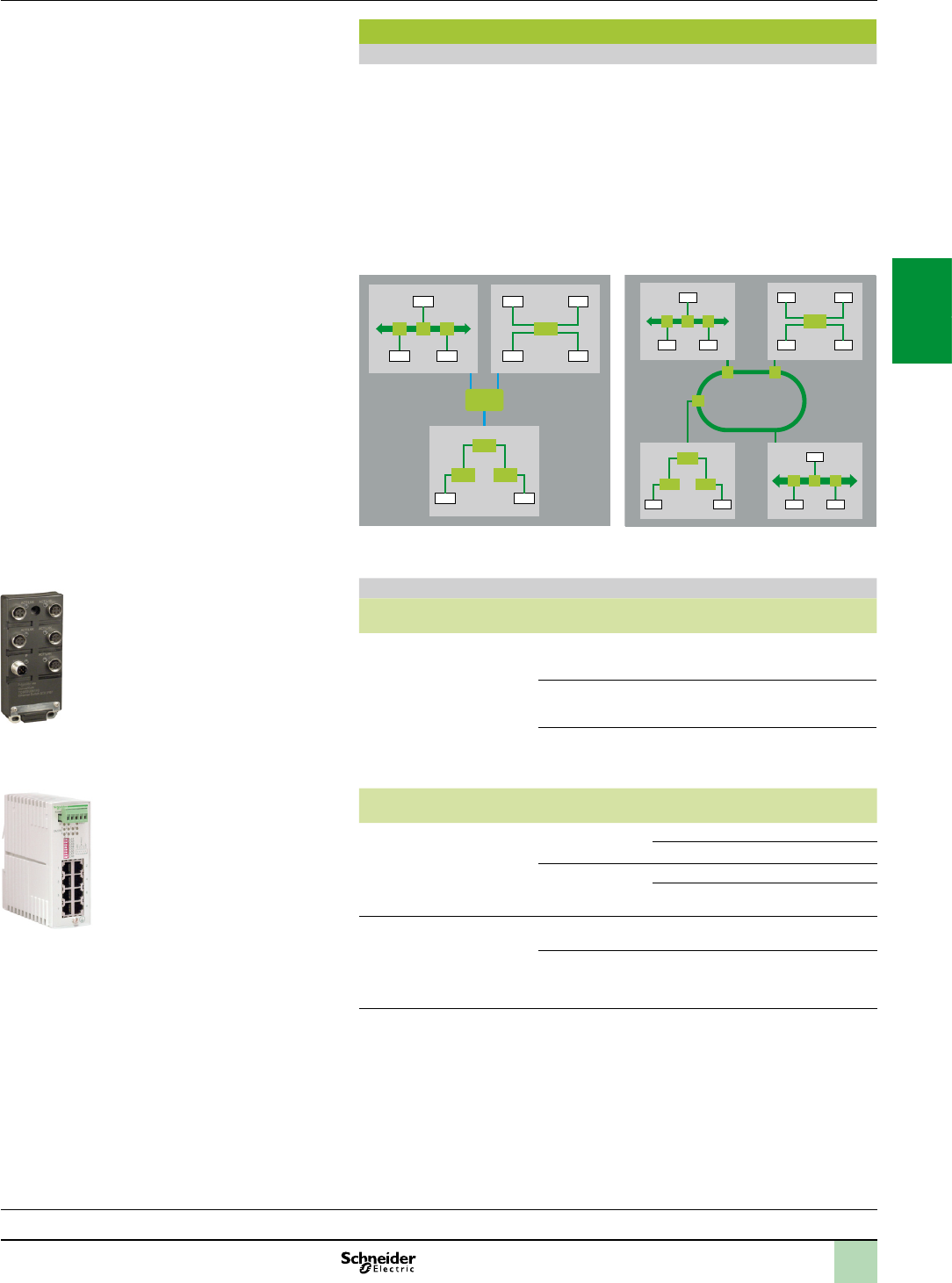
3/47
ConneXium unmanaged switches, twisted pair
Presentation
Switches are used to increase the limits of architectures based on hubs or
transceivers, by separating collision domains.
Higher layer communication is provided between the ports, and collisions at link
layer are not propagated (ltering).
They therefore improve performance by better allocation of the bandwidth due to
the reduction of collisions and network load.
Certain ConneXium switch models also enable redundant architectures to be
created on twisted pair copper ring or optical bre.
Unmanaged switches are plug and play devices that do not need to be congured
by the user. Certain models can also be managed remotely via SNMP or HTTP
protocols for monitoring and diagnostic purposes.
DTE
DTEDTE
DTE DTE
DTE DTE
DTE DTE
DTE
DTEDTE
DTE DTE
DTE
DTEDTE
DTE DTE
DTE DTE
100 Mbps
bre-optic ring
Collision
domain 1
Collision
domain 2
Collision
domain 3
Reference
Description Interfaces Reference Weight
kg
ConneXium unmanaged
switches
5 x 10BASE-T/100BASE-TX
ports (copper cable), shielded
M12 type D connectors, IP67
TCSESU051F0 0.210
8 x 10BASE-T/100BASE-TX
ports (copper cable), RJ45
shielded connectors, IP20
499NES18100 0.230
8 x 10BASE-T/100BASE-TX
ports (copper cable), RJ45
shielded connectors, IP30
TCSESU083FN0 0.246
Description With connectors
at both ends
Length Reference Weight
kg
IP67 power supply cables
(forConneXiumswitch
TCSESU051F0)
Female M12
straight connector
0.230 kg XZCP1164L2 –
5 m XZCP1164L5 –
Female M12
elbowed connector
2 m XZCP1264L2 –
5 m XZCP1264L5 –
IP67 power supply
connectors
(forConneXiumswitch
TCSESU051F0)
Female M12
straight connector
–XZCC12FDM50B –
Female M12
elbowed connector
–XZCC12FCM50B –
499NES18100
TCSESU051F0
Selection guide:
page 3/26
Presentation,
references Ethernet network
Wiring system
ConneXium unmanaged switches
2
1
3
4
5
6
7
8
9
10
2
1
3
4
5
6
7
8
9
10
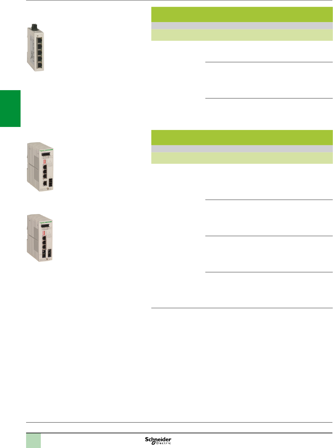
3/48
ConneXium unmanaged switches, 3, 4 and 5 ports, twisted
pair and bre optic
References
Description Interfaces Reference Weight
kg
ConneXium unmanaged
switches
3 x 10BASE-T/100BASE-TX ports
(copper cable), RJ45 shielded
connectors
TCSESU033FN0 0.113
4 x 10BASE-T/100BASE-TX
ports (copper cable), RJ45
shielded connectors
1 x 100BASE-FX port
(multimode optical bre), duplex
SC connector
TCSESU043F1N0 0.120
5 x 10BASE-T/100BASE-TX ports
(copper cable), RJ45 shielded
connectors
TCSESU053FN0 0.113
ConneXium unmanaged switches, 5 ports, twisted pair and
bre optic
Reference
Description Interfaces Reference Weight
kg
ConneXium unmanaged
switches
4 x 10BASE-T/100BASE-TX
ports (copper cable), RJ45
shielded connectors
1 x 100BASE-FX port
(multimode optical bre), duplex
SC connector
499NMS25101 0.330
3 x 10BASE-T/100BASE-TX
ports (copper cable), RJ45
shielded connectors
2 x 100BASE-FX ports
(multimode optical bre), duplex
SC connector
499NMS25102 0.335
4 x 10BASE-T/100BASE-TX
ports (copper cable), RJ45
shielded connectors
1 x 100BASE-FX port (single
mode optical bre), duplex SC
connector
499NSS25101 0.330
3 x 10BASE-T/100BASE-TX
ports (copper cable), RJ45
shielded connectors
2 x 100BASE-FX ports (single
mode optical bre), duplex SC
connector
499NSS25102 0.335
TCSESU053FN0
499NMS25101
499NSS25102
Selection guide:
page 3/26
References(continued) Ethernet network
Wiring system
ConneXium unmanaged switches
2
1
3
4
5
6
7
8
9
10
2
1
3
4
5
6
7
8
9
10
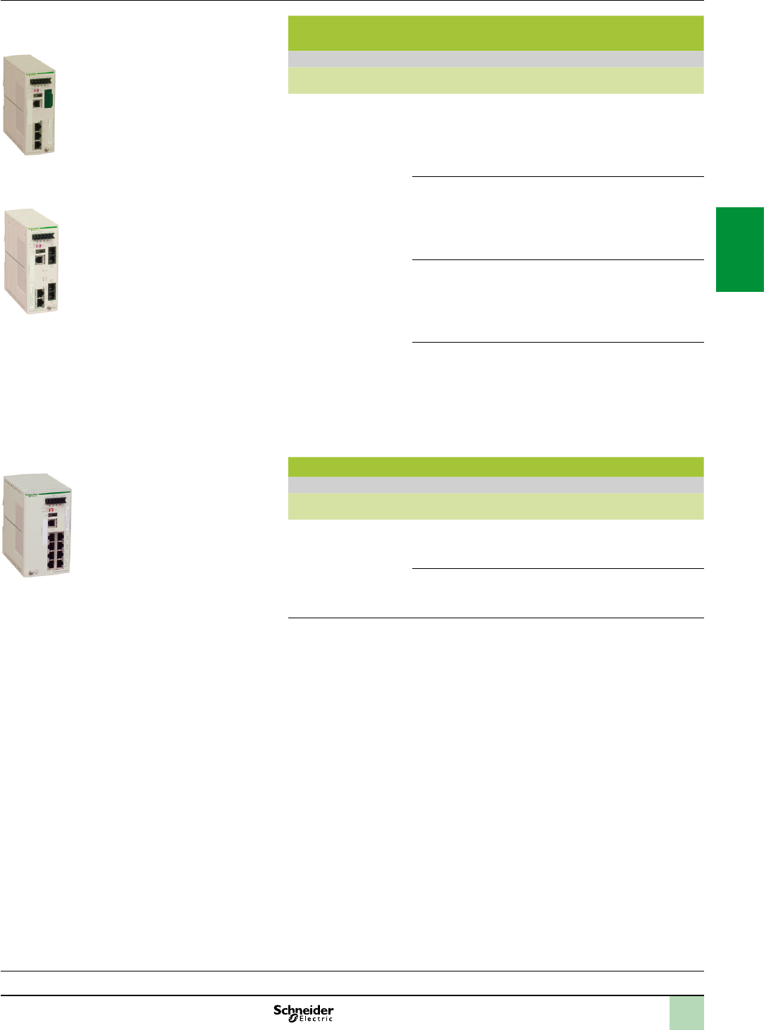
3/49
ConneXium managed switches, 4 ports, twisted pair and bre
optic
References
Description Interfaces Reference Weight
kg
ConneXium managed
switches
3 x 10BASE-T/100BASE-
TX ports (copper cable), RJ45
shielded connectors
1 x 100BASE-FX port
(multimode optical bre), duplex
SC connector
TCSESM043F1CU0 0.400
2 x 10BASE-T/100BASE-
TX ports (copper cable), RJ45
shielded connectors
2 x 100BASE-FX ports
(multimode optical bre), duplex
SC connector
TCSESM043F2CU0 0.400
3 x 10BASE-T/100BASE-
TX ports (copper cable), RJ45
shielded connectors
1 x 100BASE-FX port (single
mode optical bre), duplex SC
connector
TCSESM043F1CS0 0.400
2 x 10BASE-T/100BASE-
TX ports (copper cable), RJ45
shielded connectors
2 x 100BASE-FX ports
(single mode optical bre),
duplex SC connector
TCSESM043F2CS0 0.400
ConneXium managed switches, 4 and 8 ports, twisted pair
References
Description Interfaces Reference Weight
kg
ConneXium managed
switches
4 x 10/100BASE-TX ports
(copper cable), RJ45 shielded
connectors
TCSESM043F23F0 0.400
8 x 10/100BASE-TX ports
(copper cable), RJ45 shielded
connectors
TCSESM083F23F0 0.410
TCSESM043F1CU0
TCSESM043F2CS0
TCSESM083F23F0
Selection guide:
page 3/26
References(continued) Ethernet network
Wiring system
ConneXium managed switches
2
1
3
4
5
6
7
8
9
10
2
1
3
4
5
6
7
8
9
10
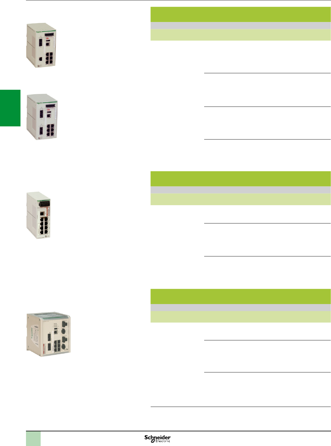
3/50
ConneXium managed switches, 8 ports, twisted pair and bre
optic
References
Description Interfaces Reference Weight
kg
ConneXium managed
switches
7 x 10/100BASE-TX ports
(copper cable), RJ45 shielded
connectors
1 x 100BASE-FX port
(multimode optical bre),
duplex SC connector
TCSESM083F1CU0 0.410
6 x 10/100BASE-TX ports
(copper cable), RJ45 shielded
connectors
2 x 100BASE-FX ports
(multimode optical bre),
duplex SC connector
TCSESM083F2CU0 0.410
7 x 10/100BASE-TX ports
(copper cable), RJ45 shielded
connectors
1 x 100BASE-FX port (single
mode optical bre), duplex SC
connector
TCSESM083F1CS0 0.410
6 x 10/100BASE-TX ports
(copper cable), RJ45 shielded
connectors
2 x 100BASE-FX ports
(single mode optical bre),
duplex SC connector
TCSESM083F2CS0 0.410
Basic ConneXium managed switches, 8 and 9 ports, twisted
pair and bre optic
References
Description Interfaces Reference Weight
kg
Basic ConneXium
managed switches
8 x 10/100BASE-TX ports
(copper cable), RJ45 shielded
connectors
TCSESB083F23F0 0.400
6 x 10/100BASE-TX ports
(copper cable), RJ45 shielded
connectors
2 x 100BASE-FX ports
(multimode optical bre),
duplex SC connector
TCSESB083F2CU0 0.400
6 x 10/100BASE-TX ports
(copper cable), RJ45 shielded
connectors
3 x 100BASE-FX ports
(multimode optical bre),
duplex SC connector
TCSESB093F2CU0 0.400
ConneXium managed switches, 8 extended ports, twisted
pair and bre optic
References
Description Interfaces Reference Weight
kg
ConneXium managed
switches
8 x 10/100BASE-TX ports
(copper cable), RJ45 shielded
connectors, IP30
TCSESM083F23F1 (1) 1.000
6 x 10/100BASE-TX ports
(copper cable), RJ45 shielded
connectors, IP30
2 x 100BASE-FX ports
(multimode optical bre),
duplex SC connector
TCSESM063F2CU1 (1) 1.000
6 x 10/100BASE-TX ports
(copper cable), RJ45 shielded
connectors, IP30
2 x 100BASE-FX ports
(single mode optical bre),
duplex SC connector
TCSESM063F2CS1 (1) 1.000
(1)AvailableinConformalCoatingversion.Forthisversion,addtheletterCattheendofthe
reference.Forexample,theTCSESM083F23F1 switchbecomesTCSESM083F23F1Cinthe
ConformalCoatingversion.Forfurtherinformationontreatmentsforharshenvironments,see
page
6/2orconsultourwebsitewww.schneider-electric.com.
TCSESM083F1CU0
TCSESM083F2CS0
TCSESM063F2CS1
TCSESB083F23F0
References(continued) Ethernet network
Wiring system
ConneXium managed switches
2
1
3
4
5
6
7
8
9
10
2
1
3
4
5
6
7
8
9
10
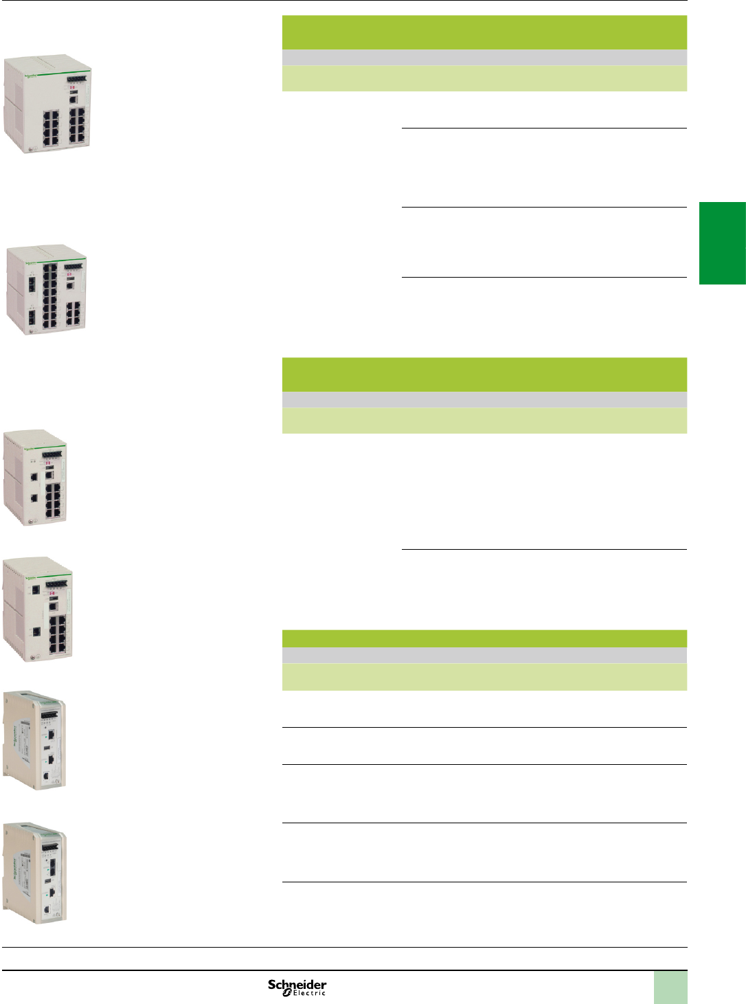
3/51
ConneXium managed switches, 16 and 24 ports, twisted pair
and bre optic
References
Description Interfaces Reference Weight
kg
ConneXium managed
switches
16 x 10/100BASE-TX ports
(copper cable), RJ45 shielded
connectors
TCSESM163F23F0 0.600
14 x 10/100BASE-TX ports
(copper cable), RJ45 shielded
connectors
2 x 100BASE-FX ports
(multimode optical bre), duplex
SC connector
TCSESM163F2CU0 0.600
14 x 10/100BASE-TX ports
(copper cable), RJ45 shielded
connectors
2 x 100BASE-FX ports (single
mode optical bre), duplex SC
connector
TCSESM163F2CS0 0.600
22 x 10/100BASE-TX ports
(copper cable), RJ45 shielded
connectors
2 x 100BASE-FX ports
(multimode optical bre), duplex
SC connector
TCSESM243F2CU0 0.650
ConneXium managed switches, 8 ports and 2 Gigabit ports,
twisted pair and bre optic
References
Description Interfaces Reference Weight
kg
ConneXium managed
switches
8 x 10/100BASE-TX ports
(copper cable), RJ45 shielded
connectors
2 x 1000BASE-SX ports
(multimode optical bre) (1), or
2 x 1000BASE-LH ports
(single mode optical bre) (2), or
2 x 1000BASE-LX ports
(single mode and multimode
optical bre) (3)
TCSESM103F2LG0 0.410
8 x 10/100BASE-TX ports
(copper cable), RJ45 shielded
connectors
2 x 10/100/1000BASE-TX
(Gigabit) ports (copper cable),
RJ45 shielded connectors
TCSESM103F23G0 0.410
ConneXium Industrial Ethernet Firewalls
References
Description Interfaces Reference Weight
kg
ConneXium Industrial
Ethernet Firewall TX/TX
2 x 10/100BASE-TX ports
(copper cable) for internal and
external network connections
TCSEFEC23F3F20 0.600
ConneXium Tono
Industrial Ethernet
Firewall TX/TX
2 x 10/100BASE-TX ports
(copper cable) for internal and
external network connections
TCSEFEA23F3F20 0.615
ConneXium Industrial
Ethernet Firewall TX/MM
1 x 10/100BASE-TX port (copper
cable) for internal network and
1 x 100BASE-FX port (multimode
optical ber) (1) for external
network connections
TCSEFEC23FCF20 0.630
ConneXium Industrial
Ethernet Firewall MM/TX
1 x 100BASE-FX port for internal
network (multimode optical ber)
(1) and 1 x 10/100BASE-TX port
(copper cable) (2)for external
network connections
TCSEFEC2CF3F20 0.630
(1)WithTCSEAAF1LFU00breopticmoduletobeorderedseparately(seepage3/45)
(2)WithTCSEAAF1LFH00breopticmoduletobeorderedseparately(seepage3/45)
(3)WithTCSEAAF1LFS00breopticmoduletobeorderedseparately(seepage3/45)
TCSESM163F23F0
TCSESM243F2CU0
TCSESM103F23G0
TCSESM103F2LG0
Selection guide:
page 3/26
References(continued) Ethernet network
Wiring system
ConneXium managed switches,
ConneXium Industrial Ethernet Firewalls
TCSEFEC23FCF20
TCSEFEA23F3F20
2
1
3
4
5
6
7
8
9
10
2
1
3
4
5
6
7
8
9
10
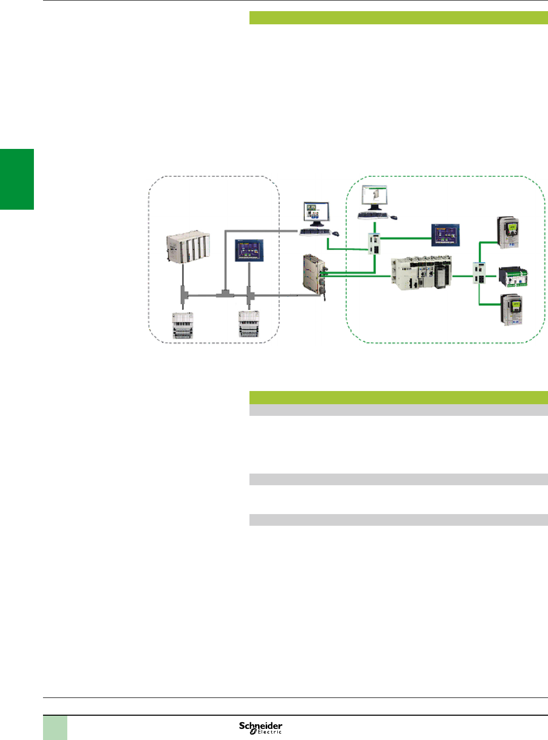
3/52
Presentation Modicon M340 automation
platform
Modbus Plus Proxy module
Presentation
The TCSEGDB23F24FA Modbus Plus Proxy module (also called M340EGD) is a
network gateway which allows the Modicon M340 PLC to communicate with existing
Modbus Plus devices.
It is not necessary to modify the applications for these devices to communicate with
the Modicon M340 PLC, since the module automatically addresses the platforms
and the various communication functions between the M340 and other PLC
platforms (especially 984LL).
The M340 Modbus Plus Proxy offers Modbus Plus PLC users the chance to integrate
the M340 PLC easily into their Modbus Plus network and thus access to advanced
communications via Ethernet, or to migrate gradually from other PLC models to
Modicon M340 and Unity.
Key benets
Reduced startup time
Online conguration of the proxy via a simple Web browser
Setup Web pages similar to the screens of the Modbus Plus Peer Cop utility,
accessible under Concept/Unity for the Global Data transaction
Simpler data exchange with Global Data transactions performed on all network nodes
Point-to-point communication without programming with Peer Cop
Increased network reliability and maintainability
Standard diagnostics provide data on all network nodes for easy troubleshooting
Dual Modbus Plus ports provide Modbus Plus network redundancy
Reduced total cost of ownership
Protects your investment in Modbus Plus while migrating to Ethernet
Dual Ethernet ports allow connection of both the M340 PLC and the conguration
PC to the proxy, without any additional switches
Processors:
page 1/4
I/O:
pages 2/12 and 2/24
Software:
page 4/2
Ruggedized Modicon M340 modules:
page 6/2
Compact 984
Distributed I/O
Modbus Plus
SCADA
Modbus Plus
Proxy
Web
conguration
interface
Modicon M340
Ethernet
2
1
3
4
5
6
7
8
9
10
2
1
3
4
5
6
7
8
9
10

3/53
Modicon M340 automation
platform
Modbus Plus Proxy module
References
Embedded Web server
Web server functions
The M340EGD includes an embedded Web server which can be used to perform
diagnostics and congure the module connection. All the data is presented in the
form of standard Web pages in HTML format. To access a Web page, you need
Internet Explorer 6.0 (or later version) and Java 1.5 (or later version).
Embedded Web server functions
1 - Setup: The Setup pages allow you to dene the parameters for several different
module services, including security, IP, SNMP, Global Data, Peer Cop and Ethernet
ports.
2 - Diagnostics: These network diagnostic pages contain Ethernet, TCP and SNMP
statistics, as well as a log of the diagnostics performed.
Complementary characteristics
The following characteristics complement those introduced in the communication
selection guide on page 3/6:
External power supply voltage: 19.2...31.2 V
Consumption: 300 mA max.
Dissipated power: 6.2 W
Conformity with standards: UL 508, CSA 22.2 No. 142 (cUL), EMI EN 55011,
EN 61131-2, C-Tick
References
System and network requirements
Unity Pro XL 3.x programming software (or later version)
Internet Explorer 6.0 (or later version)
Java 1.5 (or later version)
Microsoft Windows XP or Vista
Modicon M340 processor:
BMXP342020 (Modbus and Ethernet version)
BMXP3420302 (CANopen and Ethernet version)
BMXP3420302CL (CANopen and Ethernet version) (1)
Ethernet Modicon M340 communication modules:
BMXNOE0100
BMXNOE0110
BMXNOC0401
Modicon M340 Modbus Plus Proxy module
Description Type Reference Weight
kg
Modbus Plus Proxy module
for Modicon M340 PLC
supplied with 2 front-mounted
power supply connectors
(2 positions)
Standard TCSEGDB23F24FA –
Conformal coating TCSEGDB23F24FK –
(1)MemorycardmustbeorderedseparatelyfortheBMXP3420302CLprocessor(see
page1/9).
Processors:
page 1/4
I/O:
pages 2/12 and 2/24
Software:
page 4/2
Ruggedized Modicon M340 modules:
page 6/2
TCSEGDB23F24FA
2
1
3
4
5
6
7
8
9
10
2
1
3
4
5
6
7
8
9
10
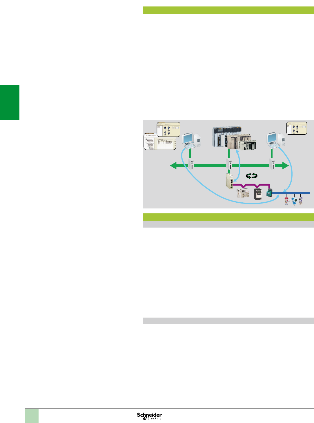
3/54
Probus DP eldbus
Probus DP is one of the most widely used eldbuses in industry.
Based on a master/slave protocol, only master stations, sometimes called active
stations, have the right to access the bus, with slave, or passive, stations being
limited to responding to interrogations.
Version V0 of Probus only allows cyclic exchanges with I/O, whereas version V1
offers an acyclic message handling channel which can be used for device adjustment
or diagnostics during operation.
The physical link is a single shielded twisted pair, but numerous interfaces are
available for creating all sorts of topologies - tree, star or ring - including those using
optical bre or a non-physical link.
Gateways can be used to communicate transparently with Probus PA, one of the
most commonly used standards in process applications for connecting
instrumentation.
Probus PA can be used to supply devices across the network and also to install
sensors in potentially explosive zones (ATEX).
Unity V5.0
PRM master DTM
PRM Com DTM
Ethernet
Probus PA
PRM Probus DP
DP Class 1
Probus Remote Master (PRM) module
Presentation
The Probus Remote Master (PRM) module is connected to the Ethernet Modbus
TCP/IP network via its integrated 2-port switch, as close as possible to the process
and the instrumentation.
The PRM module can be used to connect Modicon Quantum, Modicon Premium and
Modicon M340 PLCs to Probus DP V1 via the I/O scanner function.
Irrespective of the type of PLC, only one product reference is required and setup is
identical, thus reducing training and maintenance costs.
Two versions are available, standard and tropicalized, so as to adapt to any type of
environment.
The PRM module is open to Asset Management tools.
A dedicated communication DTM is supplied with the product, thus allowing any
compatible FDT standard tool to remotely adjust devices on Probus using Ethernet
(see page 4/5).
Conguration
From a single Unity tool, the user can create the Probus conguration, the PLC
application and congure or calibrate devices.
The latter are integrated in the Unity catalogue via their DTMs if they exist, or their
gsd les.
The I/O scanner conguration is created implicitly in Unity Pro using the Probus
conguration. The parameters assigned by default guarantee optimized performance,
as well as the consistency of I/O data in the PLC application, irrespective of the PLC
platform.
Similarly, the I/O variables dened and presymbolized in the DTMs can be used
directly in the application. Finally, the screens integrated in Unity Pro, together with
the diagnostic functions integrated in the device DTMs simplify application
maintenance.
Presentation Modicon M340 automation
platform
Probus DP V1 and Probus PA buses
Probus Remote Master module
2
1
3
4
5
6
7
8
9
10
2
1
3
4
5
6
7
8
9
10

3/55
Probus Remote Master (PRM) module (continued)
Connectable devices
The following Schneider Electric devices can be connected to this bus:
TeSys U and TeSys T starter-controllers
Momentum and Modicon STB distributed I/O
Altivar 312/61/71 variable speed drives for asynchronous motors
Lexium 05/15 servo drives for brushless motors
Altistart ATS 48 soft start-soft stop units
Any third-party device compatible with Probus DP and PA standard proles
Limitations
Once saved, the Unity project incorporates all the Probus parameters as well as
those of the slaves connected to the bus. Modicon Quantum, Modicon Premium and
Modicon M340 PLCs are capable of embedding all this data so that an empty Unity
terminal without any applications is able, after a simple transfer from the PLC, to
locate the whole application, including the slave parameters. This function is called
ETS (EmptyTerminalService).
In certain cases, it may be that the memory size required to save the device parameters
exceeds the PLC memory capacity (signalled by a “memory full” message during the
build). This is particularly likely on devices which have DTM (the most common
instrumentation on PA). Typically, each device of this type takes up around 20 KB of
the PLC memory.
It is therefore essential to create a memory map according to the type of conguration
used and possibly adapt it accordingly, either by increasing the amount of memory
dedicated to the application (by reducing the zone allocated to data), or by increasing
the overall memory via cartridges available in the catalogue.
If the ETS function is not required, Unity Pro can also be congured in such a way as
to reduce the size of the embedded data by disabling comments and animation
tables, or by disabling the upload function so that the application does not include
data relating to DTMs. In this case, the upload from an empty terminal function is no
longer available.
References
The Probus Remote Master module is supplied with a CD-ROM, which includes:
PRM master DTMs and generic Probus DTMs (for conguration in Unity Pro V5.0
or later)
The PRM communication DTM for third-party (non-Schneider Electric) FDT
Probus Remote Master modules
Description Type Reference Weight
kg
Probus Remote Master
modules
Standard TCSEGPA23F14F 0.620
Ruggedized (1) TCSEGPA23F14FK 0.620
Probus DP bus connection components
Description Type Reference Weight
kg
Distributed I/O on
Probus DP bus
Modicon STB
network interface module
STBNDP2212 0.140
Momentum communication
module
170DNT11000 0.070
Connectors for remote I/O
communication module
Line terminators 490NAD91103 –
In-line connector 490NAD91104 –
In-line connector
and terminal port
490NAD91105 –
Description Length Reference Weight
kg
Probus DP
connection cables
100 m TSXPBSCA100 –
400 m TSXPBSCA400 –
(1)Conformalcoatingandextendedoperatingtemperaturesbetween-25and+70°C.
Seeruggedizedmodulecharacteristicsonpage6/2.
490NAD91103
TCSEGPA23F14F
Modicon M340 automation
platform
Probus DP V1 and Probus PA buses
Probus Remote Master module
Presentation(continued),
references
2
1
3
4
5
6
7
8
9
10
2
1
3
4
5
6
7
8
9
10
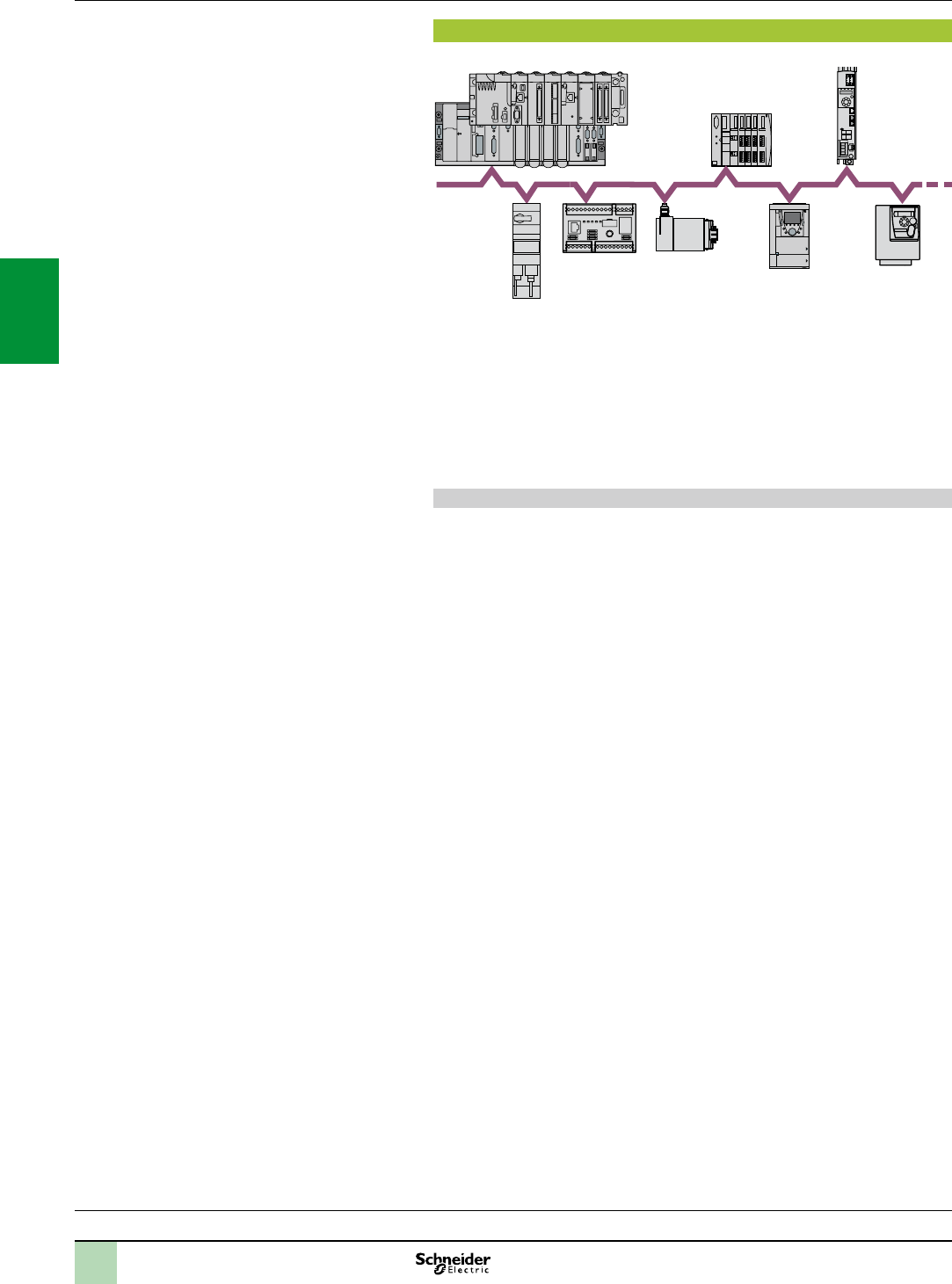
3/56
Presentation
Presentation
TeSys U
Osicoder
Altivar 71
1 to 63
slaves
Premium
Modicon M340
CANopen bus
Modicon STB
Lexium 32
Altivar 312
TeSys T
Schneider Electric has selected CANopen for its machines and installations
because of its wealth of functions and its resulting benets in the automation world.
This decision was based on the general acceptance of CANopen, and the fact that
CANopen products are increasingly used in control system architectures.
CANopen is an open network supported by more than 400 companies worldwide,
and promoted by CAN in Automation (CiA).
CANopen conforms to standards EN 50325-4 and ISO 15745-2.
Schneider Electric is heavily involved in working groups, which are important for
machine and installation architectures, systems and products.
CANopen brings transparency to Ethernet
CAN in Automation and Modbus-IDA have worked together to create a standard that
ensures total transparency between CANopen and Modbus/TCP. The result of this
collaboration has been the CiA DSP309-2 specication, which denes the
communication standards between a Modbus/TCP network and a CANopen bus.
The specication denes the mapping services which enable CANopen devices to
communicate with a Modbus/TCP network through a gateway. The data in a
CANopen device can be accessed in both read and write mode.
This specication is the rst standard available for developing open standard
communication between Modbus/TCP and CANopen. It is driving Schneider Electric
network solutions toward better integration, diagnostics and conguration of
distributed applications. It allows machines and installations to be connected to an
Ethernet network continuously, while combining the advantages of each network in
its specic area.
The CANopen bus is a multi-master bus which ensures reliable, deterministic access
to real-time data in control system devices. The CSMA/CA protocol is based on
broadcast exchanges, sent cyclically or on an event, to ensure optimum use of the
bandwidth. A message handling channel can also be used to dene slave parameters.
The bus uses a double shielded twisted pair on which, with the Modicon M340
platform, a maximum of 63 devices are connected by daisy-chaining or by tap
junctions. The variable data rate between 20 Kbps and 1 Mbps depends on the
length of the bus (between 20 m and 2500 m).
Each end of the bus must be tted with a line terminator.
The Modicon M340 automation platform, via its BMXP3420102/20302/20102CL/
20302CL processor with integrated CANopen link, performs the role of master on
the bus.
Modicon M340 automation
platform
CANopen machine and installation bus
Processors:
page 1/4
I/O:
pages 2/12 and 2/24
Software:
page 4/2
Ruggedized Modicon M340 modules:
page 6/2
2
1
3
4
5
6
7
8
9
10
2
1
3
4
5
6
7
8
9
10
3/57
Connectabledevices
Connectable Schneider Electric devices
The following Schneider Electric devices can be connected to the CANopen bus,
depending on the model (1):
Osicoder absolute encoders
TeSys U starter-controllers with LULC08 communication module
TeSys T motor management system, with LTM controller
TeSys D motor-starters using the TeSys Quickt installation help system with
APP1CCO0/O2 communication module
Modicon OTB IP 20 distributed I/O, with Twido I/O expansion modules and OTB
interface module
Modicon STB IP 20 modular distributed I/O, with STB NIM interface module
Preventa congurable safety controllers
0.18…15 kW Altivar 312/71/61 variable speed drives for asynchronous motors:
Lexium 32 servo drives for BMH and BSH servo motors
IcLA intelligent compact motor-drives
Integration of third-party devices
Unity Pro version u4.0 offers the HardwareCatalogManager tool which can be
used to integrate third-party devices at an identical level to that of Schneider Electric
devices. These third-party devices and their EDS le must conform to the CiA (CAN
InAutomation) standard.
The HardwareCatalogManager tool is used to:
Integrate third-party devices in Unity Pro
Optimize the size of the BMXP3420102/20302/20102CL/20302CL processor
memory area reserved for PDO (ProcessDataObject) process variables
Customize the parameters specic to each third-party device
Unity Pro version u4.1, combined with BMXP3420102/20302/20102CL/20302CL
processors with integrated CANopen link, can be used to customize conguration of
the device BootUp procedure, and thus be compatible with all commercially-
available CANopen third-party products.
___________________________________________________________________________
(1)Seeourwebsiteschneider-electric.comforcompatibledeviceversionsandtheirsetupsoftware.
Modicon M340 automation
platform
CANopen machine and installation bus
HardwareCatalogManagerforintegrationofthird-partydevices
Processors:
page 1/4
I/O:
pages 2/12 and 2/24
Software:
page 4/2
Ruggedized Modicon M340 modules:
page 6/2
Lexium32
TeSysQuickt AltivarATV312
ModiconOTB
2
1
3
4
5
6
7
8
9
10
2
1
3
4
5
6
7
8
9
10
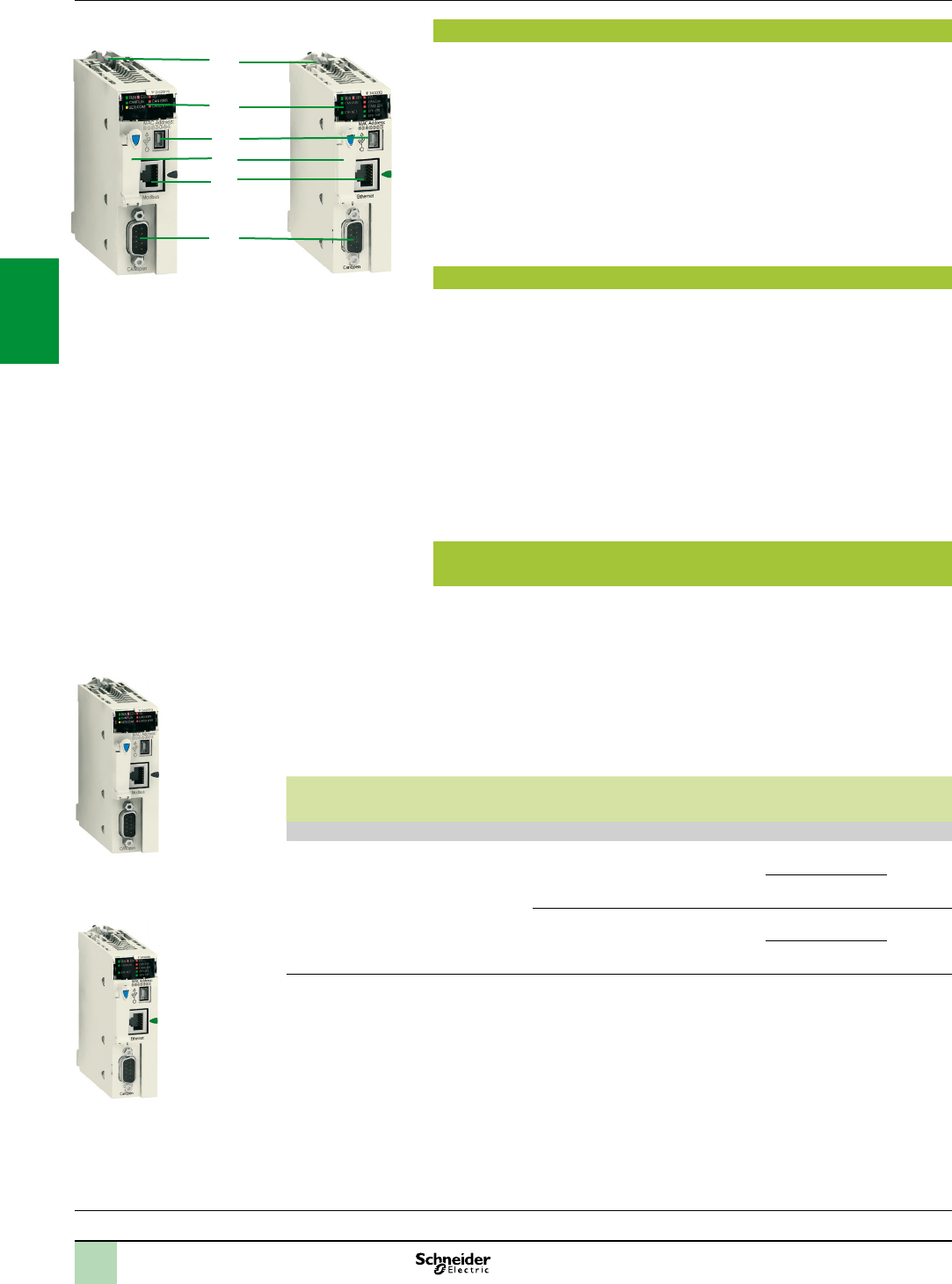
3/58
Description,
references Modicon M340 automation
platform
CANopen machine and installation bus
Processors:
page 1/4
I/O:
pages 2/12 and 2/24
Software:
page 4/2
Ruggedized Modicon M340 modules:
page 6/2
Description
BMXP3420102/20102CL and BMXP3420302/20302CL Performance processors on
the Modicon M340 platform have an integrated CANopen communication port. They
feature the following on the front panel:
1 A safety screw for locking the module in its slot in the rack, marked “00”.
2 A display block comprising at least:
CAN RUN LED (green): Integrated machine/installation bus operational
CAN ERR LED (red): Integrated machine/installation bus fault
3 A mini B USB connector for a programming terminal
4 A slot equipped with Flash memory card for backing up the application (1)
5 An RJ45 connector for serial link (with BMXP3420102/20102CL model) or
Ethernet Modbus/TCP port (with BMXP3420302/20302CL model)
6 A 9-way SUB-D connector for the CANopen master machine and installation bus
Complementary characteristics
The following characteristics complement those introduced in the communication
selection guide on page 3/4:
Data rate: 20 Kbps to 1 Mbps
Maximum length of CANopen bus (2):
20 m at 1 Mbps, 40 m at 800 Kbps, 100 m at 500 Kbps, 250 m at 250 Kbps
500 m at 125 Kbps, 1000 m at 50 Kbps, 2500 m at 20 Kbps
Maximum length of tap-offs on one tap junction (3):
0.6 m at 1 Mbps, 6 m at 800 Kbps, 10 m at 500 Kbps, 10 m at 250 Kbps
10 m at 125 Kbps, 120 m at 50 Kbps, 300 m at 20 Kbps
Limitation per segment:
Max. number of products: 64 at 1 Mbps, 32 at 800 Kbps, 16 at 500 Kbps
Maximum length of segment (4): 160 m at 1 Mbps, 185 m at 800 Kbps,
205 m at 500 Kbps
Modicon M340 Performance processors with integrated
CANopen bus link
Modicon M340 processor modules are supplied with the Flash card
BMXRMS008MP (1).
This card performs the following actions transparently:
Backing up the application (program, symbols and constants) supported in the
processor internal RAM that is not backed up
Activation of the Transparent Ready class B10 standard web server
(with BMXP3420302/20302CL processor)
This card can be replaced by another card featuring a le storage option
(see page 1/9).
Capacitance Max. no. of network/
bus modules
Integrated
communication
ports
Compatibility with
Unity software
(5)
Reference Weight
kg
Performance BMXP3420, 4 racks
1024 discrete I/O
256 analog I/O
36 application-
specic channels
4096 KB integrated
2 Ethernet Modbus/
TCP networks
4 AS-Interface buses
CANopen bus
Modbus serial link
Version 4.1 BMXP3420102 0.210
BMXP3420102CL (1)
CANopen bus
Ethernet network
Modbus/TCP
Version 4.1 BMXP3420302 0.215
BMXP3420302CL (1)
(1)MemorycardmustbeorderedseparatelyfortheBMXP3420102CL/302CLprocessors(seepage1/9).
(2)Deduct15mperrepeaterfromthelengthofthebus.
(3)Forotherrestrictions,pleaserefertotheCANopenhardwaresetupmanualavailableonourwebsite
www.schneider-electric.com.
(4)WiththeuseofTSXCANCp50/100/300CANopencablesandTSXCANCpDD03/1/3/5preformedcordsets.
(5)See“Integrationofthird-partydevices”paragraphonpage3/57.
2
3
5
1
4
6
BMXP3420102
BMXP3420102CL
BMXP3420302
BMXP3420302CL
BMXP3420102CL
BMXP3420102CL
BMXP3420302
BMXP3420302CL
2
1
3
4
5
6
7
8
9
10
2
1
3
4
5
6
7
8
9
10

3/59
Connections Modicon M340 automation
platform
CANopen machine and installation bus
CANopen bus cabling system
9
10
2
55
2
1
6a
6a6b
5
4
Altivar 312 Altivar 71
Lexium 32 TeSys U
Modicon
OTB
Modicon STB
Modicon M340 with
BMXP3420102/20302 processor
PC or monitoring
tool
ILA/ILE/ILS
Preventa
safety
controller
Magelis
XBTG
TeSys T ILA/ILE/ILS
Note: Forkeyandreferences1,2,…,17,seepages3/60and3/61.
Different types of cable are available, making it possible to create any type of
application, including for harsh environments (for a denition of standard and harsh
environments, see page 3/60).
Several connectors are available to meet any requirement: straight or 90° angled
connectors, or angled connectors with the option of connecting a PC or diagnostic
pocket PC.
Power can be supplied to devices by means of cables, cordsets and tap junctions:
one AWG24 pair for the CAN signals, one AWG22 pair for the power supply and the
ground.
In addition to the IP 20 cabling offer, there is also an IP 67 cabling offer.
Processors:
page 1/4
I/O:
pages 2/12 and 2/24
Software:
page 4/2
Ruggedized Modicon M340 modules:
page 6/2
2
1
3
4
5
6
7
8
9
10
2
1
3
4
5
6
7
8
9
10
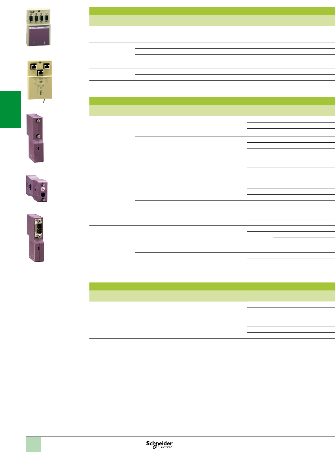
3/60
Modicon M340 automation
platform
CANopen machine and installation bus
Cabling system
Standard tap junctions and connectors
Designation Description No.
(1)
Reference Weight
kg
IP 20 CANopen tap
junction
4 SUB-D ports. Screw terminal block for
connecting the trunk cables
Line termination
1TSXCANTDM4 0.196
IP 20 connectors
CANopen female
9-way SUB-D.
Switch for line
termination
90° angled 2TSXCANKCDF90T 0.046
Straight (2) –TSXCANKCDF180T 0.049
Right angle with 9-way SUB-D for connecting a
PC or diagnostic tool
4TSXCANKCDF90TP 0.051
IP 67 M12 connectors Male –FTXCN12M5 0.050
Female –FTXCN12F5 0.050
IP 20 CANopen tap
junctions for Altivar
and Lexium 32
2 RJ45 ports 9VW3CANTAP2 –
IP 20 standard cables and preformed cordsets
Designation Description No.
(1)
Length Unit
reference
Weight
kg
CANopen cables
(AWG 24)
Standard, marking: low smoke emission. Zero
halogen. Flame-retardant (IEC 60332-1)
550 m TSXCANCA50 4.930
100 m TSXCANCA100 8.800
300 m TSXCANCA300 24.560
Standard, UL certication, marking:
ame-retardant (IEC 60332-2)
550 m TSXCANCB50 3.580
100 m TSXCANCB100 7.840
300 m TSXCANCB300 21.870
For harsh environments (3)or mobile
installations, marking: low smoke emission.
Zero halogen. Flame-retardant (IEC 60332-1).
Oil-resistant
550 m TSXCANCD50 3.510
100 m TSXCANCD100 7.770
300 m TSXCANCD300 21.700
CANopen preformed
cordsets
One 9-way female
SUB-D connector at
each end
(AWG 24)
Standard, marking: low smoke emission.
Zero halogen. Flame-retardant (IEC 60332-1)
6a 0.3 m TSXCANCADD03 0.091
1 m TSXCANCADD1 0.143
3 m TSXCANCADD3 0.295
5 m TSXCANCADD5 0.440
Standard, UL certication, marking:
ame-retardant (IEC 60332-2)
6a 0.3 m TSXCANCBDD03 0.086
1 m TSXCANCBDD1 0.131
3 m TSXCANCBDD3 0.268
5 m TSXCANCBDD5 0.400
CANopen preformed
cordsets
One 9-way SUB-D connector,
One RJ45 connector
(AWG 24)
6b 0.5 m TCSCCN4F3M05T –
1 m TCSCCN4F3M1T –
VW3M3805R010 (4) –
3 m TCSCCN4F3M3T –
Two 9-way SUB-D connectors, one male and
one female
–0.5 m TLACDCBA005 –
1.5 m TLACDCBA015 –
3 m TLACDCBA030 –
5 m TLACDCBA050 –
IP 67 standard preformed cordsets
Designation Description No.
(1)
Length Unit
reference
Weight
kg
CANopen preformed
cordsets
Preformed cordsets of two 5-way M12 A-coded
angled connectors (one male connector and one
female connector)
12 0.3 m FTXCN3203 0.40
0.6 m FTXCN3206 0.70
1 m FTXCN3210 0.100
2 m FTXCN3220 0.160
3 m FTXCN3230 0.220
5 m FTXCN3250 0.430
(1)Forkeytonumbers,seepage3/59.
(2)ForconnectiontoControllerInsideprogrammablecard,theVW3CANKCDF180Tconnectorcanalsobeused.
(3)Standard environment:
-- Without any particular environmental constraints
-- Operating temperature between + 5°C and + 60°C
-- Fixed installation
Harsh environment:
-- Resistance to hydrocarbons, industrial oils, detergents, solder splashes
-- Relative humidity up to 100%
-- Saline atmosphere
-- Signicant temperature variations
-- Operating temperature between - 10°C and + 70°C
-- Mobile installation
(4)Cordsetwithlinetermination.
References
Processors:
page 1/4
I/O:
pages 2/12 and 2/24
Software:
page 4/2
Ruggedized Modicon M340 modules:
page 6/2
TSXCANTDM4
TSXCANKCDF90T
TSXCANKCDF180T
TSXCANKCDF90TP
VW3CANTAP2
2
1
3
4
5
6
7
8
9
10
2
1
3
4
5
6
7
8
9
10

3/61
Modicon M340 automation
platform
CANopen machine and installation bus
Cabling system
IP 20 connection accessories
Designation Description No.
(1)
Length Reference Weight
kg
CANopen
connector
for Altivar 71
drive (2)
9-way female SUB-D. Switch for line termination.
Cables exit at 180°
––VW3CANKCDF180T –
Adaptor for Altivar 71
drive
SUB-D to RJ45 CANopen adaptor ––VW3CANA71 –
Preformed CANopen
cordsets for Altivar
drives
One RJ45 connector at each end 10 0.3 m VW3CANCARR03 –
1 m VW3CANCARR1 –
Y-connector CANopen/Modbus ––TCSCTN011M11F –
IP 67 connection accessories
For Modicon FTB monobloc splitter boxes
Designation Composition No.
(1)
Length
m
Reference Weight
kg
IP 67 line terminator Equipped with one M12 connector
(for end of bus)
13 –FTXCNTL12 0.010
24 V c power supply
connection cables
Equipped with two 5-way 7/8 connectors 16 0.6 FTXDP2206 0.150
1 FTXDP2210 0.190
2 FTXDP2220 0.310
5 FTXDP2250 0.750
Equipped with one 5-way 7/8 connector at one
end and ying leads at the other end
17 1.5 FTXDP2115 0.240
3 FTXDP2130 0.430
5 FTXDP2150 0.700
T-connector
for power supply
Equipped with two 5-way 7/8 connectors – – FTXCNCT1 0.100
Separate parts
Designation Composition Sold in
lots of
Reference Weight
kg
Connectors 7/8 type, 5-way Male – FTXC78M5 0.050
Female – FTXC78F5 0.050
Straight, M12 type, 5 screw terminals Male – XZCC12MDM50B 0.020
Female – XZCC12FDM50B 0.020
Angled, M12 type, 5 screw terminals Male – XZCC12MCM50B 0.020
Female – XZCC12FCM50B 0.020
Sealing plugs For M8 connector (sold in packs of 10) – FTXCM08B 0.100
For M12 connector
(sold in packs of 10)
–FTXCM12B 0.100
For 7/8 connector – FTXC78B 0.020
Y-connectors Connection of two M8 connectors to M12 connector on
splitter box
–FTXCY1208 0.020
Connection of two M12 connectors to M12 connector on
splitter box
–FTXCY1212 0.030
Diagnostics adaptor Equipped with two M12 connectors – FTXDG12 0.020
Marker labels For plastic splitter boxes 10 FTXBLA10 0.010
For metal splitter boxes 10 FTXMLA10 0.010
(1)Forkeytonumbers,seepage3/59.
(2)ForATV71HpppM3,ATV71HD11M3X,HD15M3X,ATV71H075N4 ...HD18N4drives,thisconnectorcanbereplacedbythe
TSXCANKCDF180T connector.
References(continued)
Processors:
page 1/4
I/O:
pages 2/12 and 2/24
Software:
page 4/2
Ruggedized Modicon M340 modules:
page 6/2
VW3CANA71
FTXCY1208
XZCC12CM50B
XZCC12DM50B
FTXDP21
2
1
3
4
5
6
7
8
9
10
2
1
3
4
5
6
7
8
9
10

3/62
Presentation
Modicon M340
Magelis XBT
Preventa
XPSMC
Altivar 71
Twido
Lexium 32
LU9GC3
Modbus
Third-party Modbus device
The Modbus serial link is used for master/slave architectures (it is necessary,
however, to check that the Modbus services used by the application have been
implemented on all relevant devices).
The bus consists of a master station and slave stations. Only the master station can
initiate the exchange (direct communication between slave stations is not possible).
Two exchange mechanisms are available:
Question/response, where requests from the master are addressed to a given slave.
The master then waits for the response from the slave which has been interrogated.
Broadcasting, where the master broadcasts a message to all slave stations on the
bus. The latter execute the order without transmitting a reply.
The Modicon M340 platform offers serial link connection options for Modbus or
Character mode:
Via the serial link integrated in the following processors:
Standard processor BMXP341000
Performance processors BMXP342000/20102/2020/20102CL
The number of serial link modules is limited by the maximum number of application-
specic channels permitted per station, depending on the type of processor:
Standard processor BMXP341000: maximum of 20 application-specic channels (1).
Performance processors BMXP342: maximum of 36 application-specic
channels (1).
Description
Processors with integrated serial link
BMXP341000/2000/20102/2020/20102CL processors integrate a serial link which
can be used with either the Modbus RTU/ASCII master/slave protocol or with the
Character mode protocol.
These processors have the following elements on the front panel, relating to the
serial port:
1 A display block including at least the following LEDs:
SER COM LED (yellow): Activity on the serial link (lit) or fault on a device present
on the serial link (ashing).
2 An RJ45 connector for Modbus serial link or Character mode link (non-isolated
RS 232C/RS 485) with its black indicator (2).
Note: Formoreinformationabouttheprocessors,seepage1/7
(1)Application-specicchannels:BMXEHC0200countermodules(2channels),
BMXEHC0800(8channels),BMXMSP0200motioncontrolmodules(2channels)and
BMXNOR0200HRTUcommunicationmodule(1channel).
(2)Forisolatedseriallinks,theTWDXCAISOisolationboxmustbeused.
Modicon M340 automation
platform
Modbus and Character mode serial link
Presentation,
description
Processors:
page 1/4
I/O:
pages 2/12 and 2/24
Software:
page 4/2
Ruggedized Modicon M340 modules:
page 6/2
BMXP3420102/20102CL BMXP341000/2000/2020
1
2
2
1
3
4
5
6
7
8
9
10
2
1
3
4
5
6
7
8
9
10
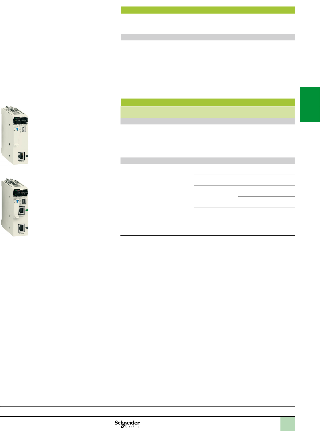
3/63
Processors:
page 1/4
I/O:
pages 2/12 and 2/24
Software:
page 4/2
Ruggedized Modicon M340 modules:
page 6/2
Complementary characteristics
The following characteristics complement those indicated in the selection guide on
page 3/5.
Serial link integrated in the processors
Physical interface:
In Modbus: RS 232 4-wire or RS 485 2-wire, non-isolated (1)
In Character mode: RS 232 4-wire or RS 485 2-wire
Frame:
In Modbus: RTU/ASCII half duplex
In Character mode: full duplex in RS 232, half duplex in RS 485
Maximum length of a tap link in RS 485 2-wire:
15 m in a non-isolated serial link
40 m in an isolated serial link (1)
References
I/O capacity Memory
capacity
Integrated
communication ports
Reference Weight
kg
BMX P3410 Standard processor with integrated serial link, 2 racks
512 discrete I/O
128 analog I/O
20 application-
specic channels
2048 KB
integrated
Modbus serial link BMXP341000 0.200
BMX P3420 Performance processors with integrated serial link, 4 racks
1024 discrete I/O
256 analog I/O
36 application-
specic channels
4096 KB
integrated
Modbus serial link BMXP342000 0.200
Modbus serial link
CANopen bus
BMXP342010 0.210
Modbus serial link
CANopen bus
version V2.1 (2)
BMXP3420102 0.210
BMXP3420102CL (3) 0.210
Modbus serial link
Ethernet Modbus/TCP
network
BMXP342020 0.205
(1)Forisolatedseriallinks,theTWDXCAISOisolationboxmustbeused.
(2)VersionwhichcanbeusedtocustomizecongurationofthedeviceBootUpprocedure
compatiblewithallthird-partyCANopenproducts.RequiresUnityProversionV4.1.
(3)MemorycardmustbeorderedseparatelyfortheBMXP3420102CLprocessor(see
page1/9).
Modicon M340 automation
platform
Modbus and Character mode serial link
Characteristics,
references
BMXP341000/2000
BMXP342020
2
1
3
4
5
6
7
8
9
10
2
1
3
4
5
6
7
8
9
10
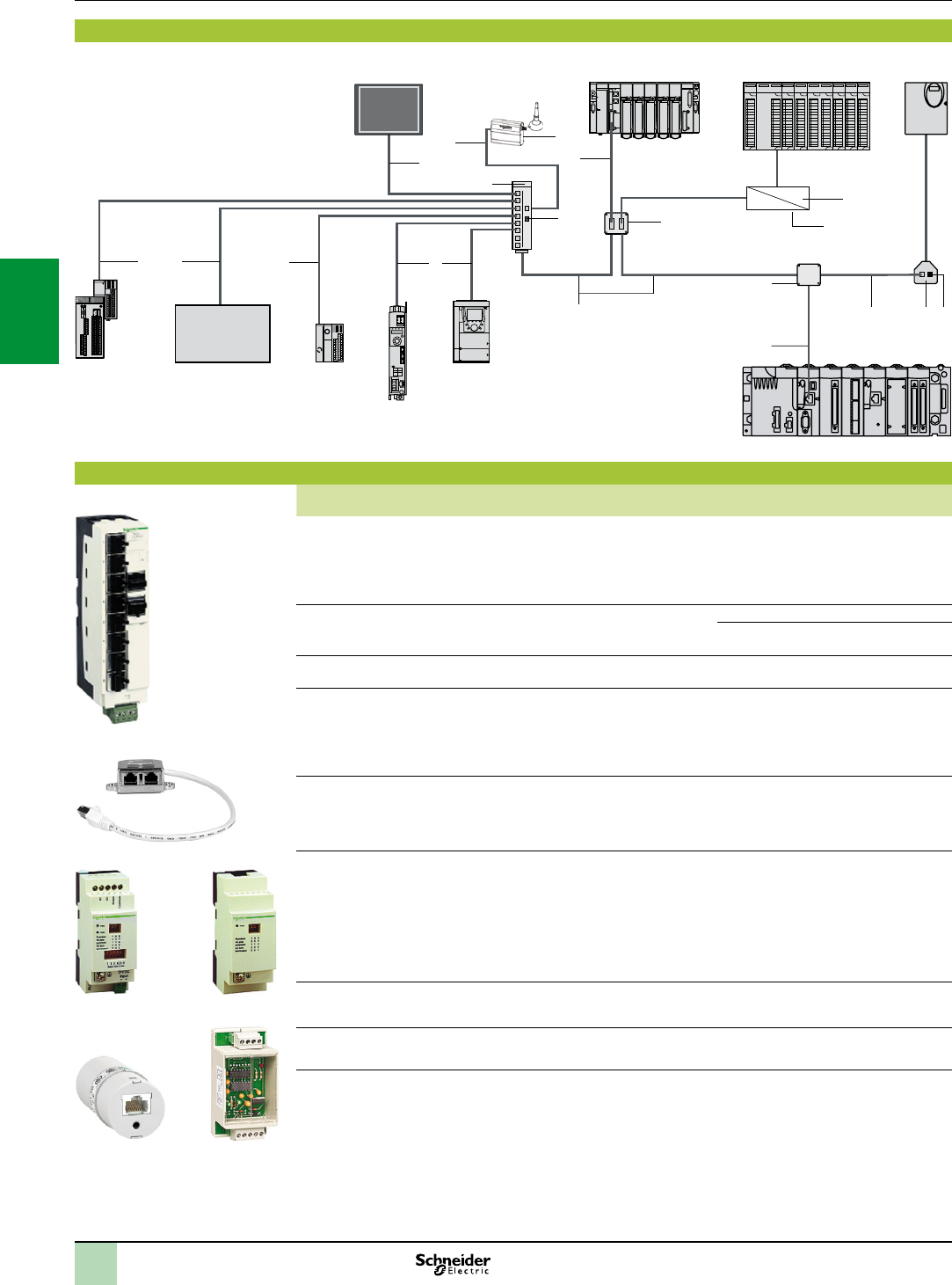
3/64
Cabling system
Modicon M340 automation
platform
Modbus and Character mode serial link
Cabling system
Connections,
references
Extension and adaptation elements for RS 485 serial link
Designation Description No. Length Unit
reference
Weight
kg
Modbus splitter box - 1 screw terminal block for trunk cable:
D(A), D(B), and 0V
- 8 x RJ45 connectors for tap-off
- 2 x RJ45 connectors for series
connection of LU9 GC3 splitter boxes
Mounting on 35 mm rail
1–LU9GC3 0.500
T-junction boxes
dedicated to Altivar and
Lexium
- 2 x RJ45 connectors
- 1 integrated cable with RJ45 connector
20.3 m VW3A8306TF03 0.190
1 m VW3A8306TF10 0.210
Passive T-junction box - Tap-off and extension of the bus
- Line termination
4–
TSXSCA50
0.520
2-channel passive
subscriber socket
2 x 15-way female
SUB-D connectors and 2
screw terminal blocks
- 2-channel tap-off point and extension
of trunk cable
- Address coding
- Line termination
3–TSXSCA62 0.570
Tap junction
3 x RJ45 connectors
- Line termination
(R =120 Ω, C = 1 nF)
- Line pre-polarization (1)
(2 R = 620 Ω)
Mounting on 35 mm rail
––TWDXCAT3RJ 0.080
Modbus/Bluetooth®
adaptor
- 1 Bluetooth® adaptor (range 10 m,
class 2) with 1 x RJ45 connector
- 1 x0.1 m long cordset for PowerSuite
with 2 x RJ45 connectors
- 1 x0.1 m long cordset for TwidoSuite,
with 1 x RJ45 connector and 1 mini-DIN
connector
- 1 RJ45/9-way male SUB-D adaptor
for Altivar drives
––VW3A8114 0.155
RS 232C/RS 485 line
converter without
modem signals
24 V /20 mA power supply,
19.2 Kbps
Mounting on 35 mm rail
5–XGSZ24 0.100
Line terminator For RJ45 connector
R = 120 Ω, C = 1 nF
12 Sold in
lots of 2
VW3A8306RC 0.200
(1)LinepolarizationrequiredforconnectiontothemasterTwidoprogrammablecontroller.
(2)24Vc powersupply,orpowersupplyviatheserialportintegratedinModiconM340processors.
1
7
8
7
3
9
5
2 12
10
12
RS 232
RS 485
11
6
7
9
24 V c
4
Magelis XBT Modicon Premium Modicon Quantum Altivar 31
Modbus RS 232
Modbus
Modicon OTB
Preventa XPSMC
Twido
Lexium 32
Altivar 71
Modicon M340
In
Out
14
13
OptiM2M
Third-party Modbus
device
LU9GC3
XGSZ24
TWDXCAISO TWDXCAT3RJ
VW3A8306TF
VW3A8114
2
1
3
4
5
6
7
8
9
10
2
1
3
4
5
6
7
8
9
10

3/65
Modicon M340 automation
platform
Modbus and Character mode serial link
Cabling system
Cables and cordsets for RS 485 serial link
Designation Description No. Length Unit
reference
Weight
kg
RS 485 double
shielded twisted pair
trunk cables
Modbus serial link, supplied without
connector
6100 m TSXCSA100 5.680
200 m TSXCSA200 10.920
500 m TSXCSA500 30.000
Modbus RS 485
cordsets
2 x RJ45 connectors 70.3 m VW3A8306R03 0.030
1 m VW3A8306R10 0.050
3 m VW3A8306R30 0.150
1 x RJ45 connector and 1 x 15-way
SUB-D connector
–3 m VW3A8306 0.150
1 x mini-DIN connector for Twido
controller and 1 x RJ45 connector
80.3 m TWDXCARJ003 0.040
1 m TWDXCARJ010 0.090
3 m TWDXCARJ030 0.160
1 x RJ45 connector and
1 end with ying leads
93 m VW3A8306D30 0.150
1 miniature connector and 1 x 15-way
SUB-D connector
10 3 m TSXSCPCM4530 0.180
Cordsets for Magelis
XBT display units and
terminals
1 x RJ45 connector and 1 x 25-way
SUB-D connector for:
- XBTN200/N400/NU400
- XBTR410/411
- XBTGT2...GT7 (COM1 port) (1)
11 2.5 m XBTZ938 0.210
2 x RJ45 connectors for:
- XBTGT1 (COM1 port)
- XBTGT2...GT7 (COM2 port)
11 3 m VW3A8306R30 0.150
Cordsets for RS 232 serial link
Designation Description Length Reference Weight
kg
Cordset for
Data Terminal
Equipment (DTE)
(printer)
Serial link for DTE (2)
1 x RJ45 connector and 1 x 9-way female SUB-D
connector
3 m TCSMCN3M4F3C2 0.150
Cordset for
Data Communication
Equipment (DCE)
(modem, converter)
Serial link for DCE
1 x RJ45 connector and 1 x 9-way male SUB-D
connector
3 m TCSMCN3M4M3S2 0.150
OptiM2M
Designation Description No. Length Reference Weight
kg
Modbus RS485
Cordset (2)
1 x RJ45 connector and
1 x 9-way SUB-D connector
13 3 m SERM2MUNI2 –
OptiM2M Pack (3) The modem with embedded SIM card
35 mm (1.38 in) DIN rail mounting clip
2 mounting brackets
Instructions
2-wire cable (red/black) with in-line fuse
GSM magnetic antenna (SMA-M)
Modbus RS485 cordset
14 3 m SERM2MMOD485 –
(1)ForusewithXBTZG909adaptor.
(2)OnlycompatiblewithaOptiM2Mmodem.
(3)OPTIM2M,thereadytousesolution.
OptiM2Mcomprises:
-TheOPTIM2MpackwhichconnectsthemachinetotheSchneiderCloudviatheGPRSnetwork.
-AwebapplicationembeddedintheSchneiderCloudwhichallows:
Managementofagroupofmachinesorequipmentanywhereintheworld.
Monitoringandanalysisofmachineandinstallationdata.
-Asubscription,whichallows:
UseoftheOptiM2Mportalandservices(Hosting,Roaming,Dataconsumption,Dashboards).
References(continued)
Processors:
page 1/4
I/O:
pages 2/12 and 2/24
Software:
page 4/2
Ruggedized Modicon M340 modules:
page 6/2
2
1
3
4
5
6
7
8
9
10
2
1
3
4
5
6
7
8
9
10

4
4/0
Contents
0
4 - Software
6
Unity Pro software
Selection guide . . . . . . . . . . . . . . . . . . . . . . . . . . . . . . . . . . . . . . . . . . . . . . . . . . . . . page4/2
Unity Pro Small / Medium / Large / Extra Large software
Presentation ............................................................................................ page4/4
FDT/DTM function ................................................................................... page4/5
The 5 IEC langages ................................................................................. page4/5
Data Editor ............................................................................................... page4/6
DFB user function blocks ......................................................................... page4/7
Function block libraries ............................................................................ page4/8
Debugging tools ....................................................................................... page4/9
PLC simulator ........................................................................................ page4/10
Documentation editor ............................................................................ page4/10
Diagnostics integrated into Modicon automation platforms ....................page4/11
Modifying the program with the PLC in RUN mode ............................... page4/12
Cross references function ..................................................................... page4/12
Import/export function ............................................................................ page4/12
Application converters .......................................................................... page4/13
Operating system update utilities .......................................................... page4/13
Online modication of the Quantum conguration ................................. page4/13
Process control in machines .................................................................. page4/14
Communication drivers .......................................................................... page4/16
Unity Developer’s Edition, advanced open access ................................ page4/16
Upgrade kits for Concept, PL7 Pro and ProWORX software .................. page4/16
Composition and Windows OS compatibility ......................................... page4/17
Unity Pro update .................................................................................... page4/17
References ............................................................................................ page4/18
Unity EFB Toolkit software
Presentation, setup ............................................................................. page4/22
References ........................................................................................... page4/23
Unity DIF software
Presentation, setup ............................................................................. page4/24
References ........................................................................................... page4/25
Unity Loader software
Presentation ......................................................................................... page4/26
References ........................................................................................... page4/27
Unity Pro specic libraries
Presentation ......................................................................................... page4/28
References ........................................................................................... page4/29
2
1
4
5
6
7
8
9
10
2
1
4
5
6
7
8
9
10

4/1
UAG (Unity Application Generator) software
Presentation ......................................................................................... page4/30
References ........................................................................................... page4/31
OPC data server software
Presentation ......................................................................................... page4/32
Setup .................................................................................................... page4/35
Functions ............................................................................................. page4/36
References ........................................................................................... page4/37
2
1
4
5
6
7
8
9
10
2
1
4
4
5
6
7
8
9
10

2
1
3
4
5
6
7
8
9
10
2
1
3
4
5
6
7
8
9
10
2
1
3
4
5
6
7
8
9
10
2
1
3
4
5
6
7
8
9
10
4/2 4/24/3
Unity Pro programming software for Modicon M340 M, Premium P, Quantum Q, Safety S
and Modicon distributed I/O D platforms
Unity Pro programming software for Modicon M340 M, Premium P, Quantum Q, Safety S
and Modicon distributed I/O D platforms
IEC 61131-3
languages
Instruction List (IL) M - D M - P - D M - P - Q - D M - P - Q - D M - P - Q - D
Ladder (LD) M - D M - P - D M - P - Q - D M - P - Q - D M - P - Q - S - D
Structured Text (ST) M - D M - P - D M - P - Q - D M - P - Q - D M - P - Q - D
Function Block Diagram (FBD) M - D M - P - D M - P - Q - D M - P - Q - D M - P - Q - S - D
Sequential Function Chart (SFC)/Grafcet M - D M - P - D M - P - Q - D M - P - Q - D M - P - Q - D
Ladder Logic Language LL984 M M M - Q M - Q M - Q
Programming
services
Multitask programming (Master, fast and
event-triggered)
M - D M - P - D M - P - Q - D M - P - Q - D M - P - Q - D
Multitask programming (Master, fast,
auxiliary and event-triggered)
P (TSXP575) - Q (140CPU651/671) - D P (TSXP575) - Q (140CPU651/671)- D
Functional view and function modules M - D M - P - D M - P - Q - D M - P - Q - D M - P - Q - S - D
DFB editor and instances M - D M - P - D M - P - Q - D M - P - Q - D M - P - Q - S - D
DDT compound data editors M - D M - P - D M - P - Q - D M - P - Q - D M - P - Q - D
Data structure instances and tables M - D M - P - D M - P - Q - D M - P - Q - D M - P - Q - D
EF and EFB libraries M - D M - P - D M - P - Q - D M - P - Q - D M - P - Q - D
User-denable control loops P (TSXP572) - D P (TSXP572/3/4) - D P (TSXP572/3/4/5) - D P (TSXP572/3/4/5)- D
Programmable control loops (with process
control FB library)
M - D M - P - D M - P - Q - D M - P - Q - D M - P - Q - D
Safety function block libraries S - D
Motion function block (MFB) libraries M - D M - P - D M - P - Q - D M - P - D M - P - D
Hot Standby PLC redundancy system P (TSXP5724M) - D P (TSXH5724M/44M) - D P (TSXH5724M/44M) - Q (140CPU67160) - D P (TSXH5724M/44M) - Q (140CPU67160) - S - D
System diagnostics M - D M - P - D M - P - Q - D M - P - Q - D M - P - Q - S - D
Application diagnostics M - D M - P - D M - P - Q - D M - P - Q - D M - P - Q - D
Diagnostics with location of error source M - D M - P - D M - P - Q - D M - P - Q - D M - P - Q - D
Bus and network conguration to slave
devices (Modicon distributed I/O, etc.)
M - D M - P - D M - P - Q - D M - P - Q - D M - P - Q - D
Debugging
and display
services
PLC simulator M - D M - P - D M - P - Q - D M - P - Q - D M - P - Q - S - D
Hypertext link animations in graphic languages M - D M - P - D M - P - Q - D M - P - Q - D M - P - Q - S - D
Step by step execution, breakpoint M - D M - P - D M - P - Q - D M - P - Q - D M - P - Q - S - D
Watchpoint M - D M - P - D M - P - Q - D M - P - Q - D M - P - Q - S - D
Runtime screens M - D M - P - D M - P - Q - D M - P - Q - D M - P - Q - S - D
Diagnostics viewer M - D M - P - D M - P - Q - D M - P - Q - D M - P - Q - S - D
Other services Creation of hyperlinks M - D M - P - D M - P - Q - D M - P - Q - D M - P - Q - S - D
XML import/export M - D M - P - D M - P - Q - D M - P - Q - D M - P - Q - S - D
Application converters (Concept, PL7) M - P - D M - P - Q - D M - P - Q - D M - P - Q - D
Utilities for updating PLCs and Advantys
operating system
M - D M - P - D M - P - Q - D M - P - Q - D M - P - Q - D
Communication drivers for Modicon platforms M - D M - P - D M - P - Q - D M - P - Q - D M - P - Q - S - D
Unity Pro servers - Openness M - P - Q - D M - P - Q - S - D
Online modication of the conguration Q Q
Importing of applications (Modsoft, Concept,
ProWORX) written in LL984 language
Q Q
UDE support
OFS exchanges
Dynamic exchange with 3rd party tools, OFS M - P - Q - D M - P - Q - S - D
Static exchange via XML/XVM export les M - D M - P - D M - P - Q - D M - P - Q - D M - P - Q - S - D
Compatible
Modicon
platforms
Modicon M340 CPUs MAll models All models All models All models All models
Premium CPUs P– TSXP57104M/1634M/154M
TSXP57204M/2634M/254M
TSXH5724M
TSXP57104M/1634M/154M
TSXP57204M/2634M/254M
TSXP57304M/3634M/354M
TSXP574634M/454M
TSXH5724M/44M
TSXP57104M/1634M/154M
TSXP57204M/2634M/254M
TSXP57304M/3634M/354M
TSXP574634M/454M
TSXP575634M/554M
TSXP576634M
TSXH5724M/44M
TSXP57104M/1634M/154M
TSXP57204M/2634M/254M
TSXP57304M/3634M/354M
TSXP574634M/454M
TSXP575634M/554M
TSXP576634M
TSXH5724M/44M
Quantum CPUs Q– – 140CPU31110
140CPU43412U
140CPU53414U
140CPU31110
140CPU43412U
140CPU53414U
140CPU65150/60
140CPU65260
140CPU67160
140CPU67260/61
140CPU31110
140CPU43412U
140CPU53414U
140CPU65150/60
140CPU65260
140CPU67160
140CPU67260/61
Safety CPUs S– – – – 140CPU65160S
140CPU67160S
Compatible Modicon distributed I/O DSTB, OTB, TM7, ETB, Momentum STB, OTB, TM7, ETB, Momentum STB, OTB, TM7, ETB, Momentum STB, OTB, TM7, ETB, Momentum STB, OTB, TM7, ETB, Momentum
Software name Unity Pro Small Unity Pro Medium Unity Pro Large Unity Pro Extra Large Unity Pro XL Safety
Unity Pro software type UNYSPUSFCD70 UNYSPUMFCD70 UNYSPULFCD70 UNYSPUEFCD70 UNYSPUXFCD70
Page/website 4/18 4/19 4/19 4/20 www.schneider-electric.com
Selectionguide Software
Unity Pro software
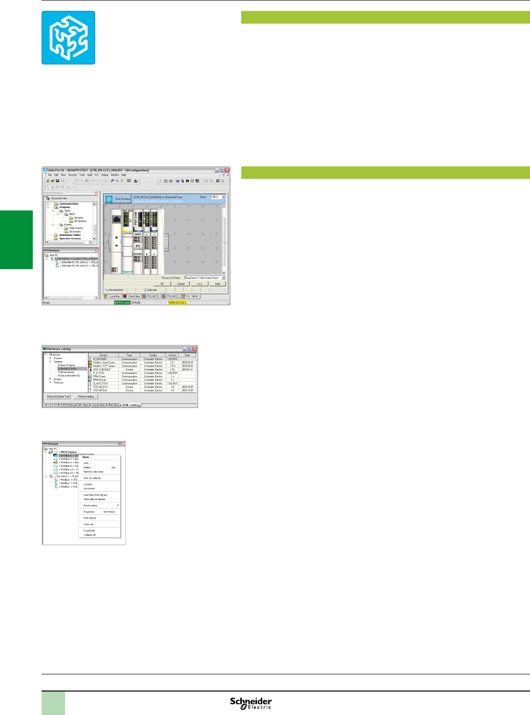
4/4
Software
Unity Pro software
Small/Medium/Large/Extra Large
Presentation,
functions
Presentation
Unity Pro is the common programming, debugging and operating software for the
Modicon M340, Premium and Quantum PLC ranges.
Unity Pro is multitasking software offering the following features:
All in one software
Five IEC 61131-3 programming languages
LL 984 programming language
Integrated, customizable DFB library
PLC simulator on PC for program validation prior to installation
Built-in tests and diagnostics
Wide range of online services
FDT/DTM function
Unity Pro facilitates integration of eldbus architectures into engineering control
systems using FDT/DTM technology:
FDT (FieldDeviceTool) is the container which supports the device DTMs.
DTM (DeviceTypeManager)is the conguration tool for devices with integrated
graphic interfaces. It contains all the properties specic to each device.
In addition to the FDT/DTM standard, Unity Pro uses specic information from the
Master DTM created for the Probus Remote Master (PRM) module and the
Modbus/TCP and EtherNet/IP network module BMX NOC 0401.
Use of the Master DTM allows Unity Pro to perform the following actions:
Manage the PLC I/O scan
Create the application variables based on the description of the process objects
available from the connected DTM devices
Manage synchronization with the PLC conguration
Create a generic DTM from the description les (GSD or EDS)
The DTM conguration is stored in the PLC memory so that the application can be
downloaded in its entirety. It is also saved in the PLC project le (STU) and the
archive le (STA).
A third-party DTM can be installed in the DTM hardware catalogue.
The DTM hardware catalogue can be used to sort or lter the DTMs according to
various criteria such as Device, Vendor, Groups or Protocols.
The DTM Browser in Unity Pro:
Displays the eldbus topologies in a tree structure
Allows the user to congure the DTM devices:
Add and delete DTMs
Connect and disconnect DTMs to/from their physical devices
Display and print the properties of a DTM
Transfer DTM conguration data to and from the physical device
Functions specic to the DTM, via the Device menu
Selection guide:
page 4/2
Unity Pro
DTMeditor(ModiconSTBisland)
DTMhardwarecatalogue
DTMbrowserandDTMcontextmenu
2
1
3
4
5
6
7
8
9
10
2
1
3
4
5
6
7
8
9
10
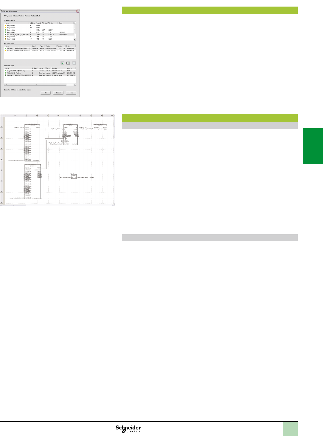
4/5
FDT/DTM function (continued)
The eldbus lookup function scans the physical devices in a eldbus network and
adds the selected devices to the DTM Browser.
Programming languages
The ve IEC 61131-3 compliant languages
The ve graphical or textual languages available in Unity Pro are used for
programming Modicon M340, Premium and Quantum automation platforms.
The three graphical languages are:
Ladder (LD) language
Function Block Diagram (FBD)
Sequential Function Chart (SFC) or Grafcet
The two textual languages are:
Structured Text (ST)
Instruction List (IL)
For these ve languages, you can use the standard set of instructions compliant with
IEC standard 61131-3 to create applications which can be transferred from one
platform to another. Unity Pro software also provides extensions to this standard set
of instructions. As they are specic to Modicon M340, Premium and Quantum PLCs,
these extensions support the development of more complex applications in order to
maximize the potential of the specic features of each of these platforms.
LL984 language
LL984 (Ladder Logic 984) language enables migration from legacy Modicon ranges.
Software
Unity Pro software
Small/Medium/Large/Extra Large
Functions(continued)
Selection guide:
page 4/2
Fieldbuslookupscreen
FBDlanguageeditor
2
1
3
4
5
6
7
8
9
10
2
1
3
4
5
6
7
8
9
10
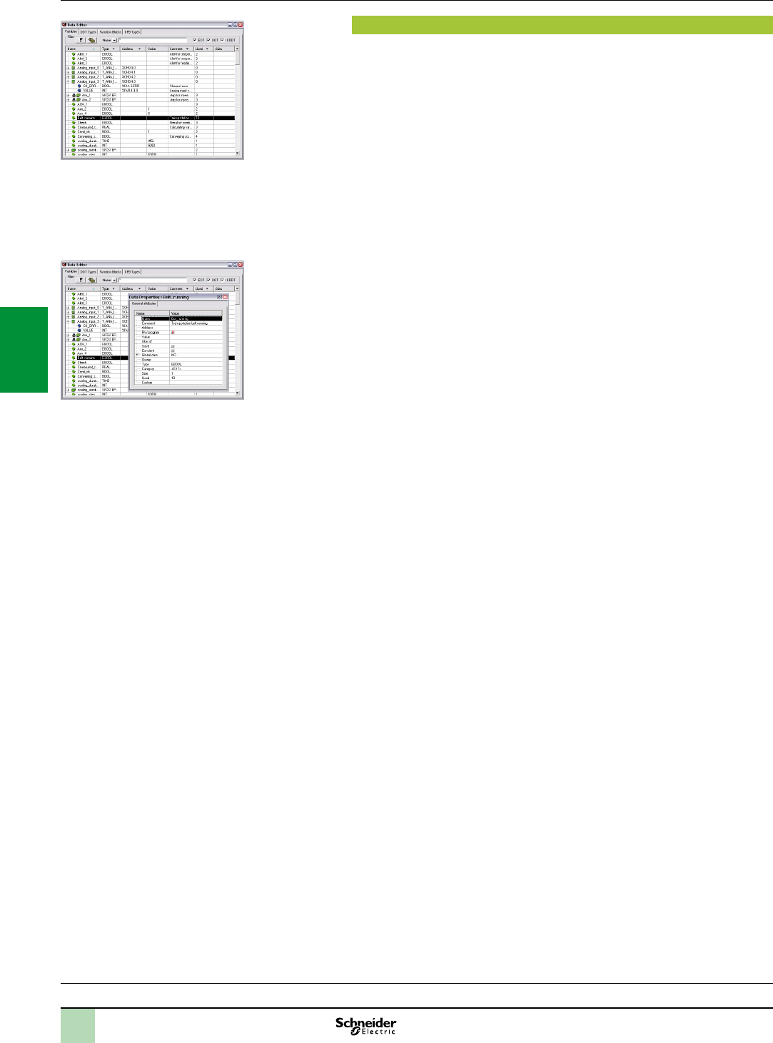
4/6
Software
Unity Pro software
Small/Medium/Large/Extra Large
Data editor
The data editor, which can be accessed from the structural view of the project,
provides a single tool for performing the following editing tasks:
Declaration of data including variables and function blocks (declaration of their
type, instances and attributes)
Use and archiving of function block data types in different libraries
Hierarchical view of data structures
Searching, sorting and ltering of data
Creation of a hyperlink to access a description from any variable comment
The data is displayed in four tabs:
“Variables” tab for the creation and management of the following data instances:
Bits, words, double words, inputs/outputs, tables and structures
“DDT Types” tab for the creation of derived data types (tables and structures)
“Function Blocks” tab for the declaration of EFBs and DFBs
“DFB Types” tab for the creation of DFB user function block data types
Each data element has several attributes, of which:
The variable name and type are mandatory
The comment, physical address in the memory and initial values are optional
The data editor columns can be congured (number of columns, order). All the
attributes associated with a variable can be displayed in a properties window.
This editor can be accessed at any time during programming by selecting variables
for data modication or creation.
Functions(continued)
Selection guide:
page 4/2
Dataeditor
Dataproperties
2
1
3
4
5
6
7
8
9
10
2
1
3
4
5
6
7
8
9
10
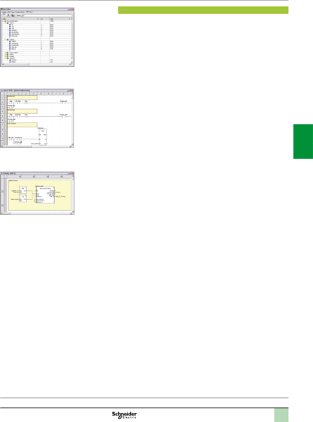
4/7
Software
Unity Pro software
Small/Medium/Large/Extra Large
DFB user function blocks
With Unity Pro software, users can create their own function blocks for specic
application requirements on Modicon M340, Premium and Quantum platforms.
Once created and saved in the library, these user function blocks can be reused as
easily as EFBs (Elementary Function Blocks).
The user function blocks can be used to structure an application. They are used
when a program sequence is repeated several times in the application or for freezing
a standard programming routine. They can be read-only or read/write. They can be
exported to all other Unity Pro applications.
Using a DFB in one or more applications:
Simplies program design and entry
Improves program readability and understanding
Facilitates program debugging (all variables handled by the DFB are identied in
the data editor)
Enables the use of private variables specic to the DFBs, which are independent
of the application
A DFB is set up in several stages:
The DFB is designed by assigning a name, a set of parameters (inputs, outputs,
public and private internal variables) and a comment to it via the data editor.
The code is created in one or more sections of the program, with the following
languages selected according to requirements: Structured Text, Instruction List,
Ladder or Function Block Diagram (ST, IL, LD or FBD).
The DFB may be stored in a library with an associated version number.
A DFB instance is created in the data editor or when the function is called
in the program editor.
This instance is used in the program in the same way as an EFB (the instance can
be created from within the program).
Functions(continued)
Selection guide:
page 4/2
Design
Creatingthecode
Usewithintheprogram
2
1
3
4
5
6
7
8
9
10
2
1
3
4
5
6
7
8
9
10
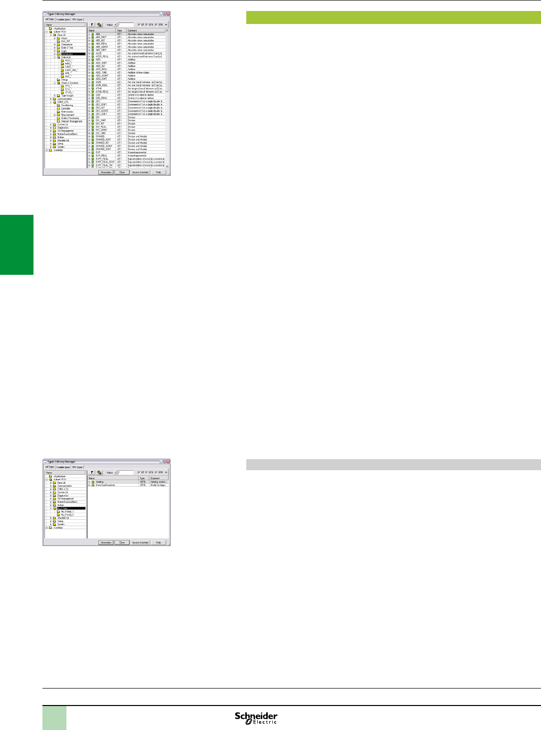
4/8
Software
Unity Pro software
Small/Medium/Large/Extra Large
Function block libraries
The function and function block libraries manager contains all the elements provided
with Unity Pro software. Functions and function blocks are organized into libraries,
which themselves consist of families. Depending on the type of PLC selected and
the processor model, users will have a subset of these libraries available to write
their applications. However, the “Base Lib” library contains a set of functions and
function blocks, for the majority of which compatibility is independent of the
platforms. In particular, it contains the blocks compliant with IEC 61131-3.
The “Base Lib” library is structured into families:
Timers and counters
Process control on integers
Table management
Comparison
Date and time management
Logic processing
Mathematical processing
Statistical processing
Character string processing
Type-to-type data conversion
The “Base Lib” library, which covers standard automation functions, is supplemented
by other, more application-specic libraries and platform-specic functions:
Communication library, providing an easy means of integrating communication
programs from PLCs with those used by HMIs from the PLC application program.
Like other function blocks, these EFBs can be used in all languages to exchange
data among PLCs or to deliver data to be displayed on an HMI.
Process control library. The CONT_CTL library can be used to set up process-
specic control loops. It offers controller, derivative and integral control functions
plus additional algorithms, such as EFBs for calculating mean values, selecting a
maximum value, detecting edges or assigning a hysteresis to process values, etc.
Diagnostics library, which can be used to monitor actuators and contains EFBs
for active diagnostics, reactive diagnostics, interlocking diagnostics, permanent
process condition diagnostics, dynamic diagnostics, monitoring of signal groups, etc.
I/O management library, providing services to handle information exchanged
with hardware modules (formatting data, scaling, etc.).
Motion Function Blocks library, containing a set of predened functions and
structures to manage motion controlled by drives and servo drives connected on
CANopen.
Motion library for motion control and fast counting.
System library, which provides EFBs for the execution of system functions,
including: evaluation of scan time, availability of several different system clocks, SFC
section monitoring, display of system state, management of les on the memory
cartridge of the Modicon M340 processor, etc.
Finally, a library named “obsolete”, containing all function blocks used by legacy
programming software needed to perform application conversions.
Management of user standards
Users may create libraries and families in order to store their own DFBs and DDTs.
This enhancement allows users to take advantage of programming standards
adapted to their needs, along with version management. This means that it is
possible to:
Check the version of the elements used in an application program against those
stored in the library
Perform an upgrade, if necessary
Functions(continued)
Selection guide:
page 4/2
Standardfunctionblocklibraries
Userlibraries
2
1
3
4
5
6
7
8
9
10
2
1
3
4
5
6
7
8
9
10
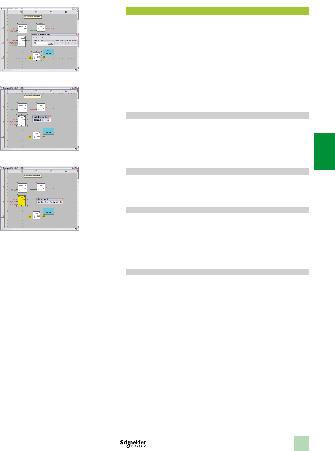
4/9
Software
Unity Pro software
Small/Medium/Large/Extra Large
Debugging tools
Unity Pro software offers a complete set of tools for debugging Modicon M340,
Premium or Quantum applications. A tool palette provides direct access to the main
functions:
Dynamic program animation
Setting of watchpoints or breakpoints (not authorized in event-triggered tasks)
Step-by-step program execution. A function in this mode enables section-by-
section execution. Instruction-by-instruction execution can be launched from the
previous breakpoint. Three execution commands are therefore possible when the
element to be processed is a subroutine (SR) or DFB user block instance:
Step Into: this command is used to move to the rst element of the SR or DFB
Step Over: this command is used to execute the entire SR or DFB
Step Out: this command is used to move to the next instruction after the SR or
DFB element
Independent execution of the master (MAST), fast (FAST), auxiliary (AUX) and
event-triggered (EVTi) tasks
Animation of program elements
Dynamic animation is managed section-by-section. A button on the toolbar is used to
activate or deactivate animation for each section.
When the PLC is in RUN, this mode can be used to view, simultaneously:
The animation of a program section, regardless of the language used
The variables window containing the application objects created automatically
from the section viewed
Animation table
Tables containing the variables of the application to be monitored or modied can be
created by data entry or initialized automatically from the selected program section.
The tables can be stored in the application and retrieved from there at a later date.
Debugging DFB user function blocks
The parameters and public variables of these blocks are displayed and animated in
real time using animation tables, with the possibility of modifying and forcing the
required objects.
In exactly the same way as with other program elements, the watchpoint, breakpoint,
step-by-step execution and program code diagnostics functions can be used to
analyze the behavior of DFBs. Setting a breakpoint in a DFB user function block
instance stops the execution of the task containing this block.
Debugging in Sequential Function Chart (SFC) language
The various debugging tools are also available in SFC language. However, unlike
other sections (IL, ST, LD or FBD) an SFC section executed step-by-step does not
stop execution of the task but instead freezes the SFC chart. Several breakpoints
can be declared simultaneously within a single SFC section.
Functions(continued)
Selection guide:
page 4/2
Dynamicanimation/adjustment
Watchpoint
Breakpoint/step-by-step
2
1
3
4
5
6
7
8
9
10
2
1
3
4
5
6
7
8
9
10
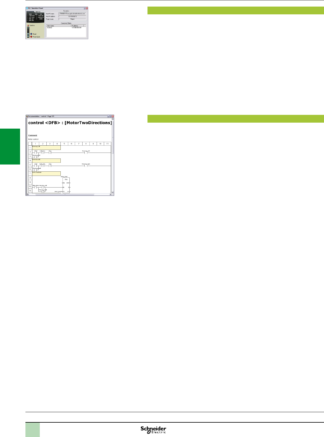
4/10
Software
Unity Pro software
Small/Medium/Large/Extra Large
PLC simulator
Unity Pro’s integrated simulator can be used to test the application program for
Modicon M340, Premium or Quantum PLCs from the PC terminal without having to
connect to the PLC processor. The functions provided by the debugging tools are
available for debugging the master, fast and auxiliary tasks.
As the simulator does not manage the PLC I/O, animation tables can be used to
simulate the state of inputs by forcing them to 0 or 1.
The simulator can be connected to third-party applications via an OPC server with
OFS(OPCFactoryServer) software.
Documentation editor
The documentation editor is based on the Documentation Browser, which shows the
le structure in tree form.
It allows all or part of the application le to be printed on any graphics printer
accessible under Windows and using True Type technology, in A4 or US letter print
format.
The documentation editor supports the creation of user-specic les using the
following headings:
Title page
Contents
General information
Footer
Conguration
EF, EFB and DFB type function blocks
User variables
Communication
Project structure
Program
Animation tables and cross-references
Runtime screens
Functions(continued)
Selection guide:
page 4/2
Simulatorcontrolpanel
Accessingthedocumentationeditor
2
1
3
4
5
6
7
8
9
10
2
1
3
4
5
6
7
8
9
10
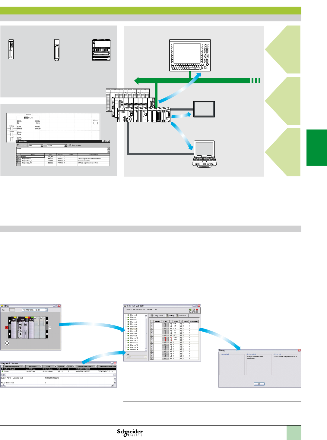
4/11
Diagnostics integrated in Modicon M340, Premium and Quantum automation platforms
Presentation
The diagnostics offer for Modicon M340, Premium and Quantum platforms is based
on the following three components:
System diagnostics
DFB and EFB diagnostic function blocks (for system and application diagnostics)
Error message display system, called viewers, supplied as a standard component
of Magelis XBT terminals, Vijeo Citect supervisory software and Unity Pro setup
software
System diagnostics
The system diagnostics for the Modicon M340, Premium and Quantum platforms
support the monitoring of system bits/words, I/O modules and activity times (minimum/
maximum) of SFC steps. By simply choosing the relevant option during application
conguration, any event will generate time-stamped messages logged in the
diagnostic buffer of the PLC.
These events are displayed automatically in a diagnostics viewer (1)without requiring
any additional programming.
With Unity Pro integrated diagnostics, this function can be used to perform rst level
diagnostics of the elements in the conguration, up to and including each I/O module
channel.
Conguration level
Viewer window (example with Unity Pro software)
Module level
Channel level
(1)Diagnosticsviewersaretoolsfordisplayingandacknowledgingdiagnosticerrormessages.
TheyaresuppliedasastandardcomponentofUnityProandVijeoDesignersoftware,with
MagelisterminalsandwiththePLCWebserverthatcanbeaccessedviaathinclientMagelis
iPC.
Processor
for system
bits and
words
In-rack I/O
modules
Remote I/O
modules on
Fipio
or CANopen
Higher-level
M.E.S.
Cell level
Machine level
Unity Pro
Diagnostics viewersSystem diagnostics
Application diagnostics
Ethernet TCP/IP
Magelis XBT
PC
Vijeo Citect
Thin client Magelis iPC
Quantum,
Premium,
Modicon M340
Vijeo Designer
Software
Unity Pro software
Small/Medium/Large/Extra Large
Integrated diagnostics
Functions(continued)
2
1
3
4
5
6
7
8
9
10
2
1
3
4
5
6
7
8
9
10
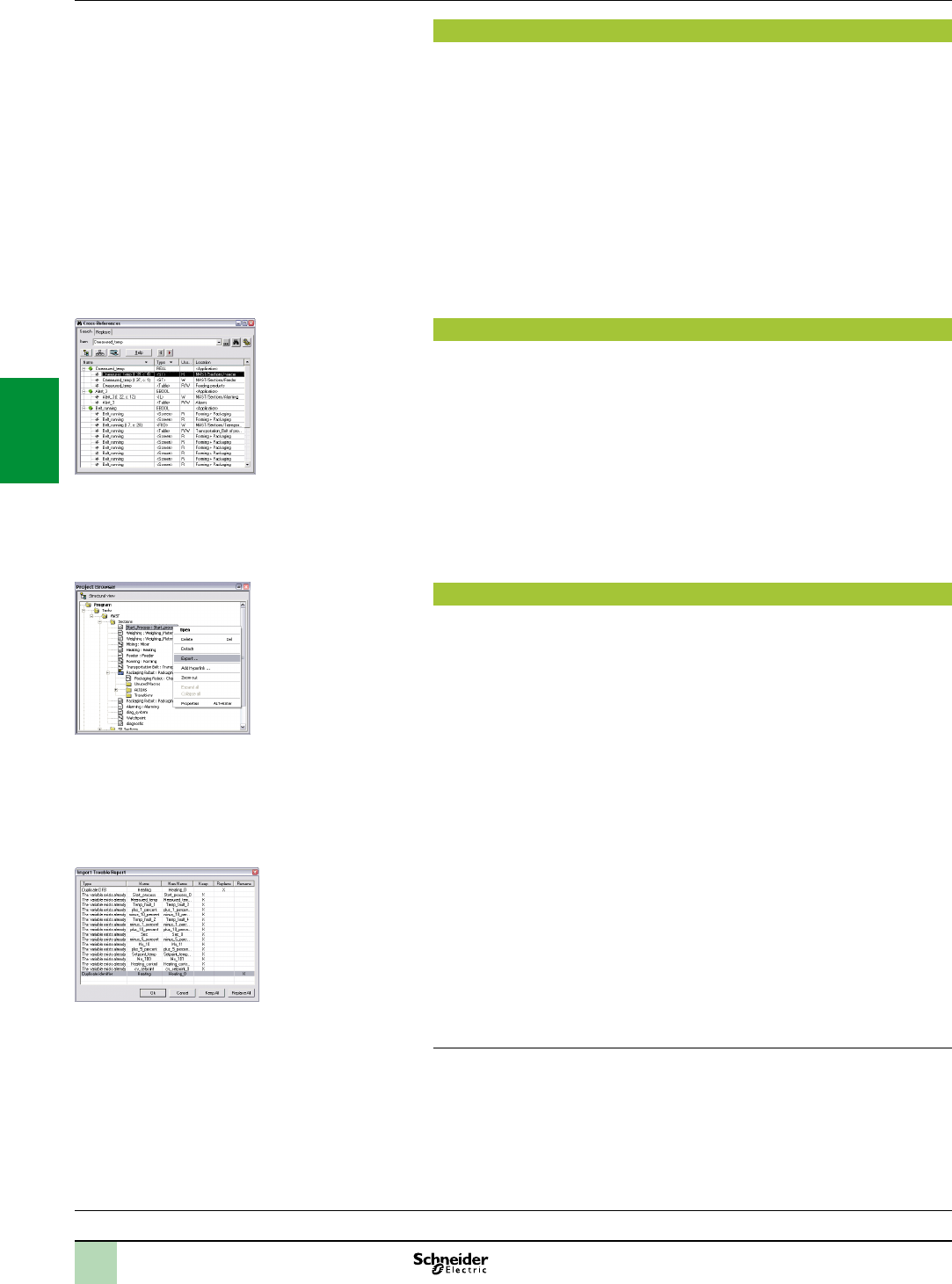
4/12
Software
Unity Pro software
Small/Medium/Large/Extra Large
Modifying the program with the PLC in RUN mode
With Unity Pro, changes can be made to the program when the PLC connected to
the programming terminal is in RUN mode. These modications are performed with
the following operations:
The application contained in the PLC is transferred to the PC terminal running
Unity Pro, if necessary.
Program changes are prepared. These program modications can be of any type
and in any language (IL, ST, LD, FBD and SFC), for example, addition or deletion of
SFC steps or actions. The code of a DFB user function block can also be modied
(however, modication of its interface is not permitted).
These program changes are updated in the PLC (in RUN mode).
This function makes it possible to add or modify program code and data in different
parts of the application in one single modication session (thus resulting in a uniform,
consistent modication with respect to the controlled process). This increased
exibility comes at a cost in terms of the amount of program memory required.
Cross-references function
Unity Pro's cross-references function, which is available in standalone mode (ofine)
and when connected to the PLC in Run (online), allows users to view all the
elements of a PLC application when searching for any type of variable. This view
indicates where the declared variable is used, as well as how it is used (for writing,
reading, etc.).
This function also provides access to the Search/Replace function for variable
names.
The variable search can be initialized from any editor (language, data, runtime
screen, animation table, etc.).
Import/export function
The import/export function available in Unity Pro supports the following operations
from the structural and functional project views:
Via the import function, reuse all or part of a previously created project in the
current project
Via the export function, copying of all or part of the current project to a le for
subsequent reuse
The les generated during export are generally in XML format (1). However, in
addition to XML, variables can be exported and imported in the following formats:
.xvm format compatible with OFS data server software
Source format, in an .scy le compatible with PL7 development software
Text format with separator (TAB) in a .txt le for compatibility with any other system
During an import, a wizard can be used to reassign data to new instances of:
DFB function blocks
DDT data structures
Simple data
In addition, when a functional module is imported, the data associated with
animation tables and runtime screens is also reassigned.
The XML import function also supports the transfer of a Modicon M340, Premium or
Quantum PLC conguration prepared in the SIS Pro costing and conguration tool
for use in the creation of a project in Unity Pro.
This import function spares the user from having to redene the PLC conguration
when the PLC has already been congured with the SIS Pro tool.
(1)XMLlanguageisanopen,text-basedlanguagethatprovidesstructuralandsemantic
information.
Functions(continued)
Selection guide:
page 4/2
Cross-referencestable
Dataexportshortcutmenu
Dataimportwizard
2
1
3
4
5
6
7
8
9
10
2
1
3
4
5
6
7
8
9
10
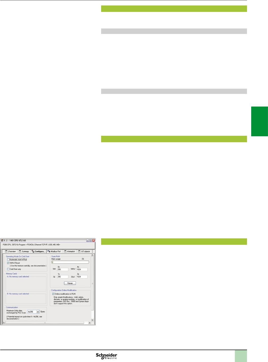
4/13
Software
Unity Pro software
Small/Medium/Large/Extra Large
Application converters
Unity Pro’s integrated conversion tools can be used to convert PLC applications
created with Concept and PL7 programming software to Unity Pro applications.
Concept/Unity Pro converter (Quantum PLC)
This conversion is performed with a Concept application V2.5 or later (it can also be
performed in V2.11 or later, but only after an update to V2.5). In order to perform the
conversion, the application must be exported to an ASCII le in Concept.
The export le is converted to a Unity Pro source le automatically. This le is then
analyzed by Unity Pro. At the end of the procedure, a conversion report is generated
and an output window displays any conversion errors and provides direct access to
the part of the program to be modied.
The Concept application converter converts the application to Unity Pro, but does
not guarantee that it will operate correctly in real-time. It is therefore essential to test
or debug all converted applications.
PL7/Unity Pro converter (Premium PLC and Atrium slot PLC)
This conversion is performed with a PL7 application V4 or later (Premium PLC or
Atrium slot PLC). In order to perform the conversion, the source le (complete
application or user function block) must be exported in PL7.
The conversion procedure is similar to that of the Concept conversion described
above.
Note: ApplicationscreatedwithConcept,ModsoftandProWORXcanbeconvertedtoLL984.
PleaseconsultourCustomerCareCentre.
Operating system update utilities
The OS-Loader software is designed for updating operating systems on Premium
and Quantum platforms. It is supplied with Unity Pro software.
It is used to upgrade Unity processors and modules as well as to upgrade PL7 or
Concept processors and modules to make them compatible with Unity Pro.
OS-Loader software supports:
Premium processors
Quantum processors
Ethernet communication modules
EtherNet/IP communication modules
The operating system updates are performed as follows:
Uni-Telway RS 485 terminal link for Premium processors
Modbus or Modbus Plus terminal link for Quantum processors
Ethernet TCP/IP network for integrated Ethernet port on Premium processors and
Premium and Quantum Ethernet modules
Note:ForModiconM340,thisserviceisprovidedbyUnityLoader(seepage4/26).
Online modication of the Quantum conguration
This function, also called ChangeCongurationOnTheFly(CCOTF), is used to modify
the Quantum conguration online (application in RUN mode):
Addition or removal of discrete or analog I/O modules
Modication of conguration parameters of discrete or analog I/O modules
(already present or newly installed)
The CCOTF function is supported by standalone processors for all three types of I/O
architecture (local, RIO, DIO) using version 5 of Unity Pro, and for Hot Standby
processors using version 4.1 of Unity Pro.
The CCOTF function must rst be validated in the Unity Pro conguration screen. A
conrmation screen appears when the conguration has been modied online.
Functions(continued)
Congurationscreen
2
1
3
4
5
6
7
8
9
10
2
1
3
4
5
6
7
8
9
10
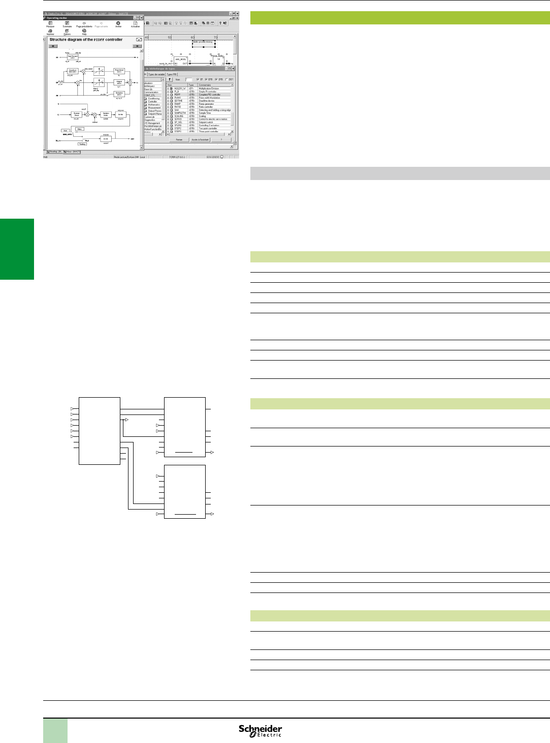
4/14
Functions(continued) Software
Unity Pro software
Small/Medium/Large/Extra Large
Programmable process control
Process control in machines
Unity Pro contains CONT_CTL, a library of 36 function blocks used to create control
loops for machine control.
All requirements for closed loop control functions in machines are adequately met by
Modicon M340, Premium and Quantum platforms thanks to the wealth of functions in
the library and the exibility with which function blocks can be linked together
through programming. This solution therefore eliminates the need for external
controllers and simplies the overall control architecture of the machine, as well as
its design, roll-out and operation.
The EFs or EFBs can be used in all Unity Pro languages (LD, ST, IL and FBD). FBD
is particularly suitable for accessing control processing operations in Unity Pro
through its wizard for entering and viewing parameters and function block variables.
CONT_CTL library functions
The library consists of ve function families:
Input data conditioning
Controllers
Mathematical functions
Process value processing
Output value processing
Input data conditioning
DTIME Pure time delay
INTEGRATOR Integrator with limiting
LAG_FILTER First order time lag
LDLG Lead/lag function with smoothing
LEAD Lead function with smoothing
MFLOW Mass ow calculation based on the measurement of differential
pressure or ow speed with pressure and temperature
compensation
QDTIME Dead time term
SCALING Scaling
TOTALIZER Integrator (typically of ow) until a limit (typically a volume) is
reached, with automatic reset
VEL_LIM Velocity limiter, with manipulated variable limiting
Controllers
PI_B Basic PI controller: PI algorithm with a mixed structure
(series/parallel)
PIDFF Complete PID controller: PID algorithm with a parallel or mixed
structure (series/parallel)
AUTOTUNE Automatic tuner setting for the PIDFF (complete PID) controller or
the PI_B (simple PI) controller
Identication using Ziegler Nichols type method
Modeling based on rst order process
Building of control parameters with criterion for prioritizing
either the reaction time to disturbance (dynamic) or the stability of
the process
IMC Model-based controller. The model is a rst order model with
delay. This corrector is useful:
When there are serious delays compared with the main time
constant of the process; this scenario cannot be satisfactorily
resolved by standard PID process control
For regulating a non-linear process
IMC can handle any stable and aperiodic process of any order.
SAMPLETM Control of controller startup and sampling
STEP2 Simple two-position controller
STEP3 Three-position controller for temperature regulation
Mathematical functions
COMP_DB Comparison of two values, with dead zone and hysteresis
K_SQRT Square root, with weighting and threshold, useful for linearization
of ow measurements
MULDIV_W Weighted multiplication/division of 3 numerical values
SUM_W Weighted summing of 3 numerical values
CONT_CTL,programmableprocesscontrolintegratedin
UnityPro
AUTOTUNE
PV
SP
RCPY
START
PREV
PARA
TR_I
TR_S
PV_O
SP_O
PARA_C
TRI
TRS
INFO
STATUS
TT18_PV
TT18_SP
TC18_OUT
TC18_START
TC18_PREV
TC_PARA
TC18_PARA
TC18_OUT
1
TC2_OUT
TC2_OUT
TC18_OUT
PV
SP
PARA
TR_I
TR_S
PIDFF
FF
RCPY
MAN_AUTO
OUT OUT
OUTD
MA_O
INFO
STATUT
TC2_OUT
MS
TC18_OUT
IN
PARA
TR_I
TR_S
FORC
MA_FORC
MAN_AUTO
OUT OUT
OUTD
MA_O
STATUT
Example:PIDcontrollerwithMSmanualcontrol
Selection guide:
page 4/2
2
1
3
4
5
6
7
8
9
10
2
1
3
4
5
6
7
8
9
10
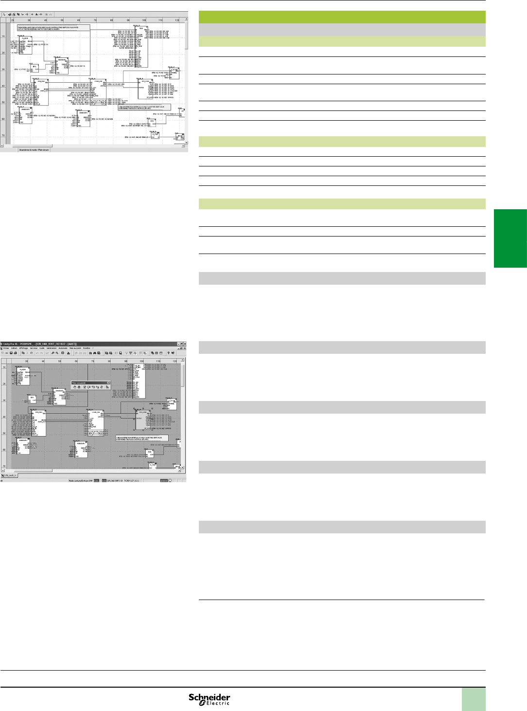
4/15
Functions(continued),Software
Unity Pro software
Small/Medium/Large/Extra Large
Programmable process control
Process control in machines (continued)
CONT_CTL library functions (continued)
Process value processing
AVGMV Moving average with xed number of samples (50 max.)
AVGMV_K Moving average with constant correction factor, 10,000 samples
max.
DEAD_ZONE Dead zone
LOOKUP_TABLE1 Linearization of characteristic curves using rst-order interpolation
SAH Detection of a rising edge
HYST_XXX Detection of high threshold with hysteresis (1)
INDLIM_XXX Detection of high and low thresholds with hysteresis (1)
Output value processing
MS Manual control of an output
MS_DB Manual control of an output with dead zone
PWM1 Control via pulse width modulation
SERVO Control for servo motors
SPLRG Control of two SplitRangeactuators
Setpoint management
RAMP Ramp generator, with separate ascending and descending ramps
RATIO Ratio controller
SP_SEL Selection of setpoint value: local (operator) or remote (processing)
Setting up process control function blocks
Based on the sequencing of function blocks, the FBD language integrated in Unity
Pro is a programming language particularly suitable for building control loops.
Designers can use FBD to easily associate blocks from the CONT_CTL library with
their own DFBs written in Unity Pro’s ST, IL or LD language, or in C language.
Debugging, operation
All Unity Pro’s standard debugging services (see page 4/9) are available. In
particular, the Modicon M340 processor simulator can be used to check correct
execution of processing ofine.
Compatibility
The CONT_CTL control function block library is available in all versions of Unity Pro.
It is compatible with all processors in the Modicon M340, Premium and Quantum
ranges.
Optional specialized libraries
The CONT_CTL control function block library can be supplemented with optional
specialized libraries, to meet specic needs such as predictive control, fuzzy logic
controller, HVAC and mass ow calculation (see page 4/28).
Resources
The technical documentation provides many examples of how to set up
programmable process control function blocks in FBD, LD, IL and ST languages.
The techniques for adjusting process control loops are described in the document
“Process control, Unity V3.0” available online at
www.schneider-electric.com.
(1)XXXaccordingtothetypeofvariable:DINT,INT,UINT,UDINT,REAL.
ProgramminginUnityProinofinemode
Programminginonlinemode
Selection guide:
page 4/2
2
1
3
4
5
6
7
8
9
10
2
1
3
4
5
6
7
8
9
10

4/16
Software
Unity Pro software
Small/Medium/Large/Extra Large
Communication drivers
The most commonly used communication drivers for Modicon M340, Premium and
Quantum platforms are installed at the same time as the Unity Pro software.
Unity Pro also includes the following drivers, which can be installed as required (1):
Protocol - Hardware Windows XP
Professional
Windows Vista Business
32-bit edition
Windows 7
32-bit and 64-bit editions
Ethway - Ethernet
Fip - FPC10 ISA card
Fip - FPC20 PCMCIA card
Fip adaptor - CUSBFIP
ISAway - PCX57 ISA card
Modbus Serial - COM port
PCIway - Atrium TPCI57 PCI card
Uni-Telway - COM port
Uni-Telway - SCP114 PCMCIA card
USB for high end PLC
XIP - XWay on TCP/IP
Driver available Driver not available
Upgrade kits for Concept, PL7 Pro and ProWORX software
The Concept, PL7 Pro and ProWORX upgrade kits allow users who already have
one of these programs from the installed base and who have a current subscription
to obtain Unity Pro version V4.1 software at a reduced price.
These upgrades are only available for licences of the same type (e.g. from Concept
XL group licence to Unity Pro Extra Large group licence).
Composition and Windows OS compatibility
Unity Pro multilingual software packages are compatible with Windows XP (32-bit),
Windows Vista (32-bit) and Windows 7 (32-bit and 64-bit) operating
systems.
They include:
Documentation in electronic format in six languages (English, French, German,
Italian, Spanish and Chinese)
Converters for converting applications created with Concept and PL7 Pro
programming software
PLC simulator
Cables for connecting the processor to the programming PC must be ordered
separately.
(1)AlsoavailableseparatelyunderreferenceTLX CD DRV 20M.
Functions(continued)
Selection guide:
page 4/2
2
1
3
4
5
6
7
8
9
10
2
1
3
4
5
6
7
8
9
10
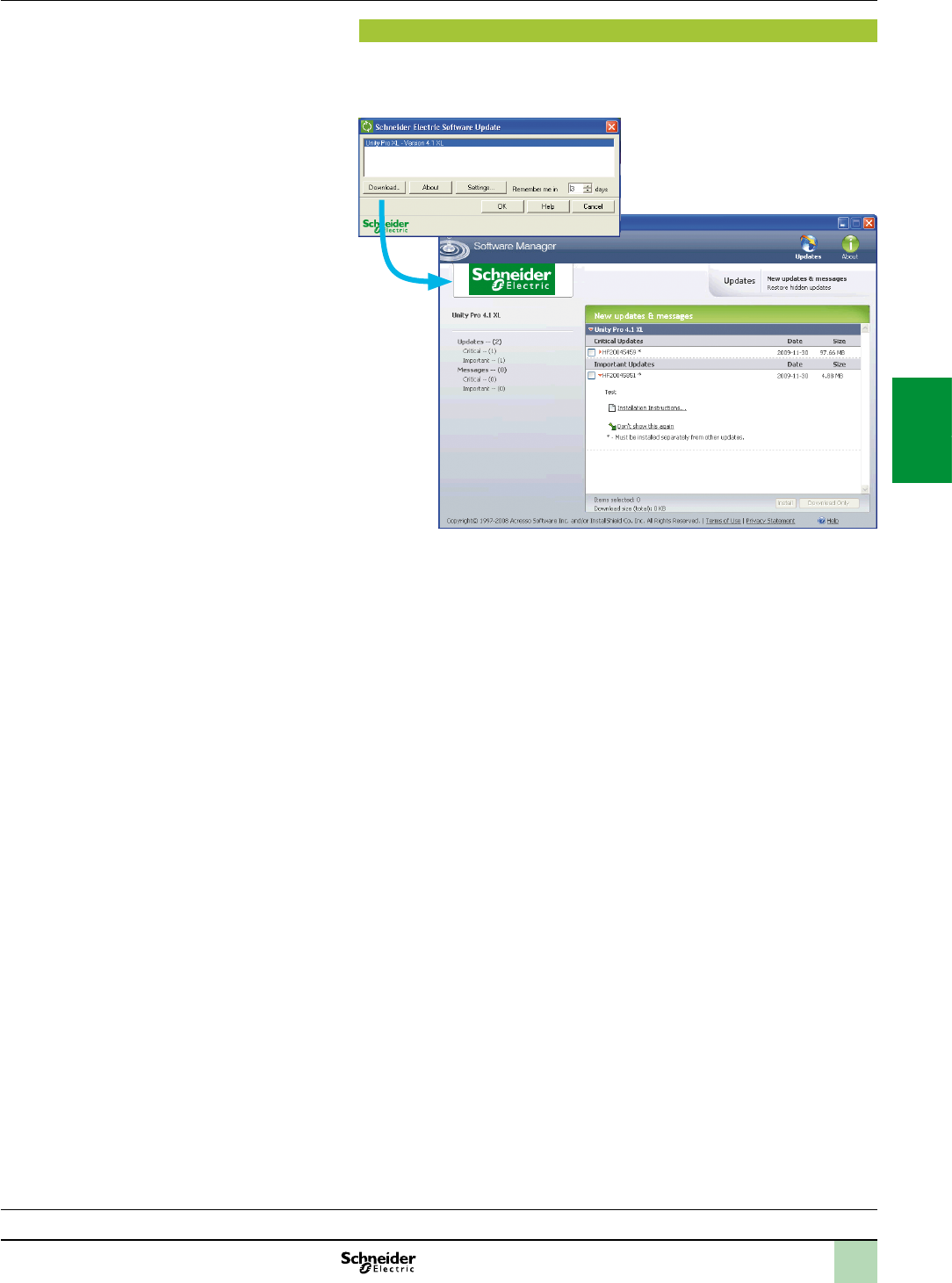
4/17
Unity Pro update
Customers are notied automatically when a new Unity Pro update becomes
available.
They can then access the software updates manager directly, download the update
and install it locally on their workstation.
Note:Thelatestrmwareversionsareavailablefordownloadfromourwebsite
www.schneider-electric.com.
Functions(continued) Software
Unity Pro software
Small/Medium/Large/Extra Large
Selection guide:
page 4/2
2
1
3
4
5
6
7
8
9
10
2
1
3
4
5
6
7
8
9
10

4/18
References
Unity Pro Small, Medium, Large and Extra Large software packages
These software packages are for programming and setting up Unity automation
platforms. The software is available in ve versions:
Unity Pro Small (see page 4/18)
Unity Pro Medium (see page 4/19)
Unity Pro Large (see page 4/19)
Unity Pro Extra Large (see page 4/20)
Upgrade kits for Concept, PL7 Pro and ProWORX software
These upgrade kits allow users who already have these software programs from the
installed base and who have a current subscription to obtain Unity Pro version
V7.0 software at a reduced price. These upgrades are only available for licences of
the same type (e.g. from Concept XL group licence to Unity Pro Extra Large group
licence). See page 4/20.
Composition and Windows OS compatibility
Unity Pro multilingual software packages are compatible with Windows XP (32-bit),
Windows Vista Business Edition (32-bit) and Windows 7 (32-bit and 64-bit)
operating systems.
The packages comprise:
A Unity Pro V7.0 DVD in six languages (English, French, German, Italian,
Spanish and Chinese)
A Unity Loader V2.3 CD
An Advantys V7.0 conguration software CD
A DVD containing the documentation in electronic format in six languages
(English, French, German, Italian, Spanish and Chinese)
A one-year services subscription
Unity Pro Small version 7.0 software
For Modicon M340: All models
For distributed I/O: Modicon ETB, TM7, OTB, STB, Momentum
Unity Pro Small version 7.0 software packages (1)
Description Licence type Reference Weight
kg
Unity Pro Small
software packages
Single (1 station) UNYSPUSFUCD70 –
Group (3 stations) UNYSPUSFGCD70 –
Team (10 stations) UNYSPUSFTCD70 –
Software upgrades from:
- Concept S
- PL7 Micro
- ProWORX NxT/32 Lite
Single (1 station) UNYSPUSZUCD70 –
Group (3 stations) UNYSPUSZGCD70 –
Team (10 stations) UNYSPUSZTCD70 –
Licence type extensions for Unity Pro Small version 7.0
From To Reference Weight
kg
Single (1 station) Group (3 stations) UNYSPUSZUGCD70 –
Group (3 stations) Team (10 stations) UNYSPUSZGTCD70 –
(1)ForcompatibilityofUnitysoftware/automationplatformsanddistributedI/O,refertothe
selectionguideonpage4/2.
Unity Pro
Selection guide:
page 4/2
References Software
Unity Pro software
Small/Medium/Large/Extra Large
2
1
3
4
5
6
7
8
9
10
2
1
3
4
5
6
7
8
9
10

4/19
Unity Pro Medium version 7.0 software
For Modicon M340: All models
For Modicon Premium: TSX571p...2p
For distributed I/O: Modicon ETB, TM7, OTB, STB, Momentum
Unity Pro Medium version 7.0 software packages (1)
Description Licence type Reference Weight
kg
Unity Pro Medium
software packages
Single (1 station) UNYSPUMFUCD70 –
Group (3 stations) UNYSPUMFGCD70 –
Team (10 stations) UNYSPUMFTCD70 –
Software upgrades from:
- Concept S, M
- PL7 Micro, Junior
- ProWORX NxT/32 Lite
Single (1 station) UNYSPUMZUCD70 –
Group (3 stations) UNYSPUMZGCD70 –
Team (10 stations) UNYSPUMZTCD70 –
Licence type extensions for Unity Pro Medium version 7.0
From To Reference Weight
kg
Single (1 station) Group (3 stations) UNYSPUMZUGCD70 –
Group (3 stations) Team (10 stations) UNYSPUMZGTCD70 –
Upgrade to Unity Pro Medium from Unity Pro Small
Type of upgrade
The number of stations is unchanged
Reference Weight
kg
Small to Medium Single (1 station) UNYSPUMZSUCD70 –
Small to Medium Group (3 stations) UNYSPUMZSGCD70 –
Small to Medium Team (10 stations) UNYSPUMZSTCD70 –
Unity Pro Large version 7.0 software
For Modicon M340: All models
For Modicon Premium: TSX571p…4p
For Modicon Quantum: 140CPU31110/43412U/53414U
For distributed I/O: Modicon ETB, TM7, OTB, STB, Momentum
Unity Pro Large version 7.0 software packages (1)
Description Licence type Reference Weight
kg
Unity Pro Large
software packages
Single (1 station) UNYSPULFUCD70 –
Group (3 stations) UNYSPULFGCD70 –
Team (10 stations) UNYSPULFTCD70 –
Site ( 100 users) UNYSPULFFCD70 –
Software upgrades from:
- Concept S, M
- PL7 Micro, Junior, Pro
- ProWORX NxT/32 Lite
Single (1 station) UNYSPULZUCD70 –
Group (3 stations) UNYSPULZGCD70 –
Team (10 stations) UNYSPULZTCD70 –
Site ( 100 users) UNYSPULZFCD70 –
Licence type extensions for Unity Pro Large version 7.0
From To Reference Weight
kg
Single (1 station) Group (3 stations) UNYSPULZUGCD70 –
Group (3 stations) Team (10 stations) UNYSPULZGTCD70 –
Upgrade to Unity Pro Large from Unity Pro Medium
Type of upgrade
The number of stations is unchanged
Reference Weight
kg
Medium to Large Single (1 station) UNYSPULZMUCD70 –
Medium to Large Group (3 stations) UNYSPULZMGCD70 –
Medium to Large Team (10 stations) UNYSPULZMTCD70 –
(1)ForcompatibilityofUnitysoftware/automationplatformsanddistributedI/O,refertothe
selectionguideonpage4/2.
Unity Pro
Selection guide:
page 4/2
References(continued) Software
Unity Pro software
Small/Medium/Large/Extra Large
2
1
3
4
5
6
7
8
9
10
2
1
3
4
5
6
7
8
9
10

4/20
Unity Pro
Selection guide:
page 4/2
Unity Pro Extra Large version 7.0 software
For Modicon M340: All models
For Modicon Premium: TSX571p...6p
For Modicon Quantum: 140CPU31110/43412U/53414U/65150/65160/65260/67160/67260/67261
For distributed I/O: Modicon ETB, TM7, OTB, STB, Momentum
Unity Pro Extra Large version 7.0 software packages (1)
Description Licence type Reference Weight
kg
Unity Pro Extra Large
software packages
Single (1 station) UNYSPUEFUCD70 –
Group (3 stations) UNYSPUEFGCD70 –
Team (10 stations) UNYSPUEFTCD70 –
Site ( 100 users) UNYSPUEFFCD70 –
Software upgrades from:
- Concept S, M, XL
- PL7 Micro, Junior, Pro
- ProWORX NxT Lite, Full
- ProWORX 32 Lite, Full
Single (1 station) UNYSPUEZUCD70 –
Group (3 stations) UNYSPUEZGCD70 –
Team (10 stations) UNYSPUEZTCD70 –
Site ( 100 users) UNYSPUEZFCD70 –
Licence type extensions for Unity Pro Extra Large
From To Reference Weight
kg
Single (1 station) Group (3 stations) UNYSPUEZUGCD70 –
Group (3 stations) Team (10 stations) UNYSPUEZGTCD70 –
Upgrade to Unity Pro Extra Large from Unity Pro Large
Type of upgrade
The number of stations is unchanged
Reference Weight
kg
Large to Extra Large Single (1 station) UNYSPUEZLUCD70 –
Large to Extra Large Group (3 stations) UNYSPUEZLGCD70 –
Large to Extra Large Team (10 stations) UNYSPUEZLTCD70 –
Documentation for Unity Pro version 7.0
Description Licence type Reference Weight
kg
Hardware and software manuals (on DVD)
- Platform setup for: Modicon M340,
Premium, Quantum, Momentum
- Electromagnetic compatibility of networks
and eldbuses
- Software setup for: Unity Pro, Function block
library
Multilingual: English, French,
German, Italian, Spanish,
Chinese
UNYUSE909CDM –
(1)ForcompatibilityofUnitysoftware/automationplatformsanddistributedI/O,refertotheselectionguideonpage4/2.
References(continued) Software
Unity Pro software
Small/Medium/Large/Extra Large
2
1
3
4
5
6
7
8
9
10
2
1
3
4
5
6
7
8
9
10

4/21
Accessories for connecting to the PC programming terminal
Description Use Length Reference Weight
kg
From processor port To PC port
PC terminal connection
cables
(PC to PLC)
USB mini B port
BMXP341000/200/2002
USB port 1.8 m BMXXCAUSBH018 0.065
4.5 m BMXXCAUSBH045 0.110
Mini-DIN port
Premium TSX571/2/3/4RS 232D
(9-way SUB-D
connector)
2.5 m TSXPCX1031 0.170
USB port
(USB/RS 485
converter)
0.4 m TSXCUSB485
(1)
0.144
USB port
(mini-DIN/
RJ45
cordset)
2.5 m TSXCRJMD25
(1)
0.150
Modbus port
15-way SUB-D Quantum
140CPU31110
140CPU43412A
140CPU53414B
RS 232D
(9-way SUB-D
connector)
3.7 m 990NAA26320 0.300
15 m 990NAA26350 0.180
USB port
Premium TSX575/6
Quantum 140CPU61
USB port 3.3 m UNYXCAUSB033 –
Modbus port, RJ45 connector
Quantum 140CPU61
RJ 45
connector
1 m 110XCA28201 –
3 m 110XCA28202 –
6 m 110XCA28203 –
PC terminal connection
cables
(PC SUB-D to
Modicon STB I/O)
HE13 connector Modicon STB
I/O network interface module
(NIM)
RS 232D (2)
(9-way SUB-D
connector)
2 m STBXCA4002 0.210
USB/SUB-D adaptor
(PC USB to Modicon STB
I/O)
HE13 connector Modicon STB
I/O network interface module
(NIM) with STBXCA4002 cable
(3)
USB port (3) –SR2CBL06 0.185
Description Use Reference Weight
kg
Universal Bluetooth®
interface (UBI)
Provides Bluetooth® connectivity for products such as the
Modicon M340/Premium platforms and Altivar/Lexium servo
drives, via their serial port (RS 485).
Used for setting-up and maintenance of products.
Designed for permanent installation and can be safely tted on
the inside or outside of electrical enclosures.
Protocols supported: Modbus and Uni-Telway
Powered via the product’s RS 485 serial port
Max. range in direct line of sight: 20 m
The kit comprises:
A Universal Bluetooth® interface (UBI)
An RJ45/mini-DIN cable (length 1 m)
An RJ45/RJ45 cable (length 1 m)
A xing clamp for installation inside the electrical
enclosure
A CD with conguration software and user manual
TCSWAAC13FB 0.320
(1)TheTSXCUSB485converterrequiresuseoftheTSXCRJMD25mini-DIN/RJ45cordset.
(2)ForconnectiononaUSBport,theSR2CBL06cablemustalsobeused(3).
(3)AdaptorequippedwithaUSBconnector(PCside)anda9-waySUB-Dconnector(STBXCA4002cableside);requiresthe
STBXCA4002cable(9-waySUB-D/HE13)forconnectiontotheHE13connectorontheModiconSTBNIM.
TSXPCX1031
BMXXCAUSBH0
Selection guide:
page 4/2
TSXCUSB485
TCSWAAC13FB
References(continued) Software
Unity Pro software
Small/Medium/Large/Extra Large
2
1
3
4
5
6
7
8
9
10
2
1
3
4
5
6
7
8
9
10
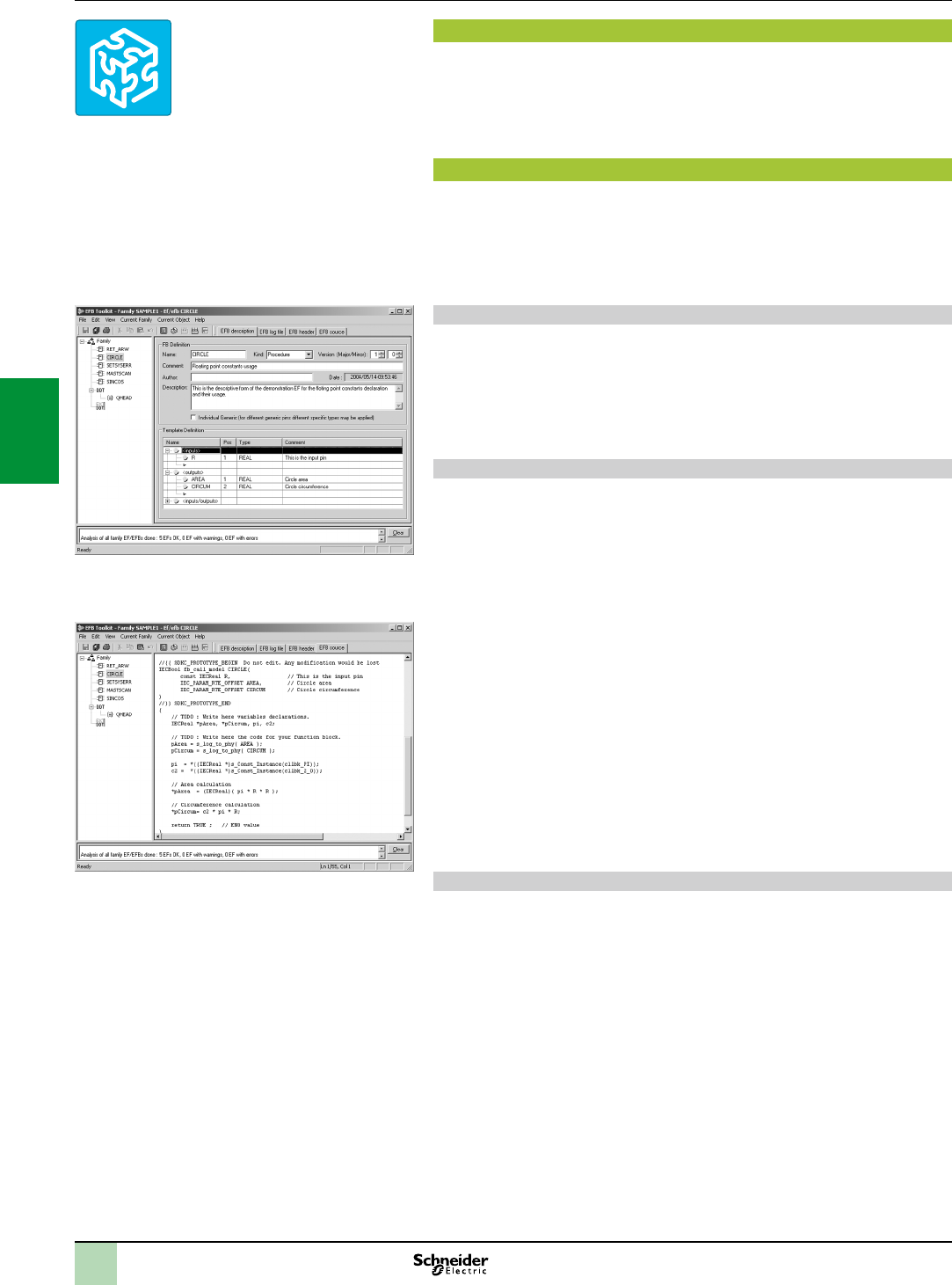
4/22
Presentation
Unity EFB Toolkit is the software for developing EFs and EFBs in “C” programming
language. As an option with Unity Pro, it can be used to extend all the standard Unity
Pro function blocks in order to increase functionality. This software comes with
MicrosoftVisualStudio, which can be used to debug the function blocks developed
in the Unity Pro PLC simulator. Unity EFB Toolkit also includes a service for creating
and managing families of function blocks and integrating them in Unity Pro.
Setup
Unity EFB Toolkit manages the whole process of developing Unity Pro function
blocks:
User-friendly graphical user interface with automatic le organization
Powerful tools for testing and debugging
Management of compatibilities and software versions of created functions
Generation of les for subsequent installation of functions on other Unity Pro stations
Managing function block families
The software can be used to create function block families. The function blocks
developed, also known as EFs/EFBs, are stored in families. This makes it possible to
create an organized library of functions written in “C” language. Once created, these
function block families are installed on the Unity Pro stations for the purpose of
extending the standard Unity Pro libraries. Integration in Unity Pro can be executed
from Unity EFB Toolkit or via the tool for updating Unity Pro libraries, which allows
these families to be distributed without the use of any other software.
Developing function blocks
The EFB Toolkit software allows the user to create a function block as follows:
Declaration of the function block interface in the same way as for the DFBs in
Unity Pro
Denition of all data types needed (elementary, structures, tables)
Support of public and private variables
Generation of all les and the block “C” coding frame (the user only adds
functionality to this frame)
Granting of access to numerous internal PLC services, such as the real-time
clock, PLC variables and data, system words and math functions, including
high-precision numerical processing in “double” format
Structure of the function block family (compilation/link for all Unity Pro automation
platforms)
Provision of a debugging environment: the function blocks created can easily be
debugged in MicrosoftVisualStudio by downloading a Unity Pro application
containing the function developed in the Unity Pro PLC simulator. All the debugging
functions in MicrosoftVisualStudio, especially breakpoints, step-by-step operations,
display of the code/data and manipulation of the data, can be accessed without
restriction.
Support for managing Unity Pro versions, important during the function block
maintenance phase
Note:AspecicGNUcompilerisusedtogeneratethecodeforaModiconM340platform.Itis
suppliedwiththeUnityEFBToolkit.
Compatibility
Unity EFB Toolkit is compatible with Unity Pro Small, Medium, Large and
Extra Large. EFs and EFBs can be developed for Modicon Premium, Modicon M340
and Modicon Quantum platforms.
Presentation,
setup Software
Unity Pro software
Unity EFB Toolkit software
Unity EFB Toolkit
EFBToolkit:Managingfunctionblockfamilies
EFBToolkit:Editor
2
1
3
4
5
6
7
8
9
10
2
1
3
4
5
6
7
8
9
10

4/23
References
Unity Pro companion software, Unity EFB Toolkit, can be used to create Unity Pro
function blocks in “C” programming language. The developed function blocks can
then be integrated in standard Unity Pro function block libraries.
Unity EFB Toolkit and its documentation are supplied in electronic format on
CD-ROM in English.
Description Type Language Reference Weight
kg
Unity EFB Toolkit
software
Single licence
(1 station)
English (software
and electronic
documentation)
UNYSPUZFUCD70 –
Software
Unity Pro software
Unity EFB Toolkit software
References
2
1
3
4
5
6
7
8
9
10
2
1
3
4
5
6
7
8
9
10

4/24
Presentation
Unity Dif is an optional program for Unity Pro. It can handle all Unity Pro automation
platforms. It compares two Unity Pro applications and returns an exhaustive list of all
the differences. Unity Dif improves productivity during the main life stages of a
control system, mainly during development and debugging of applications and
commissioning, operation and maintenance of the installation.
Software setup
Unity Dif can be launched in several ways:
From Unity Pro
From the Windows Start menu
From a command line interface without a graphical user interface
Unity Dif identies all the differences between two Unity Pro applications at different
levels:
Hardware conguration
Network conguration (Modbus/TCP, CANopen and RIO (Quantum only))
All the variables and instances of function blocks
Structure and content of the application, regardless of which language is used
(including LL 984)
DFB and DDT code
Project options
DTM catalogue
The result of the comparison can be displayed in the user interface, printed or saved
in .txt le format.
Comparison
The end of the comparison operation is signaled by the appearance of the
application browser with its two tabs:
1 Identication tab for accessing the
characteristics of the two applications being
compared. The differences are summarized.
2 Browser tab for accessing the application
tree structure.
Displaying results
The tree structure can be accessed after comparison, via the Browser tab. It shows any
differences using four symbols, where the information associated with application 1
appears in blue and that associated with application 2 appears in red:
This branch, appearing at this level in the tree structure, contains at
least one difference
This block contains at least one difference
This section is only present in application 1
This section is only present in application 2
In the example opposite, a difference is detected on the rung:
1 The line displayed in green belongs to application 1 [Prj1]
2 The line displayed in red belongs to application 2 [Prj2]
The source code extracts of both applications can be used to locate the differences
precisely.
21
Software
Unity Pro software
Unity Dif application comparison software
Presentation,
setup
Unity Dif
Selectionofelementstocompare
Displayingresults
12
2
1
3
4
5
6
7
8
9
10
2
1
3
4
5
6
7
8
9
10

4/25
References
This Unity Dif software extension is used to compare two Unity applications
generated by Unity Pro software version V2.1 or later.
Description Target extension
PLC target
Type Reference Weight
kg
Unity Dif comparison
software extension for
Unity Pro applications
CD-ROM containing
software and electronic
documentation
(English-French)
All Unity Pro
Modicon M340,
Premium, Quantum
versions
Single
licence
(1 station)
Download
or CD
UNYSDUZFUCD70 –
Site licence
(100 stations)
CD only
UNYSDUZFFCD70 –
Software
Unity Pro software
Unity Dif application comparison software
References
2
1
3
4
5
6
7
8
9
10
2
1
3
4
5
6
7
8
9
10
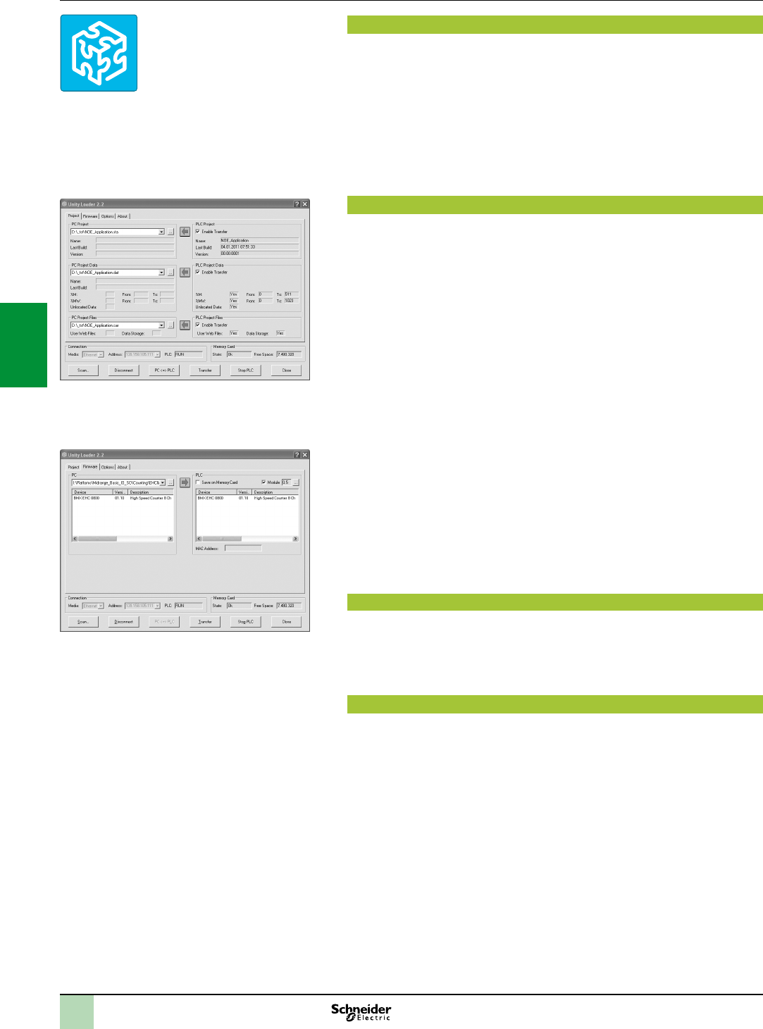
4/26
Software
Unity Pro software
Unity Loader software
Presentation
Unity Loader is companion software to Unity Pro and is used to perform maintenance
operations on automation applications. Its easy setup and the small size of its
executable make it an essential tool for updating Unity Pro projects without needing
to use Unity Pro. It can also be used for updating the embedded software on
Modicon M340 modules. It performs the following main functions:
Transferring automation project components, such as the program and data, from
the PC to the PLC or the PLC to the PC
Transferring les and user Web pages stored in the memory card of Modicon
M340 PLCs
Transferring the rmware from the PC to Modicon M340 modules only
Software graphic interface
The interface is easy to use and has four tabs for access to different operations:
The “Project” tab manages the transfer of projects (program and data) between
the PC and the PLC CPU. The software transfers the program (application le
format: .stu; archive le format: .sta) and data (located and unlocated) of a Unity Pro
project in both directions. The program and data les created by Unity Loader are
compatible with Unity Pro. When it is connected to the PLC, Unity Loader displays
the information associated with the data read in the PLC. This information is
displayed on the PC for the selected les. The user decides which project elements
will be transferred by a single command after validation of the required transfers.
ModiconM340PLCsandBMXRMSpp8MFPmemorycardonly: the les and user
Web pages can be transferred from the memory card to the PC and vice versa.
BMXNOE0110withashmemorycardonly: Web pages stored in the ash
memory can be transferred from the module to the PC and vice versa.
The “Firmware” tab can be used to update the rmware in the Modicon M340
modules. The screen displays the detailed content of the rmware versions existing
in the module and on the PC. Firmware updating works in the same way as project
transfers.
The “Options” tabs is used to congure the working environment, especially the
location of les on the PC and the selection of one of the six languages supported
(English, French, German, Italian, Spanish and Chinese) for the user interface and
online help.
The “About…” tab displays information about the software.
Note: Regardlessofwhichtabisselected,theconnectionstatuswiththePLCisalways
displayed,togetherwithcommandsforconnection/disconnectionandchangingthePLC
operatingmode.
Modicon M340 PLC and BMXRMSpp8MFP memory card only
The Unity Loader software can download the project les and the rmware (PLC or
module) onto a ash memory card (BMXRMSpp8MFP only) plugged into the PLC
CPU.
This rmware download can then be used to update a remote Modicon M340 PLC.
Automation of Unity Loader commands
Projects can be downloaded/uploaded between a PLC and a supervisory station
equipped with Unity Loader software by means of a command le included in the
supervisory application.
Presentation
Unity Loader
UnityLoader:Projecttab
UnityLoader:Firmwaretab
2
1
3
4
5
6
7
8
9
10
2
1
3
4
5
6
7
8
9
10

4/27
Software
Unity Pro software
Unity Loader software
Communication between the PC and the PLC
Unity Loader supports the following PC-to-PLC communication:
Quantum Unity Pro PLCs: Modbus communication, transfer of project
components only
Premium Unity Pro PLCs: Unitelway communication, transfer of project
components only
Modicon M340 PLCs and modules: communication via Ethernet and USB ports,
transfer of project components and rmware. See the table below.
Reference Type of module Ethernet port USB port
BMXP342000 CPU with Modbus
BMXP342010/20103 CPU with CANopen
BMXP342020 CPU with integrated
Ethernet port
BMXP342030/20302
BMXNOE0100/0110 Ethernet Modbus/TCP
BMXAMI/ART/AMO/AMM Analog I/O
BMXEHC0200/0800 Counter
BMXMSP0200 Motion control
Supported Supported if CPU has integrated Ethernet port
For Ethernet networks, Unity Loader contains a network scanner which can be used
to scan a range of network addresses. Once a recognized Modicon M340 PLC has
been selected, data transfer operations can be performed.
References
Unity Loader is supplied with Unity Pro Small, Medium, Large and Extra Large.
It can also be downloaded free of charge from our website
www.schneider-electric.com, download section.
Compatibility:
Unity Loader is independent of Unity Pro and compatible with all Modicon M340
PLCs, Unity Pro Quantum PLCs via Modbus and Unity Pro Premium PLCs via
Unitelway. The program les and PLC data les are compatible between Unity Pro
and Unity Loader.
Description Type Reference Weight
kg
Unity Loader software Single licence
(1 station)
Software can be downloaded
free of charge from our website
www.schneider-electric.com
–
Presentation(continued),
references
Unity Loader
2
1
3
4
5
6
7
8
9
10
2
1
3
4
5
6
7
8
9
10

4/28
Software
Unity Pro software
Specic libraries
Presentation
Presentation
The CONT_CTL process control function block library supplied with Unity Pro
software can be supplemented with optional specialized libraries so as to meet
specic needs such as:
Predictive control
Fuzzy logic controller
HVAC
Mass ow calculation
Fuzzy Control Library
This library is used in particular in the water treatment eld, for example for
controlling chlorine levels in fresh water pools or controlling water levels in high-level
reservoirs.
Flow Calculation Library
This library is used in the vertical Oil & Gas eld, for measuring the gas ow in
compliance with the AmericanGasAssociation(AGA) standard. This version of the
library includes the AGA3, AGA7 and AGA8 function blocks.
TeSys Library
This library provides function blocks for TeSys T and TeSys U starter-controllers for
M340 and Premium platforms.
It includes function blocks and a help function for Unity Pro.
PCR Library for Unity Pro and Concept
This library is used for predictive control of process applications.
Originally developed for reactors, predictive control can be used in other industrial
sectors.
Schneider Electric’s CompanionUnity&Libraries team works in partnership with the
French company SherpaEngineering, who specialize in predictive control
consultancy services.
Heating Ventilation & Air Conditioning Library
This library is used in the HVAC eld and deals with repetitive temperature control
and humidity problems using ventilation equipment.
System Library for Unity Pro
This library offers functional blocks that are derived from Devices and Process
Library but only has Unity Pro components (DFBs).
The Devices and Process Library supports several Schneider Electric devices
including TeSys T and TeSys U starters-controllers, Modicon STB distributed inputs/
outputs, powermeters, Altivar variable speed drives, Icla and Lexium integrated
drives, SEPAM digital protection relais, various eldbus communications and other
standard objects for motors.
There are approximately 100 objects in the library.
Unity specific Libraries
2
1
3
4
5
6
7
8
9
10
2
1
3
4
5
6
7
8
9
10

4/29
Software
Unity Pro software
Specic libraries
Specic libraries depending on the software used
Specic libraries depending on the software used (see below) can be ordered
separately.
Control libraries
Description Target
software
Type Reference Weight
kg
PCR Library Unity Pro
and
Concept
Single
licence
(1 station)
UNYLPCZAUWB –
Fuzzy Control Library Unity Pro Single
licence
(1 station)
UNYLFZZAUWB12 –
TeSys Library UNYLTSZAUWB10 –
Heating Ventilation & Air
Conditioning Library
UNYLHVZAUWB10 –
Flow Calculation Library UNYLAGZAUWB20 –
System Library UNYLSYSFU –
System libraries for Unity Pro
Description Target
software
Type Reference Weight
kg
Enhanced Process Library (1) UAG Single
licence
(1 station)
UAGSBTCFUCD10 –
Devices and Process Library (1) UAGSBTDFUWB13 –
(1)CompatiblewithUnityProV5.0max.ForUnityProuV6.0,pleaseconsultourCustomerCare
Centre.
References
Unity specific Libraries
2
1
3
4
5
6
7
8
9
10
2
1
3
4
5
6
7
8
9
10
4/30
Advanced design tool for automation solutions (1)
Deliver your automation projects faster and re-use your know how!
Unity Application Generator (UAG) is an advanced design and generation software
tool that integrates multiple PLCs and HMI/SCADA systems to provide an
automation solution similar to a distributed control system. Using an approach based
upon reusable objects (application libraries) and automatic application generation,
UAG ensures consistent design and implementation of user-dened standards and
specications. Featuring change tracking and automatic documentation functions,
UAG supports standards such as ISA-88 and GAMP.
Business advantage
UAG provides signicant business advantages in terms of cost reduction, quality and
performance improvement.
Cost
Savings in system implementation cost
Improved time-to-market for the end user by allowing the project
Quicker return on investment
Quality
Improved software quality,
Improved maintainability
Reduced risk and improved project schedules
Performance
Standardized design and systematic improvement
Capture and re-use of your best practices
Integrated automation system design in your plant engineering workow
Working efciently
UAG provides the key features for an advanced automation solution to increase
efciency and share and re-use your know-how.
Structured project design - bridge from the process engineer to the control/
automation designer (from the PID to the automation system).
It is possible to capture and re-use the customer’s best practices within application
specic libraries which reduces the dependency on experts, allows standardization
and increases software robustness.
Single database entry avoids duplicate effort and resulting errors.
Automatic application generation, including the automatic conguration of
networks in multi device systems increases efciency, improves software quality
and shortens setup times while simultaneously reducing project risk. Integrated
change tracking and automatic documentation generation reduces engineering
effort and enables system validation.
Advanced automation platform
UAG integrates best in class products from Schneider Electric and leading partners
into an advanced automation platform based on standards, including: ISA-88, GAMP
and IEC 61131-3.
Single data point entry and management integrates the process control, monitoring
and supervision and ensures data consistency and integrated communication
between all devices.
Applications (1)
Methodology: UAG allows you to capture and re-use your know-how. Through
automatic generation, the project information is propagated to all applications
consistently, easily and quickly.
Creating user libraries: libraries are based on re-usable control devices – Smart
Control Devices (SCoDs).
High level objects (template types) consisting of multiple SCoDs: template
types allow you to pre-dene complex objects, e.g. a PID or a sequence, which
consist of multiple SCoDs. A common graphic symbol can also be dened. This
makes instantiation more efcient as the number of individual steps can be reduced
by using the type denition.
Structuring your project: a structured project design provides a bridge from the
process engineer to the control automation designer (from the PID to the automation
system) based on the ISA-88 standard. The PID drawing is mapped to the physical
model in UAG.
(1)Formoretechnicalinformation,pleaseconsultourwebsitewww.schneider-electric.com.
Standards
Workingefciently
Unity Pro
Vijeo Citect
XML
UAG
Process design
(PID, Excel,
XML, CAD, …)
Businessadvantage
Engineering project
Conventional Project
Basic design
Basic design
System
design
Detailed
design
Procurement &
Commissioning
Reduced schedule
Detailed design Procurement & Commissioning
UAG
Presentation Software
Unity software
Unity Application Generator
2
1
3
4
5
6
7
8
9
10
2
1
3
4
5
6
7
8
9
10

4/31
Applications (continued) (1)
Multi-station automation conguration: the entire process control, monitoring
and supervision topology of the distributed automation system is managed within
UAG.
Generating the application: the automation solution is generated based on the
structured design and your standards contained within the pre-qualied UAG library,
ensuring consistent information for the PLCs and the HMI/SCADA. The use of
resources (addresses, name space, etc.) is optimized to avoid conicts and errors.
UAG can generate complete projects, as well as incremental changes when
modications occur.
Validation: UAG simplies validation when required by regulation or to comply
with GAMP (Good Automation Manufacturing Practice). UAG uses ISA 88 standard
terminology for batch control and supports the GAMP methodology for creating an
automation system.
Process Application Library for Vijeo Citect: the Process Application Library
for Vijeo Citect is shipped together with the UAG CD and can be installed from there.
A separate order is not necessary; simply complete the registration details during
installation.
Device and Process Library: the Device and Process Library is shipped
together with the UAG CD and can be installed from there. A separate order is not
necessary; simply complete the registration details during installation.
Segment/Application-specic libraries
A number of more specialized libraries have been developed to provide a more
complete starting point for certain projects, such as:
Water & Wastewater
Mining, Minerals, Metals
etc.
Supported platforms and environment
Supported platforms
PLC software: Unity Pro V4.1
PLC hardware: M340, Premium and Quantum
M340 I/O, Premium I/O, Quantum I/O and Modicon I/O
Modbus TCP and Modbus Plus
Fieldbus support
Advantys STB conguration and debugging software V4.7
HMI/SCADA
Vijeo Citect V6.1
Wonderware Archestra V3.0
OPC data server software (OFS)
Other HMI/SCADA via the UAG “Plug-In” interface
Export of information for other devices/applications
XML export le
CSV export le
Environment: Compatible with Microsoft Windows® 7 Professional (2),
Windows® Vista Business and Windows® XP Professional operating systems
References (1)
Description License type Reference Weight
kg
UAG software suites (3)
Comprising:
UAG (Unity Application
Generator) software in
English, French, German,
Documentation (electronic
format)
Single (1 station) UAGSEWLFUCD33 –
Site (> 10 stations) UAGSEWLFFCD33 –
(1)Formoretechnicalinformation,pleaseconsultourwebsitewww.schneider-electric.com.
(2)PleasecontactourCustomerCareCentre.
(3)ThePLC/SCADAprogrammingtoolsand/orcommunicationdrivermustbeordered
separately.
Multi-stationautomationconguration
Graphic object Logic object
ScoD
Instantiation
Generation
HMI PLC Documentation
Generatingtheapplication
UAG
Presentation(continued),
references Software
Unity software
Unity Application Generator
2
1
3
4
5
6
7
8
9
10
2
1
3
4
5
6
7
8
9
10

4/32
Presentation
Based on the OLE for Process Control (OPC) standard, Schneider Electric's OPC
Factory Server (OFS) software allows “client” software applications, such as
supervisors/SCADA and customized interfaces, to access the data of Schneider
Electric automation system and electrical distribution devices connected to networks
or eldbuses in real time.
It also allows communication with third-party devices supporting Modbus and
Modbus/TCP protocols.
OFS enables simpler, more open and transparent communication between your
software applications and your devices. These are just some of the advantages that
ensure a complete interoperability solution that is central to your process.
In version V3.4, the OFS data server integrates the following specications:
OPC-DA (OPC Data Access).
.NET API interface.
OPC XML-DA V1.0 (OPC XML Data Access).
OPC-UA (OPC Unied Architecture).
The OFS V3.4 offer is available in two levels:
OFS Small: Data server for 1000 items (1) supporting the OPC-DA and OPC-UA
protocols (OPC XML-DA protocol not supported).
OFS Large: Data server with an unlimited number of items (1) supporting the
OPC-DA, OPC XML-DA and OPC-UA protocols.
Devices and protocols supported
OFS software is a multi-device data server: it allows simultaneous use of several
communication protocols, and it provides client applications with a set of services for
accessing control system items that may be local or remote, via physical address or
via symbol.
Devices supported:
Modicon Quantum, Premium, M340, Micro, Compact and Momentum PLCs
Schneider Electric TSX Series 7 and April Series 1000 PLCs
Modbus serial devices connected via Schneider Electric gateways: TSXETG10,
EGX ranges, etc.
Uni-Telway serial devices connected via Schneider Electric gateways
(TSX ETG 1010)
Networks and protocols supported:
Modbus: Modbus serial, Modbus Plus, Modbus/TCP
X-Way/Uni-TE: Uni-Telway, Fipway, ISAway, PCIway
Openness
The development of specialized interfaces is simpler with OFS V3.4 software, which
is aimed at two types of user in particular:
End users who want either to interface their supervision or human/machine
interface applications with Schneider Electric equipment, or to develop applications
on a PC (supervisory control screens, Excel spreadsheets etc.) requiring access to
control system data.
Suppliers of control system or industrial data processing software
(supervision, human/machine interfaces, etc.) seeking to develop, within their
standard products, an OPC Client interface capable of accessing data in Schneider
Electric equipment via the OFS server.
(1)“item”:variable,structure,tableetc.intheUnityProapplication.
OPC Factory Server
Software 3
OPC data server software
OPC Factory Server
Architectures:
page 4/33
Setup:
page 4/35
Functions:
page 4/36
References:
page 4/37
Time stamping system:
page 4/38
Presentation
3
2
1
3
4
5
6
7
8
9
10
2
1
3
4
5
6
7
8
9
10
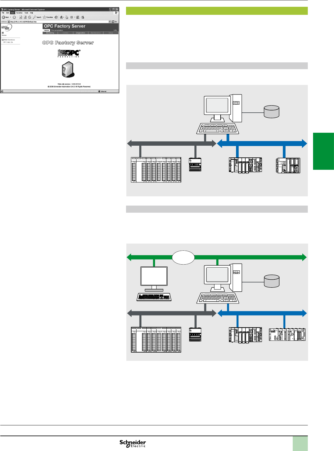
4/33
Supported architectures
The OFS server allows four access modes:
A purely local mode
Remote access from an OPC-DA client
Remote access from an OPC.NET client
Remote access from an OPC XML-DA client
Remote access from an OPC-UA client
Local access
The client application and the OFS server are on the same PC.
Remote access from an OPC-DA client
The client application and the OFS data server are on remote stations.
Communication between the client station and the OFS server is conducted through
the DCOM layer (Microsoft) via the OPC-DA protocol.
OPCFactoryServer:Homepage
Software 3
OPC data server software
OPC Factory Server
Architectures
0
Presentation:
page 4/32
Setup:
page 4/35
Functions:
page 4/36
References:
page 4/37
Time stamping system:
page 4/38
OFS station
Symbol data
(Unity Pro ,
Concept
or PL7)
Modbus network X-Way network
Premium Modicon M340
Momentum
Quantum
Remote client
application
program
DCOM
Ethernet Modbus/TCP network
Local client
applic. prog
Modicon M340Premium
Momentum
Quantum
Modbus network
OFS station
Local client
applic. prog Symbol data
(Unity Pro,
Concept
or PL7)
2
1
3
4
5
6
7
8
9
10
2
1
3
4
5
6
7
8
9
10
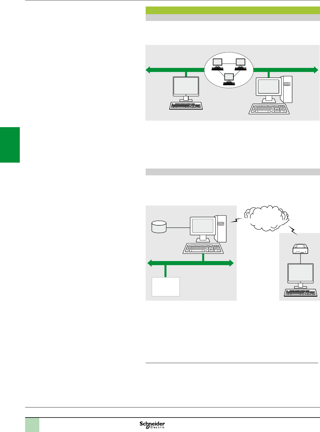
4/34
Software 3
OPC data server software
OPC Factory Server
Architectures(continued)
0
Architectures supported (continued)
Remote access from an OPC .NET client
The .NET client application program and the OFS data server are on remote
stations. Communication between the client station and the OFS server is
conducted through the DCOM layer (Microsoft) via the OPC-DA protocol.
The .NET Microsoft compatibility of the OFS server has been developed to allow an
OPC .NET client to access OFS server items on an Intranet network via the OPC
.NET API interface.
This interface ensures interoperability between existing OPC applications and
applications developed in the standard .NET environment.
Remote access from an OPC XML-DA client via HTTP
The client application program and the OFS server are on remote stations, using the
SOAP protocol to communicate via the Internet in conformity with the OPC XML-DA
V1.01 specication of the OPC Foundation.
The OFS data server is based on an HTTP server installed on the same station.
The OPC XML-DA V1.0 specications are designed to overcome the limitations of
COM/DCOM, thus providing:
An OPC interface for Windows and non-Windows client applications
Beyond the Intranet perimeter, remote access via the Internet through rewalls
The OPC XML-DA specication is based on Web Services standards such as SOAP,
XML and WSDL (1). A SOAP client can access data on the OFS server via Intranet or
Internet using the SOAP protocol in conformity with the OPC XML-DA V1.01
specication of the OPC Foundation.
(1)SOAP:SimpleObjectAccessProtocol
XML:ExtensibleMarkupLanguage
WSDL:WebServicesDescriptionLanguage
Server
OFS station
Intranet
.NET client
Ethernet Modbus/TCP networkDCOM
Site server
and OFS
station
Symbol data
(Unity Pro,
Concept or PL7)
Industrial network IIS
Internet
Industrial
PLCs
Remote client
application
program
Firewall
Presentation:
page 4/32
Setup:
page 4/35
Functions:
page 4/36
References:
page 4/37
Time stamping system:
page 4/38
2
1
3
4
5
6
7
8
9
10
2
1
3
4
5
6
7
8
9
10
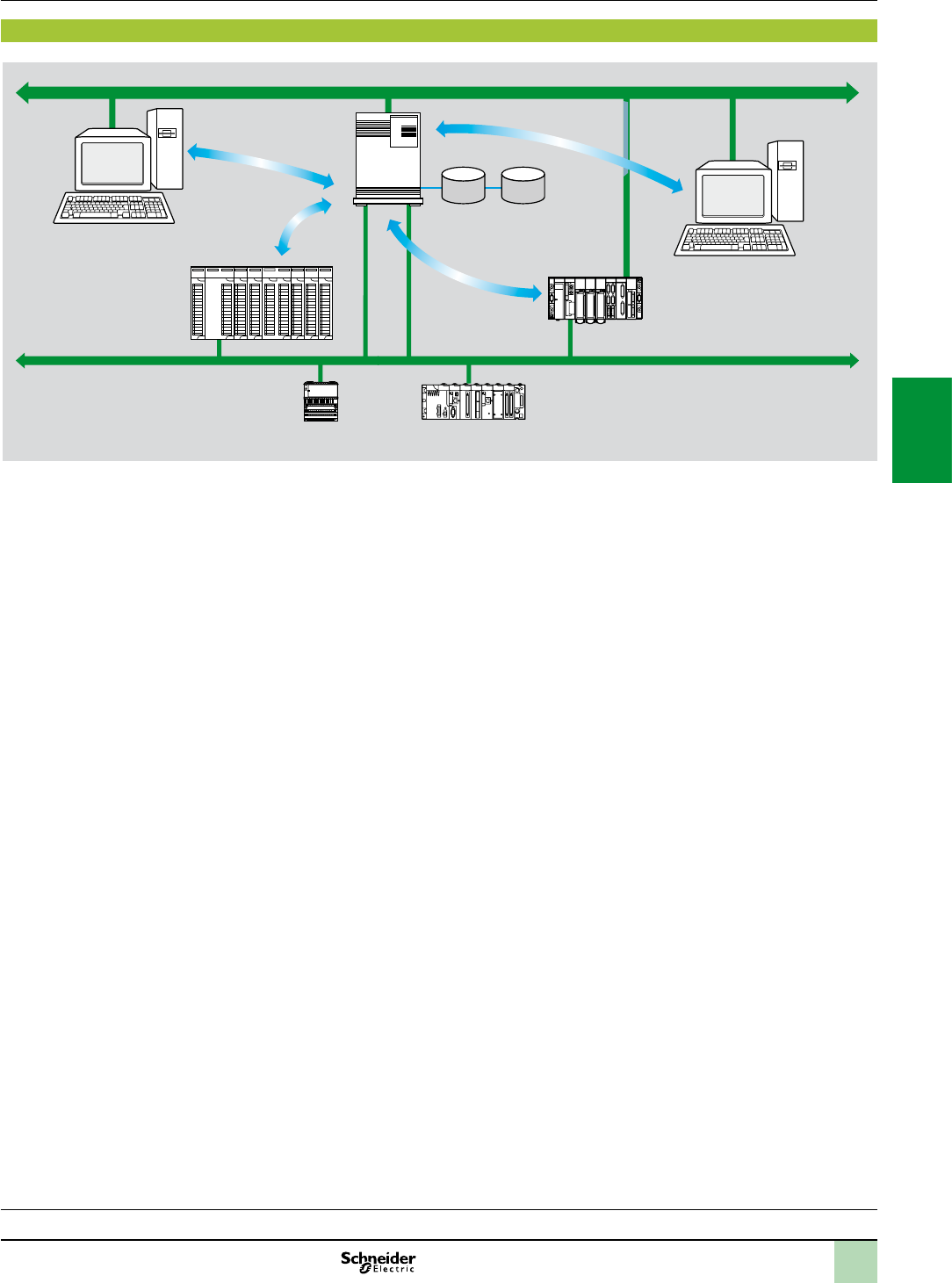
4/35
Setup
3
Setup
The OFS server 1 is at the centre of the data exchanges. It ensures that variables
exchanged between the OPC client 2 and the PLC 3, are consistent, in one of three
ways using a symbol (or variables) database:
The variables database is either the Unity Pro project 4, or the Concept project.
In both these cases, Unity Pro or Concept needs to be installed on the OFS server
station.
Or the variables database is an export le (SCY for PL7, XVM for Unity Pro). PL7
and Unity Pro are not required in either of these cases.
Or the variables database is the PLC itself. In this case neither Unity Pro nor an
export le is needed. This does not apply to Momentum and TSX Micro PLCs.
If an inconsistency is detected (following online modication of the PLC program for
example), OFS resynchronizes itself automatically as a background task, without
breaking communication between the PLC and the OPC client.
For this function the following minimum versions are required:
OFS V3.35
Unity Pro V6.0
Modicon Premium V2.9, M340 V2.3 and Quantum V3.0 PLCs
1
Ethernet Modbus/TCP
OFS server
(V3.0)
Database
Symbols.xvm (Unity Pro)
Symbols.prj (Concept)
Symbols.scy (PL7)
3 Premium
3 Modicon M340
3 Momentum
3 Quantum
Ethernet Modbus/TCP
4
Unity Pro
project
station
2 OPC client
Presentation:
page 4/32
Architectures:
page 4/33
Functions:
page 4/36
References:
page 4/37
Time stamping system:
page 4/38
Software 3
OPC data server software
OPC Factory Server
2
1
3
4
5
6
7
8
9
10
2
1
3
4
5
6
7
8
9
10

4/36
Software 3
OPC data server software
OPC Factory Server
Functions
3
Function
Development of client applications
OFS software has 4 types of interface:
OLE Automation interface (OPC-DA)
Particularly suitable for end users, this enables the development of OPC client
applications in Visual Basic, in Visual Basic for Excel, and in C++.
OLE Custom interface (OPC-DA)
Used primarily by suppliers of automated control system or industrial IT products,
this interface enables the development of applications in C++ in order to access the
OFS software OPC server. It is aimed at software development experts in particular,
so that they can integrate the client application into their standard products. It is the
interface with the highest performance, in terms of access time to data stored in the
OPC server. It requires extensive knowledge of C++ programming to set up.
OPC .NET API wrapper interface
The .NET Microsoft compatibility of the OFS data server gives an OPC .NET client
standard access to OFS server items via an Intranet network, thus ensuring greater
interoperability with standard .NET environments.
Note: Inthiscase,communicationbetweentheOPC.NETclientandtheOFSserveris
conductedthroughtheDCOMlayer(orCOMlayerinalocalconguration)viatheOPC-DA
protocol.
OPC XML-DA interface (1)
The OPC XML-DA V1.0 specications are designed to overcome the limitations of
the OPC-DA specication and COM/DCOM by providing:
An interface for Windows and non-Windows client applications
Remote access via the Internet through rewalls (beyond the Intranet perimeter)
The OPC XML-DA specication is based on Web Services standards such as SOAP,
XML, WSDL. A SOAP client can access data on the OFS server via Intranet or
Internet using the SOAP protocol in conformity with the OPC XML-DA V1.01
specication of the OPC Foundation.
The OPC-UA interface
This interface is aimed at users with software that includes an OPC-UA client
interface. This interface is based on the same communication standards as the OPC
XML-DA interface and offers the same advantages as it, which are:
An interface with Windows and non-Windows applications
Remote access, via the Internet, through a rewall
(1)AvailableonlywiththeLargeversionofOPCFactoryServer.
Presentation:
page 4/32
Architectures:
page 4/33
Setup:
page 4/35
References:
page 4/37
Time stamping system:
page 4/38
2
1
3
4
5
6
7
8
9
10
2
1
3
4
5
6
7
8
9
10

4/37
Software 3
OPC data server software
OPC Factory Server
References
3
OPC Factory Server
References
OFS V3.4 software for PC compatible stations (minimum conguration: Pentium
566 MHz processor, 128 Mb of RAM) running Windows 7 (32-bit or 64-bit).
The OFS V3.4 offer comprises:
OPC server software
OPC server simulator (for debugging the application when no PLCs are present)
OFS server conguration software
An example of OPC client for setting up applications
The setup documentation on DVD-ROM
A reference document on “time stamping system” solutions
A tool to help with sizing and conguring “time stamping system” solutions
Supplied on DVD-ROM, the software operates independently on a PC. It interfaces
with the variable export les generated by PL7, ProWORX, Concept, and Unity Pro
software.
It also provides a direct dynamic link to the Unity Pro and Concept applications.
OFS V3.4 software is available in two versions:
Small Version TLXCDSOFS34
Maximum of 1000 items (1)
Protocols supported: OPC-DA and OPC-UA
Single station and 10-station site licences
Large Version TLXCDLOFS34
Unlimited number of items (1)
Protocols supported: OPC-DA, OPC XML-DA and OPC-UA
Single station, 10-station and 200-station site licences
OPC Factory Server V3.4 Small
Description Licence type Reference Weight
kg
OPC Factory Server
V3.4 Small software
Maximum of 1000
items (1)
Protocols supported:
OPC-DA and OPC-UA
Single station TLXCDSUOFS34 –
10 stations TLXCDSTOFS34 –
OPC Factory Server V3.4 Large
Description Licence type Reference Weight
kg
OPC Factory Server
V3.4 Large software
Unlimited number of
items(1)
Protocols supported:
OPC-DA, OPC XML-DA
and OPC-UA
Single station TLXCDLUOFS34 –
10 stations TLXCDLTOFS34 –
200 stations TLXCDLFOFS34 –
(1)“item”:variable,structure,tableetc.intheUnityProapplication.
Presentation:
page 4/32
Architectures:
page 4/33
Setup:
page 4/35
Functions:
page 4/36
Time stamping system:
page 4/38
2
1
3
4
5
6
7
8
9
10
2
1
3
4
5
6
7
8
9
10
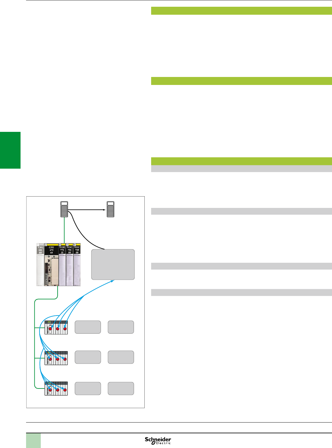
4/38
Presentation
The time stamping system is a complete solution providing a SCADA with a
sequence of events that are time-stamped at source, enabling the user to analyze
the source of any abnormal behaviour in an automated system.
The SOE (sequence of events) is displayed in the alarm log or in the list of events for
a client such as a SCADA.
Each event in the SOE is a change of value (transition) of a discrete I/O detected by
a time stamping module.
Advantages
Using the time stamping system has the following advantages:
No PLC programming
Direct communication between the time stamping modules and the client. If the
time stamping modules are in a Quantum Ethernet I/O drop, the bandwidth of the
PLC communication is not used
Consistency of the I/O values between the process (time stamping modules) and
the client
Consistency is maintained irrespective of the operating mode
No loss of events under normal operating conditions
Management of Hot Standby congurations on the PLC and/or SCADA
redundancy
Composition of a time stamping architecture
BMXCRA31210 module
This time stamping module can be at the source of any discrete I/O signal located in
the drop with a resolution of 10 ms.
To ensure no event is lost, all events are stored and kept in a buffer located in the
product until OFS takes them.
Synchronization of the CRA module uses the NTP protocol.
BMXERT1604T module
This module has 16 discrete inputs which carry out the time stamping at source
outputs with a resolution of 1 ms.
To ensure no event is lost, all events are stored and kept in a buffer located in the
product until OFS takes them.
This module can be placed either in an RIO drop, or in a local rack equipped with a
BMXCRA31210 module.
The CRA module is synchronized via the DCF 77 or IRIG-B standards.
OFS V3.40
OFS V3.40 is used to access events stored in the various buffers in the architecture
and to notify the SCADA of them via the standard OPC DA protocol.
Vijeo Citect V7.30
Vijeo Citect V7.30 receives events transmitted by OFS and displays them in the SOE
or in the list of alarms.
Presentation:
page 4/32
Architectures:
page 4/33
Setup:
page 4/35
Functions:
page 4/36
References:
page 4/37
Software 3
OPC data server software
Time stamping system
Presentation
Routing function via
Quantum NOC control
head 140 NOC 78 100
or external router
Modicon
Quantum drops
Modicon
Quantum drops
Modicon
Quantum drops
OFS server
Vijeo Citect
alarm
terminal
Quantum CPU
Ethernet
Ethernet
BMX-CRA1
event
memory
BMX-CRA2
event
memory
BMX-CRA3
event
memory
BMX-ERT1
event
memory
BMX-ERT
event
memory
BMX-ERT
event
memory
ExampleofaTimestampingarchitecture
2
1
3
4
5
6
7
8
9
10
2
1
3
4
5
6
7
8
9
10

4/39
Presentation:
page 4/32
Architectures:
page 4/33
Setup:
page 4/35
Functions:
page 4/36
References :
page 4/37
Performance
Performance Event source
module
Value
Between two identical source modules in
the same rack
BMXERT1604T 1.6 < resolution < 3.3 ms
BMXCRA31210 10 ms
Between two different inputs in the same
source module
BMXERT1604T 1 ms
BMXCRA31210 1 scan
Maximum number of events scanned BMXERT1604T 400 events (1)
BMXCRA31210 2048 events (1)
Maximum number of I/O and memory
available
BMXERT1604T 16 discrete inputs on module
512 events in internal buffer
BMXCRA31210 256 discrete I/O congured
4000 events in internal buffer
Maximum number of source modules in an
Ethernet remote drop
BMXCRA31210 1 per drop
BMXERT 9 per drop
Maximum number of event sources
controlled
BMXERT 500 sources per second (1)
(1)Thismaximumvalueisnotanabsolutevalue.Itdependsontheoverallsystemdynamics
(totalnumberofscanneditemsandnumberofeventsgeneratedbythesystem).
Software 3
OPC data server software
Time stamping system
Performance
2
1
3
4
5
6
7
8
9
10
2
1
3
4
5
6
7
8
9
10

4
5/0
2
1
4
5
6
7
8
9
10
2
1
5
6
7
8
9
10

5/1
5 - Connection interfaces
Modicon Telefast ABE7 pre-wired system
Modicon Telefast ABE7 selection guide ................................page5/2
Interface with Modicon X80 I/O modules ............................................. page5/8
References
Passive connection sub-bases .............................................................. page5/12
Adaptor sub-bases with xed relays and removable
terminal blocks ............................................................................................ page5/14
Input/output adaptor sub-bases for or with plug-in relays ....................... page5/15
Output adaptor sub-bases for plug-in relays .......................................... page5/16
Plug-in relays ......................................................................................... page5/17
Connection sub-bases for analog chanels and
application-specic channels ...................................................................... page5/18
Accessories for connection sub-bases .................................................. page5/19
Contents
2
1
4
5
6
7
8
9
10
2
1
5
6
7
8
9
10
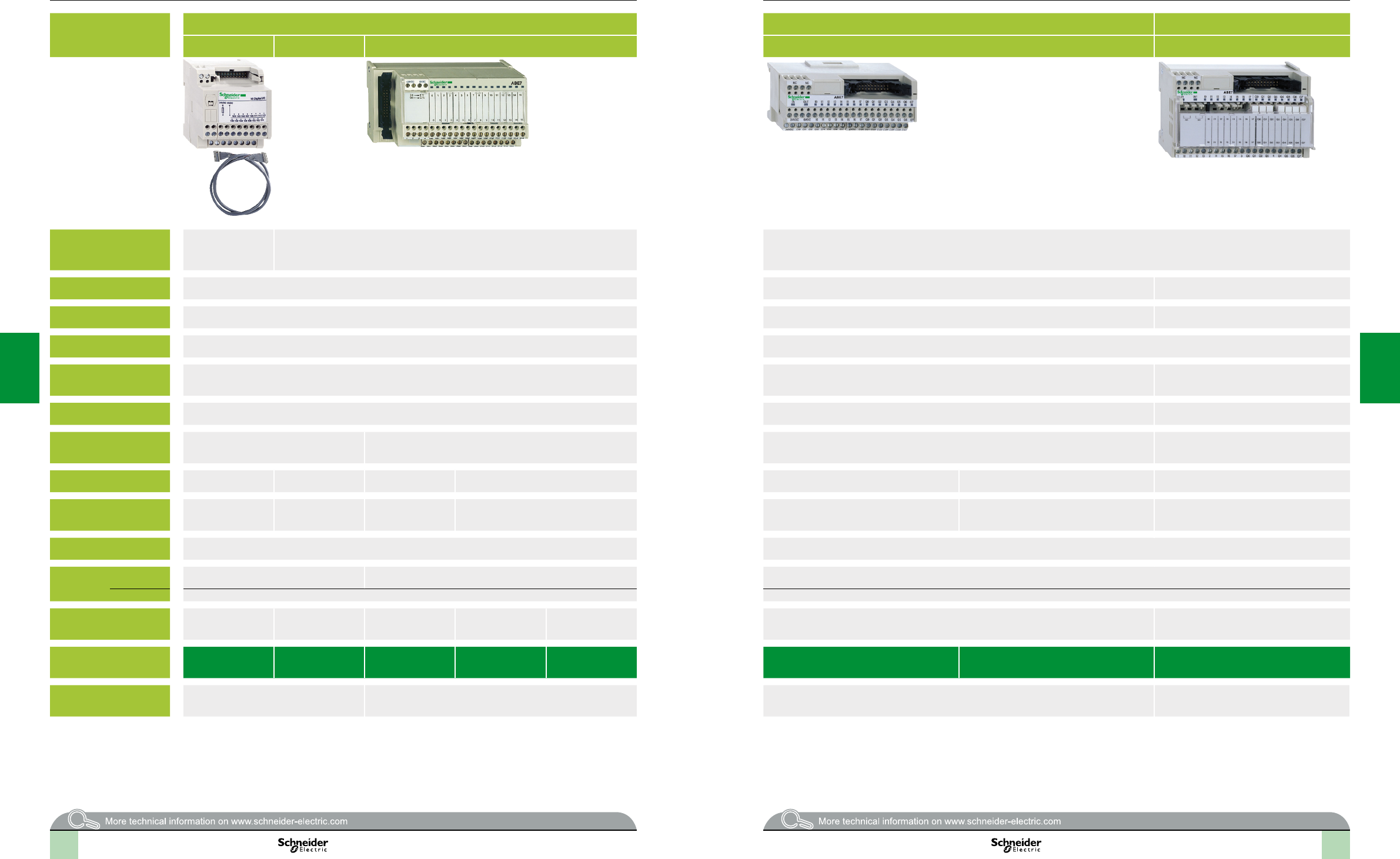
2
1
3
4
5
6
7
8
9
10
2
1
3
4
5
6
7
8
9
10
2
1
3
4
5
6
7
8
9
10
2
1
3
4
5
6
7
8
9
10
5/2 5/3
Applications Discrete inputs or outputs Discrete inputs or outputs Outputs for solid state and/or electromechanical
relays
Optimum “Economy” Optimum “Miniature” Universal Optimum “Miniature” Optimum and Universal
Compatibility TSX Micro,
Modicon Premium,
Modicon M340
TSX Micro, Modicon Premium, Modicon Quantum, Modicon M340 TSX Micro, Modicon Premium, Modicon Quantum, Modicon M340
Sub-base type Passive connection sub-bases Passive connection sub-bases Plug-in electromechanical or solid state relays
Equipped with relays – – Yes
Control voltage 24 V 24 V
Output voltage 24 V 24 V 24V (solid state)
5... 24 V , 230 V (electromechanical)
Output current per channel 0.5 A 0.5 A 5 A (th)
Modularity 16 8 -12 -16 16 16
8 passive inputs
8 relay outputs
No. of terminals per channel 1 1 to 3 1 2 1 2 1
Type of connection terminals Signal Signal, common
(congurable as
24 V or 0 V)
Signal Signal, common (congurable as 24 V or 0 V) Signal,
2 common connections between the inputs and the
outputs
Signal, common,
2 common connections between the inputs and the
outputs
1 N/O contact and common, 4 output channels
2 input connection points
Connectors 20-way HE10 connector 20-way HE10 connectors
Terminal
block
Removable No No No
Terminal type Screw Screw
Additional or optional*
function
Low-cost version tted
with cable
Miniature sub-bases Compact size *Input type 2 *
(1)
Isolator *Miniature sub-base
Synergy with Tego Power and Micro PLC
Miniature sub-base - Common per group of 4 channels
Synergy with Tego Power and Micro PLC
Type of device
ABE7HE00 ABE7H16C ABE7HR1
ABE7HppR50
ABE7HR2ABE7HS21 ABE7H16CM11 ABE7H16CM21 ABE7R16M111
Page 5/12 5/13 5/12 5/15
(1)ForModiconTSXMicroandModiconPremiumPLCs
Connection interfaces
Modicon Telefast ABE7 pre-wired system
Discrete input and/or output sub-bases
Selectionguide
15.2
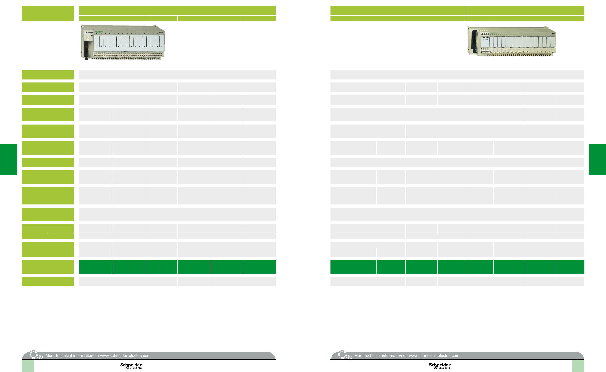
2
1
3
4
5
6
7
8
9
10
2
1
3
4
5
6
7
8
9
10
2
1
3
4
5
6
7
8
9
10
2
1
3
4
5
6
7
8
9
10
5/4 5/5
Applications Discrete outputs Discrete outputs Discrete inputs or outputs
Optimum Universal Optimum Universal Universal Universal
Compatibility TSX Micro, Modicon Premium, Modicon Quantum, Modicon M340 TSX Micro, Modicon Premium, Modicon Quantum, Modicon M340
Relay sub-base Electromechanical, xed Electromechanical or solid state Electromechanical, plug-in Solid state, xed – – Solid state, xed Solid state,
plug-in
Equipped with relays Yes Yes No No Yes Yes – – Yes No
Control voltage 24 V 24 V From 24 V
to 230 V From 5 V TTL
to 230 V
Output voltage 5 V... 30 V
230 V 5 V... 150 V
230 V 24 V (solid state)
5 V... 24 V , 230 V (E.M.)
5 V... 150 V
230 V
5 V... 150 V
230 V
24 V
Output current per channel 2 A (th) 3 A (th) 5 A (th) 2 A (solid state)
6 A (electromechanical)
0.5 to 10 A
(dependent on
relay)
5 A (th) 8 A (th) 0.5 to 2 A 125 mA 0.5 A 125 mA 12 mA
Modularity 8 8 - 16 16 8 or 16 16
No. of terminals per channel 2 1 2 1 2 to 3 2 to 3 2 to 6 2 3 2
Type of connection terminals 1 N/O contact and
common
Volt-free
1 N/O contact 1 N/O contact and
common
1 N/O contact Signal, Polarities 1 C/O contact or 1 N/O
contact and common
1 C/O contact or
2 C/O contacts
and common
Signal and 0 V 24 V and 0 V
signal
Signal can be
isolated,
Protected
common
Signal Signal and
common
Connectors 20-way HE 10 connector 20-way HE 10 connector
Terminal
block
Removable Yes Yes Yes No No No Yes No No Yes No
Terminal type Screw or spring Screw Screw Screw or spring Screw Screw or spring
Additional or optional*
function
Miniature sub-base
Latching relay
Volt-free or common per group of
8 channels
Miniature sub-bases
Common per group of 4 channels
Isolator and fuse Volt-free or common per group of: Fault signal Isolator and fuse
(indicator)
3-wire proximity
sensor
Isolator and fuse
(indicator)
–
8 channels 4 channels
Type of device
ABE7R08S216ABE7RS1 ABE7RS2 ABE7R16T111 ABE7P16T111 ABE7P16T2
ABE7P08T3
ABE7R16T2 ABE7R16T3 ABE7SS2BABE7H16F43 ABE7H16R3ABE7H16S43 ABE7S16E2E ABE7P16F31
Page 5/14 5/15 5/16 5/15 5/14 5/13 5/14 5/15
(1)ForTSXMicroandModiconPremiumPLCs
Connection interfaces
Modicon Telefast ABE7 pre-wired system
Discrete input and output sub-bases
Selectionguide(continued)
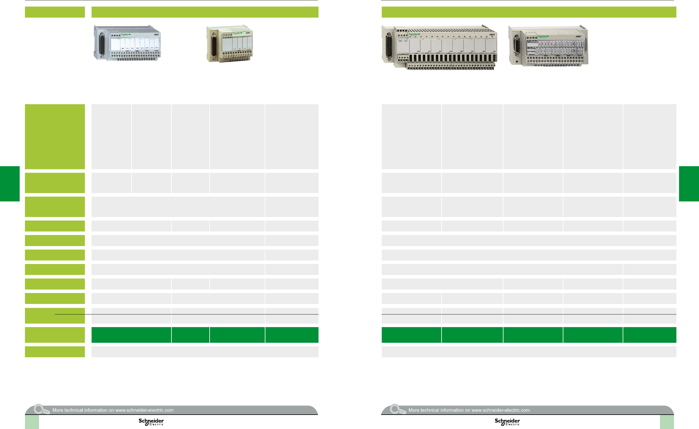
2
1
3
4
5
6
7
8
9
10
2
1
3
4
5
6
7
8
9
10
2
1
3
4
5
6
7
8
9
10
2
1
3
4
5
6
7
8
9
10
5/6 5/7
Applications Analog signals and special functions Analog signals and special functions
Compatibility TSX Micro:
TSX3722
TSXCTZA
Modicon Premium:
TSXCTYA
TSXCAY1
Modicon Premium:
TSXASY800
TSXAEY1600
TSXAY800
Modicon M340:
BMXAMI0800
BMXAMI0810
BMXAMO0802
Modicon Quantum:
140AVI03000
140ACI03000
140ACI04000
140ACO13000
Modicon Premium:
TSXASY410
TSXAEY420
Modicon M340:
BMXAMO0410
Modicon Quantum
140AVO02000
140ACO02000
Modicon M340:
BMXART0414
BMXART0814
Modicon Premium:
TSXAEY1614
Modicon Premium:
TSXAEY800
TSXAEY1600
Modicon Quantum:
140AVI03000
140ACI03000
140ACI04000
Modicon Premium:
TSXAEY810
Modicon M340:
BMXAMI0800
BMXAMI0810
BMXAMO0802
Modicon Quantum:
140AVI03000
140ACI03000
140ACI04000
Modicon Premium:
TSXCAY1,
TSXCTYA
Modicon Premium:
TSXAEY1614
Modicon Premium:
TSXPAY22
Type of signal Counter inputs and
analog I/O
Counter inputs
Axis control
Position control
Analog inputs
Current/Voltage
Pt 100
Analog outputs
Current
Voltage
Analog inputs Analog inputs
Current
Voltage
Pt 100
Isolated analog inputs Counter inputs Inputs for thermocouples I/O
Functions Passive connection, point-to-point with shield continuity Connection of cold junction
compensation or provision,
distribution of isolated
power supplies
Distribution of sensor power
supplies by limiter (25 mA)
Distribution of isolated sensor
power supplies by converter
Acquisition of value from an
absolute encoder
Connection of
16 thermocouples with cold
junction compensation
Safety module (BG)
Modularity 1 counter channel or
8 analog inputs + 2 analog outputs
8 channels 4 channels 4 channels 8 channels 8 channels 1 channel 16 channels 12 Emergency stops
Control voltage 24 V – 24 V
Output voltage 24 V – 24 V
Output current per channel 25 mA – 25 mA –
No. of terminals per channel 2 2 or 4 2 or 4 2 or 4 2 or 4 – 2 or 4 1
Connector type 15-way SUB-D + 9-way SUB-D 25-way SUB-D 25-way SUB-D 25-way SUB-D 25-way SUB-D 15-way SUB-D 25-way SUB-D 50-way SUB-D
Terminal
block
Removable No No No No No No No No
Terminal type Screw Screw Screw Screw Screw or spring Screw Screw Screw
Type of device
ABE7CPA01 ABE7CPA02 ABE7CPA21 ABE7CPA412
ABE7CPA410
ABE7CPA03 ABE7CPA31pABE7CPA11 ABE7CPA12 ABE7CPA13
Page 5/18 5/18
Connection interfaces
Modicon Telefast ABE7 pre-wired system
Analog and application-specic sub-bases
Selectionguide(continued)
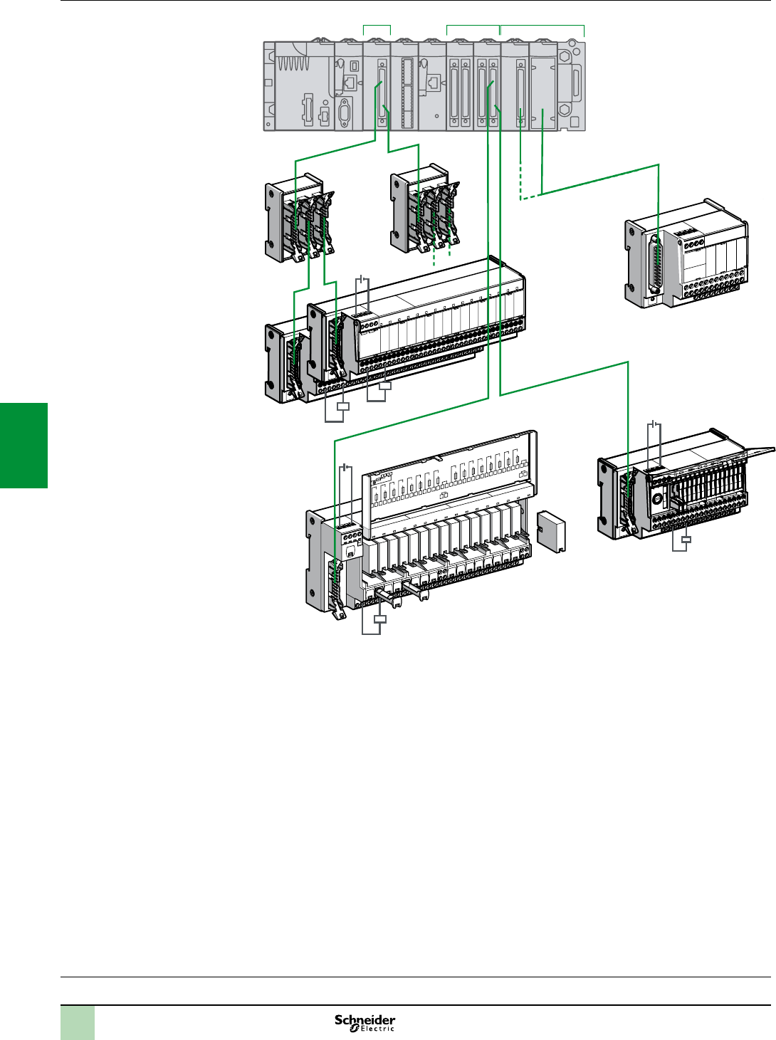
2
1
3
4
5
6
7
8
9
10
2
1
3
4
5
6
7
8
9
10
5/85/8
Presentation Connection interfaces
Modicon Telefast ABE7 pre-wired system
Interface with Modicon X80 I/O modules
(1)Connectionofthe24VpowersupplyisonlypossibleusingModiconTelefastABE7sub-bases.The0Vconnectionsmustbeequipotential.
Q8 Q9 Q10 Q11 Q12 Q13 Q14 Q15
+24Vdc 0Vdc
Fus I = 1A max
LC
Q0 Q1 Q2 Q3
ABE7P16T214
16 Relays Outputs
Q4 Q5 Q6 Q7
200
201
202
203
204
205
206
207
100
101
102
103
104
105
106
107
1
2
5
6
3
4
7
8
208
209
210
211
212
213
214
215
108
109
110
111
112
113
114
115
1
2
2
6
3
3
4-b
7
2
2
5
1 1 1-b
c 24 V (1)
c 24 V (1)
c 24 V (1)
Ch0 Ch2 Ch3 Ch4
4-c
1-c
Analog
16 channels
Sub-basefor
2/4/8analog
channels
Sub-basefor
8discreteI/O
Sub-basefor
16discrete
I/O
Sub-basefor
16discrete
I/O
16 channels
16 channels 16 channels
2x8
channels
2/4/8 channels
Discrete Discrete

2
1
3
4
5
6
7
8
9
10
2
1
3
4
5
6
7
8
9
10
5/95/9
Presentation
I/O modules on the Modicon X80 platform
1 Discrete input modules (BMXDDI02K), discrete output modules
(BMXDDO02K) and discrete mixed I/O modules (BMXDDM3202K) equipped
with one or two 40-way FCN connectors. The modularity of each module () is
32 or 64 channels.
1-b Analog input or output modules:
- Analog inputs: BMXAMI0410 (4 channels), BMXAMI0800 (4 channels) and
BMXAMI0810 (8 channels)
- Analog outputs: BMXAMO0210 (2 channels), BMXAMO0410 (4 channels)
and BMXAMO0802 (8 channels)
1-c Analog input modules BMXART0414 (4 channels) and BMXART0814
(8 channels)
2 2 types of cordset are available depending on the type of discrete module
connected to the sub-base (for combinations, see page 5/10). These cordsets are
available in 0.5, 1, 2, 3, 5 or 10 m lengths:
-BMXFCCppp1 cordsets with one 20-wire sheath (AWG 22) equipped with one
40-way FCN connector and one HE 10 moulded connector on the Telefast
sub-base end
-BMXFCCppp3 cordsets with two 20-wire sheaths (AWG 22) equipped with
one common 40-way FCN connector on the module end and two HE 10
moulded connectors on the Telefast sub-base end
3 16-channel Modicon Telefast ABE7 Optimum or Universal passive connection
sub-bases or adaptor sub-bases.
4 4 types of cordset are available depending on the type of analog module
connected to the sub-base (for combinations, see page 5/11).
4-b : Connection to analog module with removable terminal block
20-way or 28-way:
-BMXFCApp0 cordsets with a 20-way removable terminal block on the module
end and a 25-way SUB-D connector on the Telefast sub-base end Cordsets
available in 1.5, 3 or 5 m lengths.
-BMXFTApp2 cordsets with a 20-way removable terminal block on the module
end and a 25-way SUB-D connector on the Telefast sub-base end Cordsets
available in 1.5 or 3 m lengths.
-BMXFTApp0 cordsets with a 28-way removable terminal block on the module
end and a 25-way SUB-D connector on the Telefast sub-base end Cordsets
available in 1.5 or 3 m lengths.
4-c : Connection to analog module with 40-way FCN connector:
-BMXFCApp2 cordsets with a 40-way FCN connector on the module end and
a 25-way SUB-D connector on the Telefast sub-base end Cordsets available
in 1.5, 3 or 5 m lengths.
5 Modicon Telefast ABE7CPA analog and application-specic connection sub-
bases (for combinations, see pages 5/11):
- ABE7CPA410 allows connection on a screw terminal block of 4 current/
voltage inputs, with provision and distribution of 4 isolated protected power
supplies for the current loop inputs
- ABE7CPA412 allows connection on a screw terminal block of 4 thermocouple
inputs, with supply of cold-junction compensation for these inputs
- ABE7CPA21 allows connection on a screw terminal block of 4 current/voltage
outputs
- ABE7CPA02 allows connection on a screw terminal block of 8 current/voltage
I/O
- ABE7CPA03 allows connection on a screw terminal block of 8 inputs, with
provision and distribution of the power supply (with limitation of each current
loop) for the current/voltage outputs of the BMXAMO0210 analog module
- ABE7CPA31, ABE7CPA31E allows connection on a screw terminal block
(ABE7CPA31) or a spring-type terminal block (ABE7CPA31E) of 8 inputs, with
provision and distribution of the power supply (limited to 25 mA per input)
6 ABE7ACC02 sub-base for splitting 16 into 2 x 8 channels, allowing connection of
8-channel sub-bases.
7 8-channel Modicon Telefast ABE7 Optimum or Universal passive connection
sub-bases or adaptor sub-bases.
Presentation(continued) Connection interfaces
Modicon Telefast ABE7 pre-wired system
Interface with Modicon X80 I/O modules
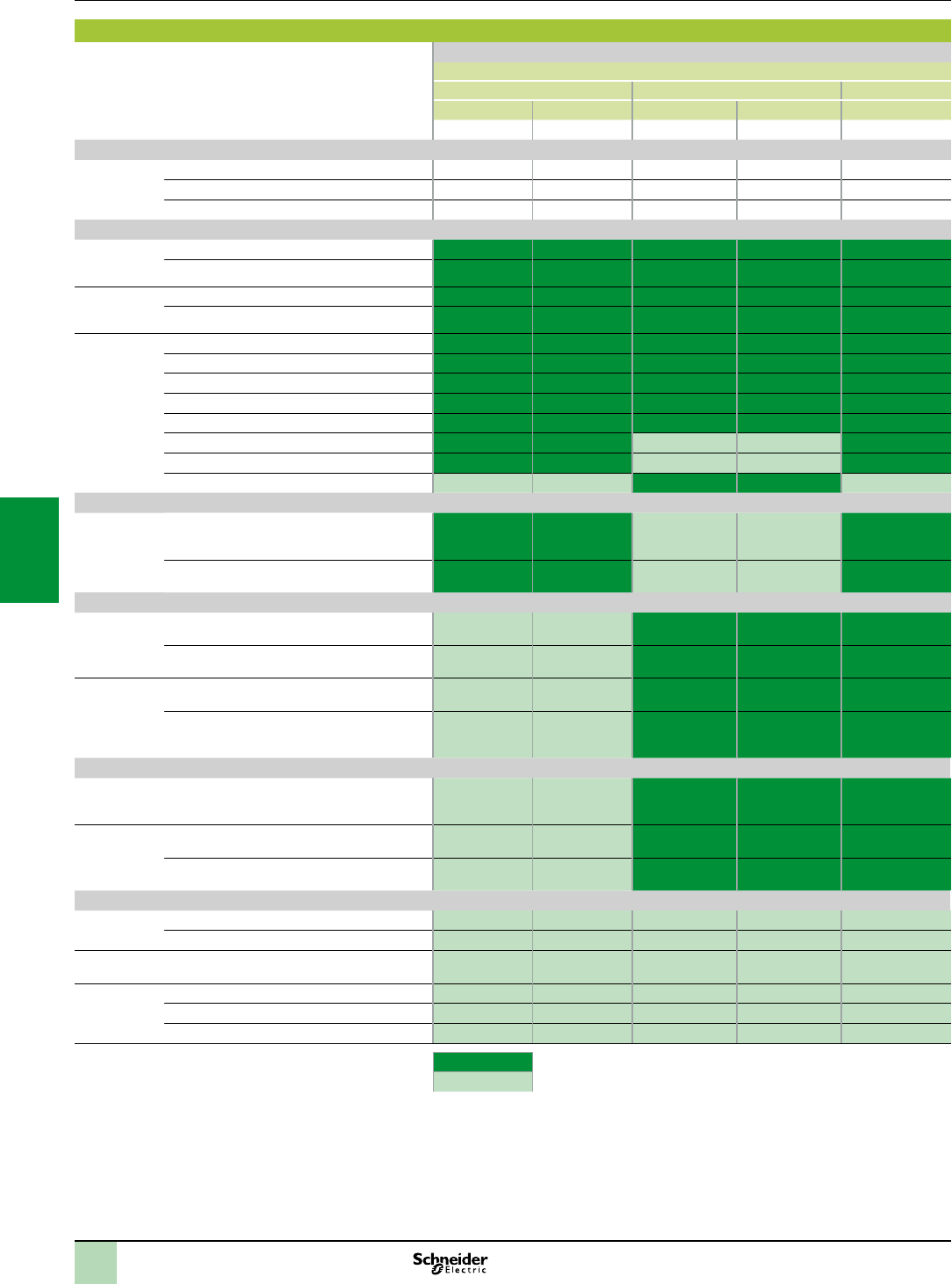
2
1
3
4
5
6
7
8
9
10
2
1
3
4
5
6
7
8
9
10
5/105/10
Combinations of discrete inputs/outputs on the Modicon X80 platform with ABE7 sub-bases.
(items 1…7), see Presentation on page 5/8 Discrete I/O modules on the Modicon X80 platform
Reference for 24 V c discrete I/O modules (item 1)
Inputs Outputs Inputs/outputs
2 x 16 I 4 x 16 I 2 x 16 Q 4 x 16 Q 1 x 16 I, 1 x 16 Q
BMXDDI3202K BMXDDI6402K BMXDDO3202K BMXDDO6402K BMXDDM3202K
Required cordsets
Preassembled
cordsets
(at both ends)
BMXFCC1, BMXFCC3 (item 2) (1) Yes Yes Yes Yes No
BMXFCC3 (item 2) (1) No No No No Yes
Quantities to be ordered 1 2 1 2 1
Passive connection sub-bases
Optimum
16 channels
(item 3)
ABE7H34E00 “economy”(2)
ABE7H16C “miniature”
Universal
8 channels
(item 7)
ABE7H08R (3) (3) (3) (3) (3)
ABE7H08S21 (3) (3) (3) (3) (3)
Universal
16 channels
(item 3)
ABE7H16R1
ABE7H16R50
ABE7H16R2
ABE7H16S21
ABE7H16R3
ABE7H16R23
ABE7H16S43
ABE7H16F43
Input adaptor sub-bases with solid state relays
Universal
16 channels
(item 3)
ABE7S16E2
Fixed solid state relays, removable terminal
blocks
ABE7P16F31
Plug-in solid state relays
Output adaptor sub-bases with xed relays, removable terminal blocks
Optimum &
Universal
8 channels
(item 7)
ABE7S08S2B
Solid state relays
(3) (3) (3)
ABE7R08S111, ABE7R08S21
Electromechanical relays
(3) (3) (3)
Optimum &
Universal
16 channels
(item 3)
ABE7S16SB
Solid state relays
ABE7R16S111, ABE7R16S210,
ABE7R16S212
Electromechanical relays
Output adaptor sub-bases with plug-in relays
Universal
8 channels
(item 7)
ABE7P08T330
Solid state relays
(3) (3) (3)
Optimum &
Universal
16 channels
(item 3)
ABE7R16T, ABE7R16M111
Electromechanical relays
ABE7P16T
Solid state and/or electromechanical relays
Sub-bases for analog I/O
4 channels
(item 5)
ABE7CPA410
ABE7CPA412
2 channels
(item 5)
ABE7CPA21
8 channels
(item 5)
ABE7CPA02
ABE7CPA03
ABE7CPA31, ABE7CPA31E
Compatible
Not compatible
(1)Referencesforcordsets:tobecompleted,seepage2/23.
(2)ABE7H34E00“economy”sub-bases:thecordsetissupplied.
(3)Viathesplittersub-base6 ABE7ACC02usedtoseparate16channelsinto2x8channels
Combinations Connection interfaces
Modicon Telefast ABE7 pre-wired system
Modicon X80 I/O modules with ABE7 sub-bases

2
1
3
4
5
6
7
8
9
10
2
1
3
4
5
6
7
8
9
10
5/115/11
Combinations(continued) Connection interfaces
Modicon Telefast ABE7 pre-wired system
ABE7 interfaces with Modicon X80 I/O modules
Combinations of analog inputs/outputs on the Modicon X80 platform with ABE7 sub-bases
(items 1…7), see Presentation on page 5/8 Analog I/O modules on the Modicon X80 platform
Reference for analog I/O modules (item 1-b and 1-c)
Inputs Outputs
4 I 4 I 2 x 4 I 8 I 8 I 2 Q 4 Q 8 Q
BMXAMI
0410
BMXART
0414
BMXART
0814
BMXAMI
0800
BMXAMI
0810
BMXAMO
0210
BMXAMO
0410
BMXAMO
0802
Required cordsets
Preassembled
cordsets
(at both ends)
BMXFCA0 (item 4-b) (1) Yes No No No No Yes Yes No
BMXFCA2 (item 4-c) (1) No Yes Yes No No No No Yes
BMXFTA0 (item 4-c) (1) No No No Yes Yes No Yes No
BMXFTA2 (item 4-c) (1) No No No No No No No Yes
Quantities to be ordered 1 1 2 1 1 1 1 1
Passive connection sub-bases
Optimum
16 channels
(item 3)
ABE7H16C “miniature”
Universal
8 channels
(item 7)
ABE7H08R
ABE7H08S21
Universal
16 channels
(item 3)
ABE7H16R1
ABE7H16R50
ABE7H16R2
ABE7H16S21
ABE7H16R3
ABE7H16R23
ABE7H16S43
ABE7H16F43
Input adaptor sub-bases with solid state relays
Universal
16 channels
(item 3)
ABE7S16E2
Fixed solid state relays, removable terminal
blocks
ABE7P16F31
Plug-in solid state relays
Output adaptor sub-bases with xed relays, removable terminal blocks
Optimum &
Universal
8 channels
(item 7)
ABE7S08S2B
Solid state relays
ABE7R08S111, ABE7R08S21
Electromechanical relays
Optimum &
Universal
16 channels
(item 3)
ABE7S16SB
Solid state relays
ABE7R16S111, ABE7R16S210,
ABE7R16S212
Electromechanical relays
Output adaptor sub-bases with plug-in relays
Universal
8 channels
(item 7)
ABE7P08T330
Solid state relays
Optimum &
Universal
16 channels
(item 3)
ABE7R16T, ABE7R16M111
Electromechanical relays
ABE7P16T
Solid state and/or electromechanical relays
Sub-bases for analog I/O
4 channels
(item 5)
ABE7CPA410
ABE7CPA412
2 channels
(item 5)
ABE7CPA21
8 channels
(item 5)
ABE7CPA02
ABE7CPA03
ABE7CPA31, ABE7CPA31E
Compatible
Not compatible
(1)Referencesforcordsets:tobecompleted,seepage2/33.
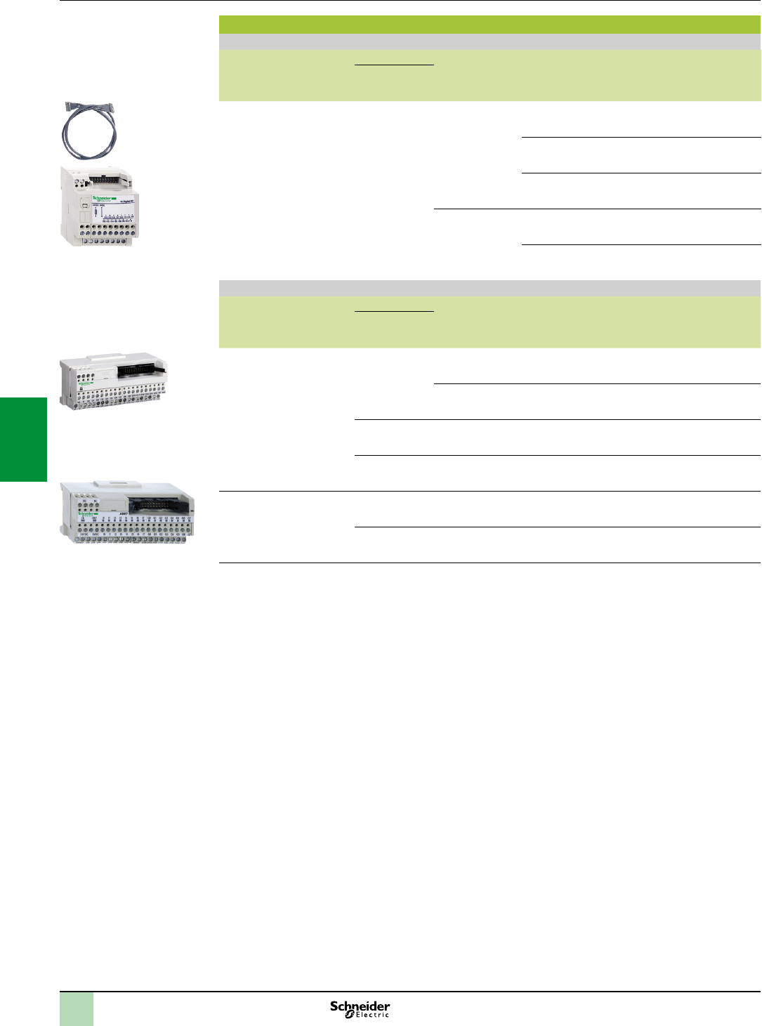
5/12
Passive connection sub-bases for discrete signals
Optimum "Economy" sub-bases
Function No. of
channels
No. of terminals For PLCs Length of
PLC
connection
cable
Type of
connection
Reference Weight
kg
per
channel
on row
number
Input or output 16 1 2 Modicon TSX Micro
Modicon Premium
1 m Screw ABE7H20E100 0.330
2 m Screw ABE7H20E200 0.410
3 m Screw ABE7H20E300 0.480
Siemens S7 1.5 m Screw ABE7H32E150 0.360
3 m Screw ABE7H32E300 0.460
Optimum "Miniature" sub-bases
Function No. of
channels
No. of terminals LED per channel Polarity
distribution
Type of
connection
Reference Weight
kg
per
channel
on row
number
Input or output 16 1 1 No No Screw ABE7H16C10 0.160
Yes No Screw ABE7H16C11 0.160
2 2 Yes 0 or 24 V Screw ABE7H16C21 0.205
3 3 Yes 0 or 24 V Screw ABE7H16C31 0.260
Input and output
(1)
16 1 1 Yes No Screw ABE7H16CM11 0.160
2 2 Yes 0 or 24 V Screw ABE7H16CM21 0.200
(1)8I+8Q:theseproductshave2commonconnectionswhichenableinputsandoutputstobeconnectedtothesame
sub-baseatthesametime.
Connection interfaces
Modicon Telefast ABE7 pre-wired system
Passive connection sub-bases
References
ABE7H20E
ABE7H16CM21
ABE7H16C21
2
1
3
4
5
6
7
8
9
10
2
1
3
4
5
6
7
8
9
10

5/13
Passive connection sub-bases for discrete signals (continued)
Universal sub-bases
Function No. of
channels
No. of terminals LED per
channel
Polarity
distribution
Isolator (I)
Fuse (F)
per channel
Type of
connection
Reference Weight
kg
per
channel
on row
number
Input or output 8 1 1 No No – Screw ABE7H08R10 0.187
Yes No – Screw ABE7H08R11 0.187
2 2 Yes 0 or 24 V – Screw ABE7H08R21 0.218
I Screw ABE7H08S21 0.245
12 1 1 No No – Screw ABE7H12R10 0.274
Yes No – Screw ABE7H12R11 0.274
2 No No – Screw ABE7H12R50 0.196
2 2 No 0 or 24 V – Screw ABE7H12R20 0.300
Yes 0 or 24 V – Screw ABE7H12R21 0.300
I Screw ABE7H12S21 0.375
16 1 1 No No – Screw ABE7H16R10 0.274
Yes No – Screw ABE7H16R11 0.274
2 No No – Screw ABE7H16R50 0.196
2 2 No 0 or 24 V – Screw ABE7H16R20 0.300
Yes 0 or 24 V – Screw ABE7H16R21 0.300
I Screw ABE7H16S21 0.375
3 3 No 0 or 24 V – Screw ABE7H16R30 0.346
Yes 0 or 24 V – Screw ABE7H16R31 0.346
Input type 2 (1) 16 2 2 Yes 0 or 24 V – Screw ABE7H16R23 0.320
Input 16 2 1 Yes 24 V I, F (2) Screw ABE7H16S43 0.640
Output 16 2 1 Yes 0 V I, F (2) Screw ABE7H16F43 0.640
(1)ForTSXMicro,ModiconPremium.
(2)WithLEDtoindicateblownfuse.
Connection interfaces
Modicon Telefast ABE7 pre-wired system
Passive connection sub-bases
References(continued)
ABE7HR1
2
1
3
4
5
6
7
8
9
10
2
1
3
4
5
6
7
8
9
10

5/14
Adaptor sub-bases with xed solid state relays, removable terminal blocks
Universal input sub-bases with solid state relays
Number of
channels
No. of
terminals
per channel
Isolation of PLC/
Operative part
Voltage Type of
connection
Reference Weight
kg
16 2 Yes 24 V Screw ABE7S16E2B1 0.370
Spring ABE7S16E2B1E 0.370
48 V Screw ABE7S16E2E1 0.370
48 V Screw ABE7S16E2E0 0.386
110 V Screw ABE7S16E2F0 0.397
230 V Screw ABE7S16E2M0 0.407
Spring ABE7S16E2M0E 0.407
Universal output sub-bases with solid state relays
Number of
channels
Isolation of
PLC/
Operative
part
Output
voltage
Output
current
Fault detection
signal (1)
Type of
connection
Reference Weight
kg
16 No 24 V 0.5 A Yes (2) Screw ABE7S16S2B0 0.405
Spring ABE7S16S2B0E 0.405
No Screw ABE7S16S1B2 0.400
Spring ABE7S16S1B2E 0.400
Optimum and Universal output sub-bases with electromechanical relays
Number of
channels
Number of contacts Output
current
Polarity
distribution/
operative part
Type of
connection
Reference Weight
kg
81 N/O 2 A Contact common
per group of 4
channels
Screw ABE7R08S111 0.252
Latching 2 A Volt-free Screw ABE7R08S216 0.448
1 N/O 5 A Volt-free Screw ABE7R08S210 0.448
16 1 N/O 2 A Contact common
per group of 8
channels
Screw ABE7R16S111 0.405
Spring ABE7R16S111E 0.405
1 N/O 5 A Volt-free Screw ABE7R16S210 0.405
Spring ABE7R16S210E 0.405
Common per
group of
8 channels on
both poles
Screw ABE7R16S212 0.400
(1)Afaultonasub-baseoutputQnwillsetPLCoutputQntosafetymode,whichwillbedetectedbythePLC.
(2)Canonlybeusedwithmoduleswithprotectedoutputs.
Connection interfaces
Modicon Telefast ABE7 pre-wired system
Adaptor sub-bases with xed relays and removable
terminal blocks
References(continued)
ABE7R08S216
ABE7H16E2
2
1
3
4
5
6
7
8
9
10
2
1
3
4
5
6
7
8
9
10
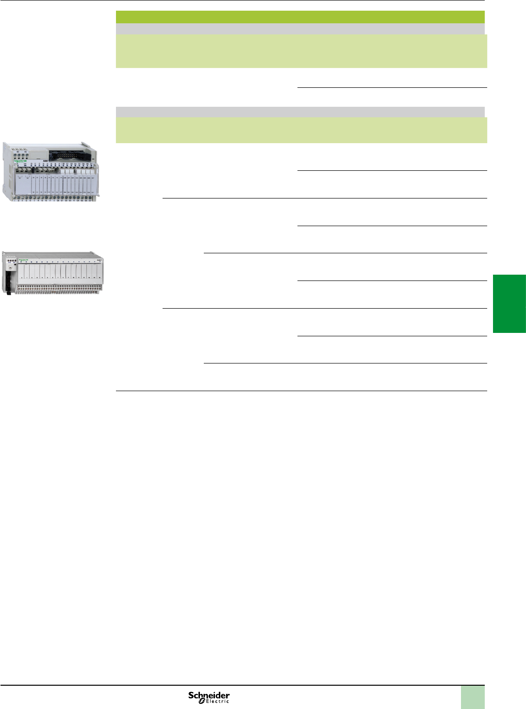
5/15
Adaptor sub-bases with plug-in relays
Universal input sub-bases for solid state relays, supplied without relays
Number of
channels
No. of
terminals
per channel
For relay type Isolation of
PLC/
Operative
part
Input
connection
Type of
connection
Reference Weight
kg
16 2 ABS7E
ABR7
ABS7S33E
Yes Volt-free Screw ABE7P16F310 0.850
Polarity
distribution
Screw ABE7P16F312 0.850
Optimum and Universal output sub-bases, supplied with electromechanical relays (1)
Number of
channels
Relay width Relay type
supplied
Number and
type of
contacts
Polarity distribution/operative
part
Reference Weight
kg
16 5 mm ABR7S11 1 N/O Contact common per group of 4
channels
ABE7R16T111 0.600
Contact common per group of 4
output channels
+ 2 common input terminals
ABE7R16M111
(2)
0.600
10 mm ABR7S21 1 N/O Volt-free ABE7R16T210 0.735
Common on both poles (3) ABE7R16T212 0.730
ABR7S23 1 C/O Volt-free ABE7R16T230 0.775
Contact common (3) ABE7R16T231 0.730
12 mm ABR7S33 1 C/O Volt-free ABE7R16T330 1.300
Common on both poles (4) ABE7R16T332 1.200
ABR7S37 2 C/O Volt-free ABE7R16T370 1.300
(1)Thesub-basesaresuppliedasstandardwithelectromechanicalrelays,allorpartofwhichcanbereplacedbysolidstate
relaysofthesamewidth(itispossibletocombinethesedifferenttechnologiesonasinglesub-base).
(2)Twoconnectionmethodsareavailable,enablinginputsandoutputstobeconnected
tothesamesub-baseatthesametime.
(3)Pergroupof8channels.
(4)Pergroupof4channels.
Connection interfaces
Modicon Telefast ABE7 pre-wired system
Input/output adaptor sub-bases for or with plug-in relays
References(continued)
ABE7R16M111
ABE7R16T210
2
1
3
4
5
6
7
8
9
10
2
1
3
4
5
6
7
8
9
10

5/16
Output adaptor sub-bases for plug-in relays
Optimum and Universal output sub-bases for solid state relays and/or electromechanical relays (1)
No. of
channels
Relay
width
For relay type Isolator
per
channel
Fuse per
channel
Polarity distribution/
operative part
Type of
connection
Reference Weight
mm kg
16 5 mm ABR7S11
ABS7SC1B
No No Contact common per
group of 4 channels
Screw ABE7P16T111 0.550
10 mm ABR7S2
ABS7SA2
ABS7SC2
ABE7ACC20
No No Volt-free Screw ABE7P16T210
(2)
0.615
ABE7P16T230
(2)
0.655
Yes Volt-free Screw ABE7P16T214 0.675
No Common on both poles
(3)
Screw ABE7P16T212 0.615
Yes Common on both poles
(3)
Screw ABE7P16T215 0.670
812 mm ABR7S33
ABS7A3
ABS7SC3
ABE7ACC21
No No Volt-free Screw ABE7P08T330 0.450
16 12 mm ABR7S33
ABS7A3
ABS7SC3
ABE7ACC21
No No Volt-free Screw ABE7P16T330 0.900
Common on both poles
(4)
Screw ABE7P16T332 0.900
ABR7S33
ABS7A3M
ABS7SC3E
ABE7ACC21
No Yes Volt-free Screw ABE7P16T334 0.900
Yes Yes Common on both poles
(4)
Screw ABE7P16T318 1.000
(1)Notequippedwithrelays.
(2)WithrelayABR7S21forsub-baseABE7P16T210,withrelayABR7S23forsub-baseABE7P16T230.
(3)Pergroupof8channels.
(4)Pergroupof4channels.
Connection interfaces
Modicon Telefast ABE7 pre-wired system
Output adaptor sub-bases for plug-in relays
References(continued)
ABE7P16T2
2
1
3
4
5
6
7
8
9
10
2
1
3
4
5
6
7
8
9
10
5/17
Plug-in solid state relays
Relay width Functions Input circuit Output circuit Unit reference
Order in lots of 4
Weight
kg
Current Nominal
voltage
Current Nominal
voltage
5 mm Output 24 V 2 A 24 V ABS7SC1B 0.010
10 mm Output 24 V 0.5 A 5…48 V ABS7SC2E 0.016
24…240 V ABS7SA2M 0.016
12 mm Input 5 V TTL – 24 V ABS7EC3AL 0.014
24 V Type 2 – 24 V ABS7EC3B2 0.014
48 V Type 2 – 24 V ABS7EC3E2 0.014
50 Hz 48 V – 24 V ABS7EA3E5 0.014
60 Hz 110…130 V – 24 V ABS7EA3F5 0.014
50 Hz 230…240 V – 24 V ABS7EA3M5 0.014
Output 24 V 2 A
Self-protected
24 V ABS7SC3BA 0.016
1.5 A 5…48 V ABS7SC3E 0.016
1.5 A 24…240 V ABS7SA3MA 0.016
Plug-in electromechanical relays
Relay width Control
voltage
Output current
(1)
Number of
contacts
Order in
lots of
Unit reference Weight
kg
5 mm 24 V 5 A (Ith) 1 N/O 4ABR7S11 0.005
10 mm 24 V 5 A (Ith) 1 N/O 4ABR7S21 0.008
1 C/O 4ABR7S23 0.008
12 mm 2 V 10 A (Ith) 1 C/O 4ABR7S33 0.017
8 A (Ith) 2 C/O 4ABR7S37 0.017
48 V 8 A (Ith) 1 C/O 4ABR7S33E 0.017
Accessory
Description Reference Weight
kg
Extractor for 5 mm miniature relay ABE7ACC12 0.010
Connection interfaces
Modicon Telefast ABE7 pre-wired system
Plug-in relays
ABS7SC1B
571152
ABR7S2
816476
ABR7S3
816474
References(continued)
2
1
3
4
5
6
7
8
9
10
2
1
3
4
5
6
7
8
9
10
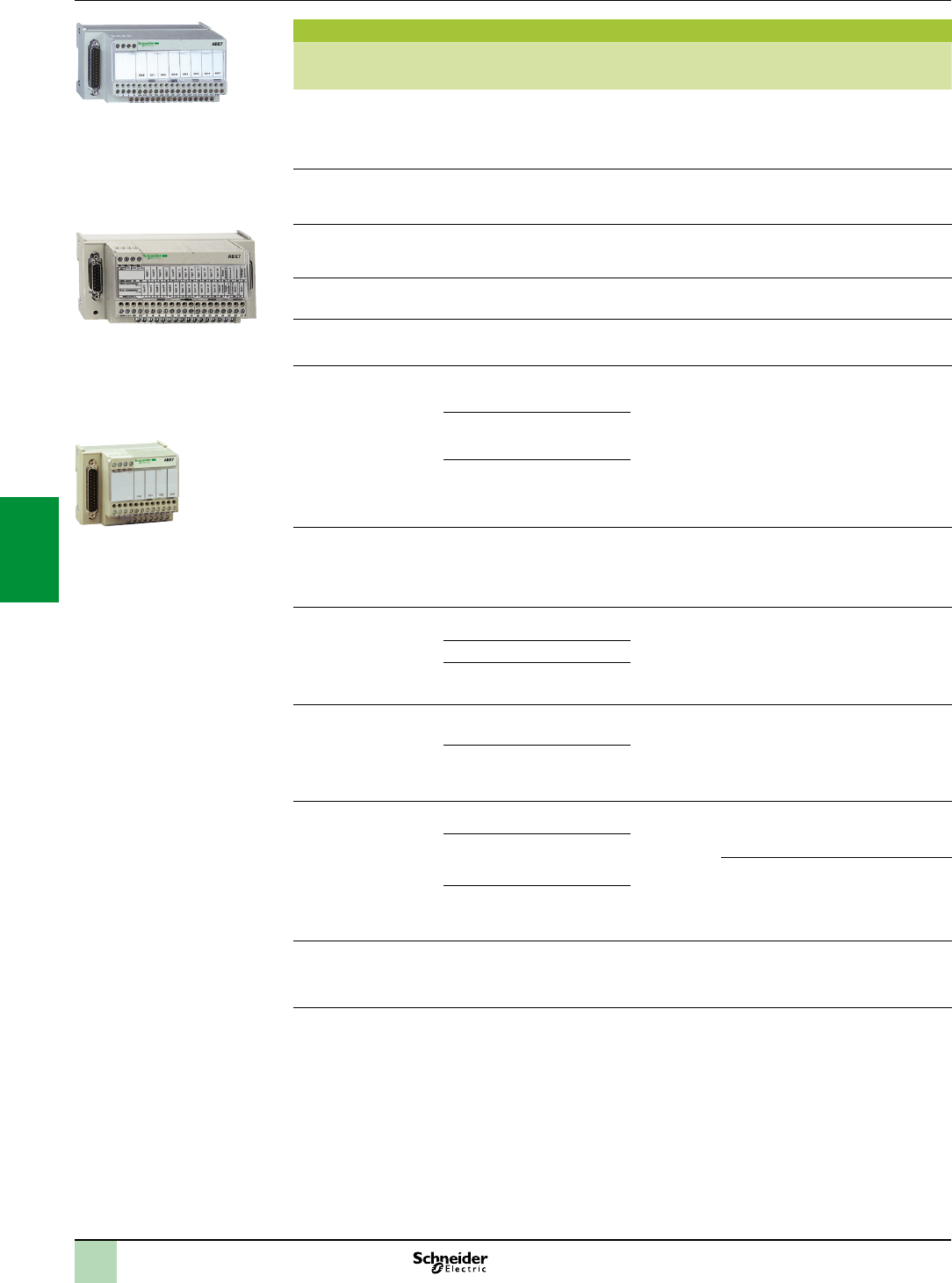
5/18
Connection sub-bases for counter and analog channels
Functions For PLCs Compatible
modules
Type of
connection on
Telefast end
Type of
connection
Reference Weight
kg
Analog and counter TSX Micro Analog and
integrated
counter
TSX3722
TSXCTZA
15-way SUB-D Screw ABE7CPA01 0.300
Counter, axis control,
position control
Modicon
Premium
TSXCTYA
TSXCAY1
15-way SUB-D Screw ABE7CPA01 0.300
Connection of absolute
encoder with parallel
output
Modicon
Premium
TSXCTYA
TSXCAY1
15-way SUB-D Screw ABE7CPA11 0.330
Distribution of
4 thermocouples
Modicon M340 BMXART0414
BMXART0814
25-way SUB-D Screw ABE7CPA412 0.180
Distribution of
16 thermocouples
Modicon
Premium
TSXAEY1614 25-way SUB-D Screw ABE7CPA12 0.300
Passive distribution
of 8 analog EIS channels
on screw terminals,
with shield continuity
Modicon
Premium
TSXASY800
TSXAEY1600
TSXAY800
25-way SUB-D Screw ABE7CPA02 0.290
Modicon M340 BMXAMI0800
BMXAMI0810
BMXAMO0802
Modicon
Quantum
140AVI03000
140ACI03000
140ACI04000
140ACO13000
Provision and
distribution of protected
isolated power supplies
for 4 analog input
channels
Modicon M340 BMXAMI0410 25-way SUB-D Screw ABE7CPA410 0.180
Distribution of 4 analog
output channels
Modicon
Premium
TSXASY410
TSXAEY420
25-way SUB-D Screw ABE7CPA21 0.210
Modicon M340 BMXAMO0410
Modicon
Quantum
140AVO02000
140ACO02000
Distribution and
supply of 8 analog
input channels
with limitation of each
current loop
Modicon
Premium
TSXAEY800
TSXAEY1600
25-way SUB-D Screw ABE7CPA03 0.330
Modicon
Quantum
140AVI03000
140ACI03000
140ACI04000
Distribution and supply
of 8 analog input
channels isolated from
one another with 25 mA/
channel limitation
Modicon
Premium
TSXAEY810 25-way SUB-D Screw ABE7CPA31 0.410
Modicon M340 BMXAMI0800
BMXAMI0810
BMXAMO0802 Spring ABE7CPA31E 0.410
Modicon
Quantum
140AVI03000
140ACI03000
140ACI04000
Safety Modicon
Premium
TSXPAY22 25-way SUB-D Screw ABE7CPA13 0.290
Connection interfaces
Modicon Telefast ABE7 pre-wired system
Connection sub-bases for analog channels and
application-specic channels
References
ABE7CPA21
ABE7CPA410
ABE7CPA412
ABE7CPA11
ABE7CPA01
2
1
3
4
5
6
7
8
9
10
2
1
3
4
5
6
7
8
9
10

5/19
Connection interfaces
Modicon Telefast ABE7 pre-wired system
Cabled connectors for Modicon Quantum I/O modules
References(continued)
Cabled connectors for Modicon Quantum I/O modules
Type of
signal
I/O
modules
Type of
connector
Gauge Cross-
section
Length No. of
channels
Reference Weight
AWG mm² m kg
Inputs and relay
outputs
See our Quantum
catalogue
2 x 20-way
HE10
22 0.324 1.5 2 x 16 ABFM32H150 0.650
3 2 x 16 ABFM32H300 1.150
0.5 A outputs See our Quantum
catalogue
2 x 20-way
HE10
+ external
power supply
22 0.324 1.5 2 x 16 ABFM32H151 0.650
3 2 x 16 ABFM32H301 1.150
Inputs or
outputs
(96 channels)
140DDI36400
140DDO36400
2 x 20-way
HE10
22 0.324 0.5 6 x 16 TSXCDP053 0.085
1 6 x 16 TSXCDP103 0.150
2 6 x 16 TSXCDP203 0.280
3 6 x 16 TSXCDP303 0.410
5 6 x 16 TSXCDP503 0.670
Analog inputs 140AVI03000
140ACI03000
1 x 25-way
SUB-D
24 0.22 2 8 ABFM08S201 0.600
140ACI04000 2 x 25-way
SUB-D
24 0.22 2 16 ABFM16S201 0.620
Analog outputs 140AVO02000 1 x 25-way
SUB-D
24 0.22 2 4 ABFM04S200 0.450
140ACO02000 1 x 25-way
SUB-D
24 0.22 2 4 ABFM04S201 0.450
140ACO13000 1 x 25-way
SUB-D
24 0.22 2 8 ABFM04S202 0.450
ABFM32Hpp1
816500
TSXCDPp03
570464
2
1
3
4
5
6
7
8
9
10
2
1
3
4
5
6
7
8
9
10
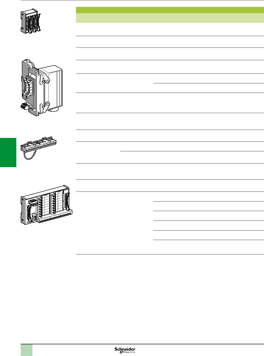
5/20
Accessories
Description No. of channels Characteristics Order in multiples
of
Unit
reference
Weight
kg
Kit for xing on solid plate ––10 ABE7ACC01 0.008
Splitter sub-base – 16 as
2 x 8 channels
1ABE7ACC02 0.075
Redundant output
sub-base
– 16 as
2 x 16 channels
1ABE7ACC10 0.075
Redundant input
sub-base
– 16 as
2 x 16 channels
1ABE7ACC11 0.075
Plug-in continuity blocks – Width 10 mm 4ABE7ACC20 0.007
Width 12 mm 4ABE7ACC21 0.010
Enclosure feedthrough
with CNOMO M23
connector (1 x 20-way HE
10 connector, PLC end)
16 19-way 1ABE7ACC82 0.150
Impedance adaptor for
compatibility
Type 2
– Used with
ABE7ACC82 and
ABE7ACC83
1ABE7ACC85 0.012
IP 65 cable gland – For 3 cables 5ABE7ACC84 0.300
Additional snap-on
terminal blocks
(shunted terminals)
8 10 screw terminals 5ABE7BV10 0.030
16 20 screw terminals 5ABE7BV20 0.060
I/O simulator sub-base 16 For display,
forcing, inhibition,
continuity
1ABE7TES160 0.350
Self-adhesive marker
tag holder
– For 6 characters 50 AR1SB3 0.001
Quick-blow fuses
5 x 20, 250 V, UL
– 0.125 A 10 ABE7FU012 0.010
0.5 A 10 ABE7FU050 0.010
1 A 10 ABE7FU100 0.010
2 A 10 ABE7FU200 0.010
4 A 10 ABE7FU400 0.010
6.3 A 10 ABE7FU630 0.010
Connection interfaces
Modicon Telefast ABE7 pre-wired system
Accessories for connection sub-bases
References(continued)
ABE7ACC02
816483
ABE7ACC80+ABE7ACC81
816480
ABE7BV20
816481
22 0 1
0
1
2
3
4
5
6
7
8
9
10
11
12
13
14
15
0 1
ABE7TES160
580700
2
1
3
4
5
6
7
8
9
10
2
1
3
4
5
6
7
8
9
10

5/21
Commoning link accessories
Description For common Colour Distance
between cable ends
Reference Weight
kg
Commoning links
Modularity 8 x 1 mm2
Coil White 12 cm ABFC08R12W 0.020
2 cm ABFC08R02W 0.010
Red 12 cm ABFC08R12R 0.020
2 cm ABFC08R02R 0.010
Blue 12 cm ABFC08R12B 0.020
2 cm ABFC08R02B 0.010
Connection interfaces
Modicon Telefast ABE7 pre-wired system
Accessories for connection sub-bases
References(continued)
AR1SB3
816479
ABEC08R
816484
2
1
3
4
5
6
7
8
9
10
2
1
3
4
5
6
7
8
9
10

6/0
2
1
3
4
5
6
7
8
9
10
2
1
3
4
5
6
7
8
9
10

6/1
Contents
Treatment for severe environments
Presentation ........................................................................................... page6/2
Harsh chemical environments .............................................................. page6/2
Extreme climatic environments ............................................................ page6/2
Ruggedized processor modules
References ............................................................................................. page6/3
Ruggedized power supply modules
References ............................................................................................. page6/4
Ruggedized racks and rack expansion module
References ............................................................................................. page6/5
Ruggedized discrete I/O modules
References ............................................................................................. page6/6
Ruggedized analog I/O modules
References ............................................................................................. page6/7
Ruggedized communication modules and network gateway
References ............................................................................................. page6/8
Ruggedized counter modules
References ............................................................................................. page6/9
6 - Ruggedized Modicon M340
modules
2
1
3
4
5
6
7
8
9
10
2
1
3
4
5
6
7
8
9
10

6/2
Presentation
Protective treatment of Modicon M340 PLCs
Modicon M340 PLCs comply with “TC” treatment requirements (Treatment for all
Climates). They are designed as standard to operate in temperatures of 0 to + 60°C.
For installations in industrial production workshops or environments corresponding
to “TH” (Treatment for Hot and humid environments), PLCs must be housed in
enclosures providing at least IP 54 protection as specied by standard
IEC/EN 60529, or an equivalent level of protection according to NEMA 250.
Modicon M340 PLCs themselves offer IP 20 degree of protection (1). They can
therefore be installed without an enclosure in reserved access areas that do not
exceed pollution level 2 (control room with no dust-producing machinery or
activity). Pollution level 2 does not take account of harsher environments, such as
those where the air is polluted with dust, fumes, corrosive or radioactive particles,
vapours or salts, moulds, insects, etc.
Treatment for more severe environments
If the Modicon M340 automation platform has to be used in more severe
environments or is required to start and operate in an extended temperature range,
from - 25°C to + 70°C, the “ruggedized” offer features industrially hardened
processor and power supply modules, Bus X I/O modules and racks which have
protective coating on all their circuit boards.
Note:Capableofstarting withinanextendedtemperaturerange(from- 25°C to + 70°C),a
single-rackcongurationisalsoabletooperate at extremely low temperatures (to - 40°C)if
placedinanappropriateenclosure.PleaseconsultourCustomerCareCentre.
This treatment increases the isolation capability of the circuit boards and their
resistance to:
Condensation
Dusty atmospheres (conducting foreign particles)
Chemical corrosion, in particular during use in sulphurous atmospheres (oil
renery, purication plant, etc.) or atmospheres containing halogens (chlorine, etc.)
This protection, combined with appropriate installation and maintenance, enables
Modicon M340 products to be used in the following environments:
Harsh chemical environments:
IEC/EN 60721-3-3 class 3C3:
- 14 days; 25°C/relative humidity 75%
- Concentrations (mm3/m3): H2S: 2100/SO2: 1850/Cl2: 100
ISA S71.04 classes G1 to G3:
- 14 days; 25°C/relative humidity 75%
- Concentrations (mm3/m3): H2S: 50/SO2: 300/Cl2: 10/NO2: 1250
IEC/EN 60068-2-52 salt mist, Kb test severity level 2:
- 3 x 24-hour cycles
- 5% NaCI
- 40°C/relative humidity 93%
Extreme climatic environments:
Temperatures from - 25 to + 70°C
Relative humidity levels up to 93% (95% depending on the device), from + 25
to + 70°C during operation
Formation of ice
Altitudes from 0 to 5000 m
Three modules are specically designed for extended temperature ranges from - 25
to + 70°C (the product references include the sufx “T”) :
125 V power supply module BMXCPS3540T (see page 2/11)
125 V discrete input module, 16 channels, BMXDDI1604T (see page 2/22)
125 V discrete relay output module, 8 channels, BMXDRA0804T (see page
2/22)
(1)EachslotinaBMXXSPppp0rackisequippedasstandardwithaprotectivecoverthat
shouldonlyberemovedwheninsertingamodule.Ifanycoversaresubsequentlymisplaced,
replacementscanbeorderedunderreferenceBMXXEM010(soldinlotsof5).
Processors:
page 1/4
I/O:
pages 2/12 and 2/24
Communication:
page 3/2
Software:
page 4/2
Modicon M340 automation
platform
Treatment for severe environments
Ruggedized modules
Presentation
2
1
3
4
5
6
7
8
9
10
2
1
3
4
5
6
7
8
9
10
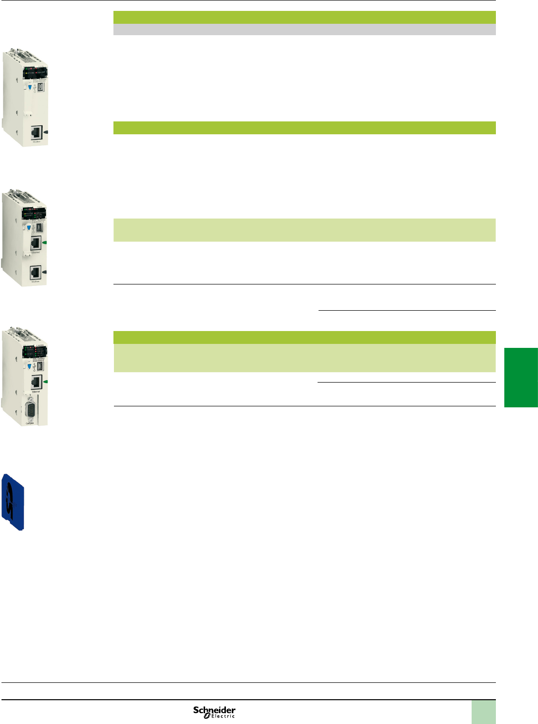
6/3
Presentation (continued)
References and characteristics
To order ruggedized modules and racks, see the reference pages 6/3 to 6/9 (the references of the ruggedized
products available include the sufx “H”).
All standard separate parts (cordsets, cables, memory cards, sub-bases, etc.) which are compatible with the
ruggedized modules offer are listed in the reference pages (see pages 6/3 to 6/9).
The majority of operating and electrical characteristics of ruggedized modules are identical to those of their
equivalent standard versions. However, some characteristics are subject to either derating or limitation. Please
consult our website www.schneider-electric.com.
BMXP34 Modicon M340 ruggedized processors(1)
Modicon M340 processor modules are supplied with the BMXRMS008MP Flash memory card. This card
performs the following actions transparently:
Backup of the application (program, symbols and constants) supported in the processor's internal RAM
which is not backed up
Activation of the Transparent Ready class B10 standard Web server with BMXP341000H Standard
processors and BMXP342020H/20302H Performance processors.
This card can be replaced by either of the BMXRMS008MPF or BMXRMS128MPF cards which feature a le
storage option.
Max. capacity Memory
capacity
Max. no. of network
modules
Integrated
communication ports
Reference Weight
kg
2 racks
512 discrete I/O
128 analog I/O
20 application-specic
channels
2048 KB
integrated
2 Ethernet networks Modbus serial link BMXP341000H 0.200
4 racks
1024 discrete I/O
256 analog I/O
36 application-specic
channels
4096 KB
integrated
2 Ethernet networks
Modbus serial link
Ethernet network
BMXP342020H 0.205
Ethernet network
CANopen bus
BMXP3420302H 0.215
Standard memory cards
Description Processor compatibility Capacity Reference Weight
kg
Flash memory cards (2) BMXP342020H
BMXP3420302H
8 MB/8 MB les BMXRMS008MPF 0.002
8 MB/128 MB les BMXRMS128MPF 0.002
(1)Generalcharacteristicsarethesameasthoseofthestandardequivalentversions(seepage1/4).
(2)Cardstoreplacethememorycardsuppliedasstandardwitheachprocessor,usedfor:
-Backinguptheprogram,constants,symbolsanddata
-Filestorage
-ActivationofclassB10Webserver
Processors:
page 1/4
I/O:
pages 2/12 and 2/24
Communication:
page 3/2
Software:
page 4/2
BMXP342020H
Modicon M340 automation
platform
Dedicated parts for severe environments
Ruggedized processor modules
Presentation(continued),
references
BMXP341000H
BMXRMS008MPF/128MPF
BMXP3420302H
2
1
3
4
5
6
7
8
9
10
2
1
3
4
5
6
7
8
9
10
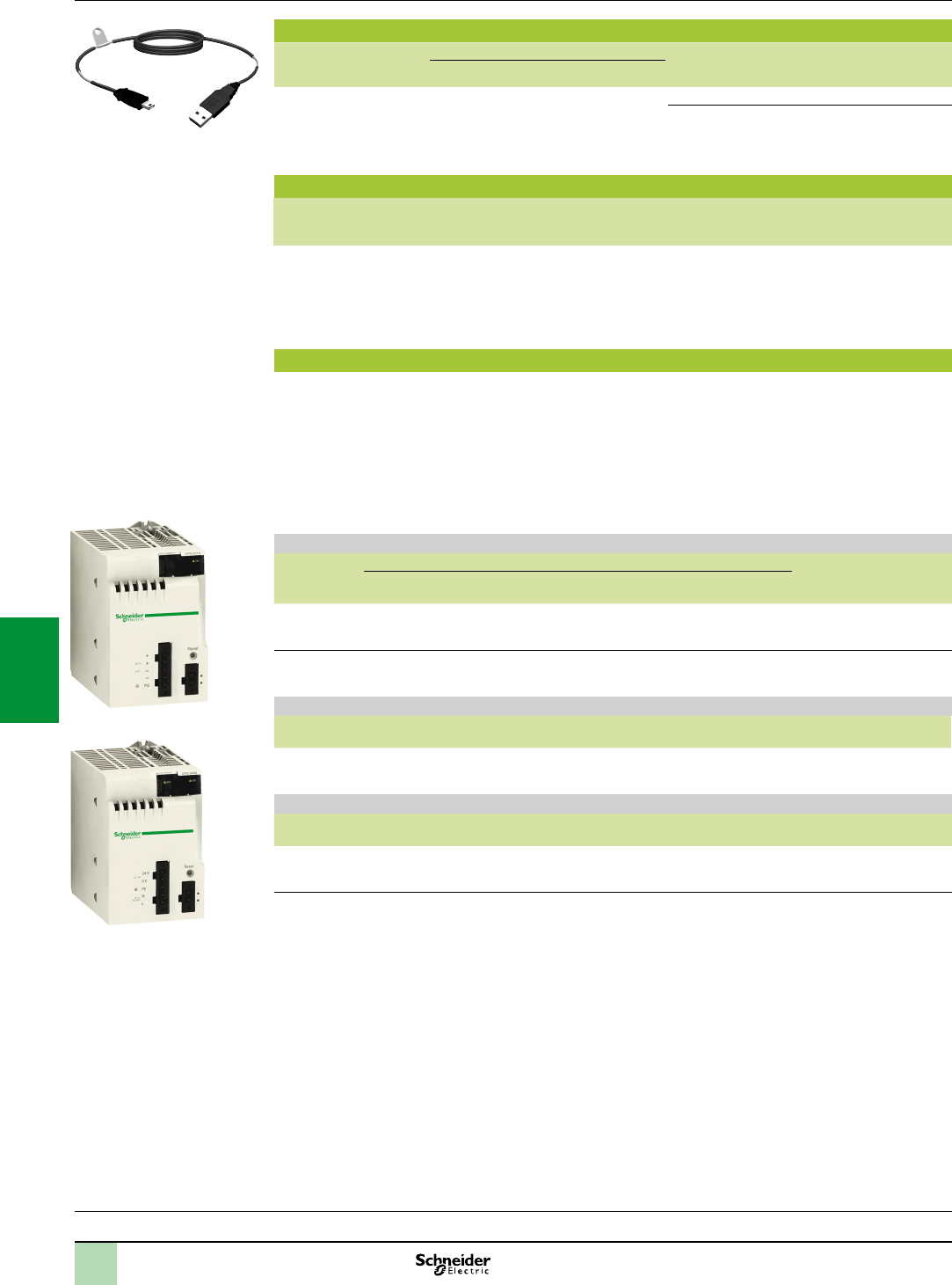
6/4
Processors:
page 1/4
I/O:
pages 2/12 and 2/24
Communication:
page 3/2
Software:
page 4/2
Standard separate parts
Description Use Length Reference Weight
kg
From To
Terminal port/USB
cordsets
Mini B USB port on
the Modicon M340
processor
Type A USB port on:
- PC terminal
- Magelis XBTGT/
GK/GTW, GTWHMI,
STU/STOHMI
graphic terminal
1.8 m BMXXCAUSBH018 0.065
4.5 m BMXXCAUSBH045 0.110
Standard replacement part
Description Use Processor compatibility Reference Weight
kg
8 MB Flash memory card Supplied as standard with each
processor. Used for:
- Backing up the program,
constants, symbols and data
- Activation of class B10 Web
server
BMXP342020H
BMXP3420302H
BMXRMS008MP 0.002
Ruggedized power supply modules
Each BMXXBP00H rack must be equipped with a power supply module. These modules are inserted in the
rst two slots of each rack (marked CPS).
The available power values given below in bold italic correspond to operation at - 25°C and + 70°C (see
temperature derating curves on our website
www.schneider-electric.com).
The power required to supply each rack depends on the type and number of modules installed in the rack. It is
therefore necessary to draw up a power consumption table for each rack in order to determine which is the
most appropriate BMXCPS0H power supply module for your requirements (see page 7/22).
Power supply modules (1)
Line supply Available power (2) Reference Weight
kg
3.3 V c
(3)
24 V c rack
(3)
24 V c sensors
(4)
Total
24...48 V
c isolated
15 W
11.3 W
31.2 W
23.4 W
– 31.2 W
23.4 W
BMXCPS3020H 0.340
100...240 V a 15 W
11.3 W
31.2 W
23.4 W
21.6 W
16.2 W
36 W
27 W
BMXCPS3500H 0.360
Standard separate part
Description Type Composition Reference Weight
kg
Set of 2 removable connectors Spring-type One 5-way terminal block and one
2-way terminal block
BMXXTSCPS20 0.015
Standard replacement part
Description Type Composition Reference Weight
kg
Set of 2 removable connectors Cage clamp One 5-way terminal block and one
2-way terminal block
BMXXTSCPS10 0.020
(1)Includesasetof2cageclampremovableconnectorsBMXXTSCPS10.
(2)Thetotalpowerconsumedoneachvoltage(3.3Vcand24Vc)mustnotexceedthetotalpowerofthemodule.Seethe
powerconsumptiontableonpage7/22
.
(3)3.3Vcand24VcrackvoltagesforpoweringModiconM340PLCmodules.
(4)24Vcsensorvoltageforpoweringtheinputsensors(voltageavailableviathe2-wayremovableconnectoronthefront
panel).
Modicon M340 automation
platform
Dedicated parts for severe environments
Ruggedized processor modules and ruggedized power
supply modules
References(continued)
BMXCPS3020H
BMXCPS3500H
BMXXCAUSBH0pp
2
1
3
4
5
6
7
8
9
10
2
1
3
4
5
6
7
8
9
10
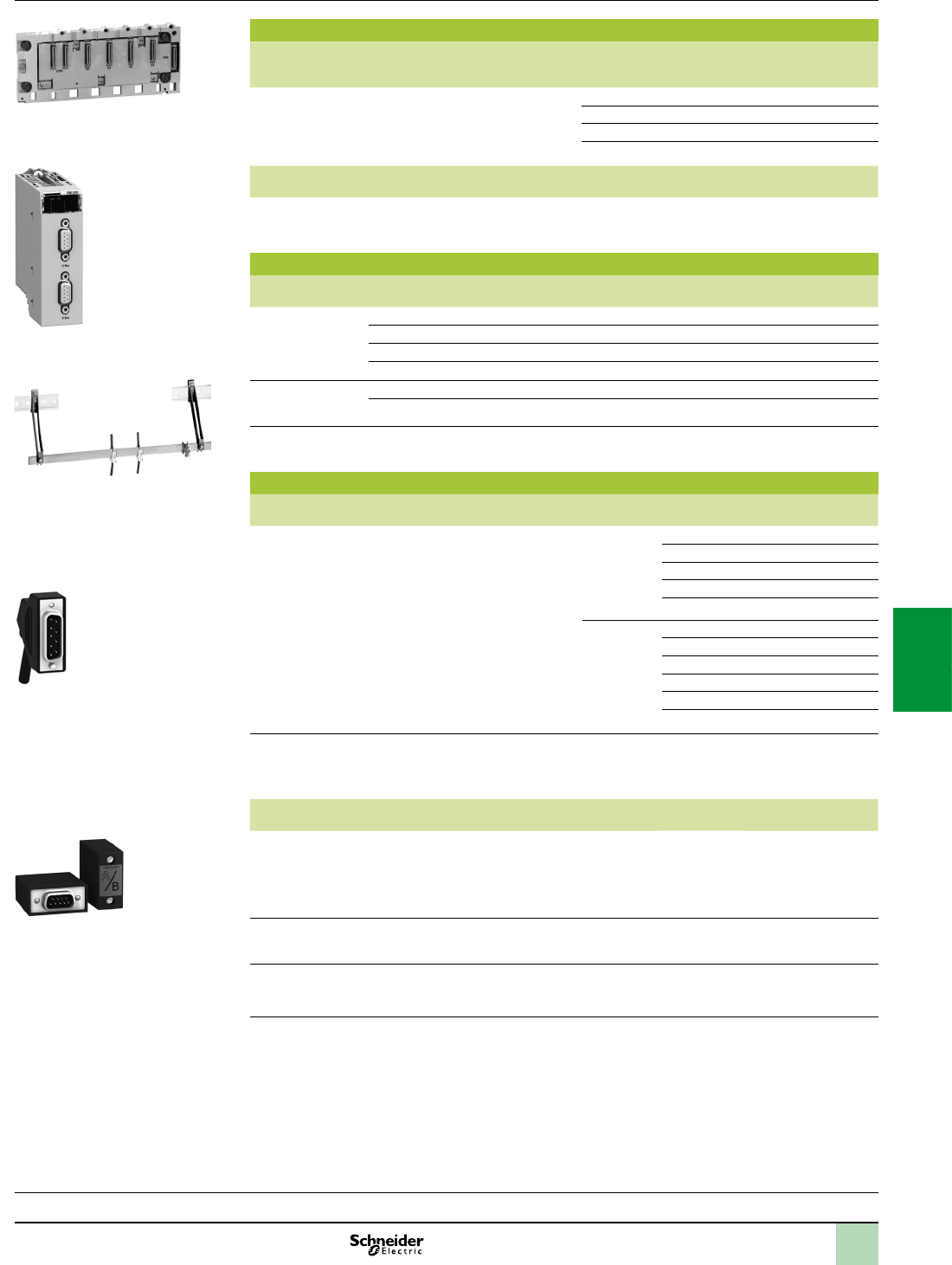
6/5
BMXXBP0400H
Processors:
page 1/4
I/O:
pages 2/12 and 2/24
Communication:
page 3/2
Software:
page 4/2
Ruggedized racks
Description Type of module
to be inserted
No. of slots
(1)
Power
consumption
(2)
Reference Weight
kg
Ruggedized racks BMXCPS power supply, BMXP34
processor, I/O modules and application-
specic (counter and communication)
modules
4 1 W
BMXXBP0400H
0.630
6 1.5 W
BMXXBP0600H
0.790
8 2 W
BMXXBP0800H
0.950
12 0.74 W
BMXXBP1200H
1.270
Description Use Reference Weight
kg
Ruggedized rack
expansion module
(3)
Standard module to be installed in each rack (XBE slot)
Used to daisy chain up to 4 racks
BMXXBE1000H
0.178
Standard accessories for racks
Description For use with Sold in
lots of
Reference Weight
kg
Shielding
connection kits
comprising:
- A metal bar
- 2 support bases
BMXXBP0400H rack –
BMX
X
SP0400
0.280
BMXXBP0600H rack –
BMX
X
SP0600
0.310
BMXXBP0800H rack –
BMX
X
SP0800
0.340
BMXXBP1200H rack –
BMX
X
SP1200
0.400
Spring clamping
rings
Cables, cross-section 1.5...6 mm210 STBXSP3010 0.050
Cables, cross-section 5...11 mm210 STBXSP3020 0.070
Protective covers
(replacement parts)
Unoccupied slots on BMXXBP00H rack 5BMXXEM010 0.005
Standard cordsets and connection accessories
Description Use Composition Type of
connector
Length Weight
kg
Bus X extension
cordsets
total length 30 m max.
(3)
Between two
BMXXBE1000H
rack expansion
modules.
2 x 9-way SUB-D
connectors
Angled 0.8 m 0.165
1.5 m 0.250
3 m 0.420
5 m 0.650
12 m 1.440
Straight 1 m 0.160
3 m 0.260
5 m 0.360
12 m 1.260
18 m 1.860
28 m 2.860
Cable reel
(3)
Length of cable
to be tted with
TSXCBYK9
connectors.
Ends with ying leads,
2 line testers
100 m 12.320
Description Use Composition Sold in
lots of
Reference Weight
kg
Line terminator Required on
both
BMXXBP0H
modules at each
end of the daisy
chain
2 x 9-way SUB-D
connectors marked A/ and /B
2
TSXTLYEX
0.050
Bus X
straight connectors
For ends of
TSXCBY1000
cables
2 x 9-way SUB-D
straight connectors
2
TSXCBYK9
0.080
Connector
assembly kit
Fitting
TSXCBYK9
connectors
2 crimping pliers, 1 pen
(4)
–
TSXCBYACC10
–
(1)Numberofslotstakingtheprocessormodule,I/Omodulesandapplication-specicmodules(excludingpower
supplymodule).
(2)Powerconsumptionofanti-condensationresistor(s)
(3)Moduleandcordsetsdonotoperateproperlyattemperatureslower than - 25°C.
(4)Tottheconnectorsonthecable,youalsoneedawirestripper,apairofscissorsandadigitalohmmeter.
Modicon M340 automation
platform
Dedicated parts for severe environments
Ruggedized racks and rack expansion module
References
BMXXSP000+BMXXSP300
TSXTLYEX
Angledconnectoron
extensioncordsets
BMXXBE1000H
2
1
3
4
5
6
7
8
9
10
2
1
3
4
5
6
7
8
9
10

6/6
References Modicon M340 automation
platform
Dedicated parts for severe environments
Ruggedized discrete I/O modules
Processors:
page 1/4
I/O:
pages 2/12 and 2/24
Communication:
page 3/2
Software:
page 4/2
References
Ruggedized discrete input modules
Type of
current
Input voltage Connection via
(1)
IEC/EN
61131-2
conformity
No. of channels
(common)
Reference Weight
kg
c24 V (positive
logic)
Screw or spring-type 20-way
removable terminal block
Type 3 16 isolated inputs
(1 x 16)
BMXDDI1602H 0.115
24 V (negative
logic)
Screw or spring-type 20-way
removable terminal block
Non-IEC 16 isolated inputs
(1 x 16)
BMXDAI1602H 0.115
48 V (positive
logic)
Screw or spring-type 20-way
removable terminal block
Type 1 16 isolated inputs
(1 x 16)
BMXDDI1603H 0.115
a24 V Screw or spring-type 20-way
removable terminal block
Type 1 16 isolated inputs
(1 x 16)
BMXDAI1602H 0.115
48 V Screw or spring-type 20-way
removable terminal block
Type 3 16 isolated inputs
(1 x 16)
BMXDAI1603H 0.115
100…120 V Screw or spring-type 20-way
removable terminal block
Type 3 16 isolated inputs
(1 x 16)
BMXDAI1604H 0.115
Ruggedized discrete output modules
Type of
current
Output voltage Connection via
(1)
IEC/EN
61131-2
conformity
No. of channels
(common)
ReferenceWeight
kg
c
transistor 24 V/0.5 A
(positive logic)
Screw or spring-type 20-way
removable terminal block
Yes 16 protected outputs
(1 x 16)
BMXDDO1602H 0.120
24 V/0.5 A
(negative logic)
Screw or spring-type 20-way
removable terminal block
– 16 protected outputs
(1 x 16)
BMXDDO1612H 0.120
atriac 100…240 Screw or spring-type 20-way
removable terminal block
– 16 outputs
(4 x 4)
BMXDAO1605H 0.140
c or a
relay
12…24 V/2 A
24…240 V/2 A
Screw or spring-type 20-way
removable terminal block
Yes
8 non-protected outputs
(without common)
BMXDRA0805H 0.145
24 V /2 A,
240 V /2 A
Screw or spring-type 20-way
removable terminal block
Yes
16 non-protected outputs
(2 x 8)
BMXDRA1605H 0.150
Ruggedized mixed discrete I/O modules
Number
of I/O
Connection via
(1)
No. of input channels
(common)
No. of output
channels
(common)
IEC/EN
61131-2 conformity
Reference Weight
kg
16 Screw or
spring-type
20-way
removable
terminal block
8 (positive logic)
(1 x 8)
8, transistor
24 V c /0.5 A
(1 x 8)
Inputs, type 3 BMXDDM16022H 0.115
8, 24 V or
24…240 V a
relay
(1 x 8)
Inputs, type 3 BMXDDM16025H 0.135
Standard removable connection blocks
Description Use Type Reference Weight
kg
20-way removable
terminal blocks
For module with 20-way removable
terminal block
Cage clamp BMXFTB2000 0.093
Screw clamp BMXFTB2010 0.075
Spring-type BMXFTB2020 0.060
Standard preformed cordsets for I/O modules with removable terminal block
Description Composition Length Reference Weight
kg
Preassembled cordsets
with one end with ying
leads
One 20-way spring-type removable
terminal block (BMXFTB2020)
One end with colour-coded ying leads
3 m BMXFTW301 0.850
5 m BMXFTW501 1.400
10 m BMXFTW1001 2.780
(1)Byconnector,modulesuppliedwithcover(s)
BMXDI160H
BMXDDM1602H
BMXFTB2000
BMXDDO162H BMXDRA0805H/
1605H
2
1
3
4
5
6
7
8
9
10
2
1
3
4
5
6
7
8
9
10
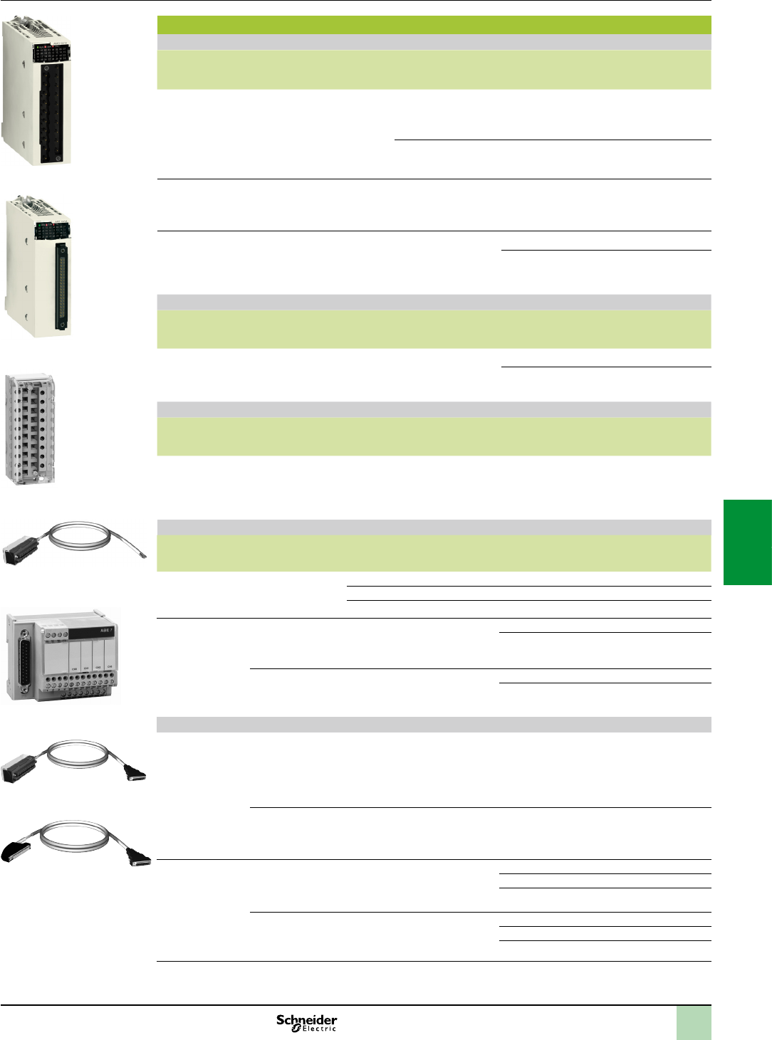
6/7
Modicon M340 automation
platform
Dedicated parts for severe environments
Ruggedized analog I/O modules
References(continued)
References
Ruggedized analog input modules
Type of inputs Input
signal range
Resolution Connection No. of
channels
Reference Weight
kg
Isolated high-level
inputs
± 10 V, 0…10 V,
0…5 V, 1…5 V, ± 5 V
0…20 mA,
4…20 mA, ± 20 mA
16 bits Via cage clamp, screw
clamp or spring-type
removable terminal
block
4 high-speed
channels
BMXAMI0410H 0.143
Via cage clamp or
spring-type removable
terminal block
8 isolated
high-speed
channels
BMXAMI0810H 0.175
Non-isolated
high-level inputs
± 10 V, 0…10 V,
0…5 V, 1…5 V, ± 5 V
0…20 mA,
4…20 mA, ± 20 mA
15 bits
+ sign
Via cage clamp or
spring-type removable
terminal block
8 isolated
high-speed
channels
BMXAMI0800H 0.175
Isolated low-level
inputs
Temperature probe,
thermocouple
± 40 mV, ± 80 mV,
± 160 mV, ± 320 mV,
± 640 mV, ± 1.28 V
15 bits
+ sign
40-way connector 4 channels BMXART0414H 0.135
8 channels BMXART0814H 0.165
Ruggedized analog output module
Type of outputs Output signal
range
Resolution Connection No. of
channels
Reference Weight
kg
Isolated
high-level outputs
± 10 V,
0…20 mA, 4…20 mA
16 bits Via cage clamp, screw
clamp or spring-type
removable terminal
block
2 channels BMXAMO0210H 0.144
4 channels BMXAMO0410H 0.175
Ruggedized mixed analog I/O module
Type of outputs Signal range Resolution Connection No. of
channels
Reference Weight
kg
Mixed I/O,
non-isolated
± 10 V, 0…10 V,
0…5 V, 1…5 V,
0…20 mA, 4…20 mA
14 bits or
12 bits
depending
on the
range
Via cage clamp, screw
clamp or spring-type
removable
terminal block
I: 4 channels
Q: 2 channels
BMXAMM0600H 0.155
Standard connection accessories for analog modules (1)
Description For use with
modules
Type, composition Length Reference Weight
kg
20-way removable
terminal blocks
BMXAMI0410H
BMXAMO0210H
BMXAMM0600H
Cage clamp – BMXFTB2000 0.093
Screw clamp – BMXFTB2010 0.075
Spring-type – BMXFTB2020 0.060
Preassembled
cordsets
BMXAMI0410H
BMXAMO0210H
BMXAMM0600H
One 20-way removable
terminal block (BMXFTB2020)
One end with colour-coded
ying leads
3 m BMXFTW301S 0.470
5 m BMXFTW501S 0.700
BMXART0414H
BMXART0814H (2)
One 40-way connector
One end with colour-coded
ying leads
3 m BMXFCW301S 0.480
5 m BMXFCW501S 0.710
Modicon Telefast ABE7 pre-wired system
Modicon Telefast
ABE7 sub-bases
BMXAMI0410H Distribution of isolated power
supplies
Delivers 4 protected isolated
power supplies for
4...20 mA inputs
Direct connection of 4 inputs
–ABE7CPA410 0.180
BMXART0414H
BMXART0814H
Connection and provision
of cold-junction compensation
for thermocouples
Direct connection of 4 inputs
–ABE7CPA412 0.180
Preformed
cordsets for
Modicon Telefast
ABE7CPA41
BMXAMI0410H
BMXAMO0210H
One 20-way removable terminal
block and one 25-way SUB-D
connector for ABE7CPA410/
CPA21 sub-base
1.5 m BMXFCA150 0.320
3 m BMXFCA300 0.500
5 m BMXFCA500 0.730
BMXART0414H
BMXART0814H
One 40-way connector and
one 25-way SUB-D connector
for ABE7CPA412 sub-base
1.5 m BMXFCA152 0.330
3 m BMXFCA302 0.510
5 m BMXFCA502 0.740
(1)TheshieldingonthecordsetscarryingtheanalogsignalsmustalwaysbeconnectedtotheBMXXSPpp00shielding
connectionkitmountedundertherackholdingtheanalogmodules(seepage2/7).
(2)TheBMXART0814H8-channelmodulerequirestwoABE7CPA412sub-basesandtwoBMXFCApp2cordsets.
BMXAM00H
BMXART0414H
BMXFTB200
BMXFTW01S
BMXFCA0
BMXFCA2
ABE7CPA41
2
1
3
4
5
6
7
8
9
10
2
1
3
4
5
6
7
8
9
10
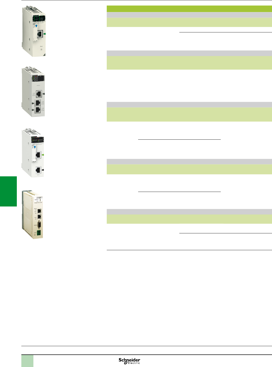
6/8
Communication
BMXNOE0100H/0110H ruggedized Ethernet communication modules
Description Data rate Transparent Ready
Class
Reference Weight
kg
Ethernet Modbus/
TCP network
modules
10/100 Mbps B30 BMXNOE0100H 0.200
C30 BMXNOE0110H 0.200
BMXNOM0200H ruggedized serial link module
Description Protocol Physical layer Reference Weight
kg
Serial link module
2-channels
Modbus master/slave
RTU/ASCII,
Character mode,
Modem
GSM/GPRS
1 non-isolated RS 232
channel (SL0)
2 isolated RS 485
channels
(SL0 and SL1)
BMXNOM0200H 0.230
RTU BMXNOR0200H ruggedized communication module
Description Protocols Physical
layer
Reference Weight
kg
RTU
communication
module
Modbus TCP,
IEC 60870-5-104
or DNP3 IP
(client or server)
1 Ethernet port
10BASE-T/
100BASE-TX
BMXNOR0200H 0.205
IEC 60870-5-101
or DNP3 serial
(master or slave)
1 non-isolated
RS 232/485
serial link port
Ruggedized Probus DP network gateway
Description Protocols Physical
layer
Reference Weight
kg
Probus
Remote Master
(PRM) module
Modbus TCP 1 Ethernet switch,
2 ports
10BASE-T/
100BASE-TX
TCSEGPA23F14FK –
Probus DP V1
and Probus PA
(via gateway)
1 isolated RS 485
Probus DP port
Standard connection accessory
Designation Description RS 232
interface
Reference Weight
kg
Cordset for
DCE terminal
(modem, etc.)
Equipped with 1 x RJ45
connector and 1 x 9-way
male SUB-D connector
Length 3 m
Simplied 4-wire (RX, TX,
RTS and CTS)
TCSMCN3M4M3S2 0.150
Full 8-wire
(except RI signal)
TCSXCN3M4F3S4 0.165
References(continued) Modicon M340 automation
platform
Dedicated parts for severe environments
Ruggedized communication modules and network
gateway
Processors:
page 1/4
I/O:
pages 2/12 and 2/24
Communication:
page 3/2
Software:
page 4/2
BMXNOR0200H
TCSEGPA23F14FK
BMXNOE0100H/0110H
BMXNOM0200H
2
1
3
4
5
6
7
8
9
10
2
1
3
4
5
6
7
8
9
10
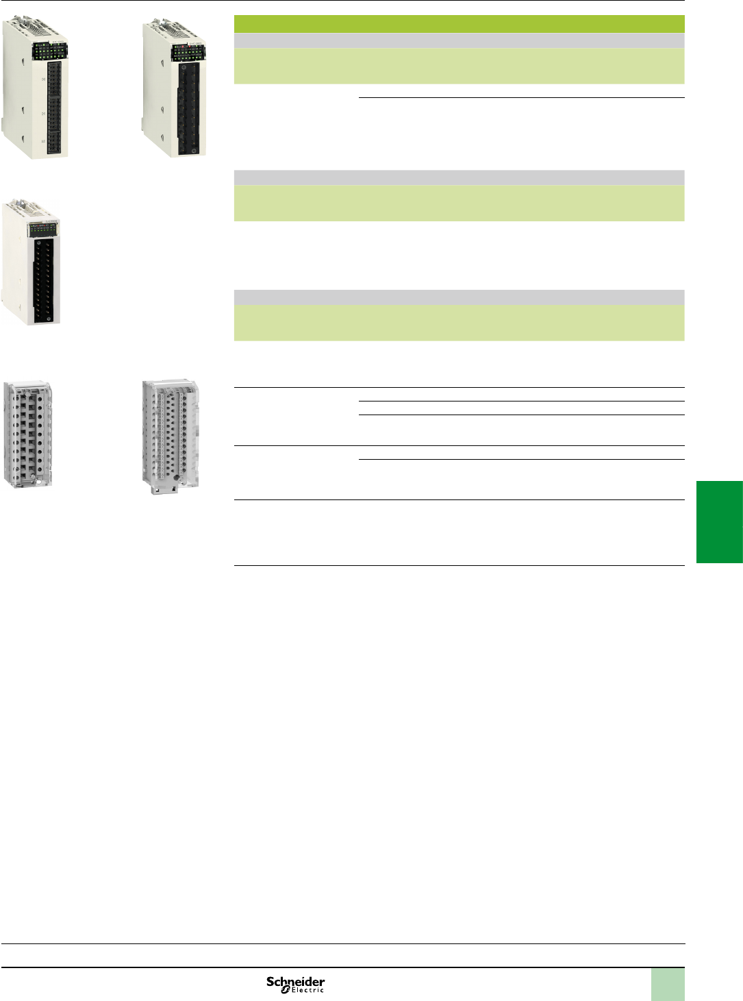
6/9
Modicon M340 automation
platform
Dedicated parts for severe environments
Ruggedized application-specic modules
References(continued)
Processors:
page 1/4
I/O:
pages 2/12 and 2/24
Communication:
page 3/2
Software:
page 4/2
Application-specic modules
BMXEHC0200H/0800H ruggedized counter modules
Description No. of channels Characteristics Reference Weight
kg
Counter modules
for 24 V 2 and
3 wire sensors and
10/30 V incremental
encoders with push-pull
outputs
2 60 kHz counting BMXEHC0200H 0.112
8 10 kHz counting
BMXEHC0800H 0.113
BMXEAE0300H ruggedized SSI encoder interface module
Description No. of channels Characteristics Reference Weight
kg
SSI encoder interface
module
3 8 to 31 bits data width
4 ranks of baud rates:
100 kHz, 200 kHz,
500 kHz, 1 MHz
BMXEAE0300H 0.138
Standard connection accessories (1)
Description Composition Unit reference Weight
kg
Connector kit
for BMXEHC0200H
module
Two 16-way connectors and
one 10-way connector
BMXXTSHSC20 0.021
20-way removable
terminal blocks
for BMXEHC0800H
module
Cage clamp BMXFTB2000 0.093
Screw clamp BMXFTB2010 0.075
Spring-type BMXFTB2020 0.060
28-way removable
terminal blocks
for BMXEAE0300H
module
Cage clamp BMXFTB2800 0.111
Spring-type BMXFTB2820 0.080
Shielding connection kits
for BMXEHC0200H/0800H
and BMXEAE0300H
modules
Comprising a metal bar and two support
bases for mounting on rack
See page 2/7 –
(1)Theshieldingonthecordsetscarryingthecountersignalsmustalwaysbeconnectedtothe
BMXXSPpp00shieldingconnectionkitmountedundertherackholdingtheBMXEHC0200Hmodule(see
page2/7).
BMXEHC0200H BMXEHC0800H
BMXFTB20p0BMXFTB28p0
BMXEAE0300H
2
1
3
4
5
6
7
8
9
10
2
1
3
4
5
6
7
8
9
10

7/0
2
1
3
4
5
6
7
8
9
10
2
1
3
4
5
6
7
8
9
10

7/1
7 - Services
6
Technical appendices
Standards, certications and environmental conditions ................... page7/2
Ethernet network infrastructure ........................................................... page7/6
Certications for automation products and EC regulations ............ page7/12
Power consumption table and calculation sheet .............................. page7/22
Compatibility with sensors
OsiSense XU photo-electric sensors ................................................. page7/14
OsiSense XS inductive proximity sensors ........................................ page7/16
A dedicated services offer for your installed base
Operation services .............................................................................. page7/24
Modernization services ....................................................................... page7/25
Customization services ...................................................................... page7/25
Migration solutions
TSX7 PLCs to Modicon X80 I/O platform
Presentation .......................................................................................... page7/26
TSX7 module - X80 I/O platform compatibility ....................................... page7/27
Modicon Compact PLCs to Modicon X80 I/O platform
Presentation .......................................................................................... page7/28
Compact module - X80 I/O platform compatibility ................................. page7/28
Index
Product reference index ..................................................................... page7/38
Contents
2
1
3
4
5
6
7
8
9
10
2
1
3
4
5
6
7
8
9
10
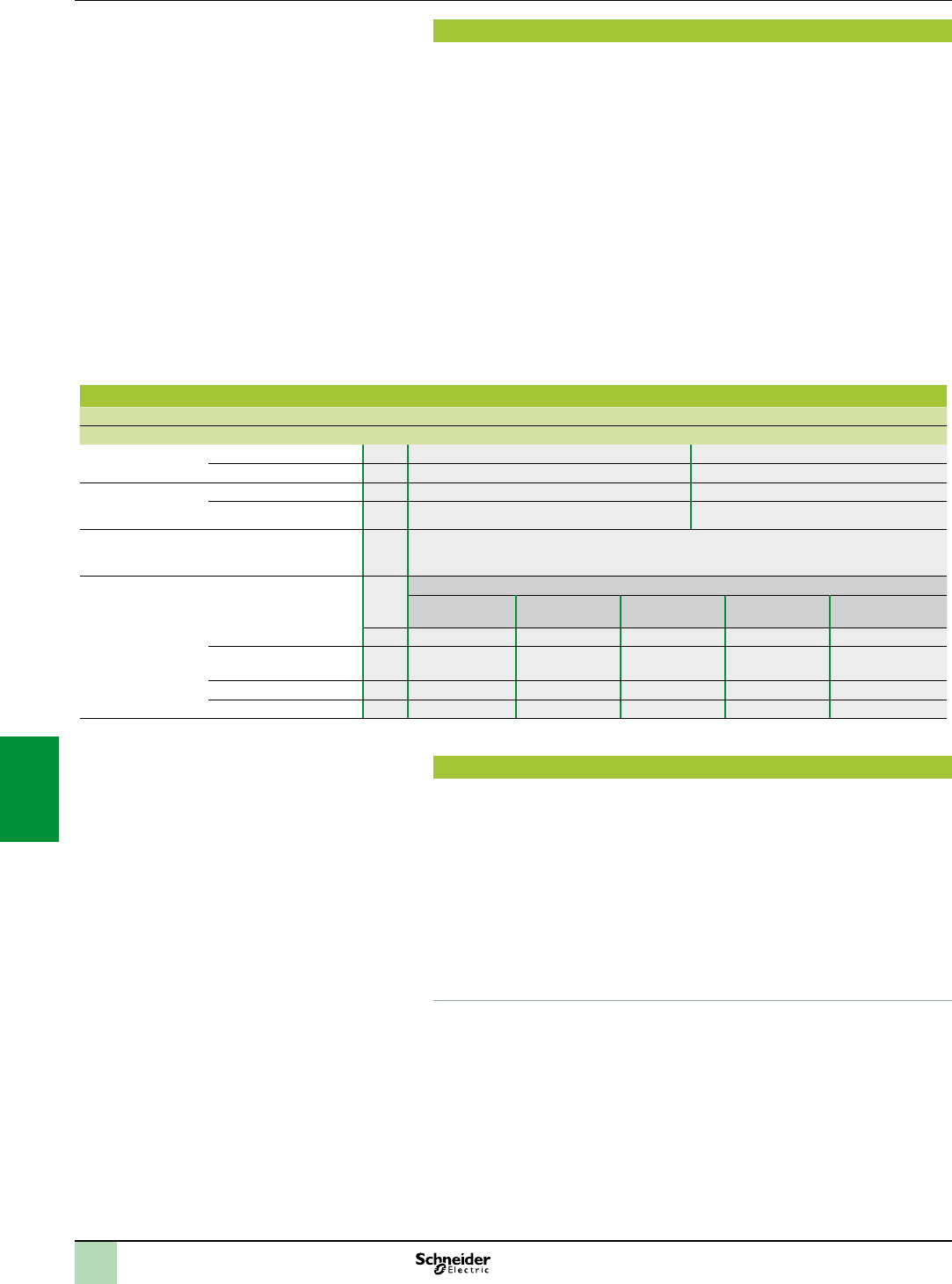
7/2
Standards and certications
Modicon M340 PLCs have been developed to comply with the principal national and
international standards concerning electronic equipment for industrial automation
systems.
Requirements specic to programmable controllers: functional characteristics,
immunity, resistance, safety, etc.: IEC/EN 61131-2, UL and CSA standards for
industry (UL 508, CSA E61131-2).
Requirements specic to power utility automation system: IEC/EN 61850-3.
Merchant navy requirements of the major international organizations: unied in
IACS (International Association of Classication Societies).
Compliance with European Directives for marking:
Low Voltage: 2006/95/EC,
Electromagnetic Compatibility: 2004/108/EC.
Ex areas:
For USA and Canada: Hazardous location class I, division 2, groups A,B,C and D
For other countries: ATEX (directive 94/9/EC) or IECEx in dened atmosphere
Zone 2 (gas) and/or Zone 22 (dust).
Up to date information on which certications have been obtained are available on
our website..
Characteristics
Service conditions and recommendations relating to environment
M340 M340H
Temperature Operation ° C 0...+ 60 - 25...+ 70
Storage ° C - 40...+ 85 - 40...+ 85
Relative humidity
(without condensation)
Cyclical humidity %+ 5 ... + 95 up to 55°C + 5 ... + 95 up to 55 °C
Continuous humidity %+ 5 ... + 93 up to 55°C + 5 ... + 93 up to 60 °C
Altitude Operation m0…2000 (full specication: temperature and isolation)
2000 ... 4000 (temperature derating: 1 °C / 400 m, isolation lost: 150 V / 1000 m)
Supply voltage Modicon X80 I/O power supply modules
BMXCPS2010 BMXCPS3020
BMXCPS3020H
BMXCPS3540T BMXCPS2000 BMXCPS3500
BMXCPS3500H
Nominal voltage V 24 24...48 125 100...240 100...240
Limit voltages V 18...31.2 18...62.4 100…150 85...264 85...264
Nominal frequencies Hz – – – 50/60 50/60
Limit frequencies Hz – – – 47/63 47/63
Protective treatment of Modicon Premium PLCs
Modicon M340 PLCs meet the requirements of “TC” treatment (Treatmentforall
Climates).
For installations in industrial production workshops or environments corresponding to
“TH” treatment (treatmentforhotandhumidenvironments), Modicon M340 PLCs
must be embedded in envelopes with a minimum IP 54 protection.
Modicon M340 PLCs themselves offer protection to IP 20 level and protection
against pins (enclosed equipement) (1). They can therefore be installed without an
envelope in reserved-access areas which do not exceed pollution level 2 (control
room with no dust-producing machine or activity). The pollution level 2 does not take
account of more severe environmental conditions: air pollution by dust, smoke,
corrosive or radioactive particles, vapours or salts, attack by fungi, insects, ...
(1)Inthecasewhereapositionisnotoccupiedbyamodule,aBMXXEM010protectioncover
mustbeinstalled.
():testsrequiredbyEuropeandirectives() andbasedonIEC/EN61131-2standards.
Standardsand
certications Modicon M340 automation
platform
Standards, certications and environment
conditions
2
1
3
4
5
6
7
8
9
10
2
1
3
4
5
6
7
8
9
10

7/3
Environmenttests
Environment tests
Name of test Standards Levels
Immunity to LF interference() (1)
Voltage and frequency variations IEC/EN 61131-2; IEC/EN 61000-6-2; IEC 61000-4-11 0.85...1.10 Un - 0.94...1.04 Fn; 4 steps t = 30 min
IACS E10; IEC 61000-4-11 0.80 Un...0.90 Fn; 1.20 Un...1.10 Fn; t = 1.5 s/5 s
Direct voltage variations EC/EN 61131-2; IEC 61000-4-29;
IACS E10 (PLC not connected to charging battery)
0.85...1.2 Un + ripple: 5 % peak; 2 steps t = 30 min
Third Harmonic IEC/EN 61131-2 H3 (10 % Un) , 0 ° / 180 °; 2 steps t = 5 min
Immunity to conducted low
frequency (only IACS)
IACS E10 For :
H2…H15 (10 % Un), H15…H100 (10 %...1 % Un),
H100…H200 (1 % Un)
For :
H2…H200 (10 % Un)
Voltage interruptions IEC/EN 61131-2; IEC/EN 61000-6-2;
IEC 61000-4-11; IEC 61000-4-29; IACS E10
Power supply immunity:
1ms for c PS1 / 10ms for a/c PS2
Check operating mode for longer interruptions
For IACS:
30 s for or
IEC/EN 61131-2; IEC/EN 61000-6-2;
IEC 61000-4-11
For PS2:
20 % Un, t0: ½ period
40 % Un, cycle 10/12
70 % Un, cycle: 25/30
0 % Un, cycle 250/300
Voltage shut-down and start-up IEC/EN 61131-2 Un…0…Un; t = Un/60 s
Umin…0…Umin; t = Umin/5 s
Umin…0.9 Udl…Umin; t = Umin/60 s
Magnetic eld IEC/EN 61131-2; IEC/TS 61000-6-5; IEC 61000-4-8
(for MV power stations: IEC 61850-3)
Power frequency: 50/60 Hz, 100 A/m continuous ...1000 A/m; t = 3 s;
3 axes
IEC 61000-4-10
(for MV power stations: IEC 61850-3)
Oscillatory: 100 kHz...1 MHz , 100 A/m; t = 9 s; 3 axes
Conducted common mode
disturbances range 0 Hz …150 kHz
IEC 61000-4-16
(for MV power stations: IEC 61850-3)
For remote systems:
50/60 Hz and , 300 V , t = 1s
50/60 Hz and , 30 V , t = 1 min
5 Hz…150 kHz, sweep 3 V…30 V
Where:
PS1 applies to PLC supplied by battery, PS2 applies to PLC energized from or supplies
Un: nominal voltage, Fn: nominal frequency, Udl: detection level when powered
Name of test Standards Levels
Immunity to HF interference.() (1)(2)
Electrostatic discharges IEC/EN 61131-2; IEC/EN 61000-6-2;
IEC 61000-4-2; IACS E10
6 kV contact; 8 KV air; 6 KV indirect contact
Radiated radio frequency
electromagnetic eld
IEC/EN 61131-2; IEC/EN 61000-6-2;
IEC 61000-4-3; IACS E10
15 V/m , 80 MHz … 3 GHz
Sinus amplitude modulated 80 %,1 kHz + internal clock frequencies
Electrical fast transient bursts IEC/EN 61131-2; IEC/EN 61000-6-2;
IEC 61000-4-4; IACS E10
For or main supplies:
2 kV in common mode / 2 kV in wire mode
For or auxiliary supplies, unshielded I/Os:
2 kV in common mode
For analog, unshielded I/Os, communication and all shielded
lines:
1 kV in common mode
Surge IEC/EN 61131-2; IEC/EN 61000-6-2; IEC 61000-4-5;
IACS E10
For / main and auxiliary supplies, unshielded I/Os:
2 kV in common mode / 1 kV in differential mode
For analog, unshielded I/Os:
0.5 kV in common mode / 0.5 kV in differential mode
For communication and all shielded lines:
1 kV in common mode
Conducted disturbances induced by
radiated electromagnetic elds
IEC/EN 61131-2; IEC/EN 61000-6-2; IEC 61000-4-6;
IACS E10
10 V; 0,15 MHz...80 MHz
Sinus amplitude 80%, 1 kHz + spot frequencies
Damped oscillatory wave IEC/EN 61131-2; IEC 61000-4-18;
IACS E10
For / main supplies and auxiliary supplies,
unshielded I/Os:
2.5 kV in common mode / 1 kV in differential mode
For auxiliary supplies, analog, unshielded I/Os:
1 kV in common mode / 0.5 kV in differential mode
For communication and all shielded lines:
0.5 kV in common mode
(1)Devicesmustbeinstalled,wiredandmaintainedincompliancewiththeinstructionsprovidedinthemanual“GroundingandElectromagneticCompatibilityofPLCSystems”.
standards.
(2)Thesetestsareperformedwithoutacabinet,withdevicesxedonametalgridandwiredaspertherecommendationsinthemanual“GroundingandElectromagneticCompatibilityofPLC
systems”.
():testsrequiredbyEuropeandirectivesandbasedonIEC/EN61131-2.
Modicon M340 automation
platform
Standards, certications and environment
conditions
2
1
3
4
5
6
7
8
9
10
2
1
3
4
5
6
7
8
9
10

7/4
Environment tests (continued)
Name of test Standards Levels
Electromagnetic emissions () (1)
Conducted emission IEC/EN 61131-2; FCC part 15; IEC/EN 61000-6-4;
CISPR 11 & 22, Class A, Group 1
150 kHz … 500 kHz : quasi-peak 79 dB (µV/m); average
66 dB (µV/m)
500 kHz … 30 MHz : quasi-peak 73 dB (µV/m); average
60 dB (µV/m)
IACS E10 / power (general power distribution zone):
10 kHz … 150 kHz : quasi-peak 120...69 dB (µV/m);
150 kHz … 0.5 MHz : quasi-peak 79 dB (µV/m)
0.5 MHz … 30 MHz : quasi-peak 73 dB (µV/m)
/ power (bridge and deck zone for evaluation):
10 kHz … 150 kHz : quasi-peak 96…50 dB (µV/m)
150 kHz … 0,35 MHz : quasi-peak 60…50 dB (µV/m)
0.35 MHz … 30 MHz : quasi-peak 50 dB (µV/m)
Radiated emission IEC/EN 61131-2; FCC part 15; IEC/EN 61000-6-4;
CISPR 11 & 22, Class A, Group 1
30 MHz ... 230 MHz : quasi-peak 40 dB (µV/m) (at 10 m);
50 dB (µV/m) (at 3m)
230 MHz ... 1 GHz : quasi-peak 47 dB(µV/m) (at 10 m);
57 dB (µV/m) (at 3m)
IACS E10 For general power distribution zone
0.15 MHz … 30 Mhz: quasi-peak 80…50 dB (µV/m) (at 3m)
30 MHz-100 MHz: quasi-peak 60…54 dB (µV/m) (at 3m)
100 MHz - 2 GHz: quasi-peak 54 dB (µV/m) (at 3m)
156 … 165 MHz: quasi-peak 24 dB (µV /m) (at 3m)
Name of test Standards Levels
Immunity to climatic variations (1) (power on)
Dry heat IEC 60068-2-2 (Bb & Bd) 60 °C , t = 16 h [for ruggedized range: 70 °C , t = 16 h] (2)
IACS E10 60 °C , t = 16 h + 70 °C , t = 2 h
[for ruggedized range: 70 °C , t = 18 h] (2)
Cold IEC 60068-2-1 (Ab & Ad)
IACS E10
0 °C … - 25 °C , t = 16 h + power on at 0 °C
[for ruggedized range: power on at -25 °C] (2)
Damp heat, steady state
(continuous humidity)
IEC 60068-2-78 (Cab);
IACS E10
55 °C , 93 % relative humidity , t = 96 h
[for ruggedized range: 60 °C] (2)
Damp heat, cyclic
(cyclical humidity)
IEC 60068-2-30 (Db);
IACS E10
55 °C … 25 °C , 93…95 % relative humidity , 2 cycles t = 12 h +12 h
Change of temperature IEC 60068-2-14 (Na & Nb) 0 °C … 60 °C , 5 cycles t = 6 h + 6 h
[for ruggedized range: - 25 … 70 °C] (2)
Name of test Standards Levels
Withstand to climatic variations (1) (power off)
Dry heat IEC/EN 61131-2; IEC 60068-2-2 (Bb & Bd)
IEC/EN 60945
85 °C , t = 96 h
Cold IEC/EN 61131-2; IEC 60068-2-1 (Ab & Ad);
IACS E10
- 40 °C , t = 96 h
Damp heat, cyclic
(cyclical humidity)
IEC/EN 61131-2; IEC 60068-2-30 (Db) 55 °C … 25 °C , 93…95 % relative humidity , 2 cycles t = 12 h + 12 h
Change of temperature
(thermal shocks)
IEC/EN 61131-2; IEC 60068-2-14 (Na & Nb) - 40 °C ... 85 °C , 5 cycles t = 3 h + 3 h
(1)Devicesmustbeinstalled,wiredandmaintainedincompliancewiththeinstructionsprovidedinthemanual“GroundingandElectromagneticCompatibilityof
PLCSystems”.
(2)Referalsotochapter“Treatmentforsevereenvironments”.
():testsrequiredbyEuropeandirectivesandbasedonIEC/EN61131-2standards.
Modicon M340 automation
platform
Standards, certications and environment
conditions
Environmenttests(continued)
2
1
3
4
5
6
7
8
9
10
2
1
3
4
5
6
7
8
9
10

7/5
Modicon M340 automation
platform
Standards, certications and environment
conditions
Environment tests (continued)
Name of test Standards Levels
Immunity to mechanical constraints (1) (power on)
Sinusoidal vibrations IEC/EN 61131-2;
IEC 60068-2-6 (Fc)
Basic IEC/EN 61131-2: 5 Hz ... 150 Hz , ± 3.5 mm amplitude (5 Hz …. 8.4 Hz) ,
1g (8.4 Hz …. 150 Hz)
Specic prole: 5 Hz ... 150 Hz , ± 10.4 mm amplitude (5 Hz …. 8.4 Hz) , 3 g (8.4 Hz …. 150 Hz)
For basic and specic, endurance: 10 sweep cycles for each axis
IACS E10 3 Hz ... 100 Hz , 1 mm amplitude (3 Hz …. 13.2 Hz) , 0.7 g (13.2 Hz …. 100 Hz)
Endurance at each resonance frequency : 90 min for each axis , amplication coefcient < 10
IEC 60068-2-6 Sismic analysis: 3 Hz ... 35 Hz , 22.5 mm amplitude (3 Hz …. 8.1 Hz) , 6 g (8.1 Hz …. 35 Hz)
Shocks IEC/EN 61131-2;
IEC 60068-2-27 (Ea)
30 g , 11 ms; 3 shocks/direction/axis (2)
25 g , 6 ms; 100 bumps/direction/axis (bumps) (3)
Free fall during operation IEC/EN 61131-2;
IEC 60068-2-32 (Ed
Method 1)
1 m , 2 falls
Name of test Standards Levels
Withstand to mechanical constraints (power off)
Random free fall with packaging IEC/EN 61131-2;
IEC 60068-2-32 (Method 1)
1 m , 5 falls
Flat free fall IEC/EN 61131-2;
IEC 60068-2-32 (Ed
Method 1)
10 cm , 2 falls
Controlled free fall IEC/EN 61131-2;
IEC 60068-2-31 (Ec)
30 ° or 10 cm , 2 falls
Plugging / Unplugging IEC/EN 61131-2 For modules and connectors:
Operations: 50 for permanent connections , 500 for non-permanent connections
Name of test Standards Levels
Equipment and personnel safety(1) ()
Dielectric strength and insulation
resistance
IEC/EN 61131-2;
IEC 61010-2-201; UL; CSA
Dielectric: 2 Un + 1000 V; t = 1 min
Insulation: Un y 50 V: 10 MΩ , 50 V y Un y 250 V : 100 MΩ
Continuity of earth IEC/EN61131-2;
IEC 61010-2-201; UL; CSA
30A , R y 0,1Ω; t = 2min
Leakage current UL; CSA y 3.5 mA after disconnecting
Protection offered by enclosures IEC/EN 61131-2;
IEC61010-2-201;
IP20 and protection against standardized pins
Impact withstand IEC/EN 61131-2;
IEC 61010-2-201; UL; CSA
Sphere of 500 g, fall from 1.30 m (energy 6.8 J minimum)
Stored energy injury risk IEC/EN 61131-2;
IEC 61010-2-201
Non permanent connection: 37 % Un after 1 s
Permanent connection: 37 % Un after 10 s
Overload IEC/EN 61131-2;
IEC 61010-2-201; UL; CSA
50 cycles, Un, 1.5 In; t = 1 s ON + 9 s OFF
Endurance IEC/EN 61131-2;
IEC 61010-2-201; UL; CSA
In, Un; 12 cycles: t=100 ms ON + 100 ms OFF, 988 cycles : t = 1 s ON + 1 s OFF, 5000 cycles :
t = 1 s ON + 9 s OFF
Temperature rise IEC/EN 61131-2; UL; CSA;
ATEX; IECEx
Ambient temperature 60 °C [for ruggedized range: 70 °C] (4)
Name of test Standards Levels
Specic Environment (1)
Corrosion areas - gas, salt, dust ISAS 71.4 Mixed owing gases: class G3 , 25 °C, 75 % relative humidity, t = 14 days (4)
IEC 60721-3-3 Mixed owing gases: class 3C3 , 25 °C, 75 % relative humidity, t = 14 days (4)
IEC 60068-2-52 Salt spray: test Kb , severity 2 (4)
(1)Devicesmustbeinstalled,wiredandmaintainedincompliancewiththeinstructionsprovidedinthemanual“GroundingandElectromagneticCompatibilityof
PLCSystems”.
(2)Incaseofusingfastactuators(responsetimey 5ms)drivenbyrelayoutputs:15g,11ms;3shocks/direction/axis.
(3)Incaseofusingfastactuators(responsetimey15ms)drivenbyrelayoutputs:15g,6ms;100bumps/direction/axis.
(4)Referalsotochapter“Treatmentforsevereenvironments”.
():testsrequiredbyEuropeandirectivesandbasedonIEC/EN61131-2standards.
Environmenttests(continued)
2
1
3
4
5
6
7
8
9
10
2
1
3
4
5
6
7
8
9
10

7/6
Presentation Technical information
Ethernet network
Infrastructure
Presentation
The ConneXium Industrial Ethernet Offer is comprised of a complete family of
products and tools required to build the infrastructure of an Industrial Ethernet
network. In the following pages, information for the proper design of a network and
the selections of its components is offered.
Ofce Ethernet versus Industrial Ethernet
There are three main areas of differentiation between Ethernet applications in an
ofce environment and Ethernet applications in an Industrial environment, they are:
Environment
Layout (not physical layer specication)
Performance
Contrary to the ofce environment and even though ISO/IEC is working on it, there
are not yet clearly dened specications for Ethernet devices targeted to Industrial
applications. The specications of what it is called Industrial Ethernet are dened by
different agencies or entities based upon its nature and based upon what the
automation market has traditionally used.
The environmental specications of Industrial Ethernet devices are today dened by
the traditional agencies that dene the environmental specications for standard
industrial devices (UL, CSA, , ...).
The IEEE 802.3 denes the physical layer specications of the Ethernet network
(types of connectors, distance between devices, number of devices, ...) while
the 11801 (similarly to the TIAEIA 568B, and CENELEC EN 50173) provide
installers the layout guidelines.
The performance specications are actually being worked on by ISO/IEC.
Ethernet 802.3 principles
The Ethernet 802.3 Link Layer is based on a collision detection mechanism
(CSMA CD): every node whose information has collided on the network realizes the
collision and re-sends the information.
The process of re-sending information causes delays in its propagation and could
affect the application.
A collision domain is a group of Ethernet end devices interconnected by hubs or
repeaters (devices that receive information and send it out to all their other ports, no
matter where the destination device is connected): it means that all devices will be
affected by collisions.
With the availability of full duplex switches (devices that receive information and send
it out just through the port to which the destination device is connected) the collision
domains have disappeared.
Therefore, for industrial automation applications it is strongly recommended to use
in every case full duplex switches to interconnect devices. In this way the collision
domains will be eliminated completely.
2
1
3
4
5
6
7
8
9
10
2
1
3
4
5
6
7
8
9
10
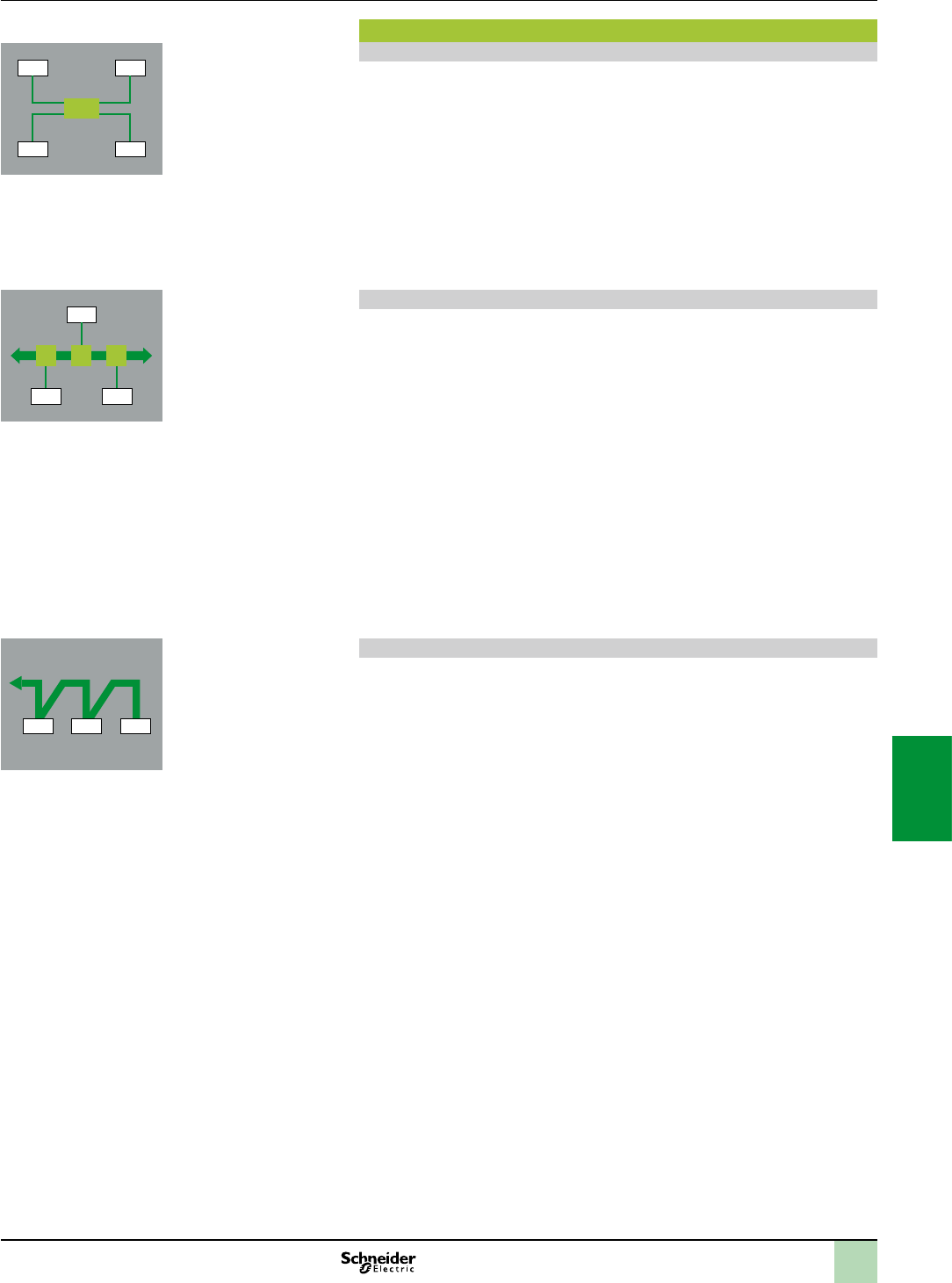
7/7
Topologies Technical information
Ethernet network
Infrastructure
Different network topologies
Star topology
In a star topology, all devices are connected though an intermediate device.
Ethernet Star
In an Ethernet star the intermediate device may be a hub or a switch. Star is the
commonly used topology in corporate networks and as of today is adopted in almost
every automation application. As mentioned previously, for industrial Ethernet
applications the use of full duplex switches as central device rather than hubs is
strongly recommended.
Deploying Star topologies with ConneXium
With any of the hubs and switches offered by the ConneXium offer, star topologies
can be implemented.
Bus topology
The bus is one of the most adopted topologies in traditional industrial automation
networks. A single trunk cable connects all the devices on the network usually via
passive or active T-connectors, or directly chained (daisy chain). Devices usually
can be installed anywhere along the bus.
Ethernet Bus
An Ethernet bus can be deployed by interconnecting hubs and/or switches in line
and considering every one of them as the connection for a drop device. A limited
number of hubs and an unlimited number of switches can be interconnected to
achieve this purpose.
Deploying Bus topologies with ConneXium
With any of the hubs and switches offered by the ConneXium offer bus topologies
can be implemented.
Specially suitable for this purpose are the switches with 1 or 2 ber optic ports:
The 2 ber optic ports switches could be for connection of inline devices.
The single ber optic port switches could be used for the connection of end line
devices.
Daisy chain topology
Daisy chain -along bus- is the other most adopted topology in traditional industrial
automation networks. Cable segments interconnect multiple devices, being the
devices “part ” of the network cable.
Ethernet daisy chain
Daisy chain is not today a very common Ethernet topology, but it will soon become
one of the most popular ones when enough quantity of devices is made available.
In Ethernet daisy chain the devices have:
2 Ethernet ports and
1 embedded switch.
Schneider Electric is releasing to the Industrial market Industrial Ethernet devices to
be connected in daisy chain architectures.
Deploying daisy chain topologies
To deploy daisy chain topologies, no hubs or switches are required. All devices have
an embedded switch.
Dual port Ethernet at the device level is an absolute integral component for
daisy chain topologies.
One port of the device connects to one port of the neighboring device on either side
of the device. These neighboring connections make up the daisy chain.
Ethernet switches can be employed in a daisy chain topology when multiple scan
chains are in use by the controlling device. It is expected that the Ethernet switch will
be located near the controlling device with the different scan chains emanating from
the switch.
DTE
DTEDTE
DTE DTEDTE
DTE DTE
DTE DTE
2
1
3
4
5
6
7
8
9
10
2
1
3
4
5
6
7
8
9
10
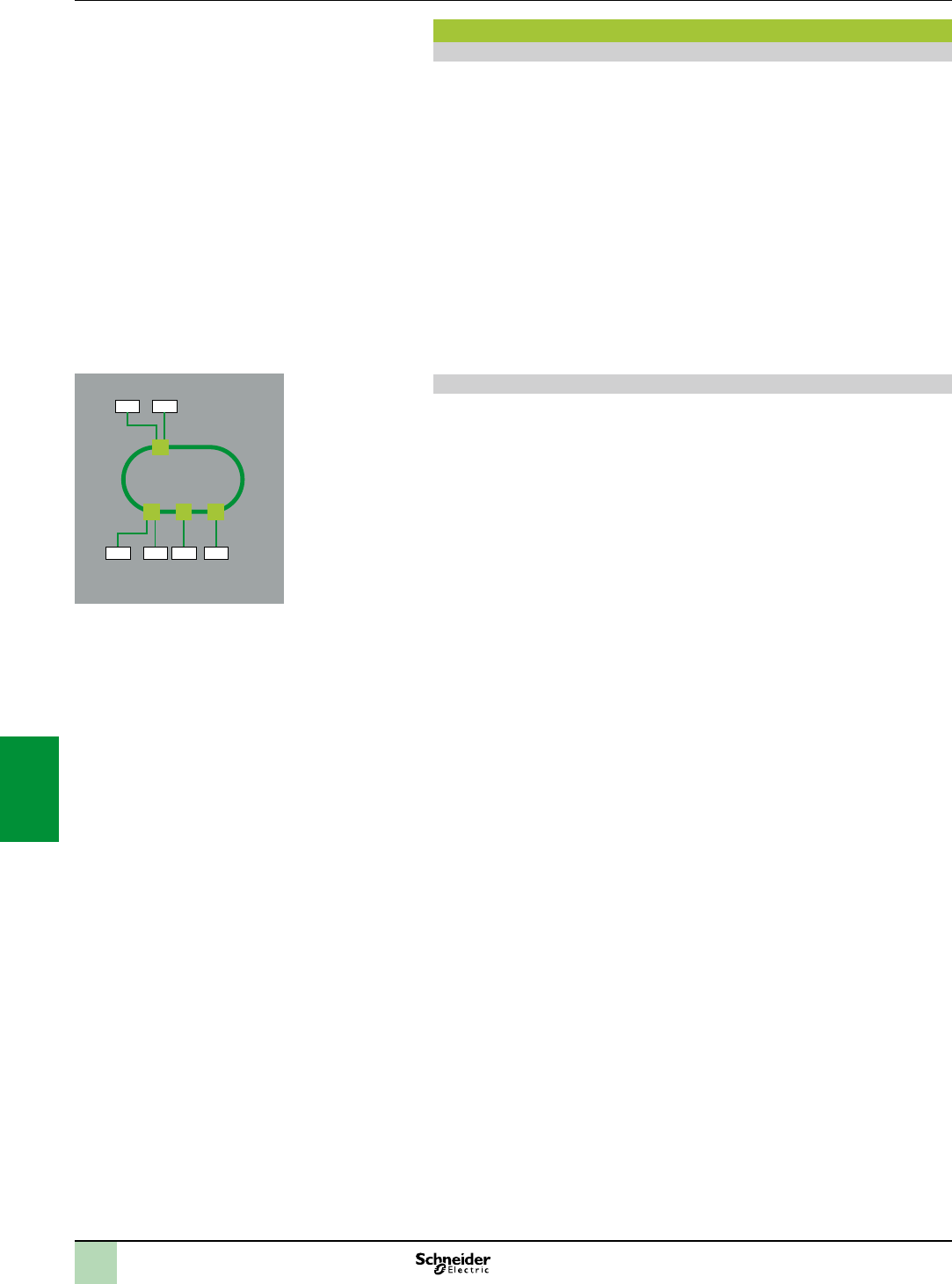
7/8
Topologies(continued) Technical information
Ethernet network
Infrastructure
Different network topologies (continued)
Daisy chain topology (continued)
Limitations of daisy chain:
Limitations of daisy chain to insure the operational integrity of the network and meet
performance metrics, are:
Dual port Ethernet devices only support 10 Mbit/s and/or 100 Mbit/s operational
speeds and must use one or the other.
The network will operate only as fast as the slowest device that is connected to the
network
In order to improve network trafc latency the numbers of devices in a single scan
chain, has been limited to 32 devices. Limiting a single scan chain to 32 devices the
time for a round trip of a packet through the daisy Chain is expected less than 5
milliseconds.
The maximum packet latency of a packet passing through any device in a scan chain
is no more than 10 µs.
Ring topology
In a ring topology, all devices or network infrastructure components are connected in
a loop. Through this type of topology, a type of network redundancy is achieved.
Ethernet Ring
Ethernet rings are usually the backbones of applications in which high availability is
required. If ring topology is required then switches that support this feature should be
ordered.
Deploying Ring topologies using ConneXium.
The ConneXium line offers hubs and switches that allow the deployment of single
and coupled self-healing rings. There is additional information about this topic
page 7/11.
DTEDTE
DTEDTE DTE DTE
2
1
3
4
5
6
7
8
9
10
2
1
3
4
5
6
7
8
9
10

7/9
Characteristics Technical information
Ethernet network
Infrastructure
Distance limitations and number of devices per segment
Based upon the 802.3, the distance limits and the numbers of devices in cascade are the following:
Type Maximum segment
length (1)
Maximum segment
length (offered by
ConneXium devices)
Maximum number of
hubs in cascade
Maximum number of
switches in cascade
10BASE-T 100 m 100 m 4 Unlimited
100BASE-TX 100 m 100 m 2 Unlimited
1000BASE-T 100 m 100 m – Unlimited
10BASE-FL 2000 m 3100 m (2) 11 (ber ring) –
100BASE-FX 412 m/2000 m 4000 m with multimode
ber, 32.500 m with
monomode ber (3)
– Unlimited
1000BASE-SX 275 m – – Unlimited
(1)Basedon802.3,fullduplex/halfduplex.
(2)Dependsontheopticalberbudgetandberattenuation.
(3)Dependsontheopticalberbudgetandberattenuation,typicalspecicationis2kmfor
multimodeand15kmformonomode.
Physical Media
The Ethernet 802.3 denes the Physical Layer. A summary of the most common ones are shown below:
Type Data rate Cable type Connector type
Dened by 802.3 Recommended by
Schneider Electric
Dened
by 802.3
Recommended by
Schneider Electric
10BASE-T 10 Mbit/s CAT 3 - UTP CAT 5E - STP RJ45 RJ45
100BASE-TX 100 Mbit/s CAT 5 - UTP CAT 5E - STP RJ45 RJ45
1000BASE-T 1 Gbit/s CAT 5 - UTP CAT 5E - STP RJ45 RJ45
10BASE-FL 10 Mbit/s Two multimode ber optic
cables typically
62.5/125 µm ber,
850 nm light wavelength
Two multimode ber optic
cables typically
62.5/125 µm ber,
850 nm light wavelength
ST ST
100BASE-FX 100 Mbit/s Two multimode optical
bers typically
62.5/125 µm multimode
ber,
1300 nm light wavelength
Two multimode optical
bers typically
62.5/125 µm multimode
ber,
1300 nm light wavelength
ST SC
– Two monomode optical
bers typically 9/125 µm
multimode ber,
1300 nm light wavelength
– SC
1000BASE-SX 1 Gbit/s Two 62.5/125 or 50/125
multimode optical bers,
770 to 860 nm light
wavelength
Two 62.5/125 µm or
50/125 m multimode
optical bers ,
1300 nm light wavelength
SC LC
1000BASE-LX 1 Gbit/s – Two 9/125 µm monomode
optical bers,
1300 nm light wavelength
– LC
Nota : TheabovearethespecicationsdenedbyIEEE802.3.Howeversomeofthecablesare
nolongerbeingdeveloped.Forinstance,for10BASE-Tand100BASE-TX,aCAT-5Ecableis
used.
2
1
3
4
5
6
7
8
9
10
2
1
3
4
5
6
7
8
9
10

7/10
Management Technical information
Ethernet network
Infrastructure
Management
The Ethernet devices in general (end devices and the cabling devices) devices may
be divided in two categories: unmanaged and managed devices:
The unmanaged devices are those which there is no possibility to congure or
control any of the parameters of the device.
The managed devices are those which there is possibility to congure or control
the parameters of the device (manage them) and to access to its internal information.
The ConneXium product line offers both types of devices.
There is also a third category of devices not specically dened but is important to
understand the difference. These devices only allow access to its information but
can not be controlled and/or congured. Usually these devices are considered in the
category of managed devices.
Managed devices
The managed devices offer the following features:
Trafc optimization and ltering, goal is to increase the bandwidth, or the trafc
capacity in a network (some of the features in this area are message and port priority,
ow control, multicast ltering, broadcast limiting, IGMP snooping, Vlan, etc.).
VLAN, a virtual LAN (VLAN) consists of a group of network participants in one or
more network segments who can communicate with each other as if they belonged
to the same LAN.
VLANs are based on logical (instead of physical) links. The biggest advantage of
VLANs is their possibility of forming user groups based on the participant function
and not on their physical location or medium.
Since broad/multicast data packets are transmitted exclusively within a virtual LAN,
the remaining data network is unaffected. VLAN can also serve as a security
mechanism to block unwanted Unicast messages.
Security, feature that helps the user protect the switch from unauthorized access
that could result in changes in its conguration and impact the trafc going through
the switch (some of the features in this area are port security, read/write community
name, etc.).
User can also set up the switch so that it blocks messages coming from unauthorized
“devices” source addresses connected to the switch.
Time Synchronization, feature that allows all the devices in the network to be
synchronized on time.
Network Redundancy, to develop high availability applications.
…
2
1
3
4
5
6
7
8
9
10
2
1
3
4
5
6
7
8
9
10
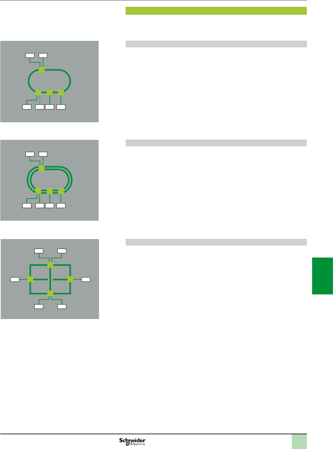
7/11
RedundancyTechnical information
Ethernet network
Infrastructure
Redundancy
To develop high availability applications, “redundancy” in the networking
infrastructure is the answer. By implementing a single ring architecture, or a coupled
ring one, can protect themselves against losses of network segments.
Single Ring
The rst level of redundancy is achieved by implementing a single ring. The
ConneXium switches allow the set up of backbone ring congurations.
The ring is constructed using the HIPER-Ring ports. If a section of the line fails, a ring
structure of up to 50 switches transforms back to a line-type conguration within
0.5 seconds.
Dual Ring
The second level of redundancy is achieved by implementing a dual ring. The control
intelligence built into the ConneXium switches allows the redundant coupling of
HIPER-Rings and network segments.
Mesh topology using the rapid “Spanning Tree” protocol
A third level of redundancy can be achieved by implementing a mesh topology.
In simple terms,“Spaning Tree” is a protocol that ensures a single path for the signal,
when multiple paths exist. If the active path is broken, the “Spanning Tree” protocol
enables one of the alternatives paths.
The ConneXium switches offer the possibility.
DTEDTE
DTEDTE DTE DTE
DTEDTE
DTEDTE DTE DTE
DTE
DTE
DTE DTE
DTE
DTE
2
1
3
4
5
6
7
8
9
10
2
1
3
4
5
6
7
8
9
10
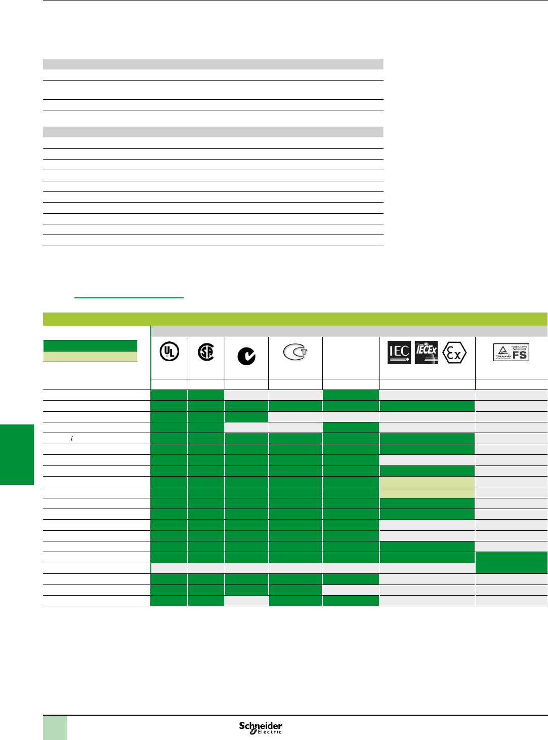
7/12
Some countries require certain electrical components to undergo certication by law. This certication takes the form of a certicate of
conformity to the relevant standards and is issued by the ofcial body in question. Where applicable, certied devices must be labelled
accordingly. Use of electrical equipment on board merchant vessels generally implies that it has gained prior approval (i.e. certication) by
certain shipping classication societies.
Abbreviation Certication body Country
CSA Canadian Standards Association Canada
RCM
(formerly C-Tick)
Australian Communications and Media Authority Australia, New Zealand
GOST Scientic research institute for GOST standards Russia
UL Underwriters Laboratories USA
Abbreviation Classication authority Country
IACS International Association of Classication Societies International
ABS American Bureau of Shipping USA
BV Bureau Veritas France
DNV Det Norske Veritas Norway
GL Germanischer Lloyd Germany
LR Lloyd’s Register UK
RINA Registro Italiano Navale Italy
RMRS Russian Maritime Register of Shipping Russia
RRR Russian River Register Russia
CCS China Classication Society China
The tables below provide an overview of the situation as at 1st June 2013 in terms of which certications (listed next to their respective bodies)
have been granted or are pending for our automation products.
Up-to-date information on which certications have been obtained by products bearing the Schneider Electric brand can be viewed on our
website: www.schneider-electric.com
Product certications
Certications
C-Tick Hazardous
locations (1)
Class I, div 2
Certied
Certicationpending
UL CSA ACMA GOST (6) TÜV Rheinland
USA Canada Australia Russia USA, Canada
Modicon OTB
Modicon STB FM Zone 2 (2)(5)
Modicon Telefast ABE 7
ConneXium (2)
Magelis PC/GTW (3) (2) (3) Zone 2/22 (2)
Magelis XBT GT (3) (2) (2)(3) Zone 2/22 (2)(5)
Magelis XBT GK (3) (3)
Magelis XBT N/R/RT CSA Zone 2/22 (2)(5)
Magelis HMI GTO (3) (2) (3) (2)
Magelis HMI STO/STU (3) (2) (2)(3) (2)
Modicon M340 CSA Zone 2/22 (2)(8)
Modicon X80 I/O CSA Zone 2/22 (2)(8)
Modicon Momentum FM
Modicon Premium (2) CSA
Modicon Quantum (2) CSA, FM (2) Zone 2/22 (2)
Modicon Quantum Safety (2) CSA Zone 2/22 (2) SIL 2, SIL 3 (7)
Preventa XPSMF SIL 3 (7)
Modicon TSX Micro CSA
Phaseo (3)
Twido (4) (4) CSA/UL(4)
(1)Hazardouslocations:AccordingtoANSI/ISA12.12.01,CSA22.2No.213andFM3611,certiedproductsareonlyapprovedforuseinhazardous
locationscategorizedasClassI,division2,groupsA,B,CandD,orinnon-classiedlocations.
(2)Dependsonproduct;pleasevisitourwebsite:www.schneider-electric.com.
(3)NorthAmericancerticationcULus(CanadaandUSA).
(4)ExceptforAS-InterfacemoduleTWDNOI10M3,eonly.
(5)Forzonesnotcoveredbythisspecication,SchneiderElectricoffersasolutionaspartoftheCAPP(CollaborativeAutomationPartnerProgram).Pleaseconsult
ourCustomerCareCentre.
(6)RefertotheinstructionssuppliedwitheachATEXand/orIECExcertiedproduct.
(7)AccordingtoIEC61508.CertiedbyTÜVRheinlandforintegrationintoasafetyfunctionofuptoSIL2orSIL3.
(8)Canbeusedingassyminesundercertainconditions.
Technical appendices
Automation product certications
EC regulations
2
1
3
4
5
6
7
8
9
10
2
1
3
4
5
6
7
8
9
10

7/13
Merchant navy certications
Shipping classication societies
Certied
Certication pending
ABS BV DNV GL KRS LR RINA RMRS RRR PRS CCS
USA France Norway Germany Korea Great Britain Italy Russia Russia Poland China
Modicon OTB
Modicon STB (1)(2) (2) (2) (2) (2) (2)
Modicon Telefast ABE 7
ConneXium
Magelis PC/GTW Bridge(2)
Magelis XBT GT (2) (2) (2) (2) (2) (2) (2) (2)
Magelis XBT GK
Magelis XBT N/R
Magelis XBT RT
Magelis HMI GTO
Magelis HMI STO/STU (2) (2)
Modicon M340 (2) (2)
Modicon X80 I/O (2) (2)
Modicon Momentum
Modicon Premium
Modicon Quantum
Modicon TSX Micro
Phaseo
Twido
(1)AlsocoversUSNavyrequirementsABS-NRV part 4.
(2)Dependsonproduct;pleasevisitourwebsite:www.schneider-electric.com.
EC regulations
European Directives
The open nature of the European markets assumes harmonization between the regulations set by the member states of the European Union.
European Directives are texts whose aim is to remove restrictions on free circulation of goods and which must be applied within all European
Union states.
Member states are obligated to incorporate each Directive into their national legislation, and to simultaneously withdraw any regulations that
contradict it.
Directives - and particularly those of a technical nature with which we are concerned - merely set out the objectives to be fullled (referred to as
“essential requirements”). Manufacturers must take all necessary measures to ensure that their products conform to the requirements of each
Directive applicable to their equipment.
As a general rule, manufacturers certify compliance with the essential requirements of the Directive(s) that apply to their products by applying a
mark. The mark is afxed to our products where applicable.
Signicance of the mark
The mark on a product indicates the manufacturer's certication that the product conforms to the relevant European Directives; this is a
prerequisite for placing a product which is subject to the requirements of one or more Directives on the market and allowing its free circulation
within European Union countries. The mark is intended for use by those responsible for regulating national markets.
Where electrical equipment is concerned, conformity to standards indicates that the product is t for use. Only a warranty by a well-known
manufacturer can provide assurance of a high level of quality.
As far as our products are concerned, one or more Directives are likely to apply in each case; in particular:
The Low Voltage Directive (2006/95/EC)
The Electromagnetic Compatibility Directive (2004/108/EC)
The ATEX Directive (94/9/EC)
Dangerous substances
These products are compatible with:
The WEEE Directive (2002/96/EC)
The RoHS Directive ((2011/65/EU)
The China RoHS Directive (Standard SJ/T 11363-2006)
The REACH regulations Directive (EC 1907/2006)
Note: Documentationonsustainabledevelopmentisavailableonourwebsitewww.schneider-electric.com(productenvironmentalprofilesandinstructionsforuse,
ROHSandREACHdirectives).
End of life (WEEE)
End of life products containing electronic cards must be dealt with by specic treatment processes.
When products containing backup batteries are unusable or at end of life they must be collected and treated separately. Batteries do not contain
a percentage by weight of heavy metals above the limit specied by European Directive 2006/66/EC.
Technical appendices
Automation product certications
EC regulations
2
1
3
4
5
6
7
8
9
10
2
1
3
4
5
6
7
8
9
10
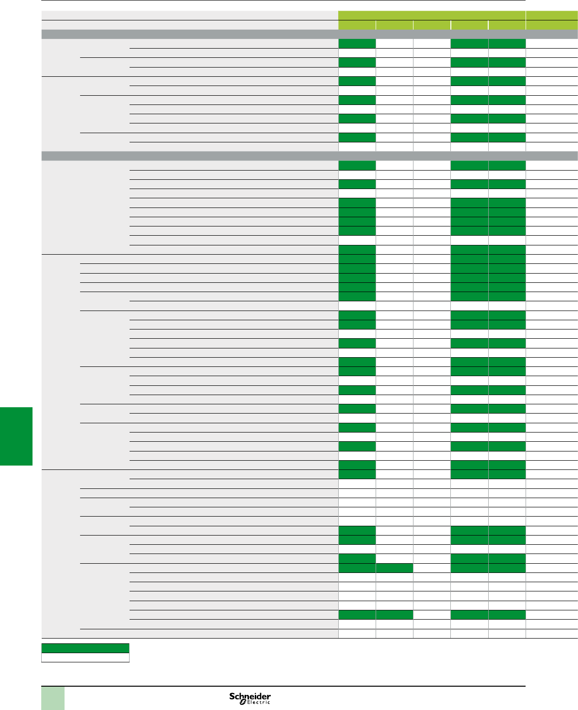
7/14
Photo-electric sensors c Inputs, BMXDDI c Inputs, BMXDDM c Inputs, BMXAMI a Inputs, BMXDAI
Type Reference 1602 1603 1604T 3202K 6402K 16022 16025 3202K 0810 0800 1602 1603 1604 0805
General purpose
Design
Ø 18
Metal 3 wire, PNP 24V XUB0/1/2/4/5/9BP
3 wire, NPN 24V XUB0/1/2/4/5/9BN
Plastic 3 wire, PNP 24V XUB0/1/2/4/5/9AP
3 wire, NPN 24V XUB0/1/2/4/5/9AN
Design Miniature 3 wire, PNP 24V XUM0/2/5/9AP
3 wire, NPN 24V XUM0/2/5/9AN
Compact 50x50 3 wire, PNP 24V XUK1/2/5/8/9AP
3 wire, NPN 24V XUK1/2/5/8/9AN
3 wire, programmable PNP/NPN DC XUK0AK
5 wire, programmable AC/DC XUK0/1/2/5/8/9AR
Compact 92x71 3 wire, programmable PNP/NPN DC XUX0/1/2/5/8/9AK
5 wire, programmable AC DC XUX0/1/2/5/8/9AR
Application
Material
handling
Optical fork 3 wire, PNP 24V XUVRP
3 wire, NPN 24V XUVRN
3 wire, PNP 24V XUVAP
3 wire, NPN 24V XUVAN
4 wire, PNP or NPN 24V XUYF
4 wire, PNP or NPN 24V XUVU06
4 wire, PNP or NPN 24V XUVK
3 wire, PNP 24V XUVH
3 wire, NPN 24V XUVJ
4 wire, PNP or NPN 24V XUVF
Packaging Fiber 4 wire, PNP or NPN 24V XUYDCF
Compact 4 wire, PNP or NPN 24V XUKS
M 18, threaded 3 wire, PNP 24V XU5M18U1D
Fiber 4 wire, PNP or NPN 24V XUYAFL
M 18, threaded 3 wire, PNP 24V XUBTP
3 wire, NPN 24V XUBTN
Compact 4 wire, PNP or NPN 24V XUKT
3 wire, PNP 24V XUKC1N
3 wire, NPN 24V XUKC1P
3 wire, PNP 24V XURC3P
3 wire, NPN 24V XURC3N
4 wire, PNP or NPN 24V XUMW
M 18, threaded 3 wire, PNP 24V XUB0SP
3 wire, NPN 24V XUB0SN
3 wire, PNP 24V XUN18P
3 wire, NPN 24V XUN18N
M 8, threaded 3 wire, PNP 24V XUAH
3 wire, NPN 24V XUAJ
Miniature 3 wire, PNP 24V XUYPP
3 wire, NPN 24V XUYPN
3 wire, PNP 24V XUM2/5/9BP
3 wire, NPN 24V XUM2/5/9BN
3 wire, PNP 24V XUY929
Hoisting M 18, threaded 3 wire, PNP 24V XUBLBP
3 wire, NPN 24V XUBLBN
Compact 2 wire 4…20 mA ; 3 wire 0…10V XUJK803538
M 18, threaded 2 wire 4…20 mA XU5M18AB20D
PNP, 2 wire 4…20 mA XU2M18AB20D
Compact PNP, 2 wire 4…20 mA XUYP925
4 wire, PNP or NPN 24V XUYPS
Fiber 3 wire, PNP 24V XUDAP
3 wire, NPN 24V XUDAN
4 wire, PNP or NPN 24V XUYAF
Other formats 3 wire, programmable PNP/NPN DC XUC2/8/9AK
5 wire, programmable AC/DC XUC2/8/9ARC
3 wire, NPN 24V + analog XUEAA
2 wire, AC XULA
5 wire, programmable AC/DC XULM
3 wire, programmable PNP/NPN DC XUYBS
5 wire, programmable AC/DC XUYBR
M 18, threaded 2 wire, AC/DC XU5/8/9M18MA
Compatible
Non compatible
Compatibility Modicon M340 automation
platform
Inputs and OsiSense XU photo-electric sensors
2
1
3
4
5
6
7
8
9
10
2
1
3
4
5
6
7
8
9
10
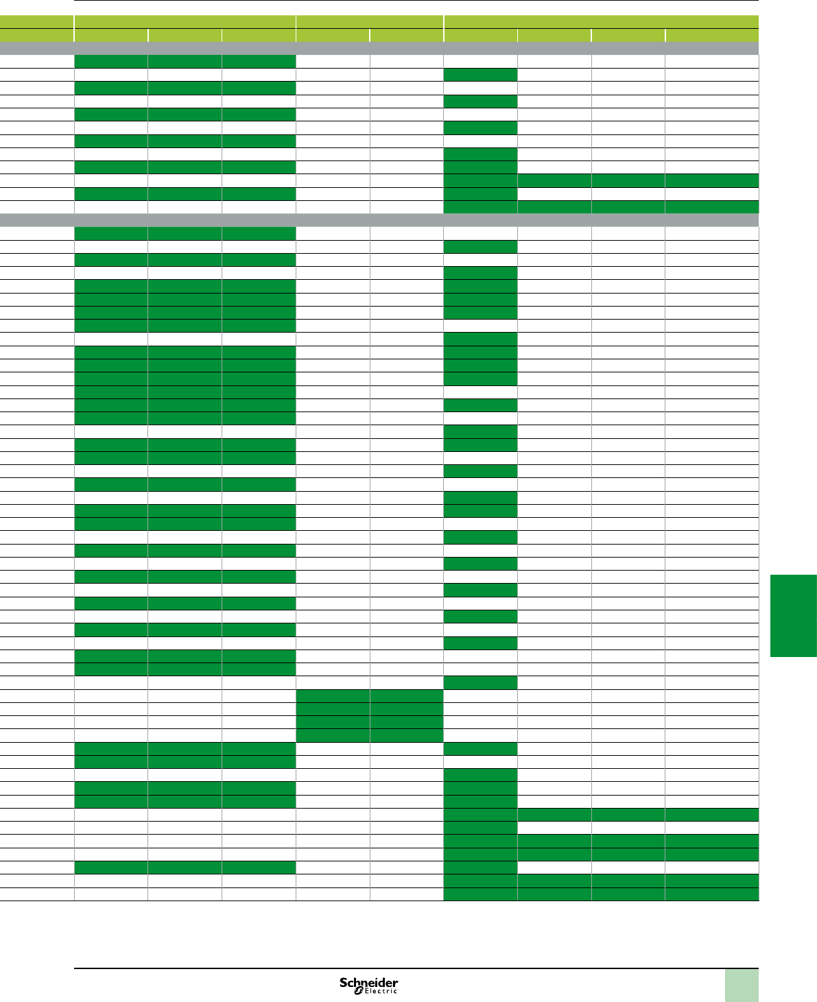
7/15
Photo-electric sensors c Inputs, BMXDDI c Inputs, BMXDDM c Inputs, BMXAMI a Inputs, BMXDAI
Type Reference 1602 1603 1604T 3202K 6402K 16022 16025 3202K 0810 0800 1602 1603 1604 0805
General purpose
Design
Ø 18
Metal 3 wire, PNP 24V XUB0/1/2/4/5/9BP
3 wire, NPN 24V XUB0/1/2/4/5/9BN
Plastic 3 wire, PNP 24V XUB0/1/2/4/5/9AP
3 wire, NPN 24V XUB0/1/2/4/5/9AN
Design Miniature 3 wire, PNP 24V XUM0/2/5/9AP
3 wire, NPN 24V XUM0/2/5/9AN
Compact 50x50 3 wire, PNP 24V XUK1/2/5/8/9AP
3 wire, NPN 24V XUK1/2/5/8/9AN
3 wire, programmable PNP/NPN DC XUK0AK
5 wire, programmable AC/DC XUK0/1/2/5/8/9AR
Compact 92x71 3 wire, programmable PNP/NPN DC XUX0/1/2/5/8/9AK
5 wire, programmable AC DC XUX0/1/2/5/8/9AR
Application
Material
handling
Optical fork 3 wire, PNP 24V XUVRP
3 wire, NPN 24V XUVRN
3 wire, PNP 24V XUVAP
3 wire, NPN 24V XUVAN
4 wire, PNP or NPN 24V XUYF
4 wire, PNP or NPN 24V XUVU06
4 wire, PNP or NPN 24V XUVK
3 wire, PNP 24V XUVH
3 wire, NPN 24V XUVJ
4 wire, PNP or NPN 24V XUVF
Packaging Fiber 4 wire, PNP or NPN 24V XUYDCF
Compact 4 wire, PNP or NPN 24V XUKS
M 18, threaded 3 wire, PNP 24V XU5M18U1D
Fiber 4 wire, PNP or NPN 24V XUYAFL
M 18, threaded 3 wire, PNP 24V XUBTP
3 wire, NPN 24V XUBTN
Compact 4 wire, PNP or NPN 24V XUKT
3 wire, PNP 24V XUKC1N
3 wire, NPN 24V XUKC1P
3 wire, PNP 24V XURC3P
3 wire, NPN 24V XURC3N
4 wire, PNP or NPN 24V XUMW
M 18, threaded 3 wire, PNP 24V XUB0SP
3 wire, NPN 24V XUB0SN
3 wire, PNP 24V XUN18P
3 wire, NPN 24V XUN18N
M 8, threaded 3 wire, PNP 24V XUAH
3 wire, NPN 24V XUAJ
Miniature 3 wire, PNP 24V XUYPP
3 wire, NPN 24V XUYPN
3 wire, PNP 24V XUM2/5/9BP
3 wire, NPN 24V XUM2/5/9BN
3 wire, PNP 24V XUY929
Hoisting M 18, threaded 3 wire, PNP 24V XUBLBP
3 wire, NPN 24V XUBLBN
Compact 2 wire 4…20 mA ; 3 wire 0…10V XUJK803538
M 18, threaded 2 wire 4…20 mA XU5M18AB20D
PNP, 2 wire 4…20 mA XU2M18AB20D
Compact PNP, 2 wire 4…20 mA XUYP925
4 wire, PNP or NPN 24V XUYPS
Fiber 3 wire, PNP 24V XUDAP
3 wire, NPN 24V XUDAN
4 wire, PNP or NPN 24V XUYAF
Other formats 3 wire, programmable PNP/NPN DC XUC2/8/9AK
5 wire, programmable AC/DC XUC2/8/9ARC
3 wire, NPN 24V + analog XUEAA
2 wire, AC XULA
5 wire, programmable AC/DC XULM
3 wire, programmable PNP/NPN DC XUYBS
5 wire, programmable AC/DC XUYBR
M 18, threaded 2 wire, AC/DC XU5/8/9M18MA
Compatible
Non compatible
2
1
3
4
5
6
7
8
9
10
2
1
3
4
5
6
7
8
9
10
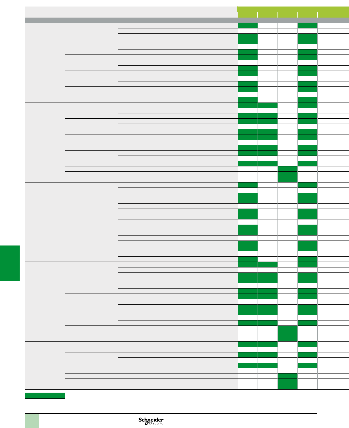
7/16
Compatibility Modicon M340 automation
platform
Inputs and OsiSense XS inductive proximity
sensors
Proximity sensors c Inputs, BMXDDI c Inputs, BMXDDM c Inputs, BMXAMI a Inputs, BMXDAI
Type Reference 1602 1603 1604T 3202K 6402K 16022 16025 3202K 0810 0800 1602 1603 1604 0805
General purpose
Cylindrical,
ush,
sensing distance
standard,
barel short
Ø 6,5 plain short 3 wire, PNP 24V XS506B1P
3 wire, NPN 24V XS506B1N
2 wire, DC 24V XS506BSC
M8, threaded short 3 wire, PNP 24V XS508B1P
3 wire, NPN 24V XS508B1N
2 wire, DC 24V XS508BSC
M12, threaded short 3 wire, PNP 24V XS512B1P
3 wire, NPN 24V XS512B1N
2 wire, DC 24V XS512BSD/C
M18, threaded short 3 wire, PNP 24V XS518B1P
3 wire, NPN 24V XS518B1N
2 wire, DC 24V XS518BSD/C
M30, threaded short 3 wire, PNP 24V XS530B1P
3 wire, NPN 24V XS530B1N
2 wire, DC 24V XS530BSD/C
Cylindrical,
ush, sensing
distance standard,
barel long
M8, threaded long 3 wire, PNP 24V-48V XS508BLP
3 wire, NPN 24V-48V XS508BLN
2 wire, DC 24V-48V XS508B1D/C
M12, threaded long 3 wire, PNP 24V-48V XS512BLP
3 wire, NPN 24V-48V XS512BLN
2 wire, DC 24V-48V XS512B1D/C
M18, threaded long 3 wire, PNP 24V-48V XS518BLP
3 wire, NPN 24V-48V XS518BLN
2 wire, DC 24V-48V XS518B1D/C
M30, threaded long 3 wire, PNP 24V-48V XS530BLP
3 wire, NPN 24V-48V XS530BLN
2 wire, DC 24V-48V XS530B1D/C
M12, threaded long 2 wire, AC/DC XS512B1M
M18, threaded long 2 wire, AC/DC XS518B1M
M30, threaded long 2 wire, AC/DC XS530B1M
Cylindrical,
ush, sensing
distance extending,
barel short
Ø 6,5 plain short 3 wire, PNP 24V XS106B3P
3 wire, NPN 24V XS106B3N
2 wire, DC 24V XS606B3C
M8, threaded short 3 wire, PNP 24V XS108B3P
3 wire, NPN 24V XS108B3N
2 wire, DC 24V XS608B3C
M12, threaded short 3 wire, PNP 24V XS112B3P
3 wire, NPN 24V XS112B3N
2 wire, DC 24V XS612B3D
M18, threaded short 3 wire, PNP 24V XS118B3P
3 wire, NPN 24V XS118B3N
2 wire, DC 24V XS618B3D
M30, threaded short 3 wire, PNP 24V XS130B3P
3 wire, NPN 24V XS130B3N
2 wire, DC 24V XS630B3D
Cylindrical,
ush, sensing
distance extending,
barel long
M8, threaded long 3 wire, PNP 24V-48V XS608B1P
3 wire, NPN 24V-48V XS608B1N
2 wire, DC 24V-48V XS608B1D
M12, threaded long 3 wire, PNP 24V-48V XS612B1P
3 wire, NPN 24V-48V XS612B1N
2 wire, DC 24V-48V XS612B1D
M18, threaded long 3 wire, PNP 24V-48V XS618B1P
3 wire, NPN 24V-48V XS618B1N
2 wire, DC 24V-48V XS618B1D
M30, threaded long 3 wire, PNP 24V-48V XS630B1P
3 wire, NPN 24V-48V XS630B1N
2 wire, DC 24V-48V XS630B1D
M12, threaded long 2 wire, AC/DC XS612B1M
M18, threaded long 2 wire, AC/DC XS618B1M
M30, threaded long 2 wire, AC/DC XS630B1M
Cylindrical,
non ush, sensing
distance extending,
barel long
M12, threaded long 3 wire, PNP 24V-48V XS612B4P
3 wire, NPN 24V-48V XS612B4N
M18, threaded long 3 wire, PNP 24V-48V XS618B4P
3 wire, NPN 24V-48V XS618B4N
M30, threaded long 3 wire, PNP 24V-48V XS630B4P
3 wire, NPN 24V-48V XS630B4N
M12, threaded long 2 wire, AC/DC XS612B4M
M18, threaded long 2 wire, AC/DC XS618B4M
M30, threaded long 2 wire, AC/DC XS630B4M
Compatible
Non compatible
2
1
3
4
5
6
7
8
9
10
2
1
3
4
5
6
7
8
9
10

7/17
Proximity sensors c Inputs, BMXDDI c Inputs, BMXDDM c Inputs, BMXAMI a Inputs, BMXDAI
Type Reference 1602 1603 1604T 3202K 6402K 16022 16025 3202K 0810 0800 1602 1603 1604 0805
General purpose
Cylindrical,
ush,
sensing distance
standard,
barel short
Ø 6,5 plain short 3 wire, PNP 24V XS506B1P
3 wire, NPN 24V XS506B1N
2 wire, DC 24V XS506BSC
M8, threaded short 3 wire, PNP 24V XS508B1P
3 wire, NPN 24V XS508B1N
2 wire, DC 24V XS508BSC
M12, threaded short 3 wire, PNP 24V XS512B1P
3 wire, NPN 24V XS512B1N
2 wire, DC 24V XS512BSD/C
M18, threaded short 3 wire, PNP 24V XS518B1P
3 wire, NPN 24V XS518B1N
2 wire, DC 24V XS518BSD/C
M30, threaded short 3 wire, PNP 24V XS530B1P
3 wire, NPN 24V XS530B1N
2 wire, DC 24V XS530BSD/C
Cylindrical,
ush, sensing
distance standard,
barel long
M8, threaded long 3 wire, PNP 24V-48V XS508BLP
3 wire, NPN 24V-48V XS508BLN
2 wire, DC 24V-48V XS508B1D/C
M12, threaded long 3 wire, PNP 24V-48V XS512BLP
3 wire, NPN 24V-48V XS512BLN
2 wire, DC 24V-48V XS512B1D/C
M18, threaded long 3 wire, PNP 24V-48V XS518BLP
3 wire, NPN 24V-48V XS518BLN
2 wire, DC 24V-48V XS518B1D/C
M30, threaded long 3 wire, PNP 24V-48V XS530BLP
3 wire, NPN 24V-48V XS530BLN
2 wire, DC 24V-48V XS530B1D/C
M12, threaded long 2 wire, AC/DC XS512B1M
M18, threaded long 2 wire, AC/DC XS518B1M
M30, threaded long 2 wire, AC/DC XS530B1M
Cylindrical,
ush, sensing
distance extending,
barel short
Ø 6,5 plain short 3 wire, PNP 24V XS106B3P
3 wire, NPN 24V XS106B3N
2 wire, DC 24V XS606B3C
M8, threaded short 3 wire, PNP 24V XS108B3P
3 wire, NPN 24V XS108B3N
2 wire, DC 24V XS608B3C
M12, threaded short 3 wire, PNP 24V XS112B3P
3 wire, NPN 24V XS112B3N
2 wire, DC 24V XS612B3D
M18, threaded short 3 wire, PNP 24V XS118B3P
3 wire, NPN 24V XS118B3N
2 wire, DC 24V XS618B3D
M30, threaded short 3 wire, PNP 24V XS130B3P
3 wire, NPN 24V XS130B3N
2 wire, DC 24V XS630B3D
Cylindrical,
ush, sensing
distance extending,
barel long
M8, threaded long 3 wire, PNP 24V-48V XS608B1P
3 wire, NPN 24V-48V XS608B1N
2 wire, DC 24V-48V XS608B1D
M12, threaded long 3 wire, PNP 24V-48V XS612B1P
3 wire, NPN 24V-48V XS612B1N
2 wire, DC 24V-48V XS612B1D
M18, threaded long 3 wire, PNP 24V-48V XS618B1P
3 wire, NPN 24V-48V XS618B1N
2 wire, DC 24V-48V XS618B1D
M30, threaded long 3 wire, PNP 24V-48V XS630B1P
3 wire, NPN 24V-48V XS630B1N
2 wire, DC 24V-48V XS630B1D
M12, threaded long 2 wire, AC/DC XS612B1M
M18, threaded long 2 wire, AC/DC XS618B1M
M30, threaded long 2 wire, AC/DC XS630B1M
Cylindrical,
non ush, sensing
distance extending,
barel long
M12, threaded long 3 wire, PNP 24V-48V XS612B4P
3 wire, NPN 24V-48V XS612B4N
M18, threaded long 3 wire, PNP 24V-48V XS618B4P
3 wire, NPN 24V-48V XS618B4N
M30, threaded long 3 wire, PNP 24V-48V XS630B4P
3 wire, NPN 24V-48V XS630B4N
M12, threaded long 2 wire, AC/DC XS612B4M
M18, threaded long 2 wire, AC/DC XS618B4M
M30, threaded long 2 wire, AC/DC XS630B4M
Compatible
Non compatible
2
1
3
4
5
6
7
8
9
10
2
1
3
4
5
6
7
8
9
10
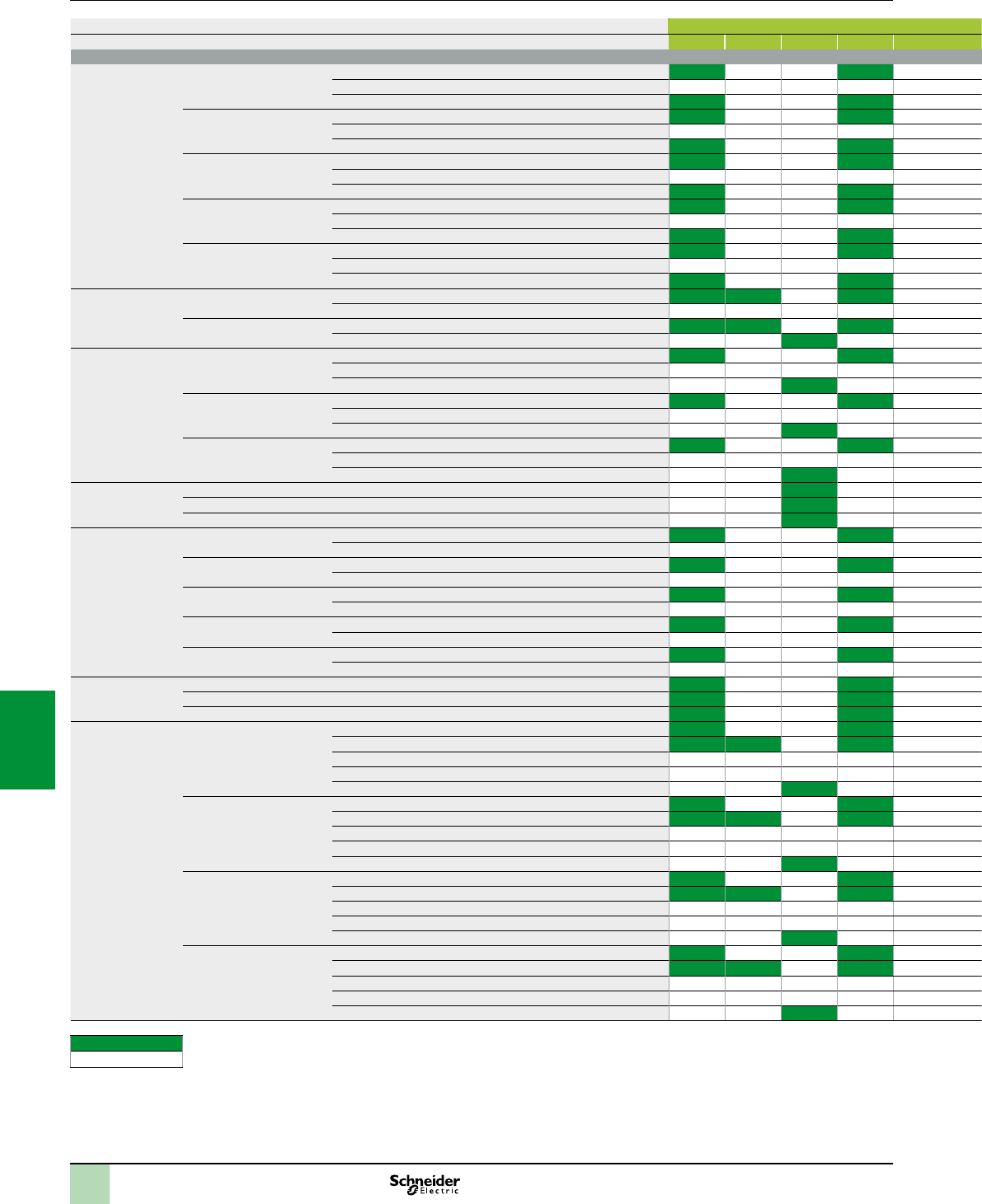
7/18
Compatibility Modicon M340 automation
platform
Inputs and OsiSense XS inductive proximity
sensors (continued)
Proximity sensors c Inputs, BMXDDI c Inputs, BMXDDM c Inputs, BMXAMI a Inputs, BMXDAI
Type Reference 1602 1603 1604T 3202K 6402K 16022 16025 3202K 0810 0800 1602 1603 1604 0805
General purpose
Flat, ush montable,
sensing distance
standard
Format J 8x22x8 3 wire, PNP 24V XS7J1A1P
3 wire, NPN 24V XS7J1A1N
2 wire, DC 24V XS7J1A1D
Format F 15x22x8 3 wire, PNP 24V XS7F1A1P
3 wire, NPN 24V XS7F1A1N
2 wire, DC 24V XS7F1A1D
Format E 26x26x13 3 wire, PNP 24V XS7E1A1P
3 wire, NPN 24V XS7E1A1N
2 wire, DC 24V XS7E1A1D/C
Format C 40x40x15 3 wire, PNP 24V XS7C1A1P
3 wire, NPN 24V XS7C1A1N
2 wire, DC 24V XS7C1A1D/C
Format D 80x80x26 3 wire, PNP 24V XS7D1A1P
3 wire, NPN 24V XS7D1A1N
2 wire, DC 24V XS7D1A1D/C
Format 40X40X70
and 40X40X117
Plastic, with turret
head: 5 positions
NO + NC 4 wire, PNP 24V-48V XS7/XS8C2/C4A1/A4P
4 wire, NPN 24V-48V XS7/XS8C2/C4A1/A4N
NO/NC programmable 2 wire, DC 24V-48V XS7/XS8C2/C4A1/A4D
2 wire, AC/DC XS7/XS8C2/C4A1/A4M
Flat, ush montable,
sensing distance
extending
Format E 26x26x13 3 wire, PNP 24V XS8E1A1P
3 wire, NPN 24V XS8E1A1N
2 wire, AC/DC XS8E1A1M
Format C 40x40x15 3 wire, PNP 24V XS8C1A1P
3 wire, NPN 24V XS8C1A1N
2 wire, AC/DC XS8C1A1M
Format D 80x80x26 3 wire, PNP 24V XS8D1A1P
3 wire, NPN 24V XS8D1A1N
2 wire, AC/DC XS8D1A1M
Cylindrical multi
tension
M12, threaded 2 wire, AC/DC XS1/2M12M250
M18, threaded 2 wire, AC/DC XS1/2M18M250
M30, threaded 2 wire, AC/DC XS1/2M30M250
Cylindrical Metal,
4 wire
Ø 6,5, plain 4 wire, PNP 24V XS1L06PC410
4 wire, NPN 24V XS1L06NC410
M8, threaded 4 wire, PNP 24V XS1/2M08PC410
4 wire, NPN 24V XS1/2M08NC410
M12, threaded 4 wire, PNP 24V XS1/2N12PC410
4 wire, NPN 24V XS1/2N12NC410
M18, threaded 4 wire, PNP 24V XS1/2N18PC410
4 wire, NPN 24V XS1/2N18NC410
M30, threaded 4 wire, PNP 24V XS1/2N30PC410
4 wire, NPN 24V XS1/2N30NC410
Cylindrical Metal,
4 wire PNP + NPN
M12, threaded 4 wire, PNP+NPN, prog. 24V XS1/2/4M12KP340
M18, threaded 4 wire, PNP+NPN, prog. 24V XS1/2/4M18KP340
M30, threaded 4 wire, PNP+NPN, prog. 24V XS1/2/4M30KP340
Cylindrical Plastic,
non ush,
sensing distance
standard
M8, threaded 3 wire, PNP 24V XS4P08P340
3 wire, PNP 24V-48V XS4P08P370
3 wire, NPN 24V XS4P08N340
3 wire, NPN 24V-48V XS4P08N370
2 wire, AC/DC XS4P08M230
M12, threaded 3 wire, PNP 24V XS4P12P340
3 wire, PNP 24V-48V XS4P12P370
3 wire, NPN 24V XS4P12N340
3 wire, NPN 24V-48V XS4P12N370
2 wire, AC/DC XS4P12M230
M18, threaded 3 wire, PNP 24V XS4P18P340
3 wire, PNP 24V-48V XS4P18P370
3 wire, NPN 24V XS4P18N340
3 wire, NPN 24V-48V XS4P18N370
2 wire, AC/DC XS4P18M230
M30, threaded 3 wire, PNP 24V XS4P30P340
3 wire, PNP 24V-48V XS4P30P370
3 wire, NPN 24V XS4P30N340
3 wire, NPN 24V-48V XS4P30N370
2 wire, AC/DC XS4P30M230
Compatible
Non compatible
2
1
3
4
5
6
7
8
9
10
2
1
3
4
5
6
7
8
9
10
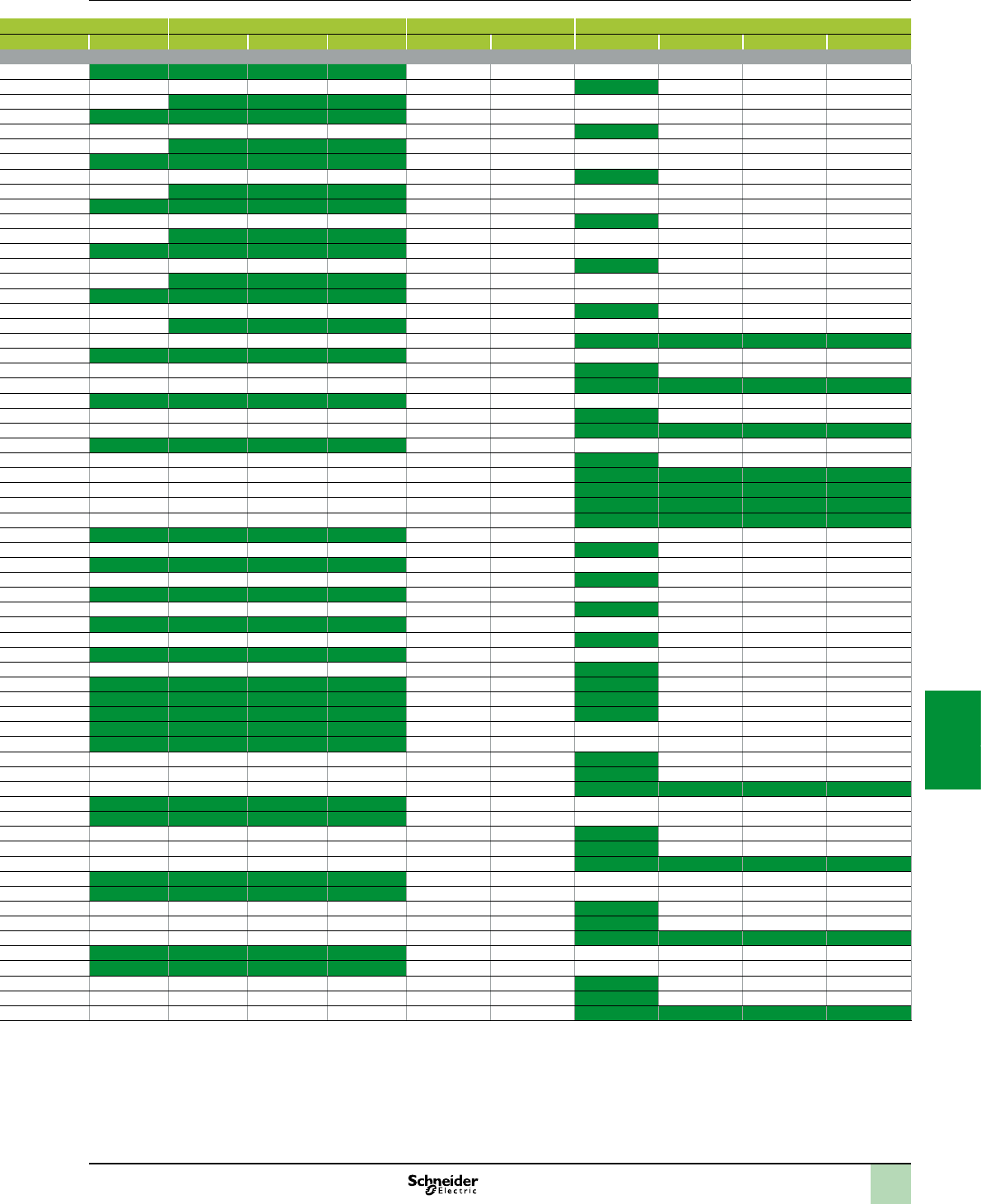
7/19
Proximity sensors c Inputs, BMXDDI c Inputs, BMXDDM c Inputs, BMXAMI a Inputs, BMXDAI
Type Reference 1602 1603 1604T 3202K 6402K 16022 16025 3202K 0810 0800 1602 1603 1604 0805
General purpose
Flat, ush montable,
sensing distance
standard
Format J 8x22x8 3 wire, PNP 24V XS7J1A1P
3 wire, NPN 24V XS7J1A1N
2 wire, DC 24V XS7J1A1D
Format F 15x22x8 3 wire, PNP 24V XS7F1A1P
3 wire, NPN 24V XS7F1A1N
2 wire, DC 24V XS7F1A1D
Format E 26x26x13 3 wire, PNP 24V XS7E1A1P
3 wire, NPN 24V XS7E1A1N
2 wire, DC 24V XS7E1A1D/C
Format C 40x40x15 3 wire, PNP 24V XS7C1A1P
3 wire, NPN 24V XS7C1A1N
2 wire, DC 24V XS7C1A1D/C
Format D 80x80x26 3 wire, PNP 24V XS7D1A1P
3 wire, NPN 24V XS7D1A1N
2 wire, DC 24V XS7D1A1D/C
Format 40X40X70
and 40X40X117
Plastic, with turret
head: 5 positions
NO + NC 4 wire, PNP 24V-48V XS7/XS8C2/C4A1/A4P
4 wire, NPN 24V-48V XS7/XS8C2/C4A1/A4N
NO/NC programmable 2 wire, DC 24V-48V XS7/XS8C2/C4A1/A4D
2 wire, AC/DC XS7/XS8C2/C4A1/A4M
Flat, ush montable,
sensing distance
extending
Format E 26x26x13 3 wire, PNP 24V XS8E1A1P
3 wire, NPN 24V XS8E1A1N
2 wire, AC/DC XS8E1A1M
Format C 40x40x15 3 wire, PNP 24V XS8C1A1P
3 wire, NPN 24V XS8C1A1N
2 wire, AC/DC XS8C1A1M
Format D 80x80x26 3 wire, PNP 24V XS8D1A1P
3 wire, NPN 24V XS8D1A1N
2 wire, AC/DC XS8D1A1M
Cylindrical multi
tension
M12, threaded 2 wire, AC/DC XS1/2M12M250
M18, threaded 2 wire, AC/DC XS1/2M18M250
M30, threaded 2 wire, AC/DC XS1/2M30M250
Cylindrical Metal,
4 wire
Ø 6,5, plain 4 wire, PNP 24V XS1L06PC410
4 wire, NPN 24V XS1L06NC410
M8, threaded 4 wire, PNP 24V XS1/2M08PC410
4 wire, NPN 24V XS1/2M08NC410
M12, threaded 4 wire, PNP 24V XS1/2N12PC410
4 wire, NPN 24V XS1/2N12NC410
M18, threaded 4 wire, PNP 24V XS1/2N18PC410
4 wire, NPN 24V XS1/2N18NC410
M30, threaded 4 wire, PNP 24V XS1/2N30PC410
4 wire, NPN 24V XS1/2N30NC410
Cylindrical Metal,
4 wire PNP + NPN
M12, threaded 4 wire, PNP+NPN, prog. 24V XS1/2/4M12KP340
M18, threaded 4 wire, PNP+NPN, prog. 24V XS1/2/4M18KP340
M30, threaded 4 wire, PNP+NPN, prog. 24V XS1/2/4M30KP340
Cylindrical Plastic,
non ush,
sensing distance
standard
M8, threaded 3 wire, PNP 24V XS4P08P340
3 wire, PNP 24V-48V XS4P08P370
3 wire, NPN 24V XS4P08N340
3 wire, NPN 24V-48V XS4P08N370
2 wire, AC/DC XS4P08M230
M12, threaded 3 wire, PNP 24V XS4P12P340
3 wire, PNP 24V-48V XS4P12P370
3 wire, NPN 24V XS4P12N340
3 wire, NPN 24V-48V XS4P12N370
2 wire, AC/DC XS4P12M230
M18, threaded 3 wire, PNP 24V XS4P18P340
3 wire, PNP 24V-48V XS4P18P370
3 wire, NPN 24V XS4P18N340
3 wire, NPN 24V-48V XS4P18N370
2 wire, AC/DC XS4P18M230
M30, threaded 3 wire, PNP 24V XS4P30P340
3 wire, PNP 24V-48V XS4P30P370
3 wire, NPN 24V XS4P30N340
3 wire, NPN 24V-48V XS4P30N370
2 wire, AC/DC XS4P30M230
Compatible
Non compatible
2
1
3
4
5
6
7
8
9
10
2
1
3
4
5
6
7
8
9
10
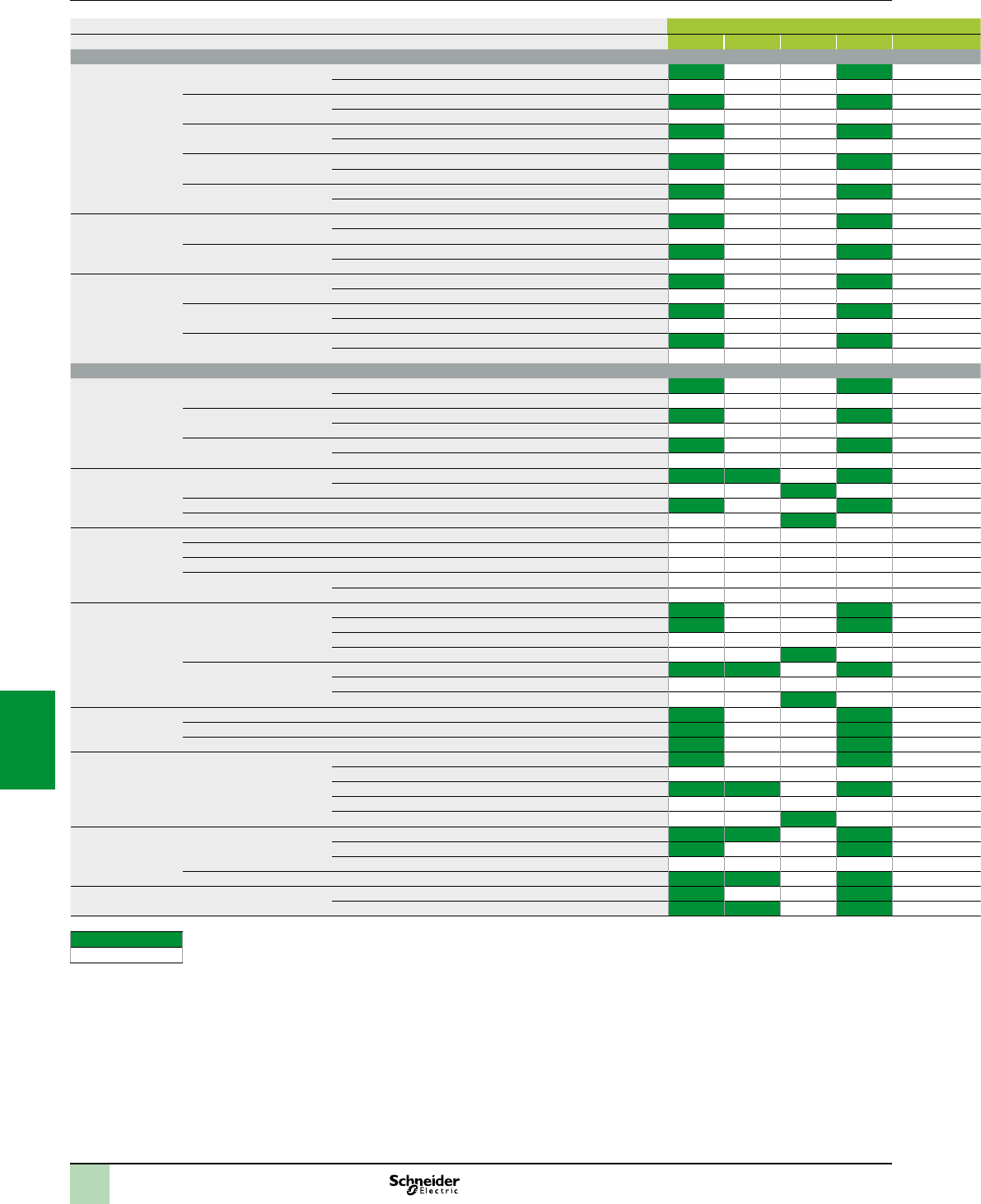
7/20
Compatibility Modicon M340 automation
platform
Inputs and OsiSense XS inductive proximity
sensors (continued)
Proximity sensors c Inputs, BMXDDI c Inputs, BMXDDM c Inputs, BMXAMI a Inputs, BMXDAI
Type Reference 1602 1603 1604T 3202K 6402K 16022 16025 3202K 0810 0800 1602 1603 1604 0805
General purpose
Cylindrical basic
ush or non ush,
sensing distance
standard,
Plastic or Metal
Ø 6,5 plain 3 wire, PNP 24V XS1/206BLP
3 wire, NPN 24V XS1/206BLN
M8, threaded 3 wire, PNP 24V XS1/208A/BLP
3 wire, NPN 24V XS1/208A/BLN
M12, threaded 3 wire, PNP 24V XS1/212A/BLP
3 wire, NPN 24V XS1/212A/BLN
M18, threaded 3 wire, PNP 24V XS1/218A/BLP
3 wire, NPN 24V XS1/218A/BLN
M30, threaded 3 wire, PNP 24V XS1/230A/BLP
3 wire, NPN 24V XS1/230A/BLN
Cylindrical,
almost ush, sensing
distance extending
M18, threaded 3 wire, PNP 24V XS1N18P349
3 wire, NPN 24V XS1N18N349
M30, threaded 3 wire, PNP 24V XS1N30P349
3 wire, NPN 24V XS1N30N349
Cylindrical,
miniature
Ø 4 plain 3 wire, PNP 24V XS1L04P31
3 wire, NPN 24V XS1L04N31
M5, threaded 3 wire, PNP 24V XS1N05P31
3 wire, NPN 24V XS1N05N31
Ø 6,5 plain 3 wire, PNP 24V XS2L06P340
3 wire, NPN 24V XS2L06N340
Application
Cylindrical,
adjustable sensing
distance,
M12, threaded 3 wire, PNP 24V XS612B2P
3 wire, NPN 24V XS612B2N
M18, threaded 3 wire, PNP 24V XS618B2P
3 wire, NPN 24V XS618B2N
M30, threaded 3 wire, PNP 24V XS630B2P
3 wire, NPN 24V XS630B2N
Rotation monitoring M18, threaded 3 wire, PNP 24V-48V XSAV11/2373
2 wire, AC/DC XSAV11/2801
Format E 26x26x13 3 wire, PNP 24V XS911RP
Format C 40x40x15 2 wire, AC/DC XS911RM
Analog output M12, threaded 2 wire 4…20mA; 3 wire 0…10V XS12AB
M18, threaded 2 wire 4…20mA; 3 wire 0…10V XS18AB
M30, threaded 2 wire 4…20mA; 3 wire 0…10V XS30AB
Block format 2 wire 4…20mA; 3 wire 0…10V XS9C2/C4A2A
2 wire 4…20mA; 3 wire 0…10V XS9111A
Food and beverage Cylindrical threaded Metal 3 wire, PNP 24V XS2SAP
3 wire, PNP 24V XS908/12/18/30R/SP
3 wire, NPN 24V XS2SAN
2 wire, AC/DC XS2SAMA
Cylindrical threaded Plastic 3 wire, PNP 24V-48V XS2AAP
3 wire, NPN 24V XS2AAN
2 wire, AC/DC XS2AAMA
Factor 1 Cylindrical threaded Metal 4 wire, PNP+NPN 24V XS1MKPM40
Forme C, 40 x 117 x 41 4 wire, PNP+NPN 24V XS9C2/C4A
Cylindrical threaded Metal 3 wire, PNP 24V XS1M18PAS
Packaging Format 12x26x40 3 wire, PNP 24V XS7G12P140
3 wire, NPN 24V XS7G12N140
4 wire, PNP 24V-48V XS7G12P440
4 wire, NPN 24V-48V XS7G12N440
2 wire, AC/DC XS7G12M230
Material handling Format C 40x40x40 2 wire, DC 24V-48V XS7T4DA
4 wire, PNP 24V-48V XS7T4PC
4 wire, NPN 24V-48V XS7T4NC
Format D 80x80x26 2 wire, DC 24V-48V XS7D1
Welding Cylindrical Metal 3 wire, PNP 24V XS1MPAW
2 wire, DC 24V-48V XSLC
Compatible
Non compatible
2
1
3
4
5
6
7
8
9
10
2
1
3
4
5
6
7
8
9
10
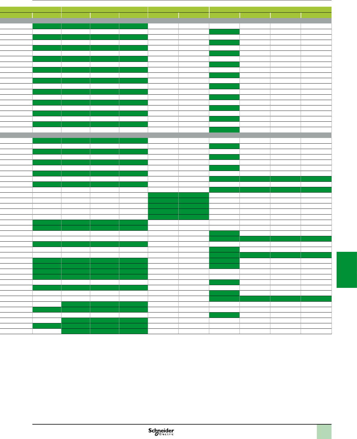
7/21
Proximity sensors c Inputs, BMXDDI c Inputs, BMXDDM c Inputs, BMXAMI a Inputs, BMXDAI
Type Reference 1602 1603 1604T 3202K 6402K 16022 16025 3202K 0810 0800 1602 1603 1604 0805
General purpose
Cylindrical basic
ush or non ush,
sensing distance
standard,
Plastic or Metal
Ø 6,5 plain 3 wire, PNP 24V XS1/206BLP
3 wire, NPN 24V XS1/206BLN
M8, threaded 3 wire, PNP 24V XS1/208A/BLP
3 wire, NPN 24V XS1/208A/BLN
M12, threaded 3 wire, PNP 24V XS1/212A/BLP
3 wire, NPN 24V XS1/212A/BLN
M18, threaded 3 wire, PNP 24V XS1/218A/BLP
3 wire, NPN 24V XS1/218A/BLN
M30, threaded 3 wire, PNP 24V XS1/230A/BLP
3 wire, NPN 24V XS1/230A/BLN
Cylindrical,
almost ush, sensing
distance extending
M18, threaded 3 wire, PNP 24V XS1N18P349
3 wire, NPN 24V XS1N18N349
M30, threaded 3 wire, PNP 24V XS1N30P349
3 wire, NPN 24V XS1N30N349
Cylindrical,
miniature
Ø 4 plain 3 wire, PNP 24V XS1L04P31
3 wire, NPN 24V XS1L04N31
M5, threaded 3 wire, PNP 24V XS1N05P31
3 wire, NPN 24V XS1N05N31
Ø 6,5 plain 3 wire, PNP 24V XS2L06P340
3 wire, NPN 24V XS2L06N340
Application
Cylindrical,
adjustable sensing
distance,
M12, threaded 3 wire, PNP 24V XS612B2P
3 wire, NPN 24V XS612B2N
M18, threaded 3 wire, PNP 24V XS618B2P
3 wire, NPN 24V XS618B2N
M30, threaded 3 wire, PNP 24V XS630B2P
3 wire, NPN 24V XS630B2N
Rotation monitoring M18, threaded 3 wire, PNP 24V-48V XSAV11/2373
2 wire, AC/DC XSAV11/2801
Format E 26x26x13 3 wire, PNP 24V XS911RP
Format C 40x40x15 2 wire, AC/DC XS911RM
Analog output M12, threaded 2 wire 4…20mA; 3 wire 0…10V XS12AB
M18, threaded 2 wire 4…20mA; 3 wire 0…10V XS18AB
M30, threaded 2 wire 4…20mA; 3 wire 0…10V XS30AB
Block format 2 wire 4…20mA; 3 wire 0…10V XS9C2/C4A2A
2 wire 4…20mA; 3 wire 0…10V XS9111A
Food and beverage Cylindrical threaded Metal 3 wire, PNP 24V XS2SAP
3 wire, PNP 24V XS908/12/18/30R/SP
3 wire, NPN 24V XS2SAN
2 wire, AC/DC XS2SAMA
Cylindrical threaded Plastic 3 wire, PNP 24V-48V XS2AAP
3 wire, NPN 24V XS2AAN
2 wire, AC/DC XS2AAMA
Factor 1 Cylindrical threaded Metal 4 wire, PNP+NPN 24V XS1MKPM40
Forme C, 40 x 117 x 41 4 wire, PNP+NPN 24V XS9C2/C4A
Cylindrical threaded Metal 3 wire, PNP 24V XS1M18PAS
Packaging Format 12x26x40 3 wire, PNP 24V XS7G12P140
3 wire, NPN 24V XS7G12N140
4 wire, PNP 24V-48V XS7G12P440
4 wire, NPN 24V-48V XS7G12N440
2 wire, AC/DC XS7G12M230
Material handling Format C 40x40x40 2 wire, DC 24V-48V XS7T4DA
4 wire, PNP 24V-48V XS7T4PC
4 wire, NPN 24V-48V XS7T4NC
Format D 80x80x26 2 wire, DC 24V-48V XS7D1
Welding Cylindrical Metal 3 wire, PNP 24V XS1MPAW
2 wire, DC 24V-48V XSLC
Compatible
Non compatible
2
1
3
4
5
6
7
8
9
10
2
1
3
4
5
6
7
8
9
10

7/22
Modicon M340 automation
platform 9
Power consumption table
ChoiceofBMXCPS
powersupplies
Presentation
The power required to supply each BMXXBP00 rack depends on the type and
number of modules installed in the racks. It is therefore necessary to draw up a
power consumption table rack by rack in order to determine the BMXCPS
power supply module most suitable for each rack.
The calculation sheet on the page opposite can be used to calculate the power
consumption of the 2 or 3 voltages provided (depending on the model) by the
BMXCPS power supply module: 3.3 V , 24 V (rack) and
24 V (sensors).
Method
Check and select a power supply module corresponding to the power available on
the 2 or 3 voltages.
Check that the sum of the absorbed power on these three voltages does not
exceed the total power of the power supply module.
Values to be entered depending on the Modicon M340 PLC
conguration.
2
1
3
4
5
6
7
8
9
10
2
1
3
4
5
6
7
8
9
10
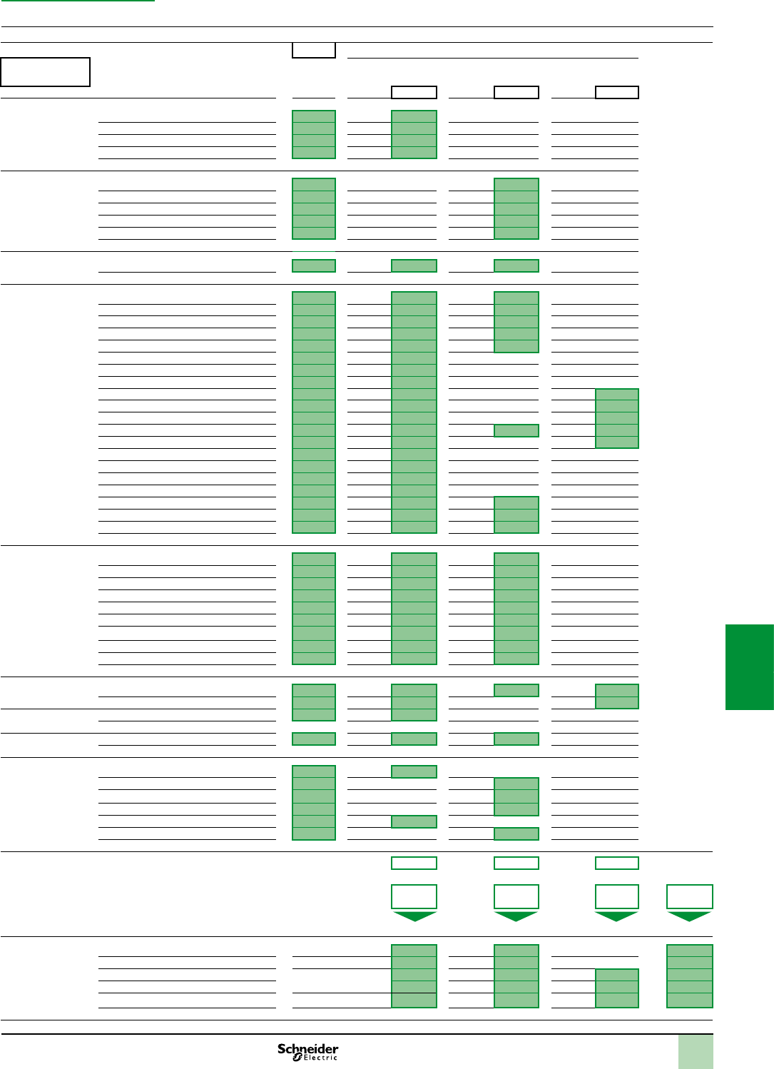
7/23
Module reference Format Number Consumption in mA (1)
Rack no.
0 - 1 - 2 - 3
S : Standard
D : Double
3.3 V
voltage
24 V
rack voltage
24 V
sensor voltage
Module Total Module Total Module Total
Rack BMXXBP0400(H) – 304
BMXXBP0600(H) – 455
BMXXBP0800(H) – 607
BMXXBP1200H – 225
Processor
(rack 0)
BMXP341000(H) S 72
BMXP342000 S 72
BMXP342010/20102 S 90
BMXP342020(H) S 95
BMXP342030/20302H S 135
Rack expansion
(rack 0, 1, 2 or 3)
BMXXBE1000 – 22 160
Discrete I/O BMXDAI0805 S 76 13
BMXDAI1602
(H) S 90 60
BMXDAI1603
(H) S 90 60
BMXDAI1604
(H) S 90 60
BMXDAO1605
(H) S 100 95
BMXDDI1602
(H) S 90
BMXDDI1603
(H) S 90
BMXDDI1604T S 76
BMXDDI3202K S 140 110
BMXDDI6402K S 200 110
BMXDDM16022
(H) S 100 30
BMXDDM16025
(H) S 100 50 30
BMXDDM3202K S 150 55
BMXDDO1602
(H) S 100
BMXDDO1612
(H) S 100
BMXDDO3202K S 150
BMXDDO6402K S 240
BMXDRA0804T S 61 104
BMXDRA0805
(H) S 100 55
BMXDRA1605
(H) S 100 95
Analog I/O
BMXAMI0410
(H) S 150 45
BMXAMI0800 S 150 30
BMXAMI0810 (H) S 150 45
BMXAMM0600
(H) S 150 130
BMXAMO0210
(H) S 150 110
BMXAMO0410(H) S 150 84
BMXAMO0802 S 150 74
BMXART0414
(H) S 150 40
BMXART0814
(H) S 150 100
Counting BMXEHC0200(H) S 200 40 80
BMXEHC0800(H) S 200 80
SSI encoder
interface
BMXEAE0300(H) S 150
Motion control BMXMSP0200 S 200 150
Communication BMXEIA0100 S 160
BMXNOE0100(H) S 90
BMXNOE0110(H) S 90
BMXNOM0200(H) S 80
BMXNOC0401 S 555
BMXNOR0200H S 95
Power consumption Courant total (mA)
x 3,3 V x 24 V x 24 V
Puissance
consommée (mW)
+ + =
Available power (mW) Total power (mW)
Choice of power
supply module
BMXCPS2010 D 24 V isolated 8250 16 800 17 000
BMXCPS3020 (H) D 24...48 V isolated 14850 31 200 32 000
BMXCPS2000 D 100...240 V 8250 16 800 10 800 20 000
BMXCPS3500 (H) D14850 31 200 21 600 36 000
BMXCPS3540T D 125 V 14850 31 200 21 600 36 000
(1)Typicalvaluegivenfor100%ofinputsoroutputsatstate1.
Modicon M340 automation
platform 9
Power consumption table
Calculation sheet
ChoiceofBMXCPS
powersupplies
Photocopythisdocumentorusethe
M340 Design software,availableonourwebsite:
www.schneider-electric.com
2
1
3
4
5
6
7
8
9
10
2
1
3
4
5
6
7
8
9
10

2
1
3
4
5
6
7
8
9
10
2
1
3
4
5
6
7
8
9
10
7/247/24
A dedicated services offer for your
installed base
Presentation
Schneider Electric, with its experts, products and dedicated tools, provides services
such as system design, consultancy, maintenance contracts, modernisation of
facilities or delivering projects.
The Schneider Electric services offer is structured around several key areas:
Maintenance and support services:
A set of services to help maintain reliability and availability of automated control
systems. These services may be the subject of a bespoke maintenance contract to
meet your requirements more closely.
Consultancy services:
Diagnostics of the installed base
Modernization solutions:
Migration solutions including consultancy, expertise, tools and technical support
to help ensure a smooth transition to newer technology while keeping the wiring and
the encoding in most cases.
Customization services are also available to accommodate specic requirements.
For more information, please consult the specic pages on our website
www.schneider-electric.com/automationservices.
Maintenance and support services
Spare parts, exchanges and repairs Everythingyouneedtogetequipmentworkingagainasquicklyaspossible
Solutions to respond very quickly to requests for spare parts, exchanges and repairs
to your installed automation equipment (automation platforms, Human Machine
Interfaces, drives, distributed I/O):
Spare parts management:
Identication of critical parts
Stock of spare parts: a Schneider Electric owned stock of spare parts, on your
site or in one of our warehouses, with immediate availability on site or a contractually
agreed delivery time if stored off site
Testing of spare parts stored on site
Automatic stock lling
Repairs:
Broken down products are repaired in a network of worldwide repair centres. For
each repaired product, our experts provide a detailed report.
On-site repair:
Our experts' knowledge and expertise
Monitoring of specic repair procedures
Availability of our teams to respond 24/7
Exchanges:
With standard replacements, receive a new or reconditioned product before the
broken down product has even been sent back
Fast exchanges offer the option to receive the replacement product within
24 hours (in Europe)
Preventive maintenance Improvingandguaranteeingthelong-termreliabilityandperformanceofyour
installations
Schneider Electric's preventive maintenance expert assesses your site, the
equipment to be managed and sets up a maintenance program to accommodate
specic requirements. A list is provided of the tasks to be performed and their
frequency, including site-specic tasks, describing how preventive maintenance is to
be managed.
Extended warranty Anadditionalmanufacturerwarrantycoveringreplacementorrepairofthe
equipment
The extended warranty offers the option to take out a 3-year warranty. The warranty
period can vary according to the geographical area, consult your Customer Care
Centre.
Online support Accesstodedicatedexperts
Priority access to experts who can answer technical questions promptly concerning
equipment and software both on sale and no longer commercially available.
Software subscription Accesstosoftwareupgradesandnewfeatures
By subscribing to software updates, users are able to:
Purchase licences
Receive updates, upgrades, software migrations and transitions
Download software from Schneider Electric's software library
Renew
Improve
Build
Design
Operate
Maintain
Design-Build-Operate/Maintain-Improve-Renew
Note:Tocheckavailabilityofservicesrequired,pleasecontactourCustomerCareCentre.
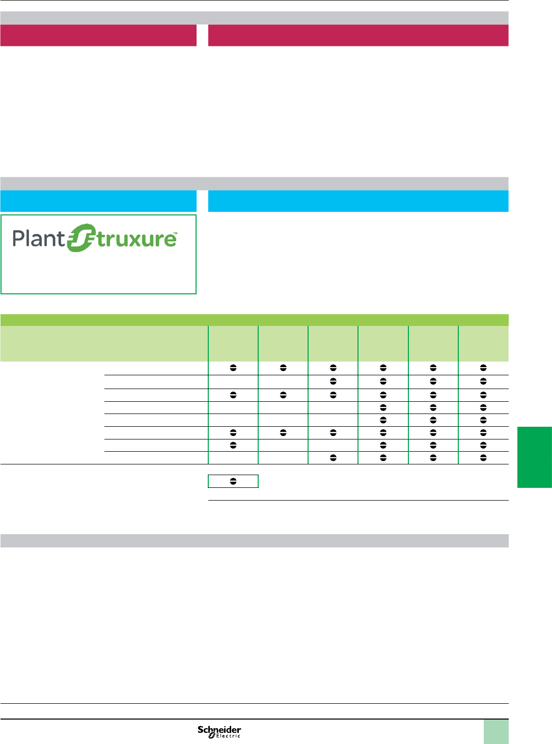
2
1
3
4
5
6
7
8
9
10
2
1
3
4
5
6
7
8
9
10
7/257/25
Presentation(continued) A dedicated services offer for your
installed base
Consultancy services
M2C (Maintenance and Modernization
Consultancy)
Professionaltoolsandmethods,provenexperienceofmanagingobsolescence
andupdatinginstalledbases,toreducedowntimesandimproveperformance.
With our maintenance and modernization consultancy offer, Schneider Electric will
help you check the state of your installed base by:
Dening the scope and depth of the analysis in collaboration with you
Collecting the technical data without shutting down production
Analyzing and identifying avenues for improvement
Producing a recommendation plan
Customer benets:
Learning about the components that make up the installed base and how
up-to-date they are
Better downtime anticipation
Expert advice designed to improve performance
Modernization solutions
Migration to PlantStruxure Provenexpertise,toolsandmethodstogiveyouaclearvisionoftheimprovement
opportunitiesandguideyoutowardasuccessfulmodernizationproject
TondoutmoreaboutPlantStruxure
architectures,pleasevisitourwebsite
www.schneider-electric.com/PlantStruxure
Schneider Electric offers a gradual program of modernization through a series of
products, tools and services that allow you to upgrade to newer technology. There
are several stages in this gradual modernization program:
Partial program: replacement of an old component with a new one
Staggered program: gradual incorporation of new offers in the system
Total program: total renovation of the system
The table below lists our various migration offers:
Wide range of migration offers
Solution Change the
CPU
Keep the
I/O racks &
wiring
Change the
I/O racks &
keep the
wiring
Migrate your
application
Manage your
project
Execute your
project
Platform (1) TSX47 to TSX107
April series 1000
Modicon 84, Compact
April SMC
Merlin Gerin PB
AEG
Symax
Rockwell SLC500
Service available
(1)OurmigrationserviceofferalsoincludesSCADA,HumanMachineInterfaces,drives,
communicationnetworksanddistributedI/O.
Customization services
Schneider Electric is able to meet your specic requirements and provide you with
adapted products:
Protective coating for Human Machine Interfaces, automation platforms and
distributed I/O modules for use in harsh environments
Customized cable lengths to match your specic needs
Customized front panels for Human Machine Interfaces
Note:Tocheckavailabilityofservicesrequired,pleasecontactourCustomerCareCentre.

7/26
Presentation
The quick wiring adaptors comprise a set of connectors designed to simplify the
replacement of legacy TSX7 PLCs by automation platforms, integrating the Modicon
X80 I/O platform, such as Modicon M340, Quantum Ethernet RIO, etc.
Replacement is carried out using the cabling of the existing installation. The
adaptors enable the I/O connectors of the TSX7 automation module in an existing
installation to be matched to the equivalent I/O modules of the Modicon X80 I/O by
using a corresponding pre-wired cable assembly.
Twenty-eight references (two swing arm rack supports and twenty-six quick wiring
adaptors) cover the main migration requirements between the TSX7 I/O modules
and the Modicon X80 I/O platform and they conform to the specications of the
Modicon M340 range.
Description of the solution
The electromechanical migration solution comprises a migration rack, that includes
a hinged door on which the backplane of an M340 rack (8 or 12 slots) is xed,
combined with a set of quick wiring adaptors.
The rear of the chassis replaces the TSX7 rack. It is designed to accommodate
the adaptors according to the modules present in the original TSX7 rack.
The existing TSX7 wiring connector of the installation is mounted on the matching
adaptor xed on the rack support behind the hinged door. The other end of the
adaptor cable is connected to the corresponding I/O module of the Modicon X80 I/O
platform.
The M340 PLC is xed at the front on the hinged door.
The adaptors transmit the same control signals to the installations without any
changes to the wiring.
Advantages of the solution
This TSX7 PLC to the Modicon X80 I/O platform migration system offers the
following advantages:
Reduced production downtimes. Migration can be made during normal stoppage
times (approximately 1 hour installation time per rack), as opposed to manual
rewiring which requires a specic stoppage of production. Backtracking possible in
the event of a problem.
Cost savings due to use of all existing wiring to sensors/actuators in the
enclosures. Rewiring, tests, validation and update of wiring diagrams no longer
required. This solution is therefore more reliable and easier to implement.
This migration solution is part of a full set of TSX7 modernization solutions that
comprise methods, dedicated solutions and tools. It can be implemented with the
help of our experts so as to optimize suitability with the existing installation.
A correspondence table between TSX7 modules and the Modicon X80 I/O platform
modules is shown on the next page. It lists only the possible compatibilities.
However, TSX module terminal, modularity, common or power supply differences
can be taken into account according to the setting up, installations and
congurations. It is therefore recommended that compatibility conditions be checked
with our Customer Care Centre.
Presentation Modicon M340 automation
platform
Migration solutions
TSX7 PLCs to Modicon X80 I/O platform
2
1
3
4
5
6
7
8
9
10
2
1
3
4
5
6
7
8
9
10

7/27
Compatibility Modicon M340 automation
platform
Migration solutions
TSX7 PLCs to Modicon X80 I/O platform
TSX7 module - X80 I/O platform compatibility
Type of
module
TSX7 modules X80 I/O platform Quick wiring adaptors
Reference Description Reference Description Reference
Rack TSXRKN8/RKS8 8-slot rack BMXXBP0800 8-slot rack TSX7SWAXBP1200
TSXRKN8/RKS8 8-slot rack BMXXBP1200 12-slot rack TSX7SWAXBP1200
Discrete
inputs
TSXDET802 8-point 24 VAC input BMXDAI1602 Adaptor, 40 cm, between modules
- TSXDET8pp
- and BMXDAI16pp or BMXDDI16pp
DET08XXDXI160X
TSXDET803 8-point 48 VAC input BMXDAI1603
TSXDET812 8-point 24 VDC input BMXDDI1602
TSXDET813 8-point 48 VDC input BMXDDI1603
TSXDET814 8-point 130 VDC input BMXDDI1604T
TSXDET824
8-point 110 VDC - 115 VAC input
BMXDAI1604
TSXDET1603 16-point 48 VAC input BMXDAI1603 Adaptor, 40 cm, between modules
- TSXDET16pp
- and BMXDAI16pp or BMXDDI16pp
DET16XXDXI160X
TSXDET1604 16-point 110/120 VAC input BMXDAI1604
TSXDET1612 16-point 24 VDC input BMXDDI1602
TSXDET1613 16-point 48 VDC input BMXDDI1603
TSXDET1633 16-point 48 VDC input BMXDDI1603
TSXDET3232 32-point 24 VDC input BMXDDI3202K Adaptor, 1 m, between modules
- TSXDET32p2
- and BMXDDI3202K
DET32X2DDI3202K
TSXDET3242 32-point 24 VDC input BMXDDI3202K
TSXDET3252 32-point 24 VDC input BMXDDI3202K
Discrete
outputs
TSXDST1632 16-point 24 VDC outputs BMXDDO1602 Adaptor, 40 cm, between modules
TSXDST1632 (24 VDC/MOS) and
BMXDDO1602
DST1632DDO1602
TSXDST1632 16-point 24 VDC outputs BMXDRA1605 Adaptor, 40 cm, between modules
TSXDST1632 (24 VDC/RELAY) and
BMXDRA1605
DST1632DRA1605
TSXDST1633 16-point 24/240 VAC outputs BMXDRA1605 Adaptor, 40 cm, between modules
TSXDST1633 (24..240 VAC/RELAY) and
BMXDRA1605
DST1633DRA1605
TSXDST1634 16-point 48/130 VDC outputs 2 modules
BMXDRA0804T
Adaptor, 40 cm, between 1 TSXDST1634
(125 VDC) module and 2 BMXDRA0804T
modules
DST1634DRA0804T
TSXDST1635 16-point 24/240 VAC outputs BMXDAO1605 Adaptor, 40 cm, between modules
TSXDST1635 (24..240 VAC/RELAY) and
BMXDAO1605
DST1635DAO1605
TSXDST1635 16-point 24/240 VAC outputs BMXDRA1605 Adaptor, 40 cm, between modules
TSXDST1635 (48..240 VAC/TRIAC) and
BMXDRA1605
DST1635DRA1605
TSXDST1682 16-point 24 VDC outputs BMXDDO1602 Adaptor, 40 cm, between modules
TSXDST1682 (48..240 VDC/MOS) and
BMXDDO1602
DST1682DDO1602
TSXDST2472 24-point 24 VDC outputs 2 modules
BMXDDO1602
Adaptor, 50 cm, between 1 TSXDST24 p
2 (24 VDC) module and 2 BMXDDO1602
modules
DST24X22DDO1602
TSXDST2482 24-point 24 VDC outputs 2 modules
BMXDDO1602
TSXDST2472 24-point 24 VDC outputs BMXDDO3202K Adaptor, 1 m, between modules TSXDST24p
2 (24 VDC) and BMXDDO3202K
DST24X2DDO3202K
TSXDST2482 24-point 24 VDC outputs BMXDDO3202K
TSXDST3292 32-point 24 VDC outputs BMXDDO3202K Adaptor, 1 m, between modules TSXDST3292
(24 VDC) and BMXDDO3202K
DST3292DDO3202K
Analog
Inputs
TSXAEM411 4-channel voltage/current inputs BMXAMI0410 Adaptor, 40 cm, between modules TSXAEM411
and BMXAMI0410 (Current type)
AEM0411AMI0410C
TSXAEM411 4-channel voltage/current inputs BMXAMI0410 Adaptor, 40 cm, between modules TSXAEM411
and BMXAMI0410 (Voltage type)
AEM0411AMI0410V
TSXAEM413 4-channel Pt100 inputs
3 or 4-wire
BMXART0414 Adaptor, 40 cm, between modules TSXAEM413
and BMXAMI0414 (RTD type)
AEM0413ART0414
TSXAEM811 8-channel voltage/current inputs BMXAMI0810 Adaptor, 40 cm, between modules TSXAEM811
and BMXAMI0810 (Current type)
AEM0811AMI0810C
TSXAEM811 8-channel voltage/current inputs BMXAMI0810 Adaptor, 40 cm, between modules TSXAEM811
and BMXAMI0810 (Voltage type)
AEM0811AMI0810V
TSXAEM821 8-channel voltage/current inputs BMXAMI0800 Adaptor, 40 cm, between modules TSXAEM821
and BMXAMI0800 (Current type)
AEM0821AMI0800C
TSXAEM821 8-channel voltage/current inputs BMXAMI0800 Adaptor, 40 cm, between modules TSXAEM821
and BMXAMI0800 (Voltage type)
AEM0821AMI0800V
TSXAEM1601 16-channel inputs 2 modules
BMXAMI0800
Adaptor, 50 cm, between 1 TSXAEM1601
module and 2 BMXAMI0800 modules
(Voltage type)
AEM1601AMI0800V
TSXAEM1602 16-channel inputs 2 modules
BMXAMI0800
Adaptor, 50 cm, between 1 TSXAEM1602
module
and 2 BMXAMI0800 (Current type)
modules
AEM1602AMI0800C
TSXASR200 2-channel voltage/current
output
BMXAMO0210
Adaptor, 50 cm, between modules TSXASR200
and BMXAMO0210
ASR0200AMO0210
2 TSXASR200
modules
2 x 2-channel voltage/current
outputs
BMXAMO0410 Adaptor, 50 cm, between 2 TSXASR200
modules and 1 BMXAMO0410 module
2 ASR0200AMO0410
adaptors
Analog
outputs
TSXASR0401 4-channel voltage output BMXAMO0410 Adaptor, 40 cm, between modules
TSXASR040p and BMXAMO0410
ASR040XAMO0410
TSXASR0402 4-channel current output BMXAMO0410
TSXASR0403 4-channel current output BMXAMO0410
TSXAST200 2-channel voltage/current
output
BMXAMO0210 Adaptor, 40 cm, between modules TSXAST200
and BMXAMO0210
AST0200AMO0210
2
1
3
4
5
6
7
8
9
10
2
1
3
4
5
6
7
8
9
10
7/28
Presentation,
compatibility Modicon M340 automation
platform
Migration solutions
Modicon Compact PLCs to Modicon X80 I/O platform
Compact module - X80 I/O platform compatibility
Type of
module
Compact module X80 I/O platform Compact module - X80 I/O platform
compatibility
Quick wiring
adaptor
reference
Reference Description Reference Description
Digital input AS-BDEO216 16-point 24 VDC input
module
BMXDDI1602 16-point 24 VDC sink
input
OK 990XSM00206
AS-BDEP208 8-point 230 VAC input
module
BMXDAI0805 8-point 200 to 240 VAC
input
OK 990XSM00201
AS-BDEP209 8-point 120 VAC input
module
BMXDAI1604 16-point 110 VAC input OK 990XSM00213
AS-BDEP210 8-point 115 VAC input
module
BMXDAI1604 16-point 110 VAC input OK 990XSM00213
AS-BDEP211 8-point 115 VAC input
module
BMXDAI1604 16-point 110 VAC input OK None
AS-BDEP214 16-point 12-60 VDC input
module
BMXDDI1602
BMXDDI1603
16-point 24 VDC input
16-point 48 VDC input
For the 24 VDC module ensure that the input current
threshold at switch on is compatible with the
application. The input voltage threshold of
BMXDDI1603 is 34 V compared to 12 V for
AS-BDEP214.
No replacement for 12 VDC and 60 VDC.
990XSM00206
AS-BDEP215 16-point 5 VDC TTL input
module
––No exact replacement but can be replaced with HMI
functionality.
None
AS-BDEP216 16-point 24 VDC input
module
BMXDDI1602 16-point 24 VDC sink
input
OK 990XSM00206
AS-BDEP217 16-point 24 VDC input
module
BMXDAI1602 16-point 24 VDC sink
input
OK but requires negative logic. 990XSM00201
AS-BDEP218 16-point 115 VAC input
module
BMXDAI1604 16-point 110 VAC input OK 990XSM00201
AS-BDEP220 16-point 24 VDC fast input
module
––The response time is a deciding factor when selecting
replacement modules.
None
AS-BDEP254 16-point 12-60 VDC input
module
BMXDDI1602H
BMXDDI1603H
16-point 24 VDC input
16-point 48 VDC input
For the 24 VDC module ensure that the input current
threshold at switch on is compatible with the
application. The input voltage threshold of
BMXDDI1603 is 34 V compared to 12 V for
AS-BDEP254. The temperature range for
BMXDDI1603 is 0 to 60 °C compared to - 40 °C to
+ 70 °C for ASBDEP254.
No replacement for 12 VDC and 60 VDC.
990XSM00206
AS-BDEP254C 16-point 12-60 VDC input
module, extd. temp.
+ coating
BMXDDI1602H
BMXDDI1603H
16-point 24 VDC input
16-point 48 VDC input
For the 24 VDC module ensure that the input current
threshold at switch on is compatible with the
application. The input voltage threshold of
BMXDDI1603 is 34 V compared to 12 V for
AS-BDEP254. The temperature range for
BMXDDI1603 is 0 to 60 °C compared to - 40 °C to
+ 70 °C for ASBDEP254.
No replacement for 12 VDC and 60 VDC.
990XSM00206
AS-BDEP256 16-point 24 VDC input
module
BMXDDI1602H 16-point 24 VDC sink
input
The nominal temperature range of BMXDDI1602 is
only 0 to + 60 °C compared to - 40 to + 70 °C for
AS-BDEP256.
990XSM00206
AS-BDEP256C 16-point 24 VDC input
module, extd. temp.
+ coating
BMXDDI1602H 16-point 24 VDC sink
input
The nominal temperature range of BMXDDI1602 is
only 0 to + 60 °C compared to - 40 to + 70 °C for
AS-BDEP256C.
990XSM00206
AS-BDEP257 16 x 110 VDC inputs, extd.
temp.
BMXDDI1604T 16-point 125 VDC input
Nominal input voltage for BMXDDI1604T is 100 to
150 VDC compared to 55 to 170 VDC for AS-BDEP257.
Response time for BMXDDI1604T is 9 ms compared to
6 ms for AS-BDEP257. Temperature range for
BMXDAI1604T from -25 to + 70 °C compared to - 40
to + 70 °C.
990XSM00206
AS-BDEP257C 16-point 110 VDC input,
extd. temp. + coating
BMXDDI1604T 16-point 125 VDC input Nominal input voltage for BMXDDI1604T is 100 to
150 VDC compared to 55 to 170 VDC for
AS-BDEP257. Response time for BMXDDI1604T is
9 ms compared to 6 ms for AS-BDEP257.
Temperature range for BMXDDI1604T from - 25
to + 70 °C compared to - 40 to + 70 °C. No conformal
coating available.
990XSM00206
AS-BDEP296 16 x 60 VDC inputs ––No replacement –
AS-BDEP297 16 x 48 VDC inputs BMXDDI1603 16-point 48 VDC input OK 990XSM00206
Presentation
The quick wiring adaptors comprise a set of connectors designed to simplify the replacement of legacy Modicon Compact PLCs by automation
platforms, integrating the Modicon X80 I/O platform, such as Modicon M340, Quantum Ethernet RIO, etc.
The adaptors enable the I/O eld connectors of the Compact PLC in an existing installation to be matched to the equivalent I/O modules of the
X80 I/O platform. Thirteen references assure the wiring translations between the I/O modules of Compact PLCs and those of the Modicon M340
platform and they fully meet the mechanical and environmental specications of the Modicon M340 range.
Quick wiring adaptors features
The quick wiring adaptors have the same look and feel as the standard I/O module connectors of the X80 I/O platform. The new connectors
increase the depth and extend below the I/O module.
The quick wiring adaptors use the same xing/retaining screws for securing the adaptor to the X80 I/O platform module.
The sockets of the adaptors accept 2 eld wiring connectors of the Compact I/O module.
A clear cover is sized to retain the wiring harness.
The cover also has enough room for attaching the wiring label that was used on the Compact module.
Green background with no comments indicates full functional equivalent between the X80 I/O platform module and the Compact module.
Green background with comments indicates full functional equivalent with differences notes. Check with your application.
Orange background indicates that, in most cases, the inputs of the X80 I/O platform fully replace those of the Compact module but differences are noted. For example, maximum current per
point. Check with your application.
Red background indicates that there are no direct replacements but other solutions exist. Please consult Schneider Electric.
2
1
3
4
5
6
7
8
9
10
2
1
3
4
5
6
7
8
9
10
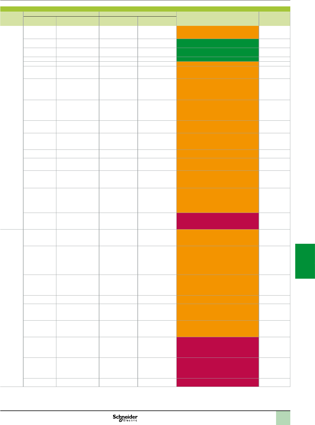
7/29
Compatibility(continued) Modicon M340 automation
platform
Migration solutions
Modicon Compact PLCs to Modicon X80 I/O platform
Compact module - X80 I/O platform compatibility
Type of
module
Compact module X80 I/O platform Compact module - X80 I/O platform
compatibility
Quick wiring
adaptor
reference
Reference Description Reference Description
Digital
output
AS-BDAO216 16-point 24 VDC output
module
BMXDDO1602 16-point 24 VDC output OK, but with slightly slower response time.
BMXDDO1602 response time of 1.2 ms compared to
< 1 ms for AS-BDAO216.
990XSM00206
AS-BDAP204 4-point relay (NO) module BMXDRA0805 8-point relay outputs OK, 4 relays on Compact, 8 on X80 I/O. 990XSM00203
AS-BDAP204 4-point relay (NO) module BMXDRA0804T 8-point 125 VDC output
relay
OK, 4 relays on Compact, 8 on X80 I/O. 990XSM00203
AS-BDAP208 8-point relay (NO) module BMXDRA0805 8-point relay outputs OK 990XSM00206
AS-BDAP258 8-point relay (NO) module BMXDRA0805H 8-point relay outputs OK, but different extended temperatures. 990XSM00206
AS-BDAP258C 8-point 24 VDC relay (NO)
module, extd. temp.
+ coating
BMXDRA0805H 8-point relay outputs OK. Temperature between 0 and + 60°C compared to
- 40 to + 70°C for BMXDRA0805H.
990XSM00206
AS-BDAP209 8-point, 1 A, 120 VAC
output module
BMXDAO1605 16-point
110 VAC to 230 VAC
output
Lower current availability.
BMXDAO1605 is limited to 600 mA compared to 1 A
for AS-BDAP210.
For AS-BDAP210, the nominal voltage goes down to
85 V compared to 100 V for BMXDAO1605.
990XSM00204
AS-BDAP210 8-point, 24-230 VAC output
module
BMXDAO1605 16-point
110 VAC to 230 VAC
output
Lower current availability.
BMXDAO1605 is limited to 600 mA compared to 1 A
for AS-BDAP210.
For AS-BDAP210, the nominal voltage goes down to
85 V compared to 100 V for BMXDAO1605.
990XSM00204
AS-BDAP212 8-point 24 VDC
input/4-point 2 A output
BMXDDM16025 8-point 24 VDC input +
8-point relay output
Compact: 2 groups of 2 outputs; X80 I/O: 1 group of
8. Consequently, issue regarding different inputs
isolation.
990XSM00205
AS-BDAP252 8-point 24 VDC
input/4-point 2 A output
BMXDDM16025H 8-point 24 VDC input +
8-point relay output
Compact: 2 groups of 2 outputs; X80 I/O: 1 group of
8. Consequently, issue regarding different inputs
isolation.
Different extended temperatures.
990XSM00205
AS-BDAP216 16-point 24 VDC output
module
BMXDDO1602 16-point 24 VDC output Compact: 2 groups of 8; X80 I/O: 1 group of 16.
Consequently, different inputs isolation.
990XSM00206
AS-BDAP256 16-point 24 VDC output
module
BMXDDO1602H 16-point 24 VDC output Compact: 2 groups of 8; X80 I/O: 1 group of 16.
Consequently, different inputs isolation.
Different extended temperatures.
990XSM00206
AS-BDAP217 16-point 5-24 VDC output
module
BMXDDO1612 16-point 24 VDC sink
output
Slightly slower response time. BMXDDO1612
response time of 1.2 ms compared to < 1 ms for
AS-BDAP217. Also, Compact: 2 groups of 8; X80 I/O:
1 group of 16.
990XSM00206
AS-BDAP218 16-point 24-240 VAC
output module
BMXDAO1605 16-point 110 VAC to
230 VAC module
Lower current availability.
BMXDAO1605 is limited to 600 mA compared to 1 A
for AS-BDAP210.
For AS-BDAP210, the nominal voltage goes down to
24 V compared to 100 V for BMXDAO1605.
If 24 V is required, select a different module.
990XSM00202
AS-BDAP211 Combined press and
stamp module, 120 VAC,
inputs controlling the
outputs
––None None
Digital
input/output
AS-BDAP220 8-point 24 VDC, 2 A,
input/output module
BMXDDM16022 8-point 24 VDC input +
8-point 24 VDC output
BMXDDM16022 is limited to 0.625 A per channel
compared to 2 A for AS-BDAP220.
Also, the response time is 1.2 ms compared to < 1 ms
for AS-BDAP220.
990XSM00207
AS-BDAP250 8-point, 24 VDC,
input/output module
BMXDDM16022H 8-point 24 VDC input +
8-point 24 VDC output
BMXDDM16022 is limited to 0.625 A per channel
compared to 2 A for AS-BDAP220 and is not
conformally coated.
Also, the response time is 1.2 ms compared to < 1 ms
for AS-BDAP220.
BMXDDM16022 temperature range of 0 to + 60 °C
compared to - 40 to + 70 °C for AS-BDAP250C.
990XSM00207
AS-BDAP250C 8-point, 24 VDC,
input/output module, extd.
temp. + coating
BMXDDM16022H 8-point 24 VDC input +
8-point 24 VDC output
BMXDDM16022 is limited to per channel compared
to 2 A for AS-BDAP250. Also, the response time is
1.2 ms compared to < 1 ms for AS-BDAP220.
DDM16022 temperature range of 0 to + 60 °C
compared to - 40 to + 70 °C for AS-BDAP250C.
990XSM00207
AS-BDAP212 8 inputs, 4 outputs, 24 VDC BMXDDM16025 8-point 24 VDC input +
8-point relay output
Compact: 2 groups of 2 outputs; X80 I/O: 1 group of
8. Consequently, different inputs isolation.
990XSM00205
AS-BDAP252 8 inputs, 4 outputs, 24 VDC BMXDDM16025H 8-point 24 VDC input +
8-point relay output
BMXDDM16025 temperature range of 0 to + 60 °C
compared to - 40 to + 70 °C. Compact: 2 groups of
2 outputs; X80 I/O: 1 group of 8. Consequently,
different inputs isolation.
990XSM00205
AS-BDAP252C 8 inputs, 4 outputs,
24 VDC, extd. temp.
+ coating
BMXDDM16025H 8-point 24 VDC input +
8-point relay output
BMXDDM16025 temperature range of 0 to + 60 °C
compared to - 40 to + 70 °C. Compact: 2 groups of
2 outputs; X80 I/O: 1 group of 8.
Consequently, different inputs isolation.
990XSM00205
AS-BDAP253 8 inputs, 4 outputs,
110 VDC
BMXDDM16025H 8-point 24 VDC input +
8-point relay output
1) Compact inputs: 110 VDC; X80 I/O: 24 VDC.
2) Compact: 2 groups of 2 outputs; X80 I/O:
1 group of 8.
a) Isolation issue
b) 4 unused references
None
AS-BDAP253C 8 inputs, 4 outputs,
110 VDC, extd. temp.
+ coating
BMXDDM16025H 8-point 24 VDC input +
8-point relay output
1) Compact inputs: 110 VDC; X80 I/O: 24 VDC.
2) Compact: 2 groups of 2 outputs; X80 I/O:
1 group of 8.
a) Isolation issue
b) 4 unused references
None
AS-BDAP292 8 inputs, 4 outputs, 60 VDC – – No exact replacement. Please consult Schneider
Electric for a solution.
None
2
1
3
4
5
6
7
8
9
10
2
1
3
4
5
6
7
8
9
10

7/30
Compact module - X80 I/O platform compatibility
Type of
module
Compact module X80 I/O platform Compact module - X80 I/O platform
compatibility
Quick wiring
adaptor
reference
Reference Description Reference Description
Analog
input
AS-BADU204 4-channel ± 0.5 V register,
PT100, 11-bit
BMXART0414 4-channel TC/RTD,
isolated, analog inputs
OK, but ± 0.5 V missing. Also, X80 I/O has channel to
channel and channel to bus isolation.
None
AS-BADU205 4-channel register input BMXAMI0410 4-channel, isolated,
analog current/voltage
input
OK, scaling differences. 990XSM00208
AS-BADU205 4-channel register input BMXAMM0600 4-channel, non-isolated,
analog current/voltage
input and 2-channel,
non-isolated, 2-channel
current/voltage output
OK, scaling differences. 990XSM00209
AS-BADU206 4-channel, isolated,
register input
BMXAMI0410 4-channel, isolated,
analog current/voltage
input
OK, but X80 I/O does not have ± 1 V range. 990XSM00210
AS-BADU206 4-channel, isolated,
register input
BMXAMM0600 4-channel, non-isolated,
analog current/voltage
input and 2-channel,
non-isolated, 2-channel
current/voltage output
OK, but X80 I/O does not have ± 1 V range.
No isolation.
990XSM00211
AS-BADU210 4-channel, isolated, analog
voltage/current input
BMXAMI0410 4-channel, isolated,
analog current/voltage
input
OK, scaling differences.
X80 I/O does not have all the corresponding voltage
ranges.
990XSM00210
AS-BADU210 4-channel, isolated, analog
voltage/current input
BMXAMM0600 4-channel, non-isolated,
analog current/voltage
input and 2-channel,
non-isolated, 2-channel
current/voltage output
OK, scaling differences.
X80 I/O does not have all the corresponding voltage
ranges.
No isolation.
990XSM00211
AS-BADU211 8-channel analog input
thermal module
BMXART0814 8-channel TC/RTD,
isolated, analog inputs
OK, X80 I/O does not have 2, 5 or 10 V inputs nor
4-20 mA, ± 20 mA, nor the 24 V external voltage,
None
AS-BADU212 8-channel analog input
thermal module
BMXART0814 8-channel TC/RTD,
isolated, analog inputs
OK, X80 I/O does not have 2, 5 or 10 V inputs nor
4-20 mA, ± 20 mA, nor the 24 V external voltage.
None
AS-BADU214 4/8-channel multi-range
Analog/Digital inputs
BMXART0414 4-channel TC/RTD,
isolated, analog inputs
X80 I/O has no 0 - 10 V, 1 - 5 V, 2 - 10 V voltage
ranges nor loop capability.
None
AS-BADU216 4/8-channel, isolated,
thermocouple
BMXART0814 8-channel TC/RTD,
isolated, analog inputs
OK None
AS-BADU254 4-channel register input BMXAMI0410H 4-channel, isolated,
analog current/voltage
input
OK and X80 I/O has CAN/CAN and CAN/bus
isolation whereas Compact has none.
Different extended temperatures.
None
AS-BADU254 4-channel register input BMXAMM0600H 4-channel analog
current/voltage input
and 2-channel current/
voltage output
OK, X80 I/O has 4 inputs and 2 outputs.
Different extended temperatures.
None
AS-BADU254C 4-channel register input,
extd. temp. + coating
BMXAMI0410H 4-channel, isolated,
analog current/voltage
input
OK and X80 I/O has CAN/CAN and CAN/bus
isolation whereas Compact has none.
Different extended temperatures.
None
AS-BADU254C 4-channel register input,
extd. temp. + coating
BMXAMM0600H 4-channel analog
current/voltage input
and 2-channel current/
voltage output
OK, X80 I/O has 4 inputs and 2 outputs. No isolation.
Different extended temperatures.
None
AS-BADU256 4-channel, isolated,
register input
BMXAMI0410H 4-channel, isolated,
analog current/voltage
input
OK, but different extended temperatures. None
AS-BADU256 4-channel, isolated,
register input
BMXAMM0600H 4-channel analog
current/voltage input
and 2-channel current/
voltage output
OK, X80 I/O has 4 inputs and 2 outputs. No isolation.
Different extended temperatures.
None
AS-BADU256C 4-channel, isolated,
register input, extd. temp.
+ coating
BMXAMI0410H 4-channel, isolated,
analog current/voltage
input
OK, but different extended temperatures. 990XSM00210
AS-BADU256C 4-channel, isolated,
register input, extd. temp.
+ coating
BMXAMM0600H 4-channel analog
current/voltage input
and 2-channel current/
voltage output
OK, X80 I/O has 4 inputs and 2 outputs without
isolation.
990XSM00211
AS-BADU257 8-channel thermocouple BMXART0814H 8-channel TC/RTD,
isolated, analog inputs
OK, but different extended temperatures. None
AS-BADU257C 8-channel thermocouple,
extd. temp. + coating
BMXART0814H 8-channel TC/RTD,
isolated, analog inputs
OK, but different extended temperatures. None
Compatibility(continued) Modicon M340 automation
platform
Migration solutions
Modicon Compact PLCs to Modicon X80 I/O platform
Green background with no comments indicates full functional equivalent between the X80 I/O platform module and the Compact module.
Green background with comments indicates full functional equivalent with differences notes. Check with your application.
Orange background indicates that, in most cases, the inputs of the X80 I/O platform fully replace those of the Compact module but differences are noted. For example, maximum current per
point. Check with your application.
Red background indicates that there are no direct replacements but other solutions exist. Please consult Schneider Electric.
2
1
3
4
5
6
7
8
9
10
2
1
3
4
5
6
7
8
9
10
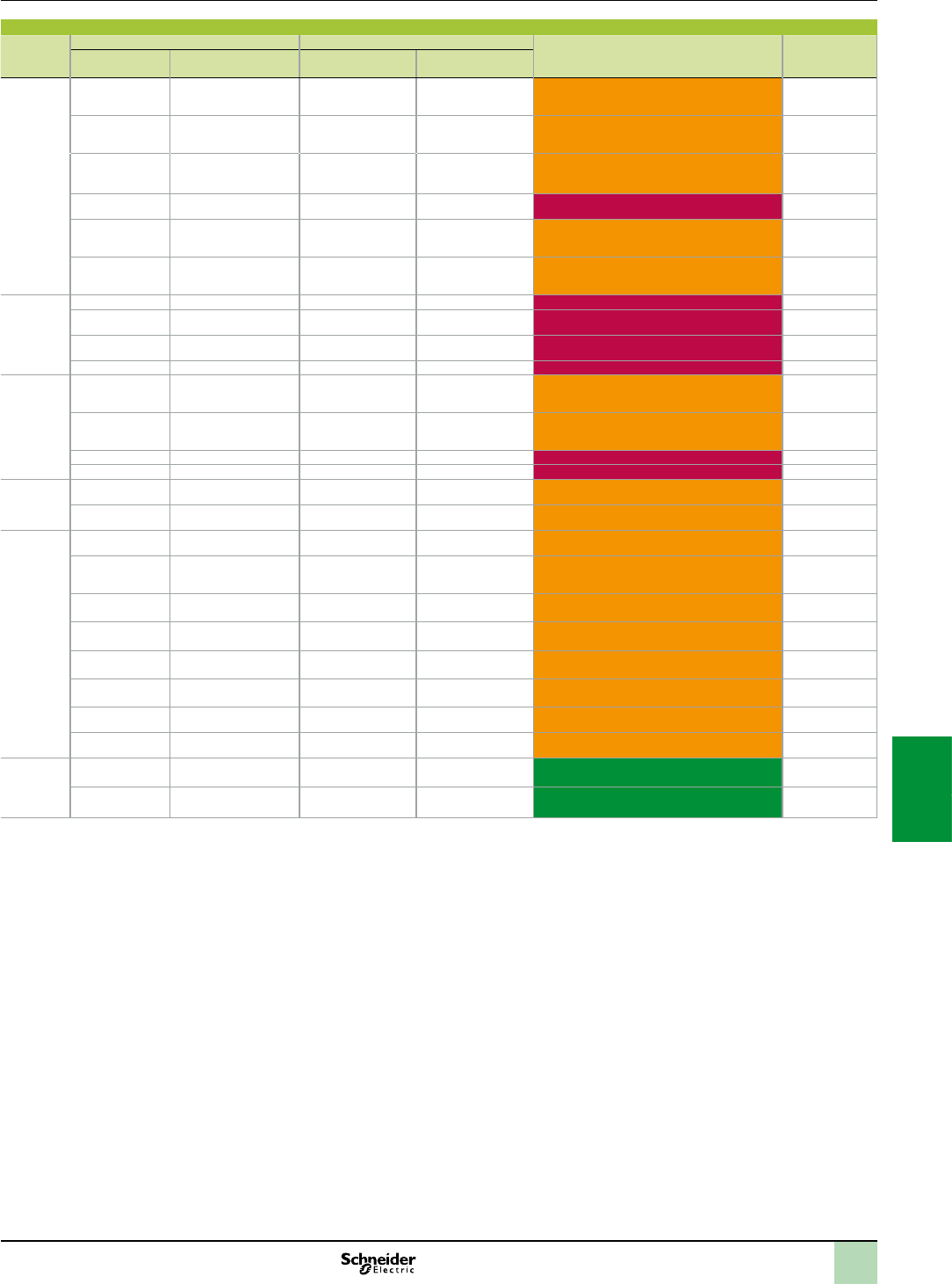
7/31
Compact module - X80 I/O platform compatibility
Type of
module
Compact module X80 I/O platform Compact module - X80 I/O platform
compatibility
Quick wiring
adaptor
reference
Reference Description Reference Description
Analog
output
AS-BDAU202 2-point analog outputs,
± 10 V, ± 20 mA
BMXAMO0210 2-channel, isolated,
analog current/voltage
output
X80 I/O has no negative 20 mA capability. 990XSM00212
AS-BDAU204 4-channel, opto-isolated,
analog output
BMXAMO0210 2-channel, isolated,
analog current/voltage
output
X80 I/O does not support 0 to 1 V,
0 to 5 V, ± 1 V ranges. +- 5 V.
None
AS-BDAU204 4-channel, opto-isolated,
analog output
BMXAMO0410 4-channel, isolated,
analog current/voltage
output
X80 I/O does not support 0 to 1 V,
0 to 5 V, ± 1 V ranges. +- 5 V.
990XSM00214
AS-BDAU208 8-channel register output ––No 8-point analog output. Two modules need to be
used.
None
AS-BDAU252 2-point analog outputs,
± 10 V, ± 20 mA. extd.
temp.
BMXAMO0210H 2-channel, isolated,
analog current/voltage
output
X80 I/O has no negative 20 mA capability.
Different extended temperatures.
990XSM00212
AS-BDAU252C 2-point analog outputs,
± 10 V, ± 20 mA, extd.
temp. + coating
BMXAMO0210H 2-channel, isolated,
analog current/voltage
output
X80 I/O has no negative 20 mA capability.
Different extended temperatures.
990XSM00212
Communi-
cation
AS-BBKF202 INTERBUS S slave – – No replacement None
AS-BBKF201-16 16 word INTERBUS S
Master
––No replacement None
AS-BBKF201-64 64 word INTERBUS S
Master
––No replacement None
CM900 Auto interface – – No replacement None
Service
communi-
cation
AS-BKOS260-24 24 word universal
communication
––Please consult Schneider Electric for assistance in
nding the best solution. READ_VAR functionality
could be a replacement solution.
None
AS-BKOS260-64 64 word universal
communication
––Please consult Schneider Electric for assistance in
nding the best solution. READ_VAR functionality
could be a replacement solution.
None
M7251 Programmable limit switch – – No replacement, no movement None
M7350 Resolver-decoder – – No replacement, no movement None
Motion AS-BMOT201 Axis motion control
encoder module
––Please consult Schneider Electric for assistance in
nding the best solution.
None
AS-BMOT202 Axis motion control
resolver encoder module
––Please consult Schneider Electric for assistance in
nding the best solution.
None
Counter AS-BFRQ204 4-point frequency module BMXEHC0200 2-channel high speed
counter
No 5 V input. Please consult Schneider Electric for
the exact replacement.
None
AS-BFRQ254C 4-channel frequency
module, extd. temp. +
coating
BMXEHC0200H 2-channel high speed
counter
No 5 V input. Please consult Schneider Electric for
the exact replacement.
None
AS-BVIC200
VRC200
4 high speed pulse or
4 VRC inputs
––Please consult Schneider Electric for assistance in
nding the best solution.
None
AS-BVIC205
CTR205
4 high speed pulse or
4 x 5 V TTL inputs
––Please consult Schneider Electric for assistance in
nding the best solution.
None
AS-BVIC212
CTR212
4 high speed pulse or
12 VDC inputs
––Please consult Schneider Electric for assistance in
nding the best solution.
None
AS-BVIC224
CTR224
4 high speed pulse or
24 VDC inputs
BMXEHC0800 8-channel high speed
counter
Please consult Schneider Electric for assistance in
nding the best solution.
None
AS-BZAE201 High speed counter/
positioner (2 relays)
BMXEHC0200 2-channel high speed
counter
12 V counter OK, no relay outputs, no 5 V, no
positioning.
None
AS-BZAE204 4-channel high speed
counter/positioner
BMXEHC0800 8-channel high speed
counter
OK. No outputs. None
CPU AS-B984-A145
up to E984-285
–BMXP342020 +
BMXCPS3020
–Only 1 Modbus port on CPU 2-port NOM serial
module available.
None
AS-P120000 105...240 VAC inputs,
24 VDC 1.0 A outputs
BMXCPS2000/
BMXCPS3500
––None
Note:
ExtendedtemperaturemodulesfortheX80I/OplatformaredistinguishedbyhavingthesufxHaddedtothereference.
TheModiconCompactrangeofPLCshadanextendedtemperaturerangeof-40°Cto+70°C.TheextendedtemperaturerangeoftheX80I/Oplatformis
-25°Cto+70°C.Deratingofthetemperatureincurstheriskofimposinglimitstosomeapplications.
AswithanyPLCmigration,evenanexactmoduletomodulereplacementmightnotprovideidenticalresults(duetoscantime,etc.).
Compatibility(continued) Modicon M340 automation
platform
Migration solutions
Modicon Compact PLCs to Modicon X80 I/O platform
2
1
3
4
5
6
7
8
9
10
2
1
3
4
5
6
7
8
9
10
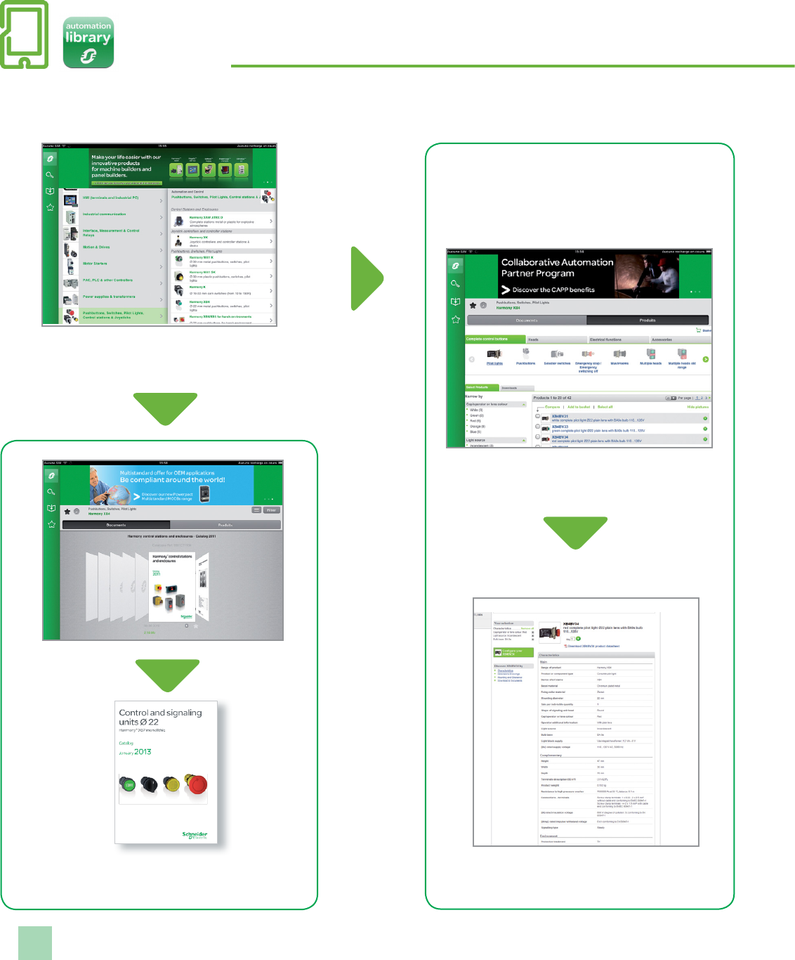
7/32
Search, visualize, and download
Use your tablet or your PC to quickly access detailed and comprehensive
information on our products
Dynamic catalogs
(hyperlinks, video, ...)
Product selector: dynamic lters to
get easily your part number
Product ranges
displayed by function
Application name: “Automation Library by Schneider Electric”
Tablets
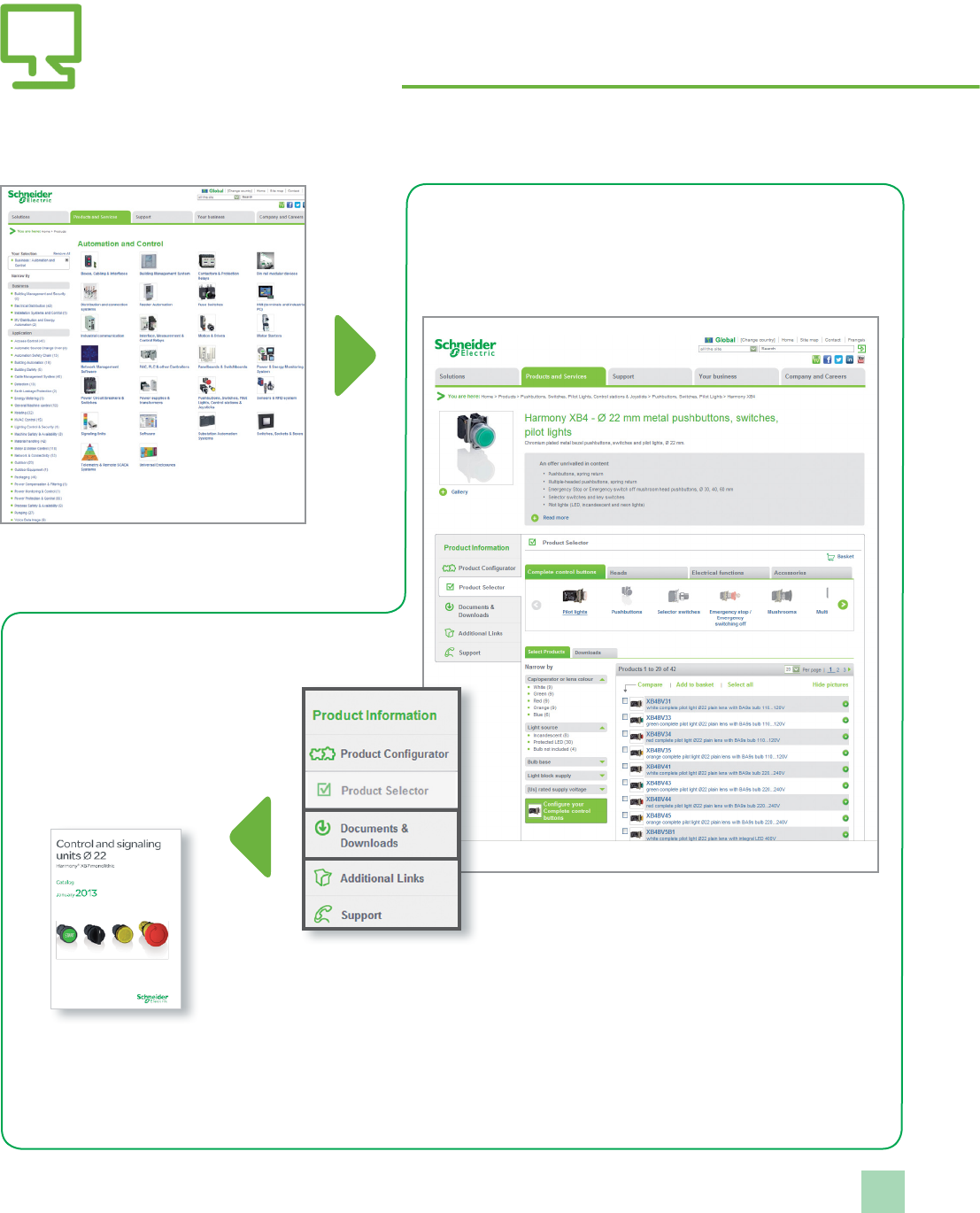
7/33
Search, visualize, and download
Use your tablet or your PC to quickly access detailed and comprehensive
information on our products
Product ranges
displayed by function
Product selector: dynamic lters to
get easily your part number
Dynamic catalogs
(hyperlinks, video, ...)
Personal computer
Path: www.schneider-electric.com > Products and Services > Automation and control > Product offer
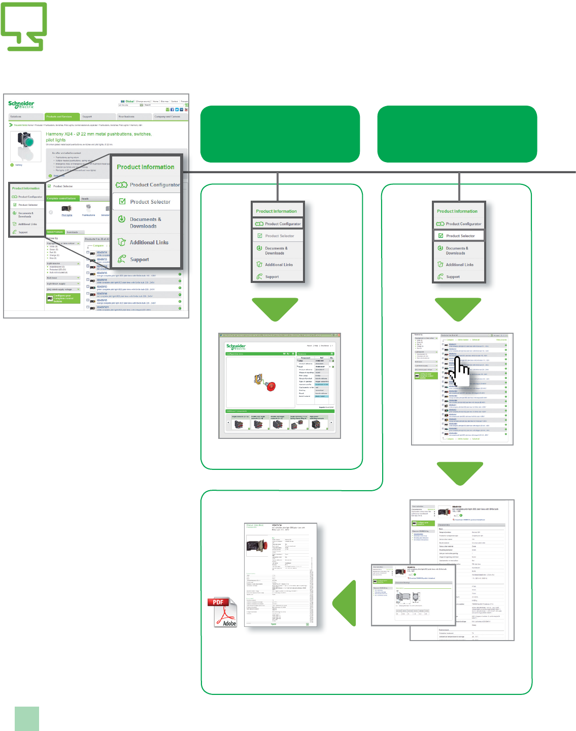
7/34
Graphic product congurator
Select the right product with just
a few clicks
Dynamic product selector
Visualize product characteristics
and dimensions
Path: www.schneider-electric.com > Products and Services > Automation and control > ... > Product offer
Technical
characteristics
Dimensions
Product data sheet
with technical characteristics
and dimensions
Access product references with
adapted tools
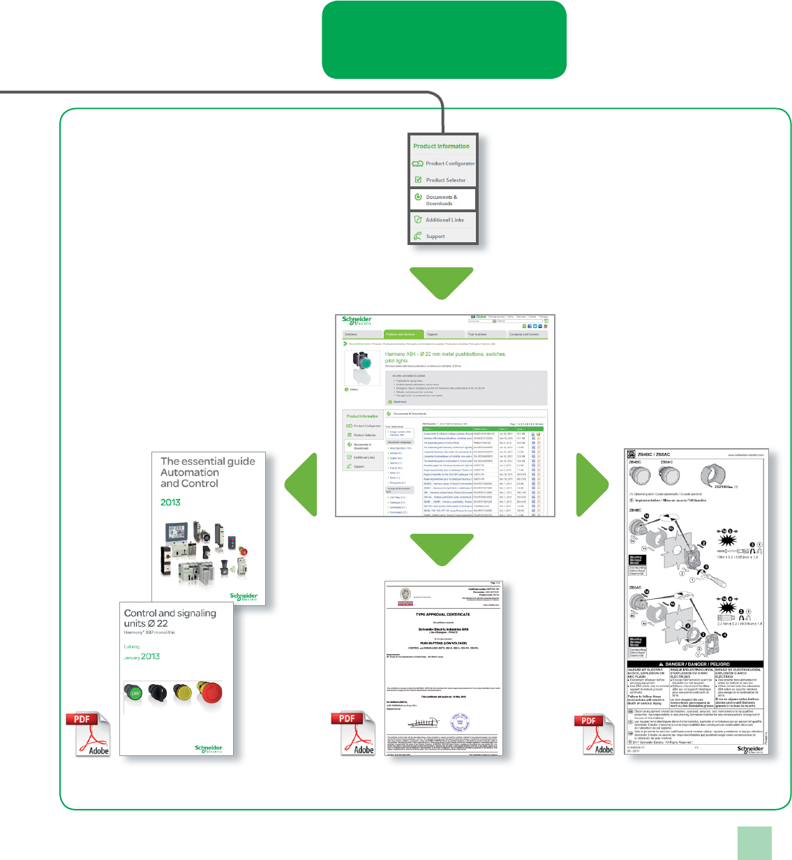
7/35
Access product references with
adapted tools
Documents and downloads
Visualize and download catalogs,
technical publications, certicates, etc.
Dynamic catalogs
Essential guides
Certicates Technical publications
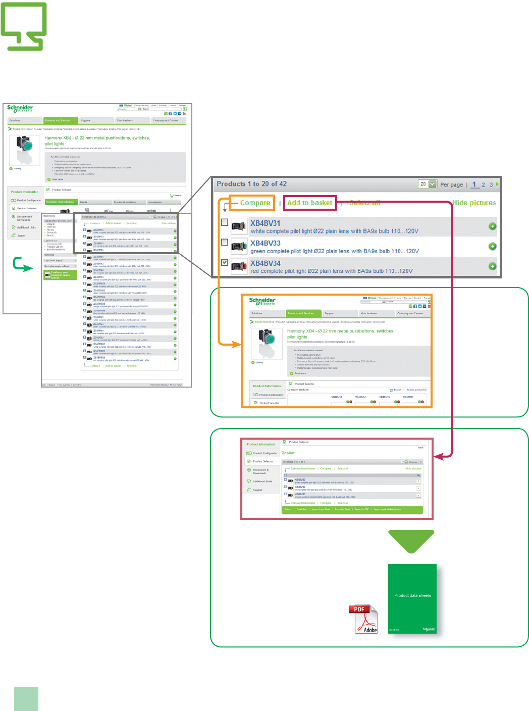
7/36
Compare, select, and compile
Path: www.schneider-electric.com > Products and Services > Automation and control > ... > Harmony XB4*
Select
and store
your products
into
the basket
* Example of research on a product
Compile
data sheets
in a unique
document
Compare
technical
characteristics

7/37
Check the product status, design your
equipment
Path: www.schneider-electric.com > Support > Product Substitution Tool
Path: www.schneider-electric.com > Support > CAD les
Please note that references to products and services are just examples.
Product status:
indicate whether the product
is still commercialized.
Otherwise, the tool suggests a
product substitution.
CAD les:
available in various formats
they will be easily integrated
into your installation design
software.

2
1
3
4
5
6
7
8
9
10
2
1
3
4
5
6
7
8
9
10
7/38
Index Product reference index
1
110XCA28201 4/21
110XCA28202 4/21
110XCA28203 4/21
170DNT11000 3/55
4
490NAD91103 3/55
490NAD91104 3/55
490NAD91105 3/55
490NOC00005 3/45
490NOR00003 3/45
490NOR00005 3/45
490NOT00005 3/45
490NTC00005 3/44
490NTC00005U 3/44
490NTC00015 3/44
490NTC00040 3/44
490NTC00040U 3/44
490NTC00080 3/44
490NTC00080U 3/44
490NTW00002 3/44
490NTW00002U 3/44
490NTW00005 3/44
490NTW00005U 3/44
490NTW00012 3/44
490NTW00012U 3/44
490NTW00040 3/44
490NTW00040U 3/44
490NTW00080 3/44
490NTW00080U 3/44
499NEH10410 3/46
499NES18100 3/47
499NMS25101 3/48
499NMS25102 3/48
499NSS25101 3/48
499NSS25102 3/48
9
990NAA26320 4/21
990NAA26350 4/21
A
ABE7ACC01 5/20
ABE7ACC02 5/20
ABE7ACC10 5/20
ABE7ACC11 5/20
ABE7ACC12 5/17
ABE7ACC20 5/20
ABE7ACC21 5/20
ABE7ACC82 5/20
ABE7ACC84 5/20
ABE7ACC85 5/20
ABE7BV10 5/20
ABE7BV20 5/20
ABE7CPA01 5/18
ABE7CPA02 2/33
5/18
ABE7CPA03 2/33
5/18
ABE7CPA11 5/18
ABE7CPA12 5/18
ABE7CPA13 5/18
ABE7CPA21 2/33
5/18
ABE7CPA31 2/33
5/18
ABE7CPA31E 2/33
5/18
ABE7CPA410 2/33
5/18
6/7
ABE7CPA412 2/33
5/18
6/7
ABE7FU012 5/20
ABE7FU050 5/20
ABE7FU100 5/20
ABE7FU200 5/20
ABE7FU400 5/20
ABE7FU630 5/20
ABE7H08R10 5/13
ABE7H08R11 5/13
ABE7H08R21 5/13
ABE7H08S21 5/13
ABE7H12R10 5/13
ABE7H12R11 5/13
ABE7H12R20 5/13
ABE7H12R21 5/13
ABE7H12R50 5/13
ABE7H12S21 5/13
ABE7H16C10 5/12
ABE7H16C11 5/12
ABE7H16C21 5/12
ABE7H16C31 5/12
ABE7H16CM11 5/12
ABE7H16CM21 5/12
ABE7H16F43 5/13
ABE7H16R10 5/13
ABE7H16R11 5/13
ABE7H16R20 5/13
ABE7H16R21 5/13
ABE7H16R23 5/13
ABE7H16R30 5/13
ABE7H16R31 5/13
ABE7H16R50 5/13
ABE7H16S21 5/13
ABE7H16S43 5/13
ABE7H20E100 5/12
ABE7H20E200 5/12
ABE7H20E300 5/12
ABE7H32E150 5/12
ABE7H32E300 5/12
ABE7P08T330 5/16
ABE7P16F310 5/15
ABE7P16F312 5/15
ABE7P16T111 5/16
ABE7P16T210 5/16
ABE7P16T212 5/16
ABE7P16T214 5/16
ABE7P16T215 5/16
ABE7P16T230 5/16
ABE7P16T318 5/16
ABE7P16T330 5/16
ABE7P16T332 5/16
ABE7P16T334 5/16
ABE7R08S111 5/14
ABE7R08S210 5/14
ABE7R08S216 5/14
ABE7R16M111 5/15
ABE7R16S111 5/14
ABE7R16S111E 5/14
ABE7R16S210 5/14
ABE7R16S210E 5/14
ABE7R16S212 5/14
ABE7R16T111 5/15
ABE7R16T210 5/15
ABE7R16T212 5/15
ABE7R16T230 5/15
ABE7R16T231 5/15
ABE7R16T330 5/15
ABE7R16T332 5/15
ABE7R16T370 5/15
ABE7S16E2B1 5/14
ABE7S16E2B1E 5/14
ABE7S16E2E0 5/14
ABE7S16E2E1 5/14
ABE7S16E2F0 5/14
ABE7S16E2M0 5/14
ABE7S16E2M0E 5/14
ABE7S16S1B2 5/14
ABE7S16S1B2E 5/14
ABE7S16S2B0 5/14
ABE7S16S2B0E 5/14
ABE7TES160 5/20
ABFC08R02B 5/21
ABFC08R02R 5/21
ABFC08R02W 5/21
ABFC08R12B 5/21
ABFC08R12R 5/21
ABFC08R12W 5/21
ABFM04S200 5/19
ABFM04S201 5/19
ABFM04S202 5/19
ABFM08S201 5/19
ABFM16S201 5/19
ABFM32H150 5/19
ABFM32H151 5/19
ABFM32H300 5/19
ABFM32H301 5/19
ABR7S11 5/17
ABR7S21 5/17
ABR7S23 5/17
ABR7S33 5/17
ABR7S33E 5/17
ABR7S37 5/17
ABS7EA3E5 5/17
ABS7EA3F5 5/17
ABS7EA3M5 5/17
ABS7EC3AL 5/17
ABS7EC3B2 5/17
ABS7EC3E2 5/17
ABS7SA2M 5/17
ABS7SA3MA 5/17
ABS7SC1B 5/17
ABS7SC2E 5/17
ABS7SC3BA 5/17
ABS7SC3E 5/17
AR1SB3 5/20
ASITERV2 2/57
B
BMXAMI0410 2/32
BMXAMI0410H 6/7
BMXAMI0800 2/32
BMXAMI0800H 6/7
BMXAMI0810 2/32
BMXAMI0810H 6/7
BMXAMM0600 2/32
BMXAMM0600H 6/7
BMXAMO0210 2/32
BMXAMO0210H 6/7
BMXAMO0410 2/32
BMXAMO0410H 6/7
BMXAMO0802 2/32
BMXART0414 2/32
BMXART0414H 6/7
BMXART0814 2/32
BMXART0814H 6/7
BMXCPS2000 2/11
BMXCPS2010 2/11
BMXCPS3020 2/11
BMXCPS3020H 6/4
BMXCPS3500 2/11
BMXCPS3500H 6/4
BMXCPS3540T 2/11
BMXCRA312p02/49
BMXCRA31200 2/45
BMXCRA31210 2/45
4/39
BMXDAI0805 2/22
BMXDAI1602 2/22
BMXDAI1602H 6/6
BMXDAI1603 2/22
BMXDAI1603H 6/6
BMXDAI1604 2/22
BMXDAI1604H 6/6
BMXDAO1605 2/22
BMXDAO1605H 6/6
BMXDDI1602 2/22
BMXDDI1602H 6/6
BMXDDI1603 2/22
BMXDDI1603H 6/6
BMXDDI1604T 2/22
BMXDDI3202K 2/22
BMXDDI6402K 2/22
BMXDDM3202K 2/23
BMXDDM16022 2/23
BMXDDM16022H 6/6
BMXDDM16025 2/23
BMXDDM16025H 6/6
BMXDDO1602 2/22
BMXDDO1602H 6/6
BMXDDO1612 2/22
BMXDDO1612H 6/6
BMXDDO3202K 2/22
BMXDDO6402K 2/22
BMXDRA0804T 2/22
BMXDRA0805 2/22
BMXDRA0805H 6/6
BMXDRA1605 2/22
BMXDRA1605H 6/6
BMXEAE0300 2/39
BMXEAE0300H 6/9
BMXEHC0200 2/37
BMXEHC0200H 6/9
BMXEHC0800 2/37
BMXEHC0800H 6/9
BMXEIA0100 2/57
BMXERT1604T 2/49
4/39
BMXFCA150 2/33
6/7
BMXFCA152 2/33
6/7
BMXFCA300 2/33
6/7
BMXFCA302 2/33
6/7
BMXFCA500 2/33
6/7
BMXFCA502 2/33
6/7
BMXFCC051 2/23
BMXFCC053 2/23
BMXFCC101 2/23
BMXFCC103 2/23
BMXFCC201 2/23
BMXFCC203 2/23
BMXFCC301 2/23
BMXFCC303 2/23
BMXFCC501 2/23
BMXFCC503 2/23
BMXFCC1001 2/23
BMXFCC1003 2/23
BMXFCW301 2/23
BMXFCW301S 2/33
6/7
BMXFCW303 2/23
BMXFCW501 2/23
BMXFCW501S 2/33
6/7
BMXFCW503 2/23
BMXFCW1001 2/23
BMXFCW1003 2/23
BMXFTA150 2/33
BMXFTA152 2/33
BMXFTA300 2/33
BMXFTA302 2/33
BMXFTB2000 2/23
2/33
2/37
6/6
6/7
6/9
BMXFTB2010 2/23
2/33
2/37
6/6
6/7
6/9

2
1
3
4
5
6
7
8
9
10
2
1
3
4
5
6
7
8
9
10
7/39
Index(continued) Product reference index
BMXFTB2020 2/23
2/33
2/37
6/6
6/7
6/9
BMXFTB2800 2/33
2/39
2/41
6/9
BMXFTB2820 2/33
2/39
2/41
6/9
BMXFTW301 2/23
6/6
BMXFTW301S 2/33
6/7
BMXFTW308S 2/33
BMXFTW501 2/23
6/6
BMXFTW501S 2/33
6/7
BMXFTW508S 2/33
BMXFTW1001 2/23
6/6
BMXMSP0200 2/41
BMXNOC0401 3/23
BMXNOE0100 3/21
BMXNOE0100H 6/8
BMXNOE0110 3/21
BMXNOE0110H 6/8
BMXNOM0200 2/59
BMXNOM0200H 6/8
BMXNOR0200H 2/55
6/8
BMXNRP0200 2/45
BMXNRP0201 2/45
BMXP341000 1/9
3/63
BMXP341000H 6/3
BMXP342000 1/9
3/63
BMXP342010 3/63
BMXP342020 1/9
3/20
3/63
BMXP342020H 6/3
BMXP3420102 1/9
3/58
3/63
BMXP3420102CL 1/9
3/58
3/63
BMXP3420302 1/9
3/20
3/58
BMXP3420302CL 1/9
3/20
3/58
BMXP3420302H 6/3
BMXPRA0100 2/47
BMXRMS008MP 1/9
6/4
BMXRMS008MPF 1/9
6/3
BMXRMS128MPF 1/9
6/3
BMXRWS128MWF 2/55
BMXRWSB000M 3/21
BMXRWSFC032M 3/21
BMXXBC008K 2/9
BMXXBC015K 2/9
BMXXBC030K 2/9
BMXXBC050K 2/9
BMXXBC120K 2/9
BMXXBE1000 2/9
BMXXBE1000H 6/5
BMXXBE2005 2/9
BMXXBP0400 2/7
BMXXBP0400H 6/5
BMXXBP0600 2/7
BMXXBP0600H 6/5
BMXXBP0800 2/7
BMXXBP0800H 6/5
BMXXBP1200 2/7
BMXXBP1200H 6/5
BMXXCAUSBH018 1/9
4/21
6/4
BMXXCAUSBH045 1/9
4/21
6/4
BMXXEM010 2/7
6/5
BMXXSP0400 2/7
6/5
BMXXSP0600 2/7
6/5
BMXXSP0800 2/7
6/5
BMXXSP1200 2/7
6/5
BMXXTSCPS10 2/11
6/4
BMXXTSCPS20 2/11
6/4
BMXXTSHSC20 2/37
6/9
F
FTXBLA10 3/61
FTXC78B 3/61
FTXC78F5 3/61
FTXC78M5 3/61
FTXCM08B 3/61
FTXCM12B 3/61
FTXCN12F5 3/60
FTXCN12M5 3/60
FTXCN3203 3/60
FTXCN3206 3/60
FTXCN3210 3/60
FTXCN3220 3/60
FTXCN3230 3/60
FTXCN3250 3/60
FTXCNCT1 3/61
FTXCNTL12 3/61
FTXCY1208 3/61
FTXCY1212 3/61
FTXDG12 3/61
FTXDP2115 3/61
FTXDP2130 3/61
FTXDP2150 3/61
FTXDP2206 3/61
FTXDP2210 3/61
FTXDP2220 3/61
FTXDP2250 3/61
FTXMLA10 3/61
L
LU9GC3 3/64
P
PMXNOW0300 2/61
S
SERM2MMOD485 3/65
SERM2MUNI2 3/65
SR2CBL06 4/21
STBNDP2212 3/55
STBXCA4002 4/21
STBXSP3010 2/7
6/5
STBXSP3020 2/7
6/5
T
TCSCCN4F3M1T 3/60
TCSCCN4F3M3T 3/60
TCSCCN4F3M05T 3/60
TCSCTN011M11F 3/61
TCSEAAF1LFH00 3/45
TCSEAAF1LFS00 3/45
TCSEAAF1LFU00 3/45
TCSEAAF11F13F00 3/45
TCSEAM0100 3/45
TCSEAM0200 3/45
TCSECE3M3M1S4 3/44
TCSECE3M3M2S4 3/44
TCSECE3M3M3S4 3/44
TCSECE3M3M5S4 3/44
TCSECE3M3M10S4 3/44
TCSECE300R2 3/45
TCSECL1M1M1S2 3/45
TCSECL1M1M3S2 3/45
TCSECL1M1M10S2 3/45
TCSECL1M1M25S2 3/45
TCSECL1M1M40S2 3/45
TCSECL1M3M1S2 3/45
TCSECL1M3M3S2 3/45
TCSECL1M3M10S2 3/45
TCSECL1M3M25S2 3/45
TCSECL1M3M40S2 3/45
TCSECN300R2 3/44
TCSECU3M3M1S4 3/44
TCSECU3M3M2S4 3/44
TCSECU3M3M3S4 3/44
TCSECU3M3M5S4 3/44
TCSECU3M3M10S4 3/44
TCSECU300R2 3/45
TCSEFEA23F3F20 3/51
TCSEFEC2CF3F20 3/51
TCSEFEC23F3F20 3/51
TCSEFEC23FCF20 3/51
TCSEGPA23F14F 3/55
TCSEGPA23F14FK 3/55
6/8
TCSEK1MDRS 3/44
TCSEK3MDS 3/44
TCSEK3MR2 3/45
TCSEK3MR10 3/45
TCSESB083F2CU0 3/50
TCSESB083F23F0 3/50
TCSESB093F2CU0 3/50
TCSESM043F1CS0 3/49
TCSESM043F1CU0 3/49
TCSESM043F2CS0 3/49
TCSESM043F2CU0 3/49
TCSESM043F23F0 3/49
TCSESM063F2CS1 3/50
TCSESM063F2CU1 3/50
TCSESM083F1CS0 3/50
TCSESM083F1CU0 3/50
TCSESM083F2CS0 3/50
TCSESM083F2CU0 3/50
TCSESM083F23F0 3/49
TCSESM083F23F1 3/50
TCSESM103F2LG0 3/51
TCSESM103F23G0 3/51
TCSESM163F2CS0 3/51
TCSESM163F2CU0 3/51
TCSESM163F23F0 3/51
TCSESM243F2CU0 3/51
TCSESU033FN0 3/48
TCSESU043F1N0 3/48
TCSESU051F0 3/47
TCSESU053FN0 3/48
TCSESU083FN0 3/47
TCSMCN3M4F3C2 2/59
3/65
TCSMCN3M4M3S2 2/59
3/65
6/8
TCSWAAC13FB 4/21
TCSXCN3M4F3S4 2/59
6/8
TLACDCBA005 3/60
TLACDCBA015 3/60
TLACDCBA030 3/60
TLACDCBA050 3/60
TLXCDLFOFS34 4/37
TLXCDLTOFS34 4/37
TLXCDLUOFS34 4/37
TLXCDSTOFS34 4/37
TLXCDSUOFS34 4/37
TSXCANCA50 3/60
TSXCANCA100 3/60
TSXCANCA300 3/60
TSXCANCADD1 3/60
TSXCANCADD03 3/60
TSXCANCADD3 3/60
TSXCANCADD5 3/60
TSXCANCB50 3/60
TSXCANCB100 3/60
TSXCANCB300 3/60
TSXCANCBDD1 3/60
TSXCANCBDD03 3/60
TSXCANCBDD3 3/60
TSXCANCBDD5 3/60
TSXCANCD50 3/60
TSXCANCD100 3/60
TSXCANCD300 3/60
TSXCANKCDF90T 3/60
TSXCANKCDF90TP 3/60
TSXCANKCDF180T 3/60
TSXCANTDM4 3/60
TSXCBY010K 2/9
TSXCBY030K 2/9
TSXCBY050K 2/9
TSXCBY120K 2/9
TSXCBY180K 2/9
TSXCBY280K 2/9
TSXCBY1000 2/9
TSXCBYACC10 2/9
6/5
TSXCBYK9 2/9
6/5
TSXCDP053 5/19
TSXCDP103 5/19
TSXCDP203 5/19
TSXCDP303 5/19
TSXCDP503 5/19
TSXCRJMD25 4/21
TSXCSA100 3/65
TSXCSA200 3/65
TSXCSA500 3/65
TSXCUSB485 4/21
TSXPBSCA100 3/55
TSXPBSCA400 3/55
TSXPCX1031 4/21
TSXSCA50 3/64
TSXSCA62 3/64
TSXSCPCM4530 3/65
TSXTLYEX 2/9
6/5
TWDXCARJ003 3/65
TWDXCARJ010 3/65
TWDXCARJ030 3/65
TWDXCAT3RJ 3/64
U
UAGSBTCFUCD10 4/29
UAGSBTDFUWB13 4/29
UAGSEWLFFCD33 4/31
UAGSEWLFUCD33 4/31
UNYLAGZAUWB20 4/29
UNYLFZZAUWB12 4/29
UNYLHVZAUWB10 4/29
UNYLPCZAUWB 4/29
UNYLSYSFU 4/29
UNYLTSZAUWB10 4/29
UNYSDUZFFCD70 4/25
UNYSDUZFUCD70 4/25
UNYSPUEFFCD70 4/20
UNYSPUEFGCD70 4/20
UNYSPUEFTCD70 4/20
UNYSPUEFUCD70 4/20

2
1
3
4
5
6
7
8
9
10
2
1
3
4
5
6
7
8
9
10
7/40
Product reference index
Index(continued)
UNYSPUEZFCD70 4/20
UNYSPUEZGCD70 4/20
UNYSPUEZGTCD70 4/20
UNYSPUEZLGCD70 4/20
UNYSPUEZLTCD70 4/20
UNYSPUEZLUCD70 4/20
UNYSPUEZTCD70 4/20
UNYSPUEZUCD70 4/20
UNYSPUEZUGCD70 4/20
UNYSPULFFCD70 4/19
UNYSPULFGCD70 4/19
UNYSPULFTCD70 4/19
UNYSPULFUCD70 4/19
UNYSPULZFCD70 4/19
UNYSPULZGCD70 4/19
UNYSPULZGTCD70 4/19
UNYSPULZMGCD70 4/19
UNYSPULZMTCD70 4/19
UNYSPULZMUCD70 4/19
UNYSPULZTCD70 4/19
UNYSPULZUCD70 4/19
UNYSPULZUGCD70 4/19
UNYSPUMFGCD70 4/19
UNYSPUMFTCD70 4/19
UNYSPUMFUCD70 4/19
UNYSPUMZGCD70 4/19
UNYSPUMZGTCD70 4/19
UNYSPUMZSGCD70 4/19
UNYSPUMZSTCD70 4/19
UNYSPUMZSUCD70 4/19
UNYSPUMZTCD70 4/19
UNYSPUMZUCD70 4/19
UNYSPUMZUGCD70 4/19
UNYSPUSFGCD70 4/18
UNYSPUSFTCD70 4/18
UNYSPUSFUCD70 4/18
UNYSPUSZGCD70 4/18
UNYSPUSZGTCD70 4/18
UNYSPUSZTCD70 4/18
UNYSPUSZUCD70 4/18
UNYSPUSZUGCD70 4/18
UNYSPUZFUCD70 4/23
UNYUSE909CDM 4/20
UNYXCAUSB033 4/21
V
VW3A8114 3/64
VW3A8306 3/65
VW3A8306D30 3/65
VW3A8306R03 3/65
VW3A8306R10 3/65
VW3A8306R30 3/65
VW3A8306RC 3/64
VW3A8306TF03 3/64
VW3A8306TF10 3/64
VW3CANA71 3/61
VW3CANCARR1 3/61
VW3CANCARR03 3/61
VW3CANKCDF180T 3/61
VW3CANTAP2 3/60
VW3M3805R010 3/60
VW3M8223R30 2/41
X
XBTZ938 3/65
XGSZ24 3/64
XZCC12FCM50B 3/45
3/61
XZCC12FDM50B 3/45
3/61
XZCC12MCM50B 3/61
XZCC12MDM50B 3/61
XZCP1164L2 3/45
XZCP1164L5 3/45
XZCP1264L2 3/45
XZCP1264L5 3/45
September 2013
DIA6ED2110104EN
Head Ofce
35, rue Joseh Monier
F-92500 Rueil-Malmaison
France
www.schneider-electric.comSchneider Electric Industries SAS
The information provided in this documentation contains general descriptions and/or technical
characteristics of the performance of the products contained herein. This documentation is not
intended as a substitute for and is not to be used for determining suitability or reliability of these
products for specic user applications. It is the duty of any such user or integrator to perform the
appropriate and complete risk analysis, evaluation and testing of the products with respect to the
relevant specic application or use thereof. Neither Schneider Electric nor any of its afliates or
subsidiaries shall be responsible or liable for misuse of the information contained herein.
Design: Schneider Electric
Photos: Schneider Electric
Printed by:

Modicon M340 automation platform
13
