69 1059 SV9540; SV9640 SmartValve System Controls Installation Directions
SmartValve-Installation-Manual SmartValve-Installation-Manual Honeywell
2016-10-27
: Pdf 155882-Installationsheet 155882-InstallationSheet B6 unilog
Open the PDF directly: View PDF ![]() .
.
Page Count: 16
®U.S. Registered Trademark
Copyright © 1997 Honeywell Inc. • All Rights Reserved X-XX UL
INSTALLATION INSTRUCTIONS
SV9540; SV9640
SmartValve™ System Controls
APPLICATION
The SV9540; SV9640 SmartValve™ System Controls
combine gas flow control and electronic intermittent pilot
sequencing functions into a single unit. The low voltage
igniter, flame sensor and pilot burner are supplied by the
Q3450 or Q3480 Pilot Hardware. Provides all gas ignition
safety functions by controlling gas flow, ignition source,
and a 120 Vac or 240 Vac combustion air blower. The
control also monitors the appliance airflow proving switch
and limit string to assure proper appliance operation.
Provides prepurge, postpurge, timed trial for pilot igniton,
with 100 percent shutoff and continuous retry. Diagnostic
LED indicates system status.
This control communicates directly with the ST9160
Electronic Fan Timer (EFT) in typical forced warm air
furnace applications. It also interfaces with the 208907
Terminal Board, providing compatibility with power stealing
thermostats. Or, it directly interfaces with the appropriate
power supplies and a system thermostat for additional
appliance applications. When controlled directly by a
thermostat, the control does not provide a postpurge
function, as power to the control is removed when the
thermostat call for heat ends.
The SV9540; SV9640 system is suitable for a wide range
of fan assisted combustion gas-fired appliances including
furnaces, rooftop furnaces, boilers, unit heaters, infrared
heaters, water heaters and commercial cooking appli-
ances. The specific application of the SmartValve System
is the responsibility of the appliance manufacturer. See
Table 1 for temperature ranges and regulator types.
SPECIFICATIONS
CAUTION
The SV9540; SV9640 provide direct replacement
only. Use the Y8610 to convert standing pilot
systems to electronic ignition systems.
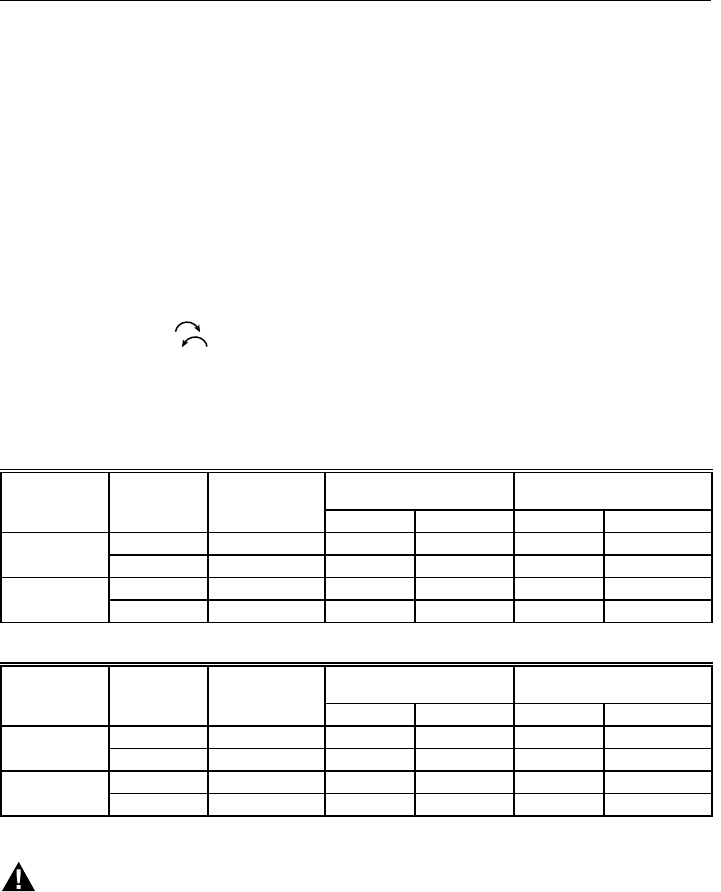
Table 1. Model Number Suffix Letter Designation.
Model No.
Suffix
Letter Ambient
Temperature Range Pressure
Regulator Type
H0°F to 175°F
(-18°C to +79°C) Slow-opening
M-40°F to +175°F
(-40°C to +79°C) Standard
P-40°F to +175°F
(-40°C to +79°C) Step-opening
Body Pattern:
SV9540: Straight through with 1/2 in. inlet and 1/2 in.
outlet; or 1/2 in. NPT inlet and 1/2 in. inverted flare
outlet.
SV9640: Straight through with 1/2 in. inlet and 1/2 in.
outlet, 1/2 in. inlet and 3/4 in. outlet, or 3/4 in. inlet
and 3/4 in. outlet.
Electrical Ratings:
System Transformer:
SV9540: 40 VA minimum NEMA rated.
SV9640: 40 VA minimum NEMA rated.
NOTE: Larger system transformer may be
required for specific applications.
Voltage and Frequency:
24 Vac, 60 Hz; 50 Hz models available.
Output Ratings:
Igniter Load: 1.5A maximum.
Induced Draft Motor Load: 2.5A Full Load, 10A
Locked Rotor at 120 Vac; 1.75A Full Load, 5A
Locked Rotor at 240 Vac.
Current at 24 Vac:
24V Thermostat: See Table 2.
Table 2. Thermostat Current (Run Mode); with
control connected directly to thermostat.
Prepurge Time (Factory-set):
3, 15, 30 or 45 seconds, depending on model.
Trial for Ignition:
90 seconds.
Postpurge Time (Factory-set):
5 seconds; this is not available when the SmartValve
System Control is connected directly to the thermostat.
Retry Delay:
5 minutes.
Flame Failure Response Time:
1.6 seconds maximum at 2 µA.
Capacity:
See Table 3.
Conversion:
Use conversion factors in Table 4 to convert capacities for
other gases.
69-1059
Model 24 Vac, 60 Hz
SV9540 0.25A
SV9640 0.25A
69-1059 2
SV9540; SV9640 SmartValve™ SYSTEM CONTROLS
PLANNING THE INSTALLATION
WARNING
FIRE OR EXPLOSION HAZARD
CAN CAUSE PROPERTY DAMAGE,
SEVERE INJURY, OR DEATH
Follow these warnings exactly:
1. Plan the installation as outlined below.
2. Plan for frequent maintenance as described in
the Maintenance section.
When intermittent pilot systems are used on central
heating equipment in barns, greenhouses, and commercial
properties and on heating appliances such as commercial
cookers, agricultural equipment, industrial heating
equipment and pool heaters, heavy demands are made on
the controls. Special steps may be required to prevent
nuisance shutdowns and control failure due to frequent
cycling, severe environmental conditions related to
moisture, corrosive chemicals, dust or excessive heat.
These applications require Honeywell Home and Building
Control Engineering review; contact your Honeywell Sales
Representative for assistance.
Review the following conditions that can apply to your
specific installation and take the precautionary steps
suggested.
Regulation Range (Btuh);
SV9540 with 1/2 in. NPT Outlet:
Natural Gas:
Minimum: 20,000.
Maximum: 200,000.
LP Gas:
Minimum: 40,000.
Maximum: 200,000.
SV9540 with 1/2 in. Inverted Flare Outlet:
Natural Gas:
Minimum: 20,000.
Maximum: 180,000.
LP Gas:
Minimum: 40,000.
Maximum: 180,000.
SV9640 (3/4 in. x 3/4 in.):
Natural Gas:
Minimum: 30,000.
Maximum: 415,000.
LP Gas:
Minimum: 30,000.
Maximum: 415,000
Natural-LP Gas Conversion Kits:
Natural Gas to LP:
393691 Conversion Kit.
LP to Natural Gas:
394588 Conversion Kit.
IMPORTANT
SV9540P; SV9640P CANNOT be field-converted
to LP or natural gas.
Pipe Adapters:
Angle and straight adapters available for 3/8-, 1/2- and 3/
4-in. pipe. See Table 5. Flange kits include one flange with
attached O-ring, four mounting screws, a 9/64 in. hex
wrench and instructions.
Approvals:
International Approval Services (IAS):
Design Certified C2030025.
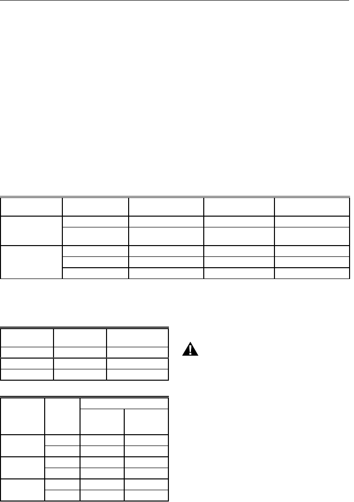
Table 3. Capacityb of SV9540; SV9640.
Model Size
(Inlet x Outlet) (in.) Capacity (at 1 in.
wc pressure drop
a,c
)Minimum
Regulated Capacity Maximum
Regulated Capacity
SV9540 1/2 x 1/2 NPT 150 ft
3
/hr (4.2 m
3
/hr) 20 ft
3
/hr (0.6 m
3
/hr) 200 ft
3
/hr (5.7 m
3
/hr)
1/2 NPT x 1/2
inverted flare 130 ft
3
/hr (3.7 m
3
/hr) 20 ft
3
/hr (0.6 m
3
/hr) 180 ft
3
/hr (5.1 m
3
/hr)
SV9640 1/2 x 1/2 240 ft
3
/hr (6.8 m
3
/hr) 30 ft
3
/hr (0.8 m
3
/hr) 340 ft
3
/hr (9.6 m
3
/hr)
1/2 x 3/4 270 ft
3
/hr (7.6 m
3
/hr) 30 ft
3
/hr (0.8 m
3
/hr) 370 ft
3
/hr (10.5 m
3
/hr)
3/4 x 3/4 300 ft3/hr (8.5 m3/hr) 30 ft3/hr (0.8 m3/hr) 415 ft3/hr (11.8 m3/hr)
Gas Specific
Gravity Multiply Listed
Capacity By
Manufactured 0.60 0.516
Mixed 0.70 0.765
Propane 1.53 1.62
aCapacity based on 1000 Btu/feet3, 0.64 specific gravity natural gas at 1 in. wc pressure drop (37.3 MJ/meter3, 0.64
specific gravity natural gas at 0.25 kPa pressure drop).
bCapacity is reduced by 5 percent with the use of outlet screen.
cValves are guaranteed at only 77 percent of the rating.
Part No.
a,b
Inlet/Outlet
Pipe Size Flange
Type
Without
Hex
Wrench With Hex
Wrench
3/8 in. NPT Straight 393690-1 393690-11
Elbow 393690-2 393690-12
1/2 in. NPT Straight 393690-6 393690-16
Elbow 393690-3 393690-13
3/4 in. NPT Straight 393690-4 393690-14
Elbow 393690-5 393690-15
Table 4. Gas Capacity Conversion Factor.
Table 5. Adapter (Flange) Part Numbers.
aFlange kits include one flange, one O-ring and four
mounting screws.
bDo not use flanges on control models with 3/4 in. inlet
and 3/4 in. outlet. On models with 1/2 in. inlet and
3/4 in. outlet, use flanges only on the 1/2 in. inlet side.

69-10593
SV9540; SV9640 SmartValve™ SYSTEM CONTROLS
Frequent Cycling
This control is designed for use on appliances that typically
cycle three to four times an hour only during the heating
season. In year-around applications with greater cycling
rates, the control can wear out more quickly. Perform a
monthly checkout.
Water or Steam Cleaning
If a control gets wet, replace it. If the appliance is likely to
be cleaned with water or steam, protect (cover) the control
and wiring from water or steam flow. Mount the control
high enough above the bottom of the cabinet so it does not
get wet during normal cleaning procedures.
High Humidity or Dripping Water
Dripping water can cause the control to fail. Never install
an appliance where water can drip on the control.
In addition, high ambient humidity can cause the control to
corrode and fail. If the appliance is in a humid atmosphere,
make sure air circulation around the control is adequate to
prevent condensation. Also, regularly check out the
system.
Corrosive Chemicals
Corrosive chemicals can attack the control, eventually
causing a failure. If chemicals are used for routine
cleaning, avoid contact with the control. Where chemicals
are suspended in air, as in some industrial or agricultural
applications, protect the control with an enclosure.
Dust or Grease Accumulation
Heavy accumulations of dust or grease can cause the
control to malfunction. Where dust or grease can be
a problem, provide covers for the control to limit
contamination.
Heat
Excessively high temperatures can damage the control.
Make sure the maximum ambient temperature at the
control does not exceed the rating of the control. If the
appliance operates at very high temperatures, use
insulation, shielding, and air circulation, as necessary, to
protect the control. Proper insulation or shielding should be
provided by the appliance manufacturer; verify proper air
circulation is maintained when the appliance is installed.
INSTALLATION
When Installing this Product…
1. Read these instructions carefully. Failure to follow
them could damage the product or cause a hazard-
ous condition.
2. Check the ratings given in the instructions and on
the product to make sure the product is suitable for
your application.
3. Installer must be a trained, experienced service
technician.
4. After installation is complete, check out product
operation as provided in these instructions.
WARNING
FIRE OR EXPLOSION HAZARD
CAN CAUSE PROPERTY DAMAGE,
SEVERE INJURY OR DEATH
Follow these warnings exactly:
1. Disconnect power supply before wiring to
prevent electrical shock or equipment
damage.
2. To avoid dangerous accumulation of fuel gas,
turn off gas supply at the appliance service
valve before starting installation, and perform
Gas Leak Test after completion of installation.
3. Do not bend pilot tubing at ignition system
control or pilot burner after compression fitting
is tightened, or gas leakage at the connection
can result.
4. Always install a sediment trap in gas supply
line to prevent contamination of ignition
system control.
WARNING
LINE VOLTAGE
CAN CAUSE PROPERTY DAMAGE,
SEVERE INJURY OR DEATH.
Never apply a jumper across or short any of the
terminals in the SV9540; SV9640 wiring harness.
This can damage the system transformer or the
control.
Follow the appliance manufacturer instructions if available;
otherwise, use these instructions as a guide.
Converting Ignition System Control
from Natural Gas to LP Gas Application
(or LP Gas to Natural Gas Application)
WARNING
FIRE OR EXPLOSION HAZARD
CAN CAUSE PROPERTY DAMAGE,
SEVERE INJURY OR DEATH
Do NOT attempt to convert step-opening models
(SV9540P/SV9542P; SV9640P/SV9642P). Always
change the main and pilot burner orifices when
converting from natural to LP gas or from LP to
natural gas. Follow appliance manufacturer
specifications and instructions carefully to assure
proper appliance conversion.
Ignition system controls are factory-set for natural (and
manufactured) or LP gas. Do not attempt to use an ignition
system control set for natural (manufactured) gas on LP
gas, or an ignition system control set for LP gas on natural
(manufactured) gas.
Ignition system controls with standard or slow opening
regulators (SV9540M,H; SV9640M,H) can be converted
from one gas to the other with a conversion kit (ordered
separately). Order part no. 393691 to convert from natural
(manufactured) to LP gas; order part no. 394588 to
convert from LP to natural (manufactured) gas.
IMPORTANT
Ignition system controls with step-opening
regulators (SV9540P; SV9640P) CANNOT be
field-converted to LP or natural gas.
69-1059 4
SV9540; SV9640 SmartValve™ SYSTEM CONTROLS
Install Adapters To Control
If adapters are being installed on the control, mount them
as follows:
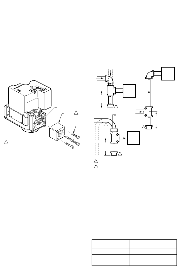
Flanges
1. Choose the appropriate flange for your application.
2. Remove the seal over the ignition system control
inlet or outlet.
3. Make sure that the O-ring is fitted in the groove of
the flange. If the O-ring is not attached or missing,
do not use the flange.
4. With the O-ring facing the ignition system control,
align the screw holes on the ignition system control
with the holes in the flange. Insert and tighten the
screws provided with the flange. See Fig. 1. Tighten
the screws to 25 inch-pounds of torque to provide a
gas-tight seal.
M12168
VALVE OUTLET
FLANGE
9/64 INCH
HEX
SCREWS
(4)
1
1 DO NOT USE FLANGES ON 3/4 IN. INLET
AND 3/4 IN. OUTLET MODELS, AND ON
THE 3/4 IN. OUTLET SIDE OF 1/2 IN.
INLET AND 3/4 IN. OUTLET MODELS.
Fig. 1. Firmly fasten flange to valve,
but do not overtighten screws.
Bushings
1. Remove the seal over the ignition system control
inlet or outlet.
2. Apply a moderate amount of good quality pipe
compound to the bushing, leaving two end threads
bare. On an LP installation, use compound resistant
to LP gas. Do not use Teflon tape.
3. Insert the bushing in the ignition system control and
carefully thread the pipe into the bushing until tight.
Complete the instructions below for installing the piping,
installing the control, connecting the pilot tubing and wiring.
Make sure the leak test you perform on the control after
completing the installation includes leak testing the
adapters and screws. If you use a wrench on the valve
after the flanges are installed, use the wrench only on the
flange, not on the control. See Fig. 5.
Location
The SV9540; SV9640 are mounted in the appliance
vestibule on the gas manifold.
IMPORTANT
These ignition system controls are shipped with
protective seals over the inlet and outlet tappings.
Do not remove the seals until ready to connect
the piping.
Fig. 2. Sediment trap installation.
Install Control
1. This ignition system control can be mounted 0 to
90 degrees in any direction, including vertically,
from the upright position of the ignition system
control switch.
2. Mount the control so the gas flow is in the direction
of the arrow on the bottom of the ignition system
control.
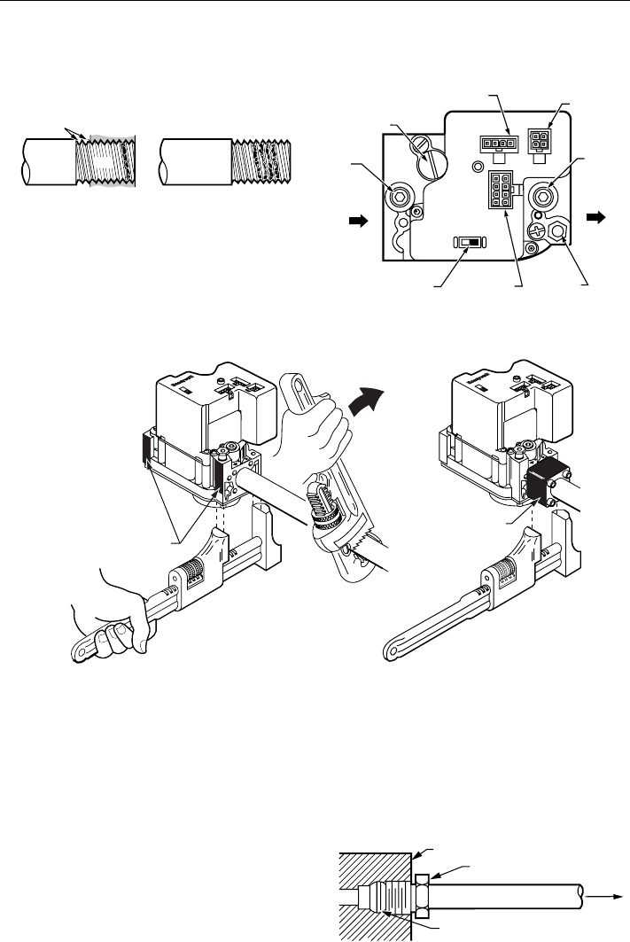
3. Thread the pipe the amount shown in Table 6 for
insertion into ignition system control or adapters. Do
not thread pipe too far. Valve distortion or malfunc-
tion can result if the pipe is inserted too deeply.
Table 6. NPT Pipe Thread Length (in.).
HORIZONTAL
DROP
PIPED
GAS
SUPPLY
PIPED
GAS
SUPPLY
3 IN.
(76 MM)
MINIMUM
3 IN.
(76 MM)
MINIMUM
RISER
IGNITION
SYSTEM
CONTROL
TUBING
GAS
SUPPLY
HORIZONTAL
DROP
3 IN.
(76 MM)
MINIMUM
RISER
M3343A
2
1
2
2
1
2
ALL BENDS IN METALLIC TUBING SHOULD BE SMOOTH.
CAUTION: SHUT OFF THE MAIN GAS SUPPLY BEFORE REMOVING
THE END CAP TO PREVENT GAS FROM FILLING THE WORK AREA.
TEST FOR GAS LEAKAGE WHEN INSTALLATION IS COMPLETE.
IGNITION
SYSTEM
CONTROL
IGNITION
SYSTEM
CONTROL
Pipe
Size Thread Pipe
this Amount Maximum Depth Pipe can
be Inserted into Control
3/8 9/16 3/8
1/2 3/4 1/2
3/4 13/16 3/4
Install Piping to Control
All piping must comply with local codes and ordinances or
with the National Fuel Gas Code (ANSI Z223.1 NFPA No.
54), whichever applies. Tubing installation must comply
with approved standards and practices.
1. Use new, properly reamed pipe free from chips. If
tubing is used, make sure the ends are square,
deburred and clean. All tubing bends must be
smooth and without deformation.
2. Run pipe or tubing to the ignition system control. If
tubing is used, obtain a tube-to-pipe coupling to
connect the tubing to the ignition system control.
3. Install a sediment trap in the supply line to the
ignition system control. See Fig. 2.
69-10595
SV9540; SV9640 SmartValve™ SYSTEM CONTROLS
TWO
IMPERFECT
THREADS
IGNITION
SYSTEM
CONTROL
THREAD PIPE THE AMOUNT
SHOWN IN TABLE FOR INSERTION
INTO IGNITION SYSTEM CONTROL
APPLY A MODERATE AMOUNT OF
PIPE COMPOUND ONLY TO PIPE
(LEAVE TWO END THREADS BARE).
M3344
PIPE
APPLY WRENCH FROM TOP OR
BOTTOM OF IGNITION SYSTEM
CONTROL TO EITHER SHADED AREA
WHEN FLANGE IS NOT USED
APPLY WRENCH
TO FLANGE ONLY
WHEN FLANGE IS USED
M12169
4. Apply a moderate amount of good quality pipe
compound (do not use Teflon tape) only to the pipe,
leaving two end threads bare. On LP installations,
use a compound resistant to LP gas. See Fig. 3.
Fig. 3. Use moderate amount of pipe compound.
5. Remove the seals over the ignition system control
inlet and outlet, if necessary.
6. Connect the pipe to the ignition system control inlet
and outlet. Use a wrench on the square ends of the
ignition system control. If a flange is used, place the
wrench on the flange rather than on the ignition
system control. Refer to Fig. 4 and 5.
Fig. 5. Proper use of wrench on ignition system control with and without flanges.
IGNITION SYSTEM CONTROL
TIGHTEN NUT ONE TURN
BEYOND FINGER TIGHT
FITTING BREAKS OFF AND CLINCHES
TUBING AS NUT IS TIGHTENED
TO PILOT
BURNER
M3346
Connect Pilot Gas Tubing
1. Cut tubing to the desired length and bend as
necessary for routing to the pilot burner. Do not
make sharp bends or deform the tubing. Do not
bend the tubing at the ignition system control after
the compression nut is tightened, because this can
result in gas leakage at the connection.
2. Square off and remove burrs from the end of
the tubing.
3. Unscrew the brass compression fitting from the pilot
outlet (Fig. 4). Slip the fitting over the tubing and
slide out of the way. See Fig. 6
4. Push the tubing into the pilot gas tapping on the
outlet end of the control until it bottoms. While
holding the tubing all the way in, slide the fitting into
place and engage the threads—turn until finger tight.
Then tighten one more turn with a wrench. Do not
overtighten.
5. Connect the other end of the tubing to the pilot
burner according to the instructions supplied with
Q3450/Q3480.
NOTE: The pilot tubing provides the SmartValve System
flame sense current path. Make sure the
connections are clean and tight for proper
operation.
Fig. 6. Always use new compression fitting.
Fig. 4. Top view of ignition system control.
OFF
ON
PRESSURE REGULATOR
ADJUSTMENT (UNDER
CAP SCREW)
INLET
PRESSURE
TAP
INLET
IGNITION SYSTEM
CONTROL SWITCH CONTROLS
CONNECTOR PILOT
OUTLET
OUTLET
OUTLET
PRESSURE
TAP
M15045
IGNITER
CONNECTOR LINE VOLTAGE
CONNECTOR
C1 C2
C3
69-1059 6
SV9540; SV9640 SmartValve™ SYSTEM CONTROLS
Wiring
Follow the wiring instructions furnished by the appliance
manufacturer, if available, or use the general instructions
provided below. When these instructions differ from the
appliance manufacturer, follow the appliance manufacturer
instructions.
All wiring must comply with applicable electrical codes and
ordinances.
Disconnect power supply before making wiring connec-
tions to prevent electrical shock or equipment damage.
1. Check the power supply rating on the ignition
system control and make sure it matches the
available supply. The system transformer should be
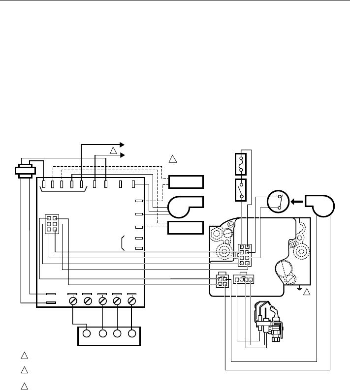
Fig. 7. SV9540; SV9640 typical wiring connections in fan assisted
warm air furnace with ST9160 Electronic Fan Timer.
NEMA rated for 40 VA or larger. An appliance
system power review is recommended. Install a
transformer, thermostat and other controls, as
required.
2. With 120 Vac power supply, connect the 120V hot
lead to L1 on the ST9160 or 208907 Terminal
Board. With 240 Vac power supply, there must be
120 Vac potential between L1 and appliance
chassis.
3. Appliance chassis must have reliable connection to
earth ground.
4. Connect control circuit to the ignition system
control using the keyed connector. See Fig. 7
through 10.
C1
C2
C3
40 VA
TRANSFORMER
CONT
EAC
HEAT
HUM
M2
MOTOR
PARKING
TERMINALS M1
L1
NEUTRALS
24 VAC
RWC
COM
XFMR COOL
LOAD
COMMON
M12176
SV9540
SV9640
AIR PROVING
SWITCH
NEUTRAL
HOT
ROLL-OUT
SWITCH
LIMIT
SWITCH
COMBUSTION
AIR BLOWER
AIR
DATA
NEUTRAL
1
2
ELECTRONIC
AIR CLEANER
CIRCULATING
FAN
HUMIDIFIER
L2
L1
(HOT)
TO 120/240 VAC, 60 HZ
POWER SUPPLY
THERMOSTAT
R
24 VAC
R
C
WY
YG
G
ST9160
ELECTRONIC
FAN TIMER
Q3450
IGNITER-
SENSOR
L1
POWER SUPPLY. PROVIDE DISCONNECT MEANS AND OVERLOAD PROTECTION
AS REQUIRED.
FOR 120 VAC INSTALLATIONS, CONNECT THE 120V (HOT) LEAD TO L1 ON ST9160.
FOR 240 VAC INSTALLATIONS, THERE MUST BE 120 V BETWEEN L1 AND APPLIANCE CHASSIS.
APPLIANCE CHASSIS MUST HAVE RELIABLE CONNECTION TO EARTH GROUND.
1
2
3
3
69-10597
SV9540; SV9640 SmartValve™ SYSTEM CONTROLS
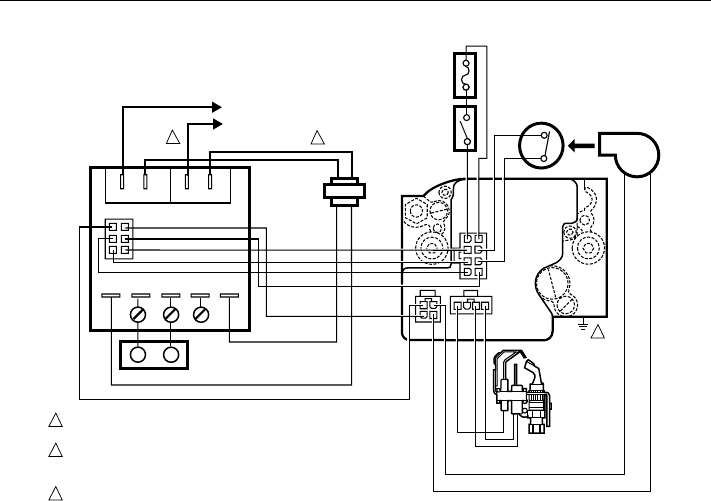
Fig. 8. SV9540; SV9640 typical wiring connections with 208907 Terminal Board.
C1
C2
C3
40 VA
TRANSFORMER
L1
L1
L2
24 VAC R W C COM
XFMR XFMR
LOAD
COMMON
M12174
AIR PROVING
SWITCH
NEUTRAL
NEUTRAL
HOT
ROLL-OUT
SWITCH
LIMIT
SWITCH
COMBUSTION
AIR BLOWER
AIR
DATA
1
2
L2
L1
(HOT)
TO 120/240 VAC, 60 HZ
POWER SUPPLY
THERMOSTAT
R
R
24 VAC
C
W
208907
TERMINAL BOARD
Q3450
IGNITER-
SENSOR
SV9540
SV9640
POWER SUPPLY. PROVIDE DISCONNECT MEANS AND OVERLOAD PROTECTION
AS REQUIRED.
FOR 120 VAC INSTALLATIONS, CONNECT THE 120V (HOT) LEAD TO L1 ON
TERMINAL BOARD. FOR 240 VAC INSTALLATIONS, THERE MUST BE 120V
BETWEEN L1 AND APPLIANCE CHASSIS.
APPLIANCE CHASSIS MUST HAVE RELIABLE CONNECTION TO EARTH GROUND.
1
2
3
3
69-1059 8
SV9540; SV9640 SmartValve™ SYSTEM CONTROLS
C1
C2
C3
L1
L2
24 VAC
M12398
AIR PROVING
SWITCH
AQUASTAT
CONTROL
NEUTRAL
HOT
ROLL-OUT
SWITCH
LIMIT
SWITCH
COMBUSTION
AIR BLOWER
AIR
DATA
R
24V THERMOSTAT
C
R8285D CONTROL CENTER Q3450
IGNITER-
SENSOR
SV9540
SV9640
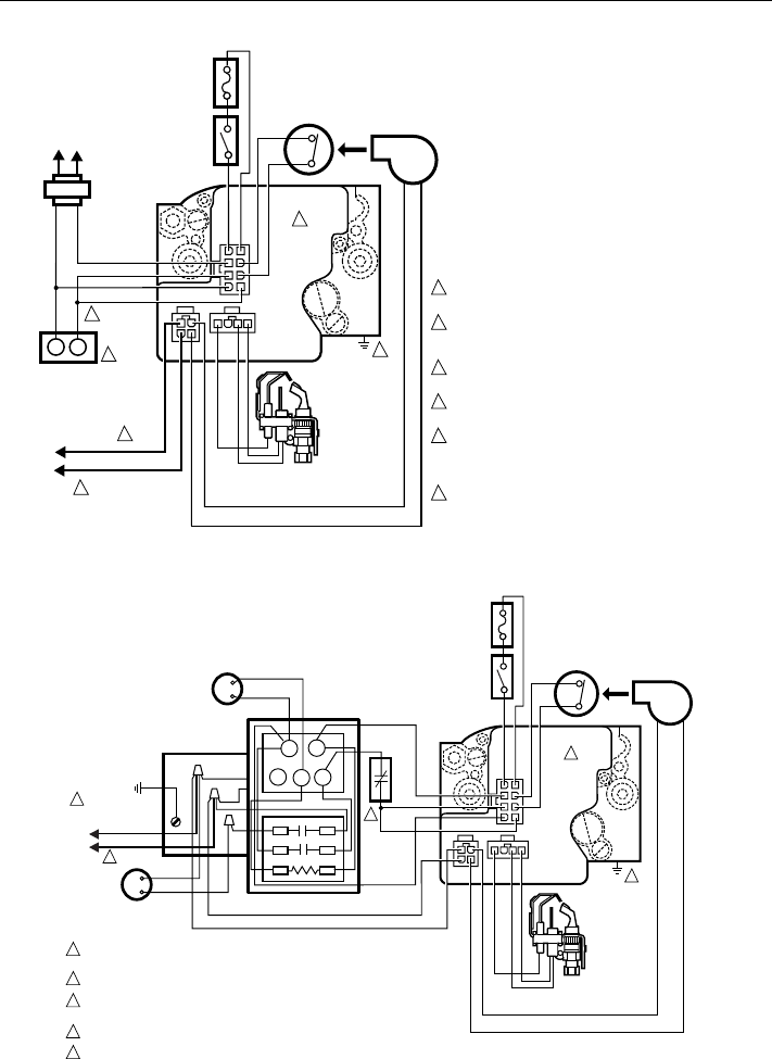
POWER SUPPLY. PROVIDE DISCONNECT MEANS AND OVERLOAD PROTECTION
AS REQUIRED.
CONNECT THE 120V (HOT) LEAD AS SHOWN.
DATA AND R LINES MUST BE CONNECTED TO AQUASTAT CONTROL FOR PROPER
SYSTEM OPERATION.
APPLIANCE CHASSIS MUST HAVE RELIABLE CONNECTION TO EARTH GROUND.
IN THIS APPLICATION, POSTPURGE FUNCTION IS NOT AVAILABLE AND THE LED
FUNCTIONS ONLY DURING A CALL FOR HEAT.
1
2
3
4
5
5
4
CIRCULATOR
RC
GY
W
13
46
L2
L1
(HOT)
1
2
3
TO 120 VAC, 60 HZ
POWER SUPPLY
Fig. 9. SV9540; SV9640 typical wiring connections direct to the system thermostat.
Fig. 10. SV9540; SV9640 typical boiler wiring diagram.
C1
C2
C3
40 VA
TRANSFORMER
L1 L2
LOAD
COMMON
THERMOSTAT
4
5
1
2
M12172
PRESSURE
SWITCH
NEUTRAL
HOT
L2
L1
(HOT)
TO
120/240 VAC, 60 HZ
POWER SUPPLY
ROLL-OUT
SWITCH
LIMIT
SWITCH
INDUCER
BLOWER
MOTOR
R
R
W
24 VAC
Q3450
IGNITER-
SENSOR
AIR
DATA
SV9540;
SV9640
POWER SUPPLY. PROVIDE DISCONNECT MEANS
AND OVERLOAD PROTECTION AS REQUIRED.
FOR 120 VAC INSTALLATIONS, CONNECT THE 120V (HOT)
LEAD TO L1. FOR 240 VAC INSTALLATIONS, THERE MUST
BE 120V BETWEEN L1 AND APPLIANCE CHASSIS.
APPLIANCE CHASSIS MUST HAVE A RELIABLE CONNECTION
TO EARTH GROUND.
DATA AND R LINES MUST BE CONNECTED TO W ON
THERMOSTAT FOR PROPER SYSTEM OPERATION.
THERMOSTAT MUST HAVE ZERO OFF-STATE CURRENT
DRAW. MECHANICAL SWITCH THERMOSTATS
RECOMMENDED. TRIAC SWITCH THERMOSTATS OR
POWER-STEALING THERMOSTATS ARE NOT RECOMMENDED.
IN THIS APPLICATION, POSTPURGE FUNCTION IS NOT
AVAILABLE AND THE LED FUNCTIONS ONLY DURING A
CALL FOR HEAT.
1
2
3
4
5
6
6
3
69-10599
SV9540; SV9640 SmartValve™ SYSTEM CONTROLS
1. Remove pilot adjustment cover screw. See Fig. 4.
2. Pilot adjustment is shipped at full flow rate. Turn the
inner adjustment screw clockwise if the inlet
pressure is too high. Turn the inner adjustment
screw clockwise to decrease or counterclock-
wise to increase pilot flame.
3. Replace the cover screw after the adjustment to
prevent gas leakage.
STARTUP AND CHECKOUT
Ignition System Control Switch Settings
Ignition system control switch settings are as follows:
OFF prevents pilot and main gas flow through the
ignition system control.
ON permits gas to flow through the control body. At the
appropriate time in the appliance operation, main
gas can flow to the main burner.
NOTE: Controls are shipped with the ignition system
control switch in the ON position. If the appliance
is operated with the ignition system control switch
in the OFF position, the system will respond as if
the air proving switch is stuck in the no airflow
position.
Turn on Main Burner
Follow the instructions provided by the appliance manufac-
turer or turn up the thermostat to call for heat.
Perform Gas Leak Test
WARNING
FIRE OR EXPLOSION HAZARD
CAN CAUSE PROPERTY DAMAGE,
SEVERE INJURY OR DEATH
Check for gas leaks with soap and water solution
any time work is done on a gas system.
CAUTION
Do not spray soap and water solution on the
SmartValve housing. Do not use an excessive
amount of soap and water solution to perform the
gas leak test. These can damage the control.
Gas Leak Test
1. Paint pipe connections upstream of the ignition
system control with rich soap and water solution.
Bubbles indicate a gas leak.
2. If a leak is detected, tighten the pipe connections.
3. Stand clear of the main burner while lighting to
prevent injury caused from hidden leaks that could
cause flashback in the appliance vestibule. Light the
main burner.
4. With the main burner in operation, paint the pipe
joints (including adapters) and the control inlet and
outlet with rich soap and water solution.
5. If another leak is detected, tighten the adapter
screws, joints, and pipe connections.
6. Replace the part if a leak cannot be stopped.
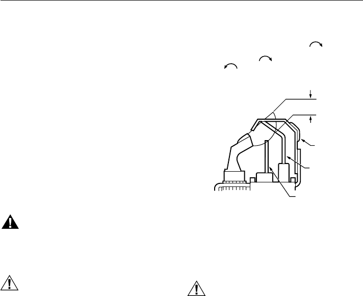
Check and Adjust Pilot Flame
The pilot flame should envelop 3/8 to 1/2 in. (10 to 13 mm)
of the tip of the flame rod. It should also be in continual
contact with the ground electrode. See Fig. 11. If the pilot
flame is small or lazy, or does not touch the ground
electrode, the inlet gas pressure may be too low, or the
pilot orifice may be partially clogged. Check and repair as
necessary. If the pilot flame is hard and noisy, the inlet gas
pressure may be too high. The ignition system control has
a pilot adjustment mechanism to reduce the pilot flow if
necessary. The pilot adjustment is shipped at the full pilot
gas flow rate. If pilot adjustment is necessary, proceed as
follows:
Fig. 11. Proper flame adjustment.
Check and Adjust Gas Input and
Burner Ignition
CAUTION
1. Do not exceed input rating stamped on
appliance nameplate, or manufacturer’s
recommended burner orifice pressure for size
orifice(s) used. Make certain primary air
supply to main burner is properly adjusted for
complete combustion. Follow instructions of
appliance manufacturer.
2. IF CHECKING GAS INPUT BY CLOCKING
GAS METER: Make certain there is no gas
flow through the meter other than to the
appliance being checked. Other appliances
must remain off with the pilots extinguished (or
that consumption must be deducted from the
meter reading). Convert flow rate to Btuh as
described in form 70-2602, Gas Controls
Handbook, and compare to Btuh input rating
on appliance nameplate.
3. IF CHECKING GAS INPUT WITH MANOM-
ETER: Make sure the ignition system control
is in the OFF position before removing outlet
pressure tap plug to connect manometer
(pressure gauge). Also move the ignition
system control switch to the OFF position
when removing the gauge and replacing the
plug. Before removing inlet pressure tap plug,
shut off gas supply at the manual valve in the
gas piping to the appliance or, for LP, at the
tank. Also shut off gas supply before discon-
necting manometer and replacing plug.
Repeat Gas Leak Test at plug with main
burner operating.
NOTE: Check the inlet pressure before adjusting the
pressure regulator.
PROPER FLAME
ADJUSTMENT
HOT SURFACE
IGNITER
FLAME ROD
M3350A
GROUND
ELECTRODE
3/8 TO 1/2 IN.
(10 TO 13 MM)
NOTE: GROUND ELECTRODE MUST NOT TOUCH FLAME
ROD (.050 IN. MINIMUM CLEARANCE). BEND GROUND
ELECTRODE IF NECESSARY. DO NOT BEND FLAME ROD.
69-1059 10
SV9540; SV9640 SmartValve™ SYSTEM CONTROLS
MAINTENANCE
WARNING
FIRE OR EXPLOSION HAZARD
CAN CAUSE PROPERTY DAMAGE,
SEVERE INJURY, OR DEATH
Do not attempt to take the control apart or clean
it. Improper cleaning or reassembly can cause
gas leakage.
Regular preventive maintenance is important in applica-
tions such as in the commercial cooking and agricultural
and industrial industries that place a heavy load on system
controls because:
• In many such applications, particularly commercial
cooking, the equipment operates 100,000 to 200,000
cycles per year. Such heavy cycling can wear out the
gas control in one to two years.
1. Carefully check the main burner lightoff. Make sure
that the main burner lights smoothly and that all
ports remain lit.
2. Check the full rate manifold pressure listed on the
appliance nameplate. Ignition system control full rate
outlet pressure should match this rating.
3. With main burner operating, check the ignition
system control flow rate using the meter clocking
method or check pressure using a manometer
connected to the outlet pressure tap on the ignition
system control. See Fig. 4.
4. If necessary, adjust the pressure regulator to
match the appliance rating. See Tables 7A and 7B
for factory-set nominal outlet pressure and
adjustment range.
a. Remove the pressure regulator adjustment
cap screw.
b. Using a screwdriver, turn the inner adjustment
screw clockwise to increase or
counterclockwise to decrease the gas
pressure to the burner.
c. Always replace the cap screw and tighten
firmly to prevent gas leakage.
5. If the desired outlet pressure or flow rate cannot be
achieved by adjusting the ignition system control,
check the ignition system control inlet pressure
using a manometer at the ignition system control
inlet pressure tap. If the inlet pressure is in the
nominal range (see Tables 7A and 7B), replace the
ignition system control. Otherwise, take the
necessary steps to provide proper gas pressure to
the control.
NOTE: If the burner firing rate is above 150,000
Btuh on SV9540 models (see Table 3 for
SV9640 capacities), it may not be possible
to deliver the desired outlet pressure. This
is an application issue, not a control failure.
Take whatever steps are required to
correct the situation.
6. STEP-OPENING PRESSURE REGULATORS
ONLY. Carefully check the burner lightoff at step
pressure. Make sure the burner lights smoothly
and without flashback to the orifice. Make sure all
ports remain lit. Cycle the burner several times,
allowing at least 60 seconds between cycles for
the regulator to resume the step function. Repeat
after allowing the burner to cool. Readjust the full
rate outlet pressure, if necessary, to improve
lightoff characteristics.
Nominal Inlet
Factory Set
Nominal Outlet Pressure Setting Range
Model Type Type of Gas Pressure Range Step Full Rate Step Full Rate
Standard, Slow NAT 5.0-7.0 — 3.5 — 3.0-5.0
LP 12.0-14.0 — 10.0 — 8.0-12.0
Step NAT 5.0-7.0 0.9 3.5 None 0.7-1.7
LP 12.0-14.0 2.2 10.0 None 1.4-5.5
Nominal Inlet
Factory Set
Nominal Outlet Pressure Setting Range
Model Type Type of Gas Pressure Range Step Full Rate Step Full Rate
Standard, Slow NAT 1.2-1.7 — 0.9 — 0.7-1.2
LP 2.9-3.9 — 2.5 — 2.0-3.0
Step NAT 1.2-1.7 0.2 0.9 None 0.17-0.48
LP 2.9-3.9 0.5 2.5 None 1.4-1.37
Table 7A. Pressure Regulator Specification Pressures (in. wc).
Table 7B. Pressure Regulator Specification Pressures (kPa).
• Exposure to water, dirt, chemicals and heat can damage
the gas control and shut down the control system.
The maintenance program should include regular check-
out of the control as outlined in the Startup and Checkout
section, and the control system as described in the
appliance manufacturer literature.
Maintenance frequency must be determined individually
for each application. Some considerations are:
• Cycling frequency. Appliances that may cycle 20,000
times annually should be checked monthly.
• Intermittent use. Appliances that are used seasonally
should be checked before shutdown and again before
the next use.
• Consequence of unexpected shutdown. Where the cost
of an unexpected shutdown would be high, the system
should be checked more often.
• Dusty, wet, or corrosive environment. Since these
environments can cause the gas control to deteriorate
more rapidly, the system should be checked more often.
69-105911
SV9540; SV9640 SmartValve™ SYSTEM CONTROLS
The system should be replaced if:
• It does not perform properly on checkout or trouble-
shooting.
• The gas control is likely to have operated for more than
200,000 cycles.
• The control is wet or looks as if it has been wet.
SERVICE
WARNING
FIRE OR EXPLOSION HAZARD
CAN CAUSE PROPERTY DAMAGE,
SEVERE INJURY OR DEATH
Do not disassemble the ignition system control; it
contains no replaceable components. Attempted
disassembly or repair can damage the ignition
system control.
CAUTION
1. Do not apply a jumper across or short any of
the terminals in the SV9540; SV9640 wiring
harness. Doing so can damage the system
transformer or the system control.
2. After servicing, verify proper system operation.
IMPORTANT
Allow 60 seconds after shutdown before re-
energizing step-opening model to assure lightoff
at step pressure.
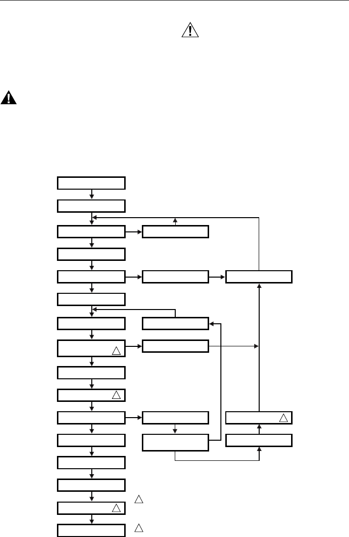
Sequence of Operation
1. Make sure the ignition system control switch is in the
ON position.
2. Follow the sequence of operation as shown in
Fig. 12.
THERMOSTAT CALLS FOR HEAT
AIR PROVING SWITCH PROVED
OPEN?
COMBUSTION AIR BLOWER ON
PILOT VALVE OPENS;
IGNITER POWERED
PILOT LIGHTS AND FLAME IS
SENSED DURING TRIAL
FOR IGNITION?
CIRCULATING AIR FAN ON
AFTER DELAY
MAIN VALVE OPENS;
IGNITER OFF
FLAME SENSE LOST?
THERMOSTAT CALL FOR
HEAT ENDS
FIVE-MINUTE WAIT PERIOD
WAIT FOR AIR PROVING
SWITCH TO OPEN
FLAME SENSE LOST MORE
THAN FIVE TIMES IN THIS CALL
FOR HEAT?
PREPURGE
AIR PROVING SWITCH PROVED
CLOSED WITHIN 30 SECONDS? COMBUSTION AIR BLOWER OFF
PILOT VALVE CLOSES;
PILOT IGNITER OFF
COMBUSTION AIR BLOWER
OFF AFTER POST PURGE
PILOT AND MAIN VALVES CLOSE
COMBUSTION AIR BLOWER OFF
AFTER POST PURGE
CIRCULATING AIR FAN OFF
AFTER DELAY
WAIT FOR NEXT CALL FOR HEAT
THREE-SECOND FLAME
FAILURE RECYCLE DELAY
NO
YES
YES
YES
NO
NO
PILOT AND MAIN VALVES
CLOSE
YES
NO
YES
NO
M12234
SV9540; SV9640 INTERMITTENT PILOT SmartValve™
SYSTEM CONTROL SEQUENCE OF OPERATION
WITH ST9160 ELECTRONIC FAN TIMER OR 208907 TERMINAL BOARD
2
1
2
CIRCULATING AIR FAN OFF
AFTER DELAY 2
1
2
IGNITER TURNS OFF ABOUT 30 SECONDS INTO THE TRIAL FOR IGNITION
IF THE PILOT FLAME HAS NOT LIT. IT TURNS BACK ON FOR THE FINAL
30 SECONDS OF THE 90 SECOND TRIAL FOR IGNITION. THE PILOT VALVE
IS ENERGIZED DURING THE ENTIRE TRIAL FOR IGNITION. THIS IS NORMAL
OPERATION FOR THIS GAS IGNITION SYSTEM.
THIS FUNCTION OCCURS ONLY WITH ST9160 CONNECTED TO SmartValve™
SYSTEM CONTROL.
POWER APPLIED TO APPLIANCE
Fig. 12. SV9540; SV9640 sequence of operation.

69-1059 12
SV9540; SV9640 SmartValve™ SYSTEM CONTROLS
TROUBLESHOOTING
Troubleshooting with LED Indicator Assistance
No cycling of appliance power or thermostat call for heat since appliance failure has occurred.
WARNING
LINE VOLTAGE POWER
CAN CAUSE PRODUCT DAMAGE, SEVERE INJURY OR DEATH
Only a trained, experienced service technician should perform this troubleshooting.
1. Check the system thermostat to make sure it is calling for heat. (Do not cycle the thermostat on and off at this time.)
2. Remove the appliance burner compartment door. Do not interrupt power to the SV9540; SV9640 by opening any
electrically interlocked panels.
3. Observe the LED indicator on the SV9540; SV9640; check and repair system as noted in the following chart:
LED Status Indicates Check/Repair
Off No power to system control. 1. Line voltage input power at L1 and L2
connectors on ST9160 Electronic Fan Timer
(EFT) or 208907 Terminal Board
2. Low voltage (24V) power at 24 VAC and COM
terminals on ST9160 or Terminal Board
3. Fuse on ST9160 EFT, if provided.
4. System wiring harness is in good condition
and securely connected at both ends.
Bright—Dim Normal Operation
This indication shows whenever the system is
powered, unless some abnormal event has
occurred.
Not Applicable
2 Flashes Airflow proving switch remains closed longer
than 30 seconds after a call for heat begins.
Combustion air blower is not energized until
airflow proving switch opens.
1. Airflow proving switch stuck closed.
2. Airflow proving switch miswired or jumpered.
3 Flashes Airflow proving switch remains open longer than
30 seconds after combustion air blower
energized.
System goes into 5 minute delay period, with
combustion air blower off. At the end of the 5
minute delay, another ignition cycle will begin.
1. Ignition system control switch must be in the
ON position.
2. Airflow proving switch operation, tubing, and
wiring.
3. Obstructions or restrictions in appliance air
intake or exhaust flue system that prevent
proper combustion airflow.
4 Flashes Limit string is open.
Combustion air blower is energized. If control
system includes ST9160 Electronic Fan Timer,
the heat speed circulating air fan will be
energized until the limit string resets.
1. Open manual reset or auto reset burner
rollout switch.
2. Open high temperature or auxiliary limit
switch.
3. Limit and rollout switch wiring is in good
condition and securely connected.
5 Flashes Flame signal sensed out of proper sequence.
Combustion air blower is energized. If control
system includes ST9160 Electronic Fan Timer,
the heat speed circulating air fan will be
energized after the selected heat fan on delay.
Flame at pilot burner.
6 Flashes System Lockout
After 5 minute delay time, control system will
reset and initiate a new ignition sequence, if the
call for heat is still present.
1. Gas supply off or at too low pressure to
operate appliance
2. Damaged or broken HSI element
3. Line voltage HOT leadwire not connected to
L1 terminal on ST9160 or Terminal Board.
4. Appliance not properly earth grounded.
5. Flame sense rod contaminated or in incorrect
location.
6. Pilot burner located in incorrect position.
7. Pilot burner leadwires are in good condition
and properly connected.

69-105913
SV9540; SV9640 SmartValve™ SYSTEM CONTROLS
4. After LED flash code analysis and appliance repair are complete, turn the thermostat below room temperature for 10
seconds; turn the thermostat above room temperature to initiate a new call for heat.
5. Observe the ignition sequence, comparing it to the Sequence of Operation shown in Fig. 12. Allow the new ignition
sequence to proceed until appliance lights or an abnormal or unexpected event is observed. See next section.
Troubleshooting Without LED Indicator Assistance
Appliance power or thermostat call for heat has cycled since appliance failure occurred.
WARNING
LINE VOLTAGE POWER
CAN CAUSE PRODUCT DAMAGE, SEVERE INJURY OR DEATH
Only a trained, experienced service technician should perform this troubleshooting.
1. Make sure the appliance power is on and any manually operated gas cock on the appliance is open.
2. Remove appliance burner compartment door. Confirm that SV9540; SV9640 LED indicator is flashing in a “bright -
dim” sequence.
3. Make sure the ignition system control switch is in the ON position.
4. Disconnect the system thermostat leadwires at the ST9160 EFT or the 208907 Terminal Board.
5. Using alligator clips on a short jumper wire, jumper the R and W terminals on the EFT or Terminal Board.
6. Observe the appliance operation, comparing it to the Sequence of Operation shown in Fig. 12 . Allow the ignition sequence
to proceed until the appliance lights or an abnormal or unexpected event is observed.
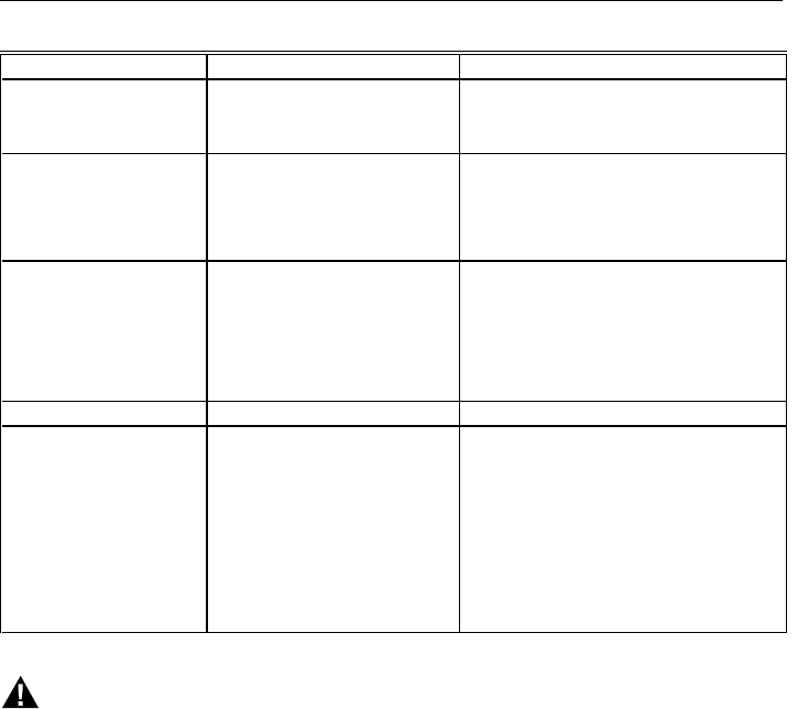
7. Check the appliance as shown in the following table:
If And Check/Repair
Combustion air blower does
not energize. 2 Flash code does not come on 30
seconds after call for heat starts. 1. Combustion air blower wiring
2. Combustion air blower
Combustion air blower does
not energize. 2 Flash code does come on 30
seconds after call for heat starts. 1. Airflow proving switch stuck closed.
2. Airflow proving switch miswired or
jumpered.
Combustion air blower is
energized. 3 Flash code does not come on
after 30 seconds. Wait for the prepurge time to expire
3 Flash code comes on 30
seconds after combustion
air blower is energized.
Combustion air blower turns off. 1. Ignition system control switch must be in
the ON position.
2. Airflow proving switch stuck in open
position.
3. Airflow proving switch tubing and wiring
4. Obstructions or restrictions in appliance
air intake or exhaust flue system that
prevent proper combustion air flow
.
Prepurge time has expired. HSI element does not glow red
within 5 seconds. 1. Broken or damaged HSI element
2. Broken or damaged HSI element leadwires
3. SV9540; SV9640 failure to power HSI
element.
HSI element is glowing red. Pilot does not light during the 90
second trial for ignition.
NOTE: HSI element will turn off
for approximately 25
seconds during the 90
second trial for igniton.
1. Pilot tubing not purged of air [Intiate
another ignition sequence with the R-W
jumper to clear pilot tubing more quickly]
2. Inlet gas pressure too low for proper
appliance operation.
3. Pilot burner improperly positioned in
airflow
4. Clogged or incorrect pilot orifice.
5. Combustion air blower moving pilot gas
away from HSI element.
Pilot lights during trial for
ignition.
Main gas does not flow.
If pilot flame is not sensed during
trial for ignition, main valve will not
open. System will shut off HSI
element and pilot gas flow, go
through a 5 minute delay period,
then initiate another ignition trial.
1. Line voltage to L1 terminal of ST9160 or
Terminal Board must be 120 volts with
reference to appliance chassis.
2. Appliance must be reliably connected to
earth ground.
3. Combustion air blower moving pilot flame
away from pilot burner flame rod.
4. Inlet gas pressure too low for proper flame
sensing.
5. Flame sense rod contaminated or in
incorrect location.
6. Wiring between SV9540; SV9640 and
pilot burner must be in good condition and
properly connected.
69-1059 14
SV9540; SV9640 SmartValve™ SYSTEM CONTROLS
Instructions to the Homeowner
WARNING
FIRE OR EXPLOSION HAZARD
CAN CAUSE PROPERTY DAMAGE,
SEVERE INJURY, OR DEATH
Follow these warnings exactly:
1. Pilot flame is lit automatically. Do not light the
pilot flame manually.
2. Before lighting the pilot burner flame, smell
around the appliance for gas. Be sure to smell
next to the floor because LP gas is heavier
than air.
3. IF YOU SMELL GAS:
• Turn off the gas supply at the appliance
service valve. On LP gas systems, turn
off the gas supply at the gas tank.
• Do not light any appliances in the house.
• Do not touch electrical switches or use
the phone.
• Leave the building and use a neighbor’s
phone to call your gas supplier.
• If you cannot reach your gas supplier, call
the fire department.
4. The ignition system control must be replaced in
event of any physical damage, tampering, bent
terminals, missing or broken parts, stripped
threads, or evidence of exposure to heat.
IMPORTANT
Follow the operating instructions provided by the
manufacturer of your heating appliance. The
information below describes a typical ignition
system control application, but the specific
controls used and the procedures outlined by the
manufacturer of your appliance can differ,
requiring special instructions.
STOP: Read the Warnings Above.
The pilot flame is lit automatically. If the appliance does not
turn on when the thermostat is set several degrees above
room temperature, follow these instructions:
1. Set the thermostat to its lowest setting to reset the
safety control.
2. Disconnect all electric power to the appliance.
3. Remove the ignition system control access panel.
4. Move the ignition system control switch to the OFF
position.
5. Wait five minutes to clear out any unburned gas. If
you then smell gas, STOP! Follow Step 3 in the
Warning above. If you do not smell gas, continue
with the next step.
6. Move the ignition system control switch to the ON
position.
7. Replace the ignition system control access panel.
8. Reconnect all electric power to the appliance.
9. Set the thermostat to the desired setting.
10. If the appliance does not turn on, move the ignition
system control switch to the OFF position and
contact a qualified service technician for assistance.
Turning off the Appliance
Vacation Shutdown—
Set the thermostat to the desired room temperature while
you are away.
Complete Shutdown—
Turn off power to the appliance. Turn off the gas supply to
the appliance. Appliance will completely shut off. Follow
the procedure in the Instructions to the Homeowner
section above to resume normal operation.
If And Check/Repair
Main burner lights. Circulating air fan is not turned on
after appropriate delay time
(systems with ST9160 Electronic
Fan Timer only).
1. Wiring between SV9540; SV9640 and
ST9160 EFT.
2. Proper operation of ST9160 EFT.
Main burner goes out before
thermostat call for heat
ends.
4 Flash code comes on. 1. Open manual reset or auto reset burner
rollout switch.
2. Open high temperature or auxiliary limit
switch.
3. Limit and rollout switch string wiring is in
good condition and securely connected
.
Main burner goes out before
thermostat call for heat
ends.
4 Flash code does not come on. 1. Intermittent wiring connection between
SV9540; SV9640 and pilot burner.
2. Combustion air blower moving pilot flame
away from pilot burner flame rod.
3. Airflow proving switch has opened.
4. Flame sense rod ceramic or leadwire
overheated.
5. Gas flow supply reduced or interrupted.
5 Flash code comes on. Flame at pilot burner.
6 Flash code comes on.
After 5 minute delay time,
control system will reset and
initiate a new ignition
sequence, if the call for heat
is still present.
1. Gas supply off or at too low pressure to
operate appliance
2. Damaged or broken HSI element
3. Line voltage to L1 terminal on ST9160 or
Terminal Board must be 120 volts with
reference to appliance chassis.
4. Appliance not properly earth grounded.
5. Flame sense rod contaminated or in
incorrect location.
6. Pilot burner located in incorrect position.
7. Pilot burner leadwires in good condition
and properly connected

69-105915
SV9540; SV9640 SmartValve™ SYSTEM CONTROLS

69-1059 16
SV9540; SV9640 SmartValve™ SYSTEM CONTROLS
Home and Building Control
Honeywell Limited-Honeywell Limitée
155 Gordon Baker Road
North York, Ontario
M2H 3N7
Helping You Control Your World®
69-1059 C.H. 5-97
Home and Building Control
Honeywell Inc.
Honeywell Plaza
P.O. Box 524
Minneapolis, MN 55408-0524
Printed in U.S.A. on recycled
paper containing at least 10%
post-consumer paper fibers.
