Installation Directions
2016-10-06
: Pdf 155894-Installationsheet 155894-InstallationSheet B5 unilog
Open the PDF directly: View PDF ![]() .
.
Page Count: 4
© 2014 Pentair Equipment Protection PH 763 422 2211 • pentairprotect.com 89115481Rev. A P/N 89114651
OPERATOR ADAPTER ABL
Installation Instructions for Allen-Bradley Bulletin 1494V,
1494C, 140G and 140U Large Handle Disconnect Switches
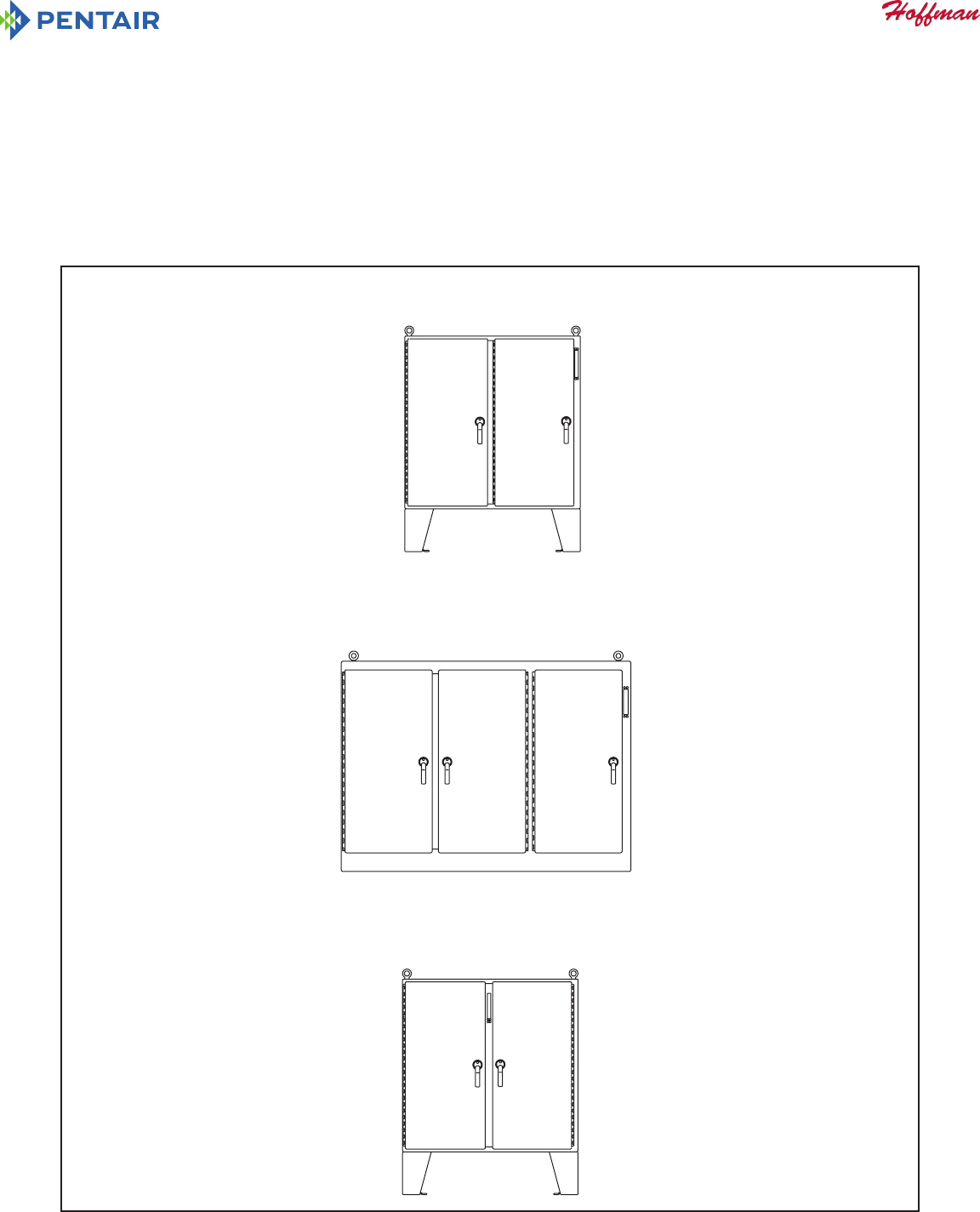
)RUIORRUPRXQWHGHQFORVXUHVZLWK
WKHGLVFRQQHFWRQWKHULJKWIODQJH
)RUIORRUPRXQWHGHQFORVXUHVZLWK
WKHGLVFRQQHFWRQWKHFHQWHUSRVW
)RURQHWKURXJKVL[GRRUIUHHVWDQGLQJHQFORVXUHV
ZLWKWKHGLVFRQQHFWWKHWKHULJKWIODQJH
0DVWHU
'RRU
0DVWHU
'RRU
0DVWHU
'RRU

© 2014 Pentair Equipment Protection PH 763 422 2211 • pentairprotect.com 89115481- 2 -
Parts List
Operator Adapter, Catalog Number ABL, for Allen-Bradley Bulletins 1494V, 1494C, 140G and 140U Disconnects
Item No. Description Part No. Qty.
1 ADAPTER PLATE, LARGE 879 32136 1
2 PLATE GASKET 89109613 1
3 SCREW, 1/4-20X1/2 PAN HEAD 99401031 4
4 SLIDE ARM, ASSEMBLY 27111002 1
5 SHOULDER COLLAR, 3/4 DIAMETER 27112001 1
6 SCREW, 5/16-18X1 HEX HEAD 99401081 1
7 WASHER FLAT 22101003 2
8 LOCK WASHER, 1/4 INTERNAL TEETH 99401300 2
9 NUT, HEX 1/4-20 99401406 2
10 DOOR CATCH 23101002 1
11 SCREW, 10-32X3/8 PAN HEAD 99401007 2
12 LOCK WASHER, #10 INTERNAL TEETH 99401307 2
13 NYLON WASHER 23132003 4
14 LOCKWASHER, 1/4 SPRING 99401305 1
15 INSTALLATION INSTRUCTIONS 89114651 1
© 2014 Pentair Equipment Protection PH 763 422 2211 • pentairprotect.com89115481 - 3 -
INTRODUCTION
This installation instruction is for the Allen−Bradley Large Handle.
Bulletin 1494V, 1494C, 140G and 140U mechanisms.
These mechanisms are for disconnect switches and circuit breakers mounted in Homan two door, oor−mounted with cutout on right
hand ange or centerpost and one through six door, free−standing enclosures with the disconnect on the right ange.
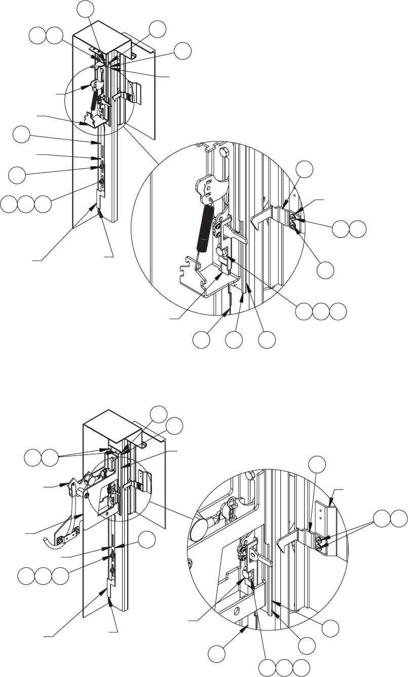
ALLEN-BRADLEY SMALL HANDLE INSTALLATION STEPS
See Figure 1 for 1494V and 140G Variable Depth or Figure 2 for 1494C, 140G and 140U Cable Control.
Step 1
Install adapter plate (item 1) and plate gasket (item 2) on the inside of the enclosure, behind the rectangular opening provided. Gasket side
with PSA should be attached to the Adapter Plate. Secure in place with four screws (item 3), and four nylon washers (item 13).
Step 2 − Install Large Handle
(1494V, 1494C, 140G and 140U) Assemble the Allen-Bradley operating mechanisem and 1494F-M2 or 1494F-S2 large handle to the
adapter plate which was installed in Step 1. Omit cap screw and lockwasher which t into bottom hole of Allen−Bradley operating handle.
Step 3 − Install Slide Arm and Defeater Bracket
(1494V and 140G Varaiable Depth) Install slide arm (item 4) through the hole in bottom of Allen−Bradley spring bracket. Put Allen−Bradley
defeater bracket through slot in the end of the slide arm and mount per Allen−Bradley instructions. Place the smaller diameter end of
3/4 diameter shoulder collar (item 5) through oval slot in slide arm. Install longer cap screw (item 6) with lockwasher (item 14) through
shoulder collar into bottom mounting hole of Allen−Bradley operating handle and tighten. The slide arm should move up and down
smoothly.
(1494C, 140G and 140U Cable Control) Put Allen−Bradley defeater bracket through slide arm (item 4) end slot and mount defeater bracket
per Allen−Bradley instructions. Place the smaller diameter end of 3/4 diameter shoulder collar (item 5) through oval slot in slide arm. Install
longer cap screw (item 6) with lockwasher (item 14) through shoulder collar into bottom mounting hole of Allen−Bradley operating handle
and tighten. The slide arm should move up and down smoothly.
Step 4
Attach the bottom of the slide arm assembly (item 4) to the oset arm of the operator release mechanism. Use two at washers (item 7),
two lockwashers (item 8), and two hex nuts (item 9). Do not tighten until parts are adjusted. (See Step 5B).
Step 5 − The operator release mechanism is adjustable in two places
(A) Check the adjustment of the factory-installed roller bracket. The door latch should hit against the latch portion of the roller bracket
when the door is closed and latched. Adjust up or down if necessary. The mechanism will then provide the necessary up−down motion
required to operate the safety lock release in the Allen−Bradley operating handle.
(B) Adjust the length of the slide arm assembly with proper adjustment of the slide arm. The safety lock (in Allen−Bradley operating
handle) should release just before the master door is fully latched. Lengthen slide arm if safety lock releases too soon. Shorten slide arm if
safety lock releases too late.
Step 6
Attach the door catch (item 10) provided by Homan to the tapped spacer on the door using the bottom set of mounting holes. Use two
screws (item 11) and two lockwashers (item 12). The door catch prevents the door from being opened when the Allen−Bradley operating
handle is in the “ON” position.
Step 7
Drill and tap holes in panel PER ALLEN-BRADLEY INSTRUCTIONS.
Step 8
Install panel in enclosure.
Step 9
Mount disconnect switch or circuit breaker on panel using Allen-Bradley instructions and parts. For variable depth disconnects, nd the
enclosure depth dimension. See Allen−Bradley instructions to cut the connecting rod to length required and install and adjust Allen−
Bradley connecting rod per Allen−Bradley instructions.
© 2014 Pentair Equipment Protection PH 763 422 2211 • pentairprotect.com 89115481- 4 -
'()($7(5+$1'/($1'
02817,1*%5$&.(7
:,7++$5':$5(
1276833/,('%<+2))0$1
2))6(7$50
$77$&+('72
23(5$7255(/($6(
0(&+$1,60
67(3
67(3
67(3
67(3
67(3
67(3
72548(,1/%6
72548(,1/%6
72548(,1/%6
72548(,1/%6
),*85(
'()($7(5+$1'/($1'
02817,1*%5$&.(7
:,7++$5':$5(
1276833/,('%<+2))0$1
2))6(7$50
$77$&+('72
23(5$7255(/($6(
0(&+$1,60
67(3
67(3
67(3
67(3
67(3
67(3
72548(,1/%6
72548(,1/%6
72548(,1/%6
),*85(
72548(,1/%6
