157806 Catalog 1
2016-07-29
: Pdf 157806-Catalog 1 157806-Catalog_1 B2 unilog
Open the PDF directly: View PDF ![]() .
.
Page Count: 240 [warning: Documents this large are best viewed by clicking the View PDF Link!]

National Electric Contact:
Paul Martinez
505-424-9144
505-660-1675
10/02/2015
National Electric Supply Co. ∙ 2200 Midtown Pl. NE, Suite C ∙ Albuquerque, NM 87107 ∙ 505.345.3577 ∙ Fax 505.344.5801
Los Alamos Teen Center
Sanbros Corporation
O&M Manual
YOUR PARTNER FOR SUCCESS

Operation & Maintenance Manual
General Order
SAQ0594802
Volume 1 of 1
Equipment:
Panelboards
Safety Switches
LOS ALAMOS TEEN CENTER
Date: 10/2/2015
NATIONAL ELEC SUP SANTA FE NM PO# 214617
SANBROS CORPORATION
©2015 Eaton Corporation, All Rights Reserved

Main Table of Contents
Contact Page
3
1.0
Panelboards
4
1.1
Drawings
5
1.2
Instruction Data
14
1.3
Component Data
44
1.4
Renewal Parts
47
2.0
Safety Switches
92
2.1
Drawings
93
2.2
Instruction Data
98
2.3
Renewal Parts
128

Visit our Web Site http://www.eatonelectrical.com to view the on-line
catalog, pricing, document support, distribution directory, news and
events.
For warranty support 877-ETNCARE
For a general directory
of Eaton Electrical products (800) 525-2000
For on-site field service,
commissioning & maintenance (800) 498-2678
Contact Information

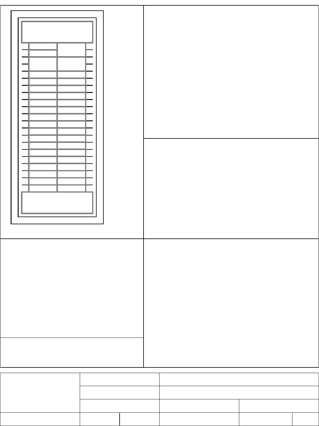
Panelboards

Drawings

1 2
3 4
5 6
7 8
9 10
11 12
13 14
15 16
17 18
19 20
21 22
23 24
25 26
27 28
29 30
31 32
33 34
35 36
37 38
39 40
41 42
43 44
45 46
47 48
49 50
51 52
53 54
Main Lugs Only
225A
BAB1020 BAB1020
BAB1020 BAB1020
BAB1020 BAB1020
BAB1020 BAB1020
BAB1020 BAB1020
BAB1020 BAB1020
BAB1020 BAB1020
BAB1020 BAB1020
BAB1020 BAB1020
BAB1020 BAB1020
BAB1020 BAB1020
BAB1020 BAB1020
BAB1020 BAB1020
BAB1020 BAB1020
BAB1020 BAB1020
BAB1020
BAB1020
BAB1020 BAB1020
BAB1020
BAB1020
BAB3025H BAB1020
BAB1020
Blank Cover
27 inches
PROV
PROV PROV
PROV PROV
PROV PROV
PROV PROV
PROV PROV
PROV PROV
General Information (Section 1 of 1)
Service Voltage: 208Y/120V 3Ph 4W Enclosure: Type 1
Bus Rating & Type: 225A Aluminum Neutral Rating: 225A
Ground Bar: Std. Bolted Copper, Cu cable only
S.C. Rating: 10k A.I.C. Fully Rated
Main Device Type: Main Lugs Only - Top Cable Entry
Main Terminals: Mechanical - (1) #4-500 kcmil (Cu/Al)
Neutral Terminals: Mechanical - (1) #4-500 kcmil (Cu/Al)
Box Catalog No.: No Box
Trim: EZ Trim, Door in Door, Concealed Hardware (EZT2072F)
Flush Mounted
Box Dimensions: 72.00" [1828.8mm]H x 20.00" [508.0mm]W x 5.75" [146.1mm]D
Min. Gutter Size: Top = 5.5" [139.7mm] Bottom = 5.5" [139.7mm]
Left = 6.0" [152.4mm] Right = 6.0" [152.4mm]
Panel ID Nameplate: (1) PANEL B
Type: Plastic, adhesive-backed (2) 208Y/120V 3Ph 4W
Color: White with Black Letters (3)
UL
Trim Lock: Standard Lock & Key (Keyed WEM2)
Circuit Directory: Plastic Sleeve with Card
Branch Devices
Qty Poles Trip Frame Amps kAIC
38 1 20 BAB 100 10
1 3 25 BAB 100 10
13 1 PROV
Device Modifications:
Ref # Description
Notes:
NEG-ALT Number
PREPARED BY DATE
APPROVED BY DATE
VERSION
REVISION DWG SIZE
JOB NAME
DESIGNATION
TYPE
G.O.
DRAWING TYPE
ITEM SHEET
The information on this document is
created by Eaton Corporation. It is
disclosed in confidence and it is only to
be used for the purpose in which it is
supplied.
D63N0325X5K1-0000
PAUL MARTINEZ 10/2/2015
1.0.0.3
0 A
Eaton
LOS ALAMOS TEEN CENTER
PANEL B
PRL1a
SAQ0594802
Final
001I 1 of 1
1 2
3 4
5 6
7 8
9 10
11 12
13 14
15 16
17 18
19 20
21 22
23 24
25 26
27 28
29 30
31 32
33 34
35 36
37 38
39 40
41 42
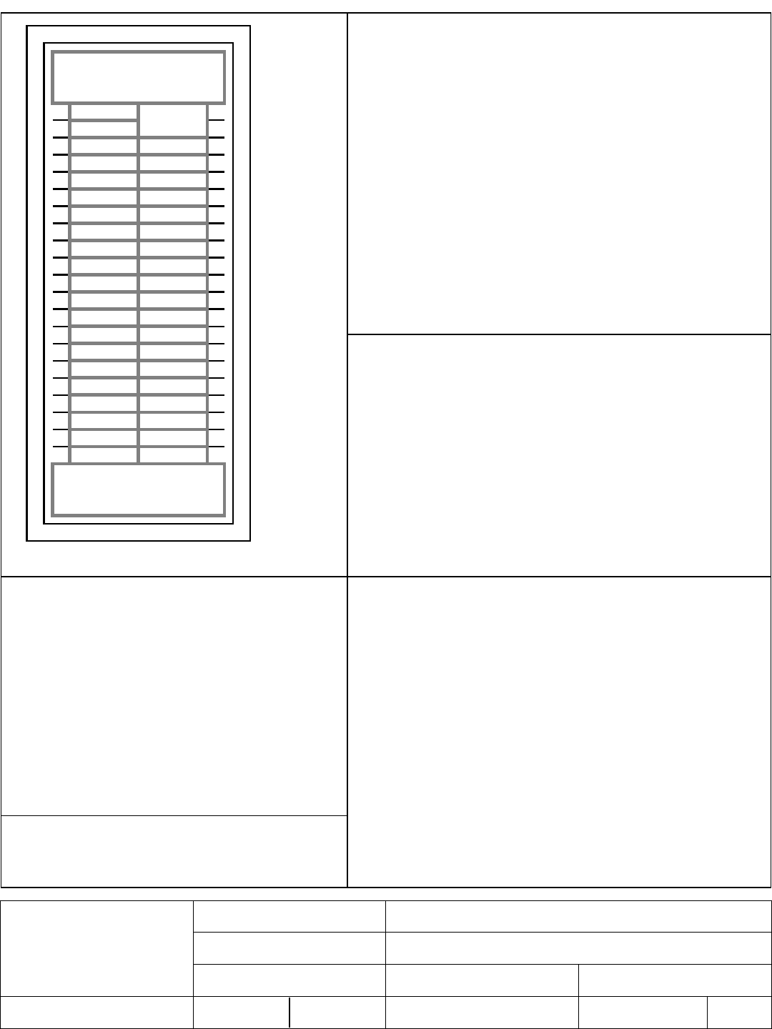
Main Lugs Only
100A
BAB2030
BAB1020
BAB1020
BAB1020
BAB1020
BAB2030
BAB1020
BAB1020
BAB1020
BAB2030
BAB1020
BAB1020
Blank Cover
2 inches
PROV PROV
PROV PROV
PROV PROV
PROV PROV
PROV
PROV PROV
PROV PROV
PROV PROV
PROV PROV
PROV PROV
PROV PROV
PROV PROV
PROV PROV
PROV PROV
General Information (Section 1 of 1)
Service Voltage: 208Y/120V 3Ph 4W Enclosure: Type 1
Bus Rating & Type: 100A Aluminum Neutral Rating: 100A
Ground Bar: Std. Bolted Copper, Cu cable only
S.C. Rating: 10k A.I.C. Fully Rated
Main Device Type: Main Lugs Only - Top Cable Entry
Main Terminals: Mechanical - (1) #6-300 kcmil (Cu/Al)
Neutral Terminals: Mechanical - (1) #6-300 kcmil (Cu/Al)
Box Catalog No.: No Box
Trim: EZ Trim, Door in Door, Concealed Hardware (EZT2042S)
Surface Mounted
Box Dimensions: 42.00" [1066.8mm]H x 20.00" [508.0mm]W x 5.75" [146.1mm]D
Min. Gutter Size: Top = 5.5" [139.7mm] Bottom = 5.5" [139.7mm]
Left = 6.0" [152.4mm] Right = 6.0" [152.4mm]
Panel ID Nameplate: (1) PANEL C
Type: Plastic, adhesive-backed (2) 208Y/120V 3Ph 4W
Color: White with Black Letters (3)
NEC Lighting & Appliance, UL CTL ***Non-Interchangeable Main Device***
Conduit Shields: Top = Open Back - 48H
Bottom = Open Back - 33H
Trim Lock: Standard Lock & Key (Keyed WEM2)
Circuit Directory: Plastic Sleeve with Card
Branch Devices
Qty Poles Trip Frame Amps kAIC
9 1 20 BAB 100 10
3 2 30 BAB 100 10
27 1 PROV
Device Modifications:
Ref # Description
Notes:
NEG-ALT Number
PREPARED BY DATE
APPROVED BY DATE
VERSION
REVISION DWG SIZE
JOB NAME
DESIGNATION
TYPE
G.O.
DRAWING TYPE
ITEM SHEET
The information on this document is
created by Eaton Corporation. It is
disclosed in confidence and it is only to
be used for the purpose in which it is
supplied.
D63N0325X5K1-0000
PAUL MARTINEZ 10/2/2015
1.0.0.3
0 A
Eaton
LOS ALAMOS TEEN CENTER
PANEL C
PRL1a
SAQ0594802
Final
002I 1 of 1
1 2
3 4
5 6
7 8
9 10
11 12
13 14
15 16
17 18
19 20
21 22
23 24
25 26
27 28
29 30
31 32
33 34
35 36
37 38
39 40
41 42
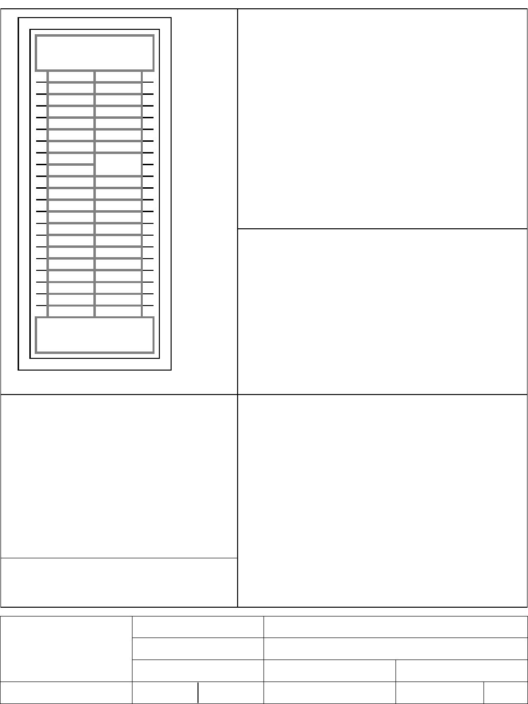
Main Lugs Only
100A
BAB1020
BAB1020
BAB1020 BAB1020
BAB1020
BAB1020
BAB1020
BAB1020
BAB1020
BAB1020
BAB1020
BAB1020
BAB2020
BAB1020
Blank Cover
2 inches
PROV PROV
PROV PROV
PROV PROV
PROV PROV
PROV
PROV PROV
PROV PROV
PROV PROV
PROV PROV
PROV PROV
PROV PROV
PROV PROV
PROV PROV
PROV PROV
General Information (Section 1 of 1)
Service Voltage: 208Y/120V 3Ph 4W Enclosure: Type 1
Bus Rating & Type: 100A Aluminum Neutral Rating: 100A
Ground Bar: Std. Bolted Aluminum, Al or Cu cable
S.C. Rating: 10k A.I.C. Fully Rated
Main Device Type: Main Lugs Only - Top Cable Entry
Main Terminals: Mechanical - (1) #6-300 kcmil (Cu/Al)
Neutral Terminals: Mechanical - (1) #6-300 kcmil (Cu/Al)
Box Catalog No.: No Box
Trim: EZ Trim, Door in Door, Concealed Hardware (EZT2042S)
Surface Mounted
Box Dimensions: 42.00" [1066.8mm]H x 20.00" [508.0mm]W x 5.75" [146.1mm]D
Min. Gutter Size: Top = 5.5" [139.7mm] Bottom = 5.5" [139.7mm]
Left = 6.0" [152.4mm] Right = 6.0" [152.4mm]
Panel ID Nameplate: (1) PANEL D
Type: Plastic, adhesive-backed (2) 208Y/120V 3Ph 4W
Color: White with Black Letters (3)
NEC Lighting & Appliance, UL CTL ***Non-Interchangeable Main Device***
Conduit Shields: Top = Open Back - 48H
Bottom = Open Back - 33H
Trim Lock: Standard Lock & Key (Keyed WEM2)
Circuit Directory: Plastic Sleeve with Card
Branch Devices
Qty Poles Trip Frame Amps kAIC
13 1 20 BAB 100 10
1 2 20 BAB 100 10
27 1 PROV
Device Modifications:
Ref # Description
Notes:
NEG-ALT Number
PREPARED BY DATE
APPROVED BY DATE
VERSION
REVISION DWG SIZE
JOB NAME
DESIGNATION
TYPE
G.O.
DRAWING TYPE
ITEM SHEET
The information on this document is
created by Eaton Corporation. It is
disclosed in confidence and it is only to
be used for the purpose in which it is
supplied.
D63N0325X5K1-0000
PAUL MARTINEZ 10/2/2015
1.0.0.3
0 A
Eaton
LOS ALAMOS TEEN CENTER
PANEL D
PRL1a
SAQ0594802
Final
003I 1 of 1
1 2
3 4
5 6
7 8
9 10
11 12
13 14
15 16
17 18
19 20
21 22
23 24
25 26
27 28
29 30
31 32
33 34
35 36
37 38
39 40
41 42
Main Lugs Only
100A
BAB1020
BAB1020
BAB1020 BAB1020
BAB1020 BAB1020
BAB1020 BAB1020
BAB1020 BAB1020
BAB1020
BAB1020
BAB1020 BAB1020
BAB1020
BAB1020
BAB1020
BAB2020
BAB1020
Blank Cover
2 inches
PROV PROV
PROV
PROV
PROV PROV
PROV PROV
PROV PROV
PROV PROV
PROV PROV
PROV PROV
PROV PROV
PROV PROV
PROV PROV
General Information (Section 1 of 1)
Service Voltage: 208Y/120V 3Ph 4W Enclosure: Type 1
Bus Rating & Type: 100A Aluminum Neutral Rating: 100A
Ground Bar: Std. Bolted Aluminum, Al or Cu cable
S.C. Rating: 10k A.I.C. Fully Rated
Main Device Type: Main Lugs Only - Top Cable Entry
Main Terminals: Mechanical - (1) #6-300 kcmil (Cu/Al)
Neutral Terminals: Mechanical - (1) #6-300 kcmil (Cu/Al)
Box Catalog No.: No Box
Trim: EZ Trim, Door in Door, Concealed Hardware (EZT2042S)
Surface Mounted
Box Dimensions: 42.00" [1066.8mm]H x 20.00" [508.0mm]W x 5.75" [146.1mm]D
Min. Gutter Size: Top = 5.5" [139.7mm] Bottom = 5.5" [139.7mm]
Left = 6.0" [152.4mm] Right = 6.0" [152.4mm]
Panel ID Nameplate: (1) PANEL F
Type: Plastic, adhesive-backed (2) 208Y/120V 3Ph 4W
Color: White with Black Letters (3)
NEC Lighting & Appliance, UL CTL ***Non-Interchangeable Main Device***
Conduit Shields: Top = Open Back - 24H
Bottom = Open Back - 33H
Trim Lock: Standard Lock & Key (Keyed WEM2)
Circuit Directory: Plastic Sleeve with Card
Branch Devices
Qty Poles Trip Frame Amps kAIC
18 1 20 BAB 100 10
1 2 20 BAB 100 10
22 1 PROV
Device Modifications:
Ref # Description
Notes:
NEG-ALT Number
PREPARED BY DATE
APPROVED BY DATE
VERSION
REVISION DWG SIZE
JOB NAME
DESIGNATION
TYPE
G.O.
DRAWING TYPE
ITEM SHEET
The information on this document is
created by Eaton Corporation. It is
disclosed in confidence and it is only to
be used for the purpose in which it is
supplied.
D63N0325X5K1-0000
PAUL MARTINEZ 10/2/2015
1.0.0.3
0 A
Eaton
LOS ALAMOS TEEN CENTER
PANEL F
PRL1a
SAQ0594802
Final
004I 1 of 1

1 2
3 4
5 6
7 8
9 10
11 12
13 14
15 16
17 18
19 20
21 22
23 24
25 26
27 28
29 30
31 32
33 34
35 36
37 38
39 40
41 42
43 44
45 46
47 48
49 50
51 52
53 54
Main Lugs Only
400A
BAB3060H
BAB3030H
BAB1020
BAB1020
BAB1020
BAB1020
BAB1020
BAB1020
BAB3040H
BAB3060H
BAB3060H
BAB3030H
BAB3030H
BAB1020
BAB1020
BAB1020
BAB1020
BAB1020
BAB1020
BAB1020
BAB1020
BAB1020
BAB3030H
BAB3060H
BAB3030H
BAB3060H
BAB3060H
BAB3060H
Blank Cover
Blank Cover
16 inches
General Information (Section 1 of 1)
Service Voltage: 208Y/120V 3Ph 4W Enclosure: Type 1
Bus Rating & Type: 400A Aluminum Neutral Rating: 400A
Ground Bar: Std. Bolted Aluminum, Al or Cu cable
S.C. Rating: 10k A.I.C. Fully Rated
Main Device Type: Main Lugs Only - Top Cable Entry
Main Terminals: Mechanical - (2) 3/0-750 kcmil (Cu/Al)
Neutral Terminals: Mechanical - (2) 3/0-750 kcmil (Cu/Al)
Box Catalog No.: No Box
Trim: EZ Trim, Door in Door, Concealed Hardware (EZT2072F)
Flush Mounted
Box Dimensions: 72.00" [1828.8mm]H x 20.00" [508.0mm]W x 5.75" [146.1mm]D
Min. Gutter Size: Top = 5.5" [139.7mm] Bottom = 5.5" [139.7mm]
Left = 6.0" [152.4mm] Right = 6.0" [152.4mm]
Panel ID Nameplate: (1) PANEL DP
Type: Plastic, adhesive-backed (2) 208Y/120V 3Ph 4W
Color: White with Black Letters (3)
UL ***Non-Interchangeable Main Device***
Trim Lock: Standard Lock & Key (Keyed WEM2)
Circuit Directory: Plastic Sleeve with Card
Branch Devices
Qty Poles Trip Frame Amps kAIC
15 1 20 BAB 100 10
1 3 40 BAB 100 10
7 3 60 BAB 100 10
5 3 30 BAB 100 10
Device Modifications:
Ref # Description
Notes:
NEG-ALT Number
PREPARED BY DATE
APPROVED BY DATE
VERSION
REVISION DWG SIZE
JOB NAME
DESIGNATION
TYPE
G.O.
DRAWING TYPE
ITEM SHEET
The information on this document is
created by Eaton Corporation. It is
disclosed in confidence and it is only to
be used for the purpose in which it is
supplied.
D63N0325X5K1-0000
PAUL MARTINEZ 10/2/2015
1.0.0.3
0 A
Eaton
LOS ALAMOS TEEN CENTER
PANEL DP
PRL1a
SAQ0594802
Final
005I 1 of 1

1 2
3 4
5 6
7 8
9 10
11 12
13 14
15 16
17 18
19 20
21 22
23 24
25 26
27 28
29 30
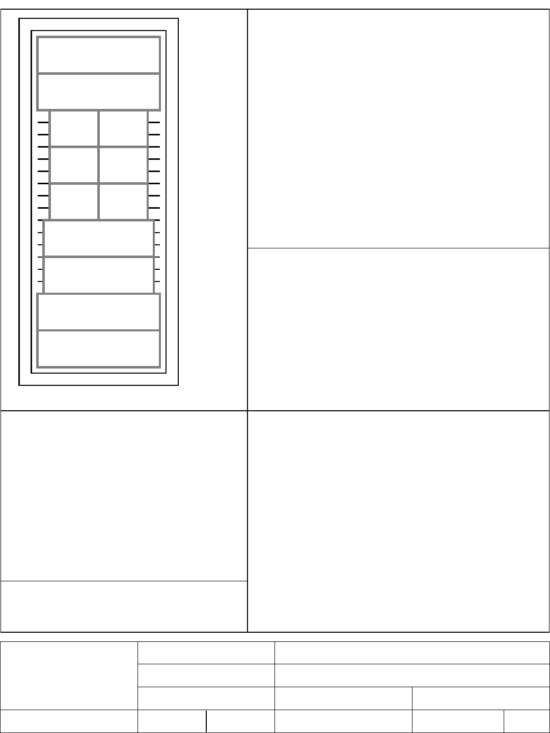
Neutral
Main Lugs Only
600A
BAB3100H
BAB3100H
BAB3100H
EDB3200
200A
FDB3150
150A
DK3300W
300A
Bus Cover
8X
Blank Cover
Blank
Blank
Blank
Blank
Blank
Blank
Blank
Blank
Blank
General Information (Section 1 of 1)
Service Voltage: 208Y/120V 3Ph 4W Enclosure: Type 3R
Bus Rating & Type: 600A Aluminum Neutral Rating: 600A
Ground Bar: Std. Bolted Aluminum, Al or Cu cable
S.C. Rating: 10k A.I.C. Fully Rated
Main Device Type: Main Lugs Only - Top Cable Entry
Main Terminals: Mechanical - (2) 3/0-750 kcmil (Cu/Al)
Neutral Terminals: Mechanical - (2) 3/0-750 kcmil (Cu/Al)
Box Catalog No.: RPCB3690
Trim: Complete Enclosure (Includes Trim)
Surface Mounted
Box Dimensions: 90.00" [2286.0mm]H x 36.00" [914.4mm]W x 12.85" [326.4mm]D
Min. Gutter Size: Top = 10.625" [269.9mm] Bottom = 10.625" [269.9mm]
Left = 6" [152.4mm] Right = 8" [203.2mm]
Panel ID Nameplate: (1) MDP SECTION 2
Type: Plastic, adhesive-backed (2) 208Y/120V 3Ph 4W
Color: White with Black Letters (3)
UL
Trim Lock: T-Handle Lock Assembly
Circuit Directory: Plastic Sleeve with Card
Painted Box: ANSI 61
Branch Devices
Qty Poles Trip Frame Amps kAIC
1 3 150 FDB 150 10
1 3 300 DK 400 10
1 3 200 EDB 225 10
3 3 100 BAB 100 10
Device Modifications:
Ref # Description
Notes:
NEG-ALT Number
PREPARED BY DATE
APPROVED BY DATE
VERSION
REVISION DWG SIZE
JOB NAME
DESIGNATION
TYPE
G.O.
DRAWING TYPE
ITEM SHEET
The information on this document is
created by Eaton Corporation. It is
disclosed in confidence and it is only to
be used for the purpose in which it is
supplied.
D63N0325X5K1-0000
PAUL MARTINEZ 10/2/2015
1.0.0.3
0 A
Eaton
LOS ALAMOS TEEN CENTER
MDP SECTION 2
PRL4
SAQ0594802
Final
006I 1 of 2

Pow-R-Line4 Device Specifications
Ckt #s Nameplate Device Trip Terminal Modifications
Main 600A-MLO (2) 3/0-750 kcmil (Cu/Al)
1,3,5 BAB3100H 100 (1) #8-1/0 (Cu/Al)
7,9,11 BAB3100H 100 (1) #8-1/0 (Cu/Al)
13,15,17 BAB3100H 100 (1) #8-1/0 (Cu/Al)
19,21,23 EDB3200 200 (1) #14-4/0 (Cu/Al)
20,22,24 FDB3150 150 (1) #4-4/0 (Cu/Al)
25,26,27 DK3300W 300 (1) 250-500 kcmil (Cu/Al)
28,29,30
NEG-ALT Number
PREPARED BY DATE
APPROVED BY DATE
VERSION
REVISION DWG SIZE
JOB NAME
DESIGNATION
TYPE
G.O.
DRAWING TYPE
ITEM SHEET
The information on this document is
created by Eaton Corporation. It is
disclosed in confidence and it is only to
be used for the purpose in which it is
supplied.
D63N0325X5K1-0000
PAUL MARTINEZ 10/2/2015
1.0.0.3
0 A
Eaton
LOS ALAMOS TEEN CENTER
MDP SECTION 2
PRL4
SAQ0594802
Final
006I 2 of 2
1 2
3 4
5 6
7 8
9 10
11 12
13 14
15 16
17 18
19 20
21 22
23 24
25 26
27 28
29 30
Through-Feed Lugs
600A
Bus Cover
11X
PROVBAB3 PROVBAB3
BAB3100H BAB3100H
BAB3060H BAB3030H
EDB3225
225A
PROVEDB3
200A
Neutral
Main Lugs Only
600A
General Information (Section 1 of 1)
Service Voltage: 208Y/120V 3Ph 4W Enclosure: Type 3R
Bus Rating & Type: 600A Copper Neutral Rating: 600A
Ground Bar: Std. Bolted Aluminum, Al or Cu cable
S.C. Rating: 10k A.I.C. Fully Rated
Main Device Type: Main Lugs Only - Bottom Cable Entry
Main Terminals: Mechanical - (2) 3/0-750 kcmil (Cu/Al)
Neutral Terminals: Mechanical - (2) 3/0-750 kcmil (Cu/Al)
Through-Feed Lugs: Mechanical - (2) 3/0-750 kcmil (Cu/Al)
Box Catalog No.: WPQ2890
Trim: Complete Enclosure (Includes Trim)
Surface Mounted
Box Dimensions: 90.00" [2286.0mm]H x 28.00" [711.2mm]W x 6.5" [165.1mm]D
Min. Gutter Size: Top = 5.5" [139.7mm] Bottom = 5.5" [139.7mm]
Left = 8" [203.2mm] Right = 8" [203.2mm]
Panel ID Nameplate: (1) MDP SECTION 1
Type: Plastic, adhesive-backed (2) 208Y/120V 3Ph 4W
Color: White with Black Letters (3)
UL
Trim Lock: T-Handle Lock Assembly
Circuit Directory: Plastic Sleeve with Card
Density Rated Bus
Painted Box: ANSI 61
Branch Devices
Qty Poles Trip Frame Amps kAIC
2 3 100 BAB 100 10
1 3 PROVEDB3
1 3 225 EDB 225 10
1 3 60 BAB 100 10
1 3 30 BAB 100 10
2 3 PROVBAB3
Device Modifications:
Ref # Description
Notes:
NEG-ALT Number
PREPARED BY DATE
APPROVED BY DATE
VERSION
REVISION DWG SIZE
JOB NAME
DESIGNATION
TYPE
G.O.
DRAWING TYPE
ITEM SHEET
The information on this document is
created by Eaton Corporation. It is
disclosed in confidence and it is only to
be used for the purpose in which it is
supplied.
D63N0325X5K1-0000
PAUL MARTINEZ 10/2/2015
1.0.0.3
0 A
Eaton
LOS ALAMOS TEEN CENTER
MDP SECTION 1
PRL3a
SAQ0594802
Final
007I 1 of 1

Instruction Data


Component Data
V4-T1-12 Volume 4—Circuit Protection CA08100005E—August 2013 www.eaton.com
1
1
1
1
1
1
1
1
1
1
1
1
1
1
1
1
1
1
1
1
1
1
1
1
1
1
1
1
1
1
1.1
Miniature Circuit Breakers and Supplementary Protectors
Industrial Circuit Breakers
Product Selection
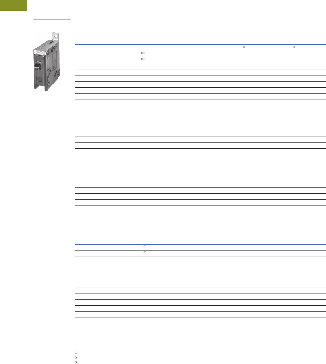
QUICKLAG Type: BA 10,000A Interrupting Capacity Thermal-Magnetic Breakers
QUICKLAG Type: BA Non-Automatic Switches
QUICKLAG Type: QBHW 22,000A Interrupting Capacity Thermal-Magnetic Breakers
Notes
Switching duty rated for 120 Vac fluorescent light applications.
For special low-magnetic breaker, order BAB1015L1 or BAB1020L1.
Not UL listed.
Continuous
Ampere Rating
at 40°C
Single-Pole Two-Pole Two-Pole Three-Pole
120/240 Vac 120/240 Vac 240 Vac 240 Vac
Catalog Number Catalog Number Catalog Number Catalog Number
10 BAB1010 BAB2010 BAB2010H BAB3010H
15 BAB1015 BAB2015 BAB2015H BAB3015H
20 BAB1020 BAB2020 BAB2020H BAB3020H
25 BAB1025 BAB2025 BAB2025H BAB3025H
30 BAB1030 BAB2030 BAB2030H BAB3030H
35 BAB1035 BAB2035 BAB2035H BAB3035H
40 BAB1040 BAB2040 BAB2040H BAB3040H
45 BAB1045 BAB2045 BAB2045H BAB3045H
50 BAB1050 BAB2050 BAB2050H BAB3050H
55 BAB1055 BAB2055 BAB2055H BAB3055H
60 BAB1060 BAB2060 BAB2060H BAB3060H
70 BAB1070 BAB2070 BAB2070H BAB3070H
80 — BAB2080 BAB2080H BAB3080H
90 — BAB2090 BAB2090H BAB3090H
100 BAB1100 BAB2100 BAB2100H BAB3100H
110 — BAB2110 — —
125 — BAB2125 — —
Continuous
Ampere Rating
at 40°C
Single-Pole Two-Pole Two-Pole Three-Pole
120/240 Vac 120/240 Vac 240 Vac 240 Vac
Catalog Number Catalog Number Catalog Number Catalog Number
50 BAB1050N — BAB2050N BAB3050N
60 BAB1060N — BAB2060N BAB3060N
100 BAB1100N — BAB2100N BAB3100N
Continuous
Ampere Rating
at 40°C
Single-Pole Two-Pole Two-Pole Three-Pole
120/240 Vac 120/240 Vac 240 Vac 240 Vac
Catalog Number Catalog Number Catalog Number Catalog Number
15 QBHW1015 QBHW2015 QBHW2015H QBHW3015H
20 QBHW1020 QBHW2020 QBHW2020H QBHW3020H
25 QBHW1025 QBHW2025 QBHW2025H QBHW3025H
30 QBHW1030 QBHW2030 QBHW2030H QBHW3030H
35 QBHW1035 QBHW2035 QBHW2035H QBHW3035H
40 QBHW1040 QBHW2040 QBHW2040H QBHW3040H
45 QBHW1045 QBHW2045 QBHW2045H QBHW3045H
50 QBHW1050 QBHW2050 QBHW2050H QBHW3050H
55 QBHW1055 QBHW2055 QBHW2055H QBHW3055H
60 QBHW1060 QBHW2060 QBHW2060H QBHW3060H
70 QBHW1070 QBHW2070 QBHW2070H QBHW3070H
80 — QBHW2080 QBHW2080H QBHW3080H
90 — QBHW2090 QBHW2090H QBHW3090H
100 — QBHW2100 QBHW2100H QBHW3100H
110 — QBHW2110 — —
125 — QBHW2125 — —
QUICKLAG Type BAB
Single-Pole

Volume 4—Circuit Protection CA08100005E—August 2013 www.eaton.com V4-T1-13
1
1
1
1
1
1
1
1
1
1
1
1
1
1
1
1
1
1
1
1
1
1
1
1
1
1
1
1
1
1
1.1
Miniature Circuit Breakers and Supplementary Protectors
Industrial Circuit Breakers
QUICKLAG Type: HBAX 42,000A Interrupting Capacity Thermal-Magnetic Breakers
QUICKLAG Type: HBAW 65,000A Interrupting Capacity Thermal-Magnetic Breakers
Dimensions
Approximate Dimensions in Inches (mm)
Shipping Data
Note
Switching duty rated for 120 Vac fluorescent light applications.
Continuous
Ampere Rating
at 40°C
Single-Pole Two-Pole Two-Pole Three-Pole
120/240 Vac 120/240 Vac 240 Vac 240 Vac
Catalog Number Catalog Number Catalog Number Catalog Number
15 HBAX1015 HBAX2015 — HBAX3015H
20 HBAX1020 HBAX2020 — HBAX3020H
25 HBAX1025 HBAX2025 — HBAX3025H
30 HBAX1030 HBAX2030 — HBAX3030H
35 HBAX1035 HBAX2035 — HBAX3035H
40 HBAX1040 HBAX2040 — HBAX3040H
45 HBAX1045 HBAX2045 — HBAX3045H
50 HBAX1050 HBAX2050 — HBAX3050H
55 HBAX1055 HBAX2055 — HBAX3055H
60 HBAX1060 HBAX2060 — HBAX3060H
70 HBAX1070 HBAX2070 — HBAX3070H
80 — HBAX2080 — HBAX3080H
80 — HBAX2080 — HBAX3080H
90 — HBAX2090 — HBAX3090H
100 — HBAX2100 — HBAX3100H
Continuous
Ampere Rating
at 40°C
Single-Pole Two-Pole Two-Pole Three-Pole
120/240 Vac 120/240 Vac 240 Vac 240 Vac
Catalog Number Catalog Number Catalog Number Catalog Number
15 HBAW1015 HBAW2015 — HBAW3015H
20 HBAW1020 HBAW2020 — HBAW3020H
25 HBAW1025 HBAW2025 — —
30 HBAW1030 HBAW2030 — —
Number
of Poles
Carton
Quantity
Approximate
Weight Lbs (kg) Dimensions
1 24 9.00 (4.1) 12.50 x 7.50 x 5.00 (317.5 x 190.5 x 127.0)
2 12 9.00 (4.1) 12.50 x 7.50 x 5.00 (317.5 x 190.5 x 127.0)
3 8 9.00 (4.1) 12.50 x 7.50 x 5.00 (317.5 x 190.5 x 127.0)

Renewal Parts
RP01400001E For more information visit: www.eatonelectrical.com
Current Cutler-Hammer Panelboards
Renewal Parts
Supersedes RP.38F.01.T.E
pages 1 – 48 dated February 2000
Description Page
Current Cutler-Hammer Panelboards
PRL1a and PRL2a . . . . . . . . . . . . . . . . . . . . . . . . . . . . . . . . . . . . . . . . . . . . . .
5
Trim Locks . . . . . . . . . . . . . . . . . . . . . . . . . . . . . . . . . . . . . . . . . . . . . . . . . . .
19
PRL3a . . . . . . . . . . . . . . . . . . . . . . . . . . . . . . . . . . . . . . . . . . . . . . . . . . . . . . .
21
PRL4B/F. . . . . . . . . . . . . . . . . . . . . . . . . . . . . . . . . . . . . . . . . . . . . . . . . . . . . .
26
PRL5P . . . . . . . . . . . . . . . . . . . . . . . . . . . . . . . . . . . . . . . . . . . . . . . . . . . . . . .
35
Branch Devices. . . . . . . . . . . . . . . . . . . . . . . . . . . . . . . . . . . . . . . . . . . . . . . .
37
PRL1a-LX and PRL2a-LX . . . . . . . . . . . . . . . . . . . . . . . . . . . . . . . . . . . . . . . .
41
Pow-R-Command
. . . . . . . . . . . . . . . . . . . . . . . . . . . . . . . . . . . . . . . . . . . .
42
PRL3a PRL4B PRL4F PRL5P Pow-R-Command
PRL1a PRL2aPRL1a-LX PRL2a-LX
For more information visit: www.eatonelectrical.com RP01400001E
Renewal Parts
Page
2
Effective: February 2009
Current Cutler-Hammer
Panelboards
Table of Contents Page
Procedure for Identifying
Panelboard Type . . . . . . . . . . . . .
3
Procedure for Identifying
Renewal Parts . . . . . . . . . . . . . . .
3
Distributor Ordering
Instructions. . . . . . . . . . . . . . . . . .
3
Cutler-Hammer Satellite Plants . .
4
PRL1a, 2a Parts Section
. . . . . . .
5
Connector Kits, Vertical
Breakers . . . . . . . . . . . . . . . . . . . .
5
Connector Kits, Main Lug . . . . . . .
6
Connector Kits,
Horizontally Mounted, PRL1a . .
9
Connector Kits,
Horizontally Mounted, PRL2a . .
11
Neutral Assemblies . . . . . . . . . . . .
12
Ground Assemblies . . . . . . . . . . . .
16
Service Entrance Kits . . . . . . . . . . .
16
Deadfront Covers . . . . . . . . . . . . . .
17
Trim Locks . . . . . . . . . . . . . . . . . . . .
19
Trim Clamps and
Hardware Kits. . . . . . . . . . . . . . . .
20
PRL3a Parts Section
. . . . . . . . . .
21
Connector Kits, Branch Breakers
QUICKLAG
. . . . . . . . . . . . . . . . .
21
GB, GHB, GHBS . . . . . . . . . . . . . .
21
Twin Mounted F-Frame
150 Ampere Maximum . . . . . .
22
Single Mounted F-Frame
175 – 225 Ampere Maximum .
22
Ground Assemblies . . . . . . . . . . . .
23
Service Entrance Kits . . . . . . . . . . .
23
Deadfront Covers . . . . . . . . . . . . . .
23
PRL4B/F Parts Section
. . . . . . . .
26
Vented Cover Assemblies
and Side Gutter Covers . . . . . . .
26
Blank Covers . . . . . . . . . . . . . . . . . .
27
Breaker Connector Kits . . . . . . . . .
28
Fusible FDPW Switch
Connector Kit . . . . . . . . . . . . . . . .
29
Breaker Retrofit Kits . . . . . . . . . . . .
30
Fusible Retrofit Kits . . . . . . . . . . . .
30
Energy Sentinel . . . . . . . . . . . . . . .
31
PRL1a, 2a, 3a and PRL4 Special
Trims and Enclosures . . . . . . . . .
32
PRL5P Parts Section
. . . . . . . . . . .
34
Ordering Procedure . . . . . . . . . . . .
34
Chassis Layout . . . . . . . . . . . . . . . .
35
Breaker Adapter Unit
Catalog Numbers . . . . . . . . . . . .
36
Branch Breaker Information . . . . .
37
Main or Through-Feed Lugs . . . . .
38
Neutrals and Grounds . . . . . . . . . .
39
Boxes, Trims and Filler Plates. . . .
40
PRL1a, 2a-LX Column
Panelboards
. . . . . . . . . . . . . . . . .
41
Pow-R-Command
. . . . . . . . . . . . . .
42
Additional Services
. . . . . . . . . . . .
42
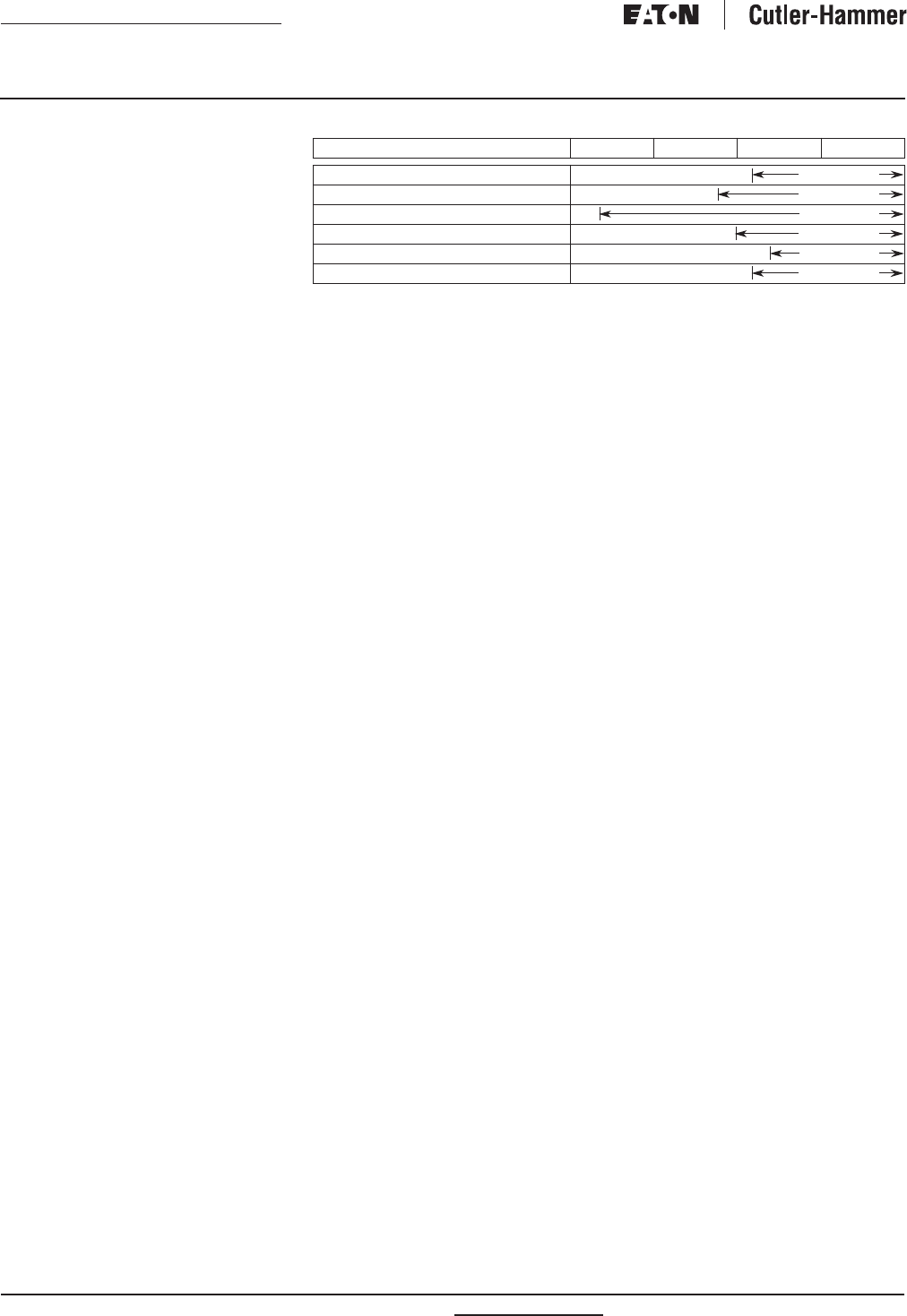
Table 1. Product History Time Line
Product 1985 1990 1995 Present
Cutler-Hammer PRL1a, 2a
Cutler-Hammer PRL3a
Cutler-Hammer PRL4B/F
Cutler-Hammer PRL5P
Cutler-Hammer PRL1a, 2a-LX
Cutler-Hammer Pow-R-Command
Oct. 1996
Mar. 1994
Oct. 1987
Aug. 1995
Dec. 1997
Mar. 1996
RP01400001E For more information visit: www.eatonelectrical.com
Renewal Parts
Effective: February 2009 Page
3
Current Cutler-Hammer
Panelboards
Procedure for Identifying
Panelboard Type
The current line of Pow-R-line C
panelboards was introduced in 1993.
A panelboard is identified by data
found on the nameplate. Pow-R-Line C
panelboard nameplates are different
in appearance, but all have the same
critical information:
■
Ampere rating of the main.
■
Ampere rating of the neutral.
■
Type of service (phase/wire).
■
Manufacturing location.
■
Type of panel.
■
General order number.
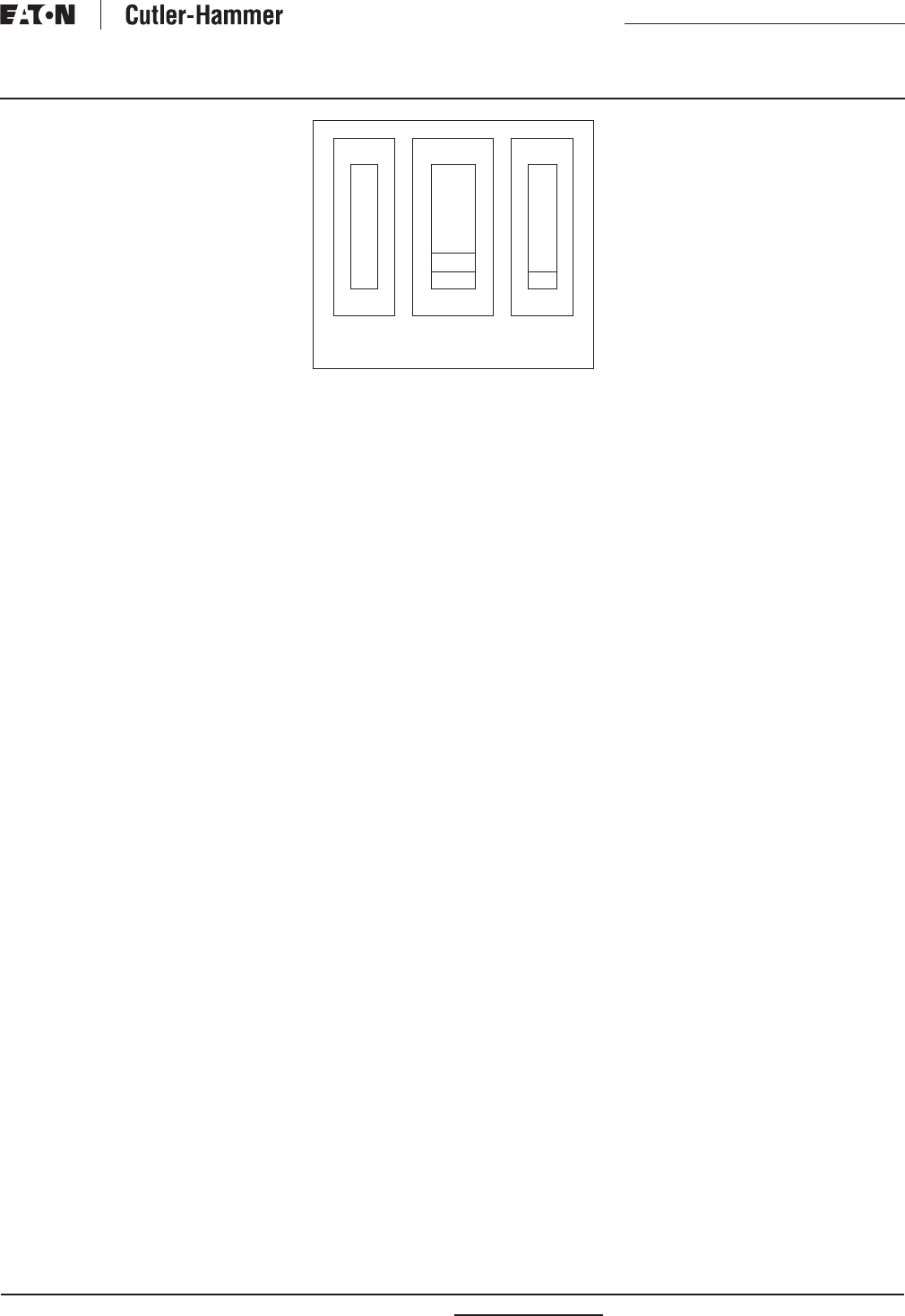
In the event the nameplate is missing,
it may still be possible to identify the
panel type by location of the neutral bar.
The illustrations to the right shows the
position of the neutral in the panelboard.
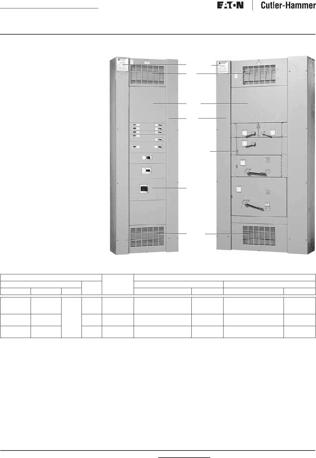
Figure 1. Position of the Neutral in the
Panelboard
PRL4F panels with vertical mounted main
switch will have the neutral mounted at the
opposite end the main.
Box width may also help identify the
panelboard type. Standard width for
PRL1a, PRL2a, and PRL3a is 20.00
inches (508.0 mm). PRL4 standard
widths are 24.00, 36.00 and 44.00
inches (609.6, 914.4 and 1117.6 mm).
WARNING
HAZARDOUS VOLTAGE WILL CAUSE
SEVERE INJURY OR DEATH. TURN
OFF POWER SUPPLY TO EQUIPMENT
BEFORE WORKING ON IT.
Procedure for Identifying
Renewal Parts
1. Identify the type of panelboard,
i.e. PRL1a, PRL2a, PRL3a, PRL4,
PRL5P by reading the nameplate.
Follow the procedure listed to
the left.
2. Refer to the listing below and turn
to the proper section in this bro-
chure to identify standard parts.
Description Page
PRL1a and PRL2a . . . . . . . . . . . .
5
PRL3a . . . . . . . . . . . . . . . . . . . . . .
21
PRL4B/F . . . . . . . . . . . . . . . . . . . .
26
PRL5P . . . . . . . . . . . . . . . . . . . . . .
35
PRL1a-LX (Column Width) . . . .
41
PRL2a-LX (Column Width) . . . .
41
Pow-R-Command . . . . . . . . . . . .
42
Trim Locks . . . . . . . . . . . . . . . . . .
19
Trim Clamps . . . . . . . . . . . . . . . .
20
Energy Sentinel . . . . . . . . . . . . .
31
Special Trims and Enclosures . .
32
3. This book identifies those replace-
ment parts most frequently
ordered and which are readily
available from stock. These parts
can be ordered by style or catalog
number to speed up processing
and delivery.
Distributor Ordering Instructions
1. Specify part by style/part number.
2. Refer to PL01400001E for pricing
information. Discount Symbol
CE9 applies.
3. Turn to
Page 4
to locate nearest
Satellite Plant.
4. Enter the order on the satellite
plant via mail, fax or phone.
5. Selling policy 25-000 applies.
Gutter
N
e
u
t
r
a
lN
Main
Gutter
N
Gutter
Pow-R-Line
1a, 2a
Pow-R-Line
3a
Pow-R-Line
4B/F

For more information visit: www.eatonelectrical.com RP01400001E
Renewal Parts
Page
4
Effective: February 2009
Current Cutler-Hammer
Panelboards
Cutler-Hammer Satellite Plants
Figure 2. Satellite Plants
Atlanta
7990-A 2nd Flag Drive
Austell, GA 30001
Phone 770-944-1022
FAX 770-944-2033
Baltimore
6671 Santa Barbara Court, Suite A
Elkridge, MD 21227
Phone 410-796-7777
FAX 410-796-7755
Chicago
959 AEC Drive
Wood Dale, IL 60191
Phone 630-860-3500
FAX 630-860-3569
Cleveland
4711 Hinkley Industrial Parkway
Cleveland, OH 44109
Phone 216-485-1940
FAX 216-485-1943
Dallas
1100 Avenue T
Grand Praire, TX 75050
Phone 972-988-3339
FAX 972-641-6435
Denver
14101 East 33rd Place, Suite F
Aurora, CO 80011
Phone: 303-371-7844
FAX 303-371-4175
Hartford
625 Day Hill Road
Windsor, CT 06095
Phone 860-688-7330
FAX 860-688-4982
Houston
10810 West Little York, Suite 100
Houston, TX 77041
Phone 713-688-8430
FAX 713-688-3764
Los Angeles
2021 Locust Court
Ontario, CA 91761
Phone 909-923-2040
FAX 909-923-2344
New Jersey
96 Stemmers Lane
Westampton, NJ 08060
Phone 609-835-4230
FAX 609-835-4777
Orlando
3827 St. Valentine Way
Orlando, FL 32811
Phone 407-843-3863
FAX 407-841-9135
Phoenix
7160 South Harl Avenue
Tempe, AZ 85283
Phone 480-777-3957
FAX 480-777-3958
Raleigh
2933 S. Miami Blvd., Suite 111
Durham, NC 27703
Phone 919-544-7074
FAX 919-572-9751
San Francisco
20919 Cabot Boulevard
Hayward, CA 94545
Phone 510-784-8981
FAX 510-784-8980
Seattle
18657 72nd Avenue South
Kent, WA 98032
Phone 425-251-9081
FAX 425-251-0079
St. Louis
12947 Gravois Road
St. Louis, MO 63127
Phone: 314-842-7797
FAX 314-842-2552
Hartford
Baltimore
Raleigh
Atlanta
Chicago
Cleveland
Orlando
St. Louis
New Jersey
Dallas
Denver
Los
Angeles Phoenix
Houston
San Francisco
Seattle
RP01400001E For more information visit: www.eatonelectrical.com
Renewal Parts
Effective: February 2009 Page
5
Current Cutler-Hammer
Panelboards
PRL1a, 2a Parts Section Page
Connector Kits,
Vertical Breakers . . . . . . . . . .
5
Connector Kits, Main Lug . . . .
6
–
8
Connector Kits, Horizontally
Mounted, PRL1a . . . . . . . . . .
9
–
10
Connector Kits, Horizontally
Mounted, PRL2a . . . . . . . . . .
11
Neutral Assemblies. . . . . . . . .
12
–
15
Ground Assemblies . . . . . . . .
16
Service Entrance Kits . . . . . . .
16
Deadfront Covers . . . . . . . . . .
17, 18
Trim Locks . . . . . . . . . . . . . . . . 19
Trim Clamps and
Hardware Kits . . . . . . . . . . . . 20
PRL1a, 2a Connector Kits
Table 2. Vertical Breaker Assemblies
Order main or sub-feed breaker separately when ordering above connector kits.
EHD, FD, HFD, FDC.
FD, HFD, FDC, ED, EDH, EDC.
KB11AFT KB13AFT
Device
Type
Device
Mounting
3-Phase 1-Phase
Tin-Plated
Aluminum
Connector
Silver-Plated
Copper
Connector
Tin-Plated
Aluminum
Connector
Silver-Plated
Copper
Connector
Catalog Number
F-Frame
(100 Ampere Maximum)
Top Fed
Bottom Fed
KB13AFT
KB13AFB
KB13SFT
KB13SFB
KB11AFT
KB11AFB
KB11SFT
KB11SFB
F-Frame
(225 Ampere Maximum)
Top Fed
Bottom Fed
KB23AFT
KB23AFB
KB23SFT
KB23SFB
KB21AFT
KB21AFB
KB21SFT
KB21SFB
J-Frame Top Fed
Bottom Fed
KB43AJT
KB43AJB
KB43SJT
KB43SJB
KB41AJT
KB41AJB
KB41SJT
KB41SJB
K-Frame Top Fed
Bottom Fed
KB43AKT
KB43AKB
KB43SKT
KB43SKB
KB41AKT
KB41AKB
KB41SKT
KB41SKB
For more information visit: www.eatonelectrical.com RP01400001E
Renewal Parts
Page 6 Effective: February 2009
Current Cutler-Hammer
Panelboards
PRL1a, 2a Connector Kits
Table 3. 100 Ampere Lug Assemblies
STD = Standard lugs. Use for main or through-feed.
SFL = Sub-feed lugs.
OVS = Oversize lugs. Use for main or through-feed.
KL13AMS KL11AVS
Lug
Type
Panel Lug
Options
Wire Size
Range
Quantity
Per Phase
3-Phase 1-Phase
Tin-Plated
Aluminum Connector
Silver-Plated
Copper Connector
Tin-Plated
Aluminum Connector
Silver-Plated
Copper Connector
Catalog Number
Aluminum/Copper
Mechanical
STD
SFL
OVS
#14 – 1/0
#14 – 1/0
#6 – 300 kcmil
1
2
1
KL13AMS
KL13AMF
KL13AMO
KL13SMS
KL13SMF
KL13SMO
KL11AMS
KL11AMF
KL11AMO
KL11SMS
KL11SMF
KL11SMO
Crimp STD
SFL
OVS
#8 – 1/0
#8 – 1/0
#4 – 300 kcmil
1
2
1
KL13AVS
KL13AVF
KL13AVO
KL13SVS
KL13SVF
KL13SVO
KL11AVS
KL11AVF
KL11AVO
KL11SVS
KL11SVF
KL11SVO
Copper
Mechanical
STD
SFL
OVS
#14 – 1/0
#14 – 1/0
#6 – 250 kcmil
1
2
1
—
—
—
KL13SCS
KL13SCF
KL13SCO
—
—
—
KL11SCS
KL11SCF
KL11SCO
RP01400001E For more information visit: www.eatonelectrical.com
Renewal Parts
Effective: February 2009 Page 7
Current Cutler-Hammer
Panelboards
PRL1a, 2a Connector Kits
Table 4. 225 Ampere Lug Assemblies
STD = Standard lugs. Use for main or through-feed.
SFL = Sub-feed lugs.
OVS = Oversize lugs. Use for main or through-feed.
KL23AMS KL21AVS
Lug
Type
Panel Lug
Options
Wire Size
Range
Quantity
Per Phase
3-Phase 1-Phase
Tin-Plated
Aluminum Connector
Silver-Plated
Copper Connector
Tin-Plated
Aluminum Connector
Silver-Plated
Copper Connector
Catalog Number
Aluminum/Copper
Mechanical
STD
SFL
OVS
#6 – 300 kcmil
#6 – 300 kcmil
4/0 – 500 kcmil
1
2
1
KL23AMS
KL23AMF
KL23AMO
KL23SMS
KL23SMF
KL23SMO
KL21AMS
KL21AMF
KL21AMO
KL21SMS
KL21SMF
KL21SMO
Crimp STD
SFL
OVS
#4 – 300 kcmil
#4 – 300 kcmil
2/0 – 500 kcmil
1
2
1
KL23AVS
KL23AVF
KL23AVO
KL23SVS
KL23SVF
KL23SVO
KL21AVS
KL21AVF
KL21AVO
KL21SVS
KL21SVF
KL21SVO
Copper
Mechanical
STD
SFL
OVS
#6 – 250 kcmil
#6 – 250 kcmil
1/0 – 600 kcmil
1
2
1
—
—
—
KL23SCS
KL23SCF
KL23SCO
—
—
—
KL21SCS
KL21SCF
KL21SCO
For more information visit: www.eatonelectrical.com RP01400001E
Renewal Parts
Page 8 Effective: February 2009
Current Cutler-Hammer
Panelboards
PRL1a, 2a Connector Kits
Table 5. 400 Ampere Lug Assemblies
STD = Standard lugs. Use for main or through-feed.
SFL = Sub-feed lugs.
OVS = Oversize lugs. Use for main or through-feed.
KL43AMS KL43AVS
Lug
Type
Panel Lug
Options
Wire Size
Range
Quantity
Per Phase
3-Phase 1-Phase
Tin-Plated
Aluminum Connector
Silver-Plated
Copper Connector
Tin-Plated
Aluminum Connector
Silver-Plated
Copper Connector
Catalog Number
Aluminum/Copper
Mechanical
STD
SFL
OVS
4/0 – 500 kcmil
N/A
3/0 – 750 kcmil
2
N/A
2
KL43AMS
—
KL43AMO
KL43SMS
—
KL43SMO
KL41AMS
—
KL41AMO
KL41SMS
—
KL41SMO
Crimp STD
SFL
OVS
2/0 – 500 kcmil
N/A
500 – 750 kcmil
2
N/A
2
KL43AVS
—
KL43AVO
KL43SVS
—
KL43SVO
KL41AVS
—
KL41AVO
KL41SVS
—
KL41SVO
Copper
Mechanical
STD
SFL
OVS
1/0 – 600 kcmil
N/A
1/0 – 600 kcmil
1
N/A
1
—
—
—
—
—
KL43SCO
—
—
—
—
—
KL41SCO
RP01400001E For more information visit: www.eatonelectrical.com
Renewal Parts
Effective: February 2009 Page 9
Current Cutler-Hammer
Panelboards
PRL1a Horizontally Mounted Connector Kit Assemblies
Table 6. Bolt-on QUICKLAG Breaker Assemblies
Order the basic drawing number, along with the equivalent G–number that’s needed.
Note: When determining branch circuit quantity, remember:
1. QUICKLAG breakers with shunt trips require one additional circuit.
2. UL listed lighting and appliance (CTL) panelboards cannot exceed 42 electrically connected
circuits in a single enclosure.
3. When bare copper is specified, use the silver-plated groups.
4. Order breakers separately with connector kit.
1C96608G01 1C96608G05
Breaker
Frame
Drawing
Number
Branch
Circuit
Quantity
3-Phase 1-Phase
Tin-Plated
Aluminum Connector
Silver-Plated
Copper Connector
Tin-Plated
Aluminum Connector
Silver-Plated
Copper Connector
Item Number
BA, BAB,
QBH, QBGF,
QBHGF,
QBGFEP,
QBHGFEP
1C96608 12
18
30
G01
G09
G17
G03
G11
G19
G05
G13
G21
G07
G15
G23
42
48
54
G25
G33
G41
G27
G35
G43
G29
G37
G45
G31
G39
G47
72
96
G49
G57
G51
G59
G53
G61
G55
G63
For more information visit: www.eatonelectrical.com RP01400001E
Renewal Parts
Page 10 Effective: February 2009
Current Cutler-Hammer
Panelboards
PRL1a Horizontally Mounted Connector Kit Assemblies
Table 7. Plug-in QUICKLAG Breaker Assemblies
Order the basic drawing number, along with the equivalent G–number that’s needed.
Note: When determining branch circuit quantity, remember:
1. QUICKLAG breakers with shunt trips require one additional circuit.
2. UL listed lighting and appliance (CTL) panelboards cannot exceed 42 electrically connected
circuits in a single enclosure.
3. When aluminum is specified, use the silver-plated groups.
4. The sum of the horizontally twin mounted breakers shall not exceed 140 amperes.
5. Order breakers separately with connector kit.
2C11642G03 2C11642G07
Breaker
Frame
Drawing
Number
Branch
Circuit
Quantity
3-Phase 1-Phase
Tin-Plated
Aluminum Connector
Silver-Plated
Copper Connector
Tin-Plated
Aluminum Connector
Silver-Plated
Copper Connector
Item Number
HQP, QPHW,
QHPX, QPGF,
QPHGF,
QPGFEP,
QPHGFEP
2C11642 12
18
30
—
—
—
G03
G11
G19
—
—
—
G07
G15
G23
42
48
54
—
—
—
G27
G35
G43
—
—
—
G31
G39
G47
72
96
—
—
G51
G59
—
—
G55
G63
RP01400001E For more information visit: www.eatonelectrical.com
Renewal Parts
Effective: February 2009 Page 11
Current Cutler-Hammer
Panelboards
PRL2a Horizontally Mounted Connector Kit Assemblies
Table 8. GB, GHB, GHQ, GHBS Breaker Assemblies
Order the basic drawing number, along with the equivalent G–number that’s needed.
Note: When determining branch circuit quantity, remember:
1. QUICKLAG breakers with shunt trips require one additional circuit.
2. UL listed lighting and appliance (CTL) panelboards cannot exceed 42 electrically connected
circuits in a single enclosure.
3. When bare copper is specified, use the silver-plated groups.
4. Order breakers separately with connector kit.
1C96609G01
Breaker
Frame
Drawing
Number
Branch
Circuit
Quantity
3-Phase 1-Phase
Tin-Plated
Aluminum Connector
Silver-Plated
Copper Connector
Tin-Plated
Aluminum Connector
Silver-Plated
Copper Connector
Item Number
GB, GHB, GHQ
GHBS
1C96609 12
18
30
G01
G09
G17
G03
G11
G19
G05
G13
G21
G07
G15
G23
42
48
54
G25
G33
G41
G27
G35
G43
G29
G37
G45
G31
G39
G47
72
96
G49
G57
G51
G59
G53
G61
G55
G63

For more information visit: www.eatonelectrical.com RP01400001E
Renewal Parts
Page 12 Effective: February 2009
Current Cutler-Hammer
Panelboards
PRL1a, 2a Neutral Assemblies
Table 9. 100 Ampere Neutral Assemblies
The assemblies shown on this page are for panelboards that mount in 30.00 – 90.00-inch (762.0 – 2286.0 mm) high enclosures only.
Reference Page 15 for assemblies for panelboards that mount in 21.00 – 27.00-inch (533.4 – 685.8 mm) high enclosures.
Order the basic drawing number, along with the equivalent G–number that’s needed.
STD = Standard lugs.
SFL/TFL = Sub-feed and through-feed lugs.
OVS = Oversize lugs.
1C96646G01
Panel Main
Bus Ampere
Rating
Neutral
Rating
Lug
Type
Drawing
Number
Panel Lug
Options
Wire Size
Range
Quantity Tin-Plated
Aluminum Connector
Silver-Plated
Copper Connector
Item Number
100 100% Mechanical 1C96646 STD
SFL/TFL
OVS
#14 – 1/0
#14 – 1/0
#6 – 300 kcmil
1
2
1
G02
G05
G09
G03
G07
G11
Crimp 1C96647 STD
SFL/TFL
OVS
#8 – 1/0
#8 – 1/0
#4 – 300 kcmil
1
2
1
G01
G05
G09
G03
G07
G11
Copper 1C96648 STD
SFL/TFL
OVS
#14 – 1/0
#14 – 1/0
#6 – 250 kcmil
1
2
1
—
—
—
G03
G07
G11
200% Mechanical 1C96649 STD
SFL/TFL
OVS
#6 – 300 kcmil
#6 – 300 kcmil
4/0 – 500 kcmil
1
2
1
G02
G06
G09
G03
G07
G11
Crimp 1C96650 STD
SFL/TFL
OVS
#4 – 300 kcmil
#4 – 300 kcmil
2/0 – 500 kcmil
1
2
1
G01
G05
G09
G03
G07
G11
Copper 1C96651 STD
SFL/TFL
OVS
#6 – 250 kcmil
#6 – 250 kcmil
1/0 – 600 kcmil
1
2
1
—
—
—
G03
G07
G11
RP01400001E For more information visit: www.eatonelectrical.com
Renewal Parts
Effective: February 2009 Page 13
Current Cutler-Hammer
Panelboards
PRL1a, 2a Neutral Assemblies
Table 10. 225 Ampere Neutral Assemblies
The assemblies shown on this page are for panelboards that mount in 30.00 – 90.00-inch (762.0 – 2286.0 mm) high enclosures.
Order the basic drawing number, along with the equivalent G–number that’s needed.
STD = Standard lugs.
SFL/TFL = Sub-feed and through-feed lugs.
OVS = Oversize lugs.
1C96649G01
Panel Main
Bus Ampere
Rating
Neutral
Rating
Lug
Type
Drawing
Number
Panel Lug
Options
Wire Size
Range
Quantity Tin-Plated
Aluminum Connector
Silver-Plated
Copper Connector
Item Number
225 100% Mechanical 1C96649 STD
SFL/TFL
OVS
#6 – 300 kcmil
#6 – 300 kcmil
4/0 – 500 kcmil
1
2
1
G02
G06
G09
G03
G07
G11
Crimp 1C96650 STD
SFL/TFL
OVS
#4 – 300 kcmil
#4 – 300 kcmil
2/0 – 500 kcmil
1
2
1
G01
G05
G09
G03
G07
G11
Copper 1C96651 STD
SFL/TFL
OVS
#6 – 250 kcmil
#6 – 250 kcmil
1/0 – 600 kcmil
1
2
1
—
—
—
G03
G07
G11
200% Mechanical 1C96652 STD
SFL/TFL
OVS
4/0 – 500 kcmil
N/A
3/0 – 750 kcmil
2
N/A
2
G01
G05
G09
G03
G07
G11
Crimp 1C96653 STD
SFL/TFL
OVS
2/0 – 500 kcmil
N/A
500 – 750 kcmil
2
N/A
2
G01
G05
G09
G03
G07
G11
Copper 1C96654 STD
SFL/TFL
OVS
1/0 – 600 kcmil
N/A
1/0 – 600 kcmil
1
N/A
1
—
—
—
G03
G07
G11
For more information visit: www.eatonelectrical.com RP01400001E
Renewal Parts
Page 14 Effective: February 2009
Current Cutler-Hammer
Panelboards
PRL1a, 2a Neutral Assemblies
Table 11. 400 Ampere Neutral Assemblies
The assemblies shown on this page are for panelboards that mount in 30.00 – 90.00-inch (762.0 – 2286.0 mm) high enclosures.
Order the basic drawing number, along with the equivalent G–number that’s needed.
STD = Standard lugs.
SFL/TFL = Sub-feed and through-feed lugs.
OVS = Oversize lugs.
1C96652G01
Panel Main
Bus Ampere
Rating
Neutral
Rating
Lug
Type
Drawing
Number
Panel Lug
Options
Wire Size
Range
Quantity Tin-Plated
Aluminum Connector
Silver-Plated
Copper Connector
Item Number
400 100% Mechanical 1C96652 STD
SFL/TFL
OVS
4/0 – 500 kcmil
N/A
3/0 – 750 kcmil
2
N/A
2
G01
G05
G09
G03
G07
G11
Crimp 1C96653 STD
SFL/TFL
OVS
2/0 – 500 kcmil
N/A
500 – 750 kcmil
2
N/A
2
G01
G05
G09
G03
G07
G11
Copper 1C96654 STD
SFL/TFL
OVS
1/0 – 600 kcmil
N/A
1/0 – 600 kcmil
1
N/A
1
—
—
—
G03
G07
G11

RP01400001E For more information visit: www.eatonelectrical.com
Renewal Parts
Effective: February 2009 Page 15
Current Cutler-Hammer
Panelboards
PRL1a, 2a Neutral Assemblies
Table 12. 100 Ampere Neutral Assemblies for 21.00 – 27.00-Inch (533.4 – 685.8 mm) High Enclosures Only
The assemblies shown on this page are for panelboards that mount in 21.00 – 27.00-inch (533.4 – 685.8 mm) high enclosures only. Reference Page 12
for assemblies for panels that mount in 36.00, 48.00, 60.00, 72.00 and 90.00-inch (914.4, 1219.2, 1524.0, 1828.8 and 2286.0 mm) high enclosures.
Order the basic drawing number, along with the equivalent G–number that’s needed.
STD = Standard lugs.
SFL/TFL = Sub-feed and through-feed lugs.
OVS = Oversize lugs.
1C96645G01
Panel Main
Bus Ampere
Rating
Neutral
Rating
Lug
Type
Drawing
Number
Panel Lug
Options
Wire Size
Range
Quantity Tin-Plated
Aluminum Connector
Silver-Plated
Copper Connector
Item Number
100 100% Mechanical 1C96645 STD
SFL/TFL
OVS
#14 – 1/0
#14 – 1/0
N/A
1
2
N/A
G01
G05
—
G03
G07
—
Crimp N/A STD
SFL/TFL
OVS
N/A
N/A
N/A
N/A
N/A
N/A
—
—
—
—
—
—
Copper N/A STD
SFL/TFL
OVS
N/A
N/A
N/A
N/A
N/A
N/A
—
—
—
—
—
—
200% Mechanical 1C97022 STD
SFL/TFL
OVS
#6 – 300 kcmil
#6 – 300 kcmil
N/A
1
2
N/A
G01
G05
—
G03
G07
—
Crimp N/A STD
SFL/TFL
OVS
N/A
N/A
N/A
N/A
N/A
N/A
—
—
—
—
—
—
Copper N/A STD
SFL/TFL
OVS
N/A
N/A
N/A
N/A
N/A
N/A
—
—
—
—
—
—
For more information visit: www.eatonelectrical.com RP01400001E
Renewal Parts
Page 16 Effective: February 2009
Current Cutler-Hammer
Panelboards
PRL1a, 2a Ground Assemblies
Table 13. Standard Ground
Order the basic drawing number, along with the equivalent G–number
that’s needed (example 5158C05G01).
5158C05G01
5158C05G02
Table 14. Isolated Ground
Order the basic drawing number, along with the equivalent G–number
that’s needed (example 5158C05G01).
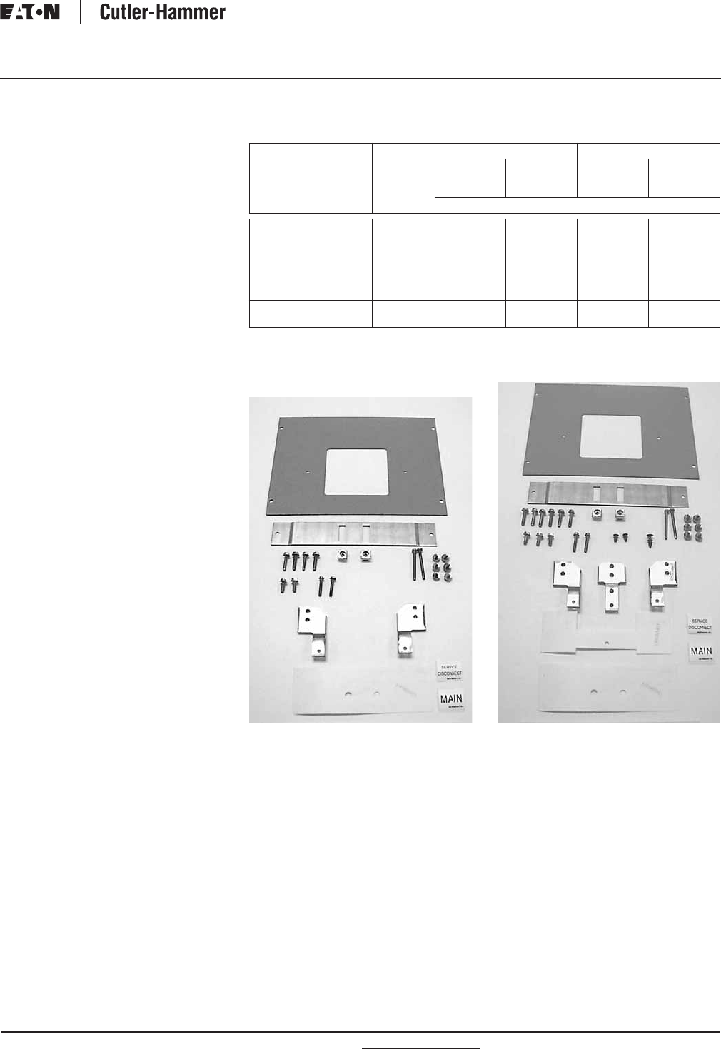
PRL1a, 2a Service Entrance Kits
Table 15. PRL1a, 2a Service Entrance Kits
Order the basic drawing number, along with the equivalent G–number
that’s needed (example 5158C05G01).
4180B62G01
Drawing
Number
Enclosure Height
in Inches (mm)
Bar
Material
Item
Number
5158C05 24.00 (609.6) Aluminum/Copper G01
Copper G03
36.00 (914.4), 48.00 (1219.2),
60.00 (1524.0), 72.00 (1828.8),
90.00 (2286.0)
Aluminum/Copper G02
Copper G04
Drawing
Number
Enclosure Height
in Inches (mm)
Bar
Material
Item
Number
2C11296 24.00 (609.6) Aluminum/Copper G01
Copper G02
36.00 (914.4), 48.00 (1219.2),
60.00 (1524.0), 72.00 (1828.8),
90.00 (2286.0)
Aluminum/Copper G03
Copper G04
Drawing
Number
Panel
Ampere
Rating
Tin-Plated
Aluminum
Bare
Copper
Silver-Plated
Copper
Tin-Plated
Copper
Item Number
Mechanical Main Lugs or Main Breakers
4180B62
4180B62
100 – 225
400
G01
G05
G02
G06
G03
G07
G04
G08
Compression (Crimp) Main Lugs
4180B62
4180B62
100 – 225
400
G09
G13
G10
G14
G11
G15
G12
G16
Copper Main Lugs
4180B62
4180B62
100 – 225
400
—
—
G18
G22
G19
G23
G20
G24
RP01400001E For more information visit: www.eatonelectrical.com
Renewal Parts
Effective: February 2009 Page 17
Current Cutler-Hammer
Panelboards
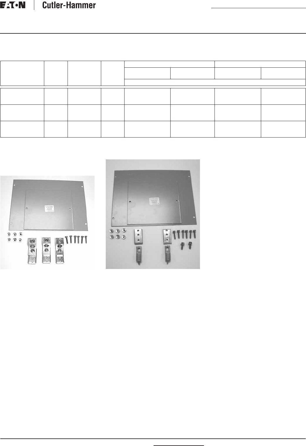
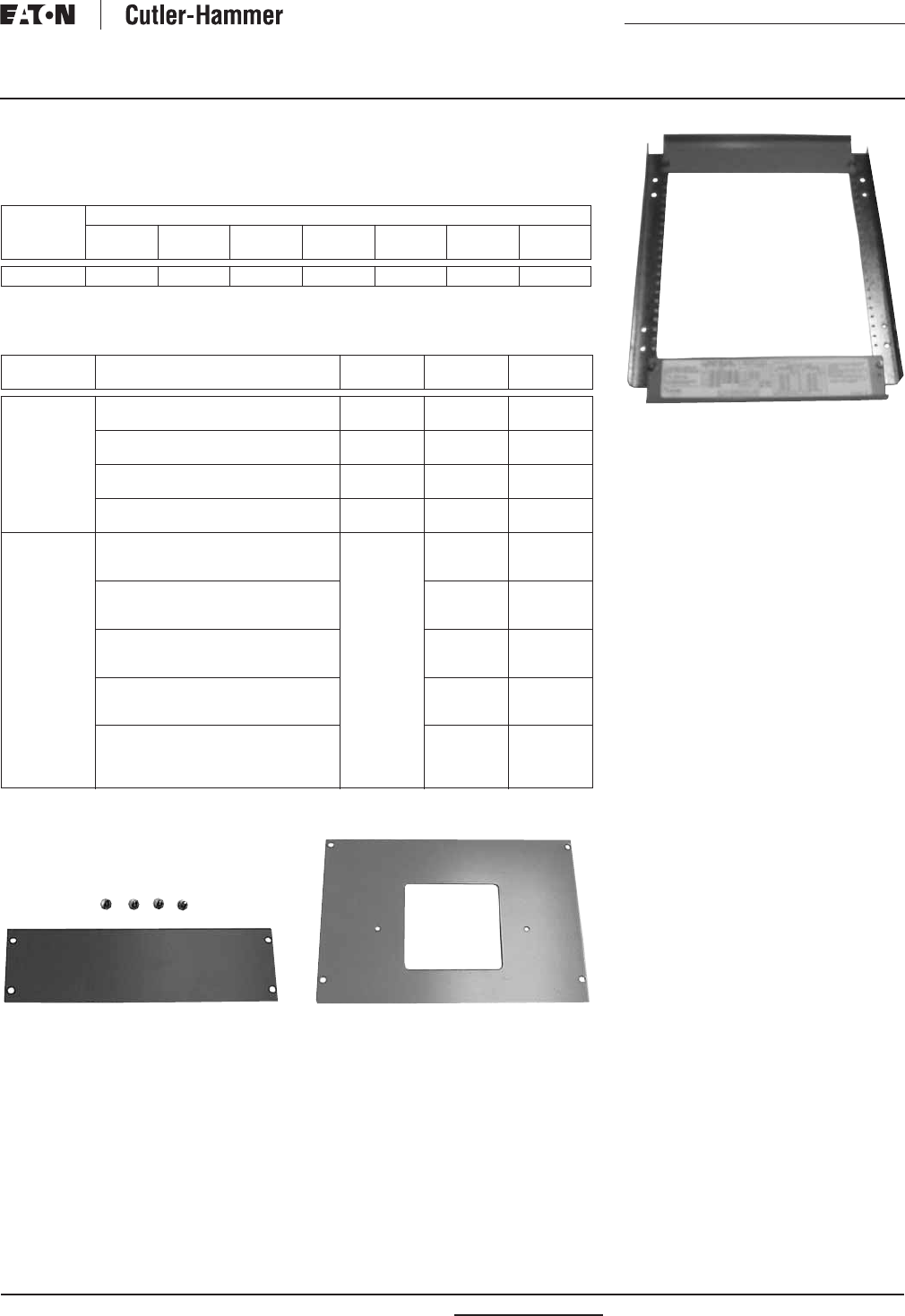
PRL1a, 2a Deadfront Covers
Note: Does not apply to PRL4 sub-chassis.
Table 16. Assembly
Order the basic drawing number, along with the equivalent G–number that’s needed
(example 1C96638G01).
Table 17. Vertically Mounted Devices
Order the basic drawing number, along with the equivalent H–number that’s needed
(example 4180B03H01).
4180B08H03 4180B03H01
Drawing
Number
Standard Enclosure Height in Inches (mm)
24.00
(609.6)
36.00
(914.4)
42.00
(1066.8)
48.00
(1219.2)
60.00
(1524.0)
72.00
(1828.8)
90.00
(2286.0)
1C96638 G01 G02 G07 G03 G04 G05 G06
Mounting
Arrangement
Device/Frame Drawing
Number
Mounting
Position
Item
Number
Vertical 100 Ampere MLO, SFL, TFL or F-Frame
(100 Ampere Maximum)
4180B03 Top
Bottom
H01
H01
225 Ampere MLO, SFL, TFL or F-Frame
(225 Ampere Maximum)
4180B61 Top
Bottom
H01
H01
400 Ampere MLO, SFL, TFL or J-Frame 4180B04 Top
Bottom
H01
H02
400 Ampere MLO, TFL or K-Frame 4180B05 Top
Bottom
H01
H02
Blank Covers
in Inches (mm)
1.00 (25.4)
2.00 (50.8)
3.00 (76.2)
4180B08 N/A
N/A
N/A
H01
H02
H03
4.00 (101.6)
5.00 (127.0)
6.00 (152.4)
N/A
N/A
N/A
H04
H05
H06
7.00 (177.8)
8.00 (203.2)
9.00 (228.6)
N/A
N/A
N/A
H07
H08
H09
10.00 (254.0)
11.00 (279.4)
12.00 (304.8)
N/A
N/A
N/A
H10
H11
H12
13.00 (330.2)
14.00 (355.6)
15.00 (381.0)
16.00 (406.4)
N/A
N/A
N/A
N/A
H13
H14
H15
H16
1C96638G01
For more information visit: www.eatonelectrical.com RP01400001E
Renewal Parts
Page 18 Effective: February 2009
Current Cutler-Hammer
Panelboards
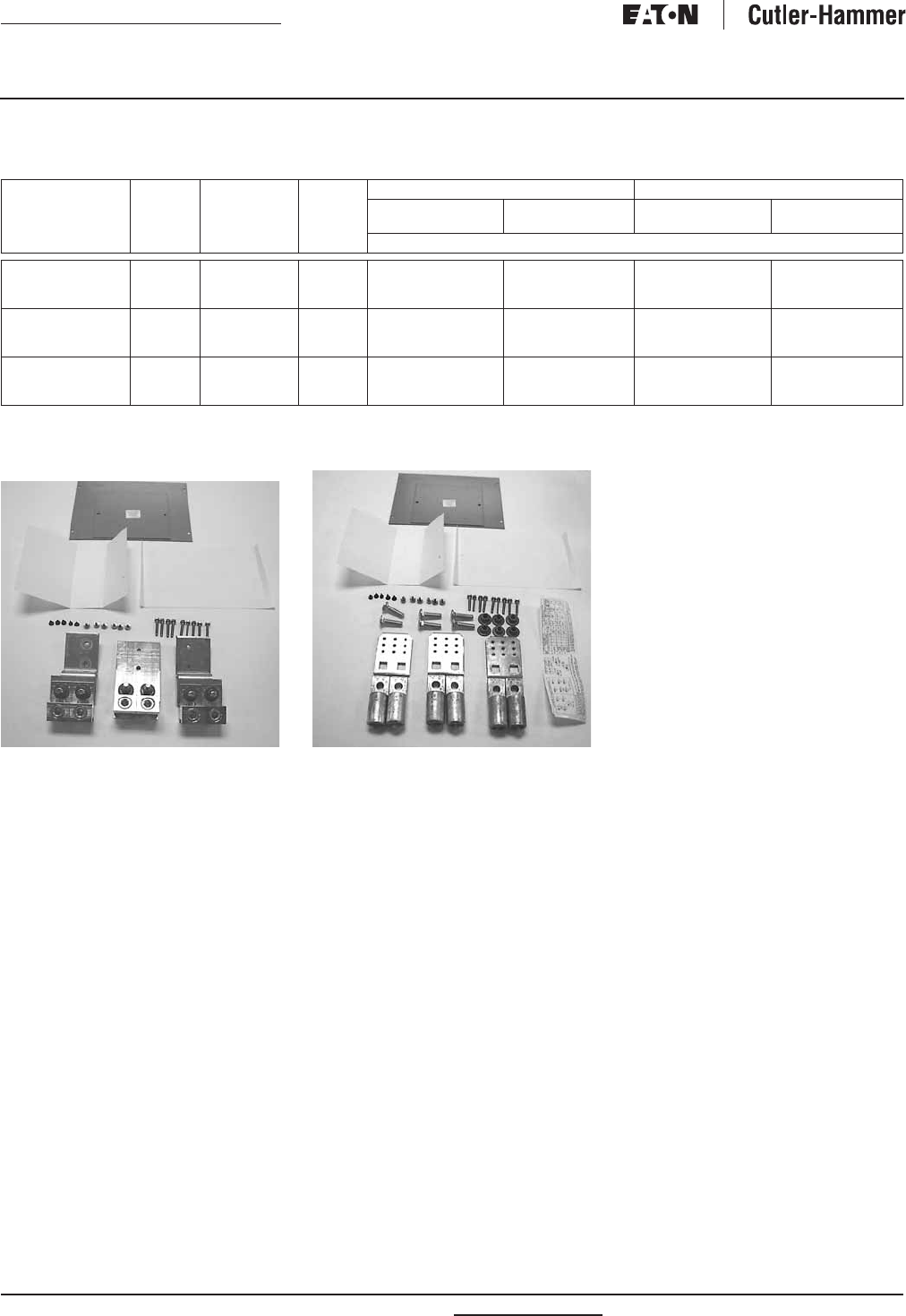
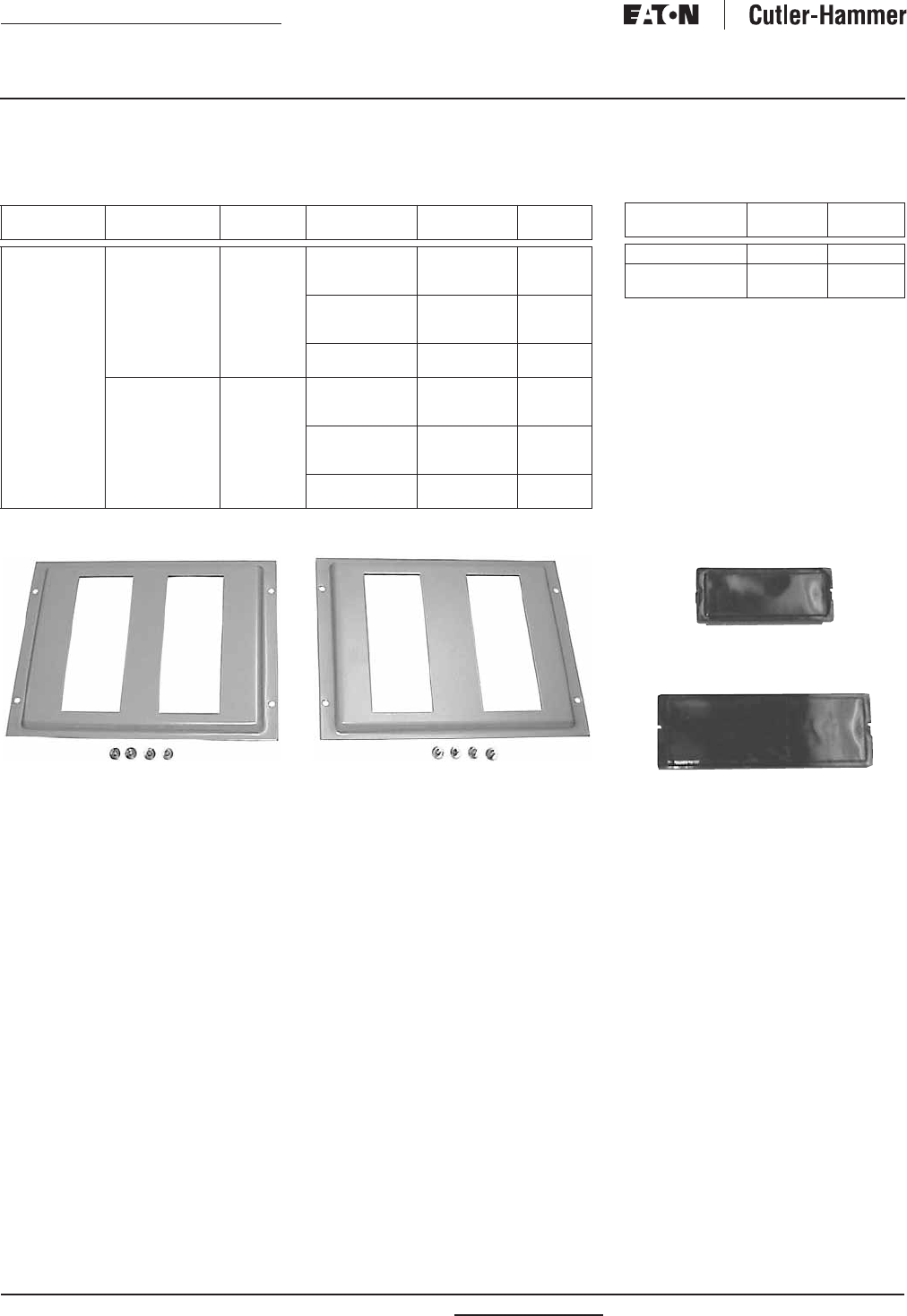
PRL1a, 2a Deadfront Covers
Note: Does not apply to PRL4 sub-chassis.
Table 18. Horizontally Mounted Devices
Order the basic drawing number, along with the equivalent H–number that’s needed
(example 1C96619H01).
1C96619H01 1C96620H01
Mounting
Arrangement
Device/
Frame
Drawing
Number
Branch Circuit
Quantity
Item
Number
Quantity
Required
Horizontal BA, BAB, QBH,
QBGF, QBHGF,
QBGFEP,
QBHGFEP
1C96619 12
18
30
H01
H02
H04
1
1
1
42
48
54
H06
H03
H03 and H04
1
2
1 Each
72
96
H05
H07
2
2
GB, GHB, GHQ,
GHBS
1C96620 12
18
30
H01
H02
H04
1
1
1
42
48
54
H06
H03
H03 and H04
1
2
1 Each
72
96
H05
H07
2
2
Table 19. Filler Covers
Filler covers are required in addition to
deadfront cover whenever MLO, SFL or TFL
are specified.
Filler covers are required in addition to
deadfront cover whenever a branch
provision is specified.
5155C62H01
4180B52H01
Device/Frame Drawing
Number
Item
Number
F, J , K 4180B52 H01
QUICKLAG,
GB, GHB
5155C62 H01

RP01400001E For more information visit: www.eatonelectrical.com
Renewal Parts
Effective: February 2009 Page 19
Current Cutler-Hammer
Panelboards
Panelboard Trim Locks
Panelboard trims use different trim locks, see pictures below for styles and part
numbers. Contact your nearest Satellite for availability on the styles listed below.
See Page 4 for Satellite listings.
Table 20. Panelboard Trim Locks
Description Catalog
Number
For use on left-handed door. (Hinged on left side.) K80522
For use on right-handed door. (Hinged on right side.) K80133
T–Handle lock, at one time used on all trims over 48.00 inches (1219.2 mm)
in height. Also used on outdoor NEMA 12/3R trims.
K80429
Used on PRL4 lighting and power panels as standard. 1A32258H03
Used on PRL1, 2, 3 and PRL1a, 2a, 3a lighting panels as standard.
WEM 2 key.
5155C81G01
K80522 K80133
K80429
1A32258H03 5155C81G01
For more information visit: www.eatonelectrical.com RP01400001E
Renewal Parts
Page 20 Effective: February 2009
Current Cutler-Hammer
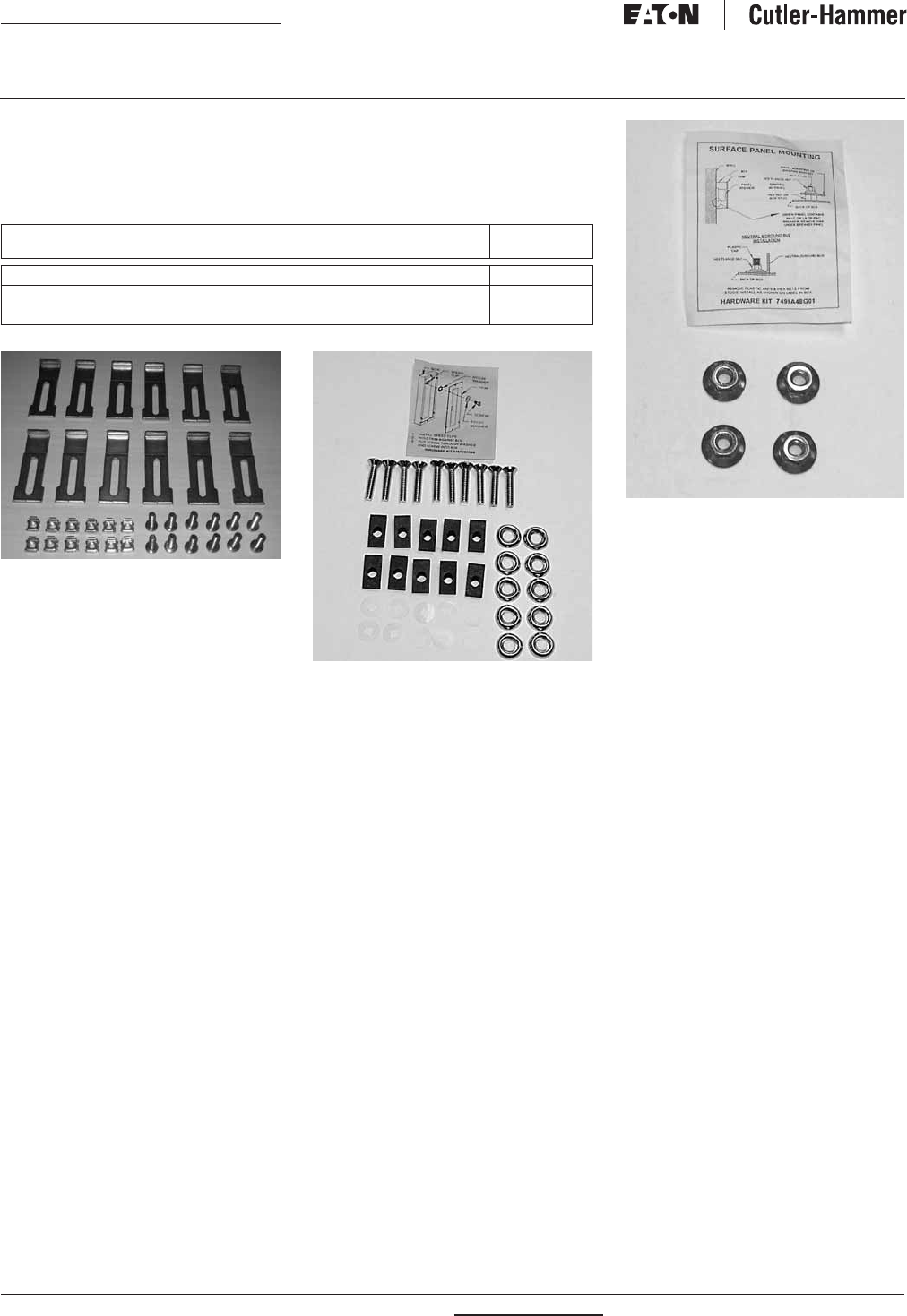
Panelboards
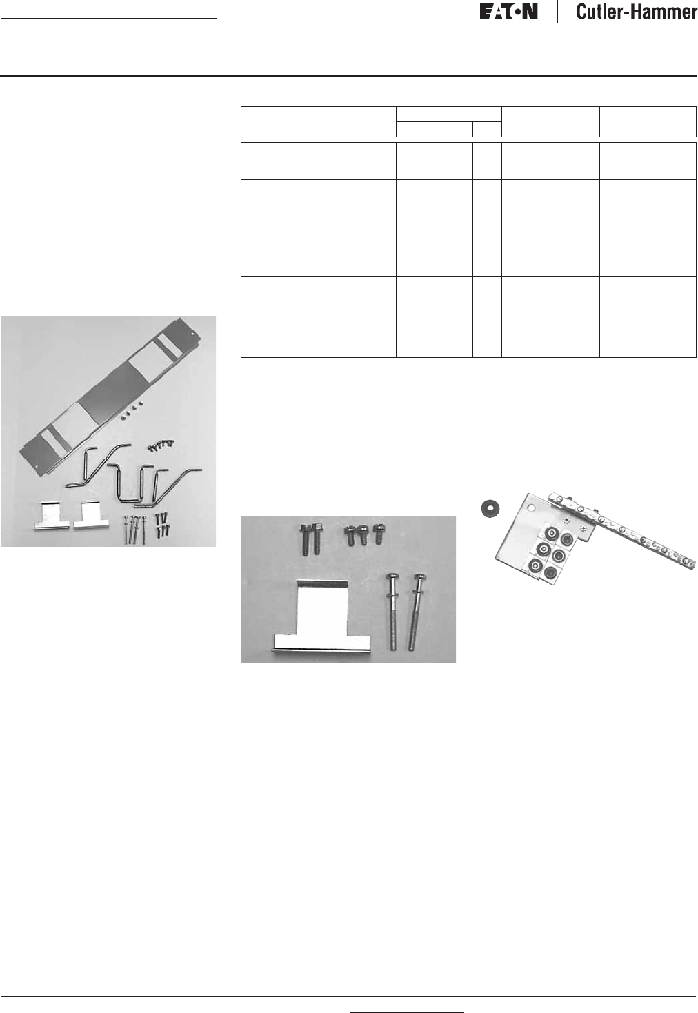
Panelboard Fastrim Clamps and Screw-on Hardware Kits
For panelboard trim clamps, contact your nearest Satellite for availability on the
styles listed below. See Page 4 for Satellite listings.
Table 21. Panelboard Fastrim Clamps and Screw-on Hardware Kits
2C11641G02
5157C83G06
Description Style
Number
Trim clamps — used on PRL1a, 2a, 3a fastrims. (6 per bag.) 2C11641G02
Trim screws — used on PRL1a, 2a, 3a, 4B standard trim. (10 per bag.) 5157C83G06
Chassis mounting hardware bag — PRL1a, 2a, 3a panels. 7499A48G04
7499A48G04
RP01400001E For more information visit: www.eatonelectrical.com
Renewal Parts
Effective: February 2009 Page 21
Current Cutler-Hammer
Panelboards
PRL3a Parts Section Page
Connector Kits,
Branch Breakers . . . . . . . . . . 21
Quicklag . . . . . . . . . . . . . . . . . . 21
GB, GHB, GHBS. . . . . . . . . . . . 21
Twin Mounted F-Frame
150 Ampere Maximum . . . . 22
Single Mounted F-Frame
175 – 225 Ampere Maximum . 22
Ground Assemblies . . . . . . . . 23
Service Entrance Kits . . . . . . . 23
Deadfront Covers . . . . . . . . . . 23 – 25
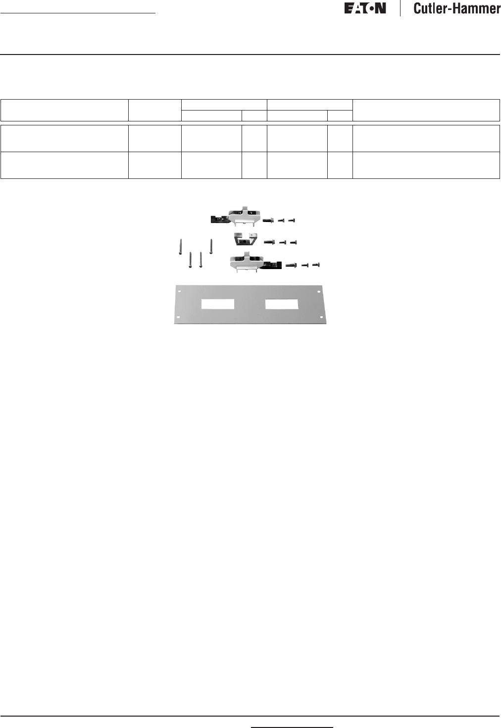
PRL3a Horizontally Mounted Connector Kit Assemblies
Table 22. Connector Kit Assemblies
Three-phase kits contain A, B and C
phase connectors. Single-phase kits
contain A and C phase connectors,
deadfront cover, hardware and instruc-
tions to twin mount breakers across
from each other. Maximum amperes
connected to any one connector
cannot exceed 200 amperes.
KPRL3ABA06
KPRL3AGB06
Devices Circuits
or Pole
3-Phase 1-Phase Notes
Catalog Number Phase Catalog Number Phase
BA, BAB, QBGF,
QBH, QBHGF,
QBGFEP,
QBHGFEP
6
12
18
24
KPRL3ABA06
KPRL3ABA12
KPRL3ABA18
KPRL3ABA24
A/B/C
A/B/C
A/B/C
A/B/C
KPRL3ABA06-1
KPRL3ABA12-1
KPRL3ABA18-1
KPRL3ABA24-1
A/C
A/C
A/C
A/C
(2) 100
Ampere
Devices
Maximum
GB, GHB, GHQ,
GHBS
6
12
18
24
KPRL3AGB06
KPRL3AGB12
KPRL3AGB18
KPRL3AGB24
A/B/C
A/B/C
A/B/C
A/B/C
KPRL3AGB06-1
KPRL3AGB12-1
KPRL3AGB18-1
KPRL3AGB24-1
A/C
A/C
A/C
A/C
For more information visit: www.eatonelectrical.com RP01400001E
Renewal Parts
Page 22 Effective: February 2009
Current Cutler-Hammer
Panelboards
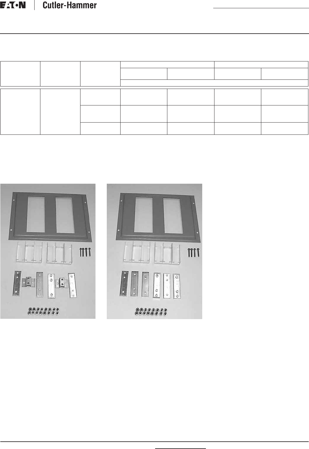
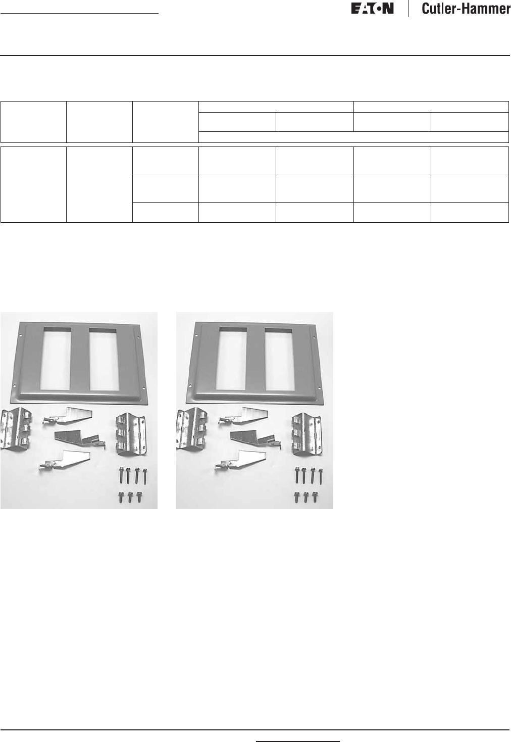
PRL3a F-Frame Horizontally Mounted Connector Kit Assemblies
Table 23. Connector Kit Assemblies
F-Frame devices rated above 150 amperes must be single mounted. No twin mounting acceptable.
Connector kits contain phase connec-
tors, deadfront cover, hardware and
instructions to mount breakers. Order
breakers separately when ordering
connector kit.
KPRL3AFD3
Devices Circuits
or Pole
3-Phase 1-Phase Notes
Catalog Number Phase Catalog Number Phase
EHD, FD, FDB,
HFD, FDC
(150 Ampere Maximum Twin Mount)
3-Pole Breaker
2-Pole Breaker
1-Pole Breaker
KPRL3AFD3
KPRL3AFD2
KPRL3AFD1
A/B/C
A/C
A/C
—
KPRL3AFD2
KPRL3AFD1
—
A/C
A/C
(2) 150 Ampere Devices Maximum
FD, HFD, FDC,
ED, EDH, EDC
(175 – 225 Ampere Single Mount)
3-Pole Breaker
2-Pole Breaker
KPRL3AED3
KPRL3AED2
A/B/C
A/C
—
KPRL3AED2
—
A/C
(1) 225 Ampere Maximum Single Mounted
RP01400001E For more information visit: www.eatonelectrical.com
Renewal Parts
Effective: February 2009 Page 23
Current Cutler-Hammer
Panelboards
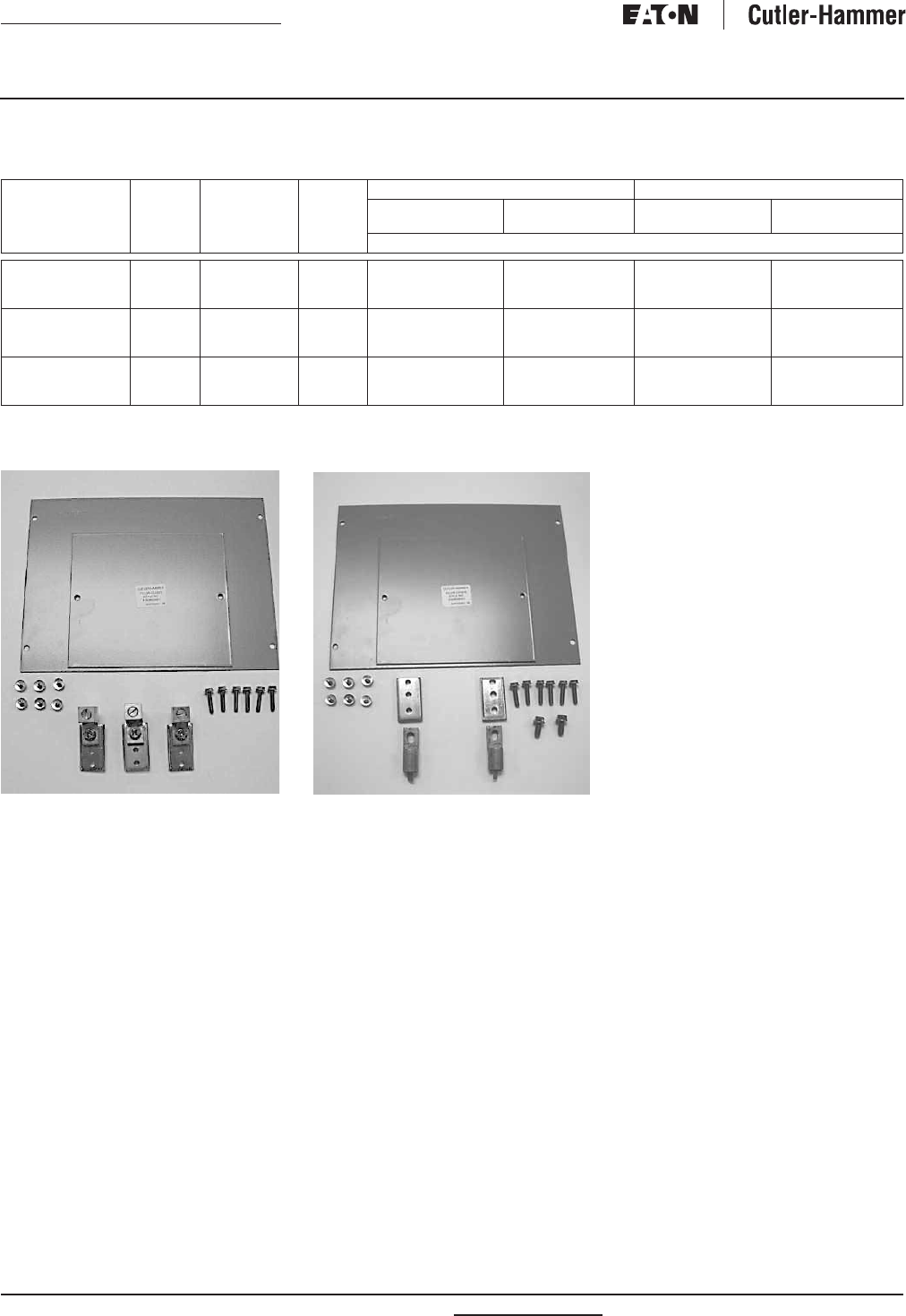
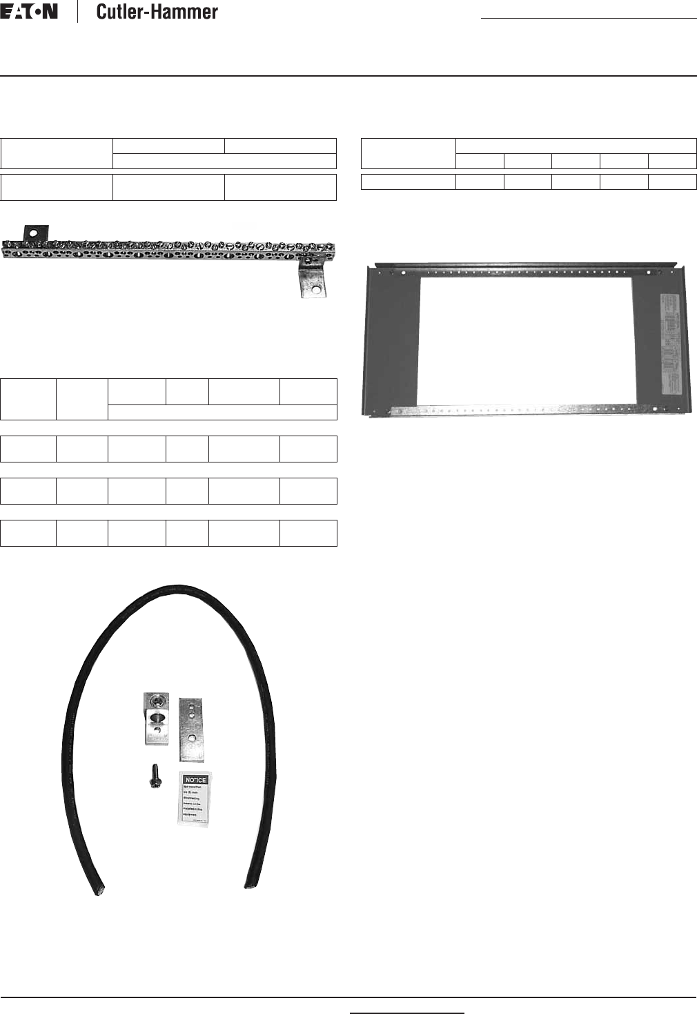
PRL3a Ground Assemblies
Table 24. PRL3a Ground Assemblies
5158C05G02
PRL3a Service Entrance Kits
Table 25. PRL3a Service Entrance Kits
When ordering, use complete style number
(example 100 Ampere Tin-Plated Aluminum 5078A98G01).
5078A98G01
PRL3a Deadfront Covers
Table 26. Assembly
Assembly groups include the frame only (two rails and two end
covers). Reference Pages 24 and 25 for specific device covers.
All connector kits ship with a deadfront cover for that device.
When ordering, use complete style number
(example 14X High Assembly 6559C59G01).
6559C59G01
Material Standard Isolated
Catalog Number
Aluminum/Copper
Copper Only
5158C05G02
5158C05G04
2C11296G02
2C11296G04
Style
Number
Panel
Ampere
Rating
Tin-Plated
Aluminum
Bare
Copper
Silver-Plated
Copper
Tin-Plated
Copper
Item Number
Mechanical Main Lugs or Main Breakers
5078A98 100
250 – 600
G01
G13
G02
G14
G03
G15
G04
G16
Crimp Main Lugs
5078A98 100
250 – 600
G05
G17
G06
G18
G07
G19
G08
G20
Copper Main Lugs
5078A98 100
250 – 600
G09
G21
G10
G22
G11
G23
G12
G24
Style
Number
Chassis Height/Item Number
14X 23X 31X 40X 53X
6559C59 G01 G02 G03 G04 G05
For more information visit: www.eatonelectrical.com RP01400001E
Renewal Parts
Page 24 Effective: February 2009
Current Cutler-Hammer
Panelboards
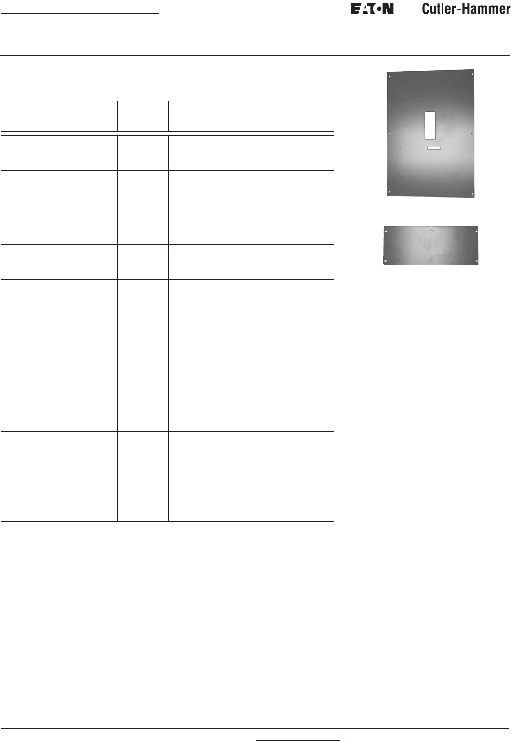
PRL3a Vertical Devices Deadfront Covers
Table 27. Vertical Mounting Position
When ordering covers, order complete style and item numbers (example 4176B68H01).
4/0 Maximum acceptable terminal size.
300 kcmil maximum acceptable terminal size.
Device/Frame Trip Unit
Type
Style
Number
“X”
Space
Required
Item Number
Without
Lock-offs
With
Lock-offs
EHD, FD, FDB, HFD,
FDC, ED, EDH, EDC (Top)
EHD, FD, FDB, HFD,
FDC, ED, EDH, EDC (Bottom)
N/A
N/A
4176B68 7X
7X
H01
H04
H03
H05
FD, HFD, FDC, ED, EDH (Top)
FD, HFD, FDC, ED, EDH (Bottom)
N/A 4180B93 10X H01
H04
H03
H05
J-Frame (Bottom)
J-Frame (Top)
N/A 4176B60 14X
14X
H01
H03
H02
H04
K-Frame (Bottom)
K-Frame (Bottom)
K-Frame (Top)
K-Frame (Top)
Thermal-Mag.
Electronic
Thermal-Mag.
Electronic
4176B61 15X
15X
15X
15X
H01
H03
H05
H07
H02
H04
H06
H08
L-Frame (Bottom)
L-Frame (Bottom)
L-Frame (Top)
L-Frame (Top)
Thermal-Mag.
Electronic
Thermal-Mag.
Electronic
4176B51 17X
17X
17X
17X
H01
H03
H05
H07
H02
H04
H06
H08
FB-P (Top Only) N/A 4176B70 9X H02 H02
LA-P (Top Only) N/A 4176B57 21X H01 H01
FCL N/A 4176B70 9X H01 H01
LCL (Top)
LCL (Bottom)
N/A
N/A
4176B56 21X
21X
H01
H03
H02
H04
Neutral/Blank Cover N/A 4176B72 1X
2X
3X
4X
5X
6X
7X
8X
9X
10X
11X
12X
H01
H02
H03
H04
H05
H06
H07
H08
H09
H10
H11
H12
—
J-Frame Sub-Feed Twin Bottom N/A 4176B79 20X H01 H02 (2 L/O)
H03 (1 L/O RT)
H04 (1 L/O LT)
J-Frame Sub-Feed Twin Top N/A 4176B79 20X H05 H05 (2 L/O)
H07 (1 L/O RT)
H08 (1 L/O LT)
PT363 (Top)
PT363 (Bottom)
PT364 (Top)
PT364 (Bottom)
N/A
N/A
N/A
N/A
4180B79 7X
7X
9X
9X
H01
H02
H03
H04
—
J Main 4176B60H04
Neutral Blank Cover 4176B72H04
RP01400001E For more information visit: www.eatonelectrical.com
Renewal Parts
Effective: February 2009 Page 25
Current Cutler-Hammer
Panelboards
PRL3a Horizontal Devices Deadfront Covers
Table 28. Horizontal Mounting Position
When ordering covers, order complete style and item number (example 4178B08H01).
Device/Frame Device
Poles
Style
Number
Total Circuit
Quantity
“X” Space
Required
Item
Number
EHD, FD, FDB, HFD, FDC
(Twin Mounted)
1, 2 or 3 4178B08 6
12
18
24
30
36
42
48
3X
6X
9X
12X
15X
18X
21X
24X
H01
H02
H03
H04
H05
H06
H07
H08
EHD, FD, FDB, HFD, FDC
(Twin Mounted)
1 or 2 4179B39 4
8
12
16
20
24
28
32
2X
4X
6X
8X
10X
12X
14X
16X
H01
H02
H03
H04
H05
H06
H07
H08
EHD, FD, FDB, HFD, FDC
(Twin Mounted)
14179B40 2 1X H01
FD, HFD, FDC, ED, EDH, EDC
(Single Mounted)
34179B41 3 3X H01
FD, HFD, FDC, ED, EDH, EDC
(Single Mounted)
24179B42 2 2X H01
CA, CAH, HCA 3 4176B66 3 3X H01
CA, CAH, HCA 2 4176B80 2 2X H01
BA, BAB, BABRP, BABRSP
QBH, QBGF,
QBGFEP,
QBHGFEP
1, 2 or 3 4176B67 6
12
18
24
3X
5X
8X
10X
H01
H02
H03
H04
GB, GHB, GHBS,
GHBGFEP, HGHB, GHQ
1, 2 or 3 4176B69 6
12
18
24
3X
5X
8X
10X
H01
H02
H03
H04
Pow-R-Command Controller N/A 4180B91 N/A 5X H01
Pow-R-Command Expansion N/A 4180B91 N/A 7X
16X
H02
H03
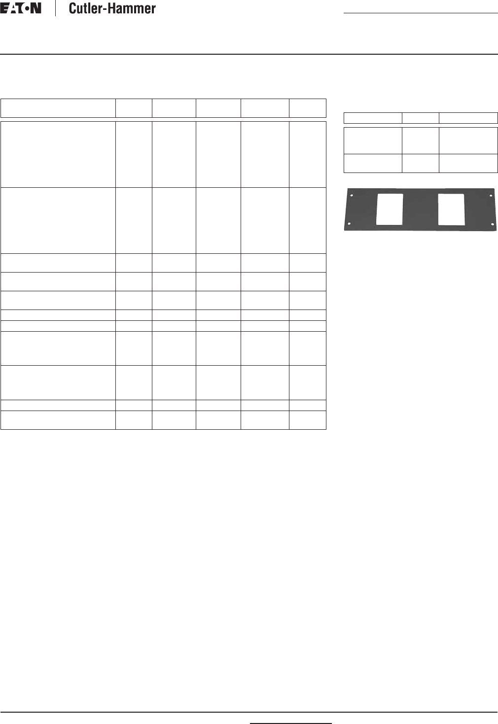
PRL3a Deadfront Cover
Blank Fillers
Table 29. PRL3a Deadfront Cover Blank Fillers
BAB Cover 4176B67H01
Device/Frame Poles Style Number
F-Frame
C-Frame
C-Frame
1, 2 or 3
2
3
4178B06H01
6555C40H01
6555C41H01
QUICKLAG, GB,
GHB, GHBS
1, 2 or 3 5155C62H01
For more information visit: www.eatonelectrical.com RP01400001E
Renewal Parts
Page 26 Effective: February 2009
Current Cutler-Hammer
Panelboards
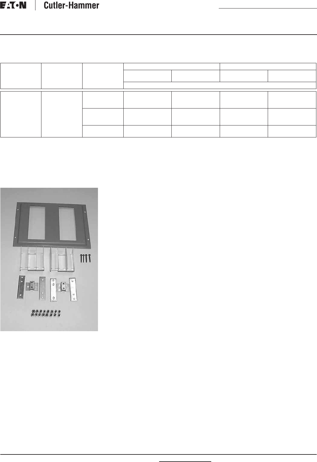
PRL4B/F Parts Section Page
Vented Cover Assemblies
and Side Gutter Covers . . . . . 26
PRL4 Blank Covers . . . . . . . . . . 27
PRL4 Breaker Connector Kits . . 28
PRL4 Fusible FDPW Switch
Connector Kit . . . . . . . . . . . . . 29
PRL4 Breaker Retrofit Kits . . . . 30
PRL4 Fusible Retrofit Kits. . . . . 30
PRL4 Energy Sentinel . . . . . . . . 31
PRL1a, 2a, 3a and PRL4
Special Trims and
Enclosures . . . . . . . . . . . . . . . 32
Table 30. Vented Cover Assemblies and Side Gutter Covers — Dimensions in Inches (mm)
NEMA 1 Box Vented Cover
Assembly
Style Number
Side Gutter Covers
Dimensions Catalog
Number
Left Right
Height Width Depth Size Style Number Size Style Number
57.00 (1447.8)
73.00 (1854.2)
90.00 (2286.0)
24.00 (609.6)
24.00 (609.6)
24.00 (609.6)
10.40
(264.2)
BX2457
BX2473
BX2490
6574C74G02
6574C74G03
6574C74G04
5.00 (127.0) x 57.00 (1447.8)
5.00 (127.0) x 73.00 (1854.2)
5.00 (127.0) x 90.00 (2286.0)
6555C20H01
6555C21H01
6555C25H01
5.00 (127.0) x 57.00 (1447.8)
5.00 (127.0) x 73.00 (1854.2)
5.00 (127.0) x 90.00 (2286.0)
6555C20H01
6555C21H01
6555C25H01
73.00 (1854.2)
90.00 (2286.0)
36.00 (914.4)
36.00 (914.4)
BX3673
BX3690
6574C74G05
6574C74G06
6.00 (152.4) x 73.00 (1854.2)
6.00 (152.4) x 90.00 (2286.0)
6555C22H01
6555C26H01
8.00 (203.2) x 73.00 (1854.2)
8.00 (203.2) x 90.00 (2286.0)
6555C23H01
6555C27H01
73.00 (1854.2)
90.00 (2286.0)
44.00 (1117.6)
44.00 (1117.6)
BX4473
BX4490
6574C74G05
6574C74G06
8.00 (203.2) x 73.00 (1854.2)
8.00 (203.2) x 90.00 (2286.0)
6555C23H01
6555C27H01
14.00 (355.6) x 73.00 (1854.2)
14.00 (355.6) x 90.00 (2286.0)
6555C24H01
6555C28H01
Covers add .90 inches (22.9 mm) to box depth for overall enclosure depth of 11.30 inches (287.0 mm).
Cover assembly consists of 2 side rails, top and bottom vented covers.
Important: Order individual device covers and blanks separately.
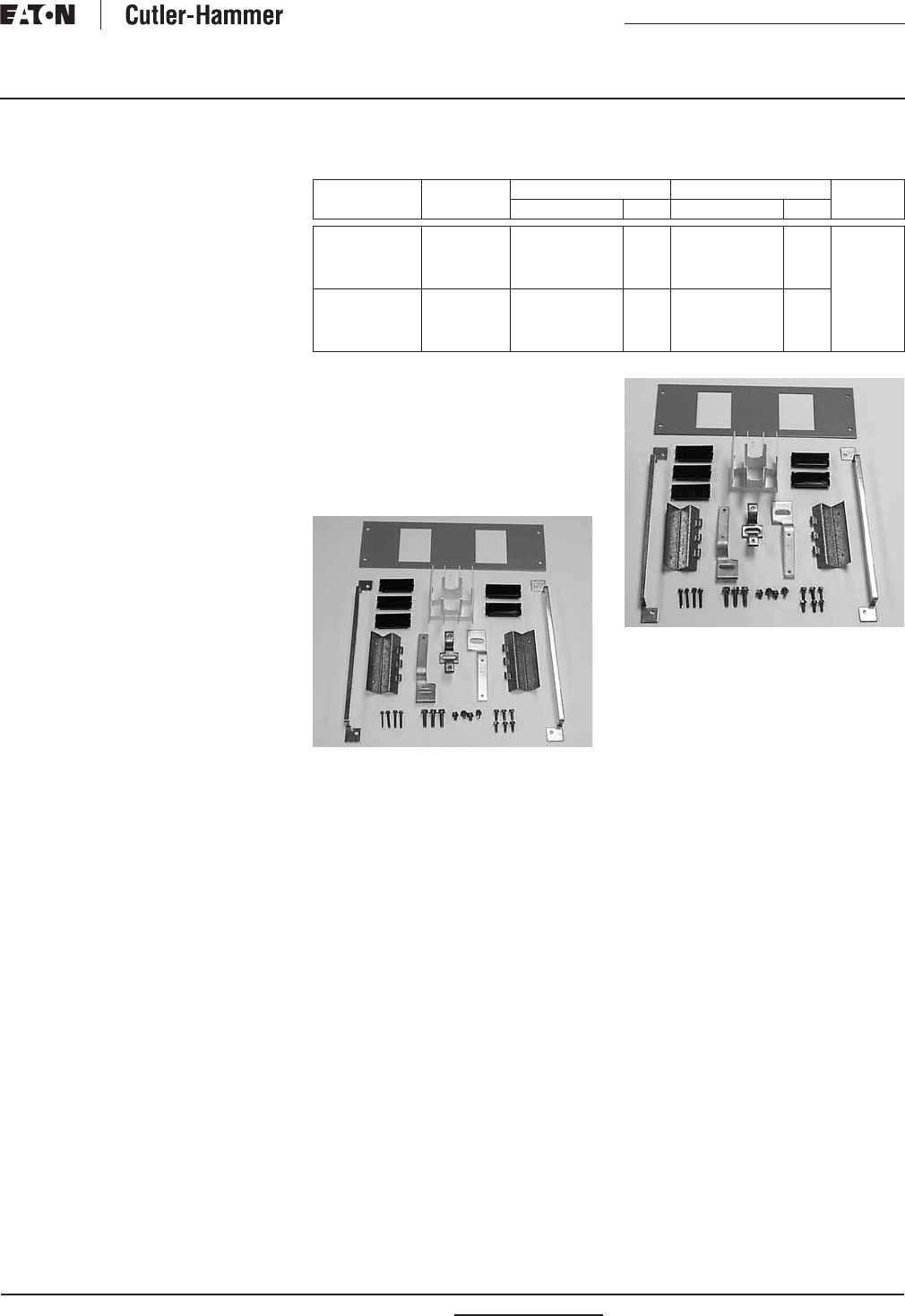
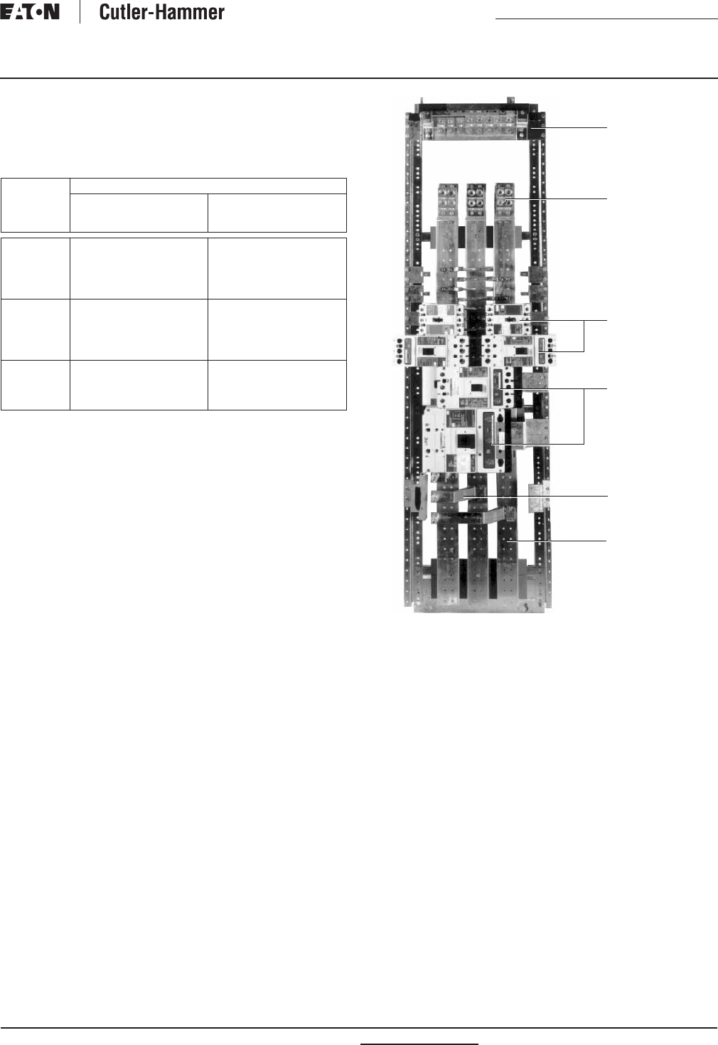
PRL4 Vented Cover Assemblies
Nameplate
Top
Vented
Cover
Blank
Cover
Side
Gutter
Covers
Extension
Wings
Device
Cover
Bottom
Vented
Cover
PRL4B PRL4F
RP01400001E For more information visit: www.eatonelectrical.com
Renewal Parts
Effective: February 2009 Page 27
Current Cutler-Hammer
Panelboards
PRL4 Blank Covers
Used to cover blank space on chassis. All PRL4 cover heights
are measured in “X” units. 1X equals 1.38 inches (35.1 mm).
Table 31. PRL4 Blank Covers
PRL4B Interior
Cover
Size
Style Number
24.00-Inch
(609.6 mm)
Width Box
36.00, 44.00-Inch
(914.4, 1117.6 mm)
Width Box
1X
2X
3X
4X
5X
6554C01H01
6554C01H02
6554C01H03
6554C01H13
6554C01H14
6554C02H01
6554C02H02
6554C02H03
6554C02H13
6554C02H14
6X
7X
9X
10X
11X
6554C01H04
6554C01H05
6554C01H06
6554C01H07
6554C01H08
6554C02H04
6554C02H05
6554C02H06
6554C02H07
6554C02H08
12X
13X
15X
20X
6554C01H09
6554C01H10
6554C01H11
6554C01H12
6554C02H09
6554C02H10
6554C02H11
6554C02H12
Neutral
Space Only
Breaker
Provision
Single Mounted
Breakers
Twin Mounted
Breakers
1200 Ampere MLO
For more information visit: www.eatonelectrical.com RP01400001E
Renewal Parts
Page 28 Effective: February 2009
Current Cutler-Hammer
Panelboards
PRL4 Breaker Connector Kits
Breaker Connector Kits
Each kit includes copper connectors,
mounting brackets, covers, hard-
ware and instructions for mounting
breaker(s) in a PRL4. Breakers are not
included. Contact your local Satellite
plant for availability and application
information (see Page 4).
Connector Kit
Each kit includes copper connectors
mounting brackets, cover, hardware
and instructions.
Connector Kit
Table 32. Breaker Connector Kits
Two sets of twin mounted 1-pole breakers.
36.00-inch (914.4 mm) minimum box width required.
44.00-inch (1117.6 mm) box width required.
Requires density rated bus in existing panel chassis.
Hardware Kit
Each kit includes mounting bracket(s)
and mounting hardware only. Use the
appropriate Connector Kit catalog
number and add an “H” to designate
hardware only (example: KPRL4FD-H).
Hardware Kit
Standard Ground Bus
Copper bus with (3) 6 – 300 kcmil lugs
plus a 24-circuit terminal bar with
#14 – 1/0 wire range.
6572C746G01
Breaker
Frame
Space Required Poles Mounting
Type
Connector Kit
Catalog Number
Inches (mm) “X”
EHD, FD, HFD
EHD, FD, FDB, HFD, FDC
ED, EDH, EDC
2.75
(69.9)
2X 1
2
2
Twin
Twin
Twin
KPRL4FD1
KPRL4FD2
KPRL4ED2
EHD, FD, FDB, HFD, FDC
FCL, FB-P, FD/LFD
ED, EDH, EDC
JD, JDB, HJD, JDC
JD, JDB, HJD, JDC
4.13
(104.9)
3X 3
3
3
2, 3
2,3
Twin
Twin
Twin
Single
Twin
KPRL4FD
KPRL4FBP
KPRL4ED
KPRL4JDS
KPRL4JDT
DK, KD, KDB, HKD, KDC
DK, KD, KDB, HKD, KDC
CKD, CHKD
5.50
(139.7)
4X 2, 3
2,3
2,3
Single
Twin
Single
KPRL4KDS
KPRL4KDT
KPRL4CKD
LCL
LA-P
LD, LDB, HLD, LDC, CLD, LC
MDL, HMDL
NB-P
CND, CHND
ND, HND
8.25
(209.5)
6X 2, 3
2, 3
2, 3
2, 3
2, 3
3
2, 3
Single
Single
Single
Single
Single
Single
Single
KPRL4LCL
KPRL4LAP
KPRL4LD
KPRL4MC
KPRL4NBP
KPRL4CND
KPRL4ND
RP01400001E For more information visit: www.eatonelectrical.com
Renewal Parts
Effective: February 2009 Page 29
Current Cutler-Hammer
Panelboards
PRL4 Fusible Connector Kits
Fusible Switch Connector Kits
Each kit includes copper connectors,
extension wings (when required),
hardware and instructions to mount
a fusible switch. Switches are not
included. Contact your local Satellite
plant for availability and application
information (see Page 4).
Table 33. Fusible Switch Connector Kits
These connector kits will fit the FDP and FDPW switches.
44.00-inch (1117.6 mm) box width required for both R and J fuse applications.
Switch Height Switch
Ampere
Rating
3-Pole Switch Connector Kit
Inches
(mm)
“X” Space
Required
240 Volts 600 Volts
Catalog Number
5.50 (139.7) 4X 30 – 30
60 – 60
100 – 100
FDPWT3211R
FDPWT3222R
FDPWT3233R
FDPWT3611R
FDPWT3622R
—
—
KPRL44X
—
6.88 (174.8) 5X 100 – 100 — FDPWT3633R KPRL45X
8.25 (209.6) 6X 200
200 – 200
FDPBS324R
FDPBT3244R
FDPBS364R
FDPBT3644R
KPRL4B6XS
KPRL4B6XT
12.38 (314.5) 9X 400 FDPW325R FDPW365R KPRL4W9X
15.13 (384.3) 11X 600
800
FDPW326R
FDPW327
FDPW366R
FDPW367
KPRL4W11X
KPRL4W11X
20.63 (524.0) 15X 1200 FDPW328 FDPW368 KPRL4W15X
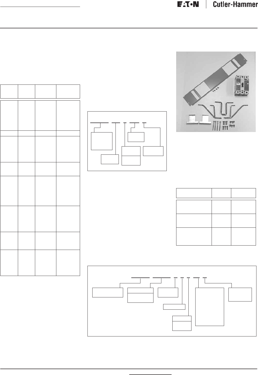
For more information visit: www.eatonelectrical.com RP01400001E
Renewal Parts
Page 30 Effective: February 2009
Current Cutler-Hammer
Panelboards
PRL4 Breaker and Fusible
Switch Retrofit Kits
Breaker Retrofit Kits
Each kit includes one breaker, copper
connectors, covers, hardware and
instructions to mount in a PRL4.
Table 34. Breaker Retrofit Kits
Breaker
Frame
Frame
Ampere
Rating
Trip
Range
Mounting
Type
EHD
FDB
FD
HFD
FDC
FCL
FB-P
100 15 – 100
15 – 100
15 – 100
15 – 100
15 – 100
15 – 100
15 – 100
Twin
Twin
Twin
Twin
Twin
Twin
Twin
FDB 150 110 – 150 Twin
FD
HFD
FDC
ED
EDH
EDC
225 110 – 225
110 – 225
110 – 225
100 – 225
100 – 225
100 – 225
Twin
Twin
Twin
Twin
Twin
Twin
JD
HJD
JDC
250 70 – 250
70 – 250
70 – 250
Twin/Single
Twin/Single
Twin/Single
DK
KD
HKD
KDC
CKD
LCL
LA-P
400 100 – 400
100 – 400
100 – 400
100 – 400
100 – 400
125 – 400
70 – 400
Twin/Single
Twin/Single
Twin/Single
Twin/Single
Single
Single
Single
LD
CLD
HLD
CHLD
LDC
CLDC
600 300 – 600
300 – 600
300 – 600
300 – 600
300 – 600
300 – 600
Single
Single
Single
Single
Single
Single
MDL
CMDL
HMDL
CHMDL
800 300 – 800
300 – 800
300 – 800
300 – 800
Single
Single
Single
Single
ND
CND
HND
CHND
NDC
CNDC
1200 600 – 1200
600 – 1200
600 – 1200
600 – 1200
600 – 1200
600 – 1200
Single
Single
Single
Single
Single
Single
How to Order a Breaker Retrofit Kit
by Catalog Number
Use “KPRL4” prefix and add catalog
number of breaker as shown below.
Use suffix “T” or “S” to denote twin
or single mounting. Twin mounting
indicates that one set of connectors
is required to mount two breakers (of
similar frames) opposite one another.
RETROFIT KIT INCLUDES ONE
BREAKER ONLY, FOR EITHER SINGLE
OR TWIN MOUNTED APPLICATIONS.
Table 35. Catalog Numbering System —
Breaker Retrofit Kit
Breaker Retrofit Kit
Fusible Retrofit Kits
Each kit includes a 3-pole switch,
copper connectors, extension wings
(if required), hardware and instructions
to horizontally mount in a PRL4.
How to Order a Fusible Retrofit Kit
by Catalog Number
Use “KPRL4” prefix and add catalog
number of appropriate switch (refer
to Page 29 for 3-pole switch catalog
number).
Example: The Retrofit Kit catalog number
for a 600 volt, 100 ampere twin FDPW
switch is:
Table 36. Fusible Retrofit Kits
Table 37. Catalog Numbering System — Fusible Retrofit Kit
KPRL4 KD 3 400 S
Designates
KPRL4
Connector
Kit
Breaker
Frame
Number
of Poles
2 = 2-Pole
3 = 3-Pole
Ampere
Rating
T = Twin
S = Single
Switch
Ampere Rating
Switch
Type
Mounting
Type
30 – 30
60 – 60
100 – 100
FDPW
FDPW
FDPW
Twin
Twin
Twin
100
200
200 – 200
FDPW
FDPB
FDPB
Single
Single
Twin
400
600
800
1200
FDPW
FDPW
FDPW
FDPW
Single
Single
Single
Single
KPRL4 FDPW T 3 6 33 R
Volts
2= 240
6= 600
Designates
PRL4 Connector
T = Twin
S = Single
R = R Fuse
J = J Fuse
T = T Fuse
Switch Type
FDPW
FDPB
11 = 30 – 30
22 = 60 – 60
33 = 100 – 100
44 = 200 – 200
4= 200
5= 400
6= 600
7= 800
8= 1200
3= 3-Pole
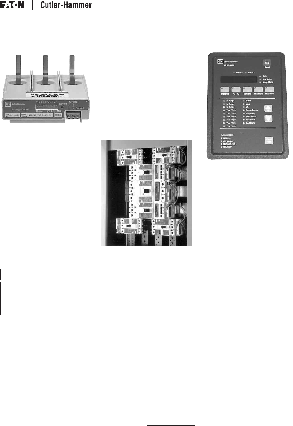
RP01400001E For more information visit: www.eatonelectrical.com
Renewal Parts
Effective: February 2009 Page 31
Current Cutler-Hammer
Panelboards
PRL4 Energy Sentinel
Energy Sentinel
The IQ Energy Sentinel is a submeter-
ing device that mounts directly on
a circuit breaker and monitors both
power and energy with an overall
accuracy of 99%.
This high system accuracy is achieved
by use of the Cutler-Hammer SURE
Plus Chip, which is a sophisticated
microprocessor.
All that is necessary to complete an
IQ Energy Sentinel installation is to
insert it into the load side of a breaker,
feed the load conductors through it,
and run the shielded twisted pair wire
for communications. The IQ Energy
Sentinel has a nonvolatile memory,
is powered by the circuit breaker,
and can be applied on 3-phase, 4-wire
or single-phase, 3-wire systems.
The space-saving design characteris-
tics of the IQ Energy Sentinel mean
they can be quickly and easily retrofit-
ted onto Series C circuit breakers
in existing equipment…with no addi-
tional space required. Additionally,
IQ Energy Sentinel can be installed
when upgrading to Series C from
older breakers that are physically
interchangeable…with no additional
space required.
Power and energy information from
IQ Energy Sentinels can be communi-
cated to a PC, a panel mounted Central
Energy Display (CED), or even existing
building management or distribution
control systems.
Energy Sentinels Installed
Table 38. Energy Sentinel
Series C Breaker
Frame
Voltage
ac
Maximum
Amperes
Catalog
Number
F
F
120/208, 120/240
277/480
150
150
IQESF208
IQESF480
J
J
120/208, 120/240
277/480
250
250
IQESJ208
IQESJ480
K
K
120/208, 120/240
277/480
350
350
IQESK208
IQESK480
IQ Central Energy Display
IQ Central Energy Display
The IQ Central Energy Display may
be panel mounted or located remotely
(up to 7500 feet [2286 m] away).
It displays power, peak demand,
and energy readings of up to 50 IQ
Energy Sentinels and eight IQ Data
Plus meters.
Additional capabilities include:
peak demand alarming, demand
and energy totals for groups of
IQ Energy Sentinels and IQ Data
Plus 11 digital meters.
Refer to your local Satellite for
retrofit and upgrade options available
for existing equipment.
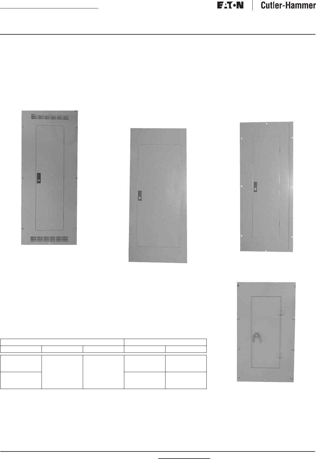
For more information visit: www.eatonelectrical.com RP01400001E
Renewal Parts
Page 32 Effective: February 2009
Current Cutler-Hammer
Panelboards
PRL1a, 2a, 3a Special Trims and Enclosures
Ventilated Trim
Required on PRL1a, 2a, 3a, 600 ampere
and above panels only. Order by add-
ing the letter “V” to the standard trim
catalog number. Add 10% to standard
trim list price.
Example: LT2072S becomes LTV2072S.
Ventilated Trim
Fastrim
Used when concealed trim mounting
hardware is required for PRL1a, 2a and
PRL3a. Trim clamps are included and
shipped with the trim. Order by adding
the letter “F” to the standard trim cata-
log number. Add 20% to standard trim
list price.
Example: LT2072S becomes LTF2072S.
For trim clamps only, refer to Page 20.
Fastrim
Type 12/3R Enclosures
The complete enclosure consists of
a box and trim. The enclosure meets
code requirements for both Type 12
(dust-tight) and Type 3R (rainproof)
standards. Features include a laser cut
trim with rounded corners, concealed
hinges and a T-handle lock. Gasketing
is provided around the trim door.
The box is gasketed and made from
code gauge steel with dripshield and
is painted ANSI-61.
Table 39. Type 12/3R Enclosures for PRL1a, 2a, 3a
Box Dimensions in Inches (mm) Catalog Number
Height Width Depth Box Trim
24.00 (609.6)
36.00 (914.4)
48.00 (1219.2)
20.00 (508.0) 6.00 (152.4) VWPB2024
VWPB2036
VWPB2048
LWPT2024
LWPT2036
LWPT2048
60.00 (1524.0)
72.00 (1828.8)
90.00 (2286.0)
VWPB2060
VWPB2072
VWPB2090
LWPT2060
LWPT2072
LWPT2090
Door-In-Door
Piano hinge on the right side of the
trim provides access to the wiring
gutters without requiring removal of
the trim. Order by adding the letters
“DD” to the standard trim catalog
number. Add 20% to standard trim
list price.
Example: LT2072S becomes LTDD2072S.
Door-in-Door
Type 12/3R Enclosures

RP01400001E For more information visit: www.eatonelectrical.com
Renewal Parts
Effective: February 2009 Page 33
Current Cutler-Hammer
Panelboards
PRL4 Special Trims
and Enclosures
Door-In-Door Trim
Door-In-Door Trim
A piano hinge on the right side of
the trim provides access to the wiring
gutter without requiring the removal
of the trim. When used with a standard
PRL4 box, a special mounting channel
must be used to add extra depth to
the enclosure.
An extra depth box, not requiring a
mounting channel, is another available
option. Contact your local Satellite for
ordering information.
Table 40. Special Trims and Enclosures
Type 12/3R Enclosures
Type 12, 24.00 Inches (609.6 mm) Wide Type 3R, 36.00 Inches (914.4 mm) Wide
PRL4 enclosures are available in both Type 12 (dust-tight) and Type 3R (rainproof)
designs. The 24.00-inch (609.6 mm) wide enclosure includes a single hinged door
while the 36.00-inch (914.4 mm) wide is provided with double hinged doors.
The side gutter covers are an integral part of the box in all styles. Sizes and catalog
numbers are shown in the table below.
Table 41. Type 12/3R Enclosures
Standard Box
Catalog Number
Mounting Channel
Style Number
Door-In-Door Trim Catalog Number
Surface Flush
BX2457
BX2473
BX2490
8708C82G02
8708C82G03
8708C82G04
LDD2457STW
LDD2473STW
LDD2490STW
LDD2457FTW
LDD2473FTW
LDD2490FTW
BX3673
BX3690
BX4473
BX4490
8708C82G05
8708C82G06
8708C82G07
8708C82G08
LDD3673STW
LDD3690STW
LDD4473STW
LDD4490STW
LDD3673FTW
LDD3690FTW
LDD4473FTW
LDD4490FTW
Enclosure Dimensions in Inches (mm) Catalog Number
Height Width Depth Type 3R Type 12
57.00 (1447.8)
73.00 (1854.2)
90.00 (2286.0)
24.00 (609.6)
24.00 (609.6)
24.00 (609.6)
13.90 (353.1) RPC2457
RPC2473
RPC2490
DPC2457
DPC2473
DPC2490
73.00 (1854.2)
90.00 (2286.0)
36.00 (914.4)
36.00 (914.4)
RPC3673
RPC3690
DPC3673
DPC3690

For more information visit: www.eatonelectrical.com RP01400001E
Renewal Parts
Page 34 Effective: February 2009
Current Cutler-Hammer
Panelboards
PRL5P Parts Section Page
PRL5P Chassis Layout . . . . . . . 35
PRL5P Breaker Adapter Unit
Catalog Numbers . . . . . . . . . . 36
PRL5P Branch Breaker
Information . . . . . . . . . . . . . . . 37
PRL5P Main or
Through-Feed Lugs . . . . . . . . 38
PRL5P Neutrals and Grounds . . 39
PRL5P Boxes, Trims and
Filler Plates . . . . . . . . . . . . . . . 40
Ordering Procedure
Step 1 Select the correct part
or Branch Device. When
selecting, you need to know
the following:
■Panelboard type.
■Amperage.
■System voltage.
■Available short circuit rating.
■Number of poles available.
■Size and number of wires
per phase.
■“X” space required.
Step 2 Refer to the 5P panelboard
layout on Page 35 to verify the
amount of “X” space available.
Step 3 Create a 5P breaker unit
catalog number, by following
the instructions on Page 36, or
order the catalog number for
parts on Pages 38 through 40.
Step 4 Determine if extra filler covers
are required. Additional filler
covers may be necessary to
fill the unused space. Refer
to Page 40 for filler plate
information.
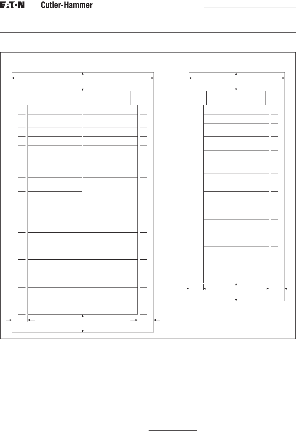
RP01400001E For more information visit: www.eatonelectrical.com
Renewal Parts
Effective: February 2009 Page 35
Current Cutler-Hammer
Panelboards
PRL5P Chassis Layout
Figure 3. PRL5P Chassis Layout — Dimensions in Inches (mm)
If used as a main device, must be mounted at the neutral end of panel.
Fixed bus covers are required for unused spaces if NEC six circuit disconnect rule is to be met.
Blank wireway fillers are required opposite any dual breaker unit.
One “X” = 1.38 inches (35.1 mm).
6X
2-Pole
EHD, FD, FDB, HFD, FDC, ED, EDH, EDC
3-Pole
EHD, FD, FDB, HFD, FDC,
ED, EDH, EDC
2-Pole
EHD, FD, FDB, HFD,
FDC, ED, EDH, EDC
2-Pole
EHD, FD, FDB, HFD,
FDC, ED, EDH, EDC
Blank Wireway➂
3-Pole
FDB, EDH, HFD, FDC,
ED, EHD, EDC, FD
3-Pole
FDB, EDH, HFD, FDC,
ED, EHD, EDC, FD
Filler Plate
2- or 3-Pole
JD, HJD, JDC
2- or 3-Pole
DK, KD, HKD, KDB
Filler Plate
Neutral — No “X” Space Required
Top or Bottom
2-Pole
EHD, FD, FDB, HFD, FDC, ED, EDH, EDC
3-Pole
EHD, FD, FDB, HFD, FDC,
ED, EDH, EDC
Blank Wireway➂
2-Pole
EHD, FD, FDB, HFD,
FDC, ED, EDH, EDC
2-Pole
EHD, FD, FDB, HFD,
FDC, ED, EDH, EDC
Blank Wireway➂
2- or 3-Pole
HLD, LDC, LD
800A MDL, HMDL➀
Main or Branch
800A ND, HND, NDC➀
Main or Branch
1200A ND, HND, NDC➀
Main or Branch
Main Lug or Branch Lug Unit
600A, (2) 600 kcmil
800A, (3) 800 kcmil
1200A, (4) 750 kcmil
2X
3X
2X
2X
3X
4X
3X
3X
6X
6X
6X
7X
2X
3X
2X
2X
3X
4X
6X
6X
6X
7X
10
(254.0)
48
(1219.2)
10
(254.0)
10
(254.0)
2X
2X
3X
3X
3X
1X-6X
6X
4X
6X
8X
Neutral — No “X” Space Required
Top or Bottom
2-Pole
EHD, ED, EDH, EDC, FD, FDB, HFD, FDC
2-Pole
EHD, FD, FDB, HFD, FDC,
ED, EDC, EDH
2-Pole
EHD, FD, FDB, HFD, FDC,
ED, EDC, EDH
3-Pole
FDB, ED, HFD, FDC,
EHD, EDC, FD
3-Pole
FDB, ED, HFD, FDC,
EHD, EDC, FD
3-Pole
EHD, FD, FDB, HFD, FDC,
ED, EDH, EDC
2 or 3-Pole
JD, HJD, JDC
Bus Cover➁
2- or 3-Pole➀
DK, KD, HKD, KDB
Main or Branch
2- or 3-Pole➀
LD, HLD, LDC
Main or Branch
800A MDL, HMDL➀
Main Only
400A, 600A and 800A
Main Lug or Branch Lug➀
400A, (1) 750 kcmil or (2) 300 kcmil
600A, (2) 750 kcmil
800 (3) 600 kcmil
10
(254.0)
10
(254.0)
7
(177.8)
30
(762.0)
Single-Bus Interior in
30-inch (762.0 mm) Wide Enclosure
Double-Bus Interior Mounted in
48-inch (1219.2 mm) Wide Enclosure
10
(254.0)
10
(254.0)
➃
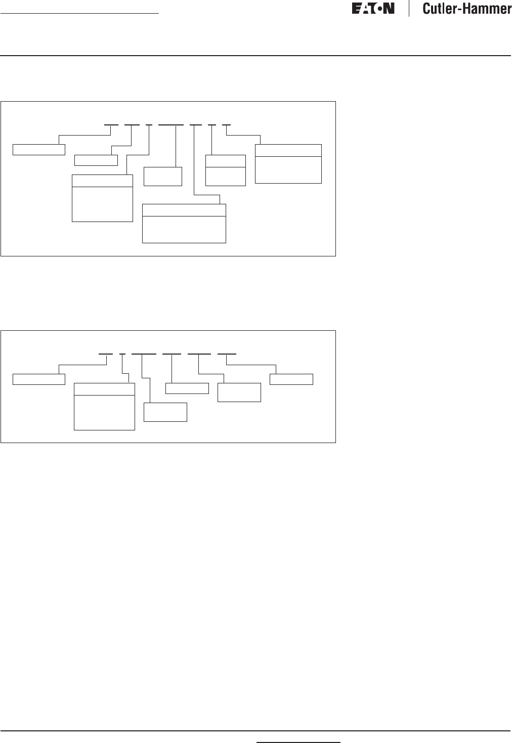
For more information visit: www.eatonelectrical.com RP01400001E
Renewal Parts
Page 36 Effective: February 2009
Current Cutler-Hammer
Panelboards
PRL5P Breaker Assemblies Catalog Numbers
Table 42. Catalog Numbering System — 5P Single or Twin Breakers with Adapters
A plug-on unit is a complete assembly
with a circuit breaker and mounting
adapter to mount on a 5P panelboard.
Single indicates units that may be
mounted in a single or double bus
panel, and twin indicates double
bus panels only. See Tables 44 and 45
on Page 37.
Table 43. Catalog Numbering System — 5P Dual Breakers with Adapters
Any two F-Frame breakers listed may
be mounted on the same 2X or 3X
dual breaker adapter.
Dual breaker adapters may be
used in single or double bus panels.
Dual breaker adapters can NOT be
mounted
across from another adapter
in a double
bus panel. See Table 46
on Page 37.
5P FD 3 0060 M S B
Panelboard
Mounting
T = Twin
S = Single
Phasing
2=AB
3= ABC
4= ABL or BCR
5= BCL or ABR
Breaker
Ampere
Rating
Trip Unit
E= Electronic
G= Ground Fault
M= Thermal Magnetic
Connection
B= Branch
C= Combination
M=Main
5P 3 EDH 200 FDB 060
Panelboard
Phasing
2=AB
3= ABC
4= ABL or BCR
5= BCL or ABR
Breaker
Frame
Breaker
Frame
Amperes
Amperes
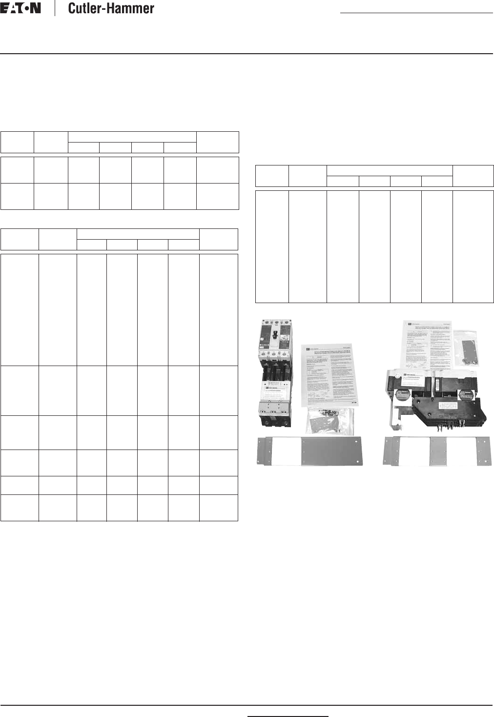
RP01400001E For more information visit: www.eatonelectrical.com
Renewal Parts
Effective: February 2009 Page 37
Current Cutler-Hammer
Panelboards
Branch Devices
Single-pole breakers in single adapter units. Include two
or three single-pole 15 – 60 ampere assembled on one unit.
(One X = 1.38 inches [35.1 mm])
Table 44. Single-Pole Breakers in Single Adapter Units
Table 45. 2- and 3-Pole Breakers in Single Adapter Units
For use only in double bus chassis panelboards.
100% rated breakers are NOT available in 5P panelboards.
Dual breaker adapters — Any two breakers listed in Table 46
may be mounted on the same 2X or 3X dual breaker adapter.
Dual breaker adapters may be used in single or double
bus chassis. Dual breaker adapters can NOT be mounted
across from another in a double bus chassis. (One X = 1.38
inches [35.1 mm])
Table 46. Dual Breaker Adapters
Breaker
Type
Ampere
Rating
Interrupting Rating (kA Sym.) “X” Space
Required
120 Vac 240 Vac 277 Vac 125 Vdc
EHD
FD
HFD
15 – 60
15 – 60
15 – 60
—
—
—
—
—
—
14
25
65
10
10
10
2X
2X
2X
EHD
FD
HFD
15 – 60
15 – 60
15 – 60
—
—
—
—
—
—
14
25
65
10
10
10
3X
3X
3X
Breaker
Type
Ampere
Rating
Interrupting Rating (kA Sym.) “X” Space
Required
240 Vac 480 Vac 600 Vac 250 Vdc
ED
EDH
EDC
EHD
EHD
FD
FD
FD
HFD
HFD
HFD
FDC
FDC
FDC
100 – 225
100 – 225
100 – 225
15 – 60
70 – 100
15 – 60
70 – 100
110 – 225
15 – 60
70 – 100
110 – 225
15 – 60
70 – 100
110 – 225
65
100
200
18
18
65
65
65
100
100
100
200
200
200
—
—
—
14
14
25
25
25
65
65
65
100
100
100
—
—
—
—
—
18
18
18
25
25
25
35
35
35
—
—
—
10
10
10
10
10
22
22
22
22
22
22
3X
3X
3X
3X
3X
3X
3X
3X
3X
3X
3X
3X
3X
3X
JD, JDB
JD, JDB
HJD
HJD
JDC
JDC
70 – 225
250
70 – 225
250
70 – 225
250
65
65
100
100
200
200
35
35
65
65
100
100
18
18
25
25
35
35
10
10
22
22
22
22
3X
3X
3X
3X
3X
3X
DK
KD, KDB
HKD
KDC
100 – 400
250 – 400
250 – 400
250 – 400
65
65
100
200
—
35
65
100
—
25
35
50
—
10
22
22
4X
4X
4X
4X
LD, LDB
HLD
LDC
300 – 600
300 – 600
300 – 600
65
100
200
35
65
100
25
35
50
22
25
25
6X
6X
6X
MDL
HMDL
400 – 800
400 – 800
65
100
50
65
25
35
22
25
6X
6X
ND
HND
NDC
400 – 1200
400 – 1200
400 – 1200
65
100
200
50
65
100
25
35
50
—
—
—
6X
6X
6X
Breaker
Type
Ampere
Rating
Interrupting Rating (kA Sym.) “X” Space
Required
240 Vac 480 Vac 600 Vac 250 Vdc
ED
EDH
EDC
EHD
EHD
FD
FD
FD
HFD
HFD
HFD
FDC
FDC
FDC
100 – 225
100 – 225
100 – 225
15 – 60
70 – 100
15 – 60
70 – 100
110 – 225
15 – 60
70 – 100
110 – 225
15 – 60
70 – 100
110 – 225
65
100
200
18
18
65
65
65
100
100
100
200
200
200
—
—
—
14
14
25
25
25
65
65
65
100
100
100
—
—
—
—
—
18
18
18
25
25
25
35
35
35
—
—
—
10
10
10
10
10
22
22
22
22
22
22
3X
3X
3X
3X
3X
3X
3X
3X
3X
3X
3X
3X
3X
3X
5PFD30060MSB 5P3EDH200FDB060
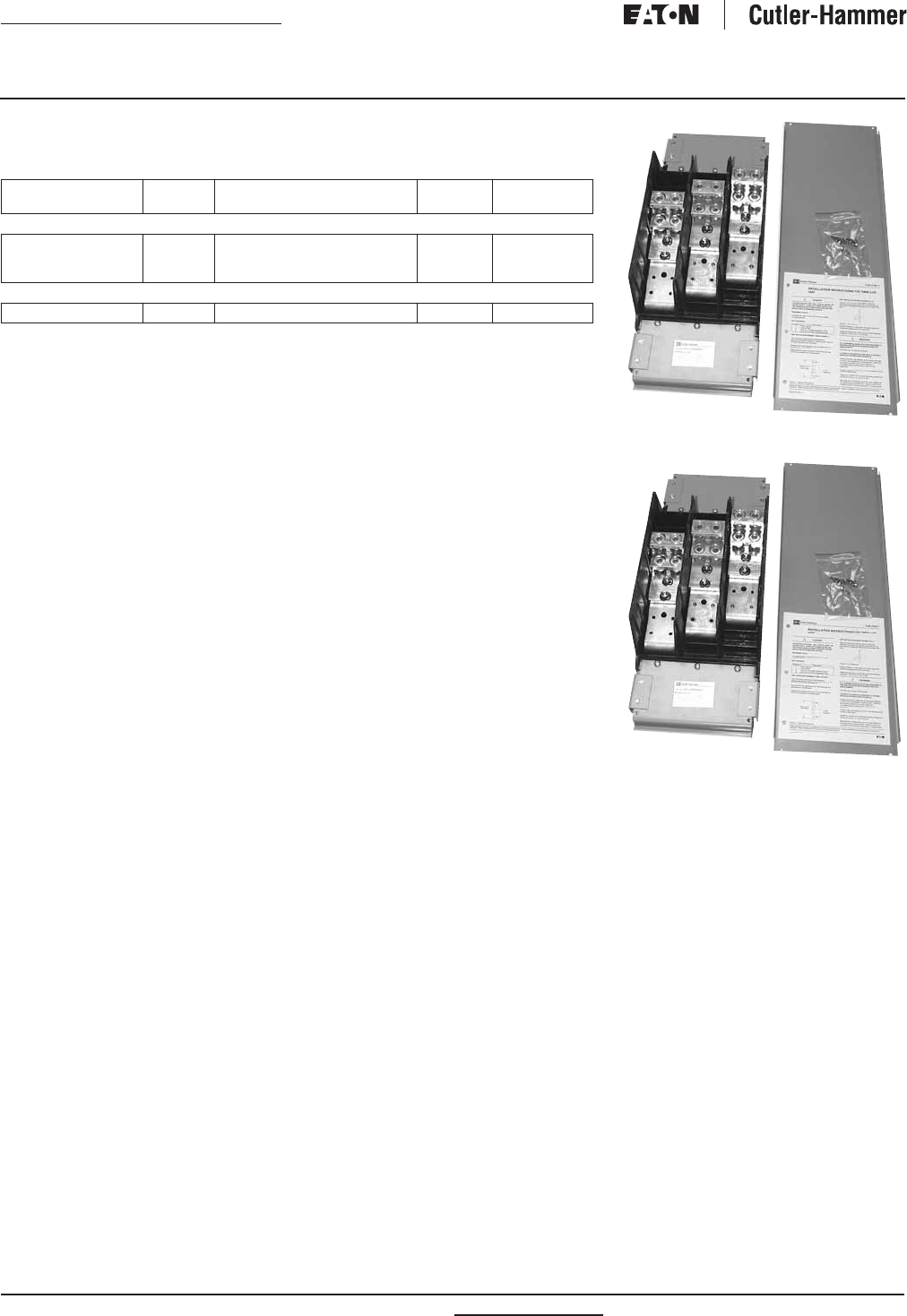
For more information visit: www.eatonelectrical.com RP01400001E
Renewal Parts
Page 38 Effective: February 2009
Current Cutler-Hammer
Panelboards
PRL5P Main or Through-Feed Lugs
Table 47. PRL5P Main or Through-Feed Lugs
Description Ampere
Rating
Wire Size
Range
“X” Space
Required
Catalog
Number
Single Bus Chassis Mounting
Ampere Lug Unit
Ampere Lug Unit
Ampere Lug Unit
400
600
800
(1) 1/0 – 500 or (2) 1/0 – 250 kcmil
(2) 1/0 – 500 kcmil
(2) #2 – 500 or (3) #2 – 400 kcmil
8X
8X
8X
5PLUG3400SC
5PLUG3600SC
5PLUG3800SC
Double Bus Chassis Mounting
1200 Ampere Lug Unit 600 – 1200 (4) #4 – 750 kcmil 7X 5PLUG31200TC
5PLUG3800SC
5PLUG31200TC
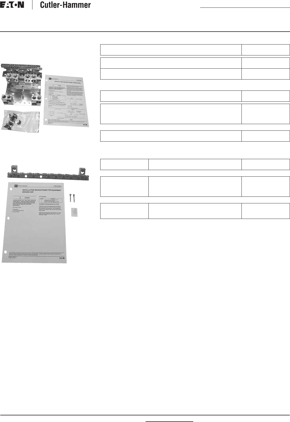
RP01400001E For more information visit: www.eatonelectrical.com
Renewal Parts
Effective: February 2009 Page 39
Current Cutler-Hammer
Panelboards
PRL5P Neutrals and Grounds
Neutral Assembly
5PN800A
Ground Bar Assemblies
5PG1200A
Table 48. Neutral Assemblies with Lugs
Table 49. Additional Lugs for Neutral Assemblies
Table 50. Grounded “B” Phase Adapter Kits
Incoming Number of Cables
and Wire Size
Catalog
Number
(4) 250 – 500 kcmil 800 Amperes Aluminum/Copper
(4) 250 – 500 kcmil 800 Amperes Copper
5PN800A
5PN800C
(4) 250 – 500 kcmil 1200 Amperes Aluminum/Copper
(4) 250 – 500 kcmil 1200 Amperes Copper
5PN1200A
5PN1200C
Description Catalog
Number
(1) 1/0 – 750 kcmil or (2) 1/0 – 300 kcmil Aluminum/Copper
(2) 250 – 500 kcmil Aluminum/Copper
(3) 3/0 – 750 kcmil Aluminum/Copper
(4) 3/0 – 750 kcmil Aluminum/Copper
5PNL400
5PNL600
5PNL800
5PNL1200
Ground Bar Type
1200 Amperes Aluminum/Copper
1200 Amperes Copper
5PG1200A
5PG1200C
Ampere
Rating
Main
Device
Catalog
Number
Single Bus Chassis
400
600
600
800
Main Lugs
Main Lugs
LD Breaker
Main Lugs
5PCGBLUG400S
5PCGBLUG600S
5PCGBLD600S
5PCGBLUG800S
Double Bus Chassis
800
1200
1200
MD Breaker
Main Lugs
ND Breaker
5PCGBMD800T
5PCGBLUG1200T
5PCGBND1200T
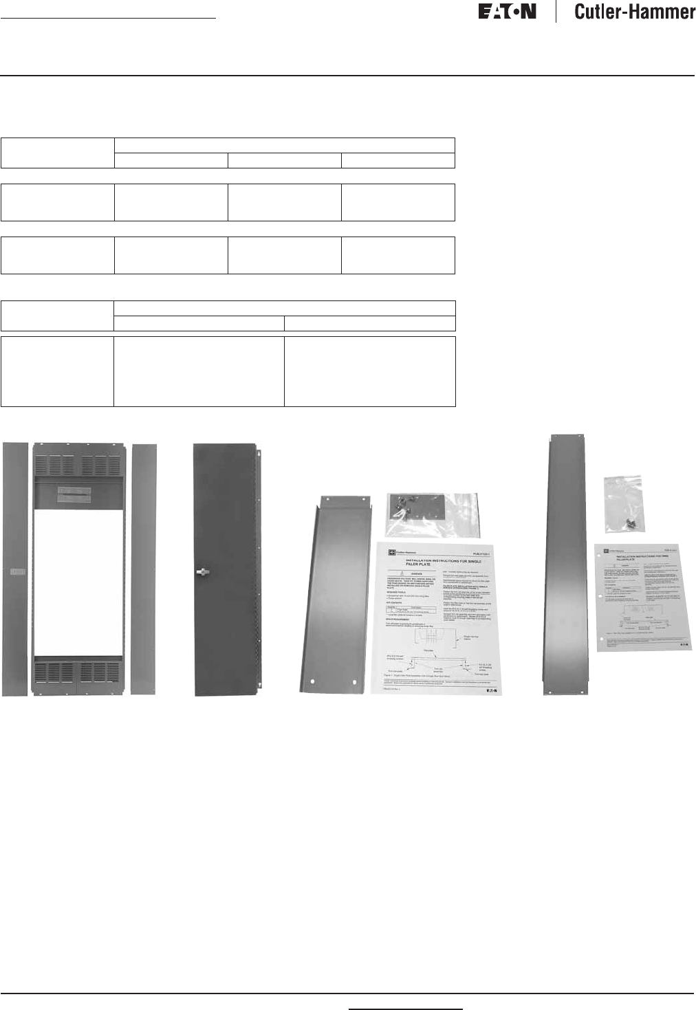
For more information visit: www.eatonelectrical.com RP01400001E
Renewal Parts
Page 40 Effective: February 2009
Current Cutler-Hammer
Panelboards
PRL5P Box, Trim and Deadfront Filler Plates
Table 51. PRL5P Box, Trim and Deadfront Filler Plates
Table 52. Deadfront Filler Plates
These fillers are also used across from a breaker unit in a double bus chassis.
Chassis
“X” Factor
Catalog Number
Back Box Trim Trim Door Kit
Single Bus Chassis — 30.00-Inch (762.0 mm) Wide Box
24X
32X
40X
5PB2430G
5PB3230G
5PB4030G
5PT2430S
5PT3230S
5PT4030S
5PD24S
5PD32S
5PD40S
Double Bus Chassis — 48.00-Inch (1219.2 mm) Wide Box
24X
32X
40X
5PB2448G
5PB3248G
5PB4048G
5PT2448S
5PT3248S
5PT4048S
5PD24T
5PD32T
5PD40T
Vertical “X”
Increment
Catalog Number
Single Bus Chassis Double Bus Chassis
1X
2X
3X
4X
5X
6X
5PFP1S
5PFP2S
5PFP3S
5PFP4S
5PFP5S
5PFP6S
5PFP1T
5PFP2T
5PFP3T
5PFP4T
5PFP5T
5PFP6T
5PT2430S 5PD24S 5PFP3S 5PFP3T
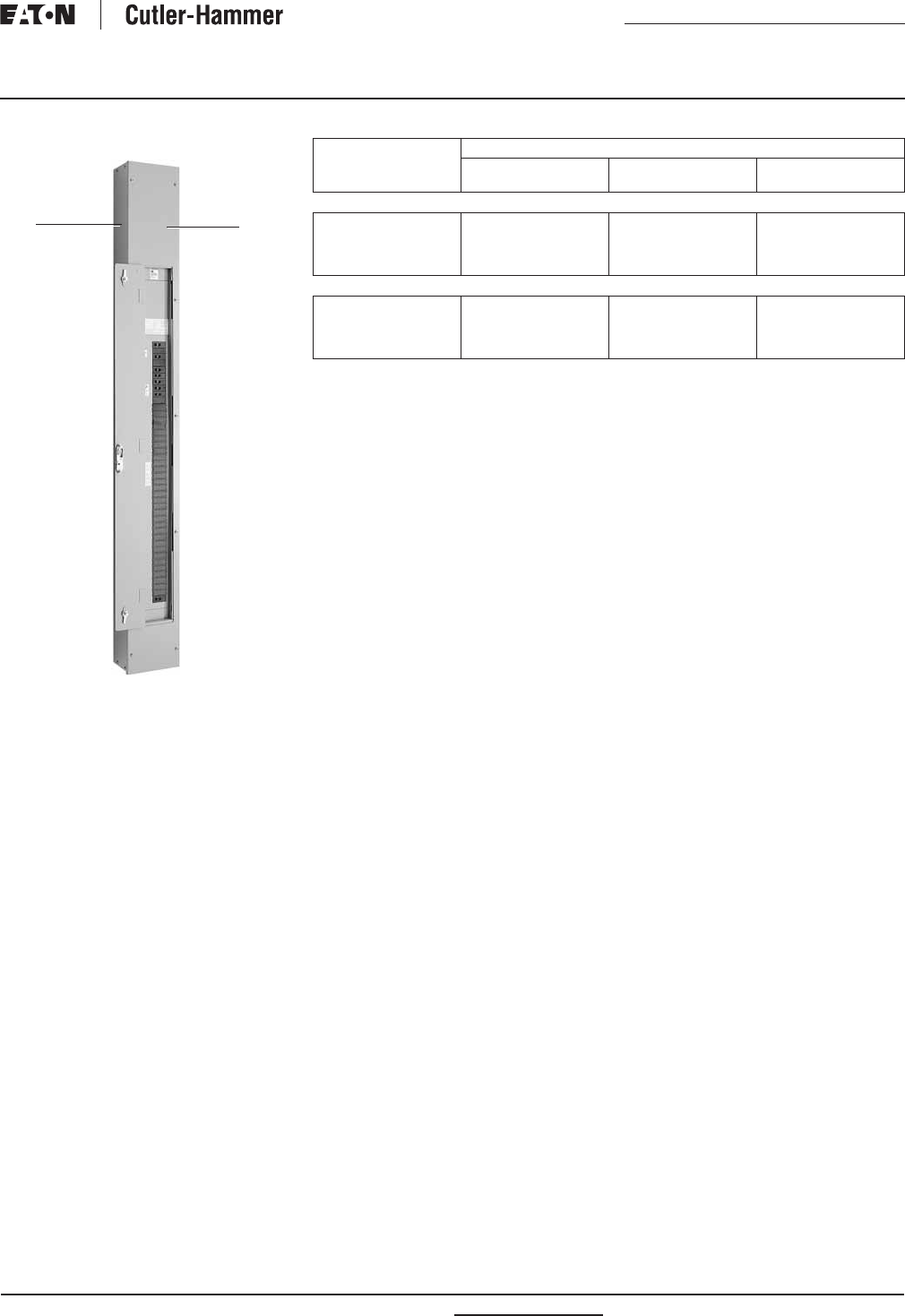
RP01400001E For more information visit: www.eatonelectrical.com
Renewal Parts
Effective: February 2009 Page 41
Current Cutler-Hammer
Panelboards
PRL1a, 2a-LX
Box Trim
Table 53. Type 1 Box and Trims
Box Height
in Inches (mm)
Catalog Number
Box Surface Trim
Standard
Surface Trim
Door-In-Door
Incoming Location Top Fed
69.00 (1752.6)
78.00 (1981.2)
81.00 (2057.4)
90.00 (2286.0)
YSC969
YSC978
YSC981
YSC990
LTC969S
LTC978S
LTC981S
LTC990S
LTCD969S
LTCD978S
LTCD981S
LTCD990S
Incoming Location Bottom Fed
69.00 (1752.6)
78.00 (1981.2)
81.00 (2057.4)
90.00 (2286.0)
YSC969
YSC978
YSC981
YSC990
LTC969SB
LTC978SB
LTC981SB
LTC990SB
LTCD969SB
LTCD978SB
LTCD981SB
LTCD990SB
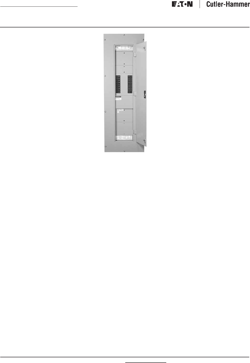
For more information visit: www.eatonelectrical.com RP01400001E
Renewal Parts
Page 42 Effective: February 2009
Current Cutler-Hammer
Panelboards
Pow-R-Command
For replacement parts, see PRL3a
Section, Page 21. Parts available are
the following:
■Connector kits.
■Ground assemblies.
■Service entrance kits.
■Deadfront covers.
■Trim locks.
Pow-R-Command
Additional Services
Since virtually all panelboards are
supplied to meet specific customer
requirements, other parts not listed in
this publication might occasionally be
needed. Price and availability for parts
not shown here may be obtained by
contacting your local Satellite plant
and providing a complete description
of the part along with the data on the
panelboard nameplate.
Should you experience difficulty in
determining what replacement parts
are needed, contact your local Satellite
Plant Manager who can provide help to:
■Identify and recommend
replacement parts.
■Remove damaged parts and
instruct you in how to install
replacement parts.
■Verify the correct connector kits
which should be ordered for each
circuit breaker or fusible switch.
■Retrofit existing panelboard boxes
with new Pow-R-Line interiors.
■Provide a recommended spare
parts list.
National Electrical Code and NEC are
registered trademarks of the National
Fire Protection Association, Quincy,
Mass. NEMA is the
registered trade-
mark and service mark of the National
Electrical
Manufacturers Association.
UL is a federally registered
trademark
of Underwriters Laboratories Inc.

RP01400001E For more information visit: www.eatonelectrical.com
Renewal Parts
Effective: February 2009 Page 43
Current Cutler-Hammer
Panelboards
This page intentionally left blank.

Renewal Parts
Page 44 Effective: February 2009
Current Cutler-Hammer
Panelboards
© 2009 Eaton Corporation
All Rights Reserved
Printed in USA
Publication No. RP01400001E/Z8339
February 2009
Eaton Electrical
1000 Cherrington Parkway
Moon Township, PA 15108-4312
USA
tel: 1-800-525-2000
www.eatonelectrical.com

Safety Switches

Drawings

Safety Switch General Information
Global Specifications
System Voltage
240 VAC
Switch Type
Single Throw - Heavy Duty
Poles/Blades
3-Pole
Amperage
600
Protection
Fusible with Neutral
Enclosure Type
NEMA 3R
Fuse Clips
Standard
Switch Lugs
Standard
Fungus Proof Treatment
N
Lock-On Provision
N
Fuse Pullers
N
Control Pole
N
Ground Lugs
N
316 Stainless
N
Stainless Mechanism
N
Mill Duty
N
Nameplate
Field Installed Kits
QUANTITY
DESCRIPTION
1
Neutral / Ground Kit : DS600NK (Field Installed)
1
"R" Fuse Adapter Kit : DS66FK (Field Installed)
Safety Switch Catalog No.
DH326NRK
NEG-ALT Number
PREPARED BY DATE
APPROVED BY DATE
VERSION
REVISION DWG SIZE
JOB NAME
DESIGNATION
TYPE
G.O.
DRAWING TYPE
ITEM SHEET
The information on this document is
created by Eaton Corporation. It is
disclosed in confidence and it is only to
be used for the purpose in which it is
supplied.
D63N0325X5K1-0000
RON ZAITZ 10/2/2015
1.0.0.1
0 A
Eaton
LOS ALAMOS TEEN CENTER
MAIN DISCONNECT
Safety Switch General Information
SAQ0594802
Final
008 1 of 1
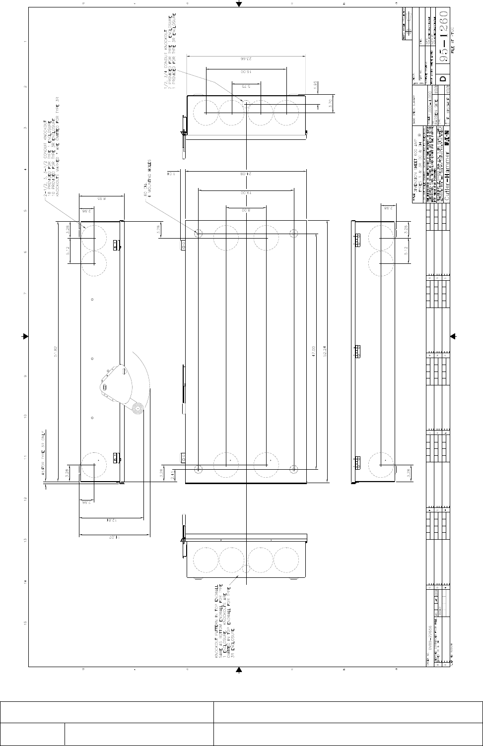
Date PDF Generated:9/25/2012 Page: 1 of 1
GO/NEG-Alt-Date: Job Name:
Item Number: Catalog Number: Designation:
SAQ0594802-0000-10/2/2015
LOS ALAMOS TEEN CENTER
008
DH326NRK
MAIN DISCONNECT

Safety Switch General Information
Global Specifications
System Voltage
240 VAC
Switch Type
Single Throw - General Duty
Poles/Blades
3-Pole
Amperage
200
Protection
Non-Fusible with No Neutral
Enclosure Type
NEMA 1
Switch Lugs
Standard
Fungus Proof Treatment
N
Lock-On Provision
N
Fuse Pullers
N
Control Pole
N
Ground Lugs
N
316 Stainless
N
Stainless Mechanism
N
Mill Duty
N
Cover Controls
QUANTITY
DESCRIPTION
Nameplate
First Line:
ELV. SHUNT TRIP
Safety Switch Catalog No.
DG324UGK3NP
NEG-ALT Number
PREPARED BY DATE
APPROVED BY DATE
VERSION
REVISION DWG SIZE
JOB NAME
DESIGNATION
TYPE
G.O.
DRAWING TYPE
ITEM SHEET
The information on this document is
created by Eaton Corporation. It is
disclosed in confidence and it is only to
be used for the purpose in which it is
supplied.
D63N0325X5K1-0000
PAUL MARTINEZ 10/2/2015
1.0.0.1
0 A
Eaton
LOS ALAMOS TEEN CENTER
ELV DISCON
Safety Switch General Information
SAQ0594802
Final
011 1 of 1
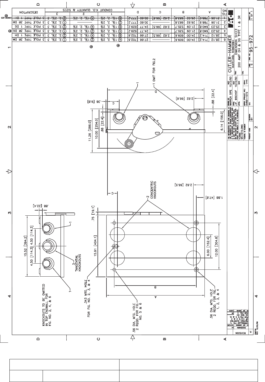
GO/NEG-Alt-Date: Job Name:
Item Number: Catalog Number: Designation:
SAQ0594802-0000-10/2/2015
LOS ALAMOS TEEN CENTER
011
DG324UGK3NP
ELV DISCON

Instruction Data


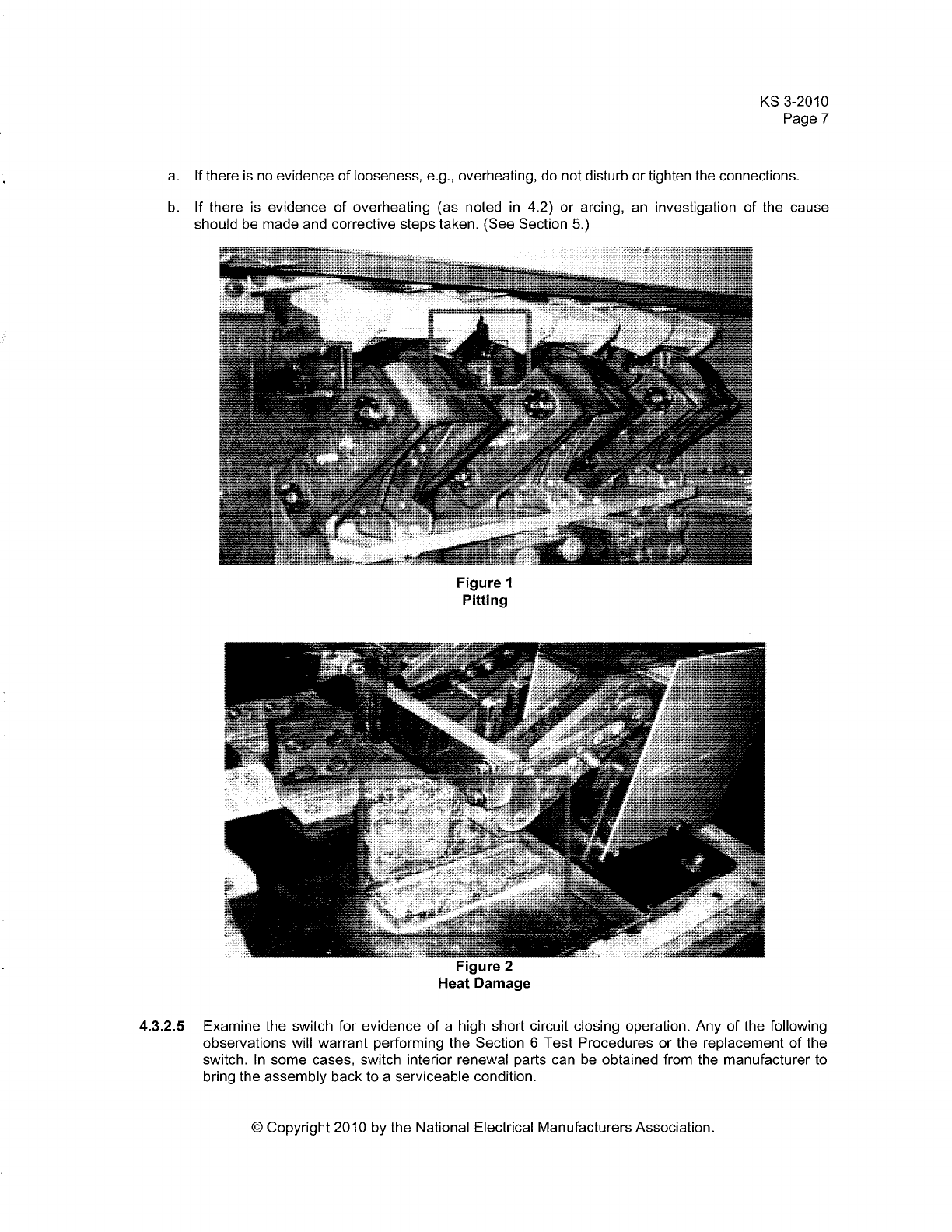

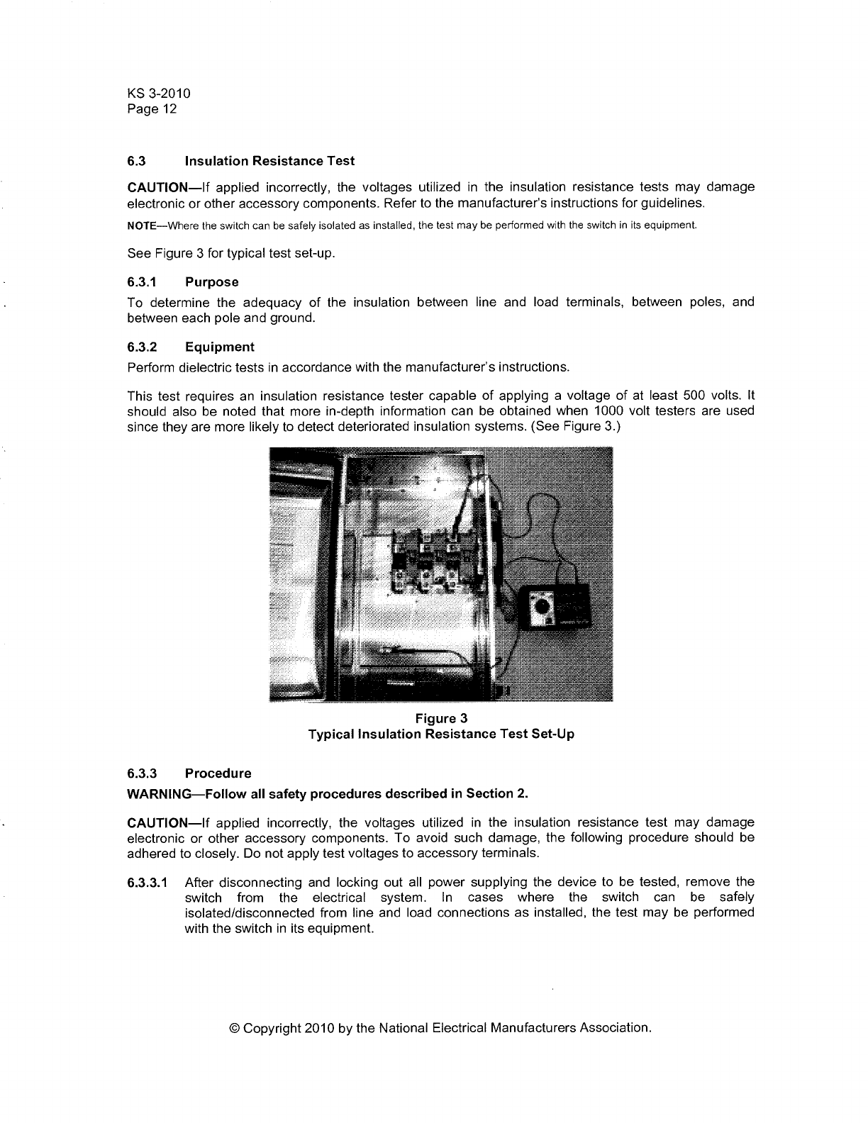
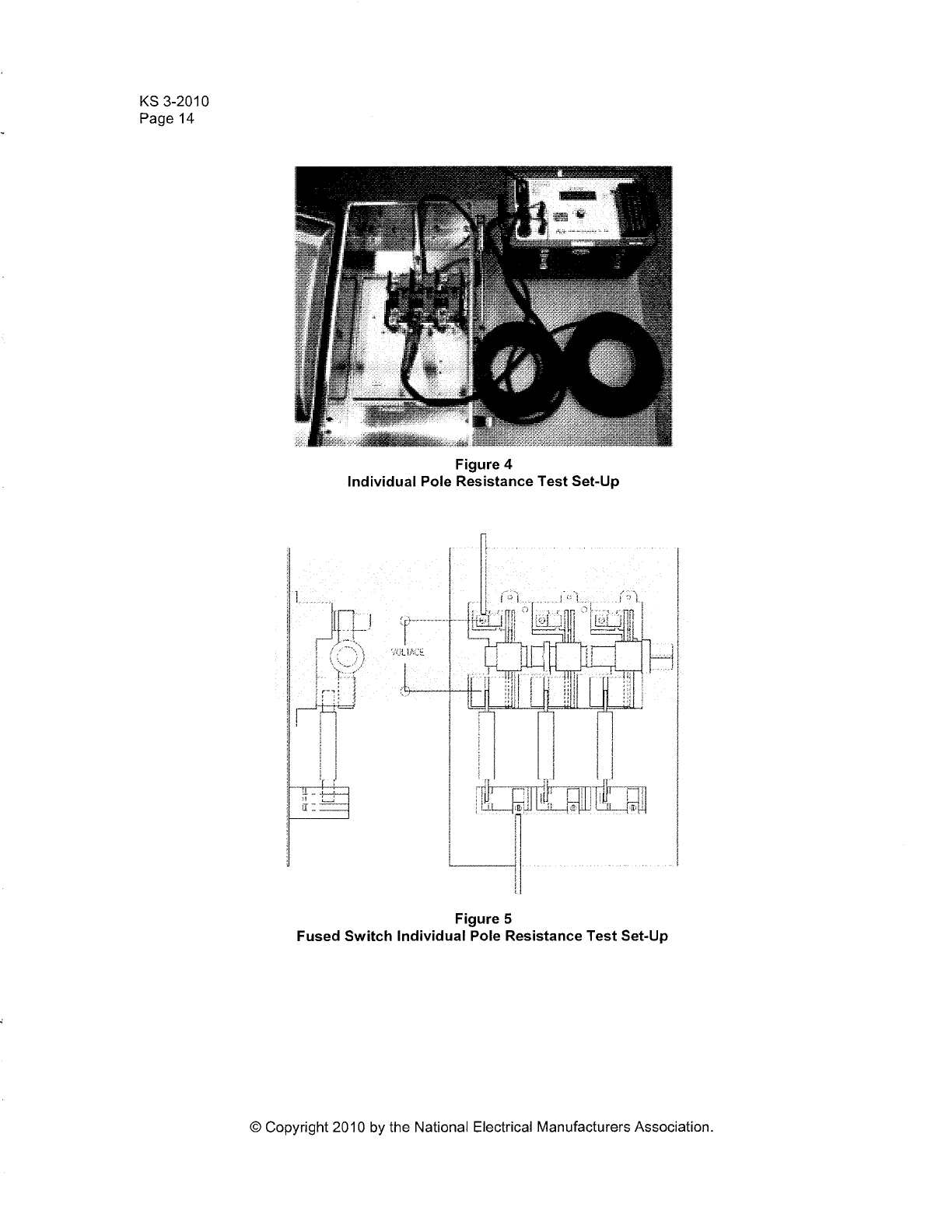
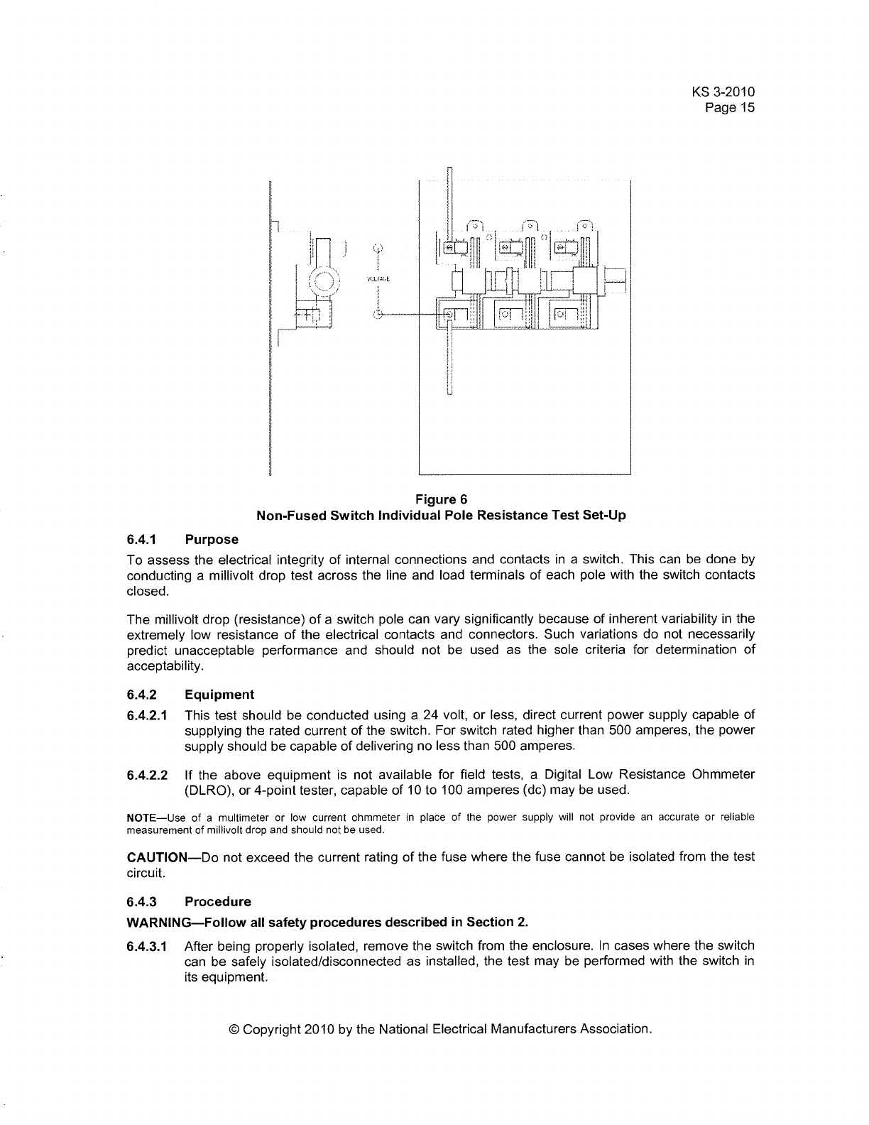
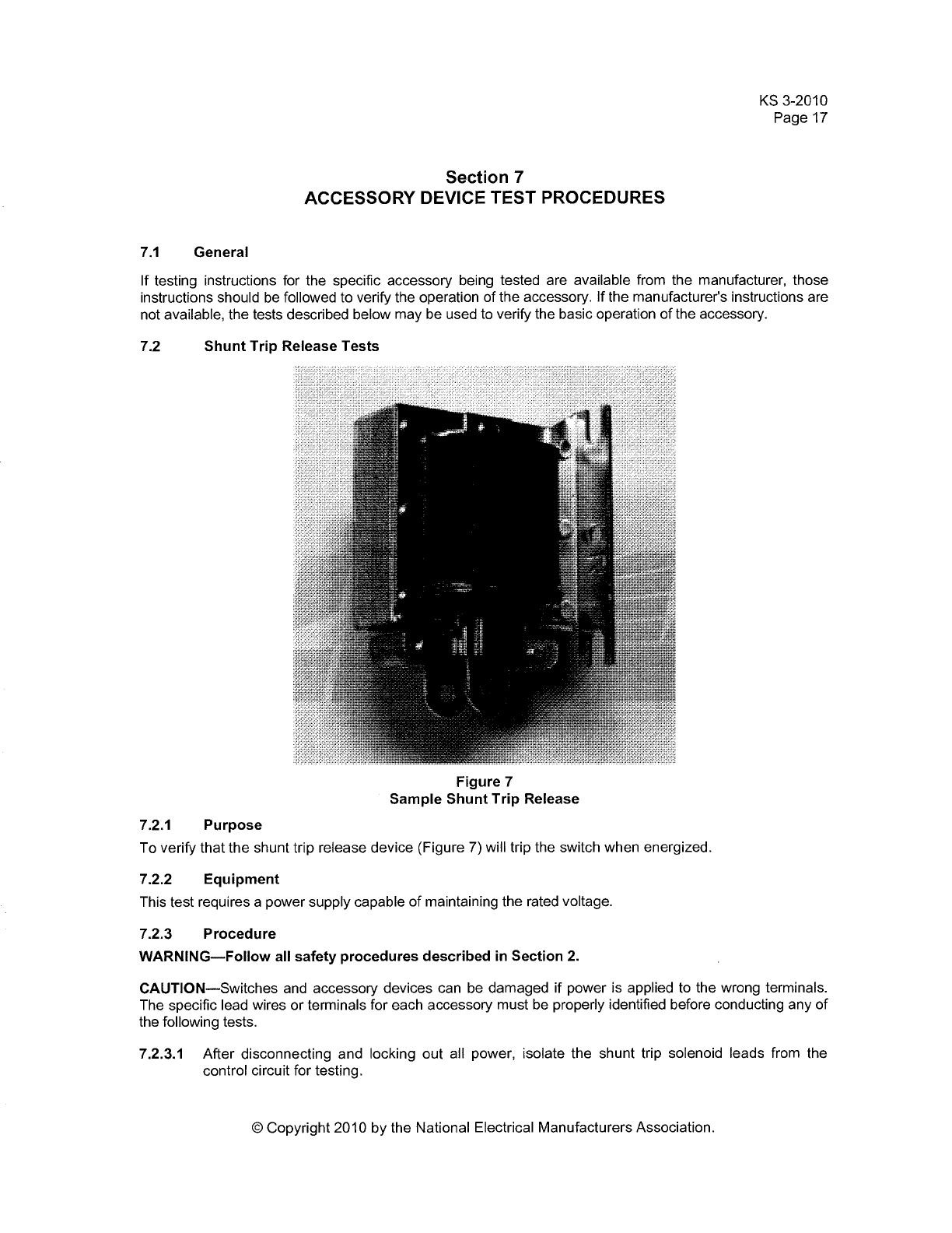
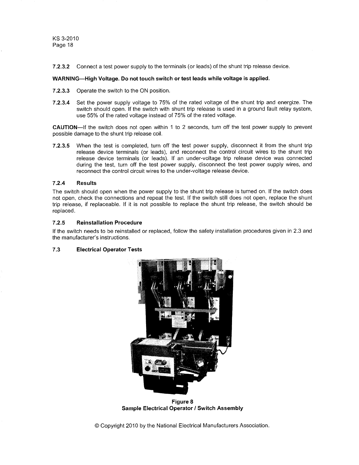
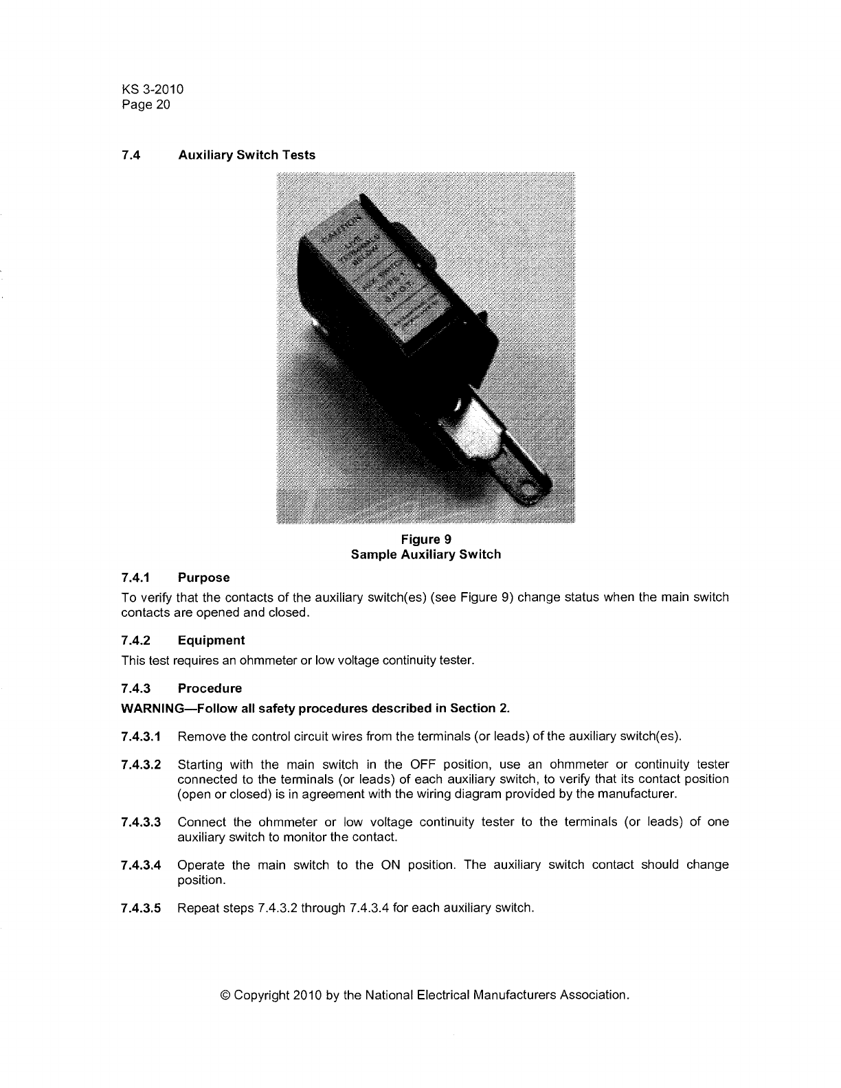


Renewal Parts

RP00801001E For more information visit: www.cutler-hammer.eaton.com
Safety Switches
Renewal Parts
New Information
Description Page
Safety Switch Renewal Parts
DG224NGK to DH225NRK . . . . . . . . . . . . . . . . . . . . . . . . . . . . . . . . . . . . . . . . 2
DH225NWK to DH321NCK . . . . . . . . . . . . . . . . . . . . . . . . . . . . . . . . . . . . . . . . 3
DH321NDK to DH325FPK . . . . . . . . . . . . . . . . . . . . . . . . . . . . . . . . . . . . . . . . . 4
DH325FRK to DH361NDK-10 . . . . . . . . . . . . . . . . . . . . . . . . . . . . . . . . . . . . . . 5
DH361NDKLW to DH362NWKX . . . . . . . . . . . . . . . . . . . . . . . . . . . . . . . . . . . . 6
DH362UCK to DH363UGK2 . . . . . . . . . . . . . . . . . . . . . . . . . . . . . . . . . . . . . . . 7
DH363URK to DH365NPKLW . . . . . . . . . . . . . . . . . . . . . . . . . . . . . . . . . . . . . . 8
DH365NRK to DH425FGK . . . . . . . . . . . . . . . . . . . . . . . . . . . . . . . . . . . . . . . . . 9
DH426FGK to DT224URK-N . . . . . . . . . . . . . . . . . . . . . . . . . . . . . . . . . . . . . . 10
DT224URK-NPS to DT363FWK. . . . . . . . . . . . . . . . . . . . . . . . . . . . . . . . . . . . 11
DT363NWK to DT663URK . . . . . . . . . . . . . . . . . . . . . . . . . . . . . . . . . . . . . . . 12
For more information visit: www.cutler-hammer.eaton.com RP00801001E
Renewal Parts
Page 2 Effective: July 2002
Safety Switches
Table 1. Safety Switch Renewal Parts
Catalog
Number
Base or Assembly Fuse Base and Lower Assembly Line
Shields
Operating
Mechanism
Operating
Handle
Type Part Number Type Part Number
DG224NGK
DG224NRK
DG225FGK
Switching Base
Switching Base
Switch Interior Assembly
70-7820-2
70-7820-2
70-8063-3
Fuse Base
Fuse Base
Fuse Base
70-7820-4
70-7820-4
70-8063-7
—
—
70-8063-8
70-7833-4
70-7833-4
70-7833-5
70-7820-6
70-7820-7
70-7833-2
DG225FRK
DG225NGK
DG225NRK
Switch Interior Assembly
Switch Interior Assembly
Switch Interior Assembly
70-8063-3
70-8063-3
70-8063-3
Fuse Base
Fuse Base
Fuse Base
70-8063-7
70-8063-7
70-8063-7
70-8063-8
70-8063-8
70-8063-8
70-7833-5
70-7833-5
70-7833-5
70-7833-2
70-7833-2
70-7833-2
DG226FGK
DG226FRK
DG226NGK
Switch Interior Assembly
Switch Interior Assembly
Switch Interior Assembly
70-8064-3
70-8064-3
70-8064-3
Fuse Base
Fuse Base
Fuse Base
70-8064-7
70-8064-7
70-8064-7
70-8064-8
70-8064-8
70-8064-8
70-7833-6
70-7833-6
70-7833-6
70-7833-2
70-7833-2
70-7833-2
DG226NRK
DG324NGK
DG324NRK
Switch Interior Assembly
Switching Base
Switching Base
70-8064-3
70-7820
70-7820
Fuse Base
Fuse Base
Fuse Base
70-8064-7
70-7820-4
70-7820-4
70-8064-8
—
—
70-7833-6
70-7833-4
70-7833-4
70-7833-2
70-7820-6
70-7820-7
DG324UGK
DG324URK
DG325FGK
Switching Base
Switching Base
Switch Interior Assembly
70-7820-3
70-7820-3
70-8063-4
—
—
Fuse Base
—
—
70-8063-7
—
—
70-8063-8
70-7833-4
70-7833-4
70-7833-5
70-7820-6
70-7820-7
70-7833-2
DG325FRK
DG325NGK
DG325NRK
Switch Interior Assembly
Switch Interior Assembly
Switch Interior Assembly
70-8063-4
70-8063-4
70-8063-4
Fuse Base
Fuse Base
Fuse Base
70-8063-7
70-8063-7
70-8063-7
70-8063-8
70-8063-8
70-8063-8
70-7833-5
70-7833-5
70-7833-5
70-7833-2
70-7833-2
70-7833-2
DG325UGK
DG325URK
DG326FGK
Switch Interior Assembly
Switch Interior Assembly
Switch Interior Assembly
70-8063-2
70-8063-2
70-8064-4
—
—
Fuse Base
—
—
70-8064-7
70-8063-8
70-8063-8
70-8064-8
70-7833-5
70-7833-5
70-7833-6
70-7833-2
70-7833-2
70-7833-2
DG326FGK-EXC
DG326FRK
DG326NGK
Switch Interior Assembly
Switch Interior Assembly
Switch Interior Assembly
70-8064-4
70-8064-4
70-8064-4
Fuse Base
Fuse Base
Fuse Base
70-8064-7
70-8064-7
70-8064-7
70-8064-8
70-8064-8
70-8064-8
70-7833-6
70-7833-6
70-7833-6
70-7833-2
70-7833-2
70-7833-2
DG326NRK
DG326UGK
DG326URK
Switch Interior Assembly
Switch Interior Assembly
Switch Interior Assembly
70-8064-4
70-8064-2
70-8064-2
Fuse Base
—
—
70-8064-7
—
—
70-8064-8
70-8064-8
70-8064-8
70-7833-6
70-7833-6
70-7833-6
70-7833-2
70-7833-2
70-7833-2
DH221FDK
DH221FGK
DH221NDK
Switching Base
Switching Base
Switching Base
70-7758-16
70-7758-16
70-7758-16
Fuse Base
Fuse Base
Fuse Base
70-7758-29
70-7758-29
70-7758-29
70-7758-34
70-7758-34
70-7758-34
70-7813
70-7813
70-7813
70-7813-2
70-7813-2
70-7813-2
DH221NDK5
DH221NGK
DH221NGK5
Switching Base
Switching Base
Switching Base
70-7758-16
70-7758-16
70-7758-16
Fuse Base
Fuse Base
Fuse Base
70-7758-29
70-7758-29
70-7758-29
70-7758-34
70-7758-34
70-7758-34
70-7813
70-7813
70-7813
70-7813-2
70-7813-2
70-7813-2
DH221NRK
DH221NWK
DH221NWKX
Switching Base
Switching Base
Switching Base
70-7758-16
70-7758-16
70-7758-16
Fuse Base
Fuse Base
Fuse Base
70-7758-29
70-7758-29
70-7758-29
70-7758-34
70-7758-34
70-7758-34
70-7813
70-7813
70-8304
70-7813-2
70-7813-3
70-7813-3
DH222NDK
DH222NDK5
DH222NGK
Switching Base
Switching Base
Switching Base
70-7758-36
70-7758-36
70-7758-36
Fuse Base
Fuse Base
Fuse Base
70-7997-4
70-7997-4
70-7997-4
70-7758-34
70-7758-34
70-7758-34
70-7813
70-7813
70-7813
70-7813-2
70-7813-2
70-7813-2
DH222NGK5
DH222NRK
DH222NRK5
Switching Base
Switching Base
Switching Base
70-7758-36
70-7758-36
70-7758-36
Fuse Base
Fuse Base
Fuse Base
70-7997-4
70-7997-4
70-7997-4
70-7758-34
70-7758-34
70-7758-34
70-7813
70-7813
70-7813
70-7813-2
70-7813-2
70-7813-2
DH222NWK
DH222NWKX
DH223NDK
Switching Base
Switching Base
Switching Base
70-7758-36
70-7758-36
70-7758-7
Fuse Base
Fuse Base
Fuse Base
70-7997-4
70-7997-4
70-7758-23
70-7758-34
70-7758-34
70-7758-35
70-7813
70-8304
70-7813
70-7813-3
70-7813-3
70-7813-2
DH223NGK
DH223NRK
DH223NRK5
Switching Base
Switching Base
Switching Base
70-7758-7
70-7758-7
70-7758-7
Fuse Base
Fuse Base
Fuse Base
70-7758-23
70-7758-23
70-7758-23
70-7758-35
70-7758-35
70-7758-35
70-7813
70-7813
70-7813
70-7813-2
70-7813-2
70-7813-2
DH223NWK
DH223NWKX
DH224NDK
Switching Base
Switching Base
Switching Base
70-7758-7
70-7758-7
70-7759-7
Fuse Base
Fuse Base
Fuse Base
70-7758-23
70-7758-23
70-7759-4
70-7758-35
70-7758-35
70-7759-11
70-7813
70-8304
70-7833-4
70-7813-3
70-7813-3
70-7833-2
DH224NGK
DH224NRK
DH224NWK
Switching Base
Switching Base
Switching Base
70-8266-3
70-8266-3
70-7759-7
Fuse Base
Fuse Base
Fuse Base
70-8266-4
70-8266-4
70-7759-4
70-7759-11
70-7759-11
70-7759-11
70-7833-4
70-7833-4
70-7833-4
70-7833-2
70-7833-2
70-7833-3
DH224NWKX
DH225FDK
DH225FGK
Switching Base
Switch Interior Assembly
Switch Interior Assembly
70-7759-7
70-8063-3
70-8063-3
Fuse Base
Fuse Base
Fuse Base
70-7759-4
70-8063-7
70-8063-7
70-7759-11
70-8063-8
70-8063-8
70-8305
70-7833-5
70-7833-5
70-7833-3
70-7833-2
70-7833-2
DH225FPK
DH225FRK
DH225NDK
Switch Interior Assembly
Switch Interior Assembly
Switch Interior Assembly
70-8063-3
70-8063-3
70-8063-3
Fuse Base
Fuse Base
Fuse Base
70-8063-7
70-8063-7
70-8063-7
70-8063-8
70-8063-8
70-8063-8
70-7833-5
70-7833-5
70-7833-5
70-7833-2
70-7833-2
70-7833-2
DH225NGK
DH225NPK
DH225NRK
Switch Interior Assembly
Switch Interior Assembly
Switch Interior Assembly
70-8063-3
70-8063-3
70-8063-3
Fuse Base
Fuse Base
Fuse Base
70-8063-7
70-8063-7
70-8063-7
70-8063-8
70-8063-8
70-8063-8
70-7833-5
70-7833-5
70-7833-5
70-7833-2
70-7833-2
70-7833-2
Two used.
Three used.

RP00801001E For more information visit: www.cutler-hammer.eaton.com
Renewal Parts
Effective: July 2002 Page 3
Safety Switches
DH225NWK
DH225NWKX
DH226FDK
Switch Interior Assembly
Switch Interior Assembly
Switch Interior Assembly
70-8063-3
70-8063-3
70-8064-3
Fuse Base
Fuse Base
Fuse Base
70-8063-7
70-8063-7
70-8064-7
70-8063-8
70-8063-8
70-8064-8
70-7833-5
70-8305-2
70-7833-6
70-7833-2
70-7833-2
70-7833-2
DH226FGK
DH226FPK
DH226FRK
Switch Interior Assembly
Switch Interior Assembly
Switch Interior Assembly
70-8064-3
70-8064-3
70-8064-3
Fuse Base
Fuse Base
Fuse Base
70-8064-7
70-8064-7
70-8064-7
70-8064-8
70-8064-8
70-8064-8
70-7833-6
70-7833-6
70-7833-6
70-7833-2
70-7833-2
70-7833-2
DH226FWK
DH226NDK
DH226NGK
Switch Interior Assembly
Switch Interior Assembly
Switch Interior Assembly
70-8064-3
70-8064-3
70-8064-3
Fuse Base
Fuse Base
Fuse Base
70-8064-7
70-8064-7
70-8064-7
70-8064-8
70-8064-8
70-8064-8
70-7833-6
70-7833-6
70-7833-6
70-7833-2
70-7833-2
70-7833-2
DH226NPK
DH226NRK
DH226NWK
Switch Interior Assembly
Switch Interior Assembly
Switch Interior Assembly
70-8064-3
70-8064-3
70-8064-3
Fuse Base
Fuse Base
Fuse Base
70-8064-7
70-8064-7
70-8064-7
70-8064-8
70-8064-8
70-8064-8
70-7833-6
70-7833-6
70-7833-6
70-7833-2
70-7833-2
70-7833-2
DH227FDK
DH227FGK
DH227NDK
Switch Interior Assembly
Switch Interior Assembly
Switch Interior Assembly
70-8065-3
70-8065-3
70-8065-3
Fuse Base
Fuse Base
Fuse Base
70-8065-7
70-8065-7
70-8065-7
70-8064-8
70-8064-8
70-8064-8
70-7833-6
70-7833-6
70-7833-6
70-7833-2
70-7833-2
70-7833-2
DH227NGK
DH227NPK
DH227NRK
Switch Interior Assembly
Switch Interior Assembly
Switch Interior Assembly
70-8065-3
70-8065-3
70-8065-3
Fuse Base
Fuse Base
Fuse Base
70-8065-7
70-8065-7
70-8065-7
70-8064-8
70-8064-8
70-8064-8
70-7833-6
70-7833-6
70-7833-6
70-7833-2
70-7833-2
70-7833-2
DH227NWK
DH261FDK
DH261FDK6
Switch Interior Assembly
Switching Base
Switching Base
70-8065-3
70-7758-17
70-7758-17
Fuse Base
Fuse Base
Fuse Base
70-8065-7
70-7758-30
70-7758-30
70-8064-8
70-7758-34
70-7758-34
70-7833-6
70-7813
70-7813
70-7833-3
70-7813-2
70-7813-2
DH261FGK
DH261FGK6
DH261FWK
Switching Base
Switching Base
Switching Base
70-7758-17
70-7758-17
70-7758-17
Fuse Base
Fuse Base
Fuse Base
70-7758-30
70-7758-30
70-7758-30
70-7758-34
70-7758-34
70-7758-34
70-7813
70-7813
70-7813
70-7813-2
70-7813-2
70-7813-3
DH261FWKX
DH261UGK
DH262FDK
Switching Base
Switching Base
Switching Base
70-7758-17
70-7758-18
70-7997-3
Fuse Base
—
Fuse Base
70-7758-30
—
70-7997-6
70-7758-34
70-7758-34
70-7758-34
70-8304
70-7813
70-7813
70-7813-3
70-7813-2
70-7813-2
DH262FDK6
DH262FGK
DH263FDK
Switching Base
Switching Base
Switching Base
70-7997-3
70-7997-3
70-7758-9
Fuse Base
Fuse Base
Fuse Base
70-7997-6
70-7997-6
70-7758-25
70-7758-34
70-7758-34
70-7758-35
70-7813
70-7813
70-7813
70-7813-2
70-7813-2
70-7813-2
DH263FGK
DH263UDK
DH263UGK
Switching Base
Switching Base
Switching Base
70-7758-9
70-7758-11
70-7758-11
Fuse Base
—
—
70-7758-25
—
—
70-7758-35
70-7758-35
70-7758-35
70-7813
70-7813
70-7813
70-7813-2
70-7813-2
70-7813-2
DH264FDK
DH264FGK
DH264FWK
—
—
—
—
—
—
Fuse Base
Fuse Base
Fuse Base
70-7759-5
70-8266-4
70-7759-5
70-7759-11
70-7759-11
70-7759-11
70-7833-4
70-7833-4
70-7833-4
70-7833-2
70-7833-2
70-7833-3
DH264FWKX
DH264UDK
DH264UDK2
—
—
—
—
—
—
Fuse Base
Lower Base & Connector
Lower Base & Connector
70-7759-5
70-7759-6
70-7759-6
70-7759-11
70-7759-11
70-7759-11
70-8305
70-7833-4
70-7833-4
70-7833-3
70-7833-2
70-7833-2
DH265FDK
DH265FDK3
DH265FGK
Switch Interior Assembly
Switch Interior Assembly
Switch Interior Assembly
70-8063-5
70-8063-5
70-8063-5
Fuse Base
Fuse Base
Fuse Base
70-8063-7
70-8063-7
70-8063-7
70-8063-8
70-8063-8
70-8063-8
70-7833-5
70-7833-5
70-7833-5
70-7833-2
70-7833-2
70-7833-2
DH265UDK
DH265UGK
DH266FDK
Switch Interior Assembly
Switch Interior Assembly
Switch Interior Assembly
70-8063
70-8063
70-8064-5
—
—
Fuse Base
—
—
70-8064-7
70-8063-8
70-8063-8
70-8064-8
70-7833-5
70-7833-5
70-7833-6
70-7833-2
70-7833-2
70-7833-2
DH266FGK
DH266UDK
DH266UGK
Switch Interior Assembly
Switch Interior Assembly
Switch Interior Assembly
70-8064-5
70-8064
70-8064
Fuse Base
—
—
70-8064-7
—
—
70-8064-8
70-8064-8
70-8064-8
70-7833-6
70-7833-6
70-7833-6
70-7833-2
70-7833-2
70-7833-2
DH267FDK
DH267FGK
DH267UDK
Switch Interior Assembly
Switch Interior Assembly
Switch Interior Assembly
70-8065-5
70-8065-5
70-8065
Fuse Base
Fuse Base
—
70-8065-7
70-8065-7
—
70-8064-8
70-8064-8
70-8064-8
70-7833-6
70-7833-6
70-7833-6
70-7833-2
70-7833-2
70-7833-2
DH267UGK
DH321FCK
DH321FDK
Switch Interior Assembly
Switching Base
Switching Base
70-8065
70-7758-14
70-7758-14
—
Fuse Base
Fuse Base
—
70-7758-26
70-7758-26
70-8064-8
70-7758-34
70-7758-34
70-7833-6
—
70-7813
70-7833-2
—
70-7813-2
DH321FDK2JK
DH321FDK5
DH321FGK
Switching Base
Switching Base
Switching Base
70-7831
70-7758-14
70-7758-14
Fuse Base
Fuse Base
Fuse Base
70-7831-3
70-7758-26
70-7758-26
70-7758-34
70-7758-34
70-7758-34
70-7813
70-7813
70-7813
70-7813-2
70-7813-2
70-7813-2
DH321FGK2
DH321FGK2JK
DH321FRK
Switching Base
Switching Base
Switching Base
70-7758-14
70-7831
70-7758-14
Fuse Base
Fuse Base
Fuse Base
70-7758-26
70-7831-3
70-7758-26
70-7758-34
70-7758-34
70-7758-34
70-7813
70-7813
70-7813
70-7813-2
70-7813-2
70-7813-2
DH321FRK2JK
DH321FRK5
DH321FWK
Switching Base
Switching Base
Switching Base
70-7831
70-7758-14
70-7758-14
Fuse Base
Fuse Base
Fuse Base
70-7831-3
70-7758-26
70-7758-26
70-7758-34
70-7758-34
70-7758-34
70-7813
70-7813
70-7813
70-7813-2
70-7813-2
70-7813-3
DH321FWKX
DH321FWK2JK
DH321NCK
Switching Base
Switching Base
Switching Base
70-7758-14
70-7831
70-7758-14
Fuse Base
Fuse Base
Fuse Base
70-7758-26
70-7831-3
70-7758-26
70-7758-34
70-7758-34
70-7758-34
70-8304
70-7813
—
70-7813-3
70-7813-3
—
Catalog
Number
Base or Assembly Fuse Base and Lower Assembly Line
Shields
Operating
Mechanism
Operating
Handle
Type Part Number Type Part Number
Two used.
Three used.

For more information visit: www.cutler-hammer.eaton.com RP00801001E
Renewal Parts
Page 4 Effective: July 2002
Safety Switches
DH321NDK
DH321NDKLW
DH321NDKW
Switching Base
Switching Base
Switching Base
70-7758-14
70-7758-14
70-7758-14
Fuse Base
Fuse Base
Fuse Base
70-7758-26
70-7758-26
70-7758-26
70-7758-34
70-7758-34
70-7758-34
70-7813
70-7813
70-7813
70-7813-2
70-7813-2
70-7813-2
DH321NDK3
DH321NGK
DH321NRK
Switching Base
Switching Base
Switching Base
70-7758-14
70-7758-14
70-7758-14
Fuse Base
Fuse Base
Fuse Base
70-7758-26
70-7758-26
70-7758-26
70 7758-34
70 7758-34
70-7758-34
70-7813
70-7813
70-7813
70-7813-2
70-7813-2
70-7813-2
DH321NWK
DH321NWKLW
DH321NWKW
Switching Base
Switching Base
Switching Base
70-7758-14
70-7758-14
70-7758-14
Fuse Base
Fuse Base
Fuse Base
70-7758-26
70-7758-26
70-7758-26
70-7758-34
70-7758-34
70-7758-34
70-7813
70-7813
70-7813
70-7813-3
70-7813-3
70-7813-3
DH321NWKX
DH322FCK
DH322FDK
Switching Base
Switching Base
Switching Base
70-7758-14
70-7997
70-7997
Fuse Base
Fuse Base
Fuse Base
70-7758-26
70-7997-5
70-7997-5
70-7758-34
70-7758-34
70-7758-34
70-8304
—
70-7813
70-7813-3
—
70-7813-2
DH322FGK
DH322FRK
DH322FRK5
Switching Base
Switching Base
Switching Base
70-7997
70-7997
70-7997
Fuse Base
Fuse Base
Fuse Base
70-7997-5
70-7997-5
70-7997-5
70-7758-34
70-7758-34
70-7758-34
70-7813
70-7813
70-7813
70-7813-2
70-7813-2
70-7813-2
DH322FWK
DH322FWKX
DH322NCK
Switching Base
Switching Base
Switching Base
70-7997
70-7997
70-7997
Fuse Base
Fuse Base
Fuse Base
70-7997-5
70-7997-5
70-7997-5
70-7758-34
70-7758-34
70-7758-34
70-7813
70-8304
—
70-7813-3
70-7813-3
—
DH322NDK
DH322NDKLW
DH322NDKW
Switching Base
Switching Base
Switching Base
70-7997
70-7997
70-7997
Fuse Base
Fuse Base
Fuse Base
70-7997-5
70-7997-5
70-7997-5
70-7758-34
70-7758-34
70-7758-34
70-7813
70-7813
70-7813
70-7813-2
70-7813-2
70-7813-2
DH322NGK
DH322NRK
DH322NRK5
Switching Base
Switching Base
Switching Base
70-7997
70-7997
70-7997
Fuse Base
Fuse Base
Fuse Base
70-7997-5
70-7997-5
70-7997-5
70-7758-34
70-7758-34
70-7758-34
70-7813
70-7813
70-7813
70-7813-2
70-7813-2
70-7813-2
DH322NWK
DH322NWKLW
DH322NWKW
Switching Base
Switching Base
Switching Base
70-7997
70-7997
70-7997
Fuse Base
Fuse Base
Fuse Base
70-7997-5
70-7997-5
70-7997-5
70-7758-34
70-7758-34
70-7758-34
70-7813
70-7813
70-7813
70-7813-3
70-7813-3
70-7813-3
DH322NWKX
DH323FCK
DH323FDK
Switching Base
Switching Base
Switching Base
70-7997
70-7758-3
70-7758-3
Fuse Base
Fuse Base
Fuse Base
70-7997-5
70-7758-21
70-7758-21
70-7758-34
70-7758-35
70-7758-35
70-8304
—
70-7813
70-7813-3
—
70-7813-2
DH323FDK-10
DH323FD3WRK
DH323FGK
Switching Base
Switching Base
Switching Base
70-7758-3
70-7758-3
70-7758-3
Fuse Base
Fuse Base
Fuse Base
70-7758-21
70-7758-21
70-7758-21
70-7758-35
70-7758-35
70-7758-35
70-7813
70-7813
70-7813
70-7813-2
70-7813-2
70-7813-2
DH323FRK
DH323NCK
DH323NDK
Switching Base
Switching Base
Switching Base
70-7758-3
70-7758-3
70-7758-3
Fuse Base
Fuse Base
Fuse Base
70-7758-21
70-7758-21
70-7758-21
70-7758-35
70-7758-35
70-7758-35
70-7813
—
70-7813
70-7813-2
—
70-7813-2
DH323NDKLW
DH323NDKW
DH323NGK
Switching Base
Switching Base
Switching Base
70-7758-3
70-7758-3
70-7758-3
Fuse Base
Fuse Base
Fuse Base
70-7758-21
70-7758-21
70-7758-21
70-7758-35
70-7758-35
70-7758-35
70-7813
70-7813
70-7813
70-7813-2
70-7813-2
70-7813-2
DH323NGK2
DH323NRK
DH323NWK
Switching Base
Switching Base
Switching Base
70-7758-3
70-7758-3
70-7758-3
Fuse Base
Fuse Base
Fuse Base
70-7758-21
70-7758-21
70-7758-21
70-7758-35
70-7758-35
70-7758-35
70-7813
70-7813
70-7813
70-7813-2
70-7813-2
70-7813-3
DH323NWKLW
DH323NWKW
DH323NWKX
Switching Base
Switching Base
Switching Base
70-7758-3
70-7758-3
70-7758-3
Fuse Base
Fuse Base
Fuse Base
70-7758-21
70-7758-21
70-7758-21
70-7758-35
70-7758-35
70-7758-35
70-7813
70-7813
70-8304
70-7813-3
70-7813-3
70-7813-3
DH324FCK
DH324FDK
DH324FGK
Switching Base
Switching Base
Switching Base
70-8266
70-7759
70-8266
Fuse Base
Fuse Base
Fuse Base
70-8266-4
70-7759-4
70-8266-4
70-7759-11
70-7759-11
70-7759-11
—
70-7833-4
70-7833-4
—
70-7833-2
70-7833-2
DH324FRK
DH324FRK5
DH324FWKX
Switching Base
Switching Base
Switching Base
70-8266
70-8266
70-7759
Fuse Base
Fuse Base
Fuse Base
70-8266-4
70-8266-4
70-7759-4
70-7759-11
70-7759-11
70-7759-11
70-7833-4
70-7833-4
70-8305
70-7833-2
70-7833-2
70-7833-3
DH324NCK
DH324NDK
DH324NDKLW
Switching Base
Switching Base
Switching Base
70-8266
70-7759
70-7759
Fuse Base
Fuse Base
Fuse Base
70-8266-4
70-7759-4
70-7759-4
70-7759-11
70-7759-11
70-7759-11
—
70-7833-4
70-7833-4
—
70-7833-2
70-7833-2
DH324NDKW
DH324NDK5
DH324NGK
Switching Base
Switching Base
Switching Base
70-7759
70-7759
70-8266
Fuse Base
Fuse Base
Fuse Base
70-7759-4
70-7759-4
70-8266-4
70-7759-11
70-7759-11
70-7759-11
70-7833-4
70-7833-4
70-7833-4
70-7833-2
70-7833-2
70-7833-2
DH324NGK2
DH324NRK
DH324NRK5
Switching Base
Switching Base
Switching Base
70-8266
70-8266
70-8266
Fuse Base
Fuse Base
Fuse Base
70-8266-4
70-8266-4
70-8266-4
70-7759-11
70-7759-11
70-7759-11
70-7833-4
70-7833-4
70-7833-4
70-7833-2
70-7833-2
70-7833-2
DH324NWK
DH324NWKLW
DH324NWKX
Switching Base
Switching Base
Switching Base
70-7759
70-7759
70-7759
Fuse Base
Fuse Base
Fuse Base
70-7759-4
70-7759-4
70-7759-4
70-7759-11
70-7759-11
70-7759-11
70-7833-4
70-7833-4
70-8305
70-7833-3
70-7833-3
70-7833-3
DH325FDK
DH325FGK
DH325FPK
Switch Interior Assembly
Switch Interior Assembly
Switch Interior Assembly
70-8063-4
70-8063-4
70-8063-4
Fuse Base
Fuse Base
Fuse Base
70-8063-7
70-8063-7
70-8063-7
70-8063-8
70-8063-8
70-8063-8
70-7833-5
70-7833-5
70-7833-5
70-7833-2
70-7833-2
70-7833-2
Catalog
Number
Base or Assembly Fuse Base and Lower Assembly Line
Shields
Operating
Mechanism
Operating
Handle
Type Part Number Type Part Number
Three used.
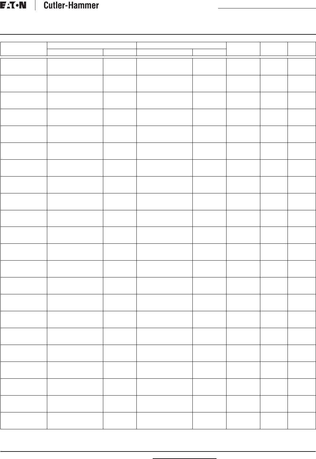
RP00801001E For more information visit: www.cutler-hammer.eaton.com
Renewal Parts
Effective: July 2002 Page 5
Safety Switches
DH325FRK
DH325FWK
DH325FWKX
Switch Interior Assembly
Switch Interior Assembly
Switch Interior Assembly
70-8063-4
70-8063-4
70-8063-4
Fuse Base
Fuse Base
Fuse Base
70-8063-7
70-8063-7
70-8063-7
70-8063-8
70-8063-8
70-8063-8
70-7833-5
70-7833-5
70-8305-2
70-7833-2
70-7833-3
70-7833-3
DH325NDK
DH325NDKLW
DH325NGK
Switch Interior Assembly
Switch Interior Assembly
Switch Interior Assembly
70-8063-4
70-8063-4
70-8063-4
Fuse Base
Fuse Base
Fuse Base
70-8063-7
70-8063-7
70-8063-7
70-8063-8
70-8063-8
70-8063-8
70-7833-5
70-7833-5
70-7833-5
70-7833-2
70-7833-2
70-7833-2
DH325NPK
DH325NPKLW
DH325NRK
Switch Interior Assembly
Switch Interior Assembly
Switch Interior Assembly
70-8063-4
70-8063-4
70-8063-4
Fuse Base
Fuse Base
Fuse Base
70-8063-7
70-8063-7
70-8063-7
70-8063-8
70-8063-8
70-8063-8
70-7833-5
70-7833-5
70-7833-5
70-7833-2
70-7833-2
70-7833-2
DH325NWK
DH325NWKLW
DH326FDK
Switch Interior Assembly
Switch Interior Assembly
Switch Interior Assembly
70-8063-4
70-8063-4
70-8064-4
Fuse Base
Fuse Base
Fuse Base
70-8063-7
70-8063-7
70-8064-7
70-8063-8
70-8063-8
70-8064-8
70-7833-5
70-7833-5
70-7833-6
70-7833-3
70-7833-3
70-7833-2
DH326FGK
DH326FPK
DH326FRK
Switch Interior Assembly
Switch Interior Assembly
Switch Interior Assembly
70-8064-4
70-8064-4
70-8064-4
Fuse Base
Fuse Base
Fuse Base
70-8064-7
70-8064-7
70-8064-7
70-8064-8
70-8064-8
70-8064-8
70-7833-6
70-7833-6
70-7833-6
70-7833-2
70-7833-2
70-7833-2
DH326FWK
DH326NDK
DH326NDKLW
Switch Interior Assembly
Switch Interior Assembly
Switch Interior Assembly
70-8064-4
70-8064-4
70-8064-4
Fuse Base
Fuse Base
Fuse Base
70-8064-7
70-8064-7
70-8064-7
70-8064-8
70-8064-8
70-8064-8
70-7833-6
70-7833-6
70-7833-6
70-7833-3
70-7833-2
70-7833-2
DH326NGK
DH326NPK
DH326NPKLW
Switch Interior Assembly
Switch Interior Assembly
Switch Interior Assembly
70-8064-4
70-8064-4
70-8064-4
Fuse Base
Fuse Base
Fuse Base
70-8064-7
70-8064-7
70-8064-7
70-8064-8
70-8064-8
70-8064-8
70-7833-6
70-7833-6
70-7833-6
70-7833-2
70-7833-2
70-7833-2
DH326NRK
DH326NWK
DH326NWKLW
Switch Interior Assembly
Switch Interior Assembly
Switch Interior Assembly
70-8064-4
70-8064-4
70-8064-4
Fuse Base
Fuse Base
Fuse Base
70-8064-7
70-8064-7
70-8064-7
70-8064-8
70-8064-8
70-8064-8
70-7833-6
70-7833-6
70-7833-6
70-7833-2
70-7833-2
70-7833-2
DH327FDK
DH327FGK
DH327FPK
Switch Interior Assembly
Switch Interior Assembly
Switch Interior Assembly
70-8065-4
70-8065-4
70-8065-4
Fuse Base
Fuse Base
Fuse Base
70-8065-7
70-8065-7
70-8065-7
70-8064-8
70-8064-8
70-8064-8
70-7833-6
70-7833-6
70-7833-6
70-7833-2
70-7833-2
70-7833-2
DH327FRK
DH327FWK
DH327NGK
Switch Interior Assembly
Switch Interior Assembly
Switch Interior Assembly
70-8065-4
70-8065-4
70-8065-4
Fuse Base
Fuse Base
Fuse Base
70-8065-7
70-8065-7
70-8065-7
70-8064-8
70-8064-8
70-8064-8
70-7833-6
70-7833-6
70-7833-6
70-7833-2
70-7833-3
70-7833-2
DH327NRK
DH328FGK
DH328FRK
Switch Interior Assembly
Switch Interior Assembly
Switch Interior Assembly
70-8065-4
70-8453-2
70-8453-2
Fuse Base
Fuse Base
Fuse Base
70-8065-7
70-8453-3
70-8453-3
70-8064-8
70-8453-4
70-8453-4
70-7833-6
—
—
70-7833-2
—
—
DH328NGK
DH328NRK
DH361FCK
Switch Interior Assembly
Switch Interior Assembly
Switching Base
70-8453-2
70-8453-2
70-7758-12
Fuse Base
Fuse Base
Fuse Base
70-8453-3
70-8453-3
70-7758-27
70-8453-4
70-8453-4
70-7758-34
—
—
—
—
—
—
DH361FDK
DH361FDK2
DH361FDK2WR
Switching Base
Switching Base
Switching Base
70-7758-12
70-7758-12
70-7758
Fuse Base
Fuse Base
Fuse Base
70-7758-27
70-7758-27
70-7758-19
70-7758-34
70-7758-34
70-7758-35
70-7813
70-7813
70-7813
70-7813-2
70-7813-2
70-7813-2
DH361FDK2WRK
DH361FDK2WRW
DH361FDK26
Switching Base
Switching Base
Switching Base
70-7758
70-7758
70-7758-12
Fuse Base
Fuse Base
Fuse Base
70-7758-19
70-7758-19
70-7758-27
70-7758-35
70-7758-35
70-7758-34
70-7813
70-7813
70-7813
70-7813-2
70-7813-2
70-7813-2
DH361FDK46
DH361FDK6
DH361FDK6JK
Switching Base
Switching Base
Switching Base
70-7758-12
70-7758-12
70-7831-2
Fuse Base
Fuse Base
Fuse Base
70-7758-27
70-7758-27
70-7831-3
70-7758-34
70-7758-34
70-7758-34
70-7813
70-7813
70-7813
70-7813-2
70-7813-2
70-7813-2
DH361FD3WRK
DH361FD4WRK
DH361FD5WRK
Switching Base
Switching Base
Switching Base
70-7758
70-7758
70-7758-14
Fuse Base
Fuse Base
Fuse Base
70-7758-19
70-7758-19
70-7758-26
70-7758-35
70-7758-35
70-7758-34
70-7813
70-7813
70-7813
70-7813-2
70-7813-2
70-7813-2
DH361FGK
DH361FGK6
DH361FGK6JK
Switching Base
Switching Base
Switching Base
70-7758-12
70-7758-12
70-7831-2
Fuse Base
Fuse Base
Fuse Base
70-7758-27
70-7758-27
70-7831-3
70-7758-34
70-7758-34
70 7758-34
70-7813
70-7813
70-7813
70-7813-2
70-7813-2
70-7813-2
DH361FG6WRK
DH361FRK
DH361FRK6
Switching Base
Switching Base
Switching Base
70-7758-2
70-7758-15
70-7758-15
Fuse Base
Fuse Base
Fuse Base
70-7758-19
70-7758-28
70-7758-28
70-7758-35
70-7758-34
70-7758-34
70-7813
70-7813
70-7813
70-7813-2
70-7813-2
70-7813-2
DH361FRK6JK
DH361FWK
DH361FWK-316
Switching Base
Switching Base
Switching Base
70-7831-2
70-7758-12
70-7758-12
Fuse Base
Fuse Base
Fuse Base
70-7831-3
70-7758-27
70-7758-27
70-7758-34
70-7758-34
70-7758-34
70-7813
70-7813
70-7813
70-7813-2
70-7813-3
70-7813-3
DH361FWKX
DH361FWK2
DH361FWK2WR
Switching Base
Switching Base
Switching Base
70-7758-12
70-7758-12
70-7758
Fuse Base
Fuse Base
Fuse Base
70-7758-27
70-7758-27
70-7758-19
70-7758-34
70-7758-34
70-7758-35
70-8304
70-7813
70-7813
70-7813-3
70-7813-3
70-7813-3
DH361FWK26
DH361FWK6
DH361FWK6JK
Switching Base
Switching Base
Switching Base
70-7758-12
70-7758-12
70-7831-2
Fuse Base
Fuse Base
Fuse Base
70-7758-27
70-7758-27
70-7831-3
70-7758-34
70-7758-34
70-7758-34
70-7813
70-7813
70-7813
70-7813-3
70-7813-3
70-7813-3
DH361NCK
DH361NDK
DH361NDK-10
Switching Base
Switching Base
Switching Base
70-7758-12
70-7758-12
70-7758-12
Fuse Base
Fuse Base
Fuse Base
70-7758-27
70-7758-27
70-7758-27
70-7758-34
70-7758-34
—
—
70-7813
70-7813
—
70-7813-2
70-7813-2
Catalog
Number
Base or Assembly Fuse Base and Lower Assembly Line
Shields
Operating
Mechanism
Operating
Handle
Type Part Number Type Part Number

For more information visit: www.cutler-hammer.eaton.com RP00801001E
Renewal Parts
Page 6 Effective: July 2002
Safety Switches
DH361NDKLW
DH361NDKW
DH361NDK6JK
Switching Base
Switching Base
Switching Base
70-7758-12
70-7758-12
70-7831-2
Fuse Base
Fuse Base
Fuse Base
70-7758-27
70-7758-27
70-7831-3
70-7758-34
70-7758-34
70-7758-34
70-7813
70-7813
70-7813
70-7813-2
70-7813-2
70-7813-2
DH361NGK
DH361NRK
DH361NWK
Switching Base
Switching Base
Switching Base
70-7758-12
70-7758-12
70-7758-12
Fuse Base
Fuse Base
Fuse Base
70-7758-27
70-7758-28
70-7758-27
70-7758-34
70 7758-34
70-7758-34
70-7813
70-7813
70-7813
70-7813-2
70-7813-2
70-7813-3
DH361NWKLW
DH361NWKW
DH361NWKW2
Switching Base
Switching Base
Switching Base
70-7758-12
70-7758-12
70-7758-12
Fuse Base
Fuse Base
Fuse Base
70-7758-27
70-7758-27
70-7758-27
70-7758-34
70-7758-34
70-7758-34
70-7813
70-7813
70-7813
70-7813-3
70-7813-3
70-7813-3
DH361NWKX
DH361UCK
DH361UDK-CPG
Switching Base
Switching Base
Switching Base
70-7758-12
70-7758-13
70-7758-13
Fuse Base
—
—
70-7758-27
—
—
70-7758-34
70-7758-34
70-7758-34
70-8304
—
70-7813
70-7813-3
—
70-7813-2
DH361UDK-LS
DH361UDK2-LS
DH361UD5WRK
Switching Base
Switching Base
Switching Base
70-7758-13
70-7758-13
70-7758-13
—
—
—
—
—
—
70-7758-34
70-7758-34
70-7758-34
70-7813
70-7813
70-7813
70-7813-2
70-7813-2
70-7813-2
DH361UGK
DH361UGK-CSA
DH361UGK2
Switching Base
Switching Base
Switching Base
70-7758-13
70-7758-13
70-7758-13
—
—
—
—
—
—
70-7758-34
70-7758-34
70-7758-34
70 7813
70 7813
70 7813
70-7813-2
70-7813-2
70-7813-2
DH361UGK3
DH361URK
DH361URK-CSA
Switching Base
Switching Base
Switching Base
70-7758-13
70-7758-13
70-7758-13
—
—
—
—
—
—
70-7758-34
70-7758-34
70-7758-34
70 7813
70-7813
70-7813
70-7813-2
70-7813-2
70-7813-2
DH361URK-NP-FP
DH361URK2
DH361URK3
Switching Base
Switching Base
Switching Base
70-7758-13
70-7758-13
70-7758-13
—
—
—
—
—
—
70-7758-34
70-7758-34
70-7758-34
70-7813
70-7813
70-7813
70-7813-2
70-7813-2
70-7813-2
DH361UWK
DH361UWK-CPG
DH361UWK-LS
Switching Base
Switching Base
Switching Base
70-7758-13
70-7758-13
70-7758-13
—
—
—
—
—
—
70-7758-34
70-7758-34
70-7758-34
70-7813
70-7813
70-7813
70-7813-3
70-7813-3
70-7813-3
DH361UWKW
DH361UWKW2
DH362FCK
Switching Base
Switching Base
Switching Base
70-7758-13
70-7758-13
70-7997-2
—
—
Fuse Base
—
—
70-7997-7
70-7758-34
70-7758-34
70-7758-34
70-7813
70-7813
—
70-7813-3
70-7813-3
—
DH362FDK
DH362FDK2
DH362FDK2WR
Switching Base
Switching Base
Switching Base
70-7997-2
70-7997-2
70-7758-2
Fuse Base
Fuse Base
Fuse Base
70-7997-7
70-7997-7
70-7758-20
70-7758-34
70 7758-34
70-7758-35
70-7813
70-7813
70-7813
70-7813-2
70-7813-2
70-7813-2
DH362FDK2WR-SP
DH362FDK2WRW
DH362FDK26
Switching Base
Switching Base
Switching Base
70-7758-2
70-7758-2
70-7997-2
Fuse Base
Fuse Base
Fuse Base
70-7758-20
70-7758-20
70-7997-7
70-7758-35
70-7758-35
70 7758-34
70-7813
70-7813
70-7813
70-7813-2
70-7813-2
70-7813-2
DH362FDK3
DH362FDK6
DH362FD3WRK
Switching Base
Switching Base
Switching Base
70-7997-2
70-7997-2
70-7758-2
Fuse Base
Fuse Base
Fuse Base
70-7997-7
70-7997-7
70-7758-20
70 7758-34
70-7758-34
70-7758-35
70-7813
70-7813
70-7813
70-7813-2
70-7813-2
70-7813-2
DH362FD4WRK
DH362FD5WRK
DH362FGK
Switching Base
Switching Base
Switching Base
70-7758-2
70-7758-2
70-7997-2
Fuse Base
Fuse Base
Fuse Base
70-7758-20
70-7758-20
70-7997-7
70-7758-35
70-7758-35
70-7758-34
70-7813
70-7813
70-7813
70-7813-2
70-7813-2
70-7813-2
DH362FGK6
DH362FGK6JK
DH362FG6WRK
Switching Base
Switching Base
Switching Base
70-7997-2
70-7997-2
70-7758-2
Fuse Base
Fuse Base
Fuse Base
70-7997-7
70-7997-7
70-7758-20
70-7758-34
70-7758-34
70-7758-35
70-7813
70-7813
70-7813
70-7813-2
70-7813-2
70-7813-2
DH362FRK
DH362FRK6
DH362FWK
Switching Base
Switching Base
Switching Base
70-7997-2
70-7997-2
70-7997-2
Fuse Base
Fuse Base
Fuse Base
70-7997-7
70-7997-7
70-7997-7
70-7758-34
70-7758-34
70-7758-34
70-7813
70-7813
70-7813
70-7813-2
70-7813-2
70-7813-3
DH362FWKX
DH362FWK2WR
DH362FWK26
Switching Base
Switching Base
Switching Base
70-7997-2
70-7758-2
70-7997-2
Fuse Base
Fuse Base
Fuse Base
70-7997-7
70-7758-20
70-7997-7
70-7758-34
70-7758-35
70-7758-34
70-8304
70-7813
70-7813
70-7813-3
70-7813-3
70-7813-3
DH362FW5WRK
DH362NCK
DH362NDK
Switching Base
Switching Base
Switching Base
70-7758-2
70-7997-2
70-7997-2
Fuse Base
Fuse Base
Fuse Base
70-7758-20
70-7997-7
70-7997-7
70-7758-35
70-7758-34
70-7758-34
70-7813
—
70-7813
70-7813-3
—
70-7813-2
DH362NDKLW
DH362NDKW
DH362NDK36
Switching Base
Switching Base
Switching Base
70-7997-2
70-7997-2
70-7997-2
Fuse Base
Fuse Base
Fuse Base
70-7997-7
70-7997-7
70-7997-7
70-7758-34
70-7758-34
70-7758-34
70-7813
70-7813
70-7813
70-7813-2
70-7813-2
70-7813-2
DH362NDK6
DH362NGK
DH362NGK6
Switching Base
Switching Base
Switching Base
70-7997-2
70-7997-2
70-7997-2
Fuse Base
Fuse Base
Fuse Base
70-7997-7
70-7997-7
70-7997-7
70-7758-34
70-7758-34
70-7758-34
70-7813
70-7813
70-7813
70-7813-2
70-7813-2
70-7813-2
DH362NRK
DH362NWK
DH362NWKLW
Switching Base
Switching Base
Switching Base
70-7997-2
70-7997-2
70-7997-2
Fuse Base
Fuse Base
Fuse Base
70-7997-7
70-7997-7
70-7997-7
70-7758-34
70-7758-34
70-7758-34
70-7813
70-7813
70-7813
70-7813-2
70-7813-3
70-7813-3
DH362NWKW
DH362NWKW2
DH362NWKX
Switching Base
Switching Base
Switching Base
70-7997-2
70-7997-2
70-7997-2
Fuse Base
Fuse Base
Fuse Base
70-7997-7
70-7997-7
70-7997-7
70-7758-34
70-7758-34
70-7758-34
70-7813
70-7813
70-8304
70-7813-3
70-7813-3
70-7813-3
Catalog
Number
Base or Assembly Fuse Base and Lower Assembly Line
Shields
Operating
Mechanism
Operating
Handle
Type Part Number Type Part Number
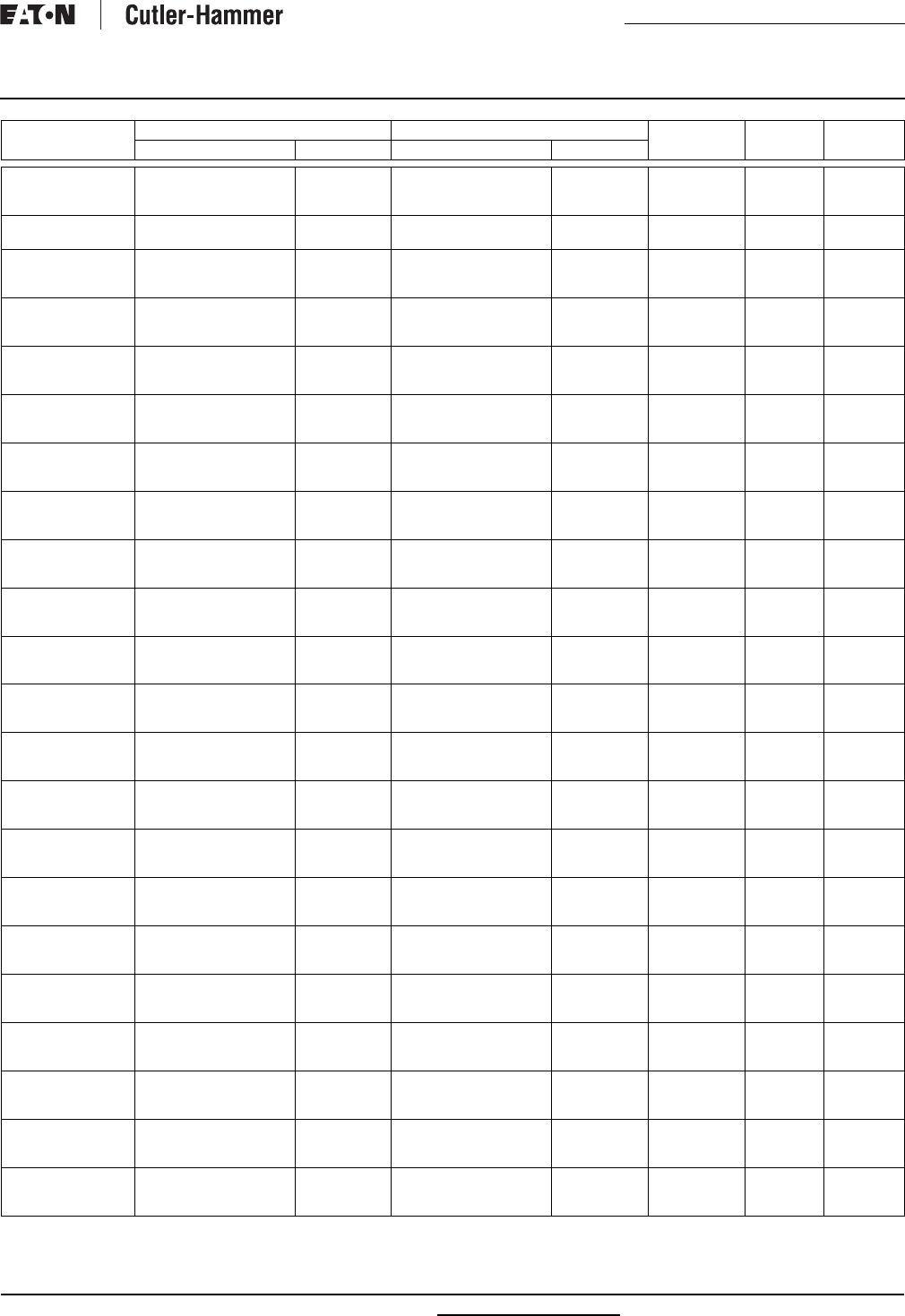
RP00801001E For more information visit: www.cutler-hammer.eaton.com
Renewal Parts
Effective: July 2002 Page 7
Safety Switches
DH362UCK
DH362UDK-CPG
DH362UDK-LS
Switching Base
Switching Base
Switching Base
70-7758-13
70-7758-13
70-7758-13
—
—
—
—
—
—
70-7758-34
70-7758-34
70-7758-34
—
70-7813
70-7813
—
70-7813-2
70-7813-2
DH362UDK2-LS
DH362UDK2WR
Switching Base
Switching Base
70-7758-13
70-7758-4
—
—
—
—
70-7758-34
70-7758-35
70-7813
70-7813
70-7813-2
70-7813-2
DH362UDK2WRCP10
DH362UD5WRK
DH362UGK
Switching Base
Switching Base
Switching Base
70-7758-4
70-7758-4
70-7758-13
—
—
—
—
—
—
70-7758-35
70-7758-35
70-7758-34
70-7813
70-7813
70-7813
70-7813-2
70-7813-2
70-7813-2
DH362UGK-CSA
DH362UGK2
DH362UGK3
Switching Base
Switching Base
Switching Base
70-7758-13
70-7758-13
70-7758-13
—
—
—
—
—
—
70-7758-34
70-7758-34
70-7758-34
70-7813
70-7813
70-7813
70-7813-2
70-7813-2
70-7813-2
DH362URK
DH362URK-CSA
DH362URK-NP-FP
Switching Base
Switching Base
Switching Base
70-7758-13
70-7758-13
70-7758-13
—
—
—
—
—
—
70-7758-34
70-7758-34
70-7758-34
70-7813
70-7813
70-7813
70-7813-2
70-7813-2
70-7813-2
DH362URK2
DH362URK3
DH362UWK
Switching Base
Switching Base
Switching Base
70-7758-13
70-7758-13
70-7758-13
—
—
—
—
—
—
70-7758-34
70-7758-34
70-7758-34
70-7813
70-7813
70-7813
70-7813-2
70-7813-2
70-7813-3
DH362UWK-CPG
DH362UWK-LS
DH362UWKW
Switching Base
Switching Base
Switching Base
70-7758-4
70-7758-4
70-7758-4
—
—
—
—
—
—
70-7758-35
70-7758-35
70-7758-35
70-7813
70-7813
70-7813
70-7813-3
70-7813-3
70-7813-3
DH362UWKW2
DH362UWK2WR
DH362UW5WRK
Switching Base
Switching Base
Switching Base
70-7758-4
70-7758-4
70-7758-4
—
—
—
—
—
—
70-7758-35
70-7758-35
70-7758-35
70-7813
70-7813
70-7813
70-7813-3
70-7813-2
70-7813-3
DH363FCK
DH363FDK
DH363FDK2
Switching Base
Switching Base
Switching Base
70-7758-3
70-7758-3
70-7758-3
Fuse Base
Fuse Base
Fuse Base
70-7758-21
70-7758-21
70-7758-21
70-7758-35
70-7758-35
70-7758-35
—
70-7813
70-7813
—
70-7813-2
70-7813-2
DH363FDK2WR
DH363FDK26
DH363FDK6
Switching Base
Switching Base
Switching Base
70-7758-3
70-7758-3
70-7758-3
Fuse Base
Fuse Base
Fuse Base
70-7758-21
70-7758-21
70-7758-21
70-7758-35
70-7758-35
70-7758-35
70-7813
70-7813
70-7813
70-7813-2
70-7813-2
70-7813-2
DH363FD3WRK
DH363FD3WRK-EXC
DH363FD4WRK
Switching Base
Switching Base
Switching Base
70-7758-3
70-7758-3
70-7758-3
Fuse Base
Fuse Base
Fuse Base
70-7758-21
70-7758-21
70-7758-21
70-7758-35
70-7758-35
70-7758-35
70-7813
70-7813
70-7813
70-7813-2
70-7813-2
70-7813-2
DH363FGK
DH363FGK6
DH363FRK
Switching Base
Switching Base
Switching Base
70-7758-3
70-7758-3
70-7758-3
Fuse Base
Fuse Base
Fuse Base
70-7758-21
70-7758-21
70-7758-21
70-7758-35
70-7758-35
70-7758-35
70-7813
70-7813
70-7813
70-7813-2
70-7813-2
70-7813-2
DH363FRK-HRC
DH363FRK6
DH363FWK
Switching Base
Switching Base
Switching Base
70-7758-3
70-7758-3
70-7758-3
Fuse Base
Fuse Base
Fuse Base
70-7758-21
70-7758-21
70-7758-21
70-7758-35
70-7758-35
70-7758-35
70-7813
70-7813
70-7813
70-7813-2
70-7813-2
70-7813-3
DH363FWKX
DH363FWK26
DH363FW5WRK
Switching Base
Switching Base
Switching Base
70-7758-3
70-7758-3
70-7758-3
Fuse Base
Fuse Base
Fuse Base
70-7758-21
70-7758-21
70-7758-21
70-7758-35
70-7758-35
70-7758-35
70-8304
70-7813
70-7813
70-7813-3
70-7813-3
70-7813-3
DH363NCK
DH363NDK
DH363NDKLW
Switching Base
Switching Base
Switching Base
70-7758-3
70-7758-3
70-7758-3
Fuse Base
Fuse Base
Fuse Base
70-7758-21
70-7758-21
70-7758-21
70-7758-35
70-7758-35
70-7758-35
—
70-7813
70-7813
—
70-7813-2
70-7813-2
DH363NDKW
DH363NDK6
DH363NGK
Switching Base
Switching Base
Switching Base
70-7758-3
70-7758-3
70-7758-3
Fuse Base
Fuse Base
Fuse Base
70-7758-21
70-7758-21
70-7758-21
70-7758-35
70-7758-35
70-7758-35
70-7813
70-7813
70-7813
70-7813-2
70-7813-2
70-7813-2
DH363NGK6
DH363NRK
DH363NWK
Switching Base
Switching Base
Switching Base
70-7758-3
70-7758-3
70-7758-3
Fuse Base
Fuse Base
Fuse Base
70-7758-21
70-7758-21
70-7758-21
70-7758-35
70-7758-35
70-7758-35
70-7813
70-7813
70-7813
70-7813-2
70-7813-2
70-7813-3
DH363NWKLW
DH363NWKW
DH363NWKW2
Switching Base
Switching Base
Switching Base
70-7758-3
70-7758-3
70-7758-3
Fuse Base
Fuse Base
Fuse Base
70-7758-21
70-7758-21
70-7758-21
70-7758-35
70-7758-35
70-7758-35
70-7813
70-7813
70-7813
70-7813-3
70-7813-3
70-7813-3
DH363NWKX
DH363UCK
DH363UDK
Switching Base
Switching Base
Switching Base
70-7758-3
70-7758-5
70-7758-5
Fuse Base
—
—
70-7758-21
—
—
70-7758-35
70-7758-35
70-7758-35
70-8304
—
70-7813
70-7813-3
—
70-7813-2
DH363UDK-CP
DH363UDK-NP-FP
DH363UDK-10
Switching Base
Switching Base
Switching Base
70-7758-5
70-7758-5
70-7758-5
—
—
—
—
—
—
70-7758-35
70-7758-35
—
70-7813
70-7813
70-7813
70-7813-2
70-7813-2
70-7813-2
DH363UDKW
DH363UDKW2
DH363UDK2
Switching Base
Switching Base
Switching Base
70-7758-5
70-7758-5
70-7758-5
—
—
—
—
—
—
70-7758-35
70-7758-35
70-7758-35
70-7813
70-7813
70-7813
70-7813-2
70-7813-2
70-7813-2
DH363UDK3
DH363UGK
DH363UGK2
Switching Base
Switching Base
Switching Base
70-7758-5
70-7758-5
70-7758-5
—
—
—
—
—
—
70-7758-35
70-7758-35
70-7758-35
70-7813
70-7813
70-7813
70-7813-2
70-7813-2
70-7813-2
Catalog
Number
Base or Assembly Fuse Base and Lower Assembly Line
Shields
Operating
Mechanism
Operating
Handle
Type Part Number Type Part Number
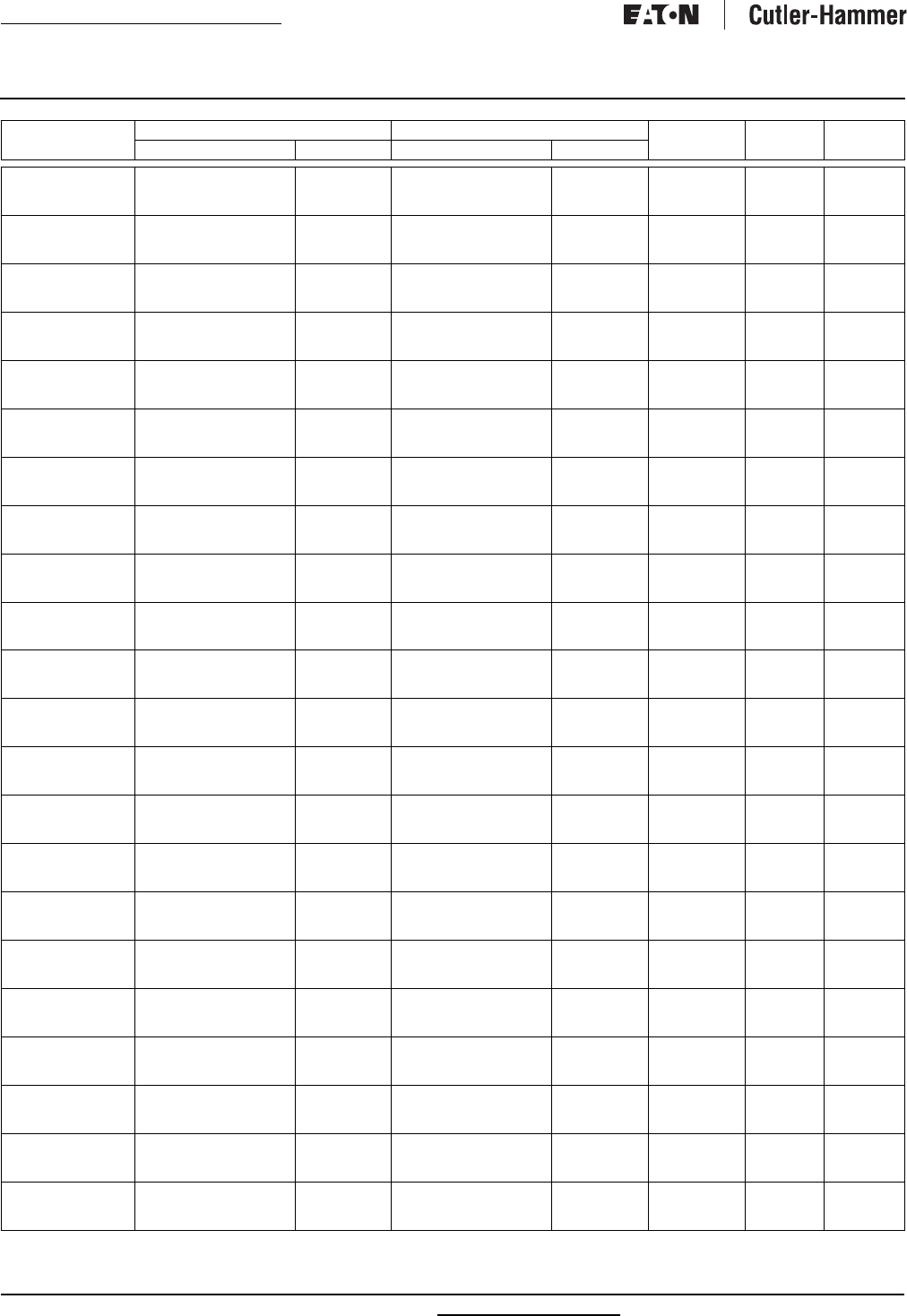
For more information visit: www.cutler-hammer.eaton.com RP00801001E
Renewal Parts
Page 8 Effective: July 2002
Safety Switches
DH363URK
DH363URK-NP-FP
DH363URK2
Switching Base
Switching Base
Switching Base
70-7758-5
70-7758-5
70-7758-5
—
—
—
—
—
—
70-7758-35
70-7758-35
70-7758-35
70-7813
70-7813
70-7813
70-7813-2
70-7813-2
70-7813-2
DH363URK3
DH363UWK
DH363UWK-316
Switching Base
Switching Base
Switching Base
70-7758-5
70-7758-5
70-7758-5
—
—
—
—
—
—
70-7758-35
70-7758-35
70-7758-35
70-7813
70-7813
70-7813
70-7813-2
70-7813-3
70-7813-3
DH363UWKW
DH363UWKW2
DH363UWKX
Switching Base
Switching Base
Switching Base
70-7758-5
70-7758-5
70-7758-5
—
—
—
—
—
—
70-7758-35
70-7758-35
70-7758-35
70-7813
70-7813
70-8304
70-7813-3
70-7813-3
70-7813-3
DH363UWK2
DH363UWK3
DH363UWK34
Switching Base
Switching Base
Switching Base
70-7758-5
70-7758-5
70-7758-5
—
—
—
—
—
—
70-7758-35
70-7758-35
70-7758-35
70-7813
70-7813
70-7813
70-7813-3
70-7813-3
70-7813-3
DH364FCK
DH364FDK
DH364FDK2
Switching Base
Switching Base
Switching Base
70-8266
70-7759
70-7759
Fuse Base
Fuse Base
Fuse Base
70-8266-4
70-7759-5
70-7759-5
70-7759-11
70-7759-11
70-7759-11
—
70-7833-4
70-7833-4
—
70-7833-2
70-7833-2
DH364FDK26
DH364FDK6
DH364FGK
Switching Base
Switching Base
Switching Base
70-7759
70-7759
70-8266
Fuse Base
Fuse Base
Fuse Base
70-7759-5
70-7759-5
70-8266-4
70-7759-11
70-7759-11
70-7759-11
70-7833-4
70-7833-4
70-7833-4
70-7833-2
70-7833-2
70-7833-2
DH364FGK6
DH364FRK
DH364FRK6
Switching Base
Switching Base
Switching Base
70-8266
70-8266
70-8266
Fuse Base
Fuse Base
Fuse Base
70-8266-4
70-8266-4
70-8266-4
70-7759-11
70-7759-11
70-7759-11
70-7833-4
70-7833-4
70-7833-4
70-7833-2
70-7833-2
70-7833-2
DH364FWK
DH364FWKX
DH364FWK26
Switching Base
Switching Base
Switching Base
70-7759
70-7759
70-7759
Fuse Base
Fuse Base
Fuse Base
70-7759-5
70-7759-5
70-7759-5
70-7759-11
70-7759-11
70-7759-11
70-7833-4
70-8305
70-7833-4
70-7833-3
70-7833-3
70-7833-3
DH364NCK
DH364NDK
DH364NDKLW
Switching Base
Switching Base
Switching Base
70-8266
70-7759
70-7759
Fuse Base
Fuse Base
Fuse Base
70-8266-4
70-7759-5
70-7759-5
70-7759-11
70-7759-11
70-7759-11
—
70-7833-4
70-7833-4
—
70-7833-2
70-7833-2
DH364NDKW
DH364NGK
DH364NGK6
Switching Base
Switching Base
Switching Base
70-7759
70-8266
70-8266
Fuse Base
Fuse Base
Fuse Base
70-7759-5
70-8266-4
70-8266-4
70-7759-11
70-7759-11
70-7759-11
70-7833-4
70-7833-4
70-7833-4
70-7833-2
70-7833-2
70-7833-2
DH364NRK
DH364NWK
DH364NWKLW
Switching Base
Switching Base
Switching Base
70-8266
70-7759
70-7759
Fuse Base
Fuse Base
Fuse Base
70-8266-4
70-7759-5
70-7759-5
70-7759-11
70-7759-11
70-7759-11
70-7833-4
70-7833-4
70-7833-4
70-7833-2
70-7833-3
70-7833-3
DH364NWKW
DH364NWKX
DH364UCK
Switching Base
Switching Base
Switching Base
70-7759
70-7759
70-8266-2
Fuse Base
Fuse Base
—
70-7759-5
70-7759-5
—
70-7759-11
70-7759-11
70-7759-11
70-7833-4
70-8305
—
70-7833-3
70-7833-3
—
DH364UDK
DH364UDK-CP
DH364UDK-NP-FP
Switching Base
Switching Base
Switching Base
70-7759-2
70-7759-2
70-7759-2
Lower Base & Connector
Lower Base & Connector
Lower Base & Connector
70-7759-6
70-7759-6
70-7759-6
70-7759-11
70-7759-11
70-7759-11
70-7833-4
70-7833-4
70-7833-4
70-7833-2
70-7833-2
70-7833-2
DH364UDK-10
DH364UDKW
DH364UDK2
Switching Base
Switching Base
Switching Base
70-7759-2
70-7759-2
70-7759-2
Lower Base & Connector
Lower Base & Connector
Lower Base & Connector
70-7759-6
70-7759-6
70-7759-6
70-7759-11
70-7759-11
70-7759-11
70-7833-4
70-7833-4
70-7833-4
70-7833-2
70-7833-2
70-7833-2
DH364UGK
DH364UGK2
DH364UGK3
Switching Base
Switching Base
Switching Base
70-8266-2
70-8266-2
70-8266-2
—
—
—
—
—
—
70-7759-11
70-7759-11
70-7759-11
70-7833-4
70-7833-4
70-7833-4
70-7833-2
70-7833-2
70-7833-2
DH364URK
DH364URK-H
DH364URK2
Switching Base
Switching Base
Switching Base
70-8266-2
70-7759-2
70-8266-2
—
Lower Base & Connector
—
—
70-7759-6
—
70-7759-11
70-7759-11
70-7759-11
70-7833-4
70-7833-4
70-7833-4
70-7833-2
70-7833-2
70-7833-2
DH364UWK
DH364UWK-316
DH364UWKW
Switching Base
Switching Base
Switching Base
70-7759-2
70-7759-2
70-7759-2
Lower Base & Connector
Lower Base & Connector
Lower Base & Connector
70-7759-6
70-7759-6
70-7759-6
70-7759-11
70-7759-11
70-7759-11
70-7833-4
70-7833-4
70-7833-4
70-7833-3
70-7833-3
70-7833-3
DH364UWKX
DH364UWK2
DH365FDK
Switching Base
Switching Base
Switch Interior Assembly
70-7759-2
70-7759-2
70-8063-6
Lower Base & Connector
Lower Base & Connector
Fuse Base
70-7759-6
70-7759-6
70-8063-7
70-7759-11
70-7759-11
70-8063-8
70-8305
70-7833-4
70-7833-5
70-7833-3
70-7833-3
70-7833-2
DH365FGK
DH365FGK6
DH365FPK
Switch Interior Assembly
Switch Interior Assembly
Switch Interior Assembly
70-8063-6
70-8063-6
70-8063-6
Fuse Base
Fuse Base
Fuse Base
70-8063-7
70-8063-7
70-8063-7
70-8063-8
70-8063-8
70-8063-8
70-7833-5
70-7833-5
70-7833-5
70-7833-2
70-7833-2
70-7833-2
DH365FRK
DH365FWK
DH365FWKX
Switch Interior Assembly
Switch Interior Assembly
Switch Interior Assembly
70-8063-6
70-8063-6
70-8063-6
Fuse Base
Fuse Base
Fuse Base
70-8063-7
70-8063-7
70-8063-7
70-8063-8
70-8063-8
70-8063-8
70-7833-5
70-7833-5
70-8305-2
70-7833-2
70-7833-3
70-7833-3
DH365NDK
DH365NDKLW
DH365NDKW
Switch Interior Assembly
Switch Interior Assembly
Switch Interior Assembly
70-8063-6
70-8063-6
70-8063-6
Fuse Base
Fuse Base
Fuse Base
70-8063-7
70-8063-7
70-8063-7
70-8063-8
70-8063-8
70-8063-8
70-7833-5
70-7833-5
70-7833-5
70-7833-2
70-7833-2
70-7833-2
DH365NGK
DH365NPK
DH365NPKLW
Switch Interior Assembly
Switch Interior Assembly
Switch Interior Assembly
70-8063-6
70-8063-6
70-8063-6
Fuse Base
Fuse Base
Fuse Base
70-8063-7
70-8063-7
70-8063-7
70-8063-8
70-8063-8
70-8063-8
70-7833-5
70-7833-5
70-7833-5
70-7833-2
70-7833-2
70-7833-2
Catalog
Number
Base or Assembly Fuse Base and Lower Assembly Line
Shields
Operating
Mechanism
Operating
Handle
Type Part Number Type Part Number
Three used.

RP00801001E For more information visit: www.cutler-hammer.eaton.com
Renewal Parts
Effective: July 2002 Page 9
Safety Switches
DH365NRK
DH365NWK
DH365NWKLW
Switch Interior Assembly
Switch Interior Assembly
Switch Interior Assembly
70-8063-6
70-8063-6
70-8063-6
Fuse Base
Fuse Base
Fuse Base
70-8063-7
70-8063-7
70-8063-7
70-8063-8
70-8063-8
70-8063-8
70-7833-5
70-7833-5
70-7833-5
70-7833-2
70-7833-2
70-7833-2
DH365UDK
DH365UDK-CP
DH365UDKW
Switch Interior Assembly
Switch Interior Assembly
Switch Interior Assembly
70-8063-2
70-8063-2
70-8063-2
—
—
—
—
—
—
70-8063-8
70-8063-8
70-8063-8
70-7833-5
70-7833-5
70-7833-5
70-7833-2
70-7833-2
70-7833-2
DH365UDK2
DH365UGK
DH365UPK
Switch Interior Assembly
Switch Interior Assembly
Switch Interior Assembly
70-8063-2
70-8063-2
70-8063-2
—
—
—
—
—
—
70-8063-8
70-8063-8
70-8063-8
70-7833-5
70-7833-5
70-7833-5
70-7833-2
70-7833-2
70-7833-2
DH365UPKW
DH365URK
DH365URK-NP-FP
Switch Interior Assembly
Switch Interior Assembly
Switch Interior Assembly
70-8063-2
70-8063-2
70-8063-2
—
—
—
—
—
—
70-8063-8
70-8063-8
70-8063-8
70-7833-5
70-7833-5
70-7833-5
70-7833-2
70-7833-2
70-7833-2
DH365URK2
DH365UWK
DH365UWKW
Switch Interior Assembly
Switch Interior Assembly
Switch Interior Assembly
70-8063-2
70-8063-2
70-8063-2
—
—
—
—
—
—
70-8063-8
70-8063-8
70-8063-8
70-7833-5
70-7833-5
70-7833-5
70-7833-2
70-7833-3
70-7833-3
DH365UWKX
DH366FDK
DH366FGK
Switch Interior Assembly
Switch Interior Assembly
Switch Interior Assembly
70-8063-2
70-8064-6
70-8064-6
—
Fuse Base
Fuse Base
—
70-8064-7
70-8064-7
70-8063-8
70-8064-8
70-8064-8
70-8305-2
70-7833-6
70-7833-6
70-7833-3
70-7833-2
70-7833-2
DH366FGK-EXC
DH366FPK
DH366FRK
Switch Interior Assembly
Switch Interior Assembly
Switch Interior Assembly
70-8064-6
70-8064-6
70-8064-6
Fuse Base
Fuse Base
Fuse Base
70-8064-7
70-8064-7
70-8064-7
70-8064-8
70-8064-8
70-8064-8
70-7833-6
70-7833-6
70-7833-6
70-7833-2
70-7833-2
70-7833-2
DH366FWK
DH366NDK
DH366NDKLW
Switch Interior Assembly
Switch Interior Assembly
Switch Interior Assembly
70-8064-6
70-8064-6
70-8064-6
Fuse Base
Fuse Base
Fuse Base
70-8064-7
70-8064-7
70-8064-7
70-8064-8
70-8064-8
70-8064-8
70-7833-6
70-7833-6
70-7833-6
70-7833-3
70-7833-2
70-7833-2
DH366NGK
DH366NPK
DH366NPKLW
Switch Interior Assembly
Switch Interior Assembly
Switch Interior Assembly
70-8064-6
70-8064-6
70-8064-6
Fuse Base
Fuse Base
Fuse Base
70-8064-7
70-8064-7
70-8064-7
70-8064-8
70-8064-8
70-8064-8
70-7833-6
70-7833-6
70-7833-6
70-7833-2
70-7833-2
70-7833-2
DH366NRK
DH366NWK
DH366NWKLW
Switch Interior Assembly
Switch Interior Assembly
Switch Interior Assembly
70-8064-6
70-8064-6
70-8064-6
Fuse Base
Fuse Base
Fuse Base
70-8064-7
70-8064-7
70-8064-7
70-8064-8
70-8064-8
70-8064-8
70-7833-6
70-7833-6
70-7833-6
70-7833-2
70-7833-3
70-7833-2
DH366UDK
DH366UDKW
DH366UDK2
Switch Interior Assembly
Switch Interior Assembly
Switch Interior Assembly
70-8064-2
70-8064-2
70-8064-2
—
—
—
—
—
—
70-8064-8
70-8064-8
70-8064-8
70-7833-6
70-7833-6
70-7833-6
70-7833-2
70-7833-2
70-7833-2
DH366UGK
DH366UPK
DH366URK
Switch Interior Assembly
Switch Interior Assembly
Switch Interior Assembly
70-8064-2
70-8064-2
70-8064-2
—
—
—
—
—
—
70-8064-8
70-8064-8
70-8064-8
70-7833-6
70-7833-6
70-7833-6
70-7833-2
70-7833-2
70-7833-2
DH366UWK
DH366UWKW
DH367FDK
Switch Interior Assembly
Switch Interior Assembly
Switch Interior Assembly
70-8064-2
70-8064-2
70-8065-6
—
—
Fuse Base
—
—
70-8065-7
70-8064-8
70-8064-8
70-8064-8
70-7833-6
70-7833-6
70-7833-6
70-7833-3
70-7833-3
70-7833-2
DH367FGK
DH367FPK
DH367FRK
Switch Interior Assembly
Switch Interior Assembly
Switch Interior Assembly
70-8065-6
70-8065-6
70-8065-6
Fuse Base
Fuse Base
Fuse Base
70-8065-7
70-8065-7
70-8065-7
70-8064-8
70-8064-8
70-8064-8
70-7833-6
70-7833-6
70-7833-6
70-7833-2
70-7833-2
70-7833-2
DH367FWK
DH367NGK
DH367NGK-NKO
Switch Interior Assembly
Switch Interior Assembly
Switch Interior Assembly
70-8065-6
70-8065-6
70-8065-6
Fuse Base
Fuse Base
Fuse Base
70-8065-7
70-8065-7
70-8065-7
70-8064-8
70-8064-8
70-8064-8
70-7833-6
70-7833-6
70-7833-6
70-7833-3
70-7833-2
70-7833-2
DH367NRK
DH367UDK
DH367UGK
Switch Interior Assembly
Switch Interior Assembly
Switch Interior Assembly
70-8065-6
70-8065-2
70-8065-2
Fuse Base
—
—
70-8065-7
—
—
70-8064-8
70-8064-8
70-8064-8
70-7833-6
70-7833-6
70-7833-6
70-7833-2
70-7833-2
70-7833-2
DH367UPK
DH367URK
DH367UWK
Switch Interior Assembly
Switch Interior Assembly
Switch Interior Assembly
70-8065-2
70-8065-2
70-8065-2
—
—
—
—
—
—
70-8064-8
70-8064-8
70-8064-8
70-7833-6
70-7833-6
70-7833-6
70-7833-2
70-7833-2
70-7833-3
DH368FGK
DH368FRK
DH368NGK
Switch Interior Assembly
Switch Interior Assembly
Switch Interior Assembly
70-8065-2
70-8065-2
70-8065-2
Fuse Base
Fuse Base
Fuse Base
70-8453-3
70-8453-3
70-8453-3
70-8453-4
70-8453-4
70-8453-4
—
—
—
—
—
—
DH368NRK
DH368UGK
DH368URK
Switch Interior Assembly
Switch Interior Assembly
Switch Interior Assembly
70-8065-2
70-8453
70-8453
Fuse Base
—
—
70-8453-3
—
—
70-8453-4
70-8453-4
70-8453-4
—
—
—
—
—
—
DH421FDK
DH421FGK
DH422FDK
Switching Base
Switching Base
Switching Base
70-7758-16
70-7758-16
70-7758-6
Fuse Base
Fuse Base
Fuse Base
70-7758-29
70-7758-29
70-7758-22
70-7758-34
70-7758-34
70-7758-35
70-7813
70-7813
70-7813
70-7813-2
70-7813-2
70-7813-2
DH422FGK
DH423FDK
DH423FGK
Switching Base
Switching Base
Switching Base
70-7758-6
70-7758-7
70-7758-7
Fuse Base
Fuse Base
Fuse Base
70-7758-22
70-7758-23
70-7758-23
70 7758-35
70-7758-35
70-7758-35
70-7813
70-7813
70-7813
70-7813-2
70-7813-2
70-7813-2
DH424FDK
DH424FGK
DH425FGK
Switching Base
Switching Base
Switch Interior Assembly
70-7759-9
Consult Factory
70-8270
Fuse Base
Fuse Base
Fuse Base
70-7759-4
Consult Factory
70-8063-7
70-7759-12
Consult Factory
70-8270-4
70-7833-4
70-7833-4
70-7833-5
70-7833-2
70-7833-2
70-7833-2
Catalog
Number
Base or Assembly Fuse Base and Lower Assembly Line
Shields
Operating
Mechanism
Operating
Handle
Type Part Number Type Part Number
Four used.

For more information visit: www.cutler-hammer.eaton.com RP00801001E
Renewal Parts
Page 10 Effective: July 2002
Safety Switches
DH426FGK
DH461FGK
DH461UDK
Switch Interior Assembly
Switching Base
Switching Base
70-8271
70-7758-36
70-7758-40
Fuse Base
Fuse Base
—
70-8064-7
70-7758-38
—
70-8270-4
70-7758-34
70-7758-34
70-7833-6
70-7813
70-7813
70-7833-2
70-7813-2
70-7813-2
DH461UGK
DH461UWK
Switching Base
Switching Base
70-7758-40
70-7758-42
—
—
—
—
70-7758-34
70-7758-35
70-7813
70-7813
70-7813-2
70-7813-3
DH462FGK
DH462UDK
DH462UGK
Switching Base
Switching Base
Switching Base
70-7758-37
70-7758-13
70-7758-13
Fuse Base
—
—
70-7758-39
—
—
70 7758-35
70-7758-34
70-7758-34
70-7813
70-7813
70 7813
70-7813-2
70-7813-2
70-7813-2
DH462UWK
DH463FDK
DH463FGK
Switching Base
Switching Base
Switching Base
70-7758-42
70-7758-7
70-7758-7
—
Fuse Base
Fuse Base
—
70-7758-23
70-7758-23
70-7758-35
70-7758-35
70-7758-35
70-7813
70-7813
70-7813
70-7813-3
70-7813-2
70-7813-2
DH463UDK
DH463UGK
DH463UWK
Switching Base
Switching Base
Switching Base
70-7758-42
70-7758-42
70-7758-42
—
—
—
—
—
—
70-7758-35
70-7758-35
70-7758-35
70-7813
70-7813
70-7813
70-7813-2
70-7813-2
70-7813-3
DH464FDK
DH464FGK
DH464UDK
Switching Base
Switching Base
Switching Base
70-7759-9
Consult Factory
70-7759-10
Fuse Base
Fuse Base
Lower Base & Connector
70-7759-5
Consult Factory
70-7759-6
70-7759-12
Consult Factory
70-7759-12
70-7833-4
70-7833-4
70-7833-4
70-7833-2
70-7833-2
70-7833-2
DH464UGK
DH465FGK
DH465UGK
Switching Base
Switch Interior Assembly
Switch Interior Assembly
Consult Factory
70-8270-2
70-8270-3
—
Fuse Base
—
—
70-8063-7
—
Consult Factory
70-8270-4
70-8270-4
70-7833-4
70-7833-5
70-7833-5
70-7833-2
70-7833-2
70-7833-2
DH466FGK
DH466UGK
DH661FDK
Switch Interior Assembly
Switch Interior Assembly
Switching Base
70-8271-2
70-8271-3
70-7758-12
Fuse Base
—
Fuse Base
70-8064-7
—
70-7758-27
70-8270-4
70-8270-4
70-7758-34
70-7833-6
70-7833-6
70-7813
70-7833-2
70-7833-2
70-7813-2
DH661UDK
DH661UDK2
DH661UDK3
Switching Base
Switching Base
Switching Base
70-7758-13
70-7758-13
70-7758-13
—
—
—
—
—
—
70-7758-34
70-7758-34
70-7758-34
70-7813
70-7813
70-7813
70-7813-2
70-7813-2
70-7813-2
DH661UWK
DH661UWK2
DH661UWK3
Switching Base
Switching Base
Switching Base
70-7758-5
70-7758-5
70-7758-5
—
—
—
—
—
—
70-7758-35
70-7758-35
70-7758-35
70-7813
70-7813
70-7813
70-7813-3
70-7813-3
70-7813-3
DH662FDK
DH662UDK
DH662UWK
Switching Base
Switching Base
Switching Base
70-7758-2
70-7758-4
70-7758-5
Fuse Base
—
—
70-7758-20
—
—
70-7758-35
70-7758-35
70-7758-35
70-7813
70-7813
70-7813
70-7813-2
70-7813-2
70-7813-3
DH663FDK
DH663UDK
DH663UWK
Switching Base
Switching Base
Switching Base
70-7758-3
70-7758-5
70-7758-5
Fuse Base
—
—
70-7758-21
—
—
70-7758-35
70-7758-35
70-7758-35
70-7813
70-7813
70-7813
70-7813-2
70-7813-2
70-7813-3
DH663UWK-316
DH664UDK
DH664UDK3
DH664UWK
Switching Base
Switching Base
Switching Base
Switching Base
70-7758-5
70-7759-13
70-7759-13
70-7759-13
—
Lower Base & Connector
Lower Base & Connector
Lower Base & Connector
—
70-7759-6
70-7759-6
70-7759-6
70-7758-35
70-7759-11
70-7759-11
70-7759-11
70-7813
70-7833-4
70-7833-4
70-7833-4
70-7813-3
70-7833-2
70-7833-2
70-7833-3
DP111NGB
DP111NRB
DP221NGB
—
—
—
—
—
—
—
—
—
—
—
—
—
—
—
—
—
—
—
—
—
DP221NRB
DT221UGK
DT221URK-NPS
—
Switching Base
Switching Base
—
70-7758-5
70-7758-5
—
—
—
—
—
—
—
—
—
—
—
—
—
—
—
DT221URK-NPS-BS
DT221URKPS
DT222UGK
Switching Base
Switching Base
Switching Base
70-7758-5
70-7758-5
70-7758-5
—
—
—
—
—
—
—
—
—
—
—
—
—
—
—
DT222URK-NPS
DT222URK-NPS-BS
DT222URKPS
Switching Base
Switching Base
Switching Base
70-7758-5
70-7758-5
70-7758-5
—
—
—
—
—
—
—
—
—
—
—
—
—
—
—
DT223UGK
DT223URK-NPS
DT223URK-NPS-BS
Switching Base
Switching Base
Switching Base
70-7758-5
70-7758-5
70-7758-5
—
—
—
—
—
—
—
—
—
—
—
—
—
—
—
DT223URKPS
DT223URKPS-N
DT224FGK
Switching Base
Switching Base
Switching Base
70-7758-5
70-7758-5
70-8058-2
—
—
Fuse Base
—
—
70-8060
—
—
70-7759-11
—
—
—
—
—
—
DT224FRK
DT224UGK
DT224UGK-FB
Switching Base
Switching Base
Switching Base
70-8058-2
70-8059
70-8059
Fuse Base
—
—
70-8060
—
—
70-7759-11
—
—
—
—
—
—
—
—
DT224URK
DT224URK-EXC
DT224URK-N
Switching Base
Switching Base
Switching Base
70-8059
70-8059
70-8059
—
—
—
—
—
—
—
—
—
—
—
—
—
—
—
Catalog
Number
Base or Assembly Fuse Base and Lower Assembly Line
Shields
Operating
Mechanism
Operating
Handle
Type Part Number Type Part Number
Two used.
Four used.
Six used.
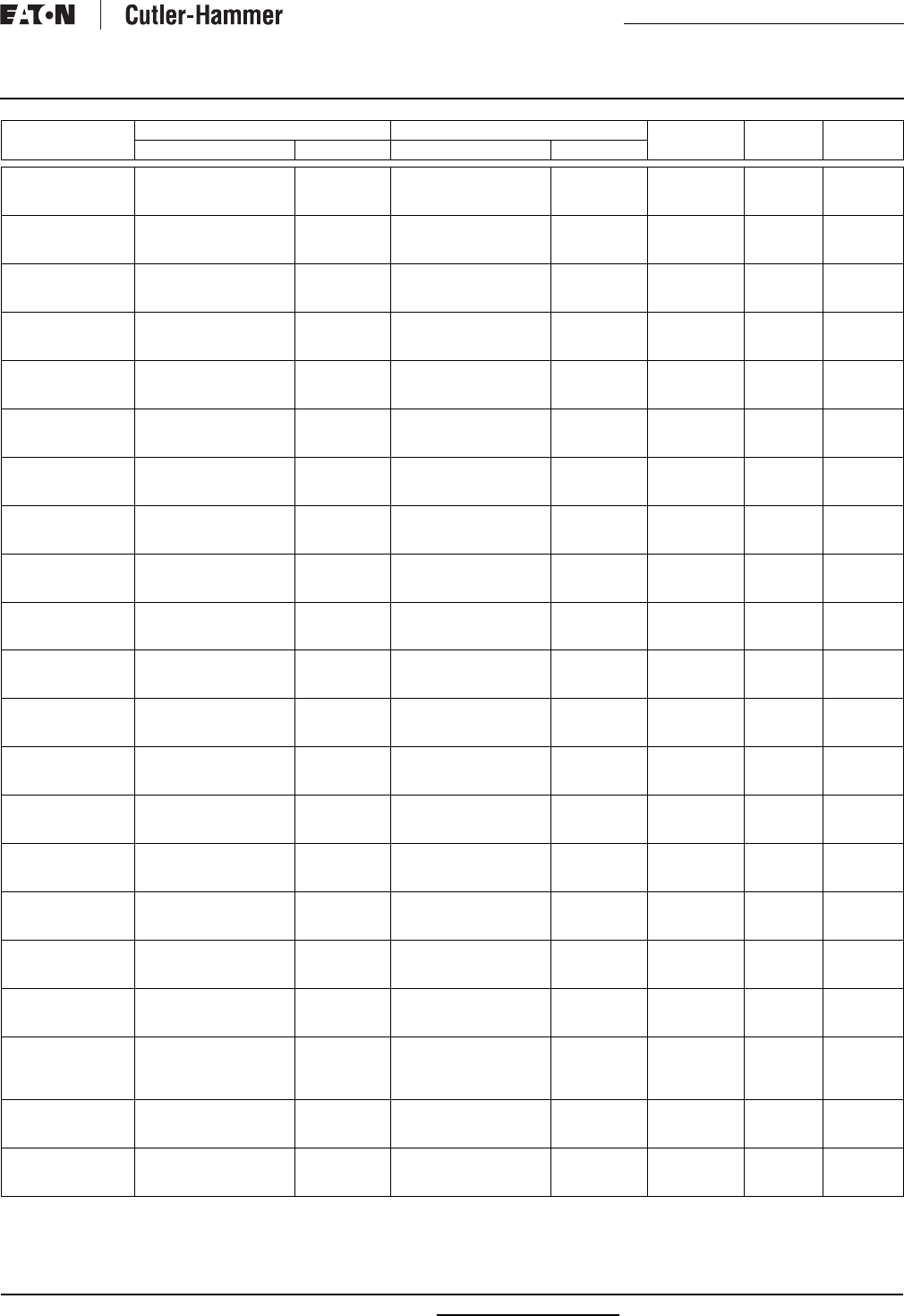
RP00801001E For more information visit: www.cutler-hammer.eaton.com
Renewal Parts
Effective: July 2002 Page 11
Safety Switches
DT224URK-NPS
DT224URK-NPS-BS
DT224URKPS
Switching Base
Switching Base
Switching Base
70-8059
70-8059
70-8059
—
—
—
—
—
—
—
—
—
—
—
—
—
—
—
DT225UGK
DT225URK
DT225URK-N
Switch Base Assembly
Switch Base Assembly
Switch Base Assembly
70-8083
70-8083
70-8083
Switch Base Assembly
Switch Base Assembly
Switch Base Assembly
70-8083-2
70-8083-2
70-8083-2
—
—
—
—
—
—
70-7833-7
70-7833-7
70-7833-7
DT225URK-NPS
DT225URK-NPS-BS
DT225URKPS
Switch Base Assembly
Switch Base Assembly
Switch Base Assembly
70-8083
70-8083
70-8083
Switch Base Assembly
Switch Base Assembly
Switch Base Assembly
70-8083-2
70-8083-2
70-8083-2
—
—
—
—
—
—
70-7833-7
70-7833-7
70-7833-7
DT226UGK
DT261UGK
DT262UGK
Switch Base Assembly
Switching Base
Switching Base
70-8083-5
70-7758-5
70-7758-5
Switch Base Assembly
—
—
70-8083-6
—
—
—
—
—
—
—
—
70-7833-7
—
—
DT263UGK
DT264UGK
DT264URK
Switching Base
Switching Base
Switching Base
70-7758-5
70-8059-2
70-8059-2
—
—
—
—
—
—
—
—
—
—
—
—
—
—
—
DT265UGK
DT265URK
DT266UGK
Switch Base Assembly
Switch Base Assembly
Switch Base Assembly
70-8083
70-8083
70-8083-5
Switch Base Assembly
Switch Base Assembly
Switch Base Assembly
70-8083-2
70-8083-2
70-8083-6
—
—
—
—
—
—
70-7833-7
70-7833-7
70-7833-7
DT266URK
DT321FGK
DT321FRK
Switch Base Assembly
—
—
70-8083-5
—
—
Switch Base Assembly
—
—
70-8083-6
—
—
—
70-7758-35
70-7758-35
—
—
—
70-7833-7
—
—
DT321UGK
DT322FGK
DT322FRK
Switching Base
Switching Base
Switching Base
70-7758-5
70-7758
70-7758
—
Fuse Base
Fuse Base
—
70-7758-19
70-7758-19
—
70-7758-35
70-7758-35
—
—
—
—
—
—
DT322NWK
DT322UGK
DT323FGK
Switching Base
Switching Base
Switching Base
70-7758
70-7758-5
70-7758-3
Fuse Base
—
Fuse Base
70-7758-19
—
70-7758-21
70-7758-35
—
70-7758-35
—
—
—
—
—
—
DT323FRK
DT323FWK
DT323NWK
Switching Base
Switching Base
Switching Base
70-7758-3
70-7758-3
70-7758-3
Fuse Base
Fuse Base
Fuse Base
70-7758-21
70-7758-21
70-7758-21
70-7758-35
70-7758-35
70-7758-35
—
—
—
—
—
—
DT323UGK
DT323URK
DT324FGK
Switching Base
Switching Base
Switching Base
70-7758-5
70-7758-5
70-8058
—
—
Fuse Base
—
—
70-8060
—
—
70-7759-11
—
—
—
—
—
—
DT324FRK
DT324FWK
DT324NWK
Switching Base
Switching Base
Switching Base
70-8058
70-8058
70-8058
Fuse Base
Fuse Base
Fuse Base
70-8060
70-8060
70-8060
70-7759-11
70-7759-11
70-7759-11
—
—
—
—
—
—
DT324UGK
DT324URK
DT325FGK
Switching Base
Switching Base
Switch Base Assembly
70-8059-3
70-8059-3
70-8084
—
—
Fuse Base
—
—
70-8085
—
—
70-8063-8
—
—
—
—
—
70-7833-7
DT325FRK
DT325NWK
DT325UDK
Switch Base Assembly
Switch Base Assembly
Switch Base Assembly
70-8084
70-8084
70-8083
Fuse Base
Fuse Base
Switch Base Assembly
70-8085
70-8085
70-8083-2
70-8063-8
70-8063-8
—
—
—
—
70-7833-7
—
70-7833-7
DT325UGK
DT326FGK
DT326FRK
Switch Base Assembly
Switch Base Assembly
Switch Base Assembly
70-8083
70-8084-3
70-8084-3
Switch Base Assembly
Fuse Base
Fuse Base
70-8083-2
70-8085-3
70-8085-3
—
70-8064-8
70-8064-8
—
—
—
70-7833-7
70-7833-7
70-7833-7
DT326UGK
DT327UGK
DT327UGK-N
Switch Base Assembly
Switch Base Assembly
Switch Base Assembly
70-8083-5
70-8083-9
70-8083-9
Switch Base Assembly
Switch Base Assembly
Switch Base Assembly
70-8083-6
70-8083-10
70-8083-10
—
—
—
—
—
—
70-7833-7
70-7833-7
70-7833-7
DT361FGK
DT361UDK
DT361UGK
Switching Base
Switching Base
Switching Base
70-7758
70-7758-5
70-7758-5
Fuse Base
—
—
70-7758-19
—
—
70-7758-35
—
—
—
—
—
—
—
—
DT361UGKW
DT361UGK22
DT361URK
Switching Base
Switching Base
Switching Base
70-7758-5
70-7758-5
70-7758-5
—
—
—
—
—
—
—
—
—
—
—
—
—
—
—
DT361UWK
DT361UWK33
DT362FGK
DT36UDK
Switching Base
Switching Base
Switching Base
Switching Base
70-7758-5
70-7758-5
70-7758-2
70-7758-5
—
—
Fuse Base
—
—
—
70-7758-20
—
—
—
70-7758-35
—
—
—
—
—
—
—
—
—
DT362UGK
DT362URK
DT362UWK
Switching Base
Switching Base
Switching Base
70-7758-5
70-7758-5
70-7758-5
—
—
—
—
—
—
—
—
—
—
—
—
—
—
—
DT363FGK
DT363FRK
DT363FWK
Switching Base
Switching Base
Switching Base
70-7758-3
70-7758-3
70-7758-3
Fuse Base
Fuse Base
Fuse Base
70-7758-21
70-7758-21
70-7758-21
70-7758-35
70-7758-35
70-7758-35
—
—
—
—
—
—
Catalog
Number
Base or Assembly Fuse Base and Lower Assembly Line
Shields
Operating
Mechanism
Operating
Handle
Type Part Number Type Part Number
Two used.
Upper.
Lower.
Renewal Parts
Page 12 Effective: July 2002
Safety Switches
© 2002 Eaton Corporation
All Rights Reserved
Printed in USA
Publication No. RP00801001E
July 2002
DT363NWK
DT363UDK
DT363UGK
Switching Base
Switching Base
Switching Base
70-7758-3
70-7758-5
70-7758-5
Fuse Base
—
—
70-7758-21
—
—
70-7758-35
—
—
—
—
—
—
—
—
DT363URK
DT363UWK
DT364FGK
Switching Base
Switching Base
Switching Base
70-7758-5
70-7758-5
70-8058
—
—
Fuse Base
—
—
70-8060
—
—
70-7759-11
—
—
—
—
—
—
DT364FRK
DT364FWK
DT364NWK
Switching Base
Switching Base
Switching Base
70-8058
70-8058
70-8058
Fuse Base
Fuse Base
Fuse Base
70-8060
70-8060
70-8060
70-7759-11
70-7759-11
70-7759-11
—
—
—
—
—
—
DT364UDK
DT364UGK
DT364UGK-N
Switching Base
Switching Base
Switching Base
70-8059-3
70-8059-3
70-8059-3
—
—
—
—
—
—
—
—
—
—
—
—
—
—
—
DT364URK
DT364UWK
DT365FGK
Switching Base
Switching Base
Switch Base Assembly
70-8059-3
70-8059-3
70-8084-2
—
—
Fuse Base
—
—
70-8085-2
—
—
70-8063-8
—
—
—
—
—
70-7833-7
DT365FRK
DT365NWK
DT365UDK
Switch Base Assembly
Switch Base Assembly
Switch Base Assembly
70-8084-2
70-8084-2
70-8083
Fuse Base
Fuse Base
Switch Base Assembly
70-8085-2
70-8085-2
70-8083-2
70-8063-8
70-8063-8
—
—
—
—
70-7833-7
—
70-7833-7
DT365UGK
DT365UGK-N
DT365UGK33
Switch Base Assembly
Switch Base Assembly
Switch Base Assembly
70-8083
70-8083
70-8083
Switch Base Assembly
Switch Base Assembly
Switch Base Assembly
70-8083-2
70-8083-2
70-8083-2
—
—
—
—
—
—
70-7833-7
70-7833-7
70-7833-7
DT365URK
DT365UWK
DT366UGK
Switch Base Assembly
Switch Base Assembly
Switch Base Assembly
70-8083
70-8083
70-8083-5
Switch Base Assembly
Switch Base Assembly
Switch Base Assembly
70-8083-2
70-8083-2
70-8083-6
—
—
—
—
—
—
70-7833-7
—
70-7833-7
DT366UGK-N
DT366URK
DT366UWK
Switch Base Assembly
Switch Base Assembly
Switch Base Assembly
70-8083-5
70-8083-5
70-8083-5
Switch Base Assembly
Switch Base Assembly
Switch Base Assembly
70-8083-6
70-8083-6
70-8083-6
—
—
—
—
—
—
70-7833-7
70-7833-7
70-7833-7
DT367UGK
DT367UGK-N
DT367URK
Switch Base Assembly
Switch Base Assembly
Switch Base Assembly
70-8083-9
70-8083-9
70-8083-9
Switch Base Assembly
Switch Base Assembly
Switch Base Assembly
70-8083-10
70-8083-10
70-8083-10
—
—
—
—
—
—
70-7833-7
70-7833-7
70-7833-7
DT367URK-N
DT461URK
DT461UWK
Switch Base Assembly
Switching Base
Switching Base
70-8083-9
70-7758-42
70-7758-42
Switch Base Assembly
—
—
70-8083-10
—
—
—
—
—
—
—
—
70-7833-7
—
—
DT462URK
DT463URK
DT463URK2
Switching Base
Switching Base
Switching Base
70-7758-42
70-7758-42
70-7758-42
—
—
—
—
—
—
—
—
—
—
—
—
—
—
—
DT464UGK
DT464URK
DT465UGK
Switching Base
Switching Base
Switch Base Assembly
70-8059-4
70-8059-4
70-8272
—
—
Switch Base Assembly
—
—
70-8272-2
—
—
—
—
—
—
—
—
70-7833-7
DT465URK
DT466UGK
DT466URK
Switch Base Assembly
Switch Base Assembly
Switch Base Assembly
70-8272
70-8273
70-8273
Switch Base Assembly
Switch Base Assembly
Switch Base Assembly
70-8272-2
70-8273-2
70-8273-2
—
—
—
—
—
—
70-7833-7
70-7833-7
70-7833-7
DT467UGK
DT467URK
DT661URK
Switch Base Assembly
Switch Base Assembly
Switching Base
70-8274
70-8274
70-7758-5
Switch Base Assembly
Switch Base Assembly
—
70-8274-2
70-8274-2
—
—
—
—
—
—
—
70-7833-7
70-7833-7
—
DT662URK
DT663URK
Switching Base
Switching Base
70-7758-5
70-7758-5
—
—
—
—
—
—
—
—
—
—
Catalog
Number
Base or Assembly Fuse Base and Lower Assembly Line
Shields
Operating
Mechanism
Operating
Handle
Type Part Number Type Part Number
Eaton Corporation
Cutler-Hammer business unit
1000 Cherrington Parkway
Moon Township, PA 15108-4312
USA
tel: 1-800-525-2000
www.cutler-hammer.eaton.com
Two used.
Four used.
Upper.
Lower.

Teen Center - Los Alamos
10/5/2015
15-18720-6
RKL SALES CORP
8804D WASHINGTON NE
ALBUQUERQUE, NM 87113-2708
Phone: 505-837-2262
Fax: 505-837-2231
Contact:

LDN6 35/20 LO6AR 120 CABL-DOWNLIGHTING
WL4 40L EZ1 LP830 D-
INTERIOR
ABL-FLUORESCENT
VIC4N L3 352 RC UN WH 1 @ 24
FEET & 1 @ 20 FEET
D-
EXTERIO
R
NEWSTAR
CTL802818LM3D-B ECon - Tech
LDN6 35/20 LO6AR 120 FABL-DOWNLIGHTING
CTR4321L-CLR-B HCon - Tech
RA4LRM-135K12D1W HCon - Tech
ZL1N L48 5000LM L/LENS MVOLT
35K 80CRI WH
IABL-FLUORESCENT
TZL1N L96 10000LM L/LENS
MVOLT 35K 80CRI WH
JABL-FLUORESCENT
2GTL 4 48L EZ1 LP830 KABL-FLUORESCENT
2GTL 2 40L EZ1 LP830 LABL-FLUORESCENT
OLWX1 LED 13W 40K MABL-HI-TEK
PGX LED P1 40K T5M MVOLT PM
PIR360SS DWHXD
M1-ALTABL-HI-TEK
OLVTCM NABL-HI-TEK
DSXB LED 16C 700 40K SYM
MVOLT DDBXD
P-ALTABL-HI-TEK
LT-24-B T4Con - Tech
LA-209-B T4Con - Tech
LT-28-B T8Con - Tech
LA-208-B TPFCon - Tech
LA-209-B T8Con - Tech
LA-203-B TFCCon - Tech
DSX0 LED 40C 700 40K TFTM
MVOLT RPA DDBXD
S1ABL-HI-TEK
RSS 20 4B DM19AS DDBXD S1ABL-HI-TEK
UCLD 12 WH M4 UCABL-FLUORESCENT
UC ERC24 U UCABL-FLUORESCENT
XC LED 2 R W SD XEELP
XC LED 2 R W RC EXEELP
RH1 LED 9.6V EXEELP
ELM2 LED EMABL-EMERGENCY
WSX PDT WH OSABL-CONTROLS
WSX PDT 2P WH OS1ABL-CONTROLS
WVR PDT 16 WH OS2ABL-CONTROLS
CMR PDT 10 2P P OS3ABL-CONTROLS
CMR PDT 10 2P OS4ABL-CONTROLS
Catalog Number
Manufacturer
Type
Project 15-18720-6
Teen Center - Los Alamos
Submitted By
RKL SALES CORP
G EUREKA 4266-SIJ LED 13.30 120V DV AC 60 4266B BLKA
CDP CDP
A COOPER 24SR-LD1-48-C-UNV-LP835-CD1-SKYTRIM
B COOPER 22SR-LD1-29-C-UNV-LP835-CD1-SKYTRIM

LDN6
6” OPEN and WALLWASH LED
Non-IC
New Construction Downlight
FEATURES & SPECIFICATIONS
INTENDED USE — Typical applications include corridors, lobbies, conference rooms and private oces.
CONSTRUCTION — 16-gauge galvanized steel mounting/plaster frame with trim clips to mount open
conical shape reector.
Vertically adjustable mounting brackets that use 16-gauge at bar hangers (included), 1/2” conduit or
C channel T-bar fasteners. Provides 3-3/4” total adjustment.
Post installation adjustment possible from above or below the ceiling.
Galvanized steel junction box with bottom-hinged access covers and spring latches. Two combination
1/2”-3/4” and three 1/2” knockouts for straight-through conduit runs. Capacity: 8 (4 in, 4 out) No. 12
AWG conductors, rated for 90°C.
Secondary housing adjustment system for precise, nal ceiling-to-ange alignment.
Maximum 1-1/2” ceiling thickness.
OPTICS — LED light source with di used lens, recessed in a deep reec tor with a 55-degree c uto. Alumi-
num full reectors are optically designed to maximize lumen output and to provide superior glare control.
Anodized trim colors for open and wallwash reectors are available in clear, pewter, wheat or gold. White
polyester powder coat also available.
Minimum CRI of 80.
ELECTRICAL — High-eciency, 0-10V dimming driver mounted to the junction box, dims luminaire to
10% of its light output. 1% dimming option available in 1500 and 2000 lumen packages only.
Dimming xture requires two (2) additional low-voltage wires to be pulled.
For compatible dimmers and dimming range, refer to Dimmer Compatibility Chart on page 4.
The system maintains 70% lumen output for more than 50,000 hours.
LISTINGS — CSA certied to US and Canadian safety standards. Open downlight (LO6): Wet location
listed. Wallwash downlight (LW6): Rated for damp and dry locations only. ENERGY STAR® certied.
WARRANTY — 5-year limited warranty. Complete warranty terms located at
www.acuitybrands.com/CustomerResources/Terms_and_conditions.aspx
Note: Specications subject to change without notice.
ORDERING INFORMATION Example: LDN6 35/15 LO6AR 120
DOWNLIGHTING LDN6
Lead times will vary depending on options selected. Consult with your sales representative.
LDN6
Series Color temperature Lumens 1,2 Reector Trim color Finish Voltage Options
LDN6 27/ 2700 K
30/ 3000 K
35/ 3500 K
40/ 4000 K
06 600
lumens
10 1000
lumens
15 1500
lumens
20 2000
lumens
LO6 Open
downlight
LW6 Wallwash
downlight 3
AR Clear
PR Pewter
WTR Wheat
GR Gold
WR White 4
(blank) Semi-
specular
LD Matte-
diuse
LS Specular
120
277
347 5
EL Emergency battery pack with integral test switch 6
ELR Emergency battery pack with remote test switch 6
SF Single fuse
TRW White painted ange 7
TRBL Black painted ange
NEPP Interface for Sensor Switch® nLight® network provided
with integral power supply. Refer to TN-623-01. 8
RRL__ RELOC®-ready luminaire connectors enables a simple and
consistent factory installed option across all ABL luminaire
brands. Refer to RRL for complete nomenclature.
EZ1 eldoLED dims to 1% 9
CP Chicago plenum 5, 10
LDN6 35/15 LO6AR 120
Maximum Overall Dimensions – All dimensions are inches (centimeters) unless otherwise indicated.
Lumen package (A) Height (B) Frame height (C) Aperture (D) Ceiling opening (E) Outside diameter (F) Width (G) Length
600 lm
6-7/16 (16.4) 5-3/4
(14.6)
6-15/16
(17.6)
7-1/8
(18.1)
7-1/2
(19.1)
12-15/16
(32.8)
10-15/16
(27.8)
1000 lm
1500 lm
2000 lm 7-13/16 (19.9)
Overall height varies by lumen package. Reference dimension chart for details.
D
I
M
M
A
B
L
E
G
F
A
B
C
D
E
Accessories: Order as separate catalog number.
EAC ISSM 375 Compact interruptible emergency AC power system
EAC ISSM 125 Compact interruptible emergency AC power system
NSP5 D ER KIT Sensor Switch nLight secondary relay and dimming pack
device used to switch and dim luminaires powered via an
emergency circuit. Refer to NSP5 D ER KIT.
GRA68 JZ Oversized trim ring with 8” outside diameter 11
SCA6 Sloped ceiling adapter. Refer to TECH-SCA for more options.
Notes
1 Approximate lumen output.
2 Overall height varies by lumen package. Reference dimension chart on page 1.
3 Rated for damp and dry locations only.
4 Not available with nishes.
5 Not available with emergency options.
6 For dimensional changes, refer to chart on page 4. Not available with CP option.
7 Not available with WR (white trim color).
8 For emergency generator/inverter applications order non-nLight enabled xture and NSP5 D ER KIT as an accessory. Refer to
NSP5 D ER KIT.
9 Only available with 1500 and 2000 lumen packages.
10 277 volt CP products require marked spacing. Install with minimal spacing between: (a) Center-to-center of adjacent lumi-
naires: 2 ft.; (b) Top of luminaire to overhead building member: 3 in.; (c) Luminaire center to side of building member: 1 ft.
11 Refer to TECH-GOOF RINGS for more options.
Catalog
Number
Notes
Type
Catalog Number
LDN6 35/20 LO6AR 120
Notes
Type
C
Project 15-18720-6
Teen Center - Los Alamos
Submitted By
RKL SALES CORP
LDN6
DOWNLIGHTING: One Lithonia Way Conyers, GA 30012 Phone: 800-315-4935 Fax: 770-860-3129 www.lithonia.com © 2014 Acuity Brands Lighting, Inc. All rights reserved. Rev. 05/29/14
LDN6
LDN6 35/10 LO6AR 120, input watts: 18, delivered lumens: 1089, LM/W = 61, spacing criterion at 0 = 1.03, test no. LTL25148SL.
LDN6 35/15 LO6AR 120, input watts: 26, delivered lumens: 1633, LM/W = 63, spacing criterion at 0 = 1.03, test no. LTL25146.
0° 20°
40°
60°
80°
600
1200
Ave Lumens
0
5
15
25
35
45
55
65
75
85
90
1564
1539
1449
1196
678
131
7
2
2
0
0
145
407
542
411
115
10
2
1
0
Zone Lumens % Lamp
0° - 30°
0° - 40°
0° - 60°
0° - 90°
90° - 180°
0° - 180°
1094.3
1505.0
1629.6
1633.3
0.0
1633.3
67.0
92.1
99.8
100.0
0.0
*100.0
*Efficiency
%02fp
pc 80% 70% 50%
pw 50% 30% 10% 50% 30% 10% 50% 30% 10%
0
1
2
3
4
5
6
7
8
9
10
119
111
103
95
89
83
78
73
68
64
60
119
108
99
90
83
77
71
66
62
58
54
119
106
95
86
79
73
67
62
58
54
50
116
108
101
94
88
82
77
72
68
64
60
116
106
97
89
83
76
71
66
62
58
54
116
104
94
86
78
72
67
62
58
54
50
111
104
98
91
86
80
75
71
66
63
59
111
103
95
88
81
75
70
65
61
57
54
111
101
92
84
78
72
66
62
57
54
50
RCR
50% beam -
53.9°
10% beam -
79.9°
Mounting
Height
Inital FC
Center
Beam Diameter FC DiameterFC
8.0
10.0
12.0
14.0
16.0
51.7
27.8
17.3
11.8
8.6
5.6
7.6
9.7
11.7
13.7
25.8
13.9
8.7
5.9
4.3
9.2
12.6
15.9
19.3
22.6
5.2
2.8
1.7
1.2
0.9
0° 20°
40°
60°
80°
40
0
80
0
Ave Lumens
0
5
15
25
35
45
55
65
75
85
90
1048
1028
968
797
452
87
4
2
1
0
0
97
272
361
273
76
6
2
0
0
Zone Lumens % Lamp
0° - 30°
0° - 40°
0° - 60°
0° - 90°
90° - 180°
0° - 180°
730.5
1004.0
1086.4
1088.8
0.0
1088.8
67.1
92.2
99.8
100.0
0.0
*100.0
*Efficiency
%02fp
pc 80% 70% 50%
pw 50% 30% 10% 50% 30% 10% 50% 30% 10%
0
1
2
3
4
5
6
7
8
9
10
119
111
103
96
89
83
78
73
68
64
60
119
108
99
90
83
77
71
67
62
58
54
119
106
95
86
79
73
67
62
58
54
51
116
108
101
94
88
82
77
72
68
64
60
116
106
97
89
83
76
71
66
62
58
54
116
104
94
86
79
72
67
62
58
54
50
111
104
98
91
86
80
75
71
67
63
59
111
103
95
88
81
75
70
65
61
57
54
111
101
92
84
78
72
66
62
57
54
50
RCR
50% beam -
53.7°
10% beam -
79.9°
Mounting
Height
Inital FC
Center
Beam Diameter FC DiameterFC
8.0
10.0
12.0
14.0
16.0
34.6
18.6
11.6
7.9
5.8
5.6
7.6
9.6
11.7
13.7
17.3
9.3
5.8
4.0
2.9
9.2
12.6
15.9
19.3
22.6
3.5
1.9
1.2
0.8
0.6
Notes
• Tested in accordance with IESNA LM-79-08.
• Tested to current IES and NEMA standards under stabilized laboratory conditions.
• Actual performance may dier as a result of end-user environment and application.
• Actual wattage may dier by +/- 10% when operating between 120-277V +/- 10%.
• CRI: 80 typical.
LDN6 35/20 LO6AR 120, input watts: 35, delivered lumens: 2143, LM/W = 61, spacing criterion at 0 = 1.04, test no. LTL25144.
0° 20°
40°
60°
80°
800
1600
Ave Lumens
0
5
15
25
35
45
55
65
75
85
90
2046
2014
1899
1569
892
171
9
3
2
1
0
190
534
711
540
150
12
3
2
1
Zone Lumens % Lamp
0° - 30°
0° - 40°
0° - 60°
0° - 90°
90° - 180°
0° - 180°
1435.1
1975.3
2137.5
2142.7
0.0
2142.7
67.0
92.2
99.8
100.0
0.0
*100.0
*Efficiency
%02fp
pc 80% 70% 50%
pw 50% 30% 10% 50% 30% 10% 50% 30% 10%
0
1
2
3
4
5
6
7
8
9
10
119
111
103
95
89
83
78
73
68
64
60
119
108
99
90
83
77
71
66
62
58
54
119
106
95
86
79
73
67
62
58
54
50
116
108
101
94
88
82
77
72
68
64
60
116
106
97
89
83
76
71
66
62
58
54
116
104
94
86
78
72
67
62
58
54
50
111
104
98
91
86
80
75
71
66
63
59
111
103
95
88
81
75
70
65
61
57
54
111
101
92
84
78
72
66
62
57
54
50
RCR
50% beam -
54.0°
10% beam -
80.0°
Mounting
Height
Inital FC
Center
BeamDiameter FC DiameterFC
8.0
10.0
12.0
14.0
16.0
67.6
36.4
22.7
15.5
11.2
5.6
7.6
9.7
11.7
13.8
33.8
18.2
11.3
7.7
5.6
9.2
12.6
15.9
19.3
22.6
6.8
3.6
2.3
1.5
1.1
PHOTOMETRY
Distribution Curve Distribution Data Output Data Coecient of Utilization Illuminance Data at 30” Above Floor for
a Single Luminaire
Catalog Number
LDN6 35/20 LO6AR 120
Notes
Type
C
Project 15-18720-6
Teen Center - Los Alamos
Submitted By
RKL SALES CORP

LDN6
LDN6
DOWNLIGHTING: One Lithonia Way Conyers, GA 30012 Phone: 800-315-4935 Fax: 770-860-3129 www.lithonia.com © 2014 Acuity Brands Lighting, Inc. All rights reserved. Rev. 05/29/14
Candlepower Data Footcandle values
LDN6 35/10 LW6AR 120, input watts: 18, delivered lumens: 1090, LM/W = 61, test no. LTL25147.
LDN6 35/15 LW6AR 120, input watts: 26, delivered lumens: 1639, LM/W = 63, test no. LTL25145.
Wallwash Illuminance Study (fc)
Illuminance on wall from 6 luminaires
Luminaire
mounted 3 ft.
from wall
Luminaire
mounted 3 ft.
from wall
Luminaire
mounted 3 ft.
from wall
3 ft. between
luminaires
4 ft. between
luminaires
5 ft. between
luminaires
ft. from ceiling33.54 33.5 433.54
1
2
3
4
5
6
7
8
9
10
17
24
22
20
18
17
15
13
11
9
13
24
22
21
19
17
15
13
11
9
17
24
22
20
18
17
15
13
11
9
16
20
17
14
13
12
11
10
8
7
7
16
16
16
15
13
11
10
8
7
16
20
17
14
13
12
11
10
8
7
15
19
15
12
10
9
9
8
7
6
4
10
11
12
12
11
9
8
7
6
15
19
15
12
10
9
9
8
7
6
Plane angle
Wall22.545 67.5 90 112.5135 157.5
0
5
15
25
35
45
55
65
75
85
90
1312
1198
956
697
442
348
283
230
121
30
5
1312
1187
976
720
482
336
269
191
88
18
6
1312
1202
1052
837
548
303
196
102
30
1
0
1312
1244
1153
953
586
222
80
22
1
1
2
1312
1285
1246
1028
583
132
19
3
1
0
1
1312
1326
1333
1082
590
105
8
2
1
0
1
1312
1371
1403
1109
612
112
10
3
1
0
1
1312
1409
1438
1126
623
115
11
6
4
0
0
Vertical Angle
Wallwash Illuminance Study (fc)
Illuminance on wall from 6 luminaires
Luminaire
mounted 3 ft.
from wall
Luminaire
mounted 3 ft.
from wall
Luminaire
mounted 3 ft.
from wall
3 ft. between
luminaires
4 ft. between
luminaires
5 ft. between
luminaires
ft. from ceiling33.54 33.5 433.54
1
2
3
4
5
6
7
8
9
10
10
15
15
13
12
12
10
9
8
6
8
15
14
14
13
12
10
9
8
6
10
15
15
13
12
12
10
9
8
6
9
13
12
10
9
8
8
7
6
5
5
10
10
11
10
9
8
7
6
5
9
13
12
10
9
8
8
7
6
5
9
12
10
8
7
7
6
5
5
4
2
6
7
8
8
7
6
5
5
4
9
12
10
8
7
7
6
5
5
4
Plane angle
Wall 22.5 45 67.5 90 112.5135 157.5
0
5
15
25
35
45
55
65
75
85
90
888
813
652
488
319
241
181
139
74
19
5
888
811
675
524
355
229
172
117
57
13
6
888
824
728
601
387
190
114
57
19
0
0
888
854
803
678
414
139
40
11
3
0
0
888
875
862
723
409
87
9
1
2
0
0
888
902
905
748
407
76
5
2
2
0
0
888
922
930
749
409
76
7
3
3
0
0
888
926
935
741
403
74
8
4
2
0
0
Vertical Angle
Notes
• Tested in accordance with IESNA LM-79-08.
• Tested to current IES and NEMA standards under stabilized laboratory conditions.
• Actual performance may dier as a result of end-user environment and application.
• Actual wattage may dier by +/- 10% when operating between 120-277V +/- 10%.
• CRI: 80 typical.
LDN6 35/20 LW6AR 120, input watts: 35, delivered lumens: 2137, LM/W = 61, test no. LTL25143.
Wallwash Illuminance Study (fc)
Illuminance on wall from 6 luminaires
Luminaire
mounted 3 ft.
from wall
Luminaire
mounted 3 ft.
from wall
Luminaire
mounted 3 ft.
from wall
3 ft. between
luminaires
4 ft. between
luminaires
5 ft. between
luminaires
ft. from ceiling33.54 33.5 433.54
1
2
3
4
5
6
7
8
9
10
17
28
28
26
24
22
20
17
15
13
13
27
27
27
25
22
20
17
15
13
17
28
28
26
24
22
20
17
15
12
16
23
22
19
17
16
15
13
11
10
7
18
19
20
20
17
15
13
11
10
16
23
22
19
17
16
15
13
11
10
16
22
19
16
13
12
11
10
9
8
4
11
14
15
16
15
13
11
9
8
16
22
19
16
13
12
11
10
9
8
Plane angle
Wall22.545 67.5 90 112.5135 157.5
0
5
15
25
35
45
55
65
75
85
90
1712
1566
1254
913
592
446
335
251
121
24
1
1712
1544
1276
956
654
425
317
213
92
14
1
1712
1598
1394
1140
766
402
248
129
39
2
1
1712
1633
1533
1307
839
325
115
35
4
0
0
1712
1710
1658
1420
851
215
32
5
1
1
1
1712
1739
1755
1489
852
170
13
4
1
0
1
1712
1783
1811
1512
855
167
12
5
1
0
1
1712
1806
1834
1521
861
167
14
5
3
0
0
Vertical Angle
room
wall
90
0
112
0
12
135
0
157
0
12
67
0
12
45
0
22
0
12
TECHNICAL INFORMATION
Footcandle values are initial and tables are based on minimum of six units. For xture-to-wall distance
other than those shown, use maximum of one-to-one spacing (distance between xtures not more than
distance to wall) for best results.
Catalog Number
LDN6 35/20 LO6AR 120
Notes
Type
C
Project 15-18720-6
Teen Center - Los Alamos
Submitted By
RKL SALES CORP

LDN6
DOWNLIGHTING: One Lithonia Way Conyers, GA 30012 Phone: 800-315-4935 Fax: 770-860-3129 www.lithonia.com © 2014 Acuity Brands Lighting, Inc. All rights reserved. Rev. 05/29/14
LDN6
DIMMER COMPATIBILITY CHART
Manufacturer Model/Series
600 & 1000 Lumen products
Leviton IllumaTech - IP710-DLX
Lutron
Nova T - NTFTV-WH
For on/o control, this switch requires a power
pack. Consult Lutron for more information.
Sensor Switch nPODM
Synergy ISD BC 120/277
1500 & 2000 Lumen products
Busch-Jaeger 2112U-101
Jung 240-10
Leviton Lighting Controls IllumaTech - IP710-DLX
Lightolier Controls ZP600FAM120
Lutron Electronics
Nova T - NTFTV
Diva - DVTV
Diva - NFTV
GraphicEye - GRX-TVI w GRX3503
Energy Savr Node - QSN-4T16-S
TVM2 Module
Merten 5729
Pass & Seymour CD4FB-W
Sensor Switch nPODM
Synergy ISD BC 120/277
The Watt Stopper DCLV1
ADDITIONAL DATA
EL/ELR DIMENSIONAL CHANGES
Add to overall housing
length for EL/ELR option
Overall housing width
with EL/ELR option
4-1/2 16-1/2
EL/ELR AVAILABILITY/COMPATIBILITY INITIAL LUMENS
Lumen
package Watts
Initial lumens
EL/ELR Emergency LED driver
600 12 500 PS1030
1000 18 575 PS1030
1500 26 640 Bodine BSL17C-C2
2000 35 690 Bodine BSL17C-C2
KEY SPECIFICATION SUMMARY
Product Description Watts (W)
Delivered
lumens (lm)
Ecacy
(lm/W)
Spacing criteria
(s/mh)
LDN6 35/06 LO6AR 12 670 56 1.03
LDN6 35/10 LO6AR 18 1090 61 1.03
LDN6 35/15 LO6AR 26 1640 63 1.03
LDN6 35/20 LO6AR 35 2140 61 1.04
Catalog Number
LDN6 35/20 LO6AR 120
Notes
Type
C
Project 15-18720-6
Teen Center - Los Alamos
Submitted By
RKL SALES CORP

LED WL4-LED
WL4
Series Lumens1Voltage Driver Color temperature Lumen management
WL4 4' wall-mount LED 20L 2000 lumens
30L 3000 lumens
40L 4000 lumens
(blank) MVOLT (120 - 277V)
347 347V
EZ1 eldoLED dims to 1%, 0-10V
EZB eldoLED dims to dark, 0-10V
SLD Step-level dimming2
LP830 3000 K
LP835 3500 K
LP840 4000 K
LP850 5000 K
(blank) No nLight
N80 nLight with 80% lumen management
N100 nLight without lumen management
N80EMG nLight with 80% lumen management
for use with generator supply
emergency power3
N100EMG nLight without lumen management
for use with generator supply
emergency power3
Occupancy control4Standby mode10 Options Finish12
NES7 Sensor Switch® nES 7 PIR integral occupancy sensor5
NESPDT7 Sensor Switch® nES PDT 7 dual technology integral occupancy control5
NES7ADCX Sensor Switch® nES 7 ADCX PIR integral occupancy sensor with
automatic dimmng control photocell5
XADS7 XPoint™ Wireless controller and micro 360° PIR occupancy and
photocell sensor6,7
XADNS7 XPoint™ Wireless controller and micro 360° PIR occupancy and
photocell sensor (egress lighting)6,7
MSD7 Sensor Switch® MSD 7 PIR integral occupancy sensor8,9
(blank) Fixture turns off when unoccupied
DIM10 Fixture dims to approximately 10%
light output when unoccupied
DIM50 Fixture dims to approximately 50%
light output when unoccupied8
EL7L LED Emergency battery pack
(nominal 700 lumens); see Life
Safety section 11
EL14L LED Emergency battery pack
(nominal 1400 lumens); see Life
Safety section11
SC Surface conduit end cap provisions
(blank) White
ORDERING INFORMATION Lead times will vary depending on options selected. Consult with your sales representative. Example: WL4 30L EZ1 LP840
Catalog
Number
Notes
Type
FEATURES & SPECIFICATIONS
INTENDED USE — For wall or ceiling mounting, vertical or horizontal. The WL combines digital LED lighting
and controls technologies with high-performance optical design to offer the most advanced wall-mount
luminaire for general ambient lighting applications. High-efficacy light engine delivers long life and excellent
color, ensuring a superior quality lighting installation that is highly efficient and sustainable.
CONSTRUCTION — Housing is roll formed from code-gauge steel.
Refractor is retained in die cast ends providing secure installation and easy maintenance.
Decorative die-cast end caps provide added durability.
Finish: All metal parts are post-painted in white polyester powder coat for smooth, finished edges and
uniform light distribution.
OPTICS — Impact modified linear faceted refractor. Optically engineered for superior light distribution
and maximum efficacy.
Crescent-shape linear faceted refractor system obscures and integrates individual LED images and uniformly
washes fixture surface with light.
ELECTRICAL — Long-life LEDs, coupled with high-efficiency drivers, provide superior quantity and quality
of illumination for extended service life. 90% LED lumen maintenance at 60,000 hours (L90/60,000). The
LEDs have a CRI of 82.
eldoLED driver options deliver choice of dimming range and choices for control, while assuring flicker-free,
low-current inrush, 89% efficiency and low EMI.
Driver disconnect provided where required to comply with US and Canadian codes.
CONTROLS — Optional nLight™ embedded controls continuously monitor system performance and allow
for constant lumen management function.
Lumen Management: Unique lumen management system (option N80) provides onboard intelligence that
actively manages the LED light source so that constant lumen output is maintained over the system life,
preventing energy waste created by the traditional practice of over-lighting.
Integral occupancy control: Integrated occupancy sensors allow luminaire to power off or dim to 10% or
50% output when space is unoccupied. Fixture designed to fail on.
The nES 7 is ideal for small rooms without obstructions or areas with primarily walking motion (e.g. corridors,
stairwells). Additionally, the NES7ADCX includes an integrated photocell, which enables daylight harvesting.
For rooms like restrooms and private offices or any space with obstructions, the nES PDT 7 dual technology
sensor is recommended. The nES PDT 7 utilizes both PIR (passive infrared) and MicrophonicsTM technologies
to detect occupancy.
Wireless networking: XPointTM Wireless technology creates a mesh network to ensure communication
between fixtures, sensors and wall stations facility-wide. This option provides superior lighting
management capabilities including granular control, configuration and custom grouping.
This option enables sensors that detect motion to wirelessly communicate to neighboring fixtures — whether
Wall bracket & Surface Mount LED
WL4
4'
LED
on different floors in a stairwell, to a corridor or hallway — illuminating the desired path.
LISTINGS — CSA certified to meet U.S. and Canadian standards. Suitable for damp location.
Patents pending. DesignLights Consortium® (DLC) qualified product. Not all versions of this product may be
DLC qualified. Please check the DLC Qualified Products List at www.designlights.org/QPL to confirm which
versions are qualified.
WARRANTY — 5-year limited warranty. Complete warranty terms located at
www.acuitybrands.com/CustomerResources/Terms_and_conditions.aspx
NOTE: Actual performance may differ as a result of end-user environment and application.
All values are design or typical values, measured under laboratory conditions at 25 °C.
Specifications subject to change without notice.
Notes
1 Approximate lumen output.
2 Not available with XPoint™ Wireless or nLight options.
3 nLight EMG option requires a connection to existing nLight
network. Power is provided from a separate N80 or N100
enabled fixture.
4 See integral occupancy control section in header.
nLIGHT
n
ENABLED
5 Requires N80 or N100.
6 Select (blank) under "Lumen management" for this option.
7 Gateway not included. Requires on-site commissioning.
Visit www.lightingcontrols.com/XPointWireless for more information.
8 Not available with EZB.or SLD.
9 Requires DIM10 or DIM50.
10 Requires occupancy control. For XPoint™ Wireless select (blank). Standby mode is
programmed at time of commissioning.
11 Not available with 347V.
12 For additional paint finishes refer to Architectural Colors.
Catalog Number
WL4 40L EZ1 LP830
Notes
Type
D-INTERIOR
Project 15-18720-6
Teen Center - Los Alamos
Submitted By
RKL SALES CORP
WL4-LED
LED: One Lithonia Way Conyers, GA 30012 Phone: 800-858-7763 Fax: 770-929-8789 www.lithonia.com ©2014-2015 Acuity Brands Lighting, Inc. All rights reserved. Rev. 08/31/15
WL4 Wall Bracket & Surface Mount LED
Specifications
Length: with sensor - 50-15/16 (129.40)
without sensor - 46-13/16 (118.90)
Height: with sensor - 3-11/16 (9.3)
without sensor - 3-7/8 (9.7)
Width: 4-3/4 (12.1)
MOUNTING DATA
For unit installation; surface ceiling or wall mounting.
3-11/16
(9.3)
3-7/8
(9.7)
4-3/4
(12.0)
4-3/4
(12.0) With sensor
Without sensor
PHOTOMETRICS
WL4 30L EZ1 LP840, 3250.8 delivered lumens, test no. LTL25482P5, tested in accordance to IESNA LM-79
0° 20°
40°
60°
80°
90°
0°0°0° 90°
180°
10
0
20
0
30
0
40
0
50
0
60
0
70
0
80
0
90
0
Coefficients of Utilization
pf 20%
pc 80% 70%50%
pw 70%50%30% 50%30%10% 50%30%10%
116
104
94
85
78
72
66
61
57
53
50
116
99
85
74
66
58
52
47
43
40
37
116
94
78
66
56
49
43
39
35
31
29
112
95
82
72
63
57
51
46
42
39
36
112
91
75
64
55
48
42
38
34
31
28
112
87
70
57
48
42
36
32
28
25
23
104
88
76
67
59
53
48
43
40
36
34
104
85
71
60
52
46
40
36
32
29
27
104
81
66
55
46
40
35
31
27
25
22
RCR
0
1
2
3
4
5
6
7
8
9
10
Zonal Lumen Summary
Zone Lumens % Lamp % Fixture
0° - 30°
0° - 40°
0° - 60°
0° - 90°
90° - 120°
90° - 130°
90° - 150°
90° - 180°
0° - 180°
701
1143
2032
2829
256
310
386
421
3251
21.6
35.2
62.5
87.0
7.9
9.5
11.9
13.0
100.0
21.6
35.2
62.5
87.0
7.9
9.5
11.9
13.0
100.0
CP Summary
0° 90
0°
5°
15°
25°
35°
45°
55°
65°
75°
85°
90
912
901
856
777
666
542
412
279
151
44
5
912
910
879
823
745
650
549
444
346
257
219
All dimensions are inches (centimeters) unless otherwise noted.
DIMENSIONS
3-3/
8
(8.1)
17-3/4
(45.1)
1-5/
8
(4.1)
1-3/8
(3.5)
1
(2.5)
46
(116.8)
22-3/8
(59.4)
3-3/8
(8.1)
1-3/8
(3.5)
1
(2.5)
2-1/4
(5.7)
1-5/8
(4.1)
Performance Data
Lumen package Input watts Lumens LPW
20L LP830 18.7 2050 110
20L LP835 18.7 2152 115
20L LP840 18.7 2255 121
20L LP850 18.7 2410 129
30L LP830 28.2 2952 105
30L LP835 28.2 3095 110
30L LP840 28.2 3251 115
30L LP850 28.2 3239 115
40L LP830 39.5 3927 99
40L LP835 39.5 4124 104
40L LP840 39.5 4325 110
40L LP850 39.5 4571 116
Catalog Number
WL4 40L EZ1 LP830
Notes
Type
D-INTERIOR
Project 15-18720-6
Teen Center - Los Alamos
Submitted By
RKL SALES CORP

PROJECT:
TYPE:
PRODUCT NUMBER:
APPROVED BY:
DATE:
DIMENSIONAL DATA
ORDERING INFORMATION
(2) Ø.88" HOLE
(4) Ø.28" HOLE
(4) Ø.28" HOLE
(2) KEYHOLE (3) Ø.88" HOLE
(2) KEYHOLE
2.37"
49.50"
22.22" 22.22"
20.00" 20.00"
2.37"
6.50"
6.50"
16.00"
19.50"
25.50"
6.50”
3.92”
SPECIFICATION FEATURES
LABEL:
GASKET:
EPDM gasketing to prevent water and dust
infiltration.
FASTENERS:
Hardened Steel Tamper Proof Head screws
(3) ea. side - (6) total.
FINISH:
5 stage wash and pre-treat, with a white
polyester powdercoat finish.
APPLICATION
• Public Areas
• Corridors
• Walls
• Stairways
• Schools
• Underpasses
• Public Washrooms
• Dormitories
• Factories
• Warehouses
FEATURES
•
Architectural linear luminaire that melds
aesthetics, function and vandal resistance
•
Extruded aluminum narrow or wide housing
with die cast end caps
• T-8/T-5/T5 HO or LED
• Many options available
•
Wet location listed (for covered ceiling only)
PATENT PENDING
WET
The “ Victory ” provides a real solution to the strength vs, style issue with uncompromising durability
and an aesthetically pleasing streamline look.
REFLECTOR:
Faceted 22 gauge specular aluminum for
maximum rigidity and controlled light
distribution.
VICTORY 2-4 N
VR ARCHITECTURAL SERIES
LINEAR LUMINAIRE
FLUORESCENT/LED
26.
HOUSING:
Marine grade extruded aluminum frame with
cast aluminum endcaps. Includes knockouts
for surface conduit and tandem mounting.
DOOR:
Available with either a clear or white
polycarbonate ribbed lens.
LENS RETENTION:
Unique swing rail design for ease of lens
removal for lamp replacement and
maintenance
ELECTRONICS:
Fluorescent: Electonic Ballast <10% THD
standard.
LED:
Available in three standard color temperatures
3500˚K,4000˚K & 5000˚K. Other color
temperatures available, consult factory.
LED NIGHT LIGHT:
Integrated switch allows light selection at
100%,70%,40% and 10% levels.
- -- --
Lens
RW = Ribbed White
Polycarbonate
RC = Ribbed Clear
Polycarbonate
Finish
WH = White
CC = Custom Color
(specify RAL
number)
Lamp Type
VIC2N
14 = Linear 14W T5
17 = Linear 17W T8
24 = Linear 24W T5
(H.O.)
VIC4N
28 = Linear 28W T5
32 = Linear 32W T8
54 = Linear 54W T5
(H.O.)
LED:
35 = White 3500˚ K
40 = White 4000˚ K
50 = White 5000˚ K
Other color temperatures
available, please consult
factory
# Ballast/Driv.
Fluorescent:
1 = Ballast
2 = Ballast
LED:
1 = Driver
2 = Driver
# of Lamps
Fluorescent:
1 = 1 Lamp
2 = 2 Lamp
3 = 3 Lamp ●
LED 2N:
L1= LED 1Row
(12.5 Watts)
L2 = LED 2 Row
(25 Watts)
L3 = LED 2 Row●
(37.5 Watts)
LED 4N:
L1 = LED 1 Row
(25 Watts)
L2 = LED 2 Row
(50 Watts)
L3 = LED 3 Row●
(75 Watts)
Product Family
VIC_
VIC2N
6-1/2” x 25-1/2“ x 3-15/16”
VIC4N
6-1/2” x 49-1/2“ x 3-15/16”
Standard (flat) End Cap
Decorative End Cap
Options
PC = Photocell (Flat end cap only )
TM = Tandem Mount Option ◘
E1 = Emergency Battery (standard) *
E2 = Emergency Battery (high) *
EML = Emergency Battery LED
DM = Dimming LED Driver (0-10V)
PR = Program Rapid Start
LN = LED Night Light. Consult factory
for available color/temperatures.
FZ = Fuse Holder *
OC = Occupancy Sensor not available
w/ LED L3-T5-T8 3 lamp / row
DE = Decorative End Caps ◘
TH = Torx Head Screws w/ctr. pin S.S
◘ Advise quanity for end row mtg.
* Cannot use with universal voltage
option
● Occupancy sensor not available
with lamping
■ Consult factory for lamp-ballast opt.
( Fluorescent Lamp only )
The VICTORY has a unique side rail design for ease
of lens removal allowing for efficient maintenance
and lamp replacement.
Voltage
12 = 120V
27 = 277V
34 = 347V ■
N/A W/LED
UN = Universal
(120V-277)
Notes:
Specifications and Dimensions are subject to change without notice. For additional options and dimensional details please consult your New Star Lighting
Representative. For specific electronic ballast, specify brand and catalog number. The New Star Promise will repair or replace any VR architectural fixture
when installed according to New Star’s instructions for the life of the original installation if the fixture should fail due to physical abuse.
New Star - 4000 S. Bell St. - Chicago, IL 60609 - TEL (773) 847-1400 - FAX (773) 254-6811 - V013
1 @ 24 FEET, 1 @ 20 FEET
Catalog Number
VIC4N L3 352 RC UN WH 1 @ 24 FEET & 1 @ 20 FEET
Notes
Type
D-EXTERIOR
Project 15-18720-6
Teen Center - Los Alamos
Submitted By
RKL SALES CORP
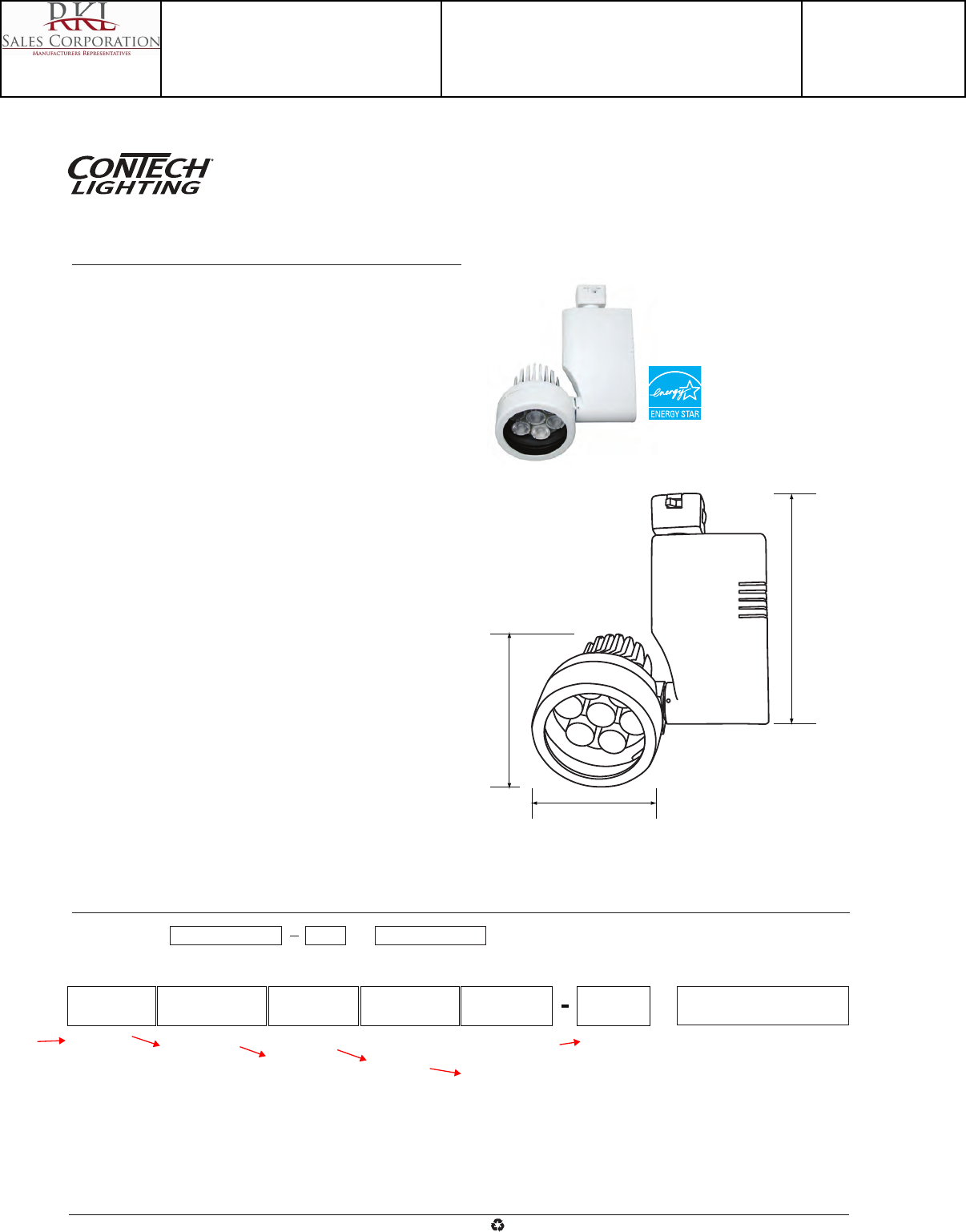
Example Order: CTL802818LS3D P LF18-UV
Dimming Option
No Dimming,
Leave Blank
D - Dimming
3-1/2"
7-1/2"
4-1/4"
Fixture
802818L
Beam Distribution
S - Spot
M - Medium
F - Flood
Color Temperature
27 - 2700K
3 - 3000K
35 - 3500K
Finish
B - Black
P - White
S - Silver
Accessories
LA-35 - Black Honeycomb Louver
LA-44-(B,P,S) - Egg Crate Louver
LF18 - A, B, CL, G, LB, R, RO,
Y, 73, LS, SL, UV
3-1/16" Dia. Tempered
Glass Lenses
Color/Pattern Legend
-A (Amber), -B (Blue), -CL (Clear),
-G (Green), -LB (Light Blue), -R (Red),
-RO (Rose),
-Y (Yellow), -73 (Spread Lens),
-LS (Linear Spread Lens), -SL (Soft Light),
-UV (Optivex UV Filter)
Ordering Information
Specifications/Features
Fixture
Low wattage, eco-friendly, LED track fixture provides high lumen output.
Select from spot, medium and flood beam distributions. Dimming option allows
illumination down to 10%.
Die cast aluminum housing with vertical driver.
Lockable, precision aiming adjustment. 350°+ Horizontal rotation, 180°
vertical rotation.
Integral ON/OFF switch and track polarity indicator are standard.
Will accept (1) LF18 lens.
Lamp
(7) LEDs, 700mA constant current input; 18W total.
Color Temperature: 2700K (2725 ± 145)
3000K (3045 ± 175)
3500K (3465 ± 245)
Electrical
Driver: 120V primary and 700mA secondary, 60Hz.
Input current: 0.20A max
Warranty
This complete fixture is covered by ConTech’s full five (5) year replacement
guarantee after date of purchase.
Listing
cCSAus Certified to UL standards. Suitable for dry locations.
Energy Star qualified for 3000K and 3500K color temperatures.
Fixture Compatibility
Standard ConTech track fixtures are UL Listed as-is for use with ConTech’s
many track systems, as well as with Juno®¹ Lighting track. By changing the
prefix in the part number, ConTech can install inserts which make our fixtures
compatible with other manufacturers. Replace “CTL” with “HTL” for Halo®²
track, “LTL” for Lightolier®³ track, and “PTL” for Capri®4 track. For more
information, please consult our factory.
Catalog No.
Type
Project
CTL802818L
Optica Series
18W Dimmable LED Track Fixture
1. Juno is a registered trademark of Juno Lighting
2. Halo is a registered trademark of Cooper Lighting
3. Lightolier is a registered trademark of Philips Lighting
4. Capri is a registered trademark of Philips Lighting
www.contechlighting.com1-847-559-5500 All specifications subject to change without notice.
Recycle
Please
Track System
CTL - Con-Tech
HTL - Halo
LT L - Lightolier
PTL - Capri
Catalog Number
CTL802818LM3D-B
Notes
Type
E
Project 15-18720-6
Teen Center - Los Alamos
Submitted By
RKL SALES CORP
Catalog No.
Type
Project
Intensity Distribution
BEAM
DISTANCE FOOTCANDLES DIAMETER
(FT.) (FC) (FT.)
6' 705.9 1.2
8' 397.1 1.6
10' 254.1 2.0
12' 176.5 2.4
14' 129.7 2.8
16' 99.3 3.2
Beam Distribution: 11°
Spacing Criterion: 0.19
CTL802818LS3 Designed for 50,000 Hour Lamp Life*; LM-63Test No. 81023
Candlepower Summary
FROM 0 CANDELA LUMENS
0 25413
5 15247 979
15 695 216
25 59 31
35 25 17
45 12 10
55 6 6
65 2 2
75 1 1
85 0 0
95 0
Light Output (Fixture Lumens): 1061
Total Watts@120V: 17
Lumens Per Watt: 75
Color Rendering Index (CRI)¹: 83
Color Temperature (CCT)²: 3003K Warm White
Spectral Power Distribution Chart³
LM-79 Test No. 81024
090°
15°0° 30°
45°
17000
8500
25500
75°
60°
Candela Curve
Wavelength (nm)
380 410 440 470 500 530 560 590 620 650 680 710 740 770
30
15
0
Designed for 50,000 Hour Lamp Life*; LM-63Test No. 80829
CTL802818LF3
Intensity Distribution
BEAM
DISTANCE FOOTCANDLES DIAMETER
(FT.) (FC) (FT.)
6' 68.8 3.4
8' 38.7 4.6
10' 24.8 5.7
12' 17.2 6.9
14' 12.6 8.0
16' 9.7 9.2
Beam Distribution: 35°
Spacing Criterion: 0.57
Candlepower Summary
FROM 0 CANDELA LUMENS
0 2476
5 2328 211
15 1492 409
25 623 291
35 194 128
45 62 50
55 22 20
65 6 6
75 2 2
85 2 2
95 0
Light Output (Fixture Lumens): 1120
Total Watts@120V: 17.5
Lumens Per Watt: 64
Color Rendering Index (CRI)¹: 82
Color Temperature (CCT)²: 2997K Warm White
Spectral Power Distribution Chart³
LM-79 Test No. 80841
090°
15°0° 30°
45°
1700
850
2550
75°
60°
Candela Curve
Wavelength (nm)
380 410 440 470 500 530 560 590 620 650 680 710 740 770
30
15
0
Designed for 50,000 Hour Lamp Life*; LM-63Test No. 80828
CTL802818LM3
Intensity Distribution
BEAM
DISTANCE FOOTCANDLES DIAMETER
(FT.) (FC) (FT.)
6' 151.4 2.5
8' 85.2 3.4
10' 54.5 4.2
12' 37.9 5.1
14' 27.8 5.9
16' 21.3 6.8
Beam Distribution: 25°
Spacing Criterion: 0.42
Candlepower Summary
FROM 0 CANDELA LUMENS
0 5452
5 4862 420
15 2099 574
25 454 227
35 82 58
45 29 23
55 13 12
65 3 3
75 1 1
85 1 1
95 0
Light Output (Fixture Lumens): 1319
Total Watts@120V: 17
Lumens Per Watt: 78
Color Rendering Index (CRI)¹: 82
Color Temperature (CCT)²: 3022K Warm White
Spectral Power Distribution Chart³
LM-79 Test No. 80840
090°
15°0° 30°
45°
3700
1850
5500
75°
60°
Candela Curve
Wavelength (nm)
380 410 440 470 500 530 560 590 620 650 680 710 740 770
30
15
0
www.contechlighting.com1-847-559-5500 All specifications subject to change without notice.
Recycle
Please
*Dependent on surrounding temperatures
1. Accuracy of rendering colors
2. Color appearance of light source
3. Colors present within the light source
CTL802818L
Optica Series
18W Dimmable LED Track Fixture
Photometrics
Catalog Number
CTL802818LM3D-B
Notes
Type
E
Project 15-18720-6
Teen Center - Los Alamos
Submitted By
RKL SALES CORP
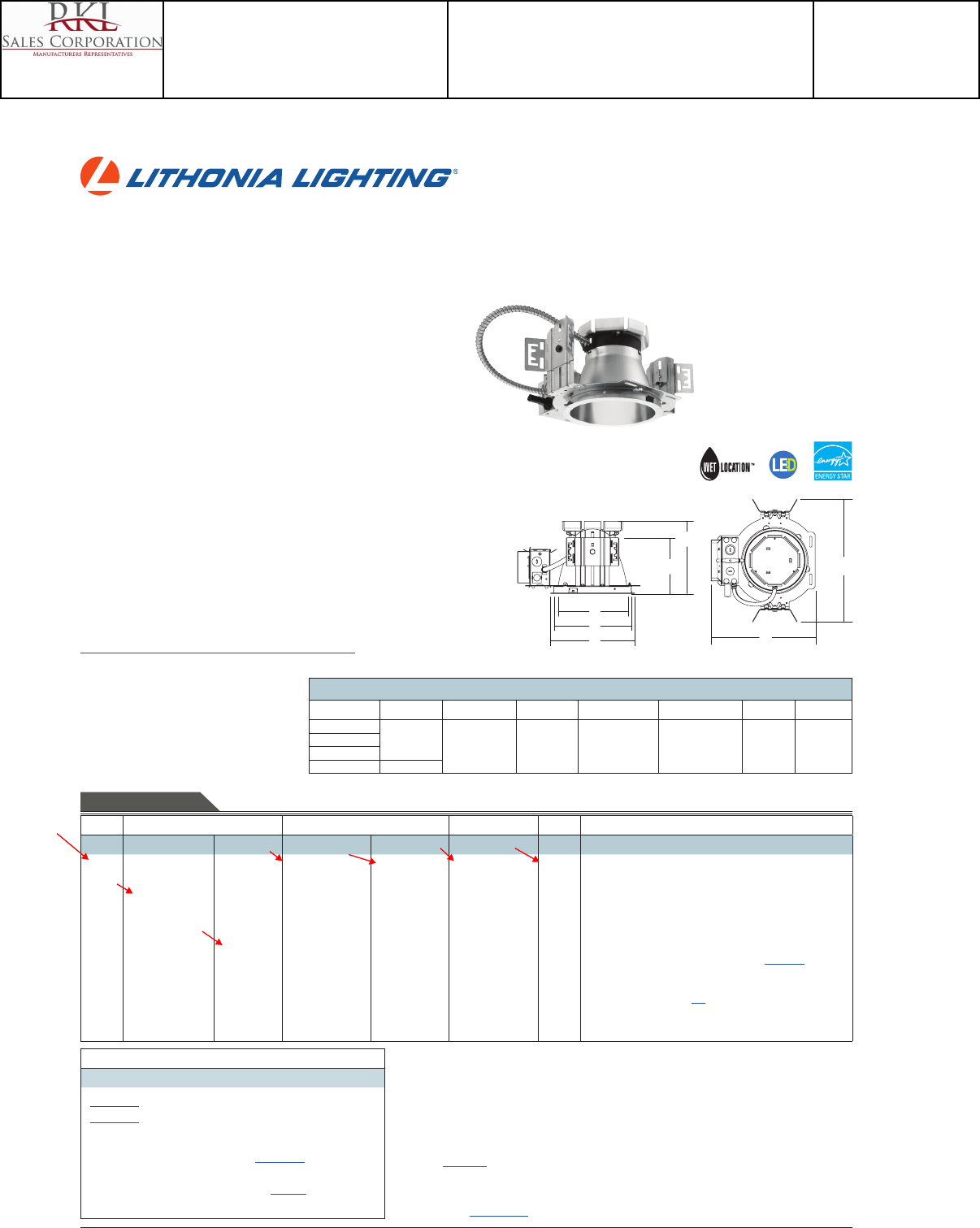
LDN6
6” OPEN and WALLWASH LED
Non-IC
New Construction Downlight
FEATURES & SPECIFICATIONS
INTENDED USE — Typical applications include corridors, lobbies, conference rooms and private oces.
CONSTRUCTION — 16-gauge galvanized steel mounting/plaster frame with trim clips to mount open
conical shape reector.
Vertically adjustable mounting brackets that use 16-gauge at bar hangers (included), 1/2” conduit or
C channel T-bar fasteners. Provides 3-3/4” total adjustment.
Post installation adjustment possible from above or below the ceiling.
Galvanized steel junction box with bottom-hinged access covers and spring latches. Two combination
1/2”-3/4” and three 1/2” knockouts for straight-through conduit runs. Capacity: 8 (4 in, 4 out) No. 12
AWG conductors, rated for 90°C.
Secondary housing adjustment system for precise, nal ceiling-to-ange alignment.
Maximum 1-1/2” ceiling thickness.
OPTICS — LED light source with di used lens, recessed in a deep reec tor with a 55-degree c uto. Alumi-
num full reectors are optically designed to maximize lumen output and to provide superior glare control.
Anodized trim colors for open and wallwash reectors are available in clear, pewter, wheat or gold. White
polyester powder coat also available.
Minimum CRI of 80.
ELECTRICAL — High-eciency, 0-10V dimming driver mounted to the junction box, dims luminaire to
10% of its light output. 1% dimming option available in 1500 and 2000 lumen packages only.
Dimming xture requires two (2) additional low-voltage wires to be pulled.
For compatible dimmers and dimming range, refer to Dimmer Compatibility Chart on page 4.
The system maintains 70% lumen output for more than 50,000 hours.
LISTINGS — CSA certied to US and Canadian safety standards. Open downlight (LO6): Wet location
listed. Wallwash downlight (LW6): Rated for damp and dry locations only. ENERGY STAR® certied.
WARRANTY — 5-year limited warranty. Complete warranty terms located at
www.acuitybrands.com/CustomerResources/Terms_and_conditions.aspx
Note: Specications subject to change without notice.
ORDERING INFORMATION Example: LDN6 35/15 LO6AR 120
DOWNLIGHTING LDN6
Lead times will vary depending on options selected. Consult with your sales representative.
LDN6
Series Color temperature Lumens 1,2 Reector Trim color Finish Voltage Options
LDN6 27/ 2700 K
30/ 3000 K
35/ 3500 K
40/ 4000 K
06 600
lumens
10 1000
lumens
15 1500
lumens
20 2000
lumens
LO6 Open
downlight
LW6 Wallwash
downlight 3
AR Clear
PR Pewter
WTR Wheat
GR Gold
WR White 4
(blank) Semi-
specular
LD Matte-
diuse
LS Specular
120
277
347 5
EL Emergency battery pack with integral test switch 6
ELR Emergency battery pack with remote test switch 6
SF Single fuse
TRW White painted ange 7
TRBL Black painted ange
NEPP Interface for Sensor Switch® nLight® network provided
with integral power supply. Refer to TN-623-01. 8
RRL__ RELOC®-ready luminaire connectors enables a simple and
consistent factory installed option across all ABL luminaire
brands. Refer to RRL for complete nomenclature.
EZ1 eldoLED dims to 1% 9
CP Chicago plenum 5, 10
LDN6 35/15 LO6AR 120
Maximum Overall Dimensions – All dimensions are inches (centimeters) unless otherwise indicated.
Lumen package (A) Height (B) Frame height (C) Aperture (D) Ceiling opening (E) Outside diameter (F) Width (G) Length
600 lm
6-7/16 (16.4) 5-3/4
(14.6)
6-15/16
(17.6)
7-1/8
(18.1)
7-1/2
(19.1)
12-15/16
(32.8)
10-15/16
(27.8)
1000 lm
1500 lm
2000 lm 7-13/16 (19.9)
Overall height varies by lumen package. Reference dimension chart for details.
D
I
M
M
A
B
L
E
G
F
A
B
C
D
E
Accessories: Order as separate catalog number.
EAC ISSM 375 Compact interruptible emergency AC power system
EAC ISSM 125 Compact interruptible emergency AC power system
NSP5 D ER KIT Sensor Switch nLight secondary relay and dimming pack
device used to switch and dim luminaires powered via an
emergency circuit. Refer to NSP5 D ER KIT.
GRA68 JZ Oversized trim ring with 8” outside diameter 11
SCA6 Sloped ceiling adapter. Refer to TECH-SCA for more options.
Notes
1 Approximate lumen output.
2 Overall height varies by lumen package. Reference dimension chart on page 1.
3 Rated for damp and dry locations only.
4 Not available with nishes.
5 Not available with emergency options.
6 For dimensional changes, refer to chart on page 4. Not available with CP option.
7 Not available with WR (white trim color).
8 For emergency generator/inverter applications order non-nLight enabled xture and NSP5 D ER KIT as an accessory. Refer to
NSP5 D ER KIT.
9 Only available with 1500 and 2000 lumen packages.
10 277 volt CP products require marked spacing. Install with minimal spacing between: (a) Center-to-center of adjacent lumi-
naires: 2 ft.; (b) Top of luminaire to overhead building member: 3 in.; (c) Luminaire center to side of building member: 1 ft.
11 Refer to TECH-GOOF RINGS for more options.
Catalog
Number
Notes
Type
Catalog Number
LDN6 35/20 LO6AR 120
Notes
Type
F
Project 15-18720-6
Teen Center - Los Alamos
Submitted By
RKL SALES CORP

LDN6
DOWNLIGHTING: One Lithonia Way Conyers, GA 30012 Phone: 800-315-4935 Fax: 770-860-3129 www.lithonia.com © 2014 Acuity Brands Lighting, Inc. All rights reserved. Rev. 05/29/14
LDN6
LDN6 35/10 LO6AR 120, input watts: 18, delivered lumens: 1089, LM/W = 61, spacing criterion at 0 = 1.03, test no. LTL25148SL.
LDN6 35/15 LO6AR 120, input watts: 26, delivered lumens: 1633, LM/W = 63, spacing criterion at 0 = 1.03, test no. LTL25146.
0° 20°
40°
60°
80°
600
1200
Ave Lumens
0
5
15
25
35
45
55
65
75
85
90
1564
1539
1449
1196
678
131
7
2
2
0
0
145
407
542
411
115
10
2
1
0
Zone Lumens % Lamp
0° - 30°
0° - 40°
0° - 60°
0° - 90°
90° - 180°
0° - 180°
1094.3
1505.0
1629.6
1633.3
0.0
1633.3
67.0
92.1
99.8
100.0
0.0
*100.0
*Efficiency
%02fp
pc 80% 70% 50%
pw 50% 30% 10% 50% 30% 10% 50% 30% 10%
0
1
2
3
4
5
6
7
8
9
10
119
111
103
95
89
83
78
73
68
64
60
119
108
99
90
83
77
71
66
62
58
54
119
106
95
86
79
73
67
62
58
54
50
116
108
101
94
88
82
77
72
68
64
60
116
106
97
89
83
76
71
66
62
58
54
116
104
94
86
78
72
67
62
58
54
50
111
104
98
91
86
80
75
71
66
63
59
111
103
95
88
81
75
70
65
61
57
54
111
101
92
84
78
72
66
62
57
54
50
RCR
50% beam -
53.9°
10% beam -
79.9°
Mounting
Height
Inital FC
Center
Beam Diameter FC DiameterFC
8.0
10.0
12.0
14.0
16.0
51.7
27.8
17.3
11.8
8.6
5.6
7.6
9.7
11.7
13.7
25.8
13.9
8.7
5.9
4.3
9.2
12.6
15.9
19.3
22.6
5.2
2.8
1.7
1.2
0.9
0° 20°
40°
60°
80°
40
0
80
0
Ave Lumens
0
5
15
25
35
45
55
65
75
85
90
1048
1028
968
797
452
87
4
2
1
0
0
97
272
361
273
76
6
2
0
0
Zone Lumens % Lamp
0° - 30°
0° - 40°
0° - 60°
0° - 90°
90° - 180°
0° - 180°
730.5
1004.0
1086.4
1088.8
0.0
1088.8
67.1
92.2
99.8
100.0
0.0
*100.0
*Efficiency
%02fp
pc 80% 70% 50%
pw 50% 30% 10% 50% 30% 10% 50% 30% 10%
0
1
2
3
4
5
6
7
8
9
10
119
111
103
96
89
83
78
73
68
64
60
119
108
99
90
83
77
71
67
62
58
54
119
106
95
86
79
73
67
62
58
54
51
116
108
101
94
88
82
77
72
68
64
60
116
106
97
89
83
76
71
66
62
58
54
116
104
94
86
79
72
67
62
58
54
50
111
104
98
91
86
80
75
71
67
63
59
111
103
95
88
81
75
70
65
61
57
54
111
101
92
84
78
72
66
62
57
54
50
RCR
50% beam -
53.7°
10% beam -
79.9°
Mounting
Height
Inital FC
Center
Beam Diameter FC DiameterFC
8.0
10.0
12.0
14.0
16.0
34.6
18.6
11.6
7.9
5.8
5.6
7.6
9.6
11.7
13.7
17.3
9.3
5.8
4.0
2.9
9.2
12.6
15.9
19.3
22.6
3.5
1.9
1.2
0.8
0.6
Notes
• Tested in accordance with IESNA LM-79-08.
• Tested to current IES and NEMA standards under stabilized laboratory conditions.
• Actual performance may dier as a result of end-user environment and application.
• Actual wattage may dier by +/- 10% when operating between 120-277V +/- 10%.
• CRI: 80 typical.
LDN6 35/20 LO6AR 120, input watts: 35, delivered lumens: 2143, LM/W = 61, spacing criterion at 0 = 1.04, test no. LTL25144.
0° 20°
40°
60°
80°
800
1600
Ave Lumens
0
5
15
25
35
45
55
65
75
85
90
2046
2014
1899
1569
892
171
9
3
2
1
0
190
534
711
540
150
12
3
2
1
Zone Lumens % Lamp
0° - 30°
0° - 40°
0° - 60°
0° - 90°
90° - 180°
0° - 180°
1435.1
1975.3
2137.5
2142.7
0.0
2142.7
67.0
92.2
99.8
100.0
0.0
*100.0
*Efficiency
%02fp
pc 80% 70% 50%
pw 50% 30% 10% 50% 30% 10% 50% 30% 10%
0
1
2
3
4
5
6
7
8
9
10
119
111
103
95
89
83
78
73
68
64
60
119
108
99
90
83
77
71
66
62
58
54
119
106
95
86
79
73
67
62
58
54
50
116
108
101
94
88
82
77
72
68
64
60
116
106
97
89
83
76
71
66
62
58
54
116
104
94
86
78
72
67
62
58
54
50
111
104
98
91
86
80
75
71
66
63
59
111
103
95
88
81
75
70
65
61
57
54
111
101
92
84
78
72
66
62
57
54
50
RCR
50% beam -
54.0°
10% beam -
80.0°
Mounting
Height
Inital FC
Center
BeamDiameter FC DiameterFC
8.0
10.0
12.0
14.0
16.0
67.6
36.4
22.7
15.5
11.2
5.6
7.6
9.7
11.7
13.8
33.8
18.2
11.3
7.7
5.6
9.2
12.6
15.9
19.3
22.6
6.8
3.6
2.3
1.5
1.1
PHOTOMETRY
Distribution Curve Distribution Data Output Data Coecient of Utilization Illuminance Data at 30” Above Floor for
a Single Luminaire
Catalog Number
LDN6 35/20 LO6AR 120
Notes
Type
F
Project 15-18720-6
Teen Center - Los Alamos
Submitted By
RKL SALES CORP
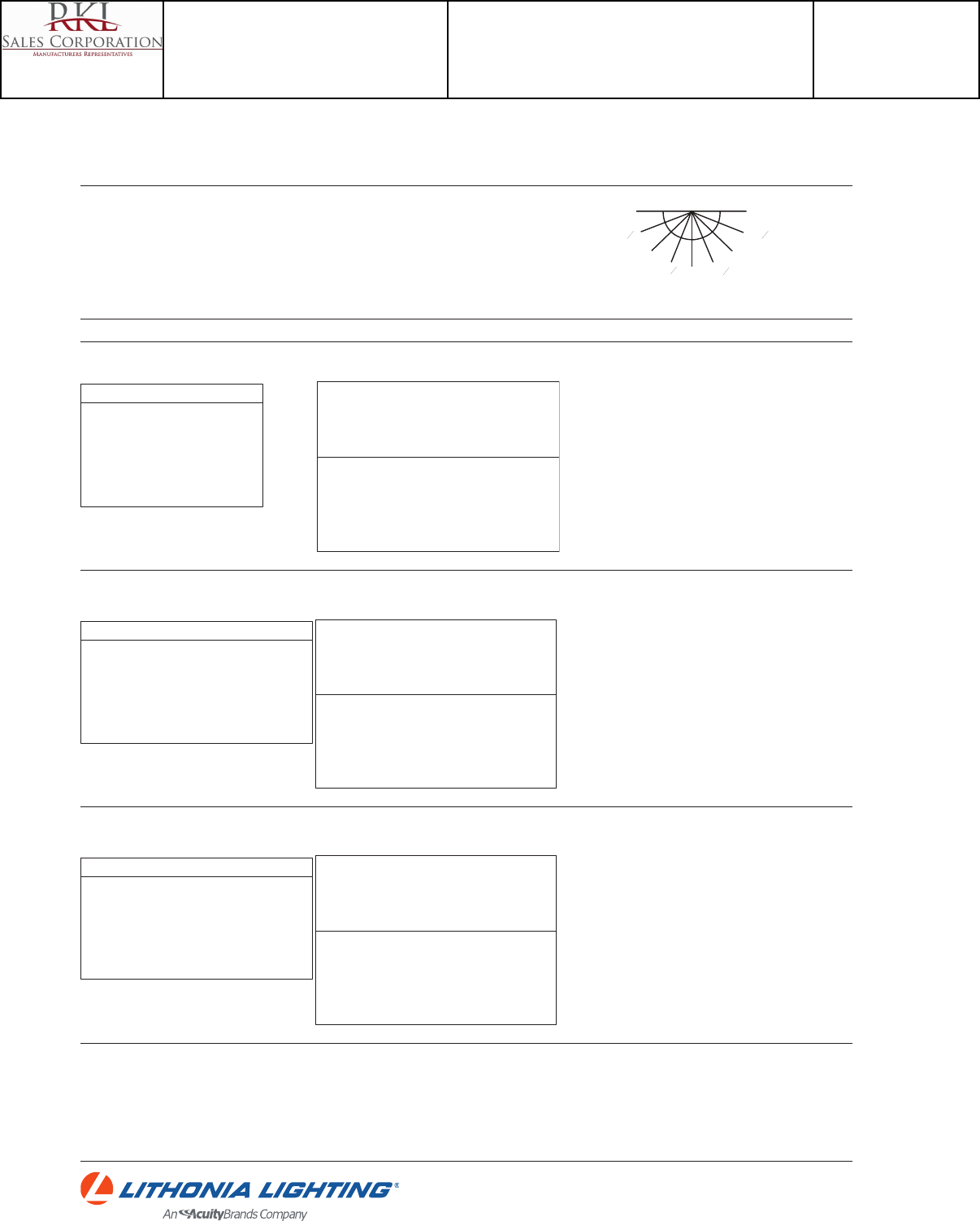
LDN6
LDN6
DOWNLIGHTING: One Lithonia Way Conyers, GA 30012 Phone: 800-315-4935 Fax: 770-860-3129 www.lithonia.com © 2014 Acuity Brands Lighting, Inc. All rights reserved. Rev. 05/29/14
Candlepower Data Footcandle values
LDN6 35/10 LW6AR 120, input watts: 18, delivered lumens: 1090, LM/W = 61, test no. LTL25147.
LDN6 35/15 LW6AR 120, input watts: 26, delivered lumens: 1639, LM/W = 63, test no. LTL25145.
Wallwash Illuminance Study (fc)
Illuminance on wall from 6 luminaires
Luminaire
mounted 3 ft.
from wall
Luminaire
mounted 3 ft.
from wall
Luminaire
mounted 3 ft.
from wall
3 ft. between
luminaires
4 ft. between
luminaires
5 ft. between
luminaires
ft. from ceiling33.54 33.5 433.54
1
2
3
4
5
6
7
8
9
10
17
24
22
20
18
17
15
13
11
9
13
24
22
21
19
17
15
13
11
9
17
24
22
20
18
17
15
13
11
9
16
20
17
14
13
12
11
10
8
7
7
16
16
16
15
13
11
10
8
7
16
20
17
14
13
12
11
10
8
7
15
19
15
12
10
9
9
8
7
6
4
10
11
12
12
11
9
8
7
6
15
19
15
12
10
9
9
8
7
6
Plane angle
Wall22.545 67.5 90 112.5135 157.5
0
5
15
25
35
45
55
65
75
85
90
1312
1198
956
697
442
348
283
230
121
30
5
1312
1187
976
720
482
336
269
191
88
18
6
1312
1202
1052
837
548
303
196
102
30
1
0
1312
1244
1153
953
586
222
80
22
1
1
2
1312
1285
1246
1028
583
132
19
3
1
0
1
1312
1326
1333
1082
590
105
8
2
1
0
1
1312
1371
1403
1109
612
112
10
3
1
0
1
1312
1409
1438
1126
623
115
11
6
4
0
0
Vertical Angle
Wallwash Illuminance Study (fc)
Illuminance on wall from 6 luminaires
Luminaire
mounted 3 ft.
from wall
Luminaire
mounted 3 ft.
from wall
Luminaire
mounted 3 ft.
from wall
3 ft. between
luminaires
4 ft. between
luminaires
5 ft. between
luminaires
ft. from ceiling33.54 33.5 433.54
1
2
3
4
5
6
7
8
9
10
10
15
15
13
12
12
10
9
8
6
8
15
14
14
13
12
10
9
8
6
10
15
15
13
12
12
10
9
8
6
9
13
12
10
9
8
8
7
6
5
5
10
10
11
10
9
8
7
6
5
9
13
12
10
9
8
8
7
6
5
9
12
10
8
7
7
6
5
5
4
2
6
7
8
8
7
6
5
5
4
9
12
10
8
7
7
6
5
5
4
Plane angle
Wall 22.5 45 67.5 90 112.5135 157.5
0
5
15
25
35
45
55
65
75
85
90
888
813
652
488
319
241
181
139
74
19
5
888
811
675
524
355
229
172
117
57
13
6
888
824
728
601
387
190
114
57
19
0
0
888
854
803
678
414
139
40
11
3
0
0
888
875
862
723
409
87
9
1
2
0
0
888
902
905
748
407
76
5
2
2
0
0
888
922
930
749
409
76
7
3
3
0
0
888
926
935
741
403
74
8
4
2
0
0
Vertical Angle
Notes
• Tested in accordance with IESNA LM-79-08.
• Tested to current IES and NEMA standards under stabilized laboratory conditions.
• Actual performance may dier as a result of end-user environment and application.
• Actual wattage may dier by +/- 10% when operating between 120-277V +/- 10%.
• CRI: 80 typical.
LDN6 35/20 LW6AR 120, input watts: 35, delivered lumens: 2137, LM/W = 61, test no. LTL25143.
Wallwash Illuminance Study (fc)
Illuminance on wall from 6 luminaires
Luminaire
mounted 3 ft.
from wall
Luminaire
mounted 3 ft.
from wall
Luminaire
mounted 3 ft.
from wall
3 ft. between
luminaires
4 ft. between
luminaires
5 ft. between
luminaires
ft. from ceiling33.54 33.5 433.54
1
2
3
4
5
6
7
8
9
10
17
28
28
26
24
22
20
17
15
13
13
27
27
27
25
22
20
17
15
13
17
28
28
26
24
22
20
17
15
12
16
23
22
19
17
16
15
13
11
10
7
18
19
20
20
17
15
13
11
10
16
23
22
19
17
16
15
13
11
10
16
22
19
16
13
12
11
10
9
8
4
11
14
15
16
15
13
11
9
8
16
22
19
16
13
12
11
10
9
8
Plane angle
Wall22.545 67.5 90 112.5135 157.5
0
5
15
25
35
45
55
65
75
85
90
1712
1566
1254
913
592
446
335
251
121
24
1
1712
1544
1276
956
654
425
317
213
92
14
1
1712
1598
1394
1140
766
402
248
129
39
2
1
1712
1633
1533
1307
839
325
115
35
4
0
0
1712
1710
1658
1420
851
215
32
5
1
1
1
1712
1739
1755
1489
852
170
13
4
1
0
1
1712
1783
1811
1512
855
167
12
5
1
0
1
1712
1806
1834
1521
861
167
14
5
3
0
0
Vertical Angle
room
wall
90
0
112
0
12
135
0
157
0
12
67
0
12
45
0
22
0
12
TECHNICAL INFORMATION
Footcandle values are initial and tables are based on minimum of six units. For xture-to-wall distance
other than those shown, use maximum of one-to-one spacing (distance between xtures not more than
distance to wall) for best results.
Catalog Number
LDN6 35/20 LO6AR 120
Notes
Type
F
Project 15-18720-6
Teen Center - Los Alamos
Submitted By
RKL SALES CORP
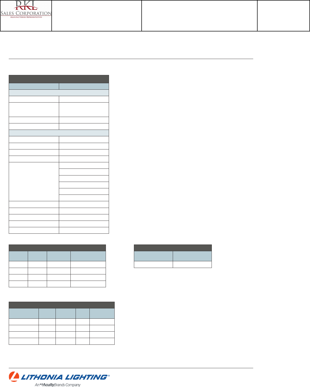
LDN6
DOWNLIGHTING: One Lithonia Way Conyers, GA 30012 Phone: 800-315-4935 Fax: 770-860-3129 www.lithonia.com © 2014 Acuity Brands Lighting, Inc. All rights reserved. Rev. 05/29/14
LDN6
DIMMER COMPATIBILITY CHART
Manufacturer Model/Series
600 & 1000 Lumen products
Leviton IllumaTech - IP710-DLX
Lutron
Nova T - NTFTV-WH
For on/o control, this switch requires a power
pack. Consult Lutron for more information.
Sensor Switch nPODM
Synergy ISD BC 120/277
1500 & 2000 Lumen products
Busch-Jaeger 2112U-101
Jung 240-10
Leviton Lighting Controls IllumaTech - IP710-DLX
Lightolier Controls ZP600FAM120
Lutron Electronics
Nova T - NTFTV
Diva - DVTV
Diva - NFTV
GraphicEye - GRX-TVI w GRX3503
Energy Savr Node - QSN-4T16-S
TVM2 Module
Merten 5729
Pass & Seymour CD4FB-W
Sensor Switch nPODM
Synergy ISD BC 120/277
The Watt Stopper DCLV1
ADDITIONAL DATA
EL/ELR DIMENSIONAL CHANGES
Add to overall housing
length for EL/ELR option
Overall housing width
with EL/ELR option
4-1/2 16-1/2
EL/ELR AVAILABILITY/COMPATIBILITY INITIAL LUMENS
Lumen
package Watts
Initial lumens
EL/ELR Emergency LED driver
600 12 500 PS1030
1000 18 575 PS1030
1500 26 640 Bodine BSL17C-C2
2000 35 690 Bodine BSL17C-C2
KEY SPECIFICATION SUMMARY
Product Description Watts (W)
Delivered
lumens (lm)
Ecacy
(lm/W)
Spacing criteria
(s/mh)
LDN6 35/06 LO6AR 12 670 56 1.03
LDN6 35/10 LO6AR 18 1090 61 1.03
LDN6 35/15 LO6AR 26 1640 63 1.03
LDN6 35/20 LO6AR 35 2140 61 1.04
Catalog Number
LDN6 35/20 LO6AR 120
Notes
Type
F
Project 15-18720-6
Teen Center - Los Alamos
Submitted By
RKL SALES CORP

5-5/8"
O.D.
4-3/8"
I.D.
Height: 3-1/8"
Specification Grade Specular Reflector
Specification grade specular reflector: narrow beam
clear, medium beam clear, wide beam clear,
platinum, or white. OD: 5-5/8"; ID: 4-3/8"
Approved for use in U.S. and Canada. Add "−C"
after finish code for wet location approved trim.
CST4322LN-CLR - Narrow Beam, Clear Reflector
CST4322LM-CLR - Medium Beam, Clear Reflector
CST4322LW-CLR - Wide Beam, Clear Reflector
CST4322L-PL - Platinum Reflector
CST4322L-WHT - White Reflector
Catalog No.
Type
Project
RA4L
4" LED Recessed Downlight Trims
Finishes: -B (black baffle), -CLR (clear reflector), -P (white baffle), -PL (matte platinum), -WHT (white reflector)
Acrylic Ring Finishes: -B (blue), -F (frosted), -G (green), -R (red), -Y (yellow)
5-5/8"
O.D.
4-3/8"
I.D.
Height: 3-1/8"
Two Piece Reflector/Baffle Trim
Two piece reflector: clear or white upper reflector,
black or white lower baffle; Includes (1) LF20-CL
glass lens. OD: 5-5/8"; ID: 3-1/2"
Approved for use in U.S. and Canada when glass
lens is installed (in dry or wet locations).
CTR4321L-CLR-(B,P) - Clear Reflector
CTR4321L-WHT-P-(B,P) - White Reflector
5-1/2"
O.D.
4"
I.D.
Lensed Wall Wash Trim
Lensed Wall Wash Trim; Clear, Platinum or White
Reflector. OD: 5-1/2"; ID: 4"
Approved for use in U.S. and Canada.
CTR4323L-CLR - Clear Reflector
CTR4323L-PL - Platinum Reflector
CTR4323L-WHT - White Reflector
5-5/8"
O.D.
4-3/8"
I.D.
Height: 3-1/8"
Two Piece Reflector Trim
Two piece reflector: clear or white upper reflector,
clear or platinum lower cone; Includes (1) LF20-CL
glass lens. OD: 5-5/8"; ID: 3-1/2"
Approved for use in U.S. and Canada when glass
lens is installed (in dry or wet locations).
CTR4321L-CLR-(CLR,PL) - Clear Reflector
CTR4321L-WHT-(CLR,PL) - White Reflector
Floating Glass Trim
Floating glass disc; clear or white reflector. 1-1/4"
Drop from ceiling. Glass OD: 6-1/16".
Approved for use in U.S. and Canada.
CTR4325L-(CLR,WHT)-P
5-5/8"
O.D.
4-3/8"
I.D.
Height: 3-1/8"
5-5/8"
O.D.
4-3/8"
I.D.
Height: 3-1/8"
Two Piece Reflector Trim with Lens
Two piece reflector with lens: Clear or white
upper reflector, clear or platinum lower cone;
regressed prismatic convex lens, Wet Location
Listed. OD: 5-5/8"; ID: 3-7/8"
Approved for use in U.S. and Canada.
CTR4327L-CLR-(CLR,PL) - Clear Reflector
CTR4327L-WHT-(CLR,PL) - White Reflector
5-5/8"
O.D.
4-3/8"
I.D.
Height: 3-1/8"
Two Piece Reflector/Baffle Trim
with Lens
Two piece reflector with lens: Clear or white upper
reflector, black or white lower baffle with regressed
prismatic convex glass lens; 1-1/2" Regress. Wet
Location Listed. OD: 5-5/8"; ID: 3-7/8"
Approved for use in U.S. and Canada.
CTR4327L-CLR-(B,P) - Clear Reflector
CTR4327L-WHT-P-(B,P) - White Reflector
Floating Glass Ring
Floating glass ring; clear or white reflector.
1-1/4" Drop from ceiling; 3-1/2" center hole.
Glass OD: 6-1/16".
Approved for use in U.S. and Canada.
CTR4326L-(CLR,WHT)-P
5-5/8"
O.D.
4-3/8"
I.D.
Height: 3-1/8"
5-5/8"
O.D.
4-3/8"
I.D.
Floating Double Acrylic Ring
Stacked floating colored acrylic rings; clear or
white reflector. 2-3/4" Drop from ceiling. Acrylic
Ring OD: 6-7/8"; ID: 4-3/8".
Approved for use in U.S. and Canada.
CTR4324L-(CLR,WHT)-P
2AR4(B,F,G,R,Y)
Floating Single Acrylic Ring
Single floating colored acrylic ring; clear or white
reflector. 1-1/2" Drop from ceiling. Acrylic Ring
OD: 6-7/8"; ID: 4-3/8".
Approved for use in U.S. and Canada.
CTR4324L-(CLR,WHT)-P
1AR4(B,F,G,R,Y)
5-5/8"
O.D.
4-3/8"
I.D.
www.contechlighting.com1-847-559-5500 Recycle
Please All specifications subject to change without notice.
Catalog Number
CTR4321L-CLR-B
Notes
Type
H
Project 15-18720-6
Teen Center - Los Alamos
Submitted By
RKL SALES CORP
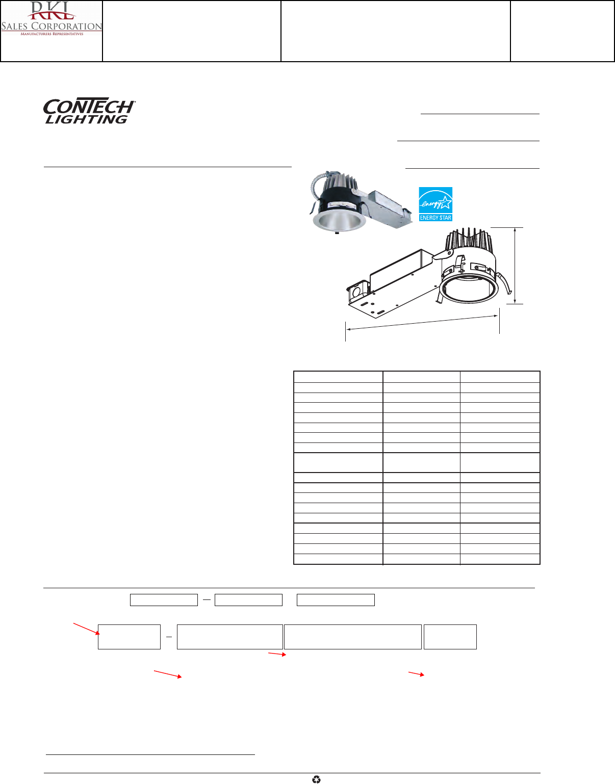
Ceiling Opening: 4-7/8"
Ceiling Thickness: 1/2" – 5/8"
Specifications/Features
Housing/Mounting
Specification grade 4" remodel housing, 5-1/4" O.D. plaster ring flange.
4-7/8" Ceiling opening. Works in ceiling thicknesses from 1/2" – 2".
16 Gauge galvanized steel housing with die-cast aluminum heat sink.
Requires minimum 3" clearance around fixture from insulation material.
Thermal protection provided in case of improper insulation use.
Heavy duty steel plaster ring is secured to ceiling by three (3) spring clamps.
LED drivers are fully accessible from below the ceiling, and with the spring-
latch housing attachment, can be easily removed.
Quick-connect LED light engine enables easy installation and removal.
Electrical
UL8750 and Class 2 Compliant; RoHS Compliant, US only.
Output over voltage, over-current and short circuit protection.
Approved for through-circuit wiring. Max.: (4) 12 AWG (2in/2out).
Pre-wired junction box with convenient screwdriver pry-outs. (4) 1/2"
concentric knockouts.
Lamp
Light engine consists of a high output multi-chip LED array arranged into a
single LED package, enabling precise optical control without requiring lensing
to diffuse multiple LED sources.
Excellent fixture-to-fixture color consistency within a 3-step MacAdam Ellipse
tolerance.
Dimming
All RA4LRM downlights are available for non-dimming and dimming applications.
For non-dimming applications, use driver option D2.
Trims
Specification Grade trims are available in several different styles and finishes
for your space. Featuring a high quality Alzak™ finish; optically designed for
reduced glare while maintaining maximum lumen output. See “4" LED
Recessed Trims” spec sheet for information and details.
Warranty
This complete fixture is covered by Con-Tech’s full five (5) year replacement
guarantee after date of purchase.
Labels/Usage
CSAus Certified to UL Standards. Suitable for damp locations.
CSA Certified to UL Standards. Refer to trim spec sheet for Canada compliant
trims.
Energy Star approved when used with CST4322L-CLR (all beam distributions)
and CST4322L-PL trims. Not approved for 4000K options.
Assembled in the USA.
Catalog No.
Type
Project
RA4LRM
4" LED Recessed Downlight:
Remodel Housing
17-1/2"
6"
Electrical/Dimming
12D1 - 120V Triac Dimming
12D2 - 120V Non-Dimming/0-10V Dimming
12D3 - 120V Lutron HiLume® Dimming
27D2 - 277V Non-Dimming/0-10V Dimming
Housing
RA4LRM
LED Module/Color Temp
1000 Series
127K - 16W/2700K
130K - 16W/3000K
135K - 16W/3500K
140K - 16W/4000K
2000 Series
227K - 29W/2700K
230K - 29W/3000K
235K - 29W/3500K
240K - 29W/4000K
Consult factory for high CRI options
Trim Type
* - All Others
Leave Blank
W - Wall Wash
Example Order: RA4LRM 130K12D2 CST4322LN-CLR
Ordering Information
*Trims
See “4" LED Recessed Trims” sheet for trim information and details.
www.contechlighting.com1-847-559-5500 Recycle
Please All specifications subject to change without notice.
1000 Series 2000 Series
Input Voltage
Non-dimming 90-305V AC, 47-63Hz 90-305V AC, 47-63Hz
0-10V dimming 90-305V AC, 47-63Hz 90-305V AC, 47-63Hz
Triac dimming 90-135V AC, 47-63Hz Not Available
Lutron HiLume® Dimming 120V AC, 50/60Hz 120V AC, 50/60Hz
Input Wattage 16 29
Output Current (mA) 350 700
Color Temp 2700K/3000K 2700K/3000K
3500K/4000K 3500K/4000K
CRI: Standard 83 (80min) 83 (80min)
Driver
Power Factor > 0.90 > 0.90
THD < 20% < 20%
Dimming
0-10V 15-100% 15-100%
Triac 10-100% Not Available
Lutron HiLume® 1-100% 1-100%
Emrgncy Batt. Backup
Not Available Not Available
RA4LRM
Catalog Number
RA4LRM-135K12D1W
Notes
Type
H
Project 15-18720-6
Teen Center - Los Alamos
Submitted By
RKL SALES CORP

Photometrics
Catalog No.
Type
Project
www.con-techlighting.com1-847-559-5500 All specifications subject to change without notice.
Recycle
Please
Wavelength (nm)
380 410 440 470 500 530 560 590 620 650 680 710 740 770
40
20
0
RA4LNC-230K12D2/CST4322L-PL Designed for 50,000 Hour Lamp Life*; LM-79 Test No. 70359
Candlepower Summary
FROM 0 CANDELA LUMENS
0 1855
5 1725 161
15 1502 428
25 1347 616
35 721 436
45 139 112
55 40 39
65 10 11
75 2 2
85 0 0
95 0
Light Output (Fixture Delivered Lumens): 1806
Total Watts@120V: 29.5
Lumens Per Watt: 61
Color Rendering Index (CRI)¹: 82
Color Temperature (CCT)²: 3080K Warm White
Spectral Power Distribution Chart³
Intensity Distribution
BEAM
DISTANCE FOOTCANDLES DIAMETER
(FT.) (FC) (FT.)
6' 51.5 6.0
8' 29.0 8.0
10' 18.5 10.0
12' 12.9 12.1
14' 9.5 14.1
16' 7.2 16.1
Beam Distribution: 68°
Spacing Criteria: 1.0
090°
15°0° 30°
45°
1300
650
1950
75°
60°
Candela Curve
Wavelength (nm)
380 410 440 470 500 530 560 590 620 650 680 710 740 770
40
20
0
RA4LNC-230K12D2/CTR4326L-CLR-P Designed for 50,000 Hour Lamp Life*; LM-63 Test No. 71563
Candlepower Summary
FROM 0 CANDELA LUMENS
0 1258
5 1280 122
15 1107 326
25 1256 587
35 628 461
45 105 84
55 53 49
65 29 29
75 14 16
85 5 6
95 5
Light Output (Fixture Delivered Lumens): 1730
Total Watts@120V: 29
Lumens Per Watt: 60
Color Rendering Index (CRI)¹: 82
Color Temperature (CCT)²: 3138K Warm White
Spectral Power Distribution Chart³
Intensity Distribution
BEAM
DISTANCE FOOTCANDLES DIAMETER
(FT.) (FC) (FT.)
6' 34.9 8.0
8' 19.7 10.6
10' 12.6 13.3
12' 8.7 15.9
14' 6.4 18.6
16' 4.9 21.2
Beam Distribution: 70°
Spacing Criteria: 1.30
090°
15°0° 30°
45°
900
450
1350
75°
60°
Candela Curve
RA4LNC-230K12D2/CTR4323L-CLR Designed for 50,000 Hour Lamp Life*; LM-79 Test No. 72139
Candlepower Summary
FROM 0 CANDELA LUMENS
0 812
5 907 76
15 931 196
25 778 239
35 479 180
45 236 99
55 131 52
65 61 24
75 16 8
85 3 3
95 0
Light Output (Fixture Delivered Lumens): 876
Total Watts@120V: 28.7
Lumens Per Watt: 31
Color Rendering Index (CRI)¹: 81
Color Temperature (CCT)²: 3168K Warm White
Spectral Power Distribution Chart³
090°
15°0° 30°
45°
700
350
1050
75°
60°
Candela Curve Footcandles on Wall
Single Unit, 3' From Wall
Distance from Ceiling
0' 1' 2' 3' 4' 5'
1' 3 2 1 0 0 0
2' 8 6 3 1 0 0
3' 9 8 4 2 1 0
4' 10 8 5 3 1 1
5' 9 8 5 3 1 1
6' 7 7 5 3 2 1
7' 6 5 4 3 2 1
8' 4 4 3 3 2 1
9' 3 3 3 2 2 1
beam center
Wavelength (nm)
380 410 440 470 500 530 560 590 620 650 680 710 740 770
40
20
0
RA4LNC-230K12D2/CST4322LW-CLR Designed for 50,000 Hour Lamp Life*; LM-79 Test No. 70358
Typical Wavelength (nm)
380 410 440 470 500 530 560 590 620 650 680 710 740 770
40
20
0
Candlepower Summary
FROM 0 CANDELA LUMENS
0 1553
5 1519 150
15 1731 489
25 1714 783
35 924 542
45 78 64
55 24 21
65 6 6
75 2 1
85 0 0
95 0
Light Output (Fixture Delivered Lumens): 2056
Total Watts@120V: 28.6
Lumens Per Watt: 72
Color Rendering Index (CRI)¹: 83
Color Temperature (CCT)²: 3079K Warm White
Spectral Power Distribution Chart³
Intensity Distribution
BEAM
DISTANCE FOOTCANDLES DIAMETER
(FT.) (FC) (FT.)
6' 43.1 7.7
8' 24.3 10.3
10' 15.5 12.9
12' 10.8 15.5
14' 7.9 18.0
16' 6.1 20.6
Beam Distribution: 72°
Spacing Criteria: 1.29
090°
15°0° 30°
45°
1200
600
1800
75°
60°
Candela Curve
RA4L
4" LED Recessed Downlight
*Dependent on surrounding temperatures
1. Accuracy of rendering colors
2. Color appearance of light source
3. Colors present within the light source For the 1000 Series/16W data, multiply results by .50
Catalog Number
RA4LRM-135K12D1W
Notes
Type
H
Project 15-18720-6
Teen Center - Los Alamos
Submitted By
RKL SALES CORP
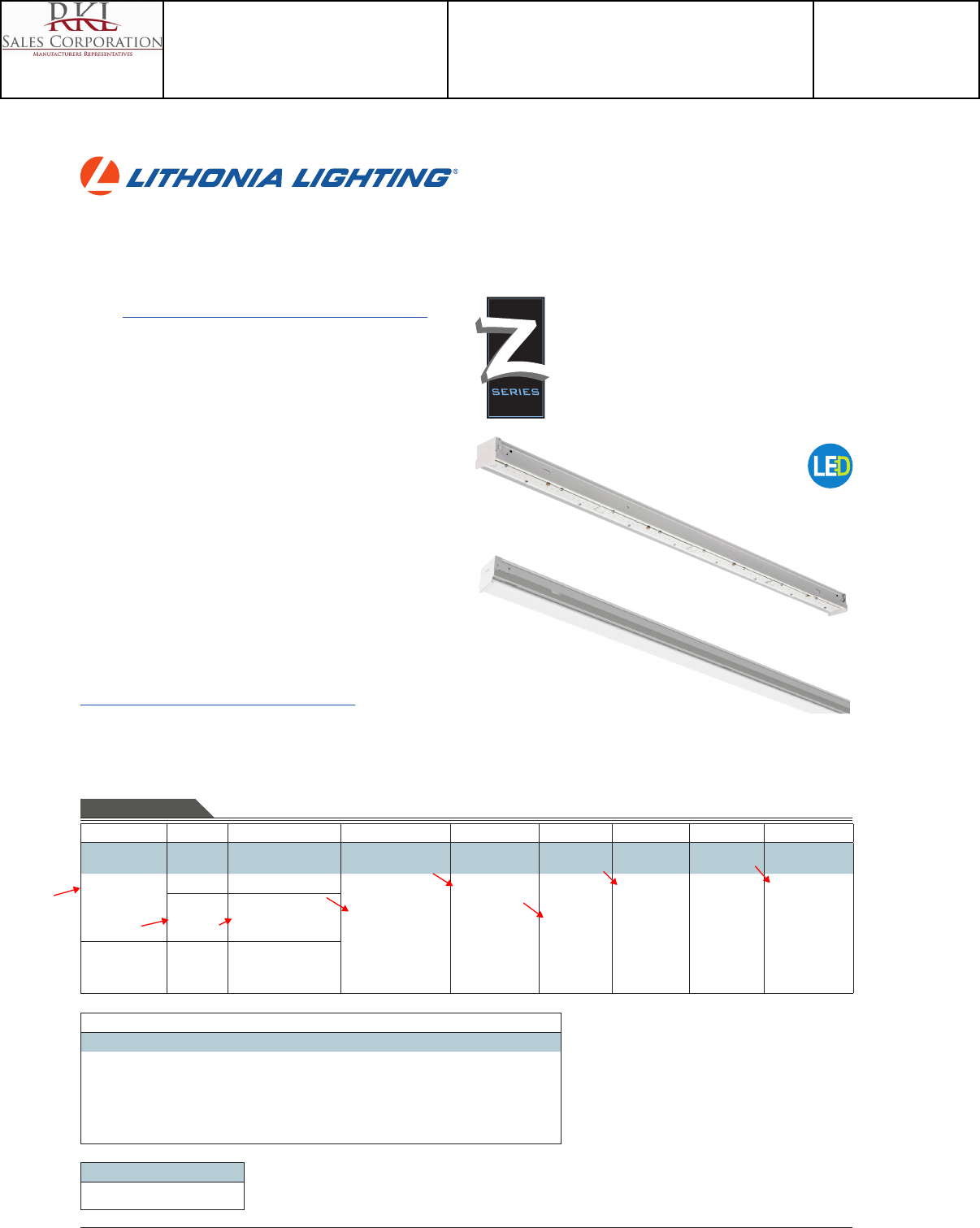
Catalog
Number
Notes
Type
Page 1 of 5
LED Striplight
ZL1N
24", 48" and 96" Lengths
FEATURES & SPECIFICATIONS
INTENDED USE — Built on the compact, low-prole Z strip channel, this LED strip oers long mainte-
nance-free life, several color temperatures, lumen outputs and lengths. Ideal for new construction and
retrot applications in T8 lengths. Ideal for uplight and downlight in commercial, retail, manufacturing,
warehouse, cove and display applications. Certain airborne contaminants can diminish integrity
of acrylic. Click here for Acrylic Environmental Compatibility table for suitable uses.
CONSTRUCTION — Compact-design channel and cover are formed from code-gauge cold-rolled steel.
Easy to install row aligner included for continuous row mounting.
Finish: Options include high-gloss, baked white enamel (WH), galvanized (GALV), matte black (MB)
and smoke gray (SKGY). Five-stage iron phosphate pre-treatment ensures superior paint adhesion and
rust resistance.
OPTICS — Standard diuse snap on/snap o lens eliminates pixels, improves uniformity and minimizes
glare. L/LENS option available.
ELECTRICAL — Utilizes high-output LEDs integrated on a two-layer circuit board, ensuring cool-running
operation. Internal pluggable wiring harness prevents wiring errors. Electronic LED driver is rated for 75
input watts maximum (see Operational Data on page two for actual wattage consumption), multi-volt
input and 0-10V dimming standard. This xture is designed to withstand a maximum line surge of
1.5kV at 0.75kA combination wave for indoor locations, for applications requiring higher level of protec-
tion additional surge protection must be provided.
LEDs provide 83 CRI at 3000 K, 3500 K,4000 K or 5000 K.
Lumen output up to 2,000 lumens per foot. In 86°F (30°C) ambient environments, L70 is predicted to
be 100,000+ hours, L85 at 65,000 hours. Luminaire should be installed in applications where ambient
temperatures do not exceed 86°F (30°C). Ambient temperatures that exceed 86°F (30°C) will result in
reduced life and will void warranty.
INSTALLATION — Tool-less channel cover for easy installation.
Fixture may be surface, pendant or stem mounted. Three-point aligner locks in place for easy continuous
row mounting.
LISTINGS — UL Listed. CSA certied to US and Canadian safety standards. For use in damp locations
between -4°F (-20°C) and 86°F (30°C).
WARRANTY — 5-year limited warranty. Complete warranty terms located at
www.acuitybrands.com/CustomerResources/Terms_and_conditions.aspx
Actual performance may dier as a result of end-user environment and application.
Actual wattage may dier by +/- 5% when operating between 120-277V +/- 10%.
Note: Specications subject to change without notice.
Notes
1 See Operational Data on page 2 for actual lumens.
2 Not available with L24, 24" xture.
3 See ordering information on page 3.
4 Order 2 for tandem double length xtures (TZL1N).
5 See ordering information on page 4.
INDUSTRIAL ZL1N
Accessories: Order as separate catalog number.
HC36 Hanger chain, 36"
ZACVH Aircraft cable with hook
ZAC72 Aircraft cable, 72"
ZACF72 Aircraft cable with feed, 72"
ZAC120 Aircraft cable, 120"
ZACF120 Aircraft cable with feed, 120"
ZAC144 Aircraft cable, 144"
ZACF144 Aircraft cable with feed, 144"
LSXR Sensor Switch® LSXR
occupancy sensor2
ZSPRG For 15/16" T-grid only
WGZ24 24" wireguard, white
WGZ48 48" wireguard, white4
L/Lens
Lensed
Series Length Nominal lumens1Diuser Voltage
Color
temperature
Color rendering
index Options Finish
ZL1N LED
striplight
TZL1N LED
striplight
L24 24"
L46 46"
L48 48"
L92 92"
L96 96"
3000LM 3,000 lumens
3000LM 3,000 lumens
5000LM 5,000 lumens
7000LM 7,000 lumens
6000LM 6,000 lumens
10000LM 10,000 lumens
14000LM 14,000 lumens
FST Snap on
frosted, diuse
L/LENS No diuser
MVOLT 120-277V
HVOLT 347-480V2
40K 4000 K
30K 3000 K
35K 3500 K
50K 5000 K
80CRI 80 CRI PLR Plug-in
wiring3
WH White
GALV Galvanized
MB Matte
black
SKGY Smoke
gray
ORDERING INFORMATION Lead times will vary depending on options selected. Consult with your sales representative. Example: ZL1N L48 3000LM FST MVOLT 40K 80CRI WH
EMERGENCY OPTIONS5
Consider EAC ISSM 125 or EAC ISSM 375
Catalog Number
ZL1N L48 5000LM L/LENS MVOLT 35K 80CRI WH
Notes
Type
I
Project 15-18720-6
Teen Center - Los Alamos
Submitted By
RKL SALES CORP
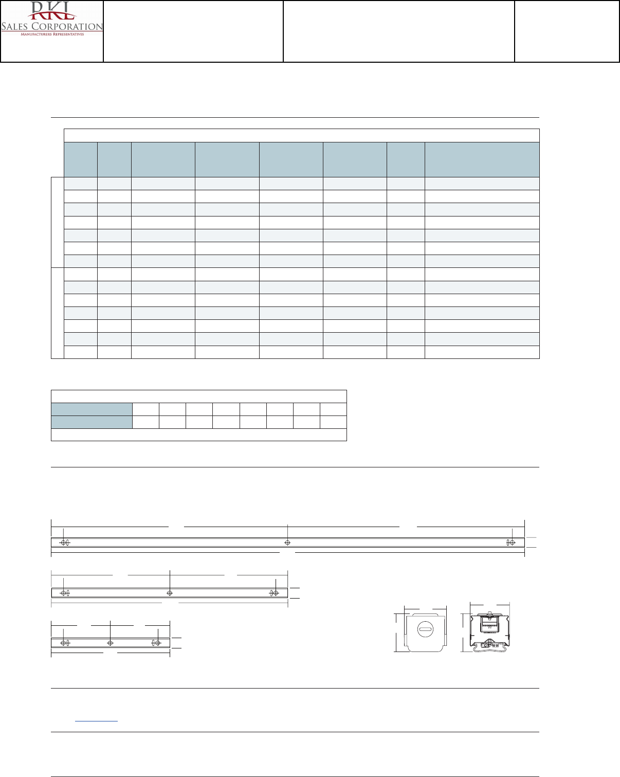
Page 2 of 5
ZL1N LED Striplight
OPERATIONAL DATA
Nominal
lumen
package
Length
(inches)
Delivered lumens
3000 K CCT @ 77°F
(25°C) ambient
temperature
Delivered lumens
3500 K CCT @ 77°F
(25°C ) ambient
temperature
Delivered lumens
4000 K CCT @ 77°F
(25°C) ambient
temperature
Delivered lumens
5000 K CCT @ 77°F
(25°C) ambient
temperature
Wattage @
120V/277V Comparable light source
Lensed
3,000LM 24 2,805 2,921 3,177 3,400 34W/32W 1-lamp 32W T8, 1-lamp 54W T5HO, 50W HID
3,000LM 46 or 48 2,532 2,636 2,834 3,068 32W/31W 1-lamp 32W T8, 1-lamp 54W T5HO, 50W HID
5,000LM 46 or 48 3,923 4,085 4,391 4,754 42W/41W 2-lamp 32W T8, 1-lamp 54W T5HO, 70W HID
7,000LM 46 or 48 5,914 6,158 6,619 7,231 72W/70W 3-lamp 32W T8, 2-lamp 54W T5HO, 100W HID
6,000LM 92 to 96 5,064 5,273 5,668 6,136 64W/62W 3-lamp 32W T8, 2-lamp 54W T5HO, 100W HID
10,000LM 92 to 96 7,846 8,170 8,782 9,508 84W/82W 4-lamp 32W T8, 2-lamp 54W T5HO, 100W HID
14,000LM 92 to 96 11,828 12,316 13,239 14,462 144W/140W 4-lamp 32W T8, 3-lamp 54W T5HO, 150W HID
Unlensed
3,000LM 24 3,165 3,295 3,582 3,835 34W/32W 1-lamp 32W T8, 1-lamp 54W T5HO, 50W HID
3,000LM 46 or 48 2,865 2,983 3,207 3,472 32W/31W 1-lamp 32W T8, 1-lamp 54W T5HO, 50W HID
5,000LM 46 or 48 4,439 4,622 4,968 5,379 42W/41W 2-lamp 32W T8, 1-lamp 54W T5HO, 70W HID
7,000LM 46 or 48 6,737 7,015 7,541 8,164 72W/70W 3-lamp 32W T8, 2-lamp 54W T5HO, 100W HID
6,000LM 92 to 96 5,730 5,966 6,413 6,944 64W/62W 3-lamp 32W T8, 2-lamp 54W T5HO, 100W HID
10,000LM 92 to 96 8,878 9,244 9,937 10,759 84W/82W 4-lamp 32W T8, 2-lamp 54W T5HO, 100W HID
14,000LM 92 to 96 13,474 14,031 15,082 16,329 144W/140W 4-lamp 32W T8, 3-lamp 54W T5HO, 150W HID
PROJECTED LUMEN MAINTENANCE
Operating hours 0 10,000 20,000 30,000 40,000 50,000 60,000 100,000
Lumen maintenance factor 1 0.9244 0.8588 0.7979 0.7413 0.6886 0.6398 0.4766
Based on incomplete LM-80 data. Update expected Q1 2014.
INDUSTRIAL ZL1N
PHOTOMETRICS
Please see www.lithonia.com.
DIMENSIONS
All dimensions are shown in inches (centimeters) unless otherwise noted.
Specications subject to change without notice.
2-1/8
(5.4)
48
(122.0) 48
(122.0)
96
(244.0)
2-1/8
(5.4)
2-1/8
(5.4)
2-1/8
(5.4)
24
(61.0) 24
(61.0)
48
(122.0)
2-1/8
(5.4)
2-1/8
(5.4)
12
(30.5) 12
(30.5)
2-1/8
(5.4)
24
(61.0)
2-1/8
(5.4)
2-1/8
(5.4)
2-1/8"
(5.39)
2-3/16
(5.56)
2-1/8"
(5.39)
2-1/8"
(5.39)
Catalog Number
ZL1N L48 5000LM L/LENS MVOLT 35K 80CRI WH
Notes
Type
I
Project 15-18720-6
Teen Center - Los Alamos
Submitted By
RKL SALES CORP

Page 3 of 5
ZL1N LED Striplight
INDUSTRIAL ZL1N
PRODUCT INFORMATION
Advanced plug-in system with three-circuit capability. Available on industrial and strip products and a
variety of architectural products mounted in continuous rows. 1, 2, 3 and 4-lamp xtures. PLR22 (2-cir-
cuit) and PLR33 (3-circuit) crossover harness switches hot circuit serving next xture in row. Reduces
xture types on job for alternating circuit applications (see example below.)
Easy one-step installation, saves up to 35% on labor costs. Expanded switching exibility helps save energy.
Rows can be 50% longer with two-circuit systems. Polarized, lock-together nylon connectors prevent
miswiring in the eld. #12 THHN conductor, rated 600V, 90°C. White neutral wire included. Grounding
accomplished by xture in-row connectors.
CSA certied systems available with up to 2 circuits. G ground required.
Note: Specications subject to change without notice.
Wiring
PLR
Advanced 3-Circuit Plug-In
Typical Applications
• Multiple-circuit and single-circuit for longer continuous rows
• Multiple-circuit with alternating xtures on separate circuits,
2-circuit (PLR 22) and 3-circuit (PLR 33)
• Multiple circuit with night-lights located along row as desired
TYPICAL APPLICATIONS
PLR 3 C PLR 3 C PLR 3 C PLR 3 C PLR 2 B PLR 2 B PLR 2 B PLR 2 B PLR 1 PLR 1 PLR 1
(All PLR22)
Circuit A Circuit B Circuit A Circuit B Circuit A Circuit B Circuit A Circuit B Circuit A Circuit B Circuit A
(All PLR33)
Circuit A Circuit B Circuit C Circuit A Circuit B Circuit C Circuit A Circuit B Circuit C Circuit A Circuit B
PLR 3 A PLR 3 A PLR 3 A PLR 3 C PLR 3 B PLR 3 B PLR 3 B PLR 3 C PLR 3 A PLR 3 A PLR 3 A
Notes
1 Ground not available.
Series Number of hot wires Branch circuits Ground
PLR
PLR22
PLR33
(blank) Not required for 22 or 33
1Black
2Black and red
3 Black, red and blue1
Circuits to which ballast is connected
(blank) Not required for 22 or 33
ABlack wire
B Red wire
CBlue wire1
AB Outboard lamps to black, inboard to red
AC Outboard lamps to black, inboard to blue
(blank) No ground in PLR
GGround. Maximum 2 circuits
ORDERING INFORMATION Lead times will vary depending on options selected. Consult with your sales representative.
Passive Infrared Indoor Occupancy Sensor
LSXR
Single Relay
PRODUCT INFORMATION
A standard occupancy time delay is also present to ensure lights turn o (once minimum on timer has
also elapsed) if no occupancy is detected.
This timer is factory set at 10 minutes to promote energy savings, but is adjustable between 30 seconds
and 30 minutes. These adjustments may be done through the unit’s push-button.
FEATURES
• Four interchangeable lenses - high mount 360°, low mount 360°, high mount aisleway, and small
motion 360°.
• Integrated mounting bracket drops lens down 3" from chase nipple - no bracket accessory required.
• 100% digital PIR detection - provides excellent RF immunity
Note: Specications subject to change without notice.
ORDERING INFORMATION Lead times will vary depending on options selected. Consult with your sales representative. Example: LSXR 10 ADC HVOLT 30M
LSXR
Series Lens option Dimming/photocell
LSXR Passive Infrared Indoor
Occupancy Sensor
(blank) No lens
6High mount, 360®
10 Low mount, 360°
50 High mount aisleway
9 Small motion, 360°
610 High and low mount 360°
650 High mount 360° and aisleway
3PK High and low mount 360° and aisleway
4PK All lenses
(blank) None
HL High/low occupancy operation
PSwitching photocell (on/o)
ADC Dimming and switching photocell
ANL Dimming and switching photocell with
high/low occupancy operation
Voltage Max dim level Min dim level Lead length Temp humidity Default time delay
(blank) 120-277 VAC
(MVOLT)
HVOLT 347-480 VAC
(blank) 10 VDC
9H 9 VDC
8H 8 VDC
7H 7 VDC
(blank) Minimum dimming level of ballast
1V 1 VDC
2V 2 VDC
3V 3 VDC
4V 4 VDC
5V 5 VDC
6V 6 VDC
(blank) 14"
42L 42"
(blank) None
LT Low temperature
(blank) 10 minutes (with minimum
15 minutes on time)
5M 5 minutes (LED only)
15M 15 minutes
20M 20 minutes
30M 30 minutes
For additional information see www.lithonia.com
Catalog Number
ZL1N L48 5000LM L/LENS MVOLT 35K 80CRI WH
Notes
Type
I
Project 15-18720-6
Teen Center - Los Alamos
Submitted By
RKL SALES CORP
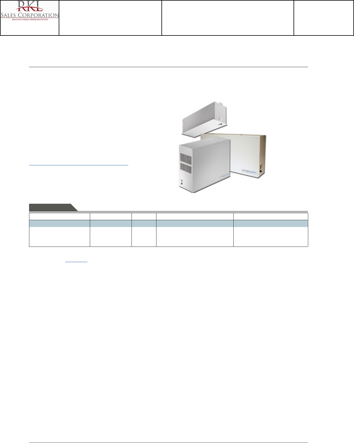
Page 4 of 5
ZL1N LED Striplight
INDUSTRIAL ZL1N
Power Systems
EAC ISSM
Compact Interruptible AC Power System
FEATURES & SPECIFICATIONS
INTENDED USE — Automatic standby AC power system for LED, incandescent and uorescent emer-
gency lighting systems, including xtures with line dimmable uorescent ballast.
CONSTRUCTION — NEMA Type 1 cabinet 16-gauge steel housing.
Status indicator: Three LED indicators display utility present, charger and inverter running.
Cooling: 375W model features forced air during emergency mode.
ELECTRICAL — Dual input and output, 120V or 277V.
Units rated for 125W or 375W provide emergency lighting power for 90 minutes of operation.
Battery: 12V Valve-regulated Lead Acid (VRLA) battery.
INSTALLATION — Line voltage allows for remote mounting of up to 1000 feet.
125W: Available with surface or recess ceiling mounting.
375W: Surface mounting only.
LISTINGS — UL Listed. Meets UL924, NFPA 101 (current life safety code), NEC, OSHA.
WARRANTY — 3-year limited warranty. Complete warranty terms located at
www.acuitybrands.com/CustomerResources/Terms_and_conditions.aspx
Note: Specications subject to change without notice.
EAC ISSM 120/277
Series System VA rating Voltage Mounting
EAC Emergency AC power system ISSM Interruptible 125
3751
120/277 Dual input and output 120V or 277V SM Surface
RGM Recess grid ceiling
ORDERING INFORMATION Lead times will vary depending on options selected. Consult with your sales representative. Example: EAC ISSM 375 120/277 SM
Notes
1 Available surface mount only.For additional information see www.lithonia.com
ZL1N LED Striplight
Catalog Number
ZL1N L48 5000LM L/LENS MVOLT 35K 80CRI WH
Notes
Type
I
Project 15-18720-6
Teen Center - Los Alamos
Submitted By
RKL SALES CORP

Page 5 of 5
ZL1N
INDUSTRIAL: One Lithonia Way, Conyers, GA 30012 Phone: 800-315-4963 Fax: 770-981-8191 www.lithonia.com © 2013-2014 Acuity Brands Lighting, Inc. All rights reserved. Rev. 02/27/14
OPTIONS AND ACCESSORIES
The Z Series xture oers numerous options for almost every electrical and optical component, including a long list of eld-installable accessories.
HANGER CHAIN
36" chain with Y hanger.
Order as:
HC36
Z SPRING HANGER
Snap ‘n’ lock design requires no fasteners and can
be used on T-grid ceiling or universal mounting
systems.
Order as:
ZSPRG
ZL1N LED Striplight
Catalog Number
ZL1N L48 5000LM L/LENS MVOLT 35K 80CRI WH
Notes
Type
I
Project 15-18720-6
Teen Center - Los Alamos
Submitted By
RKL SALES CORP
Catalog
Number
Notes
Type
Page 1 of 5
LED Striplight
ZL1N
24", 48" and 96" Lengths
FEATURES & SPECIFICATIONS
INTENDED USE — Built on the compact, low-prole Z strip channel, this LED strip oers long mainte-
nance-free life, several color temperatures, lumen outputs and lengths. Ideal for new construction and
retrot applications in T8 lengths. Ideal for uplight and downlight in commercial, retail, manufacturing,
warehouse, cove and display applications. Certain airborne contaminants can diminish integrity
of acrylic. Click here for Acrylic Environmental Compatibility table for suitable uses.
CONSTRUCTION — Compact-design channel and cover are formed from code-gauge cold-rolled steel.
Easy to install row aligner included for continuous row mounting.
Finish: Paint options include high-gloss, baked white enamel (WH), galvanized (GALV), matte black
(MB) and smoke gray (SKGY). Five-stage iron phosphate pre-treatment ensures superior paint adhesion
and rust resistance.
OPTICS — Standard diuse snap on/snap o lens eliminates pixels, improves uniformity and minimizes
glare. L/LENS option available.
ELECTRICAL — Utilizes high-output LEDs integrated on a two-layer circuit board, ensuring cool-running
operation. Internal pluggable wiring harness prevents wiring errors. Electronic LED driver is rated for 75
input watts maximum (see Operational Data on page two for actual wattage consumption), multi-volt
input and 0-10V dimming standard. This xture is designed to withstand a maximum line surge of
1.5kV at 0.75kA combination wave for indoor locations, for applications requiring higher level of protec-
tion additional surge protection must be provided.
LEDs provide 83 CRI at 3000 K, 3500 K,4000 K or 5000 K.
Lumen output up to 2,000 lumens per foot. In 86°F (30°C) ambient environments, L70 is predicted to
be 100,000+ hours, L85 at 65,000 hours. Luminaire should be installed in applications where ambient
temperatures do not exceed 86°F (30°C). Ambient temperatures that exceed 86°F (30°C) will result in
reduced life and will void warranty.
INSTALLATION — Tool-less channel cover for easy installation.
Fixture may be surface, pendant or stem mounted. Three-point aligner locks in place for easy continuous
row mounting.
LISTINGS — UL Listed. CSA certied to US and Canadian safety standards. For use in damp locations
between -4°F (-20°C) and 86°F (30°C).
DesignLights Consortium® (DLC) qualied product. Not all versions of this product may be DLC quali-
ed. Please check the DLC Qualied Products List at www.designlights.org to conrm which versions
are qualied.
WARRANTY — 5-year limited warranty. Complete warranty terms located at
www.acuitybrands.com/CustomerResources/Terms_and_conditions.aspx
Actual performance may dier as a result of end-user environment and application.
Actual wattage may dier by +/- 5% when operating between 120-277V +/- 10%.
Note: Specications subject to change without notice.
Notes
1 See Operational Data on page 2 for actual lumens.
2 Not available with L24, 24" xture.
3 See ordering information on page 3.
4 Order 2 for tandem double length xtures (TZL1N).
5 See ordering information on page 4.
INDUSTRIAL ZL1N
Accessories: Order as separate catalog number.
HC36 Hanger chain, 36"
ZACVH Aircraft cable with hook
LSXR Sensor Switch® LSXR occupancy sensor2
ZSPRG For 15/16" T-grid only
WGZ24 24" wireguard, white
WGZ48 48" wireguard, white4
L/Lens
Lensed
Series Length Nominal lumens1Diuser Voltage
Color
temperature
Color rendering
index Options Paint nish
ZL1N LED
striplight
TZL1N LED
striplight
L24 24"
L46 46"
L48 48"
L92 92"
L96 96"
3000LM 3,000 lumens
3000LM 3,000 lumens
5000LM 5,000 lumens
7000LM 7,000 lumens
6000LM 6,000 lumens
10000LM 10,000 lumens
14000LM 14,000 lumens
FST Snap on
frosted, diuse
L/LENS No diuser
MVOLT 120-277V
HVOLT 347-480V2
40K 4000 K
30K 3000 K
35K 3500 K
50K 5000 K
80CRI 80 CRI PLR Plug-in
wiring3
WH White
GALV Galvanized
MB Matte
black
SKGY Smoke
gray
ORDERING INFORMATION Lead times will vary depending on options selected. Consult with your sales representative. Example: ZL1N L48 3000LM FST MVOLT 40K 80CRI WH
EMERGENCY OPTIONS
(Order as separate catalog number.) 5
Consider EAC ISSM 125 or EAC ISSM 375
Catalog Number
TZL1N L96 10000LM L/LENS MVOLT 35K 80CRI WH
Notes
Type
J
Project 15-18720-6
Teen Center - Los Alamos
Submitted By
RKL SALES CORP

Page 2 of 5
ZL1N LED Striplight
OPERATIONAL DATA
Nominal
lumen
package
Length
(inches)
Delivered lumens
3000 K CCT @ 77°F
(25°C) ambient
temperature
Delivered lumens
3500 K CCT @ 77°F
(25°C ) ambient
temperature
Delivered lumens
4000 K CCT @ 77°F
(25°C) ambient
temperature
Delivered lumens
5000 K CCT @ 77°F
(25°C) ambient
temperature
Wattage @
120V/277V Comparable light source
Lensed
3,000LM 24 2,805 2,921 3,177 3,400 34W/32W 1-lamp 32W T8, 1-lamp 54W T5HO, 50W HID
3,000LM 46 or 48 2,532 2,636 2,834 3,068 32W/31W 1-lamp 32W T8, 1-lamp 54W T5HO, 50W HID
5,000LM 46 or 48 3,923 4,085 4,391 4,754 42W/41W 2-lamp 32W T8, 1-lamp 54W T5HO, 70W HID
7,000LM 46 or 48 5,914 6,158 6,619 7,231 72W/70W 3-lamp 32W T8, 2-lamp 54W T5HO, 100W HID
6,000LM 92 to 96 5,064 5,273 5,668 6,136 64W/62W 3-lamp 32W T8, 2-lamp 54W T5HO, 100W HID
10,000LM 92 to 96 7, 8 4 6 8,170 8,782 9,508 84W/82W 4-lamp 32W T8, 2-lamp 54W T5HO, 100W HID
14,000LM 92 to 96 11,828 12,316 13,239 14,462 144W/140W 4-lamp 32W T8, 3-lamp 54W T5HO, 150W HID
Unlensed
3,000LM 24 3,165 3,295 3,582 3,835 34W/32W 1-lamp 32W T8, 1-lamp 54W T5HO, 50W HID
3,000LM 46 or 48 2,865 2,983 3,207 3,472 32W/31W 1-lamp 32W T8, 1-lamp 54W T5HO, 50W HID
5,000LM 46 or 48 4,439 4,622 4,968 5,379 42W/41W 2-lamp 32W T8, 1-lamp 54W T5HO, 70W HID
7,000LM 46 or 48 6,737 7,015 7,541 8,164 72W/70W 3-lamp 32W T8, 2-lamp 54W T5HO, 100W HID
6,000LM 92 to 96 5,730 5,966 6,413 6,944 64W/62W 3-lamp 32W T8, 2-lamp 54W T5HO, 100W HID
10,000LM 92 to 96 8,878 9,244 9,937 10,759 84W/82W 4-lamp 32W T8, 2-lamp 54W T5HO, 100W HID
14,000LM 92 to 96 13,474 14,031 15,082 16,329 144W/140W 4-lamp 32W T8, 3-lamp 54W T5HO, 150W HID
PROJECTED LUMEN MAINTENANCE
Operating hours 0 10,000 20,000 30,000 40,000 50,000 60,000 100,000
Lumen maintenance factor 1 0.9678 0.9454 0.9235 0.9021 0.8812 0.8605 0.7839
Based on incomplete LM-80 data. Update expected Q1 2014.
INDUSTRIAL ZL1N
PHOTOMETRICS
Please see www.lithonia.com.
DIMENSIONS
All dimensions are shown in inches (centimeters) unless otherwise noted.
Specications subject to change without notice.
2-1/8
(5.4)
48
(122.0) 48
(122.0)
96
(244.0)
2-1/8
(5.4)
2-1/8
(5.4)
2-1/8
(5.4)
24
(61.0) 24
(61.0)
48
(122.0)
2-1/8
(5.4)
2-1/8
(5.4)
12
(30.5) 12
(30.5)
2-1/8
(5.4)
24
(61.0)
2-1/8
(5.4)
2-1/8
(5.4)
2-1/8"
(5.39)
2-3/16"
(5.56)
2-1/8"
(5.39)
2-1/8"
(5.39)
Catalog Number
TZL1N L96 10000LM L/LENS MVOLT 35K 80CRI WH
Notes
Type
J
Project 15-18720-6
Teen Center - Los Alamos
Submitted By
RKL SALES CORP
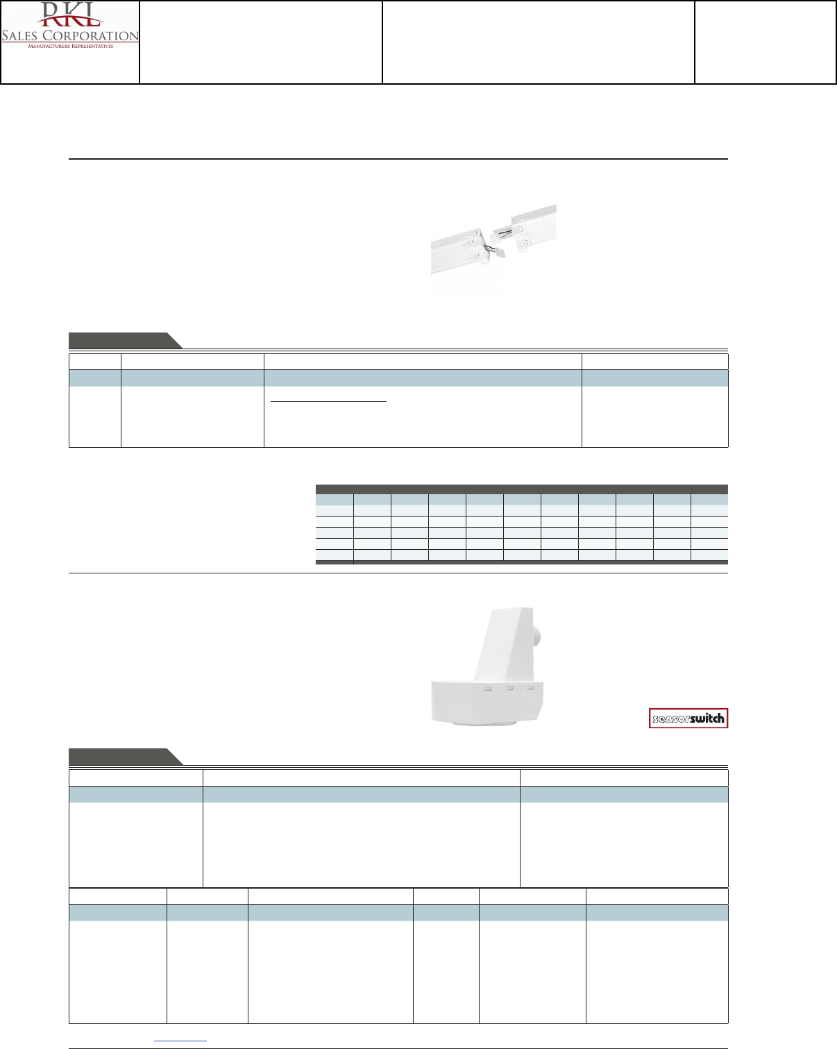
Page 3 of 5
ZL1N LED Striplight
INDUSTRIAL ZL1N
PRODUCT INFORMATION
Advanced plug-in system with three-circuit capability. Available on industrial and strip products and a
variety of architectural products mounted in continuous rows. 1, 2, 3 and 4-lamp xtures. PLR22 (2-cir-
cuit) and PLR33 (3-circuit) crossover harness switches hot circuit serving next xture in row. Reduces
xture types on job for alternating circuit applications (see example below.)
Easy one-step installation, saves up to 35% on labor costs. Expanded switching exibility helps save energy.
Rows can be 50% longer with two-circuit systems. Polarized, lock-together nylon connectors prevent
miswiring in the eld. #12 THHN conductor, rated 600V, 90°C. White neutral wire included. Grounding
accomplished by xture in-row connectors.
CSA certied systems available with up to 2 circuits. G ground required.
Note: Specications subject to change without notice.
Wiring
PLR
Advanced 3-Circuit Plug-In
Typical Applications
• Multiple-circuit and single-circuit for longer continuous rows
• Multiple-circuit with alternating xtures on separate circuits,
2-circuit (PLR 22) and 3-circuit (PLR 33)
• Multiple circuit with night-lights located along row as desired
TYPICAL APPLICATIONS
PLR 3 C PLR 3 C PLR 3 C PLR 3 C PLR 2 B PLR 2 B PLR 2 B PLR 2 B PLR 1 PLR 1 PLR 1
(All PLR22)
Circuit A Circuit B Circuit A Circuit B Circuit A Circuit B Circuit A Circuit B Circuit A Circuit B Circuit A
(All PLR33)
Circuit A Circuit B Circuit C Circuit A Circuit B Circuit C Circuit A Circuit B Circuit C Circuit A Circuit B
PLR 3 A PLR 3 A PLR 3 A PLR 3 C PLR 3 B PLR 3 B PLR 3 B PLR 3 C PLR 3 A PLR 3 A PLR 3 A
Series Number of hot wires Branch circuits Ground
PLR
PLR22
PLR33
(blank) Not required for 22 or 33
1Black
2Black and red
3 Black, red and blue
Circuits to which ballast is connected
(blank) Not required for 22 or 33
ABlack wire
B Red wire
CBlue wire
(blank) No ground in PLR
GGround. Maximum 2 circuits
ORDERING INFORMATION Lead times will vary depending on options selected. Consult with your sales representative.
Passive Infrared Indoor Occupancy Sensor
LSXR
Single Relay
PRODUCT INFORMATION
A standard occupancy time delay is also present to ensure lights turn o (once minimum on timer has
also elapsed) if no occupancy is detected.
This timer is factory set at 10 minutes to promote energy savings, but is adjustable between 30 seconds
and 30 minutes. These adjustments may be done through the unit’s push-button.
FEATURES
• Four interchangeable lenses - high mount 360°, low mount 360°, high mount aisleway, and small
motion 360°.
• Integrated mounting bracket drops lens down 3" from chase nipple - no bracket accessory required.
• 100% digital PIR detection - provides excellent RF immunity
Note: Specications subject to change without notice.
ORDERING INFORMATION Lead times will vary depending on options selected. Consult with your sales representative. Example: LSXR 10 ADC HVOLT 30M
LSXR
Series Lens option Dimming/photocell
LSXR Passive Infrared Indoor
Occupancy Sensor
(blank) No lens
6High mount, 360®
10 Low mount, 360°
50 High mount aisleway
9 Small motion, 360°
610 High and low mount 360°
650 High mount 360° and aisleway
3PK High and low mount 360° and aisleway
4PK All lenses
(blank) None
HL High/low occupancy operation
PSwitching photocell (on/o)
ADC Dimming and switching photocell
ANL Dimming and switching photocell with
high/low occupancy operation
Voltage Max dim level Min dim level Lead length Temp humidity Default time delay
(blank) 120-277 VAC
(MVOLT)
HVOLT 347-480 VAC
(blank) 10 VDC
9H 9 VDC
8H 8 VDC
7H 7 VDC
(blank) Minimum dimming level of ballast
1V 1 VDC
2V 2 VDC
3V 3 VDC
4V 4 VDC
5V 5 VDC
6V 6 VDC
(blank) 14"
42L 42"
(blank) None
LT Low temperature
(blank) 10 minutes (with minimum
15 minutes on time)
5M 5 minutes (LED only)
15M 15 minutes
20M 20 minutes
30M 30 minutes
For additional information see www.lithonia.com
Catalog Number
TZL1N L96 10000LM L/LENS MVOLT 35K 80CRI WH
Notes
Type
J
Project 15-18720-6
Teen Center - Los Alamos
Submitted By
RKL SALES CORP

Page 4 of 5
ZL1N LED Striplight
INDUSTRIAL ZL1N
Power Systems
EAC ISSM
Compact Interruptible AC Power System
For emergency options, consider EAC ISSM 125 or EAC ISSM 375. (Order as separate catalog number.)
FEATURES & SPECIFICATIONS
INTENDED USE — Automatic standby AC power system for LED, incandescent and uorescent emer-
gency lighting systems, including xtures with line dimmable uorescent ballast.
CONSTRUCTION — NEMA Type 1 cabinet 16-gauge steel housing.
Status indicator: Three LED indicators display utility present, charger and inverter running.
Cooling: 375W model features forced air during emergency mode.
ELECTRICAL — Dual input and output, 120V or 277V.
Units rated for 125W or 375W provide emergency lighting power for 90 minutes of operation.
Battery: 12V Valve-regulated Lead Acid (VRLA) battery.
INSTALLATION — Line voltage allows for remote mounting of up to 1000 feet.
125W: Available with surface or recess ceiling mounting.
375W: Surface mounting only.
LISTINGS — UL Listed. Meets UL924, NFPA 101 (current life safety code), NEC, OSHA.
WARRANTY — 3-year limited warranty. Complete warranty terms located at
www.acuitybrands.com/CustomerResources/Terms_and_conditions.aspx
Note: Specications subject to change without notice.
EAC ISSM 120/277
Series System VA rating Voltage Mounting
EAC Emergency AC power system ISSM Interruptible 125
3751
120/277 Dual input and output 120V or 277V SM Surface
RGM Recess grid ceiling
ORDERING INFORMATION Lead times will vary depending on options selected. Consult with your sales representative. Example: EAC ISSM 375 120/277 SM
Notes
1 Available surface mount only.For additional information see www.lithonia.com
ZL1N LED Striplight
Catalog Number
TZL1N L96 10000LM L/LENS MVOLT 35K 80CRI WH
Notes
Type
J
Project 15-18720-6
Teen Center - Los Alamos
Submitted By
RKL SALES CORP
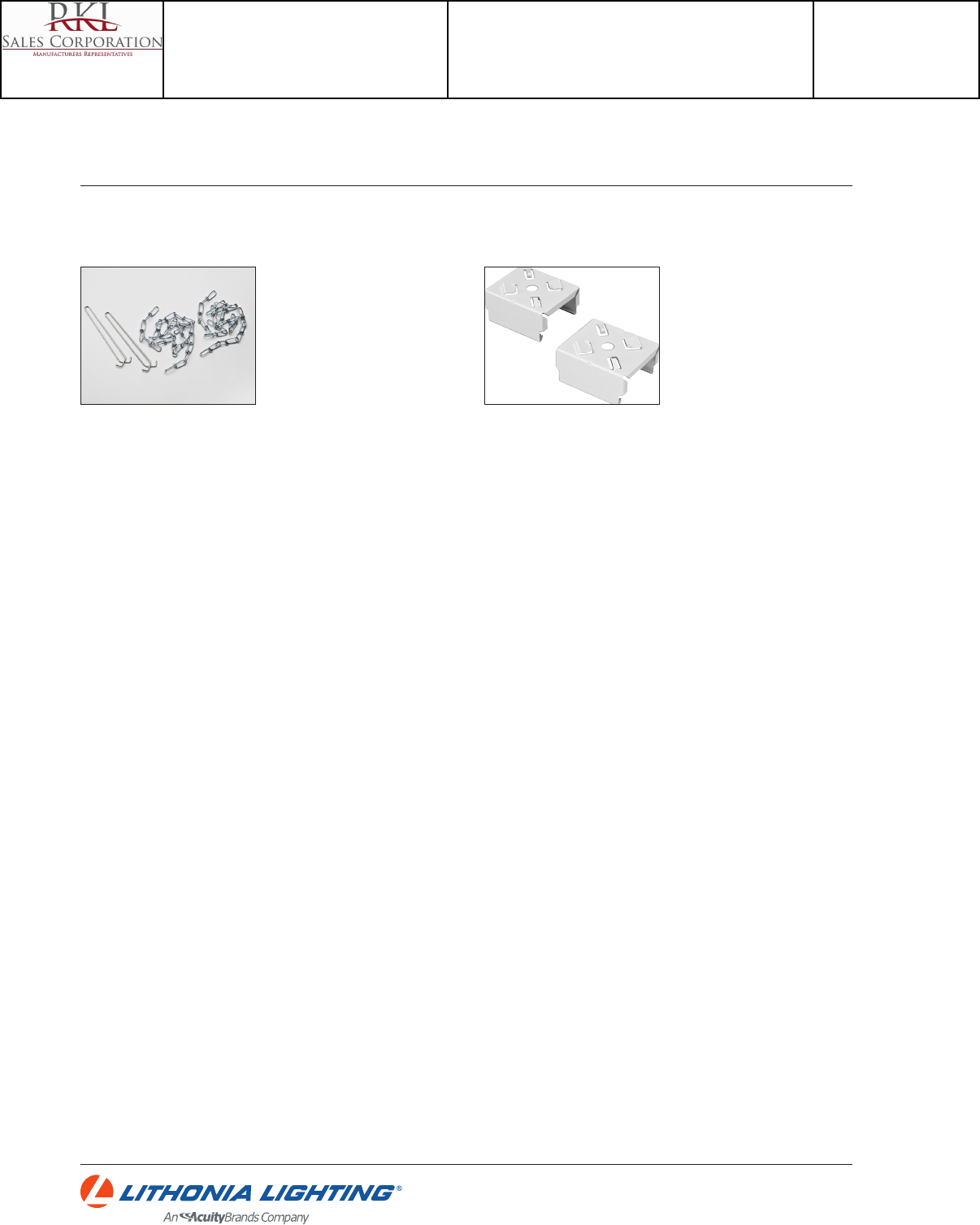
Page 5 of 5
ZL1N
INDUSTRIAL: One Lithonia Way, Conyers, GA 30012 Phone: 800-315-4963 Fax: 770-981-8191 www.lithonia.com © 2013-2015 Acuity Brands Lighting, Inc. All rights reserved. Rev. 01/06/15
OPTIONS AND ACCESSORIE
The Z Series xture oers numerous options for almost every electrical and optical component, including a long list of eld-installable accessories.
HANGER CHAIN
36" chain with Y hanger.
Order as:
HC36
Z SPRING HANGER
Snap ‘n’ lock design requires no fastener s and can
be used on T-grid ceiling or universal mounting
systems.
Order as:
ZSPRG
ZL1N LED Striplight
Catalog Number
TZL1N L96 10000LM L/LENS MVOLT 35K 80CRI WH
Notes
Type
J
Project 15-18720-6
Teen Center - Los Alamos
Submitted By
RKL SALES CORP
LED 2GTL 2X4
2GTL
Series Length Trim type Lumens1Door Lens Voltage Driver Color temperature
2GTL 2' wide
recessed
LED
luminaire
4 4' (blank) Grid
FOverlapping
ange
30L 3000
lumens
40L 4000
lumens
48L 4800
lumens
60L 6000
lumens
72L 7200
lumens
(blank) Flush steel, white
FN Flush aluminum,
natural
FM Flush aluminum,
matte black
FW Flush aluminum,
white
RN Regressed aluminum,
natural
RM Regressed aluminum,
matte black
RW Regressed aluminum,
white
(blank) #12 pattern
acrylic,
0.125"
thick
A19 #19 pattern
acrylic
SWL Satin white
(blank) MVOLT
(120-
277V)
120 120V
277 277V
347 347V2
EZ1 eldoLED
dims to
1 %
SLD Step-level
dimming3
EXA1 eldoLED
dims to
1%, XPoint
wireless
enabled
LP830 3000 K
LP835 3500 K
LP840 4000 K
LP850 5000 K
ORDERING INFORMATION Lead times will vary depending on options selected. Consult with your sales representative. Example: 2GTL 4 48L EZ1 LP835
Catalog
Number
Notes
Type
FEATURES & SPECIFICATIONS
INTENDED USE The 2GTL LED recessed troer oers a wide range of lumen packages, color temperatures,
and lens options to meet the lighting needs for a wide range of applications such as schools, oces, and
hospitals. The light engine delivers long life and excellent color to ensure a sound quality, low-maintenance
lighting installation. Certain airborne contaminants can diminish integrity of acrylic. Click here
for Acrylic Environmental Compatibility table for suitable uses.
CONSTRUCTION Housing formed from 22 gauge cold-rolled steel. Smooth hemmed sides and smooth
inward formed end anges for safe handling. Lighter-weight xture allows for safe, easy installation.
OPTICS Highly transmissive pattern #12 lens diuses the light source without compromising output.
Pattern # 19 and satin white lens options also available.
ELECTRICAL Long-life LEDs, coupled with high-eciency drivers, provide extended service life. 90%
LED lumen maintenance at 60,000 hours (L90/60,000).
eldoLED driver options deliver choice of dimming range, and choices for control, while assuring icker-free,
low-current inrush, 89% eciency and low EMI.
Optional nLight® embedded controls make each luminaire addressable - allowing it to digitally communicate
with other nLight enabled controls such as dimmers, switches, occupancy sensors and photocontrols. Simply
connect all the nLight enabled control devices and the GTL luminaires using standard Cat-5 cabling. Unique
plug-and-play convenience as devices and luminaires automatically discover each other and self-commission.
Lumen Management: Unique lumen management system (option N80) provides onboard intelligence that
actively manages the LED light source so that constant lumen output is maintained over the system life,
preventing the energy waste created by the traditional practice of over-lighting.
The step-level dimming option (SLD) allows the system to be switched to 50% power for compliance with
common energy codes while maintaining xture appearance.
Ballast disconnect is provided where required to comply with U.S. and Canadian codes.
INSTALLATION LED boards include plug-in connectors for easy of upgradeability. Suitable for direct
insulation contact.
LISTINGS CSA certied to meet U.S. and Canadian standards. IC rated. DesignLights Consortium®
(DLC) qualied product. Not all versions of this product may be DLC qualied. Please check the DLC
Qualied Products List at www.designlights.org/QPL to conrm which versions are qualied.
WARRANTY — 5-year limited warranty. Complete warranty terms located at
www.acuitybrands.com/CustomerResources/Terms_and_conditions.aspx
Actual performance may dier as a result of end-user environment and application.
Note: Specications subject to change without notice.
Controls3Options
(blank) No controls
N80 nLight with 80% (L80) lumen management
N80EMG nLight with 80% (L80) lumen management
for use with generator supply emergency
power
N100 nLight without lumen management
N100EMG nLight without lumen management for use
with generator supply emergency power
EL7L 700 lumen emergency battery3
EL14L 1400 lumen emergency battery3
CP Chicago plenum
PWS1836 6' pre-wire, 3/8" diameter, 18-gauge, 1-circuit
PWS1846 6' pre-wire, 3/8" diameter, 18-gauge, 2-circuit
ABC Door frame gasketing 4
GLR Slow-blowing fuse 5
GMF Fast-blowing fuse 5
LATC Earthquake clip
NPLT Narrow pallet
PAF Paint after fab
Notes
1 Approximate lumen output. Lumen output will vary depending upon lens
option chosen.
2 Not available with EL7L, EL14L, or SLD.
3 When using pre-wire option, use PWS1846.
4 Only available with aluminum door.
5 Must specify voltage, 120 or 277.
GTL Series
2GTL
2' x 4'
LED Recessed Troer
3-1/
4
(8.2
)
24
(61.0)
Specications
Length: 48 (122.0)
Width: 24 (61.0)
Depth: 3-1/4 (8.2)
All dimensions are inches (centimeters) unless otherwise indicated.
Accessories: Order as separate catalog number.
DGA24 Drywall grid adapter for 2x4 recessed xture.
Catalog Number
2GTL 4 48L EZ1 LP830
Notes
Type
K
Project 15-18720-6
Teen Center - Los Alamos
Submitted By
RKL SALES CORP
2GTL 2X4
LED: One Lithonia Way Conyers, GA 30012 Phone: 800-858-7763 Fax: 770-929-8789 www.lithonia.com © 2012-2015 Acuity Brands Lighting, Inc. All rights reserved. Rev. 01/05/15
2GTL LED Troer
39W
31W
39W
31W
Constant Lumen Management
Enabled by the embedded nLight control, the GTL actively tracks its run-time and manages its light source such that constant lumen output is maintained over the
system life. Referred to as lumen management, this feature eliminates the energy waste created by the traditional practice of over-lighting.
Performance Data
Lumen Package Input Watts Lumens LPW Lumen Package Input Watts Lumens LPW
30L LP830 30.5 2664.7 87.37 60L LP830 54.8 5173.3 94.40
30L LP835 30.5 2798 91.74 60L LP835 54.8 5430.7 99.10
30L LP840 30.5 2931.2 96.10 60L LP840 54.8 5702.5 104.06
30L LP850 30.5 2994.4 98.18 60L LP850 54.8 5849.1 106.74
40L LP830 38.9 3910.8 100.53 72L LP830 71.0 6731.1 94.80
40L LP835 38.9 4103.7 105.49 72L LP835 71.0 7066.9 99.53
40L LP840 38.9 4290.2 110.29 72L LP840 71.0 7421.3 104.53
40L LP850 38.9 4393.3 112.94 72L LP850 71.0 7538.5 106.18
48L LP830 46.9 4583.3 97.72
48L LP835 46.9 4815.2 102.67
48L LP840 46.9 5036.3 107.38
48L LP850 46.9 5164.2 110.11
PHOTOMETRICS
2GTL4 48L EZ1 LP835, 4815 delivered lumens, test no. LTL26406P9, tested in accordance to IESNA LM-79.
Note: Actual wattage may dier by +/- 5% when operating between
120-277V +/- 10%.
Performance based on standard #12 pattern acrylic lens.
0° 20°
40°
60°
80°
90°
0°0°0° 90°
180°
400
800
1200
1600
2000
Coefficients of Utilization
pf 20%
pc 80% 70%50%
pw 70%50%30% 50%30%10% 50%30%10%
119
109
100
92
85
78
72
67
63
59
55
119
105
92
82
73
66
60
54
50
46
42
119
101
86
74
65
57
51
46
42
38
35
116
103
90
80
72
65
59
54
49
45
42
116
99
85
73
64
57
51
46
41
38
35
116
96
80
67
58
51
45
40
36
32
30
111
98
87
77
69
63
57
52
48
44
41
111
95
82
71
63
56
50
45
41
37
34
111
93
78
66
57
50
44
40
36
32
29
RCR
0
1
2
3
4
5
6
7
8
9
10
Zonal Lumen Summary
Zone Lumens % Lamp % Fixture
0° - 30°
0° - 40°
0° - 60°
0° - 90°
90° - 120°
90° - 130°
90° - 150°
90° - 180°
0° - 180°
1551
2471
4002
4813
2
2
2
2
4815
32.2
51.3
83.1
100.0
0.0
0.0
0.0
0.0
100.0
32.2
51.3
83.1
100.0
0.0
0.0
0.0
0.0
100.0
CP Summary
0° 90
0°
5°
15°
25°
35°
45°
55°
65°
75°
85°
90
2046
2040
1959
1782
1507
1158
795
482
257
96
13
2046
2038
1948
1755
1460
1093
726
439
255
94
7
Catalog Number
2GTL 4 48L EZ1 LP830
Notes
Type
K
Project 15-18720-6
Teen Center - Los Alamos
Submitted By
RKL SALES CORP

LED 2GTL 2X2
ORDERING INFORMATION Lead times will vary depending on options selected. Consult with your sales representative. Example: 2GTL 2 33L EZ1 LP835
Catalog
Number
Notes
Type
FEATURES & SPECIFICATIONS
INTENDED USE The 2GTL LED recessed troffer offers a wide range of lumen packages, color temperatures,
and lens options to meet the lighting needs for a wide range of applications such as schools, offices, and
hospitals. The light engine delivers long life and excellent color to ensure a sound quality, low-maintenance
lighting installation. Certain airborne contaminants can diminish integrity of acrylic. Click here
for Acrylic Environmental Compatibility table for suitable uses.
CONSTRUCTION Housing formed from 22 gauge cold-rolled steel. Smooth hemmed sides and smooth
inward formed end flanges for safe handling. Lighter-weight fixture allows for safe, easy installation.
OPTICS Highly transmissive pattern #12 lens diffuses the light source without compromising output.
Pattern # 19 and satin white lens options also available.
ELECTRICAL Long-life LEDs, coupled with high-efficiency drivers, provide extended service life. 90%
LED lumen maintenance at 60,000 hours (L90/60,000).
eldoLED driver options deliver choice of dimming range, and choices for control, while assuring flicker-free,
low-current inrush, 89% efficiency and low EMI.
Optional nLight® embedded controls make each luminaire addressable - allowing it to digitally communicate
with other nLight enabled controls such as dimmers, switches, occupancy sensors and photocontrols. Simply
connect all the nLight enabled control devices and the GTL luminaires using standard Cat-5 cabling. Unique
plug-and-play convenience as devices and luminaires automatically discover each other and self-commission.
Lumen Management: Unique lumen management system (option N80) provides onboard intelligence that
actively manages the LED light source so that constant lumen output is maintained over the system life,
preventing the energy waste created by the traditional practice of over-lighting.
The step-level dimming option (SLD) allows the system to be switched to 50% power for compliance with
common energy codes while maintaining fixture appearance.
Ballast disconnect is provided where required to comply with U.S. and Canadian codes.
INSTALLATION LED boards include plug-in connectors for easy of upgradeability. Suitable for direct
insulation contact.
LISTINGS CSA certified to meet U.S. and Canadian standards. IC rated. DesignLights Consortium® (DLC)
qualified product. Not all versions of this product may be DLC qualified. Please check the DLC Qualified
Products List at www.designlights.org/QPL to confirm which versions are qualified.
Controls4Options
(blank) No controls
N80 nLight with 80% (L80) lumen management
N80EMG nLight with 80% (L80) lumen management
for use with generator supply emergency
power
N100 nLight without lumen management
N100EMG nLight without lumen management for use
with generator supply emergency power
EL7L 700 lumen emergency battery5
EL14L 1400 lumen emergency battery5
CP Chicago plenum
PWS1836 6' pre-wire, 3/8" diameter, 18-gauge, 1-circuit
PWS1846 6' pre-wire, 3/8" diameter, 18-gauge, 2-circuit
ABC Door frame gasketing 6
GLR Slow-blowing fuse7
GMF Fast-blowing fuse7
LATC Earthquake clip
NPLT Narrow pallet
PAF Paint after fab
Notes
1 Approximate lumen output. Lumen output will vary depending upon lens
option chosen.
2 Not available with EL7L, EL14L, or SLD.
3 Not available with EL7L or EL14L.
4 Not available with SLD.
5 When using pre-wire option, use PWS1846.
6 Only available with aluminum door.
7 Must specify voltage, 120 or 277.
GTL Series
2GTL
2' x 2'
LED Recessed Troffer
3-1/
4
(8.2
)
24
(61.0)
Specifications
Length: 24 (61.0)
Width: 24 (61.0)
Depth: 3-1/4 (8.2)
All dimensions are inches (centimeters) unless otherwise indicated.
Accessories: Order as separate catalog number.
DGA22 Drywall grid adapter for 2x2 recessed fixture.
2GTL
Series Length Trim type Lumens1Door Lens Voltage Driver Color temperature
2GTL 2' wide
recessed
LED
luminaire
22' (blank) Grid
FOverlapping
flange
20L 2000
lumens
33L 3300
lumens
40L 4000
lumens
(blank) Flush steel, white
FN Flush aluminum,
natural
FM Flush aluminum,
matte black
FW Flush aluminum,
white
RN Regressed
aluminum, natural
RM Regressed
aluminum, matte
black
RW Regressed
aluminum, white
(blank) #12 pattern
acrylic,
0.125"
thick
A19 #19 pattern
acrylic,
0.156"
thick
SWL Satin white
(blank) MVOLT
(120-
277V)
120 120V
277 277V
347 347V2
EZ1 eldoLED dims
to 1 %
SLD Step-level
dimming3
EXA1 eldoLED dims
to 1%, XPoint
wireless
enabled
LP830 3000 K
LP835 3500 K
LP840 4000 K
LP850 5000 K
WARRANTY — 5-year limited warranty. Complete warranty terms located at
www.acuitybrands.com/CustomerResources/Terms_and_conditions.aspx
Note: Actual performance may differ as a result of end-user environment and application.
All values are design or typical values, measured under laboratory conditions at 25 °C.
Specifications subject to change without notice.
Catalog Number
2GTL 2 40L EZ1 LP830
Notes
Type
L
Project 15-18720-6
Teen Center - Los Alamos
Submitted By
RKL SALES CORP
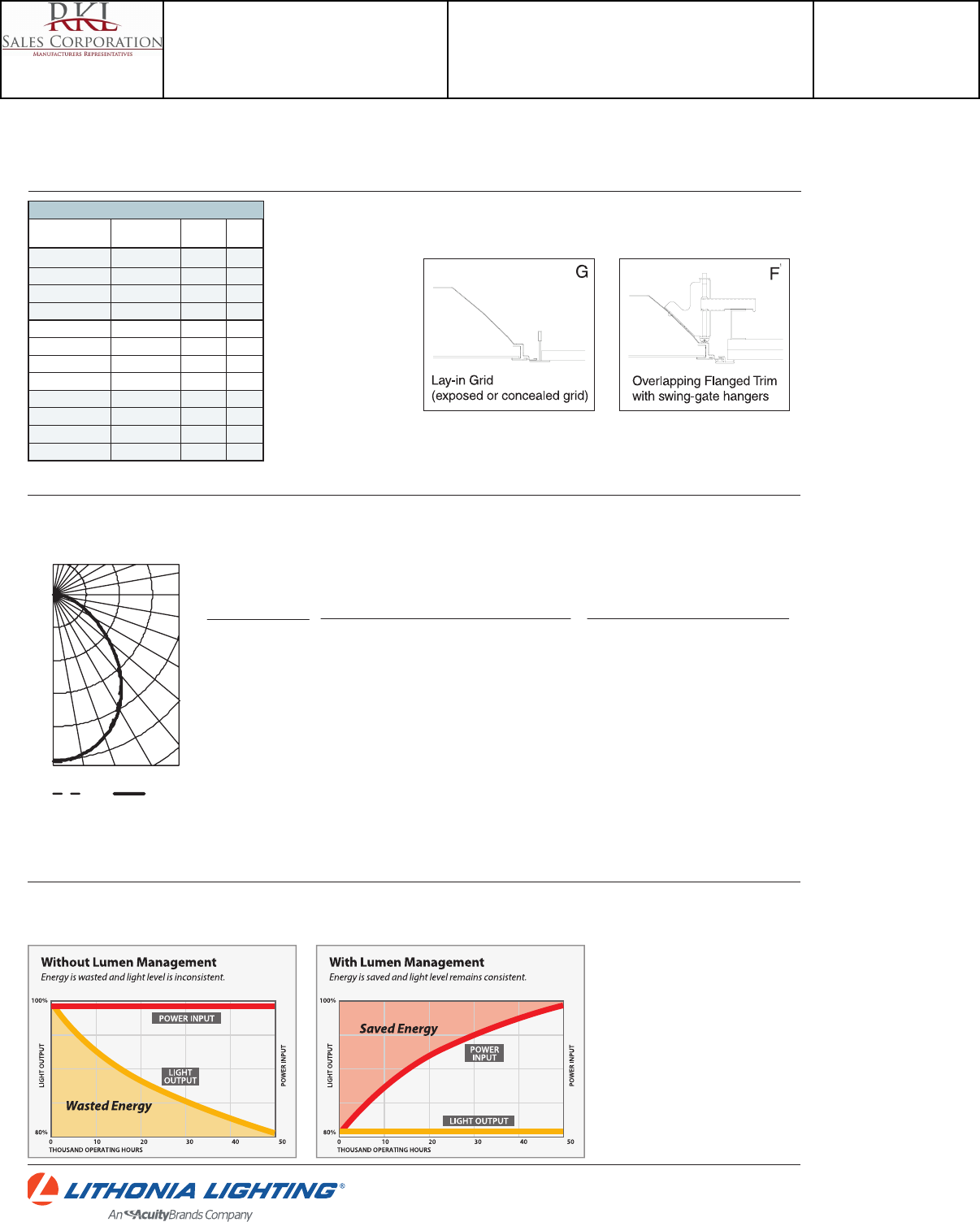
2GTL 2X2
LED: One Lithonia Way Conyers, GA 30012 Phone: 800-858-7763 Fax: 770-929-8789 www.lithonia.com © 2012-2015 Acuity Brands Lighting, Inc. All rights reserved. Rev. 06/01/15
2GTL LED Troffer
39W
31W
39W
31W
Constant Lumen Management
Enabled by the embedded nLight control, the GTL actively tracks its run-time and manages its light source such that constant lumen output is maintained over the
system life. Referred to as lumen management, this feature eliminates the energy waste created by the traditional practice of over-lighting.
2GTL2 33L EZ1 LP835, 3453 delivered lumens, test no. LTL26153P5, tested in accordance to IESNA LM-79.
Performance Data
Lumen Package Input Watts Lumens LPW
20L LP830 19.6 1981.2 101.08
20L LP835 19.6 2080.3 106.14
20L LP840 19.6 2179.4 111.19
20L LP850 19.6 2215 113.01
33L LP830 35.4 3300.7 93.24
33L LP835 35.4 3453.3 97.55
33L LP840 35.4 3619.7 102.25
33L LP850 35.4 3645.5 102.98
40L LP830 39.6 3530.6 89.16
40L LP835 39.6 3704.9 93.56
40L LP840 39.6 3883.2 98.06
40L LP850 39.6 3994.2 100.86
PHOTOMETRICS
Note: Performance based on standard #12 pattern acrylic lens.
0° 20°
40°
60°
80°
90°
0°0°0° 90°
180°
300
600
900
1200
1500
Coefficients of Utilization
pf 20%
pc 80% 70%50%
pw 70%50%30% 50%30%10% 50%30%10%
119
109
100
92
85
78
73
68
63
59
56
119
105
93
82
74
66
60
55
50
46
43
119
101
86
75
65
58
51
46
42
38
35
116
103
91
81
72
65
59
54
49
46
42
116
99
85
74
64
57
51
46
42
38
35
116
96
80
68
59
51
45
40
36
33
30
111
99
87
78
70
63
57
52
48
45
41
111
96
82
72
63
56
50
45
41
38
35
111
93
78
67
58
51
45
40
36
33
30
RCR
0
1
2
3
4
5
6
7
8
9
10
Zonal Lumen Summary
Zone Lumens % Lamp % Fixture
0° - 30°
0° - 40°
0° - 60°
0° - 90°
90° - 180°
0° - 180°
1136
1799
2889
3454
0
3454
32.9
52.1
83.6
100.0
0.0
100.0
32.9
52.1
83.6
100.0
0.0
100.0
CP Summary
0° 90
0°
5°
15°
25°
35°
45°
55°
65°
75°
85°
90
1518
1515
1433
1274
1056
795
540
328
176
61
5
1518
1504
1434
1295
1081
809
530
314
180
63
3
MOUNTING DATA
Continuous row mounting of flanged units requires CRE and CRM trim options
(see Options).
NOTE:
1 Recommended rough-in dimensions for F-trim fixtures 24"x48" (Tolerance is +1/4"-0"). Swing-gate range 1-3/16"
to 3-15/16". Swing-gate span 23-3/8" to 26-11/16". Fixture swing-gate points require additional 1-1/16" over
nominal fixture height.
Catalog Number
2GTL 2 40L EZ1 LP830
Notes
Type
L
Project 15-18720-6
Teen Center - Los Alamos
Submitted By
RKL SALES CORP
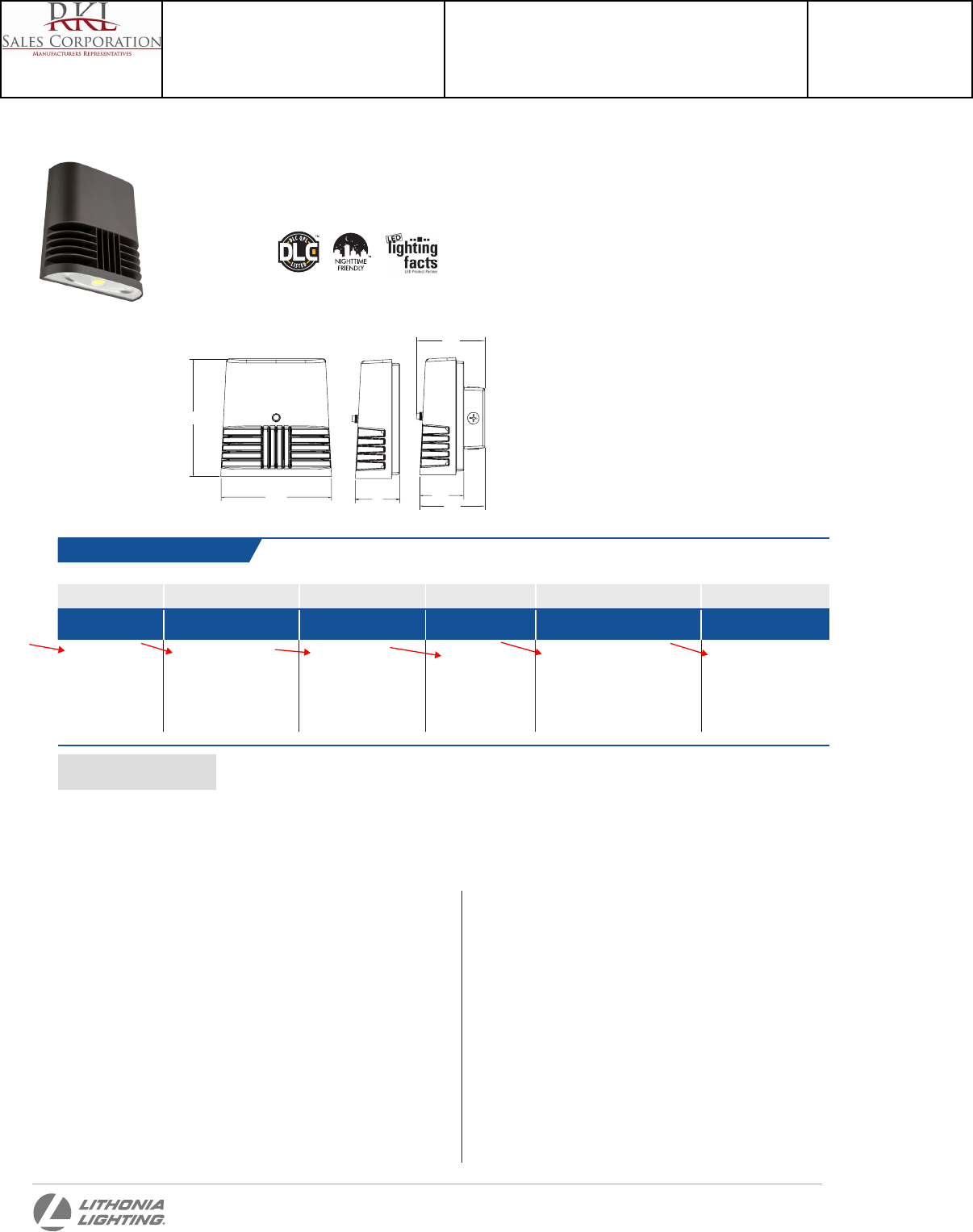
OLWX1 LED
Series Performance Package Color Temperature Voltage Controls Finish
OLWX1 LED 13W 13 watts
20W 20 watts
40W 40 watts
40K 4000 K 1
50K 5000 K
(blank) MVOLT 2
120 120V 3
347 347V
(blank) None
PE 120V button photocell 1,3
(blank) Dark bronze
OLWX1 LED
LED Wall Luminaire
Ordering Information EXAMPLE: OLWX1 LED 20W 50K
NOTES
1 Not available with 347V option.
2 MVOLT driver operates on any line voltage from 120-277V (50/60Hz).
3 Specify 120V when ordering with photocell (PE option).
Catalog
Number
Notes
Type
One Lithonia Way • Conyers, Georgia 30012 • Phone: 800.279.8041 • Fax: 770.918.1209 • www.lithonia.com
© 2013-2014 Acuity Brands Lighting, Inc. All rights reserved.
Hit the Tab key or mouse over the page to see all interactive elements.
Introduction
As versatile as it is efcient, the OLWX1 is designed
to replace up to 250W metal halide while saving
over 87% in energy costs. It combines multiple
mounting options with the latest generation of
LEDs for a wall pack luminaire that converts to a
whole lot more. Whether you are mounting it to a
recessed junction box, conduit/through wiring, as
an up light, as a down light, or as a ood light – the
OLWX1 has you covered.
Width: 7-1/2”
(19 cm)
Height: 8”
(20.3 cm)
Depth: 3”
(7.62 cm)
Weight: 5 lbs
(2.27kg)
Specifications
FEATURES & SPECIFICATIONS
INTENDED USE
The versatility of the OLWX1 LED combines a sleek, low-prole wall pack design and high-output
LEDs to provide an energy efcient, low maintenance LED wall pack suitable for replacing up to 250W
metal halide xtures. Available ood light mounting accessories convert the OLWX1 LED into a highly
efcient ood light.
OLWX1 LED is ideal for outdoor applications such as building perimeters, loading areas, driveways
and sign and building ood lighting.
CONSTRUCTION
Rugged cast-aluminum housing with textured dark bronze polyester powder paint for lasting
durability. Integral heat sinks optimize thermal management through conductive and convective
cooling. LEDs are protected behind a glass lens. Housing is sealed against moisture and
environmental contaminants (IP65).
OPTICS
High-performance LEDs behind clear glass for maximum light output. Light engines are available
in 4000K and 5000K CCTs. See Lighting Facts label and photometry reports for specic xture
performance.
ELECTRICAL
Light engine consists of 1 high-efciency Chip On Board (COB) LED with integrated circuit board
mounted directly to the housing to maximize heat dissipation and promote long life (L73/100,000
hours at 25°C). Electronic drivers have a power factor >90% and THD <20% and a minimum 2.5kV
surge rating. Flood light mounting accessories include an additional 6kV surge protection device.
INSTALLATION
Easily mounts to recessed junction boxes with the included wall mount bracket, or for
surface mounting and conduit entry - with the included junction box with ve 1/2” threaded
conduit entry hubs. Flood light mounting accessories (sold separately) include knuckle,
integral sliptter and yoke mounting options. Luminaire may be wall or ground mounted in
downward or upward orientation.
LISTINGS
UL Listed to U.S. and Canadian safety standards for wet locations. Rated for -40° C minimum
ambient. Tested in accordance with IESNA LM-79 and LM-80 standards. DesignLights
Consortium® (DLC) qualied product. Not all versions of this product may be DLC qualied.
Please check the DLC Qualied Products List at www.designlights.org to conrm which
versions are qualied.
WARRANTY
Five-year limited warranty. Full warranty terms located at
www.acuitybrands.com/CustomerResources/Terms_and_conditions.aspx.
Note: Specications are subject to change without notice. Actual performance may differ as
a result of end-user environment and application.
8
7-1/2
4-3/8
4-5/8
3
Accessories
Ordered and shipped separately.
OLWX1TS Sliptter – size 1
OLWX1YK Yoke – size 1
OLWX1THK Knuckle – size 1
3
2.97
4.41
4.63
Flush or backbox mount
Catalog Number
OLWX1 LED 13W 40K
Notes
Type
M
Project 15-18720-6
Teen Center - Los Alamos
Submitted By
RKL SALES CORP
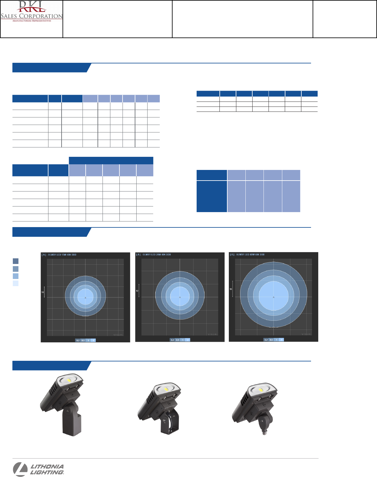
Accessories
Lumen values are from photometric tests performed in accordance with IESNA LM-79-08. Data is considered to be representative
of the configurations shown, within the tolerances allowed by Lighting Facts. Actual performance may differ as a result of end-
user environment and application. Actual wattage may differ by +/- 8% when operating between 120-347V +/- 10%.
Fixture Model Number CCT System Watts Lumens LPW B U G CRI
OLWX1 LED 13W 40K 4000 K 14 W 1,271 91 1 0 0 >70
OLWX1 LED 13W 50K 5000 K 14 W 1,289 92 1 0 0 >80
OLWX1 LED 20W 40K 4000 K 22 W 1,854 84 1 0 0 >70
OLWX1 LED 20W 50K 5000 K 22 W 1,860 84 1 0 0 >80
OLWX1 LED 40W 40K 4000 K 39 W 4,027 101 2 0 0 >70
OLWX1 LED 40W 50K 5000 K 37 W 4,079 110 2 0 0 >70
Performance Data
One Lithonia Way • Conyers, Georgia 30012 • Phone: 800.279.8041 • Fax: 770.918.1209 • www.lithonia.com
© 2014 Acuity Brands Lighting, Inc. All rights reserved.
Lumen Output Use these factors to determine relative lumen output for average ambient temperatures
from 0-40°C (32-104°F).
Lumen Ambient Temperature (LAT) Multipliers
0°C 10°C 20°C 25°C 30°C 40°C
13W 1.06 1.03 1.01 1.00 0.99 0.96
20W 1.06 1.04 1.01 1.00 0.99 0.96
40W 1.07 1.04 1.01 1.00 0.99 0.96
Projected LED Lumen Maintenance
Data references the extrapolated performance projections in a 25°C ambient, based
on 10,000 hours of LED testing (tested per IESNA LM-80-08 and projected per IESNA
TM-21-11).
To calculate LLF, use the lumen maintenance factor that corresponds to the desired number
of operating hours below. For other lumen maintenance values, contact factory.
Operating Hours 0 25,000 50,000 100,000
OLWX1 LED 13W 1.00 0.92 0.85 0.73
OLWX1 LED 20W 1.00 0.92 0.85 0.73
OLWX1 LED 40W 1.00 0.94 0.88 0.79
To see complete photometric reports or download .ies files for this product, visit the Lithonia Lighting OLWX1 LED homepage. Tested in
accordance with IESNA LM-79 and LM-80 standards
Photometric Diagrams
Test No. LTL22697 tested in accordance with IESNA LM-79-08.
LEGEND
0.2 fc
0.5 fc
1.0 fc
2.0 fc
OLWX1 LED 13W 40K, Mounting height = 10’ OLWX1 LED 20W 40K, Mounting height = 12’ OLWX1 LED 40W 40K, Mounting height = 15’
Test No. LTL22696 tested in accordance with IESNA LM-79-08. Test No. LTL22695 tested in accordance with IESNA LM-79-08.
Input current at given input voltage (amps)
Fixture Model Number Rated Power
(watts) 120V 208V 240V 277V 347V
OLWX1 LED 13W 40K 14 W 0.12 0.07 0.06 0.06 0.04
OLWX1 LED 13W 50K 14 W 0.12 0.07 0.06 0.06 0.04
OLWX1 LED 20W 40K 22 W 0.20 0.12 0.10 0.09 0.06
OLWX1 LED 20W 50K 22 W 0.20 0.12 0.10 0.09 0.06
OLWX1 LED 40W 40K 39 W 0.37 0.21 0.19 0.16 0.11
OLWX1 LED 40W 50K 37 W 0.37 0.21 0.19 0.16 0.11
Electrical Load
OLWX1 LED
Rev. 11/25/14
OLWX1TS
Sliptter – size 1
OLWX1YK
Yoke – size 1
OLWX1THK
Knuckle – size 1
Catalog Number
OLWX1 LED 13W 40K
Notes
Type
M
Project 15-18720-6
Teen Center - Los Alamos
Submitted By
RKL SALES CORP
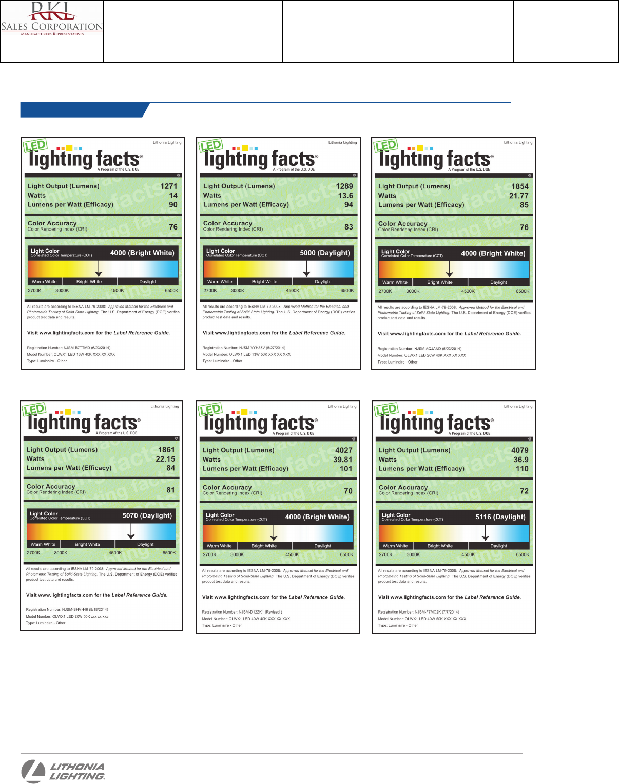
Lighting Facts Labels
One Lithonia Way • Conyers, Georgia 30012 • Phone: 800.279.8041 • Fax: 770.918.1209 • www.lithonia.com
© 2014 Acuity Brands Lighting, Inc. All rights reserved.
OLWX1 LED
Rev. 11/25/14
OLWX1 LED 13W 40K XXX XX XXX OLWX1 LED 13W 50K XXX XX XXX OLWX1 LED 20W 40K XXX XX XXX
OLWX1 LED 20W 50K XXX XX XXX OLWX1 LED 40W 40K XXX XX XXX OLWX1 LED 40W 50K XXX XX XXX
Catalog Number
OLWX1 LED 13W 40K
Notes
Type
M
Project 15-18720-6
Teen Center - Los Alamos
Submitted By
RKL SALES CORP
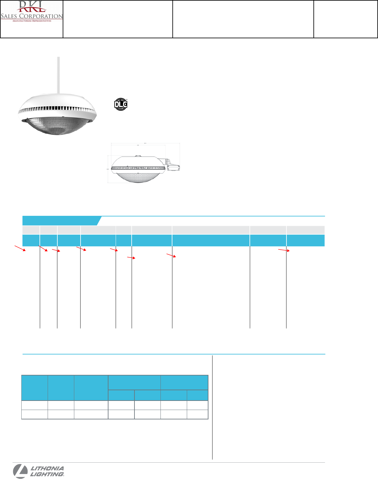
Lumen Performance
Note: Preliminary Performance
Package
System
Watts Distribution Type
40K
(4000K, 70 CRI)
50K
(5000K, 67 CRI)
Lumens LPW Lumens LPW
1 43W T5M 4000 93 4100 95
2 64W T5M 5500 86 5700 89
PENDING
PRELIMINARY SPECIFICATION
PGX LED
Series Package Color
temperature Distribution Voltage Mounting Control options Other options Finish (required)
PGX LED 1
2
40K 4000K
50K 5000K
T5M Type V medium MVOLT
120
208
240
277
347
480
Shipped included
(blank) Pendant mount
SRM Surface mount
Shipped separately
YK Yoke/trunnion
mount
Shipped installed
PIR360SS Motion/ambient sensor, 8-15’
mounting height
PIRH360SS Motion/ambien sensor, 15-30’
mounting height
XAD Wireless dimming controller
(Remote sensor)
XADPIR360SS Wireless dimming controller
(Integrated sensor 8-15’ mounting
height)
XADPIRH360SS Wireless dimming controller
(Integrated sensor 15-30’ mounting
height)
SPD10KV Separate surge protection
Shipped installed
SF Single fuse
(120, 277, 347V)
DF Double fuse
(208, 240, 480V)
BDS Bird shroud
DWHXD White
DNAXD Natural
aluminum
DDBXD Dark bronze
PGX LED
Parking Garage Luminaire
Specifications
Ordering Information EXAMPLE: PGX LED 1 40K T5M MVOLT PIR360SS DWHXD
NOTES
Catalog
Number
Notes
Type
Introduction
The PGX LED luminaire is designed to provide
energy savings, long life, and visual comfort.
Delivering up to 80% in energy savings when
replacing 175W metal halide luminaires, the PGX
LED offers over a 100,000 hour life expectancy,
significantly reducing maintenance costs.
The PGX LED’s prismatic borosilicate glass
lens delivers optimal visual comfort, superior
photometric control, and no discoloration over
the life of the luminaire.
Diameter: 16”
(40.6 cm)
Height: 8”
(20.3 cm)
Weight
(max):
TBD lbs
(TBD kg)
One Lithonia Way • Conyers, Georgia 30012 • Phone: 800.279.8041 • Fax: 770.918.1209 • www.lithonia.com
© 2011-2014 Acuity Brands Lighting, Inc. All rights reserved.
Hit the Tab key or mouse over the page to see all interactive elements.
PM
Catalog Number
PGX LED P1 40K T5M MVOLT PM PIR360SS DWHXD
Notes
Type
M1-ALT
Project 15-18720-6
Teen Center - Los Alamos
Submitted By
RKL SALES CORP

DECORATIVE INDOOR & OUTDOOR OLVT
Catalog
Number
Notes
Type
Outdoor General Purpose
OLVTCM & OLVTWM
LED VAPORTIGHT
FEATURES & SPECIFICATIONS
INTENDED USE
Provides years of maintenance-free illumination for indoor or outdoor use in residential & commercial
applications.
CONSTRUCTION
Cast-aluminum housing with corrosion-resistant paint in an industrial grey finish.
Sealed gasket protects against moisture and dust.
OPTICS
4000K CCT LEDs.
Frosted glass diffuser provides even light distribution.
LUMEN MAINTENANCE
LEDs will deliver 70% of their initial lumens at 50,000 hour average LED life. See Lighting Facts label on page
2 for performance details.
ELECTRICAL
MVOLT driver operates on any line voltage from 120-277V
Operating temperature -40ºC to 40ºC.
4kV surge protection standard.
INSTALLATION
Mounts to ceiling or wall with surface mount junction box (included).
LISTINGS
UL Listed to U.S. and Canadian safety standards for wet locations.
Tested in accordance with IESNA LM-79 and LM-80 standards.
WARRANTY
Five-year limited warranty. Full warranty terms located at
www.AcuityBrands.com/CustomerResources/Terms_and_Conditions.aspx
Actual performance may differ as a result of end-user environment and application.
All values are design or typical values, measured under laboratory conditions at 25 °C.
Note: Specifications are subject to change without notice.
Series Color temperature Voltage Finish
OLVTCM Ceiling MT
OLVTWM Wall MT
(blank) 4000K (blank) MVOLT (120V-277V) (blank) Grey
ORDERING INFORMATION For shortest lead times, configure products using bolded options. Example: OLVTCM
Specifications
All dimensions are inches (centimeters)
4-9/16
(11.5)
5-9/16
(14.1)
10-5/8
(26.9)
4-1/2
(11.4)
7-7/16
(18.8)
6
(15.2)
6
(15.2)
11-5/16
(28.6)
4-3/8
(11.1)
4-3/8
(11.1)
11-5/16
(28.6)
4-1/2
(11.4)
Catalog Number
OLVTCM
Notes
Type
N
Project 15-18720-6
Teen Center - Los Alamos
Submitted By
RKL SALES CORP
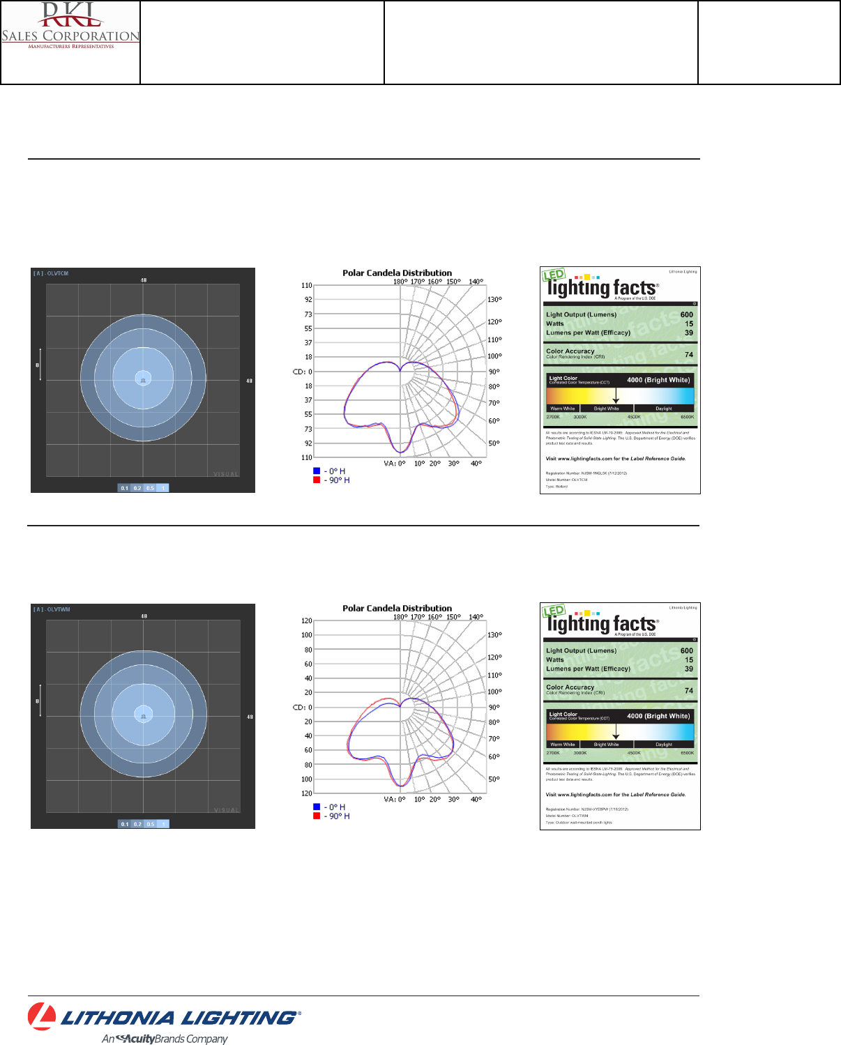
OLVT
DECORATIVE INDOOR & OUTDOOR: One Lithonia Way Conyers, GA 30012 Phone: 1-800-279-8041 Fax: 770-860-3903 www.lithonia.com © 2012-2015 Acuity Brands Lighting, Inc. All rights reserved. Rev. 09/15/15
OLVTCM & OLVTWM LED Vaportight
PHOTOMETRICS
To see complete photometric reports or download .ies files for this product,visit Lithonia Lighting’s Outdoor LED homepage
Tested in accordance with IESNA LM-79 and LM-80 standards.
OLVTCM
OLVTWM
Catalog Number
OLVTCM
Notes
Type
N
Project 15-18720-6
Teen Center - Los Alamos
Submitted By
RKL SALES CORP
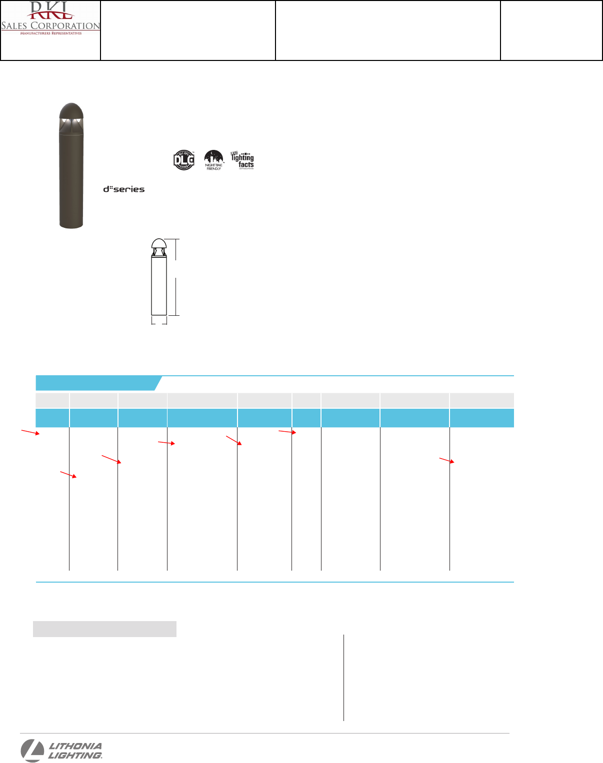
DSXB LED
Series LEDs Drive current Color temperature Distribution Voltage Control options Other options Finish (required)
DSXB LED Asymmetric
12C 12 LEDs1
Symmetric
16C 16 LEDs2
350 350 mA
450 450 mA 3,4
530 530 mA
700 700 mA
30K 3000 K
40K 4000 K
50K 5000 K
AMBPC Amber phosphor
converted
AMBLW Amber limited
wavelength 3,4
ASY Asymmetric 1
SYM Symmetric 2
MVOLT 5
120 5
208 5
240 5
277 5
347 4
Shipped installed
PE Photoelectric
cell, button
type
DMG 0-10V dim-
ming driver
(no controls)
ELCW Emergency
battery
backup6
Shipped installed
SF Single fuse
(120, 277,
347V) 4,7
DF Double fuse
(208, 240V) 4,7
H24 24” overall height
H30 30” overall height
H36 36” overall height
FG Ground-fault
festoon outlet
L/AB Without anchor
bolts
L/AB4 4-bolt retrot base
without anchor
bolts 8
DWHXD White
DNAXD Natural
aluminum
DDBXD Dark bronze
DBLXD Black
DDBTXD Textured dark
bronze
DBLBXD Textured
black
DNATXD Textured
natural
aluminum
DWHGXD Textured
white
MRAB U Anchor bolts for DSXB 8
Accessories
Ordered and shipped separately.
D
H
D-Series
LED Bollard
Specifications
Ordering Information
Catalog
Number
Notes
Type
Introduction
The D-Series LED Bollard is a stylish, energy-
saving, long-life solution designed to perform
the way a bollard should—with zero uplight. An
optical leap forward, this full cut-off luminaire
will meet the most stringent of lighting codes.
The D-Series LED Bollard’s rugged construction,
durable finish and long-lasting LEDs will provide
years of maintenance-free service.
Diameter: 8” Round
(20.3 cm)
Height: 42”
(106.7 cm)
Weight
(max): 27 lbs
(12.25 kg)
One Lithonia Way • Conyers, Georgia 30012 • Phone: 800.279.8041 • Fax: 770.918.1209 • www.lithonia.com
© 2012-2014 Acuity Brands Lighting, Inc. All rights reserved.
Hit the Tab key or mouse over the page to see all interactive elements.
EXAMPLE: DSXB LED 16C 700 40K SYM MVOLT DDBXD
NOTES
1 Only available in the 12C, ASY version.
2 Only available in the 16C, SYM version.
3 Only available with 450 AMBLW version.
4 Not available with ELCW.
5 MVOLT driver operates on any line voltage from 120-277V (50/60
Hz). Specify 120, 208, 240 or 277 options only when ordering
with fusing (SF, DF options), or photocontrol (PE option).
6 Not available with 347V. Not available with fusing. Not available
with 450 AMBLW.
7 Single fuse (SF) requires 120, 277, or 347 voltage option. Double
fuse (DF) requires 208 or 240 voltage option.
8 MRAB U not available with L/AB4 option.
Catalog Number
DSXB LED 16C 700 40K SYM MVOLT DDBXD
Notes
Type
P-ALT
Project 15-18720-6
Teen Center - Los Alamos
Submitted By
RKL SALES CORP
To see complete photometric reports or download .ies files for this product, visit Lithonia Lighting’s D-Series Bollard homepage.
Photometric Diagrams
Isofootcandle plots for the DSXB LED 700 40K. Distances are in units of mounting height (3’).
Test No. LTL24360-2 tested in accordance with
IESNA LM-79-08.
5 3 2 1 0
Test No. LTL24368 tested in accordance with
IESNA LM-79-08.
FEATURES & SPECIFICATIONS
INTENDED USE
The rugged construction and maintenance-free performance of the D-Series LED
Bollard is ideal for illuminating building entryways, walking paths and pedestrian
plazas, as well as any other location requiring a low-mounting-height light source.
CONSTRUCTION
One-piece 8-inch-round extruded aluminum shaft with thick side walls for extreme
durability, and die-cast aluminum reflector and top cap. Die-cast aluminum
mounting ring allows for easy leveling even in uneven areas and full 360-degree
rotation for precise alignment during installation. Three ½” x 11” anchor bolts
with double nuts and washers and 3-5/8” max. bolt circle template ensure stability.
Overall height is 42” standard.
FINISH
Exterior parts are protected by a zinc-infused super durable TGIC thermoset
powder coat finish that provides superior resistance to corrosion and weathering
for maximum retention of gloss and luster. A tightly controlled multi-stage process
ensures a minimum 3-mil thickness for a finish that can withstand the elements
without cracking or peeling. Available in both textured and non-textured finishes.
OPTICS
Two 0% uplight optical distributions are available: symmetrical and asymmetrical.
IP66 sealed LED light engine provides smoothly graduated illumination without
uplight. Light engines are available in standard 4000 K (>70 CRI) or optional 3000 K
(>80 CRI) or 5000 K (67 CRI). Limited-wavelength amber LEDs are also available.
ELECTRICAL
Light engines consist of high-efficacy LEDs mounted to metal-core circuit
boards to maximize heat dissipation and promote long life (L95/100,000 hours
at 700mA at 25°C). Class 2 electronic drivers are designed for an expected life
of 100,000 hours with < 1% failure rate. Electrical components are mounted on
a removable power tray.
LISTINGS
CSA certified to U.S. and Canadian standards. Light engines are IP66 rated.
Rated for -40°C minimum ambient. Cold-weather emergency battery backup
rated for -20°C minimum ambient.
DesignLights Consortium® (DLC) qualified product. Not all versions of this
product may be DLC qualified. Please check the DLC Qualified Products List at
www.designlights.org to confirm which versions are qualified.
WARRANTY
Five-year limited warranty. Complete warranty terms located at
www.acuitybrands.com/CustomerResources/Terms_and_conditions.aspx.
Note: Specifications subject to change without notice.
LEGEND
0.1 fc
0.5 fc
1.0 fc
3.0 fc
6.0 fc
4-1 -3 -4 -5-2 5 3 2 1 04 -1 -3 -4 -5-2
ASY
SYM
Lumen values are from photometric tests performed in accordance with IESNA LM-79-08. Data is considered to be representative of the configurations shown, within the tolerances allowed by Lighting Facts.
Actual performance may differ as a result of end-user environment and application. Actual wattage may differ by +/- 8% when operating between 120-480V +/- 10%.
Light
Engines
Drive
Current
System
Watts
3000 K 4000 K 5000 K Limited Wavelength Amber
Lumens LPW B U G Lumens LPW B U G Lumens LPW B U G Lumens LPW B U G
Asymmetric
3 Engines
(12 LEDs)
350 16 715 45 1 0 1 889 56 1 0 1 953 60 1 0 1
530 22 985 45 1 0 1 1,239 56 1 0 1 1,334 61 1 0 1
700 31 1,263 41 1 0 1 1,588 51 1 0 1 1,712 55 1 0 1
Amber 450 16 348 22 1 0 1
Symmetric
4 Engines
(16 LEDs)
350 20 923 46 1 0 1 1,161 58 1 0 1 1,251 63 1 0 1
530 28 1,274 46 1 0 1 1,603 57 1 0 1 1,726 62 1 0 1
700 39 1,634 42 1 0 1 2,055 53 1 0 1 2,215 57 1 0 1
Amber 450 20 419 21 1 0 1
Current (A)
Light
Engines
Drive Current
(mA)
System
Watts 120 208 240 277 347
12C
350 16W
0.158 0.118 0.114 0.109 0.105
530 22W
0.217 0.146 0.136 0.128 0.118
700 31W
0.296 0.185 0.168 0.153 0.139
Amber 450 16W
0.161 0.120 0.115 0.110 0.106
16C
350 20W
0.197 0.137 0.128 0.121 0.114
530 28W
0.282 0.178 0.162 0.148 0.135
700 39W
0.385 0.231 0.207 0.185 0.163
Amber 450 20W
0.199 0.139 0.130 0.123 0.116
Electrical Load
Projected LED Lumen Maintenance
Data references the extrapolated performance projections for the platforms noted in a
25°C ambient, based on 10,000 hours of LED testing (tested per IESNA LM-80-08 and
projected per IESNA TM-21-11).
To calculate LLF, use the lumen maintenance factor that corresponds to the desired number
of operating hours below. For other lumen maintenance values, contact factory.
Operating Hours 0 25,000 50,000 100,000
Lumen Maintenance
Factor 1.00 0.98 0.97 0.95
0
-4
-3
-2
-1
-5
2
3
4
5
1
0
-4
-3
-2
-1
-5
2
3
4
5
1
Note: Available with phosphor-converted amber LED’s (nomenclature AMBPC). These LED’s produce light with 97+% >530 nm. Output can be
calculated by applying a 0.7 factor to 4000 K lumen values and photometric files.
Performance Data
One Lithonia Way • Conyers, Georgia 30012 • Phone: 800.279.8041 • Fax: 770.918.1209 • www.lithonia.com
© 2012-2014 Acuity Brands Lighting, Inc. All rights reserved.
DSXB-LED
Rev. 7/14/14
Catalog Number
DSXB LED 16C 700 40K SYM MVOLT DDBXD
Notes
Type
P-ALT
Project 15-18720-6
Teen Center - Los Alamos
Submitted By
RKL SALES CORP
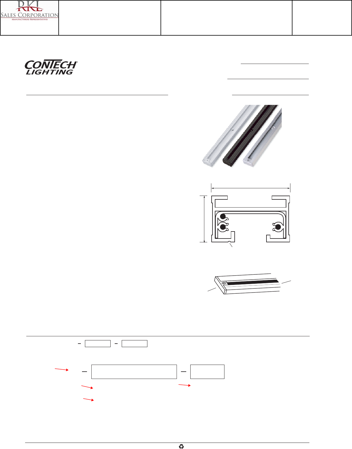
LA211 end caps are supplied with all track sections and may be ordered separately as needed.
See other sheets for Recessed Track Systems and 120V Track Accessories.
2', 4', and 6' sections supplied with (2) toggle bolts, 8' and 12' sections supplied with (3) toggle bolts.
LT
13/16"
1-3/8"
Groove
N
H1
H2
Example Order: LT 28 B
Finish
B - Black
P - White
S - Silver*
*Not Available in 12' Sections
2-Circuit Section Length
22 - 2' (24") Length; 20-1/8" Actual Length
24 - 4' (48") Length; 44-1/8" Actual Length
26 - 6' (72") Length; 68-1/8" Actual Length
28 - 8' (96") Length; 92-1/8" Actual Length
212 - 12' (144") Length; 140-1/8" Actual Length
End Cap
Groove
Track Section End View
Ordering Information
Specifications/Features
Track
Versitile 2-circuit, 120V rated commercial grade track sections. 40
amp capacity; 20 amps per circuit. Two (2) hot conductors and one
common neutral.
Split lighting loads over one run of track for higher wattage output per
running foot of track.
Change lighting effects by simply applying fixtures to desired circuits
and utilize separate switching.
Track has solid copper conductors with Noryl® insulators placed in
heavy 14 ga. extruded aluminum channels.
Mechanial polarity with a visual indicator simplifies installation and
mounting of fixtures while assuring proper electrical connections. All
ConTech track fixtures have two position contacts to access 1-circuit
conductors.
Toggle bolts are supplied for simple surface installation.
Nominal length track sections can be cut in the field for exact fit.
Set of shims supplied (1 per foot of track) to lock fixture contacts into
second circuit position.
Strong “H” design construction.
Track sections may be mounted within ConTech's Recessed Track
Housing System to minimize appearance.
Mounting accessories available for T-Bar clips, stems, threaded rods,
and aircraft cable.
All track sections are supplied with two insulated end caps.
Warranty
This fixture is covered by ConTech’s full one (1) year replacement
guarantee after date of purchase.
Listing
cULus listed. Suitable for dry locations.
www.contechlighting.com1-847-559-5500 All specifications subject to change without notice.
Recycle
Please
Catalog No.
Type
Project
LT
Two-Circuit Line Voltage Track
Catalog Number
LT-24-B
Notes
Type
T4
Project 15-18720-6
Teen Center - Los Alamos
Submitted By
RKL SALES CORP
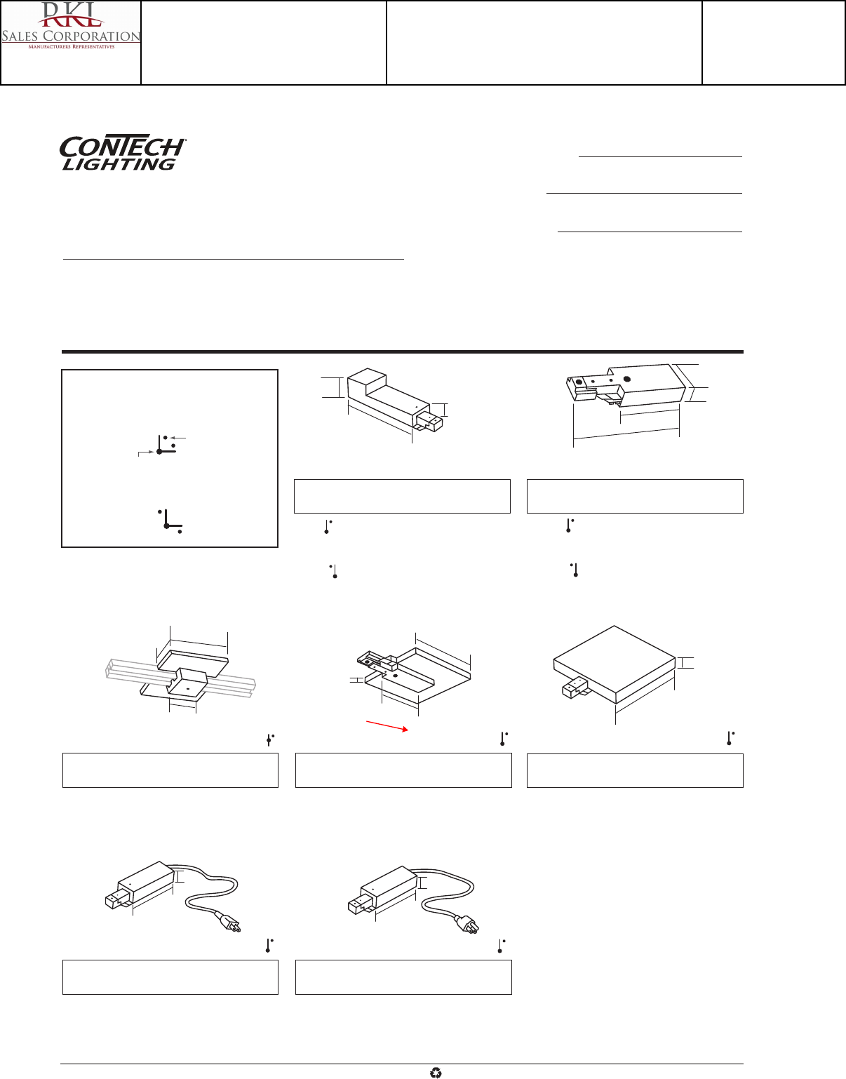
3-1/4"
3/4"
3-1/4"
3/4"
4-3/16"
5/16"
3-1/4"
15/16"
4-1/8"
4-5/8"
1-9/16"
2-1/4"
1-1/2"
Overall Depth
Polarity-Configuration Legend
Reverse Polarity Configuration
Forward Polarity Configuration
Hot Side of
Connector
Feed Point
T-Bar End Feed: LA-20
Ceiling End Feed has 4 1/8" square canopy cover.
(3) 1/2" top K.O.'s can be used with T-grid installa-
tions. Finish: -B, P
Floating Feed Point: LA-7
Can be installed anywhere along track. Kit includes
square J-Box Canopy Cover, J-Box Mounting
Bracket, Track Adaptor, and one LA-211 Series
End Cap. Finish: -B, P, S
Outlet Box Feed Kit: LA-9
Square Cover Plate With End Feed. (1) 1/2" K.O.
Kit includes J-Box Mounting Bracket, Threaded
Nipple And Nut. Finish: -B, P, S
2-Wire Cord & Plug Feed: LA-5
18 Gauge 14' End Feed Cord, 10A Max., Optional
6A/125V switch, cut-out in cover for cord, not UL
Listed.
Finish: -B, P
3-Wire Cord & Plug Feed: LA-6
18 Gauge 14' End Feed Cord, 10 Amps Max.,
grounded plug and connections, cut-out in cover for
cord, not UL Listed
. Finish: -B, P
1-1/2"
4-5/8"
5/8"
4-7/8"
3-1/4"
5/8"
1-3/8"
Top Access End Feed
LA-10
Power Feed. (1) 1/2" top K.O. for standard
electrical conduit.
Finish: -B, P, S
LA-10A
Reverse Polarity Power Feed. (1) 1/2" top K.O. for
standard electrical conduit.
Finish: -B, P, S
Surface Conduit End Feed
LA-8
End Feed. (1) 1/2" top K.O. and (1) 1/2" end K.O.
for surface conduit. Finish: -B, P, S
LA-8A
Reverse Polarity End Feed. (1) 1/2" top K.O. and (1)
1/2" end K.O. for surface conduit. Finish: -B, P, S
Power feeds are constructed of sturdy polycarbonate with galvanized steel
back plates. Every electrical component is polarized and has a grounding
capability to ensure safe usage. Visual polarity indicators simplify proper
electrical installation. Twelve gauge insulated wire is used for internal connec-
tions. Solid copper track contacts provide good electrical conductivity for
years of trouble free operation.
All track components are cULus listed except for LA-5 and LA-6. Installations
are suitable for dry locations only. Maximum power rating is 2400 Watts: 20A
at 120V, 60Hz. NEC allows 80% of full capacity or 1920 Watts.
Continued on page 2
Single-Circuit Track
Power Feeds
Specifications/Features
Catalog No.
Type
Project
www.contechlighting.com1-847-559-5500 All specifications subject to change without notice.
Recycle
Please
Double-Circuit
209
Catalog Number
LA-209-B
Notes
Type
T4
Project 15-18720-6
Teen Center - Los Alamos
Submitted By
RKL SALES CORP

Sample System Installations
Polarity Arrow In Connectors
(Hot Side)
Polarity Groove In Track Section
(Hot Side)
Line Up Polarity Arrows with Grooves, Insert Connectors Into Track Sections to Assemble Components
Floor View of Track on Ceiling
All Straight Sections are LT Series Track
Dot = Connector Polarity Arrow Location
Shaded Area = Hot Side Of Connector/Track Section
LA-10 LT- 4
LA-10
LA-7
LA-8
LA-12
Surface Conduit
LA-9
LA-3
LA-12
LA-12 LA-20
LA-14
LA-13
LA-4
Put Feed Point
at any Connector
LA-12 LA-12LA-14
LA-12 LA-14
LA-13
LA-15
LA-13
LA-12
LA-4
Put Feed Point
at any Connector
LA-15
LA-4
Put Feed Point
at any Connector
Sample Layouts with Polarity
Continued on page 2
Single-Circuit Track
Power Feeds Catalog No.
Type
Project
www.contechlighting.com1-847-559-5500 All specifications subject to change without notice.
Recycle
Please
Catalog Number
LA-209-B
Notes
Type
T4
Project 15-18720-6
Teen Center - Los Alamos
Submitted By
RKL SALES CORP
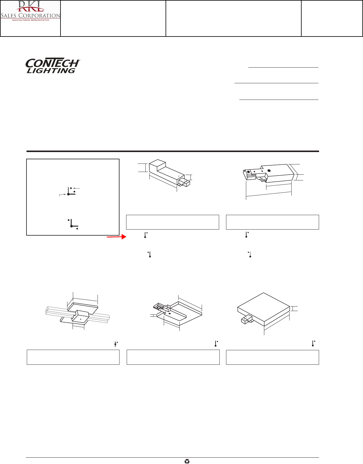
4-3/16"
5/16"
3-1/4"
15/16"
4-1/8"
4-5/8"
1-9/16"
2-1/4"
1-5/8"
Overall Depth
Polarity-Configuration Legend
Reverse Polarity Configuration
Forward Polarity Configuration
Hot Side of
Connector
Feed Point
T-Bar End Feed: LA-220
Ceiling End Feed has 4 1/8" square canopy cover.
(3) 1/2" top K.O.'s can be used with T-grid installa-
tions. Finish: -B, P
Floating Feed Point: LA-207
Can be installed anywhere along track. Kit includes
square J-Box Canopy Cover, J-Box Mounting
Bracket, Track Adaptor, and one LA-211 Series
End Cap. Finish: -B, P, S
Outlet Box Feed Kit: LA-209
Square Cover Plate With End Feed. (1) 1/2" K.O.
Kit includes J-Box Mounting Bracket, Threaded
Nipple And Nut. Finish: -B, P, S
1-1/2"
4-5/8"
5/8"
4-7/8"
3-1/4"
5/8"
1-3/8"
Top Access End Feed
LA-210
Power Feed. (1) 1/2" top K.O. for standard
electrical conduit.
Finish: -B, P, S
LA-210A
Reverse Polarity Power Feed. (1) 1/2" top K.O. for
standard electrical conduit.
Finish: -B, P, S
Surface Conduit End Feed
LA-208
End Feed. (1) 1/2" top K.O. and (1) 1/2" end K.O.
for surface conduit. Finish: -B, P, S
LA-208A
Reverse Polarity End Feed. (1) 1/2" top K.O. and (1)
1/2" end K.O. for surface conduit. Finish: -B, P, S
Power feeds are constructed of sturdy polycarbonate with galvanized steel
back plates. Every electrical component is polarized and has a grounding
capability to ensure safe usage. Visual polarity indicators simplify proper
electrical installation. Twelve gauge insulated wire is used for internal connec-
tions. Solid copper track contacts provide good electrical conductivity for
years of trouble free operation.
All track components are cULus listed. Installations are suitable for dry
locations only. Maximum power rating is 2400 Watts per circuit (4800W
total): 20A per circuit (40A total capacity) at 120V, 60Hz. NEC allows 80% of
full capacity or 1920 Watts per circuit (3840W total).
Continued on page 2
Two-Circuit Track
Power Feeds Catalog No.
Type
Project
www.contechlighting.com1-847-559-5500 All specifications subject to change without notice.
Recycle
Please
Catalog Number
LA-208-B
Notes
Type
TPF
Project 15-18720-6
Teen Center - Los Alamos
Submitted By
RKL SALES CORP

Sample System Installations
Polarity Arrow In Connectors
(Hot Side)
Polarity Groove In Track Section
(Hot Side)
Line Up Polarity Arrows with Grooves, Insert Connectors Into Track Sections to Assemble Components
Floor View of Track on Ceiling
All Straight Sections are LT Series Track
Dot = Connector Polarity Arrow Location
Shaded Area = Hot Side Of Connector/Track Section
LA-210 LT-24
LA-210
LA-207
LA-208
LA-212
Surface Conduit
LA-209
LA-203
LA-212
LA-212 LA-220
LA-214
LA-213
LA-4
Put Feed Point
at any Connector
LA-212 LA-212LA-214
LA-212 LA-214
LA-213
LA-215
LA-213
LA-212
LA-4
Put Feed Point
at any Connector
LA-215
LA-4
Put Feed Point
at any Connector
Sample Layouts with Polarity
Two-Circuit Track
Power Feeds Catalog No.
Type
Project
www.contechlighting.com1-847-559-5500 All specifications subject to change without notice.
Recycle
Please
Catalog Number
LA-208-B
Notes
Type
TPF
Project 15-18720-6
Teen Center - Los Alamos
Submitted By
RKL SALES CORP
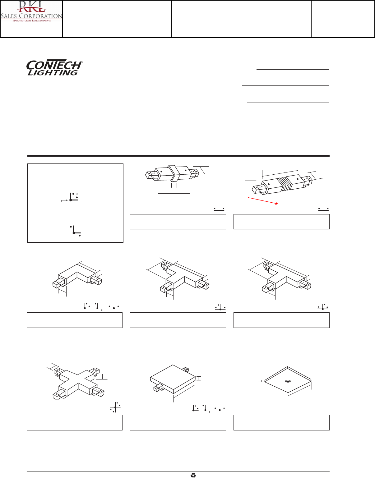
Outlet Box Cover Plate: LA-4
Square Cover Plate with threaded center access
hole. Includes grounding washer, threaded nipple
and nut. For use with LA-212, LA-213, LA-214 or
LA-215. Covers 4" octagonal J-Box. Finish: -B, P, S
Polarity-Configuration Legend
Reverse Polarity Configuration
Forward Polarity Configuration
Hot Side of
Connector
Feed Point
1-1/2"
7/8"
5-7/8"
1-3/8"
2-11/16"
5/16"
2-3/4"
3/4"
1-3/8"
4-1/8"
2-3/4"
3/4"
1-3/8"
4-1/8"
2-3/4"
3/4"
1-3/8"
7-3/8" x 4-1/8"
3/4"
1-7/16"
15/16"
4-1/8"
“X” Connector: LA-215
(1) 1/2" top K.O. that can be used as feed point,
wired as two separate “L” sections. Finish: -B, P, S
T-Bar Connector: LA-231
Connector with square canopy cover. (3) 1/2" top
K.O.'s. Can be used as straight connector feed
with T-grid installations. Can be configured as a
standard “L” connector, reverse polarity “L”
connector or straight connector. Finish: -B, P
“T” Connector: LA-213
(1) 1/2" top K.O. can be used as feed point.
Finish: -B, P, S
“T” Connector: LA-214
Reverse Polarity "T" Connector. (1) 1/2" top K.O.
which can be used as feed point. Finish: -B, P, S
Mini-Connectors: LA-202
Conductive End To End Connector
Finish: -B, P, S
Flexible Connector: LA-203
Versatile connector allows wall to ceiling or
pitched ceiling applications: ±90° horizontal range
(max.); ±135° vertical range (max.). Finish: -B, P, S
3-Way Joiner: LA-212
Use as standard “L” or reverse polarity “L”.
Includes optional straight cover. Connector has (1)
1/2" top K.O. that can be used as power feed.
Finish: -B, P, S
Connectors are constructed of sturdy polycarbonate with galvanized steel
back plates. Every electrical component is polarized and has a grounding
capability to ensure safe usage. Visual polarity indicators simplify proper
electrical installation. Twelve gauge insulated wire is used for internal connec-
tions. Solid copper track contacts provide good electrical conductivity for
years of trouble free operation.
All track components are cULus. Installations are suitable for dry locations
only. Maximum power rating is 2400 Watts per circuit (4800W total): 20A per
circuit (40A total capacity) at 120V, 60Hz. NEC allows 80% of full capacity or
1920 Watts per circuit (3840W total).
4-1/8"
1/16"
Continued on page 2
Two-Circuit Track
Connection Accessories Catalog No.
Type
Project
www.contechlighting.com1-847-559-5500 All specifications subject to change without notice.
Recycle
Please
Catalog Number
LA-203-B
Notes
Type
TFC
Project 15-18720-6
Teen Center - Los Alamos
Submitted By
RKL SALES CORP
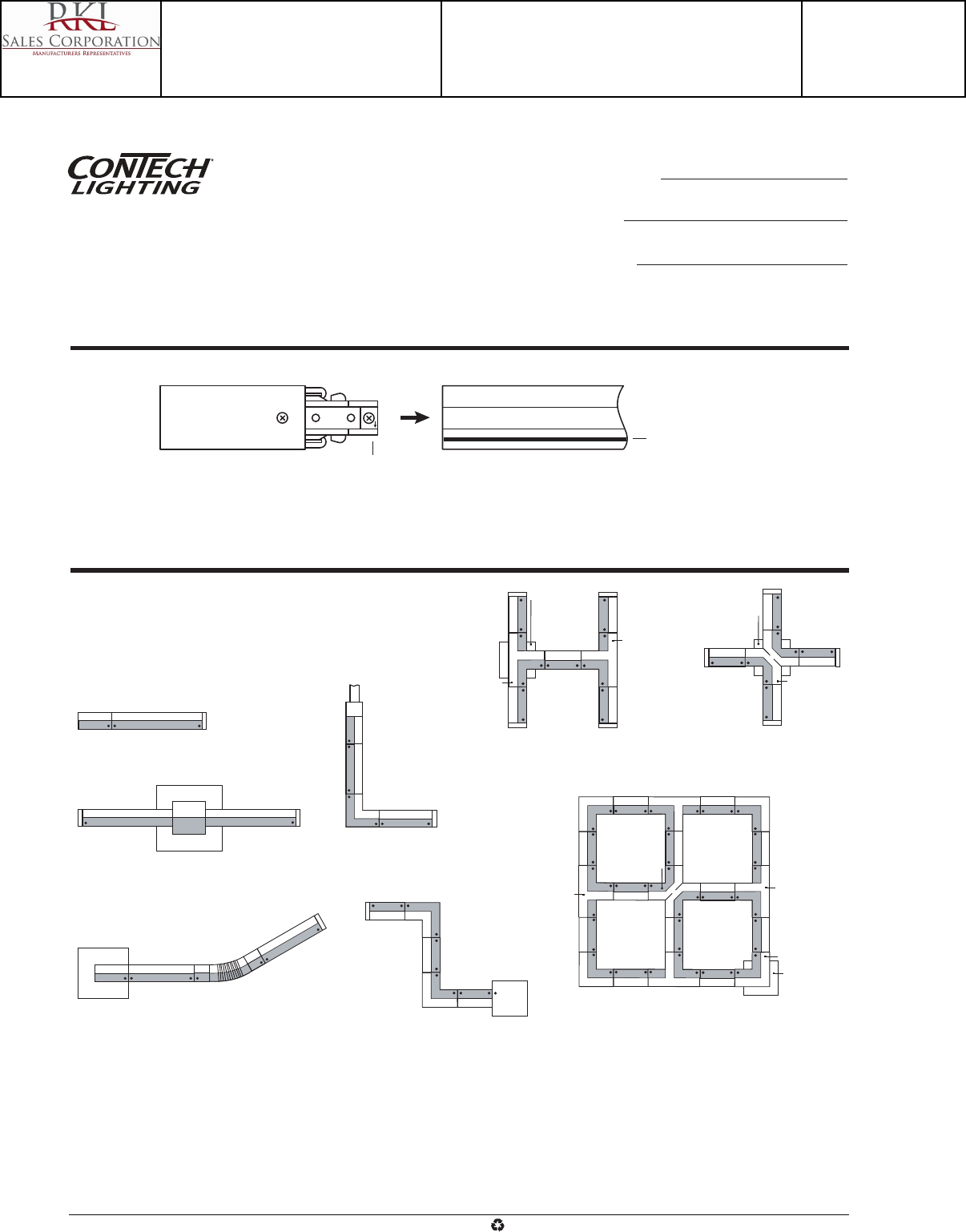
Sample System Installations
Polarity Arrow In Connectors
(Hot Side)
Polarity Groove In Track Section
(Hot Side)
Line Up Polarity Arrows with Grooves, Insert Connectors Into Track Sections to Assemble Components
Floor View of Track on Ceiling
All Straight Sections are LT Series Track
Dot = Connector Polarity Arrow Location
Shaded Area = Hot Side Of Connector/Track Section
LA-210 LT-24
LA-210
LA-207
LA-208
LA-212
Surface Conduit
LA-209
LA-203
LA-212
LA-212 LA-220
LA-214
LA-213
LA-4
Put Feed Point
at any Connector
LA-212 LA-212LA-214
LA-212 LA-214
LA-213
LA-215
LA-213
LA-212
LA-4
Put Feed Point
at any Connector
LA-215
LA-4
Put Feed Point
at any Connector
Sample Layouts with Polarity
Two-Circuit Track
Connection Accessories Catalog No.
Type
Project
www.contechlighting.com1-847-559-5500 All specifications subject to change without notice.
Recycle
Please
Catalog Number
LA-203-B
Notes
Type
TFC
Project 15-18720-6
Teen Center - Los Alamos
Submitted By
RKL SALES CORP
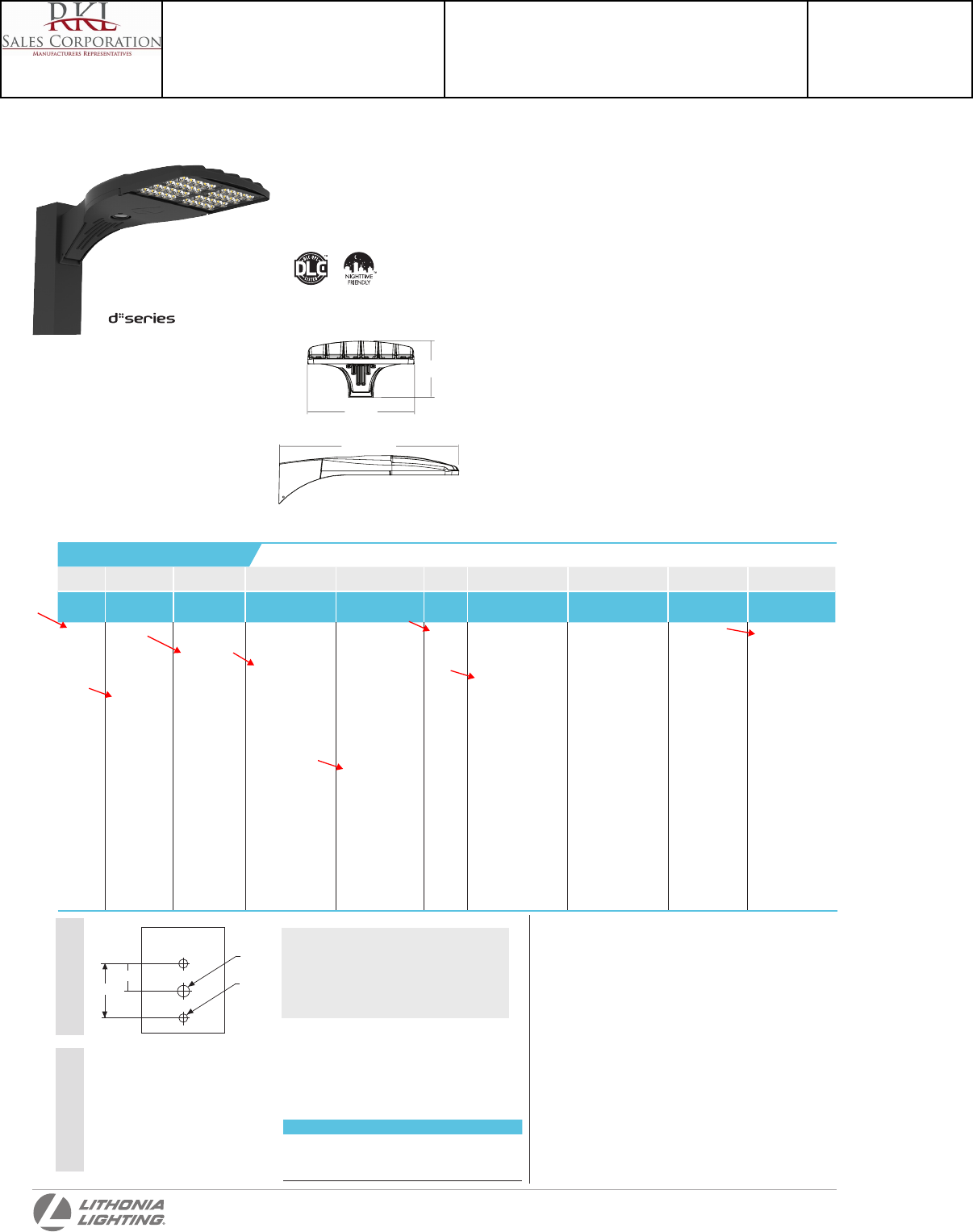
D-Series
Size 0
LED Area Luminaire
Specifications
NOTES
1 30 LEDs (30C option) and rotated options (L90 or R90) only available together.
2 1000mA is not available with AMBPC.
3 AMBPC only available with 530mA or 700mA.
4 MVOLT driver operates on any line voltage from 120-277V (50/60 Hz). Specify 120,
208, 240 or 277 options only when ordering with fusing (SF, DF options).
5 Not available with single-board, 530 mA product (20C 530 or 30C 530). Not
available with DCR, BL30, or BL50.
6 Available as a separate combination accessory: PUMBA (finish) U.
7 Must be ordered as a separate accessory; see Accessories information. For use
with 2-3/8” mast arm (not included).
8 Photocell ordered and shipped as a separate line item from Acuity Brands
Controls. See accessories.
9 DMG option for 347v or 480v requires 1000mA.
10 Specifies a ROAM® enabled luminaire with 0-10V dimming capability; PER option
required. Not available with 347 or 480V. Additional hardware and services
required for ROAM® deployment; must be purchased separately. Call 1-800-442-
6745 or email: sales@roamservices.net. N/A BL30, BL50, PIR, or PIRH.
11 PIR specifies the SensorSwitch SBGR-10-ODP control; PIRH specifies the
SensorSwitch SBGR-6-ODP control; see Motion Sensor Guide for details. Dimming
driver standard. Not available with DCR.
12 Requires an additional switched circuit. Dimming driver standard. MVOLT only.
Not available with DCR.
13 Also available as a separate accessory; see Accessories information. HS and DDL
are not available together.
14 Single fuse (SF) requires 120, 277 or 347 voltage option. Double fuse (DF) requires
208, 240 or 480 voltage option.
15 Requires luminaire to be specified with PER option. Ordered and shipped as a
separate line item from Acuity Brands Controls.
Drilling
Catalog
Number
Notes
Type
Introduction
The modern styling of the D-Series is striking
yet unobtrusive - making a bold, progressive
statement even as it blends seamlessly with its
environment.
The D-Series distills the benefits of the latest in LED
technology into a high performance, high efficacy,
long-life luminaire. The outstanding photometric
performance results in sites with excellent
uniformity, greater pole spacing and lower power
density. It is ideal for replacing up to 400W metal
halide with typical energy savings of 65% and
expected service life of over 100,000 hours.
Tenon O.D. Single Unit 2 at 180° 2 at 90° 3 at 120° 3 at 90° 4 at 90°
2-3/8” AST20-190 AST20-280 AST20-290 AST20-320 AST20-390 AST20-490
2-7/8” AST25-190 AST25-280 AST25-290 AST25-320 AST25-390 AST25-490
4” AST35-190 AST35-280 AST35-290 AST35-320 AST35-390 AST35-490
Tenon Mounting Slipfitter
**
EPA: 0.8 ft2
(.07 m2)
Length: 26”
(66.0 cm)
Width: 13”
(33.0 cm)
Height: 7”
(17.8 cm)
Weight
(max): 16 lbs
(7.25 kg)
Top of Pole
0.563”
2.650”
1.325” 0.400”
(2 PLCS)
Visit Lithonia Lighting’s POLES CENTRAL to see our wide selection of poles, accessories and educational
tools.
DSX0 shares a unique drilling pattern with the AERIS™ family. Specify
this drilling pattern when specifying poles, per the table below.
DM19AS Single unit DM29AS 2 at 90° *
DM28AS 2 at 180° DM39AS 3 at 90° *
DM49AS 4 at 90° * DM32AS 3 at 120° **
Example: SSA 20 4C DM19AS DDBXD
One Lithonia Way • Conyers, Georgia 30012 • Phone: 800.279.8041 • Fax: 770.918.1209 • www.lithonia.com
© 2011-2014 Acuity Brands Lighting, Inc. All rights reserved.
Template #8
Hit the Tab key or mouse over the page to see all interactive elements.
L
H
W
*Round pole top must be 3.25” O.D. minimum.
**For round pole mounting (RPA) only.
Accessories
Ordered and shipped separately.
For more control options, visit DTL and ROAM online.
DLL127F 1.5 JU Photocell - SSL twist-lock (120-277V) 15
DLL347F 1.5 CUL JU Photocell - SSL twist-lock (347V) 15
DLL480F 1.5 CUL JU Photocell - SSL twist-lock (480V) 15
SC U Shorting cap 15
DSX0HS 20C U House-side shield for 20 LED unit 13
DSX0HS 30C U House-side shield for 30 LED unit 13
DSX0HS 40C U House-side shield for 40 LED unit 13
DSX0DDL U Diused drop lens (polycarbonate) 13
PUMBA DDBXD U* Square and round pole universal mounting
bracket adaptor (specify nish)
KMA8 DDBXD U Mast arm mounting bracket adaptor
(specify nish) 7
DSX0 LED
Series LEDs Drive current Color temperature Distribution Voltage Mounting Control options Other options Finish (required)
DSX0 LED Forward
optics
20C 20 LEDs
(one
engine)
40C 40 LEDs
(two
engines)
Rotated
optics1
30C 30 LEDs
(one
engine)
530 530 mA
700 700 mA
1000 1000 mA
(1 A) 2
30K 3000 K 80
CRI min.)
40K 4000 K (70
CRI min.)
50K 5000 K (70
CRI)
AMBPC Amber
phosphor
converted 3
T1S Type I short
T2S Type II short
T2M Type II
medium
T3S Type III short
T3M Type III
medium
T4M Type IV
medium
TFTM Forward
throw
medium
T5VS Type V very
short
T5S Type V short
T5M Type V
medium
T5W Type V wide
MVOLT 4
120 4
208 4
240 4
277 4
347 5
480 5
Shipped included
SPA Square pole
mounting
RPA Round pole
mounting
WBA Wall bracket
SPUMBA Square pole
universal
mounting
adaptor 6
RPUMBA Round pole
universal
mounting
adaptor 6
Shipped separately 7
KMA8
DDBXD U
Mast arm
mounting
bracket adap-
tor (specify
nish)
Shipped installed
PER NEMA twist-lock
receptacle only
(no controls) 8
DMG 0-10V dimming
driver (no
controls) 9
DCR Dimmable and
controllable
via ROAM® (no
controls) 10
PIR Motion sensor,
8-15’ mounting
height 11
PIRH Motion sensor,
15-30’ mounting
height 11
BL30 Bi-level switched
dimming, 30% 12
BL50 Bi-level switched
dimming, 50% 12
Shipped
installed
HS House-side
shield 13
SF Single fuse
(120, 277,
347V) 14
DF Double fuse
(208, 240,
480V) 14
L90 Left rotated
optics 1
R90 Right
rotated
optics 1
DDL Diffused
drop lens 13
DDBXD Dark
bronze
DBLXD Black
DNAXD Natural
aluminum
DWHXD White
DDBTXD Textured
dark
bronze
DBLBXD Textured
black
DNATXD Textured
natural
aluminum
DWHGXD Textured
white
Ordering Information EXAMPLE: DSX0 LED 40C 1000 40K T3M MVOLT SPA DDBXD
Catalog Number
DSX0 LED 40C 700 40K TFTM MVOLT RPA DDBXD
Notes
Type
S1
Project 15-18720-6
Teen Center - Los Alamos
Submitted By
RKL SALES CORP
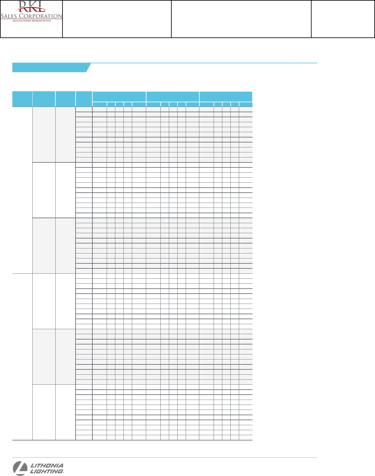
Lumen values are from photometric tests performed in accordance with IESNA LM-79-08. Data is considered to be representative of the configurations shown, within the tolerances allowed by Lighting Facts. Actual performance
may differ as a result of end-user environment and application.
Actual wattage may differ by +/- 8% when operating between 120-480V +/-10%. Contact factory for performance data on any configurations not shown here.
LEDs Drive Current
(mA)
System
Watts
Dist.
Type
30K
(3000 K, 85 CRI)
40K
(4000 K, 70 CRI)
50K
(5000 K, 70 CRI)
Lumens B U G LPW Lumens B U G LPW Lumens B U G LPW
20C
(20 LEDs)
530 mA 35W
T1S 2,904 1 0 1 83 3,655 1 0 1 104 3,941 1 0 1 113
T2M 2,902 1 0 1 83 3,652 1 0 1 104 3,937 1 0 1 112
T2S 2,959 1 0 1 85 3,723 1 0 1 106 4,014 1 0 1 115
T3M 2,952 1 0 1 84 3,715 1 0 1 106 4,005 1 0 1 114
T3S 2,923 1 0 1 84 3,679 1 0 1 105 3,966 1 0 1 113
T4M 2,937 1 0 1 84 3,696 1 0 1 106 3,984 1 0 1 114
T5M 3,037 2 0 1 87 3,823 2 0 1 109 4,121 3 0 1 118
T5S 3,074 2 0 0 88 3,869 2 0 0 111 4,171 2 0 0 119
T5VS 3,028 2 0 0 87 3,811 2 0 0 109 4,109 2 0 0 117
T5W 3,044 2 0 1 87 3,831 3 0 1 109 4,130 3 0 1 118
TFTM 2,903 1 0 1 83 3,653 1 0 1 104 3,939 1 0 2 113
700 mA 45 W
T1S 3,599 1 0 1 80 4,524 1 0 1 101 4,902 1 0 1 109
T2M 3,596 1 0 1 80 4,520 1 0 1 100 4,898 1 0 1 109
T2S 3,667 1 0 1 81 4,608 1 0 1 102 4,994 1 0 1 111
T3M 3,658 1 0 1 81 4,598 1 0 1 102 4,983 1 0 2 111
T3S 3,623 1 0 1 81 4,554 1 0 1 101 4,935 1 0 1 110
T4M 3,639 1 0 1 81 4,574 1 0 2 102 4,957 1 0 2 110
T5M 3,764 2 0 1 84 4,731 3 0 1 105 5,127 3 0 1 114
T5S 3,810 2 0 0 85 4,788 2 0 0 106 5,189 2 0 0 115
T5VS 3,753 2 0 0 83 4,717 2 0 0 105 5,112 2 0 0 114
T5W 3,772 3 0 1 84 4,741 3 0 1 105 5,138 3 0 1 114
TFTM 3,598 1 0 1 80 4,522 1 0 2 100 4,900 1 0 2 109
1000 mA 72 W
T1S 4,654 1 0 1 65 6,206 2 0 2 86 6,640 2 0 2 92
T2M 4,650 1 0 1 65 6,200 2 0 2 86 6,634 2 0 2 92
T2S 4,741 1 0 1 66 6,322 2 0 2 88 6,764 2 0 2 94
T3M 4,730 1 0 2 66 6,307 2 0 2 88 6,749 2 0 2 94
T3S 4,685 1 0 1 65 6,246 1 0 2 87 6,684 2 0 2 93
T4M 4,706 1 0 2 65 6,275 1 0 2 87 6,714 2 0 2 93
T5M 4,868 3 0 1 68 6,490 3 0 1 90 6,945 3 0 1 96
T5S 4,926 2 0 0 68 6,568 2 0 0 91 7,028 2 0 0 98
T5VS 4,853 2 0 0 67 6,471 2 0 0 90 6,924 3 0 0 96
T5W 4,878 3 0 1 68 6,504 3 0 2 90 6,959 3 0 2 97
TFTM 4,652 1 0 2 65 6,203 1 0 2 86 6,637 1 0 2 92
40C
(40 LEDs)
530 mA 68W
T1S 5,579 1 0 1 82 7,019 2 0 2 103 7,565 2 0 2 111
T2M 5,574 2 0 2 82 7,012 2 0 2 103 7,558 2 0 2 111
T2S 5,683 1 0 1 84 7,150 2 0 2 105 7,706 2 0 2 113
T3M 5,670 1 0 2 83 7,133 2 0 2 105 7,688 2 0 2 113
T3S 5,615 1 0 2 83 7,065 2 0 2 104 7,614 2 0 2 112
T4M 5,641 1 0 2 83 7,097 2 0 2 104 7,649 2 0 2 112
T5M 5,835 3 0 1 86 7,340 3 0 1 108 7,912 3 0 2 116
T5S 5,905 2 0 0 87 7,429 3 0 0 109 8,007 3 0 1 118
T5VS 5,817 2 0 0 86 7,318 3 0 0 108 7,888 1 0 2 116
T5W 5,847 3 0 1 86 7,355 3 0 2 108 7,928 3 0 2 117
TFTM 5,576 1 0 2 82 7,015 1 0 2 103 7,561 2 0 2 111
700 mA 91 W
T1S 7,074 2 0 2 78 8,930 2 0 2 98 9,619 2 0 2 106
T2M 7,068 2 0 2 78 8,922 2 0 2 98 9,610 2 0 2 106
T2S 7,207 2 0 2 79 9,097 2 0 2 100 9,798 2 0 2 108
T3M 7,190 2 0 2 79 9,076 2 0 2 100 9,776 2 0 2 107
T3S 7,121 2 0 2 78 8,988 2 0 2 99 9,682 2 0 2 106
T4M 7,153 2 0 2 79 9,029 2 0 2 99 9,726 2 0 2 107
T5M 7,399 3 0 2 81 9,339 3 0 2 103 10,060 3 0 2 111
T5S 7,488 3 0 0 82 9,452 3 0 1 104 10,181 3 0 1 112
T5VS 7,377 3 0 0 81 9,311 3 0 1 102 10,030 3 0 1 110
T5W 7,414 3 0 2 81 9,359 4 0 2 103 10,080 4 0 2 111
TFTM 7,071 1 0 2 78 8,926 2 0 3 98 9,614 2 0 3 106
1000 mA 138W
T1S 9,557 2 0 2 69 12,020 2 0 2 87 12,957 3 0 3 94
T2M 9,548 2 0 2 69 12,009 3 0 3 87 12,946 3 0 3 94
T2S 9,735 2 0 2 71 12,245 3 0 3 89 13,199 3 0 3 96
T3M 9,713 2 0 2 70 12,217 2 0 3 89 13,169 3 0 3 95
T3S 9,619 2 0 2 70 12,099 2 0 2 88 13,042 2 0 2 95
T4M 9,663 2 0 2 70 12,154 2 0 3 88 13,102 2 0 3 95
T5M 9,995 3 0 2 72 12,571 4 0 2 91 13,552 4 0 2 98
T5S 10,115 3 0 1 73 12,723 3 0 1 92 13,715 3 0 1 99
T5VS 9,965 3 0 1 72 12,534 3 0 1 91 13,511 3 0 1 98
T5W 10,015 4 0 2 73 12,597 4 0 2 91 13,579 4 0 2 98
TFTM 9,552 2 0 3 69 12,015 2 0 3 87 12,951 1 0 2 94
Note: Available with phosphor-converted amber LED’s (nomenclature AMBPC). These LED’s produce light with 97+% >530 nm. Output can be calculated by
applying a 0.7 factor to 4000 K lumen values and photometric files.
Performance Data
One Lithonia Way • Conyers, Georgia 30012 • Phone: 800.279.8041 • Fax: 770.918.1209 • www.lithonia.com
© 2011-2014 Acuity Brands Lighting, Inc. All rights reserved.
Lumen Output
DSX0-LED
Rev. 10/07/14
Catalog Number
DSX0 LED 40C 700 40K TFTM MVOLT RPA DDBXD
Notes
Type
S1
Project 15-18720-6
Teen Center - Los Alamos
Submitted By
RKL SALES CORP
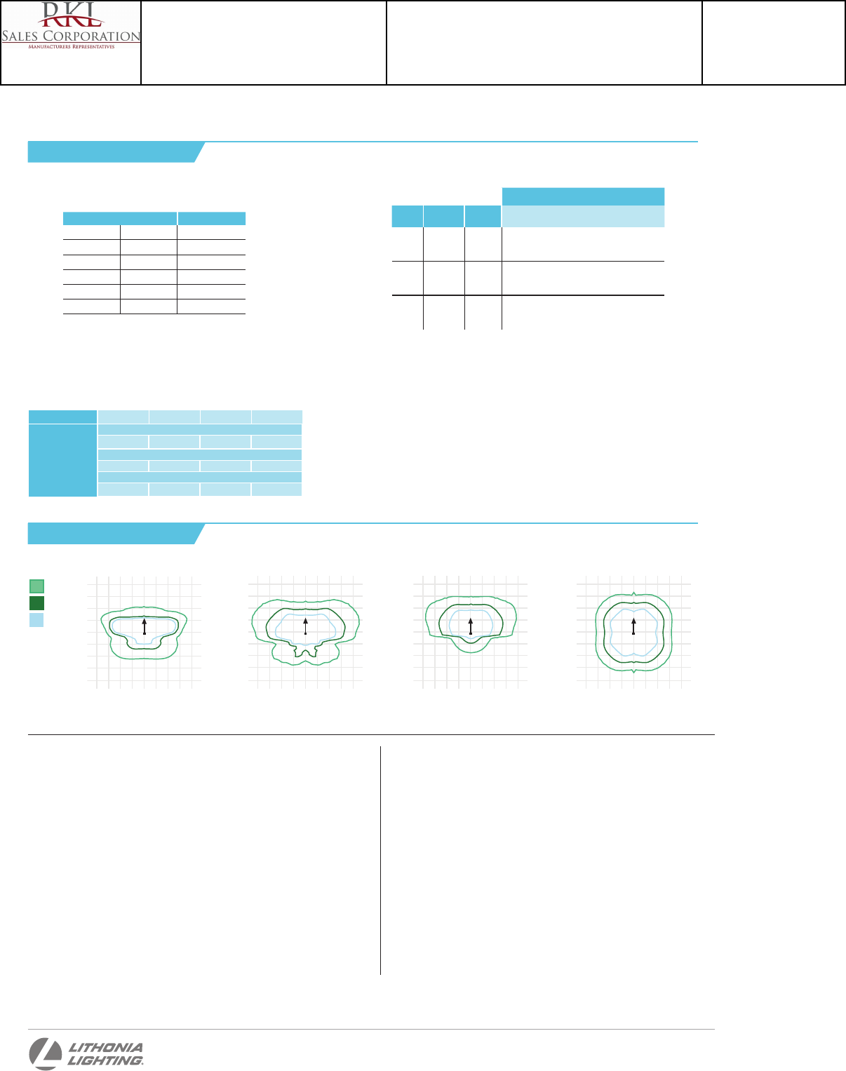
Performance Data
FEATURES & SPECIFICATIONS
INTENDED USE
The sleek design of the D-Series Size 0 reflects the embedded high performance LED technology. It
is ideal for many commercial and municipal applications, such as parking lots, plazas, campuses, and
streetscapes.
CONSTRUCTION
Single-piece die-cast aluminum housing has integral heat sink fins to optimize thermal management
through conductive and convective cooling. Modular design allows for ease of maintenance and
future light engine upgrades. The LED driver is mounted in direct contact with the casting to
promote low operating temperature and long life. Housing is completely sealed against moisture
and environmental contaminants (IP65). Low EPA (0.8 ft2) for optimized pole wind loading.
FINISH
Exterior parts are protected by a zinc-infused Super Durable TGIC thermoset powder coat finish
that provides superior resistance to corrosion and weathering. A tightly controlled multi-stage
process ensures a minimum 3 mils thickness for a finish that can withstand extreme climate
changes without cracking or peeling. Available in both textured and non-textured finishes.
OPTICS
Precision-molded proprietary acrylic lenses are engineered for superior area lighting distribution,
uniformity, and pole spacing. Light engines are available in standard 4000 K (70 minimum CRI) or
optional 3000 K (80 minimum CRI) or 5000 K (70 CRI) configurations. The D-Series Size 0 has zero
uplight and qualifies as a Nighttime FriendlyTM product, meaning it is consistent with the LEED®
and Green GlobesTM criteria for eliminating wasteful uplight.
ELECTRICAL
Light engine(s) configurations consist of high-efficacy LEDs mounted to metal-core circuit boards
to maximize heat dissipation and promote long life (up to L96/100,000 hours at 25°C). Class 1
electronic drivers are designed to have a power factor >90%, THD <20%, and an expected life of
100,000 hours with <1% failure rate. Easily serviceable 10kV or 6kV surge protection device
meets a minimum Category C Low operation (per ANSI/IEEE C62.41.2).
INSTALLATION
Included mounting block and integral arm facilitate quick and easy installation. Stainless
steel bolts fasten the mounting block securely to poles and walls, enabling the D-Series Size 0
to withstand up to a 3.0 G vibration load rating per ANSI C136.31. The D-Series Size 0 utilizes
the AERISTM series pole drilling pattern. Optional terminal block, tool-less entry, and NEMA
photocontrol receptacle are also available.
LISTINGS
UL Listed for wet locations. Light engines are IP66 rated; luminaire is IP65 rated. Rated for
-40°C minimum ambient. U.S. Patent No. D672,492 S. International patent pending.
DesignLights Consortium® (DLC) qualified product. Not all versions of this product may
be DLC qualified. Please check the DLC Qualified Products List at www.designlights.org to
confirm which versions are qualified.
WARRANTY
Five-year limited warranty. Full warranty terms located at:
www.acuitybrands.com/CustomerResources/Terms_and_conditions.aspx
Note: Specifications subject to change without notice.
One Lithonia Way • Conyers, Georgia 30012 • Phone: 800.279.8041 • Fax: 770.918.1209 • www.lithonia.com
© 2011-2014 Acuity Brands Lighting, Inc. All rights reserved.
Current (A)
Number
of LEDs
Drive Current
(mA)
System
Watts 120 208 240 277 347 480
20C
530 35 0.34 0.22
0.21
0.20
-- --
700 45
0.47 0.28 0.24 0.22 0.18 0.14
1000 72
0.76 0.45 0.39 0.36 0.36 0.26
30C
530 52
0.51 0.31 0.28 0.25 -- --
700 70
0.72 0.43 0.37 0.34 0.25 0.19
1000 104
1.11 0.64 0.56 0.49 0.47 0.34
40C
530 68
0.71 0.41 0.36 0.33 0.25 0.19
700 91
0.94 0.55 0.48 0.42 0.33 0.24
1000 138
1.45 0.84 0.73 0.64 0.69 0.50
Electrical Load
Use these factors to determine relative lumen output for average ambient temperatures
from 0-40°C (32-104°F).
Lumen Ambient Temperature (LAT) Multipliers
Ambient Lumen Multiplier
0°C 32°F 1.02
10°C 50°F 1.01
20°C 68°F 1.00
25°C 77°F 1.00
30°C 86°F 1.00
40°C 104°F 0.99
Projected LED Lumen Maintenance
Data references the extrapolated performance projections for the platforms noted in a
25°C ambient, based on 10,000 hours of LED testing (tested per IESNA LM-80-08 and
projected per IESNA TM-21-11).
To calculate LLF, use the lumen maintenance factor that corresponds to the desired number
of operating hours below. For other lumen maintenance values, contact factory.
Operating Hours 0 25,000 50,000 100,000
Lumen Maintenance
Factor
DSX0 LED 20C 1000
1 0.97 0.94 0.90
DSX0 LED 40C 1000
1 0.94 0.90 0.84
DSX0 LED 40C 700
1 0.99 0.98 0.96
DSX0-LED
Rev. 10/07/14
To see complete photometric reports or download .ies files for this product, visit Lithonia Lighting’s D-Series Area homepage.
Photometric Diagrams
Isofootcandle plots for the DSX0 LED 40C 1000 40K. Distances are in units of mounting height (20’).
Test No. LTL23456P25 tested in accordance
with IESNA LM-79-08.
Test No. LTL23451P25 tested in accordance
with IESNA LM-79-08.
Test No. LTL23422P25 tested in accordance
with IESNA LM-79-08.
4
3
2
1
0
-4
-3
-2
-1
43210 432
1
Test No. LTL23457P25 tested in accordance
with IESNA LM-79-08.
4
3
2
1
0
-4
-3
-2
-1
43210 432
1
4
3
2
1
0
-4
-3
-2
-1
43210 432
1
4
3
2
1
0
-4
-3
-2
-1
43210 432
1
T5M
T4M HS
T3M
T1S
LEGEND
0.1 fc
0.5 fc
1.0 fc
Catalog Number
DSX0 LED 40C 700 40K TFTM MVOLT RPA DDBXD
Notes
Type
S1
Project 15-18720-6
Teen Center - Los Alamos
Submitted By
RKL SALES CORP
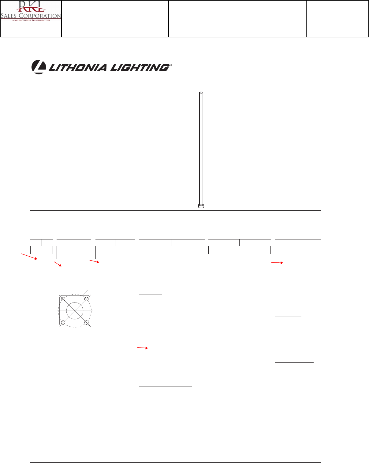
Catalog Number
Notes Type
FEATURES & SPECIFICATIONS
CONSTRUCTION — Weldable-grade, hot rolled, commercial-quality carbon
steel tubing with a minimum yield of 42,000 psi. Uniform wall thickness of .120".
Shaft is one piece with a full length, longitudinal, high-frequency electric
resistance weld. Uniformly round in cross-section down length of shaft with
no taper.
Anchor base is fabricated from hot rolled carbon steel plate (ASTM A-36),
3/4" thickness. Base plate and shaft are circumferentially welded at both the
top and the bottom to provide maximum strength at the area of critical stress.
Reinforced handhole rim is located 18" above the base. Cover and attach-
ment hardware provided.
Top cap provided with all drill-mount poles.
Fasteners are high-strength galvanized, zinc-plated or stainless steel.
Base cover is finished to match pole.
FINISH — Must specify finish.
GROUNDING — Provision located inside handhole rim. Grounding hardware
is not included (provided by others).
ANCHOR BOLTS — Top portion of anchor bolt is galvanized per ASTM A-153.
Made of steel rod having a minimum yield strength of 55,000 psi.
Anchor Base Poles
RSS
ROUND STRAIGHT STEEL
Outdoor Sheet#: Pole-RSS PL-300
Lead times will vary depending on options selected. Consult with your sales representative.
Example: RSS 20 4-5B DM19 DDB
ORDERING INFORMATION
NOTES:
1 When ordering tenon mounting and drill mounting for the
same pole, follow this example: DM28/T20. The combination
includes a required extra handhole.
2 T30 and T35 tenons available on 5" shafts only.
3 The drilling template to be used for a particular luminaire
depends on the luminaire that is used. Refer to the
Technical Data Section of the Outdoor Binder for Drilling
Templates.
4 Specify location and orientation when ordering option.
For 1st "x": Specify the height in feet above base of pole.
Example: 5ft = 5 and 20ft = 20
For 2nd "x": Specify orientation from handhole (A,B,C,D)
Refer to the Handhole Orientation diagram above.
5 Horizontal arm is 18" x 2-3/8" O.D. tenon standard.
6 Combination of tenon-top and drill mount includes extra
handhole.
7 Insert "1" or "2" to designate fixture size; e.g. DM19AST2.
8 Finish must be specified. Additional colors available; see
www.lithonia.com/archcolors or Architectural Colors
brochure (Form No. 794.3). Powder finish standard.
IMPORTANT INSTALLATION NOTES:
• Do not erect poles without having fixtures installed.
•Factory-supplied templates must be used when setting
anchor bolts. Lithonia will not accept claim for incorrect
anchorage placement due to failure to use factory template.
•If poles are stored outside, all protective wrapping must be
removed immediately upon delivery to prevent finish damage.
•Lithonia is not responsible for the foundation design.
RSS
Series
RSS
Nominal fixture
mounting height
8 – 30 feet
(See back page.)
Nominal shaft base
size/wall thickness
(See back page.)
Mounting1
Tenon mounting
PT Open top
T20 2-3/8" O.D. (2" NPS)
T25 2-7/8" O.D. (2-1/2" NPS)
T3023-1/2" O.D. (3" NPS)
T3524" O.D. (3-1/2" NPS)
Drill mounting3
DM19 1 at 90°
DM28 2 at 180°
DM28PL 2 at 180° with one side
plugged
DM29 2 at 90°
DM29 2 at 90°
DM32 3 at 120°
DM49 4 at 90°
AERIS™/OMERO™ Drill mounting3
DM19AS 1 at 90°
DM28AS 2 at 180°
DM29AS 2 at 90°
DM32AS 2 at 120°
DM39AS 3 at 90°
DM49AS 4 at 90°
AERIS™ Suspend drill mounting3,7
DMxxAST_
OMERO™ Suspend drill mounting3,7
DMxxMRT_
Options
Shipped installed
L/AB Less anchor bolts
FBC Full base cover
VD Vibration damper
TP Tamper proof
H1-18Sxx Horizontal arm
bracket (1 fixture)4,5
FDLxx Festoon outlet less
electrical4
CPL12xx 1/2" coupling4
CPL34xx 3/4" coupling4
CPL1xx 1" coupling4
NPL12xx 1/2" threaded nipple4
NPL34xx 3/4" threaded nipple4
NPL1xx 1" threaded nipple4
EHHxx Extra handhole4,6
Finish8
Standard colors
DDB Dark bronze
DWH White
DBL Black
DMB Medium
bronze
DNA Natural
aluminum
GALV Galvanized
finish
Classic colors
DSS Sandstone
DGC Charcoal
gray
DTG Tennis
green
DBR Bright red
DSB Steel blue
Architectural colors
(powder finish)8
B
C
D
HANDHOLE ORIENTATION
A
Handhole
A
C
Catalog Number
RSS 20 4B DM19AS DDBXD
Notes
Type
S1
Project 15-18720-6
Teen Center - Los Alamos
Submitted By
RKL SALES CORP
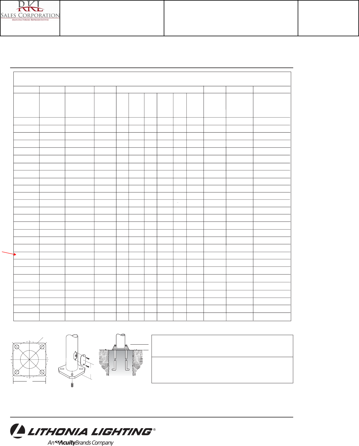
Lithonia Lighting
Outdoor
One Lithonia Way, Conyers, GA 30012
Phone: 770-922-9000 Fax: 770-918-1209
www.lithonia.com
IMPORTANT:
• These specifications are intended for general purposes only. Lithonia reserves the right to
change material or design, without prior notice, in a continuing effort to upgrade its products.
RSS Round Straight Steel Poles
TECHNICAL INFORMATION
EPA (ft2) with 1.3 gust
Nominal Wall Approximate
Catalog shaft Pole Shaft Thickness 80 Max. 90 Max. 100 Max. Bolt Circle Bolt Size ship weight
Number length (feet) Size(in x ft) (inches) mph weight mph weight mph weight (inches) (in. x in. x in.) (pounds)
RSS 8 4-5B 8 4.5 x 8.0 0.120 24.7 630 19.7 495 16.0 430 8 3/4 x 18 x 3 55
RSS 10 3B 10 3.0 x 10.0 0.120 10 250 7.7 190 6.0 175 8 3/4 x 18 x 3 55
RSS 10 4B 10 4.0 x 10.0 0.120 19.1 480 15.0 375 12.2 305 8 3/4 x 18 x 3 70
RSS 10 4-5B 10 4.5 x 10.0 0.120 24.5 615 19.5 490 15.8 395 8 3/4 x 18 x 3 75
RSS 12 3B 12 3.0 x 12.0 0.120 7.7 195 5.8 145 4.4 130 8 3/4 x 18 x 3 60
RSS 12 4B 12 4.0 x 12.0 0.120 15.0 390 11.8 300 9.5 240 8 3/4 x 18 x 3 80
RSS 12 4-5B 12 4.5 x 12.0 0.120 19.8 495 15.7 395 12.7 320 8 3/4 x 18 x 3 85
RSS 14 3B 14 3.0 x 14.0 0.120 6.0 175 4.4 130 3.3 90 8 3/4 x 18 x 3 70
RSS 14 4B 14 4.0 x 14.0 0.120 12.2 305 9.4 250 7.6 195 8 3/4 x 18 x 3 90
RSS 14 4-5B 14 4.5 x 14.0 0.120 16.2 405 12.8 320 10.3 260 8 3/4 x 18 x 3 95
RSS 15 4-5B 15 4.5 x 15.0 0.120 12.0 300 9.5 250 7.5 200 8 3/4 x 18 x 3 96
RSS 16 3B 16 3.0 x 16.0 0.120 4.6 125 3.2 100 2.3 60 8 3/4 x 18 x 3 80
RSS 16 4B 16 4.0 x 16.0 0.120 9.6 250 7.4 185 5.9 150 8 3/4 x 18 x 3 100
RSS 16 4-5B 16 4.5 x 16.0 0.120 13.1 330 10.2 265 8.2 205 8 3/4 x 18 x 3 105
RSS 18 3B 18 3.0 x 18.0 0.120 3.4 90 2.3 60 1.4 70 8 3/4 x 18 x 3 90
RSS 18 4B 18 4.0 x 18.0 0.120 7.6 190 5.7 180 4.5 130 8 3/4 x 18 x 3 110
RSS 18 4-5B 18 4.5 x 18.0 0.120 10.5 265 8.2 210 6.5 165 8 3/4 x 18 x 3 115
RSS 20 3B 20 3.0 x 20.0 0.120 2.4 100 1.4 75 -- -- 8 3/4 x 18 x 3 100
RSS 20 4B 20 4.0 x 20.0 0.120 6.0 150 4.45 150 3.45 125 8 3/4 x 18 x 3 120
RSS 20 4-5B 20 4.5 x 20.0 0.120 8.5 215 6.6 165 5.2 130 8 3/4 x 18 x 3 130
RSS 20 5B 20 5.0 x 20.0 0.120 11.75 300 9.1 230 7.25 180 8 3/4 x 18 x 3 145
RSS 22 4-5B 22 4.5 x 22.0 0.120 6.0 150 4.5 125 3.75 100 8 3/4 x 18 x 3 134
RSS 25 4B 25 4.0 x 25.0 0.120 2.85 100 1.95 75 1.35 75 8 3/4 x 18 x 3 145
RSS 25 4-5B 25 4.5 x 25.0 0.120 4.8 130 3.6 90 2.7 90 8 3/4 x 18 x 3 145
RSS 25 5B 25 5.0 x 25.0 0.120 7.25 180 5.5 150 4.25 150 8 3/4 x 18 x 3 180
RSS 30 4-5B 30 4.5 x 30.0 0.120 2.3 80 1.5 75 1.0 60 8 3/4 x 18 x 3 185
RSS 30 5B 30 5.0 x 30.0 0.120 4.2 150 3 125 2.25 100 8 3/4 x 18 x 3 210
© 1998-2010 Acuity Brands Lighting, Inc. All rights reserved. Rev. 5/10/10
Sheet #: Pole-RSS
Pole Data
Shaft Bolt Bolt
base circle projection Base Template Anchor bolt
size ABsquare description description
3" 8" 3.25"– 3.50" 8" ABTEMPLATE PJ50041 AB18-0
4" 8" 3.25"– 3.50" 8" ABTEMPLATE PJ50041 AB18-0
4.5" 8" 3.25"– 3.50" 8" ABTEMPLATE PJ50041 AB18-0
5" 8" 3.25"– 3.50" 8" ABTEMPLATE PJ50041 AB18-0
18"
A
C
B
Catalog Number
RSS 20 4B DM19AS DDBXD
Notes
Type
S1
Project 15-18720-6
Teen Center - Los Alamos
Submitted By
RKL SALES CORP
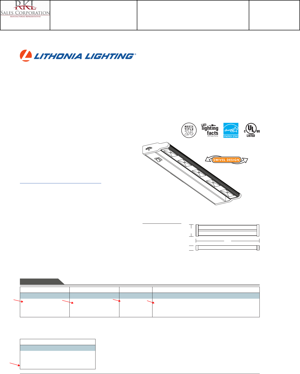
DECORATIVE INDOOR & OUTDOOR UCLD
Catalog
Number
Notes
Type
FEATURES & SPECIFICATIONS
INTENDED USE
Provides task or accent lighting in commercial, retail, hospitality and residential applications. Ideal for use
under and over cabinets, display cases, task lighting, oce lighting, coves and utility/work areas.
CONSTRUCTION
Low prole design, with on/o rocker switch. Can be direct wired or powered by 5’ cord-and-plug (Included).
Connect multiple xtures with 13” connector cord (Included).
Rugged low prole aluminum housing, available in either white, bronze, or brushed nickel nish. Swivel head
allows light to be directed to desired area.
ELECTRICAL
LEDs have a 50,000 hour L70 rated life. Provides warm color temperature, 3000 K or 2700 K with CRI 83, and
even illumination.
Standard with stepdown 120V driver (120V, 60Hz).
Can be used with standard dimmable switches.
INSTALLATION
All mounting hardware included.
LISTINGS
CUL listed to US and Canadian safety standards. ENERGY STAR® and Title 24 qualied.
WARRANTY
Five-year limited warranty. Full warranty terms located at
www.AcuityBrands.com/CustomerResources/Terms_and_Conditions.aspx.
Note: Specications are subject to change without notice.
Series Driver Color temperature Finish
UCLD 12 12” long with 3 LEDs
UCLD 18 18” long with 5 LEDs
UCLD 24 24” long with 7 LEDs
(blank) 120V dimmable driver (blank) 3000 K
2700 2700 K
WH White
BZ Bronze
BN Brushed nickel
ORDERING INFORMATION For shortest lead times, congure products using bolded options. Example: UCLD 12 WH
Accessories: Order as separate catalog number.
UCD JB Splice box - allows for quick and easy direct wiring
UC ERC 1-1/8” row connector for end-to-end connections
UC ERC24 24” connector cord for longer length connections
Indoor General Purpose
LED Cabinet Light
Linkable
All dimensions are inches (centimeters)
Specifications
Length: UCLD 12 - 12 (30.5)
UCLD 18 - 18 (45.7)
UCLD 24 - 24 (60.9)
Width: 3-5/8 (9.2)
Height: 1 (2.5)
W
L
H
Catalog Number
UCLD 12 WH M4
Notes
Type
UC
Project 15-18720-6
Teen Center - Los Alamos
Submitted By
RKL SALES CORP
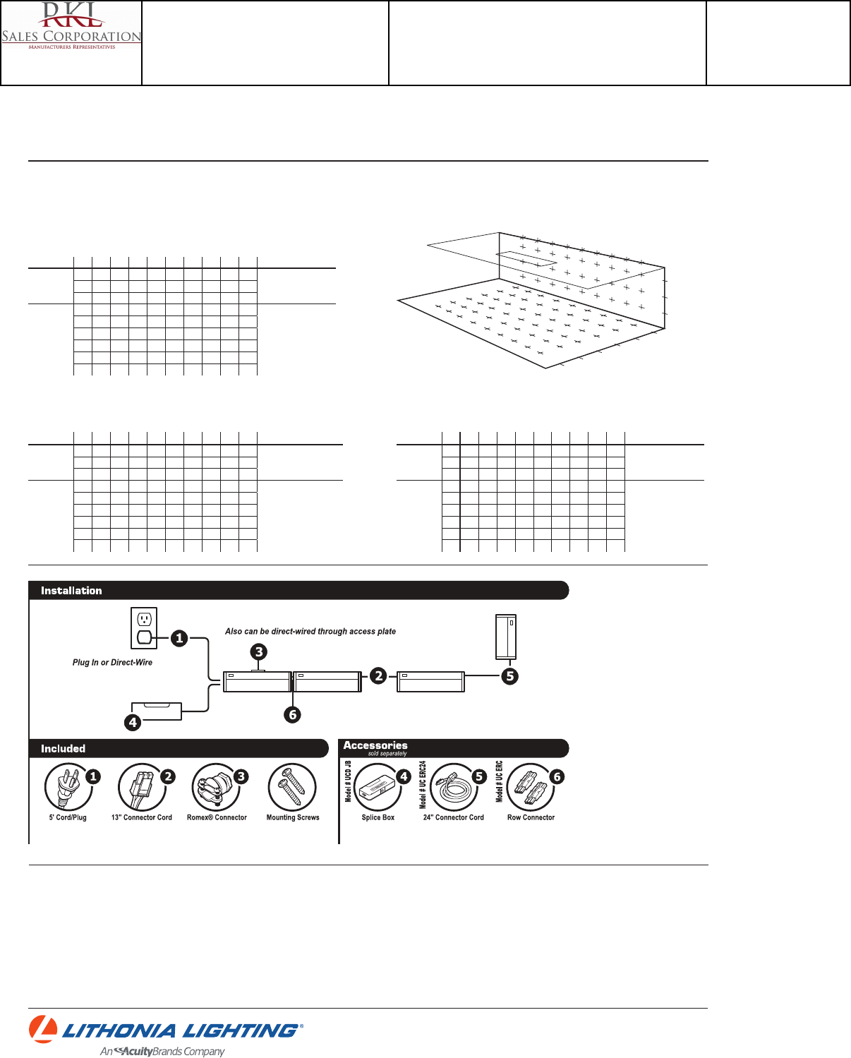
UCLD
DECORATIVE INDOOR & OUTDOOR: One Lithonia Way Conyers, GA 30012 Phone: 800-748-5070 Fax: 770-860-3903 www.lithonia.com © 2012-2013 Acuity Brands Lighting, Inc. All rights reserved. Rev. 09/09/13
UCLD LED Cabinet Light
Photometry derived in accordance with IESNA LM41 procedure. Vertical and horizontal illuminance is calculated with xture mounted 17” from work surface.
Full photometric data report available within 2 weeks from request. Consult factory.
PHOTOMETRIC DIAGRAMS
UCLD 12 Report LTL 21648
Initial Point Illuminance on wall and horizontal work surface. (fc)
X and Y coordinates are on 6” centers.
X A B C D E F G H I
Vertical
1112464211Avg.=4 fc
Max.=16 fc; Min.=1 fc
Max. to min. ratio =16
21 3 6 12 16 12 6 3 1
32 3 6 11 13 11 6 3 2
Horizontal
43 5 9 15 18 15 9 5 3
Avg.=6 fc
Max.=27 fc; Min.=1 fc
Max. to min. ratio =27
53 6 13 22 27 22 13 6 3
63 6 13 22 27 22 13 6 3
73 5 9 14 17 14 9 5 3
8235898532
9123444321
UCLD 18 Report LTL 21649
Initial Point Illuminance on wall and horizontal work surface. (fc)
X and Y coordinates are on 6” centers.
UCLD 24 Report LTL 21650
Initial Point Illuminance on wall and horizontal work surface. (fc)
X and Y coordinates are on 6” centers.
X A B C D E F G H I
Vertical
1124787421Avg.=7 fc
Max.=23 fc; Min.=2 fc
Max. to min. ratio =11.5
23 5 11 19 23 19 11 5 3
33 6 11 17 20 17 11 6 3
Horizontal
45 9 16 25 28 25 16 9 5
Avg.=11 fc
Max.=42 fc; Min.=1 fc
Max. to min. ratio =42
56 12 23 36 42 36 23 12 6
66 12 23 35 41 35 23 12 6
75 9 16 23 27 23 16 9 5
83 5 9 12 14 12 9 5 3
9235676532
X A B C D E F G H I
Vertical
12369109632Avg.=10 fc
Max.=28 fc; Min.=2 fc
Max. to min. ratio =14
24 8 16 25 28 25 16 8 4
35 9 16 23 25 23 16 9 5
Horizontal
47 14 23 32 36 32 23 14 7
Avg.=15 fc
Max.=52 fc; Min.=2 fc
Max. to min. ratio =26
59 18 32 46 52 46 32 18 9
69 18 32 46 52 46 32 18 9
77 13 22 30 34 30 22 13 7
85 8 12 16 18 16 12 8 5
9356898653
A B C D E F G H I
1
2
3
9
87654
Suggested Dimmers
This xture is designed to operate with most standard Triac Based (Forward Phase-Control or Leading Edge) dimmer and is not compatible with 0-10v dimming systems.
Noted below is a listing of dimmers that have been tested with this xture. This list of dimmers does not imply any guarantee or warranty of compatibility with a particular application.
Dimmers that are not listed do not imply non-compatibility.
Lutron Diva DV-600P Lutron Ariadni TG-603P Leviton ToggleTouch TGI06-1LW (Digital Control)
Lutron SkyLark S-600P (Slide & On-O Switch) Lutron Maestro MA-600 (Digital Fade Dimmer) Lutron MAELV-600BL (Digital Trailing Edge)
Lutron Ariadni AY-600P Leviton IllumaTech IPI06-1LX Lutron DVELV-300P-WH (Trailing Edge)
Note: When the installation exceeds 10 xtures on a single dimmer or distribution lengths exceed 100 feet, please conrm that the end product performs properly.
This is caused by a high degree of variability in the triac dimmers.
Catalog Number
UCLD 12 WH M4
Notes
Type
UC
Project 15-18720-6
Teen Center - Los Alamos
Submitted By
RKL SALES CORP

UCLD
DECORATIVE INDOOR & OUTDOOR: One Lithonia Way Conyers, GA 30012 Phone: 800-748-5070 Fax: 770-860-3903 www.lithonia.com © 2012-2013 Acuity Brands Lighting, Inc. All rights reserved. Rev. 09/09/13
UCLD LED Cabinet Light
Catalog Number
UCLD 12 WH M4
Notes
Type
UC
Project 15-18720-6
Teen Center - Los Alamos
Submitted By
RKL SALES CORP

Project:
Type:
Catalog #:
EELP • 2577 Neshaminy Interplex Dr. KOR A, Suite 102, Trevose, PA 19053 • Phone: 800-490-4496 • Fax: 877-634-6887 • www.eelp.net
ORDERING INFORMATION
MODEL FACE# LETTER COLOR FACE COLOR OPTIONS ACCESSORIES
XC-LED 1 R - Red W - White SD - Self Diagnostics WG3 - Wireguard
2 (universal) G - Green B - Black RC - Remote Capable BG3 - Bubble Guard
HO - High Output
LH - Less Heads
XC-LED 102214
Model XC-LED
LED Exit/Emergency Combo
Specications and dimensions subject to change without notice.
HOUSING
-Injection molded, engineering-grade, UV-stable thermoplastic
-UL94V-0 ame rating
-Impact, scratch, fade and corrosion-resistant
-Mounting canopy included for top or back mount
-Suitable for wall or ceiling mount
-White or black textured nish
-Double face comes standard with second face plate and back
plate for eld conversion
ELECTRICAL
-Dual voltage 120/277VAC
-Rated for use in damp locations
-Solid state charging and switching
-Brownout protection
-Battery low voltage disconnect (LVD)
-Overload and short circuit protection
-AC power indicator and test switch
LAMPS
-Long lasting red or green LED exit sign
-Supplied with 1W LED heads
-30% brighter than standard tungsten heads (XC)
-High Output option available (HO) providing 1.5W heads
BATTERY
- 9.6V Maintenance-free NiCad battery standard
- Battery will operate xture for a minimum of 90 minutes in the
event of a power outage
- Recharge time is 24 hours
- RC version will operate an additional 3W for a minimum of 90
minutes
- RC unit can run LED heads only
- For remote head options, see Remote Head specsheet
- Temperature rating: 32o (0oC) - 104oF (40oC)
CODE COMPLIANCE
-UL Listed for Damp Locations
-Meets UL924
-NFPA 101 Life Safety Code compliant
-NEC and OSHA compliant
WARRANTY
-5 year warranty
MODEL FACE# LETTER COLOR FACE COLOR OPTIONS ACCESSORIES
-----
21"
9"
12"
8"
43/8"
2"
Catalog Number
XC LED 2 R W SD
Notes
Type
X
Project 15-18720-6
Teen Center - Los Alamos
Submitted By
RKL SALES CORP
SPACING GUIDE
Using multiple units mounted at a typical 7.5' delivers 18' center-to-center spacing on a 3' wide
egress path.
18'
3'
Using multiple units mounted at a typical 7.5' delivers 14' center-to-center spacing on a 6' wide
egress path.
6'
14'
Catalog Number
XC LED 2 R W SD
Notes
Type
X
Project 15-18720-6
Teen Center - Los Alamos
Submitted By
RKL SALES CORP
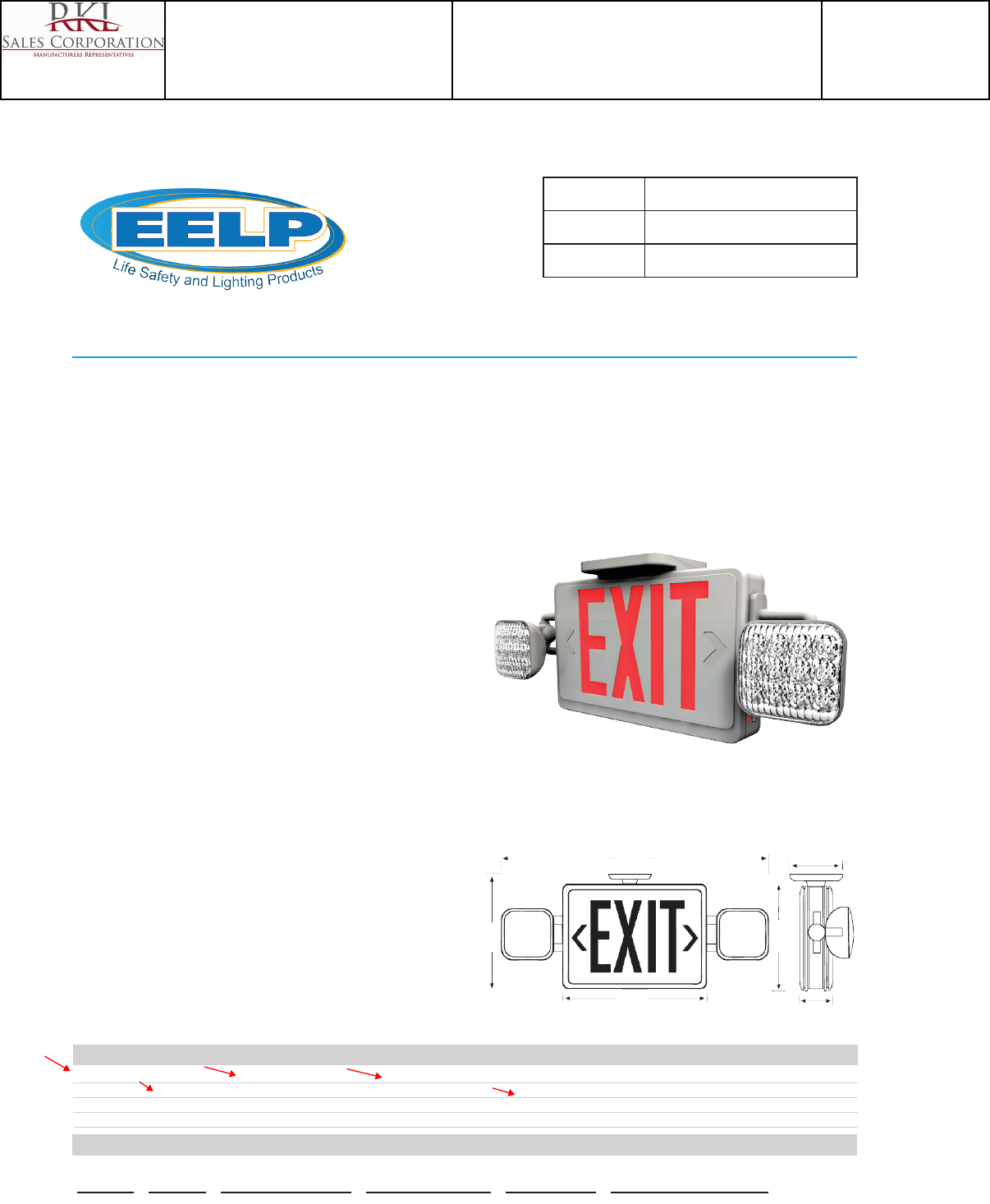
Project:
Type:
Catalog #:
EELP • 2577 Neshaminy Interplex Dr. KOR A, Suite 102, Trevose, PA 19053 • Phone: 800-490-4496 • Fax: 877-634-6887 • www.eelp.net
ORDERING INFORMATION
MODEL FACE# LETTER COLOR FACE COLOR OPTIONS ACCESSORIES
XC-LED 1 R - Red W - White SD - Self Diagnostics WG3 - Wireguard
2 (universal) G - Green B - Black RC - Remote Capable BG3 - Bubble Guard
HO - High Output
LH - Less Heads
XC-LED 102214
Model XC-LED
LED Exit/Emergency Combo
Specications and dimensions subject to change without notice.
HOUSING
-Injection molded, engineering-grade, UV-stable thermoplastic
-UL94V-0 ame rating
-Impact, scratch, fade and corrosion-resistant
-Mounting canopy included for top or back mount
-Suitable for wall or ceiling mount
-White or black textured nish
-Double face comes standard with second face plate and back
plate for eld conversion
ELECTRICAL
-Dual voltage 120/277VAC
-Rated for use in damp locations
-Solid state charging and switching
-Brownout protection
-Battery low voltage disconnect (LVD)
-Overload and short circuit protection
-AC power indicator and test switch
LAMPS
-Long lasting red or green LED exit sign
-Supplied with 1W LED heads
-30% brighter than standard tungsten heads (XC)
-High Output option available (HO) providing 1.5W heads
BATTERY
- 9.6V Maintenance-free NiCad battery standard
- Battery will operate xture for a minimum of 90 minutes in the
event of a power outage
- Recharge time is 24 hours
- RC version will operate an additional 3W for a minimum of 90
minutes
- RC unit can run LED heads only
- For remote head options, see Remote Head specsheet
- Temperature rating: 32o (0oC) - 104oF (40oC)
CODE COMPLIANCE
-UL Listed for Damp Locations
-Meets UL924
-NFPA 101 Life Safety Code compliant
-NEC and OSHA compliant
WARRANTY
-5 year warranty
MODEL FACE# LETTER COLOR FACE COLOR OPTIONS ACCESSORIES
-----
21"
9"
12"
8"
43/8"
2"
Catalog Number
XC LED 2 R W RC
Notes
Type
EX
Project 15-18720-6
Teen Center - Los Alamos
Submitted By
RKL SALES CORP

SPACING GUIDE
Using multiple units mounted at a typical 7.5' delivers 18' center-to-center spacing on a 3' wide
egress path.
18'
3'
Using multiple units mounted at a typical 7.5' delivers 14' center-to-center spacing on a 6' wide
egress path.
6'
14'
Catalog Number
XC LED 2 R W RC
Notes
Type
EX
Project 15-18720-6
Teen Center - Los Alamos
Submitted By
RKL SALES CORP
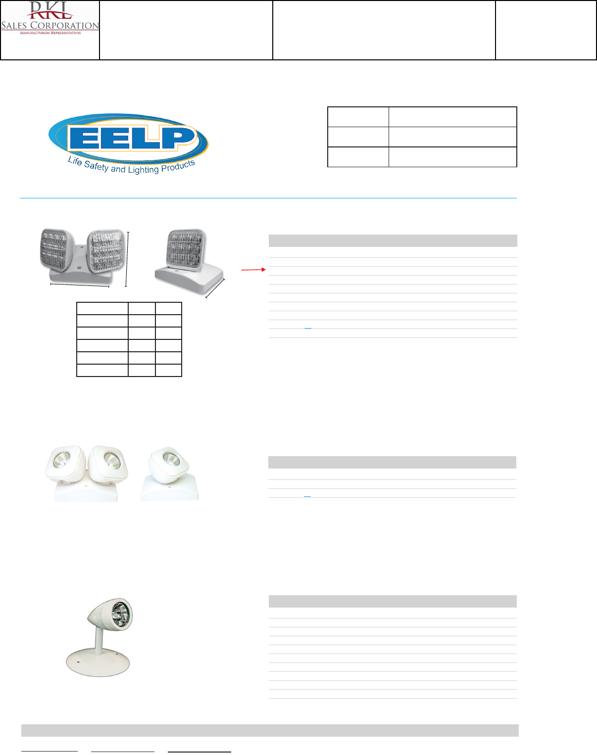
Project:
Type:
Catalog #:
EELP • 1210 Northbrook Drive Suite 135 Trevose, PA 19053 • Phone: 800-490-4496 • Fax: 877-634-6887 • www.eelp.net
INDOOR LED REMOTES 090114
Indoor LED Remote Heads
Specications and dimensions subject to change without notice.
CATALOG # HEADS VOLTAGE WATTAGE/LAMPS
RH1-LED-3.6V 1 3.6V 1W (8 LEDs)
RH1-LED-3.6V-HO 1 3.6V 1.5W (12 LEDs)
RH1-LED-9.6V 1 9.6V 1W (8 LEDs)
RH1-LED-9.6V-HO 1 9.6V 1.5W (12 LEDs)
RH2-LED-3.6V 2 3.6V 1W (8 LEDs)
RH2-LED-3.6V-HO 2 3.6V 1.5W (12 LEDs)
RH2-LED-9.6V 2 9.6V 1W (8 LEDs)
RH2-LED-9.6V-HO 2 9.6V 1.5W (12 LEDs)
* Specify ‘B’ for Black Housing
* Add ‘SD’ if used with units with the Self Diagnostics option
CATALOG # HEADS VOLTAGE WATTAGE/LAMPS
RH16-1-LED-VV* 1 Variable (4.5 - 30V) 3.3W
RH16-2-LED-VV* 2 Variable (4.5 - 30V) 3.3W
* Specify ‘B’ for Black Housing
57/8"
5"
41/2"
MODEL 3.6V 9.6V
XC-LED X
XCLB X
CAC X
EM1-LED-RC X
WLEM-LED X
CATALOG # HEADS VOLTAGE WATTAGE /LAMPS
RHBUL1-LED-6V5 1 6V 5W
RHBUL2-LED-6V5 2 6V 5W
RHBUL1-LED-12V3 1 12V 3W
RHBUL2-LED-12V3 2 12V 3W
RHBUL1-LED-12V5 1 12V 5W
RHBUL2-LED-12V5 2 12V 5W
RHBUL1-LED-12V7 1 12V 7W
RHBUL2-LED-12V7 2 12V 7W
RHBUL1-LED-24V5 1 24V 5W
RHBUL2-LED-24V5 2 24V 5W
MODEL OPTIONS
- -
Catalog Number
RH1 LED 9.6V
Notes
Type
EX
Project 15-18720-6
Teen Center - Los Alamos
Submitted By
RKL SALES CORP
ELM2 LED
Series Lamp type Housing Options
ELM2 LED Two 1.5W/3.6V white LED (blank) White
BBlack
HO High-output ni-cad battery for 6W remote capacity 1
SD Self-diagnostics
NOM Meets Mexican standards
ORDERING INFORMATION Lead times will vary depending on options selected. Consult with your sales representative. Example: ELM2 LED
Accessories: Order as separate catalog number.
ELA Q L0304 SD Single LED indoor remote head, white, self-diagnostics 2,3,4 ELA Q L0304 Single LED indoor remote head, white 2,3,4
ELA T Q L0304 SD Twin LED indoor remote head, white, self-diagnostics 2,3,4 ELA T Q L0304 Twin LED indoor remote head, white 2,3,4
ELA QWP L0304 SD Single LED weather-proof remote head, gray, self-diagnostics 2,3,4 ELA QWP L0304 Single LED weather-proof remote head, gray 2,4
ELA T QWP L0304 SD Twin LED weather-proof remote head, gray, self-diagnostics ELA T QWP L0304 Twin LED weather-proof remote head, gray 2,4
ELA WG1 Wireguard, 15” W x 13-1/2” H x 6” D (See spec sheet ELA-WG)
EMERGENCY ELM2-LED
Catalog
Number
Notes
Type
Thermoplastic Emergency Light
ELM2 LED
LED Lamp Head
Ni-Cad Battery
FEATURES & SPECIFICATIONS
INTENDED USE — Provides a minimum of 90 minutes of illumination for the rated wattage upon loss of AC
power. Ideal for applications requiring attractive unit equipment with quick installation. Certain airborne
contaminants can diminish integrity of acrylic. Click here for Acrylic Environmental Compatibility
table, for suitable uses.
CONSTRUCTION — White, compact, low-profile contemporary design. Engineering-grade thermoplastic
housing is impact-resistant, scratch-resistant and corrosion-proof. UL94V-O flame rating. UV-stable resin resists
discoloration from natural and man-made light sources.
Low-profile, integrated test switch/pilot light. Easily visible bright red status indicator.
Unique track-and-swivel arrangement permits full range of direction of lamp head adjustment. Universal J-box
mounting pattern. Tool-less access for maintenance.
OPTICS — Two LED lamp heads with 12 series-parallel white LEDs each, provide redundant light sources to
ensure emergency lighting performance. Typical LED lamp life is 10 years.
ELECTRICAL — Dual-voltage input capability (120/277V). Edge connector on printed circuit board ensures
long-term durability.
Current-limiting charger maximizes battery life and minimizes energy consumption. Provides low operating costs.
Short-circuit protection — current-limiting charger circuitry protects printed circuit board from shorts.
Thermal compensation adjusts charger output to provide optimum charge voltage relative to ambient tem-
perature.
Regulated charge voltage maintains constant-charge voltage over a wide range of line voltages. Prevents over/
undercharging that shortens battery life and reduces capacity.
Filtered charger input minimizes charge voltage ripple and extends battery life.
AC/LVD reset allows battery connection before AC power is applied and prevents battery damage from deep
discharge.
BATTERY: Sealed, maintenance-free nickel-cadmium battery delivers 90 minute capacity to emergency lamps.
Two-state constant-current charge maximizes battery life and automatically recharges after battery discharge.
Low-voltage disconnect prevents excessively deep discharge that can permanently damage the battery. Optional
high-output battery available to power both local and optional LED remote lamp heads simultaneously.
Self -Diagnostics (SD- Option) Single multi-color LED indicator to display two-state charging, test activation
and three-state diagnostic test. Test switch provides manual activation of 30-second diagnostic testing for on-de-
mand visual inspection. Self-diagnostic testing for 30 seconds every 30 days, 30 minutes at 180-day interval, and
90 minutes annually. Diagnostic evaluation of LED light source, AC to DC transfer, charging and battery condition.
INSTALLATION — Ceiling- or wall-mount standard. Flexible conduit entry provision on top of the unit.
LISTINGS — UL damp location listed standard 50-104°F (10-40°C). Meets UL 924, NFPA 101 (current Life Safety
Code), NEC and OSHA illumination standards.
Notes
1 Not available with NOM.
2 Only available with HO option. See
spec sheet ELA Q LED.
3 Also available in black. Add "B" after
ELA to order black finish. Example:
ELA B Q L0304 SD. See spec sheet
ELA Q LED.
4 Only compatible with Quantum
LED series.
WARRANTY — 5-year limited warranty. (Battery is prorated). Complete warranty terms located at
www.AcuityBrands.com/CustomerResources/Terms_and_Conditions.aspx.
Note: Actual performance may differ as a result of end-user environment and application.
All values are design or typical values, measured under laboratory conditions at 25 °C.
Specifications subject to change without notice.
Catalog Number
ELM2 LED
Notes
Type
EM
Project 15-18720-6
Teen Center - Los Alamos
Submitted By
RKL SALES CORP
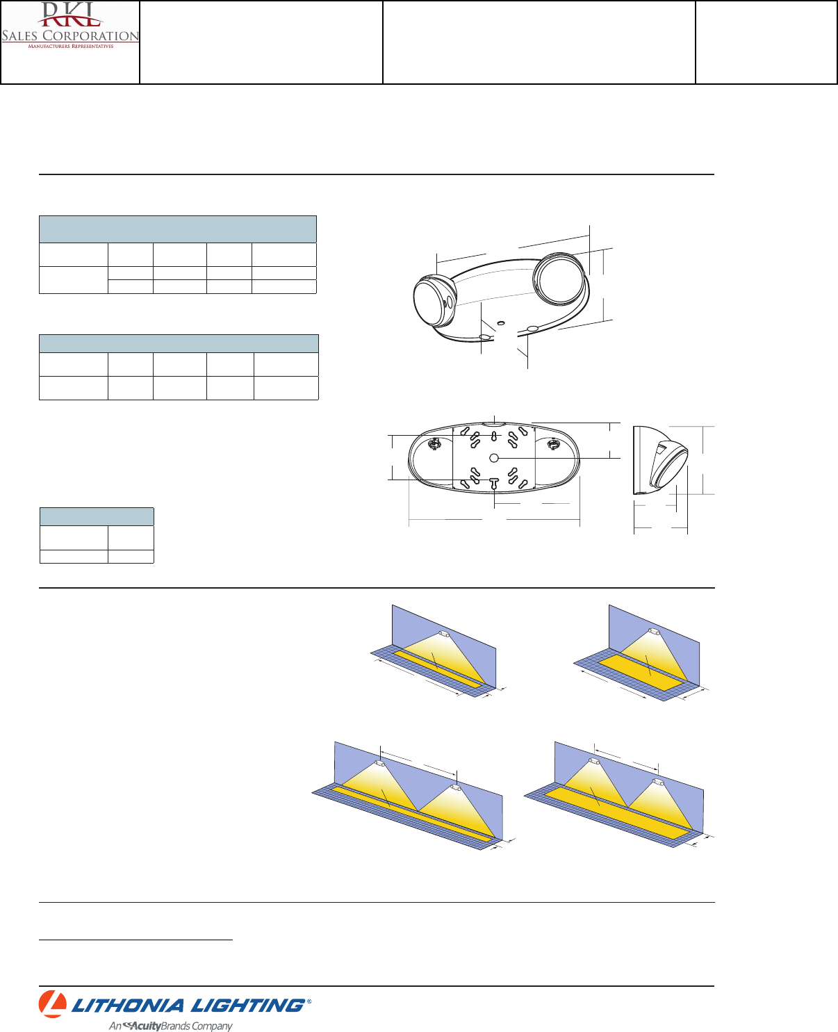
ELM2-LED
EMERGENCY: One Lithonia Way Conyers, GA 30012 Phone: 800.334.8694 Fax: 770-981-8141 www.lithonia.com ©2012-2015 Acuity Brands Lighting, Inc. All rights reserved. Rev. 06/30/15
ELM2 LED QUANTUM® Thermoplastic Emergency Light
MOUNTING
All dimensions are inches (centimeters).
Shipping weight: 4.0 lbs. (1.8 kgs.)
Mounting Plate
4-1/4
(10.8)
10-1/4
(26.0)
2-3/4
(7.0)
1/2” flexible conduit knockout
2-1/8
(5.4)
4-1/4
(10.8)
3-1/8
(7.9)
5-1/8
(13.0)
10-1/4
(26.0)
2-5/8
(6.7)
3-5/8
(9.2)
* Meets Life Safety Code standard minimum illuminance of 0.1 FC and average illuminance of 1.0 FC.
Assumes open space with no obstructions, mounting height: 7.5’, ceiling height: 9’, and reflectances:
80/50/20. Analysis based on independently tested photometrics.
SPECIFICATIONS
1 Based on continuous operation.
2 At 77°F (25°C).
3 All life safety equipment, including emergency lighting path of egress, must be maintained, serviced and tested
in accordance with all National Fire Protection Association and local codes. Failure to perform the required
maintenance, service or testing could jeopardize the safety of occupants and will void all warranties.
4 Optimum ambient temperature range where unit will provide capacity for 90 minutes. Higher and lower
temperatures affect life and capacity. Consult factory for detailed information.
LAMP PHOTOMETRICS
QUANTUM LED SERIES – SINGLE COVERAGE
3W Total White LEDs
Using a single unit at a typical 7.5’ mounting height delivers an average illuminance
of 1.0 FC over a distance of 24’ on a 3’ path of egress and 18’ on a 6’ path of egress.
QUANTUM LED SERIES – MULTIPLE COVERAGE
3W Total White LEDs
Using multiple units at a typical 7.5’ mounting height delivers 25’ center-to-center
spacing on a 3’ path of egress and 20’ center-to-center spacing on a 6’ path of egress.
24'
3'
1 FC average
18'
1 FC average
6'
1 FC average
25'
3'
6'
20'
1 FC average
Example of single ELM2 LED unit
illuminating a 3' path of egress
Example of single ELM2 LED unit
illuminating a 6' path of egress
Example of multiple ELM2 LED units
illuminating a 3' path of egress
Example of multiple ELM2 LED units
illuminating a 6' path of egress
EXTENDED RUNTIME FOR HIGHOUTPUT UNITS
Product Run time
ELM2 LED HO (no remotes) 3.9 hours
Electrical
Primary Circuit
Typical
LED life1Supply
voltage Max
amps Max
watts HO/max
watts
10 years 120 .04 1.44 2.88
277 .03 1.44 2.88
Ni-Cad
Voltage Shelf
life2Typical
life2Maintenance3Optimum
temperature4
3.6 3 years 7-9 years none 50-104°F
(10-40°C)
BATTERY
Remote Output Capacity
Standard
unit Unit/HO
battery
NA 6W
Catalog Number
ELM2 LED
Notes
Type
EM
Project 15-18720-6
Teen Center - Los Alamos
Submitted By
RKL SALES CORP
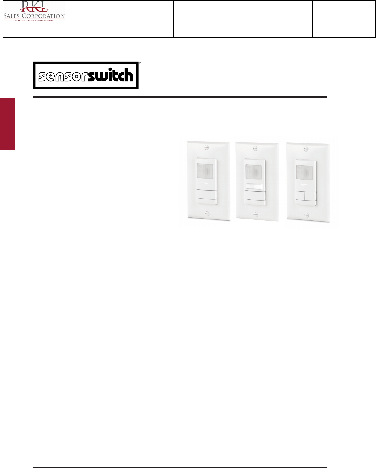
1 of 4Sensor Switch 900 Northrop Road, Wallingford, CT 06492 Phone: 1.800.PASSIVE sensorswitch.com ©2013 Acuity Brands Lighting, Inc. All rights reserved 03/01/13
Catalog Number
Notes Type
PRODUCT OVERVIEW
The WSX Family of wall switch occupancy sensors provides simple and cost eective
solutions for commercial and residential lighting control applications. All WSX
Family sensors have a stylish low prole appearance, soft-click buttons, and provide
small motion detection up to 20 ft (6.10 m), making them perfect for private
oces, private rest rooms, closets, copy rooms, or any other small enclosed space.
Additionally, all WSX Family sensors have a patent-pending wiring method that
enables them to function either with or without a neutral connection. WSX units
come pre-congured for wiring without a neutral, however if connection to neutral
is required by code, contractors can convert the unit in seconds (see page 3).
All WSX Family sensors utilize 100% digital Passive Infrared (PIR) detection.
Dual Technology (PDT option) versions add Microphonics detection and are
recommended for oces and rooms with obstructions. Additional versions include
units with dual relays - perfect for bi-level applications, and units with an integrated
nightlight - perfect for restrooms and residential applications.
SENSOR OPERATION WSX sensors detect changes in the Passive Infrared (PIR)
energy given o by occupants as they move within the eld-of-view. In an Auto-On
sensor, once occupancy is detected, an internal relay switches on the connected
lighting load. In a Vacancy (Manual On) sensor, the unit’s push button must rst be
pressed to initiate the lights on. In a dual relay sensor, once occupancy is detected
the unit will automatically close Pole 1’s relay while still requiring Pole 2’s push-
button be pressed in order to close Pole 2’s relay. All modes are user adjustable (see
On Modes section).
After the lights are turned on, an internal timer keeps them on during brief periods
of inactivity. Once the time delay has expired, lights are turned o automatically.
The default time delay is 10 minutes - chosen in order to maximize energy savings
while preventing false-os. This timer is programmable from 30 seconds to 30
minutes, and is reset every time occupancy is re-detected. Patented LampMaximzer
technology is also present in these sensors, providing an additional minimum on
time (disabled by default) to be utilized if desired.
WSX sensors with Passive Dual Technology (PDT option) rst see motion using
Passive Infrared (PIR) and then engage Microphonics to listen for sounds that also
indicate continued occupancy. This patented technology dynamically adapts a
sensor to its environment by ltering out constant background noise and detecting
only noises typical of human activity.
KEY OPTIONS
NIGHT LIGHT (NL)
Ideal for bathrooms (hotel / hospital) or residential applications
• Ultra low power White LED night light (24/7 operation)
• Capable of powering over Ground (no Neutral required)
• Manual On / Auto O operation of lights (default)
• Available with Single or Dual Relays
DUAL RELAY (2P)
Ideal for bi-level switched rooms or restroom with light & fan
• Includes two isolated relays, Pole 1 defaulted to Auto On, Pole 2 to Vacancy
• Enables separate time delay per pole - programmed via each pole’s push-button
• UL listed to switch dierent loads per pole - e.g. 277 VAC lights on Pole 1 and 120
VAC fan on Pole 2
LOW TEMPERATURE / HIGH HUMIDITY (LT)
Required for cold / humid areas
• Device electronics are coated for corrosion resistance
• Operates down to -40º F/C (-4º F / 20º C for PDT)
WSX
FAMILY
WALL SWITCH SENSOR w/
CONVERTIBLE NEUTRAL / NO NEUTRAL WIRING,
PASSIVE INFRARED (PIR) or DUAL TECH (PDT)
• 100% digital PIR detection - excellent RF immunity
• Ruggedized assembly, vandal resistant lens standard
• Small motion detection to 20 ft
• Dual Technology (PDT) utilizes PIR / Microphonics
detection (patented)
• 100% passive detection, no potential for
interference with other building systems
• Self-grounding mounting strap
• White LED status indicator
• Device accommodates powering over ground or
neutral connection (patent pending)
• Ultra low current leakage (<0.5 mA) when
connected via ground
• Fully meets NEC 2011 Section 404.2C neutral
requirements - no current leakage to ground when
connected to neutral
• Line power and load wires are interchangeable -
impossible to wire backwards (patented)
• Compatible w/ LEDs, Electronic & Magnetic Ballasts,
CFLs, & Incandescents
• Photocell standard (disabled by default) prevents
lights from initially turning on if sucient daylight
is present, but does not turn lights o. Photocell not
available in Night Light or Vacancy only versions.
• Integrated LampMaximizer minimum on time
(patented) provides increased uorescent lamp life -
disabled by default
• Push-button programmable without removing cover
plate - adjustable time delays & operating modes
• Non-volatile settings memory
• Includes wall plate (screwless sold separate)
WSX
WSX PDT
WSX 2P
WSX PDT 2P
WSX NL
WSX PDT NL
FEATURES
Catalog Number
WSX PDT WH
Notes
Type
OS
Project 15-18720-6
Teen Center - Los Alamos
Submitted By
RKL SALES CORP

2 of 4Sensor Switch 900 Northrop Road, Wallingford, CT 06492 Phone: 1.800.PASSIVE sensorswitch.com ©2013 Acuity Brands Lighting, Inc. All rights reserved 03/01/13
WSX Family
On Mode
Restore
Factory
Defaults
Switch
Mode
LED
Operation
Predictive
Exit
Time
Microphone
Grace Period
Occupancy
Time
Delay
Photocell
Set-Pt
Minimum
On Time
Manual On
Grace
Period
Dual
Technology
(MicrophonicsTM)
Predictive
Grace
Time
4x
5x
7x
9x10x
2x 3x
12x
11x
13x
15x 16x
PRESS BUTTON
3.
While LED
flashes
back current
setting 10x...
OPERATIONAL SETTINGS _________________________________________________________________________________________________
PROGRAMMING INSTRUCTIONS ______________________________________________________________________________________
4.
PRESS BUTTON
30 sec
20 min
30 min
17.5 min
15.0 min
12.5 min 10 min
5.0 min
2.5 min
7.5 min
1x
10x
2x
3x
4x
5x6x
7x
8x
9x
1.
While LED
flashes back new
setting 10x...
5.
6.
On Mode
Restore
Factory
Defaults
Switch
Mode
LED
Operation
Predictive
Exit
Time
Microphone
Grace Period
Occupancy
Time
Delay
Photocell
Set-Pt
Minimum
On Time
Manual On
Grace
Period
Dual
Technology
(MicrophonicsTM)
Predictive
Grace
Time
4x
5x
7x
9x10x
2x 3x
12x
11x
13x
15x 16x
PRESS BUTTON
4.1.
5. 6.
LED FLASHES
CONFIRMATION
TWICE
PROGRAMMING
COMPLETE
7.
7.
Operational settings can be changed via the push-button sequence outlined below (note the example used is for changing occupancy time delay). Programming for 2P units done with each
pole’s corresponding push-button.
e.g., 5 ashes is default
10 min time delay
e.g., press 4x
to change
to 7.5 min
e.g., 4 ashes
indicates new
7.5 min time
delay setting
e.g., press 2x to
save and exit
2. 3.
e.g., press 2x for
Occupancy Time
Delay
NOTE: (*) Indicates factory default (unless otherwise marked)
2 = Occupancy Time Delay
Time sensor keeps lights on after last occupancy detection.
1 30 sec 4 7.5 min 7 15.0 min 10 30.0 min
2 2.5 min 5 10.0 min* 8 17.5 min
3 5.0 min 6 12.5 min 9 20.0 min
For additional time settings, contact technical support at
1.800.PASSIVE
3 = On Mode
Automatic On turns lights on when occupancy is detected. Manual
On requires a button press to turn the lights on. Reduced Turn-On
directs the sensor to only turn on when a large motion, such as
a person entering a room, is detected. Weaker signals, such
as reections from glass, are ignored. Once lights are on, the
sensor returns to maximum sensitivity.
1 Automatic On 2 Manual On 3 Reduced Turn-On
Settings 1 & 3 not available on -VA (Vacancy only) sensors.
Notes on Default Settings
• WSX (PDT) Series default: Automatic On
• Default for units with -SA, -VA, or -NL option: Manual On
• WSX (PDT) 2P Series default: Pole 1 Auto On, Pole 2 Manual
• Default for 2P units with -2SA, -2VA, or NL options:
Both poles Manual On
4 = Switch Modes
These modes dictate switch functionality.
Pressing the button in Override Off mode (setting 1) turns off
and keeps lights off until pressed again.
Disabling the Switch (setting 2) prevents the button from turning
the lights on. (continued next column)
Predictive Mode (setting 3) determines if a user has left the room
after the lights are switched off. It does this by monitoring the
space for a period after the button is pressed (Predictive Grace
Time), following a delay to allow exiting the room (Predictive Exit
Time). If occupancy is detected the device will disable auto-on
& hold the lights off until manually switched. If no occupancy is
detected the sensor instantly reverts to auto-on mode.
If Predictive Mode with Expiration (setting 4) is enabled, once
the sensor has disabled auto-on it will continue to monitor the
space. When no occupancy is detected for a duration equal to the
occupancy time delay, the sensor will revert to auto-on mode.
1 Override Off **
2 Switch Disable
3 Predictive Mode
4 Predictive Mode with Expiration*
* Default for WSX (PDT) units & Pole 1 of WSX (PDT) 2P units
** Default for units with -SA, -VA, or -NL options, Pole 2 of WSX
(PDT) 2P units, and both poles of 2P units with -2SA, -2VA,
or -NL options
5 = Photocell Set-Point
The ambient light level at which the sensor prevents the lights
from initially turning on. Once on, the lights will remain on until
the occupancy time delay expires and turns them off.
1 Disabled* 5 2 fc 9 32 fc
2 Auto Setpoint 6 4 fc 10 64 fc
3 0.5 fc 7 8 fc
4 1 fc 8 16 fc
Note: Sensor changes to Auto On mode if photocell is enabled.
Photocell not present in -NL versions.
7 = LED Operation
Indicates behavior of device’s LED.
1 Occupancy Indication* 3 Disabled
2 Relay Indication 4 Override On***
*Standard Factory Default *** Factory Default for -NL version
9 = Restore Factory Defaults
Returns all functions to original settings.
1 Maintain Current* 2 Restore Defaults
10 = Minimum On Time
Required initial time for lamps to be on after each switch on,
regardless of occupancy status. Once met, lights resume
following occupancy time delay.
1 0 min (disabled)* 3 30 min 5 60 min
2 15 min 4 45 min
11 = Manual On Grace Period
Time period after lights automatically turn off that they can be
reactivated by motion. (Manual On (Semi-Auto) mode only)
1 0 sec 2 Unused 3 15 sec*
12 = Dual Technology (MicrophonicsTM)
Relative responsiveness of Microphonics detection.
1 Normal* 3 Medium 5 Phase Off
2 Off 4 Low (15-10-5 min)
13 = Microphone Grace Period
Time period after lights are automatically turned off that they
can be voice reactivated.
1 0 sec 3 20 sec 5 40 sec 7 60 sec
2 10 sec* 4 30 sec 6 50 sec
15 = Predictive Exit Time
Time period after manually switching lights off for occupant to
leave the space.
1 5 sec 3 7 sec 5 9 sec 7 15 sec 9 30 sec
2 6 sec 4 8 sec 6 10 sec* 8 20 sec
16 = Predictive Grace Time
Time period after Predictive Exit Time that sensor rescans the
room for remaining occupants.
1 0 sec 3 10 sec 5 30 sec* 7 50 sec
2 5 sec 4 20 sec 6 40 sec 8 60 sec
Catalog Number
WSX PDT WH
Notes
Type
OS
Project 15-18720-6
Teen Center - Los Alamos
Submitted By
RKL SALES CORP
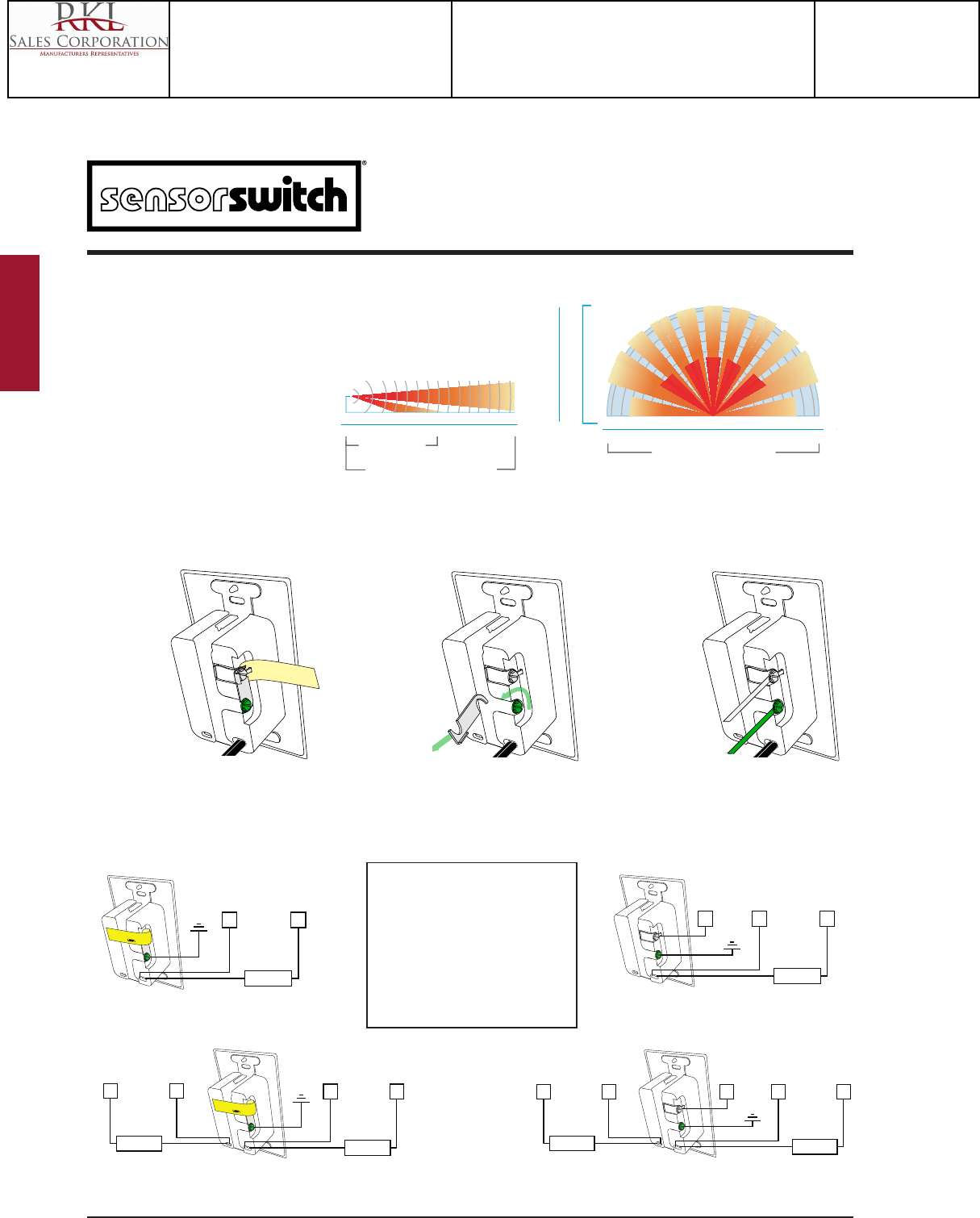
3 of 4Sensor Switch 900 Northrop Road, Wallingford, CT 06492 Phone: 1.800.PASSIVE sensorswitch.com ©2013 Acuity Brands Lighting, Inc. All rights reserved 03/01/13
WSX Family
H
NGND
LOAD 2 BLU
BLU
HN
LOAD 1
BLK
BLK
REMOVE METAL LINK
IF CONNECTING TO
NEUTRAL
GND
HN
LOAD 1
BLK
BLK
N
H
N
LOAD 2 BLU
BLU
COVERAGE PATTERN
• Small motion (e.g., hand movements) detection up to 20 ft (6.10 m), ~625 ft2
• Large motion (e.g., walking) detection greater than 36 ft (10.97 m), ~2025 ft2
• Wall-to-Wall coverage
• Passive Dual Technology (Microphonics) provides
overlapping detection of human activity over the
complete PIR coverage area. Advanced filtering is
utilized to prevent non-occupant noises from
keeping the lights on.
36 30 20 10 0 ft 10 20
30 36
12 9 6 3 0 m
3 6 9 12
Small
motion
detection
Small
motion
detection
to ~20 ft
6
3
0 m
20
10
0 ft
Small motion ~40 ft coverage
TOP VIEW
1.2 m
4 ft
Small motion
detection to ~20 ft
Large motion detection to >36 ft
SIDE VIEW
0 18 27 369
ft
0 6 9 123
m
WIRING TO GROUND NO NEUTRAL
GND HN
LOAD 1
BLK
BLK
REMOVE METAL LINK
IF CONNECTING TO
NEUTRAL
GND
HN
LOAD 1
BLK
BLK
N
SINGLE RELAY SINGLE RELAY
DUAL RELAY
This product is pre-congured for wiring without a neutral, however if connection to neutral is required by code, contractors can quickly and easily convert the unit in seconds.
CONVERSION FROM GROUND ONLY NO NEUTRAL TO NEUTRAL WIRING
120/277 VAC WIRING
BLACK* - Line 1 Input
BLACK* - Load 1 Output
*BLACK wires
can be reversed
}
BLUE* - Line 2 Input
BLUE* - Load 2 Output *BLUE wires
can be reversed
}
DUAL RELAY
REMOVE METAL LINK
IF CONNECTING TO
NEUTRAL
REMOVE METAL LINK
IF CONNECTING TO
NEUTRAL
REMOVE METAL LINK
IF CONNECTING TO
NEUTRAL
Step 1:
Remove Yellow
Label
Step 2:
Loosen Screws and
Remove Metal Link
Step 3:
Connect Neutral to
Silver Screw and
Ground to Green Screw
WIRING TO NEUTRAL
WIRE COLOR KEY
347 VAC WIRING (-347 Option)
Red wires replace Black wires.
Notes:
- Unit will draw power from either line connection.
- Both poles’ line connection must be same phase.
Catalog Number
WSX PDT WH
Notes
Type
OS
Project 15-18720-6
Teen Center - Los Alamos
Submitted By
RKL SALES CORP
4 of 4Sensor Switch 900 Northrop Road, Wallingford, CT 06492 Phone: 1.800.PASSIVE sensorswitch.com ©2013 Acuity Brands Lighting, Inc. All rights reserved 03/01/13
WSX Family
WARRANTY: Sensor Switch warrants these products to be free of defects in manufacture and workmanship for a period of 60 months.
Sensor Switch, upon prompt notice of such defect, will, at its option, provide a Returned Material Authorization number and repair or replace
returned product.
LIMITATIONS AND EXCLUSIONS: This Warranty is in full lieu of all other representation and expressed and implied warranties (including
the implied warranties of merchantability and tness for use) and under no circumstances shall Sensor Switch be liable for any incidental or
consequential property damages or losses.
Sheet#: TS-WSX-001A
C US LISTED
TITLE 24
ASSEMBLED in U.S.A.
5 YEAR WARRANTY
ORDERING LOGIC
Series
Series
Operating Mode1Voltage
Voltage
Color3
Color3
Temp/Humidity
Temp/Humidity
WSX
WSX PDT
Passive Infrared (PIR)
Dual Technology
(PIR / Microphonics)
Blank
SA
VA
Auto On (default)
or Vacancy
Vacancy (default)
or Auto-On
Vacancy only
Blank
3472
120/277 VAC
347 VAC
Blank
3472
120/277 VAC
347 VAC
WH
IV
GY
AL
BK
RD
White
Ivory
Gray
Lt. Almond
Black
Red
WH
IV
GY
AL
BK
RD
White
Ivory
Gray
Lt. Almond
Black
Red
Blank
LT
Standard
Low Temp
Blank
LT
Standard
Low Temp
PHYSICAL SPECS
SIZE: 2.74”H x 1.68”W x 1.63”D (6.96 cm x 4.27 cm x 4.14 cm)
(not including ground strap)
WEIGHT: 5 oz
MOUNTING: Single Gang Switch Box
MOUNTING HEIGHT: 30-48 in (76.2-121.9 cm)
SILICONE FREE
ROHS COMPLIANT
ELECTRICAL SPECS
MAXIMUM LOAD / POLE (RELAY)
800 W @ 120 VAC
1200 W @ 277 VAC
1500 W @ 347 VAC
MINIMUM LOAD: None
MOTOR LOAD: 1/4 HP
FREQUENCY: 50/60 Hz (timers are 1.2x for 50 Hz)
ENVIRONMENTAL SPECS
OPERATING TEMP
Standard: 14º to 122º F (-10º to 50º C)
LT Option (PIR): -40º to 122º F (-40º to 50º C)
LT Option (PDT): -4º to 122º F (-20º to 50º C)
RELATIVE HUMIDITY:
Standard: 20 to 75% non-condensing
LT Option: 20 to 90% non-condensing
(electronics coated for corrosion resistance)
EXAMPLE: WSX PDT WH
EXAMPLE: WSX 2P WH LT
SINGLE RELAY
DUAL RELAY
Operating Mode1
Blank
2SA
2VA
Pole 1-Auto On
Pole 2-Vacancy
(default)
Both Poles
Vacancy
(defaut)
Both Poles
only Vacancy
WSX 2P
WSX PDT 2P
Passive Infrared (PIR)
Dual Technology
(PIR / Microphonics)
Series4Voltage Color3Temp/Humidity
WSX NL
WSX PDT NL
WSX 2P NL
WSX PDT 2P NL
Passive Infrared (PIR)
Dual Technology (PIR / Microphonics)
Dual Relay, Passive Infrared (PIR)
Dual Relay, Dual Technology (PIR / Microphonics)
Blank
3472
120/277 VAC
347 VAC
WH
IV
GY
AL
BK
RD
White
Ivory
Gray
Lt. Almond
Black
Red
Blank
LT
Standard
Low Temp
EXAMPLE: WSX 2P NL WH
NIGHTLIGHT
SPECIFICATIONS
Notes:
1 Operating Modes reprogrammable via push-button except for VA version
2 Wall plates included in white or ivory only for 347 VAC units
3 Matching wall plate provided for 120/277 VAC units
4 Units factory set to Vacancy (Manual On) Operating Mode
Catalog Number
WSX PDT WH
Notes
Type
OS
Project 15-18720-6
Teen Center - Los Alamos
Submitted By
RKL SALES CORP

1 of 4Sensor Switch 900 Northrop Road, Wallingford, CT 06492 Phone: 1.800.PASSIVE sensorswitch.com ©2013 Acuity Brands Lighting, Inc. All rights reserved 03/01/13
Catalog Number
Notes Type
PRODUCT OVERVIEW
The WSX Family of wall switch occupancy sensors provides simple and cost eective
solutions for commercial and residential lighting control applications. All WSX
Family sensors have a stylish low prole appearance, soft-click buttons, and provide
small motion detection up to 20 ft (6.10 m), making them perfect for private
oces, private rest rooms, closets, copy rooms, or any other small enclosed space.
Additionally, all WSX Family sensors have a patent-pending wiring method that
enables them to function either with or without a neutral connection. WSX units
come pre-congured for wiring without a neutral, however if connection to neutral
is required by code, contractors can convert the unit in seconds (see page 3).
All WSX Family sensors utilize 100% digital Passive Infrared (PIR) detection.
Dual Technology (PDT option) versions add Microphonics detection and are
recommended for oces and rooms with obstructions. Additional versions include
units with dual relays - perfect for bi-level applications, and units with an integrated
nightlight - perfect for restrooms and residential applications.
SENSOR OPERATION WSX sensors detect changes in the Passive Infrared (PIR)
energy given o by occupants as they move within the eld-of-view. In an Auto-On
sensor, once occupancy is detected, an internal relay switches on the connected
lighting load. In a Vacancy (Manual On) sensor, the unit’s push button must rst be
pressed to initiate the lights on. In a dual relay sensor, once occupancy is detected
the unit will automatically close Pole 1’s relay while still requiring Pole 2’s push-
button be pressed in order to close Pole 2’s relay. All modes are user adjustable (see
On Modes section).
After the lights are turned on, an internal timer keeps them on during brief periods
of inactivity. Once the time delay has expired, lights are turned o automatically.
The default time delay is 10 minutes - chosen in order to maximize energy savings
while preventing false-os. This timer is programmable from 30 seconds to 30
minutes, and is reset every time occupancy is re-detected. Patented LampMaximzer
technology is also present in these sensors, providing an additional minimum on
time (disabled by default) to be utilized if desired.
WSX sensors with Passive Dual Technology (PDT option) rst see motion using
Passive Infrared (PIR) and then engage Microphonics to listen for sounds that also
indicate continued occupancy. This patented technology dynamically adapts a
sensor to its environment by ltering out constant background noise and detecting
only noises typical of human activity.
KEY OPTIONS
NIGHT LIGHT (NL)
Ideal for bathrooms (hotel / hospital) or residential applications
• Ultra low power White LED night light (24/7 operation)
• Capable of powering over Ground (no Neutral required)
• Manual On / Auto O operation of lights (default)
• Available with Single or Dual Relays
DUAL RELAY (2P)
Ideal for bi-level switched rooms or restroom with light & fan
• Includes two isolated relays, Pole 1 defaulted to Auto On, Pole 2 to Vacancy
• Enables separate time delay per pole - programmed via each pole’s push-button
• UL listed to switch dierent loads per pole - e.g. 277 VAC lights on Pole 1 and 120
VAC fan on Pole 2
LOW TEMPERATURE / HIGH HUMIDITY (LT)
Required for cold / humid areas
• Device electronics are coated for corrosion resistance
• Operates down to -40º F/C (-4º F / 20º C for PDT)
WSX
FAMILY
WALL SWITCH SENSOR w/
CONVERTIBLE NEUTRAL / NO NEUTRAL WIRING,
PASSIVE INFRARED (PIR) or DUAL TECH (PDT)
• 100% digital PIR detection - excellent RF immunity
• Ruggedized assembly, vandal resistant lens standard
• Small motion detection to 20 ft
• Dual Technology (PDT) utilizes PIR / Microphonics
detection (patented)
• 100% passive detection, no potential for
interference with other building systems
• Self-grounding mounting strap
• White LED status indicator
• Device accommodates powering over ground or
neutral connection (patent pending)
• Ultra low current leakage (<0.5 mA) when
connected via ground
• Fully meets NEC 2011 Section 404.2C neutral
requirements - no current leakage to ground when
connected to neutral
• Line power and load wires are interchangeable -
impossible to wire backwards (patented)
• Compatible w/ LEDs, Electronic & Magnetic Ballasts,
CFLs, & Incandescents
• Photocell standard (disabled by default) prevents
lights from initially turning on if sucient daylight
is present, but does not turn lights o. Photocell not
available in Night Light or Vacancy only versions.
• Integrated LampMaximizer minimum on time
(patented) provides increased uorescent lamp life -
disabled by default
• Push-button programmable without removing cover
plate - adjustable time delays & operating modes
• Non-volatile settings memory
• Includes wall plate (screwless sold separate)
WSX
WSX PDT
WSX 2P
WSX PDT 2P
WSX NL
WSX PDT NL
FEATURES
Catalog Number
WSX PDT 2P WH
Notes
Type
OS1
Project 15-18720-6
Teen Center - Los Alamos
Submitted By
RKL SALES CORP
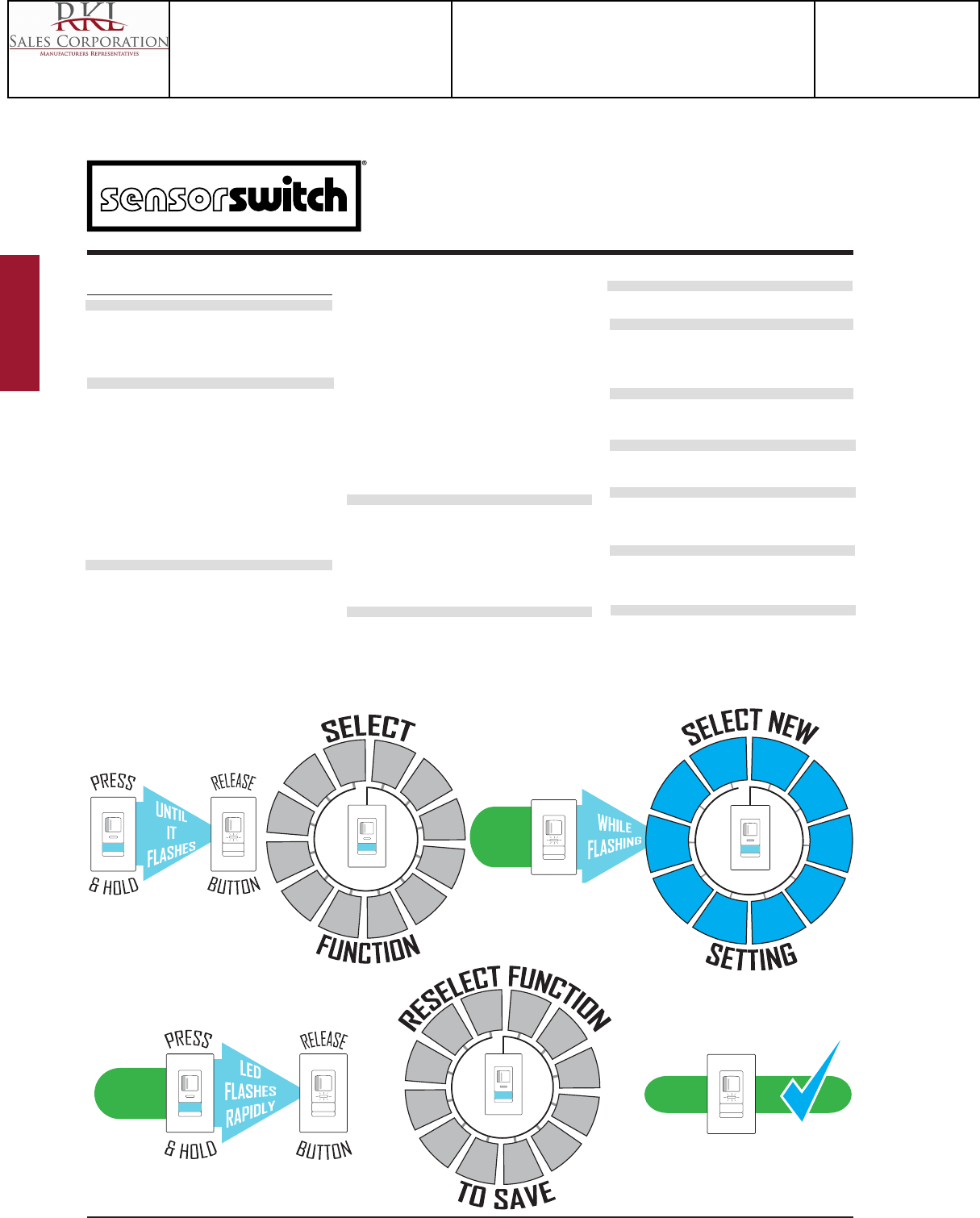
2 of 4Sensor Switch 900 Northrop Road, Wallingford, CT 06492 Phone: 1.800.PASSIVE sensorswitch.com ©2013 Acuity Brands Lighting, Inc. All rights reserved 03/01/13
WSX Family
On Mode
Restore
Factory
Defaults
Switch
Mode
LED
Operation
Predictive
Exit
Time
Microphone
Grace Period
Occupancy
Time
Delay
Photocell
Set-Pt
Minimum
On Time
Manual On
Grace
Period
Dual
Technology
(MicrophonicsTM)
Predictive
Grace
Time
4x
5x
7x
9x10x
2x 3x
12x
11x
13x
15x 16x
PRESS BUTTON
3.
While LED
flashes
back current
setting 10x...
OPERATIONAL SETTINGS _________________________________________________________________________________________________
PROGRAMMING INSTRUCTIONS ______________________________________________________________________________________
4.
PRESS BUTTON
30 sec
20 min
30 min
17.5 min
15.0 min
12.5 min 10 min
5.0 min
2.5 min
7.5 min
1x
10x
2x
3x
4x
5x6x
7x
8x
9x
1.
While LED
flashes back new
setting 10x...
5.
6.
On Mode
Restore
Factory
Defaults
Switch
Mode
LED
Operation
Predictive
Exit
Time
Microphone
Grace Period
Occupancy
Time
Delay
Photocell
Set-Pt
Minimum
On Time
Manual On
Grace
Period
Dual
Technology
(MicrophonicsTM)
Predictive
Grace
Time
4x
5x
7x
9x10x
2x 3x
12x
11x
13x
15x 16x
PRESS BUTTON
4.1.
5. 6.
LED FLASHES
CONFIRMATION
TWICE
PROGRAMMING
COMPLETE
7.
7.
Operational settings can be changed via the push-button sequence outlined below (note the example used is for changing occupancy time delay). Programming for 2P units done with each
pole’s corresponding push-button.
e.g., 5 ashes is default
10 min time delay
e.g., press 4x
to change
to 7.5 min
e.g., 4 ashes
indicates new
7.5 min time
delay setting
e.g., press 2x to
save and exit
2. 3.
e.g., press 2x for
Occupancy Time
Delay
NOTE: (*) Indicates factory default (unless otherwise marked)
2 = Occupancy Time Delay
Time sensor keeps lights on after last occupancy detection.
1 30 sec 4 7.5 min 7 15.0 min 10 30.0 min
2 2.5 min 5 10.0 min* 8 17.5 min
3 5.0 min 6 12.5 min 9 20.0 min
For additional time settings, contact technical support at
1.800.PASSIVE
3 = On Mode
Automatic On turns lights on when occupancy is detected. Manual
On requires a button press to turn the lights on. Reduced Turn-On
directs the sensor to only turn on when a large motion, such as
a person entering a room, is detected. Weaker signals, such
as reections from glass, are ignored. Once lights are on, the
sensor returns to maximum sensitivity.
1 Automatic On 2 Manual On 3 Reduced Turn-On
Settings 1 & 3 not available on -VA (Vacancy only) sensors.
Notes on Default Settings
• WSX (PDT) Series default: Automatic On
• Default for units with -SA, -VA, or -NL option: Manual On
• WSX (PDT) 2P Series default: Pole 1 Auto On, Pole 2 Manual
• Default for 2P units with -2SA, -2VA, or NL options:
Both poles Manual On
4 = Switch Modes
These modes dictate switch functionality.
Pressing the button in Override Off mode (setting 1) turns off
and keeps lights off until pressed again.
Disabling the Switch (setting 2) prevents the button from turning
the lights on. (continued next column)
Predictive Mode (setting 3) determines if a user has left the room
after the lights are switched off. It does this by monitoring the
space for a period after the button is pressed (Predictive Grace
Time), following a delay to allow exiting the room (Predictive Exit
Time). If occupancy is detected the device will disable auto-on
& hold the lights off until manually switched. If no occupancy is
detected the sensor instantly reverts to auto-on mode.
If Predictive Mode with Expiration (setting 4) is enabled, once
the sensor has disabled auto-on it will continue to monitor the
space. When no occupancy is detected for a duration equal to the
occupancy time delay, the sensor will revert to auto-on mode.
1 Override Off **
2 Switch Disable
3 Predictive Mode
4 Predictive Mode with Expiration*
* Default for WSX (PDT) units & Pole 1 of WSX (PDT) 2P units
** Default for units with -SA, -VA, or -NL options, Pole 2 of WSX
(PDT) 2P units, and both poles of 2P units with -2SA, -2VA,
or -NL options
5 = Photocell Set-Point
The ambient light level at which the sensor prevents the lights
from initially turning on. Once on, the lights will remain on until
the occupancy time delay expires and turns them off.
1 Disabled* 5 2 fc 9 32 fc
2 Auto Setpoint 6 4 fc 10 64 fc
3 0.5 fc 7 8 fc
4 1 fc 8 16 fc
Note: Sensor changes to Auto On mode if photocell is enabled.
Photocell not present in -NL versions.
7 = LED Operation
Indicates behavior of device’s LED.
1 Occupancy Indication* 3 Disabled
2 Relay Indication 4 Override On***
*Standard Factory Default *** Factory Default for -NL version
9 = Restore Factory Defaults
Returns all functions to original settings.
1 Maintain Current* 2 Restore Defaults
10 = Minimum On Time
Required initial time for lamps to be on after each switch on,
regardless of occupancy status. Once met, lights resume
following occupancy time delay.
1 0 min (disabled)* 3 30 min 5 60 min
2 15 min 4 45 min
11 = Manual On Grace Period
Time period after lights automatically turn off that they can be
reactivated by motion. (Manual On (Semi-Auto) mode only)
1 0 sec 2 Unused 3 15 sec*
12 = Dual Technology (MicrophonicsTM)
Relative responsiveness of Microphonics detection.
1 Normal* 3 Medium 5 Phase Off
2 Off 4 Low (15-10-5 min)
13 = Microphone Grace Period
Time period after lights are automatically turned off that they
can be voice reactivated.
1 0 sec 3 20 sec 5 40 sec 7 60 sec
2 10 sec* 4 30 sec 6 50 sec
15 = Predictive Exit Time
Time period after manually switching lights off for occupant to
leave the space.
1 5 sec 3 7 sec 5 9 sec 7 15 sec 9 30 sec
2 6 sec 4 8 sec 6 10 sec* 8 20 sec
16 = Predictive Grace Time
Time period after Predictive Exit Time that sensor rescans the
room for remaining occupants.
1 0 sec 3 10 sec 5 30 sec* 7 50 sec
2 5 sec 4 20 sec 6 40 sec 8 60 sec
Catalog Number
WSX PDT 2P WH
Notes
Type
OS1
Project 15-18720-6
Teen Center - Los Alamos
Submitted By
RKL SALES CORP

3 of 4Sensor Switch 900 Northrop Road, Wallingford, CT 06492 Phone: 1.800.PASSIVE sensorswitch.com ©2013 Acuity Brands Lighting, Inc. All rights reserved 03/01/13
WSX Family
H
NGND
LOAD 2 BLU
BLU
HN
LOAD 1
BLK
BLK
REMOVE METAL LINK
IF CONNECTING TO
NEUTRAL
GND
HN
LOAD 1
BLK
BLK
N
H
N
LOAD 2 BLU
BLU
COVERAGE PATTERN
• Small motion (e.g., hand movements) detection up to 20 ft (6.10 m), ~625 ft2
• Large motion (e.g., walking) detection greater than 36 ft (10.97 m), ~2025 ft2
• Wall-to-Wall coverage
• Passive Dual Technology (Microphonics) provides
overlapping detection of human activity over the
complete PIR coverage area. Advanced filtering is
utilized to prevent non-occupant noises from
keeping the lights on.
36 30 20 10 0 ft 10 20
30 36
12 9 6 3 0 m
3 6 9 12
Small
motion
detection
Small
motion
detection
to ~20 ft
6
3
0 m
20
10
0 ft
Small motion ~40 ft coverage
TOP VIEW
1.2 m
4 ft
Small motion
detection to ~20 ft
Large motion detection to >36 ft
SIDE VIEW
0 18 27 369
ft
0 6 9 123
m
WIRING TO GROUND NO NEUTRAL
GND HN
LOAD 1
BLK
BLK
REMOVE METAL LINK
IF CONNECTING TO
NEUTRAL
GND
HN
LOAD 1
BLK
BLK
N
SINGLE RELAY SINGLE RELAY
DUAL RELAY
This product is pre-congured for wiring without a neutral, however if connection to neutral is required by code, contractors can quickly and easily convert the unit in seconds.
CONVERSION FROM GROUND ONLY NO NEUTRAL TO NEUTRAL WIRING
120/277 VAC WIRING
BLACK* - Line 1 Input
BLACK* - Load 1 Output
*BLACK wires
can be reversed
}
BLUE* - Line 2 Input
BLUE* - Load 2 Output *BLUE wires
can be reversed
}
DUAL RELAY
REMOVE METAL LINK
IF CONNECTING TO
NEUTRAL
REMOVE METAL LINK
IF CONNECTING TO
NEUTRAL
REMOVE METAL LINK
IF CONNECTING TO
NEUTRAL
Step 1:
Remove Yellow
Label
Step 2:
Loosen Screws and
Remove Metal Link
Step 3:
Connect Neutral to
Silver Screw and
Ground to Green Screw
WIRING TO NEUTRAL
WIRE COLOR KEY
347 VAC WIRING (-347 Option)
Red wires replace Black wires.
Notes:
- Unit will draw power from either line connection.
- Both poles’ line connection must be same phase.
Catalog Number
WSX PDT 2P WH
Notes
Type
OS1
Project 15-18720-6
Teen Center - Los Alamos
Submitted By
RKL SALES CORP
4 of 4Sensor Switch 900 Northrop Road, Wallingford, CT 06492 Phone: 1.800.PASSIVE sensorswitch.com ©2013 Acuity Brands Lighting, Inc. All rights reserved 03/01/13
WSX Family
WARRANTY: Sensor Switch warrants these products to be free of defects in manufacture and workmanship for a period of 60 months.
Sensor Switch, upon prompt notice of such defect, will, at its option, provide a Returned Material Authorization number and repair or replace
returned product.
LIMITATIONS AND EXCLUSIONS: This Warranty is in full lieu of all other representation and expressed and implied warranties (including
the implied warranties of merchantability and tness for use) and under no circumstances shall Sensor Switch be liable for any incidental or
consequential property damages or losses.
Sheet#: TS-WSX-001A
C US LISTED
TITLE 24
ASSEMBLED in U.S.A.
5 YEAR WARRANTY
ORDERING LOGIC
Series
Series
Operating Mode1Voltage
Voltage
Color3
Color3
Temp/Humidity
Temp/Humidity
WSX
WSX PDT
Passive Infrared (PIR)
Dual Technology
(PIR / Microphonics)
Blank
SA
VA
Auto On (default)
or Vacancy
Vacancy (default)
or Auto-On
Vacancy only
Blank
3472
120/277 VAC
347 VAC
Blank
3472
120/277 VAC
347 VAC
WH
IV
GY
AL
BK
RD
White
Ivory
Gray
Lt. Almond
Black
Red
WH
IV
GY
AL
BK
RD
White
Ivory
Gray
Lt. Almond
Black
Red
Blank
LT
Standard
Low Temp
Blank
LT
Standard
Low Temp
PHYSICAL SPECS
SIZE: 2.74”H x 1.68”W x 1.63”D (6.96 cm x 4.27 cm x 4.14 cm)
(not including ground strap)
WEIGHT: 5 oz
MOUNTING: Single Gang Switch Box
MOUNTING HEIGHT: 30-48 in (76.2-121.9 cm)
SILICONE FREE
ROHS COMPLIANT
ELECTRICAL SPECS
MAXIMUM LOAD / POLE (RELAY)
800 W @ 120 VAC
1200 W @ 277 VAC
1500 W @ 347 VAC
MINIMUM LOAD: None
MOTOR LOAD: 1/4 HP
FREQUENCY: 50/60 Hz (timers are 1.2x for 50 Hz)
ENVIRONMENTAL SPECS
OPERATING TEMP
Standard: 14º to 122º F (-10º to 50º C)
LT Option (PIR): -40º to 122º F (-40º to 50º C)
LT Option (PDT): -4º to 122º F (-20º to 50º C)
RELATIVE HUMIDITY:
Standard: 20 to 75% non-condensing
LT Option: 20 to 90% non-condensing
(electronics coated for corrosion resistance)
EXAMPLE: WSX PDT WH
EXAMPLE: WSX 2P WH LT
SINGLE RELAY
DUAL RELAY
Operating Mode1
Blank
2SA
2VA
Pole 1-Auto On
Pole 2-Vacancy
(default)
Both Poles
Vacancy
(defaut)
Both Poles
only Vacancy
WSX 2P
WSX PDT 2P
Passive Infrared (PIR)
Dual Technology
(PIR / Microphonics)
Series4Voltage Color3Temp/Humidity
WSX NL
WSX PDT NL
WSX 2P NL
WSX PDT 2P NL
Passive Infrared (PIR)
Dual Technology (PIR / Microphonics)
Dual Relay, Passive Infrared (PIR)
Dual Relay, Dual Technology (PIR / Microphonics)
Blank
3472
120/277 VAC
347 VAC
WH
IV
GY
AL
BK
RD
White
Ivory
Gray
Lt. Almond
Black
Red
Blank
LT
Standard
Low Temp
EXAMPLE: WSX 2P NL WH
NIGHTLIGHT
SPECIFICATIONS
Notes:
1 Operating Modes reprogrammable via push-button except for VA version
2 Wall plates included in white or ivory only for 347 VAC units
3 Matching wall plate provided for 120/277 VAC units
4 Units factory set to Vacancy (Manual On) Operating Mode
Catalog Number
WSX PDT 2P WH
Notes
Type
OS1
Project 15-18720-6
Teen Center - Los Alamos
Submitted By
RKL SALES CORP
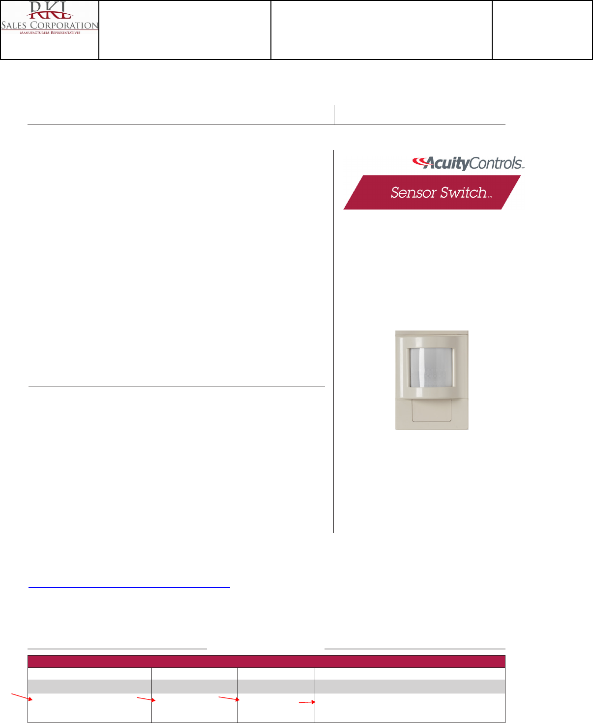
1 of 2
Acuity Brands | One Lithonia Way Conyers, GA 30012 Phone: 800.535.2465 www.acuitycontrols.com © 2014-2015 Acuity Brands Lighting, Inc. All rights reserved. 07/14/15
WVR PDT 16 Example: WVR PDT 16 2P WH
Series Poles Voltage Color
WVR PDT 16 Wide View Sensor [blank] 1 Pole
2P 2 Pole
[blank] None
347 347 VAC
WH White
IV Ivory
OVERVIEW
The WVR PDT 16 Series sensor mounts in a corner, provides line of sight PIR detection of small
movements up to 40 ft away as well as Microphonics™ for detection around obstructions. These
features make it ideal for retrofit applications like classrooms with inaccessible ceilings. WVR
PDT 16 sensors are powered by and directly switch line voltage, therefore no Power Packs are
needed. Additionally, these sensors do not require a neutral, making wiring directly off local
switches with wiremold a convenient option. Together, these features make them perfect for
retrofit applications where running new wiring is difficult. A WVR PDT 16 sensor is equipped
with either one relay or an optional 2nd realy (2P), each with the ability to control up to 13 Amps.
FEATURES
• 100% Digital PIR Detection, Excellent RF Immunity
• 120º by 40 ft (12.19 m) Coverage for Small Motion
• Patented Dual Technology with PIR/Microphonics™ Detection
• Single and 2-Pole Versions
• Interchangeable Hot & Load Wires -Impossible to Wire Backwards
• No Neutral Required / No Minimum Load
• Compatible w/ Electronic & Magnetic Ballasts, CFLs, & Incandescents
• Adjustable Time Delay
• Push-Button Programmable
• Non-Volatile Settings Memory
WVR PDT 16
WVR PDT 16 2P
Wide View Sensor
ORDERING INFORMATION
SPECIFICATIONS
Warranty
Five-year limited warranty. Complete warranty terms located at:
www.acuitybrands.com/CustomerResources/Terms_and_conditions.aspx
Note: Actual performance may differ as a result of end-user environment and application.
Specifications subject to change without notice.
Catalog Number: Date: Project:
*Note: 2P units with 347 VAC option must be of the same phasee
Size: 3.0” H x 3.6” W x 1.75” D (7.62 cm x 9.14 cm x 4.45 cm)
Weight: 7 oz
Mounting: Single Gang Handy Box (add Wiremold Box # V5719 for Corner
Mounting)
Mounting Height: 7 to 8 ft
Operating Voltage: 120/277, 347 VAC 13 Amps / Pole (347 VAC must be same phase)
Motor Load: 1/4 HP
Frequency: 50/60Hz
Max. humidity: 20–90% non-condensing
Ambient temperature: 14–160° F (-10–71° C)
ROHS compliant
Catalog Number
WVR PDT 16 WH
Notes
Type
OS2
Project 15-18720-6
Teen Center - Los Alamos
Submitted By
RKL SALES CORP
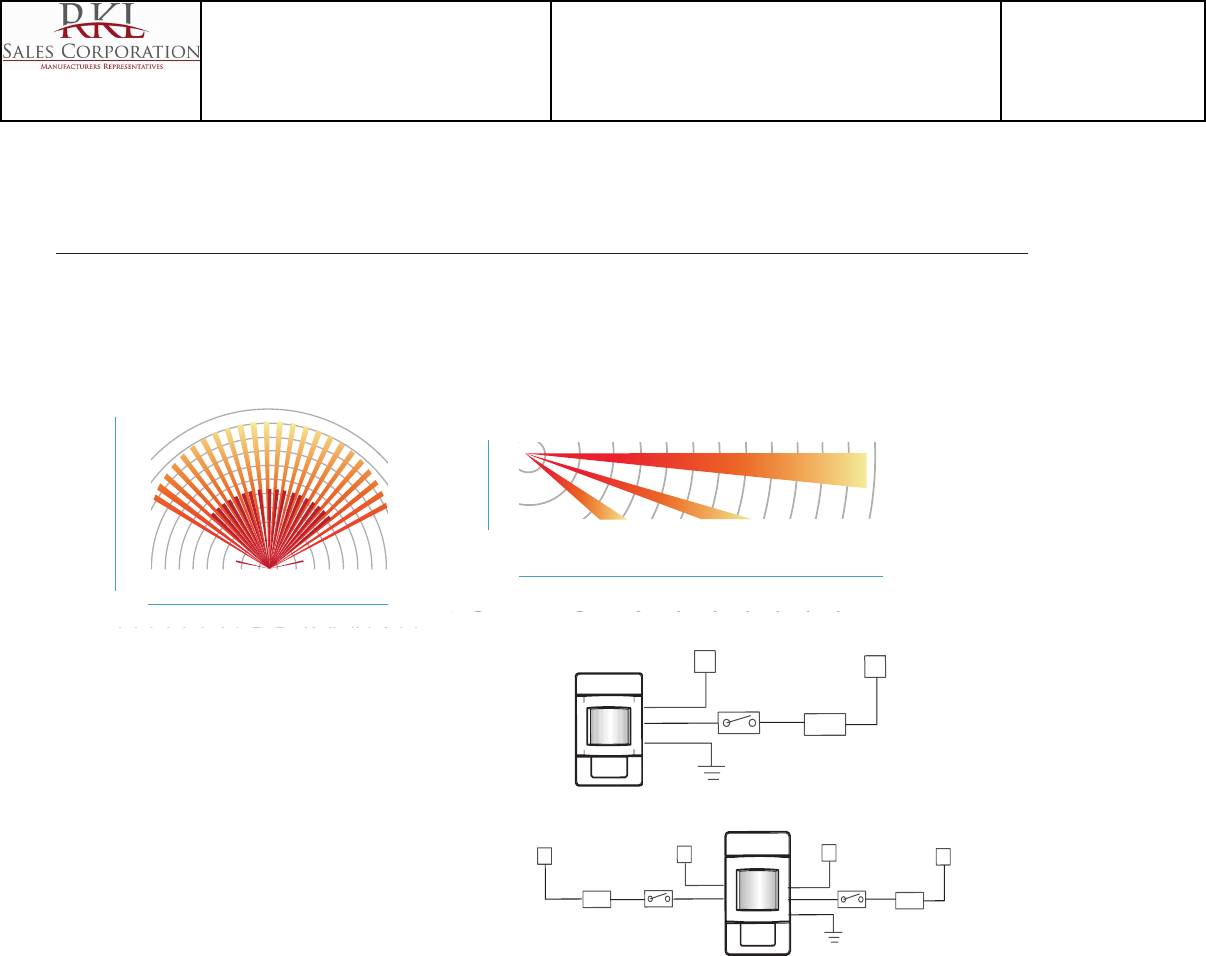
2 of 2
Acuity Brands | One Lithonia Way Conyers, GA 30012 Phone: 800.535.2465 www.acuitycontrols.com © 2014-2015 Acuity Brands Lighting, Inc. All rights reserved. 07/14/15
WVR PDT 16 (2P) - TS-WVR-003A
SIDE VIEW
TOP VIEW
0 ft 10 20 30 40
0 m 10 20 30 40
30 20 10 0 ft 10 20 30
30 20 10 0 m 10 20 30
12.2
9.1
6
3
0 m
40
30
20
10
0 ft
0 ft
9
0 m
2.7
WIDE VIEW LENS WITH MICROPHONICS™
H
LOAD
N
SYSTEM
GROUND
BLK
BLK
GRN
SWITCH
BLK
• Small motion (e.g. hand movements) detection up to 40 ft (12.19 m).
• Large motion (e.g. walking) detection up to 70 ft (21.34 m).
• Designed for 8 to 10 ft (2.44 to 3.05 m) high mounting in room corner.
• Microphonics™ provides overlapping detection of human activity over the complete PIR coverage area. Advanced filtering is also utilized
to prevent non-occupant noises from keeping the lights on.
SIDE VIEW
TOP VIEW
0 ft 10 20 30 40
0 m 10 20 30 40
30 20 10 0 ft 10 20 30
30 20 10 0 m 10 20 30
12.2
9.1
6
3
0 m
40
30
20
10
0 ft
0 ft
9
0 m
2.7
STANDARD WIRING
BLACK* - Line Input 1
BLACK* - Load Output 1
BLUE* - Line Input 2
BLUE* - Load Output 2
GREEN - Ground
347 VAC OPTION (347)
Black wires are replaced w/ Red wires
*BLACK wires can be reversed
}
*BLUE wires can be reversed
}
H
LOAD
N
SYSTEM
GROUND
GRN
SWITCH
H
LOAD
N
SWITCH BLK
BLK
BLU
BLU
2-Pole
COVERAGE PATTERNS
WIRING (DO NOT WIRE HOT)
Catalog Number
WVR PDT 16 WH
Notes
Type
OS2
Project 15-18720-6
Teen Center - Los Alamos
Submitted By
RKL SALES CORP
®
SPECIFICATIONS
ORDERING INFO
OPTIONS
INHIBIT PHOTOCELL (P)
• Photocell can prevent lights from
turning on if adequate daylight is
available, but cannot turn lights off
• Maintains two set-points, enabling
separate control of both poles
DUAL ZONE PHOTOCELL (DZ)
• Provides more advanced control than
P option
• DUO Operation: Determines
necessary on/off combination of poles
in inboard/outboard applications
• Percentage Offset Operation: Uses
relative set-point for second pole in
dual zone applications
347 VAC (347)
• Allows sensor to be powered from
and switch 347 VAC
LOW TEMP/HIGH HUMIDITY (LT)
• Sensor is corrosion resistant to
moisture
• Operates down to -4º F (-20ºC)
OVERVIEW
Classroom lighting control has never been
more cost effective than with the CMR PDT
10 2P. This sensor provides Dual Technology
detection up to a 40 ft by 40 ft (12.19 x 12.19
m) classroom, and can handle A/B (Inboard/
Outboard) switching. On a typical 9 ft (2.74 m)
ceiling, simply mount sensor 20 ft (6.10 m) up
and in from the door. Universal mounting allows
for 3.5” octagon boxes, wiremold, or standard
mud rings.
SENSOR OPERATION
Sensors with Passive Dual Technology
(PDT) rst see motion using 100% digital
Passive Infrared (PIR) detection and then
engage Microphonics™ to hear sounds that
indicate continued occupancy. This patented
technology uses Automatic Gain Control
(AGC) to dynamically self adapt a sensor
to its environment by ltering out constant
background noise and registering only noises
typical of human activity. When occupancy
is detected, two self-contained relays switch
the connected lighting loads on. If needed, a
10 second grace period also allows the lights
to be voice reactivated after shutting off. This
sensor is line powered, switches line voltage,
and requires no eld calibration or sensitivity
adjustments.
LAMPMAXIMIZER®
This sensor also contains patent pending
LampMaximizer technology that allows users
to aggressively target energy savings while still
protecting lamp life. A minimum on timer, factory
set at 15 minutes, helps preserve lamp life by
eliminating all lamp cycles shorter than lamp
warranties specify.
A standard occupancy time delay is also present
that ensures lights turn off (assuming minimum
on timer has elapsed) if no occupancy is
detected. This timer is factory set at 10 minutes
to promote energy savings, but is adjustable
between 30 seconds and 20 minutes. These
adjustments are done manually through the
unit’s push-button; no tools required.
EXTENDED RANGE 360º SENSOR
CEILING MOUNT • LINE VOLTAGE • DUAL TECHNOLOGY (PDT) • 2 POLE
CMR PDT 10 2P
FEATURES
100% Digital PIR Detection,
Excellent RF Immunity
360º Coverage Pattern
Two Self-Contained Relays,
No Power Pack(s) Needed
No Minimum Load Requirements
Interchangeable Hot & Load Wires,
Impossible to Wire Backwards
Push-Button Programmable
Adjustable Time Delays
No Field Calibration or Sensitivity
Adjustments Required
Convenient Test Mode
100 hr Lamp Burn-in Timer
Green LED Indicator
LAMPMAXIMIZER® TECHNOLOGY
• Protects Lamp Life while
Maximizing Energy Savings
• Minimum On Timer (15 min default)
• Occ. Time Delay (10 min defatult)
PHYSICAL / MATERIAL SPECS
SIZE 4.55” Dia. (11.56 cm)
1.55” Deep (3.94 cm)
WEIGHT 6 oz
MOUNTING
3.5” Octagon Box
Single Gang Handy Box
COLOR White
ELECTRICAL SPECS
MAXIMUM LOAD / POLE
(1 Phase Only)
800 W @ 120 VAC
1200 W @ 277 VAC
1500 W @ 347 VAC
MINIMUM LOAD None
MOTOR LOAD 1/4 HP
FREQUENCY 50/60 Hz
ENVIRONMENTAL SPECS
OPERATING TEMP
14º to 160º F (-10º to 71º C)
STORAGE TEMP
-14º to 160º F (-26º to 71º C)
RELATIVE HUMIDITY
20 to 90% non-condensing
SILICONE FREE
ROHS COMPLIANT
VOLTAGE TEMP/HUMIDITY
Blank = None Blank = 120/277 VAC Blank = Standard
P = Inhibit Photocell 347 = 347 VAC LT = Low Temp
DZ = Dual Zone Photocell
CMR PDT 10 2P [PHOTOCELL] [VOLTAGE] [TEMP/HUMIDITY]
PHOTOCELL CHOOSE ONE ONLY
C US LISTED
TITLE 24
MADE in U.S.A.
5 YEAR WARRANTY
TYPE: OC2
Catalog Number
CMR PDT 10 2P P
Notes
Type
OS3
Project 15-18720-6
Teen Center - Los Alamos
Submitted By
RKL SALES CORP
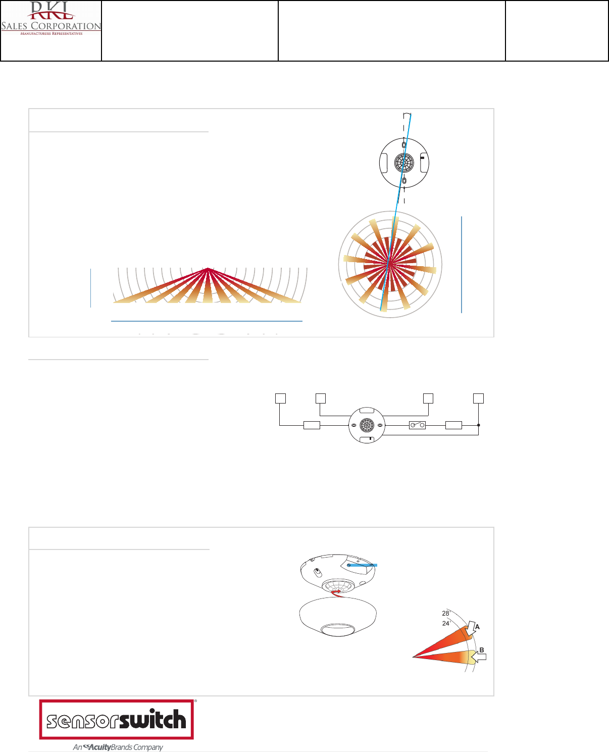
900 Northrop Road, Wallingford, CT 06492 • 1.800.PASSIVE • FX 203.269.9621 • www.sensorswitch.com
WARRANTY: Sensor Switch, Inc. warrants these products to be free of defects in manufacture and workmanship for
a period of 60 months. Sensor Switch, Inc., upon prompt notice of such defect, will, at its option, provide a Returned
Material Authorization number and repair or replace returned product.
LIMITATIONS AND EXCLUSIONS: This Warranty is in full lieu of all other representation and expressed and
implied warranties (including the implied warranties of merchantability and tness for use) and under no circumstances
shall Sensor Switch, Inc. be liable for any incidental or consequential property damages or losses.
TS-CMR-010A
Revised 07.18.10 ©2010 Sensor Switch
INSTALLATION
WIRING (DO NOT WIRE HOT)
COVERAGE PATTERN
PUSH BUTTON
PROGRAMMING
Refer to instruction card IC8.001 for default settings and directions on programming the sensor via the push-button.
10 EXTENDED RANGE 360º LENS WITH MICROPHONICS™
0
ft
9
0 m
2.7
28 21 14 7 0 ft 7 14 21 28
8.5 6.4 4.3 2.1 0 m 2.1 4.3 6.4 8.5
SIDE VIEW
TOP VIEW
28
14
0
ft
14
28
8.5
4.3
0
m
4.3
8.5
0 ft
9
0 m
2.7
28 21 14 7 0 ft 7 14 21 28
8.5 6.4 4.3 2.1 0 m 2.1 4.3 6.4 8.5
SIDE VIEW
TOP VIEW
28
14
0 ft
14
28
8.5
4.3
0 m
4.3
8.5
• Best choice for large motion detection (e.g. walking)
• Viewing angle of 67º in a 360º conical shaped pattern
• Provides 28 ft (8.53 m) radial coverage when mounted to
standard 9 ft (2.74 m) ceiling
• 7 to 15 ft (2.13 to 4.57 m) mounting heights provide 16 to 36
ft (4.88 to 10.97 m) radial coverage
• Microphonics™ provides overlapping detection of human
activity over the complete PIR coverage area. Advanced
ltering is also utilized to prevent non-occupant noises from
keeping the lights on.
Note: Sensor’s screw
axis is offset 7.5º from a
long detection segment
• Sensor’s mounting holes align with 3.5” octagon or single gang
handy box (screws not provided).
• For optimal detection, position sensor such that segments are
crossed upon entrance and unable to view outside the space.
• Sensor will detect motions crossing segments more effectively
than motions parallel to beams.
• For maximum Microphonics™ sensitivity avoid locating sensor
near HVAC air diffusers.
LOAD LOAD
HN NH
120 OR
277 VAC
120 OR
277 VAC
SWITCH
BLK
BLK
WHT
BLU
BLU
STANDARD WIRING
BLACK* - Line Input 1
BLACK* - Load Output 1
BLUE** - Line Input 2
BLUE** - Load Output 2
WHITE - Neutral
347 VAC OPTION (347)
Black wires are replaced w/ Red wires
*At 9ft Mtg.
A: When walking across beam, detection
will occur at approximately 28 ft.
B: When walking into beam, detection
will occur at approximately 24 ft.
*BLACK wires can be reversed
}
**BLUE wires can be reversed
}
INITIAL POWER UP
The sensor’s relays are shipped in a latched closed position so the lights will come on upon initial power-up. If the lights do
not immediately turn on (initial installation only) the latching relays opened during shipment and will close within 30 secs.
Note: If the sensor loses power, the internal relays will latch to on.
Catalog Number
CMR PDT 10 2P P
Notes
Type
OS3
Project 15-18720-6
Teen Center - Los Alamos
Submitted By
RKL SALES CORP

®
SPECIFICATIONS
ORDERING INFO
OPTIONS
INHIBIT PHOTOCELL (P)
• Photocell can prevent lights from
turning on if adequate daylight is
available, but cannot turn lights off
• Maintains two set-points, enabling
separate control of both poles
DUAL ZONE PHOTOCELL (DZ)
• Provides more advanced control than
P option
• DUO Operation: Determines
necessary on/off combination of poles
in inboard/outboard applications
• Percentage Offset Operation: Uses
relative set-point for second pole in
dual zone applications
347 VAC (347)
• Allows sensor to be powered from
and switch 347 VAC
LOW TEMP/HIGH HUMIDITY (LT)
• Sensor is corrosion resistant to
moisture
• Operates down to -4º F (-20ºC)
OVERVIEW
Classroom lighting control has never been
more cost effective than with the CMR PDT
10 2P. This sensor provides Dual Technology
detection up to a 40 ft by 40 ft (12.19 x 12.19
m) classroom, and can handle A/B (Inboard/
Outboard) switching. On a typical 9 ft (2.74 m)
ceiling, simply mount sensor 20 ft (6.10 m) up
and in from the door. Universal mounting allows
for 3.5” octagon boxes, wiremold, or standard
mud rings.
SENSOR OPERATION
Sensors with Passive Dual Technology
(PDT) rst see motion using 100% digital
Passive Infrared (PIR) detection and then
engage Microphonics™ to hear sounds that
indicate continued occupancy. This patented
technology uses Automatic Gain Control
(AGC) to dynamically self adapt a sensor
to its environment by ltering out constant
background noise and registering only noises
typical of human activity. When occupancy
is detected, two self-contained relays switch
the connected lighting loads on. If needed, a
10 second grace period also allows the lights
to be voice reactivated after shutting off. This
sensor is line powered, switches line voltage,
and requires no eld calibration or sensitivity
adjustments.
LAMPMAXIMIZER®
This sensor also contains patent pending
LampMaximizer technology that allows users
to aggressively target energy savings while still
protecting lamp life. A minimum on timer, factory
set at 15 minutes, helps preserve lamp life by
eliminating all lamp cycles shorter than lamp
warranties specify.
A standard occupancy time delay is also present
that ensures lights turn off (assuming minimum
on timer has elapsed) if no occupancy is
detected. This timer is factory set at 10 minutes
to promote energy savings, but is adjustable
between 30 seconds and 20 minutes. These
adjustments are done manually through the
unit’s push-button; no tools required.
EXTENDED RANGE 360º SENSOR
CEILING MOUNT • LINE VOLTAGE • DUAL TECHNOLOGY (PDT) • 2 POLE
CMR PDT 10 2P
FEATURES
100% Digital PIR Detection,
Excellent RF Immunity
360º Coverage Pattern
Two Self-Contained Relays,
No Power Pack(s) Needed
No Minimum Load Requirements
Interchangeable Hot & Load Wires,
Impossible to Wire Backwards
Push-Button Programmable
Adjustable Time Delays
No Field Calibration or Sensitivity
Adjustments Required
Convenient Test Mode
100 hr Lamp Burn-in Timer
Green LED Indicator
LAMPMAXIMIZER® TECHNOLOGY
• Protects Lamp Life while
Maximizing Energy Savings
• Minimum On Timer (15 min default)
• Occ. Time Delay (10 min defatult)
PHYSICAL / MATERIAL SPECS
SIZE 4.55” Dia. (11.56 cm)
1.55” Deep (3.94 cm)
WEIGHT 6 oz
MOUNTING
3.5” Octagon Box
Single Gang Handy Box
COLOR White
ELECTRICAL SPECS
MAXIMUM LOAD / POLE
(1 Phase Only)
800 W @ 120 VAC
1200 W @ 277 VAC
1500 W @ 347 VAC
MINIMUM LOAD None
MOTOR LOAD 1/4 HP
FREQUENCY 50/60 Hz
ENVIRONMENTAL SPECS
OPERATING TEMP
14º to 160º F (-10º to 71º C)
STORAGE TEMP
-14º to 160º F (-26º to 71º C)
RELATIVE HUMIDITY
20 to 90% non-condensing
SILICONE FREE
ROHS COMPLIANT
VOLTAGE TEMP/HUMIDITY
Blank = None Blank = 120/277 VAC Blank = Standard
P = Inhibit Photocell 347 = 347 VAC LT = Low Temp
DZ = Dual Zone Photocell
CMR PDT 10 2P [PHOTOCELL] [VOLTAGE] [TEMP/HUMIDITY]
PHOTOCELL CHOOSE ONE ONLY
C US LISTED
TITLE 24
MADE in U.S.A.
5 YEAR WARRANTY
Catalog Number
CMR PDT 10 2P
Notes
Type
OS4
Project 15-18720-6
Teen Center - Los Alamos
Submitted By
RKL SALES CORP

900 Northrop Road, Wallingford, CT 06492 • 1.800.PASSIVE • FX 203.269.9621 • www.sensorswitch.com
WARRANTY: Sensor Switch, Inc. warrants these products to be free of defects in manufacture and workmanship for
a period of 60 months. Sensor Switch, Inc., upon prompt notice of such defect, will, at its option, provide a Returned
Material Authorization number and repair or replace returned product.
LIMITATIONS AND EXCLUSIONS: This Warranty is in full lieu of all other representation and expressed and
implied warranties (including the implied warranties of merchantability and tness for use) and under no circumstances
shall Sensor Switch, Inc. be liable for any incidental or consequential property damages or losses.
TS-CMR-010A
Revised 07.18.10 ©2010 Sensor Switch
INSTALLATION
WIRING (DO NOT WIRE HOT)
COVERAGE PATTERN
PUSH BUTTON
PROGRAMMING
Refer to instruction card IC8.001 for default settings and directions on programming the sensor via the push-button.
10 EXTENDED RANGE 360º LENS WITH MICROPHONICS™
0
ft
9
0 m
2.7
28 21 14 7 0 ft 7 14 21 28
8.5 6.4 4.3 2.1 0 m 2.1 4.3 6.4 8.5
SIDE VIEW
TOP VIEW
28
14
0
ft
14
28
8.5
4.3
0
m
4.3
8.5
0 ft
9
0 m
2.7
28 21 14 7 0 ft 7 14 21 28
8.5 6.4 4.3 2.1 0 m 2.1 4.3 6.4 8.5
SIDE VIEW
TOP VIEW
28
14
0 ft
14
28
8.5
4.3
0 m
4.3
8.5
• Best choice for large motion detection (e.g. walking)
• Viewing angle of 67º in a 360º conical shaped pattern
• Provides 28 ft (8.53 m) radial coverage when mounted to
standard 9 ft (2.74 m) ceiling
• 7 to 15 ft (2.13 to 4.57 m) mounting heights provide 16 to 36
ft (4.88 to 10.97 m) radial coverage
• Microphonics™ provides overlapping detection of human
activity over the complete PIR coverage area. Advanced
ltering is also utilized to prevent non-occupant noises from
keeping the lights on.
Note: Sensor’s screw
axis is offset 7.5º from a
long detection segment
• Sensor’s mounting holes align with 3.5” octagon or single gang
handy box (screws not provided).
• For optimal detection, position sensor such that segments are
crossed upon entrance and unable to view outside the space.
• Sensor will detect motions crossing segments more effectively
than motions parallel to beams.
• For maximum Microphonics™ sensitivity avoid locating sensor
near HVAC air diffusers.
LOAD LOAD
HN NH
120 OR
277 VAC
120 OR
277 VAC
SWITCH
BLK
BLK
WHT
BLU
BLU
STANDARD WIRING
BLACK* - Line Input 1
BLACK* - Load Output 1
BLUE** - Line Input 2
BLUE** - Load Output 2
WHITE - Neutral
347 VAC OPTION (347)
Black wires are replaced w/ Red wires
*At 9ft Mtg.
A: When walking across beam, detection
will occur at approximately 28 ft.
B: When walking into beam, detection
will occur at approximately 24 ft.
*BLACK wires can be reversed
}
**BLUE wires can be reversed
}
INITIAL POWER UP
The sensor’s relays are shipped in a latched closed position so the lights will come on upon initial power-up. If the lights do
not immediately turn on (initial installation only) the latching relays opened during shipment and will close within 30 secs.
Note: If the sensor loses power, the internal relays will latch to on.
Catalog Number
CMR PDT 10 2P
Notes
Type
OS4
Project 15-18720-6
Teen Center - Los Alamos
Submitted By
RKL SALES CORP

NEWSTAR WARRANTY
Warranty Statement
In addition to the New Star Promise, all fluorescent fixtures manufactured by New Star are
warranted to be free from defects in workmanship and material for three (3) years from the date
of invoice. New Star reserves the right to issue credit, repair or replace any defective material at
our discretion upon notification and verification of the defect by our local representative and/or
New Star employee. New Star reserves the right to require a physical examination
and verification of the defective material and to deny this warranty if the material and/or product
were damaged, installed improperly, altered or used for applications for which it was not
intended. There is no labor reimbursement indicated to be part of New Star’s warranty. Labor
back charges will not be honored without pre-approval. Pre-approved labor back charges will be
accepted only with written approval at a mutually agreed upon dollar amount between New
Star and the party involved. Fluorescent ballasts are covered according to our standard terms and
conditions.
All LED fixtures are warranted to be free from defects in workmanship and material for five (5)
years from the date of invoice. Additionally, LEDs and power regulation components will carry a
warranty from New Star Lighting against defects that result in a fixture lumen depreciation of
30% or greater for a period of 5 years from invoice date*. Lumen depreciation is compared to the
published lumen output of the product on the date of manufacture per IESNA LM79-8 reporting
procedures. Normal accumulation of particles on the optical surfaces is not factored into the
lumen depreciation.
MRI products that fail to perform to acceptable MRI room interference and
susceptibility standards will be repaired or replaced for a period of 1 year from the date of
invoice*.
*Fixture must be installed according to manufacturer’s instructions.
Catalog Number
NEWSTAR WARRANTY
Notes
Type
Project 15-18720-6
Teen Center - Los Alamos
Submitted By
RKL SALES CORP
EELP • 15 Lantern Lane, Cherry Hill, NJ 08002 • Phone: 800-490-4496 • Fax: 877-634-6887 • www.eelp.net
EELP WARRANTY
Emergency & Exit
Any component of our emergency or exit lighting products that
fails due to a manufacturing defect will be replaced at no cost
within 5 years of the invoice date. Replacement will be for the
failed component or a new unit at EELP’s discretion. All defective
units are subject to manufacture testing. Should any failed units
be found defective from misuse, improper installation, or faulty
wiring, the customer will be charged for the replacement. Under
no circumstances will EELP be responsible for back charg-
es of any kind, including, without limitation, labor charges,
equipment rental fees or late penalties unless prior written
approval has been given. To activate the warranty, the product
must be installed and maintained properly. The batteries must
be placed in service and fully charged within 90 days of invoice
date. Damaged products must be reported to EELP, in writing,
within 10 days of the invoice date.
Inverters
EELP shall warranty all inverter systems against defects in
materials and workmanship for 1 year. The warranty shall cover
all parts for 1 year. With optional start-up provided by an EELP
authorized technician, onsite warranty shall be covered for one
year. Maintenance contract packages and extended warranties
are also be available.
*This warranty statement supersedes all previous warranties
Catalog Number
EELP WARRANTY
Notes
Type
Project 15-18720-6
Teen Center - Los Alamos
Submitted By
RKL SALES CORP

Acuity Brands Terms and Conditions of Sale
For Shipments Within the United States
Effective August 1, 2012
PAYMENT TERMS:
Purchaser agrees to pay the prices quoted by Acuity Brands
Lighting, Inc. or Acuity Brands Technology Services, Inc.
(collectively, “Acuity Brands”), and is responsible for
applicable shipping and handling charges, taxes and duties
as provided below. Payment terms for sales by Acuity
Brands of Acuity Brands products, services and service
offerings are available at
http://www.acuitybrands.com/CustomerResources/Terms_an
d_conditions.aspx.
If purchaser does not pay any invoice, in whole or in part,
when due, Acuity Brands shall assess a finance charge on
any past due balance at the maximum legal rate permitted
on open accounts. If any amount due Acuity Brands is
collected by or through an attorney, Acuity Brands shall be
entitled to recover all costs of collection, including attorney’s
fees equal to 15% of the total principal and interest owed.
PRICES:
All prices are those in effect at the time of quotation and are
subject to change without notice. Unless prices are quoted as
“firm,” Acuity Brands reserves the right to invoice at the prices
in effect on the date of shipment. Acuity Brands reserves the
right to require minimum order amounts. Prices exclude all
taxes. Prices do not include lamps unless specified.
FREIGHT ALLOWANCE:
Any orders that qualify for a freight allowance will be shipped
F.O.B. Origin, freight prepaid and allowed or as otherwise
agreed to in writing by Acuity Brands. Any orders that do not
qualify for a freight allowance will be shipped F.O.B. Origin,
freight prepaid and add. For all orders that qualify for freight
allowance, Acuity Brands reserves the right to select the
carrier and method of shipment and to route shipments at
Acuity Brands’ discretion. Acuity Brands will ship in the
manner selected by purchaser provided purchaser assumes
any additional transportation costs. See
http://www.acuitybrands.com/CustomerResources/Terms_an
d_conditions.aspx for specific freight requirements.
TAXES:
Purchaser has responsibility for paying and reporting all
applicable taxes levied or based on account of the purchase
price or the acquisition, ownership, license or use of the
products or services.
TRANSPORTATION CLAIMS:
Title and risk of loss passes to purchaser upon delivery of
products by Acuity Brands to the carrier. Therefore, claims
for damages or shortages in transit are the responsibility of
purchaser. Bills of Lading marked with “Shippers Load and
Count” do not constitute a transfer of liability for the freight or
damages from purchaser to Acuity Brands.
PACKAGING:
Acuity Brands reserves the right to optimize packaging at its
discretion. Some products may only be available in bulk
package multiples or case quantities.
SERVICE AREA LIMITATION:
Acuity Brands reserves the right to refuse to make
quotations, accept orders or make shipments to points of
destination outside of the regular or assigned selling and
service area of the applicable Acuity Brands distributor.
RETURN OF STOCK MERCHANDISE:
No merchandise may be returned without prior written
authorization from Acuity Brands. Requests to return
merchandise must be made within four (4) months from date of
shipment by Acuity Brands. All returns must be shipped
prepaid to the location designated on the return authorization.
Credit will be issued based on the original invoice price, or price
in effect at time of return, whichever is lower, less a minimum
disposition charge of 35% (to defray the cost of handling). All
returned product must be in salable condition in order to qualify
for credit. Return authorization will not be granted when the
value of all items to be returned is less than $300.
NON-RETURNABLE MERCHANDISE:
The following products are not returnable: all non-stock,
special, custom made or modified products; all stock products
containing time-sensitive components that have reached the
end of their warranty or shelf life; outdated or phase-out stock
products; and all Lithonia Lighting C&I stock and non-stock
poles.
CANCELLATIONS:
Stock products may be cancelled prior to shipment without
charge. Cancellation of any order for non-stock products will
incur charges for work already performed and for special
material purchased by Acuity Brands. Cancellation of any
product order after shipment will be subject to the return
provisions of these Terms and Conditions of Sale. Orders for
services are non-cancellable, and except as provided in the
applicable Acuity Brands services warranty, fees for services
are non-refundable. If services are not provided prior to
invoice, the purchaser is entitled to the performance of ordered
services only within the 18-month period after the services
invoice date.
LIMITED WARRANTY:
Statements of the limited warranties provided by Acuity Brands
for Acuity Brands products, services and service offerings are
available at
http://www.acuitybrands.com/CustomerResources/Terms_and
_conditions.aspx.
LIMITATION OF LIABILITY:
The total liability of Acuity Brands on any and all claims of any
kind, whether in contract, warranty, tort (including negligence),
strict liability or otherwise, arising out of or in connection with, or
resulting from, Acuity Brands’ sale, delivery, resale, repair, or
replacement of any products, service offerings, or the
performance of any services, shall in no event exceed the
purchase price allocable to the specific product or service
which gives rise to the claim, and any and all such liability shall
terminate upon the expiration of the applicable warranty period.
Acuity Brands shall not be liable for damages that result from
the delivery of products or the performance of services that do
not occur within purchaser’s specified time frame or for any
delay or default in delivering products or performing services
where occasioned by any cause beyond the control of Acuity
Brands, including without limitation embargoes; shortages of
labor, raw materials, or fuel; fires; floods; accidents; acts of war;
or other similar causes.
IN NO EVENT SHALL ACUITY BRANDS BE LIABLE FOR
ANY INDIRECT, SPECIAL, INCIDENTAL,
CONSEQUENTIAL, EXEMPLARY OR PUNITIVE DAMAGES
ARISING OUT OF THE SALE OR PERFORMANCE OF ANY
PRODUCTS, SERVICES OR SERVICE OFFERINGS, OR
ANY BREACH OF WARRANTY OR OBLIGATIONS UNDER
WARRANTY, EVEN IF INFORMED OF THE POSSIBILITY
OF SUCH DAMAGES, WHETHER AS THE RESULT OF
BREACH OF CONTRACT, WARRANTY, TORT (INCLUDING
NEGLIGENCE), STRICT LIABILITY, OR ANY OTHER
THEORY, INCLUDING WITHOUT LIMITATION LABOR OR
EQUIPMENT REQUIRED TO REMOVE AND/OR
REINSTALL ORIGINAL OR REPLACEMENT PARTS, LOSS
OF TIME, PROFITS OR REVENUES, LACK OR LOSS OF
PRODUCTIVITY, INTEREST CHARGES OR COST OF
CAPITAL, COST OF SUBSTITUTE EQUIPMENT, SYSTEMS
OR SERVICES, DOWNTIME COSTS, LOSS OR
CORRUPTION OF DATA, LOSS OF USE OF PROPERTY
OR EQUIPMENT, OR ANY INCONVENIENCE.
INTELLECTUAL PROPERTY:
Nothing herein shall be construed to grant to purchaser or
any end user of an Acuity Brands product any right, title, or
interest in or to any intellectual property rights (including,
without limitation, any patent, trademark or copyright)
embodied in or associated with the products, services,
service offerings or related software that may be already
installed in or included with the products, services or service
offerings (the “Software”). The Software is not sold, and is
protected by international intellectual property laws and
treaties. Such Software may be used solely in connection
with the product, service or service offering with which it is
included, subject to any additional terms and conditions that
may become applicable when the end user installs or
accepts the Software or part of a written agreement between
Acuity Brands and the end user. The products may not be
loaned, rented or disclosed, nor may access be provided to
the Software, for a fee or otherwise, to any third party. The
Software may be permanently transferred, but only as part of
a sale or transfer of the products, provided that no copies are
retained, all Software is transferred, and such sale is subject
to the applicable terms of these Terms and Conditions of
Sale. No product or Software shall be duplicated, reverse
engineered, or decompiled by anyone other than Acuity
Brands except and only to the extent this restriction is
prohibited by law.
CHOICE OF LAW; CONSENT TO JURISDICTION:
These Terms and Conditions of Sale shall be construed and
enforced in accordance with the substantive laws of the State
of Georgia, USA, without regard to such state's laws related to
choice of law. Any State or Federal Court in Fulton County,
Georgia shall have jurisdiction for the purpose of any suit or
other proceeding arising out of the transactions under these
Terms and Conditions of Sale.
GENERAL:
Unless otherwise specifically agreed in writing by an
authorized representative of Acuity Brands, any different or
additional terms and conditions proposed by any purchaser
in a purchase order, response to a quotation or other
proposal, are hereby rejected by Acuity Brands and shall not
be incorporated into any order or other agreement for the
sale of Acuity Brands products, services or service offerings.
Purchaser’s assent to these Terms and Conditions of Sale
shall be conclusively presumed from purchaser’s acceptance
of all or part of any products, services or service offerings
ordered. If an authorized representative of Acuity Brands
has acknowledged purchaser’s order or proposal, and such
acknowledgement is found to constitute an acceptance of an
offer, such acceptance is expressly made conditional on
purchaser’s assent solely to these Terms and Conditions of
Sale which shall form part of the acknowledgement, and
acceptance or authorized resale by purchaser of any
products or services shall be deemed to constitute such
assent. If any quotation or other document of Acuity Brands
is deemed to constitute an offer to purchaser, purchaser’s
acceptance of such offer is limited to these Terms and
Conditions of Sale. These Terms and Conditions of Sale,
together with any warranty statement by Acuity Brands,
constitute the entire sales agreement between Acuity Brands
and purchaser, unless they are made part of a written
agreement between Acuity Brands and purchaser. No
custom, practice, or course of prior dealings between the
parties and no usage of trade shall modify or otherwise affect
these Terms and Conditions of Sale. Acuity Brands objects
to and rejects any terms between purchaser and any other
party, and no such terms, including but not limited to any
government regulations or “flowdown” terms, shall be a part
of or incorporated into any order from purchaser to Acuity
Brands, unless agreed to in writing by an authorized
representative of Acuity Brands. These Terms and
Conditions of Sale supersede all those published or issued
previously by Acuity Brands. All orders are subject to final
acceptance by Acuity Brands and credit approval. Acuity
Brands will not accept orders that require customer-furnished
components, unless agreed to in writing by an authorized
representative of Acuity Brands. Acuity Brands price sheets
are not offers to sell and possession of a price sheet does
not entitle one to purchase. Acuity Brands shall not be
bound to sell any products or provide any services unless it
shall (in its sole discretion) accept submitted purchase
orders.
Acuity Brands reserves the right to change these Terms
and Conditions of Sale at any time without notice.
ONE LITHONIA WAY, CONYERS, GEORGIA 30012
PHONE 770-922-9000 www.acuitybrands.com
© 2012 Acuity Brands Lighting, Inc. All rights reserved.
Terms and Conditions of Sale-Acuity US, Rev. 8/1/12
Section 26 51 00 Paragraph 3.5/3.5.1
Catalog Number
ACUITY WARRANTY
Notes
Type
Project 15-18720-6
Teen Center - Los Alamos
Submitted By
RKL SALES CORP

Sales Terms and Conditions
January 1, 2015
Terms for Domestic Sales
1% 10 Days - Net 30 (O.E.M sales are Net 30)
1-1/2% per-month interest will be charged for accounts paid beyond 30 day terms.
Freight
All shipments F.O.B Factory Warehouses (Northbrook, IL and Sante Fe Springs, CA). Full freight allowed
on orders shipped within the continental U.S. totaling $2,000.00 or more (excluding O.E.M. shipments).
Full freight allowance for Hawaii and Alaska is $2,300.00. For Canada, the allowance is $2,800.00. Back
ordered items qualifying for prepaid shipping charges will be shipped prepaid. Freight and shipping fees
will be charged for shipments to a customer's place of business anywhere in the contiguous United States
should you require a carrier of your choice. Any extra charges incurred for additional services, such as
customer's carrier, lift gate or special handling by the carrier, must be paid by the consignee (including
prepaid orders). Title and risk of loss pass to the customer upon tender of shipment to the carrier.
Consignee must make all claims for loss or damage to carrier.
Cancellations
Any cancellation must be approved by ConTech Lighting, and may be subject to restocking and other
charges.
Returns
No return will be accepted for credit without prior approval by the factory in writing and/or an
accompanying RGA. All returns for credit are subject to inspection and must be in original factory fresh
condition and in original packaging. All returns to be made freight prepaid to location designated on
Return Goods Authorization (RGA). No refunds will be made against credits. No returns will be accepted
that are Freight Collect. All returns will be subject to a 50% Restocking Charge with a $200.00 minimum.
No material will be accepted for credit that was purchased over 90 days prior to request.
Minimum Charge Order
A Service Charge of $25.00 will be added to all original customer orders less than $100.00 net.
Pricing
All prices subject to change without notice.
Full Replacement Guarantee
All non-operable materials that are under warranty can be returned to our Northbrook facility for
inspection. ConTech Lighting will either repair or replace material at no charge. All products must be
installed and/or used in accordance with applicable National or Local Electrical Codes; and for the
general use and practices as advised in our literature and instruction information.
Catalog Number
CON-TECH WARRANTY
Notes
Type
Project 15-18720-6
Teen Center - Los Alamos
Submitted By
RKL SALES CORP

No collect shipments will be accepted. ConTech Lighting disclaims any liability for product defect claims
that are due to product misuse, improper product selection or misapplication. ConTech Lighting shall not
be liable for any delay in or impairment of performance resulting in whole or in part from any circumstance
or cause beyond the control of ConTech Lighting in the conduct of its business.
Warranty
ConTech Lighting guarantees our products to be free from manufacturing defects for a period of one (1)
year from date of purchase.
-LED Fixtures, inlcuding Energy Star LED fixtures, carry a five (5) year complete warranty from date of
purchase. This warranty covers the entire fixture, and that it will be free of defects in material and
workmanship in normal use for five (5) years. This warranty also guarantees lumen depreciation of no
more than 30% (L70) within the warranty period and color shift no greater than that which is specified in
the Energy Star Luminaires Requirements Version 1.1. LED Tapelight carries a three (3) year limited
warranty when installed without the aluminum mounting channel. Should any defects be found, ConTech
Lighting may, at its option, repair or replace the defective part or else make available a replacement part
that will provide equal or better performance. Usage documentation may be requested to validate hours.
This warranty is conditioned upon proper installation, use, and maintenance and does not include
modifications, power surges, or overheating due to external conditions. Normal wear and tear on the
fixture is not covered by this warranty.
-LED Drivers, when not installed in a fixture housing, carry a one (1) year warranty by ConTech Lighting.
Additional warranties may be available from the driver manufacturer. See specific manufacturer website
for details.
-Energy Star CFL products are covered for three (3) years by a full replacement guarantee after date of
installation.
-Electronic CFL/CMH Ballasts carry a five (5) year warranty from date of purchase.
-Electronic Transformers carry a four (4) year warranty from date of purchase except for 60W and 75W
transformers, which carry a three (3) yearwarranty from date of purchase, and the LRT60 carries a one
(1) year warranty from date of purchase.
-Remote Low Voltage Transformers carry a four (4) year warranty from date of purchase.
-Magnetic CFL Ballasts carry a one (1) year warranty from date of purchase.
-Magnetic Transformers carry a two (2) year warranty from date of purchase.
-Lamps (LED, CFL, CMH, Incandescent) carry a one (1) year warranty by the manufacturer. Additional
warranties may be available from the lamp manufacturer. See specific manufacturer website for details.
Catalog Number
CON-TECH WARRANTY
Notes
Type
Project 15-18720-6
Teen Center - Los Alamos
Submitted By
RKL SALES CORP
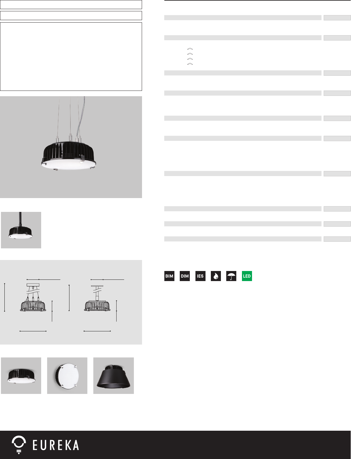
Eureka Lighting © 2014 www.eurekalighting.com V1.0-201401
PROJECT PROJET
SPEC TYPE
NOTES
SPECIFICATION
COUPÉ 4266-SIJ
ORDERING SPECIFICATION SPÉCIFICATION DE COMMANDE CODE
MODEL MODÈLE
4266-SIJ
4266B-SIJ
COUPÉ (AIRCRAFT CABLE)
COUPÉ (STEM)
LIG HT SO URCE SOURCE LUMINEUSE
(WATTAGE, LAMP TYPE, LAMP FORM, BASE TYPE, OTHER INFO)
LED.13.30
LED.13.40
LED.26.30
LED.26.40
13W, LED 3000K (WARM)
13W, LED 4000K (NEUTRAL)
26W, LED 3000K (WARM)
26W, LED 4000K (NEUTRAL)
VO LTAG E VOLTAGE
120V
277V
120 VOLT
277 VOLT
DIMMING OP TION OPTION DE GRADATION
DV
DP
0-10V DIMMING (120-277V)
PHASE DIMMING (120V ONLY)
LED DIMMING DRIVER IS STANDARD IN THESE PRODUCTS, PLEASE SPECIFY YOUR DIMMING TYPE.
STEM OR CABLE TIGE OU CABLE
AC
S7
AIRCRAFT MOUNTING & CLEAR CABLE, FIELD ADJUSTABLE (FOR 4266 ONLY)
27/32", (21MM) STEM, NOT FIELD ADJUSTABLE (FOR 4266B)
STEM OR CABLE LENGTH LONGUEUR DE TIGE OU CABLE
36
60
**
**
36" STEM (STD LENGHT)
60" AIRCRAFT CABLE (STD LENGTH)
CUSTOM STEM LENGTH (12", 24", 48", 60", 72", 84", 96") (PLEASE SPECIFY)
CUSTOM AIRCRAFT CABLE LENGTH (PLEASE SPECIFY)
FOR OVERALL LENGTH PLEASE CONTACT YOUR EUREKA REPRESENTATIVE
STRU CTUR E FINIS H FINI STRUCTURE
4266
CHR
4266B
BLKE
CHROME
BLACK FINE TEXTURE
HEATSINK FINISH FINI RADIATEUR BLKA
BLKA BLACK ANODISED
DIFFUSER INTERIOR FINISH FINI DIFFUSEUR INTÉRIEUR
CDP CONICAL DEGLARING PRISM
DIFFUSER FINISH FINI DIFFUSEUR
CDP CONICAL DEGLARING PRISM
4266-SIJ 4266B-SIJ
Ø4.57"
Ø116mm
64.66''
1642mm
Ø9.37"
Ø238mm
3.66''
93m
m
Ø9.37"
Ø238mm
40.00''
1016mm
Ø4.13"
Ø105mm
3.66''
93m
m
PRODUCT CHARACTERISTICS CARACTÉRISTIQUES DU PRODUIT
4266 4266B
DESIGN: Coupé is an industrial-looking shallow xture that can be installed on low ceilings.
Add a conical metal shade for a modern look and you have the Turbo.
LIGHT SOURCE: 13W and 26W LED Chip-on-board (COB) emitter available in 3000K and 4000K.
Electronic dimming available on all models.
STRUCTURE: Durable die cast aluminum enclosure with stainless steel spring clips. Turbo has an
additional spun aluminum shade with exterior grade ne texture powder coat nish.
DIFFUSER: Compound lens structured around layers of diffusing and conical deglaring prismatic (CDP)
sheet PMMA.
CERTIFIED: c-CSA-us Wet Location to UL standards – Suitable for interior and exterior projects (4266B only)
CONCEPTION: Coupé est un luminaire au look industriel, assez mince pour être installé sur des plafonds
bas. Ajoutez-y un abat-jour métallique conique pour obtenir un look moderne avec le Turbo.
SOURCE LUMINEUSE: Émetteur DEL de format « Chip-on-board » (COB) de 13W et 26W, disponible en 3000K et
4000K. Gradation disponible sur tous les modèles.
STRUCTURE: Boîtier durable en aluminium moulé avec fermoirs en acier ressort. Turbo est muni d’un
abat-jour additionnel en aluminium repoussé, nition peinture en poudre à texture ne
de grade extérieur.
DIFFUSEUR: Lentille composée de couches de PMMA munis de prismes anti-éblouissement (CDP).
CERTIFIÉ: c-CSA-us Emplacement Mouillé au standard UL – Convient aux projets intérieurs et
extérieurs (4266B seulement)
FA MI LY FAMILLE
4766-SIJ 4766-SIJ 4766-SCR
STEM OPTIONS
4266B-SIJ
TEEN CTR
G
4266-SIJ LED 13.30 120V DV AC 60 4266B BLKA CDP CDP
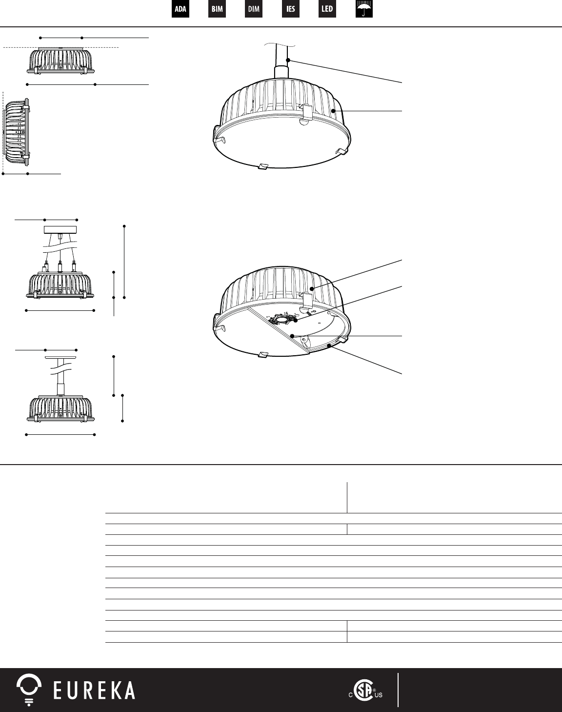
4766-SIJ
4266-SIJ / 4266B-SIJ
ANATOMY COUPÉ
CHARACTERISTICS 4766 / 4266 / 4266b
LIGHT SOURCE
MODULE
DELIVERED LUMENS
CRI
ROHS
HOUSING
HEAT SINK
LIGHT DISTRIBUTION
OPTICS
VOLTAGE
DRIVER (DIMMING)
LM-79
WARRANTY
1 x Cree CXA2520 COB - total ±26 w1 x Cree CXA2520 COB - total ±13 w
UL Recognized
2250 lm (3000K) - 2400 lm (4000K)1170 lm (3000K) - 1250 lm (4000K)
80 CRI (3000K) - 80 CRI (4000K)
Yes
Die-cast aluminum, black anodised (2,5mm thickness)
Die-cast aluminum, black anodised (variable thickness)
Direct
Diffusing flat PMMA lens, Deglaring CDP PMMA lens (minimum 3 mm thickness for each layer)
GASKETS Die-cut self-adhesive silicone gasket (minimum 3,2mm thickness)
120V or 277V
Lightech 700 mA (”Reverse Phase Dimming”) Lightech 350 mA (”Reverse Phase Dimming”)
Available In process
5 years
KEEPING THINGS COOL
Precisely calculated, air exposed heat
sink, sturdy die cast aluminum, black
anodised finish.
V1.1-201403www.eurekalighting.comEureka Lighting©2013
6B624
Variable length
depending on
stem options.
6624
6674
SURFACE
SUSPENSION CABLE
SUSPENSION STEM
Ø 9.37"
Ø 238mm
Ø 9.37"
Ø 238mm
3.66''
93mm
64.66''
1642mm
3.66''
93mm
Ø 4.13"
Ø 105mm
Ø 4.57"
Ø 116mm
Ø 5.90"
Ø 150mm
Ø 9.37"
Ø 238mm
3.66''
93mm
WEATHERPROOF
Self-adhesive gaskets
Die-cut silicone sponge
Mechanically compressed
Fully sealed
Wet location rated (CSA to UL standards)
HIGH OUTPUT FOR GENERAL ILLUMINATION
Center mounted COB LED technology
As much as 2400 lumens for only 26 W
Color temperatures: 3000 / 4000 K
STAINLESS STEEL SPRING CLIPS
Easy access inside light chamber, if need be
INDUSTRIAL CHIC
Works in a wide range of environments
(bars, hotels, lofts, indoor, outdoor,...)
FLAT OPTICS
Compound lens structured around
layers of diffusing and deglaring CDP PMMA.
DESIGNED FOR DISASSEMBLY
Easy installation and maintenance
Recyclable materials
Mechanically fastened parts
MOUNTING OPTIONS
Rigid stem / aircraft cable, or surface.
MAX
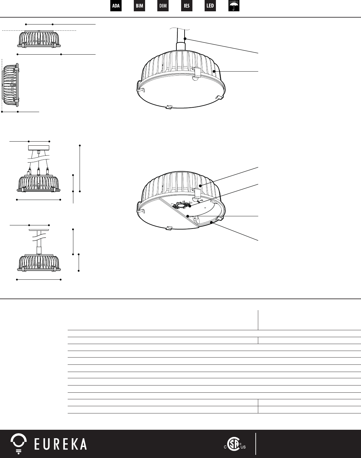
4766-SIJ
4266-SIJ / 4266B-SIJ
ANATOMIE COUPÉ
GARDER LA TÊTE FROIDE
Aluminium moulé sous pression
Anodisé noir pour une gestion
thermique améliorée
V1.1-201403www.eurekalighting.comEureka Lighting©2013
6B624
Variable length
depending on
stem options.
6624
6674
PLAFONNIER
SUSPENSION SUR CÂBLES
SUSPENSION SUR TIGE
Ø 9.37"
Ø 238mm
Ø 9.37"
Ø 238mm
3.66''
93mm
64.66''
1642mm
3.66''
93mm
Ø 4.13"
Ø 105mm
Ø 4.57"
Ø 116mm
Ø 5.90"
Ø 150mm
Ø 9.37"
Ø 238mm
3.66''
93mm
RÉSISTE AUX INTEMPÉRIES
Joints d’étanchéité autocollants
Silicone éponge découpé à l’emporte-pièce
Compression mécanique
Scellage complet
Convient aux endroits mouillés
(CSA aux standards UL)
INTENSITÉ POUR ÉCLAIRAGE GÉNÉRAL
Densité de sources (”Chip-on-Board” COB)
Jusqu’à 2400 lm pour aussi peu que 26 W
Températures couleur: 3000 / 4000 K
FERMOIRS EN ACIER RESSORT
Accès facile à la source lumineuse, au besoin
CHIC INDUSTRIEL
Compatible dans un éventail de décors
(plafond bas, escalier, garage, extérieur,...)
LENTILLE COMPOSÉE
Superposition de couches de PMMA qui
diffusent et réduisent l'éblouissement (CDP).
OPTIONS DE MONTAGE
Câble d’acier, tige fixe, ou en surface.
MAX
CONÇU POUR LE DÉSASSEMBLAGE
Installation et entretien facile
Matériaux recyclables
Pièces jointes mécaniquement
CARACTÉRISTIQUES 4766 / 4266 / 4266b
SOURCE LUMINEUSE
MODULE
LUMENS RÉELS
IRC
ROHS
BOÎTIER
RADIATEUR
DISTRIBUTION LUMINEUSE
OPTIQUES
VOLTAGE
PILOTES (AVEC GRADATION)
LM-79
GARANTIE
1 x Cree CXA2520 COB - total ±26 w
Reconnu par UL
2250 lm (3000K) - 2400 lm (4000K)
80 IRC (3000K) - 80 IRC (4000K)
Conforme
Aluminium moulé sous pression, anodisé noir (épaisseur 2,5mm)
Aluminium moulé sous pression, anodisé noir (épaisseurs variables)
Direct
Lentille composée de couches de PMMA qui diffusent et réduisent l'éblouissement. (CDP, épaisseur minimum 3 mm)
JOINTS D’ÉTANCHÉITÉ Silicone éponge autocollant, découpé à l’emporte-pièce (épaisseur minimum 3,2mm)
120V ou 277V
Lightech 700 m (”Reverse phase dimming”)
Disponible En cours d’obtention
5 ans
1 x Cree CXA2520 COB - total ±13 w
1170 lm (3000K) - 1250 lm (4000K)
Lightech 350 mA (”Reverse phase dimming”)
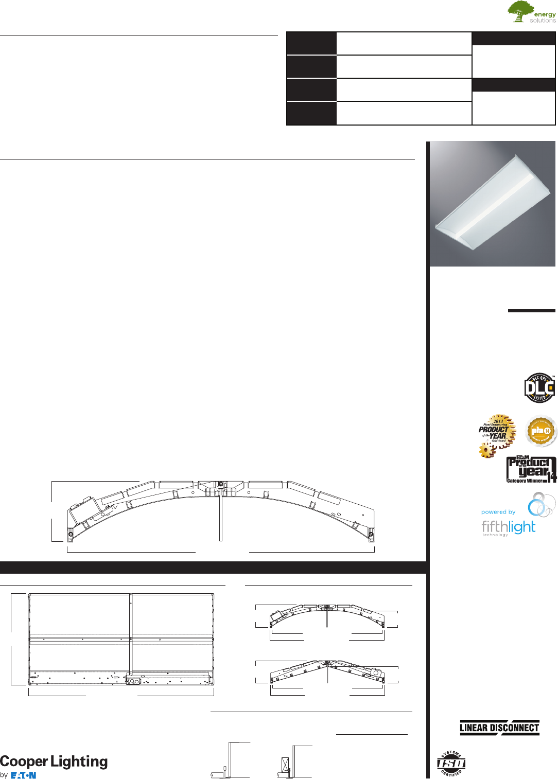
COOPER LIGHTING - METALUX
®
24SR
LED
2' X 4' TROFFER
LED MODULE
Specification Grade Troffer
Catalog # Type
Date
Project
Comments
Prepared by
SPECIFICATION FEATURES
Construction
Shallow 4.75” deep housing is
extruded aluminum frame and
injected molded composite end
plates. End plates are securely
attached with screws for strength
and rigidity and the elimination of
gaps. End plates have accessory
grid-lock feature for safety and
convenience. Four auxiliary
fixture end suspension points are
provided. Large access plate for
supply connection.
Controls
The SkyRidge LED is Powered by
Fifth Light, with a standard 0-10V
continuous dimming driver that
works with any 0-10V control/
dimmer. Combine with energy
saving products like occupancy
sensors, daylighting controls and
lighting relay panels from Cooper
Controls (www.coopercontrol.com)
to maximize energy savings. In
addition, the SkyRidge can include
a factory-installed integrated
sensor system for occupancy and
daylight dimming control and
manual control from an optional
handheld remote. Or, specify
the Digital Addressable Lighting
Interface (DALI) drivers, dimmable
down to 1% with the HD option, for
use with Fifth Light controls. See
ordering information for details on
all three options.
Electrical
Long-life LED system coupled with
electrical driver to deliver optimal
performance. LED’s available in
3000K, 3500K, 4000K or 5000K with
a typical CRI ≥ 85. Projected life is
60,000 hours at 84% lumen output.
Electronic drivers are available for
120-277V applications.
Driver Access
Drivers can be accessed via
plenum.
Finish
Durable frame has high reflectance
baked matte white enamel finish
for luminous uniformity.
Optics
Precision formed optical assembly
with positively retained high
optical grade acrylic lens provides
a directed optical distribution using
WaveStream LED technology.
SkyTrim Accessory
Designed for an array of interior
applications, SkyTrim is a luminous
decorative accent that can be
mounted directly on the light guide
of a SkyRidge fixture either at the
factory or in the field. It is ideal for
spaces where color is necessary
to provide visual cues, emphasize
brand identity, directional
awareness or simply as an artistic
expression.
Compliance
Components are UL recognized.
Indoor luminaires are cULus listed
for 25° C ambient environments,
RoHS compliant, and comply with
IESNA LM-79. LEDs comply with
LM-80 standards. DesignLights
Consortium® Qualified. Refer to
www.designlights.org Qualified
Products List under Family Models
for details.
Warranty
Five year warranty.
ADF130560
2014-12-29 15:31:02
The SkyRidge™ transforms ambient lighting by perfectly blending a refined
modern styling with our breakthrough WaveStream™ LED technology to
deliver exceptional performance and superior energy savings. SkyRidge’s
advanced engineered LED system with superior optical design delivers
an unparalleled combination of optimal light uniformity and exceptional
efficiency for greater energy savings.
SkyRidge is compatible with all of today's popular ceiling systems and
available in a variety of configurations for application versatility. Its perfect
balance of form and function make it an ideal choice for commercial office
spaces, schools, hospitals, retail and other indoor ambient applications.
DESCRIPTION
CERTIFICATION DATA
cULus - 1598 and 2043**
Damp Location Listed
IC Rated
LM79/LM80 Compliant
ROHS Compliant
DesignLights Consortium® Qualified
NOM Compliant
*See Drywall Frame Kit Accessory in
Ordering Information section.
**Fixture construction is suitable for
use in Air-handling and plenum rated
spaces in accordance with Section
300.22 (C) of the National Electrical
Code, Section 4.3.11.2.6.5 of NFPA
90A and Section 602.2.1.4 of ICC.
23-3/4" [603mm]
4-11/16"
[120mm]
CURVED
Safe and convenient means of
disconnecting power
STRAIGHT
4-11 /16"
[120mm] 3-1/2"
[89mm]
23-3/4" [603mm]
22-15/16" [584mm]
23-3/4"
[603mm]
47-15/16" [1218mm]
MOUNTING DATA
23-3/4" [603mm]
22-15/16" [583mm]
3-17/32"
[90mm]
4-11 /16"
[120mm]
CURVED
LAMP CONFIGURATIONS
G
Grid/Lay-in
Standard
F
Drywall Frame
Kit
Ceiling Trim
Type Type
Exposed GridG
Concealed
TG
or T
Slot Grid G or T
Flange *
CEILING COMPATIBILITY
24SR-LD1-48-C-UNV-
LP835-CD1-SKYTRIM A
LOS ALAMOS TEEN
CENTER
Eaton
1000 Eaton Boulevard
Cleveland, OH 44122
United States
Eaton.com
Specifications and
dimensions subject to
change without notice.
Eaton’s Cooper Lighting Business
1121 Highway 74 South
Peachtree City, GA 30269
P: 770-486-4800
www.cooperlighting.com
Coefficients of Utilization
Effective floor cavity reflectance 20%
rc 80%70% 50%30% 10
%0
%
rw 70 50 30 10 70 50 30 10 50 30 10 50 30 10 50 30 10 0
RCR
0
1
2
3
4
5
6
7
8
9
10
Luminance Data
Average AverageAverage
Angle0-Deg 45-Deg 90-Deg
in Deg cd/smcd/sm cd/sm
45 1649 2220 2240
55 1444 206
62
003
65 1143 1954 1897
75 8832058 1954
85 8802577 2052
Zonal Lumen Summary
Zone Lumens %Fixture
0-30
0-40
0-60
0-90
0-180
600
0˚ 15˚ 30˚
45˚
60˚
75˚
90˚
1200
1800
Candlepower
AngleAlong II 45°Across ⊥
0
5
10
15
20
25
30
35
40
45
50
55
60
65
70
75
80
85
90
24SR-LD1-48-C-UNV-
L835-CD1-U
Dimming Driver
Linear LED 3500K
Spacing criterion:
(II) 1. 2 x mounting
height, (⊥) 1.6 x
mounting height
Lumens: 4810
Input Watts: 49.1W
Efficacy: 98 LPW
Test Report:
22SR-LD1-48-C-UNV-
L835-CD1-U.IES
1298 27.0
2154 44.8
3734 77.6
4810 100.0
4810 100.0
1388 1388 1388
1389 1461 1524
1371 1547 1639
1338 1591 1718
1291 1605 1759
1230 1584 1741
11 59 1520 1661
1071 1422 1523
976 1302 1354
867 11 67 11 80
746 1026 1015
616 881 854
481 742 722
359 614 596
251 497 483
170 396 376
107 293 256
57 167 133
0 0 0
119119 119119 11 6116 11 6116 111111 111 106106 106 102102 102 100
108103 99 95 105101 97 93 97 93 90 93 90 87 89 87 85 83
98 90 83 77 96 88 81 76 84 79 74 81 76 72 78 74 71 69
90 79 70 64 87 77 69 63 74 67 62 71 66 61 69 64 60 58
82 70 61 54 80 68 60 54 66 59 53 64 57 52 61 56 51 49
75 62 53 46 73 61 53 46 59 51 46 57 50 45 55 49 45 43
70 56 47 41 68 55 47 40 53 46 40 52 45 40 50 44 39 37
64 51 42 36 63 50 42 36 48 41 35 47 40 35 46 40 35 33
60 46 38 32 58 46 37 32 44 37 32 43 36 31 42 36 31 29
56 43 34 29 55 42 34 29 41 33 28 40 33 28 39 33 28 26
53 39 31 26 51 39 31 26 38 31 26 37 30 26 36 30 25 24
Coefficients of Utilization
Effective floor cavity reflectance20%
rc 80%70% 50% 30% 10% 0%
rw 70 50 30 10 70 50 30 10 50 30 10 50 30 10 50 30 10 0
RCR
0
1
2
3
4
5
6
7
8
9
10
Luminance Data
Average AverageAverage
Angle 0-Deg45-Deg 90-Deg
in Deg cd/sm cd/sm cd/sm
45 1453 1934 1966
55 1282 1809 1754
65 1014170
31
648
75 792 1778 1678
85 773 2204 1825
Zonal Lumen Summary
Zone Lumens %Fixture
0-30
0-40
0-60
0-90
0-180
500
0˚ 15˚ 30˚
45˚
60˚
75˚
90˚
1000
1500
Candlepower
Angle Along II 45° Across ⊥
0
5
10
15
20
25
30
35
40
45
50
55
60
65
70
75
80
85
90
24SR-LD1-39-C-UNV-
L835-CD1-U
Dimming Driver
Linear LED 3500K
Spacing criterion:
(II) 1.2 x mounting
height, (⊥) 1.6 x
mounting height
Lumens: 3940
Input Watts: 38.8W
Efficacy: 102 LPW
Test Report:
22SR-LD1-39-C-UNV-
L835-CD1-U.IES
1063 27.0
1763 44.7
3060 77.7
3940 100.0
3940 100.0
1140 11 40 11 40
1140 1203 1251
11 23 1270 1338
1097 1301 1400
1060 1311 1435
1012 1291 1421
951 1244 1355
883 11 62 1247
804 1062 1111
717 954 970
621 840 834
513 724 702
402 609 592
299 502 486
213 408 393
143 321 303
91 238 205
47 134 111
0 0 0
119119 119119 11 6116 11 6116 111 111 111 106106 106 102102 102 10 0
108103 99 95 105101 97 93 97 93 90 93 90 87 89 87 85 83
98 90 83 77 96 88 81 76 84 79 74 81 76 72 78 74 71 69
90 79 70 64 87 77 69 63 74 68 62 71 66 61 69 64 60 58
82 70 61 54 80 68 60 54 66 59 53 64 57 52 61 56 51 49
75 62 53 46 73 61 53 46 59 51 46 57 50 45 55 49 45 43
70 56 47 41 68 55 47 40 53 46 40 52 45 40 50 44 39 37
64 51 42 36 63 50 42 36 48 41 35 47 40 35 46 39 35 33
60 46 38 32 58 46 37 32 44 37 32 43 36 31 42 36 31 29
56 43 34 29 55 42 34 29 41 33 28 40 33 28 39 33 28 26
53 39 31 26 51 39 31 26 38 31 26 37 30 26 36 30 25 24
PHOTOMETRICS
ADF130560
2014-12-29 15:31:02
24SR LED 2' X 4'
Eaton
1000 Eaton Boulevard
Cleveland, OH 44122
United States
Eaton.com
Specifications and
dimensions subject to
change without notice.
Eaton’s Cooper Lighting Business
1121 Highway 74 South
Peachtree City, GA 30269
P: 770-486-4800
www.cooperlighting.com
Stock or
MTO*
Catalog Logic
(Curved)
Delivered
Lumens WattsEfficacy
(LPW)
MTO 24SR-LD1-29-C-UNV-L830-CD1-U 2867 28.2 102
MTO 24SR-LD1-29-C-UNV-L835-CD1-U 2998 28.2 106
MTO 24SR-LD1-29-C-UNV-L840-CD1-U 3034 28.2 108
MTO 24SR-LD1-29-C-UNV-L850-CD1-U 3209 28.1 114
MTO 24SR-LD1-34-C-UNV-L830-CD1-U 3302 33.1 100
MTO 24SR-LD1-34-C-UNV-L835-CD1-U 3451 33.0 104
MTO 24SR-LD1-34-C-UNV-L840-CD1-U 3503 33.0 106
MTO 24SR-LD1-34-C-UNV-L850-CD1-U 3705 33.1 112
MTO 24SR-LD1-39-C-UNV-L830-CD1-U 3713 39.1 95
Stock 24SR-LD1-39-C-UNV-L835-CD1-U 3940 38.8 102
Stock 24SR-LD1-39-C-UNV-L840-CD1-U 4019 39.2 102
MTO 24SR-LD1-39-C-UNV-L850-CD1-U 4251 39.2 108
MTO 24SR-LD1-45-C-UNV-L830-CD1-U 4288 46.7 92
MTO 24SR-LD1-45-C-UNV-L835-CD1-U 4538 46.2 98
MTO 24SR-LD1-45-C-UNV-L840-CD1-U 4656 46.3 101
MTO 24SR-LD1-45-C-UNV-L850-CD1-U 4925 46.8 105
MTO 24SR-LD1-48-C-UNV-L830-CD1-U 4512 49.0 92
Stock 24SR-LD1-48-C-UNV-L835-CD1-U 4810 49.1 98
Stock 24SR-LD1-48-C-UNV-L840-CD1-U 4944 49.0 101
MTO 24SR-LD1-48-C-UNV-L850-CD1-U 5230 49.0 107
MTO 24SR-LD1-53-C-UNV-L830-CD1-U 5053 56.6 89
MTO 24SR-LD1-53-C-UNV-L835-CD1-U 5396 56.6 95
MTO 24SR-LD1-53-C-UNV-L840-CD1-U 5567 56.6 98
MTO 24SR-LD1-53-C-UNV-L850-CD1-U 5888 56.6 104
MTO 24SR-LD1-59-C-UNV-L830-CD1-U 5530 63.4 87
MTO 24SR-LD1-59-C-UNV-L835-CD1-U 5909 63.6 93
MTO 24SR-LD1-59-C-UNV-L840-CD1-U 6111 63.4 96
MTO 24SR-LD1-59-C-UNV-L850-CD1-U 6464 63.5 102
MTO 24SR-LD1-64-C-UNV-L830-CD1-U 6007 70.9 85
MTO 24SR-LD1-64-C-UNV-L835-CD1-U 6420 71.0 90
MTO 24SR-LD1-64-C-UNV-L840-CD1-U 6656 70.8 94
MTO 24SR-LD1-64-C-UNV-L850-CD1-U 7041 71.1 99
*Made to order (MTO) requires a typical four week lead time.
ENERGY AND PERFORMANCE DATA BY CATALOG NUMBER
ADF130560
2014-12-29 15:31:02
24SR LED 2' X 4'
Eaton
1000 Eaton Boulevard
Cleveland, OH 44122
United States
Eaton.com
Specifications and
dimensions subject to
change without notice.
Eaton’s Cooper Lighting Business
1121 Highway 74 South
Peachtree City, GA 30269
P: 770-486-4800
www.cooperlighting.com
ADF130560
2014-12-29 15:31:02
24SR LED 2' X 4'
Stock or
MTO*
Catalog Logic
(Straight)
Delivered
Lumens WattsEfficacy
(LPW)
MTO24SR-LD1-29-S-UNV-L830-CD1-U 2886 28.1 103
MTO24SR-LD1-29-S-UNV-L835-CD1-U 2959 28.1 105
MTO24SR-LD1-29-S-UNV-L840-CD1-U 3048 28.1 108
MTO24SR-LD1-29-S-UNV-L850-CD1-U 3224 28.1 11 5
MTO 24SR-LD1-34-S-UNV-L830-CD1-U 3325 32.9 101
MTO 24SR-LD1-34-S-UNV-L835-CD1-U 3409 32.9 104
MTO 24SR-LD1-34-S-UNV-L840-CD1-U 3512 32.9 107
MTO 24SR-LD1-34-S-UNV-L850-CD1-U 3715 32.9 11 3
MTO 24SR-LD1-39-S-UNV-L830-CD1-U 3789 39.1 97
MTO 24SR-LD1-39-S-UNV-L835-CD1-U 3884 39.1 99
MTO 24SR-LD1-39-S-UNV-L840-CD1-U4002 39.1 102
MTO 24SR-LD1-39-S-UNV-L850-CD1-U4233 39.1 108
MTO 24SR-LD1-45-S-UNV-L830-CD1-U4384 46.7 94
MTO 24SR-LD1-45-S-UNV-L835-CD1-U4494 46.7 96
MTO 24SR-LD1-45-S-UNV-L840-CD1-U 4630 46.7 99
MTO24SR-LD1-45-S-UNV-L850-CD1-U 4898 46.7 105
MTO24SR-LD1-48-S-UNV-L830-CD1-U 4659 49.0 95
MTO24SR-LD1-48-S-UNV-L835-CD1-U 4776 49.0 97
MTO24SR-LD1-48-S-UNV-L840-CD1-U 492149.
01
00
MTO24SR-LD1-48-S-UNV-L850-CD1-U 520549.
01
06
MTO24SR-LD1-53-S-UNV-L830-CD1-U 505756.
78
9
MTO24SR-LD1-53-S-UNV-L835-CD1-U540156.
79
5
MTO24SR-LD1-53-S-UNV-L840-CD1-U 557256.
79
8
MTO24SR-LD1-53-S-UNV-L850-CD1-U 589456.
71
04
MTO24SR-LD1-59-S-UNV-L830-CD1-U 552063.
58
7
MTO 24SR-LD1-59-S-UNV-L835-CD1-U 5898 63.5 93
MTO 24SR-LD1-59-S-UNV-L840-CD1-U 6100 63.5 96
MTO 24SR-LD1-59-S-UNV-L850-CD1-U 6452 63.5 102
MTO 24SR-LD1-64-S-UNV-L830-CD1-U 5990 71.0 84
MTO 24SR-LD1-64-S-UNV-L835-CD1-U640271.
09
0
MTO 24SR-LD1-64-S-UNV-L840-CD1-U663771.
09
3
MTO 24SR-LD1-64-S-UNV-L850-CD1-U 7020 71.0 99
*Made to order (MTO) requires a typical four week lead time.
ENERGY AND PERFORMANCE DATA BY CATALOG NUMBER
Ambient Tem-
perature
TM-21 Lumen
Maintenance
(60,000 hours)
Theoretical
L70
(Hours)
25°C > 85% > 154,000
LUMEN MAINTENANCE
Color Choice Kit Catalog Number Kit Quantity
Tahitian Blue STK-4-TB-10PK 10
Primary GreenSTK-4-PG-10PK 10
Storaro OrangeSTK-4-SO-10PK 10
Belladonna Rose STK-4-BR-10PK 10
Medium RedSTK-4-MR-10PK 10
Pearl STK-4-PL-10PK 10
Straw STK-4-ST- 10PK 10
Custom Color STK-4-CC-*-10PK 10
*Custom color requires Roscolux numeric specification
color code, consult factory for more information.
Note: Chosen color will be matched on acrylic but will
appear lighter once applied to lit light guide.
SKYTRIM FIELD INSTALLATION KITS
Please select color
Eaton
1000 Eaton Boulevard
Cleveland, OH 44122
United States
Eaton.com
Specifications and
dimensions subject to
change without notice.
Eaton’s Cooper Lighting Business
1121 Highway 74 South
Peachtree City, GA 30269
P: 770-486-4800
www.cooperlighting.com
SAMPLE NUMBER: 24SR-LD1-48-C-UNV-L835-CD1-SVDP1-U
Voltage(1)
347V=347 Volt
UNV=Universal Voltage
120-277
Options
Emergency
EL=Emergency Installed, 700 Lumens (4)
CCT
L830=3000K
L835=3500K
L840=4000K
Flex (17)
Multiple Configurations Available
Packaging
U=Unit Pack
PALC=Job
Pack, in carton
Optics
Blank=Standard
Series
24SR=2' x 4' SkyRidge
Series
ACCESSORIES
T3A END E.Q. BRACKET PARTS BAG (Standard with fixture)
DF-24-W=2' x 4' Drywall Frame Kit
DF10P-C =Devine Decorator Dimmer, 0-10V
SF10P- =Skye Decorator Slide Dimmer, 0-10V
HHPRG-MS=Programming Remote for Integrated Sensor
Driver Type
CD=0-10V Dimming Driver
(Standard)
SD=Step-Dim Driver (13)
5LTD=Fifth Light DALI Driver (3)
(10%- 100% Dimming)
5LTHD=Fifth Light DALI Driver (3)
(1%- 100% Dimming)
Number of Drivers
1=1 Driver
Rating
Blank=Standard
ATW-SW4= Chicago
Rated (7) Stock Lumen Outputs
39=3900 Lumens
48=4800 Lumens
MTO Lumen Outputs(5)
29=2900 Lumens (6), (14)
(14)
(15)
(15)
34=3400 Lumens
45=4500 Lumens
53=5300 Lumens
59=5900 Lumens
64=6400 Lumens
Lamp Type
LD1=LED 1. 0
Air
[Blank]=Standard
A=Air (Vented)(8)
Reflector
C=Curved (Standard)
S=Straight
NOTES: (1) Products also available in non-US voltages and frequencies for international markets. (2) Must specify voltage (120V or 277V) when selecting EL option. (3) Must be used in conjunction with a DALI control
system. For complete DALI soluitions by Fifth Light, visit www.coopercontrol.com. (4) EL test switch and light must be remote mounted. (5) Made-to-order (MTO) requites four week lead time. (6) 2900 lumen option is not
available with Step-Dim. (7) Chicago rated version does not allow for row mounting. (8)Air version is vented but does not meet air handling requirements. Air version is non-IC. Air version is not available with integrated
sensor. (9) DesignLights Consortium® Qualified (all lumen packages). Refer to www.designlights.org Qualified Products List under Family Models for details. (10) For delivered lumens, take lumens per watt of desired
fixture and multiply by 10 watts (100 lp/W x 10 = 1000 lumens delivered). (11) Fixtures using factory installed SkyTrim option are not DLC qualified. (12) Custom color must list Roscolux numeric color specification code.
(13) 3400, 5900 and 6400 lumen packages are not available with Step-Dim driver. (14) 5LTD option is not available in 2900 and 3400 lumen packages. (15) 5LTHD not available in 4800, 5300, 5900 and 6400 lumen packages.
(16) Integral sensor works only with “CD” driver and is factory prewired to the driver for stand-alone control. (17) Flex does not include dimming leads. Control leads provided by othyers.
Specifications & dimensions subject to change without notice. Consult your Cooper Lighting Representative for availability and ordering information.
(9)
EL14=Emergency Installed , 1400 Lumens (2), (4)
EL10W=Emergency Installed , 10 Watts (10)
SkyTrim (11)
TB=Tahitian Blue
PG=Primary Green
SO=Storaro Orange
PL=Pearl
BR=Belladonna Rose
MR=Medium Red
ST=Straw
CC=Custom (12)
Product Family
S=Integrated Sensor
Control Type
B=Sensor Mounting, No Sensor
V=Analog (0-10V) Output for Local Control (16)
Occupancy Technology
P=Passive Infrared
Sensing Technology
D=Dimming Daylight
Harvesting (Closed Loop)
Coverage Pattern
1= ~144 Square Feet
(15)
(15)
L850=5000K
ORDERING INFORMATION
24SR LED 2' X 4'
ADF130560
2014-12-29 15:31:02
Catalog No. Wt.
24SR-LD1-39 24 lbs.
24SR-LD1-48 24 lbs.
SHIPPING DATA

Eaton
1000 Eaton Boulevard
Cleveland, OH 44122
United States
Eaton.com
Specifications and
dimensions subject to
change without notice.
Eaton’s Cooper Lighting Business
1121 Highway 74 South
Peachtree City, GA 30269
P: 770-486-4800
www.cooperlighting.com
Description
This innovative luminaire-integrated sensor control system is built on Greengate technology and optimized for code-
compliant occupancy detection and daylight harvesting – all from within the foot print of Metalux’s award-winning
recessed ambient luminaires.
No New Wires
An in-place fixture retrofit is all that’s needed to meet most energy codes in commercial spaces. The sensor
system is factory wired to the luminaire, switching on or off based on occupancy, and dimming the light
when enough daylight is available.
Sophisticated lighting control without commissioning
The luminaire-integrated sensor system offers out-of-the-box operation using thoughtful default settings.
Flexibility and Individual Control
When the application demands more, the sensor system has the option to make changes using a remote control. The
remote allows changes from the default settings for occupancy, target light level, preset lighting levels, and more.
Cost-effective, Stand-alone Operation
With a single product to mount and a single electrical connection to make, the SkyRidge with an integrated sensor system saves money on the total
installed cost when occupancy or daylight harvesting controls are needed. The integrated sensor system works stand-alone, without the need for
additional switches and dimmers. When manual-on, manual dimming or other code-required control schemes are needed, please see the
comprehensive offering of Greengate and Fifth Light solutions from Cooper Controls at www.coopercontrol.com.
Metalux Integrated Sensor Sequence of Operation
The occupancy sensing portion of the sensor uses Passive Infrared (PIR) technology with Auto-on/Auto-off operation. The small lens in the center of the
sensor directs the view of a passive infrared occupancy detector to sense occupants moving through the room. To trigger the light on, an occupant
must cross at least two passive infrared beams. When motion in the coverage area ceases, the sensor logic concludes the room is unoccupied, and
begins a count-down timer. By default, the timer is factory-set to 30 minutes, and can be adjusted to 5, 10, 15 and 30 minutes using the optional remote
control, model number HHPRG-MS. Any motion detected during the count-down timer will cause the light to remain on and resets the timer. When
motion is detected, a red LED will blink. In addition to the default on/off functionality, the sensor has an Energy Saver feature, where the light can be
set to dim to a preset level after the sensor detects no occupancy for half of the count-down timer, when the timer is complete the lighting will change
to the unoccupied setting. The Energy Saver feature works when the count-down timer is set to at least 15 minutes, and the preset level and feature are
configured using the optional remote control. See the Sensor Programming Guide that comes with the HHPRG-MS remote for details on this feature.
The sensitivity of the occupancy detection can be adjusted, using the HHPRG-MS remote. By default, the sensor operates at the full detection range
shown on the coverage pattern diagram. Using the “LO” button on the HHPRG-MS remote, reduces the sensor detection range by 50%. Full coverage
can be restored at any time by pressing the “HI” button on the remote. The red LED indicator will blink repeatedly to confirm any programming
change.
The dimming daylight harvesting portion of the sensor uses a small photo sensor located next to the occupancy sensing lens. The sensor continuously
measures the available light in the room, even when the fixture is turned off. This allows sensor to operate in one of three daylighting modes, where
the artificial light from the paired Metalux luminaire can adjust the light based on the amount of ambient light from surrounding natural and artificial
light sources. Since the sensor measures light from its luminaire along with other light sources, this sensor follows a closed-loop dimming daylight
harvesting style. The first mode, Daytime, is active when the sensor detects light of at least 100 lux in the room. In Daytime mode, when the light is
turned on after detecting occupancy, the sensor will begin balancing the luminaire light level relative to the total available light it measures. The default
light balancing target in daytime mode is 500 lux. This level can be adjusted higher or lower using the optional HHPRG-MS remote, and pressing
“SET” and then the “DO” (Daytime Occupied) button to store the new light level. Similarly, the Daytime Unoccupied, “DU” has a default of level of 0
lux, or off, but can be adjusted higher to prevent the lights from turning off completely when unoccupied. More details on this function are found in
the Sensor Programming Guide for the HHPRG-MS remote.
The next two modes, Twilight and Nighttime, function in a similar way, allowing the artificial light to adjust to different levels based on the
surroundings. While primarily for use in outdoor luminaires, these modes are available for use in areas with a wide range of natural light, including
atriums, day lit stairwells, and rooms with large or continuous windows. The Twilight mode is active when the sensor detects 50-100 lux in the off
position, and has a 300 lux default light balancing target. The Nighttime mode is active when the sensor detects less than 50 lux, and has a 250 lux
default light balancing target. Like the Daytime mode, there are separate settings for Tw ilight Occupied (“TO”), Tw ilight Unoccupied (“TU”), Nighttime
Occupied (“NO”) and Nighttime Unoccupied (“NU”) which can be adjusted and set using the optional HHPRG-MS remote.
In addition to programming the sensor, the optional HHPRG-MS remote can be used for personal control to adjust the lighting temporarily override the
functions of the sensor temporarily. The remote has raise/lower buttons to adjust the light level for special tasks, as well as a power button to turn the
lights on or off. Unless the SET button and another function is selected, any changes made using these buttons will revert to the programmed settings
after the sensor has detected no occupancy for its programmed time out, and turned off the lighting. The next time the sensor detects occupancy, it will
revert to its programmed settings for count-down timer and light balancing.
Coverage Optional Remote
Control
HHPRG-MS Remote
Programming Remote
HHPRG-MS
Scenes:
To save scenes press SET
and select scene
Raise/
Lower
Time
Out
5
10
15
30
HI
LO
ES
SET
NO
TO
DO
NU
TU
DU
C
L
Top View Side Vi ew
4m
[12 ft.]
4m
[12 ft.]
0m
[0 ft.]
Coverage
Major Motion
3.3m
[10 ft.]
0m
[0 ft.]
0m
[0 ft.]
4m
[12 ft.]
4m
[12 ft.]
Reccomended Mounting Height 8–12 ft.
INTEGRATED SENSOR
ADF130560
2014-12-29 15:31:02
24SR LED 2' X 4'
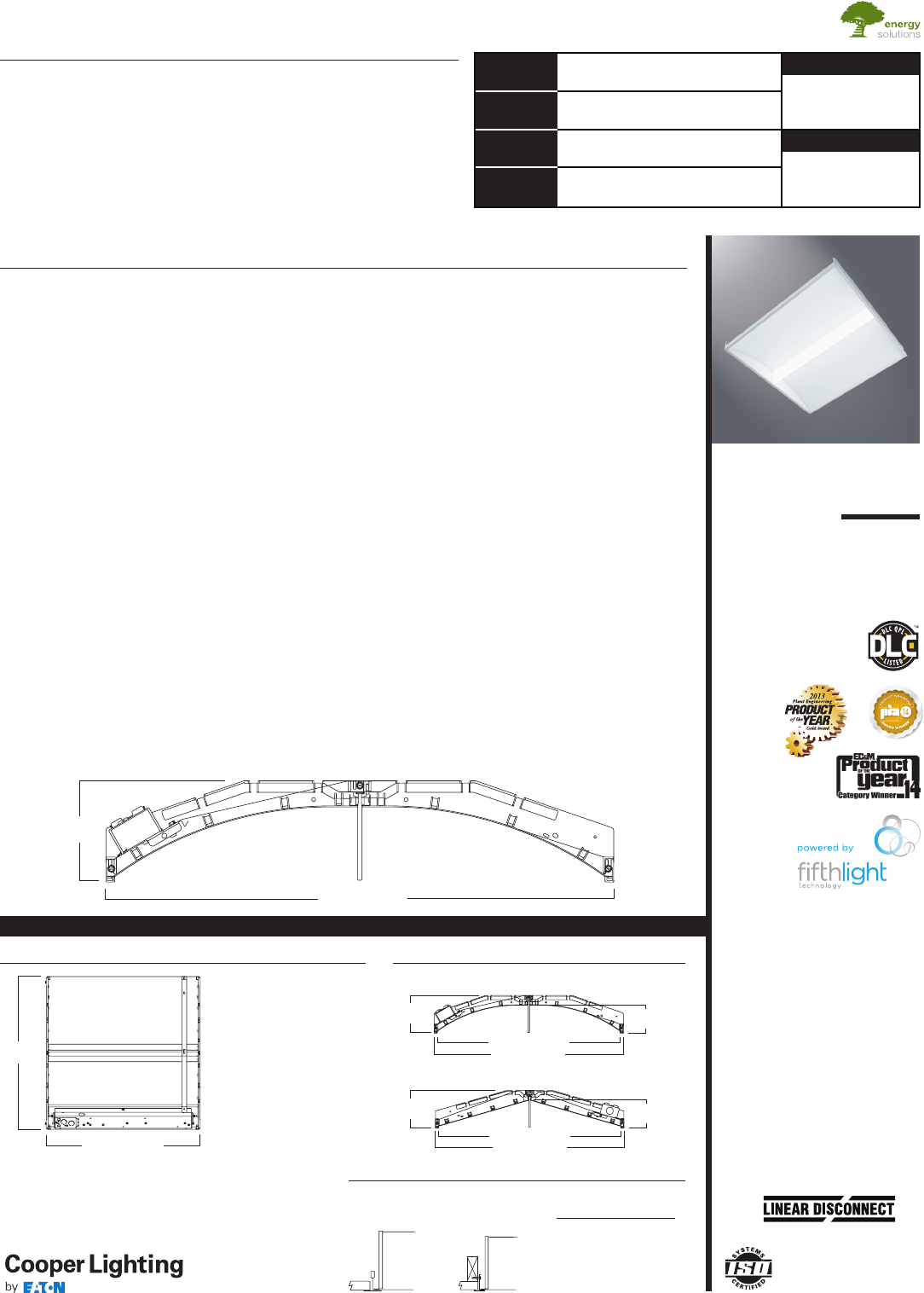
COOPER LIGHTING - METALUX
®
STRAIGHT
4-11 /16"
[120mm] 3-1/2"
[89mm]
23-3/4" [603mm]
22-15/16" [584mm]
22SR
LED
2' X 2' TROFFER
LED MODULE
Specification Grade Troffer
Catalog # Type
Date
Project
Comments
Prepared by
SPECIFICATION FEATURES
Construction
Shallow 4.75” deep housing is
extruded aluminum frame and
injected molded composite end
plates. End plates are securely
attached with screws for strength
and rigidity and the elimination of
gaps. End plates have accessory
grid-lock feature for safety and
convenience. Four auxiliary
fixture end suspension points are
provided. Large access plate for
supply connection.
Controls
The SkyRidge LED is Powered by
Fifth Light, with a standard 0-10V
continuous dimming driver that
works with any 0-10V control/
dimmer. Combine with energy
saving products like occupancy
sensors, daylighting controls and
lighting relay panels from Cooper
Controls (www.coopercontrol.com)
to maximize energy savings. In
addition, the SkyRidge can include
a factory-installed integrated
sensor system for occupancy and
daylight dimming control and
manual control from an optional
handheld remote. Or, specify
the Digital Addressable Lighting
Interface (DALI) drivers, dimmable
down to 1% with the HD option, for
use with Fifth Light controls. See
ordering information for details on
all three options.
Electrical
Long-life LED system coupled with
electrical driver to deliver optimal
performance. LED’s available in
3000K, 3500K, 4000K or 5000K with
a typical CRI ≥ 85. Projected life is
60,000 hours at 84% lumen output.
Electronic drivers are available for
120-277V applications.
Driver Access
Drivers can be accessed via
plenum.
Finish
Durable frame has high reflectance
baked matte white enamel finish
for luminous uniformity.
Optics
Precision formed optical assembly
with positively retained high
optical grade acrylic lens provides
a directed optical distribution using
WaveStream LED technology.
SkyTrim Accessory
Designed for an array of interior
applications, SkyTrim is a luminous
decorative accent that can be
mounted directly on the light guide
of a SkyRidge fixture either at the
factory or in the field. It is ideal for
spaces where color is necessary
to provide visual cues, emphasize
brand identity, directional
awareness or simply as an artistic
expression.
Compliance
Components are UL recognized.
Indoor luminaires are cULus listed
for 25° C ambient environments,
RoHS compliant, and comply with
IESNA LM-79. LEDs comply with
LM-80 standards. DesignLights
Consortium® Qualified. Refer to
www.designlights.org Qualified
Products List under Family Models
for details.
Warranty
Five year warranty.
ADF130559
2014-12-29 15:52:44
The SkyRidge™ transforms ambient lighting by perfectly blending a refined
modern styling with our breakthrough WaveStream™ LED technology to
deliver exceptional performance and superior energy savings. SkyRidge’s
advanced engineered LED system with superior optical design delivers
an unparalleled combination of optimal light uniformity and exceptional
efficiency for greater energy savings.
SkyRidge is compatible with all of today's popular ceiling systems and
available in a variety of configurations for application versatility. Its perfect
balance of form and function make it an ideal choice for commercial office
spaces, schools, hospitals, retail and other indoor ambient applications.
DESCRIPTION
CERTIFICATION DATA
cULus - 1598 and 2043**
Damp Location Listed
IC Rated
LM79/LM80 Compliant
ROHS Compliant
DesignLights Consortium® Qualified
NOM Compliant
*See Drywall Frame Kit Accessory in
Ordering Information section.
**Fixture construction is suitable for
use in Air-handling and plenum rated
spaces in accordance with Section
300.22 (C) of the National Electrical
Code, Section 4.3.11.2.6.5 of NFPA
90A and Section 602.2.1.4 of ICC.
23-3/4" [603mm]
4-11/16"
[120mm]
CURVED
Safe and convenient means of
disconnecting power
23-3/4" [603mm]
22-15/16" [583mm]
3-17/32"
[90mm]
4-11 /16"
[120mm]
CURVED
LAMP CONFIGURATIONS
23-3/4"
[603mm]
23-15/16" [609mm]
MOUNTING DATA
G
Grid/Lay-in
Standard
F
Drywall Frame
Kit
Ceiling Trim
Type Type
Exposed GridG
Concealed TG or T
Slot Grid G or T
Flange *
CEILING COMPATIBILITY
22SR-LD1-29-C-UNV-LP835
-CD1-SKYTRIM
B

Eaton
1000 Eaton Boulevard
Cleveland, OH 44122
United States
Eaton.com
Specifications and
dimensions subject to
change without notice.
Eaton’s Cooper Lighting Business
1121 Highway 74 South
Peachtree City, GA 30269
P: 770-486-4800
www.cooperlighting.com
Coefficients of Utilization
Effective floor cavity reflectance 20%
rc 80% 70% 50% 30%10% 0%
rw 70 50 30 10 70 50 30 10 50 30 10 50 30 10 50 30 10 0
RCR
0
1
2
3
4
5
6
7
8
9
10
Luminance Data
Average Average Average
Angle0-Deg 45-Deg 90-Deg
in Deg cd/smcd/sm cd/sm
45 1929 2636 2808
55 1731 2542 2575
65 1470 2533 2527
75 1289 2785 2754
85 1389 3488 2901
Zonal Lumen Summary
Zone Lumens %Fixture
0-30
0-40
0-60
0-90
0-180
350
0˚ 15˚ 30˚
45˚
60˚
75˚
90˚
700
1050
Candlepower
AngleAlong II 45° Across ⊥
0
5
10
15
20
25
30
35
40
45
50
55
60
65
70
75
80
85
90
22SR-LD1-29-C-
UNV-L835-CD1-U
Dimming Driver
Linear LED 3500K
Spacing criterion:
(II) 1. 2 x mounting
height, (⊥) 1.6 x
mounting height
Lumens: 2935
Input Watts: 30.0W
Efficacy: 98 LPW
Test Report:
22SR-LD1-29-C-UNV-
L835-CD1-U.IES
762 26.0
1267 43.2
2227 75.9
2935 100.0
2935 100.0
818 818 818
811 869 904
799 918 965
778 938 1011
749 940 1039
715 924 1039
672 890 1001
624 836 933
568 768 840
507 693 738
438 617 641
369 542 549
299 469 470
231 398 397
174 333 332
124 268 265
83 200 180
45 11 3 94
0 0 0
119119 119119 11 6116 11 6116 111111 111 106106 106 102102 102 10 0
108103 98 94 105100 96 92 96 93 89 92 89 87 89 86 84 82
98 89 82 76 95 87 80 75 83 78 73 80 75 71 77 73 70 68
89 78 69 63 86 76 68 62 73 66 61 70 65 60 68 63 59 57
81 69 60 53 79 68 59 52 65 58 52 63 56 51 60 55 50 48
75 61 52 45 73 60 52 45 58 50 45 56 49 44 54 48 44 41
69 55 46 39 67 54 46 39 52 45 39 51 44 39 49 43 38 36
64 50 41 35 62 49 41 35 48 40 34 46 39 34 45 39 34 32
59 46 37 31 58 45 37 31 44 36 31 42 35 30 41 35 30 28
55 42 33 28 54 41 33 28 40 33 28 39 32 27 38 32 27 25
52 39 30 25 51 38 30 25 37 30 25 36 29 25 35 29 25 23
22SR LED 2' X 2'
Coefficients of Utilization
Effective floor cavity reflectance 20%
rc 80% 70%50% 30% 10
%0
%
rw 70 50 30 10 70 50 30 10 50 30 10 50 30 10 50 30 10 0
RCR
0
1
2
3
4
5
6
7
8
9
10
Luminance Data
Average Average Average
Angle 0-Deg 45-Deg 90-Deg
in Deg cd/sm cd/sm cd/sm
45 1343 1841 1959
55 1205 1773 1796
65 1018 1769 1763
75 8941944 1892
85 926 231
51
944
Zonal Lumen Summary
Zone Lumens %Fixture
0-30
0-40
0-60
0-90
0-180
250
0˚ 15˚ 30˚
45˚
60˚
75˚
90˚
500
750
Candlepower
AngleAlong II 45° Across ⊥
0
5
10
15
20
25
30
35
40
45
50
55
60
65
70
75
80
85
90
22SR-LD1-20-C-
UNV-L835-CD1-U
Dimming Driver
Linear LED 3500K
Spacing criterion:
(II) 1.2 x mounting
height, (⊥) 1.6 x
mounting height
Lumens: 2046
Input Watts: 19.9W
Efficacy: 103 LPW
Test Report:
22SR-LD1-20-C-UNV-
L835-CD1-U.IES
533 26.1
886 43.3
1556 76.0
2046 100.0
2046 100.0
572 572 572
567 611 634
559 644 678
543 658 709
524 659 728
499 647 727
469 623 700
435 584 650
396 536 585
353 484 515
306 431 446
257 378 383
207 327 327
160 278 277
119 231 230
86 187 182
57 138 124
30 75 63
0 0 0
119119 119119 11 6116 11 6116 111 111111 106106 106 102102 102 100
108103 98 94 105100 96 92 96 93 90 92 89 87 89 86 84 82
98 89 82 76 95 87 81 75 84 78 73 80 76 71 77 73 70 68
89 78 69 63 86 76 68 62 73 67 61 71 65 60 68 63 59 57
81 69 60 53 79 68 59 53 65 58 52 63 56 51 60 55 50 48
75 62 52 45 73 60 52 45 58 51 45 56 49 44 54 48 44 41
69 55 46 40 67 54 46 39 53 45 39 51 44 39 49 43 38 36
64 50 41 35 62 49 41 35 48 40 34 46 39 34 45 39 34 32
59 46 37 31 58 45 37 31 44 36 31 42 36 31 41 35 30 28
56 42 34 28 54 41 33 28 40 33 28 39 32 27 38 32 27 25
52 39 31 25 51 38 30 25 37 30 25 36 30 25 35 29 25 23
PHOTOMETRICS
ADF130559
2014-12-29 15:52:44
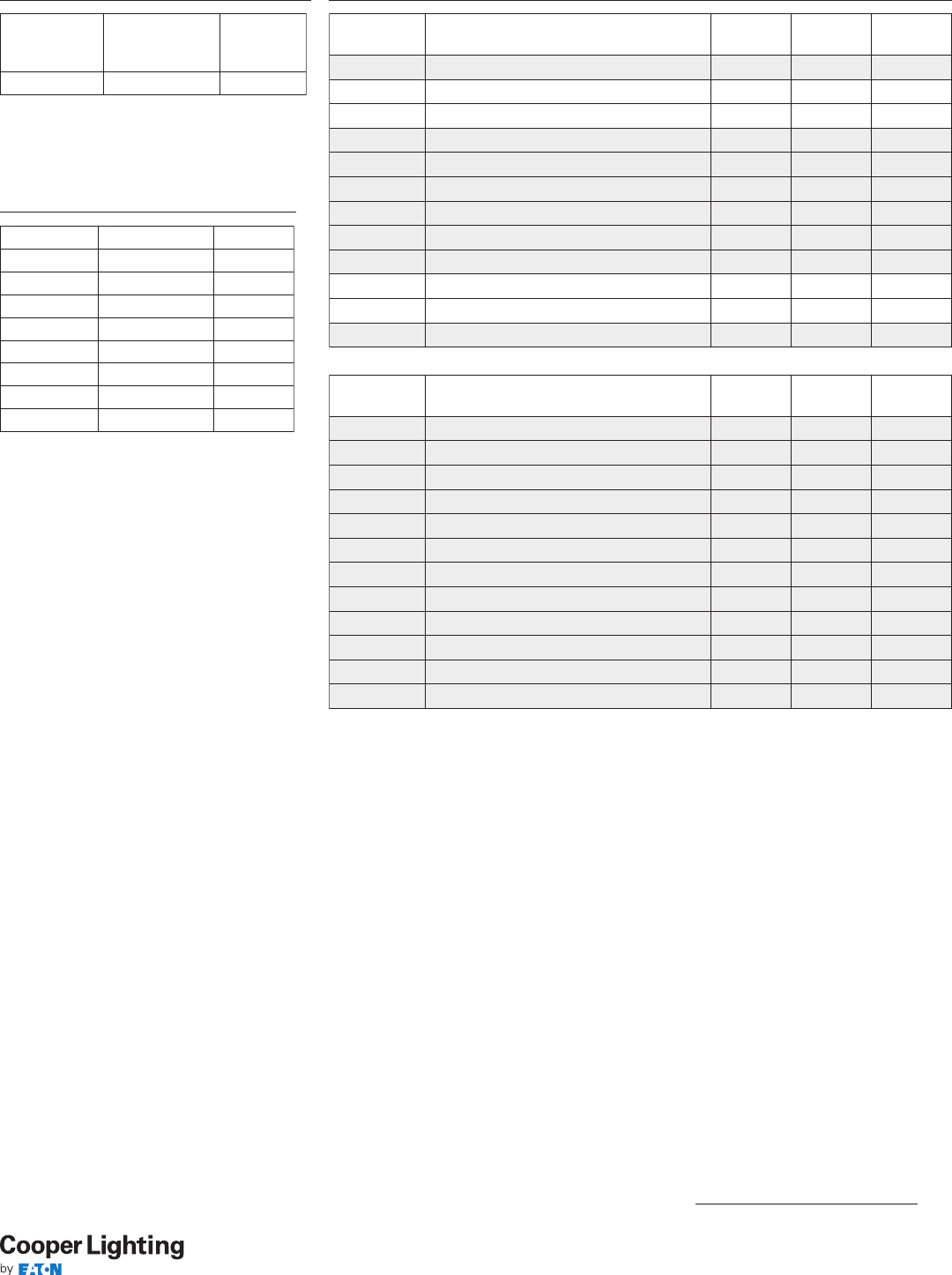
Eaton
1000 Eaton Boulevard
Cleveland, OH 44122
United States
Eaton.com
Specifications and
dimensions subject to
change without notice.
Eaton’s Cooper Lighting Business
1121 Highway 74 South
Peachtree City, GA 30269
P: 770-486-4800
www.cooperlighting.com
Stock or
MTO*
Catalog Logic
(Curved)
Delivered
Lumens WattsEfficacy
(LPW)
MTO 22SR-LD1-20-C-UNV-L830-CD1-U 1981 19.9 99
Stock 22SR-LD1-20-C-UNV-L835-CD1-U 2046 19.9 103
Stock 22SR-LD1-20-C-UNV-L840-CD1-U 2095 19.9 105
MTO 22SR-LD1-20-C-UNV-L850-CD1-U 221619.9 111
MTO 22SR-LD1-25-C-UNV-L830-CD1-U 2464 25.4 97
MTO 22SR-LD1-25-C-UNV-L835-CD1-U 2550 25.5 100
MTO 22SR-LD1-25-C-UNV-L840-CD1-U 2617 25.5 103
MTO 22SR-LD1-25-C-UNV-L850-CD1-U 2768 25.5 109
MTO 22SR-LD1-29-C-UNV-L830-CD1-U 2820 29.9 94
Stock 22SR-LD1-29-C-UNV-L835-CD1-U 2935 30.0 98
Stock 22SR-LD1-29-C-UNV-L840-CD1-U 3003 30.0 100
MTO 22SR-LD1-29-C-UNV-L850-CD1-U 3177 30.0 106
Stock or
MTO*
Catalog Logic
(Straight)
Delivered
Lumens WattsEfficacy
(LPW)
MTO 22SR-LD1-20-S-UNV-L830-CD1-U 1977 19.7 101
MTO 22SR-LD1-20-S-UNV-L835-CD1-U 2083 19.7 106
MTO 22SR-LD1-20-S-UNV-L840-CD1-U 2140 19.7 109
MTO 22SR-LD1-20-S-UNV-L850-CD1-U 2140 19.6 109
MTO 22SR-LD1-25-S-UNV-L830-CD1-U 2467 25.1 98
MTO 22SR-LD1-25-S-UNV-L835-CD1-U 2597 25.1 103
MTO 22SR-LD1-25-S-UNV-L840-CD1-U 2672 25.1 106
MTO 22SR-LD1-25-S-UNV-L850-CD1-U 2826 25.1 113
MTO 22SR-LD1-29-S-UNV-L830-CD1-U 2824 29.6 95
MTO 22SR-LD1-29-S-UNV-L835-CD1-U 2984 29.7 101
MTO 22SR-LD1-29-S-UNV-L840-CD1-U 3075 29.7 104
MTO 22SR-LD1-29-S-UNV-L850-CD1-U 3253 29.7 110
*Made to order (MTO) requires a typical four week lead time.
ENERGY AND PERFORMANCE DATA BY CATALOG NUMBER
Ambient Tem-
perature
TM-21 Lumen
Maintenance
(60,000 hours)
Theoretical
L70
(Hours)
25°C > 84% > 144,000
LUMEN MAINTENANCE
Catalog No. Wt.
22SR-LD1-20 12 lbs.
22SR-LD1-29 12 lbs.
SHIPPING DATA
ADF130559
2014-12-29 15:52:44
22SR LED 2' X 2'
Color Choice Kit Catalog Number Kit Quantity
Tahitian Blue STK-2-TB-10PK 10
Primary GreenSTK-2-PG-10PK 10
Storaro OrangeSTK-2-SO-10PK 10
Belladonna Rose STK-2-BR-10PK 10
Medium RedSTK-2-MR-10PK 10
Pearl STK-2-PL-10PK 10
Straw STK-2-ST- 10PK 10
Custom Color STK-2-CC-*-10PK 10
*Custom color requires Roscolux numeric specification
color code, consult factory for more information.
Note: Chosen color will be matched on acrylic but will
appear lighter once applied to lit light guide.
SKYTRIM FIELD INSTALLATION KITS
CHOOSE COLOR
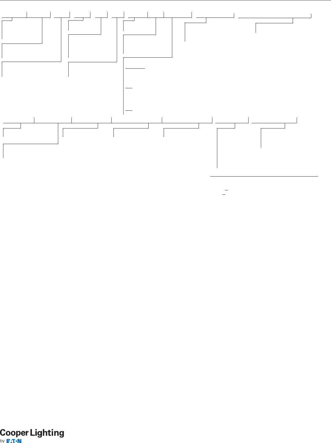
Eaton
1000 Eaton Boulevard
Cleveland, OH 44122
United States
Eaton.com
Specifications and
dimensions subject to
change without notice.
Eaton’s Cooper Lighting Business
1121 Highway 74 South
Peachtree City, GA 30269
P: 770-486-4800
www.cooperlighting.com
ADF130559
2014-12-29 15:52:44
22SR LED 2' X 2'
SAMPLE NUMBER: 22SR-LD1-29-C-UNV-L835-CD1-SVPD1-U
Voltage(1)
347V=347 Volt
UNV=Universal Voltage
120-277
Options
Emergency
EL=Emergency Installed, 700 Lumens(3)
CCT
L830=3000K
L835=3500K
L840=4000K
Flex (14)
Multiple Configurations Available
Optics
Blank=Standard
Series
22SR=2' x 2' SkyRidge
Series
ACCESSORIES
T3A END E.Q. BRACKET PARTS BAG (Standard with fixture)
DF-22-W=2' x 2' Drywall Frame Kit
DF10P-C =Devine Decorator Dimmer, 0-10V
SF10P- =Skye Decorator Slide Dimmer, 0-10V
HHPRG-MS=Programming Remote for Integrated Sensor
Rating
Blank=Standard
ATW-SW4= Chicago
Rated (6)
Lamp Type
LD1=LED 1. 0
Air
[Blank]=Standard
A=Air (Vented)(7)
Reflector
C=Curved (Standard)
S=Straight
Stock Lumen Outputs
20=2000 Lumens
29=2900 Lumens
MTO Lumen Outputs(5)
25=2500 Lumens
(8)
NOTES: (1) Products also available in non-US voltages and frequencies for international markets. (2) Must specify voltage (120V or 277V) when selecting EL option. (3) EL test switch and light must be remote mounted.
(4) Call factory for step-dimming options. (5) Made-to-order (MTO) requites four week lead time. (6) Chicago rated version does not allow for row mounting. (7) Air version is vented but does not meet air handling
requirements. Air version is non-IC. Air version is not available with integrated sensor. (8) DesignLights Consortium® Qualified (all lumen packages). Refer to www.designlights.org Qualified Products List under Family
Models for details. (9) For delivered lumens, take lumens per watt of desired fixture and multiply by 10 watts (100 lp/W x 10 = 1000 lumens delivered). (10) Fixtures using factory installed SkyTrim option are not DLC
qualified. (11) Custom color must list Roscolux numeric color specification code. (12) Must be used in conjunction with a DALI control system. For complete DALI soluitions by Fifth Light, visit www.coopercontrol.com
(13) Integral sensor works only with “CD” driver and is factory prewired to the driver for stand-alone control. (14) Flex does not include dimming leads. Control leads provided by others.
Specifications & dimensions subject to change without notice. Consult your Cooper Lighting Representative for availability and ordering information.
EL14=Emergency Installed , 1400 Lumens (2), (3)
EL10W=Emergency Installed , 10 Watts (9)
Driver Type (4)
CD=0-10V Dimming Driver
(Standard)
5LTHD=Fifth Light DALI Driver
(1% - 100% Dimming) (12)
Number of Drivers
1=1 Driver
Packaging
U=Unit Pack
PALC=Job
Pack, in carton
SkyTrim (11)
TB=Tahitian Blue
PG=Primary Green
SO=Storaro Orange
PL=Pearl
BR=Belladonna Rose
MR=Medium Red
ST=Straw
CC=Custom (11)
Product Family
S=Integrated Sensor
Control Type
B=Sensor Mounting, No Sensor
V=Analog (0-10V) Output for Local Control (13)
Occupancy Technology
P=Passive Infrared
Sensing Technology
D=Dimming Daylight
Harvesting (Closed Loop)
Coverage Pattern
1= ~144 Square Feet
L850=5000K
ORDERING INFORMATION
Eaton
1000 Eaton Boulevard
Cleveland, OH 44122
United States
Eaton.com
Specifications and
dimensions subject to
change without notice.
Eaton’s Cooper Lighting Business
1121 Highway 74 South
Peachtree City, GA 30269
P: 770-486-4800
www.cooperlighting.com
Description
This innovative luminaire-integrated sensor control system is built on Greengate technology and optimized for code-
compliant occupancy detection and daylight harvesting – all from within the foot print of Metalux’s award-winning
recessed ambient luminaires.
No New Wires
An in-place fixture retrofit is all that’s needed to meet most energy codes in commercial spaces. The sensor
system is factory wired to the luminaire, switching on or off based on occupancy, and dimming the light
when enough daylight is available.
Sophisticated lighting control without commissioning
The luminaire-integrated sensor system offers out-of-the-box operation using thoughtful default settings.
Flexibility and Individual Control
When the application demands more, the sensor system has the option to make changes using a remote control. The
remote allows changes from the default settings for occupancy, target light level, preset lighting levels, and more.
Cost-effective, Stand-alone Operation
With a single product to mount and a single electrical connection to make, the SkyRidge with an integrated sensor system saves money on the total
installed cost when occupancy or daylight harvesting controls are needed. The integrated sensor system works stand-alone, without the need for
additional switches and dimmers. When manual-on, manual dimming or other code-required control schemes are needed, please see the
comprehensive offering of Greengate and Fifth Light solutions from Cooper Controls at www.coopercontrol.com.
Metalux Integrated Sensor Sequence of Operation
The occupancy sensing portion of the sensor uses Passive Infrared (PIR) technology with Auto-on/Auto-off operation. The small lens in the center of the
sensor directs the view of a passive infrared occupancy detector to sense occupants moving through the room. To trigger the light on, an occupant
must cross at least two passive infrared beams. When motion in the coverage area ceases, the sensor logic concludes the room is unoccupied, and
begins a count-down timer. By default, the timer is factory-set to 30 minutes, and can be adjusted to 5, 10, 15 and 30 minutes using the optional remote
control, model number HHPRG-MS. Any motion detected during the count-down timer will cause the light to remain on and resets the timer. When
motion is detected, a red LED will blink. In addition to the default on/off functionality, the sensor has an Energy Saver feature, where the light can be
set to dim to a preset level after the sensor detects no occupancy for half of the count-down timer, when the timer is complete the lighting will change
to the unoccupied setting. The Energy Saver feature works when the count-down timer is set to at least 15 minutes, and the preset level and feature are
configured using the optional remote control. See the Sensor Programming Guide that comes with the HHPRG-MS remote for details on this feature.
The sensitivity of the occupancy detection can be adjusted, using the HHPRG-MS remote. By default, the sensor operates at the full detection range
shown on the coverage pattern diagram. Using the “LO” button on the HHPRG-MS remote, reduces the sensor detection range by 50%. Full coverage
can be restored at any time by pressing the “HI” button on the remote. The red LED indicator will blink repeatedly to confirm any programming
change.
The dimming daylight harvesting portion of the sensor uses a small photo sensor located next to the occupancy sensing lens. The sensor continuously
measures the available light in the room, even when the fixture is turned off. This allows sensor to operate in one of three daylighting modes, where
the artificial light from the paired Metalux luminaire can adjust the light based on the amount of ambient light from surrounding natural and artificial
light sources. Since the sensor measures light from its luminaire along with other light sources, this sensor follows a closed-loop dimming daylight
harvesting style. The first mode, Daytime, is active when the sensor detects light of at least 100 lux in the room. In Daytime mode, when the light is
turned on after detecting occupancy, the sensor will begin balancing the luminaire light level relative to the total available light it measures. The default
light balancing target in daytime mode is 500 lux. This level can be adjusted higher or lower using the optional HHPRG-MS remote, and pressing
“SET” and then the “DO” (Daytime Occupied) button to store the new light level. Similarly, the Daytime Unoccupied, “DU” has a default of level of 0
lux, or off, but can be adjusted higher to prevent the lights from turning off completely when unoccupied. More details on this function are found in
the Sensor Programming Guide for the HHPRG-MS remote.
The next two modes, Twilight and Nighttime, function in a similar way, allowing the artificial light to adjust to different levels based on the
surroundings. While primarily for use in outdoor luminaires, these modes are available for use in areas with a wide range of natural light, including
atriums, day lit stairwells, and rooms with large or continuous windows. The Twilight mode is active when the sensor detects 50-100 lux in the off
position, and has a 300 lux default light balancing target. The Nighttime mode is active when the sensor detects less than 50 lux, and has a 250 lux
default light balancing target. Like the Daytime mode, there are separate settings for Tw ilight Occupied (“TO”), Tw ilight Unoccupied (“TU”), Nighttime
Occupied (“NO”) and Nighttime Unoccupied (“NU”) which can be adjusted and set using the optional HHPRG-MS remote.
In addition to programming the sensor, the optional HHPRG-MS remote can be used for personal control to adjust the lighting temporarily override the
functions of the sensor temporarily. The remote has raise/lower buttons to adjust the light level for special tasks, as well as a power button to turn the
lights on or off. Unless the SET button and another function is selected, any changes made using these buttons will revert to the programmed settings
after the sensor has detected no occupancy for its programmed time out, and turned off the lighting. The next time the sensor detects occupancy, it will
revert to its programmed settings for count-down timer and light balancing.
Coverage Optional Remote
Control
HHPRG-MS Remote
Programming Remote
HHPRG-MS
Scenes:
To save scenes press SET
and select scene
Raise/
Lower
Time
Out
5
10
15
30
HI
LO
ES
SET
NO
TO
DO
NU
TU
DU
C
L
Top View Side Vi ew
4m
[12 ft.]
4m
[12 ft.]
0m
[0 ft.]
Coverage
Major Motion
3.3m
[10 ft.]
0m
[0 ft.]
0m
[0 ft.]
4m
[12 ft.]
4m
[12 ft.]
Reccomended Mounting Height 8–12 ft.
INTEGRATED SENSOR
ADF130559
2014-12-29 15:52:44
22SR LED 2' X 2'

1. Applicable Terms and Conditions
(a) These terms and conditions of sale establish the rights, obligations,
and remedies of Buyer and Seller that apply to any order issued by Buyer for the
purchase of Seller’s products and/or services (“Products”). No additional or differ-
ent terms or conditions, whether contained in Buyer’s purchase order form or in any
other document or communication pertaining to Buyer’s order, will be binding on
Seller unless accepted in writing by an authorized representative of Seller. Seller
expressly objects to and rejects any additional or different terms and conditions,
which shall be ineffective.
(b) If Seller’s order acknowledgement, invoice, other document, or elec-
tronic transmittal including or attaching these terms and conditions is found to be
an acceptance of an offer, acceptance is expressly made conditional upon Buyer’s
assent solely to these terms and conditions, and acceptance of any part of Products
delivered by Seller shall be deemed to constitute such assent by Buyer. If the order
acknowledgement, invoice, other document, or electronic transmittal including or
attaching these terms and conditions constitutes an offer, Buyer’s acceptance of the
offer is hereby limited to the terms of the offer.
2. Price, Payment Terms, and Title
(a) All prices represent those in effect at the time of quotation and are
subject to change without notice. Unless prices are bid or quoted as “firm,” Seller
reserves the right to invoice at prices in effect at the date of shipment, regardless of
any prior bid and whether notice was received by Buyer. Prices are stated in United
States dollars unless otherwise indicated, are exclusive of shipping, handling, ship-
ping insurance, duties, and sales, use, excise or similar taxes. Export packaging or
any other special handling requested by Buyer will be at Buyer’s expense. A service
charge of $25 will be assessed for any order less than $100.
(b) Buyer acknowledges that the pricing of the Products has been set
based on the agreed allocation of risks contained in these terms and conditions. If,
notwithstanding the provisions of these terms and conditions, a court of competent
jurisdiction determines that Buyer’s terms and conditions apply to an order, then
Seller shall have the right to either (i) modify the prices (including retroactively)
according to the additional level of risk and responsibility that Buyer’s terms and
conditions require Seller to undertake; or (ii) cancel the order any time after such a
determination without liability for the termination other than for the Products already
delivered on these terms and conditions.
(c) Unless different credit terms have been extended to Buyer in writing
by Seller, payment terms are net 30 days after delivery or date of invoice, whichever
first occurs, in the currency invoiced. Seller reserves the right to modify or withdraw
credit terms at any time without notice. If Buyer fails to fulfill the terms of payment,
Seller may defer further shipments to Buyer or, at its option, cancel the unshipped
portions of Buyer’s orders. Buyer agrees to pay interest on all past due invoices at
the lesser of 18% per annum, compounded monthly, or the highest contractual rate
allowable under the law.
(d) Until full payment of all obligations of the Buyer for an order, Seller
reserves the title (but not the risk of loss) to all Products furnished under that order.
If the Buyer defaults in payment or performance or becomes subject to insolvency,
receivership or bankruptcy proceedings or makes an assignment for the benefit of
creditors, or without the consent of Seller voluntarily or involuntarily sells, trans-
fers, leases or permits any lien or attachment on the Products, Seller may treat
all amounts then or thereafter owing by Buyer to be immediately due and payable
and Seller at its election may repossess Products for which Buyer has not paid in
full. In the event of repossession of Products under this section, Buyer agrees that
Seller may enter the premises where the Products may be located and remove them
without notice and without being liable to Buyer for such repossession. Buyer will
not set off invoiced amounts or any portion thereof against sums that are due or
may become due from Seller, its parents, affiliates, or subsidiaries. Buyer grants
Seller a security interest in all Products for which title has passed (including all
after-acquired Products) that Seller sells Buyer and all proceeds of Products (includ-
ing but not limited to all products in which Products are incorporated and any funds
and products that Buyer receives in exchange for Products). Buyer consents to
Seller’s execution of any documents to evidence and perfect this security interest,
and agrees to execute the same if requested by Seller.
3. Delivery and Risk of Loss
(a) Unless otherwise agreed in writing, all deliveries of Products will be
EXW (Incoterms 2000) Seller’s facility. Products will be packed in Seller’s standard
commercial shipping packages. Charges for shipping may not reflect net transpor-
tation costs paid by Seller. Buyer shall reimburse Seller for all costs of storage and
handling incurred by Seller after the date that Seller is prepared to make shipment.
(b) Delivery and shipping dates are approximate and represent Seller’s
best estimate of the time required to make delivery or shipment. Time is not of the
essence with respect to the transactions covered by these terms and conditions,
except with respect to Buyer’s obligation to make all related payments. Seller’s
obligations under these terms and conditions will be dependent upon Seller’s ability
to obtain necessary raw materials and components. Seller shall have the right to
make partial deliveries and to ship up to forty (40) days in advance of shipping date.
4. Acceptance
Acceptance shall occur, if not before, when Buyer fails to reject within
ten (10) days after delivery of the Products. Buyer may rightfully reject only when
a reasonable inspection shows that the Products fail to conform substantially to
the specifications for the Products. Buyer waives any right to revoke acceptance.
Buyer’s remedies for any nonconformity detected after acceptance are limited to
those expressly provided in these terms and conditions for breach of warranty.
5. Limited Warranty
(a) Seller warrants to each original Buyer of Products that Products are,
at the time of delivery to the Buyer, in good working order and conform to Seller’s
official published specifications, provided that no warranty is made with respect to
any Products, ballasts, lamps, component parts, or accessories manufactured by
others but supplied by Seller.
(b) Seller’s obligation under this warranty for any Product proved not
to be as warranted within the applicable warranty period is limited to, at its option,
replacing the Product, refunding the purchase price of the Product, or using reason-
able efforts to repair the Product during normal business hours at any authorized
service facility of Seller. All costs of transportation of any Product claimed not to be
as warranted and of any repaired or replacement Product to or from such service
facility shall be borne by Buyer.
(c) Seller may require the return of any Product claimed not to be as
warranted to one of its facilities as designated by Seller, transportation prepaid by
Buyer, to establish a claim under this warranty. The cost of labor for removing
a Product and for installing a repaired or replacement Product shall be borne by
Buyer. Replacement parts provided under the terms of this warranty are warranted
for the remainder of the warranty period of the Products in which they are installed
to the same extent as if such parts were original components. Warranty services
provided under these terms and conditions do not assure uninterrupted operations
of Products; Seller shall not be liable for damages caused by any delays involving
warranty service.
(d) The warranty period for Products is twelve (12) months from the
date of shipment unless otherwise agreed by Seller in writing.
(e) EXCEPT FOR THE EXPRESS WARRANTY SET FORTH ABOVE, SELL-
ER PROVIDES PRODUCTS AS-IS AND MAKES NO OTHER REPRESENTATIONS OR
WARRANTIES, EXPRESS OR IMPLIED, STATUTORY OR OTHERWISE, REGARDING
THE PRODUCTS, THEIR FITNESS FOR ANY PARTICULAR PURPOSE, THEIR MER-
CHANTIBILITY, THEIR QUALITY, THEIR NONINFRINGEMENT, OR OTHERWISE. IN
NO EVENT SHALL SELLER BE LIABLE FOR THE COST OF PROCUREMENT OR IN-
STALLATION OF SUBSTITUTE GOODS. THIS WARRANTY SPECIFICALLY EXCLUDES
POLE FAILURE RESULTING FROM A THIRD-PARTY ACT OR OMISSION, MISUSE,
UNANTICIPATED USE, FATIGUE, FAILURE, OR SIMILAR PHENOMENA RESULTING
FROM INDUCED VIBRATION, HARMONIC OSCILLATION, OR RESONANCE FROM AIR
CURRENT MOVEMENT AROUND THE PRODUCT. THIS WARRANTY SPECIFICALLY
EXCLUDES POLES INSTALLED WITHOUT THE LUMINAIRES OR WITH UNAPPROVED
DEVICES SUCH AS BANNERS, PENNANTS, CAMERAS, OR SIGNS, FOR WHICH THE
POLE WAS NOT DESIGNED. USE OF SUCH ACCESSORIES MAY RESULT IN INJURY,
DEATH OR PROPERTY DAMAGE. THIS WARRANTY SPECIFICALLY EXCLUDES POLES
USING PRE-EXISTING ANCHORAGES, ANCHOR BOLTS, OR BOLT ADAPTERS NOT
SUPPLIED BY COOPER LIGHTING. IT ALSO EXCLUDES ISSUES RELATED TO FOUN-
DATION OR SOIL CONDITIONS AT THE INSTALLATION SITE.
6. LIMITATION OF LIABILITY
IN NO EVENT WILL SELLER BE LIABLE FOR ANY SPECIAL DAMAGES,
CONSEQUENTIAL DAMAGES, INDIRECT DAMAGES, INCIDENTAL DAMAGES, STATU-
TORY DAMAGES, EXEMPLARY OR PUNITIVE DAMAGES, LOSS OF PROFITS, LOSS
OF REVENUE, LIQUIDATED DAMAGES, OR LOSS OF USE, EVEN IF INFORMED
OF THE POSSIBILITY OF SUCH DAMAGES. SELLER’S LIABILITY FOR DAMAGES
ARISING OUT OF OR RELATED TO A PRODUCT SHALL IN NO CASE EXCEED THE
PURCHASE PRICE OF THE PRODUCT FROM WHICH THE CLAIM ARISES. TO THE
EXTENT PERMITTED BY APPLICABLE LAW, THESE LIMITATIONS AND EXCLUSIONS
WILL APPLY WHETHER SELLER’S LIABILITY ARISES OR RESULTS FROM BREACH
OF CONTRACT, BREACH OF WARRANTY, TORT (INCLUDING BUT NOT LIMITED TO
NEGLIGENCE, GROSS NEGLIGENCE, MALICE, OR INTENTIONAL CONDUCT), STRICT
LIABILITY, BY OPERATION OF LAW, OR OTHERWISE.
7. Cancellation and Return of Products
Orders shall not be subject to cancellation or modification either in
whole or in part without Seller’s written consent and then only with terms that will
reimburse Seller for all applicable costs incurred by virtue of the sale, including
costs of purchased materials, engineering costs and a reasonable allowance for
profit. Seller’s written consent must be given in advance of Buyer’s return of Prod-
ucts for credit. Seller reserves the right to cancel any sale of Products without
liability to Buyer (except for refund of monies already paid), if the manufacture or
sale of the goods is or becomes technically or economically impractical.
8. Force Majeure
Seller shall not be liable for any failure to perform or delay in performing
its obligations resulting directly or indirectly from or contributed to by any acts of
God, acts of Buyer or those under Buyer’s control, acts of government or other civil
or military authorities, priorities, strikes, or other labor disputes, fires, accidents,
floods, epidemics, war, riot, embargoes, delays in transportation, lack of or inability
to obtain raw materials, components, labor, fuel or supplies, or other circumstances
beyond Seller’s reasonable control (“Force Majeure Event”). If Seller elects, the
time for performance shall be extended by a period of time equal to the time lost
because of any delays caused by reasons of a Force Majeure Event. Should Seller
be prevented from completing Buyer’s order or any part thereof because of any
Force Majeure Event, then Buyer agrees promptly upon request and upon receipt of
invoice therefor, to pay Seller for any Product or Products then completed.
9. Work Product
“Work Product” shall include, without limitation, all designs, discov-
eries, creations, works, devices, masks, models, work in progress, service deliv-
erables, inventions, products, special tooling, computer programs, procedures,
improvements, developments, drawings, notes, documents, business processes,
information and materials made, conceived or developed by Seller alone or with
others that result from or relate to the Products. All Work Product shall at all times
be and remain the sole and exclusive property of Seller. Buyer hereby agrees to
irrevocably assign and transfer to Seller and does hereby assign and transfer to
Seller all of its worldwide right, title and interest in and to the Work Product includ-
ing all associated intellectual property rights. Buyer hereby waives any and all moral
and other rights in any Work Product or any other intellectual property created,
developed or acquired in respect of the Products. Seller will have the sole right to
determine the treatment of any Work Product, including the right to keep it as trade
secret, execute and file patent applications on it, to use and disclose it without prior
patent application, to file registrations for copyright or trademark in its own name
or to follow any other procedure that Seller deems appropriate. All tools and equip-
ment supplied by Buyer to Seller shall remain the sole property of Seller.
10. Confidentiality
(a) Buyer may acquire knowledge of Seller Confidential Information
(as defined below) in connection with Products and/or its performance hereunder
and agrees to keep Seller Confidential Information in confidence during and fol-
lowing termination or expiration of this Agreement. “Seller Confidential Informa-
tion” includes but is not limited to all information, whether written or oral, in any
form, including, without limitation, information relating to the research, develop-
ment, products, methods of manufacture, trade secrets, business plans, customers,
vendors, finances, personnel data, Work Product, and other material or information
considered proprietary by Seller relating to the current or anticipated business
or affairs of Seller that is disclosed directly or indirectly to Buyer. In addition, Seller
Confidential Information means any third party’s proprietary or confidential informa-
tion disclosed to Buyer in the course of providing Products to Buyer.
(b) Buyer agrees not to copy, alter or directly or indirectly disclose any
Seller Confidential Information. Additionally, Buyer agrees to limit its internal distri-
bution of Seller Confidential Information to Buyer‘s employees who have a need to
know, and to take steps to ensure that the dissemination is so limited. In no event
will Buyer use less than the degree of care and means that it uses to protect its own
information of like kind, but in any event not less than reasonable care to prevent
the unauthorized use of Seller Confidential Information. Buyer may disclose Seller
Confidential Information that is required to be disclosed pursuant to a requirement
of a government agency or law but only after Buyer provides prompt notice to Seller
of such requirement and gives Seller the opportunity to challenge or limit the scope
of the disclosure.
(c) Buyer further agrees not to use Seller Confidential Information
except in the course of performing hereunder and will not use such Seller Confi-
dential Information for its own benefit or for the benefit of any third party. All Seller
Confidential Information is and shall remain the property of Seller. Upon Seller’s
written request, Buyer shall return, transfer or assign to Seller all Seller Confidential
Information, including all Work Product, and all copies containing Seller Confidential
Information.
11. Patent Indemnity
In the event any Product is made in accordance with drawings, samples
or manufacturing specifications designated by Buyer, Buyer agrees to indemnify,
defend and hold Seller harmless from any and all damages, costs and expenses
(including attorney’s fees) relating to any claim arising from or relating to the design,
distribution, manufacture, marketing, sale, or use of the Product or arising from or
relating to a claim that such Product furnished to Buyer by Seller, or the use thereof,
infringes any claim of any patent, foreign or domestic, and Buyer agrees at its own
expense to undertake the defense of any suit against Seller brought upon such claim
or claims.
12. Changes in Product Design or Manufacture
Seller shall have the right to change, discontinue or modify the design
and construction of any of its products and to substitute material equal to or superior
to that originally specified.
13. Software License
Software, if included with a Product, is hereby licensed and not sold.
The license is nonexclusive, and is limited to use with the Product with which it is
included. No other use is permitted and Seller retains for itself (or, if applicable, its
suppliers) all title and ownership to any software delivered hereunder, all of which
contains confidential and proprietary information and which ownership includes
without limitation all rights in patents, copyrights, trademarks and trade secrets.
Buyer shall not attempt any sale, transfer, sublicense, reverse compilation or dis-
assembly (save to the extent expressly permitted by law) or redistribution of the
software. Buyer shall not copy, disclose or display any such software, or otherwise
make it available to others.
14. Compliance with Laws
Buyer shall comply with all laws and regulations applicable to Products,
including but not limited to all applicable import and export laws and regulations.
Buyer and Buyer’s Agent shall provide all information requested by Seller relat-
ing to Seller’s voluntary or mandatory compliance with any law or regulation, and
Buyer shall indemnify Seller for any losses incurred by Seller arising from Buyer’s or
Buyer’s Agent’s failure to provide the information requested by Seller.
15. Waiver
No waiver of any provision of these terms and conditions (or any right or
default hereunder) shall be effective unless in writing and signed by an authorized
representative Seller. Any such waiver shall be effective only for the instance given,
and shall not operate as a waiver with respect to any other rights or obligations
under these terms and conditions or applicable law in connection with any other
instances or circumstances.
16. Language
The parties have expressly required that these terms and conditions
be prepared in the English language. Les parties aux présentes ont expressément
exigé que les présents termes et les bons de commandes émis aux termes des
présentes soient rédigés en langue Anglaise.
17. Choice of Law and Dispute Resolution
Except as set forth below, these terms and conditions shall be governed
by and construed in accordance with the laws of the State of Texas, without refer-
ence to its choice of law rules. If both Seller and Buyer are incorporated under
the laws of Canada or a province of Canada, these terms and conditions shall be
governed by and construed in accordance with the laws of the Province of Ontario
and the federal laws of Canada. If Buyer is incorporated in the United States, any
claim or litigation arising out of or relating to Products shall be brought exclusively
in a court of competent jurisdiction in Harris County, Texas. If Buyer is incorporated
outside of the United States, any dispute will be resolved by arbitration in Houston,
Texas, by three arbitrators and under the International Chamber of Commerce Rules
of Arbitration. The language of the arbitration will be English. In all cases, Buyer
and Seller expressly exclude from application the United Nations Convention on
Contracts for the International Sale of Goods.
18. Assignment
Buyer may not assign, transfer or subcontract the performance of its
services, or any of its rights and/or obligations hereunder, without Seller’s prior writ-
ten consent.
19. Severability
If any provision of these terms and conditions is determined to be ille-
gal, invalid, or unenforceable, the validity and enforceability of the remaining provi-
sions of these terms and conditions will not be affected and, in lieu of such illegal,
invalid, or unenforceable provision, there will be added, as part of these terms and
conditions, one or more provisions as similar in terms as may be legal, valid and
enforceable under applicable law. CL 022311
Terms and Conditions
Cooper Lighting, LLC
ACF110706
April 6, 2011
