Connections & Cabling Systems (07 FLC) 160023 Catalog
111891-Attachment 111891-Attachment 111891-Attachment 002209 Batch7 unilog cesco-content
2014-11-11
: Pdf 160023-Catalog 160023-Catalog 002209 Batch12 unilog
Open the PDF directly: View PDF ![]() .
.
Page Count: 124 [warning: Documents this large are best viewed by clicking the View PDF Link!]
FOUNDED IN 1910, SUTTLE IS THE WORLD’S LARGEST SUPPLIER OF HIGH-VOLUME VOICE
CONNECTION PRODUCTS USED BY THE WORLD’S LARGEST COMMUNICATIONS COMPANIES.
Suttle provides connections for voice, data, and video communications throughout the world.
Residential or commercial, new installation or retrofi t, Suttle has the products to enable reliable
communications. Our high-quality and innovative products include the industry leading brand of
SOHO Access™ residential structured wiring products, DSL fi lters, and CorroShield®, a unique
line of corrosion-resistant voice and data connectors for hostile operating environments.
A ISO9001/TL9000 registered company, headquartered in Hector, MN, Suttle is a wholly owned
subsidiary of Communications Systems, Inc., a publicly traded company (AMEX: JCS).
Warranty
PLUS
PLUS
PLUS
Blue Ribbon
Blue Ribbon
ASSURANCE
Suttle is proud of our long-standing reputation for providing the telecommunications industry superior products backed
by our Certifi ed Installation Training program and 25-Year Warranty.
Suttle’s Installer Certifi cation and Warranty Plan gives your installations an
edge with the knowledge and support of Suttle, an ISO9001/TL9000 Certifi ed
Manufacturer with a reputation of over 97 years of quality and service.
The 25-Year Warranty covers the performance of Suttle’s Category 6 and
Category 5e Cabling Systems, using Suttle’s partners for horizontal cable.
Certifi ed training is now available 24/7 with our online certifi cation program where you can earn both BICSI and CEDIA
certifi cation credits. On site training is also offered in several major cities throughout the U.S.
The Installer Certifi cation & Training Program has been rated among the best in the industry. Our knowledgeable trainers
or online environment provide excellent training on structured cabling communication systems for beginners, experts,
and everyone in-between. Please contact us today to learn more.
Call 800-852-8662 to fi nd a Suttle certifi ed installer in your area or for more information on the warranty
and training programs.
Ú
HABLAMOS ESPAÑOL
Con una reputación de mas de 97 años de calidad y servicio, Suttle es el proveedor mas grande a nivel mundial
de productos de conectividad para voz, datos y microfi ltros (ADSL) en la industria de telecomunicaciones.
Para hablar con un representante en español, y recibir información sobre nuestros productos, distribuidores o servicios,
marque al +1-320-848-6711 o correo electrónico: suttlesales@commsysinc.com
Ú
COLOR CHIPS
Suttle provides several products in a variety of colors and shades. The following color chips represent these colors;
please use this key to help you determine the color you need.
Ú
WEBSITE
Visit our websites at www.suttleonline.com and www.suttlesoho.com where you can further explore the breadth and depth
of our product and service offerings. Suttle’s websites also feature:
Ú
As part of Suttle’s continuous product improvement efforts, Suttle reserves the right to change specifi cations and availability without notice.
Product Releases
News Updates
Online Training & Certification Program
■
■
■
Inventory Reduction Sales
Literature Library
■
■
Distributor Locator
Tradeshow Schedule
■
■
Ash = (44) Gray = (48) Ivory = (50) Electrical Ivory = (52) Light Almond = (64) White = (85) Black = (03)
Green = (51) Red = (53) Yellow = (56) Purple = (57) Blue = (62) Orange = (97)
3

1-800-852-8662 WWW.SUTTLEONLINE.COM
4

TABLE OF CONTENTS
TRADITIONAL TELEPHONY STRUCTURED WIRING FIBERDSL USOC WIRING GUIDE GLOSSARY INDEXSOHO ACCESS™
p06 TRADITIONAL TELEPHONY
Suttle’s Traditional Telephony product line offers the broadest selection of traditional telephone
connecting devices in the world. Our long-standing history of delivering high quality products
is apparent throughout our entire offering.
p36 SOHO ACCESS™
Our SOHO Access™ residential structured cabling enclosures and modules provide fl exibility
and versatility for the termination and management of voice, data, and video connections.
Competitively priced and quality built, the SOHO line of products are well equipped to meet
all of your communication needs.
p54 STRUCTURED WIRING
Our full line of residential and commercial Structured Wiring solutions meets the voice, data, and
video (VDV) connectivity needs of both today and tomorrow. Suttle’s versatile multimedia products
allow you to maximize the performance of your network and are a perfect complement to the SOHO
Access™ line of products.
p78 DSL
Addressing the challenges created by DSL broadband technology deployment’s in the home, Suttle’s
Line Conditioners® fi lter out any erratic impedances from telephone equipment, delivering reliable
high bandwidth DSL transmission capabilities. Suttle DSL Line Conditioners are customer installable
and should be used for each active phone line to insure uninterrupted broadband transmission.
p86 FIBER
Suttle’s fi ber product line includes the revolutionary Terminator™ Field Termination System,
QuickTerm connectors, assemblies, and a variety of other complementary products to meet
your fi ber connectivity needs.
p98 USOC
A listing of Suttle part numbers with wiring diagrams which meet USOC requirements, assisting our
valued Suttle customers in ordering appropriate products.
p112 GLOSSARY
A listing of common terms and abbreviations with defi nitions.
p118 INDEX
A complete listing of part numbers with page locations for products featured in this catalog.
5

1-800-852-8662 WWW.SUTTLEONLINE.COM
6

TRADITIONAL TELEPHONY
Ú TRADITIONAL TELEPHONY CONTENT OVERVIEW
Suttle’s Traditional Telephony Product line offers the broadest selection of
traditional telephone connecting devices in the world. Our long - standing history
of delivering high quality products is apparent throughout our entire offering:
p08 CORROSHIELD®
Our line of CorroShield products utilize specially formulated dielectric gels which are applied during
manufacturing to all surfaces at risk for corrosion. The gel completely surrounds the conducting
surfaces protecting them from outside contamination while still maintaining the electrical
performance of high speed data transmission.
p10 JACKS AND JACK ASSEMBLIES
Available in surface and fl ush mount, modular and non - modular, indoor and outdoor, 4, 6, and 8
conductor keyed and non - keyed wire confi gurations. These products are offered in a wide variety of
smooth, sleek, durable, and easy - to install designs as well as several designer colors to complement
any home. They install without mounting brackets, can be equipped with spring - loaded trap doors
and are available in CorroShield® versions.
p20 DUAL PROVIDER SWITCH PRODUCTS
This unique line of Suttle products is designed for multiple service providers to distribute voice
service through a home’s existing wiring by way of a customer controlled switch.
p21 CONNECTING BLOCKS
These connecting blocks provide a simple screw terminal telephony distribution point for
a premise network.
p24 FACEPLATES AND BRACKETS
The fl ame - resistant thermoplastic design of our faceplates assures that Suttle’s products are built to
last. Our mounting brackets are compatible with fl ush mounting modular and non - modular jacks and
our mounting boxes come in a variety of depths to customize your job. They are used to cover jacks,
connecting blocks, and unused pre - wired junction boxes.
p26 ADAPTERS AND COUPLERS
Used as an inline device, Suttle’s adapters modify circuitry without rewiring. Also, our couplers
extend modular circuits without hassle by connecting two modular plug - ended line cords.
Both Suttle’s adapter and coupler products are available in fl ame - resistant thermoplastic and
are UL certifi ed.
p31 NETWORK INTERFACE DEVICES
Suttle’s line of NIDs provide access for subscriber testing. The 603NID1 is ideal for voice distribution
in the MDU and single family home environment by providing up to 6 POTS phone lines and 11
phone/voice outlets. Our junction boxes come in three designs and can be mounted on baseboards
or within the telephone service box.
p33 MISCELLANEOUS
To fulfi ll your communication needs, Suttle provides a variety of audio and visual ring indicators
including loud ringing bells, electronic ringers, and chime ringers to complement any telephone
system. Also included are indicator lights, neon lamps, and standard switch board lamps. Repair,
replace, or add as your needs evolve with modular and non - modular plugs, modular line cords and
extension cords.
7
GEL
TRADITIONAL
TELEPHONY
1-800-852-8662 WWW.SUTTLEONLINE.COM
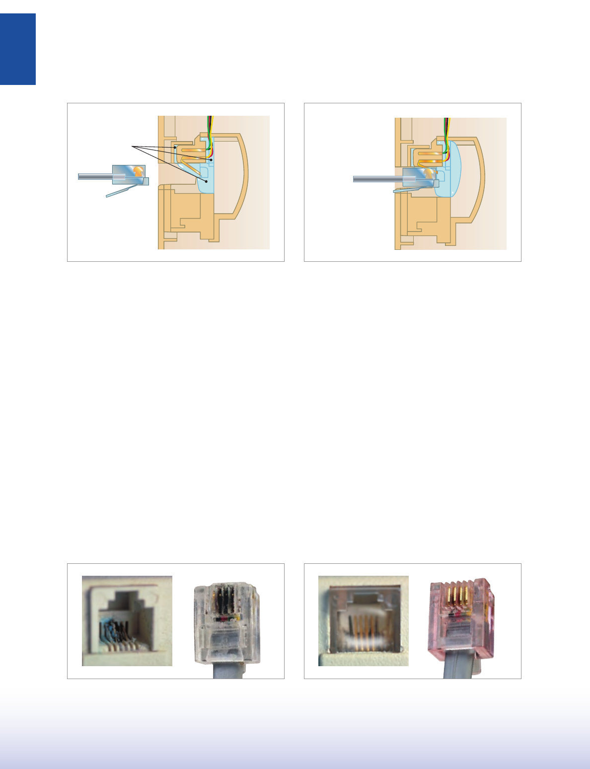
HOW CORROSHIELD PROTECTS YOUR CONNECTIONSÚ
CORROSHIELD®
❚
WHAT IS CORROSHIELD?
What is CorroShield? It is the highest level of protection against the
corrosive effects of humidity, saltwater, chemicals, water, dirt, and other
contaminants. Now the patented product that the world’s largest carriers
have standardized on for voice line service has been expanded into modular
voice and data products. The applications are far - reaching from high
humidity inland communities to coastal locations.
Suttle’s family of CorroShield products are designed to deliver improved
performance and reduced service calls through increased connector
reliability. During manufacturing, a specially formulated gel is applied to all
surfaces at risk of contamination, completely surrounding the gold contact
wires. When the voice or data cord is inserted, the gel forms an airtight seal
around the connection, preventing corrosion and other contact problems.
The unique memory characteristics of the CorroShield gel continue to deliver
long after installation. When the voice or data cord is removed from the
connector, the gel will return to its original position, maintaining the airtight
seal for up to one hundred insertion events.
Ú
Prior to plug insertion, the CorroShield gel maintains an airtight
seal around all conducting surfaces in the jack.
The gel is displaced upon plug insertion, resulting in a protective
airtight seal around the plug and jack conducting surfaces.
The CorroShield family of products is available in a variety of configurations
including enclosed terminals, filled splice connectors, trap doors, and
swinger doors.
TYPICAL APPLICATIONS
Residential
Business
MDU
Hospitality
Industrial
Ask a Suttle representative for a copy of our White Paper titled: “Improving
Voice & Data Network Reliability and Reducing Service Costs: Benefits from
an Enhanced Reliability Modular Connection Block.’’
Ú
■
■
■
■
■
Contact corrosion is easily preventable with Suttle’s
CorroShield Connectors.
Modular jack corrosion and contamination results in more than
$1.25 billion in service costs each year in the U.S. alone.
1
1. “Improving Voice & Data Network Reliability and Reducing Service Costs:
Benefits From an Enhanced Reliability Modular Connection Block.” Pg. 2. Suttle, 2002.
8
TRADITIONAL
TELEPHONY
STRUCTURED WIRING FIBERDSLSOHO ACCESS™ USOC WIRING GUIDE GLOSSARY INDEX
CORROSHIELD PRODUCT DIRECTORY
TRADITIONAL TELEPHONY
FLUSH MOUNT JACK AND JACK ASSEMBLIES >
SMOOTH FINISH
> SIMPLEX : VOICE
PART# DESCRIPTION PAGE
2 - 3010 - xx 4 - conductor, screw terminals 10
2 - 3011 - xx 4 - conductor, screw terminals, trap door 10
2 - 3012 - xx 4 - conductor, filled splice connectors 10
2 - 3013 - xx 4 - conductor, filled splice connectors, trap door 10
2 - 3014 - xx 6 - conductor, screw terminals 10
2 - 3015 - xx 6 - conductor, screw terminals, trap door 10
2 - 3016 - xx 6 - conductor, filled splice connectors 10
2 - 3017 - xx 6 - conductor, filled splice connectors, trap door 10
> DUPLEX : VOICE, EAST/WEST
PART# DESCRIPTION PAGE
2 - 1010 - xx 4/4 - conductor, screw terminals 10
2 - 1011 - xx 4/4 - conductor, filled splice connectors 10
2 - 1012 - xx 6/6 - conductor, screw terminals 10
2 - 1013 - xx 6/6 - conductor, filled splice connectors 10
> DUPLEX : VOICE, NORTH/SOUTH
PART# DESCRIPTION PAGE
2 - 2010 - xx 4/4 - conductor, screw terminals 11
2 - 2011 - xx 4/4 - conductor, screw terminals, trap door 11
2 - 2012 - xx 4/4 - conductor, filled splice connectors 11
2 - 2013 - xx 4/4 - conductor, filled splice connectors, trap door 11
2 - 2014 - xx 6/6 - conductor, screw terminals 11
2 - 2015 - xx 6/6 - conductor, screw terminals, trap door 11
2 - 2016 - xx 6/6 - conductor, filled splice connectors 11
2 - 2017 - xx 6/6 - conductor, filled splice connectors, trap door 11
TRADITIONAL JACK PLATES
> SIMPLEX : STANDARD
PART# DESCRIPTION PAGE
625B4 - 4 - xxRC 4 - conductor, screw terminals 12
625B4 - 4NS - xxRC 4 - conductor, filled splice connectors 12
625B4 - 6NS - xxRC 6 - conductor, filled splice connectors 12
> SIMPLEX : SWINGER DOOR
PART# DESCRIPTION PAGE
625FS4 - xxRC 4 - conductor, screw terminals, swinger door 12
625FSNS4 - xxRC 4 - conductor, filled splice connectors, swinger door 12
625FSNS6 - xxRC 6 - conductor, filled splice connectors, swinger door 12
> DUPLEX : EAST/WEST
PART# DESCRIPTION PAGE
625D4 - xxRC 4/4 - conductor, screw terminals 13
625D4NS - xxRC 4/4 - conductor, filled splice connectors 13
625D6 - xxRC 6/6 - conductor, screw terminals 13
625D6NS - xxRC 6/6 - conductor, filled splice connectors 13
MODULAR STYLE JACKS
> MODULAR JACKS WITH FACEPLATES WITH BRACKETS
PART# DESCRIPTION PAGE
625BE4NS - xxRC 4 - conductor, filled splice connectors, 13
trap door, 19E faceplate, 43C bracket
625B1E4 - xxRC 4 - conductor, screw terminals, 19A faceplate, 13
43A bracket, trap door
625B1E4NS - xxRC 4 - conductor, filled splice connectors, 13
19A faceplate, 43A bracket, trap door
625B2E4NS - xxRC 4 - conductor, filled splice connectors, 13
16A faceplate, with bracket, trap door
> MODULAR JACKS
PART# DESCRIPTION PAGE
625FE4 - xxRC 4 - conductor, screw terminals, trap door 14
625FE4NS - xxRC 4 - conductor, filled splice connectors, trap door 14
Ú
WALL MOUNT JACK AND JACK ASSEMBLIES >
> PLASTIC : WITH MOUNTING LUGS
PART# DESCRIPTION PAGE
630AC4 - xxRC 4 - conductor, screw terminals 15
630AC4NS - xxRC 4 - conductor, filled splice connectors, riser plate 15
630AC6NS - 50RC 6 - conductor, filled splice connectors, riser plate 15
630AP4NS - 50RC 4 - conductor, filled splice connectors 15
630AP6NS - 50RC 6 - conductor, filled splice connectors 15
> STAINLESS STEEL : WALL MOUNT JACK ASSEMBLIES
PART# DESCRIPTION PAGE
630AD4NS - RC 4 - conductor, filled splice connectors, 16
riser plate, mounting lugs
630AD6NS - RC 6 - conductor, filled splice connectors, 16
riser plate, mounting lugs
SURFACE MOUNT JACK AND JACK ASSEMBLIES >
SCREW ON COVER
> SIMPLEX
PART# DESCRIPTION PAGE
625C4 - xxRC 4 - conductor, spade terminals, cover only, 17
used with 020031 - 50 block
625A4 - xxRC 4 - conductor, screw terminals 17
625A6 - xxRC 6 - conductor, screw terminals 17
625AS4 - xxRC 4 - conductor, screw terminals 17
625AS4NS - xxRC 4 - conductor, filled splice connectors 17
625AS6NS - xxRC 6 - conductor, filled splice connectors 17
> DUPLEX
PART# DESCRIPTION PAGE
104A4NS - RC 4/4 conductor, filled splice connectors 18
> SNAP ON COVER, FACTORY WIRED
PART# DESCRIPTION PAGE
625A2 - 4 - xxRC 4 - conductor, screw terminals 18
625A2 - 6 - xxRC 6 - conductor, screw terminals 18
625A2 - 4NS - xxRC 4 - conductor, filled splice connectors 18
625A2 - 6NS - xxRC 6 - conductor, filled splice connectors 18
> SWINGER DOOR SURFACE MOUNT
PART# DESCRIPTION PAGE
625SA4 - xxRC 4 - conductor, screw terminals 19
625SA6 - xxRC 6 - conductor, screw terminals 19
625SANS4 - xxRC 4 - conductor, filled splice connectors 19
625SANS6 - xxRC 6 - conductor, filled splice connectors 19
OUTDOOR JACK ASSEMBLIES
> SURFACE MOUNT BOX/JACKS
PART# DESCRIPTION PAGE
19316L7 - 4NS - RC 4 - conductor, filled splice connectors 23
MISCELLANEOUS
> MODULAR LINE CORDS
PART# DESCRIPTION PAGE
7200 - 07 - WRC1 4 - conductor, 7 - ft., CorroShield plugs 33
STRUCTURED WIRING
SPEEDSTAR > JACKS
> DATA JACKS: CATEGORY 5e
PART# DESCRIPTION PAGE
STAR600A - RC 8 - position, 8 - conductor, 568A, 110 IDC blocks 57
STAR600B - RC 8 - position, 8 - conductor, 568B, 110 IDC blocks 57
> VOICE JACKS
PART# DESCRIPTION PAGE
STAR600V6 - RC 6 - position, 6 - conductor, 110 IDC blocks 57
9
2 - 3001 - xx
2 - 1001 - xx
TRADITIONAL
TELEPHONY
1-800-852-8662 WWW.SUTTLEONLINE.COM
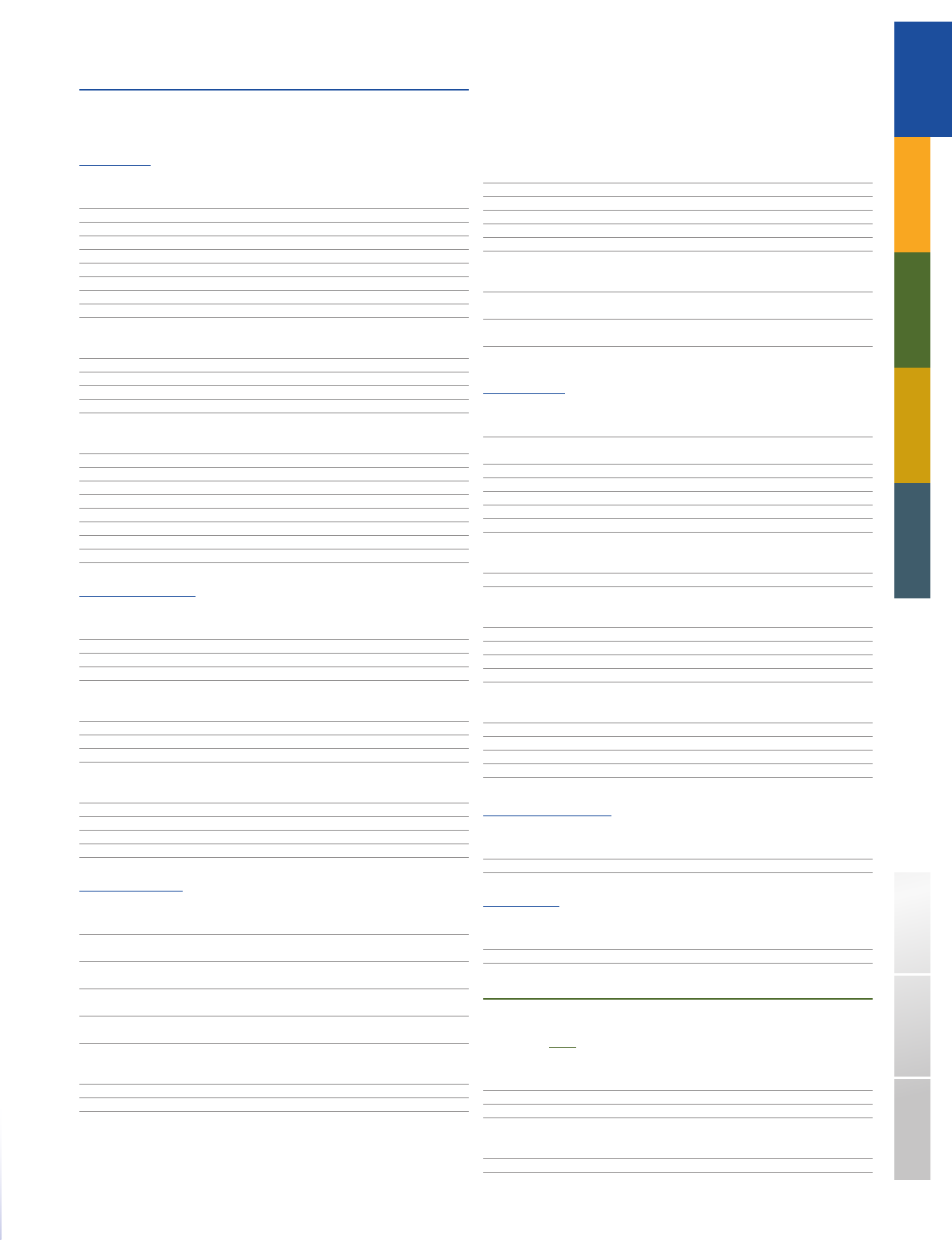
FLUSH MOUNT > SMOOTH FINISH
Behind the sleek modern surface of our smooth finish jack plates, you’ll find the durable, easy mounting design that makes Suttle the industry leader.
They install without mounting brackets, can be equipped with spring - loaded trap doors and are available in both standard (dry) and CorroShield (gelled)
versions for long - lasting corrosion protection.
Smooth, sleek design matches electrical faceplates
Mounting screws provided with painted heads to blend smoothly into the design of the faceplate
SIMPLEX : VOICE
PART# DESCRIPTION CORROSHIELD WIRING
2 - 3001 - xx 4 - conductor, screw terminals USOC
2 - 3002 - xx 4 - conductor, screw terminals USOC
2 - 3010 - xx 4 - conductor, screw terminals CorroShield USOC
2 - 3011 - xx 4 - conductor, screw terminals, trap door CorroShield USOC
2 - 3012 - xx 4 - conductor, filled splice connectors CorroShield USOC
2 - 3013 - xx 4 - conductor, filled splice connectors, trap door CorroShield USOC
2 - 3003 - xx 6 - conductor, screw terminals USOC
2 - 3004 - xx 6 - conductor, screw terminals, trap door USOC
2 - 3014 - xx 6 - conductor, screw terminals CorroShield USOC
2 - 3015 - xx 6 - conductor, screw terminals, trap door CorroShield USOC
2 - 3016 - xx 6 - conductor, filled splice connectors CorroShield USOC
2 - 3017 - xx 6 - conductor, filled splice connectors, trap door CorroShield USOC
COLORS
( - xx): Electrical Ivory = (52) Light Almond = (64) White = (85)
Ú
■
■
JACK AND JACK ASSEMBLIES❚
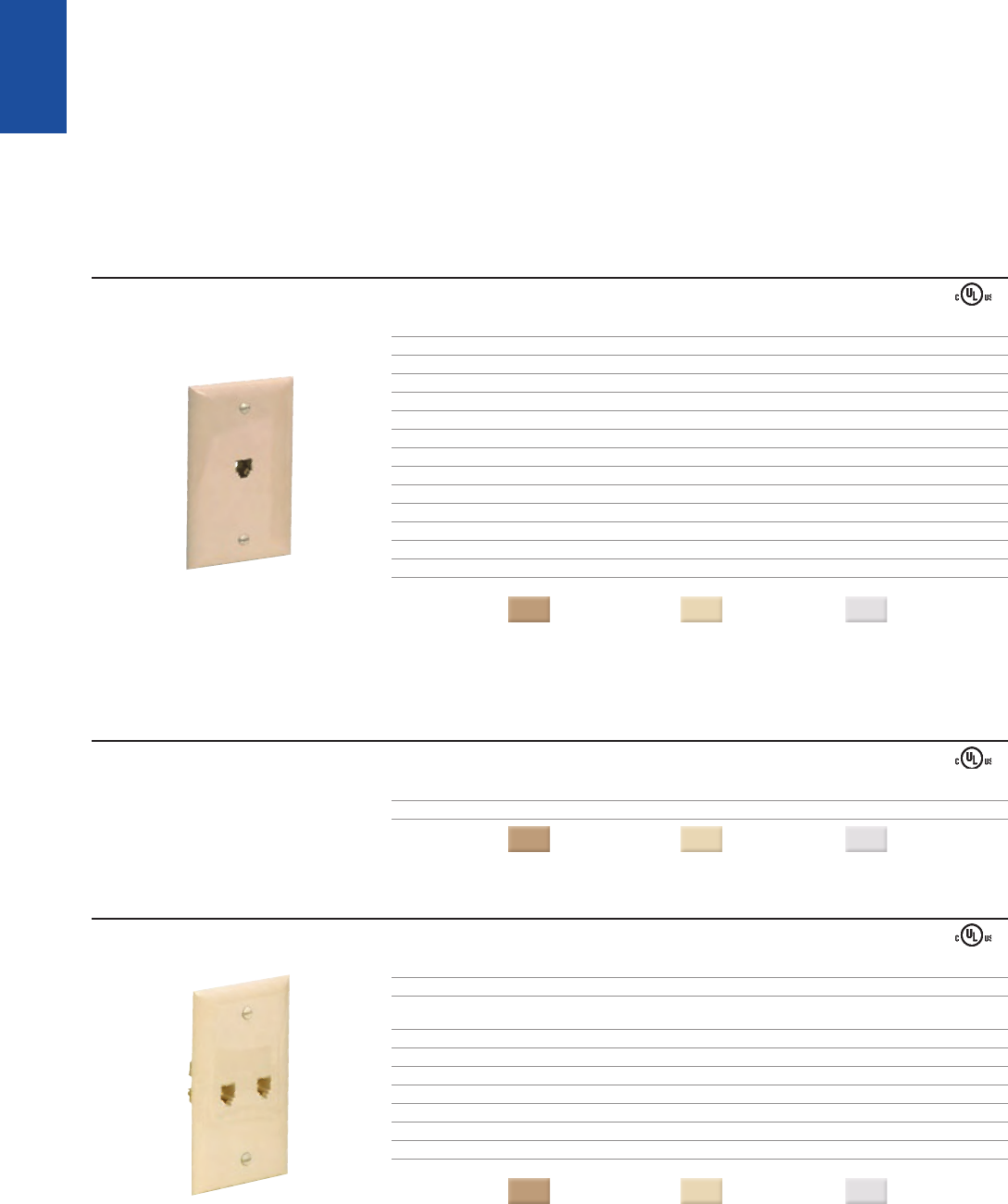
SIMPLEX : VIDEO
PART# DESCRIPTION
2 - 3020 - xx F81 barrel connector
COLORS
( - xx): Electrical Ivory = (52) Light Almond = (64) White = (85)
DUPLEX : VOICE, EAST/WEST
PART# DESCRIPTION CORROSHIELD WIRING
2 - 1001 - xx 4/4 - conductor, screw terminals USOC
2 - 1001S - xx 4/4 - conductor, screw terminals, USOC
Line 1 & 2 switches for Service Provider A/Service Provider B
2 - 1010 - xx 4/4 - conductor, screw terminals CorroShield USOC
2 - 1011 - xx 4/4 - conductor, filled splice connectors CorroShield USOC
2 - 1002 - xx 6/6 - conductor, screw terminals USOC
2 - 1012 - xx 6/6 - conductor, screw terminals CorroShield USOC
2 - 1013 - xx 6/6 - conductor, filled splice connectors CorroShield USOC
2 - 1014 - xx 4/4 - conductor, filled splice connectors, loop wiring (bridged) USOC
COLORS
( - xx): Electrical Ivory = (52) Light Almond = (64) White = (85)
10
2 - 2001 - xx
2 - 2022 - xx
2 - 5001 - xx
2 - 5001 - FC - xx
TRADITIONAL
TELEPHONY
STRUCTURED WIRING FIBERDSLSOHO ACCESS™ USOC WIRING GUIDE GLOSSARY INDEX
DUPLEX : VOICE, NORTH/SOUTH
PART# DESCRIPTION CORROSHIELD WIRING
2 - 2001 - xx 4/4 - conductor, screw terminals USOC
2 - 2002 - xx 4/4 - conductor, screw terminals, trap door USOC
2 - 2010 - xx 4/4 - conductor, screw terminals CorroShield USOC
2 - 2011 - xx 4/4 - conductor, screw terminals, trap door CorroShield USOC
2 - 2012 - xx 4/4 - conductor, filled splice connectors CorroShield USOC
2 - 2013 - xx 4/4 - conductor, filled splice connectors, trap door CorroShield USOC
2 - 2006 - xx 6/6 - conductor, 110 IDC block terminals USOC
2 - 2003 - xx 6/6 - conductor, screw terminals USOC
2 - 2004 - xx 6/6 - conductor, screw terminals, trap door USOC
2 - 2008 - xx Oversized 6/6 - conductor, screw terminals USOC
2 - 2014 - xx 6/6 - conductor, screw terminals CorroShield USOC
2 - 2015 - xx 6/6 - conductor, screw terminals, trap door CorroShield USOC
2 - 2016 - xx 6/6 - conductor, filled splice connectors CorroShield USOC
2 - 2017 - xx 6/6 - conductor, filled splice connectors, trap door CorroShield USOC
2 - 2030 - xx 4/4 - conductor, filled splice connectors, loop wiring (bridged) USOC
COLORS
( - xx): Electrical Ivory = (52) Light Almond = (64) White = (85)
VOICE/VIDEO COMBINATION, NORTH/SOUTH
Combination Voice/Video jack assemblies are ideal for video applications in a residential setting.
PART# DESCRIPTION WIRING
2 - 2021 - xx (1) 4 - conductor, screw terminal USOC
(1) F81 Barrel connector
2 - 2022 - xx (1) 4 - conductor, screw terminal, trap door USOC
(1) F81 Barrel connector
2 - 2023 - xx (1) 6 - conductor, screw terminal USOC
(1) F81 Barrel connector
2 - 2024 - xx (1) 6 - conductor, screw terminal, trap door USOC
(1) F81 Barrel connector
2 - 2020 - xx (2) F81 Barrel connector USOC
COLORS
( - xx): Electrical Ivory = (52) Light Almond = (64) White = (85)
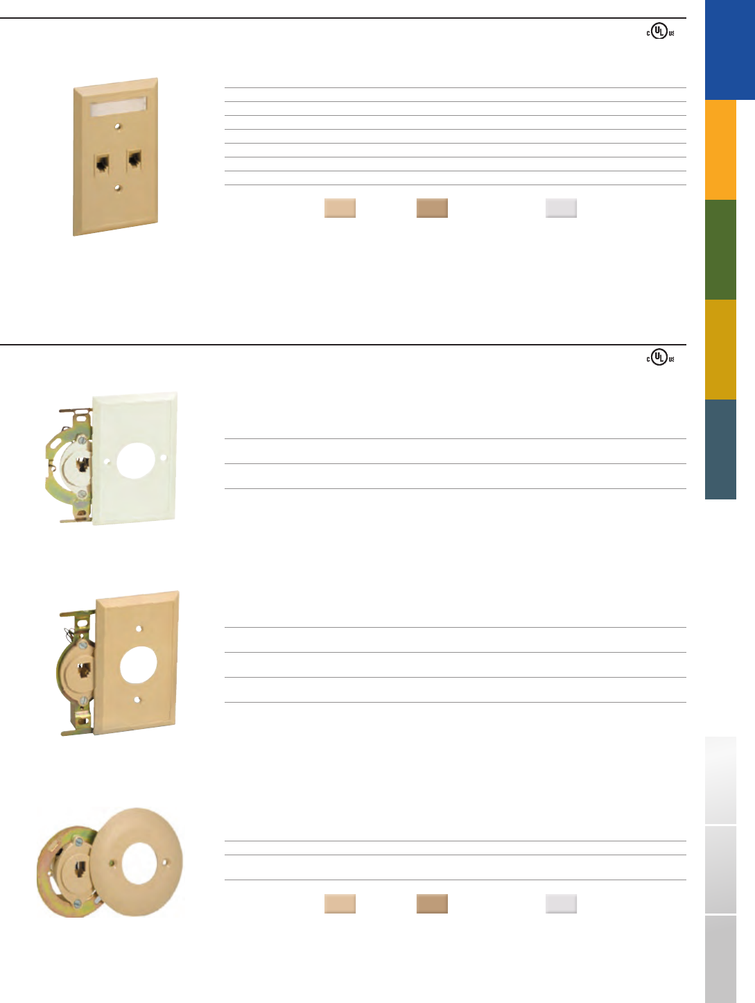
➥NEW VOICE/DATA COMBINATION, EAST/WEST
PART# DESCRIPTION
2 - 5001 - xx Standard faceplate, voice/data: 6 - conductor/8 - conductor, CAT5e, 110 IDC
2 - 5001M - xx Oversized faceplate, voice/data: 6 - conductor/8 - conductor, CAT5e, 110 IDC
COLORS
( - xx): Electrical Ivory = (52) Light Almond = (64) White = (85)
➥NEW VOICE/DATA/VIDEO COMBINATION, EAST/WEST
PART# DESCRIPTION
2 - 5001 - F - xx Standard faceplate, voice/data: 6 - conductor/8 - conductor, CAT5e, 110 IDC, video: 1GHz F81 barrel connector
2 - 5001M - F - xx Oversized faceplate, voice/data: 6 - conductor/8 - conductor, CAT5e, 110 IDC, video: 1GHz F81 barrel connector
2 - 5001 - FC - xx Standard faceplate, voice/data: 6 - conductor/8 - conductor, CAT5e, 110 IDC;
video: 3GHz F81 barrel connector, SCTE compliant (SCTE 02 2006)
2 - 5001M - FC - xx Oversized faceplate, voice/data: 6 - conductor/8 - conductor, CAT5e, 110 IDC,
video: 3GHz F81 barrel connector, SCTE compliant (SCTE 02 2006)
COLORS
( - xx): Electrical Ivory = (52) Light Almond = (64) White = (85)
Attractive one piece design
Labeled ports PHONE, DATA
■
■
Available in standard and oversized
Mounting screws included
■
■
Attractive one piece design
Labeled ports PHONE, DATA, VIDEO
■
■
Available in standard and oversized
Mounting screws included
■
■
11
625B4 - 4 - xx
625FSNS4 - xxRC
625B3
- 4 - xx
TRADITIONAL
TELEPHONY
1-800-852-8662 WWW.SUTTLEONLINE.COM
FLUSH MOUNT > TRADITIONAL JACK PLATES
Suttle’s simplex and duplex jack plates provide versatile flush mounted connections in aesthetically pleasing styles and colors. Available in both standard (dry)
and CorroShield (gelled) versions for long - lasting corrosion protection.
Mounted with brackets or directly to the wall
Available in 4, 6, and 8 conductor configurations
USOC Wiring
SIMPLEX : STANDARD
PART# DESCRIPTION CORROSHIELD WIRING
625B4 - 4 - xx 4 - conductor, screw terminals USOC
625B4 - 4 - xxRC 4 - conductor, screw terminals CorroShield USOC
625B4 - 4NS - xxRC 4 - conductor, filled splice connectors CorroShield USOC
625B4E4 - xx 4 - conductor, screw terminals, trap door USOC
625B4 - 6 - xx 6 - conductor, screw terminals USOC
625B4 - 6NS - xxRC 6 - conductor, filled splice connectors CorroShield USOC
635A8 - 50 8 - conductor, screw terminals, non - keyed jack RJ31X, Shorting bar (1&4, 5&8)
697B8 - 50 8 - conductor, screw terminals, keyed jack Programmable resistors
697B8NK - xx 8 - conductor, screw terminals, non - keyed jack USOC
COLORS
( - xx): Ivory = (50) Electrical Ivory = (52) White = (85)
Ú
■
■
■
SIMPLEX : SWINGER DOOR
PART# DESCRIPTION CORROSHIELD WIRING
625FS4 - xx 4 - conductor, screw terminals, swinger door USOC
625FS4 - xxRC 4 - conductor, screw terminals, swinger door CorroShield USOC
625FSNS4 - xxRC 4 - conductor, filled splice connectors, swinger door CorroShield USOC
COLORS
( - xx): Electrical Ivory = (52) White = (85)
DUPLEX : NORTH/SOUTH
PART# DESCRIPTION WIRING
625B3 - 4 - xx 4/4 - conductor, screw terminals USOC
625B3E4 - xx 4/4 - conductor, screw terminals, trap door USOC
625B3 - 6 - xx 6/6 - conductor, screw terminals USOC
625B3E6 - xx 6/6 - conductor, screw terminals, trap door USOC
625B3 - 8 - 50 8/8 - conductor, screw terminals, keyed/non - keyed USOC
625B38NK - 50 8/8 - conductor, screw terminals, non - keyed/non - keyed USOC
635B68 - 50 (1) 8 - conductor, screw terminals, non - keyed RJ31X, Shorting bar (1&4, 5&8)
(1) 4 - conductor, screw terminals, trap door USOC
635B68JP - 50 (1) 6 - position, 4 - conductor, modular jack RJ31X, Shorting bar (1&4, 5&8)
(1) 8 - position, 8 - conductor, modular jack USOC
RJ11 and RJ45 are bridged
(1) RJ45 Dust plug included
697B68H - 50 6/8 conductor, screw terminals, non - keyed/keyed USOC
COLORS
( - xx): Ivory = (50) White = (85)
12
625D4 - xx
625B - xx
625B1 - 4 - 50
625B2 - 4 - 50
TRADITIONAL
TELEPHONY
STRUCTURED WIRING FIBERDSLSOHO ACCESS™ USOC WIRING GUIDE GLOSSARY INDEX
DUPLEX : EAST/WEST
Includes label for easy identification
PART# DESCRIPTION CORROSHIELD WIRING
625D4 - xx 4/4 - conductor, screw terminals USOC
625D4 - xxRC 4/4 - conductor, screw terminals CorroShield USOC
625D4NS - 52RC 4/4 - conductor, filled splice connectors CorroShield USOC
625D6 - xx 6/6 - conductor, screw terminals USOC
625D6 - 52RC 6/6 - conductor, screw terminals CorroShield USOC
625D6NS - 52RC 6/6 - conductor, filled splice connectors CorroShield USOC
COLORS
( - xx): Ivory = (50) Electrical Ivory = (52) White = (85)
■
FLUSH MOUNT > MODULAR STYLE JACKS
MODULAR JACKS WITH FACEPLATES WITH BRACKETS
PART# DESCRIPTION CORROSHIELD WIRING
625B - xx 4 - conductor, screw terminals, USOC
19E faceplate, 43C bracket
625BE4NS - xxRC 4 - conductor, filled splice connectors, trap door, CorroShield USOC
19E faceplate, 43C bracket
PART# DESCRIPTION CORROSHIELD WIRING
625B1 - 4 - 50 4 - conductor, screw terminals, USOC
19A faceplate, 43A bracket
625B1E4 - 50 4 - conductor, screw terminals, USOC
19A faceplate, 43A bracket, trap door
625B1E4 - 85RC 4 - conductor, screw terminals, 19A faceplate, 43A bracket, CorroShield USOC
19A faceplate, 43A bracket, trap door
PART# DESCRIPTION CORROSHIELD WIRING
625B2 - 4 - 50 4 - conductor, screw terminals, 16A faceplate, with bracket USOC
625B2E4NS - xxRC 4 - conductor, filled splice connectors, CorroShield USOC
16A faceplate, with bracket, trap door
COLORS
( - xx): Ivory = (50) Electrical Ivory = (52) White = (85)
Ú
13
625F4 - xx
625FE4NS - xxRC
102A6 - 50
333AE4 - 85
TRADITIONAL
TELEPHONY
1-800-852-8662 WWW.SUTTLEONLINE.COM
MODULAR JACKS
PART# DESCRIPTION WIRING
625F4 - xx 4 - conductor, screw terminals USOC
COLORS
( - xx): Ivory = (50) Electrical Ivory = (52) White = (85)
PART# DESCRIPTION CORROSHIELD WIRING
625FE4NS - xxRC 4 - conductor, filled splice connectors, trap door CorroShield USOC
COLORS
( - xx): Ivory = (50) Electrical Ivory = (52) White = (85)
PART# DESCRIPTION WIRING
102A6 - 50 6 - conductor, 110 IDC terminals USOC
102A8 - 52 8 - conductor, 110 IDC terminals, non - keyed 568B
COLORS
( - xx): Ivory = (50) Electrical Ivory = (52)
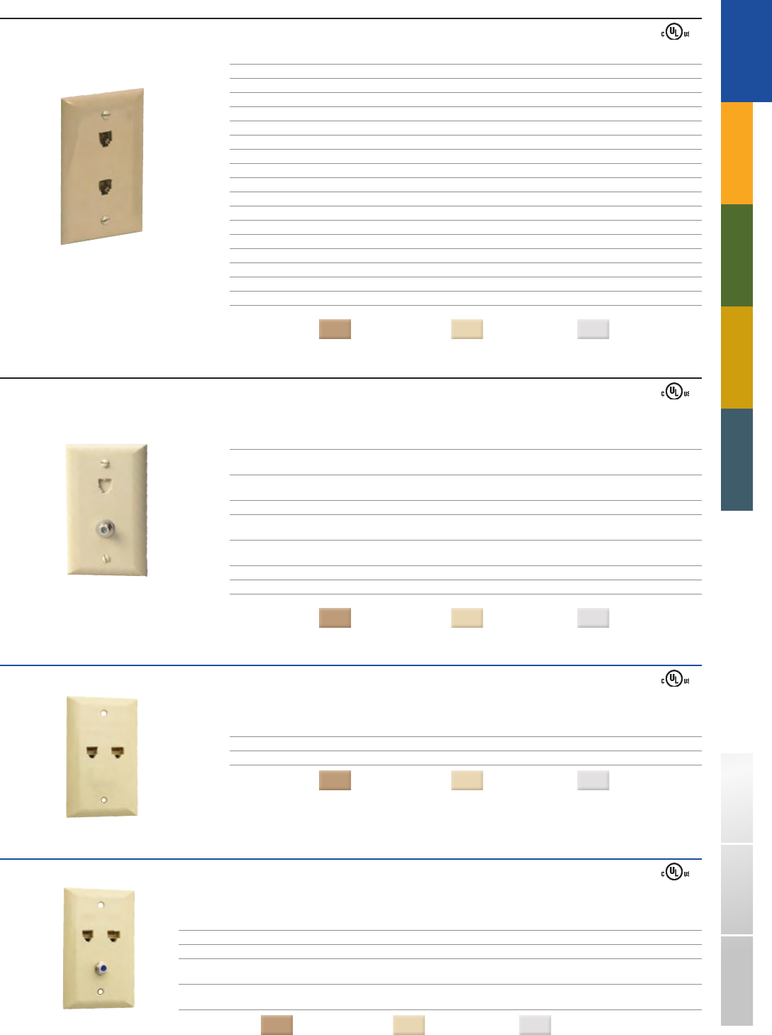
FLUSH MOUNT > EUROPEAN - STYLE JACKS
Suttle’s European style flush mount jacks allow for mounting on 85mm square outlet boxes typically used in European wiring systems.
All are supplied with 3.5 x 6.0 mm mounting screws.
EUROPEAN - STYLE FLUSH MOUNT JACKS
PART# DESCRIPTION WIRING
333AE4 - 85 4 - conductor, screw terminals, trap door USOC
333AE6 - 85 6 - conductor, screw terminals, trap door USOC
COLOR
: White
Ú
14
630AB4 - xx
630ABS6 - xx
630ABC4 - xx
630AC4 - xx
630AP4 - xx
TRADITIONAL
TELEPHONY
STRUCTURED WIRING FIBERDSLSOHO ACCESS™ USOC WIRING GUIDE GLOSSARY INDEX
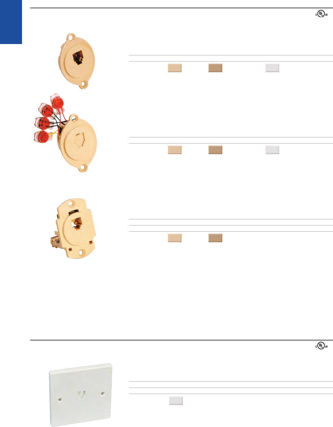
WALL MOUNT JACK ASSEMBLIES
Versatile mounting options
Can be mounted on a standard outlet box for pre - wired installations, or attached directly to the wall
Entire terminal block is enclosed in a plastic wrapper to eliminate corrosion and shorting out due to condensation or incidental moisture
PLASTIC : WITHOUT MOUNTING LUGS
PART# DESCRIPTION WIRING
630AB4 - xx 4 - conductor, quick - connect terminals, no mounting lugs USOC
630AB6 - xx 6 - conductor, quick - connect terminals, no mounting lugs USOC
Note: Quick Connect Terminals require use of 797A installation tool (see page 35).
PART# DESCRIPTION WIRING
630ABS4 - xx 4 - conductor, screw terminals, no mounting lugs USOC
630ABS6 - xx 6 - conductor, screw terminals, no mounting lugs USOC
COLORS
( - xx): Ash = (44) Ivory = (50)
Ú
■
■
■
PLASTIC : WITH MOUNTING LUGS
Packaged with mounting lugs for use with modular wall telephones or plastic inserts for desk applications
PART# DESCRIPTION WIRING
630ABC4 - xx 4 - conductor, quick - connect terminals, includes 797A termination tool USOC
630ABC6 - xx 6 - conductor, quick - connect terminals, includes 797A termination tool USOC
PART# DESCRIPTION CORROSHIELD WIRING
630AC4 - xx 4 - conductor, screw terminals USOC
630AC4 - xxRC 4 - conductor, screw terminals CorroShield USOC
630AC4NS - xxRC 4 - conductor, filled splice connectors, riser plate CorroShield USOC
630AC6 - xx 6 - conductor, screw terminals USOC
630AC6NS - 50RC 6 - conductor, filled splice connectors, riser plate CorroShield USOC
COLORS
( - xx): Ash = (44) Ivory = (50) Electrical Ivory = (52)
IN DEPTH: 630AP wall plates feature an all plastic wall plate with a snap - on cover
PART# DESCRIPTION CORROSHIELD WIRING
630AP4 - xx 4 - conductor, screw terminals USOC
630AP4NS - 50RC 4 - conductor, filled splice connectors CorroShield USOC
630AP6
- xx 6 - conductor, screw terminals USOC
630AP6NS - 50RC 6 - conductor, filled splice connectors CorroShield USOC
630AP8
- xx 8 - conductor, screw terminals USOC
COLORS
( - xx): Ash = (44) Ivory = (50) Elect. Ivory = (52) White = (85)
■
➥
15
630A4
630B4
630ANS4
630CI - 52
631A
TRADITIONAL
TELEPHONY
1-800-852-8662 WWW.SUTTLEONLINE.COM
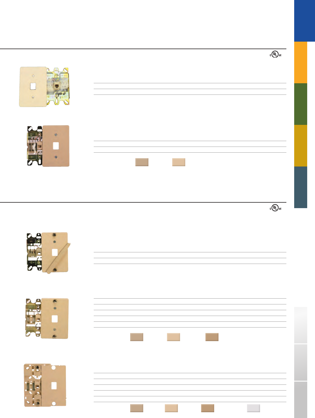
STAINLESS STEEL – WALL MOUNT JACK ASSEMBLIES
Can be mounted on a standard outlet box for pre - wired installations, or attached directly to the wall
Entire terminal block is enclosed in a plastic wrapper to eliminate corrosion and shorting out due to condensation or incidental moisture
Stainless steel resists scratching, cleaning solutions, and corrosive environments
Riser plate included with CorroShield models
PART# DESCRIPTION WIRING
630A4 4 - conductor, quick connect terminals, mounting lugs USOC
630A6 6 - conductor, quick connect terminals, mounting lugs USOC
Note: Quick Connect Terminals require use of 797A installation tool (see page 35).
PART# DESCRIPTION WIRING
630B4 4 - conductor, quick connect terminals with retaining clips, mounting lugs USOC
630B6 6 - conductor, quick connect terminals with retaining clips, mounting lugs USOC
Note: Quick Connect Terminals require use of 797A installation tool (see page 35).
PART# DESCRIPTION CORROSHIELD WIRING
630AD4 4 - conductor, screw terminals, mounting lugs USOC
630AD4NS - RC 4 - conductor, filled splice connectors, riser plate, mounting lugs CorroShield USOC
630AD4 - RC44 4 - conductor, no riser plate, mounting lugs CorroShield USOC
630AD6 6 - conductor, screw terminals, mounting lugs USOC
630AD6NS - RC 6 - conductor, filled splice connectors, riser plate, mounting lugs CorroShield USOC
PART# DESCRIPTION WIRING
630ANS4 4 - conductor, screw terminals, no mounting lugs USOC
630ANS6 6 - conductor, screw terminals, no mounting lugs USOC
■
■
■
■
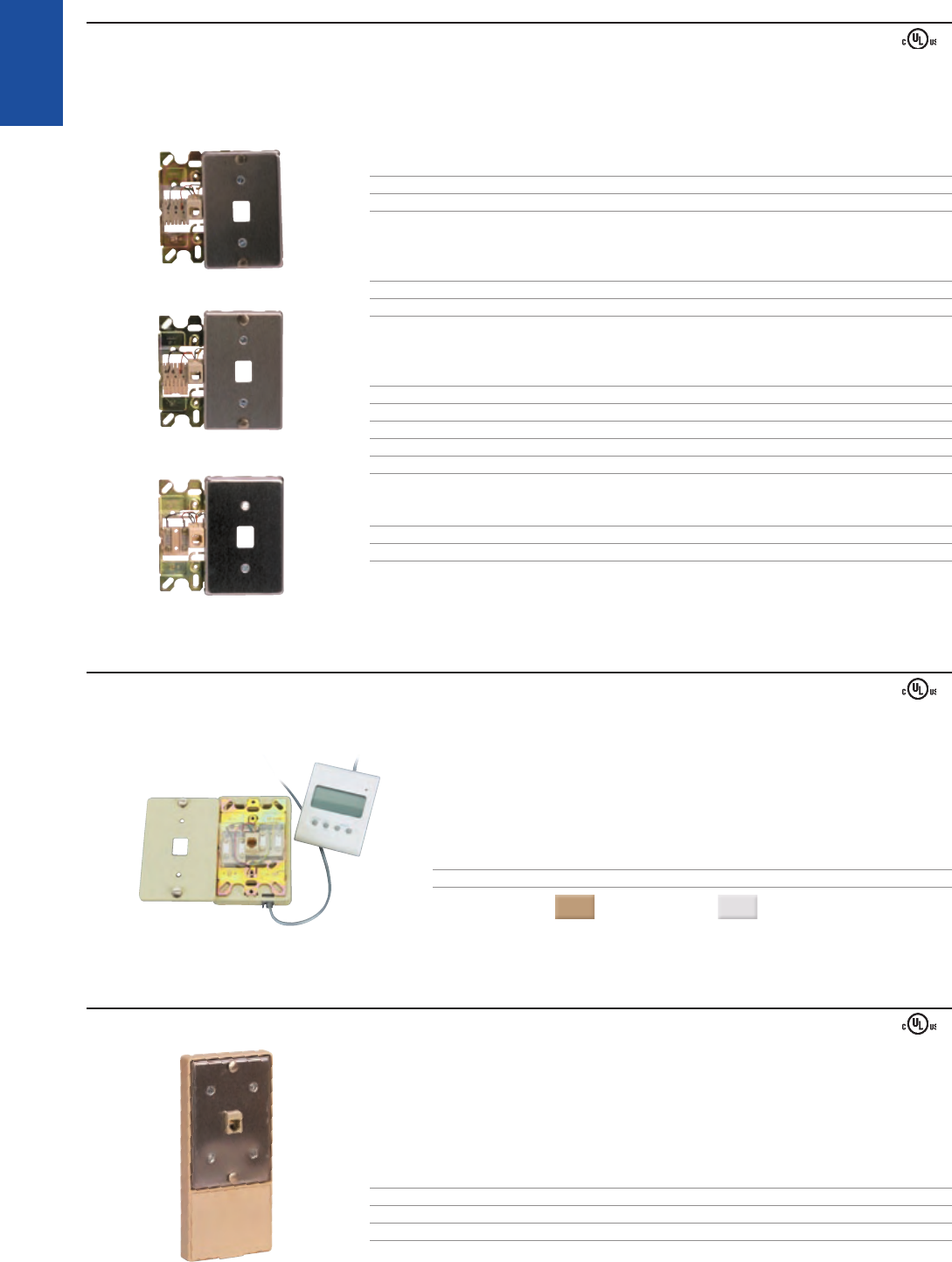
CALLER ID WALL MOUNT JACK ASSEMBLIES
Suttle’s 630CI wall - mount jack assembly is designed for the connection of Caller ID display modules. The user’s Caller ID module is plugged into the 630CI base for connection. In
addition to Caller ID boxes, this can also be used with any ancillary device with a plug - ended line cord such as answering machines and auto dialers.
Thermoplastic faceplate allows for two mounting options:
• Mounting lugs for wall telephones
• Color - keyed inserts for desk telephones
Riser plate
Jack is wired directly to terminal screws of the 630AC4
PART# DESCRIPTION WIRING
630CI - xx 4 - conductor, screw terminal, mounting lugs, riser plate USOC
COLORS
( - xx): Electrical Ivory = (52) White = (85)
Caller ID module not included (pictured)
■
■
■
MODULAR WALL - IN - STALL JACKS
Suttle wall - in - stall jacks provide an extra modular jack when installing a wall phone.
Adapter easily installs over most wall phone jacks
No new wiring or disassembly of the telephone is necessary
Extra modular jack for connecting answering machines, recording devices, automatic dialer,
and other phone accessories requiring a modular jack
Equipped with mounting lugs
PART# DESCRIPTION LABEL WIRING
631A One jack wired parallel for extension phones USOC
632A Two jacks wired for series connection LINE and PHONE USOC
■
■
■
■
16
625C4 - xx
625A4 - xx
625AS4 - xxRC
625AS4NS - xxRC
103A8 - xx
TRADITIONAL
TELEPHONY
STRUCTURED WIRING FIBERDSLSOHO ACCESS™ USOC WIRING GUIDE GLOSSARY INDEX
SURFACE MOUNT JACK ASSEMBLIES > SCREW ON COVER
Available in both standard (dry) and CorroShield (gelled) versions.
Captive retaining screw keeps the cover securely fastened, preventing damage to the assembly
110 IDC or filled splice connector terminations eliminate stripping and wrapping of wires
Threaded brass screw inserts and washered screw terminals increase reliability and provide positive long - lasting connections
Designed for mounting on baseboards, walls, or other flat surfaces
103 & 104 jacks include double - sided adhesive pad
SIMPLEX
PART# DESCRIPTION CORROSHIELD WIRING
625C4 - xx 4 - conductor, spade terminals, cover only, USOC
used with 020031 - 50 block
625C4 - xxRC 4 - conductor, spade terminals, cover only, USOC
used with 020031 - 50 block CorroShield USOC
COLORS
( - xx): Ivory = (50) Electrical Ivory = (52) White = (85)
PART# DESCRIPTION CORROSHIELD WIRING
625A4 - xx 4 - conductor, screw terminals USOC
625A4 - xxRC 4 - conductor, screw terminals CorroShield USOC
625A6 - xx 6 - conductor, screw terminals USOC
625A6 - xxRC 6 - conductor, screw terminals CorroShield USOC
COLORS
( - xx): Ivory = (50) Electrical Ivory = (52) White = (85)
PART# DESCRIPTION CORROSHIELD WIRING
625AS4 - xxRC 4 - conductor, screw terminals CorroShield USOC
COLORS
( - xx): Ivory = (50) Electrical Ivory = (52) White = (85)
PART# DESCRIPTION CORROSHIELD WIRING
625AS4NS - xxRC 4 - conductor, filled splice connectors CorroShield USOC
625AS6NS - xxRC 6 - conductor, filled splice connectors CorroShield USOC
COLORS
( - xx): Ivory = (50) Electrical Ivory = (52) White = (85)
PART# DESCRIPTION WIRING
103A4 - 50 4 - conductor, 110 IDC terminals USOC
103A6 - xx 6 - conductor, 110 IDC terminals USOC
103A8 - xx 8 - conductor, 110 IDC terminals 568B
103AY8 - xx 8 - conductor, 110 IDC terminals USOC
COLORS
( - xx): Electrical Ivory = (52) White = (85)
Includes double - sided adhesive pad
Ú
■
■
■
■
■
17
625C2 - 4 - xx
104C8 - xx
104A4NS - xxRC
625A2 - 4 - xx
625A2 - 4NS - xxRC
TRADITIONAL
TELEPHONY
1-800-852-8662 WWW.SUTTLEONLINE.COM
DUPLEX
PART# DESCRIPTION WIRING
625C2A - 4 - xx 2/2 conductor, spade tipped leads. Cover with 020031 - 50 block USOC
625C2 - 4 - xx 2/2 conductor, spade tipped leads – cover only, requires 020031 - 50 block USOC
COLORS
( - xx): Ivory = (50) Electrical Ivory = (52) White = (85)
PART# DESCRIPTION LABEL WIRING
104A4 - xx 4/4 conductor, 110 IDC terminals LINE 1/LINE 2 USOC
104B4 - 50 4/4 conductor, 110 IDC terminals VOICE/VOICE USOC
104A6 - xx 6/6 conductor, 110 IDC terminals LINE 1/LINE 2 USOC
104B6 - xx 6/6 conductor, 110 IDC terminals VOICE/VOICE USOC
104A8 - xx 8/8 conductor, 110 IDC terminals, non - keyed LINE 1/LINE 2 568B
104AY8 - 52 8/8 conductor, 110 IDC terminals, non - keyed LINE 1/LINE 2 USOC
104B8 - xx 8/8 conductor, 110 IDC terminals, keyed/non - keyed VOICE/DATA 568B
104BY8 - xx 8/8 conductor, 110 IDC terminals, keyed/non - keyed VOICE/DATA USOC
104C8 - xx 8/8 conductor, 110 IDC terminals, keyed DATA/DATA 568B
COLORS
( - xx): Ivory = (50) Electrical Ivory = (52) White = (85)
Includes double - sided adhesive pad
PART# DESCRIPTION CORROSHIELD LABEL WIRING
104A4NS - xxRC 4/4 Conductor, filled splice connectors CorroShield 1 / 2 USOC
COLORS
( - xx): Electrical Ivory = (52) White = (85)
Includes double - sided adhesive pad
SNAP - ON COVER, FACTORY WIRED
Available in both standard (dry) and CorroShield (gelled) versions.
Snap - on cover and factory wired for quick installation
Double - sided adhesive pad included for versatile mounting options
Available with USOC RJ48X/RJ31X wiring for security alarm or life - line applications
PART# DESCRIPTION CORROSHIELD WIRING
625A2 - 4 - xx 4 - conductor, screw terminals USOC
625A2 - 4 - xxRC 4 - conductor, screw terminals CorroShield USOC
625A2 - 4NS - xxRC 4 - conductor, filled splice connectors CorroShield USOC
625A2 - 6 - xx 6 - conductor, screw terminals USOC
625A2 - 6 - xxRC 6 - conductor, screw terminals CorroShield USOC
625A2 - 6NS - xxRC 6 - conductor, filled splice connectors CorroShield USOC
COLORS
( - xx): Ivory = (50) Electrical Ivory = (52) White = (85)
PART# DESCRIPTION WIRING
625A28NKxx 8 - conductor, screw terminals, non - keyed USOC
625A28K - xx 8 - conductor, screw terminals, keyed USOC
625A28SBxx 8 - conductor, screw terminals, non - keyed RJ31X shorting bar (1&4, 5&8)
625A28KRxx 8 - conductor, screw terminals, keyed programming resistors
625A28NK - 2 - xx 8 - conductor, screw terminals, non - keyed RJ48X shorting bar (1&4, 2&5)
625A28K - 2 - xx 8 - conductor, screw terminals, keyed RJ48X shorting bar (1&4, 2&5)
COLORS
( - xx): Ivory = (50) Electrical Ivory = (52)
■
■
■
18
635A - 48 635B - 48 635D - 48
625T4 - 52
625SA4 - xx
625SANS4 - xxRC
404M - 50
TRADITIONAL
TELEPHONY
STRUCTURED WIRING FIBERDSLSOHO ACCESS™ USOC WIRING GUIDE GLOSSARY INDEX
SCREW-ON COVER, FACTORY WIRED
The 635 Series is designed for series connection of alarm reporting devices or ancillary equipment.
Screw on cover for secure fastening and damage protection
Blocks are factory wired to a screw terminal board
Mounting available via double - sided adhesive pad (included) or with wood screws (not included)
PART# DESCRIPTION LABEL WIRING
635A - 48 8 - conductor, non - keyed VOICE RJ31X shorting bar (1&4, 5&8)
635B - 48 6/8 conductor duplex, non - keyed VOICE/VOICE RJ31X shorting bar (1&4, 5&8)/ USOC
635D - 48 6/6 conductor duplex, non - keyed VOICE/VOICE USOC/USOC
COLOR
: Gray
■
■
■
SWINGER DOOR SURFACE MOUNT
Available in both standard (dry) and CorroShield (gelled) versions.
Thermoplastic cover
Sealed jack cavity
Notched, spring - loaded, rotating access cover provides contamination protection
(for added protection see CorroShield versions)
PART# DESCRIPTION WIRING
625T4 - 52 4 - conductor, spade tipped leads, cover only, for use with 020031 - 50 block USOC
COLOR
: Electrical Ivory
PART# DESCRIPTION WIRING
625S4 - 50 4 - conductor, screw terminals, includes 020031 - 50 block USOC
COLOR
: Ivory
PART# DESCRIPTION CORROSHIELD WIRING
625SA4 - xx 4 - conductor, screw terminals USOC
625SA4 - xxRC 4 - conductor, screw terminals CorroShield USOC
625SA6 - xx 6 - conductor, screw terminals USOC
625SA6 - xxRC 6 - conductor, screw terminals CorroShield USOC
COLORS
( - xx): Ivory = (50) Electrical Ivory = (52) White = (85)
PART# DESCRIPTION CORROSHIELD WIRING
625SANS4 - xxRC 4 - conductor, filled splice connectors CorroShield USOC
625SANS6 - xxRC 6 - conductor, filled splice connectors CorroShield USOC
COLORS
( - xx): Ivory = (50) Electrical Ivory = (52) White = (85)
■
■
■
BASEBOARD SURFACE MOUNT
Compact size and low profile to fit narrow baseboards
Outward facing jack opening for easy access
Provided with wood screws for baseboard mounting
PART# DESCRIPTION WIRING
404M - 50 4 - conductor, screw terminals USOC
COLOR
: Ivory
■
■
■
19
VOICE
VOICE
VOICE
BEDROOM OFFICELIVING ROOM
LINE 1
COMPANY B
LINE 1
COMPANY B
COAX
IN
EMTA/VOICE MODEM
NID
Switch Jack
Location
VOICE
OFFICE
VOICE
BEDROOM
VOICE
LIVING ROOM
COAX
IN
EMTA/VOICE MODEM
EXISTING
SERVICE Inline Switch
or
Switch NID
Location
DISTRIBUTION
DEVICE
LINE 1
COMPANY B
LINE 1
COMPANY B
LINE 1
COMPANY B
2 - 1001S - xx
630S2 - 12 - 52
TRADITIONAL
TELEPHONY
1-800-852-8662 WWW.SUTTLEONLINE.COM
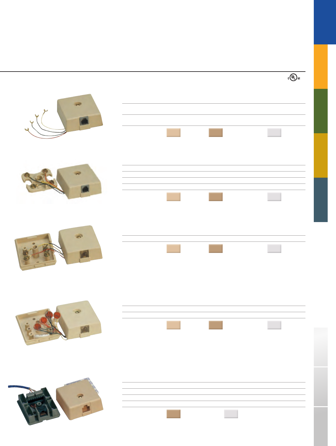
The line of Suttle Dual Provider Switch Products is designed for an alternate service provider to distribute voice service through a home’s existing wiring.
This customer controlled switch is available in five different variations for maximum versatility.
DUAL PROVIDER SWITCH PRODUCTS❚
WALL MOUNT SWITCH JACKS
PART# DESCRIPTION
630S1 - 52 Single line switch jack, 2 - conductor, screw terminals, filled splice connectors
630S2 - 52 Dual line switch jack, 4 - conductor, screw terminals, filled splice connectors
630S1 - 12 - 52 Single line switch jack, 2 - conductor, screw terminals, filled splice connectors,
w/ dedicated auxiliary jack
630S2 - 12 - 52 Dual line switch jack, 4 - conductor, screw terminals, filled splice connectors,
w/ dedicated auxiliary jack
COLOR
: Electrical Ivory
FLUSH MOUNT SWITCH JACKS
PART# DESCRIPTION
2 - 3001S - xx Dual line simplex switch jack, 4 - conductor, screw terminals, filled splice connectors
2 - 1001S - xx Duplex switch jack, 4/4 - conductor, screw terminals, filled splice connectors
COLORS
( - xx): Electrical Ivory = (52) White = (85)
Suttle’s Dual Provider Switch NID and Switch Jack products enable competitive digital voice installations without disrupting incumbent equipment or requiring
new cabling inside the premisess. A range of form factors support the multiple installation scenarios found in both existing homes and new construction.
Reduces service truck rolls
Eliminates further jack rewiring
Customizable name/logo branding available (call for minimum ordering quantities)
■
■
■
APPLICATIONSÚ
20
625S2SM - xx
625ILS - 52
650S2 - SB - 48
41A - 50
42A - 50
TRADITIONAL
TELEPHONY
STRUCTURED WIRING FIBERDSLSOHO ACCESS™ USOC WIRING GUIDE GLOSSARY INDEX
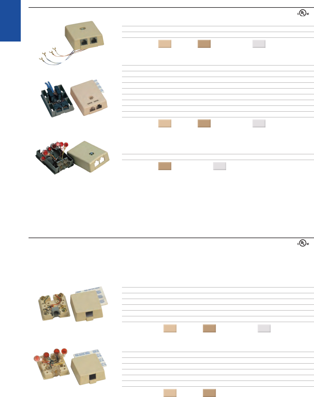
➥NEW SURFACE MOUNT SWITCH JACKS
PART# DESCRIPTION
625S2SM - xx Dual line duplex switched jack, 4/4 - conductor, screw terminals, filled splice connectors
COLORS
( - xx): Ivory = (50) Electrical Ivory = (52) White = (85)
INLINE SWITCH
PART# DESCRIPTION
625ILS - 52 Dual line inline switch, 12 inch flying leads, filled splice connectors
COLOR
: Electrical Ivory
SWITCH NID
PART# DESCRIPTION
650S1 - 48 Single line (indoor/outdoor), screw terminals, grease filled switches
650S2 - 48 Dual line (indoor/outdoor), screw terminals, grease filled switches
650S1 - SB - 48 Single line with RJ31X interface (indoor only), screw terminals, grease filled switches
650S2 - SB - 48 Dual line with RJ31X interface (indoor only), screw terminals, grease filled switches
COLOR
: Gray
41A CONNECTING BLOCKS
Durable plastic molding
Hinged snap - lock cover connected to base for easy access
PART# DESCRIPTION WIRING
41A - 50 4 terminating posts, hinged snap - lock cover USOC
41B - 50 6 terminating posts, hinged snap - lock cover USOC
COLOR
: Ivory
■
■
42A CONNECTING BLOCKS
Separate base and cover
Cover includes captive retaining screw to securely fasten to the assembly
Plastic base contains molded brass inserts
PART# DESCRIPTION WIRING
42A - 50 4 terminating posts, includes screw - on cover USOC
020031 - 50 4 terminating posts, block only USOC
COLOR
: Ivory
■
■
■
CONNECTING BLOCKS❚
21
97B - 48
97D - 48
630TNI - 2 - xxRC
631NTB - 2 - xxRC
634NTB - xxRC
305A
TRADITIONAL
TELEPHONY
1-800-852-8662 WWW.SUTTLEONLINE.COM
DATA CONNECTING BLOCKS
Provides access to the telephone network by registered voice and data equipment and allows on - site programming of appropriate loop loss or resistance on the line.
Factory wired, binding screw terminals on the printed circuit board provide long - term strain resistant connections
Screw on cover for secure fastening and damage protection
Double - sided adhesive pad provided for versatile mounting options
PART# DESCRIPTION LABEL WIRING
97B - 48 8 - conductor, programmable, keyed. DATA USOC
Includes eight programming resistors allowing
on - site programming of appropriate loop loss.
97D - 48 8/6 conductor, duplex, non - keyed/N.A. Provides VOICE/DATA RJ31X
connection of registered permissive data equipment
shorting bar
and registered exclusion key telephone sets. (1&4, 5&8)
COLOR
: Gray
■
■
■
INDOOR NETWORK TERMINATION BLOCKS
PART# DESCRIPTION CORROSHIELD
630TNI - 2 - xxRC Wall - mount network termination block, indoor, single - gang, CorroShield
2 line, test port for each line, 1 auxiliary jack,
PART# DESCRIPTION CORROSHIELD
631NTB - 2 - xxRC Network termination block, indoor, single - gang, CorroShield
2 line, test port for each line
PART# DESCRIPTION CORROSHIELD
634NTB - xxRC Network termination block, indoor, oversized double - gang, CorroShield
4 line, test port for each line
COLOR
: Electrical Ivory = (52) White = (85)
305 TERMINAL BLOCK
The 305 block provides modular access to a wire entry point, or as an unprotected premisess network interface.
Allows multiple station runs from a service entry point
Flame - retardant thermoplastic
Captive retaining screw keeps the cover securely fastened
PART# DESCRIPTION WIRING
305A Two line without modular jack USOC
305C Two line with modular jack disconnect USOC
COLOR
: Ivory
■
■
■
22
19316L7 - 4
16152L8E - 4
105AF - xx
106BFD - xx 625B3EF450
TRADITIONAL
TELEPHONY
STRUCTURED WIRING FIBERDSLSOHO ACCESS™ USOC WIRING GUIDE GLOSSARY INDEX
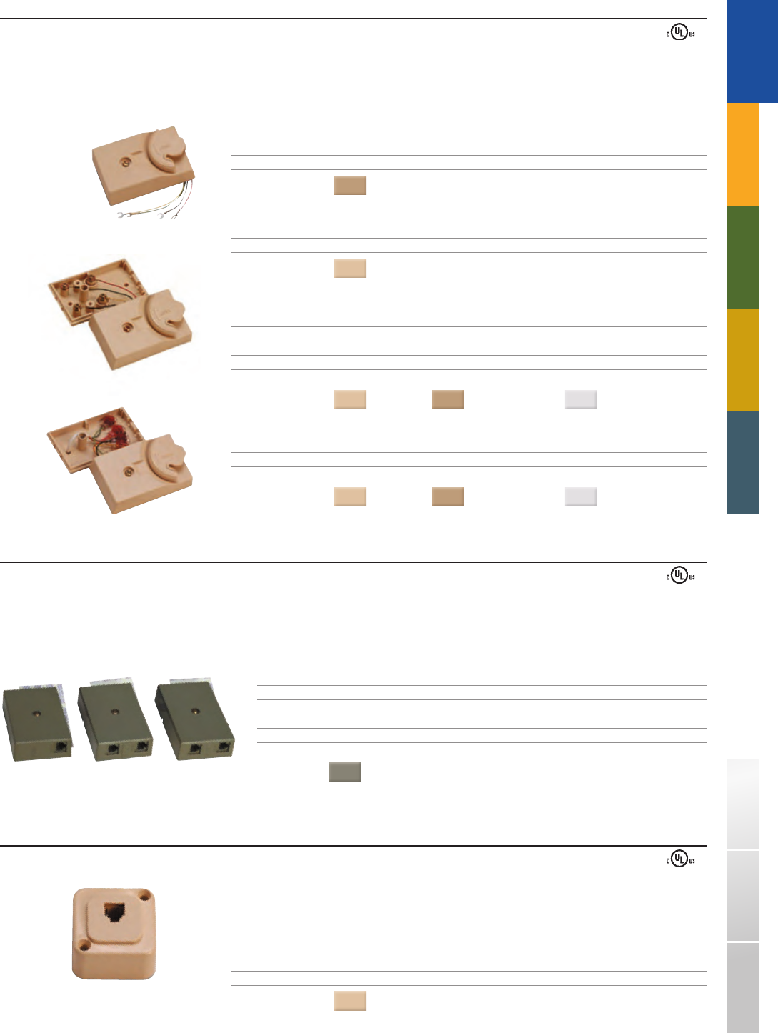
OUTDOOR JACK ASSEMBLIES
SURFACE MOUNT BOX/JACKS
Removable mounting tabs
Station wire entrance coupling contains neoprene bushing for added protection.
Wire entrance available from top, bottom, or either side
Conduit or pipe entrance can be made by removing the 1/2 inch threaded pipe nipple
Housing is die cast aluminum with corrosion resistant finish
PART# DESCRIPTION CORROSHIELD WIRING
19316L7 - 4 4 - conductor, screw terminals USOC
19316L7 - 4NS - RC 4 - conductor, filled splice connectors CorroShield USOC
19316L7E - 4 4 - conductor, screw terminals, trap door USOC
19316L7 - 6 6 - conductor, screw terminals USOC
STAR19316 1 - port, designed for use w/SpeedStar modular connector (not included)
19316 - L4 Surface mount outdoor box and cover assembly only
Ú
■
■
■
■
FLUSH MOUNT OUTDOOR JACKS
Neoprene rubber gasket provides water - resistant seal on masonry, wood, or uneven surfaces
Faceplate is constructed of aluminum with baked enamel finish
PART# DESCRIPTION WIRING
16152L7 - 4 4 - conductor, screw terminals, includes outlet box USOC
16152L7E - 4 4 - conductor, screw terminals, trap door, includes outlet box USOC
16152L7 - 6 6 - conductor, screw terminals, includes outlet box USOC
16152L8 - 4 4 - conductor, screw terminals, no outlet box USOC
16152L8E - 4 4 - conductor, screw terminals, trap door, no outlet box USOC
STAR16152 1 - port, designed for use w/SpeedStar connector (not included)
16152 - L5 Cover assembly only
■
■
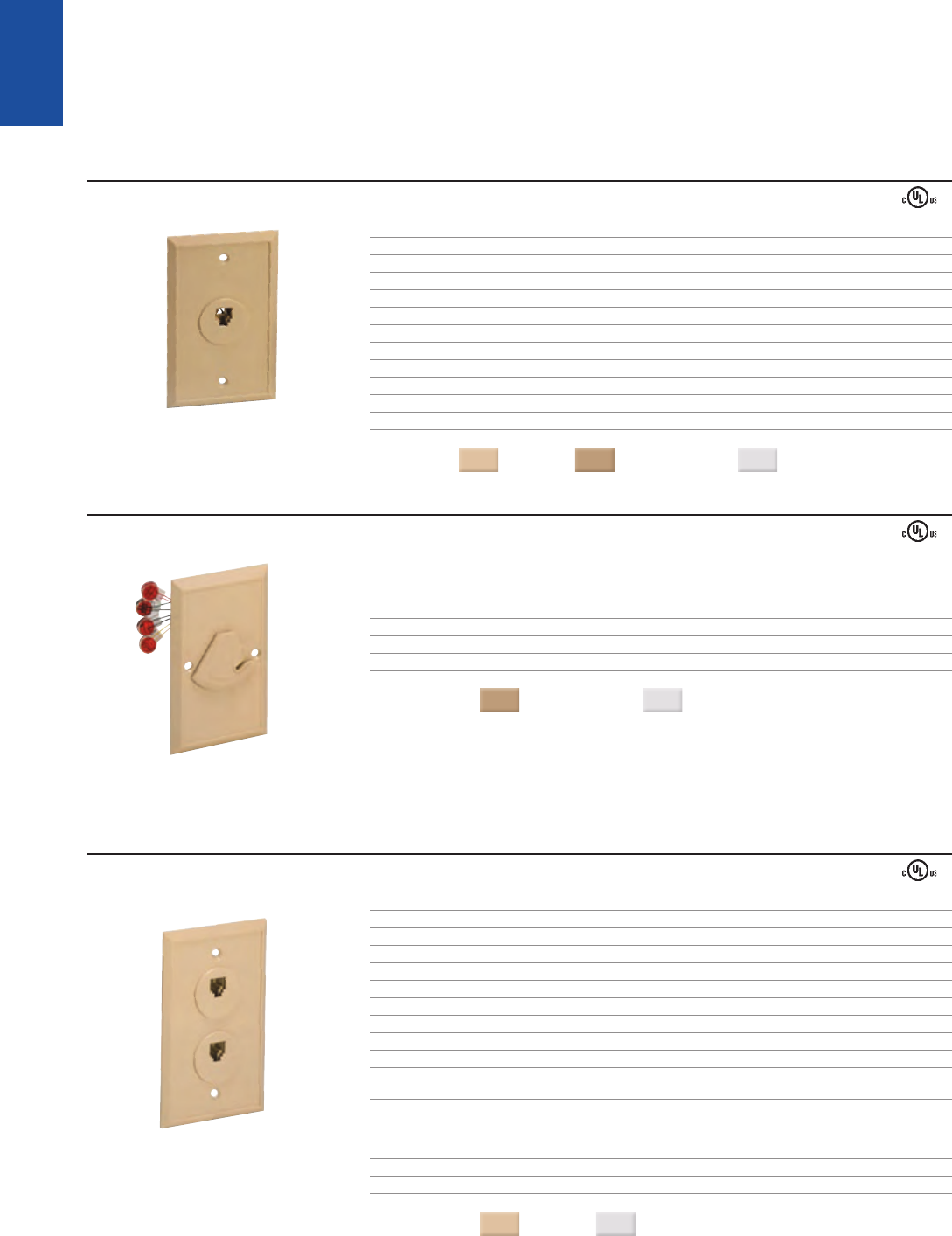
FLOOR JACKS
Suttle’s series of simplex and duplex floor jacks allows mounting in standard outlet boxes and tombstone - style outlets for under carpet cabling and mounting in
overhead raceway. Color matched 860 faceplates must be ordered separately.
Screw or 110 Type terminations available
Simplex or Duplex
SIMPLEX FLOOR JACKS
PART# DESCRIPTION WIRING
105AF - xx 8 - conductor, 110 IDC terminals, non - keyed 568B
COLORS
( - xx): Ivory = (50) Electrical Ivory = (52)
Ú
■
■
DUPLEX FLOOR JACKS
PART# DESCRIPTION LABEL WIRING
106AFD - xx 8 - /8 - conductor, 110 IDC terminals, non - keyed LINE 1/LINE 2 568B
106BFD - xx 8/8 - conductor, 110 IDC terminals, non - keyed/keyed VOICE/DATA 568B
106BFDY - xx 8/8 - conductor, 110 IDC terminals, non - keyed/keyed VOICE/DATA USOC
COLORS
( - xx): Ivory = (50) Electrical Ivory = (52) White = (85)
PART# DESCRIPTION WIRING
625B3EF450 4/4 - conductor, screw terminals, trap door USOC
COLOR
: Ivory
23
19A - 50 19C - 50
19D - 50 19E - 50
19X - 50 19Y - 50
19BP1 - 50
860B - xx
65B - 50
860A - xx
43A 43B
43C 43U
16A - xx 16D - xx
TRADITIONAL
TELEPHONY
1-800-852-8662 WWW.SUTTLEONLINE.COM
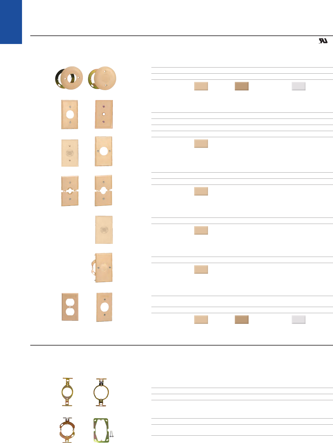
TRADITIONAL TELCO FACEPLATES
Flame - resistant thermoplastic
All are provided with mounting screws
PART# DESCRIPTION
16A - xx Round faceplate for 625F jacks, includes mounting ring
16D - xx Covers unused pre - wired junction boxes
COLORS
( - xx): Ivory = (50) Electrical Ivory = (52) White = (85)
PART# DESCRIPTION
19A - 50 Faceplate for 625F jacks/43A brackets, 2 3/8" mounting center
19C - 50 Faceplate for hard - wired telephone sets, 2 3/8" mounting center
19D - 50 Cover for unused pre - wire boxes, 2 3/8" mounting center
19E - 50 Faceplate for 625F jacks/43C brackets, 1 1/8" mounting center
COLOR
: Ivory
PART# DESCRIPTION
19X - 50 Faceplate for 25 pair inside wiring cable, 2 3/8" mounting center
19Y - 50 Faceplate for 50, 75, and 100 Pair inside wiring cable, 2 3/8" mounting center
COLOR
: Ivory
PART# DESCRIPTION
19BP1 - 50 Cover for unused pre - wire boxes, 3 9/32" mounting center
COLOR
: Ivory
PART# DESCRIPTION
65B - 50 Faceplate kit includes 43C mounting bracket, 3 sets of mounting screws
COLOR
: Ivory
PART# DESCRIPTION
860A - xx Duplex, electrical style faceplate for mounting frame (STAR1064)
and duplex floor jacks
860B - xx Simplex faceplate for simplex floor jacks
COLORS
( - xx): Ivory = (50) Electrical Ivory = (52) White = (85)
■
■
FACEPLATES AND BRACKETS❚
MOUNTING BRACKETS
Designed for flush mounting modular or non - modular jacks with Suttle faceplates, rings, and junction boxes
Heavy gauge steel construction with chromate finish
PART# DESCRIPTION
43A Mounting bracket for 625F type jacks, 2 3/8" faceplate center
43B Mounting bracket for 625F and 102 type jacks, 2 3/8" faceplate center
PART# DESCRIPTION
43C Mounting bracket for 625F type jacks, 1 7/8" faceplate center
43U Mounting bracket (optional) for 2 - 1001, 2 - 2002
and 2 - 3001 type jacks, 3 9/32" faceplate center
■
■
24
625MB 625MBD
STARMBD STARMBDD
147 - 1 147 - 2
102B 100C - 1
700A - 48
TRADITIONAL
TELEPHONY
STRUCTURED WIRING FIBERDSLSOHO ACCESS™ USOC WIRING GUIDE GLOSSARY INDEX
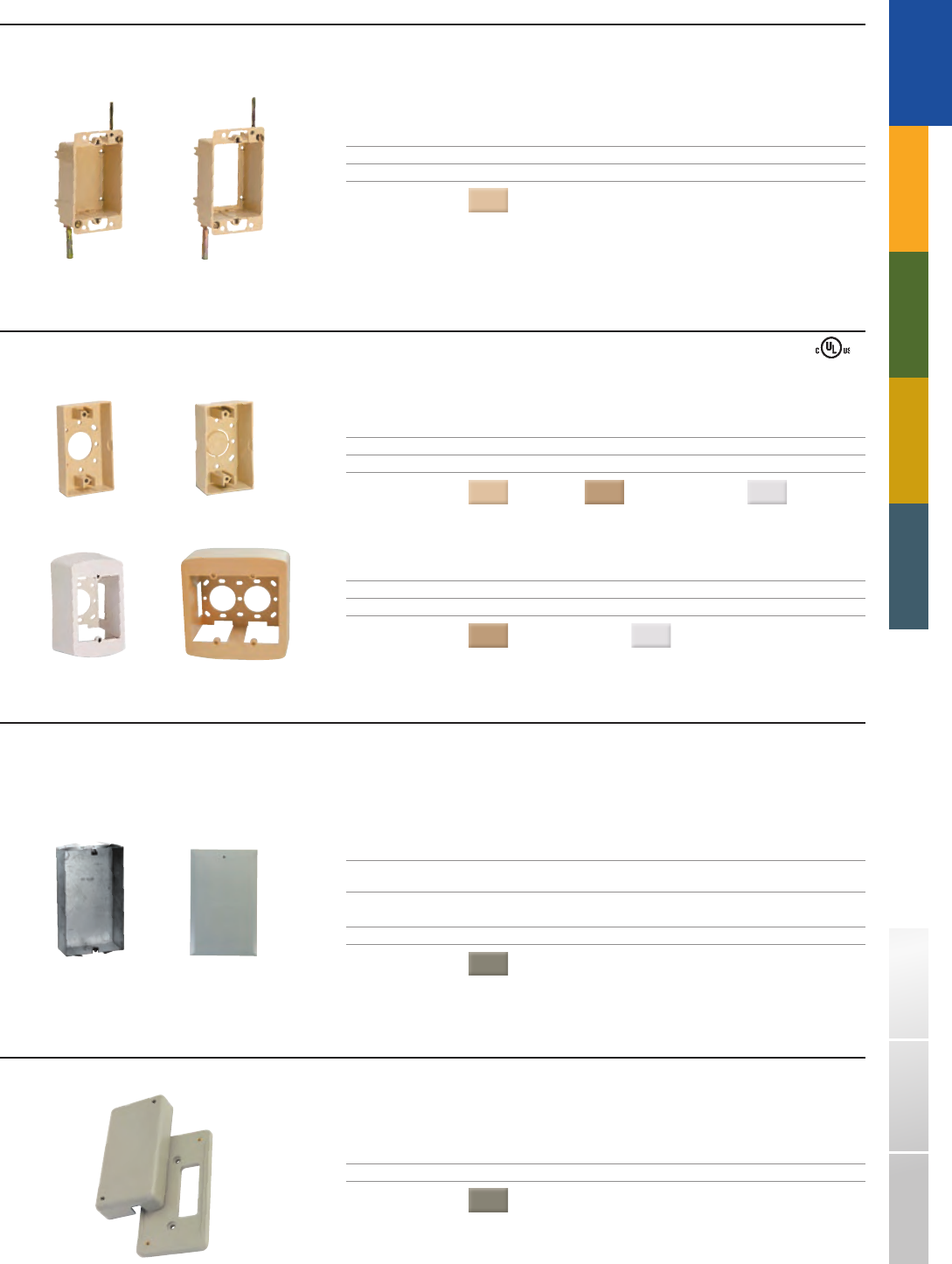
MOUNTING BOXES : FLUSH
Designed for retrofit installation behind finished walls
Rotating clamp arms
PART# DESCRIPTION
147 - 1 Flush mount box, solid back
147 - 2 Flush mount box, open back for added depth
COLOR
: Ivory
■
■
MOUNTING BOXES : SURFACE
Double - sided adhesive pad included for versatile mounting options
PART# DESCRIPTION
625MB - xx Surface mount box, 1" depth
625MBD - xx Surface mount box, 1.5" depth
COLORS
( - xx): Ivory = (50) Electrical Ivory = (52) White = (85)
PART# DESCRIPTION
STARMBD - xx Surface mount box, single gang, 2.25" depth
STARMBDD - xx Surface mount box, dual gang, 2.25" depth
COLORS
( - xx): Electrical Ivory = (52) White = (85)
■
TELEPHONE SERVICE BOX
Designed for use as an indoor demarcation housing
Heavy gauge galvanized sheet metal box (102B) with heavy gauge sheet metal cover with gray baked enamel finish
Conduit knockouts in the top, bottom, and back of the box
Nail holes on each side for mounting on studs
PART# DESCRIPTION DIMENSIONS
102B Telephone service box, compatible for 9.75"H x 5.75"W x 2.5"D
742 & 625TD Network Interface Devices
PART# DESCRIPTION LABEL
100C - 1 Cover for 102B TELEPHONE
COLOR
: Gray
■
■
■
■
700A HOUSING FOR 25 - PAIR CABLES
Designed for floor or wall - mounting, and may be mounted over a standard outlet box
Provides a neat closure for mated plug and connector ends of two 25 - pair connector cables
PART# DESCRIPTION
700A - 48 700A housing for two 25 - pair cables
COLOR
: Gray
■
■
25
159MC - 4
159MC - 8A
267 Series
TRADITIONAL
TELEPHONY
1-800-852-8662 WWW.SUTTLEONLINE.COM
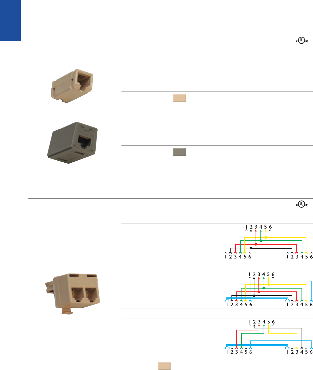
COUPLERS
Used as an in - line device for connecting two modular plug - ended line cords, for extending modular circuits without the hassle and expense of hard - wired connecting blocks.
Flame - resistant thermoplastic
PART# DESCRIPTION
159MC - 4 4 - conductor, coupler, reverse wiring
159MC - 6 6 - conductor, coupler, reverse wiring
COLOR
: Ivory
PART# DESCRIPTION
159MC - 8A 8 - conductor, coupler, straight through wiring
159MC - 8B 8 - conductor, coupler, reverse wiring
COLOR
: Gray
■
ADAPTERS AND COUPLERS❚
MODULAR “T” ADAPTERS
267A6 Similar to 267A4 –
2 additional contacts are wired parallel
to each other in the jack but are not
connected to the 4 conductor plug.
PART# DESCRIPTION DIAGRAM
267A4 “2 for 1" adapter –
designed for connecting two telephones
or equipment to an existing modular jack.
267B Used for connecting two telephones
and/or ancillary devices to separate
outside lines through a single 4 contact
jack wired for termination of two lines.
COLOR
: Ivory
26
267 Series
468A
464
400 Series
TRADITIONAL
TELEPHONY
STRUCTURED WIRING FIBERDSLSOHO ACCESS™ USOC WIRING GUIDE GLOSSARY INDEX
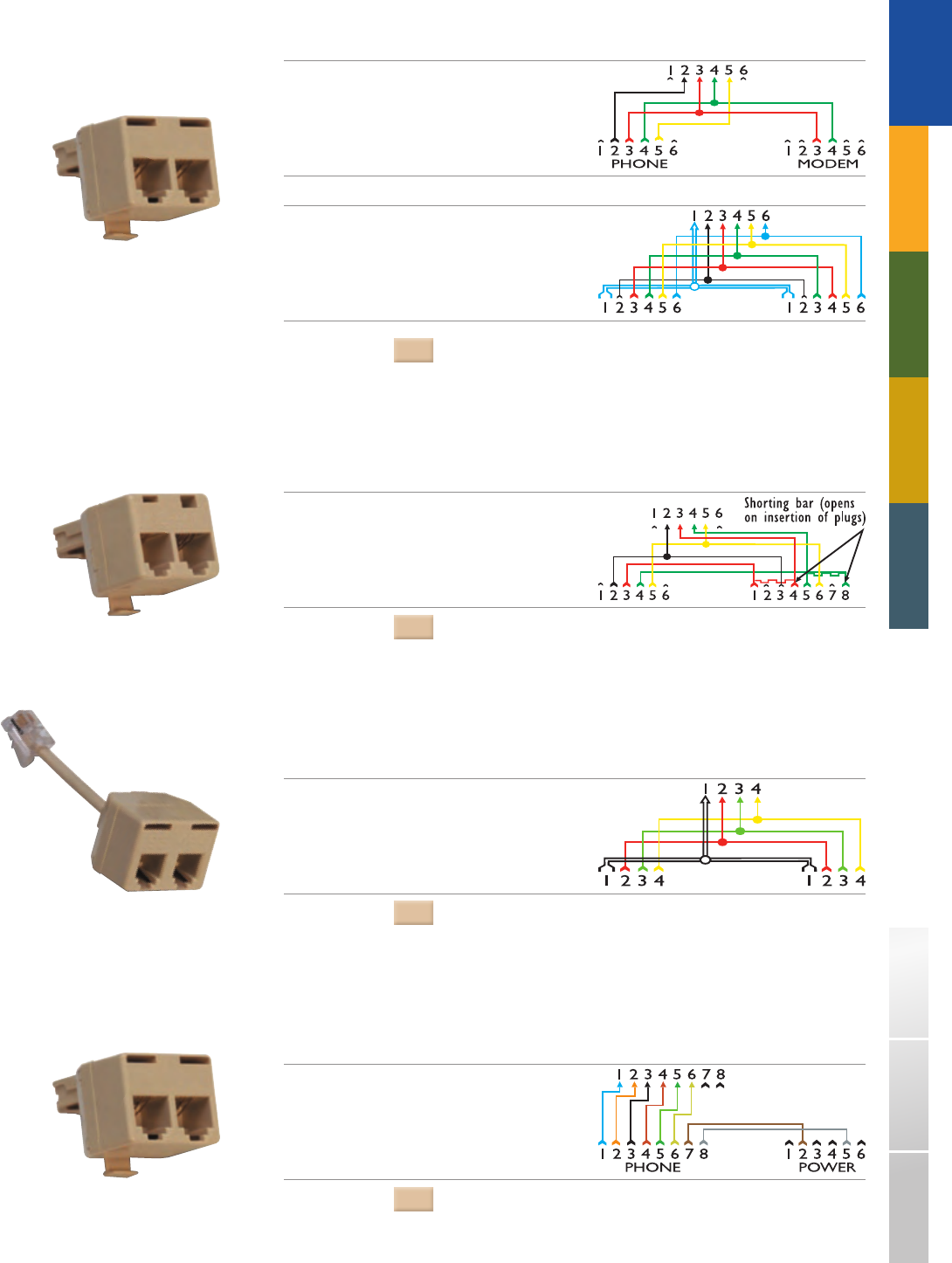
(MODULAR “T” ADAPTERS - CONTINUED)
PART# DESCRIPTION DIAGRAM
267C Ideal for combining voice and data
transmission through a single jack.
Voice labeled: PHONE
Data labeled: MODEM
267E Provides modular connection for
2 - 6 conductor line cords wired
to a 6 conductor modular plug.
COLOR
: Ivory
PART# DESCRIPTION DIAGRAM
468A Designed to permit quick connection
of one telephone and one automatic
dialing device to the same line without
changing existing installation RJ31X.
COLOR
: Ivory
PART# DESCRIPTION DIAGRAM
464 Used for operator training purposes
where two headsets can be plugged
into the 464 for student and instructor
use. Designed to plug into a standard
console headset jack.
COLOR
: Ivory
PART# DESCRIPTION DIAGRAM
400B Provides auxiliary power to telephones.
Labeled: Phone / Power
COLOR
: Ivory
27
400 Series
450A
174
TRADITIONAL
TELEPHONY
1-800-852-8662 WWW.SUTTLEONLINE.COM
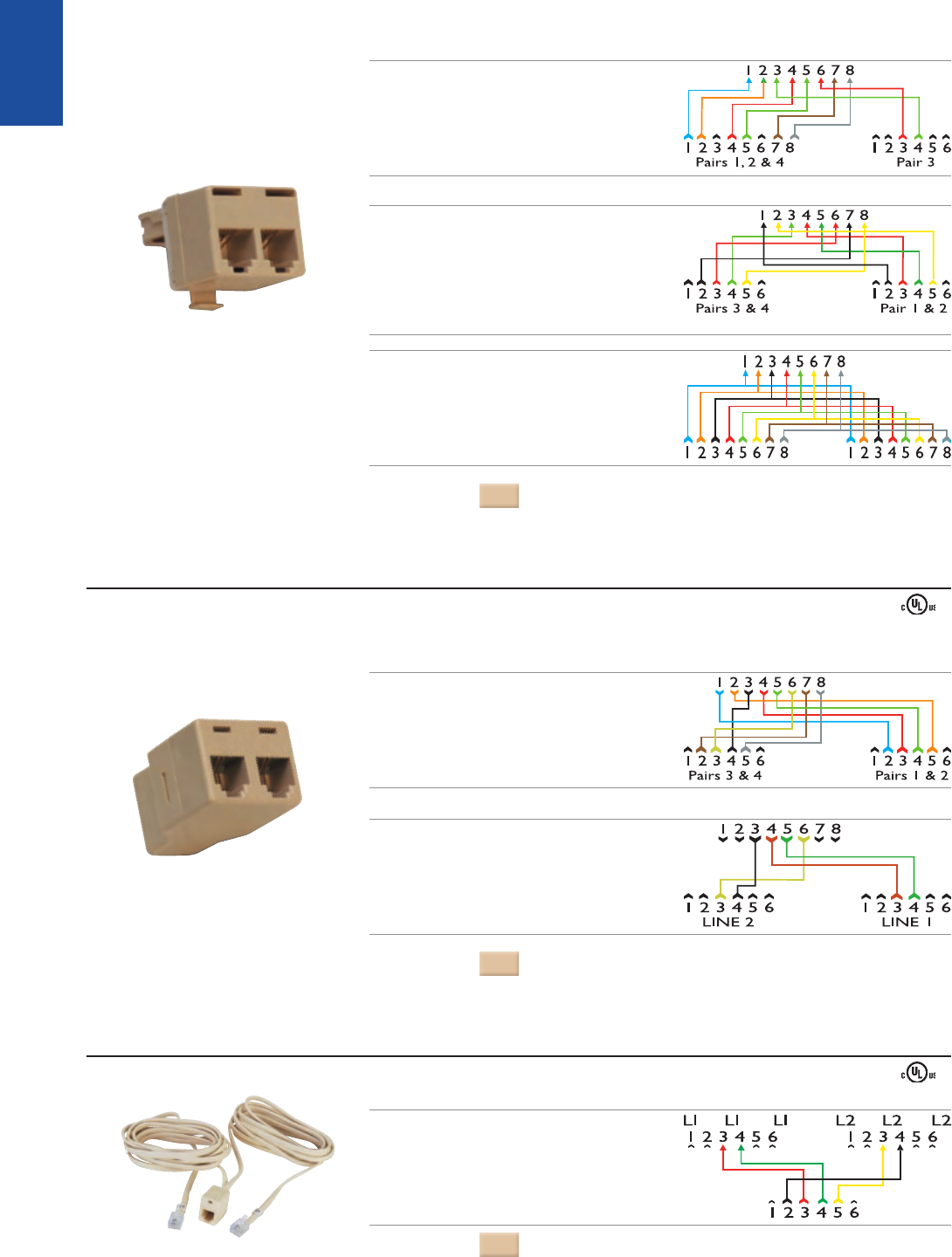
(MODULAR “T” ADAPTERS - CONTINUED)
PART# DESCRIPTION DIAGRAM
400D Allows the spare pair from multi - line
electronic telephone wiring to provide
tip and ring to a single line set
Labeled: Pr. 1, 2 & 4 / Pr. 3
400E Used to split eight conductor premisess
wiring into two four conductor
modular outputs.
Labeled: Pr. 1&2 / Pr. 3&4
400S Two 8 - conductor jacks wired
to a single eight conductor plug.
COLOR
: Ivory
PART# DESCRIPTION DIAGRAM
450A Used to split an 8 - conductor
plug ended cord for output
in two 4 - conductor jacks.
Labeled: Pr. 1&2 / Pr. 3&4
450B Allows a 4 - conductor plug - ended
cord to be output in two 6 - position,
2 - conductor jacks.
Labeled: Line 1 / Line 2
COLOR
: Ivory
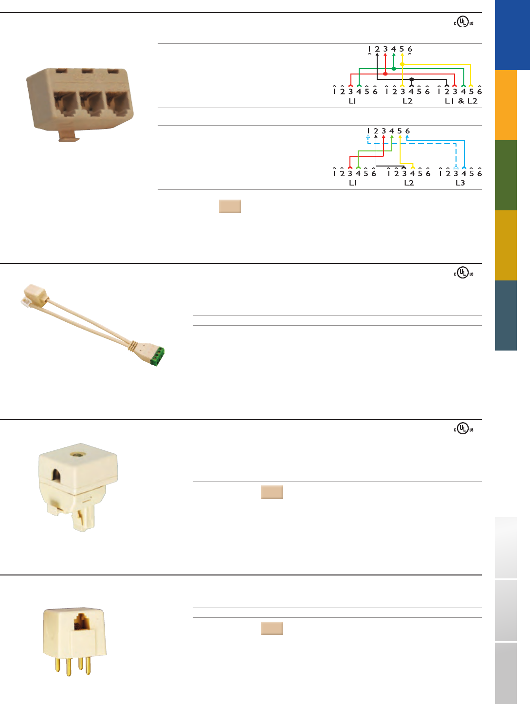
MODULAR “Y” ADAPTERS
One modular jack split to two modular jacks.
PART# DESCRIPTION DIAGRAM
174 Consists of a modular jack and
two plug - ended 6’ line cords.
Labeled: L1 / L2
COLOR
: Ivory
TWO - LINE ADAPTERS
28
173 Series
AIC1
152MRL - 4
283M - 50
TRADITIONAL
TELEPHONY
STRUCTURED WIRING FIBERDSLSOHO ACCESS™ USOC WIRING GUIDE GLOSSARY INDEX
PART# DESCRIPTION DIAGRAM
173 Provides modular plug - in connections
for Line 1, Line 2, Line 1 & 2 respectively.
Allows simultaneous connection of single
line modular telephone sets to Line 1
and Line 2 while the 2 - line circuit may
be extended with a 3rd modular jack.
173A Allows connection of three
single - line phones to a single
modular outlet.
Labeled: L1 / L2 / L3
COLOR
: Ivory
TRIPLEX ADAPTERS
NON MODULAR TO MODULAR RETROFIT ADAPTER
Adapts non - modular ring or spade tipped telephone line cords with modular jacks.
PART# DESCRIPTION
152MRL - 4 Screw terminals to 6 - position, 4 - conductor plug
COLOR
: Ivory
MODULAR TO NON–MODULAR ADAPTER
PART# DESCRIPTION
283M - 50 4 - prong plug to 4 - conductor jack
COLOR
: Ivory
ALARM INTERFACE ADAPTER
Screw terminals to 6 - position, 4 - conductor plug and jack.
PART# DESCRIPTION
AIC1 Screw terminals to 6 - position, 2 - conductor plug and jack
29
153AM - xx
259A
2580A
TRADITIONAL
TELEPHONY
1-800-852-8662 WWW.SUTTLEONLINE.COM
25 - PAIR CABLING ADAPTER
Cabling adapters permit utilization of existing 25 - pair cabling to connect terminal equipment with modular 6 - or 8 - position plugs.
A variety of wiring configurations are available.
Thermoplastic hood
25 - Pair, 50 - pin connector/plug wired to modular jack
4 - AND 6 - CONDUCTOR, 25 - PAIR CABLING ADAPTERS
Wiring Sequence – Color and Pin Number
PART# W (1) BK (2) R (3) G (4) Y (5) BL (6)
153AM - 01 - 27 1 26 2 -
153AM - 02
- 24 48 23 49 -
153AM - 03
- 49 25 50 24
153AM - 05
- 2 26 1 27 -
153AM - 06 25 27 1 26 2 50
COLOR
: Black
Ú
■
■
8 CONDUCTOR, 25 - PAIR CABLING ADAPTERS
Wiring Sequence – Color and Pin Number
PART# BL (1) O (2) BK (3) R (4) G (5) Y (6) BR (7) SL (8)
259A 27 2 28 1 26 3 29 4
259B 31 6 32 5 30 7 33 8
COLOR
: Black
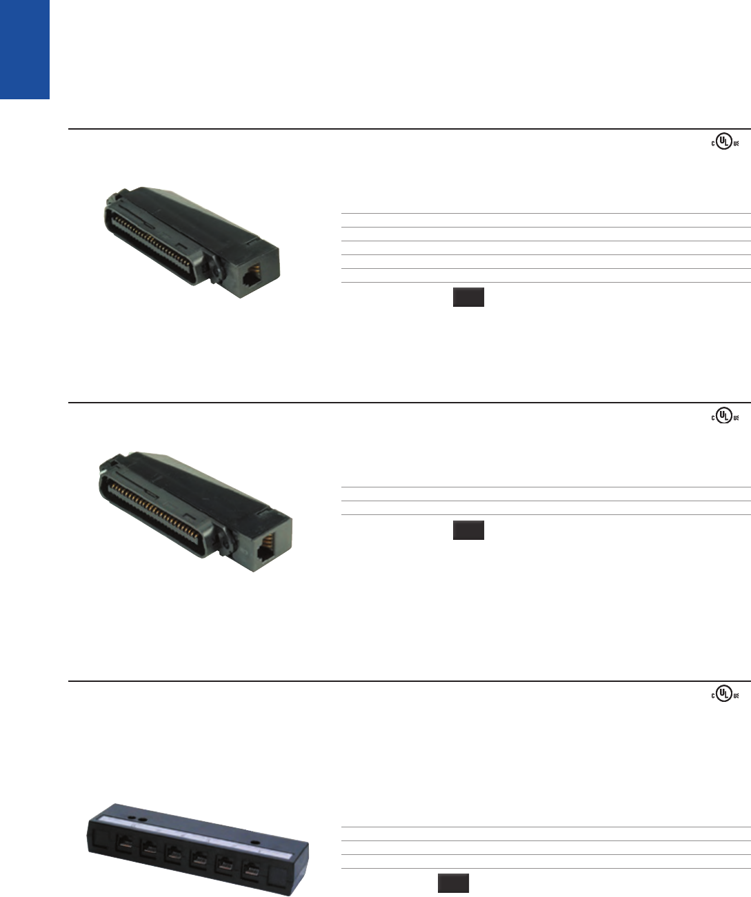
CONNECTORIZED MULTI - LINE ADAPTERS
Connected to 25 - pair cable, these pre - connectorized adapters may be permanently mounted to walls or baseboards
with the double - sided adhesive pad (included), wood screws (not included).
Thermoplastic housing
Label facilitates jack identification and internal wiring info
PART# DESCRIPTION
2580A Six 8 - conductor modular jacks wired to a 25 - pair plug
2560A Eight 6 - conductor modular jacks wired to a 25 - pair plug
2540A Twelve 4 - conductor modular jacks wired to a 25 - pair plug
COLOR
: Black
■
■
30
603NID1 - 660 - 58
305A
742A - xx
TRADITIONAL
TELEPHONY
STRUCTURED WIRING FIBERDSLSOHO ACCESS™ USOC WIRING GUIDE GLOSSARY INDEX
NETWORK INTERFACE DEVICES (NID)❚
603NID1
The 603NID1 Indoor Telephone Network Interface Device is designed for the distribution for up to 6 POTS phone lines to up to 11 phone/voice outlets. This product is ideal for voice
distribution in the MDU (Multi - Dwelling Unit) and single family home environments.
3 Grommeted cable entry/exit points
Can be mounted on standard single gang NEMA junction boxes
Separate access for customer and Telco
RJ31X alarm intercept jack on line 1
110 IDC punchdowns to 11 outlets
RJ11 customer line test ports
Integrated half ringers for remote testing on each line
UL60950 tested and certified
PART# DESCRIPTION
603NID1 - 660 - 58 6 - pair Network Interface Device
COLOR
: White
Note: additional options may be available upon request
■
■
■
■
■
■
■
■
305 TERMINAL BLOCK
The 305 block provides modular access to a wire entry point, or as an unprotected premisess network interface.
Allows multiple station runs from a service entry point
Flame - retardant thermoplastic
Captive retaining screw keeps the cover securely fastened
PART# DESCRIPTION WIRING
305A Two line without modular jack USOC
305C Two line with modular jack disconnect USOC
COLOR
: Ivory
■
■
■
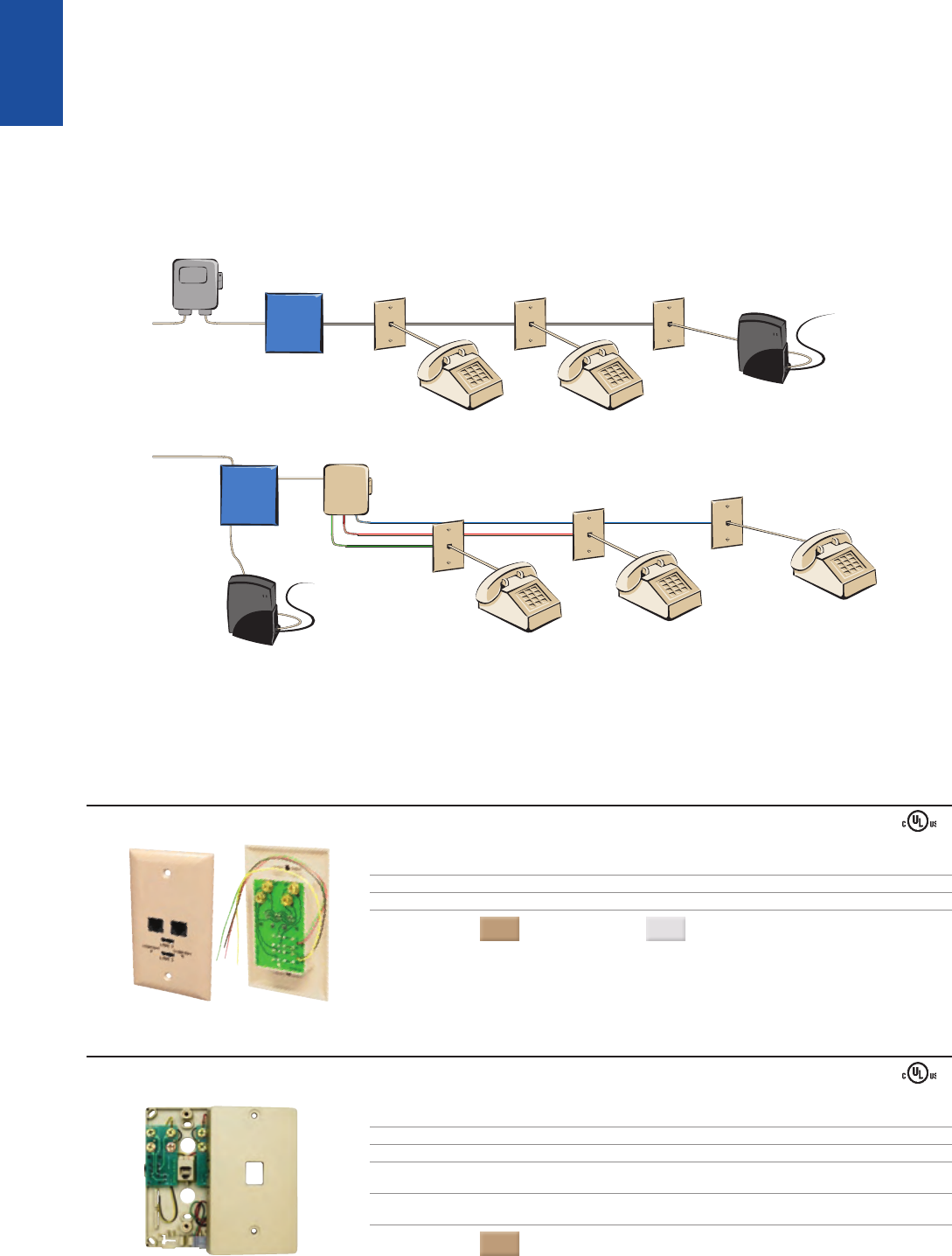
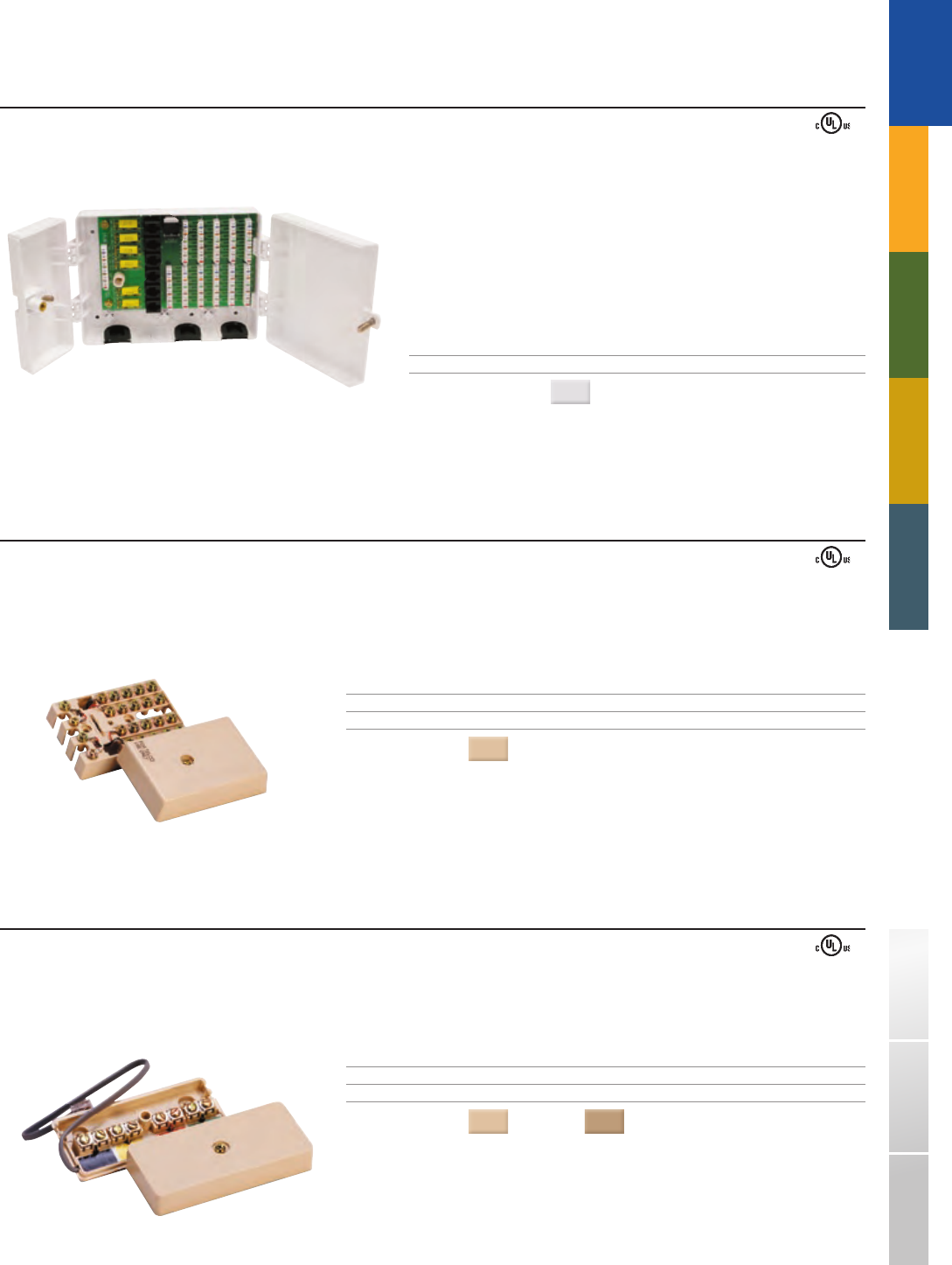
JUNCTION BOX
Allows up to four hardwired, additional extensions and/or accessories to be added to an existing telephone system.
Entrance bridge provides a convenient disconnect point for premisess wiring systems
Color - coded strip facilitates wiring
Break - away entrance tabs for incoming and extension wiring
PART# DESCRIPTION WIRING
742A - xx 4 - conductor, screw terminals, with modular cord USOC
742B - 50 4 - conductor, screw terminals, without modular cord USOC
COLORS
( - xx): Ivory = (50) Electrical Ivory = (52)
■
■
■
31
625TD1 - 50
650S2 - SB - 48
TRADITIONAL
TELEPHONY
1-800-852-8662 WWW.SUTTLEONLINE.COM
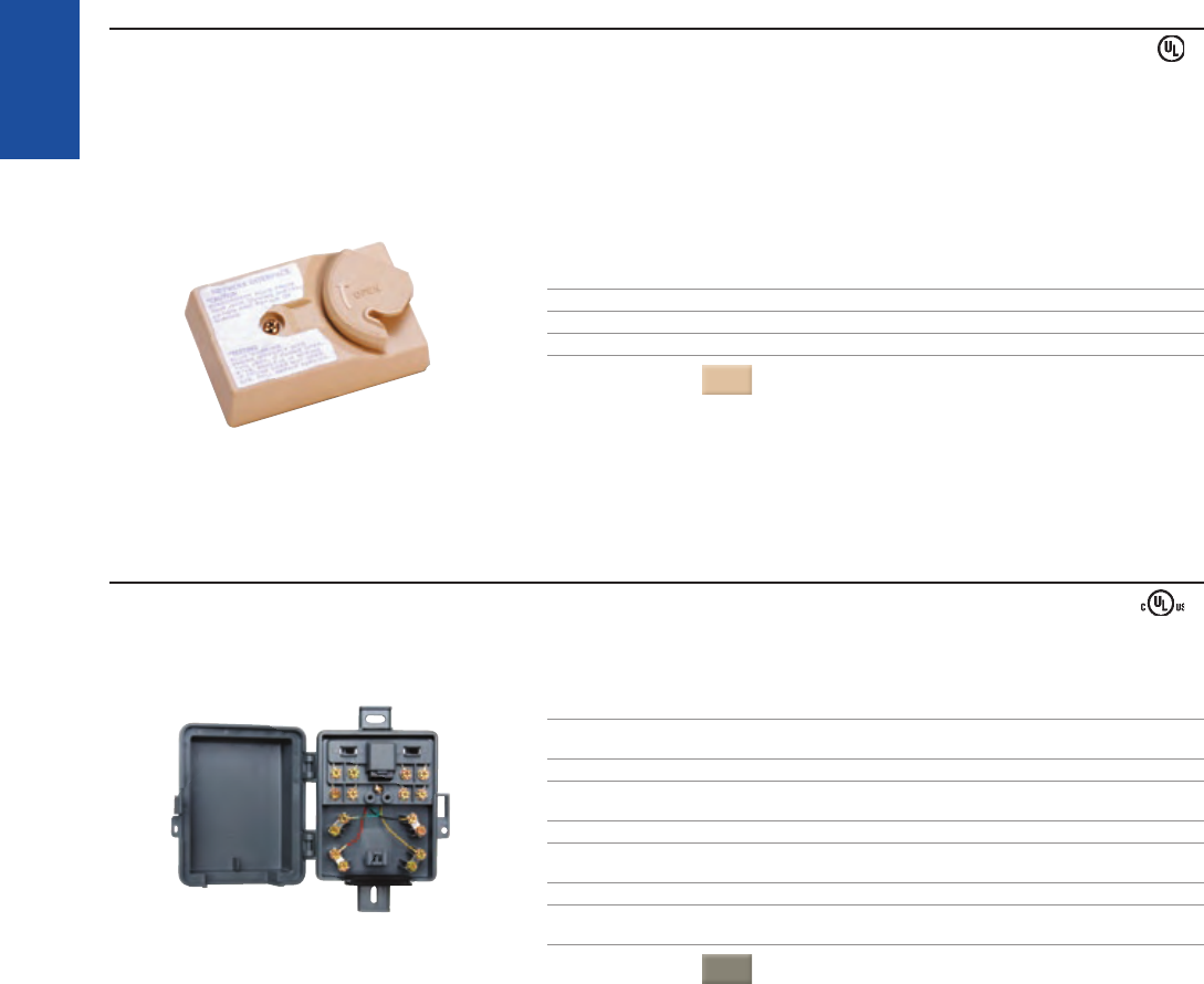
625TD
Provides remote testing
Installs between the leased telephone service and customer owned premisess wiring
Designed for mounting on baseboards or within the 102B telephone service box
Cover label provides instructions for customer connection and testing
Swinger door with enclosed base, reduces contamination and corrosion
Equipped with a line terminating unit (half ringer)
PART# DESCRIPTION WIRING
625TD1 - 50 4 - conductor, screw terminals, single line terminating unit USOC
625TD2 - 50 4 - conductor, screw terminals, two line terminating unit USOC
COLOR
: Ivory
■
■
■
■
■
■
DUAL PROVIDER SWITCH NID
Reduces service truck rolls
Eliminates further rewiring
PART# DESCRIPTION
650S1 - 48 Single line (indoor/outdoor), screw terminals,
grease filled switches
650S2 - 48 Dual line (indoor/outdoor), screw terminals,
grease filled switches
650S1 - SB - 48 Single line with RJ31X interface (indoor only), screw terminals,
grease filled switches
650S2 - SB - 48 Dual line with RJ31X interface (indoor only), screw terminals,
grease filled switches
COLOR
: Gray
■
■
32
1542AM - xx
466S
7200 - 07 - W
7200 - 07 - WRC1
460
TRADITIONAL
TELEPHONY
STRUCTURED WIRING FIBERDSLSOHO ACCESS™ USOC WIRING GUIDE GLOSSARY INDEX
MISCELLANEOUS❚
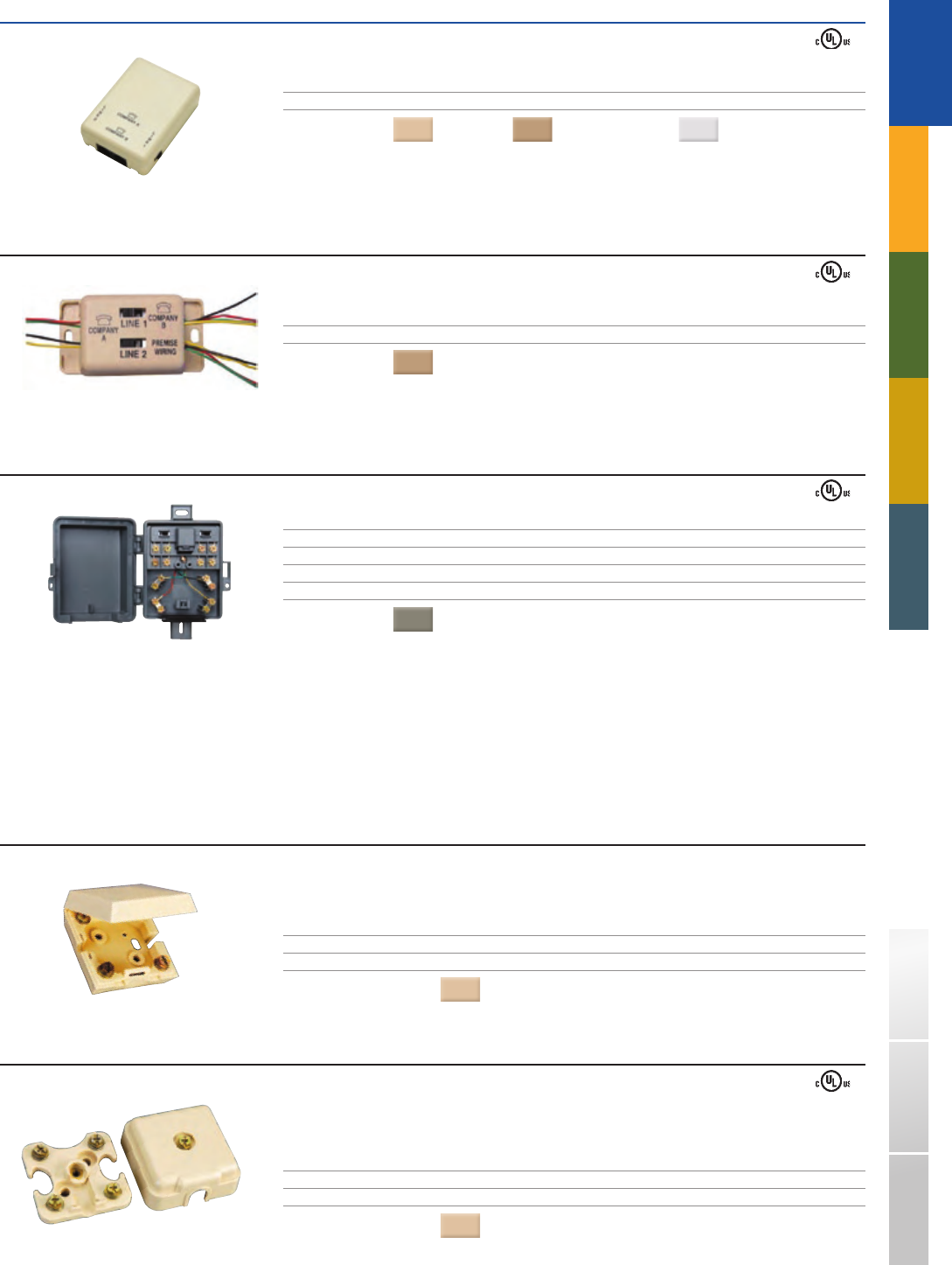
RADIO INTERFERENCE FILTER
Used in place of a surface mounted jack assembly to eliminate AM/FM and CB radio broadcast interference in telephone sets caused by nearby transmitting antennae.
PART# DESCRIPTION
1542A - 50 Non - modular, screw terminals
1542AM - xx Modular filter, 4 - conductor, 6 - position, screw terminals
COLORS
( - xx): Gray = (48) Ivory = (50)
MODULAR CORDAGE
The silver - satin outer jacket encloses coated, stranded copper of 26 gauge flat cable. The 266 and 266 - 6 modular plugs can easily be installed with use of the 166 and 166 - 6
modular crimping tools (See crimping tools on page 35).
PART# DESCRIPTION LENGTH
466S 4 - conductor 500 - ft.
366S 4 - conductor 1000 - ft.
466S - 6 6 - conductor 500 - ft.
366S - 6 6 - conductor 1000 - ft.
366S - 8 8 - conductor 1000 - ft.
MODULAR LINE CORDS
All - purpose, flat, silver - satin line cords with plugs on both ends.
PART# DESCRIPTION WIRING LENGTH
453 4 - conductor, interface cord through 8 - inch
454 4 - conductor reverse 5 - inch
7200 - 07 - W 4 - conductor reverse 7 - ft.
7200 - 14 - W 4 - conductor reverse 14 - ft.
7200 - 25 - W 4 - conductor reverse 25 - ft
1200 - 07 - W 6 - conductor reverse 7 - ft.
1200 - 14 - W 6 - conductor reverse 14 - ft.
1200 - 25 - W 6 - conductor reverse 25 - ft.
PART# DESCRIPTION WIRING CORROSHIELD LENGTH
7200 - 07 - WRC1 4 - conductor reverse CorroShield plugs 7 - ft.
MODULAR EXTENSION CORDS
All modular extension cords consist of a 4 - conductor, 6 - position modular plug on one end, and a simplex or duplex 4 - conductor jack on the other end.
PART# DESCRIPTION LENGTH
459 Modular extension cord plug and simplex jack 25 - ft.
460 Modular extension cord plug and duplex jack 25 - ft.
33
266 - 8K
15E - xx
264 266
266 - 8NK
12A1
21B - xx
070230 - 00
20C
260
24E1 48C
TRADITIONAL
TELEPHONY
1-800-852-8662 WWW.SUTTLEONLINE.COM
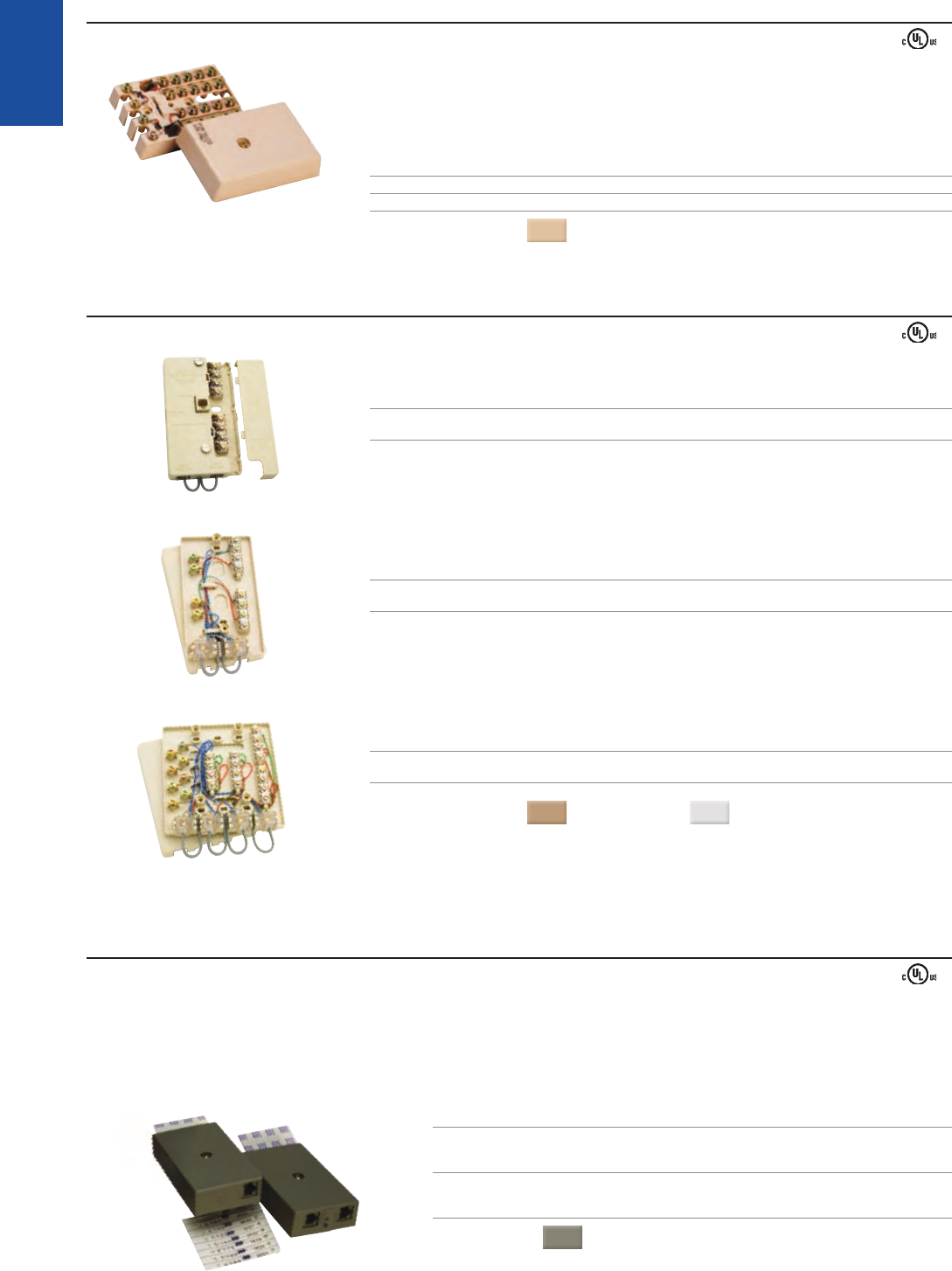
MODULAR PLUGS
Replace, repair, or add modular plugs to stranded or solid inside wiring cables. Plugs meet FCC part 68 requirements.
PART# DESCRIPTION
264 4 - position, 4 - conductor plug, for handset cords
266 6 - position, 4 - conductor plug, for stranded wire
266 - 4S 6 - position, 4 - conductor plug, for solid wire only
266 - 6 6 - position, 6 - conductor plug, for stranded wire
266 - 8K 8 - position, 8 - conductor, keyed plug, for stranded wire
266 - 8NK 8 - position, 8 - conductor, non - keyed plug, for stranded wire
SIGNALING DEVICES
The 15 Series off - hook indicator lights illuminate when the telephone set is off the hook only.
These are not equipped with switchboard lamps, which must be ordered separately (below).
PART# DESCRIPTION COLOR REN
15D - xx Off - hook indicator without lamp White 0
15E - xx Off - hook indicator without lamp Ruby 0
15G - xx Off - hook indicator without lamp Amber 0
15H - xx Off - hook indicator without lamp Blue 0
COLOR
: Black = (03) Gray = (48)
PART# DESCRIPTION
12A1 12V DC switchboard lamp
24E1 24V DC switchboard lamp
48C 48V DC switchboard lamp
The 21 Series ringing indicator lights illuminate when the telephone rings only.
These are equipped with neon lamps. Replacement lamps may be ordered separately (below).
PART# DESCRIPTION COLOR REN
21B - xx Ringing indicator with lamp Clear 0.4B
21C - xx Ringing indicator with lamp Amber 0.4B
21H - xx Ringing indicator with lamp Blue 0.4B
COLOR
: Black = (03) Gray = (48)
PART# DESCRIPTION
070230 - 00 Neon replacement lamp
PART# DESCRIPTION COLOR REN LISTED
20C Ring indicator - modular Amber 0.4B
PART# DESCRIPTION RING VOLTS SOUND REN
260 Electronic ringer 90 VAC – 120 VAC 95dB 0.8B
34
400AQ
171
554 - xx
77A
166
797A
798
814B
TRADITIONAL
TELEPHONY
STRUCTURED WIRING FIBERDSLSOHO ACCESS™ USOC WIRING GUIDE GLOSSARY INDEX
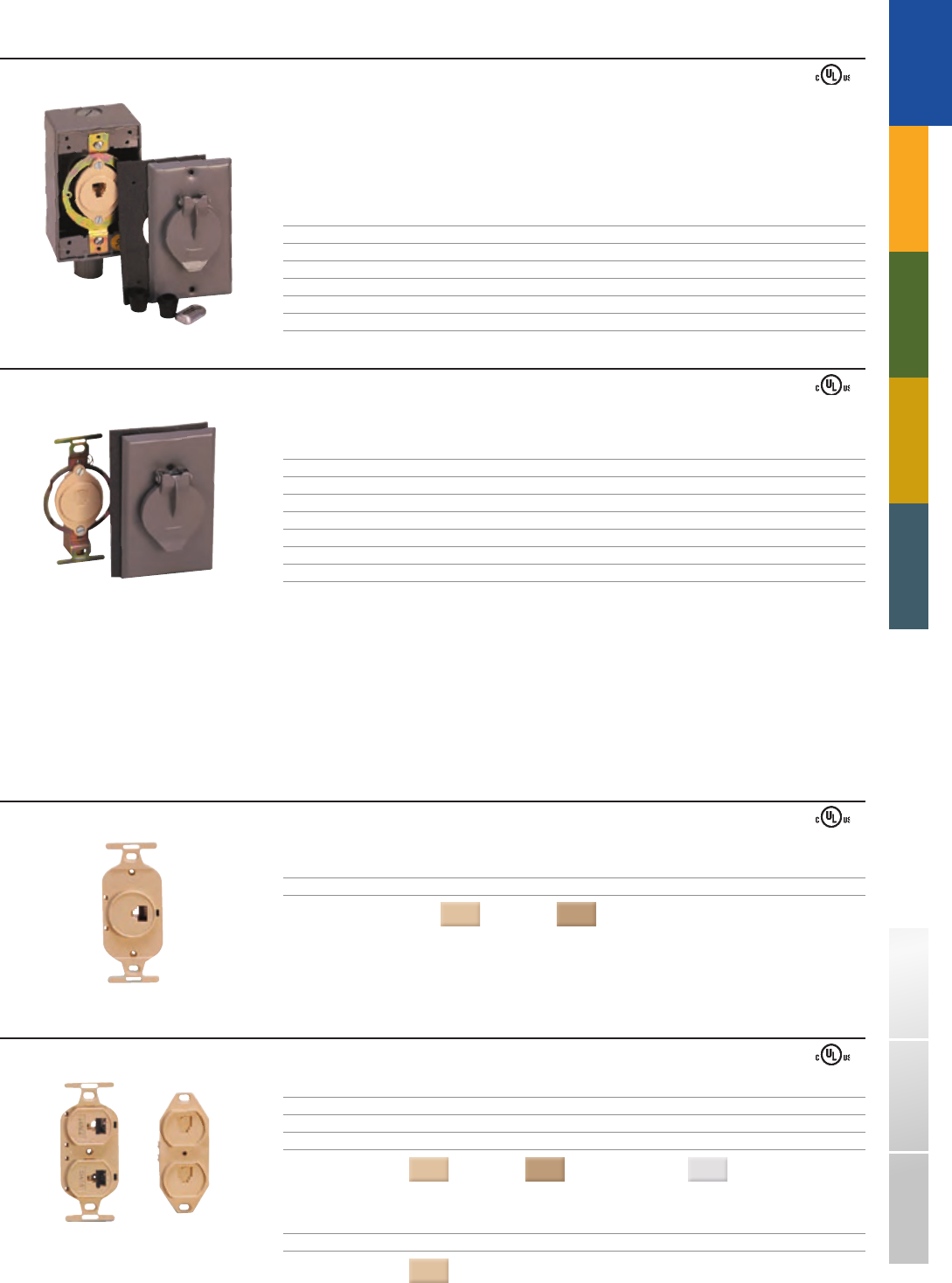
PUSH BUTTON AND MOUNTING BRACKET
For use in intercom systems or other signaling needs. It operates on AC and DC current not to exceed 120 volts.
PART# DESCRIPTION
554 - xx Push button; molded plastic with clear label window
COLORS
( - xx): Ash = (44) Ivory = (50)
PART# DESCRIPTION
77A Mounting bracket, heavy gauge steel construction with yellow
chromate finish; bottom covered with cork for protection of desks
or other finishes; the bracket clips onto the telephone instrument
base (side flange) for operator convenience
TOOLS
A variety of tools are available for installations and terminations.
PART# DESCRIPTION
166 Modular crimping tool for 4 - contact plugs on 4 - conductor wire
includes handset cord adapter
166 - 6 Modular crimping tool for 6 - contact plugs on 6 - conductor wire
PART# DESCRIPTION
797A Quick - connect tool for 630 jacks. Allows quick connections
without the added step of stripping the wires
PART# DESCRIPTION
798 110 IDC connect tool; for use with 22 - 26 AWG PVC and PIC cables
PART# DESCRIPTION
814B Impact tool; for use with 22 - 26 AWG station wire;
spring - loaded for consistent connections;
blades provided for use with 110 IDC and 66 - clip termination
PART# DESCRIPTION RING VOLTS SOUND REN LISTED
400AQ Chime ringer
> Chime mode 45 VAC – 130 VAC 80dB 1.7B
> Ring mode 45 VAC – 130 VAC 100dB 1.0B
PART# DESCRIPTION RING VOLTS SOUND REN LISTED
171 Loud ringer 45 VAC – 130 VAC 90dB 1.0B
(SIGNALING DEVICES - CONTINUED)
35

1 - 800 - 852 - 8662 WWW.SUTTLEONLINE.COM
36

SOHO ACCESS™
Ú SOHO ACCESS CONTENT OVERVIEW
Our full line of enclosures and modules deliver a superior ability to not only
provide reliable distribution for today, but into the future as well. This innovative
and rugged line of products facilitates effortless moves, adds, and changes while
maintaining a simple and attractive design.
p40 ENCLOSURES
The SOHO Access™ Enclosure is perfect for both residential and commercial applications.
Available in 4 sizes and with a variety of cover choices, this installation friendly enclosure
can fulfi ll all of your voice, data, video, and audio connectivity needs.
p44 VOICE MODULES
Suttle’s SOHO Access™ Voice Modules are an ideal way to distribute phone service throughout
a premise. We provide many unique products such as our Dual and Multi - Provider Modules which
are designed for maximum fl exibility with little or no rewiring.
p47 DATA MODULES
Our Data Modules are perfect for a home or small offi ce network and provide centralized distribution
to make networking easy.
p48 VIDEO MODULES
With our video Amplifi ers, Splitters, and Patch Panel, Suttle has the tools to give you the richest
television experience possible no matter what the source.
p50 DISTRIBUTED AUDIO
Listen to music throughout the home with Suttle’s line of A - BUS™ audio products. It distributes
audio signal over CAT5 cabling (or better) for less wiring and a simple, user friendly system.
This system sounds great with our new line of SONIK™ speakers, available in both in - wall and
in - ceiling confi gurations.
p52 MODULE ACCESSORIES
If you need to replace a module part, mount existing hardware, or add an active device Suttle has
the accessories you need to get it done.
37
SOHO
ACCESS™
1-800-852-8662 WWW.SUTTLEONLINE.COM
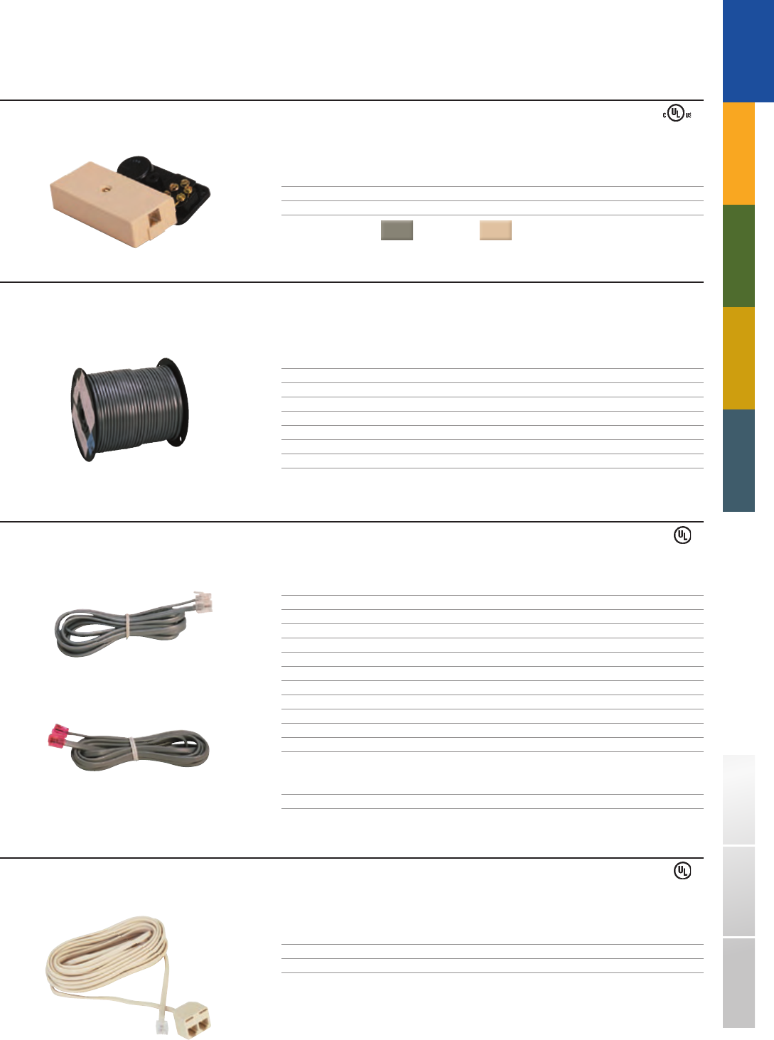
www.SUTTLESOHO.com❚
Suttle’s SOHO Access™ website is a comprehensive listing of the entire SOHO Access™ and relevant SpeedStar™ product lines
and features dynamically updated product information, spec sheets, wiring diagrams, news, and much more.
SUTTLE’S SOHO ACCESS™ WEBSITEÚ
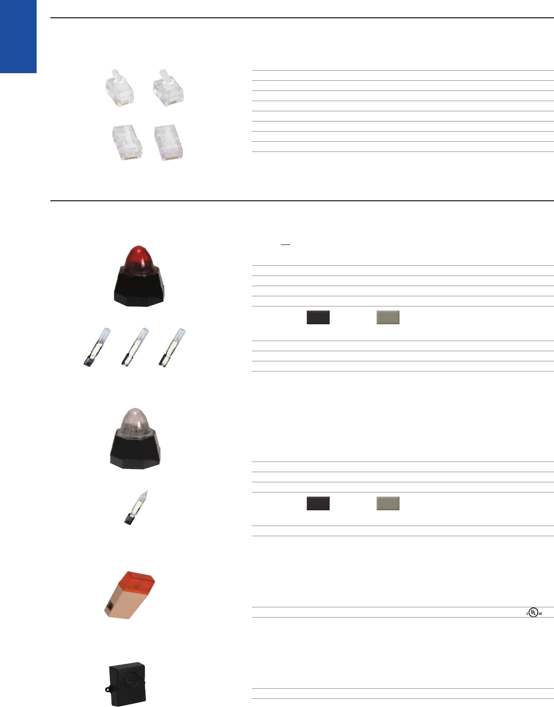
Also hosted on this site is the online version of Suttle’s 25 - Year Warranty Training and Certifi cation Program.
This new functionality enables users to access on - line training and industry information allowing them to perform
research and to become Suttle Certifi ed Installers 24 hours a day, 365 days a year.
SOHO ACCESS™ ONLINE TRAININGÚ
The SOHO Access
™
Online Training Program
can be found at www.suttlesoho.com
under the “Support” section.
38
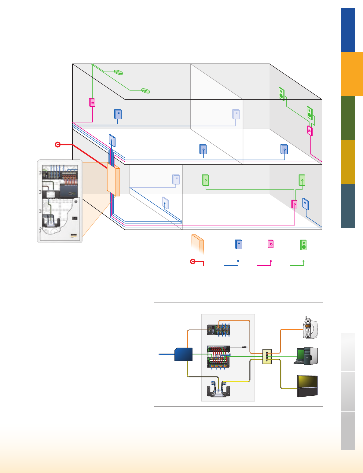
*Refers to a drop of 2 CAT5e (or better), 2 RG6, and 1 fiber (optional) as defined in the ANSI/TIA-570-B standards.
KEY
Speaker
Wire
CAT5 or
better
Wiring
Drops*
Incoming
Signal
SpeakerWallplate
Amplifier
Connector
Location
Distribution
Device
Gateway
Device
SAM-RF6
Video Splitter
SAM-D8
Data Patch Panel
SAM-V8
Voice Distribution
SAM-SW8U
Network Switch
Incoming
Service Ethernet
COAX
Phone
CAT5e
CAT5e
CAT5e
CAT5e
COAX
COAX
ENCLOSURE
TRADITIONAL TELEPHONY STRUCTURED WIRING FIBERDSL USOC WIRING GUIDE GLOSSARY INDEX
SOHO
ACCESS™
DISTRIBUTION DEVICE❚
WHAT IS STRUCTURED WIRING?
Structured wiring is a standards based system of cabling
that distributes communication services (including voice,
data, video, and audio) from a centrally located distribution
device over a network of built - in cables throughout a home
or offi ce.
WHY INSTALL IT?
Structured wiring systems simplify and enhance a
homebuyer’s lifestyle and create long - term value for the
home. Today’s entertainment and lifestyle products are
developing at a tremendous pace. These systems often
include computers, phones, gaming devices, lighting
systems, appliances, security cameras, set - top boxes,
and health monitoring systems. In addition to products,
evolving communication and entertainment service options
from Service Providers continue to provide more choices
which often drive greater challenges for the “in home”
communication network. Suttle’s line of SOHO Access™
products are an effective way to integrate and utilize these
changing products and services to enhance the home
owner’s lifestyle today and in the future.
Ú
Ú
BASIC STRUCTURED WIRINGÚ
The distribution device is used for connection of access providers to the
residence and to facilitate moves, adds, and changes. This is a typical wiring
applications found in a residence to organize and effi ciently distribute voice,
data, and video wire a home.
39
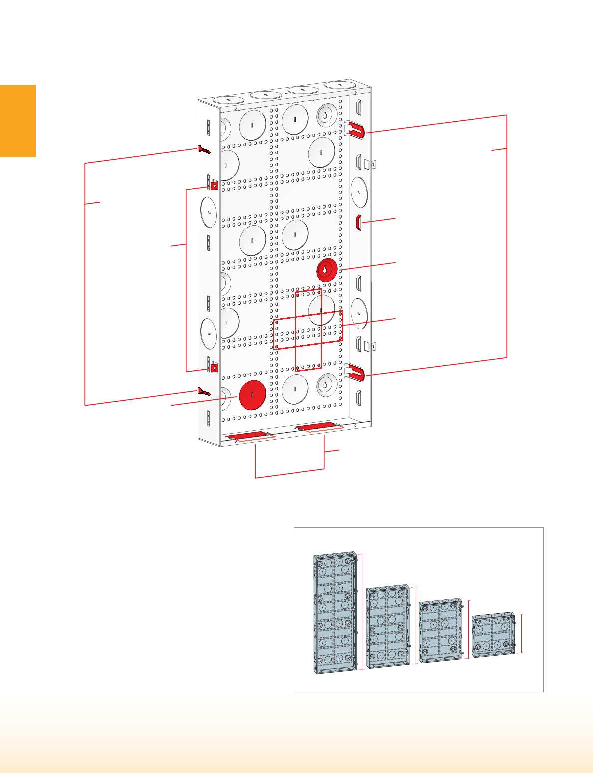
Vertical & Horizontal
Hole Pattern for Better
Cable Management
Recessed Screw Mounts
for Surface Mounting
Loops for
Cable Ties
Dual Knock-outs
for 110 outlets
Slotted Screw
Mounts allow for
Quicker Installs
Flexible Mounting Tabs
allow for variations
in stud spacing
Flush Mount Tabs
pre-set at depth
for most wall
boards
2.5" Keyed
Knock- outs
4
2
"
2
8
"
2
1
"
1
4
"
SOHO
ACCESS™
1-800-852-8662 WWW.SUTTLEONLINE.COM
The SOHO Access™ Enclosure provides a fast, fl exible, and clean distribution
management solution for voice, data, video, and audio connections.
Available in 14", 21", 28", and 42" heights these feature - rich, ruggedized
enclosures are designed to be either fl ush mounted between sixteen inch
centered studs or surface mounted via recessed mounting holes.
The SOHO Access™ Enclosure also offers numerous 2.5" cable entry
knockouts, a vertical and horizontal mounting hole pattern, and multiple
cable tie attachment points offering better, cleaner cable management.
Each enclosure accommodates a variety of cover options including the
solid Panel Cover, the Door Cover with security lock knock-out, the Dual
Door Cover for locking service provider assets, and the Stylized Cover with
smoked plexiglass window and added depth.
ENCLOSURES❚
SOHO Access
™
Enclosures are available in 14", 21", 28", and 42" heights.
40
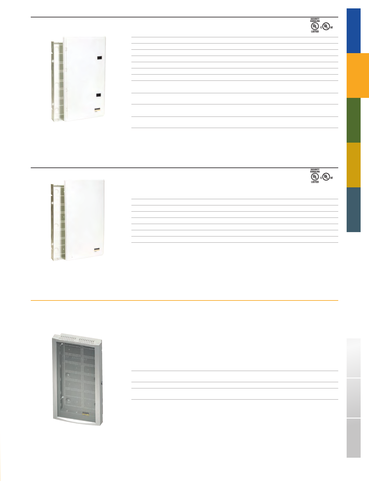
SAE - 28DC
SAE - 28PC
SAE - 28SC
TRADITIONAL TELEPHONY STRUCTURED WIRING FIBERDSL USOC WIRING GUIDE GLOSSARY INDEX
SOHO
ACCESS™
ENCLOSURES WITH DOOR COVER
PART# DESCRIPTION
SAE - 14DC 14" surface/flush mount home network enclosure, fits between 16" studs, includes door cover
SAE - 21DC 21" surface/flush mount home network enclosure, fits between 16" studs, includes door cover
SAE - 28DC 28" surface/flush mount home network enclosure, fits between 16" studs, includes door cover
SAE - 42DC 42" surface/flush mount home network enclosure, fits between 16" studs, includes door cover
➦COMING SOON
SAE - 42DDC - 1428 42" network enclosure with 14"/28" dual door cover,
includes SAM-EMP partition module (see pg 43)
➦COMING SOON
SAE - 42DDC - 2121 42" network enclosure with 21"/21" dual door cover,
includes SAM-EMP partition module (see pg 43)
ENCLOSURE
DIMENSIONS:
14", 21", 28", 42"H x 14.25"W x 3.75"D
ENCLOSURES WITH PANEL COVER
PART# DESCRIPTION
SAE - 14PC 14" surface/flush mount home network enclosure, fits between 16" studs, includes panel cover
SAE - 21PC 21" surface/flush mount home network enclosure, fits between 16" studs, includes panel cover
SAE - 28PC 28" surface/flush mount home network enclosure, fits between 16" studs, includes panel cover
SAE - 42PC 42" surface/flush mount home network enclosure, fits between 16" studs, includes panel cover
ENCLOSURE
DIMENSIONS:
14", 21", 28", 42"H x 14.25"W x 3.75"D
➥COMING SOON ENCLOSURES WITH STYLIZED COVER
Available for 28" and 42" enclosures, the Stylized Cover consists of a sturdy metal frame that holds an attractively,
smoked plexiglass window for diagnosing (and admiring) network equipment.
2.5" of added depth
Vents to dissipate heat
Security lock included standard
Attractive smoked plexiglass window
PART# DESCRIPTION
SAE - 28SC 28" surface/flush mount home network enclosure, fits between 16" studs,
includes stylized door cover with smoked glass
SAE - 42SC 42" surface/flush mount home network enclosure, fits between 16" studs,
includes stylized door cover with smoked glass
ENCLOSURE
DIMENSIONS:
28", 42"H x 14.25"W x 3.75"D
■
■
■
■
41
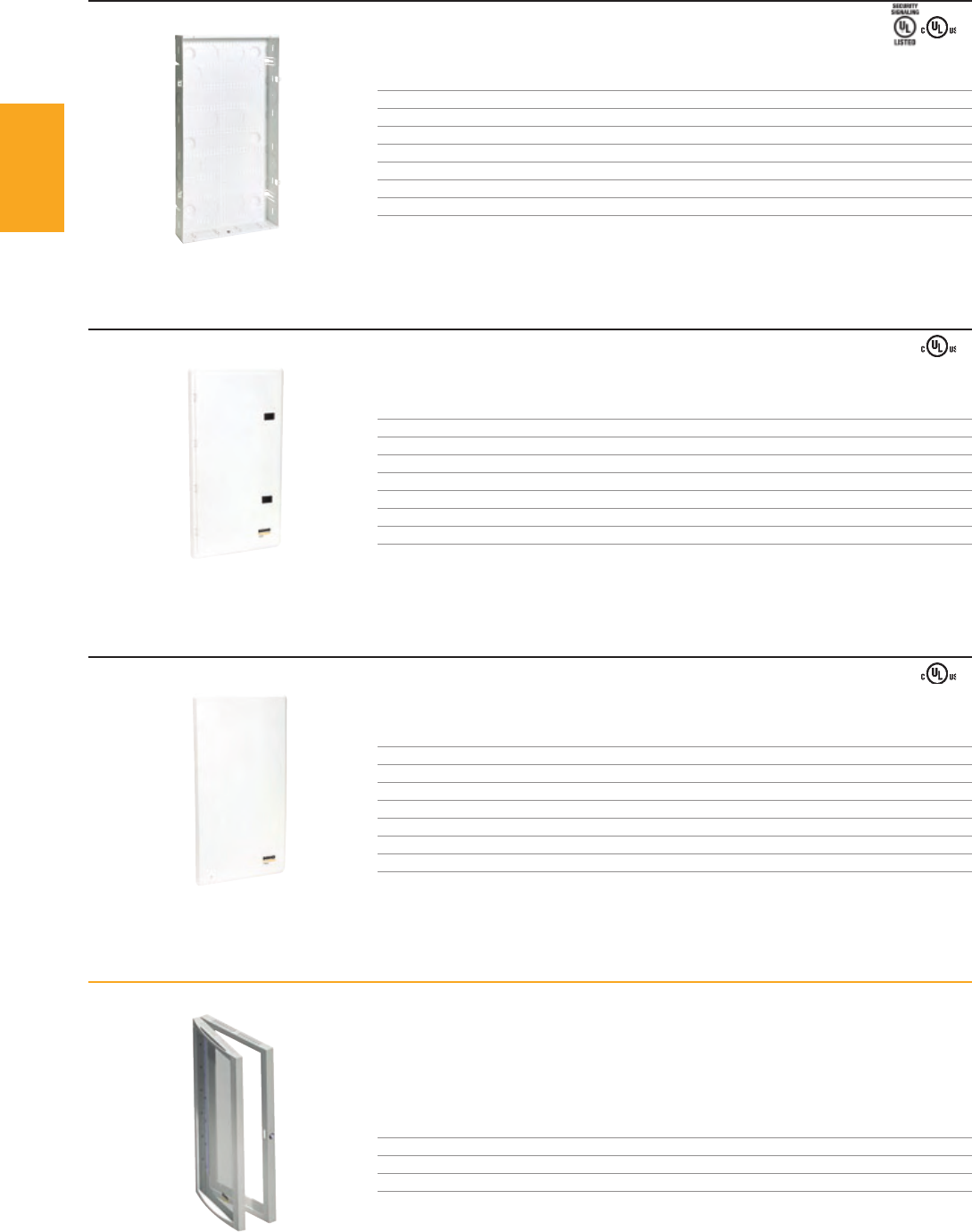
SAE - 28
SADC - 28
SAPC - 28
SASC - 28
SOHO
ACCESS™
1-800-852-8662 WWW.SUTTLEONLINE.COM
ENCLOSURES
PART# DESCRIPTION
SAE - 14 14" surface/flush mount home network enclosure, fits between 16" studs, no cover
SAE - 21 21" surface/flush mount home network enclosure, fits between 16" studs, no cover
SAE - 28 28" surface/flush mount home network enclosure, fits between 16" studs, no cover
SAE - 42 42" surface/flush mount home network enclosure, fits between 16" studs, no cover
ENCLOSURE
DIMENSIONS:
14", 21", 28", 42"H x 14.25"W x 3.75"D
DOOR COVERS
PART# DESCRIPTION
SADC - 14 Door cover for 14" network enclosure, no enclosure
SADC - 21 Door cover for 21" network enclosure, no enclosure
SADC - 28 Door cover for 28" network enclosure, no enclosure
SADC - 42 Door cover for 42" network enclosure, no enclosure
PANEL COVERS
PART# DESCRIPTION
SAPC - 14 Panel cover for 14" network enclosure, no enclosure
SAPC - 21 Panel cover for 21" network enclosure, no enclosure
SAPC - 28 Panel cover for 28" network enclosure, no enclosure
SAPC - 42 Panel cover for 42" network enclosure, no enclosure
➥COMING SOON STYLIZED COVERS
2.5" of added depth
Vents to dissipate heat
Security lock included standard
Attractive smoked plexiglass window
PART# DESCRIPTION
SASC - 28 Stylized door cover with smoked glass for 28" network enclosure, no enclosure
SASC - 42 Stylized door cover with smoked glass for 42" network enclosure, no enclosure
■
■
■
■
42

SADDC - 2121
SADDC - 1428
SAE - ACN
SAE - ACS
SAE - LOCK
SAE - GMT8
SAM - FAN
SAM - EPM
SAM - PS3
TRADITIONAL TELEPHONY STRUCTURED WIRING FIBERDSL USOC WIRING GUIDE GLOSSARY INDEX
SOHO
ACCESS™
➥COMING SOON DUAL DOOR COVERS
The dual door covers for the 42" SOHO Access™ Enclosure are designed to secure the
bottom portion of the enclosure while allowing the top portion to be accessed freely.
PART# DESCRIPTION
SADDC - 1428 14" / 28" dual door cover for 42" network enclosure, no enclosure
SADDC - 2121 21" / 21" dual door cover for 42" network enclosure, no enclosure
*Requires SAM - EPM to separate top and bottom sections.
PART# DESCRIPTION
SAM - EPM Enclosure partition module for use with dual door covers
POWER
PART# DESCRIPTION
SAE - ACS Surge protected AC outlet kit, includes NEMA 5 - 15R 15A,
125V surge suppression receptacle, faceplate and J - Box, white
SAE - ACN Non - surge protected AC outlet kit, includes 15A,
125V receptacle, faceplate and J - Box, white
➦COMING SOON
SAM - PS3 3-outlet power extension module
*For use with SAM-EPM
ACCESSORIES
PART# DESCRIPTION
SAE - GMT8 Enclosure grommet kit, 8 additional 2.5" rubber grommets for cable entry/exit holes
SAE - LOCK Enclosure door security lock for enclosure door covers
➦COMING SOON
SAM - FAN Fan module to reduce heat inside the enclosure, integrated power adapter
43
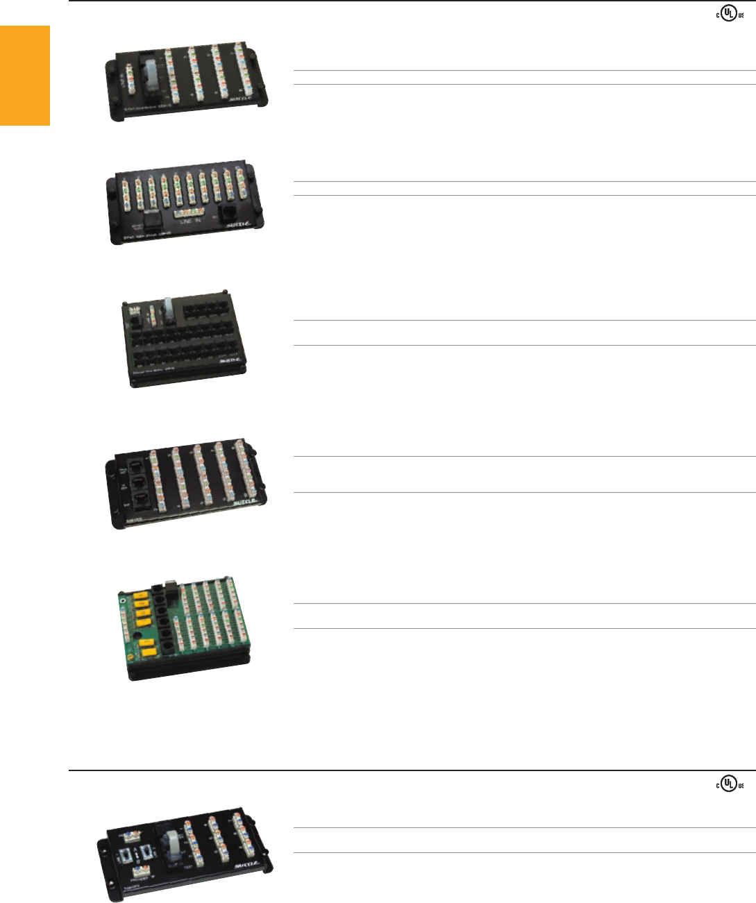
SAM - V8
SAM - DP9
SAM - V10
SAM - VE
SAM - VX10
SAM - 603
SOHO
ACCESS™
1-800-852-8662 WWW.SUTTLEONLINE.COM
VOICE MODULES ❚
VOICE DISTRIBUTION MODULES
PART# DESCRIPTION
SAM - V8 4 - line input, 8 output, 110 IDC blocks, RJ31X alarm jack, 2 RJ45 test jacks (568A)
➦NEW
SAM - V10 4 - line input, 10 output, 110 IDC blocks, RJ31X alarm jack, 1 RJ45 test jack (568A)
SAM - VE 4 - line input (110 IDC), 22 output (RJ45), 10 outs pass all 4 lines,
12 outs pass 2 lines in varying combinations, RJ31X alarm jack, 2 RJ45 test jacks (568A)
SAM - VX10 Expansion module bridges 4 lines from SAM - V8, SAM - V10, or SAM - VE
to an additional 10 outputs (110 IDC blocks), expandable to additional SAM - VX10s,
includes 2 RJ45 patch cords for bridging, 568A wiring
SAM - 603 6 - line input, 11 output, 110 IDC blocks, RJ31X alarm jack, 6 test jacks,
6 half - ringers for remote testing
DUAL PROVIDER MODULES
PART# DESCRIPTION
SAM - DP9 2 - line input (110 IDC), 9 output (110 IDC), RJ31X alarm jack, 2 RJ45 test jacks (568A),
allows connection for two service providers, controlled by a switch for each line
44
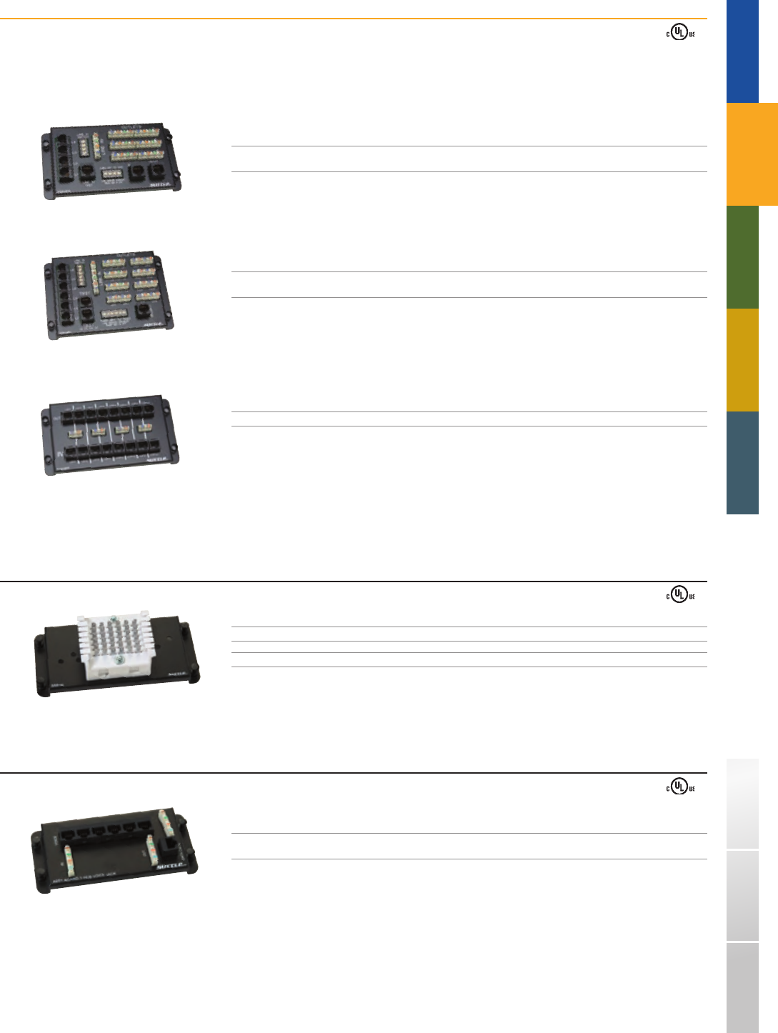
SAM - MP4
SAM - MP6
SAM - MPP
SAM - 66
SAM - V6D1
TRADITIONAL TELEPHONY STRUCTURED WIRING FIBERDSL USOC WIRING GUIDE GLOSSARY INDEX
SOHO
ACCESS™
➥NEW MULTI - PROVIDER MODULES
The new Multi - Provider solution delivers a new level of flexibility and functionality for today’s multifamily property owners and managers. These modules facilitate a centralized
distribution of phone services in each unit that is simple to manage with no expensive rewiring when residents change their phone service provider. Each module can support
a basic offering from a single telephone service provider, or a more comprehensive offering of multiple lines and multiple providers.
PART# DESCRIPTION
SAM - MP4 4 - line input to 6 outputs (110 IDC), security interface jack,
2 RJ45 test jacks (568A), allows switching between up to 4 alternate voice providers (RJ11)
SAM - MP6 6 - line input to 8 outputs (110 IDC) in various combinations, security interface jack,
1 RJ45 test jack (568A), allows switching between up to 6 alternate voice providers (RJ11)
SAM - MPP Patch module, 8 inputs (RJ11 or 110 IDC) to 8 outputs (RJ11)
* For use with SAM - MP4 and SAM - MP6
66 BLOCK MODULES
PART# DESCRIPTION
SAM - 66 3 - pair 66 connecting block via 6 - clip terminals
SAM - 66 - 3 6 - pair 66 connecting block via 3 - clip terminals
VOICE / DATA COMBINATION MODULE
PART# DESCRIPTION
SAM - V6D1 VOICE: 4 - line input (110 IDC), 6 output (RJ45), 568B wiring
DATA: 1 CAT5e, RJ45 to 110 IDC, 568B wiring
45
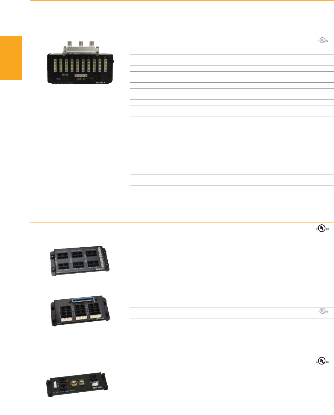
SAM - VTC
SAM - VC12
SAM - VV4
SAM - DSL
SOHO
ACCESS™
1-800-852-8662 WWW.SUTTLEONLINE.COM
➥NEW TELEPHONY ADAPTER MODULES
These modules interconnect a PBX system of a small business with an EMTA
and accommodate 8 (SAM - VTC) or 12 (SAM - VC12) lines of service.
PART# DESCRIPTION
SAM - VTC 8 - line input (RJ14 or 110 IDC) to 8 - line output (RJ11), 4 test ports (RJ11)
PART# DESCRIPTION
SAM - VC12 12 - line input (RJ21X 25 - pair female connector) to 12 - line output (RJ11 or 110 IDC)
➥NEW VOICE / VIDEO COMBINATION MODULES
The new Voice / Video Combination Module is designed to minimize the amount of space required to network a home’s voice and video systems.
These modules are available with any of the current 1GHz or 3GHz splitters offered by Suttle or with no splitter and just mounting hardware.
PART# DESCRIPTION
SAM - BV VOICE: 4 - line input, 10 output, 110 IDC, RJ31X alarm jack, 1 RJ45 test jack (568A)
VIDEO: No splitter
SAM - VV4 VOICE: 4 - line input, 10 output, 110 IDC, RJ31X alarm jack, 1 RJ45 test jack (568A)
VIDEO: 1x4 RF splitter, F connector, 1GHz, SCTE compliant
SAM - VV6 VOICE: 4 - line input, 10 output, 110 IDC, RJ31X alarm jack, 1 RJ45 test jack (568A)
VIDEO: 1x6 RF splitter, F connector, 1GHz, SCTE compliant
SAM - VV8 VOICE: 4 - line input, 10 output, 110 IDC, RJ31X alarm jack, 1 RJ45 test jack (568A)
VIDEO: 1x8 RF splitter, F connector, 1GHz, SCTE compliant
SAM - VVH2 VOICE: 4 - line input, 10 output, 110 IDC, RJ31X alarm jack, 1 RJ45 test jack (568A)
VIDEO: 1x2 RF splitter, F connector, 3GHz, SCTE compliant
SAM - VVH3 VOICE: 4 - line input, 10 output, 110 IDC, RJ31X alarm jack, 1 RJ45 test jack (568A)
VIDEO: 1x3 RF splitter, F connector, 3GHz, SCTE compliant
SAM - VVH4 VOICE: 4 - line input, 10 output, 110 IDC, RJ31X alarm jack, 1 RJ45 test jack (568A)
VIDEO: 1x4 RF splitter, F connector, 3GHz, SCTE compliant
SAM - VVH6 VOICE: 4 - line input, 10 output, 110 IDC, RJ31X alarm jack, 1 RJ45 test jack (568A)
VIDEO: 1x6 RF splitter, F connector, 3GHz, SCTE compliant
SAM - VVH8 VOICE: 4 - line input, 10 output, 110 IDC, RJ31X alarm jack, 1 RJ45 test jack (568A)
VIDEO: 1x8 RF splitter, F connector, 3GHz, SCTE compliant
DSL FILTER MODULE
Filter all voice jacks with one central filter
Easy to install, just patches into the existing phone distribution module (to filter line 1)
110 IDC input and output accommodates filtering of any line
RJ45 or 110 IDC unfiltered output for modem
PART# DESCRIPTION
SAM - DSL DSL module fi lters voice signal from a voice module to eliminate the need
for fi
ltering at jack locations
■
■
■
■
PENDING
PENDING
46
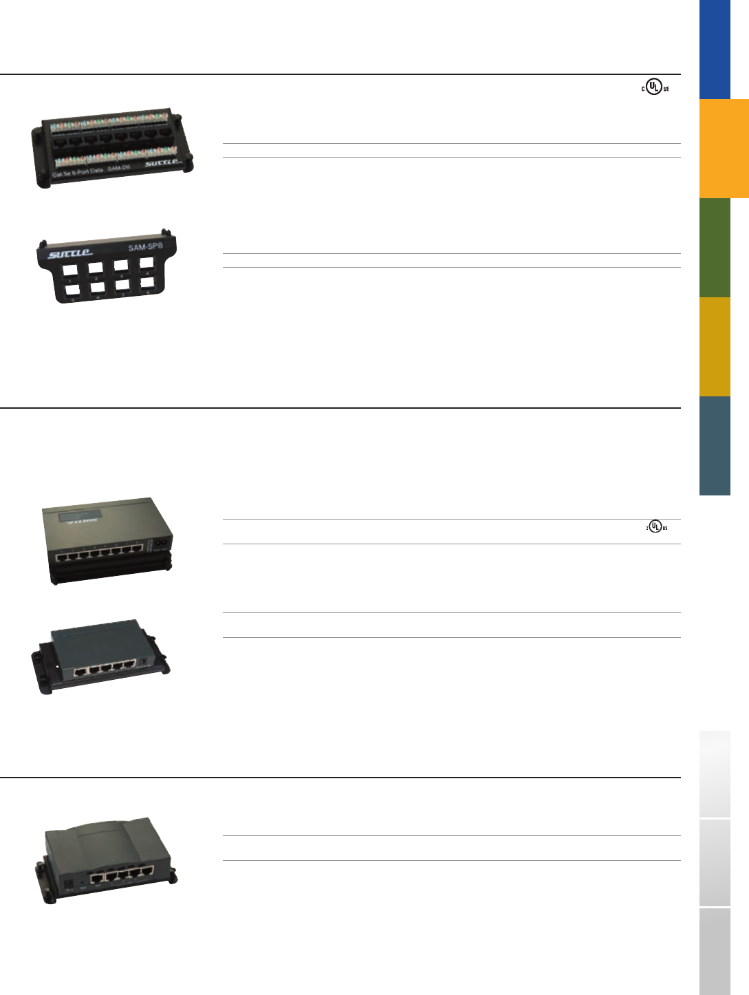
SAM - D8
SAM - SP8
SAM - SW8U
SAM - SW5U
SAM - RTR4
TRADITIONAL TELEPHONY STRUCTURED WIRING FIBERDSL USOC WIRING GUIDE GLOSSARY INDEX
SOHO
ACCESS™
DATA MODULES ❚
PATCH MODULES
PART# DESCRIPTION
SAM - D8 8 - port CAT5e data/voice networking module, RJ45 to 110 IDC blocks, 568A wiring
SAM - SP8 8 - port universal patch panel, utilizes all standard SpeedStar™ connectors (sold separately)
NETWORK SWITCH MODULES
The SOHO Access™ 10/100 Ethernet Switch Modules provide full wire - speed, Fast Ethernet switching to ensure high - performance and low - cost connectivity. These switches feature
a store - and - forward architecture along with Auto MDI/MDIX support to allow the user to connect any ethernet device with standard, straight or crossover ethernet cables making it
a simple plug - and - play device. The 8 - port switch (SAM - SW8U) is also equipped with an internal power supply to eliminate external power adapters.
PART# DESCRIPTION
SAM - SW8U 8 - port 10/100 switch, integrated power adapter, auto - sensing ports,
includes eight 12" patch cords
SAM - SW5U 5 - port 10/100 switch, auto - sensing ports,
includes five 12" patch cords and external DC power adapter
NETWORK ROUTER MODULE
PART# DESCRIPTION
SAM - RTR4 4 - port 10/100 router, firewall protection,
includes five 12" patch cords and external DC power adapter
47
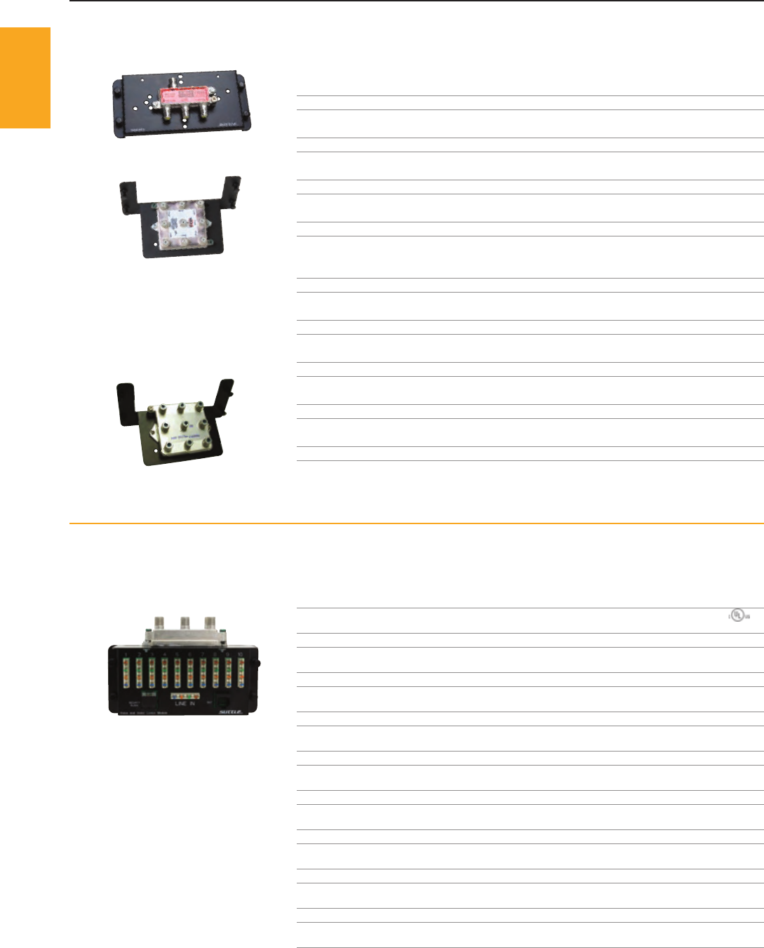
SAM - RF3
SAM - RF8
SAM - RFH8
SAM - VV4
SOHO
ACCESS™
1-800-852-8662 WWW.SUTTLEONLINE.COM
VIDEO MODULES ❚
VIDEO SPLITTER MODULES
Suttle’s 1GHz and 3GHz video splitter modules provide high quality and reliable video distribution with industry approved splitters that meet ANSI/SCTE standards.
The angled mounting brackets maximize enclosure space, minimize cable strain, and facilitate better cable management and ease of installation.
PART# DESCRIPTION CONNECTIONS FREQUENCY STANDARD BRACKET
SAM - RF3 1x3 RF splitter F connector 1GHz SCTE compliant fl at
SAM - RF4 1x4 RF splitter F connector 1GHz SCTE compliant angled
SAM - RF6 1x6 RF splitter F connector 1GHz SCTE compliant angled
SAM - RF8 1x8 RF splitter F connector 1GHz SCTE compliant angled
➦NEW
SAM - RFH2 1x2 RF splitter F connector 3GHz SCTE compliant angled
➦NEW
SAM - RFH3 1x3 RF splitter F connector 3GHz SCTE compliant angled
➦NEW
SAM - RFH4 1x4 RF splitter F connector 3GHz SCTE compliant angled
➦NEW
SAM - RFH6 1x6 RF splitter F connector 3GHz SCTE compliant angled
➦NEW
SAM - RFH8 1x8 RF splitter F connector 3GHz SCTE compliant angled
➥NEW VOICE / VIDEO COMBINATION MODULES
The new Voice / Video Combination Module is designed to minimize the amount of space required to network a home’s voice and video systems.
These modules are available with any of the current 1GHz or 3GHz splitters offered by Suttle or with no splitter and just mounting hardware.
PART# DESCRIPTION
SAM - BV VOICE: 4 - line input, 10 output, 110 IDC, RJ31X alarm jack, 1 RJ45 test jack (568A)
VIDEO: No splitter
SAM - VV4 VOICE: 4 - line input, 10 output, 110 IDC, RJ31X alarm jack, 1 RJ45 test jack (568A)
VIDEO: 1x4 RF splitter, F connector, 1GHz, SCTE compliant
SAM - VV6 VOICE: 4 - line input, 10 output, 110 IDC, RJ31X alarm jack, 1 RJ45 test jack (568A)
VIDEO: 1x6 RF splitter, F connector, 1GHz, SCTE compliant
SAM - VV8 VOICE: 4 - line input, 10 output, 110 IDC, RJ31X alarm jack, 1 RJ45 test jack (568A)
VIDEO: 1x8 RF splitter, F connector, 1GHz, SCTE compliant
SAM - VVH2 VOICE: 4 - line input, 10 output, 110 IDC, RJ31X alarm jack, 1 RJ45 test jack (568A)
VIDEO: 1x2 RF splitter, F connector, 3GHz, SCTE compliant
SAM - VVH3 VOICE: 4 - line input, 10 output, 110 IDC, RJ31X alarm jack, 1 RJ45 test jack (568A)
VIDEO: 1x3 RF splitter, F connector, 3GHz, SCTE compliant
SAM - VVH4 VOICE: 4 - line input, 10 output, 110 IDC, RJ31X alarm jack, 1 RJ45 test jack (568A)
VIDEO: 1x4 RF splitter, F connector, 3GHz, SCTE compliant
SAM - VVH6 VOICE: 4 - line input, 10 output, 110 IDC, RJ31X alarm jack, 1 RJ45 test jack (568A)
VIDEO: 1x6 RF splitter, F connector, 3GHz, SCTE compliant
SAM - VVH8 VOICE: 4 - line input, 10 output, 110 IDC, RJ31X alarm jack, 1 RJ45 test jack (568A)
VIDEO: 1x8 RF splitter, F connector, 3GHz, SCTE compliant
PENDING
48
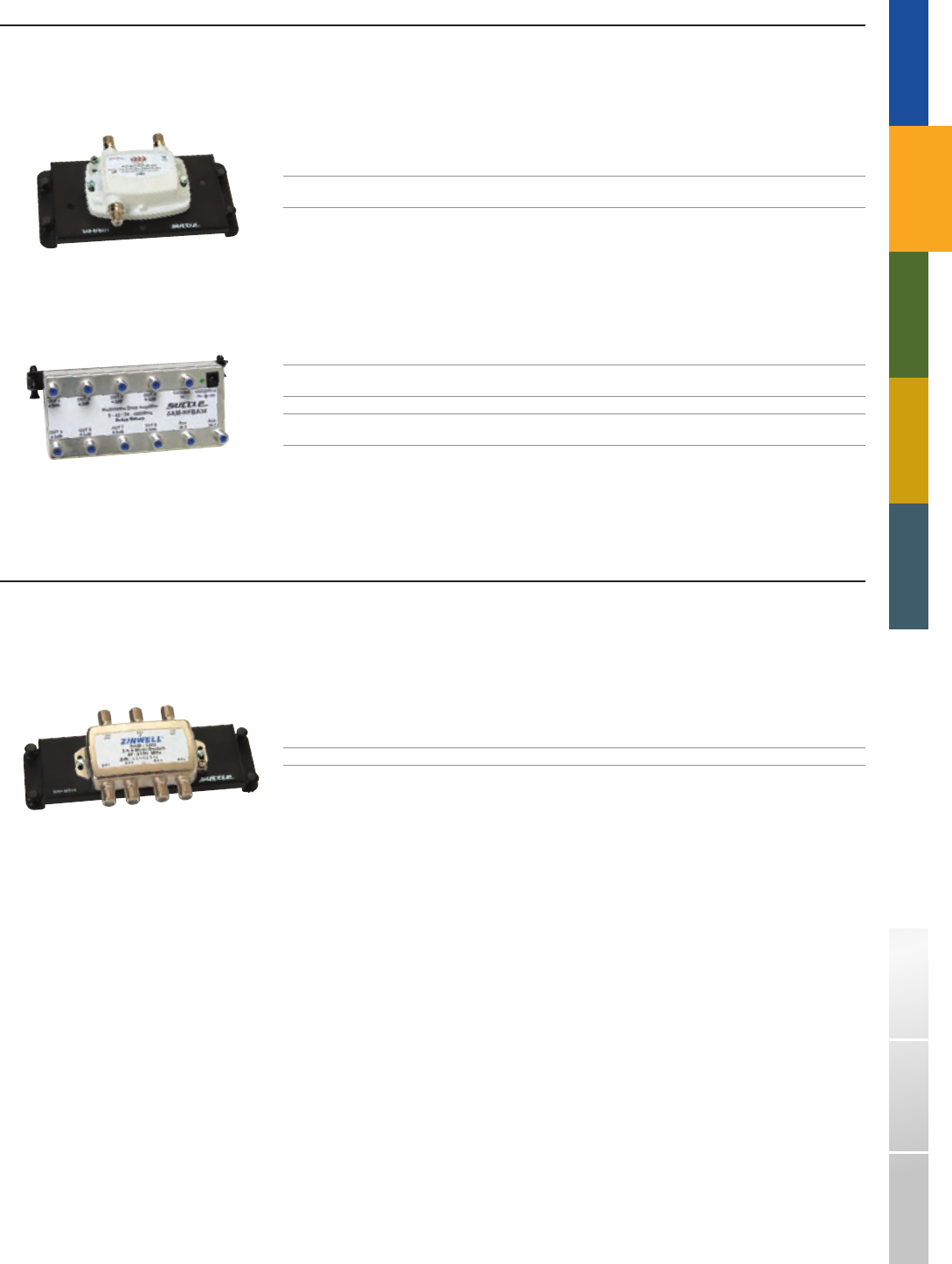
SAM - RFBA11
SAM - RFBA38
SAM - MS34
TRADITIONAL TELEPHONY STRUCTURED WIRING FIBERDSL USOC WIRING GUIDE GLOSSARY INDEX
SOHO
ACCESS™
VIDEO AMPLIFIER MODULES
The SOHO Access™ Bi - directional RF Amplifiers boost the incoming signals from the CATV, satellite (after set - top box), or antenna providing high quality video for a TV in your home.
Easily integrate modulated signals from DVD/VCRs or security cameras into your video network with the built - in auxiliary ports on the SAM - RFBA38.
PART# DESCRIPTION
SAM - RFBA11 1x1 Bi - directional RF amplifier, 1GHz, +15dB, power passing (forward only), SCTE compliant,
includes external DC power adapter
SAM - RFBA18 1x8 Bi - directional amplified splitter, 1GHz, +4.5dB, SCTE compliant,
includes terminator caps and external DC power adapter
SAM - RFBA38 3x8 Bi - directional amplified splitter, 1GHz, +2.0dB, SCTE compliant,
includes terminator caps and external DC power adapter
SATELLITE MULTI - SWITCH MODULE
Distribute satellite and off - air antenna signal (or other input) on a single cable for up to 4 receivers with this DirecTV® approved satellite multi - switch.
It provides 2 LNB and 1 ANT/auxiliary inputs to 4 outputs. Just take the two feeds from the satellite and connect them to the correct inputs on the multiswitch.
Connect the signal from the off - air antenna or other input device. Then run the 4 outputs to the four receivers located throughout the home.
PART# DESCRIPTION
SAM - MS34 3x4 Multi - switch, DirecTV® approved
49
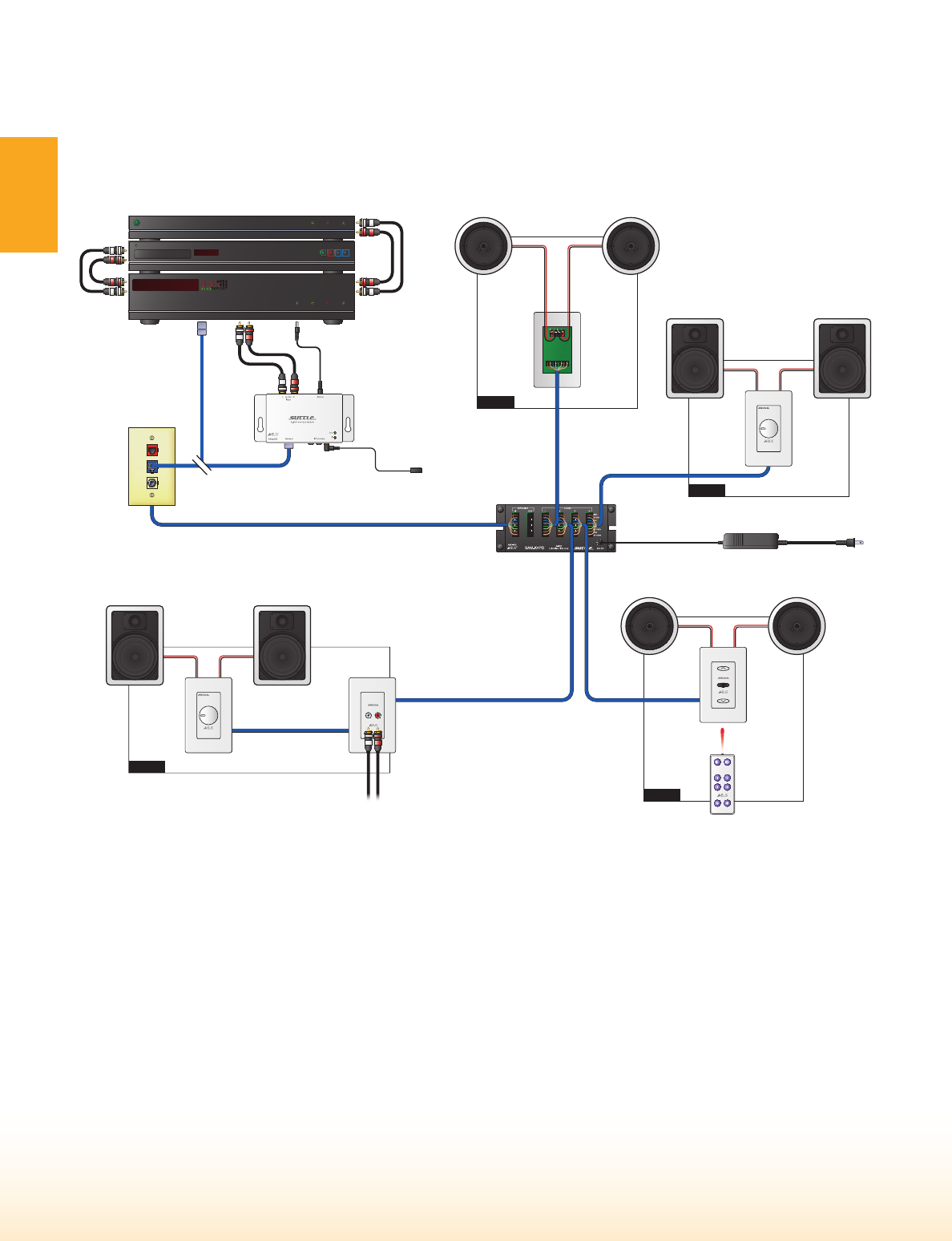
Zone 1
24VDC Adapter
to 110 outlet
If A-BUS™ Ready
Amplifier
CAT5e Cable
CAT5e Cable
CAT5e
Cable
CAT5e
Cable
CAT5e Cable
CAT5e Cable
Audio from
Local Source
Speaker Wire
to R Speaker
Local Zone
Volume
Control
SAA-020
Dial
Volume
Control
RightLeft
Speaker Wire
to L Speaker
Line Level
Audio Signal
12VDC Status Input
(optional)
IR flasher
SAA-K50
Audio Interface Module
SOURCE
SAM-K4PD
4 Zone Distribution
Module
IR Remote
SAA-020
Dial Volume
Control
RightLeft
SAA-070
Local Source
Audio Input
SAA-042
Push Button
Volume
Control
with IR
RightLeft
Zone 4
Zone 3
Zone 2
SAS-6W
6.5" In-wall Speakers
SAS-6C
6.5" In-ceiling Speakers
SAS-6W
6.5" In-wall Speakers
SAS-6C
6.5" In-ceiling Speakers
SOHO
ACCESS™
1-800-852-8662 WWW.SUTTLEONLINE.COM
Simply run one CAT5 cable (or better) from the 4 - zone/room distribution module in the enclosure to a
standard network jack near the main audio input, and another cable from each output to a volume control
or volume control and local source input in each zone. 16 - gauge speaker wire is then run from each volume
control to speakers in that zone.
DISTRIBUTED AUDIO ❚
The A - BUS
™
Distributed Audio system from Suttle is simple to use and install, and offers a better way to bring music to
any and every room of the home. The Audio interface module takes line - level audio, IR, and source on/off status from
a central source (i.e., PC, TV, CD player, etc.) over CAT5 cabling (or better) to amplifi ed volume controls thus eliminating
the need for a separate amplifi er.
50
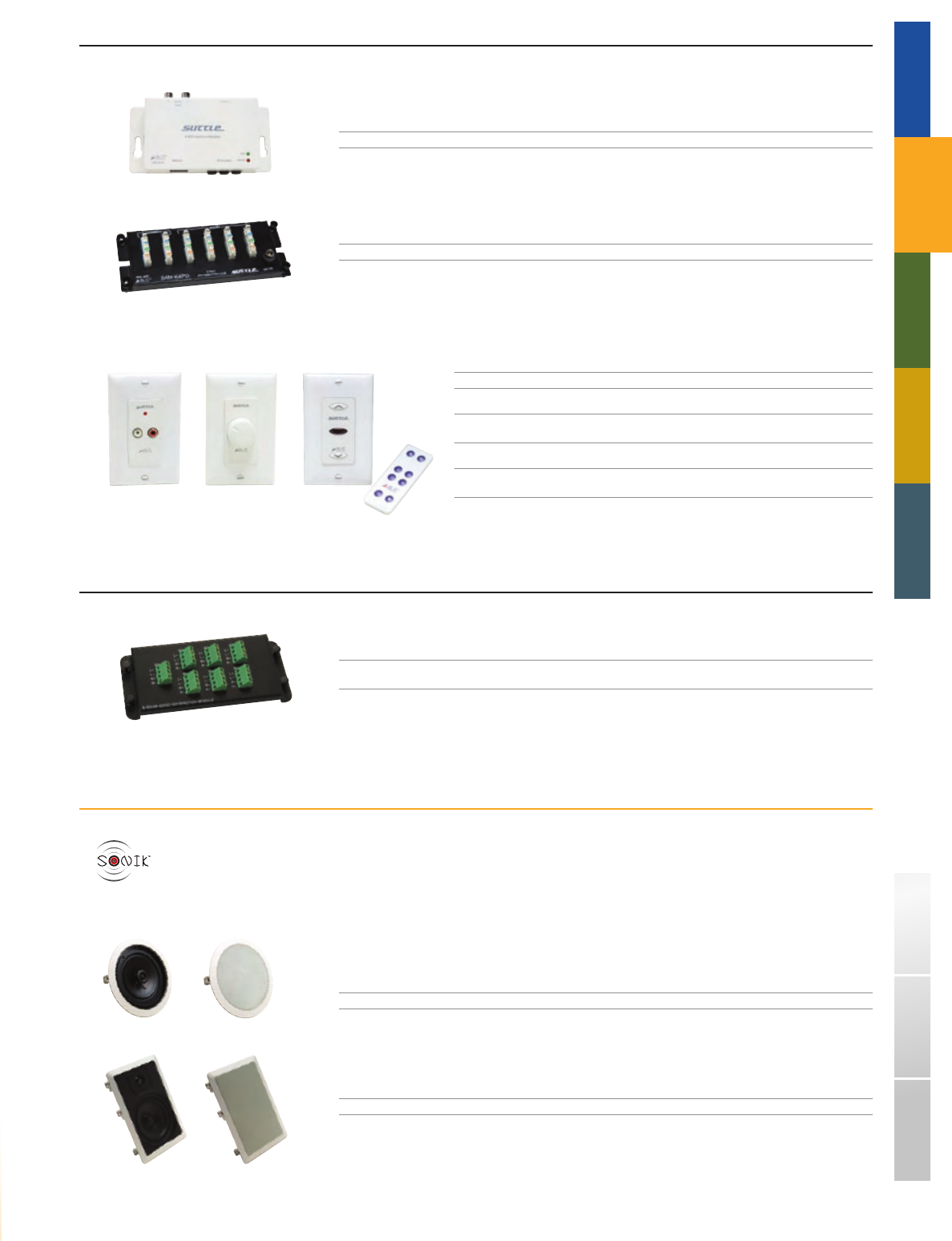
SAA - K50
SAM - K4PD
SAA - 070 SAA - 020 SAA - 042
SAM - SA6
SAS - 6C
SAS - 6W
TRADITIONAL TELEPHONY STRUCTURED WIRING FIBERDSL USOC WIRING GUIDE GLOSSARY INDEX
SOHO
ACCESS™
A - BUS™ DISTRIBUTED AUDIO SYSTEM
PART# DESCRIPTION
SAA - K50 Audio interface module, converts line level input and IR to CAT5e
SAM - K4PD 4 - zone audio distribution module, includes power supply
PART# DESCRIPTION
SAA - 070 Local audio source input module, includes faceplate
SAA - 020 Dial volume control, amplified (powered remotely
from distribution module, SAM - K4PD), includes faceplate
SAA - 042 Push button volume control w/ IR for remote control, amplified
(powered remotely from distribution module, SAM - K4PD), includes faceplate
STANDARD DISTRIBUTED AUDIO MODULE
PART# DESCRIPTION
SAM - SA6 6 - zone standard audio distribution module,
for speaker wire runs from amplifier to impedance matching volume controls (not included)
➥NEW SONIK™ SPEAKERS
Suttle’s new line of SONIK™ in - wall and in - ceiling speakers deliver a high performance, clean, crisp sound that provides entertainment throughout the home.
Our stylish, flush mounted speakers blend easily with any décor.
1” Ultra - wide dispersion dome tweeter.
Polypropylene cone handles moist environments while delivering solid bass response.
Durable Santoprene™ surround offers long life and responsive performance.
1” aluminum voice coil easily copes with the heat and power of extended usage.
The SONIK™ two - piece connector simplifies installation and provides better connection.
PART# DESCRIPTION
SAS - 6C One pair of 6.5" in - ceiling speakers, 20/60 Watts, 89dB, 8Ω
SAS - 6W One pair of 6.5" in - wall speakers, 20/60 Watts, 89dB, 8Ω
■
■
■
■
■
51
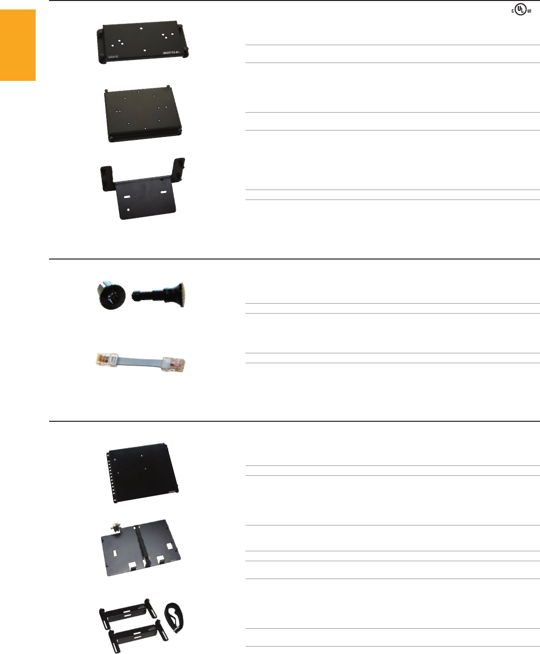
SAM - B
SAM - B3
SAM - B6
SAM - NYL
SAM - PC3
SAM - B5
SAM - MMB - 2S
SAM - EMBX
SOHO
ACCESS™
1-800-852-8662 WWW.SUTTLEONLINE.COM
MODULE ACCESSORIES ❚
BLANK MODULE PLATES
PART# DESCRIPTION
SAM - B Blank mounting plate, 3" x 5.5" mounting surface,
includes double - stick adhesive foam
SAM - B3 Blank mounting plate, 4.5" x 6.4" mounting surface,
includes double - stick adhesive foam
➦NEW
SAM - B6 Blank angled mounting plate, 3" x 4.5" mounting surface
MODULE REPLACEMENT PARTS
PART# DESCRIPTION
SAM - NYL Push - pin replacement kit, plunger and grommet, 10/bag
➦COMING SOON
SAM - PC3 Replacement 3" module patch cord, 5/bag
* For use with SAM - V8, SAM - VE, and SAM - DP9
CUSTOM MOUNTING BRACKETS
PART# DESCRIPTION
SAM - B5 2 - line EMTA mounting plate
SAM - MMB - 2S Mounting bracket designed to hold a modem or EMTA,
7.7" x 10.5" mounting surface includes Velcro® strap
and pre - mounted 1x2 2GHz RF splitter
SAM - MMB Mounting bracket designed to hold a modem or EMTA,
7.7" x 10.5" mounting surface includes Velcro® strap
➦NEW
SAM - EMBX 2 piece adjustable mounting bracket
with connecting Velcro® strap for mounting 1U rack mount equipment
52
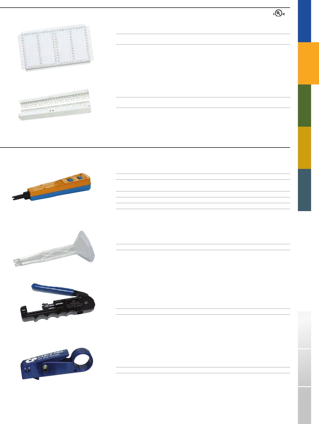
SAM - CMB
SAM - UMB
814B
798
SCPLCCT - SLM
SPSA
TRADITIONAL TELEPHONY STRUCTURED WIRING FIBERDSL USOC WIRING GUIDE GLOSSARY INDEX
SOHO
ACCESS™
ADAPTER BRACKETS
PART# DESCRIPTION
SAM - CMB Large 10" x 20" mounting bracket
which allows up to 4 Suttle modules to fit into a variety of non - Suttle enclosures
SAM - UMB Dual mounting brackets
which allow a variety of non - Suttle modules to fit into Suttle enclosures
TOOLS
PART# DESCRIPTION
814B Automatic impact tool
* For use with 22 - 26 AWG PVC and PIC cable
81401 - 110 - 88 Replacement blade for 814B tool, 110 IDC style
81401 - 66 Replacement blade for 814B tool, 66 clip style
798 110 IDC connect tool
* For use with 22 - 26 AWG PVC and PIC cable
➦NEW
SCPLCCT - SLM Coax compression tool, includes various tips for different connector types
➦NEW
SPSA Adjustable RG59/RG6 quad - shield cable stripper with RG6 flaring tool
53

1-800-852-8662 WWW.SUTTLEONLINE.COM
54

STRUCTURED WIRING
Ú STRUCTURED WIRING CONTENT OVERVIEW
Our full line of residential and commercial structured cabling solutions meets
the voice, data, and video (VDV) connectivity needs of both today and tomorrow.
The versatility of Suttle’s multimedia products allows you to maximize the
performance of your network.
p56 MODULAR MULTIMEDIA
Our modular multimedia line of SpeedStar® products is available in multiple configurations to install
whatever VDV solution you need. Used with Suttle’s line of modular and surface mount faceplates,
these products offer an attractive design, choice of colors, and quick assembly. Many are available
in CorroShield® configurations.
p66 PATCH PANELS
The CAT5e and CAT6 patch panels are ideal for cross - connect applications. Their design makes
individual jacks easy to identify and reach, facilitating moves and changes. Suttle’s panels are
available in 12, 24, and 48 port configurations and their rolled edge steel construction eliminates
flex during termination.
p67 RACKS & CABLE MANAGEMENT
Cables are easily managed between components within or between racks with the 19WM350
horizontal trough. The aluminum alloy relay rack offers a convenient way to organize panels.
Access holes on both sides of the rails allow cables to be routed between adjacent racks.
p67 PATCH CORDS
Suttle’s CAT5e patch cords provide performance that exceeds TIA/EIA 568 - B.2 specifications for
component performance while our CAT6 rated patch cords exceed TIA/EIA - 568 - B.2 - 1 specifications.
Both styles have molded boot covers to provide bend radius protection and are available in a wide
variety of lengths and colors.
p68 110 CROSS - CONNECTS
110 Cross - Connects are ideal for use where space is limited. Angled IDC connector pins aid in
maintaining maximum CAT6 performance, providing a gas tight connection and improved cable
retention. The wiring block design permits neat, organized wiring behind the block. All 110
Cross - Connect products exceed CAT6 TIA/EIA - 568 - B.2 - 1 performance.
p71 66 BLOCK SYSTEM
Suttle offers a complete line of CAT5 and industry standard 66 blocks. The CAT5 blocks distribute
data using familiar quick - clips for termination and transmit data rates up to 100 MHz. The 66
blocks are easily stacked to provide flexibility and use quick - connect 66 clips for ease of installation
and proven termination reliability.
55
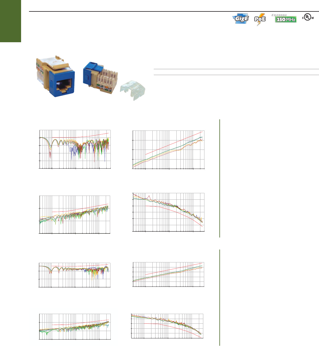
RETURN LOSS
dB
-20
-40
-60
-80
-100
0
0.3 1 100
10
300
Worst Case Limit Margin : 4.9 dB @ 1.362 MHz
Frequency (MHz)
0.3 1 100
10
300
Frequency (MHz)
PSELFEXT
Worst Case Limit Margin : 9.5 dB @ 187.847 MHz
dB
-30
-50
-70
-90
-10
0.3 1 100
10
300
Frequency (MHz)
1Frequency (MHz)
PSACR
dB
-20
0
20
40
60
80
100
0.3 100
10
300
Worst Case Limit Margin : 11.3 dB @ 245.832 MHz
Worst Case Limit Margin : 5.4 dB @ 218.536 MHz
dB
-150
-100
-50
0
NEXT
PSACR
dB
Worst Case Limit Margin : 11.3 dB @ 245.832 MHz
100
80
60
40
20
0
0.3 1 100
10
300
Frequency (MHz)
PSELFEXT
dB
Worst Case Limit Margin : 10.2 dB @ 200.916 MHz
-30
-50
-70
-110
-90
-10
0.3 1 100
10
300
Frequency (MHz)
-50
-150
-100
0
RETURN LOSS
dB
Worst Case Limit Margin : 5.1 dB @ 1.585 MHz
0.3 1 100
10
300
Frequency (MHz)
Worst Case Limit Margin : 8.0 dB @ 229.842 MHz
-150
-100
-50
0
0.3 3001
10
100
Frequency (MHz)
NEXT
dB
STAR6000C6
STRUCTURED
WIRING
1-800-852-8662 WWW.SUTTLEONLINE.COM
Suttle modular connection products make it easy to install whatever voice, data, or video solution you need.
Our full selection of structured cabling multimedia product features our SpeedStar line available in multiple configurations.
Connectors for use with modular faceplates, frames, and surface mount housings
Data products exceed Category 6 and 5e performance specifications
Simple, snap - in assembly
Voice and data modules available in CorroShield sealed configurations for the ultimate in corrosion protection
JACKS
DATA JACKS: CATEGORY 6
Get your network up to speed with Suttle’s CAT6 SpeedStar structured cabling system. This system's series of Category 6 rated products provides performance
that exceeds TIA/EIA - 568 - B.2 - 1 specifications for channel and link performance. Installing Suttle’s SpeedStar Category 6 products helps insure your network
is clean and ready for new emerging applications.
PART# DESCRIPTION
STAR6000C6 8 - Position, 8 - conductor, 568A/B, 110 IDC
* Includes 8 colored bezels
■
■
■
■
Ú
MODULAR MULTIMEDIA❚
➥CHANNEL PERFORMANCE TESTS
Suttle Category 6 products go beyond
standards to provide performance well
beyond 250 MHz.
Note: Link and Channel performance verified by Underwriters Laboratories,
example results from CommScope UltraMedia 7504 Plenum Cable.
➥LINK PERFORMANCE TESTS
Suttle Category 6 products go beyond
standardsto provide performance well
beyond 250 MHz.
56
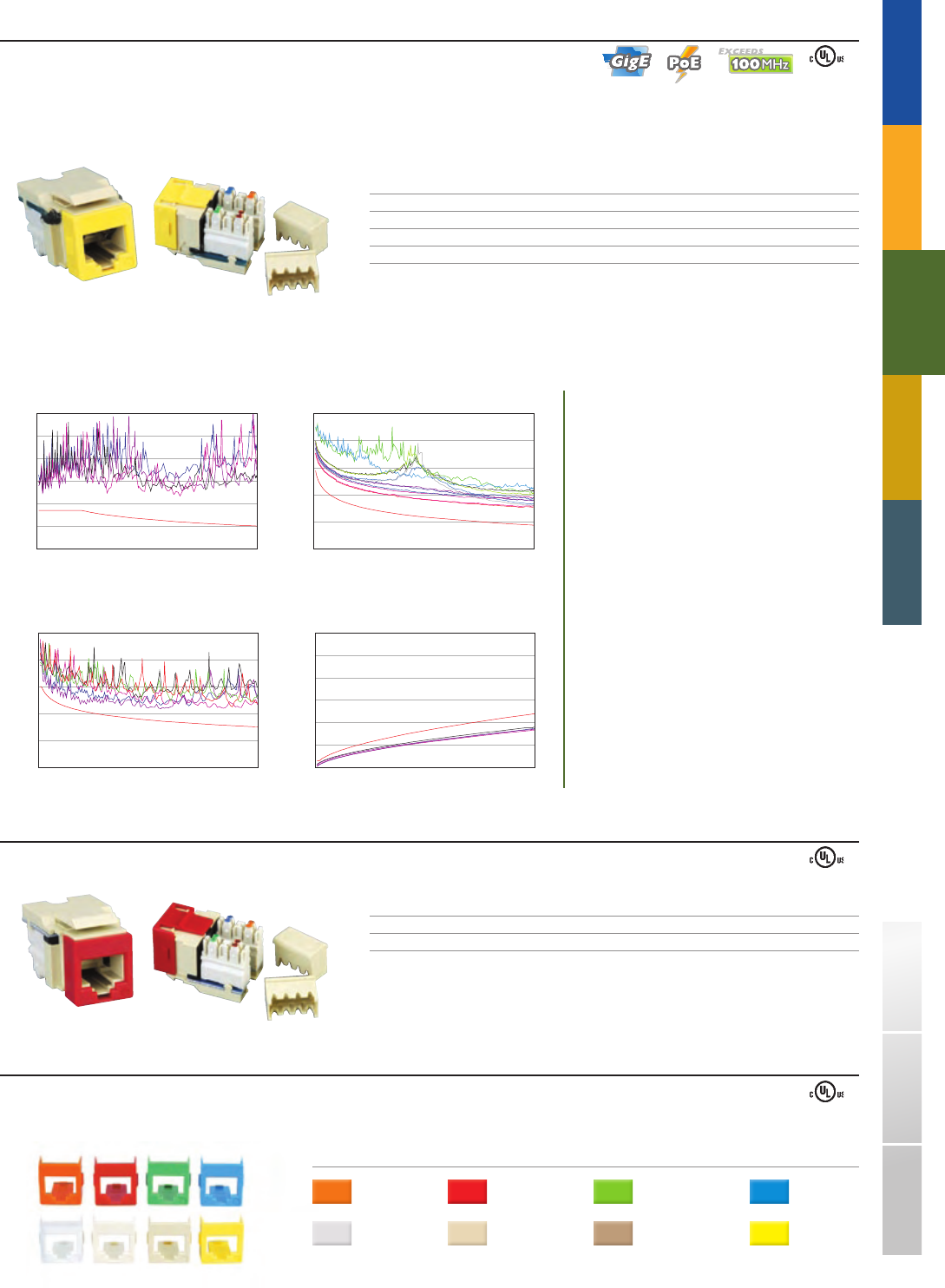
0
60
10
20
30
40
50
0 100
RETURN LOSSdB
Frequency (MHz)
0
100
20
40
60
80
0 100
ELFEXTdB
Frequency (MHz)
0
100
20
40
60
80
0 100
NEXTdB
Frequency (MHz)
0
60
10
20
30
40
50
0 100
AttenuationdB
Frequency (MHz)
STAR600A
STAR600V6
TRADITIONAL TELEPHONY
STRUCTURED
WIRING
FIBERDSLSOHO ACCESS™ USOC WIRING GUIDE GLOSSARY INDEX
DATA JACKS: CATEGORY 5e
Make sure your network is capable of handling the traffic demands required for today’s growing applications.
The SpeedStar Category 5e system provides performance that exceeds TIA/EIA 568 - B.2 specifications for channel and link, and component performance.
PART# DESCRIPTION CORROSHIELD
STAR600A 8 - position, 8 - conductor, 568A, 110 IDC
STAR600B 8 - position, 8 - conductor, 568B, 110 IDC
STAR600A - RC 8 - position, 8 - conductor, 568A, 110 IDC CorroShield
STAR600B - RC 8 - position, 8 - conductor, 568B, 110 IDC CorroShield
* Includes 8 colored bezels
Note: Test results based on use of Mohawk/CDT Cable
JACK BEZELS
Voice and data modules come packaged with the following color identifying bezels:
COLORS:
Orange = (97) Red = (53) Green = (51) Blue = (62)
White = (85) Light Almond = (64) Electrical Ivory = (52) Yellow = (56)
■
VOICE JACKS
PART# DESCRIPTION CORROSHIELD
STAR600V6 6 - position, 6 - conductor, 110 IDC
STAR600V6 - RC 6 - position, 6 - conductor, 110 IDC CorroShield
* Includes 8 colored bezels
➥CHANNEL PERFORMANCE TESTS
Suttle Category 5e products go beyond
standards to provide performance well
beyond 100 MHz.
57
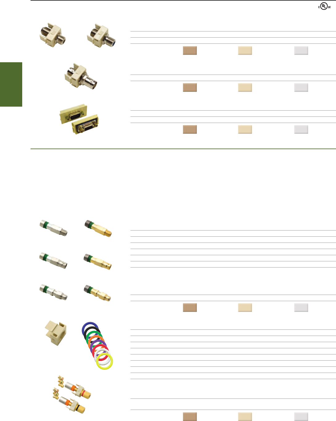
STAR500F - xx STAR500F - C - xx
STAR506SVGA - xx
STAR500BNC - xx
SRG6U - HI
STAR - BP - GCP - xx
SFS6U - HI
SRG6BNCU - HISFS6BNCU - HI
SRG6RCAU - HISFS6RCAU - HI
HIO - x
STAR - HPC - xx
STRUCTURED
WIRING
1-800-852-8662 WWW.SUTTLEONLINE.COM
AUDIO/VIDEO CONNECTORS
BARREL STYLE CONNECTORS
PART# DESCRIPTION
STAR500F - xx F81 barrel connector, 1GHz
STAR500F - C - xx F81 barrel connector, 3GHz, SCTE compliant
COLORS
( - xx): Electrical Ivory = (52) Light Almond = (64) White = (85)
PART# DESCRIPTION
STAR500BNC - xx BNC barrel connector
COLORS
( - xx): Electrical Ivory = (52) Light Almond = (64) White = (85)
PART# DESCRIPTION
STAR - SVGA - xx SVGA connector for STAR1064M mounting frame
STAR506SVGA - xx SVGA connector for use with STAR5501P or STAR5502P insert style faceplates
COLORS
( - xx): Electrical Ivory = (52) Light Almond = (64) White = (85)
Ú
➥NEW COMPRESSION STYLE CONNECTORS
Ideal for home theater and network connections, Suttle offers multiple grades of reliable broadband cable connectors. These connectors are ruggedly built to
meet the demands of the residential and commercial digital wiring market. The gold series brings discriminating clients excellent electrical performance and
dependability. The adaptable color rings and housing inserts let you retrofit connectors quickly and easily no matter which type or grade.
No soldering required
One - step crimp process
Meets SCTE - IPC and Bellcore requirements
Adaptable color rings and housings
PART# DESCRIPTION MOQ
SFS6U - HI Compression F connector, female, nickel plated, RG6 Universal 25
SRG6U - HI Compression F connector, female, gold plated, RG6 Universal 25
SFS6BNCU - HI BNC compression connector, female, nickel plated, RG6 Universal 25
SRG6BNCU - HI BNC compression connector, female, gold plated, RG6 Universal 25
SFS6RCAU - HI RCA compression connector, female, nickel plated, RG6 Universal 25
SRG6RCAU - HI RCA compression connector, female, gold plated, RG6 Universal 25
* For use with STAR - HCP - xx housing inserts and HIO - x indicator rings
PART# DESCRIPTION MOQ
STAR - HCP - xx SpeedStar housing inserts for female compression connectors 25
COLORS
( - xx): Electrical Ivory = (52) Light Almond = (64) White = (85)
PART# DESCRIPTION MOQ
HIO - B Blue universal indicator ring for female connectors 100
HIO - BK Black universal indicator ring for female connectors 100
HIO - G Green universal indicator ring for female connectors 100
HIO - O Orange universal indicator ring for female connectors 100
HIO - P Purple universal indicator ring for female connectors 100
HIO - R Red universal indicator ring for female connectors 100
HIO - W White universal indicator ring for female connectors 100
HIO - Y Yellow universal indicator ring for female connectors 100
PART# DESCRIPTION
STAR - BP - GCP - xx 2 speaker binding post compression connectors (1 Red,1 Black), gold plated,
includes 2 sets of 12, 14, and 16 AWG speaker wire inserts
COLORS
( - xx): Electrical Ivory = (52) Light Almond = (64) White = (85)
■
■
■
■
58
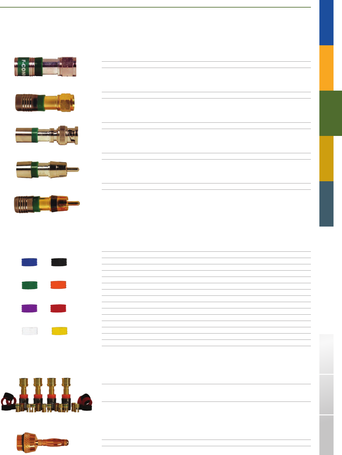
SRG6RCAU
SRG6U
SFS6U
SFS6RCAU
SFS6BNCU
SFSCR - B SFSCR - BK
SFSCR - G SFSCR - O
SFSCR - P SFSCR - R
SFSCR - W SFSCR - Y
SRGSPB
SRGSPU
TRADITIONAL TELEPHONY
STRUCTURED
WIRING
FIBERDSLSOHO ACCESS™ USOC WIRING GUIDE GLOSSARY INDEX
➥NEW BULK MALE COMPRESSION STYLE CONNECTORS
No soldering required
One - step crimp process
Meets SCTE - IPC and Bellcore requirements
Prevents moisture migration with internal sealing "O" rings
PART# DESCRIPTION MOQ
SFS6U Compression F connector, male, nickel plated, RG6 Universal 25
PART# DESCRIPTION MOQ
SRG6U Compression F connector, male, gold plated, RG6 Universal 25
PART# DESCRIPTION MOQ
SFS6BNCU BNC compression connector, male, nickel plated, RG6 Universal 25
PART# DESCRIPTION MOQ
SFS6RCAU RCA compression connector, male, nickel plated, RG6 Universal 25
PART# DESCRIPTION MOQ
SRG6RCAU RCA compression connector, male, gold plated, RG6 Universal 25l
PART# DESCRIPTION COLOR MOQ
SFSCR - B Universal indicator ring for male compression connectors Blue 100
SFSCR - BK Universal indicator ring for male compression connectors Black 100
SFSCR - G Universal indicator ring for male compression connectors Green 100
SFSCR - O Universal indicator ring for male compression connectors Orange 100
SFSCR - P Universal indicator ring for male compression connectors Purple 100
SFSCR - R Universal indicator ring for male compression connectors Red 100
SFSCR - W Universal indicator ring for male compression connectors White 100
SFSCR - Y Universal indicator ring for male compression connectors Yellow 100
* For use with all Bulk Male Compression Style Connectors
PART# DESCRIPTION MOQ
SRGSPU 4 speaker compression connectors, gold plated, speaker wire, 20
includes 4 sets of 12, 14, and 16 AWG wire inserts,
4 red and 6 black color indicator rings
* For use with SRGSPB
PART# DESCRIPTION MOQ
SRGSPB Banana tip for SRGSPU, gold plated 20
■
■
■
■
59
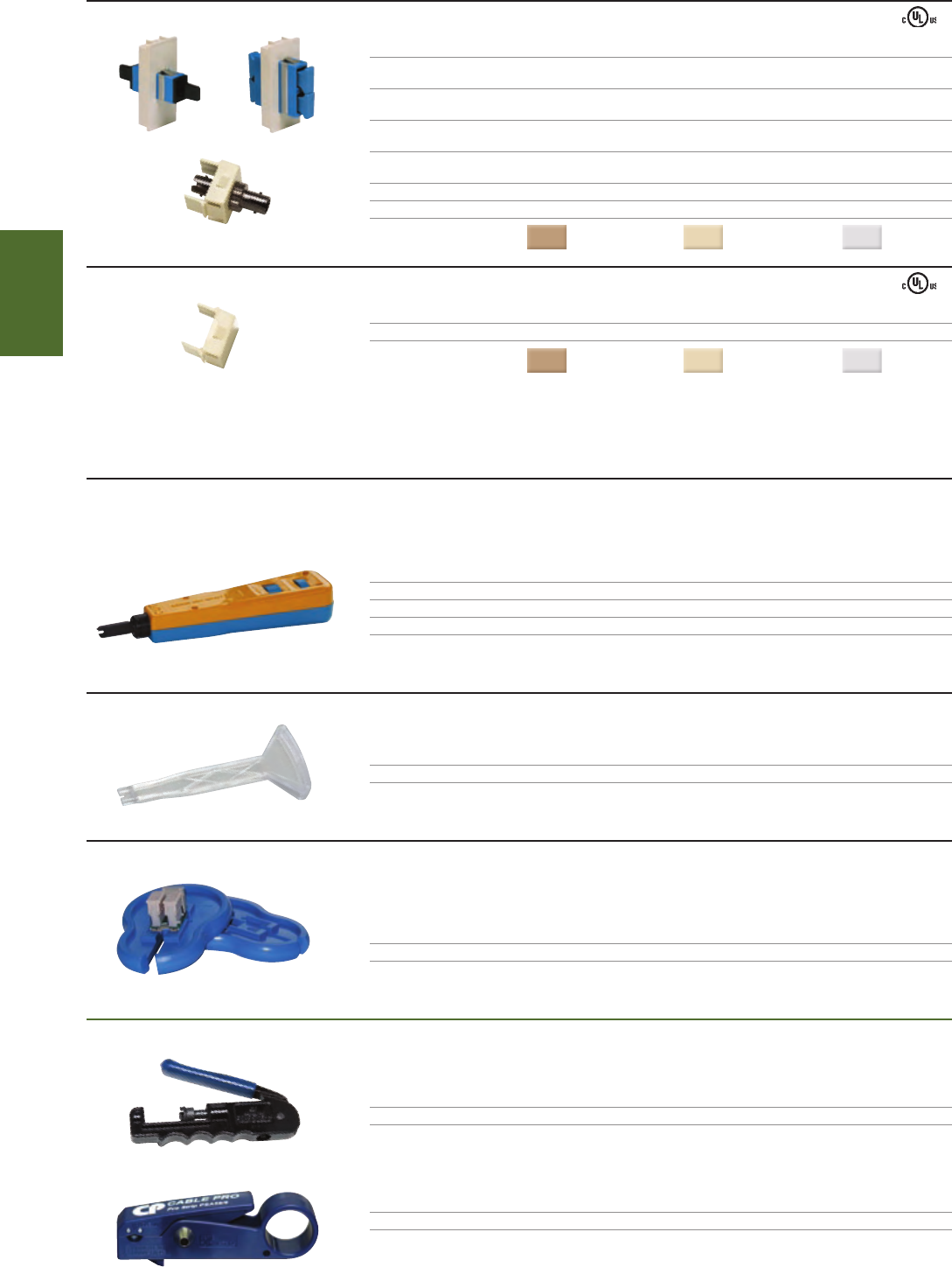
814B
798
2 - FTP
SCPLCCT - SLM
SPSA
STAR504SC - xx STAR505SC - xx
STAR500STB
STAR500B - xx
STRUCTURED
WIRING
1-800-852-8662 WWW.SUTTLEONLINE.COM
TOOLS
814 AUTOMATIC TERMINATING TOOL
The 814B impact tool is designed for termination of 22 - 26 AWG station wire on 110 or 66 type terminations. Spring - loaded and fully adjustable.
This tool is ideal when working with wires of varying thickness. Reversible Termination Blade can terminate and cut off excess wire or terminate only.
PART# DESCRIPTION
814B Automatic impact tool
81401 - 110 - 88 Replacement blade for 814B tool, 110 clip style
81401 - 66 Replacement blade for 814B tool, 66 clip style
798 PUNCHDOWN TOOL
PART# DESCRIPTION
798 110 IDC connect tool; for use with 22 - 26 AWG PVC and PIC cables.
FIELD TERMINATION PUCK
The ergonomically designed Suttle termination puck protects workers hands while providing a fast and easy way of
terminating modules requiring punchdown termination. Modules easily slide and lock into position creating a safe and
convenient way of terminating.
PART# DESCRIPTION
2 - FTP Punchdown termination puck
➥NEW COAX COMPRESSION TOOLS
PART# DESCRIPTION
SCPLCCT - SLM Coax compression tool, includes various tips for different connector types
PART# DESCRIPTION
SPSA Adjustable RG59/RG6 quad - shield cable stripper with RG6 flaring tool
Ú
FIBER OPTIC CONNECTORS
PART# DESCRIPTION
STAR - SCS - xx Simplex SC insert and adapter for use with
STAR1064M single gang duplex mounting frame only (pg 63)
STAR - SCD - xx Duplex SC insert and adapter for use with
STAR1064M single gang duplex mounting frame only (pg 63)
STAR504SC - xx Simplex SC insert and adapter for use with
insert style modular faceplates or surface mount housings
STAR505SC - xx Duplex SC insert and adapter for use with
insert style modular faceplates only or surface mount housings
STAR500STB - xx Simplex ST snap - in module housing and adapter
STAR500HST - xx Simplex ST snap - in module housing only
COLORS
( - xx): Electrical Ivory = (52) Light Almond = (64) White = (85)
BLANK CONNECTOR INSERT
PART# DESCRIPTION
STAR500B - xx Blank insert
COLORS
( - xx): Electrical Ivory = (52) Light Almond = (64) White = (85)
60
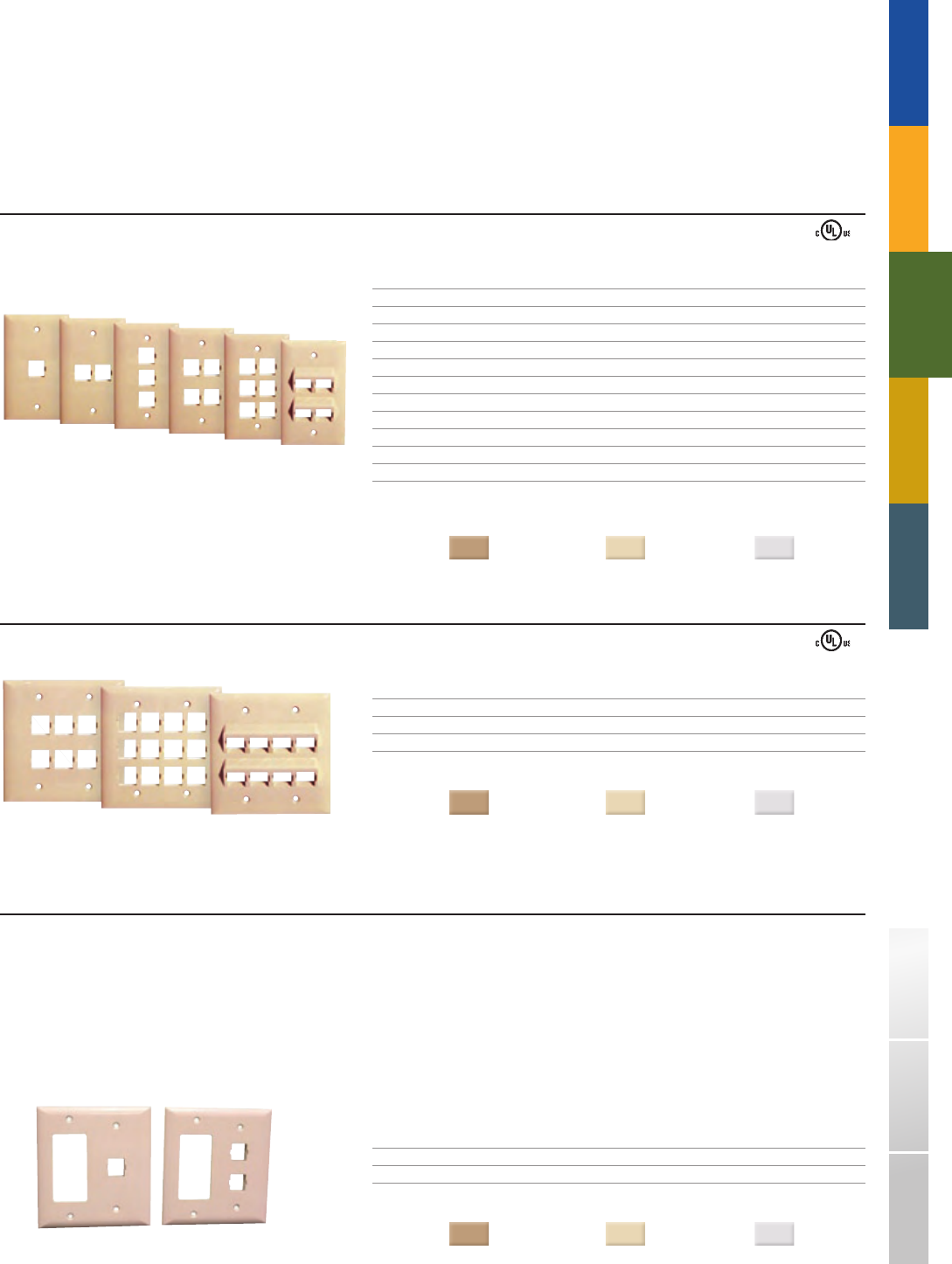
2 - 2501 - xx
2 - 2506D - xx
2 - 2501DS - xx
2 - 2503 - xx 2 - 2506 - xx
2 - 2504A - xx
2 - 2504 - xx
2 - 2502 - xx
2 - 2512D - xx 2 - 2508AD - xx
2 - 2502DS - xx
TRADITIONAL TELEPHONY
STRUCTURED
WIRING
FIBERDSLSOHO ACCESS™ USOC WIRING GUIDE GLOSSARY INDEX
SMOOTH MODULAR FACEPLATES : DOUBLE GANG
PART# DESCRIPTION
2 - 2506D - xx 6 - port faceplate, double gang, smooth finish
2 - 2512D - xx 12 - port faceplate, double gang, smooth finish
2 - 2508AD - xx 8 - port faceplate, double gang, smooth finish, angled
DIMENSIONS:
4.57"H x 4.5"W x 0.2"D
COLORS
( - xx): Electrical Ivory = (52) Light Almond = (64) White = (85)
FACEPLATES AND FRAMES
Faceplates are available in Smooth or Textured finishes
Modular ports provide versatile configuration options
Flush mount faceplates and surface mount housings deliver flexibility to any application
Mounting frames fit standard floor and wall J - box designs and can utilize standard electrical faceplates
SMOOTH MODULAR FACEPLATES : SINGLE GANG
PART# DESCRIPTION
2 - 2501 - xx 1 - port faceplate, single gang, smooth finish
2 - 2501M - xx 1 - port faceplate, oversized, smooth finish
2 - 2502 - xx 2 - port faceplate, single gang, smooth finish
2 - 2502M - xx 2 - port faceplate, oversized, smooth finish
2 - 2503 - xx 3 - port faceplate, single gang, smooth finish
2 - 2503M - xx 3 - port faceplate, oversized, smooth finish
2 - 2504 - xx 4 - port faceplate, single gang, smooth finish
2 - 2504M - xx 4 - port faceplate, oversized, smooth finish
2 - 2506 - xx 6 - port faceplate, single gang, smooth finish
2 - 2506M - xx 6 - port faceplate, oversized, smooth finish
2 - 2504A - xx 4 - port faceplate, single gang, smooth finish
DIMENSIONS:
Oversized – 4.875"H x 3.125"W x 0.2"D
Single Gang – 4.57"H x 2.81"W x 0.2"D
COLORS
( - xx): Electrical Ivory = (52) Light Almond = (64) White = (85)
Ú
■
■
■
■
SMOOTH MODULAR FACEPLATES: COMBO ELECTRIC/MULTIMEDIA FACEPLATE
This double gang electric/multimedia combo faceplate provides a single gang electrical port for standard GFCI electrical receptacles as well as one or two multimedia ports (for
voice, data, video, audio, or fiber modules). The smooth, sleek design matches electrical style faceplates and is available in 3 colors.
Single gang electrical port – fits standard GFCI electrical receptacles
Available with one or two multimedia connector ports
Smooth, Sleek design
Snap - in module ports provide versatile configurations for voice, data, video, audio, or fiber connections
Note: check local building codes about wiring
PART# DESCRIPTION
2 - 2501DS - xx 1 multimedia port, single gang GFCI port, smooth finish
2 - 2502DS - xx 2 multimedia port, single gang GFCI port, smooth finish
DIMENSIONS:
4.8"H x 4.5"W x 0.2"D
COLORS
( - xx): Electrical Ivory = (52) Light Almond = (64) White = (85)
■
■
■
■
■
61
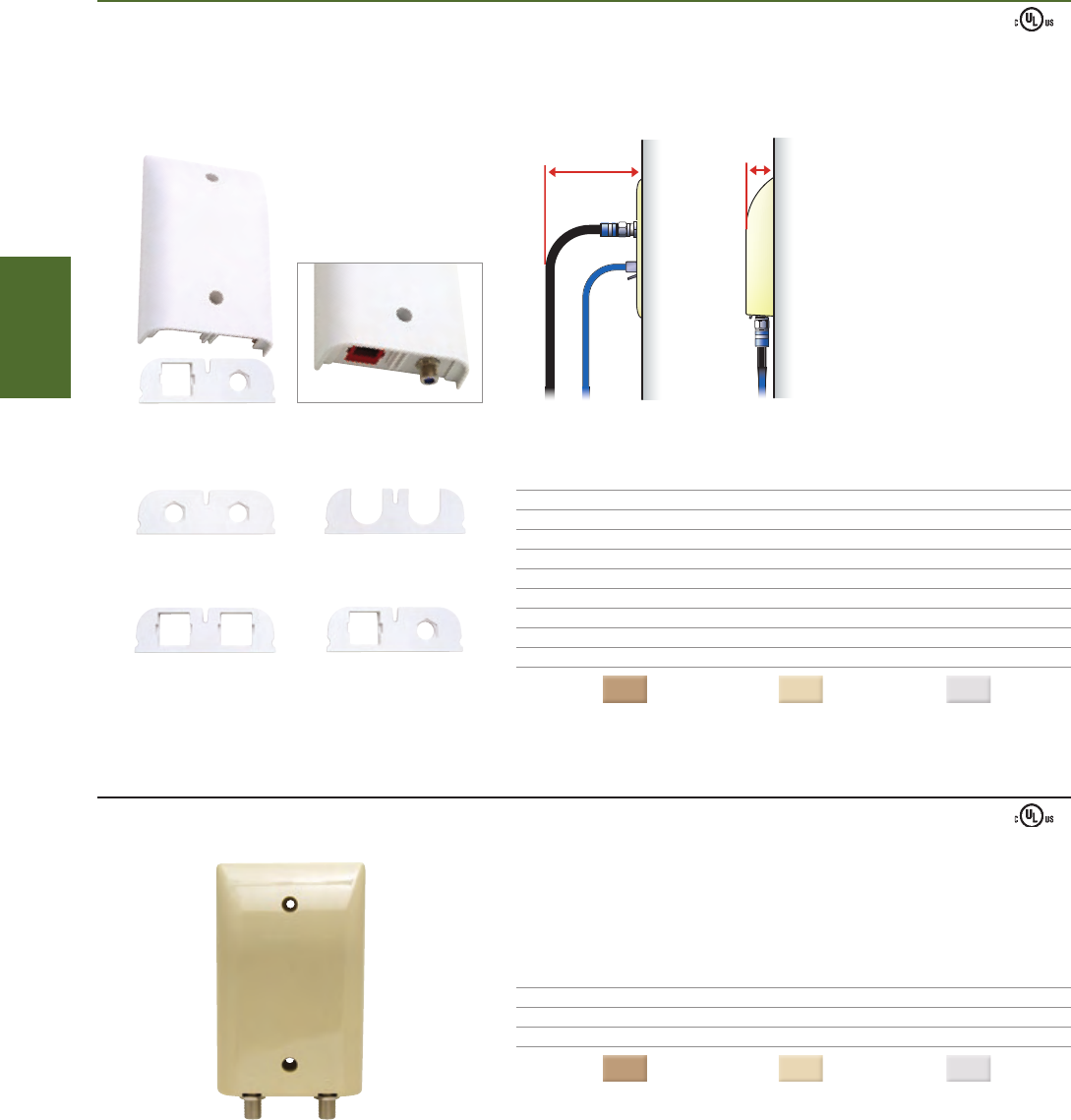
Normal Profile
Integrity II
Profile
The downward orientation
of the faceplate delivers
improved performance
and value in the areas
of network integrity,
bend radius integrity,
and connection integrity.
2 - 6001 - 2FC - xx
2 - 6504 - xx
2-port F81 insert
2-port SpeedStar insert
CablePass™ insert
Combo F81/SpeedStar insert
STRUCTURED
WIRING
1-800-852-8662 WWW.SUTTLEONLINE.COM
➥NEW INTEGRITY™ II PLATE
The Integrity™ II line of products provides a different way to look at trouble free installations.
Protects connectors from damage caused by objects forced against the plate
Four insert configurations for maximum flexibility
Mounting screws included
■
■
■
PART# DESCRIPTION
2 - 6501 - xx Plate w/ 2 - port F81 connector insert, connectors not included
2 - 6502 - xx Plate w/ 2 - port SpeedStar connector insert, connectors not included
2 - 6503 - xx Plate w/ CablePass™ feed through insert
2 - 6504 - xx Plate w/ combo F81/SpeedStar connector insert, connectors not included
2 - 6500 - xx Plate w/ all 4 inserts
COLORS
( - xx): Electrical Ivory = (52) Light Almond = (64) White = (85)
INTEGRITY™ COAX PLATE
Protects connectors from damage caused by objects forced against the plate
Tear out feature for CablePass™ feed through
Mounting screws included
PART# DESCRIPTION
2 - 6001 - xx Plate only, no connectors
2 - 6001 - 1FC - xx Plate w/ 1 F81 barrel connector, 3GHz, SCTE compliant (SCTE 02 2006)
2 - 6001 - 2FC - xx Plate w/ 2 F81 barrel connector, 3GHz, SCTE compliant (SCTE 02 2006)
COLORS
( - xx): Electrical Ivory = (52) Light Almond = (64) White = (85)
■
■
■
62
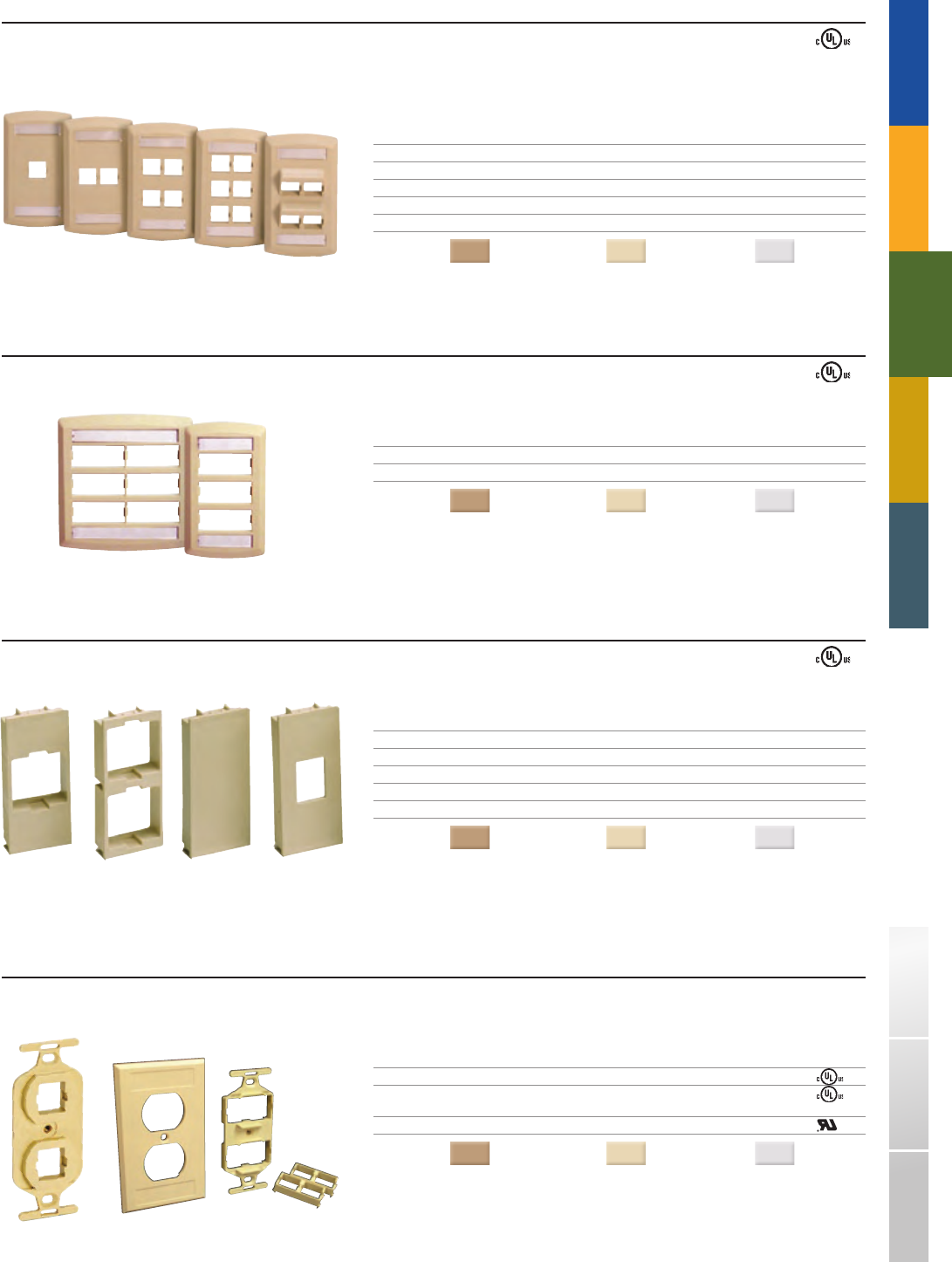
STAR500S1 - xx
STAR500S4 - xx
STAR500AF - xx
STAR500S6 - xx
STAR500S2 - xx
STAR5502P - xx STAR5501P - xx
STAR503 - xx STAR504 - xx
STAR501 - xx STAR502 - xx
STAR1062 - xx 860A - xx STAR1064M - xx
TRADITIONAL TELEPHONY
STRUCTURED
WIRING
FIBERDSLSOHO ACCESS™ USOC WIRING GUIDE GLOSSARY INDEX
TEXTURED MODULAR FACEPLATES WITH LABELS : STANDARD
PART# DESCRIPTION
STAR500S1 - xx 1 - port, single gang
STAR500S2 - xx 2 - port, single gang
STAR500S4 - xx 4 - port, single gang
STAR500S6 - xx 6 - port, single gang
STAR500AF - xx 4 - port, angled, single gang
COLORS
( - xx): Electrical Ivory = (52) Light Almond = (64) White = (85)
TEXTURED MODULAR FACEPLATES WITH LABELS : INSERT
PART# DESCRIPTION
STAR5501P - xx 6 - port, single gang (requires mounting plate inserts)
STAR5502P - xx 12 - port, double gang (requires mounting plate inserts)
COLORS
( - xx): Electrical Ivory = (52) Light Almond = (64) White = (85)
MOUNTING PLATE INSERTS
PART# DESCRIPTION
STAR501 - xx 1 - port insert
STAR502 - xx 2 - port insert
STAR503 - xx Blank insert (no ports)
STAR504 - xx Simplex SC insert
STAR505 - xx Duplex SC insert
COLORS
( - xx): Electrical Ivory = (52) Light Almond = (64) White = (85)
106 TYPE MODULAR MOUNTING FRAMES : SINGLE GANG
PART# DESCRIPTION
STAR1062 - xx 2 - port insert mounting frame
STAR1064M - xx 4 - port duplex insert style mounting frame
(includes mounting plate inserts)
860A - xx Duplex electrical style faceplate with label location
COLORS
( - xx): Electrical Ivory = (52) Light Almond = (64) White = (85)
63
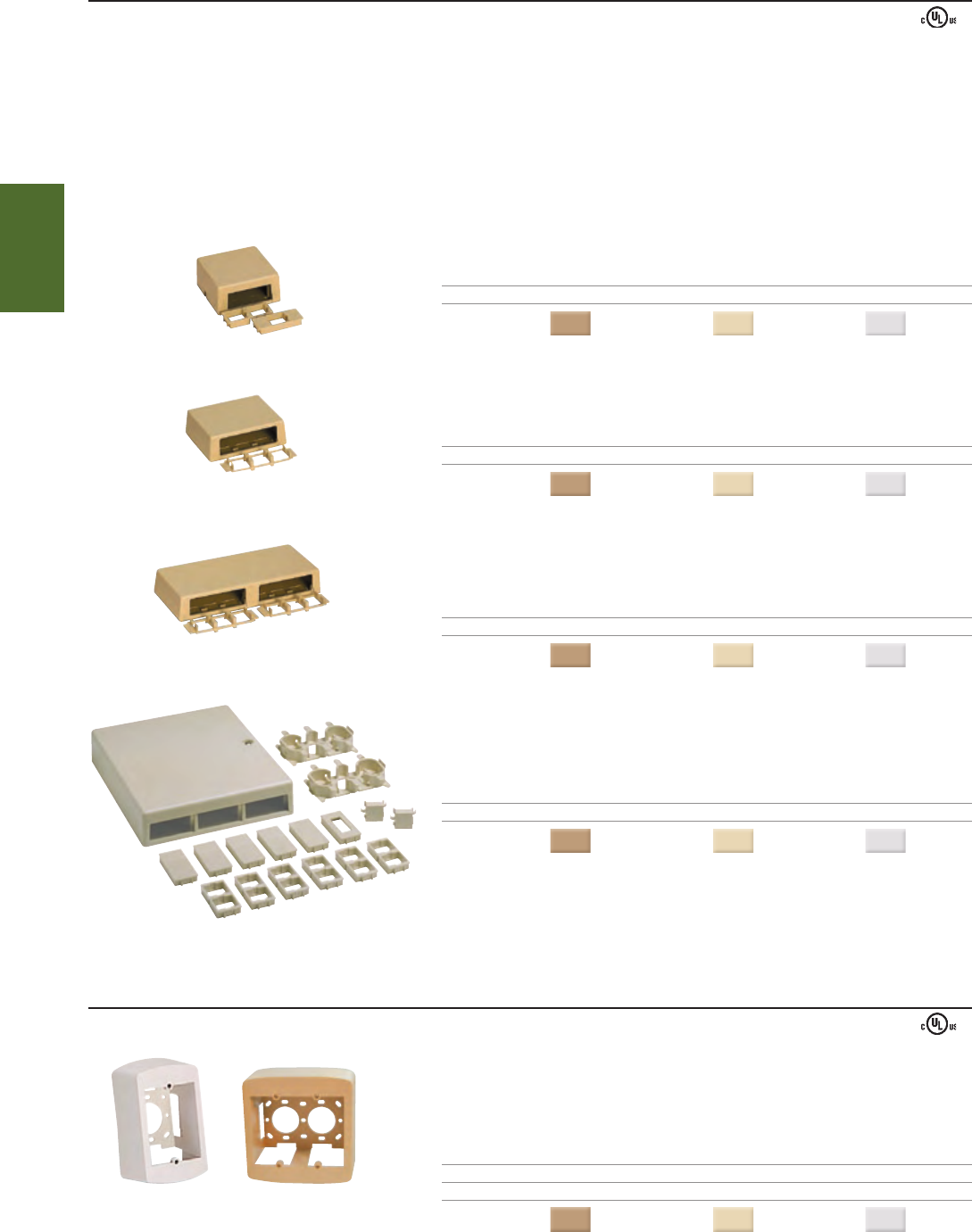
STAR558 - xx
STAR107SM - xx
STAR108SM - xx
STARMMB - xx
STARMBD - xx STARMBDD - xx
STRUCTURED
WIRING
1-800-852-8662 WWW.SUTTLEONLINE.COM
SURFACE MOUNT HOUSINGS AND BOXES
SURFACE MOUNT HOUSINGS
SpeedStar surface mount housings are available in several configurations for use with Suttle’s multimedia connectors. Each housing provides simple snap - in installation
through the use of versatile insert plates.
Easily field configured with snap - in connectors which can be terminated directly in each port
Snap - in wiring spools provide cable management and recommended strain relief (STARMMB only)
Screw or adhesive pad mounting options (both included)
Easy to read port designations for quick identification (STARMMB only)
Snap on cover reduces installation time (STARMMB has a screw - on cover)
The STARMMB (Multi - Media Box) contains knockouts to accommodate cable or raceway entry and fits single, double, and European style electrical
PART# DESCRIPTION DIMENSIONS
STAR558 - xx 1 - or 2 - ports 2.5"L x 2.7"W x 1.18"H
COLORS
( - xx): Electrical Ivory = (52) Light Almond = (64) White = (85)
PART# DESCRIPTION DIMENSIONS
STAR107SM - xx Up to 3 - ports 3.25"L x 2.63"W x 1.04"H
COLORS
( - xx): Electrical Ivory = (52) Light Almond = (64) White = (85)
PART# DESCRIPTION DIMENSIONS
STAR108SM - xx Up to 6 - ports 6.2"L x 2.63"W x 1.04"H
COLORS
( - xx): Electrical Ivory = (52) Light Almond = (64) White = (85)
PART# DESCRIPTION DIMENSIONS
STARMMB - xx Up to 12 - ports 6.82"L x 5.61"W x 1.35"H
COLORS
( - xx): Electrical Ivory = (52) Light Almond = (64) White = (85)
Ú
■
■
■
■
■
■
SURFACE MOUNT BOXES
Contoured to match textured SpeedStar faceplates
Provides for proper Category 5e and Category 6 bend radius
Oversized to accommodate most faceplates
Rear cable entry and mounting holes to fit most brackets
Knockouts on top, bottom, and sides for raceway entry
ART# DESCRIPTION
STARMBD - xx Surface mount box, single gang
STARMBDD - xx Surface mount box, double gang
COLORS
( - xx): Electrical Ivory = (52) Light Almond = (64) White = (85)
■
■
■
■
■
64
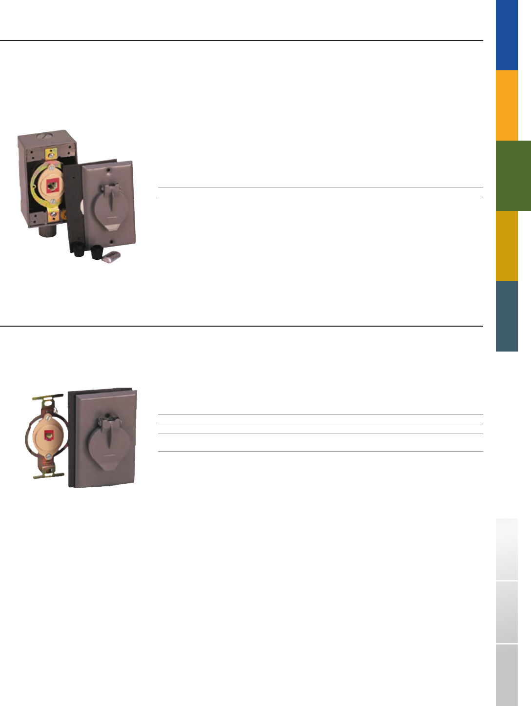
STAR16152
STAR19316
TRADITIONAL TELEPHONY
STRUCTURED
WIRING
FIBERDSLSOHO ACCESS™ USOC WIRING GUIDE GLOSSARY INDEX
OUTDOOR JACK ASSEMBLIES
OUTDOOR SURFACE MOUNT JACK ASSEMBLIES
Removable mounting tabs
Station wire entrance coupling contains bushing for added protection
Wire entrance available from top, bottom, or either side
Conduit or pipe entrance can be made by removing the 1/2 inch threaded pipe nipple
Housing is die cast aluminum with corrosion resistance finish
PART# DESCRIPTION
STAR19316 1 - port, designed for use w/Speedstar modular connector (not included)
Ú
■
■
■
■
■
OUTDOOR FLUSH MOUNT JACK ASSEMBLIES
Neoprene rubber gasket provides water - resistant seal on masonry, wood, or uneven surfaces
Faceplate is constructed of aluminum with baked enamel finish
PART# DESCRIPTION
STAR16152 1 - port, designed for use w/SpeedStar modular connector (not included)
STAR16152L8 1 - port, includes outlet box, designed for use
w/SpeedStar modular connector (not included)
■
■
65
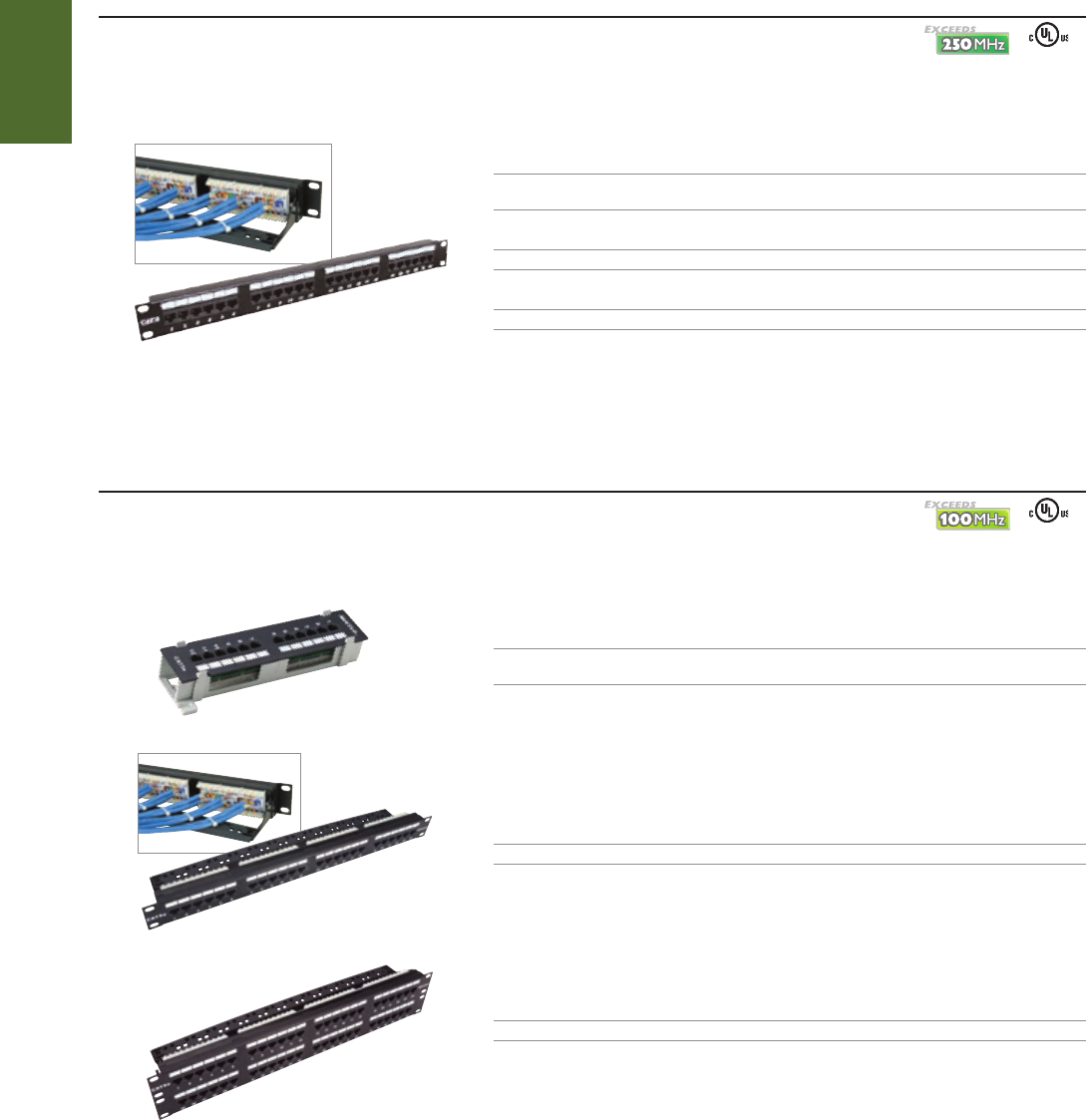
STAR19110C6 - 24
2 - 7030 - 24
2 - 7032 - 48
2 - 7034 - 12
STRUCTURED
WIRING
1-800-852-8662 WWW.SUTTLEONLINE.COM
CATEGORY 5e PATCH PANELS
Exceeds TIA/EIA - 568 - B.2 specifications for component performance
Supports bandwidth beyond 100MHz
PART# DESCRIPTION DIMENSIONS
2 - 7034 - 12 12 - port, Category 5e, 568A/B, wall mount 3.25"H x 10"W x 2"D
(89B bracket included)
PART# DESCRIPTION DIMENSIONS
2 - 7030 - 24 24 - port, Category 5e, 568A/B, 19" rack mount 1.75"H x 19"W x 3.5"D
PART# DESCRIPTION DIMENSIONS
2 - 7032 - 48 48 - port, Category 5e, 568A/B, 19" rack mount 3.5"H x 19"W x 3.5"D
■
■
Patch panels are 19 - inch rack mountable and are equipped with IDC terminated PCB assemblies. The 12- port patch panels include a bracket for wall mounting.
Rugged steel construction, with rolled edges eliminates flex during termination
Write - on label and number designations provide easy identification
Rear cable management bar provides cable strain relief
Multiple cable tie locations facilitate cable dressing, moves, adds, and changes
Termination labels provide port numbering and 568A/B color - coding for quick installation
Available in 12, 24, and 48 port configurations
DATA JACKS: CATEGORY 6
Exceeds TIA/EIA - 568 - B.2 - 1 specifications for performance
Supports bandwidth beyond 250MHz
Angled and paired IDC pins aid in maintaining maximum Category 6 performance, providing a gas tight connection and improved cable retention
PART# DESCRIPTION DIMENSIONS
STAR19110C6 - 12 12 - port, Category 6, 568A/B, wall mount 3.2"H x 10"W x 2"D
(bracket included)
STAR19110C6 - 24 24 - port, Category 6, 568A/B, 19" rack mount) 1.75"H x 19"W x 3.5"D
STAR19110C6 - 48 48 - port, Category 6, 568A/B, 19" rack mount) 3.5"H x 19"W x 3.5"D
■
■
■
■
■
■
■
■
■
PATCH PANELS❚
SEE PAGE 56
SEE PAGE 57
66
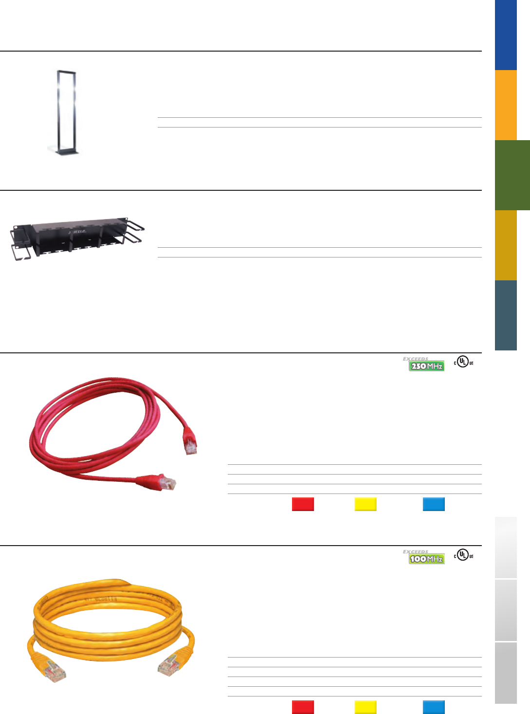
19110RK
19WM350
STAR661 - 04 - 53
2 - 7407 - 56
TRADITIONAL TELEPHONY
STRUCTURED
WIRING
FIBERDSLSOHO ACCESS™ USOC WIRING GUIDE GLOSSARY INDEX
EQUIPMENT RACK
Aluminum alloy relay rack for mounting computer room panels, enclosures and related communications equipment.
Side rails are drilled and tapped on both sides. Includes thirty (30) #12 - 24 screws.
PART# DESCRIPTION
19110RK Relay rack (19" W x 84" H)
RACKS AND CABLE MANAGEMENT❚
CATEGORY 6 PATCH CORDS
Exceeds TIA/EIA - 568 - B.2 - 1 specifications for performance
Category 6 products support bandwidth beyond 250MHz
Molded boot covers and protects the protruding latch, preventing connector disruption
The easily depressed latch mechanism makes it a snap to insert and unplug
Additional sizes and colors may be available by request
PART # DESCRIPTION LENGTH
STAR661 - 04 - xx Category 6 patch cord 4 - ft
STAR661 - 08 - xx Category 6 patch cord 8 - ft
STAR661 - 12 - xx Category 6 patch cord 12 - ft
COLORS
( - xx): Red = (53) Yellow = (56) Blue = (62)
■
■
■
■
■
PATCH CORDS❚
CATEGORY 5e PATCH CORDS
Exceeds TIA/EIA - 568 - B.2 specifications for component performance
Category 5e products support bandwidth beyond 100MHz
Molded boot covers provide bend radius protection
The easily depressed latch mechanism makes it a snap to insert and unplug
Additional sizes and colors may be available by request
PART # DESCRIPTION LENGTH
2 - 7403 - xx Category 5e patch cord 3 - ft
2 - 7407 - xx Category 5e patch cord 7 - ft
2 - 7410 - xx Category 5e patch cord 10 - ft
2 - 7415 - xx Category 5e patch cord 15 - ft
COLORS
( - xx): Red = (53) Yellow = (56) Blue = (62)
■
■
■
■
■
HORIZONTAL TROUGH
The 19WM350 provides a horizontal trough to route cable between components within or between racks.
PART# DESCRIPTION
19WM350 Horizontal trough (19" W x 3.5" H)
SEE PAGE 56
SEE PAGE 57
67
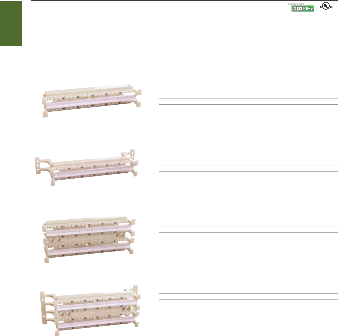
STAR110C6 - 48
STAR110C6 - 48L
STAR110C6 - 96
STAR110C6 - 96L
STRUCTURED
WIRING
1-800-852-8662 WWW.SUTTLEONLINE.COM
CATEGORY 6 110 CROSS - CONNECTS
Suttle’s SpeedStar 110 Cross - Connect System provides a high performance Category 6 or 5e solution for data communications management in a
telecommunications closet, main distribution frame, or consolidation point. 110 Cross - Connects are ideal for use where space is limited or a cost - effective
solution is preferred over a modular patch panel.
CATEGORY 6 CROSS - CONNECT SYSTEM
Exceeds Category 6 TIA/EIA - 568 - B.2 - 1 specifications for channel performance
Angled and paired IDC pins aid in maintaining maximum CAT6 performance and provide a gas tight connection and improved cable retention
Wiring Block design permits neat, organized wiring behind the block
Solder - plated quick clips easily cut through insulation on 22 - 26 AWG conductors
Color - coded for rapid pair identification and termination
Available with or without legs
PART# DESCRIPTION
STAR110C6 - 48 48 - pair base includes 4 - pair connecting blocks and label kits
PART# DESCRIPTION
STAR110C6 - 48L 48 - pair base with legs, includes 4 - pair connecting blocks and label kits
PART# DESCRIPTION
STAR110C6 - 96 96 - pair base includes 4 - pair connecting blocks and label kits
PART# DESCRIPTION
STAR110C6 - 96L 96 - pair base with legs, includes 4 - pair connecting blocks and label kits
Ú
■
■
■
■
■
■
110 CROSS - CONNECTS❚
SEE PAGE 56
68
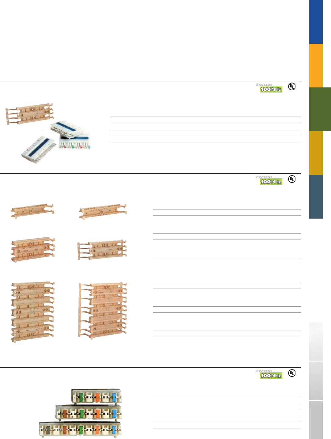
110DW1 - 50110DW1 - 25
110AW2 - 100
110DW2 - 100
110AW2 - 300
110DW2 - 300
110C - 5
110C - 4
110C - 3
TRADITIONAL TELEPHONY
STRUCTURED
WIRING
FIBERDSLSOHO ACCESS™ USOC WIRING GUIDE GLOSSARY INDEX
CATEGORY 5e 110 CROSS - CONNECTS
The Suttle Category 5e 110 Cross - Connect System is available in easy - to - order kits or individual components.
Exceeds Category 5e TIA/EIA - 568 - B.2 specifications for component performance
Wiring Block design permits neat, organized wiring behind the block
Solder - plated quick clips easily cut through insulation on 22 - 26 AWG conductors
Color - coded for rapid pair identification and termination
Available with or without legs
CATEGORY 5e CROSS - CONNECT SYSTEM : TERMINATION KITS
PART# DESCRIPTION DIMENSIONS
110AA2 - 100 100 - pair base with legs; 5 - pair connecting blocks and labels 3.6"H x 10.7"W x 3.4"D
110AB2 - 100 100 - pair base with legs; 4 - pair connecting blocks and labels 3.6"H x 10.7"W x 3.4"D
110AA2 - 300 300 - pair base with legs; 5 - pair connecting blocks and labels 10.8"H x 10.7"W x 3.4"D
110AB2 - 300 300 - pair base with legs; 4 - pair connecting blocks and labels 10.8"H x 10.7"W x 3.4"D
CATEGORY 5e 110 WIRING BLOCKS
PART# DESCRIPTION DIMENSIONS
110DW1 - 25 25 - pair base 0.8"H x 8.5"W x 1.6"D
PART# DESCRIPTION DIMENSIONS
110DW1 - 50 50 - pair base 1.7"H x 8.5"W x 1.6"D
PART# DESCRIPTION DIMENSIONS
110DW2 - 100 100 - pair base 3.6"H x 8.5"W x 1.6"D
PART# DESCRIPTION DIMENSIONS
110AW2 - 100 100 - pair base with legs 3.6"H x 10.7"W x 3.4"D
PART# DESCRIPTION DIMENSIONS
110DW2 - 300 300 - pair base 10.8"H x 8.5"W x 1.6"D
PART# DESCRIPTION DIMENSIONS
110AW2 - 300 300 - pair base with legs 10.8"H x 10.7"W x 3.4"D
CATEGORY 5e 110 CONNECTING BLOCKS
PART# DESCRIPTION
110C - 3 3 - pair connecting block
110C - 4 4 - pair connecting block
110C - 5 5 - pair connecting block
Ú
■
■
■
■
■
SEE PAGE 57
SEE PAGE 57
SEE PAGE 57
69
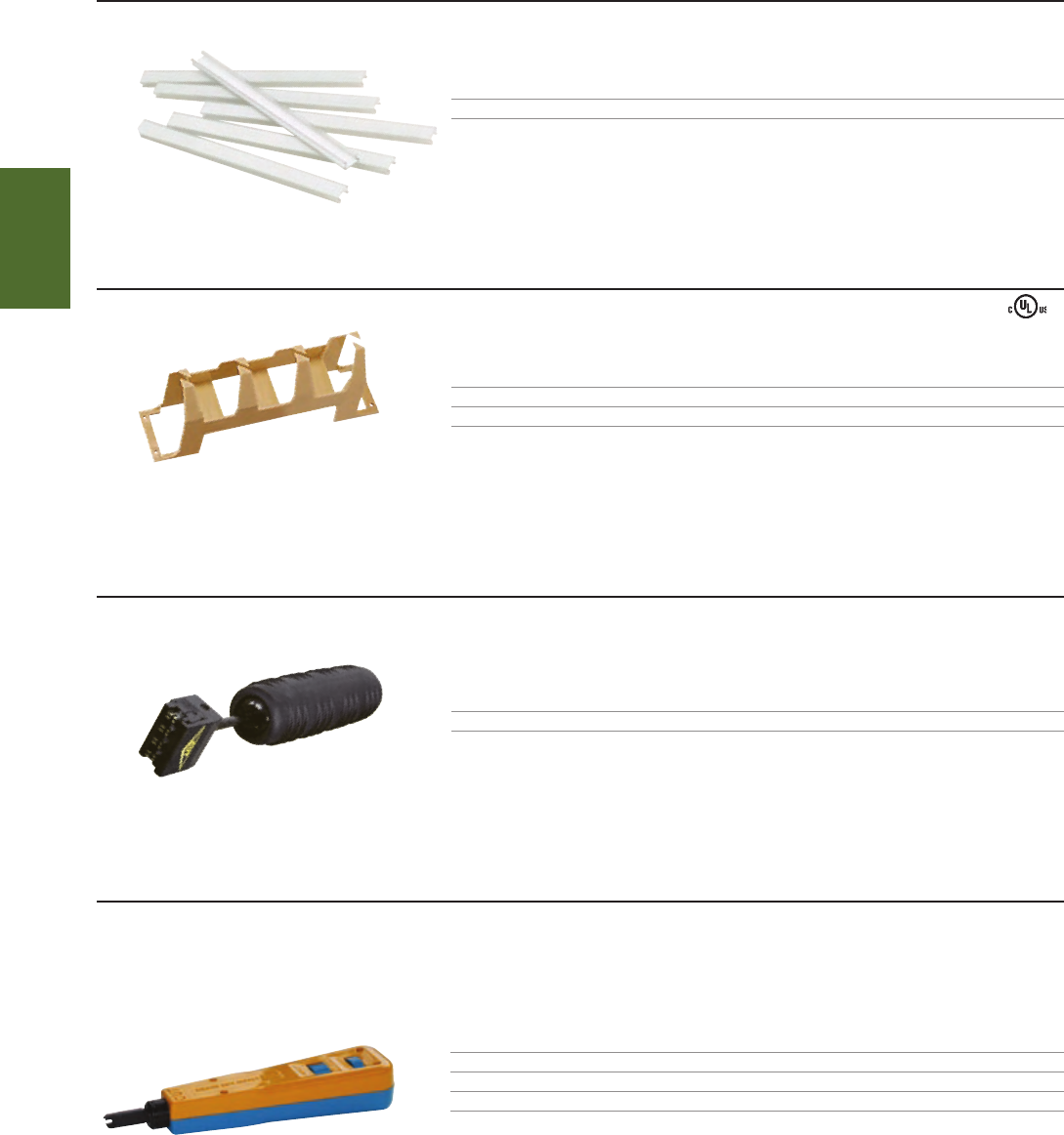
814B
STAR110C6 - T
110A2
188UT1 - 50
STRUCTURED
WIRING
1-800-852-8662 WWW.SUTTLEONLINE.COM
110 ACCESSORIES
LABELS
PART# DESCRIPTION
188UT1 - 50 Label kit with 6 unmarked strips and 6 transparent holders
TROUGHS
PART# DESCRIPTION DIMENSIONS
110A2 110 jumper trough with legs 1.85"H x 10.75"W x 4.4"D
110B1 110 jumper trough without legs 1.75"H x 8.5"W x 2.5"D
TOOL : 110 CATEGORY 6 MULTI - PAIR TERMINATION TOOL
PART# DESCRIPTION
STAR110C6 - T 4 - pair punchdown tool for Category 6 110 Cross Connect System
* For use with STAR19110C6 - xx patch panels and STAR110C6 - 4 - xx connecting block
TOOL : 814 TERMINATION TOOL
The 814B impact tool is designed for termination of 22 - 26 AWG station wire on 110 or 66 type terminations. Spring - loaded and fully adjustable. This tool is ideal when working
with wires of varying thickness. Reversible Termination Blade can terminate and cut off excess wire or terminate only.
PART# DESCRIPTION
814B Automatic impact tool
81401 - 110 - 88 Replacement blade for 814B tool, 110 clip style
81401 - 66 Replacement blade for 814B tool, 66 clip style
Ú
70
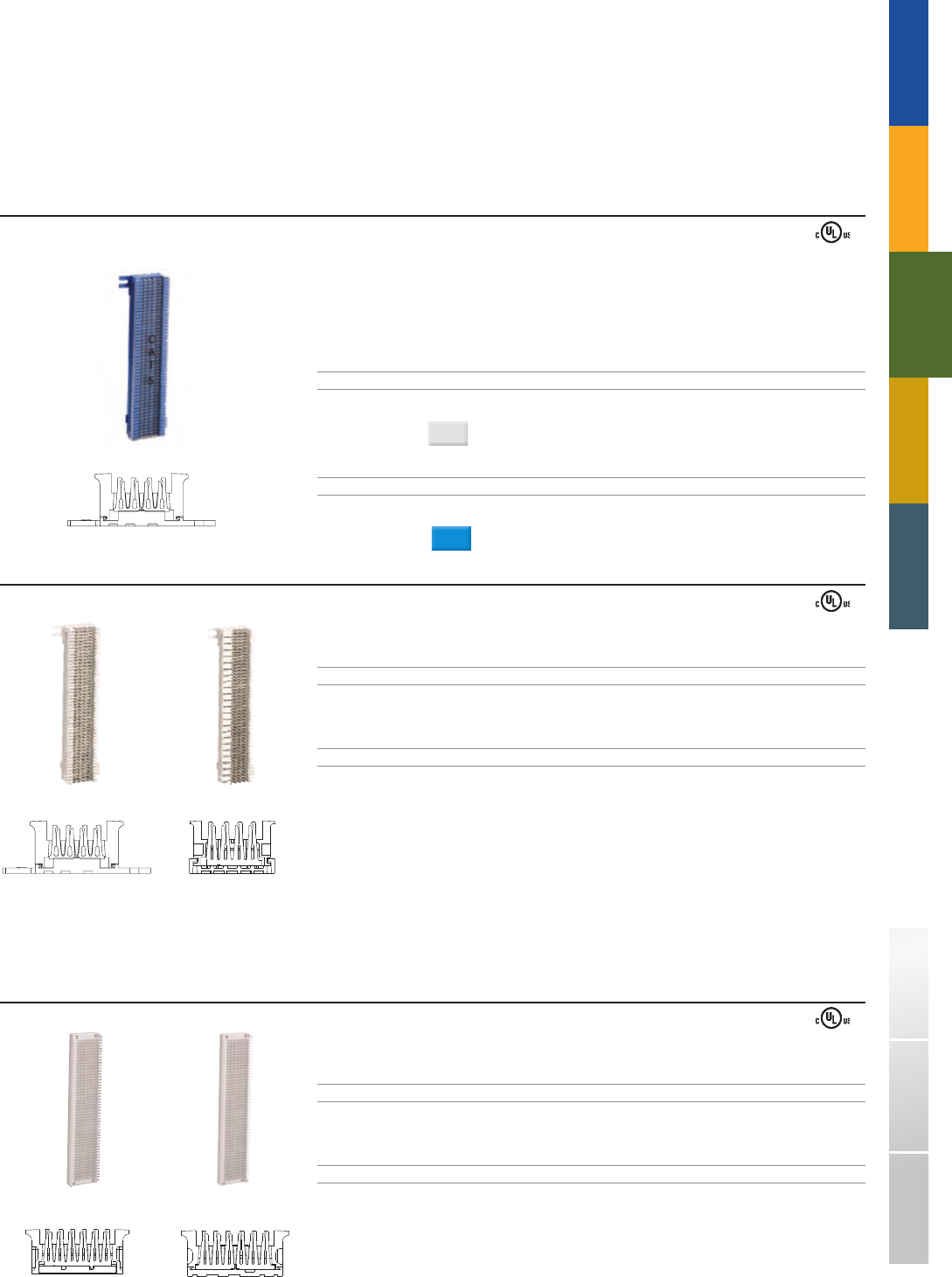
66M1 - 50 - C5 - 62
2 - clip
A66M1 - 50
2 - clip
A66M1 - 25
4 - clip
A66B4 - 25
6 - clip
A66B3 - 50
3 - clip
TRADITIONAL TELEPHONY
STRUCTURED
WIRING
FIBERDSLSOHO ACCESS™ USOC WIRING GUIDE GLOSSARY INDEX
Suttle’s 66 Block system is used in equipment rooms or in remote and intermediate wiring closets to connect voice or data wiring to customer premise equipment.
Blocks are molded of flame retardant thermoplastic with quick - connect 66 clips for ease of installation and proven termination reliability
FIELD TERMINATED 66M BLOCKS
CATEGORY 5 CONNECTING BLOCKS
Designed to fill the need for CAT5 distribution using familiar quick - clips for termination.
Ability to transmit data rates up to 100 MHz
Exceeds TIA/EIA 568 - B specifications for Category 5 performance
Includes cover labeled CAT5
PART# DESCRIPTION PAIR CAPACITY TERMINAL
66M1 - 50 - C5 4 x 50, Category 5, 66M connecting block 50 2 - clip
DIMENSIONS:
10"H x 3.4"W x 1.25"D
COLORS
( - xx): White = (85)
PART# DESCRIPTION PAIR CAPACITY TERMINAL
66M1 - 50 - C5 - 62 4 x 50, Category 5, 66M connecting block 50 2 - clip
DIMENSIONS:
10"H x 3.4"W x 1.25"D
COLORS
( - xx): Blue = (62)
■
Ú
■
■
■
66 BLOCK SYSTEM❚
4 x 50 BLOCKS
PART# DESCRIPTION PAIR CAPACITY TERMINAL
A66M1 - 25 4 x 50, 66M connecting block, includes 1 designation strip 25 4 - clip
DIMENSIONS:
10"H x 3.4"W x 1.2"D
PART# DESCRIPTION PAIR CAPACITY TERMINAL
A66M1 - 50 4 x 50, 66M connecting block, includes 2 designation strips 50 2 - clip
DIMENSIONS:
10"H x 3.4"W x 1.2"D
FIELD TERMINATED 66B BLOCKS
6 x 50 BLOCKS
PART# DESCRIPTION PAIR CAPACITY TERMINAL
A66B4 - 25 6 x 50, 66B connecting block 25 6 - clip
DIMENSIONS:
13.44"H x 2.8"W x 1.25"D
PART# DESCRIPTION PAIR CAPACITY TERMINAL
A66B3 - 50 6 x 50, 66B connecting block 50 3 - clip
DIMENSIONS:
13.44"H x 2.8"W x 1.25"D
Ú
71
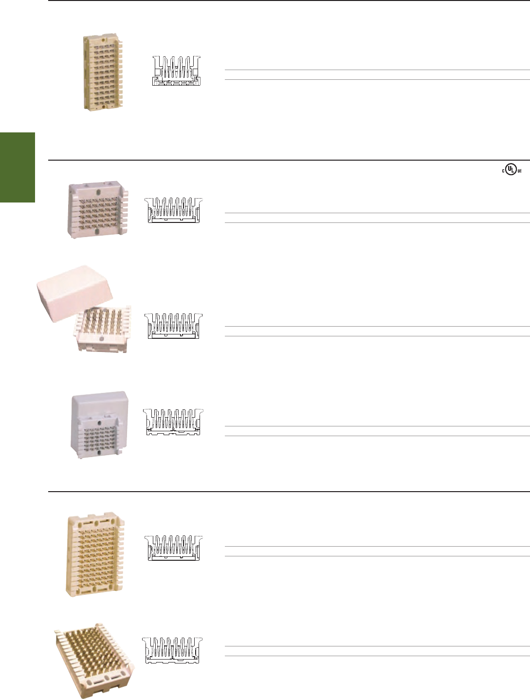
66CB1 - 6
4 - clip
A66B4 - 3
6 - clip
A66B6 - 3
6 - clip
A66B3 - 6
3 - clip
66B1 - 6
6 - clip
66B1 - 12
6 - clip
STRUCTURED
WIRING
1-800-852-8662 WWW.SUTTLEONLINE.COM
4 x 12 BLOCKS
PART# DESCRIPTION PAIR CAPACITY TERMINAL
66CB1 - 6 4 x 12, 66CB connecting block 6 4 - clip
DIMENSIONS:
2"H x 4.25"W x 1.4"D
6 x 6 BLOCKS
PART# DESCRIPTION PAIR CAPACITY TERMINAL
A66B4 - 3 6 x 6, 66B connecting block 3 6 - clip
DIMENSIONS:
2.4"H x 2.8"W x 1.2"D
PART# DESCRIPTION PAIR CAPACITY TERMINAL
A66B6 - 3 6 x 6, 66B connecting block, includes a snap - on cover 3 6 - clip
DIMENSIONS:
3.5"H x 3.5"W x 1.25"D w/cover
PART# DESCRIPTION PAIR CAPACITY TERMINAL
A66B3 - 6 6 x 6, 66B connecting block, includes a snap - on cover 6 3 - clip
DIMENSIONS:
3.5"H x 3.5"W x 1.25"D w/cover
6 x 12 Blocks
PART# DESCRIPTION PAIR CAPACITY TERMINAL
66B1 - 6 6 x 12, 66B connecting block 6 6 - clip
DIMENSIONS:
3.9"H x 2.8"W x 1.2"D
PART# DESCRIPTION PAIR CAPACITY TERMINAL
66B1 - 12 6 x 12, 66B connecting block 12 3 - clip
DIMENSIONS:
3.9"H x 2.8"W x 1.2"D
72
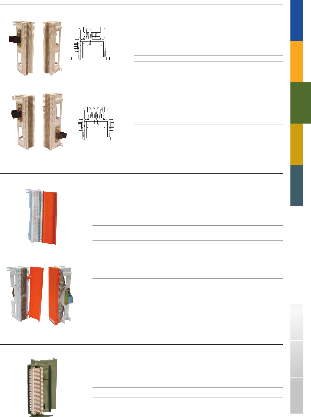
A66C2 - 16
66M2 - 3W
66M2 - 5W
2 - clip
2 - clip
TRADITIONAL TELEPHONY
STRUCTURED
WIRING
FIBERDSLSOHO ACCESS™ USOC WIRING GUIDE GLOSSARY INDEX
CONNECTORIZED NETWORK INTERFACE JACKS
Provides clear demarcation between the telephone company and the customer - owned equipment.
Furnished with an attached hinged cover
Fulfills FCC requirement for a registered interface for connection of customer terminal equipment to the network
CONNECTING
PART# DESCRIPTION ARRANGEMENT PAIRS TERMINAL
AJK - 700A - 66 - B1 - 25 Ideal for most installations, this 66 terminal RJ21X 25 2 - clip
block consists of a RJ21X female connector
pre - wired to the right side.
CONNECTING
PART# DESCRIPTION ARRANGEMENT PAIRS TERMINAL
AJK - 700B - 66 - B1 - 12 This 66 terminal block consists of a RJ71C RJ71C 12 2 - clip
self - shorting female connector pre - wired to
the right side column of the block, and provides
automatic circuit continuation between the
network and equipment when disconnecting
ancillary equipment.
■
■
66C CONNECTING BLOCK WITH HOUSING
Each block is mounted on a metal base for mounting directly to walls and includes a distribution ring for dressing of cable.
Provides termination of 16 incoming pairs
PART# DESCRIPTION PAIR CAPACITY TERMINAL
A66C2 - 16 4 x 32, 66C connecting block, equipped 16 4 - clip
with metal housing
DIMENSIONS:
10"H x 5"W x 2.5"D
■
PRE - WIRED 66M2 CONNECTING BLOCKS
These are connectorized quick connect blocks designed for rapid installation of key telephone
systems, PBX systems, cables and other low voltage terminal equipment.
Available with female connectors, designed for top cable entry
Pre - wired to the 25 - pair connectors on the side
PART# DESCRIPTION PAIR CAPACITY TERMINAL
66M2 - 3W One female 25 - pair connector 25 2 - clip
PART# DESCRIPTION PAIR CAPACITY TERMINAL
66M2 - 5W Two female 25 - pair connectors 50 2 - clip
■
■
73
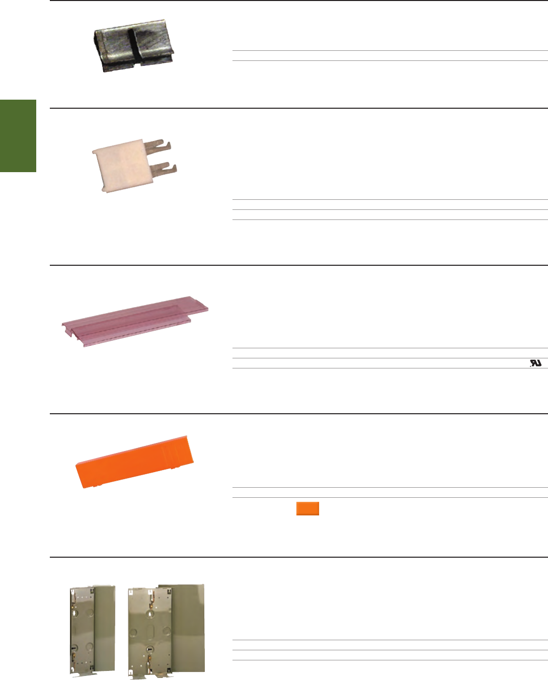
1127 - A1
183A2
031709 - 97
A115C1 A115D1
STRUCTURED
WIRING
1-800-852-8662 WWW.SUTTLEONLINE.COM
66 ACCESSORIES
BRIDGING CLIP
These clips can be used to bridge terminals on a block having two 2 - clips or two 3 - clips across a row.
PART# DESCRIPTION DIMENSIONS
1127 - A1 66 block bridging clip 0.5"W x 0.25"H
CAPACITY EXPANDING BLOCK ADAPTERS
These can be installed on every row but not side by side on a 66 connecting block to expand capacity.
This adapter is not for use on CAT5 rated 66M1 - 50 blocks.
Provides additional connections without interfering with already connected wires
Provides positive insulation from one row to the adjacent row
PART# DESCRIPTION
183A3 66 block adapter, 1 single quick clip
183A2 66 block adapter, 1 double quick clip
COVERS : PROTECTIVE
For use with 66B and 66M connecting blocks.
Self - extinguishing transparent plastic
Snaps on for convenience
PART# DESCRIPTION DIMENSIONS
66BC6 Transparent cover for 6 x 50, 66B blocks 12.63"H x 3"W x 0.36"D
66MC - 4 Transparent cover for 4 x 50, 66M blocks 10"H x 2.3"W x 0.29"D
COVERS : HINGED
For use with 66M connecting blocks.
Self - extinguishing plastic
PART# DESCRIPTION DIMENSIONS
031709 - 97 Hinged cover 10"H x 2.26"W x 0.5"D
COLOR
: Orange * Additional colors may be available by request.
66 BLOCK APPARATUS BOXES
Used to terminate and fan out horizontal distribution cable.
Furnished with a snap - on cover, distribution rings and mounting hardware
These offer greater flexibility where space is limited
PART# DESCRIPTION DIMENSIONS
A115C1 Fits one 4 x 50 or 6 x 50 block 17.25"W x 5.2"H x 2.5"D
A115D1 Fits two 4 x 50 or 6 x 50 blocks 17.25"H x 9.25"W x 2.5"D
Ú
■
■
■
■
■
■
■
74
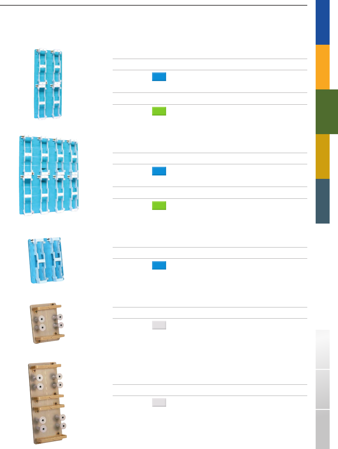
A183A1
A183B1
A183C1
A187A1
A187B1
TRADITIONAL TELEPHONY
STRUCTURED
WIRING
FIBERDSLSOHO ACCESS™ USOC WIRING GUIDE GLOSSARY INDEX
BACKBOARDS
Used to mount 66 type connecting blocks and for horizontal jumper runs.
Available in several different sizes and colors for identification of functional areas in cross - connect fields
66M1 - 50 blocks ordered separately
PART# DESCRIPTION DIMENSIONS
A183A1 200 - pair capacity via four 66M1 - 50 blocks, 20"H x 8.5"W
equipped with four 89B brackets
COLOR
: Blue
PART# DESCRIPTION DIMENSIONS
A183A2 200 - pair capacity via four 66M1 - 50 blocks, 20"H x 8.5"W
equipped with four 89B brackets
COLOR
: Green
PART# DESCRIPTION DIMENSIONS
A183B1 400 - pair capacity via eight 66M1 - 50 blocks, 20"H x 17"W
equipped with eight 89B brackets
COLOR
: Blue
PART# DESCRIPTION DIMENSIONS
A183B2 400 - pair capacity via eight 66M1 - 50 blocks, 20"H x 17"W
equipped with eight 89B brackets
COLOR
: Green
PART# DESCRIPTION DIMENSIONS
A183C1 100 - pair capacity via two 66M1 - 50 blocks, 10"H x 8.5"W
equipped with two 89B brackets
COLOR
: Blue
PART# DESCRIPTION DIMENSIONS
A187A1 Wire management backboard; equipped with eight A20A 6.6"H x 8.5"W
distributing posts/spools and 2 distributing rings
COLOR
: White
PART# DESCRIPTION DIMENSIONS
A187B1 Wire management backboard; equipped with eight A20A 6.63"H x 17"W
distributing posts/spools and 4 distributing rings
COLOR
: White
■
■
75
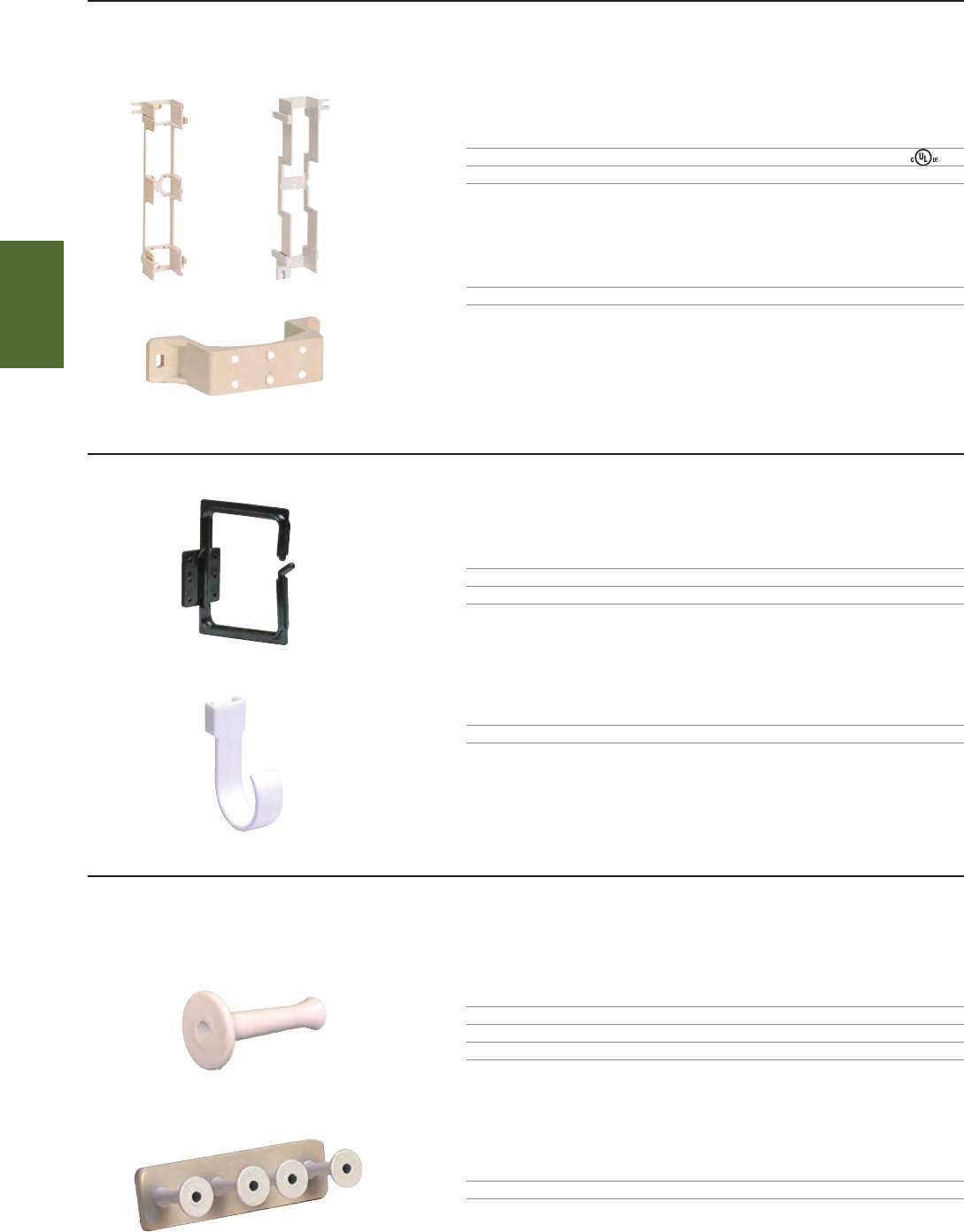
89D A89B
66B8 - 10
66146
606P
A20A
A198A
STRUCTURED
WIRING
1-800-852-8662 WWW.SUTTLEONLINE.COM
66 BLOCK MOUNTING BRACKETS
Durable self - extinguishing thermoplastic
Mounting holes are provided for use in a variety of mounting options
PART# DESCRIPTION
89D For use with 66M1 - 25 and 66M1 - 50 blocks
A89B For use with 66M1 - 25 and 66M1 - 50 blocks
PART# DESCRIPTION
66B8 - 10 For use with 66B blocks
■
■
CABLE MANAGEMENT : WIRE AND CABLE HANGERS
PART# DESCRIPTION DIMENSIONS
66145 Wall mounting 4.12"D x 2.5"H
66146 Wall mounting 3.8"D x 5.87"H
PART# DESCRIPTION
606P Organizer ring, clips on side of A89B or 89D bracket
CABLE MANAGEMENT : WIRE DISTRIBUTION SPOOLS AND MANAGEMENT FRAMES
Provides control and dressing of distribution cables and jumper wires
Allows rapid and easy access for moves and changes
PART# DESCRIPTION
A20A Spool without screw
A20B Spool with #10 wood screw
A20C Spool with #12 - 24 machine screw
PART# DESCRIPTION DIMENSIONS
A198A Management frame with 4 spools 2.4"H x 8.5"W
■
■
76
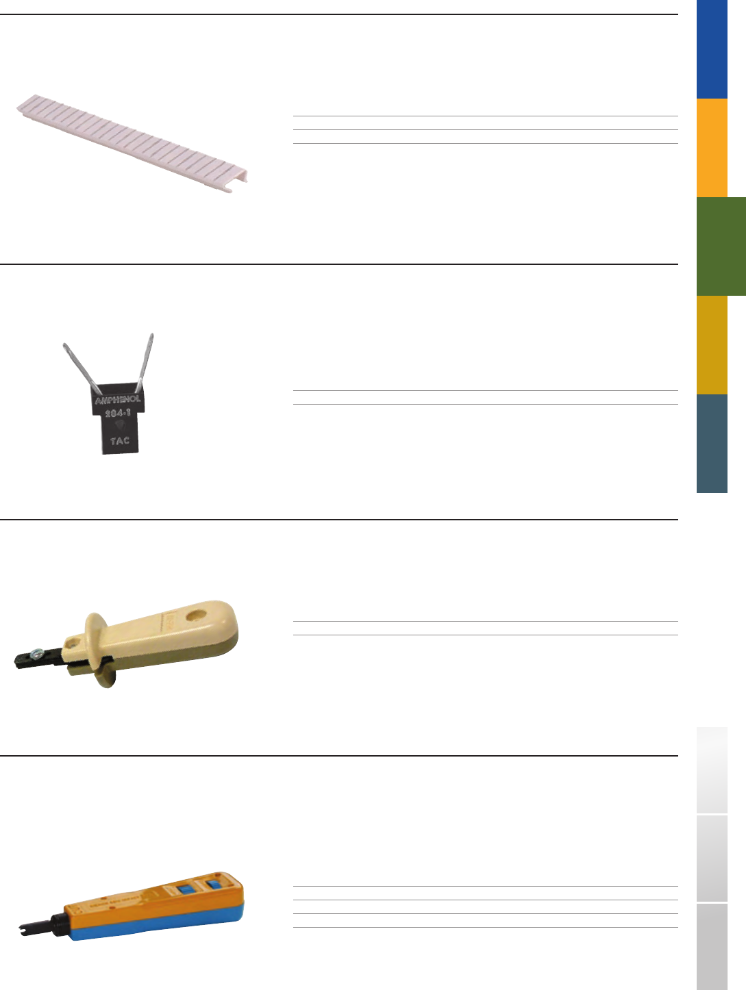
814B
D10
284 - 1
714B
TRADITIONAL TELEPHONY
STRUCTURED
WIRING
FIBERDSLSOHO ACCESS™ USOC WIRING GUIDE GLOSSARY INDEX
DESIGNATION STRIPS
Designated for use on most 66M or 66B type connecting blocks to identify the circuits terminated on the block
Strips are installed by snap - fitting to the side of the block
PART# DESCRIPTION
D10 Designation strip for 66M connecting block
D13 Designation strip for 66B connecting block
■
■
TEST APPARATUS CONNECTOR
Provides a fast, safe access to any pair of quick - clip contacts in a 66 type block
The TAC (test apparatus connector) grips the contact firmly to prevent annoying disconnection from the line being tested
PART# DESCRIPTION
284 - 1 Apparatus test connector
■
■
TERMINATING TOOLS
Designed for terminating 66 type quick - connect blocks, simply place the wire in position, set the tool over the split terminal and with slight pressure push the wire into the terminal.
The blade will cut off the excess wire automatically, reducing a termination step.
PART# DESCRIPTION
714B 66 Style termination tool
TERMINATING TOOLS
The 814B impact tool is designed for termination of 22 - 26 AWG station wire on 110 or 66 type terminations. Spring - loaded and fully adjustable. This tool is ideal when working
with wires of varying thickness. Reversible Termination Blade can terminate and cut off excess wire or terminate only.
Spring loaded feature provides consistent connections
Replacement blades available for 110 and 66 clip style terminations
PART# DESCRIPTION
814B Automatic impact tool
81401 - 110 - 88 Replacement blade for 814B tool, 110 clip style
81401 - 66 Replacement blade for 814B tool, 66 clip style
■
■
77

1-800-852-8662 WWW.SUTTLEONLINE.COM
78

DSL LINE CONDITIONERS®
Ú DSL CONTENT OVERVIEW
Addressing the challenges created by DSL broadband technology deployment’s
in the home, Suttle’s Line Conditioners® fi lter out any erratic impedances
from telephone equipment, delivering reliable high bandwidth DSL transmission
capabilities. Suttle DSL Line Conditioners® are customer installable and
should be used for each active phone line to insure uninterrupted voice and
broadband transmission.
p81 DSL SPLITTERS
DSL Splitters allow one line of combined voice and data communications to be split at the customer
premise into two separate signals.
p82 INLINE FILTERS
Suttle’s inline fi lters isolate telephone equipment impedences by connecting between the wall jack
and voice device to provide a single fi ltered jack for one or two lines of voice device communications.
p83 FLUSH MOUNT FILTERS
Available with or without an auxiliary DSL jack, these stylish faceplates provide one or two fi ltered
lines of voice device communications in a design sure to match any décor.
p84 WALL MOUNT FILTERS
Designed to mount between wall mount telephone and wall mount jack, Suttle’s wall mount fi lters
provide and unfi ltered DSL connection plus one or two fi ltered line for voice device communications.
p84 DSL TEST KITS
The DSL Test Kit provides testing without interruption to the DSL connection. The hand - held device
is available with test cords of varying length.
79
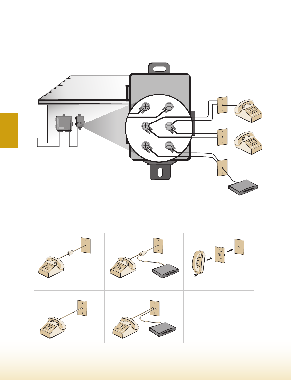
DSL MODEM
SUTTLE 649A
OUTDOOR
POTS SPLITTER
CENTRAL
OFFICE NID
NETWORK
VOICE
DATA
INSIDE
900 STYLE ADAPTER
625LCC1 FLUSH MOUNT ADAPTER 625LCC2 FLUSH MOUNT ADAPTER
630 WALL MOUNT FILTER
DSL MODEM
DSL MODEM
WALL MOUNT
PHONE
EXISTING
WALL JACK
630 WALL MOUNT
FILTER
900 STYLE INLINE FILTER
VOICE
VOICE DATA
DSL
1-800-852-8662 WWW.SUTTLEONLINE.COM
DSL SPLITTING AT THE PREMISEÚ
DSL APPLICATION❚
Using a Suttle splitter, such as the 649A1 POTS splitter
shown above, allows Service Providers to prepare a home
for DSL deployment without ever entering the residence.
Simply mount the device near the Network Interface
Device (NID) and make the connections as shown.
Suttle’s line of DSL filtering products provides a wide variety of deployment options for service providers and end - users
alike. Whether your deployment strategy involves filtering the home or business at the demarcation point, or if you decide
to filter individual POTS devices, Suttle has a certified filtering product to help you get connected.
USING MICROFILTERSÚ
Microfilters are a cost - effective means of
providing filtering at the residence without
ever rolling a truck. Simply install a filter
at each jack where a phone, FAX, caller ID, or
other POTS device is installed.
That’s all it takes to protect your DSL and
voice devices from the interference created
by high bandwidth DSL transmission.
80
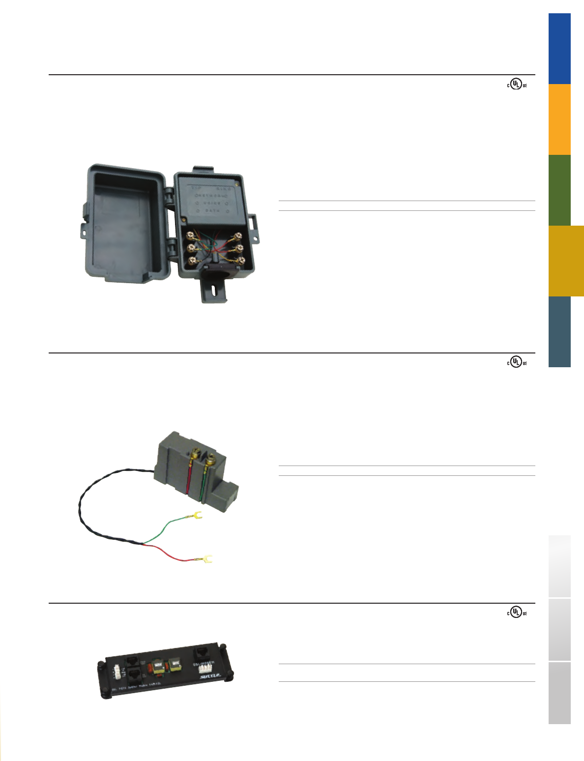
649A1
649N1 - 49
SAM - DSL
TRADITIONAL TELEPHONY STRUCTURED WIRING FIBER
DSL
SOHO ACCESS™ USOC WIRING GUIDE GLOSSARY INDEX
OUTDOOR DSL POTS SPLITTER
The Outdoor DSL POTS Splitter is attached at the subscriber premise to split the network, voice, and data signals. Suttle DSL filters isolate telephone equipment impedances
that interfere with ADSL communications.
Outdoor housing for protection from environmental conditions
Mounts to wall or conduit
Terminals for Network, Voice, and Data
PART# DESCRIPTION DIMENSIONS
649A1 Outdoor DSL POTS Splitter 4.7"H x 3.3"W x 2.3"D
■
■
■
DSL SPLITTERS❚
DSL NID SPLITTER
The DSL NID Splitter Module is designed for use in a variety of Network Interface Devices (NID) at the subscriber premise. This device occupies one line module position
within the NID providing POTS on one ADSL service line. The module is easy to install and can snap in and out of the NID with access to the network portion.
Environmentally sealed
Versatile design accommodates a variety of NIDs
Maintenance test signature included
PART# DESCRIPTION
649N1 - 49 Single line DSL NID splitter module
■
■
■
DSL SPLITTER MODULE
The DSL Splitter module allows the phone and data signal to be split with one centrally based filter rather than with inline filters at every phone outlet location.
PART# DESCRIPTION
SAM - DSL DSL module filters voice signal from a voice module
to eliminate the need for filtering at jack locations
* For use with SOHO Access™ Enclosures and Modules
81
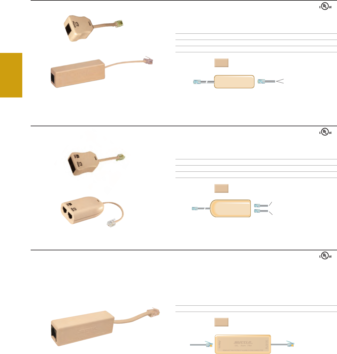
1 Filtered Voice Device - LCCS-50
Unfiltered DSL/modem (both versions)
2 Filtered Voice Devices - LCCS-2F-50
1 Filtered Voice Device - LCC-50
2 Filtered Voice Devices - LCC-2F-50
RJ31X
or
RJ38X
Alarm Auto
Dailer
1 Filtered Voice Device - LCCU-xx
2 Filtered Voice Devices - LCCU-2F-xx
1 Filtered Voice Device - LCCU-xx
2 Filtered Voice Devices - LCCU-2F-xx
1 Filtered Voice Device - 625LCC1-xx
2 Filtered Voice Devices - 625LCC1-2F-xx
Network In
1 Unfiltered DSL/modem (both versions)
1 Voice Device - 625LCC2-xx
2 Filtered Voice Devices - 625LCC2-2F-xx
Network In
Network In
Network In
Network In
DATAVOICE
Unfiltered DSL Signal
Network In
Wall Jack
Unfiltered DSL Signal
Filtered POTS Signal
Filtered POTS Signal
Unfiltered DSL/modem
(both versions)
900LCCS - 50
900A
900LCC - 50
900LCC - 2F - 50
900LCCS - 2F - 50
DSL
1-800-852-8662 WWW.SUTTLEONLINE.COM
900 SERIES ADAPTERS
Provides both an unfiltered DSL jack for DSL connection and a filtered jack for one or two lines of voice device communications.
PART# DESCRIPTION DIMENSIONS
900LCCS - 50 1 - line filtered, auxiliary DSL jack 1.3"L x 1.8"W x 0.9"H
900LCCS - 2F - 50 2 - lines filtered, auxiliary DSL jack 1.6"L x 2.8"W x 0.9"H
COLOR
: Ivory
900 SERIES ALARM DSL FILTER
The 900A alarm filters are designed to allow residential alarm panels to take control of the main phone line via the RJ31X or RJ38X connector. The 900A blocks DSL service to the alarm
panel while providing uninterrupted DSL service to the household telephone wiring. This inline filter is designed to plug into a RJ31X jack, including other similar jacks up to RJ38X.
Customer installable
Automated alarm dialer compatible
PART# DESCRIPTION DIMENSIONS
900A Inline DSL alarm filter 3.0"L x 1.0"H x 0.8"D
COLOR
: Ivory
■
■
The Inline Filter connects between the wall jack and POTS device (e.g. phone, fax, answering machine, Caller ID) providing a single filtered jack for one or two
lines of voice device communications. Suttle DSL filters isolate telephone equipment impedances that interfere with ADSL communications.
Filters are available in one or two line filtering configurations
Meets ANSI T1E1.421 standards for DSL filter compliance
Customer installable
900 SERIES INLINE
Provides a single filtered jack for one or two lines of voice device communications.
PART# DESCRIPTION DIMENSIONS
900LCC - 50 1 - line filtered 1.3"L x 1.3"H x 0.8"D
900LCC - 2F - 50 2 - lines filtered 3"L x 1"H x 0.8"D
COLOR
: Ivory
■
■
■
INLINE FILTERS❚
82
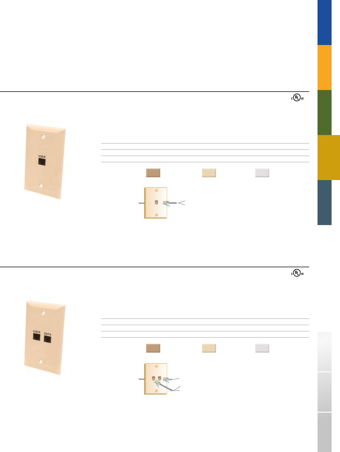
1 Filtered Voice Device - LCCS-50
Unfiltered DSL/modem (both versions)
2 Filtered Voice Devices - LCCS-2F-50
1 Filtered Voice Device - LCC-50
2 Filtered Voice Devices - LCC-2F-50
RJ31X
or
RJ38X
Alarm Auto
Dailer
1 Filtered Voice Device - LCCU-xx
2 Filtered Voice Devices - LCCU-2F-xx
1 Filtered Voice Device - LCCU-xx
2 Filtered Voice Devices - LCCU-2F-xx
1 Filtered Voice Device - 625LCC1-xx
2 Filtered Voice Devices - 625LCC1-2F-xx
Network In
1 Unfiltered DSL/modem (both versions)
1 Voice Device - 625LCC2-xx
2 Filtered Voice Devices - 625LCC2-2F-xx
Network In
Network In
Network In
Network In
DATAVOICE
Unfiltered DSL Signal
Network In
Wall Jack
Unfiltered DSL Signal
Filtered POTS Signal
Filtered POTS Signal
Unfiltered DSL/modem
(both versions)
625LCC1 - xx
625LCC2 - xx
TRADITIONAL TELEPHONY STRUCTURED WIRING FIBER
DSL
SOHO ACCESS™ USOC WIRING GUIDE GLOSSARY INDEX
The flush mount filters are wired directly to the homes internal wiring system providing one or two lines for voice device communications (e.g., phone, fax,
answering machine, Caller ID box). Adapter style jacks provide the same with an unfiltered DSL jack for direct connection for DSL communications. These
filters eliminate the need for inline or wall mount filtering devices providing a smooth sleek design that matches electrical faceplates.
Install without mounting brackets
Meets ANSI T1E1.421 standards for DSL filter compliance
Smooth, sleek faceplate design matches electrical faceplates
■
■
■
FLUSH MOUNT FILTERS❚
SIMPLEX, SMOOTH FINISH, FLUSH MOUNT FILTER
Provides a single filtered jack for one or two lines of voice device communications in a smooth finish, flush mount design.
PART# DESCRIPTION DIMENSIONS
625LCC1 - xx 1 - Line filtered, screw terminals 4.6"H x 2.8"W x 0.2"D
625LCC1 - 2F - xx 2 - Lines filtered, screw terminals 4.6"H x 2.8"W x 0.2"D
COLORS
( - xx): Electrical Ivory = (52) Light Almond = (64) White = (85)
DUPLEX EAST/WEST, SMOOTH FINISH, FLUSH MOUNT ADAPTER
Provides both an unfiltered DSL jack for DSL connection and a filtered jack for one or two lines of voice device communications in a flush mount design.
PART# DESCRIPTION DIMENSIONS
625LCC2 - xx 1 - Line filtered, auxiliary DSL jack, screw terminals 4.6"H x 2.8"W x 0.2"D
625LCC2 - 2F - xx 2 - Lines filtered, auxiliary DSL jack, screw terminals 4.6"H x 2.8"W x 0.2"D
COLORS
( - xx): Electrical Ivory = (52) Light Almond = (64) White = (85)
83
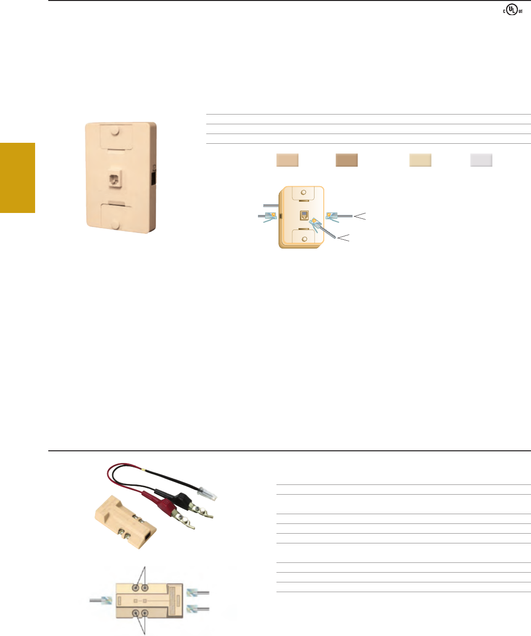
1 Filtered Voice Device - LCCS-50
Unfiltered DSL/modem (both versions)
2 Filtered Voice Devices - LCCS-2F-50
1 Filtered Voice Device - LCC-50
2 Filtered Voice Devices - LCC-2F-50
RJ31X
or
RJ38X
Alarm Auto
Dailer
1 Filtered Voice Device - LCCU-xx
2 Filtered Voice Devices - LCCU-2F-xx
1 Filtered Voice Device - LCCU-xx
2 Filtered Voice Devices - LCCU-2F-xx
1 Filtered Voice Device - 625LCC1-xx
2 Filtered Voice Devices - 625LCC1-2F-xx
Network In
1 Unfiltered DSL/modem (both versions)
1 Voice Device - 625LCC2-xx
2 Filtered Voice Devices - 625LCC2-2F-xx
Network In
Network In
Network In
Network In
DATAVOICE
Unfiltered DSL Signal
Network In
Wall Jack
Unfiltered DSL Signal
Filtered POTS Signal
Filtered POTS Signal
Unfiltered DSL/modem
(both versions)
630LCCU - xx
DSL
1-800-852-8662 WWW.SUTTLEONLINE.COM
The Suttle DSL test unit allows an active DSL line to be tested for POTS (voice) verification without interfering with the DSL connection. The hand - held device
has an RJ - 14 modular jack for the input connection. The input can be made with a double - ended modular cord or with a universal test cord equipped with a
modular plug on one end and test clips on the other as used with a typical Butt set.
The connection for testing is provided via two RJ - 14 modular jacks, labeled “Non - Filtered" for the DSL port and “Filtered" for the POTS port, or through the test
access point terminals for use with a test cord.
Provides testing without interfering with the DSL connection
Available with Test cords of varying length
■
■
DSL TEST KITS❚
DSL TEST KITS
PART# DESCRIPTION DIMENSIONS
DSLTEST - 1 DSL test unit 3.61"L x 1.84"W x 0.85"H
PART# DESCRIPTION
DSLTESTKIT1 DSL test unit with 1 ft. test cord
DSLTESTKIT3 DSL test unit with 3 ft. test cord
DSLTESTKIT7 DSL test unit with 7 ft. test cord
PART# DESCRIPTION
DSLTESTCORD1 1 ft. test cord
DSLTESTCORD3 3 ft. test cord
DSLTESTCORD7 7 ft. test cord
WALL MOUNT FILTERS❚
WALL MOUNT ADAPTER
The Wall Mount DSL Adapter mounts to an existing wall mount phone jack providing an unfiltered jack for your DSL connection plus one or two filtered lines for voice device
communications (e.g. phone, fax, answering machine, Caller ID box) via two auxiliary phone jacks. Suttle DSL filters isolate telephone equipment impedances that interfere with
ADSL communications . Features mounting lugs for wall mount phones.
Customer installable
Securely snaps over existing wall jack
The single line version provides unfiltered access to line two in all ports
Meets ANSI T1E1.421 standards for DSL filter compliance
PART# DESCRIPTION DIMENSIONS
630LCCU - xx 1 - line filtered, 2 voice jacks, auxiliary DSL jack 4.5"H x 3.0"W x 0.7"D
630LCCU - 2F - xx 2 - lines filtered, 2 voice jacks, auxiliary DSL jack 4.5"H x 3.0"W x 0.7"D
COLORS
( - xx): Ivory = (50) Elec. Ivory = (52) Lt. Al. = (64) White = (85)
■
■
■
■
84

TRADITIONAL TELEPHONY STRUCTURED WIRING FIBER
DSL
SOHO ACCESS™ USOC WIRING GUIDE GLOSSARY INDEX
Q: Why are ADSL line conditioners needed?
A: With ADSL service, phone lines are used to send and receive voice and data on the same line. The line conditioners
enable simultaneous use of Internet and voice by isolating the noise caused by analog telephone devices such as
(telephone, fax machines, answering machines and cable TV pay per view dial ups) from the ADSL signal.
Q: What do I do with the line conditioners I received?
A: Disconnect the telephone from the wall jack and plug the line conditioner into the wall jack, connect the telephone into
the phone jack on the filter. Your telephone or telephone device is now isolated from the ADSL modem.
Q: Where should I install the line conditioners?
A: Install a line conditioner everywhere an analog telephone device is used within the home or office.
Analog phone devices include: telephones, fax machines, analog modems, caller ID and answering machines.
Q: What do I do if I have two line phones and do not know which line is carrying the ADSL signal?
A: In - line and Wall mount line conditioners that filter both lines 1 and 2 are available. Install the line conditioner into the
phone jack and plug the phone into the line conditioner.
Q: How do I install a line conditioner on my wall - mount telephone?
A: The 630 line conditioner is designed so no tools are needed. Simply remove the telephone from the wall - plate and plug
the 630 wall mount line conditioner into the wall jack. The unique toggle design on the 630 line conditioner locks the unit
onto the existing wall mount jack. Snap the telephone back onto the filter, align the key holes, slide the phone down into
place and you are finished.
Q: Should I connect a line conditioner onto my DSL modem?
A: No, if connected directly to the modem it would block access.
Q: Can I use a filter for a phone that has call waiting?
A: Yes, the line conditioner does not affect telephone service.
Q: Will the line conditioner work with all forms of DSL?
A: The line conditioner is designed to function with ADSL, ADSL2, and ADSL2+, G.lite and full rate G.dmt formats.
DSL FREQUENTLY ASKED QUESTIONS❚
85

1-800-852-8662 WWW.SUTTLEONLINE.COM
86

FIBER
Ú FIBER CONTENT OVERVIEW
Suttle incorporates the latest technology into its fi ber products. Our product
line includes the revolutionary Terminator™ Field Termination System, QuickTerm
connectors, assemblies, and a variety of other complementary products to meet
your fi ber connectivity needs.
p88 FIELD TERMINATION PRODUCTS
Providing an incredibly quick and easy fi eld termination solution, the Terminator System is a polish-
free fi ber system consisting of the Terminator Universal Cleave Tool and Terminator Connectors.
QuickTerm1 and 2 and MTRJ connectors are also available depending on your cable requirements.
p92 BULKHEAD INTERCONNECT ADAPTERS
Adapters can be used in both singlemode and multimode applications to provide proper ferrule
alignment. Available for use with AFP and ATC fi ber panels, these adapters meet IEC, Telcordia,
and TIA/EIA performance standards.
p93 FIBER ASSEMBLIES
Multimode and singlemode and duplex pre - terminated fi ber assemblies are inspected for fl aws and
tested to meet industry standard requirements. Custom confi gurations are available upon request.
p94 ULTRASPLICE
Available for use in any combination of buffer sizes, the Ultrasplice allows singlemode and multimode
splicing and requires no fi xtures or special tools.
p94 TERMINATION KITS/ASSEMBLIES
Suttle’s portable termination kits include all tools necessary for fi ber connector terminations.
The kit is designed for use with ST, SC, and FC connectors. Universal accessories and consumable
refi ll kits can also be found here.
87
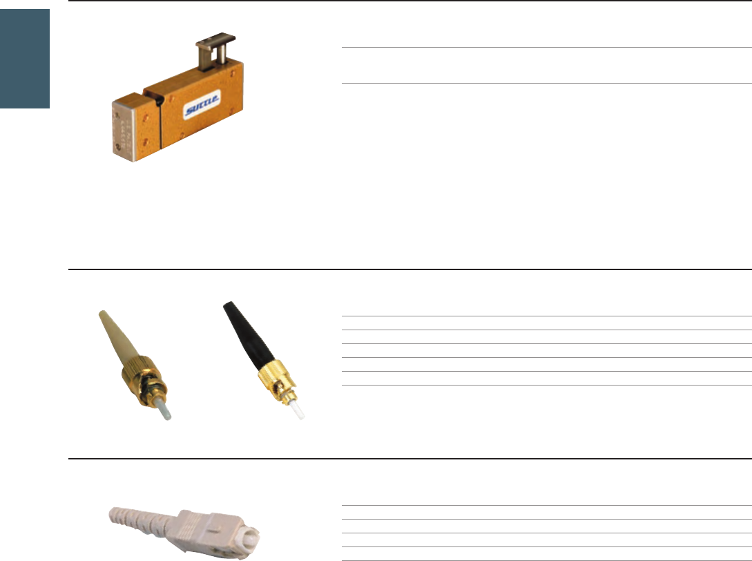
ATCF - TR1 - U
ASTA - 02 - C - T - G
ASCA - TR - T - 10
ASTA - 02 - C - D - G
FIBER
1-800-852-8662 WWW.SUTTLEONLINE.COM
TERMINATOR® FIELD TERMINATION SYSTEM
Providing an incredibly quick and easy field termination solution, the terminator system is a polish - free fiber termination system consisting of the Terminator
Universal Cleave Tool and Terminator Connectors.
The Terminator Universal Cleave Tool cleaves off the fiber at the ferrule tip of multimode ST, SC, and FC connectors, eliminating the need for polishing while
maintaining continuous glass to the end of the ferrule.
The most efficient and consistent polish - free termination system in the industry
The terminator is the only polish - free system that employs traditional uninterrupted glass to the ferrule tip
Terminates with an exceptionally low dB loss
25 - year warranty when tested and installed by Suttle certified installers
Crimp, cleave, and leave in three minutes or less
No curing oven or polishing required
Suttle’s Terminator connectors are designed specifically for use with the terminator tool. The connectors have multimode zirconia ceramic ferrules and are
compatible with 250 or 900 micron buffered cables and 50/125 and 62.5/125 fiber.
Three step crimp securing buffer, optical fiber, strength member and jacket of cable
One step crimp when using 900 micron boot (distribution type fiber)
Terminator connectors for use with the universal cleave tool ATCF - TR1 - U*
* Use of any other connectors invalidates all warranties and may cause permanent damage to the tool.
Ú
■
■
■
■
■
■
■
■
■
TERMINATOR TOOL
PART# DESCRIPTION
ATCF - TR1 - U Terminator universal cleave tool. For use with Suttle terminator style
connectors only. Use of any other connectors with this tool invalidates
all warranties and may cause permanent damage to the tool.
TERMINATOR CONNECTORS (MULTIMODE ONLY)
ST TERMINATOR CONNECTORS
PART# DESCRIPTION
ASTA - 02 - C - B - G 250 micron buffer, unjacketed (loose tube)
ASTA - 02 - C - D - G 900 micron buffer, unjacketed (distribution type)
ASTA - 02 - C - T - G 900 micron, 3.0 mm jacket
ASTA - 02 - C - P - G 900 micron, 2.5 mm jacket
Ú
SC TERMINATOR CONNECTORS
PART# DESCRIPTION
ASCA - TR - B - 10 250 micron, unjacketed (loose tube)
ASCA - TR - D - 10 900 micron, unjacketed (distribution type)
ASCA - TR - T - 10 900 micron, 3.0 mm jacket
FIELD TERMINATION PRODUCTS❚
88
AFCA - 02 - T - G
ATCF - SY - QS
ATCC - UNV
AFTK - TR1 - KIT
TRADITIONAL TELEPHONY STRUCTURED WIRING
FIBER
DSL USOC WIRING GUIDE GLOSSARY INDEXSOHO ACCESS™
FC TERMINATOR CONNECTORS
PART# DESCRIPTION
AFCA - 02 - T - G 900 micron buffer, unjacketed (distribution type) or 3.0 mm jacket
TERMINATOR ACCESSORIES/KITS
PART# DESCRIPTION
ATCF - SY - QS Pre-loaded syringe with needles (200 connectors/tube)
PART# DESCRIPTION
ATCC - UNV Universal crimp tool, ratcheted, size 1–4 hex crimp cavities
IN DEPTH
Ratchet feature on the crimp tool ensures a proper crimp on the connector back post. Provides 1–4 size hex
crimp cavities for simple crimping of Suttle ST, SC, & FC connectors.
Ergonomic design is easier on hands
Longer handle means less force required for crimping
Ratchet feature ensures a proper crimp every time
PART# DESCRIPTION
AFTK - TR - U Express terminator kit. Contents include: universal terminator cleave tool,
universal crimp tool, jacket stripper, buffer stripper (125 - 150 micron), kevlar
scissors. See component part numbers for this kit on page 94.
PART# DESCRIPTION
AFTK - TRMT - KIT MTRJ field terminator kit. Contents include: terminator tool, warranty card, click
terminator kit case, universal terminator label, fiber US video, MTRJ cam tool
FIB CARD, score-flex cleaver, cam assembly tool, permanent black marker, 900mm
MTRJ/SC/ST/FC template, visual fault locator laser, cam assembly – MTRJ adapter,
MTRJ jumper ST. See component part numbers for this kit on page 95.
PART# DESCRIPTION
AFTK - TR1 - KIT Full terminator kit. Contents include: universal terminator cleave tool, universal
crimp tool, wipes, isopropyl alcohol, t - type jacket stripper, kevlar scissors, buffer
stripper (125 - 150 micron), cleaning wire, dust blaster kit, continuity detector,
inspection microscope. See component part numbers for this kit on page 94.
➥
■
■
■
89
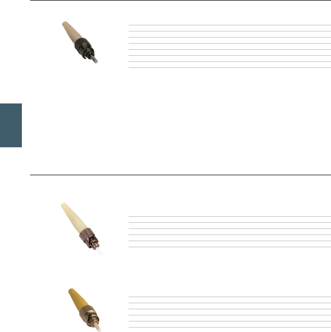
ASTA - 01 - C - T
ASTA - 02 - C - T2
ASTB - 02 - 126 - T2
FIBER
1-800-852-8662 WWW.SUTTLEONLINE.COM
QUICKTERM 1™ CONNECTORS
Suttle’s QuickTerm™ ST® epoxyless style connectors are constructed of an all metal body with a stainless steel ferrule for use with multimode cable.
This design uses a 4 - step crimping process to secure buffer, optical fiber, strength member and jacket. No adhesive required.
Mates with all standard ST style connectors and compatible with all 250 and 900 micron buffer cables
No adhesives required
Epoxyless design allows assembly within 2 - 3 minutes
A low cost crimp tool is utilized, eliminating the need for an expensive curing oven
Once assembled, the ST connectors boast an extremely low dB loss of 0.25dB
ST QT1 CONNECTORS
PART# DESCRIPTION FIBER TYPE FERRULE
ASTA - 01 - C - B 250 micron buffer, unjacketed (loose tube) Multimode Stainless
ASTA - 01 - C - D 900 micron buffer, unjacketed (distribution type) Multimode Stainless
ASTA - 01 - C - P 900 micron buffer, 2.5 mm jacket Multimode Stainless
ASTA - 01 - C - T 900 micron buffer, 3.0 mm jacket Multimode Stainless
Ú
■
■
■
■
■
QUICKTERM 2™ CONNECTORS
Suttle’s QuickTerm2 ST, FC, and SC epoxyless style connectors with zirconia ceramic ferrules are designed for use with singlemode and multimode cable. The
simple three - step crimp process provides a consistent quality termination with low dB loss and reduction of disposables.
User friendly, saving time and money
2 to 3 minute termination time
Extremely low dB loss
Quick set adhesive
No curing oven needed
Multimode connectors accept both 50/125 micron and 62.5/125 micron fiber
ST QT2 CONNECTORS
PART# DESCRIPTION FIBER TYPE FERRULE
ASTA - 02 - C - B2 250 micron buffer, unjacketed (loose tube) Multimode Zirconia
ASTA - 02 - C - D2 900 micron buffer, unjacketed (distribution type) Multimode Zirconia
ASTA - 02 - C - T2 900 micron buffer, 3.0 mm jacket Multimode Zirconia
PART# DESCRIPTION FIBER TYPE FERRULE
ASTB - 02 - 126 - B2 250 micron, buffer, unjacketed (loose tube) Singlemode Zirconia
ASTB - 02 - 126 - D2 900 micron buffer, unjacketed (distribution type) Singlemode Zirconia
ASTB - 02 - 126 - T2 900 micron buffer, 3.0 mm jacket Singlemode Zirconia
Ú
■
■
■
■
■
■
90
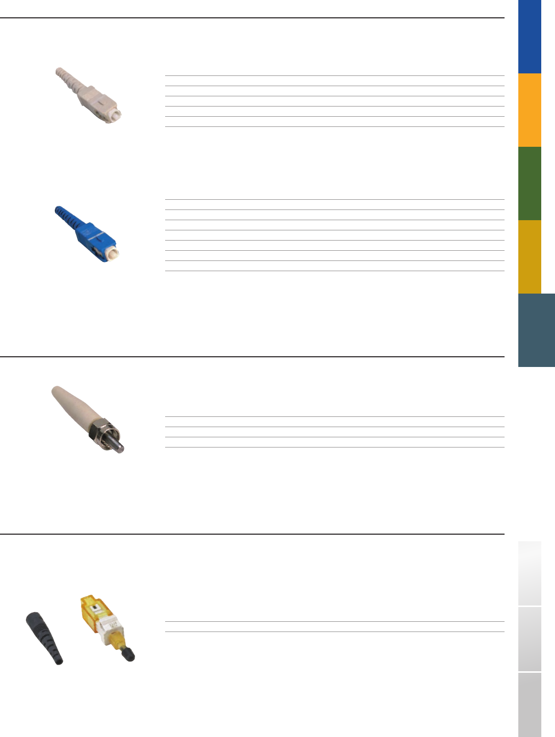
ASCA - 02 - D2 - 10
ASCB - 02 - T2 - 62
ASMA - 22 - C - T2
AMTA - 62 - P
TRADITIONAL TELEPHONY STRUCTURED WIRING
FIBER
DSL USOC WIRING GUIDE GLOSSARY INDEXSOHO ACCESS™
SC QT2 CONNECTORS
PART# DESCRIPTION FIBER TYPE FERRULE
ASCA - 02 - B2 - 10 250 micron, buffer, unjacketed (loose tube) Multimode Zirconia
ASCA - 02 - D2 - 10 900 micron buffer, unjacketed (distribution type) Multimode Zirconia
ASCA - 02 - T2 - 10 900 micron buffer, 3.0 mm jacket Multimode Zirconia
PART# DESCRIPTION FIBER TYPE FERRULE
ASCB - 02 - B2 - 62 250 micron, buffer, unjacketed (loose tube) Singlemode Zirconia
ASCB - 02 - D2 - 62 900 micron buffer, unjacketed (distribution type) Singlemode Zirconia
ASCB - 02 - T2 - 62 900 micron buffer, 3.0 mm jacket Singlemode Zirconia
ASCAPC - 02 - T2 900 micron buffer, 3.0 mm jacket Singlemode Zirconia 8° angle
SMA QT2 CONNECTORS
PART# DESCRIPTION FIBER TYPE FERRULE
ASMA - 22 - C - T2 900 micron buffer, 3.0 mm jacket 140µm multimode 905 stainless
ASMA - 02 - C - T2 900 micron buffer, 3.0 mm jacket 125µm multimode 905 stainless
MTRJ FIELD INSTALLABLE CONNECTORS
Factory - installed fiber stub that is fully bonded in the ferrule
Superior end face polish
Installs in under two minutes
PART# DESCRIPTION
AMTA - 62 - P MTRJ, MM 62.5, Male, Field Mount
■
■
■
91
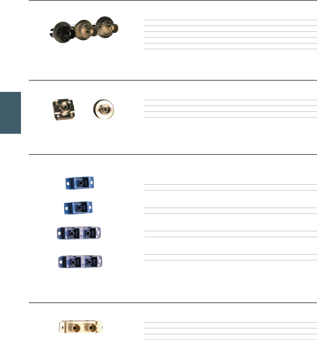
ASTA - 03 - B
AFCB - 03 - N
ASTA - 03 - N ASTB - 03 - N
AFCB
- 03 - D - C
ASCAS - 03 - 62
ASCAD - 03 - 62
ASCBS - 03 - 62
ASCBD - 03 - 62
ASCBS - 03 - 62
FIBER
1-800-852-8662 WWW.SUTTLEONLINE.COM
Suttle’s bulkhead interconnect adapters are constructed with either phosphorous bronze or zirconia sleeves providing proper alignment for both singlemode and
multimode applications. Packaging includes dust caps, press fit bushing, and a nut and lock washer to facilitate panel mounting.
Singlemode or Multimode fiber type
Phosphor bronze or zirconia sleeves
Meets IEC, Telcordia, and TIA/EIA performance standards
For use with AFP and ATC fiber panels
■
■
■
■
ST STYLE BULKHEAD INTERCONNECT ADAPTERS
PART# DESCRIPTION TYPE
ASTA - 03 - B ST adapter, black nickel plating, phosphor bronze sleeve MM or SM fiber
ASTA - 03 - N ST adapter, bright nickel plating, phosphor bronze sleeve MM or SM fiber
ASTB - 03 - N ST adapter, bright nickel plating, zirconia sleeve SM fiber
FC BULKHEAD INTERCONNECT ADAPTERS
PART# DESCRIPTION TYPE
AFCB - 03 - N FC adapter, bright nickel plating, phosphor bronze sleeve MM or SM fiber
AFCB - 03 - D - C FC adapter, bright nickel plating, zirconia sleeve SM fiber
SC BULKHEAD INTERCONNECT ADAPTERS
PART# DESCRIPTION TYPE COLOR
ASCAS - 03 - 62 SC simplex adapter, phosphor bronze sleeve SM or MM fiber blue
ASCBS - 03 - 62 SC simplex adapter, zirconia sleeve SM fiber blue
ASCAD - 03 - 62 SC duplex adapter, phosphor bronze sleeve SM or MM fiber blue
ASCBD - 03 - 62 SC duplex adapter, zirconia sleeve SM fiber blue
HYBRID ADAPTERS ST TO SC
PART# DESCRIPTION TYPE COLOR
ASCSTAD - 03 - 62 ST - SC duplex adapter, phosphor bronze sleeve SM fiber blue
ASCSTAD - 03 - 10 ST - SC duplex adapter, phosphor bronze sleeve MM fiber beige
BULKHEAD INTERCONNECT ADAPTERS❚
92
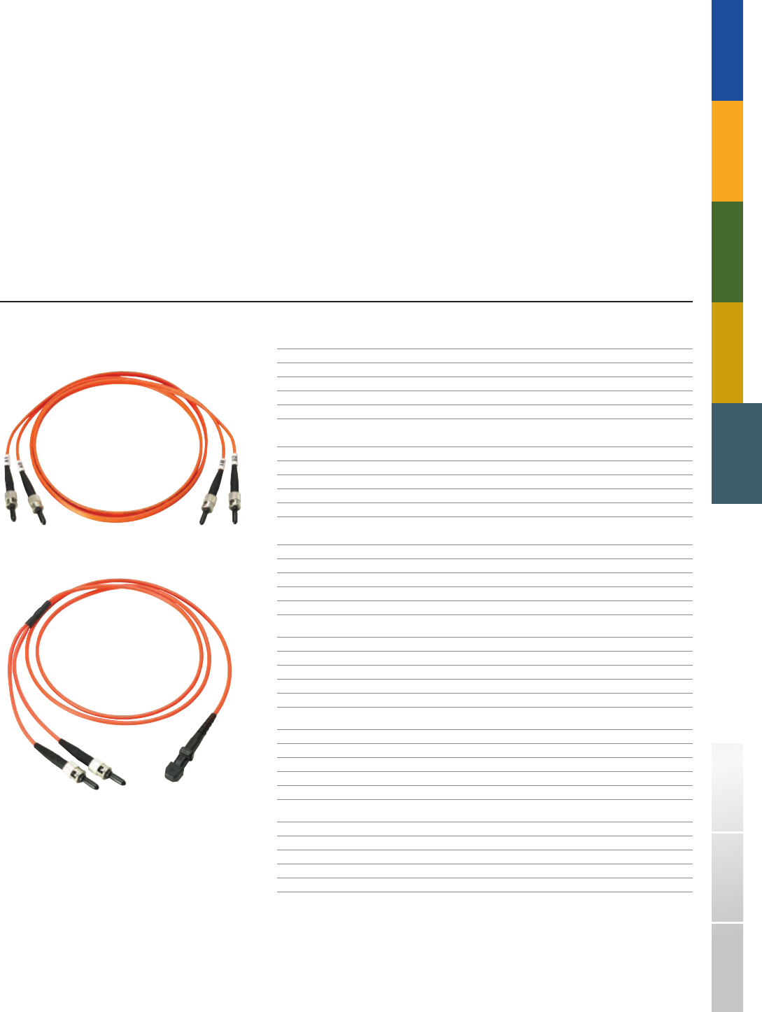
TRADITIONAL TELEPHONY STRUCTURED WIRING
FIBER
DSL USOC WIRING GUIDE GLOSSARY INDEXSOHO ACCESS™
Suttle offers a wide range of high performance pre - terminated singlemode and multimode cable assemblies. Jumpers and pigtails are supplied in various
lengths utilizing Suttle Fiber Solutions cable or cable specified by the customer.
Multimode (MM) and Singlemode (SM) simplex and duplex fiber optic jumpers utilize OFNR riser - rated 1 - or 2 - fiber 62.5/125µm, 50/125µm multimode, or
8.3/125µm singlemode cable that meets UL 1666 requirements.
Each connector on a fiber optic jumper assembly is visually inspected for flaws, and tested to meet industry standard requirements. Test reports are provided for
each jumper assembly. Suttle offers a 15 - year warranty on tested installations when installed by Suttle certified installers.
50/125µm multimode and Singlemode assemblies available
Singlemode jumpers and pigtails feature an ultrapolish (UPC) with a minimum return loss of 55dB
Available in a variety of connector styles and lengths
Multimode jumper assemblies incorporate connectors with ceramic ferrules for precision and durability
All connectors include protective dust caps
Standard or custom configurations available
■
■
■
■
■
■
STANDARD FIBER ASSEMBLY PATCH CORDS
PART# DESCRIPTION MODE THICKNESS LENGTH
AU02 - C - C/C - 001M - S ST - ST Multimode, Duplex 62.5 1 Meter
AU02 - C - C/C - 003M - S ST - ST Multimode, Duplex 62.5 3 Meter
AU02 - C - C/C - 005M - S ST - ST Multimode, Duplex 62.5 5 Meter
AU02 - C - C/MT - 001M - S ST - MTRJ Multimode, Duplex 62.5 1 Meter
AU02 - C - C/MT - 003M - S ST - MTRJ Multimode, Duplex 62.5 3 Meter
AU02 - C - C/MT - 005M - S ST - MTRJ Multimode, Duplex 62.5 5 Meter
AU02 - C - MT/MT - 001MS MTRJ - MTRJ Multimode, Duplex 62.5 1 Meter
AU02 - C - MT/MT - 003MS MTRJ - MTRJ Multimode, Duplex 62.5 3 Meter
AU02 - C - MT/MT - 005MS MTRJ - MTRJ Multimode, Duplex 62.5 5 Meter
AU02 - C - Z/C - 001M - S SC - ST Multimode, Duplex 62.5 1 Meter
AU02 - C - Z/C - 003M - S SC - ST Multimode, Duplex 62.5 3 Meter
AU02 - C - Z/C - 005M - S SC - ST Multimode, Duplex 62.5 5 Meter
AU02 - C - Z/MT - 001M - S SC - MTRJ Multimode, Duplex 62.5 1 Meter
AU02 - C - Z/MT - 003M - S SC - MTRJ Multimode, Duplex 62.5 3 Meter
AU02 - C - Z/MT - 005M - S SC - MTRJ Multimode, Duplex 62.5 5 Meter
AU02 - C - Z/Z - 001M - S SC - SC Multimode, Duplex 62.5 1 Meter
AU02 - C - Z/Z - 003M - S SC - SC Multimode, Duplex 62.5 3 Meter
AU02 - C - Z/Z - 005M - S SC - SC Multimode, Duplex 62.5 5 Meter
Note: All MTRJ connectors are male. Contact Customer Service or visit us on the web
at www.suttleonline.com for information regarding custom fiber assembly options.
FIBER ASSEMBLIES❚
93
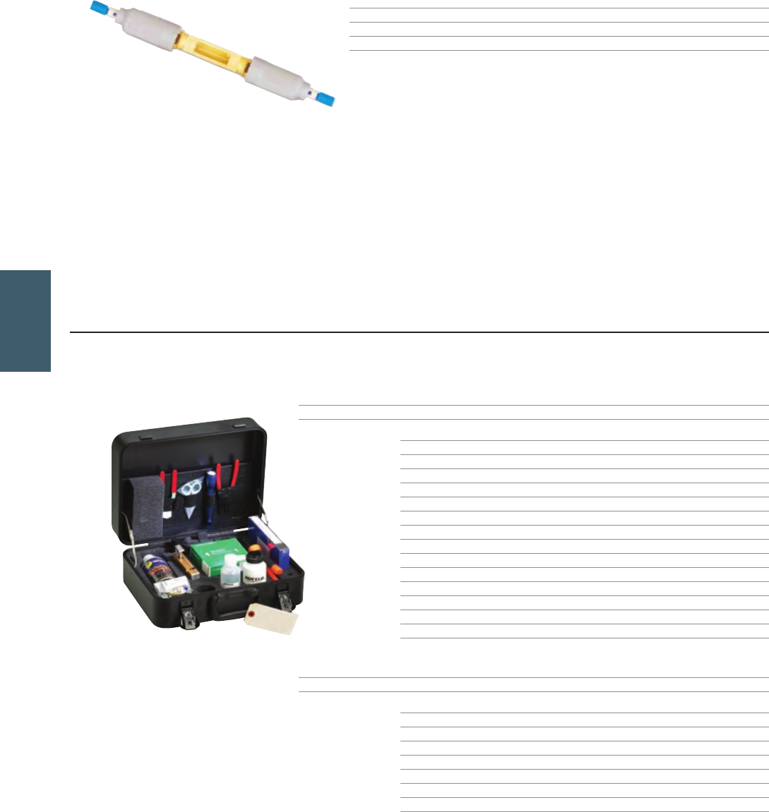
AUS - 126
AFTK - TR1 - KIT
FIBER
1-800-852-8662 WWW.SUTTLEONLINE.COM
The ULTRAsplice™ is a fully mechanical fiber optic splice for singlemode and multimode splicing. No fixtures or special tools are required and they are tunable
and reusable. An uncovered glass capillary allows visual inspection for proper fiber location. The ULTRA splice can be used in any combination of buffer sizes.
PART# DESCRIPTION
AUS - 126 Singlemode splice
AUS - 125 Multimode splice
TERMINATOR KITS
TERMINATOR UNIVERSAL TERMINATION KIT
Suttle’s universal termination kit is used for the termination of Terminator™ series ST, SC and FC connectors.
PART# DESCRIPTION
AFTK - TR1 - KIT Full terminator universal termination kit
The AFTK - TR1 - KIT terminator kit includes:
ATCF - TR1 - U Universal terminator cleave tool
ATCC - UNV Universal crimp tool
ATCF - KW Wipes
ATCF - IA Isopropyl alcohol, 4oz. bottle
ATCF - TTS Jacket stripper
ATCF - SC Kevlar scissors
ATCF - US - 150 Buffer stripper (125 - 150 micron)
ATCF - CW Cleaning wire
ATCF - DB Dust blaster kit
ATCF - LS - U Fiber optic continuity detector
ATCF - MS Inspection microscope
ATCF - TC1 Fiber trash can for disposing of scrap fiber
FIBCARD Termination information card
FIBVIDUS Termination instruction video
PART# DESCRIPTION
AFTK - TR - U Express terminator universal termination kit
The AFTK - TR - U terminator kit includes:
ATCF - TR1 - U Universal terminator cleave tool
ATCC - UNV Universal crimp tool
ATCF - TTS Jacket stripper
ATCF - US - 150 Buffer stripper (125 - 150 micron)
ATCF - SC Kevlar scissors
FIBCARD Termination information card
FIBVIDUS Termination instruction video
Ú
ULTRASPLICE™
❚
TERMINATION KITS / ASSEMBLIES❚
94
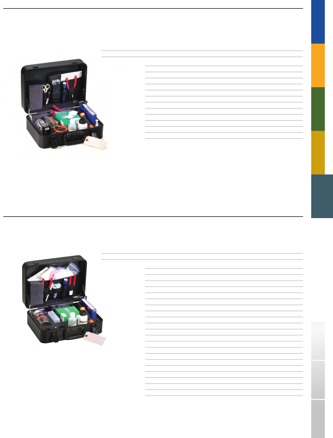
AFTK - TRMT - KIT
AFTK - QT - UNV
TRADITIONAL TELEPHONY STRUCTURED WIRING
FIBER
DSL USOC WIRING GUIDE GLOSSARY INDEXSOHO ACCESS™
MTRJ FIELD TERMINATION KIT
Provides the tools to perform MTRJ, ST, SC, FC field terminations
No epoxy or polishing
Direct termination eliminates unnecessary cable slack and storage
PART# DESCRIPTION
AFTK - TRMT - KIT MTRJ Field termination kit
The AFTK - TRMT - KIT terminator kit includes:
098042 - 00 Warranty Card
098061 - 03 Click Terminator Kit Case
108007 - 00 Universal Terminator Label
FIBVIDUS Fiber US Video
108009 - 00 MTRJ Cam Tool FIBCARD
ATCF - SFC Score - Flex Cleaver
ATCF - CAT Cam Assembly Tool
098068 - 00 Permanent Black Marker
108008 - 00 900µm MTRJ/SC/ST/FC Template
ATCF - VFL Visual Fault Locator Laser
ATCF - ADPMTRJ Cam Assembly – MTRJ Adapter
AU02 - C - C/MT - 001M - S MTRJ Jumper ST
■
■
■
QUICKTERM™ TERMINATION KIT (FOR QT1 OR QT2 STYLE CONNECTORS)
Suttle’s quick term termination kit is used for the termination of QuickTerm1, QuickTerm2 connectors.
Includes all tools and materials necessary for fiber connector termination.
PART# DESCRIPTION
AFTK - QT - UNV QuickTerm termination kit for termination of QT1 and QT2 style connectors
The AFTK - QT - UNV includes:
ATCC - UNV Universal crimp tool
ATCF - FX - UNV Universal polishing fixture
ATCF - PF - 12 12 micron polishing film
ATCF - PF - 3 3 micron polishing film
ATCF - PF - 1 1 micron polishing film
ATCF - PF - .3 .3 micron polishing film
ATCF - KW Wipes
ATCF - IA Isopropyl alcohol, 4oz. bottle
ATCF - TTS Jacket stripper
ATCF - SC Kevlar scissors
ATCF - US - 150 Buffer stripper (125 - 150 micron)
ATCF - PP Polycarbonate polishing plate
ATCF - RP Rubber pad 5” x 5”
ATCF - CW Cleaning wire
ATCF - DB Dust blaster kit
ATCF - ST - 1 Scribe tool
ATCF - LS - U Fiber optic continuity detector
AT - 221 4 compartment box
ATCF - TC1 Fiber Trash Can for disposing of scrap fiber
FIBCARD Process instruction cards
FIBVIDUS Instructional video
95
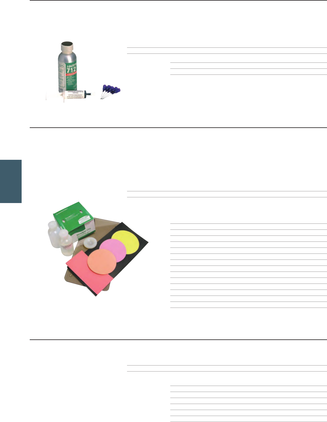
ATCF - QT2 - KIT
AFTK - PK - xx
FIBER
1-800-852-8662 WWW.SUTTLEONLINE.COM
QUICK SET ADHESIVE KIT (FOR QT2 STYLE CONNECTORS)
This kit is required for termination of all QT2 style connectors.
Designed specifically for bonding of glass to ceramic
Curing time is about 3 seconds after the accelerator is applied
PART# DESCRIPTION
ATCF - QT2 - KIT Quick set adhesive kit
The kit includes:
ATCF - AC Accelerator
ATCF - SY - QS Pre - loaded syringe with needles (sufficient for 200 connectors)
■
■
ULTRA POLISHING KIT
The revolutionary Suttle ultra polishing kit provides a low cost solution for polishing of singlemode ST, SC, FC, SCAPC, and FCAPC connector styles. Use of high quality materials
provides tight control of radius of curvature, apex offset and fiber height. Performance results meet or exceed TIA, IEC/Telcordia standards.
This portable, low cost kit, when used properly would outperform expensive polishing machines
For use on PC and 8° APC connector styles
PC connector’s typical Return loss is < - 55.00dB using this kit
APC connector’s typical Return loss is < - 75.00dB using this kit
PART# DESCRIPTION
AFTK - PK - xx Ultra Polishing Kit (Sufficient for 120+ connectors)
- xx = one of the following connector styles: ST, SC, FC, FCAPC, SCAPC
The ultra polishing kit includes:
Specify the connector style being used by selecting from the list ATCF - FX - xx…
QTY
ATCF - WB Water bottle 1
ATCF - IA Isopropyl alcohol bottle 1
ATCF - KW Kim wipes 1
ATCF - PP Polycarbonate polishing plate 1
ATCF - PF - A Polishing film, 12µm 10
ATCF - PF - B Polishing film, 5µm diamond 6
ATCF - PF - C Polishing film, 3µm diamond 6
ATCF - PF - D Final polishing film 10
ATCF - FX - STN STPC polishing fixture, for ST connectors* *
ATCF - FX - SCN SCPC polishing fixture, for SC connectors* *
ATCF - FX - FCN FCPC polishing fixture, for FC connectors* *
ATCF - FX - FCAPC FCAPC polishing fixture, for FCAPC connectors* *
ATCF - FX - SCAPC SCAPC polishing fixture, for SCAPC connectors* *
ATCF - FX - STN STPC polishing fixture, for ST connectors* *
Do not use this kit with metal polishing pucks. Use of metal polishing pucks will scratch fiber surface.
* Note: polishing fixture quantities are selected according to the customer’s needs.
■
■
■
■
ULTRA POLISHING CONSUMABLES REFILL KIT
PART# DESCRIPTION
AFTK - PK - FR Ultra Polishing Kit Consumables Refill (Sufficient for 120+ connectors)
The ultra polishing consumables refill kit Includes:
QTY
ATCF - IA Isopropyl alcohol bottle 1
ATCF - KW Kim wipes 1
ATCF - PF - A Polishing film, 12µm 10
ATCF - PF - B Polishing film, 5µm diamond 6
ATCF - PF - C Polishing film, 3µm diamond 6
ATCF - PF - D Final polishing film 10
96
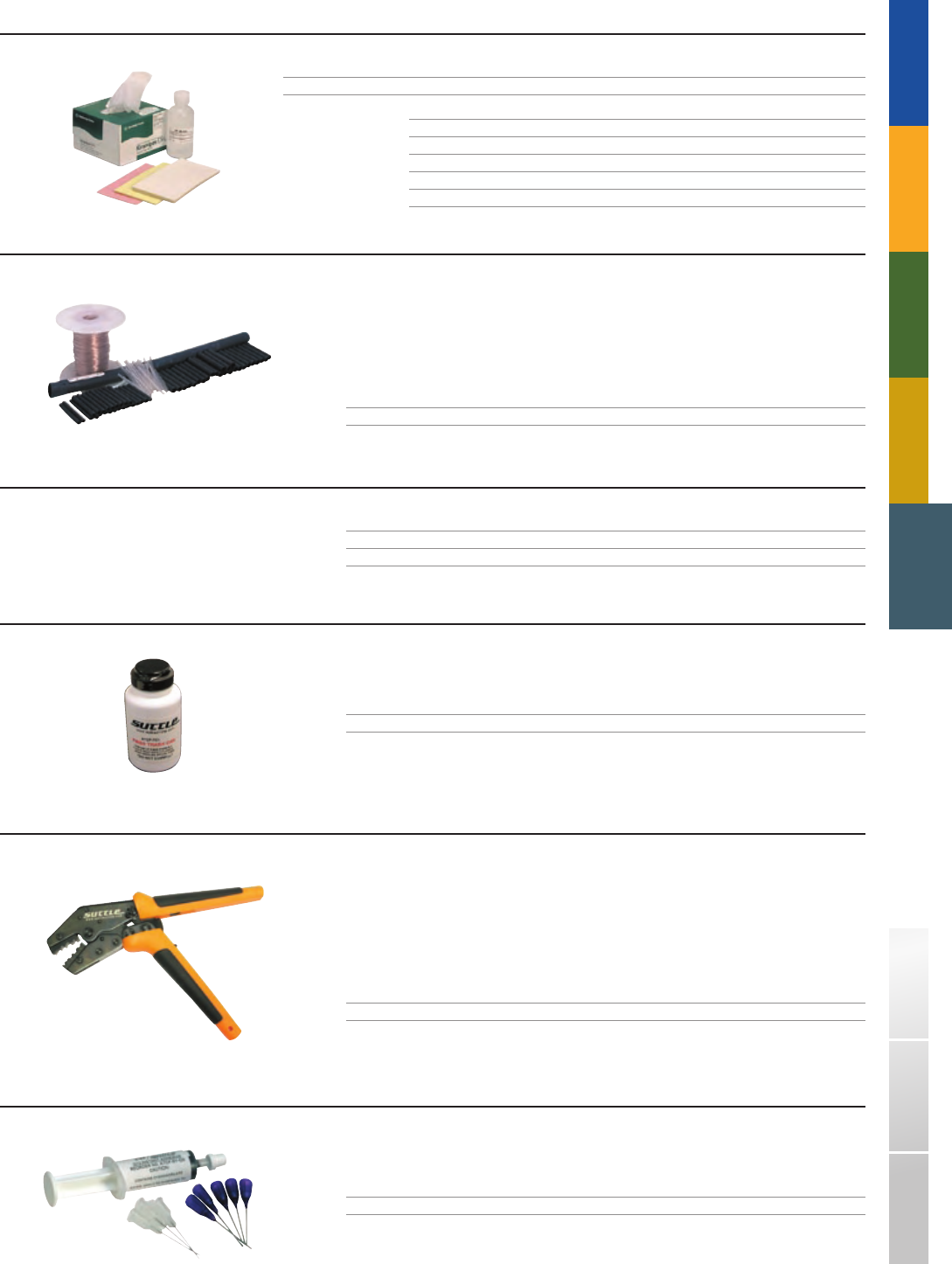
AFRP - QT
ATCF - BKIT - C
ATCC - UNV
ATCF - SY - QS
ATCF - TC1
TRADITIONAL TELEPHONY STRUCTURED WIRING
FIBER
DSL USOC WIRING GUIDE GLOSSARY INDEXSOHO ACCESS™
CONSUMABLES REFILL KIT
PART# DESCRIPTION
AFRP - QT Refill kit for consumable items in the termination kits
The consumables refill kit includes:
ATCF - IA Isopropyl alcohol, 4oz
ATCF - KW Wipes for fiber cleaning
ATCF - PF - 12 Lapping film (pink)
ATCF - PF - 3 Lapping film (yellow)
ATCF - PF - .3 Lapping film (white)
FIBER OPTIC BREAKOUT KITS
Suttle’s breakout router allows bundles of up to six fibers to be directed to different routes.
The ATCF - BKIT - C kit is required for termination of all loose - tube (250µm) fiber
A snap - in slot simplifies assembling the fibers into the routers
Unused fibers are stored for future applications
PART# DESCRIPTION
ATCF - BKIT - C 200 ft reel with PVC tubing, strain reliefs and adhesive shrink tubing (1/4” and 3/16”)
■
■
■
DUST BLAST KIT
PART# DESCRIPTION
ATCF - DB Compressed air canister with nozzle
ATCF - DB - R Compressed air canister refill
FIBER TRASH CAN
For safely scrapping and storing remnants during termination.
PART# DESCRIPTION
ATCF - TC1 Fiber trash can
UNIVERSAL CRIMP TOOL
Ratchet feature on the crimp tool ensures a proper crimp on the connector back post. Provides 1–4 size hex
crimp cavities for simple crimping of Suttle ST, SC, & FC connectors.
Ergonomic design is easier on hands
Longer handle means less force required for crimping
Ratchet feature ensures a proper crimp every time
PART# DESCRIPTION
ATCC - UNV Universal crimp tool, ratcheted, size 1–4 hex crimp cavities
■
■
■
PRE - LOADED SYRINGE
For safely scrapping and storing remnants during termination.
PART# DESCRIPTION
ATCF - SY - QS Pre - loaded syringe with needles (200 connectors/tube)
97
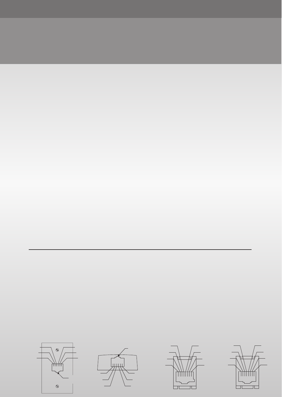
USOC WIRING GUIDE
Ú NOTICE
The information contained herein has been compiled for use by our distributors and others in the telecommunications
fi eld desiring pertinent facts relative to the USOC (Universal Systems Ordering Code) numbers. The descriptions are
considered to be basically equivalent to similar descriptions contained within part 68 subpart F of the code of Federal
Regulations, and to the best of our knowledge believed to be correct.
The primary purpose of the material covered on the following pages is to give Suttle part numbers which meet USOC
requirements, assisting our valued Suttle customers in ordering appropriate products.
There are fi ve basic types of telephone company - provided jacks used for the connection of registered equipment
to telecommunications network:
1. THE MINIATURE 6 - POSITION JACK (miniature)
The miniature 6 - position jacks provide bridged connections to the tip and ring conductors of a telephone line.
2. THE WEATHER - PROOF JACK
The weather - proof jack is used to provide bridged connections to the tip and ring conductors in environments
exposed to moisture.
3. THE 50 - POSITION MINIATURE RIBBON JACK (miniature ribbon)
The 50 - position miniature ribbon is used when registered equipment is connected to several telephone lines.
4. THE MINIATURE 8 - POSITION JACK (non - keyed) The miniature 8 - position series jack provides series connections
to the tip and ring conductors.
5. THE MINIATURE 8 - POSITION KEYED JACK (keyed)
The miniature 8 - position keyed jack is for data equipment providing bridged connections to the tip and ring conductors
of a telephone line and mode indication leads for use with an exclusion key telephone set if required.
Each type, except for the weather proof and 8 - position keyed jacks, may be arranged to provide bridge connections
of A and A1 conductors.
USOC NOTES
RJ (Registered Jack) numbers end with a letter designating wiring or mounting arrangement.
The Letter “C” in the USOC indicates the jack is baseboard or flush mounted for a desk type unit.
“W” indicates the jack is for a wall mounted unit.
“M” is for multiple mounting arrangements.
“X” is a single series connection.
RJA1X converts a 4 - hole jack to a miniature - bridged jack.
RJA2X converts a single jack to a duplex jack.
RJA3X converts a 12 - hole jack to a miniature - bridged jack.
RJ37X is used with registered telephone set equipped with an exclusion key for a data application.
■
■
■
■
■
Wall Flush Mount Version of the Miniature
Modular Jack Showing Pin Placement and
Associated Color Coding.
Surface Mount Version of the Miniature
Modular Jack Showing Pin Placement and
Associated Color Coding.
Keyed, 8-Position Modular Jack
Showing Pin Placement and
Associated Color Coding.
Non-Keyed, 8-Position Modular Jack Showing
Pin Placement and
Associated Color Coding.
6 45 3 2 1
WHITE
BLACK
REDGREEN
YELLOW
BLUE
SPRING RELEASE
TAB AREA
87654321 87654321
BLUE
ORANGE
BLACK
RED GREEN
YELLOW
BROWN
SLATE BLUE
ORANGE
BLACK
RED GREEN
YELLOW
BROWN
SLATE
1 2 3 4 5 6
WHITE
BLACK
RED GREEN
YELLOW
BLUE
SPRING RELEASE
TAB AREA
98
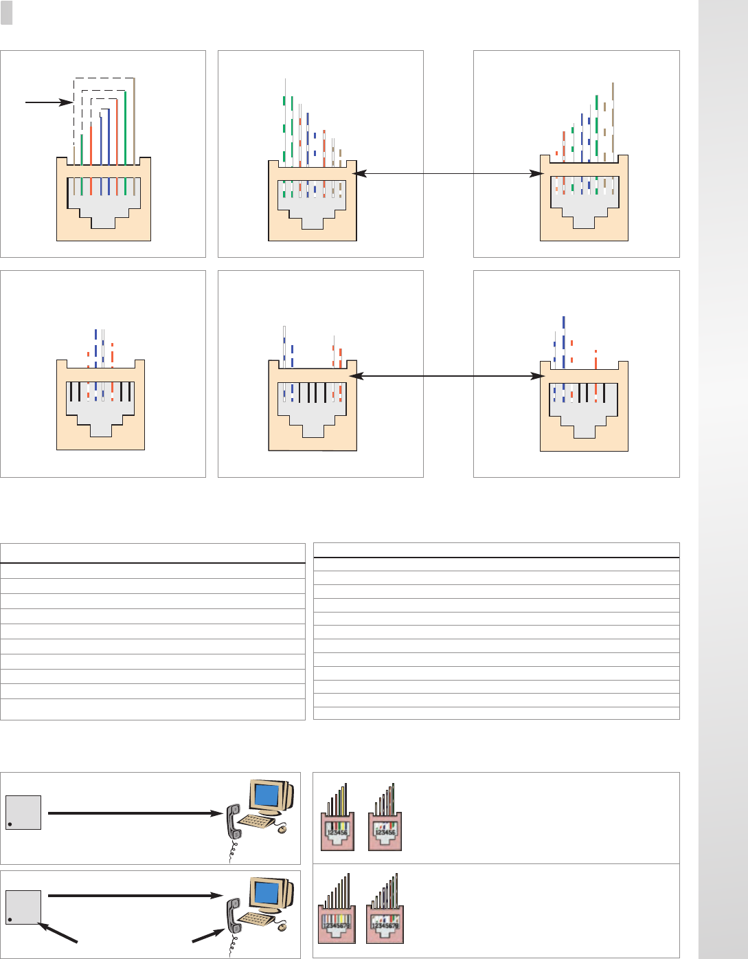
QUICK REFERENCE WIRING GUIDE❚
TOKEN RING TP-PMD 10BASE-T
T568A T568B
1
4
32
Wir e
Pairs
12345678
T+
R-
T+
T+
T+
R-
R-
R-
W/Green
Blue/W
W/Blue
W/Br ow n
W/Orange
Orange/W
Gr een/W
Bro w n/W
14322 14
3 32
T+
W/Green
R-
Blue/W
T+
W/Blue
T+
W/Br ow n
T+
W/Orange
R-
Orange/W
R-
Gr een/W
R-
Bro w n/W
Wire
Pairs
12345678 12345678
TX
RX
W/Blue
Orange/W
W/Orange
Blue/W
1
2 2
12345678
RX
2
Blue/W
W/Blue W/Orange
Orange/W
1
RX
Blue/W
W/Blue W/Orange
TX
11 22
Orange/W
Wire
Pairs
12345678 12345678
USOC
TX=Transmit RX=Receive Bi=Bidirectional
TX=Transmit RX=Receive Bi=Bidirectional
MATRIX FOR APPLICATION SPECIFIC PAIR ASSIGNMENT
FOR 8-POSITION MODULAR CONNECTOR RJ-45
1 & 2
-
TX
-
TX
TX
RX
TX/RX
T3/R3
T2/R2
RX
Power
3 & 6
T2/R2
RX
TX
-
-
-
TX/RX
T2/R2
T3/R3
-
RX
4 & 5
R1/T1
-
RX
-
-
-
TX/RX
R1/T1
R1/T1
TX
TX
7 & 8
-
-
-
RX
RX
TX
TX/RX
T4/R4
T4/R4
-
Power
1 & 8
T4/R4
-
-
-
-
-
-
-
-
-
2 & 7
T3/R3
-
-
-
-
-
-
-
-
-
PIN#
TIA/EIA 606-A TERMINATION HARDWARE
COLOR DESIGNATION
COLOR DESCRIPTION COLOR # EXAMPLE
White 1st Level Backbone -85 MC/IC
Red Key System Connection -53 N/A
Gray 2nd Level Backbone -48 IC/HC
Yellow Miscellaneous -56 Aux. Alarms
Blue Horizontal Cable Terms -62 Station Cable
Green Network Connections -51 Customer Side Demarc
Purple Common Equipment -57 PBX, Host, LAN’s, MUXES
Orange Demarcation Point -97 C.O. Termination
Brown Interbuilding Backbone ---- Cabling Between Buildings
APPLICATION
ANALOG USOC
10/100 BASE TX
TOKEN RING
TP-PMD
ATM USER
ATM HUB
1000 BASE-T
T-568A
T-568B
T2/T3
ISDN
Modular Jack Type: 6 Position/6 Conductor
Contact Position: 1 2 3 4 5 6
Telco Wire Color: W BK R G Y BL
TIA/EIA Wire Color:
W/G W/O BL/W W/BL O/W G/W
Modular Jack Type: 8 Position/8 Conductor
Contact Position: 1 2 3 4 5 6 7 8
Telco Wire Color: BL OR BK R G Y BR SL
TIA/EIA Wire Color:
W/BR W/G W/O BL/W W/BL O/W G/W BR/W
8 POSITION-8 CONDUCTOR
6 POSITION-6 CONDUCTOR
TELCO TIA/EIA T568A
TELCO TIA/EIA
Horizontal Cabling “Channel”
90 Meters (295 feet) MAXIMUM
PLUS
5 Meters (16.5ft) 5 Meters (16.5ft)
Maximum M ax im u m
Patch CordsPatch Cords
XX
Telephone
Room
Horizontal Cabling “Permanent Link”
90 Meters (295 feet) MAXIMUM
Telephone
Room
WORK AREA
WORK AREA
TIA/EIA - TELCO WIRE COLOR CONVERSION
99
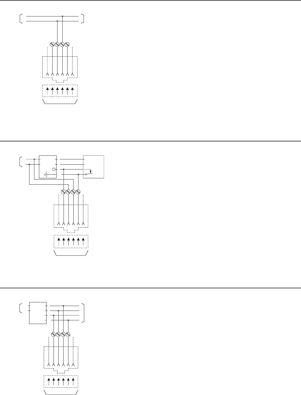
MINIATURE
6 POSITION
PLUG
MINIATURE
6 POSITION
JACK
R T
123456
TO REGISTERED CPE
T
TO
NETWORK R
A A
T
A
A1
R
LINE
CIRCUIT
24 VAC
KEY
TELEPHONE
(TELCO)
(TELCO)
MINIATURE
6 POSITION
PLUG
MINIATURE
6 POSITION
JACK
R T
123456
TO REGISTERED
TERMINAL EQUIPMENT
T
TO
NETWORK TO
OTHER
EQUIPMENT
R
A A1
T
A
A1
R
LINE
CIRCUIT
MINIATURE
6 POSITION
PLUG
MINIATURE
6 POSITION
JACK
R T
123456
TO REGISTERED
TERMINAL EQUIPMENT
T
TO
NETWORK
TO
OTHER
EQUIPMENT
R
1-800-852-8662 WWW.SUTTLEONLINE.COM
RJ11C and RJ11W
103A4
104A4
104B4
105AF4
106AFD4
1542AM
16150 - 4
16152L7 - 4
16152L7E - 4
16152L8 - 4
16152L8E - 4
19316L7 - 4
19316L7E - 4
2 - 1001
2 - 2001
2 - 3001
305C
305D
333AE4
404M
468DV48
468L44
625A4
625A2 - 4
625A3 - 4
625B
625B1 - 4
625B1E - 4
625B2 - 4
625B3 - 4
625B3E - 4
625B3EF4
625B4 - 4
625B4E - 4
625B4EF4
625C2 - 4
625C4
625D4
625F4
625FE - 4
625FS4
625S4
625SA4
625T4
625TD1
630AB4
630ABC4
630ABS4
630AC4
630ANS4
635B
635D
630ABC4
630AC4
630AD4
630AP4
630B4
631A
632A
633A
Suttle Products which can be used for USOC RJ11W:
USOC RJ11C: Surface or flush mounted jacks.
USOC aRJ11W: Wall mounted equipment.
Mechanical Arrangement: Miniature 6 - position jack.
Typical Usage: Single line non - key telephones and ancillary devices.
Electrical Network Connection: Single line bridged tip and ring.
RJ12C and RJ12W
103A4
104A4
104B4
105AF4
106AFD4
1542AM
16150 - 4
16152L7 - 4
16152L7E - 4
16152L8 - 4
16152L8E - 4
19316L7 - 4
19316L7E - 4
2 - 1001
2 - 2001
2 - 3001
305C
305D
333AE4
404M
468L44
625A2 - 4
625A3 - 4
625B
625B1 - 4
625B1E - 4
625B2 - 4
625B2E - 4
625B3 - 4
625B3EF4
625B3E - 4
625B4 - 4
625B4E - 4
625B4EF4
625C4
625D4
625F4
625FE - 4
625FS4
625S4
625SA4
625T4
625TD1
630AB4
630ABC4
630ABS - 4
630ANS4
630AC4
635B
635D
630A4
630ABC4
630AC4
630AP4
630AD4
630B4
631A
632A
633A
Suttle Products which can be used for USOC RJ11W:
USOC RJ12C: Surface or flush mounted jacks.
USOC RJ12W: Wall mounted equipment.
Mechanical Arrangement: Miniature 6 - position jack.
Typical Usage: Single line non - keyed telephone sets and ancillary devices connected to a key system where registered terminal
equipment is not compatible with electrical characteristics of tip and ring behind line circuit.
Electrical Network Connection: Single line bridged tip and ring ahead of the line circuit of a key system, with A and A1 leads.
RJ13C and RJ13W
103A4
104A4
104B4
105AF4
106AFD4
180ST
1650 - 4
16152L7 - 4
16152LE - 4
16152L8 - 4
16152L8E - 4
19316L7 - 4
19316L7E - 4
2 - 1001
2 - 2001
2 - 3001
305C
305D
333AE4
404M
468L44
625A4
625A2 - 4
625A3 - 4
625B
625B1 - 4
625B1E - 4
625B2 - 4
625B3 - 4
625B3E - 4
625B3EF4
625B4 - 4
625B4E - 4
625B4EF4
625C4
625D4
625F4
625FE - 4
625FS4
625S4
625SA4
625T4
625TD1
630AB4
630ABC4
630ABS4
630AC4
630ANS4
635B
635D
630A4
630ABC4
630AC4
630AD4
630AP4
630B4
631A
632A
633A
Suttle Products which can be used for USOC RJ11W:
USOC RJ13C: Surface or flush mounted jacks.
USOC RJ13W: Wall mounted equipment.
Mechanical Arrangement: Miniature 6 - position jack.
Typical Usage: Single line non - key telephone sets and ancillary devices connected to a key system.
Electrical Network Connection: Single line bridged tip and ring, A and A1 leads behind the line circuit of a key system.
Suttle products which can be used for USOC RJ11C:
Suttle Products which can be used for USOC RJ12C:
Suttle Products which can be used for USOC RJ13C:
USOC WIRING DIAGRAMSÚ
100
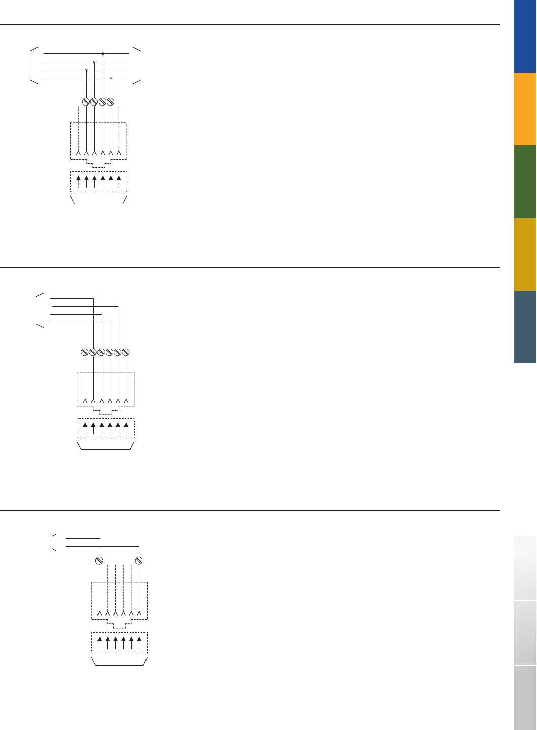
MINIATURE
6 POSITION
PLUG
MINIATURE
6 POSITION
JACK
R1 T1
123456
TO REGISTERED
TERMINAL EQUIPMENT
MI
T1
TO SERIES
JACK SUCH
AS RJ36X
(NOTE)
MIC
MI MIC
R1
MI=MODE INDICATION
MIC=MODE INDICATION COMMON
MINIATURE
6 POSITION
PLUG
MINIATURE
6 POSITION
JACK
RT
123456
TO REGISTERED
TERMINAL EQUIPMENT
NOTE: EQUIPMENT
MUST COMPLY WITH
ARTICLE 517 OF THE
NATIONAL ELECTRIC CODE
TO
NETWORK
T
R
MINIATURE
6 POSITION
PLUG
MINIATURE
6 POSITION
JACK
R1 T1
123456
TO REGISTERED
TERMINAL EQUIPMENT
T1
R2
TO
NETWORK
TO
OTHER
EQUIPMENT
R1
T2 R2
T2
TRADITIONAL TELEPHONY STRUCTURED WIRING FIBERDSLSOHO ACCESS™ USOC WIRING GUIDE GLOSSARY INDEX
RJ14C and RJ14W
103A4
104A4
104B4
105AF4
106AFD4
16150 - 4
16152L7 - 4
16152L7E - 4
16152L8 - 4
16152L8E - 4
19316L7 - 4
193416L7E - 4
2 - 1001
2 - 2001
2 - 3001
333AE4
404M
468L44
625A4
625A2 - 4
625A3 - 4
625B
625B1 - 4
625B1E - 4
625B2 - 4
625B3 - 4
625B3E - 4
625B3EF4
625B4 - 4
625B4E - 4
625B4EF4
625C4
625D4
625F4
625FE - 4
625FS4
625S4
625SA4
625T4
625TD1
630AB4
630ABC4
630ABS4
630AC4
630A4
630ABC4
630AC4
630AD4
630AP4
630B4
631A
632A
633A
630A4
Suttle Products which can be used for USOC RJ14W:
NOTE: The telephone company will wire the lines to the jack in the sequence designated by the customer.
USOC RJ14C: Surface or flush mounted jacks.
USOC RJ14W: Wall mounted equipment.
Mechanical Arrangement: Miniature 6 - position jack.
Typical Usage: Two line non - key telephone sets and ancillary devices. Two separate telephone lines.
Electrical Network Connection: Two line bridged tip and ring.
RJ16X
625MB 635B 635D 635B68
NOTE: MI and MIC leads are typically wired to an RJ36X series jack which can be used to conect an exclusion key
telephone set ahead of the data equipment.
USOC RJ16X: Surface or flush mounted jacks.
Mechanical Arrangement: Miniature 6 - position jack.
Typical Usage: 9dBm (Permissive) data equipment with MI (mode indications) and MIC (mode indication common) leads.
Electrical Network Connection: Single line bridged tip and ring with mode indication to a series connection
ahead of the bridged connection.
RJ17C
102A6
468L66
625B2
625D6
625TD2
630A6
630AD6
630AP6
630B6
697B68H102A6
468L66
625B2
625D6
625TD2
630A6
630AD6
630AP6
630B6
697B68H102A6
468L66
625B2
625D6
625TD2
630A6
630AD6
630AP6
630B6
697B68H102A6
468L66
625B2
USOC RJ17C: Surface or flush mounted jack.
Mechanical Arrangement: Miniature 6 - position jack.
Typical Usage: Special non - key telephone set or certain hospital ancillary equipment in hospital critical care areas.
Use is restricted to devices which comply with Article 517 of the1978 National Electrical Codes.
Electrical Network Connection: Single line bridged tip and ring leads. Tip and ring appear on pins 1 and 6 rather than
3 and 4. Positions 2, 3, 4 and 5 are not equipped with contacts.
Suttle products which can be used for USOC RJ16X (including RJ36X jack):
Suttle Products which can be used for USOC RJ14C:
Suttle Products which can be used for USOC RJ17C:
101
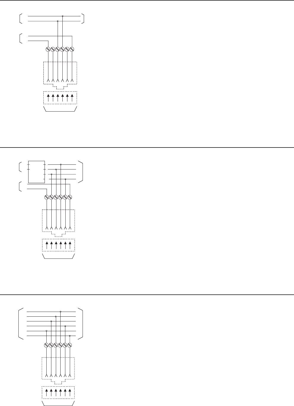
MINIATURE
6 POSITION
PLUG
MINIATURE
6 POSITION
JACK
MB1MB R T
123456
TO REGISTERED
TERMINAL EQUIPMENT
TO
NETWORK
TO
OTHER
EQUIPMENT
MB1
MB
T
R
TO
MAKE BUSY
CIRCUIT
MINIATURE
6 POSITION
PLUG
MINIATURE
6 POSITION
JACK
MB1M R T
123456
TO
REGISTERED
TERMINAL EQUIPMENT
TO
NETWORK
TO
TELCO
PROVIDED
EQUIPMENT
MB1
A A1
MB
T
A
A
R
LINE
CIRCUIT
T
R
TO
MAKE BUSY
CIRCUIT
MINIATURE
6 POSITION
PLUG
MINIATURE
6 POSITION
JACK
R3T3 R1 T1
123456
TO REGISTERED
TERMINAL EQUIPMENT
T1
R2
TO
NETWORK
TO
OTHER
EQUIPMENT
T3
R1
T2 R2
R3
T2
1-800-852-8662 WWW.SUTTLEONLINE.COM
RJ18C
102A6
103A6
104B6
16150 - 6
16152L7 - 6
19316L7 - 6
2 - 1002
2 - 2003
2 - 3003
333AE6
468L66
625A6
625A2 - 6
625A3 - 6
625B3 - 6
625B3E - 6
625B3EF6
625B4 - 6
625B4E - 6
625B4EF6
625D6
625FS6
625S6
625SA6
625T6
625TD2
630A6
630AB6
630ABC6
630ABS6
630AC6
630AD6
630ANS6
630AP6
630B6
635B
635D
697B68H102A6
103A6
104B6
USOC RJ18C: Surface or flush mounted jack.
Mechanical Arrangement: Miniature 6 - position jack.
Typical Usage: When the registered equipment provides a contact closure between the MB and MB1 leads,
a make - busy indication is transmitted to the network equipment busying out the line from further incoming calls. It is recommended that
the busy indication (contact closure) be provided while line is in idle state.
Electrical Network Connection: A bridged connection of single line tip and ring with make busy leads MB/MB1.
Suttle Products which can be used for USOC RJ18C:
RJ19C
102A6
103A6
104B6
16150 - 6
16152L7 - 6
19316L7 - 6
2 - 1002
2 - 2003
2 - 3003
333AE6
468L66
625A6
625A2 - 6
625A3 - 6
625B3 - 6
625B3E - 6
625B3EF6
625B4 - 6
625B4E - 6
625B4EF6
625D6
625FS6
625S6
625SA6
625T6
625TD2
630A6
630AB6
630ABC6
630ABS6
630AC6
630AD6
630ANS6
630AP6
630B6
635B
635D
697B68H
102A6
103A6
USOC RJ19C: Surface or flush mounted jacks.
Mechanical Arrangement: Miniature 6 - position jack.
Typical Usage: When the registered equipment provides a contact closure between the MB and MB1 leads,
a make - busy indication is transmitted to the network equipment busying out the line from further incoming calls. It is recommended that
the busy indication (contact closure) be provided while line is in idle state.
Electrical Network Connection: A bridged connection of single line tip and ring behind a key system line circuit,
with A and A1 lead control, and a direct connection for MB/MB1 make - busy leads.
Suttle Products which can be used for USOC RJ19C:
RJ25C
102A6
103A6
104A6
104B6
106AFD6
16150 - 6
16152L7 - 6
19316L7 - 6
2 - 1002
2 - 2003
2 - 3003
333AE6
625A6
625A2 - 6
625A3 - 6
625B3 - 6
625B3E - 6
625B3EF6
625B4 - 6
625B4E - 6
625B4EF6
625D6
625FS6
625S6
625SA6
625T6
625TD2
630A6
630AB6
630AD6
630ANS6
630AP6
630ABC6
630ABS6
630AC6
630B6
635B
635D
697B68H
102A6
USOC RJ25C: Surface or flush mounted jack.
Mechanical Arrangement: Miniature 6 - position jack.
Typical Usage: Three line non - key telephone sets, ancillary devices, including message registration, automantic identification,
outward dialing and off - premise station.
Electrical Network Connection: Up to three lines bridged connection.
Suttle Products which can be used for USOC RJ25C:
102

MINIATURE
8 POSITION
PLUG
MINIATURE
8 POSITION
SERIES JACK
SHORTING BAR
SHORT REMOVED ON
PLUG INSERTION
T1R1 R T
12345678
TO REGISTERED
TERMINAL EQUIPMENT
T
T1
R1
TO
NETWORK
TO
TELCO
WIRING
R
MINIATURE
8 POSITION
PLUG
MINIATURE
8 POSITION
SERIES JACK
SHORTING BAR
SHORT REMOVED ON
PLUG INSERTION
T1R1 R T
12345678
TO REGISTERED CPE
T
T1
R1
TO
NETWORK
TO
EQUIPMENT
ASSOCIATED
WITH
REGISTERED
CPE
R
MINIATURE
8 POSITION
PLUG
MINIATURE
8 POSITION
SERIES JACK
SHORTING BAR
SHORT REMOVED ON
PLUG INSERTION
T1R1 R T
12345678
TO REGISTERED CPE
R1
A
TO
NETWORK
TO
EQUIPMENT
ASSOCIATED
WITH
REGISTERED
CPE
A1
T1
LINE
CIRCUIT
T
R
24 VAC
TRADITIONAL TELEPHONY STRUCTURED WIRING FIBERDSLSOHO ACCESS™ USOC WIRING GUIDE GLOSSARY INDEX
RJ31X
468A
625A28SB
625A38SB
635A
635B
*635B68
*635B68F
648C8SB
97D
Mechanical Arrangement: Miniature 8 - position series on non - keyed jack with shorting bars.
Typical Usage: Alarm reporting device.
Electrical Network Connection: Series tip and ring ahead of all station equipment. Single line telephone.
Suttle Products which can be used for USOC RJ31X:
RJ32X
625A28SB
625A38SB
635A
635A8
*635B68
648C8SB
648A
*97D
Mechanical Arrangement: Miniature 8 - position series on non - keyed jack with shorting bars.
Typical Usage: Automatic dialer.
Electrical Network Connection: Series tip and ring at the station. Single line telephone.
Suttle Products which can be used for USOC RJ32X:
RJ33X
625A28SB
625A38SB
635A
635A8
*635B68
648C8SB
*97D
Mechanical Arrangement: Miniature 8 - position series non - keyed jack with shorting bars.
Typical Usage: Series ancillary devices connected to a key system where registered terminal equipment is not compatible
with electrical characteristics of tip and ring behind line circuit.
Electrical Network Connection: Series tip and ring ahead of the line circuit of a key system with A and A1 leads.
Suttle Products which can be used for USOC RJ33X:
*Asterisked products are those which include the RJ11C Jack.
*Asterisked products are those which include the RJ11C Jack.
*Asterisked products are those which include the RJ11C Jack.
103
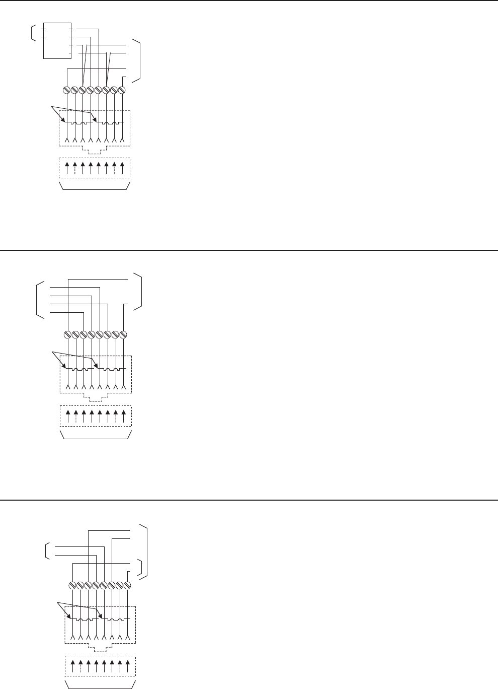
MINIATURE
8 POSITION
PLUG
MINIATURE
8 POSITION
SERIES JACK
SHORTING BAR
SHORT REMOVED ON
PLUG INSERTION
T1R1 R T
12345678
TO REGISTERED
TERMINAL EQUIPMENT
T
A A
R1
TO
NETWORK
TO
OTHER
EQUIPMENT
T1
A1A1
R
A A1
LINE
CIRCUIT
T
R
MINIATURE
8 POSITION
PLUG
MINIATURE
8 POSITION
SERIES JACK
SHORTING BAR
SHORT REMOVED ON
PLUG INSERTION
T1R1 R T
12345678
TO REGISTERED
TERMINAL EQUIPMENT
R
T1A1
TO STATION
SET
TERMINALS
TO STATION
SET KEY
PICK UP
A
R1
T
A A1
MINIATURE
8 POSITION
PLUG
MINIATURE
8 POSITION
SERIES JACK
SHORTING BAR
SHORT REMOVED ON
PLUG INSERTION
T1R1 R T
12345678
TO
REGISTERED
TERMINAL EQUIPMENT
R
R1
MI
TO
NETWORK
TO OTHER
JACKS
RJ16X,
ETC.
MIC
T1
T
MI MIC
SUBJECT TO EFFECTIVE
TARRIF and/or
FCC RULE MAKING
MI=MODE INDICATION
MIC=MODE INDICATION COMMON
1-800-852-8662 WWW.SUTTLEONLINE.COM
RJ34X
625A28SB
625A38SB
635A
635A8
*635B68 648C8 - SB
Mechanical Arrangement: Miniature 8 - position series non - keyed jack with shorting bars.
Typical Usage: A single line set with exclusion or series ancillary device connected to a key system.
Electrical Network Connection: Series tip, ring, A and A1 leads behind the line circuit of a key system.
RJ35X
625A28SB
625A38SB
635A
635A8
*635B68 648C8SB
Mechanical Arrangement: Miniature 8 - position series on non - keyed jack with shorting bars.
Typical Usage: Series ancillary devices connected to key telephone sets.
Electrical Network Connection: Series connection to the multiplied tip, ring, A and A1 leads behind the pick - up keys
of a key telephone.
RJ36X
625A28SB
625A38SB
635A
635A8
635B68
648C8SB
*97D
Mechanical Arrangement: Miniature 8 - position series non - keyed jack with shorting bars.
Typical Usage: Mode indication (exclusion key) telephone set in series with jack for data equipment.
Electrical Network Connection: Series tip and ring with mode indication to station behind series connection.
Suttle Products which can be used for USOC RJ36X:
*Asterisked products are those which include the RJ11C Jack.
*Asterisked products are those which include the RJ11C Jack.
*Asterisked products are those which include the RJ11C Jack.
Suttle Products which can be used for USOC RJ34X:
Suttle Products which can be used for USOC RJ35X:
104
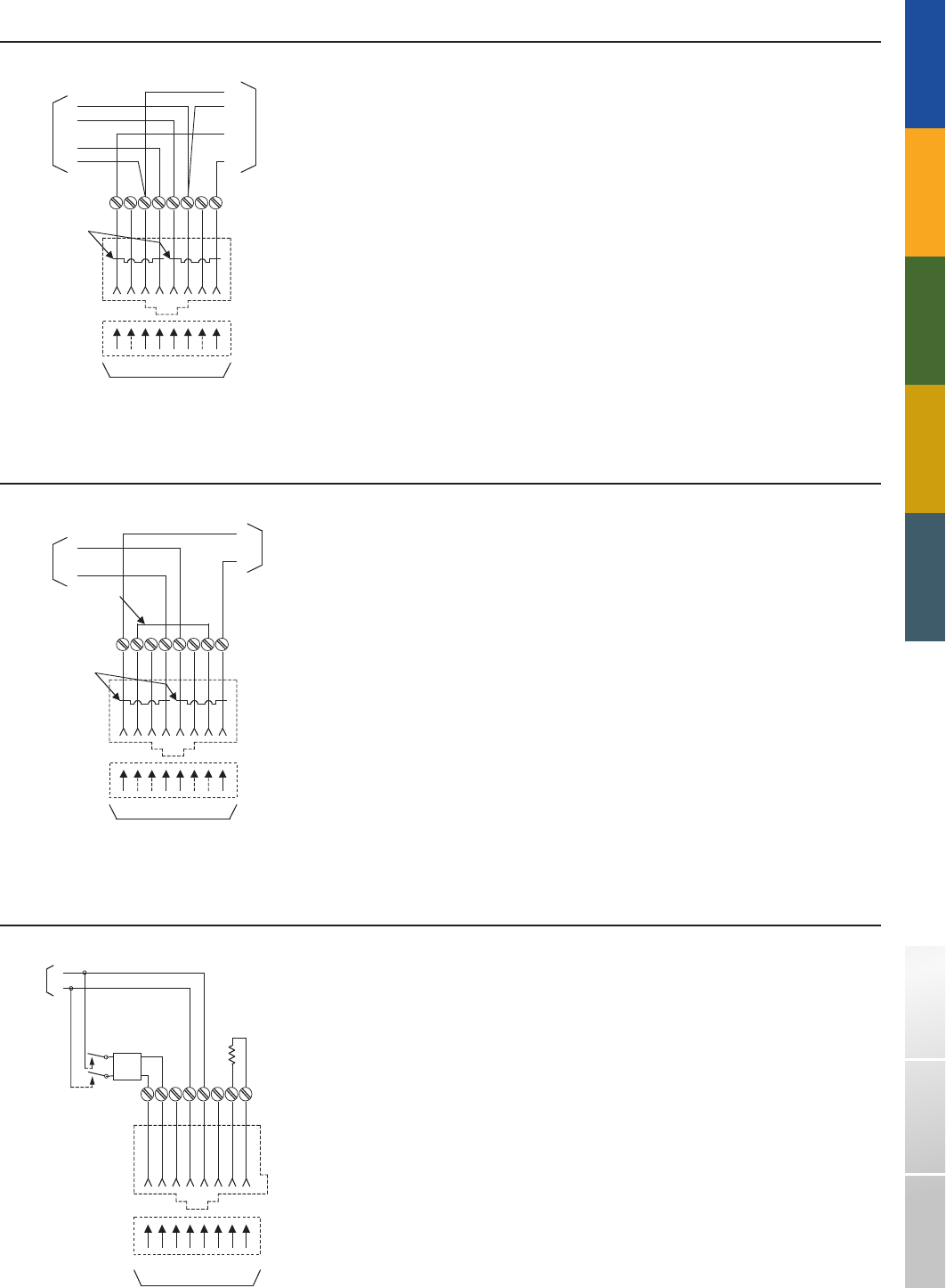
MINIATURE
8 POSITION
PLUG
MINIATURE
8 POSITION
JACK
SHORTING BAR
EXTEXR R1 T1
12345678
TO REGISTERED
TERMINAL EQUIPMENT
R2
R1
EXR
T2
TO
NETWORK
TO
EXCLUDED
SET
R2
EXTT2
T1
T2 R2
MINIATURE
8 POSITION
PLUG
MINIATURE
8 POSITION
SERIES JACK
SHORTING BAR
SHORT REMOVED ON
PLUG INSERTION
T1R1 R T
12345678
TO REGISTERED
TERMINAL EQUIPMENT
T
R
T1
R1
TO
NETWORK
STRAP
PROVIDED BY THE
TELEPHONE CO.
TO
TELCO
WIRING
MINIATURE
8 POSITION
KEYED
PLUG
MINIATURE
8 POSITION
KEYED
JACK
MI
R
P
T
P
12345678
T
R
TO
NETWORK
PROGRAMMING
RESISTOR
MIC
PR PCR
FLL
T
FLL
PAD
TRADITIONAL TELEPHONY STRUCTURED WIRING FIBERDSLSOHO ACCESS™ USOC WIRING GUIDE GLOSSARY INDEX
RJ37X
625A28SB
625A38SB
635A
635A8
*635B68
648C8 - SB
*97D
NOTE: The telephone company will wire the lines to the jack in the sequence designated by the customer.
Mechanical Arrangement: Miniature 8 - position series non - keyed jack with shorting bars.
Typical Usage: Two line telephone with the exclusion on one line.
Electrical Network Connection: Two line bridged tip and ring with exclusion on line 1.
Suttle Products which can be used for USOC RJ37X:
RJ38X
625A28SB
625A38SB
635A
635A8
*635B68
648C8SB
*97D
Mechanical Arrangement: Miniature 8 - position series non - keyed jack with shorting bars.
Typical Usage: Registered alarm dialers.
Electrical Network Connection: Series connection to the tip and ring of telephone line identitical to that of JR31X.
Strap provides a continuity circuit between 2 and 7, which is used as an indication that the plug of the registered equipment
is engaged with the jack. The jack is wired ahead of all station equipment electrically.
Suttle Products which can be used for USOC RJ32X:
RJ41S
Mechanical Arrangement: Single miniature 8 - position keyed jack for surface mounting.
Typical Usage: Universial jack for fixed loss loop (FLL) or programmed (P) types of data equipment.
Electrical Network Connection: Single line bridged tip and ring.
*Asterisked products are those which include the RJ11C Jack.
*Asterisked products are those which include the RJ11C Jack.
105
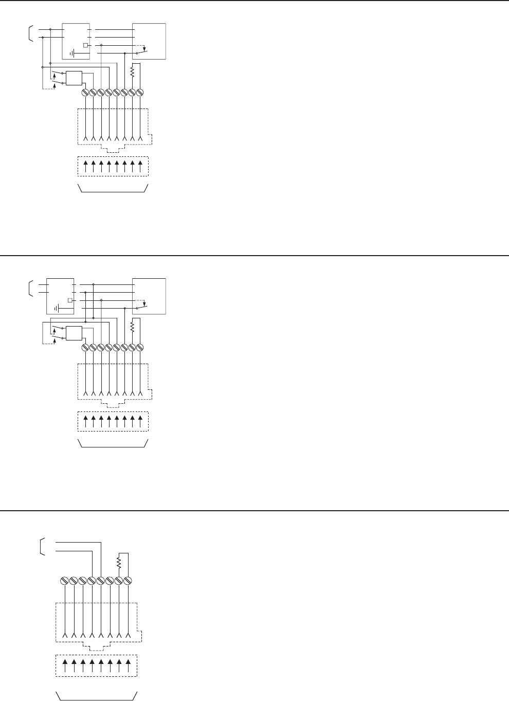
MINIATURE
8 POSITION
KEYED
PLUG
MINIATURE
8 POSITION
KEYED
JACK
A R
P
T
P
12345678
T
R
TO
NETWORK
PROGRAMMING
RESISTOR
A1 PR PC
24 VDC
KEY
TELEPHONE
(TELCO)
LINE
CIRCUIT
TO REGISTERED
TERMINAL EQUIPMENT
R
FLL
T
FLL
PA
T
R
A
A
MINIATURE
8 POSITION
KEYED
PLUG
MINIATURE
8 POSITION
KEYED
JACK
A R
P
T
P
12345678
T
R
TO
NETWORK
PROGRAMMING
RESISTOR
A1 P R PC
24 VDC
KEY
TELEPHONE
(TELCO)
LINE
CIRCUIT
TO REGISTERED
TERMINAL EQUIPMENT
R
FLL
T
FLL
PA
T
R
A
A1
MINIATURE
8 POSITION
KEYED
PLUG
MINIATURE
8 POSITION
KEYED
JACK
A
or
MI
PR PT
12345678
T
R
TO
NETWORK
PROGRAMMING
RESISTOR
A1
or
MIC
PR PC
1-800-852-8662 WWW.SUTTLEONLINE.COM
RJ42S
97AB
Mechanical Arrangement: Single miniature 8 - position keyed jack for surface mounting.
Typical Usage: Universial jack for fixed loss loop (FLL) or programmed (P) types of data equipment.
Electrical Network Connection: Single line bridged tip and ring.
Suttle Products which can be used for USOC RJ42S:
RJ43S
97AB
Mechanical Arrangement: Single miniature 8 - position keyed jack.
Typical Usage: Universial jack for fixed loss loop (FLL) or programmed (P) types of data equipment.
Electrical Network Connection: Single line bridged tip and ring.
Suttle Products which can be used for USOC RJ43S:
RJ45S
Mechanical Arrangement: Single miniature 8 - position keyed jack.
Typical Usage: Programmed data equipment.
Electrical Network Connection: Single line bridged tip and ring.
103AY8 625A28KR 697B8 97B
Suttle Products which can be used for USOC RJ45S:
*Asterisked products are those which include the RJ11C Jack.
106

MINIATURE
8 POSITION
KEYED
PLUG
MINIATURE
8 POSITION
KEYED
JACK
A R
P
T
P
12345678
T
R
TO
NETWORK
PROGRAMMING
RESISTOR
A1 P R PC
24
KEY
TELEPHONE
(TELCO)
LINE
CIRCUIT
T
R
A
A1
MINIATURE
8 POSITION
KEYED
PLUG
MINIATURE
8 POSITION
KEYED
JACK
A R
P
T
P
12345678
T
R
TO
NETWORK
PROGRAMMING
RESISTOR
A1 P R PC
24 VAC
KEY
TELEPHONE
(TELCO)
LINE
CIRCUIT
T
R
A
A1
MINIATURE
8 POSITION
PLUG
MINIATURE
8 POSITION
JACK
T1R1 R T
12345678
TO REGISTERED
TERMINAL EQUIPMENT
R1
T1
T
R
TRANSMIT
TO
NETWORK
RECEIVE
FROM
NETWORK
RESERVED FOR
FUTURE USE
TO
NETWORK
TRADITIONAL TELEPHONY STRUCTURED WIRING FIBERDSLSOHO ACCESS™ USOC WIRING GUIDE GLOSSARY INDEX
RJ46S
103AY8 625A28KR 697B8 97B
Mechanical Arrangement: Single miniature 8 - position keyed jack.
Typical Usage: Programmed data equipment connected to a key system where the registered terminal equipment is not
compatible with electrical characteristics of tip and ring ahead of the line circuit.
Electrical Network Connection: Programmed 8 - position keyed jack with T/R connected ahead of the line circuit.
Suttle Products which can be used for USOC RJ46S:
RJ47S
625A28KR 697B8 97B
Mechanical Arrangement: Single miniature 8 - position keyed jack.
Typical Usage: Programmed data equipment connected to a key system.
Electrical Network Connection: Programmed keyed data jack with T/R connected behind the line circuit.
Suttle Products which can be used for USOC RJ47S:
RJ48C
Mechanical Arrangement: Miniature 8 - position jack.
Typical Usage: 1.544 Mbps digital services.
Electrical Network Connection: Tip and Ring, T1 R1. Conductors 7 and 8 provide cable shield integrity.
Conductors 3 and 6 are reserved for future use.
102A8
103A8
104A8
105AF
106AFD
106BFD
625B3 - 8
625A2 - 8
625A3 - 8
Suttle Products which can be used for USOC RJ48C:
107
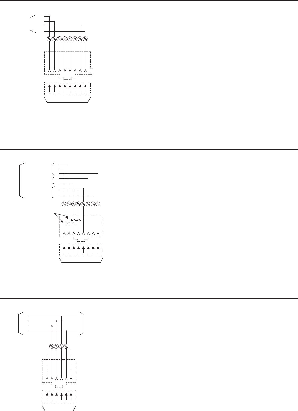
MINIATURE
8 POSITION
KEYED
PLUG
MINIATURE
8 POSITION
KEYED
JACK
T1R1 RT
12345678
T1
R1
T
R
TO
NETWORK
MINIATURE
8 POSITION
PLUG
MINIATURE
8 POSITION
JACK
SHORTING BAR
SHORT REMOVED ON
PLUG INSERTION
TR R1 T 1
12345678
TO REGISTERED
TERMINAL EQUIPMENT
R
T
T1
R1
TRANSMIT
TO
NETWORK
RECEIVE
FROM
NETWORK
RESERVED FOR
FUTURE USE
TO
NETWORK
MINIATURE
6 POSITION
PLUG
MINIATURE
6 POSITION
JACK
R T
123456
TO REGISTERED
TERMINAL EQUIPMENT
T
R1
TO
NETWORK
TO
OTHER
EQUIPMENT
R
T1 R1
T1
1-800-852-8662 WWW.SUTTLEONLINE.COM
RJ48S
104B8
106BFD
625A28 - K
625A38 - K
625B3 - 8 697B8LR
Mechanical Arrangement: Miniature 8 - position keyed jack.
Typical Usage: Local area data channels/subrate digital services.
Electrical Network Connection: One or two line Tip and Ring or T&R, T1 R1.
Suttle Products which can be used for USOC RJ48S:
RJ48X
625A28K - 2 625A28NK - 2 625A38K - 2 648C848X625A28K - 2
Mechanical Arrangement: Miniature 8 - position jack.
Typical Usage: 1.544 Mbps digital services.
Electrical Network Connection: Tip and Ring, T1 R1. Conductors 7 and 8 provide cable shield integrity.
Conductors 2 and 6 are reserved for future use.
Suttle Products which can be used for USOC RJ48X:
RJ1DC
Mechanical Arrangement: Miniature 6 - position jack.
Typical Usage: Terminal equipment and systems requiring 4 - wire exchange access.
Electrical Network Connection: Single line bridged 4 - wire, tip/ring and T1/R1.
103A4
104B4
105AF4
106AFD4
16150 - 4
16152L7 - 4
16152L7E - 4
19316L7 - 4
19316L7E - 4
2 - 1001
2 - 2001
2 - 3001
333AE4
404M
625A4
625A2 - 4
625A3 - 4
625B
625B1 - 4
625B1E - 4
625B2 - 4
625B3 - 4
625B3E - 4
625B3EF4
625B4 - 4
625B4E - 4
625B4EF4
625C4
625F4
625FE - 4
625FS4
625S4
625SA4
625T4
630AB4
630ABC4
630ABS4
630AC4
630ANS4
635D
Suttle Products which can be used for USOC RJ1DC:
108
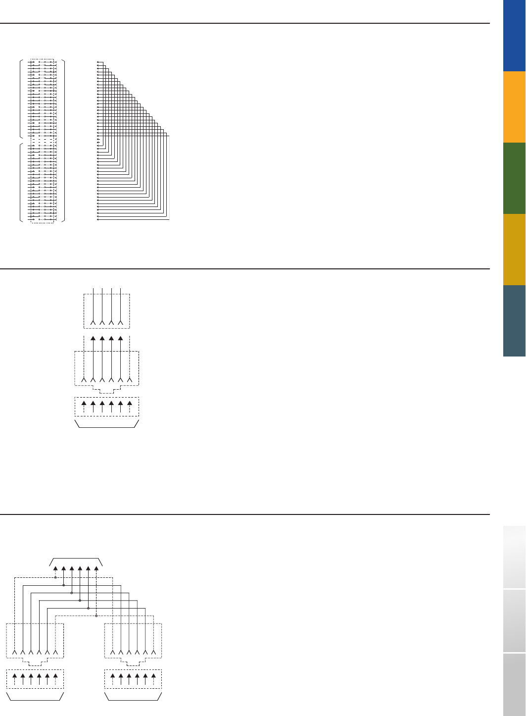
MINIATURE
6 POSITION
PLUG
4 PRONG
TO
MINIATURE
6 POSITION
JACK
TO REGISTERED
TERMINAL EQUIPMENT
EXISTING
4 PIN
JACK
123456
TO REGISTERED
TERMINAL EQUIPMENT
TO MINIATU RE
6 POSITION
JACK
TO REGISTERED
TERMINAL EQUIPMENT
123456 123456
123456 123456
123456
T 1
5
CONNECTING BLOCK
INCOMING
LINES
TO
REGISTERED
EQUIPMENT
OR
BRIDGING
ADAPTER
R 1
26
27
T 2
R 2
28
29
T 3
R 3
30
31
T 4
R 4
32
33
T 5
R 5
34
35
T 6
R 6
36
37
T 7
R 7
38
39
T 8
R 8
40
41
T 9
R 9
42
43
T1
R1
44
45
T1
R1
46
47
T1
R1
48
49
T 1
OUTGOING
TO OTHER
EQUIPMENT
R 1
1
2
T 2
R 2
3
4
T 3
R 3
5
6
T 4
R 4
7
8
T 5
R 5
9
10
T 6
R 6
11
12
T 7
R 7
13
14
T 8
R 8
15
16
T 9
R 9
17
18
T1
R1
19
20
T1
R1
21
22
T1
R1
23
24
50
25
A B C D
NOTE 1
26
27
28
29
30
31
32
33
34
35
36
37
38
39
40
41
42
43
44
45
46
47
48
49
1
2
3
4
5
6
7
8
9
10
11
12
13
14
15
16
17
18
19
20
21
22
23
24
50
25
1
1
1
2
2
2
3
3
4
4
5
BRIDGING ADAPTER
J1
NOTE 2 NOTES:
1. CROSS-CONNECT COLUMNS
B AND C WITH "C" BRIDGING
CLIP AS REQUIRED.
2. J1 (50 PIN CONNECTOR) IS
TERMINAL EQUIPMENT
ACCESS POINT.
TRADITIONAL TELEPHONY STRUCTURED WIRING FIBERDSLSOHO ACCESS™ USOC WIRING GUIDE GLOSSARY INDEX
RJ71C
AJK - 700 - 66 - B1 - 12B Connecting Blk.
Connecting Block.
Suttle Products which can be used for USOC RJ71C:
RJA1X
283M
Mechanical Arrangement: Miniature 6 - position jack to 4 - pin plug adapter.
Typical Usage: Single line non - key telephone sets or ancillary devices where a working 4 - pin jack exists and the
registered terminal equipment is equipped with a miniature 6 - position plug.
Electrical Network Connection: Single line bridged tip and ring. Adapter.
Suttle Products which can be used for USOC RJA1X:
RJA2X
Mechanical Arrangement: Miniature 6 - position plug to duplex (2) miniature 6 - position jack - adapter.
Typical Usage: Single line non - key telephone sets or ancillary device where a working miniature 6 - position jack exists.
Electrical Network Connection: Single line bridged tip and ring. Adapter.
267A 267E
Suttle Products which can be used for USOC RJA2X:
109

1-800-852-8662 WWW.SUTTLEONLINE.COM
RJ11W (Wall)
RJ11C
Bridged configurations other than data; single line connections;
bridged T/R; 6 position jack.
Single line non - key telephone, ancillary devices,
PBXS and key telephone systems.
RJ12W (Wall)
RJ12C
Bridged T/R ahead of the line circuit of a key telephone system
with A/A1; 6 position jack.
Single line non - key telephone sets and ancillary devices connected to a key
system where registered terminal equipment is not compatible with electrical
characteristics of tip and ring behind line circuit.
RJ13W (Wall)
RJ13C
Bridged T/R behind of the line circuit of a key telephone system
with A/A1; 6 position jack.
Single line non - key telephone sets and ancillary devices
connected to a key system.
RJ14W (Wall)
RJ14C
Two line bridged T/T; 6 position jack. Two line non - key telephone sets and ancillary devices.
RJ15C
Bridged T/R; 3 position weatherproof jack. Providing telephone service to boats and marinas.
RJ16X
Bridged tip and ring with mode Indication to A Series Connection ahead
of bridged connector: 6 postion jack.
9dBM (Permissine data equipment with MI (mode indication) and MIC
(mode indication common) leads.
RJ17C
Single line bridged tip and ring leads. Tip and ring appear on pins 1 and 6
rather than 3 and 4. Positions 2,3,4 and 5 are not equipped with contacts,
6 position jack.
Special non - key telephone set or certain hospital ancillary equipment
in hospital critical care areas.
RJ18C
A bridged connection of a single line tip and ring with make - busy leads
MB/MB1. 6 position jack.
When the registered equipment provides a contact closure between the
MB and MBI leads, a make busy indication is transmitted to the network
equipment busying out the line from further incoming calls.
RJ19C
Bridged tip and ring behind key telephone Line Circuit plus A, A1 and
Make busy Control. 6 position jack.
When the registered equipment provides a contact closure between the
MB and MBI leads, a make busy indication is transmitted to the network
equipment busying out the line from further incoming calls.
RJ21X
Multiple line; up to 25 bridged T/R; 50 position jack. Traffic data recording equipment.
RJ22X
Multiline: up to 12 bridged T/R ahead of the line circuit of a key telephone
system with A/A1 connections; 50 position jack.
2 to 12 ancillary devices connected to a key system at one location
where registered terminal equipment is not compatible with electrical
characteristics of tip and ring behind the line circuit.
RJ23X
Multiline: up to 12 bridged T/R ahead of the line circuit of a key telephone
system with A/A1 connections; 50 position jack.
2 to 12 ancillary devices connected to a key system at one location.
RJ24X
Multiline: up to 5 bridged T/R behind the line circuit of a key telephone
system. This arrangement has the same wiring arrangement as a standard
5 line key telephone set.
Ancillary devices connected to a key system such as
5 line conferencing devices.
RJ2MB
Multiline bridge tip ending with make busy indication. 2 to 12 non - key telephone and ancillary devices connected directly
to c.o. lines with make busy requirement.
RJ25C
Up to three lines bridged connection 6 - position jack. Three line non - key telephone sets, ancillary devices,
including message registration, automatic identification,
outward dialing, and off - premises station.
RJ26X
Data: bridged T/R; 50 position ribbon jack, universal. Universal jack for fixed loss loop (FLL)
or programmed (P) types of data equipment.
RJ27X
Bridged T/R; 50 position ribbon jack, programmed. Programmed jack for programmed (P) types of data equipment.
RJ31M
Multiline: up to 8 position series jacks. Multiple series T/R ahead of all station equipment
(reference section 68.502 (b) (1). FCC.
RJ31X
Series T/R ahead of all staion equipment; 8 position series jack. Alarm reporting devices.
RJ32M
Multiline: up to 8 position series jacks. Multiple series T/R at station
(reference section 68.502 (b) (2). FCC.
RJ32X
Series T/R at station; 8 position series jack. Series ancillary devices such as automatic dialers.
Single line sets with exclusion.
RJ32X
Series T/R at station; 8 position series jack. Series ancillary devices such as automatic dialers.
Single line sets with exclusion.
RJ33M
Multiline: up to 8 position series jacks. Multiple series T/R ahead of the line circuits of a key telephone system,
with A/A1(reference section 68.502 (b) (3). FCC.
RJ33X
Series T/R behind the line circuit of a key telephone system
with A/A1; 8 position series jack.
Series ancillary devices connected to a key system where registered terminal
equipment is not compatible with electrical characteristics of tip and ring
behind line circuit.
RJ34M
Multiline: up to 8 position series jacks. Multiple series T/R behind the line circuits of a key telephone system
with A/A1(reference section 68.502 (b) (4). FCC.
RJ34X
Series T/R behind the line circuit of a key telephone system
with A/A1; 8 position series jack.
A single line set with exclusion or series ancillary device connected
to a key system.This arrangement is preferred to arrangement shown
in subsection (b) (3). FCC.
RJ35M
Multiline: up to 8 position series jacks. Multiple series T/R behind the line circuits leading to one key telephone
station instrument of a key telephone system, with A/A1.
RJ35X
Series T/R at key telepone station, line circuit of a key telephone system
with A/A1; 8 position series jack.
Series ancillary devices connected to a key telephone set.
RJ36X
Series T/R with mode indication signal; 6 position jack. Mode indication (exclusion key) telephone set in series with data jack.
Customer shall specify whether a closure or open shall indicate “exclusion”
mode.
USOC DESCRIPTION TYPICAL APPLICATION
USOC INDEXÚ
110

TRADITIONAL TELEPHONY STRUCTURED WIRING FIBERDSLSOHO ACCESS™ USOC WIRING GUIDE GLOSSARY INDEX
RJ37X
Series T/R on first line and bridged T/R on second line;
8 position series jack.
Two line telephones with exclusion on one line.
RJ38X
Series connection identical to RJ31X. Strap provides a continuity circuit
between 2 and 7, which is used as an indication that the plug of the
equipment is engaged with the jack strap provided by telephone company.
Registered alarm dialers.
RJ41M
Data: multiple bridged T/R; 8 postition keyed data jack, universal. Multiple installations of fixed loss loop
or programmed types of data equipment.
RJ41S
Data: bridged T/R; 8 position keyed data jack, universal. Universal jack for fixed loss loop (FLL)
or programmed (P) types of data equipment.
RJ42S
Data: multiple tip and ring. A and A1. Tip and ring ahead of line circuit;
8 position keyed data jack.
Universal jack for FLL or Programmed (P) types of data equipment connected
to a key system where the registered terminal equipment is not compatible
with electrical charactaristics of tip and ring behind the line circuit.
RJ42M
Data: multiple tip and ring connected ahead of the line circuit.
8 position keyed data jack.
Multiple installations of fixed loss loop or prorammed types
of data equipment.
RJ43S
Data: multiple tip and ring A/A1. Tip and ring behind line circuit;
8 position keyed data jack.
Universal jack for FLL or Programmed types of data equipment
connected to a key system.
RJ43M
Data: multiple tip and ring A/A1 tip and ring behind line circuit;
8 position keyed data jack.
Multiple installation of FLL or P data equipment.
RJ45M
Data: multiple bridged T/R; 8 position keyed data jack. Multiple installations of programmed types of data equipment.
RJ45S
Data: bridged T/R; 8 position keyed data jack, programmed. Programmed data equipment.
RJ46S
Data: Single Line bridged tip and ring. A/A1 tip and ring ahead of line
circuit; 8 position keyed.
Programmed data equipment connected to a key system where
the registered terminal equipment is not compatible with electrical
characteristics of tip and ring ahead line circuit.
RJ46M
Same as RJ46S only in Multiple Mounting arrangements bridged tip and ring
with or without A/A1.
Programmed data equipment connected to a key system.
RJ47M
Data same as RJ47S only in Multiple Mounting arrangements. Programmed data equipment connected to a key system.
RJ47S
Data: Single Line bridged tip and ring. A/A1 tip and ring behind line circuit;
8 position keyed.
Programmed data equipment connected to a key system where
the registered terminal equipment is not compatible with electrical
characteristics of tip and ring behind line circuit.
RJ48C
8 position digital services jack. Network connection for ISDN terminal equipment using 1.544 Mbps.
RJ48M
50 position miniature ribbon connector for digital services. Multiline (8 T & R, 8 T1 R1) connections for terminal equipment using
1.544 Mbps.
RJ48S
8 position keyed digital services jack. Network connection for local area data channels and/or subrate digital
services.
RJ48T
50 position miniature ribbon connector. Multiline network connection for local area data channels
and/or subrate digital services.
RJ48X
8 position digital services jack with shorting bars. Network connection for ISDN terminal equipment using 1.544 Mpbs.
RJM2X
Wall or rack mounting enclosure for use with multiple lines of data and voice
blocks and adapters.
RJ51X
Data: bridged T/R with A/A1 and Mode Indication; 50 position ribbon jack,
universal; T/R connected ahead of the line circuit.
Universal jack for fixed loop (FLL) or programmed (p) types of data
equipment requiring both Mode Indication function and A/A1 connections
to a key telephone system. This configuration will normally be used in
conjunction with RJ36X series configuration.
RJ52X
Data: bridged T/R with A/A1 and Mode Indication; 50 position ribbon jack,
programmed; T/R connected ahead of the line circuit.
Universal jack for fixed loop (FLL) or programmed (P) types of data
equipment requiring both Mode Indication function and A/A1 connections
to a key telephone system. This configuration will normally be used in
conjunction with RJ36X series configuration.
RJ53X
Data: bridged T/R with A/A1 and Mode Indication; 50 position ribbon jack,
programmed. T/R connected ahead of the line circuit.
Programmed jack for programmed (P) types of data equipment requiring
both Mode Indication function and A/A1 connections to a key telephone
system. This configuration will normally be used in conjunction with RJ36X
series configuration.
RJ54X
Data: bridged T/R and A/A1 and Mode Indication; 50 position ribbon jack,
programmed. T/R connected behind the line circuit.
Programmed jack for programmed (P) types of data equipment requiring
both Mode Indication function and A/A1 connections to a key telephone
system. This configuration will normally be used in conjunction with RJ36X
series configuration.
RJ71A
8 postion jack.
RJ71M
50 position ribbon.
RJA1X
Adapter between non - standard square - array 4 pin jack and standard 6
postion plug.
Single line non - key telephone set or ancillary devices where a working
4 pin jack exists and the registered terminal equipment is equuipped
with a miniature 6 position plug.
RJA2X
Adapters between one standard 6 position jack and two standard 6 postion
plugs (“cube tap” or “T” adapter).
Single line non - key telephone set or ancillary device where a working
miniature 6 position jack exists.
RJA3X
Adapter between non - standard 12 pin jack and standard 6 postion plug. Single line non - key telephone set or ancillary devices where a working
12 pin jack exists and the registered terminal equipment is equuipped
with a miniature 6 position plug.
RJA4X
Adapter between non - standard rectangular - array 6 pin jack and standard 6
postion plug.
Single line non - key telephone set or ancillary devices where a working
rectangular - array jack exists and the registered terminal equipment is
equipped with a miniature 6 postion plug.
RJ1DC
Single line bridged 4 - Wire tip/ring and T1/R1. Terminal equipment and systems requiring 4 - wire exchange access.
USOC DESCRIPTION TYPICAL APPLICATION
111

GLOSSARY
ABBREVIATIONS
ACR Attenuation-to-Crosstalk Ratio
ADO Auxiliary Disconnect Outlet
ADSL Asynchronous Digital Subscriber Line
ADSL2+ Asynchronous Digital Subscriber Line 2+
ANSI American National Standards Institute
ATM Asynchronous Transfer Mode
AWG American Wire Gauge
BD Building Distributor
BER Bit Error Rate
BFOC Bayonet Fiber Optic Connector
BICSI Building Industry Consulting Service International
bps Bits per second
CAT3 Category 3
CAT5 Category 5
CAT5e Category 5 Enhanced
CAT6 Category 6
CD Campus Distributor
CDDI® Copper Distributed Data Interface
CEDIA Custom Electronics Design & Installation Association
CM Common Mode
CO Central Offi ce
coax Coaxial Cable
CP Consolidation Point
CPE Customer Premises Equipment
CSA Canadian Standards Association
cULus® UL® Listed for Canada and the United States
dB Decibel
DD Distribution Device
DNS Domain Name Server
DSL Digital Subscriber Line
DTMF Dual Tone Multi-Frequency
DTV Digital Television
EF Entrance Facility
EIA Electronic Industries Alliance
ELFEXT Equal Level Far-End Crosstalk
EMC Electromagnetic Compatibility
EMIEMR Electromagnetic Interference
Electromagnetic Radiation
ER Equipment Room
FCC Federal Communications Commission
FD Floor Distributor
FDDI® Fiber Distributed Data Interface
FEXT Far-End Crosstalk
FIPSPUB Federal Information Processing Standard Publication
ft Feet
FTP Foil Twisted-Pair
Gbps Gigabit Per Second
GHz Gigahertz
HC Horizontal Cross-connect
HDTV High-Defi nition Television
HVAC Heating Ventilation and Air Conditioning
Hz Hertz
IC Intermediate Cross-connect
IDC Insulation Displacement Connection
IDF Intermediate Distribution Frame
IED International Electrotechnical Commission
IEEE® Institute of Electrical and Electronic Engineers®
Ú
IP Internet Protocol
ISDN Integrated Services Digital Network
ISO International Standards Organization
JTC Joint Technical Committee
Kbps Kilobit per second
kHz Kilohertz
Km Kilometer
KTS Key Telephone System
LAN Local Area Network
lbf Pounds force
LEC Local Exchange Carrier
LED Light Emitting Diode
lx Lux
m Meter
Mbps Megabits per second
MC Main Cross-connect
MDF Main Distribution Frame
MHz Megahertz
MHzkm Megahertz kilometer
mm Millimeter
MMJ Modifi ed Modular Jack
MT-RJ Mechanical Transfer Registered Jack
MuTOA Multi-user Telecommunications Outlet Assembly
NEC® National Electrical Code®
NEMA® National Electrical Manufacturers Association
NEXT Near-End Crosstalk
NFPA® National Fire Protection Association®
nm Nanometer
PBX Private Branch Exchange
POTS Plain Old Telephone Service
PVC Polyvinyl Chloride
RBOC Regional Bell Operation Company
RCDD Registered Communications Distribution Designer
RF Radio Frequency
RJ Registered Jack
RMS Rock Mount Space
SC Subscriber Connector
SCTE Society of Cable Telecommunications Engineers
ScTP Screened Twisted-Pair
SDTV Standard Defi nition Television
SOHO Small Offi ce Home Offi ce
STP Shielded Twisted-Pair
TIA Telecommunications Industry Association
TO Telecommunications Outlet
TP Transition point
TPDDI® Twisted-Pair Distributed Data Interface
TP-PMD Twisted-Pair Physical Media Dependent
TSB Telecommunications System Bulletin
UL® Underwriters Laboratories Inc.®
UPS Uninterruptible power supply
USOC Universal Service Order Code
UTP Unshielded Twisted-Pair
VoIP Voice Over Internet Protocol
Vrms Volts root mean square
WA Work Area
µm Micron; one millionth of a meter (0.000001);
also micrometer
W Ohm
112

A
ACR (Attenuation Crosstalk Ratio) – One of the factors that limits the distance
a signal may be sent through a given medium. ACR is the ratio of the power of the
received signal, attenuated by the media, over the power of the NEXT crosstalk from
the local transmitter, usually expressed in decibels (dB).
ADSL (Asymmetric Digital Subscriber Line) – A type of DSL in which the bandwidth
of the transmission system is divided asymmetrically (or unevenly) between the two
directions. The data transmission rate from the central office to the customer premise
is typically a much higher bandwidth than the transmission from the customer premise
to the central office.
ADSL Splitter – A filter circuit that is installed on the customer premises, providing
separate connections for the wiring that will carry ADSL and regular telephone signals.
The regular voice signals and the ADSL signals run on separate wire pairs inside the
customer premises.
ADSL2+ (Asymmetric Digital Subscriber Line) – Similar to ADSL with extended range
and increase bandwidth. See ADSL.
ATM (Asynchronous Transfer Mode) – A very high-speed transmission technology,
ATM features high bandwidth, low delay, packet-like switching and multiplexing.
Utilizes fixed-size cells with header and information fields.
Amplifier (or Amp) – A device that uses an active component to increase the voltage
or power of a signal without distorting its waveshape.
Amplitude – The distance between high or low points of a waveform or signal.
Also referred to as wave “height”.
Analog – Refers to electronic signals that vary continuously over time, representing
any complex value of voltage. Analog signals can vary at any single or combination
of frequencies representing information by value and/or frequency rather than by
state (digital).
Analog TV – A term used to mean conventional broadcast television technology
(in use for the past 50+ years)
Attenuation – Loss of volume during transmission, or decrease in the power of a
signal, light beam, or light wave. Measured in decibels. Opposite of gain.
AWG (American Wire Gauge) – Standard measuring gauge for nonferrous conductors
(i.e., non-iron and non-steel). Gauge measures the diameter of a conductor
(thickness of cable).
B
Backbone Wiring – The physical/electrical interconnections between
telecommunications closets and equipment rooms. Cross-connect hardware and
cabling in the Main and intermediate Cross-Connects are considered part of the
backbone wiring.
Bandwidth – The difference between the highest and the lowest frequencies of a
transmission channel (path for information transmission). Identifies the amount
of data that can be sent through a given channel. Measured in Hertz (Hz); higher
bandwidth numbers mean higher data capacity.
Baseband – A baseband signal means (1) that there is only one signal or channel
on the network or cable, usually occupying a bandwidth that starts at zero hertz. The
signal has exclusive use of the cable or network, (2) the technique of sending a singla
(analog or digital) on a medium without modulating the signal by another carrier
signal.
Bass – Low-frequency audio signals below 500Hz.
Bend Radius (Fiber) – Radius of curvature that a fiber can bend without breaking.
Also see Cable Bend Radius.
BICSI (Building Industry Consulting Service International) – BICSI is a non-profit
professional association, for the promotion of telecom industry standards.
❚
❚
Bit Error Rate (BER) – In digital applications, the percentage of received bits in
error to the total number of bits received. Usually expressed as a number to the
power of 10. For example 10 to the fifth power means that one in every 100,000 bits
transmitted will be wrong.
Bluetooth – A RF network technology intended for short range communications (less
than 10 meters) in the 2.4 GHz band to connect devices such as desktop computers,
wireless phones, printers, etc.
BNC connector – Short for Bayonet Neill Concelman connector, a BNC connector
is typically used with the RG-58 or RG-59 coaxial cable on professional electronic
equipment. The connector is bayonet-style meaning that it is put in then turned and
locked in.
Broadband – A broadband network or communications medium refers to its ability
to support multiple channels of information (analog or digital) typically using some
form of frequency division multiplexing. The term is also used tot refer to “high speed”
communications in general.
Buffer Coating – Protective material coating applied to fibers. Stated in microns.
Bus – A network topology in which nodes are connected to a single cable with
terminations at each end.
C
Cable Assembly – A fixed length of cable with connectors installed on both ends.
Sometimes called a Patch Cord, or Patch Cable.
Cable Bend Radius – The amount of bend that can occur before a cable may sustain
damage or increased attenuation.
Cable Modem – a gateway device that connects to a cable service provider network
and converts the digital channel used for Internet data to a local area network format
such as 10BaseT Ethernet.
Category 3 (CAT3) – A Category of Performance for inside wire and cable systems.
Commonly used for voice applications and data to 10 Mbps. Defined by FCC Part 68,
ANSI/EIA/TIA-568, TIA TSB-36 and TIA TSB-40
Category 5 (CAT5) – A Category of Performance for inside wire and cable systems.
Used in support of voice and data applications requiring a carrier frequency of up to
100 MHz. Now the most common cabling being installed for LAN connectivity. Defined
by FCC Part 68, EIA/TIA-568, TIA TSB-36 and TIA TSB-40.
Category 5e, Enhanced (CAT5e) – A Category of Performance for inside wire and
cable. Used in support of signaling rates of up to 100 MHz over distances of up to
100 meters. Calls for tighter twists, electrical balancing between pairs and fewer cable
anomalies. CAT5e is intended to support 100Base-T, ATM and Gigabit Ethernet and
wiring under development.
Category 6 (CAT6) – A Category of Performance for inside wire and cable. Category
6 is intended to specify the best performance that UTP (Unshielded Twisted Pair) and
screened twisted-pair cabling can be designed to deliver based on current technology.
Used in support of signaling rates of up to 250 MHz. CAT6 is intended to support
100Base-T, ATM, 10 Gigabit Ethernet among others.
Category of Performance – Cabling and cabling component standard adopted by the
telecommunications industry.
CEDIA (Custom Electronics Design & Installation Association) – An international
trade association of companies that specialize in designing and installing electronic
systems for the home.
Cladding – The transparent material, usually glass, that surrounds the core of an
optical fiber, causing any dispersed light to be reflected back into the central core,
there by helping to maintain signal strength over long distances.
Cleaving – To cut the end of fiber at 90 degrees with as few rough edges as possible
before a fiber termination.
CO (Central Office) – Telephone company facility where subscribers’ lines are joined
to switching equipment for connection to each other, locally and long distance.
Sometimes the same as the overseas term “public exchange”.
❚
113

1-800-852-8662 WWW.SUTTLEONLINE.COM
Coaxial Cable – A cable composed of an insulated central conducting wire wrapped
in another cylindrical conductor (the shield). The whole thing is usually wrapped
in another insulating layer and an outer protective layer. A coaxial cable has great
capacity to carry vast quantities of information. It is typically used in high-speed data
and CATV applications.
Compliance – A wiring device that meets all characteristics of a standard is said to be
in compliance with that standard.
Conductor – Any substance, usually a wire or cable, that can carry an electrical
current.
Cone – The cone-shaped part of the speaker that works as a piston to cause air
motion and consequently sound.
Connecting Block – Also called a terminal block, punch down block, quick connect
block, or cross-connect block. A plastic block containing metal wiring terminals to
establish connections from one group of wires to another. Usually each wire can be
connected to several other wires in a bus or common arrangement. There are several
types of connecting blocks: 66 clip, BIX, Krone, 110, etc. A connecting block has
insulation displacement connections (IDCs), which means you don’t have to remove
insulation from around the wire conductor before you “punch it down” (terminate it).
Connector – A device that connects wires or fibers in cable to equipment or other
wires or fibers. Wire and optical connectors most often join transmission media to
equipment or cross connects. A connector at the end of a telephone cable or wire is
used to join that cable to another cable with a mating connector or to some other
telecommunications device. Note: Connectors are sometimes referred to as jacks, but
though all jacks are connectors, not all connectors are jacks.
Cross-connect – Distribution system equipment used to terminate and administer
communication circuits. In a wire cross-connect, jumper wires or patch cords are used
to make circuit connections. In an optical cross-connect, fiber patch cords are used.
The crossconnect is located in an equipment room, riser closet, or satellite closet.
Crosstalk – See Near-End Crosstalk.
CSA – Canadian Standards Association. A non-profit, independent organization which
operates a listing service for electrical and electronic materials and equipment. It
is the body that establishes telephone equipment (and other) standards for use in
Canada.
D
Daisy Chain – In telecommunications, a wiring method where each telephone jack in
a building is wired in series from the previous jack. Daisy chain is NOT the preferred
wiring method, since a break in the wiring would disable all jacks “down stream” from
the break. See also Home Run.
dB (Decibel) – A dB is a unit of measure of signal strength, usually the relation
between a transmitted signal and a standard signal source. Every 3 dB equals 50%
of signal strength, so therefore a 6 dB loss is a loss of 75% of total signal strength.
Decibel measurements are commonly used in acoustics.
Demarcation Point – The point of interconnection between telephone company
terminal equipment and your building wiring. The protective apparatus or wiring at a
subscriber’s premises.
Device – As distinguished from equipment. In telecommunications, a “device” is the
physical interconnection outlet. Equipment (a computer, phone, fax machine, etc.) then
plugs into the device. See also Equipment and Plug.
Digital Cable – Carries several (usually 6 or 8) conventional channels that are digitally
encoded, compressed, and modulated into one standard cable channel, This provides
a dramatic increase in the number of channels available
DNS (Domain Name Server) – A computer program that matches URL names such as,
www.suttlesoho.com, to their numeric IP address. The tables are maintained at local,
regional and global levels by various organizations.
Down Converting – Process by which a high-definition signal is converted to a
standard definition picture
Drop Wire – Outside wire pair(s) from the telco plant (cable), to a house or building for
connection to a protector.
❚
DSL (Digital Subscriber Line) – A generic name for a family of digital lines (also
called xDSL) being provided by service providers to their local subscribers. DSL uses
sophisticated modulation schemes to pack data onto a pair of copper wires. DSL can
coexist on the same line as voice service.
DTMF (Dual Tone, Multi-Frequency) – See Tone Dial.
DTV (Digital TV) – Umbrella term encompassing High Definition television and several
other applications including standard definition television, datacasting, multicasting,
and interactivity Pair Bonding.
E
Efficiency – The measure of an amplifier or speaker's ability to convert input power to
work. Expressed as a percentage.
EIA (Electronic Industries Alliance) – A trade organization of manufacturers which set
standards for use of its member companies. Many associations fall under the umbrella
of EIA, though is has recently been absorbed by the TIA, or Telecommunications
Industry Association. See www.eia.org or www.tiaonline.org.
Electromagnetic Interference (EMI) – The interference in signal transmission or
reception caused by the radiation of electrical and magnetic fields.
ELFEXT (Equal Level Far End Crosstalk) – A calculated result, that is derived by
subtracting the insertion loss of the disturbing pair from the FEXT this pair induces in
an adjacent pair
Equipment – As distinguished from Device. Telecom equipment (computers, phone,
faxes, etc.) plugs into telecommunications outlets or devices. See also Device.
Epoxy Connector – A type of fiber optic connector that requires a chemical bond, or
epoxy.
Ethernet – A type of local area network used for connecting computers, printers,
workstations, terminals, etc. within the same building. Ethernet is a physical link and
data link protocol that operates over twisted pair wire and over coaxial cable at speeds
up to 10 Mbps. Ethernet LANs are being promoted by DEC, Intel and Xerox. Compare
with Token Ring.
F
Ferrule – A component of a fiber optic connection that holds a fiber in place and aids
in its alignment.
FEXT (Far-End Crosstalk) – A type of crosstalk which occurs when signals on one
twisted pair are coupled to another pair as they arrive at the far end of the multi-pair
cable system.
Fiber Optics – A technology in which light is used to transport information from one
point to another. More specifically, fiber optics are thin filaments of glass through
which light beams are transmitted over long distances carrying enormous amounts of
data.
Firewall – Software and/or hardware that limits outside access from the Internet to a
local area network or computer. Firewalls are the primary line of security defense for
businesses and homes.
Frequency – The number of vibrations or cycles completed by a signal in one second.
Frequency is expressed in cycles, or more commonly, Hertz (Hz).
G
Gateway – A device that is responsible for connecting one network to another,
typically used to connect a home LAN to the Internet via an ISP. A gateway must
convert the WAN physical layer and protocol to the LAN physical layer and protocol.
Typical examples of a gateway are a cable or DSL modem. The term gateway is often
incorrectly used to describe a router.
❚
❚
❚
114

TRADITIONAL TELEPHONY STRUCTURED WIRING FIBERDSLSOHO ACCESS™ USOC WIRING GUIDE GLOSSARY INDEX
H
HDTV (High-Definition Television) – This is the highest resolution video picture
available in Digital TV. In the U.S., the 1080i and 720p formats in a 16:9 aspect ratio
are the two acceptable HDTV formats. HDTV is a component of DTV.
Headroom (also called Overhead or Margin) – The number of decibels by which a
system exceeds the minimum defined requirements. The benefit of headroom is that
it reduces the bit-error rate (BER), and provides a performance ‘safety net’ to help
ensure that current and future high speed applications will run at peak accuracy,
efficiency and throughput.
Home Network – The infrastructure, both wired and wireless, used to interconnect
products and systems in the home to support voice, data, and broadband RF
applications and to connect those systems and applications to outside services.
Home Run – Phone system wiring where the individual cables run from each phone
directly back to the central switching equipment. Home run cabling can be thought of
as “star” cabling. Every cable radiates out from the central equipment. All PBXs and
virtually all key stems work on home run wiring. See also Star Wiring, Daisy Chain.
Hub – The point on a network where circuits are connected. Also, a switching node. In
Local Area Networks, a hub is the core of a star as in ARCNET, StarLAN, Ethernet, and
Token Ring. Hub hardware can be either active or passive. Wiring hubs are useful for
their centralized management capabilities and for their ability to isolate nodes from
disruption.
Hybrid Connector – A connector containing both optical fiber and electrical
conductors.
I
Insertion Loss – The difference in the amount of power received before and after
something is inserted into the circuit. In optical fiber, insertion loss is the optical power
loss due to all causes, usually expressed at decibel/kilometer.
Insulation Displacement Connection (IDC) – A type of wire termination where wire
is “punched down” into a metal holder which cuts into the insulation wire and makes
contact with the conductor, causing the electrical connection to be made.
IDF (Intermediate Distribution Frame) – A metal rack designed to connect cables
and located in an equipment room or closet. Consists of components that provide the
connection between inter-building cabling and the intra-building cabling, i.e. between
the Main Distribution Frame (MDF) and individual phone wiring. There’s usually a
permanent, large cable running between the MDF and IDF. The changes in wiring are
done at the IDF. This saves confusions in wiring.
IEEE 802.3 – IEEE stands for the Institute of Electrical and Electronic Engineers,
a publishing and standards-making body responsible for many standards used in
LANs, including the 802 series. Ethernet and StarLan both follow the 802.3 standard.
Typically they transit at 10 megabits per second. This is the most common local area
network specification.
Impedance – The total opposition (i.e. resistance and reactance) a circuit offers to
the flow of alternating current. It is measured in ohms, and the lower ohmic value, the
better the quality of the conductor.
Interconnect – 1. A circuit administration point, other than a cross-connect or an
information outlet, that provides capability for routing and rerouting circuits. It does
not use patch cords or jumper wires, and typically is a jack-and-plug device used in
smaller distribution arrangements or that connects circuits in large cables to those in
smaller cables. 2. An interconnect Company is one which sells, installs, and maintains
telephone systems for end users, typically businesses.
IP (Internet Protocol) – IP is the protocol on which the Internet is based. The IP
Protocol is a standard describing software that keeps track of the Internet’s addresses
for different nodes, routes outgoing messages, and recognizes incoming messages.
It allows a packet of information to traverse multiple networks on the way to its final
destination.
ISDN (Integrated Services Digital Network) – According to AT&T, today’s public
switched phone network has many limitations; ISDN’s vision is to overcome these
deficiencies.
❚
❚
J
Jack – A receptacle used in conjunction with a plug to make electrical contact between
communication circuits. Jacks and their associated plugs are used in a variety for
connecting hardware applications including cross connects, interconnects, information
outlets, and equipment connections. Jacks are used to connect cords or lines to
telephone systems. A jack is the female component of a plug/jack connector system,
and may be standard, modified, or keyed.
Jacket – Also Cable Jacket or Sheath. The outer covering applied over internal cable
elements for protection.
L
LAN (Local Area Network) – A short distance network (typically within a building or
campus) used to link together computers and peripheral devices (such as printers)
under some form of standard control.
Loop – 1. Typically a complete electrical circuit. 2. The loop is also the pair of wires that
winds it’s way from the central office to the telephone set or system at the customer’s
office, home or factory (i.e., ‘premises’ in telephony terms).
Loudspeaker – An electro-acoustic transducer that converts an electrical signal to
audible sound waves.
M
Magnet – The device at the back of a speaker that provides a stationary magnetic field
to attract or repel the voice coil as the signal passes through it.
Mbps (Megbits per second) – One million bits per second. (Different from MBps, or a
million bytes per second.)
MDF (Main Distribution Frame) – A wiring arrangement which connects the telephone
lines coming from outside on one side and the internal lines on the other. A main
distribution frame may also carry protective devices as well as function as a central
testing point.
MHz (Megahertz) – A unit of frequency denoting one million Hertz (i.e., 1,000,000
cycles per second).
Micron – One thousandth of a millimeter, or one millionth of a meter. Can be used to
specify the core diameter of fiber optic network cable.
MMJ (Modified Modular Jack) – A six-wire modular jack with the locking tab shifted
off to the right hand side. Used in the DEC wiring system.
Modular – Equipment is said to be modular when it is made of “plug-in units” which
can be added together to make the system larger, improve the capabilities, or expand
its size.
Modulation – The process of applying an analog or digital baseband signal to a higher
frequency analog carrier signal. It is called a carrier signal because it “carries” the
baseband signal. A good example is AM radio where a radio frequency carrier signal is
modulated by a voice or music signal.
MT-RJ – A small form factor style of fiber optic connector that is defined by its high
density footprint and RJ-47 locking mechanism.
Multimode – An optical fiber designed to allow light to carry multiple carrier signals,
distinguished by frequency or phase, at the same time. (Contrasts with singlemode.)
❚
❚
❚
115

1-800-852-8662 WWW.SUTTLEONLINE.COM
N
Nanometer (nm) – One billionth of a meter. The nanometer is a convenient unit for
describing the wavelength of light.
Near-End Crosstalk (NEXT) – Electrical noise coupled from one pair of wires to
another within a multi-pair cable; same applies to pins in a connector.
Network – A network ties things together. Computer networks connect all types of
computers and computer-related things — terminals, printers, modems, door entry
sensors, temperature monitors, etc. The networks we’re most familiar with are long
distance ones, like phones and trains. Local Area Networks (LANs) connect computer
equipment within a building or campus.
O
Open (Fault) – Means that the circuit is not complete of the cable/fiber is broken.
Outlet – A telecommunications outlet is a single-piece cable termination assembly
(typically on the floor or in the wall), containing one or more modular telecom jacks.
Such jacks might be RJs, coaxial terminator, fiber optic couplers, etc. See also Device
and Equipment.
P
Part 68 Requirements – Specifications established by the FCC as the minimum
acceptable protection communications equipment must provide the telephone
network.
Patching – A means of connecting circuits via cords and connectors that can be
easily disconnected and reconnected at another point. May be accomplished by using
modular cords connected between jack fields or by patch cord assemblies that plug
onto connecting blocks.
PBX (Private Branch Exchange) – A small, privately-owned version of the phone
company’s larger telephone central switching office.
Performance – Compare with Compliance. A device can exhibit performance
characteristics without being compliant to an industry standard.
Plug – A male component of a plug/jack connector system. In premises wiring, a
plug provides the means for a user to connect communications equipment to the
communications outlet.
Polarity – The term describing which connection is positive and which is negative.
POTS (Plain Old Telephone Service) – The basic service supplying standard single line
telephones, telephone lines and access to the public switched network. Just receive
and place calls. No added features like Call Waiting or Call Forwarding.
Power Sum – A test method for four pair cable whereby the mathematical sum of pair-
to-pair crosstalk from three pairs to one pair is measured.
Premise – In telecommunications, a term for the space occupied by a customer or
authorized/joint user in a building(s) on continuous or contiguous property (except
railroad rights of way, etc.) not separated by a public road or highway.
Premise Wiring System – The entire wiring system on the user’s premises, especially
the supporting wiring that connects the communications outlets to the network
interface jack.
R
RBOC (Regional Bell Operation Company) – Originally seven RBOCs existed, each of
which owned two or more Bell Operation Companies (BOCs). The RBOCs were carved
out of the old AT&T/Bell System during the divestiture of the Bell operating companies
from AT&T in 1984.
RCDD (Registered Communications Distribution Designer) – A professional rating
granted by BICSI (the Building Industry Consulting Service International). RCDDs have
demonstrated a superior level of knowledge of the telecommunications wiring industry
and associated disciplines.
❚
❚
❚
❚
Return Loss – A measure of the similarity of the impedance of a transmission line and
the impedance at its terminations. It is a ratio, expressed in decibels, of the power of
the out going signal to the power of the signal reflected back.
RG – Original military designations for 75-ohm coaxial cables. RG stands for Radio
Grade and was used to designate the part number of the cable.
RG-6 – The most commonly-recognized variety of RG-6 is CATV distribution coax,
used to route cable television signals to and within homes, and RG-6 type cables
have become the standard for CATV, mostly replacing the smaller RG-59, in recent
years. CATV distribution coax typically has a copper-coated steel center conductor
and a combination aluminum foil/aluminum braid shield, typically with low coverage
(about 60%). RG-6 type cables are also used in professional video applications,
carrying either baseband analog video signals or serial digital (SDI) signals; in these
applications, the center conductor is ordinarily solid copper, the shielding is much
heavier (typically aluminum foil/95% copper braid), and tolerances are more tightly
controlled, to improve impedance stability. RG-6 cables typically are fitted with some
type of connector at each end; in CATV distribution applications, these are typically F
connector style; in professional baseband video, BNC connectors; and in consumer
a/v applications other than RF and CATV, RCA plugs.
RG-59 – is a specific type of coaxial cable, often used for low-power video and RF
signal connections. The cable has a characteristic impedance of 75 ohms. It can be
used at baseband video frequencies or, for short distances, at broadcast frequencies.
Its high-frequency losses are too great to allow its use over long distances at broadcast
frequencies; in these applications, RG-6 is used instead. Typical use for these cables
are to run from your satellite dish system on the outside of your home to the satellite
TV receiver above your television.
Ring – As in Tip and Ring. One of the two wires needed to set up a telephone
connection. See Tip.
RJ (Registered Jack) – RJs are telephone and data jacks/applications registered
with the FCC. Numbers, like RJ-11, RJ-45, etc. are widely misused in the
telecommunications industry. A much more precise way to identify a jack is to specify
the number of positions (width of opening) and number of conductors. Example: “8-
position, 8-conductor jack” or “6-position, 4-conductor jack.”
RMU (Rack Mount Unit) – A standard unit of measure of utilized space on a rack (or
frame) equal to 1.75 inches in height.
S
SCTE (Society of Cable Telecommunications Engineers) – A non-profit professional
association for the promotion of coaxial information and standards.
Sensitivity – A measurement of the sound output of a speaker or speaker system's
output relative to the power put in. Typically measured in dB at 1 watt of input, 1 meter
away.
Series Wiring – See Daisy Chain.
Service Loop – When a device is terminated to the wire in the communications
outlet, a fair amount of “slack” should be left on the wire and wound in the box to
accommodate future trimming when devices are changed out.
Singlemode – A fiber that allows only a single mode of light to propagate. This
eliminates the main limitation to bandwidth, modal dispersion.
Sound – Acoustical energy in waves generally accepted to be between 20 and 20,000
cycles per second.
Splice – The joining of two or more cables together by connecting the conductors pair
to pair.
Standards – Agreed principles of protocol. Standards are set by committees working
under various trade and international organizations.
Standard Definition Television (SDTV) – Digital television that provides roughly the
same resolution as existing analog television.
Star Wiring/Star Topology – See Home Run.
❚
116

TRADITIONAL TELEPHONY STRUCTURED WIRING FIBERDSLSOHO ACCESS™ USOC WIRING GUIDE GLOSSARY INDEX
T
T1 – A standard for digital transmission in North America. A digital transmission link
with a capacity of 1.544 Mbps (1,544,000 bits per second.) T1 lines are used for
connection networks across remote distances. Bridges and routers are used to connect
LANs over T1 networks.
Talk Battery – The DC voltage supplied by the central office to the subscriber’s loop,
which allows voice conversation.
TCP/IP – A set of protocols developed by the department of the defense to link
dissimilar computers across many kinds of networks.
Telco – An Americanism for Telephone Company.
Ten Base-T – See 10Base-T at end of Glossary.
Terminate – To connect a wire conductor to something, typically a piece of equipment.
TIA – Telecommunications Industry Association. A trade organization of manufacturers
which sets standards for use of its member companies. Formerly fell under the
umbrella or EIA (Electronic Industries Alliance). See www.tiaonline.org.
Tip – 1. The first wire in a pair of wires. (The second wire is called the “ring” wire.) 2.
A conductor in a telephone cable pair which is usually connected to positive side
of a battery at the telco. It is the phone industry’s equivalent of Ground in a normal
electrical circuit. See Ring.
Tone Dial – A push-button telephone dial that makes a different sound (in fact, a
combination of two tones) for each number pushed. The technically correct name for
tone dial is Dual Tone Multi Frequency, or DTMF.
Token Ring – A ring topology for a local area network (LAN) in which a supervisory
frame, or token, must be received by an attached terminal or workstation before that
terminal or workstation can start transmitting. The workstation with the token then
transmits and sues the entire bandwidth of whatever communications media the
token ring network is using. A token ring can be wired as a circle or a star, with the
workstations wired to a central wiring center, or to multiple wiring centers. The most
common wiring scheme is called a starwired ring. Whatever the wiring, a token ring LAN
always works logically as a circle, with the token passing around the circle from one
workstation to another. The advantage of token ring LANs is that media faults (broken
cable) can be fixed easily, since it’s easy to isolate the faults. Token rings are typically
installed in centralized closets, with loops snaking to served workstations.
Topology – As in network topology. The geometric physical or electrical configuration
describing a local communication network; the shape or arrangement of a system. The
most common topologies are the bus, ring and star.
TP-PMD – Twisted Pair-Physical Media Dependent. Technology under review by the ANSI
X3T9.5 working group that allows 100 Mbps transmission over twisted-pair cable.
Tweeter – A small loudspeaker responsive only to the higher acoustic frequencies and
reproducing sounds of high pitch.
Twisted Pair – Two insulated copper wires twisted around each other to reduce
induction (thus interference) from one wire to the other. The twists, or lays, are varied
in length to reduce the potential for signal interference between pairs. Several sets of
twisted pair wires may be enclosed in a single cable. In cables greater than 25 pairs,
the twisted pairs are grouped and bound together.
U
UL – Underwriters Laboratories, a privately owned company that tests to make
sure that products meet safety standards. UL also administers a program for the
certification of Category-Rated Cable.
USOC – Universal Service Order Code. An old Bell system term identifying a particular
service or equipment offered under tariff.
UTP (Unshielded Twisted Pair) – See Twisted Pair.
❚
❚
V
VoIP (Voice over Internet Protocol) – The technology used to transmit voice
conversations over a data network using Internet Protocol.
W
Watt – The basic measuring unit for electrical or acoustical power.
Workstation – The working area in a building required by one telecommunications
user. Industry standards call for one voice drop and one data drop for each
workstation. The voice drop is on 4-pair unshielded twisted pair (UTP). The data drop
may be 100W 4-pair UTP, 150W 2-pair shielded twisted pair (STP), or optical fiber.
#
10BASE-T – This is the IEEE standard that defines the requirement for sending
information at 10 Mbps on unshielded twisted-pair cabling, and defines various
aspects of running Ethernet on this cabling
100BASE-T – This is the IEEE standard that defines the requirement for sending
information at 100 Mbps on unshielded twisted-pair cabling, and defines various
aspects of running base band Ethernet on this cabling.
1000BASE-T – This is the proposed IEEE standard that defines the requirement for
sending information at 1000 Mbps on unshielded twisted-pair cabling, and defines
various aspects of running base band Ethernet on this cabling.
❚
❚
❚
117

1-800-852-8662 WWW.SUTTLEONLINE.COM
INDEX
0
020031 - 50 21
031709 - 97 74
070230 - 00 34
1
100C - 1 25
102A6 - 50 14
102A8 - 52 14
102B 25
103A4 - 50 17
103A6 - xx 17
103A8 - xx 17
103AY8 - xx 17
104A4NS - xxRC 18
104A4 - xx 18
104A6 - xx 18
104A8 - xx 18
104AY8 - 52 18
104B4 - 50 18
104B6 - xx 18
104B8 - xx 18
104BY8 - xx 18
104C8 - xx 18
105AF - xx 23
106AFD - xx 23
106BFD - xx 23
106BFDY - xx 23
110A2 70
110AA2 - 100 69
110AA2 - 300 69
110AB2 - 100 69
110AB2 - 300 69
110AW2 - 100 69
110AW2 - 300 69
110B1 70
110C - 3 69
❚
❚
110C - 5 69
110DW1 - 25 69
110DW1 - 50 69
110DW2 - 100 69
110DWQ2 - 300 69
1127 - A1 74
1200 - 07 - W 33
1200 - 14 - W 33
1200 - 25 - W 33
12A1 34
140C - 4 69
147 - 1 25
147 - 2 25
152MRL - 4 29
153AM - 01 30
153AM - 02 30
153AM - 03 30
153AM - 05 30
153AM - 06 30
1542A - 50 33
1542AM - xx 33
159MC - 4 26
159MC - 6 26
159MC - 8A 26
159MC - 8B 26
15D - xx 34
15E - xx 34
15G - xx 34
15H - xx 34
16152 - L5 23
16152L7 - 4 23
16152L7 - 6 23
16152L7E - 4 23
16152L8 - 4 23
16152L8E - 4 23
166 35
166 - 6 35
16A - xx 24
16D - xx 24
171 35
173 29
173A 29
174 28
183A2 74
183A3 74
188UT1 - 50 70
19110RK 67
19316 - L4 23
19316L7 - 4 23
19316L7 - 4NS - RC 23
19316L7 - 6 23
19316L7E - 4 23
19A - 50 24
19BP1 - 50 24
19C - 50 24
19D - 50 24
19E - 50 24
19WM350 67
19X - 50 24
19Y - 50 24
2
20C 34
2 - 1001S - xx 20
2 - 1001 - xx 10
2 - 1002 - xx 10
2 - 1010 - xx 10
2 - 1011 - xx 10
2 - 1012 - xx 10
2 - 1013 - xx 10
2 - 1014 - xx 10
21B - xx 34
21C - xx 34
21H - xx 34
2 - 2001 - xx 11
2 - 2002 - xx 11
2 - 2010 - xx 11
2 - 2011 - xx 11
2 - 2012 - xx 11
2 - 2013 - xx 11
2 - 2020 - xx 11
2 - 2021 - xx 11
2 - 2022 - xx 11
2 - 2023 - xx 11
2 - 2024 - xx 11
2 - 2501DS - xx 61
2 - 2501M - xx 61
2 - 2501 - xx 61
❚
118118

2 - 2502DS - xx 61
2 - 2502M - xx 61
2 - 2502 - xx 61
2 - 2503M - xx 61
2 - 2503 - xx 61
2 - 2504A - xx 61
2 - 2504M - xx 61
2 - 2504 - xx 61
2 - 2506D - xx 61
2 - 2506M - xx 61
2 - 2506 - xx 61
2 - 2508AD - xx 61
2 - 2512D - xx 61
2 - 3001S - xx 20
2 - 3001 - xx 10
2 - 3002 - xx 10
2 - 3003 - xx 10
2 - 3004 - xx 10
2 - 3010 - xx 10
2 - 3011 - xx 10
2 - 3012 - xx 10
2 - 3013 - xx 10
2 - 3014 - xx 10
2 - 3015 - xx 10
2 - 3016 - xx 10
2 - 3017 - xx 10
24E1 34
2 - 5001 - FC - xx 11
2 - 5001 - F - xx 11
2 - 5001M - FC - xx 11
2 - 5001M - F - xx 11
2 - 5001M - xx 11
2 - 5001 - xx 11
2540A 30
2560A 30
2580A 30
259A 30
259B 30
260 34
2 - 6001 - 1FC - xx 62
2 - 6001 - 2FC - xx 62
2 - 6001 - xx 62
264 34
2 - 6500 - xx 62
2 - 6501 - xx 62
2 - 6502 - xx 62
2 - 6503 - xx 62
2 - 6504 - xx 62
266 34
266 - 4S 34
266 - 6 34
266 - 8K 34
2668NK 34
267A4 26
267A6 26
267B 26
267C 27
267E 27
2 - 7030 - 24 66
2 - 7032 - 48 66
2 - 7034 - 12 66
2 - 7403 - xx 67
2 - 7407 - xx 67
2 - 7410 - xx 67
2 - 7415 - xx 67
283M - 50 29
284 - 1 77
2 - FTP 60
3
305A 22, 31
305C 22, 31
325TD1 - 50 32
333AE4 - 85 14
333AE6 - 85 14
366S 33
366S - 6 33
366S - 8 3
4
400AQ 35
400B 27
400D 28
400E 28
400S 28
404M - 50 19
41A - 50 21
41B - 50 21
42A - 50 21
43A 24
43B 24
43C 24
43U 24
450A 28
450B 28
453 33
❚
❚
454 33
459 33
460 33
464 27
466S 33
466S - 6 33
468A 27
48C 34
5
554 - xx 35
6
603NlD1 - 660 - 58 31
606P 76
625A2 - 4NS - xxRC 18
625A2 - 4 - xx 18
625A2 - 4 - xxRC 18
625A2 - 6NS - xxRC 18
625A2 - 6 - x 18
625A2 - 6 - xxRC 18
625A28K - 2 - xx 18
625A28KRxx 18
625A28K - xx 18
625A28NK - 2 - xx 18
625A28NKxx 18
625A28SBxx 18
625A4 - xx 17
625A4 - xxRC 17
625A6 - xx 17, 19
625A6 - xxRC 17
625AS4NS - xxRC 17
625AS4 - xxRC 17
625AS6NS - xxRC 17
625B1 - 4 - 50 13
625B1E4 - 50 13
625B1E4 - 85RC 13
625B2 - 4 - 50 13
625B2E4NS - xxRC 13
625B3 - 4 - xx 12
625B3 - 6 - xx 12
625B3 - 8 - 50 12
625B38NK - 50 12
625B3E4 - xx 12
625B3E6 - xx 12
625B3EF450 23
❚
❚
119

1-800-852-8662 WWW.SUTTLEONLINE.COM
625B4 - 4NSxxRC 12
625B4 - 4 - xx 12
625B4 - 4 - xxRC 12
625B4 - 6NS - xxRC 12
625B4E4 - xx 12
625BE4NS - xxRC 13
625B - xx 13
625C2 - 4 - xx 18
625C2A - 4 - xx 18
625C4 - xx 17
625C4 - xxRC 17
625D4NS - 52RC 13
625D4 - xx 13
625D4 - xxRC 13
625D6 - 52RC 13
625D6NS - 52RC 13
625D6 - xx 13
625F4 - xx 14
625FE4NS - xxRC 14
625FS4 - xx 12
625FS4 - xxRC 12
625FSNS4 - xxRC 12
625LCC1 - 2F - xx 83
625LCC1 - xx 83
625LCC2 - 2F - xx 83
625LCC2 - xx 83
625lLS - 52 21
625MBD - xx 25
625MB - xx 25
625S2SM - xx 21
625S4 - 50 19
625SA4 - xx 19
625SA4 - xxRC 19
625SA6 - xxRC 19
625SANS4 - xxRC 19
625SANS6 - xxRC 19
625T4 - 52 19
625TD2 - 50 32
630A4 16
630A6 16
630AB4 - xx 15
630AB6 - xx 15
630ABC4 - xx 15
630ABC6 - xx 15
630ABS4 - xx 15
630ABS6 - xx 15
630AC4NS - xxRC 15
630AC4 - xx 15
630AC4 - xxRC 15
630AC6NS - 50RC 15
630AC6 - xx 15
630AD4 16
630AD4NS - RC 16
630AD4 - RC44 16
630AD6 16
630AD6NS - RC 16
630ANS4 16
630ANS6 16
630AP4NS - 50RC 15
630AP4 - xx 15
630AP6NS - 50RC 15
630AP6 - xx 15
630AP8 - xx 15
630B4 16
630B6 16
630Cl - xx 16
630LCCU - 2F - xx 84
630LCCU - xx 84
630S1 - 12 - 52 20
630S1 - 52 20
630S2 - 12 - 52 20
630S2 - 52 20
630TNl - 2 - xxRC 22
631A 16
631NTB - 2 - xxRC 22
632A 16
634NTB - xxRC 22
635A - 48 19
635A8 - 50 12
635B - 48 19
635B68 - 50 12
635B68JP - 50 12
635D - 48 19
649A1 81
649N1 - 49 81
650S1 - SB - 48 21, 32
650S1 - 48 21, 32
650S2 - SB - 48 21, 32
650S2 - 48 21, 32
65B - 50 24
66145 76
66146 76
66B1 - 12 72
66B1 - 6 72
66B8 - 10 76
66BC6 74
66CB1 - 6 72
66M1 - 50 - C5 71
66M1 - 50 - C5 - 62 71
66M2 - 3W 73
66M2 - 5W 73
66MC - 4 74
697B68H - 50 12
697B8 - 50 12
697B8NK - xx 12
7
700A - 48 25
714B 77
7200 - 07 - W 33
7200 - 07 - WRC1 33
7200 - 14 - W 33
7200 - 25 - W 33
742A - xx 31
742B - 50 31
77A 35
797A 35
798 35, 53, 60
81401 - 110 - 88 53, 60, 70, 77
81401 - 66 53, 60, 70, 77
814B 35, 53, 60, 70, 77
860A - xx 24, 63
860B - xx 24
89D 76
9
900A 82
900LCC - 2F - 50 82
900LCC - 50 82
900LCCS - 2F - 50 82
900LCCS - 50 82
97B - 48 22
97D - 48 22
A
A115C1 74
A115D1 74
A183A1 75
A183A2 75
A183B1 75
A183B2 75
A183C1 75
A187A1 75
A187B1 75
❚
❚
❚
120

A20A 76
A20B 76
A20C 76
A66B3 - 50 71
A66B3 - 6 72
A66B4 - 25 71
A66B4 - 3 72
A66B6 - 3 72
A66C2 - 16 73
A66M1 - 25 71
A66M1 - 50 71
A89B 76
A98A 76
AFCA - 02 - T - G 89
AFCB - 03 - D - C 92
AFCB - 03 - N 92
AFRP - QT 97
AFTK - PK - FR 96
AFTK - PK - xx 96
AFTK - QT - UNV 95
AFTK - TR1 - KIT 89, 94
AFTK - TRMT - KIT 89, 95
AFTK - TR - U 89, 94
AJK - 700A - 66 - B1 - 25 73
AJK - 700B - 66 - B1 - 12 73
AlC1 29
AMTA - 62 - P 91
ASCA - 02 - B2 - 10 91
ASCA - 02 - D2 - 10 91
ASCA - 02 - T2 - 10 91
ASCAD - 03 - 62 92
ASCAPC - 02 - T2 91
ASCAS - 03 - 62 92
ASCA - TR - B - 10 88
ASCA - TR - D - 10 88
ASCA - TR - T - 10 88
ASCB - 02 - B2 - 62 91
ASCB - 02 - D2 - 62 91
ASCB - 02 - T2 - 62 91
ASCBD - 03 - 62 92
ASCBS - 03 - 62 92
ASCSTAD - 03 - 10 92
ASCSTAD - 03 - 62 92
ASMA - 02 - C - T2 91
ASMA - 22 - C - T2 91
ASTA - 01 - C - B 90
ASTA - 01 - C - D 90
ASTA - 01 - C - P 90
ASTA - 01 - C - T 90
ASTA - 02 - C - B2 90
ASTA - 02 - C - B - G 88
ASTA - 02 - C - D2 90
ASTA - 02 - C - D - G 88
ASTA - 02 - C - P - G 88
ASTA - 02 - C - T2 90
ASTA - 02 - C - T - G 88
ASTA - 03 - B 92
ASTA - 03 - N 92
ASTB - 02 - 126 - B2 90
ASTB - 02 - 126 - D2 90
ASTB - 02 - 126 - T2 90
ASTB - 03 - N 92
ATCC - UNV 89, 97
ATCF - 1T2 - KIT 96
ATCF - BKIT - C 97
ATCF - DB 97
ATCF - DB - R 97
ATCF - SY - QS 89, 97
ATCF - TC1 97
ATCF - TR1 - U 88
AU02 - C - C/C - 001M - S 93
AU02 - C - C/C - 003M - S 93
AU02 - C - C/C - 005M - S 93
AU02 - C - C/MT - 001M - S 93
AU02 - C - C/MT - 003M - S 93
AU02 - C - C/MT - 005M - S 93
AU02 - C - MT/MT - 001MS 93
AU02 - C - MT/MT - 003MS 93
AU02 - C - MT/MT - 005MS 93
AU02 - C - Z/C - 001M - S 93
AU02 - C - Z/C - 003M - S 93
AU02 - C - Z/C - 005M - S 93
AU02 - C - Z/MT - 001M - S 93
AU02 - C - Z/MT - 003M - S 93
AU02 - C - Z/MT - 005M - S 93
AU02 - C - Z/Z - 001M - S 93
AU02 - C - Z/Z - 003M - S 93
AU02 - C - Z/Z - 005M - S 93
AUS - 125 94
AUS - 126 94
D
D10 77
D13 77
DSLTEST - 1 84
DSLTESTCORD1 84
DSLTESTCORD3 84
DSLTESTCORD7 84
❚
DSLTESTKIT1 84
DSLTESTKIT3 84
DSLTESTKIT7 84
H
Hl0 - 0 58
Hl0 - B 58
Hl0 - BK 58
Hl0 - G 58
Hl0 - P 58
Hl0 - R 58
Hl0 - W 58
Hl0 - Y 58
S
SAA - 020 51
SAA - 042 51
SAA - 070 51
SAA - K50 51
SABC - 42 42
SADC - 14 42
SADC - 21 42
SADC - 28 42
SADC - 42 42
SADDC - 1428 43
SADDC - 2121 43
SAE - 14 42
SAE - 14DC 41
SAE - 14PC 41
SAE - 21 42
SAE - 21DC 41
SAE - 21PC 41
SAE - 28 42
SAE - 28DC 41
SAE - 28PC 41
SAE - 28SC 41
SAE - 42 42
SAE - 42DC 41
SAE-42DDC-1428 41
SAE-42DDC-2121 41
SAE - 42PC 41
SAE-42SC 41
SAE - ACS 43
SAE - CAN 43
SAE - GMTS 43
SAE - LOCK 43
❚
❚
121

SAM - 603 44
SAM - 66 45
SAM - 66 - 3 45
SAM - B 52
SAM - B3 52
SAM - B5 52
SAM - B6 52
SAM - BV 46, 48
SAM - CMB 53
SAM - D8 47
SAM - DP9 44
SAM - DSL 46, 81
SAM - EPM 43
SAM - FAN 43
SAM - K4PD 51
SAM - MMB 52
SAM - MMB - 2S 52
SAM - MP4 45
SAM - MP6 45
SAM - MPP 45
SAM - MS34 49
SAM - NYL 52
SAM - PC3 52
SAM - RF3 48
SAM - RF4 48
SAM - RF6 48
SAM - RF8 48
SAM - RFBA11 49
SAM - RFBA18 49
SAM - RFBA38 49
SAM - RFH2 48
SAM - RFH3 48
SAM - RFH4 48
SAM - RFH6 48
SAM - RFHB 48
SAM - RTR4 47
SAM - SA6 51
SAM - SP8 47
SAM - SW5U 47
SAM - SW8U 47
SAM - UMB 53
SAM - V10 44
SAM - V6D1 45
SAM - V8 44
SAM - VC12 46
SAM - VE 44
SAM - VTC 46
SAM - VV4 46, 48
SAM - VV6 46, 48
SAM - VV8 46, 48
SAM - VVH2 46, 48
SAM - VVH3 46, 48
SAM - VVH4 46, 48
SAM - VVH6 46, 48
SAM - VVH8 46, 48
SAM - VX10 44
SAM - XMB 43
SAPC - 14 42
SAPC - 28 42
SAS - 6C 51
SAS - 6W 51
SASC - 28 42
SASC - 42 42
SCPLCCT - SLM 53, 60
SFS6BNCU 59
SFS6BNCU - Hl 58
SFS6RCAU 59
SFS6RCAU - Hl 58
SFS6U 59
SFS6U - Hl 58
SFSCR - B 59
SFSCR - BK 59
SFSCR - G 59
SFSCR - O 59
SFSCR - P 59
SFSCR - R 59
SFSCR - W 59
SFSCR - Y 59
SPSA 53, 60
SRG6BNCU - Hl 58
SRG6RCAU 59
SRG6RCAU - Hl 58
SRG6U 59
SRG6U - Hl 58
SRGSPB 59
SRGSPU 59
STAR1062 - xx 63
STAR1064M - xx 63
STAR107SM - xx 64
STAR108SM - xx 64
STAR110C6 - 48 68
STAR110C6 - 48L 68
STAR110C6 - 96 68
STAR110C6 - 96L 68
STAR110C6 - T 70
STAR16152 23, 65
STAR16152L8 65
STAR19110C6 - 12 66
STAR19110C6 - 24 66
STAR19110C6 - 48 66
STAR19316 23, 65
STAR500AF - xx 63
STAR500BNC - xx 58
STAR500B - xx 60
STAR500F - C - xx 58
STAR500F - xx 58
STAR500HST - xx 60
STAR500S1 - xx 63
STAR500S2 - xx 63
STAR500S4 - xx 63
STAR500S6 - xx 63
STAR500STB - xx 60
STAR501 - xx 63
STAR502 - xx 63
STAR503 - xx 63
STAR504SC - xx 60
STAR504 - xx 63
STAR505SC - xx 60
STAR505 - xx 63
STAR506SVGA - xx 58
STAR5501P - xx 63
STAR5502P - xx 63
STAR558 - xx 64
STAR6000C6 56
STAR600A 57
STAR600A - RC 57
STAR600B 57
STAR600B - RC 57
STAR600V6 57
STAR600V6 - RC 57
STAR661 - 04 - xx 67
STAR661 - 08 - xx 67
STAR661 - 12 - xx 67
STAR - BP - GCP - xx 58
STAR - HCP - xx 58
STARMBDD - xx 25, 64
STARMBD - xx 25, 64
STARMMB - xx 64
STAR - SCD - xx 60
STAR - SCS - xx 60
STAR - SVGA - xx 58
122

WARRANTY
Ú 1-YEAR STANDARD WARRANTY
Suttle warrants its complete product offering to be free of factory defects in material and workmanship for
a period of One Year (1) from date of shipment. Suttle will replace, FOB factory, within One Year (1) from date
of shipment any product returned with proof of failure due to factory defects, provided the product has not been
subjected to alterations, misuse, negligence or accident.
The exchange of any factory defective Suttle product is at the option of Suttle and in no event does Suttle
assume liability for any damage beyond refund of purchase price of its nonconforming goods, or repair or
replacement of the same. Do not return any product without prior authorization. To obtain approval to return
merchandise, address correspondence to Suttle Customer Service.
Suttle reserves the right to modify, replace or alter material design and/or specifi cation where form, fi t and/or
function of the product is unaffected. In the event of such change the level of product quality will be retained
or improved.
Ú SUTTLE’S 25-YEAR WARRANTY ON CERTIFIED SYSTEMS
Suttle Warrants that its Category 3, Category 5e and Category 6 Permanent Link & Channel Performance
Connection Hardware products and Fiber Optic products manufactured by Suttle, or on its behalf, installed
by a Suttle Certifi ed Installer, to be free from defects in materials and workmanship. Performance will be as
specifi ed for 25 years from date of shipment when Suttle’s Category 3, Category 5e and Category 6 Permanent
Link and Channel Performance Connection Hardware is installed by utilizing a Suttle approved cable partner.
Certifi cation shall be as required under normal and proper use and that all passive components meet or exceed
the specifi cations per TIA/EIA or ISO/IEC standards.
Suttle exclusive remedy and liability for Non-Compliant / Non-Performing connecting hardware per the above
standards and performance criteria for a period of 25 years is as follows.
Suttle’s product must be used in both termination areas defi ned in ANSI/TIA/EIA-568 B.1 and
ANSI/TIA/EIA-570-B as Work Area and “MC” and/or “IC”.
Suttle will replace product failing to meet the performance requirements of the standards when installed per
the aforementioned criteria and installed by a Suttle certifi ed company using Suttle certifi ed installers and
having applied for the warranty or received the warranty approval. Testing is defi ned by TIA/EIA 568-B.2-1 as
Permanent Link or Channel performance.
Suttle’s Warranty covering product and labor is void if the product is deemed damaged by intentional
or unintentional misuse of the product in applications and/or methods not covered by the above
mentioned standards.
Warranty is nontransferable, Neither the Seller nor the Manufacturer shall be liable for injury, loss or damage,
whether direct or indirect, resulting from non-compliant products. Warranty is limited to the replacement of the
original connectors or components supplied by Suttle and does not include lost time, system downtime.
EXCEPT FOR THE WARRANTY DESCRIBED HEREIN, SUTTLE DOES NOT MAKE ANY
FURTHER WARRANTY, IMPLIED OR EXPRESSED.

223 S. Main St. Hector, MN 55342 PH (DOMESTIC): 800.852.8662 INTERNATIONAL: +1.320.848.6711 FAX (DOMESTIC): 320.848.6218 WEB: suttleonline.com EMAIL: suttlesales@commsysinc.com
2007 Full-Line Catalog: 07-FLC Copyright 2007 Suttle, a subsidiary of Communications Systems, Inc. All rights reserved. Printed in USA.
2007C O N N E C T I O N S & C A B L I N G S Y S T E M S
