Supplement Catalog 2014 164816
2016-09-04
: Pdf 164816-Catalog 164816-Catalog B4 unilog
Open the PDF directly: View PDF ![]() .
.
Page Count: 446 [warning: Documents this large are best viewed by clicking the View PDF Link!]
2014
SUPPLEMENT
Catalog
Connection technology for field devices
• Plug connectors
• Cables and connectors
Modular terminal blocks
• Modular terminal blocks
Sensor/actuator cabling and industrial plug connectors
•Sensor/actuator cabling
• Cables and connectors
• Plug connectors
Marking systems, tools, and mounting material
• Marking and labeling
•Tools
• Installation and mounting material
Surge protection and power supply units
• Lightning monitoring system
• Surge protection and interference filters
• Power supply units and UPS
• Protective devices
Interface technology and switching devices
• Electronic switching devices and motor control
• Measurement and control technology • Monitoring and signaling
• Relay modules • System cabling for controllers
Control technology, I/O systems and automation infrastructure
• Ethernet networks • Functional safety • HMIs and industrial PCs • I/O systems
• Industrial lighting and signaling • Industrial communication technology
• Fieldbus components and systems • Wireless data communication
• Process infrastructure • Software • Controllers
PCB connection technology and electronics housing
• PCB terminal blocks and plug connectors
• Electronics housing
The Phoenix Contact catalog system
2 PCB connection technology and electronics housing Catalog 1
40 Connection technology for field devices Catalog 2
86 Modular terminal blocks Catalog 3
174 Sensor/actuator cabling and industrial connectors Catalog 4
240 Marking systems, tools, and mounting material Catalog 5
302 Surge protection and power supplies Catalog 6
322 Interface technology and switching devices Catalog 7
374 Control technology, I/O systems, and
automation infrastructure
Catalog 8
434 Index
Table of contents
PHOENIX CONTACT
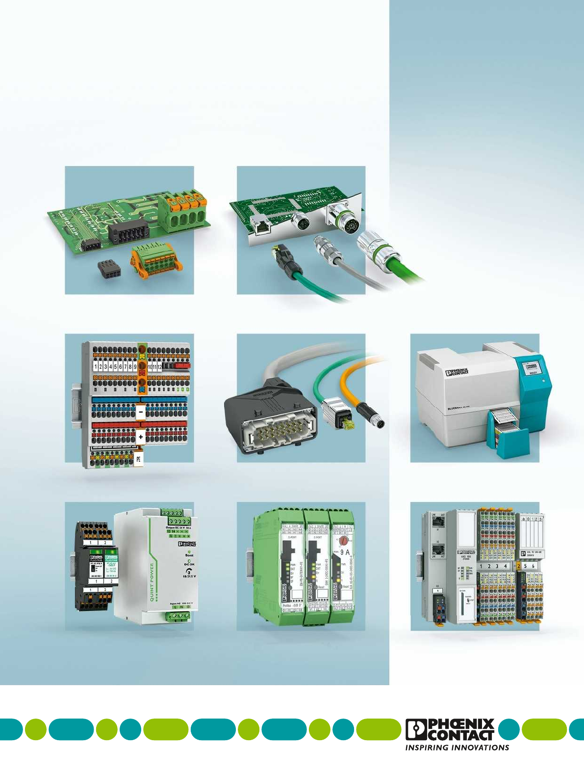
SMD PCB terminal blocks with push-in
spring connection up to 1.5 mm², 3.5 and
3.81 mm pitch
SPT-SMD 1,5/ ....-H-... R32 Page 7
SPT-SMD 1,5/ ...-V-... R32 Page 7
SMD PCB terminal blocks with push-in
spring connection up to 1.5 mm², 5.0 and
5.08 mm pitch
SPT-SMD 1,5/ ...-H-5,0 R32 Page 9
SPT-SMD 1,5/ ...-V-5,0 R32 Page 9
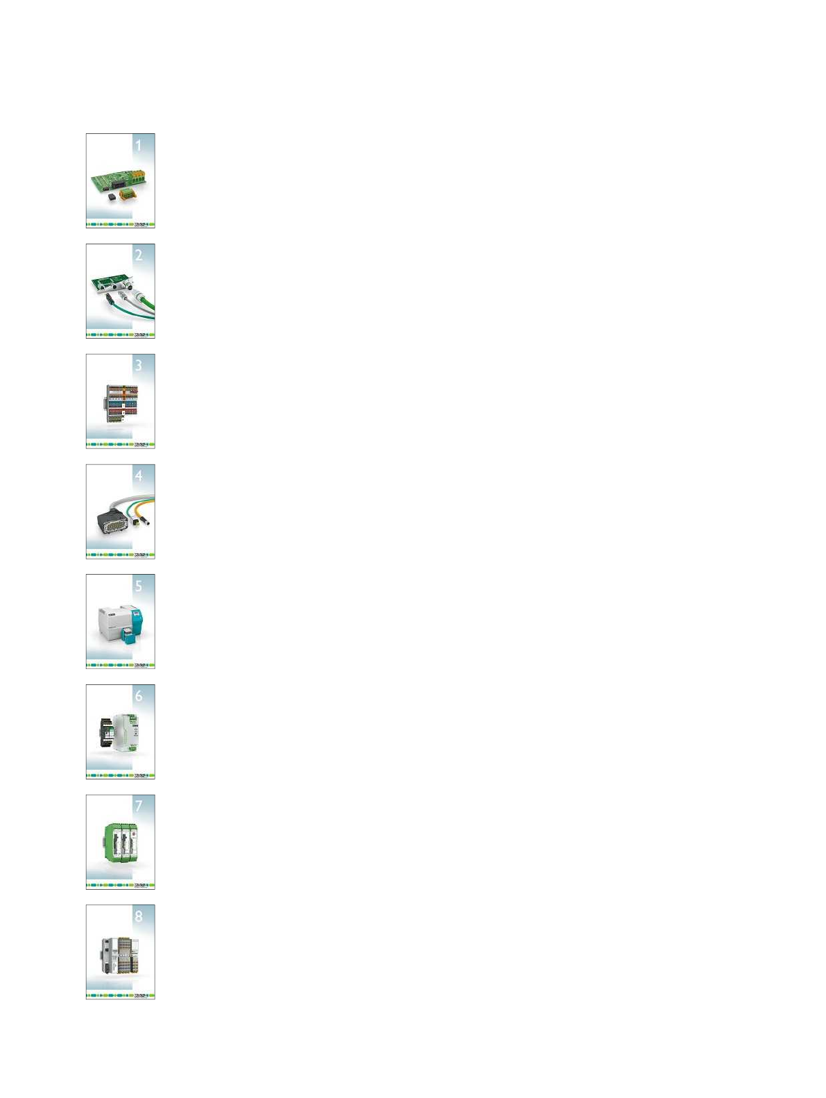
THR PCB terminal blocks with push-in spring
connection up to 1.5 mm², 5.0 and 5.08 mm
pitch
SPT-THR 1,5/ ...-H-5,0 P26 Page 12
SPT-THR 1,5/ ...-V-5,0 P26 Page 13
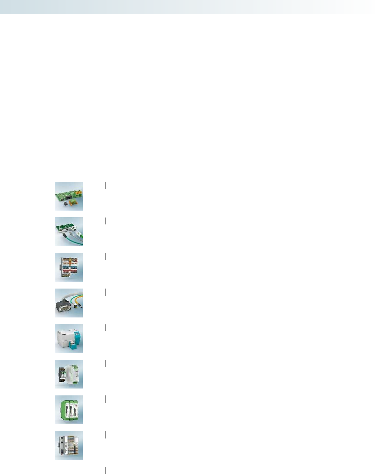
Inverted headers for reflow processes,
3.5 mm pitch
IMC 1,5/ ...-G-3,5 P20 THR Page 16
IMCV 1,5/ ...-G-3,5 P20 THR Page 17
Double-row PCB terminal block
with push-in spring connection up to
1.5 mm2, 3.5 mm pitch
SPTD 1,5/ ...-H-3,5 Page 15
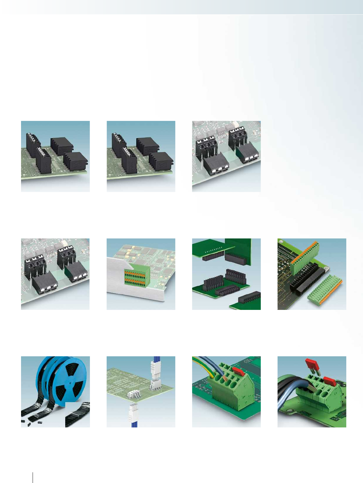
Taped single-level headers, 13 to 20-pos.,
for reflow processes, 3.81 mm pitch
MC 1,5/...-G-3,81 P20 THRR... Page 20
MCV 1,5/...-G-3,81 P20 THRR... Page 21
Plugs with push-in spring connection up to
0.75 mm², 2.5 mm pitch
PTSM 0,5/ ...-HV-2,5-SMD WH R32
Page 23
PTSM 0,5/ ...-HTB-2,5-SMD WH R32
Page 23
Angled PCB terminal blocks with push-in
spring connection up to 6 mm2, 7.5 mm pitch
SPTA 5/ ...-7,5-ZB Page 25
Angled PCB terminal blocks with push-in
spring connection up to 6 mm2, 10 mm pitch
SPTA 16/ ...-10,0-ZB Page 27
THR PCB terminal blocks with push-in spring
connection up to 1.5 mm², 3.5 and 3.81 mm
pitch
SPT-THR 1,5/ ...-H-3,5 P26 Page 10
SPT-THR 1,5/...-V-3,5 P26 Page 11
Single-level headers, 13 to 20-pos., for
reflow processes, 3.81 mm pitch
MC 1,5/...-G-3,81 P20 THR Page 18
MCV 1,5/...-G-3,81 P20 THR Page 19
2
PCB connection technology and electronics housing
Feed-through terminal blocks with push-in
spring connection up to 16 mm2 for high-
current applications
PWO 16-UW Page 29
ME-IO electronics housing with front
connection
ME-IO 18, 8.... Page 30
HSC... Page 30
PCO... power connector for ME MAX
housing
PCO ....-L KMGY Page 38
PBR 42A... Page 38
ME TBUS 4P1S and ME TBUS ADAPTER
for ME and ME MAX housing
ME ....TBUS 1,5/4P1S KMGY Page 39
ME ....TBUS ADAPTER KMGY Page 39
PCB connection technology and electronics housing
3
For additional information, visit phoenixcontact.net/products PHOENIX CONTACT
0,1
1
2
4PHOENIX CONTACT
PCB connection technology and electronics housing
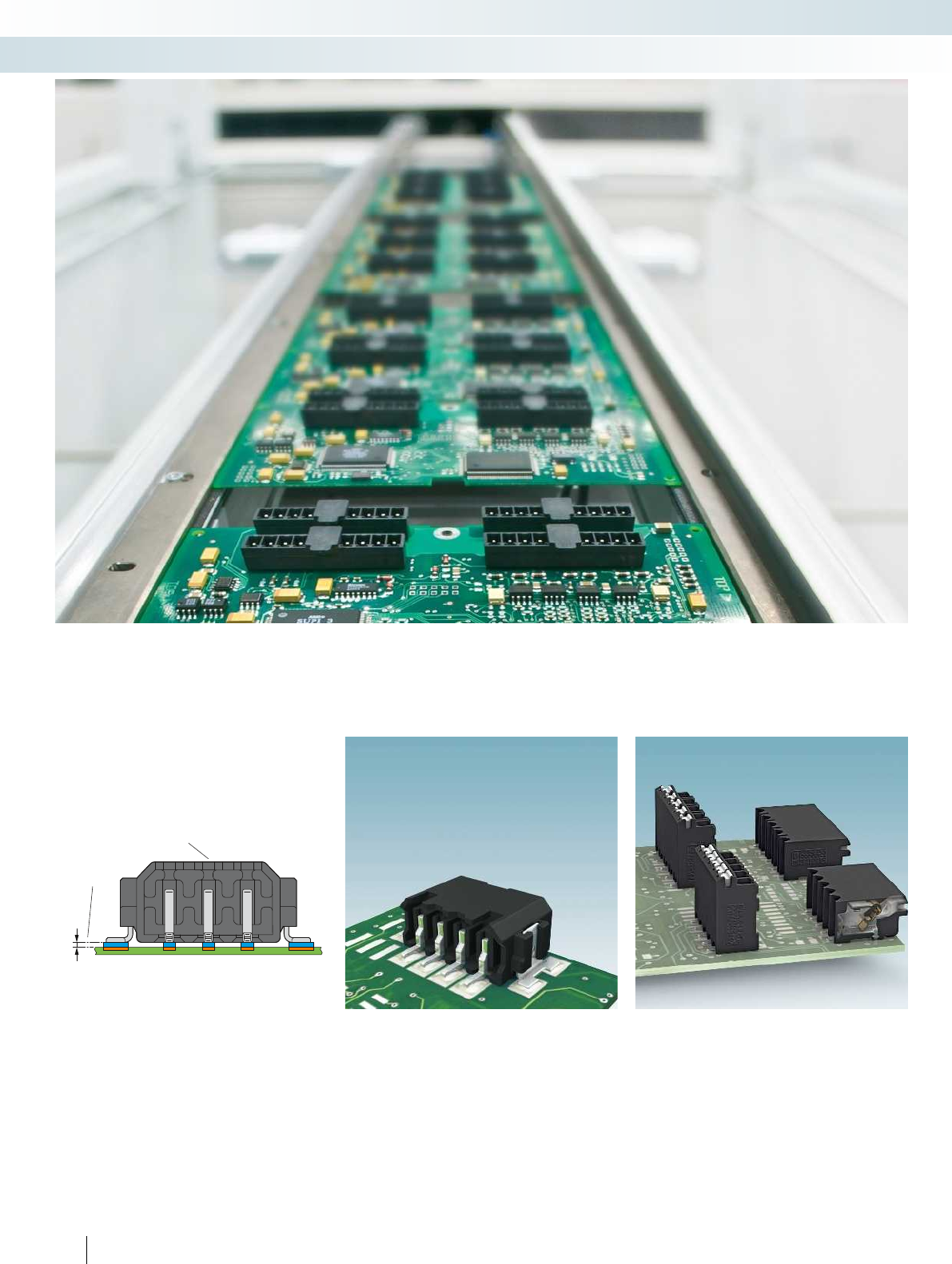
Mounting types
SMD- Surface Mount Device
Generally the term SMD or SMT (surface mount technology) refers to the dominant production method currently used for assemblies
in electronics production. In this case solder paste is applied to the contact surfaces of the PCB. The surface contacts of the component
are dipped in this paste and soldered by means of the reflow soldering process.
Properties of SMD/THR components
in the reflow process
– Resistance to high temperatures
– Suction areas (1) for automatic PCB
assembly by means of pick-and-place
– Stability in the case of mechanical loads
– Coplanarity (2) (evenness) of the SMD
contacts
PTSM 0,5...SMD
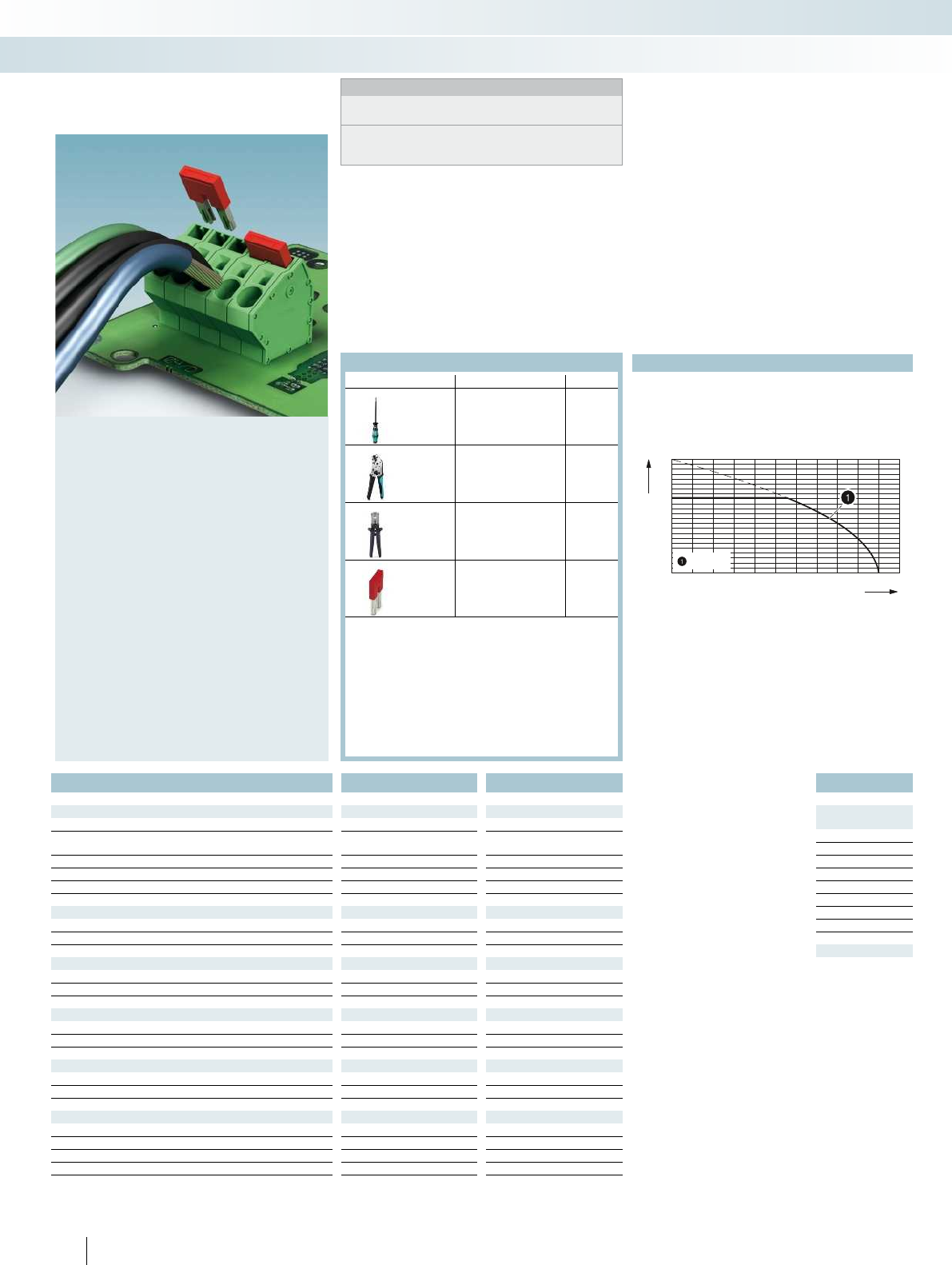
In addition to the SMD contacts, the
components have anchor metal on the side.
This ensures that the insertion and
withdrawal force of the plugs does not
overload the contact points.
SPT-SMD 1,5...
Additional solder pins on the side
position the component on the PCB and
prevent it moving during the process.
Moreover, they absorb the force when the
conductors are connected.
14,2
56
52,4
24
2
4
Ø1,5
pos. 1
0 60 120 180240300 360
0
50
100
150
200
250
<180s
<60s
<8min
217°C 245°C
For additional information, visit phoenixcontact.net/products
5PHOENIX CONTACT
PCB connection technology and electronics housing
Mounting types
The qualification of the SMD connectors
is based on IPC/JEDEC J-STD020 indicating
the MSL (Moisture Sensitive Level) and the
max. processing temperatures. The
SMD/THR components meet MSL 1 or 2
which means that dry bag packaging is not
required.
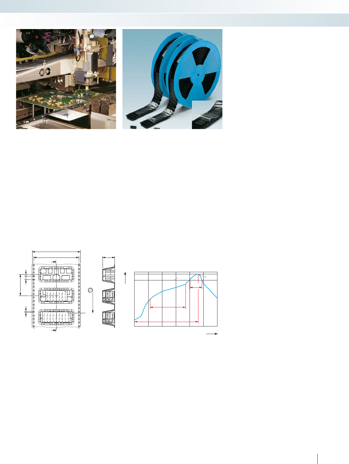
The standard tape width for tape-on-reel
packaging supports automatic PCB
assembly in pick-and-place applications.
Dimensional drawings of tape reels and
suction areas and pads can be found online
at phoenixcontact.net/products.
Reflow soldering
The reflow process and the required
temperature profiles are described in SMD
standards DIN EN 61760-1 or also IEC
60068-2-58. The profiles described are
usually used for test purposes, but are also
recommended for the application.
Time [s]
Temperature [°C]
No. of pos. Dim. a
[mm]
23.50
37.00
410.50
514.00
617.50
721.00
824.50
928.00
10 31.50
11 35.00
12 38.50
23.81
37.62
411.43
515.24
619.05
722.86
826.67
930.48
10 34.29
11 38.10
12 41.91
6PHOENIX CONTACT
Notes:
Dimensional drawings of tape reels and place pads can be found
online at phoenixcontact.net/products.
1) Current carrying capacity curve available on request.
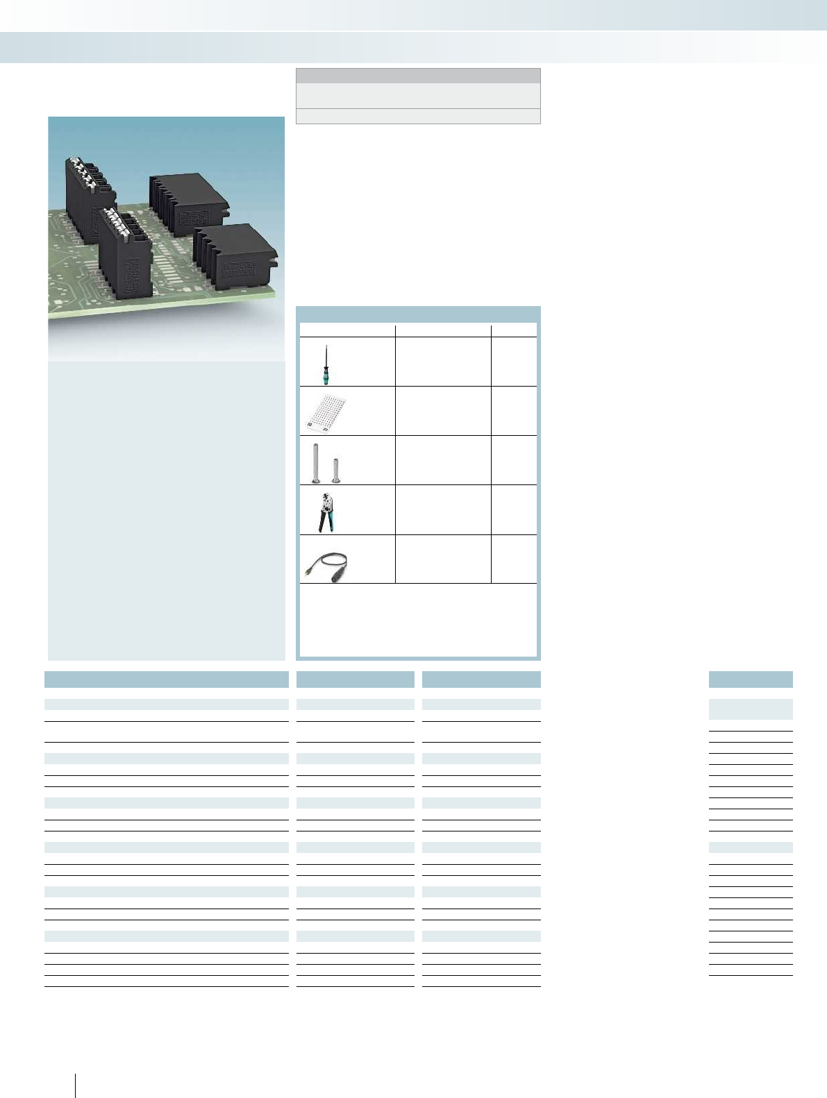
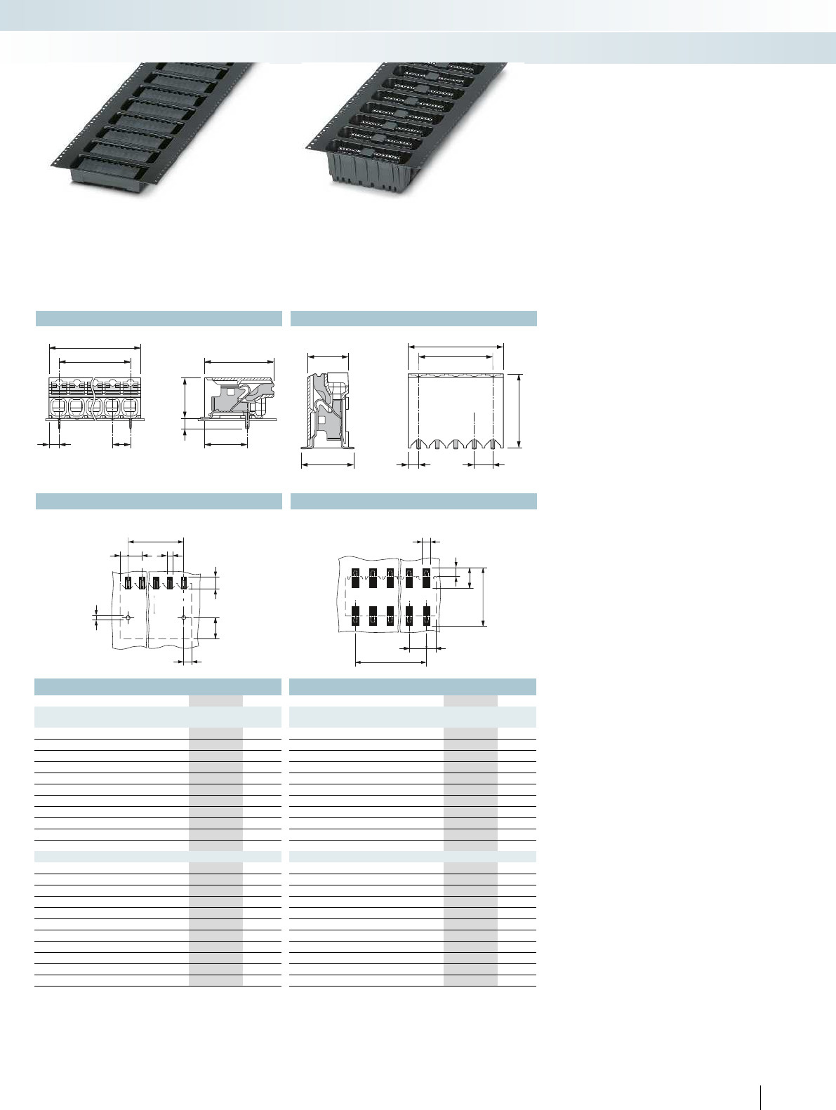
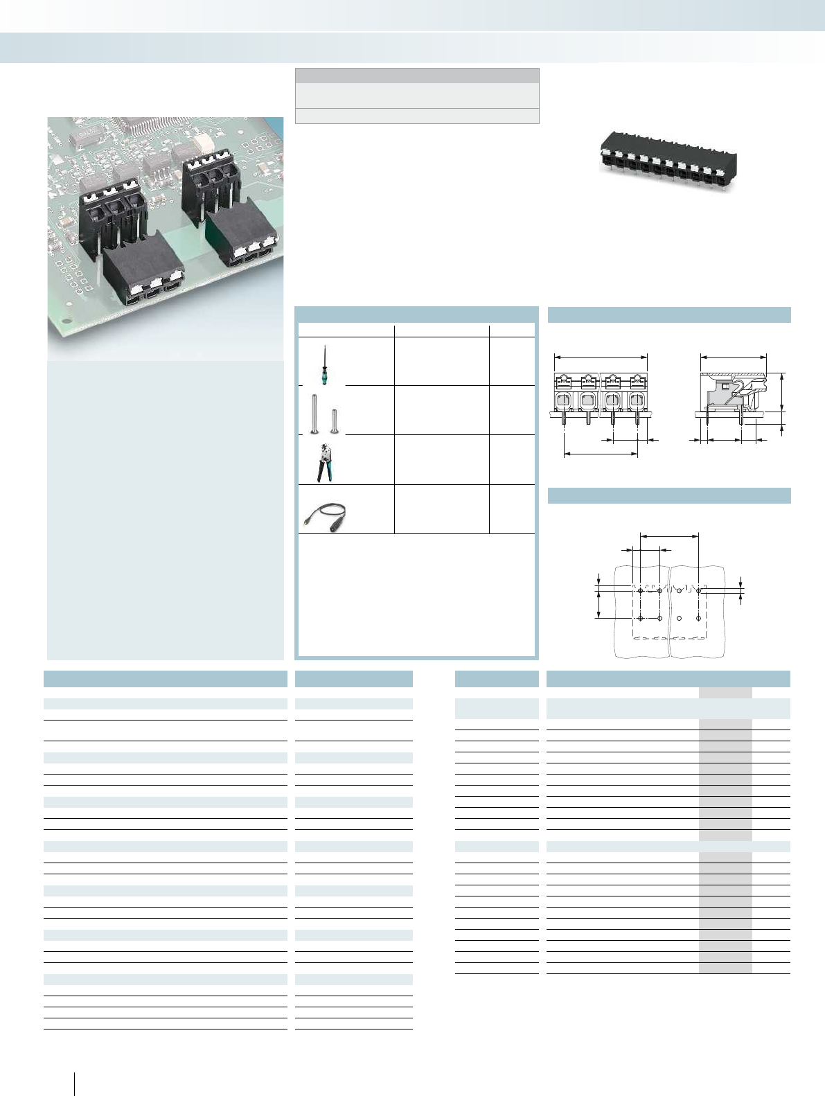
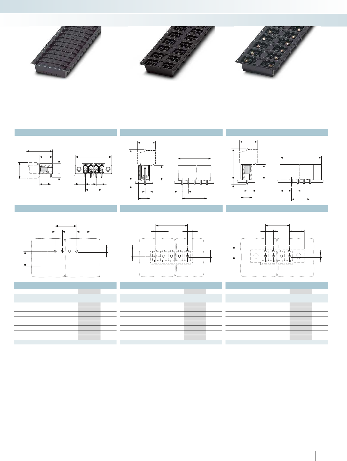
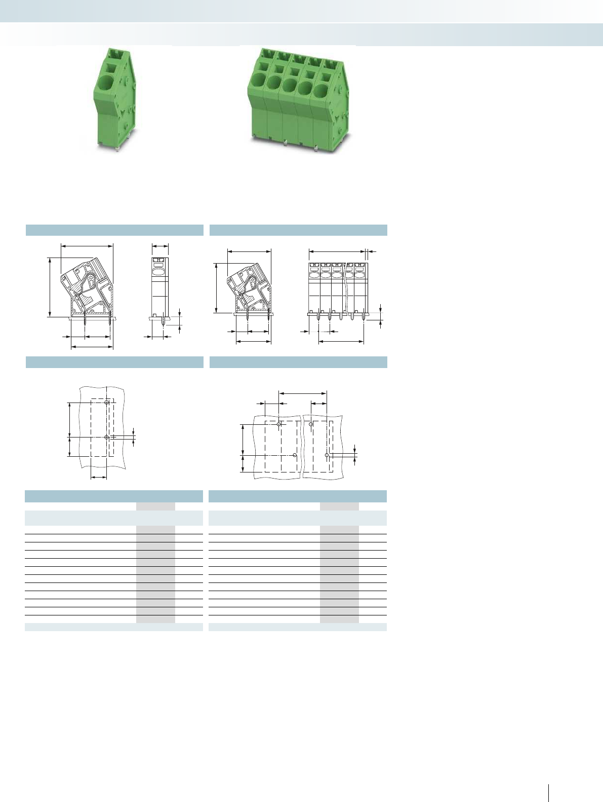
– Push-in direct plug-in technology for
solid and stranded conductors
– Suitable for use in SMD processes
– Horizontal and vertical design with a
3.5 mm and 3.81 mm pitch
– High stability due to anchor pins or two
soldering pads per position
– Supplied in taped packaging according to
IEC 60286-3 for automatic assembly
– Touch connection for voltage testing
using a 1 mm Ø test pin
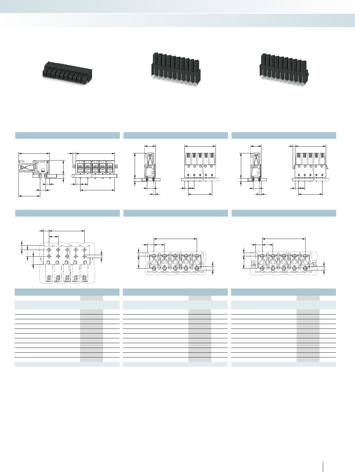
SMD PCB terminal blocks with push-
in spring connection up to 1.5 mm
Tec h n i c a l d a t a SPT-SMD 1,5/...H..R... SPT-SMD 1,5/...-V...R...
Technical data in accordance to IEC / DIN VDE
Rated current / conductor cross section [A] / [mm²] 13.51) / 1.5 13.51) / 1.5
Rated insulation voltage for pollution degree 2 [V] 160 160
Pitch [mm] 3.5 / 3.81 3.5 / 3.81
Connection capacity
Solid / stranded [mm²] / [mm²] / AWG 0.2 - 1.5 / 0.2 - 1.5 / 24 - 16 0.2 - 1.5 / 0.2 - 1.5 / 24 - 16
Stranded with ferrules without plastic sleeve [mm²] 0.2 - 1.5 0.2 - 1.5
Stranded with ferrules with plastic sleeve [mm²] 0.2 - 0.75 0.2 - 0.75
Insulation coordination
Surge voltage category / pollution degree III / 3 III / 2 II / 2 III / 3 III / 2 II / 2
Rated insulation voltage [V] 160 160 320 160 160 320
Rated surge voltage [kV] 2.5 2.5 2.5 2.5 2.5 2.5
Approval data (UL/CUL) Use Group B C D B C D
Nominal voltage [V]--- ---
Nominal current [A]--- ---
Connection capacity AWG AWG--- ---
Approval data (CSA) Use Group B C D B C D
Nominal voltage [V]--- ---
Nominal current [A]--- ---
Connection capacity AWG AWG--- ---
General data
Stripping length [mm] 8 8
Type of insulation material / insulation material group LCP / IIIa LCP / IIIa
Inflammability class according to UL 94 V0 V0
Drill hole diameter / pin dimensions [mm] 1.1 / 0.7 x 0.3 1.1 / 0.7 x 0.3
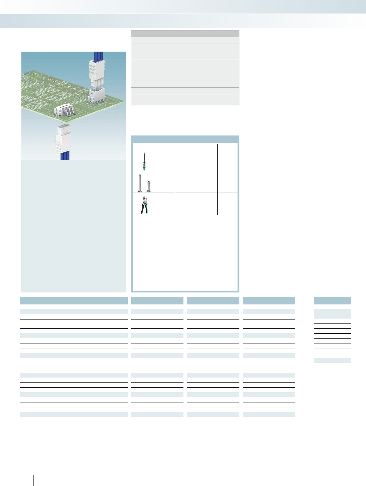
For all types Type Page
Screwdriver
SZS 0,4 x 2,5
Order No.
1205037
Marker cards
SK 3,5/2,8 or SK
3,81/2,8
796
Ferrules with and without
plastic sleeve
834
Crimping pliers for 0.25
to 6 mm²
CRIMPFOX 6
Order No.
1212034
Test plug
MPS-MT 1-S
Order No.
1944372
831
For accessories, see Catalog 1
PCB connection technology and electronics housing
PCB terminal blocks with 2.54 to 7.62 mm pitch
2
Ø1,1
4
1,6
23,5
(3,81)
5,2
a
1,6
1,75
11,4
4
2
3,5
a(3,81)
2
a+4
a
3,5
(3,81)
13,6
8,4
7,7
2
13,6
3,5
(3,81)
2
a+4
7,7
10
a
For additional information, visit phoenixcontact.net/products
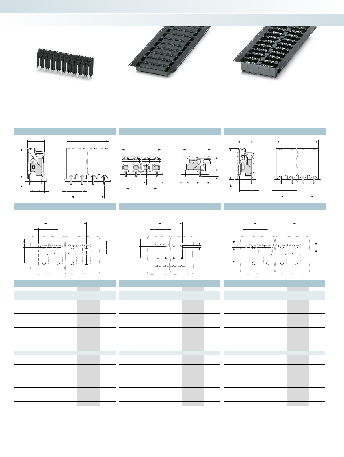
Taped PCB terminal block, connection
direction horizontal to the PCB
Ordering data Ordering data
Type Order No. Pcs. / Pkt. Type Order No. Pcs. / Pkt.
Pitch 3.5 mm, color: black Pitch 3.5 mm, color: black
SPT-SMD 1,5/ 2-H-3,5 R24 1824527 300 SPT-SMD 1,5/ 2-V-3,5 R24 1824080 200
SPT-SMD 1,5/ 3-H-3,5 R24 1824530 300 SPT-SMD 1,5/ 3-V-3,5 R32 1824093 200
SPT-SMD 1,5/ 4-H-3,5 R44 1824543 300 SPT-SMD 1,5/ 4-V-3,5 R44 1824103 200
SPT-SMD 1,5/ 5-H-3,5 R44 1824556 300 SPT-SMD 1,5/ 5-V-3,5 R44 1824116 200
SPT-SMD 1,5/ 6-H-3,5 R44 1824569 300 SPT-SMD 1,5/ 6-V-3,5 R44 1824129 200
SPT-SMD 1,5/ 7-H-3,5 R44 1824572 300 SPT-SMD 1,5/ 7-V-3,5 R44 1824132 200
SPT-SMD 1,5/ 8-H-3,5 R72 1824585 300 SPT-SMD 1,5/ 8-V-3,5 R72 1824145 200
SPT-SMD 1,5/ 9-H-3,5 R72 1824598 300 SPT-SMD 1,5/ 9-V-3,5 R72 1824158 200
SPT-SMD 1,5/10-H-3,5 R72 1824608 300 SPT-SMD 1,5/10-V-3,5 R72 1824161 200
SPT-SMD 1,5/11-H-3,5 R72 1824611 300 SPT-SMD 1,5/11-V-3,5 R72 1824174 200
SPT-SMD 1,5/12-H-3,5 R72 1824624 300 SPT-SMD 1,5/12-V-3,5 R72 1824187 200
3.81 mm pitch, color: black 3.81 mm pitch, color: black
SPT-SMD 1,5/ 2-H-3,81 R24 1824637 300 SPT-SMD 1,5/ 2-V-3,81 R24 1824190 200
SPT-SMD 1,5/ 3-H-3,81 R24 1824640 300 SPT-SMD 1,5/ 3-V-3,81 R32 1824200 200
SPT-SMD 1,5/ 4-H-3,81 R44 1824653 300 SPT-SMD 1,5/ 4-V-3,81 R44 1824213 200
SPT-SMD 1,5/ 5-H-3,81 R44 1824666 300 SPT-SMD 1,5/ 5-V-3,81 R44 1824226 200
SPT-SMD 1,5/ 6-H-3,81 R44 1824679 300 SPT-SMD 1,5/ 6-V-3,81 R44 1824239 200
SPT-SMD 1,5/ 7-H-3,81 R44 1824682 300 SPT-SMD 1,5/ 7-V-3,81 R44 1824242 200
SPT-SMD 1,5/ 8-H-3,81 R72 1824695 300 SPT-SMD 1,5/ 8-V-3,81 R72 1824255 200
SPT-SMD 1,5/ 9-H-3,81 R72 1824705 300 SPT-SMD 1,5/ 9-V-3,81 R72 1824268 200
SPT-SMD 1,5/10-H-3,81 R72 1824718 300 SPT-SMD 1,5/10-V-3,81 R72 1824271 200
SPT-SMD 1,5/11-H-3,81 R72 1824721 300 SPT-SMD 1,5/11-V-3,81 R72 1824284 200
SPT-SMD 1,5/12-H-3,81 R72 1824734 300 SPT-SMD 1,5/12-V-3,81 R72 1824297 200
Taped PCB terminal block, connection
direction vertical to the PCB
7PHOENIX CONTACT
PCB connection technology and electronics housing
PCB terminal blocks with 2.54 to 7.62 mm pitch
Dimensional drawing Dimensional drawing
Drilling diagram Drilling diagram

No. of pos. Dim. a
[mm]
25.00
310.00
415.00
520.00
625.00
730.00
835.00
940.00
10 45.00
11 50.00
12 55.00
25.08
310.16
415.24
520.32
625.40
730.48
835.56
940.64
10 45.72
11 50.80
12 55.88
8PHOENIX CONTACT
Notes:
Dimensional drawings of tape reels and place pads can be found
online at phoenixcontact.net/products.
1) Current carrying capacity curve available on request.
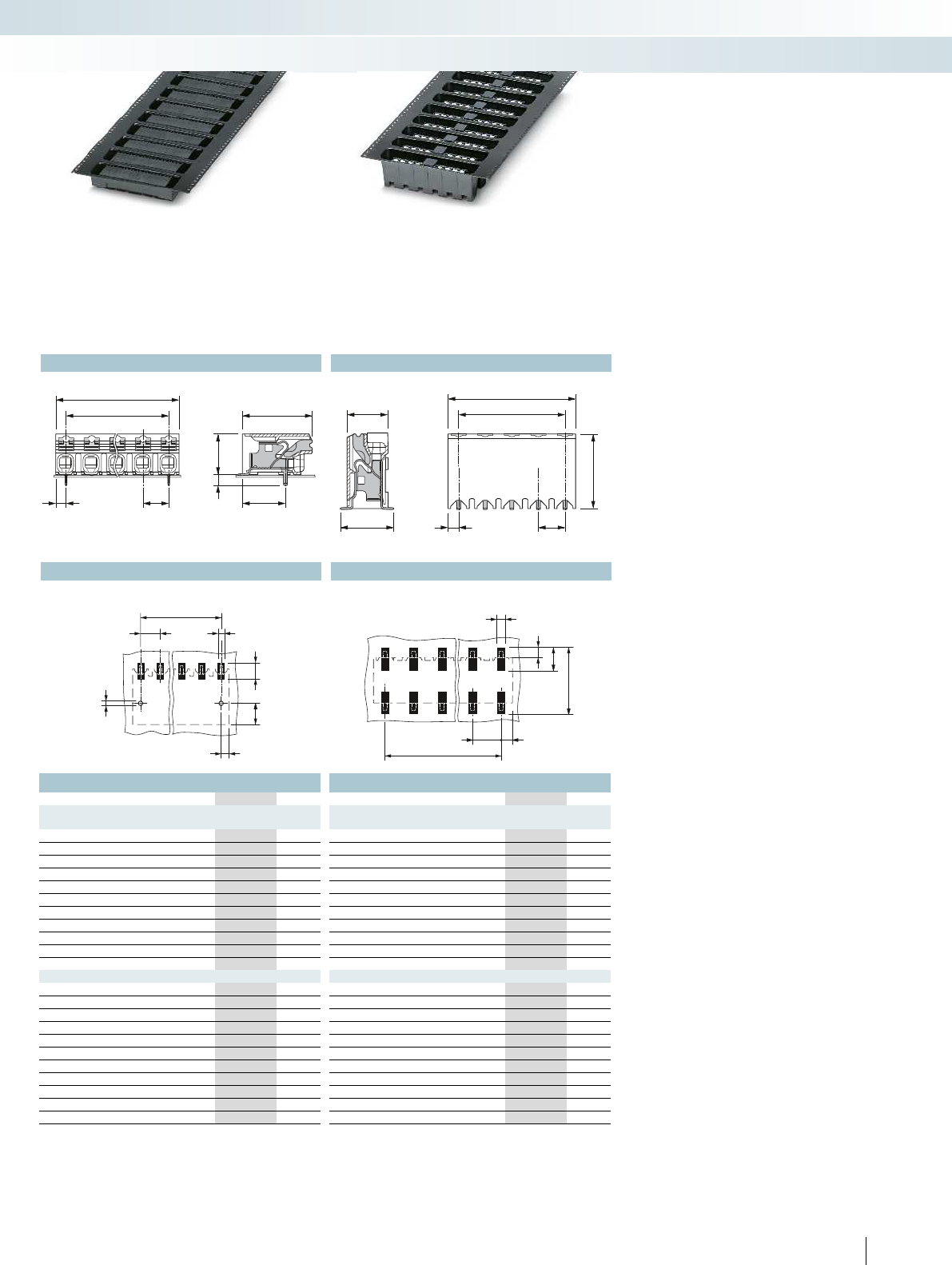
– Push-in direct plug-in technology for
solid and stranded conductors
– Suitable for use in SMD processes
– Horizontal and vertical design with a
5.0 mm and 5.08 mm pitch
– High stability due to anchor pins or two
soldering pads per position
– Supplied in taped packaging according to
IEC 60286-3 for automatic assembly
– Touch connection for voltage testing
using a 1 mm Ø test pin
SMD PCB terminal blocks with push-
in spring connection up to 1.5 mm
Tec h n i c a l d a t a SPT-SMD 1,5/...H..R SPT-SMD 1,5/...V...R...
Technical data in accordance to IEC / DIN VDE
Rated current / conductor cross section [A] / [mm²] 13.51) / 1.5 13.51) / 1.5
Rated insulation voltage for pollution degree 2 [V] 320 320
Pitch [mm] 5 / 5.08 5 / 5.08
Connection capacity
Solid / stranded [mm²] / [mm²] / AWG 0.2 - 1.5 / 0.2 - 1.5 / 24 - 16 0.2 - 1.5 / 0.2 - 1.5 / 24 - 16
Stranded with ferrules without plastic sleeve [mm²] 0.2 - 1.5 0.2 - 1.5
Stranded with ferrules with plastic sleeve [mm²] 0.2 - 0.75 0.2 - 0.75
Insulation coordination
Surge voltage category / pollution degree III / 3 III / 2 II / 2 III / 3 III / 2 II / 2
Rated insulation voltage [V] 250 320 500 250 320 500
Rated surge voltage [kV] 4 4 4 4 4 4
Approval data (UL/CUL) Use Group B C D B C D
Nominal voltage [V]--- ---
Nominal current [A]--- ---
Connection capacity AWG AWG--- ---
Approval data (CSA) Use Group B C D B C D
Nominal voltage [V]--- ---
Nominal current [A]--- ---
Connection capacity AWG AWG--- ---
General data
Stripping length [mm] 8 8
Type of insulation material / insulation material group LCP / IIIa LCP / IIIa
Inflammability class according to UL 94 V0 V0
Drill hole diameter / pin dimensions [mm] 1.1 / 0.7 x 0.3 mm 1.1 / 0.7 x 0.3 mm
For all types Type Page
Screwdriver
SZS 0,4 x 2,5
Order No.
1205037
Marker cards
SK 5/3,8 orSK 5,08/3,8
798
Ferrules with and without
plastic sleeve
834
Crimping pliers for 0.25
to 6 mm²
CRIMPFOX 6
Order No.
1212034
Test plug
MPS-MT 1-S
Order No.
1944372
831
For accessories, see Catalog 1
PCB connection technology and electronics housing
PCB terminal blocks with 2.54 to 7.62 mm pitch
2
Ø1,1
4
1,6
5
(5,08)
5,2
a
1,6
1,75
11,4
4
2
5
a(5,08)
8,4
27,7
5
(5,08)
a
a+4
2
13,6
10
7,7 a
a+4
5
(5,08)
2
13,6
For additional information, visit phoenixcontact.net/products
Taped PCB terminal block, connection
direction horizontal to the PCB
Ordering data Ordering data
Type Order No. Pcs. / Pkt. Type Order No. Pcs. / Pkt.
Pitch 5.0 mm, color: black Pitch 5.0 mm, color: black
SPT-SMD 1,5/ 2-H-5,0 R24 1824747 300 SPT-SMD 1,5/ 2-V-5,0 R24 1824307 200
SPT-SMD 1,5/ 3-H-5,0 R32 1824750 300 SPT-SMD 1,5/ 3-V-5,0 R32 1824310 200
SPT-SMD 1,5/ 4-H-5,0 R44 1824763 300 SPT-SMD 1,5/ 4-V-5,0 R44 1824323 200
SPT-SMD 1,5/ 5-H-5,0 R44 1824776 300 SPT-SMD 1,5/ 5-V-5,0 R44 1824336 200
SPT-SMD 1,5/ 6-H-5,0 R44 1824789 300 SPT-SMD 1,5/ 6-V-5,0 R44 1824349 200
SPT-SMD 1,5/ 7-H-5,0 R88 1824792 300 SPT-SMD 1,5/ 7-V-5,0 R88 1824352 200
SPT-SMD 1,5/ 8-H-5,0 R88 1824802 300 SPT-SMD 1,5/ 8-V-5,0 R88 1824365 200
SPT-SMD 1,5/ 9-H-5,0 R88 1824815 300 SPT-SMD 1,5/ 9-V-5,0 R88 1824378 200
SPT-SMD 1,5/10-H-5,0 R88 1824828 300 SPT-SMD 1,5/10-V-5,0 R88 1824381 200
SPT-SMD 1,5/11-H-5,0 R88 1824831 300 SPT-SMD 1,5/11-V-5,0 R88 1824394 200
SPT-SMD 1,5/12-H-5,0 R88 1824844 300 SPT-SMD 1,5/12-V-5,0 R88 1824404 200
Headers, 5.08 mm pitch, color: black Headers, 5.08 mm pitch, color: black
SPT-SMD 1,5/ 2-H-5,08 R24 1824857 300 SPT-SMD 1,5/ 2-V-5,08 R24 1824417 200
SPT-SMD 1,5/ 3-H-5,08 R32 1824860 300 SPT-SMD 1,5/ 3-V-5,08 R32 1824420 200
SPT-SMD 1,5/ 4-H-5,08 R44 1824873 300 SPT-SMD 1,5/ 4-V-5,08 R44 1824433 200
SPT-SMD 1,5/ 5-H-5,08 R44 1824885 300 SPT-SMD 1,5/ 5-V-5,08 R44 1824446 200
SPT-SMD 1,5/ 6-H-5,08 R44 1824899 300 SPT-SMD 1,5/ 6-V-5,08 R44 1824459 200
SPT-SMD 1,5/ 7-H-5,08 R88 1824909 300 SPT-SMD 1,5/ 7-V-5,08 R88 1824462 200
SPT-SMD 1,5/ 8-H-5,08 R88 1824912 300 SPT-SMD 1,5/ 8-V-5,08 R88 1824475 200
SPT-SMD 1,5/ 9-H-5,08 R88 1824925 300 SPT-SMD 1,5/ 9-V-5,08 R88 1824488 200
SPT-SMD 1,5/10-H-5,08 R88 1824938 300 SPT-SMD 1,5/10-V-5,08 R88 1824491 200
SPT-SMD 1,5/11-H-5,08 R88 1824941 300 SPT-SMD 1,5/11-V-5,08 R88 1824501 200
SPT-SMD 1,5/12-H-5,08 R88 1824954 300 SPT-SMD 1,5/12-V-5,08 R88 1824514 200
Taped PCB terminal block, connection
direction vertical to the PCB
9PHOENIX CONTACT
PCB connection technology and electronics housing
PCB terminal blocks with 2.54 to 7.62 mm pitch
Dimensional drawing Dimensional drawing
Drilling diagram Drilling diagram
Ø1,1
71,4
a
3,5
(3,81)
2
a+4
a
3,5
(3,81)
2
13,6
7,7
2,6
7
1,4
Pin length of 2.6 mm, box-packaged PCB
terminal blocks, connection direction
horizontal to the PCB
Ordering data
Type Order No. Pcs. / Pkt.
No. of pos. Dim. a
[mm]
Pitch 3.5 mm, color: black
23.50SPT-THR 1,5/ 2-H-3,5 P26 1822752 370
37.00SPT-THR 1,5/ 3-H-3,5 P26 1822765 240
4 10.50 SPT-THR 1,5/ 4-H-3,5 P26 1822778 170
5 14.00 SPT-THR 1,5/ 5-H-3,5 P26 1822781 150
6 17.50 SPT-THR 1,5/ 6-H-3,5 P26 1822794 130
7 21.00 SPT-THR 1,5/ 7-H-3,5 P26 1822804 110
8 24.50 SPT-THR 1,5/ 8-H-3,5 P26 1822817 80
9 28.00 SPT-THR 1,5/ 9-H-3,5 P26 1822820 80
10 31.50 SPT-THR 1,5/10-H-3,5 P26 1822833 60
11 35.00 SPT-THR 1,5/11-H-3,5 P26 1822846 60
12 38.50 SPT-THR 1,5/12-H-3,5 P26 1822859 60
3.81 mm pitch, color: black
23.81SPT-THR 1,5/ 2-H-3,81 P26 1822862 350
37.62SPT-THR 1,5/ 3-H-3,81 P26 1822875 240
4 11.43 SPT-THR 1,5/ 4-H-3,81 P26 1822888 170
5 15.24 SPT-THR 1,5/ 5-H-3,81 P26 1822891 130
6 19.05 SPT-THR 1,5/ 6-H-3,81 P26 1822901 110
7 22.86 SPT-THR 1,5/ 7-H-3,81 P26 1822914 80
8 26.67 SPT-THR 1,5/ 8-H-3,81 P26 1822927 80
9 30.48 SPT-THR 1,5/ 9-H-3,81 P26 1822930 60
10 34.29 SPT-THR 1,5/10-H-3,81 P26 1822943 60
11 38.10 SPT-THR 1,5/11-H-3,81 P26 1822956 60
12 41.91 SPT-THR 1,5/12-H-3,81 P26 1822969 60
10 PHOENIX CONTACT
Notes:
Dimensional drawings of tape reels and place pads can be found
online at phoenixcontact.net/products.
1) Current carrying capacity curve upon request.
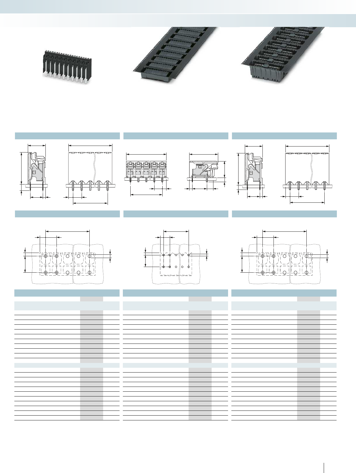
– Push-in direct plug-in technology for
solid or stranded conductors
– Suitable for use in SMT reflow processes
– Horizontal and vertical design with
3.5 mm and 3.81 mm pitch
– Two solder pins for a high level of
stability on the PCB
– Standard pin length of 2.6 mm also
suitable for wave soldering processes
– Supplied in tape-on-reel packing
according to IEC 60286-3 for automated
mounting in the reflow process with pin
length of 2.0 mm
– Touch connection for voltage testing
using a 1 mm Ø test pin
THR PCB terminal blocks with push-
in spring connection up to 1.5 mm
Tec h n i c a l d a t a
Technical data in accordance to IEC / DIN VDE
Rated current / conductor cross section [A] / [mm²] 13.51) / 1.5
Rated insulation voltage for pollution degree 2 [V] 160
Pitch [mm] 3.5 / 3.81
Connection capacity
Solid / stranded [mm²] / [mm²] / AWG 0.2 - 1.5 / 0.2 - 1.5 / 24 - 16
Stranded with ferrules without plastic sleeve [mm²] 0.2 - 1.5
Stranded with ferrules with plastic sleeve [mm²] 0.2 - 0.75
Multi-conductor connection capacity (two conductors with the same cross section)
Solid / stranded [mm²] - / -
Stranded with ferrules without plastic sleeve [mm²] -
Stranded with TWIN ferrule with plastic sleeve [mm²] -
Insulation coordination
Surge voltage category / pollution degree III / 3 III / 2 II / 2
Rated insulation voltage [V] 160 160 320
Rated surge voltage [kV] 2.5 2.5 2.5
Approval data (UL/CUL) Use Group B C D
Nominal voltage [V] - - -
Nominal current [A] - - -
Connection capacity AWG AWG - - -
Approval data (CSA) Use Group B C D
Nominal voltage [V] - - -
Nominal current [A] - - -
Connection capacity AWG AWG - - -
General data
Stripping length [mm] 8
Type of insulation material / insulation material group LCP / IIIa
Inflammability class according to UL 94 V0
Drill hole diameter / pin dimensions [mm] 1.1 / 0.7 x 0.3
For all types Type Page
Screwdriver
SZS 0,4 x 2,5
Order No.
1205037
Ferrules with and without
plastic sleeve
834
Crimping pliers for 0.25
to 6 mm²
CRIMPFOX 6
Order No.
1212034
Test plug
MPS-MT 1-S
Order No.
1944372
831
For accessories, see Catalog 1
PCB connection technology and electronics housing
PCB terminal blocks with 2.54 to 7.62 mm pitch
Dimensional drawing Dimensional drawing D
Drilling diagram Drilling diagram Drilling diagram Drilling diagram
a
3,5
(3,81)
2
Ø1,1
5,5 1,2
Ø1,1
71,4
a
3,5
(3,81)
2
a
3,5
(3,81)
2
Ø1,1
5,5 1,2
a+4
a
3,5
(3,81)
2
2,6 13,6
7,7
5,5 1,2
a+4
a
3,5
(3,81)
2
13,6
7,7
2
73
1,4
a+4
a
3,5
(3,81)
2
213,6
7,7
5,5 1,2
For additional information, visit phoenixcontact.net/products
Ordering data Ordering data Ordering data
Type Order No. Pcs. / Pkt. Type Order No. Pcs. / Pkt. Type Order No. Pcs. / Pkt.
Pitch 3.5 mm, color: black Pitch 3.5 mm, color: black Pitch 3.5 mm, color: black
SPT-THR 1,5/ 2-V-3,5 P26 1822312 540 SPT-THR 1,5/ 2-H-3,5 P20 R24 1823638 250 SPT-THR 1,5/ 2-V-3,5 P20 R24 1823191 180
SPT-THR 1,5/ 3-V-3,5 P26 1822325 350 SPT-THR 1,5/ 3-H-3,5 P20 R32 1823641 250 SPT-THR 1,5/ 3-V-3,5 P20 R24 1823201 180
SPT-THR 1,5/ 4-V-3,5 P26 1822338 250 SPT-THR 1,5/ 4-H-3,5 P20 R32 1823654 250 SPT-THR 1,5/ 4-V-3,5 P20 R44 1823214 180
SPT-THR 1,5/ 5-V-3,5 P26 1822341 220 SPT-THR 1,5/ 5-H-3,5 P20 R32 1823667 250 SPT-THR 1,5/ 5-V-3,5 P20 R44 1823227 180
SPT-THR 1,5/ 6-V-3,5 P26 1822354 190 SPT-THR 1,5/ 6-H-3,5 P20 R44 1823670 250 SPT-THR 1,5/ 6-V-3,5 P20 R44 1823230 180
SPT-THR 1,5/ 7-V-3,5 P26 1822367 160 SPT-THR 1,5/ 7-H-3,5 P20 R44 1823683 250 SPT-THR 1,5/ 7-V-3,5 P20 R44 1823243 180
SPT-THR 1,5/ 8-V-3,5 P26 1822370 120 SPT-THR 1,5/ 8-H-3,5 P20 R44 1823696 250 SPT-THR 1,5/ 8-V-3,5 P20 R72 1823256 180
SPT-THR 1,5/ 9-V-3,5 P26 1822383 120 SPT-THR 1,5/ 9-H-3,5 P20 R72 1823706 250 SPT-THR 1,5/ 9-V-3,5 P20 R72 1823269 180
SPT-THR 1,5/10-V-3,5 P26 1822396 90 SPT-THR 1,5/10-H-3,5 P20 R72 1823719 250 SPT-THR 1,5/10-V-3,5 P20 R72 1823272 180
SPT-THR 1,5/11-V-3,5 P26 1822406 90 SPT-THR 1,5/11-H-3,5 P20 R72 1823722 250 SPT-THR 1,5/11-V-3,5 P20 R72 1823285 180
SPT-THR 1,5/12-V-3,5 P26 1822419 90 SPT-THR 1,5/12-H-3,5 P20 R72 1823735 250 SPT-THR 1,5/12-V-3,5 P20 R72 1823298 180
3.81 mm pitch, color: black 3.81 mm pitch, color: black 3.81 mm pitch, color: black
SPT-THR 1,5/ 2-V-3,81 P26 1822422 510 SPT-THR 1,5/ 2-H-3,81 P20 R24 1823748 250 SPT-THR 1,5/ 2-V-3,81 P20 R24 1823308 180
SPT-THR 1,5/ 3-V-3,81 P26 1822435 350 SPT-THR 1,5/ 3-H-3,81 P20 R32 1823751 250 SPT-THR 1,5/ 3-V-3,81 P20 R24 1823311 180
SPT-THR 1,5/ 4-V-3,81 P26 1822448 250 SPT-THR 1,5/ 4-H-3,81 P20 R32 1823764 250 SPT-THR 1,5/ 4-V-3,81 P20 R44 1823324 180
SPT-THR 1,5/ 5-V-3,81 P26 1822451 190 SPT-THR 1,5/ 5-H-3,81 P20 R32 1823777 250 SPT-THR 1,5/ 5-V-3,81 P20 R44 1823337 180
SPT-THR 1,5/ 6-V-3,81 P26 1822464 160 SPT-THR 1,5/ 6-H-3,81 P20 R44 1823780 250 SPT-THR 1,5/ 6-V-3,81 P20 R44 1823340 180
SPT-THR 1,5/ 7-V-3,81 P26 1822477 120 SPT-THR 1,5/ 7-H-3,81 P20 R44 1823793 250 SPT-THR 1,5/ 7-V-3,81 P20 R44 1823353 180
SPT-THR 1,5/ 8-V-3,81 P26 1822480 120 SPT-THR 1,5/ 8-H-3,81 P20 R44 1823803 250 SPT-THR 1,5/ 8-V-3,81 P20 R72 1823366 180
SPT-THR 1,5/ 9-V-3,81 P26 1822493 90 SPT-THR 1,5/ 9-H-3,81 P20 R72 1823816 250 SPT-THR 1,5/ 9-V-3,81 P20 R72 1823379 180
SPT-THR 1,5/10-V-3,81 P26 1822503 90 SPT-THR 1,5/10-H-3,81 P20 R72 1823829 250 SPT-THR 1,5/10-V-3,81 P20 R72 1823382 180
SPT-THR 1,5/11-V-3,81 P26 1822516 90 SPT-THR 1,5/11-H-3,81 P20 R72 1823832 250 SPT-THR 1,5/11-V-3,81 P20 R72 1823395 180
SPT-THR 1,5/12-V-3,81 P26 1822529 60 SPT-THR 1,5/12-H-3,81 P20 R72 1823845 250 SPT-THR 1,5/12-V-3,81 P20 R72 1823405 180
Pin length of 2.6 mm, box-packaged PCB
terminal blocks, connection direction vertical
to the PCB
Pin length of 2.0 mm, taped PCB terminal
blocks, connection direction horizontal to the
PCB
Pin length of 2.0 mm, taped PCB terminal
blocks, connection direction vertical to the
PCB
11PHOENIX CONTACT
PCB connection technology and electronics housing
PCB terminal blocks with 2.54 to 7.62 mm pitch
Dimensional drawing Dimensional drawing Dimensional drawing Dimensional drawing
Drilling diagram Drilling diagram Drilling diagram Drilling diagram
Ø1,1
71,4
a
5
(5,08)
2
a+4
a
5
(5,08)
2
13,6
7,7
2,6
73
1,4
Pin length of 2.6 mm, box-packaged PCB
terminal blocks, connection direction
horizontal to the PCB
Ordering data
Type Order No. Pcs. / Pkt.
No. of pos. Dim. a
[mm]
Pitch 5.0 mm, color: black
25.00SPT-THR 1,5/ 2-H-5,0 P26 1822972 300
3 10.00 SPT-THR 1,5/ 3-H-5,0 P26 1822985 190
4 15.00 SPT-THR 1,5/ 4-H-5,0 P26 1822998 130
5 20.00 SPT-THR 1,5/ 5-H-5,0 P26 1823007 110
6 25.00 SPT-THR 1,5/ 6-H-5,0 P26 1823010 80
7 30.00 SPT-THR 1,5/ 7-H-5,0 P26 1823023 60
8 35.00 SPT-THR 1,5/ 8-H-5,0 P26 1823036 60
9 40.00 SPT-THR 1,5/ 9-H-5,0 P26 1823049 40
10 45.00 SPT-THR 1,5/10-H-5,0 P26 1823052 40
11 50.00 SPT-THR 1,5/11-H-5,0 P26 1823065 40
12 55.00 SPT-THR 1,5/12-H-5,0 P26 1823078 40
Headers, 5.08 mm pitch, color: black
25.08SPT-THR 1,5/ 2-H-5,08 P26 1823081 300
3 10.16 SPT-THR 1,5/ 3-H-5,08 P26 1823094 190
4 15.24 SPT-THR 1,5/ 4-H-5,08 P26 1823104 130
5 30.32 SPT-THR 1,5/ 5-H-5,08 P26 1823117 110
6 25.40 SPT-THR 1,5/ 6-H-5,08 P26 1823120 80
7 30.48 SPT-THR 1,5/ 7-H-5,08 P26 1823133 60
8 35.56 SPT-THR 1,5/ 8-H-5,08 P26 1823146 60
9 40.64 SPT-THR 1,5/ 9-H-5,08 P26 1823159 40
10 45.72 SPT-THR 1,5/10-H-5,08 P26 1823162 40
11 50.80 SPT-THR 1,5/11-H-5,08 P26 1823175 40
12 55.88 SPT-THR 1,5/12-H-5,08 P26 1823188 40
12 PHOENIX CONTACT
Notes:
Dimensional drawings of tape reels and place pads can be found
online at phoenixcontact.net/products.
1) Current carrying capacity curve upon request.
– Push-in direct plug-in technology for
solid or stranded conductors
– Suitable for use in SMT reflow processes
– Horizontal and vertical design with
5.0 mm and 5.08 mm pitch
– Two solder pins for a high level of
stability on the PCB
– Standard pin length of 2.6 mm also
suitable for wave soldering processes
– Supplied in tape-on-reel packing
according to IEC 60286-3 for automated
mounting in the reflow process with pin
length of 2.0 mm
– Touch connection for voltage testing
using a 1 mm Ø test pin
THR PCB terminal blocks with push-
in spring connection up to 1.5 mm
Tec h n i c a l d a t a
Technical data in accordance to IEC / DIN VDE
Rated current / conductor cross section [A] / [mm²] 13.51) / 1.5
Rated insulation voltage for pollution degree 2 [V] 320
Pitch [mm] 5 / 5.08
Connection capacity
Solid / stranded [mm²] / [mm²] / AWG 0.2 - 1.5 / 0.2 - 1.5 / 24 - 16
Stranded with ferrules without plastic sleeve [mm²] 0.2 - 1.5
Stranded with ferrules with plastic sleeve [mm²] 0.2 - 0.75
Multi-conductor connection capacity (two conductors with the same cross section)
Solid / stranded [mm²] - / -
Stranded with ferrules without plastic sleeve [mm²] -
Stranded with TWIN ferrule with plastic sleeve [mm²] -
Insulation coordination
Surge voltage category / pollution degree III / 3 III / 2 II / 2
Rated insulation voltage [V] 250 320 500
Rated surge voltage [kV] 4 4 4
Approval data (UL/CUL) Use Group B C D
Nominal voltage [V] - - -
Nominal current [A] - - -
Connection capacity AWG AWG - - -
Approval data (CSA) Use Group B C D
Nominal voltage [V] - - -
Nominal current [A] - - -
Connection capacity AWG AWG - - -
General data
Stripping length [mm] 8
Type of insulation material / insulation material group LCP / IIIa
Inflammability class according to UL 94 V0
Drill hole diameter / pin dimensions [mm] 1.1 / 0.7 x 0.3 mm
For all types Type Page
Screwdriver
SZS 0,4 x 2,5
Order No.
1205037
Ferrules with and without
plastic sleeve
834
Crimping pliers for 0.25
to 6 mm²
CRIMPFOX 6
Order No.
1212034
Test plug
MPS-MT 1-S
Order No.
1944372
831
For accessories, see Catalog 1
PCB connection technology and electronics housing
PCB terminal blocks with 2.54 to 7.62 mm pitch
Dimensional drawing Dimensional drawing D
Drilling diagram Drilling diagram Drilling diagram Drilling diagram
a
5
(5,08)
2
Ø1,1
5,5 1,2
Ø1,1
71,4
a
5
(5,08)
2
a
5
(5,08)
2
Ø1,1
5,5 1,2
a+4
a
5
(5,08)
2
2,6 13,6
7,7
5,5 1,2
13,6
7,7
2
73
1,4
a+4
a
5
(5,08)
2
a+4
a
5
(5,08)
2
213,6
7,7
5,5 1,2
For additional information, visit phoenixcontact.net/products
Ordering data Ordering data Ordering data
Type Order No. Pcs. / Pkt. Type Order No. Pcs. / Pkt. Type Order No. Pcs. / Pkt.
Pitch 5.0 mm, color: black Pitch 5.0 mm, color: black Pitch 5.0 mm, color: black
SPT-THR 1,5/ 2-V-5,0 P26 1822532 440 SPT-THR 1,5/ 2-H-5,0 P20 R24 1823858 250 SPT-THR 1,5/ 2-V-5,0 P20 R24 1823418 180
SPT-THR 1,5/ 3-V-5,0 P26 1822545 280 SPT-THR 1,5/ 3-H-5,0 P20 R32 1823861 250 SPT-THR 1,5/ 3-V-5,0 P20 R32 1823421 180
SPT-THR 1,5/ 4-V-5,0 P26 1822558 190 SPT-THR 1,5/ 4-H-5,0 P20 R32 1823874 250 SPT-THR 1,5/ 4-V-5,0 P20 R56 1823434 180
SPT-THR 1,5/ 5-V-5,0 P26 1822561 160 SPT-THR 1,5/ 5-H-5,0 P20 R56 1823887 250 SPT-THR 1,5/ 5-V-5,0 P20 R56 1823447 180
SPT-THR 1,5/ 6-V-5,0 P26 1822574 120 SPT-THR 1,5/ 6-H-5,0 P20 R56 1823890 250 SPT-THR 1,5/ 6-V-5,0 P20 R56 1823450 180
SPT-THR 1,5/ 7-V-5,0 P26 1822587 90 SPT-THR 1,5/ 7-H-5,0 P20 R56 1823900 250 SPT-THR 1,5/ 7-V-5,0 P20 R56 1823463 180
SPT-THR 1,5/ 8-V-5,0 P26 1822590 90 SPT-THR 1,5/ 8-H-5,0 P20 R56 1823913 250 SPT-THR 1,5/ 8-V-5,0 P20 R88 1823476 180
SPT-THR 1,5/ 9-V-5,0 P26 1822600 60 SPT-THR 1,5/ 9-H-5,0 P20 R88 1823926 250 SPT-THR 1,5/ 9-V-5,0 P20 R88 1823489 180
SPT-THR 1,5/10-V-5,0 P26 1822613 60 SPT-THR 1,5/10-H-5,0 P20 R88 1823939 250 SPT-THR 1,5/10-V-5,0 P20 R88 1823492 180
SPT-THR 1,5/11-V-5,0 P26 1822626 60 SPT-THR 1,5/11-H-5,0 P20 R88 1823942 250 SPT-THR 1,5/11-V-5,0 P20 R88 1823502 180
SPT-THR 1,5/12-V-5,0 P26 1822639 60 SPT-THR 1,5/12-H-5,0 P20 R88 1823955 250 SPT-THR 1,5/12-V-5,0 P20 R88 1823515 180
Headers, 5.08 mm pitch, color: black Headers, 5.08 mm pitch, color: black Headers, 5.08 mm pitch, color: black
SPT-THR 1,5/ 2-V-5,08 P26 1822642 440 SPT-THR 1,5/ 2-H-5,08 P20 R24 1823968 250 SPT-THR 1,5/ 2-V-5,08 P20 R24 1823528 180
SPT-THR 1,5/ 3-V-5,08 P26 1822655 280 SPT-THR 1,5/ 3-H-5,08 P20 R32 1823971 250 SPT-THR 1,5/ 3-V-5,08 P20 R32 1823531 180
SPT-THR 1,5/ 4-V-5,08 P26 1822668 190 SPT-THR 1,5/ 4-H-5,08 P20 R32 1823984 250 SPT-THR 1,5/ 4-V-5,08 P20 R56 1823544 180
SPT-THR 1,5/ 5-V-5,08 P26 1822671 160 SPT-THR 1,5/ 5-H-5,08 P20 R56 1823997 250 SPT-THR 1,5/ 5-V-5,08 P20 R56 1823557 180
SPT-THR 1,5/ 6-V-5,08 P26 1822684 120 SPT-THR 1,5/ 6-H-5,08 P20 R56 1824006 250 SPT-THR 1,5/ 6-V-5,08 P20 R56 1823560 180
SPT-THR 1,5/ 7-V-5,08 P26 1822697 90 SPT-THR 1,5/ 7-H-5,08 P20 R56 1824019 250 SPT-THR 1,5/ 7-V-5,08 P20 R56 1823573 180
SPT-THR 1,5/ 8-V-5,08 P26 1822707 90 SPT-THR 1,5/ 8-H-5,08 P20 R56 1824022 250 SPT-THR 1,5/ 8-V-5,08 P20 R88 1823586 180
SPT-THR 1,5/ 9-V-5,08 P26 1822710 60 SPT-THR 1,5/ 9-H-5,08 P20 R88 1824035 250 SPT-THR 1,5/ 9-V-5,08 P20 R88 1823599 180
SPT-THR 1,5/10-V-5,08 P26 1822723 60 SPT-THR 1,5/10-H-5,08 P20 R88 1824048 250 SPT-THR 1,5/10-V-5,08 P20 R88 1823609 180
SPT-THR 1,5/11-V-5,08 P26 1822736 60 SPT-THR 1,5/11-H-5,08 P20 R88 1824051 250 SPT-THR 1,5/11-V-5,08 P20 R88 1823612 180
SPT-THR 1,5/12-V-5,08 P26 1822749 60 SPT-THR 1,5/12-H-5,08 P20 R88 1824064 250 SPT-THR 1,5/12-V-5,08 P20 R88 1823625 180
Pin length of 2.6 mm, box-packaged PCB
terminal blocks, connection direction vertical
to the PCB
Pin length of 2.0 mm, taped PCB terminal
blocks, connection direction horizontal to the
PCB
Pin length of 2.0 mm, taped PCB terminal
blocks, connection direction vertical to the
PCB
13PHOENIX CONTACT
PCB connection technology and electronics housing
PCB terminal blocks with 2.54 to 7.62 mm pitch
Dimensional drawing Dimensional drawing Dimensional drawing Dimensional drawing
Drilling diagram Drilling diagram Drilling diagram Drilling diagram
No. of pos. Dim. a
[mm]
23.50
37.00
410.50
514.00
617.50
721.00
824.50
928.00
10 31.50
11 35.00
12 38.50
14 PHOENIX CONTACT
Notes:
1) Current carrying capacity curve upon request.
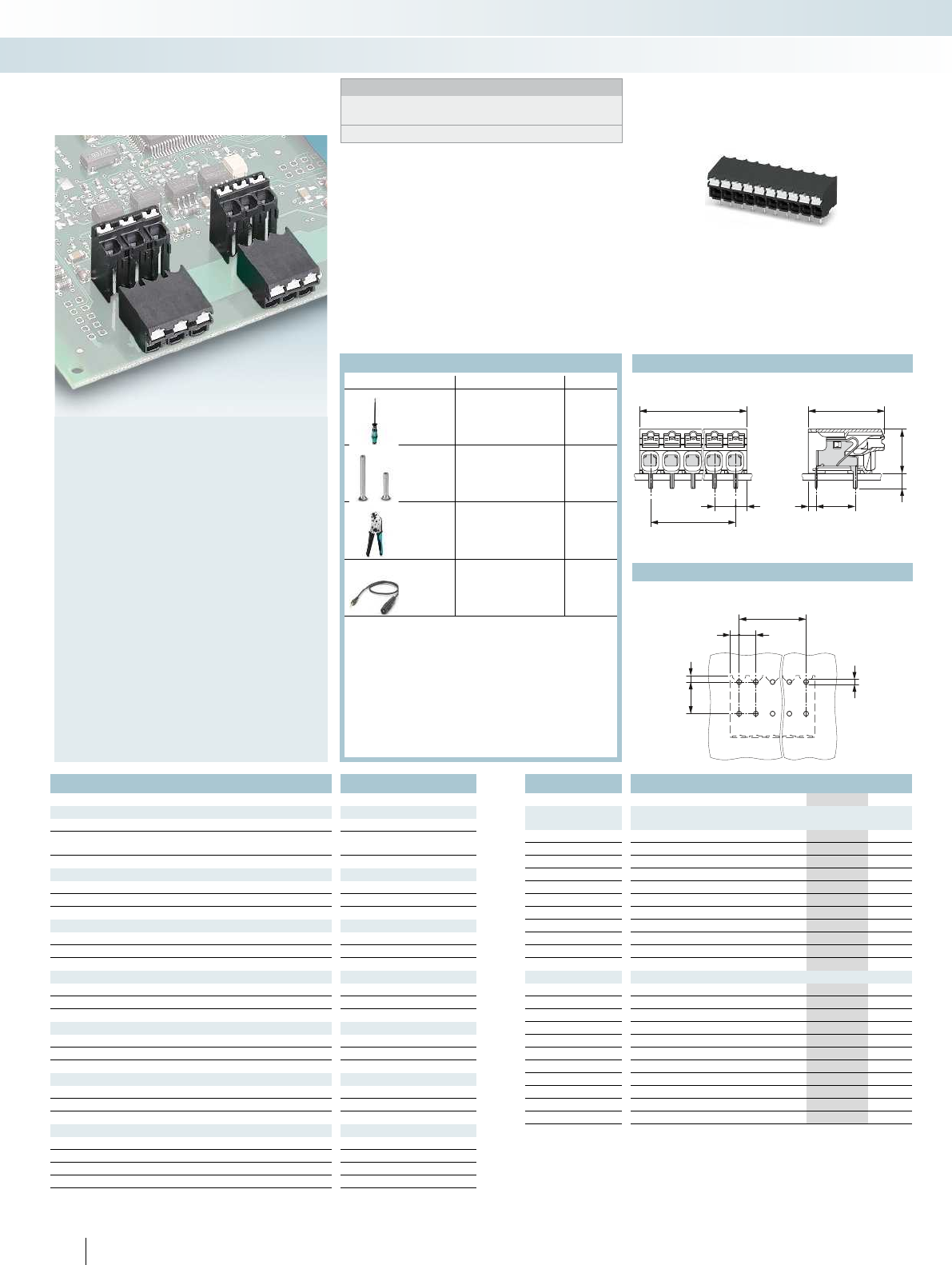
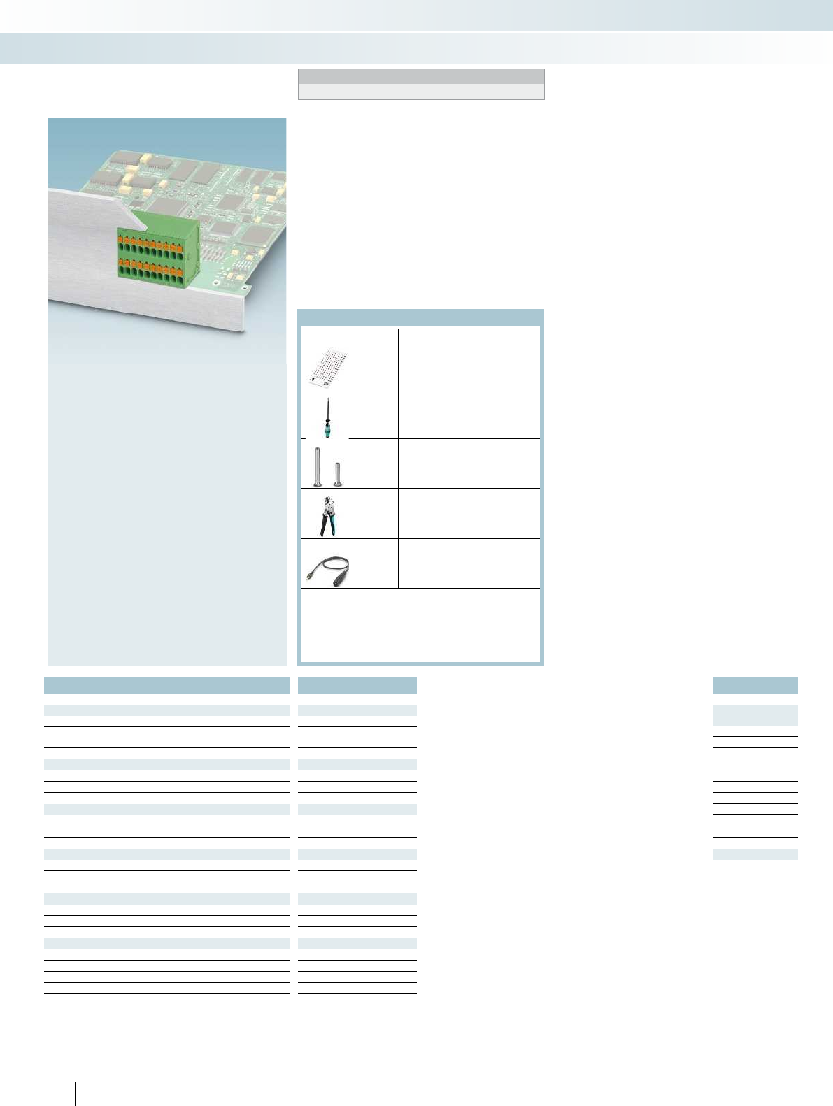
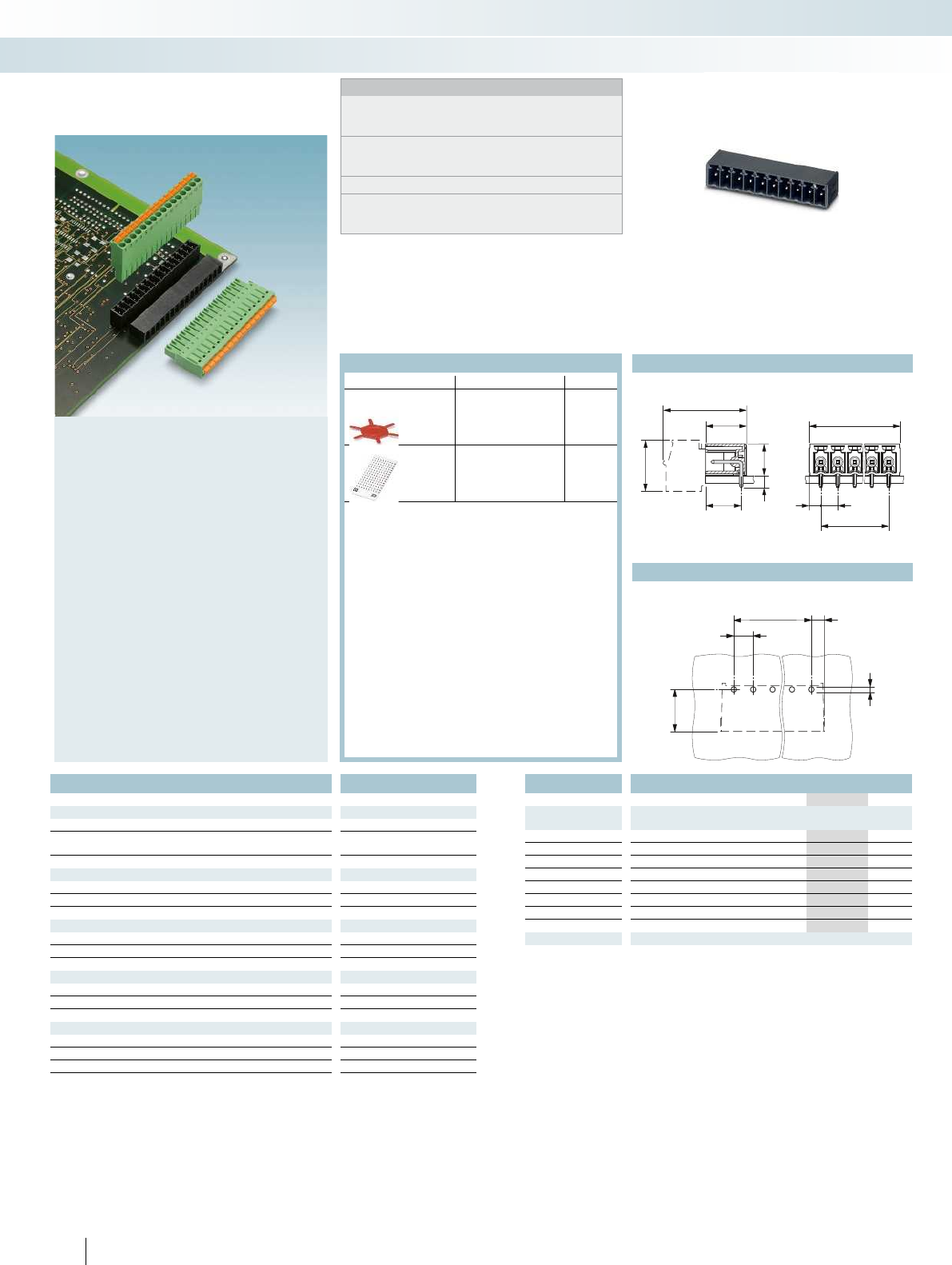
– Push-in connection with spring lever for
tool-free conductor connection
– Unique integration into front panels in
two rows
– Conductor cross sections up to 1.5 mm
with ferrule
– Printing area at the front
– Touch connection for voltage testing
using a 1 mm test pin
Double-level PCB terminal blocks
with push-in spring connection up to
1.5 mm
Tec h n i c a l d a t a
Technical data in accordance to IEC / DIN VDE
Rated current / conductor cross section [A] / [mm²] 101) / 1.5
Rated insulation voltage for pollution degree 2 [V] 200
Pitch [mm] 3.5
Connection capacity
Solid / stranded [mm²] / [mm²] / AWG 0.14 - 1.5 / 0.14 - 1.5 / 24 - 14
Stranded with ferrules without plastic sleeve [mm²] 0.2 - 1.5
Stranded with ferrules with plastic sleeve [mm²] 0.2 - 1.5
Insulation coordination
Surge voltage category / pollution degree III / 3 III / 2 II / 2
Rated insulation voltage [V] 160 200 400
Rated surge voltage [kV] 2.5 2.5 2.5
Approval data (UL/CUL) Use Group B C D
Nominal voltage [V] - - -
Nominal current [A] - - -
Connection capacity AWG AWG - - -
Approval data (CSA) Use Group B C D
Nominal voltage [V] - - -
Nominal current [A] - - -
Connection capacity AWG AWG - - -
General data
Stripping length [mm] 8
Type of insulation material / insulation material group PA / I
Inflammability class according to UL 94 V0
Drill hole diameter / pin dimensions [mm] 1.3 / 0.6 x 1.0 mm
For all types Type Page
Marker cards
SK 3,5/2,8
796
Screwdriver
SZS 0,4 x 2,5
Order No.
1205037
Ferrules with and without
plastic sleeve
834
Crimping pliers for 0.25
to 6 mm²
CRIMPFOX 6
Order No.
1212034
Test plug
MPS-MT 1-S
Order No.
1944372
831
For accessories, see Catalog 1
PCB connection technology and electronics housing
PCB terminal blocks with 2.54 to 7.62 mm pitch

a
Ø1,3
3,5
6,9 9,35
2,1
a
a+5
2,1
3,5 24,2
9,356,9
18
3,5
For additional information, visit phoenixcontact.net/products
Horizontal connection direction
Ordering data
Type Order No. Pcs. / Pkt.
3.5 mm pitch, color: green
SPTD 1,5/ 2-H-3,5 1841490 100
SPTD 1,5/ 3-H-3,5 1841500 100
SPTD 1,5/ 4-H-3,5 1841513 100
SPTD 1,5/ 5-H-3,5 1841526 100
SPTD 1,5/ 6-H-3,5 1841539 100
SPTD 1,5/ 7-H-3,5 1841542 100
SPTD 1,5/ 8-H-3,5 1841555 100
SPTD 1,5/ 9-H-3,5 1841568 100
SPTD 1,5/10-H-3,5 1841571 100
SPTD 1,5/11-H-3,5 1841584 100
SPTD 1,5/12-H-3,5 1841597 100
15PHOENIX CONTACT
PCB connection technology and electronics housing
PCB terminal blocks with 2.54 to 7.62 mm pitch
Dimensional drawing
Drilling diagram
3,5
2,15 a
1,85
2,54
3,46
1,2
3,46
1,85
2,54
14,45
26,3
a+4,3
2,15 3,5
a
2.0 mm pin length
Box-packaged headers,
Plug-in direction parallel to the PCB
Ordering data
Type Order No. Pcs. / Pkt.
No. of pos. Dim. a
[mm]
Pitch 3.5 mm, color: black
23.50IMC 1,5/ 2-G-3,5 P20 THR 1830414 50
37.00IMC 1,5/ 3-G-3,5 P20 THR 1830427 50
4 10.50 IMC 1,5/ 4-G-3,5 P20 THR 1830430 50
5 14.00 IMC 1,5/ 5-G-3,5 P20 THR 1830443 50
6 17.50 IMC 1,5/ 6-G-3,5 P20 THR 1830456 50
7 21.00 IMC 1,5/ 7-G-3,5 P20 THR 1830469 50
8 24.50 IMC 1,5/ 8-G-3,5 P20 THR 1830472 50
9 28.00 IMC 1,5/ 9-G-3,5 P20 THR 1830485 50
10 31.50 IMC 1,5/10-G-3,5 P20 THR 1830498 50
11 35.00 IMC 1,5/11-G-3,5 P20 THR 1830508 50
12 38.50 IMC 1,5/12-G-3,5 P20 THR 1830511 50
16 PHOENIX CONTACT
Notes:
In accordance with DIN EN 61984, COMBICON connectors have
no switching power. During designated use, they must not be
plugged in or disconnected when carrying voltage or under load.
COMBICON select
Possible combinations for connectors can be found in
COMBICON select at phoenixcontact.net/products.
1) Current carrying capacity curve upon request.
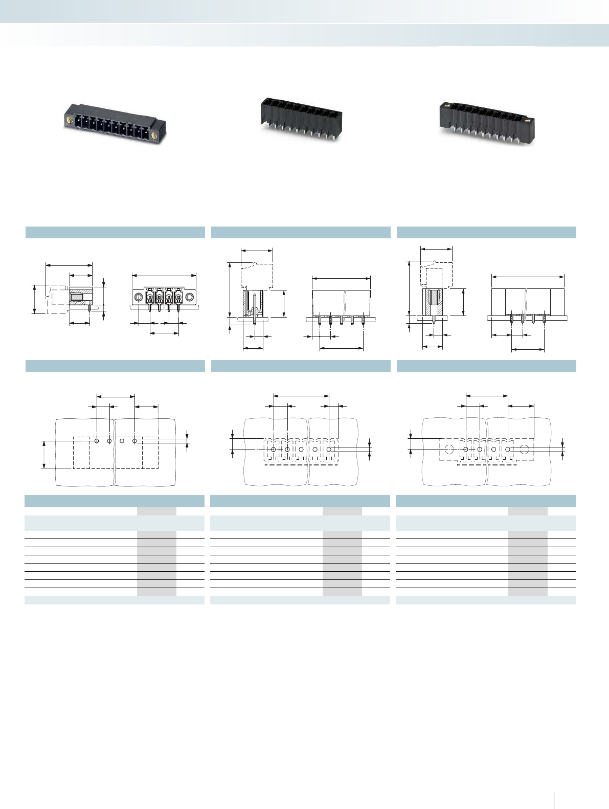
– Inverted headers with a 3.5 mm pitch
– Plug-in direction parallel or vertical to
the PCB
– Versions with snap-in lug for locking
inverted plugs with self-locking flanges
– You can find user notes and
recommendations for the THR
procedure in Catalog 1
– Combination with MC 1,5 pin strips for
the PCB/PCB connection
Inverted headers for reflow processes
Tec h n i c a l d a t a
Technical data in accordance to IEC / DIN VDE
Rated current [A] 81)
Rated insulation voltage for pollution degree 2 [V] 160
Pitch [mm] 3.5
Insulation coordination
Surge voltage category / pollution degree III / 3 III / 2 II / 2
Rated insulation voltage [V] 160 160 320
Rated surge voltage [kV] 2.5 2.5 2.5
Approval data (UL/CUL) Use Group B C D
Nominal voltage [V] - - -
Nominal current [A] - - -
Connection capacity AWG AWG - - -
Approval data (CSA) Use Group B C D
Nominal voltage [V] - - -
Nominal current [A] - - -
Connection capacity AWG AWG - - -
General data
Type of insulation material / insulation material group LCP / IIIa
Inflammability class according to UL 94 V0
Drill hole diameter / pin dimensions [mm] 1.2 / 0.8 x 0.8 mm
For all types Type Page
Marker cards
SK 3,5/2,8
796
For accessories, see Catalog 1
PCB connection technology and electronics housing
Connector systems with a 3.5/3.81 and 5.08 mm pitch
Dimensional drawing Dimensional drawing D
Drilling diagram Drilling diagram Drilling diagram Drilling diagram
3,5
2,15 a
1,85
2,54
3,46
1,2
a
3,52,15
1,1
3,81
1,2
a
3,52,15
1,1
3,81
1,2
3,46
1,85
2,54
14,45
26,3
a+4,3
2,15 3,5
a
1,4
214,45
3,81
6,3
1,1
a+4,3
2,15 3,5
a
214,45
3,81
6,3
1,1
a+4,3
2,15 3,5
a
1,4
For additional information, visit phoenixcontact.net/products
Ordering data Ordering data Ordering data
Type Order No. Pcs. / Pkt. Type Order No. Pcs. / Pkt. Type Order No. Pcs. / Pkt.
Pitch 3.5 mm, color: black Pitch 3.5 mm, color: black Pitch 3.5 mm, color: black
IMC 1,5/ 2-G-3,5 RN P20 THR 1830566 50 IMCV 1,5/ 2-G-3,5 P20 THR 1830715 50 IMCV 1,5/ 2-G-3,5 RN P20 THR 1830867 50
IMC 1,5/ 3-G-3,5 RN P20 THR 1830579 50 IMCV 1,5/ 3-G-3,5 P20 THR 1830728 50 IMCV 1,5/ 3-G-3,5 RN P20 THR 1830870 50
IMC 1,5/ 4-G-3,5 RN P20 THR 1830582 50 IMCV 1,5/ 4-G-3,5 P20 THR 1830731 50 IMCV 1,5/ 4-G-3,5 RN P20 THR 1830883 50
IMC 1,5/ 5-G-3,5 RN P20 THR 1830595 50 IMCV 1,5/ 5-G-3,5 P20 THR 1830744 50 IMCV 1,5/ 5-G-3,5 RN P20 THR 1830896 50
IMC 1,5/ 6-G-3,5 RN P20 THR 1830605 50 IMCV 1,5/ 6-G-3,5 P20 THR 1830757 50 IMCV 1,5/ 6-G-3,5 RN P20 THR 1830906 50
IMC 1,5/ 7-G-3,5 RN P20 THR 1830618 50 IMCV 1,5/ 7-G-3,5 P20 THR 1830760 50 IMCV 1,5/ 7-G-3,5 RN P20 THR 1830919 50
IMC 1,5/ 8-G-3,5 RN P20 THR 1830621 50 IMCV 1,5/ 8-G-3,5 P20 THR 1830773 50 IMCV 1,5/ 8-G-3,5 RN P20 THR 1830922 50
IMC 1,5/ 9-G-3,5 RN P20 THR 1830634 50 IMCV 1,5/ 9-G-3,5 P20 THR 1830786 50 IMCV 1,5/ 9-G-3,5 RN P20 THR 1830935 50
IMC 1,5/10-G-3,5 RN P20 THR 1830647 50 IMCV 1,5/10-G-3,5 P20 THR 1830799 50 IMCV 1,5/10-G-3,5 RN P20 THR 1830948 50
IMC 1,5/11-G-3,5 RN P20 THR 1830650 50 IMCV 1,5/11-G-3,5 P20 THR 1830809 50 IMCV 1,5/11-G-3,5 RN P20 THR 1830951 50
IMC 1,5/12-G-3,5 RN P20 THR 1830663 50 IMCV 1,5/12-G-3,5 P20 THR 1830812 50 IMCV 1,5/12-G-3,5 RN P20 THR 1830964 50
Pin length of 2.0 mm, with snap-in lug,
box-packaged headers,
plug-in direction parallel to the PCB
2.0 mm pin length
Box-packaged headers,
Plug-in direction vertical to the PCB
Pin length of 2.0 mm, with snap-in lug,
box-packaged headers,
plug-in direction vertical to the PCB
17PHOENIX CONTACT
PCB connection technology and electronics housing
Connector systems with a 3.5/3.81 and 5.08 mm pitch
Dimensional drawing Dimensional drawing Dimensional drawing Dimensional drawing
Drilling diagram Drilling diagram Drilling diagram Drilling diagram
8
a
Ø1,4
3,5
(3,81)
2,45
(2,6)
a+4,9
(a+5,2)
a
2,45
(2,6) (3,81)
3,5
11,1
8
18,7
9,2
6,9
2
Pin length 2.0 mm,
Box-packaged headers,
Plug-in direction parallel to the PCB
Ordering data
Type Order No. Pcs. / Pkt.
No. of pos. Dim. a
[mm]
3.81 mm pitch, color: black
13 45.72 MC 1,5/13-G-3,81 P20 THR 1829056 50
14 49.53 MC 1,5/14-G-3,81 P20 THR 1829069 50
15 53.34 MC 1,5/15-G-3,81 P20 THR 1829072 50
16 57.15 MC 1,5/16-G-3,81 P20 THR 1829085 50
17 60.96 MC 1,5/17-G-3,81 P20 THR 1829098 50
18 64.77 MC 1,5/18-G-3,81 P20 THR 1829108 50
19 68.58 MC 1,5/19-G-3,81 P20 THR 1829111 50
20 72.39 MC 1,5/20-G-3,81 P20 THR 1829124 50
18 PHOENIX CONTACT
Notes:
In accordance with DIN EN 61984, COMBICON connectors have
no switching power. During designated use, they must not be
plugged in or disconnected when carrying voltage or under load.
COMBICON select
Possible combinations for connectors can be found in
COMBICON select at phoenixcontact.net/products.
CP-MSTB and SK 3,... may only be used after reflow soldering.
Dimensional drawings of the free space for solder paste, the tape,
and pick-and-place pads can be found online at
phoenixcontact.net/products.
– 13 to 20 pos. headers with a 3.81 mm
pitch
– High-precision pin strips for increased
tolerance requirements
– Short 2.0 mm pin for reduced overhang
in 1.6 mm PCBs
– You can find user notes and
recommendations for the THR
procedure in Catalog 1
– For further numbers of positions, visit
phoenixcontact.net/products
Single-level header for reflow
processes
Tec h n i c a l d a t a
Technical data in accordance to IEC / DIN VDE
Rated current [A] 8
Rated insulation voltage for pollution degree 2 [V] 160
Pitch [mm] 3.81
Insulation coordination
Surge voltage category / pollution degree III / 3 III / 2 II / 2
Rated insulation voltage [V] 160 160 250
Rated surge voltage [kV] 2.5 2.5 2.5
Approval data (UL/CUL) Use Group B C D
Nominal voltage [V] - - -
Nominal current [A] - - -
Connection capacity AWG AWG - - -
Approval data (CSA) Use Group B C D
Nominal voltage [V] - - -
Nominal current [A] - - -
Connection capacity AWG AWG - - -
General data
Type of insulation material / insulation material group LCP / IIIa
Inflammability class according to UL 94 V0
Drill hole diameter / pin dimensions [mm] 1.4 / 0.8 x 0.8 mm
For all types Type Page
Coding profile
CP-MSTB
Order No.
1734634
Marker cards
SK 3,5/2,8 or SK
3,81/2,8
796
For accessories, see Catalog 1
PCB connection technology and electronics housing
Connector systems with a 3.5/3.81 and 5.08 mm pitch
Dimensional drawing Dimensional drawing D
Drilling diagram Drilling diagram Drilling diagram Drilling diagram
8
a
Ø1,4
3,5
(3,81)
6,9
(7,1)
a
2,63,81
3
1,4
a
7,13,81
3
1,4
11,1
6,9
2
18,7
9,2
8
a
a+13,8
(a+14,2)
4,3
(4,5)
3,5
(3,81)
a
3,5
(3,81)
a+4,9
(a+5,2)
2,45
(2,6)
3
218,7
9,2
7,25
11,1
a
3,5
(3,81)
a+13,8
(a+14,2)
6,9
(7,1)
3
218,7
9,2
7,25
11,1
For additional information, visit phoenixcontact.net/products
Ordering data Ordering data Ordering data
Type Order No. Pcs. / Pkt. Type Order No. Pcs. / Pkt. Type Order No. Pcs. / Pkt.
3.81 mm pitch, color: black 3.81 mm pitch, color: black 3.81 mm pitch, color: black
MC 1,5/13-GF-3,81 P20 THR 1829137 50 MCV 1,5/13-G-3,81 P20 THR 1828895 50 MCV 1,5/13-GF-3,81 P20 THR 1828976 50
MC 1,5/14-GF-3,81 P20 THR 1829140 50 MCV 1,5/14-G-3,81 P20 THR 1828905 50 MCV 1,5/14-GF-3,81 P20 THR 1828989 50
MC 1,5/15-GF-3,81 P20 THR 1829153 50 MCV 1,5/15-G-3,81 P20 THR 1828918 50 MCV 1,5/15-GF-3,81 P20 THR 1828992 50
MC 1,5/16-GF-3,81 P20 THR 1829166 50 MCV 1,5/16-G-3,81 P20 THR 1828921 50 MCV 1,5/16-GF-3,81 P20 THR 1829001 50
MC 1,5/17-GF-3,81 P20 THR 1829179 50 MCV 1,5/17-G-3,81 P20 THR 1828934 50 MCV 1,5/17-GF-3,81 P20 THR 1829014 50
MC 1,5/18-GF-3,81 P20 THR 1829182 50 MCV 1,5/18-G-3,81 P20 THR 1828947 50 MCV 1,5/18-GF-3,81 P20 THR 1829027 50
MC 1,5/19-GF-3,81 P20 THR 1829195 50 MCV 1,5/19-G-3,81 P20 THR 1828950 50 MCV 1,5/19-GF-3,81 P20 THR 1829030 50
MC 1,5/20-GF-3,81 P20 THR 1829205 50 MCV 1,5/20-G-3,81 P20 THR 1828963 50 MCV 1,5/20-GF-3,81 P20 THR 1829043 50
Pin length 2.0 mm, with threaded flange
Box-packaged headers,
Plug-in direction parallel to the PCB
Pin length 2.0 mm,
Box-packaged headers,
Plug-in direction vertical to the PCB
Pin length 2.0 mm, with threaded flange
Box-packaged headers,
Plug-in direction vertical to the PCB
19PHOENIX CONTACT
PCB connection technology and electronics housing
Connector systems with a 3.5/3.81 and 5.08 mm pitch
Dimensional drawing Dimensional drawing Dimensional drawing Dimensional drawing
Drilling diagram Drilling diagram Drilling diagram Drilling diagram
8
a
Ø1,4
3,5
(3,81)
2,45
(2,6)
a+4,9
(a+5,2)
a
2,45
(2,6) (3,81)
3,5
11,1
8
18,7
9,2
6,9
2
Pin length 2.0 mm,
Taped headers,
Plug-in direction parallel to the PCB
Ordering data
Type Order No. Pcs. / Pkt.
No. of pos. Dim. a
[mm]
3.81 mm pitch, color: black
13 45.72 MC 1,5/13-G-3,81 P20 THRR72 1828691 470
14 49.53 MC 1,5/14-G-3,81 P20 THRR88 1828701 470
15 53.34 MC 1,5/15-G-3,81 P20 THRR88 1828714 470
16 57.15 MC 1,5/16-G-3,81 P20 THRR88 1828727 470
17 60.96 MC 1,5/17-G-3,81 P20 THRR88 1828730 470
18 64.77 MC 1,5/18-G-3,81 P20 THRR88 1828743 470
19 68.58 MC 1,5/19-G-3,81 P20 THRR104 1828756 470
20 72.39 MC 1,5/20-G-3,81 P20 THRR104 1828769 470
20 PHOENIX CONTACT
Notes:
In accordance with DIN EN 61984, COMBICON connectors have
no switching power. During designated use, they must not be
plugged in or disconnected when carrying voltage or under load.
COMBICON select
Possible combinations for connectors can be found in
COMBICON select at phoenixcontact.net/products.
CP-MSTB and SK 3,... may only be used after reflow soldering.
Pick and place pads for taped THR articles usually protrude
beyond the components. The PCB layout must ensure that
collisions are avoided when components are assembled.
Dimensional drawings of the pick and place pads can be found
online at phoenixcontact.net/products.
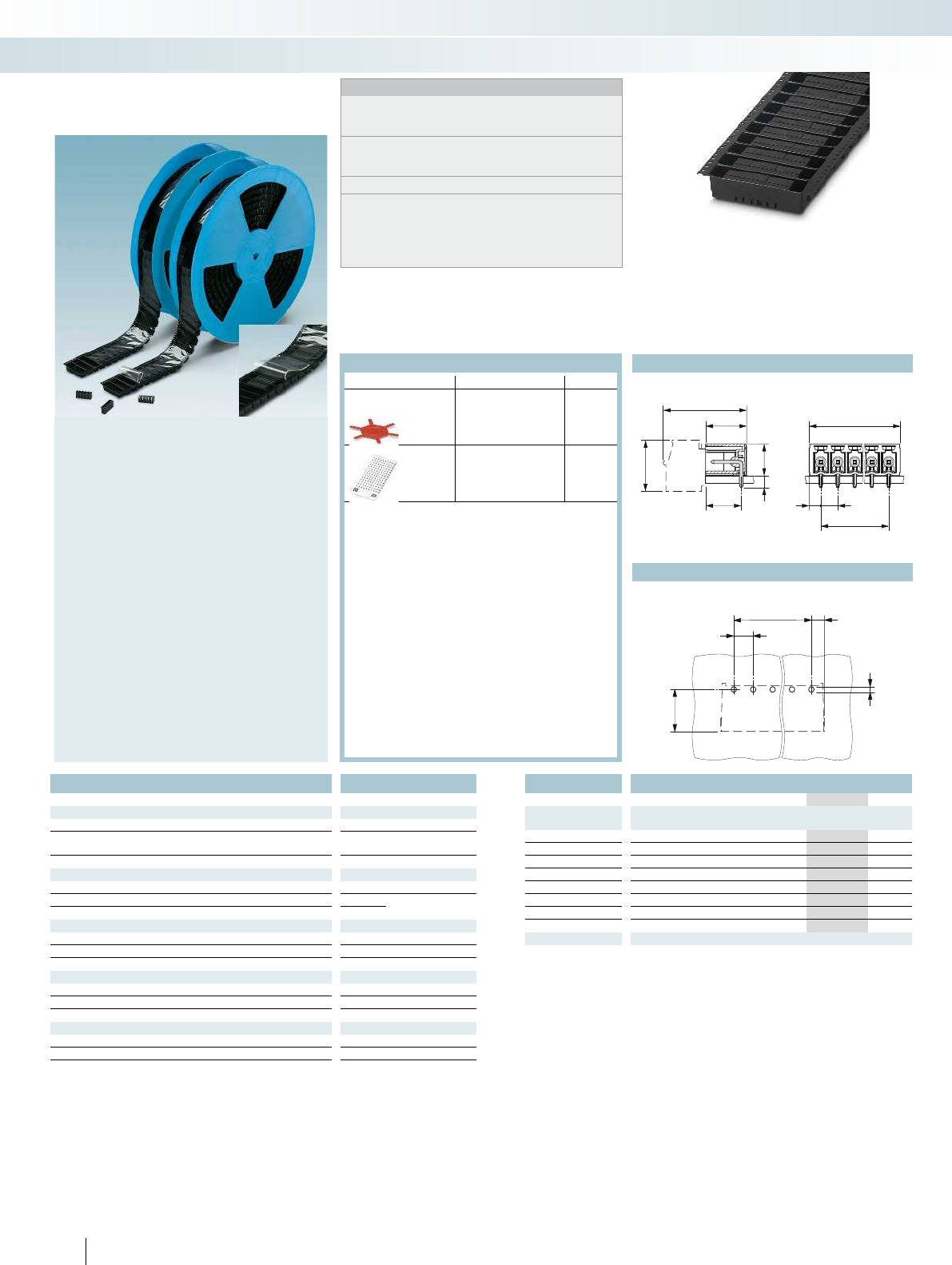
– 13 to 20 pos. headers with a 3.81 mm
pitch
– High-precision pin strips for increased
tolerance requirements
– Short 2.0 mm pin for reduced overhang
in 1.6 mm PCBs
– Tape-on-reel packing according to
IEC 60286-3 for automated mounting
– Tape width corresponds to order
designation, e.g., R32 = 32 mm tape
width
– You can find user notes and
recommendations for the THR
procedure in Catalog 1
– For further numbers of positions, visit
phoenixcontact.net/products
Single-level header for reflow
processes
Tec h n i c a l d a t a
Technical data in accordance to IEC / DIN VDE
Rated current [A] 8
Rated insulation voltage for pollution degree 2 [V] -
Pitch [mm] -
Insulation coordination
Surge voltage category / pollution degree III / 3 III / 2 II / 2
Rated insulation voltage [V] 160
Rated surge voltage [kV]
Approval data (UL/CUL) Use Group B C D
Nominal voltage [V] - - -
Nominal current [A] - - -
Connection capacity AWG AWG - - -
Approval data (CSA) Use Group B C D
Nominal voltage [V] - - -
Nominal current [A] - - -
Connection capacity AWG AWG - - -
General data
Type of insulation material / insulation material group - / -
Inflammability class according to UL 94 -
For all types Type Page
Coding profile
CP-MSTB
Order No.
1734634
Marker cards
SK 3,5/2,8 or SK
3,81/2,8
796
For accessories, see Catalog 1
PCB connection technology and electronics housing
Connector systems with a 3.5/3.81 and 5.08 mm pitch
Dimensional drawing Dimensional drawing D
Drilling diagram Drilling diagram Drilling diagram Drilling diagram
8
a
Ø1,4
3,5
(3,81)
6,9
(7,1)
a
2,45
(2,6)
3,5
(3,81)
3
Ø1,4
a
6,9
(7,1)
3,5
(3,81)
3
Ø1,4
11,1
6,9
2
18,7
9,2
8
a
a+13,8
(a+14,2)
4,3
(4,5)
3,5
(3,81)
a
3,5
(3,81)
a+4,9
(a+5,2)
2,45
(2,6)
3
218,7
9,2
7,25
11,1
a
3,5
(3,81)
a+13,8
(a+14,2)
6,9
(7,1)
3
218,7
9,2
7,25
11,1
For additional information, visit phoenixcontact.net/products
Ordering data Ordering data Ordering data
Type Order No. Pcs. / Pkt. Type Order No. Pcs. / Pkt. Type Order No. Pcs. / Pkt.
3.81 mm pitch, color: black 3.81 mm pitch, color: black 3.81 mm pitch, color: black
MC 1,5/13-GF-3,81 P20 THRR72 1828772 470 MCV 1,5/13-G-3,81 P20 THRR72 1828536 200 MCV 1,5/13-GF-3,81 P20 THRR72 1828617 200
MC 1,5/14-GF-3,81 P20 THRR88 1828785 470 MCV 1,5/14-G-3,81 P20 THRR88 1828549 200 MCV 1,5/14-GF-3,81 P20 THRR88 1828620 200
MC 1,5/15-GF-3,81 P20 THRR88 1828798 470 MCV 1,5/15-G-3,81 P20 THRR88 1828522 200 MCV 1,5/15-GF-3,81 P20 THRR88 1828633 200
MC 1,5/16-GF-3,81 P20 THRR88 1828808 470 MCV 1,5/16-G-3,81 P20 THRR88 1828565 200 MCV 1,5/16-GF-3,81 P20 THRR88 1828646 200
MC 1,5/17-GF-3,81 P20 THRR88 1828811 470 MCV 1,5/17-G-3,81 P20 THRR88 1828578 200 MCV 1,5/17-GF-3,81 P20 THRR88 1828659 200
MC 1,5/18-GF-3,81 P20 THRR88 1828824 470 MCV 1,5/18-G-3,81 P20 THRR88 1828581 200 MCV 1,5/18-GF-3,81 P20 THRR88 1828662 200
MC 1,5/19-GF-3,81 P20 THRR104 1828837 470 MCV 1,5/19-G-3,81 P20 THRR104 1828594 200 MCV 1,5/19-GF-3,81 P20 THRR104 1828675 200
MC 1,5/20-GF-3,81 P20 THRR104 1828840 470 MCV 1,5/20-G-3,81 P20 THRR104 1828604 200 MCV 1,5/20-GF-3,81 P20 THRR104 1828688 200
Pin length 2.0 mm, with threaded flange,
Taped headers,
Plug-in direction parallel to the PCB
Pin length 2.0 mm,
Taped headers,
Plug-in direction vertical to the PCB
Pin length 2.0 mm, with threaded flange,
Taped headers,
Plug-in direction vertical to the PCB
21PHOENIX CONTACT
PCB connection technology and electronics housing
Connector systems with a 3.5/3.81 and 5.08 mm pitch
Dimensional drawing Dimensional drawing Dimensional drawing Dimensional drawing
Drilling diagram Drilling diagram Drilling diagram Drilling diagram
No. of pos. Dim. a
[mm]
1
22.50
35.00
47.50
510.00
612.50
715.00
817.50
22 PHOENIX CONTACT
Notes:
PTSM plugs and headers are also available in black.
COMBICON select
Possible combinations for connectors can be found in
COMBICON select at phoenixcontact.net/products.
Pick and place pads for taped THR articles usually protrude
beyond the components. The PCB layout must ensure that
collisions are avoided when components are assembled.
Dimensional drawings of the pick and place pads can be found
online at phoenixcontact.net/products.
1) Current carrying dependent upon plug used
2) 0.75 mm²possible, terminates the conductor insulation before
the terminal block.
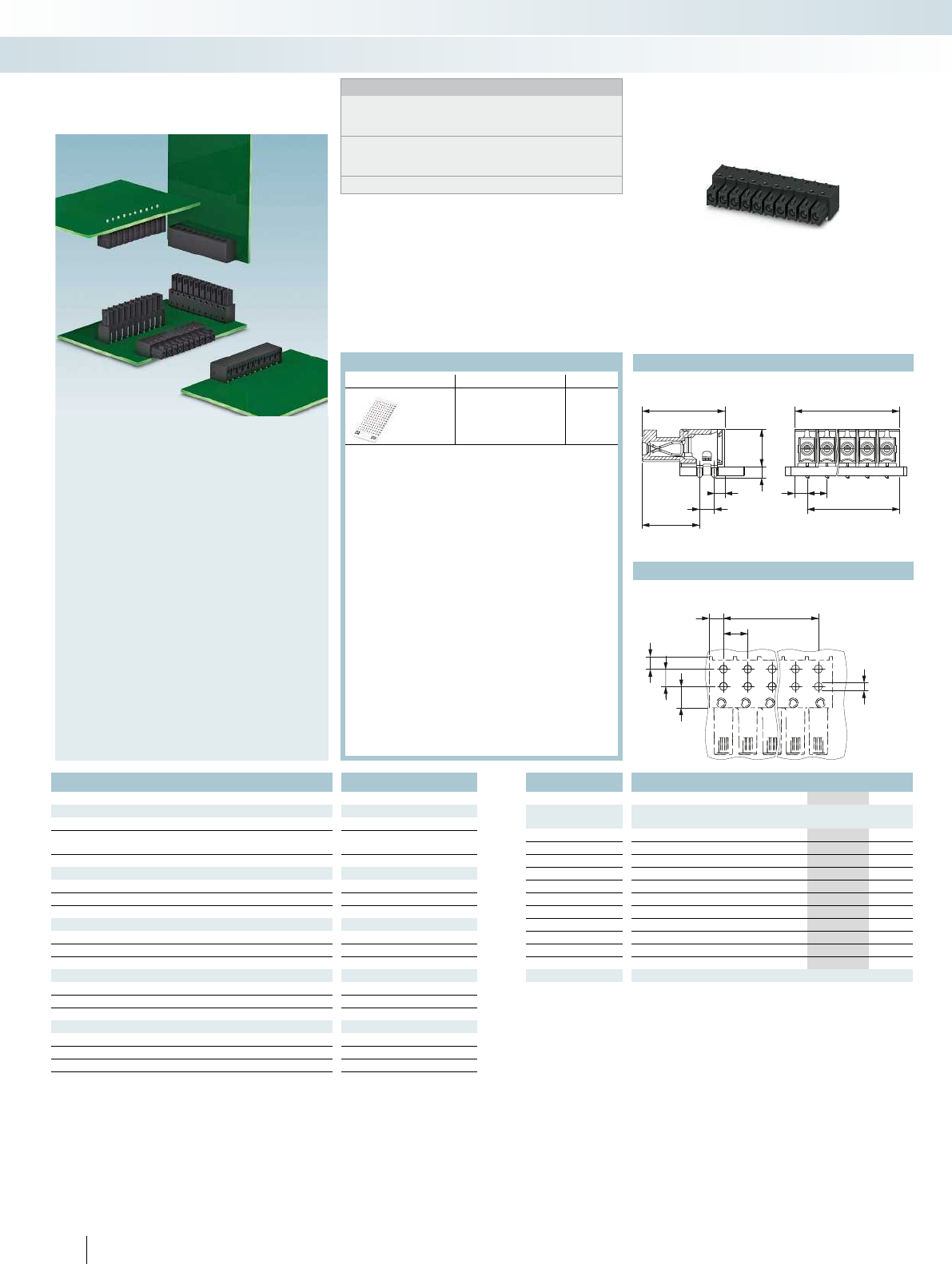
– Specifically designed for use in reflow
and SMT processes
– High current carrying capacity of 6 A
– Robust solder anchor for secure,
mechanical fixing to the surface
– Supplied in taped packaging according to
IEC 60286-3 for automatic assembly
– Compatible with PTSM...-/PTPM...plugs
– 2.5 mm pitch
Plug with spring-cage connection up
to 0.75 mm
Tec h n i c a l d a t a PTSM 0,5/...-HV-2,5-SMD R..
PTSM 0,5/ ...-HTB-2,5-SMD WH R32
PTSM 0,5/ 1-2,5-H SMD WH L R24
Technical data in accordance to IEC / DIN VDE
Rated current [A] 61)6
1)6
1) / 0.5
Rated insulation voltage for pollution degree 2 [V] 160 160 250
Pitch [mm] 2.5 2.5 -
Connection capacity
Solid / stranded [mm²] / [mm²] / AWG - / - / - - / - / - 0.14 - 0.5 / 0.2 - 0.52) / 26 - 20
Stranded with ferrules without plastic sleeve [mm²] - - 0.25 - 0.5
Stranded with ferrules with plastic sleeve [mm²] - - -
Insulation coordination
Surge voltage category / pollution degree III / 3 III / 2 II / 2 III / 3 III / 2 II / 2 III / 3 III / 2 II / 2
Rated insulation voltage [V] 125 160 250 125 160 250 63 250 320
Rated surge voltage [kV] 2.5 2.5 2.5 2.5 2.5 2.5 2.5 2.5 2.5
Approval data (UL/CUL) Use Group B C D B C D B C D
Nominal voltage [V]--- --- 150--
Nominal current [A]--- --- 5--
Connection capacity AWG AWG--- ---26-20--
Approval data (CSA) Use Group B C D B C D B C D
Nominal voltage [V]--- --- ---
Nominal current [A]--- --- ---
Connection capacity AWG AWG--- --- ---
General data
Type of insulation material / insulation material group PA / I PA / I PA / I
Inflammability class according to UL 94 V0 V0 V0
For all types Type Page
Screwdriver
SZS 0,4 X 2,0
Order No.
1205202
Ferrules with and without
plastic sleeve
834
Crimping pliers for 0.25
to 6 mm²
CRIMPFOX 6
Order No.
1212034
For accessories, see Catalog 1
PCB connection technology and electronics housing
Connection technology for building and LED applications
4,4
5,6
Ø1
2,2 1,2 3,30,75
2,1 4,3
4,9
2,5 1,4
1,2
R0,8
2,2
2,5 5,6
6,05
2,2
3,8
2,5
2,3
1,4
6,6
2,6
3,4
5,6
7,5
2,1
5
2,52,1 Ø0,8
a
a+8,1
a+2,8
a+4,2
2,1 2,5
a
a+7,2
8,2
1,5 9,5
5
4
5
92
0,3
3
1,95
For additional information, visit phoenixcontact.net/products
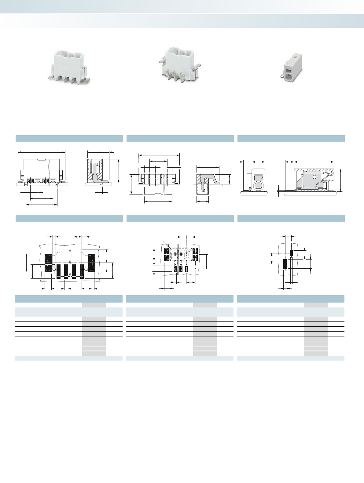
Vertical header
for SMD applications
Ordering data Ordering data Ordering data
Type Order No. Pcs. / Pkt. Type Order No. Pcs. / Pkt. Type Order No. Pcs. / Pkt.
2.5 mm pitch, color: white 2.5 mm pitch, color: white 2.5 mm pitch, color: white
PTSM 0,5/ 1-2,5-H SMD WH L R24 1840035 1000
PTSM 0,5/ 2-HV-2,5-SMD WH R32 1778696 500 PTSM 0,5/ 2-HTB-2,5-SMD WH R32 1830126 330
PTSM 0,5/ 3-HV-2,5-SMD WH R32 1778706 500 PTSM 0,5/ 3-HTB-2,5-SMD WH R32 1830139 330
PTSM 0,5/ 4-HV-2,5-SMD WH R44 1778719 400 PTSM 0,5/ 4-HTB-2,5-SMD WH R44 1830142 330
PTSM 0,5/ 5-HV-2,5-SMD WH R44 1778722 400 PTSM 0,5/ 5-HTB-2,5-SMD WH R44 1830155 330
PTSM 0,5/ 6-HV-2,5-SMD WH R44 1778735 400 PTSM 0,5/ 6-HTB-2,5-SMD WH R44 1830168 330
PTSM 0,5/ 7-HV-2,5-SMD WH R44 1778748 400 PTSM 0,5/ 7-HTB-2,5-SMD WH R44 1830171 330
PTSM 0,5/ 8-HV-2,5-SMD WH R44 1778751 400 PTSM 0,5/ 8-HTB-2,5-SMD WH R44 1830184 330
Through board header
for SMD applications
1-pos. horizontal PCB terminal block for SMD
applications
23PHOENIX CONTACT
PCB connection technology and electronics housing
Connection technology for building and LED applications
Dimensional drawing Dimensional drawing Dimensional drawing
Drilling diagram Drilling diagram Drilling diagram
30
20
10
0020304060708090100 110
1050
40
50
60
70
= 6 mm²
No. of pos. Dim. a
[mm]
10.00
27.50
315.00
422.50
530.00
637.50
745.00
852.50
960.00
10 67.50
11 75.00
12 82.50
24 PHOENIX CONTACT
Notes:
When aligning versions with double pinning, other rated insulation
voltages can occur.
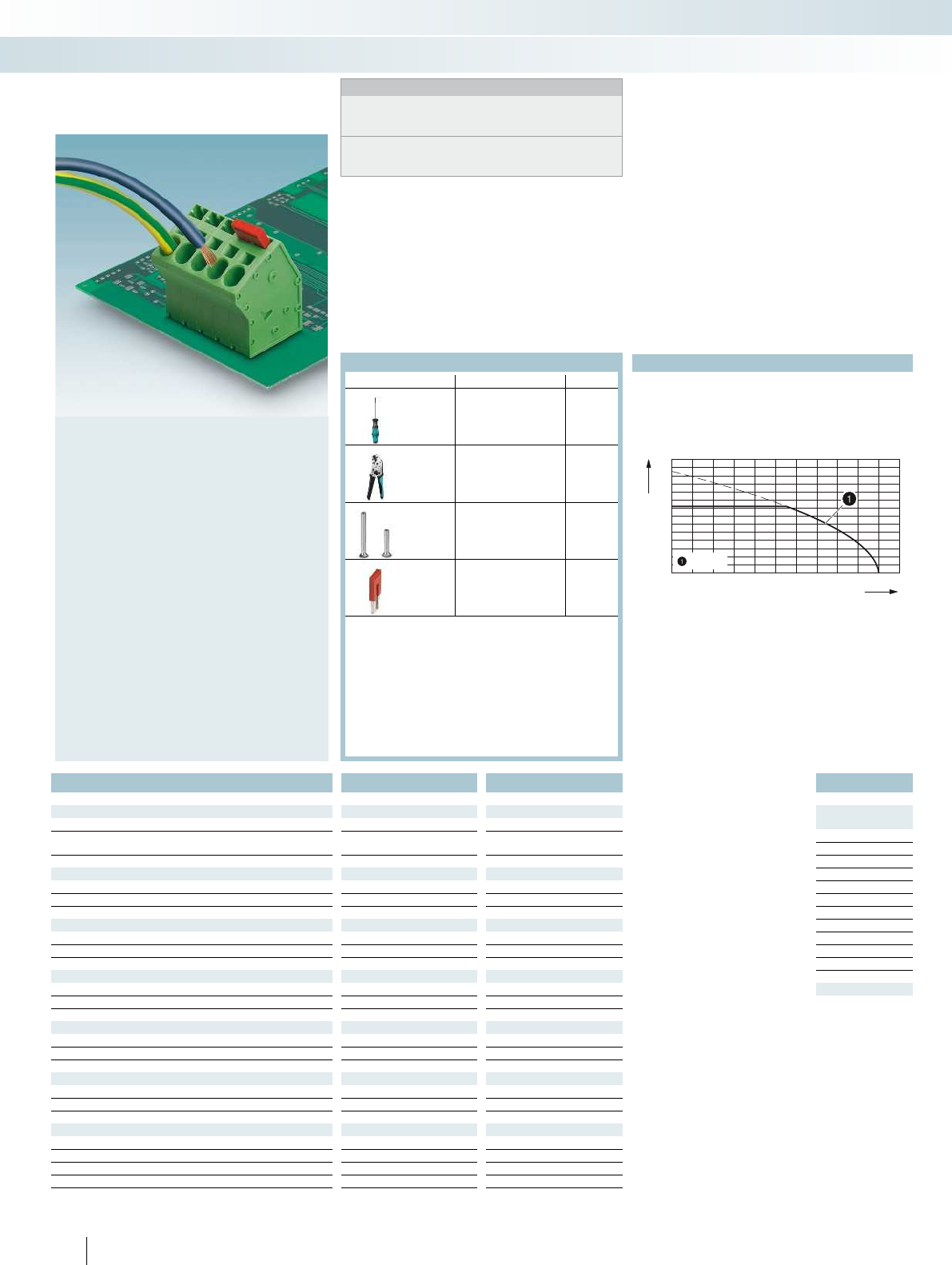
1) Please observe the current carrying capacity curves and
laboratory data sheets. Further current carrying capacity curves on
request.
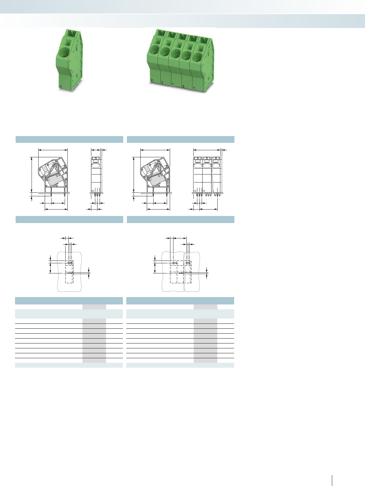
– SPTA 5 PCB terminal block with push-in
spring connection for conductor cross
sections up to 6 mm and a current
carrying capacity of 41 A
– Fully insulated bridges (FBSK) with
different numbers of positions, e.g., for
potential distribution
– Fast connection technology, thanks to
tool-free direct plug-in principle
– Unrestricted 600-V-UL approval thanks
to compact zig-zag pinning
– Conductor connection direction: 30° to
the PCB
– Single-position terminal blocks with
double pinning
PCB terminal blocks, 7.5 mm pitch
Tec h n i c a l d a t a SPTA 5/1-7,5 SPTA 5/...-7,5-ZB
Technical data in accordance to IEC / DIN VDE
Rated current / conductor cross section [A] / [mm²] 411) / 6 411) / 6
Rated insulation voltage for pollution degree 2 [V] 1000 1000
Pitch [mm] 7.5 7.5
Connection capacity
Solid / stranded [mm²] / [mm²] / AWG 0.2 - 6 / 0.2 - 6 / 24 - 8 0.2 - 6 / 0.2 - 6 / 24 - 8
Stranded with ferrules without plastic sleeve [mm²] 0.25 - 6 0.25 - 6
Stranded with ferrules with plastic sleeve [mm²] 0.25 - 4 0.25 - 4
Multi-conductor connection capacity (two conductors with the same cross section)
Solid / stranded [mm²] - / - - / -
Stranded with ferrules without plastic sleeve [mm²] - -
Stranded with TWIN ferrule with plastic sleeve [mm²] 0.25 - 1.5 0.25 - 1.5
Insulation coordination
Surge voltage category / pollution degree III / 3 III / 2 II / 2 III / 3 III / 2 II / 2
Rated insulation voltage [V] 630 1000 1000 800 1000 1000
Rated surge voltage [kV] 6 6 6 8 8 6
Approval data (UL/CUL) Use Group B C D B C D
Nominal voltage [V]--- ---
Nominal current [A]--- ---
Connection capacity AWG AWG--- ---
Approval data (CSA) Use Group B C D B C D
Nominal voltage [V]--- ---
Nominal current [A]--- ---
Connection capacity AWG AWG--- ---
General data
Stripping length [mm] 15 15
Type of insulation material / insulation material group PA / I PA / I
Inflammability class according to UL 94 V0 V0
Drill hole diameter / pin dimensions [mm] 2.1 / 1.7 x 0.8 2.1 / 1.7 x 0.8
For all types Type Page
Screwdriver
SZF 1-0,6 x 3,5
Order No.
1204517
Crimping pliers for 0.25
to 6 mm²
CRIMPFOX 6
Order No.
1212034
Ferrules with and without
plastic sleeve
834
Bridge
FBSK ...-7,5
830
For accessories, see Catalog 1
Ambient temperature [°C]
Amperage [A]
Current carrying capacity curve
Type: SPTA 5/...-7,5
Tested according to DIN EN 60512-5-2:2003-01
Reduction factor = 1
Number of positions: 4
PCB connection technology and electronics housing
PCB terminal blocks for power electronics with a pitch from 5.0 to 15.0 mm
7,7 14
6,55
Ø2,1
7,7 14
6,55
a
7,5
Ø2,1
9,3
4,6
6,55
34
29
14
23,3
7,7
14
23,3
7,7
29
34
4,6
6,55
a
7,5
7,5+a 1,8
For additional information, visit phoenixcontact.net/products
Single PCB terminal block, 30° angled
connection direction,
double pinning
Ordering data Ordering data
Type Order No. Pcs. / Pkt. Type Order No. Pcs. / Pkt.
7.5 mm pitch, color: green 7.5 mm pitch, color: green
SPTA 5/ 1-7,5 1819079 50
SPTA 5/ 2-7,5-ZB 1819082 50
SPTA 5/ 3-7,5-ZB 1819095 50
SPTA 5/ 4-7,5-ZB 1819105 50
SPTA 5/ 5-7,5-ZB 1819118 50
SPTA 5/ 6-7,5-ZB 1819121 50
SPTA 5/ 7-7,5-ZB 1819134 50
SPTA 5/ 8-7,5-ZB 1819147 50
SPTA 5/ 9-7,5-ZB 1819150 50
SPTA 5/10-7,5-ZB 1819163 50
SPTA 5/11-7,5-ZB 1819176 50
SPTA 5/12-7,5-ZB 1819189 50
30° angled connection direction,
zigzag pinning, 600 V UL approval
25PHOENIX CONTACT
PCB connection technology and electronics housing
PCB terminal blocks for power electronics with a pitch from 5.0 to 15.0 mm
Dimensional drawing Dimensional drawing
Drilling diagram Drilling diagram
30
20
10
0020304060708090100 110
1050
40
50
60
70
80
90
100
110
=16mm²
No. of pos. Dim. a
[mm]
10.00
210.00
320.00
430.00
540.00
650.00
760.00
870.00
980.00
26 PHOENIX CONTACT
Notes:
When aligning versions with double pinning, other rated insulation
voltages can occur.
1) Please observe the current carrying capacity curves and
laboratory data sheets. Further current carrying capacity curves on
request.
– SPTA 16 PCB terminal block with push-
in spring connection for conductor
cross sections up to 16 mm and a
current carrying capacity of 76 A
– Fully insulated bridges (FBSK) with
different number of positions, e. g. for
potential distribution
– Fast connection method thanks to
principle of direct plug-in without tools
– Unrestricted 600-V-UL approval thanks
to compact zig-zag pinning
– Conductor connection direction: 30° to
the PCB
– Single-position terminal blocks with
double pinning
PCB terminal blocks, angled, 10 mm
pitch
Tec h n i c a l d a t a SPTA 16/1-10,0 SPTA 16/...-10,0-ZB
Technical data in accordance to IEC / DIN VDE
Rated current / conductor cross section [A] / [mm²] 761) / 10 761) / 10
Rated insulation voltage for pollution degree 2 [V] 1000 1000
Pitch [mm] 10 10
Solid & multi-strand / stranded [mm²] / [mm²] / AWG 0.75 - 10 / 0.75 - 16 / 18 - 4 0.75 - 10 / 0.75 - 16 / 18 - 4
Stranded with ferrules without plastic sleeve [mm²] 0.75 - 16 0.75 - 16
Stranded with ferrules with plastic sleeve [mm²] 0.75 - 10 0.75 - 10
Multi-conductor connection capacity (two conductors with the same cross section)
Solid & multi-strand / stranded [mm²] - / - - / -
Stranded with ferrules without plastic sleeve [mm²] - -
Stranded with TWIN ferrule with plastic sleeve [mm²] 0.75 - 4 0.75 - 4
Insulation coordination
Surge voltage category / pollution degree III / 3 III / 2 II / 2 III / 3 III / 2 II / 2
Rated insulation voltage [V] 1000 1000 1000 1000 1000 1000
Rated surge voltage [kV] 8 8 6 8 8 6
Approval data (UL/CUL) Use Group B C D B C D
Nominal voltage [V]--- ---
Nominal current [A]--- ---
Connection capacity AWG AWG--- ---
Approval data (CSA) Use Group B C D B C D
Nominal voltage [V]--- ---
Nominal current [A]--- ---
Connection capacity AWG AWG--- ---
General data
Stripping length [mm] 18 18
Type of insulation material / insulation material group PA / I PA / I
Inflammability class according to UL 94 V0 V0
Drill hole diameter / pin dimensions [mm] 1.7 / 1.2 x 1 1.7 / 1.2 x 1
For all types Type Page
Screwdriver
SZF 2-0,8 x4,0
Order No.
1204520
Crimping pliers for 0.25
to 6 mm²
CRIMPFOX 6
Order No.
1212034
Crimping pliers for 10 to
16 mm²
CRIMPFOX 16 S
Order No.
1207983
Fixed bridge
FBSK ...-10/ZFKDS 10
830
For accessories, see Catalog 1
Ambient temperature [°C]
Amperage [A]
Current carrying capacity curve
Type: SPTA 16/...-10,0
Tested according to DIN EN 60512-5-2:2003-01
Reduction factor = 1
Number of positions: 4
PCB connection technology and electronics housing
PCB terminal blocks for power electronics with a pitch from 5.0 to 15.0 mm
15 3,35
2,52,5
4,3
Ø1,7
15 3,35
a
2,52,5
4,3
Ø1,7
2,5
2,5
6,8
10 1,8
15
7
25,35
4,1 38,1
32,7
2,5
2,5
6,8a
1,8a+10
15
7
25,35
4,1 38,1
32,7
For additional information, visit phoenixcontact.net/products
Single PCB terminal block,
30° angled connection direction,
double pinning
Ordering data Ordering data
Type Order No. Pcs. / Pkt. Type Order No. Pcs. / Pkt.
10 mm pitch, color: green 10 mm pitch, color: green
SPTA 16/ 1-10,0 1819192 50
SPTA 16/ 2-10,0-ZB 1819202 50
SPTA 16/ 3-10,0-ZB 1819215 50
SPTA 16/ 4-10,0-ZB 1819228 50
SPTA 16/ 5-10,0-ZB 1819231 50
SPTA 16/ 6-10,0-ZB 1819244 50
SPTA 16/ 7-10,0-ZB 1819257 50
SPTA 16/ 8-10,0-ZB 1819260 50
SPTA 16/ 9-10,0-ZB 1819273 50
30° angled connection direction,
zigzag pinning, 600 V UL approval
27PHOENIX CONTACT
PCB connection technology and electronics housing
PCB terminal blocks for power electronics with a pitch from 5.0 to 15.0 mm
Dimensional drawing Dimensional drawing
Drilling diagram Drilling diagram
28 PHOENIX CONTACT
PCB connection technology and electronics housing
Panel feed-through terminal blocks for high-current applications
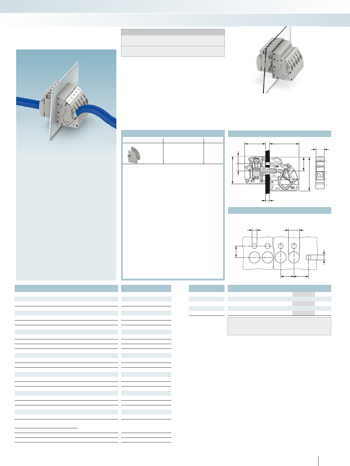
The 45° push-in spring connection enables quick, tool-free, and space-saving connection. The solid conductor or a conductor with
ferrule is simply inserted into the terminal point and pressed against the current bar by the spring. It is only when fine-strand conductors
without ferrules are connected and when this connection is released that it is necessary to use a standard bladed screwdriver. The perfect
connection for rapid wiring in the field.
Optimally seal the potting compounds -
molded feed-through terminal blocks from
Phoenix Contact
The terminal blocks consist of an internal
and external element. These pass through
the housing panel and snap together
without the need for tools. The
engagement mechanism ensures a tight fit,
however thick the panel.
The various engagement pin versions can
be used to create pre-assembled blocks for
fast mounting.
12 13,3*
10
Ø4,5 Ø10
Ø4,5
29,5 39,7
44,4
18,1
10 10,2
38,3
1
6
12
For additional information, visit phoenixcontact.net/products
16 mm² panel feed-through terminal block,
external part with push-in connection,
internal part with screw connection
Ordering data
Type Order No. Pcs. / Pkt.
Description Panel feed-through terminal block
PWO 16-UW 1844387 50
Panel feed-through terminal block, with engagement pin
PWO 16-UW/S 1844390 50
ZB 12.../ZBF12... marking material (see Catalog 5)
TMT (EX9,5)R marking material (see online catalog)
Notes:
Inside = left side of portrait photos
Outside = right side of portrait photos
Corresponding screws for fixing the panel feed-through terminal
blocks are supplied as standard.
– Outside the device with convenient
push-in connection
– Inside the device with classic screw
connection
– The two halves of the terminal can be
easily assembled by simply snapping
them together
– Automatic panel thickness
compensation
– Flange plates as alternative mounting
options
Drilling diagram
Dimensional drawing
PWO 16... high-current feed-through
terminal blocks with screw
connection
Tec h n i c a l d a t a
Technical data in accordance to IEC / DIN VDE
Current/conductor cross section [A] / [mm²] 76 / 16 // 76 / 16
Rated voltage [V] 1000
Connection capacity
Solid / stranded
[mm²] / [mm²] / A
WG 1.5 - 16 / 1.5 - 16 / 14 - 4
Stranded with ferrules without plastic sleeve [mm²] 1.5 - 16
Stranded with ferrules with plastic sleeve [mm²] 1.5 - 16
Multi-conductor connection capacity (two conductors with the same cross section)
Solid / stranded [mm²] - / -
Stranded with ferrules without plastic sleeve [mm²] -
Stranded with TWIN ferrule with plastic sleeve [mm²] 1.5 - 4
Cross section with insertion bridge (solid/stranded) [mm²] - / -
Insulation coordination
Surge voltage category / pollution degree III / 3 III / 2 II / 2
Rated insulation voltage [V] 800 1000 1000
Rated surge voltage [kV] 6 6 6
Approval data (UL/CUL) Use Group B C D
Nominal voltage [V] - - -
Nominal current [A] - - -
Connection capacity AWG AWG - - -
Approval data (CSA) Use Group B C D
Nominal voltage [V] - - -
Nominal current [A] - - -
Connection capacity AWG AWG - - -
General data
Stripping length [mm] 18
Cable lug connection: thread / tightening torque
Insulation material PA
Inflammability class according to UL 94 V0
Panel thickness [mm] 1 - 6
For all types Type
Flange plate
PWO 16-F
Order No.
1705659
Accessories
29
PHOENIX CONTACT
PCB connection technology and electronics housing
Panel feed-through terminal blocks for high-current applications
30 PHOENIX CONTACT
PCB connection technology and electronics housing
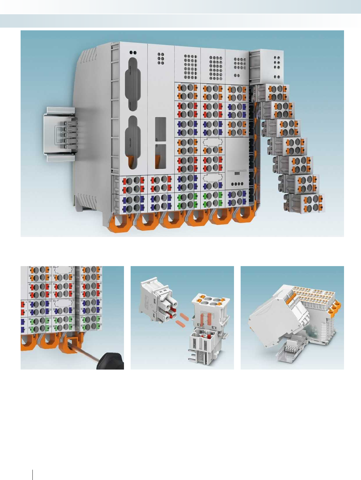
Electronics housing for industrial electronics and semi-industrial applications
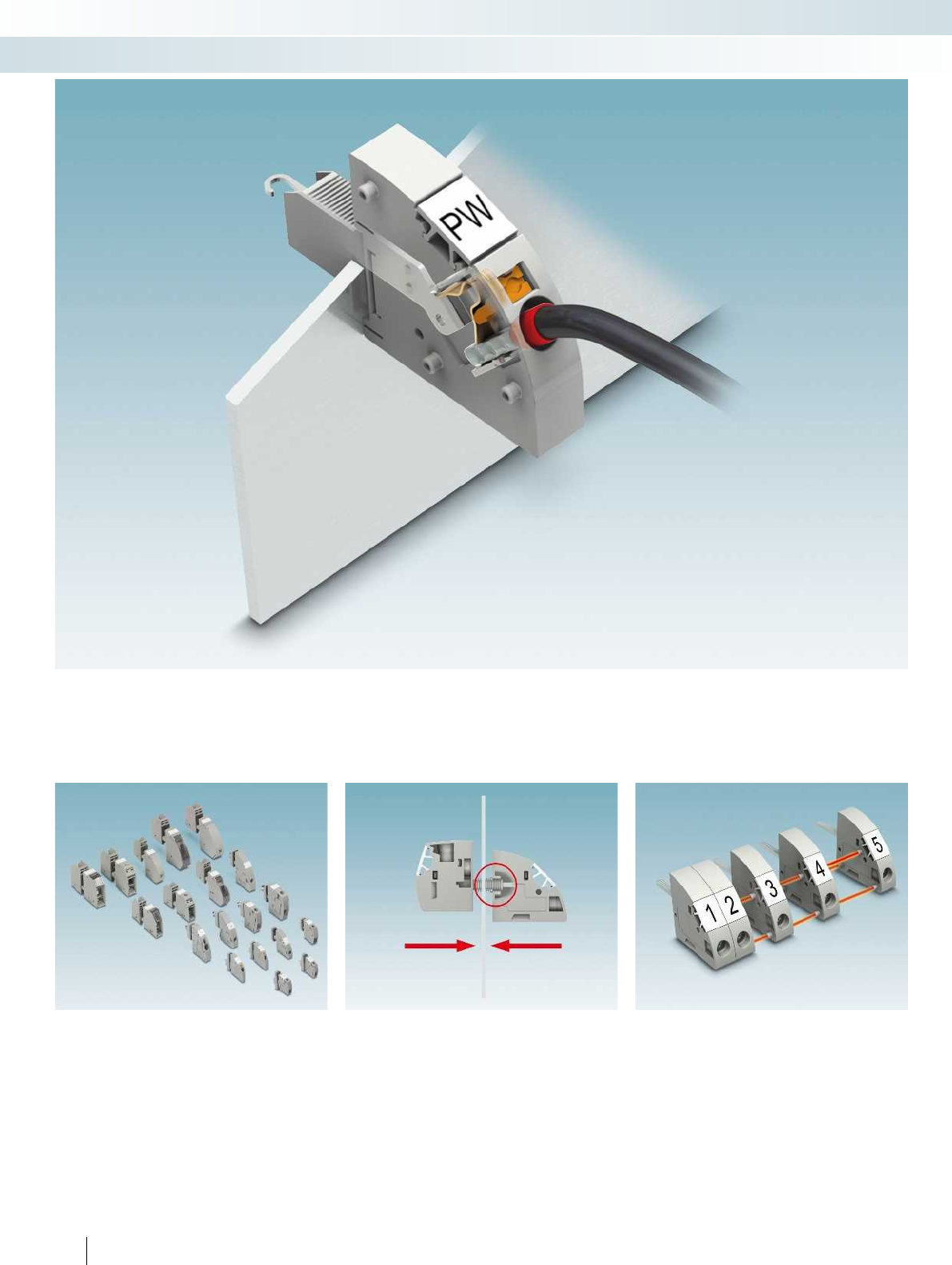
The ME-IO housing is particularly suitable for applications with a small amount of installation space. The push-in front connection
technology as well as the compact design enable devices with up to 36 positions to be implemented in a confined space.
The Lock & Release system provides
secure and defined locking and release for
plugs and headers.
Releasing the lever automatically ejects
the plug from the header. The contact
system between the plug and header is
interrupted, but the plugs do not fall out.
Coding with CP-DMC... coding profile
prevents mismatching in the device.
The HSCP-... plugs and HSCH ... headers
are mounted with corresponding CP-DMC
... coding profiles. If the coding profile is
mounted between the same positions, the
plug cannot be plugged in.
The coding can be implemented later on
site or is provided in pre-assembled
versions.
The ME 18,8 TBUS connector can be
snapped onto the NS 35/7,5 DIN rail to
connect individual modules together. This
means that the signal and supply voltage can
be implemented in the device system
without any wiring.
The bus connector is compatible with the
bus system of the ME TBUS and ME MAX
housing ranges, thereby enabling the
creation of complex devices with quick and
convenient mounting.
For additional information, visit phoenixcontact.net/products
31PHOENIX CONTACT
PCB connection technology and electronics housing
Electronics housing for industrial electronics and semi-industrial applications
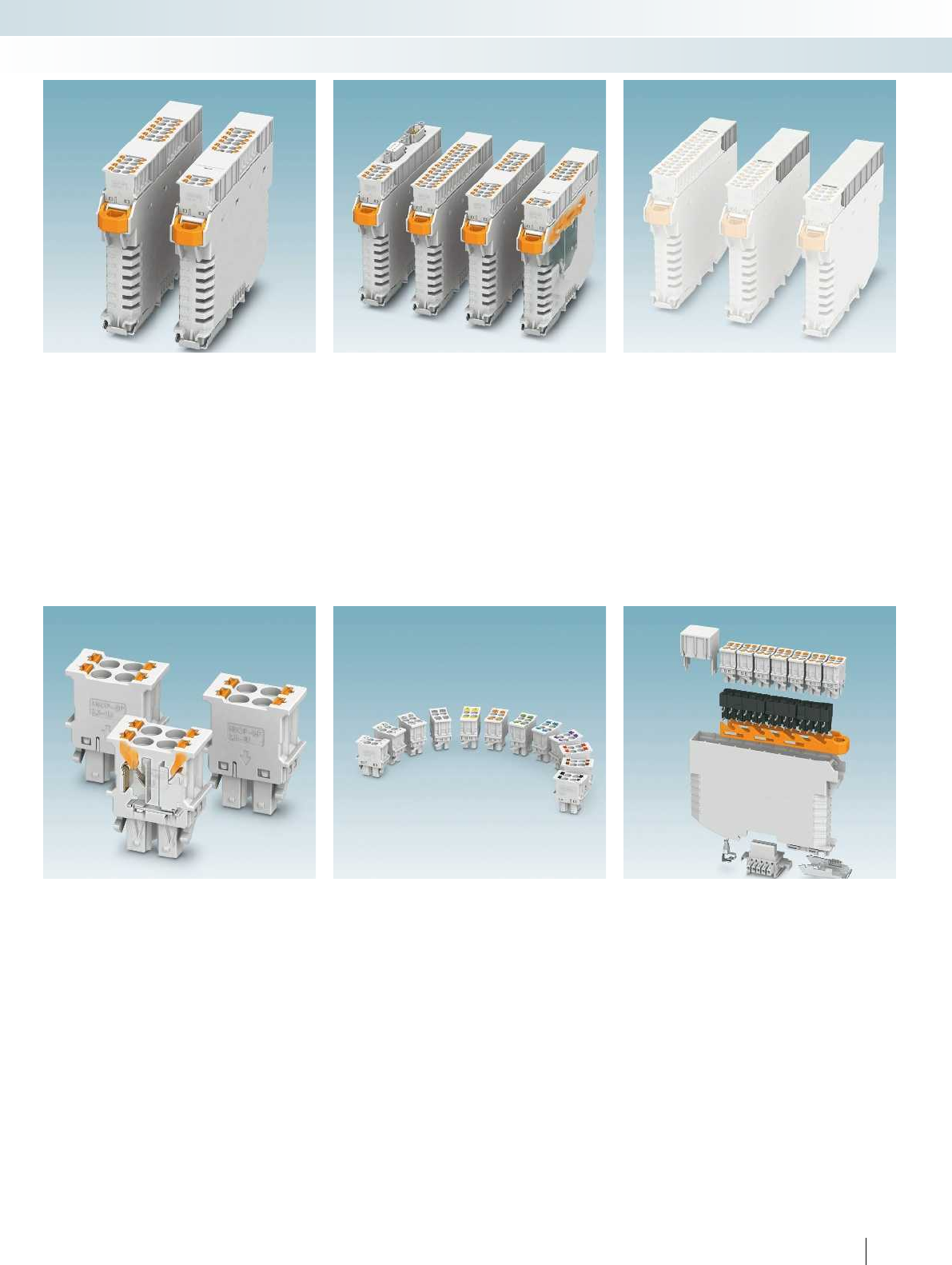
Flexible modular principle
The flexible housing concept of ME-IO
offers numerous solutions. Thanks to the
variety of covering hoods, plugs, and
headers, there is no doubt a solution for
your special requirements.
An overview of predefined assembly
versions is shown on the next page.
Lock & Release
The Lock & Release system is available in
four lengths. It is available in 3, 5, 7, and 9
units. The length of Lock & Release defines
the possible plug area.
Various covering hoods
Covering hoods are available in lengths
from 2 to 7 units. This means that the
appropriate hood can be used for display
and operating elements as well as data
connectors.
Plug version with TWIN connection
The TWIN connector is characterized by
the connection of two conductors to one
connection terminal. It is used to loop
through signals or to distribute potential or
power.
The 2 and 4-pos. plug versions can be
flexibly combined for sophisticated device
solutions.
Color options for the plug
The spring levers of plugs can also be
produced in other standard colors. This
enables easy conductor/terminal point
assignment during installation.
The plug and electronics housing can be
produced in non-standard colors as well.
Exploded view of the ME-IO housing
system
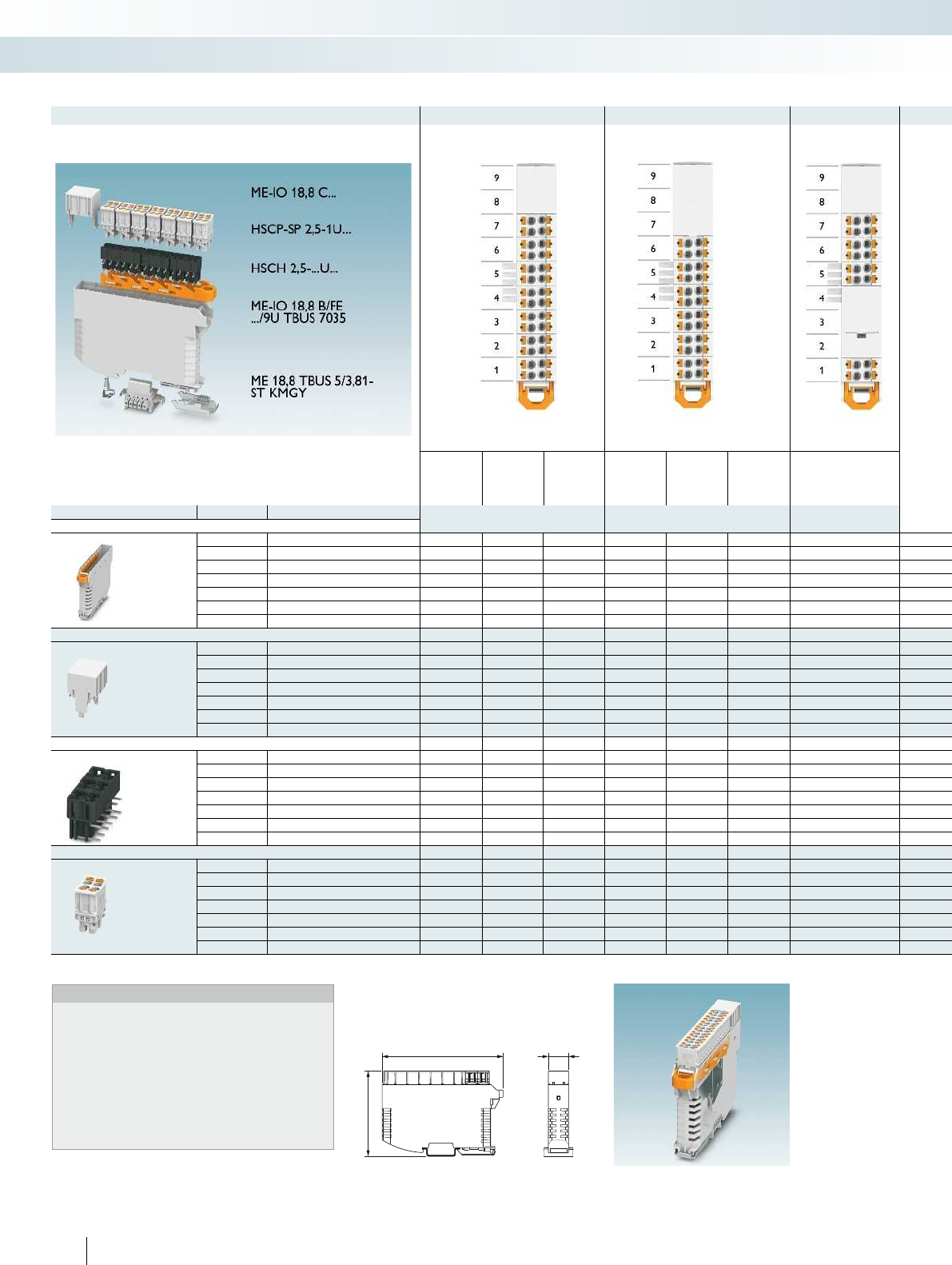
18,9
113,3
77
Example 1 Example 2 Example 3
28-pos. 20-pos. + 4
TWIN
connections
26-pos. 24-pos. 6-pos. + 4
TWIN
connections
22-pos. 12-pos. + 2
TWIN
connections
Order No. Type Quantity
(fitted position)
Quantity
(fitted position)
Quantity
(fitted position)
Lower housing part with Lock & Release
2201960 ME-IO 18,8 B/FE 9/9U TBUS 7035
2201961 ME-IO 18,8 B/FE 7/9U TBUS 7035 1 x 1 x 1 x 1 x 1 x 1 x 1 x
2201962 ME-IO 18,8 B/FE 5/9U TBUS 7035
2201963 ME-IO 18,8 B/FE 3/9U TBUS 7035
Covering hood
2201799 ME-IO 18,8 C 2U 7035 1 x (8-9) 1 x (8-9) 1 x (8-9) 1 x (8-9)
2201800 ME-IO 18,8 C 3U 7035 1 x (7-9) 1 x (7-9) 1 x (7-9)
2201801 ME-IO 18,8 C 3U S1 7035 1 x (2-4)
2201802 ME-IO 18,8 C 4U 7035
2201803 ME-IO 18,8 C 5U 7035
2201804 ME-IO 18,8 C 6U 7035
2201805 ME-IO 18,8 C 7U 7035
Header
2201788 HSCH 2,5-3U/12 9005 1 x (5-7) 1 x (5-7) 1 x (5-7) 1 x (5-7) 1 x (3-5) 1 x (3-5) 1 x (3-5) 1 x (1-3) 2 x (1-3 & 7-9) 1 x (7-9)
2201789 HSCH 2,5-2U/ 8 9005 2 x (1-4) 1 x (3-4) 1 x (1-2) 3 x (1-6) 2 x (3-6) 2x(1-2 & 5-6) 1 x (1-2) 2 x (1-4) 1 x (3-4) 1 x (3-4) 1 x (1-
2201790 HSCH 2,5-2U-TTTT 9005 1 x (1-2) 1 x (1-2)
2201791 HSCH 2,5-2U-TT00 9005 1 x (1-2)
2201792 HSCH 2,5-2U-2220 9005 1 x (3-4) 1 x (3-4)
Plug with push-in spring connection
2201780 HSCP-SP 2,5-1U/ 4 7035 7 x (1-7) 5 x (3-7) 6x(1-3 & 5-7) 6 x (1-6) 4 x (3-6) 5x(1-3 & 5-6) 3 x (5-7)
2201781 HSCP-SP 2,5-1U-TT 7035 2 x (1-2) 2 x (1-2) 1 x (1)
2201782 HSCP-SP 2,5-1U-20 7035 1 x (4) 1 x (4)
Matrix for selection
Notes:
For the functionality of the Lock & Release system, note the
positioning of the header. A side-by-side arrangement of the HSCH
2,5-3U/12 9005 header is not possible.
In the examples, the quantities of covering hoods, headers, and
plugs and their respective position for fitting are specified.
Data sheets for the housing system with connectors are available at
phoenixcontact.net/products.
Numerous other configurations are possible.
32 PHOENIX CONTACT
PCB connection technology and electronics housing
Electronics housing for industrial electronics and semi-industrial applications
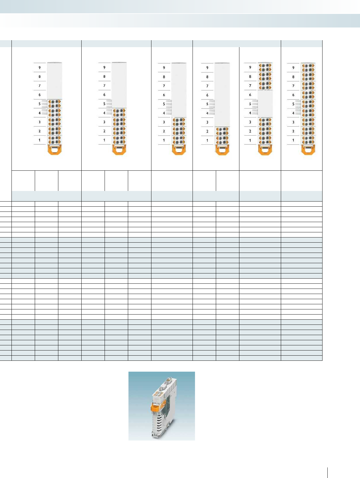
For additional information, visit phoenixcontact.net/products
Example 4 Example 5 Example 6 Example 7 Example 8 Example 9
20-pos.
12-pos. + 4
TWIN
connections
18-pos. 16-pos.
8-pos. + 4
TWIN
connections
14-pos. 12-pos.
8-pos. 4 TWIN
connections
24-pos. 36-pos.
Quantity
(fitted position)
Quantity
(fitted position)
Quantity (fitted
position)
Quantity
(fitted position)
Quantity
(fitted position)
Quantity
(fitted position)
1 x 1 x
1 x1 x1 x1 x1 x1 x
1 x 1 x 1 x
1 x (4-6)
1 x (6-9) 1 x (6-9) 1 x (6-9)
1 x (5-9) 1 x (5-9) 1 x (5-9)
1 x (4-9)
1 x (3-9) 1 x (3-9)
2201788 HSCH 2,5-3U/12 9005 1 x (5-7) 1 x (5-7) 1 x (5-7) 1 x (5-7) 1 x (3-5) 1 x (3-5) 1 x (3-5) 1 x (1-3) 2 x (1-3 & 7-9) 1 x (7-9)
2201789 HSCH 2,5-2U/ 8 9005 2 x (1-4) 1 x (3-4) 1 x (1-2) 3 x (1-6) 2 x (3-6) 2x(1-2 & 5-6) 1 x (1-2) 2 x (1-4) 1 x (3-4) 1 x (3-4) 1 x (1-2) 3 x (1-6)
1 x (1-2) 1 x (1-2) 1 x (1-2)
1 x (1-2) 1 x (1-2)
5 x (1-5) 3 x (3-5) 4 x (1 & 3-5) 4 x (1-4) 2 x (3-4) 3 x (1 & 3-4) 3 x (1-3) 2 x (1-2) 6 x (1-3 & 7-9) 9 x (1-9)
2 x (1-2) 2 x (1-2) 2 x (1-2)
1 x (2) 1 x (2)
33PHOENIX CONTACT
PCB connection technology and electronics housing
Electronics housing for industrial electronics and semi-industrial applications
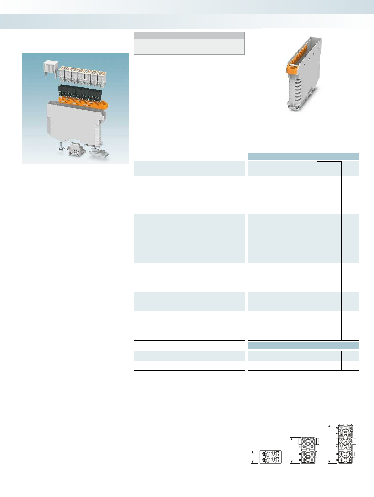
1U
2U
3U
Ordering data
Description Type Order No. Pcs. /
Pkt.
Housing base, pre-assembled, with metal foot catch, with
integrated functional earth ground contact, without TBUS plug,
color: light gray, including Lock & Release in
3 units ME-IO 18,8 B/FE 3/9U TBUS 7035 2201963 10
5 units ME-IO 18,8 B/FE 5/9U TBUS 7035 2201962 10
7 units ME-IO 18,8 B/FE 7/9U TBUS 7035 2201961 10
9 units ME-IO 18,8 B/FE 9/9U TBUS 7035 2201960 10
Covering hood, in various units, color: light gray
2 units, dimension a = 22 mm
3 units, dimension a = 33 mm
3 units, for covering 1 unit header, dimension a = 33 mm
4 units, dimension a = 44 mm
5 units, dimension a = 55 mm
6 units, dimension a = 66 mm
7 units, dimension a = 77 mm
HSC header, touch proof, in 2 units, color: black
8 connections
4 connections
2 connections
6 connections
HSC header, touch proof, in 3 units, color: black, please note the
positioning
12 connections
HSC push-in plug, for touch-proof HSC headers, in 1 unit, with
integrated test connection, color: light gray
4-pos.
Partially assembled, 2-pos.
2 TWIN connections
Accessories
DIN rail connector, 5-pos.
Coding profile, for header and push-in plug, color: natural
34 PHOENIX CONTACT
ME-IO... electronics housing with
front connection
Mounting principle:
– Electronic components and HSC headers
can be assembled and soldered in a single
step.
– Lock & Release and headers are snapped
in. The pressure springs are inserted in
the rear grips provided.
– The PCB can be easily snapped into the
housing thanks to the guide edges in the
lower housing part.
– The covering hood is placed on the free
area and snapped into the HSC headers.
– The HSC plugs are marked with an arrow
to indicate the plug-in direction.
HSC headers and plugs:
The headers are available in two and
three-unit sizes and the plugs in one unit.
Two plugs fit on the HSCH 2,5-2U... and
three plugs fit on the HSCH 2,5-3U...
The HSC headers differ with regard to
the number of terminal points and require
the relevant plug versions:
– 12 terminal points – 3 x 4-pos.
– 8 terminal points – 2 x 4-pos.
– 6 terminal points – 1 x 4-pos. and
1 x 2-pos.
– 4 terminal points – 2 x 2 TWIN
connections
– 2 terminal points – 1 x 2 TWIN
connections and ME-IO 18,8 C 3U S1
7035
PCB connection technology and electronics housing
Electronics housing for industrial electronics and semi-industrial applications
Notes:
Additional housing dimensions and details of PCB layout,
dimensions, and assembly areas can be found in the download
center at: phoenixcontact.net/products
Width: 18.8 mm Width: 18.8 mm Touch-proof headers Connector plugs for touch-proof headers
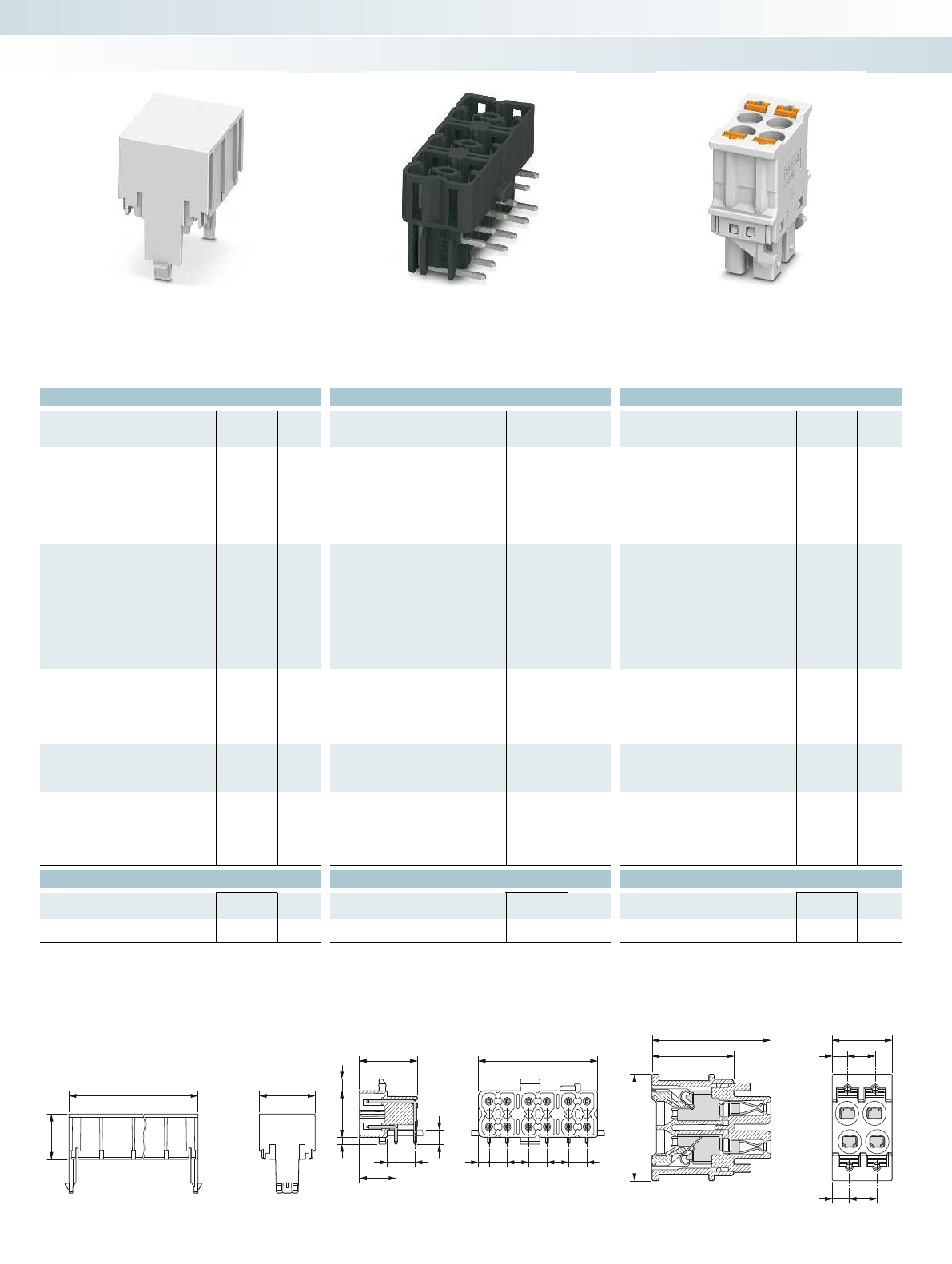
14,9
a18,9
3,8
16
12,45
1,853,15
2,4 5,3
10,1
32,9
66
555
2,95
14,9
21,6
18,8
10,9
5
2,8
3,1 5
For additional information, visit phoenixcontact.net/products
Ordering data Ordering data Ordering data
Type Order No. Pcs. /
Pkt. Type Order No. Pcs. /
Pkt. Type Order No. Pcs. /
Pkt.
ME-IO 18,8 C 2U 7035 2201799 10
ME-IO 18,8 C 3U 7035 2201800 10
ME-IO 18,8 C 3U S1 7035 2201801 10
ME-IO 18,8 C 4U 7035 2201802 10
ME-IO 18,8 C 5U 7035 2201803 10
ME-IO 18,8 C 6U 7035 2201804 10
ME-IO 18,8 C 7U 7035 2201805 10
HSCH 2,5-2U/ 8 9005 2201789 50
HSCH 2,5-2U-TTTT 9005 2201790 50
HSCH 2,5-2U-TT00 9005 2201791 50
HSCH 2,5-2U-2220 9005 2201792 50
HSCH 2,5-3U/12 9005 2201788 50
HSCP-SP 2,5-1U/ 4 7035 2201780 50
HSCP-SP 2,5-1U-TT 7035 2201781 50
HSCP-SP 2,5-1U-20 7035 2201782 50
Accessories Accessories Accessories
ME 18,8 TBUS 1,5/5-ST-3,81KMGY 2201813 50
CP-DMC 1,5-THR NAT 1790647 60
35PHOENIX CONTACT
PCB connection technology and electronics housing
Electronics housing for industrial electronics and semi-industrial applications
Width: 18.8 mm Width: 18.8 mm Touch-proof headers Connector plugs for touch-proof headers
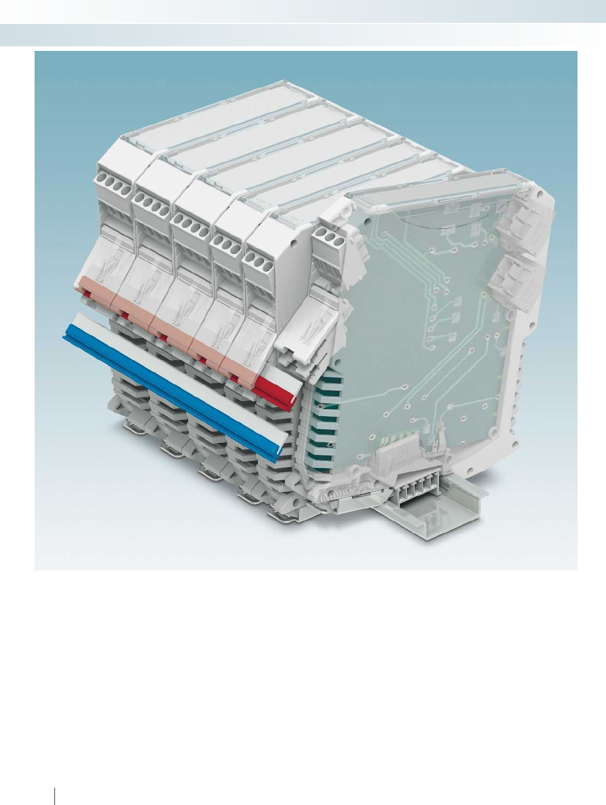
36 PHOENIX CONTACT
PCB connection technology and electronics housing
Electronics housing for industrial electronics and semi-industrial applications
Together with the PBR jumper, the new PCO power connector enables the transmission of high levels of power between modules in
ME MAX housings.
The new ME TBUS 4P1S enables the easy implementation of serial and parallel circuits for module-to-module connection in the DIN rail.
The ME TBUS ADAPTER allows even more effective use of ME TBUS technology for modules with a design width from 35 mm. ME
TBUS 4P1S and the ME TBUS ADAPTER can be used in ME and ME MAX housings.
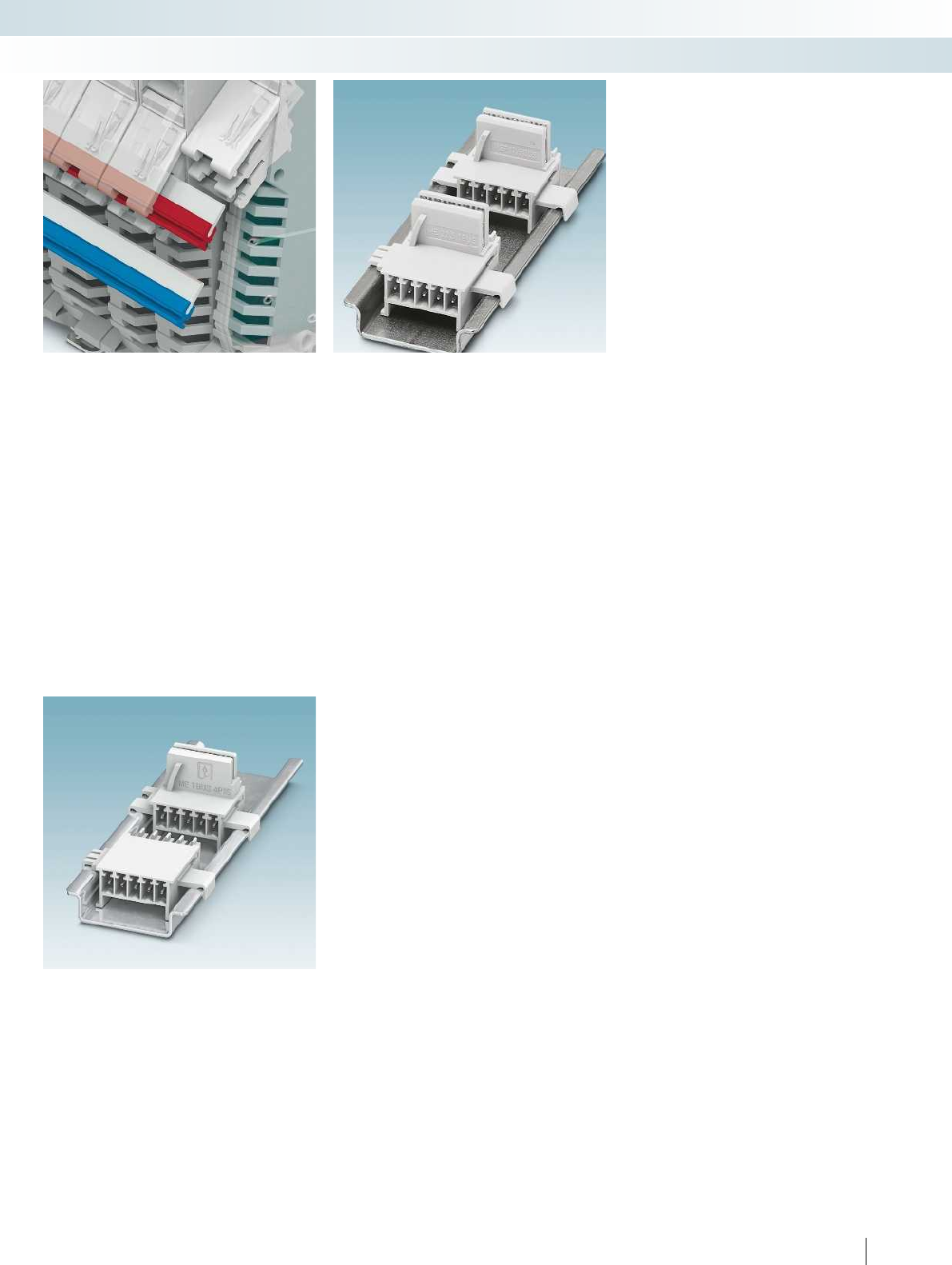
For additional information, visit phoenixcontact.net/products
37PHOENIX CONTACT
PCB connection technology and electronics housing
Electronics housing for industrial electronics and semi-industrial applications
PCO... power connector for ME MAX
housing
The PCO power connector is used to
transmit power of up to 42 A (8 A per
module) and 60 V DC between modules in
ME MAX housings. There are no
restrictions on the mounting and removal of
modules from the group while in the off-
load state.
The PCO connector can be soldered to
other electronic components in the wave
soldering process. For additional
information, please refer to the data sheets
at phoenixcontact.net/products. Cross
connection is achieved by simply inserting
the PBR jumper.
ME... TBUS 4P1S: serial and parallel
connection in the DIN rail
The ME TBUS 4P1S enables the serial and
parallel connection of modules via the DIN
rail: 4 positions are intended for parallel
circuits and 1 position for serial circuits.
ME TBUS ADAPTER: easy extension
From a housing width of 35 mm, the ME
TBUS ADAPTER is the ideal solution for
the efficient use of the TBUS system.
In addition, by using the ME TBUS
ADAPTER there is more PCB area available
for mounting in the housing as there is no T-
tap.
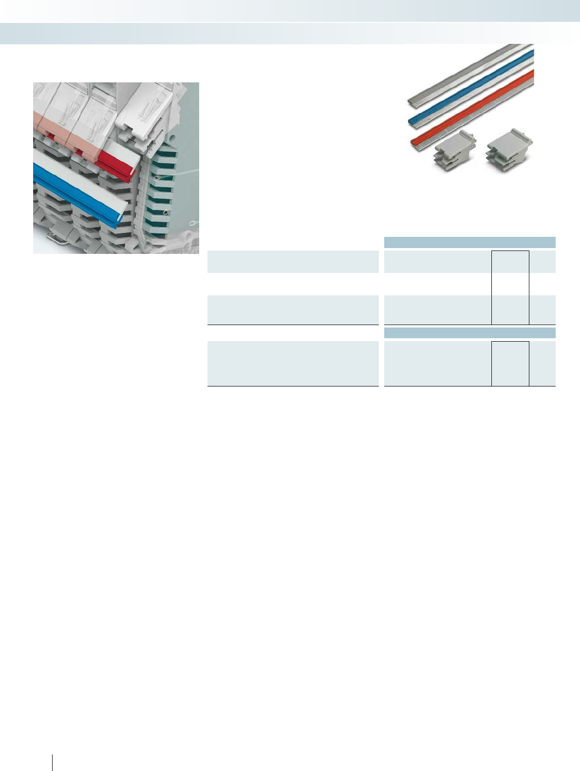
Ordering data
Description Type Order No. Pcs. /
Pkt.
Power bus connector, suitable for ME MAX 17,5, ME MAX 35, 2-
pos., color: light gray
PCO 17,5-L KMGY 2201684 50
Power bus connector, suitable for ME MAX 22,5, ME MAX 45,
ME MAX 67,5, and ME MAX 90; 2-pos.; color: light gray
PCO 22,5-L KMGY 2201685 50
Accessories
Jumper, for connecting device modules when using power bus
connectors; can be cut to length using diagonal cutter; supplied
length: 500 mm;
Color: light gray PBR 42A KMGY 2201917 10
Color: blue PBR 42A BU 2201916 10
Color: red PBR 42A RD 2201915 10
38 PHOENIX CONTACT
The PCO... power connector can be used
together with the PBR... jumper in ME MAX
housing.
Technical data:
– Voltage up to 60 V DC
– Total current of 42 A
–8 A per module
–2-pos.
– With orthogonal pin outlet
– Designed for parallel connections
– ME MAX connection technology and
accessories can also be used without
restriction
PCO... power connector for ME MAX
housing
PCB connection technology and electronics housing
Electronics housing for industrial electronics and semi-industrial applications
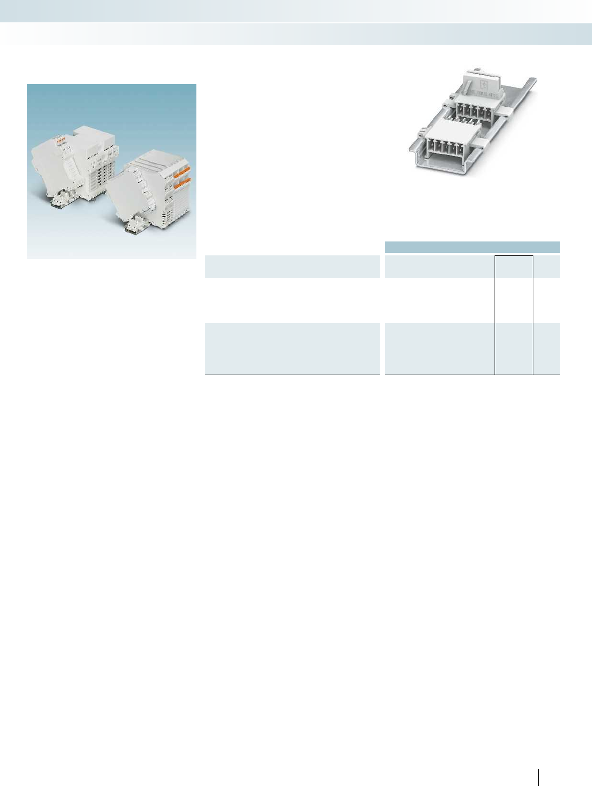
For additional information, visit phoenixcontact.net/products
Ordering data
Description No. of
pos. Type Order No. Pcs. /
Pkt.
ME TBUS connector, suitable for ME and ME MAX housing, 5
positions (4 parallel positions and 1 serial position); color: light gray
17.5 mm design width 5 ME 17,5 TBUS 1,5/4P1S KMGY 2201731 50
22.5 mm design width 5 ME 22,5 TBUS 1,5/4P1S KMGY 2201732 50
Adapter for extending the ME TBUS connector, suitable for ME
and ME MAX housing, 5 parallel positions; color: light gray
17.5 mm design width 5ME 17,5 TBUS ADAPTER KMGY 2201757 50
22.5 mm design width 5ME 22,5 TBUS ADAPTER KMGY 2201756 50
39PHOENIX CONTACT
The ME... TBUS 4P1S enables the
implementation of parallel circuits together
with serial circuits, which connect various
modules on the DIN rail in ME and ME
MAX housings.
Technical data:
– Voltage up to 50 V
– Currents up to 8 A per position
– 4 parallel positions
– 1 serial position
The ME... TBUS ADAPTER is particularly
useful for using wider modules in the ME
and ME MAX housing more efficiently
together with the ME... TBUS.
Technical data:
– Voltage up to 125 V
– Currents up to 8 A per position
– 5 parallel positions
– No tap in the electronics housing
ME TBUS 4P1S and ME TBUS
ADAPTER for ME and ME MAX
housing
PCB connection technology and electronics housing
Electronics housing for industrial electronics and semi-industrial applications
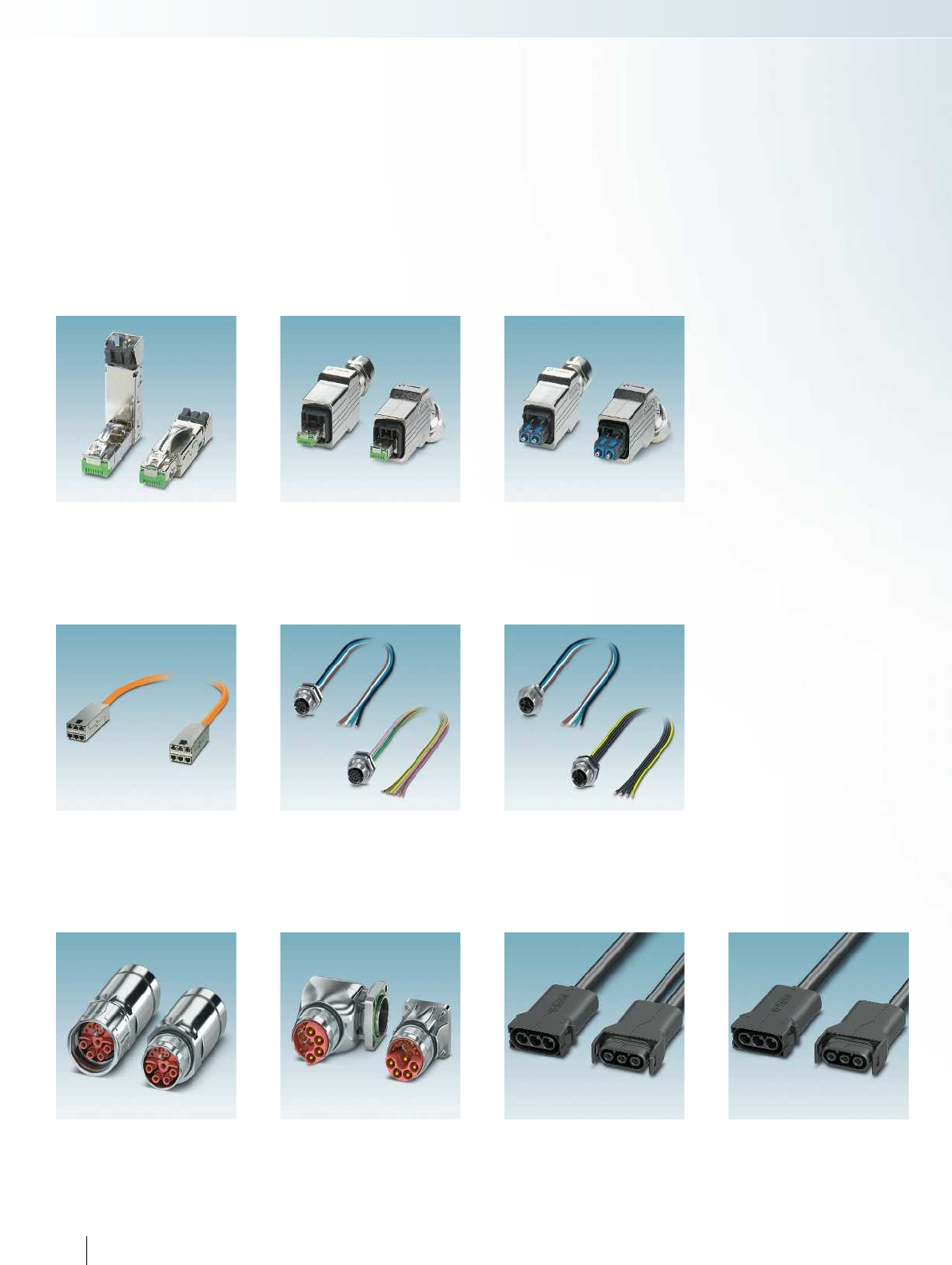
RJ45 industrial connectors, IP20
Page 44
Push-pull industrial connectors, version 14
with RJ45 insert
Page 46
Modular distribution panel, panel mounting
frame
Page 50
M12 device connectors XL
Page 54
M12 power device connectors
Page 56
M23 cable and coupler connectors, hybrid,
SPEEDCON fast locking system
Page 63
M23 device connectors, hybrid
Page 64
SUNCLIX micon, AC-Y connectors
Page 70
SUNCLIX micon, mains connector plugs
Page 70
Push-pull industrial connectors, version 14
with FO insert
Page 48
Connection technology for field devices
40 PHOENIX CONTACT
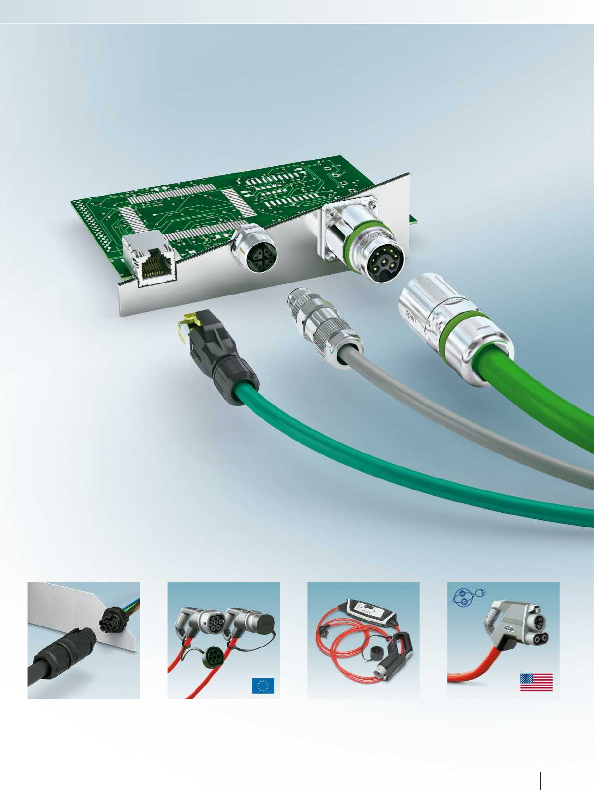
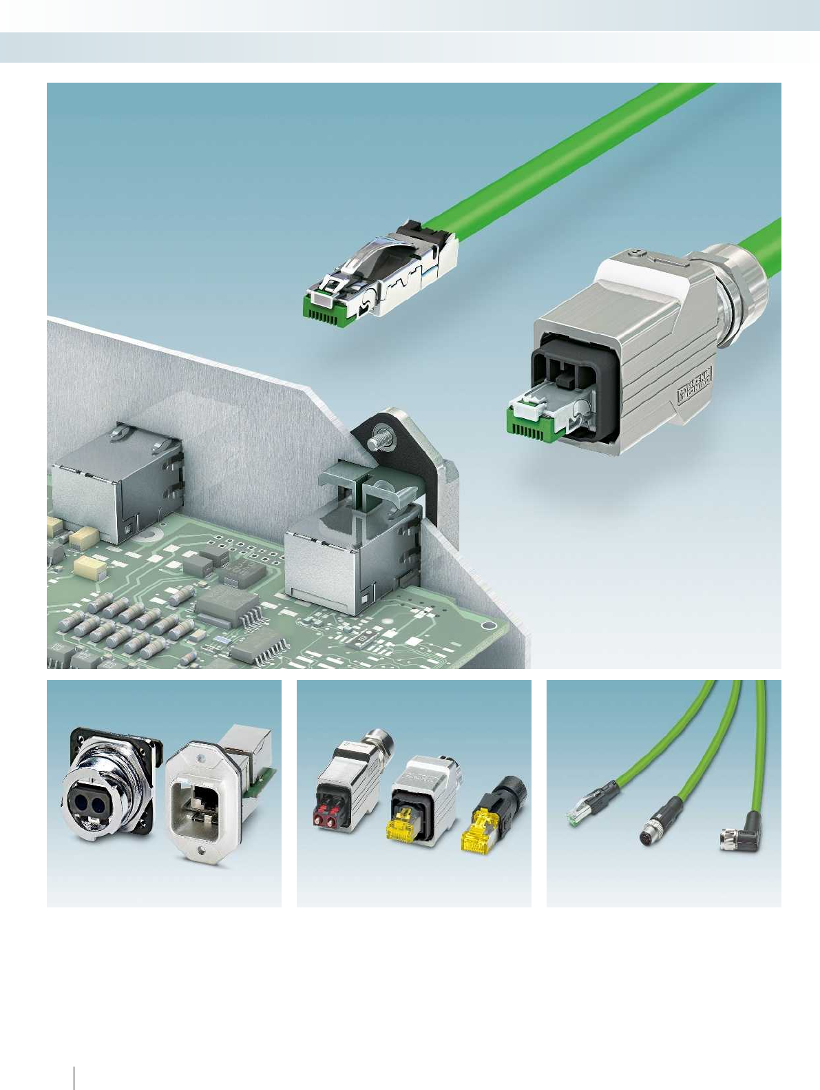
42 PHOENIX CONTACT
Connection technology for field devices
Data connectors
Unique variety for copper and fiber optics
For compact device connection For flexible cable connection For easy cabling
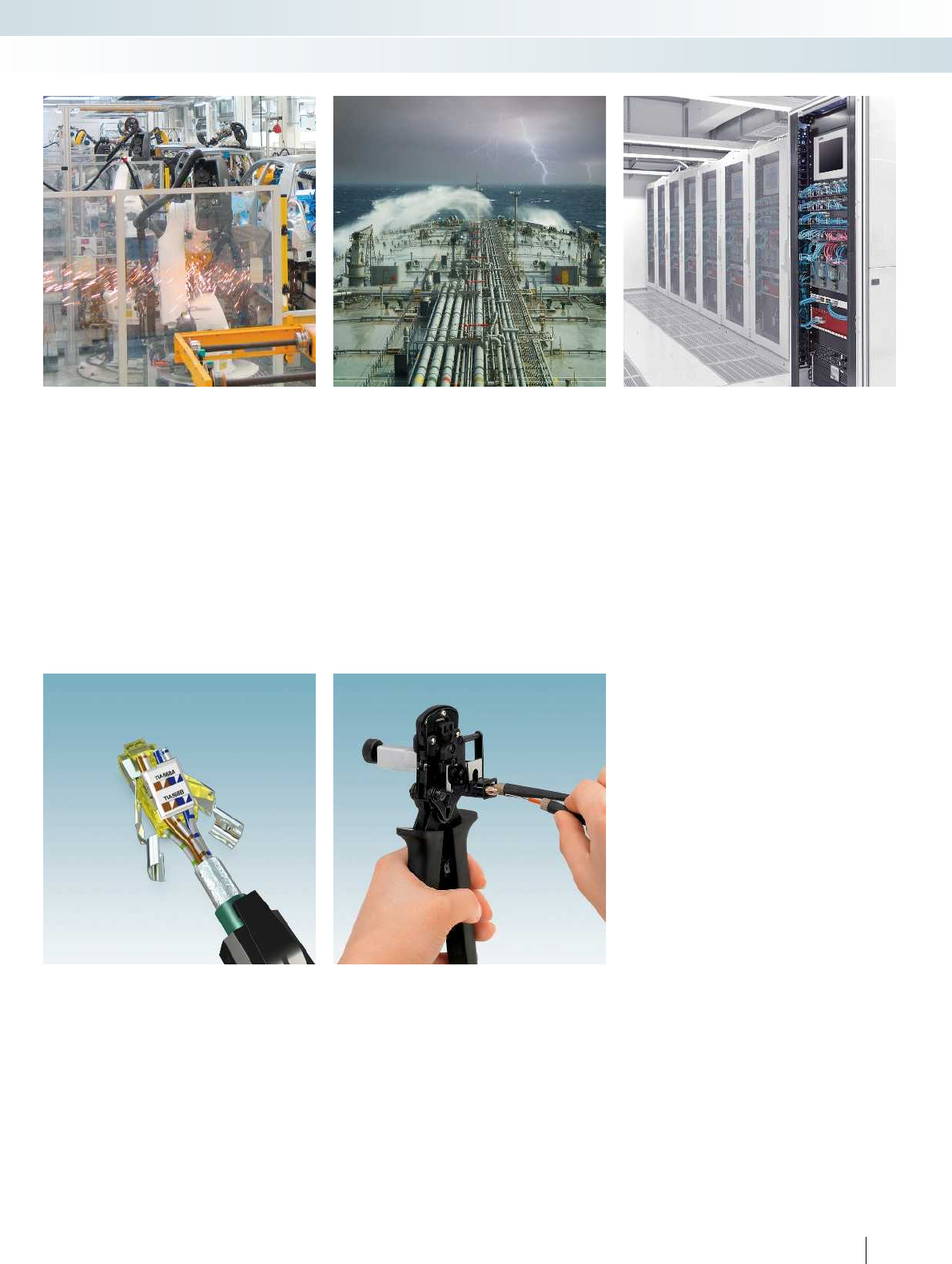
For additional information, visit phoenixcontact.net/products
43PHOENIX CONTACT
Connection technology for field devices
Data connectors
The right connection for every application
Modern industrial automation requires
connectors for large quantities of data in
robust packaging. Benefit now from
powerful connectors and cables for on-site
assembly.
High requirements are placed on
components used for outdoor data
transmission, in fields such as
telecommunications, renewable energies,
and offshore applications. Whether you're
concerned about UV, temperature or
humidity, the connectors from Phoenix
Contact offer ideal protection.
Phoenix Contact offers an extensive and
forward-looking product range for modern
building cabling which impresses with its
easy installation.
Our patch cables and patch fields allow you
to install flexible and fault-tolerant cabling.
The right connection technology for every application
Fast assembly without special tools
– with IDC and Piercecon® fast connection
Fast assembly in the field
using professional tools
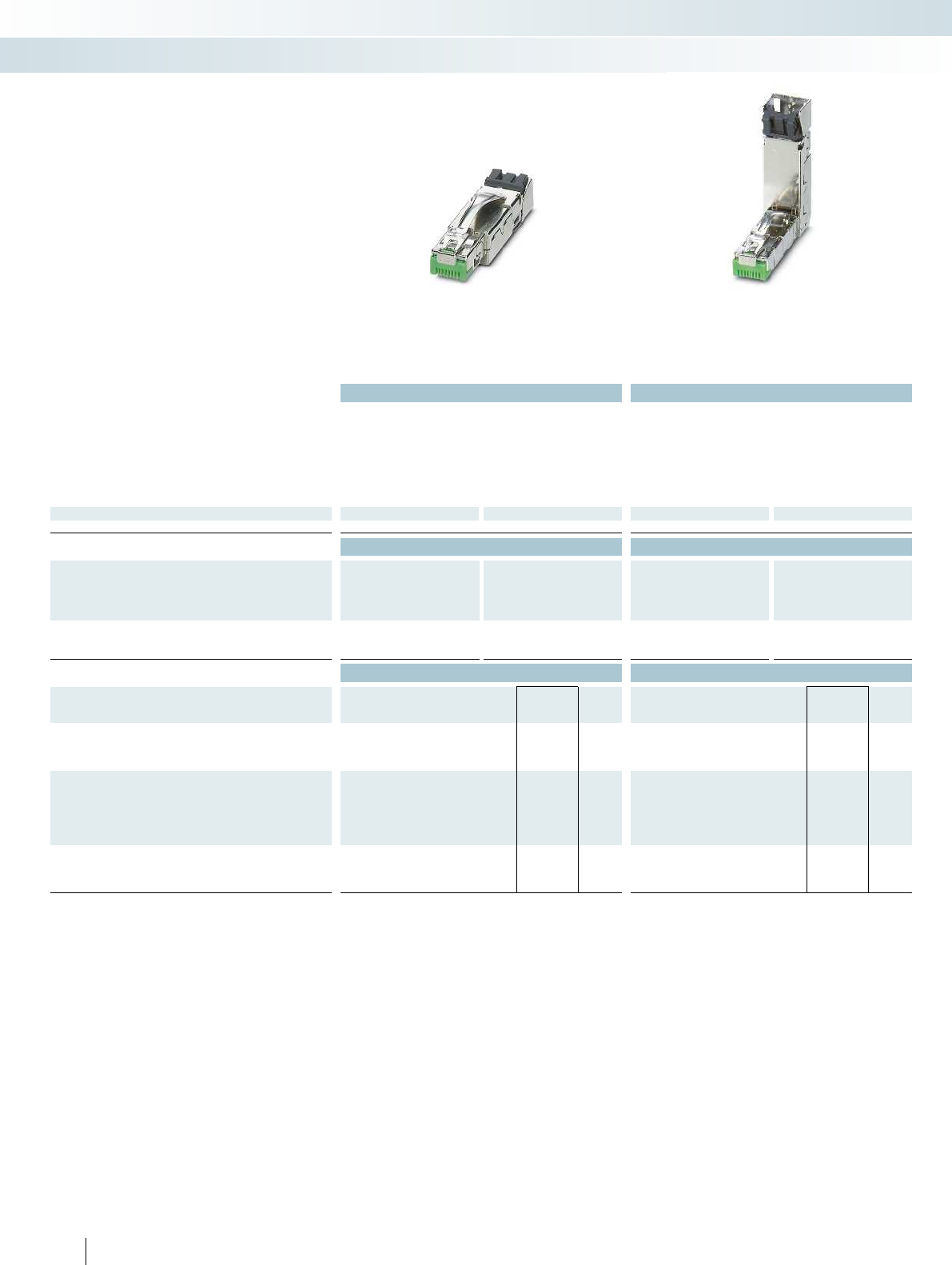
Technical data Technical data
Ethernet printing PROFINET printing Ethernet printing PROFINET printing
Degree of protection IP20 IP20 IP20 IP20
Connection cross section AWG 26 ... 24 23 ... 22 26 ... 24 23 ... 22
Transmission speed 10 Gbps 1 Gbps 10 Gbps 1 Gbps
Housing material Zinc die-cast Zinc die-cast Zinc die-cast Zinc die-cast
External cable diameter 5 mm ... 9 mm 5 mm ... 9 mm 5 mm ... 9 mm 5 mm ... 9 mm
Insertion/withdrawal cycles ≥ 750 ≥ 750 ≥ 750 ≥ 750
Temperature data
Ambient temperature (operation) -20°C ... 70°C -20°C ... 70°C -20°C ... 70°C -20°C ... 70°C
Ordering data Ordering data
Description Order No. Pcs. /
Pkt. Order No. Pcs. /
Pkt. Order No. Pcs. /
Pkt. Order No. Pcs. /
Pkt.
Ethernet printing PROFINET printing Ethernet printing PROFINET printing
RJ45 industrial connector, 8-pos.
1406333 11406334 11406336 11406337 1
Value pack 1406351 30 1406352 30 1406354 30 1406355 30
Accessories Accessories
Stripping tool, for multiple-stage repositioning of shielded
conductors
VS-CABLE-STRIP-VARIO 1657407 1VS-CABLE-STRIP-VARIO 1657407 1
Electronic diagonal cutter, tapered head, without chamfer,
with opening spring, non-reflective phosphate-treated surface,
punched version
MICROFOX-SP-1 1212487 1MICROFOX-SP-1 1212487 1
Markers for terminal blocks, roll, unmarked, can be marked
with: THERMOMARK ROLL, THERMOMARK X, THERMOMARK
S1.1
White TMT 5 R 0816430 1TMT 5 R 0816430 1
Red TMT 5 R RD 0816427 1TMT 5 R RD 0816427 1
Green TMT 5 R GN 0816401 1TMT 5 R GN 0816401 1
Marker for terminal blocks,sheet, white, unmarked, can be
marked with: BLUEMARK CLED, BLUEMARK LED, plotter
UC-TMF 5 0818153 10 UC-TMF 5 0818153 10
44 PHOENIX CONTACT
Connection technology for field devices
Data connectors – RJ45 connectors
RJ45 industrial,
straight cable outlet
RJ45 industrial,
cable outlet at the top
– Optimized for industrial use with a high
degree of resistance to vibration
– High resistance to ESD and EMI for
reliable transmission
– Easy handling, thanks to one-piece design
– Metal locking
RJ45 industrial connectors, IP20
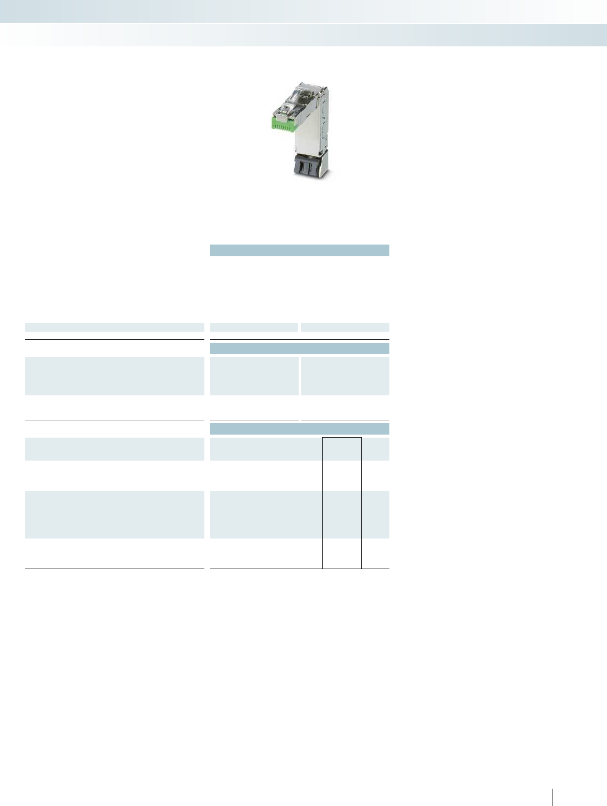
For additional information, visit phoenixcontact.net/products
Technical data
Ethernet printing PROFINET printing
Degree of protection IP20 IP20
Connection cross section AWG 26 ... 24 23 ... 22
Transmission speed 10 Gbps 1 Gbps
Housing material Zinc die-cast Zinc die-cast
External cable diameter 5 mm ... 9 mm 5 mm ... 9 mm
Insertion/withdrawal cycles ≥ 750 ≥ 750
Temperature data
Ambient temperature (operation) -20°C ... 70°C -20°C ... 70°C
Ordering data
Description Order No. Pcs. /
Pkt. Order No. Pcs. /
Pkt.
Ethernet printing PROFINET printing
RJ45 industrial connector, 8-pos.
1406339 11406340 1
Value pack 1406357 30 1406358 30
Accessories
Stripping tool, for multiple-stage repositioning of shielded
conductors
VS-CABLE-STRIP-VARIO 1657407 1
Electronic diagonal cutter, tapered head, without chamfer,
with opening spring, non-reflective phosphate-treated surface,
punched version
MICROFOX-SP-1 1212487 1
Markers for terminal blocks, roll, unmarked, can be marked
with: THERMOMARK ROLL, THERMOMARK X, THERMOMARK
S1.1
White TMT 5 R 0816430 1
Red TMT 5 R RD 0816427 1
Green TMT 5 R GN 0816401 1
Marker for terminal blocks,sheet, white, unmarked, can be
marked with: BLUEMARK CLED, BLUEMARK LED, plotter
UC-TMF 5 0818153 10
45PHOENIX CONTACT
Connection technology for field devices
Data connectors – RJ45 connectors
RJ45 industrial,
cable outlet at the bottom
RJ45 industrial connectors, IP20
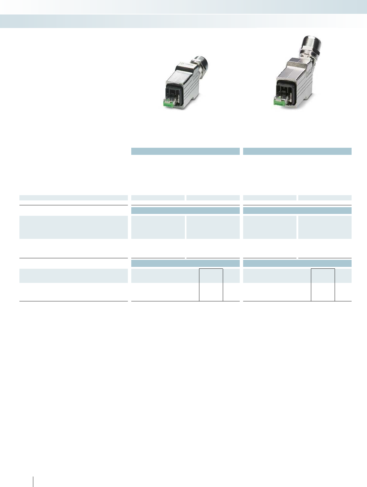
Technical data Technical data
Ethernet printing PROFINET printing Ethernet printing PROFINET printing
Degree of protection IP65/67 IP65/67 IP65/67 IP65/67
Connection cross section AWG 26 ... 24 23 ... 22 26 ... 24 23 ... 22
Transmission speed 10 Gbps 1 Gbps 10 Gbps 1 Gbps
Housing material Zinc die-cast Zinc die-cast Zinc die-cast Zinc die-cast
External cable diameter 5.5 mm ... 10 mm 5.5 mm ... 10 mm 5.5 mm ... 10 mm 5.5 mm ... 10 mm
Insertion/withdrawal cycles ≥ 750 ≥ 750 ≥ 750 ≥ 750
Temperature data
Ambient temperature (operation) -40°C ... 70°C -40°C ... 70°C -40°C ... 70°C -40°C ... 70°C
Ordering data Ordering data
Description Order No. Pcs. /
Pkt. Order No. Pcs. /
Pkt. Order No. Pcs. /
Pkt. Order No. Pcs. /
Pkt.
Ethernet printing PROFINET printing Ethernet printing PROFINET printing
Push-pull Advance, RJ45 industrial connector, IP67, 8-pos.
1407890 11407889 11468007 11408027 1
Value pack 1467901 10 1408039 10 1467807 10 1408092 10
Accessories Accessories
Stripping tool, for multiple-stage repositioning of shielded
conductors
VS-CABLE-STRIP-VARIO 1657407 1VS-CABLE-STRIP-VARIO 1657407 1
Electronic diagonal cutter, tapered head, without chamfer,
with opening spring, non-reflective phosphate-treated surface,
punched version
MICROFOX-SP-1 1212487 1MICROFOX-SP-1 1212487 1
46 PHOENIX CONTACT
Connection technology for field devices
Data connectors – RJ45 connectors
Push-pull Advance,
straight cable outlet
Push-pull Advance,
cable outlet at the top
– High resistance to ESD and EMI for
reliable transmission
– Easy handling, thanks to one-piece design
– Locking system to prevent unintentional
removal
– Consistent 360° shielding concept
Push-pull industrial connectors,
version 14
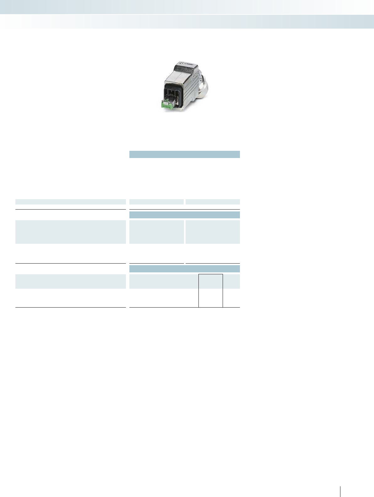
For additional information, visit phoenixcontact.net/products
Technical data
Ethernet printing PROFINET printing
Degree of protection IP65/67 IP65/67
Connection cross section AWG 26 ... 24 23 ... 22
Transmission speed 10 Gbps 1 Gbps
Housing material Zinc die-cast Zinc die-cast
External cable diameter 5.5 mm ... 10 mm 5.5 mm ... 10 mm
Insertion/withdrawal cycles ≥ 750 ≥ 750
Temperature data
Ambient temperature (operation) -40°C ... 70°C -40°C ... 70°C
Ordering data
Description Order No. Pcs. /
Pkt. Order No. Pcs. /
Pkt.
Ethernet printing PROFINET printing
Push-pull Advance, RJ45 industrial connector, IP67, 8-pos.
1408011 11407895 1
Value pack 1467804 10 1408046 10
Accessories
Stripping tool, for multiple-stage repositioning of shielded
conductors
VS-CABLE-STRIP-VARIO 1657407 1
Electronic diagonal cutter, tapered head, without chamfer,
with opening spring, non-reflective phosphate-treated surface,
punched version
MICROFOX-SP-1 1212487 1
47PHOENIX CONTACT
Connection technology for field devices
Data connectors – RJ45 connectors
Push-pull Advance,
cable outlet at the bottom
Push-pull industrial connectors,
version 14
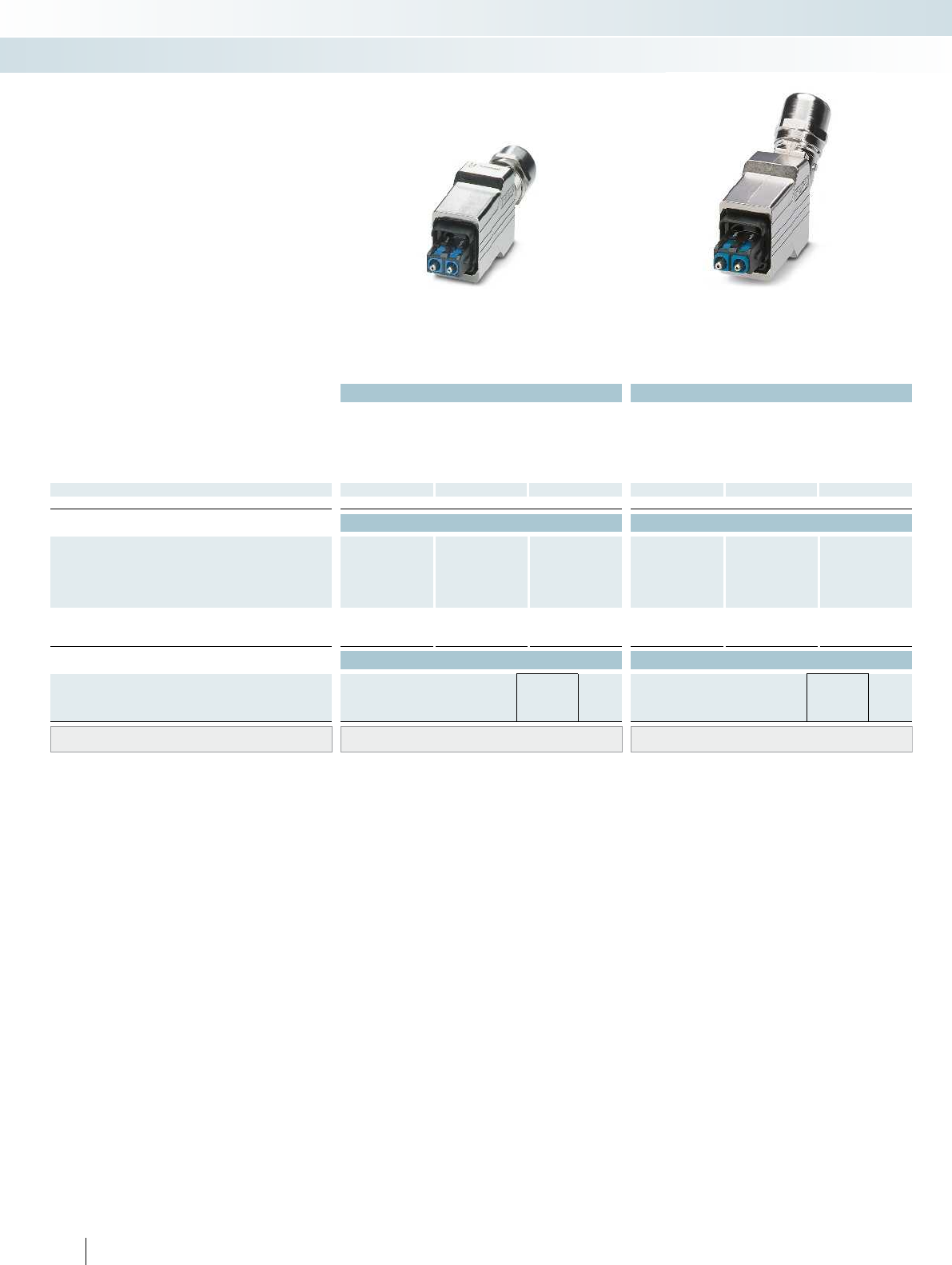
Technical data Technical data
POF
(Polymer Optical
Fiber)
PCF
(Polymer Cladded
Fiber)
GOF
(Glass Optical Fiber)
POF
(Polymer Optical
Fiber)
PCF
(Polymer Cladded
Fiber)
GOF
(Glass Optical Fiber)
Degree of protection IP65/67 IP65/67 IP65/67 IP65/67 IP65/67 IP65/67
Housing material Zinc die-cast Zinc die-cast Zinc die-cast Zinc die-cast Zinc die-cast Zinc die-cast
External cable diameter 5.5 mm ... 10 mm 5.5 mm ... 10 mm 5.5 mm ... 10 mm 5.5 mm ... 10 mm 5.5 mm ... 10 mm 5.5 mm ... 10 mm
Insertion/withdrawal cycles ≥ 750 ≥ 750 ≥ 750 ≥ 750 ≥ 750 ≥ 750
Temperature data
Ambient temperature (operation) -40°C ... 70°C -40°C ... 70°C -40°C ... 70°C -40°C ... 70°C -40°C ... 70°C -40°C ... 70°C
Ordering data Ordering data
Description Order No. Pcs. /
Pkt. Order No. Pcs. /
Pkt. Order No. Pcs. /
Pkt. Order No. Pcs. /
Pkt. Order No. Pcs. /
Pkt. Order No. Pcs. /
Pkt.
POF
(Polymer Optical
Fiber)
PCF
(Polymer Cladded
Fiber)
GOF
(Glass Optical Fiber)
POF
(Polymer Optical
Fiber)
PCF
(Polymer Cladded
Fiber)
GOF
(Glass Optical Fiber)
Push-pull Advance, SC-RJ connector
1407896 11407897 11407898 11408028 11408029 11408030 1
Value pack 1408047 10 1408048 10 1408049 10 1408093 10 1408094 10 1408095 10
Accessories Accessories
SC-RJ cutting tool set, for polymer fiber (POF),
for field assembly of connectors
TF-SCRJ-POF KONF SET 1405246 1TF-SCRJ-POF KONF SET 1405246 1
Tool set for PCF On request On request
Tool set for GOF On request On request
48 PHOENIX CONTACT
Connection technology for field devices
Data connectors – fiber optic connectors
Push-pull Advance,
straight cable outlet
Push-pull Advance,
cable outlet at the top
– Available for POF, PCF, and GOF
– Easy handling, thanks to one-piece design
– Locking system to prevent unintentional
removal
Push-pull industrial connectors,
version 14
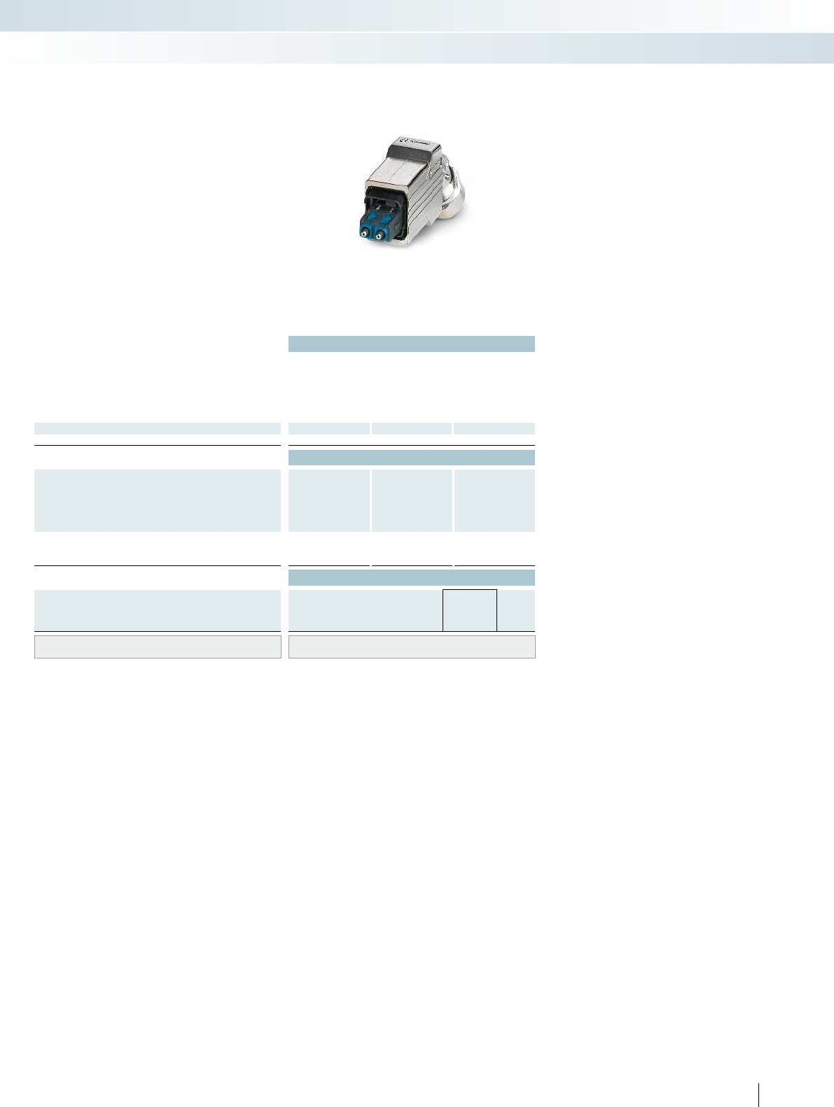
For additional information, visit phoenixcontact.net/products
Technical data
POF
(Polymer Optical
Fiber)
PCF
(Polymer Cladded
Fiber)
GOF
(Glass Optical Fiber)
Degree of protection IP65/67 IP65/67 IP65/67
Housing material Zinc die-cast Zinc die-cast Zinc die-cast
External cable diameter 5.5 mm ... 10 mm 5.5 mm ... 10 mm 5.5 mm ... 10 mm
Insertion/withdrawal cycles ≥ 750 ≥ 750 ≥ 750
Temperature data
Ambient temperature (operation) -40°C ... 70°C -40°C ... 70°C -40°C ... 70°C
Ordering data
Description Order No. Pcs. /
Pkt. Order No. Pcs. /
Pkt. Order No. Pcs. /
Pkt.
POF
(Polymer Optical
Fiber)
PCF
(Polymer Cladded
Fiber)
GOF
(Glass Optical Fiber)
Push-pull Advance, SC-RJ connector
1407902 11407904 11407905 1
Value pack 1408053 10 1408055 10 1408056 10
Accessories
SC-RJ cutting tool set, for polymer fiber (POF),
for field assembly of connectors
TF-SCRJ-POF KONF SET 1405246 1
Tool set for PCF On request
Tool set for GOF On request
49PHOENIX CONTACT
Connection technology for field devices
Data connectors – fiber optic connectors
Push-pull Advance,
cable outlet at the bottom
Push-pull industrial connectors,
version 14
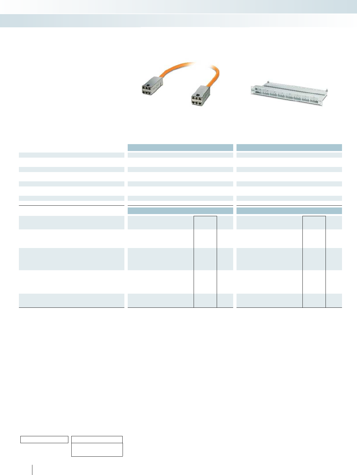
Technical data Technical data
Electrical data
Transmission speed 10 Gbps -
Transmission characteristics (category) Class EA-
Material data
Housing material High-grade steel Steel, powder-coated
Inflammability class according to UL 94 V0 V0
Connection data
External cable diameter 18 mm -
Insertion/withdrawal cycles ≥ 750 -
Temperature data
Ambient temperature (operation) -20°C ... 60°C -20°C ... 60°C
Ordering data Ordering data
Description Type Order No. Pcs. /
Pkt. Type Order No. Pcs. /
Pkt.
19" frame, empty, for using 8 modules (RJ45)
Gray (similar to RAL 7035) CUC-PP-FRAME-19 1407986 1
Black (similar to RAL 9005) CUC-PP-FRAME-19 BK 1409140 1
Module, RJ45 to RJ45, consisting of two housings each with
6 x RJ45 10 Gbps (Class EA) pre-assembled with multi-cable,
variable length, GHMT-certified.
CUC-PP-MODUL-RJ45:6-RJ45:6/... 1407995 1
Patch bay, 19", for orderly cabling in the control cabinet
Gray, with plastic hooks CUC-PP-PATCHBAY 1407994 1
Gray, with metal hooks CUC-PP-PATCHBAY-MH 1409283 1
Black, with metal hooks CUC-PP-PATCHBAY-MH BK 1409284 1
Dummy frame, size of one module, for use in the frame
CUC-PP-MODUL-COVER 1407988 1
50 PHOENIX CONTACT
Ordering example for
modules of variable length:
For an RJ45 module with a cable length of 25.0 m, the ordering data
is as follows:
Order No. Length [m]
Max. 80 m
1407995 /25
Increment:
1.5 m ... 80 m = 0.5 m
Connection technology for field devices
Data connector – patch panel, terminal outlet
Assembled modules
for 19" mounting frames
19" mounting frame
– 19" distribution field with space for
8 modules, with a total of 48 x RJ45
– Front release without special tool
– Plug and Play – thanks to pre-assembled
modules
– Up to 10 Gbps (Class EA)
– Cable length according to customer
requirements
– Optimized strain relief for every module
– GHMT certification
Modular distribution panel

For additional information, visit phoenixcontact.net/products
51PHOENIX CONTACT
Connection technology for field devices
Data connector – patch panel, terminal outlet
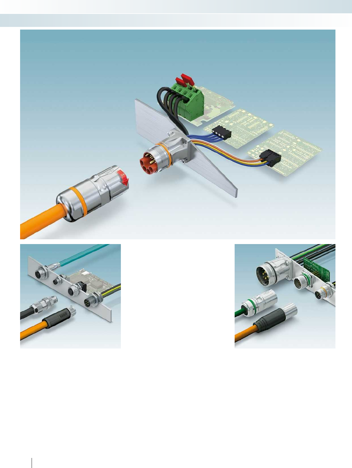
52 PHOENIX CONTACT
Connection technology for field devices
M5 to M58 circular connectors
M5 to M12 circular connectors
Circular connectors for signals, data, and
power.
M17 to M58 circular connectors
Circular connectors for signals, data, and
power.
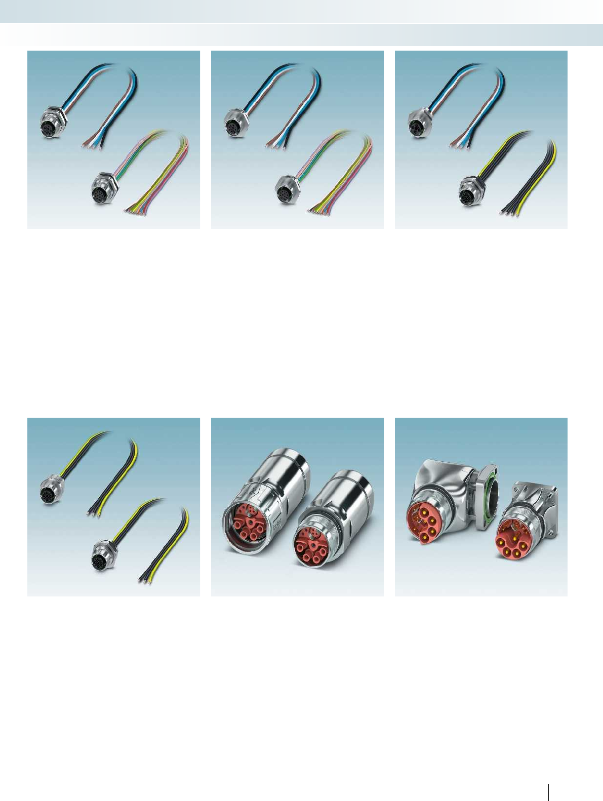
For additional information, visit phoenixcontact.net/products
53PHOENIX CONTACT
Connection technology for field devices
M5 to M58 circular connectors
M12 rear mounting XL
The new device connectors for rear
mounting feature an optimized housing
contour with additional tightening
limitation. This simplifies the housing cutout
on the device and protects the O-ring
during mounting.
M12 front mounting XL
The wrench flat on the new device
connectors for front mounting has been
enlarged and now features additional
tightening limitation. This simplifies the
device cutout and increases security and
tightness when mounting.
M12 power front/rear mounting XL
The M12 XL housing design has also been
introduced for the M12 power device
connectors with S- and T-coding. This
addition means that there is now a
consistent design available for the M12
device connectors for signal and power.
M12 power for 230V/16A
The M12 power series has been extended
with the 2+PE (S-coded) pin assignment.
The M12 design means that a compact
mains voltage plug is now available for 230V
and up to 16A.
M23 hybrid cable and coupler
connector
Special hybrid lines allow signals, data, and
power to be transmitted using just one
connector.
M23 hybrid device connectors
Angled, rotatable, and straight housing
versions are available for front mounting on
the device side.
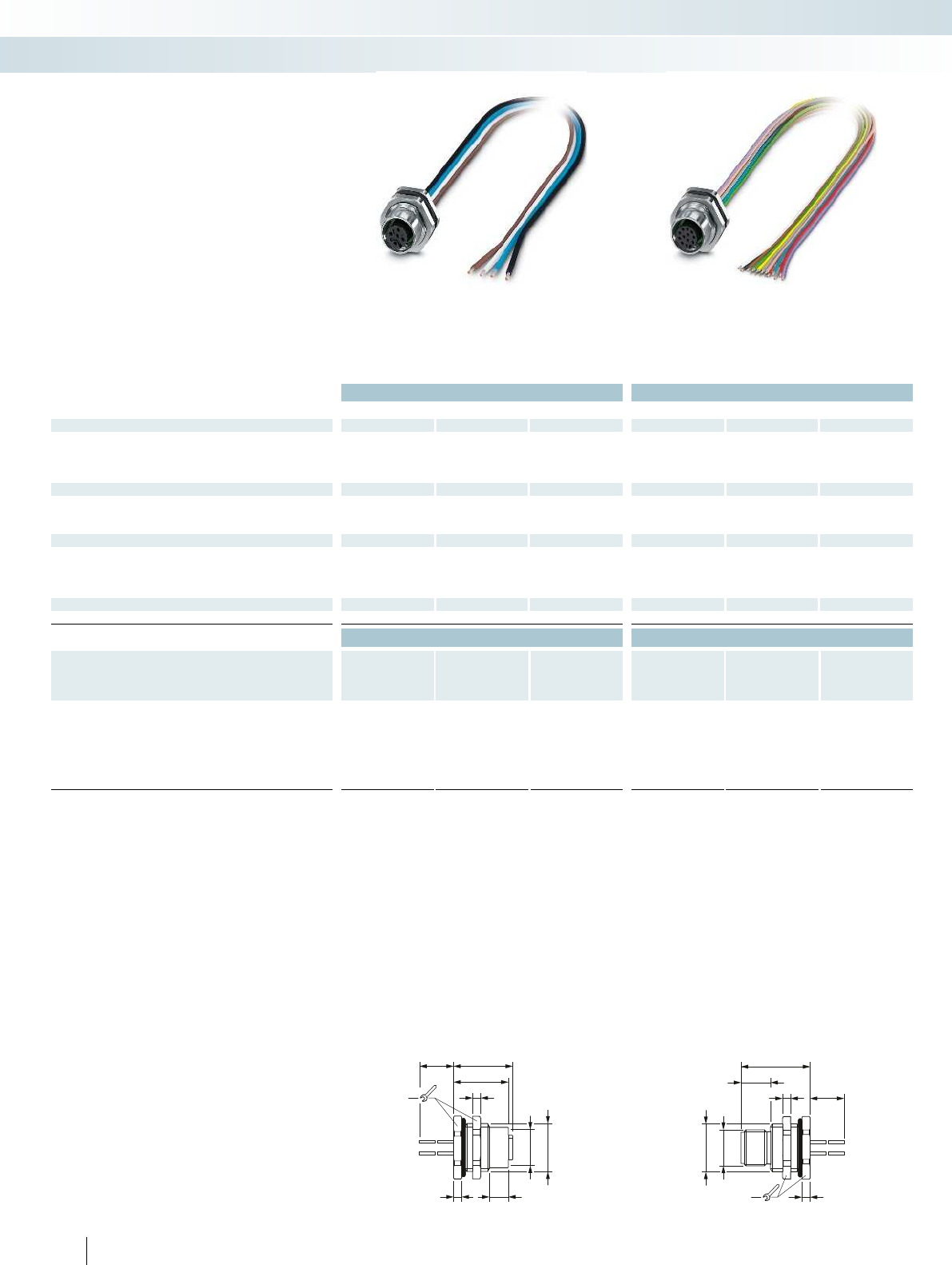
19
18,8
20,4
L
M12x1
M16x1,5
2,86,5
2,8
L
19
23,8
M12x1
M16x1,5
10,2
2,8
2,8
Technical data Technical data
4-pos. 5-pos. 8-pos. 12-pos. 17-pos.
General data
M12 circular connector according to: IEC 61076-2-101 IEC 61076-2-101 IEC 61076-2-101 IEC 61076-2-101 IEC 61076-2-101 -
Pollution degree 333 33-
Degree of protection IP67 IP67 IP67 IP67 IP67 -
Connection method Individual wires Individual wires Individual wires Individual wires Individual wires -
Electrical data
Rated voltage 250 V 60 V 30 V 30 V 30 V -
Rated current 4 A 4 A 2 A 1.5 A 1.5 A -
Contact resistance ≤ 3 mΩ≤ 3 mΩ≤ 3 mΩ≤ 3 mΩ≤ 3 mΩ-
Material data
Material contact/contact surface CuZn/Au CuZn/Au CuZn/Au CuZn/Au CuZn/Au -/-
Contact carrier material PA 66 PA 66 PA 66 PA 66 PA 66 -
Inflammability class according to UL 94 V0 V0 V0 V0 V0 -
Cable type TPE litz wire TPE litz wire TPE litz wire TPE litz wire TPE litz wire -
Temperature data
Plug/socket [°C] -25 ... 85 -25 ... 85 -25 ... 85 -25 ... 85 -25 ... 85 -
Ordering data Ordering data
Description Coding Order No. Pcs. /
Pkt. Order No. Pcs. /
Pkt. Order No. Pcs. /
Pkt. Order No. Pcs. /
Pkt. Order No. Pcs. /
Pkt. Order No. Pcs. /
Pkt.
4-pos. 5-pos. 8-pos. 12-pos. 17-pos.
Device connectors
Socket A - standard 1411584 11411586 11411588 11411589 11411590 1
Plug A - standard 1411591 11411593 11411595 11411596 11411597 1
Socket D - data 1411585 1
Plug D - data 1411592 1
Socket B - inverse 1411587 1
Plug B - inverse 1411594 1
Dimensions: socket Dimensions: plug
54 PHOENIX CONTACT
Connection technology for field devices
M5 to M12 circular connectors
4-, 5-, 8-pos. 12-, 17-pos.
– M16 fastening thread
– With 0.5m long litz wires
– Tightening limitation
– Wrench size 19
M12 device connectors XL,
rear mounting
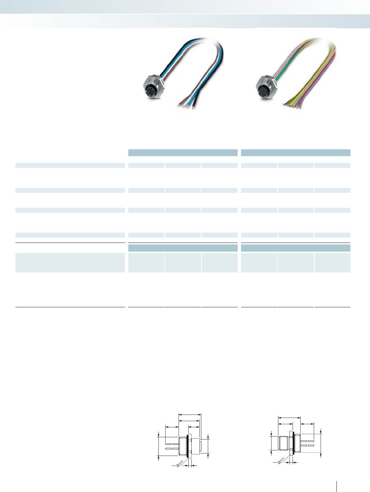
M12x1
M16x1,5
19 2,8
L
18,5
20,1
10
13
M12x1
M16x1,5
20
19 2,8
L
For additional information, visit phoenixcontact.net/products
Technical data Technical data
4-pos. 5-pos. 8-pos. 12-pos. 17-pos.
General data
M12 circular connector according to: IEC 61076-2-101 IEC 61076-2-101 IEC 61076-2-101 IEC 61076-2-101 IEC 61076-2-101 -
Pollution degree 333 33-
Degree of protection IP67 IP67 IP67 IP67 IP67 -
Connection method Individual wires Individual wires Individual wires Individual wires Individual wires -
Electrical data
Rated voltage 250 V 60 V 30 V 30 V 30 V -
Rated current 4 A 4 A 2 A 1.5 A 1.5 A -
Contact resistance ≤ 3 mΩ≤ 3 mΩ≤ 3 mΩ≤ 3 mΩ≤ 3 mΩ-
Material data
Material contact/contact surface CuZn/Au CuZn/Au CuZn/Au CuZn/Au CuZn/Au -/-
Contact carrier material PA 66 PA 66 PA 66 PA 66 PA 66 -
Inflammability class according to UL 94 V0 V0 V0 V0 V0 -
Cable type TPE litz wire TPE litz wire TPE litz wire TPE litz wire TPE litz wire -
Temperature data
Plug/socket [°C] -25 ... 85 -25 ... 85 -25 ... 85 -25 ... 85 -25 ... 85 -
Ordering data Ordering data
Description Coding Order No. Pcs. /
Pkt. Order No. Pcs. /
Pkt. Order No. Pcs. /
Pkt. Order No. Pcs. /
Pkt. Order No. Pcs. /
Pkt. Order No. Pcs. /
Pkt.
4-pos. 5-pos. 8-pos. 12-pos. 17-pos.
Device connectors
Socket A - standard 1411568 11411571 11411573 11411574 11411576 1
Plug A - standard 1411577 11411579 11411581 11411582 11411583 1
Socket D - data 1411569 1
Plug D - data 1411578 1
Socket B - inverse 1411572 1
Plug B - inverse 1411580 1
Dimensions: socket Dimensions: plug
55PHOENIX CONTACT
Connection technology for field devices
M5 to M12 circular connectors
4-, 5-, 8-pos. 12-, 17-pos.
– M16 fastening thread
– With 0.5m long litz wires
– Tightening limitation
– Wrench size 19
M12 device connectors XL,
front mounting
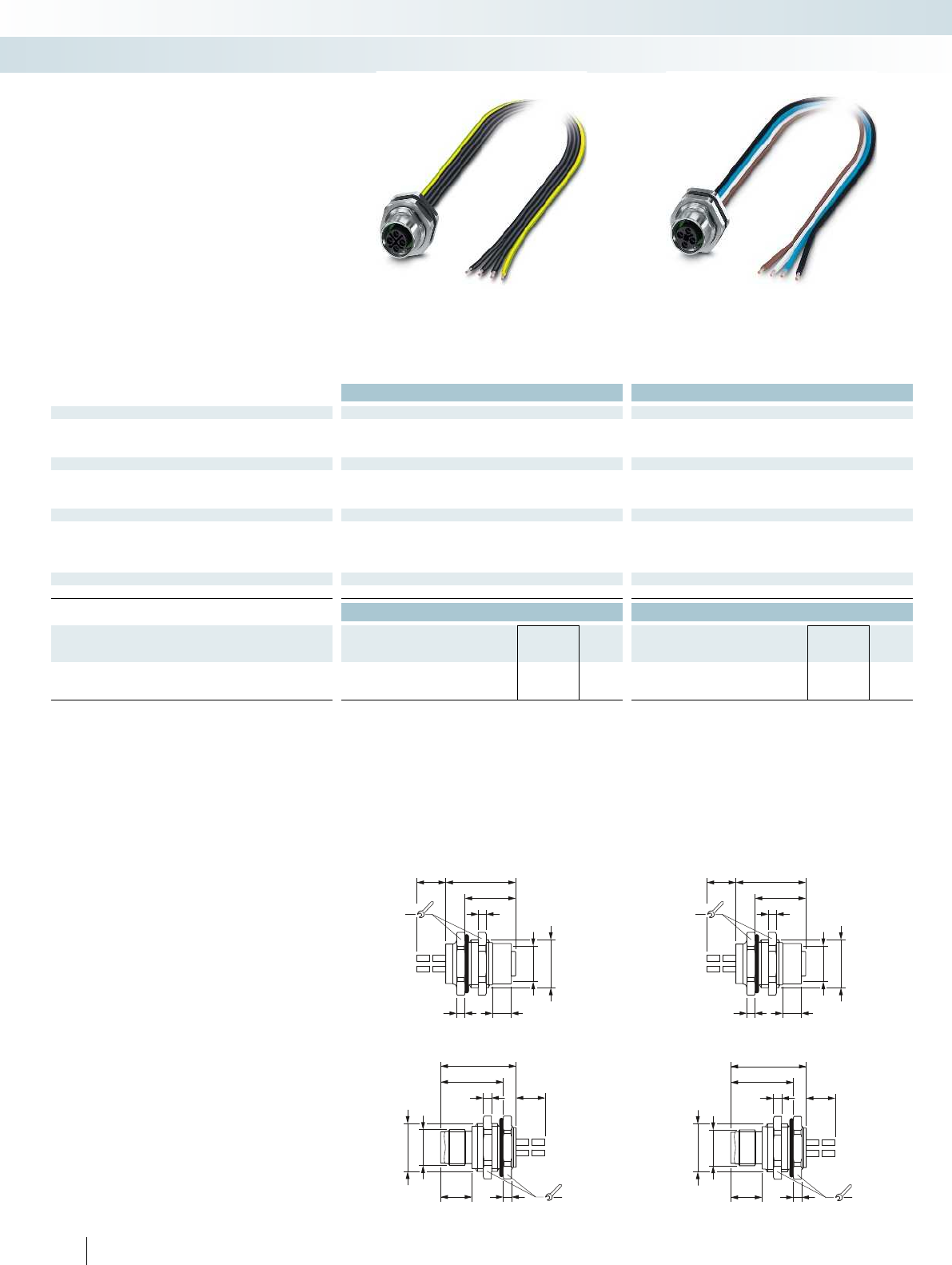
M12x1
M16x1,5
21,6
L
2,810,8
26
2,8
19
M12x1
M16x1,5
21,6
L
2,810,8
26
2,8
19
24,1
L
M12x1
M16x1,5
19
2,8
17,5
2,8
6,5
24,1
L
M12x1
M16x1,5
19
2,8
17,5
2,8
6,5
Technical data Technical data
General data
Pollution degree 3 3
Degree of protection IP67 IP67
Connection method Individual wires Individual wires
Electrical data
Rated voltage 630 V 60 V
Rated current 12 A 12 A
Contact resistance ≤ 3 mΩ≤ 3 mΩ
Material data
Material contact/contact surface CuZn/Au CuZn/Au
Contact carrier material PA PA
Inflammability class according to UL 94 V0 V0
Cable type PP litz wire PP litz wire
Temperature data
Plug/socket [°C] -25 ... 85 -25 ... 85
Ordering data Ordering data
Description Type Order No. Pcs. /
Pkt. Type Order No. Pcs. /
Pkt.
Power device connectors
Socket SACC-DSI-M12FSS-4P-M16XL/0,5PE 1411598 1SACC-DSI-M12FST-4P-M16XL/0,5 1411599 1
Plug SACC-DSI-M12MSS-4P-M16XL/0,5PE 1411603 1SACC-DSI-M12MST-4P-M16XL/0,5 1411604 1
Dimensions: plug Dimensions: plug
56 PHOENIX CONTACT
Dimensions: socket Dimensions: socket
Connection technology for field devices
M5 to M12 circular connectors
S-coded, 3-pos. + PE T-coded, 4-pos.
– M16 fastening thread
– With 0.5m long litz wires
– Tightening limitation
– Wrench size 19
M12 power device connectors XL,
rear mounting
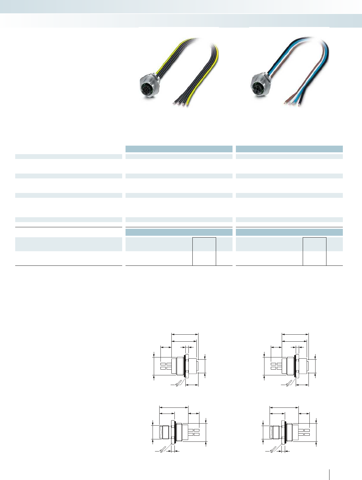
M12x1
M16x1,5
13,6
26
2,8
19
L
M12x1
M16x1,5
13,6
26
2,8
19
L
M12x1
M16x1,5
11,5
19
22,6
24,1
L2,8
M12x1
M16x1,5
11,5
19
22,6
24,1
L2,8
For additional information, visit phoenixcontact.net/products
Technical data Technical data
General data
Pollution degree 3 3
Degree of protection IP67 IP67
Connection method Individual wires Individual wires
Electrical data
Rated voltage 630 V 60 V
Rated current 12 A 12 A
Contact resistance ≤ 3 mΩ≤ 3 mΩ
Material data
Material contact/contact surface CuZn/Au CuZn/Au
Contact carrier material PA PA
Inflammability class according to UL 94 V0 V0
Cable type PP litz wire PP litz wire
Temperature data
Plug/socket [°C] -25 ... 85 -25 ... 85
Ordering data Ordering data
Description Type Order No. Pcs. /
Pkt. Type Order No. Pcs. /
Pkt.
Power device connectors
Socket SACC-E-M12FSS-4P-M16XL/0,5 PE 1411605 1SACC-E-M12FST-4P-M16XL/0,5 1411606 1
Plug SACC-E-M12MSS-4P-M16XL/0,5 PE 1411607 1SACC-E-M12MST-4P-M16XL/0,5 1411608 1
Dimensions: plug Dimensions: plug
57PHOENIX CONTACT
Dimensions: socket Dimensions: socket
Connection technology for field devices
M5 to M12 circular connectors
S-coded, 3-pos. + PE T-coded, 4-pos.
– M16 fastening thread
– With 0.5m long litz wires
– Tightening limitation
– Wrench size 19
M12 power device connectors XL,
front mounting
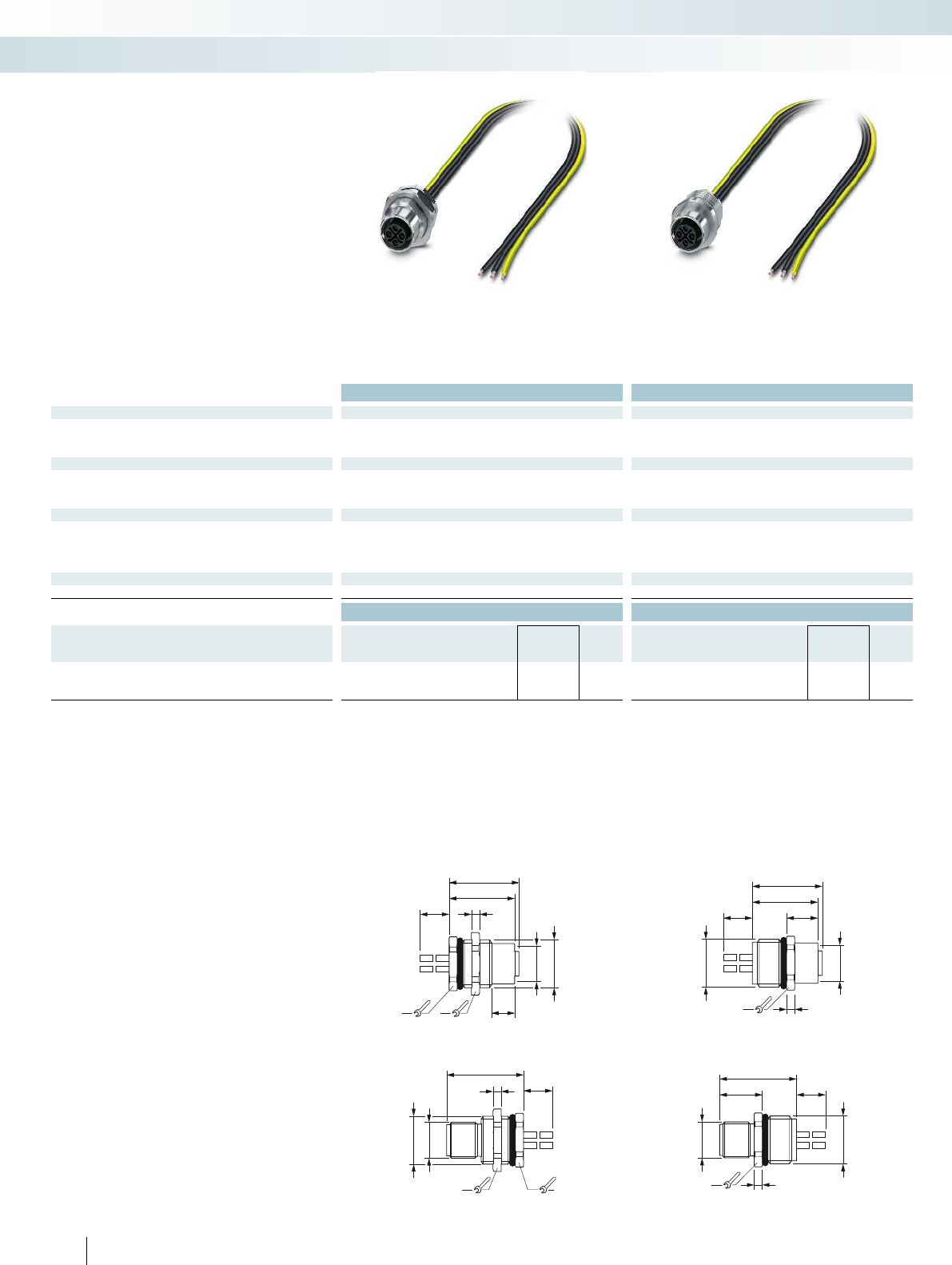
19
L
26,5
M12x1
M16x1,5
17
2,8
14,7
M12x1
M16x1,5
26,5
17 2,8
L
M16x1,5
M12x1
22,6
24,1
L10,8
17 2,8
19
M12x1
M16x1,5
8
17
22,6
24,1
L2,8
Technical data Technical data
General data
Pollution degree 3 3
Degree of protection IP67 IP67
Connection method Individual wires Individual wires
Electrical data
Rated voltage 630 V 630 V
Rated current 16 A 16 A
Contact resistance ≤ 3 mΩ≤ 3 mΩ
Material data
Material contact/contact surface CuZn/Au CuZn/Au
Contact carrier material PA PA
Inflammability class according to UL 94 V0 V0
Cable type PP litz wire PP litz wire
Temperature data
Plug/socket [°C] -25 ... 105 -25 ... 105
Ordering data Ordering data
Description Coding Type Order No. Pcs. /
Pkt. Type Order No. Pcs. /
Pkt.
Power device connectors
Socket S power SACC-DSI-M12FSS-3P-M16/0,5 PE 1411652 1SACC-E-M12FSS-3P-M16/0,5 PE 1411654 1
Plug S power SACC-DSI-M12MSS-3P-M16/0,5 PE 1411653 1SACC-E-M12MSS-3P-M16/0,5 PE 1411655 1
Dimensions: plug Dimensions: plug
58 PHOENIX CONTACT
Dimensions: socket Dimensions: socket
Connection technology for field devices
M5 to M12 circular connectors
Rear mounting Front mounting
– M16 fastening thread
– With 0.5m long litz wires
–S-coded
M12 power device connectors,
2-pos. + PE

For additional information, visit phoenixcontact.net/products
59PHOENIX CONTACT
Connection technology for field devices
M5 to M12 circular connectors

Mechanical and electrical data
Mechanical data
Housing material: Copper zinc alloy (CuZn), die-cast zinc (GD-Zn)
Housing surface: Nickel-plated/thick layer passivated (can be coated)
Insulating body: Polyamide (PA 66)
Contact material: Copper zinc alloy (CuZn)
Contact surface: Nickel-plated (Ni) with gold coating (Au)
Contact connection method: Crimp version
Sealing and O-ring: Fluorocarbon rubber (FKM)
Ambient temperature: -40°C ... 130°C
Cable entry: Cable and coupler connectors for outer cable diameter of 7.5 - 18 mm,
shielded
Type of locking: M23 SPEEDCON screw locking
Mech. insertion/withdrawal cycles: Standard: 100
Protection class: IP67 in the locked state
Electrical data
No. of positions 13 (4+4+4+PE), CAT5 13 (8+4+PE)
Contacts 4+4+4+PE 8+4+PE
Contact Ø [mm] 0.8 1.0 2.0 2.0 1.0 2.0 2.0
Litz wire cross sections
Cable and coupler connectors:
Max. cable Ø of 18 mm [mm2] 0.08 ... 0.5 0.06 … 1.0 0.25 … 4.0 0.25 … 4.0 0.06 … 1.0 0.25 … 4.0 0.25 … 4.0
Device connector:
[mm2] 0.08 ... 0.5 0.06 … 1.0 0.25 … 4.0 0.25 … 4.0 0.06 … 1.0 0.25 … 4.0 0.25 … 4.0
Nominal current per contact at 25°C 1) 3.6 830 - 8 30 –
Specifications according to DIN EN 61984:2009 –
Rated voltage [V AC/DC] 50 50 630/850 -50 630/850 –
Test/surge voltage [kV AC] 1.5 1.5 6 - 1.5 6 –
Surge voltage category III III
Pollution degree 2) 3 3
Installation height [m] Up to 3000 Up to 3000
Cable clamping area 3) Max. Ø [mm] 18 18
1) The effective current carrying capacity must be determined using a derating curve, if necessary, according to the application.
2) The values specified assume that the connector pair is correctly locked and is only disconnected for testing and maintenance purposes. If the connector is unlocked and exposed to
ambient conditions, and if there is a danger of contamination, the connector must be sealed using a protective cap ≥ IP54.
3) The cable clamping areas specified on the following pages may vary depending on the cable material/structure. Selection and testing is the responsibility of the user.
60 PHOENIX CONTACT
Connection technology for field devices
M17 to M58 circular connectors
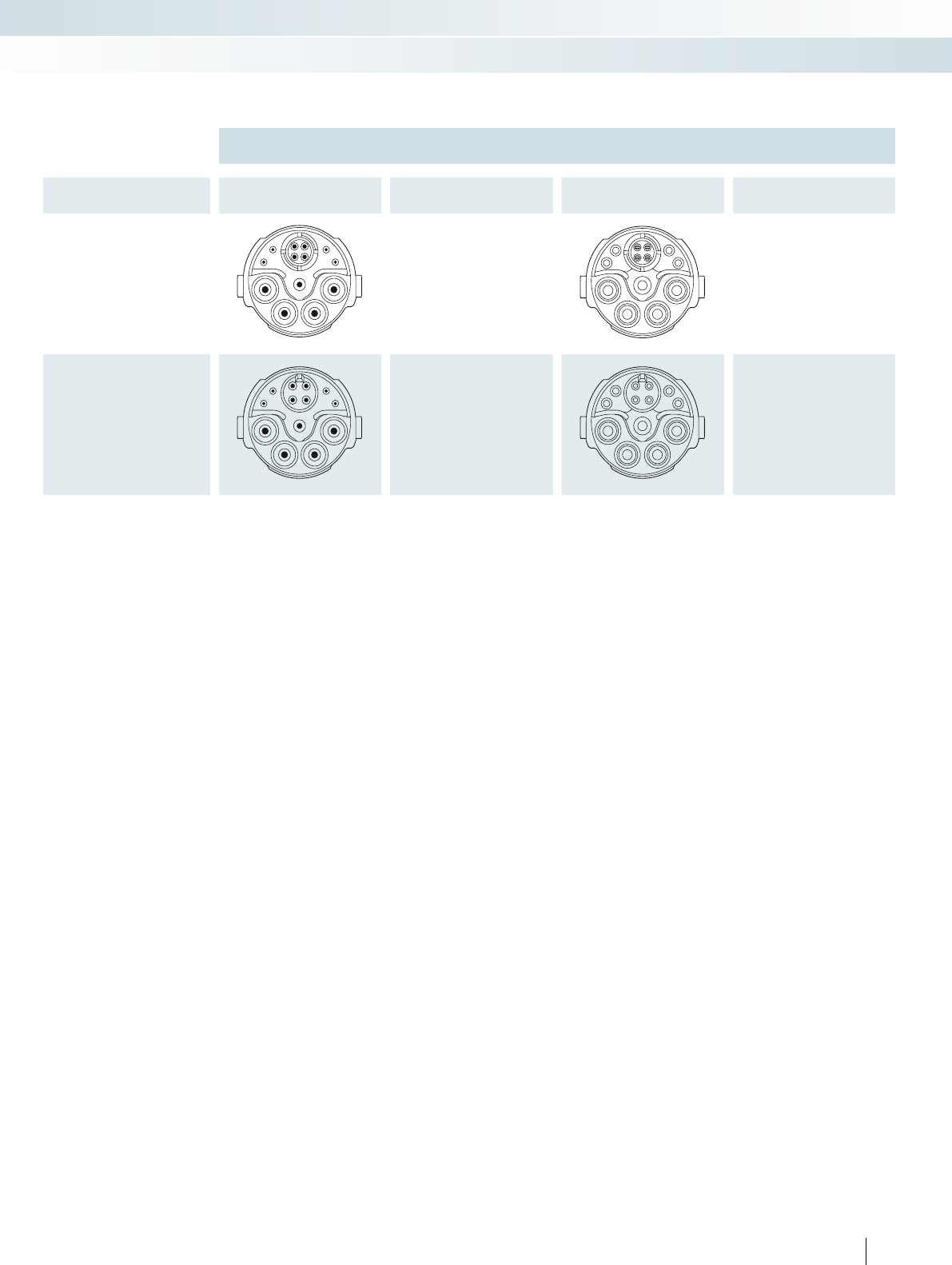
For additional information, visit phoenixcontact.net/products
Pin assignments and coding
Contact chamber numbering
(view of plug-in side)
No. of positions Pin Socket
13-pos., CAT5
(4 + 4 + 4 + PE)
Crimp
13-pos.
(8 + 4 + PE)
Crimp
61PHOENIX CONTACT
Connection technology for field devices
M17 to M58 circular connectors
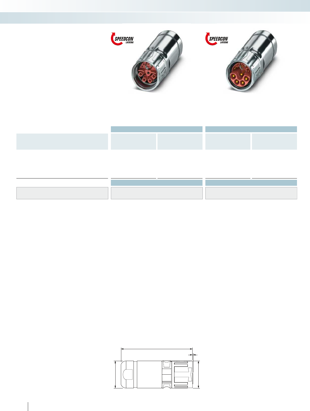
Ø28
Ø28,2
75,8
A
locked
Ordering data Ordering data
Description Cable clamping area Order No. Pcs. /
Pkt. Order No. Pcs. /
Pkt. Order No. Pcs. /
Pkt. Order No. Pcs. /
Pkt.
4 x signal + CAT5 8 x signal 4 x signal + CAT5 8 x signal
Cable connector, with contact carrier, without contacts,
crimp connection
Universal gasket 7.5 mm ... 18 mm 1621517 11621524 11621529 11621534 1
7.5 mm ... 9 mm 1621520 11621525 11621530 11621535 1
9 mm ... 12 mm 1621521 11621526 11621531 11621536 1
12 mm ... 15 mm 1621522 11621527 11621532 11621537 1
15 mm ... 18 mm 1621523 11621528 11621533 11621538 1
Accessories Accessories
Crimp contacts See page 66 See page 66
Color rings, 50 pcs. in set (to be ordered separately) See Catalog 2, page 367 See Catalog 2, page 367
Pin version: dimension A = 0.2 mm,
socket version: dimension A = 0 mm
62 PHOENIX CONTACT
Connection technology for field devices
M17 to M58 circular connectors
Cable connector,
socket assembly
Cable connector,
pin assembly
– 4 x power + PE, 4 x signal, 4 x data
– 4 x power + PE, 8 x signal
M23 cable connector, hybrid,
SPEEDCON fast locking system
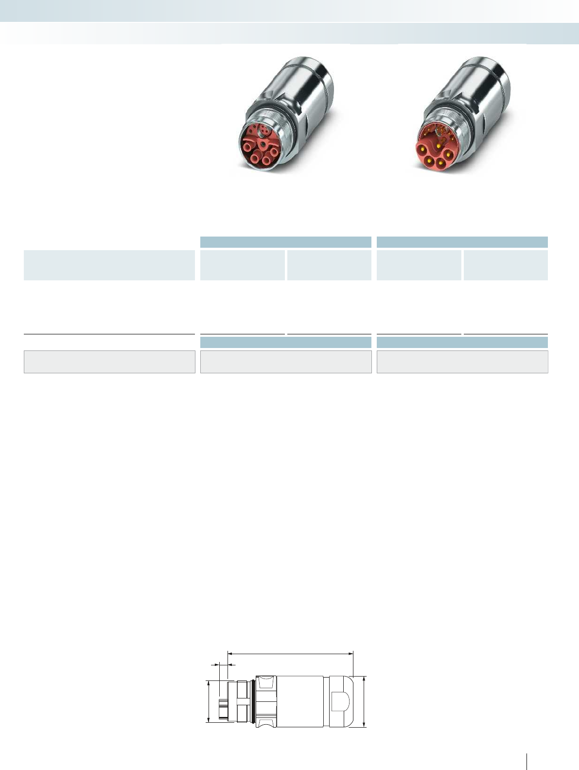
Ø28
71,2
M23x1
A
For additional information, visit phoenixcontact.net/products
Ordering data Ordering data
Description Cable clamping area Order No. Pcs. /
Pkt. Order No. Pcs. /
Pkt. Order No. Pcs. /
Pkt. Order No. Pcs. /
Pkt.
4 x signal + CAT5 8 x signal 4 x signal + CAT5 8 x signal
Coupler connector, with contact carrier, without contacts,
crimp connection
Universal gasket 7.5 mm ... 18 mm 1621539 11621544 11621549 11621554 1
7.5 mm ... 9 mm 1621540 11621545 11621550 11621555 1
9 mm ... 12 mm 1621541 11621546 11621551 11621556 1
12 mm ... 15 mm 1621542 11621547 11621552 11621557 1
15 mm ... 18 mm 1621543 11621548 11621553 11621558 1
Accessories Accessories
Crimp contacts See page 66 See page 66
Color rings, 50 pcs. in set (to be ordered separately) See Catalog 2, page 367 See Catalog 2, page 367
Pin version: dimension A = 4.7 mm,
socket version: dimension A = 0 mm
63PHOENIX CONTACT
Connection technology for field devices
M17 to M58 circular connectors
Coupler connector,
socket assembly
Coupler connector,
pin assembly
– 4 x power + PE, 4 x signal, 4 x data
– 4 x power + PE, 8 x signal
M23 coupler connector, hybrid
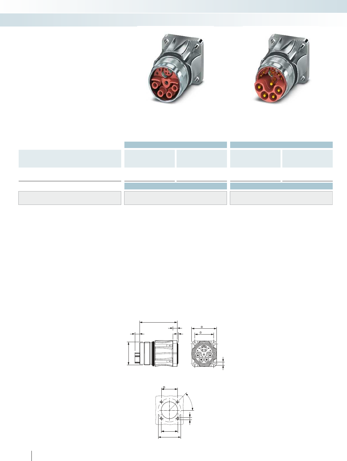
19,8±0,1
Ø20,1+0,1
4xM3
Ø28
45°
26
19,8
4xØ3,2
M23x1
1
39,4
4,7
A
Ordering data Ordering data
Description Order No. Pcs. /
Pkt. Order No. Pcs. /
Pkt. Order No. Pcs. /
Pkt. Order No. Pcs. /
Pkt.
4 x signal + CAT5 8 x signal 4 x signal + CAT5 8 x signal
Device connector, with contact carrier, without contacts
Flange dimensions: 26 mm x 26 mm 1621567 11621568 11621569 11621570 1
Accessories Accessories
Crimp contacts See page 66 See page 66
Color rings, 50 pcs. in set (to be ordered separately) See Catalog 2, page 367 See Catalog 2, page 367
Installation dimensions
64 PHOENIX CONTACT
Pin version: dimension A = 4.75 mm,
socket version: dimension A = 0 mm
Connection technology for field devices
M17 to M58 circular connectors
Device connector, straight,
socket assembly
Device connector, straight,
pin assembly
– 4 x power + PE, 4 x signal, 4 x data
– 4 x power + PE, 8 x signal
M23 device connectors, hybrid,
straight
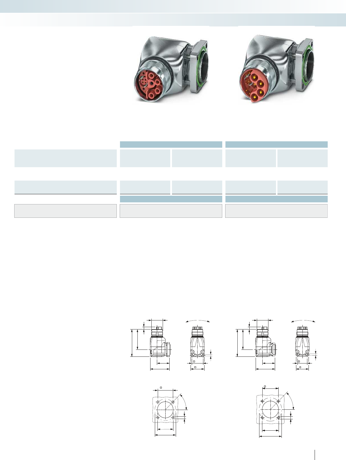
Ø20+0,1
4xM3
45°
Ø32
22,6
±0,1
19,8±0,1
Ø20,1+0,1
4xM3
Ø28
45°
212°
98°
4xØ3,2
19,8
26
25,4
39,4
M23x1
40
54
A
25,4
39,4
M23x1
40
54
A
212°
98°
4xØ3,2
22,6
28
For additional information, visit phoenixcontact.net/products
Ordering data Ordering data
Description Order No. Pcs. /
Pkt. Order No. Pcs. /
Pkt. Order No. Pcs. /
Pkt. Order No. Pcs. /
Pkt.
4 x signal + CAT5 8 x signal 4 x signal + CAT5 8 x signal
Device connector, with contact carrier, without contacts
Flange dimensions: 26 mm x 26 mm 1621563 11621564 11621565 11621566 1
Device connector, with contact carrier, without contacts
Flange dimensions: 28 mm x 28 mm 1621559 11621560 11621561 11621562 1
Accessories Accessories
Crimp contacts See page 66 See page 66
Color rings, 50 pcs. in set (to be ordered separately) See Catalog 2, page 367 See Catalog 2, page 367
Installation dimensions Installation dimensions
65PHOENIX CONTACT
Pin version: dimension A = 4.7 mm,
socket version: dimension A = 0 mm
Pin version: dimension A = 4.7 mm,
socket version: dimension A = 0 mm
Connection technology for field devices
M17 to M58 circular connectors
Device connector, angled, rotatable,
socket assembly
Device connector, angled, rotatable,
pin assembly
– 4 x power + PE, 4 x signal, 4 x data
– 4 x power + PE, 8 x signal
– Housing can be freely rotated by 310°
M23 device connector, hybrid,
angled, rotatable
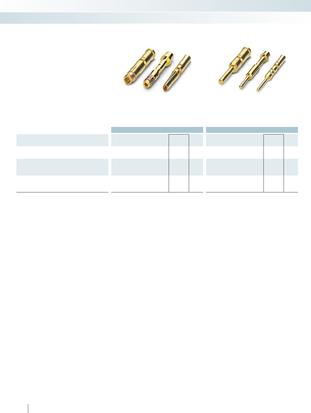
Ordering data Ordering data
Description Connection cross section
[mm²] Type Order No. Pcs. /
Pkt. Type Order No. Pcs. /
Pkt.
Contacts, Ø 0.8 mm
0.08 mm² ... 0.25 mm² SF-08KS010 1621571 100 SF-08KP010 1621574 100
0.34mm² ... 0.5mm² SF-08KS020 1621573 100 SF-08KP020 1621575 100
Contacts, Ø 1.0 mm
0.06 mm² ... 0.25 mm² ST-10KS010 1618239 100 ST-10KP010 1618255 100
0.34 mm² ... 0.5 mm² ST-10KS020 1618251 100 ST-10KP020 1618256 100
0.5 mm² ... 1.0 mm² ST-10KS030 1618254 100 ST-10KP030 1618261 100
Contacts, Ø 2.0 mm
0.25mm²... 1.0mm² SF-20KS021 1621576 50 SF-20KP021 1621579 50
1.0mm² ... 2.5mm² SF-20KS022 1621577 50 SF-20KP022 1621580 50
2.5mm² ... 4.0mm² SF-20KS023 1621578 50 SF-20KP023 1621581 50
66 PHOENIX CONTACT
Connection technology for field devices
M17 to M58 circular connectors
Crimp contacts,
socket
Crimp contacts,
pin
Crimp contacts

For additional information, visit phoenixcontact.net/products
67PHOENIX CONTACT
Connection technology for field devices
M17 to M58 circular connectors
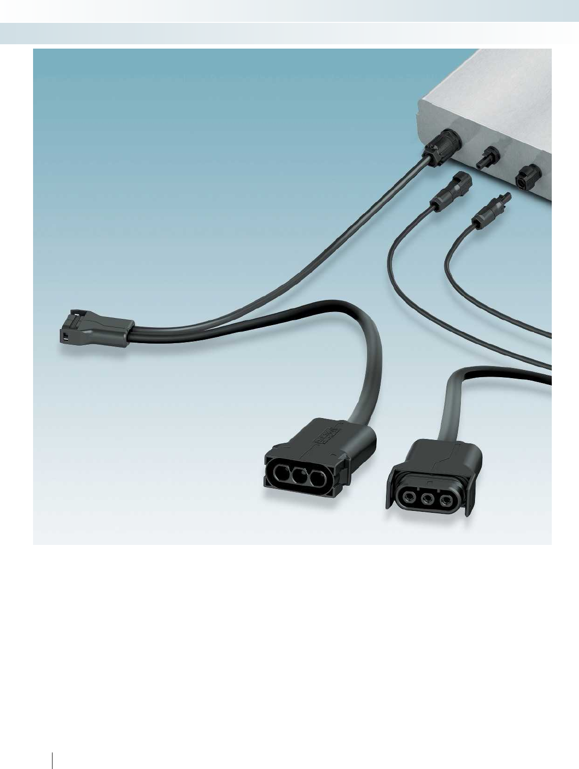
68 PHOENIX CONTACT
Connection technology for field devices
Photovoltaic AC connectors
Flexibility is required when it comes to
the structure of a sustainable power supply
system. A combination of various sources of
renewable energy – even in conjunction
with storage technologies – is already
proving cost-effective. What is striking here
is that miniaturization is more than just a
trend; it is a recognized method of
increasing system efficiency.
In photovoltaics, the micro inverter, the
little brother of the string inverter, is
particularly gaining in popularity. It can even
be used cost-effectively in locations that are
clearly less than ideal. Double-figure
percentage increases in yield in comparison
to string inverters mean that even areas that
are not ideal can be used cost-effectively.
SUNCLIX micon, the connection system
for the AC-side of micro inverters,
simplifies installation using components
which have proven themselves a million
times over.

For additional information, visit phoenixcontact.net/products
69PHOENIX CONTACT
Connection technology for field devices
Photovoltaic AC connectors
AC-Y connectors
The AC-Y connectors consist of two
3-pos. connections, which are connected to
each other via the trunk line without the
risk of polarity reversal. In addition to
accommodating the trunk line, the coupling
side also accommodates the drop line,
which serves as a connection to the
inverter.
Mains connector plugs
The mains connector plugs provide the
connecting link between the PV system and
mains. Depending on the system structure,
the mains can be connected via the plug or
coupling side of the AC Y-connector. The
free cable end is either connected in a
distributor box or fed into an incoming
mains feeder box via a cable sleeve.
Protective caps
Dust protection caps (brown) made from
biodegradable plastic protect the pin
connector pattern from contamination
during transport. When it comes to
installation, they can be easily removed
from the plug without any special tools.
During installation, the IP protective caps
(black) are inserted as an end cap on the last
connector in order to protect it from
atmospheric influences.
Contact removal tool
The locking mechanism on the connector
is extremely robust and prevents
unintentional release. The contact removal
tool enables the lock to be opened easily
and quickly. Thanks to an additional latch, it
does not fall out of the plug housing once it
has been released.
DC connectors
With the SUNCLIX DC connector as a
device plug or for field assembly, you can
also impress with performance and quality
on the module side.
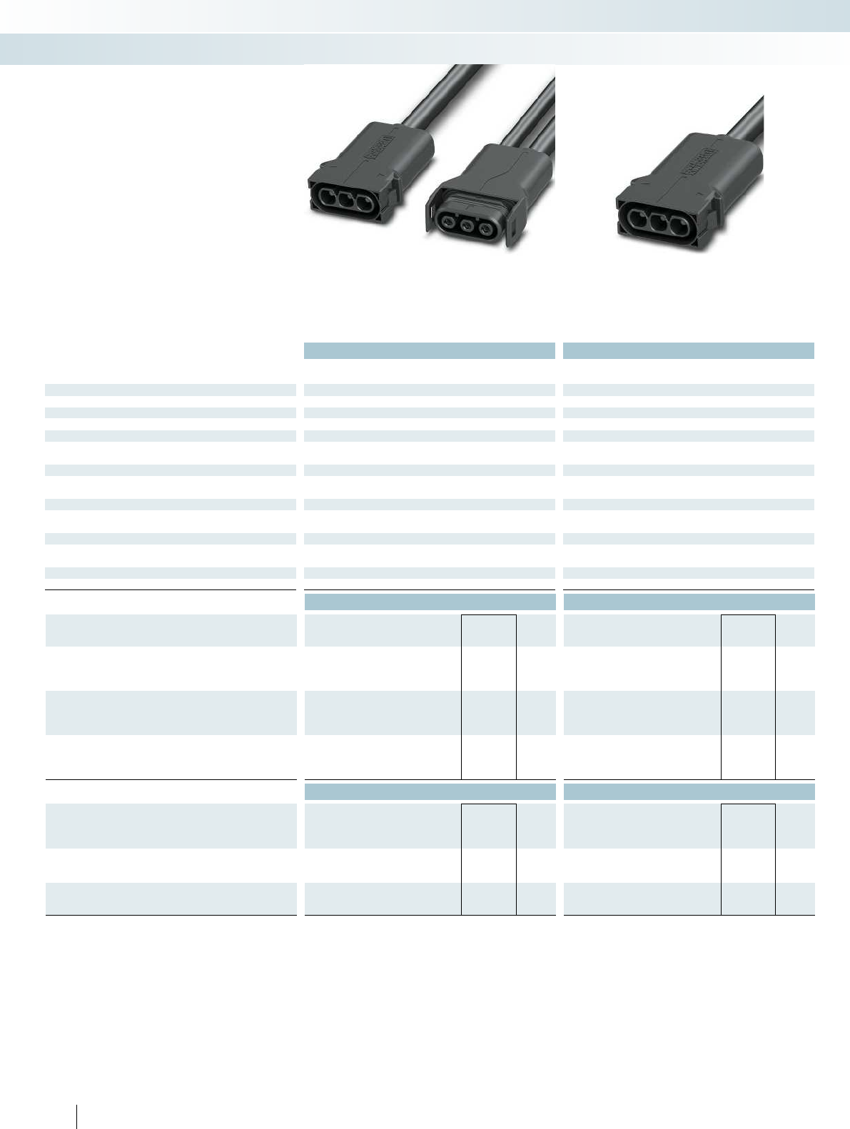
Technical data Technical data
North American version European version North American version European version North American version European version North America
General data
Degree of protection IP67 IP67 IP67 IP67 IP67 IP67 IP67 IP67
Electrical data
Rated voltage 600 V 400 V 600 V 400 V 600 V 400 V 600 V 400 V
Rated current
Trunk line 20 A 20 A 20 A 20 A 20 A 20 A 20 A 20 A
Drop line 5 A 5 A - - - - - -
Conductor cross section
Trunk line 12 AWG 2.5 mm² 12 AWG 2.5 mm² 12 AWG 2.5 mm² 12 AWG 2.5 mm²
Drop line 14 AWG 0.75 mm² - - - - - -
No. of pos.
Trunk line3333 3333
Drop line 3 3 - - - - - -
Cable length
Trunk line 1150 mm 1150 mm 1000 mm 1000 mm 1000 mm 1000 mm 1000 mm 1000 mm
Drop line500 mm500 mm-- -- --
Temperature data
Ambient temperature (operation) -40°C ... 90°C -40°C ... 85°C -40°C ... 90°C -40°C ... 85°C -40°C ... 90°C -40°C ... 85°C -40°C ... 90
Ordering data Ordering data
Description Type Order No. Pcs. /
Pkt. Type Order No. Pcs. /
Pkt.
AC Y-distributor for PV microinverters incl. dust protection caps
North American version PV-MI-YC-1,15-3-12-NA-0,50-OE 1706518 1
European version PV-MI-YC-1,15-3-25-EU-0,50-OE 1621351 1
Mains connector plug of the AC Y-distributor incl. IP protective
cap and contact removal tool
North American version PV-MI-YC-GC-P-1,00-3-12-NA SET 1707091 1
European version PV-MI-YC-GC-P-1,00-3-25-EU SET 1621349 1
Patch cable for extending the trunk line incl. dust protection caps
North American version
European version
Accessories Accessories
Dust protection cap, IP40, for SUNCLIX micon
Coupling side PV-MI-YC-CARRIER-CAP-TS 1706599 5PV-MI-YC-CARRIER-CAP-TS 1706599 5
Plug side PV-MI-YC-CARRIER-CAP-TP 1706608 5PV-MI-YC-CARRIER-CAP-TP 1706608 5
Protective cap, IP67, for SUNCLIX micon
Coupling side PV-MI-YC-PROTECTION-CAP-TS 1706515 1PV-MI-YC-PROTECTION-CAP-TS 1706515 1
Plug side PV-MI-YC-PROTECTION-CAP-TP 1706610 1PV-MI-YC-PROTECTION-CAP-TP 1706610 1
Contact removal tool, for SUNCLIX micon, trunk line
PV-MI-YC-UNLOCKTOOL 1706514 5PV-MI-YC-UNLOCKTOOL 1706514 5
70 PHOENIX CONTACT
AC Y-distributor Mains connector plug
for the coupling side
– Pre-assembled sets for minimum effort at
the installation site
– Customer-specific versions on request
– Networked cables
– Proven SUNCLIX contact technology for
optimum system performance
SUNCLIX micon
Connection technology for field devices
Photovoltaic AC connectors
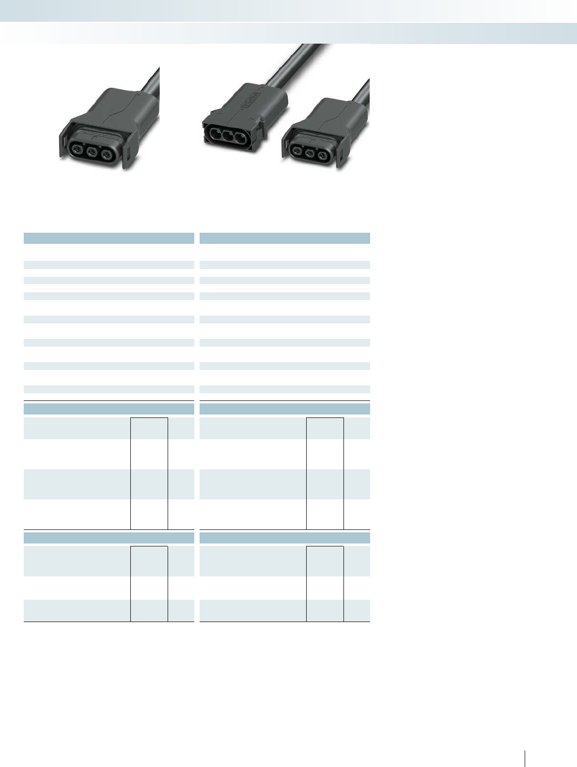
For additional information, visit phoenixcontact.net/products
Technical data Technical data
North American version European version North American version European version North American version European version North American version European version
Degree of protection IP67 IP67 IP67 IP67 IP67 IP67 IP67 IP67
Rated voltage 600 V 400 V 600 V 400 V 600 V 400 V 600 V 400 V
Trunk line 20 A 20 A 20 A 20 A 20 A 20 A 20 A 20 A
Drop line 5 A 5 A - - - - - -
Trunk line 12 AWG 2.5 mm² 12 AWG 2.5 mm² 12 AWG 2.5 mm² 12 AWG 2.5 mm²
Drop line 14 AWG 0.75 mm² - - - - - -
Trunk line3333 3333
Drop line 3 3 - - - - - -
Trunk line 1150 mm 1150 mm 1000 mm 1000 mm 1000 mm 1000 mm 1000 mm 1000 mm
Drop line500 mm500 mm-- -- --
40°C ... 90°C -40°C ... 85°C -40°C ... 90°C -40°C ... 85°C -40°C ... 90°C -40°C ... 85°C
Ordering data Ordering data
Type Order No. Pcs. /
Pkt. Type Order No. Pcs. /
Pkt.
PV-MI-YC-GC-S-1,00-3-12-NA SET 1707092 1
PV-MI-YC-GC-S-1,00-3-25-EU SET 1621350 1
PV-MI-YC-PATCH-1,00-3-12-NA 1707090 10
PV-MI-YC-PATCH-1,00-3-25-EU 1621352 10
Accessories Accessories
PV-MI-YC-CARRIER-CAP-TS 1706599 5PV-MI-YC-CARRIER-CAP-TS 1706599 5
PV-MI-YC-CARRIER-CAP-TP 1706608 5PV-MI-YC-CARRIER-CAP-TP 1706608 5
PV-MI-YC-PROTECTION-CAP-TS 1706515 1PV-MI-YC-PROTECTION-CAP-TS 1706515 1
PV-MI-YC-PROTECTION-CAP-TP 1706610 1PV-MI-YC-PROTECTION-CAP-TP 1706610 1
PV-MI-YC-UNLOCKTOOL 1706514 5PV-MI-YC-UNLOCKTOOL 1706514 5
71PHOENIX CONTACT
Mains connector plug
for the plug side
Patch cable
Connection technology for field devices
Photovoltaic AC connectors
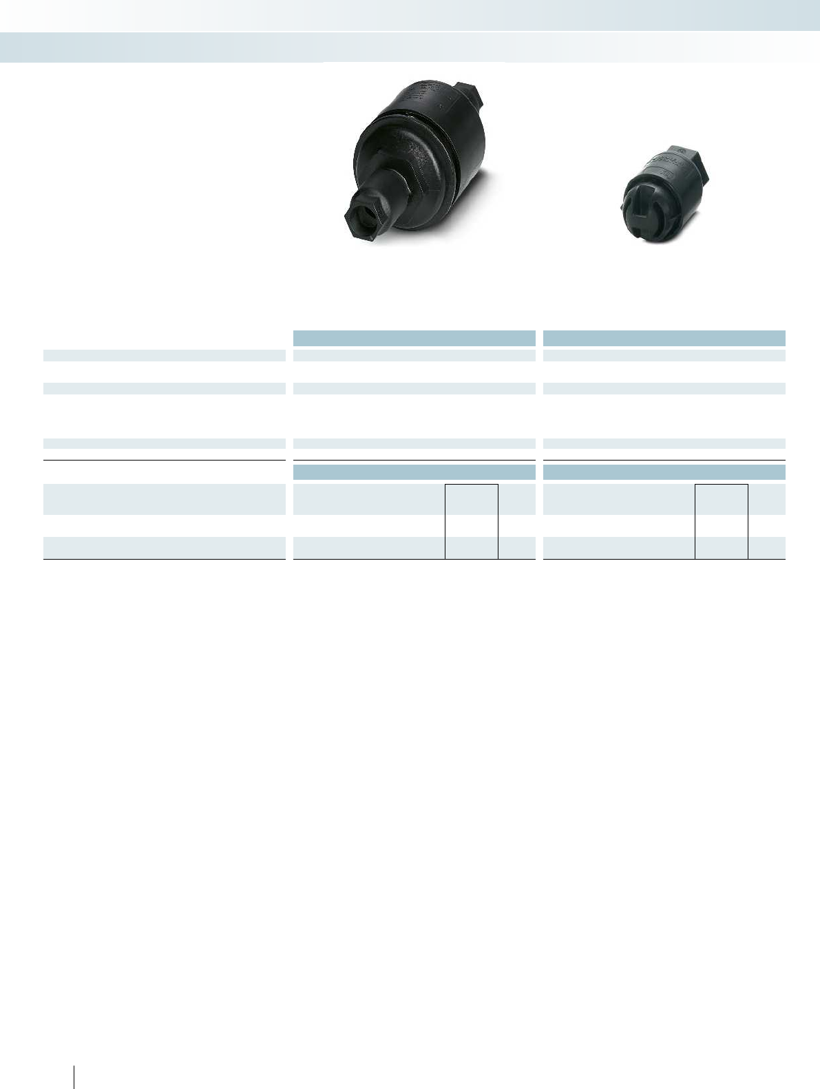
Technical data Technical data
General data
Degree of protection IP67 IP67
Connection method Screw connection within housing -
Electrical data
Rated voltage 600 V AC/DC 600 V AC/DC
Rated current 30 A -
Conductor cross section [mm² // AWG] 1.5 mm² ... 25 mm² // 16 ... 4 1.5 mm² ... 25 mm² // 16 ... 4
Cable diameter 9.5 mm ... 13 mm (0.37 ... 0.51 in.) 9.5 mm ... 13 mm (0.37 ... 0.51 in.)
Temperature data
Ambient temperature (operation) -40°C ... 90°C -40°C ... 90°C
Ordering data Ordering data
Description Type Order No. Pcs. /
Pkt. Type Order No. Pcs. /
Pkt.
Cable splice kit
- 3 conductors PV-MI-CABLE SPLICE 3P 1812403 1
Cable terminator
- 3 conductors PV-MI-CABLE TERMINATOR 3P 1812416 1
72 PHOENIX CONTACT
Connection technology for field devices
Photovoltaic AC connectors
Cable splice kit Cable terminator
Cable splice kit
– Cable-to-cable connection
– IP67 for outdoor applications
– Accepts three conductors, 1.5mm to
25mm (16 to 4AWG)
Cable terminator
– End-of-run cable terminator
– IP67 for outdoor applications
– Accepts three conductors, 1.5mm to
25mm (16 to 4AWG)
Cable installation

For additional information, visit phoenixcontact.net/products
73PHOENIX CONTACT
Connection technology for field devices
Photovoltaic AC connectors
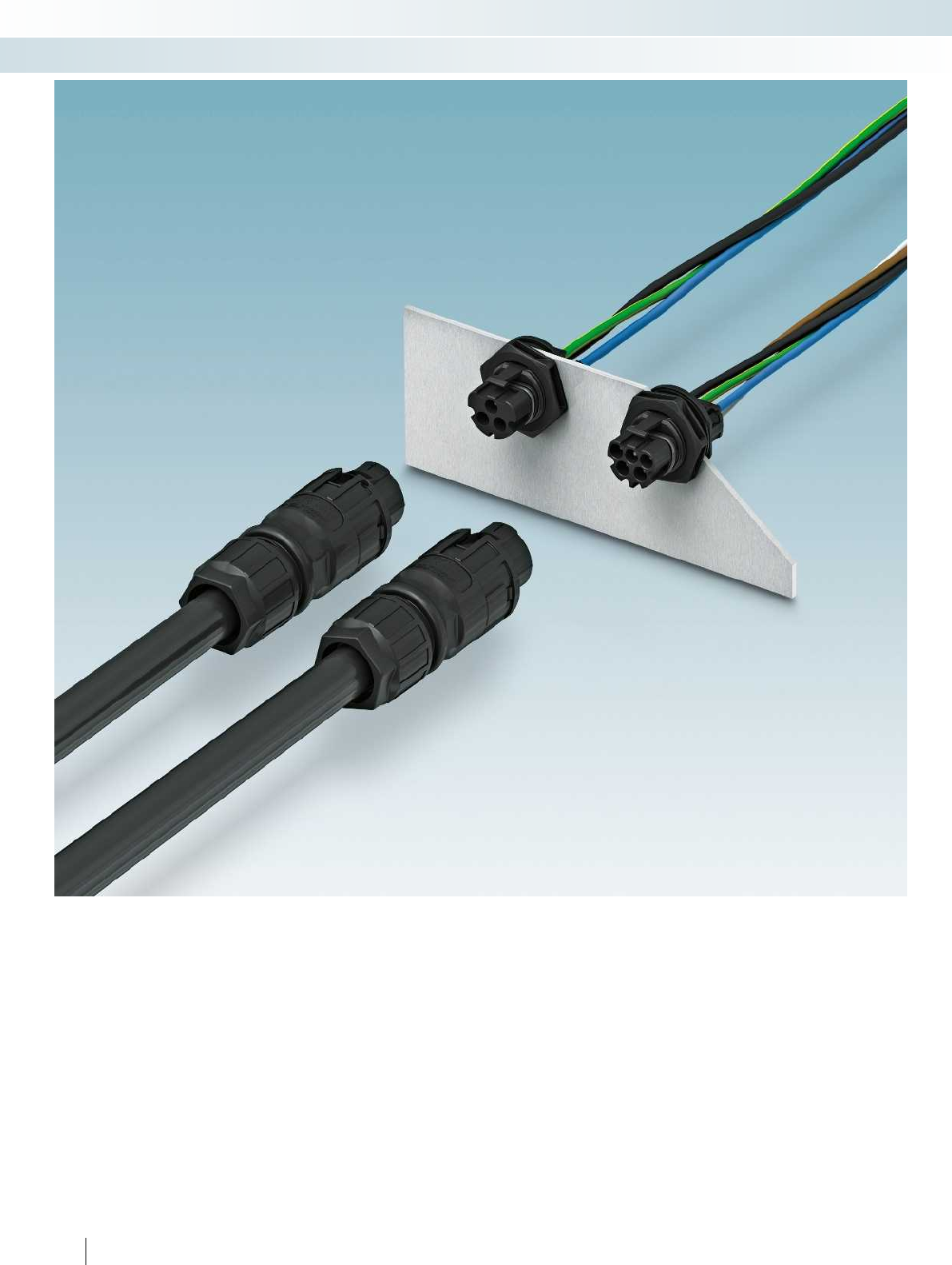
74 PHOENIX CONTACT
Connection technology for field devices
Photovoltaic AC connectors
IP-protected circular connectors for power electronics
The new power connectors in the PRC series enable you to reliably and conveniently connect 3 and 5-wire cables to your device
(e.g., a solar inverter). The device connectors with crimp connection are supplied pre-assembled with punched-on litz wires or
alternatively they can be self-assembled.
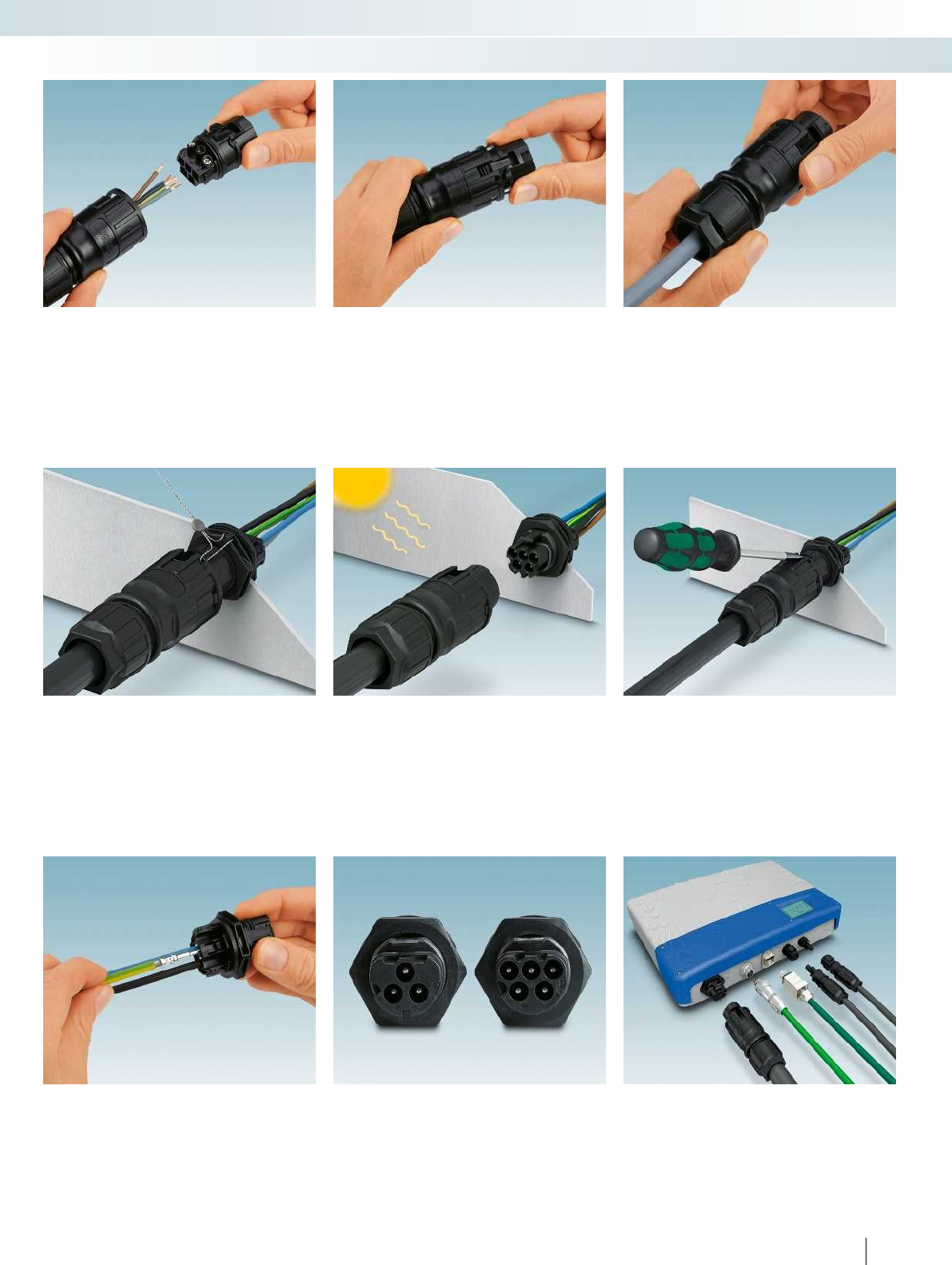
For additional information, visit phoenixcontact.net/products
75PHOENIX CONTACT
Connection technology for field devices
Photovoltaic AC connectors
Remove the cable sheath, strip the wires,
and conveniently connect with screw
connection
Snap the contact carrier into the plug
housing
Tighten the cable gland
– Sealable for protection against tampering – UV-resistant plastic for safe outdoor use – Secure latching to be disconnected using
tool
– Fully flexible for the device manufacturer:
Pre-assembled panel feed-through or
flexible and rapid self-assembly.
– The mechanical coding ensures that
3- and 5-pos. connectors are not
accidentally connected to each other.
– Everything from a single source:
Phoenix Contact supplies connectors for
all the interfaces on a solar inverter.
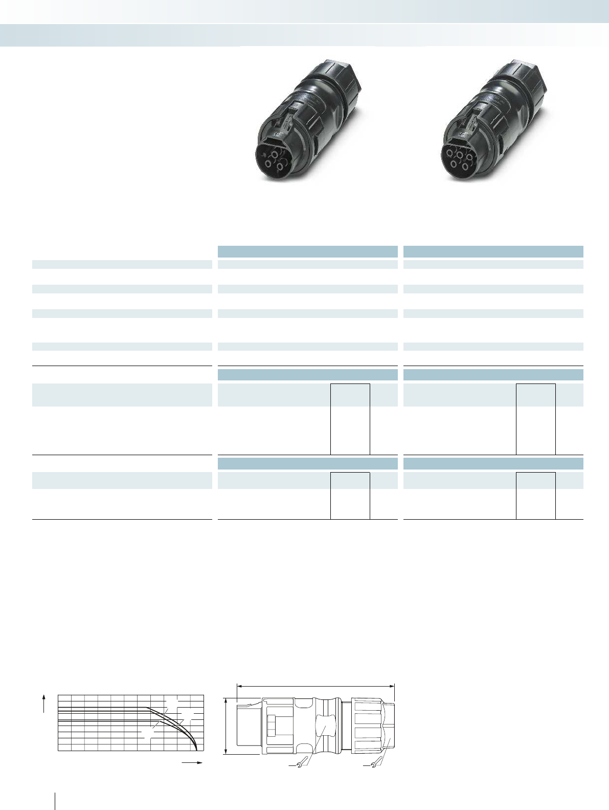
010203040 50 60 70 80 90 100 110
0
10
20
30
40
I [A]
[°C]
37,6
107,5
3230
Technical data Technical data
General data
Degree of protection IP65/IP68 IP65/IP68
Conductor cross section 1.5 mm² ... 6 mm² 1.5 mm² ... 6 mm²
Electrical data
Rated voltage 690 V 690 V
Rated current 35 A 30 A
Material data
Contact surface material Silver-plated Silver-plated
Material of grip body PPE PPE
Inflammability class according to UL 94 V0 V0
Temperature data
Ambient temperature (operation) -40°C ... 100°C
(dependent on the derating curve)
-40°C ... 100°C
(dependent on the derating curve)
Ordering data Ordering data
Description Type Order No. Pcs. /
Pkt. Type Order No. Pcs. /
Pkt.
Cable connector, with screw connection for cable diameter:
8mm ... 21mm PRC 3-FC-FS6 8-21 1410661 1PRC 5-FC-FS6 8-21 1410656 1
8mm ... 12mm PRC 3-FC-FS6 8-12 1410658 1PRC 5-FC-FS6 8-12 1410629 1
12mm ... 16mm PRC 3-FC-FS6 12-16 1409217 1PRC 5-FC-FS6 12-16 1409205 1
16mm ... 25mm PRC 3-FC-FS6 16-21 1410659 1PRC 5-FC-FS6 16-21 1410655 1
Accessories Accessories
Protective cap
PRC COVER F 1409236 50 PRC COVER F 1409236 50
Test plug, black, 1.5mm²...6mm² with screw connection,
for cables with diameter 8mm...21mm
PRC 3-TC-FS6 8-21 1621326 50 PRC 5-TC-FS6 8-21 1621325 50
Derating diagram
76 PHOENIX CONTACT
Connection technology for field devices
Photovoltaic AC connectors
3-pos.,
socket contacts
5-pos.,
socket contacts
– Snaps in automatically when inserted,
released using a screwdriver
– Screw connection of 1.5mm to 6mm
– With lagging PE contact
Cable connectors
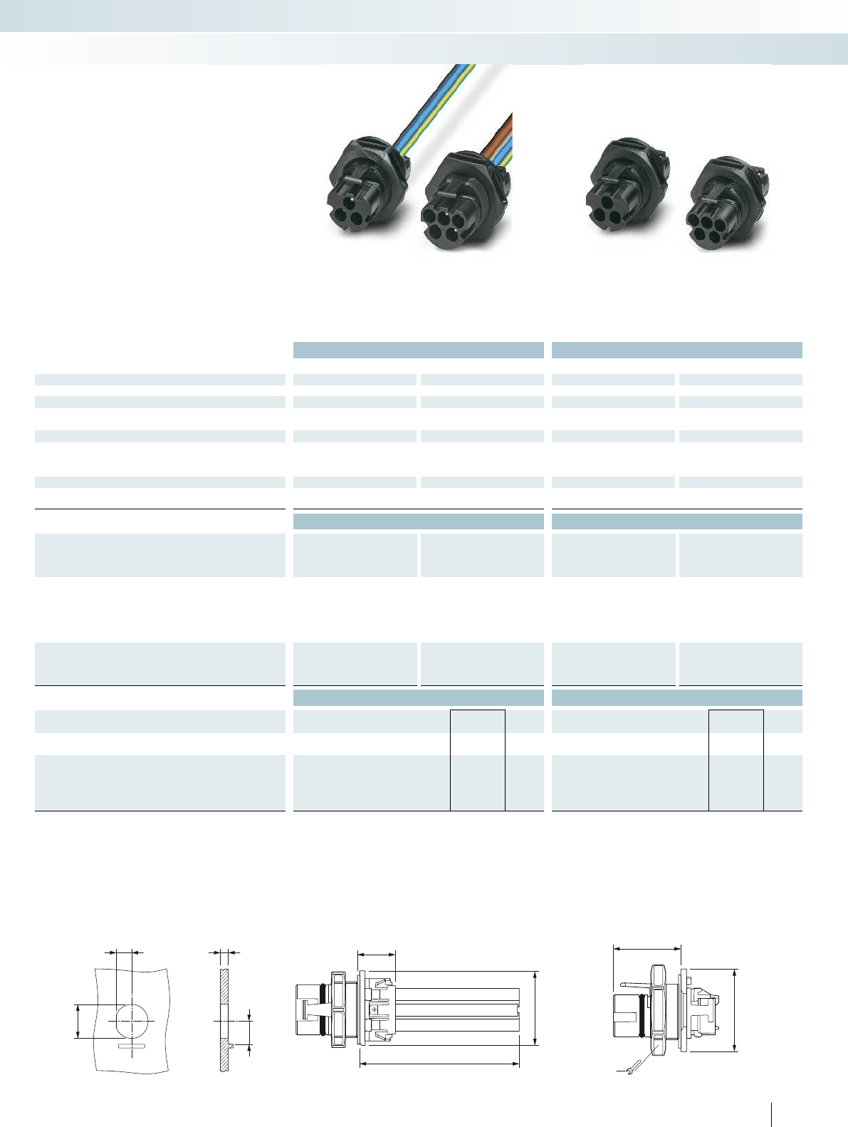
6
Ø25,5
±0,2
11,7-0,2
16,4
±0,2
N
3
33,4
15
x
29,5
Ø35
34
For additional information, visit phoenixcontact.net/products
Technical data Technical data
3-pos. 5-pos. 3-pos. 5-pos.
General data
Degree of protection (when plugged in) IP65/IP68 (2m/24h) IP65/IP68 (2m/24h)
Electrical data
Rated voltage 690 V 690 V
Rated current 35 A 30 A 35 A 30 A
Material data
Contact surface material Silver-plated Silver-plated
Material of grip body PPE PPE
Inflammability class according to UL 94 V0 V0
Temperature data
Ambient temperature (operation) -40°C ... 100°C
(dependent on the derating curve)
-40°C ... 100°C
(dependent on the derating curve)
Ordering data Ordering data
Description Order No. Pcs. /
Pkt. Order No. Pcs. /
Pkt. Order No. Pcs. /
Pkt. Order No. Pcs. /
Pkt.
3-pos. 5-pos. 3-pos. 5-pos.
M25 device connector incl. locking nut, cable length 150mm,
with conductor cross section:
2.5mm² 1409219 10 1409211 10
4mm² 1409220 10 1409212 10
6 mm² 1409221 10 1409213 10
Contact carrier incl. locking nut, without contacts,
for crimp contacts, conductor cross section of 2.5mm² ... 6mm²
1409218 50 1409206 50
Accessories Accessories
Protective cap
PRC COVER M 1409237 50 PRC COVER M 1409237 50
Replacement locking nut
FT NUT M25 BK 1457937 100 FT NUT M25 BK 1457937 100
Crimp contacts CK 2,5, silver-plated contact surface
for conductor cross section:
2.5mm² CK2,5-M-2,5 AG 1409207 100
4mm² CK2,5-M-4 AG 1409208 100
6 mm² CK2,5-M-6 AG 1409209 100
Panel cutout
77PHOENIX CONTACT
Connection technology for field devices
Photovoltaic AC connectors
Pin contacts
with litz wires
Pin contact carrier
without contacts
– Snaps in automatically when inserted,
released using a screwdriver
– Pre-assembled with litz wires or for
self-assembly
– IP65 when not plugged in
– With capacitive PE contact
Device connectors
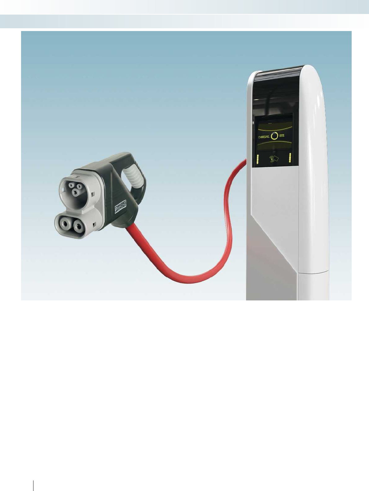
78 PHOENIX CONTACT
Connection technology for field devices
Charging cables for electric vehicles
The development of a widespread
charging infrastructure in conjunction with
renewable energy is an important step
toward a mobile future. Internationally
standardized charging systems are used to
establish an electrical connection between
the electric vehicle and the infrastructure
(e.g., a charging station). In terms of the
charging interfaces required, a distinction is
made between:
– Vehicle inlets
– Socket outlets on the charging station
– Charging cables with connectors
(charging plug on the vehicle), plugs
(charging plug in the infrastructure), and
integrated IC-CPD control units.
International standards ensure uniform
connection for charging stations and
vehicles:
– Type 1 according to SAE J1772 (USA,
Japan)
– Type 2 according to IEC-62196 (Europe)
– GB standard (China).
The charging plugs from Phoenix Contact
offer reliable, standard-compliant solutions
for a consistent charging interface for all
applications.
This is implemented, for example, with
the Combined Charging System (CCS),
which was developed by major German
automobile manufacturers in cooperation
with Phoenix Contact. The electric vehicle
can be charged conventionally with AC at
home, for example. In addition, the vehicle-
side inlet is also designed for rapid DC
charging. Only short stops are required for
the charging process - e.g., on the go at rest
stops.
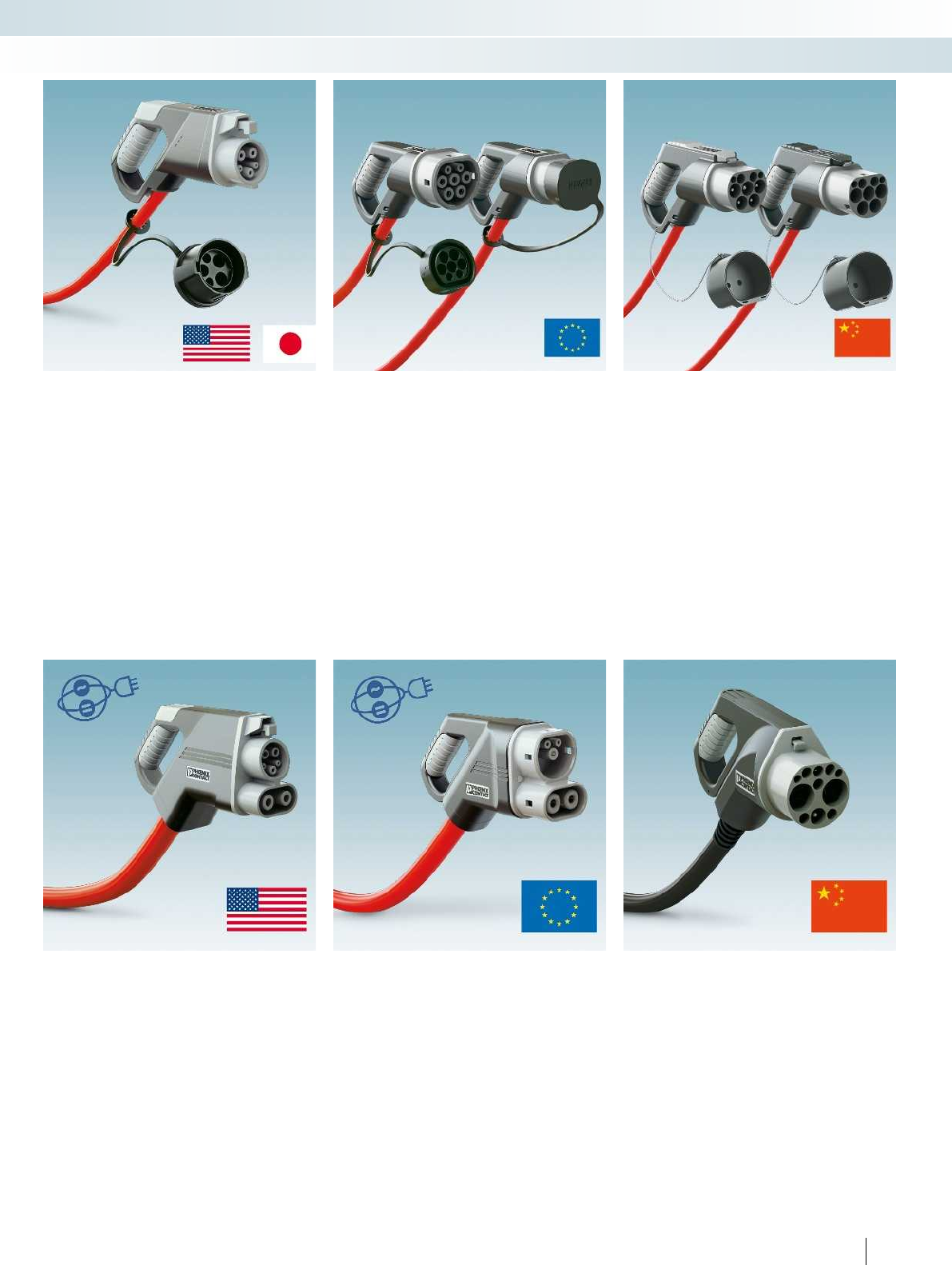
For additional information, visit phoenixcontact.net/products
79PHOENIX CONTACT
Connection technology for field devices
Charging cables for electric vehicles
AC type 1
The type 1 AC charging system is based
on standard SAE J1772. It is primarily used
in the USA and Japan. The lock is
implemented using a lever system.
AC type 2
The type 2 AC charging system,
developed for Europe, is designed according
to the IEC 62196-2 standard. It supports
single- and three-phase charging. An
electromechanical actuator lock safeguards
the charging process.
AC GB
The AC charging system standardized
according to the Chinese GB standard
enables both single- and three-phase
charging. Charging takes place securely
thanks to a special lever system.
DC CCS type 1
In the USA, the type 1 DC CCS charging
system is used for fast DC charging,
according to SAE J1772 and IEC 62196-3.
The lever locking mechanism is also
supported by an additional actuator lock.
DC CCS type 2
In Europe, the type 2 DC CCS charging
system is the vanguard for rapid DC
charging according to IEC-62196-3. The
electromechanical actuator lock prevents
premature removal during the charging
process.
DC GB
The DC GB charging system is based on
the GB standard. It offers rapid DC charging
for Chinese charging stations. The lever
lock is also supported by an additional
actuator lock.
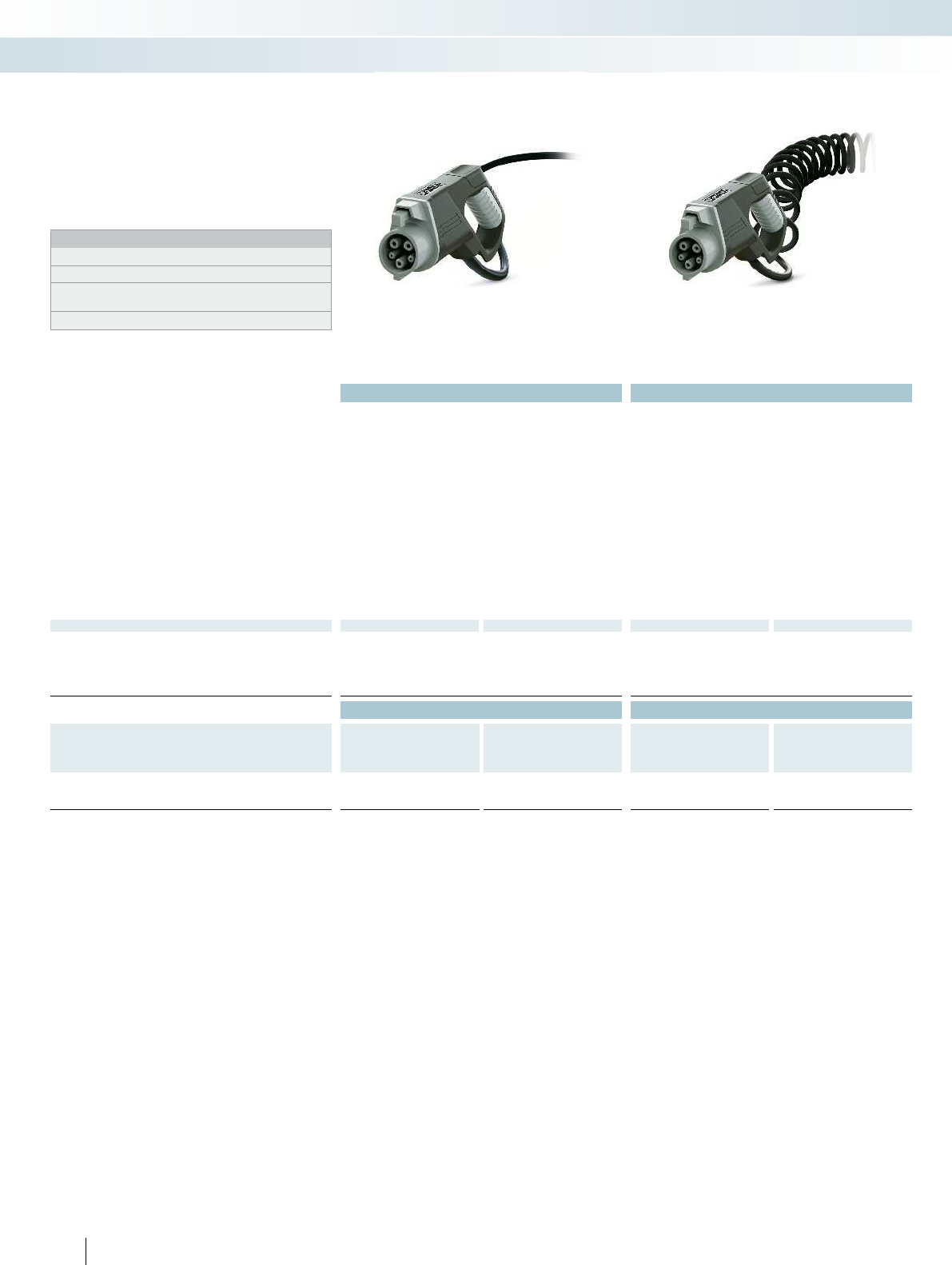
Technical data Technical data
16 A 30 A 20 A 32 A
Rated current 16 A30 A 20 A32 A
Number of phases 1 1 1 1
Rated voltage 240 V AC 240 V AC 250 V AC 250 V AC
Standards SAE J1772 SAE J1772 SAE J1772 SAE J1772
Charging mode AC level 2 AC level 2 Mode 3 Mode 3
Resistor coding 150 Ω (Lever actuated)
480 Ω (Lever not actuated)
150 Ω (Lever actuated)
480 Ω (Lever not actuated)
150 Ω (Lever actuated)
480 Ω (Lever not actuated)
150 Ω (Lever actuated)
480 Ω (Lever not actuated)
Ambient temperature
(Operation)
-30°C ... 50°C -30°C ... 50°C -30°C ... 50°C -30°C ... 50°C
Number of power contacts 3 (L1, N, PE) 3 (L1, N, PE) 3 (L1, N, PE) 3 (L1, N, PE)
Insertion/withdrawal cycles > 10000 > 10000 > 10000 > 10000
Insertion/withdrawal force < 100 N < 100 N < 100 N < 100 N
Type of protection (when plugged in) IP44 IP44 IP44 IP44
Degree of protection (with protective cap) IP24 IP24 IP24 IP24
Degree of protection (when not plugged in) IP20 IP20 IP20 IP20
Cable data
Cable type Straight Straight Spiraled Spiraled
Cable length 4 m4 m 4 m4 m
Cable diameter 9.4 mm ± 0.2 16.4 mm ± 0.2 10.5 mm ±0.5 13.9 mm ±0.5
Cable structure 3 x 14 AWG + 1 x 18 AWG 3 x 10 AWG + 1 x 18 AWG 3 x 2.5 mm² + 1 x 0.5 mm² 3 x 6.0 mm² + 1 x 0.5 mm²
Sheath color Black Black Black Black
Ordering data Ordering data
Description Order No. Pcs. /
Pkt. Order No. Pcs. /
Pkt. Order No. Pcs. /
Pkt. Order No. Pcs. /
Pkt.
16 A 30 A 20 A 32 A
AC charging cable with open cable end, mode 3, type 1
1621484 11409949 11621670 11621794 1
80 PHOENIX CONTACT
Connection technology for field devices
Charging cables for electric vehicles
Type 1 AC connector,
with AWG cable
Type 1 AC connector,
with metric cable
Type 1 AC charging cables with open
cable end are primarily installed in charging
stations and wall boxes in the USA and
Japan. They are used to charge electric
vehicles with alternating current.
Notes:
Further cable types and lengths are available on request.
Color variants for housing and cables are available on request.
Additional charging cables with higher rated currents are available
on request.
All connectors are supplied with a protective cap.
Type 1 AC charging cables
with open cable end
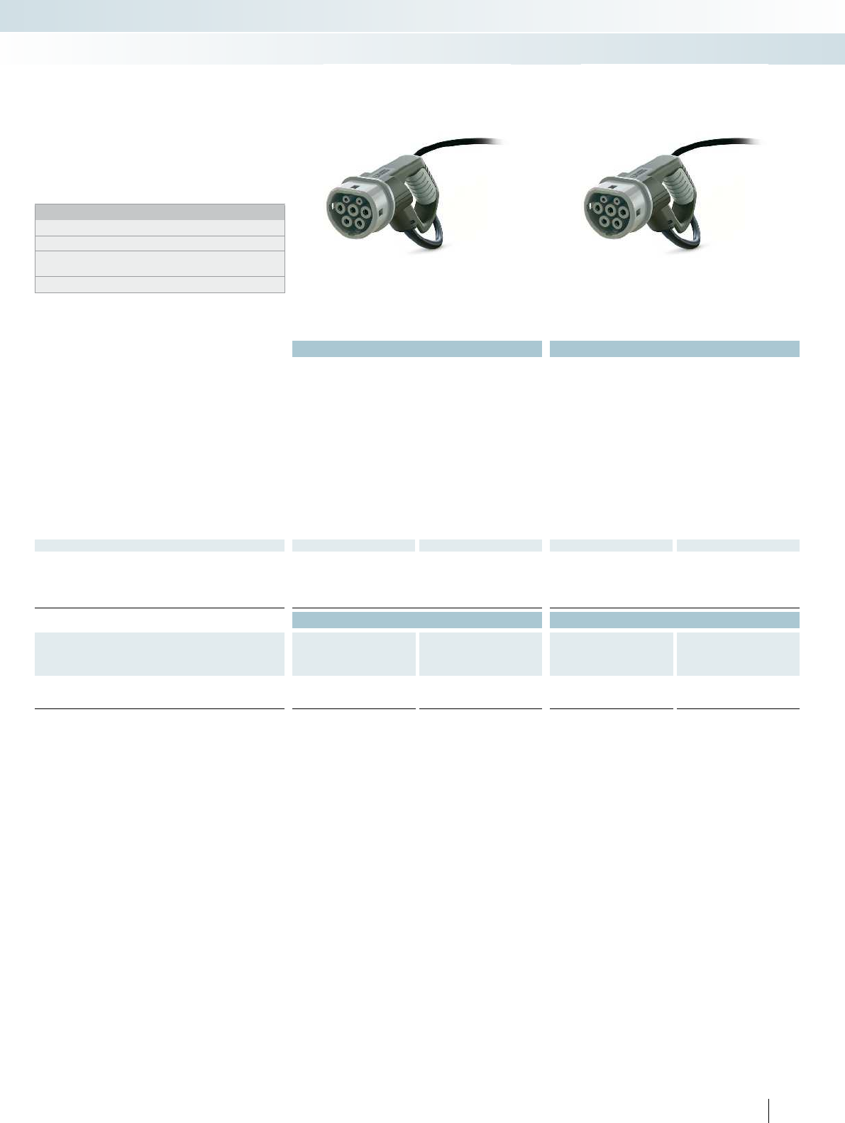
For additional information, visit phoenixcontact.net/products
Technical data Technical data
20 A 20 A 32 A 32 A
Rated current 20 A 20 A 32 A 32 A
Number of phases 13 13
Rated voltage 250 V AC 480 V AC 250 V AC 480 V AC
Standards IEC 62196-2 IEC 62196-2 IEC 62196-2 IEC 62196-2
Charging mode Mode 3 Mode 3 Mode 3 Mode 3
Resistor coding 680 Ω (between PE and PP) 680 Ω (between PE and PP) 220 Ω (between PE and PP) 220 Ω (between PE and PP)
Ambient temperature
(Operation)
-30°C ... 50°C -30°C ... 50°C -30°C ... 50°C -30°C ... 50°C
Number of power contacts 3 (L1, N, PE) 5 (L1, L2, L3, N, PE) 3 (L1, N, PE) 5 (L1, L2, L3, N, PE)
Insertion/withdrawal cycles > 10000 > 10000 > 10000 > 10000
Insertion/withdrawal force < 100 N < 100 N < 100 N < 100 N
Type of protection (when plugged in) IP44 IP44 IP44 IP44
Degree of protection (with protective cap) IP24 IP24 IP24 IP24
Degree of protection (when not plugged in) IP20 IP20 IP20 IP20
Cable data
Cable type Straight Straight Straight Straight
Cable length 4 m4 m 4 m4 m
Cable diameter 10.5 mm ±0.5 13 mm ±0.5 13.9 mm ±0.5 17 mm ±0.5
Cable structure 3 x 2.5 mm² + 1 x 0.5 mm² 5 x 2.5 mm² + 1 x 0.5 mm² 3 x 6 mm² + 1 x 0.5 mm² 5 x 6 mm² + 1 x 0.5 mm²
Sheath color Black Black Black Black
Ordering data Ordering data
Description Order No. Pcs. /
Pkt. Order No. Pcs. /
Pkt. Order No. Pcs. /
Pkt. Order No. Pcs. /
Pkt.
20 A 20 A 32 A 32 A
AC charging cable with open cable end, mode 3, type 2
1409319 11409320 11405198 11405199 1
81PHOENIX CONTACT
Connection technology for field devices
Charging cables for electric vehicles
Type 2 AC connector,
20 A
Type 2 AC connector,
32 A
Type 2 AC charging cables with open
cable end are installed in charging stations
and wall boxes in European infrastructure.
They are used to charge electric vehicles
with alternating current.
Notes:
Further cable types and lengths are available on request.
Color variants for housing and cables are available on request.
Additional charging cables with higher rated currents are available
on request.
All connectors are supplied with a protective cap.
Type 2 AC charging cables
with open cable end

Technical data Technical data
20 A 32 A 20 A 32 A
Rated current 20 A32 A 20 A32 A
Number of phases 1 1 1 3
Rated voltage 250 V AC 250 V AC 250 V AC 480 V AC
Standards IEC 62196-2 IEC 62196-2 IEC 62196-2 IEC 62196-2
Charging mode Mode 3 Mode 3 Mode 3 Mode 3
Ambient temperature
(Operation)
-30°C ... 50°C -30°C ... 50°C -30°C ... 50°C -30°C ... 50°C
Number of power contacts 3 (L1, N, PE) 3 (L1, N, PE) 3 (L1, N, PE) 5 (L1, L2, L3, N, PE)
Insertion/withdrawal cycles > 10000 > 10000 > 10000 > 10000
Insertion/withdrawal force < 100 N < 100 N < 100 N < 100 N
Type of protection (when plugged in) IP44 IP44 IP44 IP44
Degree of protection (with protective cap) IP24 IP24 IP24 IP24
Degree of protection (when not plugged in) IP20 IP20 IP20 IP20
Cable data
Cable type Straight Straight Straight Straight
Cable length 4 m4 m 4 m4 m
Cable diameter 10.5 mm ±0.5 13.9 mm ±0.5 10.5 mm ±0.5 17 mm ±0.5
Cable structure 3 x 2.5 mm² + 1 x 0.5 mm² 3 x 6 mm² + 1 x 0.5 mm² 3 x 2.5 mm² + 1 x 0.5 mm² 5 x 6 mm² + 1 x 0.5 mm²
Sheath color Black Black Black Black
Ordering data Ordering data
Description Order No. Pcs. /
Pkt. Order No. Pcs. /
Pkt. Order No. Pcs. /
Pkt. Order No. Pcs. /
Pkt.
20 A 32 A 20 A 32 A
AC charging cable with plug, mode 3
1621481 11410090 11405193 11404569 1
82 PHOENIX CONTACT
Connection technology for field devices
Charging cables for electric vehicles
Type 1 AC connector
with type 2 plug
Type 2 AC connector
with type 2 plug
The mobile AC charging cables enable
electric vehicles to be charged with
alternating current at European charging
stations or wall boxes at home and while on
the move. They can easily be stored inside
the vehicle.
Notes:
Further cable types and lengths are available on request.
Color variants for housing and cables are available on request.
All connectors and plugs are supplied with a protective cap.
Type 1 and type 1 mobile AC charging
cables (mode 3)
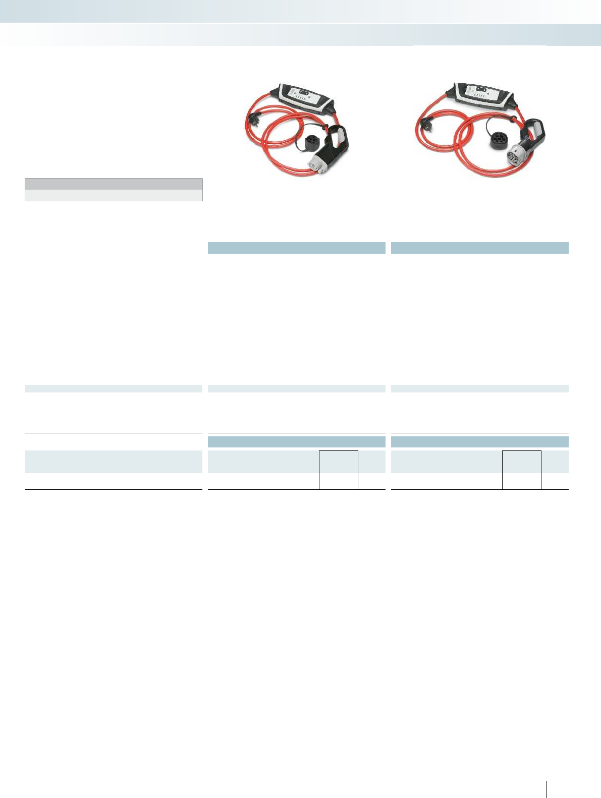
For additional information, visit phoenixcontact.net/products
Technical data Technical data
Rated current 6 A ... 13 A 6 A ... 13 A
Number of phases 1 1
Rated voltage 200 V AC ... 250 V AC 200 V AC ... 250 V AC
Frequency 50 Hz 50 Hz
Charging power 1.4 kW ... 3 kW 1.4 kW ... 3 kW
Standards IEC61851-1 IEC61851-1
Charging mode Mode 2 Mode 2
Ambient temperature
(Operation)
-30°C ... 40°C -30°C ... 40°C
Tripping characteristics / residual current Type A/30 mA Type A/30 mA
Infrastructure plug SCHUKO (type AF) SCHUKO (type AF)
Temperature sensor (infrastructure plug) Available Available
Degree of protection (IC-CPD) IP67 IP67
Type of protection (when plugged in) IP44 IP44
Degree of protection (with protective cap) IP24 IP24
Degree of protection (when not plugged in) IP20 IP20
Cable data
Cable type Straight Straight
Cable length 4 m 4 m
Cable diameter 10.5 mm ±0.5 10.5 mm ±0.5
Cable structure 3 x 2.5 mm² + 2 x 0.5 mm² 3 x 2.5 mm² + 2 x 0.5 mm²
Sheath color Red Red
Ordering data Ordering data
Description Type Order No. Pcs. /
Pkt. Type Order No. Pcs. /
Pkt.
AC charging cable with IC-CPD, mode 2
EV-ICCPD-T1C-EU-S-13A1-A-GEN2 1621797 1EV-ICCPD-T2C-EU-S-13A1-A 1621516 1
83PHOENIX CONTACT
Connection technology for field devices
Charging cables for electric vehicles
Type 1 AC connector
with IC-CPD and SCHUKO plug
Type 2 AC connector
with IC-CPD and SCHUKO plug
The mobile AC charging cables with In
Cable Control and Protection Device (IC-
CPD) enable electric vehicles to be charged
with alternating current at a normal,
European socket at home and while on the
move. Standardized communication with
the vehicle as well as the safety equipment
are integrated in the IC-CPD.
Notes:
All connectors are supplied with a protective cap.
Type 1 and type 2 mobile AC charging
cables (mode 2)

Technical data Technical data
60 A 125 A 200 A 60 A 125 A 200 A
Rated current 60 A 125 A 200 A 60 A 125 A 200 A
Rated voltage 600 V DC 600 V DC 600 V DC 850 V DC 850 V DC 850 V DC
Standards SAE J1772 SAE J1772 SAE J1772 IEC62196-3 IEC62196-3 IEC62196-3
Charging mode DC level 2 DC level 2 DC level 2 Mode 4 Mode 4 Mode 4
Resistor coding 150 Ω
(Lever actuated)
480 Ω
(Lever not actuated)
150 Ω
(Lever actuated)
480 Ω
(Lever not actuated)
150 Ω
(Lever actuated)
480 Ω
(Lever not actuated)
1500 Ω (between PE
and PP)
1500 Ω (between PE
and PP)
1500 Ω (between PE
and PP)
Ambient temperature
(Operation)
-30°C ... 50°C -30°C ... 50°C -30°C ... 50°C -30°C ... 50°C -30°C ... 50°C -30°C ... 50°C
Number of power contacts 3 (PE, DC+, DC-) 3 (PE, DC+, DC-) 3 (PE, DC+, DC-) 3 (PE, DC+, DC-) 3 (PE, DC+, DC-) 3 (PE, DC+, DC-)
Insertion/withdrawal cycles > 10000 > 10000 > 10000 > 10000 > 10000 > 10000
Insertion/withdrawal force < 100 N < 100 N < 100 N < 100 N < 100 N < 100 N
Temperature sensor Pt1000 Pt1000 Pt1000 Pt1000 Pt1000 Pt1000
Type of protection (when plugged in) IP44 IP44 IP44 IP44 IP44 IP44
Degree of protection (when not plugged in) IP20 IP20 IP20 IP24 IP24 IP24
Cable data
Cable type Straight Straight Straight Straight Straight Straight
Cable length 5 m5 m5 m 4.5 m5 m5 m
Cable diameter 20.6 mm ± 0.2 32.2 mm ± 0.2 37.4 mm ± 0.2 19 mm ± 0.2 28.2 mm ± 0.2 32 mm ± 0.2
Cable structure 3 x 6 AWG +
3 x 2 x 18 AWG
2 x 1 AWG +
1 x 3 AWG +
3 x 2 x 18 AWG
2 x 00 AWG +
1 x 1 AWG +
3 x 2 x 18 AWG
3 x 16 mm² +
3 x 2 x 0.75 mm²
2 x 50 mm² +
1 x 25 mm² +
3 x 2 x 0.75 mm²
2 x 70 mm² +
1 x 35 mm² +
3 x 2 x 0.75 mm²
Sheath color Black Black Black Black Black Black
Ordering data Ordering data
Description Order No. Pcs. /
Pkt. Order No. Pcs. /
Pkt. Order No. Pcs. /
Pkt. Order No. Pcs. /
Pkt. Order No. Pcs. /
Pkt. Order No. Pcs. /
Pkt.
60 A 125 A 200 A 60 A 125 A 200 A
DC charging cable with open cable end,
combined charging system (CCS)
1621488 11409950 11621489 11618306 11409060 11621653 1
84 PHOENIX CONTACT
Connection technology for field devices
Charging cables for electric vehicles
Type 1 combined DC connector,
with AWG cable
Type 2 combined DC connector,
with metric cable
The CCS DC charging cables with open
cable end are connected directly to a DC
charging station. They are suitable for fast
DC charging of electric vehicles.
The CCS connector is compatible with
the CCS inlet, which also accommodates an
AC connector.
Notes:
Further cable types and lengths are available on request.
Color variants for housing and cables are available on request.
Combined charging system (CCS)
DC charging cables type 1 and type 2

For additional information, visit phoenixcontact.net/products
Technical data
Rated current 60 A
Rated voltage 750 V DC
Standards GB/T Part 3
Charging mode Mode 4
Resistor coding 1000 Ω
Ambient temperature
(Operation)
-30°C ... 50°C
Number of power contacts 3
Insertion/withdrawal cycles > 10000
Insertion/withdrawal force < 100 N
Type of protection (when plugged in) IP55
Cable data
Cable type Straight
Cable length 5 m
Cable diameter 20.2 mm ± 0.2
Cable structure 3 x 16 mm² + 2 x 2.5 mm² + 9 x 0.5 mm²
Sheath color Black
Ordering data
Description Type Order No. Pcs. /
Pkt.
DC charging cable with open cable end, GB/T
EV-GBM4C-DC60A-5,0M16ESBK00 1621468 1
85PHOENIX CONTACT
Connection technology for field devices
Charging cables for electric vehicles
DC GB connector,
with metric cable
DC GB charging cables with open cable
end are installed in Chinese charging
stations with a stationary AC/DC
converter. They are suitable for fast DC
charging of electric vehicles.
Notes:
Further cable types and lengths are available on request.
Color variants for housing and cables are available on request.
DC charging cables
GB standard (China)
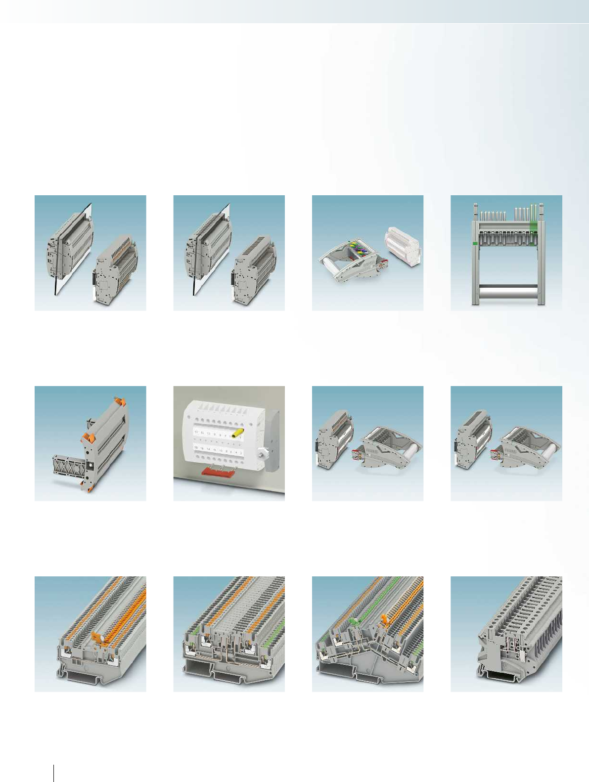
FAME plug-in test system with push-in
connection, for wall and DIN rail mounting
PT ... Page 92
FAME plug-in test system with screw
connection, for wall and DIN rail mounting
UT ... Page 94
Blind plugs, coding profile, and colored test
sockets
Page 98
FAME plug-in test system with push-in
connection, VDE types, for wall and
DIN rail mounting
PT ... Page 102
Accessories
Bridges and cover profiles
Page 100
Push-in knife disconnect terminal blocks
PT 1,5..., PTT 1,5... Page 156
Push-in double-level disconnect and knife
disconnect terminal blocks
PTT 2,5... Page 158
Push-in double-level disconnect and knife
disconnect terminal blocks in desk design
PTTBS ... Page 160
Screw connection disconnect and knife
disconnect terminal blocks with fuse plug
UT ...-TG Page 162
UTT ...-TG Page 164
FAME test plug, multi-position, freely
configurable contact tabs
FTPR ..., FTP ... Page 96
Ordering example for configurable test plugs
with twist grip or standard grip
Page 97
FAME plug-in test system with screw
connection, VDE types, for wall and
DIN rail mounting
UT ... Page 128
86 PHOENIX CONTACT
Modular terminal blocks
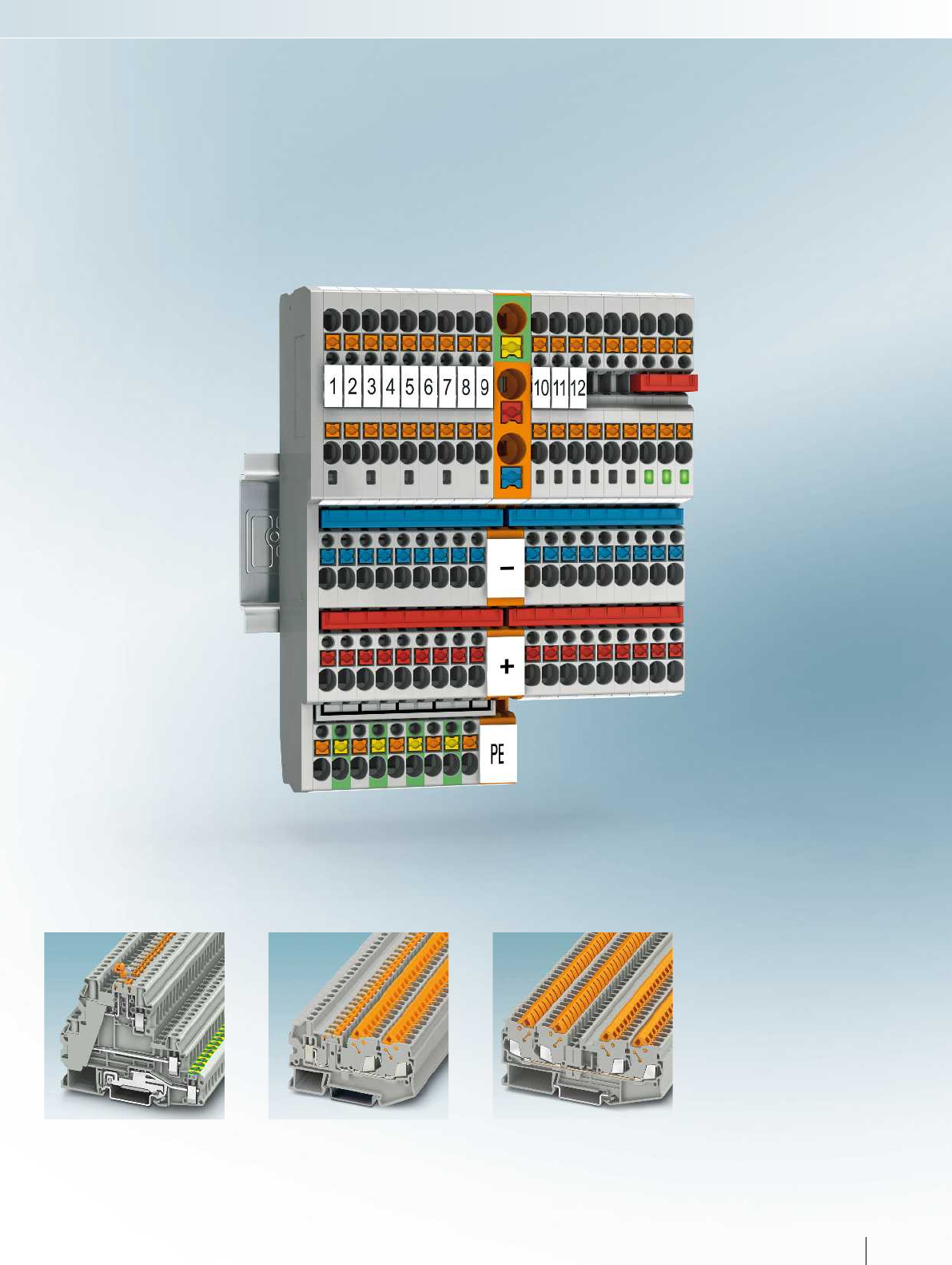
Screw connection multi-level function and
lever-type fuse terminal blocks with PE foot
UT 4...-TG/MT Page 166
UT 4...-HESI Page 168
Fast connection hybrid knife disconnect
terminal block with single-sided screw
connection
QTCU 2,5-TWIN-MT Page 172
Fast connection feed-through and ground
terminal blocks
QTC 2,5-QUATTRO Page 173
87PHOENIX CONTACT
Modular terminal blocks
For additional information, visit phoenixcontact.net/products
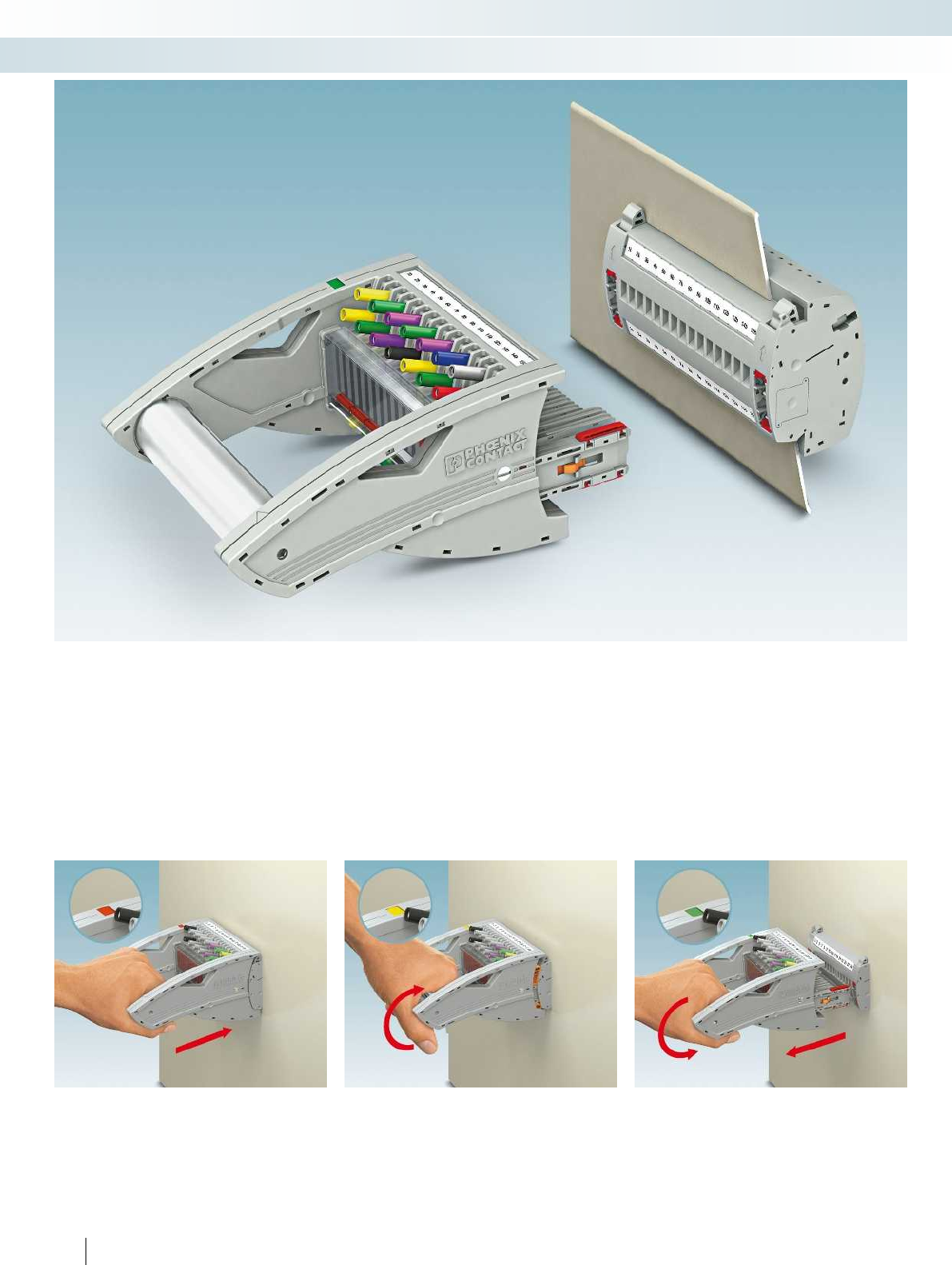
88 PHOENIX CONTACT
Modular terminal blocks
FAME plug-in test system
FAME is the innovative test system for all measuring and testing tasks in network protection technology for medium and high-voltage
switchgear. With the modular system, you can now perform manual testing automatically, safely, and more quickly. Suitable for every
application, the modular system can be directly integrated into the control cabinet panel or used as a DIN rail version.
The test plug is completely inserted and
engaged, the display window turns red. All
test contacts are contacted according to
the test setup.
The twist grip is turned upward as far as
it will go, the display window turns yellow.
Test contacts with short contact tab lengths
(e.g., current transformers) are once again
connected to the protective device.
The twist grip must be turned back to its
starting position. Now the mechanism
releases the plug so it can be fully removed.
The display window turns green.
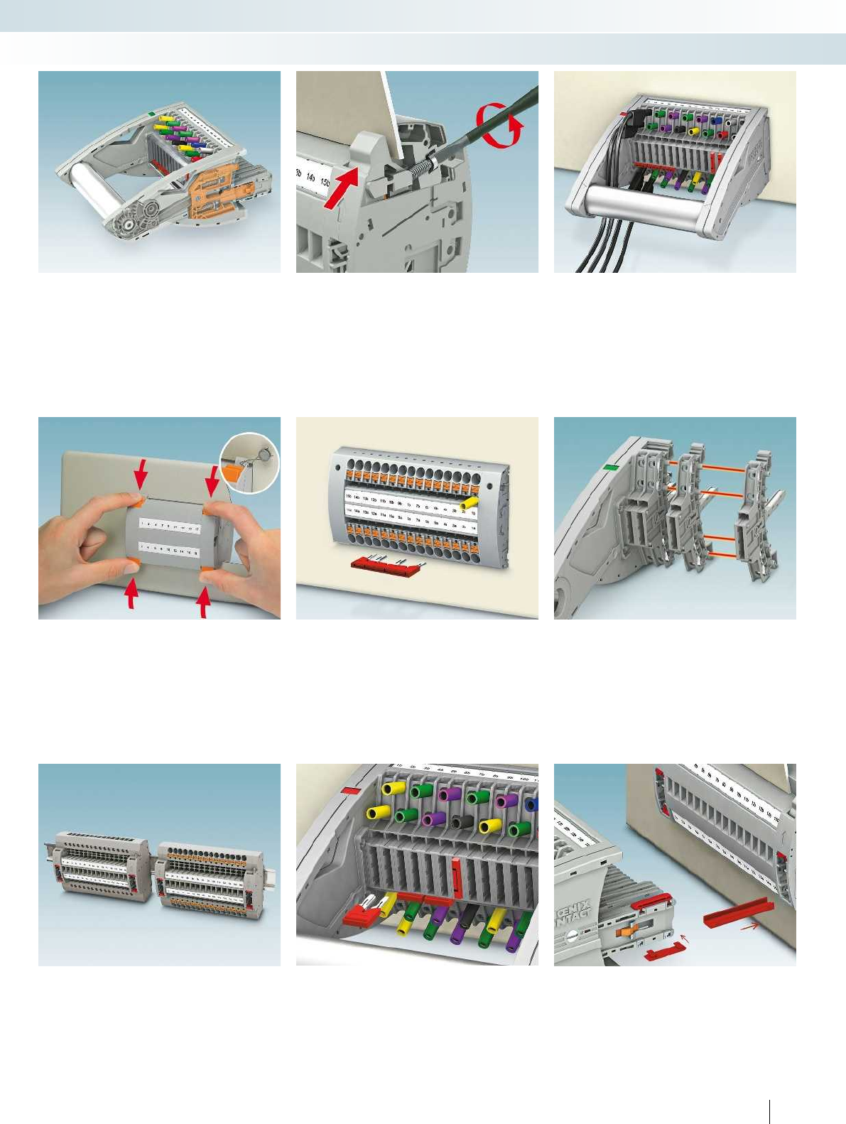
For additional information, visit phoenixcontact.net/products
89PHOENIX CONTACT
Modular terminal blocks
FAME plug-in test system
Preprogrammed short-circuit and
switching operations depend on consistent
insertion and removal of the test plug.
Undefined contact states are effectively
avoided thanks to the twist grip mechanism.
The patented wall fastening is easy to use
and has a robust design. Even tolerances in
the panel cutout of up to 4mm are
compensated.
The offset test socket arrangement
enables the use of CATIII and CATIV/1000
V safety test leads according to EN61010-
031 in a confined space.
FAME test terminal strips have an IP20
design. Blind plugs without switching
function can be inserted and secured with
seals. These can only be released with two-
hand operation.
In addition to the two marking grooves,
the test terminal strips for wall mounting
also offer two function shafts, or six
function shafts in the case of the DIN rail
version, inside the control cabinet for
forming and grounding the star point.
The compact and modular design of the
system, as well as the plugs and test
terminal strips, provides an extensive range
of options for every application with
positions from 4 to 25.
All applications which do not involve
testing through the closed door and the
open rack mounting can be implemented
with the DIN rail version. Terminal points
and plug-in zone can be operated from one
direction.
The test plug provides three function
shafts between the 4 mm test contacts.
Horizontally aligned, as leading short-circuit
jumper - vertically aligned as through
connection in the plug.
The coding profiles can be applied by the
user according to their application. VDE-
compliant versions are pre-coded on
delivery. This ensures maximum safety.
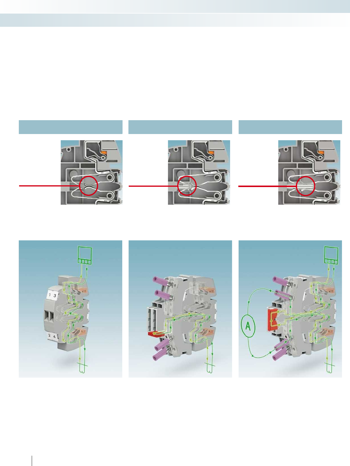
The new, modular FAME measuring transducer test system enables all transformer
testing tasks to be carried out quickly and safely.
The automatically generated transformer short circuit, the twist grip mechanism, and the
shock-proof design provide maximum safety during measurement.
FAME 2 – safe in every operating state
Normal operation Transformer short circuit Test operation
Due to the N/C contact function of the
FAME 2 system, additional power plugs are
not required for normal operation. If desired,
the plug-in zone can be covered with a blind
plug to prevent unauthorized access.
When replacing the protective device or
even in the case of a relay test, a leading short
circuit of the current transformer (for the
purpose of signal splitting) can be easily
carried out by means of a jumper inserted
crossways.
With the jumper simply inserted lengthways
in the test plug, test equipment can be easily
looped into the current path via the 4 mm
test sockets.
Leading short
circuit by means
of auxiliary
contact
N/O contact
connected via
test socket
Closed N/O
contact
90 PHOENIX CONTACT
Modular terminal blocks
FAME plug-in test system
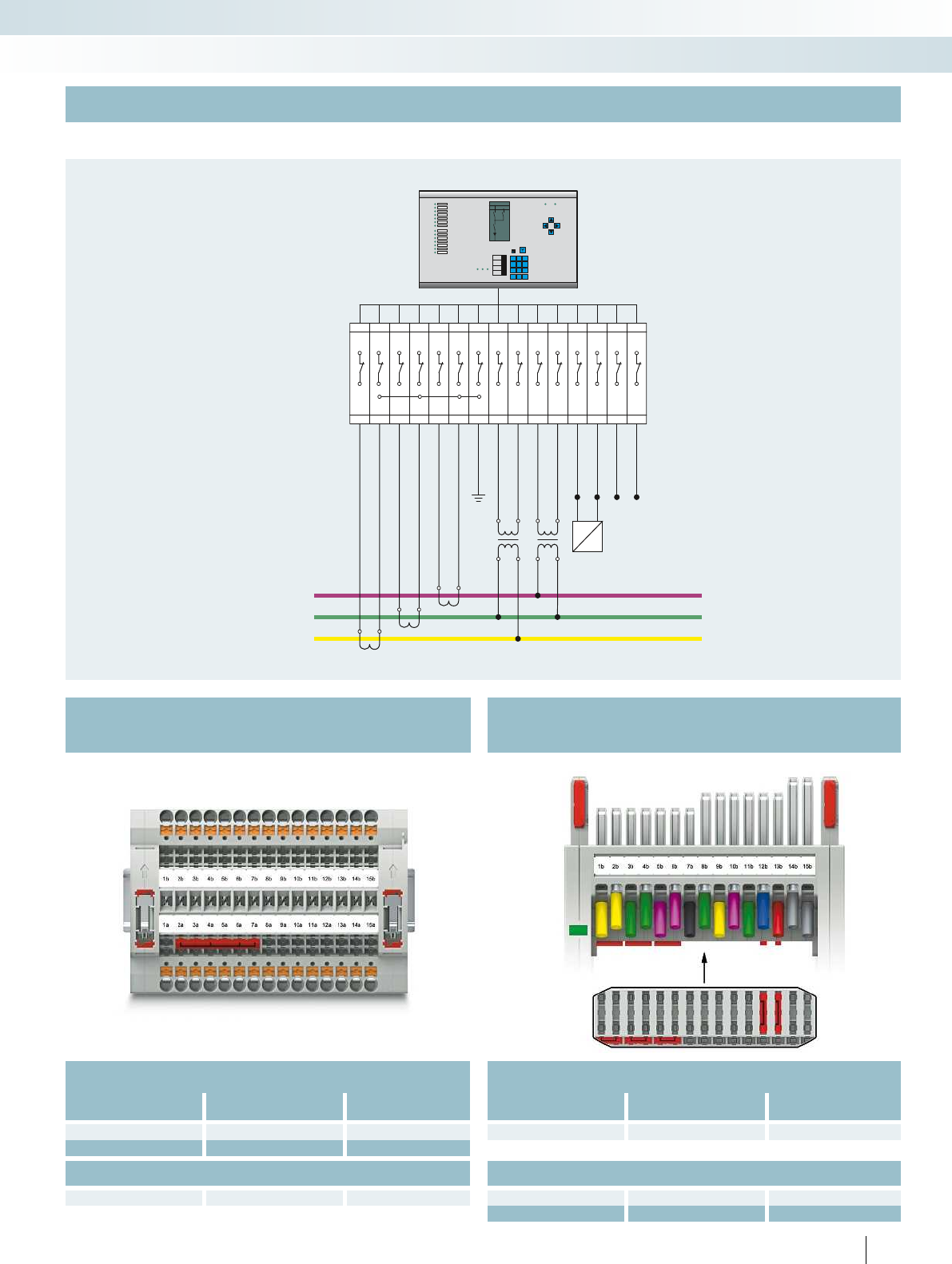
1b
1a
2b
2a
3b
3a
4b
4a
5b
5a
6b
6a
7b
7a
8b
8a9a
9b 10b
10a
11b
11a
12b
12a
13b
13a
14b
14a
15b
15a
1
L1 L2 L3
2
1
4
7
*
2
5
8
9
3
6
9
#
L3
L2
L1
For additional information, visit phoenixcontact.net/products
Auxiliary voltage
OFF
Status
U
H-
U
H+
uv uv
UV UV
S1 S2
S1 S2
S1 S2
Medium-voltage circuit example with star point grounding in the test terminal strip
Test plug with current transformer,
voltage transducer, and signals
Test plug
Order No. Type Required quantity
3001693 FTPR 2/15 1
Jumper
3030284 FBS 2-8 3
3030297 FBS 3-8 2
Test terminal strip with current
transformer, voltage transducer, and signals
Test terminal strip, blind plug
Order No. Type Required quantity
3069864 PTRE 6-2/15 1
3069886 FBP 2/15 1
Jumper
3032470 FBS 6-8 1
91PHOENIX CONTACT
Modular terminal blocks
FAME plug-in test system
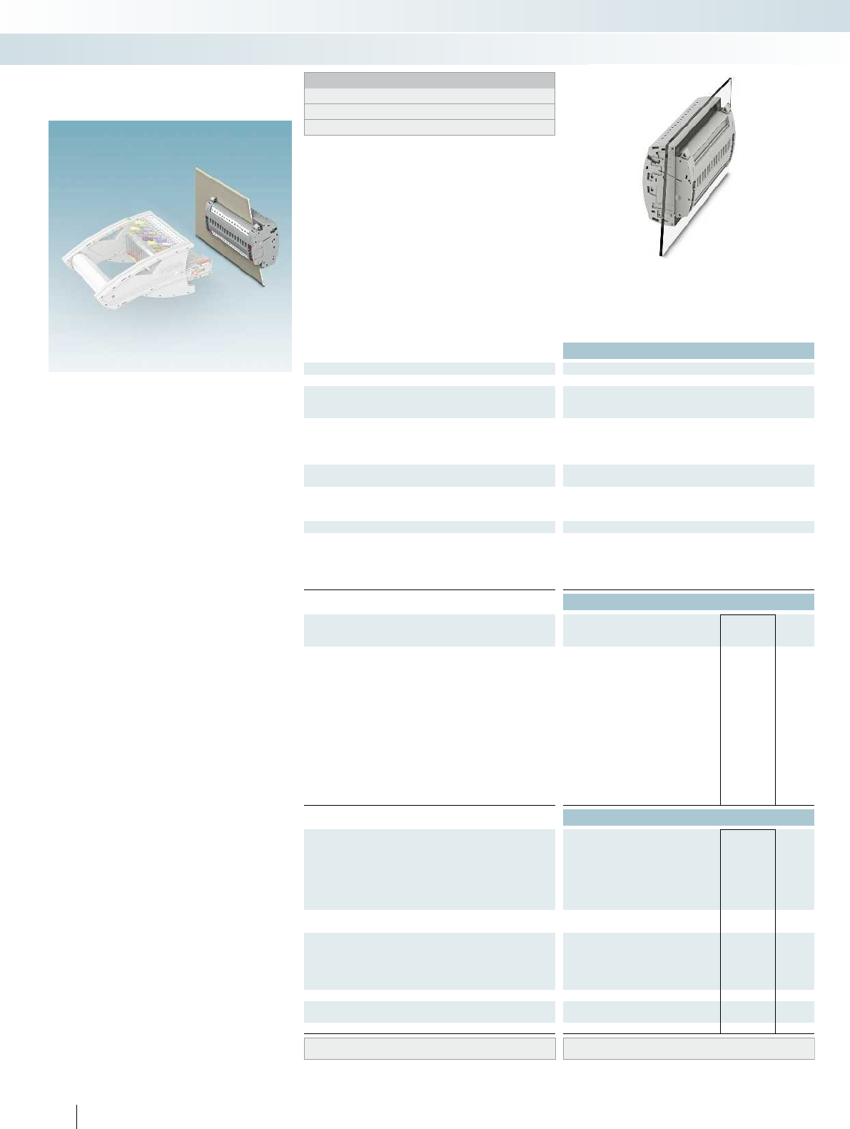
Technical data
Max. electrical data Imax. [A] Umax. [V] max. Ø [mm²] AWG
30 4002) 0.5 - 10 20 - 8
IEC 60947-7-1
Rated data IEC UL/CUL CSA IEC/
EN60079-7
Rated voltage [V] 4002)---
Nominal current / cross section [A] / [mm²] 241)/6---
Rated cross section [mm²] 6 - - -
Cross section range AWG 20 - 8 - - -
Connection capacity solid stranded ferrule
with/without plastic sleeve
1 conductor [mm²] 0.5 - 10 0.5 - 6 0.5 - 6 0.5 - 6
2 stranded conductors with a TWIN ferrule [mm²] 0.5 - 1.5
Plug-in connection cross sections [mm²] 1 - 10 - 1 - 6 1 - 6
General data
Stripping length [mm] 12
Tightening torque for wall fastening [Nm] 0.8 - 1
Panel thickness [mm] 1 - 4
Insulating material PA
Inflammability class according to UL 94 V0
Ordering data
Description No. of
pos. Color Type Imax Order No. Pcs. /
Pkt.
Test terminal strip, for wall mounting,
4-pos. gray PTWE 6-2/4 3069827 1
5-pos. gray PTWE 6-2/5 3069828 1
9-pos. gray PTWE 6-2/9 3069832 1
10-pos. gray PTWE 6-2/10 3069833 1
12-pos. gray PTWE 6-2/12 3069835 1
14 pos. gray PTWE 6-2/14 3069837 1
15-pos. gray PTWE 6-2/15 3069838 1
17-pos. gray PTWE 6-2/17 3069840 1
19 pos. gray PTWE 6-2/19 3069842 1
20 pos. gray PTWE 6-2/20 3069843 1
21 pos. gray PTWE 6-2/21 3069844 1
22 pos. gray PTWE 6-2/22 3069845 1
25 pos. gray PTWE 6-2/25 3069848 1
Accessories
Jumper
2red FBS 2-8 24 A 3030284 10
3red FBS 3-8 24 A 3030297 10
4red FBS 4-8 24 A 3030307 10
5red FBS 5-8 24 A 3030310 10
6red FBS 6-8 24 A 3032470 10
10 red FBS 10-8 24 A 3030323 10
Jumper
16 red FBSR 16-8 24 A 3033816 10
Pre-assembled bridge, labeled
3-pos., positions 1, 3 3red FBS 1/3-8 24 A 3032363 10
4-pos., positions 1, 4 4red FBS 1/4-8 24 A 3032376 10
5-pos., positions 1, 3, 5 5red FBS 1/3/5-8 24 A 3032389 10
10-pos., positions 1, 4, 7, 10 10 red FBS 1/4/7/10-8 24 A 3032402 10
Cover profile, supply length 1m transparent AP RSC-T 3059139 10
Cover profile holder, can be snapped on and
sealed
gray APH-UTWE 6-2 3069057 10
Screwdriver SF-SL 0,8X4,0-100 1212551 10
Lateral groove labeling UC-TM 8, UCT-TM 8, ZB 8 or TMT(EX9,5)R
(see Catalog 5)
92 PHOENIX CONTACT
The modular FAME measuring transducer
test system, with the innovative push-in
connection technology, enables all
transformer testing tasks to be carried out
quickly and safely. The transformer is short-
circuited and the testing device is looped in
automatically through the insertion process.
– The test terminal strips can be used
universally for current and voltage
transducers
– The test terminal strip can be mounted
on the control cabinet door or on the
DIN rail
– Signal and status messages can be wired in
combination in a test terminal strip
– The correct switching sequence when
removing the test plug is ensured by a
locking device and a mechanical drive in
the twist grip
– All test signals can be connected with
touch-proof safety test leads (CATIII
and CATIV/1000V according to
EN61010-031)
– All versions listed can be equipped with
coding for the matching test plug
– Star points of the current transformer
can easily be created in the test terminal
strip on the rear by means of FBS
jumpers.
– You can find corresponding accessories
from page 99
Test terminal strip, multi-position
with PT... push-in connection,
for PTWE... wall mounting
Modular terminal blocks
FAME plug-in test system
6 (10) mm², 30 A, 4...25-pos. test terminal
strip, for wall mounting
Notes:
To create panel cutouts, see phoenixcontact.net/products.
1) Derating curve available on request.
2) Rated surge voltage of 5 kV.
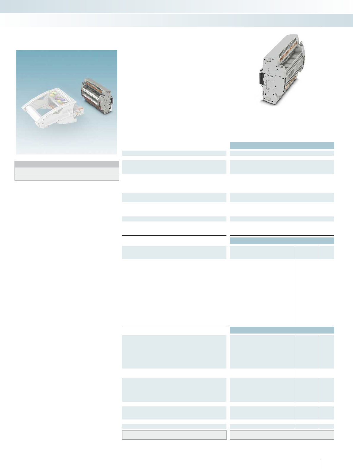
For additional information, visit phoenixcontact.net/products
Technical data
Max. electrical data Imax. [A] Umax. [V] max. Ø [mm²] AWG
30 4002) 0.5 - 10 20 - 8
IEC 60947-7-1
Rated data IEC UL/CUL CSA IEC/
EN60079-7
Rated voltage [V] 4002)---
Nominal current / cross section [A] / [mm²] 241)/6---
Rated cross section [mm²] 6 - - -
Cross section range AWG 20 - 8 - - -
Connection capacity solid stranded ferrule
with/without plastic sleeve
1 conductor [mm²] 0.5 - 10 0.5 - 6 0.5 - 6 0.5 - 6
2 stranded conductors with a TWIN ferrule [mm²] 0.5 - 1.5
Plug-in connection cross sections [mm²] 1 - 10 - 1 - 6 1 - 6
General data
Stripping length [mm] 12
Insulating material PA
Inflammability class according to UL 94 V0
Ordering data
Description No. of
pos. Color Type Imax Order No. Pcs. /
Pkt.
Test terminal strip, for DIN rail mounting,
4-pos. gray PTRE 6-2/4 3069849 1
5-pos. gray PTRE 6-2/5 3069850 1
9-pos. gray PTRE 6-2/9 3069854 1
10-pos. gray PTRE 6-2/10 3069855 1
12-pos. gray PTRE 6-2/12 3069861 1
14 pos. gray PTRE 6-2/14 3069863 1
15-pos. gray PTRE 6-2/15 3069864 1
17-pos. gray PTRE 6-2/17 3069866 1
19 pos. gray PTRE 6-2/19 3069868 1
20 pos. gray PTRE 6-2/20 3069869 1
21 pos. gray PTRE 6-2/21 3069870 1
22 pos. gray PTRE 6-2/22 3069871 1
25 pos. gray PTRE 6-2/25 3069874 1
Accessories
Jumper
2red FBS 2-8 24 A 3030284 10
3red FBS 3-8 24 A 3030297 10
4red FBS 4-8 24 A 3030307 10
5red FBS 5-8 24 A 3030310 10
6red FBS 6-8 24 A 3032470 10
10 red FBS 10-8 24 A 3030323 10
Jumper
16 red FBSR 16-8 24 A 3033816 10
Pre-assembled bridge, labeled
3-pos., positions 1, 3 3red FBS 1/3-8 24 A 3032363 10
4-pos., positions 1, 4 4red FBS 1/4-8 24 A 3032376 10
5-pos., positions 1, 3, 5 5red FBS 1/3/5-8 24 A 3032389 10
10-pos., positions 1, 4, 7, 10 10 red FBS 1/4/7/10-8 24 A 3032402 10
Cover profile, supply length 1m transparent AP-ME METER 3034361 10
End brackets, for AP-ME cover profile, sealable,
with storage option for jumpers
gray APH-ME 3034374 10
Holder, for AP-ME cover profile gray APT-ME 3034358 10
Screwdriver SF-SL 0,8X4,0-100 1212551 10
Lateral groove labeling UC-TM 8, UCT-TM 8, ZB 8 or TMT(EX9,5)R
(see Catalog 5)
93PHOENIX CONTACT
Notes:
1) Derating curve available on request.
2) Rated surge voltage of 5 kV.
Test terminal strip, multi-position
with PT... push-in connection,
for PTRE... DIN rail mounting
Modular terminal blocks
FAME plug-in test system
6 (10) mm², 30 A, 4...25-pos. test terminal
strip, for DIN rail mounting
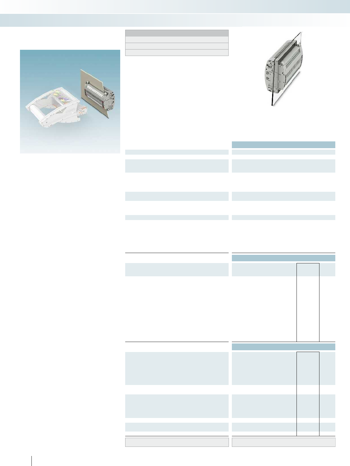
Technical data
Max. electrical data Imax. [A] Umax. [V] max. Ø [mm²] AWG
30 4002) 0.2 - 10 24 - 8
IEC 60947-7-1
Rated data IEC UL/CUL CSA IEC/
EN60079-7
Rated voltage [V] 4002)---
Nominal current / cross section [A] / [mm²] 241)/6---
Rated cross section [mm²] 6 - - -
Cross section range AWG 24 - 8 - - -
Connection capacity solid stranded ferrule
with/without plastic sleeve
1 conductor [mm²] 0.2 - 10 0.2 - 10 0.25 - 6 0.25 - 6
2 conductors (of the same type) [mm²] 0.2 - 2.5 0.2 - 2.5 0.25 - 1.5 -
2 stranded conductors with a TWIN ferrule [mm²] 0.5 - 2.5
General data
Stripping length [mm] 10
Screw thread M4
Tightening torque [Nm] 1.5 - 1.8
Tightening torque for wall fastening [Nm] 0.8 - 1
Panel thickness [mm] 1 - 4
Insulating material PA
Inflammability class according to UL 94 V0
Ordering data
Description No. of
pos. Color Type Imax Order No. Pcs. /
Pkt.
Test terminal strip, for wall mounting,
4-pos. gray UTWE 6-2/4 3069650 1
5-pos. gray UTWE 6-2/5 3069651 1
9-pos. gray UTWE 6-2/9 3069656 1
10-pos. gray UTWE 6-2/10 3069658 1
12-pos. gray UTWE 6-2/12 3069660 1
14 pos. gray UTWE 6-2/14 3069663 1
15-pos. gray UTWE 6-2/15 3069664 1
17-pos. gray UTWE 6-2/17 3069667 1
19 pos. gray UTWE 6-2/19 3069672 1
20 pos. gray UTWE 6-2/20 3069673 1
21 pos. gray UTWE 6-2/21 3069800 1
22 pos. gray UTWE 6-2/22 3069801 1
25 pos. gray UTWE 6-2/25 3069804 1
Accessories
Jumper
2red FBS 2-8 24 A 3030284 10
3red FBS 3-8 24 A 3030297 10
4red FBS 4-8 24 A 3030307 10
5red FBS 5-8 24 A 3030310 10
6red FBS 6-8 24 A 3032470 10
10 red FBS 10-8 24 A 3030323 10
Jumper
16 red FBSR 16-8 24 A 3033816 10
Pre-assembled bridge, labeled
3-pos., positions 1, 3 3red FBS 1/3-8 24 A 3032363 10
4-pos., positions 1, 4 4red FBS 1/4-8 24 A 3032376 10
5-pos., positions 1, 3, 5 5red FBS 1/3/5-8 24 A 3032389 10
10-pos., positions 1, 4, 7, 10 10 red FBS 1/4/7/10-8 24 A 3032402 10
Cover profile, supply length 1m transparent AP RSC-T 3059139 10
Cover profile holder, can be snapped on and
sealed
gray APH-UTWE 6-2 3069057 10
Screwdriver SF-SL 0,8X4,0-100 1212551 10
Lateral groove labeling UC-TM 8, UCT-TM 8, ZB 8 or TMT(EX9,5)R
(see Catalog 5)
94 PHOENIX CONTACT
The modular FAME measuring transducer
test system, with universal screw
connection technology, enables all
transformer testing tasks to be carried out
quickly and safely. The transformer is short-
circuited and the testing device is looped in
automatically through the insertion process.
– The test terminal strips can be used
universally for current and voltage
transducers
– The test terminal strip can be mounted
on the control cabinet door or on the
DIN rail
– Signal and status messages can be wired in
combination in a test terminal strip
– The correct switching sequence when
removing the test plug is ensured by a
locking device and a mechanical drive in
the twist grip
– All test signals can be connected with
touch-proof safety test leads (CATIII
and CATIV/1000V according to
EN61010-031)
– All versions listed can be equipped with
coding for the matching test plug
– Star points of the current transformer
can easily be created in the test terminal
strip on the rear by means of FBS jumpers
– You can find corresponding accessories
from page 99
Test terminal strip, multi-position
with UT... screw connection,
for UTWE... wall mounting
Modular terminal blocks
FAME plug-in test system
6 (10) mm², 30 A, 4...25-pos. test terminal
strip, for wall mounting
Notes:
To create panel cutouts, see phoenixcontact.net/products.
1) Derating curve available on request.
2) Rated surge voltage of 5 kV.
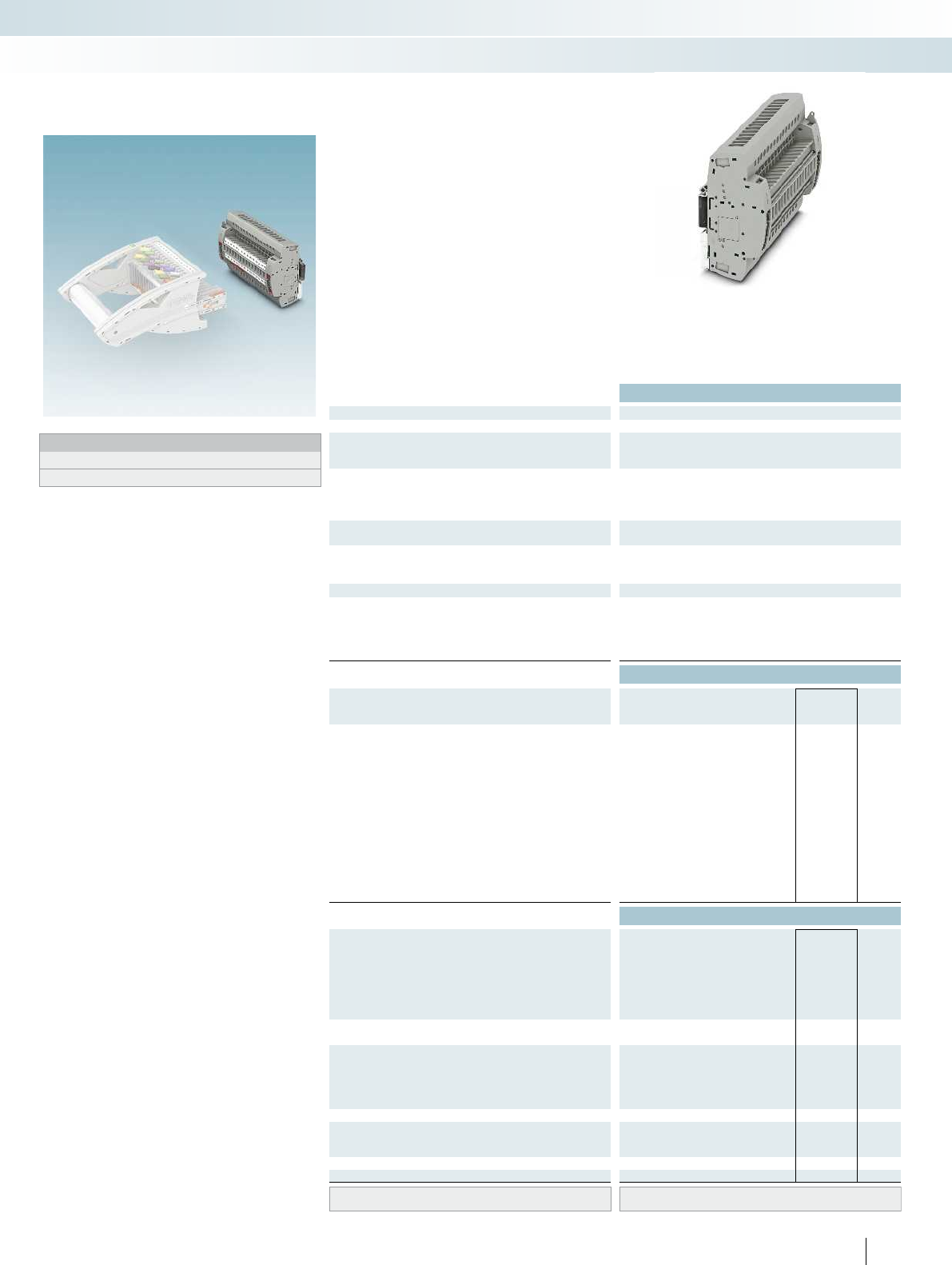
For additional information, visit phoenixcontact.net/products
Technical data
Max. electrical data Imax. [A] Umax. [V] max. Ø [mm²] AWG
30 4002) 0.2 - 10 24 - 8
IEC 60947-7-1
Rated data IEC UL/CUL CSA IEC/
EN60079-7
Rated voltage [V] 4002)---
Nominal current / cross section [A] / [mm²] 241)/6---
Rated cross section [mm²] 6 - - -
Cross section range AWG 24 - 8 - - -
Connection capacity solid stranded ferrule
with/without plastic sleeve
1 conductor [mm²] 0.2 - 10 0.2 - 10 0.25 - 6 0.25 - 6
2 conductors (of the same type) [mm²] 0.2 - 2.5 0.2 - 2.5 0.25 - 1.5 -
2 stranded conductors with a TWIN ferrule [mm²] 0.5 - 2.5
General data
Stripping length [mm] 10
Screw thread M4
Tightening torque [Nm] 1.5 - 1.8
Insulating material PA
Inflammability class according to UL 94 V0
Ordering data
Description No. of
pos. Color Type Imax Order No. Pcs. /
Pkt.
Test terminal strip, for DIN rail mounting,
4-pos. gray UTRE 6-2/4 3069805 1
5-pos. gray UTRE 6-2/5 3069806 1
9-pos. gray UTRE 6-2/9 3069810 1
10-pos. gray UTRE 6-2/10 3069811 1
12-pos. gray UTRE 6-2/12 3069813 1
14 pos. gray UTRE 6-2/14 3069815 1
15-pos. gray UTRE 6-2/15 3069816 1
17-pos. gray UTRE 6-2/17 3069818 1
19 pos. gray UTRE 6-2/19 3069820 1
20 pos. gray UTRE 6-2/20 3069821 1
21 pos. gray UTRE 6-2/21 3069822 1
22 pos. gray UTRE 6-2/22 3069823 1
25 pos. gray UTRE 6-2/25 3069826 1
Accessories
Jumper
2red FBS 2-8 24 A 3030284 10
3red FBS 3-8 24 A 3030297 10
4red FBS 4-8 24 A 3030307 10
5red FBS 5-8 24 A 3030310 10
6red FBS 6-8 24 A 3032470 10
10 red FBS 10-8 24 A 3030323 10
Jumper
16 red FBSR 16-8 24 A 3033816 10
Pre-assembled bridge, labeled
3-pos., positions 1, 3 3red FBS 1/3-8 24 A 3032363 10
4-pos., positions 1, 4 4red FBS 1/4-8 24 A 3032376 10
5-pos., positions 1, 3, 5 5red FBS 1/3/5-8 24 A 3032389 10
10-pos., positions 1, 4, 7, 10 10 red FBS 1/4/7/10-8 24 A 3032402 10
Cover profile, supply length 1m transparent AP-ME METER 3034361 10
End brackets, for AP-ME cover profile, sealable,
with storage option for jumpers
gray APH-ME 3034374 10
Holder, for AP-ME cover profile gray APT-ME 3034358 10
Screwdriver SF-SL 0,8X4,0-100 1212551 10
Lateral groove labeling UC-TM 8, UCT-TM 8, ZB 8 or TMT(EX9,5)R
(see Catalog 5)
95PHOENIX CONTACT
Notes:
1) Derating curve available on request.
2) Rated surge voltage of 5 kV.
Test terminal strip, multi-position
with UT... screw connection,
for UTRE... DIN rail mounting
Modular terminal blocks
FAME plug-in test system
6 (10) mm², 30 A, 4...25-pos. test terminal
strip, for DIN rail mounting
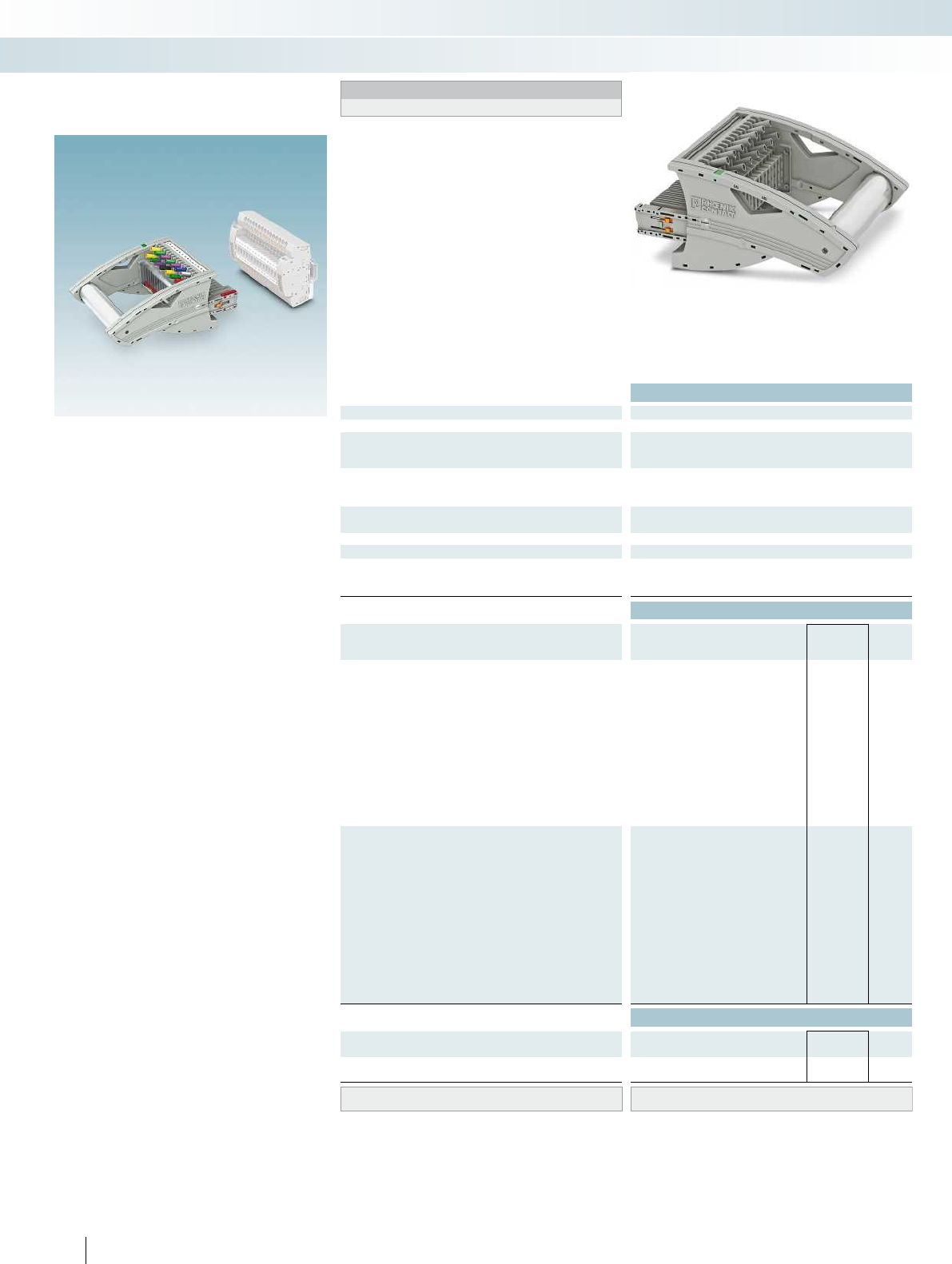
Technical data
Max. electrical data Imax. [A] Umax. [V] max. Ø [mm²] AWG
24 4001) 0.5 - 2.5 20 - 14
Rated data IEC UL/CUL CSA IEC/
EN60079-7
Rated voltage [V] 4001)---
Nominal current / cross section [A] / [mm²] 24/2.5 - - -
Cross section range AWG 20 - 14 - - -
Connection capacity solid stranded ferrule
with/without plastic sleeve
1 conductor [mm²] - 0.5 - 2.5 - -
General data
Tightening torque: test socket screw [Nm] 0.5 - 0.6
Insulating material PA
Inflammability class according to UL 94 V0
Ordering data
Description Color Type Order No. Pcs. /
Pkt.
Test plug, with twist grip, 4-pos. gray FTPR-2/4 3001681 1
5-pos. gray FTPR-2/5 3001683 1
9-pos. gray FTPR-2/9 3001687 1
10-pos. gray FTPR-2/10 3001688 1
12-pos. gray FTPR-2/12 3001690 1
14 pos. gray FTPR-2/14 3001692 1
15-pos. gray FTPR-2/15 3001693 1
17-pos. gray FTPR-2/17 3001696 1
19 pos. gray FTPR-2/19 3001698 1
20 pos. gray FTPR-2/20 3001699 1
21 pos. gray FTPR-2/21 3001700 1
22 pos. gray FTPR-2/22 3001701 1
25 pos. gray FTPR-2/25 3001704 1
Test plug, with standard grip, 4-pos. gray FTP-2/4 3001706 1
5-pos. gray FTP-2/5 3001707 1
9-pos. gray FTP-2/9 3001711 1
10-pos. gray FTP-2/10 3001712 1
12-pos. gray FTP-2/12 3001714 1
14 pos. gray FTP-2/14 3001716 1
15-pos. gray FTP-2/15 3001717 1
17-pos. gray FTP-2/17 3001720 1
19 pos. gray FTP-2/19 3001723 1
20 pos. gray FTP-2/20 3001724 1
21 pos. gray FTP-2/21 3001725 1
22 pos. gray FTP-2/22 3001726 1
25 pos. gray FTP-2/25 3001729 1
Accessories
Fork-type cable lug, insulated according to UL red C-FCI 1,5/M3 3240032 100
blue C-FCI 2,5/M3 3240037 100
Ring cable lug, insulated according to UL red C-RCI 1,5/M3 3240016 100
blue C-RCI 2,5/M3 3240021 100
Marking UC-TM 8, UCT-TM 8, ZB 8 or TMT(EX9,5)R
(see Catalog 5)
96 PHOENIX CONTACT
The test plugs allow the switching
sequence of the individual functions to be
carried out with safe chronological
disconnection with a switching operation
via three different contact tab lengths.
Configure the lengths of the contact tabs of
the test plug to suit your application. We
can provide you with a test plug according
to your requirements in next to no time.
– The test plugs can be easily
configured and ordered with just a
click of the mouse in the product
area on our website at
phoenixcontact.net/products
– To order via fax or e-mail, please use
the ordering data as shown in the
ordering example on the following
page
The test plugs are characterized by:
– User-friendly twist grip function with
latching
– Robust and warp resistant design
– Mechanically secure, molded contact tabs
– High-quality contact surfaces for reliable
transmission of signals
– Strain relief for the connected test leads
on the plug
– Flexibility in the number of positions
thanks to the modular design (additional
options on request)
– Large-surface marking options for each
contact
– Use of CLIPLINE complete accessories
for testing, bridging, and marking
– Additional test leads, assembled with ring
and fork-type cable lugs, can be attached
with test sockets
– All test signals can be connected with
touch-proof safety test leads (CATIII
and CATIV/1000V according to
EN61010-031)
– You can find corresponding accessories
from page 99
Test plug, multi-position,
freely-configurable contact tabs
FTPR... and FTP...
Modular terminal blocks
FAME plug-in test system
24A, 4...25-pos. test plug with twist grip or
standard grip, 4 mm test sockets
Notes:
1) Rated surge voltage of 5 kV.
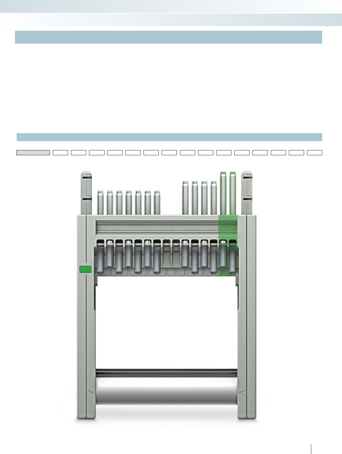
For additional information, visit phoenixcontact.net/products
97PHOENIX CONTACT
Ordering example: configurable test plug with twist grip function
To ensure that your order is correct, you need a defined view of how everything is counted.
This is achieved when the status window in the top view is on the left-hand side.
Position 1 is then on the left.
Each position of a test plug is described by a contact tab feature that is selected.
The following features are possible:
SShort contact tab, gray
MMedium contact tab, gray
LLong contact tab, gray
LGN Long contact tab, green
NNo contact tab, gray
Each position with a contact tab is supplied fitted with two gray test sockets.
Ordering example:
A 15-pos. test plug with twist grip needs to be
configured as follows:
Pos. 1 Short contact tab, gray
Pos. 2 Short contact tab, gray
Pos. 3 Short contact tab, gray
Pos. 4 Short contact tab, gray
Pos. 5 Short contact tab, gray
Pos. 6 Short contact tab, gray
Pos. 7 Short contact tab, gray
Pos. 8 No contact tab, gray
Pos. 9 No contact tab, gray
Pos. 10 Medium contact tab, gray
Pos. 11 Medium contact tab, gray
Pos. 12 Medium contact tab, gray
Pos. 13 Medium contact tab, gray
Pos. 14 Long contact tab, green
Pos. 15 Long contact tab, green
The order data for this ordering example is therefore:
Order No. Pos. 1 Pos. 2 Pos. 3 Pos. 4 Pos. 5 Pos. 6 Pos. 7 Pos. 8 Pos. 9 Pos. 10 Pos. 11 Pos. 12 Pos. 13 Pos. 14 Pos. 15
3001693 / S / S / S / S / S / S / S / N / N / M / M / M / M / LGN / LGN
Modular terminal blocks
FAME plug-in test system
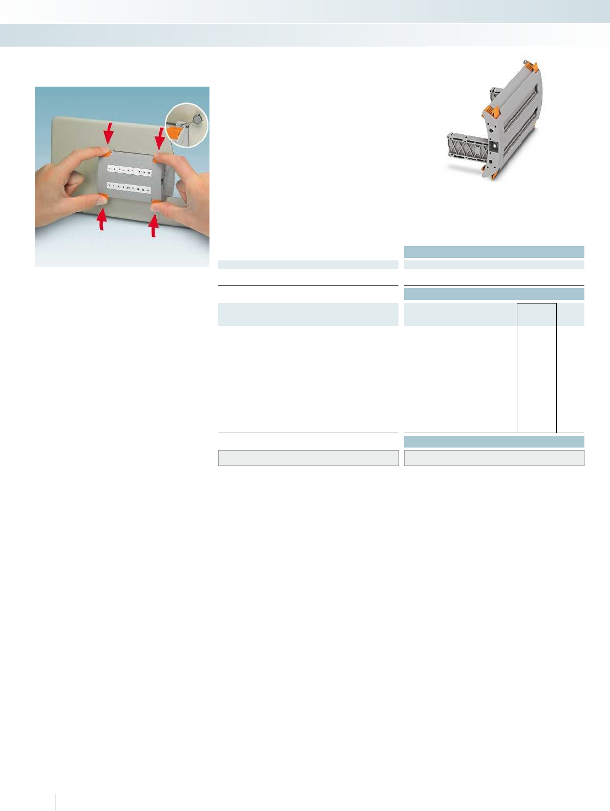
Technical data
General data
Insulating material PA
Inflammability class according to UL 94 V0
Ordering data
Description Color Type Order No. Pcs. /
Pkt.
Blind plug, 4-pos. gray FBP-2/4 3069875 1
5-pos. gray FBP-2/5 3069876 1
9-pos. gray FBP-2/9 3069880 1
10-pos. gray FBP-2/10 3069881 1
12-pos. gray FBP-2/12 3069883 1
14 pos. gray FBP-2/14 3069885 1
15-pos. gray FBP-2/15 3069886 1
17-pos. gray FBP-2/17 3069888 1
19 pos. gray FBP-2/19 3069890 1
20 pos. gray FBP-2/20 3069891 1
21 pos. gray FBP-2/21 3069892 1
22 pos. gray FBP-2/22 3069893 1
25 pos. gray FBP-2/25 3069896 1
Accessories
Lateral groove labeling UC-TM 8, UCT-TM 8, ZB 8 or TMT(EX9,5)R
(see Catalog 5)
98 PHOENIX CONTACT
During normal operation, the blind plug
acts as a protective cover for the test
terminal strip and is characterized by:
– Secure latching on the test terminal strip
– The robust latching can only be released
with two-hand operation
– The optional seal protects against
unauthorized actuation
– Large-surface marking options
– The coding profile set can be used to
assign test terminal strips and blind plugs
according to the specific application, see
right-hand page
Blind plug, multi-position, sealable
FBP-2/...
Modular terminal blocks
FAME plug-in test system
Blind plug 4...25-pos.
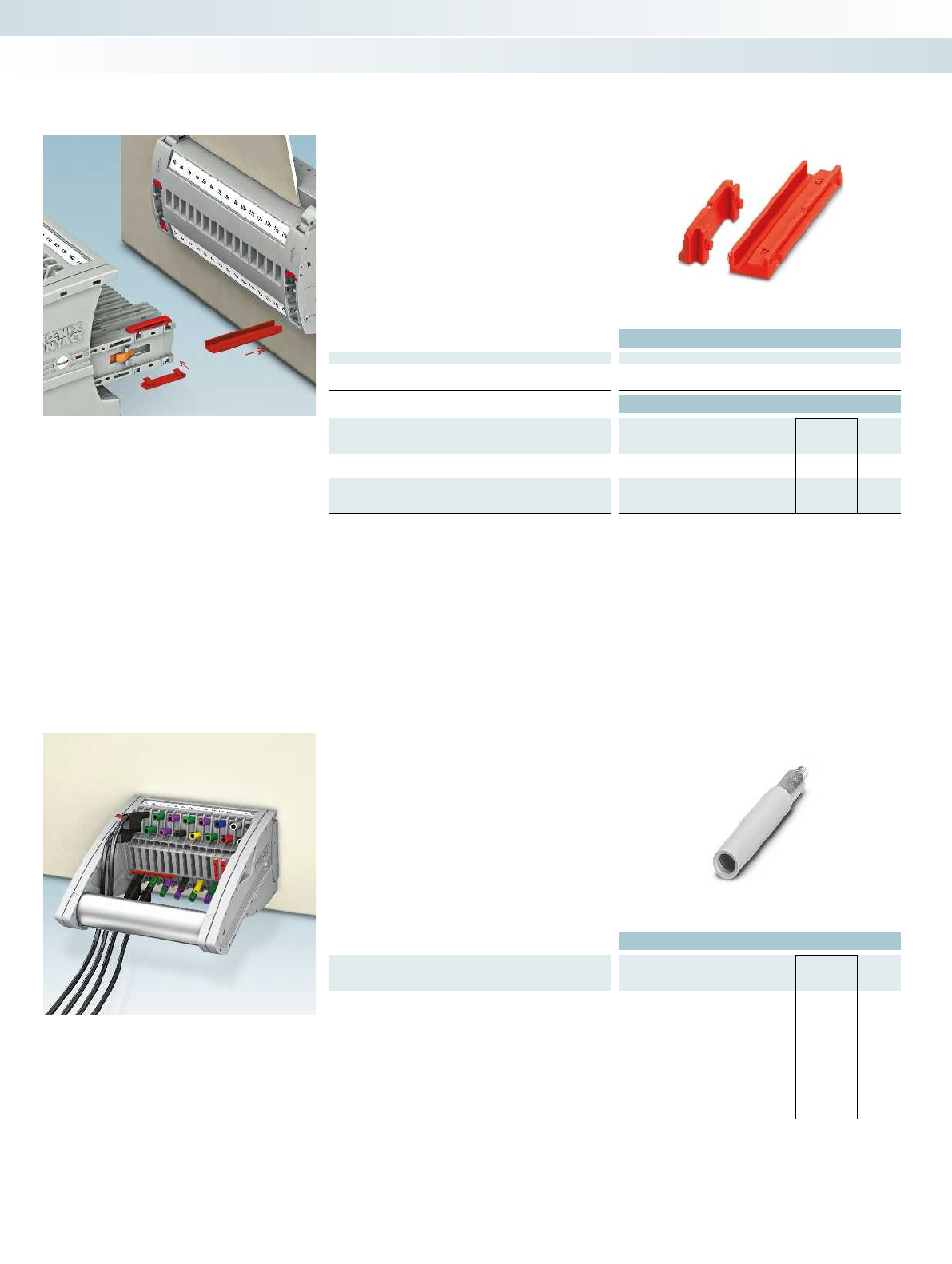
For additional information, visit phoenixcontact.net/products
Technical data
General data
Material PA
Inflammability class according to UL 94 V0
Ordering data
Description Color Type Order No. Pcs. /
Pkt.
Coding profile set, for the test terminal strip red PC-UTWE-TRI 3069897 50
Coding profile set, for FTP-2 and FTPR-2 test
plugs and FBP-2 blind plugs
red PC-FTP-TRI 3069898 50
– The coding profile set can be used to
assign test terminal strips and test plugs
according to the specific application
– Maximum safety is therefore ensured for
all testing tasks
PC-...-TRI coding profile set
Modular terminal blocks
FAME plug-in test system
Ordering data
Description Color Type Order No. Pcs. /
Pkt.
Test socket, insulated
transparent PSBJ-URTK 6 FARBLOS 3026450 10
red PSBJ-URTK 6 RD 3026719 10
blue PSBJ-URTK 6 BU 3026434 10
yellow PSBJ-URTK 6 YE 3026405 10
green PSBJ-URTK 6 GN 3026418 10
violet PSBJ-URTK 6 VT 3026421 10
black PSBJ-URTK 6 BK 3026447 10
gray PSBJ-URTK 6 GY 3026612 10
brown PSBJ-URTK 6 BN 3026971 10
99
PHOENIX CONTACT
– 4 mm safety test leads with fixed
insulation according to
EN61010031CATIII and CATIV up to
1000V can be coded in true color
– Additional test leads, assembled with ring
and fork-type cable lugs (see accessories,
e.g., page 96) can be attached with test
sockets
Colored PSBJ... test sockets
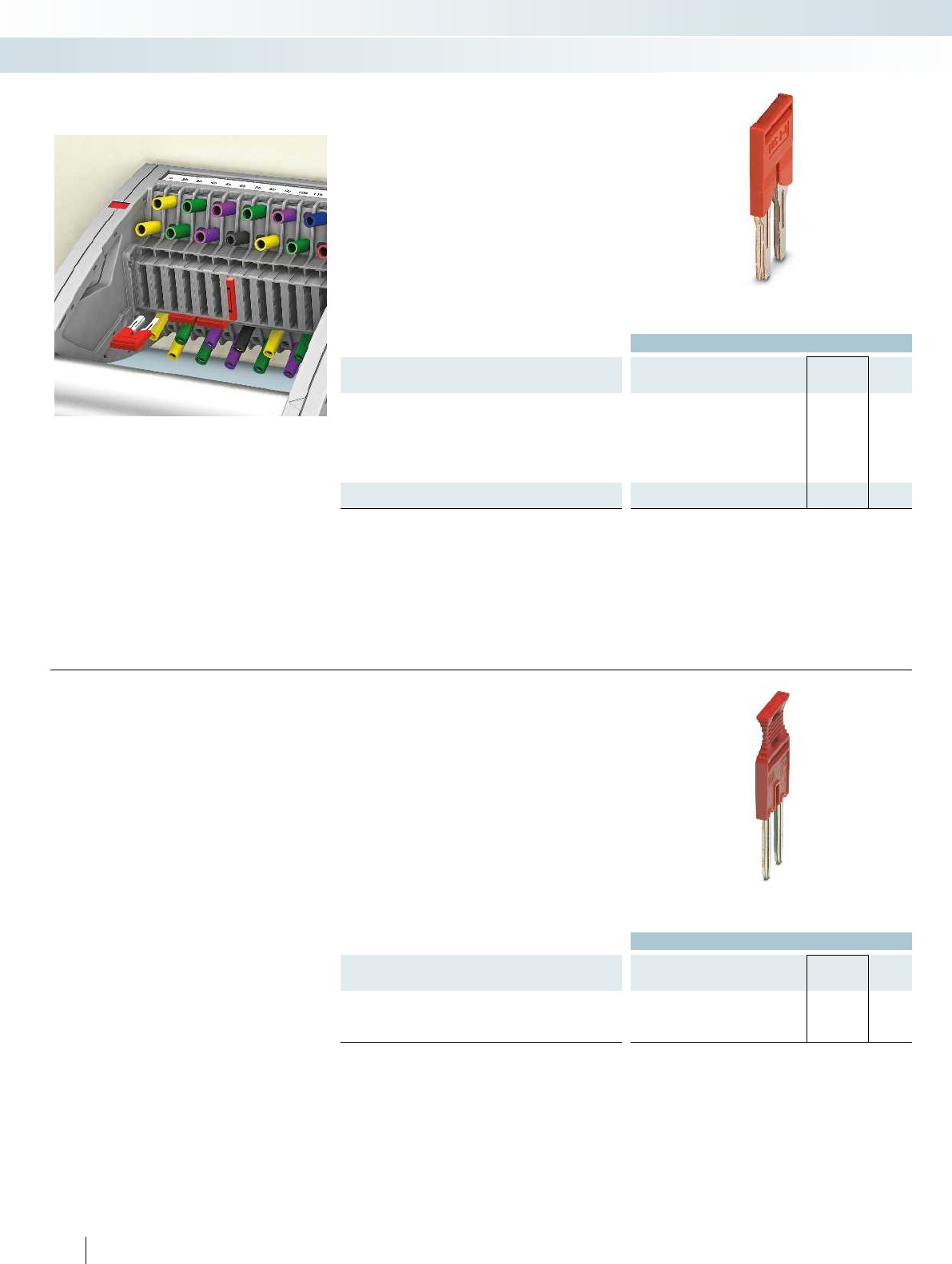
Ordering data
Description No. of pos. Type Imax Order No. Pcs. /
Pkt.
Jumper
2FBS 2-8 41 A 3030284 10
3FBS 3-8 3030297 10
4FBS 4-8 3030307 10
5FBS 5-8 3030310 10
6FBS 6-8 3032470 10
10 FBS 10-8 3030323 10
Jumper
16 FBSR 16-8 32 A 3033816 10
– The FBS...-8 plug-in bridges are used for
short-circuiting, as star-point jumpers,
and also to establish grounding in
connection with a PE modular terminal
block on the terminal strip
Jumper, red, 8.2 mm pitch,
FBS...
Modular terminal blocks
FAME plug-in test system
Ordering data
Description No. of pos. Type Imax Order No. Pcs. /
Pkt.
Jumper, with extraction tool
2FBSRH 2-8 32 A 3033802 10
3FBSRH 3-8 3033803 10
4FBSRH 4-8 3033804 10
100 PHOENIX CONTACT
– The FBSRH...-8 bridges have a molded
extraction tool which means that they
can be used conveniently and without
tools for individual bridging tasks. This
enables a transformer short circuit to be
created in test disconnect terminal
blocks, for example.
Jumper with extraction tool, red,
8.2 mm pitch, FBSRH...
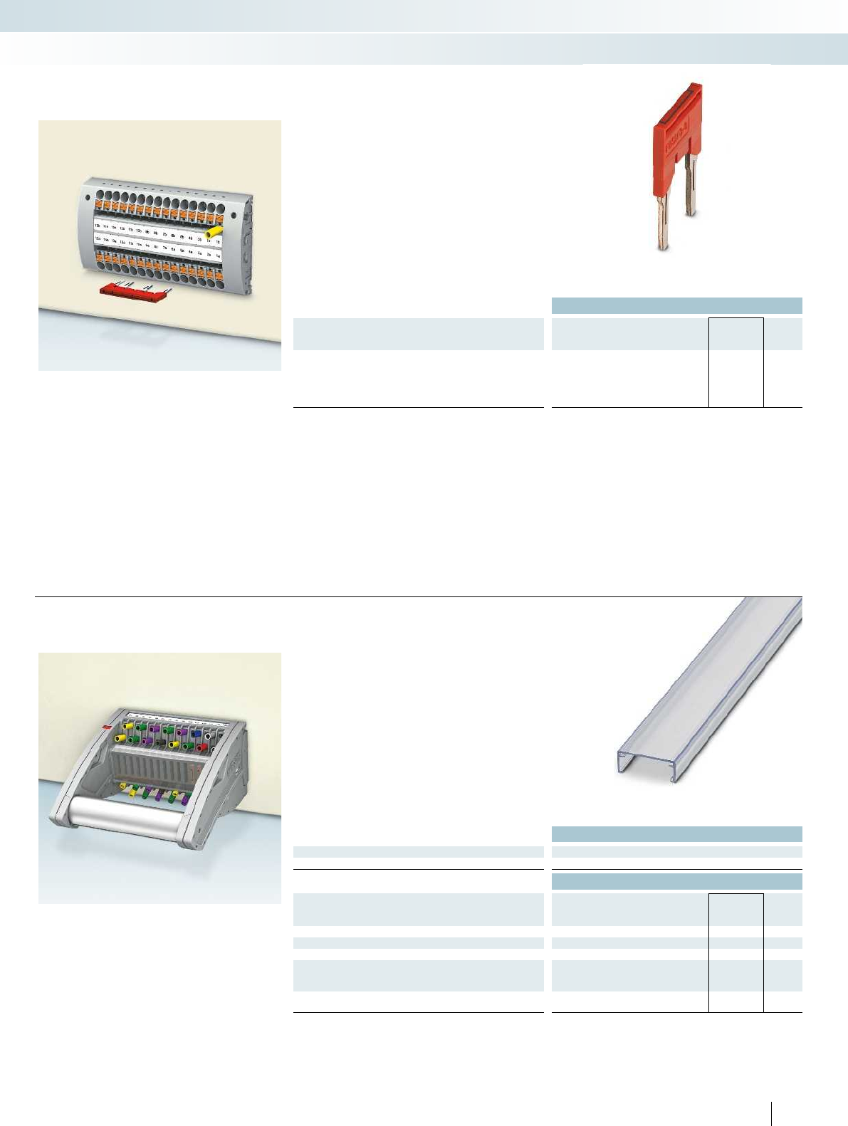
For additional information, visit phoenixcontact.net/products
Ordering data
Description No. of pos. Type Imax Order No. Pcs. /
Pkt.
Pre-assembled bridge, labeled
3-pos., positions 1, 3 3 FBS 1/3-8 41 A 3032363 10
4-pos., positions 1, 4 4 FBS 1/4-8 3032376 10
5-pos., positions 1, 3, 5 5 FBS 1/3/5-8 3032389 10
10-pos., positions 1, 4, 7, 10 10 FBS 1/4/7/10-8 3032402 10
– Plug-in star-point jumpers or jumpers for
bridging several positions can be supplied
pre-configured without additional
expense
– The bridges are printed and provide
unique identification for bridging between
non-adjacent terminal blocks
Pre-assembled bridge, red, 8.2 mm
pitch
Modular terminal blocks
FAME plug-in test system
Technical data
General data
Material PVC
Ordering data
Description Color Type Order No. Pcs. /
Pkt.
Cover profile, supply length 1m transparent AP-FTP METER 3069899 1
Cover profile, supply length 1mtransparent AP-ME METER 3034361 10
Cover profile, supply length 1m transparent AP RSC-T 3059139 10
End brackets, for AP-ME cover profile, sealable,
with storage option for jumpers
gray APH-ME 3034374 10
Cover profile holder, can be snapped on and
sealed
gray APH-UTWE 6-2 3069057 10
101
PHOENIX CONTACT
– The APFTP cover profile prevents
undesired changes to the star point, feed-
through, and short-circuit jumpers on the
completely assembled test plug
– To mount, gently release the side screw
connection of the plug and snap the
profile into place
– The APHME end bracket is used in
conjunction with the APME cover for
the DIN rail mounted test terminal strip
Cover profiles for test plug or test
terminal strip mounted on DIN rail
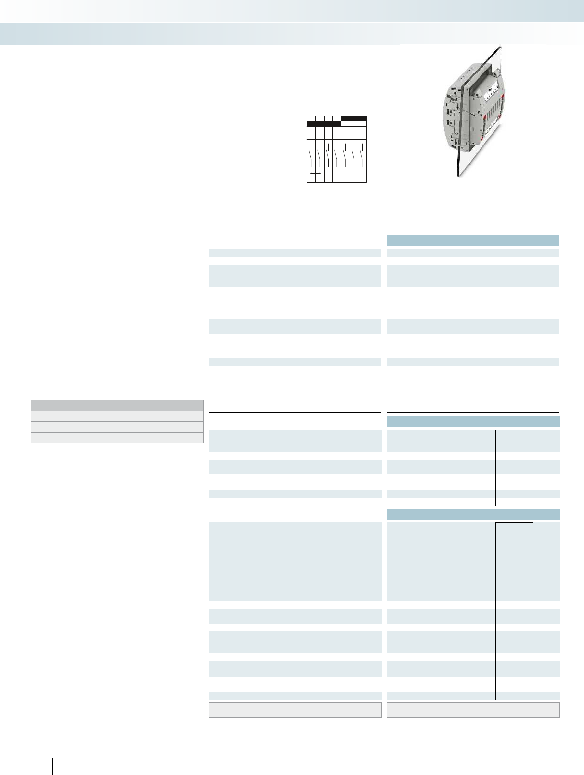
A7
1a 2a 3a4a5a6a7a
1b2b3b4b5b6b7b
Technical data
Max. electrical data Imax. [A] Umax. [V] max. Ø [mm²] AWG
30 4002) 0.5 - 10 20 - 8 30 400
IEC 60947-7-1
Rated data IEC UL/CUL CSA IEC/
EN60079-7
Rated voltage [V] 4002)--- 400
Nominal current / cross section [A] / [mm²] 241)/6--- 24
Rated cross section [mm²]6--- 6--- 6--- ----
Cross section range AWG20 - 8--- 20 - 8--- 20 - 14--- ----
Connection capacity solid stranded ferrule
with/without plastic sleeve
1 conductor [mm²] 0.5 - 10 0.5 - 6 0.5 - 6 0.5 - 6 0.5 - 10 0.5 - 6 0.5 - 6 0.5 - 6 - 0.5 - 2.5 - - - - - -
2 stranded conductors with a TWIN ferrule [mm²] 0.5 - 1.5
Plug-in connection cross sections [mm²] 1 - 10 - 1 - 6 1 - 6 1 - 10 - 1 - 6 1 - 6 - - - - - - - -
General data
Stripping length [mm] 12
Tightening torque for wall fastening [Nm] 0.8 - 1
Panel thickness [mm] 1 - 4
Tightening torque: test socket screw [Nm] -
Insulating material PA
Inflammability class according to UL 94 V0
Ordering data
Description Color Type Order No. Pcs. /
Pkt.
Test terminal strip, for wall mounting gray PTWE 6-2/A7 3069436 1
Test terminal strip, for mounting on NS35... gray
Test plug, with twist grip gray
With standard handle gray
Test plug, 1-pos., with cover gray
Blind plug, sealable gray
Accessories
Test socket, insulated
transparent
red
blue
yellow
green
violet
black
gray
brown
Cover profile, supply length 1m transparent AP RSC-T 3059139 10
Cover profile holder, can be snapped on and
sealed
gray APH-UTWE 6-2 3069057 10
Cover profile, supply length 1m transparent
End brackets, for AP-ME cover profile, sealable,
with storage option for jumpers
gray
Holder, for AP-ME cover profile gray
Fork-type cable lug, insulated according to UL red
blue
Ring cable lug, insulated according to UL red
blue
Screwdriver SF-SL 0,8X4,0-100 1212551 10
Lateral groove labeling UC-TM 8, UCT-TM 8, ZB 8 or TMT(EX9,5)R
(see Catalog 5)
102 PHOENIX CONTACT
Test terminal strip with PT... push-in
connection, VDEtype A7, for wall and
DIN rail mounting
Long contacts
Short contacts
The VDEA7 version described here is
suitable as a plug-in test system in single-
system current, voltage, and power relays,
wattmetric and ground fault wiper relays,
detuning level controllers or reverse power
protection for generators.
– The test plugs are assembled with
jumpers and contact tab lengths
according to the circuit diagram
– A transparent covering hood protects the
jumpers. The covering hood can only be
removed by dismantling the test plug
– All VDE-specified 7, 14, and 19-pos.
versions are supplied with exclusive
coding for the matching test plug and
blind plug
– The components are supplied pre-marked
according to the VDE Directive
– Test signals can be connected with touch-
proof safety test leads (CATIII and
IV/1000V according to EN61010-031)
– The test plugs are equipped with two gray
test sockets per position, for further
color versions, see the range of
accessories
– Additional test leads, assembled with ring
and fork-type cable lugs, can be attached
with test sockets
– Other VDE versions available on request
Notes:
To create panel cutouts, see phoenixcontact.net/products.
1) Derating curve available on request.
2) Rated surge voltage of 5 kV.
Modular terminal blocks
FAME plug-in test system
6 (10) mm², 30A, test terminal strip, for wall
mounting, VDE coded type A7
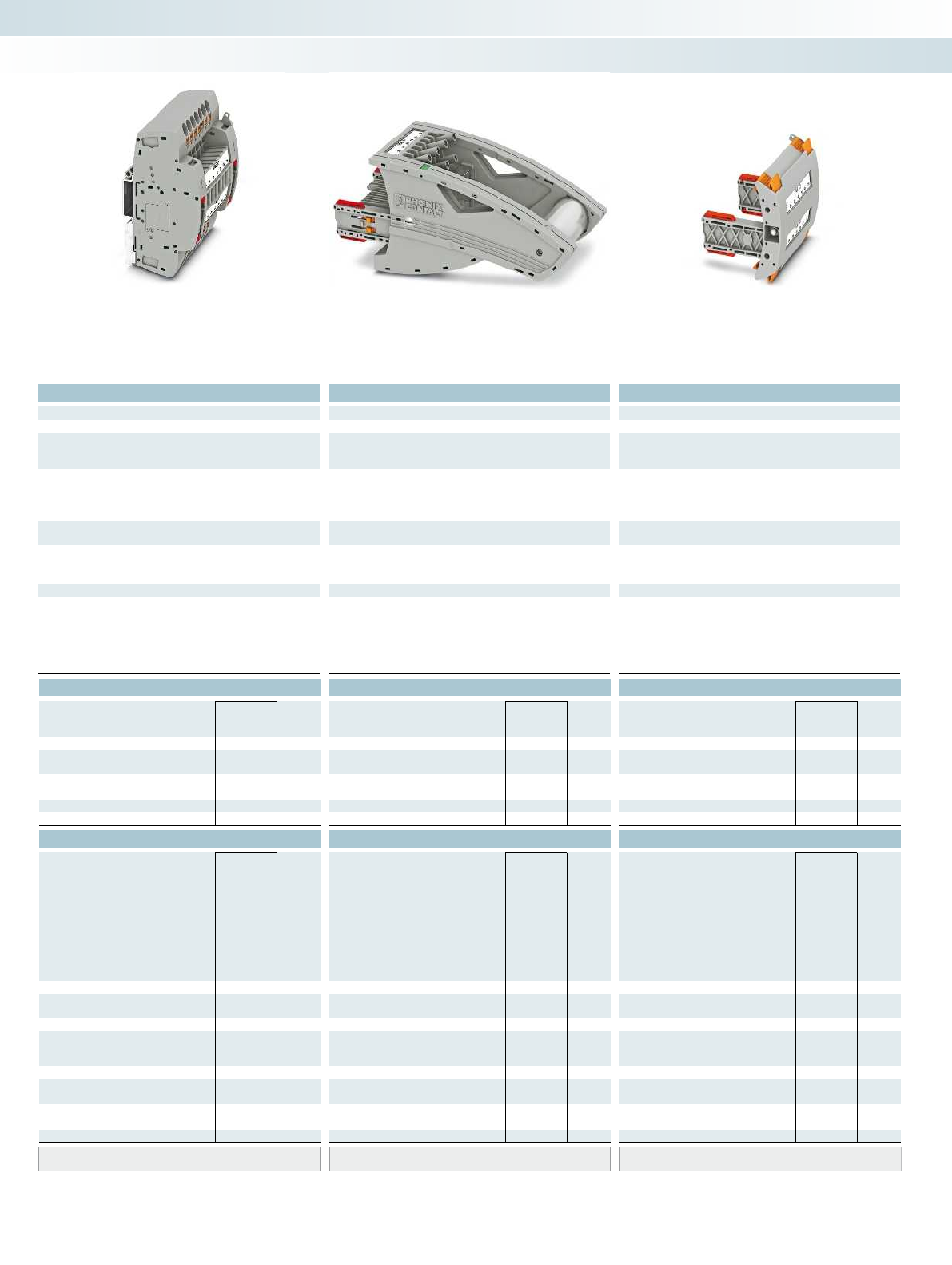
For additional information, visit phoenixcontact.net/products
Technical data Technical data Technical data
Imax. [A] Umax. [V] max. Ø [mm²] AWG Imax. [A] Umax. [V] max. Ø [mm²] AWG max. Ø [mm²] AWG
) 0.5 - 10 20 - 8 30 4002) 0.5 - 10 20 - 8 24 4002) 0.5 - 2.5 20 - 14 - -
IEC 60947-7-1
IEC UL/CUL CSA IEC/
EN60079-7
IEC UL/CUL CSA IEC/
EN60079-7
IEC UL/CUL CSA IEC/
EN60079-7
)--- 400
2)- - - 400
2)--- ----
)/6--- 24
1)/6--- 24/2.5--- ----
Rated cross section [mm²]6--- 6--- 6--- ----
Cross section range AWG20 - 8--- 20 - 8--- 20 - 14--- ----
solid stranded ferrule solid stranded ferrule solid stranded ferrule
with/without plastic sleeve with/without plastic sleeve with/without plastic sleeve
1 conductor [mm²] 0.5 - 10 0.5 - 6 0.5 - 6 0.5 - 6 0.5 - 10 0.5 - 6 0.5 - 6 0.5 - 6 - 0.5 - 2.5 - - - - - -
0.5 - 1.5
Plug-in connection cross sections [mm²] 1 - 10 - 1 - 6 1 - 6 1 - 10 - 1 - 6 1 - 6 - - - - - - - -
12 - -
---
---
-0.5 - 0.6-
PA PA PA
V0 V0 V0
Ordering data Ordering data Ordering data
Type Order No. Pcs. /
Pkt. Type Order No. Pcs. /
Pkt. Type Order No. Pcs. /
Pkt.
PTRE 6-2/A7 3069449 1
FTPR-2/A7 3069484 1
FTP-2/A7 3069470 1
FTP-2/1 3069469 1
FBP-2/A7 3069497 1
Accessories Accessories Accessories
PSBJ-URTK 6 FARBLOS 3026450 10
PSBJ-URTK 6 RD 3026719 10
PSBJ-URTK 6 BU 3026434 10
PSBJ-URTK 6 YE 3026405 10
PSBJ-URTK 6 GN 3026418 10
PSBJ-URTK 6 VT 3026421 10
PSBJ-URTK 6 BK 3026447 10
PSBJ-URTK 6 GY 3026612 10
PSBJ-URTK 6 BN 3026971 10
AP-ME METER 3034361 10
APH-ME 3034374 10
APT-ME 3034358 10
C-FCI 1,5/M3 3240032 100
C-FCI 2,5/M3 3240037 100
C-RCI 1,5/M3 3240016 100
C-RCI 2,5/M3 3240021 100
SF-SL 0,8X4,0-100 1212551 10
UC-TM 8, UCT-TM 8, ZB 8 or TMT(EX9,5)R
(see Catalog 5)
UC-TM 8, UCT-TM 8, ZB 8 or TMT(EX9,5)R
(see Catalog 5)
UC-TM 8, UCT-TM 8, ZB 8 or TMT(EX9,5)R
(see Catalog 5)
103PHOENIX CONTACT
Modular terminal blocks
FAME plug-in test system
6 (10) mm², 30A, test terminal strip, for DIN rail
mounting, VDE coded type A7
24A, test plug, bridge assignment according
to circuit diagram, VDE coded type A7
Blind plug, VDE coded type A7
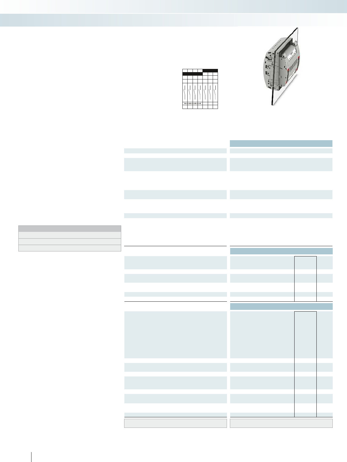
B7
1a 2a 3a4a5a6a7a
1b2b3b4b5b6b7b
Technical data
Max. electrical data Imax. [A] Umax. [V] max. Ø [mm²] AWG
30 4002) 0.5 - 10 20 - 8 30 400
IEC 60947-7-1
Rated data IEC UL/CUL CSA IEC/
EN60079-7
Rated voltage [V] 4002)--- 400
Nominal current / cross section [A] / [mm²] 241)/6--- 24
Rated cross section [mm²]6--- 6--- 6--- ----
Cross section range AWG20 - 8--- 20 - 8--- 20 - 14--- ----
Connection capacity solid stranded ferrule
with/without plastic sleeve
1 conductor [mm²] 0.5 - 10 0.5 - 6 0.5 - 6 0.5 - 6 0.5 - 10 0.5 - 6 0.5 - 6 0.5 - 6 - 0.5 - 2.5 - - - - - -
2 stranded conductors with a TWIN ferrule [mm²] 0.5 - 1.5
Plug-in connection cross sections [mm²] 1 - 10 - 1 - 6 1 - 6 1 - 10 - 1 - 6 1 - 6 - - - - - - - -
General data
Stripping length [mm] 12
Tightening torque for wall fastening [Nm] 0.8 - 1
Panel thickness [mm] 1 - 4
Tightening torque: test socket screw [Nm] -
Insulating material PA
Inflammability class according to UL 94 V0
Ordering data
Description Color Type Order No. Pcs. /
Pkt.
Test terminal strip, for wall mounting gray PTWE 6-2/B7 3069437 1
Test terminal strip, for mounting on NS35... gray
Test plug, with twist grip gray
With standard handle gray
Test plug, 1-pos., with cover gray
Blind plug, sealable gray
Accessories
Test socket, insulated
transparent
red
blue
yellow
green
violet
black
gray
brown
Cover profile, supply length 1m transparent AP RSC-T 3059139 10
Cover profile holder, can be snapped on and
sealed
gray APH-UTWE 6-2 3069057 10
Cover profile, supply length 1m transparent
End brackets, for AP-ME cover profile, sealable,
with storage option for jumpers
gray
Holder, for AP-ME cover profile gray
Fork-type cable lug, insulated according to UL red
blue
Ring cable lug, insulated according to UL red
blue
Screwdriver SF-SL 0,8X4,0-100 1212551 10
Lateral groove labeling UC-TM 8, UCT-TM 8, ZB 8 or TMT(EX9,5)R
(see Catalog 5)
104 PHOENIX CONTACT
Test terminal strip with PT... push-in
connection, VDEtype B7, for wall and
DIN rail mounting
Long contacts
Short contacts
The VDEB7 version described here is
suitable as a plug-in test system in digital
differential protection as an addition to the
F19 plug-in test system, see page 120.
– The test plugs are assembled with
jumpers and contact tab lengths
according to the circuit diagram
– A transparent covering hood protects the
jumpers. The covering hood can only be
removed by dismantling the test plug
– All VDE-specified 7, 14, and 19-pos.
versions are supplied with exclusive
coding for the matching test plug and
blind plug
– The components are supplied pre-marked
according to the VDE Directive
– Test signals can be connected with touch-
proof safety test leads (CATIII and
IV/1000V according to EN61010-031)
– The test plugs are equipped with two gray
test sockets per position, for further
color versions, see the range of
accessories
– Additional test leads, assembled with ring
and fork-type cable lugs, can be attached
with test sockets
– Other VDE versions available on request
Notes:
To create panel cutouts, see phoenixcontact.net/products.
1) Derating curve available on request.
2) Rated surge voltage of 5 kV.
Modular terminal blocks
FAME plug-in test system
6 (10) mm², 30A, test terminal strip, for wall
mounting, VDE coded type B7
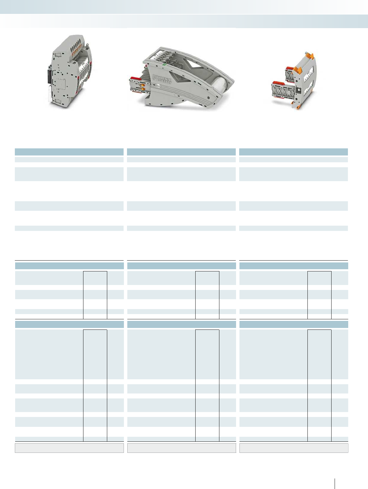
For additional information, visit phoenixcontact.net/products
Technical data Technical data Technical data
Imax. [A] Umax. [V] max. Ø [mm²] AWG Imax. [A] Umax. [V] max. Ø [mm²] AWG max. Ø [mm²] AWG
) 0.5 - 10 20 - 8 30 4002) 0.5 - 10 20 - 8 24 4002) 0.5 - 2.5 20 - 14 - -
IEC 60947-7-1
IEC UL/CUL CSA IEC/
EN60079-7
IEC UL/CUL CSA IEC/
EN60079-7
IEC UL/CUL CSA IEC/
EN60079-7
)--- 400
2)- - - 400
2)--- ----
)/6--- 24
1)/6--- 24/2.5--- ----
Rated cross section [mm²]6--- 6--- 6--- ----
Cross section range AWG20 - 8--- 20 - 8--- 20 - 14--- ----
solid stranded ferrule solid stranded ferrule solid stranded ferrule
with/without plastic sleeve with/without plastic sleeve with/without plastic sleeve
1 conductor [mm²] 0.5 - 10 0.5 - 6 0.5 - 6 0.5 - 6 0.5 - 10 0.5 - 6 0.5 - 6 0.5 - 6 - 0.5 - 2.5 - - - - - -
0.5 - 1.5
Plug-in connection cross sections [mm²] 1 - 10 - 1 - 6 1 - 6 1 - 10 - 1 - 6 1 - 6 - - - - - - - -
12 - -
---
---
-0.5 - 0.6-
PA PA PA
V0 V0 V0
Ordering data Ordering data Ordering data
Type Order No. Pcs. /
Pkt. Type Order No. Pcs. /
Pkt. Type Order No. Pcs. /
Pkt.
PTRE 6-2/B7 3069450 1
FTPR-2/B7 3069485 1
FTP-2/B7 3069471 1
FTP-2/1 3069469 1
FBP-2/B7 3069498 1
Accessories Accessories Accessories
PSBJ-URTK 6 FARBLOS 3026450 10
PSBJ-URTK 6 RD 3026719 10
PSBJ-URTK 6 BU 3026434 10
PSBJ-URTK 6 YE 3026405 10
PSBJ-URTK 6 GN 3026418 10
PSBJ-URTK 6 VT 3026421 10
PSBJ-URTK 6 BK 3026447 10
PSBJ-URTK 6 GY 3026612 10
PSBJ-URTK 6 BN 3026971 10
AP-ME METER 3034361 10
APH-ME 3034374 10
APT-ME 3034358 10
C-FCI 1,5/M3 3240032 100
C-FCI 2,5/M3 3240037 100
C-RCI 1,5/M3 3240016 100
C-RCI 2,5/M3 3240021 100
SF-SL 0,8X4,0-100 1212551 10
UC-TM 8, UCT-TM 8, ZB 8 or TMT(EX9,5)R
(see Catalog 5)
UC-TM 8, UCT-TM 8, ZB 8 or TMT(EX9,5)R
(see Catalog 5)
UC-TM 8, UCT-TM 8, ZB 8 or TMT(EX9,5)R
(see Catalog 5)
105PHOENIX CONTACT
Modular terminal blocks
FAME plug-in test system
6 (10) mm², 30A, test terminal strip, for DIN rail
mounting, VDE coded type B7
24A, test plug, bridge assignment according
to circuit diagram, VDE coded type B7
Blind plug, VDE coded type B7
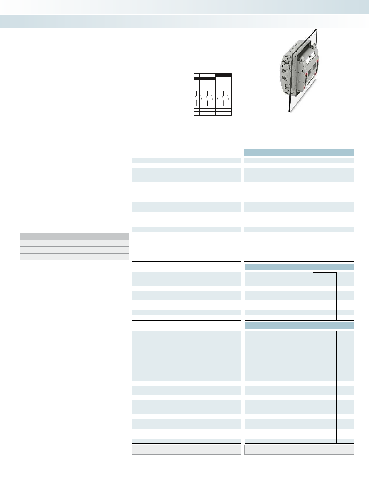
E7
1a 2a 3a4a5a6a7a
1b2b3b4b5b6b7b
Technical data
Max. electrical data Imax. [A] Umax. [V] max. Ø [mm²] AWG
30 4002) 0.5 - 10 20 - 8 30 400
IEC 60947-7-1
Rated data IEC UL/CUL CSA IEC/
EN60079-7
Rated voltage [V] 4002)--- 400
Nominal current / cross section [A] / [mm²] 241)/6--- 24
Rated cross section [mm²]6--- 6--- 6--- ----
Cross section range AWG20 - 8--- 20 - 8--- 20 - 14--- ----
Connection capacity solid stranded ferrule
with/without plastic sleeve
1 conductor [mm²] 0.5 - 10 0.5 - 6 0.5 - 6 0.5 - 6 0.5 - 10 0.5 - 6 0.5 - 6 0.5 - 6 - 0.5 - 2.5 - - - - - -
2 stranded conductors with a TWIN ferrule [mm²] 0.5 - 1.5
Plug-in connection cross sections [mm²] 1 - 10 - 1 - 6 1 - 6 1 - 10 - 1 - 6 1 - 6 - - - - - - - -
General data
Stripping length [mm] 12
Tightening torque for wall fastening [Nm] 0.8 - 1
Panel thickness [mm] 1 - 4
Tightening torque: test socket screw [Nm] -
Insulating material PA
Inflammability class according to UL 94 V0
Ordering data
Description Color Type Order No. Pcs. /
Pkt.
Test terminal strip, for wall mounting gray PTWE 6-2/E7 3069438 1
Test terminal strip, for mounting on NS35... gray
Test plug, with twist grip gray
With standard handle gray
Test plug, 1-pos., with cover gray
Blind plug, sealable gray
Accessories
Test socket, insulated
transparent
red
blue
yellow
green
violet
black
gray
brown
Cover profile, supply length 1m transparent AP RSC-T 3059139 10
Cover profile holder, can be snapped on and
sealed
gray APH-UTWE 6-2 3069057 10
Cover profile, supply length 1m transparent
End brackets, for AP-ME cover profile, sealable,
with storage option for jumpers
gray
Holder, for AP-ME cover profile gray
Fork-type cable lug, insulated according to UL red
blue
Ring cable lug, insulated according to UL red
blue
Screwdriver SF-SL 0,8X4,0-100 1212551 10
Lateral groove labeling UC-TM 8, UCT-TM 8, ZB 8 or TMT(EX9,5)R
(see Catalog 5)
106 PHOENIX CONTACT
Test terminal strip with PT... push-in
connection, VDEtype E7, for wall and
DIN rail mounting
Long contacts
Short contacts
The VDE E7 version described here is
suitable as a plug-in test system for single-
stage automatic frequency load shedding
(AFLS) and as rotor ground fault protection.
– The test plugs are assembled according to
the circuit diagram
– A transparent covering hood protects the
jumpers. The covering hood can only be
removed by dismantling the test plug
– All VDE-specified 7, 14, and 19-pos.
versions are supplied with exclusive
coding for the matching test plug and
blind plug
– The components are supplied pre-marked
according to the VDE Directive
– Test signals can be connected with touch-
proof safety test leads (CATIII and
IV/1000V according to EN61010-031)
– The test plugs are equipped with two gray
test sockets per position, for further
color versions, see the range of
accessories
– Additional test leads, assembled with ring
and fork-type cable lugs, can be attached
with test sockets
– Other VDE versions available on request
Notes:
To create panel cutouts, see phoenixcontact.net/products.
1) Derating curve available on request.
2) Rated surge voltage of 5 kV.
Modular terminal blocks
FAME plug-in test system
6 (10) mm², 30A, test terminal strip, for wall
mounting, VDE coded type E7

For additional information, visit phoenixcontact.net/products
Technical data Technical data Technical data
Imax. [A] Umax. [V] max. Ø [mm²] AWG Imax. [A] Umax. [V] max. Ø [mm²] AWG max. Ø [mm²] AWG
) 0.5 - 10 20 - 8 30 4002) 0.5 - 10 20 - 8 24 4002) 0.5 - 2.5 20 - 14 - -
IEC 60947-7-1
IEC UL/CUL CSA IEC/
EN60079-7
IEC UL/CUL CSA IEC/
EN60079-7
IEC UL/CUL CSA IEC/
EN60079-7
)--- 400
2)- - - 400
2)--- ----
)/6--- 24
1)/6--- 24/2.5--- ----
Rated cross section [mm²]6--- 6--- 6--- ----
Cross section range AWG20 - 8--- 20 - 8--- 20 - 14--- ----
solid stranded ferrule solid stranded ferrule solid stranded ferrule
with/without plastic sleeve with/without plastic sleeve with/without plastic sleeve
1 conductor [mm²] 0.5 - 10 0.5 - 6 0.5 - 6 0.5 - 6 0.5 - 10 0.5 - 6 0.5 - 6 0.5 - 6 - 0.5 - 2.5 - - - - - -
0.5 - 1.5
Plug-in connection cross sections [mm²] 1 - 10 - 1 - 6 1 - 6 1 - 10 - 1 - 6 1 - 6 - - - - - - - -
12 - -
---
---
-0.5 - 0.6-
PA PA PA
V0 V0 V0
Ordering data Ordering data Ordering data
Type Order No. Pcs. /
Pkt. Type Order No. Pcs. /
Pkt. Type Order No. Pcs. /
Pkt.
PTRE 6-2/E7 3069451 1
FTPR-2/E7 3069486 1
FTP-2/E7 3069472 1
FTP-2/1 3069469 1
FBP-2/E7 3069499 1
Accessories Accessories Accessories
PSBJ-URTK 6 FARBLOS 3026450 10
PSBJ-URTK 6 RD 3026719 10
PSBJ-URTK 6 BU 3026434 10
PSBJ-URTK 6 YE 3026405 10
PSBJ-URTK 6 GN 3026418 10
PSBJ-URTK 6 VT 3026421 10
PSBJ-URTK 6 BK 3026447 10
PSBJ-URTK 6 GY 3026612 10
PSBJ-URTK 6 BN 3026971 10
AP-ME METER 3034361 10
APH-ME 3034374 10
APT-ME 3034358 10
C-FCI 1,5/M3 3240032 100
C-FCI 2,5/M3 3240037 100
C-RCI 1,5/M3 3240016 100
C-RCI 2,5/M3 3240021 100
SF-SL 0,8X4,0-100 1212551 10
UC-TM 8, UCT-TM 8, ZB 8 or TMT(EX9,5)R
(see Catalog 5)
UC-TM 8, UCT-TM 8, ZB 8 or TMT(EX9,5)R
(see Catalog 5)
UC-TM 8, UCT-TM 8, ZB 8 or TMT(EX9,5)R
(see Catalog 5)
107PHOENIX CONTACT
Modular terminal blocks
FAME plug-in test system
6 (10) mm², 30A, test terminal strip, for DIN rail
mounting, VDE coded type E7
24A, test plug, bridge assignment according
to circuit diagram, VDE coded type E7
Blind plug, VDE coded type E7

A14
1a 2a 3a4a5a6a7a8a9a
14a13a12a11a10a
1b2b3b4b5b6b7b8b9b
14b13b12b11b10b
Technical data
Max. electrical data Imax. [A] Umax. [V] max. Ø [mm²] AWG
30 4002) 0.5 - 10 20 - 8 30 400
IEC 60947-7-1
Rated data IEC UL/CUL CSA IEC/
EN60079-7
Rated voltage [V] 4002)--- 400
Nominal current / cross section [A] / [mm²] 241)/6--- 24
Rated cross section [mm²]6--- 6--- 6--- ----
Cross section range AWG20 - 8--- 20 - 8--- 20 - 14--- ----
Connection capacity solid stranded ferrule
with/without plastic sleeve
1 conductor [mm²] 0.5 - 10 0.5 - 6 0.5 - 6 0.5 - 6 0.5 - 10 0.5 - 6 0.5 - 6 0.5 - 6 - 0.5 - 2.5 - - - - - -
2 stranded conductors with a TWIN ferrule [mm²] 0.5 - 1.5
Plug-in connection cross sections [mm²] 1 - 10 - 1 - 6 1 - 6 1 - 10 - 1 - 6 1 - 6 - - - - - - - -
General data
Stripping length [mm] 12
Tightening torque for wall fastening [Nm] 0.8 - 1
Panel thickness [mm] 1 - 4
Tightening torque: test socket screw [Nm] -
Insulating material PA
Inflammability class according to UL 94 V0
Ordering data
Description Color Type Order No. Pcs. /
Pkt.
Test terminal strip, for wall mounting gray PTWE 6-2/A14 3069439 1
Test terminal strip, for mounting on NS35... gray
Test plug, with twist grip gray
With standard handle gray
Test plug, 1-pos., with cover gray
Blind plug, sealable gray
Accessories
Test socket, insulated
transparent
red
blue
yellow
green
violet
black
gray
brown
Cover profile, supply length 1m transparent AP RSC-T 3059139 10
Cover profile holder, can be snapped on and
sealed
gray APH-UTWE 6-2 3069057 10
Cover profile, supply length 1m transparent
End brackets, for AP-ME cover profile, sealable,
with storage option for jumpers
gray
Holder, for AP-ME cover profile gray
Fork-type cable lug, insulated according to UL red
blue
Ring cable lug, insulated according to UL red
blue
Screwdriver SF-SL 0,8X4,0-100 1212551 10
Lateral groove labeling UC-TM 8, UCT-TM 8, ZB 8 or TMT(EX9,5)R
(see Catalog 5)
108 PHOENIX CONTACT
Test terminal strip with PT... push-in
connection, VDEtype A14, for wall
and DIN rail mounting
Long contacts
Short contacts
The VDEA14 version described here is
suitable as a plug-in test system for three-
stage automatic frequency load shedding
(AFLS), as zero-power comparison
protection, and as stator and rotor ground
fault protection.
– The test plugs are assembled according to
the circuit diagram
– A transparent covering hood protects the
jumpers. The covering hood can only be
removed by dismantling the test plug
– All VDE-specified 7, 14, and 19-pos.
versions are supplied with exclusive
coding for the matching test plug and
blind plug
– The components are supplied pre-marked
according to the VDE Directive
– Test signals can be connected with touch-
proof safety test leads (CATIII and
IV/1000V according to EN61010-031)
– The test plugs are equipped with two gray
test sockets per position, for further
color versions, see the range of
accessories
– Additional test leads, assembled with ring
and fork-type cable lugs, can be attached
with test sockets
– Other VDE versions available on request
Notes:
To create panel cutouts, see phoenixcontact.net/products.
1) Derating curve available on request.
2) Rated surge voltage of 5 kV.
Modular terminal blocks
FAME plug-in test system
6 (10) mm², 30A, test terminal strip, for wall
mounting, VDE coded type A14

For additional information, visit phoenixcontact.net/products
Technical data Technical data Technical data
Imax. [A] Umax. [V] max. Ø [mm²] AWG Imax. [A] Umax. [V] max. Ø [mm²] AWG max. Ø [mm²] AWG
) 0.5 - 10 20 - 8 30 4002) 0.5 - 10 20 - 8 24 4002) 0.5 - 2.5 20 - 14 - -
IEC 60947-7-1
IEC UL/CUL CSA IEC/
EN60079-7
IEC UL/CUL CSA IEC/
EN60079-7
IEC UL/CUL CSA IEC/
EN60079-7
)--- 400
2)- - - 400
2)--- ----
)/6--- 24
1)/6--- 24/2.5--- ----
Rated cross section [mm²]6--- 6--- 6--- ----
Cross section range AWG20 - 8--- 20 - 8--- 20 - 14--- ----
solid stranded ferrule solid stranded ferrule solid stranded ferrule
with/without plastic sleeve with/without plastic sleeve with/without plastic sleeve
1 conductor [mm²] 0.5 - 10 0.5 - 6 0.5 - 6 0.5 - 6 0.5 - 10 0.5 - 6 0.5 - 6 0.5 - 6 - 0.5 - 2.5 - - - - - -
0.5 - 1.5
Plug-in connection cross sections [mm²] 1 - 10 - 1 - 6 1 - 6 1 - 10 - 1 - 6 1 - 6 - - - - - - - -
12 - -
---
---
-0.5 - 0.6-
PA PA PA
V0 V0 V0
Ordering data Ordering data Ordering data
Type Order No. Pcs. /
Pkt. Type Order No. Pcs. /
Pkt. Type Order No. Pcs. /
Pkt.
PTRE 6-2/A14 3069452 1
FTPR-2/A14 3069487 1
FTP-2/A14 3069474 1
FTP-2/1 3069469 1
FBP-2/A14 3069500 1
Accessories Accessories Accessories
PSBJ-URTK 6 FARBLOS 3026450 10
PSBJ-URTK 6 RD 3026719 10
PSBJ-URTK 6 BU 3026434 10
PSBJ-URTK 6 YE 3026405 10
PSBJ-URTK 6 GN 3026418 10
PSBJ-URTK 6 VT 3026421 10
PSBJ-URTK 6 BK 3026447 10
PSBJ-URTK 6 GY 3026612 10
PSBJ-URTK 6 BN 3026971 10
AP-ME METER 3034361 10
APH-ME 3034374 10
APT-ME 3034358 10
C-FCI 1,5/M3 3240032 100
C-FCI 2,5/M3 3240037 100
C-RCI 1,5/M3 3240016 100
C-RCI 2,5/M3 3240021 100
SF-SL 0,8X4,0-100 1212551 10
UC-TM 8, UCT-TM 8, ZB 8 or TMT(EX9,5)R
(see Catalog 5)
UC-TM 8, UCT-TM 8, ZB 8 or TMT(EX9,5)R
(see Catalog 5)
UC-TM 8, UCT-TM 8, ZB 8 or TMT(EX9,5)R
(see Catalog 5)
109PHOENIX CONTACT
Modular terminal blocks
FAME plug-in test system
6 (10) mm², 30A, test terminal strip, for DIN rail
mounting, VDE coded type A14
24A, test plug, bridge assignment according
to circuit diagram, VDE coded type A14
Blind plug, VDE coded type A14
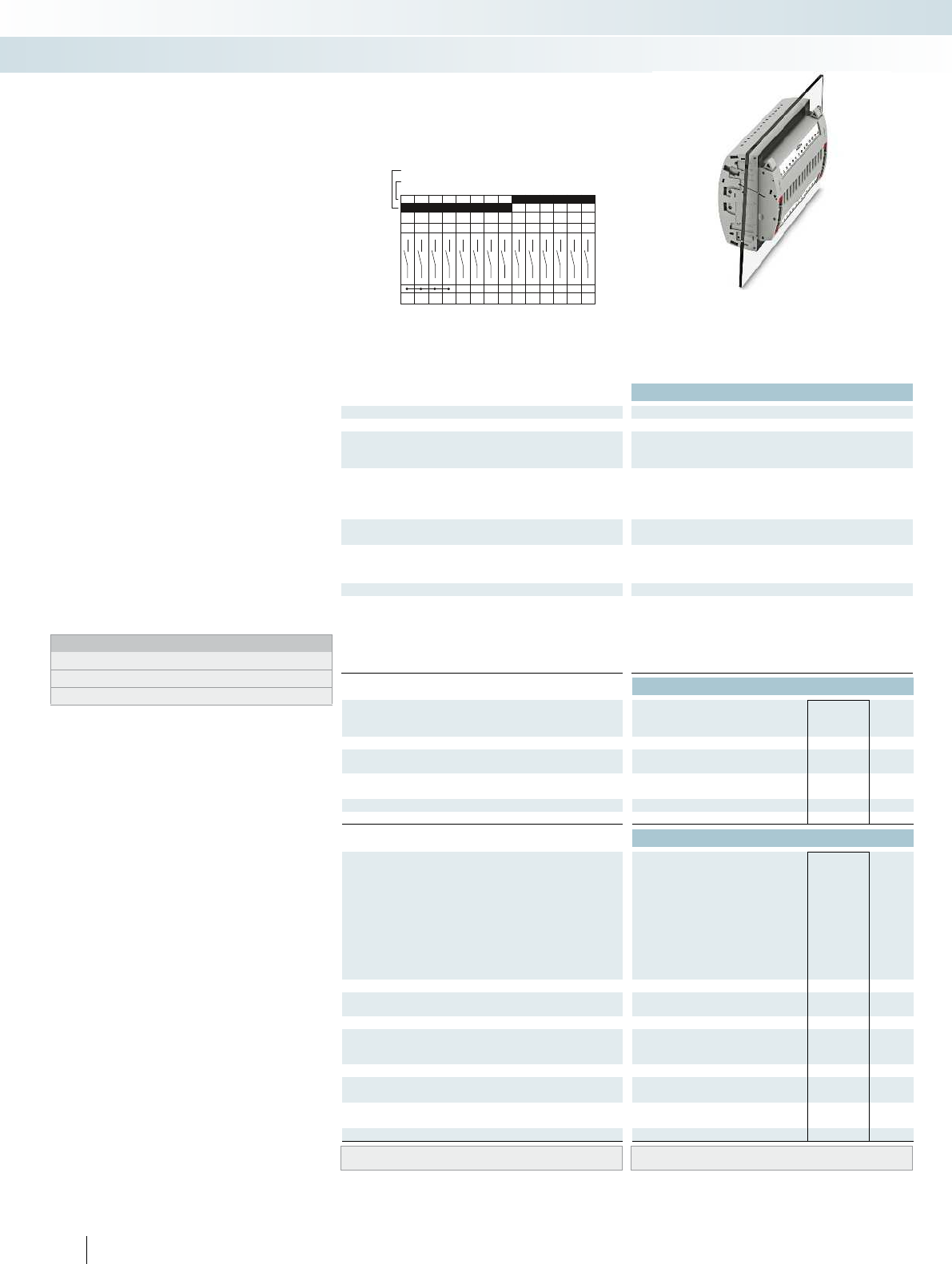
B14
1a 2a 3a 4a 5a 6a 7a 8a 9a
14a13a12a11a10a
1b 2b 3b 4b 5b 6b 7b 8b 9b
14b13b12b11b10b
Technical data
Max. electrical data Imax. [A] Umax. [V] max. Ø [mm²] AWG
30 4002) 0.5 - 10 20 - 8 30 400
IEC 60947-7-1
Rated data IEC UL/CUL CSA IEC/
EN60079-7
Rated voltage [V] 4002)--- 400
Nominal current / cross section [A] / [mm²] 241)/6--- 24
Rated cross section [mm²]6--- 6--- 6--- ----
Cross section range AWG20 - 8--- 20 - 8--- 20 - 14--- ----
Connection capacity solid stranded ferrule
with/without plastic sleeve
1 conductor [mm²] 0.5 - 10 0.5 - 6 0.5 - 6 0.5 - 6 0.5 - 10 0.5 - 6 0.5 - 6 0.5 - 6 - 0.5 - 2.5 - - - - - -
2 stranded conductors with a TWIN ferrule [mm²] 0.5 - 1.5
Plug-in connection cross sections [mm²] 1 - 10 - 1 - 6 1 - 6 1 - 10 - 1 - 6 1 - 6 - - - - - - - -
General data
Stripping length [mm] 12
Tightening torque for wall fastening [Nm] 0.8 - 1
Panel thickness [mm] 1 - 4
Tightening torque: test socket screw [Nm] -
Insulating material PA
Inflammability class according to UL 94 V0
Ordering data
Description Color Type Order No. Pcs. /
Pkt.
Test terminal strip, for wall mounting gray PTWE 6-2/B14 3069440 1
Test terminal strip, for mounting on NS35... gray
Test plug, with twist grip gray
With standard handle gray
Test plug, 1-pos., with cover gray
Blind plug, sealable gray
Accessories
Test socket, insulated
transparent
red
blue
yellow
green
violet
black
gray
brown
Cover profile, supply length 1m transparent AP RSC-T 3059139 10
Cover profile holder, can be snapped on and
sealed
gray APH-UTWE 6-2 3069057 10
Cover profile, supply length 1m transparent
End brackets, for AP-ME cover profile, sealable,
with storage option for jumpers
gray
Holder, for AP-ME cover profile gray
Fork-type cable lug, insulated according to UL red
blue
Ring cable lug, insulated according to UL red
blue
Screwdriver SF-SL 0,8X4,0-100 1212551 10
Lateral groove labeling UC-TM 8, UCT-TM 8, ZB 8 or TMT(EX9,5)R
(see Catalog 5)
110 PHOENIX CONTACT
Test terminal strip with PT... push-in
connection, VDEtype B14, for wall
and DIN rail mounting
Long contacts
Short contacts
The VDEB14 version described here is
suitable as a plug-in test system in
overcurrent directional protection, distance
protection for high and medium voltage, as
well as voltage regulation.
– The test plugs are assembled with
jumpers and contact tab lengths
according to the circuit diagram
– A transparent covering hood protects the
jumpers. The covering hood can only be
removed by dismantling the test plug
– All VDE-specified 7, 14, and 19-pos.
versions are supplied with exclusive
coding for the matching test plug and
blind plug
– The components are supplied pre-marked
according to the VDE Directive
– Test signals can be connected with touch-
proof safety test leads (CATIII and
IV/1000V according to EN61010-031)
– The test plugs are equipped with two gray
test sockets per position, for further
color versions, see the range of
accessories
– Additional test leads, assembled with ring
and fork-type cable lugs, can be attached
with test sockets
– Other VDE versions available on request
Notes:
To create panel cutouts, see phoenixcontact.net/products.
1) Derating curve available on request.
2) Rated surge voltage of 5 kV.
Modular terminal blocks
FAME plug-in test system
6 (10) mm², 30A, test terminal strip, for wall
mounting, VDE coded type B14
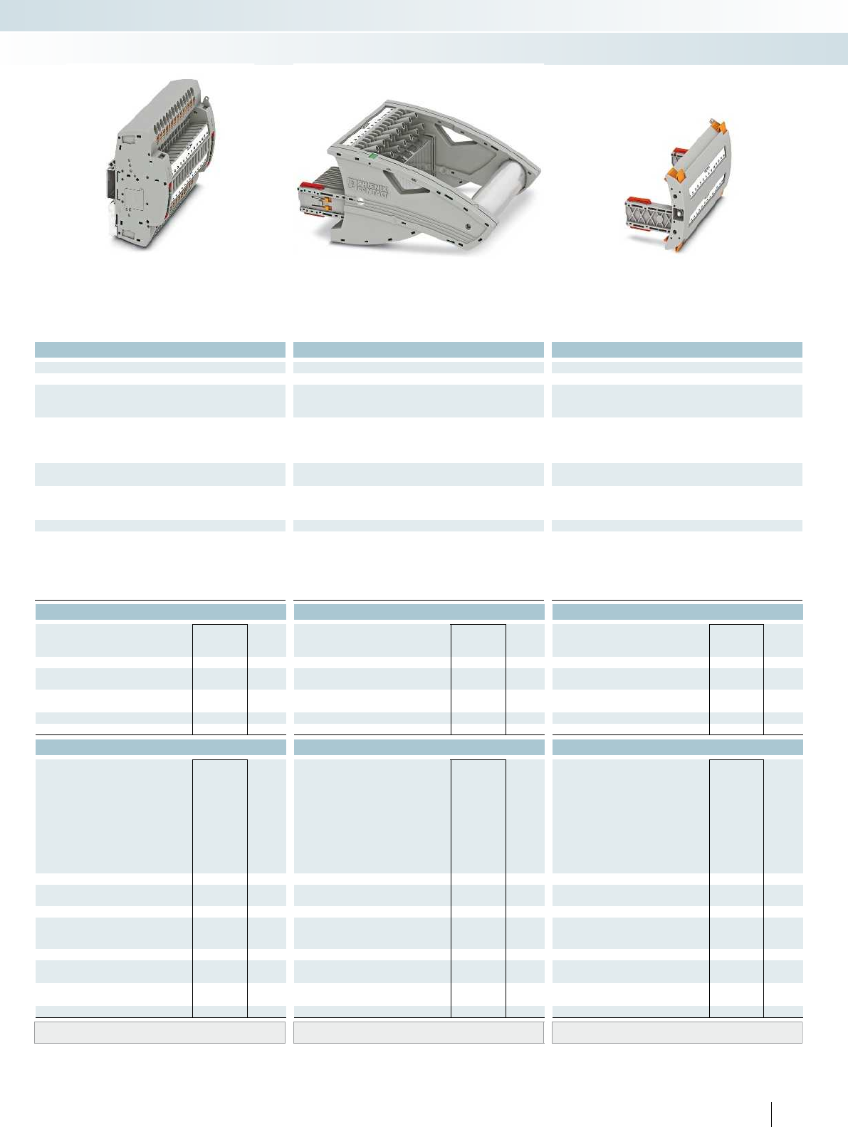
For additional information, visit phoenixcontact.net/products
Technical data Technical data Technical data
Imax. [A] Umax. [V] max. Ø [mm²] AWG Imax. [A] Umax. [V] max. Ø [mm²] AWG max. Ø [mm²] AWG
) 0.5 - 10 20 - 8 30 4002) 0.5 - 10 20 - 8 24 4002) 0.5 - 2.5 20 - 14 - -
IEC 60947-7-1
IEC UL/CUL CSA IEC/
EN60079-7
IEC UL/CUL CSA IEC/
EN60079-7
IEC UL/CUL CSA IEC/
EN60079-7
)--- 400
2)- - - 400
2)--- ----
)/6--- 24
1)/6--- 24/2.5--- ----
Rated cross section [mm²]6--- 6--- 6--- ----
Cross section range AWG20 - 8--- 20 - 8--- 20 - 14--- ----
solid stranded ferrule solid stranded ferrule solid stranded ferrule
with/without plastic sleeve with/without plastic sleeve with/without plastic sleeve
1 conductor [mm²] 0.5 - 10 0.5 - 6 0.5 - 6 0.5 - 6 0.5 - 10 0.5 - 6 0.5 - 6 0.5 - 6 - 0.5 - 2.5 - - - - - -
0.5 - 1.5
Plug-in connection cross sections [mm²] 1 - 10 - 1 - 6 1 - 6 1 - 10 - 1 - 6 1 - 6 - - - - - - - -
12 - -
---
---
-0.5 - 0.6-
PA PA PA
V0 V0 V0
Ordering data Ordering data Ordering data
Type Order No. Pcs. /
Pkt. Type Order No. Pcs. /
Pkt. Type Order No. Pcs. /
Pkt.
PTRE 6-2/B14 3069453 1
FTPR-2/B14 3069488 1
FTP-2/B14 3069475 1
FTP-2/1 3069469 1
FBP-2/B14 3069501 1
Accessories Accessories Accessories
PSBJ-URTK 6 FARBLOS 3026450 10
PSBJ-URTK 6 RD 3026719 10
PSBJ-URTK 6 BU 3026434 10
PSBJ-URTK 6 YE 3026405 10
PSBJ-URTK 6 GN 3026418 10
PSBJ-URTK 6 VT 3026421 10
PSBJ-URTK 6 BK 3026447 10
PSBJ-URTK 6 GY 3026612 10
PSBJ-URTK 6 BN 3026971 10
AP-ME METER 3034361 10
APH-ME 3034374 10
APT-ME 3034358 10
C-FCI 1,5/M3 3240032 100
C-FCI 2,5/M3 3240037 100
C-RCI 1,5/M3 3240016 100
C-RCI 2,5/M3 3240021 100
SF-SL 0,8X4,0-100 1212551 10
UC-TM 8, UCT-TM 8, ZB 8 or TMT(EX9,5)R
(see Catalog 5)
UC-TM 8, UCT-TM 8, ZB 8 or TMT(EX9,5)R
(see Catalog 5)
UC-TM 8, UCT-TM 8, ZB 8 or TMT(EX9,5)R
(see Catalog 5)
111PHOENIX CONTACT
Modular terminal blocks
FAME plug-in test system
6 (10) mm², 30A, test terminal strip, for DIN rail
mounting, VDE coded type B14
24A, test plug, bridge assignment according
to circuit diagram, VDE coded type B14
Blind plug, VDE coded type B14

C14
1a 2a 3a4a5a6a7a8a9a
14a13a12a11a10a
1b2b3b4b5b6b7b8b9b
14b13b12b11b10b
Technical data
Max. electrical data Imax. [A] Umax. [V] max. Ø [mm²] AWG
30 4002) 0.5 - 10 20 - 8 30 400
IEC 60947-7-1
Rated data IEC UL/CUL CSA IEC/
EN60079-7
Rated voltage [V] 4002)--- 400
Nominal current / cross section [A] / [mm²] 241)/6--- 24
Rated cross section [mm²]6--- 6--- 6--- ----
Cross section range AWG20 - 8--- 20 - 8--- 20 - 14--- ----
Connection capacity solid stranded ferrule
with/without plastic sleeve
1 conductor [mm²] 0.5 - 10 0.5 - 6 0.5 - 6 0.5 - 6 0.5 - 10 0.5 - 6 0.5 - 6 0.5 - 6 - 0.5 - 2.5 - - - - - -
2 stranded conductors with a TWIN ferrule [mm²] 0.5 - 1.5
Plug-in connection cross sections [mm²] 1 - 10 - 1 - 6 1 - 6 1 - 10 - 1 - 6 1 - 6 - - - - - - - -
General data
Stripping length [mm] 12
Tightening torque for wall fastening [Nm] 0.8 - 1
Panel thickness [mm] 1 - 4
Tightening torque: test socket screw [Nm] -
Insulating material PA
Inflammability class according to UL 94 V0
Ordering data
Description Color Type Order No. Pcs. /
Pkt.
Test terminal strip, for wall mounting gray PTWE 6-2/C14 3069441 1
Test terminal strip, for mounting on NS35... gray
Test plug, with twist grip gray
With standard handle gray
Test plug, 1-pos., with cover gray
Blind plug, sealable gray
Accessories
Test socket, insulated
transparent
red
blue
yellow
green
violet
black
gray
brown
Cover profile, supply length 1m transparent AP RSC-T 3059139 10
Cover profile holder, can be snapped on and
sealed
gray APH-UTWE 6-2 3069057 10
Cover profile, supply length 1m transparent
End brackets, for AP-ME cover profile, sealable,
with storage option for jumpers
gray
Holder, for AP-ME cover profile gray
Fork-type cable lug, insulated according to UL red
blue
Ring cable lug, insulated according to UL red
blue
Screwdriver SF-SL 0,8X4,0-100 1212551 10
Lateral groove labeling UC-TM 8, UCT-TM 8, ZB 8 or TMT(EX9,5)R
(see Catalog 5)
112 PHOENIX CONTACT
Test terminal strip with PT... push-in
connection, VDEtype C14, for wall
and DIN rail mounting
Long contacts
Short contacts
The VDEC14 version described here is
suitable as a plug-in test system in
overcurrent time protection, unbalanced
load protection, and stator ground fault
protection for busbar operation.
– The test plugs are assembled with
jumpers and contact tab lengths
according to the circuit diagram
– A transparent covering hood protects the
jumpers. The covering hood can only be
removed by dismantling the test plug
– All VDE-specified 7, 14, and 19-pos.
versions are supplied with exclusive
coding for the matching test plug and
blind plug
– The components are supplied pre-marked
according to the VDE Directive
– Test signals can be connected with touch-
proof safety test leads (CATIII and
IV/1000V according to EN61010-031)
– The test plugs are equipped with two gray
test sockets per position, for further
color versions, see the range of
accessories
– Additional test leads, assembled with ring
and fork-type cable lugs, can be attached
with test sockets
– Other VDE versions available on request
Notes:
To create panel cutouts, see phoenixcontact.net/products.
1) Derating curve available on request.
2) Rated surge voltage of 5 kV.
Modular terminal blocks
FAME plug-in test system
6 (10) mm², 30A, test terminal strip, for wall
mounting, VDE coded type C14

For additional information, visit phoenixcontact.net/products
Technical data Technical data Technical data
Imax. [A] Umax. [V] max. Ø [mm²] AWG Imax. [A] Umax. [V] max. Ø [mm²] AWG max. Ø [mm²] AWG
) 0.5 - 10 20 - 8 30 4002) 0.5 - 10 20 - 8 24 4002) 0.5 - 2.5 20 - 14 - -
IEC 60947-7-1
IEC UL/CUL CSA IEC/
EN60079-7
IEC UL/CUL CSA IEC/
EN60079-7
IEC UL/CUL CSA IEC/
EN60079-7
)--- 400
2)- - - 400
2)--- ----
)/6--- 24
1)/6--- 24/2.5--- ----
Rated cross section [mm²]6--- 6--- 6--- ----
Cross section range AWG20 - 8--- 20 - 8--- 20 - 14--- ----
solid stranded ferrule solid stranded ferrule solid stranded ferrule
with/without plastic sleeve with/without plastic sleeve with/without plastic sleeve
1 conductor [mm²] 0.5 - 10 0.5 - 6 0.5 - 6 0.5 - 6 0.5 - 10 0.5 - 6 0.5 - 6 0.5 - 6 - 0.5 - 2.5 - - - - - -
0.5 - 1.5
Plug-in connection cross sections [mm²] 1 - 10 - 1 - 6 1 - 6 1 - 10 - 1 - 6 1 - 6 - - - - - - - -
12 - -
---
---
-0.5 - 0.6-
PA PA PA
V0 V0 V0
Ordering data Ordering data Ordering data
Type Order No. Pcs. /
Pkt. Type Order No. Pcs. /
Pkt. Type Order No. Pcs. /
Pkt.
PTRE 6-2/C14 3069454 1
FTPR-2/C14 3069489 1
FTP-2/C14 3069476 1
FTP-2/1 3069469 1
FBP-2/C14 3069502 1
Accessories Accessories Accessories
PSBJ-URTK 6 FARBLOS 3026450 10
PSBJ-URTK 6 RD 3026719 10
PSBJ-URTK 6 BU 3026434 10
PSBJ-URTK 6 YE 3026405 10
PSBJ-URTK 6 GN 3026418 10
PSBJ-URTK 6 VT 3026421 10
PSBJ-URTK 6 BK 3026447 10
PSBJ-URTK 6 GY 3026612 10
PSBJ-URTK 6 BN 3026971 10
AP-ME METER 3034361 10
APH-ME 3034374 10
APT-ME 3034358 10
C-FCI 1,5/M3 3240032 100
C-FCI 2,5/M3 3240037 100
C-RCI 1,5/M3 3240016 100
C-RCI 2,5/M3 3240021 100
SF-SL 0,8X4,0-100 1212551 10
UC-TM 8, UCT-TM 8, ZB 8 or TMT(EX9,5)R
(see Catalog 5)
UC-TM 8, UCT-TM 8, ZB 8 or TMT(EX9,5)R
(see Catalog 5)
UC-TM 8, UCT-TM 8, ZB 8 or TMT(EX9,5)R
(see Catalog 5)
113PHOENIX CONTACT
Modular terminal blocks
FAME plug-in test system
6 (10) mm², 30A, test terminal strip, for DIN rail
mounting, VDE coded type C14
24A, test plug, bridge assignment according
to circuit diagram, VDE coded type C14
Blind plug, VDE coded type C14
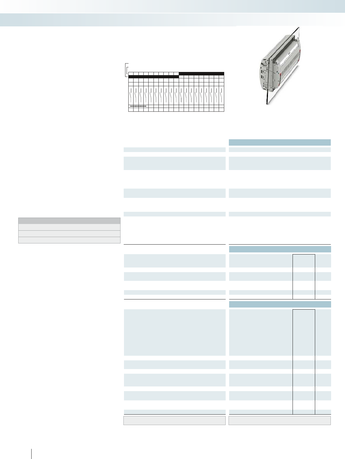
B19
1a 2a 3a 4a 5a 6a 7a 8a 9a
19a18a17a16a15a14a13a12a11a10a
1b 2b 3b 4b 5b 6b 7b 8b 9b
19b18b17b16b15b14b13b12b11b10b
Technical data
Max. electrical data Imax. [A] Umax. [V] max. Ø [mm²] AWG
30 4002) 0.5 - 10 20 - 8 30 400
IEC 60947-7-1
Rated data IEC UL/CUL CSA IEC/
EN60079-7
Rated voltage [V] 4002)--- 400
Nominal current / cross section [A] / [mm²] 241)/6--- 24
Rated cross section [mm²]6--- 6--- 6--- ----
Cross section range AWG20 - 8--- 20 - 8--- 20 - 14--- ----
Connection capacity solid stranded ferrule
with/without plastic sleeve
1 conductor [mm²] 0.5 - 10 0.5 - 6 0.5 - 6 0.5 - 6 0.5 - 10 0.5 - 6 0.5 - 6 0.5 - 6 - 0.5 - 2.5 - - - - - -
2 stranded conductors with a TWIN ferrule [mm²] 0.5 - 1.5
Plug-in connection cross sections [mm²] 1 - 10 - 1 - 6 1 - 6 1 - 10 - 1 - 6 1 - 6 - - - - - - - -
General data
Stripping length [mm] 12
Tightening torque for wall fastening [Nm] 0.8 - 1
Panel thickness [mm] 1 - 4
Tightening torque: test socket screw [Nm] -
Insulating material PA
Inflammability class according to UL 94 V0
Ordering data
Description Color Type Order No. Pcs. /
Pkt.
Test terminal strip, for wall mounting gray PTWE 6-2/B19 3069442 1
Test terminal strip, for mounting on NS35... gray
Test plug, with twist grip gray
With standard handle gray
Test plug, 1-pos., with cover gray
Blind plug, sealable gray
Accessories
Test socket, insulated
transparent
red
blue
yellow
green
violet
black
gray
brown
Cover profile, supply length 1m transparent AP RSC-T 3059139 10
Cover profile holder, can be snapped on and
sealed
gray APH-UTWE 6-2 3069057 10
Cover profile, supply length 1m transparent
End brackets, for AP-ME cover profile, sealable,
with storage option for jumpers
gray
Holder, for AP-ME cover profile gray
Fork-type cable lug, insulated according to UL red
blue
Ring cable lug, insulated according to UL red
blue
Screwdriver SF-SL 0,8X4,0-100 1212551 10
Lateral groove labeling UC-TM 8, UCT-TM 8, ZB 8 or TMT(EX9,5)R
(see Catalog 5)
114 PHOENIX CONTACT
Test terminal strip with PT... push-in
connection, VDEtype B19, for wall
and DIN rail mounting
Long contacts
Short contacts
The VDEB19 version described here is
suitable as a plug-in test system in distance
protection for high voltage.
– The test plugs are assembled with
jumpers and contact tab lengths
according to the circuit diagram
– A transparent covering hood protects the
jumpers. The covering hood can only be
removed by dismantling the test plug
– All VDE-specified 7, 14, and 19-pos.
versions are supplied with exclusive
coding for the matching test plug and
blind plug
– The components are supplied pre-marked
according to the VDE Directive
– Test signals can be connected with touch-
proof safety test leads (CATIII and
IV/1000V according to EN61010-031)
– The test plugs are equipped with two gray
test sockets per position, for further
color versions, see the range of
accessories
– Additional test leads, assembled with ring
and fork-type cable lugs, can be attached
with test sockets
– Other VDE versions available on request
Notes:
To create panel cutouts, see phoenixcontact.net/products.
1) Derating curve available on request.
2) Rated surge voltage of 5 kV.
Modular terminal blocks
FAME plug-in test system
6 (10) mm², 30A, test terminal strip, for wall
mounting, VDE coded type B19

For additional information, visit phoenixcontact.net/products
Technical data Technical data Technical data
Imax. [A] Umax. [V] max. Ø [mm²] AWG Imax. [A] Umax. [V] max. Ø [mm²] AWG max. Ø [mm²] AWG
) 0.5 - 10 20 - 8 30 4002) 0.5 - 10 20 - 8 24 4002) 0.5 - 2.5 20 - 14 - -
IEC 60947-7-1
IEC UL/CUL CSA IEC/
EN60079-7
IEC UL/CUL CSA IEC/
EN60079-7
IEC UL/CUL CSA IEC/
EN60079-7
)--- 400
2)- - - 400
2)--- ----
)/6--- 24
1)/6--- 24/2.5--- ----
Rated cross section [mm²]6--- 6--- 6--- ----
Cross section range AWG20 - 8--- 20 - 8--- 20 - 14--- ----
solid stranded ferrule solid stranded ferrule solid stranded ferrule
with/without plastic sleeve with/without plastic sleeve with/without plastic sleeve
1 conductor [mm²] 0.5 - 10 0.5 - 6 0.5 - 6 0.5 - 6 0.5 - 10 0.5 - 6 0.5 - 6 0.5 - 6 - 0.5 - 2.5 - - - - - -
0.5 - 1.5
Plug-in connection cross sections [mm²] 1 - 10 - 1 - 6 1 - 6 1 - 10 - 1 - 6 1 - 6 - - - - - - - -
12 - -
---
---
-0.5 - 0.6-
PA PA PA
V0 V0 V0
Ordering data Ordering data Ordering data
Type Order No. Pcs. /
Pkt. Type Order No. Pcs. /
Pkt. Type Order No. Pcs. /
Pkt.
PTRE 6-2/B19 3069455 1
FTPR-2/B19 3069490 1
FTP-2/B19 3069477 1
FTP-2/1 3069469 1
FBP-2/B19 3069503 1
Accessories Accessories Accessories
PSBJ-URTK 6 FARBLOS 3026450 10
PSBJ-URTK 6 RD 3026719 10
PSBJ-URTK 6 BU 3026434 10
PSBJ-URTK 6 YE 3026405 10
PSBJ-URTK 6 GN 3026418 10
PSBJ-URTK 6 VT 3026421 10
PSBJ-URTK 6 BK 3026447 10
PSBJ-URTK 6 GY 3026612 10
PSBJ-URTK 6 BN 3026971 10
AP-ME METER 3034361 10
APH-ME 3034374 10
APT-ME 3034358 10
C-FCI 1,5/M3 3240032 100
C-FCI 2,5/M3 3240037 100
C-RCI 1,5/M3 3240016 100
C-RCI 2,5/M3 3240021 100
SF-SL 0,8X4,0-100 1212551 10
UC-TM 8, UCT-TM 8, ZB 8 or TMT(EX9,5)R
(see Catalog 5)
UC-TM 8, UCT-TM 8, ZB 8 or TMT(EX9,5)R
(see Catalog 5)
UC-TM 8, UCT-TM 8, ZB 8 or TMT(EX9,5)R
(see Catalog 5)
115PHOENIX CONTACT
Modular terminal blocks
FAME plug-in test system
6 (10) mm², 30A, test terminal strip, for DIN rail
mounting, VDE coded type B19
24A, test plug, bridge assignment according
to circuit diagram, VDE coded type B19
Blind plug, VDE coded type B19

C19
1a 2a 3a 4a 5a 6a 7a 8a 9a
19a18a17a16a15a14a13a12a11a10a
1b 2b 3b 4b 5b 6b 7b 8b 9b
19b18b17b16b15b14b13b12b11b10b
Technical data
Max. electrical data Imax. [A] Umax. [V] max. Ø [mm²] AWG
30 4002) 0.5 - 10 20 - 8 30 400
IEC 60947-7-1
Rated data IEC UL/CUL CSA IEC/
EN60079-7
Rated voltage [V] 4002)--- 400
Nominal current / cross section [A] / [mm²] 241)/6--- 24
Rated cross section [mm²]6--- 6--- 6--- ----
Cross section range AWG20 - 8--- 20 - 8--- 20 - 14--- ----
Connection capacity solid stranded ferrule
with/without plastic sleeve
1 conductor [mm²] 0.5 - 10 0.5 - 6 0.5 - 6 0.5 - 6 0.5 - 10 0.5 - 6 0.5 - 6 0.5 - 6 - 0.5 - 2.5 - - - - - -
2 stranded conductors with a TWIN ferrule [mm²] 0.5 - 1.5
Plug-in connection cross sections [mm²] 1 - 10 - 1 - 6 1 - 6 1 - 10 - 1 - 6 1 - 6 - - - - - - - -
General data
Stripping length [mm] 12
Tightening torque for wall fastening [Nm] 0.8 - 1
Panel thickness [mm] 1 - 4
Tightening torque: test socket screw [Nm] -
Insulating material PA
Inflammability class according to UL 94 V0
Ordering data
Description Color Type Order No. Pcs. /
Pkt.
Test terminal strip, for wall mounting gray PTWE 6-2/C19 3069443 1
Test terminal strip, for mounting on NS35... gray
Test plug, with twist grip gray
With standard handle gray
Test plug, 1-pos., with cover gray
Blind plug, sealable gray
Accessories
Test socket, insulated
transparent
red
blue
yellow
green
violet
black
gray
brown
Cover profile, supply length 1m transparent AP RSC-T 3059139 10
Cover profile holder, can be snapped on and
sealed
gray APH-UTWE 6-2 3069057 10
Cover profile, supply length 1m transparent
End brackets, for AP-ME cover profile, sealable,
with storage option for jumpers
gray
Holder, for AP-ME cover profile gray
Fork-type cable lug, insulated according to UL red
blue
Ring cable lug, insulated according to UL red
blue
Screwdriver SF-SL 0,8X4,0-100 1212551 10
Lateral groove labeling UC-TM 8, UCT-TM 8, ZB 8 or TMT(EX9,5)R
(see Catalog 5)
116 PHOENIX CONTACT
Test terminal strip with PT... push-in
connection, VDEtype C19, for wall
and DIN rail mounting
Long contacts
Short contacts
The VDEC19 version described here is
suitable as a plug-in test system in distance
protection as system busbar protection,
overcurrent directional protection, and
current comparison protection for cables.
– The test plugs are assembled with
jumpers and contact tab lengths
according to the circuit diagram
– A transparent covering hood protects the
jumpers. The covering hood can only be
removed by dismantling the test plug
– All VDE-specified 7, 14, and 19-pos.
versions are supplied with exclusive
coding for the matching test plug and
blind plug
– The components are supplied pre-marked
according to the VDE Directive
– Test signals can be connected with touch-
proof safety test leads (CATIII and
IV/1000V according to EN61010-031)
– The test plugs are equipped with two gray
test sockets per position, for further
color versions, see the range of
accessories
– Additional test leads, assembled with ring
and fork-type cable lugs, can be attached
with test sockets
– Other VDE versions available on request
Notes:
To create panel cutouts, see phoenixcontact.net/products.
1) Derating curve available on request.
2) Rated surge voltage of 5 kV.
Modular terminal blocks
FAME plug-in test system
6 (10) mm², 30A, test terminal strip, for wall
mounting, VDE coded type C19

For additional information, visit phoenixcontact.net/products
Technical data Technical data Technical data
Imax. [A] Umax. [V] max. Ø [mm²] AWG Imax. [A] Umax. [V] max. Ø [mm²] AWG max. Ø [mm²] AWG
) 0.5 - 10 20 - 8 30 4002) 0.5 - 10 20 - 8 24 4002) 0.5 - 2.5 20 - 14 - -
IEC 60947-7-1
IEC UL/CUL CSA IEC/
EN60079-7
IEC UL/CUL CSA IEC/
EN60079-7
IEC UL/CUL CSA IEC/
EN60079-7
)--- 400
2)- - - 400
2)--- ----
)/6--- 24
1)/6--- 24/2.5--- ----
Rated cross section [mm²]6--- 6--- 6--- ----
Cross section range AWG20 - 8--- 20 - 8--- 20 - 14--- ----
solid stranded ferrule solid stranded ferrule solid stranded ferrule
with/without plastic sleeve with/without plastic sleeve with/without plastic sleeve
1 conductor [mm²] 0.5 - 10 0.5 - 6 0.5 - 6 0.5 - 6 0.5 - 10 0.5 - 6 0.5 - 6 0.5 - 6 - 0.5 - 2.5 - - - - - -
0.5 - 1.5
Plug-in connection cross sections [mm²] 1 - 10 - 1 - 6 1 - 6 1 - 10 - 1 - 6 1 - 6 - - - - - - - -
12 - -
---
---
-0.5 - 0.6-
PA PA PA
V0 V0 V0
Ordering data Ordering data Ordering data
Type Order No. Pcs. /
Pkt. Type Order No. Pcs. /
Pkt. Type Order No. Pcs. /
Pkt.
PTRE 6-2/C19 3069456 1
FTPR-2/C19 3069491 1
FTP-2/C19 3069478 1
FTP-2/1 3069469 1
FBP-2/C19 3069504 1
Accessories Accessories Accessories
PSBJ-URTK 6 FARBLOS 3026450 10
PSBJ-URTK 6 RD 3026719 10
PSBJ-URTK 6 BU 3026434 10
PSBJ-URTK 6 YE 3026405 10
PSBJ-URTK 6 GN 3026418 10
PSBJ-URTK 6 VT 3026421 10
PSBJ-URTK 6 BK 3026447 10
PSBJ-URTK 6 GY 3026612 10
PSBJ-URTK 6 BN 3026971 10
AP-ME METER 3034361 10
APH-ME 3034374 10
APT-ME 3034358 10
C-FCI 1,5/M3 3240032 100
C-FCI 2,5/M3 3240037 100
C-RCI 1,5/M3 3240016 100
C-RCI 2,5/M3 3240021 100
SF-SL 0,8X4,0-100 1212551 10
UC-TM 8, UCT-TM 8, ZB 8 or TMT(EX9,5)R
(see Catalog 5)
UC-TM 8, UCT-TM 8, ZB 8 or TMT(EX9,5)R
(see Catalog 5)
UC-TM 8, UCT-TM 8, ZB 8 or TMT(EX9,5)R
(see Catalog 5)
117PHOENIX CONTACT
Modular terminal blocks
FAME plug-in test system
6 (10) mm², 30A, test terminal strip, for DIN rail
mounting, VDE coded type C19
24A, test plug, bridge assignment according
to circuit diagram, VDE coded type C19
Blind plug, VDE coded type C19

D19
1a 2a 3a 4a 5a 6a 7a 8a 9a
19a18a17a16a15a14a13a12a11a10a
1b 2b 3b 4b 5b 6b 7b 8b 9b
19b18b17b16b15b14b13b12b11b10b
Technical data
Max. electrical data Imax. [A] Umax. [V] max. Ø [mm²] AWG
30 4002) 0.5 - 10 20 - 8 30 400
IEC 60947-7-1
Rated data IEC UL/CUL CSA IEC/
EN60079-7
Rated voltage [V] 4002)--- 400
Nominal current / cross section [A] / [mm²] 241)/6--- 24
Rated cross section [mm²]6--- 6--- 6--- ----
Cross section range AWG20 - 8--- 20 - 8--- 20 - 14--- ----
Connection capacity solid stranded ferrule
with/without plastic sleeve
1 conductor [mm²] 0.5 - 10 0.5 - 6 0.5 - 6 0.5 - 6 0.5 - 10 0.5 - 6 0.5 - 6 0.5 - 6 - 0.5 - 2.5 - - - - - -
2 stranded conductors with a TWIN ferrule [mm²] 0.5 - 1.5
Plug-in connection cross sections [mm²] 1 - 10 - 1 - 6 1 - 6 1 - 10 - 1 - 6 1 - 6 - - - - - - - -
General data
Stripping length [mm] 12
Tightening torque for wall fastening [Nm] 0.8 - 1
Panel thickness [mm] 1 - 4
Tightening torque: test socket screw [Nm] -
Insulating material PA
Inflammability class according to UL 94 V0
Ordering data
Description Color Type Order No. Pcs. /
Pkt.
Test terminal strip, for wall mounting gray PTWE 6-2/D19 3069444 1
Test terminal strip, for mounting on NS35... gray
Test plug, with twist grip gray
With standard handle gray
Test plug, 1-pos., with cover gray
Blind plug, sealable gray
Accessories
Test socket, insulated
transparent
red
blue
yellow
green
violet
black
gray
brown
Cover profile, supply length 1m transparent AP RSC-T 3059139 10
Cover profile holder, can be snapped on and
sealed
gray APH-UTWE 6-2 3069057 10
Cover profile, supply length 1m transparent
End brackets, for AP-ME cover profile, sealable,
with storage option for jumpers
gray
Holder, for AP-ME cover profile gray
Fork-type cable lug, insulated according to UL red
blue
Ring cable lug, insulated according to UL red
blue
Screwdriver SF-SL 0,8X4,0-100 1212551 10
Lateral groove labeling UC-TM 8, UCT-TM 8, ZB 8 or TMT(EX9,5)R
(see Catalog 5)
118 PHOENIX CONTACT
Test terminal strip with PT... push-in
connection, VDEtype D19, for wall
and DIN rail mounting
Long contacts
Short contacts
The VDED19 version described here is
suitable as a plug-in test system for
electromechanical differential protection
for transformers.
– The test plugs are assembled with
jumpers and contact tab lengths
according to the circuit diagram
– A transparent covering hood protects the
jumpers. The covering hood can only be
removed by dismantling the test plug
– All VDE-specified 7, 14, and 19-pos.
versions are supplied with exclusive
coding for the matching test plug and
blind plug
– The components are supplied pre-marked
according to the VDE Directive
– Test signals can be connected with touch-
proof safety test leads (CATIII and
IV/1000V according to EN61010-031)
– The test plugs are equipped with two gray
test sockets per position, for further
color versions, see the range of
accessories
– Additional test leads, assembled with ring
and fork-type cable lugs, can be attached
with test sockets
– Other VDE versions available on request
Notes:
To create panel cutouts, see phoenixcontact.net/products.
1) Derating curve available on request.
2) Rated surge voltage of 5 kV.
Modular terminal blocks
FAME plug-in test system
6 (10) mm², 30A, test terminal strip, for wall
mounting, VDE coded type D19

For additional information, visit phoenixcontact.net/products
Technical data Technical data Technical data
Imax. [A] Umax. [V] max. Ø [mm²] AWG Imax. [A] Umax. [V] max. Ø [mm²] AWG max. Ø [mm²] AWG
) 0.5 - 10 20 - 8 30 4002) 0.5 - 10 20 - 8 24 4002) 0.5 - 2.5 20 - 14 - -
IEC 60947-7-1
IEC UL/CUL CSA IEC/
EN60079-7
IEC UL/CUL CSA IEC/
EN60079-7
IEC UL/CUL CSA IEC/
EN60079-7
)--- 400
2)- - - 400
2)--- ----
)/6--- 24
1)/6--- 24/2.5--- ----
Rated cross section [mm²]6--- 6--- 6--- ----
Cross section range AWG20 - 8--- 20 - 8--- 20 - 14--- ----
solid stranded ferrule solid stranded ferrule solid stranded ferrule
with/without plastic sleeve with/without plastic sleeve with/without plastic sleeve
1 conductor [mm²] 0.5 - 10 0.5 - 6 0.5 - 6 0.5 - 6 0.5 - 10 0.5 - 6 0.5 - 6 0.5 - 6 - 0.5 - 2.5 - - - - - -
0.5 - 1.5
Plug-in connection cross sections [mm²] 1 - 10 - 1 - 6 1 - 6 1 - 10 - 1 - 6 1 - 6 - - - - - - - -
12 - -
---
---
-0.5 - 0.6-
PA PA PA
V0 V0 V0
Ordering data Ordering data Ordering data
Type Order No. Pcs. /
Pkt. Type Order No. Pcs. /
Pkt. Type Order No. Pcs. /
Pkt.
PTRE 6-2/D19 3069457 1
FTPR-2/D19 3069492 1
FTP-2/D19 3069479 1
FTP-2/1 3069469 1
FBP-2/D19 3069671 1
Accessories Accessories Accessories
PSBJ-URTK 6 FARBLOS 3026450 10
PSBJ-URTK 6 RD 3026719 10
PSBJ-URTK 6 BU 3026434 10
PSBJ-URTK 6 YE 3026405 10
PSBJ-URTK 6 GN 3026418 10
PSBJ-URTK 6 VT 3026421 10
PSBJ-URTK 6 BK 3026447 10
PSBJ-URTK 6 GY 3026612 10
PSBJ-URTK 6 BN 3026971 10
AP-ME METER 3034361 10
APH-ME 3034374 10
APT-ME 3034358 10
C-FCI 1,5/M3 3240032 100
C-FCI 2,5/M3 3240037 100
C-RCI 1,5/M3 3240016 100
C-RCI 2,5/M3 3240021 100
SF-SL 0,8X4,0-100 1212551 10
UC-TM 8, UCT-TM 8, ZB 8 or TMT(EX9,5)R
(see Catalog 5)
UC-TM 8, UCT-TM 8, ZB 8 or TMT(EX9,5)R
(see Catalog 5)
UC-TM 8, UCT-TM 8, ZB 8 or TMT(EX9,5)R
(see Catalog 5)
119PHOENIX CONTACT
Modular terminal blocks
FAME plug-in test system
6 (10) mm², 30A, test terminal strip, for DIN rail
mounting, VDE coded type D19
24A, test plug, bridge assignment according
to circuit diagram, VDE coded type D19
Blind plug, VDE coded type D19
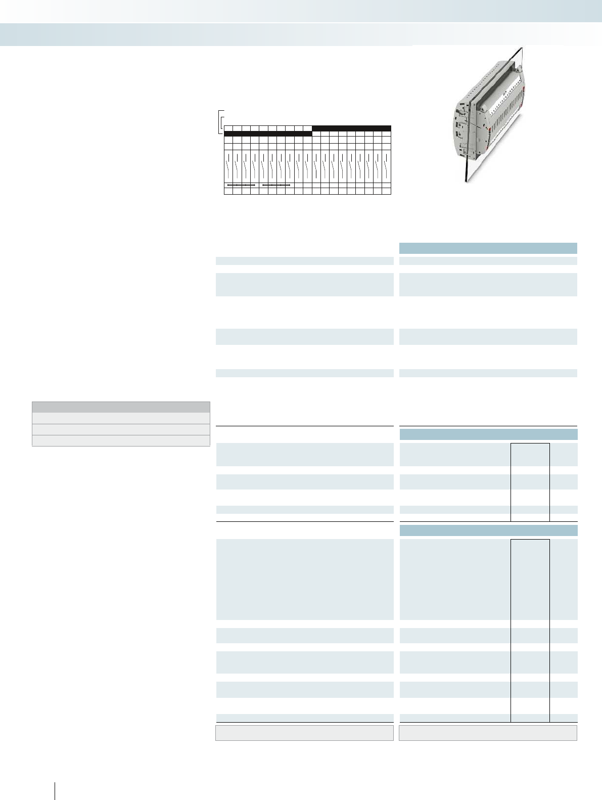
F19
1a 2a 3a 4a 5a 6a 7a 8a 9a
19a18a17a16a15a14a13a12a11a10a
1b 2b 3b 4b 5b 6b 7b 8b 9b
19b18b17b16b15b14b13b12b11b10b
Technical data
Max. electrical data Imax. [A] Umax. [V] max. Ø [mm²] AWG
30 4002) 0.5 - 10 20 - 8 30 400
IEC 60947-7-1
Rated data IEC UL/CUL CSA IEC/
EN60079-7
Rated voltage [V] 4002)--- 400
Nominal current / cross section [A] / [mm²] 241)/6--- 24
Rated cross section [mm²]6--- 6--- 6--- ----
Cross section range AWG20 - 8--- 20 - 8--- 20 - 14--- ----
Connection capacity solid stranded ferrule
with/without plastic sleeve
1 conductor [mm²] 0.5 - 10 0.5 - 6 0.5 - 6 0.5 - 6 0.5 - 10 0.5 - 6 0.5 - 6 0.5 - 6 - 0.5 - 2.5 - - - - - -
2 stranded conductors with a TWIN ferrule [mm²] 0.5 - 1.5
Plug-in connection cross sections [mm²] 1 - 10 - 1 - 6 1 - 6 1 - 10 - 1 - 6 1 - 6 - - - - - - - -
General data
Stripping length [mm] 12
Tightening torque for wall fastening [Nm] 0.8 - 1
Panel thickness [mm] 1 - 4
Tightening torque: test socket screw [Nm] -
Insulating material PA
Inflammability class according to UL 94 V0
Ordering data
Description Color Type Order No. Pcs. /
Pkt.
Test terminal strip, for wall mounting gray PTWE 6-2/F19 3069445 1
Test terminal strip, for mounting on NS35... gray
Test plug, with twist grip gray
With standard handle gray
Test plug, 1-pos., with cover gray
Blind plug, sealable gray
Accessories
Test socket, insulated
transparent
red
blue
yellow
green
violet
black
gray
brown
Cover profile, supply length 1m transparent AP RSC-T 3059139 10
Cover profile holder, can be snapped on and
sealed
gray APH-UTWE 6-2 3069057 10
Cover profile, supply length 1m transparent
End brackets, for AP-ME cover profile, sealable,
with storage option for jumpers
gray
Holder, for AP-ME cover profile gray
Fork-type cable lug, insulated according to UL red
blue
Ring cable lug, insulated according to UL red
blue
Screwdriver SF-SL 0,8X4,0-100 1212551 10
Lateral groove labeling UC-TM 8, UCT-TM 8, ZB 8 or TMT(EX9,5)R
(see Catalog 5)
120 PHOENIX CONTACT
Test terminal strip with PT... push-in
connection, VDEtype F19, for wall
and DIN rail mounting
Long contacts
Short contacts
The VDEF19 version described here is
suitable as a plug-in test system in
electromechanical differential protection
for transformers, generators, motors, and
cables.
– The test plugs are assembled with
jumpers and contact tab lengths
according to the circuit diagram
– A transparent covering hood protects the
jumpers. The covering hood can only be
removed by dismantling the test plug
– All VDE-specified 7, 14, and 19-pos.
versions are supplied with exclusive
coding for the matching test plug and
blind plug
– The components are supplied pre-marked
according to the VDE Directive
– Test signals can be connected with touch-
proof safety test leads (CATIII and
IV/1000V according to EN61010-031)
– The test plugs are equipped with two gray
test sockets per position, for further
color versions, see the range of
accessories
– Additional test leads, assembled with ring
and fork-type cable lugs, can be attached
with test sockets
– Other VDE versions available on request
Notes:
To create panel cutouts, see phoenixcontact.net/products.
1) Derating curve available on request.
2) Rated surge voltage of 5 kV.
Modular terminal blocks
FAME plug-in test system
6 (10) mm², 30A, test terminal strip, for wall
mounting, VDE coded type F19

For additional information, visit phoenixcontact.net/products
Technical data Technical data Technical data
Imax. [A] Umax. [V] max. Ø [mm²] AWG Imax. [A] Umax. [V] max. Ø [mm²] AWG max. Ø [mm²] AWG
) 0.5 - 10 20 - 8 30 4002) 0.5 - 10 20 - 8 24 4002) 0.5 - 2.5 20 - 14 - -
IEC 60947-7-1
IEC UL/CUL CSA IEC/
EN60079-7
IEC UL/CUL CSA IEC/
EN60079-7
IEC UL/CUL CSA IEC/
EN60079-7
)--- 400
2)- - - 400
2)--- ----
)/6--- 24
1)/6--- 24/2.5--- ----
Rated cross section [mm²]6--- 6--- 6--- ----
Cross section range AWG20 - 8--- 20 - 8--- 20 - 14--- ----
solid stranded ferrule solid stranded ferrule solid stranded ferrule
with/without plastic sleeve with/without plastic sleeve with/without plastic sleeve
1 conductor [mm²] 0.5 - 10 0.5 - 6 0.5 - 6 0.5 - 6 0.5 - 10 0.5 - 6 0.5 - 6 0.5 - 6 - 0.5 - 2.5 - - - - - -
0.5 - 1.5
Plug-in connection cross sections [mm²] 1 - 10 - 1 - 6 1 - 6 1 - 10 - 1 - 6 1 - 6 - - - - - - - -
12 - -
---
---
-0.5 - 0.6-
PA PA PA
V0 V0 V0
Ordering data Ordering data Ordering data
Type Order No. Pcs. /
Pkt. Type Order No. Pcs. /
Pkt. Type Order No. Pcs. /
Pkt.
PTRE 6-2/F19 3069458 1
FTPR-2/F19 3069493 1
FTP-2/F19 3069480 1
FTP-2/1 3069469 1
FBP-2/F19 3069675 1
Accessories Accessories Accessories
PSBJ-URTK 6 FARBLOS 3026450 10
PSBJ-URTK 6 RD 3026719 10
PSBJ-URTK 6 BU 3026434 10
PSBJ-URTK 6 YE 3026405 10
PSBJ-URTK 6 GN 3026418 10
PSBJ-URTK 6 VT 3026421 10
PSBJ-URTK 6 BK 3026447 10
PSBJ-URTK 6 GY 3026612 10
PSBJ-URTK 6 BN 3026971 10
AP-ME METER 3034361 10
APH-ME 3034374 10
APT-ME 3034358 10
C-FCI 1,5/M3 3240032 100
C-FCI 2,5/M3 3240037 100
C-RCI 1,5/M3 3240016 100
C-RCI 2,5/M3 3240021 100
SF-SL 0,8X4,0-100 1212551 10
UC-TM 8, UCT-TM 8, ZB 8 or TMT(EX9,5)R
(see Catalog 5)
UC-TM 8, UCT-TM 8, ZB 8 or TMT(EX9,5)R
(see Catalog 5)
UC-TM 8, UCT-TM 8, ZB 8 or TMT(EX9,5)R
(see Catalog 5)
121PHOENIX CONTACT
Modular terminal blocks
FAME plug-in test system
6 (10) mm², 30A, test terminal strip, for DIN rail
mounting, VDE coded type F19
24A, test plug, bridge assignment according
to circuit diagram, VDE coded type F19
Blind plug, VDE coded type F19

G19
1a 2a 3a4a5a6a7a
1b2b3b4b5b6b7b
8a9a10a 11a 12a 13a 14a
8b9b10b 11b12b13b14b
15a 16a 17a
15b16b17b
18a19a
18b19b
Technical data
Max. electrical data Imax. [A] Umax. [V] max. Ø [mm²] AWG
30 4002) 0.5 - 10 20 - 8 30 400
IEC 60947-7-1
Rated data IEC UL/CUL CSA IEC/
EN60079-7
Rated voltage [V] 4002)--- 400
Nominal current / cross section [A] / [mm²] 241)/6--- 24
Rated cross section [mm²]6--- 6--- 6--- ----
Cross section range AWG20 - 8--- 20 - 8--- 20 - 14--- ----
Connection capacity solid stranded ferrule
with/without plastic sleeve
1 conductor [mm²] 0.5 - 10 0.5 - 6 0.5 - 6 0.5 - 6 0.5 - 10 0.5 - 6 0.5 - 6 0.5 - 6 - 0.5 - 2.5 - - - - - -
2 stranded conductors with a TWIN ferrule [mm²] 0.5 - 1.5
Plug-in connection cross sections [mm²] 1 - 10 - 1 - 6 1 - 6 1 - 10 - 1 - 6 1 - 6 - - - - - - - -
General data
Stripping length [mm] 12
Tightening torque for wall fastening [Nm] 0.8 - 1
Panel thickness [mm] 1 - 4
Tightening torque: test socket screw [Nm] -
Insulating material PA
Inflammability class according to UL 94 V0
Ordering data
Description Color Type Order No. Pcs. /
Pkt.
Test terminal strip, for wall mounting gray PTWE 6-2/G19 3069446 1
Test terminal strip, for mounting on NS35... gray
Test plug, with twist grip gray
With standard handle gray
Test plug, 1-pos., with cover gray
Blind plug, sealable gray
Accessories
Test socket, insulated
transparent
red
blue
yellow
green
violet
black
gray
brown
Cover profile, supply length 1m transparent AP RSC-T 3059139 10
Cover profile holder, can be snapped on and
sealed
gray APH-UTWE 6-2 3069057 10
Cover profile, supply length 1m transparent
End brackets, for AP-ME cover profile, sealable,
with storage option for jumpers
gray
Holder, for AP-ME cover profile gray
Fork-type cable lug, insulated according to UL red
blue
Ring cable lug, insulated according to UL red
blue
Screwdriver SF-SL 0,8X4,0-100 1212551 10
Lateral groove labeling UC-TM 8, UCT-TM 8, ZB 8 or TMT(EX9,5)R
(see Catalog 5)
122 PHOENIX CONTACT
Test terminal strip with PT... push-in
connection, VDEtype G19, for wall
and DIN rail mounting
Long contacts
Short contacts
The VDEG19 version described here is
suitable as a plug-in test system in digital
differential protection for transformers.
– The test plugs are assembled with
jumpers and contact tab lengths
according to the circuit diagram
– A transparent covering hood protects the
jumpers. The covering hood can only be
removed by dismantling the test plug
– All VDE-specified 7, 14, and 19-pos.
versions are supplied with exclusive
coding for the matching test plug and
blind plug
– The components are supplied pre-marked
according to the VDE Directive
– Test signals can be connected with touch-
proof safety test leads (CATIII and
IV/1000V according to EN61010-031)
– The test plugs are equipped with two gray
test sockets per position, for further
color versions, see the range of
accessories
– Additional test leads, assembled with ring
and fork-type cable lugs, can be attached
with test sockets
– Other VDE versions available on request
Notes:
To create panel cutouts, see phoenixcontact.net/products.
1) Derating curve available on request.
2) Rated surge voltage of 5 kV.
Modular terminal blocks
FAME plug-in test system
6 (10) mm², 30A, test terminal strip, for wall
mounting, VDE coded type G19

For additional information, visit phoenixcontact.net/products
Technical data Technical data Technical data
Imax. [A] Umax. [V] max. Ø [mm²] AWG Imax. [A] Umax. [V] max. Ø [mm²] AWG max. Ø [mm²] AWG
) 0.5 - 10 20 - 8 30 4002) 0.5 - 10 20 - 8 24 4002) 0.5 - 2.5 20 - 14 - -
IEC 60947-7-1
IEC UL/CUL CSA IEC/
EN60079-7
IEC UL/CUL CSA IEC/
EN60079-7
IEC UL/CUL CSA IEC/
EN60079-7
)--- 400
2)- - - 400
2)--- ----
)/6--- 24
1)/6--- 24/2.5--- ----
Rated cross section [mm²]6--- 6--- 6--- ----
Cross section range AWG20 - 8--- 20 - 8--- 20 - 14--- ----
solid stranded ferrule solid stranded ferrule solid stranded ferrule
with/without plastic sleeve with/without plastic sleeve with/without plastic sleeve
1 conductor [mm²] 0.5 - 10 0.5 - 6 0.5 - 6 0.5 - 6 0.5 - 10 0.5 - 6 0.5 - 6 0.5 - 6 - 0.5 - 2.5 - - - - - -
0.5 - 1.5
Plug-in connection cross sections [mm²] 1 - 10 - 1 - 6 1 - 6 1 - 10 - 1 - 6 1 - 6 - - - - - - - -
12 - -
---
---
-0.5 - 0.6-
PA PA PA
V0 V0 V0
Ordering data Ordering data Ordering data
Type Order No. Pcs. /
Pkt. Type Order No. Pcs. /
Pkt. Type Order No. Pcs. /
Pkt.
PTRE 6-2/G19 3069459 1
FTPR-2/G19 3069494 1
FTP-2/G19 3069481 1
FTP-2/1 3069469 1
FBP-2/G19 3069676 1
Accessories Accessories Accessories
PSBJ-URTK 6 FARBLOS 3026450 10
PSBJ-URTK 6 RD 3026719 10
PSBJ-URTK 6 BU 3026434 10
PSBJ-URTK 6 YE 3026405 10
PSBJ-URTK 6 GN 3026418 10
PSBJ-URTK 6 VT 3026421 10
PSBJ-URTK 6 BK 3026447 10
PSBJ-URTK 6 GY 3026612 10
PSBJ-URTK 6 BN 3026971 10
AP-ME METER 3034361 10
APH-ME 3034374 10
APT-ME 3034358 10
C-FCI 1,5/M3 3240032 100
C-FCI 2,5/M3 3240037 100
C-RCI 1,5/M3 3240016 100
C-RCI 2,5/M3 3240021 100
SF-SL 0,8X4,0-100 1212551 10
UC-TM 8, UCT-TM 8, ZB 8 or TMT(EX9,5)R
(see Catalog 5)
UC-TM 8, UCT-TM 8, ZB 8 or TMT(EX9,5)R
(see Catalog 5)
UC-TM 8, UCT-TM 8, ZB 8 or TMT(EX9,5)R
(see Catalog 5)
123PHOENIX CONTACT
Modular terminal blocks
FAME plug-in test system
6 (10) mm², 30A, test terminal strip, for DIN rail
mounting, VDE coded type G19
24A, test plug, bridge assignment according
to circuit diagram, VDE coded type G19
Blind plug, VDE coded type G19
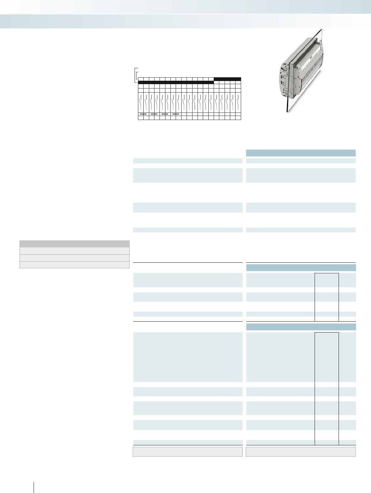
H19
1a 2a 3a 4a 5a 6a 7a 8a 9a
19a18a17a16a15a14a13a12a11a10a
1b 2b 3b 4b 5b 6b 7b 8b 9b
19b18b17b16b15b14b13b12b11b10b
Technical data
Max. electrical data Imax. [A] Umax. [V] max. Ø [mm²] AWG
30 4002) 0.5 - 10 20 - 8 30 400
IEC 60947-7-1
Rated data IEC UL/CUL CSA IEC/
EN60079-7
Rated voltage [V] 4002)--- 400
Nominal current / cross section [A] / [mm²] 241)/6--- 24
Rated cross section [mm²]6--- 6--- 6--- ----
Cross section range AWG20 - 8--- 20 - 8--- 20 - 14--- ----
Connection capacity solid stranded ferrule
with/without plastic sleeve
1 conductor [mm²] 0.5 - 10 0.5 - 6 0.5 - 6 0.5 - 6 0.5 - 10 0.5 - 6 0.5 - 6 0.5 - 6 - 0.5 - 2.5 - - - - - -
2 stranded conductors with a TWIN ferrule [mm²] 0.5 - 1.5
Plug-in connection cross sections [mm²] 1 - 10 - 1 - 6 1 - 6 1 - 10 - 1 - 6 1 - 6 - - - - - - - -
General data
Stripping length [mm] 12
Tightening torque for wall fastening [Nm] 0.8 - 1
Panel thickness [mm] 1 - 4
Tightening torque: test socket screw [Nm] -
Insulating material PA
Inflammability class according to UL 94 V0
Ordering data
Description Color Type Order No. Pcs. /
Pkt.
Test terminal strip, for wall mounting gray PTWE 6-2/H19 3069447 1
Test terminal strip, for mounting on NS35... gray
Test plug, with twist grip gray
With standard handle gray
Test plug, 1-pos., with cover gray
Blind plug, sealable gray
Accessories
Test socket, insulated
transparent
red
blue
yellow
green
violet
black
gray
brown
Cover profile, supply length 1m transparent AP RSC-T 3059139 10
Cover profile holder, can be snapped on and
sealed
gray APH-UTWE 6-2 3069057 10
Cover profile, supply length 1m transparent
End brackets, for AP-ME cover profile, sealable,
with storage option for jumpers
gray
Holder, for AP-ME cover profile gray
Fork-type cable lug, insulated according to UL red
blue
Ring cable lug, insulated according to UL red
blue
Screwdriver SF-SL 0,8X4,0-100 1212551 10
Lateral groove labeling UC-TM 8, UCT-TM 8, ZB 8 or TMT(EX9,5)R
(see Catalog 5)
124 PHOENIX CONTACT
Test terminal strip with PT... push-in
connection, VDEtype H19, for wall
and DIN rail mounting
Long contacts
Short contacts
The VDEH19 version described here is
suitable as a plug-in test system in
overcurrent directional protection and
distance protection as system protection.
– The test plugs are assembled with
jumpers and contact tab lengths
according to the circuit diagram
– A transparent covering hood protects the
jumpers. The covering hood can only be
removed by dismantling the test plug
– All VDE-specified 7, 14, and 19-pos.
versions are supplied with exclusive
coding for the matching test plug and
blind plug
– The components are supplied pre-marked
according to the VDE Directive
– Test signals can be connected with touch-
proof safety test leads (CATIII and
IV/1000V according to EN61010-031)
– The test plugs are equipped with two gray
test sockets per position, for further
color versions, see the range of
accessories
– Additional test leads, assembled with ring
and fork-type cable lugs, can be attached
with test sockets
– Other VDE versions available on request
Notes:
To create panel cutouts, see phoenixcontact.net/products.
1) Derating curve available on request.
2) Rated surge voltage of 5 kV.
Modular terminal blocks
FAME plug-in test system
6 (10) mm², 30A, test terminal strip, for wall
mounting, VDE coded type H19
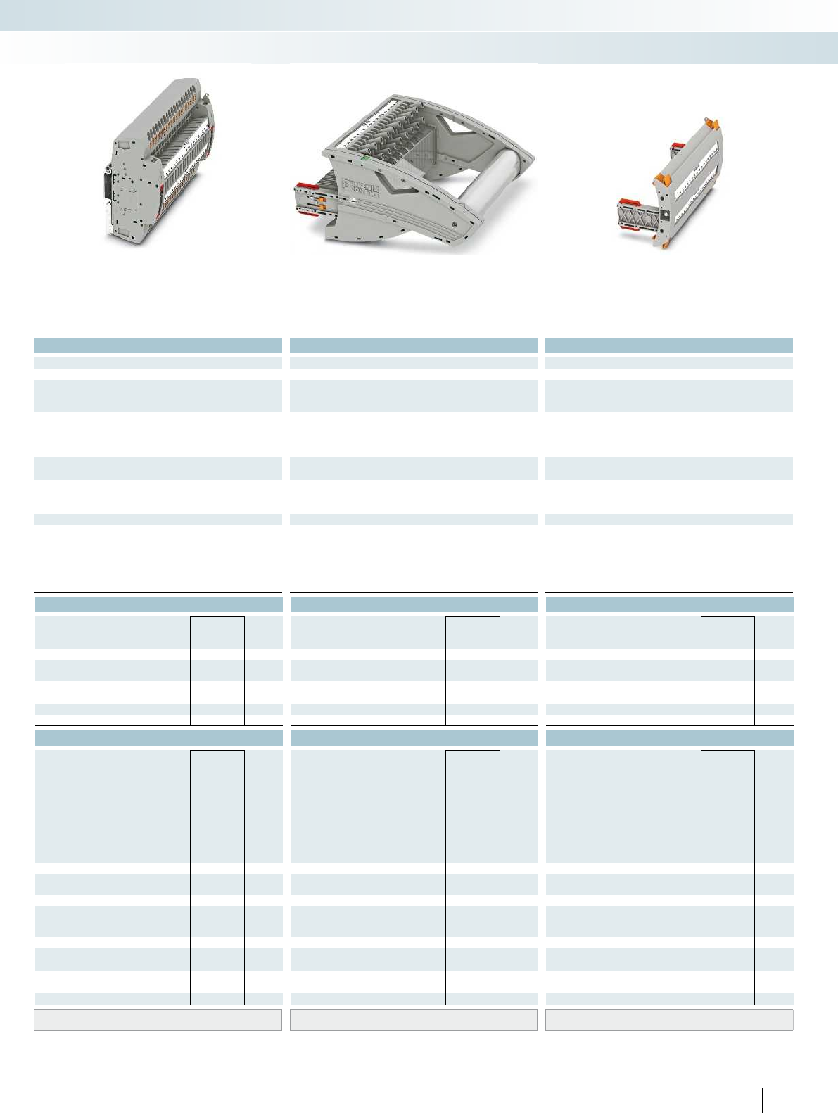
For additional information, visit phoenixcontact.net/products
Technical data Technical data Technical data
Imax. [A] Umax. [V] max. Ø [mm²] AWG Imax. [A] Umax. [V] max. Ø [mm²] AWG max. Ø [mm²] AWG
) 0.5 - 10 20 - 8 30 4002) 0.5 - 10 20 - 8 24 4002) 0.5 - 2.5 20 - 14 - -
IEC 60947-7-1
IEC UL/CUL CSA IEC/
EN60079-7
IEC UL/CUL CSA IEC/
EN60079-7
IEC UL/CUL CSA IEC/
EN60079-7
)--- 400
2)- - - 400
2)--- ----
)/6--- 24
1)/6--- 24/2.5--- ----
Rated cross section [mm²]6--- 6--- 6--- ----
Cross section range AWG20 - 8--- 20 - 8--- 20 - 14--- ----
solid stranded ferrule solid stranded ferrule solid stranded ferrule
with/without plastic sleeve with/without plastic sleeve with/without plastic sleeve
1 conductor [mm²] 0.5 - 10 0.5 - 6 0.5 - 6 0.5 - 6 0.5 - 10 0.5 - 6 0.5 - 6 0.5 - 6 - 0.5 - 2.5 - - - - - -
0.5 - 1.5
Plug-in connection cross sections [mm²] 1 - 10 - 1 - 6 1 - 6 1 - 10 - 1 - 6 1 - 6 - - - - - - - -
12 - -
---
---
-0.5 - 0.6-
PA PA PA
V0 V0 V0
Ordering data Ordering data Ordering data
Type Order No. Pcs. /
Pkt. Type Order No. Pcs. /
Pkt. Type Order No. Pcs. /
Pkt.
PTRE 6-2/H19 3069460 1
FTPR-2/H19 3069495 1
FTP-2/H19 3069482 1
FTP-2/1 3069469 1
FBP-2/H19 3069677 1
Accessories Accessories Accessories
PSBJ-URTK 6 FARBLOS 3026450 10
PSBJ-URTK 6 RD 3026719 10
PSBJ-URTK 6 BU 3026434 10
PSBJ-URTK 6 YE 3026405 10
PSBJ-URTK 6 GN 3026418 10
PSBJ-URTK 6 VT 3026421 10
PSBJ-URTK 6 BK 3026447 10
PSBJ-URTK 6 GY 3026612 10
PSBJ-URTK 6 BN 3026971 10
AP-ME METER 3034361 10
APH-ME 3034374 10
APT-ME 3034358 10
C-FCI 1,5/M3 3240032 100
C-FCI 2,5/M3 3240037 100
C-RCI 1,5/M3 3240016 100
C-RCI 2,5/M3 3240021 100
SF-SL 0,8X4,0-100 1212551 10
UC-TM 8, UCT-TM 8, ZB 8 or TMT(EX9,5)R
(see Catalog 5)
UC-TM 8, UCT-TM 8, ZB 8 or TMT(EX9,5)R
(see Catalog 5)
UC-TM 8, UCT-TM 8, ZB 8 or TMT(EX9,5)R
(see Catalog 5)
125PHOENIX CONTACT
Modular terminal blocks
FAME plug-in test system
6 (10) mm², 30A, test terminal strip, for DIN rail
mounting, VDE coded type H19
24A, test plug, bridge assignment according
to circuit diagram, VDE coded type H19
Blind plug, VDE coded type H19

I19
1a 2a 3a 4a 5a 6a 7a 8a 9a
19a18a17a16a15a14a13a12a11a10a
1b 2b 3b 4b 5b 6b 7b 8b 9b
19b18b17b16b15b14b13b12b11b10b
Technical data
Max. electrical data Imax. [A] Umax. [V] max. Ø [mm²] AWG
30 4002) 0.5 - 10 20 - 8 30 400
IEC 60947-7-1
Rated data IEC UL/CUL CSA IEC/
EN60079-7
Rated voltage [V] 4002)--- 400
Nominal current / cross section [A] / [mm²] 241)/6--- 24
Rated cross section [mm²]6--- 6--- 6--- ----
Cross section range AWG20 - 8--- 20 - 8--- 20 - 14--- ----
Connection capacity solid stranded ferrule
with/without plastic sleeve
1 conductor [mm²] 0.5 - 10 0.5 - 6 0.5 - 6 0.5 - 6 0.5 - 10 0.5 - 6 0.5 - 6 0.5 - 6 - 0.5 - 2.5 - - - - - -
2 stranded conductors with a TWIN ferrule [mm²] 0.5 - 1.5
Plug-in connection cross sections [mm²] 1 - 10 - 1 - 6 1 - 6 1 - 10 - 1 - 6 1 - 6 - - - - - - - -
General data
Stripping length [mm] 12
Tightening torque for wall fastening [Nm] 0.8 - 1
Panel thickness [mm] 1 - 4
Tightening torque: test socket screw [Nm] -
Insulating material PA
Inflammability class according to UL 94 V0
Ordering data
Description Color Type Order No. Pcs. /
Pkt.
Test terminal strip, for wall mounting gray PTWE 6-2/I19 3069448 1
Test terminal strip, for mounting on NS35... gray
Test plug, with twist grip gray
With standard handle gray
Test plug, 1-pos., with cover gray
Blind plug, sealable gray
Accessories
Test socket, insulated
transparent
red
blue
yellow
green
violet
black
gray
brown
Cover profile, supply length 1m transparent AP RSC-T 3059139 10
Cover profile holder, can be snapped on and
sealed
gray APH-UTWE 6-2 3069057 10
Cover profile, supply length 1m transparent
End brackets, for AP-ME cover profile, sealable,
with storage option for jumpers
gray
Holder, for AP-ME cover profile gray
Fork-type cable lug, insulated according to UL red
blue
Ring cable lug, insulated according to UL red
blue
Screwdriver SF-SL 0,8X4,0-100 1212551 10
Lateral groove labeling UC-TM 8, UCT-TM 8, ZB 8 or TMT(EX9,5)R
(see Catalog 5)
126 PHOENIX CONTACT
Test terminal strip with PT... push-in
connection, VDEtype I19, for wall and
DIN rail mounting
Long contacts
Short contacts
The VDEI19 version described here is
suitable as a plug-in test system in medium
voltage, outlet, and coupling protection,
including selective ground fault detection.
– The test plugs are assembled with
jumpers and contact tab lengths
according to the circuit diagram
– A transparent covering hood protects the
jumpers. The covering hood can only be
removed by dismantling the test plug
– All VDE-specified 7, 14, and 19-pos.
versions are supplied with exclusive
coding for the matching test plug and
blind plug
– The components are supplied pre-marked
according to the VDE Directive
– Test signals can be connected with touch-
proof safety test leads (CATIII and
IV/1000V according to EN61010-031)
– The test plugs are equipped with two gray
test sockets per position, for further
color versions, see the range of
accessories
– Additional test leads, assembled with ring
and fork-type cable lugs, can be attached
with test sockets
– Other VDE versions available on request
Notes:
To create panel cutouts, see phoenixcontact.net/products.
1) Derating curve available on request.
2) Rated surge voltage of 5 kV.
Modular terminal blocks
FAME plug-in test system
6 (10) mm², 30A, test terminal strip, for wall
mounting, VDE coded type I19

For additional information, visit phoenixcontact.net/products
Technical data Technical data Technical data
Imax. [A] Umax. [V] max. Ø [mm²] AWG Imax. [A] Umax. [V] max. Ø [mm²] AWG max. Ø [mm²] AWG
) 0.5 - 10 20 - 8 30 4002) 0.5 - 10 20 - 8 24 4002) 0.5 - 2.5 20 - 14 - -
IEC 60947-7-1
IEC UL/CUL CSA IEC/
EN60079-7
IEC UL/CUL CSA IEC/
EN60079-7
IEC UL/CUL CSA IEC/
EN60079-7
)--- 400
2)- - - 400
2)--- ----
)/6--- 24
1)/6--- 24/2.5--- ----
Rated cross section [mm²]6--- 6--- 6--- ----
Cross section range AWG20 - 8--- 20 - 8--- 20 - 14--- ----
solid stranded ferrule solid stranded ferrule solid stranded ferrule
with/without plastic sleeve with/without plastic sleeve with/without plastic sleeve
1 conductor [mm²] 0.5 - 10 0.5 - 6 0.5 - 6 0.5 - 6 0.5 - 10 0.5 - 6 0.5 - 6 0.5 - 6 - 0.5 - 2.5 - - - - - -
0.5 - 1.5
Plug-in connection cross sections [mm²] 1 - 10 - 1 - 6 1 - 6 1 - 10 - 1 - 6 1 - 6 - - - - - - - -
12 - -
---
---
-0.5 - 0.6-
PA PA PA
V0 V0 V0
Ordering data Ordering data Ordering data
Type Order No. Pcs. /
Pkt. Type Order No. Pcs. /
Pkt. Type Order No. Pcs. /
Pkt.
PTRE 6-2/I19 3069461 1
FTPR-2/I19 3069496 1
FTP-2/I19 3069483 1
FTP-2/1 3069469 1
FBP-2/I19 3069678 1
Accessories Accessories Accessories
PSBJ-URTK 6 FARBLOS 3026450 10
PSBJ-URTK 6 RD 3026719 10
PSBJ-URTK 6 BU 3026434 10
PSBJ-URTK 6 YE 3026405 10
PSBJ-URTK 6 GN 3026418 10
PSBJ-URTK 6 VT 3026421 10
PSBJ-URTK 6 BK 3026447 10
PSBJ-URTK 6 GY 3026612 10
PSBJ-URTK 6 BN 3026971 10
AP-ME METER 3034361 10
APH-ME 3034374 10
APT-ME 3034358 10
C-FCI 1,5/M3 3240032 100
C-FCI 2,5/M3 3240037 100
C-RCI 1,5/M3 3240016 100
C-RCI 2,5/M3 3240021 100
SF-SL 0,8X4,0-100 1212551 10
UC-TM 8, UCT-TM 8, ZB 8 or TMT(EX9,5)R
(see Catalog 5)
UC-TM 8, UCT-TM 8, ZB 8 or TMT(EX9,5)R
(see Catalog 5)
UC-TM 8, UCT-TM 8, ZB 8 or TMT(EX9,5)R
(see Catalog 5)
127PHOENIX CONTACT
Modular terminal blocks
FAME plug-in test system
6 (10) mm², 30A, test terminal strip, for DIN rail
mounting, VDE coded type I19
24A, test plug, bridge assignment according
to circuit diagram, VDE coded type I19
Blind plug, VDE coded type I19

A7
1a 2a 3a4a5a6a7a
1b2b3b4b5b6b7b
Technical data
Max. electrical data Imax. [A] Umax. [V] max. Ø [mm²] AWG
30 4002) 0.2 - 10 24 - 8 30 400
IEC 60947-7-1
Rated data IEC UL/CUL CSA IEC/
EN60079-7
Rated voltage [V] 4002)--- 400
Nominal current / cross section [A] / [mm²] 241)/6--- 24
Rated cross section [mm²]6--- 6--- 6--- ----
Cross section range AWG24 - 8--- 24 - 8--- 20 - 14--- ----
Connection capacity solid stranded ferrule
with/without plastic sleeve
1 conductor [mm²] 0.2 - 10 0.2 - 10 0.25 - 6 0.25 - 6 0.2 - 10 0.2 - 10 0.25 - 6 0.25 - 6 - 0.5 - 2.5 - - - - - -
2 conductors (of the same type) [mm²] 0.2 - 2.5 0.2 - 2.5 0.25 - 1.5 - 0.2 - 2.5 0.2 - 2.5 0.25 - 1.5 - - - - - - - - -
2 stranded conductors with a TWIN ferrule [mm²] 0.5 - 2.5
General data
Stripping length [mm] 10
Screw thread M4
Tightening torque [Nm] 1.5 - 1.8
Tightening torque for wall fastening [Nm] 0.8 - 1
Panel thickness [mm] 1 - 4
Tightening torque: test socket screw [Nm] -
Insulating material PA
Inflammability class according to UL 94 V0
Ordering data
Description Color Type Order No. Pcs. /
Pkt.
Test terminal strip, for wall mounting gray UTWE 6-2/A7 3069410 1
Test terminal strip, for mounting on NS35... gray
Test plug, with twist grip gray
With standard handle gray
Test plug, 1-pos., with cover gray
Blind plug, sealable gray
Accessories
Test socket, insulated
transparent
red
blue
yellow
green
violet
black
gray
brown
Cover profile, supply length 1m transparent AP RSC-T 3059139 10
Cover profile holder, can be snapped on and
sealed
gray APH-UTWE 6-2 3069057 10
Cover profile, supply length 1m transparent
End brackets, for AP-ME cover profile, sealable,
with storage option for jumpers
gray
Holder, for AP-ME cover profile gray
Fork-type cable lug, insulated according to UL red
blue
Ring cable lug, insulated according to UL red
blue
Screwdriver SF-SL 0,8X4,0-100 1212551 10
Lateral groove labeling UC-TM 8, UCT-TM 8, ZB 8 or TMT(EX9,5)R
(see Catalog 5)
128 PHOENIX CONTACT
Test terminal strip with UT... screw
connection, VDEtype A7, for wall and
DIN rail mounting
Long contacts
Short contacts
The VDEA7 version described here is
suitable as a plug-in test system in single-
system current, voltage, and power relays,
wattmetric and ground fault wiper relays,
detuning level controllers or reverse power
protection for generators.
– The test plugs are assembled with
jumpers and contact tab lengths
according to the circuit diagram
– A transparent covering hood protects the
jumpers. The covering hood can only be
removed by dismantling the test plug
– All VDE-specified 7, 14, and 19-pos.
versions are supplied with exclusive
coding for the matching test plug and
blind plug
– The components are supplied pre-marked
according to the VDE Directive
– Test signals can be connected with touch-
proof safety test leads (CATIII and
IV/1000V according to EN61010-031)
– The test plugs are equipped with two gray
test sockets per position, for further
color versions, see the range of
accessories
– Additional test leads, assembled with ring
and fork-type cable lugs, can be attached
with test sockets
– Other VDE versions available on request
Notes:
To create panel cutouts, see phoenixcontact.net/products.
1) Derating curve available on request.
2) Rated surge voltage of 5 kV.
Modular terminal blocks
FAME plug-in test system
6 (10) mm², 30A, test terminal strip, for wall
mounting, VDE coded type A7
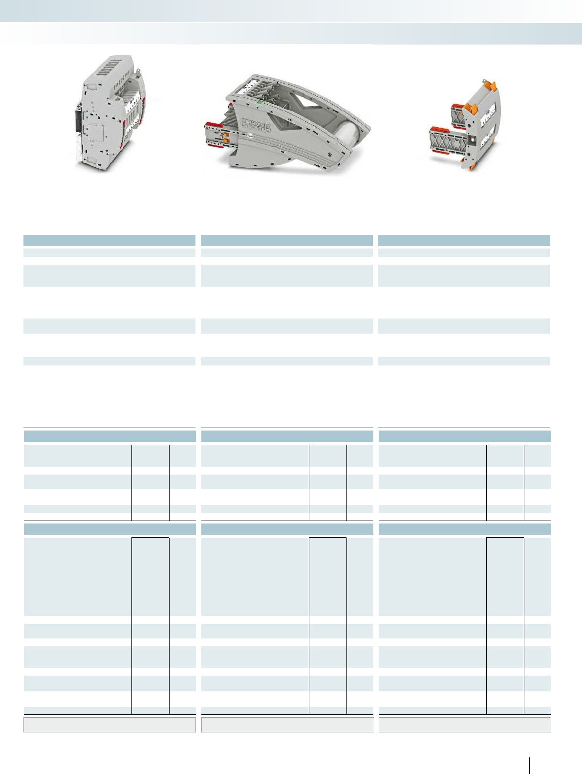
For additional information, visit phoenixcontact.net/products
Technical data Technical data Technical data
Imax. [A] Umax. [V] max. Ø [mm²] AWG Imax. [A] Umax. [V] max. Ø [mm²] AWG max. Ø [mm²] AWG
) 0.2 - 10 24 - 8 30 4002) 0.2 - 10 24 - 8 24 4002) 0.5 - 2.5 20 - 14 - -
IEC 60947-7-1
IEC UL/CUL CSA IEC/
EN60079-7
IEC UL/CUL CSA IEC/
EN60079-7
IEC UL/CUL CSA IEC/
EN60079-7
)--- 400
2)- - - 400
2)--- ----
)/6--- 24
1)/6--- 24/2.5--- ----
Rated cross section [mm²]6--- 6--- 6--- ----
Cross section range AWG24 - 8--- 24 - 8--- 20 - 14--- ----
solid stranded ferrule solid stranded ferrule solid stranded ferrule
with/without plastic sleeve with/without plastic sleeve with/without plastic sleeve
1 conductor [mm²] 0.2 - 10 0.2 - 10 0.25 - 6 0.25 - 6 0.2 - 10 0.2 - 10 0.25 - 6 0.25 - 6 - 0.5 - 2.5 - - - - - -
2.5 0.25 - 1.5 - 0.2 - 2.5 0.2 - 2.5 0.25 - 1.5 - - - - - - - - -
0.5 - 2.5
10 - -
M4 - -
1.5 - 1.8 - -
---
---
-0.5 - 0.6-
PA PA PA
V0 V0 V0
Ordering data Ordering data Ordering data
Type Order No. Pcs. /
Pkt. Type Order No. Pcs. /
Pkt. Type Order No. Pcs. /
Pkt.
UTRE 6-2/A7 3069423 1
FTPR-2/A7 3069484 1
FTP-2/A7 3069470 1
FTP-2/1 3069469 1
FBP-2/A7 3069497 1
Accessories Accessories Accessories
PSBJ-URTK 6 FARBLOS 3026450 10
PSBJ-URTK 6 RD 3026719 10
PSBJ-URTK 6 BU 3026434 10
PSBJ-URTK 6 YE 3026405 10
PSBJ-URTK 6 GN 3026418 10
PSBJ-URTK 6 VT 3026421 10
PSBJ-URTK 6 BK 3026447 10
PSBJ-URTK 6 GY 3026612 10
PSBJ-URTK 6 BN 3026971 10
AP-ME METER 3034361 10
APH-ME 3034374 10
APT-ME 3034358 10
C-FCI 1,5/M3 3240032 100
C-FCI 2,5/M3 3240037 100
C-RCI 1,5/M3 3240016 100
C-RCI 2,5/M3 3240021 100
SF-SL 0,8X4,0-100 1212551 10
UC-TM 8, UCT-TM 8, ZB 8 or TMT(EX9,5)R
(see Catalog 5)
UC-TM 8, UCT-TM 8, ZB 8 or TMT(EX9,5)R
(see Catalog 5)
UC-TM 8, UCT-TM 8, ZB 8 or TMT(EX9,5)R
(see Catalog 5)
129PHOENIX CONTACT
Modular terminal blocks
FAME plug-in test system
6 (10) mm², 30A, test terminal strip, for DIN rail
mounting, VDE coded type A7
24A, test plug, bridge assignment according
to circuit diagram, VDE coded type A7
Blind plug, VDE coded type A7

B7
1a 2a 3a4a5a6a7a
1b2b3b4b5b6b7b
Technical data
Max. electrical data Imax. [A] Umax. [V] max. Ø [mm²] AWG
30 4002) 0.2 - 10 24 - 8 30 400
IEC 60947-7-1
Rated data IEC UL/CUL CSA IEC/
EN60079-7
Rated voltage [V] 4002)--- 400
Nominal current / cross section [A] / [mm²] 241)/6--- 24
Rated cross section [mm²]6--- 6--- 6--- ----
Cross section range AWG24 - 8--- 24 - 8--- 20 - 14--- ----
Connection capacity solid stranded ferrule
with/without plastic sleeve
1 conductor [mm²] 0.2 - 10 0.2 - 10 0.25 - 6 0.25 - 6 0.2 - 10 0.2 - 10 0.25 - 6 0.25 - 6 - 0.5 - 2.5 - - - - - -
2 conductors (of the same type) [mm²] 0.2 - 2.5 0.2 - 2.5 0.25 - 1.5 - 0.2 - 2.5 0.2 - 2.5 0.25 - 1.5 - - - - - - - - -
2 stranded conductors with a TWIN ferrule [mm²] 0.5 - 2.5
General data
Stripping length [mm] 10
Screw thread M4
Tightening torque [Nm] 1.5 - 1.8
Tightening torque for wall fastening [Nm] 0.8 - 1
Panel thickness [mm] 1 - 4
Tightening torque: test socket screw [Nm] -
Insulating material PA
Inflammability class according to UL 94 V0
Ordering data
Description Color Type Order No. Pcs. /
Pkt.
Test terminal strip, for wall mounting gray UTWE 6-2/B7 3069411 1
Test terminal strip, for mounting on NS35... gray
Test plug, with twist grip gray
With standard handle gray
Test plug, 1-pos., with cover gray
Blind plug, sealable gray
Accessories
Test socket, insulated
transparent
red
blue
yellow
green
violet
black
gray
brown
Cover profile, supply length 1m transparent AP RSC-T 3059139 10
Cover profile holder, can be snapped on and
sealed
gray APH-UTWE 6-2 3069057 10
Cover profile, supply length 1m transparent
End brackets, for AP-ME cover profile, sealable,
with storage option for jumpers
gray
Holder, for AP-ME cover profile gray
Fork-type cable lug, insulated according to UL red
blue
Ring cable lug, insulated according to UL red
blue
Screwdriver SF-SL 0,8X4,0-100 1212551 10
Lateral groove labeling UC-TM 8, UCT-TM 8, ZB 8 or TMT(EX9,5)R
(see Catalog 5)
130 PHOENIX CONTACT
Test terminal strip with UT... screw
connection, VDEtype B7, for wall and
DIN rail mounting
Long contacts
Short contacts
The VDEB7 version described here is
suitable as a plug-in test system in digital
differential protection as an addition to the
F19 plug-in test system, see page 120.
– The test plugs are assembled with
jumpers and contact tab lengths
according to the circuit diagram
– A transparent covering hood protects the
jumpers. The covering hood can only be
removed by dismantling the test plug
– All VDE-specified 7, 14, and 19-pos.
versions are supplied with exclusive
coding for the matching test plug and
blind plug
– The components are supplied pre-marked
according to the VDE Directive
– Test signals can be connected with touch-
proof safety test leads (CATIII and
IV/1000V according to EN61010-031)
– The test plugs are equipped with two gray
test sockets per position, for further
color versions, see the range of
accessories
– Additional test leads, assembled with ring
and fork-type cable lugs, can be attached
with test sockets
– Other VDE versions available on request
Notes:
To create panel cutouts, see phoenixcontact.net/products.
1) Derating curve available on request.
2) Rated surge voltage of 5 kV.
Modular terminal blocks
FAME plug-in test system
6 (10) mm², 30A, test terminal strip, for wall
mounting, VDE coded type B7

For additional information, visit phoenixcontact.net/products
Technical data Technical data Technical data
Imax. [A] Umax. [V] max. Ø [mm²] AWG Imax. [A] Umax. [V] max. Ø [mm²] AWG max. Ø [mm²] AWG
) 0.2 - 10 24 - 8 30 4002) 0.2 - 10 24 - 8 24 4002) 0.5 - 2.5 20 - 14 - -
IEC 60947-7-1
IEC UL/CUL CSA IEC/
EN60079-7
IEC UL/CUL CSA IEC/
EN60079-7
IEC UL/CUL CSA IEC/
EN60079-7
)--- 400
2)- - - 400
2)--- ----
)/6--- 24
1)/6--- 24/2.5--- ----
Rated cross section [mm²]6--- 6--- 6--- ----
Cross section range AWG24 - 8--- 24 - 8--- 20 - 14--- ----
solid stranded ferrule solid stranded ferrule solid stranded ferrule
with/without plastic sleeve with/without plastic sleeve with/without plastic sleeve
1 conductor [mm²] 0.2 - 10 0.2 - 10 0.25 - 6 0.25 - 6 0.2 - 10 0.2 - 10 0.25 - 6 0.25 - 6 - 0.5 - 2.5 - - - - - -
2.5 0.25 - 1.5 - 0.2 - 2.5 0.2 - 2.5 0.25 - 1.5 - - - - - - - - -
0.5 - 2.5
10 - -
M4 - -
1.5 - 1.8 - -
---
---
-0.5 - 0.6-
PA PA PA
V0 V0 V0
Ordering data Ordering data Ordering data
Type Order No. Pcs. /
Pkt. Type Order No. Pcs. /
Pkt. Type Order No. Pcs. /
Pkt.
UTRE 6-2/B7 3069424 1
FTPR-2/B7 3069485 1
FTP-2/B7 3069471 1
FTP-2/1 3069469 1
FBP-2/B7 3069498 1
Accessories Accessories Accessories
PSBJ-URTK 6 FARBLOS 3026450 10
PSBJ-URTK 6 RD 3026719 10
PSBJ-URTK 6 BU 3026434 10
PSBJ-URTK 6 YE 3026405 10
PSBJ-URTK 6 GN 3026418 10
PSBJ-URTK 6 VT 3026421 10
PSBJ-URTK 6 BK 3026447 10
PSBJ-URTK 6 GY 3026612 10
PSBJ-URTK 6 BN 3026971 10
AP-ME METER 3034361 10
APH-ME 3034374 10
APT-ME 3034358 10
C-FCI 1,5/M3 3240032 100
C-FCI 2,5/M3 3240037 100
C-RCI 1,5/M3 3240016 100
C-RCI 2,5/M3 3240021 100
SF-SL 0,8X4,0-100 1212551 10
UC-TM 8, UCT-TM 8, ZB 8 or TMT(EX9,5)R
(see Catalog 5)
UC-TM 8, UCT-TM 8, ZB 8 or TMT(EX9,5)R
(see Catalog 5)
UC-TM 8, UCT-TM 8, ZB 8 or TMT(EX9,5)R
(see Catalog 5)
131PHOENIX CONTACT
Modular terminal blocks
FAME plug-in test system
6 (10) mm², 30A, test terminal strip, for DIN rail
mounting, VDE coded type B7
24A, test plug, bridge assignment according
to circuit diagram, VDE coded type B7
Blind plug, VDE coded type B7
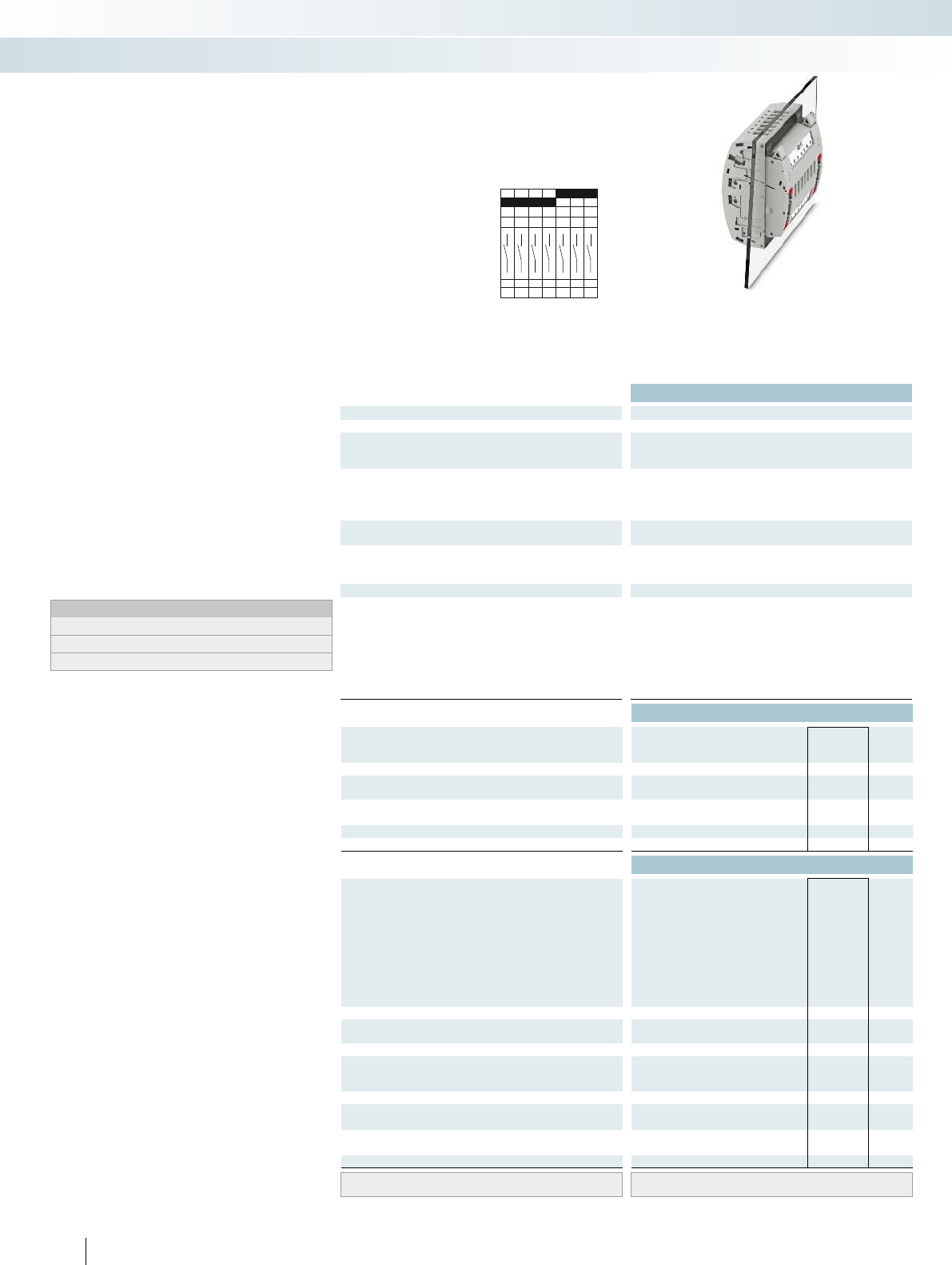
E7
1a 2a 3a4a5a6a7a
1b2b3b4b5b6b7b
Technical data
Max. electrical data Imax. [A] Umax. [V] max. Ø [mm²] AWG
30 4002) 0.2 - 10 24 - 8 30 400
IEC 60947-7-1
Rated data IEC UL/CUL CSA IEC/
EN60079-7
Rated voltage [V] 4002)--- 400
Nominal current / cross section [A] / [mm²] 241)/6--- 24
Rated cross section [mm²]6--- 6--- 6--- ----
Cross section range AWG24 - 8--- 24 - 8--- 20 - 14--- ----
Connection capacity solid stranded ferrule
with/without plastic sleeve
1 conductor [mm²] 0.2 - 10 0.2 - 10 0.25 - 6 0.25 - 6 0.2 - 10 0.2 - 10 0.25 - 6 0.25 - 6 - 0.5 - 2.5 - - - - - -
2 conductors (of the same type) [mm²] 0.2 - 2.5 0.2 - 2.5 0.25 - 1.5 - 0.2 - 2.5 0.2 - 2.5 0.25 - 1.5 - - - - - - - - -
2 stranded conductors with a TWIN ferrule [mm²] 0.5 - 2.5
General data
Stripping length [mm] 10
Screw thread M4
Tightening torque [Nm] 1.5 - 1.8
Tightening torque for wall fastening [Nm] 0.8 - 1
Panel thickness [mm] 1 - 4
Tightening torque: test socket screw [Nm] -
Insulating material PA
Inflammability class according to UL 94 V0
Ordering data
Description Color Type Order No. Pcs. /
Pkt.
Test terminal strip, for wall mounting gray UTWE 6-2/E7 3069412 1
Test terminal strip, for mounting on NS35... gray
Test plug, with twist grip gray
With standard handle gray
Test plug, 1-pos., with cover gray
Blind plug, sealable gray
Accessories
Test socket, insulated
transparent
red
blue
yellow
green
violet
black
gray
brown
Cover profile, supply length 1m transparent AP RSC-T 3059139 10
Cover profile holder, can be snapped on and
sealed
gray APH-UTWE 6-2 3069057 10
Cover profile, supply length 1m transparent
End brackets, for AP-ME cover profile, sealable,
with storage option for jumpers
gray
Holder, for AP-ME cover profile gray
Fork-type cable lug, insulated according to UL red
blue
Ring cable lug, insulated according to UL red
blue
Screwdriver SF-SL 0,8X4,0-100 1212551 10
Lateral groove labeling UC-TM 8, UCT-TM 8, ZB 8 or TMT(EX9,5)R
(see Catalog 5)
132 PHOENIX CONTACT
Test terminal strip with UT... screw
connection, VDEtype E7, for wall and
DIN rail mounting
Long contacts
Short contacts
The VDE E7 version described here is
suitable as a plug-in test system for single-
stage automatic frequency load shedding
(AFLS) and as rotor ground fault protection.
– The test plugs are assembled according to
the circuit diagram
– A transparent covering hood protects the
jumpers. The covering hood can only be
removed by dismantling the test plug
– All VDE-specified 7, 14, and 19-pos.
versions are supplied with exclusive
coding for the matching test plug and
blind plug
– The components are supplied pre-marked
according to the VDE Directive
– Test signals can be connected with touch-
proof safety test leads (CATIII and
IV/1000V according to EN61010-031)
– The test plugs are equipped with two gray
test sockets per position, for further
color versions, see the range of
accessories
– Additional test leads, assembled with ring
and fork-type cable lugs, can be attached
with test sockets
– Other VDE versions available on request
Notes:
To create panel cutouts, see phoenixcontact.net/products.
1) Derating curve available on request.
2) Rated surge voltage of 5 kV.
Modular terminal blocks
FAME plug-in test system
6 (10) mm², 30A, test terminal strip, for wall
mounting, VDE coded type E7
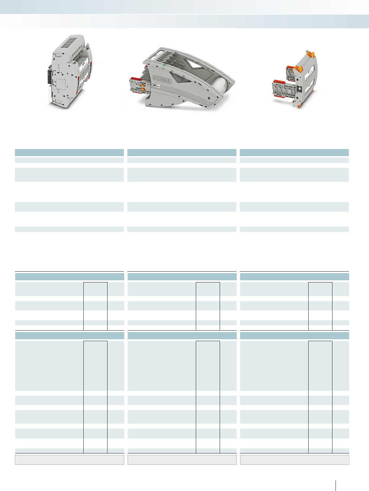
For additional information, visit phoenixcontact.net/products
Technical data Technical data Technical data
Imax. [A] Umax. [V] max. Ø [mm²] AWG Imax. [A] Umax. [V] max. Ø [mm²] AWG max. Ø [mm²] AWG
) 0.2 - 10 24 - 8 30 4002) 0.2 - 10 24 - 8 24 4002) 0.5 - 2.5 20 - 14 - -
IEC 60947-7-1
IEC UL/CUL CSA IEC/
EN60079-7
IEC UL/CUL CSA IEC/
EN60079-7
IEC UL/CUL CSA IEC/
EN60079-7
)--- 400
2)- - - 400
2)--- ----
)/6--- 24
1)/6--- 24/2.5--- ----
Rated cross section [mm²]6--- 6--- 6--- ----
Cross section range AWG24 - 8--- 24 - 8--- 20 - 14--- ----
solid stranded ferrule solid stranded ferrule solid stranded ferrule
with/without plastic sleeve with/without plastic sleeve with/without plastic sleeve
1 conductor [mm²] 0.2 - 10 0.2 - 10 0.25 - 6 0.25 - 6 0.2 - 10 0.2 - 10 0.25 - 6 0.25 - 6 - 0.5 - 2.5 - - - - - -
2.5 0.25 - 1.5 - 0.2 - 2.5 0.2 - 2.5 0.25 - 1.5 - - - - - - - - -
0.5 - 2.5
10 - -
M4 - -
1.5 - 1.8 - -
---
---
-0.5 - 0.6-
PA PA PA
V0 V0 V0
Ordering data Ordering data Ordering data
Type Order No. Pcs. /
Pkt. Type Order No. Pcs. /
Pkt. Type Order No. Pcs. /
Pkt.
UTRE 6-2/E7 3069425 1
FTPR-2/E7 3069486 1
FTP-2/E7 3069472 1
FTP-2/1 3069469 1
FBP-2/E7 3069499 1
Accessories Accessories Accessories
PSBJ-URTK 6 FARBLOS 3026450 10
PSBJ-URTK 6 RD 3026719 10
PSBJ-URTK 6 BU 3026434 10
PSBJ-URTK 6 YE 3026405 10
PSBJ-URTK 6 GN 3026418 10
PSBJ-URTK 6 VT 3026421 10
PSBJ-URTK 6 BK 3026447 10
PSBJ-URTK 6 GY 3026612 10
PSBJ-URTK 6 BN 3026971 10
AP-ME METER 3034361 10
APH-ME 3034374 10
APT-ME 3034358 10
C-FCI 1,5/M3 3240032 100
C-FCI 2,5/M3 3240037 100
C-RCI 1,5/M3 3240016 100
C-RCI 2,5/M3 3240021 100
SF-SL 0,8X4,0-100 1212551 10
UC-TM 8, UCT-TM 8, ZB 8 or TMT(EX9,5)R
(see Catalog 5)
UC-TM 8, UCT-TM 8, ZB 8 or TMT(EX9,5)R
(see Catalog 5)
UC-TM 8, UCT-TM 8, ZB 8 or TMT(EX9,5)R
(see Catalog 5)
133PHOENIX CONTACT
Modular terminal blocks
FAME plug-in test system
6 (10) mm², 30A, test terminal strip, for DIN rail
mounting, VDE coded type E7
24A, test plug, bridge assignment according
to circuit diagram, VDE coded type E7
Blind plug, VDE coded type E7

A14
1a 2a 3a4a5a6a7a8a9a
14a13a12a11a10a
1b2b3b4b5b6b7b8b9b
14b13b12b11b10b
Technical data
Max. electrical data Imax. [A] Umax. [V] max. Ø [mm²] AWG
30 4002) 0.2 - 10 24 - 8 30 400
IEC 60947-7-1
Rated data IEC UL/CUL CSA IEC/
EN60079-7
Rated voltage [V] 4002)--- 400
Nominal current / cross section [A] / [mm²] 241)/6--- 24
Rated cross section [mm²]6--- 6--- 6--- ----
Cross section range AWG24 - 8--- 24 - 8--- 20 - 14--- ----
Connection capacity solid stranded ferrule
with/without plastic sleeve
1 conductor [mm²] 0.2 - 10 0.2 - 10 0.25 - 6 0.25 - 6 0.2 - 10 0.2 - 10 0.25 - 6 0.25 - 6 - 0.5 - 2.5 - - - - - -
2 conductors (of the same type) [mm²] 0.2 - 2.5 0.2 - 2.5 0.25 - 1.5 - 0.2 - 2.5 0.2 - 2.5 0.25 - 1.5 - - - - - - - - -
2 stranded conductors with a TWIN ferrule [mm²] 0.5 - 2.5
General data
Stripping length [mm] 10
Screw thread M4
Tightening torque [Nm] 1.5 - 1.8
Tightening torque for wall fastening [Nm] 0.8 - 1
Panel thickness [mm] 1 - 4
Tightening torque: test socket screw [Nm] -
Insulating material PA
Inflammability class according to UL 94 V0
Ordering data
Description Color Type Order No. Pcs. /
Pkt.
Test terminal strip, for wall mounting gray UTWE 6-2/A14 3069413 1
Test terminal strip, for mounting on NS35... gray
Test plug, with twist grip gray
With standard handle gray
Test plug, 1-pos., with cover gray
Blind plug, sealable gray
Accessories
Test socket, insulated
transparent
red
blue
yellow
green
violet
black
gray
brown
Cover profile, supply length 1m transparent AP RSC-T 3059139 10
Cover profile holder, can be snapped on and
sealed
gray APH-UTWE 6-2 3069057 10
Cover profile, supply length 1m transparent
End brackets, for AP-ME cover profile, sealable,
with storage option for jumpers
gray
Holder, for AP-ME cover profile gray
Fork-type cable lug, insulated according to UL red
blue
Ring cable lug, insulated according to UL red
blue
Screwdriver SF-SL 0,8X4,0-100 1212551 10
Lateral groove labeling UC-TM 8, UCT-TM 8, ZB 8 or TMT(EX9,5)R
(see Catalog 5)
134 PHOENIX CONTACT
Test terminal strip with UT... screw
connection, VDEtype A14, for wall
and DIN rail mounting
Long contacts
Short contacts
The VDEA14 version described here is
suitable as a plug-in test system for three-
stage automatic frequency load shedding
(AFLS), as zero-power comparison
protection, and as stator and rotor ground
fault protection.
– The test plugs are assembled according to
the circuit diagram
– A transparent covering hood protects the
jumpers. The covering hood can only be
removed by dismantling the test plug
– All VDE-specified 7, 14, and 19-pos.
versions are supplied with exclusive
coding for the matching test plug and
blind plug
– The components are supplied pre-marked
according to the VDE Directive
– Test signals can be connected with touch-
proof safety test leads (CATIII and
IV/1000V according to EN61010-031)
– The test plugs are equipped with two gray
test sockets per position, for further
color versions, see the range of
accessories
– Additional test leads, assembled with ring
and fork-type cable lugs, can be attached
with test sockets
– Other VDE versions available on request
Notes:
To create panel cutouts, see phoenixcontact.net/products.
1) Derating curve available on request.
2) Rated surge voltage of 5 kV.
Modular terminal blocks
FAME plug-in test system
6 (10) mm², 30A, test terminal strip, for wall
mounting, VDE coded type A14

For additional information, visit phoenixcontact.net/products
Technical data Technical data Technical data
Imax. [A] Umax. [V] max. Ø [mm²] AWG Imax. [A] Umax. [V] max. Ø [mm²] AWG max. Ø [mm²] AWG
) 0.2 - 10 24 - 8 30 4002) 0.2 - 10 24 - 8 24 4002) 0.5 - 2.5 20 - 14 - -
IEC 60947-7-1
IEC UL/CUL CSA IEC/
EN60079-7
IEC UL/CUL CSA IEC/
EN60079-7
IEC UL/CUL CSA IEC/
EN60079-7
)--- 400
2)- - - 400
2)--- ----
)/6--- 24
1)/6--- 24/2.5--- ----
Rated cross section [mm²]6--- 6--- 6--- ----
Cross section range AWG24 - 8--- 24 - 8--- 20 - 14--- ----
solid stranded ferrule solid stranded ferrule solid stranded ferrule
with/without plastic sleeve with/without plastic sleeve with/without plastic sleeve
1 conductor [mm²] 0.2 - 10 0.2 - 10 0.25 - 6 0.25 - 6 0.2 - 10 0.2 - 10 0.25 - 6 0.25 - 6 - 0.5 - 2.5 - - - - - -
2.5 0.25 - 1.5 - 0.2 - 2.5 0.2 - 2.5 0.25 - 1.5 - - - - - - - - -
0.5 - 2.5
10 - -
M4 - -
1.5 - 1.8 - -
---
---
-0.5 - 0.6-
PA PA PA
V0 V0 V0
Ordering data Ordering data Ordering data
Type Order No. Pcs. /
Pkt. Type Order No. Pcs. /
Pkt. Type Order No. Pcs. /
Pkt.
UTRE 6-2/A14 3069426 1
FTPR-2/A14 3069487 1
FTP-2/A14 3069474 1
FTP-2/1 3069469 1
FBP-2/A14 3069500 1
Accessories Accessories Accessories
PSBJ-URTK 6 FARBLOS 3026450 10
PSBJ-URTK 6 RD 3026719 10
PSBJ-URTK 6 BU 3026434 10
PSBJ-URTK 6 YE 3026405 10
PSBJ-URTK 6 GN 3026418 10
PSBJ-URTK 6 VT 3026421 10
PSBJ-URTK 6 BK 3026447 10
PSBJ-URTK 6 GY 3026612 10
PSBJ-URTK 6 BN 3026971 10
AP-ME METER 3034361 10
APH-ME 3034374 10
APT-ME 3034358 10
C-FCI 1,5/M3 3240032 100
C-FCI 2,5/M3 3240037 100
C-RCI 1,5/M3 3240016 100
C-RCI 2,5/M3 3240021 100
SF-SL 0,8X4,0-100 1212551 10
UC-TM 8, UCT-TM 8, ZB 8 or TMT(EX9,5)R
(see Catalog 5)
UC-TM 8, UCT-TM 8, ZB 8 or TMT(EX9,5)R
(see Catalog 5)
UC-TM 8, UCT-TM 8, ZB 8 or TMT(EX9,5)R
(see Catalog 5)
135PHOENIX CONTACT
Modular terminal blocks
FAME plug-in test system
6 (10) mm², 30A, test terminal strip, for DIN rail
mounting, VDE coded type A14
24A, test plug, bridge assignment according
to circuit diagram, VDE coded type A14
Blind plug, VDE coded type A14
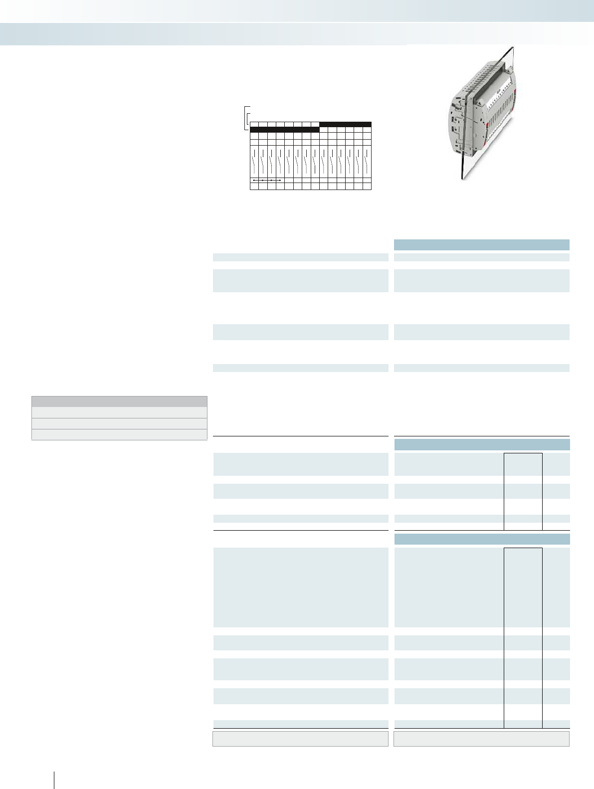
B14
1a 2a 3a4a5a6a7a8a9a
14a13a12a11a10a
1b2b3b4b5b6b7b8b9b
14b13b12b11b10b
Technical data
Max. electrical data Imax. [A] Umax. [V] max. Ø [mm²] AWG
30 4002) 0.2 - 10 24 - 8 30 400
IEC 60947-7-1
Rated data IEC UL/CUL CSA IEC/
EN60079-7
Rated voltage [V] 4002)--- 400
Nominal current / cross section [A] / [mm²] 241)/6--- 24
Rated cross section [mm²]6--- 6--- 6--- ----
Cross section range AWG24 - 8--- 24 - 8--- 20 - 14--- ----
Connection capacity solid stranded ferrule
with/without plastic sleeve
1 conductor [mm²] 0.2 - 10 0.2 - 10 0.25 - 6 0.25 - 6 0.2 - 10 0.2 - 10 0.25 - 6 0.25 - 6 - 0.5 - 2.5 - - - - - -
2 conductors (of the same type) [mm²] 0.2 - 2.5 0.2 - 2.5 0.25 - 1.5 - 0.2 - 2.5 0.2 - 2.5 0.25 - 1.5 - - - - - - - - -
2 stranded conductors with a TWIN ferrule [mm²] 0.5 - 2.5
General data
Stripping length [mm] 10
Screw thread M4
Tightening torque [Nm] 1.5 - 1.8
Tightening torque for wall fastening [Nm] 0.8 - 1
Panel thickness [mm] 1 - 4
Tightening torque: test socket screw [Nm] -
Insulating material PA
Inflammability class according to UL 94 V0
Ordering data
Description Color Type Order No. Pcs. /
Pkt.
Test terminal strip, for wall mounting gray UTWE 6-2/B14 3069414 1
Test terminal strip, for mounting on NS35... gray
Test plug, with twist grip gray
With standard handle gray
Test plug, 1-pos., with cover gray
Blind plug, sealable gray
Accessories
Test socket, insulated
transparent
red
blue
yellow
green
violet
black
gray
brown
Cover profile, supply length 1m transparent AP RSC-T 3059139 10
Cover profile holder, can be snapped on and
sealed
gray APH-UTWE 6-2 3069057 10
Cover profile, supply length 1m transparent
End brackets, for AP-ME cover profile, sealable,
with storage option for jumpers
gray
Holder, for AP-ME cover profile gray
Fork-type cable lug, insulated according to UL red
blue
Ring cable lug, insulated according to UL red
blue
Screwdriver SF-SL 0,8X4,0-100 1212551 10
Lateral groove labeling UC-TM 8, UCT-TM 8, ZB 8 or TMT(EX9,5)R
(see Catalog 5)
136 PHOENIX CONTACT
Test terminal strip with UT... screw
connection, VDEtype B14, for wall
and DIN rail mounting
Long contacts
Short contacts
The VDEB14 version described here is
suitable as a plug-in test system in
overcurrent directional protection, distance
protection for high and medium voltage, as
well as voltage regulation.
– The test plugs are assembled with
jumpers and contact tab lengths
according to the circuit diagram
– A transparent covering hood protects the
jumpers. The covering hood can only be
removed by dismantling the test plug
– All VDE-specified 7, 14, and 19-pos.
versions are supplied with exclusive
coding for the matching test plug and
blind plug
– The components are supplied pre-marked
according to the VDE Directive
– Test signals can be connected with touch-
proof safety test leads (CATIII and
IV/1000V according to EN61010-031)
– The test plugs are equipped with two gray
test sockets per position, for further
color versions, see the range of
accessories
– Additional test leads, assembled with ring
and fork-type cable lugs, can be attached
with test sockets
– Other VDE versions available on request
Notes:
To create panel cutouts, see phoenixcontact.net/products.
1) Derating curve available on request.
2) Rated surge voltage of 5 kV.
Modular terminal blocks
FAME plug-in test system
6 (10) mm², 30 A, test terminal strip, for wall
mounting, VDE coded type B14

For additional information, visit phoenixcontact.net/products
Technical data Technical data Technical data
Imax. [A] Umax. [V] max. Ø [mm²] AWG Imax. [A] Umax. [V] max. Ø [mm²] AWG max. Ø [mm²] AWG
) 0.2 - 10 24 - 8 30 4002) 0.2 - 10 24 - 8 24 4002) 0.5 - 2.5 20 - 14 - -
IEC 60947-7-1
IEC UL/CUL CSA IEC/
EN60079-7
IEC UL/CUL CSA IEC/
EN60079-7
IEC UL/CUL CSA IEC/
EN60079-7
)--- 400
2)- - - 400
2)--- ----
)/6--- 24
1)/6--- 24/2.5--- ----
Rated cross section [mm²]6--- 6--- 6--- ----
Cross section range AWG24 - 8--- 24 - 8--- 20 - 14--- ----
solid stranded ferrule solid stranded ferrule solid stranded ferrule
with/without plastic sleeve with/without plastic sleeve with/without plastic sleeve
1 conductor [mm²] 0.2 - 10 0.2 - 10 0.25 - 6 0.25 - 6 0.2 - 10 0.2 - 10 0.25 - 6 0.25 - 6 - 0.5 - 2.5 - - - - - -
2.5 0.25 - 1.5 - 0.2 - 2.5 0.2 - 2.5 0.25 - 1.5 - - - - - - - - -
0.5 - 2.5
10 - -
M4 - -
1.5 - 1.8 - -
---
---
-0.5 - 0.6-
PA PA PA
V0 V0 V0
Ordering data Ordering data Ordering data
Type Order No. Pcs. /
Pkt. Type Order No. Pcs. /
Pkt. Type Order No. Pcs. /
Pkt.
UTRE 6-2/B14 3069427 1
FTPR-2/B14 3069488 1
FTP-2/B14 3069475 1
FTP-2/1 3069469 1
FBP-2/B14 3069501 1
Accessories Accessories Accessories
PSBJ-URTK 6 FARBLOS 3026450 10
PSBJ-URTK 6 RD 3026719 10
PSBJ-URTK 6 BU 3026434 10
PSBJ-URTK 6 YE 3026405 10
PSBJ-URTK 6 GN 3026418 10
PSBJ-URTK 6 VT 3026421 10
PSBJ-URTK 6 BK 3026447 10
PSBJ-URTK 6 GY 3026612 10
PSBJ-URTK 6 BN 3026971 10
AP-ME METER 3034361 10
APH-ME 3034374 10
APT-ME 3034358 10
C-FCI 1,5/M3 3240032 100
C-FCI 2,5/M3 3240037 100
C-RCI 1,5/M3 3240016 100
C-RCI 2,5/M3 3240021 100
SF-SL 0,8X4,0-100 1212551 10
UC-TM 8, UCT-TM 8, ZB 8 or TMT(EX9,5)R
(see Catalog 5)
UC-TM 8, UCT-TM 8, ZB 8 or TMT(EX9,5)R
(see Catalog 5)
UC-TM 8, UCT-TM 8, ZB 8 or TMT(EX9,5)R
(see Catalog 5)
137PHOENIX CONTACT
Modular terminal blocks
FAME plug-in test system
6 (10) mm², 30A, test terminal strip, for DIN rail
mounting, VDE coded type B14
24A, test plug, bridge assignment according
to circuit diagram, VDE coded type B14
Blind plug, VDE coded type B14
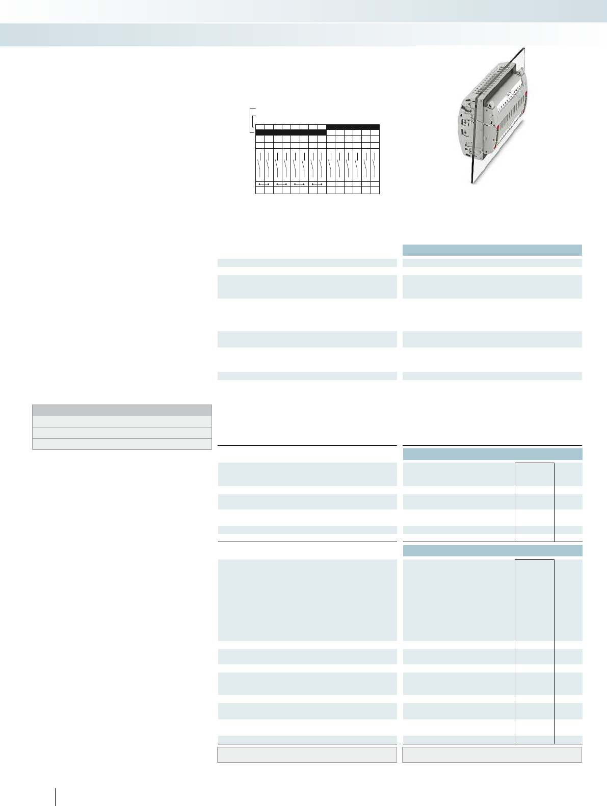
C14
1a 2a 3a4a5a6a7a8a9a
14a13a12a11a10a
1b2b3b4b5b6b7b8b9b
14b13b12b11b10b
Technical data
Max. electrical data Imax. [A] Umax. [V] max. Ø [mm²] AWG
30 4002) 0.2 - 10 24 - 8 30 400
IEC 60947-7-1
Rated data IEC UL/CUL CSA IEC/
EN60079-7
Rated voltage [V] 4002)--- 400
Nominal current / cross section [A] / [mm²] 241)/6--- 24
Rated cross section [mm²]6--- 6--- 6--- ----
Cross section range AWG24 - 8--- 24 - 8--- 20 - 14--- ----
Connection capacity solid stranded ferrule
with/without plastic sleeve
1 conductor [mm²] 0.2 - 10 0.2 - 10 0.25 - 6 0.25 - 6 0.2 - 10 0.2 - 10 0.25 - 6 0.25 - 6 - 0.5 - 2.5 - - - - - -
2 conductors (of the same type) [mm²] 0.2 - 2.5 0.2 - 2.5 0.25 - 1.5 - 0.2 - 2.5 0.2 - 2.5 0.25 - 1.5 - - - - - - - - -
2 stranded conductors with a TWIN ferrule [mm²] 0.5 - 2.5
General data
Stripping length [mm] 10
Screw thread M4
Tightening torque [Nm] 1.5 - 1.8
Tightening torque for wall fastening [Nm] 0.8 - 1
Panel thickness [mm] 1 - 4
Tightening torque: test socket screw [Nm] -
Insulating material PA
Inflammability class according to UL 94 V0
Ordering data
Description Color Type Order No. Pcs. /
Pkt.
Test terminal strip, for wall mounting gray UTWE 6-2/C14 3069415 1
Test terminal strip, for mounting on NS35... gray
Test plug, with twist grip gray
With standard handle gray
Test plug, 1-pos., with cover gray
Blind plug, sealable gray
Accessories
Test socket, insulated
transparent
red
blue
yellow
green
violet
black
gray
brown
Cover profile, supply length 1m transparent AP RSC-T 3059139 10
Cover profile holder, can be snapped on and
sealed
gray APH-UTWE 6-2 3069057 10
Cover profile, supply length 1m transparent
End brackets, for AP-ME cover profile, sealable,
with storage option for jumpers
gray
Holder, for AP-ME cover profile gray
Fork-type cable lug, insulated according to UL red
blue
Ring cable lug, insulated according to UL red
blue
Screwdriver SF-SL 0,8X4,0-100 1212551 10
Lateral groove labeling UC-TM 8, UCT-TM 8, ZB 8 or TMT(EX9,5)R
(see Catalog 5)
138 PHOENIX CONTACT
Test terminal strip with UT... screw
connection, VDEtype C14, for wall
and DIN rail mounting
Long contacts
Short contacts
The VDEC14 version described here is
suitable as a plug-in test system in
overcurrent time protection, unbalanced
load protection, and stator ground fault
protection for busbar operation.
– The test plugs are assembled with
jumpers and contact tab lengths
according to the circuit diagram
– A transparent covering hood protects the
jumpers. The covering hood can only be
removed by dismantling the test plug
– All VDE-specified 7, 14, and 19-pos.
versions are supplied with exclusive
coding for the matching test plug and
blind plug
– The components are supplied pre-marked
according to the VDE Directive
– Test signals can be connected with touch-
proof safety test leads (CATIII and
IV/1000V according to EN61010-031)
– The test plugs are equipped with two gray
test sockets per position, for further
color versions, see the range of
accessories
– Additional test leads, assembled with ring
and fork-type cable lugs, can be attached
with test sockets
– Other VDE versions available on request
Notes:
To create panel cutouts, see phoenixcontact.net/products.
1) Derating curve available on request.
2) Rated surge voltage of 5 kV.
Modular terminal blocks
FAME plug-in test system
6 (10) mm², 30A, test terminal strip, for wall
mounting, VDE coded type C14
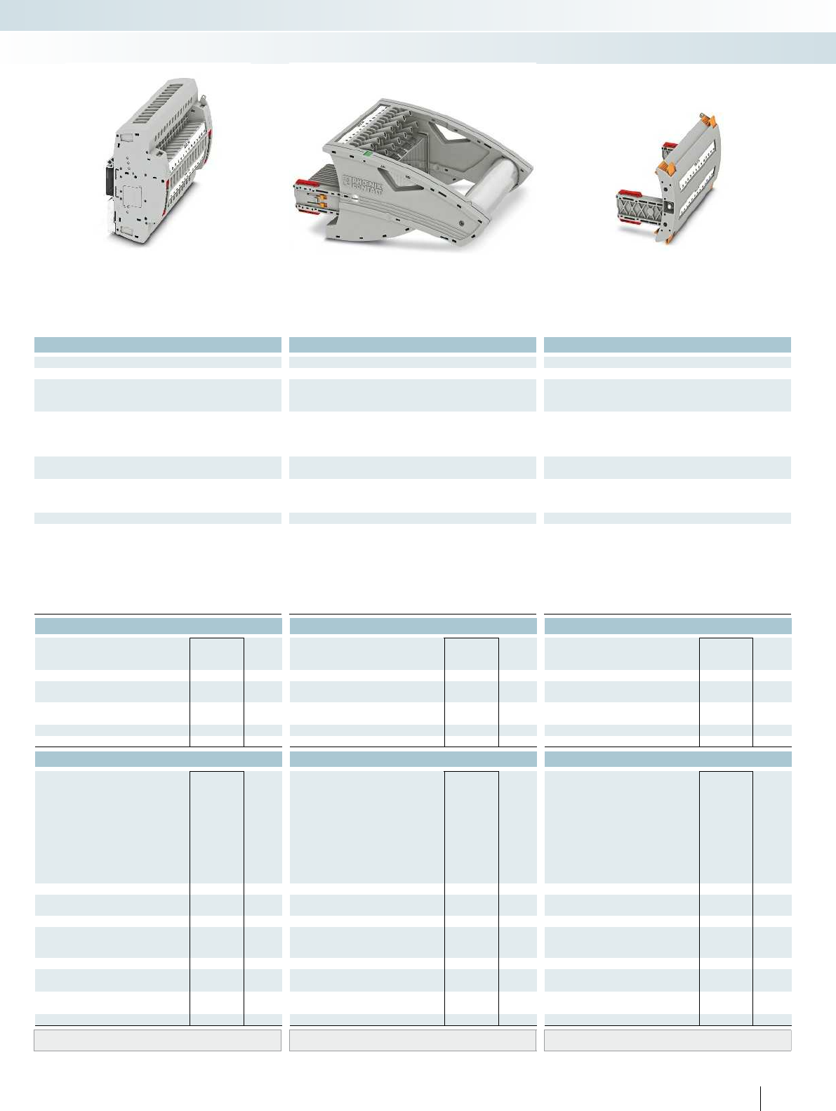
For additional information, visit phoenixcontact.net/products
Technical data Technical data Technical data
Imax. [A] Umax. [V] max. Ø [mm²] AWG Imax. [A] Umax. [V] max. Ø [mm²] AWG max. Ø [mm²] AWG
) 0.2 - 10 24 - 8 30 4002) 0.2 - 10 24 - 8 24 4002) 0.5 - 2.5 20 - 14 - -
IEC 60947-7-1
IEC UL/CUL CSA IEC/
EN60079-7
IEC UL/CUL CSA IEC/
EN60079-7
IEC UL/CUL CSA IEC/
EN60079-7
)--- 400
2)- - - 400
2)--- ----
)/6--- 24
1)/6--- 24/2.5--- ----
Rated cross section [mm²]6--- 6--- 6--- ----
Cross section range AWG24 - 8--- 24 - 8--- 20 - 14--- ----
solid stranded ferrule solid stranded ferrule solid stranded ferrule
with/without plastic sleeve with/without plastic sleeve with/without plastic sleeve
1 conductor [mm²] 0.2 - 10 0.2 - 10 0.25 - 6 0.25 - 6 0.2 - 10 0.2 - 10 0.25 - 6 0.25 - 6 - 0.5 - 2.5 - - - - - -
2.5 0.25 - 1.5 - 0.2 - 2.5 0.2 - 2.5 0.25 - 1.5 - - - - - - - - -
0.5 - 2.5
10 - -
M4 - -
1.5 - 1.8 - -
---
---
-0.5 - 0.6-
PA PA PA
V0 V0 V0
Ordering data Ordering data Ordering data
Type Order No. Pcs. /
Pkt. Type Order No. Pcs. /
Pkt. Type Order No. Pcs. /
Pkt.
UTRE 6-2/C14 3069428 1
FTPR-2/C14 3069489 1
FTP-2/C14 3069476 1
FTP-2/1 3069469 1
FBP-2/C14 3069502 1
Accessories Accessories Accessories
PSBJ-URTK 6 FARBLOS 3026450 10
PSBJ-URTK 6 RD 3026719 10
PSBJ-URTK 6 BU 3026434 10
PSBJ-URTK 6 YE 3026405 10
PSBJ-URTK 6 GN 3026418 10
PSBJ-URTK 6 VT 3026421 10
PSBJ-URTK 6 BK 3026447 10
PSBJ-URTK 6 GY 3026612 10
PSBJ-URTK 6 BN 3026971 10
AP-ME METER 3034361 10
APH-ME 3034374 10
APT-ME 3034358 10
C-FCI 1,5/M3 3240032 100
C-FCI 2,5/M3 3240037 100
C-RCI 1,5/M3 3240016 100
C-RCI 2,5/M3 3240021 100
SF-SL 0,8X4,0-100 1212551 10
UC-TM 8, UCT-TM 8, ZB 8 or TMT(EX9,5)R
(see Catalog 5)
UC-TM 8, UCT-TM 8, ZB 8 or TMT(EX9,5)R
(see Catalog 5)
UC-TM 8, UCT-TM 8, ZB 8 or TMT(EX9,5)R
(see Catalog 5)
139PHOENIX CONTACT
Modular terminal blocks
FAME plug-in test system
6 (10) mm², 30A, test terminal strip, for DIN rail
mounting, VDE coded type C14
24A, test plug, bridge assignment according
to circuit diagram, VDE coded type C14
Blind plug, VDE coded type C14
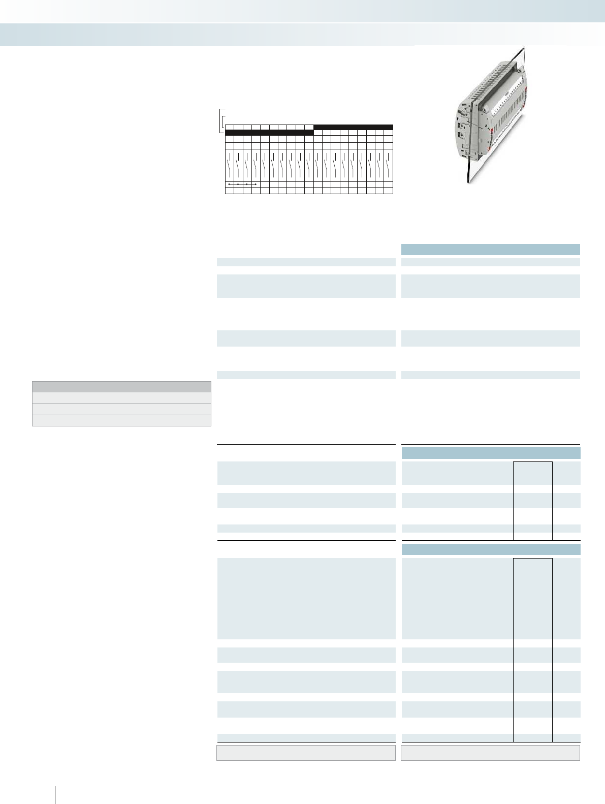
B19
1a 2a 3a 4a 5a 6a 7a 8a 9a
19a18a17a16a15a14a13a12a11a10a
1b 2b 3b 4b 5b 6b 7b 8b 9b
19b18b17b16b15b14b13b12b11b10b
Technical data
Max. electrical data Imax. [A] Umax. [V] max. Ø [mm²] AWG
30 4002) 0.2 - 10 24 - 8 30 400
IEC 60947-7-1
Rated data IEC UL/CUL CSA IEC/
EN60079-7
Rated voltage [V] 4002)--- 400
Nominal current / cross section [A] / [mm²] 241)/6--- 24
Rated cross section [mm²]6--- 6--- 6--- ----
Cross section range AWG24 - 8--- 24 - 8--- 20 - 14--- ----
Connection capacity solid stranded ferrule
with/without plastic sleeve
1 conductor [mm²] 0.2 - 10 0.2 - 10 0.25 - 6 0.25 - 6 0.2 - 10 0.2 - 10 0.25 - 6 0.25 - 6 - 0.5 - 2.5 - - - - - -
2 conductors (of the same type) [mm²] 0.2 - 2.5 0.2 - 2.5 0.25 - 1.5 - 0.2 - 2.5 0.2 - 2.5 0.25 - 1.5 - - - - - - - - -
2 stranded conductors with a TWIN ferrule [mm²] 0.5 - 2.5
General data
Stripping length [mm] 10
Screw thread M4
Tightening torque [Nm] 1.5 - 1.8
Tightening torque for wall fastening [Nm] 0.8 - 1
Panel thickness [mm] 1 - 4
Tightening torque: test socket screw [Nm] -
Insulating material PA
Inflammability class according to UL 94 V0
Ordering data
Description Color Type Order No. Pcs. /
Pkt.
Test terminal strip, for wall mounting gray UTWE 6-2/B19 3069416 1
Test terminal strip, for mounting on NS35... gray
Test plug, with twist grip gray
With standard handle gray
Test plug, 1-pos., with cover gray
Blind plug, sealable gray
Accessories
Test socket, insulated
transparent
red
blue
yellow
green
violet
black
gray
brown
Cover profile, supply length 1m transparent AP RSC-T 3059139 10
Cover profile holder, can be snapped on and
sealed
gray APH-UTWE 6-2 3069057 10
Cover profile, supply length 1m transparent
End brackets, for AP-ME cover profile, sealable,
with storage option for jumpers
gray
Holder, for AP-ME cover profile gray
Fork-type cable lug, insulated according to UL red
blue
Ring cable lug, insulated according to UL red
blue
Screwdriver SF-SL 0,8X4,0-100 1212551 10
Lateral groove labeling UC-TM 8, UCT-TM 8, ZB 8 or TMT(EX9,5)R
(see Catalog 5)
140 PHOENIX CONTACT
Test terminal strip with UT... screw
connection, VDEtype B19, for wall
and DIN rail mounting
Long contacts
Short contacts
The VDEB19 version described here is
suitable as a plug-in test system in distance
protection for high voltage.
– The test plugs are assembled with
jumpers and contact tab lengths
according to the circuit diagram
– A transparent covering hood protects the
jumpers. The covering hood can only be
removed by dismantling the test plug
– All VDE-specified 7, 14, and 19-pos.
versions are supplied with exclusive
coding for the matching test plug and
blind plug
– The components are supplied pre-marked
according to the VDE Directive
– Test signals can be connected with touch-
proof safety test leads (CATIII and
IV/1000V according to EN61010-031)
– The test plugs are equipped with two gray
test sockets per position, for further
color versions, see the range of
accessories
– Additional test leads, assembled with ring
and fork-type cable lugs, can be attached
with test sockets
– Other VDE versions available on request
Notes:
To create panel cutouts, see phoenixcontact.net/products.
1) Derating curve available on request.
2) Rated surge voltage of 5 kV.
Modular terminal blocks
FAME plug-in test system
6 (10) mm², 30A, test terminal strip, for wall
mounting, VDE coded type B19

For additional information, visit phoenixcontact.net/products
Technical data Technical data Technical data
Imax. [A] Umax. [V] max. Ø [mm²] AWG Imax. [A] Umax. [V] max. Ø [mm²] AWG max. Ø [mm²] AWG
) 0.2 - 10 24 - 8 30 4002) 0.2 - 10 24 - 8 24 4002) 0.5 - 2.5 20 - 14 - -
IEC 60947-7-1
IEC UL/CUL CSA IEC/
EN60079-7
IEC UL/CUL CSA IEC/
EN60079-7
IEC UL/CUL CSA IEC/
EN60079-7
)--- 400
2)- - - 400
2)--- ----
)/6--- 24
1)/6--- 24/2.5--- ----
Rated cross section [mm²]6--- 6--- 6--- ----
Cross section range AWG24 - 8--- 24 - 8--- 20 - 14--- ----
solid stranded ferrule solid stranded ferrule solid stranded ferrule
with/without plastic sleeve with/without plastic sleeve with/without plastic sleeve
1 conductor [mm²] 0.2 - 10 0.2 - 10 0.25 - 6 0.25 - 6 0.2 - 10 0.2 - 10 0.25 - 6 0.25 - 6 - 0.5 - 2.5 - - - - - -
2.5 0.25 - 1.5 - 0.2 - 2.5 0.2 - 2.5 0.25 - 1.5 - - - - - - - - -
0.5 - 2.5
10 - -
M4 - -
1.5 - 1.8 - -
---
---
-0.5 - 0.6-
PA PA PA
V0 V0 V0
Ordering data Ordering data Ordering data
Type Order No. Pcs. /
Pkt. Type Order No. Pcs. /
Pkt. Type Order No. Pcs. /
Pkt.
UTRE 6-2/B19 3069429 1
FTPR-2/B19 3069490 1
FTP-2/B19 3069477 1
FTP-2/1 3069469 1
FBP-2/B19 3069503 1
Accessories Accessories Accessories
PSBJ-URTK 6 FARBLOS 3026450 10
PSBJ-URTK 6 RD 3026719 10
PSBJ-URTK 6 BU 3026434 10
PSBJ-URTK 6 YE 3026405 10
PSBJ-URTK 6 GN 3026418 10
PSBJ-URTK 6 VT 3026421 10
PSBJ-URTK 6 BK 3026447 10
PSBJ-URTK 6 GY 3026612 10
PSBJ-URTK 6 BN 3026971 10
AP-ME METER 3034361 10
APH-ME 3034374 10
APT-ME 3034358 10
C-FCI 1,5/M3 3240032 100
C-FCI 2,5/M3 3240037 100
C-RCI 1,5/M3 3240016 100
C-RCI 2,5/M3 3240021 100
SF-SL 0,8X4,0-100 1212551 10
UC-TM 8, UCT-TM 8, ZB 8 or TMT(EX9,5)R
(see Catalog 5)
UC-TM 8, UCT-TM 8, ZB 8 or TMT(EX9,5)R
(see Catalog 5)
UC-TM 8, UCT-TM 8, ZB 8 or TMT(EX9,5)R
(see Catalog 5)
141PHOENIX CONTACT
Modular terminal blocks
FAME plug-in test system
6 (10) mm², 30A, test terminal strip, for DIN rail
mounting, VDE coded type B19
24A, test plug, bridge assignment according
to circuit diagram, VDE coded type B19
Blind plug, VDE coded type B19
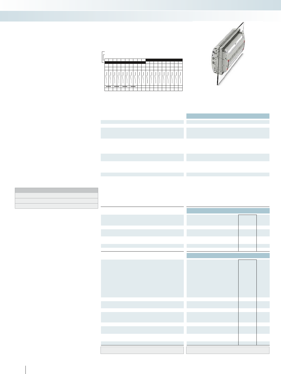
C19
1a 2a 3a 4a 5a 6a 7a 8a 9a
19a18a17a16a15a14a13a12a11a10a
1b 2b 3b 4b 5b 6b 7b 8b 9b
19b18b17b16b15b14b13b12b11b10b
Technical data
Max. electrical data Imax. [A] Umax. [V] max. Ø [mm²] AWG
30 4002) 0.2 - 10 24 - 8 30 400
IEC 60947-7-1
Rated data IEC UL/CUL CSA IEC/
EN60079-7
Rated voltage [V] 4002)--- 400
Nominal current / cross section [A] / [mm²] 241)/6--- 24
Rated cross section [mm²]6--- 6--- 6--- ----
Cross section range AWG24 - 8--- 24 - 8--- 20 - 14--- ----
Connection capacity solid stranded ferrule
with/without plastic sleeve
1 conductor [mm²] 0.2 - 10 0.2 - 10 0.25 - 6 0.25 - 6 0.2 - 10 0.2 - 10 0.25 - 6 0.25 - 6 - 0.5 - 2.5 - - - - - -
2 conductors (of the same type) [mm²] 0.2 - 2.5 0.2 - 2.5 0.25 - 1.5 - 0.2 - 2.5 0.2 - 2.5 0.25 - 1.5 - - - - - - - - -
2 stranded conductors with a TWIN ferrule [mm²] 0.5 - 2.5
General data
Stripping length [mm] 10
Screw thread M4
Tightening torque [Nm] 1.5 - 1.8
Tightening torque for wall fastening [Nm] 0.8 - 1
Panel thickness [mm] 1 - 4
Tightening torque: test socket screw [Nm] -
Insulating material PA
Inflammability class according to UL 94 V0
Ordering data
Description Color Type Order No. Pcs. /
Pkt.
Test terminal strip, for wall mounting gray UTWE 6-2/C19 3069417 1
Test terminal strip, for mounting on NS35... gray
Test plug, with twist grip gray
With standard handle gray
Test plug, 1-pos., with cover gray
Blind plug, sealable gray
Accessories
Test socket, insulated
transparent
red
blue
yellow
green
violet
black
gray
brown
Cover profile, supply length 1m transparent AP RSC-T 3059139 10
Cover profile holder, can be snapped on and
sealed
gray APH-UTWE 6-2 3069057 10
Cover profile, supply length 1m transparent
End brackets, for AP-ME cover profile, sealable,
with storage option for jumpers
gray
Holder, for AP-ME cover profile gray
Fork-type cable lug, insulated according to UL red
blue
Ring cable lug, insulated according to UL red
blue
Screwdriver SF-SL 0,8X4,0-100 1212551 10
Lateral groove labeling UC-TM 8, UCT-TM 8, ZB 8 or TMT(EX9,5)R
(see Catalog 5)
142 PHOENIX CONTACT
Test terminal strip with UT... screw
connection, VDEtype C19, for wall
and DIN rail mounting
Long contacts
Short contacts
The VDEC19 version described here is
suitable as a plug-in test system in distance
protection as system busbar protection,
overcurrent directional protection, and
current comparison protection for cables.
– The test plugs are assembled with
jumpers and contact tab lengths
according to the circuit diagram
– A transparent covering hood protects the
jumpers. The covering hood can only be
removed by dismantling the test plug
– All VDE-specified 7, 14, and 19-pos.
versions are supplied with exclusive
coding for the matching test plug and
blind plug
– The components are supplied pre-marked
according to the VDE Directive
– Test signals can be connected with touch-
proof safety test leads (CATIII and
IV/1000V according to EN61010-031)
– The test plugs are equipped with two gray
test sockets per position, for further
color versions, see the range of
accessories
– Additional test leads, assembled with ring
and fork-type cable lugs, can be attached
with test sockets
– Other VDE versions available on request
Notes:
To create panel cutouts, see phoenixcontact.net/products.
1) Derating curve available on request.
2) Rated surge voltage of 5 kV.
Modular terminal blocks
FAME plug-in test system
6 (10) mm², 30A, test terminal strip, for wall
mounting, VDE coded type C19
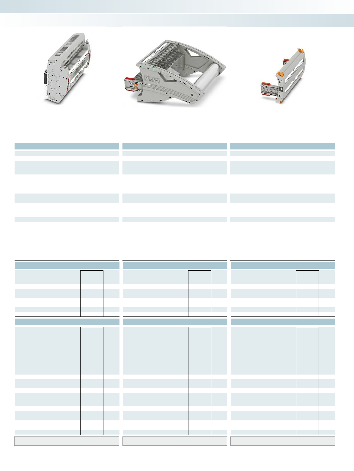
For additional information, visit phoenixcontact.net/products
Technical data Technical data Technical data
Imax. [A] Umax. [V] max. Ø [mm²] AWG Imax. [A] Umax. [V] max. Ø [mm²] AWG max. Ø [mm²] AWG
) 0.2 - 10 24 - 8 30 4002) 0.2 - 10 24 - 8 24 4002) 0.5 - 2.5 20 - 14 - -
IEC 60947-7-1
IEC UL/CUL CSA IEC/
EN60079-7
IEC UL/CUL CSA IEC/
EN60079-7
IEC UL/CUL CSA IEC/
EN60079-7
)--- 400
2)- - - 400
2)--- ----
)/6--- 24
1)/6--- 24/2.5--- ----
Rated cross section [mm²]6--- 6--- 6--- ----
Cross section range AWG24 - 8--- 24 - 8--- 20 - 14--- ----
solid stranded ferrule solid stranded ferrule solid stranded ferrule
with/without plastic sleeve with/without plastic sleeve with/without plastic sleeve
1 conductor [mm²] 0.2 - 10 0.2 - 10 0.25 - 6 0.25 - 6 0.2 - 10 0.2 - 10 0.25 - 6 0.25 - 6 - 0.5 - 2.5 - - - - - -
2.5 0.25 - 1.5 - 0.2 - 2.5 0.2 - 2.5 0.25 - 1.5 - - - - - - - - -
0.5 - 2.5
10 - -
M4 - -
1.5 - 1.8 - -
---
---
-0.5 - 0.6-
PA PA PA
V0 V0 V0
Ordering data Ordering data Ordering data
Type Order No. Pcs. /
Pkt. Type Order No. Pcs. /
Pkt. Type Order No. Pcs. /
Pkt.
UTRE 6-2/C19 3069430 1
FTPR-2/C19 3069491 1
FTP-2/C19 3069478 1
FTP-2/1 3069469 1
FBP-2/C19 3069504 1
Accessories Accessories Accessories
PSBJ-URTK 6 FARBLOS 3026450 10
PSBJ-URTK 6 RD 3026719 10
PSBJ-URTK 6 BU 3026434 10
PSBJ-URTK 6 YE 3026405 10
PSBJ-URTK 6 GN 3026418 10
PSBJ-URTK 6 VT 3026421 10
PSBJ-URTK 6 BK 3026447 10
PSBJ-URTK 6 GY 3026612 10
PSBJ-URTK 6 BN 3026971 10
AP-ME METER 3034361 10
APH-ME 3034374 10
APT-ME 3034358 10
C-FCI 1,5/M3 3240032 100
C-FCI 2,5/M3 3240037 100
C-RCI 1,5/M3 3240016 100
C-RCI 2,5/M3 3240021 100
SF-SL 0,8X4,0-100 1212551 10
UC-TM 8, UCT-TM 8, ZB 8 or TMT(EX9,5)R
(see Catalog 5)
UC-TM 8, UCT-TM 8, ZB 8 or TMT(EX9,5)R
(see Catalog 5)
UC-TM 8, UCT-TM 8, ZB 8 or TMT(EX9,5)R
(see Catalog 5)
143PHOENIX CONTACT
Modular terminal blocks
FAME plug-in test system
6 (10) mm², 30A, test terminal strip, for DIN rail
mounting, VDE coded type C19
24A, test plug, bridge assignment according
to circuit diagram, VDE coded type C19
Blind plug, VDE coded type C19

D19
1a 2a 3a 4a 5a 6a 7a 8a 9a
19a18a17a16a15a14a13a12a11a10a
1b 2b 3b 4b 5b 6b 7b 8b 9b
19b18b17b16b15b14b13b12b11b10b
Technical data
Max. electrical data Imax. [A] Umax. [V] max. Ø [mm²] AWG
30 4002) 0.2 - 10 24 - 8 30 400
IEC 60947-7-1
Rated data IEC UL/CUL CSA IEC/
EN60079-7
Rated voltage [V] 4002)--- 400
Nominal current / cross section [A] / [mm²] 241)/6--- 24
Rated cross section [mm²]6--- 6--- 6--- ----
Cross section range AWG24 - 8--- 24 - 8--- 20 - 14--- ----
Connection capacity solid stranded ferrule
with/without plastic sleeve
1 conductor [mm²] 0.2 - 10 0.2 - 10 0.25 - 6 0.25 - 6 0.2 - 10 0.2 - 10 0.25 - 6 0.25 - 6 - 0.5 - 2.5 - - - - - -
2 conductors (of the same type) [mm²] 0.2 - 2.5 0.2 - 2.5 0.25 - 1.5 - 0.2 - 2.5 0.2 - 2.5 0.25 - 1.5 - - - - - - - - -
2 stranded conductors with a TWIN ferrule [mm²] 0.5 - 2.5
General data
Stripping length [mm] 10
Screw thread M4
Tightening torque [Nm] 1.5 - 1.8
Tightening torque for wall fastening [Nm] 0.8 - 1
Panel thickness [mm] 1 - 4
Tightening torque: test socket screw [Nm] -
Insulating material PA
Inflammability class according to UL 94 V0
Ordering data
Description Color Type Order No. Pcs. /
Pkt.
Test terminal strip, for wall mounting gray UTWE 6-2/D19 3069418 1
Test terminal strip, for mounting on NS35... gray
Test plug, with twist grip gray
With standard handle gray
Test plug, 1-pos., with cover gray
Blind plug, sealable gray
Accessories
Test socket, insulated
transparent
red
blue
yellow
green
violet
black
gray
brown
Cover profile, supply length 1m transparent AP RSC-T 3059139 10
Cover profile holder, can be snapped on and
sealed
gray APH-UTWE 6-2 3069057 10
Cover profile, supply length 1m transparent
End brackets, for AP-ME cover profile, sealable,
with storage option for jumpers
gray
Holder, for AP-ME cover profile gray
Fork-type cable lug, insulated according to UL red
blue
Ring cable lug, insulated according to UL red
blue
Screwdriver SF-SL 0,8X4,0-100 1212551 10
Lateral groove labeling UC-TM 8, UCT-TM 8, ZB 8 or TMT(EX9,5)R
(see Catalog 5)
144 PHOENIX CONTACT
Test terminal strip with UT... screw
connection, VDEtype D19, for wall
and DIN rail mounting
Long contacts
Short contacts
The VDED19 version described here is
suitable as a plug-in test system for
electromechanical differential protection
for transformers.
– The test plugs are assembled with
jumpers and contact tab lengths
according to the circuit diagram
– A transparent covering hood protects the
jumpers. The covering hood can only be
removed by dismantling the test plug
– All VDE-specified 7, 14, and 19-pos.
versions are supplied with exclusive
coding for the matching test plug and
blind plug
– The components are supplied pre-marked
according to the VDE Directive
– Test signals can be connected with touch-
proof safety test leads (CATIII and
IV/1000V according to EN61010-031)
– The test plugs are equipped with two gray
test sockets per position, for further
color versions, see the range of
accessories
– Additional test leads, assembled with ring
and fork-type cable lugs, can be attached
with test sockets
– Other VDE versions available on request
Notes:
To create panel cutouts, see phoenixcontact.net/products.
1) Derating curve available on request.
2) Rated surge voltage of 5 kV.
Modular terminal blocks
FAME plug-in test system
6 (10) mm², 30A, test terminal strip, for wall
mounting, VDE coded type D19
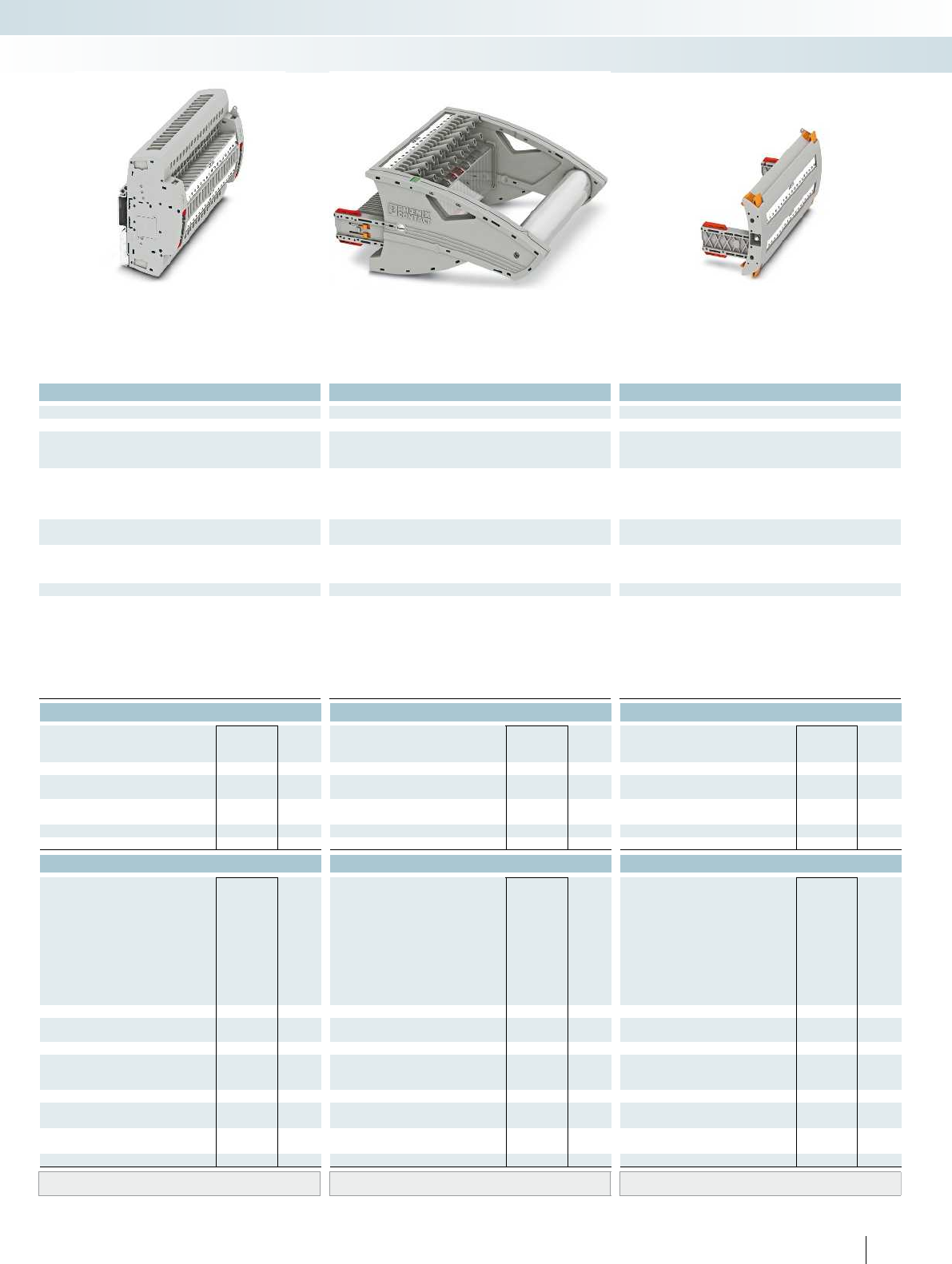
For additional information, visit phoenixcontact.net/products
Technical data Technical data Technical data
Imax. [A] Umax. [V] max. Ø [mm²] AWG Imax. [A] Umax. [V] max. Ø [mm²] AWG max. Ø [mm²] AWG
) 0.2 - 10 24 - 8 30 4002) 0.2 - 10 24 - 8 24 4002) 0.5 - 2.5 20 - 14 - -
IEC 60947-7-1
IEC UL/CUL CSA IEC/
EN60079-7
IEC UL/CUL CSA IEC/
EN60079-7
IEC UL/CUL CSA IEC/
EN60079-7
)--- 400
2)- - - 400
2)--- ----
)/6--- 24
1)/6--- 24/2.5--- ----
Rated cross section [mm²]6--- 6--- 6--- ----
Cross section range AWG24 - 8--- 24 - 8--- 20 - 14--- ----
solid stranded ferrule solid stranded ferrule solid stranded ferrule
with/without plastic sleeve with/without plastic sleeve with/without plastic sleeve
1 conductor [mm²] 0.2 - 10 0.2 - 10 0.25 - 6 0.25 - 6 0.2 - 10 0.2 - 10 0.25 - 6 0.25 - 6 - 0.5 - 2.5 - - - - - -
2.5 0.25 - 1.5 - 0.2 - 2.5 0.2 - 2.5 0.25 - 1.5 - - - - - - - - -
0.5 - 2.5
10 - -
M4 - -
1.5 - 1.8 - -
---
---
-0.5 - 0.6-
PA PA PA
V0 V0 V0
Ordering data Ordering data Ordering data
Type Order No. Pcs. /
Pkt. Type Order No. Pcs. /
Pkt. Type Order No. Pcs. /
Pkt.
UTRE 6-2/D19 3069431 1
FTPR-2/D19 3069492 1
FTP-2/D19 3069479 1
FTP-2/1 3069469 1
FBP-2/D19 3069671 1
Accessories Accessories Accessories
PSBJ-URTK 6 FARBLOS 3026450 10
PSBJ-URTK 6 RD 3026719 10
PSBJ-URTK 6 BU 3026434 10
PSBJ-URTK 6 YE 3026405 10
PSBJ-URTK 6 GN 3026418 10
PSBJ-URTK 6 VT 3026421 10
PSBJ-URTK 6 BK 3026447 10
PSBJ-URTK 6 GY 3026612 10
PSBJ-URTK 6 BN 3026971 10
AP-ME METER 3034361 10
APH-ME 3034374 10
APT-ME 3034358 10
C-FCI 1,5/M3 3240032 100
C-FCI 2,5/M3 3240037 100
C-RCI 1,5/M3 3240016 100
C-RCI 2,5/M3 3240021 100
SF-SL 0,8X4,0-100 1212551 10
UC-TM 8, UCT-TM 8, ZB 8 or TMT(EX9,5)R
(see Catalog 5)
UC-TM 8, UCT-TM 8, ZB 8 or TMT(EX9,5)R
(see Catalog 5)
UC-TM 8, UCT-TM 8, ZB 8 or TMT(EX9,5)R
(see Catalog 5)
145PHOENIX CONTACT
Modular terminal blocks
FAME plug-in test system
6 (10) mm², 30A, test terminal strip, for DIN rail
mounting, VDE coded type D19
24A, test plug, bridge assignment according
to circuit diagram, VDE coded type D19
Blind plug, VDE coded type D19

F19
1a 2a 3a 4a 5a 6a 7a 8a 9a
19a18a17a16a15a14a13a12a11a10a
1b 2b 3b 4b 5b 6b 7b 8b 9b
19b18b17b16b15b14b13b12b11b10b
Technical data
Max. electrical data Imax. [A] Umax. [V] max. Ø [mm²] AWG
30 4002) 0.2 - 10 24 - 8 30 400
IEC 60947-7-1
Rated data IEC UL/CUL CSA IEC/
EN60079-7
Rated voltage [V] 4002)--- 400
Nominal current / cross section [A] / [mm²] 241)/6--- 24
Rated cross section [mm²]6--- 6--- 6--- ----
Cross section range AWG24 - 8--- 24 - 8--- 20 - 14--- ----
Connection capacity solid stranded ferrule
with/without plastic sleeve
1 conductor [mm²] 0.2 - 10 0.2 - 10 0.25 - 6 0.25 - 6 0.2 - 10 0.2 - 10 0.25 - 6 0.25 - 6 - 0.5 - 2.5 - - - - - -
2 conductors (of the same type) [mm²] 0.2 - 2.5 0.2 - 2.5 0.25 - 1.5 - 0.2 - 2.5 0.2 - 2.5 0.25 - 1.5 - - - - - - - - -
2 stranded conductors with a TWIN ferrule [mm²] 0.5 - 2.5
General data
Stripping length [mm] 10
Screw thread M4
Tightening torque [Nm] 1.5 - 1.8
Tightening torque for wall fastening [Nm] 0.8 - 1
Panel thickness [mm] 1 - 4
Tightening torque: test socket screw [Nm] -
Insulating material PA
Inflammability class according to UL 94 V0
Ordering data
Description Color Type Order No. Pcs. /
Pkt.
Test terminal strip, for wall mounting gray UTWE 6-2/F19 3069419 1
Test terminal strip, for mounting on NS35... gray
Test plug, with twist grip gray
With standard handle gray
Test plug, 1-pos., with cover gray
Blind plug, sealable gray
Accessories
Test socket, insulated
transparent
red
blue
yellow
green
violet
black
gray
brown
Cover profile, supply length 1m transparent AP RSC-T 3059139 10
Cover profile holder, can be snapped on and
sealed
gray APH-UTWE 6-2 3069057 10
Cover profile, supply length 1m transparent
End brackets, for AP-ME cover profile, sealable,
with storage option for jumpers
gray
Holder, for AP-ME cover profile gray
Fork-type cable lug, insulated according to UL red
blue
Ring cable lug, insulated according to UL red
blue
Screwdriver SF-SL 0,8X4,0-100 1212551 10
Lateral groove labeling UC-TM 8, UCT-TM 8, ZB 8 or TMT(EX9,5)R
(see Catalog 5)
146 PHOENIX CONTACT
Test terminal strip with UT... screw
connection, VDEtype F19, for wall
and DIN rail mounting
Long contacts
Short contacts
The VDEF19 version described here is
suitable as a plug-in test system in
electromechanical differential protection
for transformers, generators, motors, and
cables.
– The test plugs are assembled with
jumpers and contact tab lengths
according to the circuit diagram
– A transparent covering hood protects the
jumpers. The covering hood can only be
removed by dismantling the test plug
– All VDE-specified 7, 14, and 19-pos.
versions are supplied with exclusive
coding for the matching test plug and
blind plug
– The components are supplied pre-marked
according to the VDE Directive
– Test signals can be connected with touch-
proof safety test leads (CATIII and
IV/1000V according to EN61010-031)
– The test plugs are equipped with two gray
test sockets per position, for further
color versions, see the range of
accessories
– Additional test leads, assembled with ring
and fork-type cable lugs, can be attached
with test sockets
– Other VDE versions available on request
Notes:
To create panel cutouts, see phoenixcontact.net/products.
1) Derating curve available on request.
2) Rated surge voltage of 5 kV.
Modular terminal blocks
FAME plug-in test system
6 (10) mm², 30A, test terminal strip, for wall
mounting, VDE coded type F19
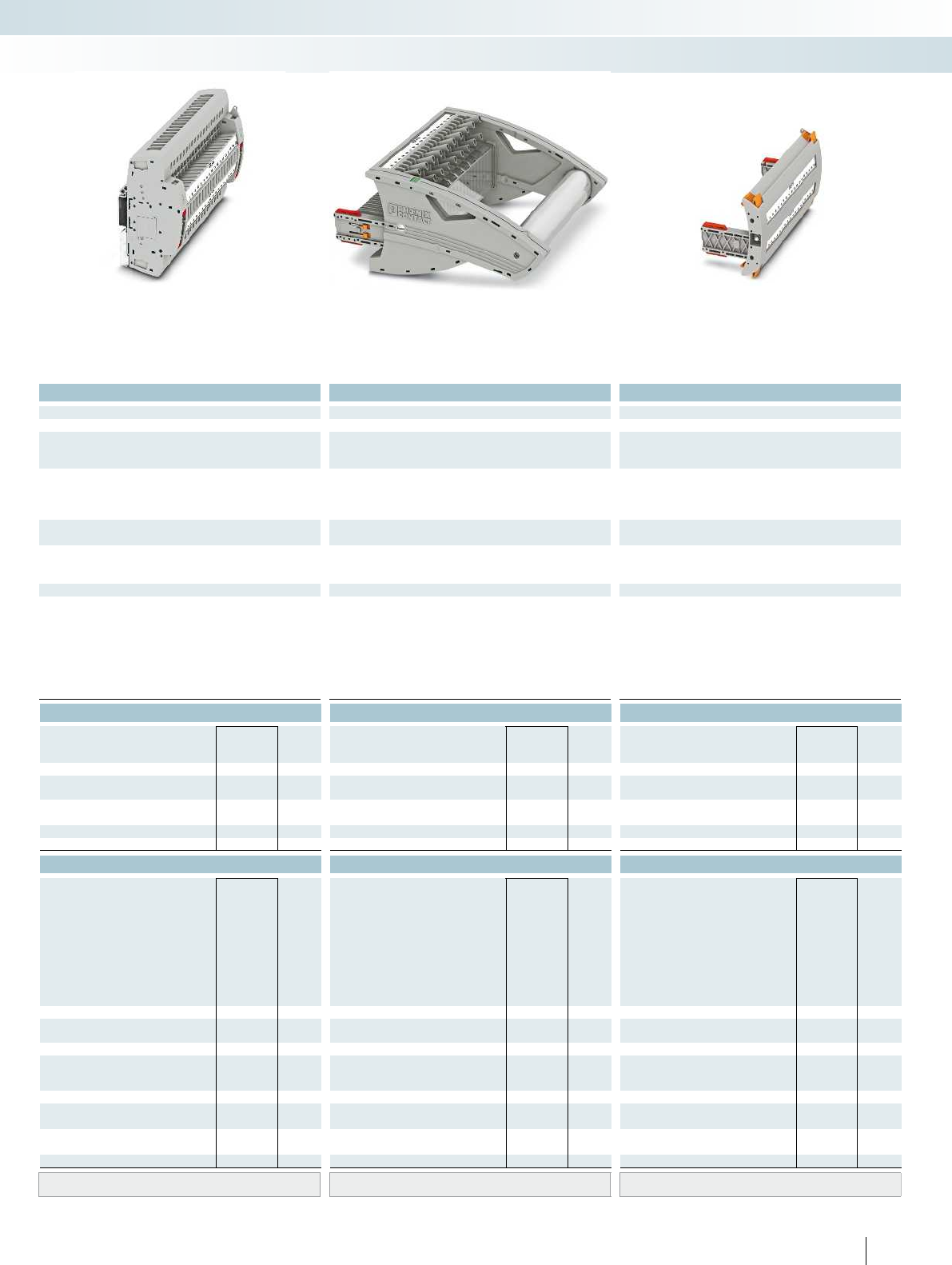
For additional information, visit phoenixcontact.net/products
Technical data Technical data Technical data
Imax. [A] Umax. [V] max. Ø [mm²] AWG Imax. [A] Umax. [V] max. Ø [mm²] AWG max. Ø [mm²] AWG
) 0.2 - 10 24 - 8 30 4002) 0.2 - 10 24 - 8 24 4002) 0.5 - 2.5 20 - 14 - -
IEC 60947-7-1
IEC UL/CUL CSA IEC/
EN60079-7
IEC UL/CUL CSA IEC/
EN60079-7
IEC UL/CUL CSA IEC/
EN60079-7
)--- 400
2)- - - 400
2)--- ----
)/6--- 24
1)/6--- 24/2.5--- ----
Rated cross section [mm²]6--- 6--- 6--- ----
Cross section range AWG24 - 8--- 24 - 8--- 20 - 14--- ----
solid stranded ferrule solid stranded ferrule solid stranded ferrule
with/without plastic sleeve with/without plastic sleeve with/without plastic sleeve
1 conductor [mm²] 0.2 - 10 0.2 - 10 0.25 - 6 0.25 - 6 0.2 - 10 0.2 - 10 0.25 - 6 0.25 - 6 - 0.5 - 2.5 - - - - - -
2.5 0.25 - 1.5 - 0.2 - 2.5 0.2 - 2.5 0.25 - 1.5 - - - - - - - - -
0.5 - 2.5
10 - -
M4 - -
1.5 - 1.8 - -
---
---
-0.5 - 0.6-
PA PA PA
V0 V0 V0
Ordering data Ordering data Ordering data
Type Order No. Pcs. /
Pkt. Type Order No. Pcs. /
Pkt. Type Order No. Pcs. /
Pkt.
UTRE 6-2/F19 3069432 1
FTPR-2/F19 3069493 1
FTP-2/F19 3069480 1
FTP-2/1 3069469 1
FBP-2/F19 3069675 1
Accessories Accessories Accessories
PSBJ-URTK 6 FARBLOS 3026450 10
PSBJ-URTK 6 RD 3026719 10
PSBJ-URTK 6 BU 3026434 10
PSBJ-URTK 6 YE 3026405 10
PSBJ-URTK 6 GN 3026418 10
PSBJ-URTK 6 VT 3026421 10
PSBJ-URTK 6 BK 3026447 10
PSBJ-URTK 6 GY 3026612 10
PSBJ-URTK 6 BN 3026971 10
AP-ME METER 3034361 10
APH-ME 3034374 10
APT-ME 3034358 10
C-FCI 1,5/M3 3240032 100
C-FCI 2,5/M3 3240037 100
C-RCI 1,5/M3 3240016 100
C-RCI 2,5/M3 3240021 100
SF-SL 0,8X4,0-100 1212551 10
UC-TM 8, UCT-TM 8, ZB 8 or TMT(EX9,5)R
(see Catalog 5)
UC-TM 8, UCT-TM 8, ZB 8 or TMT(EX9,5)R
(see Catalog 5)
UC-TM 8, UCT-TM 8, ZB 8 or TMT(EX9,5)R
(see Catalog 5)
147PHOENIX CONTACT
Modular terminal blocks
FAME plug-in test system
6 (10) mm², 30A, test terminal strip, for DIN rail
mounting, VDE coded type F19
24A, test plug, bridge assignment according
to circuit diagram, VDE coded type F19
Blind plug, VDE coded type F19

G19
1a 2a 3a4a5a6a7a
1b2b3b4b5b6b7b
8a9a10a 11a 12a 13a 14a
8b9b10b 11b12b13b14b
15a 16a 17a
15b16b17b
18a19a
18b19b
Technical data
Max. electrical data Imax. [A] Umax. [V] max. Ø [mm²] AWG
30 4002) 0.2 - 10 24 - 8 30 400
IEC 60947-7-1
Rated data IEC UL/CUL CSA IEC/
EN60079-7
Rated voltage [V] 4002)--- 400
Nominal current / cross section [A] / [mm²] 241)/6--- 24
Rated cross section [mm²]6--- 6--- 6--- ----
Cross section range AWG24 - 8--- 24 - 8--- 20 - 14--- ----
Connection capacity solid stranded ferrule
with/without plastic sleeve
1 conductor [mm²] 0.2 - 10 0.2 - 10 0.25 - 6 0.25 - 6 0.2 - 10 0.2 - 10 0.25 - 6 0.25 - 6 - 0.5 - 2.5 - - - - - -
2 conductors (of the same type) [mm²] 0.2 - 2.5 0.2 - 2.5 0.25 - 1.5 - 0.2 - 2.5 0.2 - 2.5 0.25 - 1.5 - - - - - - - - -
2 stranded conductors with a TWIN ferrule [mm²] 0.5 - 2.5
General data
Stripping length [mm] 10
Screw thread M4
Tightening torque [Nm] 1.5 - 1.8
Tightening torque for wall fastening [Nm] 0.8 - 1
Panel thickness [mm] 1 - 4
Tightening torque: test socket screw [Nm] -
Insulating material PA
Inflammability class according to UL 94 V0
Ordering data
Description Color Type Order No. Pcs. /
Pkt.
Test terminal strip, for wall mounting gray UTWE 6-2/G19 3069420 1
Test terminal strip, for mounting on NS35... gray
Test plug, with twist grip gray
With standard handle gray
Test plug, 1-pos., with cover gray
Blind plug, sealable gray
Accessories
Test socket, insulated
transparent
red
blue
yellow
green
violet
black
gray
brown
Cover profile, supply length 1m transparent AP RSC-T 3059139 10
Cover profile holder, can be snapped on and
sealed
gray APH-UTWE 6-2 3069057 10
Cover profile, supply length 1m transparent
End brackets, for AP-ME cover profile, sealable,
with storage option for jumpers
gray
Holder, for AP-ME cover profile gray
Fork-type cable lug, insulated according to UL red
blue
Ring cable lug, insulated according to UL red
blue
Screwdriver SF-SL 0,8X4,0-100 1212551 10
Lateral groove labeling UC-TM 8, UCT-TM 8, ZB 8 or TMT(EX9,5)R
(see Catalog 5)
148 PHOENIX CONTACT
Test terminal strip with UT... screw
connection, VDEtype G19, for wall
and DIN rail mounting
Long contacts
Short contacts
The VDEG19 version described here is
suitable as a plug-in test system in digital
differential protection for transformers.
– The test plugs are assembled with
jumpers and contact tab lengths
according to the circuit diagram
– A transparent covering hood protects the
jumpers. The covering hood can only be
removed by dismantling the test plug
– All VDE-specified 7, 14, and 19-pos.
versions are supplied with exclusive
coding for the matching test plug and
blind plug
– The components are supplied pre-marked
according to the VDE Directive
– Test signals can be connected with touch-
proof safety test leads (CATIII and
IV/1000V according to EN61010-031)
– The test plugs are equipped with two gray
test sockets per position, for further
color versions, see the range of
accessories
– Additional test leads, assembled with ring
and fork-type cable lugs, can be attached
with test sockets
– Other VDE versions available on request
Notes:
To create panel cutouts, see phoenixcontact.net/products.
1) Derating curve available on request.
2) Rated surge voltage of 5 kV.
Modular terminal blocks
FAME plug-in test system
6 (10) mm², 30A, test terminal strip, for wall
mounting, VDE coded type G19
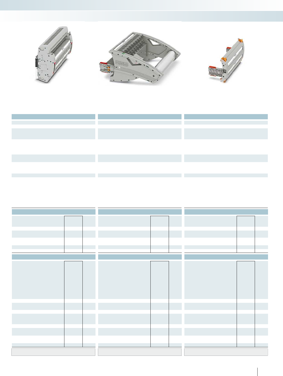
For additional information, visit phoenixcontact.net/products
Technical data Technical data Technical data
Imax. [A] Umax. [V] max. Ø [mm²] AWG Imax. [A] Umax. [V] max. Ø [mm²] AWG max. Ø [mm²] AWG
) 0.2 - 10 24 - 8 30 4002) 0.2 - 10 24 - 8 24 4002) 0.5 - 2.5 20 - 14 - -
IEC 60947-7-1
IEC UL/CUL CSA IEC/
EN60079-7
IEC UL/CUL CSA IEC/
EN60079-7
IEC UL/CUL CSA IEC/
EN60079-7
)--- 400
2)- - - 400
2)--- ----
)/6--- 24
1)/6--- 24/2.5--- ----
Rated cross section [mm²]6--- 6--- 6--- ----
Cross section range AWG24 - 8--- 24 - 8--- 20 - 14--- ----
solid stranded ferrule solid stranded ferrule solid stranded ferrule
with/without plastic sleeve with/without plastic sleeve with/without plastic sleeve
1 conductor [mm²] 0.2 - 10 0.2 - 10 0.25 - 6 0.25 - 6 0.2 - 10 0.2 - 10 0.25 - 6 0.25 - 6 - 0.5 - 2.5 - - - - - -
2.5 0.25 - 1.5 - 0.2 - 2.5 0.2 - 2.5 0.25 - 1.5 - - - - - - - - -
0.5 - 2.5
10 - -
M4 - -
1.5 - 1.8 - -
---
---
-0.5 - 0.6-
PA PA PA
V0 V0 V0
Ordering data Ordering data Ordering data
Type Order No. Pcs. /
Pkt. Type Order No. Pcs. /
Pkt. Type Order No. Pcs. /
Pkt.
UTRE 6-2/G19 3069433 1
FTPR-2/G19 3069494 1
FTP-2/G19 3069481 1
FTP-2/1 3069469 1
FBP-2/G19 3069676 1
Accessories Accessories Accessories
PSBJ-URTK 6 FARBLOS 3026450 10
PSBJ-URTK 6 RD 3026719 10
PSBJ-URTK 6 BU 3026434 10
PSBJ-URTK 6 YE 3026405 10
PSBJ-URTK 6 GN 3026418 10
PSBJ-URTK 6 VT 3026421 10
PSBJ-URTK 6 BK 3026447 10
PSBJ-URTK 6 GY 3026612 10
PSBJ-URTK 6 BN 3026971 10
AP-ME METER 3034361 10
APH-ME 3034374 10
APT-ME 3034358 10
C-FCI 1,5/M3 3240032 100
C-FCI 2,5/M3 3240037 100
C-RCI 1,5/M3 3240016 100
C-RCI 2,5/M3 3240021 100
SF-SL 0,8X4,0-100 1212551 10
UC-TM 8, UCT-TM 8, ZB 8 or TMT(EX9,5)R
(see Catalog 5)
UC-TM 8, UCT-TM 8, ZB 8 or TMT(EX9,5)R
(see Catalog 5)
UC-TM 8, UCT-TM 8, ZB 8 or TMT(EX9,5)R
(see Catalog 5)
149PHOENIX CONTACT
Modular terminal blocks
FAME plug-in test system
6 (10) mm², 30A, test terminal strip, for DIN rail
mounting, VDE coded type G19
24A, test plug, bridge assignment according
to circuit diagram, VDE coded type G19
Blind plug, VDE coded type G19

H19
1a 2a 3a 4a 5a 6a 7a 8a 9a
19a18a17a16a15a14a13a12a11a10a
1b 2b 3b 4b 5b 6b 7b 8b 9b
19b18b17b16b15b14b13b12b11b10b
Technical data
Max. electrical data Imax. [A] Umax. [V] max. Ø [mm²] AWG
30 4002) 0.2 - 10 24 - 8 30 400
IEC 60947-7-1
Rated data IEC UL/CUL CSA IEC/
EN60079-7
Rated voltage [V] 4002)--- 400
Nominal current / cross section [A] / [mm²] 241)/6--- 24
Rated cross section [mm²]6--- 6--- 6--- ----
Cross section range AWG24 - 8--- 24 - 8--- 20 - 14--- ----
Connection capacity solid stranded ferrule
with/without plastic sleeve
1 conductor [mm²] 0.2 - 10 0.2 - 10 0.25 - 6 0.25 - 6 0.2 - 10 0.2 - 10 0.25 - 6 0.25 - 6 - 0.5 - 2.5 - - - - - -
2 conductors (of the same type) [mm²] 0.2 - 2.5 0.2 - 2.5 0.25 - 1.5 - 0.2 - 2.5 0.2 - 2.5 0.25 - 1.5 - - - - - - - - -
2 stranded conductors with a TWIN ferrule [mm²] 0.5 - 2.5
General data
Stripping length [mm] 10
Screw thread M4
Tightening torque [Nm] 1.5 - 1.8
Tightening torque for wall fastening [Nm] 0.8 - 1
Panel thickness [mm] 1 - 4
Tightening torque: test socket screw [Nm] -
Insulating material PA
Inflammability class according to UL 94 V0
Ordering data
Description Color Type Order No. Pcs. /
Pkt.
Test terminal strip, for wall mounting gray UTWE 6-2/H19 3069421 1
Test terminal strip, for mounting on NS35... gray
Test plug, with twist grip gray
With standard handle gray
Test plug, 1-pos., with cover gray
Blind plug, sealable gray
Accessories
Test socket, insulated
transparent
red
blue
yellow
green
violet
black
gray
brown
Cover profile, supply length 1m transparent AP RSC-T 3059139 10
Cover profile holder, can be snapped on and
sealed
gray APH-UTWE 6-2 3069057 10
Cover profile, supply length 1m transparent
End brackets, for AP-ME cover profile, sealable,
with storage option for jumpers
gray
Holder, for AP-ME cover profile gray
Fork-type cable lug, insulated according to UL red
blue
Ring cable lug, insulated according to UL red
blue
Screwdriver SF-SL 0,8X4,0-100 1212551 10
Lateral groove labeling UC-TM 8, UCT-TM 8, ZB 8 or TMT(EX9,5)R
(see Catalog 5)
150 PHOENIX CONTACT
Test terminal strip with UT... screw
connection, VDEtype H19, for wall
and DIN rail mounting
Long contacts
Short contacts
The VDEH19 version described here is
suitable as a plug-in test system in
overcurrent directional protection and
distance protection as system protection.
– The test plugs are assembled with
jumpers and contact tab lengths
according to the circuit diagram
– A transparent covering hood protects the
jumpers. The covering hood can only be
removed by dismantling the test plug
– All VDE-specified 7, 14, and 19-pos.
versions are supplied with exclusive
coding for the matching test plug and
blind plug
– The components are supplied pre-marked
according to the VDE Directive
– Test signals can be connected with touch-
proof safety test leads (CATIII and
IV/1000V according to EN61010-031)
– The test plugs are equipped with two gray
test sockets per position, for further
color versions, see the range of
accessories
– Additional test leads, assembled with ring
and fork-type cable lugs, can be attached
with test sockets
– Other VDE versions available on request
Notes:
To create panel cutouts, see phoenixcontact.net/products.
1) Derating curve available on request.
2) Rated surge voltage of 5 kV.
Modular terminal blocks
FAME plug-in test system
6 (10) mm², 30A, test terminal strip, for wall
mounting, VDE coded type H19
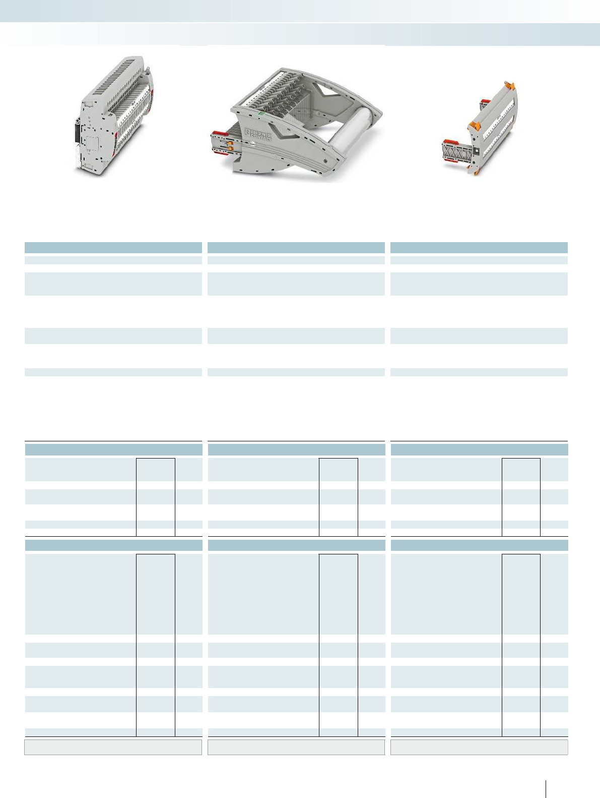
For additional information, visit phoenixcontact.net/products
Technical data Technical data Technical data
Imax. [A] Umax. [V] max. Ø [mm²] AWG Imax. [A] Umax. [V] max. Ø [mm²] AWG max. Ø [mm²] AWG
) 0.2 - 10 24 - 8 30 4002) 0.2 - 10 24 - 8 24 4002) 0.5 - 2.5 20 - 14 - -
IEC 60947-7-1
IEC UL/CUL CSA IEC/
EN60079-7
IEC UL/CUL CSA IEC/
EN60079-7
IEC UL/CUL CSA IEC/
EN60079-7
)--- 400
2)- - - 400
2)--- ----
)/6--- 24
1)/6--- 24/2.5--- ----
Rated cross section [mm²]6--- 6--- 6--- ----
Cross section range AWG24 - 8--- 24 - 8--- 20 - 14--- ----
solid stranded ferrule solid stranded ferrule solid stranded ferrule
with/without plastic sleeve with/without plastic sleeve with/without plastic sleeve
1 conductor [mm²] 0.2 - 10 0.2 - 10 0.25 - 6 0.25 - 6 0.2 - 10 0.2 - 10 0.25 - 6 0.25 - 6 - 0.5 - 2.5 - - - - - -
2.5 0.25 - 1.5 - 0.2 - 2.5 0.2 - 2.5 0.25 - 1.5 - - - - - - - - -
0.5 - 2.5
10 - -
M4 - -
1.5 - 1.8 - -
---
---
-0.5 - 0.6-
PA PA PA
V0 V0 V0
Ordering data Ordering data Ordering data
Type Order No. Pcs. /
Pkt. Type Order No. Pcs. /
Pkt. Type Order No. Pcs. /
Pkt.
UTRE 6-2/H19 3069434 1
FTPR-2/H19 3069495 1
FTP-2/H19 3069482 1
FTP-2/1 3069469 1
FBP-2/H19 3069677 1
Accessories Accessories Accessories
PSBJ-URTK 6 FARBLOS 3026450 10
PSBJ-URTK 6 RD 3026719 10
PSBJ-URTK 6 BU 3026434 10
PSBJ-URTK 6 YE 3026405 10
PSBJ-URTK 6 GN 3026418 10
PSBJ-URTK 6 VT 3026421 10
PSBJ-URTK 6 BK 3026447 10
PSBJ-URTK 6 GY 3026612 10
PSBJ-URTK 6 BN 3026971 10
AP-ME METER 3034361 10
APH-ME 3034374 10
APT-ME 3034358 10
C-FCI 1,5/M3 3240032 100
C-FCI 2,5/M3 3240037 100
C-RCI 1,5/M3 3240016 100
C-RCI 2,5/M3 3240021 100
SF-SL 0,8X4,0-100 1212551 10
UC-TM 8, UCT-TM 8, ZB 8 or TMT(EX9,5)R
(see Catalog 5)
UC-TM 8, UCT-TM 8, ZB 8 or TMT(EX9,5)R
(see Catalog 5)
UC-TM 8, UCT-TM 8, ZB 8 or TMT(EX9,5)R
(see Catalog 5)
151PHOENIX CONTACT
Modular terminal blocks
FAME plug-in test system
6 (10) mm², 30A, test terminal strip, for DIN rail
mounting, VDE coded type H19
24A, test plug, bridge assignment according
to circuit diagram, VDE coded type H19
Blind plug, VDE coded type H19
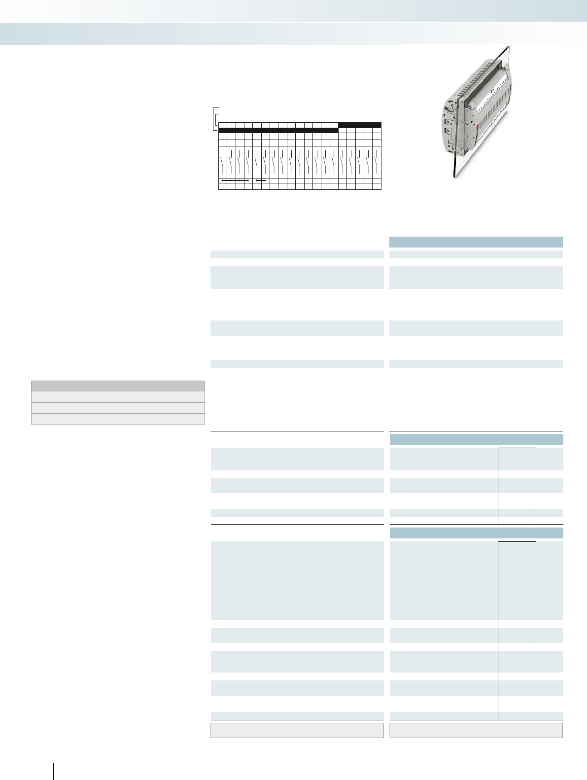
I19
1a 2a 3a 4a 5a 6a 7a 8a 9a
19a18a17a16a15a14a13a12a11a10a
1b 2b 3b 4b 5b 6b 7b 8b 9b
19b18b17b16b15b14b13b12b11b10b
Technical data
Max. electrical data Imax. [A] Umax. [V] max. Ø [mm²] AWG
30 4002) 0.2 - 10 24 - 8 30 400
IEC 60947-7-1
Rated data IEC UL/CUL CSA IEC/
EN60079-7
Rated voltage [V] 4002)--- 400
Nominal current / cross section [A] / [mm²] 241)/6--- 24
Rated cross section [mm²]6--- 6--- 6--- ----
Cross section range AWG24 - 8--- 24 - 8--- 20 - 14--- ----
Connection capacity solid stranded ferrule
with/without plastic sleeve
1 conductor [mm²] 0.2 - 10 0.2 - 10 0.25 - 6 0.25 - 6 0.2 - 10 0.2 - 10 0.25 - 6 0.25 - 6 - 0.5 - 2.5 - - - - - -
2 conductors (of the same type) [mm²] 0.2 - 2.5 0.2 - 2.5 0.25 - 1.5 - 0.2 - 2.5 0.2 - 2.5 0.25 - 1.5 - - - - - - - - -
2 stranded conductors with a TWIN ferrule [mm²] 0.5 - 2.5
General data
Stripping length [mm] 10
Screw thread M4
Tightening torque [Nm] 1.5 - 1.8
Tightening torque for wall fastening [Nm] 0.8 - 1
Panel thickness [mm] 1 - 4
Tightening torque: test socket screw [Nm] -
Insulating material PA
Inflammability class according to UL 94 V0
Ordering data
Description Color Type Order No. Pcs. /
Pkt.
Test terminal strip, for wall mounting gray UTWE 6-2/I19 3069422 1
Test terminal strip, for mounting on NS35... gray
Test plug, with twist grip gray
With standard handle gray
Test plug, 1-pos., with cover gray
Blind plug, sealable gray
Accessories
Test socket, insulated
transparent
red
blue
yellow
green
violet
black
gray
brown
Cover profile, supply length 1m transparent AP RSC-T 3059139 10
Cover profile holder, can be snapped on and
sealed
gray APH-UTWE 6-2 3069057 10
Cover profile, supply length 1m transparent
End brackets, for AP-ME cover profile, sealable,
with storage option for jumpers
gray
Holder, for AP-ME cover profile gray
Fork-type cable lug, insulated according to UL red
blue
Ring cable lug, insulated according to UL red
blue
Screwdriver SF-SL 0,8X4,0-100 1212551 10
Lateral groove labeling UC-TM 8, UCT-TM 8, ZB 8 or TMT(EX9,5)R
(see Catalog 5)
152 PHOENIX CONTACT
Test terminal strip with UT... screw
connection, VDEtype I19, for wall and
DIN rail mounting
Long contacts
Short contacts
The VDEI19 version described here is
suitable as a plug-in test system in medium
voltage, outlet, and coupling protection,
including selective ground fault detection.
– The test plugs are assembled with
jumpers and contact tab lengths
according to the circuit diagram
– A transparent covering hood protects the
jumpers. The covering hood can only be
removed by dismantling the test plug
– All VDE-specified 7, 14, and 19-pos.
versions are supplied with exclusive
coding for the matching test plug and
blind plug
– The components are supplied pre-marked
according to the VDE Directive
– Test signals can be connected with touch-
proof safety test leads (CATIII and
IV/1000V according to EN61010-031)
– The test plugs are equipped with two gray
test sockets per position, for further
color versions, see the range of
accessories
– Additional test leads, assembled with ring
and fork-type cable lugs, can be attached
with test sockets
– Other VDE versions available on request
Notes:
To create panel cutouts, see phoenixcontact.net/products.
1) Derating curve available on request.
2) Rated surge voltage of 5 kV.
Modular terminal blocks
FAME plug-in test system
6 (10) mm², 30A, test terminal strip, for wall
mounting, VDE coded type I19

For additional information, visit phoenixcontact.net/products
Technical data Technical data Technical data
Imax. [A] Umax. [V] max. Ø [mm²] AWG Imax. [A] Umax. [V] max. Ø [mm²] AWG max. Ø [mm²] AWG
) 0.2 - 10 24 - 8 30 4002) 0.2 - 10 24 - 8 24 4002) 0.5 - 2.5 20 - 14 - -
IEC 60947-7-1
IEC UL/CUL CSA IEC/
EN60079-7
IEC UL/CUL CSA IEC/
EN60079-7
IEC UL/CUL CSA IEC/
EN60079-7
)--- 400
2)- - - 400
2)--- ----
)/6--- 24
1)/6--- 24/2.5--- ----
Rated cross section [mm²]6--- 6--- 6--- ----
Cross section range AWG24 - 8--- 24 - 8--- 20 - 14--- ----
solid stranded ferrule solid stranded ferrule solid stranded ferrule
with/without plastic sleeve with/without plastic sleeve with/without plastic sleeve
1 conductor [mm²] 0.2 - 10 0.2 - 10 0.25 - 6 0.25 - 6 0.2 - 10 0.2 - 10 0.25 - 6 0.25 - 6 - 0.5 - 2.5 - - - - - -
2.5 0.25 - 1.5 - 0.2 - 2.5 0.2 - 2.5 0.25 - 1.5 - - - - - - - - -
0.5 - 2.5
10 - -
M4 - -
1.5 - 1.8 - -
---
---
-0.5 - 0.6-
PA PA PA
V0 V0 V0
Ordering data Ordering data Ordering data
Type Order No. Pcs. /
Pkt. Type Order No. Pcs. /
Pkt. Type Order No. Pcs. /
Pkt.
UTRE 6-2/I19 3069435 1
FTPR-2/I19 3069496 1
FTP-2/I19 3069483 1
FTP-2/1 3069469 1
FBP-2/I19 3069678 1
Accessories Accessories Accessories
PSBJ-URTK 6 FARBLOS 3026450 10
PSBJ-URTK 6 RD 3026719 10
PSBJ-URTK 6 BU 3026434 10
PSBJ-URTK 6 YE 3026405 10
PSBJ-URTK 6 GN 3026418 10
PSBJ-URTK 6 VT 3026421 10
PSBJ-URTK 6 BK 3026447 10
PSBJ-URTK 6 GY 3026612 10
PSBJ-URTK 6 BN 3026971 10
AP-ME METER 3034361 10
APH-ME 3034374 10
APT-ME 3034358 10
C-FCI 1,5/M3 3240032 100
C-FCI 2,5/M3 3240037 100
C-RCI 1,5/M3 3240016 100
C-RCI 2,5/M3 3240021 100
SF-SL 0,8X4,0-100 1212551 10
UC-TM 8, UCT-TM 8, ZB 8 or TMT(EX9,5)R
(see Catalog 5)
UC-TM 8, UCT-TM 8, ZB 8 or TMT(EX9,5)R
(see Catalog 5)
UC-TM 8, UCT-TM 8, ZB 8 or TMT(EX9,5)R
(see Catalog 5)
153PHOENIX CONTACT
Modular terminal blocks
FAME plug-in test system
6 (10) mm², 30A, test terminal strip, for DIN rail
mounting, VDE coded type I19
24A, test plug, bridge assignment according
to circuit diagram, VDE coded type I19
Blind plug, VDE coded type I19
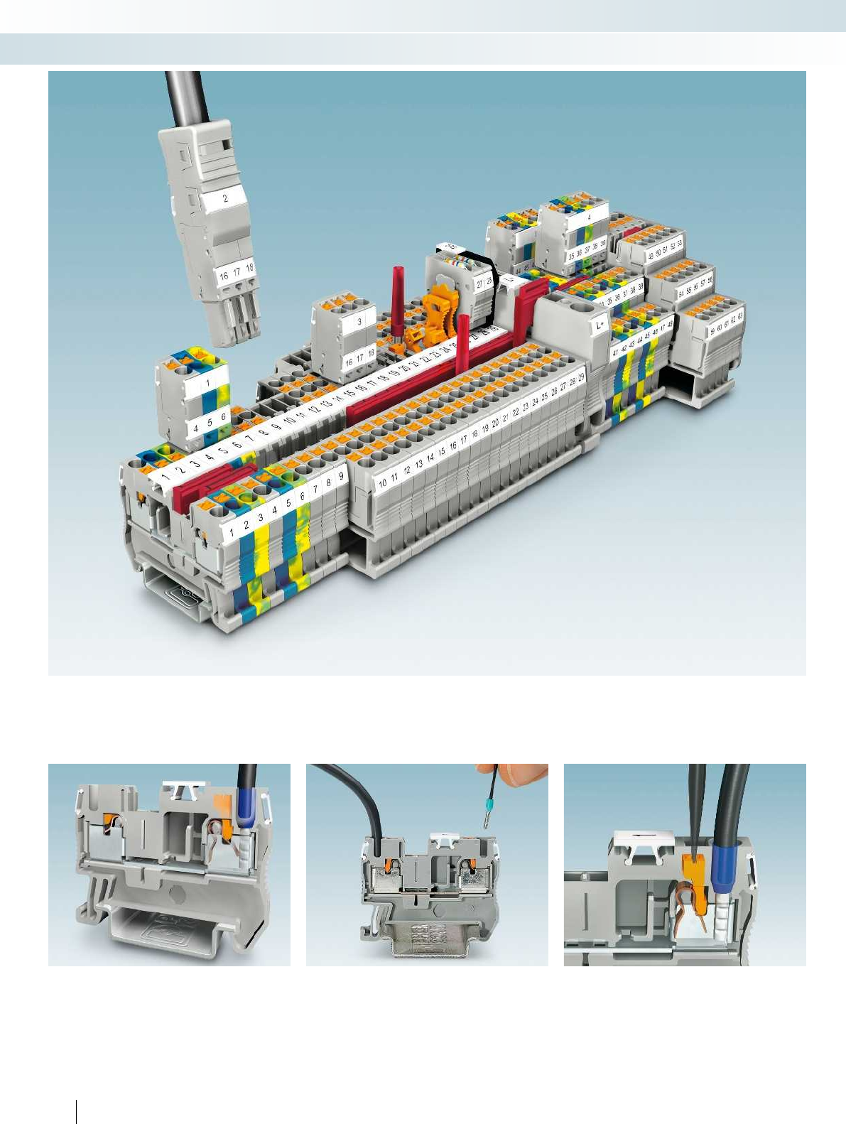
154 PHOENIX CONTACT
Modular terminal blocks
Modular terminal blocks - CLIPLINE complete
Push-in connection technology
The PT series is characterized by the easy,
direct conductor connection and makes
consistent use of the benefits of the
CLIPLINE complete system.
Easy insertion
The up to 50 percent reduction in
insertion force offered by push-in
technology supports simple and direct
insertion of solid and stranded conductors
featuring ferrules with a cross section of
0.34mm or higher.
Latch function
The integrated latch allows you to release
connections with any type of tool – easily
and without direct contact with live parts.
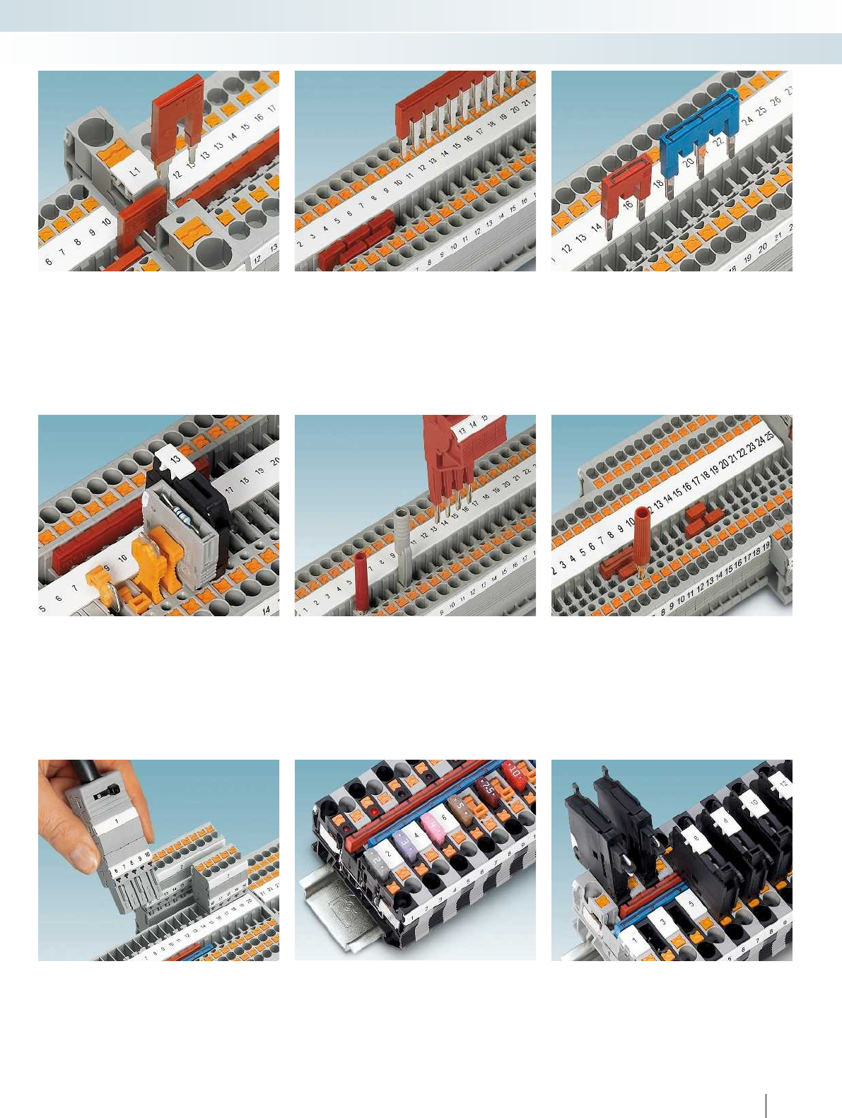
For additional information, visit phoenixcontact.net/products
155PHOENIX CONTACT
Modular terminal blocks
Modular terminal blocks - CLIPLINE complete
The reducing bridge allows terminal
blocks with different nominal cross sections
to be connected with ease, e.g., a PT10
push-in terminal block to a PT2,5. Power
blocks can be created quickly using the
reducing bridge.
The double function shaft can be used to
connect any number of terminal blocks with
two-position bridges. The 2 to 50-pos.
bridges allow up to 50 terminal blocks to be
bridged in one step.
Bridging between non-adjacent terminal
blocks is created by removing individual
contact tabs from the standard bridge. Two
potentials can then be routed in parallel
through a terminal strip. The contact points
can also be marked.
The isolated feed-through connector
P-FIX, isolating plug P-DI, component plug
P-CO, and the cartridge fuse plug P-FU can
be used in the universal plug-in zone of the
disconnect terminal block.
A test plug with a 2.3mm diameter is
available for measuring lines. All
measurement and test work can be
completed at speed using test adapters for
4mm diameter test plugs and the modular
test plugs.
As well as offering a testing facility in the
double function shaft, all push-in technology
terminal blocks offer an additional test
contact for test plugs with a 2.3 mm
diameter.
Push-in COMBI terminal blocks are
available for the plug-in configuration of
signal wiring. The system is touch-proof and
offers plugs for self-assembly with extensive
accessories.
Automatic flat-type fuse terminal blocks
with a 4mm conductor connection are
available in the same shape as the feed-
through terminal blocks. All terminal blocks
can be continuously bridged with one
another with the double function shaft.
The compact lever-type fuse terminal
blocks are of the same shape as the feed-
through terminal blocks and can be labeled
and bridged continuously. A time-saving
potential distribution is easily created using
bridging between non-adjacent terminal
blocks.
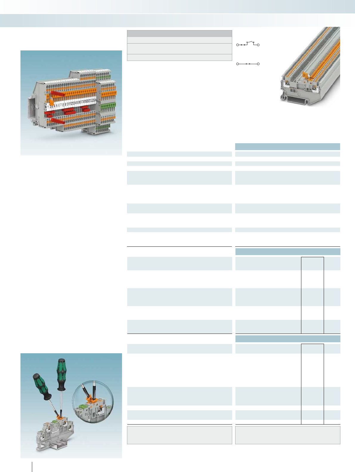
Technical data
Dimensions Width Length Height NS 35/7,5
[mm] 3.5 58.9 32 3.5 67.8 32 3.5 76.9 32 3.5 86 42.6
Max. electrical data Imax. [A] Umax. [V] max. Ø [mm²] AWG
10 400 0.14 - 1.5 26 - 14 10
IEC 60947-7-1
Rated data IEC UL/CUL CSA IEC/
EN60079-7
Rated voltage [V]400--- 400--- 400--- 400---
Nominal current / cross section [A] / [mm²] 10/1.5 - - - 10
Rated cross section [mm²]1.5--- 1.5--- 1.5--- 1.5---
Cross section range AWG 26 - 14 - - - 26 - 14 - - - 26 - 16 - - - 26 - 14 - - -
Connection capacity solid stranded Ferrule
with/without plastic sleeve
1 conductor [mm²] 0.14 - 1.5 0.14 - 1.5 0.14 - 1.5 0.14 - 1 0.14 - 1.
Two stranded conductors with a TWIN ferrule [mm²]
Connection cross sections directly plug-in [mm²] 0.25 - 1.5 - 0.34 - 1.5 0.34 - 1 0.25 - 1.5 - 0.34 - 1.5 0.34 - 1 0.25 - 1.5 - 0.34 - 1.5 0
General data
Stripping length [mm] 8
Insulating material PA
Inflammability class according to UL 94 V0
Ordering data
Description No. of
pos. Color Type Order No. Pcs. /
Pkt.
Double-level knife disconnect terminal block,
disconnection on both levels, for mounting on
NS35...
gray
blue
Double-level knife disconnect terminal block,
disconnection on the upper level, for mounting on
NS35...
gray
blue
Knife disconnect terminal block, for mounting
on NS35...
gray PT 1,5/S-MT 3210301 50
blue PT 1,5/S-MT BU 3210302 50
Feed-through terminal block, same shape, for
mounting on NS35...
gray PT 1,5/S-MTD 3210308 50
blue PT 1,5/S-MTD BU 3210309 50
Accessories
Cover, 0.8mm width gray D-PT 1,5/S-MT-0,8 3210303 50
orange D-PT 1,5/S-MT-0,8 OG 3210304 50
Jumper
2redFBS 2-3,5 3213014 50
3redFBS 3-3,5 3213027 50
4redFBS 4-3,5 3213030 50
5redFBS 5-3,5 3213043 50
10 red FBS 10-3,5 3213056 50
20 red FBS 20-3,5 3213069 50
Reducing bridge2)
2red RB ST (2,5/4)-1,5/S 3214356 10
2red RB ST 6-1,5/S 3213250 10
Partition plate, 2mm width gray ATP-ST-TWIN 3030789 50
Test plug metal part, 2.3 mm Ø silver MPS-MT 0201744 10
Insulating sleeve, for MPS metal part red MPS-IH RD 0201676 10
Screwdriver SZF 0-0,4X2,5 1204504 10
Center groove labeling UCT-TM 3,5 or ZB 3,5
(see Catalog 5)
Center and side groove labeling UCT-TMF 3,5 or ZBF 3,5
(see Catalog 5)
156 PHOENIX CONTACT
PT1,5/S... and PTT1,5/S... push-in
knife disconnect terminal blocks
Notes:
The nominal current for PT...MTD... terminal blocks is 17.5A.
1) The max. load current must not be exceeded by the total current
of all connected conductors.
2) Refer to the reducing bridge table; see Catalog 3.
– Now available for the first time with a
design width of just 3.5 mm
– Testing facility on both sides of the
disconnect point
– Actuation cross on the disconnect knife
enables the use of different sized
screwdrivers, see image below
– Same shape feed-through versions
– Clear grouping of the terminal strips
through orange cover with a design width
of just 0.8mm
Single-level PT1,5/S...
– Three and four-conductor terminal blocks
can be used for multi-conductor
connections
– Seamless and can be double bridged for all
tasks in time-saving potential supply and
distribution
Double-level PTT1,5/S-2MT
– Space-saving design for maximum wiring
density
– Disconnection option on each level
– The assignment from the disconnect knife
to the contact points is indicated by the
colored levers and the height offset
Modular terminal blocks
Modular terminal blocks - CLIPLINE complete
1.5(1.5)mm², 10A, knife disconnect terminal
block, two connections, bridgeable
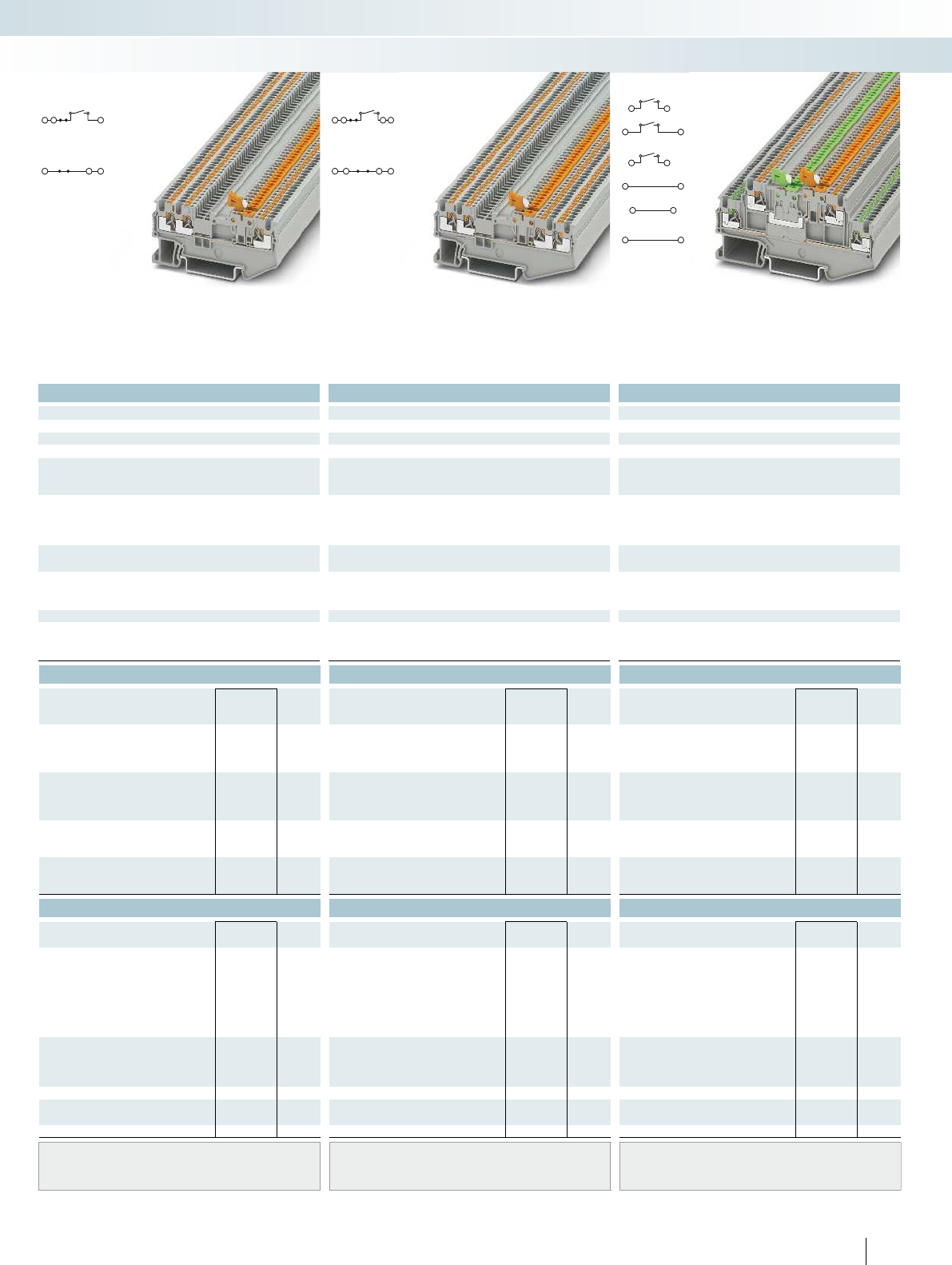
For additional information, visit phoenixcontact.net/products
Technical data Technical data Technical data
Width Length Height NS 35/7,5 Width Length Height NS 35/7,5 Width Length Height NS 35/7,5
3.5 58.9 32 3.5 67.8 32 3.5 76.9 32 3.5 86 42.6
Imax. [A] Umax. [V] max. Ø [mm²] AWG Imax. [A] Umax. [V] max. Ø [mm²] AWG Imax. [A] Umax. [V] max. Ø [mm²] AWG
10 400 0.14 - 1.5 26 - 14 101) 400 0.14 - 1.5 26 - 14 101) 400 0.14 - 1.5 26 - 16 8 400 0.14 - 1.5 26 - 14
IEC 60947-7-1 IEC 60947-7-1 IEC 60947-7-1
IEC UL/CUL CSA IEC/
EN60079-7
IEC UL/CUL CSA IEC/
EN60079-7
IEC UL/CUL CSA IEC/
EN60079-7
Rated voltage [V]400--- 400--- 400--- 400---
Nominal current / cross section [A] / [mm²] 10/1.5 - - - 101)/1.5 - - - 101)/1.5--- 8/1.5---
Rated cross section [mm²]1.5--- 1.5--- 1.5--- 1.5---
Cross section range AWG 26 - 14 - - - 26 - 14 - - - 26 - 16 - - - 26 - 14 - - -
solid stranded Ferrule solid stranded Ferrule solid stranded Ferrule
with/without plastic sleeve with/without plastic sleeve with/without plastic sleeve
1 conductor [mm²] 0.14 - 1.5 0.14 - 1.5 0.14 - 1.5 0.14 - 1 0.14 - 1.5 0.14 - 1.5 0.14 - 1.5 0.14 - 1 0.14 - 1.5 0.14 - 1.5 0.14 - 1.5 0.14 - 1 0.14 - 1.5 0.14 - 1.5 0.14 - 1.5 0.14 - 1
- 1.5 0.34 - 1 0.25 - 1.5 - 0.34 - 1.5 0.34 - 1 0.25 - 1.5 - 0.34 - 1.5 0.34 - 1 0.25 - 1.5 - 0.34 - 1.5 0.34 - 1
888
PA PA PA
V0 V0 V0
Ordering data Ordering data Ordering data
Type Order No. Pcs. /
Pkt. Type Order No. Pcs. /
Pkt. Type Order No. Pcs. /
Pkt.
PTT 1,5/S-2MT 3210351 50
PTT 1,5/S-2MT BU 3210352 50
PTT 1,5/S-L/MT 3210341 50
PTT 1,5/S-L/MT BU 3210342 50
PT 1,5/S-TWIN-MT 3210311 50 PT 1,5/S-QUATTRO-MT 3210321 50
PT 1,5/S-TWIN-MT BU 3210312 50 PT 1,5/S-QUATTRO-MT BU 3210322 50
PT 1,5/S-TWIN-MTD 3210317 50 PT 1,5/S-QUATTRO-MTD 3210328 50 PTT 1,5/S-2L 3210356 50
PT 1,5/S-TWIN-MTD BU 3210319 50 PT 1,5/S-QUATTRO-MTD BU 3210329 50 PTT 1,5/S-2L BU 3210357 50
Accessories Accessories Accessories
D-PT 1,5/S-TWIN-MT-0,8 3210313 50 D-PT 1,5/S-QUATTRO-MT-0,8 3210333 50 D-PTT 1,5/S-2MT-0,8 3210353 50
D-PT 1,5/S-TWIN-MT-0,8 OG 3210314 50 D-PT 1,5/S-QUATTRO-MT-0,8 OG 3210334 50 D-PTT 1,5/S-2MT-0,8 OG 3210354 50
FBS 2-3,5 3213014 50 FBS 2-3,5 3213014 50
FBS 3-3,5 3213027 50 FBS 3-3,5 3213027 50
FBS 4-3,5 3213030 50 FBS 4-3,5 3213030 50
FBS 5-3,5 3213043 50 FBS 5-3,5 3213043 50
FBS 10-3,5 3213056 50 FBS 10-3,5 3213056 50
FBS 20-3,5 3213069 50 FBS 20-3,5 3213069 50
RB ST (2,5/4)-1,5/S 3214356 10 RB ST (2,5/4)-1,5/S 3214356 10
RB ST 6-1,5/S 3213250 10 RB ST 6-1,5/S 3213250 10
ATP-ST-TWIN 3030789 50 ATP-ST QUATTRO 3030815 50 ATP-STTB 4 3030747 50
MPS-MT 0201744 10 MPS-MT 0201744 10 MPS-MT 0201744 10
MPS-IH RD 0201676 10 MPS-IH RD 0201676 10 MPS-IH RD 0201676 10
SZF 0-0,4X2,5 1204504 10 SZF 0-0,4X2,5 1204504 10 SZF 0-0,4X2,5 1204504 10
UCT-TM 3,5 or ZB 3,5
(see Catalog 5)
UCT-TM 3,5 or ZB 3,5
(see Catalog 5)
UCT-TMF 3,5 or ZBF 3,5
(see Catalog 5)
UCT-TMF 3,5 or ZBF 3,5
(see Catalog 5)
UCT-TMF 3,5 or ZBF 3,5
(see Catalog 5)
157PHOENIX CONTACT
Modular terminal blocks
Modular terminal blocks - CLIPLINE complete
1.5(1.5)mm², 10A, knife disconnect terminal
block, three connections, bridgeable
1.5(1.5)mm², 10A, knife disconnect terminal
block, four connections, bridgeable
1.5(1.5)mm², 8A, double-level knife
disconnect terminal block, four connections,
not bridgeable
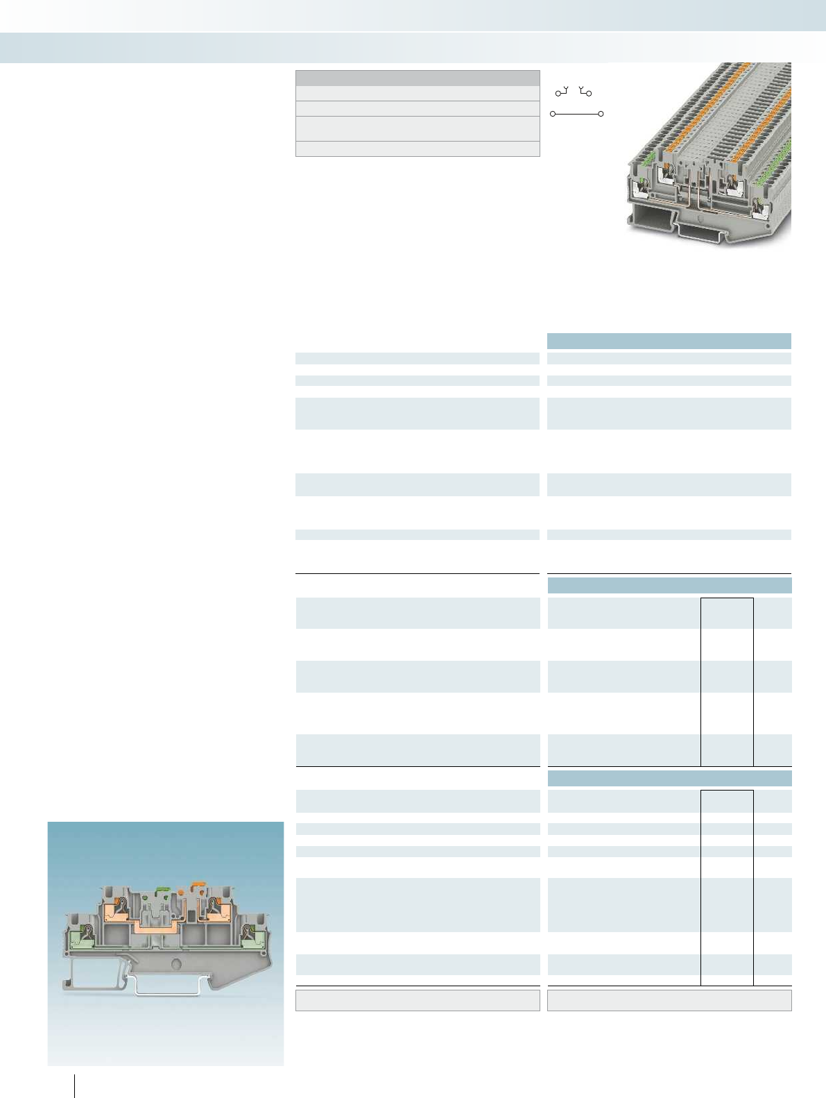
Technical data
Dimensions Width Length Height NS 35/7,5
[mm] 5.2 92.4 47.4 5.2 92.4 47.4 5.2 92.4 47.4 5.2 92.4 47.4
Max. electrical data Imax. [A] Umax. [V] max. Ø [mm²] AWG
16 400 0.14 - 4 26 - 12 16 400 0.14 - 4 26 - 12 16 400 0.14 - 4 26 - 12 20 400 0.14 - 4 26 - 12
IEC 60947-7-1
Rated data IEC UL/CUL CSA IEC/
EN60079-7
Rated voltage [V]400--- 400--- 400--- 400---
Nominal current / cross section [A] / [mm²] 16/2.5 - - - 16/2.5 - - - 16/2.5 - - - 20/2.5 - - -
Rated cross section [mm²]2.5--- 2.5--- 2.5--- 2.5---
Cross section range AWG 26 - 12 - - - 26 - 12 - - - 26 - 12 - - - 26 - 12 - - -
Connection capacity solid stranded Ferrule
with/without plastic sleeve
1 conductor [mm²] 0.14 - 4 0.14 - 2.5 0.14 - 2.5 0.14 - 2.5 0.14 - 4 0
Two stranded conductors with a TWIN ferrule [mm²] 0.5
Connection cross sections directly plug-in [mm²] 0.34 - 4 - 0.34 - 2.5 0.34 - 2.5 0.34 - 4 - 0.34 - 2.5 0.34 - 2.5 0.34 - 4 - 0.34 - 2.5 0.3
General data
Stripping length [mm] 10
Insulating material PA
Inflammability class according to UL 94 V0
Ordering data
Description Color Type Order No. Pcs. /
Pkt.
Disconnect terminal block, for mounting on
NS 35...
gray PTT 2,5-L/TG 3210230 50
blue PTT 2,5-L/TG BU 3210270 50
Knife disconnect terminal block, for mounting
on NS35...
gray
blue
Double-level knife disconnect terminal block,
disconnection on both levels, for mounting on
NS35...
gray
blue
Feed-through terminal block, same shape, for
mounting on NS35...
gray
blue
Accessories
Cover, 0.8mm width gray D-PTT 2,5-2MT-0,8 3210300 50
orange D-PTT 2,5-2MT-0,8 OG 3210299 50
Partition plate, 2mm width gray ATP-STTB 4 3030747 50
Switching lock, plug-in4)white
Isolating plug2)orangeP-DI 3036783 50
Feed-through connector2)gray P-FIX 3038956 50
Component plug, labeled with ZBF5 or
UC-TMF53)
gray P-CO 3036796 10
Fuse plug, width 5.2 mm1)black P-FU 5X20-5 3209235 10
with LED for 12-30 V DC, 0.35-0.95mA black P-FU 5X20 LED 24-5 3209248 10
for 30-60VAC/DC, 0.36-0.95mA black P-FU 5X20 LED 60-5 3209251 10
for 110-250VAC/DC, 0.4-0.95mA black P-FU 5X20 LED 250-5 3209264 10
Test plug metal part, 2.3 mm Ø silver MPS-MT 0201744 10
Insulating sleeve, for MPS metal part red MPS-IH RD 0201676 10
Modular test plug housing, for MPS metal part,
can be marked with ZB 5
red PS-5/2,3MM RD 3038723 10
Screwdriver SZF 1-0,6X3,5 1204517 10
Lateral groove labeling UC-TMF 5, UCT-TMF 5 or ZBF 5
(see Catalog 5)
158 PHOENIX CONTACT
PTT2,5... push-in double-level
disconnect and knife disconnect
terminal blocks
Notes:
1) If the fuse is faulty, the downstream circuit is not disconnected.
2) Observe max. load current.
3) Observe max. load current, depending on the power dissipation
of the components. Max. 0.5 W with single arrangement.
4) see Catalog 3.
– Design width of just 5.2 mm
– Testing facility on both sides of the
disconnect point
– Space-saving design for maximum wiring
density
– Clear grouping of the terminal strips
through orange cover with a design width
of just 0.8mm
– Disconnection option on each level
– The assignment from the disconnect knife
to the contact points is indicated by the
colored levers and the height offset
Modular terminal blocks
Modular terminal blocks - CLIPLINE complete
2.5(4)mm², 16A, double-level terminal block,
with one disconnect zone
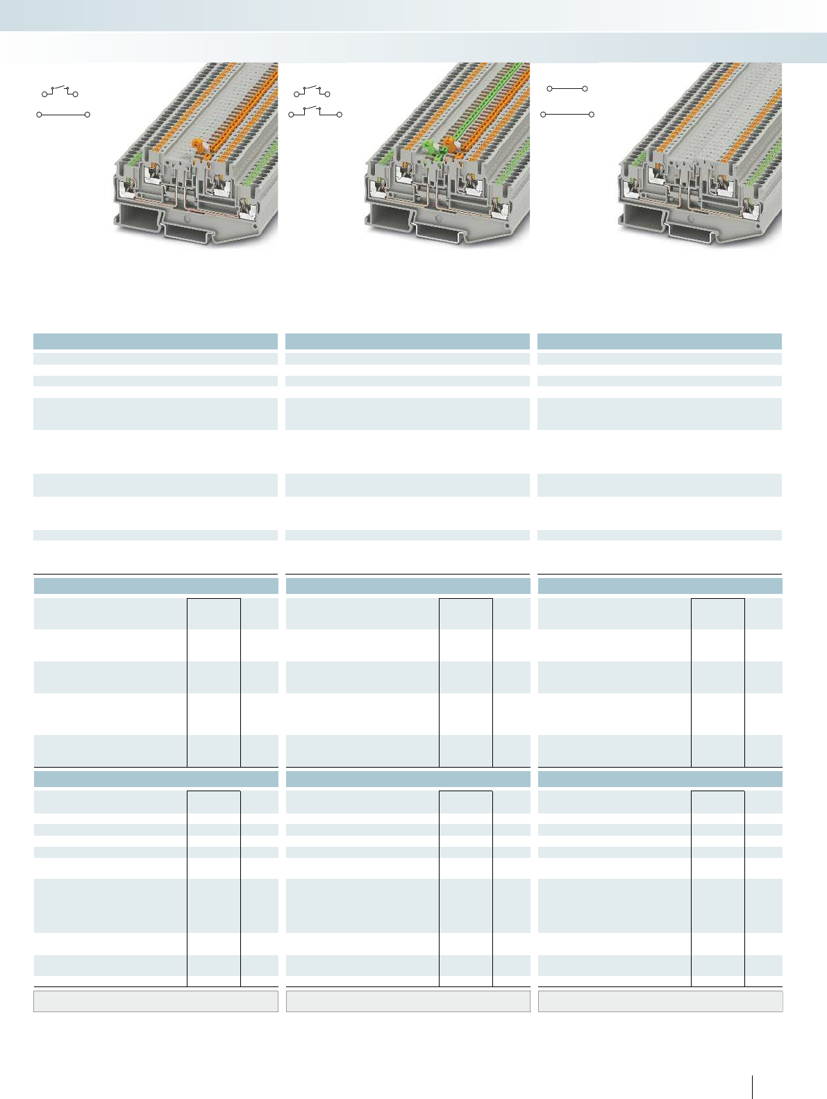
For additional information, visit phoenixcontact.net/products
Technical data Technical data Technical data
Width Length Height NS 35/7,5 Width Length Height NS 35/7,5 Width Length Height NS 35/7,5
5.2 92.4 47.4 5.2 92.4 47.4 5.2 92.4 47.4 5.2 92.4 47.4
Imax. [A] Umax. [V] max. Ø [mm²] AWG Imax. [A] Umax. [V] max. Ø [mm²] AWG Imax. [A] Umax. [V] max. Ø [mm²] AWG
16 400 0.14 - 4 26 - 12 16 400 0.14 - 4 26 - 12 16 400 0.14 - 4 26 - 12 20 400 0.14 - 4 26 - 12
IEC 60947-7-1 IEC 60947-7-1 IEC 60947-7-1
IEC UL/CUL CSA IEC/
EN60079-7
IEC UL/CUL CSA IEC/
EN60079-7
IEC UL/CUL CSA IEC/
EN60079-7
Rated voltage [V]400--- 400--- 400--- 400---
Nominal current / cross section [A] / [mm²] 16/2.5 - - - 16/2.5 - - - 16/2.5 - - - 20/2.5 - - -
Rated cross section [mm²]2.5--- 2.5--- 2.5--- 2.5---
Cross section range AWG 26 - 12 - - - 26 - 12 - - - 26 - 12 - - - 26 - 12 - - -
solid stranded Ferrule solid stranded Ferrule solid stranded Ferrule
with/without plastic sleeve with/without plastic sleeve with/without plastic sleeve
1 conductor [mm²] 0.14 - 4 0.14 - 2.5 0.14 - 2.5 0.14 - 2.5 0.14 - 4 0.14 - 2.5 0.14 - 2.5 0.14 - 2.5 0.14 - 4 0.14 - 2.5 0.14 - 2.5 0.14 - 2.5 0.14 - 4 0.14 - 2.5 0.14 - 2.5 0.14 - 2.5
0.5 0.5 0.5
2.5 0.34 - 2.5 0.34 - 4 - 0.34 - 2.5 0.34 - 2.5 0.34 - 4 - 0.34 - 2.5 0.34 - 2.5 0.34 - 4 - 0.34 - 2.5 0.34 - 2.5
10 10 10
PA PA PA
V0 V0 V0
Ordering data Ordering data Ordering data
Type Order No. Pcs. /
Pkt. Type Order No. Pcs. /
Pkt. Type Order No. Pcs. /
Pkt.
PTT 2,5-L/MT 3210251 50
PTT 2,5-L/MT BU 3210257 50
PTT 2,5-2MT 3210258 50
PTT 2,5-2MT BU 3210265 50
PTT 2,5-2L 3210267 50
PTT 2,5-2L BU 3210268 50
Accessories Accessories Accessories
D-PTT 2,5-2MT-0,8 3210300 50 D-PTT 2,5-2MT-0,8 3210300 50 D-PTT 2,5-2MT-0,8 3210300 50
D-PTT 2,5-2MT-0,8 OG 3210299 50 D-PTT 2,5-2MT-0,8 OG 3210299 50 D-PTT 2,5-2MT-0,8 OG 3210299 50
ATP-STTB 4 3030747 50 ATP-STTB 4 3030747 50 ATP-STTB 4 3030747 50
S-MT 3247954 50 S-MT 3247954 50
MPS-MT 0201744 10 MPS-MT 0201744 10 MPS-MT 0201744 10
MPS-IH RD 0201676 10 MPS-IH RD 0201676 10 MPS-IH RD 0201676 10
PS-5/2,3MM RD 3038723 10 PS-5/2,3MM RD 3038723 10 PS-5/2,3MM RD 3038723 10
SZF 1-0,6X3,5 1204517 10 SZF 1-0,6X3,5 1204517 10 SZF 1-0,6X3,5 1204517 10
UC-TMF 5, UCT-TMF 5 or ZBF 5
(see Catalog 5)
UC-TMF 5, UCT-TMF 5 or ZBF 5
(see Catalog 5)
UC-TMF 5, UCT-TMF 5 or ZBF 5
(see Catalog 5)
159PHOENIX CONTACT
Modular terminal blocks
Modular terminal blocks - CLIPLINE complete
2.5(4)mm², 16A, double-level terminal block
with one knife disconnect zone
2.5(4)mm², 16A, double-level terminal block
with two knife disconnect zones
2.5(4)mm², 20A, double-level terminal block,
same shape
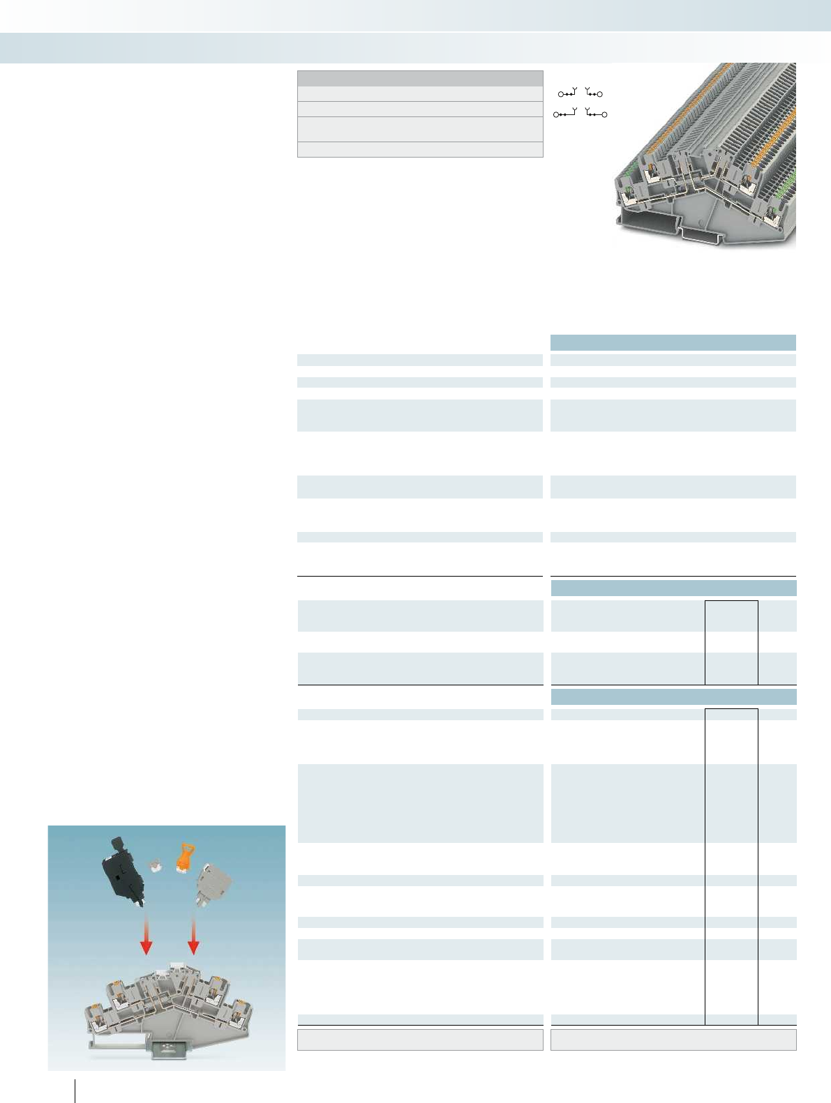
Technical data
Dimensions Width Length Height NS 35/7,5
[mm] 5.2 124.8 64.3 5.2 124.8 64.3
Max. electrical data Imax. [A] Umax. [V] max. Ø [mm²] AWG
16 400 0.14 - 4 26 - 12 16 400 0.14 - 4 26 - 12
IEC 60947-7-1
Rated data IEC UL/CUL CSA IEC/
EN60079-7
Rated voltage [V]400--- 400---
Nominal current / cross section [A] / [mm²] 16/2.5 - - - 16/2.5 - - -
Rated cross section [mm²] 2.5 - - - 2.5 - - -
Cross section range AWG 26 - 12 - - - 26 - 12 - - -
Connection capacity solid stranded Ferrule
with/without plastic sleeve
1 conductor [mm²] 0.14 - 4 0.14 - 2.5 0.14 - 2.5 0.14 - 2.5 0.14 - 4 0.14 - 2.5 0.14 - 2.5 0.14 - 2.5
Two stranded conductors with a TWIN ferrule [mm²] 0.5
Connection cross sections, plug-in [mm²] 0.34 - 4 - 0.34 - 2.5 0.34 - 2.5 0.34 - 4 - 0.34 - 2.5 0.34 - 2.5
General data
Stripping length [mm] 10
Insulating material PA
Inflammability class according to UL 94 V0
Ordering data
Description No. of
pos. Color Type Order No. Pcs. /
Pkt.
Disconnect terminal block, for mounting on
NS 35...
gray PTTBS 2,5-2TGB 3210402 50
Knife disconnect terminal block, for mounting
on NS35...
gray
blue
Accessories
Cover, 0.8mm width gray D-PTTBS 2,5-2MTB 3210404 50
Insulation stop sleeve, cross section range:
0.08 - 0.2 mm² white ISH 2,5/0,2 3002843 50
0.25 - 0.5 mm² gray ISH 2,5/0,5 3002856 50
0.75 - 1 mm² black ISH 2,5/1,0 3002869 50
Jumper
2red FBS 2-5 3030161 50
3red FBS 3-5 3030174 50
4red FBS 4-5 3030187 50
5red FBS 5-5 3030190 50
10 red FBS 10-5 3030213 10
20 red FBS 20-5 3030226 10
Vertical potential bridge, to connect the upper and lower level
black FBS-PV 3032185 50
Switching lock, plug-in4)white
Modular test plug, for the individual assembly of
test pin strips
red PS-5 3030983 10
Isolating plug2)orange P-DI 3036783 50
Feed-through connector2)grayP-FIX 3038956 50
Component plug, labeled with ZBF5 or
UC-TMF53)
gray P-CO 3036796 10
Fuse plug, width 5.2 mm1)blackP-FU 5X20-5 3209235 10
With LED for 12-30 V DC, 0.35-0.95mA black P-FU 5X20 LED 24-5 3209248 10
for 30-60VAC/DC, 0.36-0.95mA black P-FU 5X20 LED 60-5 3209251 10
for 110-250VAC/DC, 0.4-0.95mA black P-FU 5X20 LED 250-5 3209264 10
Screwdriver SZF 1-0,6X3,5 1204517 10
Center groove labeling UC-TM 5, UCT-TM 5 or ZB 5
(see Catalog 5)
160 PHOENIX CONTACT
PTTBS2,5... push-in double-level
disconnect and knife disconnect
terminal blocks in desk design
Notes:
1) If the fuse is faulty, the downstream circuit is not disconnected.
2) Observe max. load current.
3) Observe max. load current, depending on the power dissipation
of the components. Max. 0.5 W with single arrangement.
4) see Catalog 3.
The angled push-in terminal blocks in
desk-design were developed for wiring
systems where space is saved by means of
underfloor wiring. They offer numerous
advantages:
– Design width of just 5.2 mm
– Angled conductor entry for use in flat
terminal boxes
– Disconnection option on each level
– The assignment from the disconnect knife
to the contact points is indicated by the
colored levers and the height offset
– Two function shafts before and after the
disconnect point for flexible potential
distribution
– Additional 2.3 mm test connections on
the contact chamber lever
– Two large-surface, central marking
options, marking assigned through a
height offset
– Convenient potential bridging of the
levels with the vertical FBS-PV potential
bridge
– PTTBS2,52TGB with universal
disconnect zone, for accommodating
isolating plugs, feed-through connectors,
component and fuse plugs
CLIPPROJECTPlanning enables the
quick and convenient planning and
configuration of fault-free terminal strips.
Modular terminal blocks
Modular terminal blocks - CLIPLINE complete
2.5 (4) mm², 16 A, double-level terminal block
with two disconnect zones
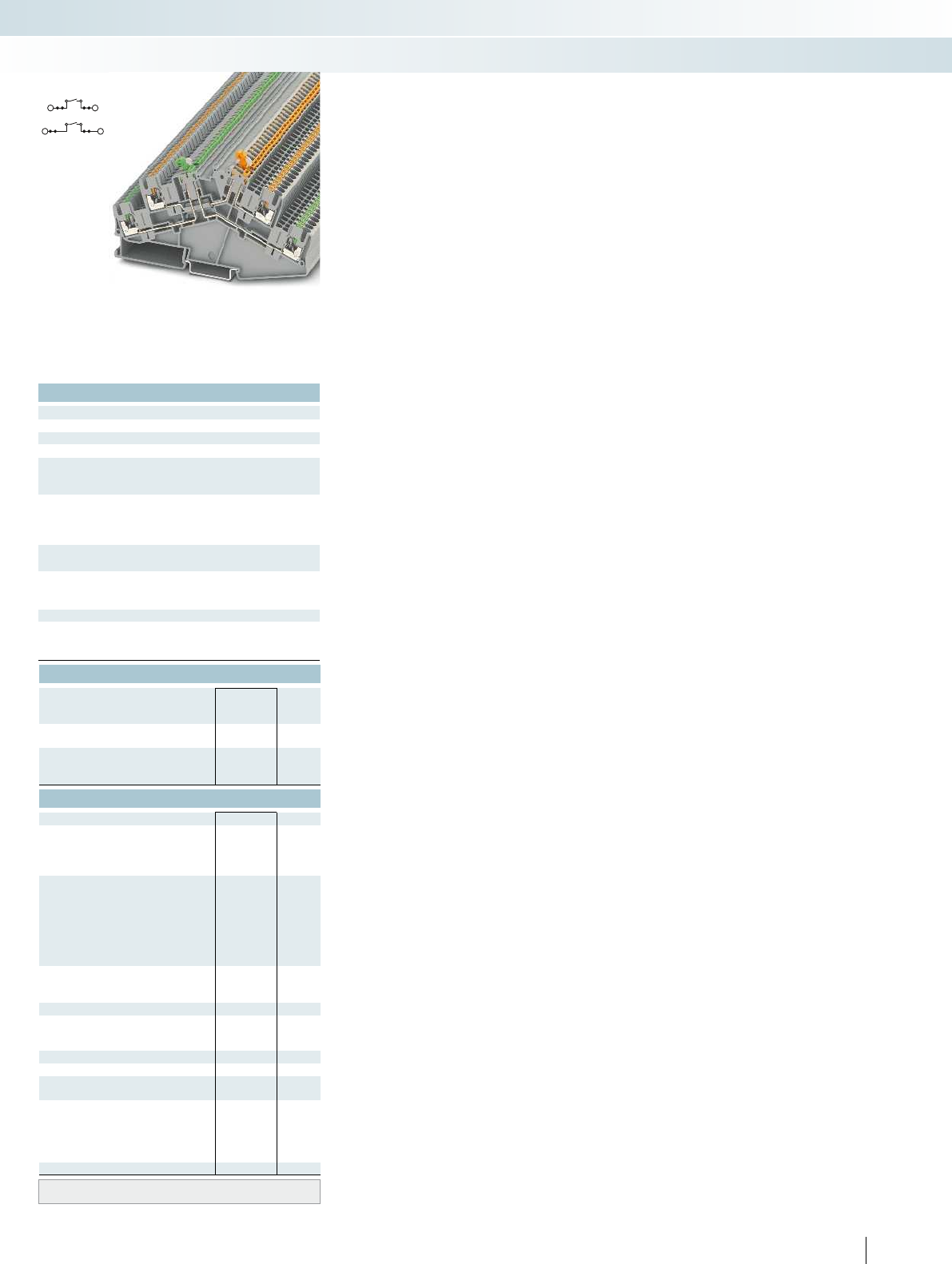
For additional information, visit phoenixcontact.net/products
Technical data
Width Length Height NS 35/7,5
5.2 124.8 64.3 5.2 124.8 64.3
Imax. [A] Umax. [V] max. Ø [mm²] AWG
16 400 0.14 - 4 26 - 12 16 400 0.14 - 4 26 - 12
IEC 60947-7-1
IEC UL/CUL CSA IEC/
EN60079-7
Rated voltage [V]400--- 400---
Nominal current / cross section [A] / [mm²] 16/2.5 - - - 16/2.5 - - -
Rated cross section [mm²] 2.5 - - - 2.5 - - -
Cross section range AWG 26 - 12 - - - 26 - 12 - - -
solid stranded Ferrule
with/without plastic sleeve
4 - 2.5 0.14 - 4 0.14 - 2.5 0.14 - 2.5 0.14 - 2.5
0.5
34 - 2.5 0.34 - 2.5 0.34 - 4 - 0.34 - 2.5 0.34 - 2.5
10
PA
V0
Ordering data
Type Order No. Pcs. /
Pkt.
PTTBS 2,5-2MTB 3210400 50
PTTBS 2,5-2MTB BU 3210401 50
Accessories
D-PTTBS 2,5-2MTB 3210404 50
ISH 2,5/0,2 3002843 50
ISH 2,5/0,5 3002856 50
ISH 2,5/1,0 3002869 50
FBS 2-5 3030161 50
FBS 3-5 3030174 50
FBS 4-5 3030187 50
FBS 5-5 3030190 50
FBS 10-5 3030213 10
FBS 20-5 3030226 10
FBS-PV 3032185 50
S-MT 3247954 50
PS-5 3030983 10
SZF 1-0,6X3,5 1204517 10
UC-TM 5, UCT-TM 5 or ZB 5
(see Catalog 5)
161PHOENIX CONTACT
Modular terminal blocks
Modular terminal blocks - CLIPLINE complete
2.5 (4) mm², 16 A, double-level terminal block
with two knife disconnect zones
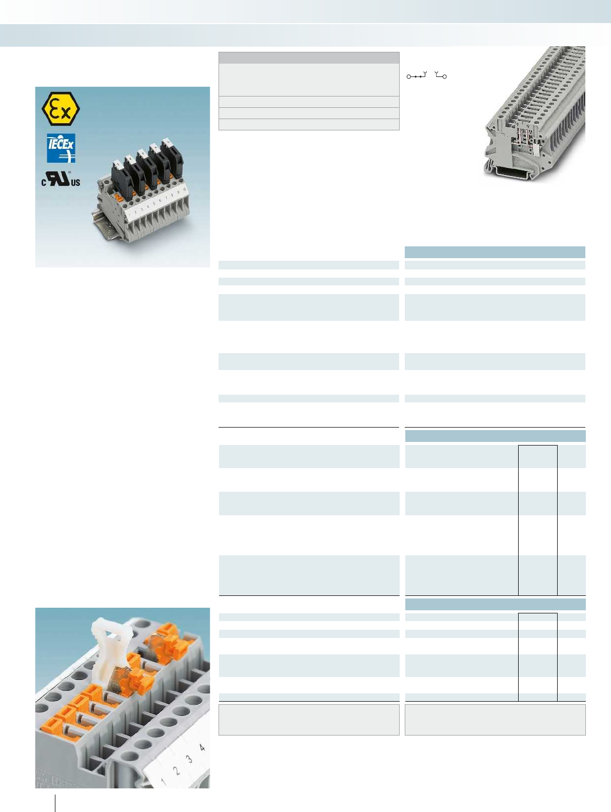
Ex:
IECEx UL 13.0007U
Technical data
Dimensions Width Length Height NS 35/7,5
[mm] 6.2 57.8 47.5 6.2 57.8 49.1 8.2 57.8 47.5 - - -
Max. electrical data Imax. [A] Umax. [V] max. Ø [mm²] AWG
202)500
2) 0.14 - 6 26 - 10 20 500 0.14 - 6 26 - 10 20
IEC 60947-7-1
Rated data IEC UL/CUL CSA IEC/
EN60079-7
Rated voltage [V] 5002)--250 500--500500
Nominal current / cross section [A] / [mm²] 202)/2.5 - - 6.3 20/2.5 - - 16 20
Rated cross section [mm²]4--0.14-4 4--0.14-46--0.2-6----
Cross section range AWG26 - 10--26 - 10 26 - 10--26 - 1024 - 8--24 - 8----
Connection capacity solid stranded Ferrule
with/without plastic sleeve
1 conductor [mm²] 0.14 - 6 0.14 - 6 0.14 - 4 0.14 - 4 0.14 - 6 0.
Two conductors (of the same type) [mm²] 0.14 - 1.5 0.14 - 1.5 0.14 - 1.5 - 0.14 - 1.5 0.14 - 1.5 0.14 - 1.5 - 0.2 - 2.5 0.2 - 2.5 0.25 - 1.
Two stranded conductors with a TWIN ferrule [mm²] 0.5 - 2.5
General data
Stripping length [mm] 9
Insulating material PA
Inflammability class according to UL 94 V0
Ordering data
Description No. of
pos. Color Type Order No. Pcs. /
Pkt.
Disconnect terminal block, for mounting on
NS 35...
gray UT 4-TG-EX 3046143 50
with test socket screws gray UT 4-TG-P/P-EX 3046169 50
Knife disconnect terminal block, for mounting
on NS35...
gray
gray
Fuse plug, width 6.2 mm1)black
with LED for 12-30 V DC, 0.35-0.95mA black
for 30-60VAC/DC, 0.36-0.95mA black
for 110-250VAC/DC, 0.4-0.95mA black
Fuse plug, width 8.2 mm1)black
with LED for 12-30 V DC, 0.35-0.95mA black
for 30-60VAC/DC, 0.36-0.95mA black
for 110-250VAC/DC, 0.4-0.95mA black
Accessories
Switching lock, plug-in3)white
Partition plate, 2.2 mm wide gray ATP-UT-TWIN 3047183 50
Test adapter, 4 mm test socket hole gray PAI-4-N GY 3032871 10
Test plug metal part, 2.3 mm Ø silver MPS-MT 0201744 10
Insulating sleeve, for MPS metal part red MPS-IH RD 0201676 10
Modular test plug, for the individual assembly of
test pin strips
red PS-6 3030996 10
Fuse plug, width 6.2 mm1)blackP-FU 5X20-EX 3036807 10
Width 8.2 mm black
Screwdriver SZS 0,6X3,5 1205053 10
Center groove labeling
Lateral groove labeling UC-TM 6, UCT-TM 6 or ZB 6
(see Catalog 5)
162 PHOENIX CONTACT
UT...-TG screw connection,
disconnect and knife disconnect
terminal blocks with fuse plug
Notes:
Detailed information and data sheets regarding modular terminal
blocks in the Ex area are available in the product area on our
website at phoenixcontact.net/products and in IECExCertificate
of Conformity IECExUL13.0007U and in UL fileE192998.
1) If the fuse is faulty, the downstream circuit is not disconnected.
2) Current and voltage are determined by the plug used.
3) see Catalog 3.
– Compact design and high current carrying
capacity of up to 20A
– Double bridge shaft enables individual
potential distribution and supply
– The function terminals are suitable for
use in potentially explosive areas (zone 2)
according to standards established
worldwide.
They meet the requirements of the
following ignition protection concepts:
Marking
IECEx:
–ExnAIICGc
ATEX:
–II3GExnAIICGc
–Ex i
– AEx nAIICGc
– ClassIzone2
– ClassIDivision2GroupsAB
S-MT switching lock
– The optional switching lock snaps in and
effectively prevents accidental switching,
see figure below
Modular terminal blocks
Modular terminal blocks - CLIPLINE complete
4 (6) mm², 20 A, disconnect terminal block,
with test socket screws
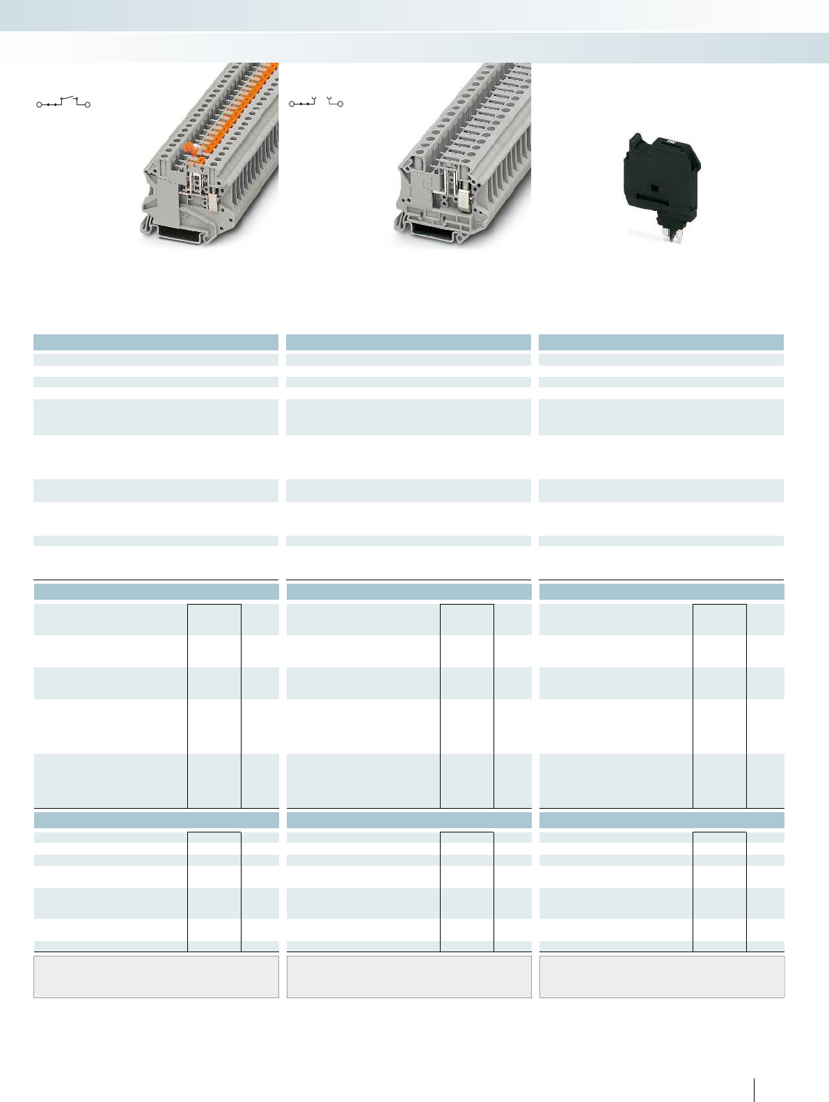
For additional information, visit phoenixcontact.net/products
Ex:
Ex: Ex:
IECEx UL 13.0007U IECEx UL 13.0007U IECEx UL 13.0007U
Technical data Technical data Technical data
Width Length Height NS 35/7,5 Width Length Height NS 35/7,5 Width Length Height NS 35/7,5
6.2 57.8 47.5 6.2 57.8 49.1 8.2 57.8 47.5 - - -
Imax. [A] Umax. [V] max. Ø [mm²] AWG Imax. [A] Umax. [V] max. Ø [mm²] AWG max. Ø [mm²] AWG
) 0.14 - 6 26 - 10 20 500 0.14 - 6 26 - 10 202)500
2) 0.2 - 10 24 - 8 - -
IEC 60947-7-1 IEC 60947-7-1
IEC UL/CUL CSA IEC/
EN60079-7
IEC UL/CUL CSA IEC/
EN60079-7
IEC UL/CUL CSA IEC/
EN60079-7
)--250 500--500500
2)--250----
)/2.5 - - 6.3 20/2.5 - - 16 202)/2.5--6.3----
Rated cross section [mm²]4--0.14-4 4--0.14-46--0.2-6----
Cross section range AWG26 - 10--26 - 10 26 - 10--26 - 1024 - 8--24 - 8----
solid stranded Ferrule solid stranded Ferrule solid stranded Ferrule
with/without plastic sleeve with/without plastic sleeve with/without plastic sleeve
1 conductor [mm²] 0.14 - 6 0.14 - 6 0.14 - 4 0.14 - 4 0.14 - 6 0.14 - 6 0.14 - 4 0.14 - 4 0.2 - 10 0.2 - 10 0.25 - 6 0.25 - 6 - - - -
- 1.5 - 0.14 - 1.5 0.14 - 1.5 0.14 - 1.5 - 0.2 - 2.5 0.2 - 2.5 0.25 - 1.5--- --
0.5 - 2.5 0.5 - 4
910-
PA PA PA
V0 V0 V0
Ordering data Ordering data Ordering data
Type Order No. Pcs. /
Pkt. Type Order No. Pcs. /
Pkt. Type Order No. Pcs. /
Pkt.
UT 6-TG-EX 3046486 50
UT 6-TG P/P-EX 3073870 50
UT 4-MT-EX 3046141 50
UT 4-MT-P/P-EX 3046173 50
P-FU 5X20-EX 3036807 10
P-FU 5X20 LED 24-EX 3036821 10
P-FU 5X20 LED 60-EX 3036823 10
P-FU 5X20 LA 250-EX 3036836 10
P-FU 6,3X32-EX 3046499 10
P-FU 6,3X32 LED 24-EX 3046509 10
P-FU 6,3X32 LED 60-EX 3046512 10
P-FU 6,3X32 LA 250-EX 3046525 10
Accessories Accessories Accessories
S-MT 3247954 50
ATP-UT-TWIN 3047183 50 ATP-UT-TWIN 3047183 50
PAI-4-N GY 3032871 10 PAI-4-N GY 3032871 10
MPS-MT 0201744 10 MPS-MT 0201744 10
MPS-IH RD 0201676 10 MPS-IH RD 0201676 10
PS-6 3030996 10 PS-6 3030996 10
P-FU 6,3X32-EX 3046499 10
SZS 0,6X3,5 1205053 10 SZS 1,0X4,0 VDE 1205066 10
UC-TM 6, UCT-TM 6 or ZB 6
(see Catalog 5)
UC-TM 8, UCT-TM 8 or ZB 8
(see Catalog 5)
UC-TMF 5, UCT-TMF 5 or ZBF 5
(see Catalog 5)
163PHOENIX CONTACT
Modular terminal blocks
Modular terminal blocks - CLIPLINE complete
4 (6) mm², 20 A, knife disconnect terminal
block, with test socket screws
6 (10) mm², 20 A, disconnect terminal block,
with test socket screws
6.2mm and 8.2mm fuse plug, for 5x20mm
and 6.3x32mm cartridge fuses
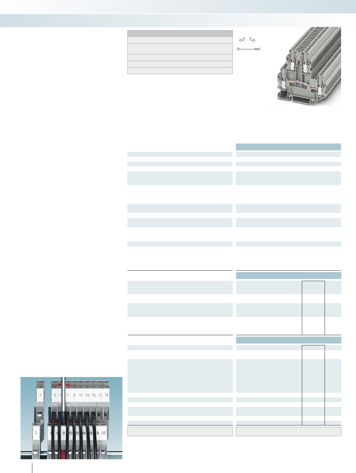
Technical data
Dimensions Width Length Height NS 35/7,5
[mm] 5.2 69.9 64.8 5.2 69.9 64.8 5.2 80.1 58.1
Max. electrical data Imax. [A] Umax. [V] max. Ø [mm²] AWG
20 400 0.14 - 4 26 - 12 20 400 0.14 - 4 26 - 12 16 400 0.14 - 4 26 - 12
IEC 60947-7-1
Rated data lower level IEC UL/CUL CSA IEC/
EN60079-7
Rated voltage [V]400--- 400--- 400---
Nominal current / cross section [A] / [mm²] 20/2.5 - - - 20/2.5 - - - 16/2.5 - - -
Rated cross section [mm²]2.5--- 2.5--- 2.5---
Cross section range AWG 26 - 12 - - - 26 - 12 - - - 26 - 12 - - -
Rated data, upper level IEC UL/CUL CSA IEC/
EN60079-7
Nominal current / cross section [A] / [mm²] 163)/2.5 - - - 16/2.5 - - - 16/2.5 - - -
Connection capacity solid stranded Ferrule
with/without plastic sleeve
1 conductor [mm²] 0.14 - 4 0.14 - 4 0.14 - 2.5 0.14 - 2.5 0.14 - 4 0.
Two conductors (of the same type) [mm²] 0.14 - 1.5 0.14 - 1.5 0.14 - 1.5 - 0.14 - 1.5 0.14 - 1.5 0.14 - 1.5 - 0.14 - 1.5 0.14 - 1.5 0.14 -
Two stranded conductors with a TWIN ferrule [mm²] 0.5 - 1.5
General data
Stripping length [mm] 9
Screw thread M3
Tightening torque [Nm] 0.5 - 0.6
Insulating material PA
Inflammability class according to UL 94 V0
Ordering data
Description No. of
pos. Color Type Order No. Pcs. /
Pkt.
Disconnect terminal block, for mounting on
NS 35...
gray UTTB 2,5-TG-P/P 3044644 50
Knife disconnect terminal block, for mounting
on NS35...
gray
blue
Double-level knife disconnect terminal block,
disconnection on both levels, for mounting on
NS35...
gray
blue
Accessories
Cover, width 2.2 mm gray D-UTT 2,5/4 3044676 50
Spacer plate, compensates for level offsets,
width 2.5mm
gray DP-UTT 2,5/4 3044677 50
Jumper
2red FBS 2-5 3030161 50
3red FBS 3-5 3030174 50
4red FBS 4-5 3030187 50
5red FBS 5-5 3030190 50
10 red FBS 10-5 3030213 10
20 red FBS 20-5 3030226 10
Switching lock, plug-in4)white
Isolating plug1)orange P-DI 3036783 50
Feed-through connector1)grayP-FIX 3038956 50
Component plug, labeled with ZBF5 or
UC-TMF52)
gray P-CO 3036796 10
Fuse plug, width 6.2 mm5)blackP-FU 5X20 3036806 10
Screwdriver SZG 0,6X3,5 VDE 1205121 10
Lateral groove labeling UC-TM 5, UCT-TM 5 or ZB 5
(see Catalog 5)
164 PHOENIX CONTACT
UTTB...-TG, UTT...-2(MT) screw
connection, double-level disconnect
and knife disconnect terminal blocks
Notes:
1) Observe max. load current.
2) Observe max. load current, depending on the power dissipation
of the components. Max. 0.5 W with single arrangement.
3) Current and voltage are determined by the plug used.
4) see Catalog 3.
5) For maximum power dissipation, see Catalog 3.
Optimized for process technology
through:
– Design width of just 5.2 mm
– Space-saving design for maximum wiring
density
– Disconnection option on each level
– Testing facility on both sides of the
disconnect point
– Clear assignment of the disconnect levels
thanks to height offset and color
disconnect knife, green at the bottom,
orange at the top
Offset levels
Offset levels provide:
– Unobstructed access to the lower
connection level if fully wired
– Better view of the lower marking labels
and conductor entry funnel
Modular terminal blocks
Modular terminal blocks - CLIPLINE complete
2.5 (4) mm², 20 A, double-level terminal block
with disconnect zone, test socket screw
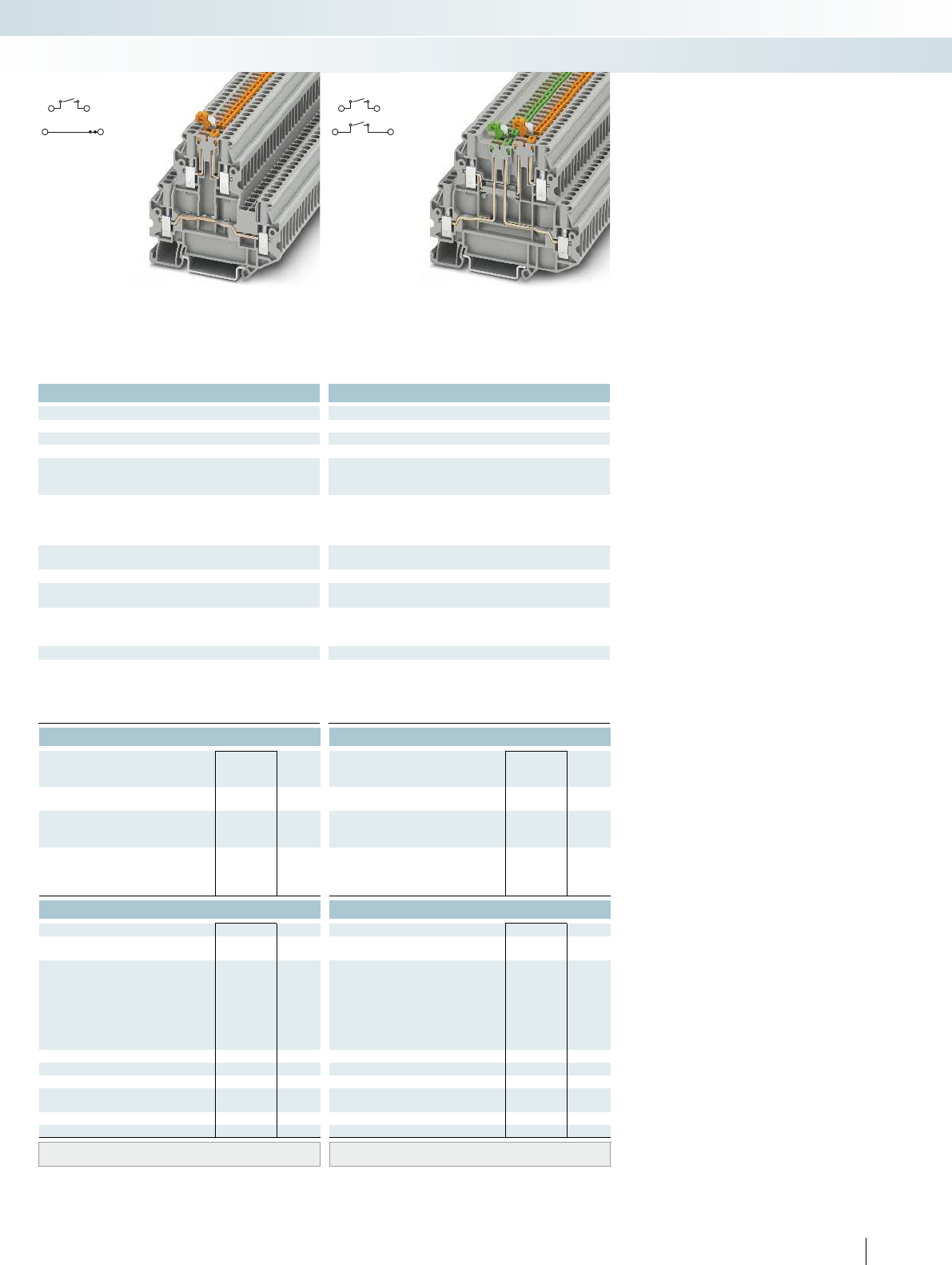
For additional information, visit phoenixcontact.net/products
Technical data Technical data
Width Length Height NS 35/7,5 Width Length Height NS 35/7,5
5.2 69.9 64.8 5.2 69.9 64.8 5.2 80.1 58.1
Imax. [A] Umax. [V] max. Ø [mm²] AWG Imax. [A] Umax. [V] max. Ø [mm²] AWG
20 400 0.14 - 4 26 - 12 20 400 0.14 - 4 26 - 12 16 400 0.14 - 4 26 - 12
IEC 60947-7-1 IEC 60947-7-1
IEC UL/CUL CSA IEC/
EN60079-7
IEC UL/CUL CSA IEC/
EN60079-7
Rated voltage [V]400--- 400--- 400---
Nominal current / cross section [A] / [mm²] 20/2.5 - - - 20/2.5 - - - 16/2.5 - - -
Rated cross section [mm²]2.5--- 2.5--- 2.5---
Cross section range AWG 26 - 12 - - - 26 - 12 - - - 26 - 12 - - -
IEC UL/CUL CSA IEC/
EN60079-7
IEC UL/CUL CSA IEC/
EN60079-7
)/2.5 - - - 16/2.5 - - - 16/2.5 - - -
solid stranded Ferrule solid stranded Ferrule
with/without plastic sleeve with/without plastic sleeve
1 conductor [mm²] 0.14 - 4 0.14 - 4 0.14 - 2.5 0.14 - 2.5 0.14 - 4 0.14 - 4 0.14 - 2.5 0.14 - 2.5 0.14 - 4 0.14 - 4 0.14 - 2.5 0.14 - 2.5
- 1.5 - 0.14 - 1.5 0.14 - 1.5 0.14 - 1.5 - 0.14 - 1.5 0.14 - 1.5 0.14 - 1.5 -
0.5 - 1.5 0.5 - 1.5
99
M3 M3
0.5 - 0.6 0.5 - 0.6
PA PA
V0 V0
Ordering data Ordering data
Type Order No. Pcs. /
Pkt. Type Order No. Pcs. /
Pkt.
UTTB 2,5-MT-P/P 3044640 50
UTTB 2,5-MT-P/P BU 3044641 50
UTT 2,5-2MT-P/P 3044670 50
UTT 2,5-2MT-P/P BU 3044671 50
Accessories Accessories
D-UTT 2,5/4 3044676 50 D-UTT 2,5/4 3044676 50
DP-UTT 2,5/4 3044677 50 DP-UTT 2,5/4 3044677 50
FBS 2-5 3030161 50
FBS 3-5 3030174 50
FBS 4-5 3030187 50
FBS 5-5 3030190 50
FBS 10-5 3030213 10
FBS 20-5 3030226 10
S-MT 3247954 50 S-MT 3247954 50
SZG 0,6X3,5 VDE 1205121 10 SZG 0,6X3,5 VDE 1205121 10
UC-TM 5, UCT-TM 5 or ZB 5
(see Catalog 5)
UC-TM 5, UCT-TM 5 or ZB 5
(see Catalog 5)
165PHOENIX CONTACT
Modular terminal blocks
Modular terminal blocks - CLIPLINE complete
2.5 (4) mm², 20 A, double-level terminal block
with disconnect knife, test socket screw
2.5 (4) mm², 16 A, double-level terminal block
with a disconnect knife per level, test socket
screw
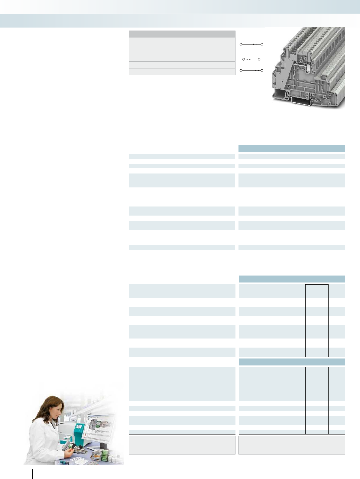
Technical data
Dimensions Width Length Height NS 35/7,5
[mm] 6.2 92.7 61.7 6.2 92.7 61.7 6.2 92.7 61.7 6.2 92.7 61.7
Max. electrical data Imax. [A] Umax. [V] max. Ø [mm²] AWG
36 500 0.14 - 6 26 - 10 36 500 0.14 - 6 26 - 10 36 500 0.14 - 6 26 - 10 36 500 0.14 - 6 26 - 10
IEC 60947-7-1
Rated data lower level IEC UL/CUL CSA IEC/
EN60079-7
Rated voltage [V]500--- 500--- 500--- 500---
Nominal current / cross section [A] / [mm²]30/4--- 30/4--- 30/4--- 30/4---
Rated cross section [mm²]4--- 4--- 4--- 4---
Cross section range AWG 26 - 10 - - - 26 - 10 - - - 26 - 10 - - - 26 - 10 - - -
Rated data, upper level IEC UL/CUL CSA IEC/
EN60079-7
Nominal current / cross section [A] / [mm²] 32/4 - - - 32/4 - - - 20
Connection capacity solid stranded Ferrule
with/without plastic sleeve
1 conductor [mm²] 0.14 - 6 0.14 - 6 0.14 - 4 0.14 - 4 0.14 - 6 0.14 -
Two conductors (of the same type) [mm²] 0.14 - 1.5 0.14 - 1.5 0.14 - 1.5 - 0.14 - 1.5 0.14 - 1.5 0.14 - 1.5 - 0.14 - 1.5 0.14 - 1.5 0.14 -
Two stranded conductors with a TWIN ferrule [mm²] 0.5 - 1.5
General data
Stripping length [mm] 9
Screw thread M3
Tightening torque [Nm] 0.6 - 0.8
Insulating material PA
Inflammability class according to UL 94 V0
Ordering data
Description No. of
pos. Color Type Imax Order No. Pcs. /
Pkt.
Feed-through terminal block, only in the upper
level, for mounting on NS35...
gray UT 4-L 3214363 50
Multi-level terminal block, upper and middle
level, for mounting on NS35...
gray UT 4-L/L 3214362 50
Multi-level terminal block, 2x feed-through,
1x PE, for mounting on NS35...
gray
Multi-level terminal block, 1x feed-through,
1x blue printed feed-through, 1x PE, for mounting
on NS35...
gray
Disconnect terminal block, for mounting on
NS 35...
gray
Knife disconnect terminal block, for mounting
on NS35...
gray
Accessories
Jumper
2red FBS 2-6 28 A 3030336 50
3red FBS 3-6 28 A 3030242 50
4red FBS 4-6 28 A 3030255 50
5red FBS 5-6 28 A 3030349 50
10 red FBS 10-6 28 A 3030271 10
20 red FBS 20-6 28 A 3030365 10
Switching lock, plug-in4)white
Isolating plug1)orange
Feed-through connector1)gray
Component plug, labeled with ZBF5 or
UC-TMF52)
gray
Fuse plug, width 6.2 mm5)black
Screwdriver SZS 0,6X3,5 1205053 10
Center and side groove labeling UC-TM 6, UCT-TM 6 or ZB 6
(see Catalog 5)
Lateral groove labeling
166 PHOENIX CONTACT
Screw connection, multi-level
function and lever-type fuse terminal
blocks with UT4... PE foot
Notes:
1) Observe max. load current.
2) Observe max. load current, depending on the power dissipation
of the components. Max. 0.5 W with single arrangement.
3) Current and voltage are determined by the plug used.
4) see Catalog 3.
5) For maximum power dissipation, see Catalog 3.
– Suitable for process technology thanks to
applied for ExnA approval
– For power and signal transmission in
potentially explosive areas
– Same shape as UT4-PE/L/HESI multi-level
lever-type fuse terminal blocks on the
following page
Terminal strip service
We produce fully pre-assembled terminal
strips for fitting straight into the control
cabinet or switch system. This simplifies
installation, saves time, and cuts costs.
Modular terminal blocks
Modular terminal blocks - CLIPLINE complete
4 (6) mm², 36 A, feed-through terminal block 4 (6) mm², 36 A, multi-level terminal block,
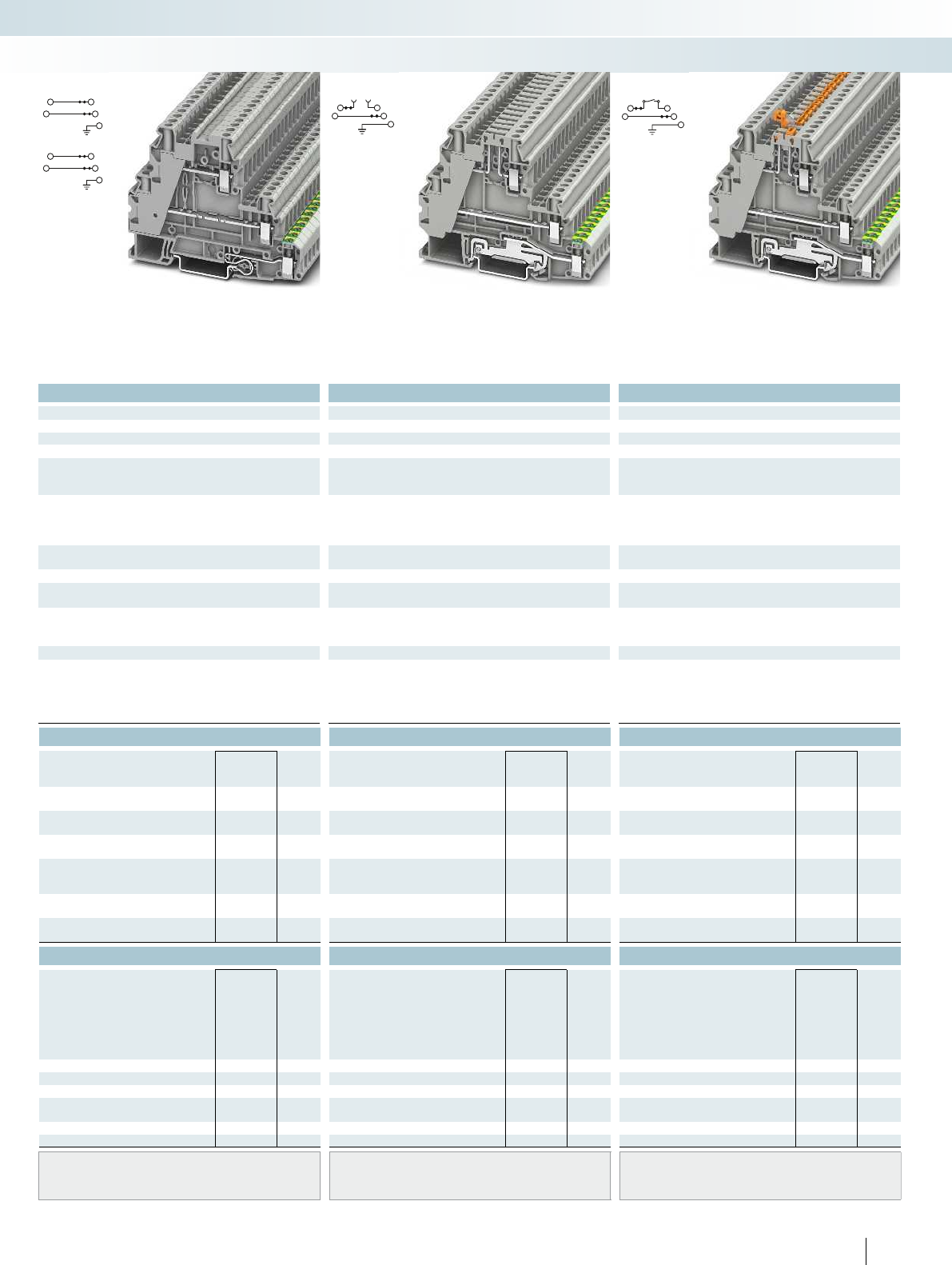
For additional information, visit phoenixcontact.net/products
Technical data Technical data Technical data
Width Length Height NS 35/7,5 Width Length Height NS 35/7,5 Width Length Height NS 35/7,5
6.2 92.7 61.7 6.2 92.7 61.7 6.2 92.7 61.7 6.2 92.7 61.7
Imax. [A] Umax. [V] max. Ø [mm²] AWG Imax. [A] Umax. [V] max. Ø [mm²] AWG Imax. [A] Umax. [V] max. Ø [mm²] AWG
36 500 0.14 - 6 26 - 10 36 500 0.14 - 6 26 - 10 36 500 0.14 - 6 26 - 10 36 500 0.14 - 6 26 - 10
IEC 60947-7-1/IEC 60947-7-2 IEC 60947-7-1/IEC 60947-7-2 IEC 60947-7-1/IEC 60947-7-2
IEC UL/CUL CSA IEC/
EN60079-7
IEC UL/CUL CSA IEC/
EN60079-7
IEC UL/CUL CSA IEC/
EN60079-7
Rated voltage [V]500--- 500--- 500--- 500---
Nominal current / cross section [A] / [mm²]30/4--- 30/4--- 30/4--- 30/4---
Rated cross section [mm²]4--- 4--- 4--- 4---
Cross section range AWG 26 - 10 - - - 26 - 10 - - - 26 - 10 - - - 26 - 10 - - -
IEC UL/CUL CSA IEC/
EN60079-7
IEC UL/CUL CSA IEC/
EN60079-7
IEC UL/CUL CSA IEC/
EN60079-7
Nominal current / cross section [A] / [mm²] 32/4 - - - 32/4 - - - 203)/2.5--- 20
3)/2.5---
solid stranded Ferrule solid stranded Ferrule solid stranded Ferrule
with/without plastic sleeve with/without plastic sleeve with/without plastic sleeve
1 conductor [mm²] 0.14 - 6 0.14 - 6 0.14 - 4 0.14 - 4 0.14 - 6 0.14 - 6 0.14 - 4 0.14 - 4 0.14 - 6 0.14 - 6 0.14 - 4 0.14 - 4 0.14 - 6 0.14 - 6 0.14 - 4 0.14 - 4
- 1.5 - 0.14 - 1.5 0.14 - 1.5 0.14 - 1.5 - 0.14 - 1.5 0.14 - 1.5 0.14 - 1.5 - 0.14 - 1.5 0.14 - 1.5 0.14 - 1.5 -
0.5 - 1.5 0.5 - 1.5 0.5 - 1.5
999
M3 M3 M3
0.6 - 0.8 0.6 - 0.8 0.6 - 0.8
PA PA PA
V0 V0 V0
Ordering data Ordering data Ordering data
Type Imax Order No. Pcs. /
Pkt. Type Imax Order No. Pcs. /
Pkt. Type Imax Order No. Pcs. /
Pkt.
UT 4-PE/L/L 3214360 50
UT 4-PE/L/N 3214361 50
UT 4-PE/L/TG 3214365 50
UT 4-PE/L/MT 3214364 50
Accessories Accessories Accessories
FBS 2-6 28 A 3030336 50 FBS 2-6 28 A 3030336 50 FBS 2-6 28 A 3030336 50
FBS 3-6 28 A 3030242 50 FBS 3-6 28 A 3030242 50 FBS 3-6 28 A 3030242 50
FBS 4-6 28 A 3030255 50 FBS 4-6 28 A 3030255 50 FBS 4-6 28 A 3030255 50
FBS 5-6 28 A 3030349 50 FBS 5-6 28 A 3030349 50 FBS 5-6 28 A 3030349 50
FBS 10-6 28 A 3030271 10 FBS 10-6 28 A 3030271 10 FBS 10-6 28 A 3030271 10
FBS 20-6 28 A 3030365 10 FBS 20-6 28 A 3030365 10 FBS 20-6 28 A 3030365 10
S-MT 3247954 50
P-DI 3036783 50
P-FIX 3038956 50
P-CO 3036796 10
P-FU 5X20 3036806 10
SZS 0,6X3,5 1205053 10 SZS 0,6X3,5 1205053 10 SZS 0,6X3,5 1205053 10
UC-TM 6, UCT-TM 6 or ZB 6
(see Catalog 5)
UC-TM 6, UCT-TM 6 or ZB 6
(see Catalog 5)
UC-TM 6, UCT-TM 6 or ZB 6
(see Catalog 5)
167PHOENIX CONTACT
Modular terminal blocks
Modular terminal blocks - CLIPLINE complete
4 (6) mm², 36 A, feed-through terminal block 4 (6) mm², 36 A, multi-level terminal block,
PE foot
4 (6) mm², 36 A, multi-level terminal block,
disconnect zone, PE foot
4 (6) mm², 36 A, multi-level terminal block,
disconnect knife, PE foot
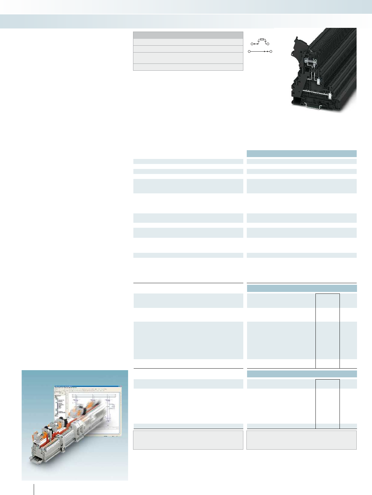
Technical data
Dimensions Width Length Height NS 35/7,5
[mm] 6.2 92.7 88.9 6.2 92.7 88.9 6.2 92.7 88.9 6.2 92.7 88.9
Max. electrical data Imax. [A] Umax. [V] max. Ø [mm²] AWG
364)500
4) 0.14 - 6 26 - 10 36
IEC 60947-7-3
Rated data lower level IEC UL/CUL CSA IEC/
EN60079-7
Rated voltage [V] 5004)--- 500
Nominal current / cross section [A] / [mm²]30/4--- 30/4--- 30/4--- 30/4---
Rated cross section [mm²]4--- 4--- 4--- 4---
Cross section range AWG 26 - 10 - - - 26 - 10 - - - 26 - 10 - - - 26 - 10 - - -
Rated data, upper level IEC UL/CUL CSA IEC/
EN60079-7
Nominal current / cross section [A] / [mm²] 6.32)/1 -/- - - 6.3
Connection capacity solid stranded Ferrule
with/without plastic sleeve
1 conductor [mm²] 0.14 - 6 0.14 - 6 0.14 - 4 0.14 - 4 0.14 - 6 0.14 -
Two conductors (of the same type) [mm²] 0.14 - 1.5 0.14 - 1.5 0.14 - 1.5 - 0.14 - 1.5 0.14 - 1.5 0.14 - 1.5 - 0.14 - 1.5 0.14 - 1.5 0.14 -
Two stranded conductors with a TWIN ferrule [mm²] 0.5 - 1.5
General data
Stripping length [mm] 9
Screw thread M3
Tightening torque [Nm] 0.6 - 0.8
Insulating material PA
Inflammability class according to UL 94 V0
Ordering data
Description No. of
pos. Color Type Imax Order No. Pcs. /
Pkt.
Fuse terminal block, for mounting on NS35..., for
cartridge fuse inserts 5 x 20 mm
black UT 4-L/HESI (5X20) 3214325 50
Fuse terminal block, for mounting on NS35..., for
5x20 cartridge fuse inserts
black
with LED for 12-30 V DC, 0.31-0.95mA1)black
for 30-60VAC/DC, 0.40-0.86mA1)black
for 110-250VAC/DC, 0.41-0.96mA1)black
Disconnect terminal block, for mounting on
NS 35...
black
Accessories
Feed-through metal, in the shape of a 5x20mm
glass tube fuse insert
DMET 5X20 3032075 50
Jumper
2redFBS 2-6 28 A 3030336 50
3redFBS 3-6 28 A 3030242 50
4redFBS 4-6 28 A 3030255 50
5redFBS 5-6 28 A 3030349 50
10 red FBS 10-6 28 A 3030271 10
20 red FBS 20-6 28 A 3030365 10
Screwdriver SZS 0,6X3,5 1205053 10
Lever labeling UC-TM 5, UCT-TM 5 or ZB 5
(see Catalog 5)
Lateral groove labeling UC-TM 6, UCT-TM 6 or ZB 6
(see Catalog 5)
168 PHOENIX CONTACT
Screw connection, multi-level lever-
type fuse terminal blocks with
UT4... PE foot
Notes:
1) If the fuse is faulty, the downstream circuit is not disconnected.
2) The current is determined by the fuse used.
3) The current is determined by the fuse used, the voltage by the
light indicator.
4) For maximum power dissipation, see Catalog 3.
– Suitable for process technology thanks to
applied for ExnA approval
– For power and signal transmission in
potentially explosive areas
– Compact design for maximum space
saving
– Two function shafts mean that all
potential distribution tasks can be
undertaken at speed
– Test connection on both sides in safety
lever
– Same shape as the UT4-PE/L... feed-
through and disconnect terminal blocks
CLIPPROJECTPlanning enables the
quick and convenient planning and
configuration of fault-free terminal strips.
Modular terminal blocks
Modular terminal blocks - CLIPLINE complete
4 (6) mm², 36 A, multi-level terminal block,
safety lever
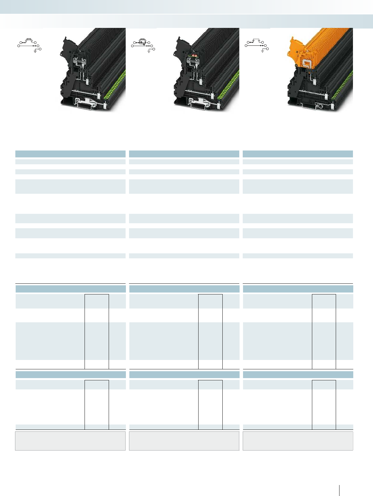
For additional information, visit phoenixcontact.net/products
Technical data Technical data Technical data
Width Length Height NS 35/7,5 Width Length Height NS 35/7,5 Width Length Height NS 35/7,5
6.2 92.7 88.9 6.2 92.7 88.9 6.2 92.7 88.9 6.2 92.7 88.9
Imax. [A] Umax. [V] max. Ø [mm²] AWG Imax. [A] Umax. [V] max. Ø [mm²] AWG Imax. [A] Umax. [V] max. Ø [mm²] AWG
) 0.14 - 6 26 - 10 364) 5004) 0.14 - 6 26 - 10 364)500
4) 0.14 - 6 26 - 10 364)500
4) 0.14 - 6 26 - 10
IEC 60947-7-2/IEC 60947-7-3 IEC 60947-7-2/IEC 60947-7-3 IEC 60947-7-1/IEC 60947-7-2
IEC UL/CUL CSA IEC/
EN60079-7
IEC UL/CUL CSA IEC/
EN60079-7
IEC UL/CUL CSA IEC/
EN60079-7
)--- 500
4)- - - 500
4)--- 500
4)---
Nominal current / cross section [A] / [mm²]30/4--- 30/4--- 30/4--- 30/4---
Rated cross section [mm²]4--- 4--- 4--- 4---
Cross section range AWG 26 - 10 - - - 26 - 10 - - - 26 - 10 - - - 26 - 10 - - -
IEC UL/CUL CSA IEC/
EN60079-7
IEC UL/CUL CSA IEC/
EN60079-7
IEC UL/CUL CSA IEC/
EN60079-7
)/1 -/- - - 6.32)/1 -/- - - 6.33)/1 -/- - - 20/1 -/- - -
solid stranded Ferrule solid stranded Ferrule solid stranded Ferrule
with/without plastic sleeve with/without plastic sleeve with/without plastic sleeve
1 conductor [mm²] 0.14 - 6 0.14 - 6 0.14 - 4 0.14 - 4 0.14 - 6 0.14 - 6 0.14 - 4 0.14 - 4 0.14 - 6 0.14 - 6 0.14 - 4 0.14 - 4 0.14 - 6 0.14 - 6 0.14 - 4 0.14 - 4
- 1.5 - 0.14 - 1.5 0.14 - 1.5 0.14 - 1.5 - 0.14 - 1.5 0.14 - 1.5 0.14 - 1.5 - 0.14 - 1.5 0.14 - 1.5 0.14 - 1.5 -
0.5 - 1.5 0.5 - 1.5 0.5 - 1.5
999
M3 M3 M3
0.6 - 0.8 0.6 - 0.8 0.6 - 0.8
PA PA PA
V0 V0 V0
Ordering data Ordering data Ordering data
Type Imax Order No. Pcs. /
Pkt. Type Imax Order No. Pcs. /
Pkt. Type Imax Order No. Pcs. /
Pkt.
UT 4-PE/L/HESI (5X20) 3214320 50
UT 4-PE/L/HESILED 24 (5X20) 3214321 50
UT 4-PE/L/HESILED 60 (5X20) 3214322 50
UT 4-PE/L/HESILED 250 (5X20) 3214323 50
UT 4-PE/L/HEDI 3214324 50
Accessories Accessories Accessories
DMET 5X20 3032075 50 DMET 5X20 3032075 50
FBS 2-6 28 A 3030336 50 FBS 2-6 28 A 3030336 50 FBS 2-6 28 A 3030336 50
FBS 3-6 28 A 3030242 50 FBS 3-6 28 A 3030242 50 FBS 3-6 28 A 3030242 50
FBS 4-6 28 A 3030255 50 FBS 4-6 28 A 3030255 50 FBS 4-6 28 A 3030255 50
FBS 5-6 28 A 3030349 50 FBS 5-6 28 A 3030349 50 FBS 5-6 28 A 3030349 50
FBS 10-6 28 A 3030271 10 FBS 10-6 28 A 3030271 10 FBS 10-6 28 A 3030271 10
FBS 20-6 28 A 3030365 10 FBS 20-6 28 A 3030365 10 FBS 20-6 28 A 3030365 10
SZS 0,6X3,5 1205053 10 SZS 0,6X3,5 1205053 10 SZS 0,6X3,5 1205053 10
UC-TM 5, UCT-TM 5 or ZB 5
(see Catalog 5)
UC-TM 5, UCT-TM 5 or ZB 5
(see Catalog 5)
UC-TM 5, UCT-TM 5 or ZB 5
(see Catalog 5)
UC-TM 6, UCT-TM 6 or ZB 6
(see Catalog 5)
UC-TM 6, UCT-TM 6 or ZB 6
(see Catalog 5)
UC-TM 6, UCT-TM 6 or ZB 6
(see Catalog 5)
169PHOENIX CONTACT
Modular terminal blocks
Modular terminal blocks - CLIPLINE complete
4 (6) mm², 36 A, multi-level terminal block,
safety lever, PE foot
4 (6) mm², 36 A, multi-level terminal block,
safety lever with LED, PE foot
4 (6) mm², 36 A, multi-level terminal block,
disconnect lever, PE foot
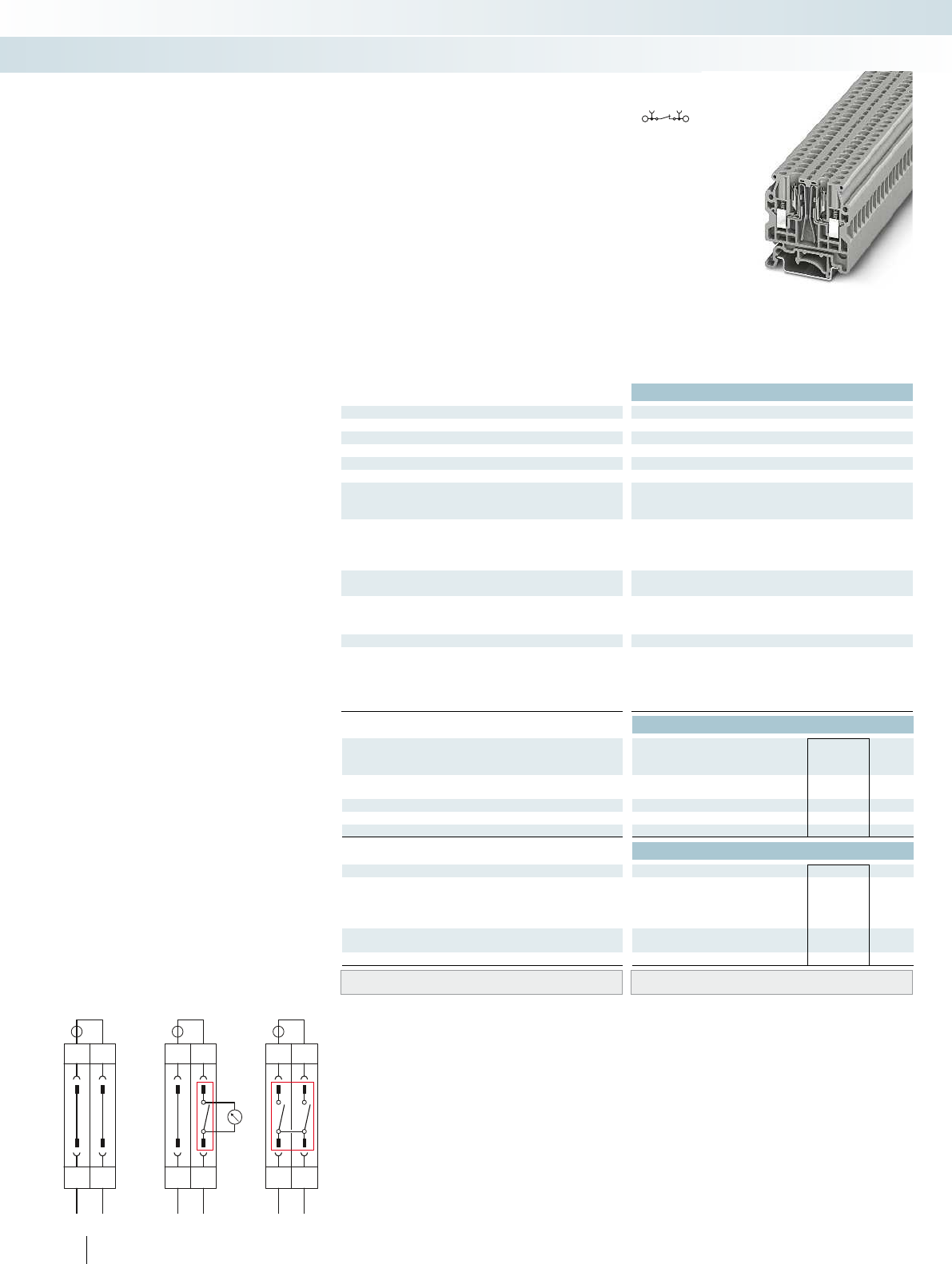
a
1
s1
2
s2
b
1
s1
2
s2
c
1
s1
2
s2
Technical data
Dimensions Width Length Height NS 35/7,5
[mm] 6.2 45.5 47.3 6.2 39.3 - 6.2 39.3 - 6.2 39.3 -
Dimensions Width Length Height NS 32
[mm] 6.2 45.5 52.2 6.2 39.3 - 6.2 39.3 - 6.2 39.3 -
Max. electrical data Imax. [A] Umax. [V] max. Ø [mm²] AWG
10 500 0.2 - 6 20 - 10 - - 8 250 0.5 - 2.5 20 - 14 8 250 0.5 - 2.5 20 - 14
IEC 60947-7-1
Rated data IEC UL/CUL CSA IEC/
EN60079-7
Rated voltage [V]500--- ---- 250--- 250---
Nominal current / cross section [A] / [mm²]10/4--- ---- 6--- 6---
Rated cross section [mm²]4--- ---- 2.5--- 2.5---
Cross section range AWG20 - 10--- ---- 20 - 14--- 20 - 14---
Connection capacity solid stranded Ferrule
with/without plastic sleeve
1 conductor [mm²] 0.5 - 6 0.2 - 4 0.5 - 4 0.5 - 4 - - - - 0.5 - 2.5 0.5
Two conductors (of the same type) [mm²]0.5 - 1.50.5 - 1.50.5 - 1.5- -- ---- ---- --
Two stranded conductors with a TWIN ferrule [mm²] 0.5 - 1.5
General data
Stripping length [mm] 9
Screw thread M3
Tightening torque [Nm] 0.5 - 0.6
Insulating material PA
Inflammability class according to UL 94 V0
Ordering data
Description No. of
pos. Color Type Imax Order No. Pcs. /
Pkt.
Test disconnect terminal block, for mounting on
NS35
gray UK 4-SD 3246861 50
Isolating plug gray
Test isolating plug green
Test isolating plug red
Accessories
Cover, width 2.2 mm gray D-UK 4-SD 3246862 50
Insertion bridge, insulated
2grayEB 2- 6 11 A 0201155 100
3grayEB 3- 6 11 A 0201142 100
10 gray EB 10- 6 11 A 0201139 10
Partition plate, 1.5mm wide gray ATP-UK 3003224 50
Screwdriver SF-SL 0,6X3,5-100 S-VDE 1212587 10
Lateral groove labeling UC-TM 6, UCT-TM 6 or ZB 6
(see Catalog 5)
170 PHOENIX CONTACT
Screw connection test disconnect
terminal block with UK4-SD test
isolating plug
This disconnect terminal block offers
numerous advantages especially for testing
in measuring and signal circuits:
– Simultaneous interruption of individual or
multiple neighboring disconnect terminal
blocks by using the PS6-DI-SD isolating
plug
– Safe, uninterruptible looping in of
measuring devices in the circuit with the
aid of the PS6CTSD test isolating plug
– Safe contacting of the potentials after
opening the disconnect point through use
of the PS6VTSD test isolating plug
– Terminal points in the test isolating plugs
allow individual test applications to be
wired.
– Easy potential distribution in the terminal
strip with insertion bridges
CLIPPROJECTPlanning enables the
quick and convenient planning and
configuration of fault-free terminal strips.
Circuit examples
a) Normal operation: no plug inserted
b) Measurement checking: looping in a
measuring device with the PS6-CT-SD test
isolating plug
c) Current transformer short circuit:
measurement split between two positions
Modular terminal blocks
Modular terminal blocks - CLIPLINE complete
4 (6) mm², test disconnect terminal block Isolating plug, disconnect function only 1.5
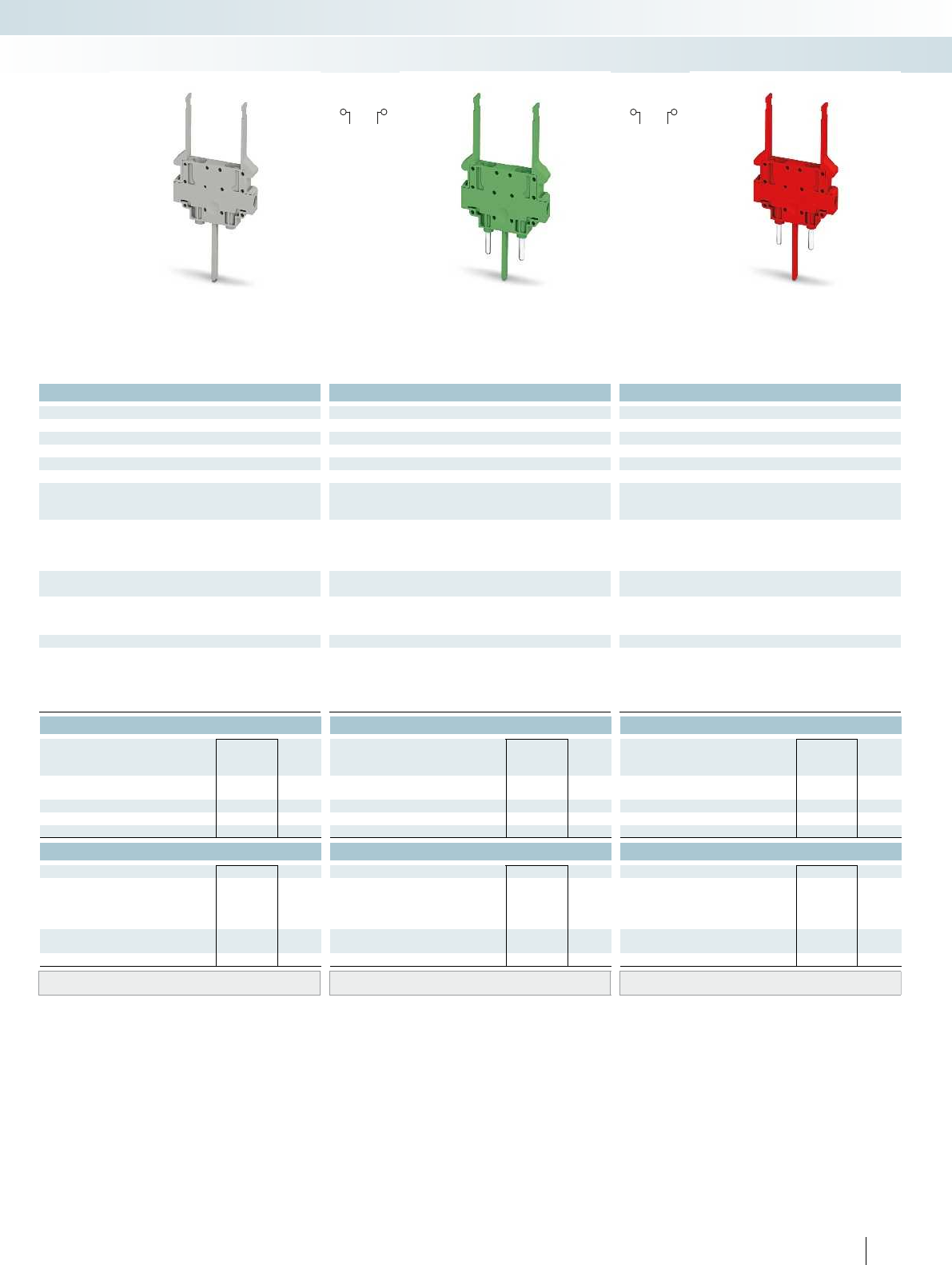
For additional information, visit phoenixcontact.net/products
Technical data Technical data Technical data
Width Length Height NS 35/7,5 Width Length Height NS 35/7,5 Width Length Height NS 35/7,5
6.2 45.5 47.3 6.2 39.3 - 6.2 39.3 - 6.2 39.3 -
Width Length Height NS 32 Width Length Height NS 32 Width Length Height NS 32
6.2 45.5 52.2 6.2 39.3 - 6.2 39.3 - 6.2 39.3 -
max. Ø [mm²] AWG Imax. [A] Umax. [V] max. Ø [mm²] AWG Imax. [A] Umax. [V] max. Ø [mm²] AWG
10 500 0.2 - 6 20 - 10 - - 8 250 0.5 - 2.5 20 - 14 8 250 0.5 - 2.5 20 - 14
IEC 60947-7-1 IEC 60947-7-1
IEC UL/CUL CSA IEC/
EN60079-7
IEC UL/CUL CSA IEC/
EN60079-7
IEC UL/CUL CSA IEC/
EN60079-7
Rated voltage [V]500--- ---- 250--- 250---
Nominal current / cross section [A] / [mm²]10/4--- ---- 6--- 6---
Rated cross section [mm²]4--- ---- 2.5--- 2.5---
Cross section range AWG20 - 10--- ---- 20 - 14--- 20 - 14---
solid stranded Ferrule solid stranded Ferrule solid stranded Ferrule
with/without plastic sleeve with/without plastic sleeve with/without plastic sleeve
1 conductor [mm²] 0.5 - 6 0.2 - 4 0.5 - 4 0.5 - 4 - - - - 0.5 - 2.5 0.5 - 2.5 0.5 - 1.5 0.5 - 1.5 0.5 - 2.5 0.5 - 2.5 0.5 - 1.5 0.5 - 1.5
Two conductors (of the same type) [mm²]0.5 - 1.50.5 - 1.50.5 - 1.5- -- ---- ---- --
-77
-M3M3
- 0.3 - 0.5 0.3 - 0.5
PA PA PA
V0 V0 V0
Ordering data Ordering data Ordering data
Type Order No. Pcs. /
Pkt. Type Order No. Pcs. /
Pkt. Type Order No. Pcs. /
Pkt.
PS 6-DI-SD 3246856 50
PS 6-CT-SD 3246857 50
PS 6-VT-SD 3246858 50
Accessories Accessories Accessories
SZF 1-0,6X3,5 1204517 10 SZF 1-0,6X3,5 1204517 10
UC-TM 6, UCT-TM 6 or ZB 6
(see Catalog 5)
UC-TM 6, UCT-TM 6 or ZB 6
(see Catalog 5)
UC-TM 6, UCT-TM 6 or ZB 6
(see Catalog 5)
171PHOENIX CONTACT
Modular terminal blocks
Modular terminal blocks - CLIPLINE complete
4 (6) mm², test disconnect terminal block Isolating plug, disconnect function only 1.5(2.5)mm² test isolating plug,
contacts before the signal isolation
1.5(2.5)mm² test isolating plug,
contacts after the signal isolation
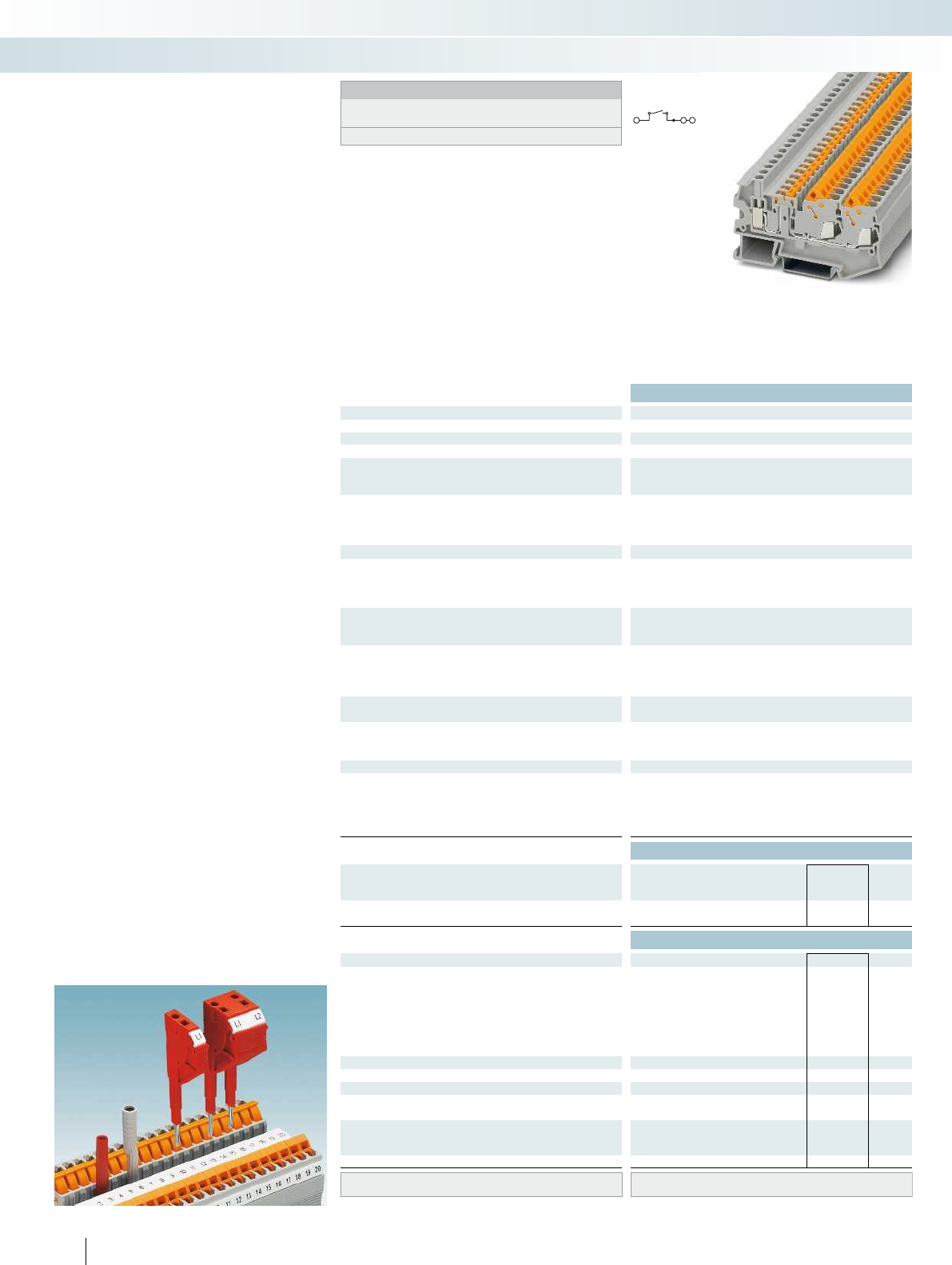
Technical data
Dimensions Width Length Height NS 35/7,5
[mm] 6.2 79.3 42.8
Max. electrical data Imax. [A] Umax. [V] max. Ø [mm²] AWG
201) 400 0.14 - 6 26 - 10
IEC 60947-7-1
Rated data, fast connection IEC UL/CUL CSA IEC/
EN60079-7
Rated voltage [V] 400 - - -
Nominal current / cross section [A] / [mm²] 20/2.5 - - -
Rated cross section [mm²] 2.5 - - -
Cross section range AWG 20 - 14 - - -
Connection cross section in acc. with DIN VDE 0295
H05V(Z) / H07V(Z) [mm²] 0.5 - 2.5
[Litz wires Ø ≥ 0.19 mm] AWG 20 - 14
Frequency of connections with the same cross section 100
IEC 60947-7-1
Rated data, screw connection IEC UL/CUL CSA IEC/
EN60079-7
Rated voltage [V] 400 - - -
Nominal current / cross section [A] / [mm²] 20/2.5 - - -
Rated cross section [mm²] 2.5 - - -
Cross section range AWG 26 - 10 - - -
Connection capacity screw connection solid stranded Ferrule
with/without plastic sleeve
1 conductor [mm²] 0.14 - 6 0.14 - 4 0.14 - 4 0.14 - 4
Two conductors (of the same type) [mm²] 0.14 - 1.5 0.14 - 1.5 0.14 - 1.5 -
Two conductors with a TWIN ferrule [mm²] 0.5 - 2.5
General data
Stripping length [mm] 9
Screw thread M3
Tightening torque [Nm] 0.6 - 0.8
Insulating material PA
Inflammability class according to UL 94 V0
Ordering data
Description No. of
pos. Color Type Imax Order No. Pcs. /
Pkt.
Terminal block, for mounting on NS 35... gray QTCU 2,5-TWIN-MT 3050304 50
blue QTCU 2,5-TWIN-MT BU 3050317 50
Accessories
Cover, width 2.2 mm gray D-QTCU 2,5-TWIN-MT 3050511 50
Jumper
2redFBS 2-6 20 A 3030336 50
3redFBS 3-6 20 A 3030242 50
4redFBS 4-6 20 A 3030255 50
5redFBS 5-6 20 A 3030349 50
10 red FBS 10-6 20 A 3030271 10
20 red FBS 20-6 20 A 3030365 10
Partition plate, 2mm width gray ATP-QTC TWIN 3206212 50
Switching lock, plug-in2)whiteS-MT 3247954 50
Test adapter, 4-mm test socket hole gray PAI-4-N GY 3032871 10
Test plug metal part, 2.3 mm Ø silver MPS-MT 0201744 10
Insulating sleeve, for MPS metal part red MPS-IH RD 0201676 10
Modular test plug, for the individual assembly of
test pin strips
red PS-6 3030996 10
Screwdriver SZF 1-0,6X3,5 1204517 10
Lateral groove labeling UC-TMF 6, UCT-TMF 6 or ZBF 6
(see Catalog 5)
172 PHOENIX CONTACT
The advantages of the different
connection methods are as follows:
– The TWIN fast connection is used inside
the control cabinet and the universal
screw connection is used on the end
customer side
– Compact design and high current carrying
capacity of 20A
– Testing facility on both sides of the
disconnect point
S-MT switching lock
– The optional switching lock snaps in and
effectively prevents accidental switching
A test plug with a 2.3mm diameter is
available for measuring lines. All
measurement and test work can be
completed at speed using test adapters for
4mm diameter test plugs and the modular
test plugs.
Fast connection
QTCU2,5TWINMT hybrid knife
disconnect terminal block
Modular terminal blocks
Modular terminal blocks - CLIPLINE complete
2.5 (2.5) mm², 20 A, knife disconnect terminal
block, three connections
Notes:
1) The max. load current must not be exceeded by the total current
of all connected conductors.
2) see Catalog 3.
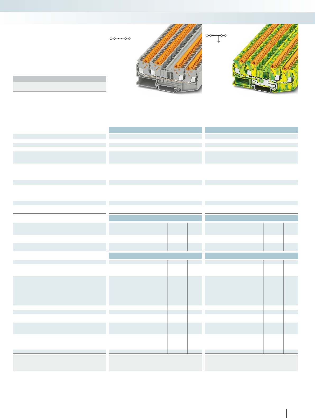
For additional information, visit phoenixcontact.net/products
Technical data Technical data
Dimensions Width Length Height NS 35/7,5 Width Length Height NS 35/7,5
[mm] 6.2 102.4 39.3 6.2 102.4 39.3
Max. electrical data Imax. [A] Umax. [V] max. Ø [mm²] AWG max. Ø [mm²] AWG
241) 800 0.5 - 2.5 20 - 14 0.5 - 2.5 20 - 14
IEC 60947-7-1 IEC 60947-7-2
Rated data IEC UL/CUL CSA IEC/
EN60079-7
IEC UL/CUL CSA IEC/
EN60079-7
Rated voltage [V]800--- ----
Nominal current / cross section [A] / [mm²]24/2.5--- ----
Rated cross section [mm²]2.5--- 2.5---
Cross section range AWG 20 - 14 - - - 20 - 14 - - -
Connection cross section in acc. with DIN VDE 0295
H05V(Z) / H07V(Z) [mm²] 0.5 - 2.5 0.5 - 2.5
[Litz wires Ø ≥ 0.19 mm] AWG 20 - 14 20 - 14
Frequency of connections with the same cross section 100 100
General data
Insulating material PA PA
Inflammability class according to UL 94 V0 V0
Ordering data Ordering data
Description No. of
pos. Color Type Imax Order No. Pcs. /
Pkt. Type Order No. Pcs. /
Pkt.
Terminal block, for mounting on NS 35... gray QTC 2,5-QUATTRO 3206446 50
gray QTC 2,5-QUATTRO BU 3206447 50
Ground terminal block, for mounting on NS35... green-yellow QTC 2,5-QUATTRO-PE 3206448 50
Accessories Accessories
Cover, width 2.2 mm gray D-QTC 2,5-QUATTRO 3206449 50 D-QTC 2,5-QUATTRO 3206449 50
End cover segment, for covering multi-conductor
terminal blocks when two-conductor terminal
blocks are aligned
gray DS-QTC 2,5 3206607 50 DS-QTC 2,5 3206607 50
Jumper
2red FBS 2-6 24 A 3030336 50 FBS 2-6 3030336 50
3red FBS 3-6 24 A 3030242 50 FBS 3-6 3030242 50
4red FBS 4-6 24 A 3030255 50 FBS 4-6 3030255 50
5red FBS 5-6 24 A 3030349 50 FBS 5-6 3030349 50
10 red FBS 10-6 24 A 3030271 10 FBS 10-6 3030271 10
20 red FBS 20-6 24 A 3030365 10 FBS 20-6 3030365 10
Partition plate, 2mm width gray ATP-QTC QUATTRO 3206225 50 ATP-QTC QUATTRO 3206225 50
Test adapter, 4-mm test socket hole gray PAI-4-N GY 3032871 10 PAI-4-N GY 3032871 10
Test plug metal part, 2.3 mm Ø silver MPS-MT 0201744 10 MPS-MT 0201744 10
Insulating sleeve, for MPS metal part red MPS-IH RD 0201676 10 MPS-IH RD 0201676 10
Modular test plug, for the individual assembly of
test pin strips
red PS-6 3030996 10 PS-6 3030996 10
Double marker carrier, can be snapped into all
terminal blocks with a width of 5.2mm or above
and a zack marker strip center groove, can be
marked with ZB5 or ZBF5
gray STP 5-2-ZB 3037643 100 STP 5-2-ZB 3037643 100
Screwdriver SZF 1-0,6X3,5 1204517 10 SZF 1-0,6X3,5 1204517 10
Center groove labeling UC-TM 6, UCT-TM 6 or ZB 6
(see Catalog 5)
UC-TM 6, UCT-TM 6 or ZB 6
(see Catalog 5)
Center and side groove labeling UC-TMF 6, UCT-TMF 6 or ZBF 6
(see Catalog 5)
UC-TMF 6, UCT-TMF 6 or ZBF 6
(see Catalog 5)
173PHOENIX CONTACT
Modular terminal blocks
Modular terminal blocks - CLIPLINE complete
2.5 (2.5) mm², 24 A, feed-through terminal
block, four connections
2.5 (2.5) mm², ground terminal block,
four connections
– The fastest conductor connection for
signal and low-spectrum power wiring
– Large packing density with a maximum
conductor cross section of 2.5mm
–Compact design
Notes:
1) The max. load current must not be exceeded by the total current
of all connected conductors.
QTC2,5-QUATTRO... fast connection
feed-through and ground terminal
blocks
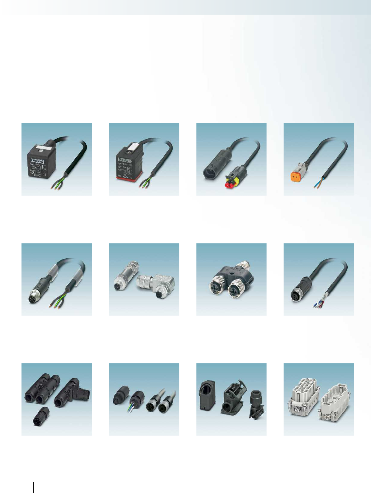
Valve connector
with energy-reducing function
Page 177
M12 power cable
Page 184
M12 connector
with crimp connection
Page 185
M12 Y-distributor
for power connectors
Page 186
M12 assembled cables,
for outdoor applications
Page 187
H and T-distributors, 6.0 mm²
Cable connectors, 6.0 mm²
Page 188
Panel feed-throughs, 2.5 mm² and 6.0 mm²
Assembled cables, 2.5 mm²
Page 191
HEAVYCON EVO housing
Type D15 and D25
Page 196
HEAVYCON contact inserts
Type B, BB series and HS series
Page 198
Valve connector
superseal connector
Page 181
Valve connector
Deutsch connector
Page 182
Sensor/actuator cabling and industrial connectors
174 PHOENIX CONTACT
Valve connector
for outdoor applications
Page 180
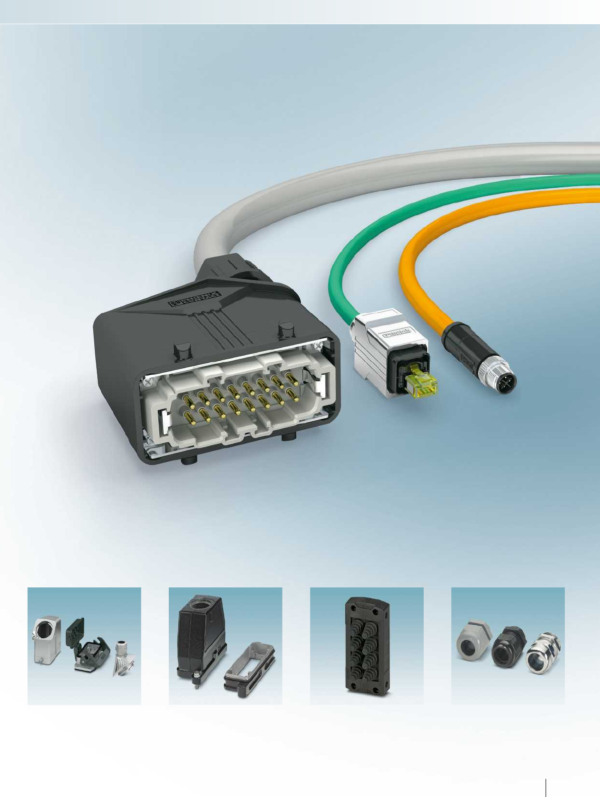
For additional information, visit phoenixcontact.net/products
HEAVYCON EVO housing
Type B, for EMC applications
Page 202
HEAVYCON HPR housing
Type B, for railway applications
Page 214
CES cable entry system
Sealing frames with cone-shaped
cable sleeves
Page 222
Plastic, brass, EMC, and
Ex cable glands
Page 224
Sensor/actuator cabling and industrial connectors
175PHOENIX CONTACT
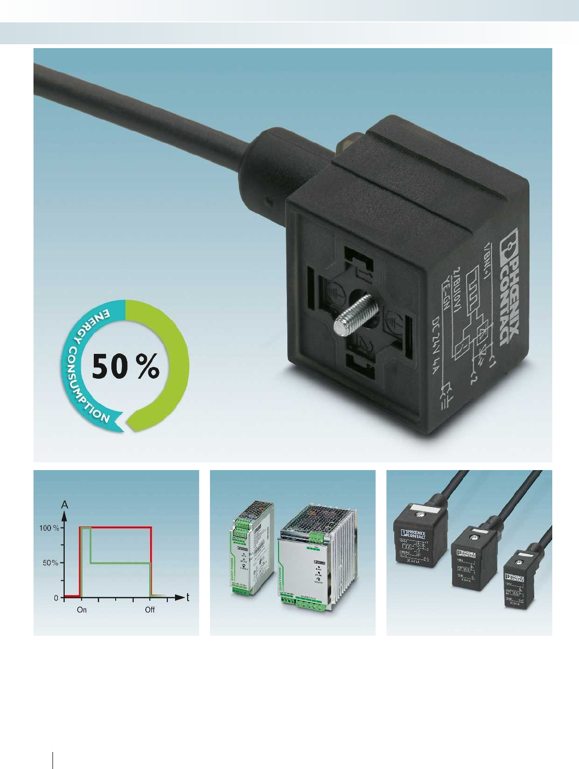
176 PHOENIX CONTACT
Sensor/actuator cabling and industrial connectors
Sensor/actuator cabling - assembled cables
Save energy
The new valve connectors with energy-
reducing function are characterized by up to
50%reduced current consumption
compared to conventional versions.
Save costs
After controlling the valve, the holding
current is reduced to 50% by the energy-
reducing function. This means that power
supply units with smaller dimensions can be
used.
Compatible with the standard
The functionality and compatibility of
valve connectors corresponds to the
familiar standard. Integration in existing
systems can be easily accomplished.
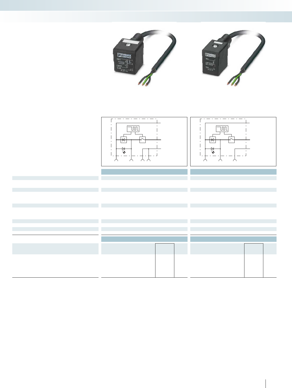
12
PE
BK 1
BK 2
GNYE (PE)
12
PE
BK 1
BK 2
GNYE (PE)
For additional information, visit phoenixcontact.net/products
Technical data Technical data
General data
Valve connector according to: EN 175301-803 EN 175301-803
Degree of protection IP67 IP67
Electrical data
Rated voltage 24 V DC 24 V DC
Rated current 4 A 1 A
Contact resistance ≤ 5 mΩ≤ 5 mΩ
Material data
Material contact valve connector CuSn CuSn
Material contact surface valve connector Ag Ag
Material housing valve connector TPU TPU
Mechanical data
No. of pos. 3 3
Temperature data
Valve connectors [°C] -25 ... 80 -25 ... 80
Ordering data Ordering data
Description Cable length Type Order No. Pcs. /
Pkt. Type Order No. Pcs. /
Pkt.
Assembled cable, with valve connector,
and free conductor end
1.5 m SAC-3P- 1,5-PUR/A-1L-R-ES 4A 1400827 1SAC-3P- 1,5-PUR/B-1L-R-ES 1401294 1
3 m SAC-3P- 3,0-PUR/A-1L-R-ES 4A 1401131 1SAC-3P- 3,0-PUR/B-1L-R-ES 1401295 1
5 m SAC-3P- 5,0-PUR/A-1L-R-ES 4A 1401136 1SAC-3P- 5,0-PUR/B-1L-R-ES 1401338 1
10 m SAC-3P-10,0-PUR/A-1L-R-ES 4A 1401168 1SAC-3P-10,0-PUR/B-1L-R-ES 1401339 1
177PHOENIX CONTACT
– Energy-reducing function by means of
holding current limiting device
Valve connector
with energy-reducing function
Sensor/actuator cabling and industrial connectors
Sensor/actuator cabling - assembled cables
Valve connector with freewheeling diode,
type A, 3-pos.
Valve connector with freewheeling diode,
type B, 3-pos.
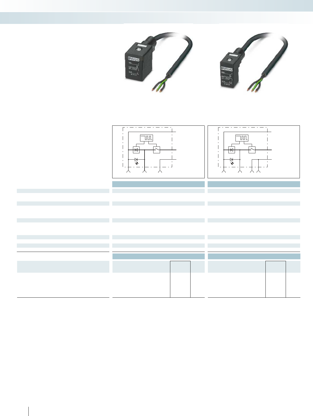
12
PE
BK 1
BK 2
GNYE (PE)
12
PE
BK 1
BK 2
GNYE (PE)
Technical data Technical data
General data
Valve connector according to: - EN 175301-803
Degree of protection IP67 IP67
Electrical data
Rated voltage 24 V DC 24 V DC
Rated current 1 A 1 A
Contact resistance ≤ 5 mΩ≤ 5 mΩ
Material data
Material contact valve connector CuSn CuSn
Material contact surface valve connector Ag Ag
Material housing valve connector TPU TPU
Mechanical data
No. of pos. 3 3
Temperature data
Valve connectors [°C] -25 ... 80 -25 ... 80
Ordering data Ordering data
Description Cable length Type Order No. Pcs. /
Pkt. Type Order No. Pcs. /
Pkt.
Assembled cable, with valve connector,
and free conductor end
1.5 m SAC-3P- 1,5-PUR/BI-1L-R-ES 1401340 1SAC-3P- 1,5-PUR/C-1L-R-ES 1401434 1
3 m SAC-3P- 3,0-PUR/BI-1L-R-ES 1401350 1SAC-3P- 3,0-PUR/C-1L-R-ES 1401435 1
5 m SAC-3P- 5,0-PUR/BI-1L-R-ES 1401358 1SAC-3P- 5,0-PUR/C-1L-R-ES 1401448 1
10 m SAC-3P-10,0-PUR/BI-1L-R-ES 1401359 1SAC-3P-10,0-PUR/C-1L-R-ES 1401465 1
178 PHOENIX CONTACT
– Energy-reducing function by means of
holding current limiting device
Valve connector
with energy-reducing function
Sensor/actuator cabling and industrial connectors
Sensor/actuator cabling - assembled cables
Valve connector with freewheeling diode,
type BI, 3-pos.
Valve connector with freewheeling diode,
type C, 3-pos.
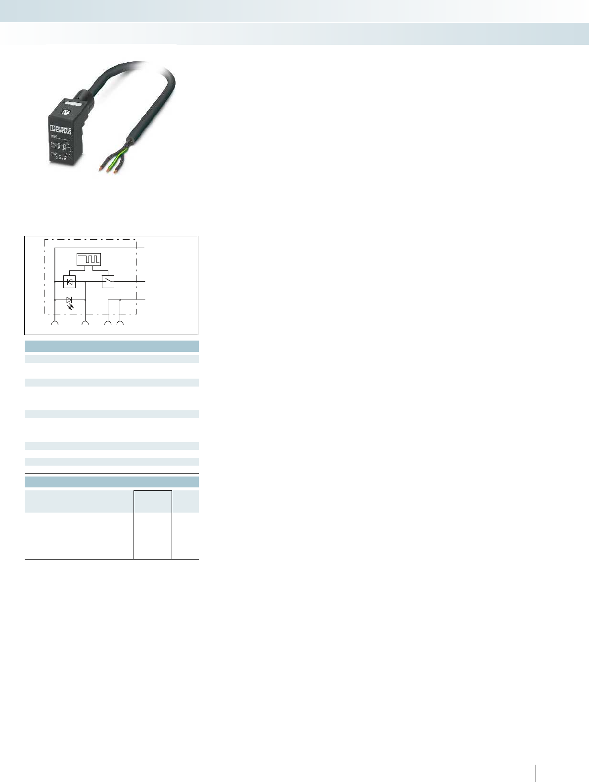
12
PE
BK 1
BK 2
GNYE (PE)
For additional information, visit phoenixcontact.net/products
Technical data
-
IP67
24 V DC
1 A
≤ 5 mΩ
CuSn
Ag
TPU
3
-25 ... 80
Ordering data
Type Order No. Pcs. /
Pkt.
SAC-3P- 1,5-PUR/CI-1L-R-ES 1401466 1
SAC-3P- 3,0-PUR/CI-1L-R-ES 1401542 1
SAC-3P- 5,0-PUR/CI-1L-R-ES 1401544 1
SAC-3P-10,0-PUR/CI-1L-R-ES 1401617 1
179PHOENIX CONTACT
Sensor/actuator cabling and industrial connectors
Sensor/actuator cabling - assembled cables
Valve connector with freewheeling diode,
type CI, 3-pos.
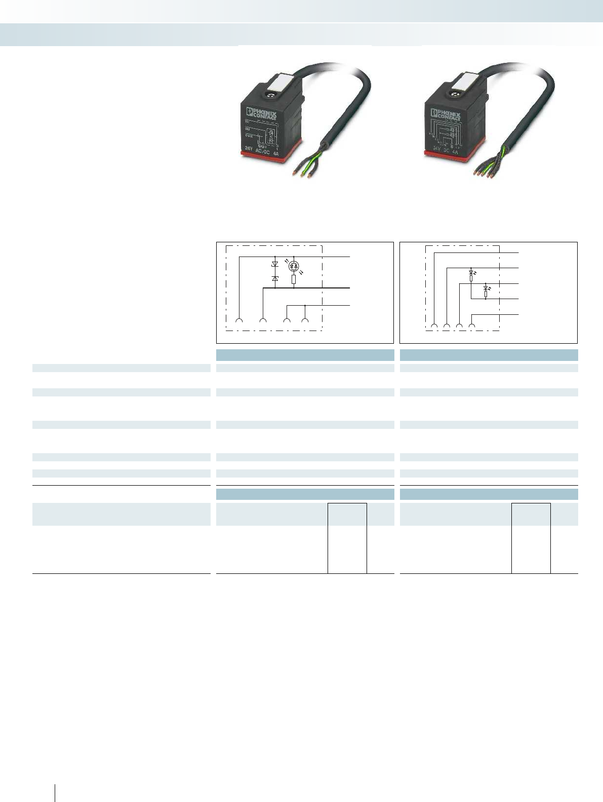
21PE
BK 2
BK 1
YE
GNYE (PE)
123PE
GNYE (PE)
BK 4
BK 3
BK 2
BK 1
RD
GN
Technical data Technical data
General data
Valve connector according to: EN 175301-803 EN 175301-803
Degree of protection IP65/IP66K/IP67/IP68 IP65/IP66K/IP67/IP68
Electrical data
Rated voltage 24 V 24 V
Rated current 4 A 4 A
Contact resistance ≤ 5 mΩ≤ 5 mΩ
Material data
Material contact valve connector CuSn CuSn
Material contact surface valve connector Sn Sn
Material housing valve connector TPU TPU
Mechanical data
No. of pos. 3 5
Temperature data
Valve connectors [°C] -40 ... 85 -40 ... 85
Ordering data Ordering data
Description Cable length Type Order No. Pcs. /
Pkt. Type Order No. Pcs. /
Pkt.
Assembled cable, with valve connector,
and free conductor end
1.5 m SAC-3P- 1,5-PUO/A-1L-Z OD 1407287 1SAC-5P- 1,5-PUO/AD-2L OD 1407291 1
3 m SAC-3P- 3,0-PUO/A-1L-Z OD 1407288 1SAC-5P- 3,0-PUO/AD-2L OD 1407292 1
5 m SAC-3P- 5,0-PUO/A-1L-Z OD 1407289 1SAC-5P- 5,0-PUO/AD-2L OD 1407293 1
10 m SAC-3P-10,0-PUO/A-1L-Z OD 1407290 1SAC-5P-10,0-PUO/AD-2L OD 1407294 1
180 PHOENIX CONTACT
– Stainless steel central screw
– Additional silicone seal ensures IP66K
protection
Valve connector
for outdoor applications
Sensor/actuator cabling and industrial connectors
Sensor/actuator cabling - assembled cables
Valve connector with Zener diode,
type A, 3-pos.
Valve connector with 2 LEDs,
type AD pressure switch, 5-pos.
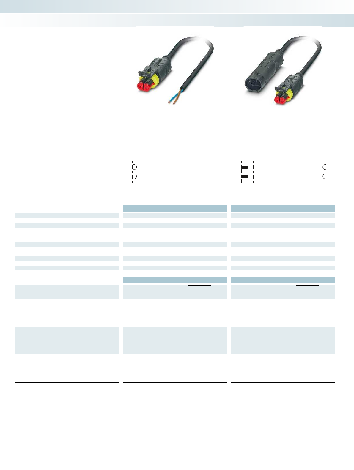
BN
1
2
BU
11
2
2
For additional information, visit phoenixcontact.net/products
Technical data Technical data
General data
Degree of protection IP67 IP67
Electrical data
Rated voltage 24 V 24 V
Rated current 8 A 8 A
Contact resistance ≤ 5 mΩ≤ 5 mΩ
Material data
Contact material PhCuSn CuZn (pin)/PhCuSn (socket)
Material of grip body PA PA
Mechanical data
No. of pos. 2 2
Temperature data
Plug/socket [°C] -20 ... 85 -20 ... 85
Ordering data Ordering data
Description Cable length Type Order No. Pcs. /
Pkt. Type Order No. Pcs. /
Pkt.
Assembled cable, with straight socket
and free cable end
1.5 m SAC-2P- 1,5-PUR/SUSFS 1410748 1
3 m SAC-2P- 3,0-PUR/SUSFS 1410749 1
5 m SAC-2P- 5,0-PUR/SUSFS 1410750 1
10 m SAC-2P-10,0-PUR/SUSFS 1410751 1
Assembled cable, with straight plug
and free cable end
1.5 m SAC-2P-SUSMS/ 1,5-PUR 1410752 1
3 m SAC-2P-SUSMS/ 3,0-PUR 1410753 1
5 m SAC-2P-SUSMS/ 5,0-PUR 1410755 1
10 m SAC-2P-SUSMS/10,0-PUR 1410756 1
Assembled cable, with straight plug
and straight socket
0.3 m SAC-2P-SUSMS/ 0,3-PUR/SUSFS 1410757 1
0.6 m SAC-2P-SUSMS/ 0,6-PUR/SUSFS 1410759 1
1.5 m SAC-2P-SUSMS/ 1,5-PUR/SUSFS 1410760 1
3 m SAC-2P-SUSMS/ 3,0-PUR/SUSFS 1410761 1
181PHOENIX CONTACT
– For mobile hydraulic applications
Valve connector,
superseal connector
Sensor/actuator cabling and industrial connectors
Sensor/actuator cabling - assembled cables
Superseal,
2-pos.
Superseal,
2-pos.
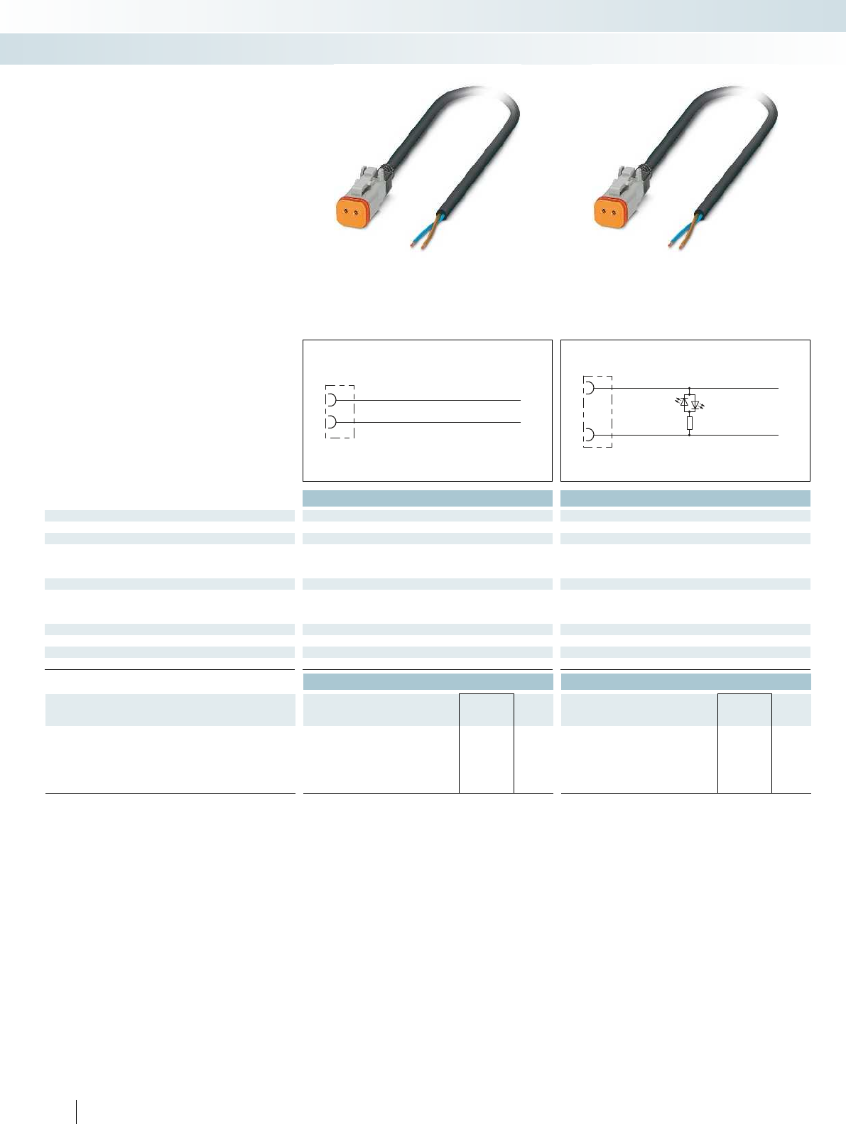
BN
1
2
BU
BN
1
2
BU
Technical data Technical data
General data
Degree of protection IP67 IP67
Electrical data
Rated voltage 48 V 24 V
Rated current 8 A 8 A
Contact resistance ≤ 8 mΩ≤ 8 mΩ
Material data
Contact material Cu alloy Cu alloy
Contact surface material Nickel-plated Nickel-plated
Material of grip body PA PA
Mechanical data
No. of pos. 2 2
Temperature data
Plug/socket [°C] -20 ... 85 -20 ... 85
Ordering data Ordering data
Description Cable length Type Order No. Pcs. /
Pkt. Type Order No. Pcs. /
Pkt.
Assembled cable, with straight socket
and free cable end
1.5 m SAC-2P- 1,5-PUR/DTFS 1410723 1SAC-2P- 1,5-PUR/DTFS-1L 1410728 1
3 m SAC-2P- 3,0-PUR/DTFS 1410724 1SAC-2P- 3,0-PUR/DTFS-1L 1410729 1
5 m SAC-2P- 5,0-PUR/DTFS 1410726 1SAC-2P- 5,0-PUR/DTFS-1L 1410730 1
10 m SAC-2P-10,0-PUR/DTFS 1410727 1SAC-2P-10,0-PUR/DTFS-1L 1410731 1
182 PHOENIX CONTACT
– For mobile hydraulic applications
Valve connector,
Deutsch DT06-2S connector
Sensor/actuator cabling and industrial connectors
Sensor/actuator cabling - assembled cables
Valve connector, Deutsch DT06-2S,
2-pos.
Valve connector, Deutsch DT06-2S,
with 1 LED, 2-pos.
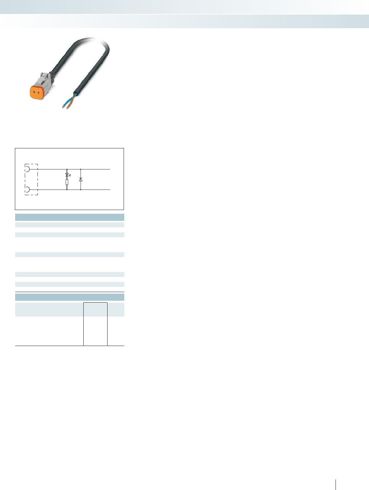
BN
1
2
BU
For additional information, visit phoenixcontact.net/products
Technical data
IP67
24 V
3 A
≤ 8 mΩ
Cu alloy
Nickel-plated
PA
2
-20 ... 85
Ordering data
Type Order No. Pcs. /
Pkt.
SAC-2P- 1,5-PUR/DTFS-1L-S 1410732 1
SAC-2P- 3,0-PUR/DTFS-1L-S 1410733 1
SAC-2P- 5,0-PUR/DTFS-1L-S 1410734 1
SAC-2P-10,0-PUR/DTFS-1L-S 1410735 1
183PHOENIX CONTACT
Sensor/actuator cabling and industrial connectors
Sensor/actuator cabling - assembled cables
Valve connector, Deutsch DT06-2S,
with suppressor diode, 2-pos.
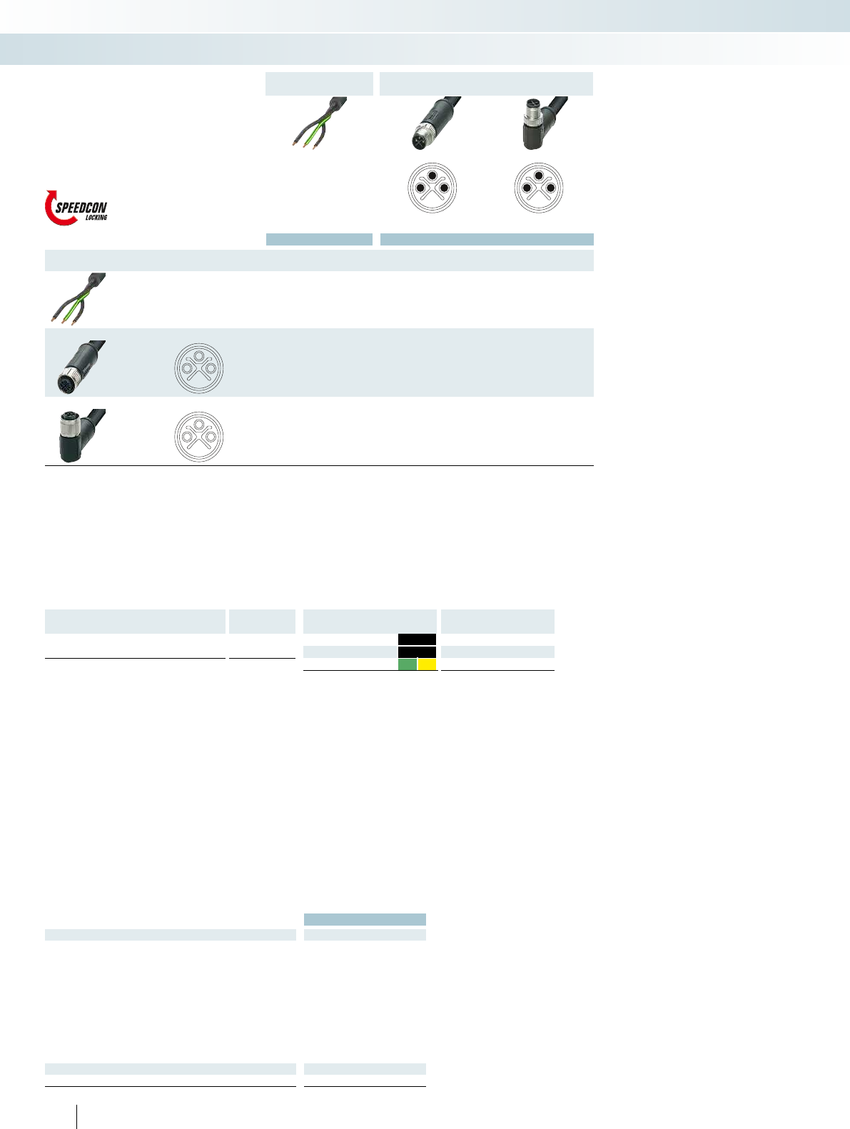
5
31
5
31
1
2
5
13
5
13
M12-SPEEDCON power cable,
2-pos.+PE, unshielded
M12 plug, SPEEDCONFree end
Ordering data Ordering data Ordering data
Free end Order No. Order No. Order No.
1 m 1411636 1 m 1411640
2 m 1411637 2 m 1411641
5 m 1411638 5 m 1411642
10 m 1411639 10 m 1411643
M12 socket, SPEEDCON, straight
1 m 1411644
2 m 1411645
5 m 1411646
10 m 1411647
M12 socket, SPEEDCON, angled
1 m 1411648
2 m 1411649
5 m 1411650
10 m 1411651
Technical data
M12
Rated voltage [V] 230
Rated current [A] 16
Contact resistance ≤ 3 mΩ
Inflammability class in acc. with UL 94 V0
Material contact M12 CuZn
Material contact surface M12 Au
Material handle M12 TPU, hardly inflammable,
self-extinguishing
Material, knurls Zinc die-cast, nickel-plated
Degree of protection IP67
Temperature data
Plug/socket [°C] -25 ... 105
184 PHOENIX CONTACT
Cable description Cable type
PVC - black PVC
Color coding Pin assignment
BK1 1
BK2 3
GNYE PE
Sensor/actuator cabling and industrial connectors
Sensor/actuator cabling - assembled cables
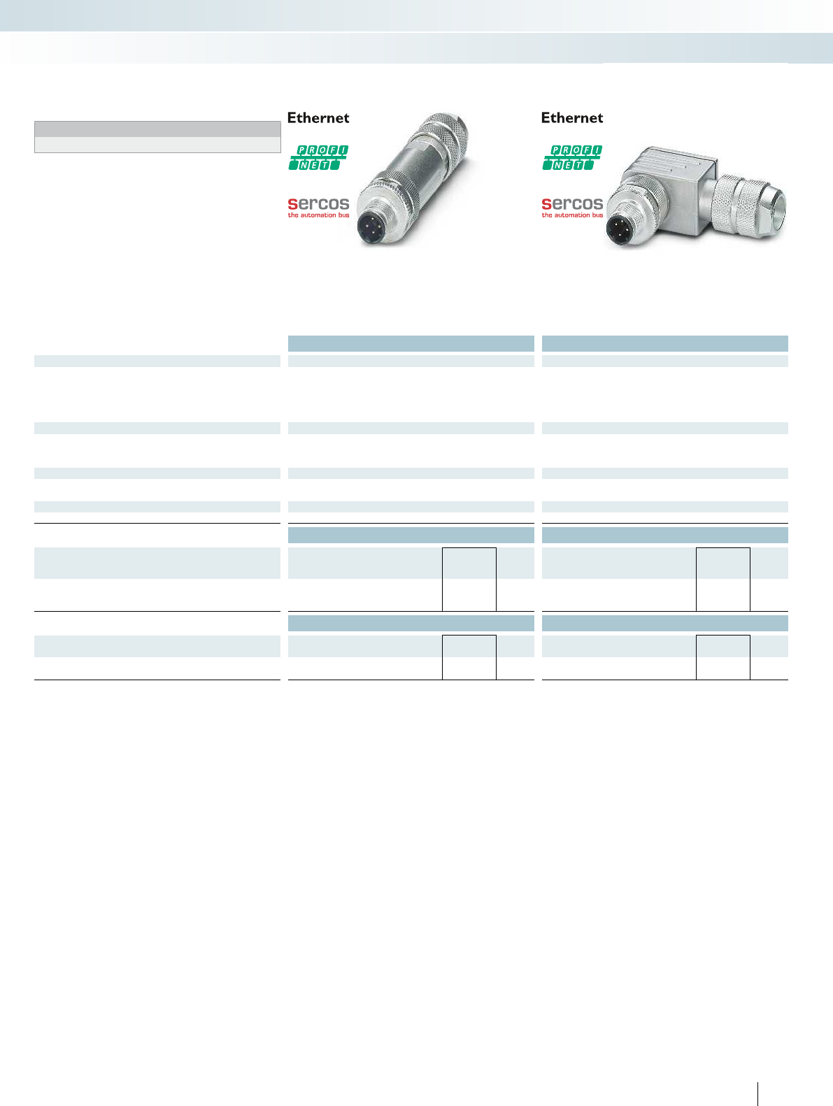
For additional information, visit phoenixcontact.net/products
Technical data Technical data
General data
M12 circular connector according to: IEC 61076-2-101 IEC 61076-2-101
Pollution degree 3 3
Degree of protection IP67 IP67
Connection method Crimp connection Crimp connection
Cable Diameter 5 mm ... 8 mm 5 mm ... 8 mm
Electrical data
Rated voltage 60 V 60 V
Rated current 4 A 4 A
Insulation resistance ≥ 10 GΩ≥ 10 GΩ
Material data
Contact carrier material PA PA
Inflammability class according to UL 94 HB HB
Temperature data
Plug/socket [°C] -25 ... 85 -25 ... 85
Ordering data Ordering data
Description Coding Type Order No. Pcs. /
Pkt. Type Order No. Pcs. /
Pkt.
Bus system plug, PROFINET, 4-pos., shielded
with Pg9 screw connection
D - data SACC-M12MSD-4CT SH PN 1411046 1SACC-M12MRD-4CT SH PN 1411047 1
Accessories Accessories
Crimp contacts, for conductor cross section:
0.34 mm² ... 0.5 mm² SACC-CC1,0-T-0,50-M AU PU100 1412351 100 SACC-CC1,0-T-0,50-M AU PU100 1412351 100
Crimping pliers
- For turned contacts; 0.14 ... 4mm² CRIMPFOX-1,6/2,5-ED-4,0 1687419 1CRIMPFOX-1,6/2,5-ED-4,0 1687419 1
185PHOENIX CONTACT
Sensor/actuator cabling and industrial connectors
Sensor/actuator cabling - connectors for assembly
M12 Plug, straight,
4-pos.
M12 Plug, angled,
4-pos.
Notes:
Order crimp contacts separately
M12 connector
with crimp connection
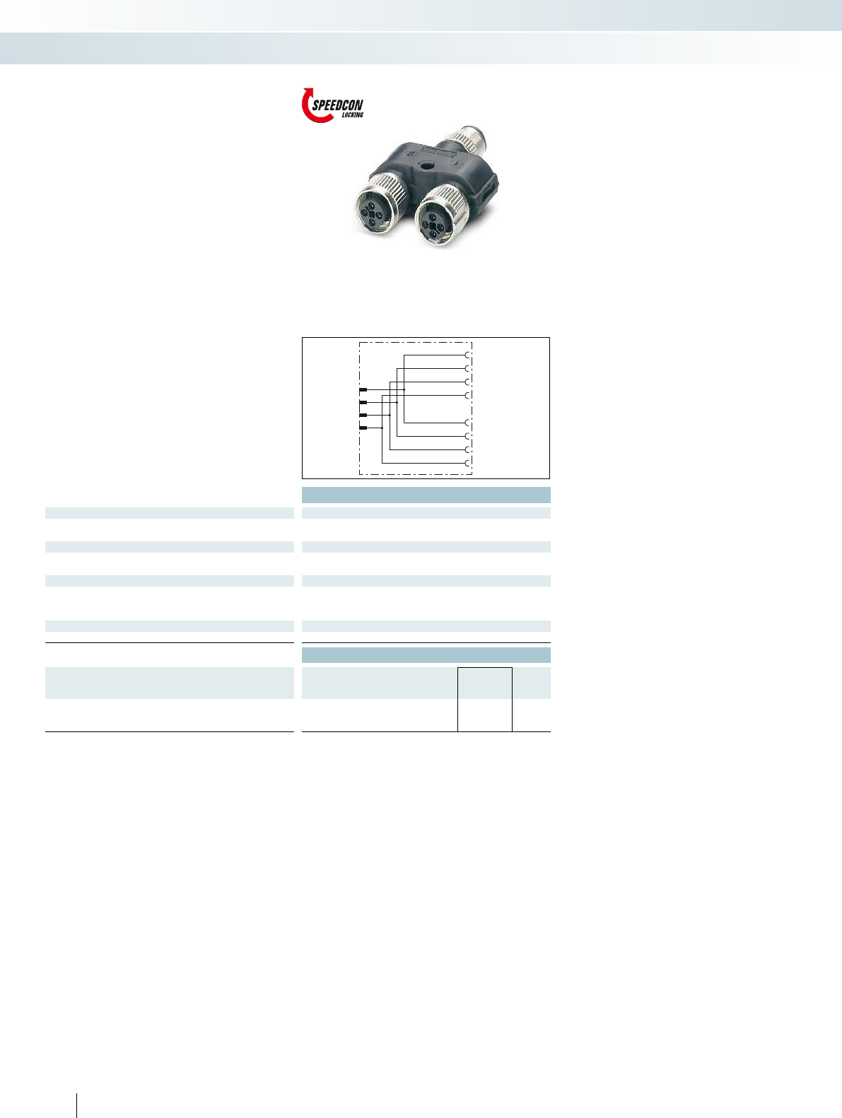
S1
S2
1
1
1
2
2
2
3
3
3
4
4
4
Technical data
General data
Pollution degree 3
Degree of protection IP65/IP67
Electrical data
Rated voltage 60 V
Rated current 12 A (at 40°C)
Material data
Contact material CuZn
Contact surface material Ni/Au
Inflammability class according to UL 94 HB
Temperature data
Plug/socket [°C] -25 ... 80
Ordering data
Description Center
distance Type Order No. Pcs. /
Pkt.
Y-distributor, M12-SPEEDCON, unshielded,
M12 plug (T-coded) to 2 x M12 socket (T-coded)
21 mm SAC-4PY-MT/2XFT VP 1410632 5
186 PHOENIX CONTACT
M12 Y-distributor
for power connectors
Sensor/actuator cabling and industrial connectors
Sensor/actuator cabling - distributors and adapters
Y-distributor, T-coded,
4-pos.
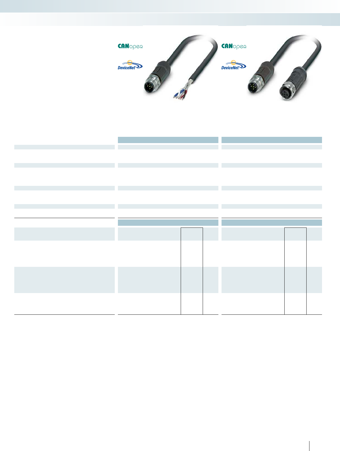
For additional information, visit phoenixcontact.net/products
Technical data Technical data
Electrical data
Rated voltage 60 V 60 V
Rated current 4 A 4 A
Contact resistance ≤ 5 mΩ≤ 5 mΩ
Material data
Contact material CuSn CuSn
Contact surface material Ni/Au Ni/Au
Contact carrier material PP PP
Inflammability class according to UL 94 V0 V0
Mechanical data
No. of pos. 5 5
Pollution degree 3 3
Degree of protection IP65/IP67/IP68/IP69K IP65/IP67/IP68/IP69K
Temperature data
Plug/socket [°C] -40 ... 105 -40 ... 105
Cable, fixed installation [°C] -40 ... 105 -40 ... 105
Ordering data Ordering data
Description Cable length Type Order No. Pcs. /
Pkt. Type Order No. Pcs. /
Pkt.
Bus system cable, 5-pos., A-coded, FRNC, halogen-free,
black, shielded, straight M12 socket to free cable ends
2 m SAC-5P- 2,0-92X/M12FS SH OD 1410474 1
5 m SAC-5P- 5,0-92X/M12FS SH OD 1410494 1
10 m SAC-5P-10,0-92X/M12FS SH OD 1410496 1
Bus system cable, 5-pos., A-coded, FRNC, halogen-free,
black, shielded, straight M12 plug to free cable ends
2 m SAC-5P-M12MS/ 2,0-92X SH OD 1410471 1
5 m SAC-5P-M12MS/ 5,0-92X SH OD 1410472 1
10 m SAC-5P-M12MS/10,0-92X SH OD 1410473 1
Bus system cable, 5-pos., A-coded, FRNC, halogen-free,
black, shielded, straight M12 plug to straight M12 socket
2 m SAC-5P-M12MS/2,0-92X/M12FSSHOD 1410467 1
5 m SAC-5P-M12MS/5,0-92X/M12FSSHOD 1410470 1
187PHOENIX CONTACT
Sensor/actuator cabling and industrial connectors
Data connectors and cables - fieldbus components
Bus system cable,
5-pos.
Bus system cable,
5-pos.
–For DeviceNet™
–For CANopen
®
M12 assembled cables
for outdoor applications
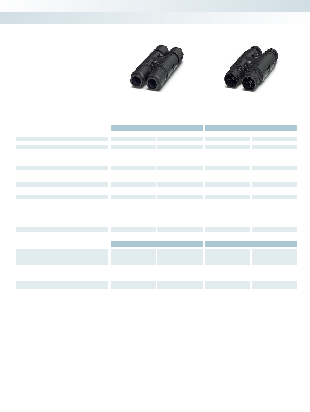
Technical data Technical data
Black Gray Black Gray
General data
Degree of protection IP68/IP69K IP68/IP69K IP68/IP69K IP68/IP69K
Electrical data
Rated voltage (III/3) 690 V 690 V 690 V 690 V
Rated surge voltage 6 kV 6 kV 6 kV 6 kV
Rated current 40 A 40 A 40 A 40 A
Surge voltage category/pollution degree III/3 III/3 III/3 III/3
Material data
Housing material PA PA PA PA
Contact material Cu Cu Cu Cu
Inflammability class according to UL 94 V0 V0 V0 V0
Mechanical data
Impact category IK07 IK07 IK07 IK07
Color Black Gray Black Gray
Connector data QUICKON connection
Core insulation PVC/PE/TPE/rubber PVC/PE/TPE/rubber PVC/PE/TPE/rubber PVC/PE/TPE/rubber
Structure of individual litz wire/ smallest wire diameter VDE 0295 class 1 to 6/
min. 0.15 mm
VDE 0295 class 1 to 6/
min. 0.15 mm
VDE 0295 class 1 to 6/
min. 0.15 mm
VDE 0295 class 1 to 6/
min. 0.15 mm
Connection frequency max. 10 max. 10 max. 10 max. 10
Conductor cross section [mm²] solid/stranded 2.5 mm² ... 6 mm²/
2.5 mm² ... 6 mm²
2.5 mm² ... 6 mm²/
2.5 mm² ... 6 mm²
2.5 mm² ... 6 mm²/
2.5 mm² ... 6 mm²
2.5 mm² ... 6 mm²/
2.5 mm² ... 6 mm²
Conductor cross section [AWG] 14 ... 10 14 ... 10 14 ... 10 14 ... 10
Temperature data
Ambient temperature (operation) -40°C ... 80°C -40°C ... 80°C -40°C ... 80°C -40°C ... 80°C
Temperature when conductor connected -5°C ... 50°C -5°C ... 50°C -5°C ... 50°C -5°C ... 50°C
Ordering data Ordering data
Description Order No. Pcs. / Pkt. Order No. Pcs. / Pkt. Order No. Pcs. / Pkt. Order No. Pcs. / Pkt.
Black Gray Black Gray
H-distributor, with four QUICKON nuts and one sealing bolt,
for cable diameters:
9mm ... 14mm 1411422 11411428 1
12 mm ... 20 mm 1411425 11411429 1
H-distributor, without QUICKON nuts
1411426 11411427 1
QUICKON nut, for connections up to 6.0mm²,
for cable diameter:
9mm ... 14mm 1410409 11410407 1
12 mm ... 20 mm 1410406 11410405 1
188 PHOENIX CONTACT
Sensor/actuator cabling and industrial connectors
Installation system - QPD installation system
With four QUICKON nuts,
4+PE-pos.
Without QUICKON nut,
4+PE-pos.
– Can be used as a H-distributor with
continuous master cable
– Can be used a star distributor
– Can be used as a Y-distributor with a
test connection
– Touch-proof in accordance with
DINEN50274
H-distributor, 6.0mm
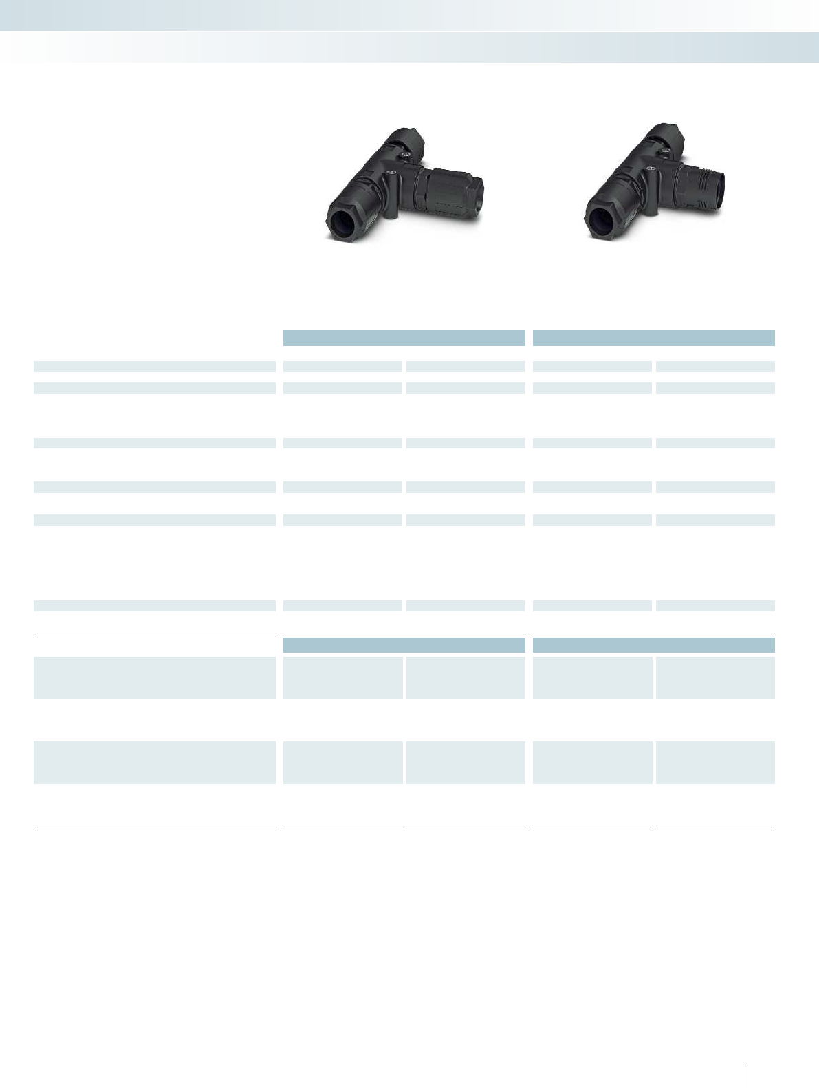
For additional information, visit phoenixcontact.net/products
Technical data Technical data
Black Gray Black Gray
General data
Degree of protection IP68/IP69K IP68/IP69K IP68/IP69K IP68/IP69K
Electrical data
Rated voltage (III/3) 690 V 690 V 690 V 690 V
Rated surge voltage 6 kV 6 kV 6 kV 6 kV
Rated current 40 A 40 A 40 A 40 A
Surge voltage category/pollution degree III/3 III/3 III/3 III/3
Material data
Housing material PA PA PA PA
Contact material Cu Cu Cu Cu
Inflammability class according to UL 94 V0 V0 V0 V0
Mechanical data
Impact category IK07 IK07 IK07 IK07
Color Black Gray Black Gray
Connector data QUICKON connection
Core insulation PVC/PE/TPE/rubber PVC/PE/TPE/rubber PVC/PE/TPE/rubber PVC/PE/TPE/rubber
Structure of individual litz wire/ smallest wire diameter VDE 0295 class 1 to 6/
min. 0.15 mm
VDE 0295 class 1 to 6/
min. 0.15 mm
VDE 0295 class 1 to 6/
min. 0.15 mm
VDE 0295 class 1 to 6/
min. 0.15 mm
Connection frequency max. 10 max. 10 max. 10 max. 10
Conductor cross section [mm²] solid/stranded 2.5 mm² ... 6 mm²/
2.5 mm² ... 6 mm²
2.5 mm² ... 6 mm²/
2.5 mm² ... 6 mm²
2.5 mm² ... 6 mm²/
2.5 mm² ... 6 mm²
2.5 mm² ... 6 mm²/
2.5 mm² ... 6 mm²
Conductor cross section [AWG] 14 ... 10 14 ... 10 14 ... 10 14 ... 10
Temperature data
Ambient temperature (operation) -40°C ... 80°C -40°C ... 80°C -40°C ... 80°C -40°C ... 80°C
Temperature when conductor connected -5°C ... 50°C -5°C ... 50°C -5°C ... 50°C -5°C ... 50°C
Ordering data Ordering data
Description Order No. Pcs. / Pkt. Order No. Pcs. / Pkt. Order No. Pcs. / Pkt. Order No. Pcs. / Pkt.
Black Gray Black Gray
T-distributor, with three QUICKON nuts,
for cable diameter:
9mm ... 14mm 1411414 11411418 1
12 mm ... 20 mm 1411415 11411419 1
T-distributor, with two QUICKON nuts,
for cable diameter:
9mm ... 14mm 1411416 11411420 1
12 mm ... 20 mm 1411417 11411421 1
QUICKON nut, for connections up to 6.0mm²,
for cable diameter:
9mm ... 14mm 1410409 11410407 1
12 mm ... 20 mm 1410406 11410405 1
189PHOENIX CONTACT
Sensor/actuator cabling and industrial connectors
Installation system - QPD installation system
With three QUICKON nuts,
4+PE-pos.
With two QUICKON nuts,
4+PE-pos.
– Can be used as a T-distributor with
continuous master cable
– Touch-proof in accordance with
DINEN50274
T-distributor, 6.0mm
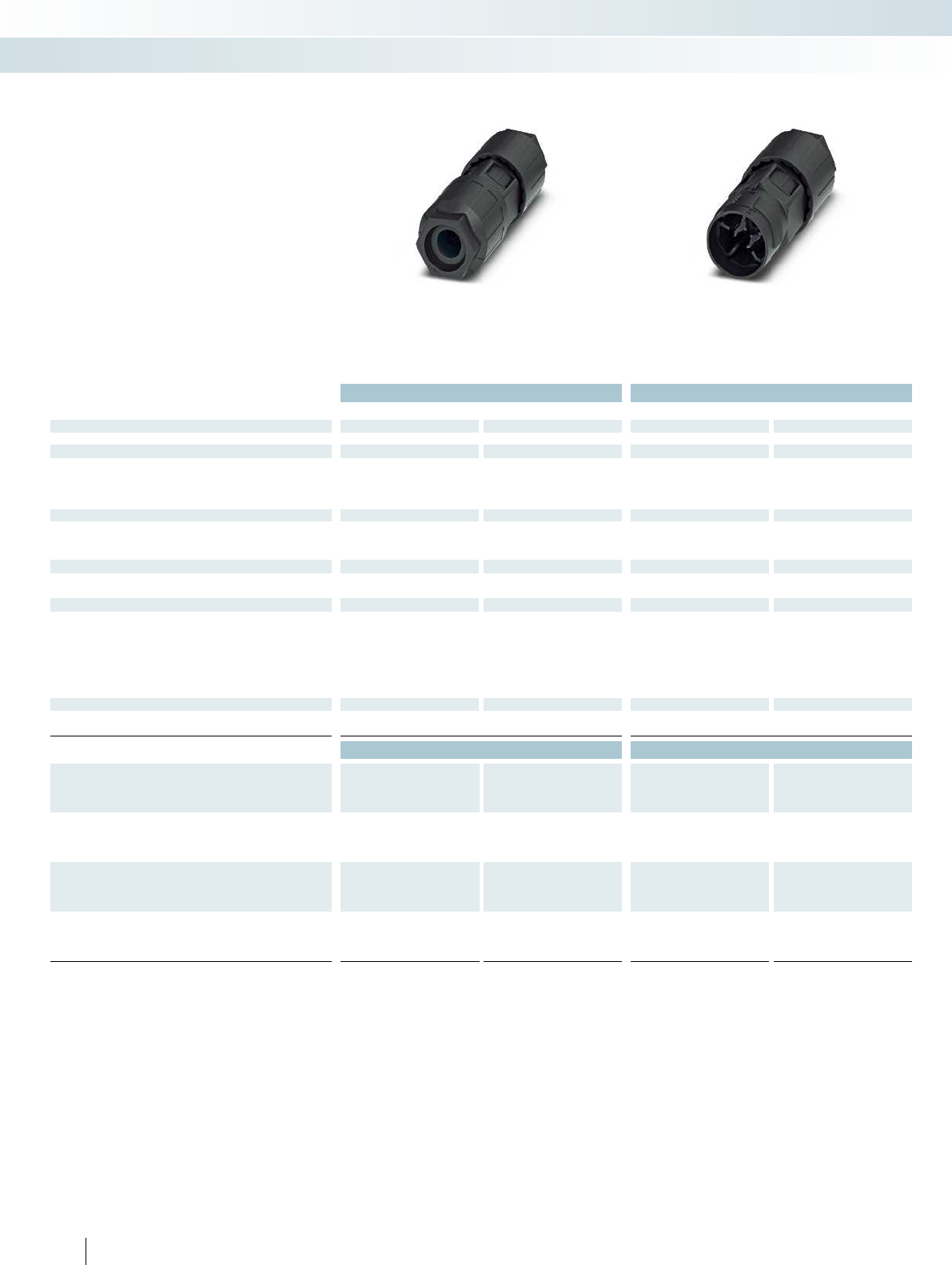
Technical data Technical data
Black Gray Black Gray
General data
Degree of protection IP68/IP69K IP68/IP69K IP68/IP69K IP68/IP69K
Electrical data
Rated voltage (III/3) 690 V 690 V 690 V 690 V
Rated surge voltage 6 kV 6 kV 6 kV 6 kV
Rated current 40 A 40 A 40 A 40 A
Surge voltage category/pollution degree III/3 III/3 III/3 III/3
Material data
Housing material PA PA PA PA
Contact material Cu Cu Cu Cu
Inflammability class according to UL 94 V0 V0 V0 V0
Mechanical data
Impact category IK07 IK07 IK07 IK07
Color Black Gray Black Gray
Connector data QUICKON connection
Core insulation PVC/PE/TPE/rubber PVC/PE/TPE/rubber PVC/PE/TPE/rubber PVC/PE/TPE/rubber
Structure of individual litz wire/ smallest wire diameter VDE 0295 class 1 to 6/
min. 0.15 mm
VDE 0295 class 1 to 6 /
min. 0.15 mm
VDE 0295 class 1 to 6/
min. 0.15 mm
VDE 0295 class 1 to 6/
min. 0.15 mm
Connection frequency max. 10 max. 10 max. 10 max. 10
Conductor cross section [mm²] solid/stranded 2.5 mm² ... 6 mm²/
2.5 mm² ... 6 mm²
2.5 mm² ... 6 mm²/
2.5 mm² ... 6 mm²
2.5 mm² ... 6 mm²/
2.5 mm² ... 6 mm²
2.5 mm² ... 6 mm²/
2.5 mm² ... 6 mm²
Conductor cross section [AWG] 10 ... 14 10 ... 14 10 ... 14 10 ... 14
Temperature data
Ambient temperature (operation) -40°C ... 80°C -40°C ... 80°C -40°C ... 80°C -40°C ... 80°C
Temperature when conductor connected -5°C ... 50°C -5°C ... 50°C -5°C ... 50°C -5°C ... 50°C
Ordering data Ordering data
Description Order No. Pcs. / Pkt. Order No. Pcs. / Pkt. Order No. Pcs. / Pkt. Order No. Pcs. / Pkt.
Black Gray Black Gray
Cable connector, with two QUICKON nuts,
for cable diameters:
9mm ... 14mm 1410410 11410413 1
12 mm ... 20 mm 1410412 11410414 1
Cable connector, with one QUICKON nut,
for cable diameters:
9mm ... 14mm 1410415 11410417 1
12 mm ... 20 mm 1410416 11410418 1
QUICKON nut, for connections up to 6.0mm²,
for cable diameter:
9mm ... 14mm 1410409 11410407 1
12 mm ... 20 mm 1410406 11410405 1
190 PHOENIX CONTACT
Sensor/actuator cabling and industrial connectors
Installation system - QPD installation system
With two QUICKON nuts,
4+PE-pos.
With one QUICKON nut,
4+PE-pos.
– The QUICKON connections at opposite
ends feature different position markings
and mechanical coding
– Touch-proof in accordance with
DINEN50274
Cable connectors, 6.0mm

For additional information, visit phoenixcontact.net/products
Technical data
Black Gray
General data
Degree of protection IP68/IP69K IP68/IP69K
Electrical data
Rated voltage (III/3) 690 V 690 V
Rated surge voltage 6 kV 6 kV
Rated current 20 A 20 A
Surge voltage category/pollution degree III/3 III/3
Material data
Housing material PA PA
Contact material Cu Cu
Inflammability class according to UL 94 V0 V0
Mechanical data
Impact category IK07 IK07
Color Black Black
Connector data QUICKON connection
Core insulation PVC/PE/Rubber/TPE PVC/PE/Rubber/TPE
Structure of individual litz wire/ smallest wire diameter VDE 0295 class 1 to 6/
min. 0.15 mm
VDE 0295 class 1 to 6/
min. 0.15 mm
Connection frequency max. 10 max. 10
Conductor cross section [mm²] solid/stranded 1 mm² ... 2.5 mm²/
1 mm² ... 2.5 mm²
1 mm² ... 2.5 mm²/
1 mm² ... 2.5 mm²
Conductor cross section [AWG] 16 ... 14 16 ... 14
Temperature data
Ambient temperature (operation) -40°C ... 80°C -40°C ... 80°C
Temperature when conductor connected -5°C ... 50°C -5°C ... 50°C
Ordering data
Description Order No. Pcs. / Pkt. Order No. Pcs. / Pkt.
Black Gray
Panel feed-through, with M25 x 1.5 mounting flange,
with QUICKON nut, for cable diameters:
6 mm ... 11 mm 1411432 11411434 1
9 mm ... 16 mm 1411433 11411435 1
191PHOENIX CONTACT
Sensor/actuator cabling and industrial connectors
Installation system - QPD installation system
With one QUICKON nut,
4+PE-pos.
– Devices no longer need to be opened in
order to connect the cables
– User-friendly connection, even on devices
that are difficult to access
– For internal push-in connection, solid
conductors are simply stripped and
inserted in the connection
– Touch-proof in accordance with
DINEN50274
Panel feed-throughs, 2.5 mm
with push-in connection
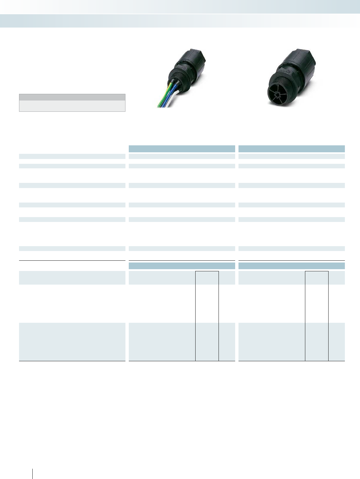
Technical data Technical data
General data
Degree of protection IP68/IP69K IP68/IP69K
Electrical data
Rated voltage 60 V 60 V
Rated surge voltage 6 kV 6 kV
Surge voltage category/pollution degree III/3 III/3
Material data
Housing material PA PA
Contact material Cu Cu
Inflammability class according to UL 94 V0 V0
Mechanical data
Impact category IK07 IK07
Color Black Black
Connector data QUICKON connection
Core insulation PVC/PE/TPE/rubber PVC/PE/TPE/rubber
Structure of individual litz wire/ smallest wire diameter VDE 0295 class 1 to 6/min. 0.15 mm VDE 0295 class 1 to 6/min. 0.15 mm
Connection frequency max. 10 max. 10
Conductor cross section [mm²] solid/stranded 1 mm² ... 2.5 mm²/1 mm² ... 2.5 mm² 1 mm² ... 2.5 mm²/1 mm² ... 2.5 mm²
Conductor cross section [AWG] 16 ... 14 16 ... 14
Temperature data
Ambient temperature (operation) -40°C ... 80°C -40°C ... 80°C
Temperature when conductor connected -5°C ... 50°C -5°C ... 50°C
Ordering data Ordering data
Description Cable length Type Order No. Pcs. /
Pkt. Type Order No. Pcs. /
Pkt.
Panel feed-through, with M20 x 1.5 mounting flange,
with QUICKON nut, for cable diameter:
6 mm ... 11 mm 0.5 m QPD W 4PE2,5 6-11 M20 0,5 EX 1411393 1
6 mm ... 11 mm 1 m QPD W 4PE2,5 6-11 M20 1,0 EX 1411394 1
6 mm ... 11 mm QPD W 4PE2,5 6-11 M20 FC EX 1411395 1
9 mm ... 16 mm 0.5 m QPD W 4PE2,5 9-16 M20 0,5 EX 1411397 1
9 mm ... 16 mm 1 m QPD W 4PE2,5 9-16 M20 1,0 EX 1411398 1
9 mm ... 16 mm QPD W 4PE2,5 9-16 M20 FC EX 1411399 1
Panel feed-through, with M25 x 1.5 mounting flange,
with QUICKON nut, for cable diameters:
6 mm ... 11 mm 0.5 m QPD W 4PE2,5 6-11 M25 0,5 EX 1411387 1
6 mm ... 11 mm 1 m QPD W 4PE2,5 6-11 M25 1,0 EX 1411388 1
6 mm ... 11 mm QPD W 4PE2,5 6-11 M25 FC EX 1411389 1
9 mm ... 16 mm 0.5 m QPD W 4PE2,5 9-16 M25 0,5 EX 1411390 1
9 mm ... 16 mm 1 m QPD W 4PE2,5 9-16 M25 1,0 EX 1411391 1
9 mm ... 16 mm QPD W 4PE2,5 9-16 M25 FC EX 1411392 1
192 PHOENIX CONTACT
Sensor/actuator cabling and industrial connectors
Installation system - QPD installation system
With litz wires,
4+PE-pos.
With manual solder/spade connection,
4+PE-pos.
– Devices no longer need to be opened in
order to connect the cables
– User-friendly connection, even on devices
that are difficult to access
– Touch-proof in accordance with
DINEN50274
Notes:
Intended for applications in intrinsically safe circuits
according to EN60079-11 and EN60079-14.
Panel feed-throughs, 2.5 mm
for intrinsically safe circuits
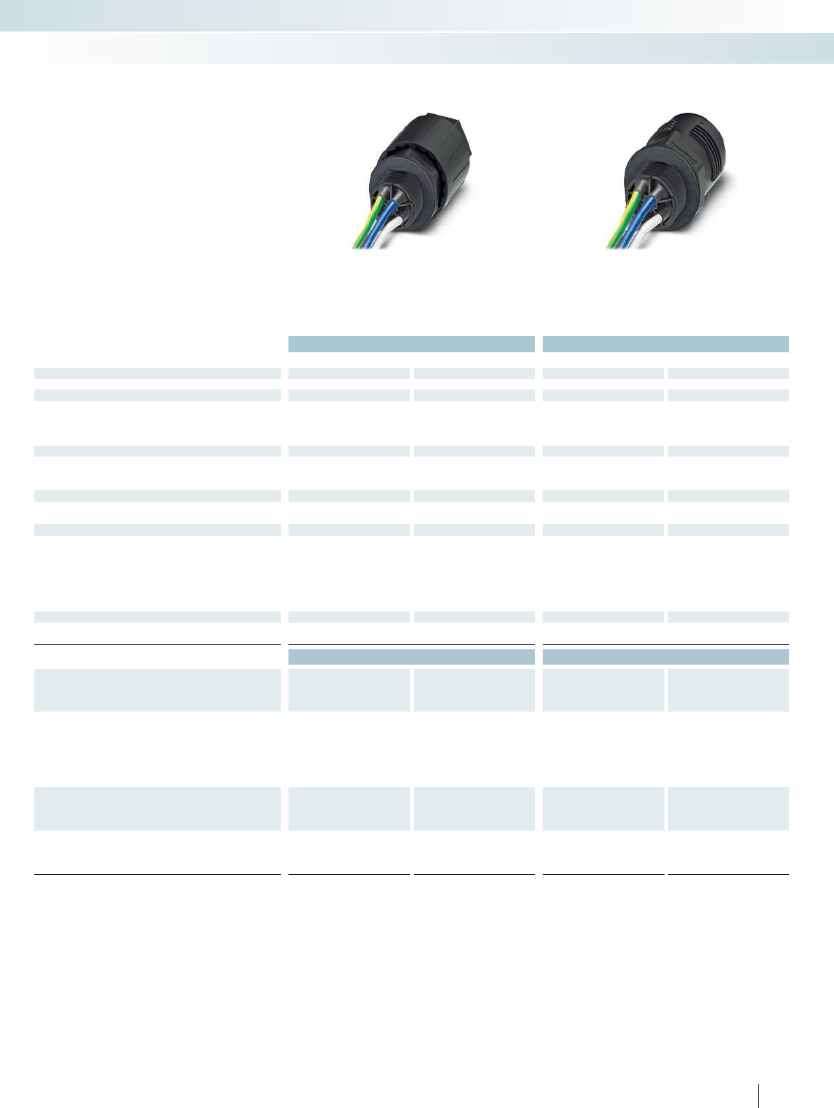
For additional information, visit phoenixcontact.net/products
Technical data Technical data
Black Gray Black Gray
General data
Degree of protection IP68/IP69K IP68/IP69K IP68/IP69K IP68/IP69K
Electrical data
Rated voltage (III/3) 690 V 690 V 690 V 690 V
Rated surge voltage 6 kV 6 kV 6 kV 6 kV
Rated current 40 A 40 A 40 A 40 A
Surge voltage category/pollution degree III/3 III/3 III/3 III/3
Material data
Housing material PA PA PA PA
Contact material Cu Cu Cu Cu
Inflammability class according to UL 94 V0 V0 V0 V0
Mechanical data
Impact category IK07 IK07 IK07 IK07
Color Black Gray Black Gray
Connector data QUICKON connection
Core insulation PVC/PE/TPE/rubber PVC/PE/TPE/rubber PVC/PE/TPE/rubber PVC/PE/TPE/rubber
Structure of individual litz wire/ smallest wire diameter VDE 0295 class 1 to 6/
min. 0.15 mm
VDE 0295 class 1 to 6/
min. 0.15 mm
VDE 0295 class 1 to 6/
min. 0.15 mm
VDE 0295 class 1 to 6/
min. 0.15 mm
Connection frequency max. 10 max. 10 max. 10 max. 10
Conductor cross section [mm²] solid/stranded 2.5 mm² ... 6 mm²/
2.5 mm² ... 6 mm²
2.5 mm² ... 6 mm²/
2.5 mm² ... 6 mm²
2.5 mm² ... 6 mm²/
2.5 mm² ... 6 mm²
2.5 mm² ... 6 mm²/
2.5 mm² ... 6 mm²
Conductor cross section [AWG] 14 ... 10 14 ... 10 14 ... 10 14 ... 10
Temperature data
Ambient temperature (operation) -40°C ... 80°C -40°C ... 80°C -40°C ... 80°C -40°C ... 80°C
Temperature when conductor connected -5°C ... 50°C -5°C ... 50°C -5°C ... 50°C -5°C ... 50°C
Ordering data Ordering data
Description Cable length Order No. Pcs. / Pkt. Order No. Pcs. / Pkt. Order No. Pcs. / Pkt. Order No. Pcs. / Pkt.
Black Gray Black Gray
Panel feed-through, with M25 x 1.5 mounting flange,
with one QUICKON nut, for cable diameter:
9mm ... 14mm 0.5 m 1410392 11410399 1
9mm ... 14mm 1 m 1410393 11410400 1
12 mm ... 20 mm 0.5 m 1410394 11410401 1
12 mm ... 20 mm 1 m 1410395 11410402 1
Panel feed-through, with M25 x 1.5 mounting flange,
without QUICKON nut
0.5 m 1410396 11410403 1
1 m 1410397 11410404 1
QUICKON nut, for connections up to 6.0mm²,
for cable diameter:
9mm ... 14mm 1410409 11410407 1
12 mm ... 20 mm 1410406 11410405 1
193PHOENIX CONTACT
Sensor/actuator cabling and industrial connectors
Installation system - QPD installation system
With one QUICKON nut,
4+PE-pos.
Without QUICKON nut,
4+PE-pos.
– Devices no longer need to be opened in
order to connect the cables
– User-friendly connection, even on devices
that are difficult to access
– Touch-proof in accordance with
DINEN50274
Panel feed-throughs, 6.0mm
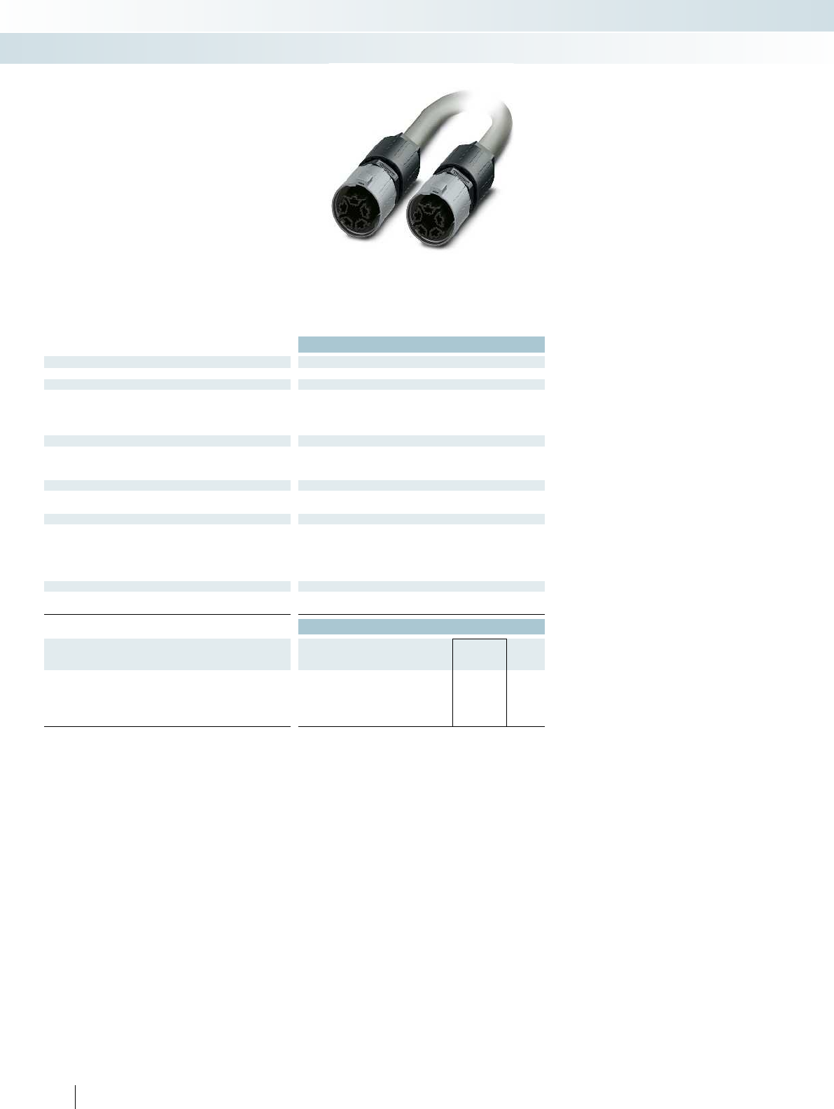
Technical data
General data
Degree of protection IP68/IP69K
Electrical data
Rated voltage (III/3) 690 V
Rated surge voltage 6 kV
Rated current 20 A
Surge voltage category/pollution degree III/3
Material data
Housing material PA
Contact material Cu
Inflammability class according to UL 94 V0
Mechanical data
Impact category IK07
Color Black
Connector data QUICKON connection
Core insulation PVC/PE/TPE/rubber
Structure of individual litz wire/ smallest wire diameter VDE 0295 class 1 to 6/min. 0.15 mm
Connection frequency max. 10
Conductor cross section [mm²] solid/stranded 1 mm² ... 2.5 mm²/1 mm² ... 2.5 mm²
Conductor cross section [AWG] 16 ... 14
Temperature data
Ambient temperature (operation) -40°C ... 80°C
Temperature when conductor connected -5°C ... 50°C
Ordering data
Description Cable length Type Order No. Pcs. /
Pkt.
Assembled cable
1 m QPD 5P/ 1,0-PVC/5P 5X2,5 BK 1408720 1
3 m QPD 5P/ 3,0-PVC/5P 5X2,5 BK 1408721 1
5 m QPD 5P/ 5,0-PVC/5P 5X2,5 BK 1408722 1
10 m QPD 5P/10,0-PVC/5P 5X2,5 BK 1408723 1
194 PHOENIX CONTACT
Sensor/actuator cabling and industrial connectors
Installation system - QPD installation system
4+PE-pos.
– Connecting cable between two
QUICKON connections
– User-friendly connection, even on devices
that are difficult to access
– Touch-proof in accordance with
DINEN50274
– Other versions available on request
Assembled cables, 2.5mm
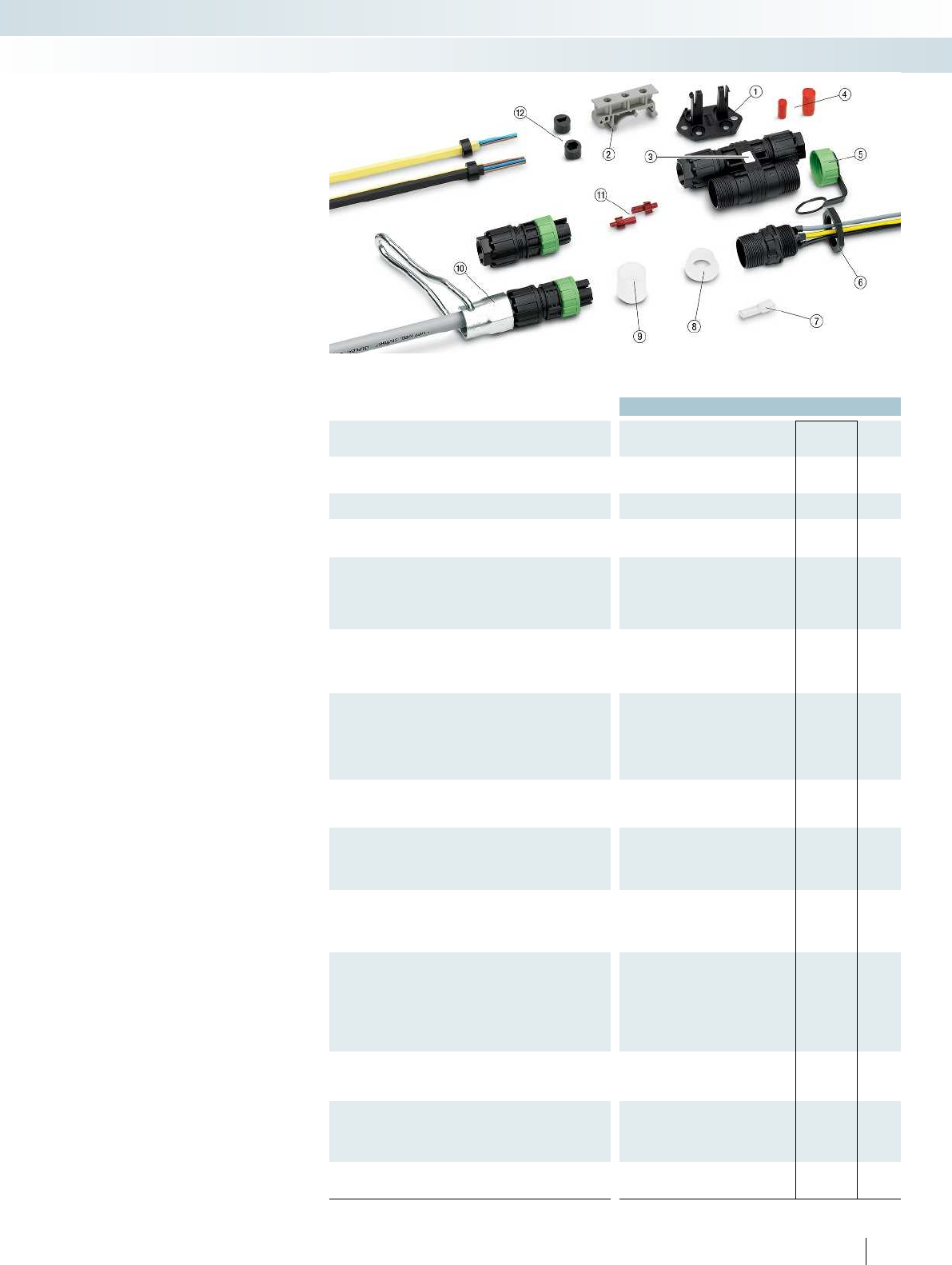
For additional information, visit phoenixcontact.net/products
Ordering data
Description Type Order No. Pcs. /
Pkt.
Mounting clip, for the 4-pos. H-distributor, color:
black
①
QPD CLIP 2,5 BK 1582235 10
DIN rail adapter ②
For M5 screws USA 10/4,6 1202713 10
Plastic label ③
For plotting and engraving GPE 13X 9 WH 0806932 10
Can be printed using thermal transfer printer EMLP (13X9)R 0819453 1
Closing cap, for closing unused bore holes in
multiple seals and cable glands
④
Ø 10 mm SEALING PLUG 10X16 RD 1400284 10
Ø 14 mm SEALING PLUG 14X22 RD 1400270 10
Protective cap, captive, IP68 ⑤
Color: green QPD QSK 2,5 FS 1582488 1
Color: black QPD QSK BK 2,5 FS 1582645 1
Color: gray QPD QSK GY 5X2,5 FS 1404526 1
Color: black QPD QSK BK 5X2,5 FS 1404525 1
Counter nut, (plastic),
to lock the contact carrier from the inside of the
device
⑥
M16 / SW22 / color: green Q-MU M16 1640692 25
M20 / SW26 / color: green Q-MU M20 1640702 25
M25 / SW32 / color: black Q-MU M25 1640715 25
Pg21 / SW36 / color: black Q-MU PG 21 BK 1582655 50
Insulating sleeve,
as shock protection for 4.8 mm slip-on sleeves;
first slide over the conductor
⑦
For 4.8mm slip-on sleeves PT/FS 4,8 1670497 25
Protective cap, transparent plastic, for QUICKON
connection, IP54
⑧
QPD QSK 2,5 1582150 10
QPD QSK 5X2,5 1404528 10
QPD QSK 5X6,0 1411403 10
Protective cap, transparent plastic, for QUICKON
connection, IP50
⑨
QPD PSK 2,5 1582151 10
QPD PSK 5X2,5 1404529 10
QPD PSK 5X6,0 1411404 10
Slotted socket wrench for QUICKON nuts and
panel feed-throughs, for wrench size:
⑩
15 mm QSS 15 1641992 1
19 mm QSS 19 1670895 1
22 mm QSS 22 1670206 1
24 mm QSS 24 1670219 1
27 mm QSS 27 1670646 1
Coding profile, for insertion into the connector
and QUICKON dome
⑪
CP-QPD 1582459 10
CP-QPD 5X2,5 1404530 10
Seal for 4-pos. versions, NBR, black, for
IP65/IP67 protection
⑫
One AS-i cable KV-DI-PG16-1XASI 1582462 10
Two AS-i cables KV-DI-PG16-2XASI 1582464 10
Shielding tape, aluminum, for the shielded QPD
versions
⑬
ALU-SB 1404531 100
195PHOENIX CONTACT
– Mounting clip ① for easily fixing the
H-distributor in place without the need
for tools
– DIN rail mounting can be achieved using
two DIN-rail adapters ②
– Plastic labels ③ can be stuck to the
middle of the H-distributor
– Red sealing plugs ④ can be easily stuck
into the QUICKON nuts and create a seal
when screwed tight
– Protective caps with retaining cords ⑤
for closing open QUICKON domes which
are going to have a connector (for
example) fitted at a later date
– Locking nuts ⑥ for fixing the panel feed-
throughs to thin panels that are unable to
accommodate a proprietary thread
–Insulating sleeve ⑦ for 4.8 mm slip-on
connections
– Transparent protective caps ⑧ for
attaching to the open QUICKON dome
– Transparent protective caps ⑨ at front
for attaching to the connector
– Slotted socket wrenches ⑩ enable you to
tighten the QUICKON nuts easily and
securely
– Red coding profiles ⑪ for preventing
QPD connector mix-ups. Simply insert
them into the QUICKON dome and
connector on the front side. They are
marked with an arrow and their
symmetrical form enables them to be
mounted in four different positions
– AS-Interface seals ⑫ for connecting 1 or
2 AS-Interface cables
– Aluminum shielding tape ⑬ prevents the
splicing of the braided shield and enables
a clean shield connection
Accessories
Sensor/actuator cabling and industrial connectors
Installation system - QPD installation system
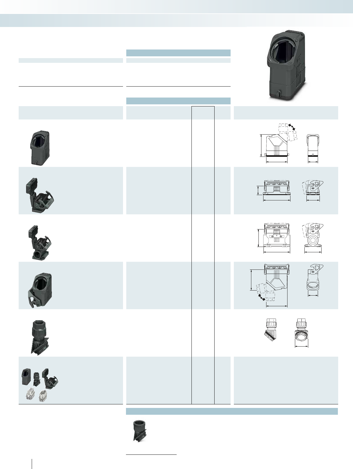
65,5
63,5 30
39
82
26
51
80
52
63,5
60
30
36
Technical data
General data
Housing material Polyamide
Locking latch material Polyamide
Sealing material NBR
Ambient temperature (operation) -40°C ... 100°C
Type of protection (when plugged in) IP66
196 PHOENIX CONTACT
Sensor/actuator cabling and industrial connectors
Heavy-duty connectors - HEAVYCON type D
EVO housing, type D15,
plastic, single locking latch
Ordering data
Description Thread Type Order No. Pcs. /
Pkt. Dimensions
Sleeve housing
Height: 65.5 mm HC-EVO-D15-HHFS-PL-BK 1411340 1
Panel mounting base
Height: 26 mm Without cover
HC-EVO-D15-BWS-PLR-BK 1411336 1
With cover
HC-EVO-D15-BWSC-PLR-BK 1411337 1
Box mounting base
Height: 52 mm Without cover
2x M25 HC-EVO-D15-SLWS-2SSM25-PLR-BK 1411341 1
With cover
2x M25
HC-EVO-D15-SLWSC-2SSM25-PLR-BK
1411343 1
Coupling housing
Height: 60 mm HC-EVO-D15-CHWS-PL-BK 1411338 1
Cable gland
1x M20 HC-D-G-M20-PLRBK 1411350 1
1x M25 HC-D-G-M25-PLRBK 1411351 1
Connector set
Without cover, screw connection
HC-EVO-A10UT-BWS-HH-M20-PLRBK 1411356 1
With cover, screw connection
HC-EVO-A10UT-BWSC-HH-M20-PLRBK
1411357 1
Accessories
Thread adapter
From page 219
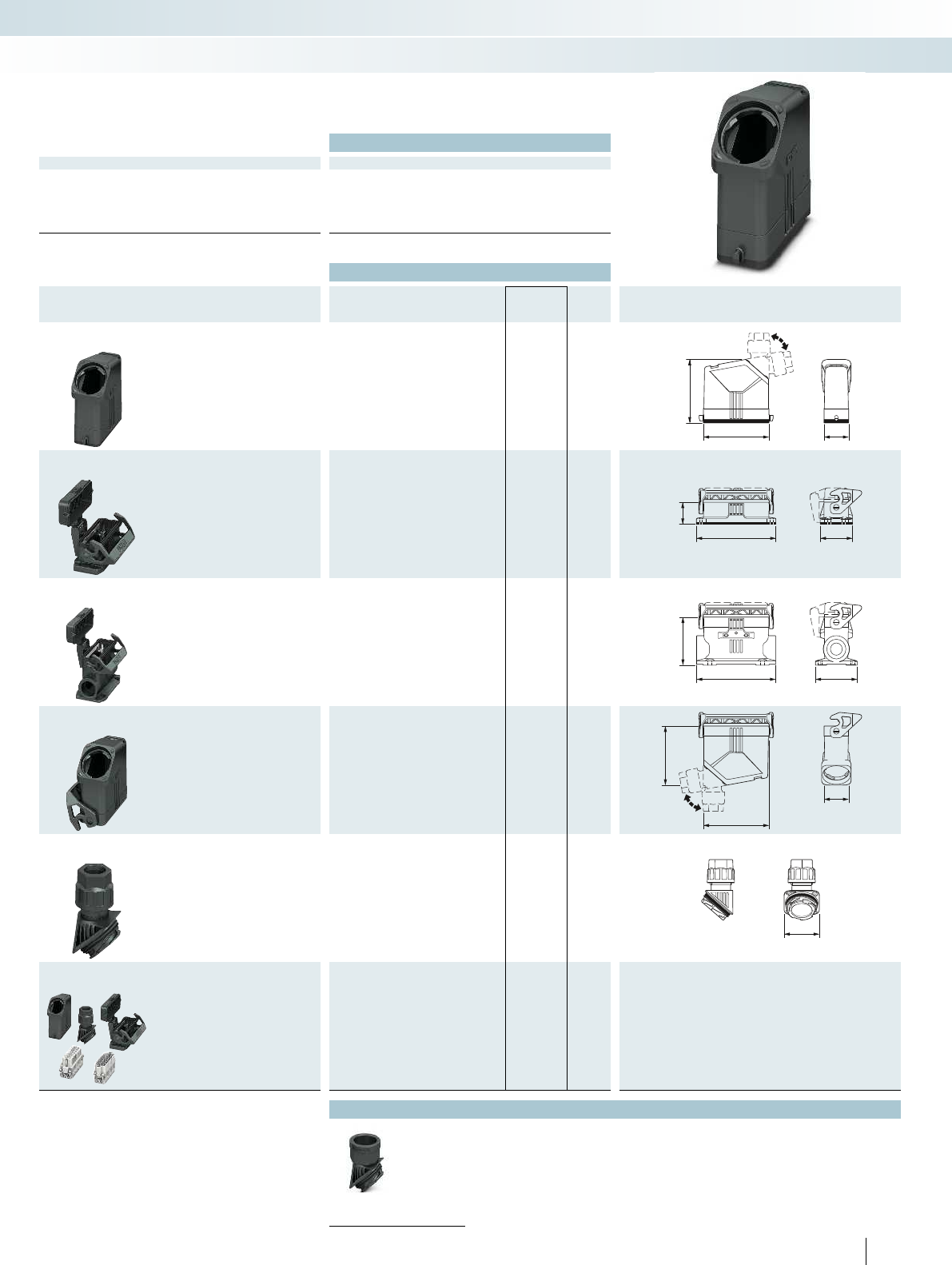
30
80
75,5
39
97
26
51
96,5
57
30
80
70
36
For additional information, visit phoenixcontact.net/products
Technical data
General data
Housing material Polyamide
Locking latch material Polyamide
Sealing material NBR
Ambient temperature (operation) -40°C ... 100°C
Type of protection (when plugged in) IP66
197PHOENIX CONTACT
Sensor/actuator cabling and industrial connectors
Heavy-duty connectors - HEAVYCON type D
EVO housing, type D25,
plastic, single locking latch
Ordering data
Description Thread Type Order No. Pcs. /
Pkt. Dimensions
Sleeve housing
Height: 75.5 mm HC-EVO-D25-HHFS-PL-BK 1411347 1
Panel mounting base
Height: 26 mm Without cover
HC-EVO-D25-BWS-PLR-BK 1411344 1
With cover
HC-EVO-D25-BWSC-PLR-BK 1411345 1
Box mounting base
Height: 57 mm Without cover
2x M25 HC-EVO-D25-SLWS-2SSM25-PLR-BK 1411348 1
With cover
2x M25
HC-EVO-D25-SLWSC-2SSM25-PLR-BK
1411349 1
Coupling housing
Height: 70 mm HC-EVO-D25-CHWS-PLR-BK 1411346 1
Cable gland
1x M20 HC-D-G-M20-PLRBK 1411350 1
1x M25 HC-D-G-M25-PLRBK 1411351 1
Connector set
Without cover, screw connection
HC-EVO-A16UT-BWS-HH-M25-PLRBK 1411358 1
With cover, screw connection
HC-EVO-A16UT-BWSC-HH-M25-PLRBK
1411359 1
Accessories
Thread adapter
From page 219
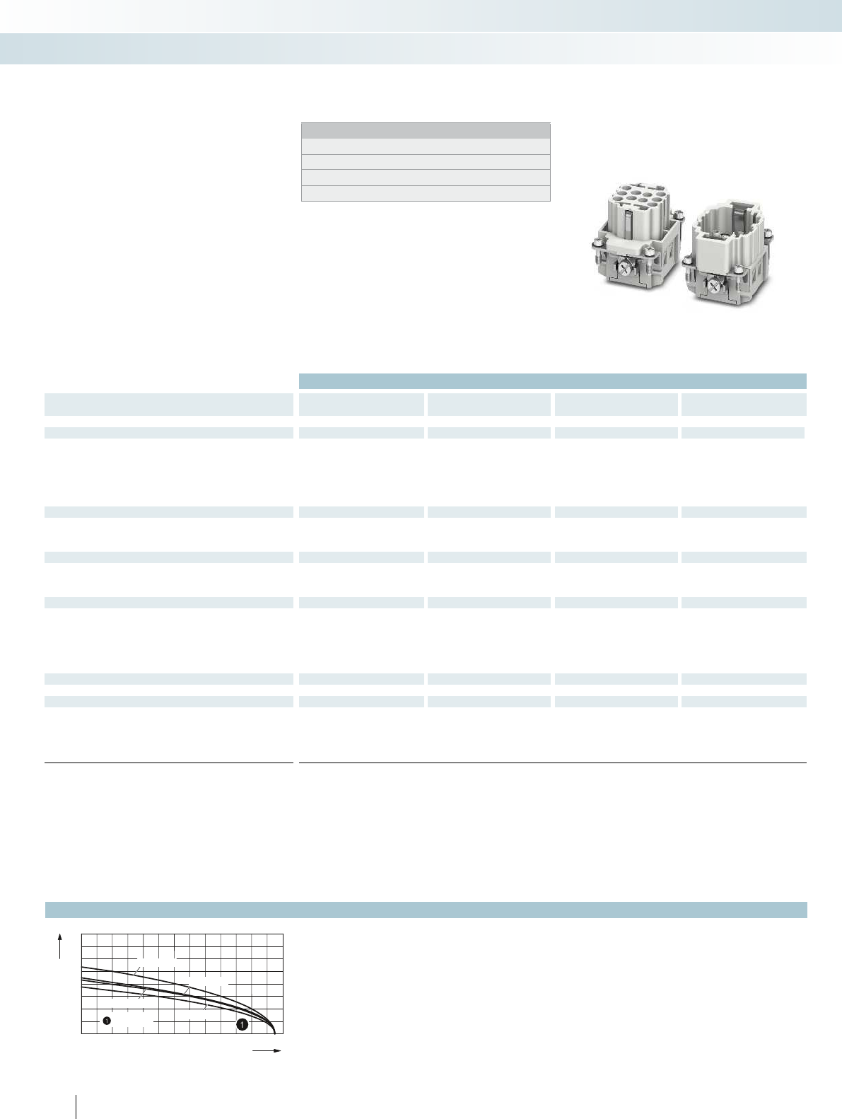
020406080100 120
0
8
16
24
32
HC-BB 10
HC-BB 18
HC-BB 46
HC-BB 32
= 2,5 mm2
198 PHOENIX CONTACT
Sensor/actuator cabling and industrial connectors
Heavy-duty connectors - HEAVYCON type B
Technical data
Type HC-BB 10-I-CT-... HC-BB 18-I-CT-... HC-BB 32-I-CT-... HC-BB 46-I-CT-...
Approvals ----
IEC data
Rated current, contacts (at 40°C) A 16 16 16 16
Surge voltage category III III III III
Pollution degree 3 3 3 3
Rated voltage (III/3) contacts V 500 500 500 500
Rated surge voltage, contacts kV 6 6 6 6
Connection cross section mm² 0.5 ... 4 0.5 ... 4 0.5 ... 4 0.5 ... 4
UL data
Rated voltage V----
Rated current A - - - -
AWG ----
CSA data
Rated voltage V----
Rated current A - - - -
AWG ----
Material data
Contact carrier material PC PC PC PC
Inflammability class in acc. with UL 94 V0 V0 V0 V0
Contact material Copper alloy Copper alloy Copper alloy Copper alloy
Contact surface material Ag (alternatively Au) Ag (alternatively Au) Ag (alternatively Au) Ag (alternatively Au)
Temperature data
Ambient temperature range °C -40 ... 125 -40 ... 125 -40 ... 125 -40 ... 125
General data
Connection method Crimp connection Crimp connection Crimp connection Crimp connection
No. of pos. 10 18 32 46
Contact numbering 1 - 10 1 - 18 1 - 32 1 - 46
Insertion/withdrawal cycles ≥ 500 ≥ 500 ≥ 500 ≥ 500
Contact inserts
BB series
500 V, 16 A
Connection technology:
–Crimp connection
With groove for accommodating coding
profiles for easy and inexpensive coding of
identical plug-in connections
– Can be coded in seconds, thanks to the
coding profile
Notes:
For accessories, see Catalog 4 from page 552
Order crimp contacts separately
Connectors may only be operated when under no load
Observe notes on the connection technology
Ambient temperature [°C]
Operating current [A]
HC-BB ...
Derating curves
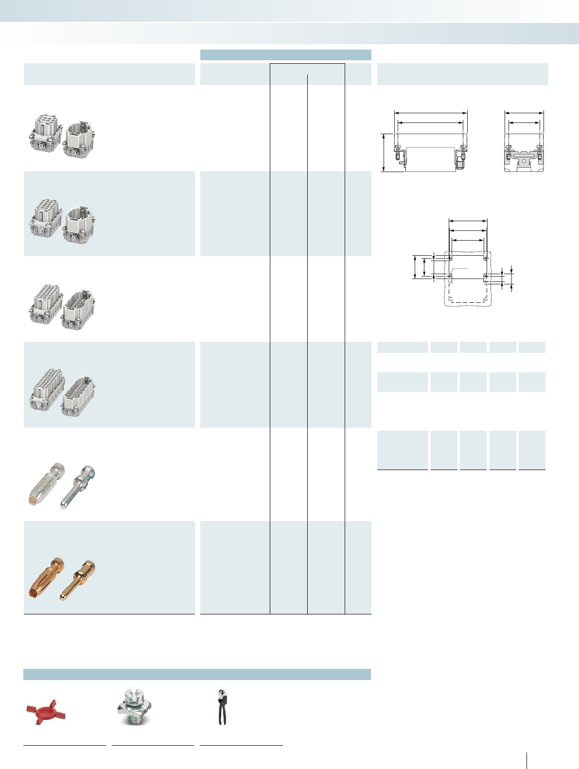
27
34
a
b
c
8
15
d+10
b
d
35
27
20
Ø3,4
For additional information, visit phoenixcontact.net/products
199PHOENIX CONTACT
Sensor/actuator cabling and industrial connectors
Heavy-duty connectors - HEAVYCON type B
Ordering data
Description Pos. Number Housing Type Order No. Pcs. /
Pkt.
Socket Plug
Crimp connection
10 1 - 10 B6 ① HC-BB 10-I-CT-... 1584703 1584774 1
Crimp connection
18 1 - 18 B10 ② HC-BB 18-I-CT-... 1584729 1584716 1
Crimp connection
32 1 - 32 B16 / B32 ③ HC-BB 32-I-CT-... 1584745 1584732 1
32 33 - 64 B16 / B32 ④
HC-BB 32-I-CT-... 33-64
1406543 1406544 1
Crimp connection
46 1 - 46 B24 / B48 ⑤ HC-BB 46-I-CT-... 1584758 1584761 1
46 47 - 92 B24 / B48 ⑥
HC-BB 46-I-CT-... 47-92
1406545 1406546 1
Turned crimp contacts CK 2,5 Cross section
Silver-plated mm² / AWG
0.5 / 20 CK2,5-ED-0,50... AG 1663640 1663572 100
0.75 / 18 CK2,5-ED-0,75... AG 1663653 1663585 100
0.75 - 1 / 18 CK2,5-ED-1,00... AG 1663666 1663598 100
1.5 / 16 CK2,5-ED-1,50... AG 1663679 1663608 100
2.5 / 14 CK2,5-ED-2,50... AG 1663682 1663611 100
4 / 12 CK2,5-ED-4,00... AG 1663705 1663637 100
Turned crimp contacts CK 2,5 Cross section
Gold-plated mm² / AWG
0.5 / 20 CK2,5-ED-0,50... AU 1674859 1674804 100
0.75 - 1 / 18 CK2,5-ED-1,00... AU 1674833 1674781 100
1.5 / 16 CK2,5-ED-1,50... AU 1674820 1674778 100
2.5 / 14 CK2,5-ED-2,50... AU 1674862 1674817 100
4 / 12 CK2,5-ED-4,00... AU 1674846 1674794 100
Accessories
Coding profiles PE screws Crimping tools
From page 221 Catalog 4 from page 580 Catalog 4 from page 562
Dimensions (in mm)
Dimensional drawing
Panel cutout
a b c d
①Socket 51 44 32.5 35
Plug 33.2
②Socket 64 57 32.5 48
Plug 33.2
③Socket 84.5 77.5 32.5 68.5
Plug 33.2
④Socket 84.5 77.5 32.5 68.5
Plug 33.2
⑤Socket 111 104 32.5 95
Plug 33.2
⑥Socket 111 104 32.5 95
Plug 33.2

020406080100 120
0
8
16
24
32
=4mm
2
=6mm
2
200 PHOENIX CONTACT
Sensor/actuator cabling and industrial connectors
Heavy-duty connectors - HEAVYCON type B
Technical data
Type HC-HS06-I-UT-... HC-HS06-I-UT-... 7-12
Approvals --
IEC data
Rated current, contacts (at 40°C) A 35 35
Surge voltage category III III
Pollution degree 3 3
Rated voltage (III/3) contacts V 400/690 400/690
Rated surge voltage, contacts kV 6 6
Connection cross section mm² 0.5 ... 6 0.5 ... 6
UL data
Rated voltage V - -
Rated current A - -
AWG --
CSA data
Rated voltage V - -
Rated current A - -
AWG --
Material data
Contact carrier material PC PC
Inflammability class in acc. with UL 94 V0 V0
Contact material Copper alloy Copper alloy
Contact surface material Ag Ag
Temperature data
Ambient temperature range °C -40 ... 125 -40 ... 125
General data
Connection method Screw connection Screw connection
No. of pos. 66
Contact numbering 1 - 6 7 - 12
Insertion/withdrawal cycles ≥ 500 ≥ 500
Contact inserts
HS series, high-current applications
500 V, 35 A
Connection technology:
–Screw connection
With groove for accommodating coding
profiles for easy and inexpensive coding of
identical plug-in connections
– Can be coded in seconds, thanks to the
coding profile
Notes:
For accessories, see Catalog 4 from page 552
Connectors may only be operated when under no load
Observe notes on the connection technology
Ambient temperature [°C]
Operating current [A]
HC-HS06-I-UT-...
Derating curves
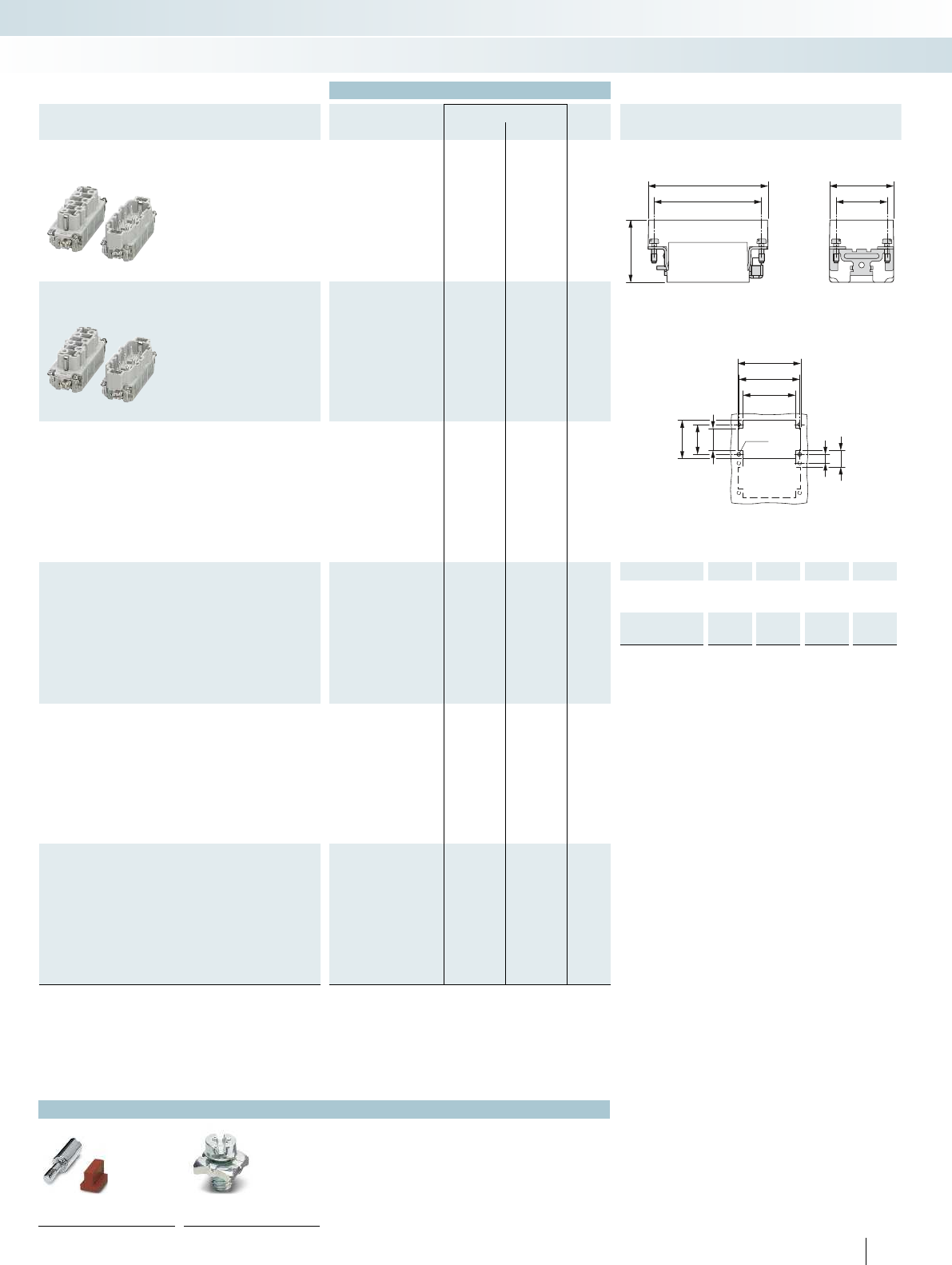
27
34
a
b
c
8
15
d+12
b
d
35
27
20
Ø3,4
For additional information, visit phoenixcontact.net/products
201PHOENIX CONTACT
Sensor/actuator cabling and industrial connectors
Heavy-duty connectors - HEAVYCON type B
Ordering data
Description Pos. Number Housing Type Order No. Pcs. /
Pkt.
Socket Plug
Screw connection
61 - 6B16 / B32① HC-HS06-I-UT-... 1406530 1406531 1
Screw connection
67 - 12 B16 / B32 ② HC-HS06-I-UT-... 7-12 1406533 1406534 1
Accessories
Coding profiles PE screws
Catalog 4 from page 581 Catalog 4 from page 580
Dimensions (in mm)
Dimensional drawing
Panel cutout
a b c d
①Socket 84.5 77.5 34 72
Plug
②Socket 84.5 77.5 34 72
Plug
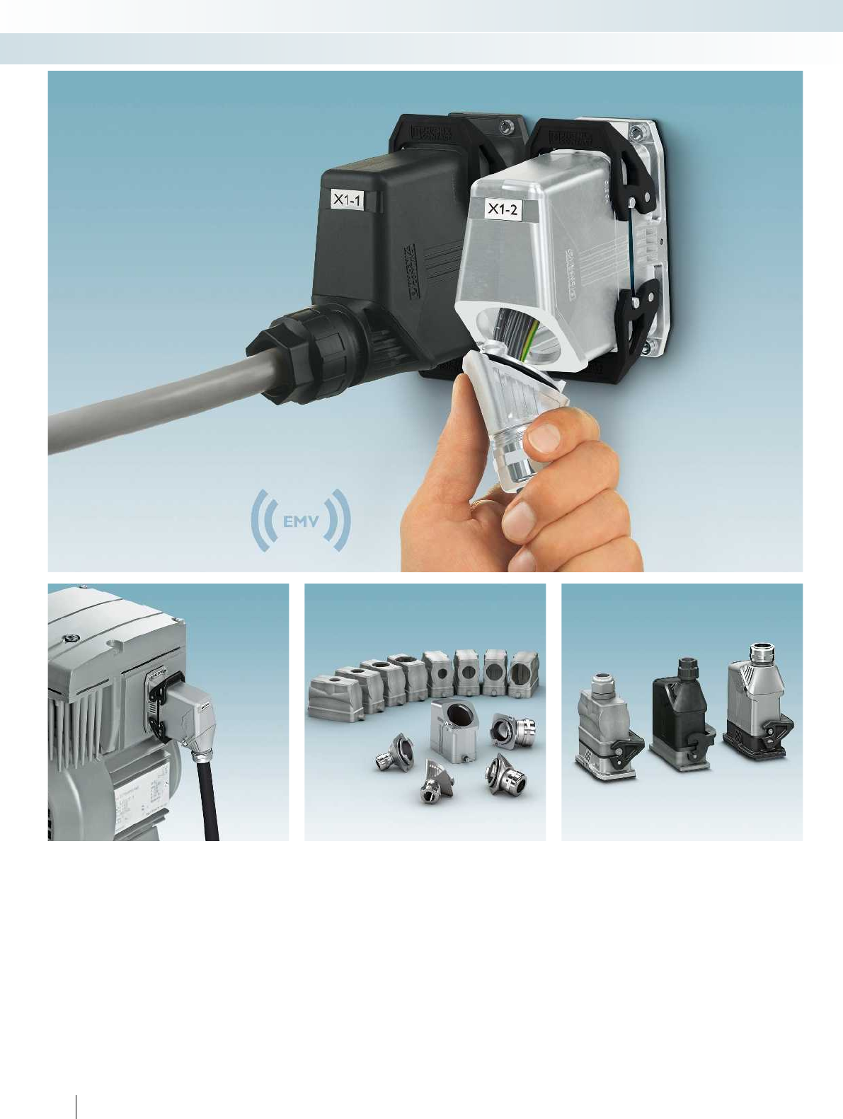
202 PHOENIX CONTACT
Sensor/actuator cabling and industrial connectors
Heavy-duty connectors - HEAVYCON type B
EMC protection
The new EMC series of HEAVYCON
EVO heavy-duty connectors has been
specifically developed for applications with
increased requirements. Furthermore, the
housing surfaces and all seals are
constructed so as to be electrically
conductive.
Flexible, thanks to reduced number
of versions
Thanks to the unique HEAVYCON EVO
bayonet locking, only the swivel cable glands
have to be replaced in order to cover the
M20, M25, M32, and M40 clamping areas
with straight and lateral outlet.
Fully compatible
The HEAVYCON EVO housing is plug-
compatible with standard aluminum
housing. It fits the standard panel cutouts of
heavy-duty connectors.
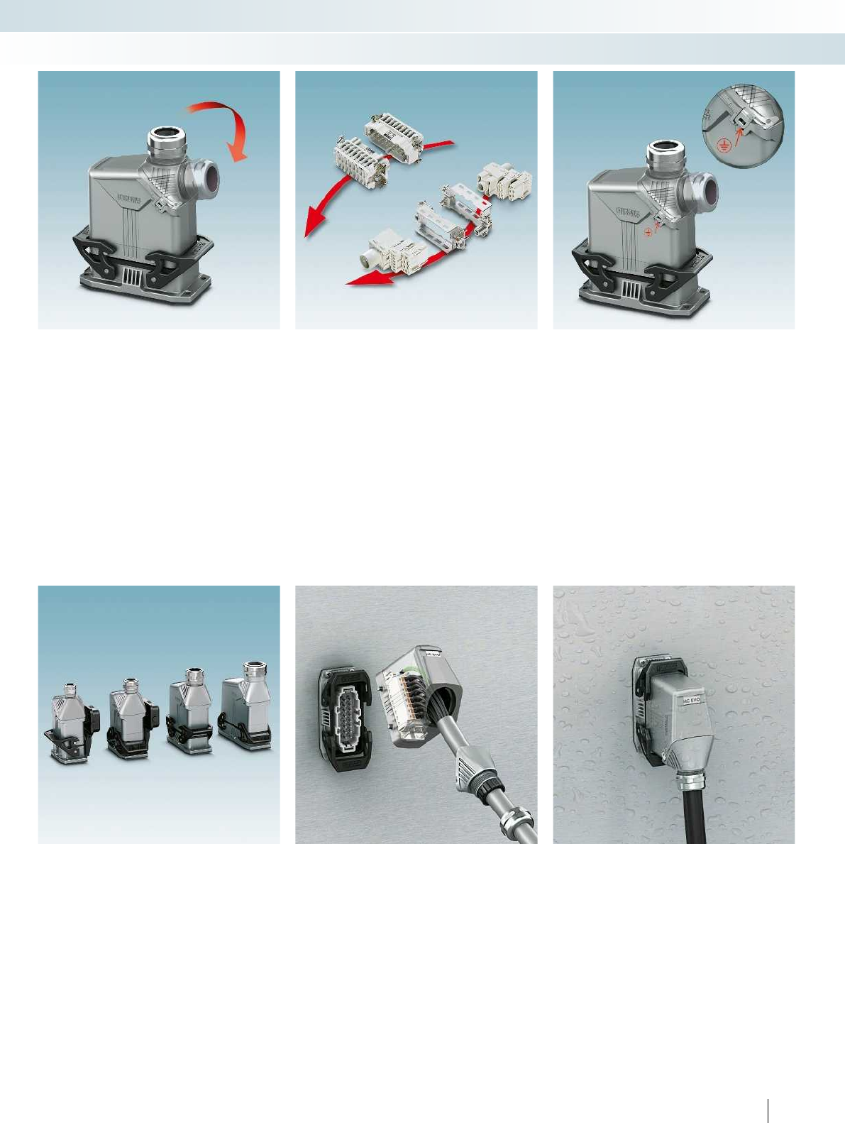
For additional information, visit phoenixcontact.net/products
203PHOENIX CONTACT
Sensor/actuator cabling and industrial connectors
Heavy-duty connectors - HEAVYCON type B
Easy closing operation
The bayonet locking designed specially
for EVO applications ensures easy on-site
assembly without tools.
For removal, a standard screwdriver is used
to push down on the locking spring.
Suitable for all inserts
All fixed and modular contact inserts in
B series format fit in HEAVYCON EVO
housing.
Electrical connection
A solid electrical connection is required
between the housing and the cable gland for
EMC and safety reasons.
The locking spring ensures a safe mechanical
and electrical connection.
Complete panel feed-through
The new EMC housings combine the
advantages of EVO plastic housing with
those of standard metal housing. A
complete panel feed-through system is
therefore available for EMC applications.
Easy cable assembly
On the HEAVYCON EVO housing, the
angled cable inlet is particularly large. This
simplifies cable assembly if the cable gland is
only mounted at the end of the process.
For harsh conditions
The metal housings are made from salt-
water-resistant aluminum. They meet the
requirements of IP66 protection and NEMA
4/4x/12.
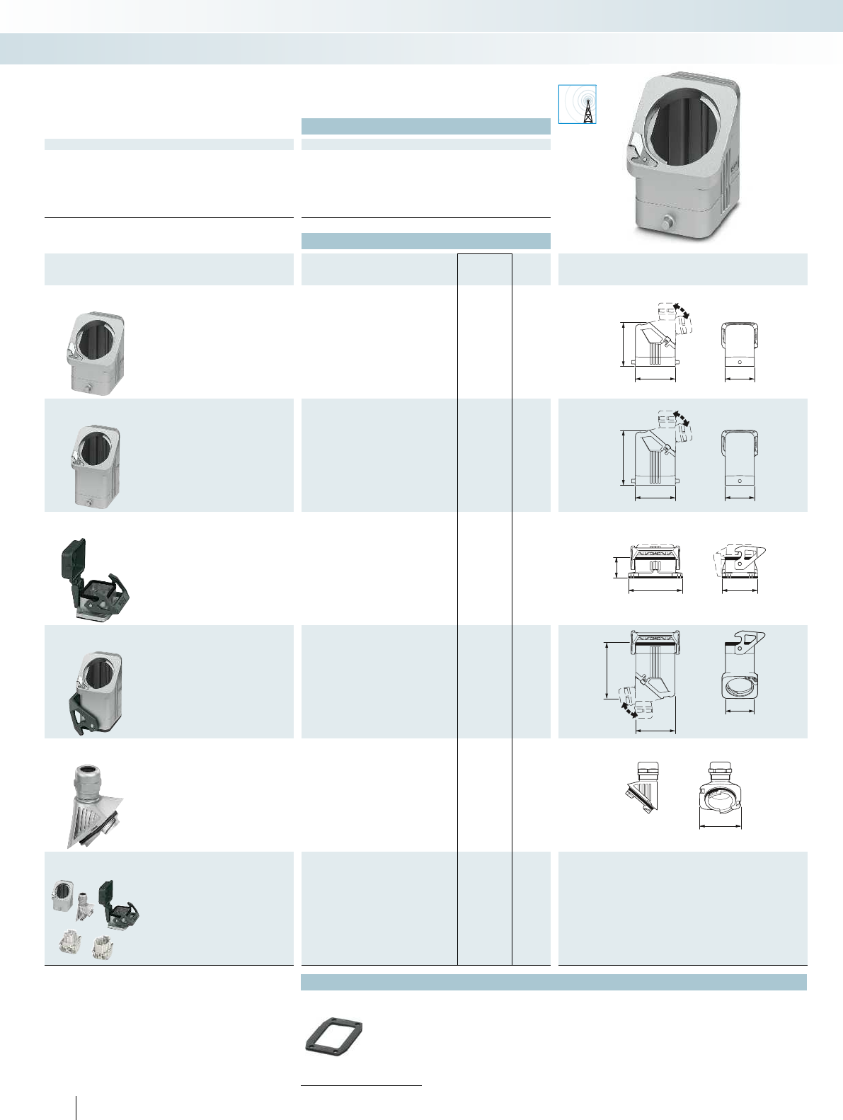
EMC
44
60
64
44
60
80
80,5
30,5
53
82
60
44
53,7
Technical data
General data
Housing material Die-cast aluminum, salt water resistant
Surface material Uncoated
Locking latch material Polyamide
Sealing material NBR, conductive
Ambient temperature (operation) -40°C ... 125°C
Type of protection (when plugged in) IP66
204 PHOENIX CONTACT
Sensor/actuator cabling and industrial connectors
Heavy-duty connectors - HEAVYCON type B
EVO housing, type B6,
metal, for EMC applications,
single locking latch
Ordering data
Description Thread Type Order No. Pcs. /
Pkt. Dimensions
Sleeve housing
Height: 64 mm HC-EVO-B06-HLFS-EL-AL 1411448 1
Sleeve housing
Height: 80 mm HC-EVO-B06-HHFS-EL-AL 1411447 1
Panel mounting base
Height: 30.5 mm Without cover
HC-STA-B06-BWS-ELC-AL 1411318 1
With cover
HC-STA-B06-BWSC-ELC-AL 1411319 1
Coupling housing
Height: 82 mm HC-EVO-B06-CHWS-ELC-AL 1411450 1
Cable gland
1x M20 HC-B-G-M20-EC-AL 1411439 1
1x M25 HC-B-G-M25-EC-AL 1411446 1
1x M32 HC-B-G-M32-EC-AL 1411440 1
1x M40 HC-B-G-M40-EC-AL 1411441 1
Connector set
Push-in connection
HC-EVO-B06PT-BWSC-HL-M20ELC-AL
1411487 1
Accessories
Replacement seals
From page 220
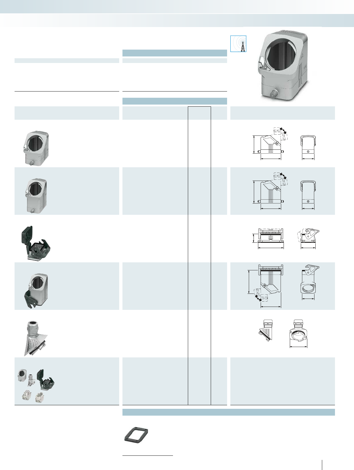
EMC
4473
64
4473
80
30,5
53
93,5
44
73
83
53,7
For additional information, visit phoenixcontact.net/products
Technical data
General data
Housing material Die-cast aluminum, salt water resistant
Surface material Uncoated
Locking latch material Polyamide
Sealing material NBR, conductive
Ambient temperature (operation) -40°C ... 125°C
Type of protection (when plugged in) IP66
205PHOENIX CONTACT
Sensor/actuator cabling and industrial connectors
Heavy-duty connectors - HEAVYCON type B
EVO housing, type B10,
metal, for EMC applications,
single locking latch
Ordering data
Description Thread Type Order No. Pcs. /
Pkt. Dimensions
Sleeve housing
Height: 64 mm HC-EVO-B10-HLFS-EL-AL 1411456 1
Sleeve housing
Height: 80 mm HC-EVO-B10-HHFS-EL-AL 1411453 1
Panel mounting base
Height: 30.5 mm Without cover
HC-STA-B10-BWS-ELC-AL 1411320 1
With cover
HC-STA-B10-BWSC-ELC-AL 1411321 1
Coupling housing
Height: 83 mm HC-EVO-B10-CHWS-ELC-AL 1411459 1
Cable gland
1x M20 HC-B-G-M20-EC-AL 1411439 1
1x M25 HC-B-G-M25-EC-AL 1411446 1
1x M32 HC-B-G-M32-EC-AL 1411440 1
1x M40 HC-B-G-M40-EC-AL 1411441 1
Connector set
Push-in connection
HC-EVO-B10PT-BWSC-HL-M25ELC-AL
1411491 1
Accessories
Replacement seals
From page 220
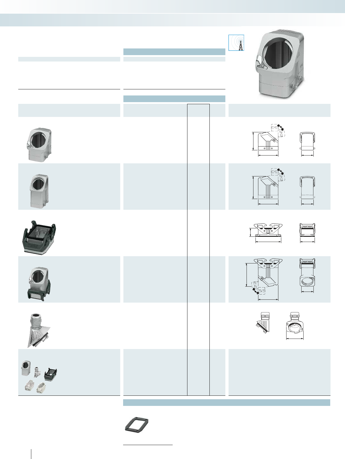
EMC
44
73
64
44
73
80
30,5
53
93,5
44
73
83
53,7
Technical data
General data
Housing material Die-cast aluminum, salt water resistant
Surface material Uncoated
Locking latch material Polyamide
Sealing material NBR, conductive
Ambient temperature (operation) -40°C ... 125°C
Type of protection (when plugged in) IP66
206 PHOENIX CONTACT
Sensor/actuator cabling and industrial connectors
Heavy-duty connectors - HEAVYCON type B
EVO housing, type B10,
metal, for EMC applications,
double locking latch
Ordering data
Description Thread Type Order No. Pcs. /
Pkt. Dimensions
Sleeve housing
Height: 64 mm HC-EVO-B10-HLFD-EL-AL 1411455 1
Sleeve housing
Height: 80 mm HC-EVO-B10-HHFD-EL-AL 1411451 1
Panel mounting base
Height: 30.5 mm Without cover
HC-STA-B10-BWD-ELC-AL 1411322 1
Coupling housing
Height: 83 mm HC-EVO-B10-CHWD-ELC-AL 1411458 1
Cable gland
1x M20 HC-B-G-M20-EC-AL 1411439 1
1x M25 HC-B-G-M25-EC-AL 1411446 1
1x M32 HC-B-G-M32-EC-AL 1411440 1
1x M40 HC-B-G-M40-EC-AL 1411441 1
Connector set
Push-in connection
HC-EVO-B10PT-BWD-HL-M25ELC-AL 1411488 1
Accessories
Replacement seals
From page 220
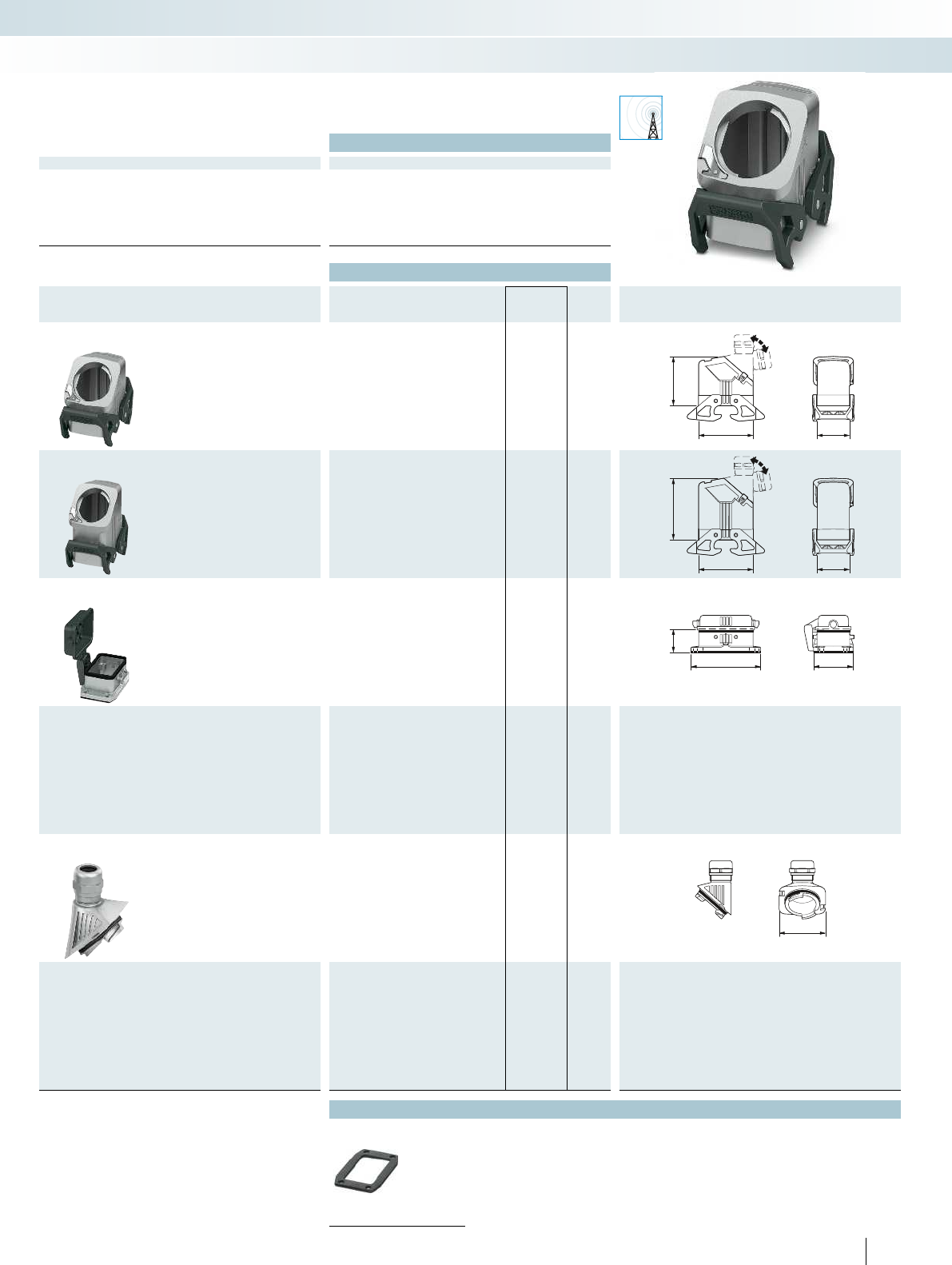
EMC
64
7344
80
7344
53
93,5
30,5
53,7
For additional information, visit phoenixcontact.net/products
Technical data
General data
Housing material Die-cast aluminum, salt water resistant
Surface material Uncoated
Locking latch material Polyamide
Sealing material NBR, conductive
Ambient temperature (operation) -40°C ... 125°C
Type of protection (when plugged in) IP66
207PHOENIX CONTACT
Sensor/actuator cabling and industrial connectors
Heavy-duty connectors - HEAVYCON type B
EVO housing, type B10,
metal, for EMC applications,
double locking latch
Ordering data
Description Thread Type Order No. Pcs. /
Pkt. Dimensions
Sleeve housing
Height: 64 mm HC-EVO-B10-HLWD-EL-AL 1411457 1
Sleeve housing
Height: 80 mm HC-EVO-B10-HHWD-EL-AL 1411454 1
Panel mounting base
Height: 30.5 mm With cover
HC-STA-B10-BFDC-ELC-AL 1411323 1
Cable gland
1x M20 HC-B-G-M20-EC-AL 1411439 1
1x M25 HC-B-G-M25-EC-AL 1411446 1
1x M32 HC-B-G-M32-EC-AL 1411440 1
1x M40 HC-B-G-M40-EC-AL 1411441 1
Accessories
Replacement seals
From page 220
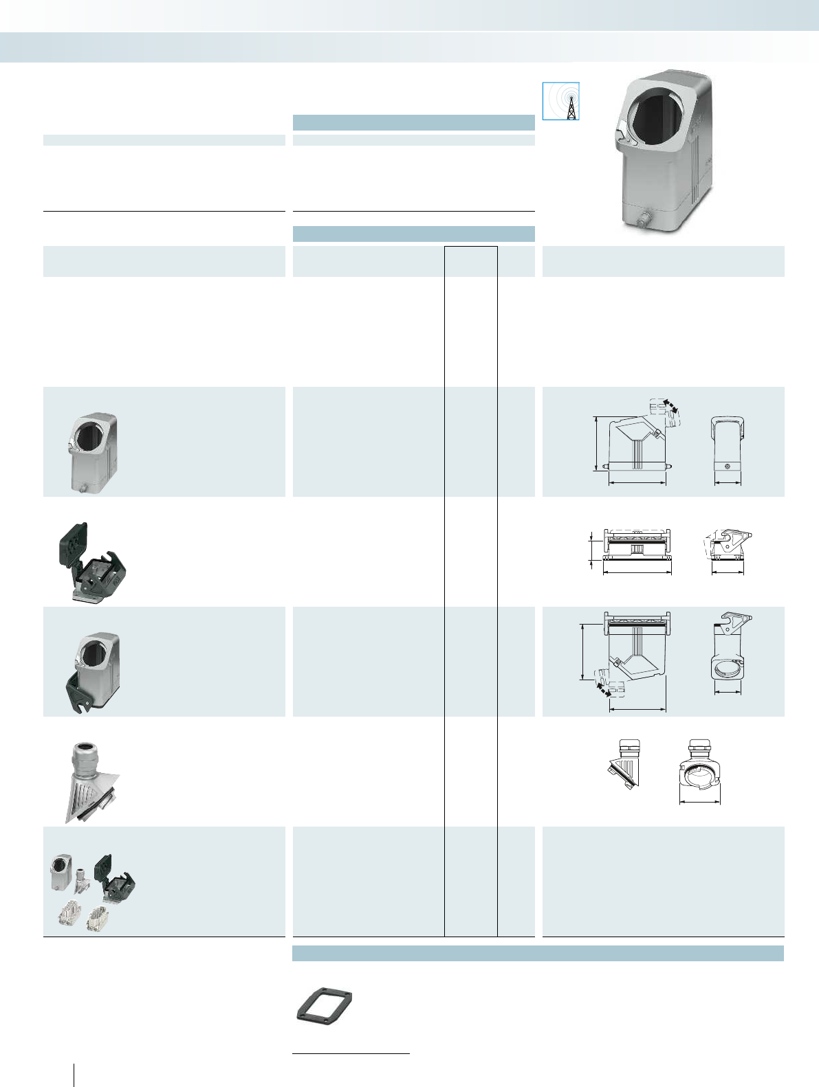
EMC
88
94 44
114 53
30,5
44
90,5
94
53,7
Technical data
General data
Housing material Die-cast aluminum, salt water resistant
Surface material Uncoated
Locking latch material Polyamide
Sealing material NBR, conductive
Ambient temperature (operation) -40°C ... 125°C
Type of protection (when plugged in) IP66
208 PHOENIX CONTACT
Sensor/actuator cabling and industrial connectors
Heavy-duty connectors - HEAVYCON type B
EVO housing, type B16,
metal, for EMC applications,
single locking latch
Ordering data
Description Thread Type Order No. Pcs. /
Pkt. Dimensions
Sleeve housing
Height: 88 mm HC-EVO-B16-HHFS-EL-AL 1411461 1
Panel mounting base
Height: 30.5 mm Without cover
HC-STA-B16-BWS-ELC-AL 1411324 1
With cover
HC-STA-B16-BWSC-ELC-AL 1411325 1
Coupling housing
Height: 90.5 mm HC-EVO-B16-CHWS-ELC-AL 1411464 1
Cable gland
1x M20 HC-B-G-M20-EC-AL 1411439 1
1x M25 HC-B-G-M25-EC-AL 1411446 1
1x M32 HC-B-G-M32-EC-AL 1411440 1
1x M40 HC-B-G-M40-EC-AL 1411441 1
Connector set
Push-in connection
HC-EVO-B16PT-BWSC-HH-M25ELC-AL
1411492 1
Accessories
Replacement seals
From page 220
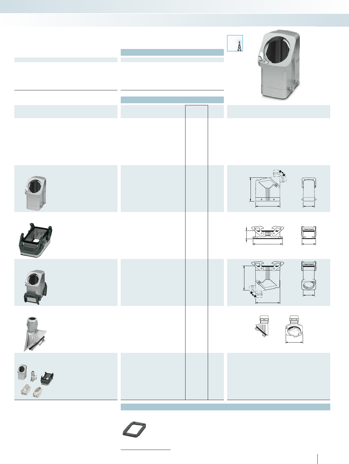
EMC
44
94
88
114 53
30,5
94
90,5
44
53,7
For additional information, visit phoenixcontact.net/products
Technical data
General data
Housing material Die-cast aluminum, salt water resistant
Surface material Uncoated
Locking latch material Polyamide
Sealing material NBR, conductive
Ambient temperature (operation) -40°C ... 125°C
Type of protection (when plugged in) IP66
209PHOENIX CONTACT
Sensor/actuator cabling and industrial connectors
Heavy-duty connectors - HEAVYCON type B
EVO housing, type B16,
metal, for EMC applications,
double locking latch
Ordering data
Description Thread Type Order No. Pcs. /
Pkt. Dimensions
Sleeve housing
Height: 88 mm HC-EVO-B16-HHFD-EL-AL 1411460 1
Panel mounting base
Height: 30.5 mm Without cover
HC-STA-B16-BWD-ELC-AL 1411327 1
Coupling housing
Height: 90.5 mm HC-EVO-B16-CHWD-ELC-AL 1411463 1
Cable gland
1x M20 HC-B-G-M20-EC-AL 1411439 1
1x M25 HC-B-G-M25-EC-AL 1411446 1
1x M32 HC-B-G-M32-EC-AL 1411440 1
1x M40 HC-B-G-M40-EC-AL 1411441 1
Connector set
Push-in connection
HC-EVO-B16PT-BWD-HH-M25ELC-AL 1411489 1
Accessories
Replacement seals
From page 220
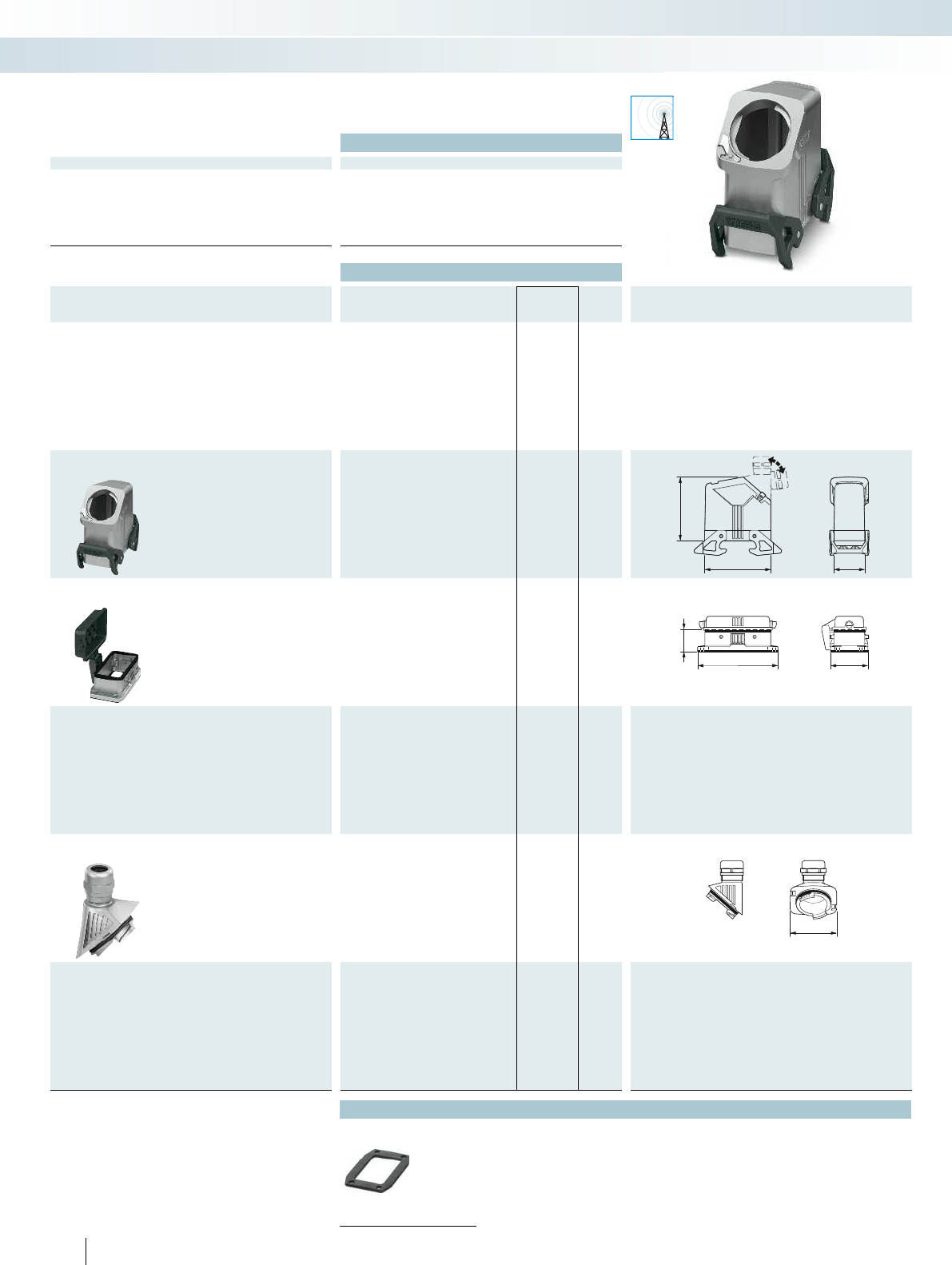
EMC
94 44
88
53
114
30,5
53,7
Technical data
General data
Housing material Die-cast aluminum, salt water resistant
Surface material Uncoated
Locking latch material Polyamide
Sealing material NBR, conductive
Ambient temperature (operation) -40°C ... 125°C
Type of protection (when plugged in) IP66
210 PHOENIX CONTACT
Sensor/actuator cabling and industrial connectors
Heavy-duty connectors - HEAVYCON type B
EVO housing, type B16,
metal, for EMC applications,
double locking latch
Ordering data
Description Thread Type Order No. Pcs. /
Pkt. Dimensions
Sleeve housing
Height: 88 mm HC-EVO-B16-HHWD-EL-AL 1411462 1
Panel mounting base
Height: 30.5 mm
With cover
HC-STA-B16-BFDC-ELC-AL 1411328 1
Cable gland
1x M20 HC-B-G-M20-EC-AL 1411439 1
1x M25 HC-B-G-M25-EC-AL 1411446 1
1x M32 HC-B-G-M32-EC-AL 1411440 1
1x M40 HC-B-G-M40-EC-AL 1411441 1
Accessories
Replacement seals
From page 220
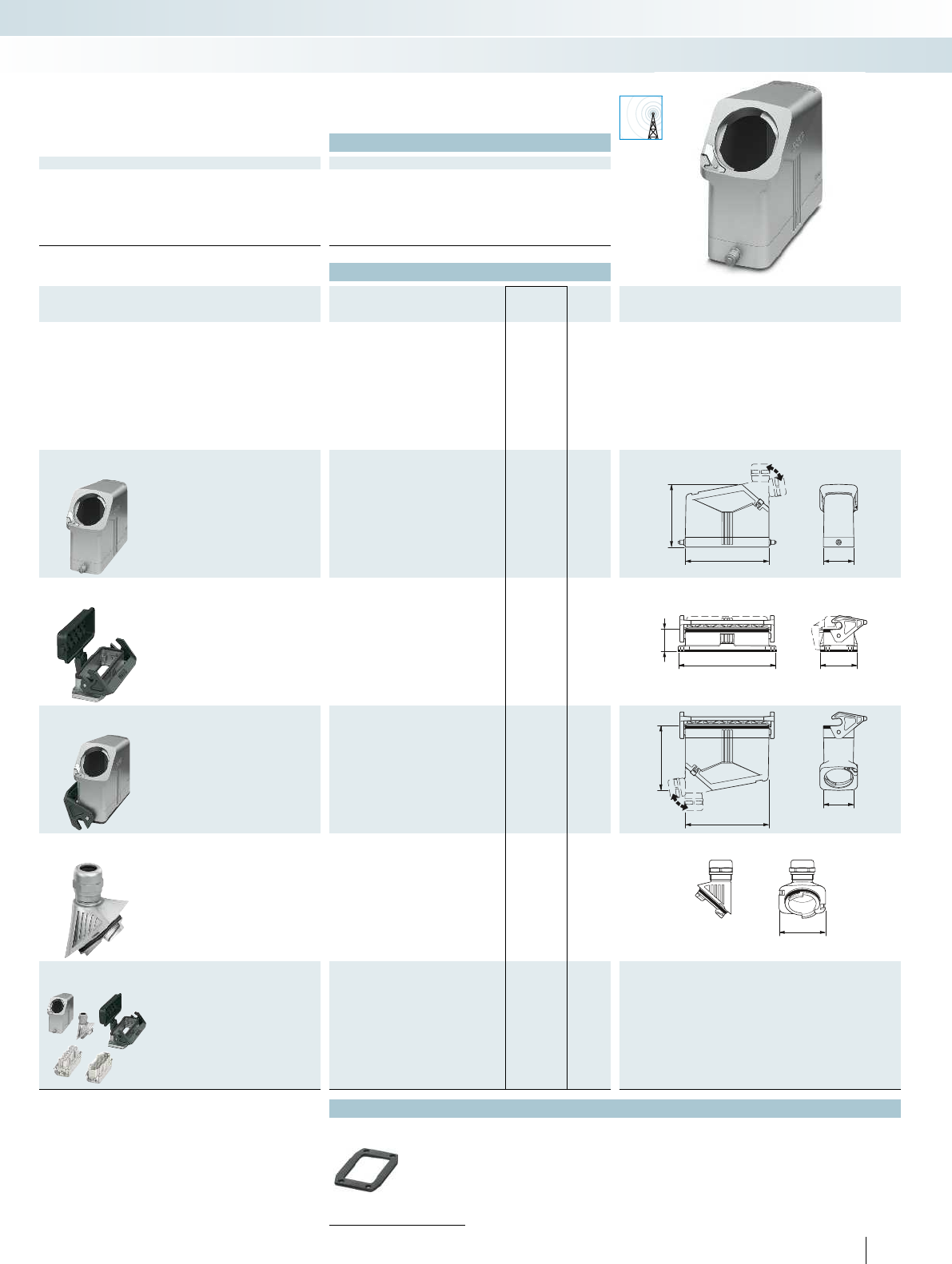
EMC
88
120 44
140,5
30,5
53
44
90
120
53,7
For additional information, visit phoenixcontact.net/products
Technical data
General data
Housing material Die-cast aluminum, salt water resistant
Surface material Uncoated
Locking latch material Polyamide
Sealing material NBR, conductive
Ambient temperature (operation) -40°C ... 125°C
Type of protection (when plugged in) IP66
211PHOENIX CONTACT
Sensor/actuator cabling and industrial connectors
Heavy-duty connectors - HEAVYCON type B
EVO housing, type B24,
metal, for EMC applications,
single locking latch
Ordering data
Description Thread Type Order No. Pcs. /
Pkt. Dimensions
Sleeve housing
Height: 88 mm HC-EVO-B24-HHFS-EL-AL 1411473 1
Panel mounting base
Height: 30.5 mm Without cover
HC-STA-B24-BWS-ELC-AL 1411329 1
With cover
HC-STA-B24-BWSC-ELC-AL 1411330 1
Coupling housing
Height: 90 mm HC-EVO-B24-CHWS-ELC-AL 1411476 1
Cable gland
1x M20 HC-B-G-M20-EC-AL 1411439 1
1x M25 HC-B-G-M25-EC-AL 1411446 1
1x M32 HC-B-G-M32-EC-AL 1411440 1
1x M40 HC-B-G-M40-EC-AL 1411441 1
Connector set
Push-in connection
HC-EVO-B24PT-BWSC-HH-M32ELC-AL
1411493 1
Accessories
Replacement seals
From page 220
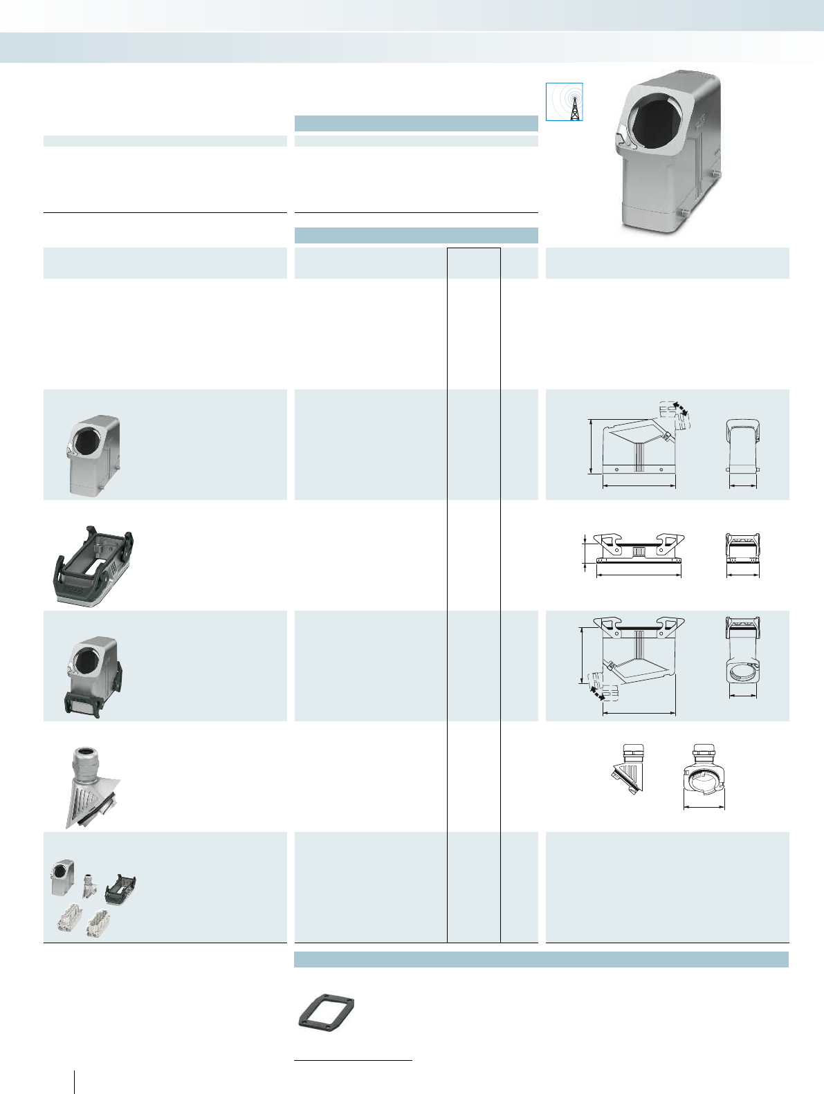
EMC
88
120 44
140,5
30,5
53
44
90
120
53,7
Technical data
General data
Housing material Die-cast aluminum, salt water resistant
Surface material Uncoated
Locking latch material Polyamide
Sealing material NBR, conductive
Ambient temperature (operation) -40°C ... 125°C
Type of protection (when plugged in) IP66
212 PHOENIX CONTACT
Sensor/actuator cabling and industrial connectors
Heavy-duty connectors - HEAVYCON type B
EVO housing, type B24,
metal, for EMC applications,
double locking latch
Ordering data
Description Thread Type Order No. Pcs. /
Pkt. Dimensions
Sleeve housing
Height: 88 mm HC-EVO-B24-HHFD-EL-AL 1411472 1
Panel mounting base
Height: 30.5 mm Without cover
HC-STA-B24-BWD-ELC-AL 1411331 1
Coupling housing
Height: 90 mm HC-EVO-B24-CHWD-ELC-AL 1411475 1
Cable gland
1x M20 HC-B-G-M20-EC-AL 1411439 1
1x M25 HC-B-G-M25-EC-AL 1411446 1
1x M32 HC-B-G-M32-EC-AL 1411440 1
1x M40 HC-B-G-M40-EC-AL 1411441 1
Connector set
Push-in connection
HC-EVO-B24PT-BWD-HH-M32ELC-AL 1411490 1
Accessories
Replacement seals
From page 220
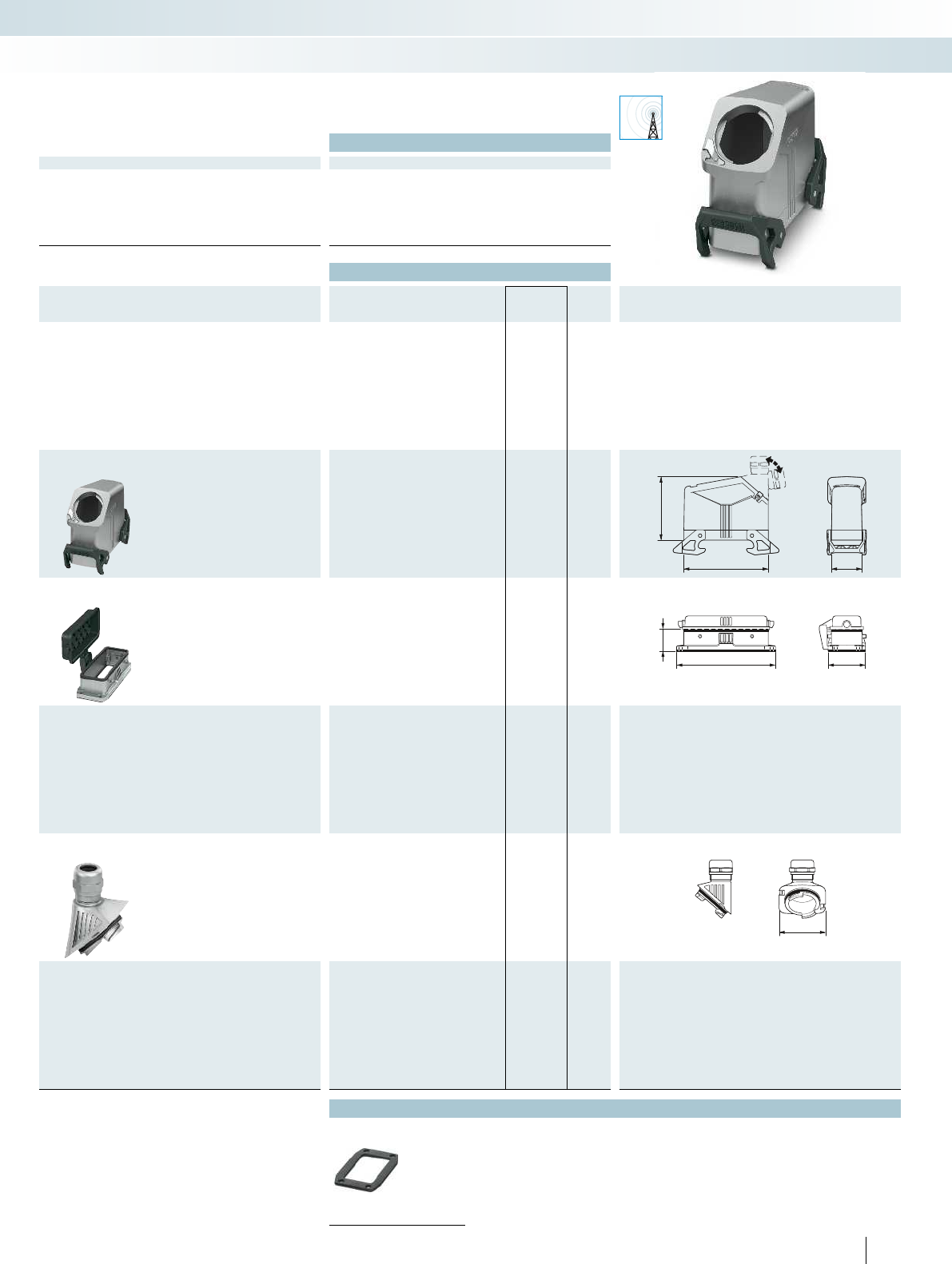
EMC
120 44
88
140,5 53
30,5
53,7
For additional information, visit phoenixcontact.net/products
Technical data
General data
Housing material Die-cast aluminum, salt water resistant
Surface material Uncoated
Locking latch material Polyamide
Sealing material NBR, conductive
Ambient temperature (operation) -40°C ... 125°C
Type of protection (when plugged in) IP66
213PHOENIX CONTACT
Sensor/actuator cabling and industrial connectors
Heavy-duty connectors - HEAVYCON type B
EVO housing, type B24,
metal, for EMC applications,
double locking latch
Ordering data
Description Thread Type Order No. Pcs. /
Pkt. Dimensions
Sleeve housing
Height: 88 mm HC-EVO-B24-HHWD-EL-AL 1411474 1
Panel mounting base
Height: 30.5 mm
With cover
HC-STA-B24-BFDC-ELC-AL 1411332 1
Cable gland
1x M20 HC-B-G-M20-EC-AL 1411439 1
1x M25 HC-B-G-M25-EC-AL 1411446 1
1x M32 HC-B-G-M32-EC-AL 1411440 1
1x M40 HC-B-G-M40-EC-AL 1411441 1
Accessories
Replacement seals
From page 220
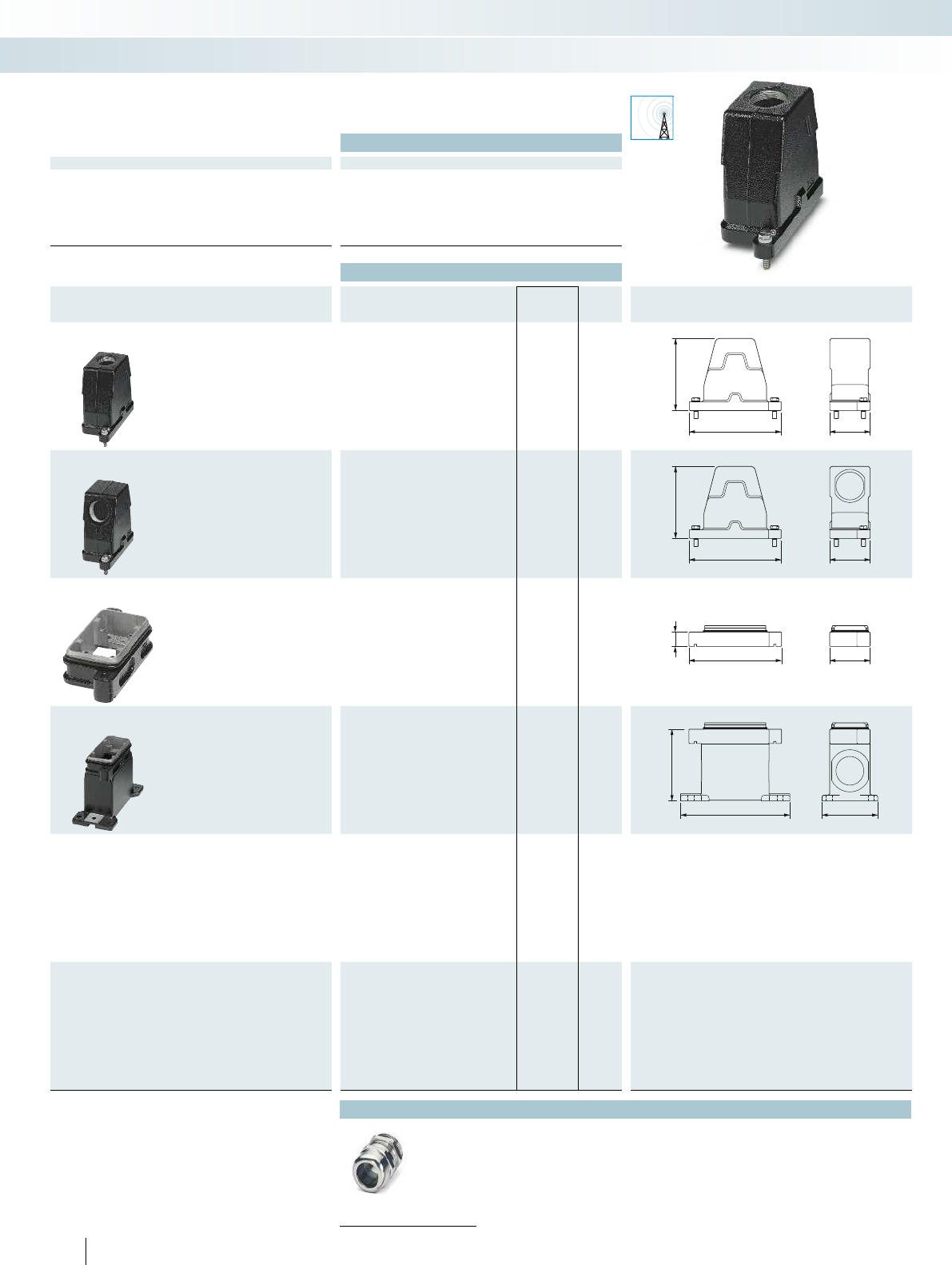
EMC
13258
100,5
13258
100,5
20
13258
100
157 80
Technical data
General data
Housing material Aluminum die-cast
Surface material Powder-coated, black
Lock material High-grade steel
Sealing material Silicon
Ambient temperature (operation) -40°C ... 125°C
Type of protection (when plugged in) IP68/IP69K
214 PHOENIX CONTACT
Sensor/actuator cabling and industrial connectors
Heavy-duty connectors - HEAVYCON type B
HPR housing, type B6,
metal, for railway applications,
screw locking
Ordering data
Description Thread Type Order No. Pcs. /
Pkt. Dimensions
Sleeve housing
Height: 100.5 mm Cable entry: top
1x M20 HC-HPR-B06-HHWH-1TTM20-EM-BK 1411879 1
1x M25 HC-HPR-B06-HHWH-1TTM25-EM-BK 1411106 1
Sleeve housing
Height: 100.5 mm Cable entry: lateral
1x M20 HC-HPR-B06-HHWH-1STM20-EM-BK 1411878 1
1x M25 HC-HPR-B06-HHWH-1STM25-EM-BK 1411119 1
Panel mounting base
Height: 20 mm Without cover
HC-HPR-B06-BFH-EMR-BK 1411122 1
Box mounting base
Height: 100 mm Without cover
2x M20 HC-HPR-B06-SHFH-2SSM20-EMR-BK 1411880 1
2x M25 HC-HPR-B06-SHFH-2SSM25-EMR-BK 1411135 1
Accessories
Cable gland
From page 229
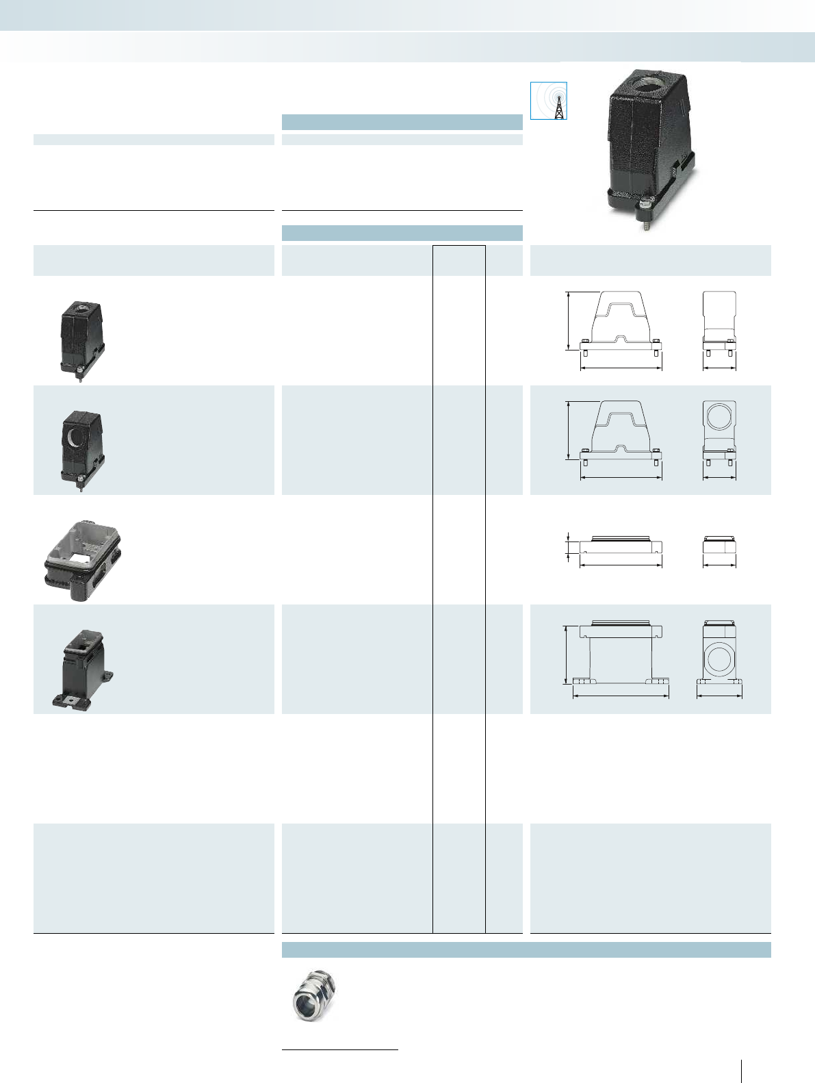
EMC
145 58
100,5
145 58
100,5
20
145 58
100
170 80
For additional information, visit phoenixcontact.net/products
Technical data
General data
Housing material Aluminum die-cast
Surface material Powder-coated, black
Lock material High-grade steel
Sealing material Silicon
Ambient temperature (operation) -40°C ... 125°C
Type of protection (when plugged in) IP68/IP69K
215PHOENIX CONTACT
Sensor/actuator cabling and industrial connectors
Heavy-duty connectors - HEAVYCON type B
HPR housing, type B10,
metal, for railway applications,
screw locking
Ordering data
Description Thread Type Order No. Pcs. /
Pkt. Dimensions
Sleeve housing
Height: 100.5 mm Cable entry: top
1x M25 HC-HPR-B10-HHWH-1TTM25-EM-BK 1411882 1
1x M32 HC-HPR-B10-HHWH-1TTM32-EM-BK 1411067 1
Sleeve housing
Height: 100.5 mm Cable entry: lateral
1x M25 HC-HPR-B10-HHWH-1STM25EM-BK 1411881 1
1x M32 HC-HPR-B10-HHWH-1STM32-EM-BK 1411070 1
Panel mounting base
Height: 20 mm Without cover
HC-HPR-B10-BFH-EMR-BK 1411083 1
Box mounting base
Height: 100 mm Without cover
2x M25 HC-HPR-B10-SHFH-2SSM25-EMR-BK 1411883 1
2x M32 HC-HPR-B10-SHFH-2SSM32-EMR-BK 1411096 1
Accessories
Cable gland
From page 229
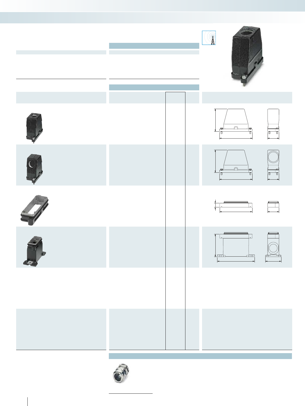
EMC
166,2 59,2
110,5
166,2 59,2
110,5
20
165 58
111
18980
Technical data
General data
Housing material Aluminum die-cast
Surface material Powder-coated, black
Lock material High-grade steel
Sealing material Silicon
Ambient temperature (operation) -40°C ... 125°C
Type of protection (when plugged in) IP68/IP69K
216 PHOENIX CONTACT
Sensor/actuator cabling and industrial connectors
Heavy-duty connectors - HEAVYCON type B
HPR housing, type B16,
metal, for railway applications,
screw locking
Ordering data
Description Thread Type Order No. Pcs. /
Pkt. Dimensions
Sleeve housing
Height: 110.5 mm Cable entry: top
1x M32 HC-HPR-B16-HHWH-1TTM32-EM-BK 1411059 1
1x M40 HC-HPR-B16-HHWH-1TTM40-EM-BK 1411885 1
Sleeve housing
Height: 110.5 mm Cable entry: lateral
1x M32 HC-HPR-B16-HHWH-1STM32-EM-BK 1411058 1
1x M40 HC-HPR-B16-HHWH-1STM40-EM-BK 1411884 1
Panel mounting base
Height: 20 mm Without cover
HC-HPR-B16-BFH-EMR-BK 1411060 1
Box mounting base
Height: 111 mm Without cover
2x M32 HC-HPR-B16-SHFH-2SSM32-EMR-BK 1411054 1
2x M40 HC-HPR-B16-SHFH-2SSM40-EMR-BK 1411886 1
Accessories
Cable gland
From page 229
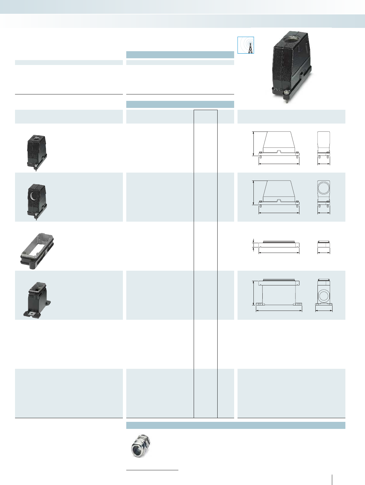
EMC
192 59,2
110,5
192 59,2
110,5
20
192 58
111
216 80
For additional information, visit phoenixcontact.net/products
Technical data
General data
Housing material Aluminum die-cast
Surface material Powder-coated, black
Lock material High-grade steel
Sealing material Silicon
Ambient temperature (operation) -40°C ... 125°C
Type of protection (when plugged in) IP68/IP69K
217PHOENIX CONTACT
Sensor/actuator cabling and industrial connectors
Heavy-duty connectors - HEAVYCON type B
HPR housing, type B24,
metal, for railway applications,
screw locking
Ordering data
Description Thread Type Order No. Pcs. /
Pkt. Dimensions
Sleeve housing
Height: 110.5 mm Cable entry: top
1x M32 HC-HPR-B24-HHWH-1TTM32-EM-BK 1411888 1
1x M40 HC-HPR-B24-HHWH-1TTM40-EM-BK 1411062 1
Sleeve housing
Height: 110.5 mm Cable entry: lateral
1x M32 HC-HPR-B24-HHWH-1STM32-EM-BK 1411887 1
1x M40 HC-HPR-B24-HHWH-1STM40-EM-BK 1411061 1
Panel mounting base
Height: 20 mm Without cover
HC-HPR-B24-BFH-EMR-BK 1411055 1
Box mounting base
Height: 111 mm Without cover
2x M32 HC-HPR-B24-SHFH-2SSM32-EMR-BK 1411889 1
2x M40 HC-HPR-B24-SHFH-2SSM40-EMR-BK 1411063 1
Accessories
Cable gland
From page 229
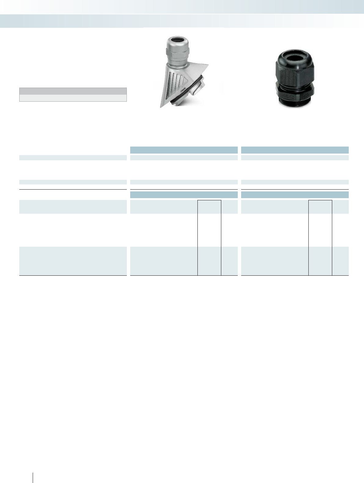
Technical data Technical data
Material data
Material Aluminum, die-cast -
Material, pressure screw Nickel-plated brass Polyamide
Cable seal material CR/NBR -
Degree of protection IP66 IP68, to 5 bar
Temperature data
Ambient temperature (operation) -40°C ... 125°C -20°C ... 100°C
Ordering data Ordering data
Description Thread type Type Order No. Pcs. /
Pkt. Type Order No. Pcs. /
Pkt.
Metal standard cable gland, for HEAVYCON EVO
metal housing, for cable diameter [mm]:
7mm ... 13mm M20 HC-B-G-M20-ER-AL 1411442 1
11 mm ... 16 mm M25 HC-B-G-M25-ER-AL 1411443 1
14 mm ... 21 mm M32 HC-B-G-M32-ER-AL 1411444 1
19 mm ... 27 mm M40 HC-B-G-M40-ER-AL 1411445 1
Plastic cable gland, with extended clamping area,
for cable diameter [mm]:
5mm ... 13mm M20 HC-K-KV-M20(5-13)BK 1411261 10
8mm ... 17mm M25 HC-K-KV-M25(8-17)BK 1411258 10
12 mm ... 21 mm M32 HC-K-KV-M32(12-21)BK 1407673 10
16 mm ... 28 mm M40 HC-K-KV-M40(16-28)BK 1407674 10
218 PHOENIX CONTACT
Sensor/actuator cabling and industrial connectors
Heavy-duty connectors - HEAVYCON accessories
EVO standard cable gland,
metal, with NBR seal
Cable gland, plastic
Metal HEAVYCON EVO standard cable
gland for higher strain relief with bayonet
locking.
Black plastic cable glands with extended
clamping area.
Notes:
Not for EMC applications
Cable glands
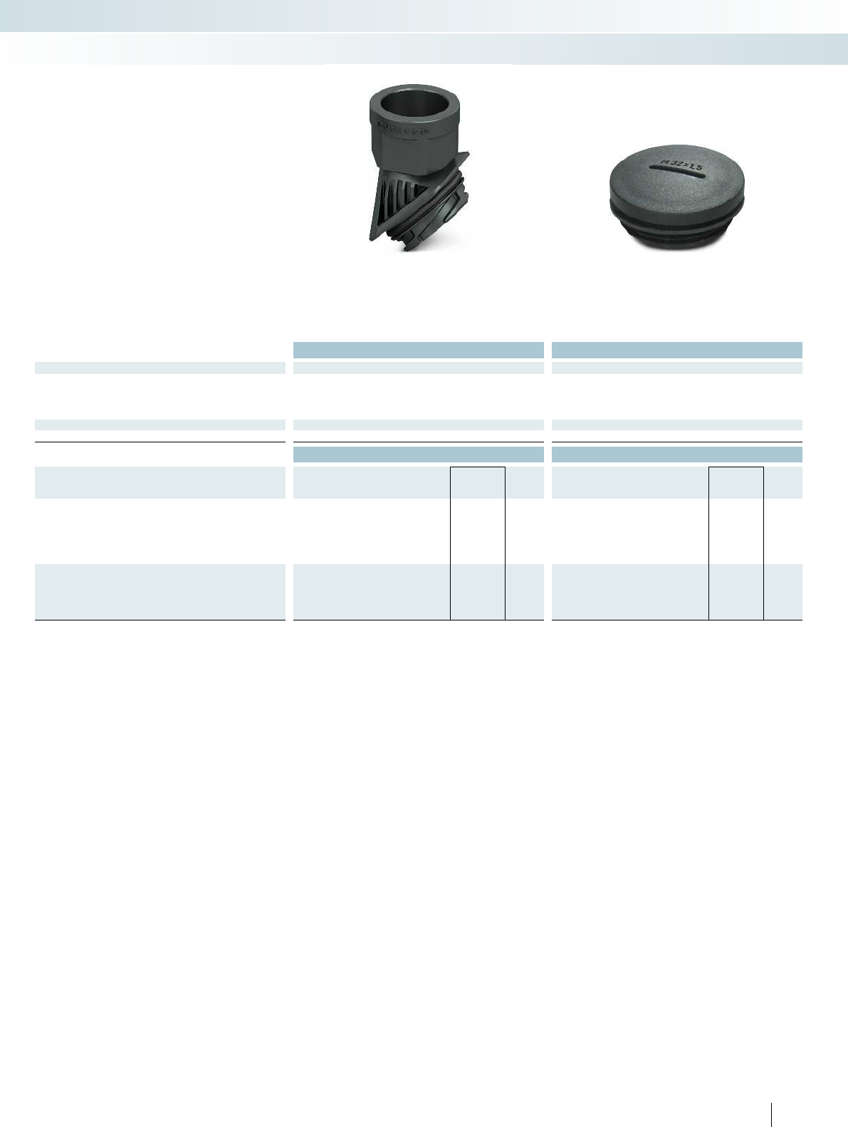
For additional information, visit phoenixcontact.net/products
Technical data Technical data
Material data
Material Polyamide fiberglass reinforced Polyamide fiberglass reinforced
Material, pressure screw - -
Cable seal material - -
Degree of protection IP66 IP65
Temperature data
Ambient temperature (operation) -40°C ... 125°C -20°C ... 80°C
Ordering data Ordering data
Description Thread type Type Order No. Pcs. /
Pkt. Type Order No. Pcs. /
Pkt.
Plastic thread adapter, for HEAVYCON EVO type D
plastic housing
M25 HC-D-TA-M25-PLRBK 1411352 1
Pg16 HC-D-TA-PG16-PLR-BK 1411353 1
NPT3/4" HC-D-TA-NPT-3/4-PLR-BK 1411354 1
Plastic filler plug, for HEAVYCON base profiles
M25 HC-K-BS-M25 BK 1411245 10
M32 HC-K-BS-M32-BK 1410754 10
M40 HC-K-BS-M40-BK 1410767 10
219PHOENIX CONTACT
Sensor/actuator cabling and industrial connectors
Heavy-duty connectors - HEAVYCON accessories
EVO D thread adapter, plastic Filler plug, plastic
These thread adapters enable the use of
special cable glands and corrugated pipe
connections with HEAVYCON EVO type D
housings.
Filler plugs for sealing unused thread
openings on box mounting bases.
Thread adapters,
filler plugs
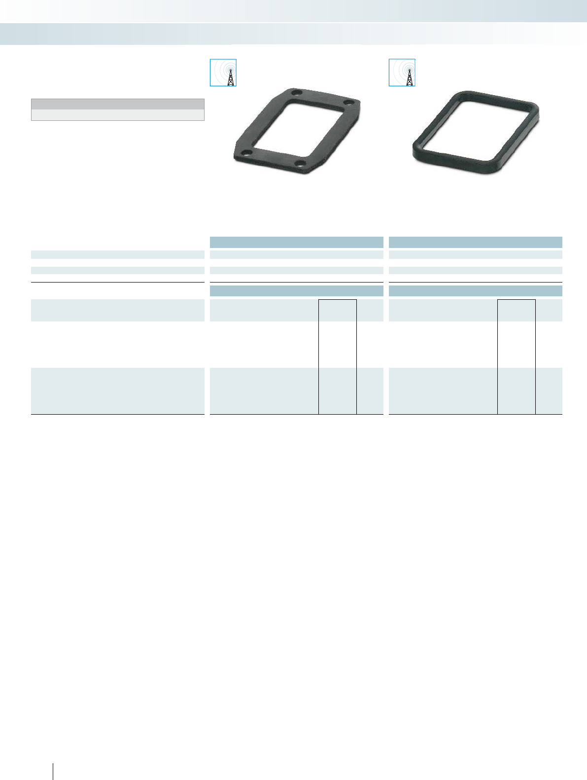
EMC EMC
Technical data Technical data
Material data
Material NBR, conductive NBR, conductive
Temperature data
Ambient temperature (operation) -40°C ... 125°C -40°C ... 125°C
Ordering data Ordering data
Description Type Order No. Pcs. /
Pkt. Type Order No. Pcs. /
Pkt.
Replacement flat seal, for HEAVYCON
panel mounting base type:
B6 HC-B06-SG-CBK 1411483 10
B10 HC-B10-SG-CBK 1411484 10
B16 HC-B16-SG-CBK 1411485 10
B24 HC-B24-SG-CBK 1411486 10
Replacement profile gasket, for HEAVYCON EVO
supporting base element type:
B6 HC-B06-SP-CBK 1411477 10
B10 HC-B10-SP-CBK 1411479 10
B16 HC-B16-SP-CBK 1411480 10
B24 HC-B24-SP-CBK 1411482 10
220 PHOENIX CONTACT
Sensor/actuator cabling and industrial connectors
Heavy-duty connectors - HEAVYCON accessories
Replacement EMC flat gasket,
for EVO B panel mounting base
Replacement EMC profile gasket,
for EVO B supporting base element
–For EMC housing
Notes:
Bond the replacement profile gaskets to the housing.
Replacement flat gaskets,
profile gaskets for type B
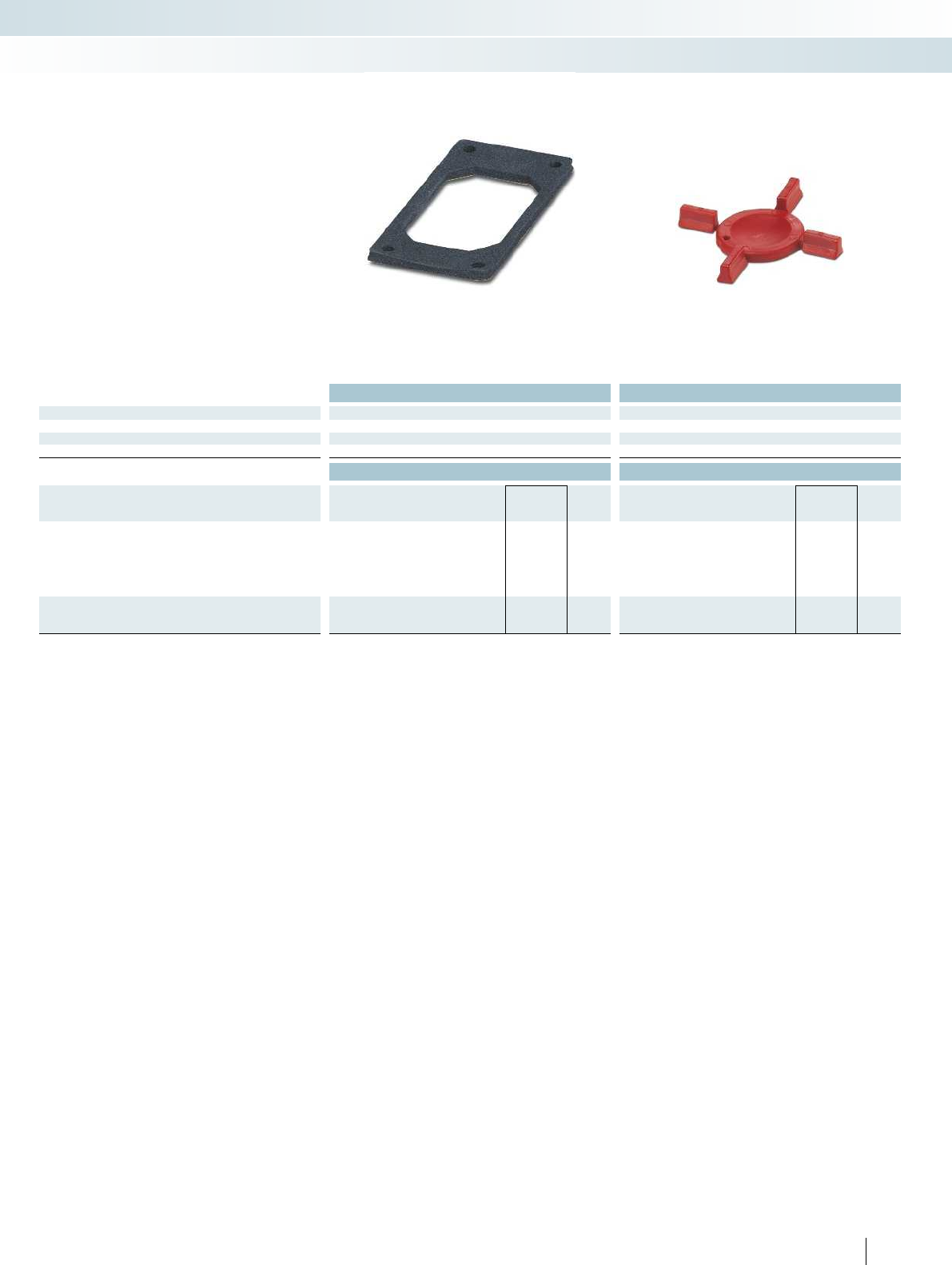
For additional information, visit phoenixcontact.net/products
Technical data Technical data
Material data
Material EPDM/CR PA
Temperature data
Ambient temperature (operation) -40°C ... 125°C -40°C ... 125°C
Ordering data Ordering data
Description Type Order No. Pcs. /
Pkt. Type Order No. Pcs. /
Pkt.
Special flat gasket, made from foam rubber for HEAVYCON
panel mounting base type:
B6 HC-B 6-FL-MDI 1410929 10
B10 HC-B 10-FL-MDI 1410932 10
B16 HC-B 16-FL-MDI 1410945 10
B24 HC-B 24-FL-MDI 1410958 10
Coding profile, for new BB series contact inserts
CP-HC-S 1410916 10
221PHOENIX CONTACT
Sensor/actuator cabling and industrial connectors
Heavy-duty connectors - HEAVYCON accessories
Special flat gasket,
for standard B panel mounting base
Coding profile
Special flat gaskets for type B panel
mounting bases for uneven mounting
surfaces.
Coding profile for new BB series contact
inserts.
– For easy and inexpensive coding of
identical plug-in connections
– Can be coded in seconds, thanks to the
coding profile
Special flat gaskets,
coding profiles
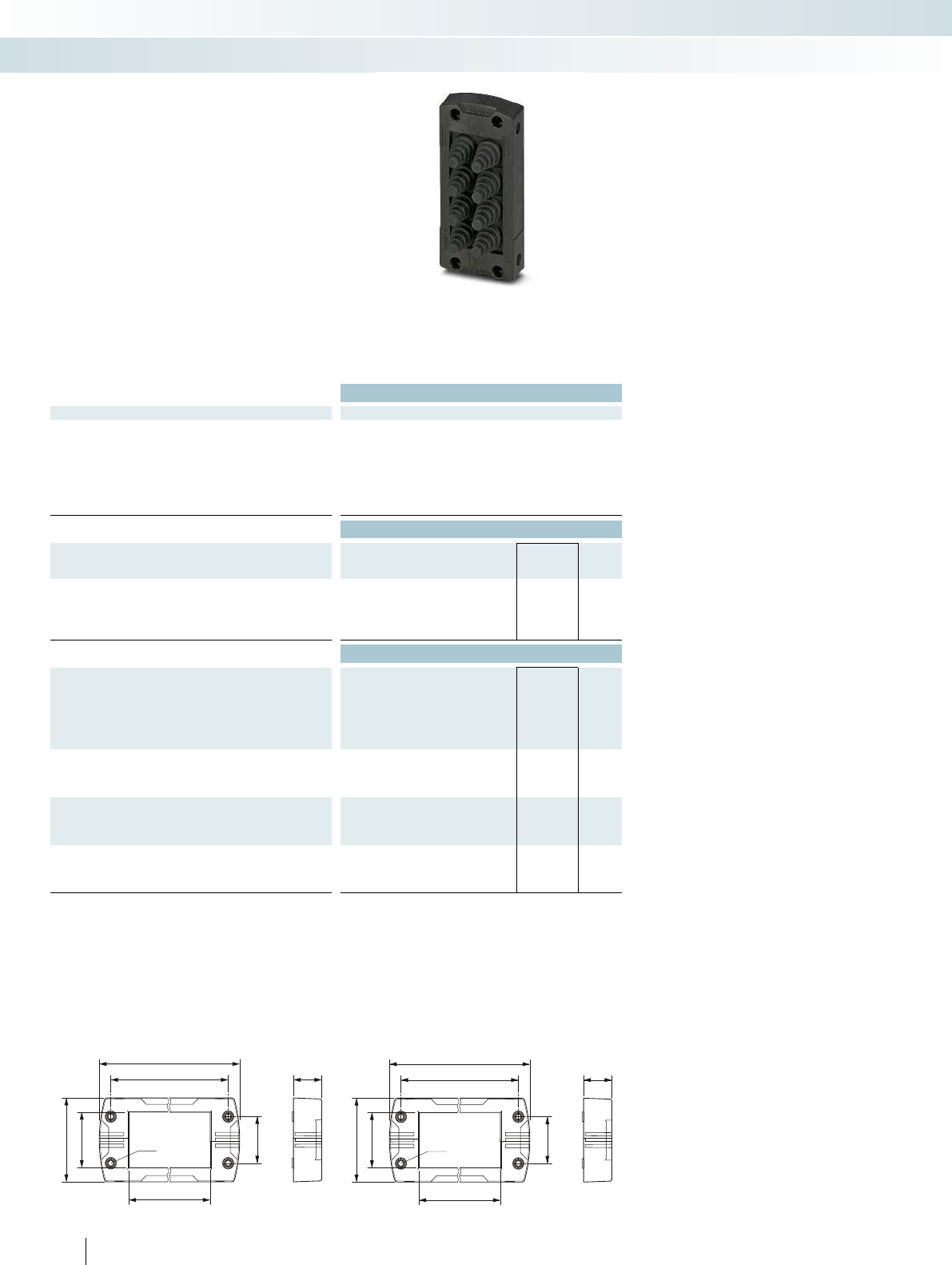
147
130
97,5
58,5
37,5
32
Ø4,5
20
120
103
78
58,5
37,5
32
Ø4,5
20
Technical data
General data
Material of frames Polyamide
Material of cable sleeves NBR
Degree of protection IP54 (DIN IEC 60529)/IP65 (when directly mounted on the housing
panel (perpendicular mounting or underwall mounting) and using a
3.6mm wide cable binder (e.g., Order No. 3240744))
Temperature range [°C] -40 ... 120
Ordering data
Description Type Order No. Pcs. /
Pkt.
Pre-assembled sealing frames with cone-shaped cable
sleeves, for cables with a diameter of:
2 - 11 mm CES-B16-8XSRC-BK 1411073 1
2 - 11 mm CES-B24-10XSRC-BK 1411074 1
Accessories
Electrician's scissors, high cutting performance, thanks to micro-
serrated cutting area, suitable for copper, aluminum, Kevlar fibers,
and plastic, two-component non-slip soft-grip handles, ergonomic
design, adjustable screw joint
CUTFOX-ES 1212621 1
M4 replacement locking screw, with 3mm Allen screw head,
for sealing frame with screw locking
CES-SFFS-H 0801728 10
Bit screwdriver, with 1/4" quick-action chuck, suitable for bits
according to DIN3126-C6.3 and E6.3/ISO1173, magnetic
SF-M BH 1212070 1
Screw bit, hexagonal, E6.3-1/4" drive, hardened, suitable for
holder according to DIN3126-F6.3/ISO1173, size: hex 3x50mm
Size: hex 3x50mm SF-BIT-HEX 3-50 1212647 5
CES-B16-8XSRC-BK CES-B24-10XSRC-BK
222 PHOENIX CONTACT
Sensor/actuator cabling and industrial connectors
Installation and mounting material - CES cable entry system
Sealing frames with cone-shaped cable
sleeves and screw locking
Pre-assembled sealing frames with 8 (B16)
or 10 (B24) cone-shaped cable sleeves.
Particularly suitable for cables that are
assembled or wired in the control cabinet.
Cables up to 11 mm in diameter can be fed
through by cutting off the sleeves.
– IP65 when using cable binders and vertical
mounting
– Resistant to oil, fuels, and grease
–Halogen-free
Sealing frames
with cone-shaped cable sleeves

For additional information, visit phoenixcontact.net/products
223PHOENIX CONTACT
Sensor/actuator cabling and industrial connectors
Installation and mounting material - CES cable entry system
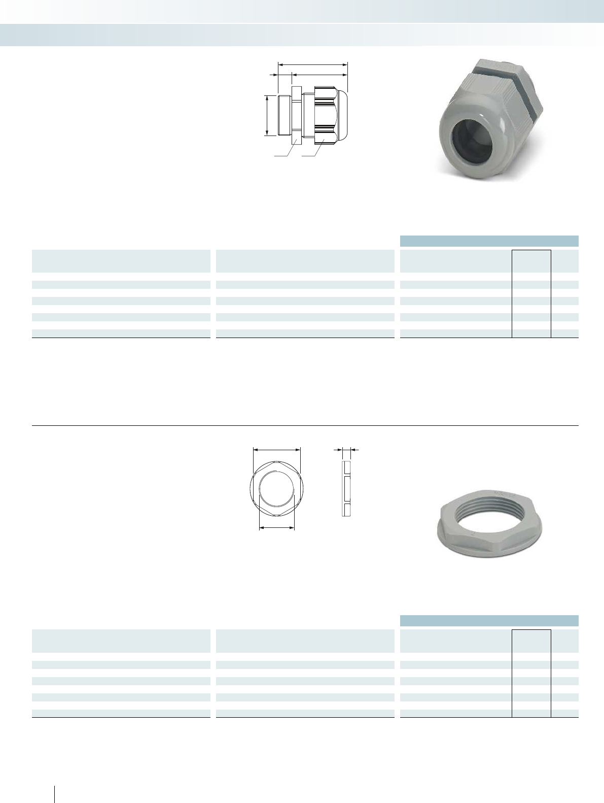
d
a b
e
f
c
ea
d
Plastic cable gland
Ordering data
Thread type Clamping area Dimensions [mm] Type Order No. Pcs. /
Pkt.
[mm] a b c d e f g
M12 3.00 - 6.50 15.00 15.00 8.00 12.00 32.10 24.10 - G-INS-M12-S68N-PNES-GY 1411123 10
M16 5.00 - 10.00 22.00 22.00 10.00 16.00 39.70 29.70 -G-INS-M16-S68N-PNES-GY 1411124 10
M20 6.00 - 12.00 24.00 24.00 10.00 20.00 42.30 32.30 - G-INS-M20-S68N-PNES-GY 1411125 5
M25 11.00 - 17.00 29.00 29.00 8.00 25.00 42.50 34.50 -G-INS-M25-M68N-PNES-GY 1411126 5
M32 15.00 - 21.00 36.00 36.00 10.00 32.00 50.80 40.80 - G-INS-M32-M68N-PNES-GY 1411127 5
M40 19.00 - 28.00 46.00 46.00 10.00 40.00 55.10 45.10 -G-INS-M40-M68N-PNES-GY 1411128 5
M50 30.00 - 38.00 60.00 60.00 18.00 50.00 71.70 53.70 - G-INS-M50-L68L-PNES-GY 1411129 1
M63 34.00 - 44.00 65.00 65.00 18.00 63.00 75.40 57.40 -G-INS-M63-L68L-PNES-GY 1411130 1
– Material: polyamide 6
– Color: silver-gray (RAL 7001)
– Seal: neoprene
– Ambient temperature:
-30°C...+80°C (+150°Cbriefly)
– Degree of protection: IP68, 5 bar
– Strain relief: integrated according to
EN50262
Plastic cable gland,
metric, EN 60423
Sensor/actuator cabling and industrial connectors
Installation and mounting material - cable glands
243143 / QCRV2.E320158 / 40024418
Plastic counter nut
Ordering data
Thread type Clamping area Dimensions [mm] Type Order No. Pcs. /
Pkt.
[mm] a b c d e f g
M12 - 18.00 - - 12.00 5.00 - - A-INL-M12-P-GY 1411205 10
M16 -22.00 - - 16.00 5.00 - - A-INL-M16-P-GY 1411206 10
M20 - 26.00 - - 20.00 6.00 - - A-INL-M20-P-GY 1411207 5
M25 -32.00 - - 25.00 6.00 - - A-INL-M25-P-GY 1411208 5
M32 - 41.00 - - 32.00 7.00 - - A-INL-M32-P-GY 1411209 5
M40 -50.00 - - 40.00 7.00 - - A-INL-M40-P-GY 1411210 5
M50 - 60.00 - - 50.00 8.00 - - A-INL-M50-P-GY 1411211 5
M63 -75.00 - - 63.00 8.00 - - A-INL-M63-P-GY 1411212 5
– Material: polyamide 6
– Color: silver-gray (RAL 7001)
– Ambient temperature:
-20°C...+80°C
Plastic counter nut,
metric, EN 60423
224 PHOENIX CONTACT
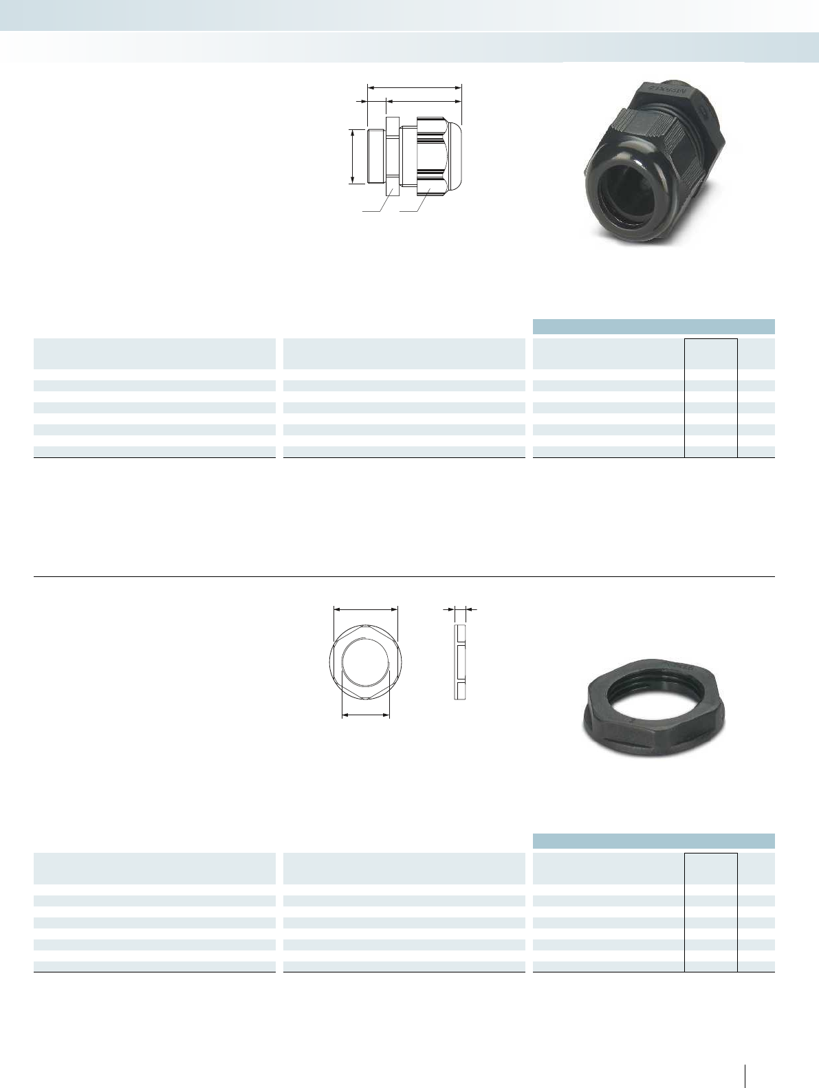
d
a b
e
f
c
ea
d
For additional information, visit phoenixcontact.net/products
Plastic cable gland
Ordering data
Thread type Clamping area Dimensions [mm] Type Order No. Pcs. /
Pkt.
[mm] a b c d e f g
M12 3.00 - 6.50 15.00 15.00 8.00 12.00 32.10 24.10 - G-INS-M12-S68N-PNES-BK 1411131 10
M16 5.00 - 10.00 22.00 22.00 10.00 16.00 39.70 29.70 -G-INS-M16-S68N-PNES-BK 1411132 10
M20 6.00 - 12.00 24.00 24.00 10.00 20.00 42.30 32.30 - G-INS-M20-S68N-PNES-BK 1411133 5
M25 11.00 - 17.00 29.00 29.00 8.00 25.00 42.50 34.50 -G-INS-M25-M68N-PNES-BK 1411134 5
M32 15.00 - 21.00 36.00 36.00 10.00 32.00 50.80 40.80 - G-INS-M32-M68N-PNES-BK 1411136 5
M40 19.00 - 28.00 46.00 46.00 10.00 40.00 55.10 45.10 -G-INS-M40-M68N-PNES-BK 1411137 5
M50 30.00 - 38.00 60.00 60.00 18.00 50.00 71.70 53.70 - G-INS-M50-L68L-PNES-BK 1411138 1
M63 34.00 - 44.00 65.00 65.00 18.00 63.00 75.40 57.40 -G-INS-M63-L68L-PNES-BK 1411139 1
– Material: polyamide 6
– Color: deep black (RAL 9005)
– Seal: neoprene
– Ambient temperature:
-30°C...+80°C (+150°Cbriefly)
– Degree of protection: IP68, 5 bar
– Strain relief: integrated according to
EN50262
Plastic cable gland,
metric, EN 60423
Sensor/actuator cabling and industrial connectors
Installation and mounting material - cable glands
243143 / QCRV.E320158 / 40024418
Plastic counter nut
Ordering data
Thread type Clamping area Dimensions [mm] Type Order No. Pcs. /
Pkt.
[mm] a b c d e f g
M12 - 18.00 - - 12.00 5.00 - - A-INL-M12-P-BK 1411213 10
M16 -22.00 - - 16.00 5.00 - - A-INL-M16-P-BK 1411214 10
M20 - 26.00 - - 20.00 6.00 - - A-INL-M20-P-BK 1411215 5
M25 -32.00 - - 25.00 6.00 - - A-INL-M25-P-BK 1411216 5
M32 - 41.00 - - 32.00 7.00 - - A-INL-M32-P-BK 1411217 5
M40 -50.00 - - 40.00 7.00 - - A-INL-M40-P-BK 1411218 5
M50 - 60.00 - - 50.00 8.00 - - A-INL-M50-P-BK 1411219 5
M63 -75.00 - - 63.00 8.00 - - A-INL-M63-P-BK 1411220 5
– Material: polyamide 6
– Color: deep black (RAL 9005)
– Ambient temperature:
-20°C...+80°C
Plastic counter nut,
metric, EN 60423
225
PHOENIX CONTACT
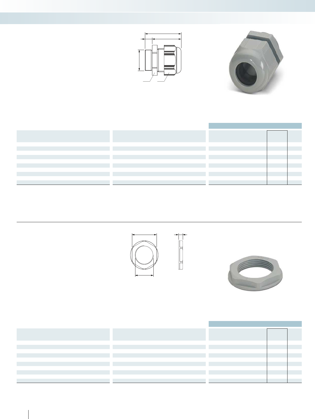
d
a b
e
f
c
ea
d
Plastic cable gland
Ordering data
Thread type Clamping area Dimensions [mm] Type Order No. Pcs. /
Pkt.
[mm] a b c d e f g
Pg7 3.00 - 6.50 15.00 15.00 8.00 12.50 32.70 24.70 - G-INS-PG7-S68N-PNES-GY 1411140 10
Pg9 4.00 - 8.00 19.00 19.00 8.00 15.20 36.20 28.20 -G-INS-PG9-S68N-PNES-GY 1411141 10
Pg11 5.00 - 10.00 22.00 22.00 8.00 18.60 38.10 30.10 - G-INS-PG11-S68N-PNES-GY 1411142 5
Pg13.5 6.00 - 12.00 24.00 24.00 9.00 20.40 40.00 31.00 -G-INS-PG13,5-S68N-PNES-GY 1411143 5
Pg16 10.00 - 14.00 27.00 27.00 10.00 22.50 44.20 34.20 - G-INS-PG16-S68N-PNES-GY 1411144 5
Pg21 13.00 - 18.00 33.00 33.00 11.00 28.30 49.30 38.30 -G-INS-PG21-M68N-PNES-GY 1411145 5
Pg29 18.00 - 25.00 42.00 42.00 11.00 37.00 53.90 42.90 - G-INS-PG29-M68N-PNES-GY 1411146 5
Pg36 22.00 - 32.00 53.00 53.00 13.00 47.00 65.40 52.40 -G-INS-PG36-L68N-PNES-GY 1411147 5
Pg42 30.00 - 38.00 60.00 60.00 13.00 54.00 65.90 52.90 - G-INS-PG42-L68N-PNES-GY 1411149 1
Pg48 34.00 - 44.00 65.00 65.00 14.00 59.30 68.80 54.80 -G-INS-PG48-L68N-PNES-GY 1411150 1
– Material: polyamide 6
– Color: silver-gray (RAL 7001)
– Seal: neoprene
– Ambient temperature:
-30°C...+80°C (+150°Cbriefly)
– Degree of protection: IP68, 5 bar
– Strain relief: integrated according to
EN50262
Plastic cable gland,
Pg, EN 40430
Sensor/actuator cabling and industrial connectors
Installation and mounting material - cable glands
243143 / QCRV2.E320158
Plastic counter nut
Ordering data
Thread type Clamping area Dimensions [mm] Type Order No. Pcs. /
Pkt.
[mm] a b c d e f g
Pg7 - 19.00 - - 12.50 5.00 - - A-INL-PG7-P-GY 1411221 10
Pg9 -22.00 - - 15.20 5.00 - - A-INL-PG9-P-GY 1411222 10
Pg11 - 24.00 - - 18.60 5.00 - - A-INL-PG11-P-GY 1411223 5
Pg13.5 -27.00 - - 20.40 6.00 - - A-INL-PG13,5-P-GY 1411224 5
Pg16 - 30.00 - - 22.50 6.00 - - A-INL-PG16-P-GY 1411225 5
Pg21 -36.00 - - 28.30 7.00 - - A-INL-PG21-P-GY 1411226 5
Pg29 - 46.00 - - 37.00 7.00 - - A-INL-PG29-P-GY 1411227 5
Pg36 -60.00 - - 47.00 8.00 - - A-INL-PG36-P-GY 1411228 5
Pg42 - 65.00 - - 54.00 8.00 - - A-INL-PG42-P-GY 1411229 5
Pg48 -70.00 - - 59.30 8.00 - - A-INL-PG48-P-GY 1411230 5
– Material: polyamide 6
– Color: silver-gray (RAL 7001)
– Ambient temperature:
-20°C...+80°C
Plastic counter nut,
Pg, EN 40430
226 PHOENIX CONTACT
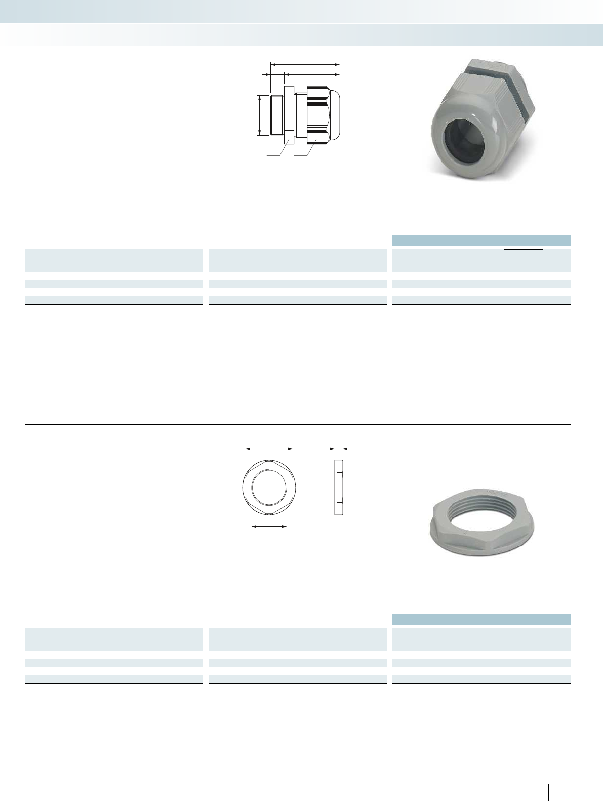
d
a b
e
f
c
ea
d
For additional information, visit phoenixcontact.net/products
Plastic cable gland
Ordering data
Thread type Clamping area Dimensions [mm] Type Order No. Pcs. /
Pkt.
[mm] a b c d e f g
NPT3/8" 5.00 - 10.00 22.00 22.00 15.00 16.60 44.50 29.50 - G-INS-N3/8-S68L-PNES-GY 1411152 10
NPT1/2" 10.00 - 14.00 27.00 27.00 15.00 20.60 47.10 32.10 -G-INS-N1/2-S68L-PNES-GY 1411153 10
NPT3/4" 13.00 - 18.00 33.00 33.00 15.00 25.90 47.50 35.50 - G-INS-N3/4-M68L-PNES-GY 1411154 5
NPT1" 18.00 - 25.00 42.00 42.00 18.00 32.40 58.50 40.50 -G-INS-N1-M68L-PNES-GY 1411155 5
– Material: polyamide 6
– Color: silver-gray (RAL 7001)
– Seal: neoprene
– Ambient temperature:
-30°C...+80°C (+150°Cbriefly)
– Degree of protection: IP68, 5 bar
– Strain relief: integrated according to
EN50262
Plastic cable gland,
NPT, ANSI B1.20.1
Sensor/actuator cabling and industrial connectors
Installation and mounting material - cable glands
243143 / QCRV.E320158
Plastic counter nut
Ordering data
Thread type Clamping area Dimensions [mm] Type Order No. Pcs. /
Pkt.
[mm] a b c d e f g
NPT3/8" - 22.00 - - 16.60 5.00 - - A-INL-NPT3/8-P-GY 1411231 10
NPT1/2" -27.00 - - 20.60 5.00 - - A-INL-NPT1/2-P-GY 1411233 10
NPT3/4" - 33.00 - - 25.90 5.00 - - A-INL-NPT3/4-P-GY 1411234 5
NPT1" -47.00 - - 32.40 6.00 - - A-INL-NPT1-P-GY 1411235 5
– Material: polyamide 6
– Color: silver-gray (RAL 7001)
– Ambient temperature:
-20°C...+80°C
Plastic counter nut,
NPT, ANSI B1.20.1
227
PHOENIX CONTACT
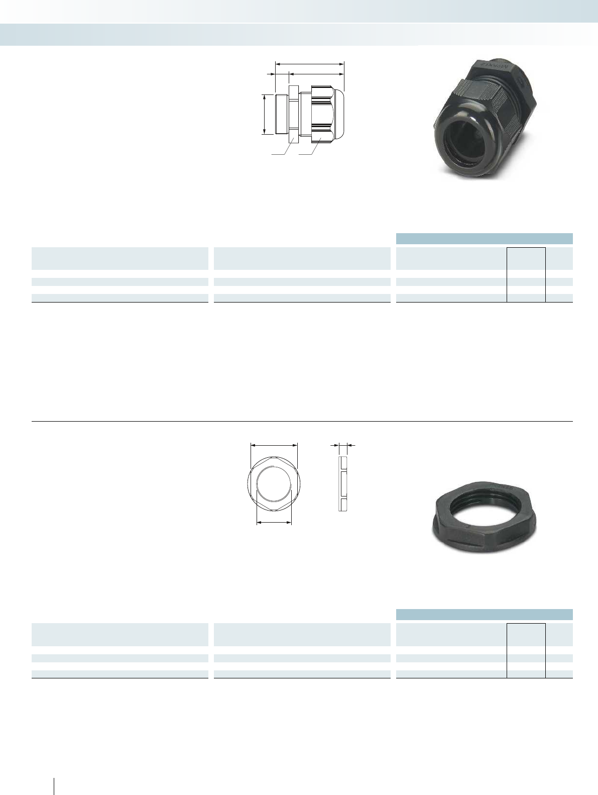
d
a b
e
f
c
ea
d
Plastic cable gland
Ordering data
Thread type Clamping area Dimensions [mm] Type Order No. Pcs. /
Pkt.
[mm] a b c d e f g
NPT3/8" 5.00 - 10.00 22.00 22.00 15.00 16.60 44.50 29.50 - G-INS-N3/8-S68L-PNES-BK 1411156 10
NPT1/2" 10.00 - 14.00 27.00 27.00 15.00 20.60 47.10 32.10 -G-INS-N1/2-S68L-PNES-BK 1411157 10
NPT3/4" 13.00 - 18.00 33.00 33.00 12.00 25.90 47.50 35.50 - G-INS-N3/4-M68L-PNES-BK 1411158 5
NPT1" 18.00 - 25.00 42.00 42.00 18.00 32.40 58.50 40.50 -G-INS-N1-M68L-PNES-BK 1411159 5
– Material: polyamide 6
– Color: deep black (RAL 9005)
– Seal: neoprene
– Ambient temperature:
-30°C...+80°C (+150°Cbriefly)
– Degree of protection: IP68, 5 bar
– Strain relief: integrated according to
EN50262
Plastic cable gland,
NPT, ANSI B1.20.1
Sensor/actuator cabling and industrial connectors
Installation and mounting material - cable glands
243143 / QCRV.E320158
Plastic counter nut
Ordering data
Thread type Clamping area Dimensions [mm] Type Order No. Pcs. /
Pkt.
[mm] a b c d e f g
NPT3/8" - 22.00 - - 16.60 5.00 - - A-INL-NPT3/8-P-BK 1411236 10
NPT1/2" -27.00 - - 20.60 5.00 - - A-INL-NPT1/2-P-BK 1411237 10
NPT3/4" - 33.00 - - 25.90 5.00 - - A-INL-NPT3/4-P-BK 1411238 5
NPT1" -47.00 - - 32.40 6.00 - - A-INL-NPT1-P-BK 1411239 5
– Material: polyamide 6
– Color: deep black (RAL 9005)
– Ambient temperature:
-20°C...+80°C
Plastic counter nut,
NPT, ANSI B1.20.1
228 PHOENIX CONTACT
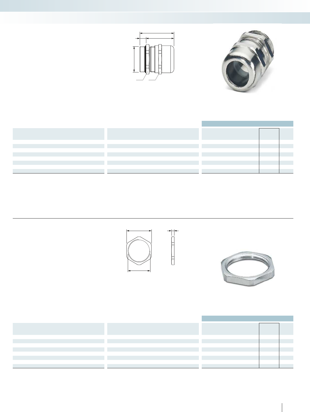
d
b a
e
f
c
ea
d
For additional information, visit phoenixcontact.net/products
Brass cable gland
Ordering data
Thread type Clamping area Dimensions [mm] Type Order No. Pcs. /
Pkt.
[mm] a b c d e f g
M12 3.00 - 6.50 14.00 14.00 6.00 12.00 27.80 21.80 - G-INS-M12-S68N-NNES-S 1411160 10
M16 5.00 - 10.00 20.00 20.00 7.00 16.00 34.50 27.50 -G-INS-M16-S68N-NNES-S 1411162 10
M20 6.00 - 12.00 22.00 22.00 8.00 20.00 37.50 29.50 - G-INS-M20-S68N-NNES-S 1411163 5
M25 11.00 - 17.00 27.00 27.00 8.00 25.00 40.00 32.00 -G-INS-M25-M68N-NNES-S 1411165 5
M32 15.00 - 21.00 34.00 34.00 8.00 32.00 43.00 35.00 - G-INS-M32-M68N-NNES-S 1411166 5
M40 19.00 - 28.00 43.00 43.00 9.00 40.00 53.70 44.70 -G-INS-M40-M68N-NNES-S 1411167 5
M50 27.00 - 38.00 58.00 58.00 9.00 50.00 61.00 52.00 - G-INS-M50-L68N-NNES-S 1411168 1
M63 34.00 - 44.00 64.00 68.00 14.00 63.00 65.20 51.20 -G-INS-M63-L68N-NNES-S 1411169 1
– Material: brass, nickel-plated
– Seal: neoprene
– Clamping insert: polyamide 6
–O-ring: NBR
– Ambient temperature:
-40°C...+100°C
– Degree of protection: IP69K
– Strain relief: integrated according to
EN50262
Brass cable gland,
metric, EN 60423
Sensor/actuator cabling and industrial connectors
Installation and mounting material - cable glands
QCRV.E320158
Brass counter nut
Ordering data
Thread type Clamping area Dimensions [mm] Type Order No. Pcs. /
Pkt.
[mm] a b c d e f g
M12 - 15.00 - - 12.00 2.80 - - A-INL-M12-N-S 1411240 100
M16 -19.00 - - 16.00 2.80 - - A-INL-M16-N-S 1411241 100
M20 - 24.00 - - 20.00 3.00 - - A-INL-M20-N-S 1411242 100
M25 -30.00 - - 25.00 3.50 - - A-INL-M25-N-S 1411243 100
M32 - 36.00 - - 32.00 4.00 - - A-INL-M32-N-S 1411244 100
M40 -46.00 - - 40.00 5.00 - - A-INL-M40-N-S 1411246 50
M50 - 57.00 - - 50.00 5.00 - - A-INL-M50-N-S 1411247 25
M63 -70.00 - - 63.00 6.00 - - A-INL-M63-N-S 1411248 25
– Material: brass, nickel-plated
– Ambient temperature:
-70°C...+220°C
Brass counter nut,
metric, EN 60423
229
PHOENIX CONTACT
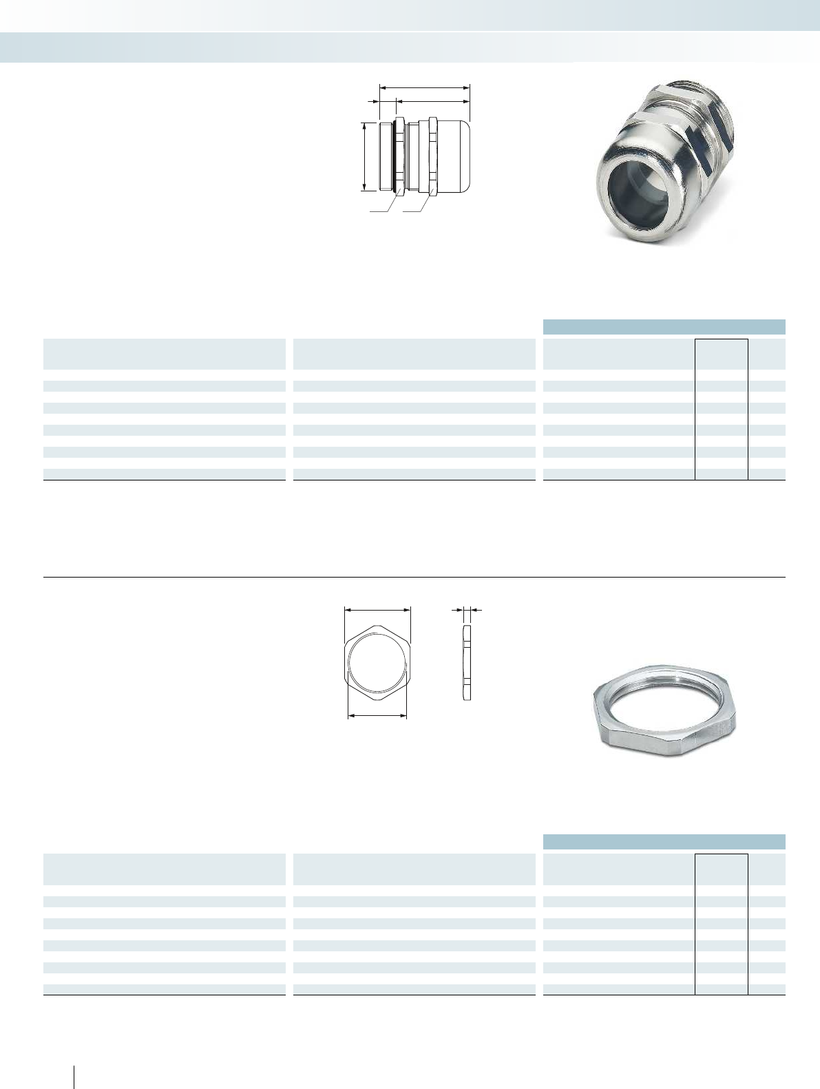
d
b a
e
f
c
ea
d
Brass cable gland
Ordering data
Thread type Clamping area Dimensions [mm] Type Order No. Pcs. /
Pkt.
[mm] a b c d e f g
Pg7 3.00 - 6.50 14.00 14.00 6.00 12.50 27.80 21.80 - G-INS-PG7-S68N-NNES-S 1411170 10
Pg9 4.00 - 8.00 17.00 17.00 6.00 15.20 28.20 22.20 -G-INS-PG9-S68N-NNES-S 1411171 10
Pg11 5.00 - 10.00 20.00 20.00 6.00 18.60 21.00 15.00 - G-INS-PG11-S68N-NNES-S 1411172 5
Pg13.5 6.00 - 12.00 22.00 22.00 6.50 20.40 30.50 24.00 -G-INS-PG13,5-S68N-NNES-S 1411173 5
Pg16 10.00 - 14.00 24.00 24.00 6.50 22.50 33.90 27.40 - G-INS-PG16-S68N-NNES-S 1411174 5
Pg21 13.00 - 18.00 30.00 30.00 7.20 28.30 38.50 31.30 -G-INS-PG21-M68N-NNES-S 1411175 5
Pg29 18.00 - 25.00 40.00 40.00 8.00 37.00 46.90 38.90 - G-INS-PG29-M68N-NNES-S 1411176 5
Pg36 22.00 - 32.00 50.00 50.00 9.00 47.00 57.20 48.20 -G-INS-PG36-L68N-NNES-S 1411178 5
Pg42 30.00 - 38.00 58.00 58.00 12.00 54.00 60.00 48.00 - G-INS-PG42-L68N-NNES-S 1411179 1
Pg48 34.00 - 44.00 64.00 64.00 14.00 59.30 63.40 49.40 -G-INS-PG48-L68N-NNES-S 1411181 1
– Material: brass, nickel-plated
– Seal: neoprene
– Clamping insert: polyamide 6
–O-ring: NBR
– Ambient temperature:
-40°C...+100°C
– Degree of protection: IP68/IP69K
– Strain relief: integrated according to
EN50262
Brass cable gland,
Pg, EN 40430
Sensor/actuator cabling and industrial connectors
Installation and mounting material - cable glands
QCRV.E320158
Brass counter nut
Ordering data
Thread type Clamping area Dimensions [mm] Type Order No. Pcs. /
Pkt.
[mm] a b c d e f g
Pg7 - 15.00 - - 12.50 2.80 - - A-INL-PG7-N-S 1411255 100
Pg9 -18.00 - - 15.20 2.80 - - A-INL-PG9-N-S 1411256 100
Pg11 - 21.00 - - 18.60 3.00 - - A-INL-PG11-N-S 1411257 100
Pg13.5 -23.00 - - 20.40 3.00 - - A-INL-PG13,5-N-S 1411259 100
Pg16 - 26.00 - - 22.50 3.00 - - A-INL-PG16-N-S 1411260 100
Pg21 -32.00 - - 28.30 3.50 - - A-INL-PG21-N-S 1411262 100
Pg29 - 41.00 - - 37.00 4.00 - - A-INL-PG29-N-S 1411263 50
Pg36 -51.00 - - 47.00 5.00 - - A-INL-PG36-N-S 1411264 50
Pg42 - 60.00 - - 54.00 5.00 - - A-INL-PG42-N-S 1411265 25
Pg48 -64.00 - - 59.30 5.50 - - A-INL-PG48-N-S 1411266 25
– Material: brass, nickel-plated
– Ambient temperature:
-70°C...+220°C
Brass counter nut,
Pg, EN 40430
230 PHOENIX CONTACT
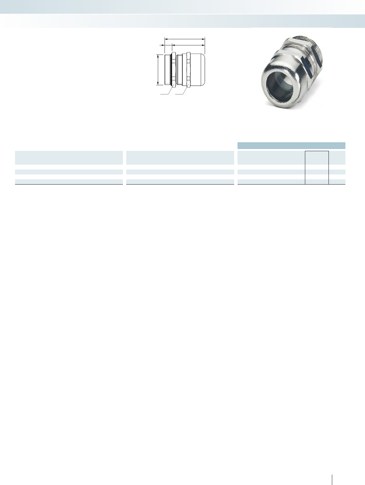
d
b a
e
f
c
For additional information, visit phoenixcontact.net/products
Brass cable gland
Ordering data
Thread type Clamping area Dimensions [mm] Type Order No. Pcs. /
Pkt.
[mm] a b c d e f g
NPT3/8" 5.00 - 10.00 17.00 19.00 11.50 16.00 34.50 23.00 - G-INS-NPT3/8-S68L-NNES-S 1411182 10
NPT1/2" 10.00 - 14.00 22.00 22.00 13.00 21.00 39.00 26.00 -G-INS-NPT1/2-S68L-NNES-S 1411183 10
NPT3/4" 13.00 - 18.00 30.00 30.00 13.00 29.00 48.50 35.50 - G-INS-NPT3/4-M68L-NNES-S 1411184 5
NPT1" 18.00 - 25.00 40.00 43.00 13.00 32.00 56.00 43.00 -G-INS-NPT1-M68L-NNES-S 1411185 5
– Material: brass, nickel-plated
– Seal: neoprene
– Clamping insert: polyamide 6
–O-ring: NBR
– Ambient temperature:
-40°C...+100°C
– Degree of protection: IP68, 5 bar
– Strain relief: integrated according to
EN50262
Brass cable gland,
NPT, ANSI B1.20.1
Sensor/actuator cabling and industrial connectors
Installation and mounting material - cable glands
QCRV2.E320158
231
PHOENIX CONTACT
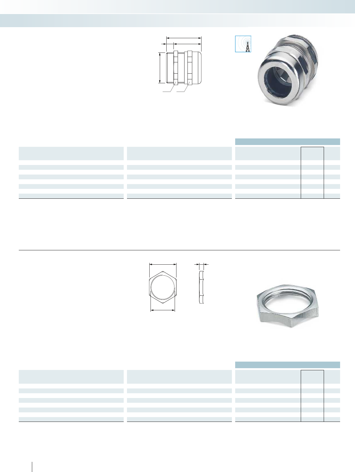
EMC
d
a b
e
f
c
ea
d
Brass cable gland
Ordering data
Thread type Clamping area Dimensions [mm] Type Order No. Pcs. /
Pkt.
[mm] a b c d e f g
M12 3.00 - 6.50 14.00 14.00 6.00 12.00 28.00 22.00 - G-INSEC-M12-S68N-NCRS-S 1411187 10
M16 5.00 - 9.00 17.00 17.00 5.00 16.00 30.00 25.00 -G-INSEC-M16-S68N-NCRS-S 1411188 10
M20 9.00 - 13.00 22.00 22.00 6.00 20.00 33.50 27.50 - G-INSEC-M20-S68N-NCRS-S 1411189 5
M25 11.00 - 16.00 27.00 27.00 7.00 25.00 36.50 29.50 -G-INSEC-M25-S68N-NCRS-S 1411190 5
M32 14.00 - 21.00 34.00 34.00 8.00 32.00 38.00 30.00 - G-INSEC-M32-M68N-NCRS-S 1411191 5
M40 19.00 - 27.00 43.00 43.00 8.00 40.00 41.00 33.00 -G-INSEC-M40-M68N-NCRS-S 1411192 5
M50 24.00 - 35.00 55.00 55.00 9.00 50.00 49.50 40.50 - G-INSEC-M50-L68N-NCRS-S 1411193 1
M63 32.00 - 42.00 65.00 65.00 10.00 63.00 52.50 42.50 -G-INSEC-M63-L68N-NCRS-S 1411194 1
– Material: brass, nickel-plated
– Seal: CR/NBR
– Clamping insert: polyamide 6
– Contact spring: stainless steel
–O-ring: NBR
– Ambient temperature (operation):
-20°C...+100°C
– Degree of protection: IP68
– Strain relief: integrated according to
EN50262
Brass EMC cable gland,
metric, EN 60423
Sensor/actuator cabling and industrial connectors
Installation and mounting material - cable glands
QCRV.E140310 / QCRV2.E140310
Brass counter nut
Ordering data
Thread type Clamping area Dimensions [mm] Type Order No. Pcs. /
Pkt.
[mm] a b c d e f g
M12 - 15.00 - - 12.00 4.70 - - A-INLE-M12-N-S 1411267 100
M16 -19.00 - - 16.00 4.70 - - A-INLE-M16-N-S 1411268 100
M20 - 24.00 - - 20.00 4.70 - - A-INLE-M20-N-S 1411269 100
M25 -30.00 - - 25.00 5.20 - - A-INLE-M25-N-S 1411270 50
M32 - 36.00 - - 32.00 5.70 - - A-INLE-M32-N-S 1411271 50
M40 -46.00 - - 40.00 6.50 - - A-INLE-M40-N-S 1411272 50
M50 - 57.00 - - 50.00 6.50 - - A-INLE-M50-N-S 1411273 10
M63 -70.00 - - 63.00 7.00 - - A-INLE-M63-N-S 1411274 10
– Material: brass, nickel-plated
– Ambient temperature:
-70°C...+220°C
– Version: ribbed
Brass counter nut,
metric, EN 60423, ribbed
232 PHOENIX CONTACT
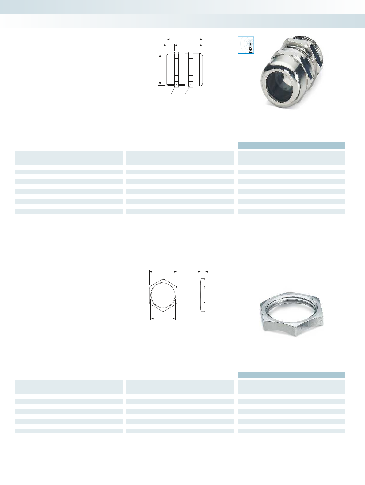
EMC
d
a b
e
f
c
ea
d
For additional information, visit phoenixcontact.net/products
Brass cable gland
Ordering data
Thread type Clamping area Dimensions [mm] Type Order No. Pcs. /
Pkt.
[mm] a b c d e f g
Pg7 3.00 - 6.50 14.00 14.00 6.00 12.50 27.00 21.00 - G-INSEC-PG7-S68N-NNES-S 1411195 10
Pg9 4.00 - 8.00 17.00 17.00 6.00 15.20 29.00 23.00 -G-INSEC-PG9-S68N-NNES-S 1411196 10
Pg11 5.00 - 10.00 20.00 20.00 6.00 18.60 30.00 24.00 - G-INSEC-PG11-S68N-NNES-S 1411197 5
Pg13.5 6.00 - 12.00 22.00 22.00 6.50 20.40 30.00 23.50 -G-INSEC-PG13,5-S68N-NNES-S 1411198 5
Pg16 10.00 - 14.00 24.00 24.00 6.50 22.50 33.90 27.40 - G-INSEC-PG16-S68N-NNES-S 1411199 5
Pg21 13.00 - 18.00 30.00 30.00 7.20 28.30 38.50 31.30 -G-INSEC-PG21-M68N-NNES-S 1411200 5
Pg29 18.00 - 25.00 40.00 40.00 8.00 37.00 47.00 39.00 - G-INSEC-PG29-M68N-NNES-S 1411201 5
Pg36 22.00 - 32.00 50.00 50.00 9.00 47.00 57.00 48.00 -G-INSEC-PG36-L68N-NNES-S 1411202 5
Pg42 30.00 - 38.00 58.00 58.00 12.00 54.00 60.00 48.00 - G-INSEC-PG42-L68N-NNES-S 1411203 1
Pg48 34.00 - 44.00 64.00 64.00 14.00 59.30 65.00 51.00 -G-INSEC-PG48-L68N-NNES-S 1411204 1
– Material: brass, nickel-plated
– Seal: neoprene
– Clamping insert: polyamide 6
– Contact spring: copper beryllium
–O-ring: NBR
– Ambient temperature:
-40°C...+100°C
– Degree of protection: IP68
– Strain relief: integrated according to
EN50262
Brass EMC cable gland,
Pg, EN 40430
Sensor/actuator cabling and industrial connectors
Installation and mounting material - cable glands
QCRV2.E320158
Brass counter nut
Ordering data
Thread type Clamping area Dimensions [mm] Type Order No. Pcs. /
Pkt.
[mm] a b c d e f g
Pg7 - 15.00 - - 12.50 4.70 - - A-INLE-PG7-N-S 1411275 100
Pg9 -18.00 - - 15.20 4.70 - - A-INLE-PG9-N-S 1411276 100
Pg11 - 21.00 - - 18.60 4.70 - - A-INLE-PG11-N-S 1411277 100
Pg13.5 -23.00 - - 20.40 4.70 - - A-INLE-PG13,5-N-S 1411278 100
Pg16 - 26.00 - - 22.50 4.70 - - A-INLE-PG16-N-S 1411279 100
Pg21 -32.00 - - 28.30 5.20 - - A-INLE-PG21-N-S 1411280 50
Pg29 - 41.00 - - 37.00 5.70 - - A-INLE-PG29-N-S 1411281 50
Pg36 -51.00 - - 47.00 6.50 - - A-INLE-PG36-N-S 1411282 50
– Material: brass, nickel-plated
– Ambient temperature:
-70°C...+220°C
– Version: ribbed
Brass counter nut,
Pg, EN 40430, ribbed
233
PHOENIX CONTACT
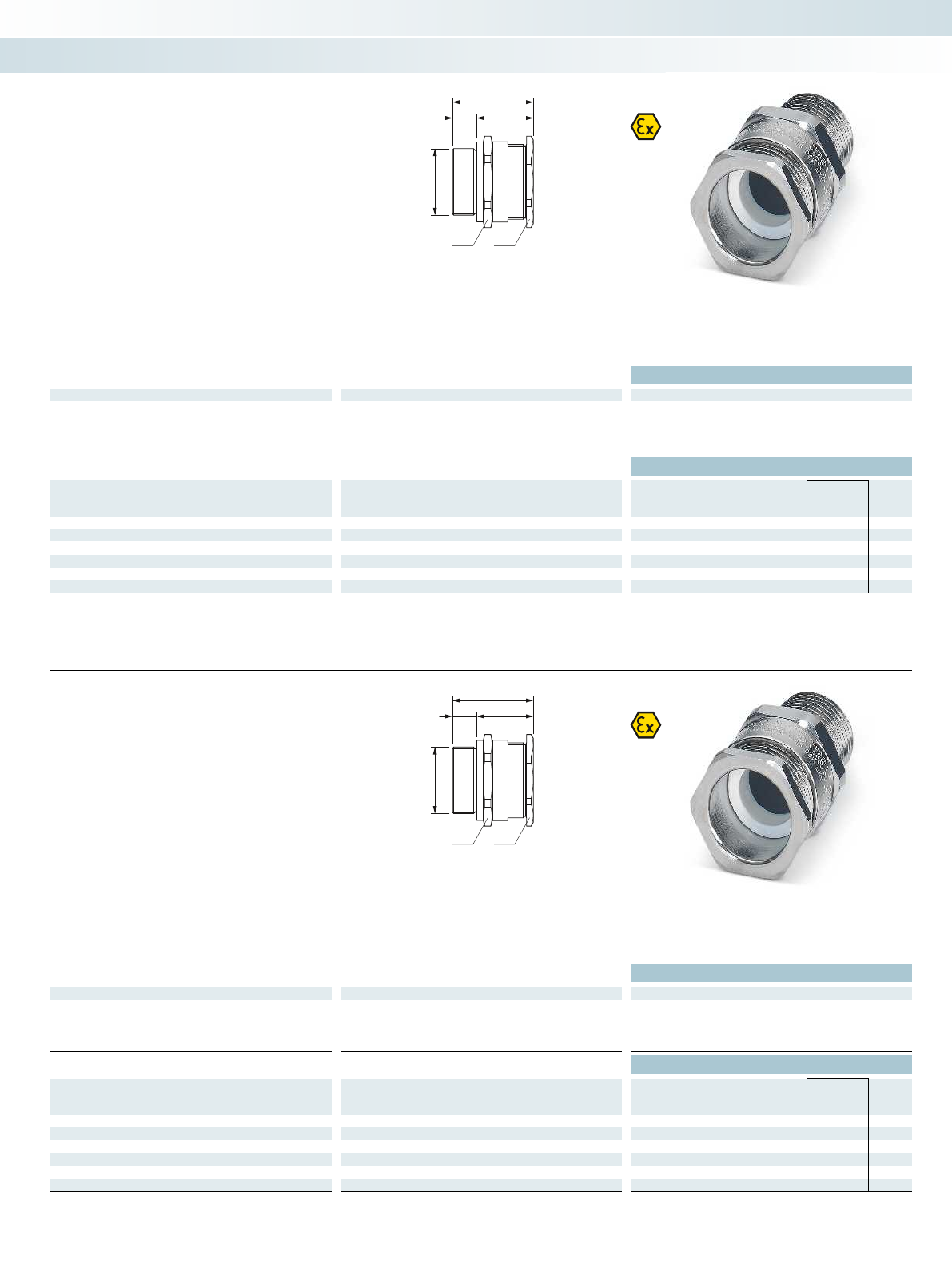
d
a b
e
f
c
d
a b
e
f
c
Brass cable gland
Technical data
General data
Cable gland material Nickel-plated brass
Seal material Thermoplastic elastomers
O-ring material Viton
Ambient temperature (operation) -60°C ... 130°C
Ordering data
Thread type Clamping area Dimensions [mm] Type Order No. Pcs. /
Pkt.
[mm] a b c d e f g
M20 6.50 - 14.00 27.00 27.00 15.00 20.00 39.00 24.00 - G-ESS-M20-S66L-NTES-S 1411075 20
M25 11.10 - 20.00 36.00 36.00 15.00 25.00 41.00 26.00 -G-ESS-M25-M66L-NTES-S 1411077 20
M32 17.00 - 26.30 41.00 41.00 15.00 32.00 42.00 27.00 - G-ESS-M32-M66L-NTES-S 1411079 10
M40 23.50 - 32.20 50.00 50.00 15.00 40.00 43.00 28.00 -G-ESS-M40-L66L-NTES-S 1411081 2
M50 35.60 - 44.10 60.00 60.00 15.00 50.00 45.00 30.00 - G-ESS-M50-L66L-NTES-S 1411084 2
M63 47.20 - 56.00 75.00 75.00 15.00 63.00 45.00 30.00 -G-ESS-M63-L66L-NTES-S 1411086 2
Cable glands for unarmored and braided
cables provide flameproof (type “d”),
increased safety (type “e”), and restricted
breathing (type “nR”) hazardous area
protection to IP66, IP67, and IP68.
Brass cable gland,
metric, Ex protection
Sensor/actuator cabling and industrial connectors
Installation and mounting material - cable glands
Ex:
SIRA13ATEX1068X / IECEx SIR13.0023X
Stainless steel cable gland
Technical data
General data
Cable gland material High-grade steel
Seal material Thermoplastic elastomers
O-ring material Viton
Ambient temperature (operation) -60°C ... 130°C
Ordering data
Thread type Clamping area Dimensions [mm] Type Order No. Pcs. /
Pkt.
[mm] a b c d e f g
M20 6.50 - 14.00 27.00 27.00 15.00 20.00 39.00 24.00 - G-ESS-M20-S66L-STES-S 1411076 20
M25 11.10 - 20.00 36.00 36.00 15.00 25.00 41.00 26.00 -G-ESS-M25-M66L-STES-S 1411078 20
M32 17.00 - 26.30 41.00 41.00 15.00 32.00 42.00 27.00 - G-ESS-M32-M66L-STES-S 1411080 10
M40 23.50 - 32.20 50.00 50.00 15.00 40.00 43.00 28.00 -G-ESS-M40-L66L-STES-S 1411082 2
M50 35.60 - 44.10 60.00 60.00 15.00 50.00 45.00 30.00 - G-ESS-M50-L66L-STES-S 1411085 2
M63 47.20 - 56.00 75.00 75.00 15.00 63.00 45.00 30.00 -G-ESS-M63-L66L-STES-S 1411087 2
Cable glands for unarmored and braided
cables provide flameproof (type “d”),
increased safety (type “e”), and restricted
breathing (type “nR”) hazardous area
protection to IP66, IP67, and IP68.
Stainless steel cable gland,
metric, Ex protection
234 PHOENIX CONTACT
Ex:
SIRA13ATEX1068X / IECEx SIR13.0023X
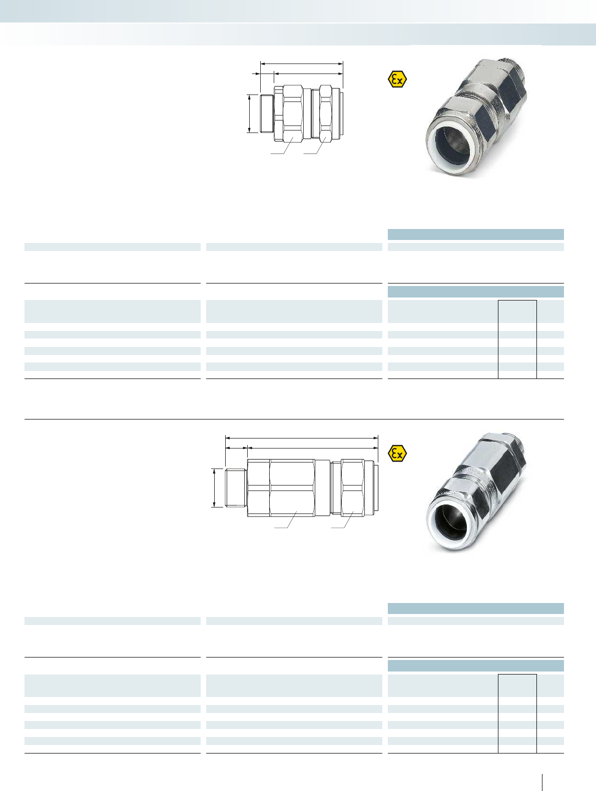
d
a b
e
f
c
d
a b
e
f
c
For additional information, visit phoenixcontact.net/products
Brass cable gland
Technical data
General data
Cable gland material Nickel-plated brass
Seal material Thermoplastic elastomers
O-ring material Viton
Ambient temperature (operation) -60°C ... 130°C
Ordering data
Thread type Clamping area Dimensions [mm] Type Order No. Pcs. /
Pkt.
[mm] a b c d e f g
M20 9.50 - 15.90 24.00 24.00 15.00 20.00 73.50 58.50 - G-ESSWU-M20S-S66L-NTES-S 1411088 10
M20 12.50 - 20.90 30.50 30.50 15.00 20.00 75.50 60.50 -G-ESSWU-M20-M66L-NTES-S 1411090 10
M25 18.20 - 26.20 37.50 37.50 15.00 25.00 82.50 67.50 - G-ESSWU-M25-M66L-NTES-S 1411092 10
M32 23.70 - 33.90 46.00 46.00 15.00 32.00 84.50 69.50 -G-ESSWU-M32-L66L-NTES-S 1411094 5
M40 27.90 - 40.40 55.00 55.00 15.00 40.00 93.00 78.00 - G-ESSWU-M40-L66L-NTES-S 1411097 1
M50 40.40 - 53.10 70.00 70.00 15.00 50.00 95.50 80.50 -G-ESSWU-M50-L66L-NTES-S 1411100 1
M63 54.60 - 65.90 80.00 80.00 15.00 63.00 107.00 92.00 - G-ESSWU-M63-L66L-NTES-S 1411102 1
Cable glands for armored cables provide
increased safety (type “e”) hazardous area
protection to IP66, IP67, and IP68.
Brass cable gland,
metric, Ex protection
Sensor/actuator cabling and industrial connectors
Installation and mounting material - cable glands
Ex:
SIRA13ATEX1070X / IECEx SIR13.0025X
Stainless steel cable gland
Technical data
General data
Cable gland material High-grade steel
Seal material Thermoplastic elastomers
O-ring material Viton
Ambient temperature (operation) -60°C ... 130°C
Ordering data
Thread type Clamping area Dimensions [mm] Type Order No. Pcs. /
Pkt.
[mm] a b c d e f g
M20 9.50 - 15.90 24.00 24.00 15.00 20.00 73.50 58.50 - G-EDSWU-M20S-S66L-STES-S 1411089 10
M20 12.50 - 20.90 30.50 30.50 15.00 20.00 75.50 60.50 -G-EDSWU-M20-M66L-STES-S 1411091 10
M25 18.20 - 26.20 37.50 37.50 15.00 25.00 82.50 67.50 - G-EDSWU-M25-M66L-STES-S 1411093 10
M32 23.70 - 33.90 46.00 46.00 15.00 32.00 84.50 69.50 -G-EDSWU-M32-L66L-STES-S 1411095 5
M40 27.90 - 40.40 55.00 55.00 15.00 40.00 93.00 78.00 - G-EDSWU-M40-L66L-STES-S 1411099 1
M50 40.40 - 53.10 70.00 70.00 15.00 50.00 95.50 80.50 -G-EDSWU-M50-L66L-STES-S 1411101 1
M63 54.60 - 65.90 80.00 80.00 15.00 63.00 107.00 92.00 - G-EDSWU-M63-L66L-STES-S 1411103 1
Cable glands for armored cables provide
flameproof (type “d”), increased safety
(type“e”), and restricted breathing
(type“nR”) hazardous area protection to
IP66, IP67, and IP68.
Stainless steel cable gland,
metric, Ex protection
235
PHOENIX CONTACT
Ex:
SIRA13ATEX1073X / IECEx SIR13.0028X
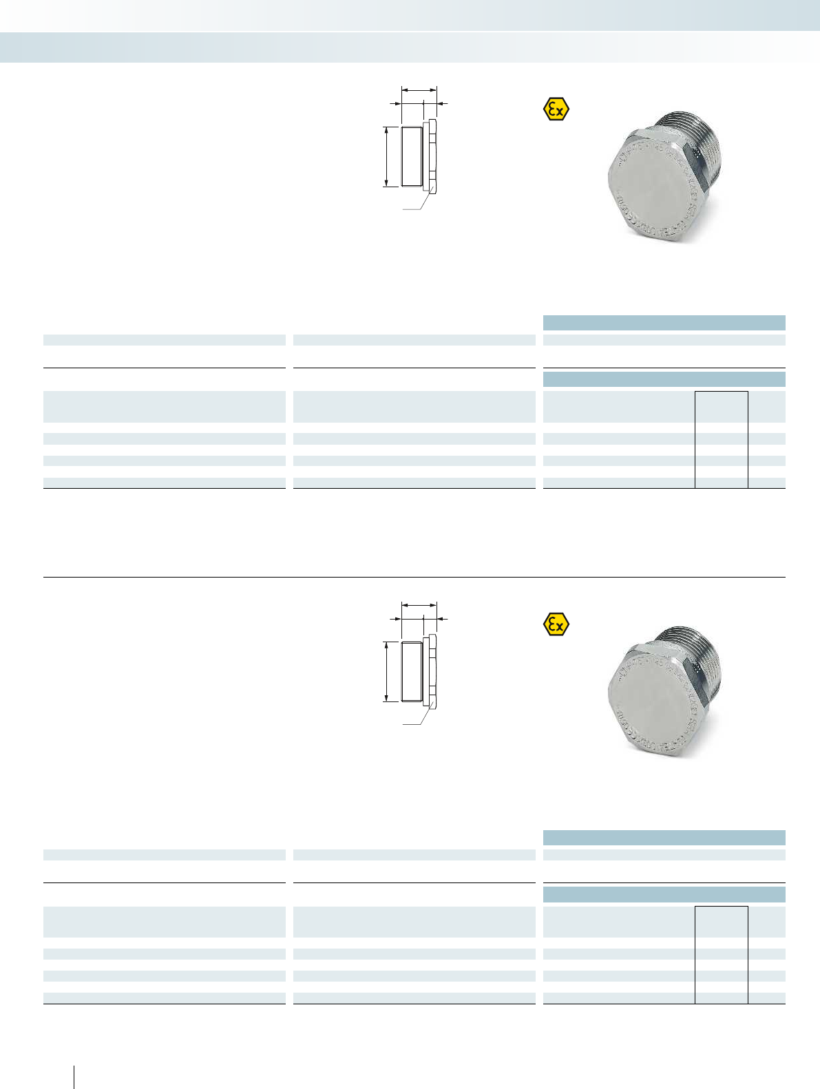
e
c f
d
a
e
c f
d
a
Brass screw plug
Technical data
General data
Material Nickel-plated brass
Ambient temperature (operation) -60°C ... 200°C
Ordering data
Thread type Clamping area Dimensions [mm] Type Order No. Pcs. /
Pkt.
[mm] a b c d e f g
M20 - 24.00 - 15.00 20.00 24.00 9.00 - A-EXSH-M20-68L-N-S 1411104 20
M25 -30.00 -15.00 25.00 24.00 9.00 -A-EXSH-M25-68L-N-S 1411107 20
M32 - 36.00 - 15.00 32.00 24.00 9.00 - A-EXSH-M32-68L-N-S 1411109 10
M40 -46.00 -15.00 40.00 24.00 9.00 -A-EXSH-M40-68L-N-S 1411111 5
M50 - 55.00 - 15.00 50.00 24.00 9.00 - A-EXSH-M50-68L-N-S 1411113 2
M63 -65.00 -15.00 63.00 24.00 9.00 -A-EXSH-M63-68L-N-S 1411115 1
Screw plugs provide IP66 and IP68
protection when installed with an entry
thread ring, sealing unused cable entries in
flameproof (type “d”) and increased safety
(type “e”) installations.
Brass screw plug,
metric, Ex protection
Sensor/actuator cabling and industrial connectors
Installation and mounting material - cable glands
Ex:
SIRA01ATEX1284U / IECEx SIR07.0083X
Stainless steel screw plug
Technical data
General data
Material High-grade steel
Ambient temperature (operation) -60°C ... 200°C
Ordering data
Thread type Clamping area Dimensions [mm] Type Order No. Pcs. /
Pkt.
[mm] a b c d e f g
M20 - 24.00 - 15.00 20.00 24.00 9.00 - A-EXSH-M20-68L-S-S 1411105 20
M25 -30.00 -15.00 25.00 24.00 9.00 -A-EXSH-M25-68L-S-S 1411108 20
M32 - 36.00 - 15.00 32.00 24.00 9.00 - A-EXSH-M32-68L-S-S 1411110 10
M40 -46.00 -15.00 40.00 24.00 9.00 -A-EXSH-M40-68L-S-S 1411112 5
M50 - 55.00 - 15.00 50.00 24.00 9.00 - A-EXSH-M50-68L-S-S 1411114 2
M63 -65.00 -15.00 63.00 24.00 9.00 -A-EXSH-M63-68L-S-S 1411116 1
Screw plugs provide IP66 and IP68
protection when installed with an entry
thread ring, sealing unused cable entries in
flameproof (type “d”) and increased safety
(type “e”) installations.
Stainless steel screw plug,
metric, Ex protection
236 PHOENIX CONTACT
Ex:
SIRA01ATEX1284U / IECEx SIR07.0083X
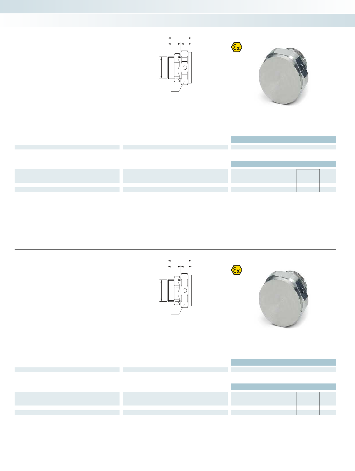
e
f
c
d
a
e
f
c
d
a
For additional information, visit phoenixcontact.net/products
Brass pressure compensation
Technical data
General data
Material Nickel-plated brass
Ambient temperature (operation) -20°C ... 130°C
Ordering data
Thread type Clamping area Dimensions [mm] Type Order No. Pcs. /
Pkt.
[mm] a b c d e f g
M20 - 30.00 - 15.00 20.00 28.00 13.00 - A-EXB-20-66L-N-S 1411117 5
M25 -36.00 -15.00 25.00 28.00 13.00 -A-EXB-25-66L-N-S 1411120 5
Breather/drain plugs for increased safety
(type “e”) provide superior ventilation for
devices. They are designed to act as a
pressure compensation element preventing
moisture build-up to IP66.
Brass pressure compensation,
metric, Ex protection
Sensor/actuator cabling and industrial connectors
Installation and mounting material - cable glands
Ex:
SIRA10ATEX1307U / IECEx SIR10.0149U
Stainless steel pressure compensation
Technical data
General data
Material High-grade steel
Ambient temperature (operation) -20°C ... 130°C
Ordering data
Thread type Clamping area Dimensions [mm] Type Order No. Pcs. /
Pkt.
[mm] a b c d e f g
M20 - 30.00 - 15.00 20.00 28.00 13.00 - A-EXB-20-66L-S-S 1411118 5
M25 -36.00 -15.00 25.00 28.00 13.00 -A-EXB-25-66L-S-S 1411121 5
Breather/drain plugs for increased safety
(type “e”) provide superior ventilation for
devices. They are designed to act as a
pressure compensation element preventing
moisture build-up to IP66.
Stainless steel pressure compensation,
metric, Ex protection
237
PHOENIX CONTACT
Ex:
SIRA10ATEX1307U / IECEx SIR10.0149U
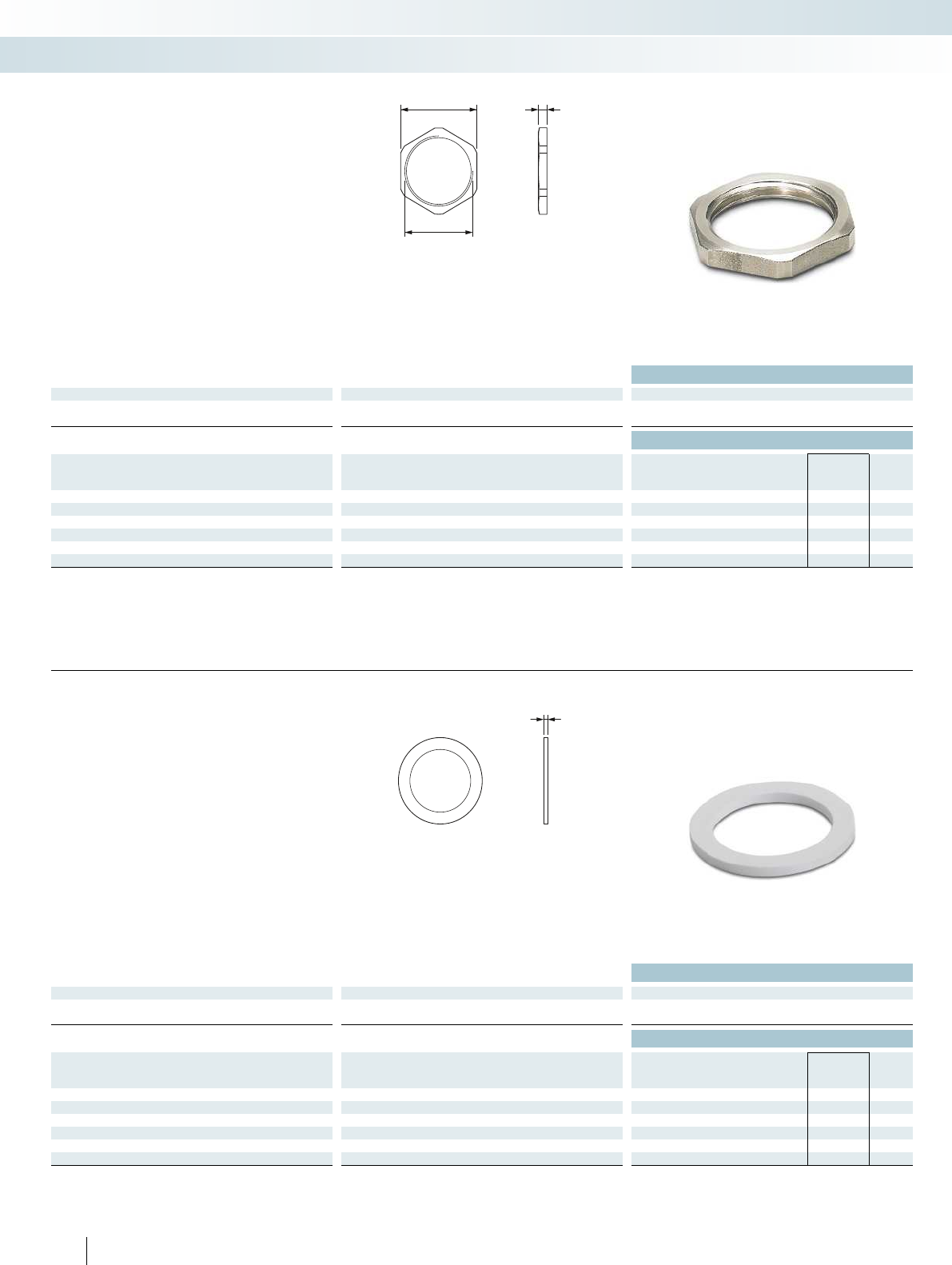
ea
d
e
Stainless steel counter nut
Technical data
General data
Material High-grade steel
Ambient temperature (operation) -70°C ... 220°C
Ordering data
Thread type Clamping area Dimensions [mm] Type Order No. Pcs. /
Pkt.
[mm] a b c d e f g
M20 - 24.00 - - 20.00 3.00 - - A-INL-M20-S-S 1411249 10
M25 -30.00 - - 25.00 3.50 - - A-INL-M25-S-S 1411250 10
M32 - 36.00 - - 32.00 4.00 - - A-INL-M32-S-S 1411251 5
M40 -46.00 - - 40.00 5.00 - - A-INL-M40-S-S 1411252 5
M50 - 55.00 - - 50.00 5.00 - - A-INL-M50-S-S 1411253 2
M63 -70.00 - - 63.00 6.00 - - A-INL-M63-S-S 1411254 1
Stainless steel counter nut,
metric
Sensor/actuator cabling and industrial connectors
Installation and mounting material - cable glands
Sealing washer
Technical data
General data
Material Nylon
Ambient temperature (operation) -70°C ... 100°C
Ordering data
Thread type Clamping area Dimensions [mm] Type Order No. Pcs. /
Pkt.
[mm] a b c d e f g
M20 -----2.00--A-SEW-20-P-W 1411283 20
M25 - - - - - 2.00 - - A-SEW-25-P-W 1411284 20
M32 -----2.00--A-SEW-32-P-W 1411285 20
M40 - - - - - 2.00 - - A-SEW-40-P-W 1411286 20
M50 -----2.00--A-SEW-50-P-W 1411287 10
M63 - - - - - 2.00 - - A-SEW-63-P-W 1411288 10
Sealing washer,
metric
238 PHOENIX CONTACT

For additional information, visit phoenixcontact.net/products
Sensor/actuator cabling and industrial connectors
Installation and mounting material - cable glands
239
PHOENIX CONTACT
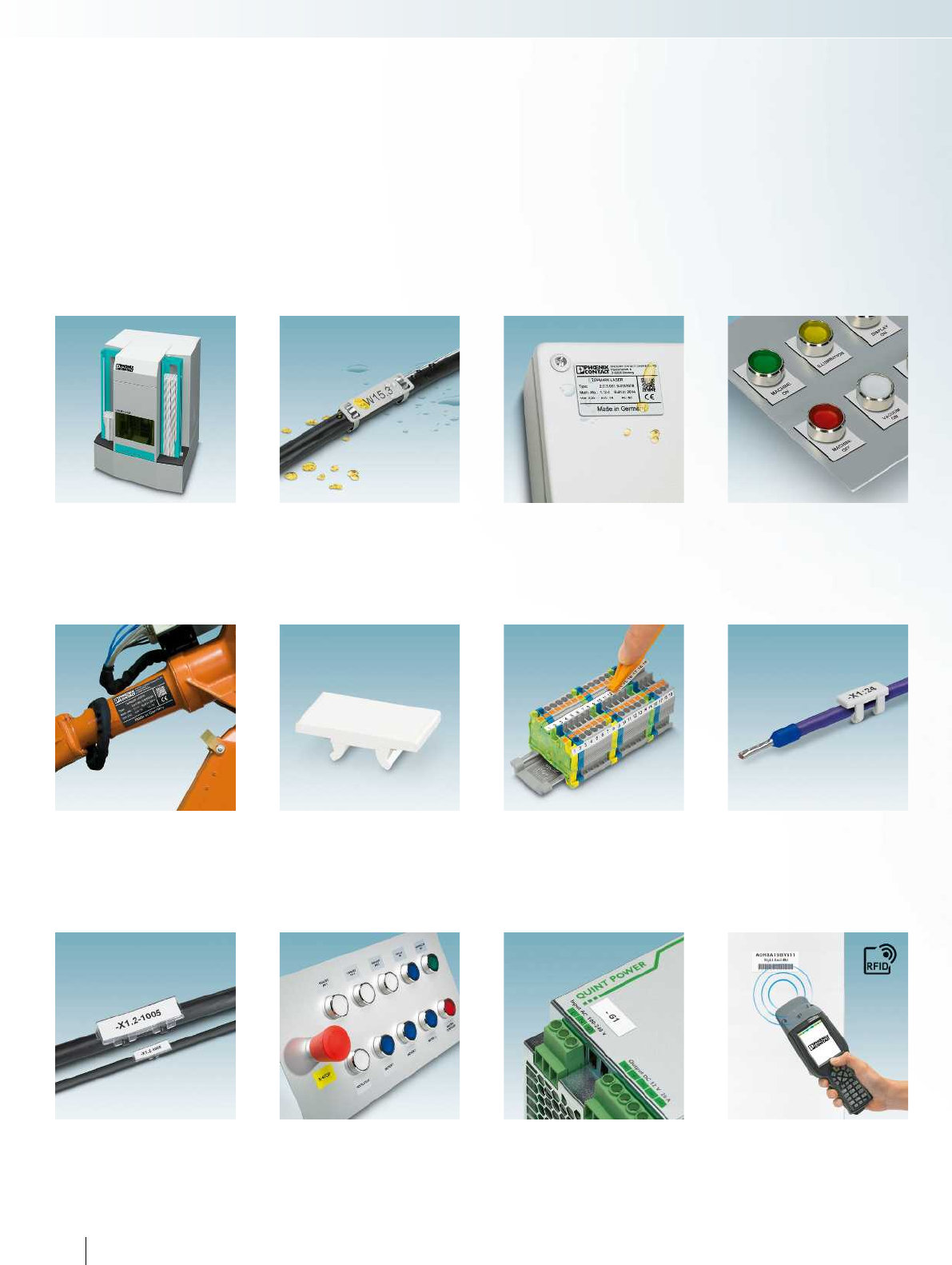
Desktop laser marker
TOPMARK LASER Page 244
Stainless steel or aluminum
laser cable marking
LS-WMTB ... Page 246
Laser device marking, laser foil
LS-EML ... Page 262
Terminal marking,
marker strips
TMT ... Page 266
Terminal marking for terminal blocks
from other manufacturers
UM1-TM ..., UM1U-TM ...,
UM1-TMF ... Page 264
Plastic cable markers
KMK HP ... Page 272
KMK UV ... Page 274
UniCard device marking, for applications
in process technology and process engineering
UC-EMLP ... EX Page 276
EML ... EX Page 277
UniSheet device marking,
with very high adhesive strength
US-EMLP-HA ... Page 278
Stainless steel or aluminum
laser device marking
LS-EMSP ... Page 250
LS-EMLP ... Page 252
LS-EMP ... Page 254
Plastic laser device marking
LS-EMLP ... Page 256
UniCard conductor and cable marking
UCT-WMCO ... Page 268
UCT-WMTBA ... Page 270
240 PHOENIX CONTACT
Marking systems, tools, and mounting material
System marking, RFID system
Handheld
RFMARK HF / UHF Page 280
Marking
UCT-PMLP ... Page 282
UCT-PMP ... Page 284
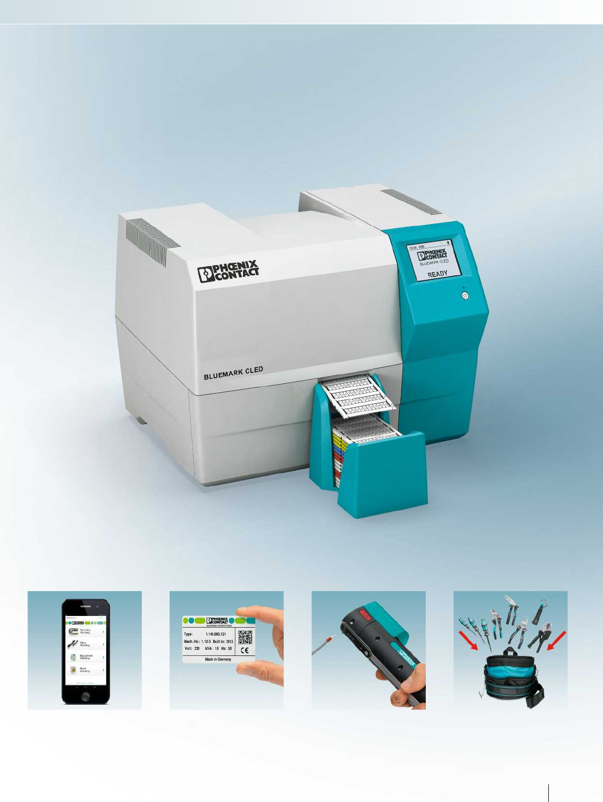
Marking solutions with
planning and marking software
Customer-specific printing service
CLIP PROJECT ... Page 290
Crimping tool, portable hand-held device
CRIMPHANDY 1.0 mm Page 292
Customized tool sets and
personalized tools
TOOL ... CUS Page 296
CRIMPFOX ... CUS Page 298
WIREFOX ... CUS Page 301
241PHOENIX CONTACT
Marking systems, tools, and mounting material
For additional information, visit phoenixcontact.net/products
Wireless exchange of printing data
MARKING system app and
MINI FD BLUETOOTH Page 288
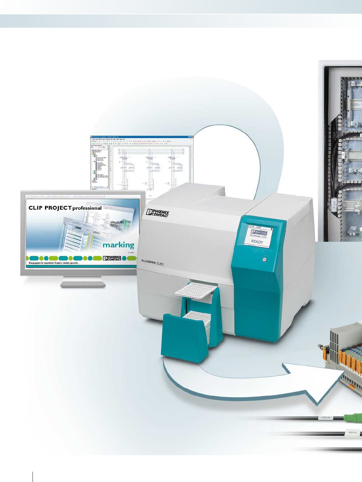
Marking systems, tools, and mounting material
Optimize all of the processes involved in the setup, installation, and maintenance
of your control cabinets and switchgear. We offer optimally coordinated products
from our marking, tool, and mounting material ranges.
242 PHOENIX CONTACT
Marking systems, tools, and mounting material
System features at a glance
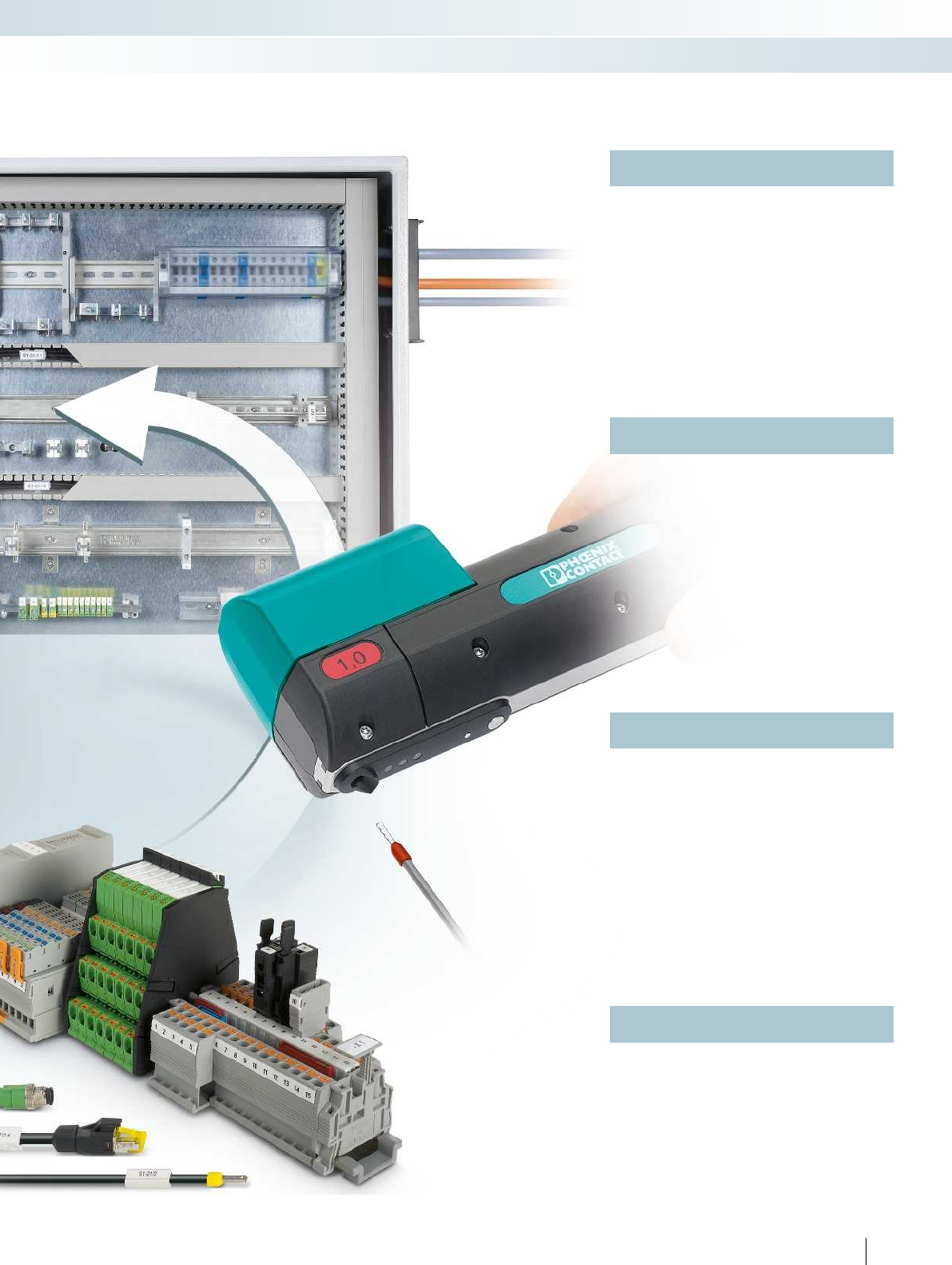
For additional information, visit phoenixcontact.net/products
TOOL fox is the complete range of
professional processing and measuring tools.
Designed for use in all processes in electrical
engineering, the tools and automatic devices
impress with their optimum handling and
quality.
CABINET add-on stands for modern
control cabinet technology. DIN rails and
end brackets ensure the secure attachment
of terminal blocks and modules, while shield
connection clamps guarantee EMC-compliant
wiring and cable ducts bring order to the
control cabinet.
TOOL fox
CABINET add-on
MARKING system provides the perfect
solutions for terminal, conductor, cable,
device, and system marking.
It places at your disposal the CLIP PROJECT
planning and marking software, various
printing systems, and a wide variety of
marking materials.
MARKING system
Choose the complete range. Working to
your specifications, we will manufacture and
label terminal strips and complete terminal
boxes or modules for direct installation in
your application.
Service
243PHOENIX CONTACT
Marking systems, tools, and mounting material
System features at a glance
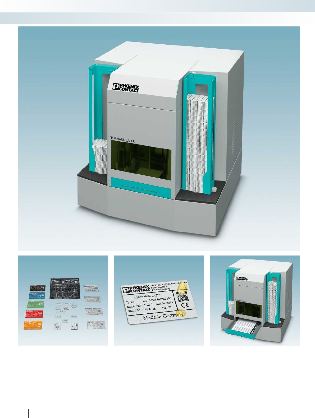
244 PHOENIX CONTACT
Marking systems, tools, and mounting material
TOPMARK LASER - MARKING system
The TOPMARKLASER marking system
provides you with the flexibility to implement the
requirements of challenging industrial
identification. With a comprehensive product
range of over 400markers for your terminal,
conductor, cable, and device marking, you will
find the ideal solution for your application.
The stainless steel material can be marked
in two ways: through material removal
(engraving) or annealing marking. The latter
involves changing the color of the material
while the material surface remains level.
You can easily mark all materials in the
UCT product range with the automated
material handling of the TOPMARKLASER.
The laser marker automatically detects the
material sheets fed in. This means that you
can carry out marking quickly and effectively
- without time-consuming parameter settings.
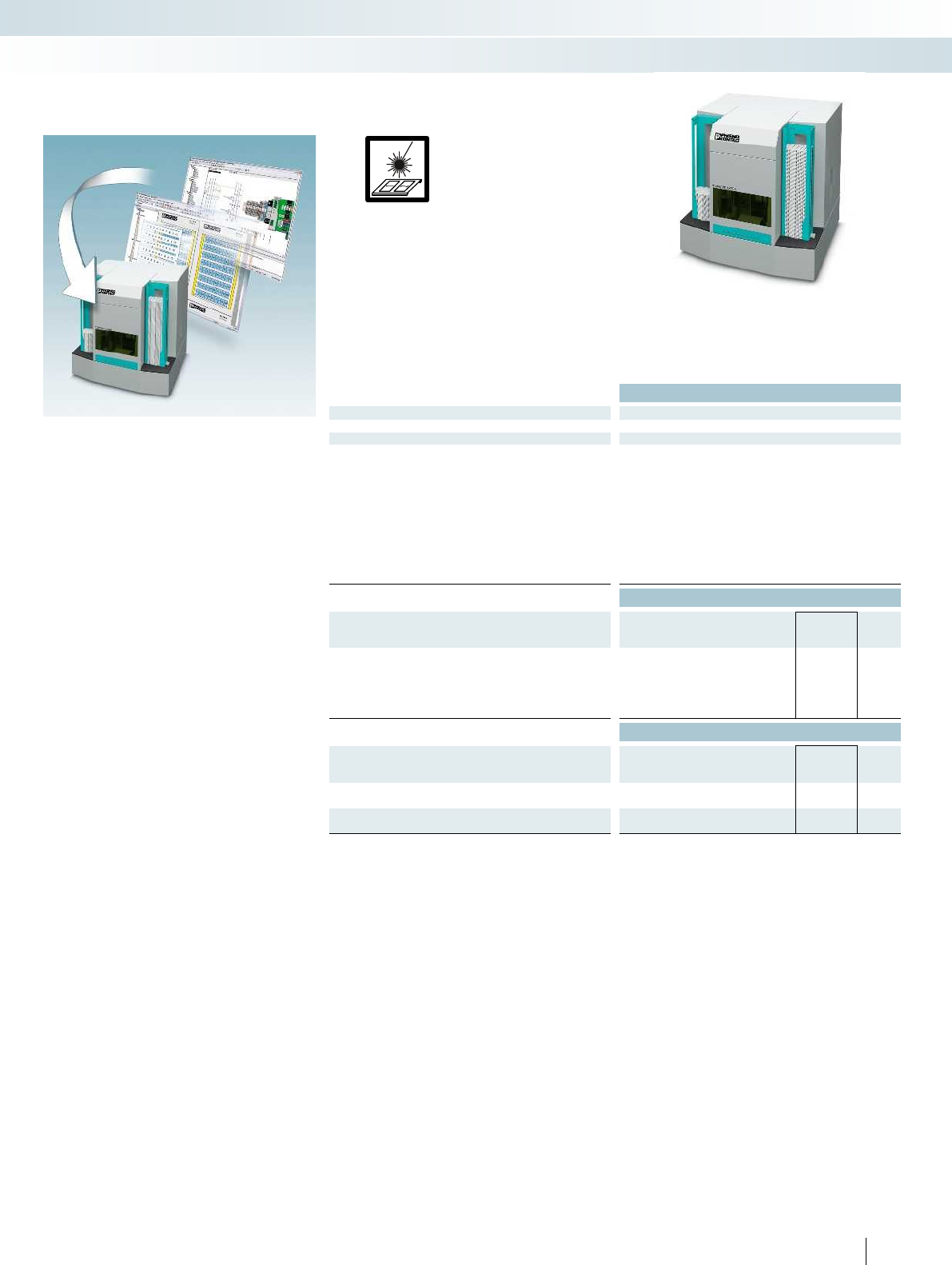
For additional information, visit phoenixcontact.net/products
Integration in the CLIPPROJECT
planning and marking software makes the
TOPMARKLASER the fastest desktop laser
marker in its class - and the easiest to use.
You can now mark all materials without
special knowledge of laser technology.
– Wide range of materials comprising
stainless steel, aluminum, ABS,
polyacrylics, and polycarbonate
– Preset optimized laser parameters are
available for all material types
– Automatic material detection enables fast
and effective marking
– The material sheet can be easily reused by
creating a project code
Technical data
Dimensions Width Length Height
[mm] 664 630 682
General data
Temperature range [°C] 5 ... 40
Marking method Direct laser marking
Laser system Ytterbium fiber laser, pulsed, 1064 nm
Laser class Laser class 1 according to EN 60825-1 classification
Interfaces 10/100 Mbps Ethernet
Power supply [V] 100 ... 240
Weight [kg] 98
Operating systems MS Windows XP SP3, MS Windows Vista,
MS Windows 7 (32/64-bit), MS Windows 8 (32/64-bit)
Power consumption [W] 450
CW laser power (continuous wave) [W] 20
Ordering data
Description Color Type Order No. Pcs. /
Pkt.
Laser marker and MARKINGNOTEBOOK,
incl. CLIPPROJECTprofessional software and installed drivers,
user manual, sheet hopper, card hopper and 230V extraction unit
With German operating system
and German keyboard
TOPMARK LASER 0831831 1
Accessories
Carriage, for accommodating TOPMARKLASER,
extraction unit, and MARKINGNOTEBOOK
TOPMARK LASER STATION 0831835 1
Sheet hopper, for TOPMARKLASER
TOPMARK LASER-MAG SHEET 0831836 1
Card hopper, for TOPMARKLASER
TOPMARK LASER-MAG CARD 0831837 1
TOPMARKLASER,
desktop laser marker
for card material and material sheets
245PHOENIX CONTACT
Marking systems, tools, and mounting material
TOPMARK LASER - MARKING system
Direct laser marking
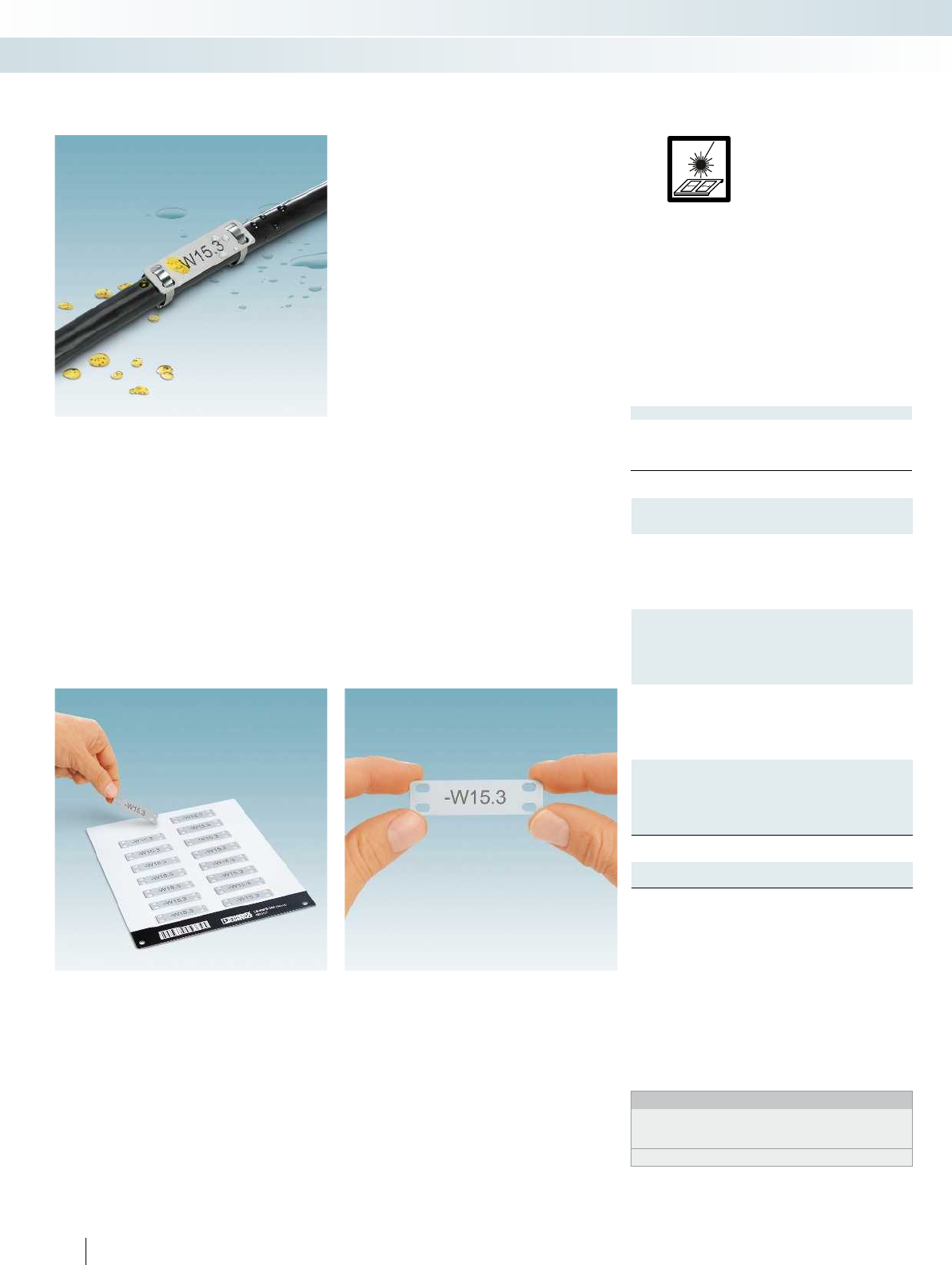
General data
Can be marked with
Material
Wipe resistance
Components
Description
Stainless steel label, for assembly with cable binders,
conductor diameter
36-section, >2.9 mm Ø
16-section, >4.6 mm Ø
16-section, >4.6 mm Ø
8-section, >4.6 mm Ø
Aluminum label, for assembly with cable binders,
conductor diameter
36-section, >2.9 mm Ø
16-section, >4.6 mm Ø
16-section, >4.6 mm Ø
8-section, >4.6 mm Ø
Stainless steel label, for assembly with cable binders, conductor
diameter, marked according to customer specifications1)
36-section, >2.9 mm Ø
16-section, >4.6 mm Ø
16-section, >4.6 mm Ø
8-section, >4.6 mm Ø
Aluminum label, for assembly with cable binders, conductor
diameter, marked according to customer specifications1)
36-section, >2.9 mm Ø
16-section, >4.6 mm Ø
16-section, >4.6 mm Ø
8-section, >4.6 mm Ø
Sheet hopper, for TOPMARKLASER
246 PHOENIX CONTACT
– The LS-WMTB... product range is
available in stainless steel (V4A) or
aluminum and includes markers that can
be quickly and easily fitted with cable
binders
– The LS-WMTB-V4A... group is
particularly characterized by its high
resistance to salt water, chloride, and
solvents and it is therefore also suitable
for the most demanding industrial
requirements
– Automatic material detection enables fast
and effective marking without time-
consuming parameter settings
– The material sheet can be easily reused by
creating a project code
–Designation example:
LS-WMTB-V4A(29x8)
Lettering field size: 29x8mm
– The use of modern laser technology
creates highly resistant and permanent
marking, which can only be removed by
destroying the material
– The LS-WMTB-V4A... product group can
be marked in two ways: by engraving or
annealing
– Labeling service: Phoenix Contact can
custom-label all markers according to
your requirements
Stainless steel and aluminum
cable marking for assembly
with cable binders
Notes:
For matching stainless steel cable binders, see page 580 in
main catalog 5 or the product area on our website at
phoenixcontact.net/products.
1) For an ordering example, see page 358 in main catalog 5.
Marking systems, tools, and mounting material
Marking material for TOPMARK LASER - MARKING system
Direct laser marking
Can be marked using:
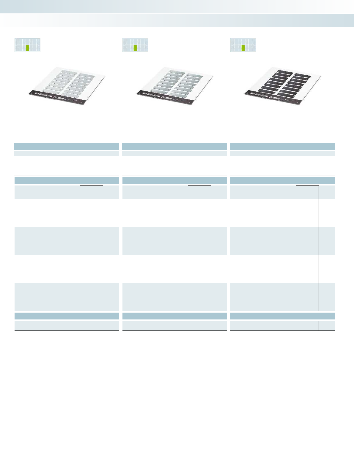
PR INTED
FOR YOU
PR INTED
FOR YOU
PR INTED
FOR YOU
For additional information, visit phoenixcontact.net/products
Technical data Technical data Technical data
TOPMARK LASER TOPMARK LASER TOPMARK LASER
V4A Aluminum Aluminum
DIN EN 61010-1 (VDE 0411-1) DIN EN 61010-1 (VDE 0411-1) DIN EN 61010-1 (VDE 0411-1)
Free from silicone, halogen, and cadmium Free from silicone, halogen, and cadmium Free from silicone, halogen, and cadmium
Ordering data Ordering data Ordering data
Type Order No. Pcs. /
Pkt. Type Order No. Pcs. /
Pkt. Type Order No. Pcs. /
Pkt.
LS-WMTB-V4A (29X8) 0831516 5
LS-WMTB-V4A (40X15) 0831517 5
LS-WMTB-V4A (60X15) 0831518 5
LS-WMTB-V4A (100X15) 0831519 5
LS-WMTB-AL (29X8) 0831500 5LS-WMTB-AL (29X8) BK 0831508 5
LS-WMTB-AL (40X15) 0831501 5LS-WMTB-AL (40X15) BK 0831509 5
LS-WMTB-AL (60X15) 0831502 5LS-WMTB-AL (60X15) BK 0831510 5
LS-WMTB-AL (100X15) 0831503 5LS-WMTB-AL (100X15) BK 0831511 5
LS-WMTB-V4A (29X8) CUS 0831802 1
LS-WMTB-V4A (40X15) CUS 0831803 1
LS-WMTB-V4A (60X15) CUS 0831804 1
LS-WMTB-V4A (100X15) CUS 0831805 1
LS-WMTB-AL (29X8) CUS 0831786 1LS-WMTB-AL (29X8) BK CUS 0831794 1
LS-WMTB-AL (40X15) CUS 0831787 1LS-WMTB-AL (40X15) BK CUS 0831795 1
LS-WMTB-AL (60X15) CUS 0831788 1LS-WMTB-AL (60X15) BK CUS 0831796 1
LS-WMTB-AL (100X15) CUS 0831789 1LS-WMTB-AL (100X15) BK CUS 0831797 1
Accessories Accessories Accessories
TOPMARK LASER-MAG SHEET 0831836 1TOPMARK LASER-MAG SHEET 0831836 1TOPMARK LASER-MAG SHEET 0831836 1
247PHOENIX CONTACT
Marking systems, tools, and mounting material
Marking material for TOPMARK LASER - MARKING system
Stainless steel, material thickness: 0.5mm Aluminum, material thickness: 0.8mm Aluminum, black, material thickness: 0.8mm
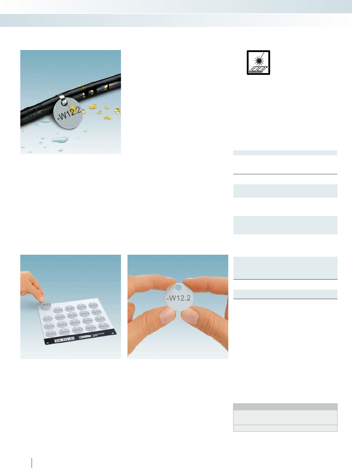
General data
Can be marked with
Material
Wipe resistance
Components
Description
Stainless steel label, round, for assembly with cable binders
30-section, diameter: 25mm
20-section, diameter: 30mm
Aluminum label, round, for assembly with cable binders
30-section, diameter: 25mm
20-section, diameter: 30mm
Stainless steel label, round, for assembly with cable binders,
labeled according to customer specifications1)
30-section, diameter: 25mm
20-section, diameter: 30mm
Aluminum label, round, for assembly with cable binders,
labeled according to customer specifications1)
30-section, diameter: 25mm
20-section, diameter: 30mm
Sheet hopper, for TOPMARKLASER
248 PHOENIX CONTACT
– The LS-WMTB... product range in
circular format is available in stainless
steel (V4A) or aluminum and includes
markers that can be quickly and easily
fitted with cable binders
– The LS-WMTB-V4A... group is
particularly characterized by its high
resistance to saltwater, chloride, and
solvents and it is therefore also suitable
for the most demanding industrial
requirements
– Automatic material detection enables fast
and effective marking without time-
consuming parameter settings
– The material sheet can be easily reused by
creating a project code
–Designation example:
LS-WMTB-V4A(D25)
Diameter: 25mm
– The use of modern laser technology
creates highly resistant and permanent
marking, which can only be removed by
destroying the material
– The LS-WMTB-V4A... product group can
be marked in two ways: by engraving or
annealing
– Labeling service: Phoenix Contact can
custom-label all markers according to
your requirements
Stainless steel and aluminum
cable marking for assembly
with cable binders
Notes:
For matching stainless steel cable binders, see page 580 in
main catalog 5 or the product area on our website at
phoenixcontact.net/products.
1) For an ordering example, see page 358 in main catalog 5.
Marking systems, tools, and mounting material
Marking material for TOPMARK LASER - MARKING system
Direct laser marking
Can be marked using:
PR INTED
FOR YOU
PR INTED
FOR YOU
PR INTED
FOR YOU
For additional information, visit phoenixcontact.net/products
Technical data Technical data Technical data
TOPMARK LASER TOPMARK LASER TOPMARK LASER
V4A Aluminum Aluminum
DIN EN 61010-1 (VDE 0411-1) DIN EN 61010-1 (VDE 0411-1) DIN EN 61010-1 (VDE 0411-1)
Free from silicone, halogen, and cadmium Free from silicone, halogen, and cadmium Free from silicone, halogen, and cadmium
Ordering data Ordering data Ordering data
Type Order No. Pcs. /
Pkt. Type Order No. Pcs. /
Pkt. Type Order No. Pcs. /
Pkt.
LS-WMTB-V4A (D25) 0831520 5
LS-WMTB-V4A (D30) 0831521 5
LS-WMTB-AL (D25) 0831504 5LS-WMTB-AL (D25) BK 0831512 5
LS-WMTB-AL (D30) 0831505 5LS-WMTB-AL (D30) BK 0831513 5
LS-WMTB-V4A (D25) CUS 0831806 1
LS-WMTB-V4A (D30) CUS 0831807 1
LS-WMTB-AL (D25) CUS 0831790 1LS-WMTB-AL (D25) BK CUS 0831798 1
LS-WMTB-AL (D30) CUS 0831791 1LS-WMTB-AL (D30) BK CUS 0831799 1
Accessories Accessories Accessories
TOPMARK LASER-MAG SHEET 0831836 1TOPMARK LASER-MAG SHEET 0831836 1TOPMARK LASER-MAG SHEET 0831836 1
249PHOENIX CONTACT
Marking systems, tools, and mounting material
Marking material for TOPMARK LASER - MARKING system
Stainless steel, material thickness: 0.5mm Aluminum, material thickness: 0.8mm Aluminum, black, material thickness: 0.8mm
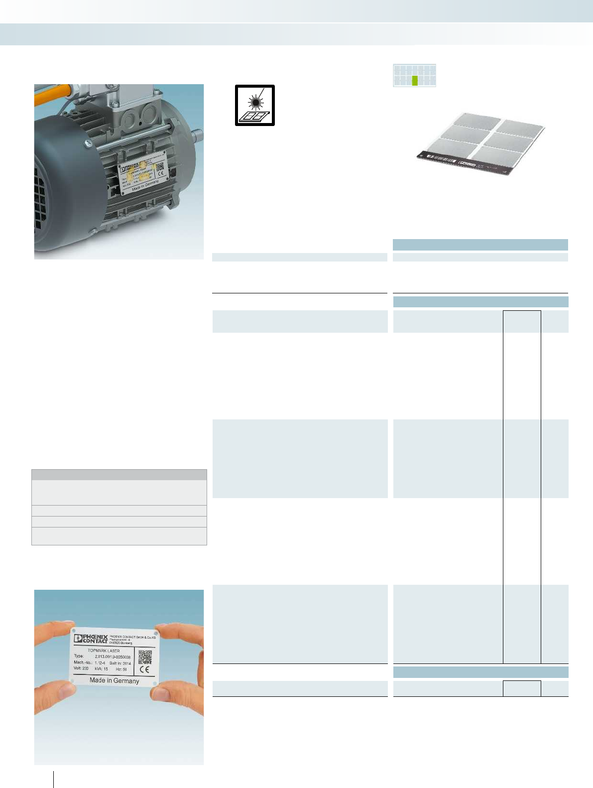
PR INTED
FOR YOU
– The LS-EMSP... product range is available
in stainless steel (V4A) or aluminum and
includes markers that can be quickly and
easily fitted with screws or rivets
– The LS-EMSP-V4A... group is particularly
characterized by its high resistance to
saltwater, chloride, and solvents and is
therefore also suitable for the most
demanding industrial requirements
– The LS-EMSP-V4A... product group can
be permanently marked in two ways:
by engraving or annealing
–Designation example:
LS-EMSP-V4A(39x15)
Lettering field size: 39x15mm
– Labeling service: Phoenix Contact can
custom-label all markers according to
your requirements
Notes:
For matching rivets for securing the LS-EMSP-V4A... and
LS-EMSP-AL..., see page370 in main catalog5 or the product
area on our website at phoenixcontact.net/products.
For drilling diagrams, visit phoenixcontact.net/products.
1) For an ordering example, see page 358 in main catalog 5.
2) From lettering field size 110x80 to 170x180mm,
the material thickness is 1.5mm.
Technical data
General data
Can be marked with TOPMARK LASER
Material V4A
Wipe resistance DIN EN 61010-1 (VDE 0411-1) DIN EN 61010-1 (VDE 0411-1) DIN EN 61010-1 (VDE 0411-1) DIN EN 61010-1 (VDE 0411-1)
Components Free from silicone, halogen, and cadmium Free from silicone, halogen, and cadmium Free from silicone, halogen, and cadm
Ordering data
Description Type Order No. Pcs. /
Pkt.
Marking label, with mounting holes 3.2mm in diameter
24-section LS-EMSP-V4A (39X15) 0831653 5
16-section LS-EMSP-V4A (50X15) 0831654 5
10-section LS-EMSP-V4A (50X30) 0831655 5
6-section LS-EMSP-V4A (75,6X54) 0831656 5
2-section LS-EMSP-V4A (90X60) 0831657 5
2-section
2-section
1-section
1-section
Marking label, with mounting holes 3.2mm in diameter
10-section, red
10-section, orange
10-section, blue
10-section, green
6-section, red
6-section, orange
6-section, blue
6-section, green
Marking label, with mounting holes 3.2mm in diameter,
marked according to customer specifications1)
24-section LS-EMSP-V4A (39X15) CUS 0831939 1
16-section LS-EMSP-V4A (50X15) CUS 0831940 1
10-section LS-EMSP-V4A (50X30) CUS 0831941 1
6-section LS-EMSP-V4A (75,6X54) CUS 0831942 1
2-section LS-EMSP-V4A (90X60) CUS 0831943 1
2-section
2-section
1-section
1-section
Marking label, with mounting holes 3.2mm in diameter,
marked according to customer specifications1)
10-section, red
10-section, orange
10-section, blue
10-section, green
6-section, red
6-section, orange
6-section, blue
6-section, green
Accessories
Sheet hopper, for TOPMARKLASER
TOPMARK LASER-MAG SHEET 0831836 1
250 PHOENIX CONTACT
Direct laser marking
Can be marked using:
Stainless steel and aluminum
device marking
for screwing or riveting
Marking systems, tools, and mounting material
Marking material for TOPMARK LASER - MARKING system
Stainless steel,
material thickness: 0.5mm
PR INTED
FOR YOU
PR INTED
FOR YOU
PR INTED
FOR YOU
For additional information, visit phoenixcontact.net/products
Technical data Technical data Technical data
TOPMARK LASER TOPMARK LASER TOPMARK LASER
Aluminum Aluminum Aluminum
Wipe resistance DIN EN 61010-1 (VDE 0411-1) DIN EN 61010-1 (VDE 0411-1) DIN EN 61010-1 (VDE 0411-1) DIN EN 61010-1 (VDE 0411-1)
Components Free from silicone, halogen, and cadmium Free from silicone, halogen, and cadmium Free from silicone, halogen, and cadmium Free from silicone, halogen, and cadmium
Ordering data Ordering data Ordering data
Type Order No. Pcs. /
Pkt. Type Order No. Pcs. /
Pkt. Type Order No. Pcs. /
Pkt.
LS-EMSP-AL (39X15) 0831615 5LS-EMSP-AL (39X15) BK 0831626 5
LS-EMSP-AL (50X15) 0831616 5LS-EMSP-AL (50X15) BK 0831627 5
LS-EMSP-AL (50X30) 0831617 5LS-EMSP-AL (50X30) BK 0831628 5
LS-EMSP-AL (75,6X54) 0831618 5LS-EMSP-AL (75,6X54) BK 0831629 5
LS-EMSP-AL (90X60) 0831619 5LS-EMSP-AL (90X60) BK 0831630 5
LS-EMSP-AL (110X80) 0831620 5LS-EMSP-AL (110X80) BK 0831631 5
LS-EMSP-AL (150X80) 0831621 5LS-EMSP-AL (150X80) BK 0831632 5
LS-EMSP-AL (150X120) 0831622 5LS-EMSP-AL (150X120) BK 0831633 5
LS-EMSP-AL (170X180) 0831623 5LS-EMSP-AL (170X180) BK 0831634 5
LS-EMSP-AL (50X30) RD 0831637 5
LS-EMSP-AL (50X30) OG 0831641 5
LS-EMSP-AL (50X30) BU 0831645 5
LS-EMSP-AL (50X30) GN 0831649 5
LS-EMSP-AL (75,6X54) RD 0831638 5
LS-EMSP-AL (75,6X54) OG 0831642 5
LS-EMSP-AL (75,6X54) BU 0831646 5
LS-EMSP-AL (75,6X54) GN 0831650 5
LS-EMSP-AL (39X15) CUS 0831901 1LS-EMSP-AL (39X15) BK CUS 0831912 1
LS-EMSP-AL (50X15) CUS 0831902 1LS-EMSP-AL (50X15) BK CUS 0831913 1
LS-EMSP-AL (50X30) CUS 0831903 1LS-EMSP-AL (50X30) BK CUS 0831914 1
LS-EMSP-AL (75,6X54) CUS 0831904 1LS-EMSP-AL (75,6X54) BK CUS 0831915 1
LS-EMSP-AL (90X60) CUS 0831905 1LS-EMSP-AL (90X60) BK CUS 0831916 1
LS-EMSP-AL (110X80) CUS 0831906 1LS-EMSP-AL (110X80) BK CUS 0831917 1
LS-EMSP-AL (150X80) CUS 0831907 1LS-EMSP-AL (150X80) BK CUS 0831918 1
LS-EMSP-AL (150X120) CUS 0831908 1LS-EMSP-AL (150X120) BK CUS 0831919 1
LS-EMSP-AL (170X180) CUS 0831909 1LS-EMSP-AL (170X180) BK CUS 0831920 1
LS-EMSP-AL (50X30) RD CUS 0831923 1
LS-EMSP-AL (50X30) OG CUS 0831927 1
LS-EMSP-AL (50X30) BU CUS 0831931 1
LS-EMSP-AL (50X30) GN CUS 0831935 1
LS-EMSP-AL (75,6X54) RD CUS 0831924 1
LS-EMSP-AL (75,6X54) OG CUS 0831928 1
LS-EMSP-AL (75,6X54) BU CUS 0831932 1
LS-EMSP-AL (75,6X54) GN CUS 0831936 1
Accessories Accessories Accessories
TOPMARK LASER-MAG SHEET 0831836 1TOPMARK LASER-MAG SHEET 0831836 1TOPMARK LASER-MAG SHEET 0831836 1
251PHOENIX CONTACT
Marking systems, tools, and mounting material
Marking material for TOPMARK LASER - MARKING system
Aluminum,
material thickness: 0.8mm2)
Aluminum, black,
material thickness: 0.8mm2)
Aluminum, colored,
material thickness: 0.8mm
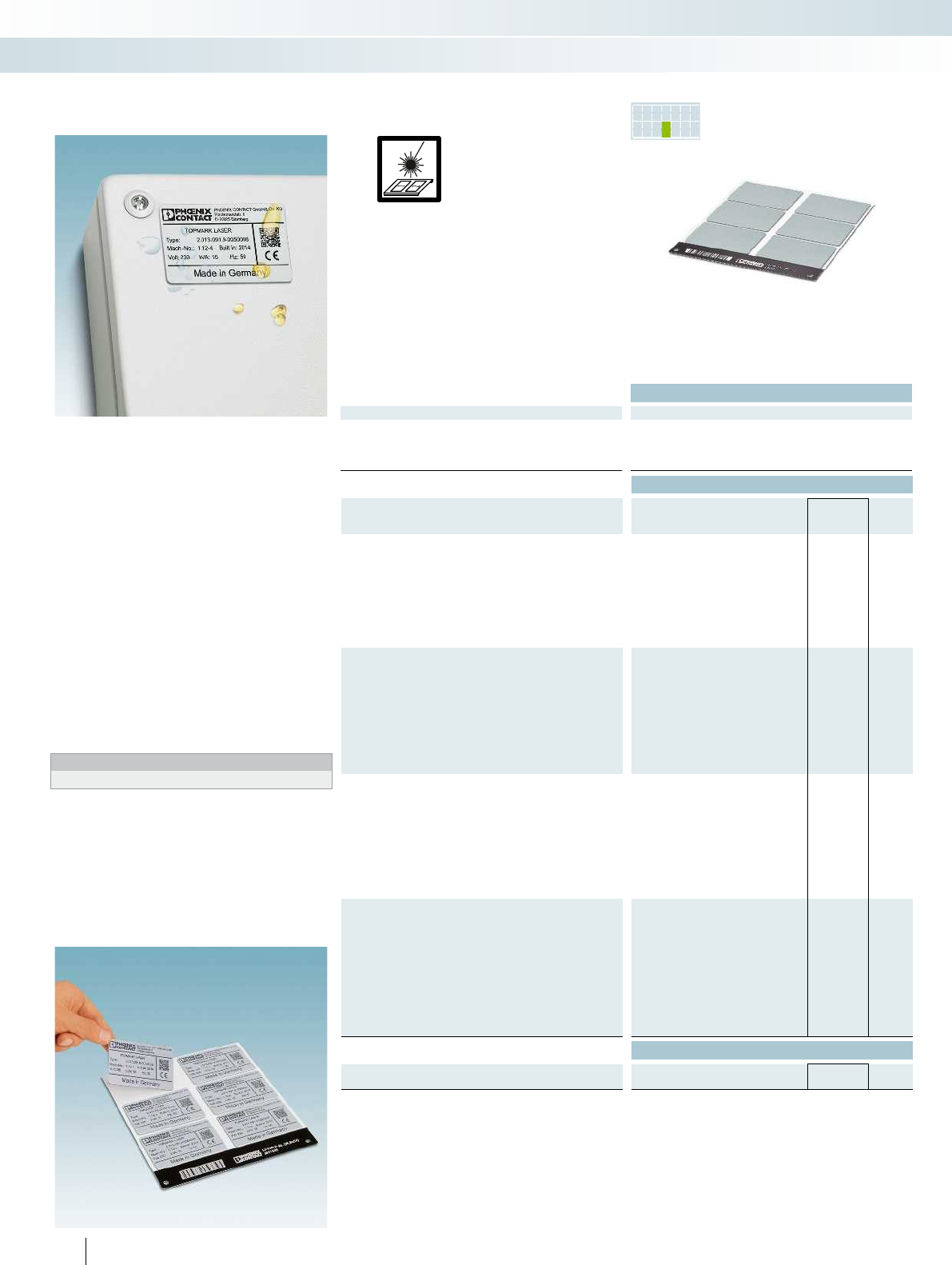
PR INTED
FOR YOU
– The aluminumLS-EMLP-AL... product
range includes self-adhesive device
markers with a high adhesive strength
– The use of modern laser technology
creates highly resistant and permanent
marking, which can only be removed by
destroying the material
– Automatic material detection enables fast
and effective marking without time-
consuming parameter settings
– The material sheet can be easily reused by
creating a project code
–Designation example:
LS-EMLP-AL(27x15)
Lettering field size: 27x15mm
– Labeling service: Phoenix Contact can
custom-label all markers according to
your requirements
Notes:
1) For an ordering example, see page 358 in main catalog 5.
Technical data
General data
Can be marked with TOPMARK LASER
Material Aluminum
Wipe resistance DIN EN 61010-1 (VDE 0411-1) DIN EN 61010-1 (VDE 0411-1) DIN EN 61010-1 (VDE 0411-1)
Components Free from silicone, halogen, and cadmium Free from silicone, halogen, and cadmium Free from silicone, halogen, and cadm
Ordering data
Description Type Order No. Pcs. /
Pkt.
Marking label, aluminum, self-adhesive
40-section LS-EMLP-AL (27X15) 0831580 5
35-section LS-EMLP-AL (27X18) 0831581 5
24-section LS-EMLP-AL (49X15) 0831582 5
16-section LS-EMLP-AL (60X15) 0831583 5
10-section LS-EMLP-AL (60X30) 0831584 5
6-section LS-EMLP-AL (85,6X54) 0831585 5
2-section LS-EMLP-AL (100X60) 0831586 5
Marking label, aluminum, self-adhesive
10-section, red
10-section, orange
10-section, blue
10-section, green
6-section, red
6-section, orange
6-section, blue
6-section, green
Marking label, aluminum, self-adhesive,
marked according to customer specifications1)
40-section LS-EMLP-AL (27X15) CUS 0831866 1
35-section LS-EMLP-AL (27X18) CUS 0831867 1
24-section LS-EMLP-AL (49X15) CUS 0831868 1
16-section LS-EMLP-AL (60X15) CUS 0831869 1
10-section LS-EMLP-AL (60X30) CUS 0831870 1
6-section LS-EMLP-AL (85,6X54) CUS 0831871 1
2-section LS-EMLP-AL (100X60) CUS 0831872 1
Marking label, aluminum, self-adhesive,
marked according to customer specifications1)
10-section, red
10-section, orange
10-section, blue
10-section, green
6-section, red
6-section, orange
6-section, blue
6-section, green
Accessories
Sheet hopper, for TOPMARKLASER
TOPMARK LASER-MAG SHEET 0831836 1
252 PHOENIX CONTACT
Direct laser marking
Can be marked using:
Adhesive aluminum device marking
Marking systems, tools, and mounting material
Marking material for TOPMARK LASER - MARKING system
Aluminum,
material thickness: 0.8mm
PR INTED
FOR YOU
PR INTED
FOR YOU
For additional information, visit phoenixcontact.net/products
Technical data Technical data
TOPMARK LASER TOPMARK LASER
Aluminum Aluminum
Wipe resistance DIN EN 61010-1 (VDE 0411-1) DIN EN 61010-1 (VDE 0411-1) DIN EN 61010-1 (VDE 0411-1)
Components Free from silicone, halogen, and cadmium Free from silicone, halogen, and cadmium Free from silicone, halogen, and cadmium
Ordering data Ordering data
Type Order No. Pcs. /
Pkt. Type Order No. Pcs. /
Pkt.
LS-EMLP-AL (27X15) BK 0831589 5
LS-EMLP-AL (27X18) BK 0831590 5
LS-EMLP-AL (49X15) BK 0831591 5
LS-EMLP-AL (60X15) BK 0831592 5
LS-EMLP-AL (60X30) BK 0831593 5
LS-EMLP-AL (85,6X54) BK 0831594 5
LS-EMLP-AL (100X60) BK 0831595 5
LS-EMLP-AL (60X30) RD 0831598 5
LS-EMLP-AL (60X30) OG 0831602 5
LS-EMLP-AL (60X30) BU 0831606 5
LS-EMLP-AL (60X30) GN 0831610 5
LS-EMLP-AL (85,6X54) RD 0831599 5
LS-EMLP-AL (85,6X54) OG 0831603 5
LS-EMLP-AL (85,6X54) BU 0831607 5
LS-EMLP-AL (85,6X54) GN 0831611 5
LS-EMLP-AL (27X15) BK CUS 0831875 1
LS-EMLP-AL (27X18) BK CUS 0831876 1
LS-EMLP-AL (49X15) BK CUS 0831877 1
LS-EMLP-AL (60X15) BK CUS 0831878 1
LS-EMLP-AL (60X30) BK CUS 0831879 1
LS-EMLP-AL (85,6X54) BK CUS 0831880 1
LS-EMLP-AL (100X60) BK CUS 0831881 1
LS-EMLP-AL (60X30) RD CUS 0831884 1
LS-EMLP-AL (60X30) OG CUS 0831888 1
LS-EMLP-AL (60X30) BU CUS 0831892 1
LS-EMLP-AL (60X30) GN CUS 0831896 1
LS-EMLP-AL (85,6X54) RD CUS 0831885 1
LS-EMLP-AL (85,6X54) OG CUS 0831889 1
LS-EMLP-AL (85,6X54) BU CUS 0831893 1
LS-EMLP-AL (85,6X54) GN CUS 0831897 1
Accessories Accessories
TOPMARK LASER-MAG SHEET 0831836 1TOPMARK LASER-MAG SHEET 0831836 1
253PHOENIX CONTACT
Marking systems, tools, and mounting material
Marking material for TOPMARK LASER - MARKING system
Aluminum, black,
material thickness: 0.8mm
Aluminum, colored,
material thickness: 0.8mm
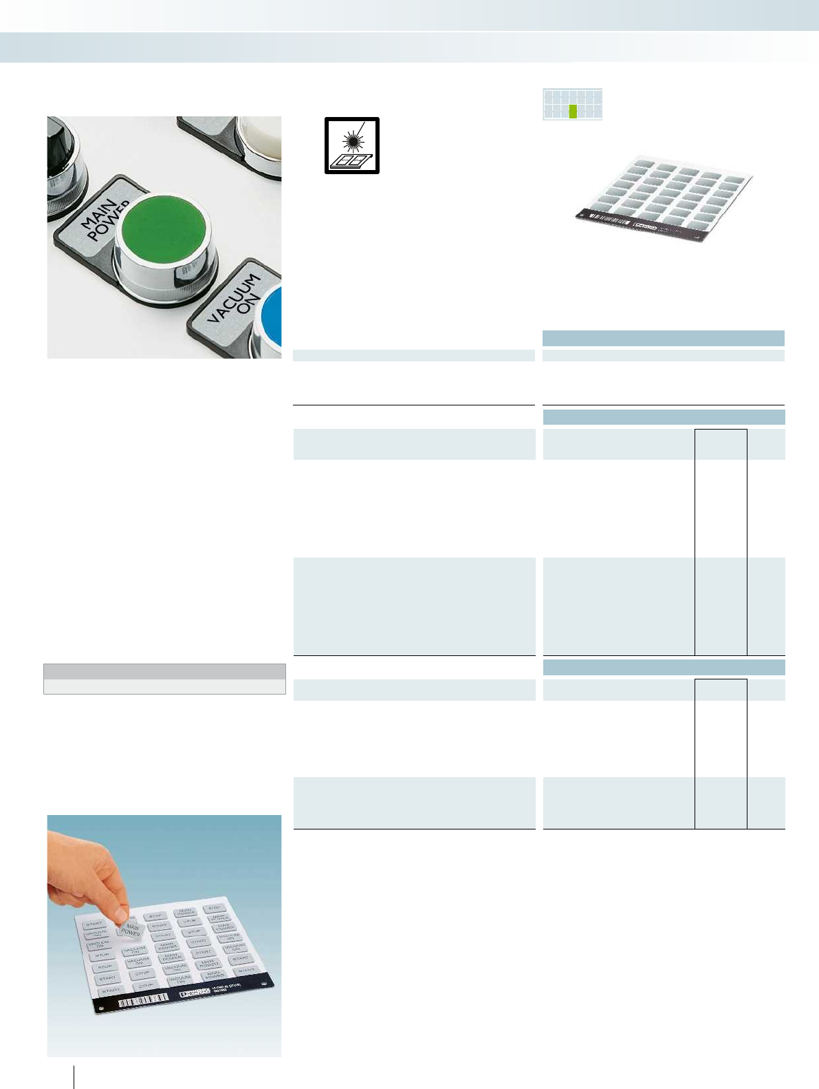
PR INTED
FOR YOU
– The aluminum LS-EMP-AL... product
range includes markers that can be
quickly and easily fitted into existing
CARRIER-EMP... label frames
– The use of modern laser technology
creates highly resistant and permanent
marking, which can only be removed by
destroying the material
– Automatic material detection enables fast
and effective marking without time-
consuming parameter settings
– The material sheet can be easily reused by
creating a project code
–Designation example:
LS-EMP-AL(27x15)
Lettering field size: 27x15mm
– Labeling service: Phoenix Contact can
custom-label all markers according to
your requirements
Notes:
1) For an ordering example, see page 358 in main catalog 5.
Technical data
General data
Can be marked with TOPMARK LASER
Material Aluminum
Wipe resistance DIN EN 61010-1 (VDE 0411-1) DIN EN 61010-1 (VDE 0411-1)
Components Free from silicone, halogen, and cadmium Free from silicone, halogen, and cadmium
Ordering data
Description Type Order No. Pcs. /
Pkt.
Marking label, aluminum, can be snapped into marker carriers
40-section LS-EMP-AL (27X15) 0831661 5
35-section LS-EMP-AL (27X18) 0831662 5
24-section LS-EMP-AL (49X15) 0831663 5
16-section LS-EMP-AL (60X15) 0831664 5
10-section LS-EMP-AL (60X30) 0831665 5
6-section LS-EMP-AL (85,6X54) 0831666 5
2-section LS-EMP-AL (100X60) 0831667 5
Marking label, aluminum, can be snapped into marker carriers,
marked according to customer specifications1)
40-section LS-EMP-AL (27X15) CUS 0831947 1
35-section LS-EMP-AL (27X18) CUS 0831948 1
24-section LS-EMP-AL (49X15) CUS 0831949 1
16-section LS-EMP-AL (60X15) CUS 0831950 1
10-section LS-EMP-AL (60X30) CUS 0831951 1
6-section LS-EMP-AL (85,6X54) CUS 0831952 1
2-section LS-EMP-AL (100X60) CUS 0831953 1
Accessories
Sheet hopper, for TOPMARKLASER
TOPMARK LASER-MAG SHEET 0831836 1
Marker carriers, for snap-in labels
Marker size: 27x15mm CARRIER-EMP (27X15) 0827451 80
Marker size: 49x15mm CARRIER-EMP (49X15) 0827452 40
Marker size: 60x15mm CARRIER-EMP (60X15) 0827453 40
Marker size: 60x30mm CARRIER-EMP (60X30) 0827454 30
Marker size: 85x54mm CARRIER-EMP (85,6X54) 0829365 10
Marker carriers, for snap-in labels,
for buttons and switches 22mm in diameter
Marker size: 27x15mm CARRIER-EMP 22 (27X15) 0827447 50
Marker size: 27x18mm CARRIER-EMP 22 (27X18) 0827448 50
254 PHOENIX CONTACT
Direct laser marking
Can be marked using:
Aluminum device marking
for snapping into marker carriers
Marking systems, tools, and mounting material
Marking material for TOPMARK LASER - MARKING system
Aluminum, material thickness: 0.8mm Aluminum, black, material thickness: 0.8
PR INTED
FOR YOU
For additional information, visit phoenixcontact.net/products
Technical data
TOPMARK LASER
Aluminum
Wipe resistance DIN EN 61010-1 (VDE 0411-1) DIN EN 61010-1 (VDE 0411-1)
Components Free from silicone, halogen, and cadmium Free from silicone, halogen, and cadmium
Ordering data
Type Order No. Pcs. /
Pkt.
LS-EMP-AL (27X15) BK 0831669 5
LS-EMP-AL (27X18) BK 0831670 5
LS-EMP-AL (49X15) BK 0831671 5
LS-EMP-AL (60X15) BK 0831672 5
LS-EMP-AL (60X30) BK 0831673 5
LS-EMP-AL (85,6X54) BK 0831674 5
LS-EMP-AL (100X60) BK 0831675 5
LS-EMP-AL (27X15) BK CUS 0831955 1
LS-EMP-AL (27X18) BK CUS 0831956 1
LS-EMP-AL (49X15) BK CUS 0831957 1
LS-EMP-AL (60X15) BK CUS 0831958 1
LS-EMP-AL (60X30) BK CUS 0831959 1
LS-EMP-AL (85,6X54) BK CUS 0831960 1
LS-EMP-AL (100X60) BK CUS 0831961 1
Accessories
TOPMARK LASER-MAG SHEET 0831836 1
CARRIER-EMP (27X15) 0827451 80
CARRIER-EMP (49X15) 0827452 40
CARRIER-EMP (60X15) 0827453 40
CARRIER-EMP (60X30) 0827454 30
CARRIER-EMP (85,6X54) 0829365 10
CARRIER-EMP 22 (27X15) 0827447 50
CARRIER-EMP 22 (27X18) 0827448 50
255PHOENIX CONTACT
Marking systems, tools, and mounting material
Marking material for TOPMARK LASER - MARKING system
mm Aluminum, black, material thickness: 0.8mm
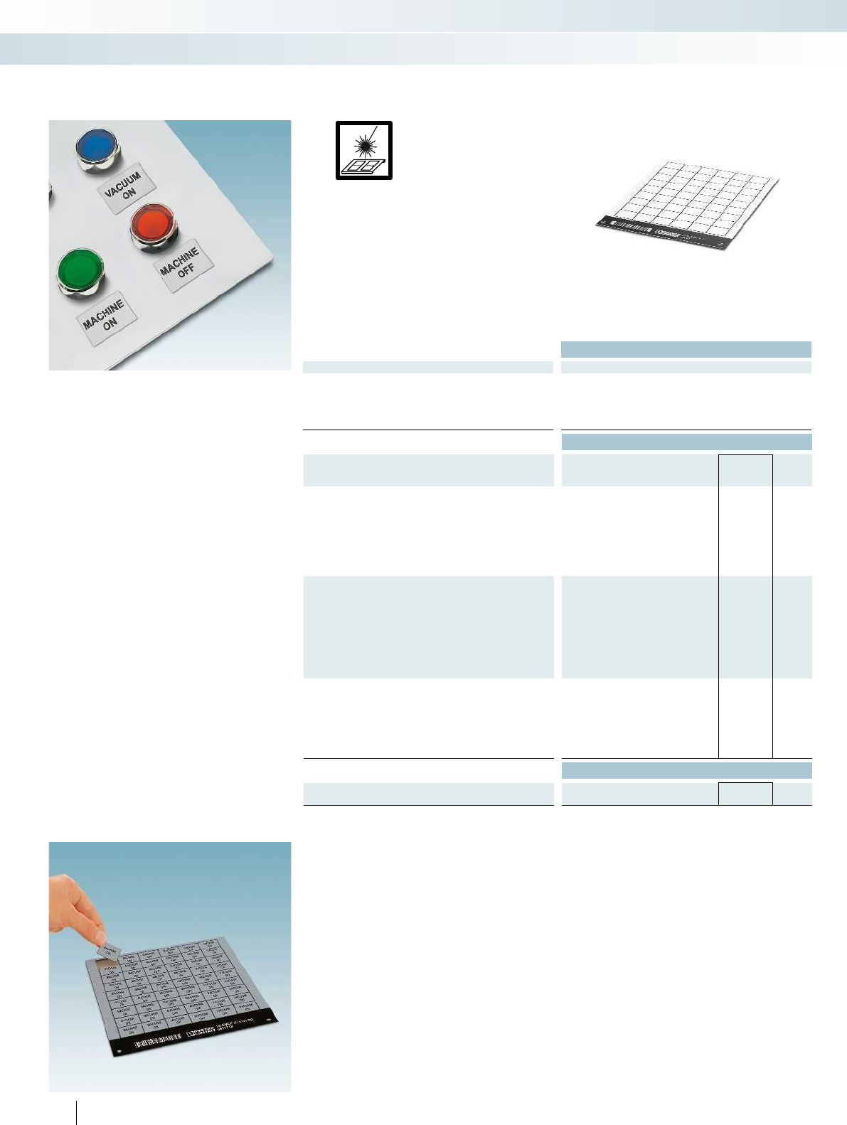
– The LS-EMLP... product range includes
self-adhesive double-layer plastic device
markers
– A wide range of different marker sizes is
available for custom designs
– Automatic material detection enables fast
and effective marking without time-
consuming parameter settings
– The material sheet can be easily reused by
creating a project code
–Designation example:
LS-EMLP(11x9)SR
Lettering field size: 11x9mm,
silver material with black marking
Technical data
General data
Can be marked with TOPMARK LASER
Material TRANSPLY-ABS
Temperature range [°C] -20 ... 85
Wipe resistance DIN EN 61010-1 (VDE 0411-1) DIN EN 61010-1 (VDE 0411-1) DIN EN 61010-1 (VDE 0411-1)
Components Free from silicone and halogen Free from silicone and halogen Free from silicone and halogen
Ordering data
Description Type Order No. Pcs. /
Pkt.
Plastic label sheet, self-adhesive, double-layer plastic labels
1sheet=255labels LS-EMLP (11X9) WH 0831678 10
1sheet=221labels LS-EMLP (13X9) WH 0831679 10
1sheet=220labels LS-EMLP (17X7) WH 0831680 10
1sheet=170labels LS-EMLP (17X9) WH 0831681 10
1sheet=130labels LS-EMLP (17,5X12) WH 0831682 10
1sheet=100labels LS-EMLP (17,5X15) WH 0831683 10
1sheet=176labels LS-EMLP (20X7) WH 0831684 10
1sheet=160labels LS-EMLP (20X8) WH 0831685 10
1sheet=104labels LS-EMLP (22X12) WH 0831686 10
1sheet=56labels LS-EMLP (22X22) WH 0831687 10
1sheet=120labels LS-EMLP (27X8) WH 0831688 10
1sheet=78labels LS-EMLP (27X12,5) WH 0831689 10
1sheet=60labels LS-EMLP (27X15) WH 0831690 10
1sheet=54labels LS-EMLP (27X18) WH 0831691 10
1sheet=36labels LS-EMLP (27X27) WH 0831692 10
1sheet=33labels LS-EMLP (45X14) WH 0831693 10
1sheet=30labels LS-EMLP (45X15) WH 0831694 10
1sheet=30labels LS-EMLP (49X15) WH 0831695 10
1sheet=20labels LS-EMLP (60X15) WH 0831696 10
1sheet=10labels LS-EMLP (60X30) WH 0831697 10
1sheet=6labels LS-EMLP (85,6X54) WH 0831698 10
1sheet=2labels LS-EMLP (100X60) WH 0831699 10
Accessories
Sheet hopper, for TOPMARKLASER
TOPMARK LASER-MAG SHEET 0831836 1
256 PHOENIX CONTACT
Direct laser marking
Can be marked using:
Plastic adhesive device marking
Marking systems, tools, and mounting material
Marking material for TOPMARK LASER - MARKING system
White, material thickness: 0.8mm Yellow, material thickness: 0.8
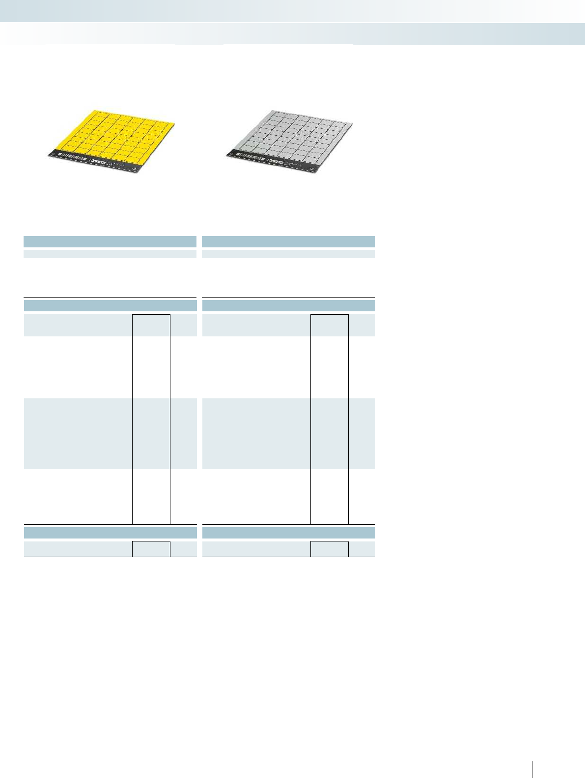
For additional information, visit phoenixcontact.net/products
Technical data Technical data
TOPMARK LASER TOPMARK LASER
TRANSPLY-ABS TRANSPLY-ABS
-20 ... 85 -20 ... 85
Wipe resistance DIN EN 61010-1 (VDE 0411-1) DIN EN 61010-1 (VDE 0411-1) DIN EN 61010-1 (VDE 0411-1)
Components Free from silicone and halogen Free from silicone and halogen Free from silicone and halogen
Ordering data Ordering data
Type Order No. Pcs. /
Pkt. Type Order No. Pcs. /
Pkt.
LS-EMLP (11X9) YE 0831732 10 LS-EMLP (11X9) SR 0831705 10
LS-EMLP (13X9) YE 0831733 10 LS-EMLP (13X9) SR 0831706 10
LS-EMLP (17X7) YE 0831734 10 LS-EMLP (17X7) SR 0831707 10
LS-EMLP (17X9) YE 0831735 10 LS-EMLP (17X9) SR 0831708 10
LS-EMLP (17,5X12) YE 0831736 10 LS-EMLP (17,5X12) SR 0831709 10
LS-EMLP (17,5X15) YE 0831737 10 LS-EMLP (17,5X15) SR 0831710 10
LS-EMLP (20X7) YE 0831738 10 LS-EMLP (20X7) SR 0831711 10
LS-EMLP (20X8) YE 0831739 10 LS-EMLP (20X8) SR 0831712 10
LS-EMLP (22X12) YE 0831740 10 LS-EMLP (22X12) SR 0831713 10
LS-EMLP (22X22) YE 0831741 10 LS-EMLP (22X22) SR 0831714 10
LS-EMLP (27X8) YE 0831742 10 LS-EMLP (27X8) SR 0831715 10
LS-EMLP (27X12,5) YE 0831743 10 LS-EMLP (27X12,5) SR 0831716 10
LS-EMLP (27X15) YE 0831744 10 LS-EMLP (27X15) SR 0831717 10
LS-EMLP (27X18) YE 0831745 10 LS-EMLP (27X18) SR 0831718 10
LS-EMLP (27X27) YE 0831746 10 LS-EMLP (27X27) SR 0831719 10
LS-EMLP (45X14) YE 0831747 10 LS-EMLP (45X14) SR 0831720 10
LS-EMLP (45X15) YE 0831748 10 LS-EMLP (45X15) SR 0831721 10
LS-EMLP (49X15) YE 0831749 10 LS-EMLP (49X15) SR 0831722 10
LS-EMLP (60X15) YE 0831750 10 LS-EMLP (60X15) SR 0831723 10
LS-EMLP (60X30) YE 0831751 10 LS-EMLP (60X30) SR 0831724 10
LS-EMLP (85,6X54) YE 0831752 10 LS-EMLP (85,6X54) SR 0831725 10
LS-EMLP (100X60) YE 0831753 10 LS-EMLP (100X60) SR 0831726 10
Accessories Accessories
TOPMARK LASER-MAG SHEET 0831836 1TOPMARK LASER-MAG SHEET 0831836 1
257PHOENIX CONTACT
Marking systems, tools, and mounting material
Marking material for TOPMARK LASER - MARKING system
mm Yellow, material thickness: 0.8mm Silver, material thickness: 0.8mm
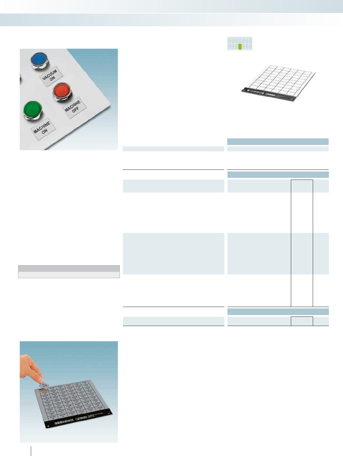
PR INTED
FOR YOU
– The LS-EMLP... product range includes
self-adhesive double-layer plastic device
markers
– A wide range of different marker sizes is
available for custom designs
– Automatic material detection enables fast
and effective marking without time-
consuming parameter settings
– The material sheet can be easily reused by
creating a project code
–Designation example:
LS-EMLP(11x9)SRCUS
Lettering field size: 11x9mm,
silver material with black marking
– Labeling service: Phoenix Contact can
custom-label all markers according to
your requirements
Notes:
1) For an ordering example, see page 358 in main catalog 5.
Technical data
General data
Material TRANSPLY-ABS
Temperature range [°C] -20 ... 85
Wipe resistance DIN EN 61010-1 (VDE 0411-1) DIN EN 61010-1 (VDE 0411-1) DIN EN 61010-1 (VDE 0411-1)
Components Free from silicone and halogen Free from silicone and halogen Free from silicone and halogen
Ordering data
Description Type Order No. Pcs. /
Pkt.
Plastic label sheet,
self-adhesive double-layer plastic labels,
marked according to customer specifications1)
1sheet=255labels LS-EMLP (11X9) WH CUS 0831964 1
1sheet=221labels LS-EMLP (13X9) WH CUS 0831965 1
1sheet=220labels LS-EMLP (17X7) WH CUS 0831966 1
1sheet=170labels LS-EMLP (17X9) WH CUS 0831967 1
1sheet=130labels LS-EMLP (17,5X12) WH CUS 0831968 1
1sheet=100labels LS-EMLP (17,5X15) WH CUS 0831969 1
1sheet=176labels LS-EMLP (20X7) WH CUS 0831970 1
1sheet=160labels LS-EMLP (20X8) WH CUS 0831971 1
1sheet=104labels LS-EMLP (22X12) WH CUS 0831972 1
1sheet=56labels LS-EMLP (22X22) WH CUS 0831973 1
1sheet=120labels LS-EMLP (27X8) WH CUS 0831974 1
1sheet=78labels LS-EMLP (27X12,5) WH CUS 0831975 1
1sheet=60labels LS-EMLP (27X15) WH CUS 0831976 1
1sheet=54labels LS-EMLP (27X18) WH CUS 0831977 1
1sheet=36labels LS-EMLP (27X27) WH CUS 0831978 1
1sheet=33labels LS-EMLP (45X14) WH CUS 0831979 1
1sheet=30labels LS-EMLP (45X15) WH CUS 0831980 1
1sheet=30labels LS-EMLP (49X15) WH CUS 0831981 1
1sheet=20labels LS-EMLP (60X15) WH CUS 0831982 1
1sheet=10labels LS-EMLP (60X30) WH CUS 0831983 1
1sheet=6labels LS-EMLP (85,6X54) WH CUS 0831984 1
1sheet=2labels LS-EMLP (100X60) WH CUS 0831985 1
Accessories
Sheet hopper, for TOPMARKLASER
TOPMARK LASER-MAG SHEET 0831836 1
258 PHOENIX CONTACT
Plastic adhesive device marking,
marked according to
customer specifications
Marking systems, tools, and mounting material
Marking material for TOPMARK LASER - MARKING system
White, material thickness: 0.8mm Yellow, material thickness: 0.8
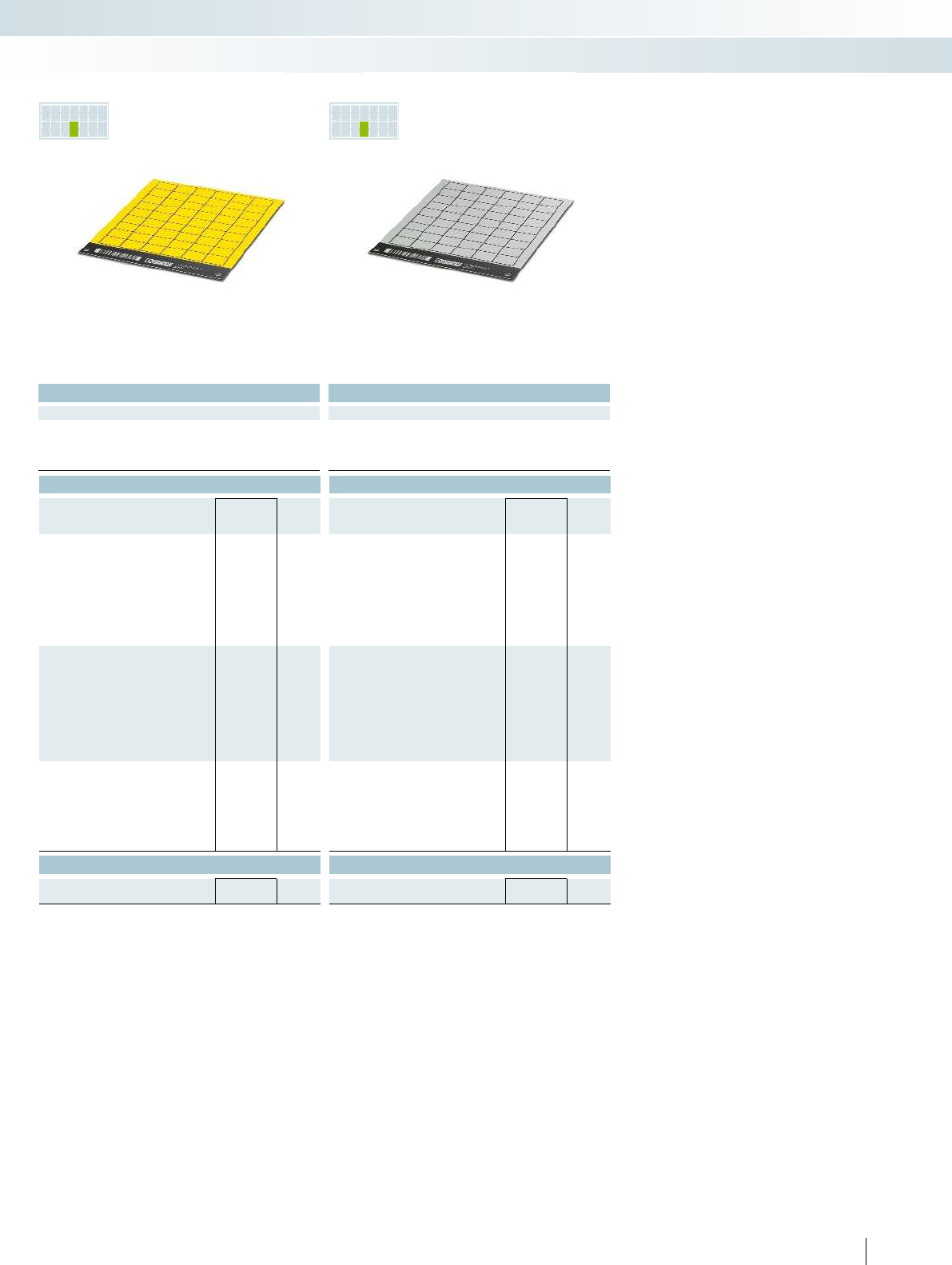
PR INTED
FOR YOU
PR INTED
FOR YOU
For additional information, visit phoenixcontact.net/products
Technical data Technical data
TRANSPLY-ABS TRANSPLY-ABS
-20 ... 85 -20 ... 85
Wipe resistance DIN EN 61010-1 (VDE 0411-1) DIN EN 61010-1 (VDE 0411-1) DIN EN 61010-1 (VDE 0411-1)
Components Free from silicone and halogen Free from silicone and halogen Free from silicone and halogen
Ordering data Ordering data
Type Order No. Pcs. /
Pkt. Type Order No. Pcs. /
Pkt.
LS-EMLP (11X9) YE CUS 0832018 1LS-EMLP (11X9) SR CUS 0831991 1
LS-EMLP (13X9) YE CUS 0832019 1LS-EMLP (13X9) SR CUS 0831992 1
LS-EMLP (17X7) YE CUS 0832020 1LS-EMLP (17X7) SR CUS 0831993 1
LS-EMLP (17X9) YE CUS 0832021 1LS-EMLP (17X9) SR CUS 0831994 1
LS-EMLP (17,5X12) YE CUS 0832022 1LS-EMLP (17,5X12) SR CUS 0831995 1
LS-EMLP (17,5X15) YE CUS 0832023 1LS-EMLP (17,5X15) SR CUS 0831996 1
LS-EMLP (20X7) YE CUS 0832024 1LS-EMLP (20X7) SR CUS 0831997 1
LS-EMLP (20X8) YE CUS 0832025 1LS-EMLP (20X8) SR CUS 0831998 1
LS-EMLP (22X12) YE CUS 0832026 1LS-EMLP (22X12) SR CUS 0831999 1
LS-EMLP (22X22) YE CUS 0832027 1LS-EMLP (22X22) SR CUS 0832000 1
LS-EMLP (27X8) YE CUS 0832028 1LS-EMLP (27X8) SR CUS 0832001 1
LS-EMLP (27X12,5) YE CUS 0832029 1LS-EMLP (27X12,5) SR CUS 0832002 1
LS-EMLP (27X15) YE CUS 0832030 1LS-EMLP (27X15) SR CUS 0832003 1
LS-EMLP (27X18) YE CUS 0832031 1LS-EMLP (27X18) SR CUS 0832004 1
LS-EMLP (27X27) YE CUS 0832032 1LS-EMLP (27X27) SR CUS 0832005 1
LS-EMLP (45X14) YE CUS 0832033 1LS-EMLP (45X14) SR CUS 0832006 1
LS-EMLP (45X15) YE CUS 0832034 1LS-EMLP (45X15) SR CUS 0832007 1
LS-EMLP (49X15) YE CUS 0832035 1LS-EMLP (49X15) SR CUS 0832008 1
LS-EMLP (60X15) YE CUS 0832036 1LS-EMLP (60X15) SR CUS 0832009 1
LS-EMLP (60X30) YE CUS 0832037 1LS-EMLP (60X30) SR CUS 0832010 1
LS-EMLP (85,6X54) YE CUS 0832038 1LS-EMLP (85,6X54) SR CUS 0832011 1
LS-EMLP (100X60) YE CUS 0832039 1LS-EMLP (100X60) SR CUS 0832012 1
Accessories Accessories
TOPMARK LASER-MAG SHEET 0831836 1TOPMARK LASER-MAG SHEET 0831836 1
259PHOENIX CONTACT
Marking systems, tools, and mounting material
Marking material for TOPMARK LASER - MARKING system
mm Yellow, material thickness: 0.8mm Silver, material thickness: 0.8mm
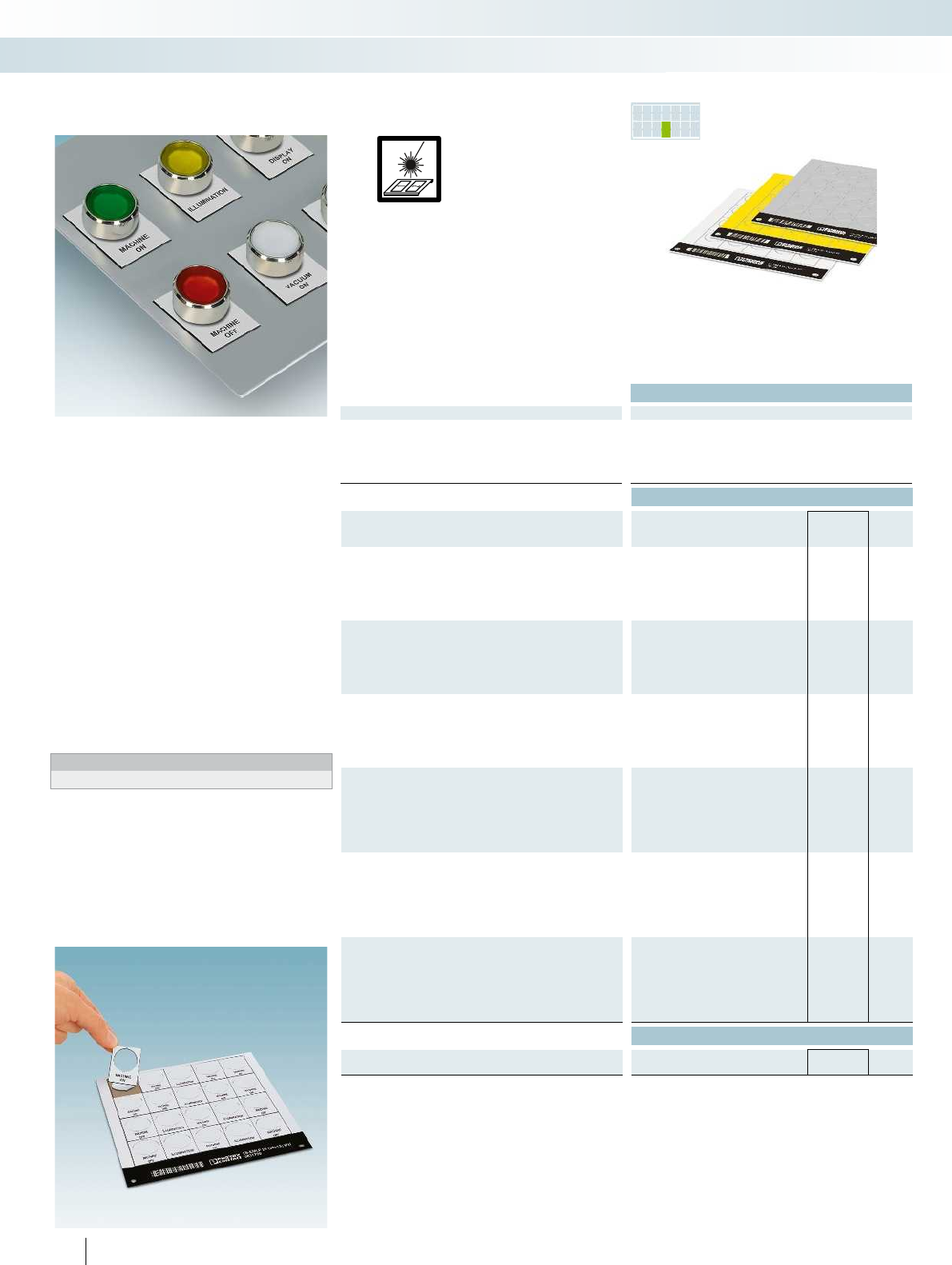
PR INTED
FOR YOU
– The LS-EMLP24/30/32... product range
includes self-adhesive double-layer plastic
device markers with a hole for the switch
– A wide range of different marker sizes is
available for custom designs
– Automatic material detection enables fast
and effective marking without time-
consuming parameter settings
– The material sheet can be easily reused by
creating a project code
–Designation example:
LS-EMLP24(30x12)WH
Lettering field size: 30x12mm
Hole diameter for switch: 24mm,
white material with black marking
– Labeling service: Phoenix Contact can
custom-label all markers according to
your requirements
Notes:
1) For an ordering example, see page 358 in main catalog 5.
Technical data
General data
Can be marked with TOPMARK LASER
Material TRANSPLY-ABS
Temperature range [°C] -20 ... 85
Wipe resistance DIN EN 61010-1 (VDE 0411-1) DIN EN 61010-1 (VDE 0411-1) DIN EN 61010-1 (VDE 0411-1)
Components Free from silicone and halogen Free from silicone and halogen Free from silicone and halogen
Ordering data
Description Color Type Order No. Pcs. /
Pkt.
Plastic label sheet, with hole for switch, diameter 24mm,
self-adhesive double-layer plastic labels
1sheet=20labels white LS-EMLP 24 (30X12) WH 0831700 10
1sheet=20labels yellow LS-EMLP 24 (30X12) YE 0831754 10
1sheet=20labels silver LS-EMLP 24 (30X12) SR 0831727 10
Plastic label sheet, with hole for switch, diameter 30mm,
self-adhesive double-layer plastic labels
1sheet=9labels white
1sheet=9labels yellow
1sheet=9labels silver
Plastic label sheet, with hole for switch, diameter 32mm,
self-adhesive double-layer plastic labels
1sheet=12labels white
1sheet=12labels yellow
1sheet=12labels silver
Plastic label sheet, with hole for switch, diameter 24mm,
self-adhesive double-layer plastic labels,
marked according to customer specifications1)
1sheet=20labels white LS-EMLP 24 (30X12) WH CUS 0831986 1
1sheet=20labels yellow LS-EMLP 24 (30X12) YE CUS 0832040 1
1sheet=20labels silver LS-EMLP 24 (30X12) SR CUS 0832013 1
Plastic label sheet, with hole for switch, diameter 30mm,
self-adhesive double-layer plastic labels,
marked according to customer specifications1)
1sheet=9labels white
1sheet=9labels yellow
1sheet=9labels silver
Plastic label sheet, with hole for switch, diameter 32mm,
self-adhesive double-layer plastic labels,
marked according to customer specifications1)
1sheet=12labels white
1sheet=12labels yellow
1sheet=12labels silver
Accessories
Sheet hopper, for TOPMARKLASER
TOPMARK LASER-MAG SHEET 0831836 1
260 PHOENIX CONTACT
Direct laser marking
Can be marked using:
Plastic adhesive device marking,
with hole for switch
Marking systems, tools, and mounting material
Marking material for TOPMARK LASER - MARKING system
Diameter: 24mm,
material thickness: 0.8mm
PR INTED
FOR YOU
PR INTED
FOR YOU
For additional information, visit phoenixcontact.net/products
Technical data Technical data
TOPMARK LASER TOPMARK LASER
TRANSPLY-ABS TRANSPLY-ABS
-20 ... 85 -20 ... 85
Wipe resistance DIN EN 61010-1 (VDE 0411-1) DIN EN 61010-1 (VDE 0411-1) DIN EN 61010-1 (VDE 0411-1)
Components Free from silicone and halogen Free from silicone and halogen Free from silicone and halogen
Ordering data Ordering data
Type Order No. Pcs. /
Pkt. Type Order No. Pcs. /
Pkt.
LS-EMLP 30 (45X10) WH 0831701 10
LS-EMLP 30 (45X10) YE 0831755 10
LS-EMLP 30 (45X10) SR 0831728 10
LS-EMLP 32 (38X14) WH 0831702 10
LS-EMLP 32 (38X14) YE 0831756 10
LS-EMLP 32 (38X14) SR 0831729 10
LS-EMLP 30 (45X10) WH CUS 0831987 1
LS-EMLP 30 (45X10) YE CUS 0832041 1
LS-EMLP 30 (45X10) SR CUS 0832014 1
LS-EMLP 32 (38X14) WH CUS 0831988 1
LS-EMLP 32 (38X14) YE CUS 0832042 1
LS-EMLP 32 (38X14) SR CUS 0832015 1
Accessories Accessories
TOPMARK LASER-MAG SHEET 0831836 1TOPMARK LASER-MAG SHEET 0831836 1
261PHOENIX CONTACT
Marking systems, tools, and mounting material
Marking material for TOPMARK LASER - MARKING system
Diameter: 30mm,
material thickness: 0.8mm
Diameter: 32mm,
material thickness: 0.8mm
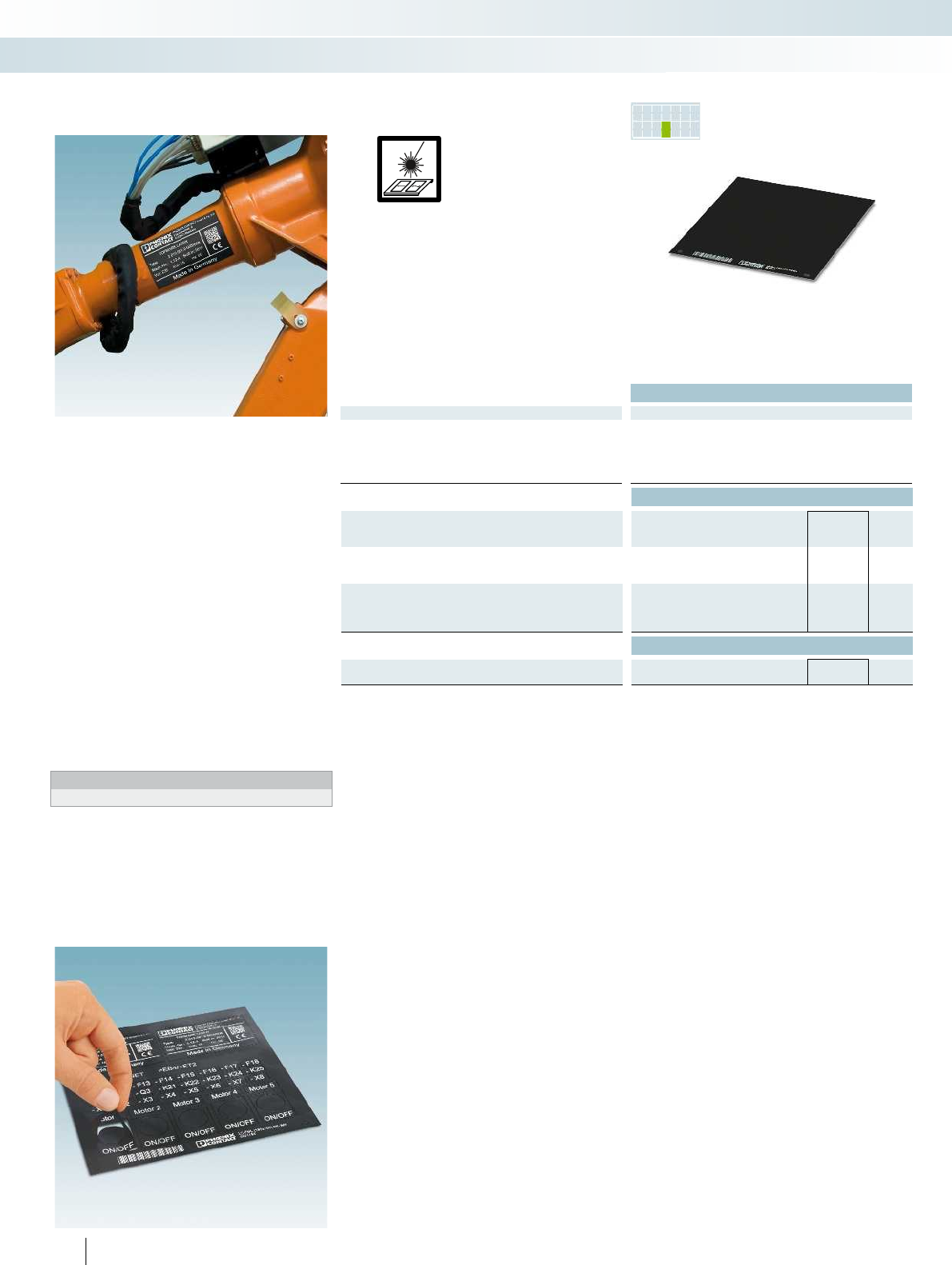
PR INTED
FOR YOU
– The LS-EML... product range includes
self-adhesive, double-layer plastic foil
labels that can be custom designed
– The laser foil is characterized by its high
heat resistance and particularly strong
adhesive properties
– Automatic material detection enables fast
and effective marking without time-
consuming parameter settings
– The material sheet can be easily reused by
creating a project code
–Designation example:
LS-EML(180x180)BK-WH
Lettering field size: 180x180mm,
can be custom designed,
black material with white marking
– Labeling service: Phoenix Contact can
custom-label all markers according to
your requirements
Notes:
1) For an ordering example, see page 358 in main catalog 5.
Technical data
General data
Can be marked with TOPMARK LASER
Material Polyacrylate
Temperature range [°C] -40 ... 300
Wipe resistance DIN EN 61010-1 (VDE 0411-1)
Components Free from silicone and halogen
Ordering data
Description Type Order No. Pcs. /
Pkt.
Laser foil, double-layer plastic foil, for custom label design
Lettering field size: 180x180mm LS-EML (180X180) BK-WH 0831784 10
Laser foil, double-layer plastic foil, for custom label design,
marked according to customer specifications1)
Lettering field size: 180x180mm LS-EML (180X180) BK-WH CUS 0832070 1
Accessories
Sheet hopper, for TOPMARKLASER
TOPMARK LASER-MAG SHEET 0831836 1
262 PHOENIX CONTACT
Direct laser marking
Can be marked using:
Laser foil adhesive device marking
Marking systems, tools, and mounting material
Marking material for TOPMARK LASER - MARKING system
Black-white

For additional information, visit phoenixcontact.net/products
263PHOENIX CONTACT
Marking systems, tools, and mounting material
Marking material for TOPMARK LASER - MARKING system
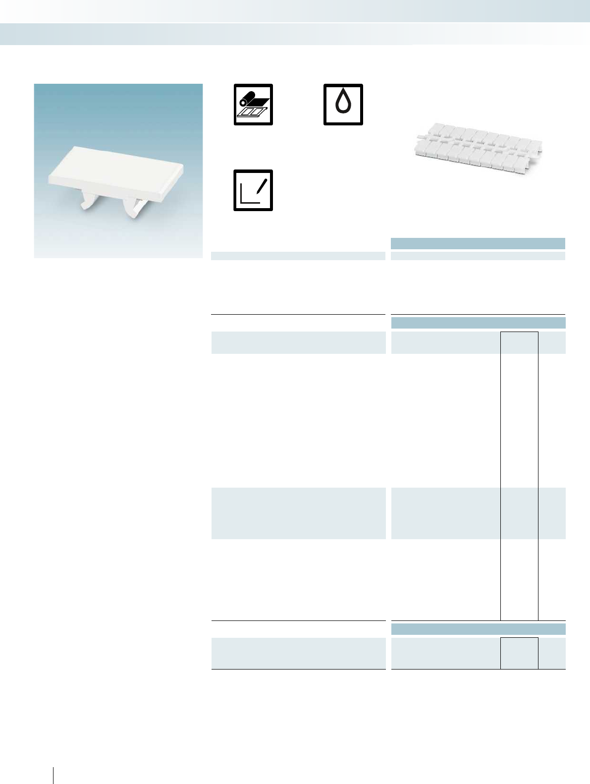
1
2
2
1
UV
x
y
1 2 3
– The universalUM1-TM...material
marking range includes markers for
Weidmüller, Conta-Clip, Klemsan, Wago,
and ABB(Entrelec) terminal blocks
– The markers, which are supplied in
double strips, can be quickly and easily
marked with BLUEMARK...,
THERMOMARKCARD...,
and the CMS-P1-PLOTTER
– The markers support multiline labeling
– The marking strips are easy to fit and can
be easily separated if required
– The marking strips are snapped into the
magazine in a twist-proof manner by
means of a coding pin and fed to the
output devices
– The format automatically ensures printing
with a high level of positional accuracy
Technical data
General data
Can be marked with THERMOMARK CARD PLUS THERMOMARK CARD
BLUEMARK CLED CMS-P1-PLOTTER
Material PC
Inflammability class according to UL 94 V2
Temperature range [°C] -40 ... 120
Wipe resistance DIN EN 61010-1 (VDE 0411-1) DIN EN 61010-1 (VDE 0411-1) DIN EN 61010-1 (VDE 0411-1)
Components Free from silicone, halogen, and cadmium Free from silicone, halogen, and cadmium Free from silicone, halogen, and cadm
Ordering data
Description Color Type Order No. Pcs. /
Pkt.
UM1-TM..., for marking terminal blocks from other manufacturers,
Weidmüller, Conta-Clip, Klemsan
34-section, lettering field size: 3.5x12mm,
pitch: 3.5mm
white UM1-TM (3,5X12) 0830925 10
24-section, lettering field size: 5x10mm,
pitch: 5mm
white UM1-TM (5X10) 0830905 10
24-section, lettering field size: 5x12mm,
pitch: 5mm
white UM1-TM (5X12) 0830912 10
20-section, lettering field size: 6x10mm,
pitch: 6mm
white UM1-TM (6X10) 0830903 10
20-section, lettering field size: 6x12mm,
pitch: 6mm
white UM1-TM (6X12) 0830909 10
14-section, lettering field size: 8x10mm,
pitch: 8mm
white UM1-TM (8X10) 0830906 10
14-section, lettering field size: 8x12mm,
pitch: 8mm
white UM1-TM (8X12) 0830920 10
10-section, lettering field size: 12x10mm,
pitch: 12mm
white UM1-TM (12X10) 0830916 10
UM1U-TM..., for marking terminal blocks from other
manufacturers, Weidmüller, Conta-Clip, Klemsan,
with an offset foot
24-section, lettering field size: 5x10mm,
pitch: 5mm
white
20-section, lettering field size: 6x10mm,
pitch: 6mm
white
UM1-TMF..., for marking terminal blocks from other
manufacturers, Weidmüller, Conta-Clip, Klemsan, Wago,
ABB(Entrelec)
34-section, lettering field size: 3.5x5mm,
pitch: 3.5mm
white
24-section, lettering field size: 5x5mm,
pitch: 5mm
white
20-section, lettering field size: 6x5mm,
pitch: 6mm
white
14-section, lettering field size: 8x5mm,
pitch: 8mm
white
Accessories
Magazine, for THERMOMARKCARD...
for accommodating UM1-TM... THERMOMARK CARD-UM-MAG1 0831200 1
for accommodating UM1U-TM...
for accommodating UM1-TMF...
264 PHOENIX CONTACT
Thermal transfer for sheets
and cards
UV LED technology
Plotter
Can be marked using:
UM marking for terminals
from other manufacturers, strips
Marking systems, tools, and mounting material
Terminal marking - MARKING system
For a tall marker groove For a tall marker groove,
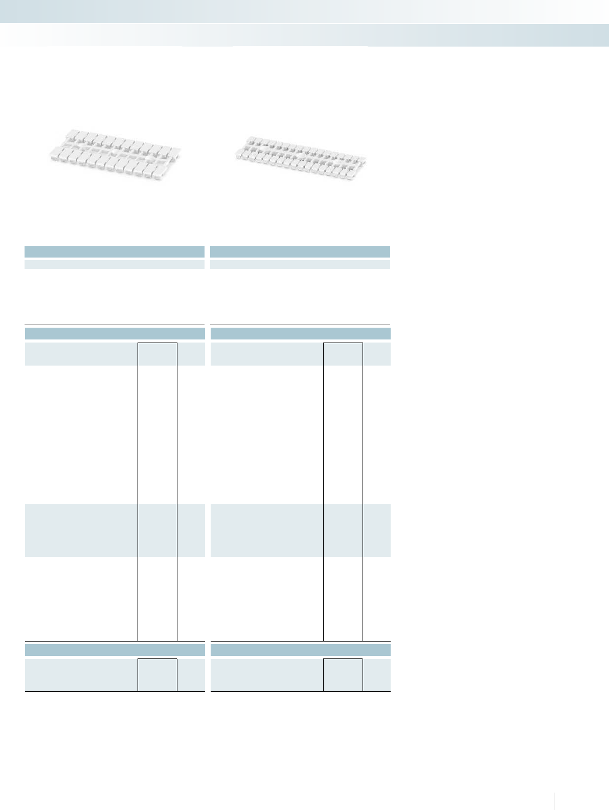
For additional information, visit phoenixcontact.net/products
Technical data Technical data
THERMOMARK CARD PLUS THERMOMARK CARD
BLUEMARK CLED CMS-P1-PLOTTER
THERMOMARK CARD PLUS THERMOMARK CARD
BLUEMARK CLED CMS-P1-PLOTTER
PC PC
V2 V2
-40 ... 120 -40 ... 120
Wipe resistance DIN EN 61010-1 (VDE 0411-1) DIN EN 61010-1 (VDE 0411-1) DIN EN 61010-1 (VDE 0411-1)
Components Free from silicone, halogen, and cadmium Free from silicone, halogen, and cadmium Free from silicone, halogen, and cadmium
Ordering data Ordering data
Type Order No. Pcs. /
Pkt. Type Order No. Pcs. /
Pkt.
UM1U-TM (5X10) 0830910 10
UM1U-TM (6X10) 0830907 10
UM1-TMF (3,5X5) 0830935 10
UM1-TMF (5X5) 0830902 10
UM1-TMF (6X5) 0830904 10
UM1-TMF (8X5) 0830924 10
Accessories Accessories
THERMOMARK CARD-UM-MAG4 0831203 1
THERMOMARK CARD-UM-MAG3 0831202 1
265PHOENIX CONTACT
Marking systems, tools, and mounting material
Terminal marking - MARKING system
For a tall marker groove For a tall marker groove, with an offset foot For a flat marker groove
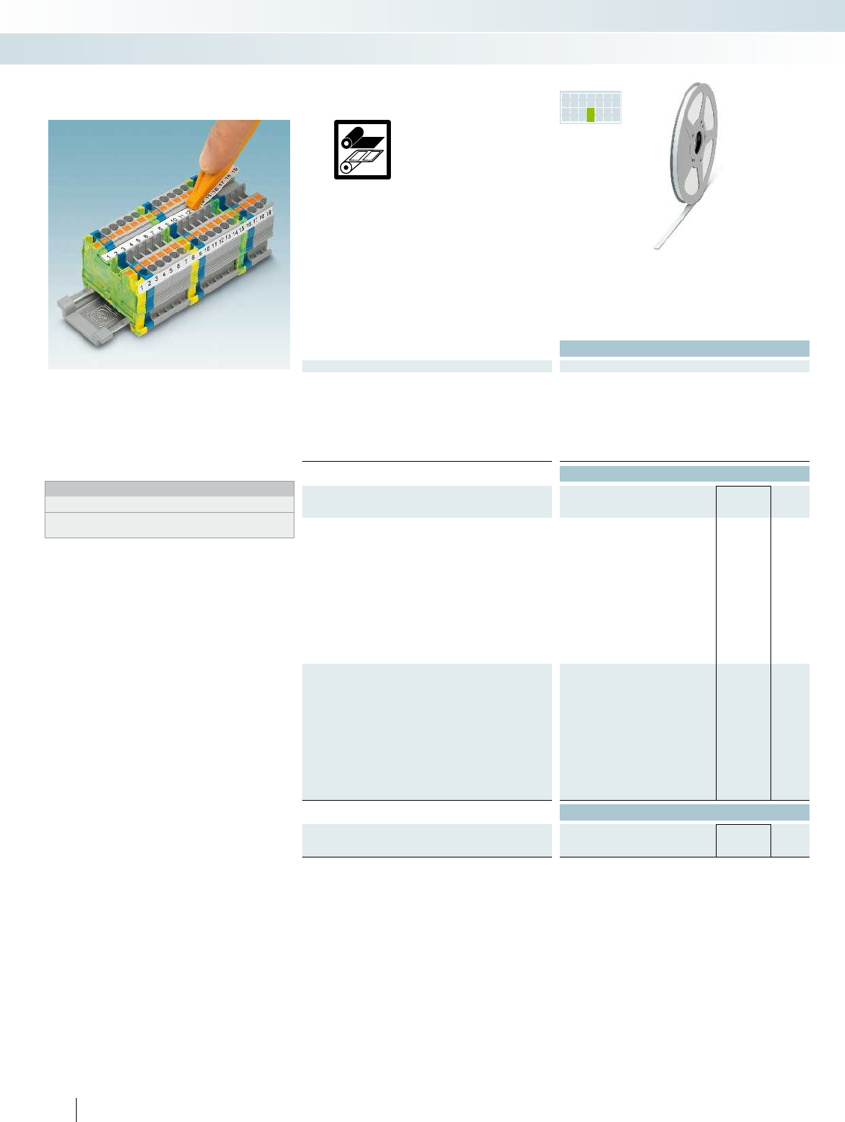
PR INTED
FOR YOU
2
1
1
2
– The TMT labeling range includes markers
for all products with tall and flat marker
grooves
– Labeling service: PhoenixContact can
custom-label all TMT markers in
accordance with your requirements
Notes:
1) For an ordering example, see page 358 in main catalog 5.
2) The TMTTOOL snap-in tool can only be used for terminal blocks
from PhoenixContact.
Technical data
General data
Can be marked with
THERMOMARK ROLL
THERMOMARK ROLL X1
THERMOMARK X1.1
THERMOMARK X1.2
THERMOMARK S1.1
Material PVC
Material strength 0.50 mm
Inflammability class according to UL 94 V0
Temperature range [°C] -30 ... 80
Wipe resistance DIN EN 61010-1 (VDE 0411-1)
Components Free from silicone and cadmium
Ordering data
Description Color Type Order No. Pcs. /
Pkt.
Insert strips, unprinted, 1roll=50m, continuous
Strip height:5.5mm white TMT (EX5,5)R 0803062 1
Strip height:6.2mm white TMT (EX6,2)R 0803063 1
Strip height:6.5mm white TMT (EX6,5)R 0803064 1
Strip height:7.5mm white TMT (EX7,5)R 0803065 1
Strip height:8mm white TMT (EX8)R 0803066 1
Strip height:8.5mm white TMT (EX8,5)R 0803067 1
Strip height:9.5mm white TMT (EX9,5)R 0828295 1
Strip height:10mm white TMT (EX10)R 0803068 1
Strip height:10.5mm white TMT (EX10,5)R 0803070 1
Strip height:11mm white TMT2 (EX11)R 0802683 1
Strip height:12mm white TMT (EX12)R 0803071 1
Insert strips, marked according to customer specifications1)
Strip height:5.5mm white TMT (EX5,5)R CUS 0803072 1
Strip height:6.2mm white TMT (EX6,2)R CUS 0803073 1
Strip height:6.5mm white TMT (EX6,5)R CUS 0803075 1
Strip height:7.5mm white TMT (EX7,5)R CUS 0803076 1
Strip height:8mm white TMT (EX8)R CUS 0803077 1
Strip height:8.5mm white TMT (EX8,5)R CUS 0803078 1
Strip height:9.5mm white TMT (EX9,5)R CUS 0803079 1
Strip height:10mm white TMT (EX10)R CUS 0803080 1
Strip height:10.5mm white TMT (EX10,5)R CUS 0803081 1
Strip height:11mm white TMT2 (EX11)R CUS 0830811 1
Strip height:12mm white TMT (EX12)R CUS 0803082 1
Accessories
Locking tool to snap into the TMT... materials2)
orange TMT TOOL 0816650 1
Can be marked using:
Terminal marking, marker strips
for tall and flat marker grooves
266 PHOENIX CONTACT
Marking systems, tools, and mounting material
Terminal marking - MARKING system
Unlabeled or labeled
according to customer specifications
Thermal transfer for rolls
For additional information, visit phoenixcontact.net/products
267PHOENIX CONTACT
TMT ... terminal marking for terminal blocks from Phoenix Contact and other manufacturers
TMT (EX5,5)R
TMT (EX6,2)R
TMT (EX6,5)R
TMT (EX7,5)R
TMT (EX8)R
TMT (EX8,5)R
TMT (EX9,5)R
TMT (EX10)R
TMT (EX10,5)R
TMT2 (EX11)R
TMT (EX12)R
TMT- markers, roll 0803062
0803063 0803064 0803065 0803066 0803067 0828295 0803068 0803070 0802683 0803071
Strip height 5.5 6.2 6.5 7.5 8 8.5 9.5 10 10.5 10.8 12
Te r m i n a l m a n u f a c t u r e r
Phoenix Contact
Fuji Electronics Industry
IDEC
KASUGA
TOGI
WAGO (2001 ...- 2016 ...)
Yoshida Electronics
Marking systems, tools, and mounting material
Terminal marking - MARKING system
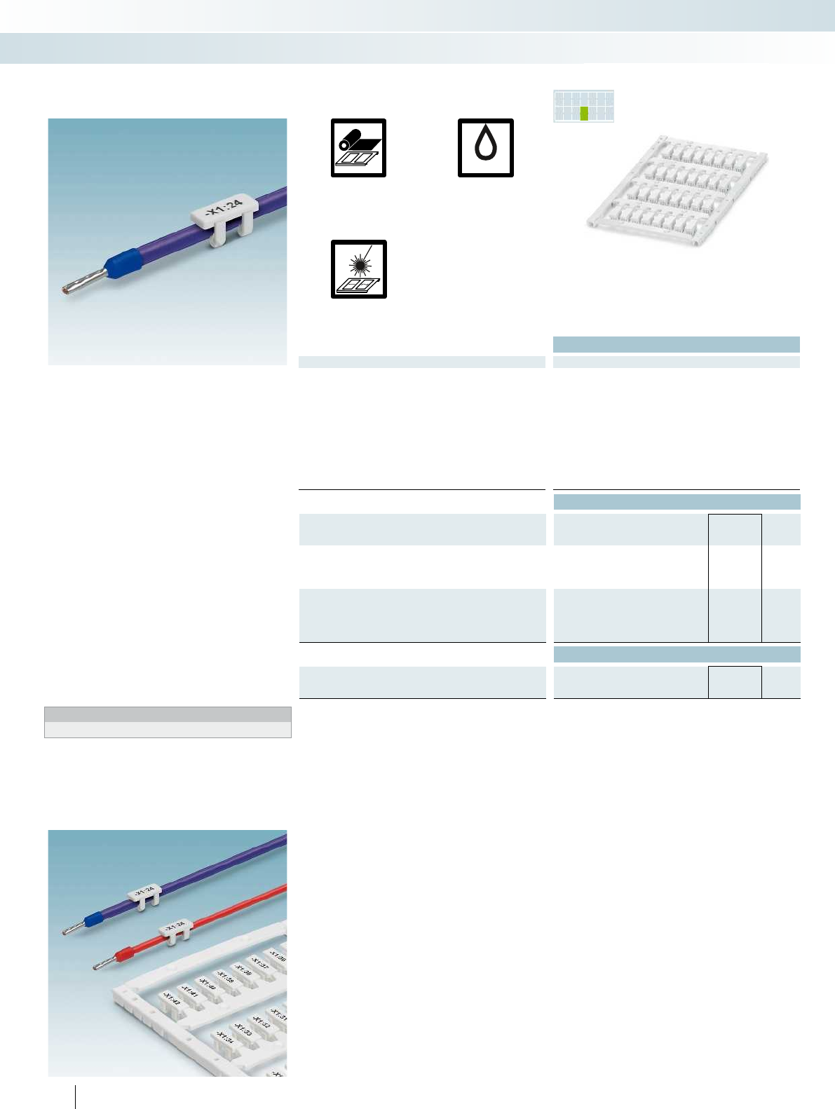
1
2
2
1
UV
PR INTED
FOR YOU
– The UCT-WMCO... UniCard marking
range includes markers for the
subsequent marking of conductors by
clipping on
– Secure tight fit even in the event of
vibrations
– The markers, which are supplied in
uniform sheets, can be marked quickly
and easily with the TOPMARKLASER,
THERMOMARKCARD,
THERMOMARKCARDPLUS, and the
BLUEMARK... printers
– The format automatically ensures printing
with a high level of positional accuracy
– Large-surface labeling in a space-saving
design
– The sheets provide space for including
function texts
– Labeling service: PhoenixContact can
custom-label all UniCard markers in
accordance with your requirements
Notes:
1) For an ordering example, see page 358 in main catalog 5.
Technical data
General data
Can be marked with THERMOMARK CARD PLUS THERMOMARK CARD
BLUEMARK CLED BLUEMARK LED TOPMARK LASER
Number of individual labels 32
Number of individual labels per strip 8
Material PC
Inflammability class according to UL 94 V0
Temperature range [°C] -40 ... 120
Wipe resistance DIN EN 61010-1 (VDE 0411-1) DIN EN 61010-1 (VDE 0411-1) DIN EN 61010-1 (VDE 0411-1) DIN EN 61010-1 (VDE 0411-1)
Components Free from silicone, halogen, and cadmium Free from silicone, halogen, and cadmium Free from silicone, halogen, and cadm
Conductor diameter range [mm] 2 ... 2.9
Conductor cross section range [mm²] 0.5 ... 1.5
Ordering data
Description Color Type Order No. Pcs. /
Pkt.
UniCard, for subsequent labeling of conductors
Lettering field size: 12x4mm white UCT-WMCO 2,9 (12X4) 0830780 9
Lettering field size: 18x4mm white UCT-WMCO 2,9 (18X4) 0830781 9
UniCard, for subsequent labeling of conductors,
labeled acc. to customer specifications1)
Lettering field size: 12x4mm white UCT-WMCO 2,9 (12X4) CUS 0830788 1
Lettering field size: 18x4mm white UCT-WMCO 2,9 (18X4) CUS 0830789 1
Accessories
Magazine, for THERMOMARKCARD...,
for accommodating: UCT-WMCO...
THERMOMARK CARD-UCT-MAG25 0802935 1
268 PHOENIX CONTACT
Thermal transfer for sheets
and cards
UV LED technology
Direct laser marking
Can be marked using:
Clip-on UniCard conductor marking
Marking systems, tools, and mounting material
Conductor and cable marking - MARKING system
32markers
for conductor diameters of 2to2.9mm
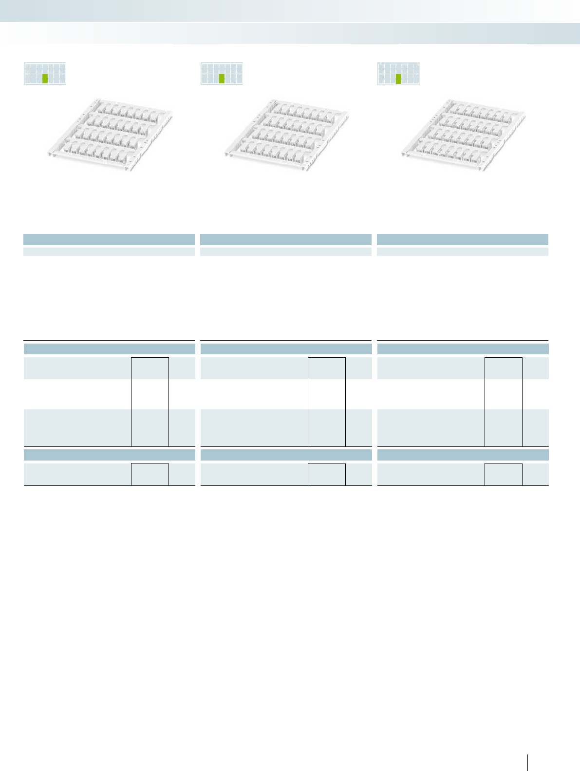
PR INTED
FOR YOU
PR INTED
FOR YOU
PR INTED
FOR YOU
For additional information, visit phoenixcontact.net/products
Technical data Technical data Technical data
THERMOMARK CARD PLUS THERMOMARK CARD
BLUEMARK CLED BLUEMARK LED TOPMARK LASER
THERMOMARK CARD PLUS THERMOMARK CARD
BLUEMARK CLED BLUEMARK LED TOPMARK LASER
THERMOMARK CARD PLUS THERMOMARK CARD
BLUEMARK CLED BLUEMARK LED TOPMARK LASER
32 32 32
888
PC PC PC
V0 V0 V0
-40 ... 120 -40 ... 120 -40 ... 120
Wipe resistance DIN EN 61010-1 (VDE 0411-1) DIN EN 61010-1 (VDE 0411-1) DIN EN 61010-1 (VDE 0411-1) DIN EN 61010-1 (VDE 0411-1)
Components Free from silicone, halogen, and cadmium Free from silicone, halogen, and cadmium Free from silicone, halogen, and cadmium Free from silicone, halogen, and cadmium
2.9 ... 3.5 3.5 ... 4.1 4.1 ... 4.7
1.5 ... 2.5 2.5 ... 4 2.5 ... 6
Ordering data Ordering data Ordering data
Type Order No. Pcs. /
Pkt. Type Order No. Pcs. /
Pkt. Type Order No. Pcs. /
Pkt.
UCT-WMCO 3,5 (12X4) 0830782 7UCT-WMCO 4,1 (12X4) 0830784 7UCT-WMCO 4,7 (12X4) 0830786 6
UCT-WMCO 3,5 (18X4) 0830783 7UCT-WMCO 4,1 (18X4) 0830785 7UCT-WMCO 4,7 (18X4) 0830787 6
UCT-WMCO 3,5 (12X4) CUS 0830790 1UCT-WMCO 4,1 (12X4) CUS 0830792 1UCT-WMCO 4,7 (12X4) CUS 0830794 1
UCT-WMCO 3,5 (18X4) CUS 0830791 1UCT-WMCO 4,1 (18X4) CUS 0830793 1UCT-WMCO 4,7 (18X4) CUS 0830795 1
Accessories Accessories Accessories
THERMOMARK CARD-UCT-MAG25 0802935 1THERMOMARK CARD-UCT-MAG25 0802935 1THERMOMARK CARD-UCT-MAG25 0802935 1
269PHOENIX CONTACT
Marking systems, tools, and mounting material
Conductor and cable marking - MARKING system
32markers
for conductor diameters of 2.9to3.5mm
32markers
for conductor diameters of 3.5to4.1mm
32markers
for conductor diameters of 4.1to4.7mm
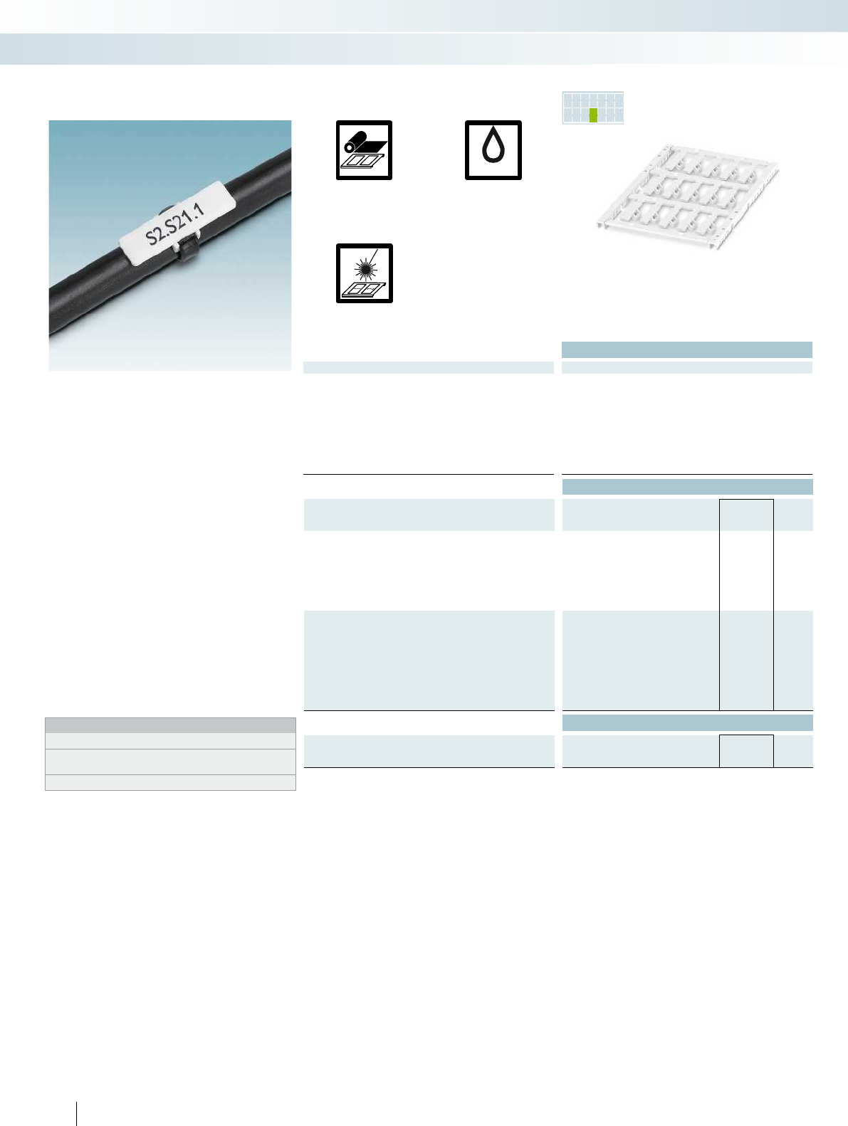
1
2
2
1
UV
PR INTED
FOR YOU
– The UCT-WMTBA... UniCard marking
range includes markers that can be
secured using standard cable binders
– The markers, which are supplied in
uniform sheets, can be marked quickly,
easily, and accurately with the
TOPMARKLASER,
THERMOMARKCARD,
THERMOMARKCARDPLUS,
and BLUEMARKCLED
– The format automatically ensures printing
with a high level of positional accuracy
– For large-surface marking of conductors
and cables > 5mm in diameter
– The sheets provide space for including
function texts
– Thanks to their angular shape the
markers fit perfectly onto cables
– Labeling service: PhoenixContact can
custom-label all UniCard markers in
accordance with your requirements
Notes:
For cable binders up to 5mm wide.
For matching cable binders, see page 574 onwards in main catalog 5
or the product area on our website at phoenixcontact.net/products.
1) For an ordering example, see page 358 in main catalog 5.
Technical data
General data
Can be marked with THERMOMARK CARD PLUS THERMOMARK CARD
BLUEMARK CLED BLUEMARK LED TOPMARK LASER
Number of individual labels 15
Number of individual labels per strip 5
Material PC
Inflammability class according to UL 94 V0
Temperature range [°C] -40 ... 120
Components Free from silicone, halogen, and cadmium Free from silicone, halogen, and cadmium Free from silicone, halogen, and cadm
Cable diameter range [mm] > 5
Ordering data
Description Color Type Order No. Pcs. /
Pkt.
UniCard, for assembly with cable binders
Lettering field size: 24x4mm white UCT-WMTBA (24X4) 1014082 10
yellow UCT-WMTBA (24X4) YE 1014083 10
Lettering field size: 29x6mm white
yellow
Lettering field size: 40x17mm white
yellow
UniCard, for assembly with cable binders,
labeled acc. to customer specifications1)
Lettering field size: 24x4mm white UCT-WMTBA (24X4) CUS 1014088 1
yellow UCT-WMTBA (24X4) YE CUS 1014089 1
Lettering field size: 29x6mm white
yellow
Lettering field size: 40x17mm white
yellow
Accessories
Magazine, for THERMOMARKCARD...,
for accommodating: UCT-WMTBA...
THERMOMARK CARD-UCT-MAG27 0802989 1
270 PHOENIX CONTACT
Thermal transfer for sheets
and cards
UV LED technology
Direct laser marking
Can be marked using:
UniCard cable marking
for assembly with cable binders
Marking systems, tools, and mounting material
Conductor and cable marking - MARKING system
15markers
for conductor diameter >5mm
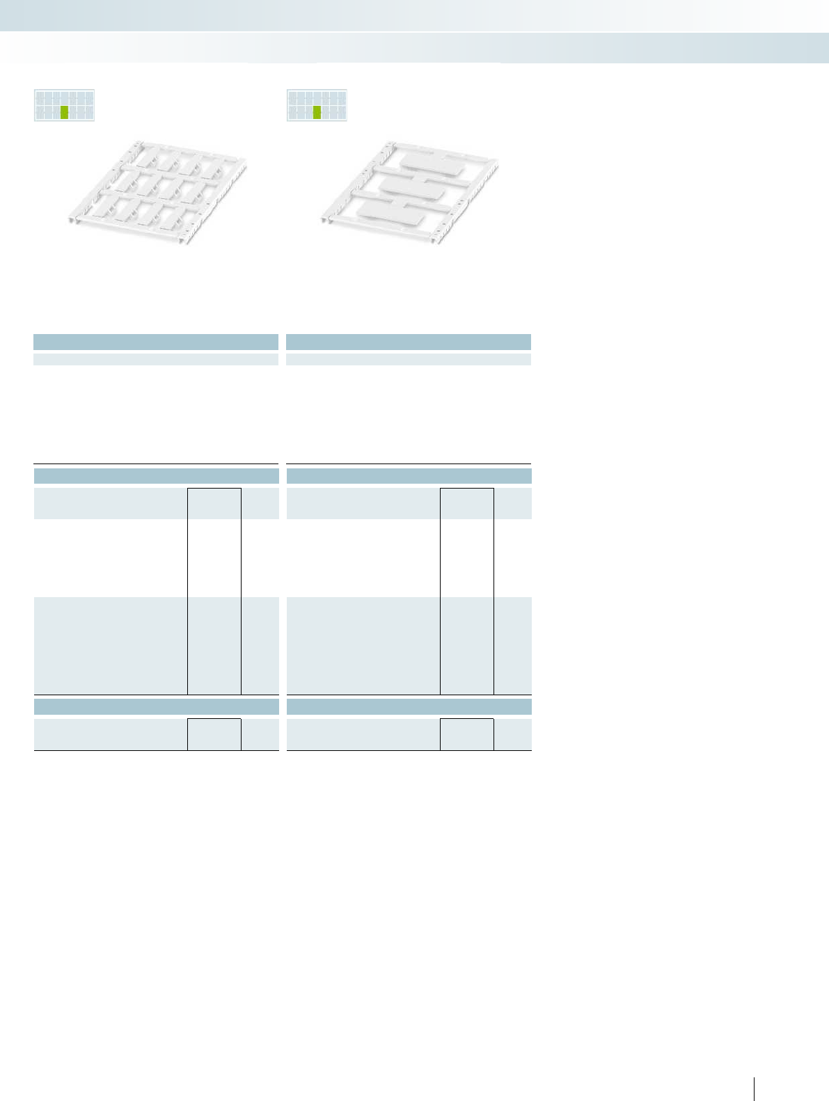
PR INTED
FOR YOU
PR INTED
FOR YOU
For additional information, visit phoenixcontact.net/products
Technical data Technical data
THERMOMARK CARD PLUS THERMOMARK CARD
BLUEMARK CLED BLUEMARK LED TOPMARK LASER
THERMOMARK CARD PLUS THERMOMARK CARD
BLUEMARK CLED BLUEMARK LED TOPMARK LASER
12 3
41
PC PC
V0 V0
-40 ... 120 -40 ... 120
Components Free from silicone, halogen, and cadmium Free from silicone, halogen, and cadmium Free from silicone, halogen, and cadmium
> 6 > 6
Ordering data Ordering data
Type Order No. Pcs. /
Pkt. Type Order No. Pcs. /
Pkt.
UCT-WMTBA (29X6) 1014084 10
UCT-WMTBA (29X6) YE 1014085 10
UCT-WMTBA (40X17) 1014086 10
UCT-WMTBA (40X17) YE 1014087 10
UCT-WMTBA (29X6) CUS 1014090 1
UCT-WMTBA (29X6) YE CUS 1014091 1
UCT-WMTBA (40X17) CUS 1014092 1
UCT-WMTBA (40X17) YE CUS 1014093 1
Accessories Accessories
THERMOMARK CARD-UCT-MAG27 0802989 1THERMOMARK CARD-UCT-MAG27 0802989 1
271PHOENIX CONTACT
Marking systems, tools, and mounting material
Conductor and cable marking - MARKING system
12markers
for conductor diameter >6mm
3markers
for conductor diameter >6mm
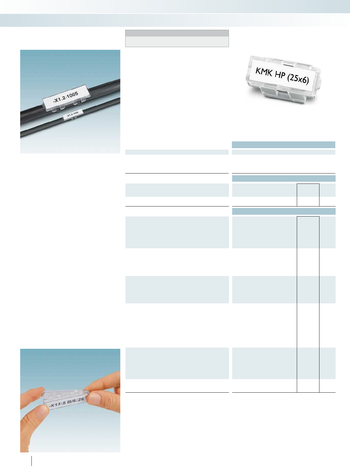
Technical data
General data
Material PC
Inflammability class according to UL 94 V0
Temperature range [°C] -40 ... 125
Components Halogen-free
Ordering data
Description Color Type Order No. Pcs. /
Pkt.
Cable marker carrier for cable binder assembly
transparent KMK HP (25X6) 0830720 100
Accessories
UniCard, insert strip for KMK... cable marker carriers, can be
marked with THERMOMARK CARD... and BLUEMARK CLED
Lettering field size: 25x6mm, 15-section UCT-EMP (25X6) 1014117 10
Lettering field size: 29x8mm, 15-section
Lettering field size: 60x15 mm, 3-section
Lettering field size: 40x17 mm, 3-section
UniCard, insert strips for KMK... cable marker carriers,
marked according to customer specifications
Lettering field size: 25x6mm, 15-section UCT-EMP (25X6) CUS 1014121 1
Lettering field size: 29x8mm, 15-section
Lettering field size: 40x17 mm, 3-section
Lettering field size: 60x15 mm, 3-section
UniSheet, 0.5mm thick,
inflammability class V0 according to UL94
84-section, lettering field size: 25x6mm US-EMP (25X6)-1 0802754 10
48-section, lettering field size: 29x8mm
9-section, lettering field size: 60x15mm
16-section, lettering field size: 40x17mm
Insert labels for thermal transfer printer, halogen-free
Lettering field size: 25x6mm, 5000labels per roll EMT (25X6)R 0817264 1
Lettering field size: 29x8mm, 5400 labels per roll
Lettering field size: 60x15mm, 2500 labels per roll
Lettering field size: 40x17mm, 2300 labels per roll
Cable binder, inflammability class according to UL94:V0,
halogen-free, temperature range: -40°C...85°C,
maximum bundle Ø [mm]/minimum tensile strength [N]
35 / 130 WT-HP HF 3,6X140 0830982 100
50 / 220 WT-HP HF 4,8X200 0830983 100
79 / 220 WT-HP HF 4,5X290 0830984 100
Magazine, for THERMOMARKCARD...,
for accommodating UCT-EMP...
THERMOMARK CARD-UCT-MAG26 0802988 1
272 PHOENIX CONTACT
Plastic cable markers for insert labels,
for assembly with cable binders
Notes:
For matching cable binders, see page 574 onwards in main catalog 5
or the product area on our website at phoenixcontact.net/products.
– KMKHP... plastic cable markers for
marking and bundling conductors and
cables indoors
– Inflammability class V0 acc. to UL 94
– The KMKHP... cable markers are
particularly suitable for use in the railway
industry, traffic technology, and building
technology thanks to their outstanding
material properties
– The KMK... versions have eyelets and are
attached with cable binders
– The printed insert label is protected from
dirt by the sealing cap
– Labeling service: Phoenix Contact can
custom-label all insert labels for plastic
cable markers in accordance with your
requirements
Marking systems, tools, and mounting material
Conductor and cable marking - MARKING system
Lettering field size: 25x6mm,
for cable diameter >6mm
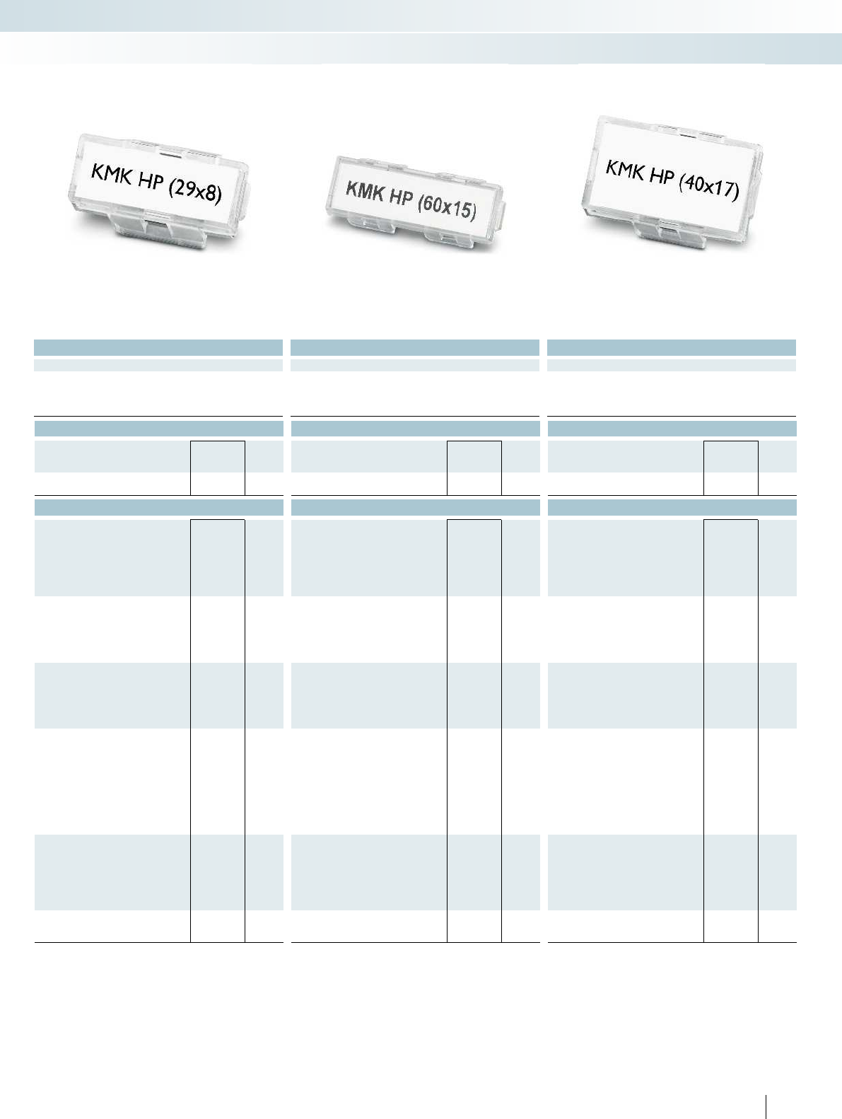
For additional information, visit phoenixcontact.net/products
Technical data Technical data Technical data
PC PC PC
V0 V0 V0
-40 ... 125 -40 ... 125 -40 ... 125
Halogen-free Halogen-free Halogen-free
Ordering data Ordering data Ordering data
Type Order No. Pcs. /
Pkt. Type Order No. Pcs. /
Pkt. Type Order No. Pcs. /
Pkt.
KMK HP (29X8) 0830721 100 KMK HP (60X15) 0830722 50 KMK HP (40X17) 0830723 50
Accessories Accessories Accessories
UCT-EMP (29X8) 1014118 10
UCT-EMP (60X15) 1014119 10
UCT-EMP (40X17) 1014120 10
UCT-EMP (29X8) CUS 1014122 1
UCT-EMP (40X17) CUS 1014124 1
UCT-EMP (60X15) CUS 1014123 1
US-EMP (29X8) 0829436 10
US-EMP (60X15) 0828781 10
US-EMP (40X17) 0829437 10
EMT (29X8)R 0817277 1
EMT (60X15)R 0801846 10
EMT (40X17)R 0817293 1
WT-HP HF 3,6X140 0830982 100 WT-HP HF 3,6X140 0830982 100 WT-HP HF 3,6X140 0830982 100
WT-HP HF 4,8X200 0830983 100 WT-HP HF 4,8X200 0830983 100 WT-HP HF 4,8X200 0830983 100
WT-HP HF 4,5X290 0830984 100 WT-HP HF 4,5X290 0830984 100 WT-HP HF 4,5X290 0830984 100
THERMOMARK CARD-UCT-MAG26 0802988 1THERMOMARK CARD-UCT-MAG26 0802988 1THERMOMARK CARD-UCT-MAG26 0802988 1
273PHOENIX CONTACT
Marking systems, tools, and mounting material
Conductor and cable marking - MARKING system
Lettering field size: 29x8mm,
for cable diameter >6mm
Lettering field size: 60x15mm,
for cable diameter >9mm
Lettering field size: 40x17mm,
for cable diameter >9mm

Technical data
General data
Material PA
Inflammability class according to UL 94 HB
Temperature range [°C] -40 ... 100
Components Halogen-free
Ordering data
Description Color Type Order No. Pcs. /
Pkt.
Cable marker carrier for cable binder assembly
transparent KMK UV (25X6) 1014106 100
Accessories
UniCard, insert strip for KMK... cable marker carriers, can be
marked with THERMOMARK CARD... and BLUEMARK CLED
Lettering field size: 25x6mm, 15-section UCT-EMP (25X6) 1014117 10
Lettering field size: 29x8mm, 15-section
Lettering field size: 60x15 mm, 3-section
Lettering field size: 40x17 mm, 3-section
UniCard, insert strips for KMK... cable marker carriers,
marked according to customer specifications
Lettering field size: 25x6mm, 15-section UCT-EMP (25X6) CUS 1014121 1
Lettering field size: 29x8mm, 15-section
Lettering field size: 40x17 mm, 3-section
Lettering field size: 60x15 mm, 3-section
UniSheet, 0.5mm thick,
inflammability class V0 according to UL94
84-section, lettering field size: 25x6mm US-EMP (25X6)-1 0802754 10
48-section, lettering field size: 29x8mm
9-section, lettering field size: 60x15mm
16-section, lettering field size: 40x17mm
Insert labels for thermal transfer printer, halogen-free
Lettering field size: 25x6mm, 5000labels per roll EMT (25X6)R 0817264 1
Lettering field size: 29x8mm, 5400 labels per roll
Lettering field size: 60x15mm, 2500 labels per roll
Lettering field size: 40x17mm, 2300 labels per roll
Cable binder, halogen-free, inflammability class according to
UL94:V2, maximum bundle Ø [mm] / min. tensile strength [N]1)
35 / 130 WT-UV HF 3,6X140 BK 3240832 100
50 / 220 WT-UV HF 4,5X200 BK 3240834 100
79 / 220 WT-UV HF 4,5X290 BK 3240835 100
Magazine, for THERMOMARKCARD...,
for accommodating UCT-EMP...
THERMOMARK CARD-UCT-MAG26 0802988 1
274 PHOENIX CONTACT
Plastic cable markers for insert labels,
for assembly with cable binders
Notes:
For matching cable binders, see page 574 onwards in main catalog 5
or the product area on our website at phoenixcontact.net/products.
1
) WT-UVHF...BK cable binders are weatherproof and UV resistant
according to ISO4892 (after QUV-B 600hours) for up to 10years.
– KMKUV... plastic cable markers for
marking and bundling conductors and
cables outdoors
– The KMKUV... cable markers are ultra-
transparent, impact resistant, and have
excellent weathering resistance. At the
same time, they also possess outstanding
chemical resistance
– The KMK... versions have eyelets and are
attached with cable binders
– The printed insert label is protected from
dirt by the sealing cap
– Labeling service: Phoenix Contact can
custom-label all insert labels for plastic
cable markers in accordance with your
requirements
Marking systems, tools, and mounting material
Conductor and cable marking - MARKING system
Lettering field size: 25x6mm,
for cable diameter >6mm
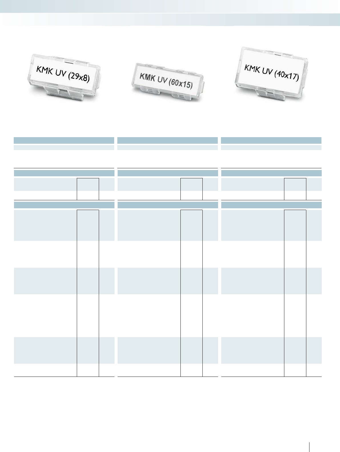
For additional information, visit phoenixcontact.net/products
Technical data Technical data Technical data
PA PA PA
HB HB HB
-40 ... 100 -40 ... 100 -40 ... 100
Halogen-free Halogen-free Halogen-free
Ordering data Ordering data Ordering data
Type Order No. Pcs. /
Pkt. Type Order No. Pcs. /
Pkt. Type Order No. Pcs. /
Pkt.
KMK UV (29X8) 1014107 100 KMK UV (60X15) 1014108 50 KMK UV (40X17) 1014109 50
Accessories Accessories Accessories
UCT-EMP (29X8) 1014118 10
UCT-EMP (60X15) 1014119 10
UCT-EMP (40X17) 1014120 10
UCT-EMP (29X8) CUS 1014122 1
UCT-EMP (40X17) CUS 1014124 1
UCT-EMP (60X15) CUS 1014123 1
US-EMP (29X8) 0829436 10
US-EMP (60X15) 0828781 10
US-EMP (40X17) 0829437 10
EMT (29X8)R 0817277 1
EMT (60X15)R 0801846 10
EMT (40X17)R 0817293 1
WT-UV HF 3,6X140 BK 3240832 100 WT-UV HF 3,6X140 BK 3240832 100 WT-UV HF 3,6X140 BK 3240832 100
WT-UV HF 4,5X200 BK 3240834 100 WT-UV HF 4,5X200 BK 3240834 100 WT-UV HF 4,5X200 BK 3240834 100
WT-UV HF 4,5X290 BK 3240835 100 WT-UV HF 4,5X290 BK 3240835 100 WT-UV HF 4,5X290 BK 3240835 100
THERMOMARK CARD-UCT-MAG26 0802988 1THERMOMARK CARD-UCT-MAG26 0802988 1THERMOMARK CARD-UCT-MAG26 0802988 1
275PHOENIX CONTACT
Marking systems, tools, and mounting material
Conductor and cable marking - MARKING system
Lettering field size: 29x8mm,
for cable diameter >6mm
Lettering field size: 60x15mm,
for cable diameter >9mm
Lettering field size: 40x17mm,
for cable diameter >9mm
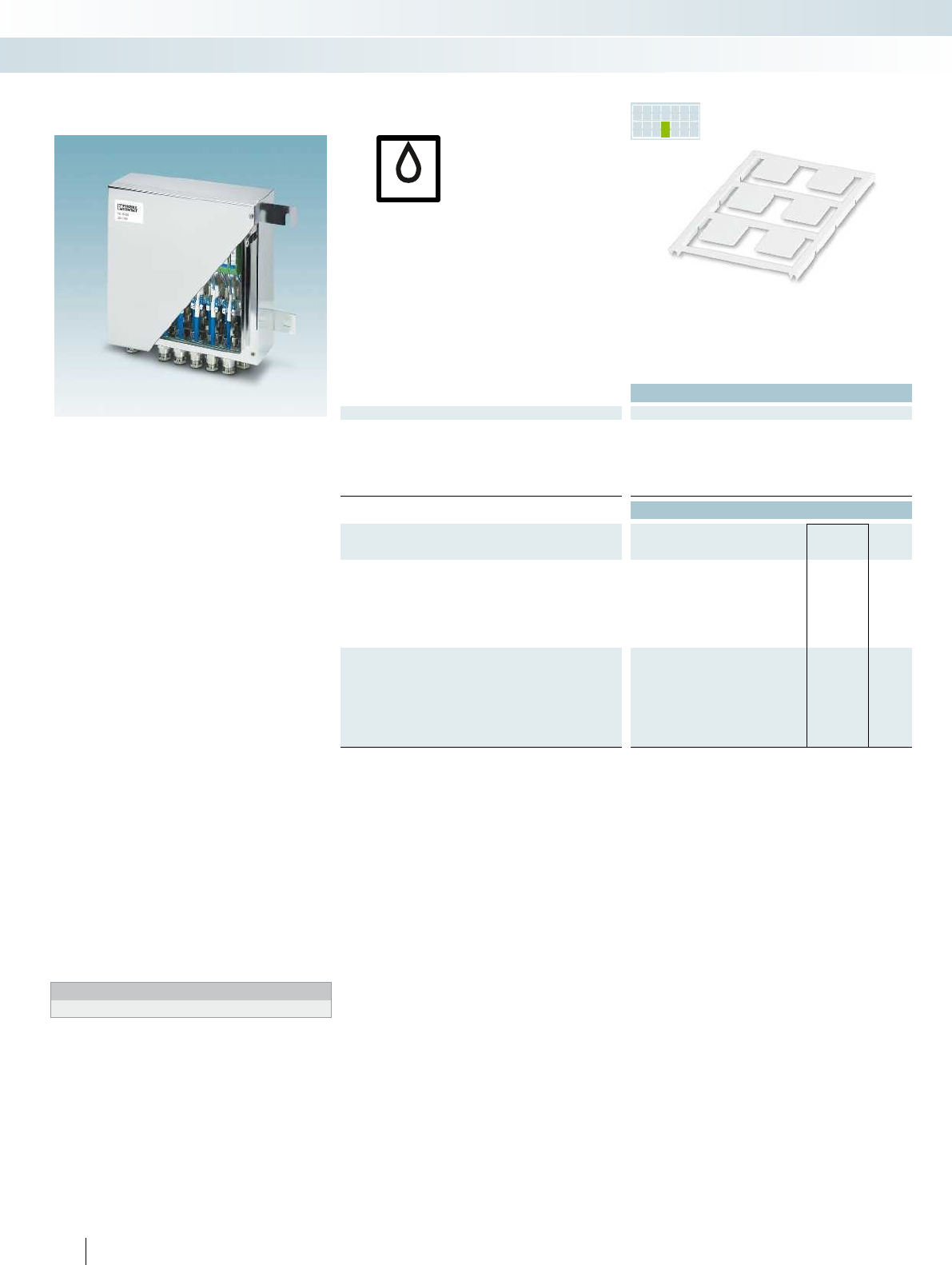
PR INTED
FOR YOU
UV
– The UC-EMLP...-EX UniCard labeling
range includes self-adhesive device
markers with good adhesive properties
– The marking requirements in terms of
legibility, adhesion, and wipe resistance in
potentially explosive areas (ATEX),
according to IEC/EN60079-0, can also be
ensured following storage in typical gas
atmospheres. PhoenixContact
developed these sheets especially for
process engineering which is where these
requirements typically arise. These sheets
meet the requirements for wipe esistance
according to DINEN61010-1 against
aggressive media such as acetone,
ethanol, and MEK
– Thanks to the special adhesive, the
marker meets the demanding
requirements of process engineering
– The markers can be marked quickly, easily,
and inexpensively with the
BLUEMARKCLEDandLED
– By using modern UV LED printing
technology, a highly resistant and
optimum printing quality can be achieved,
which is resistant to solvents and suitable
for use even under harsh industrial
conditions
– Labeling service: Phoenix Contact can
custom-label all markers according to
your requirements
Notes:
1) For an ordering example, see page 358 in main catalog 5.
Technical data
General data
Can be marked with BLUEMARK CLED BLUEMARK LED
Material PA
Inflammability class according to UL 94 V2
Temperature range [°C] -40 ... 120
Wipe resistance DIN EN 61010-1 (VDE 0411-1)
Components Free from silicone and halogen
Ordering data
Description Color Type Order No. Pcs. /
Pkt.
UniCard, with self-adhesive plastic labels
6-section, lettering field size: 22x22mm white UC-EMLP (22X22)-EX 0803224 10
8-section, lettering field size: 27x18mm white UC-EMLP (27X18)-EX 0803225 10
6-section, lettering field size: 27x27mm white UC-EMLP (27X27)-EX 0803226 10
4-section, lettering field size: 49x15mm white UC-EMLP (49X15)-EX 0803227 10
3-section, lettering field size: 60x30mm white UC-EMLP (60X30)-EX 0803228 10
UniCard, with self-adhesive plastic labels,
labeled according to customer specifications1)
6-section, lettering field size: 22x22mm white UC-EMLP (22X22)-EX CUS 0803229 1
8-section, lettering field size: 27x18mm white UC-EMLP (27X18)-EX CUS 0803230 1
6-section, lettering field size: 27x27mm white UC-EMLP (27X27)-EX CUS 0803231 1
4-section, lettering field size: 49x15mm white UC-EMLP (49X15)-EX CUS 0803232 1
3-section, lettering field size: 60x30mm white UC-EMLP (60X30)-EX CUS 0803233 1
Can be marked using:
Adhesive UniCard device marking
for applications in process engineering
276 PHOENIX CONTACT
Marking systems, tools, and mounting material
Device marking - MARKING system
Unlabeled or labeled
according to customer specifications
UV LED technology
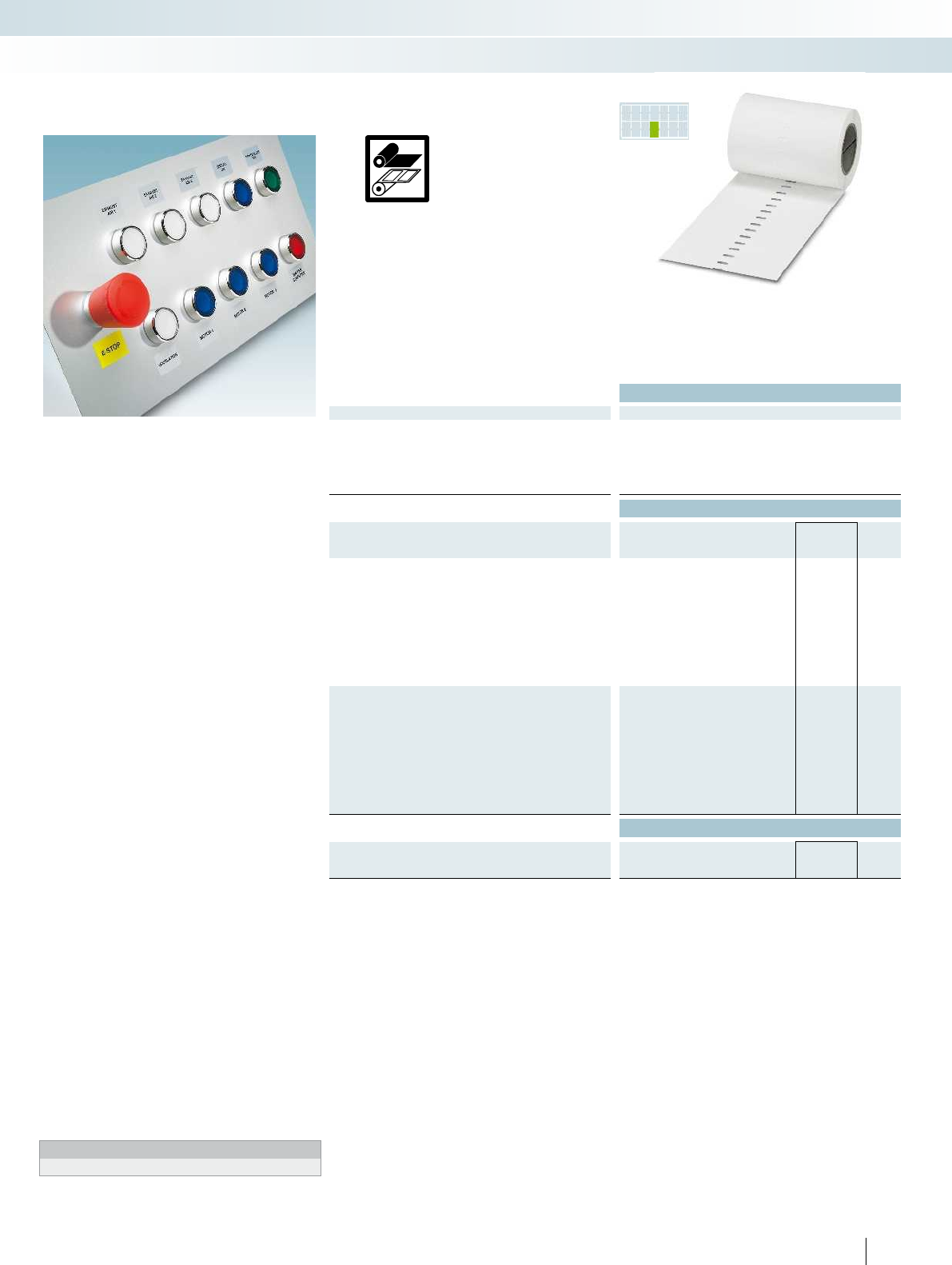
PR INTED
FOR YOU
2
1
1
2
For additional information, visit phoenixcontact.net/products
– The EML...-EX self-adhesive device
markers have been specifically developed
for marking various types of equipment in
the Ex area
– The marking requirements in terms of
legibility, adhesion, and wipe resistance in
potentially explosive areas (ATEX),
according to IEC/EN 60079-0, can also be
ensured following storage in typical gas
atmospheres. PhoenixContact
developed these labels especially for
process engineering, which is where these
requirements typically arise. These labels
meet the requirements for wipe
resistance
according to DINEN61010-1 against
aggressive media such as acetone,
ethanol, and MEK
– They are only suitable in conjunction with
the TM-RIBBON110-EX
– Thanks to the special surface and
adhesive, the marker meets the
demanding requirements of process
engineering
– If high-quality ink ribbons are used, the
labeling is resistant to solvents, making it
suitable for use even under harsh
industrial conditions
– A wide range of marker sizes and colors
are available for custom designs
– The special packaging protects rolls that
have already been started from the dirt
found in industrial environments
–Designation example:
EML(10x4)R-EX
Lettering field size: 10x4mm
Type of packaging: roll
– Marking service: Phoenix Contact can
custom-mark all EMLmarkers according
to your requirements
Notes:
1) For an ordering example, see page 358 in main catalog 5.
Technical data
General data
Can be marked with
THERMOMARK ROLL
THERMOMARK ROLL X1
THERMOMARK X1.1
THERMOMARK X1.2
THERMOMARK S1.1
Material Polyester
Temperature range [°C] -40 ... 150
Wipe resistance DIN EN 61010-1 (VDE 0411-1)
Components Free from silicone and halogen
Ordering data
Description Color Type Order No. Pcs. /
Pkt.
Labels
10,000 labels per roll white EML (10X4)R-EX 0803251 1
2500 labels per roll white EML (15X9)R-EX 0803253 1
2500 labels per roll white EML (20X8)R-EX 0803254 1
2500 labels per roll white EML (30X20)R-EX 0803255 1
1000 labels per roll white EML (40X25)R-EX 0803256 1
400 labels per roll white EML (70X50)R-EX 0803257 1
300 labels per roll white EML (100X40)R-EX 0803258 1
300 labels per roll white EML (100X73)R-EX 0803259 1
250 labels per roll white EML (100X90)R-EX 0803260 1
Labels, labeled according to customer requirements1)
8 labels per strip white EML (10X4)R-EX CUS 0803261 1
5 labels per strip white EML (15X9)R-EX CUS 0803262 1
4 labels per strip white EML (20X8)R-EX CUS 0803263 1
3 labels per strip white EML (30X20)R-EX CUS 0803264 1
2 labels per strip white EML (40X25)R-EX CUS 0803266 1
1 label per strip white EML (70X50)R-EX CUS 0803267 1
1 label per strip white EML (100X40)R-EX CUS 0803268 1
1 label per strip white EML (100X73)R-EX CUS 0803269 1
1 label per strip white EML (100X90)R-EX CUS 0803270 1
Accessories
Ink ribbon, length: 300m, width: 110mm, color: black
TM-RIBBON 110-EX 0803211 1
Can be marked using:
Adhesive device marking
for applications in process engineering
277PHOENIX CONTACT
Marking systems, tools, and mounting material
Device marking - MARKING system
Unlabeled or labeled according to customer
specifications
Thermal transfer for rolls
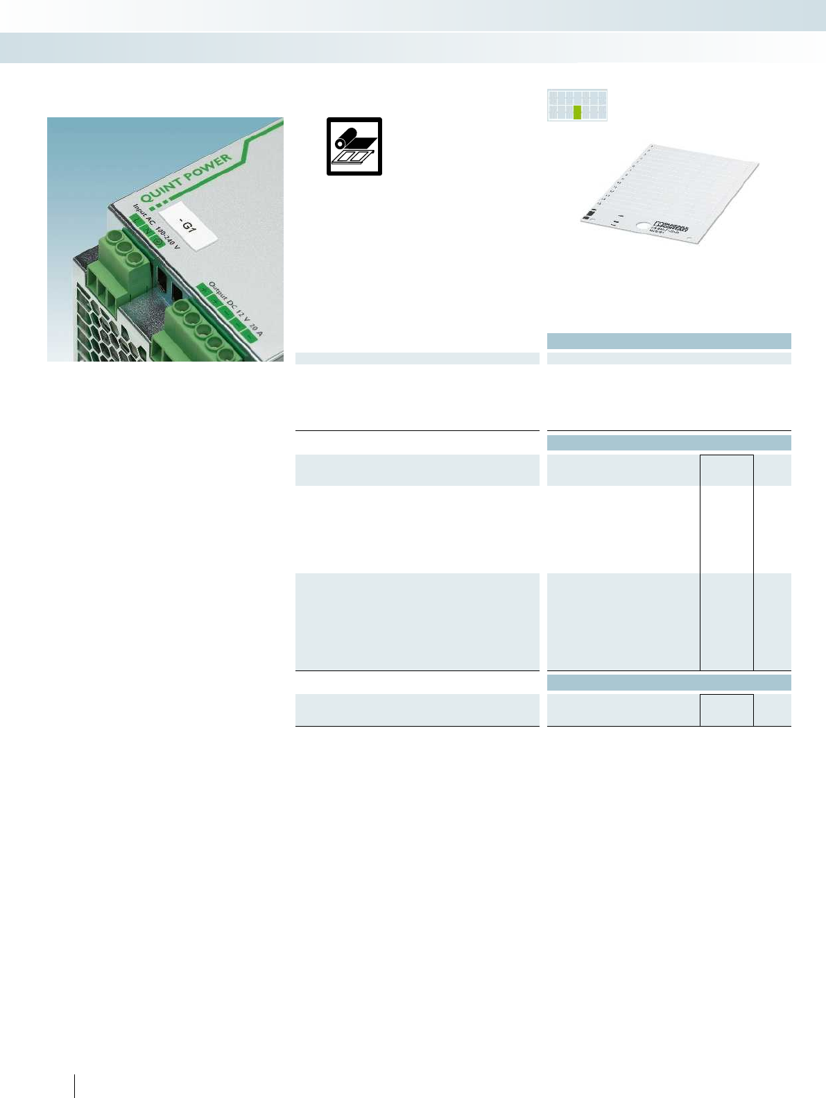
PR INTED
FOR YOU
1
2
2
1
– The US-EMLP-HA... UniSheet marking
range has excellent adhesive properties
on rough, textured, and low-energy
surfaces, thanks to the special adhesive
– The markers, which are supplied in
uniform sheets, can be marked quickly,
easily, and cost-effectively using
THERMOMARKCARD and
THERMOMARKCARDPLUS
– The perforated markers are easy to
separate and can be easily fitted
– The sheets provide space for including
function texts
– Marking service: Phoenix Contact can
custom-mark all US-EMLP-HA... markers
according to your requirements
Technical data
General data
Can be marked with THERMOMARK CARD PLUS THERMOMARK CARD
Material PVC
Inflammability class according to UL 94 V0
Temperature range [°C] -30 ... 80
Wipe resistance DIN EN 61010-1 (VDE 0411-1)
Components Silicone-free
Ordering data
Description Color Type Order No. Pcs. /
Pkt.
UniSheet, with self-adhesive plastic labels, 0.5mm thick
108-section, lettering field size: 17x7mm white US-EMLP-HA (17X7) 0830988 10
70-section, lettering field size: 20x9mm white US-EMLP-HA (20X9) 0830989 10
4-section, lettering field size: 60x30mm white US-EMLP-HA (60X30) 0830990 10
4-section, lettering field size: 60x30mm silver US-EMLP-HA (60X30) SR 0830991 10
2-section, lettering field size: 85.6x54mm white US-EMLP-HA (85,6X54) 0830992 10
2-section, lettering field size: 85.6x54mm silver US-EMLP-HA (85,6X54) SR 0830993 10
UniSheet, with self-adhesive plastic labels, 0.5mm thick,
labeled acc. to customer specifications
108-section, lettering field size: 17x7mm white US-EMLP-HA (17X7) CUS 0830994 1
70-section, lettering field size: 20x9mm white US-EMLP-HA (20X9) CUS 0830995 1
4-section, lettering field size: 60x30mm white US-EMLP-HA (60X30) CUS 0830996 1
4-section, lettering field size: 60x30mm silver US-EMLP-HA (60X30) SR CUS 0830997 1
2-section, lettering field size: 85.6x54mm white US-EMLP-HA (85,6X54) CUS 0830998 1
2-section, lettering field size: 85.6x54mm silver US-EMLP-HA (85,6X54) SR CUS 0830999 1
Accessories
Magazine, for THERMOMARKCARD...,
for accommodating all US materials
THERMOMARK CARD-US-MAG1 5146451 1
Can be marked using:
UniSheet device marking for sticking
onto rough or textured surfaces
278 PHOENIX CONTACT
Marking systems, tools, and mounting material
Device marking - MARKING system
Unlabeled or labeled
according to customer specifications
Thermal transfer for sheets
and cards

For additional information, visit phoenixcontact.net/products
279PHOENIX CONTACT
Marking systems, tools, and mounting material
Device marking - MARKING system
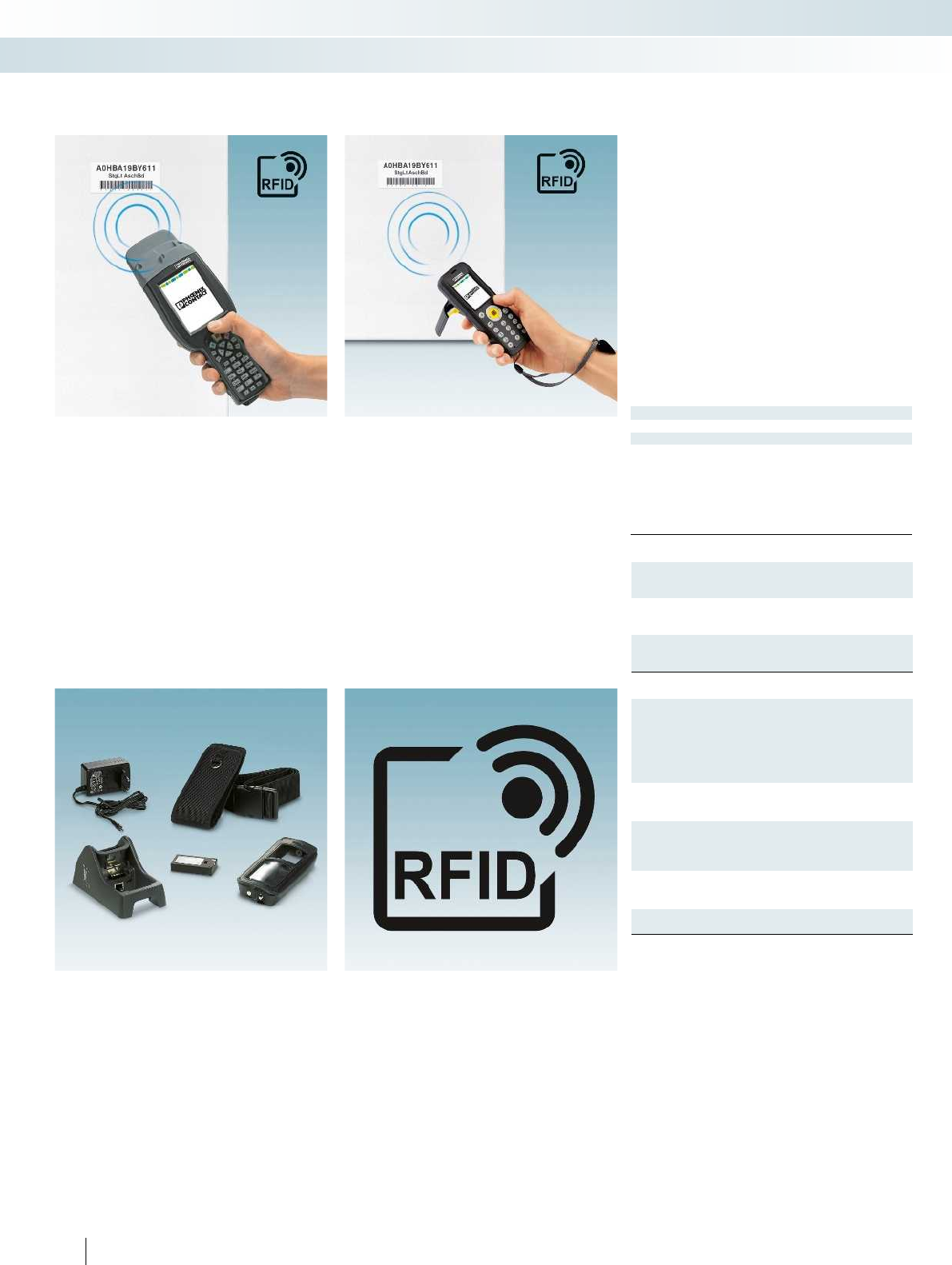
Dimensions
[mm]
General data
Degree of protection
Temperature range [°C] -20 ... 55 -20 ... 55
Weight [kg] 0.55 0.235
Frequency [MHz] 13.56 868
Read/write format [m] Max. 0.1 Max. 2
Memory
Display
Description
Handheld, high-frequency range
Range up to 0.1m, depending on the environment
Handheld, ultra-high frequency range
Range up to 2.0m, depending on the environment
Charging and data exchange station, with replacement battery,
connection for USB2.0 and Ethernet, charger
for RFMARKHF, with power supply unit and power cable (EU/UK)
for RFMARKUHF, with power supply unit and power cable
(EU/UK/US/CN)
Replacement battery
for RFMARKHF, Li-ion7.4V, 2.6Ah
for RFMARKUHF, Li-ion3.7V, 2.26Ah
Protective bag, with strap, protection against splash water,
touch screen operation not possible
for RFMARKHF
for RFMARKUHF
Belt pouch, touch screen can be operated
for RFMARKHF
for RFMARKUHF
Read and write USB stick,
Crossed dipole antenna, range: 1m
280 PHOENIX CONTACT
RFMARK high-frequency handheld
RFMARKHF is a powerful handheld
device for contact-free reading and writing
of HF transponders. The RFMARKHF can
identify and locate HF transponders. Data
can be received, transmitted, and scanned
on a contact-free basis and without visual
contact.
RFMARKultra-high frequency handheld
The RFMARKUHF is a powerful
handheld device which is equipped with a
crossed dipole antenna. This allows
UHF transponders to be written and read
regardless of their position. Bulk detection
of 150transponders persecond is also
possible.
Advantages and accessories
Advantages of the RFMARK readers:
– Easy operation via touch screen
– Low power consumption
and long battery life
– 1D laser scanner and 2D imager
Matching accessories
You can make optimum use of the
RFMARK readers and ensure they are as
user-friendly as possible with our reader
accessories.
Radio-frequency identification, RFID
Used for contact-free identification, data
exchange, and localization of
transponders/tags without visual contact.
With the aid of an RFID handheld device,
which acts as a transmitter and receiver,
data is transmitted to and received from a
transponder/tag by electromagnetic waves
(UHF) or a magnetic field (HF).
RFMARKRFID system
Marking systems, tools, and mounting material
System marking - MARKING system
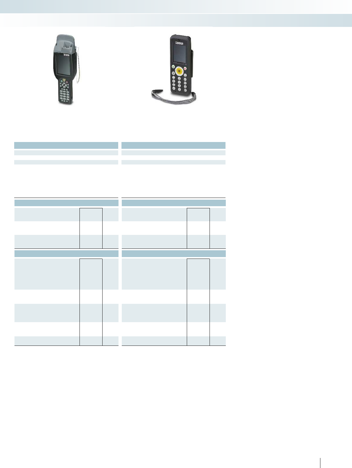
For additional information, visit phoenixcontact.net/products
Technical data Technical data
Width Length Height Width Length Height
90 250 45 60 147 39
IP54 IP54
Temperature range [°C] -20 ... 55 -20 ... 55
Weight [kg] 0.55 0.235
Frequency [MHz] 13.56 868
Read/write format [m] Max. 0.1 Max. 2
256 MB DDR RAM 256 MB DDR RAM
3.5" color touch screen 2.2" color touch screen
Ordering data Ordering data
Type Order No. Pcs. /
Pkt. Type Order No. Pcs. /
Pkt.
RFMARK HF 5148010 1
RFMARK UHF 5148011 1
Accessories Accessories
RFMARK HF POWER LINK STATION 5148013 1
RFMARK UHF POWER LINK STATION 5148014 1
RFMARK HF/ACCU 5148015 1
RFMARK UHF/ACCU 5148016 1
RFMARK HF PROTECTION CASE 5148017 1
RFMARK UHF PROTECTION CASE 5148020 1
RFMARK HF/BELTPOUCH 5148018 1
RFMARK UHF/BELTPOUCH 5148021 1
RFMARK UHF FD 5148012 1
281PHOENIX CONTACT
Marking systems, tools, and mounting material
System marking - MARKING system
Handheld, high-frequency (HF) Handheld, ultra-high frequency (UHF)
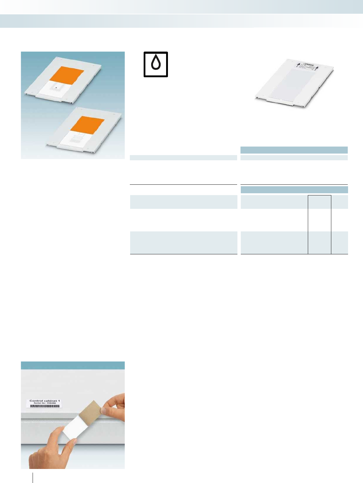
UV
Markers
– The UCT-PMLP-RFID... UniCard labeling
range includes self-adhesive markers for
system marking, with good adhesive
properties
– The markers are integrated in a uniform
matrix and can be printed quickly and
easily with the BLUEMARKCLED
– The format automatically ensures printing
with a high level of positional accuracy
– The wide temperature range means that
the labels can be used both indoors and
outdoors
Inlays
– The HF transponder inlays comply with
ISO15693 and ISO 18000-3mode1
– The UHF transponder inlays comply with
EPCClass1Gen2 and ISO18000-6C
Technical data
General data
Can be marked with BLUEMARK CLED
Material PVC/PC
Temperature range [°C] -25 ... 80
Wipe resistance DIN EN 61010-1 (VDE 0411-1) DIN EN 61010-1 (VDE 0411-1)
Components Free from silicone and cadmium Free from silicone and cadmium
Ordering data
Description Color Type Order No. Pcs. /
Pkt.
UniCard, self-adhesive plastic label,
with integrated HF transponder
1-section, lettering field size: 90x38mm,
reading performance: max.0.1m,
depending on the environment
white UCT-PMLP-RFID/HF (90X38) 0830956 10
UniCard, self-adhesive plastic label,
with integrated UHF transponder
1-section, lettering field size: 90x38mm,
reading performance: max.2.0m,
depending on the environment
white
282 PHOENIX CONTACT
UV LED technology
Can be marked using:
Adhesive system marking
with RFID transponder
Marking systems, tools, and mounting material
System marking - MARKING system
Unlabeled Unlabeled
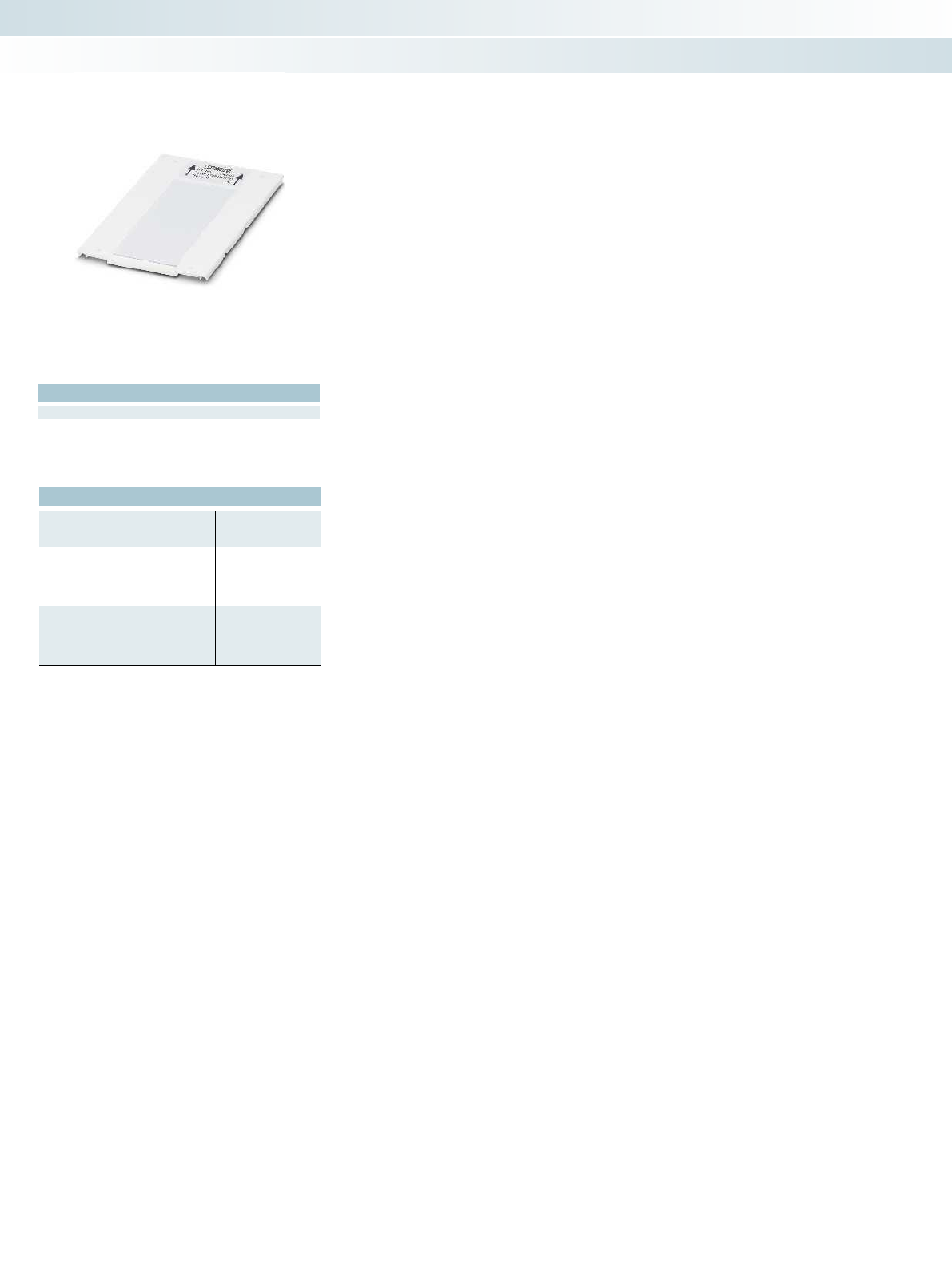
For additional information, visit phoenixcontact.net/products
Technical data
BLUEMARK CLED
PVC/PC
-25 ... 80
Wipe resistance DIN EN 61010-1 (VDE 0411-1) DIN EN 61010-1 (VDE 0411-1)
Components Free from silicone and cadmium Free from silicone and cadmium
Ordering data
Type Order No. Pcs. /
Pkt.
UCT-PMLP-RFID/UHF (90X38) 0830957 10
283PHOENIX CONTACT
Marking systems, tools, and mounting material
System marking - MARKING system
Unlabeled Unlabeled
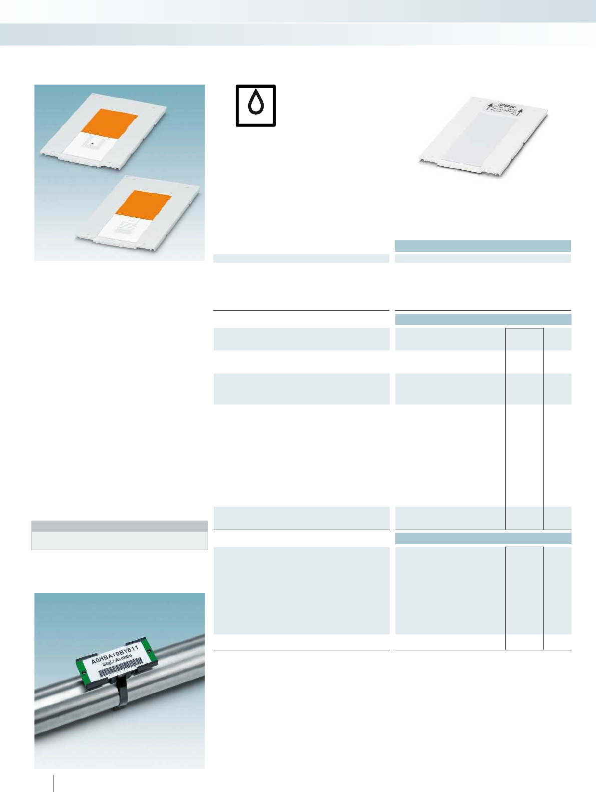
UV
Markers
– The UniCard UCT-PMP-RFID... marking
range includes markers for system
marking, specially designed to fit into
existing CARRIER-PMP(108x38) marker
carriers
– The markers are integrated in a uniform
matrix and can be printed quickly and
easily with the BLUEMARKCLED
– The format automatically ensures printing
with a high level of positional accuracy
– The wide temperature range means that
the labels can be used both indoors and
outdoors
– The CARRIER-PMP... marker carriers
can be equipped with colored
PMST markers according to DIN2403
Inlays
– The HF transponder inlays comply with
ISO15693 and ISO 18000-3mode1
– The UHF transponder inlays comply with
EPCClass1Gen2 and ISO18000-6C
Notes:
1) RVT-PA...BK rivet for fixing PMST... marker strips
to the CARRIER-PMP...
Technical data
General data
Can be marked with BLUEMARK CLED
Material PVC/PC
Inflammability class according to UL 94 V0
Temperature range [°C] -25 ... 80
Wipe resistance DIN EN 61010-1 (VDE 0411-1) DIN EN 61010-1 (VDE 0411-1) DIN EN 61010-1 (VDE 0411-1) -
Components Free from silicone and cadmium Free from silicone and cadmium Silicone-free Free from silicone and halogen
Ordering data
Description Color Type Order No. Pcs. /
Pkt.
UniCard, plastic label with integrated HF transponder
1-section, lettering field size: 90x38mm white UCT-PMP-RFID/HF (90X38) 0830954 10
UniCard, plastic label with integrated UHF transponder
1-section, lettering field size: 90x38mm white
1-section, lettering field size: 90x38mm orange
Marking label for conveyed fluids,
for equipping CARRIER-PMP... according to DIN2403
white
yellow
orange
red
violet
green
gray
brown
blue
black
Marker carriers, for UCT-PMP... labels that can be inserted
Carrier size: 108x38mm black
Accessories
Mounting strip, can be screwed, for CARRIER-PMP...
Plastic body-bound rivet, 3.5mm diameter1)
284 PHOENIX CONTACT
UV LED technology
Can be marked using:
System marking
for inserting into marker carriers,
with RFID transponder
Marking systems, tools, and mounting material
System marking - MARKING system
Unlabeled Unlabeled For securing with rivets on CARRIER-PMP
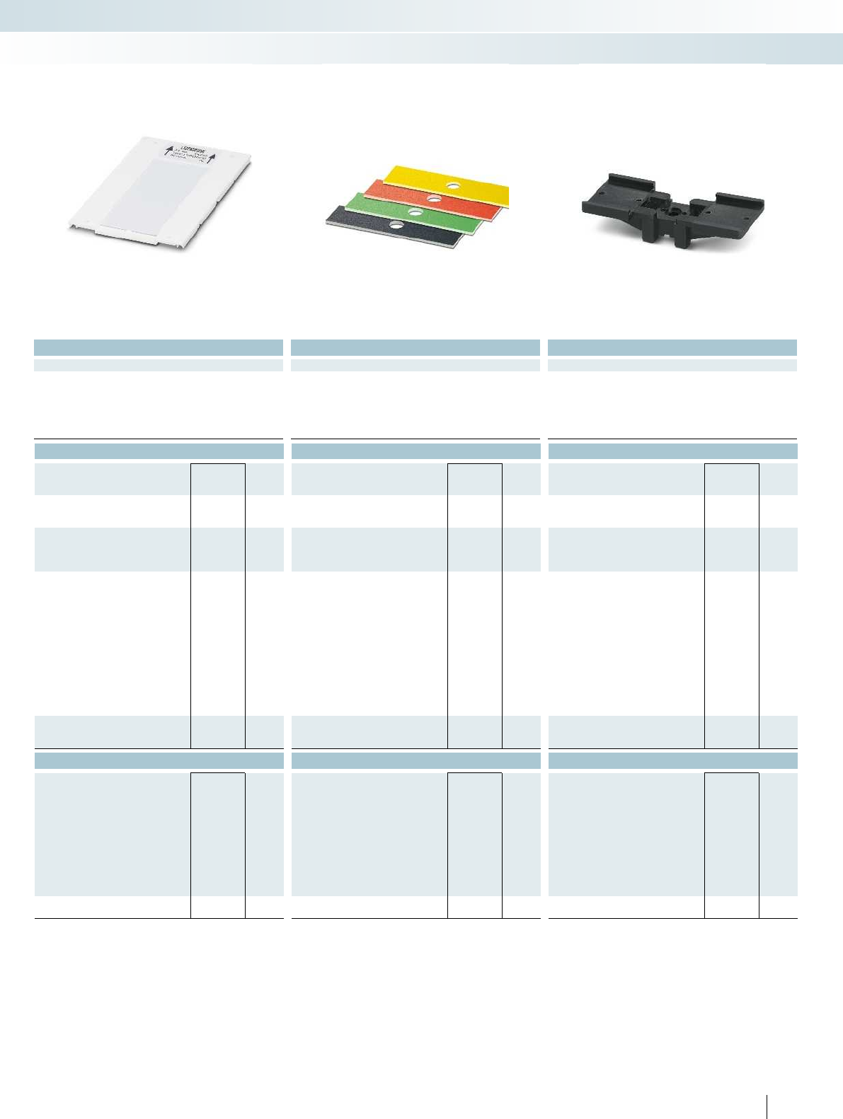
For additional information, visit phoenixcontact.net/products
Technical data Technical data Technical data
BLUEMARK CLED - -
PVC/PC PVC PA
V2 V0 V2
-25 ... 80 -30 ... 80 -40 ... 105
Wipe resistance DIN EN 61010-1 (VDE 0411-1) DIN EN 61010-1 (VDE 0411-1) DIN EN 61010-1 (VDE 0411-1) -
Components Free from silicone and cadmium Free from silicone and cadmium Silicone-free Free from silicone and halogen
Ordering data Ordering data Ordering data
Type Order No. Pcs. /
Pkt. Type Order No. Pcs. /
Pkt. Type Order No. Pcs. /
Pkt.
UCT-PMP-RFID/UHF (90X38) 0830955 10
UCT-PMP-RFID/UHF (90X38) OG 0803048 10
PMST (9X38) 0830960 100
PMST (9X38) YE 0830964 100
PMST (9X38) OG 0830966 100
PMST (9X38) RD 0830962 100
PMST (9X38) VT 0830967 100
PMST (9X38) GN 0830961 100
PMST (9X38) GY 0830963 100
PMST (9X38) BN 0830968 100
PMST (9X38) BU 0830969 100
PMST (9X38) BK 0830965 100
CARRIER-PMP (108X38) 0830958 10
Accessories Accessories Accessories
SCRT 9X16-27 0830970 50
SCRT 9X25-40 0830971 50
SCRT 9X40-60 0830972 25
SCRT 9X60-80 0830973 25
SCRT 9X80-100 0830974 25
SCRT 9X100-120 0830975 25
SCRT 9X140-160 0830976 25
SCRT 9X160-180 0830977 25
SCRT 9X180-200 0830978 25
RVT-PA 3,5 BK 0830959 100
285PHOENIX CONTACT
Marking systems, tools, and mounting material
System marking - MARKING system
Unlabeled Unlabeled For securing with rivets on CARRIER-PMP... For mounting with screws, screw clamps,
or cable binders
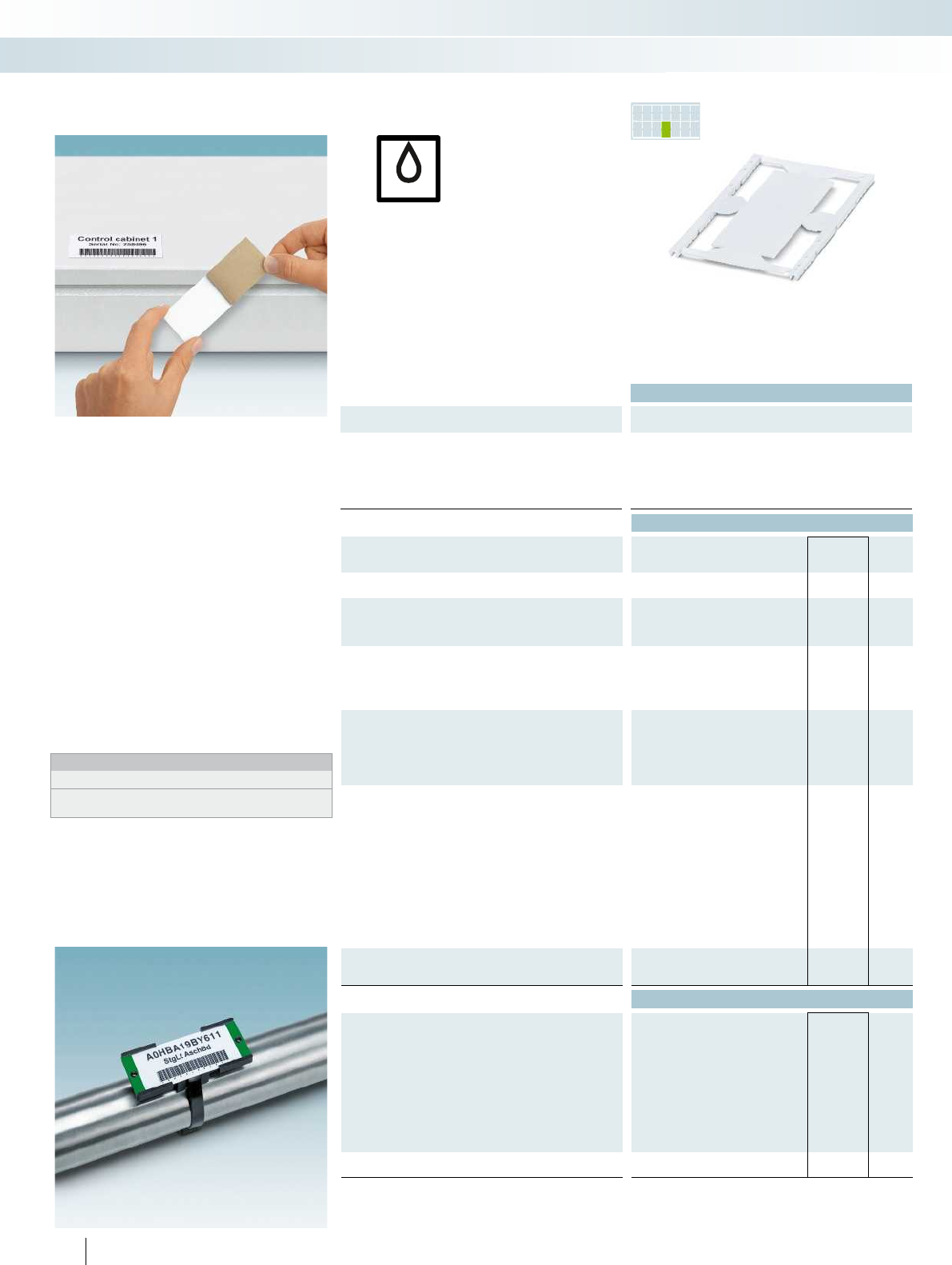
UV
PR INTED
FOR YOU
– The UCT-PMLP... UniCard marking range
includes self-adhesive markers for system
marking, with good adhesive properties
– The UniCard UCT-PMP... marking range
includes markers for system marking,
specially designed to fit into existing
CARRIER-PMP(108x38) marker carriers
– The format automatically ensures printing
with a high level of positional accuracy
– The wide temperature range means that
the labels can be used both indoors and
outdoors
– Labeling service: PhoenixContact can
custom-label all UniCard markers in
accordance with your requirements
– The CARRIER-PMP... marker carriers
can be equipped with colored
PMST markers according to DIN2403
Notes:
1) For an ordering example, see page 358 in main catalog 5.
2) RVT-PA...BK rivet for fixing PMST... marker strips
to the CARRIER-PMP...
Technical data
Dimensions Width Length Height
General data
Can be marked with BLUEMARK CLED
Material PC
Inflammability class according to UL 94 V0
Temperature range [°C] -40 ... 120
Wipe resistance DIN EN 61010-1 (VDE 0411-1) DIN EN 61010-1 (VDE 0411-1) DIN EN 61010-1 (VDE 0411-1) -
Components Free from silicone and halogen Free from silicone and halogen Silicone-free Free from silicone and halogen
Ordering data
Description Color Type Order No. Pcs. /
Pkt.
UniCard, plastic label, for gluing
1-section, lettering field size: 90x38mm white UCT-PMLP (90X38) 0803041 10
UniCard, plastic label, for gluing,
marked according to customer specifications1)
1-section, lettering field size: 90x38mm white UCT-PMLP (90X38) CUS 0803042 1
UniCard, plastic label
1-section, lettering field size: 90x38mm white
1-section, lettering field size: 90x38mm blue
1-section, lettering field size: 90x38mm violet
1-section, lettering field size: 90x38mm yellow
UniCard, plastic label,
marked according to customer specifications1)
1-section, lettering field size: 90x38mm white
1-section, lettering field size: 90x38mm blue
1-section, lettering field size: 90x38mm violet
1-section, lettering field size: 90x38mm yellow
Marking label for conveyed fluids,
for equipping CARRIER-PMP... according to DIN2403
white
yellow
orange
red
violet
green
gray
brown
blue
black
Marker carriers,
for UCT-PMP... labels that can be inserted
Carrier size: 108x38mm black
Accessories
Mounting strip, can be screwed, for CARRIER-PMP...
Plastic body-bound rivet, 3.5mm diameter2)
286 PHOENIX CONTACT
UV LED technology
Can be marked using:
System marking for sticking on or
inserting into marker carriers
Marking systems, tools, and mounting material
System marking - MARKING system
For self-adhesion For inserting into a marker carrier For securing with rivets on CARRIER-PMP
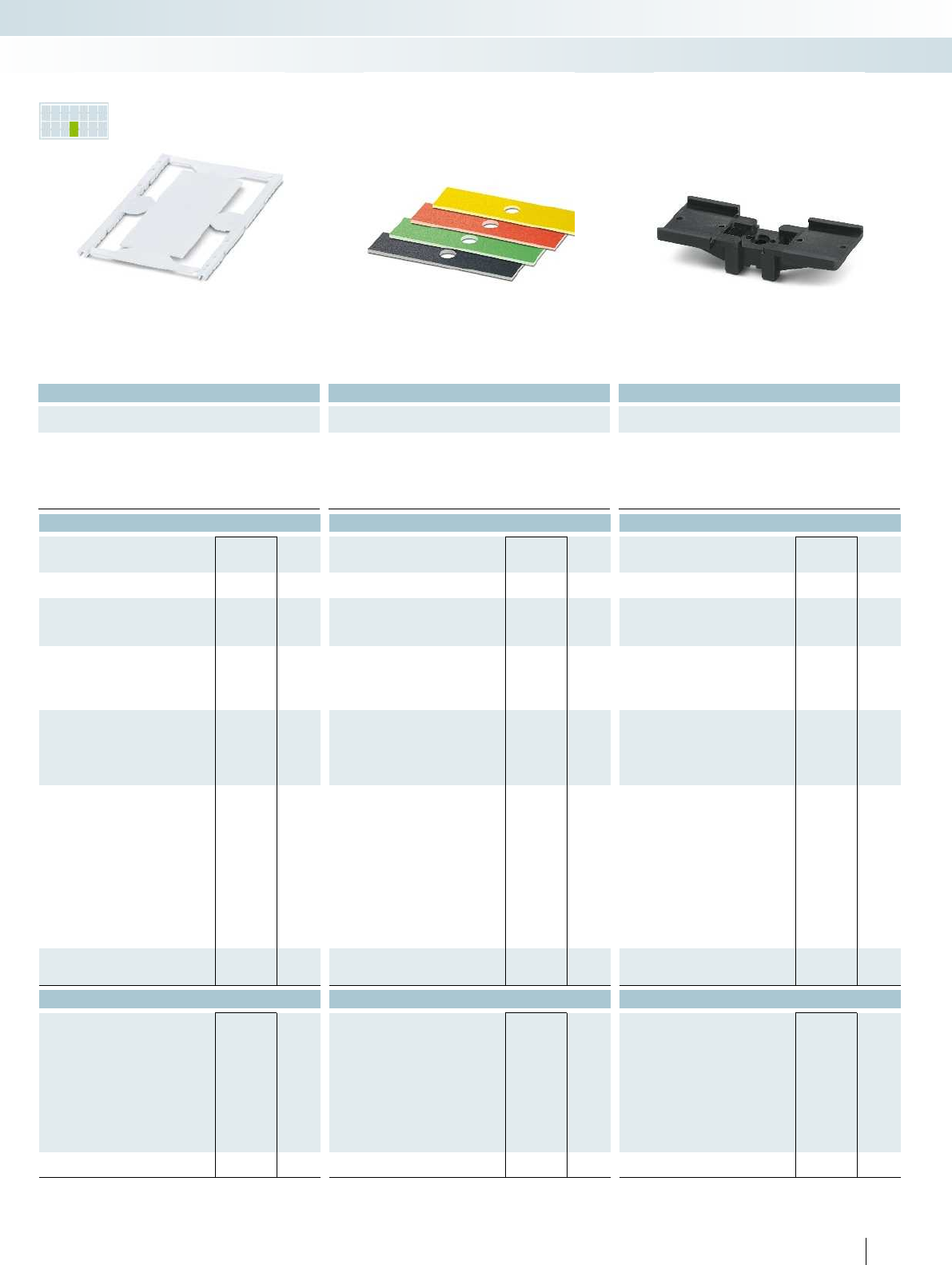
PR INTED
FOR YOU
For additional information, visit phoenixcontact.net/products
Technical data Technical data Technical data
Width Length Height Width Length Height Width Length Height
BLUEMARK CLED - -
PC PVC PA
V0 V0 V2
-40 ... 120 -30 ... 80 -40 ... 105
Wipe resistance DIN EN 61010-1 (VDE 0411-1) DIN EN 61010-1 (VDE 0411-1) DIN EN 61010-1 (VDE 0411-1) -
Components Free from silicone and halogen Free from silicone and halogen Silicone-free Free from silicone and halogen
Ordering data Ordering data Ordering data
Type Order No. Pcs. /
Pkt. Type Order No. Pcs. /
Pkt. Type Order No. Pcs. /
Pkt.
UCT-PMP (90X38) 0803039 10
UCT-PMP (90X38) BU 0803047 10
UCT-PMP (90X38) VT 0803132 10
UCT-PMP (90X38) YE 0803133 10
UCT-PMP (90X38) CUS 0803040 1
UCT-PMP (90X38) BU CUS 8190566 1
UCT-PMP (90X38) VT CUS 8190707 1
UCT-PMP (90X38) YE CUS 8190708 1
PMST (9X38) 0830960 100
PMST (9X38) YE 0830964 100
PMST (9X38) OG 0830966 100
PMST (9X38) RD 0830962 100
PMST (9X38) VT 0830967 100
PMST (9X38) GN 0830961 100
PMST (9X38) GY 0830963 100
PMST (9X38) BN 0830968 100
PMST (9X38) BU 0830969 100
PMST (9X38) BK 0830965 100
CARRIER-PMP (108X38) 0830958 10
Accessories Accessories Accessories
SCRT 9X16-27 0830970 50
SCRT 9X25-40 0830971 50
SCRT 9X40-60 0830972 25
SCRT 9X60-80 0830973 25
SCRT 9X80-100 0830974 25
SCRT 9X100-120 0830975 25
SCRT 9X140-160 0830976 25
SCRT 9X160-180 0830977 25
SCRT 9X180-200 0830978 25
RVT-PA 3,5 BK 0830959 100
287PHOENIX CONTACT
Marking systems, tools, and mounting material
System marking - MARKING system
For self-adhesion For inserting into a marker carrier For securing with rivets on CARRIER-PMP... For mounting with screws, screw clamps,
or cable binders

288 PHOENIX CONTACT
Marking systems, tools, and mounting material
MARKING system app - MARKING system
Material editor
The material editor allows you to create
the required markings directly in the
application environment via tabletPC
or smartphone.
Product scanner
The product scanner allows you to
quickly and easily call up technical data for
the marking material or directly mark it via
the material editor.
Search assistant
With the search assistant, you can carry
out a structured, targeted search for
suitable marking materials, even without
knowledge of this field.
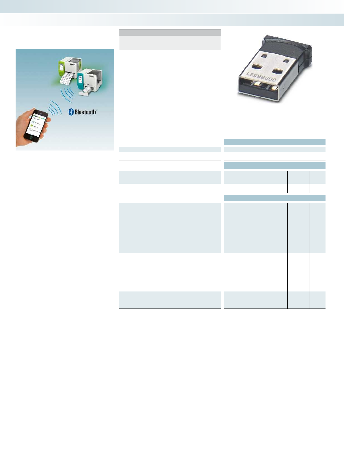
For additional information, visit phoenixcontact.net/products
Technical data
General data
Application USB/Bluetooth
Transmission speed [Mbps] 3
Ordering data
Description Type Order No. Pcs. /
Pkt.
Bluetooth USB adapter
MINI FD BLUETOOTH 0830986 1
Accessories
Thermal transfer printer for cards, incl. European power cable,
US power cable, USB cable,
DVD with CLIPPROJECTADVANCED,
CD with multilingual user manual/driver/firmware,
DINA5 printed English/German user manual,
magazine for UCT-TM materials,
magazine for US materials,
one unit pack UCT-TM6,
one unit pack US-EMLP(85.6 x 54),
one ink ribbon (50-meter sample roll)
THERMOMARK CARD 5146464 1
THERMOMARK CARD PLUS 5146481 1
Thermal transfer printer for material off the roll,
including European power cable, US power cable, USB cable,
DVD with CLIPPROJECTADVANCED,
CD with multilingual user manual/driver/firmware,
A5 printed English/German usermanual,
one roll of EML(20x8) labels containing 1000 labels,
one ink ribbon (50 meters)
THERMOMARK ROLL 5146477 1
THERMOMARK ROLL X1 5146723 1
Thermal transfer printer, incl. connecting cable, Windows®
printer driver and operating instructions, software
THERMOMARK X1.2 5146231 1
289PHOENIX CONTACT
You can retrofit your THERMOMARKLINE
printer with MINIFDBLUETOOTH.
MINIFDBLUETOOTH enables reliable,
wireless data exchange between
THERMOMARKLINE printers and mobile,
Bluetooth-capable devices, such as
smartphones and tablet PCs. This means that
print orders can be conveniently sent to the
printer using the MARKINGsystem app.
MARKINGsystem app
Marking systems, tools, and mounting material
MARKING system app - MARKING system
Notes:
For additional information on the THERMOMARKLINE printers,
please refer to the product area on our website at
phoenixcontact.net/products or main catalog5.
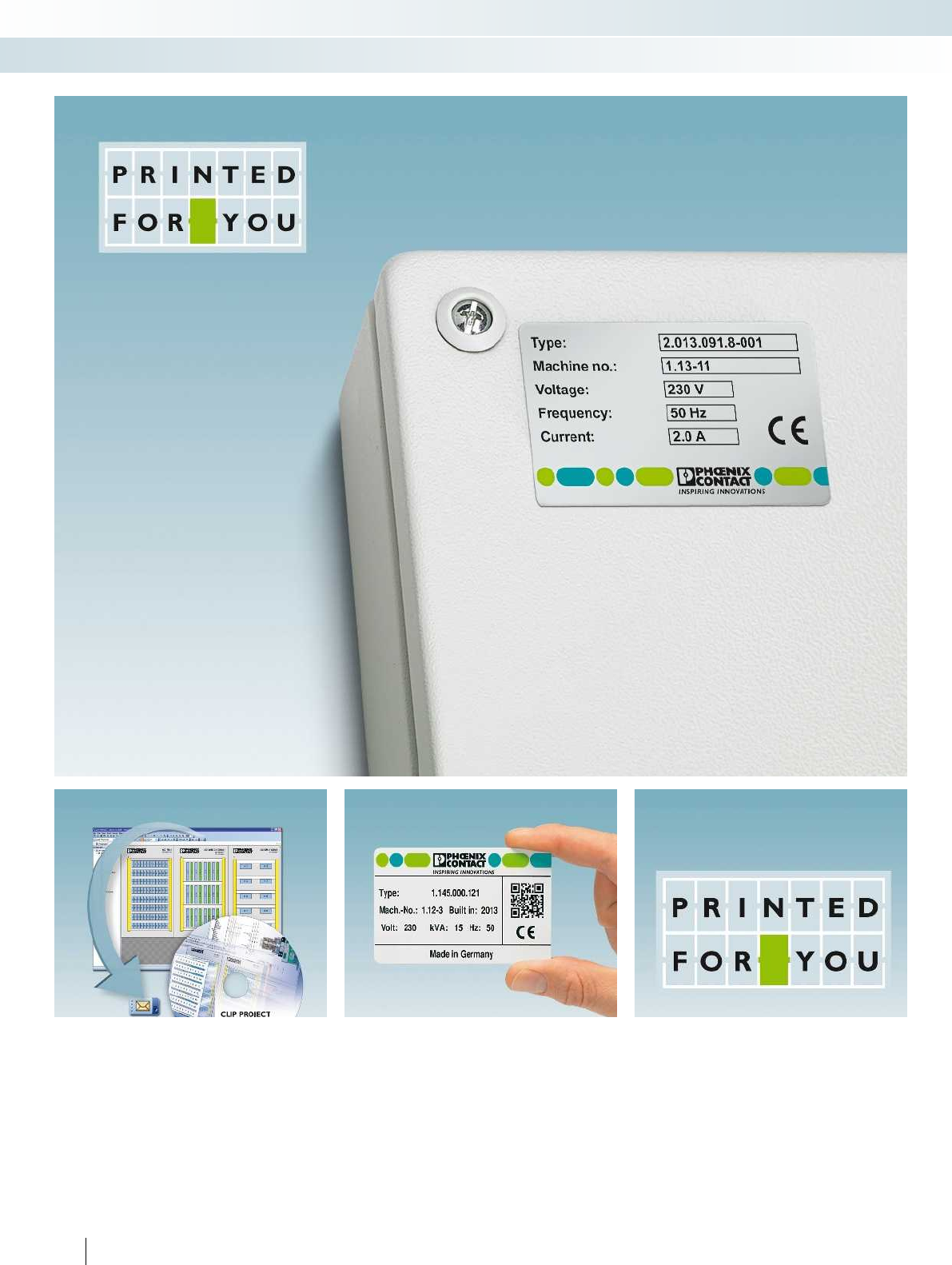
290 PHOENIX CONTACT
Marking systems, tools, and mounting material
CLIP PROJECT - MARKING system
Customer-specific printing service
Easy ordering process
via CLIPPROJECT and e-mail
You can create customer-specific marking
quickly and easily via CLIPPROJECT and
order via e-mail.
New: color-printed marking solutions
You can use marking materials in UniCard
and UniSheetformat as well as metal labels
for color printing.
We mark marking materials
according to your requirements
All materials which can be marked
according to customer requirements are
indicated with this symbol.
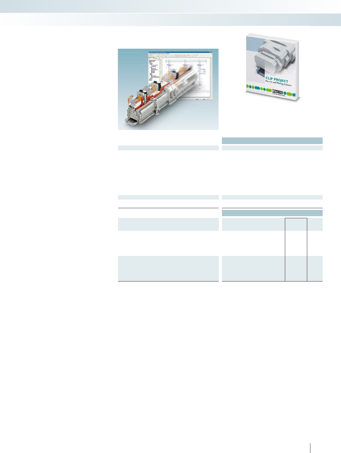
For additional information, visit phoenixcontact.net/products
Technical data
General data
Software interface EPLAN 5.7
EPLAN Electric P8
AUCOTECELCAD
AUCOTECEngineering Base
AUCOTECRUPLAN
ZUKENE³
BentleyPromis-e
WSCAD
IGE XAO
PC-Schematic AUTOMATION
SDProget SPAC
System requirements
Operating systems MS Windows XP SP3, MS Windows Vista,
MS Windows 7 (32/64-bit), MS Windows 8 (32/64-bit)
Ordering data
Description Type Order No. Pcs. /
Pkt.
CLIP PROJECT advanced, planning and marking software,
German/English/French/Dutch/Italian/Spanish/Russian/Polish/Hun
garian/Czech/Turkish/Portuguese/Chinese and Japanese
CLIP-PROJECT ADVANCED 5146040 1
CLIP PROJECT professional, planning and marking software,
with template designer,
German/English/French/Dutch/Italian/Spanish/Russian/Polish/Hun
garian/Czech/Turkish/Portuguese/Chinese and Japanese
CLIP-PROJECT PROFESSIONAL 5146053 1
291PHOENIX CONTACT
CLIPPROJECTadvanced
The CLIPPROJECTadvanced program
enables the quick planning and configuration
of terminal strips for the control cabinet
and field as well as custom-marking of
terminal blocks, cables, and lines, plus
devices and systems:
– The automatic correction function
performs a logical test of the terminal
strips and automatically adds the
necessary accessories such as covers and
end brackets
– The terminal strip configurator enables
the distributed arrangement of individual
terminal strips on different DIN rails
–3D preview and complete documentation
of the assembled DIN rails, suchas order
and mounting lists
– Numerous sorting and filter functions for
efficient management of your print jobs
– One software for all output devices:
CLIPPROJECT controls all marking
technologies from PhoenixContact, from
the BLUEMARKCLED high-speed
printer, the THERMOMARKLINE
thermal transfer printer, and the plotter
to the TOPMARKLASER desktop laser
marker
– Continual extension of the output
devices and marking materials via updates
– Automatic Internet update
– Intuitive Windows® user interface
– CLIPPROJECT supports all marking
materials from PhoenixContact, from
V4A stainless steel and aluminum
to plastics such as polyamide or
polycarbonate or foils made of PVC or
polyester. These are stored with preset
parameters
CLIPPROJECTprofessional
– The professional version also includes an
efficient template designer, which can be
used to design signs of your choice and to
adapt existing material descriptions
– Graphics, various barcode types, and
geometric elements such as squares,
circles, and lines can be accessed for
design work
– Data can also be imported into the
templates from various data sources
CLIP PROJECT
advanced and professional
Marking systems, tools, and mounting material
CLIP PROJECT - MARKING system
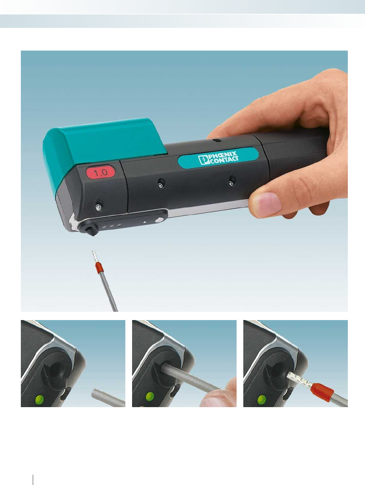
292 PHOENIX CONTACT
Marking systems, tools, and mounting material
Tools - TOOL fox
CRIMPHANDY - portable hand-held machine. Stripping and crimping in just one step.
Simply insert the conductor, ... ... stripping and crimping is carried out
automatically, ...
... and you're done.
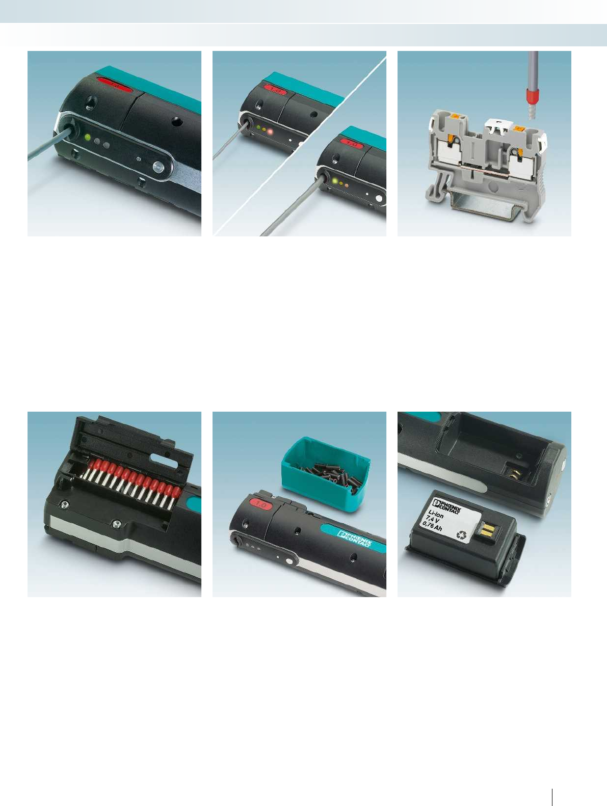
For additional information, visit phoenixcontact.net/products
293PHOENIX CONTACT
Marking systems, tools, and mounting material
Tools - TOOL fox
Easy operation thanks to the automatic
stripping and crimping function. One tool
for both work steps, resulting in time
savings of approx. 75%. The device signals
the operating states clearly by means of
colored LEDs.
Automatic cross-section monitoring
prevents faulty crimping as a result of
incorrect cross sections. The device displays
a corresponding message.
The efficiency is particularly evident when
used in combination with the push-in
connection terminal block PT: conductors
are processed and contacted in no time at all.
Integrated magazine for ferrules in strip
form. The automatic feed enables
conductors to be crimped one after another.
Easy to remove collecting chamber for
discarded insulation. This guarantees a clean
working environment. At around just
430grams, the device can also easily be
used inside the control cabinet.
Integrated lithium-ion polymer
rechargeable battery for up to 2000 crimps.
The fast charger provided charges the battery,
which is easy to replace, in just 60 minutes.
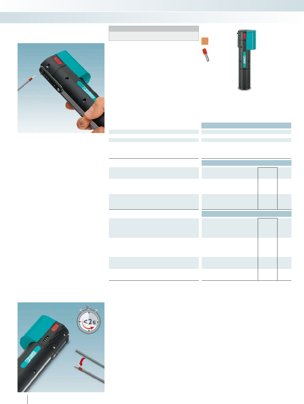
Technical data
Dimensions Width Length Height
[mm] 43 205 70 43 205 70
General data
Weight [kg] 0.43
Conductor [mm²] - 1
Working cycle [s] < 2
Compression Square crimp
Ordering data
Description Type Order No. Pcs. /
Pkt.
Portable hand-held machine, battery-powered, for ferrules,
1.0mm², incl. battery and charger, 100-240V, in a robust case
for standard PVC conductors CF CRIMPHANDY 1,0 1212465 1
Portable hand-held machine, battery-powered, for ferrules,
1.5mm², incl. battery and charger, 100-240V, in a robust case
for standard PVC conductors
Accessories
Reel ferrules, 1.0mm², 8mm, with plastic sleeve, according to
DIN46228-4, 50pieces per strip, 20strips per unit pack
Red, according to DIN46228-4 AI 1,0-8 RD-S 1212523 1000
Yellow, special color AI 1,0-8 YE-S 1212782 1000
Reel ferrules, 1.5mm², 8mm, with plastic sleeve, according to
DIN46228-4, 50pieces per strip, 20strips per unit pack
Black, according to DIN46228-4
Red, special color
Replacement battery,
for CFCRIMPHANDY..., Li-ion 7.4V, 0.76Ah
CF CRIMPHANDY/ACCU 1212518 1
Replacement charger,
for CFCRIMPHANDY..., 100-240V AC
CF CRIMPHANDY/CHARGER 1212519 1
294 PHOENIX CONTACT
CRIMPHANDY, portable hand-held
machine, for a 1.0to1.5mm
conductor cross section
Notes:
An application video can be found in the download area for the
relevant product on our website at phoenixcontact.net/products.
The product innovation for switchgear
manufacturing – the CRIMPHANDY. With
this portable hand-held machine, you can
strip and crimp your conductors in under
two seconds – 75% less time than before.
– The matching reel ferrules are suitable for
use on all modular terminal blocks,
particularly those from the
CLIPLINEcompletesystem:
– UT screw connection terminal blocks
– ST spring-cage connection terminal blocks
– PT push-in connection terminal blocks
– COMBI plug-in connection solutions
Marking systems, tools, and mounting material
Tools - TOOL fox
1.0mm² conductor cross section 1.5
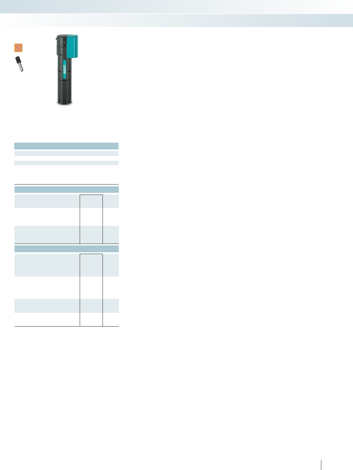
For additional information, visit phoenixcontact.net/products
Technical data
Width Length Height
43 205 70 43 205 70
0.43
- 1.5
< 2
Square crimp
Ordering data
Type Order No. Pcs. /
Pkt.
CF CRIMPHANDY 1,5 1212466 1
Accessories
AI 1,5-8 BK-S 1212524 1000
AI 1,5-8 RD-S 1212781 1000
CF CRIMPHANDY/ACCU 1212518 1
CF CRIMPHANDY/CHARGER 1212519 1
295PHOENIX CONTACT
Marking systems, tools, and mounting material
Tools - TOOL fox
mm² conductor cross section 1.5mm² conductor cross section
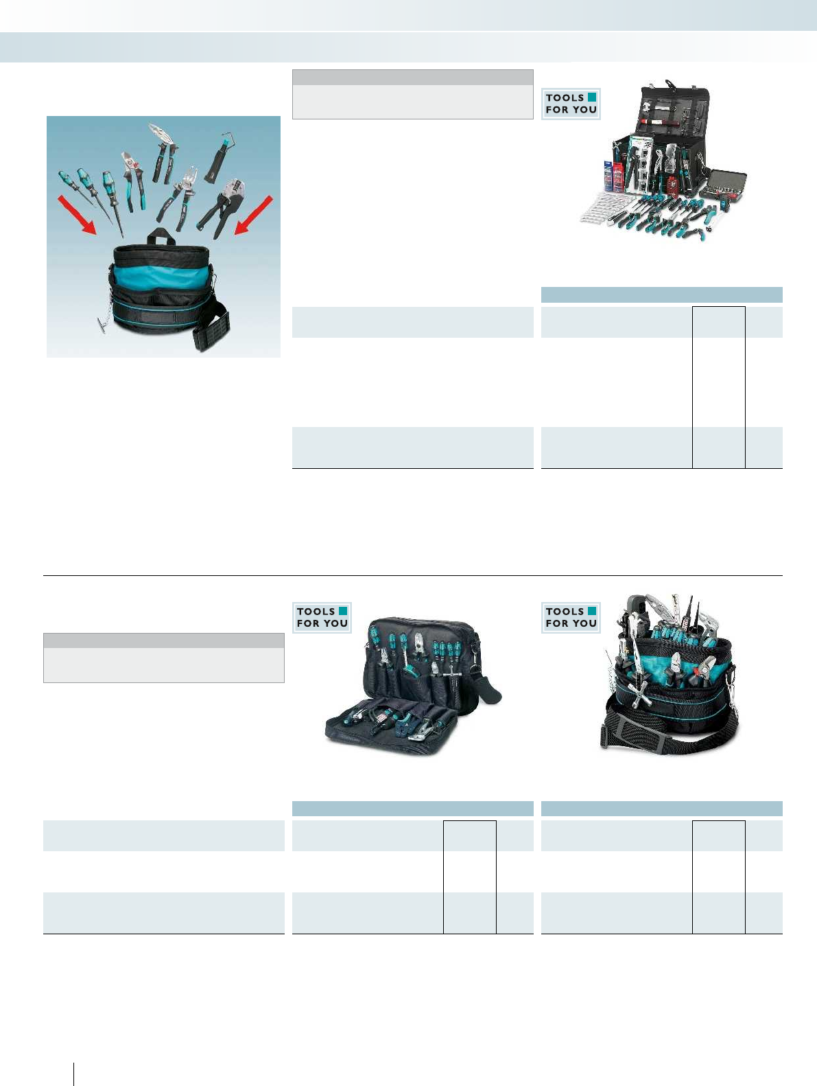
Ordering data
Description Type Order No. Pcs. /
Pkt.
Toolbox, lockable, with adjustable strap, equipped with: cable
cutter, diagonal cutter, micro cutter, stripping and sheath stripping
tools, crimping tool set, combination, needle-nose, and water pump
pliers, VDE bladed and Phillips screwdrivers, control cabinet key,
voltage tester, ferrule box, blades, tape measure, continuity tester,
marking tool, ring, open-end, and adjustable wrench set, T-handle
hexagonal wrench, safety glasses, hammer, 41-piece ratchet
socket wrench set, 1/4"
TOOL-CASE 1212629 1
Toolbox, lockable, with adjustable strap, equipped with tools
according to customer requirements
TOOL-CASE CUS 1200072 1
Notes:
The CUStool sets can be put together according to your
requirements in the product area on our website at
phoenixcontact.net/products.
You can put together your own CUS tool
set according to your individual
requirements
– Six different bags are available, designed
for typical applications
– Easily select your tools at
phoenixcontact.net/products
CUStool sets, equipped with tools
according to customer requirements
Marking systems, tools, and mounting material
Tools - TOOL fox
Tool case, lockable, with straps
Ordering data Ordering data
Description Type Order No. Pcs. /
Pkt. Type Order No. Pcs. /
Pkt.
Tool bag, with adjustable straps,
with document and laptop compartments,
equipped with tools according to customer requirements
TOOL-BAG CUS 1200081 1
Tool bag, with strap,
very comfortable to carry thanks to ergonomic shape,
equipped with tools according to customer requirements
TOOL-CARRIER CUS 1200082 1
296 PHOENIX CONTACT
Notes:
The CUStool sets can be put together according to your
requirements in the product area on our website at
phoenixcontact.net/products.
CUStool sets, equipped with tools
according to customer requirements
Tool bag,
with document and laptop compartments
Tool bag, with strap
For additional information, visit phoenixcontact.net/products
Ordering data
Description Type Order No. Pcs. /
Pkt.
Tool belt pouch, with two robust internal pockets,
equipped with tools according to customer requirements
TOOL-BELTPOUCH CUS 1200084 1
Notes:
The CUStool sets can be put together according to your
requirements in the product area on our website at
phoenixcontact.net/products.
– Individual tool sets, with cutting, stripping,
crimping, installation, and testing tools
from the TOOLfox tool range
– Rugged and heavy-duty tool bags
– Select from six types of bag and equip
these with the required tools at
phoenixcontact.net/products
CUStool sets, equipped with tools
according to customer requirements
Marking systems, tools, and mounting material
Tools - TOOL fox
Tool belt pouch
Ordering data Ordering data
Description Type Order No. Pcs. /
Pkt. Type Order No. Pcs. /
Pkt.
Tool case, with elastic straps to hold the tools in place,
equipped with tools according to customer requirements
TOOL-KIT CUS 1200085 1
Wrap-up tool bag, with slide-in compartments and robust elastic
straps to hold the tools in place,
equipped with tools according to customer requirements
TOOL-WRAP CUS 1200083 1
297
PHOENIX CONTACT
Notes:
The CUStool sets can be put together according to your
requirements in the product area on our website at
phoenixcontact.net/products.
CUStool sets, equipped with tools
according to customer requirements
Tool case Wrap-up tool bag
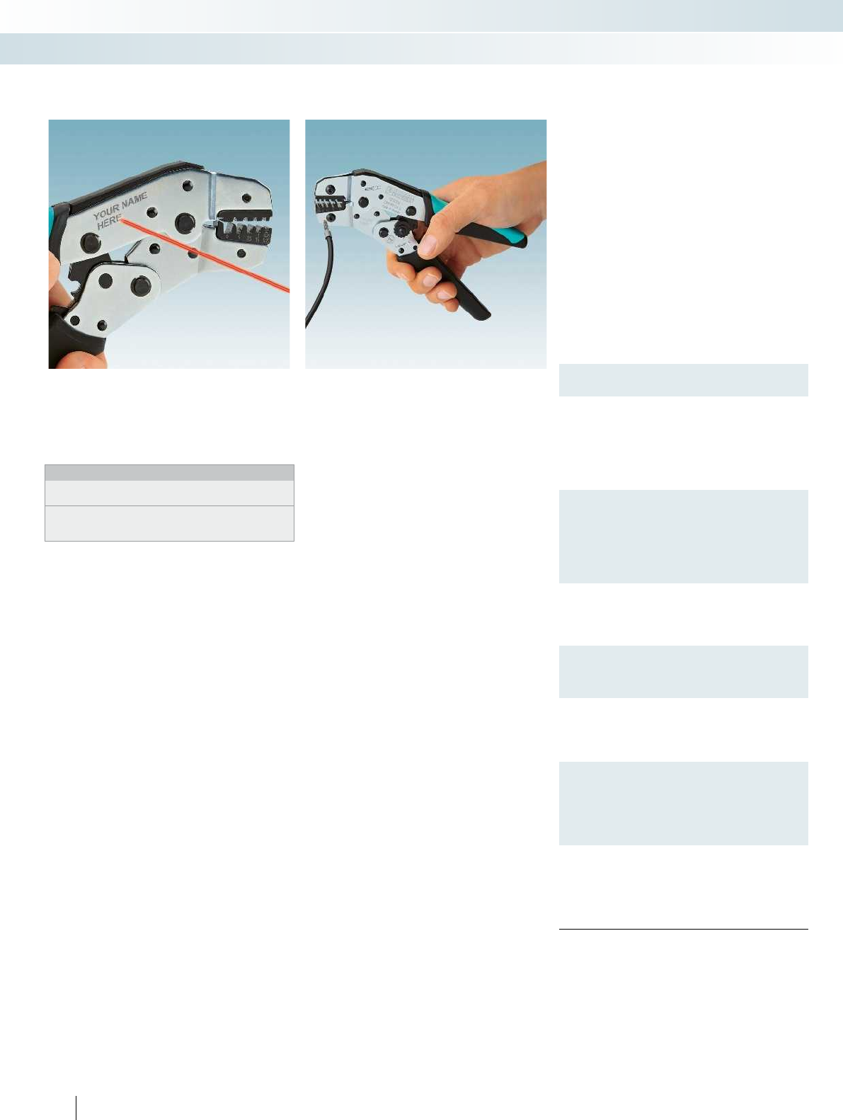
Description
Crimping pliers, for ferrules, according to DIN46228-1and-4,
five marked die stations,
laser marked according to customer specifications1)
Lateral insertion, 0.25-6.0mm²,
unlockable pressure lock, trapezoidal crimp
Front insertion, 0.5-6mm², square crimp
Crimping pliers, unlockable pressure lock, lateral insertion,
oval crimp,
laser marked according to customer specifications1)
For insulated cable lugs (light green, red),
0.14-1mm², three marked die stations
For insulated cable lugs (red, blue),
0.75-2.5mm², two marked die stations
Crimping pliers, for uninsulated cable lugs,
three marked die stations, 0.34-2.5mm²,
unlockable pressure lock, lateral insertion, indent crimp,
laser marked according to customer specifications1)
Crimping pliers, for uninsulated slip-on sleeves 2.8/4.8/6.3mm,
three marked die stations, B-crimp, 0.1-1.5mm²,
unlockable pressure lock, lateral insertion,
laser marked according to customer specifications1)
Crimping pliers, for ferrules according to DIN 46228-1and-4,
self-adjusting die, trapezoidal crimp, 0.5-6mm²,
unlockable pressure lock,
laser marked according to customer specifications1)
Front insertion
Lateral insertion
Crimping pliers, three marked die stations, 0.75-6mm²,
oval crimp, unlockable pressure lock, lateral insertion,
laser marked according to customer specifications1)
For insulated cable lugs,
symmetrical (red, blue, yellow)
For insulated cable lugs,
asymmetrical (red, blue, yellow)
Crimping pliers, for ferrules according to DIN 46228-1and-4,
WM crimp, unlockable pressure lock, lateral insertion,
laser marked according to customer specifications1)
Three marked die stations, 10-25mm²
Two marked die stations, 35-50mm²
298 PHOENIX CONTACT
– Customize your crimping tool!
– You can now use robust laser engraving to
mark CRIMPFOX pliers
– Individual laser marking prevents your
tools from being mixed up
Notes:
Matching accessories can be found in main catalog5 or the
product area on our website at phoenixcontact.net/products.
1) Tools with customer-specific laser marking can be ordered
quickly and easily in the product area on our website at
phoenixcontact.net/products.
The advantages of our CRIMPFOXtools:
– Consistently high crimping quality
– Unlockable pressure lock
– Marked die stations for precise
processing of the relevant cross sections
– Easy work thanks to improved force
transfer
– Ergonomically designed, non-slip handles
– CRIMPFOX 6S-FCUS: the self-adjusting
die automatically adapts to the
connector size
CRIMPFOX pliers, laser marked
according to customer specifications
Marking systems, tools, and mounting material
Tools - TOOL fox
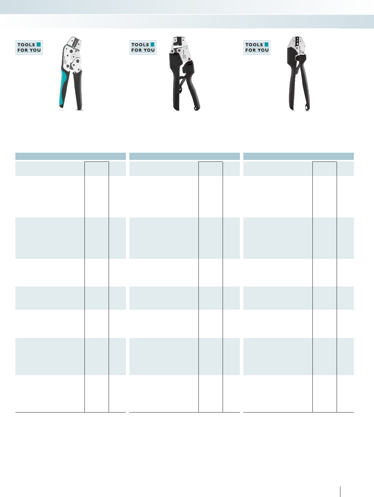
For additional information, visit phoenixcontact.net/products
Ordering data Ordering data Ordering data
Type Order No. Pcs. /
Pkt. Type Order No. Pcs. /
Pkt. Type Order No. Pcs. /
Pkt.
CRIMPFOX 6 CUS 1212767 1
CRIMPFOX 6S-F CUS 1212769 1
CRIMPFOX-RCI 1 CUS 1212772 1
CRIMPFOX-RCI 2,5 CUS 1212773 1
CRIMPFOX-RC 2,5 CUS 1212777 1
CRIMPFOX-SC 1,5 CUS 1212779 1
CRIMPFOX 6T-F CUS 1212771 1
CRIMPFOX 6T CUS 1212770 1
CRIMPFOX-RCI 6 CUS 1212774 1
CRIMPFOX-RCI 6-1 CUS 1212775 1
CRIMPFOX 25R CUS 1212765 1
CRIMPFOX 50R CUS 1212766 1
299PHOENIX CONTACT
Marking systems, tools, and mounting material
Tools - TOOL fox

Description
Crimping pliers, for uninsulated cable lugs, three marked die
stations, indent crimp, unlockable pressure lock, lateral insertion,
laser marked according to customer specifications1)
4-10mm²
10-25mm²
Crimping pliers, for uninsulated slip-on sleeves 2.8/4.8/6.3mm,
three marked die stations, 0.5-6mm², B-crimp,
unlockable pressure lock, lateral insertion,
laser marked according to customer specifications1)
Crimping pliers, for ferrules according to DIN46228,
unlockable pressure lock, lateral insertion,
laser marked according to customer specifications1)
Square crimp, 0.14-10mm²
HEX crimp, 0.14-6 mm²
Stripping tool, self-adjusting, easily replaceable blade cassettes,
stripping length of up to 18mm,
cutting capacity: up to 1.5mm² solid, up to 10mm² stranded,
laser marked according to customer specifications1)
For cables and conductors from 0.1-4mm²,
specifically also intended for rubber and
other kinds of special insulation
For cables and conductors from 1.5-6mm²,
specifically for short-circuit-proof cables and
rubber insulation
For standard cables and conductors
from 0.02-10mm²
For standard cables and conductors
from 4-16mm²
300 PHOENIX CONTACT
– Customize your crimping and stripping tool!
– You can now use robust laser engraving to
mark CRIMPFOX and WIREFOX pliers
– Individual laser marking prevents your
tools from being mixed up
Notes:
Matching accessories can be found in main catalog5 or the
product area on our website at phoenixcontact.net/products.
1) Tools with customer-specific laser marking can be ordered
quickly and easily in the product area on our website at
phoenixcontact.net/products.
The advantages of our WIREFOXtools:
– The special spring mechanism helps you
to work precisely and safely
– Ergonomically designed, non-slip handles
– The WIREFOX pliers automatically adjust
to different insulations and conductor
diameters
– Highly adjustable limit stop for the
stripping length
– Practical integrated wire cutter
– Easily replaceable blade cassettes for
different cross sections and insulation
CRIMPFOX and WIREFOX pliers,
laser marked according to customer
specifications
Marking systems, tools, and mounting material
Tools - TOOL fox
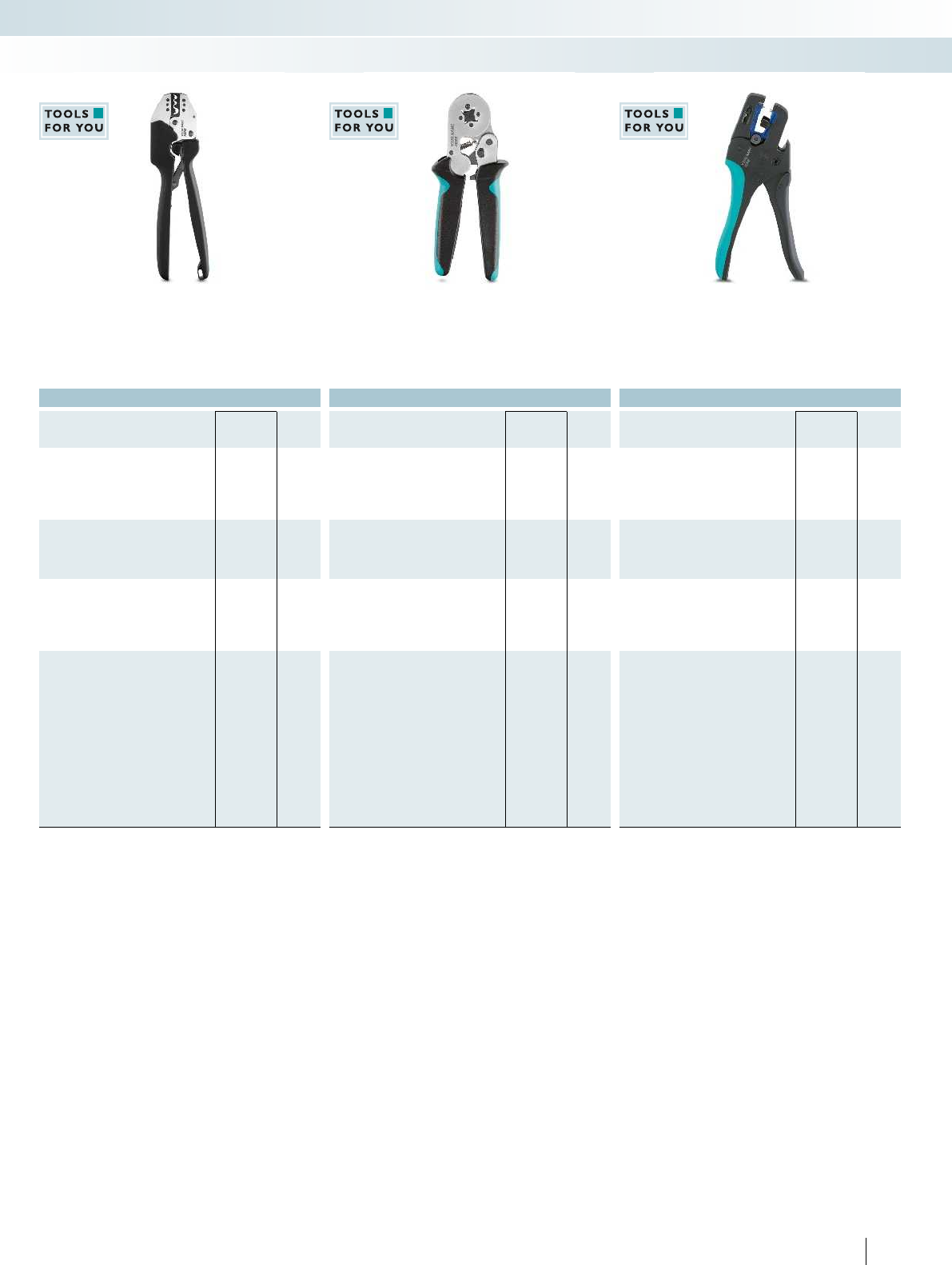
For additional information, visit phoenixcontact.net/products
Ordering data Ordering data Ordering data
Type Order No. Pcs. /
Pkt. Type Order No. Pcs. /
Pkt. Type Order No. Pcs. /
Pkt.
CRIMPFOX-RC 10 CUS 1212776 1
CRIMPFOX-RC 25 CUS 1212778 1
CRIMPFOX-SC 6 CUS 1212780 1
CRIMPFOX 10S CUS 1212764 1
CRIMPFOX 6H CUS 1212768 1
WIREFOX 4 CUS 1212762 1
WIREFOX 6SC CUS 1212763 1
WIREFOX 10 CUS 1212760 1
WIREFOX 16 CUS 1212761 1
301PHOENIX CONTACT
Marking systems, tools, and mounting material
Tools - TOOL fox
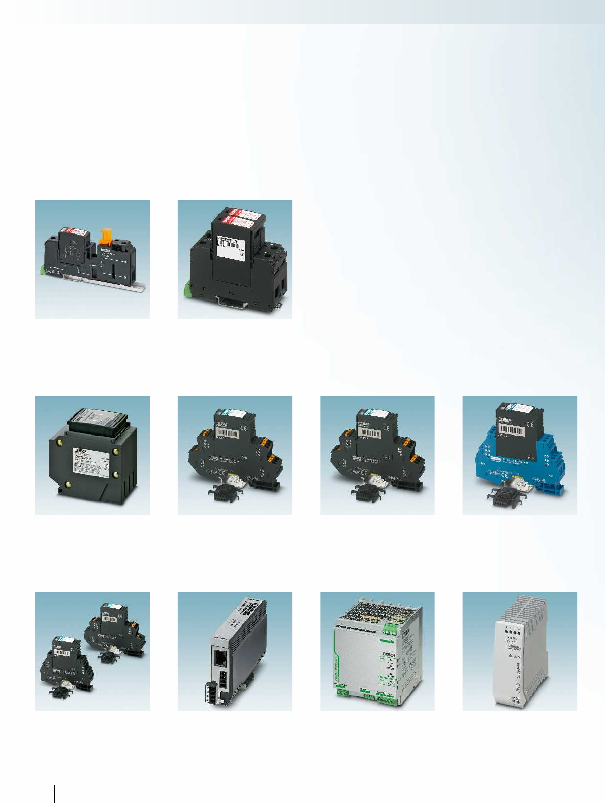
Surge protection for special applications
VAL-MS-AR... Page 306
Surge protection for special applications
VAL-MS-T1/T2... Page 307
Surge protection for NEMA
VAL-SQ NP... Page 309
Surge protection for measurement and
control technology
PT-IQ-2X2... Page 310
Surge protection for measurement and
control technology
PT-IQ-4X1... Page 310
Surge protection for intrinsically safe circuits
PT-IQ...EX Page 312
Surge protection for information technology
PT-IQ... Page 313
Surge protection for telecommunications
interfaces
DT-TELE-SHDSL Page 314
Power supplies
QUINT POWER Page 315
Power supplies
UNO POWER Page 316
Surge protection and power supplies
302 PHOENIX CONTACT
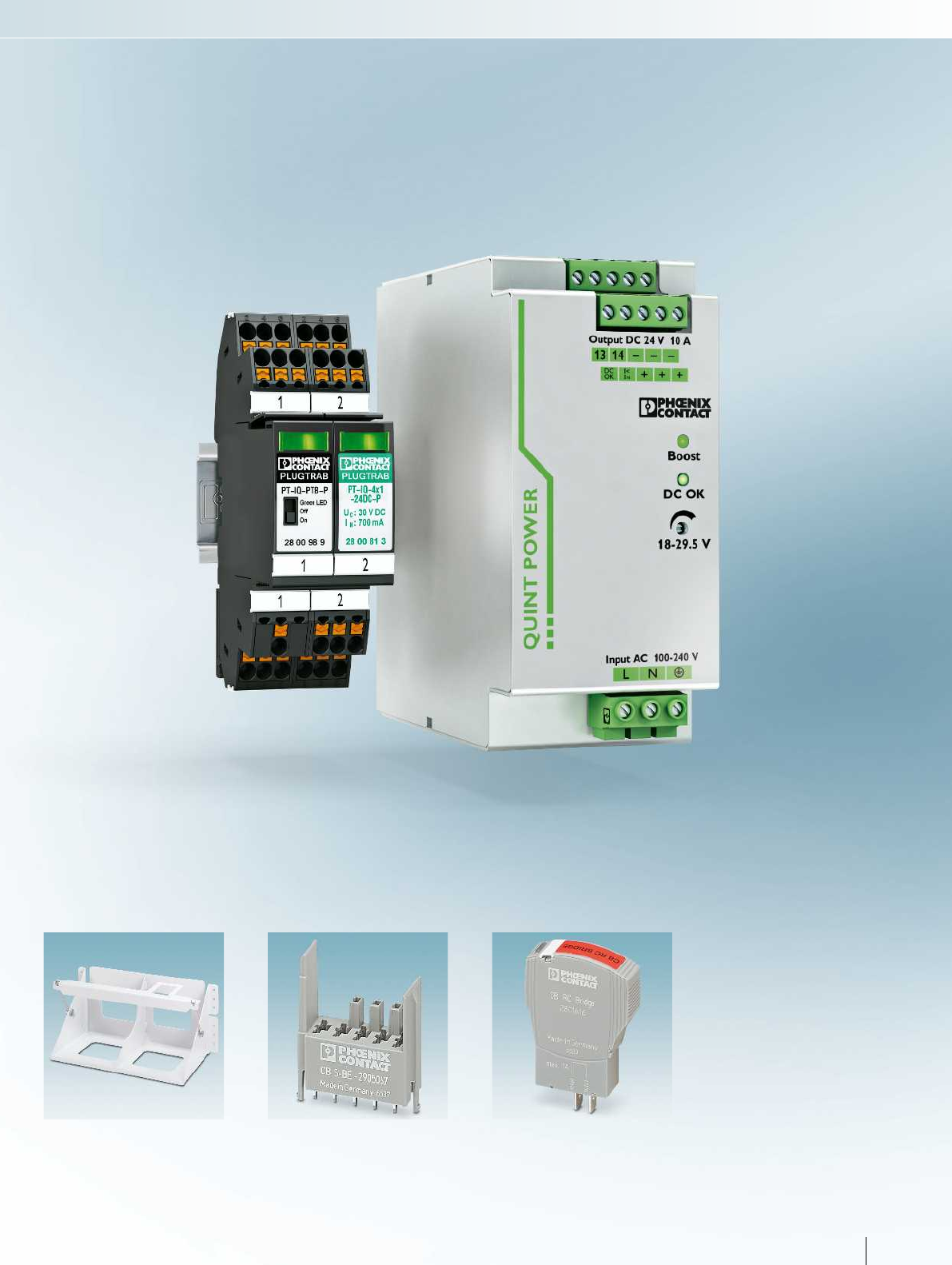

304 PHOENIX CONTACT
Surge protection and power supplies
Surge protection and interference filters
VAL-MS-AR – surge protection for the
American railway industry
The VAL-MS-AR surge protective devices
offer reliable, touch-proof protection while
also providing a connection block for
railway and signaling systems.
The VAL-MS BE-AR... base element has
been designed so that the field input and
house output connections are on the same
side. The ground connection is on the
opposite side. The integrated isolator
allows you to easily carry out field
diagnostics and insulation measurements.
VAL-MS-AR... complies with the practices
recommended by AREMA C&S. In contrast
to conventional installation with bolts and
nuts, the alternative connection technology
with base elements and plugs considerably
reduces the effort required for installation,
tests, and repair measures.
In addition to the standard products,
VAL-MS-AR... /FM feature a remote
monitoring function. This means that
immediate failure or the removal of a
protective plug can be signaled via floating
contacts.
Features:
– Easy to replace, plug-in surge protection
– Protects systems against direct lightning
strikes and coupled surge voltages
– Mechanical status indicator on each
protective plug
– Optional remote signaling via floating
PDTs
– Integrated isolator for insulation
measurements and field diagnostics
– Screw terminal blocks for copper wire up
to 4 AWG (25 mm), solid, stranded,
stripped or with sleeves
– Convenient marking options
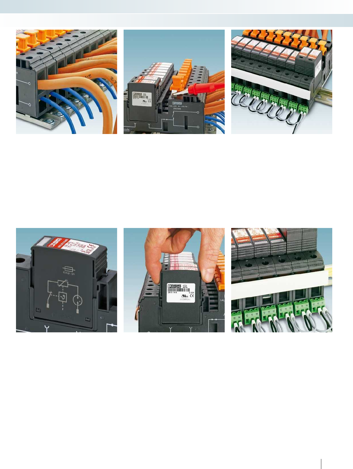
For additional information, visit phoenixcontact.net/products
305PHOENIX CONTACT
Surge protection and power supplies
Surge protection and interference filters
Field and house connection
Independent terminal points for field and
house connection enable wiring from the
field side and signal lines with one
conductor each. The terminal points are
designed for typical wire gauges for railway
applications:
House: 20 - 6 AWG (0.5 – 15 mm),
Field: 18 - 4 AWG (1.5 - 25 mm).
Disconnect and test point
Integrated isolator for carrying out
diagnostics and insulation measurements
without tampering with the installation.
The disconnect knife remains connected to
the field side for testing.
Function monitoring
Each plug has an optical, mechanical
status indicator. In the event of a fault, the
status is changed via the thermal disconnect
device. In the VAL-MS-AR.../FM versions, a
floating PDT is thereby switched, so that
the status can be remotely indicated.
Protective plug, free of leakage
current
VAL-MS...VF... plugs have a series
connection consisting of a varistor and a
spark gap. The advantage of this component
combination is that no leakage currents
flow in the passive state and therefore
signals are not impaired.
Lightning current plugs with latching
The “T1/T2” plugs are robust enough to
cope with direct lightning current. They are
heavier than standard plugs and are
equipped with latching to keep them in
place in the event of vibrations, shocks, and
magnetic influences.
Ground and bridging options
The base elements can be easily bridged
together with low impedance using
pre-assembled MPB bridges. The terminal
points for the ground connection
accommodate conductors up to 2 AWG
(35 mm).
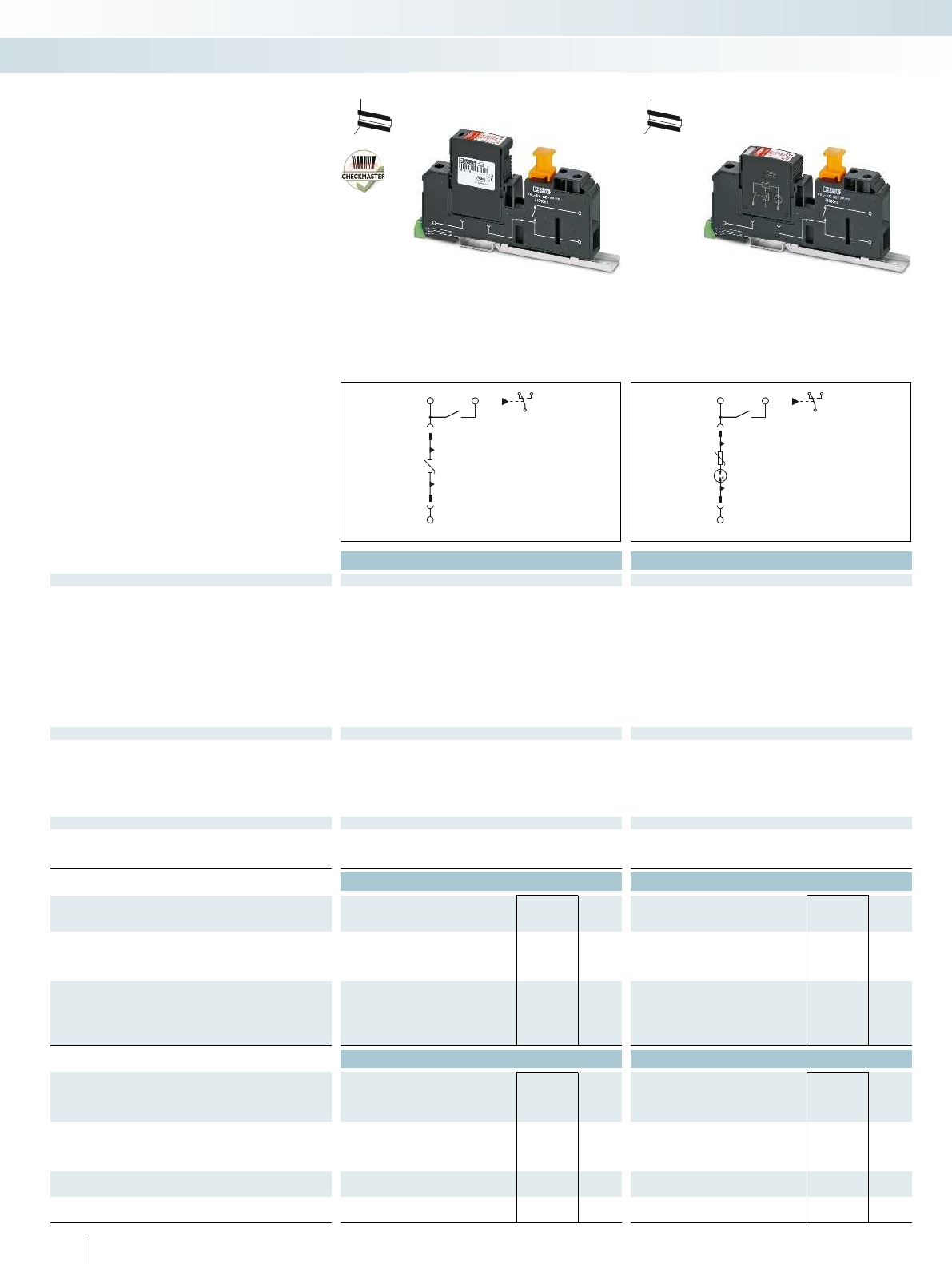
L1 L0
N/PEN
12 14
FM
11
L1 L0
N/PEN
12 14
FM
11
Total width 17.7 mm Total width 17.7 mm
Technical data Technical data
Electrical data ... 75 ... 75 ... 350
IEC test classification/EN type I/II/T1/T2 II/T2 II/T2
Nominal voltage UN60 V DC 60 V DC (5 V...48 V AC) 230 V AC
Maximum continuous operating voltage UC-/75 V DC 75 V AC/100 V DC 350 V AC/-
Impulse discharge curr. Iimp (10/350)μs
Peak value 12.5 kA 3 kA 3 kA
Charge 6.25 As - -
Specific energy 39.00 kJ/Ω--
Nominal discharge current In (8/20) µs 12.5 kA 10 kA 10 kA
Max. discharge current Imax. (8/20) µs 50 kA 20 kA 20 kA
Residual voltage Without reference direction ≤ 0.6 kV (at 5 kA) ≤ 350 V (at 5 kA) ≤ 1 kV (at 5 kA)
Voltage protection level UP Without reference direction ≤ 0.7 kV ≤ 1.4 kV ≤ 1.2 kV
General data
Dimensions W/H/D 17.7 mm/160 mm/77.5 mm 17.7 mm/160 mm/75 mm
Connection data, Ground solid / stranded / AWG 1.5 ... 35 mm²/1.5 ... 35 mm²/15 - 2 1.5 ... 35 mm²/1.5 ... 35 mm²/15 - 2
Connection data, Field solid/stranded/AWG 1.5 ... 25 mm²/1.5 ... 25 mm²/12 - 4 1.5 ... 25 mm²/1.5 ... 25 mm²/12 - 4
Connection data, House solid/stranded/AWG 0.5 ... 15 mm²/0.5 ... 15 mm²/20 - 6 0.5 ... 15 mm²/0.5 ... 15 mm²/20 - 6
Temperature range -40°C ... 80°C -40°C ... 80°C
Inflammability class in acc. with UL 94 V0 V0
Remote indication contact PDT, 1-pos. PDT, 1-pos.
Connection data solid / stranded / AWG 0.14 ... 1.5 mm²/0.14 ... 1.5 mm²/28 - 16 0.14 ... 1.5 mm²/0.14 ... 1.5 mm²/28 - 16
Max. operating voltage 250 V AC 250 V AC
Max. operating current 1.5 A AC (250 V AC)/1.5 A DC (30 V DC) 1.5 A AC (250 V AC)/1.5 A DC (30 V DC)
Ordering data Ordering data
Description Type Order No. Pcs. /
Pkt. Type Order No. Pcs. /
Pkt.
VAL-MS-AR, high-capacity lightning arrester
without remote indication contact VAL-MS-AR-T1/T2 75 2801491 10
with remote indication contact VAL-MS-AR-T1/T2 75/FM 2801492 10
VAL-MS-AR, hybrid SPD
without remote indication contact VAL-MS-AR 75 VF 2801487 10
with remote indication contact VAL-MS-AR 75 VF/FM 2801488 10
without remote indication contact VAL-MS-AR 350 VF 2801489 10
with remote indication contact VAL-MS-AR 350 VF/FM 2801490 10
Accessories Accessories
Protective plug, for inserting in base element
L-N / L-PEN VAL-MS-T1/T2 75/12.5 ST 2801146 10 VAL-MS 75 VF ST 2805318 10
1L-N/PE VAL-MS 350 VF ST 2856595 10
Base element, for individual assembly with protective connectors
with remote indication contact VAL-MS BE-AR/FM 2801066 10 VAL-MS BE-AR/FM 2801066 10
without remote indication contact VAL-MS BE-AR 2801065 10 VAL-MS BE-AR 2801065 10
Plug-in bridge
2-pos. FBS 2-18 2801068 10 FBS 2-18 2801068 10
MPB wiring bridge,
57-pos. MPB 18/1-57 2809238 1MPB 18/1-57 2809238 1
306 PHOENIX CONTACT
– Base element with isolator for easy field
diagnostics and carrying out insulation
measurements
– Independent inputs and outputs on one
side of the base element, ground
connection on the opposite side
– Optical, mechanical status indication for
the individual arresters
– Disconnect device on each individual
plug
– With or without floating remote
indication contact
– Terminal block cases capable of bearing
high-current, for solid or stranded
conductors that are stripped or with
sleeves
H
W
D
H
W
D
VAL-MS-AR surge protection with
multifunctional base element
Surge protection and power supplies
Surge protection and interference filters
Type 1/2 lightning arrester SPD Type 2 hybrid SPD
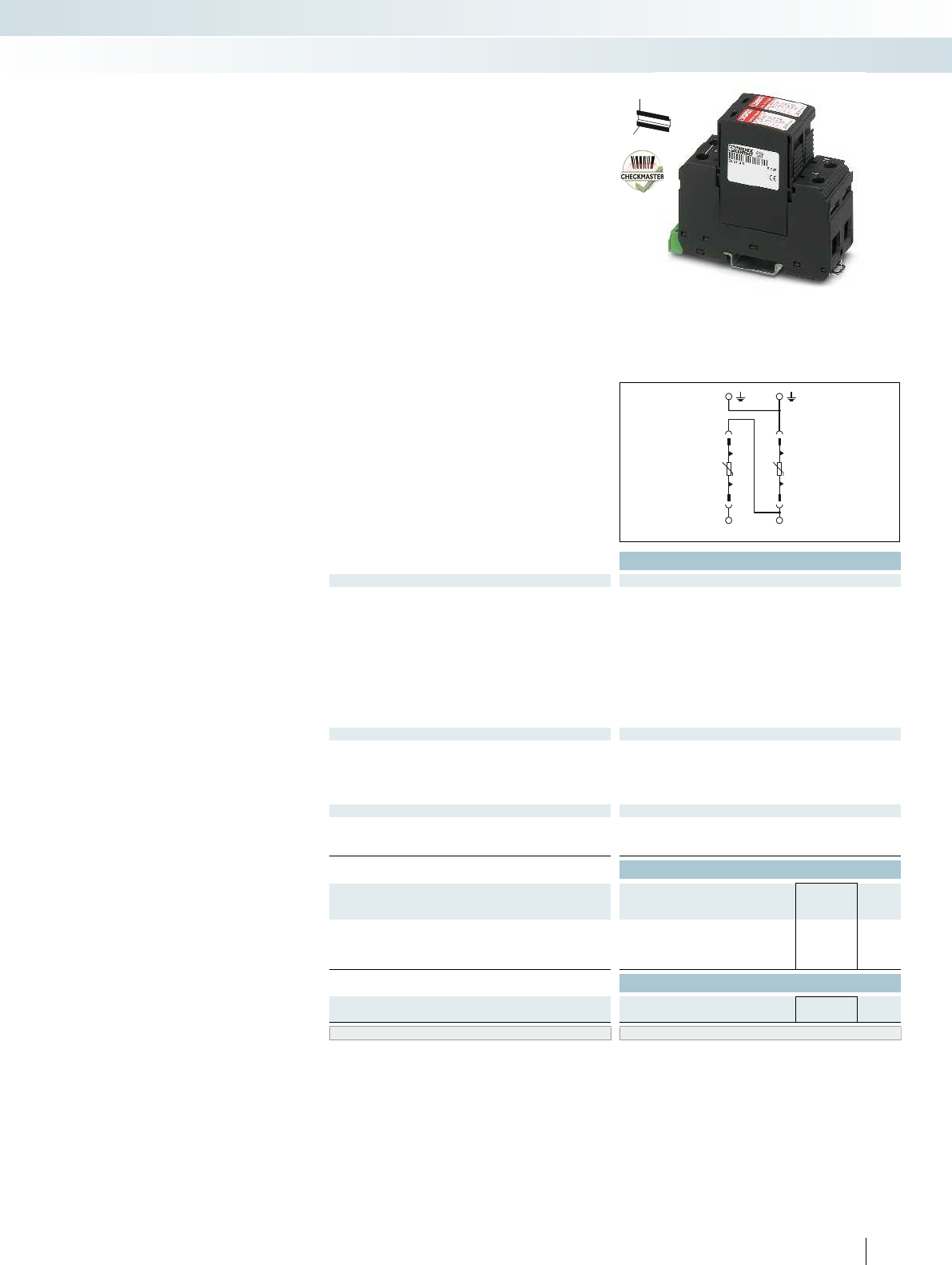
NL
For additional information, visit phoenixcontact.net/products
Total width 35.6 mm
Technical data
Electrical data ... 48
IEC test classification/EN type I/II/T1/T2
Nominal voltage UN60 V AC
Maximum continuous operating voltage UC75 V AC
Impulse discharge curr. Iimp (10/350)μs
Peak value 12.5 kA
Charge 6.25 As
Specific energy 39.00 kJ/Ω
Nominal discharge current In (8/20) µs 12.5 kA
Max. discharge current Imax. (8/20) µs 30 kA
Voltage protection level UP≤ 0.4 kV
Backup fuse max. in acc. with IEC 160 A (gL/gG)
General data
Dimensions W/H/D 35.6 mm/97 mm/77.5 mm
Connection data solid / stranded / AWG 1.5 ... 35 mm²/1.5 ... 25 mm²/15 - 2
Temperature range -40°C ... 80°C
Inflammability class in acc. with UL 94 V0
Test standards IEC 61643-11/EN 61643-11/UL 1449 ed. 3
Remote indication contact PDT, 1-pos.
Connection data solid / stranded / AWG 0.14 ... 1.5 mm²/0.14 ... 1.5 mm²/28 - 16
Max. operating voltage 250 V AC
Max. operating current 1.5 A AC (250 V AC)/1.5 A DC (30 V DC)
Ordering data
Description UCType Order No. Pcs. /
Pkt.
VALVETRAB-MS, varistor-based lightning arrester
75 V AC VAL-MS-T1/T2 48/12.5/1+1V 2801532 1
75 V AC VAL-MS-T1/T2 48/12.5/1+1V-FM 2801533 1
Accessories
Replacement plug
L-N / L-PEN VAL-MS-T1/T2 48/12.5 ST 2801242 10
Marking material ZBN 18..., see Catalog 6, page 63
307PHOENIX CONTACT
H
W
D
– Suitable for the protection of remote
radio heads in telecommunications
systems
– Extremely low voltage protection level
Up of <400 V
– Consistent plug-in arresters, type 1/2
– Secure hold of plugs in the event of high
lightning current loads and strong
vibrations thanks to latching
– Thermal disconnect device for each
individual plug
– Optical, mechanical status indication for
the individual arresters
– Mechanical coding of all slots
– With or without floating remote
indication contact
– Plugs can be checked with
CHECKMASTER
Lightning and surge arresters for
48VDC applications
Surge protection and power supplies
Surge protection and interference filters
Type 1/2 arrester for 48VDC applications
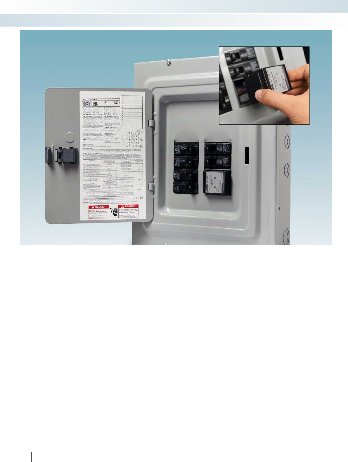
308 PHOENIX CONTACT
Surge protection and power supplies
Surge protection and interference filters
VAL-SQ NP... provides modular surge
protection for an entire house or a small
company. The surge protective device
consists of a base element and plug. It has
the same base area as two standard 1 inch
wide circuit breakers to enable installation
in the corresponding distributor boxes.
Initial installation must be performed by an
electrically skilled person. If necessary, the
surge protection plug can be replaced by the
house owner.
The status indicator on the plug indicates
the state of the surge protection. If the
protection fails, the VAL-SQ NP... ST
protective plug can be replaced quickly and
easily. Up to now, components in all other
products of this type had to be replaced by
an electrically skilled person in the event of
a fault.
The high-performance protective circuit
features a discharge capacity of 32 kA per
phase. The individual protective paths are
protected thermally as well as against
overcurrent.
The VAL-SQ NP... is suitable for single-
phase 120/240V applications with common
neutral conductor and ground.
Distributor box compatibility
VAL-SQ NP can be used in all distribution
boxes for single-phase 120/240 AC SN
systems with 1 inch pitch.
VAL-SQ NP... devices are compatible with
the following distributor boxes:
Eaton
– BR series (prefix 1BR or B) distributor
boxes
Siemens Industry, Inc.
–PL series (prefix P, PW or G)
– ES series (prefix S, SW or G)
–EQ series (prefix E or W)
General Electric Co.
– Powermark Gold series (prefix TL, TM or
TP)
Schneider Electric USA Inc./ Square D Co.
– Homeline series (prefix HOM)
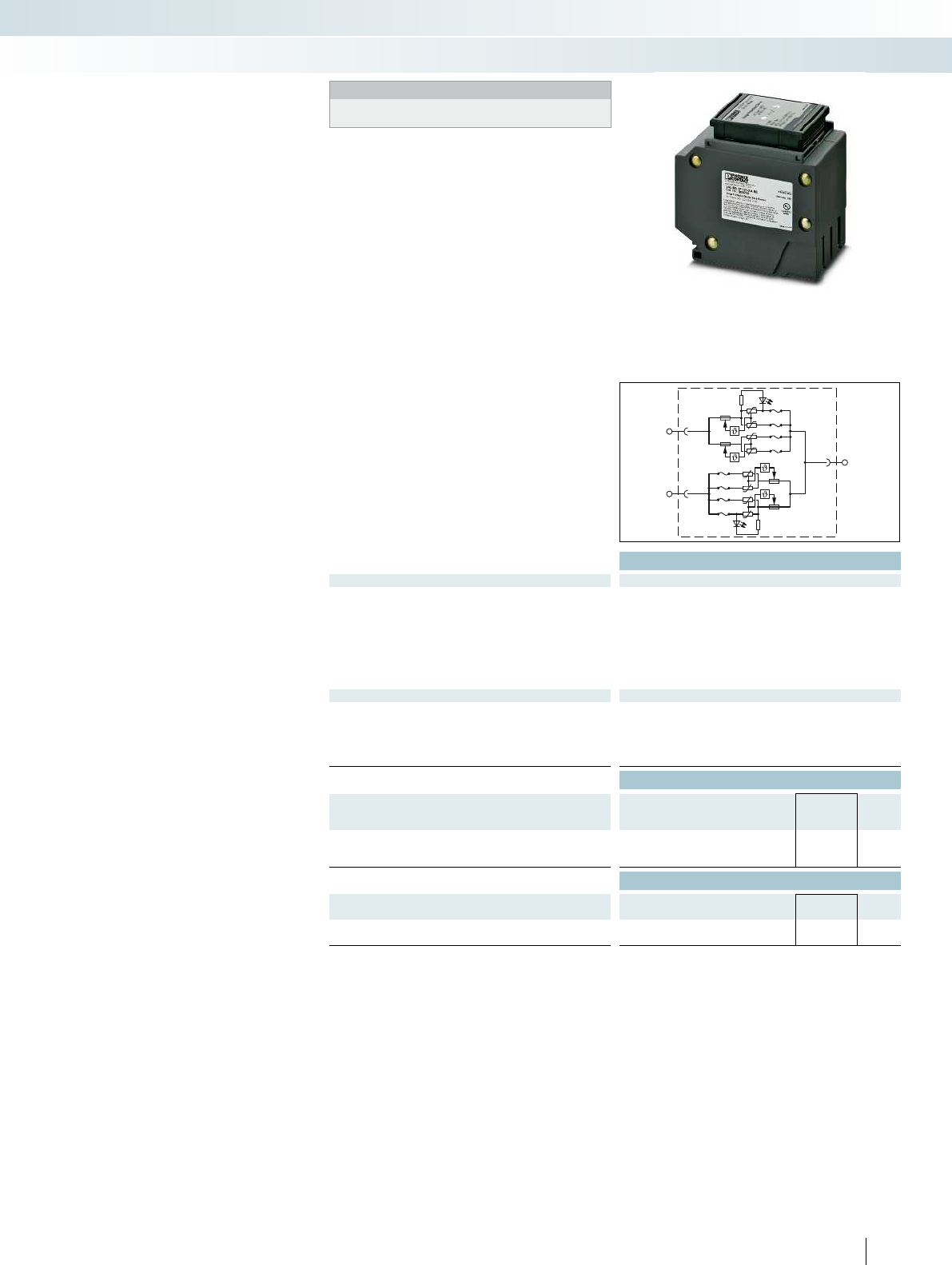
L1
L2
N/G
For additional information, visit phoenixcontact.net/products
Technical data
Electrical data
MCOV L-L /L-N 350 V/175 V
Nominal voltage UN120 V AC
Maximum continuous operating voltage UC120 V AC
Voltage Protection Rating (VPR)
L-N / L-PE 800 V/-
N-PE / L-L -/1200 V
Short-circuit current rating (SCCR) 10 kA
Nominal discharge current In10 kA
General data
UL Type type 1
Degree of protection IP20/NEMA 1
Error/status indicator LEDs
Temperature range -55°C ... 70°C
Test standards UL 1449 3rd edition
Ordering data
Description Type Order No. Pcs. /
Pkt.
Plug and base assembly, 120/240 V AC single phase
for distributor boxes with 1-inch pitch VAL-SQ NP 120-2-A 32 2800371 1
Accessories
Replacement plug
VAL-SQ NP 120-2-A 32 ST 2800369 1
Base element
VAL-SQ NP 120-2-A BE 2800749 1
309PHOENIX CONTACT
Notes:
The products are offered exclusively for export outside the
European Economic Area (EEA).
– Installs in NEMA-style distributor boxes
with 1-inch pitch
– Uses the same footprint as two standard
1-inch pitch circuit breakers
– Suitable for single-phase 120/240VAC
systems
– 32 kA surge current capacity per phase
– 10 kA (UL) nominal surge discharge
current (IN)
– LEDs provide continuous feedback on the
status of each phase
– UL 1449 3rd edition
Surge protection for distributor boxes
in houses and small businesses
Surge protection and power supplies
Surge protection and interference filters
SPD for distributor boxes with 1-inch pitch
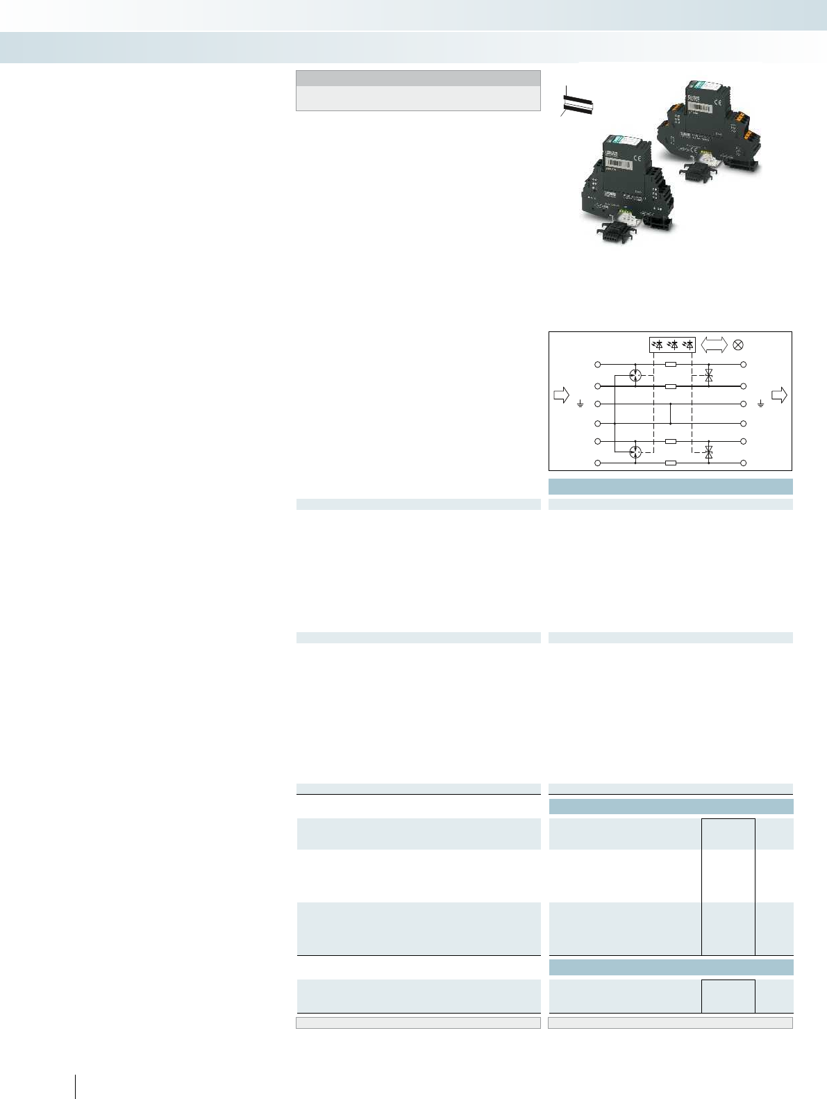
12
56
34
910
78
11 12
Total width 17.7 mm
Technical data
Electrical data ... 5DC ... 48DC
IEC test classification/EN type C1/C2/C3/D1 C1/C2/C3/D1 C1/C2/C3/D1 C1/C2/C3/D1 C1/C2/C3/D1 C1/C2/C3/D1
Maximum continuous operating voltage UC6 V DC/4 V AC 53 V DC/37 V AC 6 V DC/4 V AC 53 V DC/37 V AC 6 V DC/4 V AC 6 V DC/4 V AC
Impulse discharge curr. Iimp (10/350)μs Per path 2.5 kA 2.5 kA 2.5 kA 2.5 kA 2.5 kA 2.5 kA
Nominal current IN700 mA (up to 50°C) 300 mA 700 mA (up to 50°C) 300 mA 700 mA (up to 50°C) 700 mA (up to 50°C)
Nominal discharge current In (8/20) µs
Core-core/core-ground 10 kA/10 kA 10 kA/10 kA 10 kA/10 kA 10 kA/10 kA -/10 kA -/10 kA
Total surge current (8/20)µs 20 kA 20 kA 20 kA 20 kA 20 kA 20 kA
Voltage protection level UP
Core-core ≤ 25 V (C3 - 25 A) ≤ 90 V (C3 - 25 A)
Core-ground ≤ 600 V (C1 - 1 kV/500 A) ≤ 600 V (C1 - 1 kV/500 A)
Resistance per path 1.2 Ω1.2 Ω
General data
PT-IQ...PT dimensions W/H/D 17.7 mm/109.3 mm/77.5 mm 17.7 mm/109.3 mm/77.5 mm 17.7 mm/109.3 mm/77.5 mm 17.7 mm/109.3 mm/77.5 mm
PT-IQ...UT dimensions W/H/D 17.7 mm/91.1 mm/77.5 mm 17.7 mm/91.1 mm/77.5 mm 17.7 mm/91.1 mm/77.5 mm 17.7 mm/91.1 mm/77.5 mm
Connection data, push-in solid/stranded with ferrule/AWG 0.2 ... 4 mm²/0.2 ... 2.5 mm²/24 - 12 0.2 ... 4 mm²/0.2 ... 2.5 mm²/24 -
Connection data solid/stranded with ferrule/AWG 0.2 ... 4 mm²/0.2 ... 2.5 mm²/24 - 12 0.2 ... 4 mm²/0.2 ... 2.5 mm²/24 - 12 0.2 ..
Temperature range -40°C ... 70°C
Degree of protection in acc. with IEC 60529/EN 60529 IP20
Inflammability class in acc. with UL 94 V0
Connection method Screw connection/push-in connection Screw connection/push-in connection Screw connection/push-in connection Screw
Test standards EN 61643-21/A1/IEC 61643-21/A1/EN 61000-6-2/ EN 61643-21/A1/IEC 61643-21/A1/EN 61000-6-2/ EN 61643-21/A1/IEC 61643-
EN 61000-6-2/A1/EN 61000-6-3 EN 61000-6-2/A1/EN 61000-6-3 EN 61000-6-2/A1/EN 61000-6-3 EN 61000-6-2/A1/EN 61000-6-3
Remote indication contact Via TBUS
Ordering data
Description Voltage UNType Order No. Pcs. /
Pkt.
MCR-PLUGTRAB, consisting of a plug, base element,
and DIN rail bus, with screw connection technology
5 V DC PT-IQ-2X2-5DC-UT 2800807 1
48 V DC PT-IQ-2X2-48DC-UT 2800986 1
MCR-PLUGTRAB, consisting of a plug, base element,
and DIN rail bus, with push-in connection technology
5 V DC PT-IQ-2X2-5DC-PT 2801259 1
48 V DC PT-IQ-2X2-48DC-PT 2801265 1
Accessories
Replacement plug
5 V DC PT-IQ-2X2-5DC-P 2800802 1
48 V DC PT-IQ-2X2-48DC-P 2800810 1
Marking material ZB 6, see Catalog 6, page 111
310 PHOENIX CONTACT
PLUGTRAB PT-IQ
– Surge protection system
– Multi-level state monitoring
– Collective message about supply and
remote module
– Multi-level, floating remote signaling
– System supplied via DIN rail bus
– Up to 28 protection modules per supply
module
– Maximum ease of maintenance, thanks to
the two-piece design
–Plugs are coded
– Impedance-neutral disconnection of plug
for maintenance purposes
– Base element remains an integral part of
the installation
Surge protection and power supplies
Surge protection and interference filters
H
W
D
Notes:
For approvals and dimensional drawing, visit
phoenixcontact.net/products
2 double conductors (loops), floating,
9/10 connection grounded directly
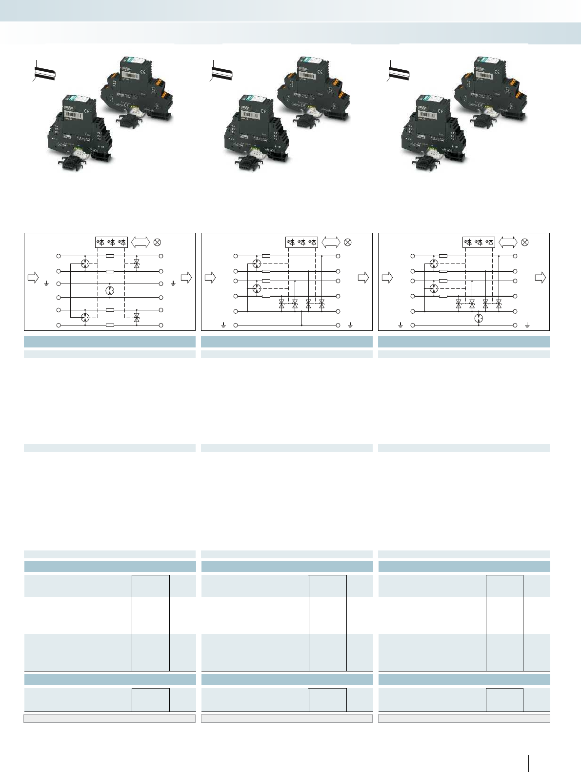
12
56
34
910
78
11 12
12
56
78
11 12
910
34
12
56
78
11 12
910
34
For additional information, visit phoenixcontact.net/products
Total width 17.7 mm Total width 17.7 mm Total width 17.7 mm
Technical data Technical data Technical data
... 5DC ... 48DC ... 5DC ... 5DC
IEC test classification/EN type C1/C2/C3/D1 C1/C2/C3/D1 C1/C2/C3/D1 C1/C2/C3/D1 C1/C2/C3/D1 C1/C2/C3/D1
6 V DC/4 V AC 53 V DC/37 V AC 6 V DC/4 V AC 53 V DC/37 V AC 6 V DC/4 V AC 6 V DC/4 V AC
s Per path 2.5 kA 2.5 kA 2.5 kA 2.5 kA 2.5 kA 2.5 kA
700 mA (up to 50°C) 300 mA 700 mA (up to 50°C) 300 mA 700 mA (up to 50°C) 700 mA (up to 50°C)
Core-core/core-ground 10 kA/10 kA 10 kA/10 kA 10 kA/10 kA 10 kA/10 kA -/10 kA -/10 kA
Total surge current (8/20)µs 20 kA 20 kA 20 kA 20 kA 20 kA 20 kA
≤ 25 V (C3 - 25 A) ≤ 90 V (C3 - 25 A) - -
≤ 900 V (C1 - 1 kV/500 A) ≤ 900 V (C1 - 1 kV/500 A) ≤ 25 V (C3 - 25 A) ≤ 720 V (C1 - 1 kV/500 A)
1.2 Ω1.2 Ω1.2 Ω1.2 Ω
PT-IQ...PT dimensions W/H/D 17.7 mm/109.3 mm/77.5 mm 17.7 mm/109.3 mm/77.5 mm 17.7 mm/109.3 mm/77.5 mm 17.7 mm/109.3 mm/77.5 mm
PT-IQ...UT dimensions W/H/D 17.7 mm/91.1 mm/77.5 mm 17.7 mm/91.1 mm/77.5 mm 17.7 mm/91.1 mm/77.5 mm 17.7 mm/91.1 mm/77.5 mm
Connection data, push-in solid/stranded with ferrule/AWG 0.2 ... 4 mm²/0.2 ... 2.5 mm²/24 - 12 0.2 ... 4 mm²/0.2 ... 2.5 mm²/24 - 12 0.2 ... 4 mm²/0.2 ... 2.5 mm²/24 - 12 0.2 ... 4 mm²/0.2 ... 2.5 mm²/24 - 12
Connection data solid/stranded with ferrule/AWG 0.2 ... 4 mm²/0.2 ... 2.5 mm²/24 - 12 0.2 ... 4 mm²/0.2 ... 2.5 mm²/24 - 12 0.2 ... 4 mm²/0.2 ... 2.5 mm²/24 - 12 0.2 ... 4 mm²/0.2 ... 2.5 mm²/24 - 12
-40°C ... 70°C -40°C ... 70°C -40°C ... 70°C
IP20 IP20 IP20
V0 V0 V0
Connection method Screw connection/push-in connection Screw connection/push-in connection Screw connection/push-in connection Screw connection/push-in connection
Test standards EN 61643-21/A1/IEC 61643-21/A1/EN 61000-6-2/ EN 61643-21/A1/IEC 61643-21/A1/EN 61000-6-2/ EN 61643-21/A1/IEC 61643-21/A1/EN 61000-6-2 / EN 61643-21/A1/IEC 61643-21/A1/EN 61000-6-2/
EN 61000-6-2/A1/EN 61000-6-3 EN 61000-6-2/A1/EN 61000-6-3 EN 61000-6-2/A1/EN 61000-6-3 EN 61000-6-2/A1/EN 61000-6-3
Via TBUS Via TBUS Via TBUS
Ordering data Ordering data Ordering data
Type Order No. Pcs. /
Pkt. Type Order No. Pcs. /
Pkt. Type Order No. Pcs. /
Pkt.
PT-IQ-2X2+F-5DC-UT 2800809 1PT-IQ-4X1-5DC-UT 2801215 1PT-IQ-4X1+F-5DC-UT 2801216 1
PT-IQ-2X2+F-48DC-UT 2800987 1
PT-IQ-2X2+F-5DC-PT 2801260 1PT-IQ-4X1-5DC-PT 2801267 1PT-IQ-4X1+F-5DC-PT 2801268 1
PT-IQ-2X2+F-48DC-PT 2801266 1
Accessories Accessories Accessories
PT-IQ-2X2-5DC-P 2800802 1PT-IQ-4X1-5DC-P 2800811 1PT-IQ-4X1-5DC-P 2800811 1
PT-IQ-2X2-48DC-P 2800810 1
ZB 6, see Catalog 6, page 111 ZB 6, see Catalog 6, page 111 ZB 6, see Catalog 6, page 111
311PHOENIX CONTACT
Surge protection and power supplies
Surge protection and interference filters
H
W
D
H
W
D
H
W
D
2 double conductors (loops), floating,
9/10 connection grounded
via gas-filled surge
4-wire with common reference potential,
9/10 connection grounded directly
4-wire with common reference potential,
9/10 connection grounded
via gas-filled surge
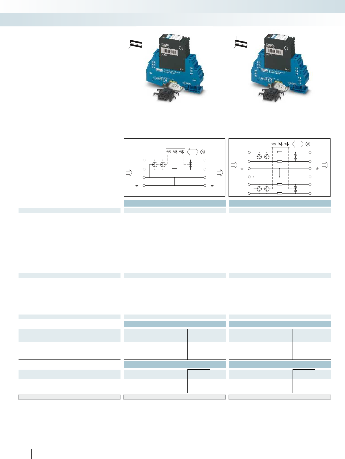
78
11 12
910
34
12
56
34
910
78
11 12
Total width 17.7 mm Total width 17.7 mm
Technical data Technical data
Electrical data ... 24DC ... 24DC
IEC test classification/EN type C1/C2/C3/D1 C1/C2/C3/D1
Maximum continuous operating voltage UC30 V DC/21 V AC 30 V DC/21 V AC
Impulse discharge curr. Iimp (10/350)μs Per path 2 kA 2 kA
Nominal current IN350 mA 350 mA
Nominal discharge current In (8/20) µs
Core-core/core-ground 10 kA/10 kA 10 kA/10 kA
Total surge current (8/20)µs 20 kA 20 kA
Voltage protection level UP
Core-core ≤ 50 V (C3 - 25 A) ≤ 50 V (C3 - 25 A)
Core-ground ≤ 1.3 kV (C3 - 100 A) ≤ 1.3 kV (C3 - 100 A)
Cut-off frequency fg (3 dB)
Symmetrical in the 150 Ω system typ. 1.1 MHz typ. 1.1 MHz
Resistance per path 1.2 Ω1.2 Ω
General data
Dimensions W/H/D 17.7 mm/91.1 mm/77.5 mm 17.7 mm/91.1 mm/77.5 mm
Connection data solid/stranded with ferrule/AWG 0.2 ... 4 mm²/0.2 ... 2.5 mm²/24 - 12 0.2 ... 4 mm²/0.2 ... 2.5 mm²/24 - 12
Temperature range -40°C ... 70°C -40°C ... 70°C
Degree of protection in acc. with IEC 60529/EN 60529 IP20 IP20
Inflammability class in acc. with UL 94 V0 V0
Test standards EN 61643-21/A1/IEC 61643-21/A1/EN 61000-6-2/ EN 61643-21/A1/IEC 61643-21/A1/EN 61000-6-2/
EN 61000-6-2/A1/EN 61000-6-3 EN 61000-6-2/A1/EN 61000-6-3
Remote indication contact Via TBUS Via TBUS
Ordering data Ordering data
Description Voltage UNType Order No. Pcs. /
Pkt. Type Order No. Pcs. /
Pkt.
MCR-PLUGTRAB, consisting of a plug, base element,
and DIN rail bus, with screw connection technology
24 V DC PT-IQ-1X2-EX-24DC-UT 2801512 1PT-IQ-2X2-EX-24DC-UT 2801513 1
Accessories Accessories
Replacement plug
24 V DC PT-IQ-1X2-EX-24DC-P 2801514 1PT-IQ-2X2-EX-24DC-P 2801515 1
Separating plate
for DIN rail NS35/7.5 PT-IQ-EX-L-PP 2905023 1PT-IQ-EX-L-PP 2905023 1
for DIN rail NS35/15 PT-IQ-EX-H-PP 2905024 1PT-IQ-EX-H-PP 2905024 1
Marking material ZB 6, see Catalog 6, page 111 ZB 6, see Catalog 6, page 111
312 PHOENIX CONTACT
– Tailored to the special requirements
of intrinsically safe circuits
– Surge protection system
– Multi-level state monitoring
– Collective message about supply and
remote module
– Multi-level, floating remote signaling
– System supplied via DIN rail bus
– Up to 10 protection modules per supply
module
– Maximum ease of maintenance, thanks to
the two-piece design
–Plugs are coded
– Impedance-neutral disconnection of plug
for maintenance purposes
– Base element remains an integral part of
the installation
H
W
D
H
W
D
PLUGTRAB PT-IQ EX
With screw connection
Surge protection and power supplies
Surge protection and interference filters
Double conductor (loop), floating,
9/10 connection grounded directly
2 double conductors (loops), floating,
9/10 connection grounded directly
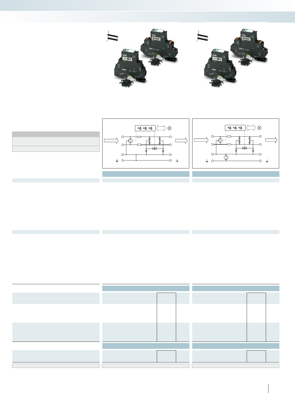
7
11
9
3
8
12
10
4
protectedunprotected
7
11
9
3
8
12
10
4
protectedunprotected
For additional information, visit phoenixcontact.net/products
Total width 17.7 mm Total width 17.7 mm
Technical data Technical data
Electrical data ... 5DC ... 12DC ... 5DC ... 12DC
IEC test classification/EN type C1/C2/C3/D1 C1/C2/C3/D1 C1/C2/C3/D1 C1/C2/C3/D1
Maximum continuous operating voltage UC6 V DC/4 V AC 15 V DC/10 V AC 6 V DC/4 V AC 15 V DC/10 V AC
Impulse discharge curr. Iimp (10/350)μs Per path 2.5 kA 2.5 kA 2.5 kA 2.5 kA
Nominal current IN600 mA (up to 40°C) 600 mA (up to 40°C) 600 mA (up to 40°C) 600 mA (up to 40°C)
Nominal discharge current In (8/20) µs
Core-core/core-ground 10 kA/10 kA 10 kA/10 kA 10 kA/10 kA 10 kA/10 kA
Total surge current (8/20)µs 20 kA 20 kA 20 kA 20 kA
Voltage protection level UP
Core-core ≤ 30 V (C3 - 25 A) ≤ 40 V (C3 - 25 A) ≤ 30 V (C3 - 25 A) ≤ 40 V (C3 - 25 A)
Core-ground ≤ 30 V (C3 - 25 A) ≤ 40 V (C3 - 25 A) ≤ 900 V (C3 - 25 A) ≤ 900 V (C3 - 25 A)
Cut-off frequency fg (3 dB)
Symmetrical in the 150 Ω system > 60 MHz > 60 MHz > 60 MHz > 60 MHz
General data
PT-IQ...PT dimensions W/H/D 17.7 mm/109.3 mm/77.5 mm 17.7 mm/109.3 mm/77.5 mm
PT-IQ...UT dimensions W/H/D 17.7 mm/91.1 mm/77.5 mm 17.7 mm/91.1 mm/77.5 mm
Connection data, push-in solid/stranded with ferrule/AWG 0.2 ... 4 mm²/0.2 ... 2.5 mm²/24 - 12 0.2 ... 4 mm²/0.2 ... 2.5 mm²/24 - 12
Connection data solid/stranded with ferrule/AWG 0.2 ... 4 mm²/0.2 ... 2.5 mm²/24 - 12 0.2 ... 4 mm²/0.2 ... 2.5 mm²/24 - 12
Temperature range -40°C ... 70°C -40°C ... 70°C
Degree of protection in acc. with IEC 60529/EN 60529 IP20 IP20
Inflammability class in acc. with UL 94 V0 V0
Connection method Screw connection/push-in connection Screw connection/push-in connection
Test standards EN 61643-21/A1/IEC 61643-21/A2/EN 61000-6-2/A1/ EN 61643-21/A1/IEC 61643-21/A2/EN 61000-6-2/A1/
EN 61000-6-3 EN 61000-6-3
Ordering data Ordering data
Description Voltage UNType Order No. Pcs. /
Pkt. Type Order No. Pcs. /
Pkt.
MCR-PLUGTRAB, consisting of a plug, base element,
and DIN rail bus, with screw connection technology
5 V DC PT-IQ-3-PB-UT 2800785 1PT-IQ-3-PB+F-UT 2800994 1
12 V DC PT-IQ-3-HF-12DC-UT 2800786 1PT-IQ-3-HF+F-12DC-UT 2800995 1
MCR-PLUGTRAB, consisting of a plug, base element,
and DIN rail bus, with push-in connection technology
5 V DC PT-IQ-3-PB-PT 2801286 1PT-IQ-3-PB+F-PT 2801287 1
12 V DC PT-IQ-3-HF-12DC-PT 2801288 1PT-IQ-3-HF+F-12DC-PT 2801289 1
Accessories Accessories
Replacement plug
5 V DC PT-IQ-3-PB-P 2800783 1PT-IQ-3-PB-P 2800783 1
12 V DC PT-IQ-3-HF-12DC-P 2800784 1PT-IQ-3-HF-12DC-P 2800784 1
Marking material ZB 6, see Catalog 6, page 111 ZB 6, see Catalog 6, page 111
313PHOENIX CONTACT
– Surge protection system
– Multi-level state monitoring
– Collective message about supply and
remote module
– Multi-level, floating remote signaling
– System supplied via DIN rail bus
– Up to 28 protection modules per supply
module
– Maximum ease of maintenance thanks to
the two-piece design
–Plugs are coded
– Impedance-neutral disconnection of plug
for maintenance purposes
– Base element remains an integral part of
the installation
Notes:
For approvals and dimensional drawing, visit
phoenixcontact.net/products
Attenuation characteristics at phoenixcontact.net/products
H
W
D
H
W
D
PLUGTRAB PT-IQ
Surge protection and power supplies
Surge protection and interference filters
3-wire with common reference potential,
9/10 connection grounded directly
3-wire with common reference potential,
9/10 connection grounded
via gas-filled surge
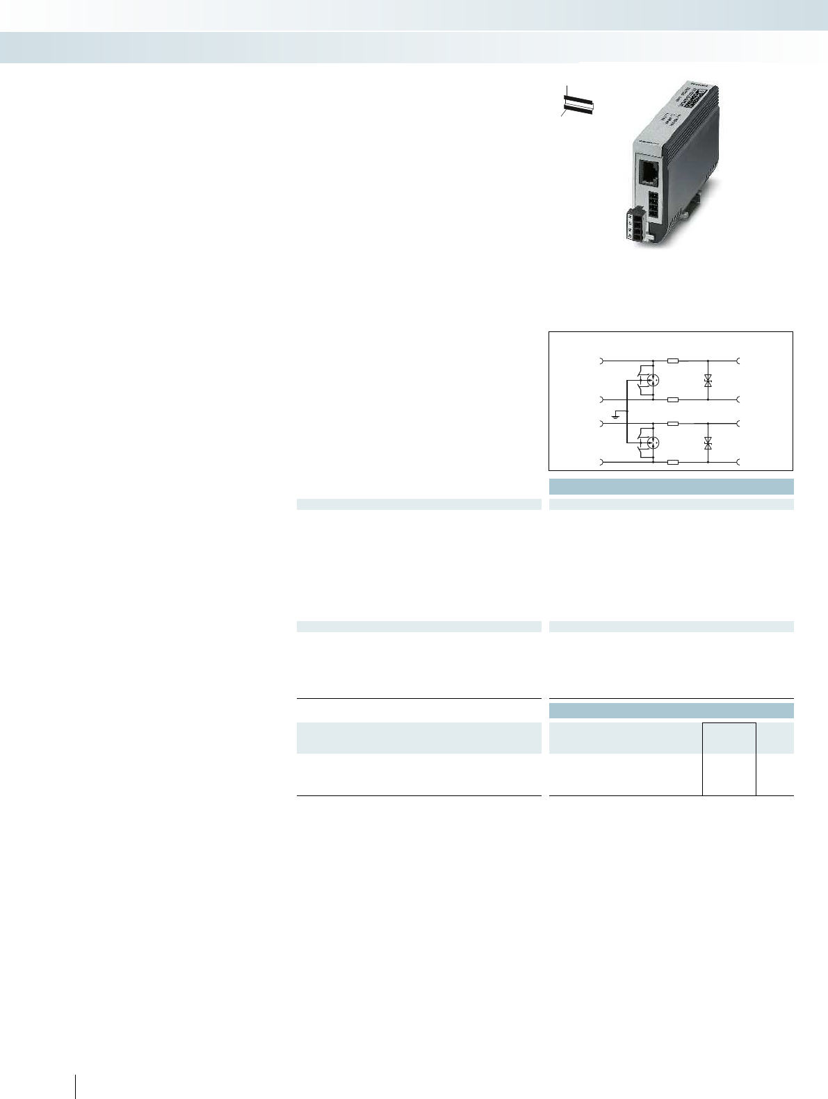
unprotected
2
3
5
4
RJ 12
1
2
4
3
RJ 11
3
4
6
5
RJ 45
Ba
Aa
Bb
Ab
Plug
protected
1
2
4
3
RJ 11
2
3
5
4
RJ 12
3
4
6
5
RJ 45
Ba
Aa
Bb
Ab
Plug
Total width 25 mm
Technical data
Electrical data
IEC test classification/EN type B2/C1/C2/C3/D1
Maximum continuous operating voltage UC185 V DC
Nominal current IN≤ 380 mA (25°C)
Nominal discharge current In (8/20) µs
Core-core/core-ground ≤ 5 kA/≤ 5 kA
Total surge current (8/20)µs 10 kA
Voltage protection level UP
Core-core/core-ground ≤ 250 V (C1 - 500 A)/≤ 580 V (C1 - 500 A)
Cut-off frequency fg (3 dB)
In a 100 Ω system Core-core 25 MHz
General data
Dimensions W/H/D 25 mm/103 mm/63 mm
Connection data solid / stranded / AWG 0.14 ... 1.5 mm²/0.14 ... 1.5 mm²/28 - 16
Temperature range -40°C ... 85°C
Degree of protection in acc. with IEC 60529/EN 60529 IP20
Connection method RJ45/Combicon
Test standards IEC 61643-21
Ordering data
Description Type Order No. Pcs. /
Pkt.
DATATRAB adapter, protective adapter with RJ45 and screw
connection for two SHDSL telecommunications interfaces
DT-TELE-SHDSL 2801593 1
314 PHOENIX CONTACT
H
W
D
–Protection for two SHDSL ports
– Connection: RJ45 (RJ12/RJ11) and plug-in
screw terminal block (COMBICON)
– Alternatively, can be snapped onto a
DIN rail
–Protective circuit:
Course/fine protection combination
between all cables of signal wire pairs, as
well as common mode voltage coarse
protection between all signal wires and
ground
– Separate ground connection line
– The adapter included enables conversion
from RJ45 to RJ11 and RJ12
(for contacting, see circuit diagram)
Surge protection for SHDSL
telecommunications interfaces
Surge protection and power supplies
Surge protection and interference filters
Attachment plug for two SHDSL interfaces
(ports)
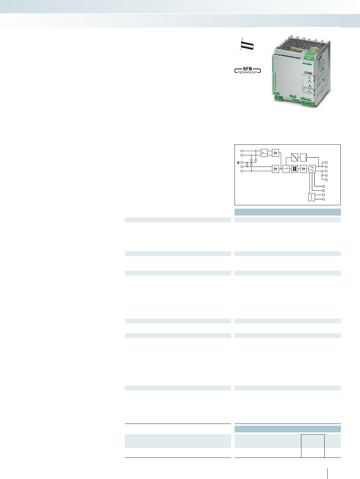
DCOK
IN
I<IN
13 DC OK
14 DC OK
+
+
-
-
-
L2
L1
+
-
For additional information, visit phoenixcontact.net/products
Technical data
Input data of AC
Nominal input voltage range 2x 400 V AC ... 500 V AC
Input voltage range AC 2x 360 V AC ... 575 V AC
Frequency range 45 Hz ... 65 Hz
Current consumption (nominal load) 2.5 A (400 V AC)/2.1 A (500 V AC)
Inrush current limitation at 25°C (typ.) / I2t< 85 A/< 1.5 A
2s
Mains buffering (IN, typ.) > 20 ms (400 V AC)
Input data of DC
Nominal input voltage range 600 V DC
Input voltage range DC 450 V DC ... 840 V DC
Max. current consumption approx. 0.9 A (600 V DC)
Output data
Nominal output voltage 24 V DC ±1%
Setting range of the output voltage 18 V DC ... 29.5 V DC (UIN ≥ 360 V AC/480 V DC)
18 V DC ... 26 V DC (< 480 V DC)
Output current/POWER BOOST/SFB (20 ms) 20 A/26 A/120 A
Magnetic fuse tripping -
Can be connected in parallel/series Yes/Yes
Max. power dissipation (no load/nominal load) 11 W/51 W
Efficiency (typ.) > 92% (600 V DC)
Residual ripple < 50 mVPP
Signaling
Signaling DC OK LED, relay contact
Boost signaling LED, active switching output
General data
Weight/dimensions W x H x D 2 kg/120 x 130 x 125 mm
Spacing when mounting Alignable: 5 mm horizontally, 15 mm next to active components,
50 mm vertically
Connection method Screw connection
Input connection data (solid/stranded/AWG) 0.2 - 6 mm²/0.2 - 4 mm²/24 - 10
Output connection data (solid/stranded/AWG) 0.2 - 6 mm²/0.2 - 4 mm²/12 - 10
Signal connection data (solid/stranded/AWG) 0.2 - 6 mm²/0.2 - 4 mm²/24 - 10
Degree of protection/protection class IP20/I
MTBF (EN 29500, 40°C) > 500000 h
Ambient temperature (operation) -25°C ... 70°C (> 60°C derating)
Standards/regulations
Insulation voltage input/output 2 kV AC (routine test)/1.5 kV AC (type test)
Electromagnetic compatibility Conformance with EMC Directive 2004/108/EC
Electrical safety EN 60950-1/VDE 0805 (SELV)
Electronic equipm. for electrical power installations EN 50178/VDE 0160 (PELV)
Safe isolation DIN VDE 0100-410
UL approvals UL applied for
Ordering data
Description Type Order No. Pcs. /
Pkt.
DC-DC converter, primary switched mode
QUINT-PS/2AC/1DC/24DC/20 2320830 1
315PHOENIX CONTACT
H
W
D
– AC and DC input in a single device
– Specially designed for connection to two
outer conductors of a three-phase system
and to a DC intermediate circuit voltage
of an inverter; typical applications include
injection molding machines.
– Starts up with two-phase AC voltage or
DC voltage. In the event of a mains failure
connected 24V loads continue to be
supplied using the kinetic energy of the
motor. In this way, the motor acts as a
generator and supplies energy to the
intermediate circuits as long as it is
moving.
– Fast tripping of standard circuit breakers
with dynamic power reserve SFB
(selective fuse breaking) technology with
up to 6 times the nominal current for
20 ms
– Reliably start difficult loads with the static
POWERBOOST power reserve
– Preventive function monitoring warns
against critical operating states before
errors occur.
QUINT POWER power supplies - with
maximum functionality
Surge protection and power supplies
Power supplies and UPS
Power supply with two separate input circuits
for frequency inverters
2 AC, 1 DC/24 V DC, 20 A
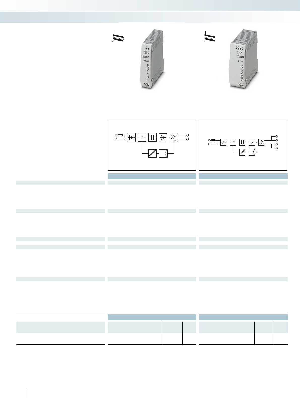
+
-
L
N
N
L
+
+
–
–
Technical data Technical data
Input data
Nominal input voltage range 100 V AC ... 240 V AC 100 V AC ... 240 V AC 100 V AC ... 240 V AC 100 V AC ... 240 V AC 100 V AC ... 240
Input voltage range AC/DC 85 V AC ... 264 V AC 85 V AC ... 264 V AC
Frequency range 45 Hz ... 65 Hz 45 Hz ... 65 Hz
Current consumption (nominal load) 0.5 A (120 V AC)/0.3 A (230 V AC) 0.7 A (120 V AC)/0.5 A (230 V AC) 1.7 A (120 V AC)/1 A (230 V
Inrush current limitation at 25°C (typ.) / I2t < 30 A/< 0.5 A2s < 30 A/< 0.5 A2s
Mains buffering (IN, typ.) > 35 ms (120 V AC)/> 135 ms (230 V AC) > 30 ms (120 V AC)/> 120 ms (230 V AC) > 20 ms (120 V AC)/> 85 ms (230 V AC) > 20 ms
Output data
Nominal output voltage 5 V DC ±1% 5 V DC ±1%
Output current 5 A 8 A
Can be connected in parallel/series Yes, with redundancy module/Yes Yes, with redundancy module/Yes Yes, with redundancy module/Ye
Max. power dissipation (no load/nominal load) < 0.3 W/< 4.5 W < 0.3 W/< 7.5 W
Efficiency (typ.) > 84% > 85% (for 230 V AC and nominal values) >
Residual ripple < 40 mVPP < 100 mVPP
Signaling
Signaling DC OK LED LED
General data
Weight/dimensions W x H x D 0.15 kg/22.5 x 90 x 84 mm 0.21 kg/35 x 90 x 84 mm 0.34 kg/55 x 90 x 84 mm 0.15 kg/22.5 x 90 x 84 mm 0.21
Spacing when mounting Alignable: 0 mm horizontally, 30 mm vertically Alignable: 0 mm horizontally, 30 mm vertically Alignable: 0 m
Connection method Screw connection Screw connection
Connection data solid / stranded / AWG 0.2 - 2.5 mm²/0.2 - 2.5 mm²/24 - 14 0.2 - 2.5 mm²/0.2 - 2.5 mm²/24 - 14 0.2 - 2.5 mm²/0.2 -
Degree of protection / Protection class IP20/II IP20/II
MTBF (EN 29500, 40°C) > 500000 h > 500000 h
Ambient temperature (operation) -25°C ... 70°C (> 55° C derating) -25°C ... 70°C (> 55° C derating) -25°C ... 70°C (> 55° C derati
Standards/regulations
Insulation voltage input/output 3 kV AC (routine test)/4 kV AC (type test) 3 kV AC (routine test)/4 kV AC (type test) 3 kV AC (rou
Electromagnetic compatibility Conformance with EMC Directive 2004/108/EC Conformance with EMC Directive 2004/108/EC Conformance wi
Electrical safety IEC 60950-1/VDE 0805 (SELV) IEC 60950-1/VDE 0805 (SELV) IEC 60950-1/VDE 0805 (SELV) IEC 60950-1/VDE 0805 (SELV) IE
Electronic equipm. for electrical power installations EN 50178/VDE 0160 (PELV) EN 50178/VDE 0160 (PELV) EN 50178/VDE 0160 (PELV) EN
Safe isolation DIN VDE 0100-410 DIN VDE 0100-410
UL approvals UL/C-UL listed UL 508, UL/C-UL Recognized UL 60950 UL/C-UL listed UL 508, UL/C-UL Recognized UL 60950 UL/C-UL listed
Limitation of harmonic line currents EN 61000-3-2 EN 61000-3-2
Ordering data Ordering data
Description Type Order No. Pcs. /
Pkt. Type Order No. Pcs. /
Pkt.
Power supply, primary-switched, 1-phase
UNO-PS/1AC/ 5DC/ 25W 2904374 1UNO-PS/1AC/ 5DC/ 40W 2904375 1
316 PHOENIX CONTACT
– Save energy, thanks to particularly low
idling losses and a high degree of
efficiency
– Save space in the control cabinet through
compact housing with high power density
– Robust and reliable at temperatures from
-25 to 70°C
UNO POWER power supplies - with
basic functionality
Surge protection and power supplies
Power supplies and UPS
Power supply,
1 AC, 5 DC, 25 W
Power supply,
1 AC, 5 DC, 40 W
H
W
D
H
W
D
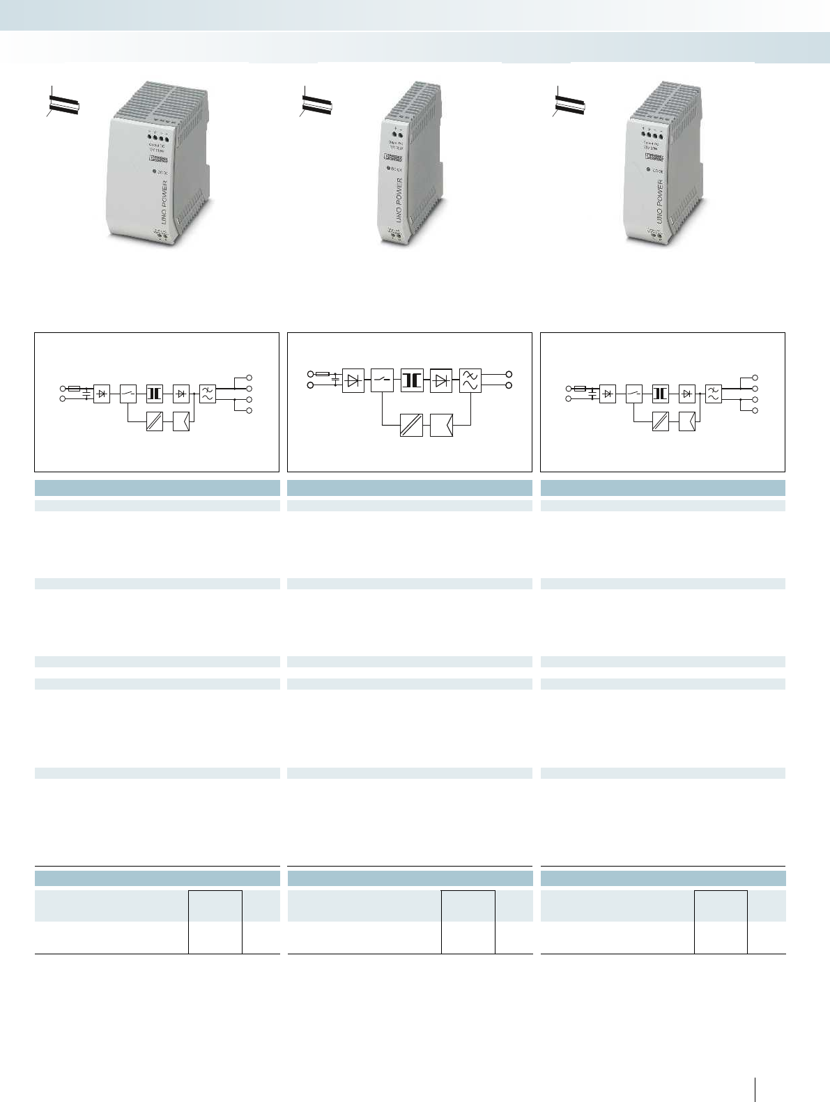
N
L
+
+
–
–
+
-
L
N
N
L
+
+
–
–
For additional information, visit phoenixcontact.net/products
Technical data Technical data Technical data
Nominal input voltage range 100 V AC ... 240 V AC 100 V AC ... 240 V AC 100 V AC ... 240 V AC 100 V AC ... 240 V AC 100 V AC ... 240 V AC
85 V AC ... 264 V AC 85 V AC ... 264 V AC 85 V AC ... 264 V AC
45 Hz ... 65 Hz 45 Hz ... 65 Hz 45 Hz ... 65 Hz
Current consumption (nominal load) 0.5 A (120 V AC)/0.3 A (230 V AC) 0.7 A (120 V AC)/0.5 A (230 V AC) 1.7 A (120 V AC)/1 A (230 V AC) 0.6 A (120 V AC)/0.4 A (230 V AC) 1 A (120 V AC)/0.6 A (230 V AC)
< 30 A/< 1.5 A2s < 30 A/< 0.3 A2s< 25 A/< 0.5 A
2s
, typ.) > 35 ms (120 V AC)/> 135 ms (230 V AC) > 30 ms (120 V AC)/> 120 ms (230 V AC) > 20 ms (120 V AC)/> 85 ms (230 V AC) > 20 ms (120 V AC)/> 115 ms (230 V AC) > 25 ms (120 V AC)/> 90 ms (230 V AC)
12 V DC ±1% 15 V DC ±1% 15 V DC ±1%
8.3 A 2 A 3.7 A
Can be connected in parallel/series Yes, with redundancy module/Yes Yes, with redundancy module/Yes Yes, with redundancy module/Yes Yes, with redundancy module/Yes Yes, with redundancy module/Yes
< 0.4 W/< 12 W < 0.3 W/< 4.6 W < 0.3 W/< 7 W
Efficiency (typ.) > 84% > 85% (for 230 V AC and nominal values) > 89.5% > 87% (for 230 V AC and nominal values) > 88.5% (for 230 V AC and nominal values)
< 75 mVPP < 40 mVPP < 50 mVPP
LED LED LED
Weight/dimensions W x H x D 0.15 kg/22.5 x 90 x 84 mm 0.21 kg/35 x 90 x 84 mm 0.34 kg/55 x 90 x 84 mm 0.15 kg/22.5 x 90 x 84 mm 0.21 kg/35 x 90 x 84 mm
Spacing when mounting Alignable: 0 mm horizontally, 30 mm vertically Alignable: 0 mm horizontally, 30 mm vertically Alignable: 0 mm horizontally, 30 mm vertically Alignable: 0 mm horizontally, 30 mm vertically Alignable: 0 mm horizontally, 30 mm vertically
Screw connection Screw connection Screw connection
mm²/24 - 14 0.2 - 2.5 mm²/0.2 - 2.5 mm²/24 - 14 0.2 - 2.5 mm²/0.2 - 2.5 mm²/24 - 14 0.2 - 2.5 mm²/0.2 - 2.5 mm²/24 - 14 0.2 - 2.5 mm²/0.2 - 2.5 mm²/24 - 14
IP20/II IP20/II IP20/II
> 500000 h > 500000 h > 500000 h
ng) -25°C ... 70°C (> 55° C derating) -25°C ... 70°C (> 55° C derating) -25°C ... 70°C (> 55° C derating) -25°C ... 70°C (> 55° C derating)
e test) 3 kV AC (routine test)/4 kV AC (type test) 3 kV AC (routine test)/4 kV AC (type test) 3 kV AC (routine test)/4 kV AC (type test) 3 kV AC (routine test)/4 kV AC (type test)
Electromagnetic compatibility Conformance with EMC Directive 2004/108/EC Conformance with EMC Directive 2004/108/EC Conformance with EMC Directive 2004/108/EC Conformance with EMC Directive 2004/108/EC Conformance with EMC Directive 2004/108/EC
Electrical safety IEC 60950-1/VDE 0805 (SELV) IEC 60950-1/VDE 0805 (SELV) IEC 60950-1/VDE 0805 (SELV) IEC 60950-1/VDE 0805 (SELV) IEC 60950-1/VDE 0805 (SELV)
Electronic equipm. for electrical power installations EN 50178/VDE 0160 (PELV) EN 50178/VDE 0160 (PELV) EN 50178/VDE 0160 (PELV) EN 50178/VDE 0160 (PELV) EN 50178/VDE 0160 (PELV)
DIN VDE 0100-410 DIN VDE 0100-410 DIN VDE 0100-410
C-UL listed UL 508, UL/C-UL Recognized UL 60950 UL/C-UL listed UL 508, UL/C-UL Recognized UL 60950 UL/C-UL listed UL 508, UL/C-UL Recognized UL 60950 UL/C-UL listed UL 508, UL/C-UL Recognized UL 60950
EN 61000-3-2 EN 61000-3-2 EN 61000-3-2
Ordering data Ordering data Ordering data
Type Order No. Pcs. /
Pkt. Type Order No. Pcs. /
Pkt. Type Order No. Pcs. /
Pkt.
UNO-PS/1AC/12DC/100W 2902997 1UNO-PS/1AC/15DC/30W 2903000 1UNO-PS/1AC/15DC/ 55W 2903001 1
317PHOENIX CONTACT
Surge protection and power supplies
Power supplies and UPS
H
W
D
Power supply,
1 AC, 12 DC, 100 W
Power supply,
1 AC, 15 DC, 30 W
Power supply,
1 AC, 15 DC, 55 W
H
W
D
H
W
D
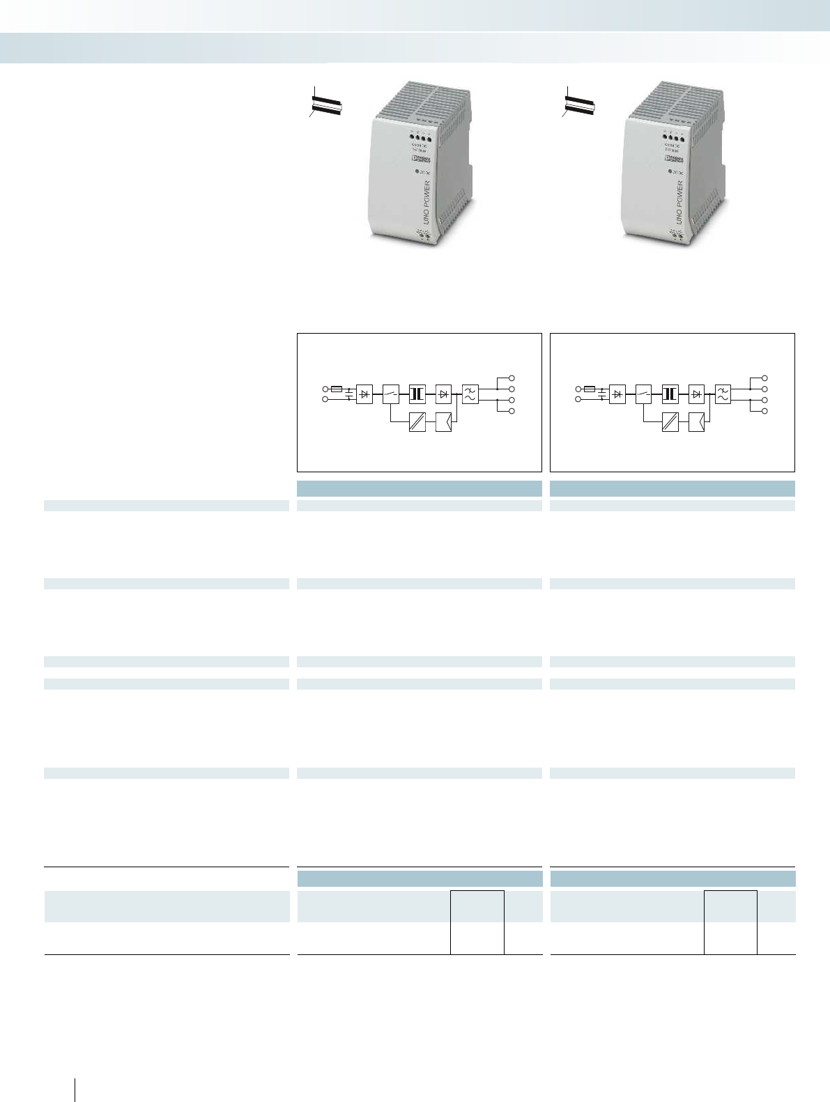
N
L
+
+
–
–
N
L
+
+
–
–
Technical data Technical data
Input data
Nominal input voltage range 100 V AC ... 240 V AC 100 V AC ... 240 V AC 100 V AC ... 240 V AC 100 V AC ... 240 V AC 2x 400 V AC ...
Input voltage range AC/DC 85 V AC ... 264 V AC 85 V AC ... 264 V AC
Frequency range 45 Hz ... 65 Hz 45 Hz ... 65 Hz
Current consumption (nominal load) 1.7 A (120 V AC)/1 A (230 V AC) 1.5 A (120 V AC)/1 A (230 V AC) 1 A (120 V AC)/0.6 A (230 V AC)
Inrush current limitation at 25°C (typ.) / I2t < 30 A/< 1.5 A2s < 40 A/< 1.5 A2s
Mains buffering (IN, typ.) > 20 ms (120 V AC)/> 85 ms (230 V AC) > 25 ms (120 V AC)/> 100 ms (230 V AC) > 20 ms (120 V AC)/> 90 ms (230 V AC) > 25 ms
Output data
Nominal output voltage 15 V DC ±1% 24 V DC ±1%
Output current 6.67 A 3.75 A
Can be connected in parallel/series Yes, with redundancy module/Yes Yes, with redundancy module/Yes Yes, with redundancy module/Ye
Max. power dissipation (no load/nominal load) < 0.4 W/< 12 W < 0.5 W/< 12 W
Efficiency (typ.) > 89% (for 230 V AC and nominal values) > 88.5% (for 230 V AC and nominal values) > 90% (for 230 V AC and nomina
Residual ripple < 75 mVPP < 45 mVPP
Signaling
Signaling DC OK LED LED
General data
Weight/dimensions W x H x D 0.34 kg/55 x 90 x 84 mm 0.34 kg/55 x 90 x 84 mm 0.21 kg/35 x 90 x 84 mm 0.34 kg/55 x 90 x 84 mm 0.32 kg/
Spacing when mounting Alignable: 0 mm horizontally, 30 mm vertically Alignable: 0 mm horizontally, 30 mm vertically Alignable: 0 m
Connection method Screw connection Screw connection
Connection data solid / stranded / AWG 0.2 - 2.5 mm²/0.2 - 2.5 mm²/24 - 12 0.2 - 2.5 mm²/0.2 - 2.5 mm²/24 - 14 0.2 - 2.5 mm²/0.2 -
Degree of protection / Protection class IP20/II IP20/II
MTBF (EN 29500, 40°C) > 500000 h > 500000 h
Ambient temperature (operation) -25°C ... 70°C (> 55° C derating) -25°C ... 70°C (> 55° C derating) -25°C ... 70°C (> 55° C derati
Standards/regulations
Insulation voltage input/output 3 kV AC (routine test)/4 kV AC (type test) 3 kV AC (routine test)/4 kV AC (type test) 3 kV AC (rou
Electromagnetic compatibility Conformance with EMC Directive 2004/108/EC Conformance with EMC Directive 2004/108/EC Conformance wi
Electrical safety IEC 60950-1/VDE 0805 (SELV) IEC 60950-1/VDE 0805 (SELV) IEC 60950-1/VDE 0805 (SELV) IEC 60950-1/VDE 0805 (SELV) IE
Electronic equipm. for electrical power installations EN 50178/VDE 0160 (PELV) EN 50178/VDE 0160 (PELV) EN 50178/VDE 0160 (PELV) EN
Safe isolation DIN VDE 0100-410 DIN VDE 0100-410
UL approvals UL/C-UL listed UL 508, UL/C-UL Recognized UL 60950 UL/C-UL listed UL 508, UL/C-UL Recognized UL 60950,
NEC Class 2 as per UL 1310
Limitation of harmonic line currents EN 61000-3-2 EN 61000-3-2
Ordering data Ordering data
Description Type Order No. Pcs. /
Pkt. Type Order No. Pcs. /
Pkt.
Power supply, primary-switched, 1-phase
UNO-PS/1AC/15DC/100W 2903002 1UNO-PS/1AC/24DC/ 90W/C2LPS 2902994 1
318 PHOENIX CONTACT
– Save energy, thanks to particularly low
idling losses and a high degree of
efficiency
– Save space in the control cabinet through
compact housing with high power density
– Robust and reliable at temperatures from
-25 to 70°C
UNO POWER power supplies - with
basic functionality
Surge protection and power supplies
Power supplies and UPS
Power supply,
1 AC, 15 DC, 100 W
Power supply,
1 AC, 24 DC, 90 W
NEC Class 2
H
W
D
H
W
D
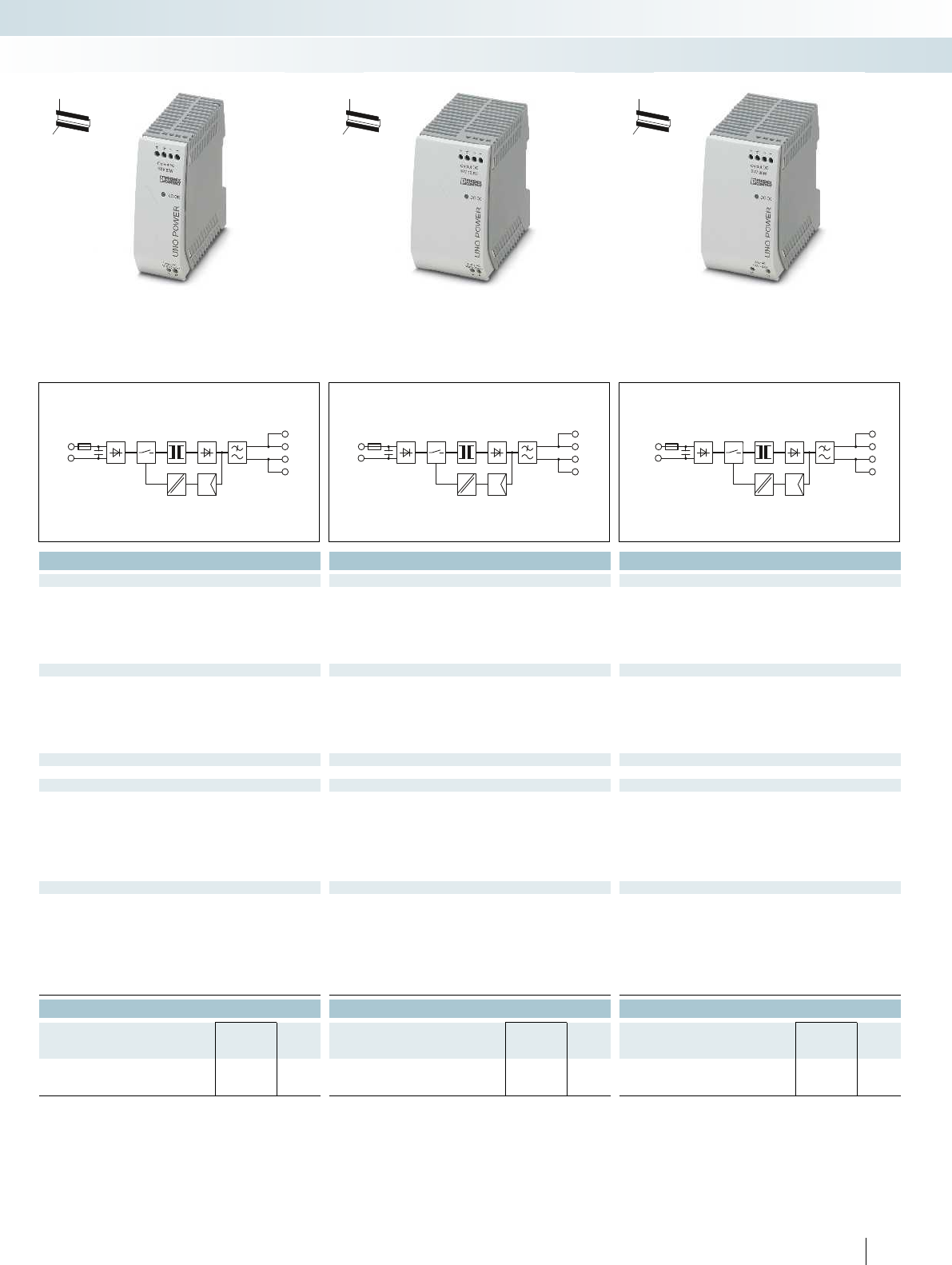
N
L
+
+
–
–
N
L
+
+
–
–
L2/N
L1/L
+
+
–
–
For additional information, visit phoenixcontact.net/products
Technical data Technical data Technical data
Nominal input voltage range 100 V AC ... 240 V AC 100 V AC ... 240 V AC 100 V AC ... 240 V AC 100 V AC ... 240 V AC 2x 400 V AC ... 500 V AC
85 V AC ... 264 V AC 85 V AC ... 264 V AC 264 V AC ... 575 V AC
45 Hz ... 65 Hz 45 Hz ... 65 Hz 45 Hz ... 65 Hz
Current consumption (nominal load) 1.7 A (120 V AC)/1 A (230 V AC) 1.5 A (120 V AC)/1 A (230 V AC) 1 A (120 V AC)/0.6 A (230 V AC) 1.7 A (120 V AC)/1 A (230 V AC) 0.6 A (400 V AC)/0.5 A (500 V AC)
< 30 A/< 0.5 A2s < 40 A/< 1.4 A2s< 30 A/< 0.5 A
2s
, typ.) > 20 ms (120 V AC)/> 85 ms (230 V AC) > 25 ms (120 V AC)/> 100 ms (230 V AC) > 20 ms (120 V AC)/> 90 ms (230 V AC) > 25 ms (120 V AC)/> 90 ms (230 V AC) > 65 ms (400 V AC)/> 100 ms (500 V AC)
48 V DC ±1% 48 V DC ±1% 24 V DC ±1%
1.25 A 2.08 A 3.75 A/3.38 A
Can be connected in parallel/series Yes, with redundancy module/Yes Yes, with redundancy module/Yes Yes, with redundancy module/Yes Yes, with redundancy module/Yes Yes, with redundancy module/Yes
< 0.4 W/< 7 W < 0.4 W/< 11 W < 0.7 W/< 12 W
(for 230 V AC and nominal values) > 90% (for 230 V AC and nominal values) > 90% (for 230 V AC and nominal values) > 89.5%
< 35 mVPP < 40 mVPP < 50 mVPP
LED LED LED
Weight/dimensions W x H x D 0.34 kg/55 x 90 x 84 mm 0.34 kg/55 x 90 x 84 mm 0.21 kg/35 x 90 x 84 mm 0.34 kg/55 x 90 x 84 mm 0.32 kg/55 x 90 x 84 mm
Spacing when mounting Alignable: 0 mm horizontally, 30 mm vertically Alignable: 0 mm horizontally, 30 mm vertically Alignable: 0 mm horizontally, 30 mm vertically Alignable: 0 mm horizontally, 30 mm vertically Alignable: 0 mm horizontally, 30 mm vertically
Screw connection Screw connection Screw connection
mm²/24 - 12 0.2 - 2.5 mm²/0.2 - 2.5 mm²/24 - 14 0.2 - 2.5 mm²/0.2 - 2.5 mm²/24 - 14 0.2 - 2.5 mm²/0.2 - 2.5 mm²/24 - 14 0.2 - 2.5 mm²/0.2 - 2.5 mm²/24 - 14
IP20/II IP20/II IP20/II
> 500000 h > 500000 h > 500000 h
ng) -25°C ... 70°C (> 55° C derating) -25°C ... 70°C (> 55° C derating) -25°C ... 70°C (> 55° C derating) -25°C ... 70°C (> 55° C derating)
e test) 3 kV AC (routine test)/4 kV AC (type test) 3 kV AC (routine test)/4 kV AC (type test) 3 kV AC (routine test)/4 kV AC (type test) 3 kV AC (routine test)/4 kV AC (type test)
Electromagnetic compatibility Conformance with EMC Directive 2004/108/EC Conformance with EMC Directive 2004/108/EC Conformance with EMC Directive 2004/108/EC Conformance with EMC Directive 2004/108/EC Conformance with EMC Directive 2004/108/EC
Electrical safety IEC 60950-1/VDE 0805 (SELV) IEC 60950-1/VDE 0805 (SELV) IEC 60950-1/VDE 0805 (SELV) IEC 60950-1/VDE 0805 (SELV) IEC 60950-1/VDE 0805 (SELV)
Electronic equipm. for electrical power installations EN 50178/VDE 0160 (PELV) EN 50178/VDE 0160 (PELV) EN 50178/VDE 0160 (PELV) EN 50178/VDE 0160 (PELV) EN 50178/VDE 0160 (PELV)
DIN VDE 0100-410 DIN VDE 0100-410 DIN VDE 0100-410
UL/C-UL listed UL 508, UL/C-UL Recognized UL 60950 UL/C-UL listed UL 508, UL/C-UL Recognized UL 60950 UL/C-UL listed UL 508, UL/C-UL Recognized UL 60950,
NEC Class 2 as per UL 1310
EN 61000-3-2 EN 61000-3-2 EN 61000-3-2
Ordering data Ordering data Ordering data
Type Order No. Pcs. /
Pkt. Type Order No. Pcs. /
Pkt. Type Order No. Pcs. /
Pkt.
UNO-PS/1AC/48DC/ 60W 2902995 1UNO-PS/1AC/48DC/100W 2902996 1UNO-PS/2AC/24DC/90W/C2LPS 2904371 1
319PHOENIX CONTACT
Surge protection and power supplies
Power supplies and UPS
H
W
D
Power supply,
1 AC, 48 DC, 60 W
Power supply,
1 AC, 48 DC, 100 W
Power supply,
2 AC, 24 DC, 90 W
NEC Class 2
H
W
D
H
W
D
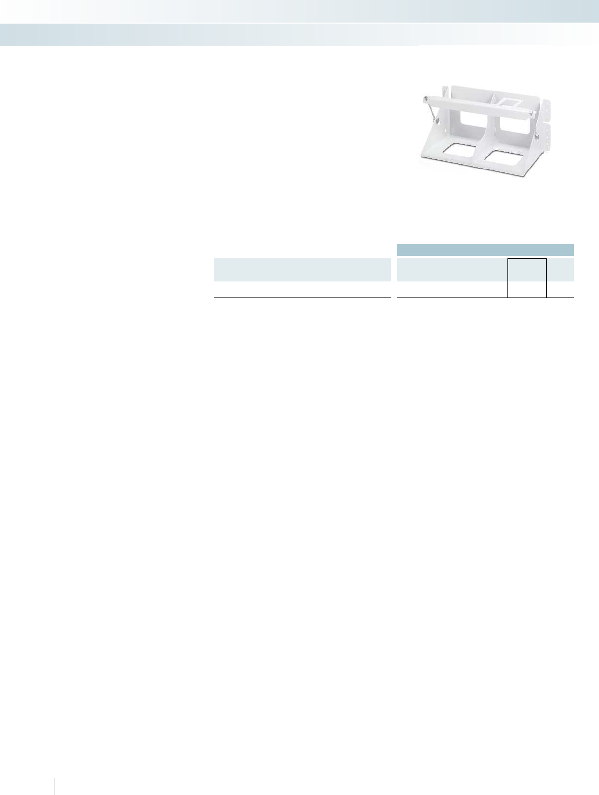
Ordering data
Description Type Order No. Pcs. /
Pkt.
Mounting set
BATTERY MOUNTING CASE 2320458 1
320 PHOENIX CONTACT
– Used for mounting power storage devices
that cannot be mounted on DIN rails
– Suitable for wall and surface mounting
Mounting set
Surge protection and power supplies
Power supplies and UPS
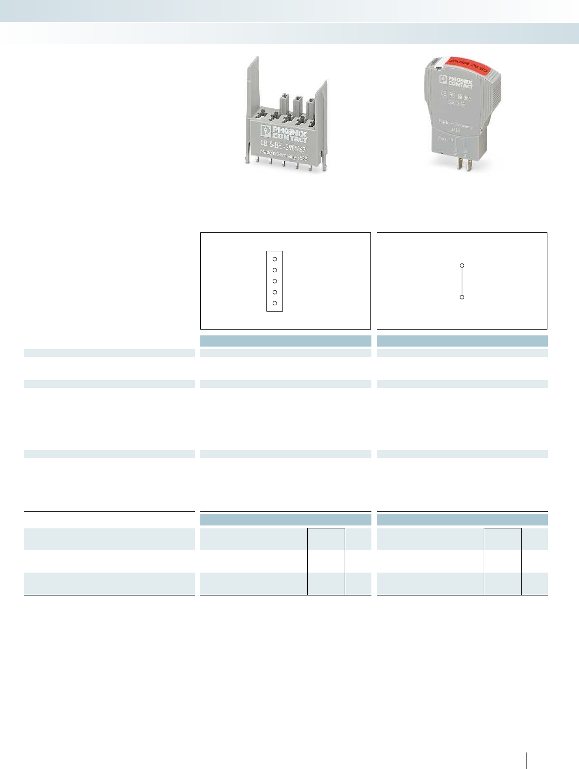
1
12 (b)
11 (a)
14 (c)
2
11 (a)
14 (c)
For additional information, visit phoenixcontact.net/products
Total width 12.3 mm Total width 12.3 mm
Technical data Technical data
Electrical data - bridge plug
Auxiliary contacts
Operating voltage Umax - 277 V AC/80 V DC
Operating current Imax -1 A
Electrical data - base element
Rated surge voltage 2.5 kV -
Rated insulation voltage Ui80 V DC -
Main circuit
Rated voltage 80 V DC/277 V AC -
Rated current In16 A -
Remote indication circuit
Rated voltage 80 V DC/277 V AC -
Rated current In1 A -
General data
Dimensions W/H/D 12.3 mm/34.8 mm/36.4 mm 12.3 mm/45 mm/52 mm
Ambient temperature (operation) -30°C ... 60°C -30°C ... 60°C
Degree of protection in acc. with IEC 60529/EN 60529 IP30 (plug-in area with plugged-in device)/IP00 (connection area) IP30 (actuation area)/IP00 (connection area)
Inflammability class in acc. with UL 94 V0 V0
Connection method Solder connection Spade connection
Test standards DINEN 50155/IEC 60068-2 IEC 60068-2
Ordering data Ordering data
Description Type Order No. Pcs. /
Pkt. Type Order No. Pcs. /
Pkt.
Soldering base element,
for accommodating device circuit breakers
CB S-BE 2905067 30
Bridge plug, for bridging contacts 11 to 14 for CB base elements
CB RC BRIDGE 2801616 1
321PHOENIX CONTACT
Base element
– For accommodating CB TM.../CB E....
device circuit breakers
–PCB module
–Codable
Bridge plug
– Signal contact bridging
– For equipping reserve spaces
Accessories for device
circuit breakers
Surge protection and power supplies
Protective devices
Base element for the PCB Plug for bridging contacts 11 to 14
Highly compact signal conditioners -
MINI Analog Pro
– 3-way signal conditioners
Page 326
Highly compact signal conditioners -
MINI Analog Pro
– Temperature transducers for
resistance thermometers and
thermocouples
Page 330
Signal conditioners with PL d and SIL
functional safety - MACX Safety
– Repeater power supplies, Ex i
Page 344
– Temperature transducers, Ex i
Page 346
Current and voltage measuring technology
– PACT RCP... current transformers
for retrofitting
Page 353
Programmable logic relay system -
PLC logic
– Logic modules
Page 356
– Accessories
Page 358
Relay modules - RIFLINE complete
– Fully mounted RIF-0 relay modules
with solid-state relay and push-in
connection
Page 362
Relay modules - RIFLINE complete
– Fully mounted RIF-1 relay modules
with relay with detectable manual
operation, status LED, and push-in
connection
Page 364
Highly compact signal conditioners -
MINI Analog Pro
– Potiposition transducers
Page 334
Energy and power measuring technology
– Software for usage data
acquisition
Page 348
– Software for data logging
Page 349
Energy and power measuring technology
– Pressure sensor with IO-Link
Page 350
Interface technology and switching devices
Signal conditioners with PL d and SIL
functional safety - MACX Safety
– Repeater power supply
Page 342
– Temperature transducers
Page 343
Highly compact signal conditioners -
MINI Analog Pro
– Supply components,
fault monitoring module,
marking material
Page 336
322 PHOENIX CONTACT
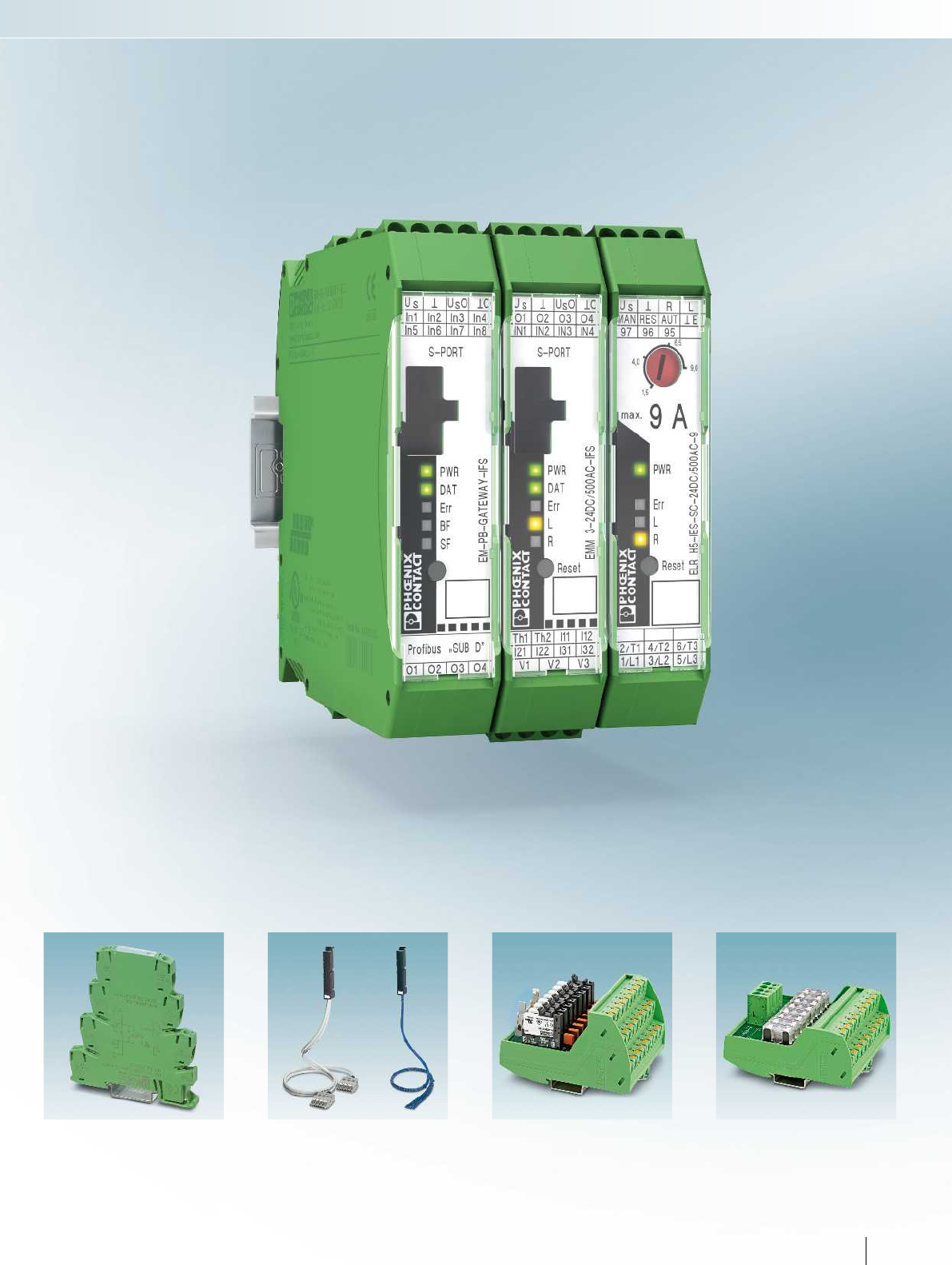
For additional information, visit phoenixcontact.net/products
Relay modules - PLC series
– With integrated solid-state relay
Page 366
VARIOFACE system cabling
–VIP power cabling
Universal front adapters for
SIMATIC® S7-300
Page 368
VARIOFACE system cabling
– VIP I/O modules
Page 370
– VIP interface module for Emerson DeltaV
Page 372
VARIOFACE wiring interface
– VIP potential distributor with fuses
Page 373
Interface technology and switching devices
323PHOENIX CONTACT
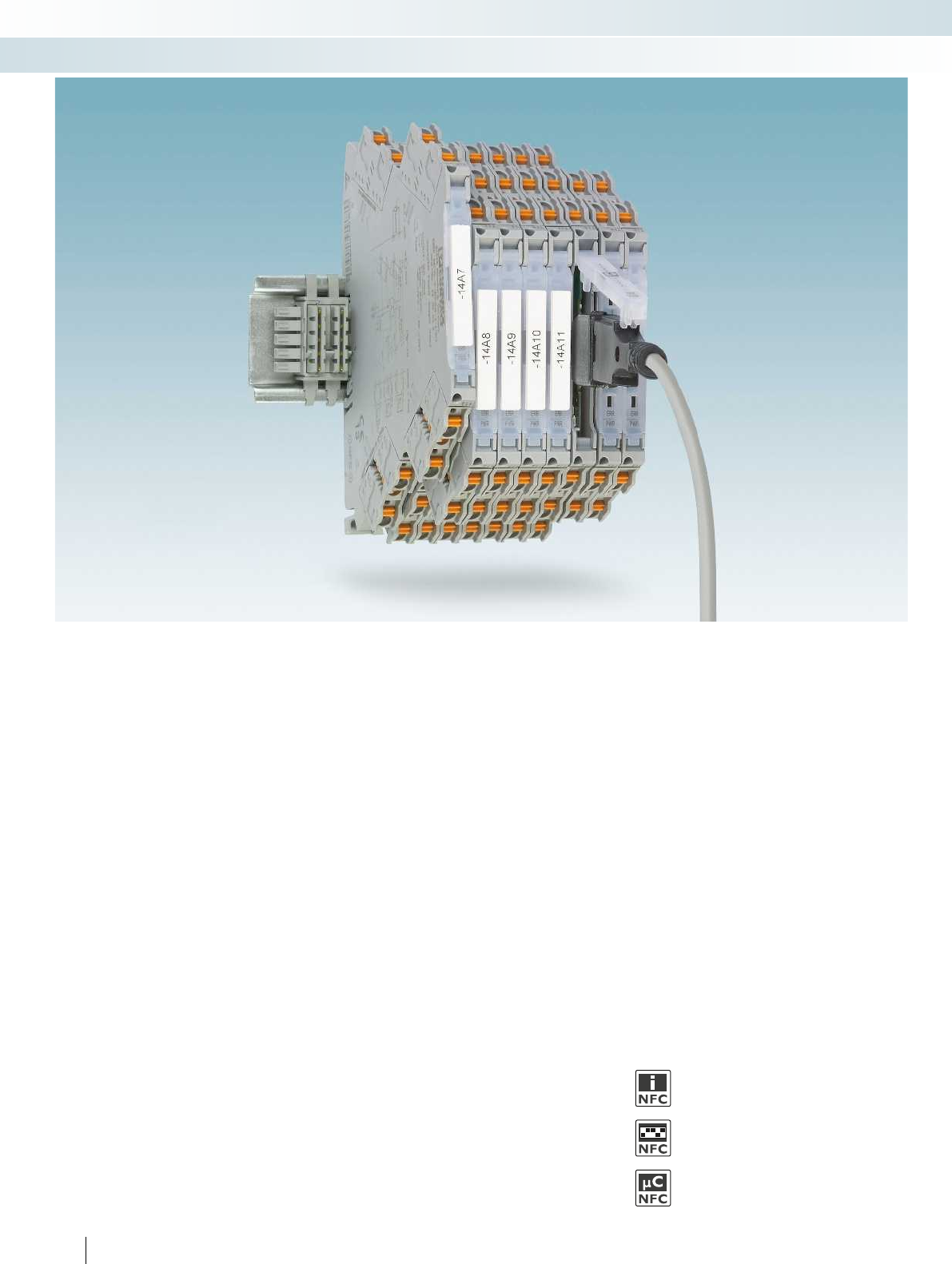
324 PHOENIX CONTACT
Easier than ever but slim as before
The new highly compact MINI Analog Pro
signal conditioners offer the easiest
installation and startup in a confined space.
Easily accessible terminal points, current
measurement during operation, and the
unique FASTCON Pro plug-in connection
technology make your work considerably
easier.
Choose the right MINI Analog signal
conditioner for your application:
Analog IN/OUT
– Universal and standard 3-way signal
conditioners
– 3-way repeater power supplies
Te m p e r a t u r e
– Universal measuring transducers for
resistance thermometers and
thermocouples
Universal potiposition transducer
– Potiposition transducers with automatic
potentiometer detection
Accessories
– Supply components
– Fault monitoring module
–Marking material
– Surge protection, see Catalog 6
Easy installation in a confined space
– Thanks to the front orientation, all
terminal points are easily visible and
accessible at all times – this not only saves
time, but also space above and below
devices
– All conductors can be fed individually and in
any order, regardless of whether you start
wiring from the input or output side
– The FASTCON Pro connection terminal
blocks can be inserted and removed in
any order
Measure current signals during
operation
You can conveniently measure signals for
startup and servicing during operation,
thanks to integrated test disconnect
terminal blocks:
– The circuit does not have to be separated
in order to integrate the measuring device
in the signal circuit
– By setting the plug to the disconnect
position, signal circuits can be easily
interrupted during servicing and startup
Numerous parameterization options
Easy DIP switch configuration
Many of the MINI Analog modules can be
configured: the basic functions can be easily
set using DIP switches – without the need
for any software.
PC configuration for extended
function and monitoring
For extended functionality, you can
configure the modules conveniently with
the S port interface on your PC using one of
the free software solutions.
Smart configuration without
accessories
Place your smartphone on the device and
establish a wireless connection via near field
communication (NFC). Depending on the
device type, the free MINI Analog Pro app
offers different functions.
App functions via NFC communication
Configuration via NFC
– Access module information
– Display DIP switch setting help
– Wireless configuration via smartphone
DIP switch setting help
– Access module information
– Display DIP switch setting help on the smartphone
Access to information
– Access module information
Interface technology and switching devices
Measurement and control technology - MINI Analog Pro highly compact signal conditioners
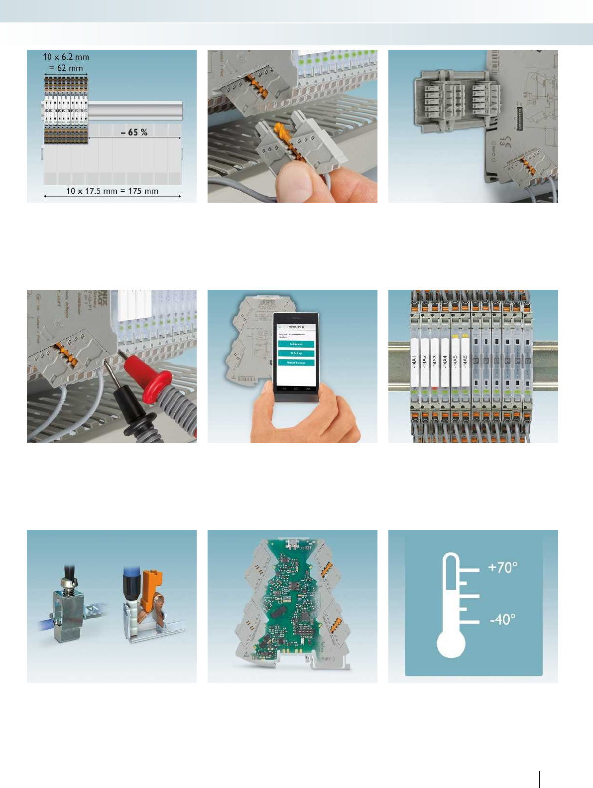
For additional information, visit phoenixcontact.net/products
325PHOENIX CONTACT
Interface technology and switching devices
Measurement and control technology - MINI Analog Pro highly compact signal conditioners
Space savings of up to 65%
– Compared to other signal conditioners
on the market with design widths up to
17.5 mm.
Easy installation
– Easily visible and accessible terminal
points and FASTCON Pro plug-in
connection terminal blocks.
Power bridging and fault monitoring
– The DIN rail connector simplifies supply
and enables group error monitoring via
remote diagnostics.
Easy to start up and control
– Measure current signals during operation,
without disconnecting current loops, plus
optional disconnect function.
Numerous parameterization options
– Easy configuration via DIP switches as
well as extended configuration via
software or smartphone app without
additional accessories.
Easy maintenance
– Large-surface marking areas for complete
loop identification using standard marking
material as well as constantly visible
status LEDs in every module.
Choice of connection technology
– Wiring with screw connection or fast and
tool-free push-in technology.
Optimum signal quality
– The latest transmission technology and
safe electrical isolation between input,
output, and supply with 3 kV test voltage.
Suitable for any application
– Extended supply voltage and temperature
range as well as multifunctional device
types.
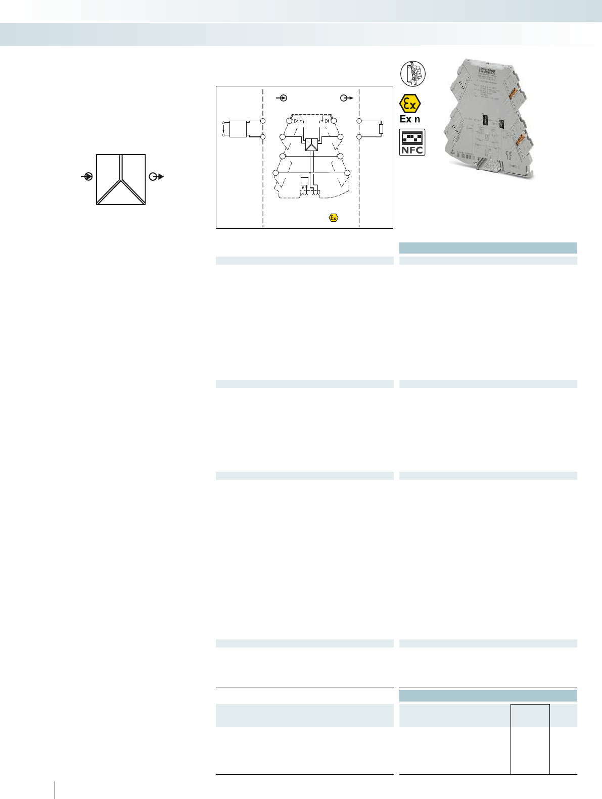
POWER
U,I U,I OUT
IN
FM
Zone 2
passive
IN
Sensor / Field
OUT
PLC / DCS
4-wire
OUT
U,I
GND
US
5
6
1
2
PWR+
PWR–
+
+
+
–
–
–
–
+PWR+
FM
1 5
2 6
37
48
active
OUT U, I–
PWR–
IN U, I+
IN U, I–
PWR+
PWR–
OUT U, I+
TI+TI–
Ex:
Housing width 6.2 mm
Technical data
Input data U input I input
Input signal 0 V ... 5 V
1 V ... 5 V
-5 V ... 5 V
0 V ... 10 V
2 V ... 10 V
-10 V ... 10 V
0 V ... 20 V
4 V ... 20 V
-20 V ... 20 V
0 V ... 24 V
4.8 V ... 24 V
-24 V ... 24 V
0 V ... 30 V
6 V ... 30 V
-30 V ... 30 V
0 mA ... 20 mA
4 mA ... 20 mA
-20 mA ... 20 mA
Input resistance > 1000 kΩapprox. 63 Ω
Output data U output I output
Output signal 0 V ... 5 V
1 V ... 5 V
-5 V ... 5 V
0 V ... 10 V
2 V ... 10 V
-10 V ... 10 V
0 mA ... 20 mA
4 mA ... 20 mA
Maximum output signal 22 mA
No-load voltage < 17 V
Short-circuit current < 32 mA
Load RB≥ 10 kΩ≤ 600 Ω (at 20 mA)
Ripple < 20 mVPP (at 600 Ω) < 20 mVPP (at 600 Ω)
General data U output I output
Supply voltage UB9.6 V DC ... 30 V DC
Nominal supply voltage 24 V DC
Current consumption 25 mA (current output,
at 24 V DC incl. load)
54 mA (current output,
at 12 V DC incl. load)
Power consumption ≤ 800 mW (at IOUT = 20 mA,
9.6 V DC, 600 Ω load)
Maximum transmission error ≤ 0.1% (of final value)
Temperature coefficient 0.01%/K
Limit frequency (3 dB) 30 Hz (via DIP switch)
Step response (10-90%) < 8.5 ms (with 30 Hz filter)
Electrical isolation Reinforced insulation in accordance with IEC 61010-1
Test voltage, input/output/supply 3 kV (50 Hz, 1 min.)
Degree of protection IP20
Ambient temperature (operation) -40°C ... 70°C
Mounting Any
Housing material PBT
Dimensions W/H/D 6.2/110.5/120.5 mm
Push-in connection solid/stranded/AWG 0.2 ... 2.5 mm²/0.2 ... 2.5 mm²/26 - 12
Screw connection solid/stranded/AWG 0.2 ... 1.5 mm²/0.2 ... 1.5 mm²/26 - 16
EMC note Class A product, see page 443
Conformance / approvals
Conformance CE-compliant
ATEX II 3 G Ex nA IIC T4 Gc X
UL, USA / Canada 508 listing applied for
Class I, Div. 2, Groups A, B, C, D T5 applied for
GL GL applied for
Ordering data
Description Type Order No. Pcs. /
Pkt.
3-way signal conditioner, for electrical isolation of analog signals
Standard configuration Push-in connection MINI MCR-2-UI-UI-PT 2902040 1
Standard configuration Screw connection MINI MCR-2-UI-UI 2902037 1
Order configuration Push-in connection MINI MCR-2-UI-UI-PT-C 2902039 1
Order configuration Screw connection MINI MCR-2-UI-UI-C 2902036 1
326 PHOENIX CONTACT
– Configurable, ultra-compact signal
conditioner for electrical isolation,
conversion, amplification, and filtering of
standard analog signals
– Plug-in connection system
– Safe 3-way isolation
– Standard signal combinations configurable
via DIP switches
– Power supply and fault monitoring
possible via DIN rail connector
–Status LED
Analog IN / Analog OUT
3-way signal conditioner
Interface technology and switching devices
Measurement and control technology - MINI Analog Pro highly compact signal conditioners
Configurable,
Up to 144 signal combinations
For additional information, visit phoenixcontact.net/products
327PHOENIX CONTACT
Order key for MINI-MCR-2-UI-UI...C 3-way signal conditioner (standard configuration entered as an example)
Order No. Input Output Cut-off frequency
2902036 / IN03 / OUT01 / 5K
2902036
MINI-MCR-2-
UI-UI-C
IN 01 0...20 mA OUT 01 0...20 mA 30 Hz
IN 02 4...20 mA OUT 02 4...20 mA 5 kHz
IN 03 0...10 V OUT 03 0...10 V
IN 04 2...10 V OUT 04 2...10 V
2902039
MINI-MCR-2-
UI-UI-PT-C
IN 05 0...5 V OUT 05 0...5 V
IN 06 1...5 V OUT 06 1...5 V
IN 21 -5...5 V OUT 13 -5...5 V
IN 22 -10...10 V OUT 14 -10...10 V
IN 23 -20...20 V
IN 32 0...20 V
IN 35 -20...20 mA
IN 38 0...24 V
IN 39 0...30 V
IN 80 -30...30 V
IN 93 -24...24 V
IN 94 4.8...24 V
IN 95 6...30 V
IN 96 4...20 V
Signal combinations for MINI-MCR-2-UI-UI-... signal conditioners
Output
Input 0...20 mA 4...20 mA 0...5 V 1...5 V -5...5 V 0...10 V 2...10 V -10...10 V
0...20 mA X X X X X X X X
4...20 mA XXXXXXXX
-20...20 mA X X X X X X X X
0...5 V XXXXXXXX
1...5 V X X X X X X X X
-5...5 V XXXXXXXX
0...10 V X X X X X X X X
2...10 V XXXXXXXX
-10...10 V X X X X X X X X
0...20 V XXXXXXXX
4...20 V X X X X X X X X
-20...20 V XXXXXXXX
0...24 V X X X X X X X X
4.8...24 V XXXXXXXX
-24...24 V X X X X X X X X
0...30 V XXXXXXXX
6...30 V X X X X X X X X
-30...30 V XXXXXXXX
Interface technology and switching devices
Measurement and control technology - MINI Analog Pro highly compact signal conditioners
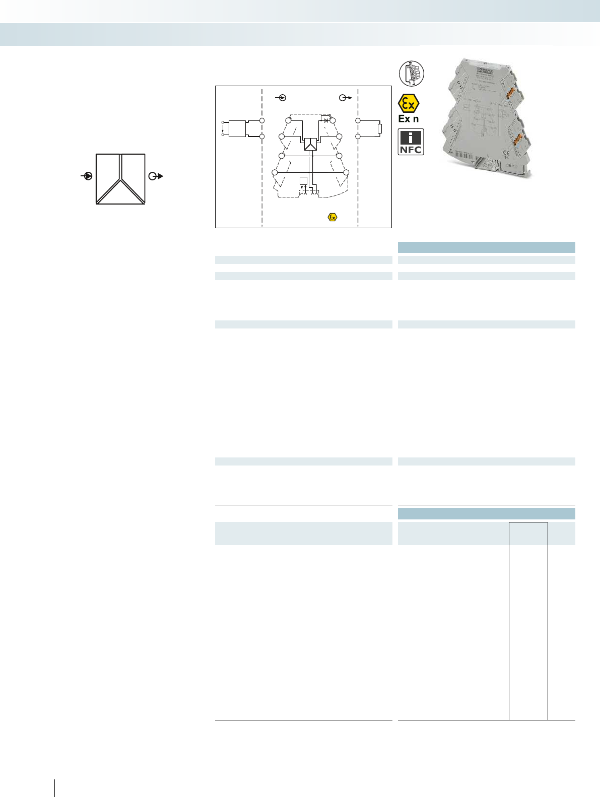
POWER
U,I U,I OUT
IN
FM
Zone 2
IN
Sensor / Field
OUT
PLC / DCS
4-wire
OUT
U+
US
5
6
1
2
OUT
U-
PWR+
PWR–
+
+
+
–
–
–
–
+
FM
1 5
2 6
37
48
IN U+ OUT I+
TI+
PWR+
OUT I–
PWR–
IN U–
PWR+
PWR–
activepassive
Technical data
Input data U input I input
Input resistance approx. 100 kΩapprox. 63 Ω
Output data U output I output
Maximum output signal 11 V 22 mA
No-load voltage < 17 V
Short-circuit current < 15 mA
Load RB≥ 10 kΩ≤ 600 Ω (at 20 mA)
Ripple < 20 mVPP (at 10 kΩ) < 20 mVPP (at 600 Ω)
General data
Supply voltage UB9.6 V DC ... 30 V DC
Nominal supply voltage 24 V DC
Typ. current consumption 25 mA (at 24 V DC)
Maximum transmission error 0.1% (of final value)
Temperature coefficient 0.01%/K
Limit frequency (3 dB) approx. 30 Hz
Step response (10-90%) approx. 10 ms
Degree of protection IP20
Electrical isolation Reinforced insulation in accordance with IEC 61010-1
Test voltage, input/output/supply 3 kV (50 Hz, 1 min.)
Ambient temperature (operation) -40°C ... 70°C
Housing material PBT
Dimensions W/H/D 6.2/110.5/120.5 mm
Push-in connection solid/stranded/AWG 0.2 ... 2.5 mm²/0.2 ... 2.5 mm²/26 - 12
Screw connection solid/stranded/AWG 0.2 ... 1.5 mm²/0.2 ... 1.5 mm²/26 - 16
EMC note Class A product, see page 443
Conformance / approvals
Conformance CE-compliant
ATEX II 3 G Ex nA IIC T4 Gc X
UL, USA / Canada 508 listing applied for
Class I, Div. 2, Groups A, B, C, D T5 applied for
GL GL applied for
Ordering data
Description Input signal Output signal Type Order No. Pcs. /
Pkt.
3-way signal conditioner, for electrical isolation of analog signals
Push-in connection 0 ... 10 V 0 ... 20 mA MINI MCR-2-U-I0-PT 2902023 1
Screw connection 0 ... 10 V 0 ... 20 mA MINI MCR-2-U-I0 2902022 1
Push-in connection 0 ... 10 V 4 ... 20 mA MINI MCR-2-U-I4-PT 2902030 1
Screw connection 0 ... 10 V 4 ... 20 mA MINI MCR-2-U-I4 2902029 1
Push-in connection 0 ... 20 mA 0 ... 10 V MINI MCR-2-I0-U-PT 2902001 1
Screw connection 0 ... 20 mA 0 ... 10 V MINI MCR-2-I0-U 2902000 1
Push-in connection 4 ... 20 mA 0 ... 10 V MINI MCR-2-I4-U-PT 2902003 1
Screw connection 4 ... 20 mA 0 ... 10 V MINI MCR-2-I4-U 2902002 1
Push-in connection 0 ... 20 mA,
4 ... 20 mA
0 ... 20 mA,
4 ... 20 mA
MINI MCR-2-I-I-PT 2901999 1
Screw connection 0 ... 20 mA,
4 ... 20 mA
0 ... 20 mA,
4 ... 20 mA
MINI MCR-2-I-I 2901998 1
Push-in connection 0 ... 10 V,
-10 ... 10 V
0 ... 10 V,
-10 ... 10 V
MINI MCR-2-U-U-PT 2902043 1
Screw connection 0 ... 10 V,
-10 ... 10 V
0 ... 10 V,
-10 ... 10 V
MINI MCR-2-U-U 2902042 1
328 PHOENIX CONTACT
– Highly compact signal conditioner for
electrical isolation, conversion,
amplification, and filtering of standard
analog signals
– Fixed signal combinations
– Plug-in connection system
– Safe 3-way isolation
– Power supply and fault monitoring
possible via DIN rail connector
–Status LED
Analog IN / Analog OUT
3-way signal conditioner
Interface technology and switching devices
Measurement and control technology - MINI Analog Pro highly compact signal conditioners
With fixed signal combinations
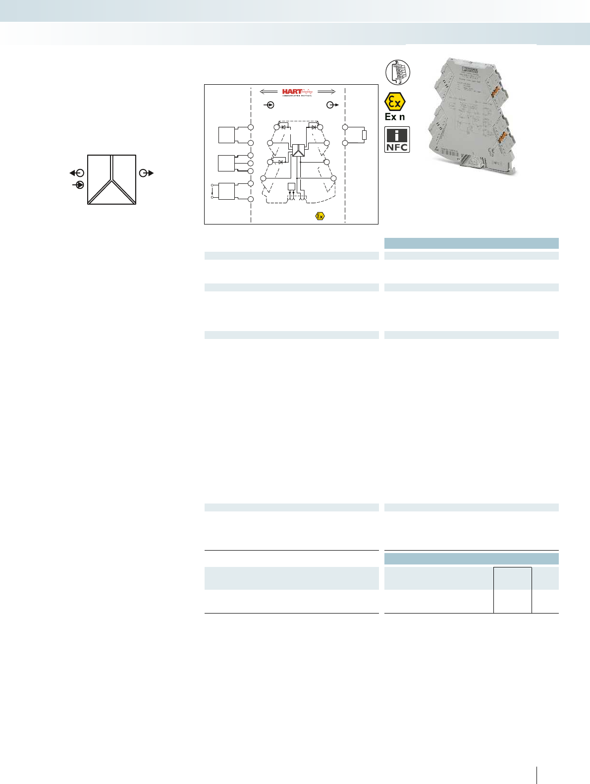
POWER
II OUT
IN
POWER
FM
PWR+
PWR–
++
–
–
–
+
passive
IN OUT
FM
1 5
2 6
37
48
5
6
Zone 2
2-wire
1
2OUT I–
PWR–
PWR OUT +
IN I–
Sensor / Field PLC / DCS
OUT I+
PWR
IN+
OUT I–
TI+
PWR+
IN I+
4-wire
US
3
4
3-wire
1
4
3
PWR
IN+
OUT I–
OUT I+
OUT I–
OUT I+
IN I–
TI–
TI+
active
+
–
For additional information, visit phoenixcontact.net/products
Housing width 6.2 mm
Technical data
Input data
Input signal 0 ... 20 mA, isolator operation/4 ... 20 mA
Input resistance approx. 68 Ω
Transmitter supply voltage > 19.5 V
Output data
Output signal 0 ... 20 mA/4 ... 20 mA
Maximum output signal
No-load voltage < 20 V
Load RB≤ 600 Ω (at 20 mA)
Ripple < 20 mVPP (at 600 Ω)
General data
Supply voltage UB9.6 V DC ... 30 V DC
Nominal supply voltage 24 V DC
Current consumption 25 mA (at 24 V DC and in isolator operation)
Power consumption ≤ 1400 mW (at IOUT = 20 mA, 9.6 V DC, 600 Ω load)
Maximum transmission error 0.1% (of final value)
Temperature coefficient 0.01%/K,
Limit frequency (3 dB) > 1.75 kHz (typ.)
Communication HART specification in both operating modes
(RPSS isolator/RPSS repeater power supply)
Step response (10-90%) < 200 µs (typ.)
Electrical isolation Reinforced insulation in accordance with IEC 61010-1
Test voltage, input/output/supply
Degree of protection IP20
Ambient temperature (operation) -40°C ... 70°C
Mounting Any
Housing material PBT
Dimensions W/H/D 6.2/110.5/120.5 mm
Push-in connection solid/stranded/AWG 0.2 ... 2.5 mm²/0.2 ... 2.5 mm²/26 - 12
Screw connection solid/stranded/AWG 0.2 ... 1.5 mm²/0.2 ... 1.5 mm²/26 - 16
EMC note Class A product, see page 443
Conformance / approvals
Conformance CE-compliant
ATEX II 3 G Ex nA IIC T4 Gc X
UL, USA / Canada 508 listing applied for
Class I, Div. 2, Groups A, B, C, D T5 applied for
GL GL applied for
Ordering data
Description Type Order No. Pcs. /
Pkt.
Repeater power supply with HART transmission
Push-in connection MINI MCR-2-RPSS-I-I-PT 2902015 1
Screw connection MINI MCR-2-RPSS-I-I 2902014 1
329PHOENIX CONTACT
– Highly-compact repeater power supply
for electrical isolation, conversion,
amplification, and filtering of standard
analog signals
– Supply of 2-wire and passive 3-wire
sensors
– Can also be used as an isolator without
supply
– Plug-in connection system
– Safe 3-way isolation
– Bidirectional HART transmission as an
option
– Power supply and fault monitoring
possible via DIN rail connector
–Status LED
Analog IN / Analog OUT
repeater power supplies
Interface technology and switching devices
Measurement and control technology - MINI Analog Pro highly compact signal conditioners
Repeater power supply
with HART transmission
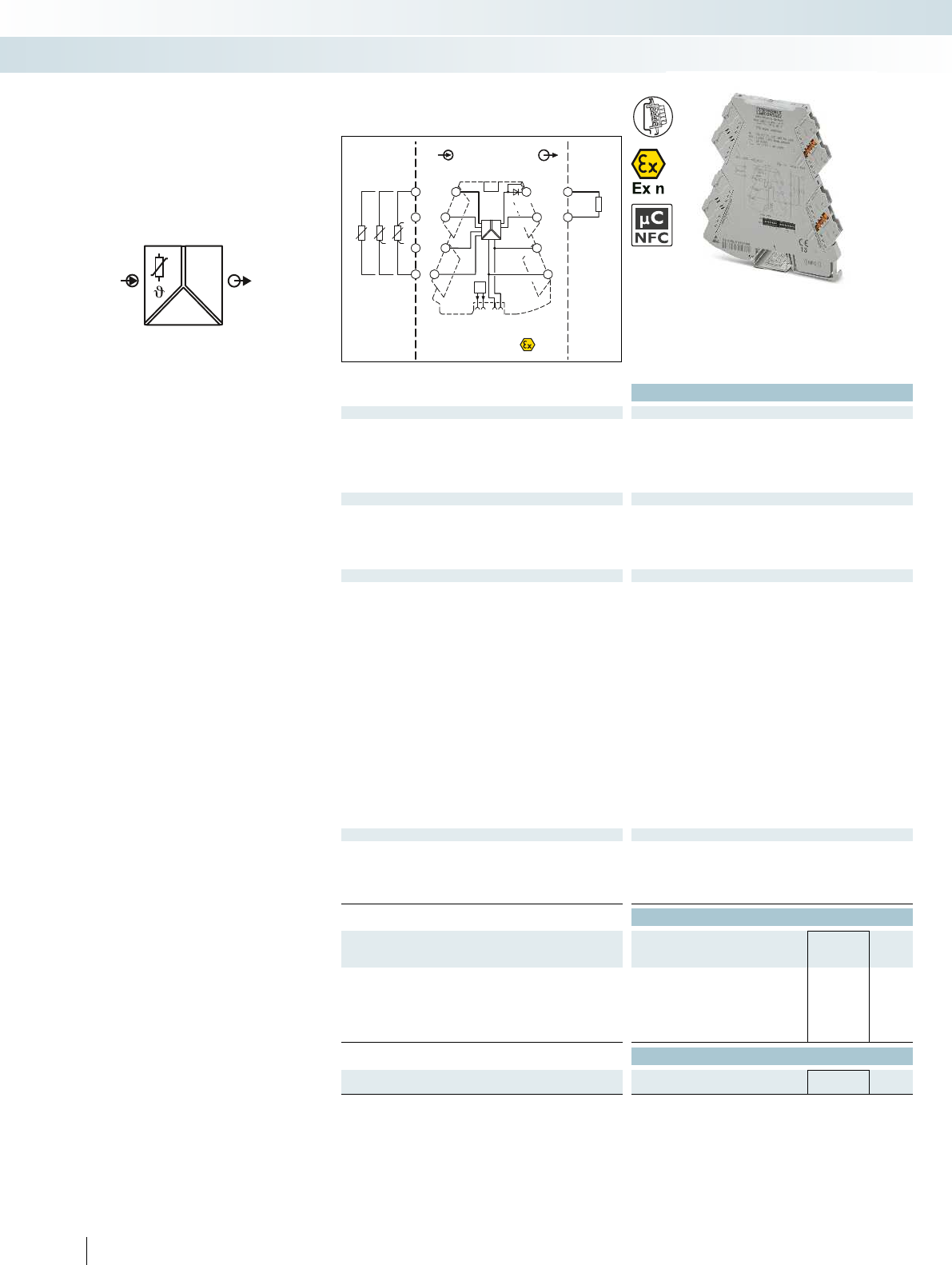
OUT
IN
POWER
U,I
FM
PWR+
PWR–
+
+
–
–
passive
IN OUT
FM
1 5
2 6
8
5
6
Zone 2
Sensor / Field PLC / DCS
3
4
7
S-Port
OUT U, I–
OUT U, I+
PWR+
PWR–
ϑϑϑ
TI+
1
2
3
4
active
Ex:
Housing width 6.2 mm
Technical data
Input data
Input signal (can be configured using DIP switches) Pt, Ni, Cu sensors : 2, 3, 4-wire
Temperature range -200°C ... 850°C (range depending on the sensor type)
Measuring range span ≥ 20 K
Linear resistance measuring range 0 Ω ... 4000 Ω
(Minimum measuring span: 10% of the selected measuring range)
Output data U output I output
Output signal 0 ... 5 V/1 ... 5 V 0 ... 20 mA/4 ... 20 mA
0 ... 10 V/10 ... 0 V 20 ... 0 mA/20 ... 4 mA
Maximum output signal approx. 12.3 V 24.6 mA
Load RB≥ 10 kΩ≤ 600 Ω (at 20 mA)
Ripple < 20 mVPP < 20 mVPP (at 600 Ω)
General data
Supply voltage UB9.6 V DC ... 30 V DC
Current consumption 32 mA (at 24 V DC)
Power consumption ≤ 850 mW (at IOUT = 20 mA, 9.6 V DC, 600 Ω load)
Transmission error 0.1% * 350 K/set measuring range; 0.1% > 350 K (Pt/Ni)
0.3% * 200 K/set measuring range; 0.3% > 200 K (Cu)
Temperature coefficient 0.01%/K
Step response (0–99%) Typ. 200 ms (2-wire)
Typ. 500 ms (3-wire)
Typ. 500 ms (4-wire)
Electrical isolation Reinforced insulation in accordance with IEC 61010-1
Test voltage, input/output/supply 3 kV (50 Hz, 1 min.)
Ambient temperature (operation) -40°C ... 70°C
Housing material PBT
Dimensions W/H/D 6.2/110.5/120.5 mm
Push-in connection solid/stranded/AWG 0.2 ... 2.5 mm²/0.2 ... 2.5 mm²/26 - 12
Screw connection solid/stranded/AWG 0.2 ... 1.5 mm²/0.2 ... 1.5 mm²/26 - 16
EMC note Class A product, see page 443
Conformance / approvals
Conformance CE-compliant
ATEX II 3 G Ex nA IIC T4 Gc X
UL, USA / Canada 508 listing applied for
Class I, Div. 2, Groups A, B, C, D T5 applied for
GL GL applied for
Ordering data
Description Type Order No. Pcs. /
Pkt.
Temperature transducers for resistance thermometers
Standard configuration Push-in connection MINI MCR-2-RTD-UI-PT 2902052 1
Standard configuration Screw connection MINI MCR-2-RTD-UI 2902049 1
Order configuration Push-in connection MINI MCR-2-RTD-UI-PT-C 2902051 1
Order configuration Screw connection MINI MCR-2-RTD-UI-C 2902048 1
Accessories
Programming adapter for configuring modules with
S-PORT interface
IFS-USB-PROG-ADAPTER 2811271 1
330 PHOENIX CONTACT
– Universally configurable, highly compact
temperature transducer for electrical
isolation, conversion, amplification, and
filtering of resistance thermometer and
remote resistance-type sensor signals
– For 2, 3 or 4-wire sensors according to
IEC 751, JIS, GOST
– Plug-in connection system
– Safe 3-way isolation
– Standard signal combinations configurable
via DIP switches
– Freely configurable via software or
smartphone app
– Power supply and fault monitoring
possible via DIN rail connector
– Status and error indicator LEDs
Te m p e r a t u r e
Temperature transducers
for resistance thermometers
Interface technology and switching devices
Measurement and control technology - MINI Analog Pro highly compact signal conditioners
Universal measuring transducer
for resistance thermometers
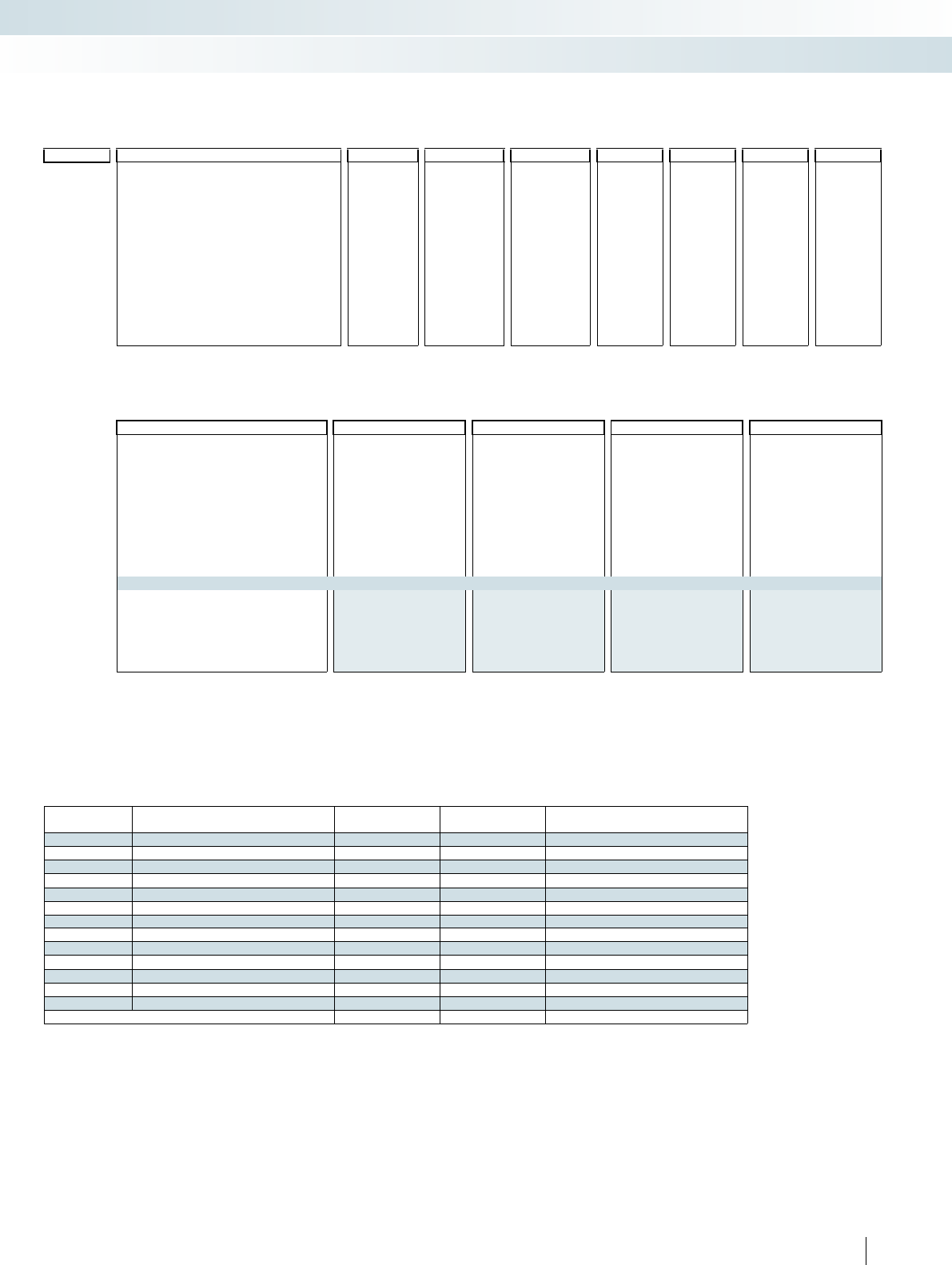
For additional information, visit phoenixcontact.net/products
331PHOENIX CONTACT
Order key for MINI-MCR-2-RTD-UI...C temperature transducer (standard configuration entered as an example)
Order No. Sensor type Connection
technology
Measuring range Measuring
unit
Output
Start End Output signal Start End
2902048 / PT100 / 3 / -50 / 150 / C / I / 4.0 / 20.0 / ...
2902048
MINI-MCR-2-
RTD-UI-C
PT100 Pt 100 IEC 751 2 2-wire freely selectable
between
-200°C...850°C
(measuring
range limits
depend on
sensor type)
freely selectable
between
-200°C...850°C
(measuring
range limits
depend on
sensor type)
C °C I I0.0 0 mA 20.0 20 mA
PT200 Pt 200 IEC 751 3 3-wire F °F U U I: freely
selectable
between
0.0...21 mA
I: freely
selectable
between
0.0...21 mA
PT500 Pt 500 IEC 751 4 4-wire
PT1000 Pt 1000 IEC 751
2902051
MINI-MCR-2-
RTD-UI-PT-C
PT100G Pt 100 GOST 6651-2009 ( = 0.00394)
PT1000G Pt 1000 GOST 6651-2009 ( = 0.00394)
PT100J Pt 100 JIS C1604/1997 U: freely
selectable
between
0.0...10.5 V
U: freely
selectable
between
0.0...10.5 V
PT1000J Pt 1000 JIS C1604/1997
NI100 Ni 100 DIN 43760
NI1000 Ni 1000 DIN 43760
CU50 Cu 50 GOST 6651-2009 ( = 0.00428)
CU100 Cu 100 GOST 6651-2009 ( = 0.00428)
CU53 Cu 53 GOST 6651-2009 ( = 0.00426)
Failure information
Behavior in the event of an error Open circuit Short circuit Overrange Underrange
... / NE43DO / 0.0 / 0.0 / 0.0 / 0.0
FD Freely definable 0.0 0 mA
I: freely selectable
between 0.0...21.5 mA
U: freely selectable between
0.0...11 V
(signal type corresponds to
selected output signal)
0.0 0 mA
I: freely selectable
between 0.0...21.5 mA
U: freely selectable between
0.0...11 V
(signal type corresponds to
selected output signal)
0.0 0 mA
I: freely selectable
between 0.0...21.5 mA
U: freely selectable between
0.0...11 V
(signal type corresponds to
selected output signal)
0.0 0 mA
I: freely selectable
between 0.0...21.5 mA
U: freely selectable between
0.0...11 V
(signal type corresponds to
selected output signal)
Note: failure information according to NE 43 can only be selected for 4...20 mA output
NE43UP NE 43 upscale 21.5 mA 21.5 mA 21.5 mA 21.5 mA
NE43DO NE 43 downscale 3.5 mA 3.5 mA 3.5 mA 3.5 mA
NE430 NE 43 0 mA 0 mA 0 mA 0 mA 0 mA
NE43UD NE 43 upscale/downscale 3.5 mA 3.5 mA 21.5 mA 21.5 mA
Sensor types and measuring ranges for MINI-MCR-2-RTD-UI-... temperature transducers
Sensor type Standard Measuring range Smallest measuring
span
Adjustable using:
Pt100 IEC 751 = GOST 6651-2009 ( = 0.00385) -200°C ... +850°C 20 K DIP switch
Pt200 IEC 751 = GOST 6651-2009 ( = 0.00385) -200°C ... +850°C 20 K DIP switch
Pt500 IEC 751 = GOST 6651-2009 ( = 0.00385) -200°C ... +850°C 20 K Software or smartphone app
Pt1000 IEC 751 = GOST 6651-2009 ( = 0.00385) -200°C ... +850°C 20 K Software or smartphone app
Pt100 GOST 6651-2009 ( = 0.00391) -200°C ... +850°C 20 K Software or smartphone app
Pt1000 GOST 6651-2009 ( = 0.00391) -200°C ... +850°C 20 K Software or smartphone app
Pt100 JIS C1604-1997 -200°C ... +850°C 20 K Software or smartphone app
Pt1000 JIS C1604-1997 -200°C ... +850°C 20 K Software or smartphone app
Ni100 DIN 43760 -60°C ... +250°C 20 K Software or smartphone app
Ni1000 DIN 43760 -60°C ... +250°C 20 K Software or smartphone app
Cu50 GOST 6651-2009 ( = 0.0428) -180°C ... +200°C 20 K Software or smartphone app
Cu100 GOST 6651-2009 ( = 0.0428) -180°C ... +200°C 20 K Software or smartphone app
Cu53 GOST 6651-2009 ( = 0.0426) -50°C ... +180°C 20 K Software or smartphone app
Customer-specific characteristic curves -200°C ... +850°C 20 K Software or smartphone app
Interface technology and switching devices
Measurement and control technology - MINI Analog Pro highly compact signal conditioners
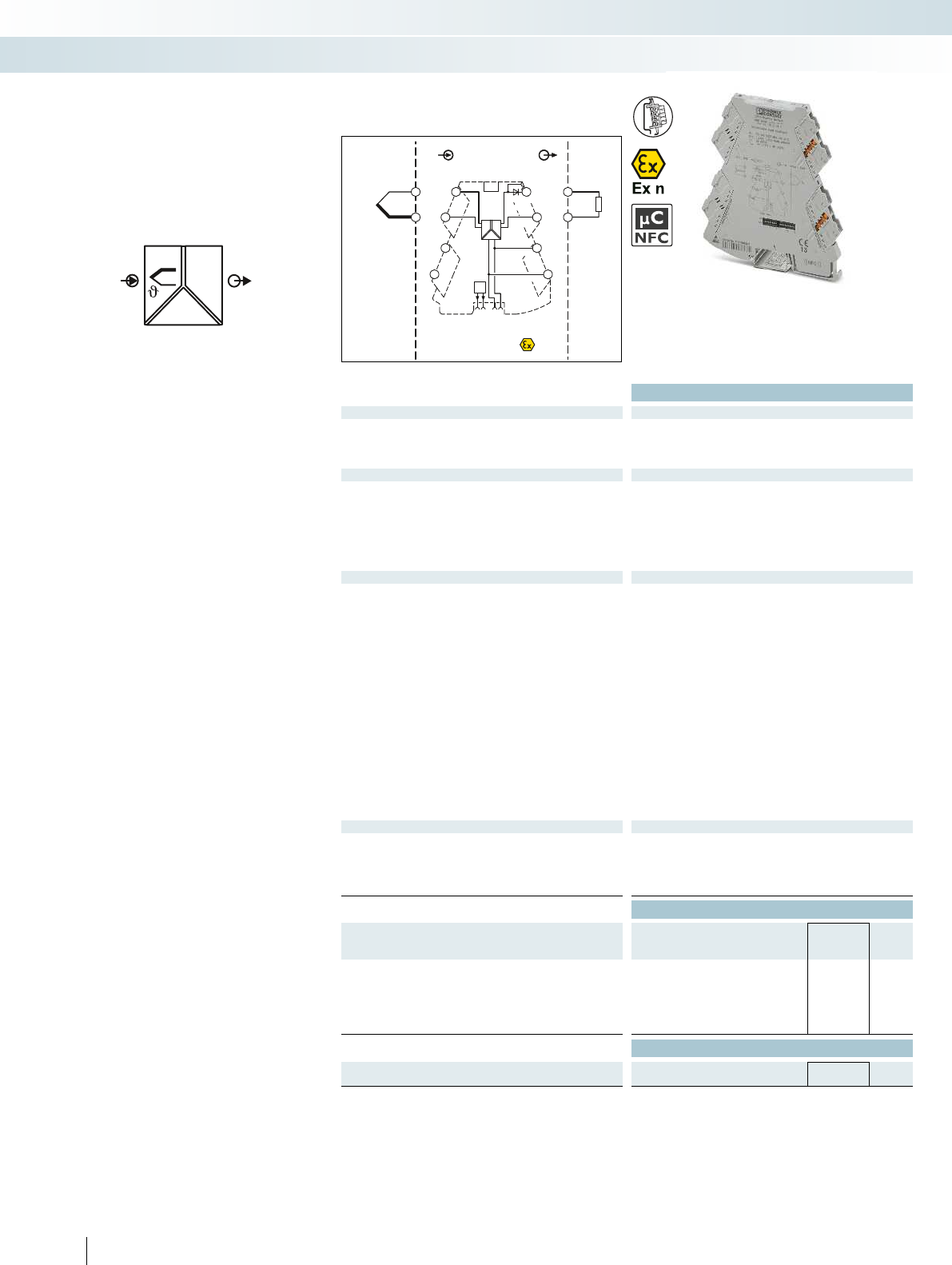
OUT
IN
POWER
U,I
FM
PWR+
PWR–
+
+
–
–
passive
IN OUT
FM
1 5
2 6
8
5
6
Zone 2
Sensor / Field PLC / DCS
3
4
7
S-Port
OUT U, I–
OUT U, I+
PWR+
PWR–
1
2
TI+
TC
+
–
active
Ex:
Housing width 6.2 mm
Technical data
Input data
Input signal (can be configured using DIP switches) B, E, J, K, N, R, S, T, L, U, A-1, A-2, A-3, M, L
Temperature range -250°C ... 2500°C (range depending on the sensor type)
Measuring range span min. 50 K
Output data U output I output
Output signal (configurable using the DIP switch) 0 ... 5 V/1 ... 5 V 0 ... 20 mA/4 ... 20 mA
0 ... 10 V/10 ... 0 V 20 ... 0 mA/20 ... 4 mA
Maximum output signal approx. 12.3 V 24.6 mA
No-load voltage < 17.5 V
Short-circuit current < 31.5 mA
Load RB≥ 10 kΩ≤ 600 Ω (at 20 mA)
Ripple < 20 mVPP < 20 mVPP (at 600 Ω)
General data
Supply voltage UB9.6 V DC ... 30 V DC
Current consumption 32 mA (at 24 V DC)
Power consumption ≤ 850 mW (at IOUT = 20 mA, 9.6 V DC, 600 Ω load)
Transmission error 0.1% * 600 K/set measuring range; 0.1% > 600 K
(E, J, K, N, T, L, U, M Gost, L Gost)
0.2% * 600 K/set measuring range; 0.2% > 600 K
(B, R, S, A1, A2, A3)
Cold junction errors (0,2 K * ΔT) ( typ. < 2 K )
Temperature coefficient ≤ 0.01%/K
Step response (0–99%) Typ. 400 ms
Electrical isolation Reinforced insulation in accordance with IEC 61010-1
Test voltage, input/output/supply 3 kV (50 Hz, 1 min.)
Ambient temperature (operation) -40°C ... 70°C
Housing material PBT
Dimensions W/H/D 6.2/110.5/120.5 mm
Push-in connection solid/stranded/AWG 0.2 ... 2.5 mm²/0.2 ... 2.5 mm²/26 - 12
Screw connection solid/stranded/AWG 0.2 ... 1.5 mm²/0.2 ... 1.5 mm²/26 - 16
EMC note Class A product, see page 443
Conformance / approvals
Conformance CE-compliant
ATEX II 3 G Ex nA IIC T4 Gc X
UL, USA / Canada 508 listing applied for
Class I, Div. 2, Groups A, B, C, D T5 applied for
GL GL applied for
Ordering data
Description Type Order No. Pcs. /
Pkt.
Temperature transducers for thermocouples
Standard configuration Push-in connection MINI MCR-2-TC-UI-PT 2905249 1
Standard configuration Screw connection MINI MCR-2-TC-UI 2902055 1
Order configuration Push-in connection MINI MCR-2-TC-UI-PT-C 2905248 1
Order configuration Screw connection MINI MCR-2-TC-UI-C 2902053 1
Accessories
Programming adapter for configuring modules with
S-PORT interface
IFS-USB-PROG-ADAPTER 2811271 1
332 PHOENIX CONTACT
– Universally configurable, highly compact
temperature transducer for electrical
isolation, conversion, amplification, and
filtering of thermocouple signals
– For thermocouples according to IEC 584
and GOST
– Internal cold junction compensation
– Plug-in connection system
– Safe 3-way isolation
– Standard signal combinations configurable
via DIP switches
– Freely configurable via software or
smartphone app
– Power supply and fault monitoring
possible via DIN rail connector
– Status and error indicator LEDs
Te m p e r a t u r e
Temperature transducers for
thermocouples
Interface technology and switching devices
Measurement and control technology - MINI Analog Pro highly compact signal conditioners
Universal measuring transducer
for thermocouples
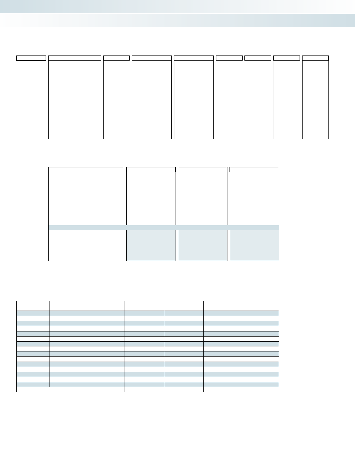
For additional information, visit phoenixcontact.net/products
333PHOENIX CONTACT
Order key for MINI-MCR-2-TC-UI...C temperature transducer (standard configuration entered as an example)
Order No. Sensor type Cold junction
compensation
Measuring range Measuring
unit
Output
Start End Output signal Start End
2902048 / J / 1 / -200 / 1200 / C / I / 4.0 / 20.0 / ...
2902253
MINI-MCR-2-
TC-UI-C
B B IEC 584-1 (Pt30Rh-Pt6Rh) 0 OFF freely selectable
between
-250°C...2500°C
(measuring range limits
depend on
sensor type)
freely selectable
between
-250°C...2500°C
(measuring range limits
depend on
sensor type)
C °C I I0.0 0 mA 20.0 20 mA
E E IEC 584-1 (NiCr-CuNi) 1 ON F °F U U I: freely
selectable
between
0.0...21 mA
I: freely
selectable
between
0.0...21 mA
J J IEC 584-1 (Fe-CuNi)
K K IEC 584-1 (NiCr-Ni)
2905248
MINI-MCR-2-
TC-UI-PT-C
N N IEC 584-1 (NiCrSi-NiSi)
R R IEC 584-1 (Pt13Rh-Pt)
S S IEC 584-1 (Pt10Rh-Pt) U: freely
selectable
between
0.0...10.5 V
U: freely
selectable
between
0.0...10.5 V
T T IEC 584-1 (Cu-CuNi)
L L DIN 43760 (Fe-CuNi)
U U DIN 43760 (Cu-CuNi)
A1G A-1 GOST 8.585-2001
A2G A-2 GOST 8.585-2001
A3G A-3 GOST 8.585-2001
MG M GOST 8.585-2001
LG L GOST 8.585-2001
Sensor types and measuring ranges for MINI-MCR-2-TC-UI-... temperature transducers
Sensor type Standard Measuring range Smallest measuring
span
Adjustable using:
BIEC 584-1 +500°C ... +1820°C 50 K Software or smartphone app
E IEC 584-1 -230°C ... +1000°C 50 K Software or smartphone app
JIEC 584-1 -210°C ... +1200°C 50 K DIP switch
K IEC 584-1 -250°C ... +1372°C 50 K DIP switch
NIEC 584-1 -200°C ... +1300°C 50 K Software or smartphone app
R IEC 584-1 -50°C ... +1768°C 50 K Software or smartphone app
SIEC 584-1 -50°C ... +1768°C 50 K Software or smartphone app
T IEC 584-1 -200°C ... +400°C 50 K Software or smartphone app
LDIN 43710 -200°C ... +900°C 50 K Software or smartphone app
U DIN 43710 -200°C ... +600°C 50 K Software or smartphone app
A-1 GOST 8.585 0°C ... +2500°C 50 K Software or smartphone app
A-2 GOST 8.585 0°C ... +1800°C 50 K Software or smartphone app
A-3 GOST 8.585 0°C ... +1800°C 50 K Software or smartphone app
M GOST 8.585 -200°C ... +100°C 50 K Software or smartphone app
LGOST 8.585 -200°C ... +800°C 50 K Software or smartphone app
Customer-specific characteristic curves -250°C ... +2500°C 50 K Software or smartphone app
Failure information
Behavior in the event of an error Open circuit Overrange Underrange
... / NE43DO / 0.0 / 0.0 / 0.0
FD Freely definable 0.0 0 mA
I: freely selectable
between 0.0...21.5 mA
U: freely selectable between
0.0...11 V
(signal type corresponds to
selected output signal)
0.0 0 mA
I: freely selectable
between 0.0...21.5 mA
U: freely selectable between
0.0...11 V
(signal type corresponds to
selected output signal)
0.0 0 mA
I: freely selectable
between 0.0...21.5 mA
U: freely selectable between
0.0...11 V
(signal type corresponds to
selected output signal)
Note: failure information according to NE 43 can only be selected for 4...20 mA output
NE43UP NE 43 upscale 21.5 mA 21.5 mA 21.5 mA
NE43DO NE 43 downscale 3.5 mA 3.5 mA 3.5 mA
NE430 NE 43 0 mA 0 mA 0 mA 0 mA
NE43UD NE 43 upscale/downscale 3.5 mA 21.5 mA 21.5 mA
Interface technology and switching devices
Measurement and control technology - MINI Analog Pro highly compact signal conditioners
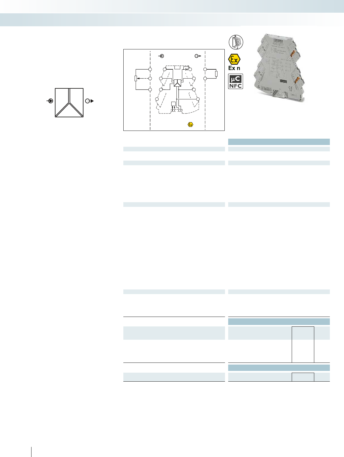
POWER
RU,I OUT
IN
FM
PWR+
PWR–
+
+
–
–
passive
IN
OUT
FM
1 5
2 6
8
5
6
Zone 2
Sensor / Field PLC / DCS
3
4
7
S-Port
OUT U, I–
OUT U, I+
PWR+
PWR–
TI+
1
3
IN
IN
IN
2
active
Ex:
Housing width 6.2 mm
Technical data
Input data
Potentiometer 100 Ω ... 100 kΩ
Reference voltage source -
Output data U output I output
Output signal 1 ... 5 V/10 ... 0 V 0 ... 20 mA/4 ... 20 mA
0 ... 5 V/0 ... 10 V 20 ... 0 mA/20 ... 4 mA
Maximum output signal approx. 12.3 V 24.6 mA
No-load voltage < 17.5 V
Short-circuit current < 31.5 mA
Load RB≥ 10 kΩ≤ 600 Ω (at 20 mA)
Ripple < 20 mVPP (at 10 kΩ) < 20 mVPP
Behavior in the event of a sensor error (configurable)
General data
Supply voltage UB9.6 V DC ... 30 V DC
Nominal supply voltage 24 V DC
Current consumption 33 mA (at 24 V DC)
Power consumption ≤ 850 mW (at IOUT = 20 mA, 9.6 V DC, 600 Ω load)
Maximum transmission error < 0.1% (R < 240 Ω = < 0,2%)
Temperature coefficient 0.01%/K
Step response (0–99%) -
Electrical isolation Reinforced insulation in accordance with IEC 61010-1
Test voltage, input/output/supply 3 kV (50 Hz, 1 min.)
Degree of protection IP20
Ambient temperature (operation) -40°C ... 70°C
Mounting Any
Housing material PBT
Dimensions W/H/D 6.2/110.5/120.5 mm
Push-in connection solid/stranded/AWG 0.2 ... 2.5 mm²/0.2 ... 2.5 mm²/26 - 12
Screw connection solid/stranded/AWG 0.2 ... 1.5 mm²/0.2 ... 1.5 mm²/26 - 16
EMC note Class A product, see page 443
Conformance / approvals
Conformance CE-compliant
ATEX II 3 G Ex nA IIC T4 Gc X
UL, USA / Canada 508 listing applied for
Class I, Div. 2, Groups A, B, C, D T5 applied for
GL GL applied for
Ordering data
Description Type Order No. Pcs. /
Pkt.
Potiposition transducer
Standard configuration Push-in connection MINI MCR-2-POT-UI-PT 2902017 1
Standard configuration Screw connection MINI MCR-2-POT-UI 2902016 1
Order configuration Push-in connection MINI MCR-2-POT-UI-PT-C 2905006 1
Order configuration Screw connection MINI MCR-2-POT-UI-C 2905005 1
Accessories
Programming adapter for configuring modules with
S-PORT interface
IFS-USB-PROG-ADAPTER 2811271 1
334 PHOENIX CONTACT
– Universally configurable, highly compact
potiposition transducer for electrical
isolation, conversion, amplification, and
filtering of potentiometer signals
– For potentiometers from 100 to 100 k
– Automatic potentiometer detection
without manual adjustment
– Plug-in connection system
– Safe 3-way isolation
– Standard signal combinations configurable
via DIP switches
– Freely configurable via software or
smartphone app
– Power supply and fault monitoring
possible via DIN rail connector
– Status and error indicator LEDs
Potentiometers,
potiposition transducers
Interface technology and switching devices
Measurement and control technology - MINI Analog Pro highly compact signal conditioners
Configurable,
automatic potentiometer detection
For additional information, visit phoenixcontact.net/products
335PHOENIX CONTACT
Order key for MINI-MCR-2-POT-UI...C 3-way signal conditioner (standard configuration entered as an example)
Order No. Automatic potentiometer
detection
Output Filter Open circuit
detect
Output signal Start End
2905005 / AUTO / I 4.0 20.0 / 1 / ON / ...
2905005
MINI-MCR-2-
POT-UI-C
AUTO ON I I0.0 0 mA 20.0 20 mA 1 ON ON
OFF OFF U U I: freely
selectable
between
0.0...21 mA
I: freely
selectable
between
0.0...21 mA
2OFF OFF
3
4
2905006
MINI-MCR-2-
POT-UI-PT-C
5
6
U: freely
selectable
between
0.0...10.5 V
U: freely
selectable
between
0.0...10.5 V
7
8
9
10
Failure information
Behavior in the event of an error Open circuit slider Input open (no potentiometer
connected)
Overrange Underrange
... / NE43DO / 0.0 / 0.0 / 0.0 / 0.0
FD Freely definable 0.0 0 mA
I: freely selectable
between 0.0...21.5 mA
U: freely selectable between
0.0...11 V
(only if open circuit detection is
on)
(signal type corresponds to
selected output signal)
0.0 0 mA
I: freely selectable
between 0.0...21.5 mA
U: freely selectable between
0.0...11 V
(signal type corresponds to
selected output signal)
0.0 0 mA
I: freely selectable
between 0.0...21.5 mA
U: freely selectable between
0.0...11 V
(signal type corresponds to
selected output signal)
0.0 0 mA
I: freely selectable
between 0.0...21.5 mA
U: freely selectable between
0.0...11 V
(signal type corresponds to
selected output signal)
Note: failure information according to NE 43 can only be selected for 4...20 mA output
NE43UP NE 43 upscale 21.5 mA 21.5 mA 21.5 mA 21.5 mA
NE43DO NE 43 downscale 3.5 mA 3.5 mA 3.5 mA 3.5 mA
NE430 NE 43 0 mA 0 mA 0 mA 0 mA 0 mA
NE43UD NE 43 upscale/downscale 3.5 mA 3.5 mA 21.5 mA 21.5 mA
Interface technology and switching devices
Measurement and control technology - MINI Analog Pro highly compact signal conditioners
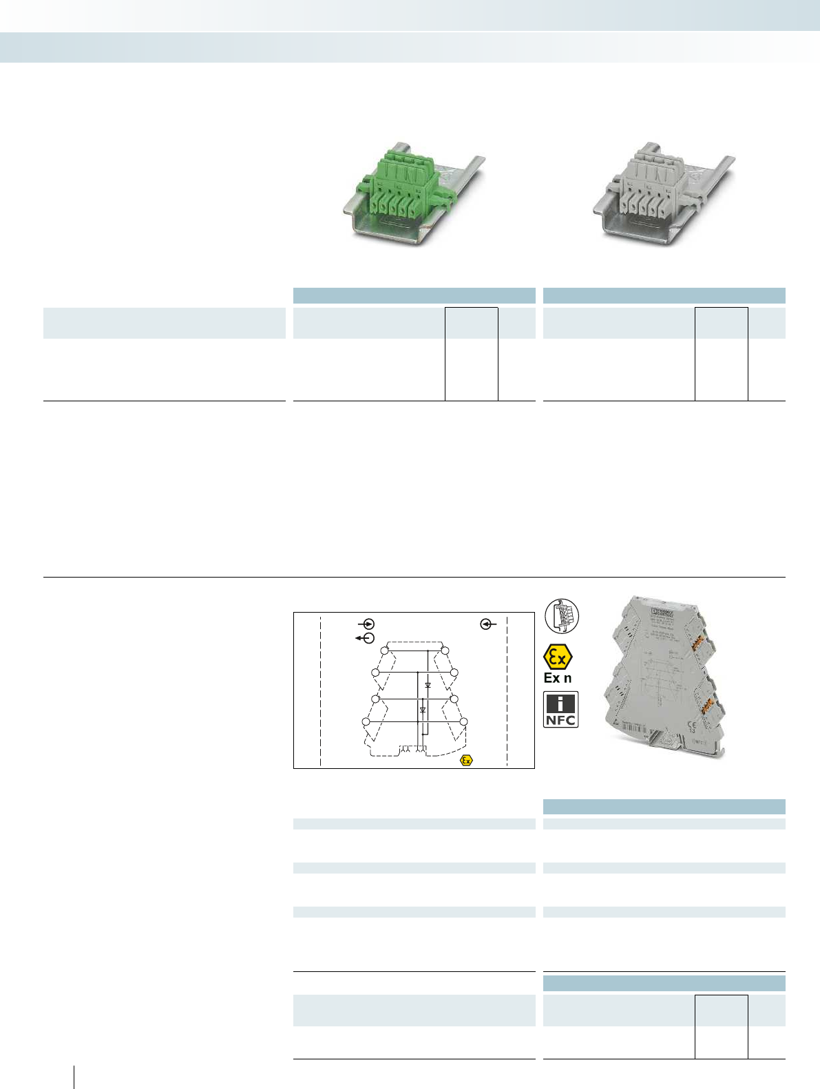
PWR OUT
+
+
+
–
–
–
–
+
PWR 1 IN
OUT-FM
PWR 2 IN
OUT-FM PWR 2 IN
PWR 1 IN
IN
OUT FM
1 5
2 6
37
48
+9,6 V
…+30 V
+9,6 V
…+30 V
Zone 2
IN
+9,6 V
…+30 V
+9,6 V
…+30 V
–
+
Ordering data Ordering data
Description Type Order No. Pcs. /
Pkt. Type Order No. Pcs. /
Pkt.
DIN rail connector (TBUS), for bridging the supply voltage,
can be snapped onto 35 mm DIN rails as per EN 60715, with
UL approval
Color: green ME 6,2 TBUS-2 1,5/5-ST-3,81 GN 2869728 10
Color: gray ME 6,2 TBUS-2 1,5/5-ST-3,81 GY 2695439 10
– For bridging the supply voltage
– Reduces wiring costs
– Module replacement without interrupting
the supply to the remaining modules
(hot swappable)
– One DIN rail connector for two
MINI Analog modules
– Only distinguished by color coding
Accessories
ME 6,2 TBUS... DIN rail connector
Interface technology and switching devices
Measurement and control technology - MINI Analog Pro highly compact signal conditioners
For bridging the supply voltage For bridging the supply voltage
Technical data
Input data/output data
Input voltage range 9.9 V DC ... 30 V DC
Output voltage (Input voltage - 0.3 V)
Output current ≤ 3.2 A
General data
Ambient temperature (operation) -40°C ... 70°C
Housing material PBT
EMC note Class A product, see page 443
Conformance / approvals
Conformance CE-compliant
ATEX II 3 G Ex nA IIC T4 Gc X
UL, USA / Canada 508 listing applied for
Class I, Div. 2, Groups A, B, C, D T5 applied for
GL GL applied for
Ordering data
Description Type Order No. Pcs. /
Pkt.
MINI Analog Pro power terminal block
Push-in connection MINI MCR-2-PTB-PT 2902067 1
Screw connection MINI MCR-2-PTB 2902066 1
336 PHOENIX CONTACT
– Power terminal block for supplying the
supply voltage to the DIN rail connector
– Plug-in connection system
– Increased output current of 3.2 A
– Monitoring of supplies in combination
with the fault monitoring module
– Flexible redundant supply from one or
both module sides
– Status and error indicator LEDs
Accessories
Power terminal blocks
Redundant supply for existing 24 V
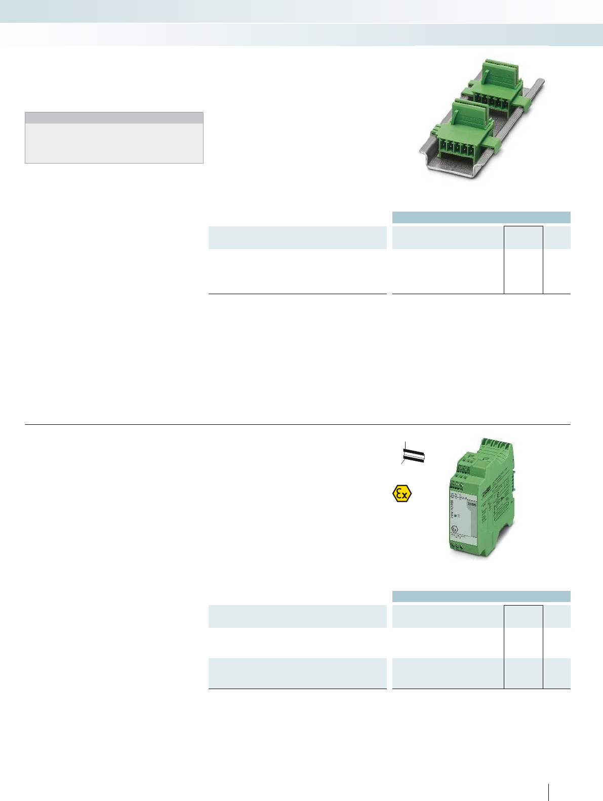
For additional information, visit phoenixcontact.net/products
Ordering data
Description Type Order No. Pcs. /
Pkt.
DIN rail connector, for bridging the supply voltage, can be
snapped onto 35 mm DIN rails as per EN 60715, with UL approval,
two pieces are required per system power supply
ME 17,5 TBUS 1,5/ 5-ST-3,81 GN 2709561 10
– For bridging the supply voltage when using
a MINI POWER system power supply
Notes:
If the system power supply is used, two ME 17,5 TBUS DIN rail
connectors are required. This allows you to establish the
connection to the ME 6,2 TBUS DIN rail connector of the MINI
Analog system and provide an effective power supply.
Accessories
ME 17,5 TBUS-... DIN rail connector
Interface technology and switching devices
Measurement and control technology - MINI Analog Pro highly compact signal conditioners
For system power supply
Ordering data
Description Type Order No. Pcs. /
Pkt.
System power supply, primary-switched, with zone 2 approval.
Further information can be found in Catalog 6, Surge protection and
power supplies.
MINI-PS-100-240AC/24DC/1.5/EX 2866653 1
System power supply, primary-switched (not for zone 2!)
Further information can be found in Catalog 6, Surge protection and
power supplies.
MINI-SYS-PS-100-240AC/24DC/1.5 2866983 1
337
PHOENIX CONTACT
H
W
D
– For supplying the supply voltage via the
DIN rail connector where AC voltages
are available
– 100 ... 240 V AC nominal input voltage
range
– 24 V DC output voltage
– For up to 60 MINI Analog modules
– For up to 1.5 A, secondary
– Status and error signaling via diagnostic
LEDs
Accessories
System power supply
For applications with local voltages
of over 100 V
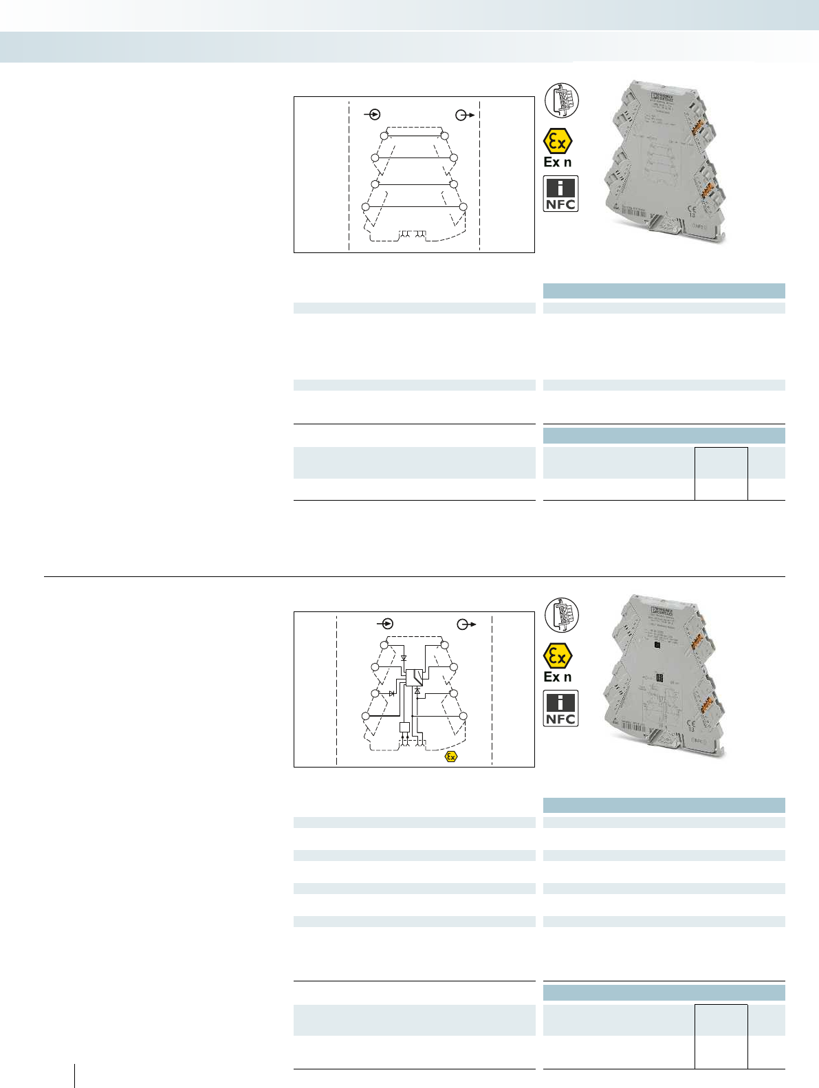
OUTIN
OUTIN
OUT
IN OUT
1 5
2 6
37
48
Sensor / Field PLC / DCS
IN
OUTIN
PWR+
PWR–
+
+
+
–
–
–
–
+
OUT RC
OUT RC
PWR 1
IN
PWR 2
IN
PWR
OUT
FAULT
CONTACT
IN OUT
FM
1 5
2 6
37
48
+9,6 V…+30 V+9,6 V…+30 V
+9,6 V…+30 V
Zone 2
Technical data
General data
Degree of protection IP20
Ambient temperature (operation) -40°C ... 70°C
Mounting Any
Housing material PBT
Dimensions W/H/D 6.2/110.5/120.5 mm
Screw connection solid/stranded/AWG 0.2 ... 1.5 mm²/0.2 ... 1.5 mm²/26 - 16
Conformance / approvals
Conformance CE-compliant
ATEX II 3 G Ex nA IIC T4 Gc X
GL GL applied for
Ordering data
Description Type Order No. Pcs. /
Pkt.
MINI Analog Pro feed-through terminal block
Screw connection MINI MCR-2-TB 2902068 1
– Feed-through terminal block for
1:1 forwarding of signals that are already
electrically isolated in the MINI Analog
Pro group
– Plug-in connection system
Accessories
Feed-through terminal blocks
Interface technology and switching devices
Measurement and control technology - MINI Analog Pro highly compact signal conditioners
1:1 connection
Technical data
Input data/output data
Input signal 9.9 V DC ... 30 V DC
Output signal 9.6 V DC ... 29.7 V DC
Switching output
Max. switching voltage 30 V DC
Max. switching current 50 mA
General data
Test voltage input/output 1.5 kV AC (50 Hz, 1 min.)
EMC note Class A product, see page 443
Conformance / approvals
Conformance CE-compliant
ATEX II 3 G Ex nA IIC T4 Gc X
UL, USA / Canada 508 listing applied for
Class I, Div. 2, Groups A, B, C, D T5 applied for
GL GL applied for
Ordering data
Description Type Order No. Pcs. /
Pkt.
MINI Analog Pro error signaling module
Push-in connection MINI MCR-2-FM-RC-PT 2904508 1
Screw connection MINI MCR-2-FM-RC 2904504 1
338 PHOENIX CONTACT
– Fault monitoring module for evaluating
and reporting group errors from the
fault monitoring system
– Monitoring of up to 115 connected
MINI Analog Pro modules
– Plug-in connection system
– Monitoring of supply voltages of
MINI MCR-2-PTB(-PT) power terminal
blocks
– Drawing off the supply is possible
– Fault signaling via an N/C contact
– Status and error indicator LEDs
Accessories
Error message modules
Group error message and
supply monitoring
For additional information, visit phoenixcontact.net/products
Technical data
General data
EMC note Class A product, see page 443
Ordering data
Description Type Order No. Pcs. /
Pkt.
Programming adapter for configuring modules with
S-PORT interface
IFS-USB-PROG-ADAPTER 2811271 1
IFS-USB-PROG-ADAPTER programming
adapter for configuring Phoenix Contact
INTERFACE modules with S-PORT
interface.
The adapter is used with FDT/DTM
software or ANALOG-CONF software.
For programming MACX Analog and
MINI Analog.
Accessories
Programming adapter
Interface technology and switching devices
Measurement and control technology - MINI Analog Pro highly compact signal conditioners
Ordering data Ordering data
Description Color Type Order No. Pcs. /
Pkt. Type Order No. Pcs. /
Pkt.
UniCard, can be labeled with THERMOMARKCARD and
BLUEMARK
Lettering field size: 30x5mm white UCT-EM (30X5) 0801505 10
Lettering field size: 30x5mm white UCT-EM (30X5) CUS 0801589 1
10-section, lettering field size: 15 x 5 mm white UC-EMLP (15X5) 0819301 10
10-section, lettering field size: 15 x 5 mm white UC-EMLP (15X5) CUS 0824550 1
Self-adhesive marker strips, unprinted, continuous, material
off the roll, for marking with thermal transfer printer, can be
separated using cutter, pitch as desired, strip length of up to
1000mm, 10strips, strip height of5.0mm, 1roll = 90m
white SK 5,0 WH:REEL 0805221 1
339
PHOENIX CONTACT
– Snap-in labels and adhesive labels with
large-area for marking
– For snapping into or sticking onto
MINI Analog Pro covers, without
overlapping the status and error LEDs
– The sheets can be marked quickly and
easily using the BLUEMARK CLED and
the THERMOMARK CARD...
– They can also be custom printed
according to customer requirements
Accessories
Marking label for transparent cover
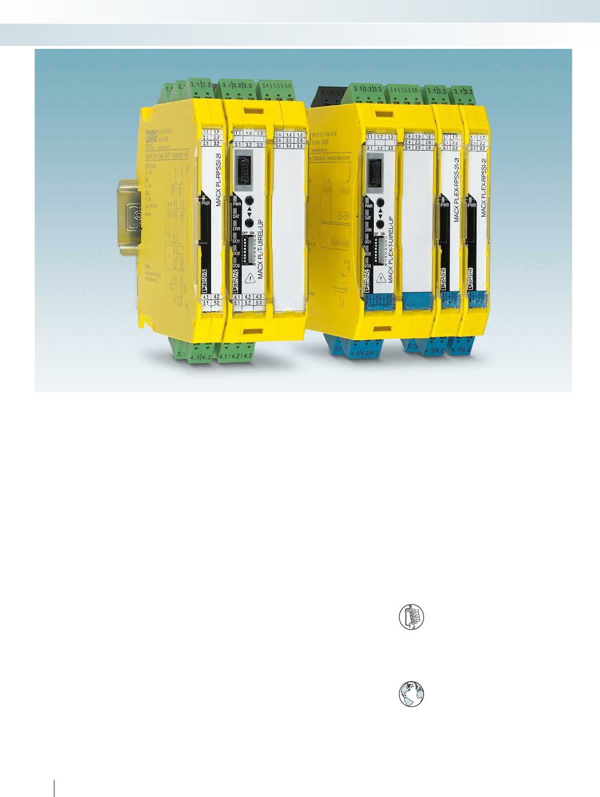
340 PHOENIX CONTACT
Integrate analog signals safely
Integrate analog signals easily into your
safety application according to the
Machinery Directive. The MACX Safety
analog signal conditioners are certified
according to EN ISO 13849-1 with
performance level PL d.
Ex i signals
MACX Safety Ex enables the easy and safe
processing of intrinsically safe analog signals
according to the Machinery Directive.
Cost savings
– Direct safe shutdown without an
additional safety controller or in
conjunction with a small-scale controller
from Phoenix Contact offers a clear cost
advantage
– Further cost savings can be made thanks
to easy configuration and easy integration
in the safety chain
– Versions with push-in technology save
installation time
Choose the right MACX Safety signal
conditioner for your application:
Analog IN
– 4...20 mA repeater power supplies and
input signal conditioners with 2
electrically isolated outputs
Te m p e r a t u r e
– Universal temperature transducers for
resistance thermometers, resistance-type
sensors, potentiometers, thermocouples,
and mV sources – with safe limit value
relay
Functional safety – from the initial
idea to the finished product
Phoenix Contact meets the requirements
of functional safety according to IEC 61508
in a standardized development process.
Here, all fault avoidance and fault control
measures are taken into consideration,
from the very development and production
of a device right up to device operation. The
devices are examined by an independent
test center.
Wide range supply
The modules featuring a wide range
supply (...-UP) can be used in all
power supply networks the world
over without the need for additional
power supply units.
DIN rail connector-compatible
The DIN rail connector enables the
modular bridging of the 24 V supply
voltage.
Interface technology and switching devices
Measurement and control technology - signal conditioners with PL and SIL functional safety - MACX Safety

For additional information, visit phoenixcontact.net/products
341PHOENIX CONTACT
Interface technology and switching devices
Measurement and control technology - signal conditioners with PL and SIL functional safety - MACX Safety
Safe and reliable functions
– Consistent PL d and SIL certification. This
ensures the highest level of reliability and
safety for your systems.
Precise transmission and high
operational reliability
– Thanks to patented transmission concept
– Safe electrical isolation.
Easy integration with Sistema
– Easy integration into the safety chain via
Sistema. The required data is already
stored in Sistema.
Easy configuration and monitoring
– Easy configuration and monitoring with
the ANALOG-CONF stand-alone
software with integrated monitoring
function or with FDT/DTM.
Easy to combine
– Analog signals, whether passive or active,
can be easily combined with other safety
modules.
Easy-maintenance connection
technology
– Plug-in connection terminal blocks with
screw connection or fast push-in techno-
logy – coded, with integrated sockets.
Precise transmission, long service life
– Patented circuit concepts ensure precise
signal transmission and minimal self-
heating.
Even for the Ex area
– Maximum explosion protection for all
Ex zones with the MACX Safety Ex range
as associated intrinsically safe equipment
and for installation in zone 2.
Direct safety shutdown
– Simple and direct shutdown for small
applications is possible without an
expensive safety controller or in
conjunction with a small-scale controller.
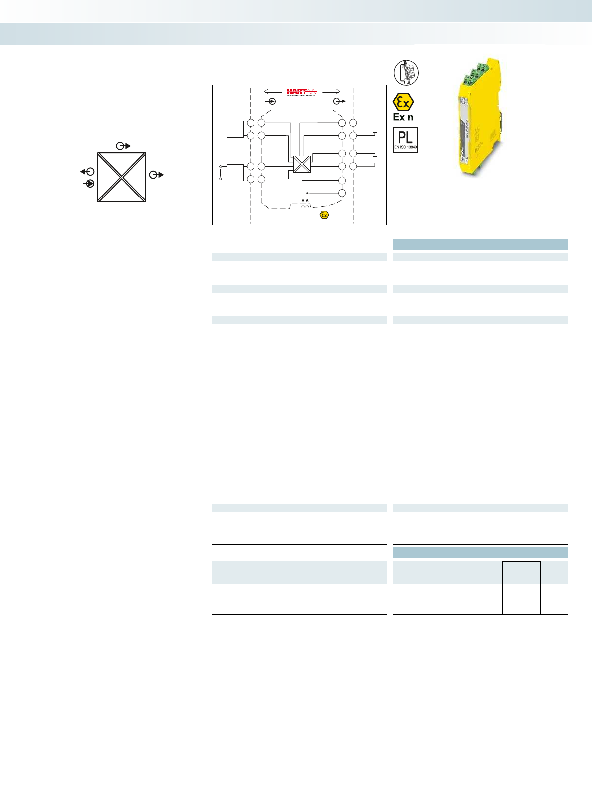
POWER
IIOUT2
I
OUT1
IN
POWER
Zone 2
Div. 2
IN OUT
4.2
5.2
4.1
5.1
3.2
3.1
2.2
2.1
1.2
1.1
GND
OUT 1
OUT 2
+24V
GND +24V
Power
+
+
-
-
+
-
PLC / DCS
passive
-
+
3.2
3.1
passive
-
+
2.2
2.1
Sensor / Field
or
4.2
4.1
2-wire
5.2
5.1
4-wire
US
Housing width 12.5 mm
Technical data
Input data
Input signal 4 mA ... 20 mA/4 mA ... 20 mA
Transmitter supply voltage > 21.5 V (at 20 mA)
Voltage drop < 3.9 V (in input signal conditioner operation)
Output data
Output signal (per output) 4 mA ... 20 mA (active)
Load < 450 Ω (at 20 mA)
Output ripple < 20 mVrms
General data
Supply voltage range 19.2 V DC ... 30 V DC (24 V DC (-20% ... +25%))
Current consumption < 75 mA (at 24 V DC)
Power dissipation < 1.45 W (at 24 V DC/20 mA)
Temperature coefficient < 0.01%/K
Step response (10-90%) < 1.3 ms (for 4 mA ... 20 mA step)
Transmission error, typical < 0.05% (of final value)
Maximum transmission error < 0.1% (of final value)
Under-/overload range According to NE 43
Electrical isolation
Input/output/power supply 300 Vrms (rated insulation voltage (surge voltage category II;
pollution degree 2, safe isolation as per EN 61010-1))
2.5 kV (50 Hz, 1 min., test voltage)
Output 1/output 2 1.5 kV AC (50 Hz, 1 min., test voltage)
Ambient temperature range -20°C ... 60°C (any mounting position)
Status indication Green LED (PWR supply voltage)
SMART communication (per output) Yes
Protocols supported HART
Housing material PA 66-FR
Dimensions W/H/D 12.5/99/114.5 mm
Screw connection solid/stranded/AWG 0.2 ... 2.5 mm²/0.2 ... 2.5 mm²/24 - 14
Spring-cage connection (solid/stranded/AWG) 0.2 ... 1.5 mm²/0.2 ... 1.5 mm²/24 - 16
EMC note Class A product, see page 443
Conformance / approvals
Conformance CE-compliant, additionally EN 61326
ATEX II 3 G Ex nA IIC T4 Gc X
SIL in accordance with IEC 61508 2
Performance level according to ISO 13849 PLd
Ordering data
Description Type Order No. Pcs. /
Pkt.
Repeater power supplies and input signal conditioners,
signal duplicator, with performance level
Screw connection MACX PL-RPSSI-2I 2904961 1
Spring-cage connection MACX PL-RPSSI-2I-SP 2904962 1
342 PHOENIX CONTACT
– 4...20 mA input, powered and not
powered
– Two electrically isolated 4...20 mA
(active) outputs
– PL d according to EN ISO 13849-1
– Up to SIL 2 according to EN 61508
– Installation in zone 2 possible
– Plug-in screw and push-in connection
technology
– 4-way electrical isolation
– Bidirectional HART communication
possible
– Power supply via DIN rail connector
possible
Analog IN
Repeater power supplies
Interface technology and switching devices
Measurement and control technology - signal conditioners with PL and SIL functional safety - MACX Safety
Repeater power supply and
input signal conditioner,
with two electrically isolated outputs
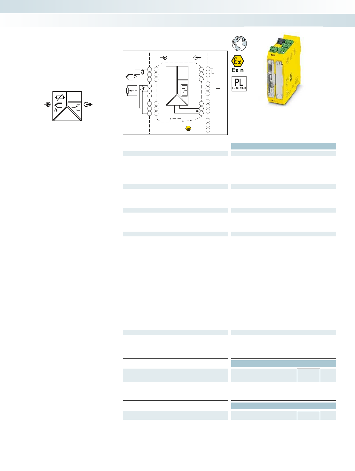
OUT
IN
POWER
I
Zone2
Div. 2
IN OUT
Power
24V ...230V AC/DC
3.3
3.1
1.2
3.2
1.1
1.3
4.3
4.1
4.2
5.3
5.1
5.2
GND
I
OUT
NC
PLC/DCS
passive
-
+
3.3
3.2
11
21
31
12
22
32
14
24
34
3.6
3.4
3.5
2.6
2.4
2.5
1.6
1.4
1.5
DI
DI
Sensor/Field
4.3
4.1
4.2
ϑ
RTD
4.3
4.1
4.2
5.3
5.1
5.2
ϑ
Poti
TC
-
+
ϑ
For additional information, visit phoenixcontact.net/products
Ex:
Housing width 35 mm
Technical data
Input data
Resistance thermometers Pt, Ni, Cu sensors: 2, 3, 4-wire
Thermocouple sensors B, E, J, K, N, R, S, T, L, U, CA, DA, A1G, A2G, A3G, MG, LG
Resistor 0 Ω ... 50 kΩ
Potentiometer 0 Ω ... 50 kΩ
Voltage -1000 mV ... 1000 mV
Output data
Output signal 4 mA ... 20 mA
Maximum output signal 22 mA
Load RB≤ 600 Ω (at 20 mA)
Behavior in the event of a sensor error According to NE 43 or freely configurable
Switching output Relay output
Contact type 2 PDT
Contact material AgSnO2, hard gold-plated
Max. switching voltage 250 V AC (250 V DC)
Max. switching current 2 A (250 V AC)/2 A (28 V DC)
General data
Supply voltage range 24 V ... 230 V AC/DC (-20%/+10%, 50/60 Hz)
Power consumption < 2.4 W
Temperature coefficient 0.01%/K
Maximum transmission error 0.1% (e.g. for Pt 100, 300 K span, 4 ... 20 mA)
Electrical isolation
Input/output/power supply 300 Vrms (rated insulation voltage (surge voltage category II;
pollution degree 2, safe isolation as per EN 61010-1))
2.5 kV (50 Hz, 1 min., test voltage)
Input/output 375 V (peak value in accordance with EN 60079-11)
Input/power supply 375 V (peak value in accordance with EN 60079-11)
Input/switching output 375 V (peak value in accordance with EN 60079-11)
Ambient temperature range -20°C ... 65°C
Humidity Typ. 5% ... 95% (non-condensing)
Housing material PA 66-FR
Inflammability class in acc. with UL 94 V0
Dimensions W/H/D 35/99/114.5 mm
Screw connection solid/stranded/AWG 0.2 ... 2.5 mm²/0.2 ... 2.5 mm²/24 - 14
Spring-cage connection (solid/stranded/AWG) 0.2 ... 1.5 mm²/0.2 ... 1.5 mm²/24 - 16
EMC note Class A product, see page 443
Conformance / approvals
Conformance CE-compliant
ATEX II 3 G Ex nA nC ic IIC T4 Gc X
IECEx Ex nA nC ic IIC T4 Gc X
SIL in accordance with IEC 61508 2
Performance level according to ISO 13849 PLd
Ordering data
Description Type Order No. Pcs. /
Pkt.
Temperature transducer and threshold value switch with
performance level
Screw connection MACX PL-T-UIREL-UP 2904901 1
Spring-cage connection MACX PL-T-UIREL-UP-SP 2904903 1
Accessories
Programming adapter for configuring modules with
S-PORT interface
IFS-USB-PROG-ADAPTER 2811271 1
Plug with 50 Ω resistor, for current signals between
+20 mA and -20 mA
MACX MCR-I20 2905680 1
343PHOENIX CONTACT
– Input for resistance thermometers,
thermocouples, resistance-type sensors,
potentiometers, mV sources
– A safety-related limit value relay, by
bridging two relays
– Differential measurement possible with
Pt 100
– An additional limit value relay for
non-safety-related function
– PL d according to EN ISO 13849-1
– Up to SIL 2 according to EN 61508
– Configuration via software
(ANALOG-CONF or FDT/DTM)
– Cold junction compensation with
separate plug
– Wide range power supply
19.2 ... 253 V AC/DC
– Status indicators for supply voltage, cable,
sensor, and module errors
– Installation in zone 2 possible
– Plug-in screw and push-in connection
technology
Te m p e r a t u r e ,
temperature transducer
Interface technology and switching devices
Measurement and control technology - signal conditioners with PL and SIL functional safety - MACX Safety
Universal, with limit value relays,
wide range power supply
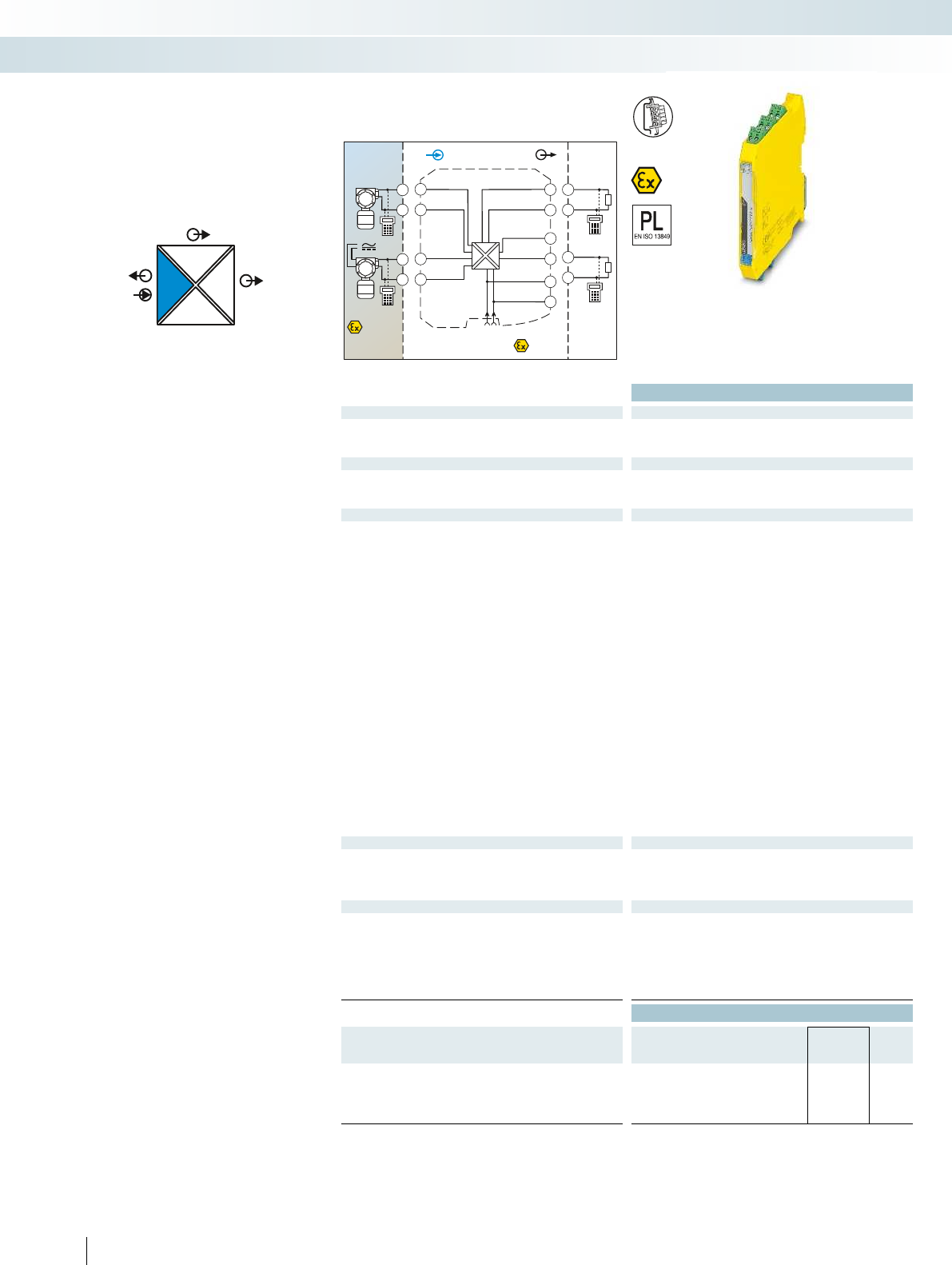
POWER
IIOUT2
I
OUT1
IN
POWER
Zone 2
Div. 2
Sensor / Field
or
4.2
5.2
4.1
5.1
Zone 0,1,2
Zone 20,21,22
Div. 1,2
4.2
5.2
4.1
5.1
3.2
3.1
2.2
2.1
1.2
1.1
GND
OUT 1
OUT 2
+24V
GND +24V
Power
+
+
-
-
IN OUT
PLC / DCS
3.2
3.1 +
-
2.2
2.1 +
-
passive
passive
AI
Housing width 12.5 mm
Technical data
Input data
Input signal 4 mA ... 20 mA/4 mA ... 20 mA
Transmitter supply voltage > 16 V (at 20 mA)
Voltage drop < 3.9 V (in input signal conditioner operation)
Output data
Output signal (per output) 4 mA ... 20 mA (active)
Load < 450 Ω (at 20 mA)
Output ripple < 20 mVrms
General data
Supply voltage range 19.2 V DC ... 30 V DC (24 V DC (-20% ... +25%))
Current consumption < 75 mA (24 V DC/ 20 mA)
Power dissipation < 1.45 W (24 V DC/ 20 mA)
Temperature coefficient < 0.01%/K
Step response (10-90%) < 1.3 ms (for 4 mA ... 20 mA step)
Transmission error, typical < 0.05% (of final value)
Maximum transmission error < 0.1% (of final value)
Under-/overload range According to NE 43
Electrical isolation
Input/output/power supply 300 Vrms (rated insulation voltage (surge voltage category II;
pollution degree 2, safe isolation as per EN 61010-1))
2.5 kV (50 Hz, 1 min., test voltage)
Input/output 375 V (peak value in accordance with EN 60079-11)
Input/power supply 375 V (peak value in accordance with EN 60079-11)
Output 1/output 2 1.5 kV AC (50 Hz, 1 min., test voltage)
Ambient temperature range -20°C ... 60°C (any mounting position)
Status indication Green LED (PWR supply voltage)
SMART communication (per output) Yes
Protocols supported HART
Housing material PA 66-FR
Dimensions W/H/D 12.5/99/114.5 mm
Screw connection solid/stranded/AWG 0.2 ... 2.5 mm²/0.2 ... 2.5 mm²/24 - 14
Spring-cage connection (solid/stranded/AWG) 0.2 ... 1.5 mm²/0.2 ... 1.5 mm²/24 - 16
EMC note Class A product, see page 443
Safety data as per ATEX
Max. output voltage Uo25.2 V
Max. output current Io93 mA
Max. output power Po587 mW
Maximum voltage Um253 V AC (125 V DC)
Conformance / approvals
Conformance CE-compliant, additionally EN 61326
ATEX II (1) G [Ex ia Ga] IIC/IIB
II (1) D [Ex ia Da] IIIC
II 3 (1)G Ex nA [ia Ga] IIC/IIB T4 Gc
IECEx [Ex ia Ga] IIC/IIB, [Ex ia Da], Ex nA [ia Ga] IIC/IIB T4 Gc
SIL in accordance with IEC 61508 2
Performance level according to ISO 13849 PLd
Ordering data
Description Type Order No. Pcs. /
Pkt.
Repeater power supplies and input signal conditioners,
signal duplicator, with performance level, intrinsically safe input
Screw connection MACX PL-EX-RPSSI-2I 2904959 1
Spring-cage connection MACX PL-EX-RPSSI-2I-SP 2904960 1
344 PHOENIX CONTACT
– 4...20 mA input, [Ex ia], powered and not
powered
– Two electrically isolated 4...20 mA
(active) outputs
– PL d according to EN ISO 13849-1
– Up to SIL 2 according to EN 61508
– Installation in zone 2 possible
– Plug-in screw and push-in connection
technology
– 4-way electrical isolation
– Bidirectional HART communication
possible
– Power supply via DIN rail connector
possible
Analog IN
Repeater power supply, Ex i
Interface technology and switching devices
Measurement and control technology - signal conditioners with PL and SIL functional safety - MACX Safety
Repeater power supply and
input signal conditioner,
with two electrically isolated outputs
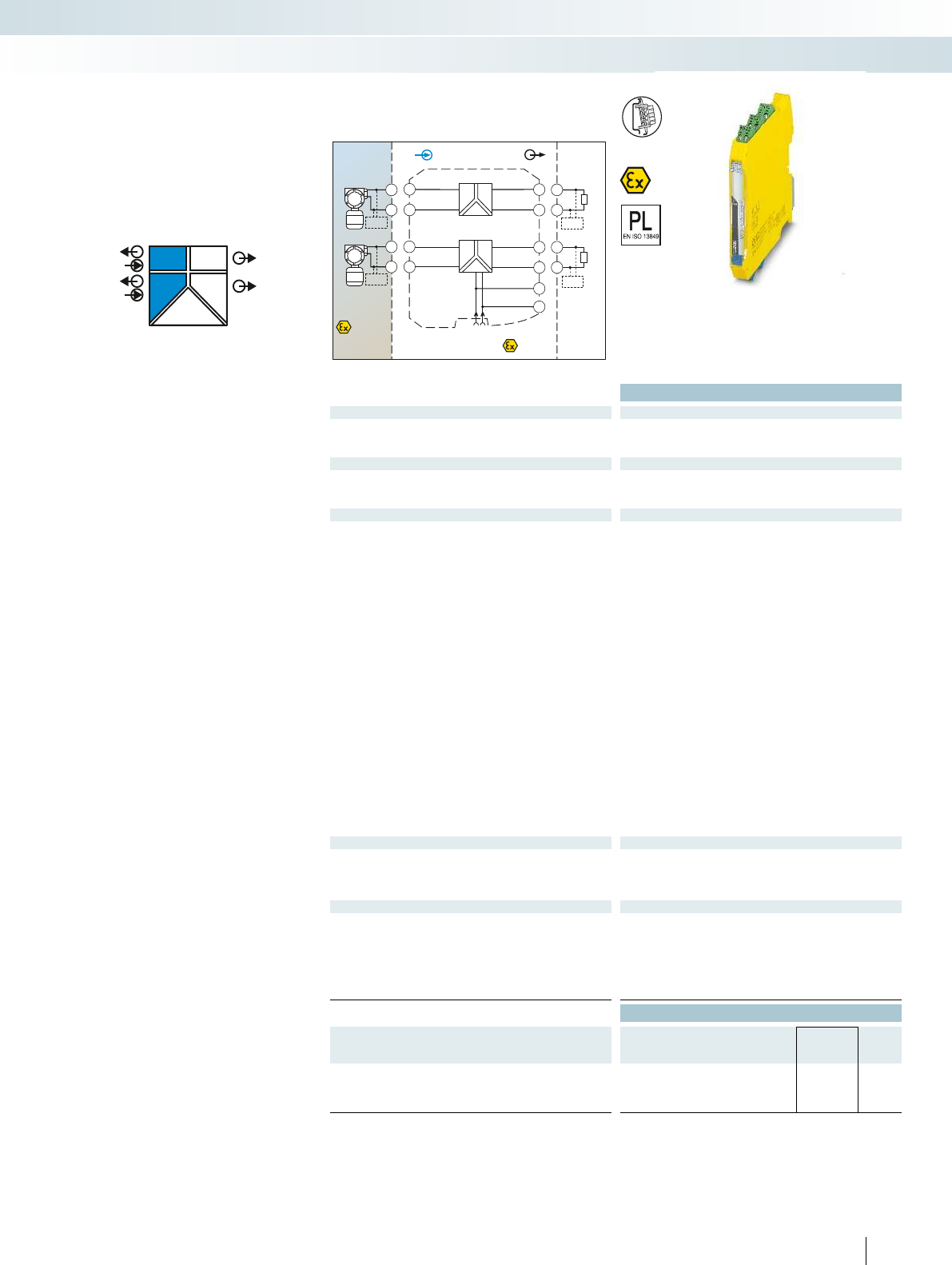
POWER
OUT
OUT
IN
POWER
IN
POWER
II
II
PLC / DCS
AI
Sensor / Field
Zone 2
3.2
3.1
2.2
2.1
GND
1.2
1.1
+24V
GND +24V
Power
Zone 0,1,2
Zone 20,21,22
passive
3.2
3.1 +
-
HHT
IN OUT
CH1
CH2
active
active
passive
2.1
2.2 -
+
HHT
5.2
5.1
5.2
5.1
+
-
CH2
HHT
4.2
4.1
4.2
4.1
+
-
CH1
HHT
For additional information, visit phoenixcontact.net/products
Ex:
Housing width 12.5 mm
Technical data
Input data per channel
Input signal 4 mA ... 20 mA
Transmitter supply voltage > 16 V (at 20 mA)
Underload/overload signal range 0 mA ... 24 mA
Output data per channel
Output signal 4 mA ... 20 mA (active)
Load ≤ 450 Ω (20 mA)
Underload/overload signal range 0 mA ... 24 mA
General data
Supply voltage range 19.2 V DC ... 30 V DC (24 V DC (-20% ... +25%))
Current consumption < 100 mA (24 V/20 mA)
Power dissipation < 1.4 W (at 24 V DC/20 mA)
Temperature coefficient < 0.01%/K
Step response (10-90%) < 1.3 ms (for 4 mA ... 20 mA step)
Transmission error, typical < 0.05% (of final value)
Maximum transmission error < 0.1% (of final value)
Electrical isolation
Input/output, power supply 300 Vrms (rated insulation voltage (surge voltage category II;
pollution degree 2, safe isolation as per EN 61010-1))
2.5 kV (50 Hz, 1 min., test voltage)
Input/output 375 V (peak value in accordance with EN 60079-11)
Input/power supply 375 V (peak value in accordance with EN 60079-11)
Output 1/output 2/ power supply 1.5 kV (50 Hz, 1 min., test voltage)
Ambient temperature range -20°C ... 60°C (any mounting position)
Status indication Green LED (supply voltage)
SMART communication Yes
Signal bandwidth as per HART specifications
Protocols supported HART
Housing material PA 66-FR
Dimensions W/H/D 12.5/99/114.5 mm
Screw connection solid/stranded/AWG 0.2 ... 2.5 mm²/0.2 ... 2.5 mm²/24 - 14
Spring-cage connection (solid/stranded/AWG) 0.2 ... 1.5 mm²/0.2 ... 1.5 mm²/24 - 16
EMC note Class A product, see page 443
Safety data as per ATEX
Max. output voltage Uo25.2 V
Max. output current Io93 mA
Max. output power Po587 mW
Maximum voltage Um253 V AC (125 V DC)
Conformance / approvals
Conformance CE-compliant, additionally EN 61326
ATEX II (1) G [Ex ia Ga] IIC/IIB
II (1) D [Ex ia Da] IIIC
II 3(1) G Ex nA [ia Ga] IIC T4 Gc
IECEx [Ex ia Ga] IIC/IIB, [Ex ia Da] IIIC, Ex nA [ia Ga] IIC T4 Gc
SIL in accordance with IEC 61508 3
Performance level according to ISO 13849 PLd
Ordering data
Description Type Order No. Pcs. /
Pkt.
Repeater power supply, two-channel, with performance level,
intrinsically safe input
Screw connection MACX PL-EX-RPSS-2I-2I 2904963 1
Spring-cage connection MACX PL-EX-RPSS-2I-2I-SP 2904964 1
345PHOENIX CONTACT
– 2-channel
– 4...20 mA input, [Ex ia], powered
– 4 ... 20 mA output (active)
– PL d according to EN ISO 13849-1
– Up to SIL 3 according to IEC 61508
– Installation in zone 2 possible
– Plug-in screw and push-in connection
technology
– 3-way electrical isolation, per channel
– Bidirectional HART communication
possible
– Power supply via DIN rail connector
possible
Analog IN
Repeater power supply, Ex i
Interface technology and switching devices
Measurement and control technology - signal conditioners with PL and SIL functional safety - MACX Safety
2-channel repeater power supply
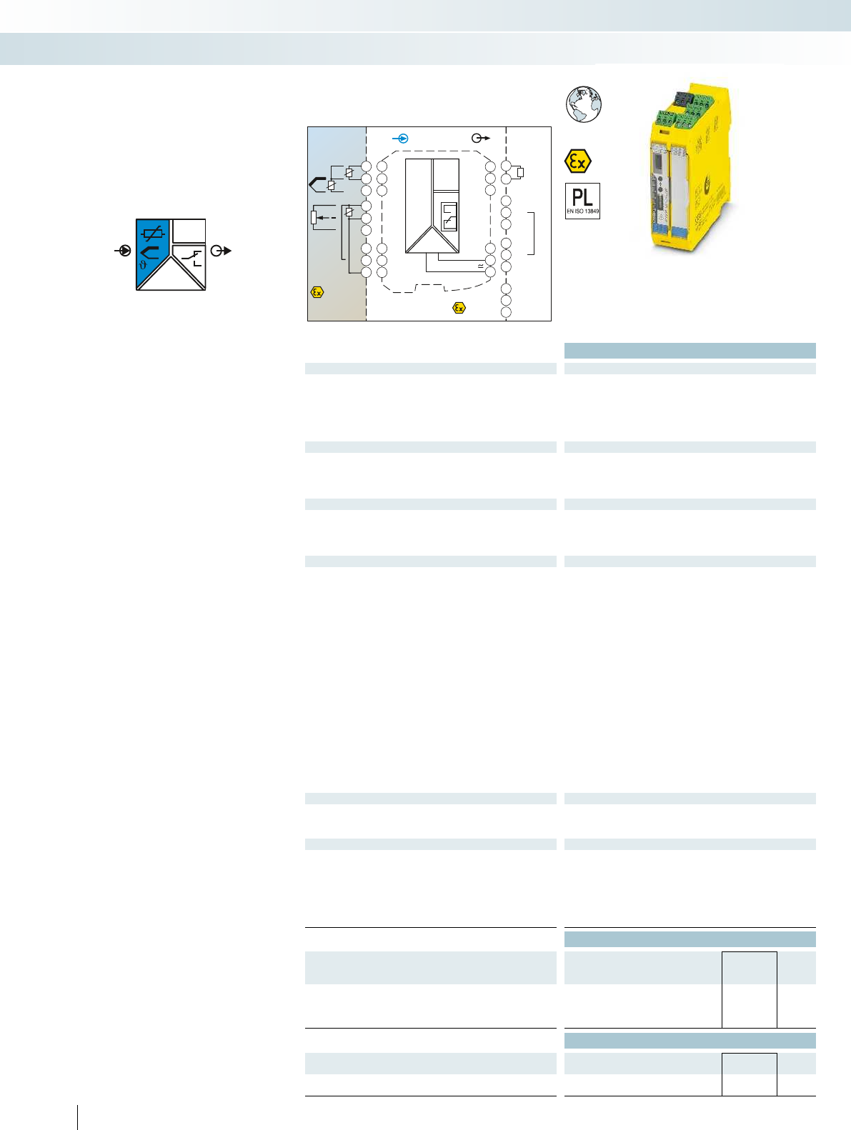
OUT
IN
POWER
I
Zone 0,1,2
Zone 20,21,22 Zone2
IN OUT
Power
24V ...230V AC/DC
3.3
3.1
1.2
3.2
1.1
1.3
4.3
4.1
4.2
5.3
5.1
5.2
GND
I
OUT
NC
PLC/DCS
passive
-
+
3.3
3.2
11
21
31
12
22
32
14
24
34
3.6
3.4
3.5
2.6
2.4
2.5
1.6
1.4
1.5
DI
DI
Sensor/Field
4.3
4.1
4.2
ϑ
RTD
4.3
4.1
4.2
5.3
5.1
5.2
ϑ
Poti
TC
-
+
ϑ
Housing width 35 mm
Technical data
Input data
Resistance thermometers Pt, Ni, Cu sensors: 2, 3, 4-wire
Thermocouple sensors B, E, J, K, N, R, S, T, L, U, CA, DA, A1G, A2G, A3G, MG, LG
Resistor 0 Ω ... 50 kΩ
Potentiometer 0 Ω ... 50 kΩ
Voltage -1000 mV ... 1000 mV
Output data
Output signal 4 mA ... 20 mA
Maximum output signal 22 mA
Load RB≤ 600 Ω (20 mA)
Behavior in the event of a sensor error According to NE 43 or freely configurable
Switching output Relay output
Contact type 2 PDT
Contact material AgSnO2, hard gold-plated
Max. switching voltage 250 V AC (250 V DC)
Max. switching current 2 A (250 V AC)/2 A (28 V DC)
General data
Supply voltage range 24 V ... 230 V AC/DC (-20%/+10%, 50/60 Hz)
Power consumption < 2.4 W
Temperature coefficient 0.01%/K
Maximum transmission error 0.1% (e.g. for Pt 100, 300 K span, 4 ... 20 mA)
Electrical isolation
Input/output/power supply 2.5 kV (50 Hz, 1 min., test voltage)
Input/output 375 V (peak value in accordance with EN 60079-11)
Input/power supply 375 V (peak value in accordance with EN 60079-11)
Input/switching output 375 V (peak value in accordance with EN 60079-11)
Output/supply 300 Vrms (rated insulation voltage (surge voltage category II;
pollution degree 2, safe isolation as per EN 61010-1))
Ambient temperature range -20°C ... 65°C
Humidity Typ. 5% ... 95% (non-condensing)
Housing material PA 66-FR
Inflammability class in acc. with UL 94 V0
Dimensions W/H/D 35/99/114.5 mm
Screw connection solid/stranded/AWG 0.2 ... 2.5 mm²/0.2 ... 2.5 mm²/24 - 14
Spring-cage connection (solid/stranded/AWG) 0.2 ... 1.5 mm²/0.2 ... 1.5 mm²/24 - 16
EMC note Class A product, see page 443
Safety data as per ATEX
Max. output voltage Uo6 V
Max. output current Io7.4 mA
Max. output power Po11 mW
Conformance / approvals
Conformance CE-compliant
ATEX II (1) G [Ex ia Ga] IIC
II (1) D [Ex ia Da] IIIC
II 3 G Ex nA nC ic IIC T4 Gc X
IECEx [Ex ia Ga] IIC, [Ex ia Da] IIIC, Ex nA nC ic IIC T4 Gc X
SIL in accordance with IEC 61508 2
Performance level according to ISO 13849 PLd
Ordering data
Description Type Order No. Pcs. /
Pkt.
Temperature transducer with threshold value switch, with
performance level, intrinsically safe input
Screw connection MACX PL-EX-T-UIREL-UP 2904910 1
Spring-cage connection MACX PL-EX-T-UIREL-UP-SP 2904912 1
Accessories
Programming adapter for configuring modules with
S-PORT interface
IFS-USB-PROG-ADAPTER 2811271 1
Plug with 50 Ω resistor, for current signals between
+20 mA and -20 mA
MACX MCR-EX-I20 2905679 1
346 PHOENIX CONTACT
– Input for resistance thermometers,
thermocouples, resistance-type sensors,
potentiometers, mV sources, [Ex ia]
– Differential measurement possible with
Pt 100
– A safety-related limit value relay, by
bridging two relays
– An additional limit value relay for
non-safety-related function
– PL d according to EN ISO 13849-1
– Up to SIL 2 according to EN 61508
– Configuration via software
(ANALOG-CONF or FDT/DTM)
– Cold junction compensation with
separate plug
– Wide range power supply
19.2 ... 253 V AC/DC
– Status indicators for supply voltage, cable,
sensor, and module errors
– Installation in zone 2 possible
– Plug-in screw and push-in connection
technology
Te m p e r a t u r e
Temperature transducer, Ex i
Interface technology and switching devices
Measurement and control technology - signal conditioners with PL and SIL functional safety - MACX Safety
Universal, with limit value relays,
wide range power supply
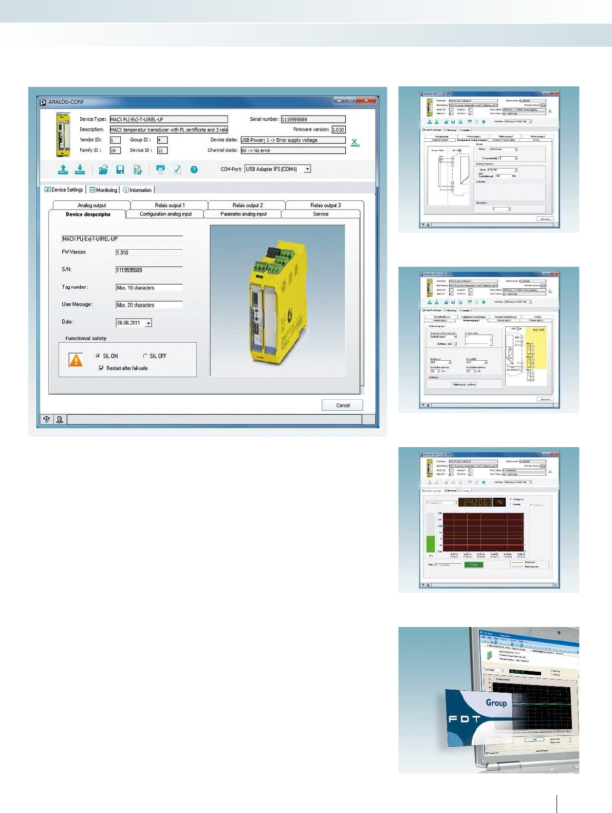
For additional information, visit phoenixcontact.net/products
ANALOG-CONF
The user-friendly ANALOG-CONF
software allows you to quickly and clearly
configure the temperature modules. The
pin assignment for the input and output is
directly displayed. You have access to the
complete range of configurable parameters.
You have the option to pre-configure
parameters and then import them into any
number of temperature transducers or read
the data from the device and directly display
the settings and measured values.
FDT/DTM
Configuration is also possible via the
FDT/DTM universal configuration tool. The
DTM files can simply be downloaded in the
download area for the item.
The following parameters can be
configured:
– Restart following failsafe
Input:
– Resistance thermometer
– Thermocouples
– Potentiometer
– Remote resistance-type sensor
– Voltage signals ±1 V
– User characteristic curve
– Additional analog signals
–Filter
– Cold junction
Analog output:
– Type of fault signaling
Switching outputs:
– Acknowledgement, switching behavior
–Switch-on/off delay
Monitoring:
– Representation in diagram or value list,
recording possible
Service:
– Reset, password protection, display
DIP switch position
–and much more
347PHOENIX CONTACT
Configuration software
ANALOG-CONF and FDT/DTM
Configuration with FDT/DTM
Monitoring function
Relay configuration
Input configuration with indication of the pin assignment
Interface technology and switching devices
Measurement and control technology - signal conditioners with PL and SIL functional safety - MACX Safety
Technical data
See phoenixcontact.net/products
Ordering data
Description Type Order No. Pcs. /
Pkt.
Program and configuration memory, plug-in, 2 GB with license
key and application program for reading from measuring devices
via pulses
SD FLASH 2GB EMWISE IMPULS 2701745 1
Program and configuration memory, plug-in, 2 GB with license
key and application program for reading from measuring devices
via pulses and analog values
SD FLASH 2GB EMWISE IMP ANALOG 2701746 1
Program and configuration memory, plug-in, 2 GB with license
key and application program for reading from measuring devices
via pulses, analog values, M-bus, Modbus RTU, and IO-Link
SD FLASH 2GB EMWISE EXTENDED 2701747 1
348 PHOENIX CONTACT
The EMwise software from
PhoenixContact is the efficient solution for
acquiring energy data regarding heat, cold,
air or electricity in conjunction with a
small-scale controller.
Integrate up to 24 digital inputs, 8 analog
channels, 50 EMpro energy meters,
30 M-bus counters, and 4 IO-Link
measuring sensors.
A web-based interface is available for
system parameterization. Each
device/channel can be configured
individually, without any programming
knowledge. The configuration is saved to a
file and can be reused for identical systems.
Your advantages:
– Startup without programming knowledge
– Direct parameterization of predefined
sensors
Three software versions, suitable for
every application:
– EMWISE IMPULS: for up to
16 digital signals
– EMWISE IMP ANALOG: for up to
16 digital and 6 analog signals
– EMWISE EXTENDED: for up to
24 digital and 8 analog signals,
EMpro energy meters, M-bus counters,
M-bus level converters, IO-Link sensors
Software for
acquisition of usage data
Interface technology and switching devices
Monitoring, energy, and power measuring technology

For additional information, visit phoenixcontact.net/products
Technical data
See phoenixcontact.net/products
Ordering data
Description Type Order No. Pcs. /
Pkt.
SD FLASH card with data logger FLEX application
SD FLASH 512MB ILDLC FLEX 2701873 1
349PHOENIX CONTACT
Turn your controller into a data logger.
The SD FLASH 512MB ILDLC FLEX
memory card from Phoenix Contact
provides all the software needed to extend
your PLC for use as a data logger. The
software contains the familiar application
from the FLEX data logger kit.
In conjunction with the ILC 151 GSM/GPRS
small-scale controller, 3 digital and 4 analog
input or output terminal blocks can be
mounted. The mounted terminals are
automatically detected and started up by the
controller. Different PCP channels can also be
selected during parameterization.
Your advantages:
– Send digital and analog status information
via SMS or e-mail or write it to an SQL
database
– Startup without programming knowledge
Software for data logging
Interface technology and switching devices
Monitoring, energy, and power measuring technology
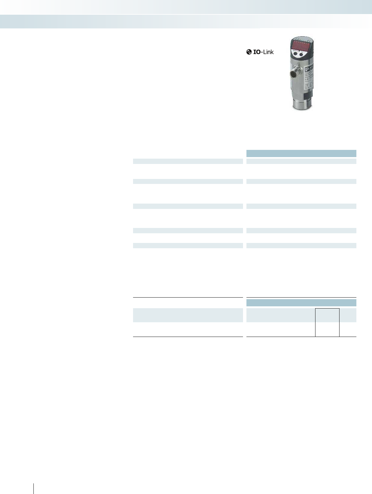
Technical data
Pressure monitoring
Measuring range -1 bar ... 10 bar (minimum burst pressure 150 bar)
Pressure resistance 75 bar
Process connection G1/4 I
Supply for module electronics
Connection method M12 connector
No. of pos. 4
Supply voltage range 18 V DC ... 36 V DC
Current draw < 35 mA
Digital outputs
Number of outputs 2 (OUT1 = switching output, OUT2 = switching output or
diagnostic output)
Connection method M12 connectors, assigned four times
Delay time 0.3 s (operational readiness)
IO-Link
Specification V1.1
Transmission speed (38.4 kbaud)
General data
Weight 263 g
Width 34 mm
Height 91.5 mm
Depth 48 mm
Degree of protection IP65
Protection class III
Ambient temperature (operation) -25°C ... 80°C
Ambient temperature (storage/transport) -40°C ... 100°C
Vibration resistance in acc. with EN 60068-2-6/IEC 60068-2-6 20g(10Hz...2000Hz)
Ordering data
Description Type Order No. Pcs. /
Pkt.
Pressure switch with indicator,
G1/4I process connection, IO-Link communication
PSK APS7004IOL 2700710 1
350 PHOENIX CONTACT
Pressure sensor with IO-Link
Pressure sensors from Phoenix Contact
detect the operating pressure of gas media
in a range from -1 to 10 bar. The overload-
proof ceramic measuring cell is designed for
in excess of 100 million cycles and enables a
high switching point accuracy. The pressure
switch offers the option of using the set
switching points via two switching outputs
or reading all process data via the IO-Link
interface.
Your advantages:
– IO-Link communication
– Parameterization, diagnostics, and
process value monitoring via IO-Link
– Programmable function
– 4-character alphanumeric display
Sensors and meters
Interface technology and switching devices
Monitoring, energy, and power measuring technology

For additional information, visit phoenixcontact.net/products
351PHOENIX CONTACT
Interface technology and switching devices
Monitoring, energy, and power measuring technology
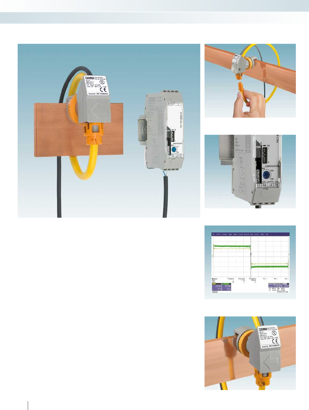
Fast installation in a confined space
PACT current transformers for
retrofitting can be conveniently mounted
where there is not enough space for split
core current transformers. System
downtimes are reduced as system parts do
not have to be removed for installation.
Simply place the handy Rogowski coil
quickly around power rails and circular
conductors. The measuring transducer
connected downstream supplies the same
typical secondary currents as a standard
current transformer.
Yo u r a d v a n t a g e s :
– High system availability due to reduced
downtimes: fast installation without
removing system parts
– Transform alternating currents up to
4000 A using a single measuring system
– Space saving and handy, as the current
strength does not affect the size and
weight of the coil
– Safe installation and operation: no
dangerous open circuit voltages
– Harmonics and transients detected with
phase accuracy with a large frequency
spectrum from 10 to 5000 Hz
– Rogowski coil secured on power rails and
circular conductors thanks to
professional holding device
352 PHOENIX CONTACT
Current transformers for retrofitting
PACT RCP
Professional holding device for power rails
Detect harmonics and transients with a
large frequency spectrum from 10 to 5000 Hz
Eight different current measuring ranges from 100 to 4000 A
Fast installation without removing system parts
Interface technology and switching devices
Monitoring, current, and voltage measuring technology
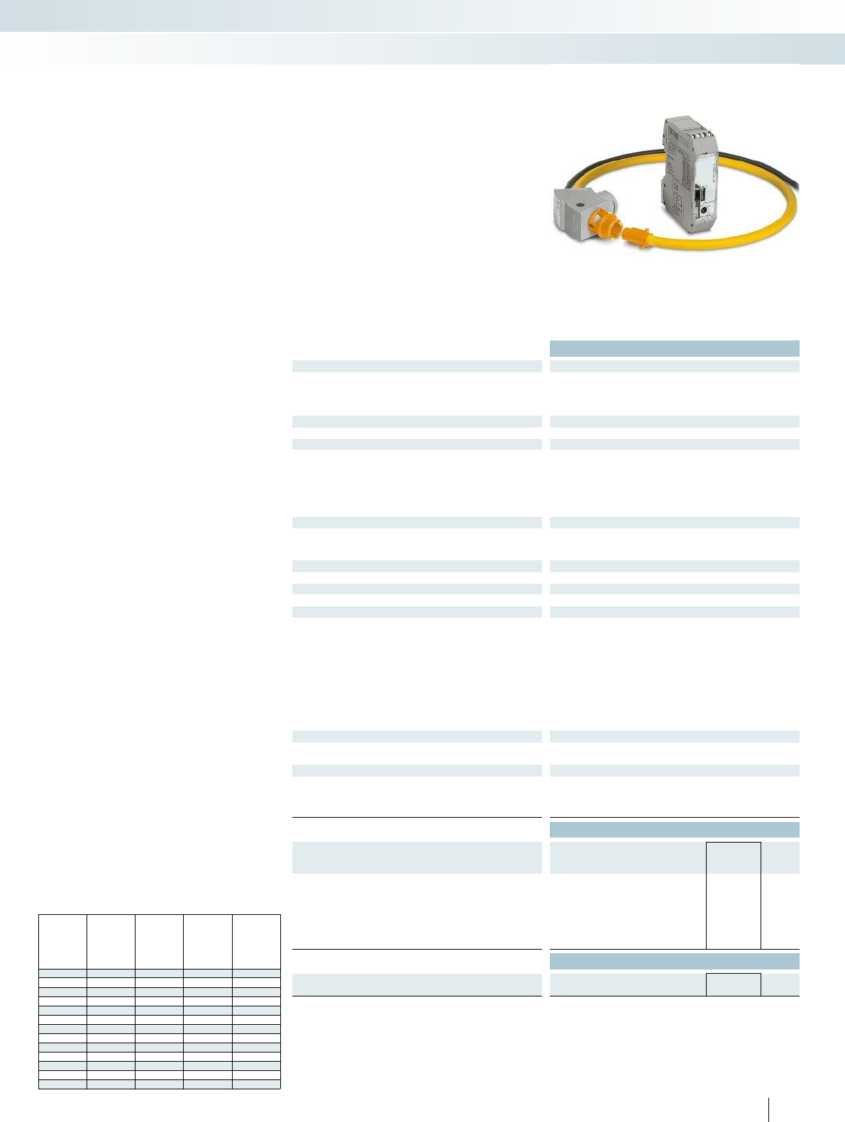
For additional information, visit phoenixcontact.net/products
Technical data
Measuring coil input data
Frequency range 10 Hz ... 5000 Hz
Input signal Sine
Position error < 1% (the measuring coil is at right angles to the live connector.)
Measuring coil signal output
Output signal (at 50 Hz) 100 mV (no load, at 1,000 A)
General data, measuring coil
Length of signal cable 3000 mm
Rated insulation voltage 1000 V AC (rms CAT III)
600 V AC (rms CAT IV)
Test voltage 10.45 kV (DC/1 min.)
Ambient temperature (operation) -30°C ... 80°C (measuring coil)
Ambient temperature (storage/transport) -40°C ... 90°C (measuring coil)
Measuring transducer input data
Measuring ranges (current) via DIP switch 100 A 250 A 400 A 630 A 1000 A 1500 A 2000 A 4000 A
Phase angle < 1 °
Measuring transducer signal input
Input signal (at 50 Hz) 100 mV (1000 A)
Measuring transducer signal output
Current output signal 1 A AC (effective at sine)
Miscellaneous data for measuring transducer
Nominal supply voltage 24 V DC -20% ... +25%
Nominal supply voltage range 19.2 V DC ... 30 V DC
Transmission error, maximum ≤ 0.5% (from the range end value)
Linearity error < 0.5% (from the range end value)
Frequency range 45 Hz ... 65 Hz
Degree of protection IP20
Test voltage 1.5 kV AC (supply/input and output)
Dimensions W/H/D 22.5/70.4/85 mm
Ambient temperature (operation) -20°C ... 70°C (measuring transducer)
Ambient temperature (storage/transport) -25°C ... 85°C (measuring transducer)
General data for the set
Altitude < 2000 m
Permissible humidity (operation) 5% ... 95% (non-condensing)
Approvals / conformities
Standards/specifications IEC 61010-1
IEC 61010-031
IEC 61010-2-031
IEC 61010-2-032
Ordering data
Description Type Order No. Pcs. /
Pkt.
Current transformer for retrofitting, set consisting of
Rogowski coil and measuring transducer,
output signal: 1 A AC (effective for sine)
Length of measuring coil 300 mm PACT RCP-4000A-1A-D95 2904921 1
Length of measuring coil 450 mm PACT RCP-4000A-1A-D140 2904922 1
Length of measuring coil 600 mm PACT RCP-4000A-1A-D190 2904923 1
Accessories
Holding device for power rail
PACT RCP-CLAMP 2904895 1
353PHOENIX CONTACT
– Practical handling due to the flexible
measuring coil for opening
– Universal application possibilities through
8 different current measuring ranges in
one device: (0 ... 100/ ... / ... /4,000 A)
– The large bandwidth (10 ... 5,000 Hz)
enables harmonics and transients to be
detected
– It is not possible for dangerous open
circuit voltages to occur
– The bracket ensures optimum alignment
of the measuring coil to the power rail
– Low space requirement in the control
cabinet
Current transformers for retrofitting
PACT RCP
Recommendations for the use of coil lengths and power rail
dimensions
Power
rail Dia-
meter/
coil
length
1 power rail
per phase 2 power rails
per phase 3 power rails
per phase
[mm x mm] [mm]
30 x 10 95/300 X X
40 x 10 95/300 X X
40 x 10 140/450 X
50 x 10 95/300 X
50 x 10 140/450 X X
60 x 10 95/300 X
60 x 10 140/450 X X
60 x 10 140/450 X X X
100 x 10 140/450 X X
100 x 10 190/600 X
120 x 10 140/450 X
120 x 10 190/600 X X
160 x 10 190/600 X X X
Interface technology and switching devices
Monitoring, current, and voltage measuring technology
Current transformer for
subsequent installation in the field
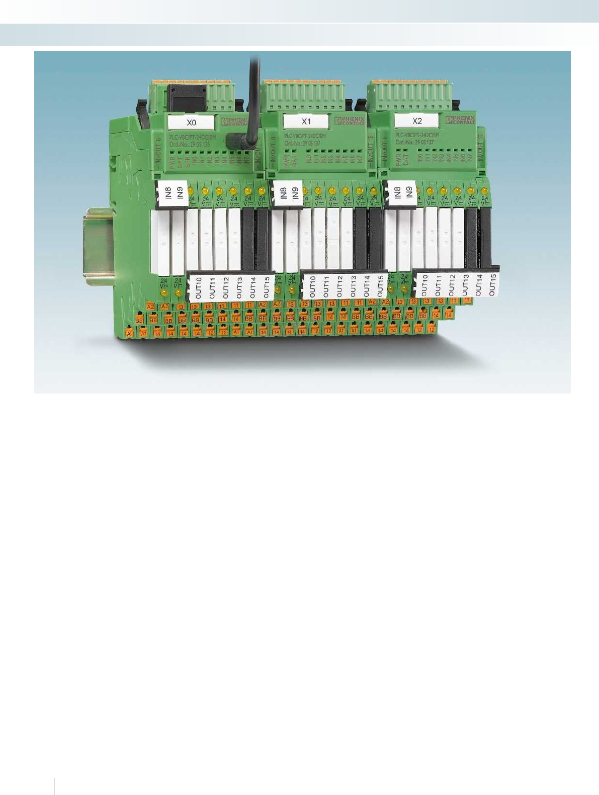
354 PHOENIX CONTACT
Interface technology and switching devices
Relay modules - PLC logic programmable logic relay system
Extremely compact control
The PLC logic programmable logic relay
system is the extremely compact way to
carry out small automation tasks easily and
flexibly. It consists of the PLC-V8C logic
modules, the PLC-INTERFACE relay
system, and the LOGIC+ software. The
logic modules are simply plugged into a row
of eight PLC-INTERFACE terminal blocks
and combine the logic and interface level in
one unit. Depending on the switching
requirements, plug-in electromechanical
and solid-state relays can be combined in
order to flexibly switch and control the I/O
signals.
PLC logic processes digital and analog
input signals as well as logic functions and
timer modules - and replaces conventional
switching and control devices. Up to 16 I/O
signals can be processed using the stand-
alone logic modules - that's with a design
width of just 50 mm. If more I/O signals are
required, a maximum of 48 I/O signals can
be linked using the basic and extension
modules.
Switching and controlling with plug-in
relays
– PLC logic brings together the standard
combination of logic module and separate
plug-in relay and eliminates the wiring
effort and additional switching elements
– Convenient connections with screw or
push-in connection technology, which
also accommodate return conductors,
remove the need for separate potential
terminal blocks
– Each relay channel can be freely
configured as an input or output. PLC
logic therefore perfectly adapts to fit the
application at hand
Intuitive programming
Programming is quick and easy with the
intuitive LOGIC+ programming software.
Ladder (LD) and function block diagrams
(FBD) can be created by selecting the
relevant functions and their connection
using drag & drop. The graphical
representation of PLC logic in the hardware
editor supports intuitive operation. The
programs created can be simulated offline
on the PC and tested online during
operation. Basic functions, such as AND,
OR, NOT, etc. are complemented by special
functions, such as counters, seven-day
timers, timer modules, and mathematical
functions, to name a few.
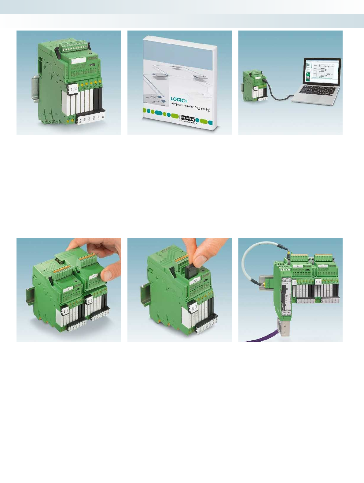
For additional information, visit phoenixcontact.net/products
355PHOENIX CONTACT
Interface technology and switching devices
Relay modules - PLC logic programmable logic relay system
Logic module with plug-in relays
PLC logic combines a logic module and
plug-in relay and eliminates the wiring effort
and additional switching elements. Each
relay channel can be flexibly equipped with
an electromechanical or a solid-state relay.
PLC logic processes 16 I/O signals with just
one logic module and boasts an extremely
compact design width of just 50 mm.
Intuitive programming with LOGIC+
– Function block diagram or ladder diagram
– Numerous integrated function blocks
– Specific function blocks are available to
download
– Hardware view in the program
– Download free of charge at
www.phoenixcontact.com.
Standard programming cable
PLC logic is connected to a PC via a
standard micro USB cable. The drivers for
PLC logic are automatically installed on
connection by means of plug and play.
Easily connect extension modules
The basic module and the extension
module are connected via integrated
connectors - no tools required. A maximum
of two extension modules can be
connected to a basic module. This means
that PLC logic can work with up to 48 I/Os.
Saving and copying data
PLC logic programs are saved by the
memory block or can be easily copied to
other devices.
If settings such as time or date are
required on the new device, these values
can be configured via the integrated web
server. The new device does not need
access to the LOGIC+ software for this.
Integration into PROFIBUS DP
Adaptable fieldbus gateways, available
as an option, can be used to integrate
PLC logic into a PROFIBUS DP network.
This enables communication with a higher-
level controller for remote control,
diagnostics, and visualization purposes.
DTM device drivers and GSD files for
configuring the gateway can be downloaded
free of charge at www.phoenixcontact.com.
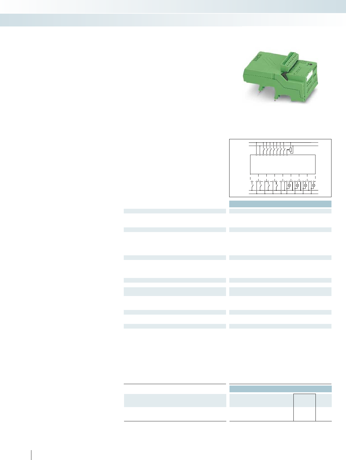
A1
A1
A1
A1
13
13
13
13
A2
A2
A2
A2
14
14
14
BB
BB
BB
BB
14
IO 8
IO 9
IO 10
IO 11
IO 12
IO 13
IO 14
IO 15
PLC-V8C/.../SAM
24 V
0 V
IN 0
IN 1
IN 2
IN 3
IN 4
IN 5
IN 6
IN 7
24 V
0 V
24 V
0 V
Technical data
Supply
Supply voltage 24 V DC
Supply voltage range 19.2 V DC ... 26.4 V DC 19.2 V DC ... 26.4 V DC 19.2 V DC ... 26.4 V DC
Max. input current at UN120 mA
Input data (digital)
Number of inputs 8 (2 configurable as analog) 8 (2 configurable as analog) 8 (2 configurable as analog)
Input voltage 24 V DC
Description of the input EN 61131-2, type 3
Input current 0-signal < 1 mA
Input current 1-signal Typ. 2.5 mA
Input data (analog)
Number of inputs 2 (IN6 and IN7 are configurable as analog) 2 (IN6 and IN7 are configurable as analog) 2 (IN6 and IN7 are configur
Input voltage range 0 V ... 10 V
Input resistance > 4 kΩ
Input data (PLC-INTERFACE)
Number of inputs ≤ 8
Output data (for controlling PLC-INTERFACE)
Number of outputs ≤ 8
Nominal voltage 24 V DC
Nominal current 9 mA
Realtime clock (basic module only)
Buffer time (capacitor) 24 h (capacitor)
Realtime clock accuracy ±2 s/d
General data
Ambient temperature (operation) -20°C ... 45°C
Ambient temperature (storage/transport) -20°C ... 70°C
Permissible humidity (operation) 90%
Air and creepage distances between the power circuits DIN EN 50178
Rated insulation voltage 50 V
Rated surge voltage 0.8 kV
Insulation Basic insulation
Mounting type Can be plugged onto 8 x PLC-INTERFACE Can be plugged onto 8 x PLC-INTERFACE Can be plugged onto 8 x PLC-INTERFACE
Degree of protection IP20
Screw connection solid/stranded/AWG 0.14 - 1.5 mm²/0.14 - 1.5 mm²/28 - 16 0.14 - 1.5 mm²/0.14 - 1.5 mm²/28 - 16 0.14 - 1.5 mm²/0.1
Push-in connection solid/stranded/AWG 0.14 - 1.5 mm²/0.14 - 1.5 mm²/26 - 16 0.14 - 1.5 mm²/0.14 - 1.5 mm²/26 - 16 0.14 - 1.5 mm²/0
Ordering data
Description Type Order No. Pcs. /
Pkt.
PLC-V8C plug-in logic modules
With screw connection PLC-V8C/SC-24DC/SAM 2905082 1
With push-in connection PLC-V8C/PT-24DC/SAM 2905136 1
356 PHOENIX CONTACT
Logic modules
PLC-V8C are the plug-in logic modules
which form the PLC logic relay system in
conjunction with the narrow 6.2 mm
PLC-INTERFACE terminal blocks. Eight
freely selectable PLC-INTERFACE terminal
blocks must be separately ordered for each
logic module. You can find an overview of
matching PLC-INTERFACE terminal blocks
on page 360.
All logic modules feature these
properties:
– 8 integrated digital inputs (of which two
inputs are configurable as analog inputs),
connection via connector with screw or
push-in connection technology
– A further 8 channels can be configured
with matching PLC-INTERFACE terminal
blocks as digital inputs or outputs
– Programming with the LOGIC+ software
PLC-V8C.../SAM
– Stand-alone logic module with 16 I/Os,
not extendable
– Connection to PC via micro USB socket
– Integrated realtime clock (RTC)
– Accommodates external
IFS-CONFSTICK memory block
PLC-V8C.../BM
– Basic logic module with 16 I/Os, can be
extended with a maximum of two
extension modules (PLC-V8C.../EM) to
48 I/Os
– Connection to PC via micro USB socket
– Integrated realtime clock (RTC)
– Accommodates external
IFS-CONFSTICK memory block
– Optional connection to
PROFIBUS-GATEWAY-IFS
PLC-V8C.../EM
– Extension logic module with 16 I/Os, for
extending the basic module
Interface technology and switching devices
Relay modules - PLC logic programmable logic relay system
Stand-alone module Basic module Extension module
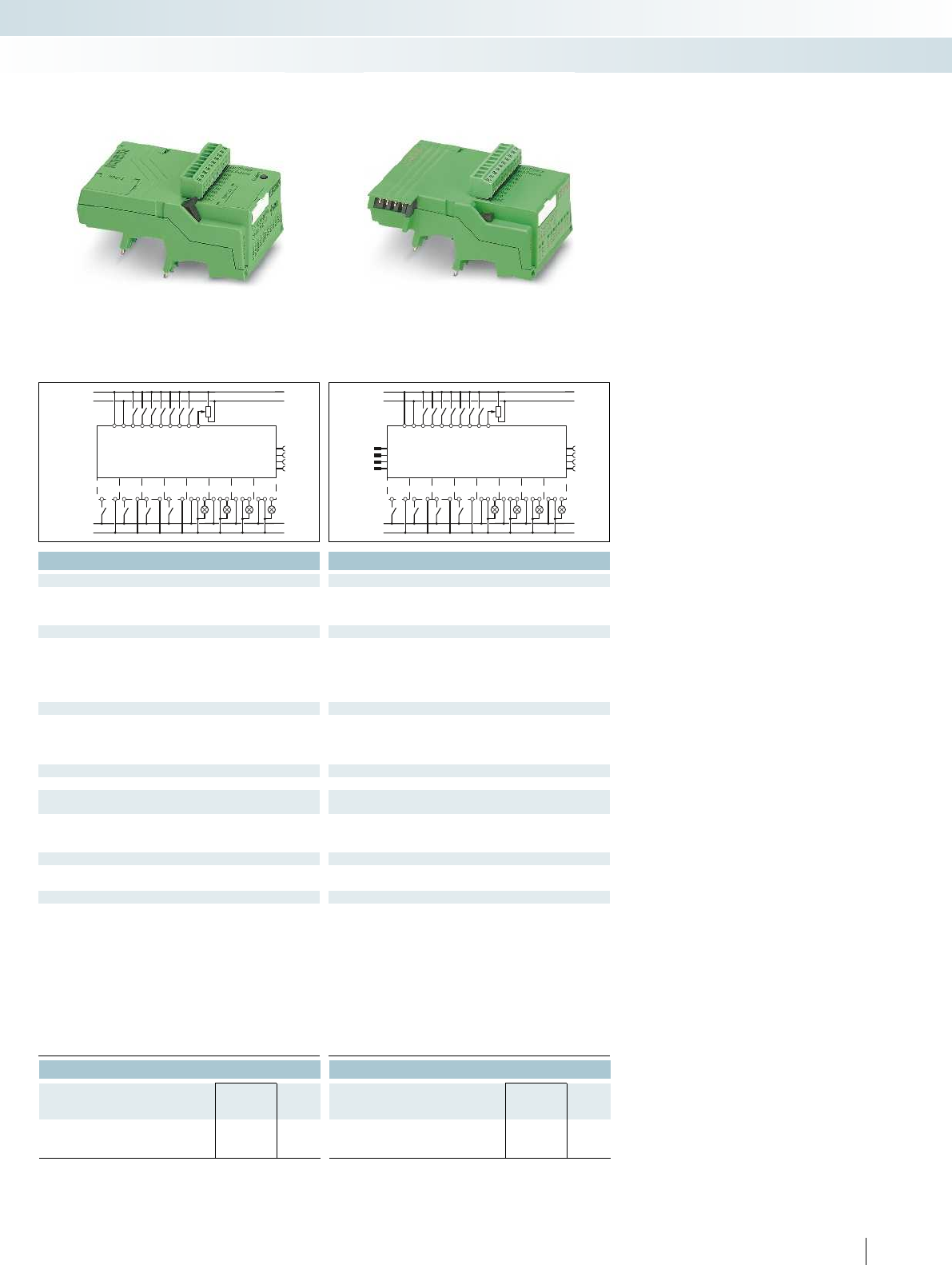
A1
A1
A1
A1
13
13
13
13
A2
A2
A2
A2
14
14
14
BB
BB
BB
BB
14
IO8
IO9
IO10
IO11
IO12
IO13
IO14
IO15
PLC-V8C/.../BM
24 V
0V
IN0
IN1
IN2
IN3
IN4
IN5
IN6
IN7
24 V
0V
24 V
0V
A1
A1
A1
A1
13
13
13
13
A2
A2
A2
A2
14
14
14
BB
BB
BB
BB
14
IO8
IO9
IO10
IO11
IO12
IO13
IO14
IO15
PLC-V8C/.../EM
24 V
0V
IN0
IN1
IN2
IN3
IN4
IN5
IN6
IN7
24 V
0V
24 V
0V
For additional information, visit phoenixcontact.net/products
Technical data Technical data
24 V DC 24 V DC
Supply voltage range 19.2 V DC ... 26.4 V DC 19.2 V DC ... 26.4 V DC 19.2 V DC ... 26.4 V DC
120 mA 65 mA
Number of inputs 8 (2 configurable as analog) 8 (2 configurable as analog) 8 (2 configurable as analog)
24 V DC 24 V DC
EN 61131-2, type 3 EN 61131-2, type 3
< 1 mA < 1 mA
Typ. 2.5 mA Typ. 2.5 mA
Number of inputs 2 (IN6 and IN7 are configurable as analog) 2 (IN6 and IN7 are configurable as analog) 2 (IN6 and IN7 are configurable as analog)
0 V ... 10 V 0 V ... 10 V
> 4 kΩ> 4 kΩ
≤ 8 ≤ 8
≤ 8 ≤ 8
24 V DC 24 V DC
9 mA 9 mA
24 h (capacitor) -
±2 s/d -
-20°C ... 45°C -20°C ... 45°C
-20°C ... 70°C -20°C ... 70°C
90% 90%
DIN EN 50178 DIN EN 50178
50 V 50 V
0.8 kV 0.8 kV
Basic insulation Basic insulation
Mounting type Can be plugged onto 8 x PLC-INTERFACE Can be plugged onto 8 x PLC-INTERFACE Can be plugged onto 8 x PLC-INTERFACE
IP20 IP20
28 - 16 0.14 - 1.5 mm²/0.14 - 1.5 mm²/28 - 16 0.14 - 1.5 mm²/0.14 - 1.5 mm²/28 - 16
²/26 - 16 0.14 - 1.5 mm²/0.14 - 1.5 mm²/26 - 16 0.14 - 1.5 mm²/0.14 - 1.5 mm²/26 - 16
Ordering data Ordering data
Type Order No. Pcs. /
Pkt. Type Order No. Pcs. /
Pkt.
PLC-V8C/SC-24DC/BM 2903094 1PLC-V8C/SC-24DC/EM 2903095 1
PLC-V8C/PT-24DC/BM 2905135 1PLC-V8C/PT-24DC/EM 2905137 1
357PHOENIX CONTACT
Contacting for
Extension module
Contacting for
Basic or
Extension module
Contacting for
Extension module
Interface technology and switching devices
Relay modules - PLC logic programmable logic relay system
Stand-alone module Basic module Extension module
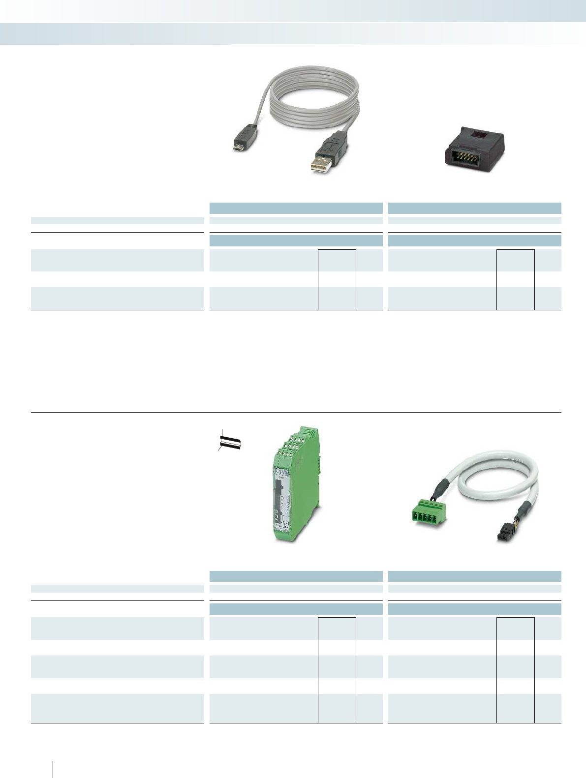
Technical data Technical data
General data
EMC note Class A product, see page 443
Ordering data Ordering data
Description Color Type Order No. Pcs. /
Pkt. Type Order No. Pcs. /
Pkt.
Programming cable
CAB-USB A/MICRO USB B/2,0M 2701626 1
Multi-functional memory block for the INTERFACE system
- Flat design IFS-CONFSTICK 2986122 1
– The programming cable (MICRO USB B
to USB A) is used to connect PLC logic to
a PC, length: 2 m
– PLC logic programs are saved by the
memory block or can be easily copied to
other devices
Accessories
Programming cable and
memory block
Interface technology and switching devices
Relay modules - PLC logic programmable logic relay system
Technical data Technical data
General data
EMC note Class A product, see page 443
Ordering data Ordering data
Description Color Type Order No. Pcs. /
Pkt. Type Order No. Pcs. /
Pkt.
IFS gateway for
PROFIBUS DP green EM-PB-GATEWAY-IFS 2297620 1
Programming adapter for configuring modules with
S-PORT interface
Cable length: 3 m IFS-USB-DATACABLE 2320500 1
DIN rail connector
green ME 22,5 TBUS 1,5/ 5-ST-3,81 GN 2707437 50
Connecting cable for connecting PLC logic with the
ME 22,5 TBUS DIN rail connector, cable length: 0.3 m
PLC-V8C/CAB/TBUS/0,3M 2905263 1
358 PHOENIX CONTACT
H
W
D
The gateways are connected to the
PLC-V8C.../BM PLC logic basic modules via
the ME 22,5 TBUS... DIN rail connector and
the PLC-V8C/CAB... connecting cable.
The gateways are connected to a PC and
configured via the integrated S-PORT
interface and the IFS-USB-DATACABLE.
Accessories
Gateway to PROFIBUS DP
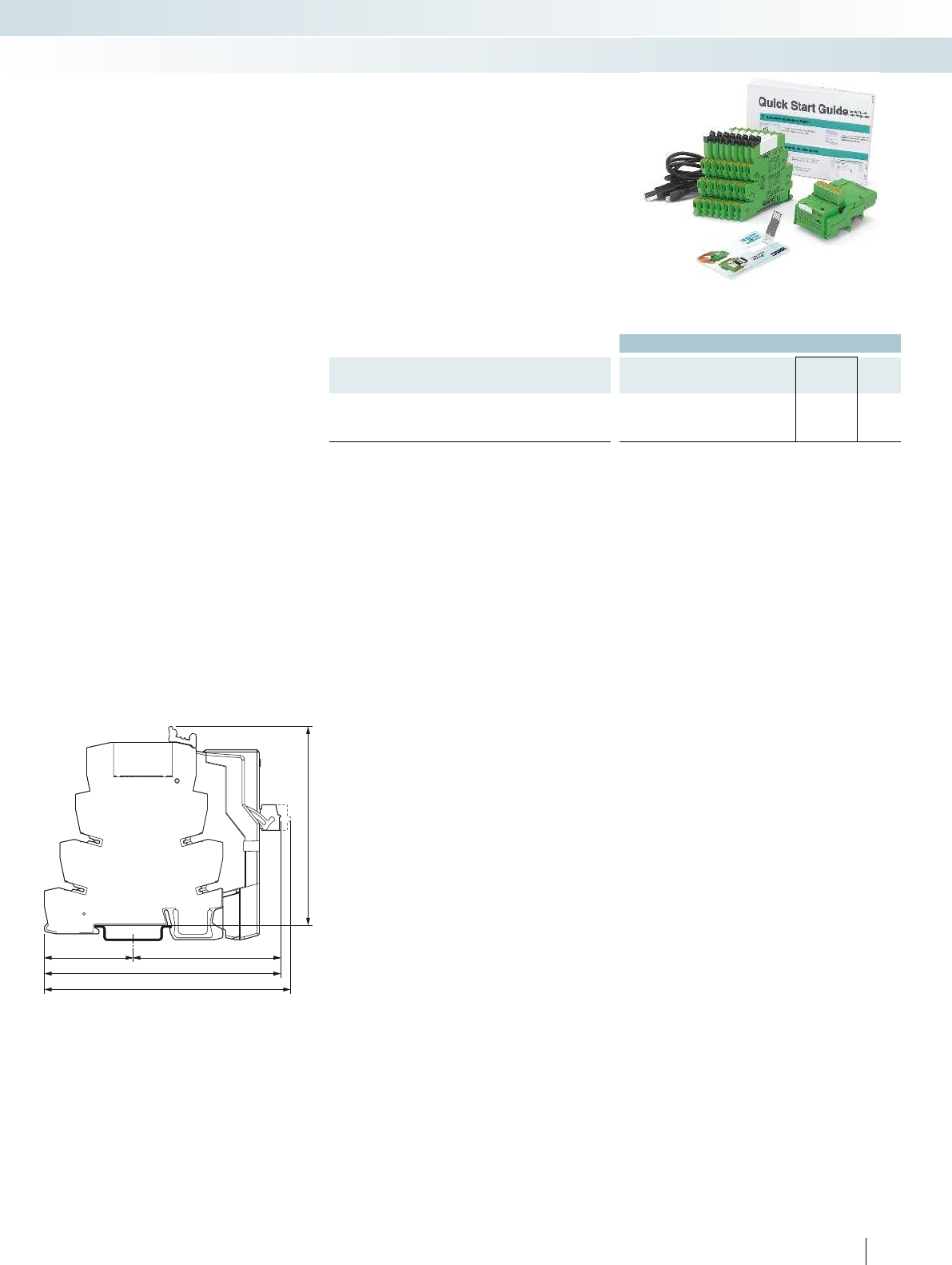
106
111
40 66
87
For additional information, visit phoenixcontact.net/products
Ordering data
Description Color Type Order No. Pcs. /
Pkt.
PLC logic starter kit 1, 8 integrated inputs (24 V DC) and
8 outputs via PLC-INTERFACE
(switching capacity 250 V AC/DC, max. 6 A)
PLC-LOGIC-STARTERKIT1 2905504 1
The PLC logic starter kit contains all the
components needed to get started quickly
and easily with PLC logic with push-in
connection technology and 8 inputs and
8 outputs.
– PLC-V8C-PT/24DC/BM plug-in logic
module
– PLC-RPT-24DC/1/ACT eight relay output
terminal blocks
– Micro USB programming cable
–Software LOGIC+
– “PLC logic quick start guide” poster
Accessories
PLC logic starter kit
Interface technology and switching devices
Relay modules - PLC logic programmable logic relay system
Dimensional drawing
359
PHOENIX CONTACT
360 PHOENIX CONTACT
Selection table for PLC-INTERFACE
Push-in connection Screw connection
Relay output Type Order No. Type Order No.
1 PDT, output data 6 A, 250 V AC/DC PLC-RPT-24DC/21
2900299
PLC-RSC-24DC/21
2966171
1 PDT, output data 50 mA, 36 V DC, gold contact PLC-RPT-24DC/21AU
2900306
PLC-RSC-24DC/21AU
2966265
1 N/O contact, output data 6 A, 250 V AC/DC, actuator type PLC-RPT-24DC/1/ACT
2900312
PLC-RSC-24DC/1/ACT
2966210
1 N/O contact with switch, output data 6 A, 250 V AC/DC PLC-RPT-24UC/1/S/H
2900328
PLC-RSC-24UC/1/S/H
2982236
Solid-state relay output
Output data 100 mA, 3 V DC - 48 V DC PLC-OPT-24DC/48DC/100
2900352
PLC-OSC-24DC/48DC/100
2966728
Output data 3 A, 3 V DC - 33 V DC PLC-OPT-24DC/24DC/2
2900364
PLC-OSC-24DC/24DC/2
2966634
Output data 750 mA, 24 V AC - 253 V AC PLC-OPT-24DC/230AC/1
2900369
PLC-OSC-24DC/230AC/1
2967840
Output data 3 A, 3 V DC - 33 V DC, actuator type PLC-OPT-24DC/24DC/2/ACT
2900376
PLC-OSC-24DC/24DC/2/ACT
2966676
Output data 750 mA, 24 V AC - 253 V AC, actuator type PLC-OSC-24DC/230AC/1/ACT
2967947
Output data 1 A, 12 V DC - 300 V DC PLC-OPT-24DC/300DC/1
2900383
PLC-OSC-24DC/300DC/1
2980678
Output data 10 A, 3 V DC - 33 V DC PLC-OPT-24DC/24 DC/10/R
2900398
PLC-OSC-24DC/24DC/10/R
2982702
Output data 500 mA, 3 V DC - 48 V DC, electronic PDT PLC-OPT-24DC/48DC/500/W
2900378
PLC-OSC-24DC/48DC/500/W
2980636
Output data, TTL, 50 mA, 5 V DC PLC-OPT-24DC/TTL
2900363
PLC-OSC-24DC/TTL
2982728
Relay input
Input voltage 24 V DC PLC-RPT-24DC/1AU/SEN
2900313
PLC-RSC-24DC/1AU/SEN
2966317
Input voltage 120 V AC/DC PLC-RPT-120UC/1AU/SEN
2900314
PLC-RSC-120UC/1AU/SEN
2966320
Input voltage 230 V AC/DC PLC-RPT-230UC/1AU/SEN
2900315
PLC-RSC-230UC/1AU/SEN
2966333
Input voltage 5 V DC (basic terminal block without relay) PLC-BSC- 5DC/ 1/SEN
2980267
Relay for 5 V DC basic terminal block REL-MR-4,5DC/21AU
2961370
Solid-state relay input
Input voltage 24 V DC PLC-OPT-24DC/48DC/100/V8C/SEN
2904693
PLC-OSC-24DC/48DC/100/V8C/SEN
2904690
Input voltage 120 V AC/DC PLC-OPT-120UC/48DC/100/V8C/SEN
2904694
PLC-OSC-120UC/48DC/100/V8C/SEN
2904691
Input voltage 230 V AC/DC PLC-OPT-230UC/48DC/100/V8C/SEN
2904695
PLC-OSC-230UC/48DC/100/V8C/SEN
2904692
Dummy or reserve
Basic terminal block output PLC-BPT-24DC/21
2900445
PLC-BSC-24DC/21
2966016
Basic terminal block input PLC-BPT-24DC/1/SEN
2900262
PLC-BSC-24DC/1/SEN
2966061
Interface technology and switching devices
Relay modules - PLC logic programmable logic relay system
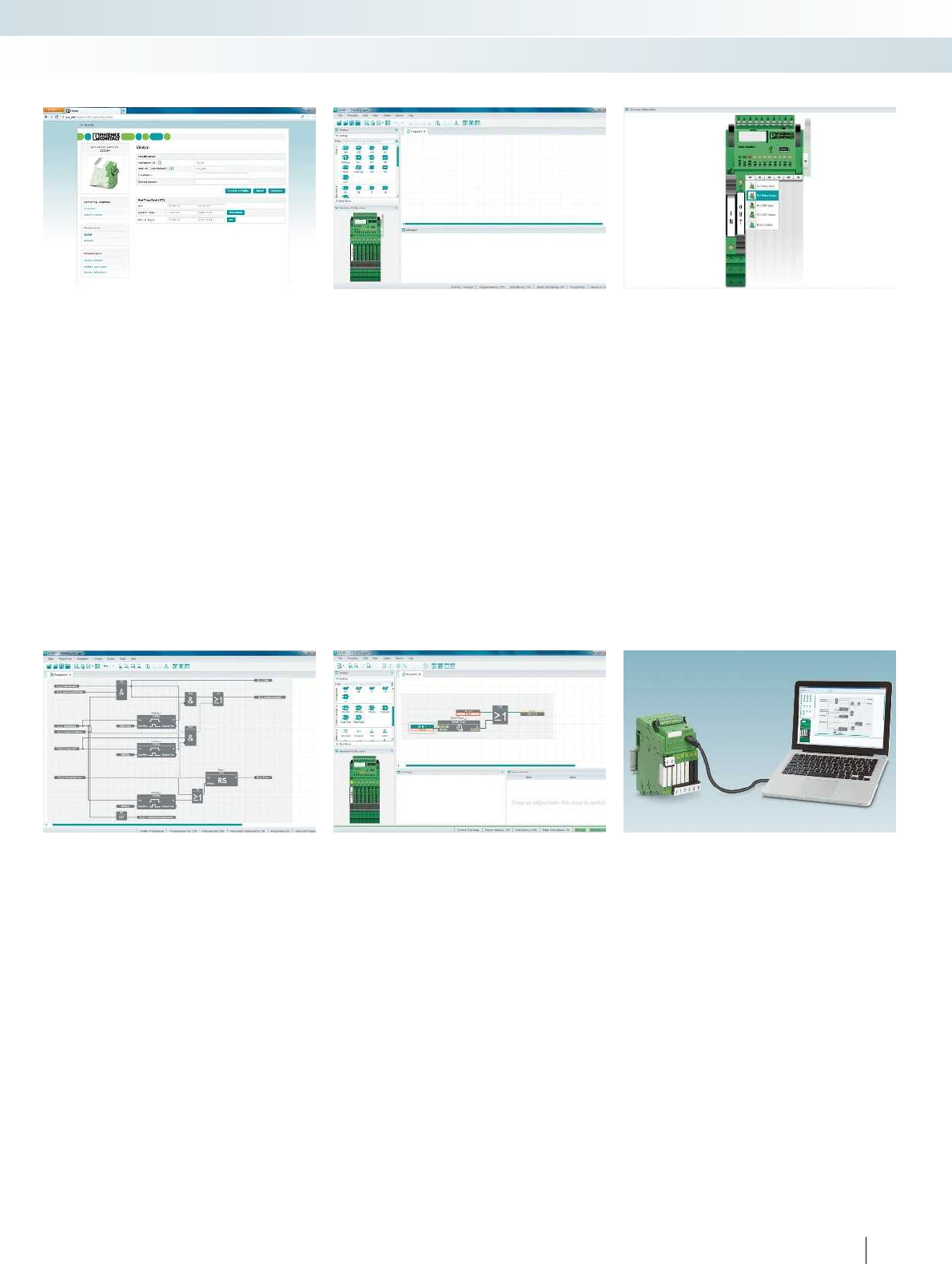
For additional information, visit phoenixcontact.net/products
361PHOENIX CONTACT
Interface technology and switching devices
Relay modules - PLC logic programmable logic relay system
LOGIC+ programming software
Integrated web server
PLC logic basic settings are easily
configured via the integrated web server.
The LOGIC+ software does not need to be
installed in order to do so.
–Time and date
– Password and access control
– Firmware update
– Status indicators for inputs and outputs
– General device information
LOGIC+ user interface
– Clear separation in program editor,
toolbox, hardware view, and signaling
window
– All elements can be easily placed using
drag & drop
– Notes and errors are highlighted in color
in the program editor
Hardware configurator
– Each relay channel can be configured as an
input or output with an
electromechanical or a solid-state relay
– Clear assignment of the inputs and
outputs thanks to the graphical
representation of the hardware
connections
Function blocks
– Basic functions: AND, OR, NOT, XOR
– Mathematical functions: add, divide,
multiply, subtract, generate absolute value
– Positive and negative edge detection
– RS and SR flip-flops
– Switch-on and switch-off delay, pulse
encoder, pulse stretching, weekly clock
timer
–Up and down counter
– Analog and digital comparators
– Special functions, e.g., solar altitude
calculations are available for download
Simulation and online values
Offline simulation:
– Simulation of the created program directly
in LOGIC+
– Virtualization of the values in the program
editor, hardware view, and in the
observation window
Online values:
– Representation of the program running
on the hardware in LOGIC+ with online
values
– Overwriting of values from LOGIC+
Example programs
Numerous application examples make
it easy to get started with LOGIC+. These
include:
– Underground garage ventilation
–Conveyor belt
– Pumping plant
–Two-way control
– Tips for creating shift registers or surge
relays
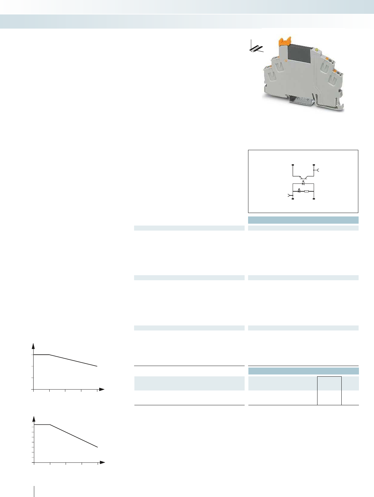
30
20405060
0
0,1
0,2
0,3
0,4
0,5
0,6
0,7
0,8
30
20405060
0
1
2
3
14 13+
A2- A1+
Technical data
Input data ①
Rated actuating voltage range with reference to UC0.8 -
1.2
Switching level (with reference to UC) 1 signal ("H") > 0.8
0 signal ("L") < 0.4
Rated actuating current IC[mA] 8.5
Typ. switch-on time at UN[ms] 0.02
Typ. switch-off time at UN[ms] 0.3
Transmission frequency flimit [Hz] 300
Input circuit DC Yellow LED, free-wheeling diode Yellow LED, free-wheeling diode Yellow LED, free-wheeling diode
Output data
Max. switching voltage 33 V DC
Min. switching voltage 3 V DC
Max. inrush current 15 A (10 ms)
Min./max. switching current -/3 A (see derating curve) -/100 mA 10 mA/0.75 A (see derating curve)
Output protection Protection against polarity reversal, surge protection Protection against polarity reversal, surge protection RC
Voltage drop at max. limiting continuous current < 200 mV
Leakage current in off state -
Phase angle (cos φ)-
Max. load value -
General data
Test voltage input/output 2.5 kVrms (50 Hz, 1 min.) 2.5 kV
Ambient temperature (operation) -25°C ... 60°C
Standards/regulations DIN EN 50178
Pollution degree/surge voltage category 2/III
Connection data solid/stranded/AWG 0.14 - 1.5 mm²/0.14 - 1.5 mm²/26 - 16 0.14 - 1.5 mm²/0.14 - 1.5 mm²/26 - 16 0.14 - 1.5 mm²/0.14
Dimensions W / H / D 6.2 mm/93 mm/66 mm 6.2 mm/93 mm/66 mm 6.2 mm/93 mm/66 mm
EMC note Class A product, see page 443 Class A product, see page 443 Class A product, see page 443
Ordering data
Description Rated actuating voltage
UC
Type Order No. Pcs. /
Pkt.
Coupling relay modules with solid-state relay and
push-in connection
①24 V DC RIF-0-OPT-24DC/24DC/2 2905293 10
362 PHOENIX CONTACT
Fully mounted RIF-0 relay modules
Fully mounted RIF-0 relay modules,
consisting of:
– Relay base with push-in connection
– Solid-state relays
– Relay ejector lever on the housing
The advantages:
– Status LED integrated into the base
– RTIII sealed solid-state relay
– Zero voltage switch at AC output
– Professional bridging of adjacent modules
saves wiring time
Ambient temperature [°C]
Load current [A]
Derating curve for RIF-0-OPT-24DC/230AC/1
Ambient temperature [°C]
Load current [A]
Derating curve for RIF-0-OPT-24DC/24DC/2
Interface technology and switching devices
Relay modules - RIFLINE complete
DW
H
Max. DC voltage output of 3 A Max. DC voltage output of 100 mA Max. AC voltage output of 750 mA
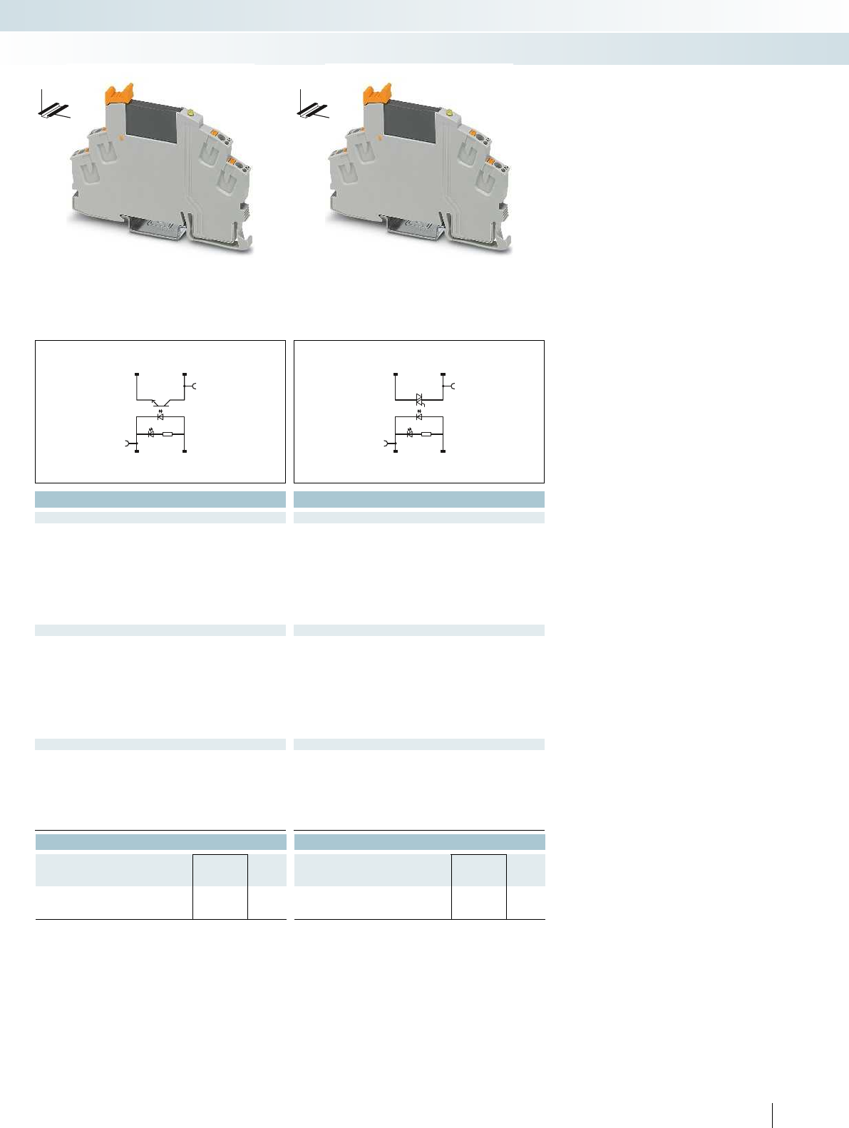
14 13+
A2- A1+
14 13+
A2- A1+
For additional information, visit phoenixcontact.net/products
Technical data Technical data
① ①
0.8 -
1.2
0.8 -
1.2
> 0.8 > 0.8
< 0.4 < 0.4
8.5 8
0.02 10
0.3 10
300 10
Input circuit DC Yellow LED, free-wheeling diode Yellow LED, free-wheeling diode Yellow LED, free-wheeling diode
48 V DC 253 V AC
3 V DC 24 V AC
- 30 A (10 ms)
Min./max. switching current -/3 A (see derating curve) -/100 mA 10 mA/0.75 A (see derating curve)
Output protection Protection against polarity reversal, surge protection Protection against polarity reversal, surge protection RCV circuit
< 1 V < 1 V
- 1 mA (in off state)
-0.5
-4.5 A
2s (tp = 10 ms, at 25°C)
(50 Hz, 1 min.) 2.5 kVrms (50 Hz, 1 min.) 2.5 kVrms (50 Hz, 1 min.)
-25°C ... 60°C -25°C ... 60°C
DIN EN 50178 DIN EN 50178
2/III 2/III
26 - 16 0.14 - 1.5 mm²/0.14 - 1.5 mm²/26 - 16 0.14 - 1.5 mm²/0.14 - 1.5 mm²/26 - 16
Dimensions W / H / D 6.2 mm/93 mm/66 mm 6.2 mm/93 mm/66 mm 6.2 mm/93 mm/66 mm
EMC note Class A product, see page 443 Class A product, see page 443 Class A product, see page 443
Ordering data Ordering data
Type Order No. Pcs. /
Pkt. Type Order No. Pcs. /
Pkt.
RIF-0-OPT-24DC/48DC/100 2905294 10 RIF-0-OPT-24DC/230AC/1 2905295 10
363PHOENIX CONTACT
Interface technology and switching devices
Relay modules - RIFLINE complete
DW
H
DW
H
Max. DC voltage output of 3 A Max. DC voltage output of 100 mA Max. AC voltage output of 750 mA
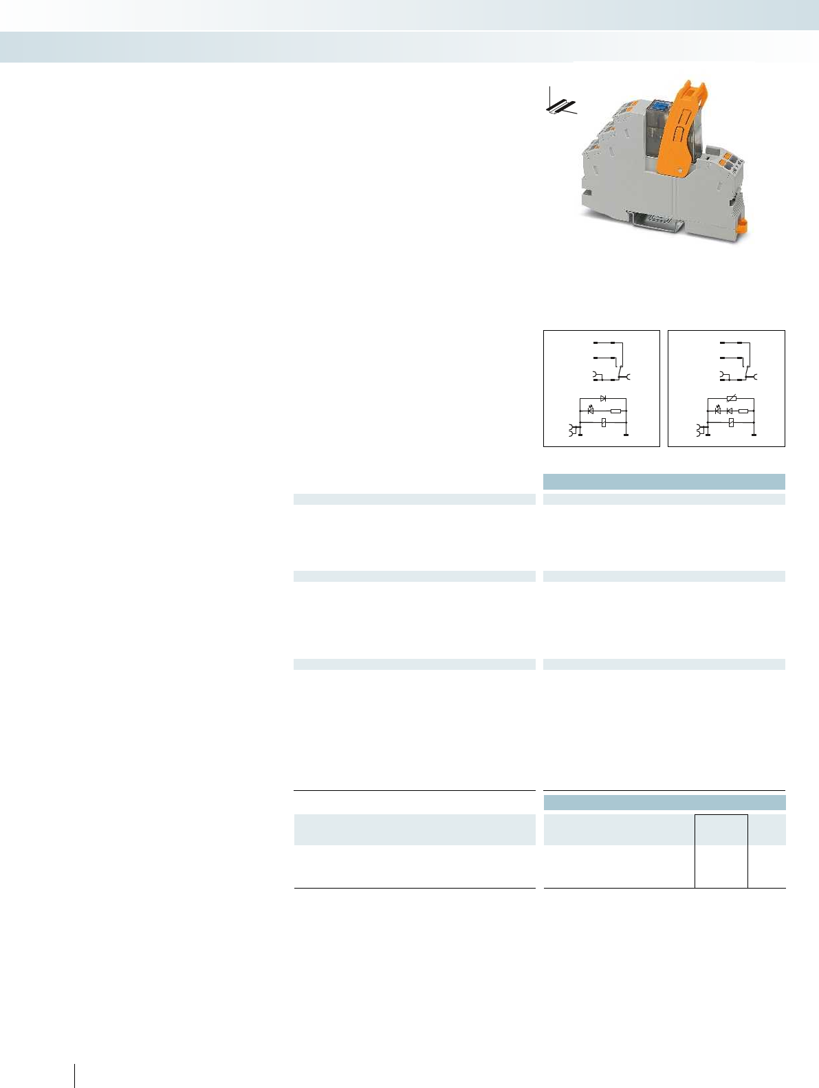
A2 A1
1222
1424
1121
A2- A1+
1222
1424
1121
Technical data
Input data ① ②
Permissible range (with reference to UN)see diagram
Typ. input current at UN[mA] 18 4.5
Typ. response time at UN[ms] 9 4 - 12
Typ. release time at UN[ms] 10 4 - 20
Input circuit AC Yellow LED, varistor
Input circuit DC Yellow LED, damping diode Yellow LED, damping diode
Output data
Contact type 1 PDT
Contact material AgNi
Max. switching voltage 250 V AC/DC
Min. switching voltage 12 V (at 10 mA)
Limiting continuous current (see diagram)
Max. inrush current 32 A (20 ms, N/O contact) 16 A (20 ms, N/O contact)
Min. switching current 10 mA (at 12 V)
General data
Test voltage (winding / contact) 4 kVrms (50 Hz, 1 min.) 4 kV
Ambient temperature (operation), AC -40°C ... 50°C
Ambient temperature (operation), DC -40°C ... 70°C
Nominal operating mode 100% operating factor 100% operating factor
Mechanical service life Approx. 5 x 10⁶ cycles Approx. 5 x 10
Standards/regulations DIN EN 50178, IEC 62103 DIN EN 50178, IEC 62103
Pollution degree/surge voltage category 2/III
Mounting position/mounting Any/in rows with zero spacing Any/in rows with zero spacing
Connection data solid/stranded/AWG 0.14 - 1.5 mm²/0.14 - 1.5 mm²/26 - 16 0.14 - 1.5 mm²/0.14 - 1.5 mm²/26 - 16
Dimensions W / H / D 16 mm/93 mm/75 mm 16 mm/93 mm/75 mm
EMC note Class A product, see page 443 Class A product, see page 443
Ordering data
Description Input voltage
UN
Type Order No. Pcs. /
Pkt.
Coupling relay modules with power contact relay with manual
operation and push-in connection
①24 V DC RIF-1-RPT-LDP-24DC/1X21MS 2905289 10
②230 V AC RIF-1-RPT-LV-230AC/1X21MS 2905290 10
364 PHOENIX CONTACT
DC coils AC coils DC coils
DW
H
Fully mounted RIF-1 relay modules
Fully mounted RIF-1 relay modules,
consisting of:
– Relay base with push-in connection
– 1 or 2 PDT relays with detectable manual
operation
–Relay retaining bracket
– Input module/interference suppr. module
(AC types only)
The advantages:
– Relay with lockable manual operation and
status LED
– With DC types, free-wheeling diode is
integrated into relay
– Mechanical switch position indicator
– Professional bridging of adjacent modules
saves wiring time
Interface technology and switching devices
Relay modules - RIFLINE complete
RIF-1 relay module with
1 PDT relay
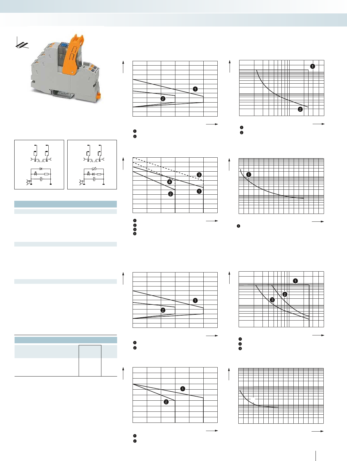
0,6
0,7
0,8
0,9
1,0
1,1
1,2
1,3
1,4
1,5
1,6
1,7
1,8
20304050607080
20
10
5
2
1
0,5
0,2
0,1
1020305070100 200 300 400 500
20304050607080
1
2
3
4
5
6
7
8
9
10
11
12
13
014 812 16
10
7
10
6
10
5
10
4
2356711910151413
0,6
0,7
0,8
0,9
1,0
1,1
1,2
1,3
1,4
1,5
1,6
1,7
1,8
20304050607080
20
10
5
2
1
0,5
0,2
0,1
1020305070100 200 300 400 500
20304050607080
1
2
3
4
5
6
7
8
9
10
11
014 812 16
107
106
105
104
23567 11910 151413
1
1
1222
A1+
A2-
1424
1121
1222
1424
1121
A2 A1
For additional information, visit phoenixcontact.net/products
Technical data
① ②
see diagram
18 4.5
94 - 12
10 4 - 20
Yellow LED, varistor
Input circuit DC Yellow LED, damping diode Yellow LED, damping diode
2 PDT
AgNi
250 V AC/DC
12 V (at 10 mA)
(see diagram)
Max. inrush current 32 A (20 ms, N/O contact) 16 A (20 ms, N/O contact)
10 mA (at 12 V)
(50 Hz, 1 min.) 4 kVrms (50 Hz, 1 min.)
-40°C ... 50°C
-40°C ... 70°C
Nominal operating mode 100% operating factor 100% operating factor
cycles Approx. 5 x 10⁶ cycles
Standards/regulations DIN EN 50178, IEC 62103 DIN EN 50178, IEC 62103
2/III
Mounting position/mounting Any/in rows with zero spacing Any/in rows with zero spacing
- 1.5 mm²/26 - 16 0.14 - 1.5 mm²/0.14 - 1.5 mm²/26 - 16
Dimensions W / H / D 16 mm/93 mm/75 mm 16 mm/93 mm/75 mm
EMC note Class A product, see page 443 Class A product, see page 443
Ordering data
Type Order No. Pcs. /
Pkt.
RIF-1-RPT-LDP-24DC/2X21MS 2905291 10
RIF-1-RPT-LV-230AC/2X21MS 2905292 10
365PHOENIX CONTACT
RIF-1-RPT.../1X21... (1 PDT)
Operating voltage range Interrupting rating
Ambient temperature [°C]
Coil voltage U/U
N
DC coils
AC coils
Switching voltage [V]
Switching current [A]
= AC, ohmic load
= DC, ohmic load
Contact derating Electrical service life
Ambient temperature [°C]
Limiting continuous current per contact [A]
DC coil
AC coil
DC coil, jumper between 11 and 21
AC coil, jumper between 11 and 21
Cycles
Switching current [A]
= 250 V AC, ohmic load
RIF-1-RPT.../2X21... (2 PDTs)
Operating voltage range Interrupting rating
Ambient temperature [°C]
Coil voltage U/U
N
DC coils
AC coils
AC, ohmic load
DC, ohmic load, contacts in series
DC, ohmic load
Switching voltage [V]
Switching current [A]
Contact derating Electrical service life
Ambient temperature [°C]
Limiting continuous current per contact [A]
DC coil
AC coil
Cycles
Switching current [A]
250 V AC, ohmic load
DC coils AC coils DC coils
DW
H
Interface technology and switching devices
Relay modules - RIFLINE complete
RIF-1 relay module with
2 PDT relay
AC coils
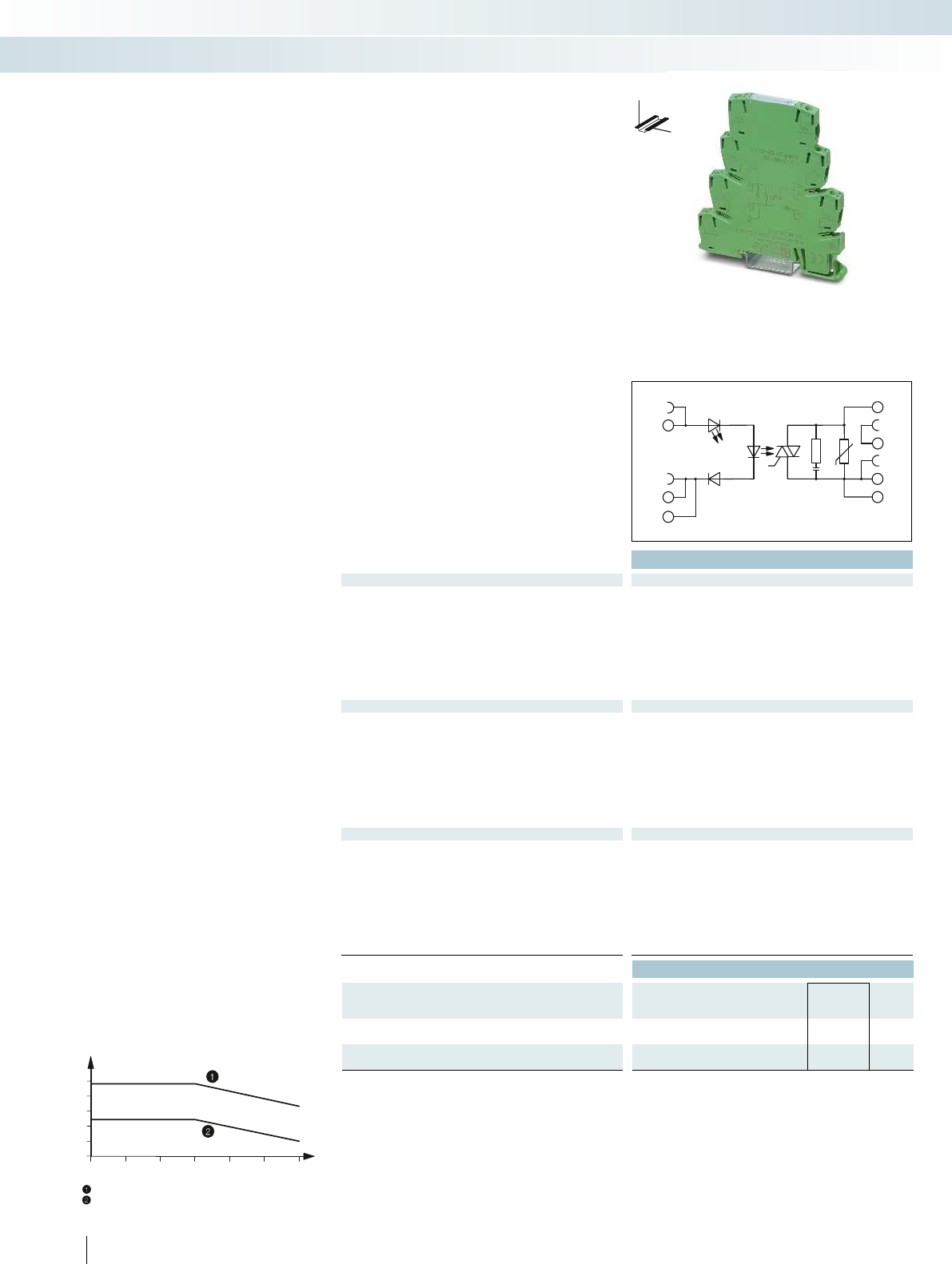
30
20405060
0
0,5
1
1,5
2
2,5
100
A1+
A2-
A2-
14
BB
13+
13+
Technical data
Input data ①
Rated actuating voltage range with reference to UC0.8 -
1.2
Switching level (with reference to UC) 1 signal ("H") > 0.8
0 signal ("L") < 0.4
Rated actuating current IC[mA] 8
Typ. switch-on time at UN[ms] 10
Typ. switch-off time at UN[ms] 10
Transmission frequency flimit [Hz] 10
Input circuit DC Yellow LED, protection against polarity reversal, surge protection
Output data
Max. switching voltage 253 V AC
Min. switching voltage 24 V AC
Max. inrush current 250 A (20 ms)
Min./max. switching current 10 mA/2.4 A (see derating)
Output protection RCV circuit
Voltage drop at max. limiting continuous current < 1 V
Leakage current in off state < 1 mA
Phase angle (cos φ)-
Max. load value 340 A2s (tp = 10 ms, at 25°C)
General data
Rated insulation voltage 260 V AC
Rated surge voltage 4 kV
Insulation Basic insulation
Ambient temperature (operation) -25°C ... 60°C
Standards/regulations DIN EN 50178
Pollution degree/surge voltage category 2/III
Connection data solid/stranded/AWG 0.14 - 2.5 mm²/0.14 - 2.5 mm²/26 - 14
Dimensions W / H / D 6.2 mm/80 mm/86 mm
EMC note Class A product, see page 443
Ordering data
Description Rated actuating voltage
UC
Type Order No. Pcs. /
Pkt.
PLC INTERFACE, with screw connection
①24 V DC PLC-OSC- 24DC/230AC/2.4/ACT 2904631 10
PLC-INTERFACE, with push-in connection
①24 V DC PLC-OPT- 24DC/230AC/2.4/ACT 2904632 10
366 PHOENIX CONTACT
PLC RELAY with an
integrated solid-state relay
6.2 mm narrow solid-state relay for
switching AC loads
– Status display
– Protection circuits in input and output
–Wear-free
– Switching capacity up to 230 V AC/2.4 A
– Screw and push-in connection technology
= aligned with > 20 mm spacing
= aligned without spacing
Ambient temperature [°C]
Load current [A]
Load current as a function of the ambient temperature
Operating time: 100% operating factor
Interface technology and switching devices
Relay modules - PLC series
DW
H
Solid-state power relay with
AC voltage output of 2.4 A, max.

For additional information, visit phoenixcontact.net/products
367PHOENIX CONTACT
Interface technology and switching devices
Relay modules - PLC series
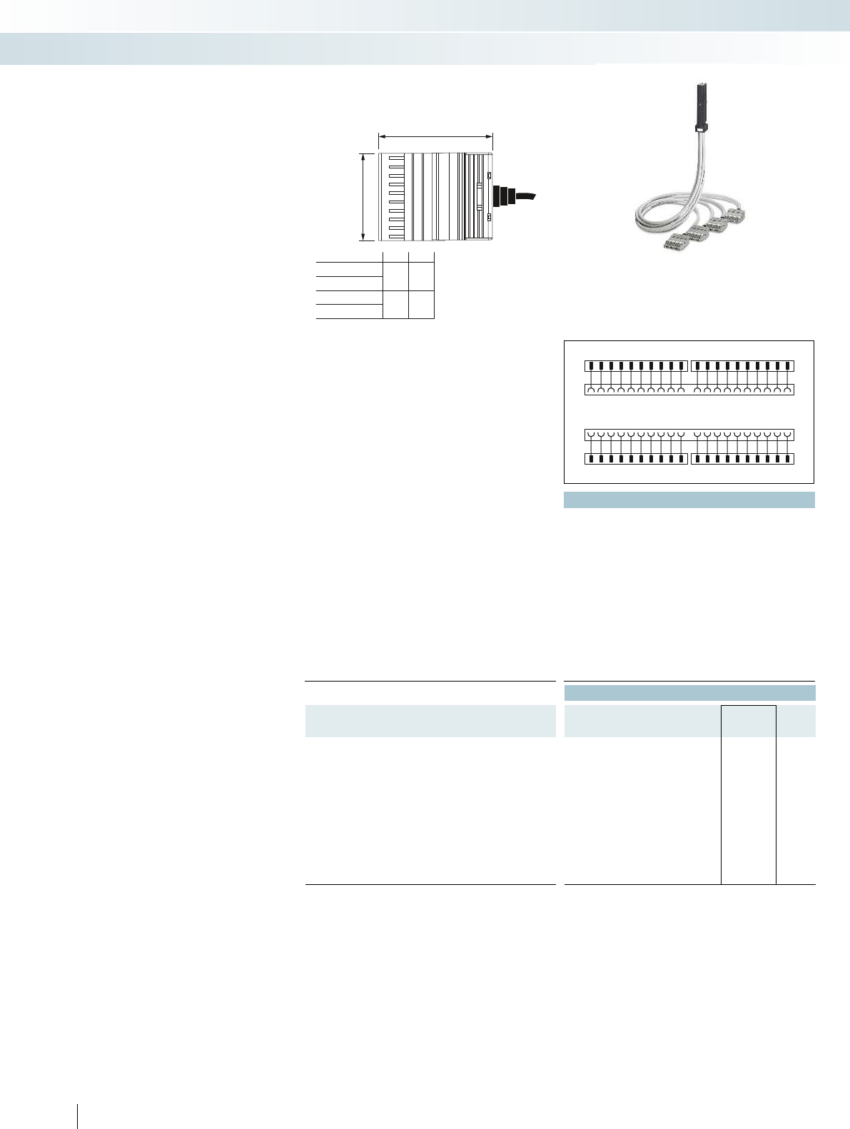
12345678910 11121314 15 16 17 1819 20
12345678910 11121314 15 16 17 1819 20
S7 - 300
COMBI
21 22 2324 25 26 27 2829 30313233 3435363738 3940
21 22 2324 25 26 27 2829 30313233 3435363738 3940
S7 - 300
COMBI
...4X10COMBI...
...2X10COMBI...
52
A
35
70
B
62
...4X10 PT...
...2X10 PT...
110
23456789
B
A
Technical data
Max. perm. operating voltage ≤ 250 V AC/DC
Max. perm. current carrying capacity per path 6 A (per single wire at 40°C)
4 A (per single wire at 60°C)
Max. perm. total current 20 A (per cable at 40°C)
16 A (per cable at 60°C)
Rated surge voltage 4 kV
Insulation Basic insulation
Max. conductor resistance 39 Ω/km
Conductor cross section AWG 21/0.5 mm²
Conductor structure: stranded wires / material 16/Cu uninsulated
Outside diameter 9 mm
Ambient temperature range -20°C ... 60°C
Standards/regulations DIN EN 50178,
Connection method Front adapter Can be plugged onto 40-pin I/O modules Can be plugged onto 20-pin I/O modules Can be plugged onto 4
System cable COMBICON connectors SP-H 2,5/10 COMBICON connectors SP-H 2,5/10 Open cable end Open cable end
Ordering data
Description Cable length Type Order No. Pcs. /
Pkt.
VIP - power adapter, for universal connection of the
SIMATIC S7-300
0.5 m VIP-PA-PWR/4X10COMBI/ 0,5M/S7 2904702 1
1 m VIP-PA-PWR/4X10COMBI/ 1,0M/S7 2904703 1
1.5 m VIP-PA-PWR/4X10COMBI/ 1,5M/S7 2904704 1
2 m VIP-PA-PWR/4X10COMBI/ 2,0M/S7 2904705 1
2.5 m VIP-PA-PWR/4X10COMBI/ 2,5M/S7 2904706 1
3 m VIP-PA-PWR/4X10COMBI/ 3,0M/S7 2904707 1
4 m VIP-PA-PWR/4X10COMBI/ 4,0M/S7 2904708 1
5 m VIP-PA-PWR/4X10COMBI/ 5,0M/S7 2904709 1
6 m VIP-PA-PWR/4X10COMBI/ 6,0M/S7 2904710 1
8 m VIP-PA-PWR/4X10COMBI/ 8,0M/S7 2904711 1
10 m VIP-PA-PWR/4X10COMBI/10,0M/S7 2904712 1
368 PHOENIX CONTACT
VIP - power cabling
Universal front adapters for
SIMATIC® S7-300
Four connection options are available:
– Connection of 40-pos. modules via four
cables, each with a 10-pos. COMBI
connector
– Connection of 20-pos. modules via two
cables, each with a 10-pos. COMBI
connector
– Connection of 40-pos. modules via
40 individual wires in rope structure
(not assembled)
– Connection of 20-pos. modules via
20 individual wires in rope structure
(not assembled)
The front adapters have the following
features:
– Can be screwed on/snapped in with the
I/O module
– Suitable for all common S7-300 modules,
up to max. 250 V AC/DC, 6 A
– Universal 1:1 connection
– Numerically marked wires/connectors
Combination example:
A front adapter with punched-on 10-pos.
COMBI connectors can be combined with
the following modular terminal blocks for
field connection:
– 3045017 UT 2,5/1P
– 3210033 PT 2,5/1P
– 3040012 ST 2,5/1P
– 3040766 ST 2,5-TWIN-MT/1P
You can find further versions, accessories,
and combination options in Catalog 3
“Modular terminal blocks” in the “Plug-in
COMBI connection solutions” section, or
online at phoenixcontact.net/products.
Interface technology and switching devices
System cabling for controllers - VARIOFACE system cabling
Front adapter with punched-on connectors for
40 plug-in modular terminal blocks
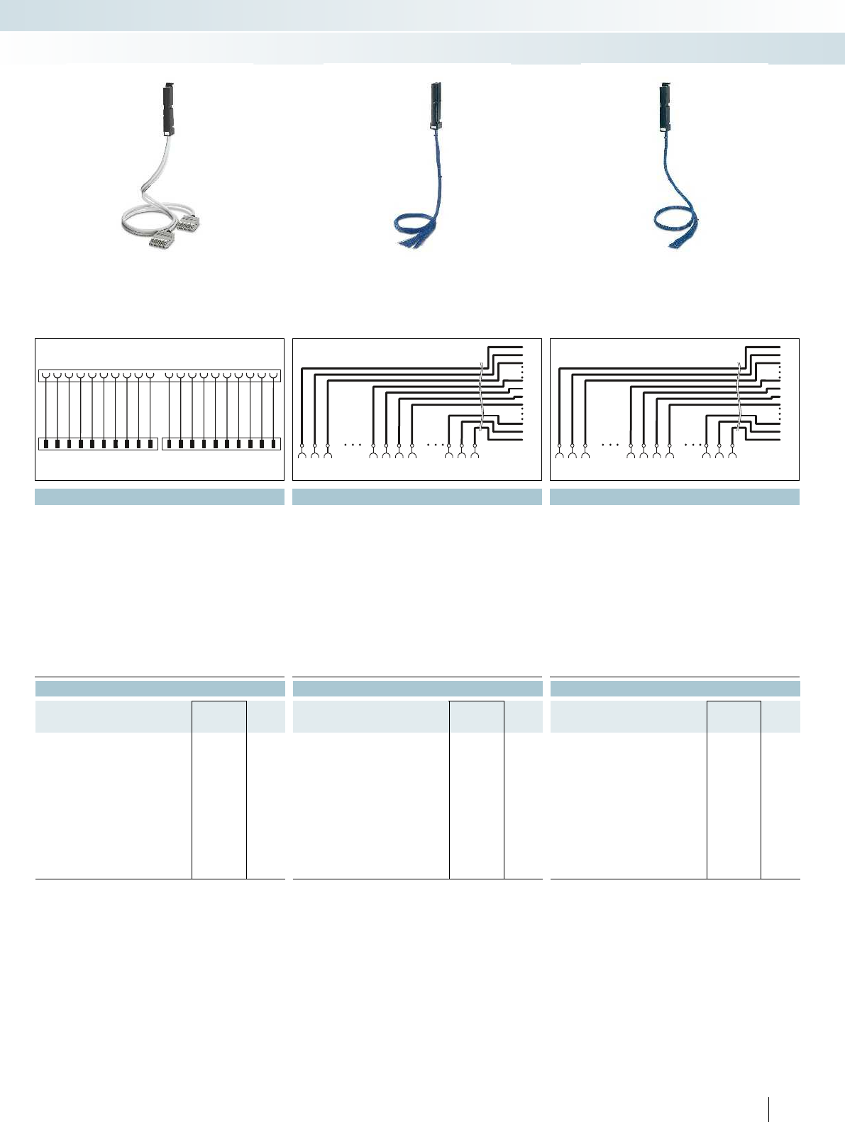
123456789 10 11121314 15 16 17 1819 20
123456789 10 11121314 15 16 17 1819 20
S7 - 300
COMBI
1
38
22
2
39
23
3
40
24
25
122
122
38
38
223
223
39
39
324 25
324 25
40
40
S7-300
1
18
8
2
19
9
3
20
10
11
18
18
18
18
29
29
19
19
310 11
310 11
20
20
S7-300
For additional information, visit phoenixcontact.net/products
Technical data Technical data Technical data
≤ 250 V AC/DC ≤ 250 V AC/DC ≤ 250 V AC/DC
6 A (per single wire at 40°C)
4 A (per single wire at 60°C)
6 A (per single wire at 40°C)
4 A (per single wire at 60°C)
6 A (per single wire at 40°C)
4 A (per single wire at 60°C)
20 A (per cable at 40°C)
16 A (per cable at 60°C)
20 A (per cable at 40°C)
16 A (per cable at 60°C)
20 A (per cable at 40°C)
16 A (per cable at 60°C)
4 kV 2.3 kV 2.3 kV
Basic insulation Basic insulation Basic insulation
39 Ω/km 39 Ω/km 39 Ω/km
AWG 21/0.5 mm² AWG 21/0.5 mm² AWG 21/0.5 mm²
16/Cu uninsulated 16/Cu uninsulated 16/Cu uninsulated
9 mm 13 mm 9 mm
-20°C ... 60°C -20°C ... 60°C -20°C ... 60°C
DIN EN 50178, DIN EN 50178, DIN EN 50178,
Connection method Front adapter Can be plugged onto 40-pin I/O modules Can be plugged onto 20-pin I/O modules Can be plugged onto 40-pin I/O modules Can be plugged onto 20-pin I/O modules
System cable COMBICON connectors SP-H 2,5/10 COMBICON connectors SP-H 2,5/10 Open cable end Open cable end
Ordering data Ordering data Ordering data
Type Order No. Pcs. /
Pkt. Type Order No. Pcs. /
Pkt. Type Order No. Pcs. /
Pkt.
VIP-PA-PWR/2X10COMBI/ 0,5M/S7 2904713 1
VIP-PA-PWR/2X10COMBI/ 1,0M/S7 2904714 1VIP-PA-PWR/40XOE/ 1,0M/S7 2904731 1VIP-PA-PWR/20XOE/ 1,0M/S7 2904724 1
VIP-PA-PWR/2X10COMBI/ 1,5M/S7 2904715 1
VIP-PA-PWR/2X10COMBI/ 2,0M/S7 2904716 1VIP-PA-PWR/40XOE/ 2,0M/S7 2904732 1VIP-PA-PWR/20XOE/ 2,0M/S7 2904725 1
VIP-PA-PWR/2X10COMBI/ 2,5M/S7 2904717 1
VIP-PA-PWR/2X10COMBI/ 3,0M/S7 2904718 1VIP-PA-PWR/40XOE/ 3,0M/S7 2904733 1VIP-PA-PWR/20XOE/ 3,0M/S7 2904726 1
VIP-PA-PWR/2X10COMBI/ 4,0M/S7 2904719 1VIP-PA-PWR/40XOE/ 4,0M/S7 2904734 1VIP-PA-PWR/20XOE/ 4,0M/S7 2904727 1
VIP-PA-PWR/2X10COMBI/ 5,0M/S7 2904720 1
VIP-PA-PWR/2X10COMBI/ 6,0M/S7 2904721 1VIP-PA-PWR/40XOE/ 6,0M/S7 2904735 1VIP-PA-PWR/20XOE/ 6,0M/S7 2904728 1
VIP-PA-PWR/2X10COMBI/ 8,0M/S7 2904722 1VIP-PA-PWR/40XOE/ 8,0M/S7 2904736 1VIP-PA-PWR/20XOE/ 8,0M/S7 2904729 1
VIP-PA-PWR/2X10COMBI/10,0M/S7 2904723 1VIP-PA-PWR/40XOE/10,0M/S7 2904737 1VIP-PA-PWR/20XOE/10,0M/S7 2904730 1
369PHOENIX CONTACT
Interface technology and switching devices
System cabling for controllers - VARIOFACE system cabling
Front adapter with punched-on connectors for
20 plug-in modular terminal blocks
Front adapter with 40 open cable ends Front adapter with 20 open cable ends
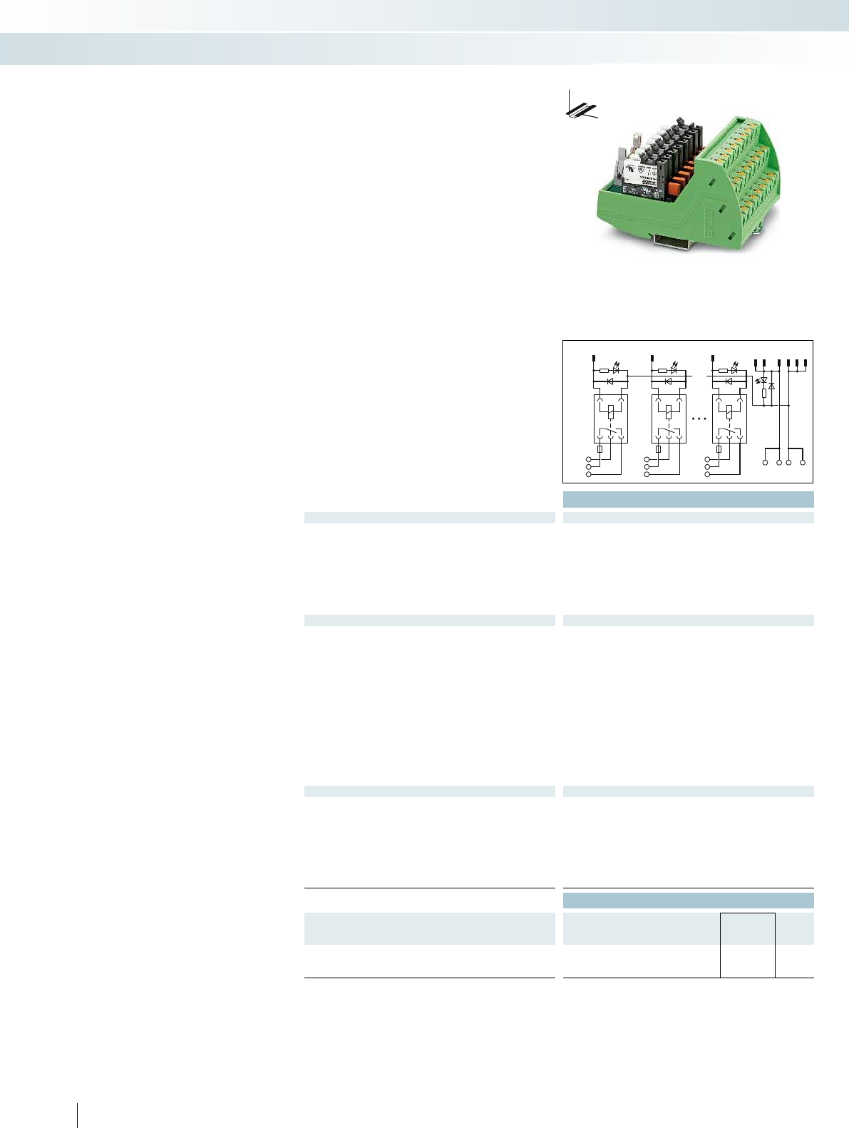
1
0
0NC
0NO
0C
F0
9
11
13
14
10
12
++--
2
1
1NC
1NO
1C
F1
8
7
7NC
7NO
7C
F7
Technical data
Coil side
Operating voltage UN24 V DC
Typ. input current at UN9 mA
Typ. response time at UN5 ms
Typ. release time at UN8 ms
Input circuit Free-wheeling diode
Status display/channel Yellow LED
Connection method IDC/FLK pin strip (2.54 mm)
No. of pos. 14
Contact side
Contact type Single contact, 1-PDT
Contact material AgSnO
Max. switching voltage 250 V AC/DC
Min. switching voltage 12 V AC/DC
Limiting continuous current 5 A (observe derating)
Min. switching current 10 mA
Max. interrupting rating: 24 V DC 140 W
48 V DC 20 W
60 V DC 18 W
110 V DC 23 W
220 V DC 40 W
250 V AC 1500 VA
Connection method Push-in connection
Connection data solid/stranded/AWG 0.14 ... 2.5 mm²/0.14 ... 2.5 mm²/26 - 14
General data
Ambient temperature (operation) -20°C ... 60°C
Nominal operating mode 100% operating factor
Mechanical service life 2 x 10⁷ cycles
Standards/regulations DIN EN 50178
Mounting position Any
Mounting In rows with zero spacing
Dimensions H / D 109.8 mm/63 mm
EMC note Class A product, see page 443
Ordering data
Description Module width
WType Order No. Pcs. /
Pkt.
VARIOFACE output module, with eight miniature relays, plugged,
for 24 V DC (incl. relays)
87.6 VIP-8RPT-24DC/21/D0/FU/PLC 2903601 1
370 PHOENIX CONTACT
DW
H
These VIP VARIOFACE output modules
are used in combination with the respective
front adapters. Like the front adapters, the
modules are connected via 14-pos. system
cables.
Features:
– Plug-in miniature relays, each with a PDT
contact
– LED status display for each signal path and
supply voltage
– Free-wheeling diode for each signal path
– Push-in connection
VIP output module
Interface technology and switching devices
System cabling for controllers - VARIOFACE system cabling
Output module with 8 miniature relays,
1 PDT and fuse per output circuit
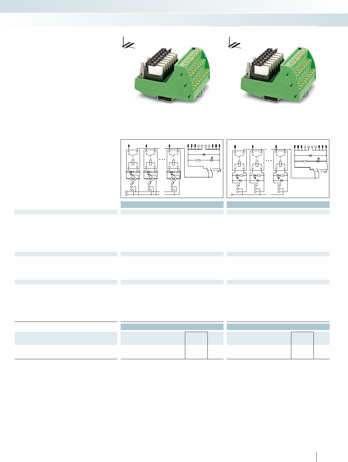
9
11
13++
14
12
10--
-
+
1
0
0.0
-
+
2
1
0.1
-
+
8
7
0.7
-
+
1
0
0.0
-
+
2
1
0.1
-
+
8
7
0.7
-
+
+
9
11
13++
14
12
10--
For additional information, visit phoenixcontact.net/products
Technical data Technical data
Coil side
Operating voltage UN24 V DC ±10% (Supply, 2 A ) 120 V AC ±10% (Supply, 2 A )
Typ. input current at UN9 mA (per channel) 3.5 mA (per channel)
Typ. response time at UN5 ms 6 ms
Typ. release time at UN8 ms 15 ms
Input circuit Free-wheeling diode Free-wheeling diode
Status display/channel Yellow LED Yellow LED
Connection method Push-in connection Push-in connection
Connection data solid/stranded/AWG 0.14 ... 2.5 mm²/0.14 ... 2.5 mm²/26 - 14 0.14 ... 2.5 mm²/0.14 ... 2.5 mm²/26 - 26
Contact side
Contact type 1 N/O contact 1 N/O contact
Contact material AgSnO, hard gold-plated AgSnO, hard gold-plated
Limiting continuous current 50 mA 50 mA
Connection method IDC/FLK pin strip (2.54 mm) IDC/FLK pin strip (2.54 mm)
No. of pos. 14 14
General data
Ambient temperature (operation) -20°C ... 60°C -20°C ... 60°C
Nominal operating mode 100% operating factor 100% operating factor
Mechanical service life 2 x 10⁷ cycles 2 x 10⁷ cycles
Standards/regulations DIN EN 50178 DIN EN 50178
Mounting position Any Any
Mounting In rows with zero spacing In rows with zero spacing
Dimensions H / D 109.8 mm/63 mm 109.8 mm/63 mm
EMC note Class A product, see page 443 Class A product, see page 443
Ordering data Ordering data
Description Module width
WType Order No. Pcs. /
Pkt. Type Order No. Pcs. /
Pkt.
VARIOFACE interface module, for eight channels,
24 V DC (incl. relays) 92.7 VIP-8RPT-24DC/1AU/DI/PLC 2903600 1
120 V AC (incl. relays) 92.7 VIP-8RPT-120AC/1AU/DI/PLC 2904576 1
371PHOENIX CONTACT
These VIP VARIOFACE input modules
are used in combination with the respective
front adapters. Like the front adapters, the
modules are connected via 14-pos. system
cables.
Features:
– Plug-in miniature relays, each with an N/O
contact
– LED status display for each signal path and
supply voltage
– Free-wheeling diode for each signal path
– Push-in connection
DW
H
DW
H
VIP input module
Interface technology and switching devices
System cabling for controllers - VARIOFACE system cabling
Digital input module with 8 channels
for 24VDC
Digital input module with 8 channels
for 120VAC
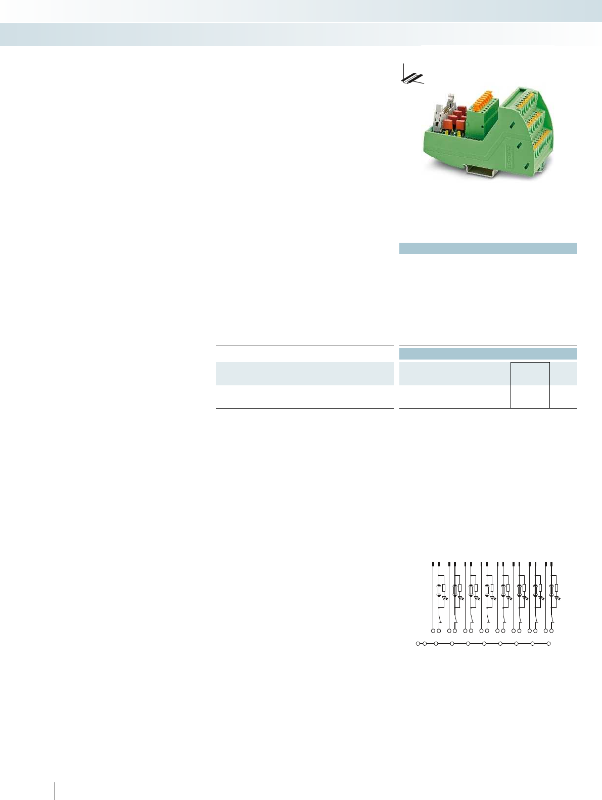
12 345678910 1112 1314 1516
1- 1+ 2- 2+ 3-3+4- 4+ 5- 5+ 6- 6+ 7- 7+ 8-8+
SHSHSHSHSHSHSHSHSHSH
372 PHOENIX CONTACT
Technical data
Max. perm. operating voltage 24 V DC
Max. perm. current (per branch) 63 mA (in as supplied state, with one 63 mA fuse)
Ambient temperature (operation) -20°C ... 60°C
Mounting position Any
Standards/regulations DIN EN 50178,
Connection method Field level Push-in connection
Controller level IDC/FLK pin strip (2.54 mm)
Connection data solid/stranded/AWG 0.14 ... 2.5 mm²/0.14 ... 2.5 mm²/26 - 14
Dimensions H / D 109.8 mm/63 mm
Ordering data
Description No. of
pos.
Module width
WType Order No. Pcs. /
Pkt.
Interface module for 16-pos. mass termination block
16 57.1 mm VIP-PT/FLK16/DS/FU/LED/AN/DV 2903599 1
Connection scheme VIP-PT/FLK16/DS/FU/LED/AN/DV
System-specific interface module for use
in combination with the respective system
cables. The controller board is connected
to 8-channel modules through 16-position
"mass termination blocks" with flat ribbon
cable connection.
Features:
– Fuse per channel
– Separate equipotential terminals per
channel
– Knife disconnection for each channel
– Push-in connection
Emerson DeltaV
VIP controller board with fuses
for 8 channels
Interface technology and switching devices
System cabling for controllers - VARIOFACE system cabling
DW
H
Interface module with fuses
for 16-pos. mass termination block
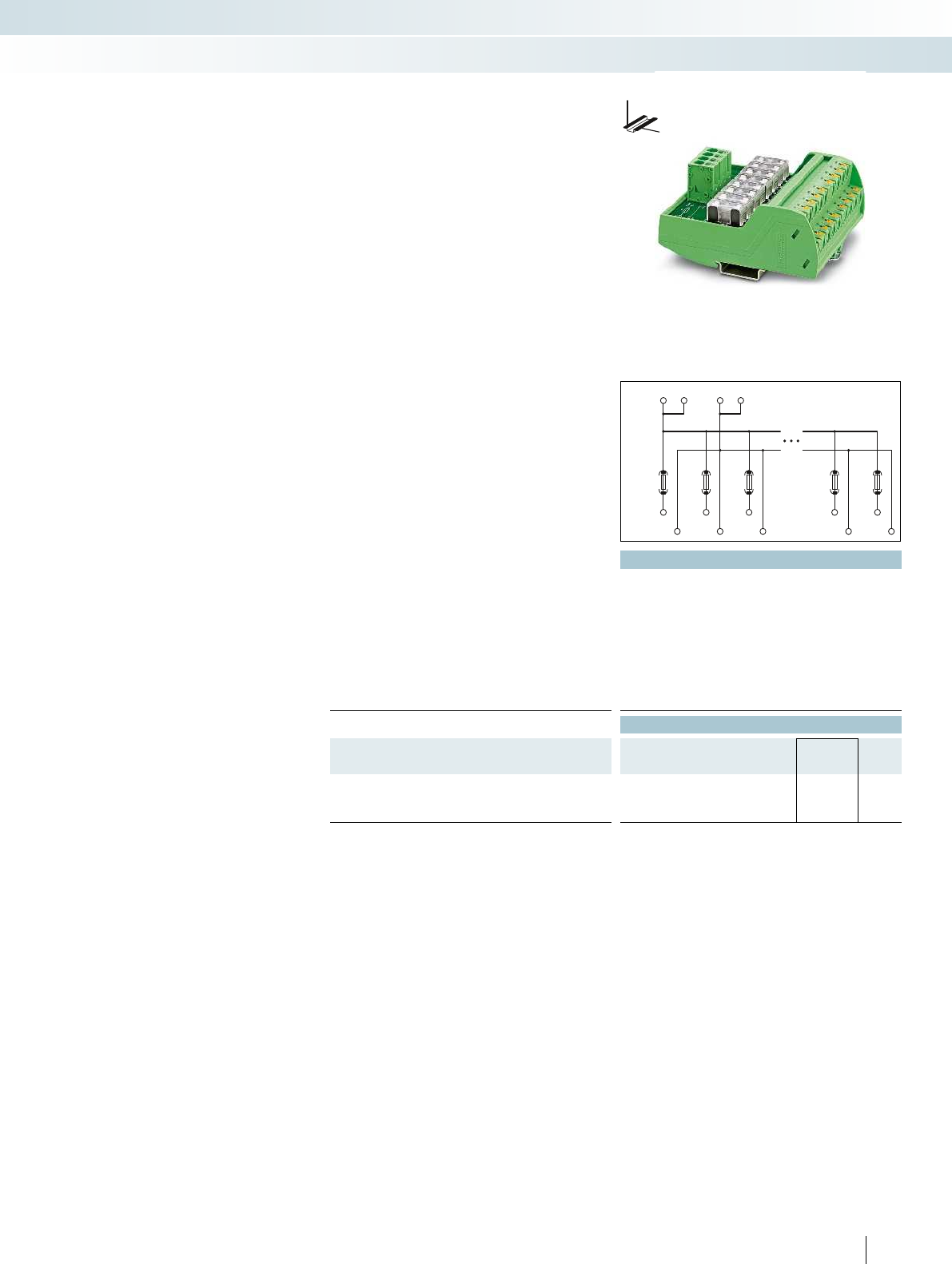
.08
.08
P1 P1 P2 P2
.07
.07
P1
P2
.01 .02 .03
.01 .02 .03
For additional information, visit phoenixcontact.net/products
Technical data
Operating voltage 250 V AC/DC
Max. perm. current (per branch) 6.3 A (fuse limited)
Total current 30 A (per potential)
Ambient temperature (operation) -20°C ... 60°C
Mounting position Any
Standards/regulations IEC 60664, DIN EN 50178, IEC 62103
Supply connection data solid/stranded/AWG 0.2 - 10 mm²/0.2 - 6 mm²/24 - 8
Distribution connection data solid/stranded/AWG 0.14 - 2.5 mm²/0.14 - 2.5 mm²/26 - 14
Dimensions H / D 109.8 mm/51 mm
Ordering data
Description No. of
pos.
Module width
WType Order No. Pcs. /
Pkt.
VARIOFACE module with 2 busbars for potential distribution
- 2 power terminal blocks/8 distributor blocks 97.70 VIP-2/PT/PDM-2/16/FU 6.3A 2903603 1
373PHOENIX CONTACT
DW
H
The VIP-2/PT/PDM-2/16/FU 6.3A module
has the following features:
– Two potential levels
– P1 potential has 6.3A fusing
– Separate supply
– Consecutive labeling
– Push-in connection
VIP potential distributor with fuses
Interface technology and switching devices
System cabling for controllers - VARIOFACE wiring interface
Push-in connection and 2 potential levels
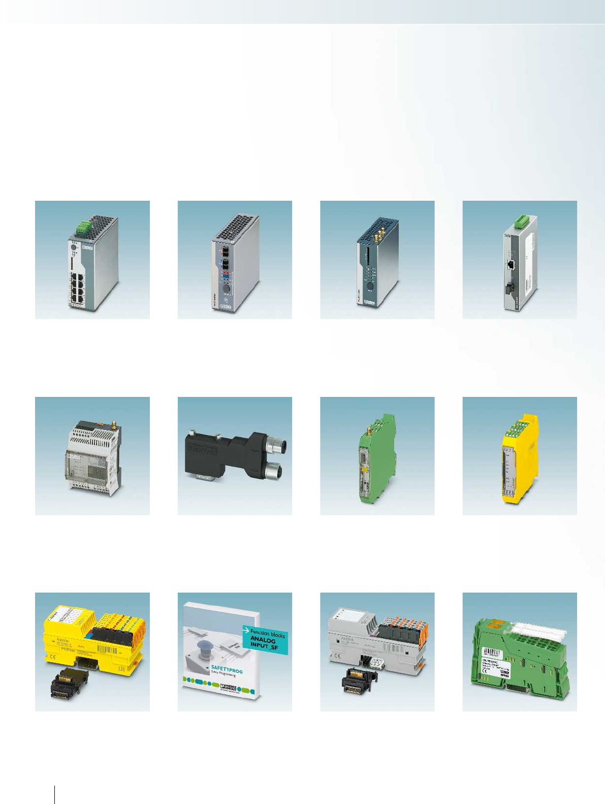
Industrial Ethernet
Power over Ethernet switch Page 376
Lean Managed Switch Page 378
Smart Managed Switches Page 379
Advanced Managed Switches Page 380
Industrial Ethernet
Redundancy modules acc. to
IEC 61850/IEEE 1613
Page 382
Managed Switches acc. to
IEC 61850/IEEE 1613
Page 383
Media module Page 386
Functional Safety
Safe I/O modules Page 404
Functional Safety
Safe analog value
processing
Page 406
I/O systems — Axioline F
Bus coupler Page 408
Digital and analog
input and output modules
Page 410
Temperature recording
modules
Page 414
I/O systems — Inline
M-bus master terminal Page 416
Industrial communication technology
Remote signaling and
remote control system
Page 394
Industrial communication technology
Fast connection plugs Page 396
Industrial communication technology
Process infrastructure
Wireless system for license-
free use in Europe
Page 398
Device couplers for field
devices
Page 399
Industrial Ethernet
WLAN access point Page 387
374 PHOENIX CONTACT
Control technology, I/O systems, and automation infrastructure
Functional Safety
Configurable safety modules
Multifunctional safety relays Page 400
Safe relay extension module Page 402
Industrial communication technology
Media converters for Ethernet
applications in realtime
Page 388
COM server for extreme fields
of application
Page 390
Patch panel Page 392
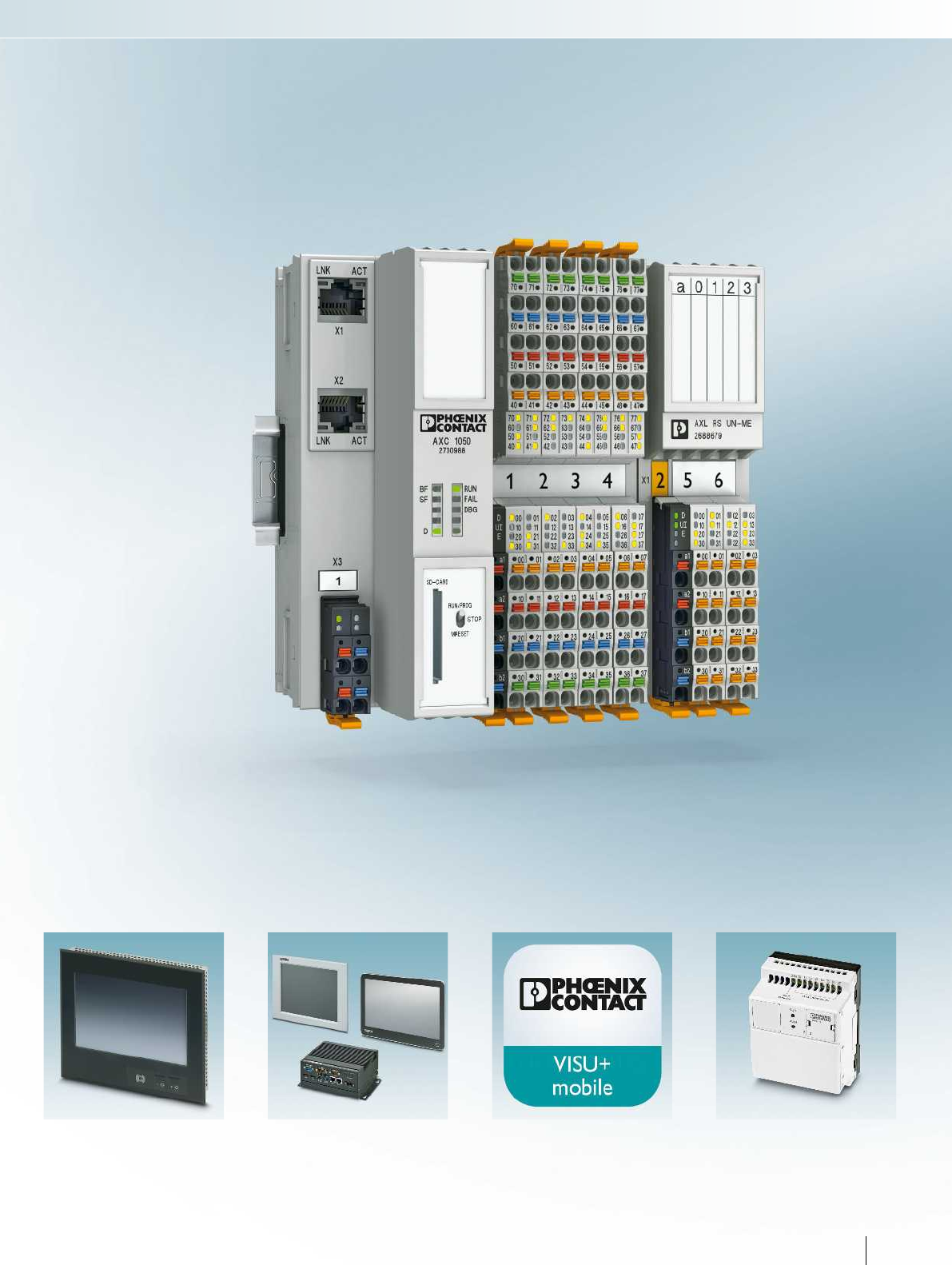
For additional information, visit phoenixcontact.net/products
HMIs and industrial PCs
HMIs for maritime applications Page 418
HMIs and industrial PCs
Box PCs Page 420
Panel PCs Page 422
Outdoor panel PCs Page 424
IP65 panel PCs Page 426
Software
Visualization app Page 428
Multiplexer function for
retrofitting
Page 429
Controllers
Standard logic modules Page 430
Programmable logic relay
system
Page 354
Control technology, I/O systems, and automation infrastructure
375PHOENIX CONTACT
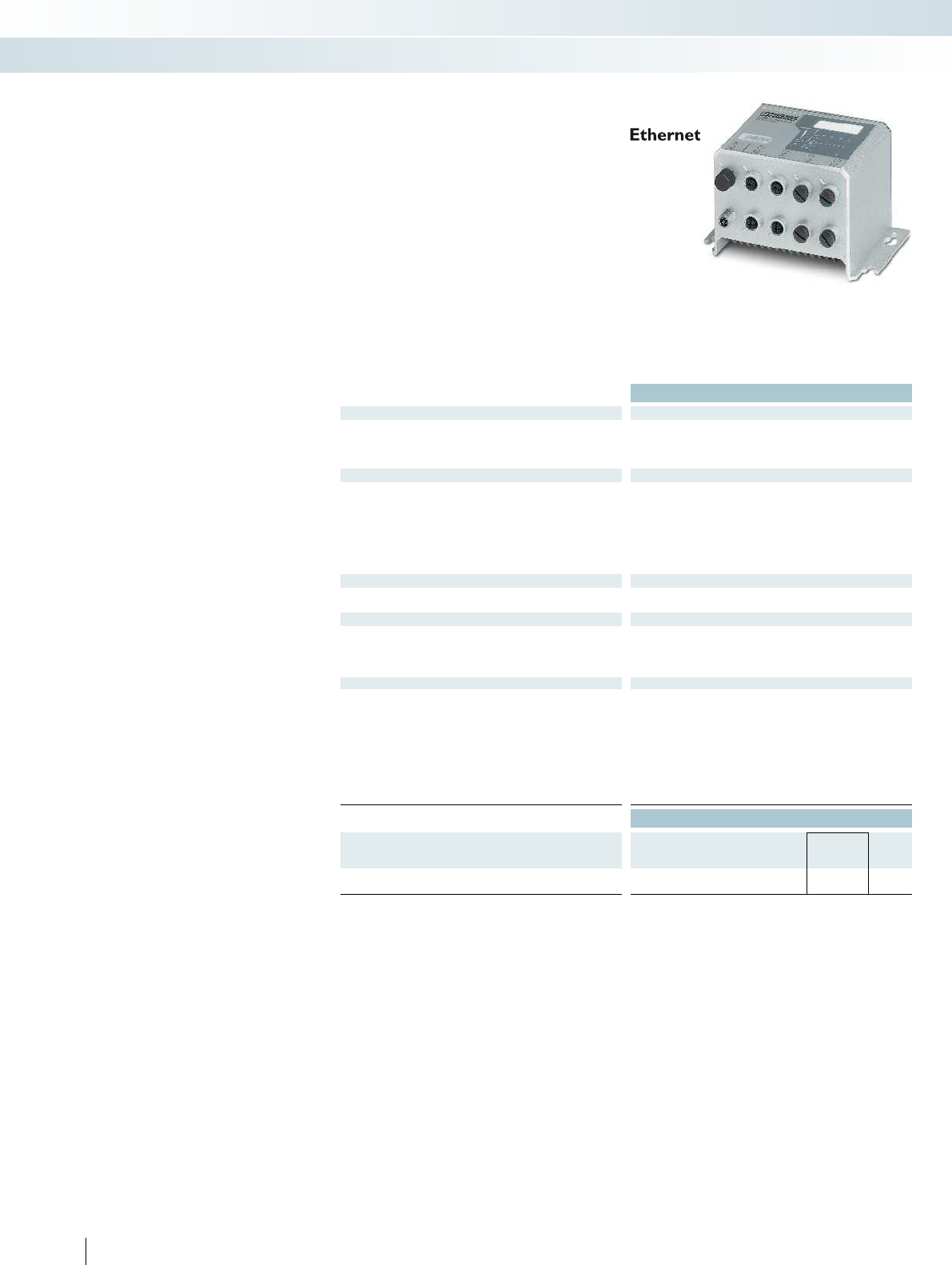
Technical data
Ethernet interface
Number of ports 8 (M12 socket)
Transmission speed 10/100/1000 Mbps
Connection method M12 connector, 8-pos.
Function
Basic functions Store-and-forward switch, 10/100/1000 Mbps, auto negotiation,
complies with standard IEEE 802.3, 4 priority classes according to
IEEE 802.1p, PoE according to IEEE 802.3at/802.3af, jumbo frames
up to 9720 bytes
Status and diagnostic indicators 3 status LEDs per Ethernet port: LINK, Activity, and PoE status.
Supply voltage US1 and US2 (redundant supply voltage) as well as
FAIL. PoE Power Status.
Network expansion parameters
Cascading depth Network, linear, and star structure: any
Maximum conductor length (twisted pair) 100 m
Power supply
Supply voltage 24 V DC (M12 connector)
Residual ripple 3.6 VPP
Supply voltage range 18 V DC ... 32 V DC
Typical current consumption 300 mA (at US = 24 V DC)
General data
Weight 2300 g
Width 176 mm
Height 112 mm
Depth 100 mm
Degree of protection IP65/IP66/IP67
Ambient temperature (operation) -40°C ... 70°C (non-condensing)
Permissible humidity (operation) 10% ... 95%
Noise emission EN 61000-6-4
Noise immunity EN 61000-6-2:2005
Ordering data
Description Type Order No. Pcs. /
Pkt.
Gigabit Power-over-Ethernet switch
FL SWITCH 1708 M12 POE 2701883 1
376 PHOENIX CONTACT
Gigabit switch
The FL SWITCH 1708 M12 POE offers a
unique combination of a high degree of
protection, gigabit transmission, and Power
over Ethernet.
The IP67 switches can be installed in a
distributed manner and enable connection
of Power over Ethernet devices with gigabit
transmission.
Features:
– Connection via gigabit M12 plug CAT6A
– Flexible use of PoE devices thanks to
powerful 30 W PoE ports (IEEE802.3at)
– -40°C ... +70°C ambient temperature
– Gigabit support
– Jumbo frames with up to 9720 bytes
– Rugged metal housing
– IP67 protection
– Easy panel mounting
Power over Ethernet switch
Control technology, I/O systems, and automation infrastructure
Industrial Ethernet switches
8 ports (M12 socket),
for wall mounting

For additional information, visit phoenixcontact.net/products
377PHOENIX CONTACT
Control technology, I/O systems, and automation infrastructure
Industrial Ethernet switches
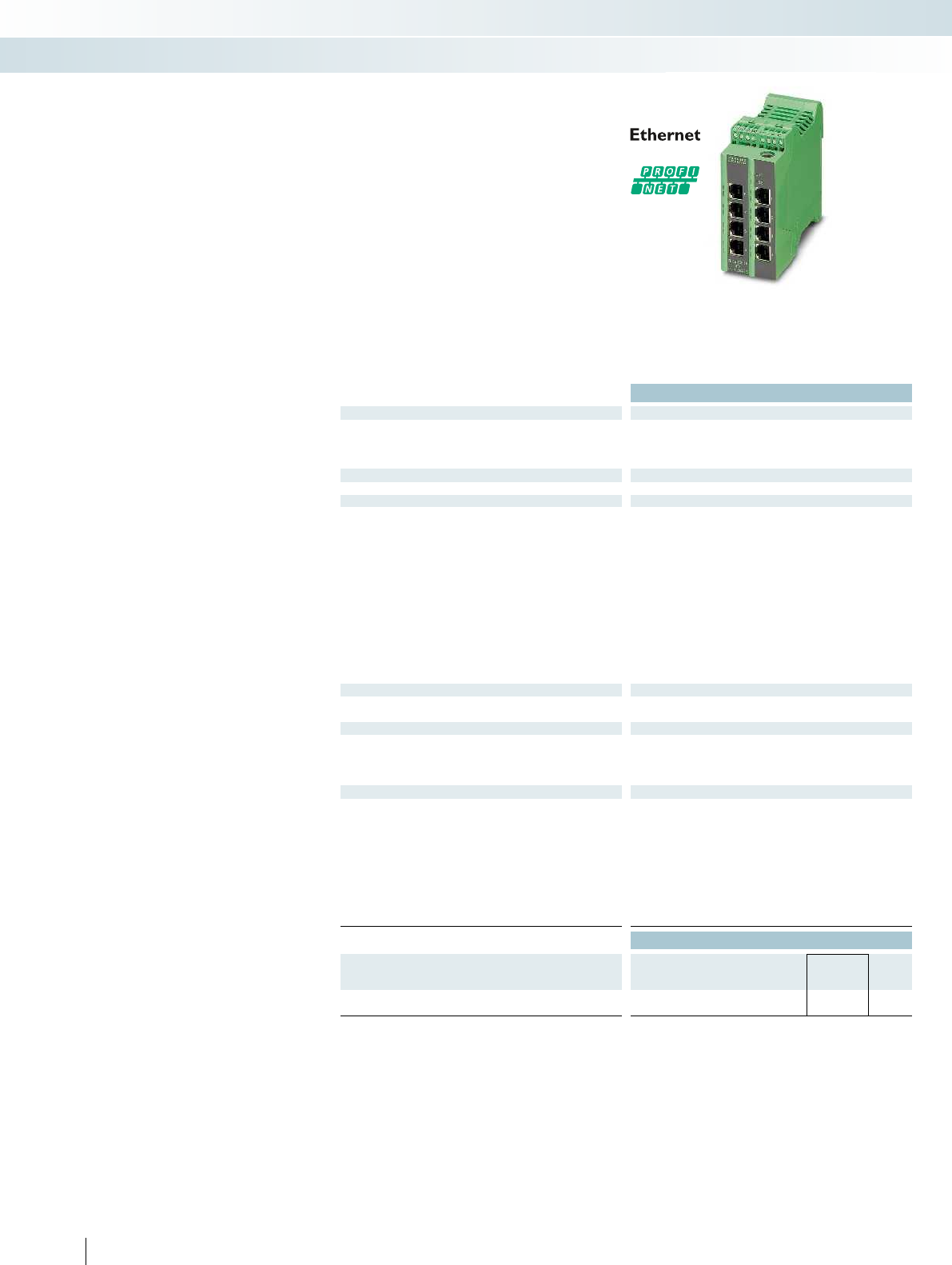
Technical data
Ethernet interface
Number of ports 8 (RJ45 ports)
Transmission speed 10/100 Mbps
Connection method RJ45
Other connections
Serial (RS-232) RS-232-C, 6-pos. MINI-DIN socket (PS/2)
Function
Basic functions Store-and-forward switch complies with IEEE 802.3 2, priority
classes according to IEEE 802.1 P, TCP/IP protocol, BootP-
compatible, port mirroring, integrated web server function, multicast
filtering, IGMP snooping, VLAN, Rapid Spanning Tree (RSTP),
DHCPserver, PTCP filter
Supported browsers Internet Explorer 5.5 or higher
SNMP – Simple Network Management Protocol Supported SNMP-MIBs: Enterprise, MIB II, Bridge
Redundancy Rapid Spanning Tree 802.1w, Fast Ring Detection
Status and diagnostic indicators 2 status LEDs per Ethernet port: Link and Status Activity, 100 Mbps,
full duplex, supply voltage US1 and US2 (redundant supply voltage)
Network expansion parameters
Cascading depth Network, linear, and star structure: any
Maximum conductor length (twisted pair) 100 m
Power supply
Supply voltage 24 V DC
Residual ripple 3.6 VPP
Supply voltage range 18.5 V DC ... 30.5 V DC
Typical current consumption 250 mA (at US = 24 V DC)
General data
Weight 230 g
Width 45 mm
Height 99 mm
Depth 112 mm
Degree of protection IP20
Ambient temperature (operation) 0°C ... 55°C
Permissible humidity (operation) 30% ... 95% (non-condensing)
EMC note Class A product, see page 443
Noise emission EN 61000-6-3/-4
Noise immunity EN 61000-6-2:2005
Ordering data
Description Type Order No. Pcs. /
Pkt.
Lean Managed Switch
FL SWITCH LM 8TX-B 2989446 1
378 PHOENIX CONTACT
Lean Managed Switch
Maximum possible diagnostics in the
minimum amount of space. The compact
Ethernet switch is optimized for PROFINET
applications in standard machine
production.
The switch supports the functions
required by PROFINET Class A, such as
PTCP filter and Quality of Service. In
addition, the Lean Managed Switch features
important management functions such as a
broadcast limiter, port mirroring, as well as
the non-proprietary redundancy protocol
RSTP.
Features:
– Compact housing
– PROFINET support
–RSTP
–PTCP filter
– Web-based management, SNMP
– Configuration can be stored externally
– Configurable alarm contact
Managed switches
Control technology, I/O systems, and automation infrastructure
Industrial Ethernet switches
8 RJ45 ports
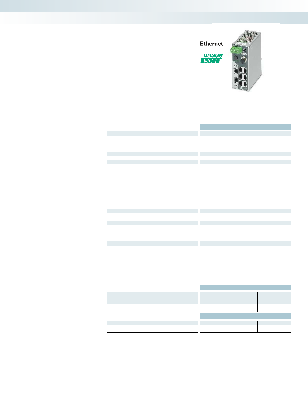
For additional information, visit phoenixcontact.net/products
Technical data
Ethernet interface
Number of ports 8 (RJ45 ports)
Transmission speed 10/100 Mbps
Connection method RJ45
Other connections
Serial (RS-232) RS-232-C, 6-pos. MINI-DIN socket (PS/2)
Function
Basic functions Store-and-forward switch complies with IEEE 802.3 4 priority
classes in acc. with IEEE 802.1 P TCP/IP protocol, BootP-capable,
port-mirroring, integrated web server function, multicast filtering,
IGMP snooping, VLAN, Rapid Spanning Tree (RSTP), PROFINET
Device, Media Redundancy Protocol (MRP).
Status and diagnostic indicators 2 status LEDs per Ethernet: LINK and selectable Status Activity,
100 Mbps, full duplex, supply voltage US1 and US2 (redundant
supply voltage) and FAIL. FD/FO LED indicates duplex mode for
Twisted-Pair ports and the system reserve for optical interfaces.
Network expansion parameters
Cascading depth Network, linear, and star structure: any
Maximum conductor length (twisted pair) 100 m
Power supply
Supply voltage 24 V DC
Residual ripple 3.6 VPP
Supply voltage range 18 V DC ... 32 V DC
Typical current consumption 320 mA (at US = 24 V DC)
General data
Weight 720 g
Width 56 mm
Height 133 mm
Depth 125 mm
Degree of protection IP20
Ambient temperature (operation) 0°C ... 55°C (non-condensing)
Permissible humidity (operation) 5% ... 95% (non-condensing)
Noise emission EN 61000-6-3 +A11
Noise immunity EN 61000-6-2:2005
Ordering data
Description Type Order No. Pcs. /
Pkt.
Smart Managed Narrow Switch
FL SWITCH SMN 8TX-PN 2989501 1
Accessories
Configuration memory, replaceable FL MEM PLUG 2891259 1
Configuration memory, can be replaced with MRM function FL MEM PLUG/MRM 2891275 1
379PHOENIX CONTACT
The Smart Managed Narrow switch
FLSWITCH SMN8TX-PN
is an Ethernet
switch suitable for industrial applications
with eight Fast Ethernet ports in RJ45
format. The switch is optimized for use in
PROFINET RT and EtherNet/IP™
applications.
The switch has PROFINET mode
activated by default. You can easily and
quickly switch to EtherNet/IP™ or
universal mode using the SMART button.
Features:
– Narrow design
–VLANs
–RSTP
– MRP client
– MRP master with FL MEM PLUG/MRM
configuration memory as an option
– Web-based management, SNMP
– PROFINET device function
– LLDP
Smart Managed Switches
Control technology, I/O systems, and automation infrastructure
Industrial Ethernet switches
8 RJ45 ports
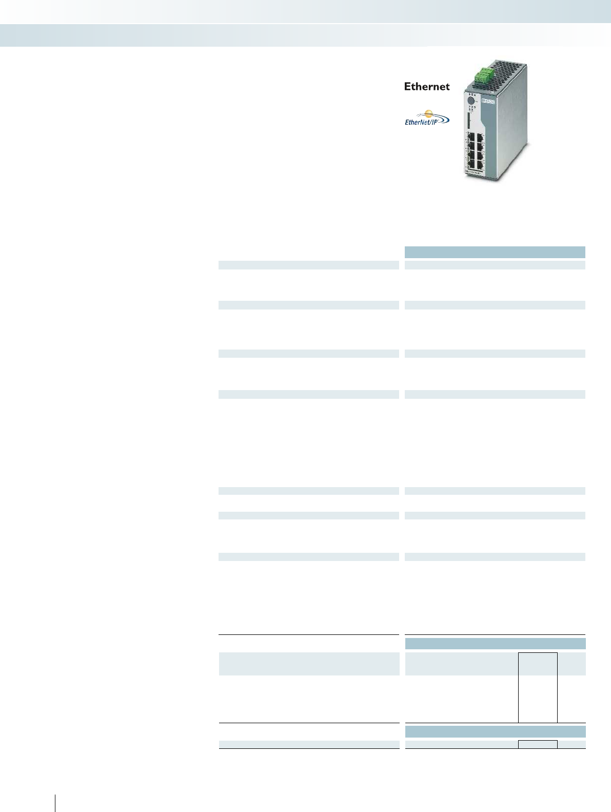
380 PHOENIX CONTACT
Advanced Managed Switches
The automation switches in the 7000
series are the first switches to support
direct integration into a Device Level Ring
(DLR). Direct integration of the switches
into the DLR is a considerable advantage
when installing and operating
EtherNet/IP™ networks.
Up to six devices can be integrated into a
DLR via the FL SWITCH 7000. In system
networks, the switches allow the redundant
rings to be connected to the higher-level
networking level. In this way, you can create
networks with minimal switch-over times of
less than three milliseconds (< 3 ms).
The Managed Switches of the 7000 series
communicate directly via the Common
Industrial Protocol (CIP) in the EtherNet/IP™
network. Via CIP, you can integrate the
switch into an EtherNet/IP™ control
system from where it can be configured and
diagnosed.
Pure copper versions and versions with
up to three fiberglass ports are available for
flexible use.
Features:
– Narrow design
– -40°C ... +70°C ambient temperature
–VLANs
– Common Industrial Protocol (CIP)
– Device Level Ring (DLR)
–RSTP
– Web-based management
Technical data
Ethernet interface
Number of ports 8 (RJ45 ports)
Transmission speed 10/100 Mbps
Connection method RJ45
Fiber optic interface
Number of ports -
Transmission speed -
Connection method -
Transmission length -
Fiber optic interface
Number of ports -
Transmission speed -
Connection method -
Transmission length -
Function
Basic functions Store-and-forward switch complies with IEEE 802.3, 8 priority
classes in acc. with IEEE 802.1 P (QoS), N:1 port mirroring, IGMP
snooping, VLANs, Rapid Spanning Tree (RSTP), Large Tree
Support, Fast Ring Detection (FRD), link aggregation (802.3ad),
MAC-based port security, DHCP option 82, LLDP, ACD, Device
Level Ring (DLR), Common Industrial Protocol (CIP)
Status and diagnostic indicators 2 status LEDs per Ethernet: LINK and selectable status LED: activity,
100 Mbps, full duplex. Supply voltage: US1 and US2 (redundant
supply voltage) and FAIL. EtherNet/IP™ status LED: Net, Mod
Network expansion parameters
Cascading depth Network, linear, and star structure: any Network, linear, and star structure: any Network, linear, and star struct
Maximum conductor length (twisted pair) 100 m
Power supply
Supply voltage 24 V DC
Residual ripple 3.6 VPP
Supply voltage range 12 V DC ... 60 V DC
Typical current consumption 350 mA (at US = 24 V DC) 470 mA (at U
General data
Weight 900 g
Width 60 mm
Height 130 mm
Depth 135.5 mm
Degree of protection IP20
Ambient temperature (operation) -40°C ... 70°C
Permissible humidity (operation) 10% ... 95% (non-condensing) 10% ... 95% (non-condensing) 10% ... 95% (non-condensing)
Noise emission EN 61000-6-4
Noise immunity EN 61000-6-2:2005
Ordering data
Description Type Order No. Pcs. /
Pkt.
Advanced Managed Switch
- 8 RJ45 ports FL SWITCH 7008-EIP 2701418 1
- 6 RJ45 ports, 2 SC FO ports (multi-mode)
- 5 RJ45 ports, 2 SC fiber optic ports (multi-mode),
1SC fiber optic port (single-mode
Accessories
Parameterization memory, replaceable SD FLASH 512MB 2988146 1
Control technology, I/O systems, and automation infrastructure
Industrial Ethernet switches
8 RJ45 ports 6 RJ45 ports and
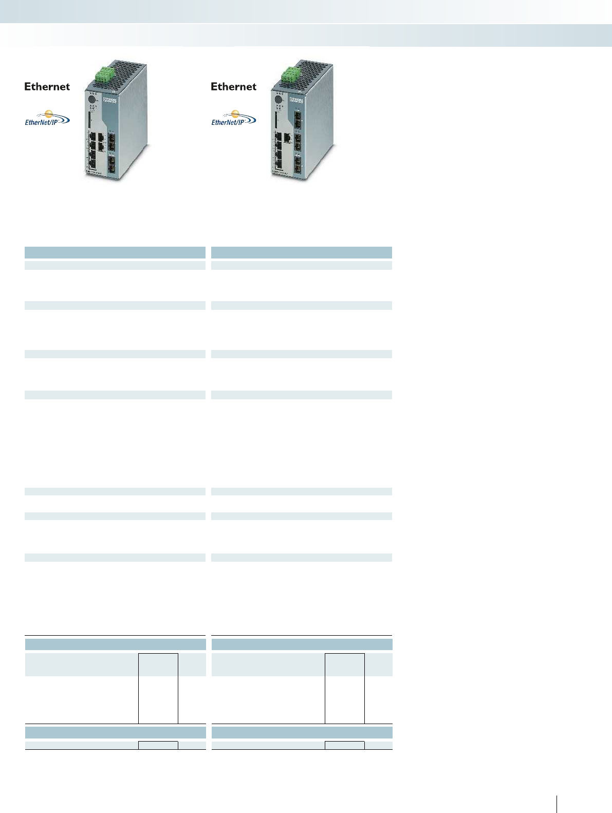
For additional information, visit phoenixcontact.net/products
381PHOENIX CONTACT
Technical data Technical data
6 (RJ45 ports) 5 (RJ45 ports)
10/100 Mbps 10/100 Mbps
RJ45 RJ45
2 (SC multi-mode) 1 (SC multi-mode)
100 Mbps (full duplex) 100 Mbps (full duplex)
SC SC
11000 m (fiberglass with F-G 62.5/125 0.7 dB/km F1000) 11000 m (fiberglass with F-G 62.5/125 0.7 dB/km F1000)
- 2 (SC single-mode)
- 100 Mbps (full duplex)
-SC
- 36000 m (fiberglass with F-G 9/125 0.36 dB/km)
Store-and-forward switch complies with IEEE 802.3, 8 priority
classes in acc. with IEEE 802.1 P (QoS), N:1 port mirroring, IGMP
snooping, VLANs, Rapid Spanning Tree (RSTP), Large Tree
Support, Fast Ring Detection (FRD), link aggregation (802.3ad),
MAC-based port security, DHCP option 82, LLDP, ACD, Device
Level Ring (DLR), Common Industrial Protocol (CIP)
2 status LEDs per Ethernet: LINK and selectable status LED: activity,
100 Mbps, full duplex. Supply voltage: US1 and US2 (redundant
supply voltage) and FAIL. EtherNet/IP™ status LED: Net, Mod
2 status LEDs per Ethernet: LINK and selectable status LED: activity,
100 Mbps, full duplex. Supply voltage: US1 and US2 (redundant
supply voltage) and FAIL. EtherNet/IP™ status LED: Net, Mod
Cascading depth Network, linear, and star structure: any Network, linear, and star structure: any Network, linear, and star structure: any
100 m 100 m
24 V DC 24 V DC
3.6 VPP 3.6 VPP
12 V DC ... 60 V DC 12 V DC ... 60 V DC
= 24 V DC) 470 mA (at US = 24 V DC) 520 mA (at US = 24 V DC)
990 g 1000 g
60 mm 60 mm
130 mm 130 mm
135.5 mm 135.5 mm
IP20 IP20
-40°C ... 70°C -40°C ... 70°C
Permissible humidity (operation) 10% ... 95% (non-condensing) 10% ... 95% (non-condensing) 10% ... 95% (non-condensing)
EN 61000-6-4 EN 61000-6-4
EN 61000-6-2:2005 EN 61000-6-2:2005
Ordering data Ordering data
Type Order No. Pcs. /
Pkt. Type Order No. Pcs. /
Pkt.
FL SWITCH 7006/2FX-EIP 2701419 1
FL SWITCH 7005/FX-2FXSM-EIP 2701420 1
Accessories Accessories
SD FLASH 512MB 2988146 1SD FLASH 512MB 2988146 1
Control technology, I/O systems, and automation infrastructure
Industrial Ethernet switches
8 RJ45 ports 6 RJ45 ports and
2 fiber optic ports (multi-mode)
5 RJ45 ports and
1 fiber optic port (multi-mode),
2 fiber optic ports (single-mode)
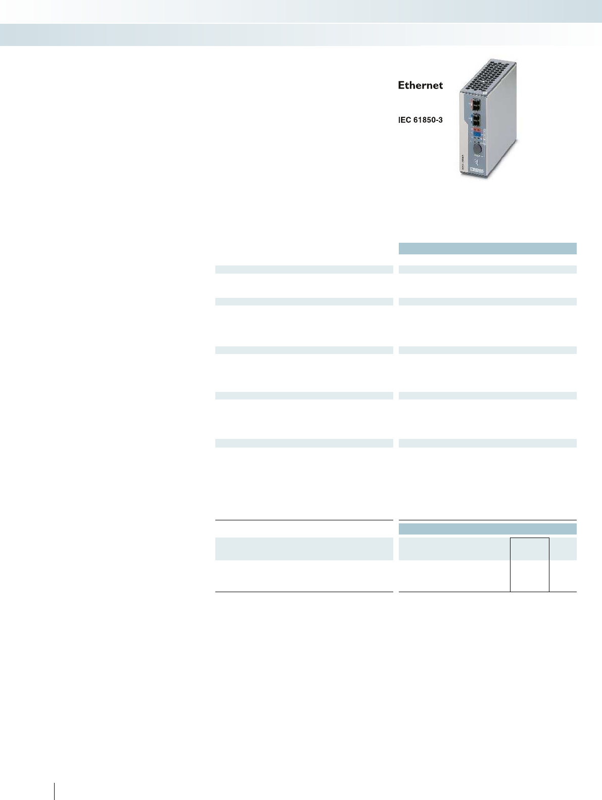
Technical data
FL RED 2003E PRP FL RED 2001E PRP 2LC
Ethernet interface
Number of ports 3 (RJ45 ports) 1 (RJ45 port)
Transmission speed 10/100 Mbps
Transmission length 100 m (per segment)
Fiber optic interface
Interface - Ethernet FO
Number of ports - 2
Transmission speed - 100 Mbps (full duplex)
Connection method - LC
Transmission length - 2 km (per segment)
Function
Basic functions Ethernet redundancy module for the Parallel Redundancy Protocol
Status and diagnostic indicators LEDs: US1, US2 (redundant voltage supply), link and activity per port
Power supply
Supply voltage 24 V DC (redundant)
48 V DC (redundant)
Residual ripple 3.6 VPP
Supply voltage range 18 V DC ... 58 V DC
Typical current consumption 250 mA (@24VDC)
General data
Weight
Width 40 mm
Height 100 mm
Depth 109 mm
Degree of protection IP20
Ambient temperature (operation) -40°C ... 70°C
Permissible humidity (operation) 10% ... 95% (non-condensing)
Noise emission EN 61000-6-4
Noise immunity IEC61850-3, IEEE1613, EN61000-6-2: 2005
Ordering data
Description Type Order No. Pcs. /
Pkt.
Redundancy module
- 3 RJ45 ports FL RED 2003E PRP 2701863 1
- 1 RJ45 port, 2 LC fiber optic ports (multi-mode) FL RED 2001E PRP 2LC 2701864 1
382 PHOENIX CONTACT
Energy networks rely on particularly high
fault tolerance. The new PRP redundancy
modules enable parallel redundancy without
switch-over time in the event of a fault. You
can therefore ensure maximum availability
of your network.
Interruption-free communication
– The FL RED 2000E redundancy module is
equipped with the Parallel Redundancy
Protocol (PRP)
– Interoperability in high-availability
networks is possible, as required in the
energy sector
– The system continues to operate in the
case of redundancy without switch-over
time
Robust design
– Developed according to the requirements
of IEC61850-3 and IEEE1613: complies
with the high requirements for network
technology in this area
– Robust to withstand voltage fluctuations
due to a wide input voltage range of
18VDC ... 58VDC
– Rugged metal housing
– -40°C ... 70°C operating termperature
Easy handling
– Design of a high-availability network
without configuration
– LED indicators provide on-site
information regarding the status of the
network and redundancy
– Alarm signal contact indicates the status
of the module and network
Redundancy modules according to
IEC61850/IEEE1613
Control technology, I/O systems, and automation infrastructure
Industrial Ethernet switches
Redundancy module
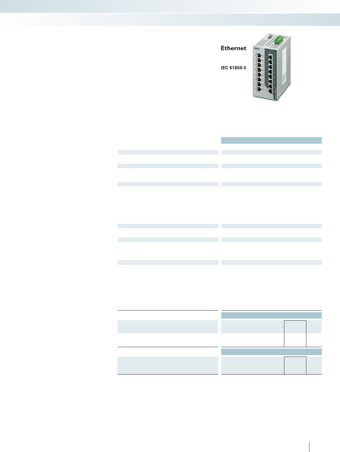
For additional information, visit phoenixcontact.net/products
Technical data
FL SWITCH 3016E FL SWITCH 3012E-2SFX
Ethernet interface
Number of ports 16 (RJ45 ports) 12 (RJ45 ports)
Transmission speed 10/100 Mbps (with auto negotiation)
Fiber optic interface
Number of ports - 2 (FO ports)
Transmission speed - 100 Mbps (full duplex)
Connection method - SFP ports
Function
Basic functions Store and forward switch, Extended Ring and IEEE redundancy,
Multicast control, IGMP snooping, trunking, Port and Tagging
VLANs, Port and IEEE 802.1x security, SNMP V3 and Https
security, SNTP, web customization, user accounts
Status and diagnostic indicators LEDs: US1, US2 (redundant voltage supply), link and activity per port
Network expansion parameters
Cascading depth Network, linear, and star structure: any
Maximum conductor length (twisted pair) 100 m
Power supply
Supply voltage 24 V DC
Residual ripple 3.6 VPP
Supply voltage range 12 V DC ... 48 V DC
Typical current consumption 312 mA (24 V DC)
General data
Weight
Width 66 mm
Height 173 mm
Depth 140 mm
Degree of protection IP20
Ambient temperature (operation) -40°C ... 70°C
Permissible humidity (operation) 5% ... 95% (non-condensing)
EMC note Class A product, see page 443
Noise emission EN 61000-6-4
Noise immunity IEC61850-3, IEEE1613, EN61000-6-2: 2005
Ordering data
Description Type Order No. Pcs. /
Pkt.
Managed switch
- 16 RJ45 ports FL SWITCH 3016E 2891066 1
- 12 RJ45 and 2 SFP FO ports FL SWITCH 3012E-2SFX 2891067 1
Accessories
Redundancy module
- 3 RJ45 ports FL RED 2003E PRP 2701863 1
- 1 RJ45 port, 2 LC fiber optic ports (multi-mode) FL RED 2001E PRP 2LC 2701864 1
383PHOENIX CONTACT
Ethernet switches control Ethernet traffic
and maximize uptime. Operation in
extreme environments is assured with a
wide temperature range and an electrical
noise immunity up to four times that of
normal industrial switches.
Features:
– DIN rail mounting
– Mix IEEE and Extended Ring redundancy
options which provide 15ms recovery
time for hundreds of switches
– Comprehensive IEEE security and
performance functions
– Unique web customization, diagnostic
viewing mode and, help pages simplify
maintenance
– Optional PRP redundancy modules
provide 0ms recovery times
Managed Switches according to
IEC61850/IEEE1613
Control technology, I/O systems, and automation infrastructure
Industrial Ethernet switches
16 RJ45 ports
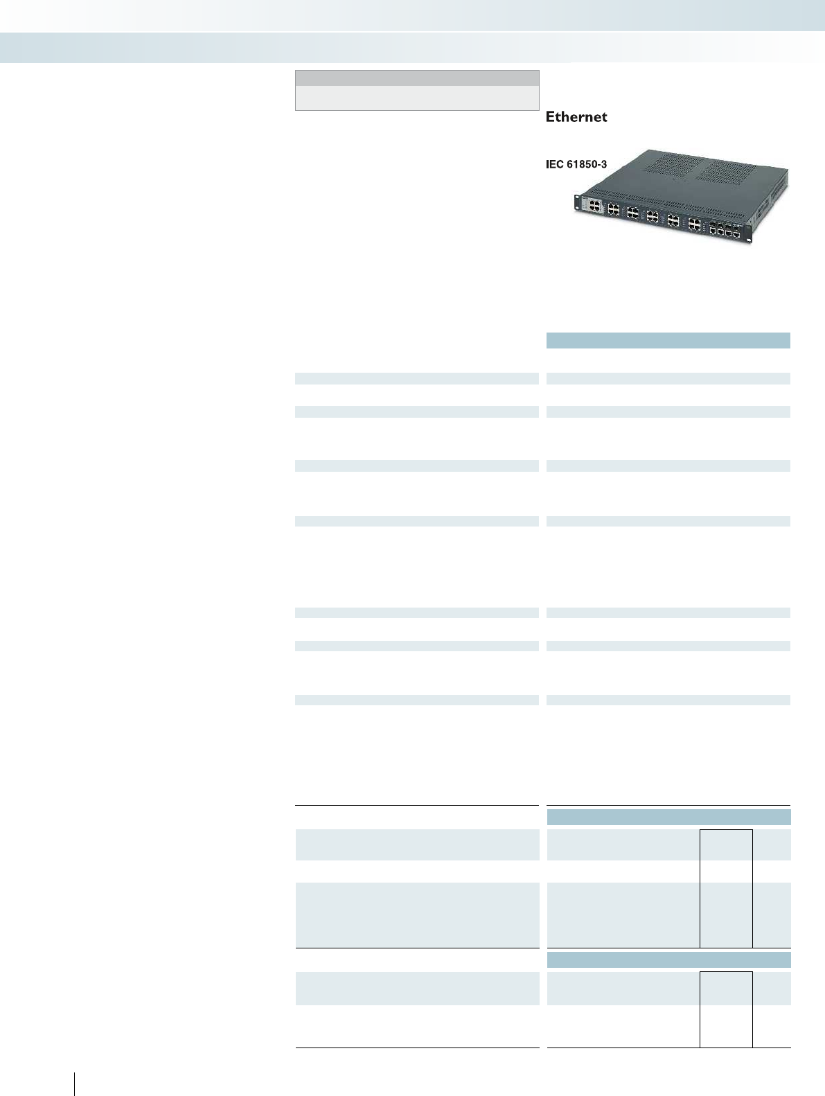
384 PHOENIX CONTACT
Managed Switches according to
IEC61850/IEEE1613, 19"rack-mount
Notes:
1) Requires the installation of at least one FLSWITCH 4800E-P1
or FLSWITCH 4800E-P5 for operation.
The FL SWITCH4800E line of managed
switches combines 24 ports of 10/100Mbps
device connections with four
10/100/1000Mbps uplink ports for a total
of 28 ports. Application flexibility is assured
with different mixes of copper/fiber and
fiber types, gigabit fiber/copper
“combination” ports and modular power
supplies. Operation in extreme
environments is assured with a wide
temperature range and an electrical noise
immunity up to four times that of normal
industrial switches.
Features:
– All switches have four Gigabit RJ45/SFP
combination ports for supervisory or high
throughput field network connections
– Flexible cabling using eight or 24
10/100Mbps RJ45 connections with up to
16 fiber (100Mbps) fiber connections
– Mix IEEE and Extended Ring redundancy
options which provide 15ms recovery
time for hundreds of switches
– Optional PRP redundancy modules
provide 0ms recovery times
– Comprehensive IEEE security and
performance functions
– Unique web customization, diagnostic
viewing mode and help pages simplify
maintenance
– Supports up to two modular, hot-
swappable power supplies for maximum
power flexibility and uptime
– Electrical noise immunity per IEC61850-
3 and IEEE1613
Technical data
Ethernet interface
Number of ports 24 (RJ45 ports)
Transmission speed 10/100 Mbps
Ethernet (RJ45/FO combo)
Interface Ethernet (RJ45/FO combo)
Connection method RJ45, shielded or SFP module (LC)
Note on connection method Auto negotiation and autocrossing (RJ45 interface) Auto negotiation and autocrossing (RJ45 interface) Au
Fiber optic interface
Number of ports -
Transmission speed -
Connection method -
Transmission length -
Function
Basic functions Store and forward switch, Extended Ring and IEEE redundancy,
Multicast control, IGMP snooping, trunking, Port and Tagging
VLANs, Port and IEEE 802.1x security, SNMP V3 and Https
security, SNTP, web customization, user accounts
Status and diagnostic indicators LEDs: US1, US2 (redundant voltage supply), link and activity per port LEDs: U
Network expansion parameters
Cascading depth Network, linear, and star structure: any Network, linear, and star structure: any Network, linear, and star struct
Maximum conductor length (twisted pair) 100 m
Power supply
Power supply connection From FLSWITCH 4800E-P...
Supply voltage -
Nominal input voltage range -
General data
Weight 4494 g
Width 442 mm
Height 44 mm
Depth 375 mm
Degree of protection IP20
Ambient temperature (operation) -40°C ... 70°C
Permissible humidity (operation) 5% ... 95% (non-condensing)
Noise emission EN 61000-6-4
Noise immunity IEC61850-3, IEEE1613, EN61000-6-2: 2005 IEC
Ordering data
Description Type Order No. Pcs. /
Pkt.
Managed switch, 19-inch rack mounted
- 24 RJ45 and 4 GB combo ports FL SWITCH 4824E-4GC1) 2891072 1
Managed switch, 19-inch rack mounted
with 8 RJ45 and 4 GB combo ports
- 16 fiber optic (LC duplex) ports
- 16 fiber optic (LC single-mode) ports
- 16 fiber optic (SC duplex) ports
- 16 fiber optic (SC single-mode) ports
Accessories
Power supply, modular redundant
- 48 V DC nominal FL SWITCH 4800E-P1 2891075 1
- 230 V nominal FL SWITCH 4800E-P5 2891076 1
Redundancy module
- 3 RJ45 ports FL RED 2003E PRP 2701863 1
- 1 RJ45 port, 2 LC fiber optic ports (multi-mode) FL RED 2001E PRP 2LC 2701864 1
Control technology, I/O systems, and automation infrastructure
Industrial Ethernet switches
24 RJ45 ports and
4 gigabit combo (SFP or RJ45) ports

For additional information, visit phoenixcontact.net/products
385PHOENIX CONTACT
Technical data Technical data Technical data
FL SWITCH 4808E-16FX LC-
4GC1)
FL SWITCH 4808E-16FX SM
LC-4GC1)
FL SWITCH 4808E-16FX-4GC1) FL SWITCH 4808E-16FX SM-
4GC1)
FL SWITCH 4800E-P1 FL SWITCH 4800E-P5
8 (RJ45 ports) 8 (RJ45 ports) -
10/100 Mbps 10/100 Mbps -
Ethernet (RJ45/FO combo) Ethernet (RJ45/FO combo) -
RJ45, shielded or SFP module (LC) RJ45, shielded or SFP module (LC) -
45 interface) Auto negotiation and autocrossing (RJ45 interface) Auto negotiation and autocrossing (RJ45 interface) -
16 (multi-mode) 16 (single-mode) 16 (multi-mode) 16 (single-mode) -
100 Mbps (full duplex) 100 Mbps (full duplex) -
LC SC -
2 km (typical) 40 km (typical) 2 km (typical) 40 km (typical) -
Store and forward switch, Extended Ring and IEEE redundancy,
Multicast control, IGMP snooping, trunking, Port and Tagging
VLANs, Port and IEEE 802.1x security, SNMP V3 and Https
security, SNTP, web customization, user accounts
Store and forward switch, Extended Ring and IEEE redundancy,
Multicast control, IGMP snooping, trunking, Port and Tagging
VLANs, Port and IEEE 802.1x security, SNMP V3 and Https
security, SNTP, web customization, user accounts
-
(redundant voltage supply), link and activity per port LEDs: US1, US2 (redundant voltage supply), link and activity per port LEDs: US1, US2 (redundant voltage supply), link and activity per port -
Cascading depth Network, linear, and star structure: any Network, linear, and star structure: any Network, linear, and star structure: any -
100 m 100 m -
From FLSWITCH 4800E-P... From FLSWITCH 4800E-P... -
- - 48 V DC 230 V AC/DC
- - 36 V DC ... 75 V DC 88 V DC ... 370 V DC
90 V AC ... 264 V AC
4706 g 4700 g 4470 g 4680 g 836 g 884 g
442 mm 442 mm 150 mm
44 mm 44 mm 40 mm
375 mm 375 mm 193 mm
IP20 IP20 IP20
-40°C ... 70°C -40°C ... 70°C -40°C ... 75°C
5% ... 95% (non-condensing) 5% ... 95% (non-condensing) 5% ... 95% (non-condensing)
EN 61000-6-4 EN 61000-6-4 -
61000-6-2: 2005 IEC61850-3, IEEE1613, EN61000-6-2: 2005 IEC61850-3, IEEE1613, EN61000-6-2: 2005 -
Ordering data Ordering data Ordering data
Type Order No. Pcs. /
Pkt. Type Order No. Pcs. /
Pkt. Type Order No. Pcs. /
Pkt.
FL SWITCH 4808E-16FX LC-4GC1)2891073 1
FL SWITCH 4808E-16FX SM LC-4GC
1
)
2891074 1
FL SWITCH 4808E-16FX-4GC1)2891079 1
FL SWITCH 4808E-16FX SM-4GC1)2891080 1
Accessories Accessories Accessories
FL SWITCH 4800E-P1 2891075 1FL SWITCH 4800E-P1 2891075 1FL SWITCH 4800E-P1 2891075 1
FL SWITCH 4800E-P5 2891076 1FL SWITCH 4800E-P5 2891076 1FL SWITCH 4800E-P5 2891076 1
FL RED 2003E PRP 2701863 1FL RED 2003E PRP 2701863 1
FL RED 2001E PRP 2LC 2701864 1FL RED 2001E PRP 2LC 2701864 1
Control technology, I/O systems, and automation infrastructure
Industrial Ethernet switches
8 RJ45 ports,
4 gigabit combo (SFP or RJ45) ports,
and 16 LC FO ports
8 RJ45 ports,
4 gigabit combo (SFP or RJ45) ports,
and 16 SC FO ports
Power supply modules for 4800E switches
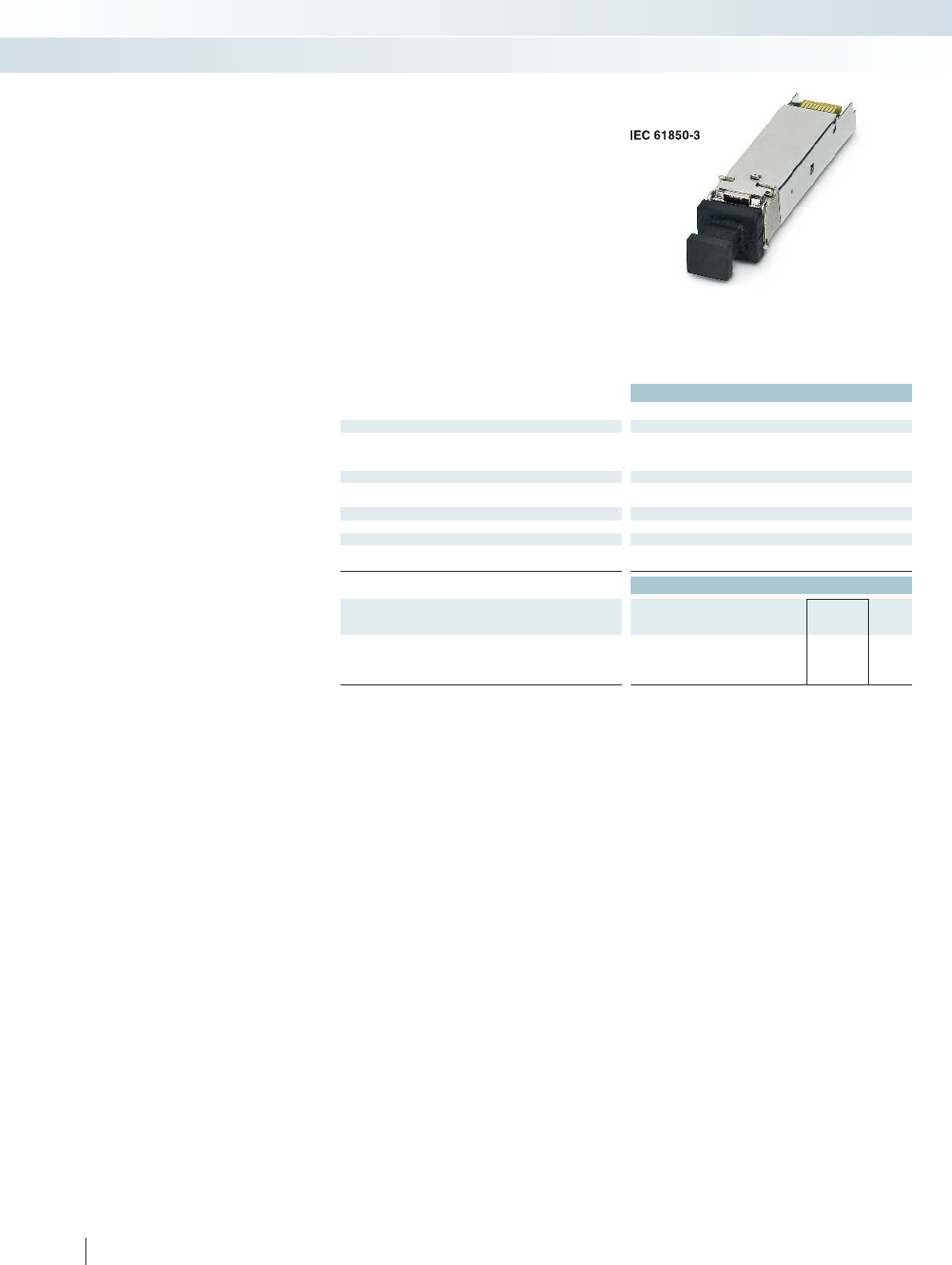
Technical data
FL SFP FX FL SFP FX SM
Fiber optic interface
Number of ports 1 (LC multi-mode) 1 (LC single-mode)
Wavelength 1300 nm
Transmission length Typ. 2 km Typ. 40 km
Function
Basic functions SFP module as FO port
Power supply
Power supply connection via SFP slot
General data
Ambient temperature (operation) -40°C ... 85°C (non-condensing)
Permissible humidity (operation) 30% ... 95% (non-condensing)
Ordering data
Description Type Order No. Pcs. /
Pkt.
Small form pluggable (SFP) fiber module (100Mbps)
- Multi-mode (2km) FL SFP FX 2891081 1
- Single-mode (40km) FL SFP FX SM 2891082 1
386 PHOENIX CONTACT
Rugged, small form-factor pluggable (SFP)
modules provide a variety of fiber optic
interfaces. They are inserted into SFP
sockets on managed switches, customizing
both quantity and type of fiber used.
Features:
– Supports 100Mbps full duplex fiber
communication
– Electrical noise immunity per
IEC61850-3 and IEEE1613
– Wide temperature range
Fiber optic interface module
Control technology, I/O systems, and automation infrastructure
Industrial Ethernet switches
SFP modules
for transmission ranges up to 40km

For additional information, visit phoenixcontact.net/products
Technical data
Wireless interface
Wireless standard IEEE 802.11
Frequency band 2.4 GHz/5 GHz
Antenna connection method RSMA (female)
Number 3
Antenna
Assembly instructions Antennas not included in scope of supply
Ethernet ports
Number 2
Connection method RJ45 socket
Power supply for module electronics
Supply voltage 24 V DC
Connection method Via COMBICON
Supply voltage range 10 V DC ... 36 V DC
Supply current 200 mA
Security
802.11i
WPA PSK (preshared key)
WPA2
AES
TKIP
Supports 802.1X/RADIUS
MAC filter
Function
Operating modes Access point/client adapter/repeater/WDS bridge
Basic functions SNMP (V2/V3), CLI, WPS, DHCP, DCP, BootP, HTTP, HTTPS,
Syslog, SD card, dual FW image, 1 x DI, 1 x DO, 2 x Ethernet 10/100
Mbit, auto crossover, auto negotiation, MODE button
Configuration Cluster management, web-based management, WPS
General data
Weight 418 g
Width 40 mm
Height 109 mm
Depth 109 mm
Degree of protection IP20
Ambient temperature (operation) -25°C ... 60°C (extended temperature range on request)
Permissible humidity (operation) 10% ... 95% (non-condensing)
Air pressure (operation) 800 hPa ... 1080 hPa (up to 2000 m above mean sea level)
Shock in acc. with EN 60068-2-27/IEC 60068-2-27 30g
Vibration resistance in acc. with EN 60068-2-6/IEC 60068-2-6 5g
Ordering data
Description Type Order No. Pcs. /
Pkt.
Wireless LAN Access Point
- Approval for Japan FL WLAN 5102 2701850 1
Accessories
Parameterization memory, Flash card without license SD FLASH 2GB 2988162 1
387PHOENIX CONTACT
The latest generation of WLAN modules
offers maximum reliability, data throughput,
and range.
Faster
– The new high-speed WLAN 5100 brings
WLAN 802.11n to industrial applications
and with it a data rate of up to 300 Mbps
Configuration
– Central cluster management enables the
entire wireless network to be set up in
just minutes
More reliable
– MiMo technology with three antennas for
wireless communication that is more
robust, faster, and covers a wider range
WLAN access point
Control technology, I/O systems, and automation infrastructure
Industrial Ethernet - wireless Ethernet
WLAN access point/client 2.4 GHz, 5 GHz
802.11 a, b, g, n
Approval for Japan
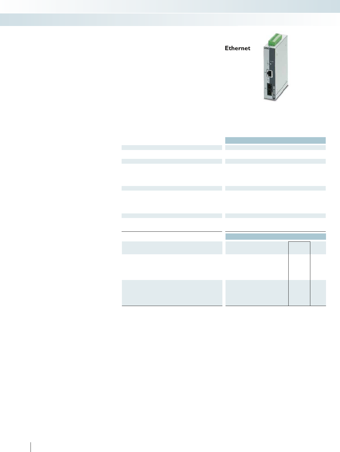
388 PHOENIX CONTACT
Media converters
FL MC 2000T... media converters
optimize the performance and reliability of
industrial Ethernet applications and are
optimized for use in extreme environments.
Selectable port settings provide usability
with a wider range of devices. Selectable
low latency (700ns) allows the media
converter to be used in time-critical
applications. Configurable link monitoring
diagnostics increase network reliability.
Features:
– Optional multi-mode or single-mode
SC duplex fiber optic connection at
100Mbps
– DIP switch selectable auto negotiate or
fixed port settings, data rate and half or
full duplex
– DIP switch selectable store-and-forward
or pass-through mode (low latency,
700ns)
– Alarm contact provides power and link
status diagnostics
– Link fault pass through (LFP) function for
easy connection monitoring
– Wide operating temperature range
(-40°C... 75°C)
Technical data
Supply
Supply voltage 12 V DC ... 48 V DC
Nominal current consumption 110 mA (24 V DC)
FO interface
Wavelength 1310 nm
Transmission length Incl. 3 dB system reserve 9.6 km (fiberglass with F-G 50/125 0.7 dB/km F1200) 20 km (fiberglass with F-G 9/12
Signal LEDs LNK/ACT
Switching output Floating relay output
Ethernet interface
Connection method RJ45 socket, shielded RJ45 socket, shielded RJ45 socket, shielded RJ45 socket, shielded
Transmission speed 10/100 Mbps
Link through Link fault pass through Link fault pass through Link fault pass through Link fault pass through
MDI-/MDI-X switchover Auto-MDI(X)
Signal LEDs LNK/ACT, 100
General data
Ambient temperature (operation) -40°C ... 75°C
Test voltage 500 V DC
Dimensions W / H / D 28 mm/110 mm/70 mm 28 mm/110 mm/70 mm 28 mm/110 mm/70 mm 30 mm/130 mm/100 mm
Ordering data
Description Type Order No. Pcs. /
Pkt.
FO converter, for converting 10/100 BASE-TX to:
Multi-mode fiberglass (1300 nm), SC duplex connection FL MC 2000T SC 2891315 1
Multi-mode fiberglass (1300 nm), B-FOC (ST®) connection FL MC 2000T ST 2891316 1
FO converter, for converting 10/100 BASE-TX to:
Single-mode fiberglass (1300 nm), SC duplex connection
Single-mode fiberglass (1300 nm), LC duplex connection
Control technology, I/O systems, and automation infrastructure
Industrial communication technology - Industrial Ethernet
Multi-mode fiberglass
SC duplex or B-FOC (ST®) connection
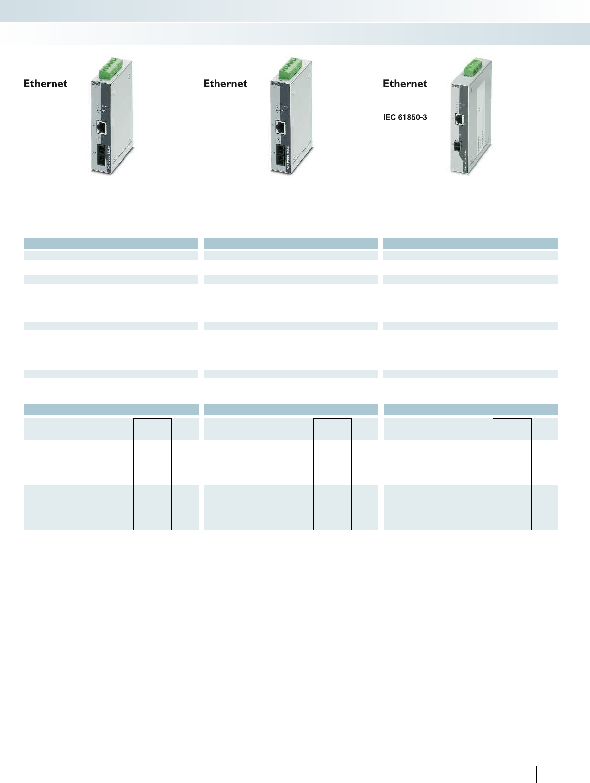
For additional information, visit phoenixcontact.net/products
389PHOENIX CONTACT
Technical data Technical data Technical data
12 V DC ... 48 V DC 12 V DC ... 48 V DC 12 V DC ... 57 V DC
110 mA (24 V DC) 110 mA (24 V DC) 110 mA (24 V DC)
1310 nm 1310 nm 1300 nm
Transmission length Incl. 3 dB system reserve 9.6 km (fiberglass with F-G 50/125 0.7 dB/km F1200) 20 km (fiberglass with F-G 9/125 0.3 dB/km) 40 km (fiberglass with F-G 9/125 0.3 dB/km) 40 km (typical)
LNK/ACT LNK/ACT LNK/ACT
Floating relay output Floating relay output Floating relay output
Connection method RJ45 socket, shielded RJ45 socket, shielded RJ45 socket, shielded RJ45 socket, shielded
10/100 Mbps 10/100 Mbps 100 Mbps
Link through Link fault pass through Link fault pass through Link fault pass through Link fault pass through
Auto-MDI(X) Auto-MDI(X) Auto-MDI(X)
LNK/ACT, 100 LNK/ACT, 100 LNK/ACT, 100
-40°C ... 75°C -40°C ... 75°C -40°C ... 75°C
500 V DC 500 V DC 500 V DC
Dimensions W / H / D 28 mm/110 mm/70 mm 28 mm/110 mm/70 mm 28 mm/110 mm/70 mm 30 mm/130 mm/100 mm
Ordering data Ordering data Ordering data
Type Order No. Pcs. /
Pkt. Type Order No. Pcs. /
Pkt. Type Order No. Pcs. /
Pkt.
FL MC 2000T SM20 SC 2891317 1FL MC 2000T SM40 SC 2891318 1
FL MC 2000E SM40 LC 2891156 1
Control technology, I/O systems, and automation infrastructure
Industrial communication technology - Industrial Ethernet
Single-mode fiberglass
SC duplex connection
Single-mode fiberglass
SC duplex connection
Single-mode fiberglass
LC duplex connection
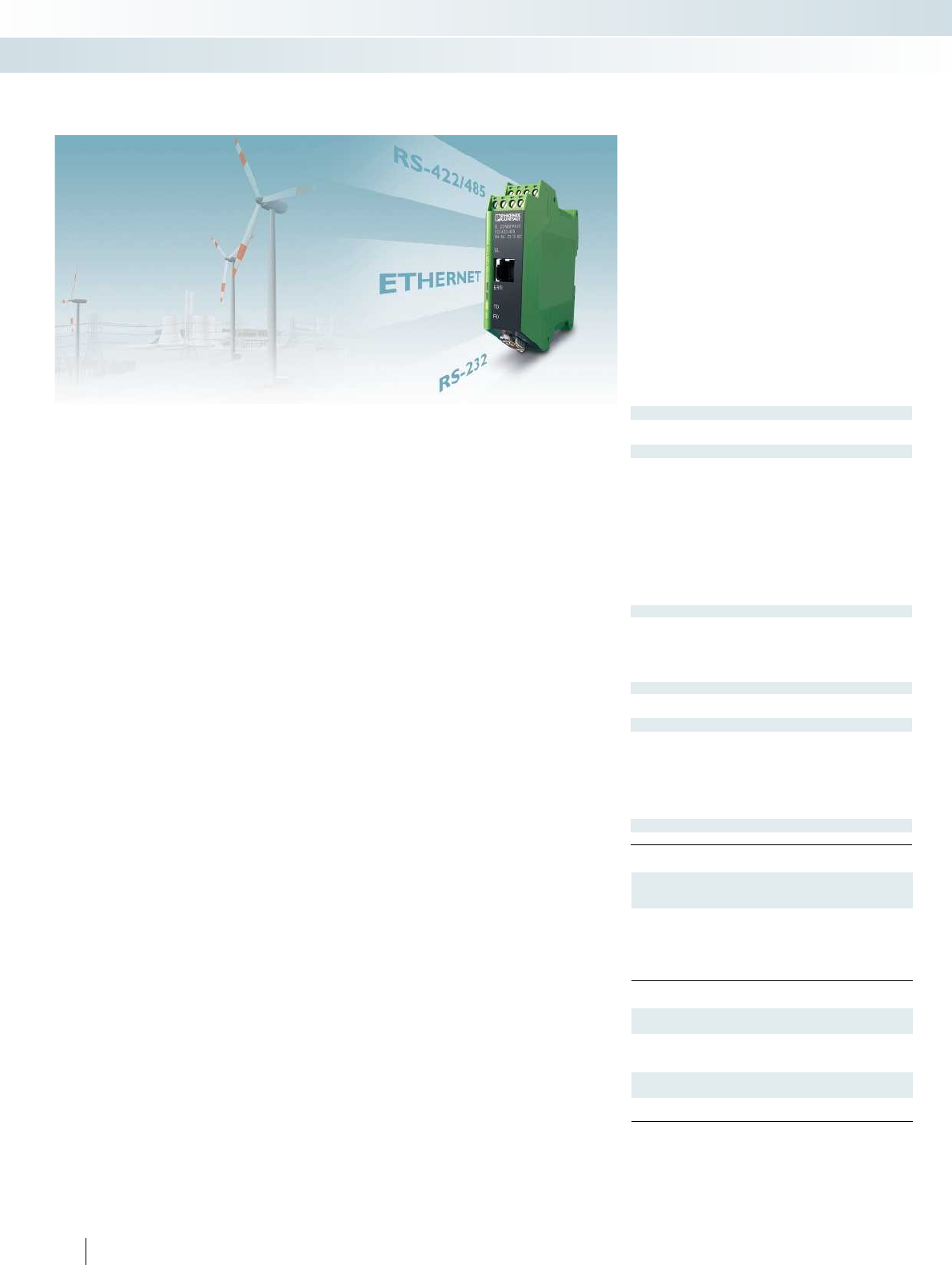
The FL COMSERVER...232/422/485-T
offer extended temperature and supply
voltage ranges. This means that you can
now integrate serial RS-232/422/485
interfaces in existing Ethernet networks,
even under extreme ambient conditions.
Implement functions such as cable
replacement, network integration or a
Modbus gateway with ease.
Both devices extend the existing FL
COMSERVER product range.
– FL COMSERVER BASIC 232/422/485
(Order No.: 2313478)
– FL COMSERVER UNI 232/422/485
(Order No.: 2313452)
– FL COMSERVER WLAN 232/422/485
(Order No.: 2313559)
– FL COMSERVER PRO 232/422/485
(Order No.: 2313465)
Cable replacement
Two devices in combination tunnel serial
connections via Ethernet, using either the
TCP or UDP protocol.
Network integration
You can integrate automation devices
such as controllers or frequency inverters
into a network using corresponding
programming and diagnostics software.
COM diversion software creates a virtual
COM port on the PC and transmits the
data to the FL COMSERVER.
Modbus gateway
The integrated Modbus gateway function
provided in FL COMSERVER UNI converts
serial Modbus ASCII or RTU data into
Modbus TCP. Naturally, the conversion
process also works in the opposite
direction.
Features of the T versions
– Extended temperaturerange
40°C to +70°C
– Supply voltage 12 ... 30 V AC/DC
– Serial interfaces:
RS-232, RS-422, RS-485
– 10/100 Base-T(X) interface
– Software for virtual COM ports supplied
as standard
– 3-way electrical isolation VCC //
RS-232/RS-422/RS-485 // network
– Configuration via web-based management
FL COMSERVER UNI...-T
– Supports TCP, UDP, Modbus
TCP/RTU/ASCII
– Can be used exactly as required on
Modbus master or slave
FL COMSERVER BAS...-T
– Best-value version
– Supports TCP and UDP
Supply
Supply voltage
Nominal current consumption 100 mA (24 V DC) 100 mA (24 V DC)
Serial port
Interfaces
Connection method RS-232 D-SUB-9 plug D-SUB-9 plug
RS-422 Plug-in/screw connection via COMBIC
RS-485 Plug-in/screw connection via COMBIC
Data format/encoding
Data flow control/protocols Software handshake, Xon/Xoff, or hardware handshake RTS/CTS //
Transmission speed
Termination resistor
Ethernet interface
Connection method
Transmission speed
Transmission length
Supported protocols
Auxiliary protocols
Functions
Management
General data
Ambient temperature (operation) -40°C ... 70°C (free-standing, 40mm space on all sides) -40°C ... 70°C (free-standing, 40mm space
Electrical isolation
Test voltage
Electromagnetic compatibility Conformance with EMC Directive 2004/108/EC Conformance with EMC Directive 2004/108/EC
Standards/regulations EN 50121-4 EN 50121-4
Dimensions W / H / D 45 mm/99 mm/116 mm 45 mm/99 mm/116 mm
Conformance / approvals
ATEX
Description
FL COMSERVER...232/422/485, for converting serial interfaces to
Ethernet. COM port redirector software and additional software
supplied as standard
TCP, UDP, MODBUS, PPP
TCP, UDP
D-SUB plug, with screw connection
- 9-pos., socket
RS-232-D-SUB cable, length: 2 m
- 9-pos. socket on 9-pos. socket
- 9-pos. socket on 25-pos. socket
Patch cable, CAT5, preassembled
3 m
Shield connection clamp for RS-485/422 operation
390 PHOENIX CONTACT
COM server for extreme fields
of application
Control technology, I/O systems, and automation infrastructure
Industrial communication technology - Industrial Ethernet
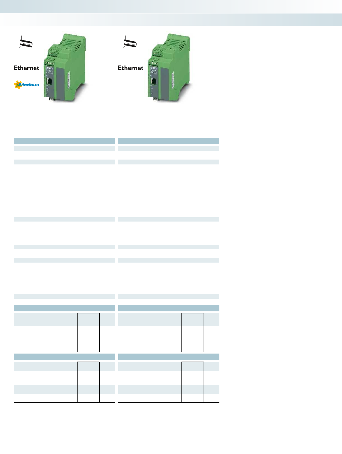
For additional information, visit phoenixcontact.net/products
Technical data Technical data
12 V AC/DC ... 30 V AC/DC (observe derating) 12 V AC/DC ... 30 V AC/DC (observe derating)
Nominal current consumption 100 mA (24 V DC) 100 mA (24 V DC)
RS-232, RS-422, RS-485 RS-232, RS-422, RS-485
Connection method RS-232 D-SUB-9 plug D-SUB-9 plug
RS-422 Plug-in/screw connection via COMBICON Plug-in/screw connection via COMBICON
RS-485 Plug-in/screw connection via COMBICON Plug-in/screw connection via COMBICON
UART/NRZ: 7/8 bit data, 1/2 bit stop, 1 bit parity UART/NRZ: 7/8 bit data, 1/2 bit stop, 1 bit parity
Data flow control/protocols Software handshake, Xon/Xoff, or hardware handshake RTS/CTS //
3964 R compatible, Modbus RTU/ASCII
Software handshake, Xon/Xoff, or hardware handshake RTS/CTS //
3964 R compatible, Modbus RTU/ASCII
0.3; 0.6; 1.2; 2.4; 4.8; 7.2; 9.6; 19.2; 38.4; 57.6; 115.2; 187.5; 230.4
kbps
0.3; 0.6; 1.2; 2.4; 4.8; 7.2; 9.6; 19.2; 38.4; 57.6; 115.2; 187.5; 230.4
kbps
390 Ω/180 Ω/390 Ω (configurable) 390 Ω/180 Ω/390 Ω (configurable)
RJ45 socket, shielded RJ45 socket, shielded
10/100 Mbps, auto negotiation 10/100 Mbps, auto negotiation
≤ 100 m (shielded twisted pair) ≤ 100 m (shielded twisted pair)
TCP/IP, UDP, Modbus (TCP, RTU/ASCII), PPP TCP/IP, UDP
ARP, DHCP, BOOTP, SNMP, RIP, RARP, HTTP, TFTP ARP, DHCP, BOOTP, SNMP, RIP, RARP, HTTP, TFTP
Web-based management, SNMP, emergency exit with Telnet and
serial
Web-based management, SNMP, emergency exit with Telnet and
serial
Ambient temperature (operation) -40°C ... 70°C (free-standing, 40mm space on all sides) -40°C ... 70°C (free-standing, 40mm space on all sides)
DIN EN 50178 (VCC // Ethernet // Serial) DIN EN 50178 (VCC // Ethernet // Serial)
1.5 kVrms (50 Hz, 1 min.) 1.5 kVrms (50 Hz, 1 min.)
Electromagnetic compatibility Conformance with EMC Directive 2004/108/EC Conformance with EMC Directive 2004/108/EC
Standards/regulations EN 50121-4 EN 50121-4
Dimensions W / H / D 45 mm/99 mm/116 mm 45 mm/99 mm/116 mm
II 3G Ex nA IIC T4 Gc X II 3G Ex nA IIC T4 Gc X
Ordering data Ordering data
Type Order No. Pcs. /
Pkt. Type Order No. Pcs. /
Pkt.
FL COMSERVER UNI 232/422/485-T 2904817 1
FL COMSERVER BAS 232/422/485-T 2904681 1
Accessories Accessories
SUBCON 9/F-SH 2761499 1SUBCON 9/F-SH 2761499 1
PSM-KA9SUB9/BB/2METER 2799474 1PSM-KA9SUB9/BB/2METER 2799474 1
PSM-KA 9 SUB 25/BB/2METER 2761059 1PSM-KA 9 SUB 25/BB/2METER 2761059 1
FL CAT5 PATCH 3,0 2832292 10 FL CAT5 PATCH 3,0 2832292 10
ME-SAS 2853899 10 ME-SAS 2853899 10
391PHOENIX CONTACT
Control technology, I/O systems, and automation infrastructure
Industrial communication technology - Industrial Ethernet
H
W
D
H
W
D
Universal device - Modbus gateway between
RTU/ASCII and TCP
Basic version for redirector operation -
TCP and UDP
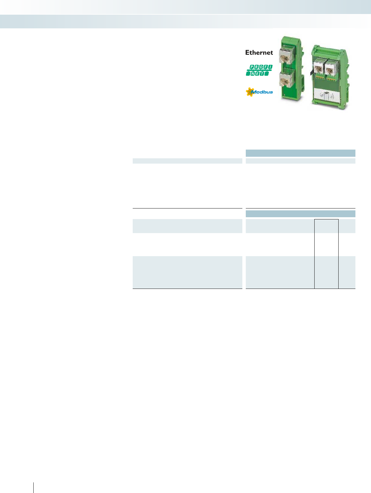
Technical data
General data
Cable impedance 100 Ω
Transmission speed 10/100 Mbps
Connection line twisted pair, shielded, CAT5 or better
Transmission length 100 m (including patch cables)
Plug connection RJ45 CAT5
Insertion/withdrawal cycles ≤ 2500
Degree of protection IP20
Housing material PA 6.6-FR
Weight 33 g
Ordering data
Description Type Order No. Pcs. /
Pkt.
Patch panel, two RJ45 sockets (1:1 assignment), extended
temperature range, CAT5, 10/100 Mbps, DIN rail mounting, IP20,
consistent shield, width 22.5 mm
FL-PP-RJ45/RJ45-B 2904933 10
Cable sharing module, two RJ45 sockets with Ethernet
assignment, to 8 spring-cage connection terminal blocks, CAT5e,
10/100Mbps, DIN rail mounting, IP20, option of shield contacting
on DIN rail via jumpers
- Cable outlet at the front, width 52 mm FL-PP-RJ45-SCC/SC041 2903532 1
- Cable outlet at the top, width 56 mm FL-PP-RJ45-SCC/SC045 2904577 1
392 PHOENIX CONTACT
The mini patch panels provide a
convenient alternative to on-site assembly
of RJ45 plugs.
The cross-control-cabinet field cabling is
simply connected to screw connection
terminal blocks or RJ45 sockets, depending
on the version selected.
The connection to the termination
devices is then completed using pre-
assembled RJ45 patch cables.
The new patch panels extend the product
range of passive connection fields with new
properties.
General features
–CAT5e
– 10/100 Mbps
– Mounted on DIN rails
FL-PP-RJ45/RJ45-B
Ethernet interface module with two RJ45
sockets as basic version with compact
design and extended temperature range.
–Two RJ45 sockets
– 8-pin assignment: 1:1
– Extended temperature range
-40°C to 85°C
– Narrow design W/H/D:
22.5 mm/78 mm/44 mm
FL-PP-RJ45-SCC/...
Y-splitter for transmission of two
individual network connections with
10/100Mbps via a CAT cable with eight
wires.
– Spring-cage connection terminal blocks
– Option of shield contacting on DIN rail
via jumpers
–For FL-PP-.../SC041:
two RJ45 sockets, vertical
–For FL-PP-.../SC045:
two RJ45 sockets, horizontal
Passive patch panel for the DIN rail
Control technology, I/O systems, and automation infrastructure
Industrial communication technology - Industrial Ethernet

For additional information, visit phoenixcontact.net/products
393PHOENIX CONTACT
Control technology, I/O systems, and automation infrastructure
Industrial communication technology - Industrial Ethernet
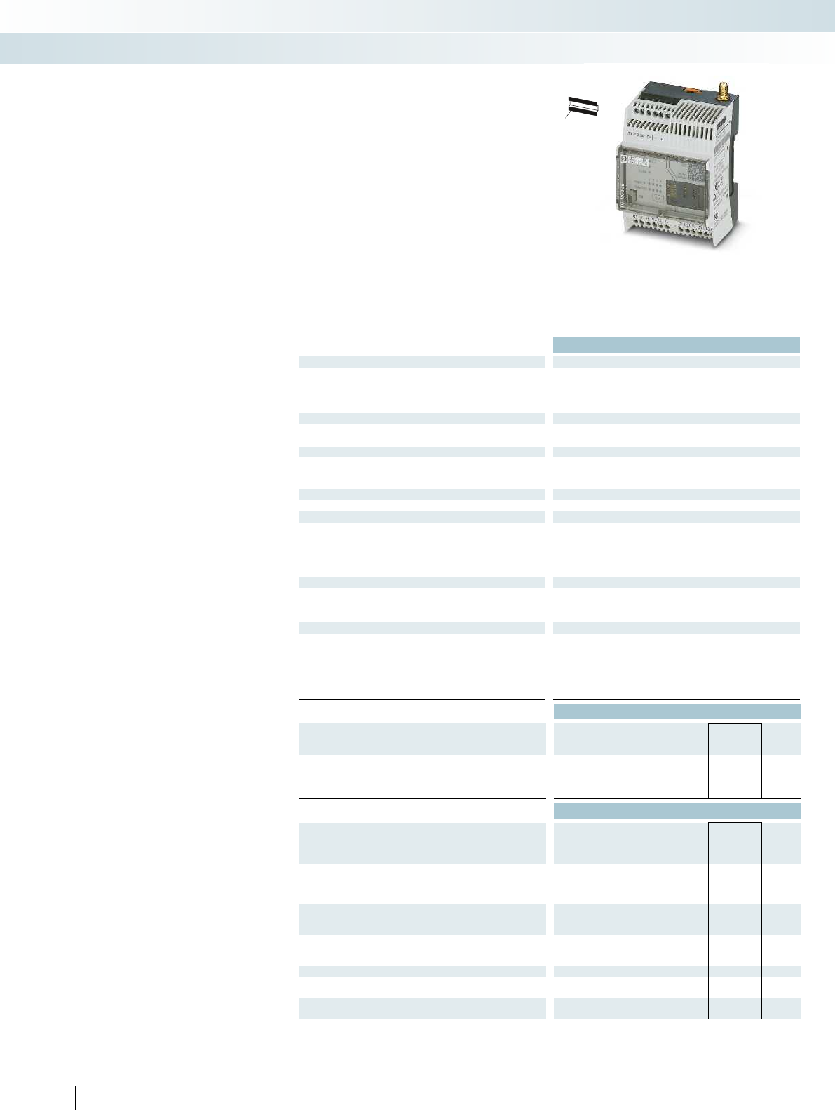
394 PHOENIX CONTACT
H
W
D
Remote signaling and remote control
system
Alarm and remote control via the
mobile phone network
Use the mobile phone network, monitor
analog and digital values, and switch relays
remotely using the TC mobile I/O product
range.
Depending on the product version, data is
transmitted via SMS, e-mail, GPRS or ODP
protocol.
Thanks to the large voltage range and the
different inputs, the signaling system is
suitable for use in a wide range of
applications.
Features:
– Event-controlled or continual
communication
– 4 digital inputs
– 2 analog inputs (current/voltage)
– 4 relay outputs, switchable via mobile
phone
– Alarming in case of voltage failure via SMS
– Configuration via USB and web browser
–Standard SIM card
– Compact design: 4 pitches (DIN 43880)
– Cover can be sealed
– Numerous helpful software functions
Applications:
– Machine, building and system monitoring
– Pumps, sewage treatment plants, water
supply
– Light controllers, remote switching
systems
– Lifts, doors
– Alarm and domestic engineering
– Climate and ventilation engineering
– Battery monitoring up to 60 V
– Railway applications according to
EN 50121-4
Technical data
Supply
Supply voltage 10 V DC ... 60 V DC
Supply voltage -
Nominal current consumption 110 mA (24 V DC)
Stand-by current consumption 40 mA (stand by)
USB interface USB 2.0
Connection method Mini-USB type B, 5-pos. Mini-USB type B, 5-pos. Mini-USB type B, 5-pos. Mini-USB type B, 5-pos.
Transmission length ≤ 3 m (only for configuration and diagnostics)
Mobile phone network
Frequencies 850 MHz (2 W (EGSM))/900 MHz (2 W (EGSM)) /
1800 MHz (1 W (EGSM))/1900 MHz (1 W (EGSM))
Digital input
Number of inputs 4
Analog input
Number of inputs 2
Signal range 0 V DC ... 60 V DC/0 mA ... 20 mA/4 mA ... 20 mA (configurable) - 0 V DC ... 60 V DC/0 mA ... 20 mA/4 mA ... 20 mA (c
Resolution 15 bit
Accuracy ± 0.1%
Switching output
Contact type 4 x N/O contact
Max. switching voltage 60 V
Limiting continuous current 6 A
General data
Ambient temperature (operation) -25°C ... 70°C (for derating, see technical documentation) -25°C ... 70°C (for derating, see tech
Approvals for countries EU, other countries in preparation EU, othe
Electromagnetic compatibility Conformance with EMC Directive 2004/108/EC Conformance with EMC Directive 2004/108/EC Conformance wi
Dimensions W / H / D 72 mm/90 mm/62 mm 72 mm/90 mm/62 mm 72 mm/90 mm/62 mm 72 mm/90 mm/62 mm
ATEX II 3 G Ex nA nC IIC T4 Gc X
Ordering data
Description Type Order No. Pcs. /
Pkt.
Compact signaling system, for mobile phone networks, monitors
inputs, switches relay outputs
- Analog and digital inputs TC MOBILE I/O X200 2903805 1
- Digital inputs
Accessories
Multi-band antenna for UMTS and quad band GSM, with
omnidirectional characteristic, 2 m antenna cable with SMA round
plug, degree of protection: IP65, dimensions: 76 x 20 mm
PSI-GSM/UMTS-QB-ANT 2313371 1
Multiband antenna for external panel and external mast mounting
for UMTS and quad-band GSM, with omnidirectional
characteristics, 5 m antenna cable with SMA round plug
PSI-GSM/UMTS-ANT-OMNI-2-5 2900982 1
Antenna extension cable for UMTS and quad-band GSM, 5 m
long, antenna cable with SMA plug and SMA coupling
PSI-CAB-GSM/UMTS- 5M 2900980 1
Antenna extension cable for UMTS and quad-band GSM, 10 m
long, antenna cable with SMA plug and SMA coupling
PSI-CAB-GSM/UMTS-10M 2900981 1
Power supply unit, primary-switched STEP-PS/ 1AC/24DC/0.75 2868635 1
USB connecting cable (individual) for configuration CABLE-USB/MINI-USB-3,0M 2986135 1
Surge protection for UMTS and quad-band GSM antenna, with
SMA plug and SMA coupling
CSMA-LAMBDA/4-2.0-BS-SET 2800491 1
Control technology, I/O systems, and automation infrastructure
Industrial communication technology - remote communication
Communication via SMS and e-mail,
2 additional analog inputs
For additional information, visit phoenixcontact.net/products
395PHOENIX CONTACT
H
W
D
H
W
D
H
W
D
Technical data Technical data Technical data
- 10 V DC ... 60 V DC -
93 V AC ... 250 V AC (47.5Hz ... 63Hz) - 93 V AC ... 250 V AC (48 Hz ... 62 Hz)
30 mA (230 VAC) 110 mA (24 V DC) 30 mA (230 VAC)
10 mA (stand by) 40 mA (stand by) 10 mA (stand by)
USB 2.0 USB 2.0 USB 2.0
Connection method Mini-USB type B, 5-pos. Mini-USB type B, 5-pos. Mini-USB type B, 5-pos. Mini-USB type B, 5-pos.
≤ 3 m (only for configuration and diagnostics) ≤ 3 m (only for configuration and diagnostics) ≤ 3 m (only for configuration and diagnostics)
850 MHz (2 W (EGSM))/900 MHz (2 W (EGSM))/
1800 MHz (1 W (EGSM))/1900 MHz (1 W (EGSM))
850 MHz (2 W (EGSM))/900 MHz (2 W (EGSM))/
1800 MHz (1 W (EGSM))/1900 MHz (1 W (EGSM))
850 MHz (2 W (EGSM))/900 MHz (2 W (EGSM))/
1800 MHz (1 W (EGSM))/1900 MHz (1 W (EGSM))
444
-2-
Signal range 0 V DC ... 60 V DC/0 mA ... 20 mA/4 mA ... 20 mA (configurable) - 0 V DC ... 60 V DC/0 mA ... 20 mA/4 mA ... 20 mA (configurable) -
-15 bit-
-± 0.1%-
4 x N/O contact 4 x N/O contact 4 x N/O contact
60 V 250 V AC 250 V AC
5 A6 A5 A
Ambient temperature (operation) -25°C ... 70°C (for derating, see technical documentation) -25°C ... 70°C (for derating, see technical documentation) -25°C ... 70°C (for derating, see technical documentation) -25°C ... 70°C (for derating, see technical documentation)
Approvals for countries EU, other countries in preparation EU, other countries in preparation EU, other countries in preparation EU, other countries in preparation
Electromagnetic compatibility Conformance with EMC Directive 2004/108/EC Conformance with EMC Directive 2004/108/EC Conformance with EMC Directive 2004/108/EC Conformance with EMC Directive 2004/108/EC
Dimensions W / H / D 72 mm/90 mm/62 mm 72 mm/90 mm/62 mm 72 mm/90 mm/62 mm 72 mm/90 mm/62 mm
II 3 G Ex nA nC IIC T4 Gc X II 3 G Ex nA nC IIC T4 Gc X II 3 G Ex nA nC IIC T4 Gc X
Ordering data Ordering data Ordering data
Type Order No. Pcs. /
Pkt. Type Order No. Pcs. /
Pkt. Type Order No. Pcs. /
Pkt.
TC MOBILE I/O X300 2903807 1
TC MOBILE I/O X200 AC 2903806 1TC MOBILE I/O X300 AC 2903808 1
Accessories Accessories Accessories
PSI-GSM/UMTS-QB-ANT 2313371 1PSI-GSM/UMTS-QB-ANT 2313371 1PSI-GSM/UMTS-QB-ANT 2313371 1
PSI-GSM/UMTS-ANT-OMNI-2-5 2900982 1PSI-GSM/UMTS-ANT-OMNI-2-5 2900982 1PSI-GSM/UMTS-ANT-OMNI-2-5 2900982 1
PSI-CAB-GSM/UMTS- 5M 2900980 1PSI-CAB-GSM/UMTS- 5M 2900980 1PSI-CAB-GSM/UMTS- 5M 2900980 1
PSI-CAB-GSM/UMTS-10M 2900981 1PSI-CAB-GSM/UMTS-10M 2900981 1PSI-CAB-GSM/UMTS-10M 2900981 1
STEP-PS/ 1AC/24DC/0.75 2868635 1STEP-PS/ 1AC/24DC/0.75 2868635 1STEP-PS/ 1AC/24DC/0.75 2868635 1
CABLE-USB/MINI-USB-3,0M 2986135 1CABLE-USB/MINI-USB-3,0M 2986135 1CABLE-USB/MINI-USB-3,0M 2986135 1
CSMA-LAMBDA/4-2.0-BS-SET 2800491 1CSMA-LAMBDA/4-2.0-BS-SET 2800491 1CSMA-LAMBDA/4-2.0-BS-SET 2800491 1
Control technology, I/O systems, and automation infrastructure
Industrial communication technology - remote communication
Communication via SMS and e-mail,
with wide range power supply
Communication via ODP protocol,
2 additional analog inputs
Communication via ODP protocol,
with wide range power supply
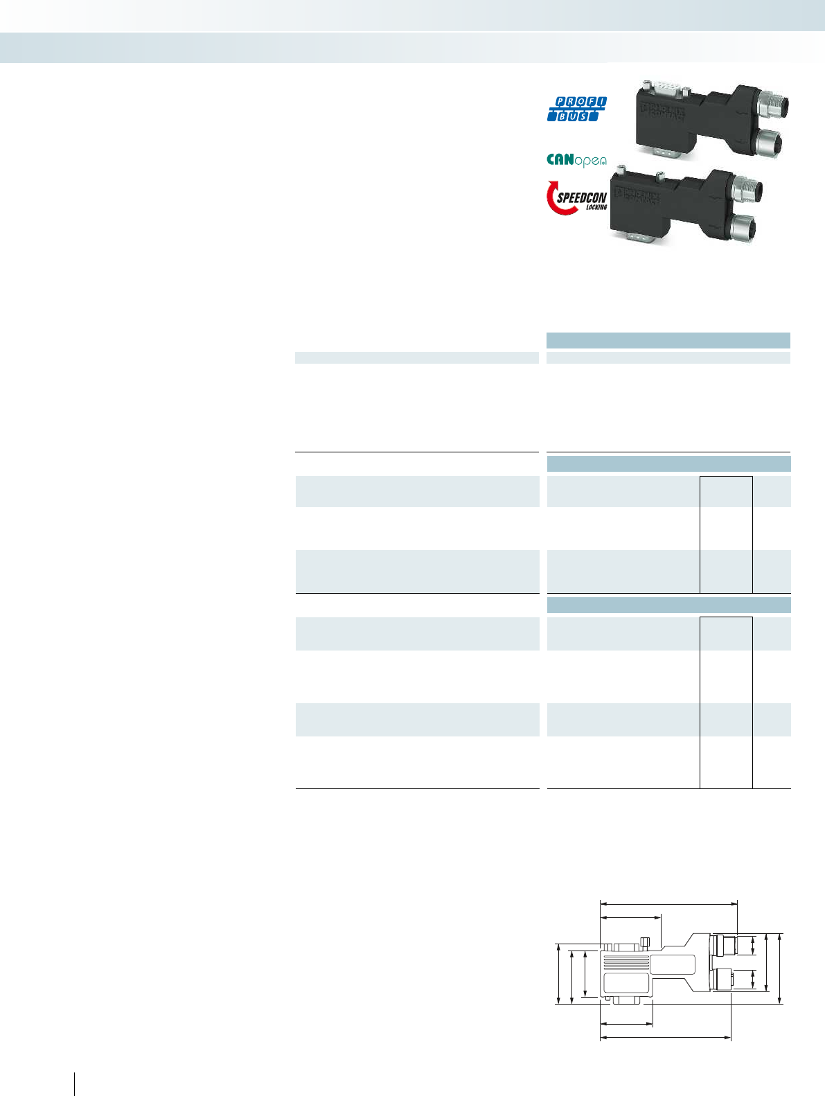
93
42
39
34
30
35
89
38
M12
M12
46
Technical data
General data
Cable entry 90° (left)
Ambient temperature (operation) -30°C ... 80°C
Degree of protection IP40
Housing material Polyamide
Number of positions 5
Termination resistor (separately via M12 termination resistor) (separately via M12 termination resistor) (separately via M12 termi
SUBCON fixing 4-40 UNC 0.4 Nm
Dimensions W / H / D 16 mm/41 mm/93 mm 16 mm/41 mm/72 mm 16 mm/48 mm /80 mm
Ordering data
Description Type Order No. Pcs. /
Pkt.
Fast connection plugs, for PROFIBUS systems,
Pin assignment 3, 5, 6, 8
- Standard version SUBCON-PLUS-PROFIB/90X/M12 2902729 1
Pg version with programming connection SUBCON-PLUS-PROFIB/90X/PG/M12 2902728 1
Fast connection plugs, for CAN-based systems,
Pin assignment 2, 3, 5, 7, 9
- Standard version SUBCON-PLUS-CAN/90X/M12 2902731 1
Pg version with programming connection SUBCON-PLUS-CAN/90X/PG/M12 2902730 1
Accessories
PROFIBUS termination resistor
- M12 pin design SAC-5P-M12MS PB TR 1507803 5
- M12 socket design SAC-5P-M12FS PB TR 1403911 1
PROFIBUS bus cable,
Straight socket, shielded, M12 B-coded, 2-pos.,
Straight pin, shielded, M12 B-coded, 2-pos.
- Cable length 1 m SAC-2P-MSB/ 1,0-910/FSB SCO 1518122 1
- Variable cable length SAC-2P-MSB-FSB SCO/910/... 1538092 1
DeviceNet™/CANopen® termination resistor
- M12 pin design SAC-5P-M12MS CAN TR 1507816 5
- M12 socket design SAC-5P-M12FS CAN TR 1529344 5
DeviceNet™/CANopen® bus cable,
Straight socket, shielded, M12 A-coded, 5-pos.,
Straight pin, shielded, M12 A-coded, 5-pos.
- Cable length 1 m SAC-5P-MS/ 1,0-920/FS SCO 1518274 1
- Variable cable length SAC-5P-MS-FS SCO/920/... 1538157 1
396 PHOENIX CONTACT
SUBCON-PLUS...90X...M12 dimensional drawing, long 90°
version
SUBCON-PLUS-M12-
fast connection
The new SUBCON-PLUS fast connection
plugs with M12 connection ensure error-
free installation of bus systems, thanks to
the use of fully-tested components, such as
cables and connection plugs.
The innovative housing concept is
lightweight yet offers optimum mechanical
protection against environmental
influences. This means that the fast
connection plugs are ideal, even in
applications subject to vibration.
The unique SPEEDCON fast locking
system on the M12 connections offers
reliable connection with just half a turn.
Features:
– Easy startup, plug and play
– Error-free installation, particularly in
standard machine production
– Quick connection thanks to M12-
SPEEDCON fast locking system
–Low weight
– Termination using M12 termination resistor
– Adapter between IP20 and IP67
environments
– For PROFIBUS and CANopen® systems
Control technology, I/O systems, and automation infrastructure
Industrial communication technology - fast connection technology
90° version, long,
suitable for Siemens S7
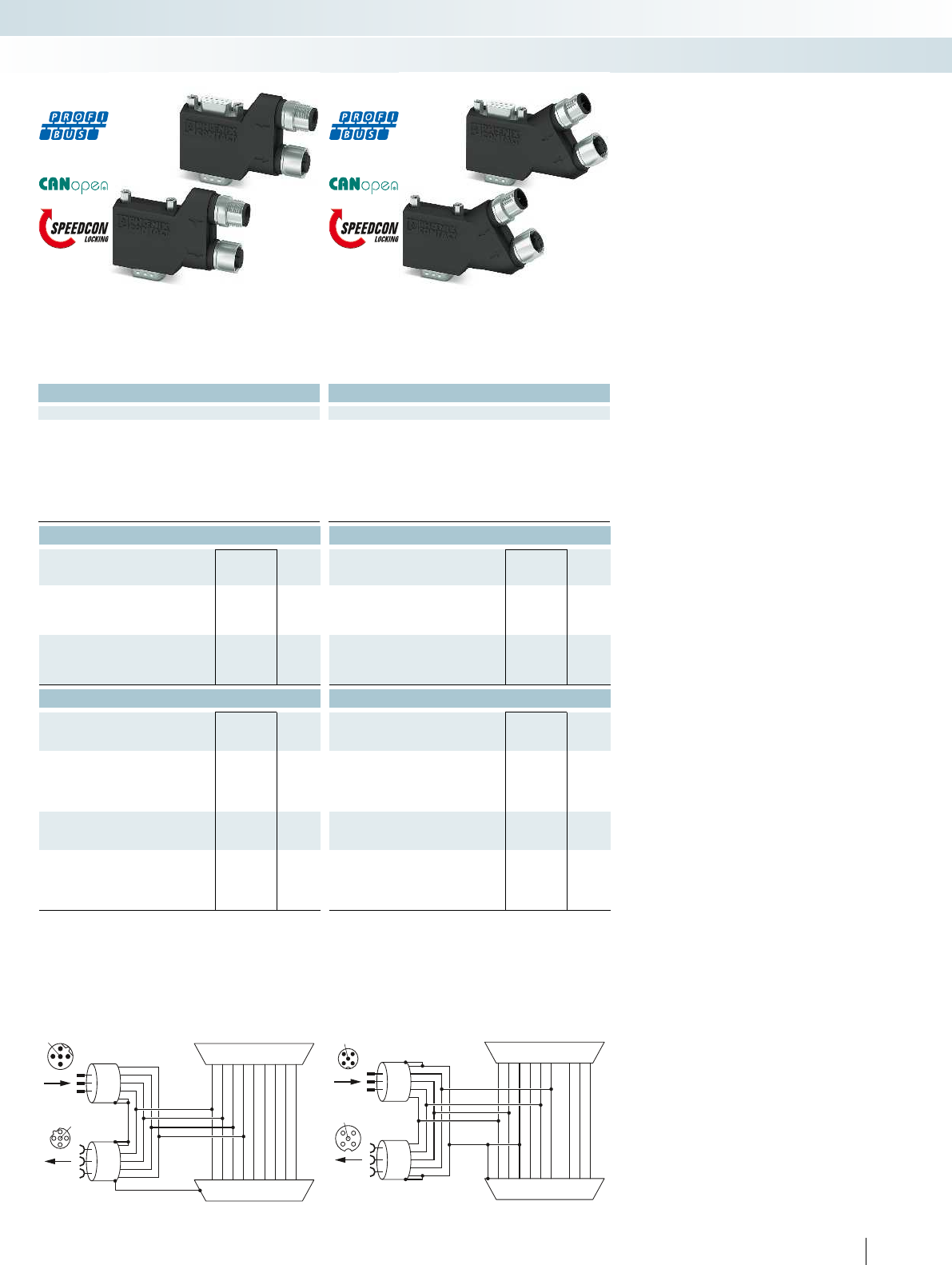
2
13
4
5
1
2
3
4
5
5
4
3
2
1
1
2
3
4
5
3 5 8 6 9 7 4 2 1
3 5 8 6 9 7 4 2 1
5
4
3
2
1
1
2
3
4
5
2 3 5 6 7 9 1 4 8
2 3 5 6 7 9 1 4 8
12
34
5
21
43
5
For additional information, visit phoenixcontact.net/products
Technical data Technical data
90° (left) 35° (left)
-30°C ... 80°C -30°C ... 80°C
IP40 IP40
Polyamide Polyamide
55
Termination resistor (separately via M12 termination resistor) (separately via M12 termination resistor) (separately via M12 termination resistor)
4-40 UNC 0.4 Nm 4-40 UNC 0.4 Nm
Dimensions W / H / D 16 mm/41 mm/93 mm 16 mm/41 mm/72 mm 16 mm/48 mm /80 mm
Ordering data Ordering data
Type Order No. Pcs. /
Pkt. Type Order No. Pcs. /
Pkt.
SUBCON-PLUS-PROFIB/90/M12 2902318 1SUBCON-PLUS-PROFIB/35/M12 2902320 1
SUBCON-PLUS-PROFIB/90/PG/M12 2902317 1SUBCON-PLUS-PROFIB/35/PG/M12 2902319 1
SUBCON-PLUS-CAN/90/M12 2902323 1SUBCON-PLUS-CAN/35/M12 2902325 1
SUBCON-PLUS-CAN/90/PG/M12 2902322 1SUBCON-PLUS-CAN/35/PG/M12 2902324 1
Accessories Accessories
SAC-5P-M12MS PB TR 1507803 5SAC-5P-M12MS PB TR 1507803 5
SAC-5P-M12FS PB TR 1403911 1SAC-5P-M12FS PB TR 1403911 1
SAC-2P-MSB/ 1,0-910/FSB SCO 1518122 1SAC-2P-MSB/ 1,0-910/FSB SCO 1518122 1
SAC-2P-MSB-FSB SCO/910/... 1538092 1SAC-2P-MSB-FSB SCO/910/... 1538092 1
SAC-5P-M12MS CAN TR 1507816 5SAC-5P-M12MS CAN TR 1507816 5
SAC-5P-M12FS CAN TR 1529344 5SAC-5P-M12FS CAN TR 1529344 5
SAC-5P-MS/ 1,0-920/FS SCO 1518274 1SAC-5P-MS/ 1,0-920/FS SCO 1518274 1
SAC-5P-MS-FS SCO/920/... 1538157 1SAC-5P-MS-FS SCO/920/... 1538157 1
397PHOENIX CONTACT
SUBCON-PLUS-PROFIB/...M12 function block diagram SUBCON-PLUS-CAN/...M12 function block diagram
Control technology, I/O systems, and automation infrastructure
Industrial communication technology - fast connection technology
90° version, short,
universal
35° version,
universal
Housing width 17.5 mm
Technical data
Wireless path
Direction Bi-directional
Frequency range 869.4 MHz ... 869.65 MHz
Transmission power ≤ 500 mW (default setting, adjustable)
Security 128-bit data encryption
Connection method RSMA (female)
Serial port RS-232 RS-485
Connection method COMBICON plug-in screw
terminal block
COMBICON plug-in screw
terminal block
Serial transmission speed 0.3 ... 115.2 kbit/s 0.3 ... 187.5 kbit/s
Termination resistor (switchable via DIP switches) - 390 Ω/150 Ω/390 Ω
Analog output RSSI voltage output
Signal range 0 V ... 3 V
Digital output RF link relay output
Contact type PDT
Switching voltage 30 V AC/60 V DC
Switching current 500 mA
General data
Supply voltage 19.2 V DC ... 30.5 V DC
Degree of protection IP20
Ambient temperature range -40°C ... 70°C
Permissible humidity (operation) 20% ... 85%
Housing material PA 6.6-FR
Dimensions W / H / D 17.5/99/114.5 mm
Screw connection solid / stranded / AWG 0.2 ... 2.5 mm²/0.2 ... 2.5 mm²/24 - 14
Conformance / approvals
Conformance CE compliance (R&TTE directive 1999/5/EC)
ATEX II 3 G Ex nA nC IIC T4 Gc X
Ordering data
Description Type Order No. Pcs. /
Pkt.
Wireless module
RAD-868-IFS 2904909 1
Accessories
Memory stick, for saving custom configuration data RAD-MEMORY 2902828 1
USB cable, for diagnostics and extended configuration RAD-CABLE-USB 2903447 1
398 PHOENIX CONTACT
The RAD-868-IFS wireless module is
suitable for license-free use in Europe.
Features:
– Trusted Wireless 2.0 wireless technology
– 868 MHz frequency band
– Adjustable transmission power up to
500 mW
– Range of up to several kilometers
– Integrated RS-232 and RS-485 interface
– Distribute signals at the turn of a switch
(I/O mapping)
– Can be easily extended with up to 32 I/O
extension modules via T-connector
– Optionally transmits I/O signals or serial
data
Wireless system for license-free use in
Europe
Control technology, I/O systems, and automation infrastructure
Industrial communication technology - wireless data communication
H
W
D
868 MHz wireless transceiver,
can be extended with I/O extension modules
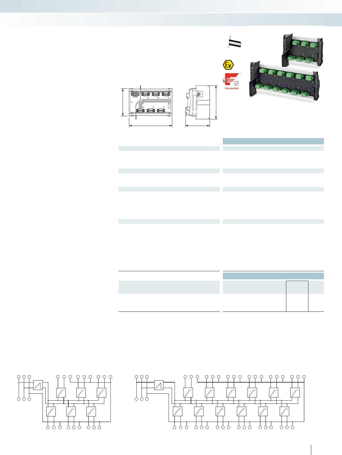
I
S12+ S12– S12S
V
I
S11+ S11– S11S
I
S10+ S10– S10S
I
S9+ S9– S9S
I
S8+S8–S8S
I
S7+ S7– S7S
I
S2+ S2– S2S
I
S3+S3–S3S
I
S4+ S4– S4S
I
S5+ S5– S5S
I
S6+ S6– S6S
I
S1+ S1– S1STi+Ti–TiS
To+ To– ToS
I
S11+ S11– S11S
I
S10+ S10– S10S
I
S12+ S12– S12S
I
S2+ S2– S2S
I
S3+S3–S3S
I
S1+ S1– S1S
V
Ti+Ti–TiS
To+ To– ToS
+–s +–s +–s
+–s +–s +–s
ERR 2 ERR 4 ERR 6
ERR 1
PWR
ERR 3ERR 5
92,3
148,2
112,5
83,2
For additional information, visit phoenixcontact.net/products
Ex:
Technical data
Supply FB-6SP FB-12SP
Supply voltage range 10.5 V DC ... 32 V DC (input on trunk line side)
Rated current ≤ 2 A
Nominal current consumption 4.8 mA 6.5 mA
Fieldbus interface
Rated voltage ≤ 32 V (each spur) ≤ 32 V (each spur)
Rated current 38 mA 38 mA
Termination resistor 100 Ω, external removable plug included
General data FB-6SP FB-12SP
Screw connection solid / stranded / AWG 0.2 - 2.5 mm²/0.2 - 2.5 mm²/24 - 12
Weight 240 g 395 g
Dimensions W / H / D 148.2 mm/112.5 mm/83.5 mm 254.1 mm/112.5 mm/83.5 mm
Degree of protection IP20
Ambient temperature (operation) -50°C ... 90°C
Max. permissible relative humidity (operation) < 95% (non-condensing)
Conformance / approvals
NE NE21
ATEX Sira 13ATEX4247X; II 3(3)G
Ex nA [ic] IIC T4 Gc, Entity/FISCO ic spurs
Ex nA [nL] IIC T4 Gc; II 3G Ex ic IIC T4 Gc, FISCO ic
IECEx SIR 08.0110X; Ex nA [ic] IIC T4 Gc, Entity/FISCO ic spurs;
Ex nA [nL] IIC T4 Gc; Ex ic IIC T4 Gc, FISCO ic
CSA, USA/Canada Class I, Div. 2, Groups A, B, C, D;
Ex nA [nL] IIC T4; Class I, Zone 2, AEx nA [nC] IIC T4
Fieldbus Foundation FF-846
Ordering data
Description Type Order No. Pcs. /
Pkt.
Device coupler, for Foundation Fieldbus and PROFIBUS PA
- 6 spurs FB-6SP 2316307 1
- 12 spurs FB-12SP 2316310 1
399PHOENIX CONTACT
– Couple field devices and provide short-
circuit current limiting
– Provide non-sparking and FISCO ic spur
connections
– Single-sided connection configuration
simplifies wiring in field housing
– Diagnostic LEDs indicate DC OK and
errors at the spur connection
– Fulfills the requirements of
EN60079-0:2012,
EN60079-11:2012,
EN60079-15:2005, and
EN60079-15:2010.
Device couplers for field devices
Connection diagram: FB-12SP
Control technology, I/O systems, and automation infrastructure
Process infrastructure - process fieldbus
H
W
D
Device couplers for 6 and 12 spurs
Connection diagram: FB-6SP
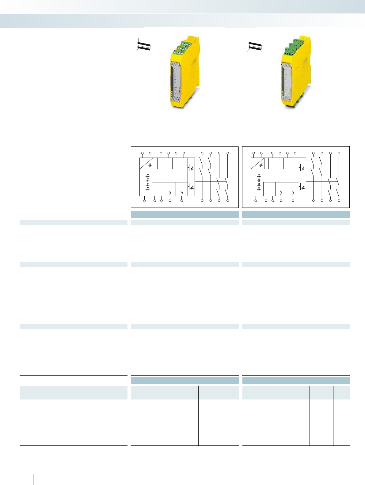
6232S11 S21I1...I6 14 24 44 54
13234353
A1 A2 S36S34S37S35
K 2
K 4
K 1
K 3
POWER
24V DCReset
K3/K4
Reset
K1/K2K1/K2
K3/K4
Monitoring
OUTPUT
K3/K4
Monitoring
OUTPUT
K1/K2
OUTPUT
ERR
I1/I2
I3/I4
I5/I6
Logic
6232S11 S21I1...I6 14 24 44 54
13234353
A1 A2 S36S34S37S35
K 2
K 4
K 1
K 3
POWER
24V DCReset
K3/K4
Reset
K1/K2K1/K2
K3/K4
Monitoring
OUTPUT
K3/K4
Monitoring
OUTPUT
K1/K2
OUTPUT
ERR
I1/I2
I3/I4
I5/I6
Logic
Technical data Technical data
Input data
Nominal input voltage UN24 V DC 24 V DC
Permissible range (with reference to UN) 0.85 ... 1.1 0.85 ... 1.1
Typ. current consumption (with reference to UN) 125 mA (with actuated relays)/55 mA (two-channel 24 V/0 V + max.
200 mA control (message outputs 32/62) with non-actuated relays)
125 mA (with actuated relays)/55 mA (two-channel 24 V/0 V + max.
200 mA control (message outputs 32/62) with non-actuated relays)
Recovery time 1 s (availability time after activation of sensor circuit: 100ms) 1 s (availability time after activation of sensor circuit: 100ms) 1 s (availability time after activation of sensor circuit: 100ms)
Output data
Contact type 4 enabling current paths
2 semiconductor alarm outputs
4 enabling current paths
2 semiconductor alarm outputs
Contact material AgCuNi, +0.2 -0.4µmAu AgCuNi, +0.2 -0.4µmAu AgCuNi, +0.2 -0.4
Max./min. switching voltage 250 V AC/DC/10 V AC/DC 250 V AC/DC/10 V AC/DC 250 V AC/DC/10 V AC/DC
Limiting continuous current 6 A (N/O contact), max. 100 mA (Alarm output (24VDC)) 6 A (N/O contact), max. 100 mA (Alarm output (24VDC)) 6 A (N/O contact), max. 100 mA (Alarm output (24
Max./min. inrush current 6 A/10 mA 6 A/10 mA
Min. switching power 0.1 W 0.1 W
Switching capacity (360/h cycles) 5 A (0.1Hz; DC13; 24V) 5 A (0.1Hz; DC13; 24V) 5 A (0.1
Switching capacity (3600/h cycles) 3 A (AC15; 230V) 3 A (AC15; 230V)
Short-circuit protection of the output circuits 6 A gL/gG NEOZED (N/O contact),
4 A gL/gG NEOZED (for low-demand applications)
6 A gL/gG NEOZED (N/O contact),
4 A gL/gG NEOZED (for low-demand applications)
General data
Ambient temperature range -20°C ... 45°C (see derating curve) -20°C ... 45°C (see derating curve)
Air and creepage distances between the circuits DIN EN 50178/VDE 0160 DIN EN 50178/VDE 0160 DIN EN 50178/VDE 0160
Rated surge voltage/insulation 4 kV/basic isolation (safe isolation, reinforced insulation and 6 kV
between input circuit, enabling current paths and safety circuit 1
(13/14, 23/24) and safety circuit 2 (43/44, 53/54).)
4 kV/basic isolation (safe isolation, reinforced insulation and 6 kV
between input circuit, enabling current paths and safety circuit 1
(13/14, 23/24) and safety circuit 2 (43/44, 53/54).)
Dimensions W / H / D 22.5 mm/112.2 mm/114.5 mm 22.5 mm/117.4 mm/114.5 mm 22.5 mm/116.4 mm/114.5 mm
Screw connection Solid/stranded/AWG 0.2 - 2.5 mm²/0.2 - 2.5 mm²/24 - 12 0.2 - 1.5 mm²/0.2 - 1.5 mm²/24 - 16 0.2 - 2.5 mm²/0.2 - 2.
EMC note Class A product, see page 443 Class A product, see page 443 Class A product, see page 443
Ordering data Ordering data
Description Type Order No. Pcs. /
Pkt. Type Order No. Pcs. /
Pkt.
Multi-functional safety relay, three safety functions, one and two-
channel, two local shutdown levels
- Emergency stop and safety door monitoring PSR-SCP- 24DC/MXF1/4X1/2X2/B 2902725 1PSR-SPP-24DC/MXF1/4X1/2X2/B 2902726 1
- Emergency stop and magnetic switch monitoring PSR-SCP-24DC/MXF2/4X1/2X2/B 2903254 1PSR-SPP-24DC/MXF2/4X1/2X2/B 2903255 1
- Emergency stop, safety door, and light grid monitoring PSR-SCP-24DC/MXF3/4X1/2X2/B 2903257 1PSR-SPP-24DC/MXF3/4X1/2X2/B 2903258 1
- Emergency stop, magnetic switch, and light grid monitoring PSR-SCP-24DC/MXF4/4X1/2X2/B 2903260 1PSR-SPP-24DC/MXF4/4X1/2X2/B 2903261 1
400 PHOENIX CONTACT
You can easily implement three safety
functions, such as emergency stop, safety
door or light grid monitoring, with the PSR-
MXF device range – and all using a single
device.
In total, there are four function versions
available each with three connection
methods.
Features:
– Up to cat. 4/PLe according to
ENISO13849-1
– Up to SIL 3 according to IEC 61508
– Up to SILCL3 according to EN62061
– Low housing width of only 22.5mm
– No software configuration required
Multifunctional safety relays
Control technology, I/O systems, and automation infrastructure
Functional Safety - safety switching devices
Screw connection Spring-cage connection Push-in connection
H
W
D
H
W
D
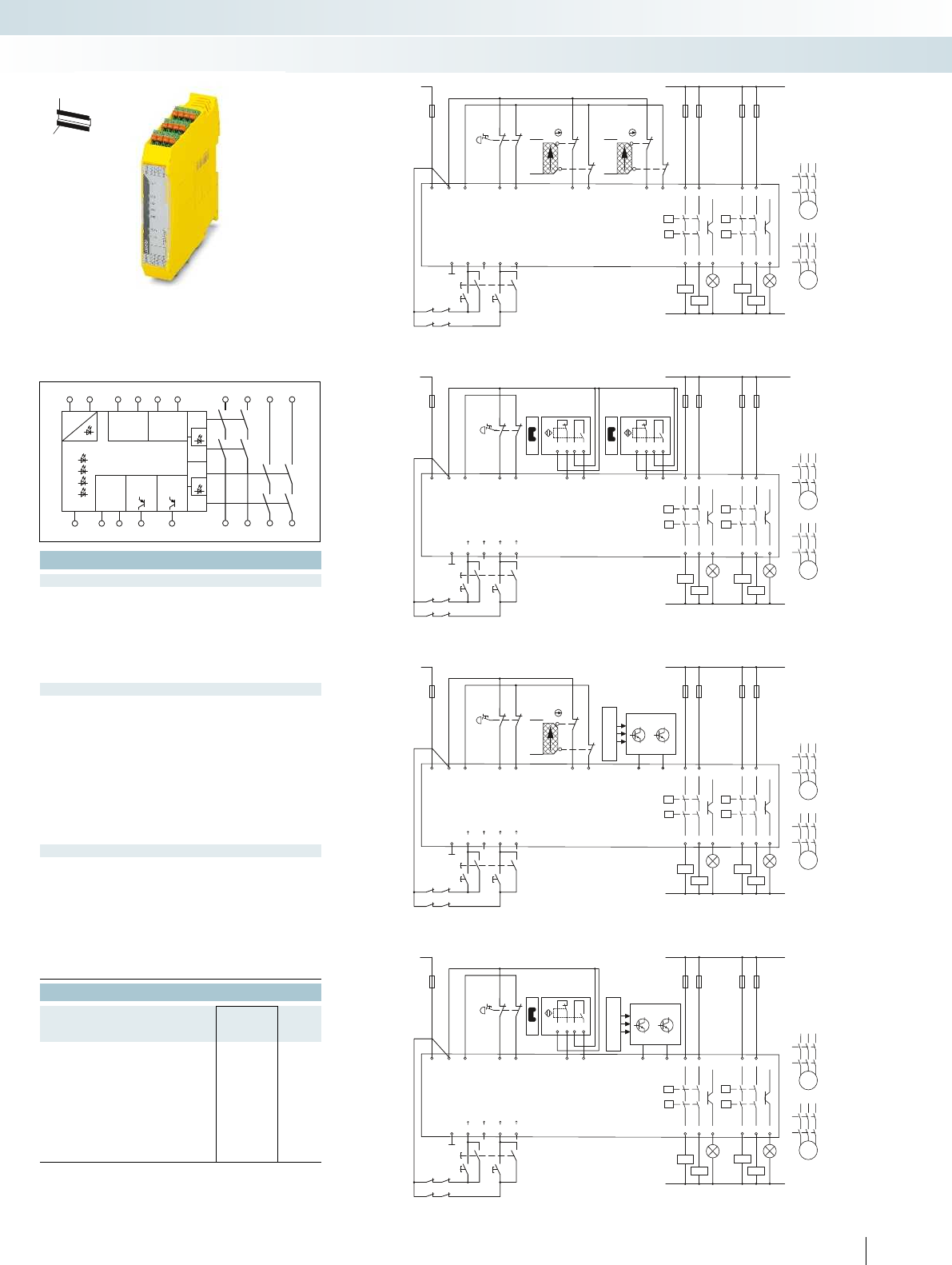
K1K2
K3 K4
S4
S3
S5
K2
K1
K4
K3
N
K1
K2
M
K3
K4
M
13234353
A2A2S34S35S36S37
()
()()
()
K1
K2
K3
K4
A1S11 S21 I1I2I3 I4I5I6
14 24 3244 54 62
PSR-...-24DC/MXF3/4x1/2x2/B
S0 S1S2
B2
B1
+24VDC L
OSDD1OSDD2
K1K2
K3 K4
S4
S3
S5
K2
K1
K4
K3
N
K1
K2
M
K3
K4
M
13234353
A2A2S34S35S36S37
K1
K2
K3
K4
A1S11 S21 I1I2I3 I4I5I6
14 24 3244 54 62
PSR-...-24DC/MXF1/4x1/2x2/B
S0 S1S2
B2
B1
+24VDC L
B4
B3
K1K2
K3 K4
S4
S3
S5
K2
K1
K4
K3
N
K1
K2
M
K3
K4
M
+24VDC
OSDD1OSDD2
11 12 1314
L
13234353
A2A2S34S35S36S37
()
()()
()
K1
K2
K3
K4
A1S11 S21 I1I2I3 I4I5I6
14 24 3244 54 62
PSR-...-24DC/MXF4/4x1/2x2/B
S0 S1S2
K1K2
K3 K4
S4
S3
S5
K2
K1
K4
K3
N
K1
K2
M
K3
K4
M
+24VDC
11 12 1314
13234353
A2A2S34S35S36S37
()
()()
()
K1
K2
K3
K4
A1S11 S21 I1I2I3 I4I5I6
14 24 3244 54 62
PSR-...-24DC/MXF2/4x1/2x2/B
S0 S1S2
11 12 1314
L
6232S11 S21I1...I6 14 24 44 54
13234353
A1 A2 S36S34S37S35
K 2
K 4
K 1
K 3
POWER
24V DCReset
K3/K4
Reset
K1/K2K1/K2
K3/K4
Monitoring
OUTPUT
K3/K4
Monitoring
OUTPUT
K1/K2
OUTPUT
ERR
I1/I2
I3/I4
I5/I6
Logic
For additional information, visit phoenixcontact.net/products
Technical data
24 V DC
0.85 ... 1.1
125 mA (with actuated relays)/55 mA (two-channel 24 V/0 V + max.
200 mA control (message outputs 32/62) with non-actuated relays)
circuit: 100ms) 1 s (availability time after activation of sensor circuit: 100ms)
4 enabling current paths
2 semiconductor alarm outputs
Au AgCuNi, +0.2 -0.4µmAu
Max./min. switching voltage 250 V AC/DC/10 V AC/DC 250 V AC/DC/10 V AC/DC 250 V AC/DC/10 V AC/DC
DC)) 6 A (N/O contact), max. 100 mA (Alarm output (24VDC))
6 A/10 mA
0.1 W
V) 5 A (0.1Hz; DC13; 24V)
3 A (AC15; 230V)
6 A gL/gG NEOZED (N/O contact),
4 A gL/gG NEOZED (for low-demand applications)
-20°C ... 45°C (see derating curve)
Air and creepage distances between the circuits DIN EN 50178/VDE 0160 DIN EN 50178/VDE 0160 DIN EN 50178/VDE 0160
4 kV/basic isolation (safe isolation, reinforced insulation and 6 kV
between input circuit, enabling current paths and safety circuit 1
(13/14, 23/24) and safety circuit 2 (43/44, 53/54).)
W / H / D 22.5 mm/112.2 mm/114.5 mm 22.5 mm/117.4 mm/114.5 mm 22.5 mm/116.4 mm/114.5 mm
- 12 0.2 - 1.5 mm²/0.2 - 1.5 mm²/24 - 16 0.2 - 2.5 mm²/0.2 - 2.5 mm²/24 - 12
EMC note Class A product, see page 443 Class A product, see page 443 Class A product, see page 443
Ordering data
Type Order No. Pcs. /
Pkt.
PSR-PIP-24DC/MXF1/4X1/2X2/B 2903253 1
PSR-PIP-24DC/MXF2/4X1/2X2/B 2903256 1
PSR-PIP-24DC/MXF3/4X1/2X2/B 2903259 1
PSR-PIP-24DC/MXF4/4X1/2X2/B 2903262 1
401PHOENIX CONTACT
Emergency stop, safety door, and light grid monitoring
Light grid type 4
Receiver
Transmitter
(emergency
stop)
Safety door
1
closed
open
(emergency
stop)
Safety door
2
Safety door
1
closed
open
closed
open
Emergency stop and safety door monitoring
Emergency stop, magnetic switch, and light grid monitoring
(emergency
stop)
Light grid type 4
Receiver
Transmitter
Emergency stop and magnetic switch monitoring
(emergency
stop)
Control technology, I/O systems, and automation infrastructure
Functional Safety - safety switching devices
Screw connection Spring-cage connection Push-in connection
H
W
D
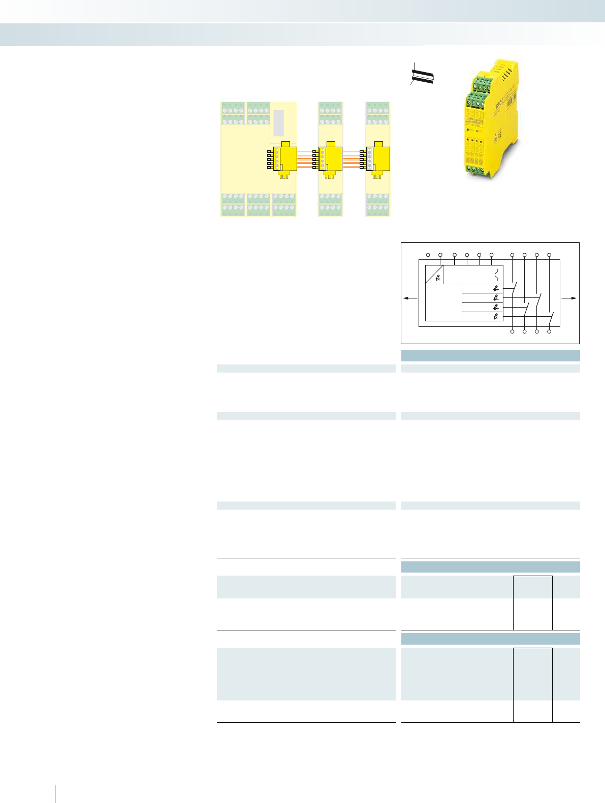
INTERFACE-PSR
use only
PSR-TBUS
INTERFACE-PSR
use only
PSR-TBUS
INTERFACE-PSR
use only
PSR-TBUS
Logic
TBUS
SAFE
TBUS
SAFE
Monitoring
Outputs
A1 M0 M1 M2 M3A2 132333 43
K1
K2
K3
K4
14 24 34
44
Power
24V DC
Technical data
Module data
Nominal input voltage UN24 V DC (via PSR-TBUS)
Permissible range (with reference to UN) 0.85 ... 1.1
Typ. current consumption (with reference to UN)120 mA
Interfaces DIN rail TBUS for connection to the master module,
supplied as standard
Output data
Contact type 4 enabling current paths
Contact material AgCuNi, + 0.2 µm Au
Max./min. switching voltage 250 V AC/5 V AC/DC
Limiting continuous current 4 A (see derating curve)
Max./min. inrush current 6 A/5 mA
Min. switching power 60 mW
Switching capacity (3600/h cycles) 3 A (230 V (AC 15)) ; 5 A (24 V (DC13))
Short-circuit protection of the output circuits 6 A gL/gG
Response time Max. 50 ms
Alarm outputs 4
General data
Ambient temperature range -20°C ... 55°C
Screw connection solid/stranded/AWG 0.2 - 2.5 mm²/0.2 - 2.5 mm²/24 - 12
Spring-cage connection (solid/stranded/AWG) 0.2 - 1.5 mm²/0.2 - 1.5 mm²/24 - 16
Dimensions Screw version 22.5 mm/99 mm/114.5 mm
W / H / D Spring-cage version 22.5 mm/112 mm/114.5 mm
EMC note Class A product, see page 443
Ordering data
Description Type Order No. Pcs. /
Pkt.
Extension module, 4 relay outputs (1-channel) or 2 relay outputs
(2-channel)
With screw connection PSR-SCP- 24DC/TS/SDOR4/4X1 2986096 1
With spring-cage connection PSR-SPP- 24DC/TS/SDOR4/4X1 2986106 1
Accessories
Freely configurable master module, for monitoring emergency
stops, safety doors, light grids, etc., with 20 safe inputs and 4 safe
outputs, 4 alarm outputs and 2 clock outputs, safe and standard
extension, including memory stick and PSR-TBUS DIN rail
connector
With screw connection PSR-SCP- 24DC/TS/M 2986012 1
With spring-cage connection PSR-SPP- 24DC/TS/M 2986025 1
PSR-TBUS DIN rail connector, for
supplying/controlling/monitoring (depending on the module)
PSR-TBUS 2890425 50
402 PHOENIX CONTACT
PSR-TBUS
connectors
PSR-TBUS
connectors
PSR-TBUS
connectors
PSR-TBUS
connectors
PSR-TBUS
connectors
H
W
D
The PSR-TS-SDOR4 is a safe relay
extension module for the PSR-TRISAFE-M
safety module. It makes additional
configurable relay outputs available to the
master module.
Features:
– Output extension for
PSR-TRISAFE-M (modular)
– 4 single-channel relay outputs or
(configurable via SAFECONF) 2 two-
channel relay outputs
–4 signal outputs
– Slim 22.5 mm housing
– Including PSR-TBUS DIN rail connector
for adapting to the PSR-TRISAFE-M
master module
– Up to cat. 4/PLe according to
ENISO13849-1
– Up to SIL 3 according to IEC 61508
– Up to SILCL3 according to EN62061
PSR-TBUS DIN rail connectors are used for cross-wiring
between the modules.
PSR-TRISAFE modular
Control technology, I/O systems, and automation infrastructure
Functional Safety - configurable safety modules
Extension module with 4 relay outputs

For additional information, visit phoenixcontact.net/products
403PHOENIX CONTACT
Control technology, I/O systems, and automation infrastructure
Functional Safety - configurable safety modules
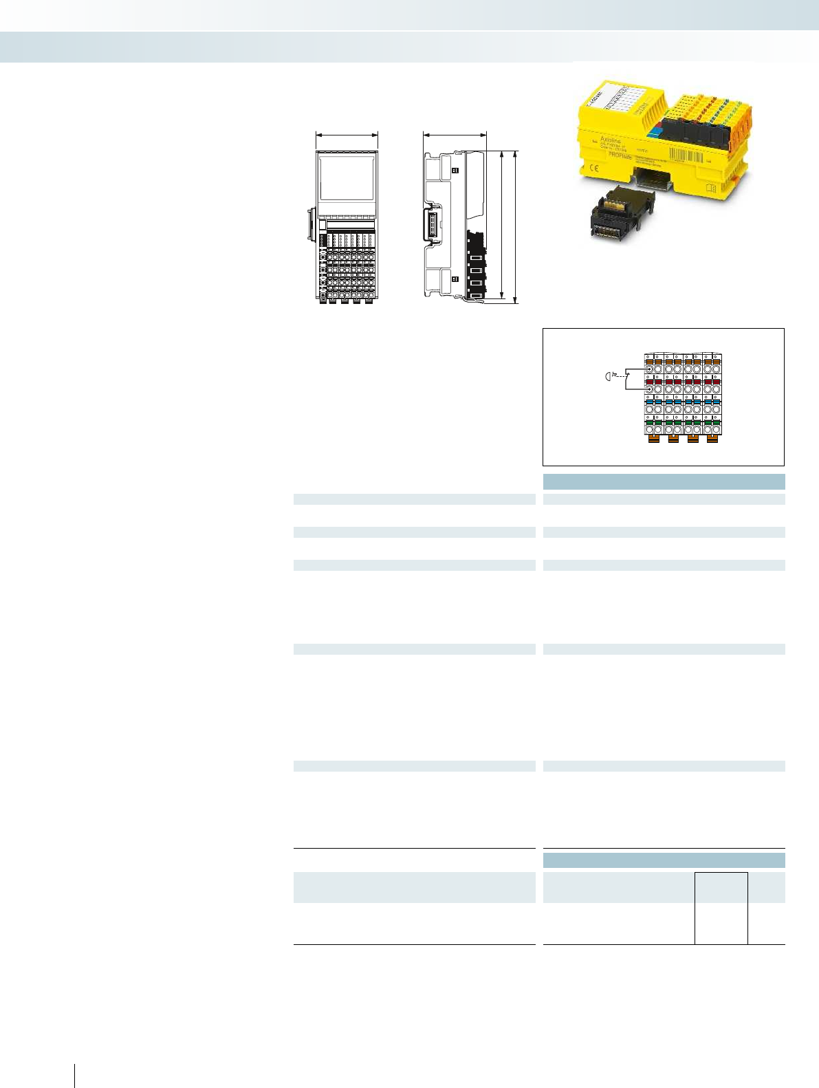
53,6 54
122,4
126,1
00
10
20
30
01
11
21
31
04
14
24
34
05
15
25
35
06
16
26
36
07
17
27
37
02
12
22
32
03
13
23
33
Technical data
Local bus interface
Name AxiolineFlocal bus
Connection method Bus base module
Power supply for module electronics
Communications power UBus 5 V DC (via bus base module)
Current consumption from Ubus Typ. 280 mA (Normal operation)
I/O supply
Supply of digital input modules UI24 V DC
Supply voltage range UI19.2 V DC ... 30.2 V DC (including all tolerances, including ripple)
Current consumption from UITyp. 40 mA (when using the appropriate clock supply)
Protective circuit Protection against polarity reversal, EMC protective circuit,
undervoltage detection
Digital inputs
Connection method 2, 3, 4-wire
Number of inputs 4 (with two-channel assignment)
8 (for single-channel assignment)
Description of the inputs IEC 61131-2 type 3
Nominal input voltage UIN 24 V DC
Nominal input current at UIN Typ. 4.2 mA
Input filter time 1.5 ms
3 ms (default)
5 ms
15 ms
General data
Connection method Direct plug-in technology
Connection data solid / stranded / AWG 0.2 ... 1.5 mm²/0.2 ... 1.5 mm²/24 - 16
Weight 220 g
Width 53.6 mm
Height 126.1 mm
Depth 54 mm
Ambient temperature (operation) -35°C ... 60°C (mounting position: any)
Ordering data
Description Type Order No. Pcs. /
Pkt.
Fail-safe digital input module
- 4 inputs (two-channel), 8 inputs (single-channel) AXL F PSDI8/4 1F 2701559 1
404 PHOENIX CONTACT
You can install the safety-related
AxiolineF PROFIsafe I/O modules
anywhere inside an Axioline station. In
addition to standard signals, this means you
can now also read and output safe signals in
the Axioline system.
Depending on the installation and
parameterization, you can achieve the
following safety characteristics with these
modules:
– Up to cat. 4/PLe according to
ENISO13849-1
– Up to SIL 3 according to IEC 61508
– Up to SILCL3 according to EN62061
Safe I/O modules
Control technology, I/O systems, and automation infrastructure
Functional Safety - network safety modules
Digital input module
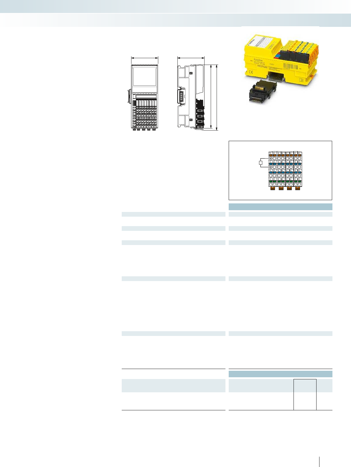
53,6 54
122,4
126,1
00
10
20
30
01
11
21
31
04
14
24
34
05
15
25
35
06
16
26
36
07
17
27
37
02
12
22
32
03
13
23
33
K
For additional information, visit phoenixcontact.net/products
Technical data
Local bus interface
Name AxiolineFlocal bus
Connection method Bus base module
Power supply for module electronics
Communications power UBus 5 V DC (via bus base module)
Current consumption from Ubus Typ. 260 mA (Normal operation)
I/O supply
Supply of digital output modules UO24 V DC
Supply voltage range UO19.2 V DC ... 30.2 V DC (including all tolerances, including ripple)
Current consumption from UOTyp. 26 mA (all outputs set including actuator current)
Protective circuit Protection against polarity reversal, EMC protective circuit,
undervoltage detection
Digital outputs
Connection method 2, 3-wire
Number of outputs 4 (with two-channel assignment)
8 (for single-channel assignment)
Output voltage 24 V DC
Maximum output current per channel 2 A
Maximum output current per module / terminal block 8 A
Behavior with overload Affected output is disabled and a diagnostic message is generated.
Protective circuit Overload protection, freewheeling circuit for inductive loads,
Discharge circuit for accelerated discharge of capacitive loads
General data
Connection method Direct plug-in technology
Connection data solid / stranded / AWG 0.2 ... 1.5 mm²/0.2 ... 1.5 mm²/24 - 16
Weight 220 g
Width 53.6 mm
Height 126.1 mm
Depth 54 mm
Ambient temperature (operation) -35°C ... 60°C (mounting position: any)
Ordering data
Description Type Order No. Pcs. /
Pkt.
Fail-safe digital output module
- 4 outputs (two-channel), 8 outputs (single-channel) AXL F PSDO8/3 1F 2701560 1
405PHOENIX CONTACT
You can install the safety-related
AxiolineF PROFIsafe I/O modules
anywhere inside an Axioline station. In
addition to standard signals, this means you
can now also read and output safe signals in
the Axioline system.
Depending on the installation and
parameterization, you can achieve the
following safety characteristics with these
modules:
– Up to cat. 4/PLe according to
ENISO13849-1
– Up to SIL 3 according to IEC 61508
– Up to SILCL3 according to EN62061
Safe I/O modules
Control technology, I/O systems, and automation infrastructure
Functional Safety - network safety modules
Digital output module
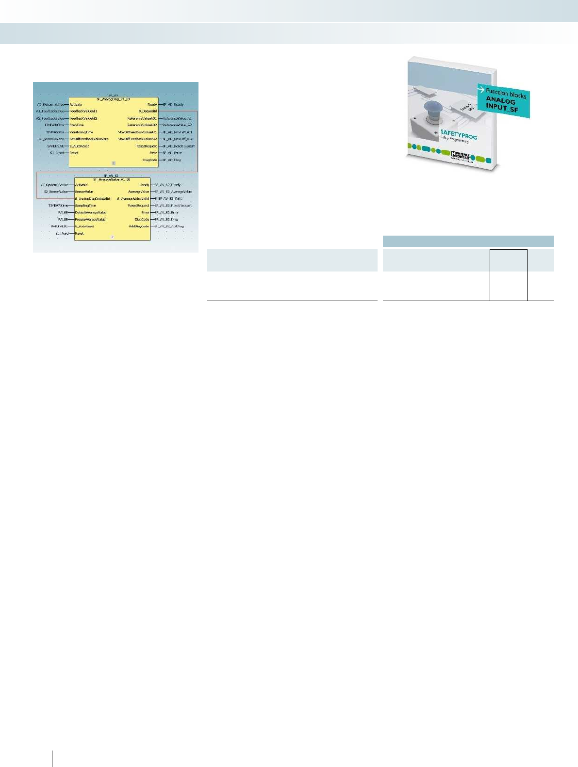
Ordering data
Description Type Order No. Pcs. /
Pkt.
Function block library for safety-related analog acquisition with
standard I/O modules
SAFE AI 2400057 1
406 PHOENIX CONTACT
Wherever analog values need to be
processed in a safety-related manner, the
SafeAI solution package from Phoenix
Contact is the ideal solution. With this
TÜV-certified and software-based analog
value processing, no safety-related I/O
modules are required. This saves you money
and offers flexibility.
Components of the Safe AI solution
package:
– Initial application advice via telephone on
the required software and hardware
components
– License key for using the
ANALOGINPUT_SF function block
library including user documentation
– Advice from the Competence Center
Safety in the form of a web meeting
24-hour safety hotline
+49 5281 9-462777
safety-service@phoenixcontact.com
Safe analog value processing
Control technology, I/O systems, and automation infrastructure
Functional Safety - safe control technology

For additional information, visit phoenixcontact.net/products
407PHOENIX CONTACT
Control technology, I/O systems, and automation infrastructure
Functional Safety - safe control technology
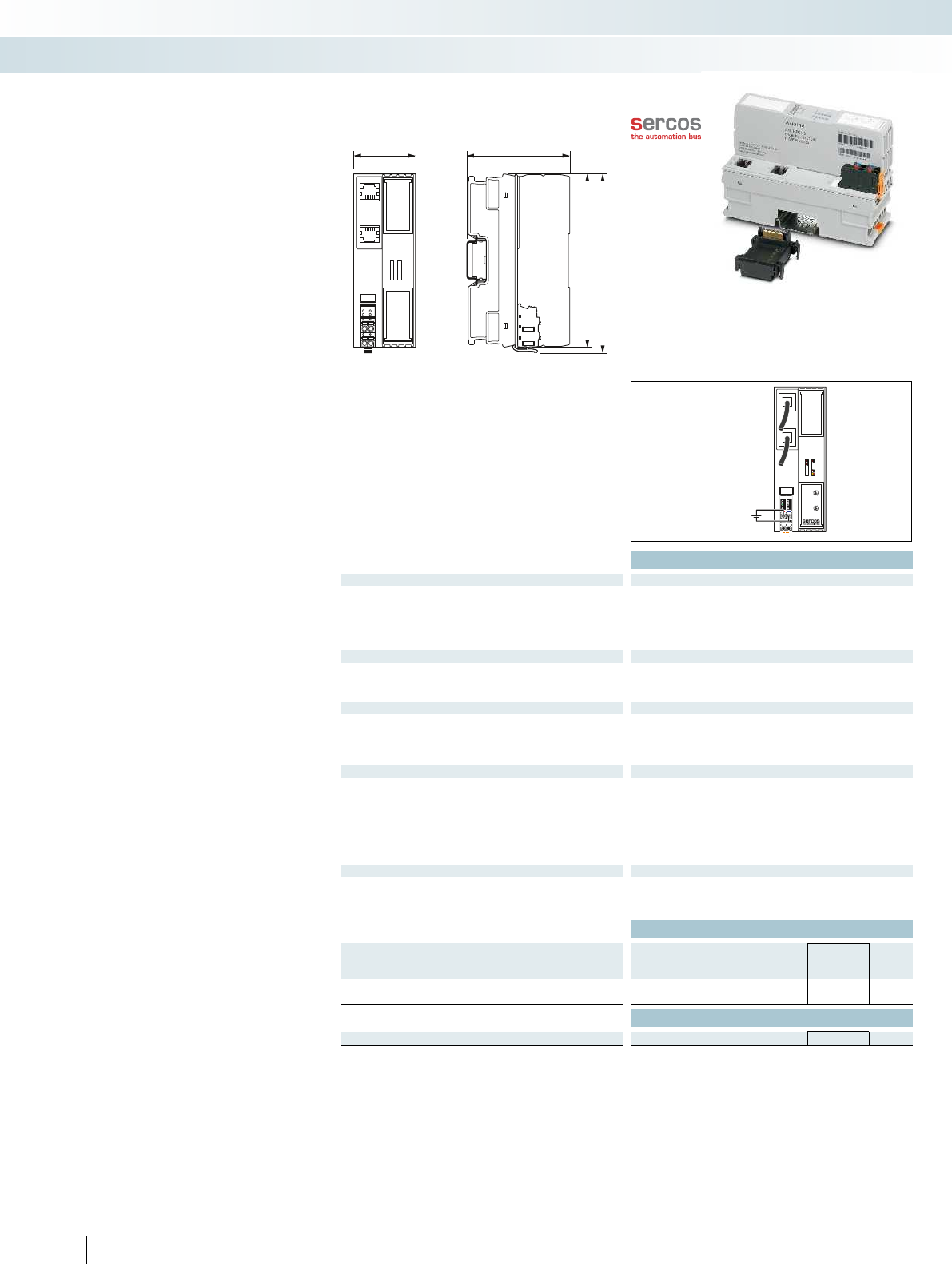
45 74
125,9
122,4
UL
24 V DC
(U )
L
+
-
S
SD
RDY
D
E
sercos
0
2
14
4
6
8
10
12
0
2
4
6
A
B
C
D
E
F
8
9
S1
X10
S2
X1
Technical data
Interface
Fieldbus system Sercos
Connection method RJ45 socket, auto negotiation and auto crossing
Number 2
Transmission speed 100 Mbps (full duplex)
Transmission length Max. 100 m
Network/bus system
Device profile FSP_IO
Equipment type Sercos slave
Update rate 31.25 µs
Local bus interface
Name AxiolineFlocal bus
Connection method Bus base module
Transmission speed 100 Mbps
Number of supported devices Max. 63 (per station)
Power supply for module electronics
Supply of communications power UL24 V DC
Maximum permissible voltage range 19.2 V DC ... 30 V DC (including all tolerances, including ripple)
Communications power UBus 5 V DC (via bus base module)
Current supply at UBus 2 A
Protective circuit Surge protection of the supply voltage
Polarity reversal protection of the supply voltage
General data
Connection method Push-in technology
Connection data solid / stranded / AWG 0.2 ... 1.5 mm²/0.2 ... 1.5 mm²/24 - 16
Weight 177 g
Ordering data
Description Type Order No. Pcs. /
Pkt.
Axioline bus coupler
- For Sercos AXL F BK S3 2701686 1
Accessories
Axioline bus base module (replacement part) AXL BS BK 2701422 5
408 PHOENIX CONTACT
The Axioline F bus coupler is the link
between the Axioline F system and the
higher-level third-generation Sercos
network.
For startup tests, the AxiolineF station
can be started up independently of the
higher-level network via either the service
interface or an Ethernet port on the bus
coupler using the Startup+ software.
Features:
– Sercos specification V1.3
– Minimum Sercos cycle time of 31.25µs
– Two rotary encoding switches for address
assignment
– 2 RJ45 connections (with integrated
switch)
– Up to 63 additional Axioline devices can
be connected
– Typical cycle time of the Axioline F local
bus is around 10s
– Runtime in bus coupler is negligible
(almost 0µs)
– FSP-IO (Function Specific Profile-IO) for
modular I/O devices
– Firmware can be updated
– Diagnostic and status indicators
Bus couplers
Control technology, I/O systems, and automation infrastructure
I/O systems - for the control cabinet (IP20) - Axioline F
Sercos III bus coupler
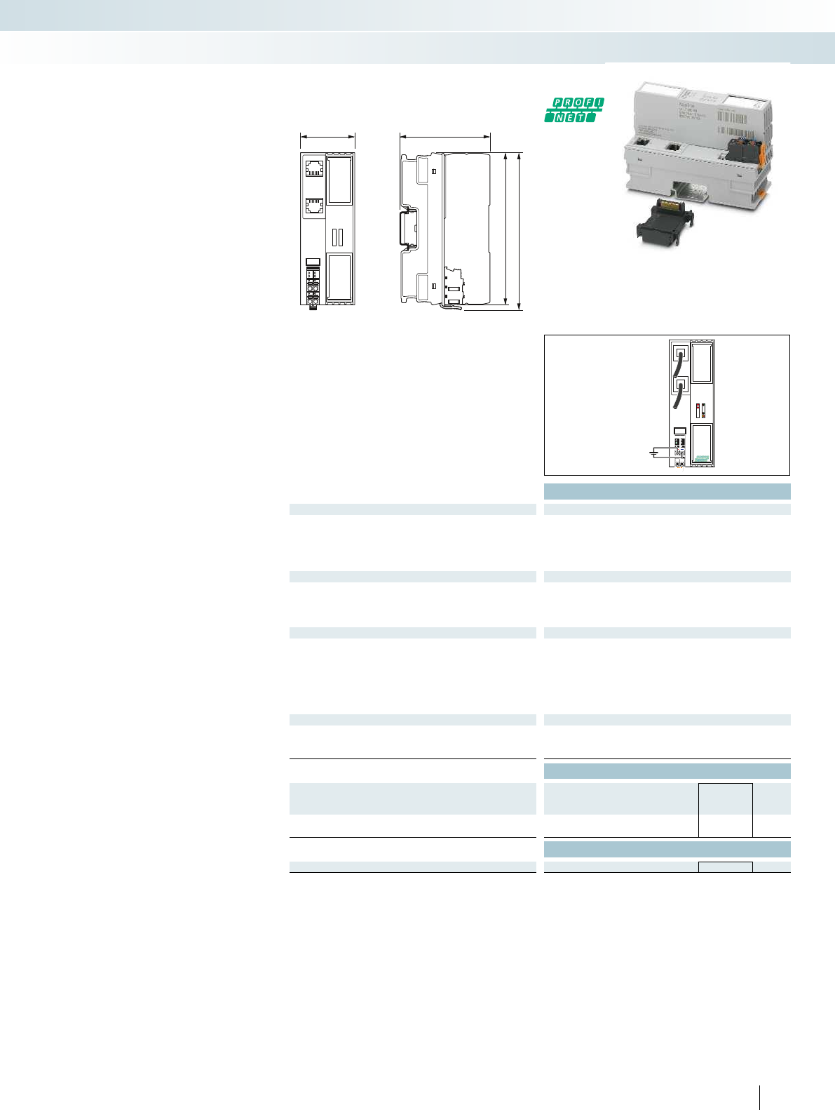
45 74
125,9
122,4
UL
24 V DC
(U )
L
+
-
BF
SF
RDY
D
E
Ethernet
For additional information, visit phoenixcontact.net/products
Technical data
Interface
Fieldbus system PROFINET
Connection method RJ45 socket, auto negotiation and autocrossing
Number 2
Transmission speed 100 Mbps (full duplex)
Transmission length Max. 100 m
Local bus interface
Name AxiolineFlocal bus
Connection method Bus base module
Transmission speed 100 Mbps
Number of supported devices Max. 63 (per station)
Power supply for module electronics
Supply of communications power UL24 V DC
Maximum permissible voltage range 19.2 V DC ... 30 V DC (including all tolerances, including ripple)
Communications power UBus 5 V DC (via bus base module)
Current supply at UBus 2 A
Protective circuit Surge protection of the supply voltage
Polarity reversal protection of the supply voltage
General data
Connection method Push-in technology
Connection data solid / stranded / AWG 0.2 ... 1.5 mm²/0.2 ... 1.5 mm²/24 - 16
Weight 177 g
Ordering data
Description Type Order No. Pcs. /
Pkt.
Axioline bus coupler
- For PROFINET AXL F BK PN 2701815 1
Accessories
Axioline bus base module (replacement part) AXL BS BK 2701422 5
409PHOENIX CONTACT
The AxiolineF bus coupler is the link
between the Axioline F system and the
higher-level Ethernet system.
The new version of the device features
web-based management. It can be used to
access static information (e.g., technical
data, MAC address) or dynamic information
(e.g., IP address, status information).
For startup tests, the AxiolineF station
can be started up independently of the
higher-level network via either the service
interface or an Ethernet port on the bus
coupler using the Startup+ software.
Features:
–PROFINET RT and PROFINET IRT
support
– Minimum cycle time of PROFINET for RT
and IRT is 250 s
– Module replacement without software
possible
– 2 RJ45 connections (with integrated
switch)
– Up to 63 additional Axioline devices can
be connected
– Typical cycle time of the Axioline F local
bus is around 10s
– MRP client
–Shared device
– Firmware can be updated
– Diagnostic and status indicators
Bus coupler
Control technology, I/O systems, and automation infrastructure
I/O systems - for the control cabinet (IP20) - Axioline F
PROFINET bus coupler
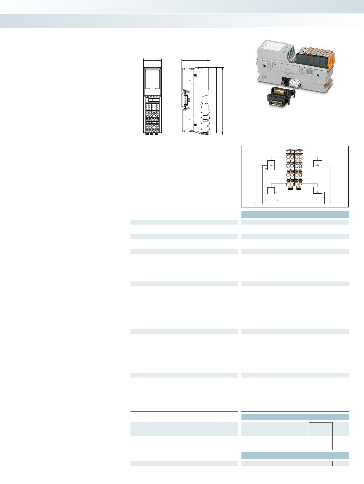
3554
122,4
126,1
+24 V
IN7
+24 V
IN1
+24 V
00
10
20
30
01
11
21
31
02
12
22
32
03
13
23
33
OUT8
OUT2
BSH
Technical data
Local bus interface
Name AxiolineFlocal bus
Connection method Bus base module
Power supply for module electronics
Communications power UBus 5 V DC (via bus base module)
Current consumption from Ubus Max. 120 mA
I/O supply
Digital input and output module supply UIO 24 V DC
Supply voltage range UIO 19.2 V DC ... 30 V DC (including all tolerances, including ripple)
Protective circuit Surge protection of the supply voltage
Polarity reversal protection of the supply voltage
Digital inputs
Connection method 1-wire
Number of inputs 8
Description of the inputs EN 61131-2 types 1 and 3
Nominal input voltage UIN 24 V DC
Nominal input current at UIN 2.4 mA
Input filter time < 100 µs
1000 µs
3000 µs (default)
Protective circuit Polarity reversal protection of the inputs
Digital outputs
Connection method 1-wire
Maximum number of outputs 8
Output voltage 24 V
Maximum output current per channel 500 mA
Maximum output current per module 4 A (external fuse)
Behavior with overload Shutdown with automatic restart
Protective circuit Short-circuit protection, overload protection of the outputs
General data
Connection method Push-in technology
Connection data solid / stranded / AWG 0.2 ... 1.5 mm²/0.2 ... 1.5 mm²/24 - 16
Weight 133 g
Width 35 mm
Height 126.1 mm
Depth 54 mm
EMC note Class A product, see page 443
Ordering data
Description Type Order No. Pcs. /
Pkt.
Axioline digital input/output module, complete with accessories
(bus base module)
- 8 inputs, 8 outputs AXL F DI8/1 DO8/1 1H 2701916 1
Accessories
Axioline bus base module (replacement part) AXL F BS H 2700992 5
410 PHOENIX CONTACT
This module is designed for use within an
AxiolineF station.
It is used to acquire and output digital
data.
You can adjust the filter times of the
inputs to increase noise immunity. Filter
times of 100 s enable you to implement a
counting function with a maximum input
frequency of 5 kHz in the application.
Features:
– 8 digital inputs and 8 digital outputs
– 24 V DC, 500 mA
– Connection of sensors or actuators in
single-wire technology
– Minimum update time < 100s, bus
synchronous
– Filter times can be set in three
increments:
< 100s, 1000s or 3000s
– Maximum input frequency: 5kHz
– Short-circuit-proof outputs
– Stored device rating plate
– Diagnostic and status indicators
Digital input and output modules
Control technology, I/O systems, and automation infrastructure
I/O systems - for the control cabinet (IP20) - Axioline F
8 digital inputs and 8 digital outputs
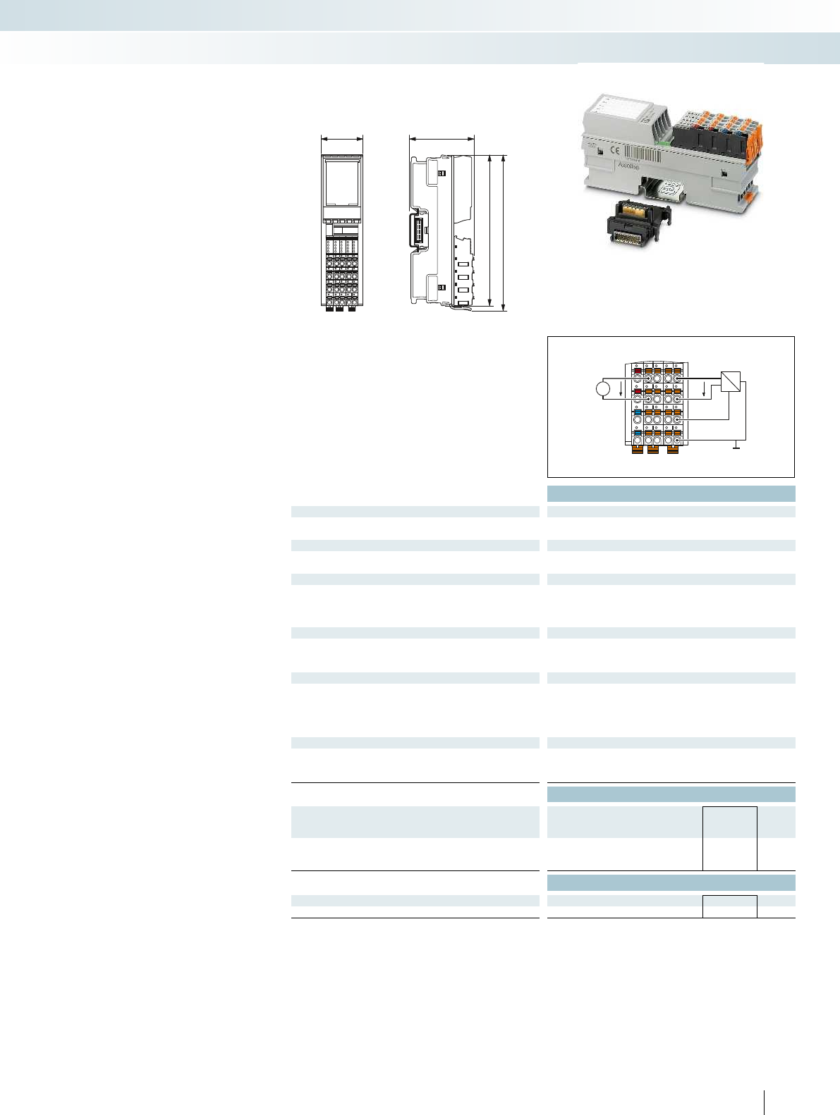
3554
122,4
126,1
00
10
20
30
01
11
21
31
02
12
22
32
03
13
23
33
a1
a2
b1
b2
U
U
GND
P
U
+24 V
U
For additional information, visit phoenixcontact.net/products
BSH
Technical data
Local bus interface
Name AxiolineFlocal bus
Connection method Bus base module
Power supply for module electronics
Communications power UBus 5 V DC (via bus base module)
Current consumption from Ubus Max. 150 mA
I/O supply
Supply of analog modules UA24 V DC
Protective circuit Surge protection
Protection against polarity reversal
Transient protection
Analog inputs
Connection method 2, 3, 4-wire (shielded)
Number of inputs Max. 4 (differential inputs, voltage)
Voltage input signal 0 V ... 5 V/-5 V ... 5 V/0 V ... 10 V/-10 V ... 10 V
Characteristics
Measured value representation 16 bits (15 bits + sign bit)
Input filter 30 Hz, 12 kHz and mean-value generation (can be parameterized)
Precision 0.1% (of measuring range final value for active mean-value
generation and 30 Hz filter)
General data
Connection method Push-in technology
Connection data solid / stranded / AWG 0.2 ... 1.5 mm²/0.2 ... 1.5 mm²/24 - 16
Weight 145 g
Ordering data
Description Type Order No. Pcs. /
Pkt.
Axioline analog input module, complete with accessories
(bus base module)
- 4 inputs AXL F AI4 U 1H 2688501 1
Accessories
Axioline bus base module (replacement part) AXL F BS H 2700992 5
Axioline shield connection set AXL SHIELD SET 2700518 1
411PHOENIX CONTACT
This module is designed for use within an
AxiolineF station.
It is used to acquire standard analog
voltage signals. Connection is via 2, 3 or 4-
wire technology and a shield connection.
Features:
– 4 analog differential signal inputs
– Voltage measuring ranges
– Input filter selection
– Minimum update time of 250s, bus
synchronous
– 16-bit measured value representation
– Stored device rating plate
– Integrated sensor supply
– Diagnostic and status indicators
Analog input modules
Control technology, I/O systems, and automation infrastructure
I/O systems - for the control cabinet (IP20) - Axioline F
4 analog inputs
Voltage signals
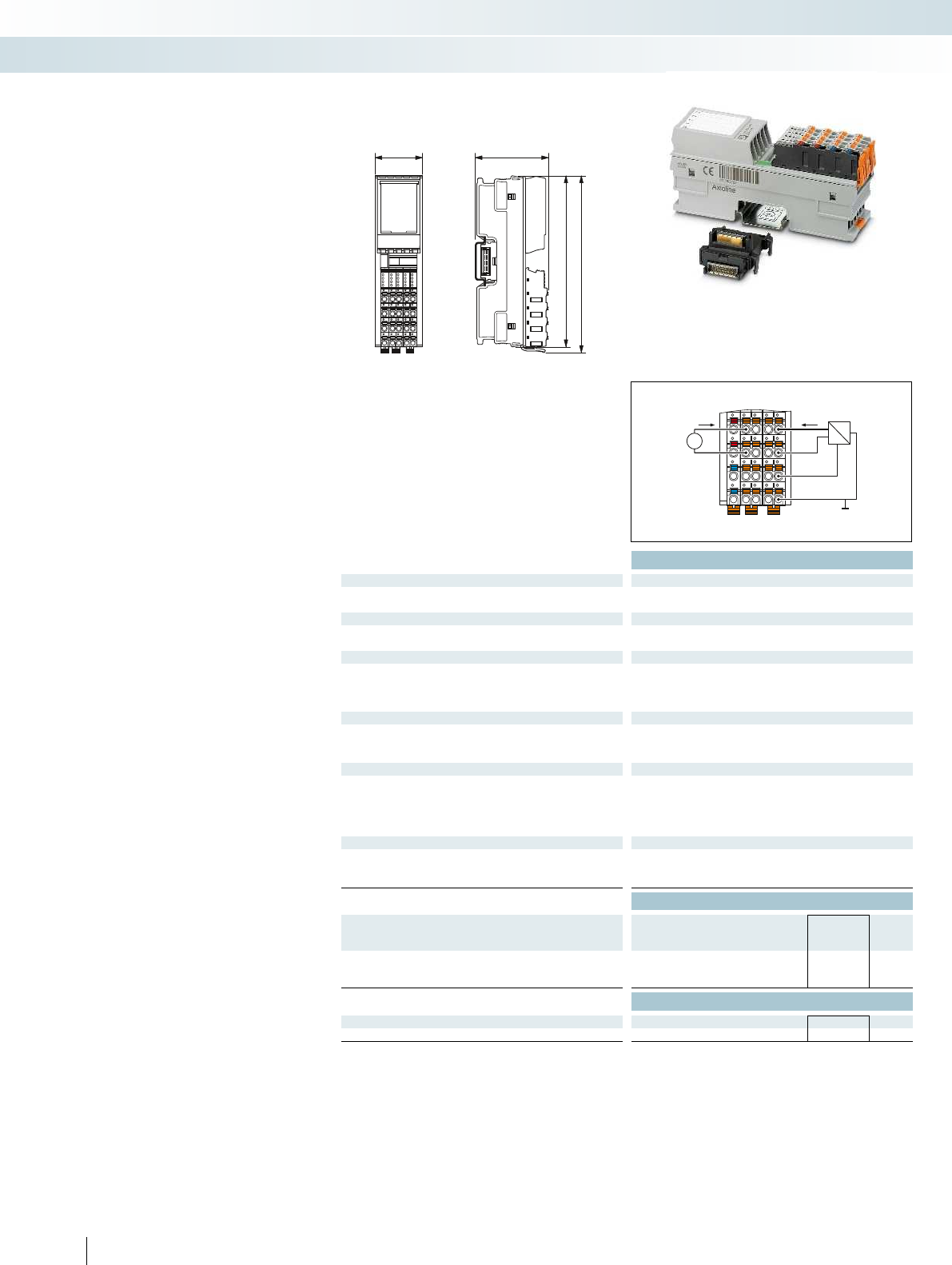
3554
122,4
126,1
00
10
20
30
01
11
21
31
02
12
22
32
03
13
23
33
a1
a2
b1
b2
I
GND
P
I
+24 V
I I
BSH
Technical data
Local bus interface
Name AxiolineFlocal bus
Connection method Bus base module
Power supply for module electronics
Communications power UBus 5 V DC (via bus base module)
Current consumption from Ubus Max. 150 mA
I/O supply
Supply of analog modules UA24 V DC
Protective circuit Surge protection
Protection against polarity reversal
Transient protection
Analog inputs
Connection method 2, 3, 4-wire (shielded)
Number of inputs Max. 4 (differential inputs, current)
Current input signal 0 mA ... 20 mA/4 mA ... 20 mA/-20 mA ... 20 mA
Characteristics
Measured value representation 16 bits (15 bits + sign bit)
Input filter 30 Hz, 12 kHz and mean-value generation (can be parameterized)
Precision 0.1% (of measuring range final value for active mean-value
generation and 30 Hz filter)
General data
Connection method Push-in technology
Connection data solid / stranded / AWG 0.2 ... 1.5 mm²/0.2 ... 1.5 mm²/24 - 16
Weight 145 g
Ordering data
Description Type Order No. Pcs. /
Pkt.
Axioline analog input module, complete with accessories
(bus base module)
- 4 inputs AXL F AI4 I 1H 2688491 1
Accessories
Axioline bus base module (replacement part) AXL F BS H 2700992 5
Axioline shield connection set AXL SHIELD SET 2700518 1
412 PHOENIX CONTACT
This module is designed for use within an
AxiolineF station.
It is used to acquire standard analog
current signals. Connection is via 2, 3 or 4-
wire technology and a shield connection.
Features:
– 4 analog differential signal inputs
– Current measuring ranges
– Input filter selection
– Minimum update time of 250s,
bus synchronous
– 16-bit measured value representation
– Stored device rating plate
– Integrated sensor supply
– Diagnostic and status indicators
Analog input modules
Control technology, I/O systems, and automation infrastructure
I/O systems - for the control cabinet (IP20) - Axioline F
4 analog inputs
Current signals
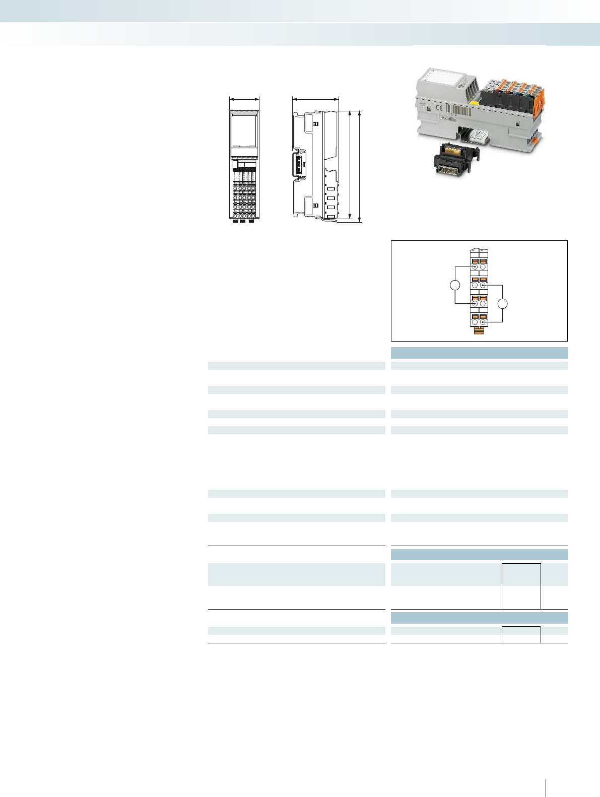
3554
122,4
126,1
U1
GND
GND
I1
U2
GND
GND
I2
U
I
For additional information, visit phoenixcontact.net/products
Technical data
Local bus interface
Name AxiolineFlocal bus
Connection method Bus base module
Power supply for module electronics
Communications power UBus 5 V DC (via bus base module)
Current consumption from Ubus Max. 150 mA
I/O supply
Supply of analog modules UA24 V DC
Analog outputs
Connection method 2-wire (shielded, twisted pair)
Number of outputs 4
Voltage output signal 0 V ... 5 V/-5 V ... 5 V/0 V ... 10 V/-10 V ... 10 V
Current output signal 0 mA ... 20 mA/4 mA ... 20 mA
Load/output load current output to 500 Ω
Protective circuit Short-circuit and overload protection
Transient protection
Characteristics
Representation of output values 16 bits (15 bits + sign)
Precision Typ. 0.1% (of output range final value)
General data
Connection method Push-in technology
Connection data solid / stranded / AWG 0.2 ... 1.5 mm²/0.2 ... 1.5 mm²/24 - 16
Weight 145 g
Ordering data
Description Type Order No. Pcs. /
Pkt.
Axioline analog output module, complete with accessories
(bus base module)
- 4 outputs AXL F AO4 1H 2688527 1
Accessories
Axioline bus base module (replacement part) AXL F BS H 2700992 5
Axioline shield connection set AXL SHIELD SET 2700518 1
413PHOENIX CONTACT
This module is designed for use within an
AxiolineF station.
The module is used to output standard
analog current and voltage signals. It is
connected using 2-wire technology and a
shield connection.
Features:
– 4 analog outputs
– Bipolar voltage outputs,
Unipolar current outputs
– Minimum update time of 250s,
bus synchronous
– 16-bit output value
– Overload and short-circuit protected
– Stored device rating plate
– Diagnostic and status indicators
Analog output modules
Control technology, I/O systems, and automation infrastructure
I/O systems - for the control cabinet (IP20) - Axioline F
4 analog outputs
Current/voltage signals
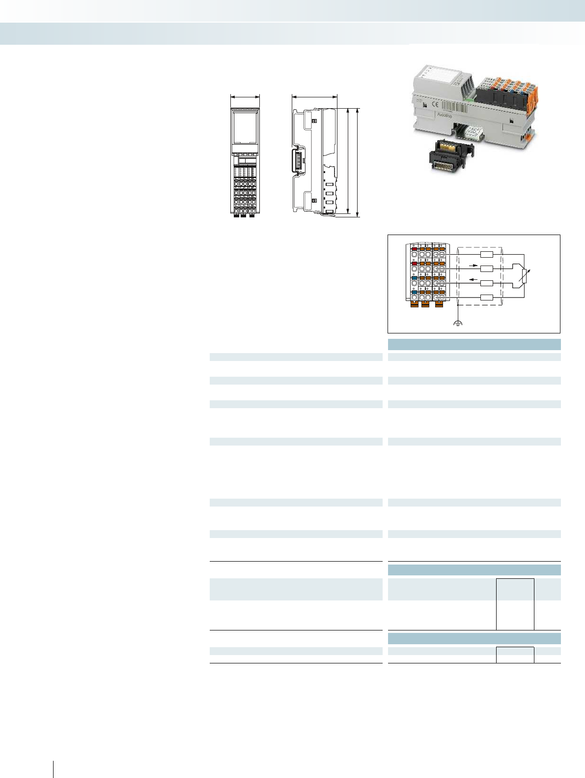
3554
122,4
126,1
00
10
20
30
01
11
21
31
02
12
22
32
03
13
23
33
a1
a2
b1
b2
RL
RL
RL
RL
U+
I+
I–
U–
RTD
ϑ
Technical data
Local bus interface
Name AxiolineFlocal bus
Connection method Bus base module
Power supply for module electronics
Communications power UBus 5 V DC (via bus base module)
Current consumption from Ubus Max. 140 mA
I/O supply
Supply of analog modules UA24 V DC
Protective circuit Surge protection
Protection against polarity reversal
Transient protection
Analog inputs
Connection method 2, 3, 4-wire (shielded)
Number of inputs 4 (for resistance temperature detectors)
Protective circuit Short-circuit protection, overload protection of the inputs
Transient protection of inputs
Transient protection of sensor supplies
Sensor types (RTD) that can be used Pt, Ni, KTY, Cu sensors
Linear resistance measuring range 0 Ω ... 500 Ω/0 kΩ ... 5 kΩ
Characteristics
Measured value representation 16 bits (15 bits + sign bit)
Input filter time 40 ms/60 ms/100 ms/120 ms (adjustable)
Accuracy Typ. ± 0.1 K (Pt100 with 3-wire termination)
General data
Connection method Push-in technology
Connection data solid / stranded / AWG 0.2 ... 1.5 mm²/0.2 ... 1.5 mm²/24 - 16
Weight 144 g
Ordering data
Description Type Order No. Pcs. /
Pkt.
Axioline analog input module, complete with accessories
(bus base module)
- 4 inputs for connecting resistance temperature detectors AXL F RTD4 1H 2688556 1
Accessories
Axioline bus base module (replacement part) AXL F BS H 2700992 5
Axioline shield connection set AXL SHIELD SET 2700518 1
414 PHOENIX CONTACT
This module is designed for use within an
AxiolineF station.
It is used to record resistive temperature
sensors. Connection is via 2, 3 or 4-wire
technology and a shield connection.
RTD features:
– 4 inputs for temperature shunts
– 500 and 5 k linear inputs
– Programmable filters
– Short-circuit-proof inputs
– Stored device rating plate
Temperature recording modules
Control technology, I/O systems, and automation infrastructure
I/O systems - for the control cabinet (IP20) - Axioline F
4 RTD inputs
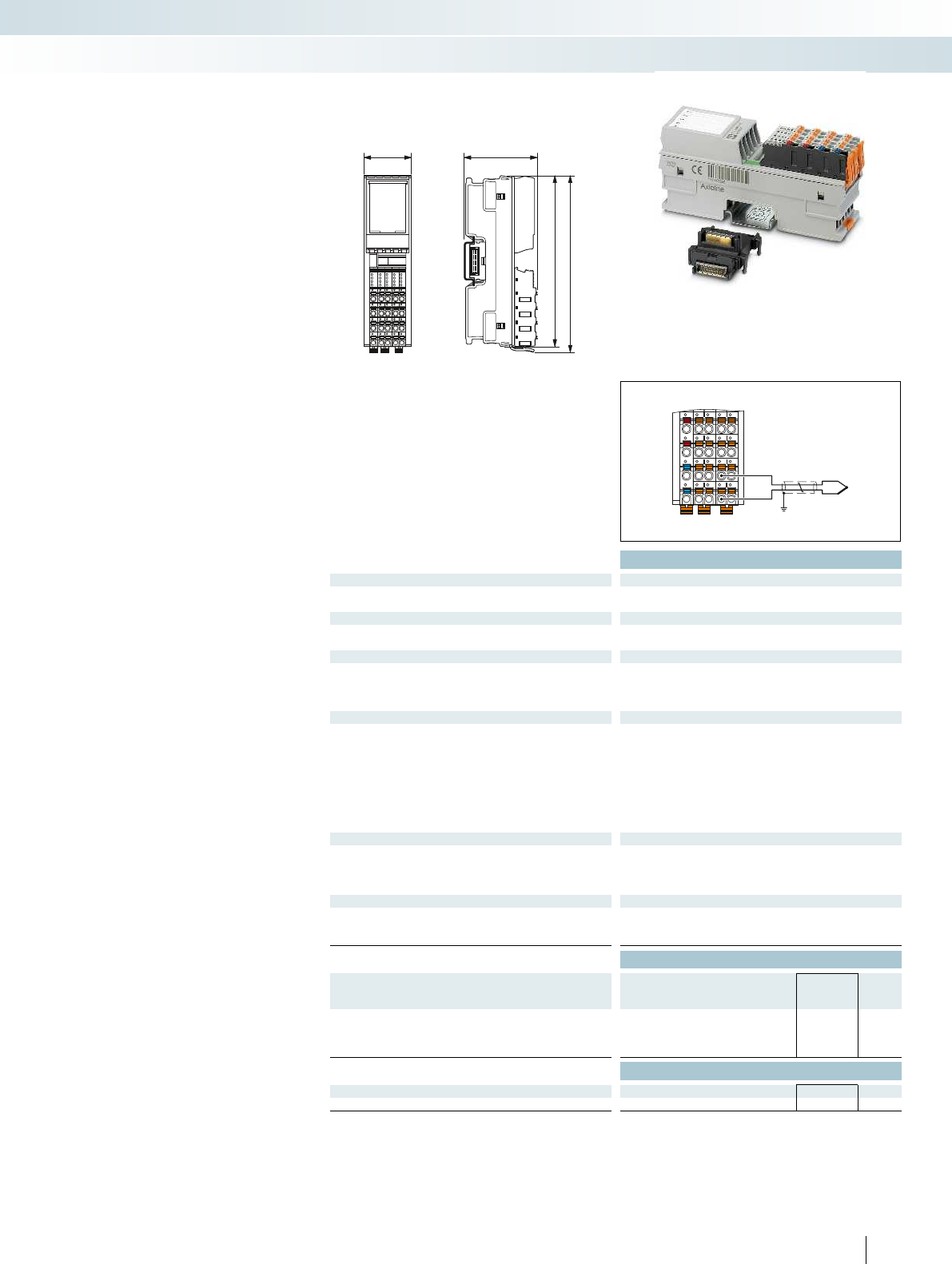
3554
122,4
126,1
00
10
20
30
01
11
21
31
02
12
22
32
03
13
23
33
a1
a2
b1
b2
For additional information, visit phoenixcontact.net/products
Technical data
Local bus interface
Name AxiolineFlocal bus
Connection method Bus base module
Power supply for module electronics
Communications power UBus 5 V DC (via bus base module)
Current consumption from Ubus Max. 40 mA
I/O supply
Supply of analog modules UA24 V DC
Protective circuit Surge protection of the supply voltage
Polarity reversal protection of the supply voltage
Transient protection
Analog inputs
Connection method 2-wire (shielded, twisted pair)
Number of inputs 4 +1 (4 inputs for thermocouples or linear voltage, plus 1 input -5V
to +5V)
Protective circuit Short-circuit protection, overload protection of the inputs
Transient protection of inputs
Sensor types (RTD) that can be used Pt 100 (2 external cold junctions, can also be used as a sensor input)
Linear voltage range -100 mV ... 100 mV
Characteristics
Measured value representation 16 bits (15 bits + sign bit)
Input filter time 40 ms/60 ms/100 ms/120 ms (adjustable)
Accuracy Typ. ± 0.19 K (Thermocouple type K, plus tolerance of cold junction)
General data
Connection method Push-in technology
Connection data solid / stranded / AWG 0.2 ... 1.5 mm²/0.2 ... 1.5 mm²/24 - 16
Weight 144 g
Ordering data
Description Type Order No. Pcs. /
Pkt.
Axioline analog input module, complete with accessories
(bus base module)
- 4inputs for connection of thermocouple sensors AXL F UTH4 1H 2688598 1
Accessories
Axioline bus base module (replacement part) AXL F BS H 2700992 5
Axioline shield connection set AXL SHIELD SET 2700518 1
415PHOENIX CONTACT
This module is designed for use within an
AxiolineF station.
It is used to acquire data from
thermocouples. Connection is via 2-wire
technology and a shield connection.
Features of UTH:
– 4 inputs for thermocouples
– Linear voltages from -100 mV to +100 mV
– 1 input from -5 V to +5 V
– 2 Pt100 inputs (external cold junction)
– Configurable cold junction type
– Stored device rating plate
Temperature recording modules
Control technology, I/O systems, and automation infrastructure
I/O systems - for the control cabinet (IP20) - Axioline F
4 UTH inputs
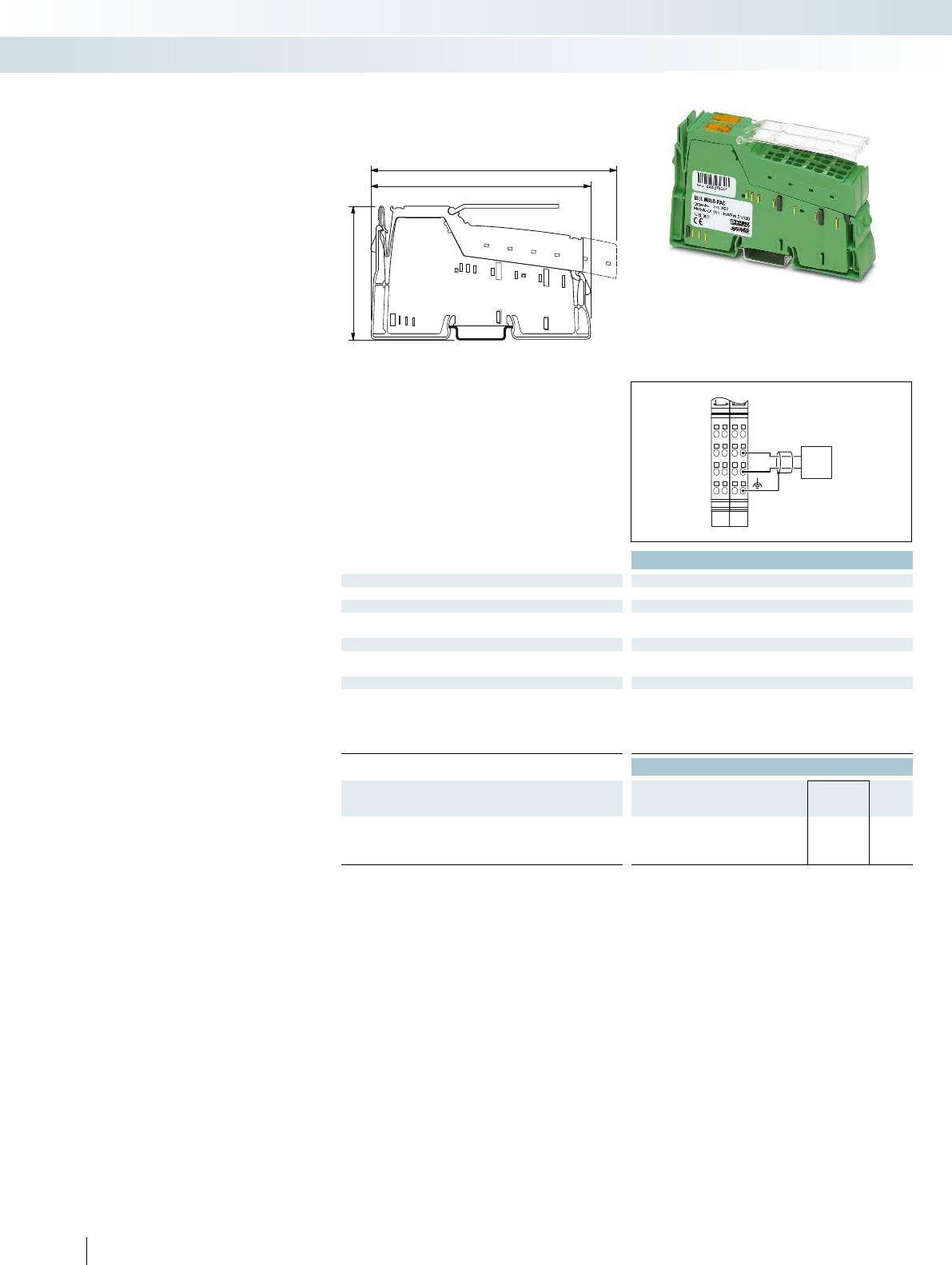
140,5
119,8
71,5
1.12.1
1.2
1.3
1.4
2.2
2.3
2.4
1.12.1
1.2
1.3
1.4
2.2
2.3
2.4
M-Bus
M+
M-
Technical data
Local bus interface
Connection method Inline data jumper
Communication interface
Interface M-Bus
Connection method Inline plugs
Power supply for module electronics
Communications power UL7.5 V (via potential jumper)
Current consumption from ULTyp. 65 mA
General data
Connection method Spring-cage connection
Connection data solid / stranded / AWG 0.08 ... 1.5 mm²/0.08 ... 1.5 mm²/28 - 16
Weight 125 g
Width 24.4 mm
Ambient temperature (operation) -25°C ... 55°C
Ordering data
Description Type Order No. Pcs. /
Pkt.
Inline Modular communication terminal, complete with
accessories (connector plug and labeling field)
- for the connection of M-bus devices IB IL MBUS-PAC 2701927 1
416 PHOENIX CONTACT
The Inline terminal is designed for use
within an Inline station.
It enables communication with standard
M-bus counters according to EN13757.
Features:
– M-bus connection for up to 30 devices
– Transmission speed can be set from
300 baud to 19,200 baud
– Parameterization via process data
– Process data width: 16 words
– Diagnostic and status indicators
M-bus master terminal
Control technology, I/O systems, and automation infrastructure
I/O systems - for the control cabinet (IP20) - Inline
M-bus master

For additional information, visit phoenixcontact.net/products
417PHOENIX CONTACT
Control technology, I/O systems, and automation infrastructure
I/O systems - for the control cabinet (IP20) - Inline

418 PHOENIX CONTACT
HMIs for maritime applications
HMI devices for maritime applications are
the reliable and robust solution for
demanding applications on ships. The touch
panels are specifically tested and approved
for shipbuilding.
Your advantages:
– Tested quality - certified according to
GL, LR, BV, DNV, and ABS
– Flexible communication, even with third-
party systems, thanks to numerous
drivers
– Save costs and increase service life, thanks
to LED backlighting that can be adjusted
directly via buttons
– Increase system availability, thanks to
temperature and voltage monitoring
– Save costs for acoustic signaling devices:
integrated buzzer
– Global use: additional fonts are easy to
install
– Cost-effective solution, since there are no
additional costs for SCADA runtime:
unlimited runtime license for Visu+RT
and AXOPCServer included
Technical data
Display data
Display 17.8 cm/7" TFT
Monitor resolution 800 x 480 pixels (WVGA) 640 x 480 pixels (VGA) 800 x 600 pixels (SVGA) 1024 x 768 pixels (XGA)
Display lighting type LED
Brightness 350 cd/m², typical (adjustable) 350 cd/m², typical (adjustable) 300 cd/m², typical (adjustable) 480 cd/m²
Display backlight MTBF 50000 h
Color spectrum 65,536 colors
Touch screen Resistive industrial touch screen Resistive industrial
Computer data
Operating systems Windows CE 6.0
Processor Xscale® PXA320, 806 MHz Xscale
RAM 128 MByte SDRAM
Mass storage 1 GB Flash
Interfaces 2x USB Host 1.1, 1x Compact Flash® 2x USB Host 1.1, 1x Compact Flash® 2x USB Host 1.1, 1x Compact Flash® 2x USB Host 1.1
Network 1 x Ethernet (10/100 Mbps), RJ45 1 x Ethernet (10/100 Mbps), RJ45 1 x Ethernet (10/100 Mbps), RJ45 1 x Ethernet (10/100 Mbp
External dimensions
Width 203 mm
Height 165 mm
Depth 5 mm
Installation dimensions
Width 195 mm
Height 157 mm
Installation depth 56 mm
General data
Degree of protection IP65 (front), IP20 (back) IP65 (front), IP20 (back) IP65 (front), IP20 (back) IP65 (front), IP20 (back)
Ambient temperature (operation) 0°C ... 55°C
Mounting type Installation in front plate Installation in front plate Installation in front plate Installation in front plate
Vibration (operation) DIN EN 60068-2-6
Shock DIN EN 60068-2-27
EMC note Class A product, see page 443 Class A product, see page 443 Class A product, see page 443 Class A product, see page 443
Ordering data
Description Type Order No. Pcs. /
Pkt.
Touch panel with graphics-capable display, for maritime
applications
TP 07T/M 211 2701452 1
Accessories
Stylus for touch screens
TOUCH PEN 2701379 1
USB Flash memory
2 GB USB STICK 2701382 1
CMOS battery
HMI BATTERY 2701383 1
Mounting kit, including hardware for installation
- panel installation HMI SCB MOUNTING KIT 6 2701385 1
Protective foil for touch screen
7" DISPLAY PROTECTIVE FOIL 2701374 1
Control technology, I/O systems, and automation infrastructure
HMIs and industrial PCS - HMIs
17.8 cm (7") TFT color display 26.4 cm (10.4") TFT color display 30.7 cm (12.1") TFT color display 38.1 cm (15") color TFT display
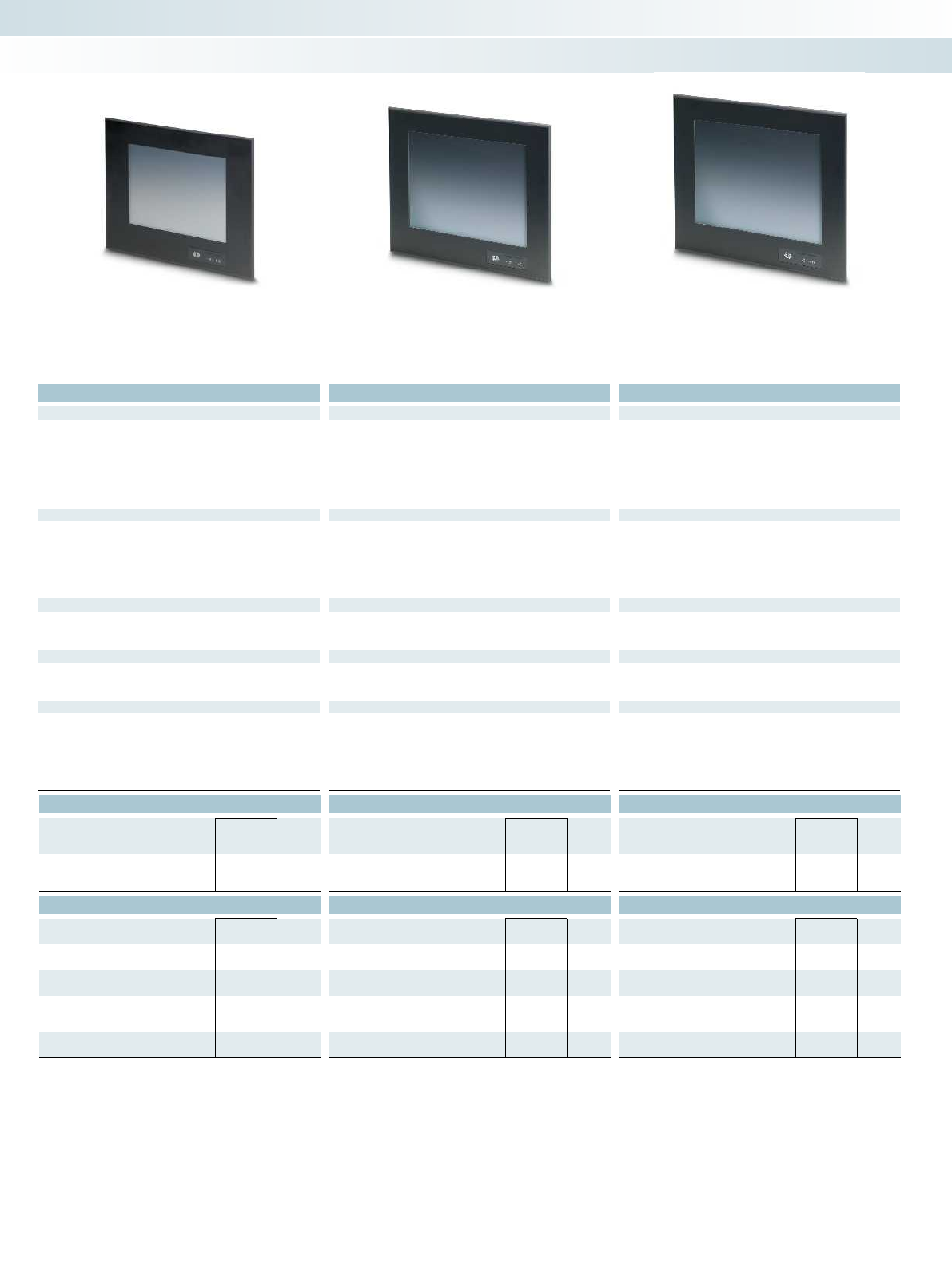
For additional information, visit phoenixcontact.net/products
419PHOENIX CONTACT
Technical data Technical data Technical data
26.4 cm/10.4" TFT 30.7 cm/12.1" TFT 38.1 cm/15" TFT
Monitor resolution 800 x 480 pixels (WVGA) 640 x 480 pixels (VGA) 800 x 600 pixels (SVGA) 1024 x 768 pixels (XGA)
LED LED LED
Brightness 350 cd/m², typical (adjustable) 350 cd/m², typical (adjustable) 300 cd/m², typical (adjustable) 480 cd/m²
50000 h 50000 h 50000 h
65,536 colors 65,536 colors 256 colors
Touch screen Resistive industrial touch screen Resistive industrial touch screen Resistive industrial touch screen Resistive industrial touch screen
Windows CE 6.0 Windows CE 6.0 Windows CE 6.0
PXA320, 806 MHz Xscale® PXA320, 806 MHz Xscale® PXA320, 806 MHz Xscale® PXA320, 806 MHz
128 MByte SDRAM 128 MByte SDRAM 128 MByte SDRAM
1 GB Flash 1 GB Flash 1 GB Flash
Interfaces 2x USB Host 1.1, 1x Compact Flash® 2x USB Host 1.1, 1x Compact Flash® 2x USB Host 1.1, 1x Compact Flash® 2x USB Host 1.1, 1x Compact Flash®
Network 1 x Ethernet (10/100 Mbps), RJ45 1 x Ethernet (10/100 Mbps), RJ45 1 x Ethernet (10/100 Mbps), RJ45 1 x Ethernet (10/100 Mbps), RJ45
328 mm 340 mm 400 mm
265 mm 285 mm 338 mm
5 mm 5 mm 5 mm
303 mm 315 mm 373 mm
238 mm 259 mm 312 mm
57 mm 62 mm 62 mm
Degree of protection IP65 (front), IP20 (back) IP65 (front), IP20 (back) IP65 (front), IP20 (back) IP65 (front), IP20 (back)
0°C ... 55°C 0°C ... 55°C 0°C ... 55°C
Mounting type Installation in front plate Installation in front plate Installation in front plate Installation in front plate
DIN EN 60068-2-6 DIN EN 60068-2-6 DIN EN 60068-2-6
DIN EN 60068-2-27 DIN EN 60068-2-27 DIN EN 60068-2-27
EMC note Class A product, see page 443 Class A product, see page 443 Class A product, see page 443 Class A product, see page 443
Ordering data Ordering data Ordering data
Type Order No. Pcs. /
Pkt. Type Order No. Pcs. /
Pkt. Type Order No. Pcs. /
Pkt.
TP 10T/M 211 2701843 1TP 12T/M 211 2701844 1TP 15T/M 211 2701845 1
Accessories Accessories Accessories
TOUCH PEN 2701379 1TOUCH PEN 2701379 1TOUCH PEN 2701379 1
2 GB USB STICK 2701382 12 GB USB STICK 2701382 12 GB USB STICK 2701382 1
HMI BATTERY 2701383 1HMI BATTERY 2701383 1HMI BATTERY 2701383 1
HMI SCB MOUNTING KIT 8 2701387 1HMI SCB MOUNTING KIT 8 2701387 1HMI SCB MOUNTING KIT 8 2701387 1
10,4" DISPLAY PROTECTIVE FOIL 2701376 112,1" DISPLAY PROTECTIVE FOIL 2701377 115,1" DISPLAY PROTECTIVE FOIL 2701378 1
Control technology, I/O systems, and automation infrastructure
HMIs and industrial PCS - HMIs
17.8 cm (7") TFT color display 26.4 cm (10.4") TFT color display 30.7 cm (12.1") TFT color display 38.1 cm (15") color TFT display
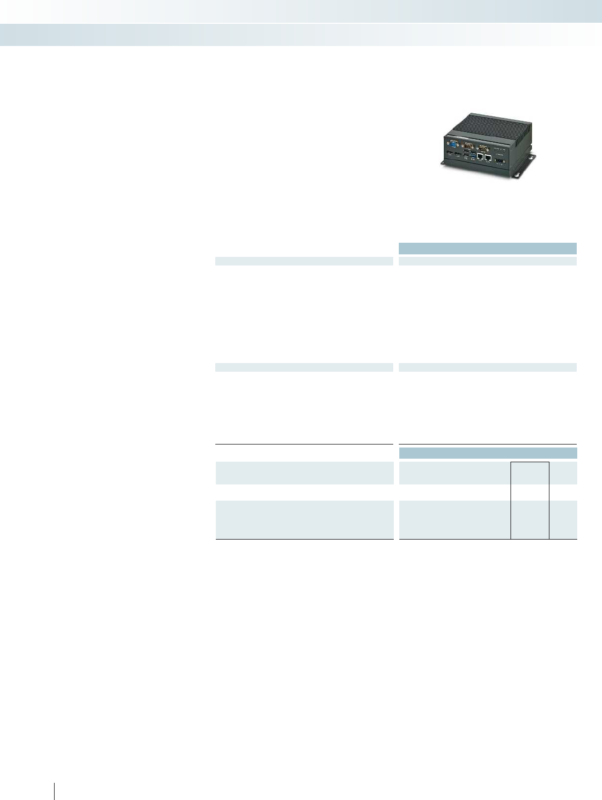
420 PHOENIX CONTACT
Box PCs
Box PCs are compact and flexible. They
can be used in a wide variety of applications
such as measurement, control and process
testing. The compact size and numerous
mounting options also work well for
distributed systems with remote monitors.
Features:
– High system availability thanks to a fanless
design or convection booster, suitable for
industrial applications and absence of
moving parts
– 3rd generation of Intel® Celeron® and
Core™ i7 processors
– Versatile use, thanks to various mounting
options, e.g., on the DIN rail
– Large-scale compatibility with open IT
standards, numerous interfaces and
operating system options
Technical data
Computer data
Processor Intel® Celeron® N2920 2.0 GHz Intel
RAM (configuration option) 2 GB DDR3 SODIMM
4 GB DDR3 SODIMM
Mass storage (configuration option) CompactFlash®
2.5" SATA hard drive
2.5" SATA solid-state drive
Interfaces 1x USB 3.0
1x COM (RS-232/422/485)
2x COM (RS-232)
3x USB 2.0
Network 2x Ethernet (10/100/1000 Mbps), RJ45 2x Ethernet (10/100/1000 Mbps), RJ45 2x Ethernet (10/100/1000 Mbps), RJ45
Power supply unit 24 V DC ±20%
General data
Width 162 mm
Height 146.2 mm
Depth 49 mm
Degree of protection IP20
Ambient temperature (operation) 0°C ... 50°C
Permissible humidity (operation) 5% ... 95% (non-condensing) 5% ... 95% (non-condensing) 5% ... 95% (non-condensing)
Mounting type Wall or DIN rail
Vibration (operation) DIN EN 60068-2-6
Shock 15g, 11 ms in accordance with IEC 60068-2-27 15g, 11 ms in
Ordering data
Description Type Order No. Pcs. /
Pkt.
Industrial computer
- Configurable BL BPC 2000 2701712 1
Industrial computer
- Preconfigured with 2 GB RAM,
no mass storage or operating system
BL BPC 2001 2701711 1
- Preconfigured with 4 GB RAM,
no mass storage or operating system
Control technology, I/O systems, and automation infrastructure
HMIs and industrial PCs - industrial PCs
Box PC for DIN rail or wall mounting Box PC for wall mounting High-performance box PC for wall mounting
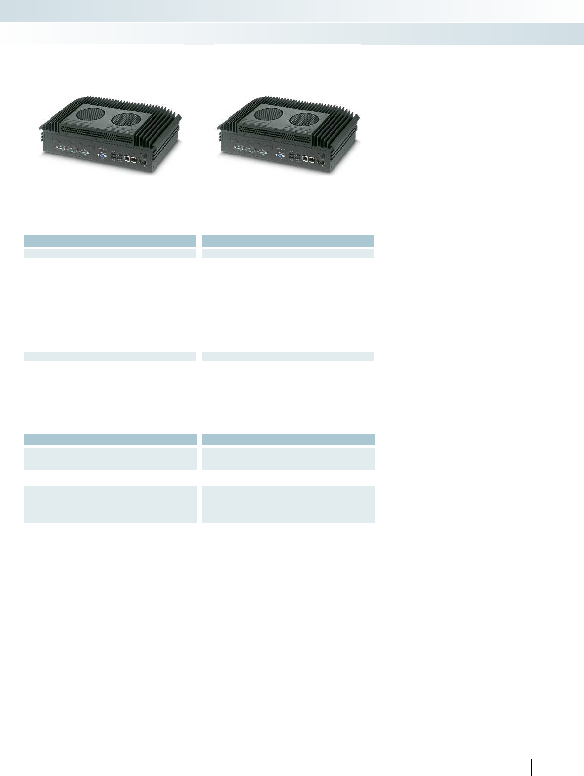
For additional information, visit phoenixcontact.net/products
421PHOENIX CONTACT
Technical data Technical data
N2920 2.0 GHz Intel® Celeron® 1020E 2.2 GHz Intel® Core™ i7-3555LE 3.2 GHz
4 GB DDR3 SODIMM
8 GB DDR3 SODIMM
16 GB DDR3 SODIMM
4 GB DDR3 SODIMM
8 GB DDR3 SODIMM
16 GB DDR3 SODIMM
CompactFlash®
2.5" SATA hard drive
2.5" SATA solid-state drive
CompactFlash®
2.5" SATA hard drive
2.5" SATA solid-state drive
4x USB 2.0
1x COM (RS-232/422/485)
2x COM (RS-232)
4x USB 2.0
1x COM (RS-232/422/485)
2x COM (RS-232)
Network 2x Ethernet (10/100/1000 Mbps), RJ45 2x Ethernet (10/100/1000 Mbps), RJ45 2x Ethernet (10/100/1000 Mbps), RJ45
24 V DC ±20% 24 V DC ±20%
357 mm 357 mm
190 mm 190 mm
87 mm 87 mm
IP20 IP20
0°C ... 45°C 0°C ... 45°C
Permissible humidity (operation) 5% ... 95% (non-condensing) 5% ... 95% (non-condensing) 5% ... 95% (non-condensing)
Wall mount Wall mount
DIN EN 60068-2-6 DIN EN 60068-2-6
Shock 15g, 11 ms in accordance with IEC 60068-2-27 15g, 11 ms in accordance with IEC 60068-2-27 15g, 11 ms in accordance with IEC 60068-2-27
Ordering data Ordering data
Type Order No. Pcs. /
Pkt. Type Order No. Pcs. /
Pkt.
BL BPC 3000 2400082 1BL BPC 7000 2400083 1
BL BPC 3001 2400080 1BL BPC 7001 2400081 1
Control technology, I/O systems, and automation infrastructure
HMIs and industrial PCs - industrial PCs
Box PC for DIN rail or wall mounting Box PC for wall mounting High-performance box PC for wall mounting

422 PHOENIX CONTACT
Panel PCs
Panel PCs combine the advantages of a
modern industrial PC with the operation
and monitoring functions of a touch screen
monitor. Typically installed in the front of
the control cabinet, they provide
monitoring and control directly on site.
Features:
– High system availability thanks to a fanless
design or convection booster, suitable for
industrial applications and absence of
moving parts
– 3rd generation of Intel® Celeron® and
Core™ i7 processors
– Large-scale compatibility with open IT
standards, numerous interfaces and
operating system options
– Display sizes from 12 (SVGA) to
17 (SXGA) inches
– High graphic performance with
Intel HD graphics 4000
Technical data
Display data
Display (configuration option) 30.7 cm/12.1" TFT
38.1 cm/15" TFT
43.2 cm/17"-TFT
Monitor resolution 800 x 600 pixels (SVGA)
1024 x 768 pixels (XGA)
1280 x 1024 pixels (SXGA)
Brightness 350 cd/m², typical (adjustable) 350 cd/m², typical (adjustable) 350 cd/m², typical (adjustable)
Display backlight MTBF > 50000 h
Touch screen Resistive industrial touch screen Resistive in
Computer data
Processor (configuration option) Intel® Atom™ N455 1.66 GHz Intel
RAM (configuration option) 2 GB DDR3 SODIMM
Mass storage (configuration option) CompactFlash®
2.5" SATA hard drive
2.5" SATA solid-state drive
Interfaces 4x USB 2.0
1x COM (RS-232/422/485)
2x COM (RS-232)
Network 2x Ethernet (10/100/1000 Mbps), RJ45 2x Ethernet (10/100/1000 Mbps), RJ45 2x Ethernet (10/100/1000 Mbps), RJ45
Power supply unit 24 V DC ±20%
General data
Degree of protection IP65 (front), IP20 (back) IP65 (front), IP20 (back) IP65 (front), IP20 (back)
Ambient temperature (operation) 0°C ... 50°C
Permissible humidity (operation) 5% ... 95% (non-condensing) 5% ... 95% (non-condensing) 5% ... 95% (non-condensing)
Mounting type Panel PC for mounting in the front panel Panel PC for mounting in the front panel Panel PC for mounting in the front
Vibration (operation) DIN EN 60068-2-6
Shock 15g, 11 ms in accordance with IEC 60068-2-27 15g, 11 ms in
EMC note Class A product, see page 443 Class A product, see page 443 Class A product, see page 443
Ordering data
Description Type Order No. Pcs. /
Pkt.
Industrial panel PC (PPC) with resistive touch screen.
Configurable options for display size, memory and mass storage.
- Atom processor BL PPC 1000 2701401 1
- Celeron processor
- Core i7 processor
Industrial panel PC (PPC) with resistive touch screen.
- Preconfigured with 12.1-inch display, 2GB RAM,
no mass storage or operating system
BL PPC12 1000 2701336 1
- Preconfigured with 15-inch display, 2GB RAM,
no mass storage or operating system
BL PPC15 1000 2701338 1
- Preconfigured with 17-inch display, 2GB RAM,
no mass storage or operating system
BL PPC17 1000 2701337 1
- Preconfigured with 15-inch display, 4GB RAM,
no mass storage or operating system
- Preconfigured with 17-inch display, 4GB RAM,
no mass storage or operating system
Control technology, I/O systems, and automation infrastructure
HMIs and industrial PCs - industrial PCs
Panel PC with Atom™ processor Panel PC with Celeron
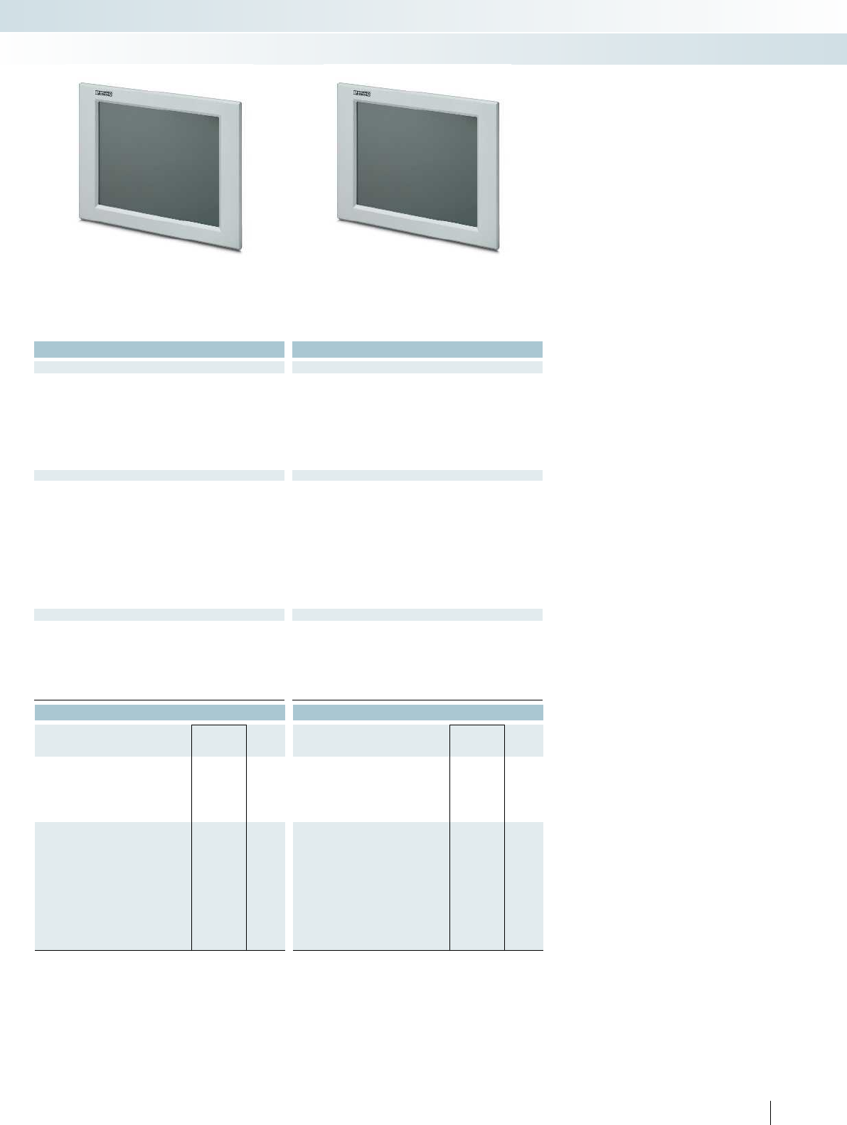
For additional information, visit phoenixcontact.net/products
423PHOENIX CONTACT
Technical data Technical data
38.1 cm/15" TFT
43.2 cm/17"-TFT
38.1 cm/15" TFT
43.2 cm/17"-TFT
1024 x 768 pixels (XGA)
1280 x 1024 pixels (SXGA)
1024 x 768 pixels (XGA)
1280 x 1024 pixels (SXGA)
Brightness 350 cd/m², typical (adjustable) 350 cd/m², typical (adjustable) 350 cd/m², typical (adjustable)
> 50000 h > 50000 h
Touch screen Resistive industrial touch screen Resistive industrial touch screen Resistive industrial touch screen
Atom™ N455 1.66 GHz Intel® Celeron® 1020E 2.2 GHz Intel® Core™ i7-3555LE 3.2 GHz
4 GB DDR3 SODIMM
8 GB DDR3 SODIMM
16 GB DDR3 SODIMM
4 GB DDR3 SODIMM
8 GB DDR3 SODIMM
16 GB DDR3 SODIMM
CompactFlash®
2.5" SATA hard drive
2.5" SATA solid-state drive
CompactFlash®
2.5" SATA hard drive
2.5" SATA solid-state drive
4x USB 2.0
1x COM (RS-232/422/485)
2x COM (RS-232)
4x USB 2.0
1x COM (RS-232/422/485)
2x COM (RS-232)
Network 2x Ethernet (10/100/1000 Mbps), RJ45 2x Ethernet (10/100/1000 Mbps), RJ45 2x Ethernet (10/100/1000 Mbps), RJ45
24 V DC ±20% 24 V DC ±20%
Degree of protection IP65 (front), IP20 (back) IP65 (front), IP20 (back) IP65 (front), IP20 (back)
0°C ... 45°C 0°C ... 45°C
Permissible humidity (operation) 5% ... 95% (non-condensing) 5% ... 95% (non-condensing) 5% ... 95% (non-condensing)
Mounting type Panel PC for mounting in the front panel Panel PC for mounting in the front panel Panel PC for mounting in the front panel
DIN EN 60068-2-6 DIN EN 60068-2-6
Shock 15g, 11 ms in accordance with IEC 60068-2-27 15g, 11 ms in accordance with IEC 60068-2-27 15g, 11 ms in accordance with IEC 60068-2-27
EMC note Class A product, see page 443 Class A product, see page 443 Class A product, see page 443
Ordering data Ordering data
Type Order No. Pcs. /
Pkt. Type Order No. Pcs. /
Pkt.
BL PPC 3000 2701397 1
BL PPC 7000 2701398 1
BL PPC15 3000 2701393 1BL PPC15 7000 2701395 1
BL PPC17 3000 2701394 1BL PPC17 7000 2701396 1
Control technology, I/O systems, and automation infrastructure
HMIs and industrial PCs - industrial PCs
Panel PC with Atom™ processor Panel PC with Celeron® processor Panel PC with Core™ i7 processor
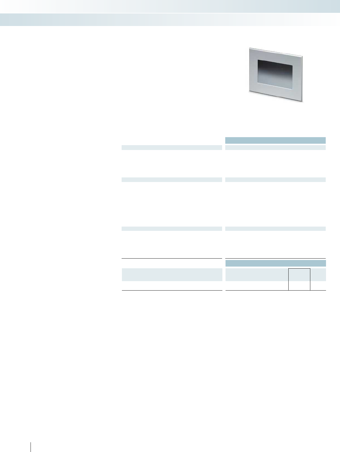
424 PHOENIX CONTACT
Outdoor panel PCs
The new outdoor panel PCs fit seamlessly
into the existing portfolio of panel PCs.
Designed for use under extreme ambient
conditions, the devices meet the
requirements for an extended temperature
range, easily readable displays in direct
sunlight, UV resistance, and a high level of
mechanical and chemical resistance.
Additional features:
– Display can be read in direct sunlight
– Resistant to UV and IR radiation
– Extended temperature range
– Watertight thanks to IP67 protection
– Resistant to environmental influences,
such as salt spray and termites
– Resistant to chemicals, e.g., aggressive
cleaning agents, deicers for aircraft
– Can be operated when wearing work
gloves
Technical data
Display data
Display 17.8 cm/7" TFT
Monitor resolution 800 x 400 pixels (WVGA) 800 x 600 pixels (SVGA) 1024 x 768 pixels (XGA)
Display lighting type LED
Brightness 350 cd/m², typical (adjustable) 350 cd/m², typical (adjustable) 350 cd/m², typical (adjustable)
Display backlight MTBF > 50000 h
Touch screen Resistive industrial touch screen (GFG) Resistive industrial touch screen (GFG) Resistive industrial touch screen (GF
Computer data
Processor Intel® Atom™ E680T 1.6 GHz Intel
RAM 2 GB DDR2 800
Mass storage (configuration option) Flash SSD 8 GB
Flash SSD 16 GB
Flash SSD 32 GB
Interfaces 4 x USB host 2.0
Slots SD card
Monitor output Without
Network 1 x Ethernet (10/100/1000 Mbps), RJ45 1 x Ethernet (10/100/1000 Mbps), RJ45 1 x Ethernet (10/100/1000 Mbps), RJ45
Power supply unit 24 V DC ±20%
General data
Degree of protection IP67 (front), IP20 (back) IP67 (front), IP20 (back) IP67 (front), IP20 (back)
Ambient temperature (operation) -20°C ... 65°C
Permissible humidity (operation) 20% ... 85% (non-condensing) 20% ... 85% (non-condensing) 20% ... 85% (non-condensing)
Mounting type Installation in front plate Installation in front plate Installation in front plate
Vibration (operation) DIN EN 60068-2-6
Shock DIN EN 60068-2-27
Ordering data
Description Type Order No. Pcs. /
Pkt.
Panel PC for outdoor applications
EL PPC7 1000/WT 2400065 1
Control technology, I/O systems, and automation infrastructure
HMIs and industrial PCs - industrial PCs
17.8 cm (7") widescreen display 30.5 cm (12.1") display 38.1 cm (15") display

For additional information, visit phoenixcontact.net/products
425PHOENIX CONTACT
Technical data Technical data
30.7 cm/12.1" TFT 38.1 cm/15" TFT
Monitor resolution 800 x 400 pixels (WVGA) 800 x 600 pixels (SVGA) 1024 x 768 pixels (XGA)
LED LED
Brightness 350 cd/m², typical (adjustable) 350 cd/m², typical (adjustable) 350 cd/m², typical (adjustable)
> 50000 h > 50000 h
Touch screen Resistive industrial touch screen (GFG) Resistive industrial touch screen (GFG) Resistive industrial touch screen (GFG)
Atom™ E680T 1.6 GHz Intel® Atom™ E680T 1.6 GHz Intel® Atom™ E680T 1.6 GHz
2 GB DDR2 800 2 GB DDR2 800
Flash SSD 8 GB
Flash SSD 16 GB
Flash SSD 32 GB
Flash SSD 8 GB
Flash SSD 16 GB
Flash SSD 32 GB
4 x USB host 2.0 4 x USB host 2.0
SD card SD card
Without Without
Network 1 x Ethernet (10/100/1000 Mbps), RJ45 1 x Ethernet (10/100/1000 Mbps), RJ45 1 x Ethernet (10/100/1000 Mbps), RJ45
24 V DC ±20% 24 V DC ±20%
Degree of protection IP67 (front), IP20 (back) IP67 (front), IP20 (back) IP67 (front), IP20 (back)
-20°C ... 65°C -20°C ... 65°C
Permissible humidity (operation) 20% ... 85% (non-condensing) 20% ... 85% (non-condensing) 20% ... 85% (non-condensing)
Mounting type Installation in front plate Installation in front plate Installation in front plate
DIN EN 60068-2-6 DIN EN 60068-2-6
DIN EN 60068-2-27 DIN EN 60068-2-27
Ordering data Ordering data
Type Order No. Pcs. /
Pkt. Type Order No. Pcs. /
Pkt.
EL PPC12 1000/WT 2400066 1EL PPC15 1000/WT 2400067 1
Control technology, I/O systems, and automation infrastructure
HMIs and industrial PCs - industrial PCs
17.8 cm (7") widescreen display 30.5 cm (12.1") display 38.1 cm (15") display

426 PHOENIX CONTACT
IP65 panel PCs Notes:
1) Configuration options can affect the operating temperature. See
data sheet for details.
Designline 7000 IPCs are powerful panel
PCs that utilize Intel® Core™ i7
processors. The fanless design and
completely enclosed IP65 housing makes
the Designline 7000 suitable for demanding
industrial applications. VESA 100 mounting
allows installation directly on a machine or
system for an integrated, attractive
appearance.
Features:
– 4th generation Intel Core i7 processors
– Projected capacitive touch screen (PCT)
– 15-inch XGA to 21.5-inch displays with
Intel HD graphics 5000
– Fanless for clean, quiet operation
– Slim, attractive design
– All-in-one, IP65-rated design
– Conforms to VESA MIS-D, 100 mounting
standard
Technical data
Display data
Display 38.1 cm/15" TFT
Monitor resolution 1024 x 768 pixels (XGA) 1366 x 768 pixels (WXGA) 1920 x 1080 pixels (Full HD)
Display lighting type LED
Brightness 400 cd/m², typical (adjustable) 300 cd/m², typical (adjustable) 300 cd/m², typical (adjustable)
Display backlight MTBF > 50000 h
Touch screen Capacitive multi-touch screen Capacitive multi-touch screen Capacitive multi-touch screen
Computer data
Processor Intel®Core™ i7-4650U 3.30 GHz Intel
RAM (configuration option) 4 GB DDR3
8 GB DDR3
12 GB DDR3
Mass storage (configuration option) 2.5" SATA hard drive
2.5" SATA solid-state drive
Interfaces 4x USB 2.0, 1x USB 3.0
1x COM (RS-232/422/485)
1x Audio
Network 2x Ethernet (10/100/1000 Mbps), RJ45 2x Ethernet (10/100/1000 Mbps), RJ45 2x Ethernet (10/100/1000 Mbps), RJ45
Power supply unit 24 V DC ±20%
General data
Degree of protection IP65
Ambient temperature (operation) 0°C ... 45°C1)
Permissible humidity (operation) 5% ... 95% (non-condensing) 5% ... 95% (non-condensing) 5% ... 95% (non-condensing)
Mounting type VESA MIS-D (100 x 100) VESA MIS-D (100 x 100) VESA MIS-D (100 x 100)
Vibration (operation) 1g with SSD, 0.5g with HDD, according to EN 60068-2-6 1g with SSD, 0.5g with HDD, according to EN 60068-2-6
Shock 15g, 11 ms in accordance with IEC 60068-2-27 15g, 11 ms in
Ordering data
Description Type Order No. Pcs. /
Pkt.
High performance IPC with touch screen and IP65 housing
- 38.1 cm (15") display DL PPC15M 7000 2400017 1
- 47 cm (18.5") display
- 54.6 cm (21.5") display
Control technology, I/O systems, and automation infrastructure
HMIs and industrial PCs - industrial PCs
Fully enclosed IP65 IPC
with 38.1cm (15") display
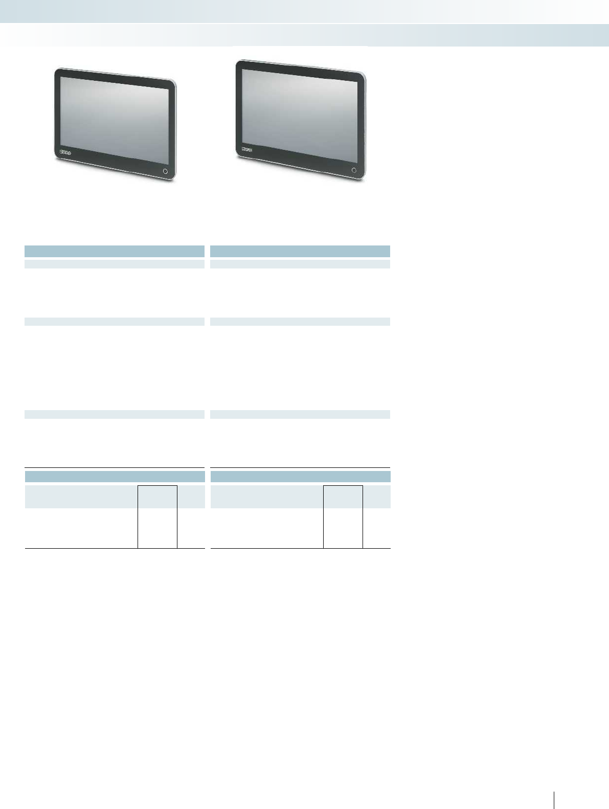
For additional information, visit phoenixcontact.net/products
427PHOENIX CONTACT
Technical data Technical data
47 cm/18,5" TFT 54.6 cm/21,5" TFT
Monitor resolution 1024 x 768 pixels (XGA) 1366 x 768 pixels (WXGA) 1920 x 1080 pixels (Full HD)
LED LED
Brightness 400 cd/m², typical (adjustable) 300 cd/m², typical (adjustable) 300 cd/m², typical (adjustable)
> 50000 h > 50000 h
Touch screen Capacitive multi-touch screen Capacitive multi-touch screen Capacitive multi-touch screen
Core™ i7-4650U 3.30 GHz Intel®Core™ i7-4650U 3.30 GHz Intel®Core™ i7-4650U 3.30 GHz
4 GB DDR3
8 GB DDR3
12 GB DDR3
4 GB DDR3
8 GB DDR3
12 GB DDR3
2.5" SATA hard drive
2.5" SATA solid-state drive
2.5" SATA hard drive
2.5" SATA solid-state drive
4x USB 2.0, 1x USB 3.0
1x COM (RS-232/422/485)
1x Audio
4x USB 2.0, 1x USB 3.0
1x COM (RS-232/422/485)
1x Audio
Network 2x Ethernet (10/100/1000 Mbps), RJ45 2x Ethernet (10/100/1000 Mbps), RJ45 2x Ethernet (10/100/1000 Mbps), RJ45
24 V DC ±20% 24 V DC ±20%
IP65 IP65
0°C ... 45°C1) 0°C ... 45°C1)
Permissible humidity (operation) 5% ... 95% (non-condensing) 5% ... 95% (non-condensing) 5% ... 95% (non-condensing)
Mounting type VESA MIS-D (100 x 100) VESA MIS-D (100 x 100) VESA MIS-D (100 x 100)
60068-2-6 1g with SSD, 0.5g with HDD, according to EN 60068-2-6 1g with SSD, 0.5g with HDD, according to EN 60068-2-6
Shock 15g, 11 ms in accordance with IEC 60068-2-27 15g, 11 ms in accordance with IEC 60068-2-27 15g, 11 ms in accordance with IEC 60068-2-27
Ordering data Ordering data
Type Order No. Pcs. /
Pkt. Type Order No. Pcs. /
Pkt.
DL PPC18.5M 7000 2400015 1
DL PPC21.5M 7000 2400016 1
Control technology, I/O systems, and automation infrastructure
HMIs and industrial PCs - industrial PCs
Fully enclosed IP65 IPC
with 47cm (18.5") display
Fully enclosed IP65 IPC
with 54.6cm (21.5") display
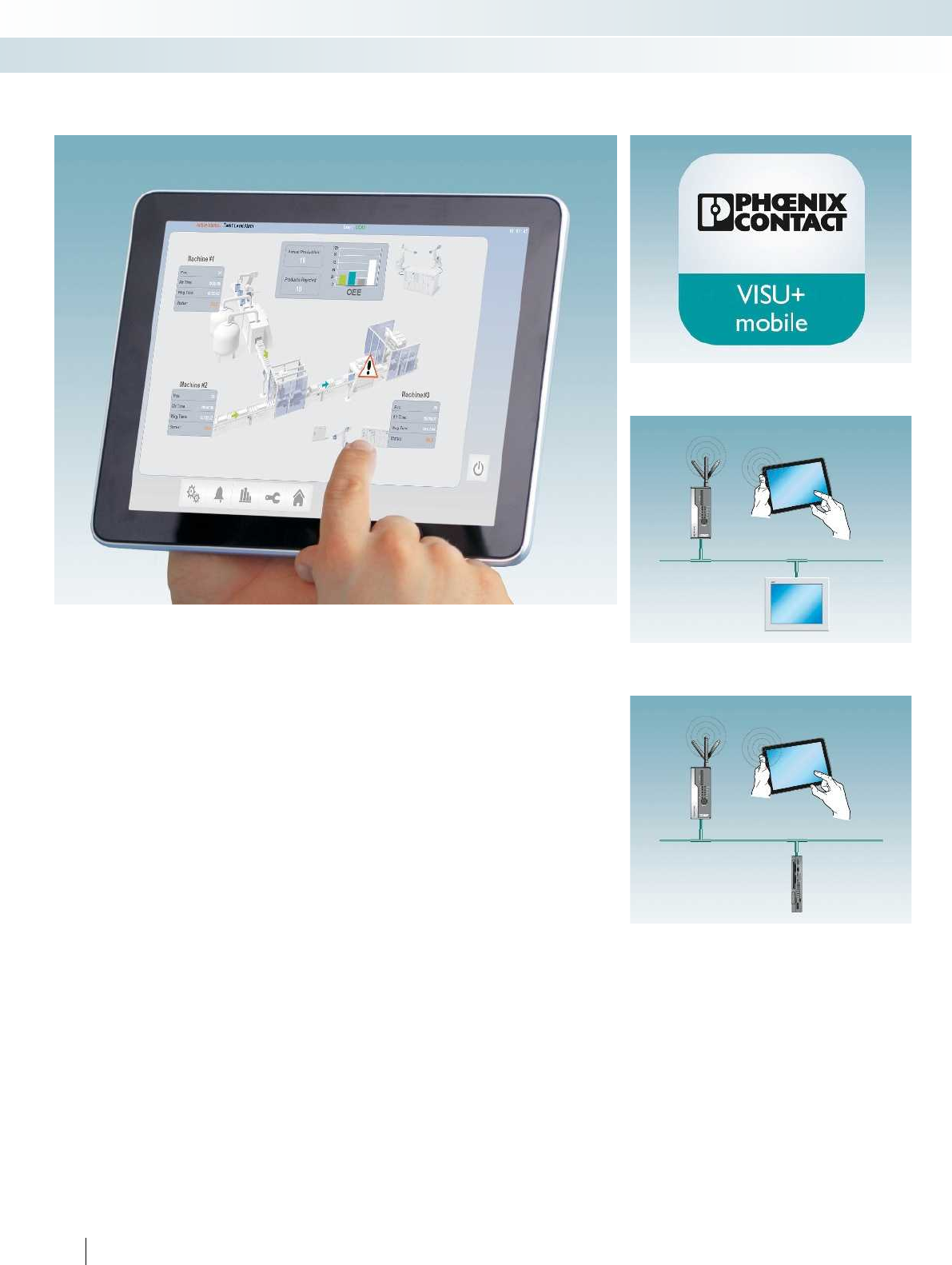
Extend your system visualization to
smartphones or tablets with the Visu+
mobile visualization app from Phoenix
Contact. You can design flexible operating
and monitoring concepts, as the Visu+
mobile app allows you to access your
system at any time and from any location.
Integrate Visu+ mobile quickly and easily
in existing touch panel or industrial PC
visualization solutions. The Visu+ web
server required for the app is already pre-
installed in numerous devices from
PhoenixContact, such as touch panels.
IPCs with Visu+ simply need to be extended
with the web license option.
You can conveniently download the app in
the usual way from the Google Play Store
for Android or the App Store for Apple
devices.
Features:
– Familiar comfort: simply use conventional
smartphones or tablets to perform
operation and monitoring
– Conventional SCADA functions such as
trend display or alarm handling now also
available on mobile devices
– Easy installation via Google Play store or
Appstore
– High-performance, scalable Visu+ web
server: up to 100 clients can be operated
simultaneously in its maximum
configuration
– Convenient generation of HTML
visualization pages for the Visu+ web
server from the Visu+ development
environment
428 PHOENIX CONTACT
Visualization app
Visu+ mobile on a mobile termination device via access point,
with an industrial PC and web server
Visu+ mobile on a mobile termination device via access point,
with a touch panel and web server
Easy app installation via GooglePlaystore or Appleappstore
Control technology, I/O systems, and automation infrastructure
Software - visualization
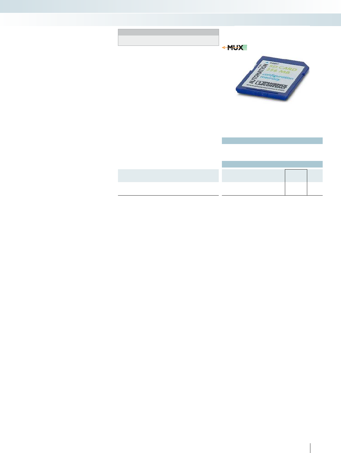
For additional information, visit phoenixcontact.net/products
Technical data
See phoenixcontact.net/products
Ordering data
Description Type Order No. Pcs. /
Pkt.
Multiplexer application on SD card for configuring two
ILC131ETH controllers as a multiplexer
SD FLASH 512MB MODULAR MUX 2701872 1
429PHOENIX CONTACT
With the software for multiplexer
systems, you can create a multiplexer
system from two ILC 131 ETH small-scale
controllers. Without any time-consuming
programming.
To do so, extend each smale-scale
controller with an SD FLASH 512MB
MODULAR MUX SD card and the
corresponding I/O panel. Configuration is
easy with few wire bridges - you just need
to define the master and slave.
The software is therefore ideal for all
areas of application where a multiplexer
solution is required, without additional
programming work for the controller.
– Wireless, Ethernet cable or network
connection
– Multiplexer solution with standard
components (2x ILC131ETH and 2x
SDFLASH 512MB MODULARMUX)
– Integration in Ethernet network via web
interface, with PC and standard browser
Multiplexer function for retrofitting
Control technology, I/O systems, and automation infrastructure
Software - programming
Notes:
When ordering, please note that you require two controllers and
two SD cards respectively.
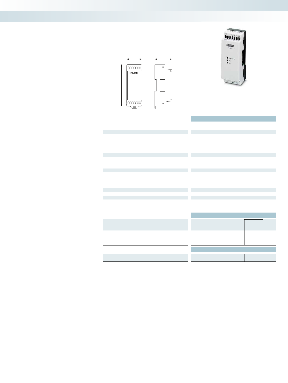
nanoLineController
40 43
103,5
Technical data
NLC-035-024D 041-02QRD-
05A
NLC-040-O24D-04I-02QRD-
05A
Power supply
Supply voltage 24 V DC (power available to the I/O and Communications modules)
Supply voltage range 19.2 V DC ... 30 V DC
Typical current consumption 74 mA
Max. current consumption 81 mA
Digital inputs
Number of inputs 4
Description of the inputs PNP
Typical response time 10 µs (channel 1 and 2)
Digital outputs
Number of outputs 2
Description of the outputs Relay output
Maximum output current per channel 5 A
Maximum output current per module / terminal block 10 A
Software interfaces
Programming tool nanoNavigator 4.2 or above LOGIC+
General data
Connection method Screw connection
Degree of protection IP20
Ambient temperature (operation) -25°C ... 70°C
Ordering data
Description Type Order No. Pcs. /
Pkt.
Nanoline controller
- Programmable with nanoNavigator 4.2 and above NLC-035-024D 041-02QRD-05A 2702031 1
- Programmable with LOGIC+ NLC-040-O24D-04I-02QRD-05A 2400079 1
Accessories
Programming cable
- 9-pos. D-SUB to RJ11/12 NLC-PC/SERIAL-CBL 1M 2701234 1
430 PHOENIX CONTACT
Minimal effort with maximum benefits –
for Nanoline programmable logic modules
the focus is on simplicity and flexibility. This
means a modular and adaptable design with
optimum networking options.
Your advantages:
– Save time – by intelligently controlling
basic tasks
– Easy use without prior knowledge, thanks
to intuitive programming
– Versatile communication with numerous
integration and networking options
– Maximum flexibility, thanks to the
modular design
Additional features:
– Two high-speed counters and two analog
inputs
– Supports four mathematical functions
– Integrated digital I/O
– Add an additional digital I/O extension
module for a maximum of 12 I/O points
– Support for large Nanoline operator
panel
– Integrated realtime clock (RTC)
– Integrated RS-232 for connection to a PC
for programming and configuration
– Integrated RS-232 and RS-485 allow you
to use your logic module as a Modbus
RTU server
– Flexible programming with nanoNavigator
or LOGIC+
Logic modules
Control technology, I/O systems, and automation infrastructure
Controllers - programmable logic modules
24 V DC, 4 digital inputs and 2 relay outputs
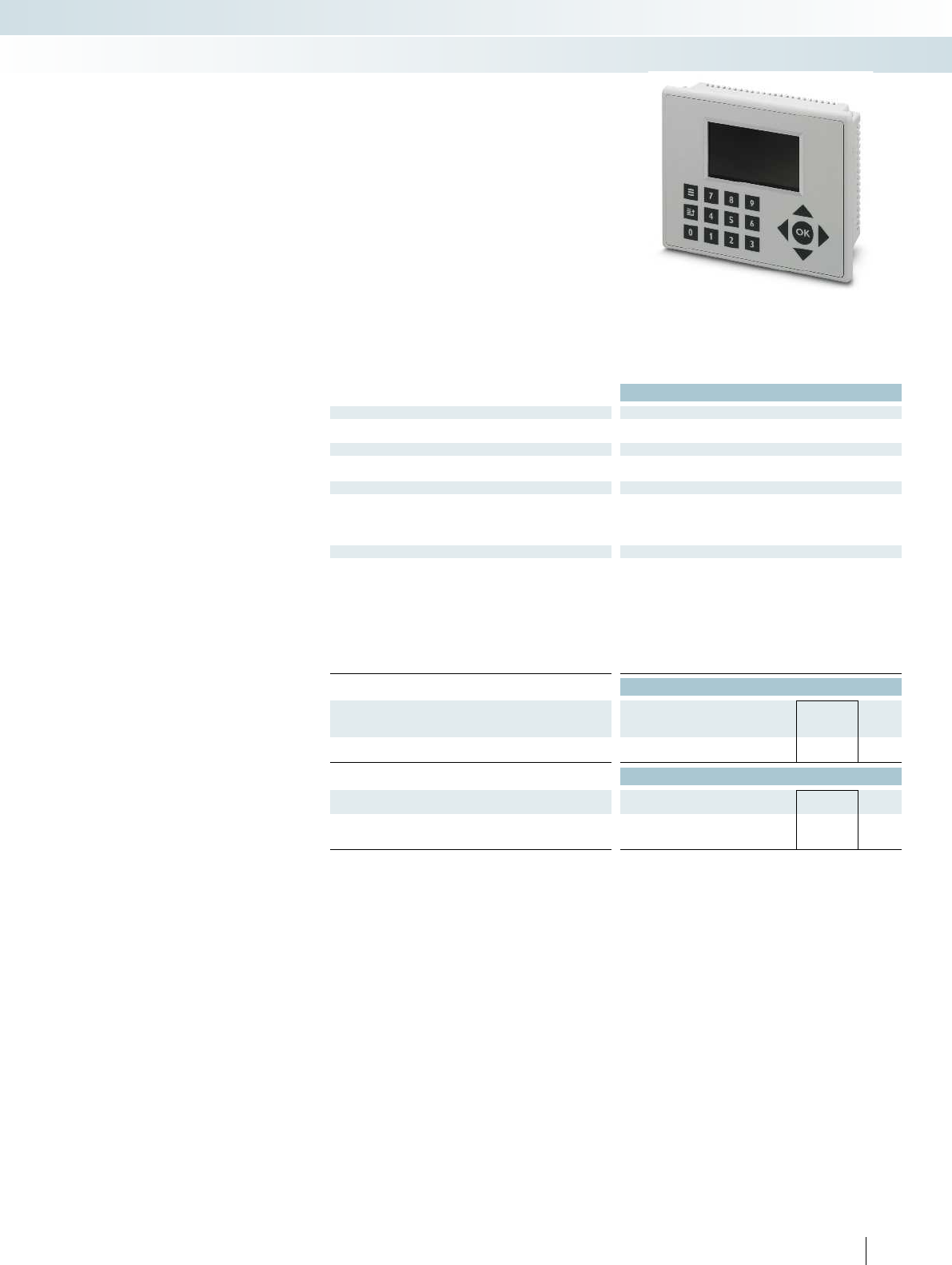
For additional information, visit phoenixcontact.net/products
Technical data
Display data
Display Backlit LC display, monochrome, 4 lines with 20 characters or 2
lines with 10 characters
Interfaces
Operator panel 9-pos. D-SUB male
Transmission length Max. 15 m
Power supply for module electronics
Supply voltage 24 V DC
Connection method 3-pos. Combicon
Typical current consumption 38 mA (24 V DC)
Max. current consumption 40 mA (24 V DC)
General data
Programming tool nanoNavigator
Mounting type Panel mounting
Keys 17
Height 102 mm
Width 128 mm
Depth 44.5 mm
Degree of protection IP66
Ambient temperature (operation) 0°C ... 50°C
Ambient temperature (storage/transport) 0°C ... 60°C
Ordering data
Description Type Order No. Pcs. /
Pkt.
Operator panel
NLC-OP2-LCD-076-4X20 2701945 1
Accessories
Base module for remote mounting Operator Panel
(included in nLC-OP1-MKT)
NLC-OP1-MKT-BASE 2701250 1
D-SUB plug, with two cable entries, universal type, pin
assignment 1,2,3,4,5,6,7,8,9 on every screw terminal block
SUBCON-PLUS-M/AX 9 2904467 1
431PHOENIX CONTACT
The operator panel is your interface for
interacting with the Nanoline system. Read
the status of all I/O points, registers, timers,
counters, and system flags directly. In
addition, the application program sends
prompts and instructions to the display. The
operator panel offers numerical (0-9),
directional (up, down, left, right), and input
keys. In addition, each of the 14 keys on the
operator panel can be used to create user-
specific menus in a flow chart.
Additional features:
– 76 mm diagonal screen
– Variable text sizes for enhanced
readability of custom messages (4 x 20 or
2 x 10 or a combination)
– Cable length of up to 15 m allows remote
mounting away from the logic module
– External 24VDC
– Variable backlight: red, blue or green
– Adjustable backlight timer to save energy
Large operator panel
Control technology, I/O systems, and automation infrastructure
Controllers - programmable logic modules
User interface for Nanoline controllers
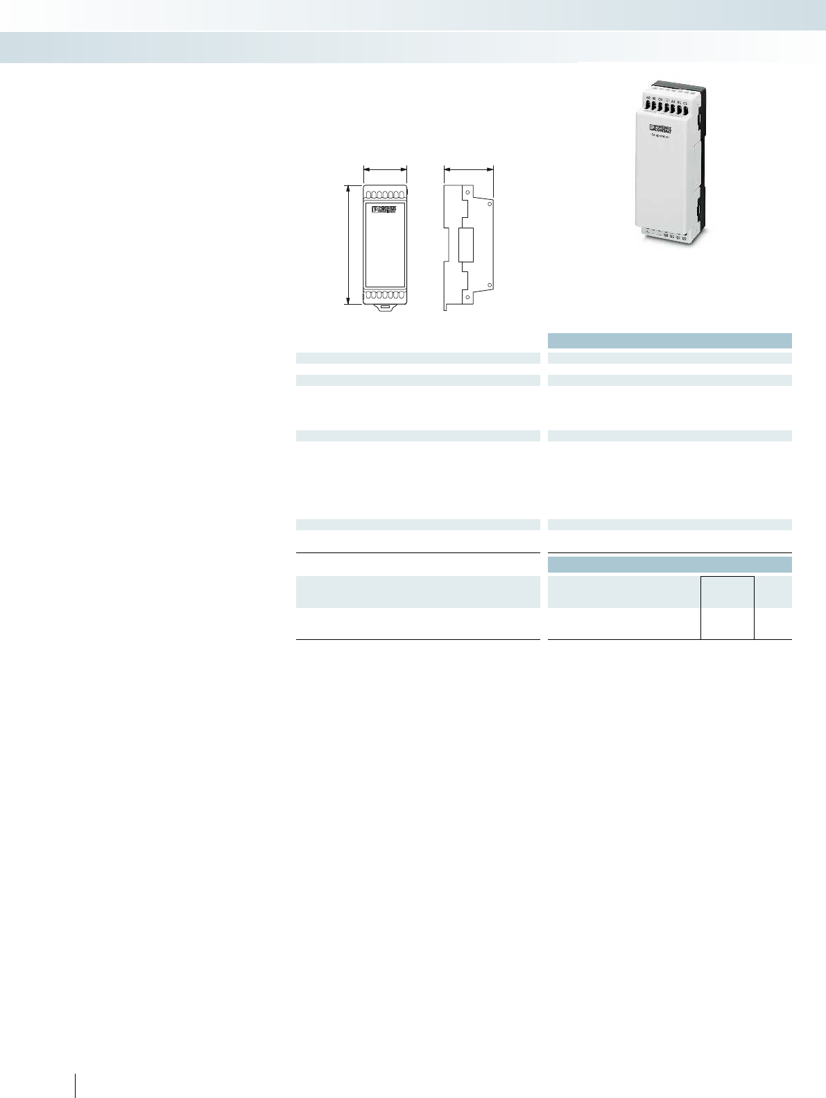
nanoLineController
40 43
103,5
Technical data
Power supply for module electronics
Supply voltage 24 V
Temperature input
Connection method 2 or 3-wire (shielded)
Number of inputs 2
Sensor types (RTD) that can be used Pt100, Pt1000
Sensor types that can be used (TC) B, E, J, K, N, R, S, T
Digital outputs
Number of outputs 4
Description of the outputs PNP outputs
Nominal output voltage 24 V DC
Maximum output current per channel 0.5 A
Maximum output current per module / terminal block 2 A
Maximum switching voltage 24 V DC
Minimum switching voltage 0.8 V DC
General data
Connection method Screw connection
Ambient temperature (operation) 0°C ... 60°C
Ordering data
Description Type Order No. Pcs. /
Pkt.
Nanoline controllers, I/O extension module
- 2 temperature inputs, 4 PNP outputs NLC-IO-2RTD/UTH-4QTP-01A 2701671 1
432 PHOENIX CONTACT
Temperature extension module provides
RTD and thermocouple inputs as well as
four digital outputs.
– Two temperature sensor inputs
– Configuration options for PT100 and
PT1000 RTD sensors with two or three
wires
– Configuration options for thermocouple
types B, E, J, K, N R, S, and T
– Four PNP digital outputs
– Automatically recognized by
nanoNavigator
Analog I/O extension module
Control technology, I/O systems, and automation infrastructure
Controllers - programmable logic modules
2 temperature inputs, 4 PNP outputs
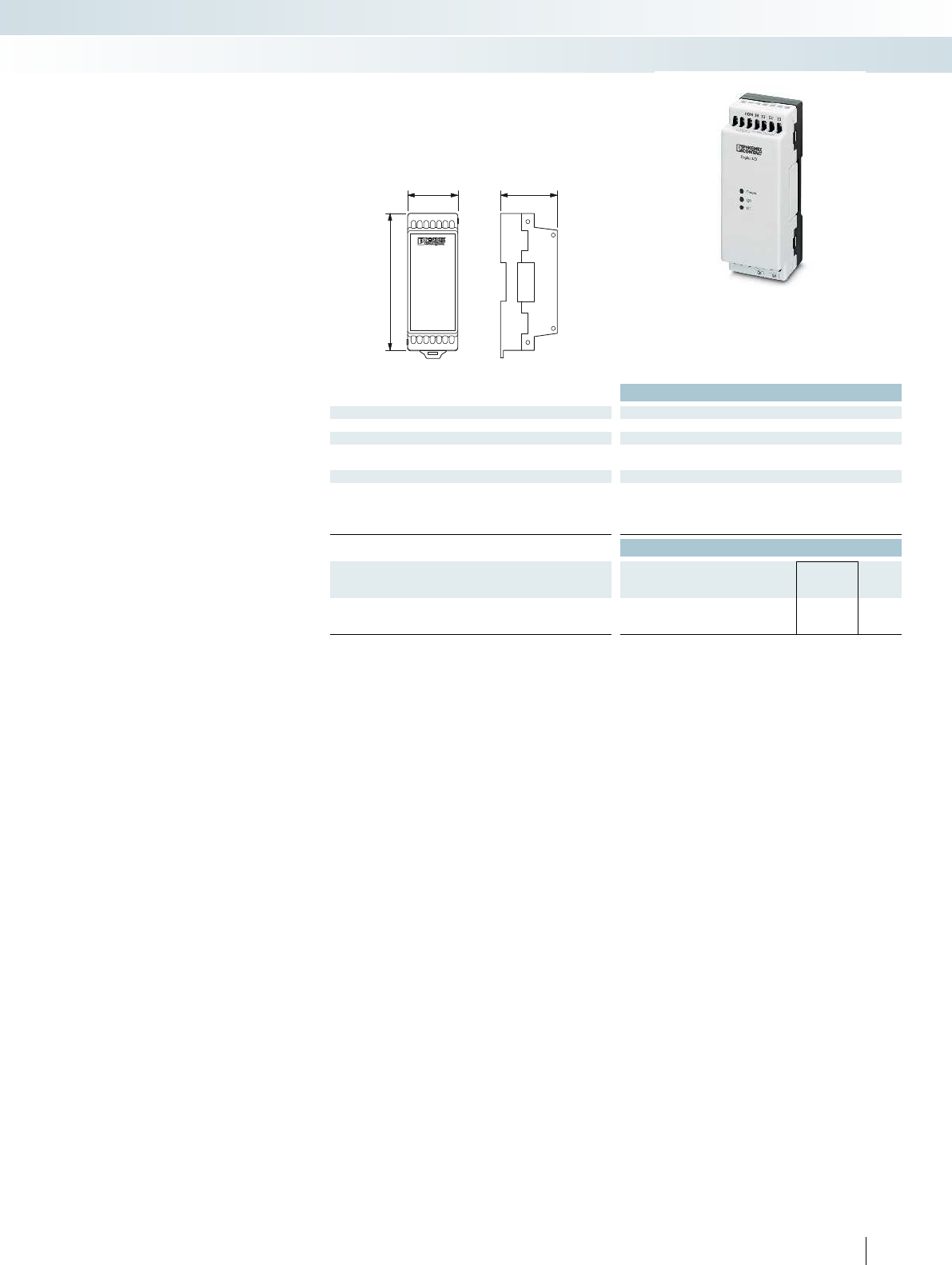
nanoLineController
40 43
103,5
For additional information, visit phoenixcontact.net/products
Technical data
Power supply for module electronics
Supply voltage 24 V DC
Digital inputs
Maximum number of inputs 4
Description of the inputs PNP
Digital outputs
Number of outputs 2
Description of the outputs Relay output
Maximum output current per channel 5 A
Maximum output current per module / terminal block 10 A
Ordering data
Description Type Order No. Pcs. /
Pkt.
Nanoline controllers, I/O extension module
- 4 digital inputs, 2 relay outputs NLC-IOX-041-02QRD-05A 2702032 1
433PHOENIX CONTACT
You can extend your Nanoline with an
additional I/O extension module. Extension
modules provide additional inputs and
outputs beyond what is available on the
logic module.
– The NLC-IOX is only compatible with the
NLC-035 and NLC-040
– One module can be added to the right
side of a logic module
– Automatically recognized by
nanoNavigator
Digital I/O extension module for
NLC-035 and NLC-040 logic modules
Control technology, I/O systems, and automation infrastructure
Controllers - programmable logic modules
Digital I/O extension module

Type Order No. Page Type Order No. Page Type Order No. Page Type Order No. Page
Index
Alphabetical
1
10,4" DISPLAY PROTECTIVE FOIL 2701376 419
12,1" DISPLAY PROTECTIVE FOIL 2701377 419
15,1" DISPLAY PROTECTIVE FOIL 2701378 419
2
2 GB USB STICK 2701382 418
7
7" DISPLAY PROTECTIVE FOIL 2701374 418
A
A-EXB-20-66L-N-S 1411117 237
A-EXB-20-66L-S-S 1411118 237
A-EXB-25-66L-N-S 1411120 237
A-EXB-25-66L-S-S 1411121 237
A-EXSH-M20-68L-N-S 1411104 236
A-EXSH-M20-68L-S-S 1411105 236
A-EXSH-M25-68L-N-S 1411107 236
A-EXSH-M25-68L-S-S 1411108 236
A-EXSH-M32-68L-N-S 1411109 236
A-EXSH-M32-68L-S-S 1411110 236
A-EXSH-M40-68L-N-S 1411111 236
A-EXSH-M40-68L-S-S 1411112 236
A-EXSH-M50-68L-N-S 1411113 236
A-EXSH-M50-68L-S-S 1411114 236
A-EXSH-M63-68L-N-S 1411115 236
A-EXSH-M63-68L-S-S 1411116 236
A-INL-M12-N-S 1411240 229
A-INL-M12-P-BK 1411213 225
A-INL-M12-P-GY 1411205 224
A-INL-M16-N-S 1411241 229
A-INL-M16-P-BK 1411214 225
A-INL-M16-P-GY 1411206 224
A-INL-M20-N-S 1411242 229
A-INL-M20-P-BK 1411215 225
A-INL-M20-P-GY 1411207 224
A-INL-M20-S-S 1411249 238
A-INL-M25-N-S 1411243 229
A-INL-M25-P-BK 1411216 225
A-INL-M25-P-GY 1411208 224
A-INL-M25-S-S 1411250 238
A-INL-M32-N-S 1411244 229
A-INL-M32-P-BK 1411217 225
A-INL-M32-P-GY 1411209 224
A-INL-M32-S-S 1411251 238
A-INL-M40-N-S 1411246 229
A-INL-M40-P-BK 1411218 225
A-INL-M40-P-GY 1411210 224
A-INL-M40-S-S 1411252 238
A-INL-M50-N-S 1411247 229
A-INL-M50-P-BK 1411219 225
A-INL-M50-P-GY 1411211 224
A-INL-M50-S-S 1411253 238
A-INL-M63-N-S 1411248 229
A-INL-M63-P-BK 1411220 225
A-INL-M63-P-GY 1411212 224
A-INL-M63-S-S 1411254 238
A-INL-NPT1-P-BK 1411239 228
A-INL-NPT1-P-GY 1411235 227
A-INL-NPT1/2-P-BK 1411237 228
A-INL-NPT1/2-P-GY 1411233 227
A-INL-NPT3/4-P-BK 1411238 228
A-INL-NPT3/4-P-GY 1411234 227
A-INL-NPT3/8-P-BK 1411236 228
A-INL-NPT3/8-P-GY 1411231 227
A-INL-PG11-N-S 1411257 230
A-INL-PG11-P-GY 1411223 226
A-INL-PG13,5-N-S 1411259 230
A-INL-PG13,5-P-GY 1411224 226
A-INL-PG16-N-S 1411260 230
A-INL-PG16-P-GY 1411225 226
A-INL-PG21-N-S 1411262 230
A-INL-PG21-P-GY 1411226 226
A-INL-PG29-N-S 1411263 230
A-INL-PG29-P-GY 1411227 226
A-INL-PG36-N-S 1411264 230
A-INL-PG36-P-GY 1411228 226
A-INL-PG42-N-S 1411265 230
A-INL-PG42-P-GY 1411229 226
A-INL-PG48-N-S 1411266 230
A-INL-PG48-P-GY 1411230 226
A-INL-PG7-N-S 1411255 230
A-INL-PG7-P-GY 1411221 226
A-INL-PG9-N-S 1411256 230
A-INL-PG9-P-GY 1411222 226
A-INLE-M12-N-S 1411267 232
A-INLE-M16-N-S 1411268 232
A-INLE-M20-N-S 1411269 232
A-INLE-M25-N-S 1411270 232
A-INLE-M32-N-S 1411271 232
A-INLE-M40-N-S 1411272 232
A-INLE-M50-N-S 1411273 232
A-INLE-M63-N-S 1411274 232
A-INLE-PG11-N-S 1411277 233
A-INLE-PG13,5-N-S 1411278 233
A-INLE-PG16-N-S 1411279 233
A-INLE-PG21-N-S 1411280 233
A-INLE-PG29-N-S 1411281 233
A-INLE-PG36-N-S 1411282 233
A-INLE-PG7-N-S 1411275 233
A-INLE-PG9-N-S 1411276 233
A-SEW-20-P-W 1411283 238
A-SEW-25-P-W 1411284 238
A-SEW-32-P-W 1411285 238
A-SEW-40-P-W 1411286 238
A-SEW-50-P-W 1411287 238
A-SEW-63-P-W 1411288 238
AI 1,0-8 RD-S 1212523 294
AI 1,0-8 YE-S 1212782 294
AI 1,5-8 BK-S 1212524 295
AI 1,5-8 RD-S 1212781 295
ALU-SB 1404531 195
AP RSC-T 3059139 101
AP-FTP METER 3069899 101
AP-ME METER 3034361 101
APH-ME 3034374 101
APH-UTWE 6-2 3069057 101
APT-ME 3034358 93
ATP-QTC QUATTRO 3206225 173
ATP-QTC TWIN 3206212 172
ATP-ST QUATTRO 3030815 157
ATP-ST-TWIN 3030789 156
ATP-STTB 4 3030747 157
ATP-UK 3003224 170
ATP-UT-TWIN 3047183 162
AXL BS BK 2701422 408
AXL F AI4 I 1H 2688491 412
AXL F AI4 U 1H 2688501 411
AXL F AO4 1H 2688527 413
AXL F BK PN 2701815 409
AXL F BK S3 2701686 408
AXL F BS H 2700992 410
AXL F DI8/1 DO8/1 1H 2701916 410
AXL F PSDI8/4 1F 2701559 404
AXL F PSDO8/3 1F 2701560 405
AXL F RTD4 1H 2688556 414
AXL F UTH4 1H 2688598 415
AXL SHIELD SET 2700518 411
B
BATTERY MOUNTING CASE 2320458 320
BL BPC 2000 2701712 420
BL BPC 2001 2701711 420
BL BPC 3000 2400082 421
BL BPC 3001 2400080 421
BL BPC 7000 2400083 421
BL BPC 7001 2400081 421
BL PPC 1000 2701401 422
BL PPC 3000 2701397 423
BL PPC 7000 2701398 423
BL PPC12 1000 2701336 422
BL PPC15 1000 2701338 422
BL PPC15 3000 2701393 423
BL PPC15 7000 2701395 423
BL PPC17 1000 2701337 422
BL PPC17 3000 2701394 423
BL PPC17 7000 2701396 423
C
C-FCI 1,5/M3 3240032 96
C-FCI 2,5/M3 3240037 96
C-RCI 1,5/M3 3240016 96
C-RCI 2,5/M3 3240021 96
CAB-USB A/MICRO USB B/2,0M 2701626 358
CABLE-USB/MINI-USB-3,0M 2986135 394
CARRIER-EMP (27X15) 0827451 254
CARRIER-EMP (49X15) 0827452 254
CARRIER-EMP (60X15) 0827453 254
CARRIER-EMP (60X30) 0827454 254
CARRIER-EMP (85,6X54) 0829365 254
CARRIER-EMP 22 (27X15) 0827447 254
CARRIER-EMP 22 (27X18) 0827448 254
CARRIER-PMP (108X38) 0830958 285
CB RC BRIDGE 2801616 321
CB S-BE 2905067 321
CES-B16-8XSRC-BK 1411073 222
CES-B24-10XSRC-BK 1411074 222
CES-SFFS-H 0801728 222
CF CRIMPHANDY 1,0 1212465 294
CF CRIMPHANDY 1,5 1212466 295
CF CRIMPHANDY/ACCU 1212518 294
CF CRIMPHANDY/CHARGER 1212519 294
CK2,5-ED-0,50BU AG 1663640 199
CK2,5-ED-0,50BU AU 1674859 199
CK2,5-ED-0,50ST AG 1663572 199
CK2,5-ED-0,50ST AU 1674804 199
CK2,5-ED-0,75BU AG 1663653 199
CK2,5-ED-0,75ST AG 1663585 199
CK2,5-ED-1,00BU AG 1663666 199
CK2,5-ED-1,00BU AU 1674833 199
CK2,5-ED-1,00ST AG 1663598 199
CK2,5-ED-1,00ST AU 1674781 199
CK2,5-ED-1,50BU AG 1663679 199
CK2,5-ED-1,50BU AU 1674820 199
CK2,5-ED-1,50ST AG 1663608 199
CK2,5-ED-1,50ST AU 1674778 199
CK2,5-ED-2,50BU AG 1663682 199
CK2,5-ED-2,50BU AU 1674862 199
CK2,5-ED-2,50ST AG 1663611 199
CK2,5-ED-2,50ST AU 1674817 199
CK2,5-ED-4,00BU AG 1663705 199
CK2,5-ED-4,00BU AU 1674846 199
CK2,5-ED-4,00ST AG 1663637 199
CK2,5-ED-4,00ST AU 1674794 199
CK2,5-M-2,5 AG 1409207 77
CK2,5-M-4 AG 1409208 77
CK2,5-M-6 AG 1409209 77
CLIP-PROJECT ADVANCED 5146040 291
CLIP-PROJECT PROFESSIONAL 5146053 291
CP-DMC 1,5-THR NAT 1790647 35
CP-HC-S 1410916 221
CP-QPD 1582459 195
CP-QPD 5X2,5 1404530 195
CRIMPFOX 10S CUS 1212764 301
CRIMPFOX 25R CUS 1212765 299
CRIMPFOX 50R CUS 1212766 299
CRIMPFOX 6 CUS 1212767 299
CRIMPFOX 6H CUS 1212768 301
CRIMPFOX 6S-F CUS 1212769 299
CRIMPFOX 6T CUS 1212770 299
CRIMPFOX 6T-F CUS 1212771 299
CRIMPFOX-1,6/2,5-ED-4,0 1687419 185
CRIMPFOX-RC 10 CUS 1212776 301
CRIMPFOX-RC 2,5 CUS 1212777 299
CRIMPFOX-RC 25 CUS 1212778 301
CRIMPFOX-RCI 1 CUS 1212772 299
CRIMPFOX-RCI 2,5 CUS 1212773 299
CRIMPFOX-RCI 6 CUS 1212774 299
CRIMPFOX-RCI 6-1 CUS 1212775 299
CRIMPFOX-SC 1,5 CUS 1212779 299
CRIMPFOX-SC 6 CUS 1212780 301
CSMA-LAMBDA/4-2.0-BS-SET 2800491 394
CUC-IND-C1ZNI-B/R4QE8 1406336 44
CUC-IND-C1ZNI-B/R4QE8:30 1406354 44
CUC-IND-C1ZNI-B/R4QP8 1406337 44
CUC-IND-C1ZNI-B/R4QP8:30 1406355 44
CUC-IND-C1ZNI-S/R4QE8 1406333 44
CUC-IND-C1ZNI-S/R4QE8:30 1406351 44
CUC-IND-C1ZNI-S/R4QP8 1406334 44
CUC-IND-C1ZNI-S/R4QP8:30 1406352 44
CUC-IND-C1ZNI-T/R4QE8 1406339 45
CUC-IND-C1ZNI-T/R4QE8:30 1406357 45
CUC-IND-C1ZNI-T/R4QP8 1406340 45
CUC-IND-C1ZNI-T/R4QP8:30 1406358 45
CUC-PP-FRAME-19 1407986 50
CUC-PP-FRAME-19 BK 1409140 50
CUC-PP-MODUL-COVER 1407988 50
CUC-PP-MODUL-RJ45:6-RJ45:6/... 1407995 50
CUC-PP-PATCHBAY 1407994 50
CUC-PP-PATCHBAY-MH 1409283 50
CUC-PP-PATCHBAY-MH BK 1409284 50
CUC-V14-C1ZNI-B/R4IE8 1408011 47
CUC-V14-C1ZNI-B/R4IE8:10 1467804 47
CUC-V14-C1ZNI-B/R4IP8 1407895 47
CUC-V14-C1ZNI-B/R4IP8:10 1408046 47
CUC-V14-C1ZNI-B/SJFG:10 1408056 49
CUC-V14-C1ZNI-S/R4IE8 1407890 46
CUC-V14-C1ZNI-S/R4IE8:10 1467901 46
CUC-V14-C1ZNI-S/R4IP8 1407889 46
CUC-V14-C1ZNI-S/R4IP8:10 1408039 46
CUC-V14-C1ZNI-T/R4IE8 1468007 46
CUC-V14-C1ZNI-T/R4IE8:10 1467807 46
CUC-V14-C1ZNI-T/R4IP8 1408027 46
CUC-V14-C1ZNI-T/R4IP8:10 1408092 46
CUC-V14-C1ZNI-T/SJFG:10 1408095 48
CUTFOX-ES 1212621 222
D
D-PT 1,5/S-MT-0,8 3210303 156
D-PT 1,5/S-MT-0,8 OG 3210304 156
D-PT 1,5/S-QUATTRO-MT-0,8 3210333 157
D-PT 1,5/S-QUATTRO-MT-0,8 OG 3210334 157
D-PT 1,5/S-TWIN-MT-0,8 3210313 157
D-PT 1,5/S-TWIN-MT-0,8 OG 3210314 157
D-PTT 1,5/S-2MT-0,8 3210353 157
D-PTT 1,5/S-2MT-0,8 OG 3210354 157
D-PTT 2,5-2MT-0,8 3210300 158
D-PTT 2,5-2MT-0,8 OG 3210299 158
D-PTTBS 2,5-2MTB 3210404 160
D-QTC 2,5-QUATTRO 3206449 173
D-QTCU 2,5-TWIN-MT 3050511 172
D-UK 4-SD 3246862 170
D-UTT 2,5/4 3044676 164
DL PPC15M 7000 2400017 426
DL PPC18.5M 7000 2400015 427
DL PPC21.5M 7000 2400016 427
DMET 5X20 3032075 168
DP-UTT 2,5/4 3044677 164
434 PHOENIX CONTACT

Type Order No. Page Type Order No. Page Type Order No. Page Type Order No. Page
Index
Alphabetical
DS-QTC 2,5 3206607 173
DT-TELE-SHDSL 2801593 314
E
EB 2- 6 0201155 170
EB 3- 6 0201142 170
EB 10- 6 0201139 170
EL PPC12 1000/WT 2400066 425
EL PPC15 1000/WT 2400067 425
EL PPC7 1000/WT 2400065 424
EM-PB-GATEWAY-IFS 2297620 358
EML (100X40)R-EX 0803258 277
EML (100X40)R-EX CUS 0803268 277
EML (100X73)R-EX 0803259 277
EML (100X73)R-EX CUS 0803269 277
EML (100X90)R-EX 0803260 277
EML (100X90)R-EX CUS 0803270 277
EML (10X4)R-EX 0803251 277
EML (10X4)R-EX CUS 0803261 277
EML (15X9)R-EX 0803253 277
EML (15X9)R-EX CUS 0803262 277
EML (20X8)R-EX 0803254 277
EML (20X8)R-EX CUS 0803263 277
EML (30X20)R-EX 0803255 277
EML (30X20)R-EX CUS 0803264 277
EML (40X25)R-EX 0803256 277
EML (40X25)R-EX CUS 0803266 277
EML (70X50)R-EX 0803257 277
EML (70X50)R-EX CUS 0803267 277
EMLP (13X9)R 0819453 195
EMT (25X6)R 0817264 272
EMT (29X8)R 0817277 273
EMT (40X17)R 0817293 273
EMT (60X15)R 0801846 273
EV-GBM4C-DC60A-5,0M16ESBK00 1621468 85
EV-ICCPD-T1C-EU-S-13A1-A-GEN2 1621797 83
EV-ICCPD-T2C-EU-S-13A1-A 1621516 83
EV-T1L2C-1AC16A-4,0M14ASBK00 1621484 80
EV-T1L2C-1AC30A-4,0M10ASBK00 1409949 80
EV-T1L2CC-DC125A-5,0M1ASBK00 1409950 84
EV-T1L2CC-DC200A-5,0M00ASBK00 1621489 84
EV-T1L2CC-DC60A-5,0M6ASBK00 1621488 84
EV-T1M3C-1AC20A-4,0M2,5EHBK00 1621670 80
EV-T1M3C-1AC32A-4,0M6,0EHBK00 1621794 80
EV-T2M3C-1AC20A-4,0M2,5ESBK00 1409319 81
EV-T2M3C-1AC32A-4,0M6,0ESBK00 1405198 81
EV-T2M3C-3AC20A-4,0M2,5ESBK00 1409320 81
EV-T2M3C-3AC32A-4,0M6,0ESBK00 1405199 81
EV-T2M3PC-1AC20A-4,0M2,5ESBK001405193 82
EV-T2M3PC-3AC32A-4,0M6,0ESBK001404569 82
EV-T2M4CC-DC125A-5,0M50ESBK001409060 84
EV-T2M4CC-DC200A-5,0M70ESBK001621653 84
EV-T2M4CC-DC60A-4,5M16ESBK00 1618306 84
EV-TAM3PC-1AC20A-4,0M2,5ESBK001621481 82
EV-TAM3PC-1AC32A-4,0M6,0ESBK001410090 82
F
FB-12SP 2316310 399
FB-6SP 2316307 399
FBP-2/10 3069881 98
FBP-2/12 3069883 98
FBP-2/14 3069885 98
FBP-2/15 3069886 98
FBP-2/17 3069888 98
FBP-2/19 3069890 98
FBP-2/20 3069891 98
FBP-2/21 3069892 98
FBP-2/22 3069893 98
FBP-2/25 3069896 98
FBP-2/4 3069875 98
FBP-2/5 3069876 98
FBP-2/9 3069880 98
FBP-2/A14 3069500 109
FBP-2/A7 3069497 103
FBP-2/B14 3069501 111
FBP-2/B19 3069503 115
FBP-2/B7 3069498 105
FBP-2/C14 3069502 113
FBP-2/C19 3069504 117
FBP-2/D19 3069671 119
FBP-2/E7 3069499 107
FBP-2/F19 3069675 121
FBP-2/G19 3069676 123
FBP-2/H19 3069677 125
FBP-2/I19 3069678 127
FBS 1/3-8 3032363 101
FBS 1/3/5-8 3032389 101
FBS 1/4-8 3032376 101
FBS 1/4/7/10-8 3032402 101
FBS 2-5 3030161 160
FBS 2-6 3030336 166
FBS 2-8 3030284 100
FBS 3-5 3030174 160
FBS 3-6 3030242 166
FBS 3-8 3030297 100
FBS 4-5 3030187 160
FBS 4-6 3030255 166
FBS 4-8 3030307 100
FBS 5-5 3030190 160
FBS 5-6 3030349 166
FBS 5-8 3030310 100
FBS 6-8 3032470 100
FBS 10-3,5 3213056 156
FBS 10-5 3030213 160
FBS 10-6 3030271 166
FBS 10-8 3030323 100
FBS 2-18 2801068 306
FBS 2-3,5 3213014 156
FBS 20-3,5 3213069 156
FBS 20-5 3030226 160
FBS 20-6 3030365 166
FBS 3-3,5 3213027 156
FBS 4-3,5 3213030 156
FBS 5-3,5 3213043 156
FBS-PV 3032185 160
FBSR 16-8 3033816 100
FBSRH 2-8 3033802 100
FBSRH 3-8 3033803 100
FBSRH 4-8 3033804 100
FL CAT5 PATCH 3,0 2832292 391
FL COMSERVER BAS 232/422/485-T 2904681 391
FL COMSERVER UNI 232/422/485-T 2904817 391
FL MC 2000E SM40 LC 2891156 389
FL MC 2000T SC 2891315 388
FL MC 2000T SM20 SC 2891317 389
FL MC 2000T SM40 SC 2891318 389
FL MC 2000T ST 2891316 388
FL MEM PLUG 2891259 379
FL MEM PLUG/MRM 2891275 379
FL RED 2001E PRP 2LC 2701864 382
FL RED 2003E PRP 2701863 382
FL SFP FX 2891081 386
FL SFP FX SM 2891082 386
FL SWITCH 1708 M12 POE 2701883 376
FL SWITCH 3012E-2SFX 2891067 383
FL SWITCH 3016E 2891066 383
FL SWITCH 4800E-P1 2891075 384
FL SWITCH 4800E-P5 2891076 384
FL SWITCH 4808E-16FX LC-4GC 2891073 385
FL SWITCH 4808E-16FX SM LC-4GC 2891074 385
FL SWITCH 4808E-16FX SM-4GC 2891080 385
FL SWITCH 4808E-16FX-4GC 2891079 385
FL SWITCH 4824E-4GC 2891072 384
FL SWITCH 7005/FX-2FXSM-EIP 2701420 381
FL SWITCH 7006/2FX-EIP 2701419 381
FL SWITCH 7008-EIP 2701418 380
FL SWITCH LM 8TX-B 2989446 378
FL SWITCH SMN 8TX-PN 2989501 379
FL WLAN 5102 2701850 387
FL-PP-RJ45-SCC/SC041 2903532 392
FL-PP-RJ45-SCC/SC045 2904577 392
FL-PP-RJ45/RJ45-B 2904933 392
FOC-V14-C1ZNI-B/SJFG 1407905 49
FOC-V14-C1ZNI-B/SJFH 1407904 49
FOC-V14-C1ZNI-B/SJFH:10 1408055 49
FOC-V14-C1ZNI-B/SJFP 1407902 49
FOC-V14-C1ZNI-B/SJFP:10 1408053 49
FOC-V14-C1ZNI-S/SJFG 1407898 48
FOC-V14-C1ZNI-S/SJFG:10 1408049 48
FOC-V14-C1ZNI-S/SJFH 1407897 48
FOC-V14-C1ZNI-S/SJFH:10 1408048 48
FOC-V14-C1ZNI-S/SJFP 1407896 48
FOC-V14-C1ZNI-S/SJFP:10 1408047 48
FOC-V14-C1ZNI-T/SJFG 1408030 48
FOC-V14-C1ZNI-T/SJFH 1408029 48
FOC-V14-C1ZNI-T/SJFH:10 1408094 48
FOC-V14-C1ZNI-T/SJFP 1408028 48
FOC-V14-C1ZNI-T/SJFP:10 1408093 48
FT NUT M25 BK 1457937 77
FTP-2/1 3069469 103
FTP-2/10 3001712 96
FTP-2/12 3001714 96
FTP-2/14 3001716 96
FTP-2/15 3001717 96
FTP-2/17 3001720 96
FTP-2/19 3001723 96
FTP-2/20 3001724 96
FTP-2/21 3001725 96
FTP-2/22 3001726 96
FTP-2/25 3001729 96
FTP-2/4 3001706 96
FTP-2/5 3001707 96
FTP-2/9 3001711 96
FTP-2/A14 3069474 109
FTP-2/A7 3069470 103
FTP-2/B14 3069475 111
FTP-2/B19 3069477 115
FTP-2/B7 3069471 105
FTP-2/C14 3069476 113
FTP-2/C19 3069478 117
FTP-2/D19 3069479 119
FTP-2/E7 3069472 107
FTP-2/F19 3069480 121
FTP-2/G19 3069481 123
FTP-2/H19 3069482 125
FTP-2/I19 3069483 127
FTPR-2/10 3001688 96
FTPR-2/12 3001690 96
FTPR-2/14 3001692 96
FTPR-2/15 3001693 96
FTPR-2/17 3001696 96
FTPR-2/19 3001698 96
FTPR-2/20 3001699 96
FTPR-2/21 3001700 96
FTPR-2/22 3001701 96
FTPR-2/25 3001704 96
FTPR-2/4 3001681 96
FTPR-2/5 3001683 96
FTPR-2/9 3001687 96
FTPR-2/A14 3069487 109
FTPR-2/A7 3069484 103
FTPR-2/B14 3069488 111
FTPR-2/B19 3069490 115
FTPR-2/B7 3069485 105
FTPR-2/C14 3069489 113
FTPR-2/C19 3069491 117
FTPR-2/D19 3069492 119
FTPR-2/E7 3069486 107
FTPR-2/F19 3069493 121
FTPR-2/G19 3069494 123
FTPR-2/H19 3069495 125
FTPR-2/I19 3069496 127
G
G-EDSWU-M20-M66L-STES-S 1411091 235
G-EDSWU-M20S-S66L-STES-S 1411089 235
G-EDSWU-M25-M66L-STES-S 1411093 235
G-EDSWU-M32-L66L-STES-S 1411095 235
G-EDSWU-M40-L66L-STES-S 1411099 235
G-EDSWU-M50-L66L-STES-S 1411101 235
G-EDSWU-M63-L66L-STES-S 1411103 235
G-ESS-M20-S66L-NTES-S 1411075 234
G-ESS-M20-S66L-STES-S 1411076 234
G-ESS-M25-M66L-NTES-S 1411077 234
G-ESS-M25-M66L-STES-S 1411078 234
G-ESS-M32-M66L-NTES-S 1411079 234
G-ESS-M32-M66L-STES-S 1411080 234
G-ESS-M40-L66L-NTES-S 1411081 234
G-ESS-M40-L66L-STES-S 1411082 234
G-ESS-M50-L66L-NTES-S 1411084 234
G-ESS-M50-L66L-STES-S 1411085 234
G-ESS-M63-L66L-NTES-S 1411086 234
G-ESS-M63-L66L-STES-S 1411087 234
G-ESSWU-M20-M66L-NTES-S 1411090 235
G-ESSWU-M20S-S66L-NTES-S 1411088 235
G-ESSWU-M25-M66L-NTES-S 1411092 235
G-ESSWU-M32-L66L-NTES-S 1411094 235
G-ESSWU-M40-L66L-NTES-S 1411097 235
G-ESSWU-M50-L66L-NTES-S 1411100 235
G-ESSWU-M63-L66L-NTES-S 1411102 235
G-INS-M12-S68N-NNES-S 1411160 229
G-INS-M12-S68N-PNES-BK 1411131 225
G-INS-M12-S68N-PNES-GY 1411123 224
G-INS-M16-S68N-NNES-S 1411162 229
G-INS-M16-S68N-PNES-BK 1411132 225
G-INS-M16-S68N-PNES-GY 1411124 224
G-INS-M20-S68N-NNES-S 1411163 229
G-INS-M20-S68N-PNES-BK 1411133 225
G-INS-M20-S68N-PNES-GY 1411125 224
G-INS-M25-M68N-NNES-S 1411165 229
G-INS-M25-M68N-PNES-BK 1411134 225
G-INS-M25-M68N-PNES-GY 1411126 224
G-INS-M32-M68N-NNES-S 1411166 229
G-INS-M32-M68N-PNES-BK 1411136 225
G-INS-M32-M68N-PNES-GY 1411127 224
G-INS-M40-M68N-NNES-S 1411167 229
G-INS-M40-M68N-PNES-BK 1411137 225
G-INS-M40-M68N-PNES-GY 1411128 224
G-INS-M50-L68L-PNES-BK 1411138 225
G-INS-M50-L68L-PNES-GY 1411129 224
G-INS-M50-L68N-NNES-S 1411168 229
G-INS-M63-L68L-PNES-BK 1411139 225
G-INS-M63-L68L-PNES-GY 1411130 224
G-INS-M63-L68N-NNES-S 1411169 229
G-INS-N1-M68L-PNES-BK 1411159 228
G-INS-N1-M68L-PNES-GY 1411155 227
G-INS-N1/2-S68L-PNES-BK 1411157 228
G-INS-N1/2-S68L-PNES-GY 1411153 227
G-INS-N3/4-M68L-PNES-BK 1411158 228
G-INS-N3/4-M68L-PNES-GY 1411154 227
G-INS-N3/8-S68L-PNES-BK 1411156 228
G-INS-N3/8-S68L-PNES-GY 1411152 227
G-INS-NPT1-M68L-NNES-S 1411185 231
G-INS-NPT1/2-S68L-NNES-S 1411183 231
G-INS-NPT3/4-M68L-NNES-S 1411184 231
G-INS-NPT3/8-S68L-NNES-S 1411182 231
G-INS-PG11-S68N-NNES-S 1411172 230
G-INS-PG11-S68N-PNES-GY 1411142 226
G-INS-PG13,5-S68N-NNES-S 1411173 230
G-INS-PG13,5-S68N-PNES-GY 1411143 226
G-INS-PG16-S68N-NNES-S 1411174 230
G-INS-PG16-S68N-PNES-GY 1411144 226
G-INS-PG21-M68N-NNES-S 1411175 230
G-INS-PG21-M68N-PNES-GY 1411145 226
G-INS-PG29-M68N-NNES-S 1411176 230
G-INS-PG29-M68N-PNES-GY 1411146 226
G-INS-PG36-L68N-NNES-S 1411178 230
G-INS-PG36-L68N-PNES-GY 1411147 226
G-INS-PG42-L68N-NNES-S 1411179 230
G-INS-PG42-L68N-PNES-GY 1411149 226
G-INS-PG48-L68N-NNES-S 1411181 230
G-INS-PG48-L68N-PNES-GY 1411150 226
G-INS-PG7-S68N-NNES-S 1411170 230
G-INS-PG7-S68N-PNES-GY 1411140 226
G-INS-PG9-S68N-NNES-S 1411171 230
G-INS-PG9-S68N-PNES-GY 1411141 226
G-INSEC-M12-S68N-NCRS-S 1411187 232
G-INSEC-M16-S68N-NCRS-S 1411188 232
435PHOENIX CONTACT

Type Order No. Page Type Order No. Page Type Order No. Page Type Order No. Page
G-INSEC-M20-S68N-NCRS-S 1411189 232
G-INSEC-M25-S68N-NCRS-S 1411190 232
G-INSEC-M32-M68N-NCRS-S 1411191 232
G-INSEC-M40-M68N-NCRS-S 1411192 232
G-INSEC-M50-L68N-NCRS-S 1411193 232
G-INSEC-M63-L68N-NCRS-S 1411194 232
G-INSEC-PG11-S68N-NNES-S 1411197 233
G-INSEC-PG13,5-S68N-NNES-S 1411198 233
G-INSEC-PG16-S68N-NNES-S 1411199 233
G-INSEC-PG21-M68N-NNES-S 1411200 233
G-INSEC-PG29-M68N-NNES-S 1411201 233
G-INSEC-PG36-L68N-NNES-S 1411202 233
G-INSEC-PG42-L68N-NNES-S 1411203 233
G-INSEC-PG48-L68N-NNES-S 1411204 233
G-INSEC-PG7-S68N-NNES-S 1411195 233
G-INSEC-PG9-S68N-NNES-S 1411196 233
GPE 13X 9 WH 0806932 195
H
HC-B 6-FL-MDI 1410929 221
HC-B 10-FL-MDI 1410932 221
HC-B 16-FL-MDI 1410945 221
HC-B 24-FL-MDI 1410958 221
HC-B-G-M20-EC-AL 1411439 204
HC-B-G-M20-ER-AL 1411442 218
HC-B-G-M25-EC-AL 1411446 204
HC-B-G-M25-ER-AL 1411443 218
HC-B-G-M32-EC-AL 1411440 204
HC-B-G-M32-ER-AL 1411444 218
HC-B-G-M40-EC-AL 1411441 204
HC-B-G-M40-ER-AL 1411445 218
HC-B06-SG-CBK 1411483 220
HC-B06-SP-CBK 1411477 220
HC-B10-SG-CBK 1411484 220
HC-B10-SP-CBK 1411479 220
HC-B16-SG-CBK 1411485 220
HC-B16-SP-CBK 1411480 220
HC-B24-SG-CBK 1411486 220
HC-B24-SP-CBK 1411482 220
HC-BB10-I-CT-F 1584703 199
HC-BB10-I-CT-M 1584774 199
HC-BB18-I-CT-F 1584729 199
HC-BB18-I-CT-M 1584716 199
HC-BB32-I-CT-F 1584745 199
HC-BB32-I-CT-F 33-64 1406543 199
HC-BB32-I-CT-M 1584732 199
HC-BB32-I-CT-M 33-64 1406544 199
HC-BB46-I-CT-F 1584758 199
HC-BB46-I-CT-F 47-92 1406545 199
HC-BB46-I-CT-M 1584761 199
HC-BB46-I-CT-M 47-92 1406546 199
HC-D-G-M20-PLRBK 1411350 196
HC-D-G-M25-PLRBK 1411351 196
HC-D-TA-M25-PLRBK 1411352 219
HC-D-TA-NPT-3/4-PLR-BK 1411354 219
HC-D-TA-PG16-PLR-BK 1411353 219
HC-EVO-A10UT-BWS-HH-M20-PLRBK
1411356 196
HC-EVO-A10UT-BWSC-HH-M20-PLRBK
1411357 196
HC-EVO-A16UT-BWS-HH-M25-PLRBK1411358 197
HC-EVO-A16UT-BWSC-HH-M25-PLRBK
1411359 197
HC-EVO-B06-CHWS-ELC-AL 1411450 204
HC-EVO-B06-HHFS-EL-AL 1411447 204
HC-EVO-B06-HLFS-EL-AL 1411448 204
HC-EVO-B06PT-BWSC-HL-M20ELC-AL
1411487 204
HC-EVO-B10-CHWD-ELC-AL 1411458 206
HC-EVO-B10-CHWS-ELC-AL 1411459 205
HC-EVO-B10-HHFD-EL-AL 1411451 206
HC-EVO-B10-HHFS-EL-AL 1411453 205
HC-EVO-B10-HHWD-EL-AL 1411454 207
HC-EVO-B10-HLFD-EL-AL 1411455 206
HC-EVO-B10-HLFS-EL-AL 1411456 205
HC-EVO-B10-HLWD-EL-AL 1411457 207
HC-EVO-B10PT-BWD-HL-M25ELC-AL 1411488 206
HC-EVO-B10PT-BWSC-HL-M25ELC-AL
1411491 205
HC-EVO-B16-CHWD-ELC-AL 1411463 209
HC-EVO-B16-CHWS-ELC-AL 1411464 208
HC-EVO-B16-HHFD-EL-AL 1411460 209
HC-EVO-B16-HHFS-EL-AL 1411461 208
HC-EVO-B16-HHWD-EL-AL 1411462 210
HC-EVO-B16PT-BWD-HH-M25ELC-AL 1411489 209
HC-EVO-B16PT-BWSC-HH-M25ELC-AL
1411492 208
HC-EVO-B24-CHWD-ELC-AL 1411475 212
HC-EVO-B24-CHWS-ELC-AL 1411476 211
HC-EVO-B24-HHFD-EL-AL 1411472 212
HC-EVO-B24-HHFS-EL-AL 1411473 211
HC-EVO-B24-HHWD-EL-AL 1411474 213
HC-EVO-B24PT-BWD-HH-M32ELC-AL1411490 212
HC-EVO-B24PT-BWSC-HH-M32ELC-AL
1411493 211
HC-EVO-D15-BWS-PLR-BK 1411336 196
HC-EVO-D15-BWSC-PLR-BK 1411337 196
HC-EVO-D15-CHWS-PL-BK 1411338 196
HC-EVO-D15-HHFS-PL-BK 1411340 196
HC-EVO-D15-SLWS-2SSM25-PLR-BK 1411341 196
HC-EVO-D15-SLWSC-2SSM25-PLR-BK 1
411343 196
HC-EVO-D25-BWS-PLR-BK 1411344 197
HC-EVO-D25-BWSC-PLR-BK 1411345 197
HC-EVO-D25-CHWS-PLR-BK 1411346 197
HC-EVO-D25-HHFS-PL-BK 1411347 197
HC-EVO-D25-SLWS-2SSM25-PLR-BK1411348 197
HC-EVO-D25-SLWSC-2SSM25-PLR-BK
1411349 197
HC-HPR-B06-BFH-EMR-BK 1411122 214
HC-HPR-B06-HHWH-1STM20-EM-BK 1411878 214
HC-HPR-B06-HHWH-1STM25-EM-BK 1411119 214
HC-HPR-B06-HHWH-1TTM20-EM-BK 1411879 214
HC-HPR-B06-HHWH-1TTM25-EM-BK 1411106 214
HC-HPR-B06-SHFH-2SSM20-EMR-BK 1411880 214
HC-HPR-B06-SHFH-2SSM25-EMR-BK 1411135 214
HC-HPR-B10-BFH-EMR-BK 1411083 215
HC-HPR-B10-HHWH-1STM25EM-BK 1411881 215
HC-HPR-B10-HHWH-1STM32-EM-BK 1411070 215
HC-HPR-B10-HHWH-1TTM25-EM-BK 1411882 215
HC-HPR-B10-HHWH-1TTM32-EM-BK 1411067 215
HC-HPR-B10-SHFH-2SSM25-EMR-BK1411883 215
HC-HPR-B10-SHFH-2SSM32-EMR-BK1411096 215
HC-HPR-B16-BFH-EMR-BK 1411060 216
HC-HPR-B16-HHWH-1STM32-EM-BK 1411058 216
HC-HPR-B16-HHWH-1STM40-EM-BK 1411884 216
HC-HPR-B16-HHWH-1TTM32-EM-BK 1411059 216
HC-HPR-B16-HHWH-1TTM40-EM-BK 1411885 216
HC-HPR-B16-SHFH-2SSM32-EMR-BK1411054 216
HC-HPR-B16-SHFH-2SSM40-EMR-BK1411886 216
HC-HPR-B24-BFH-EMR-BK 1411055 217
HC-HPR-B24-HHWH-1STM32-EM-BK 1411887 217
HC-HPR-B24-HHWH-1STM40-EM-BK 1411061 217
HC-HPR-B24-HHWH-1TTM32-EM-BK 1411888 217
HC-HPR-B24-HHWH-1TTM40-EM-BK 1411062 217
HC-HPR-B24-SHFH-2SSM32-EMR-BK 1411889 217
HC-HPR-B24-SHFH-2SSM40-EMR-BK 1411063 217
HC-HS06-I-UT-F 1406530 201
HC-HS06-I-UT-F 7-12 1406533 201
HC-HS06-I-UT-M 1406531 201
HC-HS06-I-UT-M 7-12 1406534 201
HC-K-BS-M25 BK 1411245 219
HC-K-BS-M32-BK 1410754 219
HC-K-BS-M40-BK 1410767 219
HC-K-KV-M20(5-13)BK 1411261 218
HC-K-KV-M25(8-17)BK 1411258 218
HC-K-KV-M32(12-21)BK 1407673 218
HC-K-KV-M40(16-28)BK 1407674 218
HC-STA-B06-BWS-ELC-AL 1411318 204
HC-STA-B06-BWSC-ELC-AL 1411319 204
HC-STA-B10-BFDC-ELC-AL 1411323 207
HC-STA-B10-BWD-ELC-AL 1411322 206
HC-STA-B10-BWS-ELC-AL 1411320 205
HC-STA-B10-BWSC-ELC-AL 1411321 205
HC-STA-B16-BFDC-ELC-AL 1411328 210
HC-STA-B16-BWD-ELC-AL 1411327 209
HC-STA-B16-BWS-ELC-AL 1411324 208
HC-STA-B16-BWSC-ELC-AL 1411325 208
HC-STA-B24-BFDC-ELC-AL 1411332 213
HC-STA-B24-BWD-ELC-AL 1411331 212
HC-STA-B24-BWS-ELC-AL 1411329 211
HC-STA-B24-BWSC-ELC-AL 1411330 211
HMI BATTERY 2701383 418
HMI SCB MOUNTING KIT 6 2701385 418
HMI SCB MOUNTING KIT 8 2701387 419
HSCH 2,5-2U-2220 9005 2201792 35
HSCH 2,5-2U-TT00 9005 2201791 35
HSCH 2,5-2U-TTTT 9005 2201790 35
HSCH 2,5-2U/ 8 9005 2201789 35
HSCH 2,5-3U/12 9005 2201788 35
HSCP-SP 2,5-1U-20 7035 2201782 35
HSCP-SP 2,5-1U-TT 7035 2201781 35
HSCP-SP 2,5-1U/ 4 7035 2201780 35
I
IB IL MBUS-PAC 2701927 416
IFS-CONFSTICK 2986122 358
IFS-USB-DATACABLE 2320500 358
IFS-USB-PROG-ADAPTER 2811271 339
IMC 1,5/ 2-G-3,5 P20 THR 1830414 16
IMC 1,5/ 2-G-3,5 RN P20 THR 1830566 17
IMC 1,5/ 3-G-3,5 P20 THR 1830427 16
IMC 1,5/ 3-G-3,5 RN P20 THR 1830579 17
IMC 1,5/ 4-G-3,5 P20 THR 1830430 16
IMC 1,5/ 4-G-3,5 RN P20 THR 1830582 17
IMC 1,5/ 5-G-3,5 P20 THR 1830443 16
IMC 1,5/ 5-G-3,5 RN P20 THR 1830595 17
IMC 1,5/ 6-G-3,5 P20 THR 1830456 16
IMC 1,5/ 6-G-3,5 RN P20 THR 1830605 17
IMC 1,5/ 7-G-3,5 P20 THR 1830469 16
IMC 1,5/ 7-G-3,5 RN P20 THR 1830618 17
IMC 1,5/ 8-G-3,5 P20 THR 1830472 16
IMC 1,5/ 8-G-3,5 RN P20 THR 1830621 17
IMC 1,5/ 9-G-3,5 P20 THR 1830485 16
IMC 1,5/ 9-G-3,5 RN P20 THR 1830634 17
IMC 1,5/10-G-3,5 P20 THR 1830498 16
IMC 1,5/10-G-3,5 RN P20 THR 1830647 17
IMC 1,5/11-G-3,5 P20 THR 1830508 16
IMC 1,5/11-G-3,5 RN P20 THR 1830650 17
IMC 1,5/12-G-3,5 P20 THR 1830511 16
IMC 1,5/12-G-3,5 RN P20 THR 1830663 17
IMCV 1,5/ 2-G-3,5 P20 THR 1830715 17
IMCV 1,5/ 2-G-3,5 RN P20 THR 1830867 17
IMCV 1,5/ 3-G-3,5 P20 THR 1830728 17
IMCV 1,5/ 3-G-3,5 RN P20 THR 1830870 17
IMCV 1,5/ 4-G-3,5 P20 THR 1830731 17
IMCV 1,5/ 4-G-3,5 RN P20 THR 1830883 17
IMCV 1,5/ 5-G-3,5 P20 THR 1830744 17
IMCV 1,5/ 5-G-3,5 RN P20 THR 1830896 17
IMCV 1,5/ 6-G-3,5 P20 THR 1830757 17
IMCV 1,5/ 6-G-3,5 RN P20 THR 1830906 17
IMCV 1,5/ 7-G-3,5 P20 THR 1830760 17
IMCV 1,5/ 7-G-3,5 RN P20 THR 1830919 17
IMCV 1,5/ 8-G-3,5 P20 THR 1830773 17
IMCV 1,5/ 8-G-3,5 RN P20 THR 1830922 17
IMCV 1,5/ 9-G-3,5 P20 THR 1830786 17
IMCV 1,5/ 9-G-3,5 RN P20 THR 1830935 17
IMCV 1,5/10-G-3,5 P20 THR 1830799 17
IMCV 1,5/10-G-3,5 RN P20 THR 1830948 17
IMCV 1,5/11-G-3,5 P20 THR 1830809 17
IMCV 1,5/11-G-3,5 RN P20 THR 1830951 17
IMCV 1,5/12-G-3,5 P20 THR 1830812 17
IMCV 1,5/12-G-3,5 RN P20 THR 1830964 17
ISH 2,5/0,2 3002843 160
ISH 2,5/0,5 3002856 160
ISH 2,5/1,0 3002869 160
K
KMK HP (25X6) 0830720 272
KMK HP (29X8) 0830721 273
KMK HP (40X17) 0830723 273
KMK HP (60X15) 0830722 273
KMK UV (25X6) 1014106 274
KMK UV (29X8) 1014107 275
KMK UV (40X17) 1014109 275
KMK UV (60X15) 1014108 275
KV-DI-PG16-1XASI 1582462 195
KV-DI-PG16-2XASI 1582464 195
L
LS-EML (180X180) BK-WH 0831784 262
LS-EML (180X180) BK-WH CUS 0832070 262
LS-EMLP (100X60) SR 0831726 257
LS-EMLP (100X60) SR CUS 0832012 259
LS-EMLP (100X60) WH 0831699 256
LS-EMLP (100X60) WH CUS 0831985 258
LS-EMLP (100X60) YE 0831753 257
LS-EMLP (100X60) YE CUS 0832039 259
LS-EMLP (11X9) SR 0831705 257
LS-EMLP (11X9) SR CUS 0831991 259
LS-EMLP (11X9) WH 0831678 256
LS-EMLP (11X9) WH CUS 0831964 258
LS-EMLP (11X9) YE 0831732 257
LS-EMLP (11X9) YE CUS 0832018 259
LS-EMLP (13X9) SR 0831706 257
LS-EMLP (13X9) SR CUS 0831992 259
LS-EMLP (13X9) WH 0831679 256
LS-EMLP (13X9) WH CUS 0831965 258
LS-EMLP (13X9) YE 0831733 257
LS-EMLP (13X9) YE CUS 0832019 259
LS-EMLP (17,5X12) SR 0831709 257
LS-EMLP (17,5X12) SR CUS 0831995 259
LS-EMLP (17,5X12) WH 0831682 256
LS-EMLP (17,5X12) WH CUS 0831968 258
LS-EMLP (17,5X12) YE 0831736 257
LS-EMLP (17,5X12) YE CUS 0832022 259
LS-EMLP (17,5X15) SR 0831710 257
LS-EMLP (17,5X15) SR CUS 0831996 259
LS-EMLP (17,5X15) WH 0831683 256
LS-EMLP (17,5X15) WH CUS 0831969 258
LS-EMLP (17,5X15) YE 0831737 257
LS-EMLP (17,5X15) YE CUS 0832023 259
LS-EMLP (17X7) SR 0831707 257
LS-EMLP (17X7) SR CUS 0831993 259
LS-EMLP (17X7) WH 0831680 256
LS-EMLP (17X7) WH CUS 0831966 258
LS-EMLP (17X7) YE 0831734 257
LS-EMLP (17X7) YE CUS 0832020 259
LS-EMLP (17X9) SR 0831708 257
LS-EMLP (17X9) SR CUS 0831994 259
LS-EMLP (17X9) WH 0831681 256
LS-EMLP (17X9) WH CUS 0831967 258
LS-EMLP (17X9) YE 0831735 257
LS-EMLP (17X9) YE CUS 0832021 259
LS-EMLP (20X7) SR 0831711 257
LS-EMLP (20X7) SR CUS 0831997 259
LS-EMLP (20X7) WH 0831684 256
LS-EMLP (20X7) WH CUS 0831970 258
LS-EMLP (20X7) YE 0831738 257
LS-EMLP (20X7) YE CUS 0832024 259
LS-EMLP (20X8) SR 0831712 257
LS-EMLP (20X8) SR CUS 0831998 259
LS-EMLP (20X8) WH 0831685 256
LS-EMLP (20X8) WH CUS 0831971 258
LS-EMLP (20X8) YE 0831739 257
LS-EMLP (20X8) YE CUS 0832025 259
LS-EMLP (22X12) SR 0831713 257
LS-EMLP (22X12) SR CUS 0831999 259
LS-EMLP (22X12) WH 0831686 256
LS-EMLP (22X12) WH CUS 0831972 258
LS-EMLP (22X12) YE 0831740 257
LS-EMLP (22X12) YE CUS 0832026 259
LS-EMLP (22X22) SR 0831714 257
LS-EMLP (22X22) SR CUS 0832000 259
LS-EMLP (22X22) WH 0831687 256
LS-EMLP (22X22) WH CUS 0831973 258
LS-EMLP (22X22) YE 0831741 257
LS-EMLP (22X22) YE CUS 0832027 259
LS-EMLP (27X12,5) SR 0831716 257
LS-EMLP (27X12,5) SR CUS 0832002 259
LS-EMLP (27X12,5) WH 0831689 256
LS-EMLP (27X12,5) WH CUS 0831975 258
Index
Alphabetical
436 PHOENIX CONTACT

Type Order No. Page Type Order No. Page Type Order No. Page Type Order No. Page
LS-EMLP (27X12,5) YE 0831743 257
LS-EMLP (27X12,5) YE CUS 0832029 259
LS-EMLP (27X15) SR 0831717 257
LS-EMLP (27X15) SR CUS 0832003 259
LS-EMLP (27X15) WH 0831690 256
LS-EMLP (27X15) WH CUS 0831976 258
LS-EMLP (27X15) YE 0831744 257
LS-EMLP (27X15) YE CUS 0832030 259
LS-EMLP (27X18) SR 0831718 257
LS-EMLP (27X18) SR CUS 0832004 259
LS-EMLP (27X18) WH 0831691 256
LS-EMLP (27X18) WH CUS 0831977 258
LS-EMLP (27X18) YE 0831745 257
LS-EMLP (27X18) YE CUS 0832031 259
LS-EMLP (27X27) SR 0831719 257
LS-EMLP (27X27) SR CUS 0832005 259
LS-EMLP (27X27) WH 0831692 256
LS-EMLP (27X27) WH CUS 0831978 258
LS-EMLP (27X27) YE 0831746 257
LS-EMLP (27X27) YE CUS 0832032 259
LS-EMLP (27X8) SR 0831715 257
LS-EMLP (27X8) SR CUS 0832001 259
LS-EMLP (27X8) WH 0831688 256
LS-EMLP (27X8) WH CUS 0831974 258
LS-EMLP (27X8) YE 0831742 257
LS-EMLP (27X8) YE CUS 0832028 259
LS-EMLP (45X14) SR 0831720 257
LS-EMLP (45X14) SR CUS 0832006 259
LS-EMLP (45X14) WH 0831693 256
LS-EMLP (45X14) WH CUS 0831979 258
LS-EMLP (45X14) YE 0831747 257
LS-EMLP (45X14) YE CUS 0832033 259
LS-EMLP (45X15) SR 0831721 257
LS-EMLP (45X15) SR CUS 0832007 259
LS-EMLP (45X15) WH 0831694 256
LS-EMLP (45X15) WH CUS 0831980 258
LS-EMLP (45X15) YE 0831748 257
LS-EMLP (45X15) YE CUS 0832034 259
LS-EMLP (49X15) SR 0831722 257
LS-EMLP (49X15) SR CUS 0832008 259
LS-EMLP (49X15) WH 0831695 256
LS-EMLP (49X15) WH CUS 0831981 258
LS-EMLP (49X15) YE 0831749 257
LS-EMLP (49X15) YE CUS 0832035 259
LS-EMLP (60X15) SR 0831723 257
LS-EMLP (60X15) SR CUS 0832009 259
LS-EMLP (60X15) WH 0831696 256
LS-EMLP (60X15) WH CUS 0831982 258
LS-EMLP (60X15) YE 0831750 257
LS-EMLP (60X15) YE CUS 0832036 259
LS-EMLP (60X30) SR 0831724 257
LS-EMLP (60X30) SR CUS 0832010 259
LS-EMLP (60X30) WH 0831697 256
LS-EMLP (60X30) WH CUS 0831983 258
LS-EMLP (60X30) YE 0831751 257
LS-EMLP (60X30) YE CUS 0832037 259
LS-EMLP (85,6X54) SR 0831725 257
LS-EMLP (85,6X54) SR CUS 0832011 259
LS-EMLP (85,6X54) WH 0831698 256
LS-EMLP (85,6X54) WH CUS 0831984 258
LS-EMLP (85,6X54) YE 0831752 257
LS-EMLP (85,6X54) YE CUS 0832038 259
LS-EMLP 24 (30X12) SR 0831727 260
LS-EMLP 24 (30X12) SR CUS 0832013 260
LS-EMLP 24 (30X12) WH 0831700 260
LS-EMLP 24 (30X12) WH CUS 0831986 260
LS-EMLP 24 (30X12) YE 0831754 260
LS-EMLP 24 (30X12) YE CUS 0832040 260
LS-EMLP 30 (45X10) SR 0831728 261
LS-EMLP 30 (45X10) SR CUS 0832014 261
LS-EMLP 30 (45X10) WH 0831701 261
LS-EMLP 30 (45X10) WH CUS 0831987 261
LS-EMLP 30 (45X10) YE 0831755 261
LS-EMLP 30 (45X10) YE CUS 0832041 261
LS-EMLP 32 (38X14) SR 0831729 261
LS-EMLP 32 (38X14) SR CUS 0832015 261
LS-EMLP 32 (38X14) WH 0831702 261
LS-EMLP 32 (38X14) WH CUS 0831988 261
LS-EMLP 32 (38X14) YE 0831756 261
LS-EMLP 32 (38X14) YE CUS 0832042 261
LS-EMLP-AL (100X60) 0831586 252
LS-EMLP-AL (100X60) BK 0831595 253
LS-EMLP-AL (100X60) BK CUS 0831881 253
LS-EMLP-AL (100X60) CUS 0831872 252
LS-EMLP-AL (27X15) 0831580 252
LS-EMLP-AL (27X15) BK 0831589 253
LS-EMLP-AL (27X15) BK CUS 0831875 253
LS-EMLP-AL (27X15) CUS 0831866 252
LS-EMLP-AL (27X18) 0831581 252
LS-EMLP-AL (27X18) BK 0831590 253
LS-EMLP-AL (27X18) BK CUS 0831876 253
LS-EMLP-AL (27X18) CUS 0831867 252
LS-EMLP-AL (49X15) 0831582 252
LS-EMLP-AL (49X15) BK 0831591 253
LS-EMLP-AL (49X15) BK CUS 0831877 253
LS-EMLP-AL (49X15) CUS 0831868 252
LS-EMLP-AL (60X15) 0831583 252
LS-EMLP-AL (60X15) BK 0831592 253
LS-EMLP-AL (60X15) BK CUS 0831878 253
LS-EMLP-AL (60X15) CUS 0831869 252
LS-EMLP-AL (60X30) 0831584 252
LS-EMLP-AL (60X30) BK 0831593 253
LS-EMLP-AL (60X30) BK CUS 0831879 253
LS-EMLP-AL (60X30) BU 0831606 253
LS-EMLP-AL (60X30) BU CUS 0831892 253
LS-EMLP-AL (60X30) CUS 0831870 252
LS-EMLP-AL (60X30) GN 0831610 253
LS-EMLP-AL (60X30) GN CUS 0831896 253
LS-EMLP-AL (60X30) OG 0831602 253
LS-EMLP-AL (60X30) OG CUS 0831888 253
LS-EMLP-AL (60X30) RD 0831598 253
LS-EMLP-AL (60X30) RD CUS 0831884 253
LS-EMLP-AL (85,6X54) 0831585 252
LS-EMLP-AL (85,6X54) BK 0831594 253
LS-EMLP-AL (85,6X54) BK CUS 0831880 253
LS-EMLP-AL (85,6X54) BU 0831607 253
LS-EMLP-AL (85,6X54) BU CUS 0831893 253
LS-EMLP-AL (85,6X54) CUS 0831871 252
LS-EMLP-AL (85,6X54) GN 0831611 253
LS-EMLP-AL (85,6X54) GN CUS 0831897 253
LS-EMLP-AL (85,6X54) OG 0831603 253
LS-EMLP-AL (85,6X54) OG CUS 0831889 253
LS-EMLP-AL (85,6X54) RD 0831599 253
LS-EMLP-AL (85,6X54) RD CUS 0831885 253
LS-EMP-AL (100X60) 0831667 254
LS-EMP-AL (100X60) BK 0831675 255
LS-EMP-AL (100X60) BK CUS 0831961 255
LS-EMP-AL (100X60) CUS 0831953 254
LS-EMP-AL (27X15) 0831661 254
LS-EMP-AL (27X15) BK 0831669 255
LS-EMP-AL (27X15) BK CUS 0831955 255
LS-EMP-AL (27X15) CUS 0831947 254
LS-EMP-AL (27X18) 0831662 254
LS-EMP-AL (27X18) BK 0831670 255
LS-EMP-AL (27X18) BK CUS 0831956 255
LS-EMP-AL (27X18) CUS 0831948 254
LS-EMP-AL (49X15) 0831663 254
LS-EMP-AL (49X15) BK 0831671 255
LS-EMP-AL (49X15) BK CUS 0831957 255
LS-EMP-AL (49X15) CUS 0831949 254
LS-EMP-AL (60X15) 0831664 254
LS-EMP-AL (60X15) BK 0831672 255
LS-EMP-AL (60X15) BK CUS 0831958 255
LS-EMP-AL (60X15) CUS 0831950 254
LS-EMP-AL (60X30) 0831665 254
LS-EMP-AL (60X30) BK 0831673 255
LS-EMP-AL (60X30) BK CUS 0831959 255
LS-EMP-AL (60X30) CUS 0831951 254
LS-EMP-AL (85,6X54) 0831666 254
LS-EMP-AL (85,6X54) BK 0831674 255
LS-EMP-AL (85,6X54) BK CUS 0831960 255
LS-EMP-AL (85,6X54) CUS 0831952 254
LS-EMSP-AL (110X80) 0831620 251
LS-EMSP-AL (110X80) BK 0831631 251
LS-EMSP-AL (110X80) BK CUS 0831917 251
LS-EMSP-AL (110X80) CUS 0831906 251
LS-EMSP-AL (150X120) 0831622 251
LS-EMSP-AL (150X120) BK 0831633 251
LS-EMSP-AL (150X120) BK CUS 0831919 251
LS-EMSP-AL (150X120) CUS 0831908 251
LS-EMSP-AL (150X80) 0831621 251
LS-EMSP-AL (150X80) BK 0831632 251
LS-EMSP-AL (150X80) BK CUS 0831918 251
LS-EMSP-AL (150X80) CUS 0831907 251
LS-EMSP-AL (170X180) 0831623 251
LS-EMSP-AL (170X180) BK 0831634 251
LS-EMSP-AL (170X180) BK CUS 0831920 251
LS-EMSP-AL (170X180) CUS 0831909 251
LS-EMSP-AL (39X15) 0831615 251
LS-EMSP-AL (39X15) BK 0831626 251
LS-EMSP-AL (39X15) BK CUS 0831912 251
LS-EMSP-AL (39X15) CUS 0831901 251
LS-EMSP-AL (50X15) 0831616 251
LS-EMSP-AL (50X15) BK 0831627 251
LS-EMSP-AL (50X15) BK CUS 0831913 251
LS-EMSP-AL (50X15) CUS 0831902 251
LS-EMSP-AL (50X30) 0831617 251
LS-EMSP-AL (50X30) BK 0831628 251
LS-EMSP-AL (50X30) BK CUS 0831914 251
LS-EMSP-AL (50X30) BU 0831645 251
LS-EMSP-AL (50X30) BU CUS 0831931 251
LS-EMSP-AL (50X30) CUS 0831903 251
LS-EMSP-AL (50X30) GN 0831649 251
LS-EMSP-AL (50X30) GN CUS 0831935 251
LS-EMSP-AL (50X30) OG 0831641 251
LS-EMSP-AL (50X30) OG CUS 0831927 251
LS-EMSP-AL (50X30) RD 0831637 251
LS-EMSP-AL (50X30) RD CUS 0831923 251
LS-EMSP-AL (75,6X54) 0831618 251
LS-EMSP-AL (75,6X54) BK 0831629 251
LS-EMSP-AL (75,6X54) BK CUS 0831915 251
LS-EMSP-AL (75,6X54) BU 0831646 251
LS-EMSP-AL (75,6X54) BU CUS 0831932 251
LS-EMSP-AL (75,6X54) CUS 0831904 251
LS-EMSP-AL (75,6X54) GN 0831650 251
LS-EMSP-AL (75,6X54) GN CUS 0831936 251
LS-EMSP-AL (75,6X54) OG 0831642 251
LS-EMSP-AL (75,6X54) OG CUS 0831928 251
LS-EMSP-AL (75,6X54) RD 0831638 251
LS-EMSP-AL (75,6X54) RD CUS 0831924 251
LS-EMSP-AL (90X60) 0831619 251
LS-EMSP-AL (90X60) BK 0831630 251
LS-EMSP-AL (90X60) BK CUS 0831916 251
LS-EMSP-AL (90X60) CUS 0831905 251
LS-EMSP-V4A (39X15) 0831653 250
LS-EMSP-V4A (39X15) CUS 0831939 250
LS-EMSP-V4A (50X15) 0831654 250
LS-EMSP-V4A (50X15) CUS 0831940 250
LS-EMSP-V4A (50X30) 0831655 250
LS-EMSP-V4A (50X30) CUS 0831941 250
LS-EMSP-V4A (75,6X54) 0831656 250
LS-EMSP-V4A (75,6X54) CUS 0831942 250
LS-EMSP-V4A (90X60) 0831657 250
LS-EMSP-V4A (90X60) CUS 0831943 250
LS-WMTB-AL (100X15) 0831503 247
LS-WMTB-AL (100X15) BK 0831511 247
LS-WMTB-AL (100X15) BK CUS 0831797 247
LS-WMTB-AL (100X15) CUS 0831789 247
LS-WMTB-AL (29X8) 0831500 247
LS-WMTB-AL (29X8) BK 0831508 247
LS-WMTB-AL (29X8) BK CUS 0831794 247
LS-WMTB-AL (29X8) CUS 0831786 247
LS-WMTB-AL (40X15) 0831501 247
LS-WMTB-AL (40X15) BK 0831509 247
LS-WMTB-AL (40X15) BK CUS 0831795 247
LS-WMTB-AL (40X15) CUS 0831787 247
LS-WMTB-AL (60X15) 0831502 247
LS-WMTB-AL (60X15) BK 0831510 247
LS-WMTB-AL (60X15) BK CUS 0831796 247
LS-WMTB-AL (60X15) CUS 0831788 247
LS-WMTB-AL (D25) 0831504 249
LS-WMTB-AL (D25) BK 0831512 249
LS-WMTB-AL (D25) BK CUS 0831798 249
LS-WMTB-AL (D25) CUS 0831790 249
LS-WMTB-AL (D30) 0831505 249
LS-WMTB-AL (D30) BK 0831513 249
LS-WMTB-AL (D30) BK CUS 0831799 249
LS-WMTB-AL (D30) CUS 0831791 249
LS-WMTB-V4A (100X15) 0831519 247
LS-WMTB-V4A (100X15) CUS 0831805 247
LS-WMTB-V4A (29X8) 0831516 247
LS-WMTB-V4A (29X8) CUS 0831802 247
LS-WMTB-V4A (40X15) 0831517 247
LS-WMTB-V4A (40X15) CUS 0831803 247
LS-WMTB-V4A (60X15) 0831518 247
LS-WMTB-V4A (60X15) CUS 0831804 247
LS-WMTB-V4A (D25) 0831520 249
LS-WMTB-V4A (D25) CUS 0831806 249
LS-WMTB-V4A (D30) 0831521 249
LS-WMTB-V4A (D30) CUS 0831807 249
M
MACX MCR-EX-I20 2905679 346
MACX MCR-I20 2905680 343
MACX PL-EX-RPSS-2I-2I 2904963 345
MACX PL-EX-RPSS-2I-2I-SP 2904964 345
MACX PL-EX-RPSSI-2I 2904959 344
MACX PL-EX-RPSSI-2I-SP 2904960 344
MACX PL-EX-T-UIREL-UP 2904910 346
MACX PL-EX-T-UIREL-UP-SP 2904912 346
MACX PL-RPSSI-2I 2904961 342
MACX PL-RPSSI-2I-SP 2904962 342
MACX PL-T-UIREL-UP 2904901 343
MACX PL-T-UIREL-UP-SP 2904903 343
MC 1,5/13-G-3,81 P20 THR 1829056 18
MC 1,5/13-G-3,81 P20 THRR72 1828691 20
MC 1,5/13-GF-3,81 P20 THR 1829137 19
MC 1,5/13-GF-3,81 P20 THRR72 1828772 21
MC 1,5/14-G-3,81 P20 THR 1829069 18
MC 1,5/14-G-3,81 P20 THRR88 1828701 20
MC 1,5/14-GF-3,81 P20 THR 1829140 19
MC 1,5/14-GF-3,81 P20 THRR88 1828785 21
MC 1,5/15-G-3,81 P20 THR 1829072 18
MC 1,5/15-G-3,81 P20 THRR88 1828714 20
MC 1,5/15-GF-3,81 P20 THR 1829153 19
MC 1,5/15-GF-3,81 P20 THRR88 1828798 21
MC 1,5/16-G-3,81 P20 THR 1829085 18
MC 1,5/16-G-3,81 P20 THRR88 1828727 20
MC 1,5/16-GF-3,81 P20 THR 1829166 19
MC 1,5/16-GF-3,81 P20 THRR88 1828808 21
MC 1,5/17-G-3,81 P20 THR 1829098 18
MC 1,5/17-G-3,81 P20 THRR88 1828730 20
MC 1,5/17-GF-3,81 P20 THR 1829179 19
MC 1,5/17-GF-3,81 P20 THRR88 1828811 21
MC 1,5/18-G-3,81 P20 THR 1829108 18
MC 1,5/18-G-3,81 P20 THRR88 1828743 20
MC 1,5/18-GF-3,81 P20 THR 1829182 19
MC 1,5/18-GF-3,81 P20 THRR88 1828824 21
MC 1,5/19-G-3,81 P20 THR 1829111 18
MC 1,5/19-G-3,81 P20 THRR104 1828756 20
MC 1,5/19-GF-3,81 P20 THR 1829195 19
MC 1,5/19-GF-3,81 P20 THRR104 1828837 21
MC 1,5/20-G-3,81 P20 THR 1829124 18
MC 1,5/20-G-3,81 P20 THRR104 1828769 20
MC 1,5/20-GF-3,81 P20 THR 1829205 19
MC 1,5/20-GF-3,81 P20 THRR104 1828840 21
MCV 1,5/13-G-3,81 P20 THR 1828895 19
MCV 1,5/13-G-3,81 P20 THRR72 1828536 21
MCV 1,5/13-GF-3,81 P20 THR 1828976 19
MCV 1,5/13-GF-3,81 P20 THRR72 1828617 21
MCV 1,5/14-G-3,81 P20 THR 1828905 19
MCV 1,5/14-G-3,81 P20 THRR88 1828549 21
MCV 1,5/14-GF-3,81 P20 THR 1828989 19
MCV 1,5/14-GF-3,81 P20 THRR88 1828620 21
MCV 1,5/15-G-3,81 P20 THR 1828918 19
MCV 1,5/15-G-3,81 P20 THRR88 1828522 21
MCV 1,5/15-GF-3,81 P20 THR 1828992 19
MCV 1,5/15-GF-3,81 P20 THRR88 1828633 21
MCV 1,5/16-G-3,81 P20 THR 1828921 19
MCV 1,5/16-G-3,81 P20 THRR88 1828565 21
MCV 1,5/16-GF-3,81 P20 THR 1829001 19
MCV 1,5/16-GF-3,81 P20 THRR88 1828646 21
MCV 1,5/17-G-3,81 P20 THR 1828934 19
MCV 1,5/17-G-3,81 P20 THRR88 1828578 21
MCV 1,5/17-GF-3,81 P20 THR 1829014 19
MCV 1,5/17-GF-3,81 P20 THRR88 1828659 21
Index
Alphabetical
437PHOENIX CONTACT

Type Order No. Page Type Order No. Page Type Order No. Page Type Order No. Page
MCV 1,5/18-G-3,81 P20 THR 1828947 19
MCV 1,5/18-G-3,81 P20 THRR88 1828581 21
MCV 1,5/18-GF-3,81 P20 THR 1829027 19
MCV 1,5/18-GF-3,81 P20 THRR88 1828662 21
MCV 1,5/19-G-3,81 P20 THR 1828950 19
MCV 1,5/19-G-3,81 P20 THRR104 1828594 21
MCV 1,5/19-GF-3,81 P20 THR 1829030 19
MCV 1,5/19-GF-3,81 P20 THRR104 1828675 21
MCV 1,5/20-G-3,81 P20 THR 1828963 19
MCV 1,5/20-G-3,81 P20 THRR104 1828604 21
MCV 1,5/20-GF-3,81 P20 THR 1829043 19
MCV 1,5/20-GF-3,81 P20 THRR104 1828688 21
ME 17,5 TBUS 1,5/ 5-ST-3,81 GN 2709561 337
ME 17,5 TBUS 1,5/4P1S KMGY 2201731 39
ME 17,5 TBUS ADAPTER KMGY 2201757 39
ME 18,8 TBUS 1,5/5-ST-3,81KMGY 2201813 35
ME 22,5 TBUS 1,5/ 5-ST-3,81 GN 2707437 358
ME 22,5 TBUS 1,5/4P1S KMGY 2201732 39
ME 22,5 TBUS ADAPTER KMGY 2201756 39
ME 6,2 TBUS-2 1,5/5-ST-3,81 GN 2869728 336
ME 6,2 TBUS-2 1,5/5-ST-3,81 GY 2695439 336
ME-IO 18,8 B/FE 3/9U TBUS 7035 2201963 34
ME-IO 18,8 B/FE 5/9U TBUS 7035 2201962 34
ME-IO 18,8 B/FE 7/9U TBUS 7035 2201961 34
ME-IO 18,8 B/FE 9/9U TBUS 7035 2201960 34
ME-IO 18,8 C 2U 7035 2201799 35
ME-IO 18,8 C 3U 7035 2201800 35
ME-IO 18,8 C 3U S1 7035 2201801 35
ME-IO 18,8 C 4U 7035 2201802 35
ME-IO 18,8 C 5U 7035 2201803 35
ME-IO 18,8 C 6U 7035 2201804 35
ME-IO 18,8 C 7U 7035 2201805 35
ME-SAS 2853899 391
MICROFOX-SP-1 1212487 44
MINI FD BLUETOOTH 0830986 289
MINI MCR-2-FM-RC 2904504 338
MINI MCR-2-FM-RC-PT 2904508 338
MINI MCR-2-I-I 2901998 328
MINI MCR-2-I-I-PT 2901999 328
MINI MCR-2-I0-U 2902000 328
MINI MCR-2-I0-U-PT 2902001 328
MINI MCR-2-I4-U 2902002 328
MINI MCR-2-I4-U-PT 2902003 328
MINI MCR-2-POT-UI 2902016 334
MINI MCR-2-POT-UI-C 2905005 334
MINI MCR-2-POT-UI-PT 2902017 334
MINI MCR-2-POT-UI-PT-C 2905006 334
MINI MCR-2-PTB 2902066 336
MINI MCR-2-PTB-PT 2902067 336
MINI MCR-2-RPSS-I-I 2902014 329
MINI MCR-2-RPSS-I-I-PT 2902015 329
MINI MCR-2-RTD-UI 2902049 330
MINI MCR-2-RTD-UI-C 2902048 330
MINI MCR-2-RTD-UI-PT 2902052 330
MINI MCR-2-RTD-UI-PT-C 2902051 330
MINI MCR-2-TB 2902068 338
MINI MCR-2-TC-UI 2902055 332
MINI MCR-2-TC-UI-C 2902053 332
MINI MCR-2-TC-UI-PT 2905249 332
MINI MCR-2-TC-UI-PT-C 2905248 332
MINI MCR-2-U-I0 2902022 328
MINI MCR-2-U-I0-PT 2902023 328
MINI MCR-2-U-I4 2902029 328
MINI MCR-2-U-I4-PT 2902030 328
MINI MCR-2-U-U 2902042 328
MINI MCR-2-U-U-PT 2902043 328
MINI MCR-2-UI-UI 2902037 326
MINI MCR-2-UI-UI-C 2902036 326
MINI MCR-2-UI-UI-PT 2902040 326
MINI MCR-2-UI-UI-PT-C 2902039 326
MINI-PS-100-240AC/24DC/1.5/EX 2866653 337
MINI-SYS-PS-100-240AC/24DC/1.5 2866983 337
MPB 18/1-57 2809238 306
MPS-IH RD 0201676 156
MPS-MT 0201744 156
N
NLC-035-024D-04I-02QRD-05A 2702031 430
NLC-040-O24D-04I-02QRD-05A 2400079 430
NLC-IO-2RTD/UTH-4QTP-01A 2701671 432
NLC-IOX-041-02QRD-05A 2702032 433
NLC-OP1-MKT-BASE 2701250 431
NLC-OP2-LCD-076-4X20 2701945 431
NLC-PC/SERIAL-CBL 2M 2701234 430
P
P-CO 3036796 158
P-DI 3036783 158
P-FIX 3038956 158
P-FU 5X20 3036806 164
P-FU 5X20 LA 250-EX 3036836 163
P-FU 5X20 LED 24-5 3209248 158
P-FU 5X20 LED 24-EX 3036821 163
P-FU 5X20 LED 250-5 3209264 158
P-FU 5X20 LED 60-5 3209251 158
P-FU 5X20 LED 60-EX 3036823 163
P-FU 5X20-5 3209235 158
P-FU 5X20-EX 3036807 163
P-FU 6,3X32 LA 250-EX 3046525 163
P-FU 6,3X32 LED 24-EX 3046509 163
P-FU 6,3X32 LED 60-EX 3046512 163
P-FU 6,3X32-EX 3046499 163
PACT RCP-4000A-1A-D140 2904922 353
PACT RCP-4000A-1A-D190 2904923 353
PACT RCP-4000A-1A-D95 2904921 353
PACT RCP-CLAMP 2904895 353
PAI-4-N GY 3032871 162
PBR 42A BU 2201916 38
PBR 42A KMGY 2201917 38
PBR 42A RD 2201915 38
PC-FTP-TRI 3069898 99
PC-UTWE-TRI 3069897 99
PCO 17,5-L KMGY 2201684 38
PCO 22,5-L KMGY 2201685 38
PLC-LOGIC-STARTERKIT1 2905504 359
PLC-OPT- 24DC/230AC/2.4/ACT 2904632 366
PLC-OSC- 24DC/230AC/2.4/ACT 2904631 366
PLC-V8C/CAB/TBUS/0,3M 2905263 358
PLC-V8C/PT-24DC/BM 2905135 357
PLC-V8C/PT-24DC/EM 2905137 357
PLC-V8C/PT-24DC/SAM 2905136 356
PLC-V8C/SC-24DC/BM 2903094 357
PLC-V8C/SC-24DC/EM 2903095 357
PLC-V8C/SC-24DC/SAM 2905082 356
PMST (9X38) 0830960 285
PMST (9X38) BK 0830965 285
PMST (9X38) BN 0830968 285
PMST (9X38) BU 0830969 285
PMST (9X38) GN 0830961 285
PMST (9X38) GY 0830963 285
PMST (9X38) OG 0830966 285
PMST (9X38) RD 0830962 285
PMST (9X38) VT 0830967 285
PMST (9X38) YE 0830964 285
PRC 3-FC-FS6 8-12 1410658 76
PRC 3-FC-FS6 8-21 1410661 76
PRC 3-FC-FS6 12-16 1409217 76
PRC 3-FC-FS6 16-21 1410659 76
PRC 3-FT25-MC 1409218 77
PRC 3-FT25-MC2,5-150 1409219 77
PRC 3-FT25-MC4-150 1409220 77
PRC 3-FT25-MC6-150 1409221 77
PRC 3-TC-FS6 8-21 1621326 76
PRC 5-FC-FS6 8-12 1410629 76
PRC 5-FC-FS6 8-21 1410656 76
PRC 5-FC-FS6 12-16 1409205 76
PRC 5-FC-FS6 16-21 1410655 76
PRC 5-FT25-MC 1409206 77
PRC 5-FT25-MC2,5-150 1409211 77
PRC 5-FT25-MC4-150 1409212 77
PRC 5-FT25-MC6-150 1409213 77
PRC 5-TC-FS6 8-21 1621325 76
PRC COVER F 1409236 76
PRC COVER M 1409237 77
PS 6-CT-SD 3246857 171
PS 6-DI-SD 3246856 171
PS 6-VT-SD 3246858 171
PS-5 3030983 160
PS-5/2,3MM RD 3038723 158
PS-6 3030996 162
PSBJ-URTK 6 BK 3026447 99
PSBJ-URTK 6 BN 3026971 99
PSBJ-URTK 6 BU 3026434 99
PSBJ-URTK 6 FARBLOS 3026450 99
PSBJ-URTK 6 GN 3026418 99
PSBJ-URTK 6 GY 3026612 99
PSBJ-URTK 6 RD 3026719 99
PSBJ-URTK 6 VT 3026421 99
PSBJ-URTK 6 YE 3026405 99
PSI-CAB-GSM/UMTS- 5M 2900980 394
PSI-CAB-GSM/UMTS-10M 2900981 394
PSI-GSM/UMTS-ANT-OMNI-2-5 2900982 394
PSI-GSM/UMTS-QB-ANT 2313371 394
PSK APS7004IOL 2700710 350
PSM-KA 9 SUB 25/BB/2METER 2761059 391
PSM-KA9SUB9/BB/2METER 2799474 391
PSR-PIP-24DC/MXF1/4X1/2X2/B 2903253 401
PSR-PIP-24DC/MXF2/4X1/2X2/B 2903256 401
PSR-PIP-24DC/MXF3/4X1/2X2/B 2903259 401
PSR-PIP-24DC/MXF4/4X1/2X2/B 2903262 401
PSR-SCP- 24DC/MXF1/4X1/2X2/B 2902725 400
PSR-SCP- 24DC/TS/M 2986012 402
PSR-SCP- 24DC/TS/SDOR4/4X1 2986096 402
PSR-SCP-24DC/MXF2/4X1/2X2/B 2903254 400
PSR-SCP-24DC/MXF3/4X1/2X2/B 2903257 400
PSR-SCP-24DC/MXF4/4X1/2X2/B 2903260 400
PSR-SPP- 24DC/TS/M 2986025 402
PSR-SPP- 24DC/TS/SDOR4/4X1 2986106 402
PSR-SPP-24DC/MXF1/4X1/2X2/B 2902726 400
PSR-SPP-24DC/MXF2/4X1/2X2/B 2903255 400
PSR-SPP-24DC/MXF3/4X1/2X2/B 2903258 400
PSR-SPP-24DC/MXF4/4X1/2X2/B 2903261 400
PSR-TBUS 2890425 402
PT 1,5/S-MT 3210301 156
PT 1,5/S-MT BU 3210302 156
PT 1,5/S-MTD 3210308 156
PT 1,5/S-MTD BU 3210309 156
PT 1,5/S-QUATTRO-MT 3210321 157
PT 1,5/S-QUATTRO-MT BU 3210322 157
PT 1,5/S-QUATTRO-MTD 3210328 157
PT 1,5/S-QUATTRO-MTD BU 3210329 157
PT 1,5/S-TWIN-MT 3210311 157
PT 1,5/S-TWIN-MT BU 3210312 157
PT 1,5/S-TWIN-MTD 3210317 157
PT 1,5/S-TWIN-MTD BU 3210319 157
PT-IQ-1X2-EX-24DC-P 2801514 312
PT-IQ-1X2-EX-24DC-UT 2801512 312
PT-IQ-2X2+F-48DC-PT 2801266 311
PT-IQ-2X2+F-48DC-UT 2800987 311
PT-IQ-2X2+F-5DC-PT 2801260 311
PT-IQ-2X2+F-5DC-UT 2800809 311
PT-IQ-2X2-48DC-P 2800810 310
PT-IQ-2X2-48DC-PT 2801265 310
PT-IQ-2X2-48DC-UT 2800986 310
PT-IQ-2X2-5DC-P 2800802 310
PT-IQ-2X2-5DC-PT 2801259 310
PT-IQ-2X2-5DC-UT 2800807 310
PT-IQ-2X2-EX-24DC-P 2801515 312
PT-IQ-2X2-EX-24DC-UT 2801513 312
PT-IQ-3-HF+F-12DC-PT 2801289 313
PT-IQ-3-HF+F-12DC-UT 2800995 313
PT-IQ-3-HF-12DC-P 2800784 313
PT-IQ-3-HF-12DC-PT 2801288 313
PT-IQ-3-HF-12DC-UT 2800786 313
PT-IQ-3-PB+F-PT 2801287 313
PT-IQ-3-PB+F-UT 2800994 313
PT-IQ-3-PB-P 2800783 313
PT-IQ-3-PB-PT 2801286 313
PT-IQ-3-PB-UT 2800785 313
PT-IQ-4X1+F-5DC-PT 2801268 311
PT-IQ-4X1+F-5DC-UT 2801216 311
PT-IQ-4X1-5DC-P 2800811 311
PT-IQ-4X1-5DC-PT 2801267 311
PT-IQ-4X1-5DC-UT 2801215 311
PT-IQ-EX-H-PP 2905024 312
PT-IQ-EX-L-PP 2905023 312
PT/FS 4,8 1670497 195
PTRE 6-2/10 3069855 93
PTRE 6-2/12 3069861 93
PTRE 6-2/14 3069863 93
PTRE 6-2/15 3069864 93
PTRE 6-2/17 3069866 93
PTRE 6-2/19 3069868 93
PTRE 6-2/20 3069869 93
PTRE 6-2/21 3069870 93
PTRE 6-2/22 3069871 93
PTRE 6-2/25 3069874 93
PTRE 6-2/4 3069849 93
PTRE 6-2/5 3069850 93
PTRE 6-2/9 3069854 93
PTRE 6-2/A14 3069452 109
PTRE 6-2/A7 3069449 103
PTRE 6-2/B14 3069453 111
PTRE 6-2/B19 3069455 115
PTRE 6-2/B7 3069450 105
PTRE 6-2/C14 3069454 113
PTRE 6-2/C19 3069456 117
PTRE 6-2/D19 3069457 119
PTRE 6-2/E7 3069451 107
PTRE 6-2/F19 3069458 121
PTRE 6-2/G19 3069459 123
PTRE 6-2/H19 3069460 125
PTRE 6-2/I19 3069461 127
PTSM 0,5/ 1-2,5-H SMD WH L R24 1840035 23
PTSM 0,5/ 2-HTB-2,5-SMD WH R32 1830126 23
PTSM 0,5/ 2-HV-2,5-SMD WH R32 1778696 23
PTSM 0,5/ 3-HTB-2,5-SMD WH R32 1830139 23
PTSM 0,5/ 3-HV-2,5-SMD WH R32 1778706 23
PTSM 0,5/ 4-HTB-2,5-SMD WH R44 1830142 23
PTSM 0,5/ 4-HV-2,5-SMD WH R44 1778719 23
PTSM 0,5/ 5-HTB-2,5-SMD WH R44 1830155 23
PTSM 0,5/ 5-HV-2,5-SMD WH R44 1778722 23
PTSM 0,5/ 6-HTB-2,5-SMD WH R44 1830168 23
PTSM 0,5/ 6-HV-2,5-SMD WH R44 1778735 23
PTSM 0,5/ 7-HTB-2,5-SMD WH R44 1830171 23
PTSM 0,5/ 7-HV-2,5-SMD WH R44 1778748 23
PTSM 0,5/ 8-HTB-2,5-SMD WH R44 1830184 23
PTSM 0,5/ 8-HV-2,5-SMD WH R44 1778751 23
PTT 1,5/S-2L 3210356 157
PTT 1,5/S-2L BU 3210357 157
PTT 1,5/S-2MT 3210351 157
PTT 1,5/S-2MT BU 3210352 157
PTT 1,5/S-L/MT 3210341 157
PTT 1,5/S-L/MT BU 3210342 157
PTT 2,5-2L 3210267 159
PTT 2,5-2L BU 3210268 159
PTT 2,5-2MT 3210258 159
PTT 2,5-2MT BU 3210265 159
PTT 2,5-L/MT 3210251 159
PTT 2,5-L/MT BU 3210257 159
PTT 2,5-L/TG 3210230 158
PTT 2,5-L/TG BU 3210270 158
PTTBS 2,5-2MTB 3210400 161
PTTBS 2,5-2MTB BU 3210401 161
PTTBS 2,5-2TGB 3210402 160
PTWE 6-2/10 3069833 92
PTWE 6-2/12 3069835 92
PTWE 6-2/14 3069837 92
PTWE 6-2/15 3069838 92
PTWE 6-2/17 3069840 92
PTWE 6-2/19 3069842 92
PTWE 6-2/20 3069843 92
PTWE 6-2/21 3069844 92
PTWE 6-2/22 3069845 92
PTWE 6-2/25 3069848 92
PTWE 6-2/4 3069827 92
PTWE 6-2/5 3069828 92
PTWE 6-2/9 3069832 92
PTWE 6-2/A14 3069439 108
PTWE 6-2/A7 3069436 102
Index
Alphabetical
438 PHOENIX CONTACT

Type Order No. Page Type Order No. Page Type Order No. Page Type Order No. Page
PTWE 6-2/B14 3069440 110
PTWE 6-2/B19 3069442 114
PTWE 6-2/B7 3069437 104
PTWE 6-2/C14 3069441 112
PTWE 6-2/C19 3069443 116
PTWE 6-2/D19 3069444 118
PTWE 6-2/E7 3069438 106
PTWE 6-2/F19 3069445 120
PTWE 6-2/G19 3069446 122
PTWE 6-2/H19 3069447 124
PTWE 6-2/I19 3069448 126
PV-MI-CABLE SPLICE 3P 1812403 72
PV-MI-CABLE TERMINATOR 3P 1812416 72
PV-MI-YC-1,15-3-12-NA-0,50-OE 1706518 70
PV-MI-YC-1,15-3-25-EU-0,50-OE 1621351 70
PV-MI-YC-CARRIER-CAP-TP 1706608 70
PV-MI-YC-CARRIER-CAP-TS 1706599 70
PV-MI-YC-GC-P-1,00-3-12-NA SET 1707091 70
PV-MI-YC-GC-P-1,00-3-25-EU SET 1621349 70
PV-MI-YC-GC-S-1,00-3-12-NA SET 1707092 71
PV-MI-YC-GC-S-1,00-3-25-EU SET 1621350 71
PV-MI-YC-PATCH-1,00-3-12-NA 1707090 71
PV-MI-YC-PATCH-1,00-3-25-EU 1621352 71
PV-MI-YC-PROTECTION-CAP-TP 1706610 70
PV-MI-YC-PROTECTION-CAP-TS 1706515 70
PV-MI-YC-UNLOCKTOOL 1706514 70
PWO 16-UW 1844387 29
PWO 16-UW/S 1844390 29
Q
Q-MU M16 1640692 195
Q-MU M20 1640702 195
Q-MU M25 1640715 195
Q-MU PG 21 BK 1582655 195
QPD 5P/ 1,0-PVC/5P 5X2,5 BK 1408720 194
QPD 5P/ 3,0-PVC/5P 5X2,5 BK 1408721 194
QPD 5P/ 5,0-PVC/5P 5X2,5 BK 1408722 194
QPD 5P/10,0-PVC/5P 5X2,5 BK 1408723 194
QPD C 4PE6,0 1X12-20 BK 1410416 190
QPD C 4PE6,0 1X12-20 GY 1410418 190
QPD C 4PE6,0 1X9-14 BK 1410415 190
QPD C 4PE6,0 1X9-14 GY 1410417 190
QPD C 4PE6,0 2X12-20 BK 1410412 190
QPD C 4PE6,0 2X12-20 GY 1410414 190
QPD C 4PE6,0 2X9-14 BK 1410410 190
QPD C 4PE6,0 2X9-14 GY 1410413 190
QPD CLIP 2,5 BK 1582235 195
QPD H 4PE6,0 4X12-20 BK 1411425 188
QPD H 4PE6,0 4X12-20 GY 1411429 188
QPD H 4PE6,0 4X9-14 BK 1411422 188
QPD H 4PE6,0 4X9-14 GY 1411428 188
QPD H 4PE6,0 BK 1411426 188
QPD H 4PE6,0 GY 1411427 188
QPD N 4PE6,0 12-20 BK 1410406 188
QPD N 4PE6,0 12-20 GY 1410405 188
QPD N 4PE6,0 9-14 BK 1410409 188
QPD N 4PE6,0 9-14 GY 1410407 188
QPD PSK 2,5 1582151 195
QPD PSK 5X2,5 1404529 195
QPD PSK 5X6,0 1411404 195
QPD QSK 2,5 1582150 195
QPD QSK 2,5 FS 1582488 195
QPD QSK 5X2,5 1404528 195
QPD QSK 5X6,0 1411403 195
QPD QSK BK 2,5 FS 1582645 195
QPD QSK BK 5X2,5 FS 1404525 195
QPD QSK GY 5X2,5 FS 1404526 195
QPD T 4PE6,0 2X12-20 BK 1411417 189
QPD T 4PE6,0 2X12-20 GY 1411421 189
QPD T 4PE6,0 2X9-14 BK 1411416 189
QPD T 4PE6,0 2X9-14 GY 1411420 189
QPD T 4PE6,0 3X12-20 BK 1411415 189
QPD T 4PE6,0 3X12-20 GY 1411419 189
QPD T 4PE6,0 3X9-14 BK 1411414 189
QPD T 4PE6,0 3X9-14 GY 1411418 189
QPD W 4PE2,5 6-11 M20 0,5 EX 1411393 192
QPD W 4PE2,5 6-11 M20 1,0 EX 1411394 192
QPD W 4PE2,5 6-11 M20 FC EX 1411395 192
QPD W 4PE2,5 6-11 M25 0,5 EX 1411387 192
QPD W 4PE2,5 6-11 M25 1,0 EX 1411388 192
QPD W 4PE2,5 6-11 M25 DT BK 1411432 191
QPD W 4PE2,5 6-11 M25 DT GY 1411434 191
QPD W 4PE2,5 6-11 M25 FC EX 1411389 192
QPD W 4PE2,5 9-16 M20 0,5 EX 1411397 192
QPD W 4PE2,5 9-16 M20 1,0 EX 1411398 192
QPD W 4PE2,5 9-16 M20 FC EX 1411399 192
QPD W 4PE2,5 9-16 M25 0,5 EX 1411390 192
QPD W 4PE2,5 9-16 M25 1,0 EX 1411391 192
QPD W 4PE2,5 9-16 M25 DT BK 1411433 191
QPD W 4PE2,5 9-16 M25 DT GY 1411435 191
QPD W 4PE2,5 9-16 M25 FC EX 1411392 192
QPD W 4PE6,0 12-20 M25 0,5 BK 1410394 193
QPD W 4PE6,0 12-20 M25 0,5 GY 1410401 193
QPD W 4PE6,0 12-20 M25 1,0 BK 1410395 193
QPD W 4PE6,0 12-20 M25 1,0 GY 1410402 193
QPD W 4PE6,0 9-14 M25 0,5 BK 1410392 193
QPD W 4PE6,0 9-14 M25 0,5 GY 1410399 193
QPD W 4PE6,0 9-14 M25 1,0 BK 1410393 193
QPD W 4PE6,0 9-14 M25 1,0 GY 1410400 193
QPD W 4PE6,0 M25 0,5 BK 1410396 193
QPD W 4PE6,0 M25 0,5 GY 1410403 193
QPD W 4PE6,0 M25 1,0 BK 1410397 193
QPD W 4PE6,0 M25 1,0 GY 1410404 193
QSS 15 1641992 195
QSS 19 1670895 195
QSS 22 1670206 195
QSS 24 1670219 195
QSS 27 1670646 195
QTC 2,5-QUATTRO 3206446 173
QTC 2,5-QUATTRO BU 3206447 173
QTC 2,5-QUATTRO-PE 3206448 173
QTCU 2,5-TWIN-MT 3050304 172
QTCU 2,5-TWIN-MT BU 3050317 172
QUINT-PS/2AC/1DC/24DC/20 2320830 315
R
RAD-868-IFS 2904909 398
RAD-CABLE-USB 2903447 398
RAD-MEMORY 2902828 398
RB ST (2,5/4)-1,5/S 3214356 156
RB ST 6-1,5/S 3213250 156
RFMARK HF 5148010 281
RFMARK HF POWER LINK STATION 5148013 281
RFMARK HF PROTECTION CASE 5148017 281
RFMARK HF/ACCU 5148015 281
RFMARK HF/BELTPOUCH 5148018 281
RFMARK UHF 5148011 281
RFMARK UHF FD 5148012 281
RFMARK UHF POWER LINK STATION
5148014 281
RFMARK UHF PROTECTION CASE 5148020 281
RFMARK UHF/ACCU 5148016 281
RFMARK UHF/BELTPOUCH 5148021 281
RIF-0-OPT-24DC/230AC/1 2905295 363
RIF-0-OPT-24DC/24DC/2 2905293 362
RIF-0-OPT-24DC/48DC/100 2905294 363
RIF-1-RPT-LDP-24DC/1X21MS 2905289 364
RIF-1-RPT-LDP-24DC/2X21MS 2905291 365
RIF-1-RPT-LV-230AC/1X21MS 2905290 364
RIF-1-RPT-LV-230AC/2X21MS 2905292 365
RVT-PA 3,5 BK 0830959 285
S
S-MT 3247954 159
SAC-2P- 1,5-PUR/DTFS 1410723 182
SAC-2P- 1,5-PUR/DTFS-1L 1410728 182
SAC-2P- 1,5-PUR/DTFS-1L-S 1410732 183
SAC-2P- 1,5-PUR/SUSFS 1410748 181
SAC-2P- 3,0-PUR/DTFS 1410724 182
SAC-2P- 3,0-PUR/DTFS-1L 1410729 182
SAC-2P- 3,0-PUR/DTFS-1L-S 1410733 183
SAC-2P- 3,0-PUR/SUSFS 1410749 181
SAC-2P- 5,0-PUR/DTFS 1410726 182
SAC-2P- 5,0-PUR/DTFS-1L 1410730 182
SAC-2P- 5,0-PUR/DTFS-1L-S 1410734 183
SAC-2P- 5,0-PUR/SUSFS 1410750 181
SAC-2P-10,0-PUR/DTFS 1410727 182
SAC-2P-10,0-PUR/DTFS-1L 1410731 182
SAC-2P-10,0-PUR/DTFS-1L-S 1410735 183
SAC-2P-10,0-PUR/SUSFS 1410751 181
SAC-2P-MSB-FSB SCO/910/... 1538092 396
SAC-2P-MSB/ 1,0-910/FSB SCO 1518122 396
SAC-2P-SUSMS/ 0,3-PUR/SUSFS 1410757 181
SAC-2P-SUSMS/ 0,6-PUR/SUSFS 1410759 181
SAC-2P-SUSMS/ 1,5-PUR 1410752 181
SAC-2P-SUSMS/ 1,5-PUR/SUSFS 1410760 181
SAC-2P-SUSMS/ 3,0-PUR 1410753 181
SAC-2P-SUSMS/ 3,0-PUR/SUSFS 1410761 181
SAC-2P-SUSMS/ 5,0-PUR 1410755 181
SAC-2P-SUSMS/10,0-PUR 1410756 181
SAC-3P- 1,0-PVC/FRS PE SCO 1411648 184
SAC-3P- 1,0-PVC/FSS PE SCO 1411644 184
SAC-3P- 1,5-PUO/A-1L-Z OD 1407287 180
SAC-3P- 1,5-PUR/A-1L-R-ES 4A 1400827 177
SAC-3P- 1,5-PUR/B-1L-R-ES 1401294 177
SAC-3P- 1,5-PUR/BI-1L-R-ES 1401340 178
SAC-3P- 1,5-PUR/C-1L-R-ES 1401434 178
SAC-3P- 1,5-PUR/CI-1L-R-ES 1401466 179
SAC-3P- 2,0-PVC/FRS PE SCO 1411649 184
SAC-3P- 2,0-PVC/FSS PE SCO 1411645 184
SAC-3P- 3,0-PUO/A-1L-Z OD 1407288 180
SAC-3P- 3,0-PUR/A-1L-R-ES 4A 1401131 177
SAC-3P- 3,0-PUR/B-1L-R-ES 1401295 177
SAC-3P- 3,0-PUR/BI-1L-R-ES 1401350 178
SAC-3P- 3,0-PUR/C-1L-R-ES 1401435 178
SAC-3P- 3,0-PUR/CI-1L-R-ES 1401542 179
SAC-3P- 5,0-PUO/A-1L-Z OD 1407289 180
SAC-3P- 5,0-PUR/A-1L-R-ES 4A 1401136 177
SAC-3P- 5,0-PUR/B-1L-R-ES 1401338 177
SAC-3P- 5,0-PUR/BI-1L-R-ES 1401358 178
SAC-3P- 5,0-PUR/C-1L-R-ES 1401448 178
SAC-3P- 5,0-PUR/CI-1L-R-ES 1401544 179
SAC-3P- 5,0-PVC/FRS PE SCO 1411650 184
SAC-3P- 5,0-PVC/FSS PE SCO 1411646 184
SAC-3P-10,0-PUO/A-1L-Z OD 1407290 180
SAC-3P-10,0-PUR/A-1L-R-ES 4A 1401168 177
SAC-3P-10,0-PUR/B-1L-R-ES 1401339 177
SAC-3P-10,0-PUR/BI-1L-R-ES 1401359 178
SAC-3P-10,0-PUR/C-1L-R-ES 1401465 178
SAC-3P-10,0-PUR/CI-1L-R-ES 1401617 179
SAC-3P-10,0-PVC/FRS PE SCO 1411651 184
SAC-3P-10,0-PVC/FSS PE SCO 1411647 184
SAC-3P-MRS/ 1,0-PVC PE SCO 1411640 184
SAC-3P-MRS/ 2,0-PVC PE SCO 1411641 184
SAC-3P-MRS/ 5,0-PVC PE SCO 1411642 184
SAC-3P-MRS/10,0-PVC PE SCO 1411643 184
SAC-3P-MSS/ 1,0-PVC PE SCO 1411636 184
SAC-3P-MSS/ 2,0-PVC PE SCO 1411637 184
SAC-3P-MSS/ 5,0-PVC PE SCO 1411638 184
SAC-3P-MSS/10,0-PVC PE SCO 1411639 184
SAC-4PY-MT/2XFT VP 1410632 186
SAC-5P- 1,5-PUO/AD-2L OD 1407291 180
SAC-5P- 2,0-92X/M12FS SH OD 1410474 187
SAC-5P- 3,0-PUO/AD-2L OD 1407292 180
SAC-5P- 5,0-92X/M12FS SH OD 1410494 187
SAC-5P- 5,0-PUO/AD-2L OD 1407293 180
SAC-5P-10,0-92X/M12FS SH OD 1410496 187
SAC-5P-10,0-PUO/AD-2L OD 1407294 180
SAC-5P-M12FS CAN TR 1529344 396
SAC-5P-M12FS PB TR 1403911 396
SAC-5P-M12MS CAN TR 1507816 396
SAC-5P-M12MS PB TR 1507803 396
SAC-5P-M12MS/ 2,0-92X SH OD 1410471 187
SAC-5P-M12MS/ 5,0-92X SH OD 1410472 187
SAC-5P-M12MS/10,0-92X SH OD 1410473 187
SAC-5P-M12MS/2,0-92X/M12FSSHOD1410467 187
SAC-5P-M12MS/5,0-92X/M12FSSHOD1410470 187
SAC-5P-MS-FS SCO/920/... 1538157 396
SAC-5P-MS/ 1,0-920/FS SCO 1518274 396
SACC-CC1,0-T-0,50-M AU PU100 1412351 185
SACC-DSI-M12FS-12P-M16XL/0,5 1411589 54
SACC-DSI-M12FS-17P-M16XL/0,5 1411590 54
SACC-DSI-M12FS-4P-M16XL/0,5 1411584 54
SACC-DSI-M12FS-5P-M16XL/0,5 1411586 54
SACC-DSI-M12FS-8P-M16XL/0,5 1411588 54
SACC-DSI-M12FSB-5P-M16XL/0,5 1411587 54
SACC-DSI-M12FSD-4P-M16XL/0,5 1411585 54
SACC-DSI-M12FSS-3P-M16/0,5 PE 1411652 58
SACC-DSI-M12FSS-4P-M16XL/0,5PE 1411598 56
SACC-DSI-M12FST-4P-M16XL/0,5 1411599 56
SACC-DSI-M12MS-12P-M16XL/0,5 1411596 54
SACC-DSI-M12MS-17P-M16XL/0,5 1411597 54
SACC-DSI-M12MS-4P-M16XL/0,5 1411591 54
SACC-DSI-M12MS-5P-M16XL/0,5 1411593 54
SACC-DSI-M12MS-8P-M16XL/0,5 1411595 54
SACC-DSI-M12MSB-5P-M16XL/0,5 1411594 54
SACC-DSI-M12MSD-4P-M16XL/0,5 1411592 54
SACC-DSI-M12MSS-3P-M16/0,5 PE 1411653 58
SACC-DSI-M12MSS-4P-M16XL/0,5PE 1411603 56
SACC-DSI-M12MST-4P-M16XL/0,5 1411604 56
SACC-E-M12FS-12P-M16XL/0,5 1411574 55
SACC-E-M12FS-17P-M16XL/0,5 1411576 55
SACC-E-M12FS-4P-M16XL/0,5 1411568 55
SACC-E-M12FS-5P-M16XL/0,5 1411571 55
SACC-E-M12FS-8P-M16XL/0,5 1411573 55
SACC-E-M12FSB-5P-M16XL/0,5 1411572 55
SACC-E-M12FSD-4P-M16XL/0,5 1411569 55
SACC-E-M12FSS-3P-M16/0,5 PE 1411654 58
SACC-E-M12FSS-4P-M16XL/0,5 PE 1411605 57
SACC-E-M12FST-4P-M16XL/0,5 1411606 57
SACC-E-M12MS-12P-M16XL/0,5 1411582 55
SACC-E-M12MS-17P-M16XL/0,5 1411583 55
SACC-E-M12MS-4P-M16XL/0,5 1411577 55
SACC-E-M12MS-5P-M16XL/0,5 1411579 55
SACC-E-M12MS-8P-M16XL/0,5 1411581 55
SACC-E-M12MSB-5P-M16XL/0,5 1411580 55
SACC-E-M12MSD-4P-M16XL/0,5 1411578 55
SACC-E-M12MSS-3P-M16/0,5 PE 1411655 58
SACC-E-M12MSS-4P-M16XL/0,5 PE 1411607 57
SACC-E-M12MST-4P-M16XL/0,5 1411608 57
SACC-M12MRD-4CT SH PN 1411047 185
SACC-M12MSD-4CT SH PN 1411046 185
SAFE AI 2400057 406
SCRT 9X16-27 0830970 285
SCRT 9X25-40 0830971 285
SCRT 9X40-60 0830972 285
SCRT 9X60-80 0830973 285
SCRT 9X80-100 0830974 285
SCRT 9X100-120 0830975 285
SCRT 9X140-160 0830976 285
SCRT 9X160-180 0830977 285
SCRT 9X180-200 0830978 285
SD FLASH 2GB 2988162 387
SD FLASH 2GB EMWISE EXTENDED 2701747 348
SD FLASH 2GB EMWISE IMP ANALOG
2701746 348
SD FLASH 2GB EMWISE IMPULS 2701745 348
SD FLASH 512MB 2988146 380
SD FLASH 512MB ILDLC FLEX 2701873 349
SD FLASH 512MB MODULAR MUX 2701872 429
SEALING PLUG 10X16 RD 1400284 195
SEALING PLUG 14X22 RD 1400270 195
SF-08KP010 1621574 66
SF-08KP020 1621575 66
SF-08KS010 1621571 66
SF-08KS020 1621573 66
SF-20KP021 1621579 66
SF-20KP022 1621580 66
SF-20KP023 1621581 66
SF-20KS021 1621576 66
SF-20KS022 1621577 66
SF-20KS023 1621578 66
SF-BIT-HEX 3-50 1212647 222
SF-M BH 1212070 222
SF-SL 0,6X3,5-100 S-VDE 1212587 170
SF-SL 0,8X4,0-100 1212551 92
SH-8EPC58A8LB1S 1621533 62
SH-8EPC58A8LB2S 1621532 62
SH-8EPC58A8LB3S 1621531 62
SH-8EPC58A8LB4S 1621530 62
SH-8EPC58A8LDLS 1621529 62
SH-8EPC58A9LB1S 1621553 63
SH-8EPC58A9LB2S 1621552 63
SH-8EPC58A9LB3S 1621551 63
SH-8EPC58A9LB4S 1621550 63
SH-8EPC58A9LDLS 1621549 63
Index
Alphabetical
439PHOENIX CONTACT

Type Order No. Page Type Order No. Page Type Order No. Page Type Order No. Page
SH-8EPC58AAC00S 1621561 65
SH-8EPC58AAD00S 1621565 65
SH-8EPC58AWA00S 1621569 64
SH-8EPS48A8LB1S 1621538 62
SH-8EPS48A8LB2S 1621537 62
SH-8EPS48A8LB3S 1621536 62
SH-8EPS48A8LB4S 1621535 62
SH-8EPS48A8LDLS 1621534 62
SH-8EPS48A9LB1S 1621558 63
SH-8EPS48A9LB2S 1621557 63
SH-8EPS48A9LB3S 1621556 63
SH-8EPS48A9LB4S 1621555 63
SH-8EPS48A9LDLS 1621554 63
SH-8EPS48AAC00S 1621562 65
SH-8EPS48AAD00S 1621566 65
SH-8EPS48AWA00S 1621570 64
SH-8ESC58A8LB1S 1621523 62
SH-8ESC58A8LB2S 1621522 62
SH-8ESC58A8LB3S 1621521 62
SH-8ESC58A8LB4S 1621520 62
SH-8ESC58A8LDLS 1621517 62
SH-8ESC58A9LB1S 1621543 63
SH-8ESC58A9LB2S 1621542 63
SH-8ESC58A9LB3S 1621541 63
SH-8ESC58A9LB4S 1621540 63
SH-8ESC58A9LDLS 1621539 63
SH-8ESC58AAC00S 1621559 65
SH-8ESC58AAD00S 1621563 65
SH-8ESC58AWA00S 1621567 64
SH-8ESS48A8LB1S 1621528 62
SH-8ESS48A8LB2S 1621527 62
SH-8ESS48A8LB3S 1621526 62
SH-8ESS48A8LB4S 1621525 62
SH-8ESS48A8LDLS 1621524 62
SH-8ESS48A9LB1S 1621548 63
SH-8ESS48A9LB2S 1621547 63
SH-8ESS48A9LB3S 1621546 63
SH-8ESS48A9LB4S 1621545 63
SH-8ESS48A9LDLS 1621544 63
SH-8ESS48AAC00S 1621560 65
SH-8ESS48AAD00S 1621564 65
SH-8ESS48AWA00S 1621568 64
SK 5,0 WH:REEL 0805221 339
SPT-SMD 1,5/ 2-H-3,5 R24 1824527 7
SPT-SMD 1,5/ 2-H-3,81 R24 1824637 7
SPT-SMD 1,5/ 2-H-5,0 R24 1824747 9
SPT-SMD 1,5/ 2-H-5,08 R24 1824857 9
SPT-SMD 1,5/ 2-V-3,5 R24 1824080 7
SPT-SMD 1,5/ 2-V-3,81 R24 1824190 7
SPT-SMD 1,5/ 2-V-5,0 R24 1824307 9
SPT-SMD 1,5/ 2-V-5,08 R24 1824417 9
SPT-SMD 1,5/ 3-H-3,5 R24 1824530 7
SPT-SMD 1,5/ 3-H-3,81 R24 1824640 7
SPT-SMD 1,5/ 3-H-5,0 R32 1824750 9
SPT-SMD 1,5/ 3-H-5,08 R32 1824860 9
SPT-SMD 1,5/ 3-V-3,5 R32 1824093 7
SPT-SMD 1,5/ 3-V-3,81 R32 1824200 7
SPT-SMD 1,5/ 3-V-5,0 R32 1824310 9
SPT-SMD 1,5/ 3-V-5,08 R32 1824420 9
SPT-SMD 1,5/ 4-H-3,5 R44 1824543 7
SPT-SMD 1,5/ 4-H-3,81 R44 1824653 7
SPT-SMD 1,5/ 4-H-5,0 R44 1824763 9
SPT-SMD 1,5/ 4-H-5,08 R44 1824873 9
SPT-SMD 1,5/ 4-V-3,5 R44 1824103 7
SPT-SMD 1,5/ 4-V-3,81 R44 1824213 7
SPT-SMD 1,5/ 4-V-5,0 R44 1824323 9
SPT-SMD 1,5/ 4-V-5,08 R44 1824433 9
SPT-SMD 1,5/ 5-H-3,5 R44 1824556 7
SPT-SMD 1,5/ 5-H-3,81 R44 1824666 7
SPT-SMD 1,5/ 5-H-5,0 R44 1824776 9
SPT-SMD 1,5/ 5-H-5,08 R44 1824885 9
SPT-SMD 1,5/ 5-V-3,5 R44 1824116 7
SPT-SMD 1,5/ 5-V-3,81 R44 1824226 7
SPT-SMD 1,5/ 5-V-5,0 R44 1824336 9
SPT-SMD 1,5/ 5-V-5,08 R44 1824446 9
SPT-SMD 1,5/ 6-H-3,5 R44 1824569 7
SPT-SMD 1,5/ 6-H-3,81 R44 1824679 7
SPT-SMD 1,5/ 6-H-5,0 R44 1824789 9
SPT-SMD 1,5/ 6-H-5,08 R44 1824899 9
SPT-SMD 1,5/ 6-V-3,5 R44 1824129 7
SPT-SMD 1,5/ 6-V-3,81 R44 1824239 7
SPT-SMD 1,5/ 6-V-5,0 R44 1824349 9
SPT-SMD 1,5/ 6-V-5,08 R44 1824459 9
SPT-SMD 1,5/ 7-H-3,5 R44 1824572 7
SPT-SMD 1,5/ 7-H-3,81 R44 1824682 7
SPT-SMD 1,5/ 7-H-5,0 R88 1824792 9
SPT-SMD 1,5/ 7-H-5,08 R88 1824909 9
SPT-SMD 1,5/ 7-V-3,5 R44 1824132 7
SPT-SMD 1,5/ 7-V-3,81 R44 1824242 7
SPT-SMD 1,5/ 7-V-5,0 R88 1824352 9
SPT-SMD 1,5/ 7-V-5,08 R88 1824462 9
SPT-SMD 1,5/ 8-H-3,5 R72 1824585 7
SPT-SMD 1,5/ 8-H-3,81 R72 1824695 7
SPT-SMD 1,5/ 8-H-5,0 R88 1824802 9
SPT-SMD 1,5/ 8-H-5,08 R88 1824912 9
SPT-SMD 1,5/ 8-V-3,5 R72 1824145 7
SPT-SMD 1,5/ 8-V-3,81 R72 1824255 7
SPT-SMD 1,5/ 8-V-5,0 R88 1824365 9
SPT-SMD 1,5/ 8-V-5,08 R88 1824475 9
SPT-SMD 1,5/ 9-H-3,5 R72 1824598 7
SPT-SMD 1,5/ 9-H-3,81 R72 1824705 7
SPT-SMD 1,5/ 9-H-5,0 R88 1824815 9
SPT-SMD 1,5/ 9-H-5,08 R88 1824925 9
SPT-SMD 1,5/ 9-V-3,5 R72 1824158 7
SPT-SMD 1,5/ 9-V-3,81 R72 1824268 7
SPT-SMD 1,5/ 9-V-5,0 R88 1824378 9
SPT-SMD 1,5/ 9-V-5,08 R88 1824488 9
SPT-SMD 1,5/10-H-3,5 R72 1824608 7
SPT-SMD 1,5/10-H-3,81 R72 1824718 7
SPT-SMD 1,5/10-H-5,0 R88 1824828 9
SPT-SMD 1,5/10-H-5,08 R88 1824938 9
SPT-SMD 1,5/10-V-3,5 R72 1824161 7
SPT-SMD 1,5/10-V-3,81 R72 1824271 7
SPT-SMD 1,5/10-V-5,0 R88 1824381 9
SPT-SMD 1,5/10-V-5,08 R88 1824491 9
SPT-SMD 1,5/11-H-3,5 R72 1824611 7
SPT-SMD 1,5/11-H-3,81 R72 1824721 7
SPT-SMD 1,5/11-H-5,0 R88 1824831 9
SPT-SMD 1,5/11-H-5,08 R88 1824941 9
SPT-SMD 1,5/11-V-3,5 R72 1824174 7
SPT-SMD 1,5/11-V-3,81 R72 1824284 7
SPT-SMD 1,5/11-V-5,0 R88 1824394 9
SPT-SMD 1,5/11-V-5,08 R88 1824501 9
SPT-SMD 1,5/12-H-3,5 R72 1824624 7
SPT-SMD 1,5/12-H-3,81 R72 1824734 7
SPT-SMD 1,5/12-H-5,0 R88 1824844 9
SPT-SMD 1,5/12-H-5,08 R88 1824954 9
SPT-SMD 1,5/12-V-3,5 R72 1824187 7
SPT-SMD 1,5/12-V-3,81 R72 1824297 7
SPT-SMD 1,5/12-V-5,0 R88 1824404 9
SPT-SMD 1,5/12-V-5,08 R88 1824514 9
SPT-THR 1,5/ 2-H-3,5 P20 R24 1823638 11
SPT-THR 1,5/ 2-H-3,5 P26 1822752 10
SPT-THR 1,5/ 2-H-3,81 P20 R24 1823748 11
SPT-THR 1,5/ 2-H-3,81 P26 1822862 10
SPT-THR 1,5/ 2-H-5,0 P20 R24 1823858 13
SPT-THR 1,5/ 2-H-5,0 P26 1822972 12
SPT-THR 1,5/ 2-H-5,08 P20 R24 1823968 13
SPT-THR 1,5/ 2-H-5,08 P26 1823081 12
SPT-THR 1,5/ 2-V-3,5 P20 R24 1823191 11
SPT-THR 1,5/ 2-V-3,5 P26 1822312 11
SPT-THR 1,5/ 2-V-3,81 P20 R24 1823308 11
SPT-THR 1,5/ 2-V-3,81 P26 1822422 11
SPT-THR 1,5/ 2-V-5,0 P20 R24 1823418 13
SPT-THR 1,5/ 2-V-5,0 P26 1822532 13
SPT-THR 1,5/ 2-V-5,08 P20 R24 1823528 13
SPT-THR 1,5/ 2-V-5,08 P26 1822642 13
SPT-THR 1,5/ 3-H-3,5 P20 R32 1823641 11
SPT-THR 1,5/ 3-H-3,5 P26 1822765 10
SPT-THR 1,5/ 3-H-3,81 P20 R32 1823751 11
SPT-THR 1,5/ 3-H-3,81 P26 1822875 10
SPT-THR 1,5/ 3-H-5,0 P20 R32 1823861 13
SPT-THR 1,5/ 3-H-5,0 P26 1822985 12
SPT-THR 1,5/ 3-H-5,08 P20 R32 1823971 13
SPT-THR 1,5/ 3-H-5,08 P26 1823094 12
SPT-THR 1,5/ 3-V-3,5 P20 R24 1823201 11
SPT-THR 1,5/ 3-V-3,5 P26 1822325 11
SPT-THR 1,5/ 3-V-3,81 P20 R24 1823311 11
SPT-THR 1,5/ 3-V-3,81 P26 1822435 11
SPT-THR 1,5/ 3-V-5,0 P20 R32 1823421 13
SPT-THR 1,5/ 3-V-5,0 P26 1822545 13
SPT-THR 1,5/ 3-V-5,08 P20 R32 1823531 13
SPT-THR 1,5/ 3-V-5,08 P26 1822655 13
SPT-THR 1,5/ 4-H-3,5 P20 R32 1823654 11
SPT-THR 1,5/ 4-H-3,5 P26 1822778 10
SPT-THR 1,5/ 4-H-3,81 P20 R32 1823764 11
SPT-THR 1,5/ 4-H-3,81 P26 1822888 10
SPT-THR 1,5/ 4-H-5,0 P20 R32 1823874 13
SPT-THR 1,5/ 4-H-5,0 P26 1822998 12
SPT-THR 1,5/ 4-H-5,08 P20 R32 1823984 13
SPT-THR 1,5/ 4-H-5,08 P26 1823104 12
SPT-THR 1,5/ 4-V-3,5 P20 R44 1823214 11
SPT-THR 1,5/ 4-V-3,5 P26 1822338 11
SPT-THR 1,5/ 4-V-3,81 P20 R44 1823324 11
SPT-THR 1,5/ 4-V-3,81 P26 1822448 11
SPT-THR 1,5/ 4-V-5,0 P20 R56 1823434 13
SPT-THR 1,5/ 4-V-5,0 P26 1822558 13
SPT-THR 1,5/ 4-V-5,08 P20 R56 1823544 13
SPT-THR 1,5/ 4-V-5,08 P26 1822668 13
SPT-THR 1,5/ 5-H-3,5 P20 R32 1823667 11
SPT-THR 1,5/ 5-H-3,5 P26 1822781 10
SPT-THR 1,5/ 5-H-3,81 P20 R32 1823777 11
SPT-THR 1,5/ 5-H-3,81 P26 1822891 10
SPT-THR 1,5/ 5-H-5,0 P20 R56 1823887 13
SPT-THR 1,5/ 5-H-5,0 P26 1823007 12
SPT-THR 1,5/ 5-H-5,08 P20 R56 1823997 13
SPT-THR 1,5/ 5-H-5,08 P26 1823117 12
SPT-THR 1,5/ 5-V-3,5 P20 R44 1823227 11
SPT-THR 1,5/ 5-V-3,5 P26 1822341 11
SPT-THR 1,5/ 5-V-3,81 P20 R44 1823337 11
SPT-THR 1,5/ 5-V-3,81 P26 1822451 11
SPT-THR 1,5/ 5-V-5,0 P20 R56 1823447 13
SPT-THR 1,5/ 5-V-5,0 P26 1822561 13
SPT-THR 1,5/ 5-V-5,08 P20 R56 1823557 13
SPT-THR 1,5/ 5-V-5,08 P26 1822671 13
SPT-THR 1,5/ 6-H-3,5 P20 R44 1823670 11
SPT-THR 1,5/ 6-H-3,5 P26 1822794 10
SPT-THR 1,5/ 6-H-3,81 P20 R44 1823780 11
SPT-THR 1,5/ 6-H-3,81 P26 1822901 10
SPT-THR 1,5/ 6-H-5,0 P20 R56 1823890 13
SPT-THR 1,5/ 6-H-5,0 P26 1823010 12
SPT-THR 1,5/ 6-H-5,08 P20 R56 1824006 13
SPT-THR 1,5/ 6-H-5,08 P26 1823120 12
SPT-THR 1,5/ 6-V-3,5 P20 R44 1823230 11
SPT-THR 1,5/ 6-V-3,5 P26 1822354 11
SPT-THR 1,5/ 6-V-3,81 P20 R44 1823340 11
SPT-THR 1,5/ 6-V-3,81 P26 1822464 11
SPT-THR 1,5/ 6-V-5,0 P20 R56 1823450 13
SPT-THR 1,5/ 6-V-5,0 P26 1822574 13
SPT-THR 1,5/ 6-V-5,08 P20 R56 1823560 13
SPT-THR 1,5/ 6-V-5,08 P26 1822684 13
SPT-THR 1,5/ 7-H-3,5 P20 R44 1823683 11
SPT-THR 1,5/ 7-H-3,5 P26 1822804 10
SPT-THR 1,5/ 7-H-3,81 P20 R44 1823793 11
SPT-THR 1,5/ 7-H-3,81 P26 1822914 10
SPT-THR 1,5/ 7-H-5,0 P20 R56 1823900 13
SPT-THR 1,5/ 7-H-5,0 P26 1823023 12
SPT-THR 1,5/ 7-H-5,08 P20 R56 1824019 13
SPT-THR 1,5/ 7-H-5,08 P26 1823133 12
SPT-THR 1,5/ 7-V-3,5 P20 R44 1823243 11
SPT-THR 1,5/ 7-V-3,5 P26 1822367 11
SPT-THR 1,5/ 7-V-3,81 P20 R44 1823353 11
SPT-THR 1,5/ 7-V-3,81 P26 1822477 11
SPT-THR 1,5/ 7-V-5,0 P20 R56 1823463 13
SPT-THR 1,5/ 7-V-5,0 P26 1822587 13
SPT-THR 1,5/ 7-V-5,08 P20 R56 1823573 13
SPT-THR 1,5/ 7-V-5,08 P26 1822697 13
SPT-THR 1,5/ 8-H-3,5 P20 R44 1823696 11
SPT-THR 1,5/ 8-H-3,5 P26 1822817 10
SPT-THR 1,5/ 8-H-3,81 P20 R44 1823803 11
SPT-THR 1,5/ 8-H-3,81 P26 1822927 10
SPT-THR 1,5/ 8-H-5,0 P20 R56 1823913 13
SPT-THR 1,5/ 8-H-5,0 P26 1823036 12
SPT-THR 1,5/ 8-H-5,08 P20 R56 1824022 13
SPT-THR 1,5/ 8-H-5,08 P26 1823146 12
SPT-THR 1,5/ 8-V-3,5 P20 R72 1823256 11
SPT-THR 1,5/ 8-V-3,5 P26 1822370 11
SPT-THR 1,5/ 8-V-3,81 P20 R72 1823366 11
SPT-THR 1,5/ 8-V-3,81 P26 1822480 11
SPT-THR 1,5/ 8-V-5,0 P20 R88 1823476 13
SPT-THR 1,5/ 8-V-5,0 P26 1822590 13
SPT-THR 1,5/ 8-V-5,08 P20 R88 1823586 13
SPT-THR 1,5/ 8-V-5,08 P26 1822707 13
SPT-THR 1,5/ 9-H-3,5 P20 R72 1823706 11
SPT-THR 1,5/ 9-H-3,5 P26 1822820 10
SPT-THR 1,5/ 9-H-3,81 P20 R72 1823816 11
SPT-THR 1,5/ 9-H-3,81 P26 1822930 10
SPT-THR 1,5/ 9-H-5,0 P20 R88 1823926 13
SPT-THR 1,5/ 9-H-5,0 P26 1823049 12
SPT-THR 1,5/ 9-H-5,08 P20 R88 1824035 13
SPT-THR 1,5/ 9-H-5,08 P26 1823159 12
SPT-THR 1,5/ 9-V-3,5 P20 R72 1823269 11
SPT-THR 1,5/ 9-V-3,5 P26 1822383 11
SPT-THR 1,5/ 9-V-3,81 P20 R72 1823379 11
SPT-THR 1,5/ 9-V-3,81 P26 1822493 11
SPT-THR 1,5/ 9-V-5,0 P20 R88 1823489 13
SPT-THR 1,5/ 9-V-5,0 P26 1822600 13
SPT-THR 1,5/ 9-V-5,08 P20 R88 1823599 13
SPT-THR 1,5/ 9-V-5,08 P26 1822710 13
SPT-THR 1,5/10-H-3,5 P20 R72 1823719 11
SPT-THR 1,5/10-H-3,5 P26 1822833 10
SPT-THR 1,5/10-H-3,81 P20 R72 1823829 11
SPT-THR 1,5/10-H-3,81 P26 1822943 10
SPT-THR 1,5/10-H-5,0 P20 R88 1823939 13
SPT-THR 1,5/10-H-5,0 P26 1823052 12
SPT-THR 1,5/10-H-5,08 P20 R88 1824048 13
SPT-THR 1,5/10-H-5,08 P26 1823162 12
SPT-THR 1,5/10-V-3,5 P20 R72 1823272 11
SPT-THR 1,5/10-V-3,5 P26 1822396 11
SPT-THR 1,5/10-V-3,81 P20 R72 1823382 11
SPT-THR 1,5/10-V-3,81 P26 1822503 11
SPT-THR 1,5/10-V-5,0 P20 R88 1823492 13
SPT-THR 1,5/10-V-5,0 P26 1822613 13
SPT-THR 1,5/10-V-5,08 P20 R88 1823609 13
SPT-THR 1,5/10-V-5,08 P26 1822723 13
SPT-THR 1,5/11-H-3,5 P20 R72 1823722 11
SPT-THR 1,5/11-H-3,5 P26 1822846 10
SPT-THR 1,5/11-H-3,81 P20 R72 1823832 11
SPT-THR 1,5/11-H-3,81 P26 1822956 10
SPT-THR 1,5/11-H-5,0 P20 R88 1823942 13
SPT-THR 1,5/11-H-5,0 P26 1823065 12
SPT-THR 1,5/11-H-5,08 P20 R88 1824051 13
SPT-THR 1,5/11-H-5,08 P26 1823175 12
SPT-THR 1,5/11-V-3,5 P20 R72 1823285 11
SPT-THR 1,5/11-V-3,5 P26 1822406 11
SPT-THR 1,5/11-V-3,81 P20 R72 1823395 11
SPT-THR 1,5/11-V-3,81 P26 1822516 11
SPT-THR 1,5/11-V-5,0 P20 R88 1823502 13
SPT-THR 1,5/11-V-5,0 P26 1822626 13
SPT-THR 1,5/11-V-5,08 P20 R88 1823612 13
SPT-THR 1,5/11-V-5,08 P26 1822736 13
SPT-THR 1,5/12-H-3,5 P20 R72 1823735 11
SPT-THR 1,5/12-H-3,5 P26 1822859 10
SPT-THR 1,5/12-H-3,81 P20 R72 1823845 11
SPT-THR 1,5/12-H-3,81 P26 1822969 10
SPT-THR 1,5/12-H-5,0 P20 R88 1823955 13
SPT-THR 1,5/12-H-5,0 P26 1823078 12
SPT-THR 1,5/12-H-5,08 P20 R88 1824064 13
SPT-THR 1,5/12-H-5,08 P26 1823188 12
SPT-THR 1,5/12-V-3,5 P20 R72 1823298 11
SPT-THR 1,5/12-V-3,5 P26 1822419 11
SPT-THR 1,5/12-V-3,81 P20 R72 1823405 11
SPT-THR 1,5/12-V-3,81 P26 1822529 11
SPT-THR 1,5/12-V-5,0 P20 R88 1823515 13
SPT-THR 1,5/12-V-5,0 P26 1822639 13
SPT-THR 1,5/12-V-5,08 P20 R88 1823625 13
SPT-THR 1,5/12-V-5,08 P26 1822749 13
SPTA 16/ 1-10,0 1819192 27
SPTA 16/ 2-10,0-ZB 1819202 27
SPTA 16/ 3-10,0-ZB 1819215 27
SPTA 16/ 4-10,0-ZB 1819228 27
SPTA 16/ 5-10,0-ZB 1819231 27
SPTA 16/ 6-10,0-ZB 1819244 27
SPTA 16/ 7-10,0-ZB 1819257 27
SPTA 16/ 8-10,0-ZB 1819260 27
SPTA 16/ 9-10,0-ZB 1819273 27
SPTA 5/ 1-7,5 1819079 25
SPTA 5/ 2-7,5-ZB 1819082 25
SPTA 5/ 3-7,5-ZB 1819095 25
SPTA 5/ 4-7,5-ZB 1819105 25
Index
Alphabetical
440 PHOENIX CONTACT

Type Order No. Page Type Order No. Page Type Order No. Page Type Order No. Page
SPTA 5/ 5-7,5-ZB 1819118 25
SPTA 5/ 6-7,5-ZB 1819121 25
SPTA 5/ 7-7,5-ZB 1819134 25
SPTA 5/ 8-7,5-ZB 1819147 25
SPTA 5/ 9-7,5-ZB 1819150 25
SPTA 5/10-7,5-ZB 1819163 25
SPTA 5/11-7,5-ZB 1819176 25
SPTA 5/12-7,5-ZB 1819189 25
SPTD 1,5/ 2-H-3,5 1841490 15
SPTD 1,5/ 3-H-3,5 1841500 15
SPTD 1,5/ 4-H-3,5 1841513 15
SPTD 1,5/ 5-H-3,5 1841526 15
SPTD 1,5/ 6-H-3,5 1841539 15
SPTD 1,5/ 7-H-3,5 1841542 15
SPTD 1,5/ 8-H-3,5 1841555 15
SPTD 1,5/ 9-H-3,5 1841568 15
SPTD 1,5/10-H-3,5 1841571 15
SPTD 1,5/11-H-3,5 1841584 15
SPTD 1,5/12-H-3,5 1841597 15
ST-10KP010 1618255 66
ST-10KP020 1618256 66
ST-10KP030 1618261 66
ST-10KS010 1618239 66
ST-10KS020 1618251 66
ST-10KS030 1618254 66
STEP-PS/ 1AC/24DC/0.75 2868635 394
STP 5-2-ZB 3037643 173
SUBCON 9/F-SH 2761499 391
SUBCON-PLUS-CAN/35/M12 2902325 397
SUBCON-PLUS-CAN/35/PG/M12 2902324 397
SUBCON-PLUS-CAN/90/M12 2902323 397
SUBCON-PLUS-CAN/90/PG/M12 2902322 397
SUBCON-PLUS-CAN/90X/M12 2902731 396
SUBCON-PLUS-CAN/90X/PG/M12 2902730 396
SUBCON-PLUS-M/AX 9 2904467 431
SUBCON-PLUS-PROFIB/35/M12 2902320 397
SUBCON-PLUS-PROFIB/35/PG/M12 2902319 397
SUBCON-PLUS-PROFIB/90/M12 2902318 397
SUBCON-PLUS-PROFIB/90/PG/M12 2902317 397
SUBCON-PLUS-PROFIB/90X/M12 2902729 396
SUBCON-PLUS-PROFIB/90X/PG/M12 2902728 396
SZF 0-0,4X2,5 1204504 156
SZF 1-0,6X3,5 1204517 158
SZG 0,6X3,5 VDE 1205121 164
SZS 0,6X3,5 1205053 162
SZS 1,0X4,0 VDE 1205066 163
T
TC MOBILE I/O X200 2903805 394
TC MOBILE I/O X200 AC 2903806 395
TC MOBILE I/O X300 2903807 395
TC MOBILE I/O X300 AC 2903808 395
TF-SCRJ-POF KONF SET 1405246 48
THERMOMARK CARD 5146464 289
THERMOMARK CARD PLUS 5146481 289
THERMOMARK CARD-UCT-MAG25 0802935 268
THERMOMARK CARD-UCT-MAG26 0802988 272
THERMOMARK CARD-UCT-MAG27 0802989 270
THERMOMARK CARD-UM-MAG1 0831200 264
THERMOMARK CARD-UM-MAG3 0831202 265
THERMOMARK CARD-UM-MAG4 0831203 265
THERMOMARK CARD-US-MAG1 5146451 278
THERMOMARK ROLL 5146477 289
THERMOMARK ROLL X1 5146723 289
THERMOMARK X1.2 5146231 289
TM-RIBBON 110-EX 0803211 277
TMT 5 R 0816430 44
TMT 5 R GN 0816401 44
TMT 5 R RD 0816427 44
TMT (EX10)R 0803068 266
TMT (EX10)R CUS 0803080 266
TMT (EX10,5)R 0803070 266
TMT (EX10,5)R CUS 0803081 266
TMT (EX12)R 0803071 266
TMT (EX12)R CUS 0803082 266
TMT (EX5,5)R 0803062 266
TMT (EX5,5)R CUS 0803072 266
TMT (EX6,2)R 0803063 266
TMT (EX6,2)R CUS 0803073 266
TMT (EX6,5)R 0803064 266
TMT (EX6,5)R CUS 0803075 266
TMT (EX7,5)R 0803065 266
TMT (EX7,5)R CUS 0803076 266
TMT (EX8)R 0803066 266
TMT (EX8)R CUS 0803077 266
TMT (EX8,5)R 0803067 266
TMT (EX8,5)R CUS 0803078 266
TMT (EX9,5)R 0828295 266
TMT (EX9,5)R CUS 0803079 266
TMT TOOL 0816650 266
TMT2 (EX11)R 0802683 266
TMT2 (EX11)R CUS 0830811 266
TOOL-BAG CUS 1200081 296
TOOL-BELTPOUCH CUS 1200084 297
TOOL-CARRIER CUS 1200082 296
TOOL-CASE 1212629 296
TOOL-CASE CUS 1200072 296
TOOL-KIT CUS 1200085 297
TOOL-WRAP CUS 1200083 297
TOPMARK LASER 0831831 245
TOPMARK LASER STATION 0831835 245
TOPMARK LASER-MAG CARD 0831837 245
TOPMARK LASER-MAG SHEET 0831836 245
TOUCH PEN 2701379 418
TP 07T/M 211 2701452 418
TP 10T/M 211 2701843 419
TP 12T/M 211 2701844 419
TP 15T/M 211 2701845 419
U
UC-EMLP (15X5) 0819301 339
UC-EMLP (15X5) CUS 0824550 339
UC-EMLP (22X22)-EX 0803224 276
UC-EMLP (22X22)-EX CUS 0803229 276
UC-EMLP (27X18)-EX 0803225 276
UC-EMLP (27X18)-EX CUS 0803230 276
UC-EMLP (27X27)-EX 0803226 276
UC-EMLP (27X27)-EX CUS 0803231 276
UC-EMLP (49X15)-EX 0803227 276
UC-EMLP (49X15)-EX CUS 0803232 276
UC-EMLP (60X30)-EX 0803228 276
UC-EMLP (60X30)-EX CUS 0803233 276
UC-TMF 5 0818153 44
UCT-EM (30X5) 0801505 339
UCT-EM (30X5) CUS 0801589 339
UCT-EMP (25X6) 1014117 272
UCT-EMP (25X6) CUS 1014121 272
UCT-EMP (29X8) 1014118 273
UCT-EMP (29X8) CUS 1014122 273
UCT-EMP (40X17) 1014120 273
UCT-EMP (40X17) CUS 1014124 273
UCT-EMP (60X15) 1014119 273
UCT-EMP (60X15) CUS 1014123 273
UCT-PMLP (90X38) 0803041 286
UCT-PMLP (90X38) CUS 0803042 286
UCT-PMLP-RFID/HF (90X38) 0830956 282
UCT-PMLP-RFID/UHF (90X38) 0830957 283
UCT-PMP (90X38) 0803039 287
UCT-PMP (90X38) BU 0803047 287
UCT-PMP (90X38) BU CUS 8190566 287
UCT-PMP (90X38) CUS 0803040 287
UCT-PMP (90X38) VT 0803132 287
UCT-PMP (90X38) VT CUS 8190707 287
UCT-PMP (90X38) YE 0803133 287
UCT-PMP (90X38) YE CUS 8190708 287
UCT-PMP-RFID/HF (90X38) 0830954 284
UCT-PMP-RFID/UHF (90X38) 0830955 285
UCT-PMP-RFID/UHF (90X38) OG 0803048 285
UCT-WMCO 2,9 (12X4) 0830780 268
UCT-WMCO 2,9 (12X4) CUS 0830788 268
UCT-WMCO 2,9 (18X4) 0830781 268
UCT-WMCO 2,9 (18X4) CUS 0830789 268
UCT-WMCO 3,5 (12X4) 0830782 269
UCT-WMCO 3,5 (12X4) CUS 0830790 269
UCT-WMCO 3,5 (18X4) 0830783 269
UCT-WMCO 3,5 (18X4) CUS 0830791 269
UCT-WMCO 4,1 (12X4) 0830784 269
UCT-WMCO 4,1 (12X4) CUS 0830792 269
UCT-WMCO 4,1 (18X4) 0830785 269
UCT-WMCO 4,1 (18X4) CUS 0830793 269
UCT-WMCO 4,7 (12X4) 0830786 269
UCT-WMCO 4,7 (12X4) CUS 0830794 269
UCT-WMCO 4,7 (18X4) 0830787 269
UCT-WMCO 4,7 (18X4) CUS 0830795 269
UCT-WMTBA (24X4) 1014082 270
UCT-WMTBA (24X4) CUS 1014088 270
UCT-WMTBA (24X4) YE 1014083 270
UCT-WMTBA (24X4) YE CUS 1014089 270
UCT-WMTBA (29X6) 1014084 271
UCT-WMTBA (29X6) CUS 1014090 271
UCT-WMTBA (29X6) YE 1014085 271
UCT-WMTBA (29X6) YE CUS 1014091 271
UCT-WMTBA (40X17) 1014086 271
UCT-WMTBA (40X17) CUS 1014092 271
UCT-WMTBA (40X17) YE 1014087 271
UCT-WMTBA (40X17) YE CUS 1014093 271
UK 4-SD 3246861 170
UM1-TM (12X10) 0830916 264
UM1-TM (3,5X12) 0830925 264
UM1-TM (5X10) 0830905 264
UM1-TM (5X12) 0830912 264
UM1-TM (6X10) 0830903 264
UM1-TM (6X12) 0830909 264
UM1-TM (8X10) 0830906 264
UM1-TM (8X12) 0830920 264
UM1-TMF (3,5X5) 0830935 265
UM1-TMF (5X5) 0830902 265
UM1-TMF (6X5) 0830904 265
UM1-TMF (8X5) 0830924 265
UM1U-TM (5X10) 0830910 265
UM1U-TM (6X10) 0830907 265
UNO-PS/1AC/ 5DC/ 25W 2904374 316
UNO-PS/1AC/ 5DC/ 40W 2904375 316
UNO-PS/1AC/12DC/100W 2902997 317
UNO-PS/1AC/15DC/ 55W 2903001 317
UNO-PS/1AC/15DC/100W 2903002 318
UNO-PS/1AC/15DC/30W 2903000 317
UNO-PS/1AC/24DC/ 90W/C2LPS 2902994 318
UNO-PS/1AC/48DC/ 60W 2902995 319
UNO-PS/1AC/48DC/100W 2902996 319
UNO-PS/2AC/24DC/90W/C2LPS 2904371 319
US-EMLP-HA (17X7) 0830988 278
US-EMLP-HA (17X7) CUS 0830994 278
US-EMLP-HA (20X9) 0830989 278
US-EMLP-HA (20X9) CUS 0830995 278
US-EMLP-HA (60X30) 0830990 278
US-EMLP-HA (60X30) CUS 0830996 278
US-EMLP-HA (60X30) SR 0830991 278
US-EMLP-HA (60X30) SR CUS 0830997 278
US-EMLP-HA (85,6X54) 0830992 278
US-EMLP-HA (85,6X54) CUS 0830998 278
US-EMLP-HA (85,6X54) SR 0830993 278
US-EMLP-HA (85,6X54) SR CUS 0830999 278
US-EMP (25X6)-1 0802754 272
US-EMP (29X8) 0829436 273
US-EMP (40X17) 0829437 273
US-EMP (60X15) 0828781 273
USA 10/4,6 1202713 195
UT 4-L 3214363 166
UT 4-L/HESI (5X20) 3214325 168
UT 4-L/L 3214362 166
UT 4-MT-EX 3046141 163
UT 4-MT-P/P-EX 3046173 163
UT 4-PE/L/HEDI 3214324 169
UT 4-PE/L/HESI (5X20) 3214320 169
UT 4-PE/L/HESILED 24 (5X20) 3214321 169
UT 4-PE/L/HESILED 250 (5X20) 3214323 169
UT 4-PE/L/HESILED 60 (5X20) 3214322 169
UT 4-PE/L/L 3214360 167
UT 4-PE/L/MT 3214364 167
UT 4-PE/L/N 3214361 167
UT 4-PE/L/TG 3214365 167
UT 4-TG-EX 3046143 162
UT 4-TG-P/P-EX 3046169 162
UT 6-TG P/P-EX 3073870 163
UT 6-TG-EX 3046486 163
UTRE 6-2/10 3069811 95
UTRE 6-2/12 3069813 95
UTRE 6-2/14 3069815 95
UTRE 6-2/15 3069816 95
UTRE 6-2/17 3069818 95
UTRE 6-2/19 3069820 95
UTRE 6-2/20 3069821 95
UTRE 6-2/21 3069822 95
UTRE 6-2/22 3069823 95
UTRE 6-2/25 3069826 95
UTRE 6-2/4 3069805 95
UTRE 6-2/5 3069806 95
UTRE 6-2/9 3069810 95
UTRE 6-2/A14 3069426 135
UTRE 6-2/A7 3069423 129
UTRE 6-2/B14 3069427 137
UTRE 6-2/B19 3069429 141
UTRE 6-2/B7 3069424 131
UTRE 6-2/C14 3069428 139
UTRE 6-2/C19 3069430 143
UTRE 6-2/D19 3069431 145
UTRE 6-2/E7 3069425 133
UTRE 6-2/F19 3069432 147
UTRE 6-2/G19 3069433 149
UTRE 6-2/H19 3069434 151
UTRE 6-2/I19 3069435 153
UTT 2,5-2MT-P/P 3044670 165
UTT 2,5-2MT-P/P BU 3044671 165
UTTB 2,5-MT-P/P 3044640 165
UTTB 2,5-MT-P/P BU 3044641 165
UTTB 2,5-TG-P/P 3044644 164
UTWE 6-2/10 3069658 94
UTWE 6-2/12 3069660 94
UTWE 6-2/14 3069663 94
UTWE 6-2/15 3069664 94
UTWE 6-2/17 3069667 94
UTWE 6-2/19 3069672 94
UTWE 6-2/20 3069673 94
UTWE 6-2/21 3069800 94
UTWE 6-2/22 3069801 94
UTWE 6-2/25 3069804 94
UTWE 6-2/4 3069650 94
UTWE 6-2/5 3069651 94
UTWE 6-2/9 3069656 94
UTWE 6-2/A14 3069413 134
UTWE 6-2/A7 3069410 128
UTWE 6-2/B14 3069414 136
UTWE 6-2/B19 3069416 140
UTWE 6-2/B7 3069411 130
UTWE 6-2/C14 3069415 138
UTWE 6-2/C19 3069417 142
UTWE 6-2/D19 3069418 144
UTWE 6-2/E7 3069412 132
UTWE 6-2/F19 3069419 146
UTWE 6-2/G19 3069420 148
UTWE 6-2/H19 3069421 150
UTWE 6-2/I19 3069422 152
V
VAL-MS 350 VF ST 2856595 306
VAL-MS 75 VF ST 2805318 306
VAL-MS BE-AR 2801065 306
VAL-MS BE-AR/FM 2801066 306
VAL-MS-AR 350 VF 2801489 306
VAL-MS-AR 350 VF/FM 2801490 306
VAL-MS-AR 75 VF 2801487 306
VAL-MS-AR 75 VF/FM 2801488 306
VAL-MS-AR-T1/T2 75 2801491 306
VAL-MS-AR-T1/T2 75/FM 2801492 306
VAL-MS-T1/T2 48/12.5 ST 2801242 307
VAL-MS-T1/T2 48/12.5/1+1V 2801532 307
VAL-MS-T1/T2 48/12.5/1+1V-FM 2801533 307
VAL-MS-T1/T2 75/12.5 ST 2801146 306
VAL-SQ NP 120-2-A 32 2800371 309
VAL-SQ NP 120-2-A 32 ST 2800369 309
Index
Alphabetical
441PHOENIX CONTACT

Type Order No. Page Type Order No. Page Type Order No. Page Type Order No. Page
VAL-SQ NP 120-2-A BE 2800749 309
VIP-2/PT/PDM-2/16/FU 6.3A 2903603 373
VIP-8RPT-120AC/1AU/DI/PLC 2904576 371
VIP-8RPT-24DC/1AU/DI/PLC 2903600 371
VIP-8RPT-24DC/21/D0/FU/PLC 2903601 370
VIP-PA-PWR/20XOE/ 1,0M/S7 2904724 369
VIP-PA-PWR/20XOE/ 2,0M/S7 2904725 369
VIP-PA-PWR/20XOE/ 3,0M/S7 2904726 369
VIP-PA-PWR/20XOE/ 4,0M/S7 2904727 369
VIP-PA-PWR/20XOE/ 6,0M/S7 2904728 369
VIP-PA-PWR/20XOE/ 8,0M/S7 2904729 369
VIP-PA-PWR/20XOE/10,0M/S7 2904730 369
VIP-PA-PWR/2X10COMBI/ 0,5M/S7 2904713 369
VIP-PA-PWR/2X10COMBI/ 1,0M/S7 2904714 369
VIP-PA-PWR/2X10COMBI/ 1,5M/S7 2904715 369
VIP-PA-PWR/2X10COMBI/ 2,0M/S7 2904716 369
VIP-PA-PWR/2X10COMBI/ 2,5M/S7 2904717 369
VIP-PA-PWR/2X10COMBI/ 3,0M/S7 2904718 369
VIP-PA-PWR/2X10COMBI/ 4,0M/S7 2904719 369
VIP-PA-PWR/2X10COMBI/ 5,0M/S7 2904720 369
VIP-PA-PWR/2X10COMBI/ 6,0M/S7 2904721 369
VIP-PA-PWR/2X10COMBI/ 8,0M/S7 2904722 369
VIP-PA-PWR/2X10COMBI/10,0M/S7 2904723 369
VIP-PA-PWR/40XOE/ 1,0M/S7 2904731 369
VIP-PA-PWR/40XOE/ 2,0M/S7 2904732 369
VIP-PA-PWR/40XOE/ 3,0M/S7 2904733 369
VIP-PA-PWR/40XOE/ 4,0M/S7 2904734 369
VIP-PA-PWR/40XOE/ 6,0M/S7 2904735 369
VIP-PA-PWR/40XOE/ 8,0M/S7 2904736 369
VIP-PA-PWR/40XOE/10,0M/S7 2904737 369
VIP-PA-PWR/4X10COMBI/ 0,5M/S7 2904702 368
VIP-PA-PWR/4X10COMBI/ 1,0M/S7 2904703 368
VIP-PA-PWR/4X10COMBI/ 1,5M/S7 2904704 368
VIP-PA-PWR/4X10COMBI/ 2,0M/S7 2904705 368
VIP-PA-PWR/4X10COMBI/ 2,5M/S7 2904706 368
VIP-PA-PWR/4X10COMBI/ 3,0M/S7 2904707 368
VIP-PA-PWR/4X10COMBI/ 4,0M/S7 2904708 368
VIP-PA-PWR/4X10COMBI/ 5,0M/S7 2904709 368
VIP-PA-PWR/4X10COMBI/ 6,0M/S7 2904710 368
VIP-PA-PWR/4X10COMBI/ 8,0M/S7 2904711 368
VIP-PA-PWR/4X10COMBI/10,0M/S7 2904712 368
VIP-PT/FLK16/DS/FU/LED/AN/DV 2903599 372
VS-CABLE-STRIP-VARIO 1657407 44
W
WIREFOX 10 CUS 1212760 301
WIREFOX 16 CUS 1212761 301
WIREFOX 4 CUS 1212762 301
WIREFOX 6SC CUS 1212763 301
WT-HP HF 3,6X140 0830982 272
WT-HP HF 4,5X290 0830984 272
WT-HP HF 4,8X200 0830983 272
WT-UV HF 3,6X140 BK 3240832 274
WT-UV HF 4,5X200 BK 3240834 274
WT-UV HF 4,5X290 BK 3240835 274
Index
Alphabetical
442 PHOENIX CONTACT

Type Order No. Page Type Order No. Page Type Order No. Page Type Order No. Page
Index
Alphabetical
443PHOENIX CONTACT
EMC: Class A product:
In accordance with statutory regula-
tions, our products are indicated with this
footnote if they are intended for use in in-
dustrial environments. This means that the
permissible limit values for residential appli-
cations may be exceeded in the event of
conducted and emitted interference. In
such cases, the operator may have to take
additional safety measures in order to en-
sure electromagnetic compatibility in resi-
dential applications.