CDB9C2D6BFAAB9D854BACDB8BABAC9B8F4C0EBBFAAB9D8502DD3A2CEC42831292E657073 166660 Catalog
91791-Attachment 91791-Attachment 91791-Attachment 015080 Batch12 unilog cesco-content
112302-Attachment 112302-Attachment 112302-Attachment 015080 Batch7 unilog cesco-content
123630-Catalog 123630-Catalog 123630-Catalog Batch9 unilog cesco-content
129509-Catalog 129509-Catalog 129509-Catalog Batch9 unilog cesco-content
96489-Attachment 96489-Attachment 96489-Attachment 015080 Batch10 unilog cesco-content
2016-10-06
: Pdf 166660-Catalog 166660-Catalog B5 unilog
Open the PDF directly: View PDF ![]() .
.
Page Count: 114 [warning: Documents this large are best viewed by clicking the View PDF Link!]
- fm.pdf
- f2.pdf
- 目录.pdf
- 2.pdf
- 3.pdf
- 4.pdf
- 5.pdf
- 6.pdf
- 7.pdf
- 8.pdf
- 9.pdf
- 10.pdf
- 11.pdf
- 12.pdf
- 13.pdf
- 14.pdf
- 15.pdf
- 16.pdf
- 17.pdf
- 18.pdf
- 19.pdf
- 20.pdf
- 21.pdf
- 22.pdf
- 23.pdf
- 24.pdf
- 25.pdf
- 26.pdf
- 27.pdf
- 28.pdf
- 29.pdf
- 30.pdf
- 31.pdf
- 32.pdf
- 33.pdf
- 34.pdf
- 35.pdf
- 36.pdf
- 37.pdf
- 38.pdf
- 39.pdf
- 40.pdf
- 41.pdf
- 42.pdf
- 43.pdf
- 44.pdf
- 45.pdf
- 46.pdf
- 47.pdf
- 48.pdf
- 49.pdf
- 50.pdf
- 51.pdf
- 52.pdf
- 53.pdf
- 54.pdf
- 55.pdf
- 56.pdf
- 57.pdf
- 58.pdf
- 59.pdf
- 60.pdf
- 61.pdf
- 62.pdf
- 63.pdf
- 64.pdf
- 65.pdf
- 66.pdf
- 67.pdf
- 68.pdf
- 69.pdf
- 70.pdf
- 71.pdf
- 72.pdf
- 73.pdf
- 74.pdf
- 75.pdf
- 76.pdf
- 77.pdf
- 78.pdf
- 79.pdf
- 80.pdf
- 81.pdf
- 82.pdf
- 83.pdf
- 84.pdf
- 85.pdf
- 86.pdf
- 87.pdf
- 88.pdf
- 89.pdf
- 90.pdf
- 91.pdf
- 92.pdf
- 93.pdf
- 94.pdf
- 95.pdf
- 96.pdf
- 97.pdf
- 98.pdf
- 99.pdf
- 100.pdf
- 101.pdf
- 102.pdf
- 103.pdf
- 104.pdf
- 105.pdf
- 106.pdf
- 107.pdf
- 108.pdf
- 109.pdf
- 110.pdf
- 111.pdf
- fd.pdf

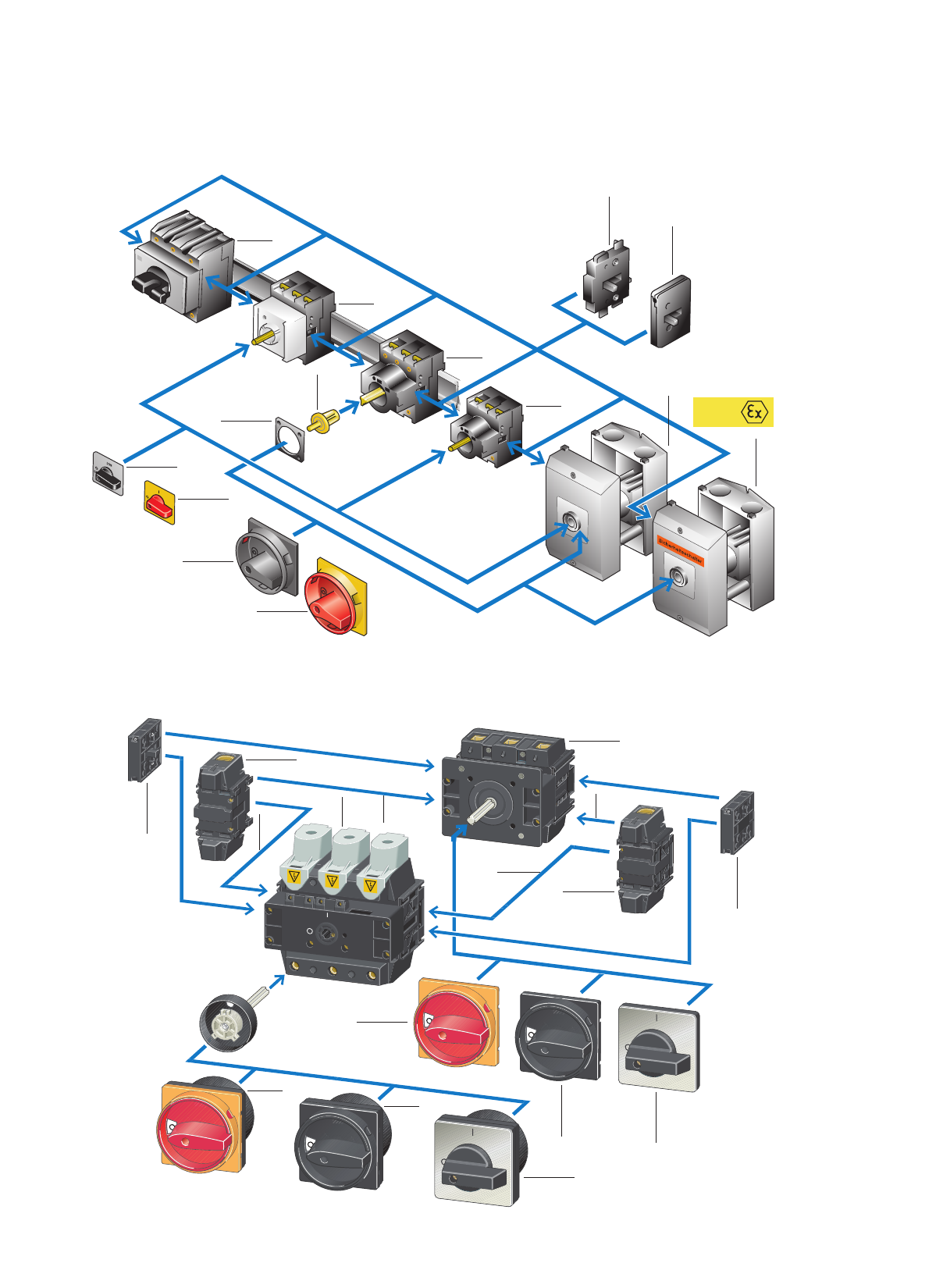
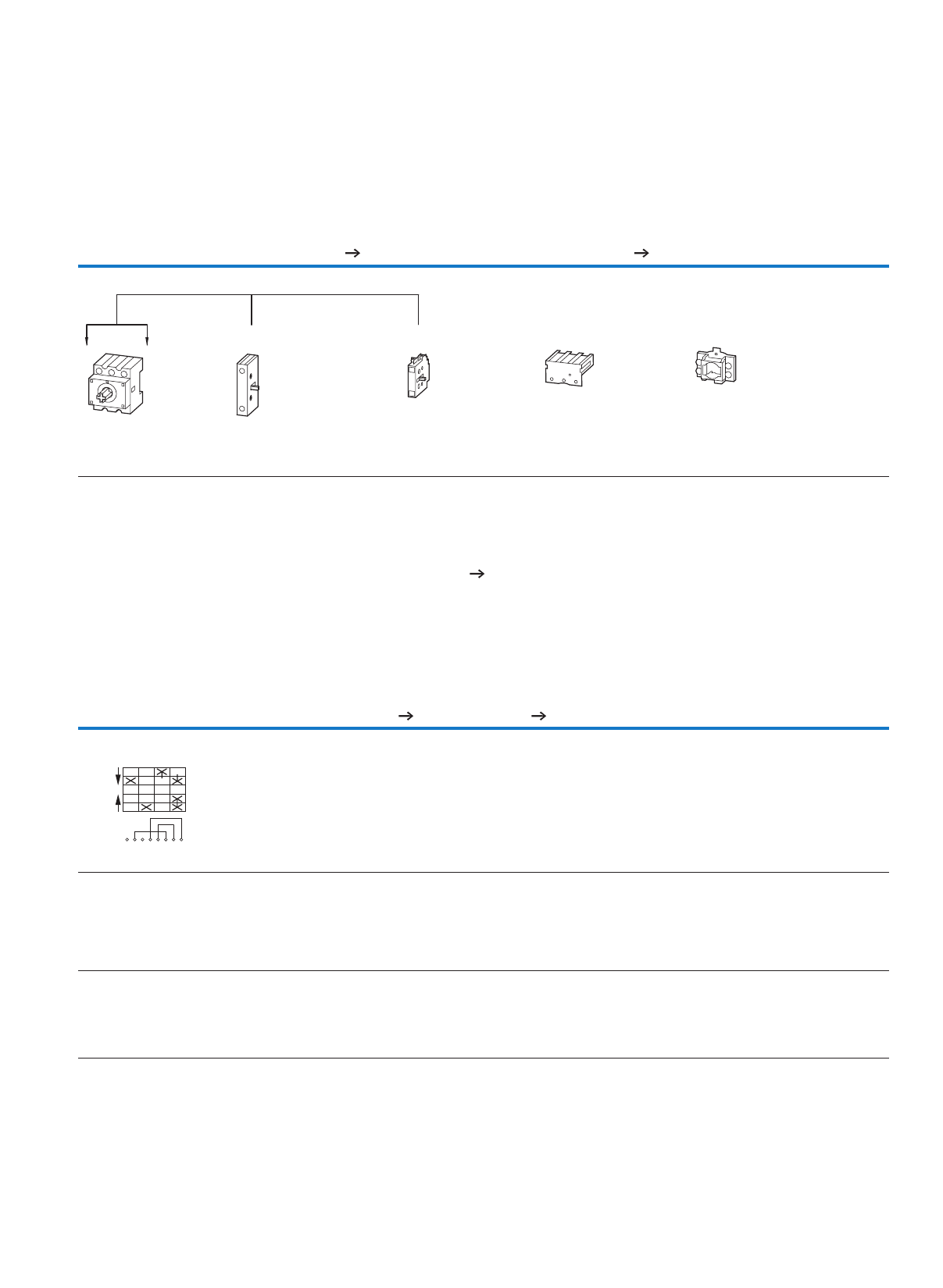
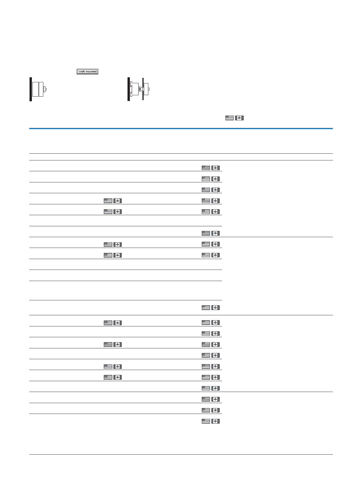
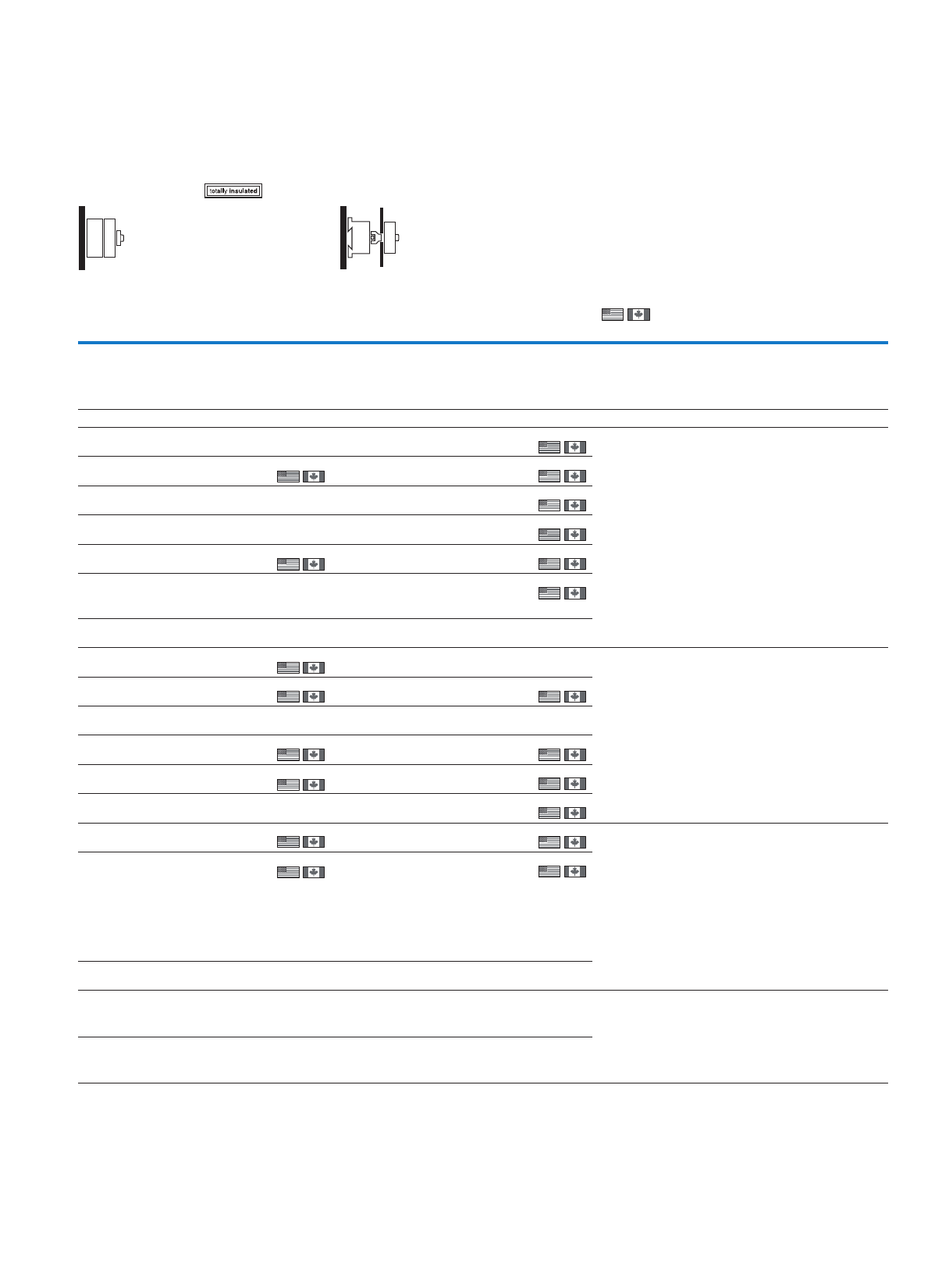
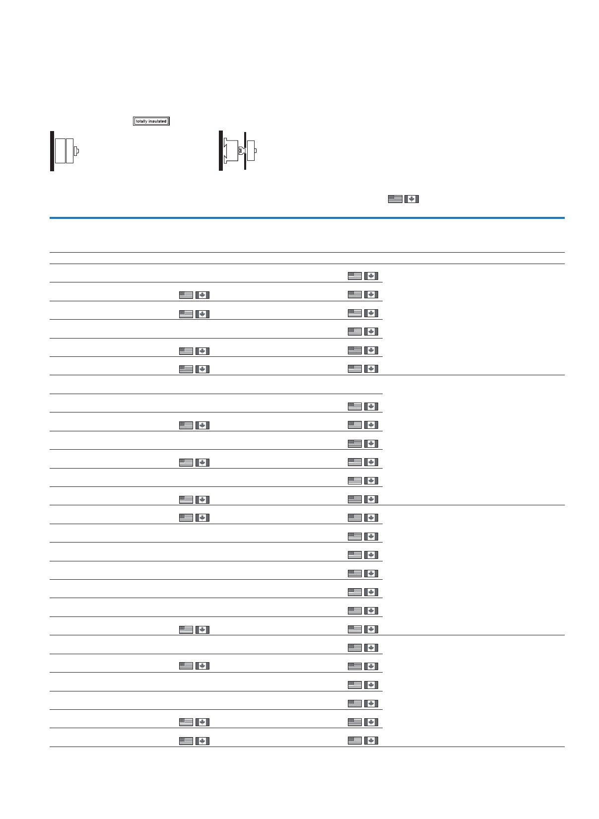
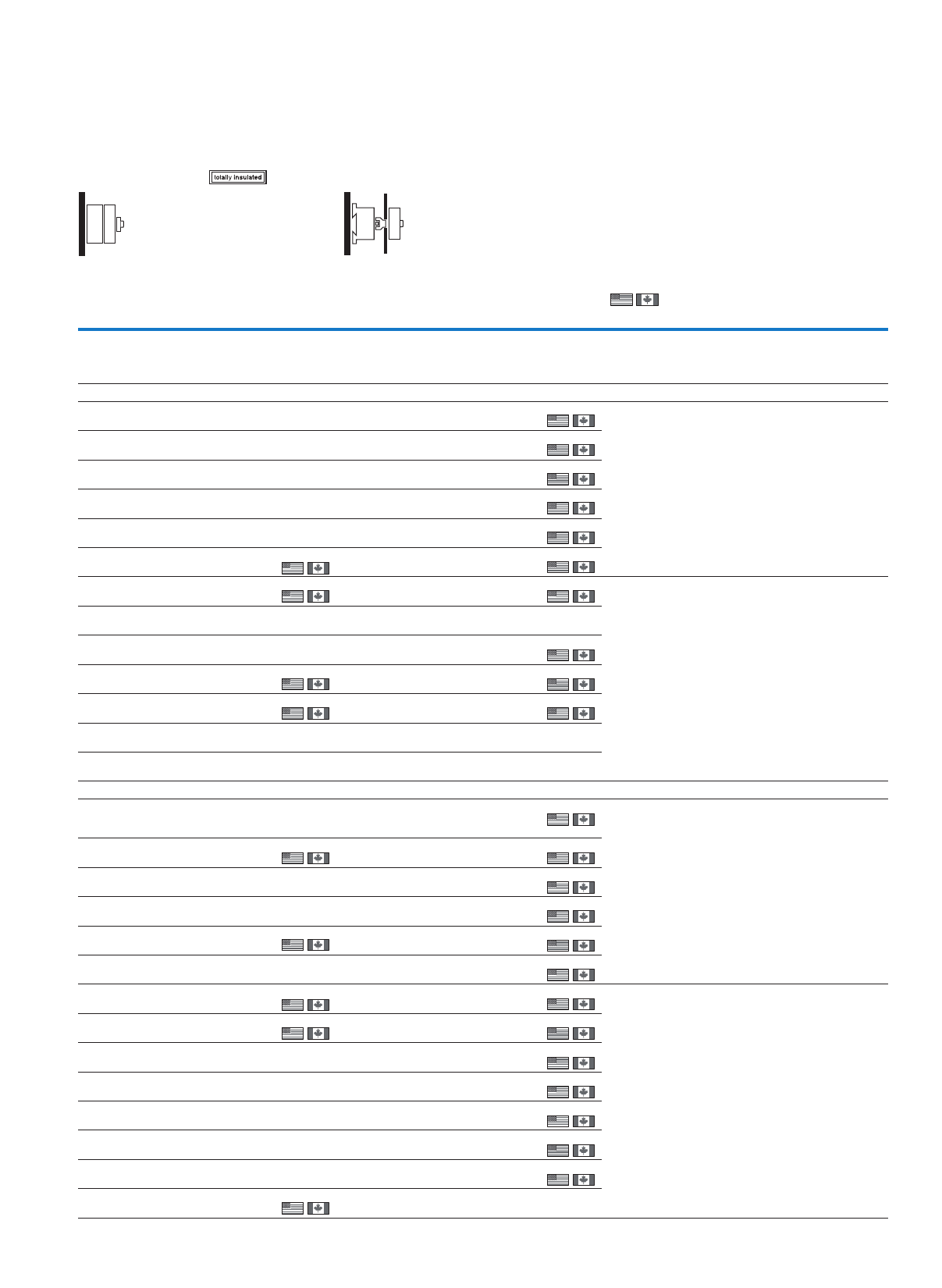
Cam switches T and switch disconnectors P
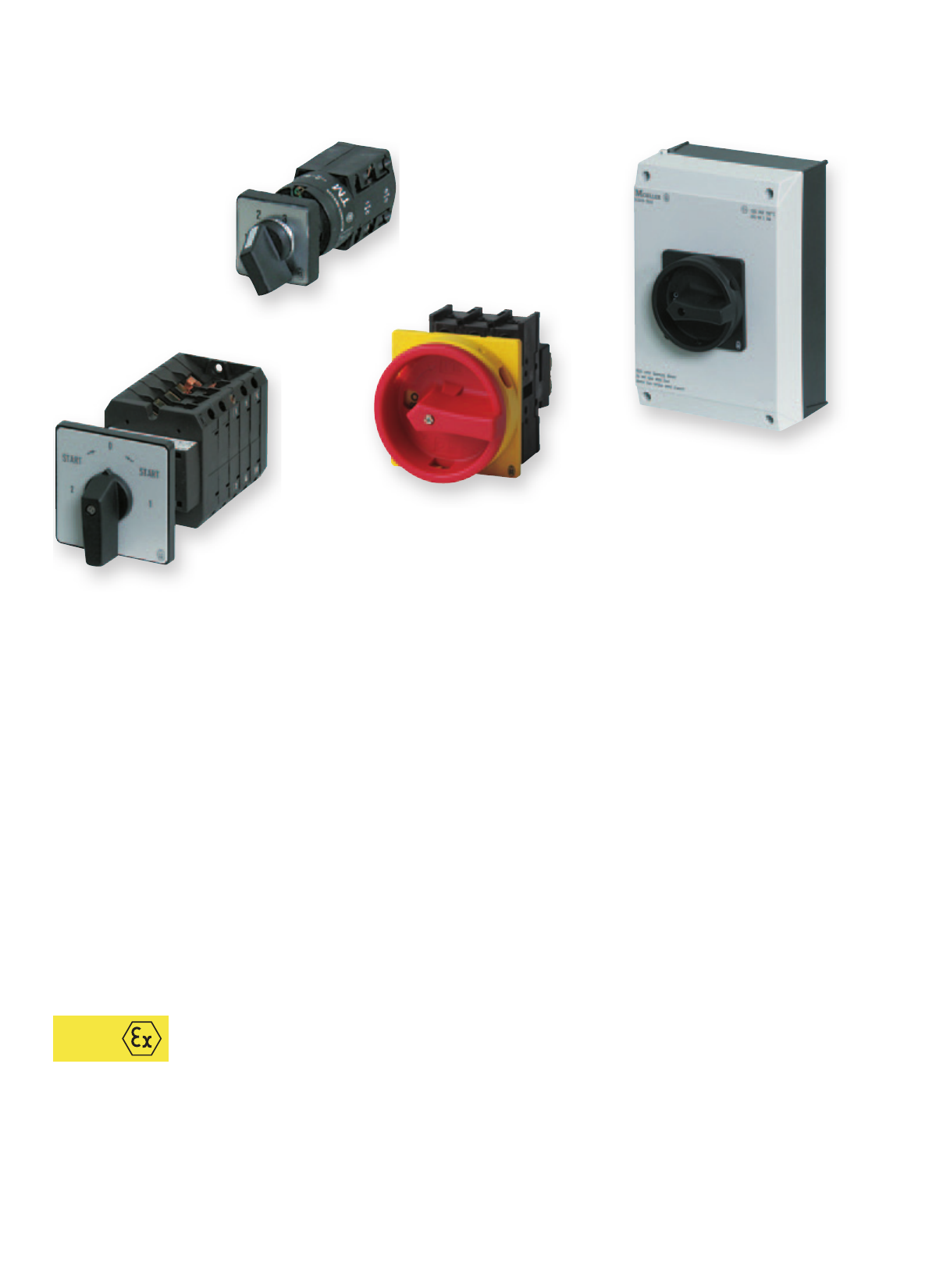
T/TM Cam switches
Performance up to 10/132 kW +++ Non-standard switches possible (see Online Catalog) +++
Several construction types
P switch-disconnectors
Performance up to 110 kW and 315 A +++ Switches up to 100 A (P1, P3) in housing IP65 +++
Four construction types
Switch for ATEX Zone 22
T Cam switches +++ Switch-disconnector up to 100 A (P1, P3) +++ IP65 Protection type
The high performance and robust cam switch and switch-disconnector are used in
industry, manual applications and building services management. Ten basic switch types
in four different construction types can be selected in a multitude of standard contact
sequences and a wide performance range.
T Cam switches
P Switch-disconnectors up to 315 A
ATEX

Contents
Cam switches, switch-disconnectors up to 315 A
48
48 17
5
41 35
b
48
48 17
5
41 35
b
Cam switches, switch-disconnectors
Technical overview
Cam switches, switch-disconnectors . . . . . . . . . . . . . . . . . . . . . . . . . . . . . . . . . . . . . . . . . . . . . . . . . . . . . . . . . . . . . .
System overview
Cam switches . . . . . . . . . . . . . . . . . . . . . . . . . . . . . . . . . . . . . . . . . . . . . . . . . . . . . . . . . . . . . . . . . . . . . . . . . . . . . . . .
Switch-disconnectors . . . . . . . . . . . . . . . . . . . . . . . . . . . . . . . . . . . . . . . . . . . . . . . . . . . . . . . . . . . . . . . . . . . . . . . . . .
Description
Key to part numbers, modular system . . . . . . . . . . . . . . . . . . . . . . . . . . . . . . . . . . . . . . . . . . . . . . . . . . . . . . . . . . . . .
Ordering
Switch-disconnectors, main switches maintenance/manual override switches . . . . . . . . . . . . . . . . . . . . . . . . . . . . .
Switch-disconnectors – On-Off switches . . . . . . . . . . . . . . . . . . . . . . . . . . . . . . . . . . . . . . . . . . . . . . . . . . . . . . . . . .
Switch-disconnectors – safety switches . . . . . . . . . . . . . . . . . . . . . . . . . . . . . . . . . . . . . . . . . . . . . . . . . . . . . . . . . .
Switch-disconnectors – changeover switches . . . . . . . . . . . . . . . . . . . . . . . . . . . . . . . . . . . . . . . . . . . . . . . . . . . . . .
Switch-disconnectors – reversing switches . . . . . . . . . . . . . . . . . . . . . . . . . . . . . . . . . . . . . . . . . . . . . . . . . . . . . . . .
Switch-disconnector - (reversing) star-delta switches, reversing multi-speed switch . . . . . . . . . . . . . . . . . . . . . . . .
Switch-disconnectors – multi-speed switches . . . . . . . . . . . . . . . . . . . . . . . . . . . . . . . . . . . . . . . . . . . . . . . . . . . . . .
Control switches - step switches . . . . . . . . . . . . . . . . . . . . . . . . . . . . . . . . . . . . . . . . . . . . . . . . . . . . . . . . . . . . . . . .
Control switches - On-Off switches . . . . . . . . . . . . . . . . . . . . . . . . . . . . . . . . . . . . . . . . . . . . . . . . . . . . . . . . . . . . . .
Control switches - changeover switches, manual/automatic switches . . . . . . . . . . . . . . . . . . . . . . . . . . . . . . . . . . .
Control switches – On switches . . . . . . . . . . . . . . . . . . . . . . . . . . . . . . . . . . . . . . . . . . . . . . . . . . . . . . . . . . . . . . . . . . .
Universal control switches . . . . . . . . . . . . . . . . . . . . . . . . . . . . . . . . . . . . . . . . . . . . . . . . . . . . . . . . . . . . . . . . . . . . .
Control switches - instrument switches . . . . . . . . . . . . . . . . . . . . . . . . . . . . . . . . . . . . . . . . . . . . . . . . . . . . . . . . . . .
Switch with locking mechanism . . . . . . . . . . . . . . . . . . . . . . . . . . . . . . . . . . . . . . . . . . . . . . . . . . . . . . . . . . . . . . . . . . .
Main switch assembly kits, thumb-grips, maintenance key . . . . . . . . . . . . . . . . . . . . . . . . . . . . . . . . . . . . . . . . . . . .
Front plates . . . . . . . . . . . . . . . . . . . . . . . . . . . . . . . . . . . . . . . . . . . . . . . . . . . . . . . . . . . . . . . . . . . . . . . . . . . . . . . . .
Add-on front plates . . . . . . . . . . . . . . . . . . . . . . . . . . . . . . . . . . . . . . . . . . . . . . . . . . . . . . . . . . . . . . . . . . . . . . . . . . .
Key operation, locking interlock . . . . . . . . . . . . . . . . . . . . . . . . . . . . . . . . . . . . . . . . . . . . . . . . . . . . . . . . . . . . . . . . .
Neutral conductor, auxiliary contact, centre mounting accessories,
service distribution board mounting accessories . . . . . . . . . . . . . . . . . . . . . . . . . . . . . . . . . . . . . . . . . . . . . . . . . . . .
Coupling drive, interlock parts, shaft extension . . . . . . . . . . . . . . . . . . . . . . . . . . . . . . . . . . . . . . . . . . . . . . . . . . . . .
Shrouds, keys . . . . . . . . . . . . . . . . . . . . . . . . . . . . . . . . . . . . . . . . . . . . . . . . . . . . . . . . . . . . . . . . . . . . . . . . . . . . . . .
Accessories . . . . . . . . . . . . . . . . . . . . . . . . . . . . . . . . . . . . . . . . . . . . . . . . . . . . . . . . . . . . . . . . . . . . . . . . . . . . . . . .
Non-standard switches . . . . . . . . . . . . . . . . . . . . . . . . . . . . . . . . . . . . . . . . . . . . . . . . . . . . . . . . . . . . . . . . . . . . . . . .
Technical data
Switch-disconnectors . . . . . . . . . . . . . . . . . . . . . . . . . . . . . . . . . . . . . . . . . . . . . . . . . . . . . . . . . . . . . . . . . . . . . . . . .
Switch-disconnectors, auxiliary contacts . . . . . . . . . . . . . . . . . . . . . . . . . . . . . . . . . . . . . . . . . . . . . . . . . . . . . . . . . .
Cam switch . . . . . . . . . . . . . . . . . . . . . . . . . . . . . . . . . . . . . . . . . . . . . . . . . . . . . . . . . . . . . . . . . . . . . . . . . . . . . . . .
Dimensions
Cam switches, switch-disconnectors . . . . . . . . . . . . . . . . . . . . . . . . . . . . . . . . . . . . . . . . . . . . . . . . . . . . . . . . . . . .
Mini rotary switches
Technical overview
Mini rotary switches . . . . . . . . . . . . . . . . . . . . . . . . . . . . . . . . . . . . . . . . . . . . . . . . . . . . . . . . . . . . . . . . . . . . . . . . . . .
Description
Key to part numbers, modular system . . . . . . . . . . . . . . . . . . . . . . . . . . . . . . . . . . . . . . . . . . . . . . . . . . . . . . . . . . . . .
System overview
Mini rotary switches . . . . . . . . . . . . . . . . . . . . . . . . . . . . . . . . . . . . . . . . . . . . . . . . . . . . . . . . . . . . . . . . . . . . . . . . . .
Ordering
Control circuit isolator, ON/OFF switches . . . . . . . . . . . . . . . . . . . . . . . . . . . . . . . . . . . . . . . . . . . . . . . . . . . . . . . . . .
Changeover switches . . . . . . . . . . . . . . . . . . . . . . . . . . . . . . . . . . . . . . . . . . . . . . . . . . . . . . . . . . . . . . . . . . . . . . . . .
Hand/Auto switches . . . . . . . . . . . . . . . . . . . . . . . . . . . . . . . . . . . . . . . . . . . . . . . . . . . . . . . . . . . . . . . . . . . . . . . . . .
Control switch - step switch . . . . . . . . . . . . . . . . . . . . . . . . . . . . . . . . . . . . . . . . . . . . . . . . . . . . . . . . . . . . . . . . . . . .
Control switches - group switches, ON/ OFF switches, reversing switches, coding switches . . . . . . . . . . . . . . . . .
Locks, front plates . . . . . . . . . . . . . . . . . . . . . . . . . . . . . . . . . . . . . . . . . . . . . . . . . . . . . . . . . . . . . . . . . . . . . . . . . . .
Non-standard switches . . . . . . . . . . . . . . . . . . . . . . . . . . . . . . . . . . . . . . . . . . . . . . . . . . . . . . . . . . . . . . . . . . . . . . . .
Technical data
Mini rotary switches . . . . . . . . . . . . . . . . . . . . . . . . . . . . . . . . . . . . . . . . . . . . . . . . . . . . . . . . . . . . . . . . . . . . . . . . . .
Dimensions
Mini rotary switches . . . . . . . . . . . . . . . . . . . . . . . . . . . . . . . . . . . . . . . . . . . . . . . . . . . . . . . . . . . . . . . . . . . . . . . . .
2
4
6
8
10
22
30
32
38
38
40
42
46
48
50
52
54
56
58
59
60
62
64
65
66
67
79
89
92
94
100
2
9
68
60
71
72
72
75
77
83
99
111
2
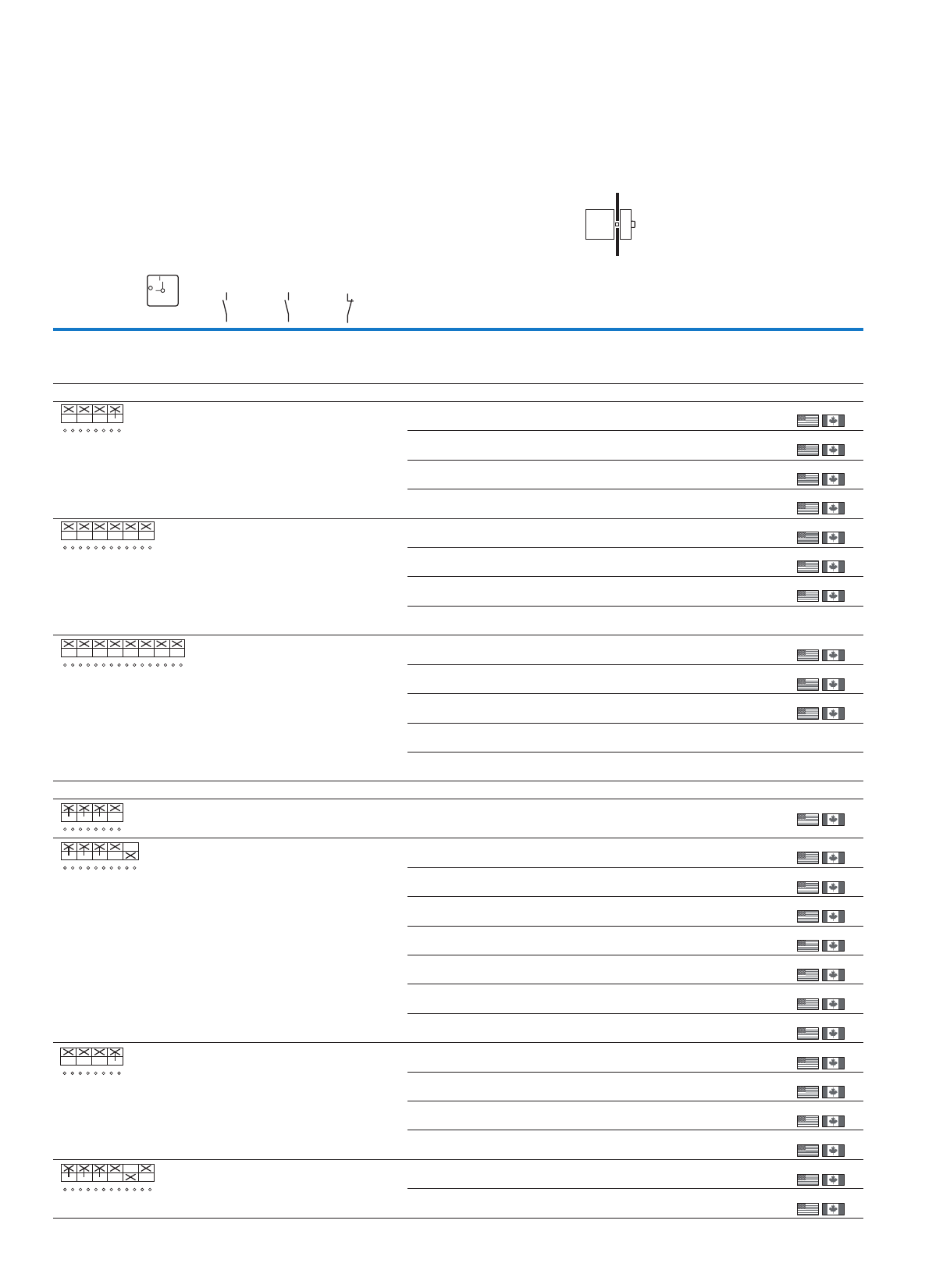
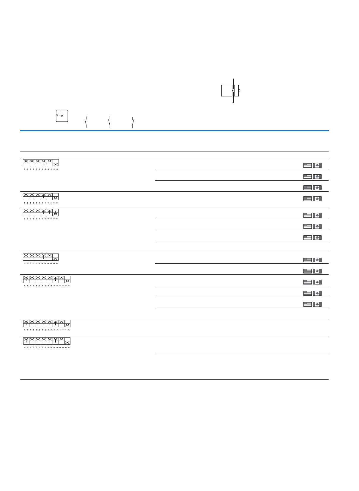
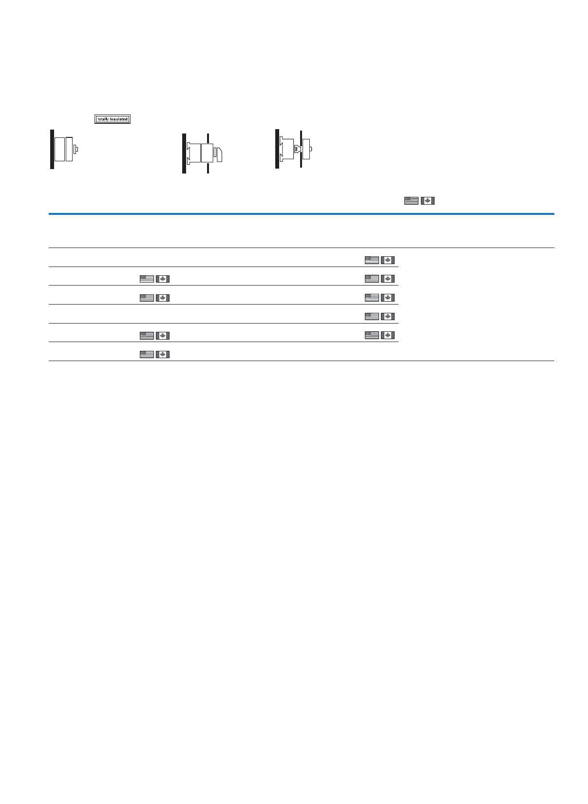
(Mini) cam switches, switch-disconnector
.ontraPepytcisab,hctiwS TMT0T3T5B
Max. motor rating
AC-23 A, 400/415 V, 50/60 Hz
3.0 kW 6.5 kW 13 kW 22 kW
Max. rated operational current Iu≦ 10 A 20 A 32 A 63 A
Switch-disconnectors
Main switches, maintenance/manual override switches
– 10 10 10
On-Off switches 70 22 22 22
Safety switches with warning label – – – 30
Changeover switches – 32 32 32
Reversing switch with 0 position – 38 38 38
Star-delta switches – 38 38 38
Reversing star-delta switches – 38 38 38
Multi-speed switch – 40 40 40
Reversing multi-speed switches – 40 40 40
Control switch
Step switch 72 42 –
On-Off switches – 46 –
–
–
Changeover switches 71 48 – –
Manual/Auto switches 72 48 – –
Push button switch – 50 – –
Universal control switches – 52––
Coding switches 76 52 – –
Series switches – 52 – –
Instrument selector switches – 54 – –
Group switches 75 – –
ON OFF button 75 –
–
––
Reversing switch 76 – – –
Switches with interlocks
Panic switches without emergency switching off function
– 56––
On-Off switches without Emergency-Stop function
– 56––
Non-standard switches 83 79 80 81
Mounting form
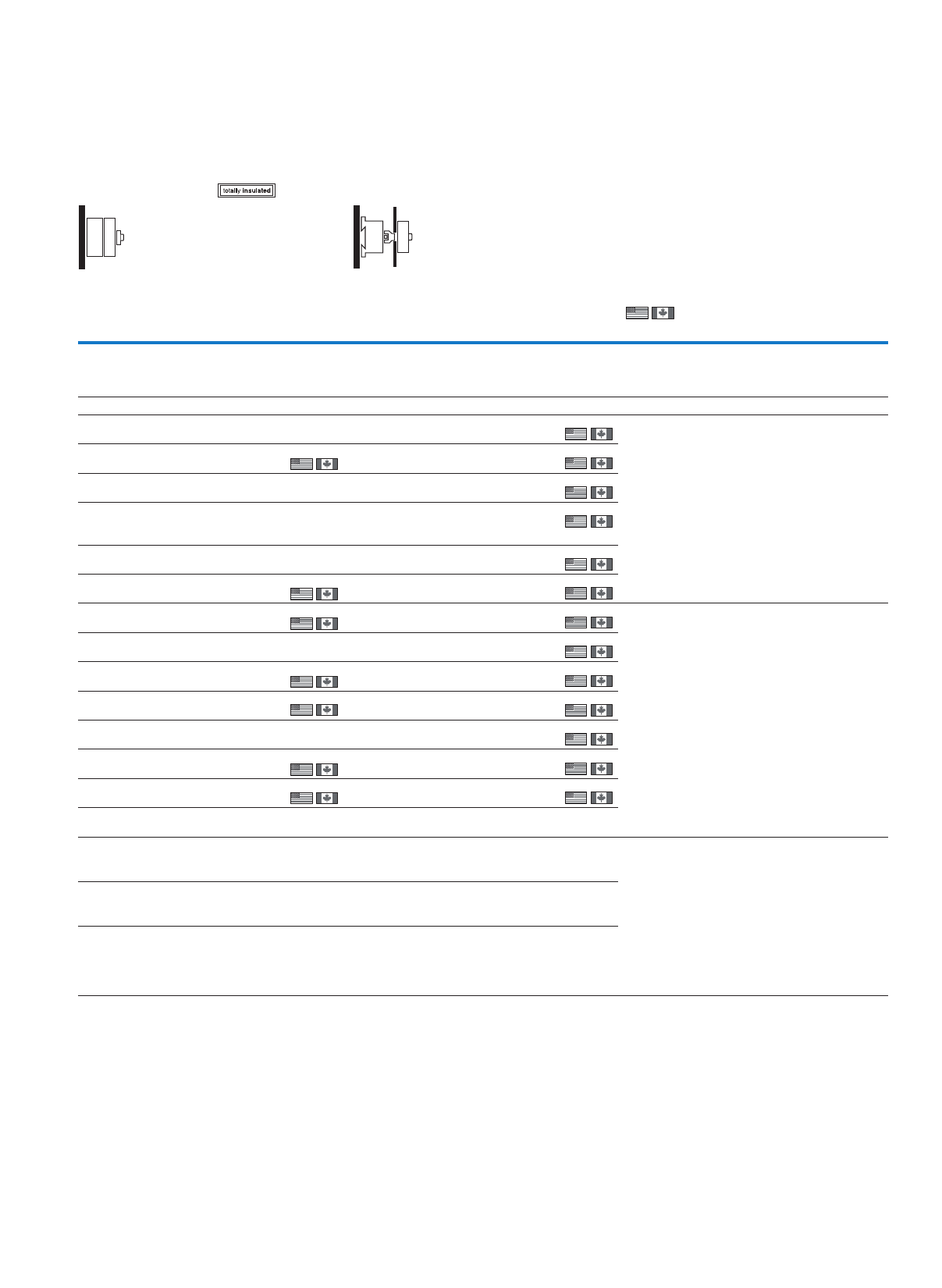
…/I…Surface mounting –
–
Surface mounting main switches …/I…/SVB… –
–
…E/...gnitnuoM
Flush mounting main switch …/E(A)/SVB…
…ZE/…gnitnuomretneC –
…Z/…gnitnuomraeR–
Rear mounting main switches …/V/SVB… –
Service distribution board mounting …/IVS… ––
ATEX
ATEX
T, P, TM
3
(Mini) cam switches, switch-disconnector
T5 T6 T8 P1-25 P1-32 P3-63 P3-100 P5-125 P5-160 P5-250 P5-315
30 kW 55 kW 132 kW 13 kW 15 kW 37 kW 50 kW 45 kW 55 kW 90 kW 110 kW
100 A 160 A 315 A 25 A 32 A 63 A 100 A 125 A 160 A 250 A 315 A
12 14 14 10 10 10 10 10 10 10 10
26 – – 28 22 22 22 22 22 22 22
30 – – 30 30 30 30 – – – –
32 32 32––––––––
–––––––––––
–––––––––––
–––––––––––
–––––––––––
–––––––––––
–––––––––––
–––––––––––
–––––––––––
–––––––––––
–––––––––––
–––––––––––
–––––––––––
–––––––––––
–––––––––––
–––––––––––
–––––––––––
–––––––––––
––– 56 56––––––
––– 56 56––––––
82––––––––––
–– ––––
–– ––––
––––
–– ––––
––
––– ––––––
–– ––––
––– ––––
4
Cam switches, switch-disconnectors
Cam switches
System overview
ON-OFF switches T0, T3, T5B, T5
Control switches T0, T3, T5B, T5
ATEX
10
9
8
7
7
6
5
4
3
2
1
6
8
9
10
10
1
2
3
4
9
9
10
ATEX
5
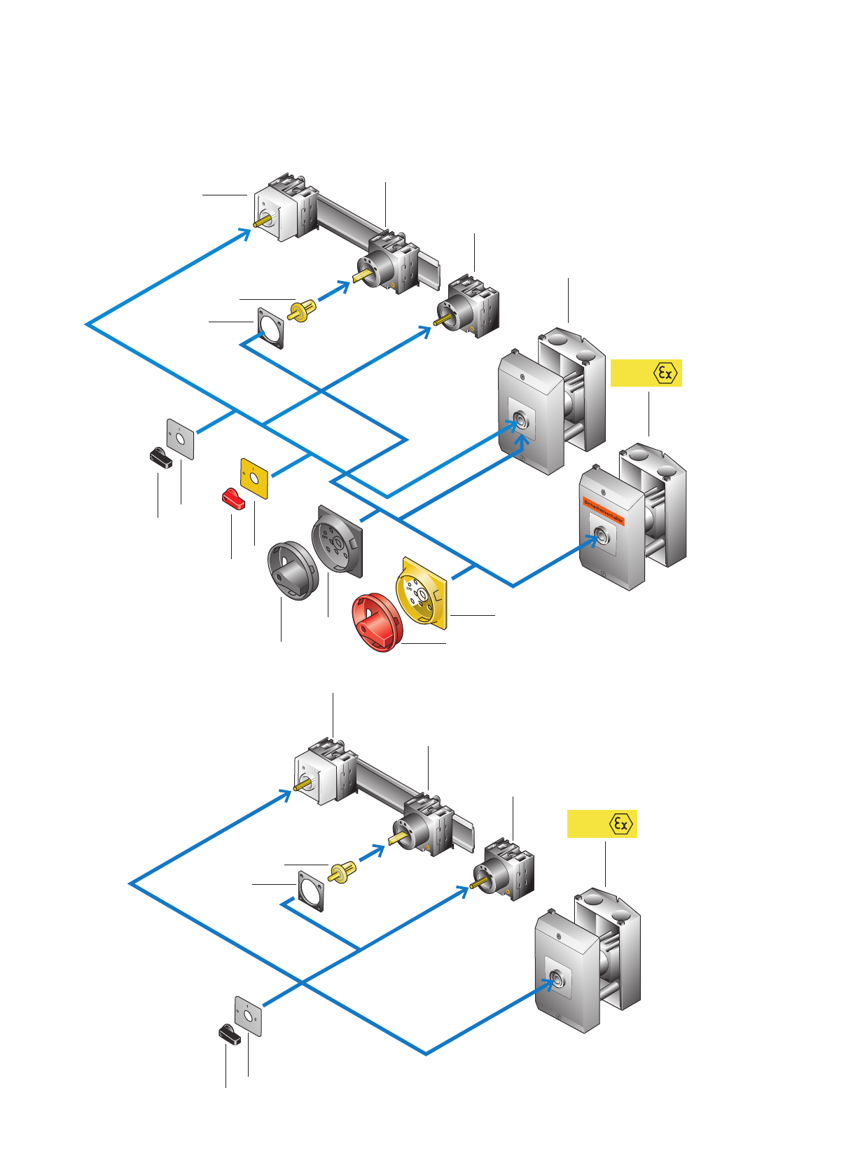
Cam switches, switch-disconnectors
Cam switches
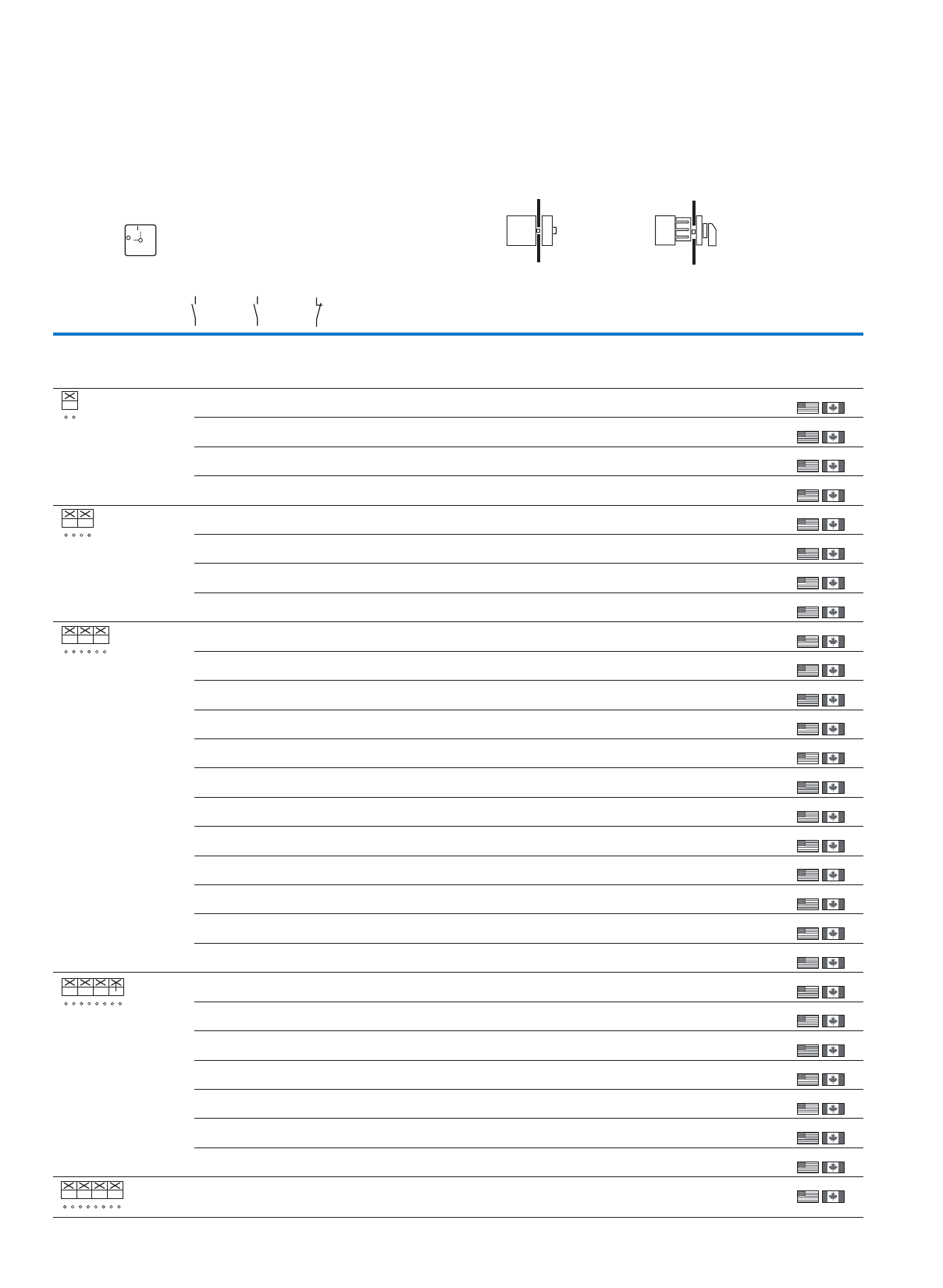
Service distribution
board mounting (…/IVS)
1
Front IP30
Can be snapped onto top-
hat rail as per IEC/EN 60715
(only T0 and T3)
Mounting
• In service distribution
board up to 3 contact
units (45 mm mounting
depth)
• In control panel up to
11 contact units
Page 22
Rear mounting (.../Z) 2
Front IP65
Fixing: optionally with
screw fixing or snap fitting,
only T0 und T3
For snap fitting to
IEC/EN 60715 top-hat rail
Drive coupling in door or
cover
Connection from front
Page 22
Rear mounting main
switch (...V/SVB)
2
Front IP65
To IEC/EN 60204, VDE 0113
and IEC/EN 60947-3
For T0…: up to 8 contacts;
For T3…: up to 12 contacts
With door interlock in "I"
position
Page 10
Flush mounting (.../E) 3
Front IP65
Flush mounting and
connection from rear
Terminals:
Crosshead screwdriver
Pozidrive
T8 always with extension
terminals
Page 22
Flush mounting main
switch (.../EA/SVB)
3
Front IP65
To IEC/EN 60204, VDE 0113
and IEC/EN 60947-3,
For T0…: up to 8 contacts;
For T3…: up to 12 contacts
N and PE terminal
Page 10
Center mounting (.../EZ) 3
Front IP65
Mounted in Ø 22.3 fixing
hole to IEC/EN 60947-5-1
"One man mounting" by
center fixing
Page 22
Surface mounting (.../I...) 4
IP65
With an additional terminal
Enclosures for metric cable
glands to EN 50262
Page 22
Surface mounting main
switch (.../I...)
4
IP65
To IEC/EN 60204, VDE 0113
and IEC/EN 60947-3,
For T0…: up to 8 contacts;
For T3…: up to 10 contacts
Position 0 lockable with
3 padlocks
Enclosures for metric cable
glands to EN 50262
With an additional terminal
Page 10
Page 58
Safety switch (.../I...) 5
IP65
With an additional terminal
With cover fixing in
0 position
Position 0 lockable with
3 padlocks
Enclosures for metric cable
glands to EN 50262
"Safety Switch" label; color:
orange
Page 30
Page 58
ATEX
ATEX
Main switch (kit) for use
as emergency switching
off device
6
To IEC/EN 60204-
1,VDE 0113 part 1
With red rotary handle and
yellow locking collar
Lockable in the 0 (Off)
position
Page 58
Main switch (kit) 7
Black rotary handle and
locking collar
Lockable in the 0 position
Page 58
Thumb-grip, for use as
emergency switching off
device
8
To IEC/EN 60204-1,
VDE 0113 part 1
Red thumb-grip and yellow
front plate
Page 58
Thumb-grip 9
Black thumb-grip with front
plate
Page 58
Coupling drive 10
Including push-fit shaft
For the retrofitting of switch
T0(T3)-.../XZ as rear
mounting, spare part for
T0(T3)/(P1)-...Z
For the conversion of
T5(B).../E flush mounting
switch to rear mounting,
spare part for T5(B)/(P3)-...Z
Page 65
Note:
Cam switches T5
and T5B are only available
with screw connections for
fixing on a mounting plate.
6
Cam switches, switch-disconnectors
Switch-disconnectors
ON-OFF switches P1, P3
ON OFF switches P5
11
9
10
8
7
2
3
1
1
4
4
6
11
5
A TEX
4
3
10
8
7
2
4
12
13
12
10
8
4
4
13
7
7
Cam switches, switch-disconnectors
Switch-disconnectors
Service distribution
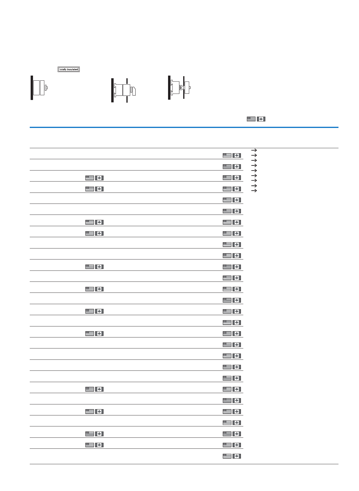
board mounting (…/IVS)
1
Front IP30
Fitting dimensions
according to DIN 43880
For snap fitting to
top-hat rail according to
IEC/EN 60715
Space requirement
P1, 3 pole: 3 space units
P3, 3 pole: 4 space units
P3-.../IVS lockable with
padlock in "0" position
Page 22
Rear mounting (.../Z) 2
Front IP65
Fixing either by snap-on
or screw fixing
For snap fitting to
top-hat rail according to
IEC/EN 60715
Drive coupling in door or
cover
Connection from front
2 add-on modules can be
retrofitted
Page 22
Rear mounting main
switch (...V/SVB)
2
Front IP65
To IEC/ENEN 60204,
VDE 0113 and
IEC/EN 60947-3
With door interlock in "I"
position
Maintenance key for
commissioning or fault-
finding
Position 0 lockable with
3 padlocks
2 add-on modules can be
retrofitted
Page 10
Flush mounting (.../E) 3
Front IP65
Flush mounting and
connection from rear
Terminals:
Crosshead screwdriver
Pozidrive
Back-of-hand proof
2 add-on modules can be
retrofitted
Page 22
Flush mounting main
switch (.../EA/SVB)
3
Front IP65
To IEC/ENEN 60204,
VDE 0113 and
IEC/EN 60947-3
N and PE terminal
Position 0 lockable with
3 padlocks
2 add-on modules can be
retrofitted
Page 10
Center mounting (.../EZ) 3
Front IP65
Mounted in Ø 22.3 fixing
hole to IEC/EN 60947-5-1
"One man mounting" by
center fixing
Page 22
Add-on modules 4
Switchable N conductor
(early-make N/O contact)
Auxiliary contacts
Finger proof
Auxiliary N/O contact:
Always connected as a
load-shedding contact
(late-make on, late-break
off)
Page 64
Surface mounting (.../I...) 5
IP65
With an additional
terminal
Installable add-on
modules:
P1: HI 11-P1/P3 or N-P1...,
P3: HI 11-P1/P3 and/or
N-P5
Enclosures for metric
cable glands to EN 50262
Page 22
Surface mounting main
switch (…/I…)
5
IP65
With an additional
terminal
To IEC/ENEN 60204,
VDE 0113 and
IEC/EN 60947-3
Position 0 lockable with
3padlocks
Installable add-on modules:
P1: HI 11-P1/P3 or N-P1...,
P3: HI 11-P1/P3 and/or
N-P5
Enclosures for metric
cable glands to EN 50262
Page 10
Page 58
Safety switch (.../I...-SI) 6
IP65
With an additional
terminal
With cover fixing in
0 position
Position 0 lockable with
3padlocks
"Safety Switch" label;
color: orange
Enclosures for metric
cable glands to EN 50262
Page 30
Page 58
ATEX
ATEX
Main switch (kit) for use
as emergency switching
off device
7
To IEC/EN 60204-1,
VDE 0113 Part 1
With red rotary handle and
yellow locking collar
Lockable in the 0 (Off)
position
Page 58
Main switch (kit) 8
Black rotary handle and
locking collar
Lockable in the
0 position
Page 58
Thumb-grip, for use as
emergency switching
off device
9
To IEC/EN 60204-1,
VDE 0113 Part 1
Red thumb-grip and
yellow front plate
Page 58
Thumb-grip 10
Black thumb-grip with
front plate
Page 58
Coupling drive 11
Including push-fit shaft
For retrofitting mounting
switches T0(T3)-…/XZ as
rear mounting design
spare part for T0(T3)/
(P1)-…/Z
For converting flush
mounting switches
T5(B)-…/E into rear
mounting switch spare
part for T5(B)/(P3)-…Z
Page 65
Ground terminal 12
Front mounting, right
Service distribution board
mounting, left
Neutral terminal 13
Front mounting, left
Service distribution board
mounting, right
Page 64
8
Cam switches, switch-disconnectors
Description
Cam switches can be used for many switching and
control applications. For example as ON-OFF
switches, main switches, main/control switches,
instrument switches.
The switches consist of a hand actuator, the switch
unit and the mounting accessories.
The contact chamber (contact unit = BE) contains
1 or 2 contacts.
Our "T Cam Switches" catalog has over 800 popular
standard contact sequences (please request under
K115D/F/GB, article no. 077643).
The following pages feature a selection of our
standard contact sequences.
T cam switches and P switch-disconnectors are
manufactured without PCB, CFC, asbestos and
silicon.The contacts are cadmium free.
The CI-K... insulated enclosures are silicon and halogen
free.
Cam switches T0 and T3
Key to part numbers
T . . . . . . . . . . . . - . . . . . . . . . . . . . . . . . . . . . . . . . . . . - . . . . . . . . . . . . . . . . . . . . . . . / . . . . . . . . . . . . . . . . . . . .
↑↑↑↑
Switch size
T0 or T3
Number of contact chambers
= contact units
Contact sequence
number
Mounting form
Page 2
Using the modular system to convert the mounting form
Cam switch TB5
Key to part numbers
T . . . . . . . . . . . . - . . . . . . . . . . . . . . . . . . . . . . . . . . . . - . . . . . . . . . . . . . . . . . . . . . . . / . . . . . . . . . . . . . . . . . . . .
↑↑↑↑
Switch size
T5(B)
Number of contact chambers
= contact units
Contact sequence
number
Mounting form
Page 2
Using the modular system to convert the mounting form T5(B)
Note 1) Including shaft
CI-K1-T0
CI-K2-T3
T0-.../I1
T3-.../I2
T0.../IVS1)
T0(3).../E
T0(3).../EZ
0T-ED0T-SVIZX/...)3(0T0T-BVS/AE/V0T-ZE
T0(3).../Z 1)
V/EA/SVB-T0
T0-1-(T3-1-).../V/SVB
.
.
.
T0-4-(T3-6-).../V/SVB
T0-1-(T3-1-).../EA/SVB
.
.
.
T0-4-(T3-6-).../EA/SVB
CI-K4-T5B
CI-K5-T5
DE-P3V/EA/SVB-T5T5(B)...E
T5(B).../EA/SVB T5(B).../Z
V/EA/SVB-T5
T5(B).../V/SVB
T5B-.../I4
T5-.../I5
SVB-P3
T5B-.../I4/SVB
T5-.../I5/SVB
9
Cam switches, switch-disconnectors
Switch-disconnectors P1 and P3
Key to part numbers
P. . . . . . . . . . . . - . . . . . . . . . . . . . . . . . . . . . . . . . . . . / . . . . . . . . . . . . . . . . . . . . - . . . . . . . . . . . . . . . . . . / . . . . . . . . . . . . . . . . . . . . .
↑↑↑↑↑
Switch size
P1 or P3
Rated uninterrupted current Mounting form
Page 2
Part no. suffix
(if required)
Accessories
from Page 7/47
Add-on functions due to modular system
TM mini cam switches
The TM mini cam switch is a particularly small switch
with a small space requirement. It is ideally suited for
small voltages and currents such as electronic
controls. For greater safety the contacts are gold
plated.
TM switches have consecutive terminal markings
starting with 1.
Selection pages: Starting on Page7/54
Key to part numbers
TM-. . . . . . . . . . . . . . . . . . . . . . . . . - . . . . . . . . . . . . . . . . . . . . . . . / . . . . . . . . . . . . . . . . . . . . + . . . . . . . . . . . . . . . . . .
↑↑↑↑
Number of contact chambers
= contact units
Contact sequence
number
Mounting form
Page 2
Accessories
Page 7/59
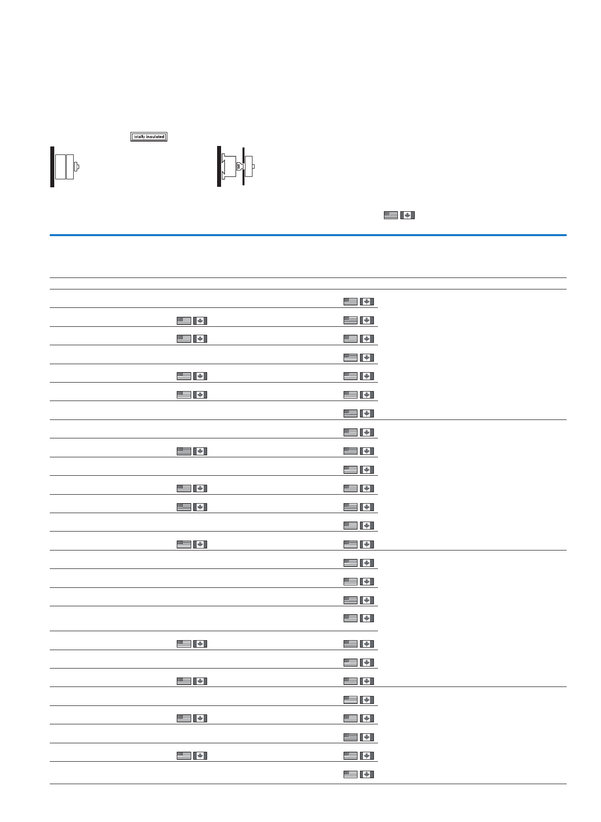
Circuit representation
(see also ordering example in the electronic
catalogue)
Switch from 0 to 1
Contact 1 – 2 open,
Contact 3 – 4 open,
Contact 5 – 6 open,
Contact 7 – 8 closed
Switch from 1 to START
with automatic return to 1
Contact 1 – 2 open,
Contact 3 – 4 closed,
Contact 5 – 6 open,
Contact 7 – 8 remains closed
Switch from 1 to 0
Contact 1 – 2 open,
Contact 3 – 4 open,
Contact 5 – 6 open,
Contact 7 – 8 open
Switch from 0 to 2
Contact 1 – 2 closed,
Contact 3 – 4 open,
Contact 5 – 6 open,
Contact 7 – 8 closed
Switch from 2 to START
with automatic return to 2
Contact 1 – 2 open,
Contact 3 – 4 open,
Contact 5 – 6 closes with early make,
Contact 7 – 8 opens with late break
Switch from 2 to 0
Contact 1 – 2 open,
Contact 3 – 4 open,
Contact 5 – 6 open,
Contact 7 – 8 open
H-P... UV-P...
N-P...Z HI 11-P1/P3Z
N-P...E HI 11-P1/P3E
3-pole basic unit
.../E or .../Z
Switched neutral
Can be fitted left
or right
(for P1.../I: left only)
Auxiliary contact
Can be fitted left
or right
(for P1.../I: left only)
Terminal shroud
can be fitted at
top or bottom
N + PE terminals,
also as cover interlock
on .../Z-switches.
or or
1
2
3
4
5
6
7
8
START
1
0
2
START
Links
Terminal markings
Front plate labeling
10
Cam switches, switch-disconnectors
Switch-disconnectors – main switches, maintenance/manual override switches
Ordering
Flush mounting
Front IP65
Contact
sequence
Front plate
no.
Main
contacts
Auxiliary contacts Max. motor rating
AC-23 A, 400/415 V,
50/60 Hz
Rated
uninterrupted
current
400 VeloP Part no.
Article no.
Price
See price
list
Std. pack
N/O N/O N/C P I u
kA
Main switch as emergency switching off/emergency stop device
With red rotary handle and yellow locking collar
To IEC/EN 60204-1, VDE 0113 Part 1
Lockable in the 0 (Off) position
Without auxiliary contacts
1006.5 20 T0-1-8200/EA/SVB
053110
1 Off
1 Off
1 Off
1 Off
1 Off
1 Off
13 32 T3-1-8200/EA/SVB1)
066576
22 63 T5B-1-8200/EA/SVB3)
094279
2006.5 20 T0-1-102/EA/SVB1)
091078
13 32 T3-1-102/EA/SVB1)
014374
22 63 T5B-1-102/EA/SVB3)
094469
30 100 T5-1-102/EA/SVB
098808
1 Off
3006.5 20 T0-2-1/EA/SVB1)
038873
1 Off
1 Off
1 Off
1 Off
1 Off
1 Off
1 Off
1 Off
1 Off
1 Off
13 25 P1-25/EA/SVB1)
041097
13 25
15 32 P1-32/EA/SVB1)
081438
37 63 P3-63/EA/SVB1)
031607
45 125 P5-125/EA/SVB4)
280898
50 100 P3-100/EA/SVB1)
074320
55 160 P5-160/EA/SVB4)
280922
90 250 P5-250/EA/SVB4)
280936
110 315 P5-315/EA/SVB4)
280950
3 + N 0 0 6.5 20 T0-2-8900/EA/SVB1)
207400
1 Off
1 Off
1 Off
1 Off
1 Off
1 Off
1 Off
1 Off
1 Off
3 + N0013 25 P1-25/EA/SVB/N1)
081587
13 25
15 32 P1-32/EA/SVB/N1)
091079
15 32
37 63 P3-63/EA/SVB/N1)
010398
45 125 P5-125/EA/SVB/N4)
280910
50 100 P3-100/EA/SVB/N1)
019890
55 160 P5-160/EA/SVB/N4)
280924
FS 908
ON
OFF
1
2
01
1
2
3
4
01
1
2
3
4
5
6
01
1
2
3
4
5
6
7
8
01
1
2
3
4
5
6
N
N
01
T, P
11
Cam switches, switch-disconnectors
Switch-disconnectors – main switches, maintenance/manual override switches
Surface mounting Rear mounting
IP65 Front IP65
Part no.
Article no.
Price
See price
list
Std. pack Part no.
Article no.
Price
See price
list
Std. pack Information relevant for export to North America
T0-1-8200/I1/SVB
207145
1 Off T0-1-8200/V/SVB
057856
1 Off
1 Off
1 Off
1 Off
1 Off
1 Off
1 Off
1)
T3-1-8200/I2/SVB2)
207200
1 Off T3-1-8200/V/SVB1)
007255
T5B-1-8200/I4/SVB3)
207240
1 Off T5B-1-8200/V/SVB3)
094273
T0-1-102/I1/SVB
207143
1 Off T0-1-102/V/SVB1)
095824
T3-1-102/I2/SVB2)
207198
1 Off T3-1-102/V/SVB1)
019120
T5B-1-102/I4/SVB3)
207238
1 Off T5B-1-102/V/SVB3)
094463
T5-1-102/I5/SVB
207273
1 Off
T0-2-1/I1/SVB
207147
1 Off T0-2-1/V/SVB1)
043619
1 Off
1 Off
1 Off
1 Off
1 Off
1 Off
1 Off
1 Off
1 Off
1 Off
2)
P1-25/I2/SVB2)
207293
1 Off P1-25/V/SVB2)
055335
P1-25/I2H/SVB
226900
1 Off
P1-32/I2/SVB2)
207314
1 Off P1-32/V/SVB1)
095676
P3-63/I4/SVB1)
207343
1 Off P3-63/V/SVB1)
048218
P5-125/V/SVB4)
280914
P3-100/I5/SVB1)
207373
1 Off P3-100/V/SVB1)
088558
P5-160/V/SVB4)
280928
3)
P5-250/V/SVB4)
280942
P5-315/V/SVB4)
280956
T0-2-8900/I1/SVB
207151
1 Off T0-2-8900/V/SVB1)
207405
1 Off
1 Off
1 Off
1 Off
1 Off
1 Off
1 Off
1 Off
1 Off
P1-25/I2/SVB/N2)
207298
1 Off P1-25/V/SVB/N2)
086333
P1-25/I2H/SVB/N
227860
1 Off
P1-32/I2/SVB/N2)
207319
1 Off P1-32/V/SVB/N1)
095825
P1-32/I2H/SVB/N
227871
1 Off 4)
P3-63/I4/SVB/N1)
207349
1 Off P3-63/V/SVB/N1)
015144
P5-125/V/SVB/N4)
280916
P3-100/I5/SVB/N1)
207379
1 Off P3-100/V/SVB/N1)
024636
P5-160/V/SVB/N4)
280930
Product Standards
UL File No.
UL CCN
CSA File No.
CSA Class No.
NA Certification
Suitable for
Degree of Protection
UL 508; CSA-C22.2 No. 14-05;
IEC/EN 60947-3; CE marking
E36332
NLRV
12528
3211-05
UL Listed, CSA certified
Branch circuits, suitable as motor
disconnect
IEC: IP65; UL/CSA Type 3R, 12
Product Standards
UL File No.
UL CCN
CSA File No.
CSA Class No.
NA Certification
Suitable for
Degree of Protection
UL 508; CSA-C22.2 No. 14-05;
IEC/EN 60947-3; CE marking
E36332
NLRV7
12528
3211-05
UL Listed, CSA certified
Branch circuits, suitable as motor
disconnect
IEC: IP65; UL/CSA Type 1, 3R, 12, 13
Product Standards
UL File No.
UL CCN
CSA File No.
CSA Class No.
NA Certification
Suitable for
Degree of Protection
UL 508; CSA-C22.2 No. 14-05;
IEC/EN 60947-3; CE marking
E36332
NLRV, NLRV7
223805
3211-05
UL Listed, CSA certified
Branch circuits, suitable as motor
disconnect
IEC: IP65; UL/CSA Type 3R, 12
Product Standards
UL File No.
UL CCN
CSA File No.
CSA Class No.
NA Certification
Suitable for
Degree of Protection
UL 508; CSA-C22.2 No. 14-05; CSA-C22.2
No. 94; IEC/EN 60947-3; CE marking
E36332
NLRV
12528
3211-05
UL Listed, CSA certified
Branch circuits, suitable as motor
disconnect
IEC: IP65; UL/CSA Type 3R, 12
12
Cam switches, switch-disconnectors
Switch-disconnectors – main switches, maintenance/manual override switches
T, P
Main switch as emergency switching off/emergency stop device
With red rotary handle and yellow locking collar
To IEC/EN 60204-1, VDE 0113 Part 1
Lockable in the 0 (Off) position
Without auxiliary contacts
3 + N 0 0 90 250 P5-250/EA/SVB/N4)
280938
1 Off
1 Off
1 Off
1 Off
1 Off
3 + N 0 0 110 315 P5-315/EA/SVB/N4)
280952
6006.5 20 T0-3-8342/EA/SVB1)
029382
13 32 T3-3-8342/EA/SVB1)
071326
22 63 T5B-3-8342/EA/SVB3)
092308
30 100 T5-3-8342/EA/SVB
096383
1 Off
8006.5 20 T0-4-8344/EA/SVB1)
008267
1 Off
1 Off
1 Off
13 32 T3-4-8344/EA/SVB1)
008964
22 63 T5B-4-8344/EA/SVB3)
092062
30 95
30 100 T5-4-8344/EA/SVB
095961
1 Off
With auxiliary contacts
3106.5 20 T0-2-15679/EA/SVB1)
081588
1 Off
1 Off
1 Off
1 Off
1 Off
1 Off
1 Off
1 Off
1 Off
1 Off
1 Off
31113 25 P1-25/EA/SVB/HI111)
091080
13 25
15 32 P1-32/EA/SVB/HI111)
072567
15 32
37 63 P3-63/EA/SVB/HI111)
019891
50 100 P3-100/EA/SVB/HI111)
029383
31045 125 P5-125/EA/SVB/HI104)
280899
55 160 P5-160/EA/SVB/HI104)
280923
90 250 P5-250/EA/SVB/HI104)
280937
110 315 P5-315/EA/SVB/HI104)
280951
Flush mounting
Front IP65
Contact
sequence
Front plate
no.
Main
contacts
Auxiliary contacts Max. motor rating
AC-23 A, 400/415 V,
50/60 Hz
Rated
uninterrupted
current
400 VeloP Part no.
Article no.
Price
See price
list
Std. pack
N/O N/O N/C P Iu
kW A
FS 908
ON
OFF
1
2
3
4
5
6
N
N
01
1
2
3
4
5
6
7
8
9
10
01
11
12
1
2
3
4
5
6
7
8
9
10
01
11
12
13
14
15
16
1
2
3
4
5
6
7
8
01
1
2
3
4
5
6
13
14
01
21
22
1
2
3
4
5
6
13
14
01
13
Cam switches, switch-disconnectors
Switch-disconnectors – main switches, maintenance/manual override switches
Product Standards
UL File No.
UL CCN
CSA File No.
CSA Class No.
NA Certification
Suitable for
Degree of Protection
UL 508; CSA-C22.2 No. 14-05;
IEC/EN 60947-3; CE marking
E36332
NLRV
12528
3211-05
UL Listed, CSA certified
Branch circuits, suitable as motor
disconnect
IEC: IP65; UL/CSA Type 3R, 12
Product Standards
UL File No.
UL CCN
CSA File No.
CSA Class No.
NA Certification
Suitable for
Degree of Protection
UL 508; CSA-C22.2 No. 14-05;
IEC/EN 60947-3; CE marking
E36332
NLRV7
12528
3211-05
UL Listed, CSA certified
Branch circuits, suitable as motor
disconnect
IEC: IP65; UL/CSA Type 1, 3R, 12, 13
Product Standards
UL File No.
UL CCN
CSA File No.
CSA Class No.
NA Certification
Suitable for
Degree of Protection
UL 508; CSA-C22.2 No. 14-05;
IEC/EN 60947-3; CE marking
E36332
NLRV, NLRV7
223805
3211-05
UL Listed, CSA certified
Branch circuits, suitable as motor
disconnect
IEC: IP65; UL/CSA Type 3R, 12
Product Standards
UL File No.
UL CCN
CSA File No.
CSA Class No.
NA Certification
Suitable for
Degree of Protection
UL 508; CSA-C22.2 No. 14-05; CSA-C22.2
No. 94; IEC/EN 60947-3; CE marking
E36332
NLRV
12528
3211-05
UL Listed, CSA certified
Branch circuits, suitable as motor
disconnect
IEC: IP65; UL/CSA Type 3R, 12
P5-250/V/SVB/N4)
280944
1 Off
1 Off
1 Off
1 Off
1 Off
1)
P5-315/V/SVB/N4)
280958
T0-3-8342/I1/SVB
207159
1 Off T0-3-8342/V/SVB1)
034128
T3-3-8342/I2/SVB2)
207208
1 Off T3-3-8342/V/SVB1)
076072
T5B-3-8342/I4/SVB3)
207242
1 Off T5B-3-8342/V/SVB3)
092300
T5-3-8342/I5/SVB
207279
1 Off T5-3-8342/V/SVB
096381
1 Off
T0-4-8344/I1/SVB
207163
1 Off T0-4-8344/V/SVB1)
014007
1 Off
1 Off
1 Off
T3-4-8344/I2/SVB2)
207212
1 Off T3-4-8344/V/SVB1)
020598
2)
T5B-4-8344/I4/SVB3)
207248
1 Off T5B-4-8344/V/SVB3)
092056
T5-4-8344/I5/SVB
207283
1 Off
T5-4-8344/V/SVB
095959
1 Off
T0-2-15679/I1/SVB
207149
1 Off T0-2-15679/V/SVB1)
086334
1 Off
1 Off
1 Off
1 Off
1 Off
1 Off
1 Off
1 Off
1 Off
1 Off
1 Off
P1-25/I2/SVB/HI112)
207297
1 Off P1-25/V/SVB/HI111)
095826
3)
P1-25/I2H/SVB/HI11
226902
1 Off
P1-32/I2/SVB/HI111)
207318
1 Off P1-32/V/SVB/HI111)
015145
P1-32/I2H/SVB/HI11
227870
1 Off
P3-63/I4/SVB/HI111)
207348
1 Off P3-63/V/SVB/HI111)
024637
P3-100/I5/SVB/HI111)
207378
1 Off P3-100/V/SVB/HI111)
034129
P5-125/V/SVB/HI104)
280915
P5-160/V/SVB/HI104)
280929
4)
P5-250/V/SVB/HI104)
280943
P5-315/V/SVB/HI104)
280957
Surface mounting Rear mounting
IP65 Front IP65
Part no.
Article no.
Price
See price
list
Std. pack Part no.
Article no.
Price
See price
list
Std. pack Information relevant for export to North America
14
Cam switches, switch-disconnectors
Switch-disconnectors – main switches, maintenance/manual override switches
T, P
Main switch as emergency switching off/emergency stop device
With red rotary handle and yellow locking collar
To IEC/EN 60204-1, VDE 0113 Part 1
Lockable in the 0 (Off) position
With auxiliary contacts
3216.5 20 T0-3-15683/EA/SVB1)
015571
1 Off
1 Off
1 Off
1 Off
1 Off
1 Off
32113 32 T3-3-15683/EA/SVB1)
040478
3 + N116.5 20 T0-3-15680/EA/SVB1)
038875
13 32 P1-25/EA/SVB/N/HI111)
048367
13 32 T3-3-15680/EA/SVB1)
012002
3 + N1115 32 P1-32/EA/SVB/N/HI111)
057859
3 + N116.5 20 T0-3-8901/EA/SVB1)
231932
1 Off
1 Off
1 Off
13 32 T3-3-8901/EA/SVB1)
231945
22 63 T5B-3-8901/EA/SVB3)
207420
30 100 T5-3-8901/EA/SVB
207408
1 Off
3 + N1137 63 P3-63/EA/SVB/N/HI111)
067351
1 Off
1 Off
1 Off
1 Off
1 Off
1 Off
3 + N 1 1 50 100 P3-100/EA/SVB/N/HI111)
076843
6116.5 20 T0-4-15682/EA/SVB1)
019892
13 32 T3-4-15682/EA/SVB1)
054716
22 63 T5B-4-15682/EA/SVB3)
207425
30 100 T5-4-15682/EA/SVB
207413
61155 160
6 1 1 132 275
Flush mounting
Front IP65
Contact
sequence
Front plate
no.
Main
contacts
Auxiliary contacts Max. motor rating
AC-23 A, 400/415 V,
50/60 Hz
Rated
uninterrupted
current
400 VeloP Part no.
Article no.
Price
See price
list
Std. pack
N/O N/O N/C P Iu
kW A
FS 908
ON
OFF
1
2
3
4
5
6
7
8
01
9
10
11
12
1
2
3
4
5
6
7
8
01
9
10
11
12
1
2
3
4
5
6
N
N
01
13
14
21
22
1
2
3
4
5
6
7
8
01
9
10
11
12
1
2
3
4
5
6
N
N
01
13
14
21
22
1
2
3
4
5
6
7
8
01
9
10
11
12
13
14
15
16
1L1
1T1
1L2
1T2
1L3
1T3
2L1
2T1
01
2L2
2T2
2L3
2T3
13
14
21
22
1L1
1T1
1L2
1T2
1L3
1T3
2L1
2T1
01
2L2
2T2
2L3
2T3
103
104
101
102
15
Cam switches, switch-disconnectors
Switch-disconnectors – main switches, maintenance/manual override switches
Product Standards
UL File No.
UL CCN
CSA File No.
CSA Class No.
NA Certification
Suitable for
Degree of Protection
UL 508; CSA-C22.2 No. 14-05;
IEC/EN 60947-3; CE marking
E36332
NLRV
12528
3211-05
UL Listed, CSA certified
Branch circuits, suitable as motor
disconnect
IEC: IP65; UL/CSA Type 3R, 12
Product Standards
UL File No.
UL CCN
CSA File No.
CSA Class No.
NA Certification
Suitable for
Degree of Protection
UL 508; CSA-C22.2 No. 14-05;
IEC/EN 60947-3; CE marking
E36332
NLRV7
12528
3211-05
UL Listed, CSA certified
Branch circuits, suitable as motor
disconnect
IEC: IP65; UL/CSA Type 1, 3R, 12, 13
Product Standards
UL File No.
UL CCN
CSA File No.
CSA Class No.
NA Certification
Suitable for
Degree of Protection
UL 508; CSA-C22.2 No. 14-05; CSA-C22.2
No. 94; IEC/EN 60947-3; CE marking
E36332
NLRV
12528
3211-05
UL Listed, CSA certified
Branch circuits, suitable as motor
disconnect
IEC: IP65; UL/CSA Type 3R, 12
T0-3-15683/I1/SVB
207157
1 Off T0-3-15683/V/SVB1)
015634
1 Off
1 Off
1 Off
1 Off
1 Off
1 Off
1)
T3-3-15683/I2/SVB2)
207206
1 Off T3-3-15683/V/SVB1)
045224
T0-3-15680/I1/SVB
207153
1 Off T0-3-15680/V/SVB1)
043621
P1-25/V/SVB/N/HI111)
053113
T3-3-15680/I2/SVB2)
207202
1 Off T3-3-15680/V/SVB1)
016748
P1-32/V/SVB/N/HI111)
062605
T0-3-8901/I1/SVB
231934
1 Off
T3-3-8901/I2/SVB2)
218987
1 Off 2)
T5B-3-8901/I4/SVB3)
207244
1 Off T5B-3-8901/V/SVB3)
207422
1 Off
T5-3-8901/I5/SVB
207277
1 Off
P3-63/I4/SVB/N/HI111)
207350
1 Off P3-63/V/SVB/N/HI111)
072097
1 Off
1 Off
1 Off
1 Off
1 Off
P3-100/I5/SVB/N/HI111)
207380
1 Off P3-100/V/SVB/N/HI111)
081589
T0-4-15682/I1/SVB
207161
1 Off T0-4-15682/V/SVB1)
024638
T3-4-15682/I2/SVB2)
207210
1 Off T3-4-15682/V/SVB1)
059462
3)
T5B-4-15682/I4/SVB3)
207246
1 Off T5B-4-15682/V/SVB3)
207427
T5-4-15682/I5/SVB
207281
1 Off
1 Off
1 Off
T5-4-15682/V/SVB
207415
1 Off
1 Off
1 Off
T6-160-6/I45/SVB/HI115)
201448
T6-160-6/V/SVB/HI11
200619
Notes
5) Enclosure without flanges with K95/1N/BR
6) With KS4-CI and K150/1/BR: Ingress protection IP64
T8-3-8342/I48/SVB/HI116)
201450
T8-3-8342/V/SVB/HI11
200620
Surface mounting Rear mounting
IP65 Front IP65
Part no.
Article no.
Price
See price
list
Std. pack Part no.
Article no.
Price
See price
list
Std. pack Information relevant for export to North America
16
Cam switches, switch-disconnectors
Switch-disconnectors – main switches, maintenance/manual override switches
T, P
Flush mounting
Front IP65
Contact
sequence
Front plate
no.
Main
contacts
Auxiliary contacts Max. motor rating
AC-23 A, 400/415 V,
50/60 Hz
Rated
uninterrupted
current
400 VeloP Part no.
Article no.
Price
See price
list
Std. pack
N/O N/O N/C P Iu
kW A
Main switch without emergency switching off/emergency stop function
With black rotary handle and locking collar
Lockable in the 0 (Off) position
Without auxiliary contacts
1006.5 20 T0-1-8200/EA/SVB-SW1)
055483
1 Off
1 Off
1 Off
1 Off
1 Off
1 Off
13 32 T3-1-8200/EA/SVB-SW1)
068949
22 63 T5B-1-8200/EA/SVB-SW3)
094278
2006.5 20 T0-1-102/EA/SVB-SW1)
093451
13 32 T3-1-102/EA/SVB-SW1)
016747
22 63 T5B-1-102/EA/SVB-SW3)
094468
30 100 T5-1-102/EA/SVB-SW
098807
1 Off
3006.5 20 T0-2-1/EA/SVB-SW1)
041246
1 Off
1 Off
1 Off
1 Off
1 Off
1 Off
1 Off
1 Off
1 Off
1 Off
1 Off
1 Off
1 Off
1 Off
1 Off
1 Off
1 Off
1 Off
1 Off
13 25 P1-25/EA/SVB-SW1)
048365
13 25
15 32 P1-32/EA/SVB-SW1)
053111
15 32
37 63 P3-63/EA/SVB-SW1)
057857
50 100 P3-100/EA/SVB-SW1)
062603
45 125 P5-125/EA/SVB-SW4)
280911
55 160 P5-160/EA/SVB-SW4)
280925
90 250 P5-250/EA/SVB-SW4)
280939
110 315 P5-315/EA/SVB-SW4)
280953
3 + N 0 0 6.5 20 T0-2-8900/EA/SVB-SW1)
207401
13 25 P1-25/EA/SVB-SW/N1)
083960
13 25
15 32 P1-32/EA/SVB-SW/N1)
093452
15 32
15 32
37 63 P3-63/EA/SVB-SW/N1)
012771
50 100 P3-100/EA/SVB-SW/N1)
022263
FS 908
ON
OFF
1
2
01
1
2
3
4
01
1
2
3
4
5
6
01
1
2
3
4
5
6
N
N
01
17
Cam switches, switch-disconnectors
Switch-disconnectors – main switches, maintenance/manual override switches
Product Standards
UL File No.
UL CCN
CSA File No.
CSA Class No.
NA Certification
Suitable for
Degree of Protection
UL 508; CSA-C22.2 No. 14-05;
IEC/EN 60947-3; CE marking
E36332
NLRV
12528
3211-05
UL Listed, CSA certified
Branch circuits, suitable as motor
disconnect
IEC: IP65; UL/CSA Type 3R, 12
Product Standards
UL File No.
UL CCN
CSA File No.
CSA Class No.
NA Certification
Suitable for
Degree of Protection
UL 508; CSA-C22.2 No. 14-05;
IEC/EN 60947-3; CE marking
E36332
NLRV7
12528
3211-05
UL Listed, CSA certified
Branch circuits, suitable as motor
disconnect
IEC: IP65; UL/CSA Type 1, 3R, 12, 13
Product Standards
UL File No.
UL CCN
CSA File No.
CSA Class No.
NA Certification
Suitable for
Degree of Protection
UL 508; CSA-C22.2 No. 14-05;
IEC/EN 60947-3; CE marking
E36332
NLRV, NLRV7
223805
3211-05
UL Listed, CSA certified
Branch circuits, suitable as motor
disconnect
IEC: IP65; UL/CSA Type 3R, 12
Product Standards
UL File No.
UL CCN
CSA File No.
CSA Class No.
NA Certification
Suitable for
Degree of Protection
UL 508; CSA-C22.2 No. 14-05;
CSA-C22.2 No. 94; IEC/EN 60947-3;
CE marking
E36332
NLRV
12528
3211-05
UL Listed, CSA certified
Branch circuits, suitable as motor
disconnect
IEC: IP65; UL/CSA Type 3R, 12
Surface mounting Rear mounting
IP65 Front IP65
Part no.
Article no.
Price
See price
list
Std. pack Part no.
Article no.
Price
See price
list
Std. pack Information relevant for export to North America
T0-1-8200/I1/SVB-SW
207146
1 Off T0-1-8200/V/SVB-SW1)
060229
1 Off
1 Off
1 Off
1 Off
1 Off
1 Off
1)
T3-1-8200/I2/SVB-SW2)
207201
1 Off T3-1-8200/V/SVB-SW1)
004882
T5B-1-8200/I4/SVB-SW3)
207241
1 Off
T0-1-102/I1/SVB-SW
207144
1 Off T0-1-102/V/SVB-SW1)
022330
T3-1-102/I2/SVB-SW2)
207199
1 Off T3-1-102/V/SVB-SW1)
021493
T5B-1-102/I4/SVB-SW3)
207239
1 Off T5B-1-102/V/SVB-SW3)
094462
2)
T0-2-1/I1/SVB-SW
207148
1 Off T0-2-1/V/SVB-SW1)
045992
1 Off
1 Off
1 Off
1 Off
1 Off
1 Off
1 Off
1 Off
1 Off
1 Off
1 Off
P1-25/I2/SVB-SW2)
207294
1 Off P1-25/V/SVB-SW2)
050738
P1-25/I2H/SVB-SW
227861
1 Off
P1-32/I2/SVB-SW2)
207315
1 Off P1-32/V/SVB-SW1)
055484
P1-32/I2H/SVB-SW
227872
1 Off
P3-63/I4/SVB-SW1)
207344
1 Off P3-63/V/SVB-SW1)
060230
P3-100/I5/SVB-SW1)
207374
1 Off P3-100/V/SVB-SW1)
064976
3)
P5-125/V/SVB-SW4)
280917
P5-160/V/SVB-SW4)
280931
P5-250/V/SVB-SW4)
280945
P5-315/V/SVB-SW4)
280959
T0-2-8900/I1/SVB-SW
207152
1 Off T0-2-8900/V/SVB-SW1)
207406
1 Off
1 Off
1 Off
1 Off
1 Off
1 Off
1 Off
1 Off
P1-25/I2/SVB-SW/N2)
207296
1 Off P1-25/V/SVB-SW/N1)
088706
P1-25/I2H/SVB-SW/N
227863
1 Off 4)
P1-32/I2/SVB-SW/N2)
207317
1 Off P1-32/V/SVB-SW/N1)
098198
P1-32/I2H/SVB-SW/N
227874
1 Off
P1-32/I2H/N
227869
1 Off
P3-63/I4/SVB-SW/N1)
207346
1 Off P3-63/V/SVB-SW/N1)
017517
P3-100/I5/SVB-SW/N1)
207376
1 Off P3-100/V/SVB-SW/N1)
027009
18
Cam switches, switch-disconnectors
Switch-disconnectors – main switches, maintenance/manual override switches
T, P
Main switch without emergency switching off/emergency stop function
With black rotary handle and locking collar
Lockable in the 0 (Off) position
Without auxiliary contacts
3 + N 0 0 45 125 P5-125/EA/SVB-SW/N4)
280913
1 Off
1 Off
1 Off
1 Off
1 Off
1 Off
1 Off
55 160 P5-160/EA/SVB-SW/N4)
280927
90 250 P5-250/EA/SVB-SW/N4)
280941
110 315 P5-315/EA/SVB-SW/N4)
280955
6006.5 20 T0-3-8342/EA/SVB-SW1)
031755
13 32 T3-3-8342/EA/SVB-SW1)
073699
22 63 T5B-3-8342/EA/SVB-SW3)
092307
30 100 T5-3-8342/EA/SVB-SW
096382
1 Off
8006.5 20 T0-4-8344/EA/SVB-SW1)
008268
1 Off
1 Off
1 Off
13 32 T3-4-8344/EA/SVB-SW1)
008965
22 63 T5B-4-8344/EA/SVB-SW3)
092061
30 95
30 100 T5-4-8344/EA/SVB-SW
095960
1 Off
With auxiliary contacts
3106.5 20 T0-2-15679/EA/SVB-SW1)
083961
1 Off
1 Off
1 Off
1 Off
1 Off
1 Off
1 Off
1 Off
31113 25 P1-25/EA/SVB-SW/HI111)
070194
13 25
13 25
15 32 P1-32/EA/SVB-SW/HI111)
012772
15 32
37 63 P3-63/EA/SVB-SW/HI111)
022264
50 100 P3-100/EA/SVB-SW/HI111)
031756
31045 125 P5-125/EA/SVB-SW/HI104)
280912
1 Off
1 Off
1 Off
1 Off
1 Off
1 Off
55 160 P5-160/EA/SVB-SW/HI104)
280926
90 250 P5-250/EA/SVB-SW/HI104)
280940
110 315 P5-315/EA/SVB-SW/HI104)
280954
3216.5 20 T0-3-15683/EA/SVB-SW1)
015600
13 32 T3-3-15683/EA/SVB-SW1)
042851
Flush mounting
Front IP65
Contact
sequence
Front plate
no.
Main
contacts
Auxiliary contacts Max. motor rating
AC-23 A, 400/415 V,
50/60 Hz
Rated
uninterrupted
current
400 VeloP Part no.
Article no.
Price
See price
list
Std. pack
N/O N/O N/C P I u
kW A
FS 908
ON
OFF
1
2
3
4
5
6
N
N
01
1
2
3
4
5
6
7
8
9
10
01
11
12
1
2
3
4
5
6
7
8
9
10
01
11
12
13
14
15
16
1
2
3
4
5
6
7
8
01
1
2
3
4
5
6
13
14
01
21
22
1
2
3
4
5
6
13
14
01
1
2
3
4
5
6
7
8
01
9
10
11
12
19
Cam switches, switch-disconnectors
Switch-disconnectors – main switches, maintenance/manual override switches
Product Standards
UL File No.
UL CCN
CSA File No.
CSA Class No.
NA Certification
Suitable for
Degree of Protection
UL 508; CSA-C22.2 No. 14-05;
IEC/EN 60947-3; CE marking
E36332
NLRV
12528
3211-05
UL Listed, CSA certified
Branch circuits, suitable as motor
disconnect
IEC: IP65; UL/CSA Type 3R, 12
Product Standards
UL File No.
UL CCN
CSA File No.
CSA Class No.
NA Certification
Suitable for
Degree of Protection
UL 508; CSA-C22.2 No. 14-05;
IEC/EN 60947-3; CE marking
E36332
NLRV7
12528
3211-05
UL Listed, CSA certified
Branch circuits, suitable as motor
disconnect
IEC: IP65; UL/CSA Type 1, 3R, 12, 13
Product Standards
UL File No.
UL CCN
CSA File No.
CSA Class No.
NA Certification
Suitable for
Degree of Protection
UL 508; CSA-C22.2 No. 14-05;
IEC/EN 60947-3; CE marking
E36332
NLRV, NLRV7
223805
3211-05
UL Listed, CSA certified
Branch circuits, suitable as motor
disconnect
IEC: IP65; UL/CSA Type 3R, 12
Product Standards
UL File No.
UL CCN
CSA File No.
CSA Class No.
NA Certification
Suitable for
Degree of Protection
UL 508; CSA-C22.2 No. 14-05; CSA-C22.2
No. 94; IEC/EN 60947-3; CE marking
E36332
NLRV
12528
3211-05
UL Listed, CSA certified
Branch circuits, suitable as motor
disconnect
IEC: IP65; UL/CSA Type 3R, 12
P5-125/V/SVB-SW/N4)
280919
1 Off
1 Off
1 Off
1 Off
1)
P5-160/V/SVB-SW/N4)
280933
P5-250/V/SVB-SW/N4)
280947
P5-315/V/SVB-SW/N4)
280961
T0-3-8342/I1/SVB-SW
207160
1 Off T0-3-8342/V/SVB-SW1)
036501
1 Off
1 Off
1 Off
T3-3-8342/I2/SVB-SW2)
207209
1 Off T3-3-8342/V/SVB-SW1)
078445
T5B-3-8342/I4/SVB-SW3)
207243
1 Off T5B-3-8342/V/SVB-SW3)
092299
2)
T5-3-8342/I5/SVB-SW
207280
1 Off T5-3-8342/V/SVB-SW
096380
1 Off
T0-4-8344/I1/SVB-SW
207164
1 Off T0-4-8344/V/SVB-SW1)
008272
1 Off
1 Off
1 Off
T3-4-8344/I2/SVB-SW2)
207213
1 Off T3-4-8344/V/SVB-SW1)
008967
T5B-4-8344/I4/SVB-SW3)
207249
1 Off T5B-4-8344/V/SVB-SW3)
092055
T5-4-8344/I5/SVB-SW
207284
1 Off
T5-4-8344/V/SVB-SW
095958
1 Off
3)T0-2-15679/I1/SVB-SW
207150
1 Off T0-2-15679/V/SVB-SW1)
088707
1 Off
1 Off
1 Off
1 Off
1 Off
1 Off
1 Off
1 Off
P1-25/I2/SVB-SW/HI112)
207295
1 Off P1-25/V/SVB-SW/HI111)
098199
P1-25/I2H/SVB-SW/HI11
227862
1 Off
P1-25/I2H/SVB/HI11
226902
1 Off
P1-32/I2/SVB-SW/HI111)
207316
1 Off P1-32/V/SVB-SW/HI111)
017518
P1-32/I2H/SVB-SW/HI11
227873
1 Off
P3-63/I4/SVB-SW/HI111)
207345
1 Off P3-63/V/SVB-SW/HI111)
027010
4)
P3-100/I5/SVB-SW/HI111)
207375
1 Off P3-100/V/SVB-SW/HI111)
036502
P5-125/V/SVB-SW/HI104)
280918
1 Off
1 Off
1 Off
1 Off
P5-160/V/SVB-SW/HI104)
280932
P5-250/V/SVB-SW/HI104)
280946
P5-315/V/SVB-SW/HI104)
280960
T0-3-15683/I1/SVB-SW
207158
1 Off T0-3-15683/V/SVB-SW1)
015664
1 Off
T3-3-15683/I2/SVB-SW2)
207207
1 Off
Surface mounting Rear mounting
IP65 Front IP65
Part no.
Article no.
Price
See price
list
Std. pack Part no.
Article no.
Price
See price
list
Std. pack Information relevant for export to North America
20
Cam switches, switch-disconnectors
Switch-disconnectors – main switches, maintenance/manual override switches
T, P
Flush mounting
Front IP65
Contact
sequence
Front plate
no.
Main
contacts
Auxiliary contacts Max. motor rating
AC-23 A, 400/415 V,
50/60 Hz
Rated
uninterrupted
current
400 VeloP Part no.
Article no.
Price
See price
list
Std. pack
N/O N/O N/C P I u
kW A
Main switch without emergency switching off/emergency stop function
With black rotary handle and locking collar
Lockable in the 0 (Off) position
With auxiliary contacts
3 + N116.5 20
3 + N 1 1
T0-3-15680/EA/SVB-SW1)
041248
1 Off
1 Off
1 Off
1 Off
1 Off
1 Off
1 Off
1 Off
1 Off
1 Off
1 Off
1 Off
13 32 P1-25/EA/SVB-SW/N/HI111)
050740
13 32 T3-3-8901/EA/SVB-SW1)
231946
15 32 P1-32/EA/SVB-SW/N/HI111)
060232
3 + N116.5 20 T0-3-8901/EA/SVB-SW1)
231933
13 32 T3-3-15680/EA/SVB-SW1)
014375
22 63 T5B-3-8901/EA/SVB-SW3)
207421
30 100 T5-3-8901/EA/SVB-SW
207409
1 Off
3 + N1137 63 P3-63/EA/SVB-SW/N/HI111)
069724
50 100 P3-100/EA/SVB-SW/N/HI111)
079216
6116.5 20 T0-4-15682/EA/SVB-SW1)
022265
13 32 T3-4-15682/EA/SVB-SW1)
057089
22 63 T5B-4-15682/EA/SVB-SW3)
207426
30 100 T5-4-15682/EA/SVB-SW
207414
1 Off
61155 160
611132 275
132 315
FS 908
ON
OFF
1
2
3
4
5
6
7
8
01
9
10
11
12
1
2
3
4
5
6
N
N
01
13
14
21
22
1
2
3
4
5
6
7
8
01
9
10
11
12
1
2
3
4
5
6
N
N
01
13
14
21
22
1
2
3
4
5
6
7
8
01
9
10
11
12
13
14
15
16
1L1
1T1
1L2
1T2
1L3
1T3
2L1
2T1
01
2L2
2T2
2L3
2T3
13
14
21
22
1L1
1T1
1L2
1T2
1L3
1T3
2L1
2T1
01
2L2
2T2
2L3
2T3
103
104
101
102
21
Cam switches, switch-disconnectors
Switch-disconnectors – main switches, maintenance/manual override switches
Product Standards
UL File No.
UL CCN
CSA File No.
CSA Class No.
NA Certification
Suitable for
Degree of Protection
UL 508; CSA-C22.2 No. 14-05;
IEC/EN 60947-3; CE marking
E36332
NLRV
12528
3211-05
UL Listed, CSA certified
Branch circuits, suitable as motor
disconnect
IEC: IP65; UL/CSA Type 3R, 12
Product Standards
UL File No.
UL CCN
CSA File No.
CSA Class No.
NA Certification
Suitable for
Degree of Protection
UL 508; CSA-C22.2 No. 14-05;
IEC/EN 60947-3; CE marking
E36332
NLRV7
12528
3211-05
UL Listed, CSA certified
Branch circuits, suitable as motor
disconnect
IEC: IP65; UL/CSA Type 1, 3R, 12, 13
Product Standards
UL File No.
UL CCN
CSA File No.
CSA Class No.
NA Certification
Suitable for
Degree of Protection
UL 508; CSA-C22.2 No. 14-05;
CSA-C22.2 No. 94; IEC/EN 60947-3;
CE marking
E36332
NLRV
12528
3211-05
UL Listed, CSA certified
Branch circuits, suitable as motor
disconnect
IEC: IP65; UL/CSA Type 3R, 12
Surface mounting Rear mounting
IP65 Front IP65
Part no.
Article no.
Price
See price
list
Std. pack Part no.
Article no.
Price
See price
list
Std. pack Information relevant for export to North America
T0-3-15680/I1/SVB-SW
207154
1 Off T0-3-15680/V/SVB-SW1)
045994
1 Off
1 Off
1 Off
1 Off
1)
T3-3-15680/I2/SVB-SW4)
207203
1 Off T3-3-15680/V/SVB-SW1)
019121
P1-32/V/SVB-SW/N/HI111)
064978
T0-3-8901/I1/SVB-SW
231935
1 Off 1 Off
1 Off
1 Off
1 Off
1 Off
1 Off
1 Off
1 Off
1 Off
T3-3-8901/I2/SVB-SW2)
218988
1 Off P1-25/V/SVB-SW/N/HI111)
055486
T5B-3-8901/I4/SVB-SW3)
207245
1 Off T5B-3-8901/V/SVB-SW3)
207423
2)
T5-3-8901/I5/SVB-SW
207278
1 Off
P3-63/I4/SVB-SW/N/HI111)
207347
1 Off P3-63/V/SVB-SW/N/HI111)
074470
P3-100/I5/SVB-SW/N/HI111)
207377
1 Off P3-100/V/SVB-SW/N/HI111)
083962
T0-4-15682/I1/SVB-SW
207162
1 Off T0-4-15682/V/SVB-SW1)
027011
T3-4-15682/I2/SVB-SW2)
207211
1 Off T3-4-15682/V/SVB-SW1)
061835
T5B-4-15682/I4/SVB-SW3)
207247
1 Off T5B-4-15682/V/SVB-SW3)
207428
T5-4-15682/I5/SVB-SW
207282
1 Off T5-4-15682/V/SVB-SW
207416
1 Off
1 Off
1 Off
1 Off
3)
T6-160-6/I45/SVB-SW/HI11
5)
201447
1 Off T6-160-6/V/SVB-SW/HI11
200127
T8-3-8342/I48/SVB-SW/
HI116)
201449
1 Off
T8-3-8342/V/SVB-SW/HI11
200128
Notes
5) Enclosure without flanges with K95/1N/BR
6) With KS4-CI and K150/1/BR: Ingress protection IP64
22
Cam switches, switch-disconnectors
Switch-disconnectors – On-Off switches
T, P
Flush mounting Center mounting
Contact
sequence
Front plate
no.
Main
contacts
Pole
Auxiliary contacts Max. motor
rating:
AC-23A
400/415 V
50/60 Hz
Rated
uninter-
rupted
current
Front IP65 Front IP65
Part no.
Article no.
Price
See price
list
Part no.
Article no.
Price
See price
list
Std. pack
N/O N/O N/C P Iu
kW A
On-Off switches
Without auxiliary contacts
With black thumb-grip and front plate
1006.520T0-1-8200/E1)
067352
T0-1-8200/EZ2)
069725
1 Off
1 Off
1 Off
1 Off
1 Off
1 Off
1 Off
1 Off
1 Off
1 Off
1 Off
1 Off
1 Off
1 Off
1 Off
1 Off
1 Off
1 Off
1 Off
1 Off
1 Off
1 Off
1 Off
1 Off
1 Off
1 Off
1 Off
1 Off
1006.520
10013 32T3-1-8200/E4)
064208
T3-1-8200/EZ4)
066581
10022 63T5B-1-8200/E6)
094281
2006.520T0-1-102/E1)
088709
T0-1-102/EZ2)
091082
2006.520
20013 32T3-1-102/E1)
076073
T3-1-102/EZ1)
078446
20022 63T5B-1-102/E6)
094471
3006.520T0-2-1/E1)
024639
T0-2-1/EZ1)
027012
3006.520
30013 25P1-25/E1)
038724
P1-25/EZ1)
041250
30013 25
30015 32P1-32/E1)
079065
P1-32/EZ1)
048369
30015 32
30037 63P3-63/E8)
026861
30045 125P5-125/E9)
280897
30050 100P3-100/E8)
067201
30055 160P5-160/E9)
280921
30090 250P5-250/E9)
280935
300110315P5-315/E9)
280949
3 + N 0 0 6.5 20 T0-2-8900/E1)
207398
T0-2-8900/EZ1)
207402
3 + N 0 0 13 25 P1-25/E/N1)
076845
P1-25/EZ/N1)
079218
3 + N 0 0 13 25
3 + N 0 0 15 32 P1-32/E/N1)
093456
P1-32/EZ/N1)
095829
3 + N 0 0 15 32
3 + N 0 0 37 63 P3-63/E/N8)
019894
3 + N 0 0 50 100 P3-100/E/N8)
031759
4006.520
FS 908
ON
OFF
1
2
01
1
2
3
4
01
1
2
3
4
5
6
01
1
2
3
4
5
6
7
8
01
1
2
3
4
5
6
7
8
01
23
Cam switches, switch-disconnectors
Switch-disconnectors – On-Off switches
Surface mounting Distribution board - mounting Rear mounting
IP65 Front IP30 Front IP65
Part no.
Article no.
Price
See price
list
Std. pack Part no.
Article no.
Price
See price
list
Part no.
Article no.
Price
See price
list
Std. pack Information relevant for export to North America
T0-1-8200/I1
207074
1 Off T0-1-8200/IVS3)
074471
T0-1-8200/Z1)
076844
1 Off
1 Off
1 Off
1 Off
1 Off
1 Off
1 Off
1 Off
1 Off
1 Off
1 Off
1 Off
1 Off
1 Off
1 Off
1 Off
1 Off
1 Off
1 Off
1 Off
1 Off
1 Off
1 Off
1 Off
1 Off
1 Off
1 Off
1 Off
1) Page 24
2) Page 24
3) Page 24
4) Page 24
5) Page 24
6) Page 24
7) Page 24
8) Page 24
9) Page 24
T0-1-15401/Z1)
048346
T3-1-8200/I24)
207167
1 Off T3-1-8200/Z4)
071327
T5B-1-8200/I45)
207218
1 Off T5B-1-8200/Z6)
094270
T0-1-102/I1
207061
1 Off T0-1-102/IVS3)
015147
T0-1-102/Z1)
095828
T0-1-15402/Z1)
062584
T3-1-102/I24)
207165
1 Off T3-1-102/Z4)
083192
T5B-1-102/I45)
207215
1 Off T5B-1-102/Z6)
094460
T0-2-1/I1
207081
1 Off T0-2-1/IVS3)
031758
T0-2-1/Z1)
036504
T0-2-15403/I1
207088
1 Off T0-2-15403/Z1)
076822
P1-25/I28)
207299
1 Off P1-25/IVS7)
052962
P1-25/Z8)
057708
P1-25/I2H
226898
1 Off
P1-32/I28)
207320
1 Off P1-32/IVS7)
093303
P1-32/Z8)
098049
P1-32/I2H
227866
1 Off
P3-63/I48)
207356
1 Off P3-63/IVS7)
041099
P3-63/Z8)
050591
P5-125/Z9)
280920
P3-100/I58)
207381
1 Off P3-100/IVS7)
081439
P3-100/Z8)
090931
P5-160/Z9)
280934
P5-250/Z9)
280948
P5-315/Z9)
280962
T0-2-8900/I1
207109
1 Off T0-2-8900/IVS3)
207403
T0-2-8900/Z1)
207407
P1-25/I2/N8)
207303
1 Off P1-25/IVS/N7)
083964
P1-25/Z/N8)
088710
P1-25/I2H/N
226901
1 Off
P1-32/I2/N8)
207324
1 Off P1-32/IVS/N7)
010402
P1-32/Z/N8)
015148
P1-32/I2H/N
227869
1 Off
P3-63/I4/N8)
207360
1 Off P3-63/IVS/N7)
022267
P3-63/Z/N8)
027013
P3-100/I5/N8)
207385
1 Off P3-100/IVS/N7)
034132
P3-100/Z/N8)
038878
T0-2-15404/I1
207089
1 Off T0-2-15404/IVS3)
088687
T0-2-15404/Z1)
091060
24
Cam switches, switch-disconnectors
Switch-disconnectors – On-Off switches
T
On-Off switches
Without auxiliary contacts
With black thumb-grip and front plate
6006.520T0-3-8342/E1)
043624
T0-3-8342/EZ1)
045997
1 Off
1 Off
1 Off
1 Off
1 Off
1 Off
60013 32T3-3-8342/E4)
045225
60022 63T5B-3-8342/E6)
092310
8006.520T0-4-8344/E1)
014000
T0-4-8344/EZ1)
014002
80013 32T3-4-8344/E4)
020593
T3-4-8344/EZ4)
020595
80022 63T5B-4-8344/E6)
092064
Information relevant for export to North America
)3)2)1
)8)7)6
Flush mounting Center mounting
Contact
sequence
Front plate
no.
Main
contacts
Pole
Auxiliary contacts Max. motor
rating:
AC-23A
400/415 V
50/60 Hz
Rated
uninter-
rupted
current
Front IP65 Front IP65
Part no.
Article no.
Price
See price
list
Part no.
Article no.
Price
See price
list
Std. pack
N/O N/O N/C P Iu
kW A
FS 908
ON
OFF
1
2
3
4
5
6
7
8
9
10
01
11
12
1
2
3
4
5
6
7
8
9
10
01
11
12
13
14
15
16
Product Standards
UL File No.
UL CCN
CSA File No.
CSA Class No.
NA Certification
Suitable for
Degree of Protection
UL 508; CSA-C22.2 No. 14-05;
IEC/EN 60947-3; CE marking
E36332
NLRV
12528
3211-05
UL Listed, CSA certified
Branch circuits, suitable as
motor disconnect
IEC: IP65; UL/CSA Type 3R, 12
Product Standards
UL File No.
UL CCN
CSA File No.
CSA Class No.
NA Certification
Suitable for
Degree of Protection
UL 508; CSA-C22.2 No. 14-05;
IEC/EN 60947-3; CE marking
E36332
NLRV
12528
3211-05
UL Listed, CSA certified
Branch circuits, suitable as
motor disconnect
IEC: IP65; UL/CSA Type: –
Product Standards
UL File No.
UL CCN
CSA File No.
CSA Class No.
NA Certification
Suitable for
Degree of Protection
UL 508; CSA-C22.2 No. 14-05;
IEC/EN 60947-3; CE marking
E36332
NLRV
12528
3211-05
UL Listed, CSA certified
Branch circuits, suitable as
motor disconnect
IEC: IP30; UL/CSA Type: –
Product Standards
UL File No.
UL CCN
CSA File No.
CSA Class No.
NA Certification
Suitable for
Degree of Protection
UL 508; CSA-C22.2 No. 14-05;
CSA-C22.2 No. 94;
IEC/EN 60947-3; CE marking
E36332
NLRV
12528
3211-07
UL Listed, CSA certified
Branch circuits, suitable as
motor disconnect
IEC: IP65; UL/CSA Type 1
Product Standards
UL File No.
UL CCN
CSA File No.
CSA Class No.
NA Certification
Suitable for
Degree of Protection
UL 508; CSA-C22.2 No. 14-05;
CSA-C22.2 No. 94;
IEC/EN 60947-3; CE marking
E36332
NLRV
12528
3211-05
UL Listed, CSA certified
Branch circuits, suitable as
motor disconnect
IEC: IP65; UL/CSA Type: –
Product Standards
UL File No.
UL CCN
CSA File No.
CSA Class No.
NA Certification
Suitable for
Degree of Protection
UL 508; CSA-C22.2 No. 14-05;
CSA-C22.2 No. 94;
IEC/EN 60947-3; CE marking
E36332
NLRV
12528
3211-05
UL Listed, CSA certified
Branch circuits, suitable as
motor disconnect
IEC: IP65; UL/CSA Type 3R, 12
25
Cam switches, switch-disconnectors
Switch-disconnectors – On-Off switches
T0-3-8342/I1
207131
1 Off T0-3-8342/IVS3)
050743
T0-3-8342/Z1)
055489
1 Off
1 Off
1 Off
1 Off
1 Off
T3-3-8342/I24)
207187
1 Off T3-3-8342/Z4)
052344
T5B-3-8342/I45)
207226
1 Off T5B-3-8342/Z6)
092297
T0-4-8344/I1
207139
1 Off T0-4-8344/IVS3)
014006
T0-4-8344/Z1)
014009
T3-4-8344/I24)
207194
1 Off T3-4-8344/Z4)
020600
T5B-4-8344/I45)
207233
1 Off
)5)4
9)
Surface mounting Distribution board - mounting Rear mounting
IP65 Front IP30 Front IP65
Part no.
Article no.
Price
See price
list
Std. pack Part no.
Article no.
Price
See price
list
Part no.
Article no.
Price
See price
list
Std. pack Information relevant for export to North America
Product Standards
UL File No.
UL CCN
CSA File No.
CSA Class No.
NA Certification
Suitable for
Degree of Protection
UL 508; CSA-C22.2 No. 14-05;
CSA-C22.2 No. 94;
IEC/EN 60947-3; CE marking
E36332
NLRV
12528
3211-07
UL Listed, CSA certified
Branch circuits, suitable as
motor disconnect
IEC: IP65; UL/CSA Type 3R, 12
Product Standards
UL File No.
UL CCN
CSA File No.
CSA Class No.
NA Certification
Suitable for
Degree of Protection
UL 508; CSA-C22.2 No. 14-05;
CSA-C22.2 No. 94;
IEC/EN 60947-3; CE marking
E36332
NLRV
12528
3211-07
UL Listed, CSA certified
Branch circuits, suitable as
motor disconnect
IEC: IP65; UL/CSA Type: –
Product Standards
UL File No.
UL CCN
CSA File No.
CSA Class No.
NA Certification
Suitable for
Degree of Protection
UL 508; CSA-C22.2 No. 14-05;
CSA-C22.2 No. 94;
IEC/EN 60947-3; CE marking
E36332
NLRV
223805
3211-05
UL Listed, CSA certified
Branch circuits, suitable as
motor disconnect
IEC: IP65; UL/CSA Type 3R, 12
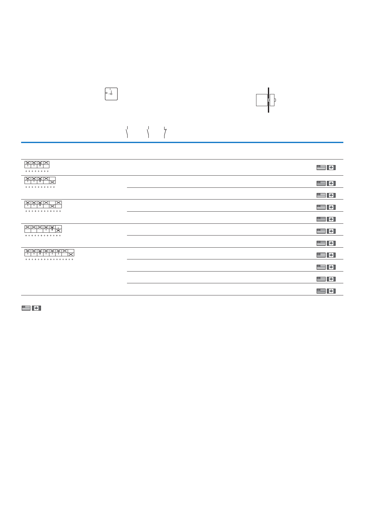
26
Cam switches, switch-disconnectors
Switch-disconnectors – On-Off switches
T, P
Information relevant for export to North America
)3)2)1
)7
Product Standards
UL File No.
UL CCN
CSA File No.
CSA Class No.
NA Certification
Suitable for
Degree of Protection
UL 508; CSA-C22.2 No. 14-05;
IEC/EN 60947-3; CE marking
E36332
NLRV
12528
3211-05
UL Listed, CSA certified
Branch circuits, suitable as
motor disconnect
IEC: IP65; UL/CSA Type 3R, 12
Product Standards
UL File No.
UL CCN
CSA File No.
CSA Class No.
NA Certification
Suitable for
Degree of Protection
UL 508; CSA-C22.2 No. 14-05;
IEC/EN 60947-3; CE marking
E36332
NLRV
12528
3211-05
UL Listed, CSA certified
Branch circuits, suitable as
motor disconnect
IEC: IP30; UL/CSA Type: –
Product Standards
UL File No.
UL CCN
CSA File No.
CSA Class No.
NA Certification
Suitable for
Degree of Protection
UL 508; CSA-C22.2 No. 14-05;
CSA-C22.2 No. 94;
IEC/EN 60947-3; CE marking
E36332
NLRV
12528
3211-05
UL Listed, CSA certified
Branch circuits, suitable as
motor disconnect
IEC: IP65; UL/CSA Type 3R, 12
Product Standards
UL File No.
UL CCN
CSA File No.
CSA Class No.
NA Certification
Suitable for
Degree of Protection
UL 508; CSA-C22.2 No. 14-05;
CSA-C22.2 No. 94;
IEC/EN 60947-3; CE marking
E36332
NLRV
12528
3211-07
UL Listed, CSA certified
Branch circuits, suitable as
motor disconnect
IEC: IP65; UL/CSA Type 3R, 12
Flush mounting
tnorFecneuqestcatnoC
plate no.
Main
contacts
Pole
Auxiliary
contacts
Max. motor rating:
AC-23A
400/415 V
50/60 Hz
Rated
uninterrupted
current
Front IP65
N/O N/O N/C 400 V
P
kW
Iu
A
Part no.
Article no.
Price
See
price
list
Std. pack
On-Off switches without emergency switching off/emergency stop function
With auxiliary contacts With black thumb-grip and front plate
3 106.5 20 T0-2-15679/E1)
029387
1 Off
1 Off
1 Off
1 Off
1 Off
1 Off
1 Off
1 Off
1 Off
1 Off
1 Off
3 1113 25
3 1115 32
3 216.5 20 T0-3-15683/E1)
016619
3 2113 32 T3-3-15683/E3)
014377
3 + N 1 1 6.5 20 T0-3-8901/E1)
231938
3 + N1113 32 T3-3-8901/E3)
231949
6 116.5 20
611
611
611
T0-4-15682/E1)
010405
13 32 T3-4-15682/E3)
023869
22 63 T5B-4-15682/E4)
207424
30 100 T5-4-15682/E
207412
FS 908
ON
OFF
1
2
3
4
5
6
7
8
01
1
2
3
4
5
6
13
14
01
21
22
1
2
3
4
5
6
7
8
01
9
10
11
12
1
2
3
4
5
6
7
8
01
9
10
11
12
1
2
3
4
5
6
7
8
01
9
10
11
12
13
14
15
16
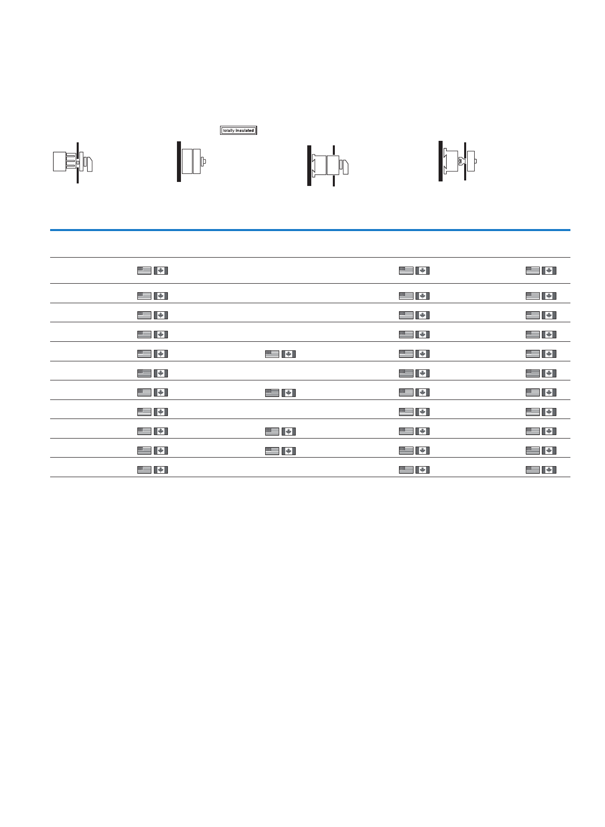
27
Cam switches, switch-disconnectors
Switch-disconnectors – On-Off switches
)5)4 )6
Product Standards
UL File No.
UL CCN
CSA File No.
CSA Class No.
NA Certification
Suitable for
Degree of Protection
UL 508; CSA-C22.2 No. 14-05;
CSA-C22.2 No. 94;
IEC/EN 60947-3; CE marking
E36332
NLRV
12528
3211-05
UL Listed, CSA certified
Branch circuits, suitable as
motor disconnect
IEC: IP65; UL/CSA Type: –
Product Standards
UL File No.
UL CCN
CSA File No.
CSA Class No.
NA Certification
Suitable for
Degree of Protection
UL 508; CSA-C22.2 No. 14-05;
CSA-C22.2 No. 94;
IEC/EN 60947-3; CE marking
E36332
NLRV
12528
3211-07
UL Listed, CSA certified
Branch circuits, suitable as
motor disconnect
IEC: IP65; UL/CSA Type 1
Product Standards
UL File No.
UL CCN
CSA File No.
CSA Class No.
NA Certification
Suitable for
Degree of Protection
UL 508; CSA-C22.2 No. 14-05;
CSA-C22.2 No. 94;
IEC/EN 60947-3; CE marking
E36332
NLRV
12528
3211-07
UL Listed, CSA certified
Branch circuits, suitable as
motor disconnect
IEC: IP65; UL/CSA Type: –
Center
mounting
Surface
mounting
Distribution board - mounting Rear mounting
Front IP65 IP65 Front IP30 Front IP65
Part no.
Article no.
Price
See
price
list
Std. pack Part no.
Article no.
Price
See
price
list
Std. pack Part no.
Article no.
Price
See
price
list
Std. pack Part no.
Article no.
Price
See
price
list
Std. pack
T0-2-15679/EZ1)
031760
1 Off
1 Off
1 Off
1 Off
1 Off
1 Off
1 Off
1 Off
1 Off
1 Off
1 Off
T0-2-15679/I1
207094
1 Off
1 Off
1 Off
1 Off
T0-2-15679/IVS2)
036506
1 Off
1 Off
1 Off
1 Off
1 Off
1 Off
1 Off
1 Off
1 Off
1 Off
1 Off
T0-2-15679/Z1)
041252
1 Off
1 Off
1 Off
1 Off
1 Off
1 Off
1 Off
1 Off
1 Off
1 Off
1 Off
P1-25/I2H/HI11
226899
P1-32/I2H/HI11
227867
T0-3-15683/EZ1)
016658
T0-3-15683/I1
207118
T0-3-15683/IVS2)
016722
T3-3-15683/I23)
207182
1 Off
T0-3-8901/EZ1)
231939
T0-3-8901/I1
231941
1 Off T0-3-8901/IVS2)
231940
T3-3-8901/EZ3)
231950
T3-3-8901/I23)
231951
1 Off T3-3-8901/Z3)
231952
T0-4-15682/EZ1)
012778
T0-4-15682/I1
207135
1 Off T0-4-15682/IVS2)
017524
T0-4-15682/Z1)
022270
T3-4-15682/I23)
207190
1 Off T3-4-15682/Z3)
030988
T5B-4-15682/I45)
207229
1 Off T5B-4-15682/Z4)
207429
T5-4-15682/I5
207269
1 Off T5-4-15682/Z
207417
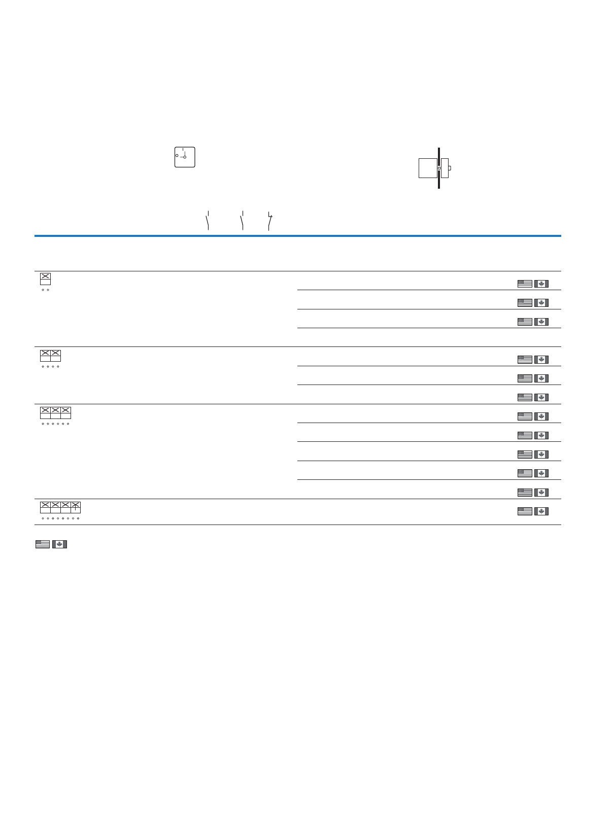
28
Cam switches, switch-disconnectors
Switch-disconnectors – On-Off switches
T, P
Information relevant for export to North America
)3)2)1
)7
Product Standards
UL File No.
UL CCN
CSA File No.
CSA Class No.
NA Certification
Suitable for
Degree of Protection
UL 508; CSA-C22.2 No. 14-05;
IEC/EN 60947-3; CE marking
E36332
NLRV
12528
3211-05
UL Listed, CSA certified
Branch circuits, suitable as
motor disconnect
IEC: IP65; UL/CSA Type 3R, 12
Product Standards
UL File No.
UL CCN
CSA File No.
CSA Class No.
NA Certification
Suitable for
Degree of Protection
UL 508; CSA-C22.2 No. 14-05;
IEC/EN 60947-3; CE marking
E36332
NLRV
12528
3211-05
UL Listed, CSA certified
Branch circuits, suitable as
motor disconnect
IEC: IP30; UL/CSA Type: –
Product Standards
UL File No.
UL CCN
CSA File No.
CSA Class No.
NA Certification
Suitable for
Degree of Protection
UL 508; CSA-C22.2 No. 14-05;
CSA-C22.2 No. 94;
IEC/EN 60947-3; CE marking
E36332
NLRV
12528
3211-05
UL Listed, CSA certified
Branch circuits, suitable as
motor disconnect
IEC: IP65; UL/CSA Type 3R, 12
Product Standards
UL File No.
UL CCN
CSA File No.
CSA Class No.
NA Certification
Suitable for
Degree of Protection
UL 508; CSA-C22.2 No. 14-05;
CSA-C22.2 No. 94;
IEC/EN 60947-3; CE marking
E36332
NLRV
12528
3211-07
UL Listed, CSA certified
Branch circuits, suitable as
motor disconnect
IEC: IP65; UL/CSA Type 3R, 12
Flush mounting
tnorFecneuqestcatnoC
plate no.
Main
contacts
Pole
Auxiliary
contacts
Max. motor rating:
AC-23A
400/415 V
50/60 Hz
Rated
uninterrupted
current
Front IP65
N/O N/O N/C 400 V
P
kW
Iu
A
Part no.
Article no.
Price
See
price
list
Std. pack
On-Off switches as an emergency switching off/emergency stop device
With red thumb-grip and yellow front plate
To IEC/EN 60204-1, VDE 113 Part 1
1 006.5 20 T0-1-8200/E-RT1)
009474
1 Off
1 Off
1 Off
13 32 T3-1-8200/E-RT3)
017025
22 63 T5B-1-8200/E-RT4)
094280
30 100 T5-1-8200/E-RT
097225
1 Off
2 006.5 20 T0-1-102/E-RT1)
009046
1 Off
1 Off
1 Off
1 Off
1 Off
1 Off
1 Off
1 Off
1 Off
13 32 T3-1-102/E-RT1)
016318
22 63 T5B-1-102/E-RT4)
094470
3 006.5 20 T0-2-1/E-RT1)
011082
13 25 P1-25/E-RT1)
002388
15 32 P1-32/E-RT1)
003197
37 63 P3-63/E-RT7)
005743
50 100 P3-100/E-RT7)
007189
3 + N 0 0 6.5 20 T0-2-8900/E-RT1)
207399
FS 908
ON
OFF
1
2
01
1
2
3
4
01
1
2
3
4
5
6
01
1
2
3
4
5
6
7
8
01
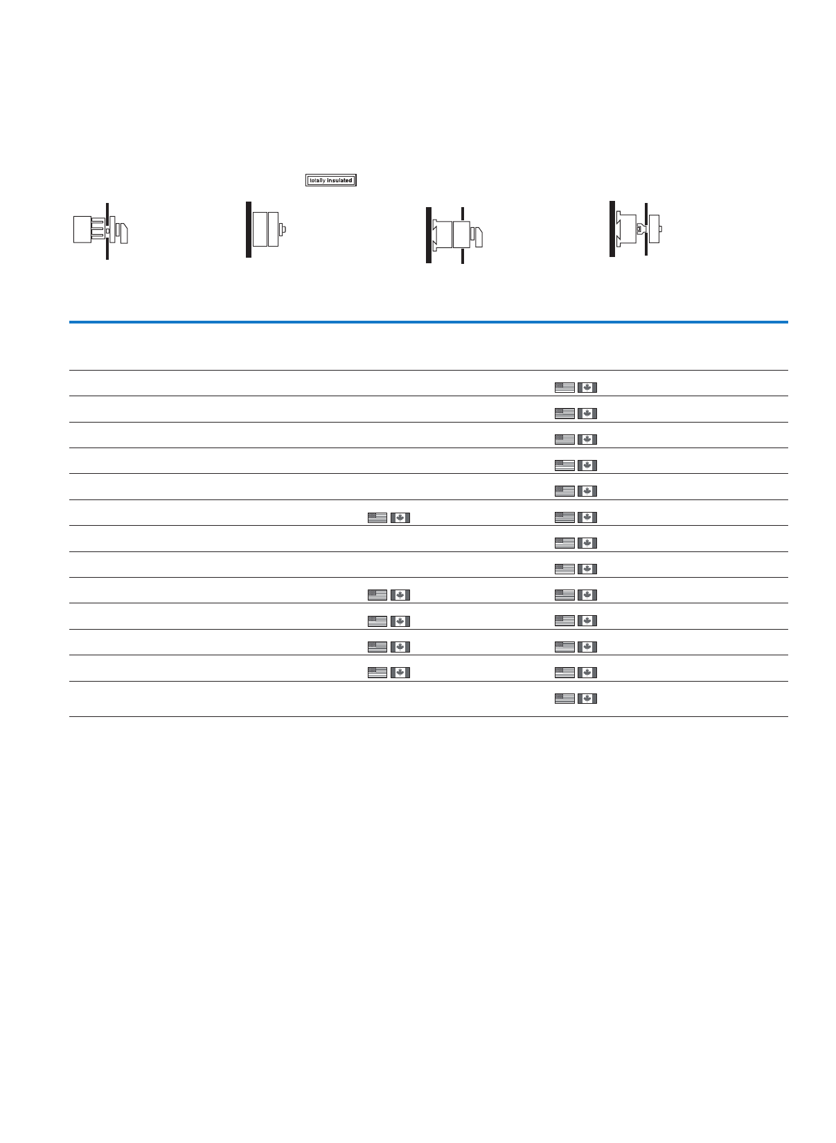
29
Cam switches, switch-disconnectors
Switch-disconnectors – On-Off switches
)5)4 )6
Product Standards
UL File No.
UL CCN
CSA File No.
CSA Class No.
NA Certification
Suitable for
Degree of Protection
UL 508; CSA-C22.2 No. 14-05;
CSA-C22.2 No. 94;
IEC/EN 60947-3; CE marking
E36332
NLRV
12528
3211-05
UL Listed, CSA certified
Branch circuits, suitable as
motor disconnect
IEC: IP65; UL/CSA Type: –
Product Standards
UL File No.
UL CCN
CSA File No.
CSA Class No.
NA Certification
Suitable for
Degree of Protection
UL 508; CSA-C22.2 No. 14-05;
CSA-C22.2 No. 94;
IEC/EN 60947-3; CE marking
E36332
NLRV
12528
3211-07
UL Listed, CSA certified
Branch circuits, suitable as
motor disconnect
IEC: IP65; UL/CSA Type 1
Product Standards
UL File No.
UL CCN
CSA File No.
CSA Class No.
NA Certification
Suitable for
Degree of Protection
UL 508; CSA-C22.2 No. 14-05;
CSA-C22.2 No. 94;
IEC/EN 60947-3; CE marking
E36332
NLRV
12528
3211-07
UL Listed, CSA certified
Branch circuits, suitable as
motor disconnect
IEC: IP65; UL/CSA Type: –
Center
mounting
Surface
mounting
Distribution board - mounting Rear mounting
Front IP65 IP65 Front IP30 Front IP65
Part no.
Article no.
Price
See
price
list
Std. pack Part no.
Article no.
Price
See
price
list
Std. pack Part no.
Article no.
Price
See
price
list
Std. pack Part no.
Article no.
Price
See
price
list
Std. pack
T0-1-8200/I1-RT
207075
1 Off T0-1-8200/IVS-RT2)
081956
1 Off
1 Off
1 Off
1 Off
1 Off
1 Off
1 Off
1 Off
1 Off
1 Off
1 Off
1 Off
1 Off
T0-1-102/I1-RT
207062
1 Off T0-1-102/IVS-RT2)
079583
T3-1-102/I2-RT3)
207166
1 Off
T0-2-1/I1-RT
207082
1 Off T0-2-1/IVS-RT2)
084329
P1-25/I2-RT7)
207300
1 Off P1-25/IVS-RT6)
013140
P1-32/I2-RT7)
207321
1 Off P1-32/IVS-RT6)
022632
P3-63/I4-RT7)
207357
1 Off P3-63/IVS-RT6)
045845
P3-100/I5-RT7)
207382
1 Off P3-100/IVS-RT6)
086185
T0-2-8900/I1-RT
207110
1 Off T0-2-8900/IVS-RT2)
207404
30
Cam switches, switch-disconnectors
Switch-disconnectors – safety switches
T, P
As an emergency switching off/
emergency stop device1)
Contact
sequence
Front plate no. Main
contacts
Pole
Auxiliary contacts Max. motor rating
AC-23 A, 400/415 V,
50/60 Hz
Rated uninterrupted
current
Surface mounting
IP65
N/O N/O N/C 400 V
P
kW
Iu
A
Part no.
Article no.
Price
See price
list
Std. pack
Safety switches with warning label
30013 25 P1-25/I2-SI3)
207308
1 Off
1 Off
1 Off
1 Off
1 Off
1 Off
1 Off
1 Off
1 Off
1 Off
1 Off
1 Off
1 Off
1 Off
1 Off
1 Off
1 Off
1 Off
15 32 P1-32/I2-SI3)
207329
37 63 P3-63/I4-SI3)
207361
50 100 P3-100/I5-SI3)
207386
31113 25 P1-25/I2-SI/HI113)
207310
15 32 P1-32/I2-SI/HI113)
207331
37 63 P3-63/I4-SI/HI113)
207363
50 100 P3-100/I5-SI/HI113)
207388
3 + N0013 25 P1-25/I2-SI/N3)
207312
15 32 P1-32/I2-SI/N3)
207333
37 63 P3-63/I4-SI/N3)
207365
50 100 P3-100/I5-SI/N3)
207390
60022 63 T5B-3-8342/I4-SI4)
207250
30 100 T5-3-8342/I5-SI4)
207447
61122 63 T5B-4-15682/I4-SI4)
207254
30 100 T5-4-15682/I5-SI4)
207285
62022 63 T5B-4-8903/I4-SI4)
207258
30 100 T5-4-8903/I5-SI4)
207289
Notes 1) Surface mounting IP65 : With red rotary handle and yellow locking collar with auxiliary contacts , lockable in position 0 with cover interlock,
according to IEC/EN 60204-1, VDE 0113 Part 1
2) Surface mounting IP65 : With black rotary handle and locking collar with auxiliary contacts Lockable in position 0 with cover interlock
FS 908
ON
OFF
1
2
3
4
5
6
01
1
2
3
4
5
6
13
14
01
21
22
1
2
3
4
5
6
N
N
01
1
2
3
4
5
6
7
8
9
10
01
11
12
1
2
3
4
5
6
7
8
01
9
10
11
12
13
14
15
16
1
2
3
4
5
6
7
8
01
9
10
11
12
13
14
15
16
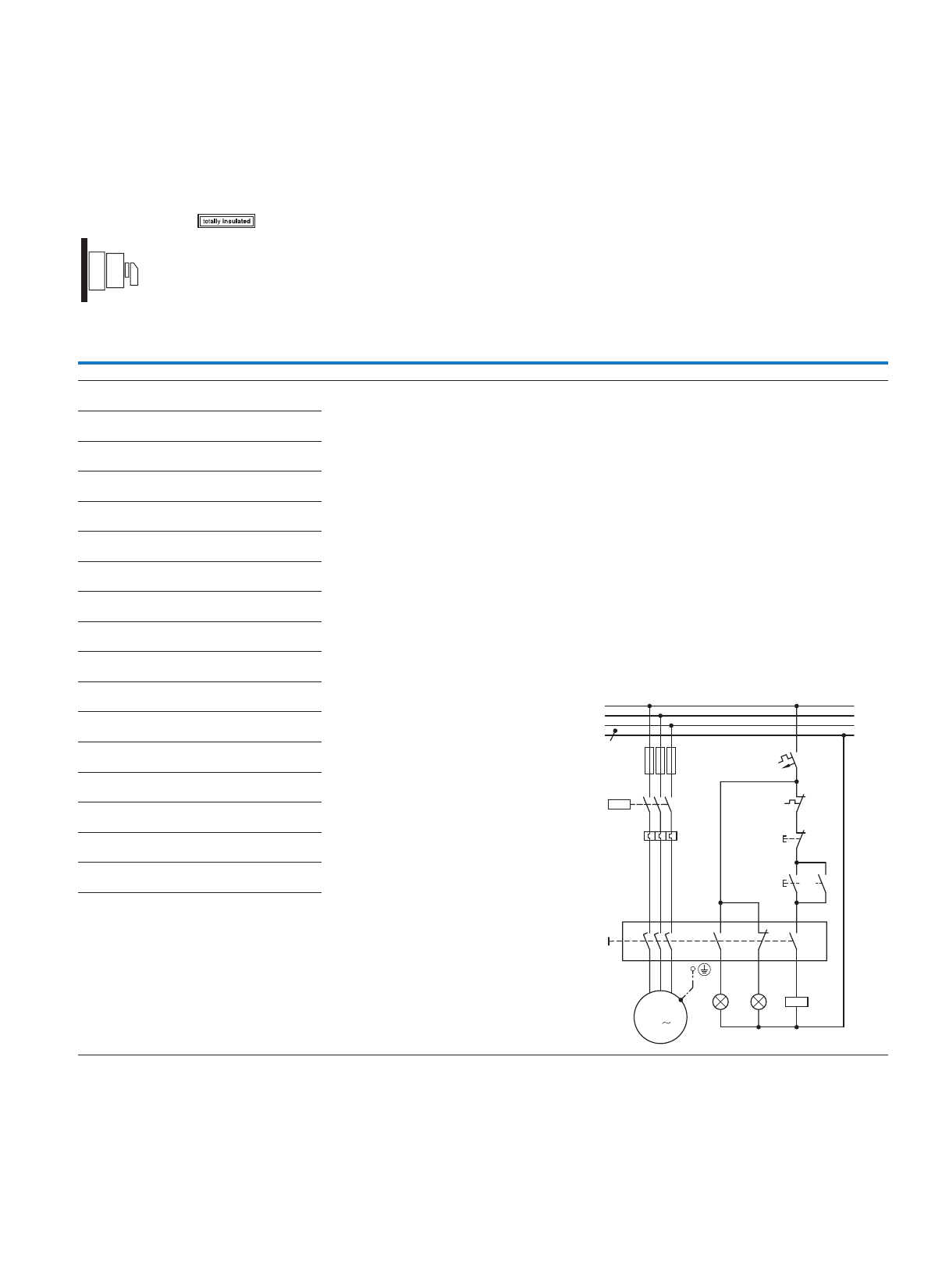
31
Cam switches, switch-disconnectors
Switch-disconnectors – safety switches
Without emergency switching off/
emergency stop function 2)
Surface mounting
IP65
Part no.
Article no.
Price
See price
list
Std. pack Notes
P1-25/I2-SI-SW3)
207309
1 Off
1 Off
1 Off
1 Off
1 Off
1 Off
1 Off
1 Off
1 Off
1 Off
1 Off
1 Off
1 Off
1 Off
1 Off
1 Off
1 Off
1 Off
P1-32/I2-SI-SW3)
207330
P3-63/I4-SI-SW3)
207362
P3-100/I5-SI-SW3)
207387
P1-25/I2-SI/HI11-SW3)
207311
P1-32/I2-SI/HI11-SW3)
207332
P3-63/I4-SI/HI11-SW3)
207364
P3-100/I5-SI/HI11-SW3)
207389
P1-25/I2-SI/N-SW3)
207313
P1-32/I2-SI/N-SW3)
207334
P3-63/I4-SI/N-SW3)
207366
P3-100/I5-SI/N-SW3)
207391
T5B-3-8342/I4-SI-SW4)
207251
T5-3-8342/I5-SI-SW4)
207448
T5B-4-15682/I4-SI-SW4)
207255
T5-4-15682/I5-SI-SW4)
207286
T5B-4-8903/I4-SI-SW4)
207259
T5-4-8903/I5-SI-SW4)
207290
Engineering
Maintenance, repair and safety switches all have
the same electrical function. They are designed to
safely isolate electrical installations (loads) from
mains power during maintenance and repair work
and to ensure that a hazard does not arise which
endangers personnel, machinery and production
materials.
A safety switch is an additional enclosed main
switch = isolator dedicated to an individual
electrical load and mounted in the immediate
vicinity of the motor or the electrical load.
This is particularly important if there is any danger
of the main switch being inadvertently operated.
Application
By using his padlock (up to 3), each fitter/electrician
involved can protect themselves by preventing
unauthorized personnel from switching the unit on.
Maintenance/manual override switches are simply
additional enclosed main switches with a
padlocking feature.
Enclosed main switch with padlocking facility
Features
• Safety switches are always housed in insulated
enclosures and have an inscription saying
"Safety Switch" on a bright orange label.
• Switches to be used for emergency stop switch-
ing have a red handle and yellow locking collar in
accordance with STOP category O (as per
IEC/EN 60204/VDE 0113).
• If the switch is not approved for emergency stop
switching, both parts will be black ("SW" part no.
suffix).
• The cover and handle are interlocked by fitting a
padlock.
Selection
The switches must be selected according to the following per-
formance specifications:
1) According to motor switching capacity, when the switch is
fitted in such a way that the operator may use it for operational
ON and OFF switching.
2) The rating data always applies to 3 poles. When the motor
rating is divided between 6 poles, such as for star-delta
switching, a 6 pole switch can be used to control 1.73 times
the rated power.
3) If the switch has a load-shedding Contact (LA), you can
select the appropriate switch according to the uninterrupted
current. The load-shedding contact is an auxiliary contact,
which is closed in the ON position and opens early when
switching off, so that a contactor located in the circuit takes
over the switching duty and the maintenance/safety switch
operates at zero load. When switching on, the load-shedding
contact closes later than or at the same time as the main con-
tacts. With P and T switches this is the N/O auxiliary contact.
4)The "ON" position can be locked with a padlock (by altering
the handle).
This is not permissible for switches with a red/yellow handle.
Safety switch with load shedding and signaling
Q11
L2
N
L3
L1
F1
Q11
2
1
4
3
6
5
F2
135
246
M
3
7911
81012
Q1
UVW
A2
Q11
A1
A2
P1 P2
F0
95
96
21
22
F2
O
13
14
I
13
14
FAZ-
B4/1-HS
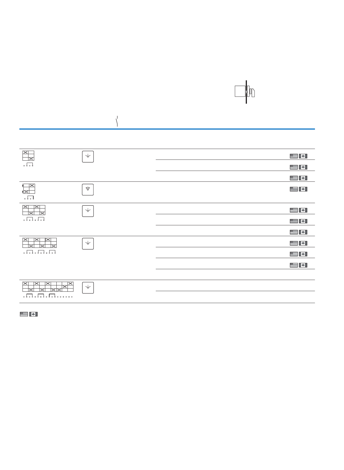
32
Cam switches, switch-disconnectors
Switch-disconnectors – changeover switches
T, P
Information relevant for export to North America
)3)2)1
Product Standards
UL File No.
UL CCN
CSA File No.
CSA Class No.
NA Certification
Suitable for
Degree of Protection
UL 508; CSA-C22.2 No. 14-05;
IEC/EN 60947-3; CE marking
E36332
NLRV
12528
3211-05
UL Listed, CSA certified
Branch circuits
IEC: IP65; UL/CSA Type 3R, 12
Product Standards
UL File No.
UL CCN
CSA File No.
CSA Class No.
NA Certification
Suitable for
Degree of Protection
UL 508; CSA-C22.2 No. 14-05;
IEC/EN 60947-3; CE marking
E36332
NLRV
12528
3211-05
UL Listed, CSA certified
Branch circuits
IEC: IP30; UL/CSA Type: –
Product Standards
UL File No.
UL CCN
CSA File No.
CSA Class No.
NA Certification
Suitable for
Degree of Protection
UL 508; CSA-C22.2 No. 14-05;
CSA-C22.2 No. 94;
IEC/EN 60947-3; CE marking
E36332
NLRV
12528
3211-05
UL Listed, CSA certified
Branch circuits
IEC: IP65; UL/CSA Type 3R, 12
Flush mounting
Contact sequence Front plate no. Main contacts
Pole
Max. operating
power
AC-23A
400/415 V
50/60 Hz
Rated
uninterrupted
current
Front IP65
N/O 400 V
P
kW
Iu
A
Part no.
Article no.
Price
See
price list
Std. pack
Changeover switches
With black thumb-grip and front plate
without emergency switching off/emergency stop function
16.520T0-1-8210/E1)
012742
1 Off
1 Off
1 Off
1 Off
1 Off
1 Off
1 Off
1 Off
1 Off
1 Off
13 32 T3-1-8210/E1)
054718
22 63 T5B-1-8210/E5)
094261
16.520
26.520T0-2-8211/E1)
022234
13 32 T3-2-8211/E1)
061837
22 63 T5B-2-8211/E5)
093094
36.520T0-3-8212/E1)
029353
13 32 T3-3-8212/E1)
068956
22 63 T5B-3-8212/E5)
092386
30 100 T5-3-8212/E
096466
1 Off
355 160T6-3-8212/E/HI12
214781
1 Off
132 315 T8-3-8212/E/HI12
214782
1 Off
1
2
3
4
201
FS 684
0
12
1
2
3
4
102
FS 4011
0
12
1
2
3
4
5
6
7
8
201
FS 684
0
12
FS 684
0
12
1
2
3
4
5
6
7
8
9
10
11
12
201
1
2
3
4
5
6
7
8
9
10
11
12
101
102
102
103
104
105
106
0
12
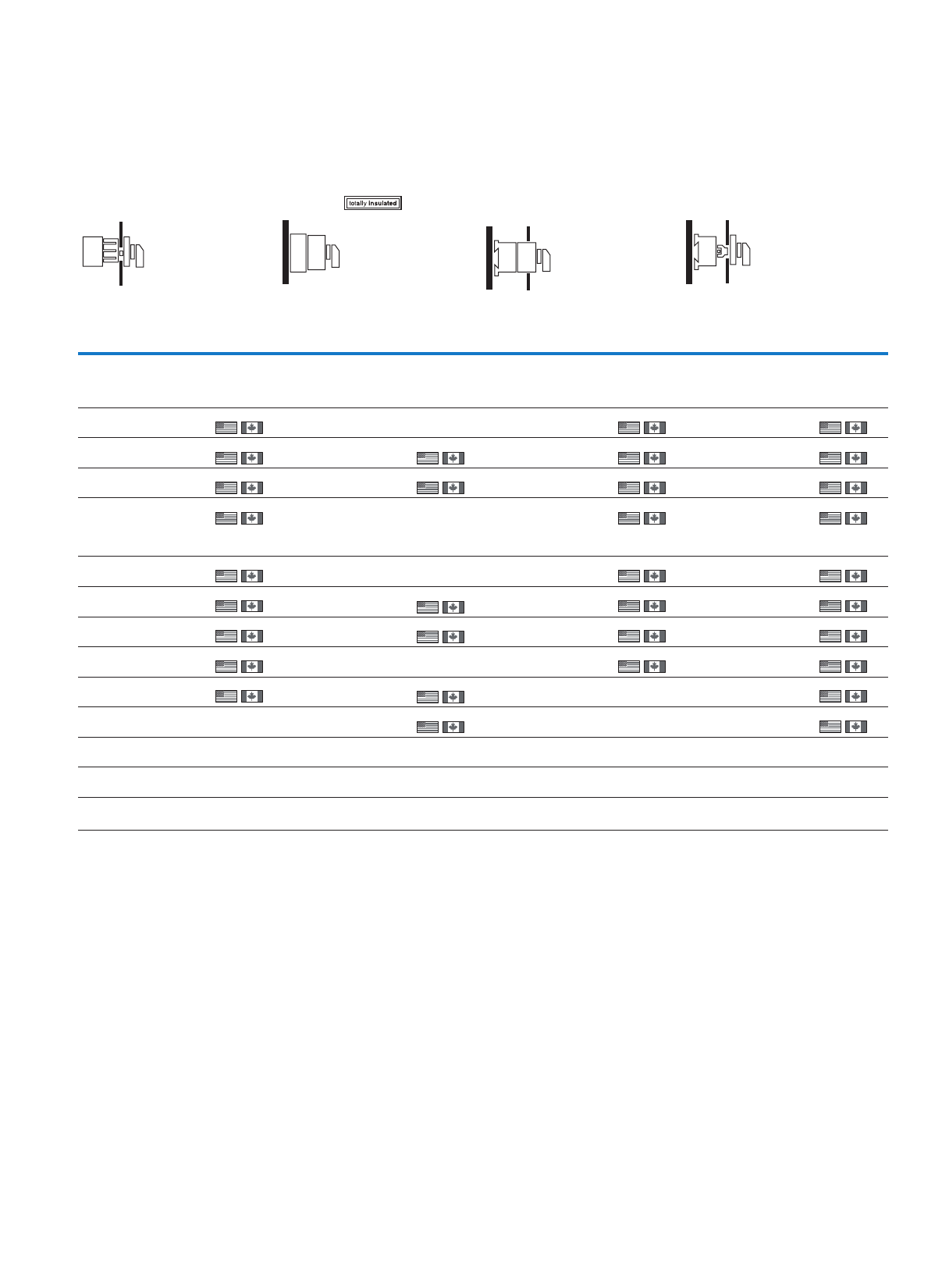
33
Cam switches, switch-disconnectors
Switch-disconnectors – changeover switches
)5)4
Product Standards
UL File No.
UL CCN
CSA File No.
CSA Class No.
NA Certification
Suitable for
Degree of Protection
UL 508; CSA-C22.2 No. 14-05;
IEC/EN 60947-3; CE marking
E36332
NLRV7
12528
3211-05
UL Listed, CSA certified
Branch circuits
IEC: IP65; UL/CSA Type: –
Product Standards
UL File No.
UL CCN
CSA File No.
CSA Class No.
NA Certification
Suitable for
Degree of Protection
UL 508; CSA-C22.2 No. 14-05;
IEC/EN 60947-3; CE marking
E36332
NLRV7
12528
3211-05
UL Listed, CSA certified
Branch circuits
IEC: IP65; UL/CSA Type 1
Center mounting Surface mounting Distribution board
mounting
Rear mounting
Front IP65 IP65 Front IP30 Front IP65
Part no.
Article no.
Price
See
price list
Std. pack Part no.
Article no.
Price
See
price list
Std. pack Part no.
Article no.
Price
See
price list
Std. pack Part no.
Article no.
Price
See
price list
Std. pack
T0-1-8210/EZ1)
048337
1 Off
1 Off
1 Off
1 Off
1 Off
1 Off
1 Off
1 Off
1 Off
T0-1-8210/I1
207076
1 Off T0-1-8210/IVS2)
074440
1 Off
1 Off
1 Off
1 Off
1 Off
1 Off
1 Off
1 Off
T0-1-8210/Z1)
019862
1 Off
1 Off
1 Off
1 Off
1 Off
1 Off
1 Off
1 Off
1 Off
1 Off
T3-1-8210/EZ1)
003072
T3-1-8210/I23)
207169
1 Off T3-1-8210/Z1)
057091
T5B-1-8210/I44)
207432
1 Off T5B-1-8210/Z5)
094258
T0-1-8214/EZ1)
076815
T0-1-8214/Z1)
050720
T0-2-8211/EZ1)
053083
T0-2-8211/I1
207102
1 Off T0-2-8211/IVS2)
076813
T0-2-8211/Z1)
029354
T3-2-8211/EZ1)
003075
T3-2-8211/I23)
207178
1 Off T3-2-8211/Z1)
064210
T5B-2-8211/I44)
207220
1 Off T5B-2-8211/Z5)
093082
T0-3-8212/EZ1)
057829
T0-3-8212/I1
207123
1 Off T0-3-8212/IVS2)
079186
T0-3-8212/Z1)
036473
T3-3-8212/EZ1)
003080
T3-3-8212/I23)
207183
1 Off T3-3-8212/Z1)
071329
T5B-3-8212/I44)
207223
1 Off T5B-3-8212/Z5)
092383
T5-3-8212/I5
207266
1 Off T5-3-8212/Z
096464
1 Off
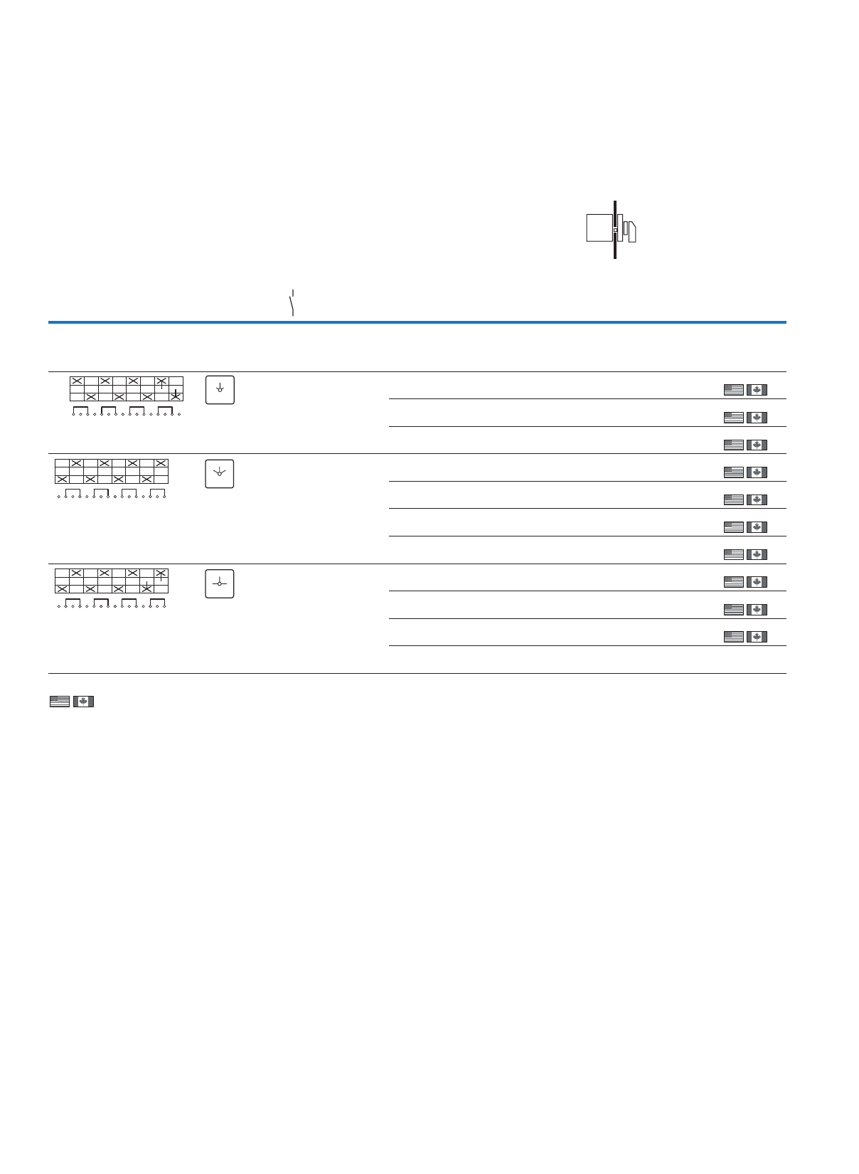
34
Cam switches, switch-disconnectors
Switch-disconnectors – changeover switches
T, P
Information relevant for export to North America
)3)2)1
Product Standards
UL File No.
UL CCN
CSA File No.
CSA Class No.
NA Certification
Suitable for
Degree of Protection
UL 508; CSA-C22.2 No. 14-05;
IEC/EN 60947-3; CE marking
E36332
NLRV
12528
3211-05
UL Listed, CSA certified
Branch circuits
IEC: IP65; UL/CSA Type 3R, 12
Product Standards
UL File No.
UL CCN
CSA File No.
CSA Class No.
NA Certification
Suitable for
Degree of Protection
UL 508; CSA-C22.2 No. 14-05;
IEC/EN 60947-3; CE marking
E36332
NLRV
12528
3211-05
UL Listed, CSA certified
Branch circuits
IEC: IP30; UL/CSA Type: –
Product Standards
UL File No.
UL CCN
CSA File No.
CSA Class No.
NA Certification
Suitable for
Degree of Protection
UL 508; CSA-C22.2 No. 14-05;
CSA-C22.2 No. 94;
IEC/EN 60947-3; CE marking
E36332
NLRV
12528
3211-05
UL Listed, CSA certified
Branch circuits
IEC: IP65; UL/CSA Type 3R, 12
Flush mounting
Contact sequence Front plate no. Main contacts
Pole
Max. operating
power
AC-23A
400/415 V
50/60 Hz
Rated
uninterrupted
current
Front IP65
N/O 400 V
P
kW
Iu
A
Part no.
Article no.
Price
See
price list
Std. pack
Changeover switches
With black thumb-grip and front plate
Without emergency switching off/emergency stop function
413 32T3-4-8902/E1)
215222
1 Off
1 Off
1 Off
1 Off
1 Off
1 Off
1 Off
1 Off
1 Off
1 Off
22 63 T5B-4-8902/E5)
207430
30 100 T5-4-8902/E
207418
46.520T0-4-8213/E1)
031726
13 32 T3-4-8213/E1)
076075
22 63 T5B-4-8213/E5)
092112
30 100 T5-4-8213/E
096014
46.520T0-4-8294/E1)
010371
13 32 T3-4-8294/E1)
002513
22 63 T5B-4-8294/E5)
092084
30 100 T5-4-8294/E
095986
1 Off
1
2
3
4
5
6
7
8
9
10
11
12
13
14
0
15
16
Netz
Notstrom
0
FS 161629
NETZ
NOT-
STROM
1
2
3
4
5
6
7
8
9
10
11
12
13
14
102
15
16
FS 684
0
12
1
2
3
4
5
6
7
8
9
10
11
12
13
14
102
15
16
FS 953
0
12
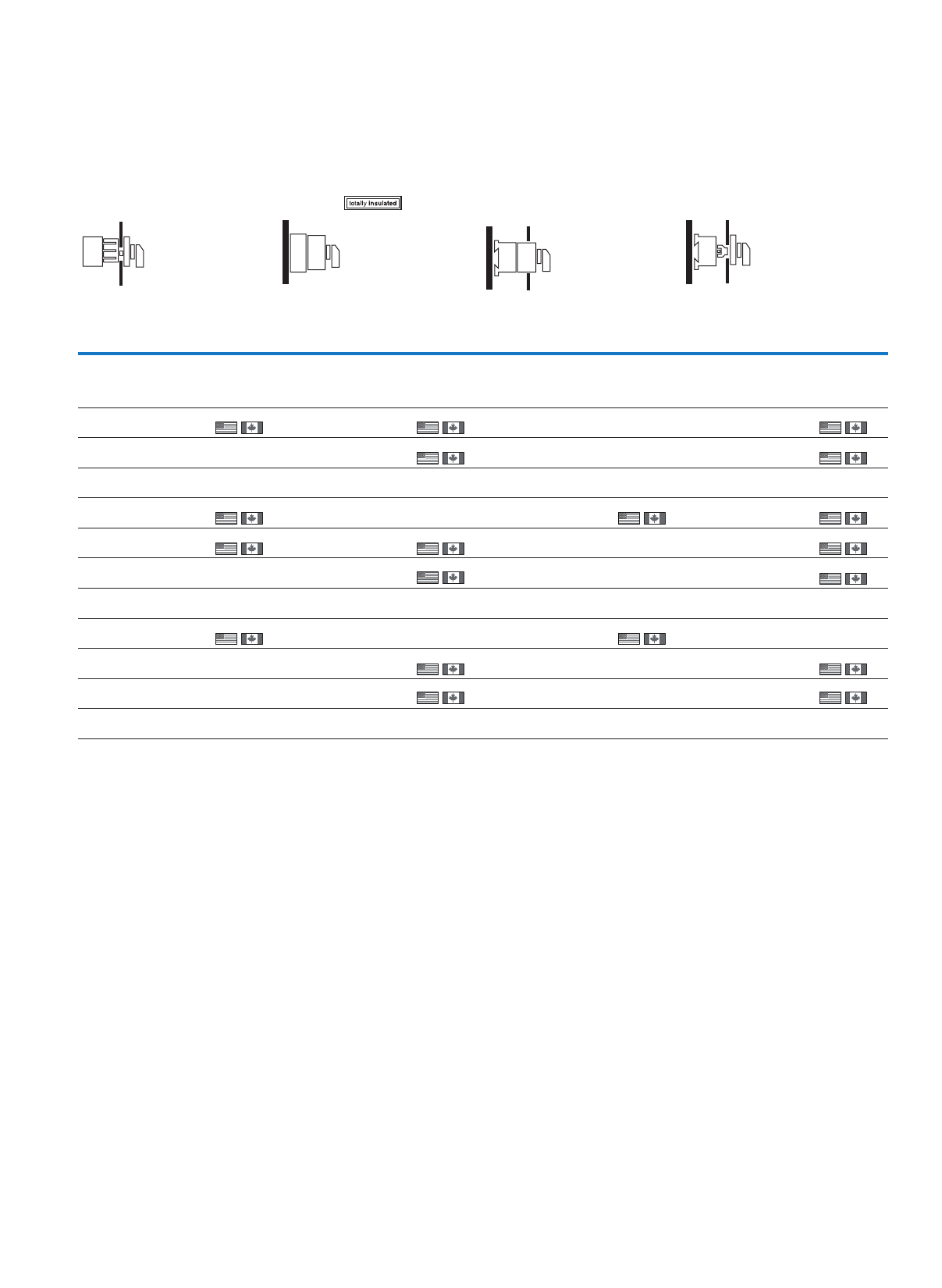
35
Cam switches, switch-disconnectors
Switch-disconnectors – changeover switches
)5)4
Product Standards
UL File No.
UL CCN
CSA File No.
CSA Class No.
NA Certification
Suitable for
Degree of Protection
UL 508; CSA-C22.2 No. 14-05;
IEC/EN 60947-3; CE marking
E36332
NLRV7
12528
3211-05
UL Listed, CSA certified
Branch circuits
IEC: IP65; UL/CSA Type: –
Product Standards
UL File No.
UL CCN
CSA File No.
CSA Class No.
NA Certification
Suitable for
Degree of Protection
UL 508; CSA-C22.2 No. 14-05;
IEC/EN 60947-3; CE marking
E36332
NLRV7
12528
3211-05
UL Listed, CSA certified
Branch circuits
IEC: IP65; UL/CSA Type 1
Center mounting Surface mounting Distribution board
mounting
Rear mounting
Front IP65 IP65 Front IP30 Front IP65
Part no.
Article no.
Price
See
price list
Std. pack Part no.
Article no.
Price
See
price list
Std. pack Part no.
Article no.
Price
See
price list
Std. pack Part no.
Article no.
Price
See
price list
Std. pack
T3-4-8902/EZ1)
215223
1 Off T3-4-8902/I23)
215224
1 Off T3-4-8902/Z1)
215225
1 Off
T5B-4-8902/I44)
207237
1 Off T5B-4-8902/Z5)
207431
1 Off
T5-4-8902/I5
207214
1 Off T5-4-8902/Z
207419
1 Off
T0-4-8213/EZ1)
062575
1 Off T0-4-8213/I1
207136
1 Off T0-4-8213/IVS2)
081559
1 Off T0-4-8213/Z1)
043592
1 Off
1 Off
1 Off
T3-4-8213/EZ1)
003079
1 Off T3-4-8213/I23)
207191
1 Off T3-4-8213/Z1)
078448
T5B-4-8213/I44)
207230
1 Off T5B-4-8213/Z5)
092109
T5-4-8213/I5
207270
1 Off T5-4-8213/Z
096012
1 Off
T0-4-8294/EZ1)
072069
1 Off T0-4-8294/I1
207138
1 Off T0-4-8294/IVS2)
043594
1 Off
T3-4-8294/I23)
207193
1 Off T3-4-8294/Z1)
004886
1 Off
T5B-4-8294/I44)
207232
1 Off T5B-4-8294/Z5)
092081
1 Off
T5-4-8294/I5
207433
1 Off T5-4-8294/Z
095984
1 Off
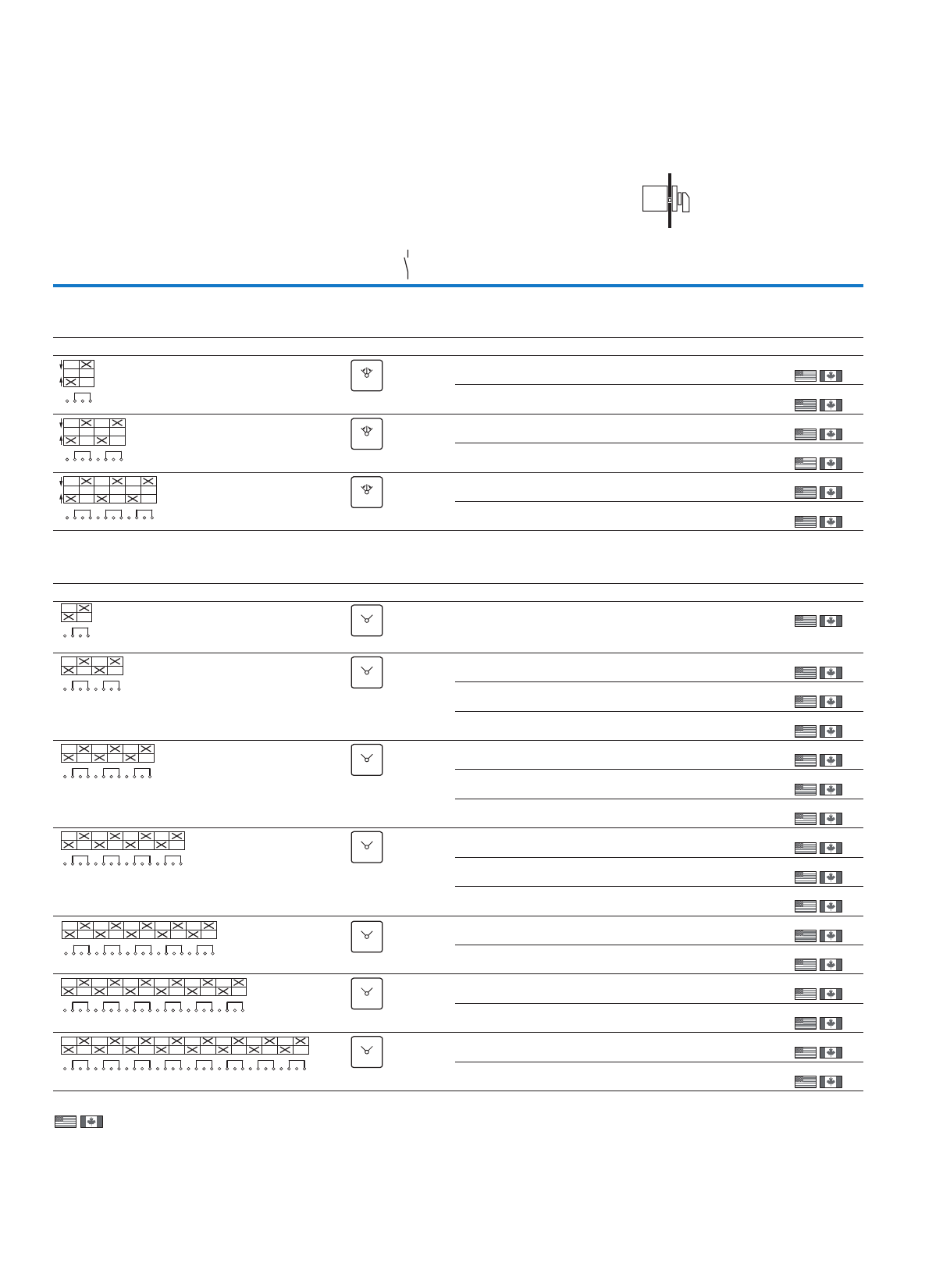
36
Cam switches, switch-disconnectors
Switch-disconnectors – changeover switches
T, P
Information relevant for export to North America )2)1
Product Standards
UL File No.
UL CCN
CSA File No.
CSA Class No.
NA Certification
Suitable for
Degree of Protection
UL 508; CSA-C22.2 No. 14-05;
IEC/EN 60947-3; CE marking
E36332
NLRV
12528
3211-05
UL Listed, CSA certified
Branch circuits
IEC: IP30; UL/CSA Type: –
Product Standards
UL File No.
UL CCN
CSA File No.
CSA Class No.
NA Certification
Suitable for
Degree of Protection
UL 508; CSA-C22.2 No. 14-05;
IEC/EN 60947-3; CE marking
E36332
NLRV
12528
3211-05
UL Listed, CSA certified
Branch circuits
IEC: IP65; UL/CSA Type 3R, 12
Flush mounting
tnorFecneuqestcatnoC
plate no.
Main
contacts
Pole
Max. motor rating
AC-23A
400/415 V
50/60 Hz
Rated
uninterrupted
current
Front IP65
N/O 400 V
P
kW
IuPart no.
Article no.
Price
See
price list
Std. pack
A
Changeover switches with 0 position
With black thumb-grip and front plate
Without emergency switching off/emergency stop function
with momentary from both directions to 0
16.5 20 T0-1-8214/E2)
019863
1 Off
1 Off
1 Off
1 Off
1 Off
1 Off
13 32 T3-1-8214/E2)
009632
26.5 20 T0-2-8215/E2)
022236
13 32 T3-2-8215/E2)
016751
36.5 20 T0-3-8216/E2)
024609
13 32 T3-3-8216/E2)
023870
Changeover switches without 0 position
With black thumb-grip and front plate
Without emergency switching off/emergency stop function
Two-way switch
16.5 20 T0-1-8220/E2)
031728
1 Off
1 Off
1 Off
1 Off
1 Off
1 Off
1 Off
1 Off
1 Off
1 Off
1 Off
1 Off
1 Off
1 Off
1 Off
1 Off
26.5 20 T0-2-8221/E2)
038847
13 32 T3-2-8221/E2)
045227
22 63 T5B-2-8221/E4)
093047
36.5 20 T0-3-8222/E2)
048339
13 32 T3-3-8222/E2)
052346
22 63 T5B-3-8222/E4)
092378
46.5 20 T0-4-8223/E2)
050712
13 32 T3-4-8223/E2)
059465
22 63 T5B-4-8223/E4)
092108
56.5 20 T0-5-8369/E2)
060204
13 32 T3-5-8369/E2)
066584
66.5 20 T0-6-8370/E2)
062577
13 32 T3-6-8370/E2)
073703
86.5 20 T0-8-8372/E2)
064950
13 32 T3-8-8372/E2)
080822
1
2
3
4
102
FS 4011
0
12
FS 4011
0
12
FS 4011
0
12
1
2
3
4
5
6
7
8
102
1
2
3
4
5
6
7
8
9
10
11
12
102
1
2
3
4
12
12
FS 943
12
FS 943
12
FS 943
12
FS 943
12
FS 943
12
FS 943
12
FS 943
1
2
3
4
5
6
7
8
12
1
2
3
4
5
6
7
8
9
10
11
12
12
1
2
3
4
5
6
7
8
9
10
11
12
13
14
12
15
16
1
2
3
4
5
6
7
8
9
10
11
12
13
14
12
15
16
17
18
19
20
1
2
3
4
5
6
7
8
9
10
11
12
13
14
12
15
16
17
18
19
20
21
22
23
24
1
2
3
4
5
6
7
8
9
10
11
12
13
14
12
15
16
17
18
19
20
21
22
23
24
25
26
27
28
29
30
31
32
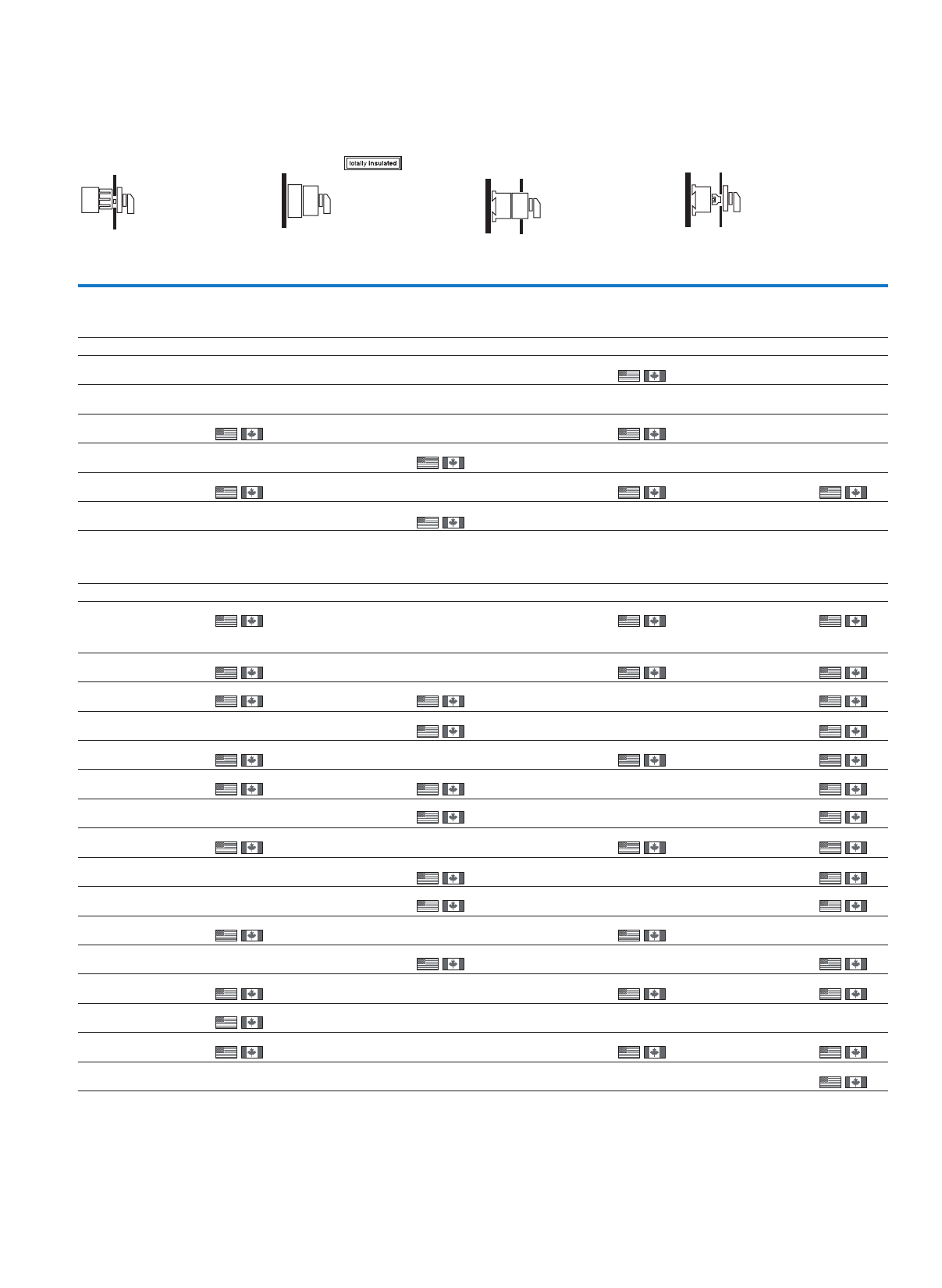
37
Cam switches, switch-disconnectors
Switch-disconnectors – changeover switches
)5)4)3
Product Standards
UL File No.
UL CCN
CSA File No.
CSA Class No.
NA Certification
Suitable for
Degree of Protection
UL 508; CSA-C22.2 No. 14-05;
CSA-C22.2 No. 94;
IEC/EN 60947-3; CE marking
E36332
NLRV
12528
3211-05
UL Listed, CSA certified
Branch circuits
IEC: IP65; UL/CSA Type 3R, 12
Product Standards
UL File No.
UL CCN
CSA File No.
CSA Class No.
NA Certification
Suitable for
Degree of Protection
UL 508; CSA-C22.2 No. 14-05;
IEC/EN 60947-3; CE marking
E36332
NLRV7
12528
3211-05
UL Listed, CSA certified
Branch circuits
IEC: IP65; UL/CSA Type 1
Product Standards
UL File No.
UL CCN
CSA File No.
CSA Class No.
NA Certification
Suitable for
Degree of Protection
UL 508; CSA-C22.2 No. 14-05;
IEC/EN 60947-3; CE marking
E36332
NLRV7
12528
3211-05
UL Listed, CSA certified
Branch circuits
IEC: IP65; UL/CSA Type: –
Center mounting Surface mounting Distribution board
mounting
Rear mounting
Front IP65 IP65 Front IP30 Front IP65
Part no.
Article no.
Price
See
price list
Std. pack Part no.
Article no.
Price
See
price list
Std. pack Part no.
Article no.
Price
See
price list
Std. pack Part no.
Article no.
Price
See
price list
Std. pack
T0-1-8214/EZ
076815
T0-1-8214/I1
207077
1 Off T0-1-8214/IVS1)
045967
1 Off T0-1-8214/Z
050720
T0-2-8215/EZ2)
081561
1 Off T0-2-8215/I1
207103
1 Off T0-2-8215/IVS1)
048340
1 Off
T3-2-8215/I23)
207179
1 Off
T0-3-8216/EZ2)
086307
1 Off T0-3-8216/I1
207434
1 Off T0-3-8216/IVS1)
050713
1 Off T0-3-8216/Z2)
055466
1 Off
T3-3-8216/I23)
207184
1 Off
T0-1-8220/EZ2)
095799
1 Off T0-1-8220/I1
207078
1 Off T0-1-8220/IVS1)
055459
1 Off T0-1-8220/Z2)
086312
1 Off
T0-2-8221/EZ2)
010372
1 Off T0-2-8221/I1
207104
1 Off T0-2-8221/IVS1)
057832
1 Off T0-2-8221/Z2)
074450
1 Off
T3-2-8221/EZ2)
001025
1 Off T3-2-8221/I23)
207180
1 Off T3-2-8221/Z2)
047600
1 Off
T5B-2-8221/I45)
207221
1 Off T5B-2-8221/Z4)
093044
1 Off
T0-3-8222/EZ2)
015118
1 Off T0-3-8222/I1
207124
1 Off T0-3-8222/IVS1)
060205
1 Off T0-3-8222/Z2)
088686
1 Off
T3-3-8222/EZ2)
001069
1 Off T3-3-8222/I23)
207185
1 Off T3-3-8222/Z2)
057092
1 Off
T5B-3-8222/I45)
207224
1 Off T5B-3-8222/Z4)
092375
1 Off
T0-4-8223/EZ2)
019864
1 Off T0-4-8223/I1
207137
1 Off T0-4-8223/IVS1)
062578
1 Off T0-4-8223/Z2)
086315
1 Off
T3-4-8223/I23)
207192
1 Off T3-4-8223/Z2)
061838
1 Off
T5B-4-8223/I45)
207231
1 Off T5B-4-8223/Z4)
092105
1 Off
T0-5-8369/EZ2)
024610
1 Off T0-5-8369/IVS1)
064951
1 Off
T3-5-8369/I23)
207536
1 Off T3-5-8369/Z2)
068957
1 Off
T0-6-8370/EZ2)
029356
1 Off T0-6-8370/IVS1)
067324
1 Off T0-6-8370/Z2)
010380
1 Off
T3-6-8370/EZ2)
004506
1 Off
T0-8-8372/EZ2)
034102
1 Off T0-8-8372/IVS1)
069697
1 Off T0-8-8372/Z2)
012753
1 Off
T3-8-8372/Z2)
083195
1 Off
38
Cam switches, switch-disconnectors
Switch-disconnectors – reversing switches
T, P
Information relevant for export to North America )2)1
Product Standards
UL File No.
UL CCN
CSA File No.
CSA Class No.
NA Certification
Suitable for
Degree of Protection
UL 508; CSA-C22.2 No. 14-05;
IEC/EN 60947-3; CE marking
E36332
NLRV
12528
3211-05
UL Listed, CSA certified
Branch circuits, suitable as
motor disconnect
IEC: IP65; UL/CSA Type 3R, 12
Product Standards
UL File No.
UL CCN
CSA File No.
CSA Class No.
NA Certification
Suitable for
Degree of Protection
UL 508; CSA-C22.2 No. 14-05;
IEC/EN 60947-3; CE marking
E36332
NLRV7
12528
3211-05
UL Listed, CSA certified
Branch circuits, suitable as
motor disconnect
IEC: IP65; UL/CSA Type 3R, 12
Flush mounting
Contact sequence Front plate no. Main contacts
Pole
Max. operating
power
AC-23A
400/415 V
50/60 Hz
Rated
uninterrupted
current
Front IP65
S 400 V
P
kW
Iu
A
Part no.
Article no.
Price
See
price list
Std. pack
Reversing switch with 0 (Off) position
With black thumb-grip and front plate
Without emergency switching off/emergency stop function
Without momentary
26.520T0-2-8400/E1)
053079
1 Off
1 Off
1 Off
1 Off
1 Off
1 Off
13 32 T3-2-8400/E1)
073695
22 63 T5B-2-8400/E2)
092918
36.520T0-3-8401/E1)
091047
13 32 T3-3-8401/E1)
030992
22 63 T5B-3-8401/E2)
092296
With momentary from both directions to 0
36.520T0-3-8228/E1)
015112
1 Off
1 Off
1 Off
13 32 T3-3-8228/E1)
002538
22 63 T5B-3-8228/E2)
092374
1
2
3
4
5
6
7
8
102
FS 684
0
12
FS 684
0
12
1
2
3
4
5
6
7
8
9
10
102
1
2
3
4
5
6
7
8
9
10
102
FS 4011
0
12
Star-delta switches
With black thumb-grip and front plate
Without emergency switching off/emergency stop function
36.520T0-4-8410/E1)
024604
1 Off
1 Off
1 Off
13 32 T3-4-8410/E1)
009657
22 63 T5B-4-8410/E1)
092052
FS 635
Y
0
Reversing star-delta switches
With black thumb-grip and front plate
Without emergency switching off/emergency stop function
Two-way operating direction
36.520
3
T0-5-15876/E1)
000893
1 Off
1 Off
1 Off
13 32 T3-5-15876/E1)
016776
22 63 T5B-5-15876/E2)
214785
FS 638
Y
0
Y
FS 4017
Y
0
Y
1
2
3
4
5
6
7
8
9
10
11
12
13
14
0yd
15
16
1
2
3
4
5
6
7
8
9
10
11
12
13
14
dy 0
15
16
17
18
19
20
y d
1
2
3
4
5
6
7
8
9
10
11
12
13
14
dy 0
15
16
17
18
19
20
y d
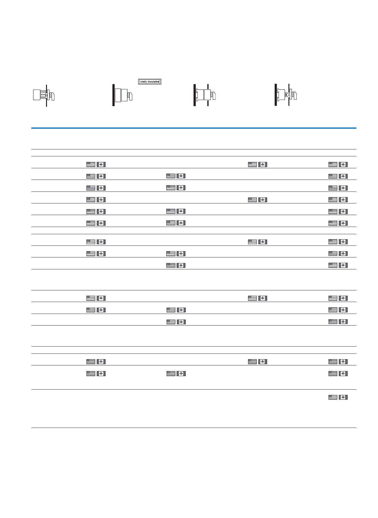
39
Cam switches, switch-disconnectors
Switch-disconnectors – reversing switches
)5)4)3
Product Standards
UL File No.
UL CCN
CSA File No.
CSA Class No.
NA Certification
Suitable for
Degree of Protection
UL 508; CSA-C22.2 No. 14-05;
CSA-C22.2 No. 94;
IEC/EN 60947-3; CE marking
E36332
NLRV
12528
3211-05
UL Listed, CSA certified
Branch circuits, suitable as
motor disconnect
IEC: IP65; UL/CSA Type 3R, 12
Product Standards
UL File No.
UL CCN
CSA File No.
CSA Class No.
NA Certification
Suitable for
Degree of Protection
UL 508; CSA-C22.2 No. 14-05;
IEC/EN 60947-3; CE marking
E36332
NLRV
12528
3211-05
UL Listed, CSA certified
Branch circuits, suitable as
motor disconnect
IEC: IP30; UL/CSA Type: –
Product Standards
UL File No.
UL CCN
CSA File No.
CSA Class No.
NA Certification
Suitable for
Degree of Protection
UL 508; CSA-C22.2 No. 14-05;
IEC/EN 60947-3; CE marking
E36332
NLRV
12528
3211-05
UL Listed, CSA certified
Branch circuits, suitable as
motor disconnect
IEC: IP65; UL/CSA Type: –
Center mounting Surface mounting Distribution board
mounting
Rear mounting
Front IP65 IP65 Front IP30 Front IP65
Part no.
Article no.
Price
See
price list
Std. pack Part no.
Article no.
Price
See
price list
Std. pack Part no.
Article no.
Price
See
price list
Std. pack Part no.
Article no.
Price
See
price list
Std. pack
T0-2-8400/EZ1)
055452
1 Off
1 Off
1 Off
1 Off
1 Off
1 Off
T0-2-8400/I1
207111
1 Off T0-2-8400/IVS4)
060198
1 Off T0-2-8400/Z1)
062571
1 Off
1 Off
1 Off
1 Off
1 Off
1 Off
1 Off
1 Off
1 Off
T3-2-8400/EZ1)
000687
T3-2-8400/I23)
207181
1 Off T3-2-8400/Z1)
095060
T5B-2-8400/I42)
207222
1 Off
T0-3-8401/EZ1)
093420
T0-3-8401/I1
207132
1 Off T0-3-8401/IVS4)
098166
1 Off T0-3-8401/Z1)
010366
T3-3-8401/EZ1)
000694
T3-3-8401/I23)
207188
1 Off T3-3-8401/Z1)
035739
T5B-3-8401/I42)
207227
1 Off T5B-3-8401/Z2)
092293
T0-3-8228/EZ1)
048334
1 Off T0-3-8228/I1
207125
1 Off T0-3-8228/IVS4)
062572
1 Off T0-3-8228/Z1)
074437
T3-3-8228/EZ1)
000695
1 Off T3-3-8228/I23)
207186
1 Off T3-3-8228/Z1)
004911
T5B-3-8228/I42)
207225
1 Off
T0-4-8410/EZ1)
053080
1 Off T0-4-8410/I1
207140
1 Off T0-4-8410/IVS5)
064945
1 Off T0-4-8410/Z1)
083929
1 Off
1 Off
1 Off
T3-4-8410/EZ1)
000721
1 Off T3-4-8410/I23)
207195
1 Off T3-4-8410/Z1)
012030
T5B-4-8410/I41)
207234
1 Off T5B-4-8410/Z1)
092049
T0-5-15876/EZ1)
000900
1 Off T0-5-15876/IVS4)
000902
1 Off T0-5-15876/Z1)
000942
1 Off
T3-5-15876/EZ1)
000797
1 Off T3-5-15876/I23)
207537
1 Off T3-5-15876/Z1)
019149
1 Off
T5B-5-15876/Z2)
214786
1 Off
40
Cam switches, switch-disconnectors
Switch-disconnectors – multi-speed switches
T, P
Information relevant for export to North America
)3)2)1
Product Standards
UL File No.
UL CCN
CSA File No.
CSA Class No.
NA Certification
Suitable for
Degree of Protection
UL 508; CSA-C22.2 No. 14-05;
IEC/EN 60947-3; CE marking
E36332
NLRV
12528
3211-05
UL Listed, CSA certified
Branch circuits, suitable as
motor disconnect
IEC: IP30; UL/CSA Type: –
Product Standards
UL File No.
UL CCN
CSA File No.
CSA Class No.
NA Certification
Suitable for
Degree of Protection
UL 508; CSA-C22.2 No. 14-05;
IEC/EN 60947-3; CE marking
E36332
NLRV
12528
3211-05
UL Listed, CSA certified
Branch circuits, suitable as
motor disconnect
IEC: IP65; UL/CSA Type 3R, 12
Product Standards
UL File No.
UL CCN
CSA File No.
CSA Class No.
NA Certification
Suitable for
Degree of Protection
UL 508; CSA-C22.2 No. 14-05;
CSA-C22.2 No. 94;
IEC/EN 60947-3; CE marking
E36332
NLRV
12528
3211-05
UL Listed, CSA certified
Branch circuits, suitable as
motor disconnect
IEC: IP65; UL/CSA Type 3R, 12
Flush mounting
tnorFecneuqestcatnoC
plate no.
Main contacts
Pole
Max. motor rating:
AC-23A
400/415 V
50/60 Hz
Rated
uninterrupted
current
Front IP65
N/O 400 V
P
kW
Iu
A
Part no.
Article no.
Price
See
price list
Std. pack
Multi-speed switches
With black thumb-grip and front plate
Without emergency switching off/emergency stop function
Two-speed, non reversing, for 2 separate windings
66.520T0-3-8451/E2)
038849
1 Off
1 Off
1 Off
13 32 T3-3-8451/E2)
028641
22 63 T5B-3-8451/E4)
092288
2-speed, 2 directions, for one tapped winding
36.520T0-4-8440/E2)
041222
1 Off
1 Off
1 Off
1 Off
1 Off
1 Off
13 32 T3-4-8440/E2)
035760
22 63 T5B-4-8440/E4)
092032
36.520T0-4-8441/E2)
043595
13 32 T3-4-8441/E2)
042879
22 63 T5B-4-8441/E4)
092028
1
2
3
4
5
6
7
8
9
10
11
12
012
FS 644
0
1
2
1
2
3
4
5
6
7
8
9
10
11
12
13
14
012
15
16
FS 644
0
1
2
1
2
3
4
5
6
7
8
9
10
11
12
13
14
102
15
16
FS 684
0
12
Reversing multi-speed switches
With black thumb-grip and front plate
Without emergency switching off/emergency stop function
2-speed, 2 directions, for one tapped winding
–6.5 20T0-6-15866/E2)
055460
1 Off
1 Off
1 Off
–13 32T3-6-15866/E2)
054744
–22 63T5B-7-15866/E4)
214788
1
2
3
4
5
6
7
8
9
10
11
12
13
14
21012
15
16
17
18
19
20
21
22
23
24
FS 629
1
0
1
22
1
2
3
4
5
6
7
8
9
10
11
12
13
14
21012
15
16
17
18
19
20
21
22
23
24
FS 441
101
22
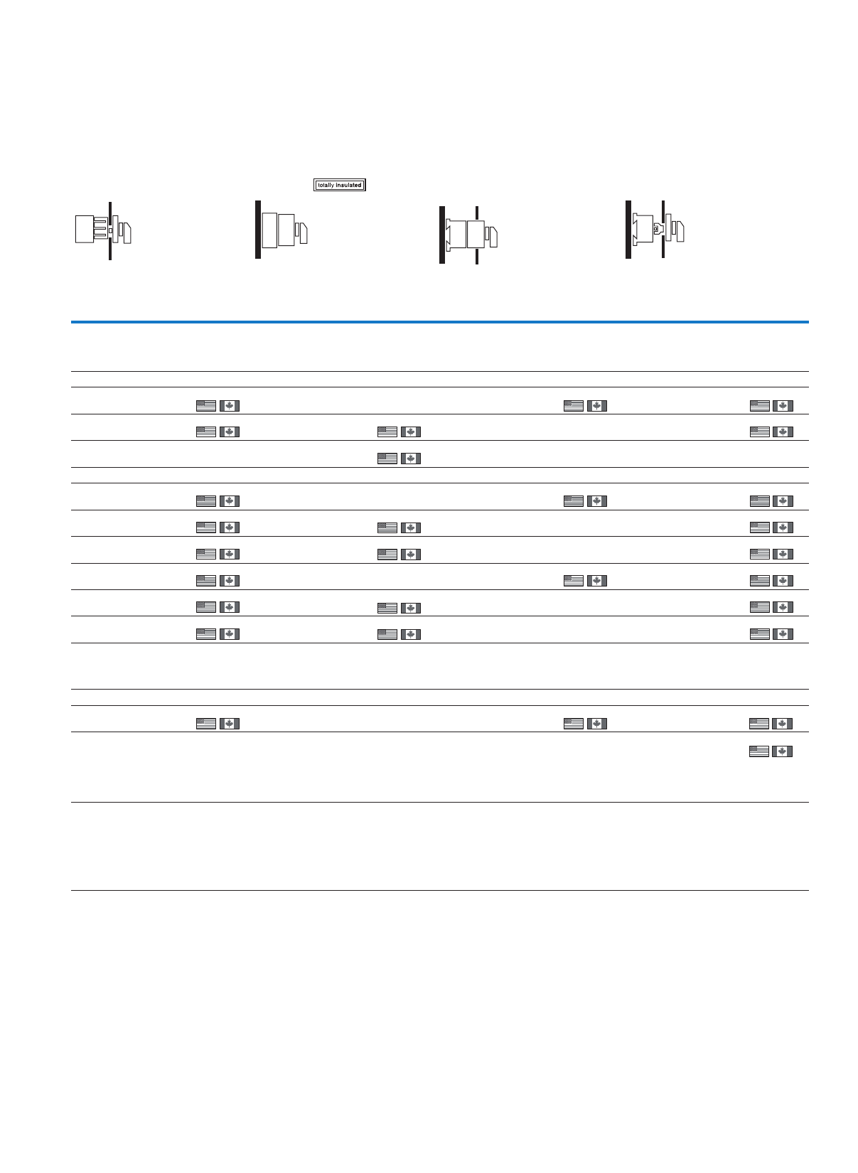
41
Cam switches, switch-disconnectors
Switch-disconnectors – multi-speed switches
)4
Product Standards
UL File No.
UL CCN
CSA File No.
CSA Class No.
NA Certification
Suitable for
Degree of Protection
UL 508; CSA-C22.2 No. 14-05;
IEC/EN 60947-3; CE marking
E36332
NLRV7
12528
3211-05
UL Listed, CSA certified
Branch circuits, suitable as
motor disconnect
IEC: IP65; UL/CSA Type 3R, 12
Center mounting Surface mounting Distribution board
mounting
Rear mounting
Front IP65 IP65 Front IP30 Front IP65
Part no.
Article no.
Price
See
price list
Std. pack Part no.
Article no.
Price
See
price list
Std. pack Part no.
Article no.
Price
See
price list
Std. pack Part no.
Article no.
Price
See
price list
Std. pack
T0-3-8451/EZ2)
083936
1 Off T0-3-8451/I1
207133
1 Off T0-3-8451/IVS1)
026985
1 Off T0-3-8451/Z2)
043596
1 Off
T3-3-8451/EZ2)
000956
1 Off T3-3-8451/I23)
207189
1 Off T3-3-8451/Z2)
031014
1 Off
T5B-3-8451/I44)
207228
1 Off
T0-4-8440/EZ2)
088682
1 Off
1 Off
1 Off
1 Off
1 Off
1 Off
T0-4-8440/I1
207141
1 Off T0-4-8440/IVS1)
029358
1 Off T0-4-8440/Z2)
048342
1 Off
1 Off
1 Off
1 Off
1 Off
1 Off
T3-4-8440/EZ2)
000959
T3-4-8440/I23)
207196
1 Off T3-4-8440/Z2)
038133
T5B-4-8440/I44)
207235
1 Off T5B-4-8440/Z4)
092029
T0-4-8441/EZ2)
093428
T0-4-8441/I1
207142
1 Off T0-4-8441/IVS1)
031731
1 Off T0-4-8441/Z2)
053088
T3-4-8441/I23)
207197
1 Off T3-4-8441/Z2)
045252
T5B-4-8441/I44)
207236
1 Off T5B-4-8441/Z4)
092025
T0-6-15866/EZ2)
012747
1 Off T0-6-15866/IVS1)
036477
1 Off T0-6-15866/Z2)
067326
1 Off
T3-6-15866/Z2)
057117
1 Off
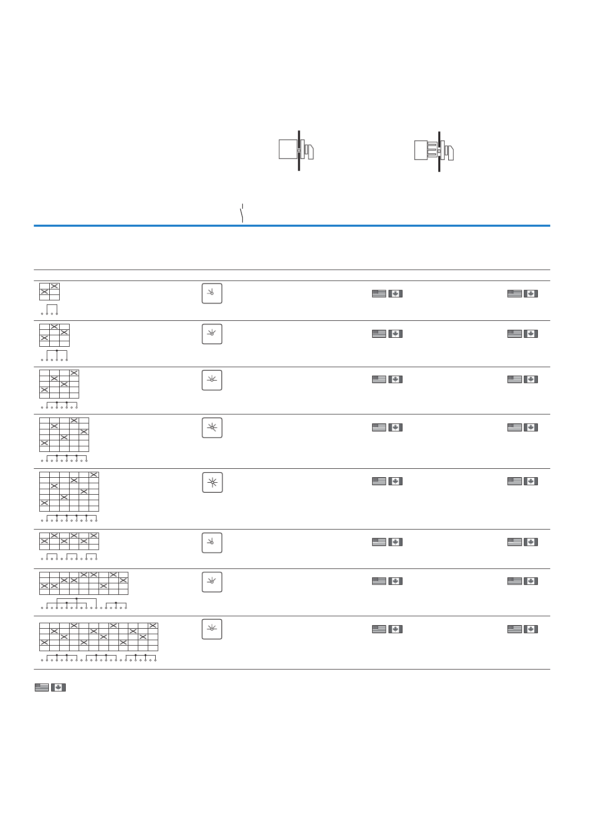
42
Cam switches, switch-disconnectors
Control switches – step switches
T
Information relevant for export to North America
)2)1
Product Standards
UL File No.
UL CCN
CSA File No.
CSA Class No.
NA Certification
Suitable for
Degree of Protection
UL 508; CSA-C22.2 No. 14-05; IEC/EN 60947-3; CE marking
E36332
NLRV
12528
3211-05
UL Listed, CSA certified
Branch circuits
IEC: IP65; UL/CSA Type 3R, 12
Product Standards
UL File No.
UL CCN
CSA File No.
CSA Class No.
NA Certification
Suitable for
Degree of Protection
UL 508; CSA-C22.2 No. 14-05; IEC/EN 60947-3; CE marking
E36332
NLRV
12528
3211-05
UL Listed, CSA certified
Branch circuits
IEC: IP30; UL/CSA Type: –
Flush mounting1) Center mounting1)
etalptnorFecneuqestcatnoC
no.
Main
contacts
Front IP65 Front IP65
Pole Part no.
Article no.
Price
See price
list
Std. pack Part no.
Article no.
Price
See price
list
Std. pack
N/O
Step switches
With black thumb-grip and front plate
One contact closed per step
Without overlap
With 0 (Off) position
1T0-1-8240/E
034105
1 Off
1 Off
1 Off
1 Off
1 Off
1 Off
1 Off
1 Off
T0-1-8240/EZ
043597
1 Off
1 Off
1 Off
1 Off
1 Off
1 Off
1 Off
1 Off
1T0-2-8241/E
050716
T0-2-8241/EZ
053089
1T0-2-8242/E
067327
T0-2-8242/EZ
069700
1T0-3-8243/E
081565
T0-3-8243/EZ
083938
1T0-3-8244/E
095803
T0-3-8244/EZ
098176
3T0-3-8280/E
034106
T0-3-8280/EZ
036479
3T0-5-8281/E
048344
T0-5-8281/EZ
050717
3T0-6-8282/E
062582
T0-6-8282/EZ
064955
1
2
3
4
012
FS 418
2
1
0
1
2
3
4
5
6
0123
FS 420
2
1
0
3
1
2
3
4
5
6
7
8
0123 4
FS 422
2
1
0
3
4
1
2
3
4
5
6
7
8
9
10
0123 4 5
FS 424
2
1
0
3
4
5
1
2
3
4
5
6
7
8
9
10
11
12
01234 5 6
FS 426
2
1
0
3
4
65
1
2
3
4
5
6
7
8
9
10
11
12
012
FS 418
2
1
0
1
2
3
4
5
6
7
8
9
10
11
12
13
14
012
15
16
17
18
3
FS 420
2
1
0
3
1
2
3
4
5
6
7
8
9
10
11
12
13
14
01234
15
16
17
18
19
20
21
22
23
24
FS 422
2
1
0
3
4
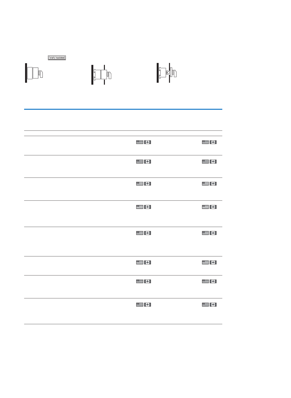
43
Cam switches, switch-disconnectors
Control switches – step switches
Surface mounting Distribution board mounting2) Rear mounting 2)
IP65 Front IP30 Front IP65
Part no.
Article no.
Price
See price
list
Std. pack Part no.
Article no.
Price
See price
list
Std. pack Part no.
Article no.
Price
See price
list
Std. pack
T0-1-8240/I1
207079
1 Off
1 Off
1 Off
1 Off
1 Off
1 Off
T0-1-8240/IVS
027076
1 Off
1 Off
1 Off
1 Off
1 Off
1 Off
1 Off
1 Off
T0-1-8240/Z
060208
1 Off
1 Off
1 Off
1 Off
1 Off
1 Off
1 Off
1 Off
T0-2-8241/I1
207107
T0-2-8241/IVS
057835
T0-2-8241/Z
062581
T0-2-8242/I1
207108
T0-2-8242/IVS
074446
T0-2-8242/Z
076819
T0-3-8243/I1
207128
T0-3-8243/IVS
088684
T0-3-8243/Z
091057
T0-3-8244/I1
207129
T0-3-8244/IVS
012749
T0-3-8244/Z
015122
T0-3-8280/I1
207130
T0-3-8280/IVS
041225
T0-3-8280/Z
043598
T0-5-8281/IVS
055463
T0-5-8281/Z
057836
T0-6-8282/IVS
069701
T0-6-8282/Z
072074
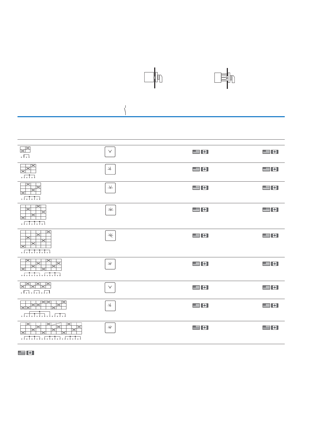
44
Cam switches, switch-disconnectors
Control switches – step switches, On-Off switches
T, P
Information relevant for export to North America
)2)1
Product Standards
UL File No.
UL CCN
CSA File No.
CSA Class No.
NA Certification
Suitable for
Degree of Protection
UL 508; CSA-C22.2 No. 14-05; IEC/EN 60947-3; CE marking
E36332
NLRV
12528
3211-05
UL Listed, CSA certified
Branch circuits
IEC: IP65; UL/CSA Type 3R, 12
Product Standards
UL File No.
UL CCN
CSA File No.
CSA Class No.
NA Certification
Suitable for
Degree of Protection
UL 508; CSA-C22.2 No. 14-05; IEC/EN 60947-3; CE marking
E36332
NLRV
12528
3211-05
UL Listed, CSA certified
Branch circuits
IEC: IP30; UL/CSA Type: –
Flush mounting1) Center mounting1)
etalptnorFecneuqestcatnoC
no.
Main
contacts
Front IP65 Front IP65
Pole Part no.
Article no.
Price
See price
list
Std. pack Part no.
Article no.
Price
See price
list
Std. pack
N/O
Step switches
With black thumb-grip and front plate
One contact closed per step
Without overlap
without 0 (Off) position
1T0-1-8220/E
031728
1 Off
1 Off
1 Off
1 Off
1 Off
1 Off
1 Off
1 Off
1 Off
T0-1-8220/EZ
095799
1 Off
1 Off
1 Off
1 Off
1 Off
1 Off
1 Off
1 Off
1 Off
1T0-2-8230/E
088685
T0-2-8230/EZ
091058
1T0-2-8231/E
012750
T0-2-8231/EZ
015123
1T0-3-8232/E
026988
T0-3-8232/EZ
029361
1T0-3-8233/E
041226
T0-3-8233/EZ
043599
2T0-4-8251/E
013971
T0-4-8251/EZ
013972
3T0-3-8222/E
048339
T0-3-8222/EZ
015118
3T0-5-8270/E
091059
T0-5-8270/EZ
093432
3T0-6-8271/E
015124
T0-6-8271/EZ
017497
1
2
3
4
12
FS 943
12
1
2
3
4
5
6
123
FS 404
3
2
1
1
2
3
4
5
6
7
8
1234
FS 606
2
4
1
3
1
2
3
4
5
6
7
8
9-
10
12345
FS 408
3
24
5
1
1
2
3
4
5
6
7
8
9
10
11
12
1234 5 6
FS 410
3
24
5
1
6
1
2
3
4
5
6
7
8
9
10
11
12
13
14
12
15
16
34
FS 406
23
1
4
1
2
3
4
5
6
7
8
9
10
11
12
12
FS 943
12
1
2
3
4
5
6
7
8
9
10
11
12
13
14
123
15
16
17
18
FS 404
3
2
1
1
2
3
4
5
6
7
8
9
10
11
12
13
14
123
15
16
17
18
19
20
21
22
23
24
4
FS 406
23
1
4
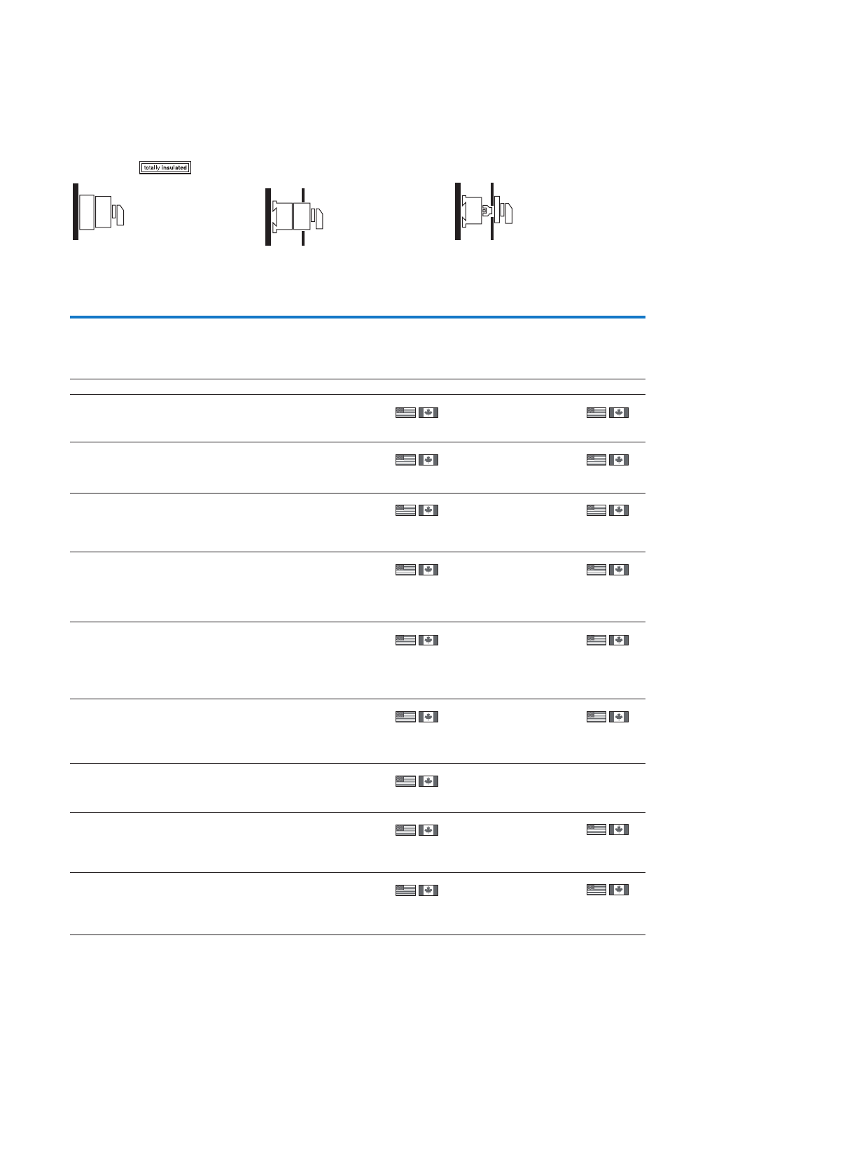
45
Cam switches, switch-disconnectors
Control switches – step switches, On-Off switches
Surface mounting Distribution board mounting 2) Rear mounting1)
IP65 Front IP30 Front IP65
Part no.
Article no.
Price
See price
list
Std. pack Part no.
Article no.
Price
See price
list
Std. pack Part no.
Article no.
Price
See price
list
Std. pack
T0-1-8220/I1
207078
1 Off
1 Off
1 Off
1 Off
1 Off
1 Off
1 Off
T0-1-8220/IVS
055459
1 Off
1 Off
1 Off
1 Off
1 Off
1 Off
1 Off
1 Off
1 Off
T0-1-8220/Z
086312
1 Off
1 Off
1 Off
1 Off
1 Off
1 Off
1 Off
1 Off
T0-2-8230/I1
207105
T0-2-8230/IVS
095804
T0-2-8230/Z
098177
T0-2-8231/I1
207106
T0-2-8231/IVS
019869
T0-2-8231/Z
022242
T0-3-8232/I1
207126
T0-3-8232/IVS
034107
T0-3-8232/Z
036480
T0-3-8233/I1
207127
T0-3-8233/IVS
048345
T0-3-8233/Z
050718
T0-4-8251/I1
218984
T0-4-8251/IVS
013974
T0-4-8251/Z
013976
T0-3-8222/I1
207124
T0-3-8222/IVS
060205
T0-5-8270/IVS
098178
T0-5-8270/Z
010378
T0-6-8271/IVS
022243
T0-6-8271/Z
024616
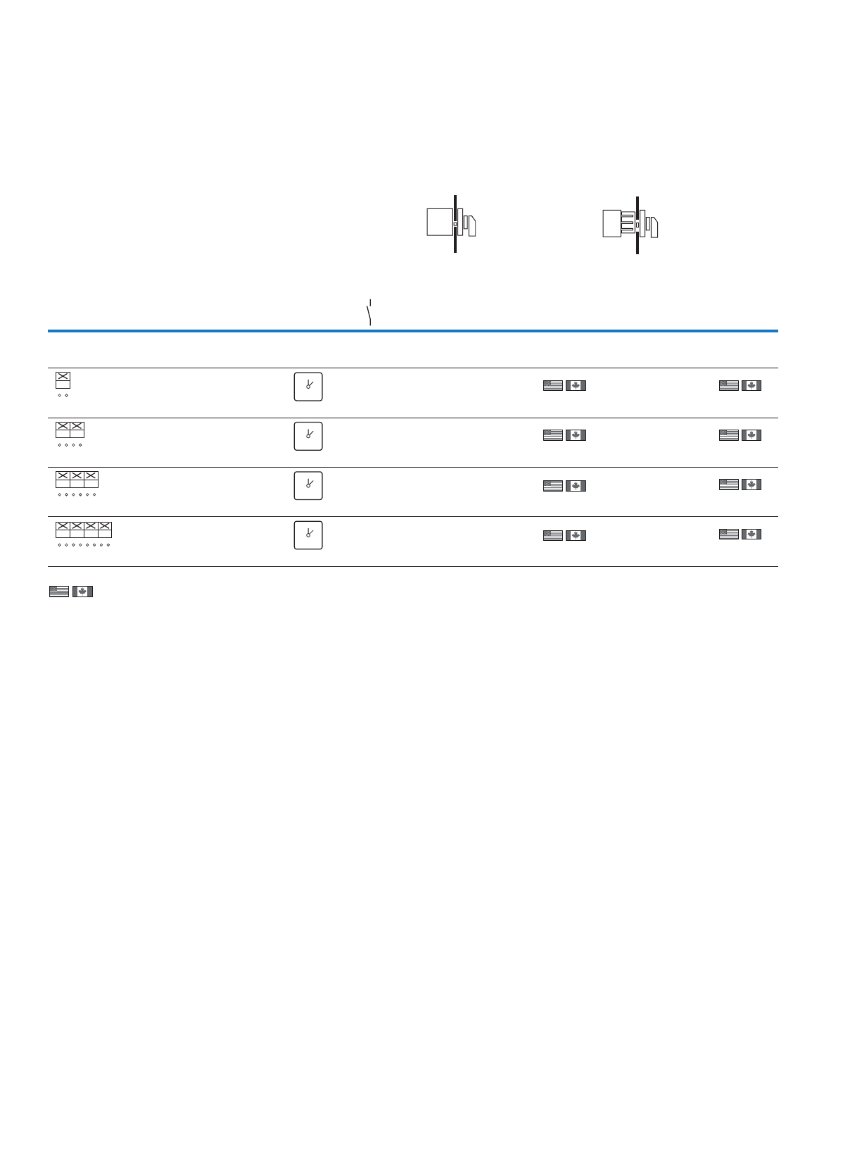
46
Cam switches, switch-disconnectors
Control switches – step switches, On-Off switches
T
Information relevant for export to North America
)2)1
Product Standards
UL File No.
UL CCN
CSA File No.
CSA Class No.
NA Certification
Suitable for
Degree of Protection
UL 508; CSA-C22.2 No. 14-05; IEC/EN 60947-3; CE marking
E36332
NLRV
12528
3211-05
UL Listed, CSA certified
Branch circuits, suitable as motor disconnect
IEC: IP65; UL/CSA Type 3R, 12
Product Standards
UL File No.
UL CCN
CSA File No.
CSA Class No.
NA Certification
Suitable for
Degree of Protection
UL 508; CSA-C22.2 No. 14-05; IEC/EN 60947-3; CE marking
E36332
NLRV
12528
3211-05
UL Listed, CSA certified
Branch circuits, suitable as motor disconnect
IEC: IP65; UL/CSA Type: –
Flush mounting1) Center mounting2)
niaM.onetalptnorFecneuqestcatnoC
contacts
Front IP65 Front IP65
Pole Part no.
Article no.
Price
See
price list
Std. pack Part no.
Article no.
Price
See
price list
Std. pack
N/O
On-Off switches
With black thumb-grip and front plate
1T0-1-15401/E
038854
1 Off
1 Off
1 Off
1 Off
T0-1-15401/EZ
041227
1 Off
1 Off
1 Off
1 Off
2T0-1-15402/E
053092
T0-1-15402/EZ
055465
3T0-2-15403/E
067330
T0-2-15403/EZ
069703
4T0-2-15404/E
081568
T0-2-15404/EZ
083941
1
2
01
FS 415
01
FS 415
01
FS 415
01
FS 415
01
1
2
3
4
01
1
2
3
4
5
6
01
1
2
3
4
5
6
7
8
01
47
Cam switches, switch-disconnectors
Control switches – step switches, On-Off switches
)3
Product Standards
UL File No.
UL CCN
CSA File No.
CSA Class No.
NA Certification
Suitable for
Degree of Protection
UL 508; CSA-C22.2 No. 14-05; IEC/EN 60947-3; CE marking
E36332
NLRV
12528
3211-05
UL Listed, CSA certified
Branch circuits, suitable as motor disconnect
IEC: IP30; UL/CSA Type: –
Surface mounting Distribution board
mounting 3)
Rear mounting
IP65 Front IP30 Front IP65
Part no.
Article no.
Price
See
price list
Std. pack Part no.
Article no.
Price
See
price list
Std. pack Part no.
Article no.
Price
See
price list
Std. pack
T0-1-15401/I1
207067
1 Off T0-1-15401/
IVS
045973
1 Off
1 Off
1 Off
T0-1-15402/I1
207068
1 Off T0-1-15402/
IVS
060211
T0-2-15403/
IVS
074449
48
Cam switches, switch-disconnectors
Control switches – changeover switches, manual/automatic switches
T
Information relevant for export to North America )1
Product Standards
UL File No.
UL CCN
CSA File No.
CSA Class No.
NA Certification
Suitable for
Degree of Protection
UL 508; CSA-C22.2 No. 14-05; IEC/EN 60947-3; CE marking
E36332
NLRV
12528
3211-05
UL Listed, CSA certified
Branch circuits
IEC: IP65; UL/CSA Type 3R, 12
Flush mounting1) Center mounting1)
Contact sequence Front plate no. Main
contacts
Front IP65 Front IP65
Pole Part no.
Article no.
Price
See price
list
Std. pack Part no.
Article no.
Price
See price
list
Std. pack
N/O
Changeover switches
With black thumb-grip and front plate
1T0-1-15421/E
095806
1 Off
1 Off
1 Off
T0-1-15421/EZ
098179
1 Off
1 Off
1 Off
2T0-2-15422/E
019871
T0-2-15422/EZ
022244
3T0-3-15423/E
034109
T0-3-15423/EZ
036482
1
2
3
4
201
FS 429
0
21
1
2
3
4
5
6
7
8
201
1
2
3
4
5
6
7
8
9
10
11
12
201
Manual/Auto switches
With 0 (Off) position
1T0-1-15431/E
019872
1 Off
1 Off
1 Off
T0-1-15431/EZ
022245
1 Off
1 Off
1 Off
2T0-2-15432/E
034110
T0-2-15432/EZ
036483
3T0-3-15433/E
048348
T0-3-15433/EZ
050721
With momentary from HAND
1T0-1-15434/E
062586
1 Off T0-1-15434/EZ
018053
1 Off
2T0-2-15435/E
003191
1 Off T0-2-15435/EZ
003192
1 Off
With momentary from START
2T0-2-15907/E
066931
1 Off T0-2-15907/EZ
069304
1 Off
Without 0 (Off) position
1T0-1-15451/E
076824
1 Off
1 Off
1 Off
T0-1-15451/EZ
079197
1 Off
1 Off
1 Off
2T0-2-15452/E
091062
T0-2-15452/EZ
093435
3T0-3-15453/E
015127
T0-3-15453/EZ
017500
1
2
3
4
HAND
0
AUTO
FS 1401
0
HAND AUTO
1
2
3
4
5
6
7
8
HAND
0
AUTO
1
2
3
4
5
6
7
8
9
10
11
12
HAND
0
AUTO
1
2
3
4
HAND
0
AUTO
FS 1414000
0
HAND AUTO
1
2
3
4
5
6
7
8
HAND
0
AUTO
1
2
3
4
5
6
7
8
AUTO
0
HAND
START
FS 1413890
0
AUTO HAND
START
1
2
3
4
HAND
AUTO
FS 19334
HAND AUTO
1
2
3
4
5
6
7
8
HAND
AUTO
1
2
3
4
5
6
7
8
9
10
11
12
HAND
AUTO
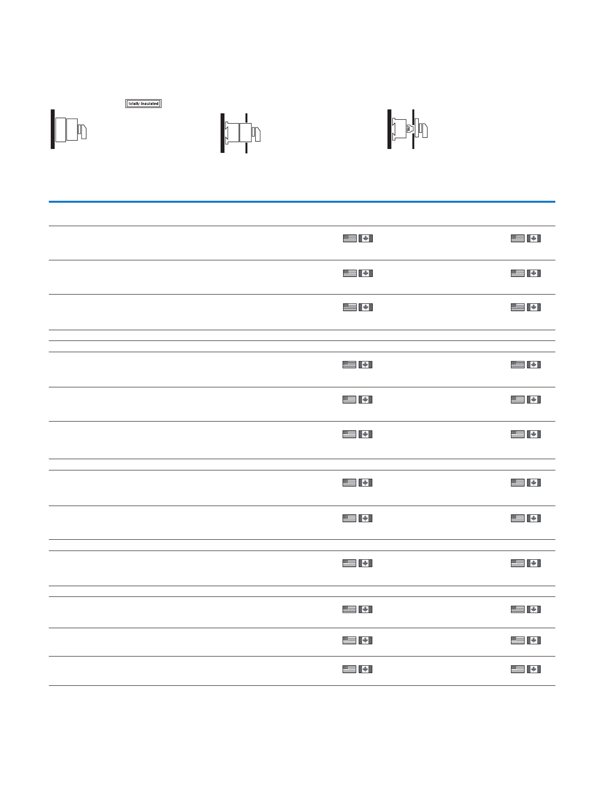
49
Cam switches, switch-disconnectors
Control switches – changeover switches, manual/automatic switches
)2
Product Standards
UL File No.
UL CCN
CSA File No.
CSA Class No.
NA Certification
Suitable for
Degree of Protection
UL 508; CSA-C22.2 No. 14-05; IEC/EN 60947-3; CE marking
E36332
NLRV
12528
3211-05
UL Listed, CSA certified
Branch circuits
IEC: IP30; UL/CSA Type: –
Surface mounting Distribution board mounting 2) Rear mounting1)
IP65 Front IP30 Front IP65
Part no.
Article no.
Price
See price list
Std. pack Part no.
Article no.
Price
See price list
Std. pack Part no.
Article no.
Price
See price list
Std. pack
T0-1-15421/I1
207069
1 Off
1 Off
1 Off
T0-1-15421/IVS
012752
1 Off
1 Off
1 Off
T0-1-15421/Z
015125
1 Off
1 Off
1 Off
T0-2-15422/I1
207090
T0-2-15422/IVS
026990
T0-2-15422/Z
029363
T0-3-15423/I1
207114
T0-3-15423/IVS
041228
T0-3-15423/Z
043601
T0-1-15431/I1
207070
1 Off
1 Off
1 Off
T0-1-15431/IVS
026991
1 Off
1 Off
1 Off
T0-1-15431/Z
029364
1 Off
1 Off
1 Off
T0-2-15432/I1
207091
T0-2-15432/IVS
041229
T0-2-15432/Z
043602
T0-3-15433/I1
207115
T0-3-15433/IVS
055467
T0-3-15433/Z
057840
T0-1-15434/I1
207071
1 Off T0-1-15434/IVS
069705
1 Off T0-1-15434/Z
072078
1 Off
T0-2-15435/I1
218971
1 Off T0-2-15435/IVS
003195
1 Off T0-2-15435/Z
003196
1 Off
T0-2-15907/I1
207095
1 Off T0-2-15907/IVS
076423
1 Off T0-2-15907/Z
078796
1 Off
T0-1-15451/I1
207072
1 Off
1 Off
1 Off
T0-1-15451/IVS
083943
1 Off
1 Off
1 Off
T0-1-15451/Z
086316
1 Off
1 Off
1 Off
T0-2-15452/I1
207092
T0-2-15452/IVS
098181
T0-2-15452/Z
010381
T0-3-15453/I1
207116
T0-3-15453/IVS
022246
T0-3-15453/Z
024619
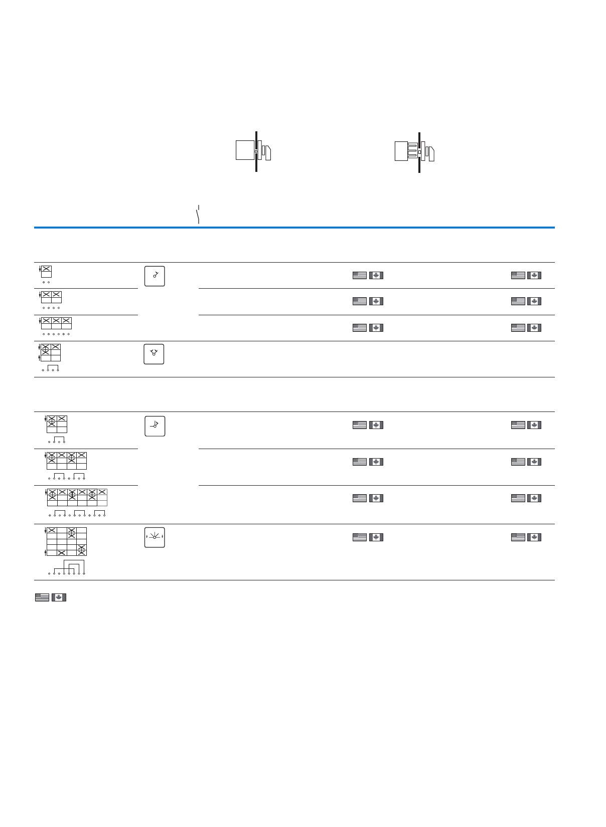
50
Cam switches, switch-disconnectors
Control switches – On switches
T
Information relevant for export to North America
)2)1
Product Standards
UL File No.
UL CCN
CSA File No.
CSA Class No.
NA Certification
Suitable for
Degree of Protection
UL 508; CSA-C22.2 No. 14-05; IEC/EN 60947-3; CE marking
E36332
NLRV
12528
3211-05
UL Listed, CSA certified
Branch circuits
IEC: IP65; UL/CSA Type 3R, 12
Product Standards
UL File No.
UL CCN
CSA File No.
CSA Class No.
NA Certification
Suitable for
Degree of Protection
UL 508; CSA-C22.2 No. 14-05; IEC/EN 60947-3; CE marking
E36332
NLRV
12528
3211-05
UL Listed, CSA certified
Branch circuits
IEC: IP30; UL/CSA Type: –
Flush mounting Center mounting
Contact sequence Front plate no. Main
contacts
Front IP65 Front IP65
Pole Part no.
Article no.
Price
See price
list
Std. pack Part no.
Article no.
Price
See price
list
Std. pack
N/O
On switch (N/O)
With black thumb-grip and front plate
Momentary from position 1
1T0-1-15321/E
086317
1 Off
1 Off
1 Off
T0-1-15321/EZ
088690
1 Off
1 Off
1 Off
2T0-1-15322/E
010382
T0-1-15322/EZ
012755
3T0-2-15323/E
024620
T0-2-15323/EZ
026993
T0-1-15366/E
081572
T0-1-15366/EZ
083945
1
2
I1
FS 4721
1
1
2
3
4
I1
1
2
3
4
5
6
I1
1
2
3
4
0I1
FS 456
0 1
ON-OFF momentary switches
With black thumb-grip and front plate
Momentary from START position
1T0-1-15511/E
019875
1 Off
1 Off
1 Off
1 Off
T0-1-15511/EZ
022248
1 Off
1 Off
1 Off
1 Off
2T0-2-15512/E
034113
T0-2-15512/EZ
036486
3T0-3-15513/E
048351
T0-3-15513/EZ
050724
see
K 115
T0-2-8177/E
015130
T0-2-8177/EZ
017503
0
1
START
1
2
3
4
FS 147767
START
1
0
0
1
START
1
2
3
4
5
6
7
8
0
1
START
1
2
3
4
5
6
7
8
9
10
11
12
START
1
0
2
START
1
2
3
4
5
6
7
8
FS 140660
0
12
START START
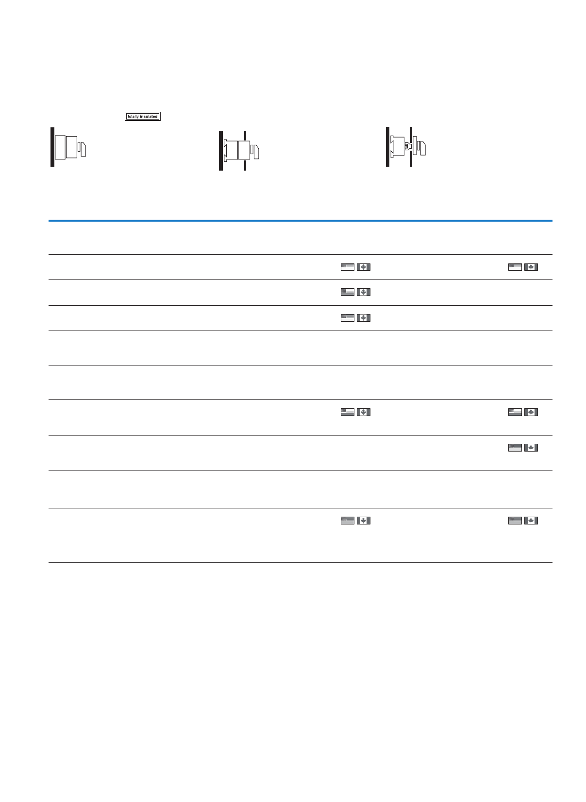
51
Cam switches, switch-disconnectors
Control switches – On switches
Surface mounting Distribution board mounting Rear mounting
IP65 Front IP30 Front IP65
Part no.
Article no.
Price
See price list
Std. pack Part no.
Article no.
Price
See price list
Std. pack Part no.
Article no.
Price
See price list
Std. pack
T0-1-15321/I1
207064
1 Off
1 Off
1 Off
T0-1-15321/IVS
093436
1 Off
1 Off
1 Off
T0-1-15321/Z
095809
1 Off
T0-1-15322/I1
207065
T0-1-15322/IVS
017501
T0-2-15323/I1
207087
T0-2-15323/IVS
031739
T0-1-15511/I1
207073
1 Off
1 Off
1 Off
1 Off
T0-1-15511/IVS
026994
1 Off T0-1-15511/Z
029367
1 Off
T0-2-15512/I1
207093
T0-2-15512/Z
043605
1 Off
T0-3-15513/I1
207117
T0-2-8177/I1
207101
T0-2-8177/IVS
022249
1 Off T0-2-8177/Z
024622
1 Off
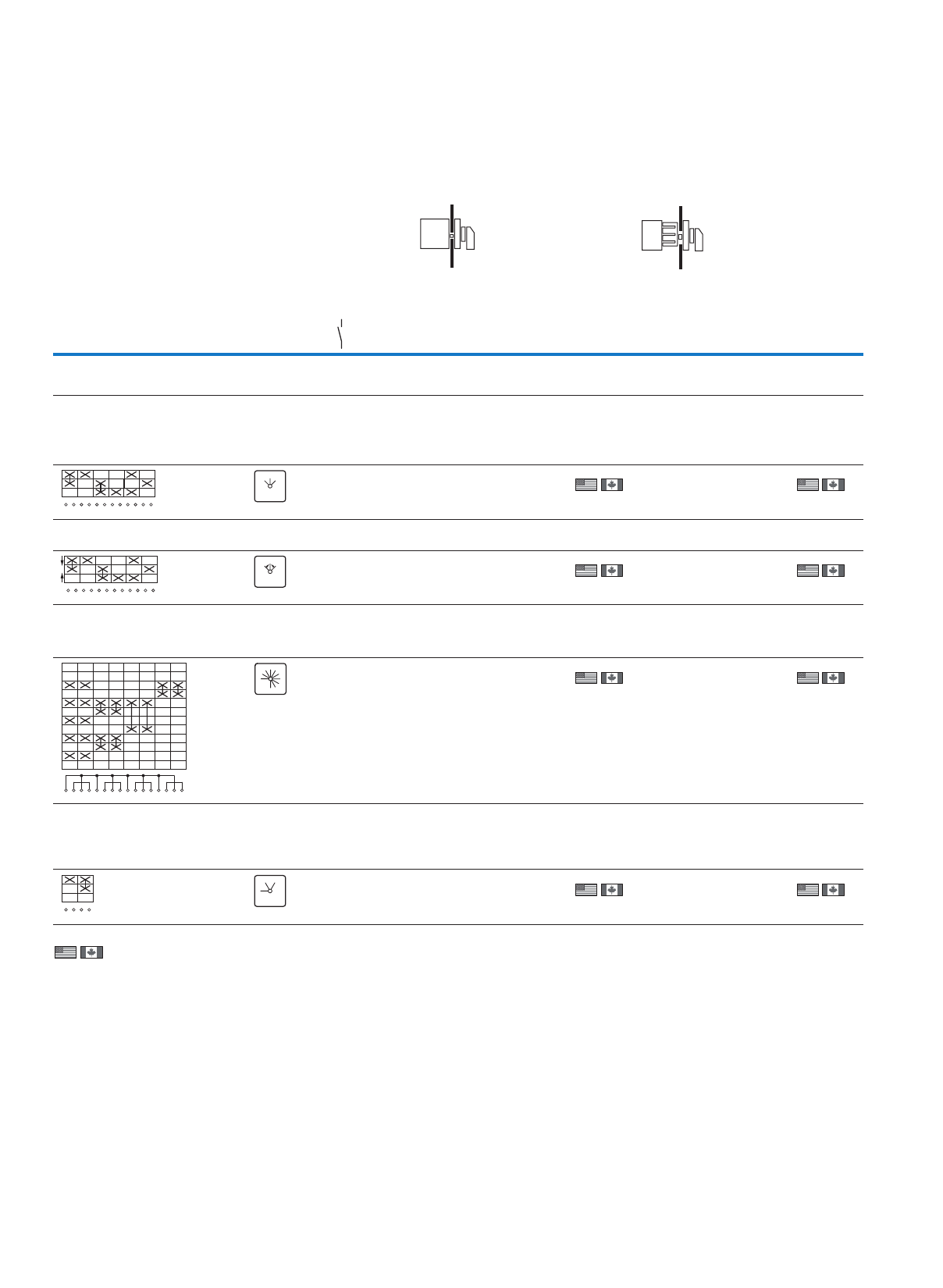
52
Cam switches, switch-disconnectors
Control switches – changeover switches, manual/automatic switches
T
Information relevant for export to North America
)2)1
Product Standards
UL File No.
UL CCN
CSA File No.
CSA Class No.
NA Certification
Suitable for
Degree of Protection
UL 508; CSA-C22.2 No. 14-05; IEC/EN 60947-3; CE marking
E36332
NLRV
12528
3211-05
UL Listed, CSA certified
Branch circuits
IEC: IP65; UL/CSA Type 3R, 12
Product Standards
UL File No.
UL CCN
CSA File No.
CSA Class No.
NA Certification
Suitable for
Degree of Protection
UL 508; CSA-C22.2 No. 14-05; IEC/EN 60947-3; CE marking
E36332
NLRV
12528
3211-05
UL Listed, CSA certified
Branch circuits
IEC: IP30; UL/CSA Type: –
Flush mounting1) Center mounting1)
Contact sequence Front plate no. Main
contacts
Front IP65 Front IP65
Pole Part no.
Article no.
Price
See price
list
Std. pack Part no.
Article no.
Price
See price
list
Std. pack
N/O
Universal control switches
With black thumb-grip and front plate
Maintained switches with 3 positions
1 contact closed in each position
• Additionally 1 contact closed in position 0 and 1
• Additionally 1 contact closed in position 0 and 2
• Additionally 1 contact closed in position 0 and 3
T0-3-15391/E
029365
1 Off T0-3-15391/EZ
031738
1 Off
Momentary from positions 1 and 2
With black thumb-grip and front plate
T0-3-15394/E
072079
1 Off T0-3-15394/EZ
074452
1 Off
1
2
3
4
5
6
7
8
9
10
11
12
201
FS 429
0
21
1
2
3
4
5
6
7
8
9
10
11
12
201
FS 458
012
Coding switches
With black thumb-grip and front plate
With complete rotation in both directions.
Binary
BCD code
T0-4-15602/E
029368
1 Off T0-4-15602/EZ
031741
1 Off
1
2
3
4
5
6
7
8
9
10
11
12
13
14
0123 4 5 6 7 8 9
15
16
42
0
3
9
6
8
15
7
FS 312
Series switches
With black thumb-grip and front plate
With 0 (Off) position
(heater switches)
1T0-1-91/E
072082
1 Off T0-1-91/EZ
074455
1 Off
1
2
3
4
012
FS 614
0
21
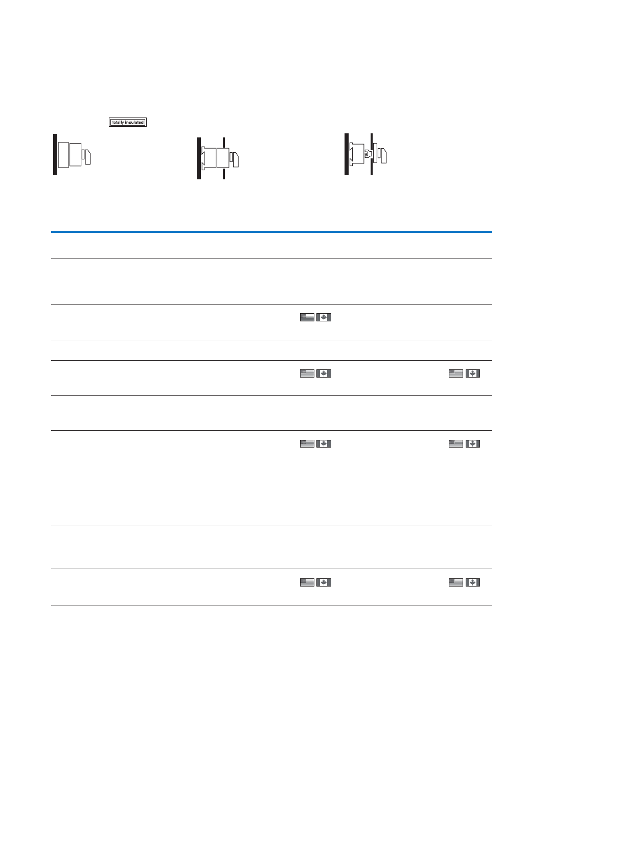
53
Cam switches, switch-disconnectors
Control switches – changeover switches, manual/automatic switches
Surface mounting Distribution board mounting 2) Rear mounting1)
IP65 Front IP30 Front IP65
Part no.
Article no.
Price
See price
list
Std. pack Part no.
Article no.
Price
See price
list
Std. pack Part no.
Article no.
Price
See price
list
Std. pack
T0-3-15391/I1
207112
1 Off T0-3-15391/IVS
036484
1 Off
T0-3-15394/I1
207113
1 Off T0-3-15394/IVS
079198
1 Off T0-3-15394/Z
081571
1 Off
T0-4-15602/I1
207134
1 Off T0-4-15602/IVS
036487
1 Off T0-4-15602/Z
038860
1 Off
T0-1-91/I1
207080
1 Off T0-1-91/IVS
079201
1 Off T0-1-91/Z
081574
1 Off
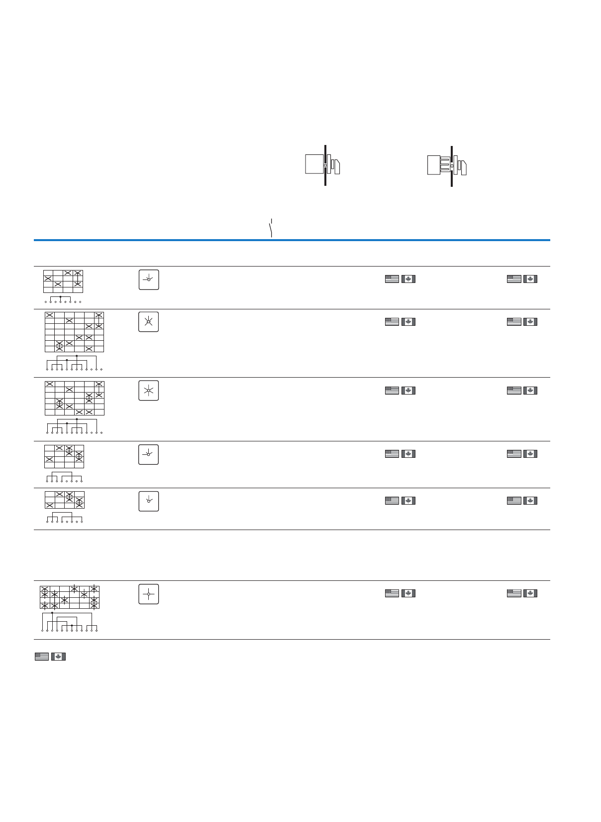
54
Cam switches, switch-disconnectors
Control switches – Instrument switches
T
Information relevant for export to North America
)2)1
Product Standards
UL File No.
UL CCN
CSA File No.
CSA Class No.
NA Certification
Suitable for
Degree of Protection
UL 508; CSA-C22.2 No. 14-05; IEC/EN 60947-3; CE marking
E36332
NLRV
12528
3211-05
UL Listed, CSA certified
Branch circuits
IEC: IP65; UL/CSA Type 3R, 12
Product Standards
UL File No.
UL CCN
CSA File No.
CSA Class No.
NA Certification
Suitable for
Degree of Protection
UL 508; CSA-C22.2 No. 14-05; IEC/EN 60947-3; CE marking
E36332
NLRV
12528
3211-05
UL Listed, CSA certified
Branch circuits
IEC: IP30; UL/CSA Type: –
Flush mounting1) Center mounting1)
Contact sequence Front plate
no.
niaMeloP
contacts
Front IP65 Front IP65
Pole Part no.
Article no.
Price
See
price
list
Std. pack Part no.
Article no.
Price
See
price
list
Std. pack
N/O
Voltmeter selector switch
With black thumb-grip and front plate
3 x phase-N with 0 position 3 + N T0-2-15921/E
067337
1 Off
1 Off
1 Off
1 Off
1 Off
T0-2-15921/EZ
069710
1 Off
1 Off
1 Off
1 Off
1 Off
3 x phase-phase
3 x phase-N with 0 position
3 + N T0-3-8007/E
095813
T0-3-8007/EZ
098186
3 x phase-phase
3 x phase-N without
0 position with complete
rotation in both directions
3 + N T0-3-15924/E
019878
T0-3-15924/EZ
022251
3 x phase-phase with
0 position
3T0-2-15920/E
038861
T0-2-15920/EZ
041234
3 x phase-phase without
0 position
3T0-2-15922/E
053099
T0-2-15922/EZ
055472
Ammeter selector switch
With black thumb-grip and front plate
With complete rotation in both directions.
Measurement via current transformer
With 0 (Off) position
T0-3-8048/E
034116
1 Off T0-3-8048/EZ
036489
1 Off
1
2
3
4
5
6
7
8
0
L1-N
L2-N
L3-N L1-N
L2-N
L3-N
FS 1410757
0
1
2
3
4
5
6
7
8
9
10
11
12
L3-L1
L2-L3
L1-L2
0
L1-N
L2-N
L3-N L1-L2
FS 1410759
0
L2-L3
L3-L1
L1-N
L2-N
L3-N
1
2
3
4
5
6
7
8
9
10
11
12
L1-L2
L2-L3
L3-L1
L1-N
L2-N
L3-N L1-L2
L2-L3
L3-L1
L1-N
L2-N
L3-N
FS 164721
1
2
3
4
5
6
7
8
0
L1-L2
L2-L3
L3-L1 L1-L2
L2-L3
L3-L1
0
FS 1410755
1
2
3
4
5
6
7
8
L1-L2
L2-L3
L3-L1 L1-L2
L2-L3
L3-L1
FS 164854
1
2
3
4
5
6
7
8
9
10
11
12
0
L1
L2
L3
L1
L2
FS 9440
0
L3
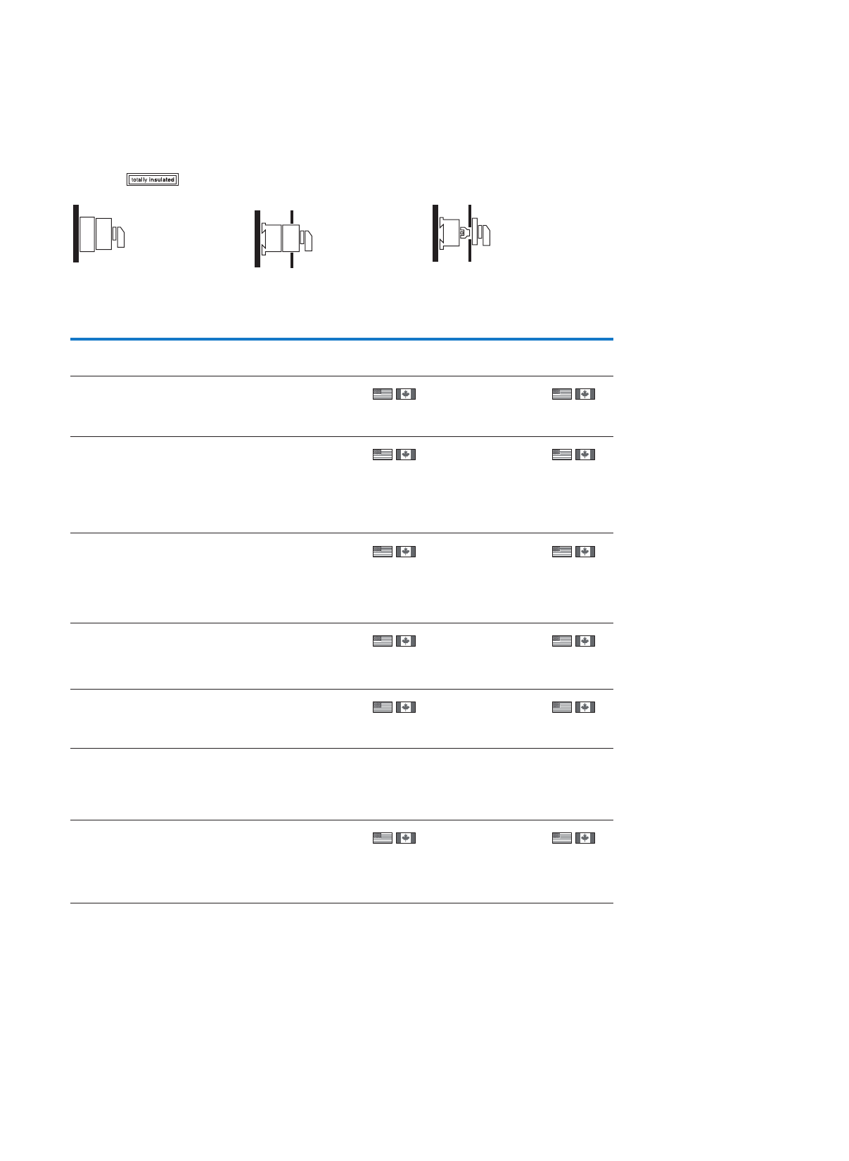
55
Cam switches, switch-disconnectors
Control switches – Instrument switches
Surface mounting Distribution board
mounting2)
Rear mounting1)
IP65 Front IP30 Front IP65
Part no.
Article no.
Price
See
price
list
Std. pack Part no.
Article no.
Price
See
price
list
Std. pack Part no.
Article no.
Price
See
price
list
Std. pack
T0-2-15921/IVS
074456
1 Off
1 Off
1 Off
1 Off
1 Off
T0-2-15921/Z
076829
1 Off
1 Off
1 Off
1 Off
1 Off
T0-3-8007/I1
207120
1 Off T0-3-8007/IVS
012759
T0-3-8007/Z
015132
T0-3-15924/I1
207119
1 Off T0-3-15924/IVS
026997
T0-3-15924/Z
029370
T0-2-15920/IVS
029452
T0-2-15920/Z
048353
T0-2-15922/IVS
060218
T0-2-15922/Z
062591
T0-3-8048/IVS
041235
1 Off T0-3-8048/Z
043608
1 Off
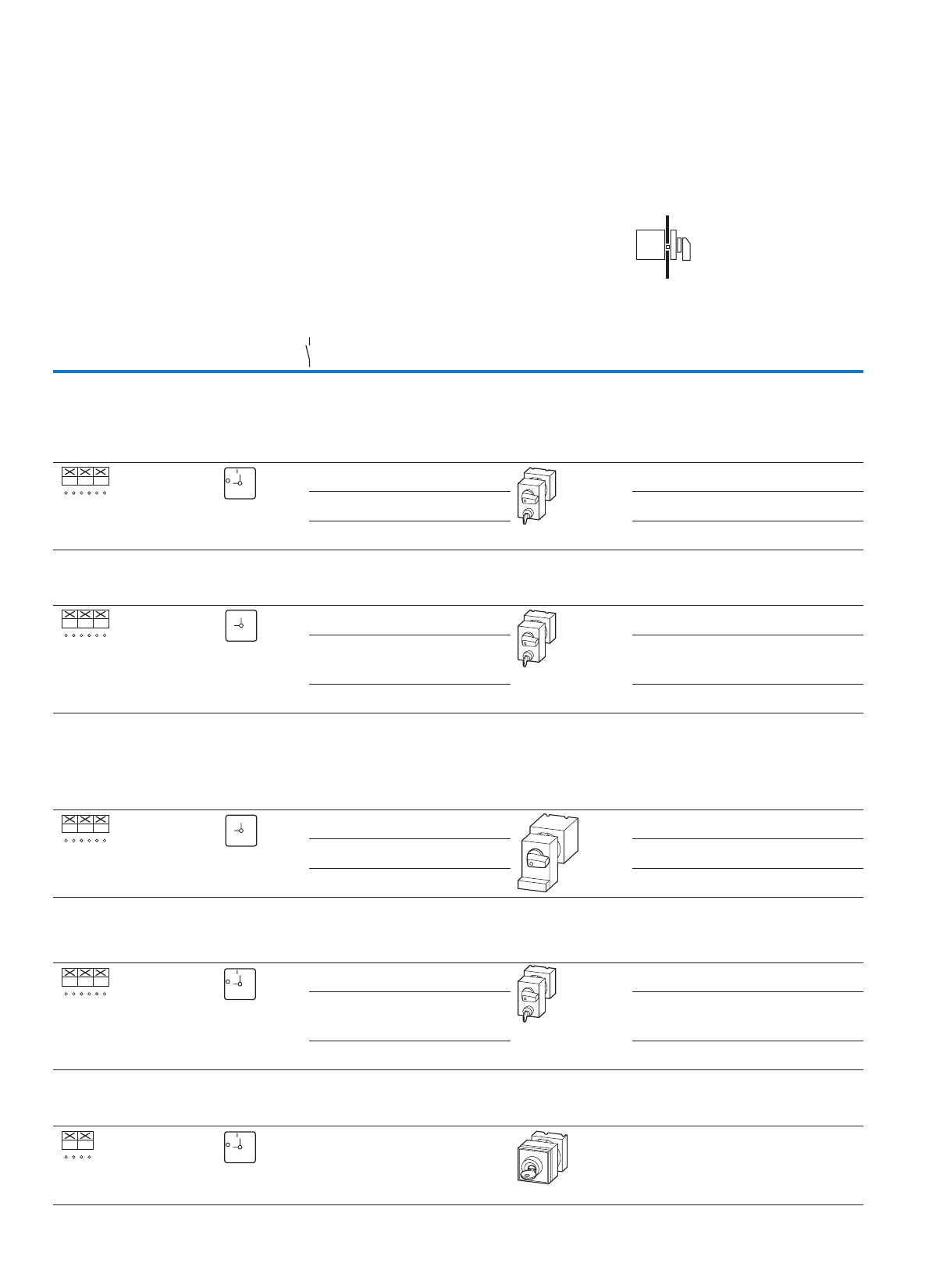
56
Cam switches, switch-disconnectors
Switches with locking mechanism
T
Flush mounting
Contact sequence Front plate no. Main
contacts
Max. motor
rating
AC-23 A, 400/415
V, 50/60 Hz
Rated
uninter-
rupted
current
IP65
Part no.
Article no.
Price
See
price
list
Std. pack
Pole 400 V Iu
N/O P A
kW
Panic switch
Cylinder lock SVA
Without emergency switching off/emergency stop function, with two keys
With black thumb-grip and front plate
If the key is withdrawn in position 1 the switch can be switched off
but not on again without the key.
36.5 20 T0-2-1/E/SVA(S)
050977
1 Off
1 Off
1 Off
313 25 P1-25/E/SVA(S)
050966
315 32 P1-32/E/SVA(S)
044977
As an emergency switching off/emergency stop device
To IEC/EN 60204-1, VDE 0113 Part 1
With two keys
With red thumb-grip and yellow front plate
36.5 20 T0-2-1/E/SVA(S)-RT
228291
1 Off
1 Off
1 Off
313 25 P1-25/E/SVA(S)-RT
050967
315 32 P1-32/E/SVA(S)-RT
050971
Padlocking feature SVC
As an emergency switching off/emergency stop device
To IEC/EN 60204-1, VDE 0113 Part 1, with two keys
With red thumb-grip and yellow front plate
If the locking slide is padlocked in position 1 the switch can be switched off but not on again
without removing the padlock.
Lockable with max. 3 padlocks.
36.5 20 T0-2-1/E/SVC(S)-RT
044973
1 Off
1 Off
1 Off
313 25 P1-25/E/SVC(S)-RT
044974
315 32 P1-32/E/SVC(S)-RT
044975
On-Off switches
Without emergency switching off/emergency stop function
With black thumb-grip and front plate
Key can only be withdrawn in position 0 (Pos A)
36.5 20 T0-2-1/E/SVA(A)
050976
1 Off
1 Off
1 Off
313 25 P1-25/E/SVA(A)
050965
315 32 P1-32/E/SVA(A)
050970
Key operation lock mechanism ST-0
Without emergency switching off/emergency stop function
With black thumb-grip and front plate
Key can only be withdrawn in position 0 (Pos A)
26.5 20 T0-1-102/EZ/S
014933
1 Off
1
2
3
4
5
6
01
FS 908
ON
OFF
1
2
3
4
5
6
01
FS 908 GE
1
0
1
2
3
4
5
6
01
FS 908 GE
1
0
1
2
3
4
5
6
01
FS 908
ON
OFF
1
2
3
4
01
FS 908
ON
OFF
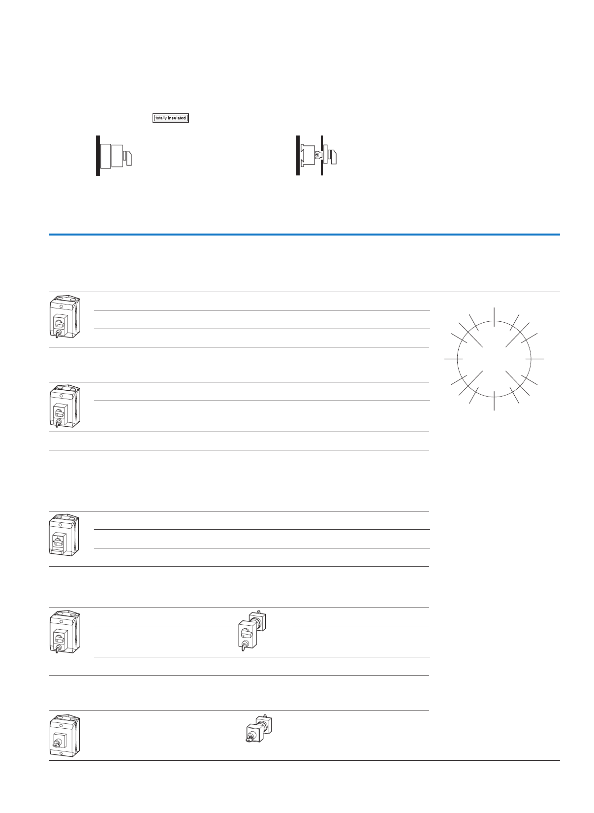
57
Cam switches, switch-disconnectors
Switches with locking mechanism
Surface mounting Rear mounting
IP65 IP65
Part no.
Article no.
Price
See
price
list
Std. pack Part no.
Article no.
Price
See
price
list
Std. pack Notes
T0-2-1/I1/SVA(S)
207084
1 Off
1 Off
1 Off
Code letters for lockable switch
positions
Letter S for panic lock with FS908GE
P1-25/I2/SVA(S)
207305
P1-32/I2/SVA(S)
207326
T0-2-1/I1/SVA(S)-RT
207085
1 Off
P1-25/I2/SVA(S)-RT
207306
1 Off
T0-2-1/I1/SVC(S)-RT
207086
1 Off
1 Off
1 Off
P1-25/I2/SVC(S)-RT
207307
P1-32/I2/SVC(S)RT
207328
T0-2-1/I1/SVA(A)
207083
1 Off
1 Off
1 Off
T0-2-1/Z/SVA(A)
050978
1 Off
P1-25/I2/SVA(A)
207304
P1-25/Z/SVA(A)
050969
1 Off
P1-32/I2/SVA(A)
207325
T0-1-102/I1/S
207063
1 Off T0-1-102/Z/S
014971
1 Off
ON
OFF
330 030
300
240 225
210 180 150
135 120
90
60
45
270
F
H
G
J
K
L
M
N
P
Q
R
A
B
C
DE
315
ON
OFF
ON
OFF
ON
OFF
58
Cam switches, switch-disconnectors
Emergency
switching
off/emergency stop
For use with Part no.
Article no.
Price
See
price list
Std. pack Notes
Main switch assembly kits
Padlocking feature
only for main switch
Permissible with T0 with up to max. 4 contact units
Permissible with T3 with up to max. 6 contact units
With red rotary
handle and
yellow locking
collar
As an emergency
switching off/emer-
gency stop device
To IEC/EN 60204-1,
VDE 0113 Part 1
T0-…/E, …/Z, …/I1
T3-…/E, …/Z, …/I2
P1-…/E, …/Z, …/I2
SVB-T0
057892
1 off • For locking the 0 position
• For switches with positions
0 -I at 90°
• Switching angle as front
plate FS908
• Lockable with max.
3 padlocks
T5B-…/E, …/Z, …/I4
T5-.../E, .../Z, .../I5
P3-63/E, …/Z, …/I4
P3-100/E, …/Z, …/I5
SVB-P3
052999
1 off
With black
rotary handle
and black
locking collar
Without emergency
switching off/emer-
gency stop function
T0-…/E, …/Z, …/I1
T3-…/E, …/Z, …/I2
P1-…/E, …/Z, …/I2
SVB-SW-T0
060265
1 off • For locking the 0 position
• For locking the I position
when required
• Lockable with max.
3 padlocks
T5B-…/E, …/Z, …/I4
T5-.../E, .../Z, .../I5
P3-63/E, …/Z, …/I4
P3-100/E, …/Z, …/I5
SVB-SW-P3
062491
1 off
Main switch assembly kits with PE terminal and N terminal
Padlocking feature
only for main switch
Permissible with T0 with up to max. 4 contact units
Permissible with T3 with up to max. 6 contact units
With red rotary
handle and
yellow locking
collar
As an emergency
switching off/emer-
gency stop device
To IEC/EN 60204-1,
VDE 0113 Part 1
T0-…/E, …/Z
T3-…/E, …/Z
V/EA/SVB-T0
062638
1 off • For converting flush
mounting switch T…/E into
flush mounting main switch
T…/EA/SVB…
• For converting rear
mounting switch T…/Z
(with FS908 front plate) into
interlocked rear mounting
main switch T…/V/SVB
T5(B)-…/E, …/Z V/EA/SVB-T5
045065
1 off
With black
rotary handle
and black
locking collar
Without emergency
switching off/emer-
gency stop function
T0-…/E, …/Z
T3-…/E, …/Z
V/EA/SVB-SW-T0
065011
1 off
T5(B)-…/E, …/Z V/EA/SVB-SW-T5
045064
1 off
Thumb-grips
Black – T0-…/E, …/EZ, …/IVS, …/Z, …/I1
T3-…/E, …/EZ, …/IVS, …/Z, …/I2
P1-…/E, …/EZ, …/IVS, …/Z, …/I2
KNB-T0
038909
10 off –
Red Only for emergency
switching off/emer-
gency stop switches
To IEC/EN 60204-1,
VDE 0113 Part 1
T0-…/E, …/IVS, …/Z, …/I1
T3-…/E, …/IVS, …/Z, …/I2
P1-…/E, …/IVS, …/Z, …/I2
KNB-RT-T0
043655
10 off • Order yellow FS908GE-T0
front plate additionally
Black – T5(B)-…/E, …/Z, …/I4
P3-63/E, …/Z, …/I4
P3-100/E, …/Z, …/I5
KNB-P3
041282
10 off –
Red Only for emergency
switching off/emer-
gency stop switches
To IEC/EN 60204-1,
VDE 0113 Part 1
T5(B)-…/E, …/Z, …/I4
P3-63/E, …/Z, …/I4
P3-100/E, …/Z, …/I5
KNB-RT-P3
046028
10 off • Order additional yellow
front plate FS908GE-P3
Maintenance key for interlocked main switches
T0…
P1…
KNK-T0
000650
5 off Special devices for electri-
cians: interlocked main
switches can be switched on
and off for repairs with the
maintenance key while the
door is open (as per IEC/EN
60204-1, Section 5.1.1.1)
P3… KNK-P3
000649
5 off
ATEX type
According to 94/9EG
Test Certificate BVS04E106X
With metric knock-outs M20 T0-…/I1 +ATEX-I1
237513
1 off Only available together with
1 off
1 off
1 off
basic unit
With solid side walls T3-…/I2
P1-…/I2
+ATEX-I2
237514
T5B-…/I4
P3-…/I4
+ATEX-I4
237516
T5-…/I5
P3-…/I5
+ATEX-I5
237517
Information relevant for export to North America
UL/CSA certification not required
SVB-...-T0(P3), KNB-...-T0(P3)
59
Cam switches, switch-disconnectors
Front plates
Blank plate
Can be engraved
Switch size Dimensions
(W x H x D)
For use with Part no.
Article no.
Price
See
price list
Std. pack Information relevant for export to
North America
mm
Standard front plate
Suitable for laser inscription
T0, T3, P1 45 x 45 (for frame 48 x 48) FS(*)-T0
231893
10 off UL/CSA certification not required
P3, T5, T5B 84 x 84 (for frame 88 x 88) FS(*)-P3
231895
10 off
Emergency switching off/emergency stop front plates
T0, T3, P1 45 x 45 (for frame 48 x 48) FS908GE-T0
003198
5 off
P3, T5, T5B 84 x 84 (for frame 88 x 88) FS908GE-P3
031475
5 off
Blank plate
Can be engraved
P3, T5, T5B 84 x 84 (for frame 88 x 88) FS-ALU980-P3
266906
10 off
T0, T3, P1 45 x 45 (for frame 48 x 48) FS-ALU980-T0
266905
50 off
Notes
Standard front plate
For standard switches the normal front plate can be replaced if required with the front plate shown here (not with T6, T8 and TM).
This is provided the switching angle, number of positions and the position of the 0 position are the same.
Switching angle 30°
Switching angle 45°
Switching angle 60°
Switching angle 90°
318
123
0
309
1
234
317
1234
0
308
1
2345
316
12345
0
307
1
23456
315
123456
0
314
12345
6
7
0
305
1
23456
7
8
313
12345
6
7
8
0
304
1
23456
7
8
9
312
42
0
3
9
6
8
15
7
303
1
23456
7
8
9
10
311
12345
6
7
8
9
10
0
302
1
23456
7
8
9
10
11
310
12345
6
7
8
9
10
11
0
301
1
234567
8
9
10
11
12
OFF ON
STOP
START
AUTO
HAND
START
STOP AUTO
HAND
HAND AUTO AUTO
OFF
AUTO
AUS
HAND
416
0
1
1
2
402
01
415 142003 147472 141883 455
1
0
142010
1
0
141879 4721
1
4722
10
4723
0
496
12
41409
12
0
429
0
21
1401
0
1413905
0
14140004117
201
462
2
1
0
4026
201
461
012
147767
1
0
14153814031404
14751420
1411
4011
0
12
458
012
1426
0
14988
0
147474
0
1413903
0
1446
0
456
0 1
1423
1
14510
1
141537 1413890
0
418
2
1
0
404
3
2
1
420
2
1
0
3
406
23
1
4
422
2
1
0
3
4
408
3
24
5
1
441
101
22
453
2
31
4
0
4017
Y
0
Y
459
2
1
0
2
1
1409
0
21
140660
0
12
14712 142074
0
21
424
2
1
0
3
4
5
410
3
24
5
1
6
426
2
1
0
3
4
65
412
3
2
1
76
5
4
449
0
2
1
1
2
33
428
0
2
13
4
5
6
7
414
2
1
34
5
6
87
1410757
0
14196
0
1410755
0
14195
0
1410756
0
1410758
0
1410759
0
147479 14944
0
1410763 140055
0
194321 194323
HAND AUTO
OFF
LANG-
SAM
AUS
SCHNELL ZU-
RUCK
LINKS RECHTS
HALT HALT
VOR.
STOP
START
FORW. REV. HAND
TRIP
EIN CLOSE
AUS ZU
AUF RAISE LOWER
LINKS RECHTS
EIN
AUS START
STOP
STOP
FORW. REV. START
START
AUTO HAND
START
START
START
REV.
STOP
START
FORW.
START
START
START
START
L2-N
L3-NL1-N
S-O
T-O
R-O
L2-L3
L3-L1
L1-L2
L2-N
L3-N
L1-N
L2-L3
L3-L1
L1-L2
S-T
T-R
R-S L2-L3
L3-L1
L1-L2
L2-N
L3-N
L1-N
L1-N
L1-L2 L2-N
L3-N
L1-N
L2-L3
L3-L1
L1-L2
OFF OFF
L2-L3
L3-L1
L1-L2
L2-N
L3-N L1-N
OFF OFF
L2-L3
L3-L1
L1-L2
L2-L3
L3-L1 L1-L2
S-T
T-R
R-S
S-O
T-O
R-O
S-T
T-R
R-S R-S
S-T
T-R
START
RUN
STOP
START
RUN
SLOW
FAST
STOP
SLOW
FAST
STOP
AUTO
SLOW
HAND
FAST STOP
START
RUN NETZ
AUF
HALT
NOT-
STROM
AB AUF AB
HALTHALT
LINKS RECHTS
AUTO
AUS
HAND AUTO
AUS
HAND AUTO
OFF
HAND
OFF
L2-N L2-L3
AUTO
OFF
MAN REV.
OFF
FORW.
STOP
SLOW FAST REV.
STOP
FORW. L1-N L3-N
0
1
611
1
2
601 1601
0
1
2
644 16052 635
Y
0
16616 684
0
12
621
0
12
161629
0
161570
0
161359 161358 1610 1614 1673 1617
21
6034
0Y
606
2
4
1
3
160772616
1
0
2
3
604
2
1
3
614
0
21
164854164855655
2
13
1665
16621628
1627
0
1
164222
2
1
3
4
0
667 645
2
1
3
4
0
629
1
0
1
22
161002 638
Y
0
Y
161683
1
0
2
3
4
618 620
1
0
2
3
4
5
610
2
1
3
4
5
6
640
2
10
0
2
1
Y0
0Y
6010 164721 661
L1-L2 L3-L1
HIGH
OFF
MED.
LOW
S-T
T-R
R-O
R-S
T-O
S-O
L2-L3
L3-L1L1-L2
L3-N L1-N
L2-N
START
HEIZUNG-
NOTSCHALTER
AUS
EIN
STOP
ON OFF
EIN START AUTO ZU SLOW
ZU
OFF
AUS STOP HAND AUF AB
AUF DOWN
UP FAST
AUTO
AUF
AUS
L3
L2
L1
908
0
1
9508
2
1
902 190719
1
193935
0
1
907
01
945 1992
12
943 19334 190550 19143 193975 190431
192219589
0
TR
S
935
0
9440
2
13
4
906
1
02
3
912
1+2
1
0
2
1938409441
0
0
12
1
22
1
923
1
2
00
9281921911957
1
00
1
926
2
13
904
2
1
192190
0
12
953
02
1
910
190334
L3
L2
L1
OFF
ONON ON
OFFOFF OFF
ON
OFF
ON
OFF
911
13
0
2
FS...-T0(P3)
60
Cam switches, switch-disconnectors
Add-on front plates
ZFS...
Cam switches T0, T3, P1 Switch-disconnectors T5(B), P3
Language Part no.
Article no.
Price
See price list
Std. pack Part no.
Article no.
Price
See price list
Std. pack
Add-on front plate, clip-on, complete
For padlocking features
consisting of of label mount and insert label
• Inscribed with standard text
"Main switch - Open only in 0 position"
in various languages
• Front plates are already included as a standard with:
T…/EA/SVB, P…/EA/SVB main switches for flush mounting
T…/V/SVB, P…/V/SVB main switches for rear mounting
• Inscribed with standard text German/English ZFS61/62-T0
030170
25 off
25 off
25 off
25 off
25 off
25 off
25 off
25 off
ZFS61/62-P3
065739
25 off
French ZFS63-T0
047424
ZFS63-P3
047423
25 off
Italian ZFS68-T0
065751
Portuguese ZFS72-T0
205541
Swedish ZFS75-T0
205544
Spanish ZFS77-T0
065752
ZFS77-P3
047422
25 off
25 off
25 off
Hungarian ZFS80-T0
205548
ZFS80-P3
205565
Blank, can be engraved None ZFS60-T0
019924
ZFS60-P3
022297
Label mounts, black, clip-on
ZFSX-T0
024670
25 off ZFSX-P3
027043
25 off
Insert label
BS45X14-T0
029416
25 off BS84X24-P3
031789
25 off
P5 switch-disconnector add-on front plate
Clip-on
Enter country reference when ordering:
D = German
GB = English
F = French
I = Italian
E = Spanish
P5-…/EA/SVB
P5-…/V/SVB
ZFS(*)-P5
105225
1 off
Information relevant for export to North America
UL/CSA certification not required

61
Cam switches, switch-disconnectors
Notes
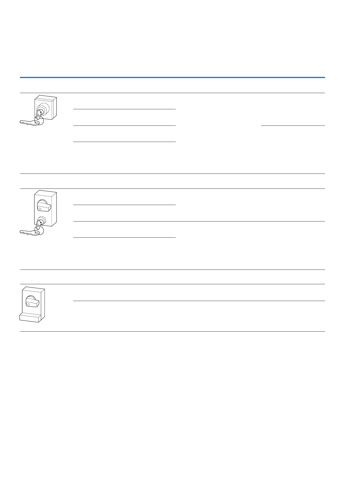
62
Cam switches, switch-disconnectors
Key operation, padlocking feature
S..., SVA..., SVC...
ytilibawardhtiWhtiwesuroF
S-T0 key operated lock mechanism, front IP53
With two keys
KMS 1 lock mechanism: individual lock mechanism, not
suitable for master key systems
Key withdrawable in all positions
T0-1.../I1 to T0-4.../I1
T0-1.../E to T0-6.../E
T0-1.../Z to T0-6.../Z
T3-1.../E to T3-5.../E
T3-1.../Z to T3-5.../Z
T3-1.../I2 to T3-4.../I2
P1-.../E
P1-.../I2
P1-.../Z
Withdrawable positions can be
programmed by user
KMS 2-10, KMS 201-400 lock mechanisms: individual lock
mechanisms, not suitable for master key systems
Key withdrawable in all positions
Lock KMS1: Switches with FS908 are possible as main
switch.
Key can be withdrawn in positions as specified
Withdrawable positions
programmed at factory as
ordered
SA(...) = master key system (master-key facility) with
security certificate. Ordering only with lock plan filled out
with the full configuration of the envisaged lock system.
When reordering state item number from the lock plan,
e.g (A 6294-1.2).
Key can be withdrawn in positions as specified
SVA-T3 cylinder lock, front IP65
With two keys
KMS 1 lock mechanism: individual lock mechanism, not
suitable for master key systems
Key withdrawable in all positions
T0-…/E, T0-…/I1, T0-…/Z
T3-…/E, T3-…/I2, T3-…/Z
P1-…/E, P1-…/I2, P1-…/Z
Withdrawable positions can be
programmed by user
KMS 2-10, KMS 201-400 lock mechanisms: individual lock
mechanisms, not suitable for master key systems
Key withdrawable in all positions
Lock KMS1: Switches with FS908 are possible as main
switch.
Key can be withdrawn in positions as specified
T0-1-… to T0-4-…/I1
T0-1-.../E to T0-4-.../E
T3-1-... to T3-5-.../I2
T3-1-... to T3-6-.../E
P1-.../I2, P1-.../E
Withdrawable positions
programmed at factory as
ordered
SA(...) = master key system (master-key facility) with
security certificate. Ordering only with lock plan filled out
with the full configuration of the envisaged lock system.
When reordering state item number from the lock plan,
e.g (A 6294-1.2).
Key can be withdrawn in positions as specified
SVC-T3 padlocking feature, front IP65
The locking slide can be locked with a max. of 3 padlocks when in its pressed, interlocked position
Z/…-0T,1I/…-0T,E/…-0TdekcolebnacsnoitisopllA
T3-…/E, T3-…/I2, T3-…/Z
P1-…/E, P1-…/I2, P1-…/Z
The positions that can be locked
can be programmed by the user
Specific positions or ranges can be locked Switches with FS908 can be used as main
switches for:
T0-1-... to T0-4-.../I1, .../E
T3-1-... to T3-5-.../I2
T3-1-... to T3-6-.../E
P1-.../I2, P1-.../E
The positions that can be locked
are programmable at the factory
as ordered

63
Cam switches, switch-disconnectors
Key operation, padlocking feature
Part no.
Article no.
Price
See price
list
Std. pack Notes
S-T0
086709
1 off The key replaces the thumb-grip, cannot be switched without key. The switch position indication is on the lock.
Normally the key is withdrawable in every position.
On cam switches ordered with front plate FS908 together with key operation, the key is only withdrawable in the
0 position.
The key withdraw can be changed (also retrospectively) with the locking cam "VR-T0".
When retrofitting the key operation, the existing front plate of the cam switch must be used.
Keys Page 66
S-SOND-KMS(*)-T0
231957
1 off
S(*)-T0
231959
1 off
S(*)-SOND-SA(*)-T0
231965
1 off
SVA-T3
050974
1 off
SVA-SOND-KMS(*)-T3
231967
1 off
SVA(*)-T3
907745
1 off
SVA(*)-SOND-SA(*)-T3
231971
1 off
SVC-T3
050975
1 off
SVC(*)-T3
907748
1 off
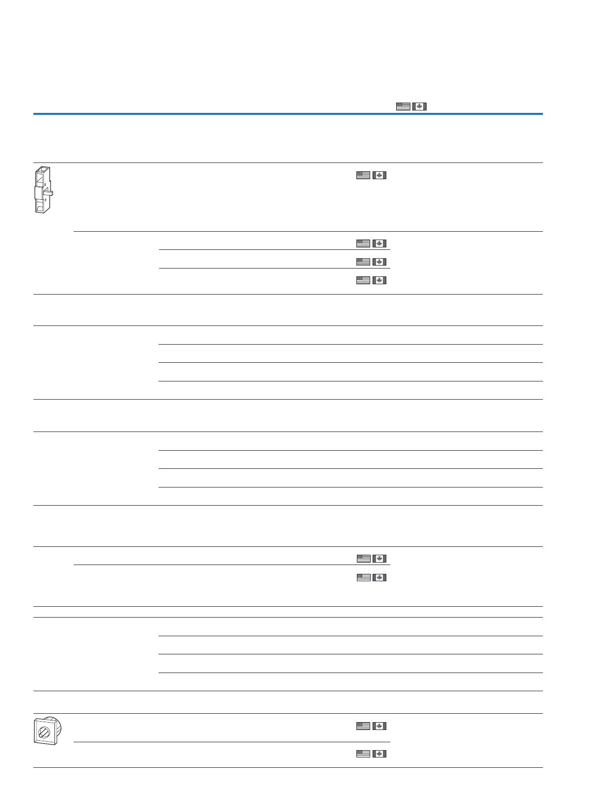
64
Cam switches, switch-disconnectors
Neutral conductor, auxiliary contact, mounting accessories
N-P1, N-P3, N-P5
For use with Part no.
Article no.
Price
See price list
Std. pack Information relevant for export to North America
Neutral conductor
Early-make on switching, late-break off switching
The N contact always behaves as an early-make contact when
switching on and as a late-break contact when switching off.
N-P1(P3)… switching capacity same as for contacts P1(P3)-…
For left or right side
mounting
P1-…/E, …/EA, …/EZ N-P1E
000651
5 off
5 off
5 off
5 off
For P1-…/I2: optionally,
N-P1Z or HI11-P1/P3Z,
can only be fitted on the
left
P1-…/Z, …/V, …/I2, …/IVS N-P1Z
000652
P3-…/E, …/EA… N-P3E
062432
P3-…/Z, …/V, …/IVS
P3-63…/Z, …/I4
P3-100…/Z, …/I5
N-P3Z
064805
Neutral terminal
Front mounting, left
Service distribution board mounting, right
P5-125(160)/E(EA) N-P5-125/160E
280969
1 off
1 off
1 off
1 off
P5-125(160)/Z(V) N-P5-125/160Z
280970
P5-250(315)/E(EA) N-P5-250/315E
280971
P5-250(315)/Z(V) N-P5-250/315Z
280972
Ground terminal
Front mounting, right
Service distribution board mounting, left
P5-125(160)/E(EA) PE-P5-125/160E
280973
1 off
1 off
1 off
1 off
P5-125(160)/Z(V) PE-P5-125/160Z
280974
P5-250(315)/E(EA) PE-P5-250/315E
280975
P5-250(315)/Z(V) PE-P5-250/315Z
280976
Auxiliary contacts
1 normally open (N/O), 1 normally close contact (N/C)
Late-break on switching, early-make off switching. The N/O is always
connected as a load-shedding contact.
For left and/or right side
mounting
P1-…/E, …/EA…, …/EZ
P3-…/E, …/EA
HI11-P1/P3E
061813
5 off
For P1…/I2: optionally,
HI11-P1/P3Z or N-P1Z, can
only be fitted on the left
P1-…/Z, …/V, …/I2, …/IVS
P3-63/Z, …/V, …/I4, …/IVS
P3-100/Z, …/V, …/I5, …/
IVS
HI11-P1/P3Z
062031
5 off
2 normally open (N/O), 1 normally close contact (N/C)
For left and/or right side
mounting
P5-125(160)/E(EA) HI21-P5-125/160E
280963
1 off
1 off
1 off
1 off
P5-125(160)/Z(V) HI21-P5-125/160Z
280964
P5-250(315)/E(EA) HI21-P5-250/315E
280965
P5-250(315)/Z(V) HI21-P5-250/315Z
280966
Center mounting accessories
For single-hole fitting 22.3 mm
For cam switches with existing
front plate - quick installation
with snap fitting system
T0-…/E
T3-…/E
EZ-T0
081622
1 off UL/CSA certification not required
Mounting diameter 22.3
mm, one man mounting
with screw fixing
T0-…/E
T3-…/E
P1-…/E
EZ-P1
091455
1 off
Product Standards
UL File No.
UL CCN
CSA File No.
CSA Class No.
NA Certification
UL 508; CSA-C22.2 No. 14-05;
IEC/EN 60947-3; CE marking
CSA report applies to both
Canada and US
–
12528
3211-05
UL Listed, CSA certified
Product Standards
UL File No.
UL CCN
CSA File No.
CSA Class No.
NA Certification
UL 508; CSA-C22.2 No. 14-05;
IEC/EN 60947-3; CE marking
E36332
NLRV
12528
3211-05
UL Listed, CSA certified
Product Standards
UL File No.
UL CCN
CSA File No.
CSA Class No.
NA Certification
UL 508; CSA-C22.2 No. 14-05;
IEC/EN 60947-3; CE marking
E36332
NLRV
12528
3211-05
UL Listed, CSA certified
65
Cam switches, switch-disconnectors
Coupling drive, interlock parts, shaft extension
For use with Part no.
Article no.
Price
See
price
list
Std. pack Notes Information rele-
vant for export to
North America
Service distribution board mounting accessories
Including push-fit shaft
For retrofitting in service
distribution board mounting
T0-…/IVS design. Use the basic
switch's front plate.
T0-…/XZ IVS-T0
091114
1 off UL/CSA certifica-
tion not required
Coupling drive
Including push-fit shaft
For the retrofitting of switch
T0(T3)-.../XZ as rear mounting,
spare part for T0(T3)/(P1)-.../Z
–DE-T0
093487
1 off UL/CSA certifica-
tion not required
UL/CSA certifica-
tion not required
For the conversion of T5(B)-.../E
flush mounting switch to rear
mounting, spare part for
T5(B)/(P3)-.../Z
–DE-P3
093972
3 off
Interlock sections
With PE and neutral conductor connection
Mounting on the back of flush mounting switch, with interlock function in
rear mounting switches.
T0-…/E, …EZ, …Z
T3-…/E, …EZ, …Z
P1-…/E, …EZ, …Z
UV-T0
019925
1 off Mounting on the
back of flush
mounting switch
UL/CSA certifica-
tion not required
UL/CSA certifica-
tion not required
T5(B)-…/E, …Z
P3-…/E, …Z
UV-P3
048289
1 off With interlock
function for rear
mounting switches
Interlock extensions
A max. of 4 units can be plugged on the interlock section every 25 mm
(an equal number of shaft extensions is required for this)
Use only with T0/T3-… and
P3-…/Z designs
UV-T0 ZVV-T0
022298
10 off – UL/CSA certifica-
tion not required
– UL/CSA certifica-
tion not required
Use only with T5(B)-…/Z and
P3-…/Z designs
UV-P3 ZVV-P3
024671
10 off
Shaft extensions
A max. of 4 units can be put on the switch shaft every 25 mm
T0-…/Z, T0-…/V
T3-…/Z, T3-…/V
P1-…/Z, P1-…/V
ZAV-T0
027044
10 off – UL/CSA certifica-
tion not required
– UL/CSA certifica-
tion not required
T5(B)-…/Z
P3-…/Z
P3-…/V
ZAV-P3
029417
10 off
Shaft
Aluminum, length: 480 mm P5-…/V…
P5-…/Z
ZAV-P5
280979
1 off UL/CSA certifica-
tion not required
Interlock extensions und shaft extensions, complete
Extension to 25 mm
When ordering with basic unit
+ZAV(X1)+ZVV(X1)-T0/P3
254546
1 off UL/CSA certifica-
tion not required
Control cable terminal
P5-250/315 ST-P5-250/315
280978
1 off Terminal capacity:
• Solid or stranded:
4 mm
2
• Flexible with
ferrules to
DIN 46228: 4 mm2
UL/CSA certifica-
tion not required
DE-T0(P3), ZAV-T0(P3)
66
Cam switches, switch-disconnectors
Shrouds, keys
H...
For use with Part no.
Article no.
Price
See price
list
Std. pack Notes
Shrouds1)
For flush mounting switches with up
to 4 contact units
T0-…/E
T3-…/E
H3-T0
093828
1 off Cable entries
Quantity:
2 x Ø 20 mm
+ 2 x Ø 15 mm
Cross-section:
5 x 6 mm 2
5 x 2.5 mm 2
For covering the connection
terminals of up to 2 contact units
T5(B)-…/E, …/Z H1-T5
045062
1 off Can be optionally used for input
wiring and/or outgoer
Extension for H1-T5 protective
shroud on 3 - 8 contact units
H1-T5 HZ-T5
045063
10 off One HZ-T5 required per contact
unit
For covering the connection termi-
nals on 3 pole switch-disconnectors
P1-…/E, …/EZ, …/Z, …/EA,
…/V
H-P1
017253
5 off Can be optionally used for input
wiring and/or outgoer
For covering the connection termi-
nals on 4 pole switch-disconnectors
P1-…N, …HI11,
…N…HI11
H-P14
019626
5 off Can be optionally used for input
wiring and/or outgoer
For covering the connection
terminals on 3 pole open switch-
disconnectors with N neutral
conductor and/or HI11 auxiliary
contact
P3-…/E, …/Z, …/EA, …/V
P3-…N, …HI11,
…N…HI11
H-P3
021999
5 off The protective shroud is
designed for mounting on the
switch-disconnector on both
sides; non-required parts can be
broken off.
For covering the terminals P5 H-P5-125/160
293977
1 off
For covering the terminals P5 H-P5-250/315
293978
1 off
Set (6 units) for covering the
connection terminals
T8-3-8342/… H-T8
200184
6 off
Key
For KMS 1 individual lock
mechanism
–ES-KMS1-T0
231972
10 off
For KMS 2 - 10 or KMS 201 - 400
individual lock mechanism
–ES-KMS(*)-T0
231973
1 off
Individual key, stainless, for master
key system and stored individual
lock mechanisms, state lock plan
no. and key.
–HS-SA(*)-T0
256151
1 off Master key must be ordered additionally.
The security certificate must be
sent when reordering.
Ordering example:
HS-SA(A6294-1.2)-T0
Locking cams (2 cams per set)
For later change of key withdraw-
ability in the engagement positions
S-T0 for all switching
angles
VR-T0
089082
1 off
For changing the blocked positions/
ranges
SVA-T3
SVC-T3
VR-T3
050987
1 off
Mounting plate shield
2)
To connect the
shielding
CI-K2 MBS-I2
290191
1 off
To connect the
shielding
CI-K4 MBS-I4
118742
1 off
Information relevant for export to North America
)2)1
UL/CSA certification not required Product Standards
UL File No.
UL CCN
CSA File No.
CSA Class No.
NA Certification
UL 508; CSA-C22.2 No. 14-05; CSA-C22.2
No. 94; IEC/EN 60947-3; CE marking
E36332
NLRV
12528
3211-07
UL Listed, CSA certified
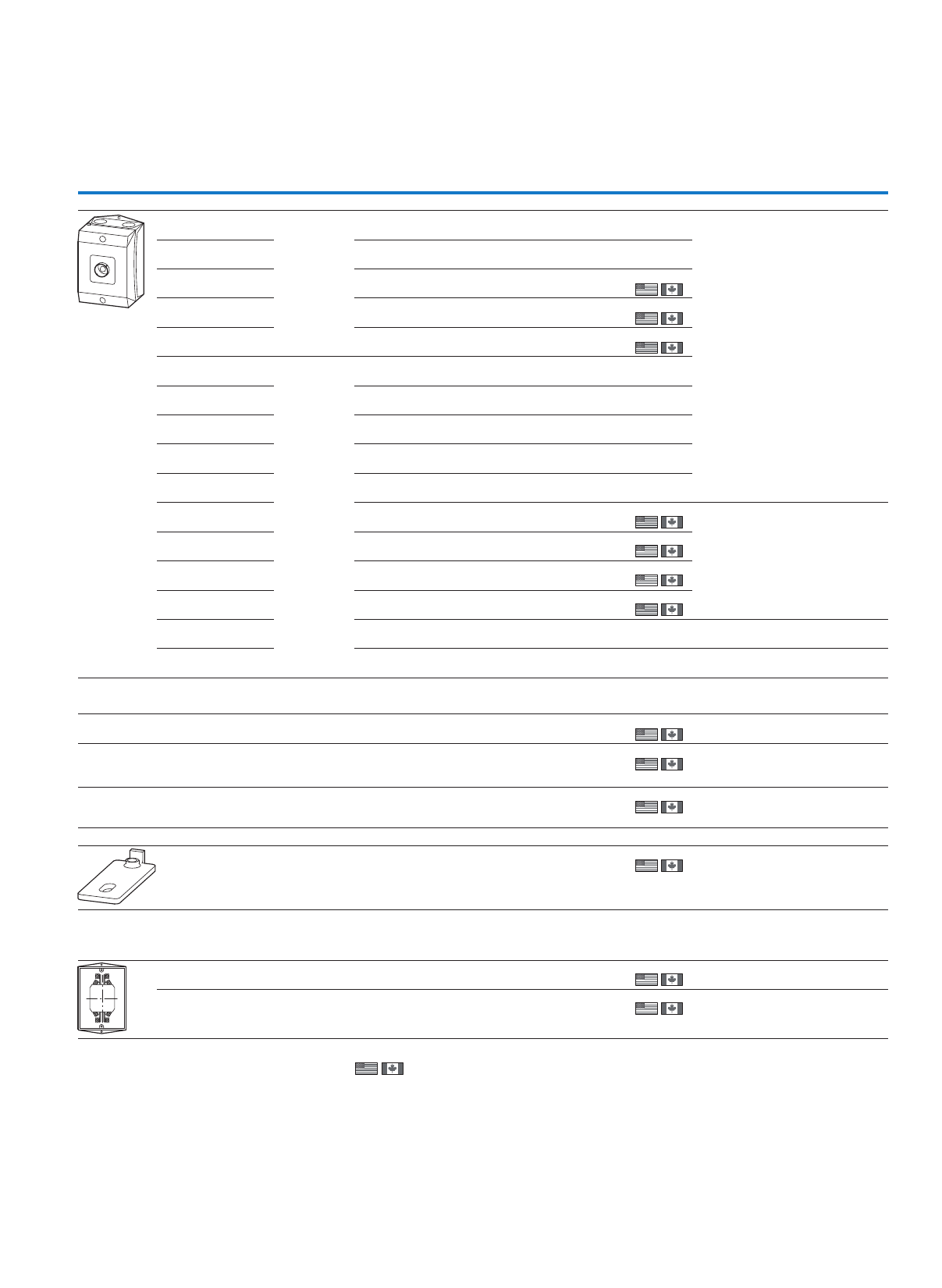
67
Cam switches, switch-disconnectors
Insulated enclosures, accessories
Insulated enclosures, accessories
For use with Part no.
Article no.
Price
See price list
Std. pack Notes
IP65 insulated enclosures
1 - 2 contact units With push-
through
cable entry
diaphragm.
T0-…/Z CI-K1-T0-2
207435
1 off The diaphragm can be pierced with
the cable
Main current/control current:
12 mm/- 16 mm/8 mm
1 contact unit = 2 contacts
3 - 4 contact units T0-…/Z CI-K1-T0-4
207436
1 off
1 - 2 contact units T3-…/Z CI-K2-T3-21)
207437
1 off
1 off
1 off
3 - 4 contact units T3-…/Z CI-K2-T3-41)
225325
Z/…-3Tstinutcatnoc5 CI-K2-T3-51)
207438
1 - 2 contact units With metric
knockouts
T0-…/Z CI-K1H-T0-2
105854
1 off
1 off
1 off
1 off
1 off
3 - 4 contact units T0-…/Z CI-K1H-T0-4
105855
1 - 2 contact units T3-…/Z CI-K2H-T3-2
269462
3 - 4 contact units T3-…/Z CI-K2H-T3-4
105859
Z/…-3Tstinutcatnoc5 CI-K2H-T3-5
105860
1 - 2 contact units T5B-…/E CI-K4-T5B-2
207439
1 off
1 off
1 off
1 off
For converting T5-…/Z into T5-…/I5
and T5B-…/E into T5B…/I4:
Order AW-T5-… extension terminal
additionally
1 contact unit = 2 contacts
3 - 4 contact units T5B-…/Z CI-K4-T5B-4
207440
1 - 2 contact units T5-…/Z CI-K5-T5-2
207441
3 - 4 contact units T5-…/Z CI-K5-T5-4
207442
Only available together
with basic unit
T0-…/I1 +I1H
105870
1 off
Only available together
with basic unit
T3-…/I2
P1-…/I2
+I2H
105871
1 off
Neutral terminals
For connection of a 5th conductor
CI-K2-PKZ0-... K-CI-K1/22)
207451
20 off
20 off
20 off
T5B-…/I4,
Cl-K4-T5B-…
P3-…/I4, CI-K4
K-CI-K42)
206916
T5-…/I5,
CI-K5-T5-…
P3-…/I5, CI-K5
K-CI-K52)
218488
Set of external fixing brackets
T5B-…/I4,
T5-…/I5,
P3-63/I4,
P3-100/I5
AB-CI-K4/52)
206914
1 off For fixing CI-K4 and CI-K5 directly on
walls.
One set contains 4 brackets.
Set of extension terminals
For retrofitting
for connection inside enclosure
For the bottom contact unit T5B-…/I4
T5-…/I5
AW-T5-1/22)
032601
10 off Already included in equipment
supplied with T5B-…/I4 and T5-…/I5.
For the second contact unit from the
bottom
T5-…/I5 AW-T5-3/42)
032602
1 off Already included in equipment
supplied with T5B-…/I4 and T5-…/I5.
oftnavelernoitamrofnIsetoN r export to North America
1)
2) UL/CSA certification not required
Product Standards
UL File No.
UL CCN
CSA File No.
CSA Class No.
NA Certification
Degree of Protection
UL 508; CSA-C22.2 No. 14-05; CSA-C22.2 No. 94;
IEC/EN 60947-3; CE marking
E54120
MITW2
12528
3211-07
UL Listed, CSA certified
IEC: IP65; UL/CSA Type1, 3R, 4X, 12, 13 – indoor
and outdoor use
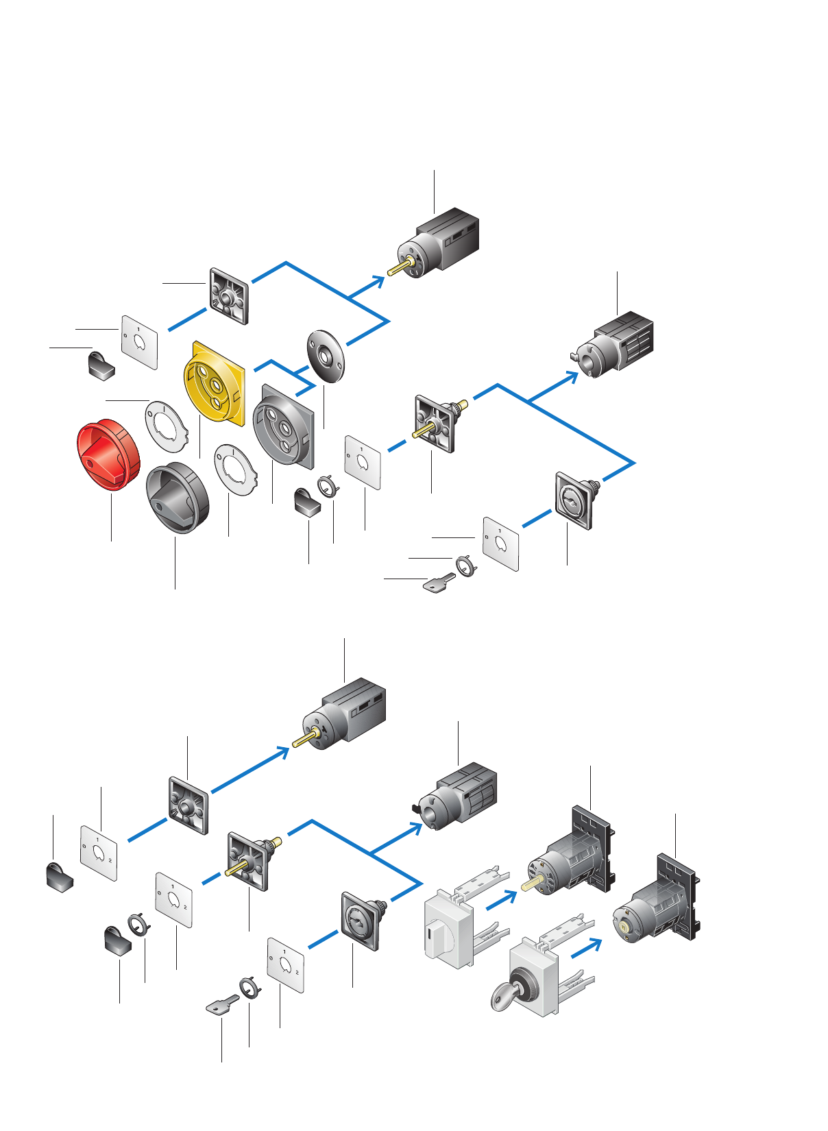
68
Mini cam switches
TM ON-OFF switches
TM control switch
1
2
5
3
4
4
4
6
6
6
7
8
8
8
8
9
8
9
10
8
AUTO
HAND
O
1
0
2
11
3
4
4
4
5
6
6
6
9
9
10
1
11
System overview
69
Mini cam switches
Product features
Contact chamber
• Rated uninterrupted current 10 A
• Positively opening contacts
• 1 – 2 contacts per contact chamber, up
to 16 contacts per switch
• For switching unequal potentials
• Control circuit reliability
Switch position
• Safety due to indexing
• Switching angles 30°, 45°, 60°, 90°
• Spring action with automatic return
with max. 6 contacts,
switching angle ≧ 60°
• Complete rotation
• If the total switching angle is 360°,
complete rotation possible in both
operating directions
Flush mounting (.../E) 1
Front IP65
Mounting from rear in panel
sides, plates or doors
Terminals
Crosshead screwdriver
Pozidriv
Finger proof
Page 70
Flush mounting control
circuit isolator (.../E/SVB)
1
Front IP65
TO IEC/EN 60 947-5, VDE 0660
0 position lockable with
2 padlocks 4 mm Ø or
1 padlock 6 mm Ø
Can be used with up to
250 V AC per contact
Maximum 6 contacts
permissible
Page 70
Center mounting (.../EZ) 2
Front IP65
Mounted in 16.2 Ø or 22.3 Ø
fixing hole, as specified in
IEC/EN 60 947-5-1, after the
included adapter is removed
Page 70
Key operation for
center mounting
3, 4
2 keys are supplied
Key withdrawable 90°
Key withdrawable 60° with
RONIS lock cylinder.
Page 77
Standard switches for
center mounting
5, 6
Black thumb-grip
Page 70
Control circuit isolators 7, 8
Red rotary handle and yellow
locking collar
Black rotary handle and black
locking collar
Lockable in the 0 position
Page 70
Standard switches for flush
mounting
9, 10
Black thumb-grip
Page 71
Standard switches
for IVS distribution board
mounting
11
Mounting in installation
distribution board
Overall width: 2 space units
(45 mm mounting depth)
Up to 2 contact units
70
Mini cam switches
Control circuit isolators, ON/OFF switches
TM
Flush mounting Center mounting
Front IP65 Front IP65
Contact sequence Front plate
no.
Pole Part no.
Article no.
Price
See
price
list
Std. pack Part no.
Article no.
Price
See
price
list
Std. pack
Control circuit isolators, 90°
with padlocking feature
Lockable in the 0 (Off) position
Up to 250 V AC per contact
1TM-1-8290/E/SVB
045477
1 off
1 off
1 off
1 off
1 off
1 off
1 off
1 off
1TM-1-8290/E/SVB-SW
215351
2TM-1-8291/E/SVB
045478
2TM-1-8291/E/SVB-SW
215352
3TM-2-8292/E/SVB
045484
3TM-2-8292/E/SVB-SW
210955
3 + N TM-2-8293/E/SVB
045485
6TM-3-8326/E/SVB
045498
On-Off switches, 90°
1TM-1-8290/E
070131
1 off
1 off
1 off
1 off
1 off
TM-1-8290/EZ
000693
1 off
1 off
1 off
1 off
2TM-1-8291/E
072504
TM-1-8291/EZ
015073
3TM-2-8292/E
074877
TM-2-8292/EZ
015096
3 + N TM-2-8293/E
077250
TM-2-8293/EZ
045486
6TM-3-8326/E
079623
Information relevant for export to North America
1
2
01
1
2
3
4
01
1
2
3
4
5
6
01
1
2
3
4
5
6
7
8
01
1
2
3
4
5
6
7
8
9
10
01
11
12
1
2
01
1
0
F 056
1
2
3
4
01
1
2
3
4
5
6
01
1
2
3
4
5
6
7
8
01
1
2
3
4
5
6
7
8
9
10
01
11
12
Product Standards
UL File No.
UL CCN
CSA File No.
CSA Class No.
NA Certification
UL 508; CSA-C22.2 No. 14-05; IEC/EN 60947-3; CE marking
E36332
NLRV
UL report applies to both US and Canada
–
UL Listed, certified by UL for use in Canada
71
Mini cam switches
Changeover switches
TM
Flush mounting Center mounting
Front IP65 Front IP65
etalptnorFecneuqestcatnoC
no.
Pole Part no.
Article no.
Price
See price
list
Std. pack Part no.
Article no.
Price
See price
list
Std. pack
Changeover switches without 0 (Off) position 60°
1TM-1-8220/E
081996
1 off
1 off
1 off
1 off
1 off
1 off
TM-1-8220/EZ
000692
1 off
1 off
1 off
1 off
1 off
2TM-2-8221/E
084369
TM-2-8221/EZ
015197
3TM-3-8222/E
086742
TM-3-8222/EZ
045493
4TM-4-8223/E
089115
TM-4-8223/EZ
046119
5TM-5-8369/E
091488
TM-5-8369/EZ
046126
6TM-6-8370/E
093861
Changeover switches with 0 (Off) position 60°
1TM-1-8210/E
096234
1 off
1 off
1 off
1 off
TM-1-8210/EZ
015137
1 off
1 off
1 off
1 off
2TM-2-8211/E
098607
TM-2-8211/EZ
015166
3TM-3-8212/E
010807
TM-3-8212/EZ
045491
4TM-4-8213/E
013180
TM-4-8213/EZ
045847
Changeover switches with 0 (Off) position 90°
2TM-2-8219/E
017926
1 off
3TM-3-8299/E
020299
1 off
Information relevant for export to North America
1
2
3
4
12
F 072
12
1
2
3
4
5
6
7
8
12
1
2
3
4
5
6
7
8
9
10
11
12
12
1
2
3
4
5
6
7
8
9
10
11
12
13
14
12
15
16
1
2
3
4
5
6
7
8
9
10
11
12
13
14
12
15
16
17
18
19
20
1
2
3
4
5
6
7
8
9
10
11
12
13
14
12
15
16
17
18
19
20
21
22
23
24
1
2
3
4
102
F 071
12
0
1
2
3
4
5
6
7
8
102
1
2
3
4
5
6
7
8
9
10
11
12
102
1
2
3
4
5
6
7
8
9
10
11
12
13
14
102
15
16
1
2
3
4
5
6
7
8
102
F 057
0
12
1
2
3
4
5
6
7
8
9
10
11
12
102
F 071
12
0
Product Standards
UL File No.
UL CCN
CSA File No.
CSA Class No.
NA Certification
UL 508; CSA-C22.2 No. 14-05; IEC/EN 60947-3; CE marking
E36332
NLRV
UL report applies to both US and Canada
–
UL Listed, certified by UL for use in Canada
72
Mini cam switches
Manual/auto switches, changeover switches
TM
Information relevant for export to North America
Product Standards
UL File No.
UL CCN
CSA File No.
CSA Class No.
NA Certification
UL 508; CSA-C22.2 No. 14-05; IEC/EN 60947-3; CE marking
E36332
NLRV
UL report applies to both US and Canada
–
UL Listed, certified by UL for use in Canada
Flush mounting Center mounting Distribution board - mounting
Front IP65 Front IP65 Front IP30
tnorFecneuqestcatnoC
plate no.
Pole Part no.
Article no.
Price
See price
list
Part no.
Article no.
Price
See price
list
Part no.
Article no.
Price
See price
list
Std. pack
Manual/auto switch 60°
1TM-1-8220F288/EZ
016925
1 off
1TM-1-15431/E
025045
TM-1-15431/EZ
000691
TM-1-15431/IVS
225342
1 off
2TM-2-15432/E
027418
TM-2-15432/EZ
016878
1 off
3TM-3-15433/E
029791
TM-3-15433/EZ
045490
1 off
Changeover switches with spring-return
from both directions, 30°
1TM-1-8214/E
032164
1 off
2TM-2-8215/E
034537
1 off
Step switches without 0 (Off) position
3 steps, 60°
1TM-2-8230/E
039283
TM-2-8230/EZ
000701
1 off
3TM-5-8270/E
041656
TM-5-8270/EZ
046124
1 off
4 steps, 60°
1TM-2-8231/E
044029
TM-2-8231/EZ
000700
1 off
3TM-6-8271/E
046402
TM-6-8271/EZ
046128
1 off
1
2
3
4
HAND
AUTO
F 288
HAND AUTOM
1
2
3
4
HAND
0
AUTO
F 085
0
HAND AUTO
F 085
0
HAND AUTO
F 085
0
HAND AUTO
1
2
3
4
5
6
7
8
HAND
0
AUTO
1
2
3
4
5
6
7
8
9
10
11
12
HAND
0
AUTO
1
2
3
4
102
F 025
0
12
F 025
0
12
1
2
3
4
5
6
7
8
102
1
2
3
4
5
6
123
F 076
2
1
3
F 076
2
1
3
1
2
3
4
5
6
7
8
9
10
11
12
13
14
123
15
16
17
18
1
2
3
4
5
6
7
8
1234
F 077
2
1
3
4
F 077
2
1
3
4
1
2
3
4
5
6
7
8
9
10
11
12
13
14
123
15
16
17
18
19
20
21
22
23
24
4
73
Mini cam switches
Control switches, step switches
TM
Information relevant for export to North America
Product Standards
UL File No.
UL CCN
CSA File No.
CSA Class No.
NA Certification
UL 508; CSA-C22.2 No. 14-05; IEC/EN 60947-3; CE marking
E36332
NLRV
UL report applies to both US and Canada
–
UL Listed, certified by UL for use in Canada
Flush mounting Center mounting
Front IP65 Front IP65
etalptnorFecneuqestcatnoC
no.
Pole Part no.
Article no.
Price
See price
list
Std. pack Part no.
Article no.
Price
See price
list
Std. pack
Step switches without 0 (Off) position
5 steps, 60°
1TM-3-8232/E
039298
1 off TM-3-8232/EZ
015592
1 off
2TM-5-8252/E
041671
1 off TM-5-8252/EZ
046123
1 off
6 steps 60°, no full rotation
1TM-3-8233/E
053521
1 off TM-3-8233/EZ
015630
1 off
2TM-6-8253/E
055894
1 off TM-6-8253/EZ
046127
1 off
10 steps, 30°
1TM-5-8237/E
069150
1 off TM-5-8237/EZ
015661
1 off
1
2
3
4
5
6
7
8
9-
10
12345
F 07 8
2
1
3
4
5
F 07 8
2
1
3
4
5
1
2
3
4
5
6
7
8
9
10
11
12
13
14
123
15
16
17
18
19
20
4 5
1
2
3
4
5
6
7
8
9
10
11
12
123456
2
1
3
4
5
6
F 079
2
1
3
4
5
6
F 079
1
2
3
4
5
6
7
8
9
10
11
12
13
14
123
15
16
17
18
19
20
21
22
23
24
4 5 6
1
2
3
4
5
6
7
8
9
10
1234 5
11
12
6 7 8 9 10
13
14
15
16
17
18
19
20
F 011
1234567
8
9
10
74
Mini cam switches
Control switches, step switches
TM
Information relevant for export to North America
Product Standards
UL File No.
UL CCN
CSA File No.
CSA Class No.
NA Certification
UL 508; CSA-C22.2 No. 14-05; IEC/EN 60947-3; CE marking
E36332
NLRV
UL report applies to both US and Canada
–
UL Listed, certified by UL for use in Canada
Flush mounting Center mounting
Front IP65 Front IP65
eloP.onetalptnorFecneuqestcatnoC Part no.
Article no.
Price
See price list
Std. pack Part no.
Article no.
Price
See price list
Std. pack
Step switches
With 0 (Off) position
2 steps, 60°
1TM-1-8240/E
058267
1 off TM-1-8240/EZ
015226
1 off
1 off
1 off
2TM-2-8260/E
060640
1 off TM-2-8260/EZ
045483
3TM-3-8280/EZ
045496
3 steps, 45°
1TM-2-8241/E
065386
1 off
1 off
1 off
TM-2-8241/EZ
015256
1 off
1 off
1 off
2TM-3-8261/E
067759
TM-3-8261/EZ
000698
3TM-5-8281/E
070132
TM-5-8281/EZ
046125
3 steps, 60°
3TM-3-8280/E
063013
1 off
4 steps, 30°
1TM-2-8242/E
072505
1 off
1 off
1 off
TM-2-8242/EZ
015506
1 off
2TM-4-8262/E
074878
TM-4-8262/EZ
046120
1 off
3TM-6-8282/E
077251
1
2
3
4
012
F 075
1
0
2
F 075
1
0
2
F 075
1
0
2
1
2
3
4
5
6
7
8
012
1
2
3
4
5
6
7
8
9
10
11
12
012
1
2
3
4
5
6
0123
F 109
0
123
F 109
0
123
F 109
0
123
1
2
3
4
5
6
7
8
9
10
11
12
0123
1
2
3
4
5
6
7
8
9
10
11
12
13
14
012
15
16
17
18
3
1
2
3
4
5
6
7
8
9
10
11
12
012
F 075
1
0
2
1
2
3
4
5
6
7
8
0123 4
F 002
0
1234
F 002
0
1234
F 002
0
1234
1
2
3
4
5
6
7
8
9
10
11
12
13
14
01234
15
16
1
2
3
4
5
6
7
8
9
10
11
12
13
14
01234
15
16
17
18
19
20
21
22
23
24
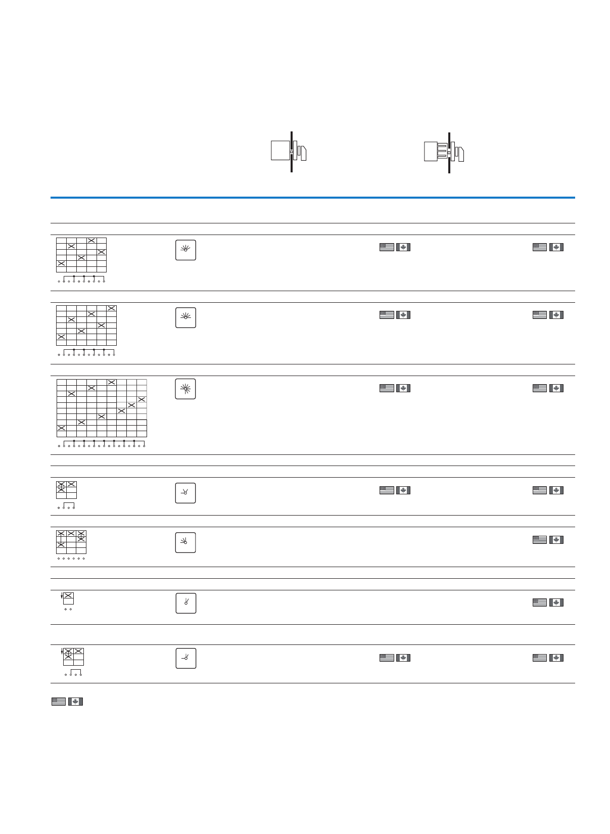
75
Mini cam switches
Control switches – step switches, group switches, ON/OFF switches
TM
Information relevant for export to North America
Product Standards
UL File No.
UL CCN
CSA File No.
CSA Class No.
NA Certification
UL 508; CSA-C22.2 No. 14-05; IEC/EN 60947-3; CE marking
E36332
NLRV
UL report applies to both US and Canada
–
UL Listed, certified by UL for use in Canada
Flush mounting Center mounting
Front IP65 Front IP65
Contact sequence Front plate no. Pole Part no.
Article no.
Price
See price list
Std. pack Part no.
Article no.
Price
See price list
Std. pack
Step switches
With 0 (Off) position
5 steps, 30°
1TM-3-8243/E
079624
1 off TM-3-8243/EZ
015537
1 off
6 steps, 30°
1TM-3-8244/E
081997
1 off TM-3-8244/EZ
045495
1 off
9 steps, 30°
1TM-5-8247/E
009741
1 off TM-5-8247/EZ
015565
1 off
Group switches
2 groups, 60°
1TM-1-8310/E
084370
1 off TM-1-8310/EZ
045479
1 off
3 groups, 30°
1TM-2-8311/EZ
045487
1 off
ON OFF switches
ON switch 30°
1TM-1-8175/EZ
015690
1 off
ON OFF switches 90°/30°
With spring-return from start to 1
1TM-1-8178/E
098608
1 off TM-1-8178/EZ
016786
1 off
1
2
3
4
5
6
7
8
9
10
0123 4 5
F 003
12345
0
1
2
3
4
5
6
7
8
9
10
11
12
0123 4 56
F 004
12345
6
0
1
2
3
4
5
6
7
8
9
10
01234
11
12
5678 9
13
14
15
16
17
18
F 007
0
12345
6
7
8
9
0
1
2
1
2
3
4
F 075
1
0
2
1
2
3
4
5
6
0123
F 001
123
0
START
1
2
F 023
START
0
1
START
1
2
3
4
0
1
F 119
START
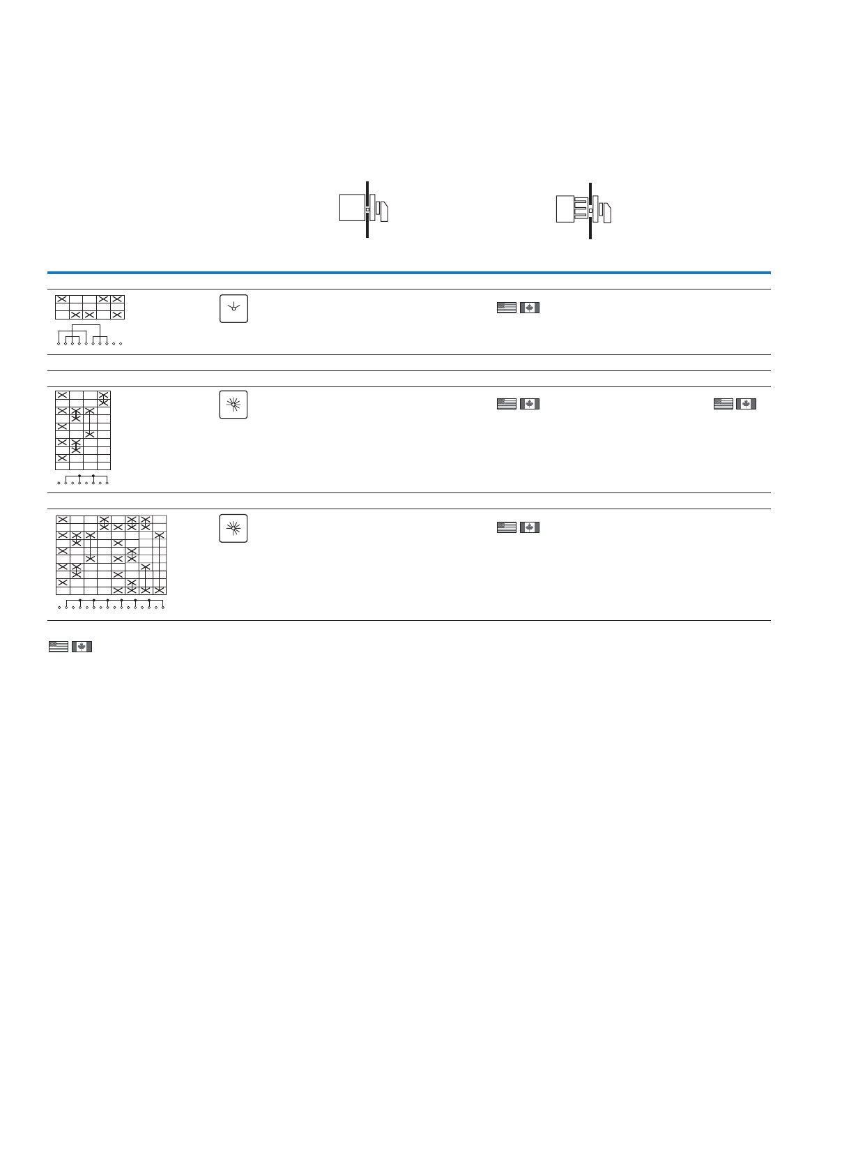
76
Mini cam switches
Control switches – step switches, group switches, ON/OFF switches
TM
Information relevant for export to North America
Product Standards
UL File No.
UL CCN
CSA File No.
CSA Class No.
NA Certification
UL 508; CSA-C22.2 No. 14-05; IEC/EN 60947-3; CE marking
E36332
NLRV
UL report applies to both US and Canada
–
UL Listed, certified by UL for use in Canada
Flush mounting Center mounting
Front IP65 Front IP65
Contact sequence Front plate no. Pole Part no.
Article no.
Price
See price list
Std. pack Part no.
Article no.
Price
See price list
Std. pack
Reversing switches, 60°
3TM-3-8401/E
015554
1 off
Coding switches
BCD code 0-9, 30°
1TM-2-8550/E
020300
1 off TM-2-8550/EZ
000699
1 off
BCD code 0-9 + complement, 30°
1TM-4-8552/E
025046
1 off
1
2
3
4
5
6
7
8
9
10
102
F 071
12
0
1
2
3
4
5
6
7
8
0123456789
F 007
0
12345
6
7
8
9
1
2
3
4
5
6
7
8
9
10
01234
11
12
5 6 7 89
13
14
15
16
F 007
0
12345
6
7
8
9
77
Mini cam switches
Locks
EZ/S-...
For mounting form EZ
With two keys
When ordering with basic unit
Part no.
Article no.
Price
See price
list
Std. pack Notes
Key operated lock mechanism
KABA lock 90° switch angle
Protection type IP65
With two keys
When ordering with basic unit
0° +EZ/S-A
045458
1 off Key operation lock mechanism, incl. 2 keys.
The key can only be removed in certain positions; see diagram
below. The KABA lock for 90° can be used for other switching
angles as well if the key withdrawability characteristics match
the type of switch.
Example: +EZ/S-B can be used with a step switch with a
switching angle of 30° if the key is only to be withdrawable in
the 0 position at 270°.
Options for key withdrawal
Position marking as in example
270° +EZ/S-B
045459
270 + 0° +EZ/S-F
045463
RONIS lock 60° switching angle
Protection type IP55
With two keys
When ordering with basic unit
270 + 90° +EZ/S-D
045461
1 off
1 off
1 off
1 off
1 off
1 off
300 + 0 + 60 + 120 + 180 + 240° +EZ/S-H
045465
270 + 330 + 30 + 90 + 150 + 210° +EZ/S-J
045466
270 + 330 + 90 + 150° +EZ/S-N
045468
ABF
E
R
G
CD
HJMNPQ
330 030
300
270
240 225
210 180 150
135 120
90
60
315 45
78
Mini cam switches
Locks, front plates
EZ/S-...
Size Dimensions
(W x H x D)
For use with Part no.
Article no.
Price
See price
list
Std. pack Notes
mm
Front plates
Blank plate
Can be engraved
TM 29 x 29
(for frame 30 x 30)
FS980-TM-E
071438
10 off Standard front plates for separate order
For standard switches the normal front plate can be replaced if
required with the front plate shown here.
This is provided the switching angle, number of positions and the
position of the 0 position are the same.
Switching angles 30°
Switching angle 45°
Switching angle 60°
Switching angle 90°
TM 29 x 29
(for frame 30 x 30)
FS980-TM-EZ
073811
50 off
Standard front plates
TM…/E 29 x 29
(for frame 30 x 30)
TM/E-FRONTSCHILD-NR(*)
239021
1 off
TM…/EZ 29 x 29
(for frame 30 x 30)
TM/EZ-FRONTSCHILD-NR(*)
239022
1 off
Information relevant for export to North America
UL/CSA certification not required
F023
START
F024
STOP START
F025
102
F039
MAN OFF AUTO
F053
0
12
F258
AUTO 0HAND AUTO 0MAN
F259 F708
F004 F007
F006F005
F003
F002 F011F001
AUTO OFF HAND
123
0
1234
0
12345
0
12345
6
0
12345
6
7
0
12345
6
7
8
0
12345
6
7
8
9
0
23456
7
8
9
10
1
1
0
23
4
5
76
2
1
34
5
6
87
0
L2-L3
L3-L1
L1-L2
L2-L3
L3-L1
L1-L2
0
L2-N
L3-N
L1-N
L2-L3
L3-L1
L1-L2
2
1
34
5
6
7
1
2
01
2
3
3
3
2
1
4
5
2
1
0
3
4
OFF
1
2
1
2
0
1
2
1
2
3
2
1
4
2
1
OFF
3
2
1
0
3
13
2
12
0
02
1
F215 F216 F738 F109 F115 F330 F105 F113
F110 F111
F788F785
F106
F741 F322F293
START START
12
0
2
1
3
4
5
6
2
1
3
4
5
1
0
2
3
2
1
3
4
AUTO HAND
OFF
MAN AUTO
0
21
0
HAND AUTO
0
1
0
2
02
1
12
0
AUTO MAN
12
F072 F234 F288 F071 F073 F075 F076 F085
F077 F079F078F102F732F373 F121F249
AUTOHAND 2
1
3
START
0
1
NOT-
STROM
NETZ
0
31
2
4
ON
OFF
ON
OFF
11
0
0
24
1
3
13
0
2
31
2
MAN
OFF
AUTO
21
0
12
01
AUS
EIN
OFF
ON
0
1
F056 F063 F068 F700 F743 F057 F209 F719
F206 F119F437F718F062F060 F990F059
79
Cam switches, switch-disconnectors
Non-standard switches
T0
Part no. Article
no.
Price
See price
list
Part no. Article
no.
Price
See price
list
Std. pack
T0 cam switches T0-1-SOND*/E1) 907765 T0-5-SOND*/E1) 907769 1 off
T0-1-SOND*/EA/SVB2) 907776 T0-5-SOND*/EZ3) 907791
T0-1-SOND*/EA/SVB-SW2) 908043 T0-5-SOND*/IVS4) 907810
T0-1-SOND*/EZ3) 907787 T0-5-SOND*/Z2) 907843
T0-1-SOND*/I1 207480
T0-1-SOND*/I1/SVB 207481 T0-6-SOND*/E1) 907770
T0-1-SOND*/I1/SVB-SW 207482 T0-6-SOND*/EZ3) 907792
T0-1-SOND*/IVS4) 907806 T0-6-SOND*/IVS4) 907811
T0-1-SOND*/V/SVB2) 907817 T0-6-SOND*/Z2) 907844
T0-1-SOND*/V/SVB-SW2) 908054
T0-1-SOND*/Z2) 907839 T0-7-SOND*/E1) 907771
T0-7-SOND*/EZ3) 907793
T0-2-SOND*/E1) 907766 T0-7-SOND*/IVS4) 907812
T0-2-SOND*/EA/SVB2) 907777 T0-7-SOND*/Z2) 907845
T0-2-SOND*/EA/SVB-SW2) 908044
T0-2-SOND*/EZ3) 907788 T0-8-SOND*/E1) 907772
T0-2-SOND*/I1 207483 T0-8-SOND*/EZ3) 907794
T0-2-SOND*/I1/SVB 207484 T0-8-SOND*/IVS4) 907813
T0-2-SOND*/I1/SVB-SW 207485 T0-8-SOND*/Z2) 907846
T0-2-SOND*/IVS4) 907807
T0-2-SOND*/V/SVB2) 907818 T0-9-SOND*/E1) 907773
T0-2-SOND*/V/SVB-SW2) 908055 T0-9-SOND*/EZ3) 907795
T0-2-SOND*/Z2) 907840 T0-9-SOND*/IVS4) 907814
T0-9-SOND*/Z2) 907847
T0-3-SOND*/E1) 907767
T0-3-SOND*/EA/SVB2) 907778 T0-10-SOND*/E1) 907774
T0-3-SOND*/EA/SVB-SW2) 908045 T0-10-SOND*/EZ3) 907796
T0-3-SOND*/EZ3) 907789 T0-10-SOND*/IVS4) 907815
T0-3-SOND*/I1 207486 T0-10-SOND*/Z2) 907848
T0-3-SOND*/I1/SVB 207487
T0-3-SOND*/I1/SVB-SW 207488 T0-11-SOND*/E1) 907775
T0-3-SOND*/IVS4) 907808 T0-11-SOND*/EZ3) 907797
T0-3-SOND*/V/SVB2) 907819 T0-11-SOND*/IVS4) 907816
T0-3-SOND*/V/SVB-SW2) 908056 T0-11-SOND*/Z2) 907849
T0-3-SOND*/Z2) 907841
T0-4-SOND*/E1) 907768
T0-4-SOND*/EA/SVB2) 907779
T0-4-SOND*/EA/SVB-SW2) 908046
T0-4-SOND*/EZ3) 907790
T0-4-SOND*/I1 207489
T0-4-SOND*/I1/SVB 207490
T0-4-SOND*/I1/SVB-SW 207491
T0-4-SOND*/IVS4) 907809
T0-4-SOND*/V/SVB2) 907820
T0-4-SOND*/V/SVB-SW2) 908057
T0-4-SOND*/Z2) 907842
Notes The prices apply to T cam switches with non-standard contact sequences.
Please use the "Ordering Non-Standard Contact Sequences" order form when ordering for the first time.
When placing repeat orders, specify the contact sequence number together with the country identifier (e.g. 4711D).
Information relevant for export to North America
Product Standards
UL File No.
UL CCN
CSA File No.
CSA Class No.
NA Certification
Degree of Protection
UL 508; CSA-C22.2 No. 14-05; IEC/EN 60947-3; CE marking
E36332
NLRV
12528
3211-05
UL Listed, CSA certified
IEC: IP65; UL/CSA Type 3R, 12
1)
Product Standards
UL File No.
UL CCN
CSA File No.
CSA Class No.
NA Certification
Degree of Protection
UL 508; CSA-C22.2 No. 14-05; IEC/EN 60947-3; CE marking
E36332
NLRV
12528
3211-05
UL Listed, CSA certified
IEC: IP65; UL/CSA Type: -
3) Product Standards
UL File No.
UL CCN
CSA File No.
CSA Class No.
NA Certification
Degree of Protection
UL 508; CSA-C22.2 No. 14-05; IEC/EN 60947-3; CE marking
E36332
NLRV
12528
3211-05
UL Listed, CSA certified
IEC: IP30; UL/CSA Type: -
4)
Product Standards
UL File No.
UL CCN
CSA File No.
CSA Class No.
NA Certification
UL 508; CSA-C22.2 No. 14-05; IEC/EN 60947-3; CE marking
E36332
NLRV
12528
3211-05
UL Listed, CSA certified
2)
80
Cam switches, switch-disconnectors
Non-standard switches
T3
Product Standards
UL File No.
UL CCN
CSA File No.
CSA Class No.
NA Certification
Degree of Protection
UL 508; CSA-C22.2 No. 14-05; CSA-C22.2 No. 94;
IEC/EN 60947-3; CE marking
E36332
NLRV
12528
3211-05
UL Listed, CSA certified
IEC: IP65; UL/CSA Type 3R, 12
Product Standards
UL File No.
UL CCN
CSA File No.
CSA Class No.
NA Certification
UL 508; CSA-C22.2 No. 14-05; IEC/EN 60947-3; CE marking
E36332
NLRV
12528
3211-05
UL Listed, CSA certified
Part no. Article
no.
Price
See price
list
Part no. Article
no.
Price
See price
list
Std. pack
T3 cam switches T3-1-SOND*/E1) 907850 T3-5-SOND*/E1) 907854 1 off
T3-1-SOND*/EA/SVB1) 907861 T3-5-SOND*/EA/SVB1) 907865
T3-1-SOND*/EA/SVB-SW1) 908080 T3-5-SOND*/EA/SVB-SW1) 908084
T3-1-SOND*/EZ1) 907872 T3-5-SOND*/EZ1) 907876
T3-1-SOND*/I22) 207492 T3-5-SOND*/I22) 207504
T3-1-SOND*/I2/SVB2) 207493 T3-5-SOND*/I2/SVB2) 207506
T3-1-SOND*/I2/SVB-SW2) 207494 T3-5-SOND*/I2/SVB-SW2) 207507
T3-1-SOND*/V/SVB1) 907891 T3-5-SOND*/V/SVB1) 907895
T3-1-SOND*/V/SVB-SW1) 908091 T3-5-SOND*/V/SVB-SW1) 908095
T3-1-SOND*/Z1) 907913 T3-5-SOND*/Z1) 907917
T3-2-SOND*/E1) 907851 T3-6-SOND*/E1) 907855
T3-2-SOND*/EA/SVB1) 907862 T3-6-SOND*/EA/SVB1) 907866
T3-2-SOND*/EA/SVB-SW1) 908081 T3-6-SOND*/EA/SVB-SW1) 908085
T3-2-SOND*/EZ1) 907873 T3-6-SOND*/EZ1) 907877
T3-2-SOND*/I22) 207495 T3-6-SOND*/V/SVB1) 907896
T3-2-SOND*/I2/SVB2) 207496 T3-6-SOND*/V/SVB-SW1) 908096
T3-2-SOND*/I2/SVB-SW2) 207497 T3-6-SOND*/Z1) 907918
T3-2-SOND*/V/SVB1) 907892
T3-2-SOND*/V/SVB-SW1) 908092 T3-7-SOND*/E1) 907856
T3-2-SOND*/Z1) 907914 T3-7-SOND*/EZ1) 907878
T3-7-SOND*/Z1) 907919
T3-3-SOND*/E1) 907852
T3-3-SOND*/EA/SVB1) 907863 T3-8-SOND*/E1) 907857
T3-3-SOND*/EA/SVB-SW1) 908082 T3-8-SOND*/EZ1) 907879
T3-3-SOND*/EZ1) 907874 T3-8-SOND*/Z1) 907920
T3-3-SOND*/I22) 207498
T3-3-SOND*/I2/SVB2) 207499 T3-9-SOND*/E1) 907858
T3-3-SOND*/I2/SVB-SW2) 207500 T3-9-SOND*/EZ1) 907880
T3-3-SOND*/V/SVB1) 907893 T3-9-SOND*/Z1) 907921
T3-3-SOND*/V/SVB-SW1) 908093
T3-3-SOND*/Z1) 907915 T3-10-SOND*/E1) 907859
T3-10-SOND*/EZ1) 907881
T3-4-SOND*/E1) 907853 T3-10-SOND*/Z1) 907922
T3-4-SOND*/EA/SVB1) 907864
T3-4-SOND*/EA/SVB-SW1) 908083 T3-11-SOND*/E1) 907860
T3-4-SOND*/EZ1) 907875 T3-11-SOND*/EZ1) 907882
T3-4-SOND*/I22) 207501 T3-11-SOND*/Z1) 907923
T3-4-SOND*/I2/SVB2) 207502
T3-4-SOND*/I2/SVB-SW2) 207503
T3-4-SOND*/V/SVB1) 907894
T3-4-SOND*/V/SVB-SW1) 908094
T3-4-SOND*/Z1) 907916
Notes The prices apply to T cam switches with non-standard contact sequences.
Please use the "Ordering Non-Standard Contact Sequences" order form when ordering for the first time.
When placing repeat orders, specify the contact sequence number together with the country identifier (e.g. 4711D).
Information relevant for export to North America
2)1)
81
Cam switches, switch-disconnectors
Non-standard switches
T5B
Product Standards
UL File No.
UL CCN
CSA File No.
CSA Class No.
NA Certification
UL 508; CSA-C22.2 No. 14-05; IEC/EN 60947-3; CE marking
E36332
NLRV7
12528
3211-05
UL Listed, CSA certified
Part no. Article
no.
Price
See price
list
Part no. Article
no.
Price
See price
list
Std. pack
T5B cam switches T5B-1-SOND*/E 907924 T5B-5-SOND*/E 907928 1 off
T5B-1-SOND*/EA/SVB 907934 T5B-5-SOND*/EA/SVB 907938
T5B-1-SOND*/EA/SVB-SW 908106 T5B-5-SOND*/EA/SVB-SW 908110
T5B-1-SOND*/I4 207510 T5B-5-SOND*/V/SVB 907954
T5B-1-SOND*/I4/SVB 207511 T5B-5-SOND*/V/SVB-SW 908118
T5B-1-SOND*/I4/SVB-SW 207512 T5B-5-SOND*/Z 907972
T5B-1-SOND*/V/SVB 907950
T5B-1-SOND*/V/SVB-SW 908114 T5B-6-SOND*/E 907929
T5B-1-SOND*/Z 907968 T5B-6-SOND*/EA/SVB 907939
T5B-6-SOND*/EA/SVB-SW 908111
T5B-2-SOND*/E 907925 T5B-6-SOND*/V/SVB 907955
T5B-2-SOND*/EA/SVB 907935 T5B-6-SOND*/V/SVB-SW 908119
T5B-2-SOND*/EA/SVB-SW 908107 T5B-6-SOND*/Z 907973
T5B-2-SOND*/I4 207514
T5B-2-SOND*/I4/SVB 207515 T5B-7-SOND*/E 907930
T5B-2-SOND*/I4/SVB-SW 207516 T5B-7-SOND*/EA/SVB 907940
T5B-2-SOND*/V/SVB 907951 T5B-7-SOND*/EA/SVB-SW 908112
T5B-2-SOND*/V/SVB-SW 908115 T5B-7-SOND*/V/SVB 907956
T5B-2-SOND*/Z 907969 T5B-7-SOND*/V/SVB-SW 908120
T5B-7-SOND*/Z 907974
T5B-3-SOND*/E 907926
T5B-3-SOND*/EA/SVB 907936 T5B-8-SOND*/E 907931
T5B-3-SOND*/EA/SVB-SW 908108 T5B-8-SOND*/EA/SVB 907941
T5B-3-SOND*/I4 207518 T5B-8-SOND*/EA/SVB-SW 908113
T5B-3-SOND*/I4/SVB 207519 T5B-8-SOND*/V/SVB 907957
T5B-3-SOND*/I4/SVB-SW 207520 T5B-8-SOND*/V/SVB-SW 908121
T5B-3-SOND*/V/SVB 907952 T5B-8-SOND*/Z 907975
T5B-3-SOND*/V/SVB-SW 908116
T5B-3-SOND*/Z 907970 T5B-9-SOND*/E 907932
T5B-9-SOND*/Z 907976
T5B-4-SOND*/E 907927
T5B-4-SOND*/EA/SVB 907937 T5B-10-SOND*/E 907933
T5B-4-SOND*/EA/SVB-SW 908109 T5B-10-SOND*/Z 907977
T5B-4-SOND*/I4 207521
T5B-4-SOND*/I4/SVB 207522
T5B-4-SOND*/I4/SVB-SW 207523
T5B-4-SOND*/V/SVB 907953
T5B-4-SOND*/V/SVB-SW 908117
T5B-4-SOND*/Z 907971
Notes The prices apply to T cam switches with non-standard contact sequences.
Please use the "Ordering Non-Standard Contact Sequences" order form when ordering for the first time.
When placing repeat orders, specify the contact sequence number together with the country identifier (e.g. 4711D).
Information relevant for export to North America
82
Cam switches, switch-disconnectors
Non-standard switches
T5
Product Standards
UL File No.
UL CCN
CSA File No.
CSA Class No.
NA Certification
Suitable for
UL 508; CSA-C22.2 No. 14-05; IEC/EN 60947-3; CE marking
E36332
NLRV7
12528
3211-05
UL Listed, CSA certified
Branch Circuits
Information relevant for export to North America
Part no. Article
no.
Price
See price
list
Part no. Article
no.
Price
See price
list
Std. pack
T5 cam switches T5-1-SOND*/E 907978 T5-5-SOND*/E 907982 1 off
T5-1-SOND*/EA/SVB 908031 T5-5-SOND*/EA/SVB 907991
T5-1-SOND*/EA/SVB-SW 908126 T5-5-SOND*/EA/SVB-SW 908130
T5-1-SOND*/I5 207524 T5-5-SOND*/V/SVB 908007
T5-1-SOND*/I5/SVB 207525 T5-5-SOND*/V/SVB-SW 908138
T5-1-SOND*/I5/SVB-SW 207526 T5-5-SOND*/Z 908025
T5-1-SOND*/V/SVB 908003
T5-1-SOND*/V/SVB-SW 908134 T5-6-SOND*/E 907983
T5-1-SOND*/Z 908021 T5-6-SOND*/EA/SVB 907992
T5-6-SOND*/EA/SVB-SW 908131
T5-2-SOND*/E 907979 T5-6-SOND*/V/SVB 908008
T5-2-SOND*/EA/SVB 907988 T5-6-SOND*/V/SVB-SW 908139
T5-2-SOND*/EA/SVB-SW 908127 T5-6-SOND*/Z 908026
T5-2-SOND*/I5 207527
T5-2-SOND*/I5/SVB 207528 T5-7-SOND*/E 907984
T5-2-SOND*/I5/SVB-SW 207529 T5-7-SOND*/EA/SVB 907993
T5-2-SOND*/V/SVB 908004 T5-7-SOND*/EA/SVB-SW 908132
T5-2-SOND*/V/SVB-SW 908135 T5-7-SOND*/V/SVB 908009
T5-2-SOND*/Z 908022 T5-7-SOND*/V/SVB-SW 908140
T5-7-SOND*/Z 908027
T5-3-SOND*/E 907980
T5-3-SOND*/EA/SVB 907989 T5-8-SOND*/E 907985
T5-3-SOND*/EA/SVB-SW 908128 T5-8-SOND*/EA/SVB 907994
T5-3-SOND*/I5 207530 T5-8-SOND*/EA/SVB-SW 908133
T5-3-SOND*/I5/SVB 207531 T5-8-SOND*/V/SVB 908010
T5-3-SOND*/I5/SVB-SW 207532 T5-8-SOND*/V/SVB-SW 908141
T5-3-SOND*/V/SVB 908005 T5-8-SOND*/Z 908028
T5-3-SOND*/V/SVB-SW 908136
T5-3-SOND*/Z 908023 T5-9-SOND*/E 907986
T5-9-SOND*/Z 908029
T5-4-SOND*/E 907981 T5-10-SOND*/E 907987
T5-4-SOND*/EA/SVB 907990 T5-10-SOND*/Z 908030
T5-4-SOND*/EA/SVB-SW 908129
T5-4-SOND*/I5 207533
T5-4-SOND*/I5/SVB 207534
T5-4-SOND*/I5/SVB-SW 207535
T5-4-SOND*/V/SVB 908006
T5-4-SOND*/V/SVB-SW 908137
Notes The prices apply to T cam switches with non-standard contact sequences.
Please use the "Ordering Non-Standard Contact Sequences" order form when ordering for the first time.
When placing repeat orders, specify the contact sequence number together with the country identifier (e.g. 4711D).
83
Cam switches, switch-disconnectors
Non-standard switches
TM
Product Standards
UL File No.
UL CCN
CSA File No.
CSA Class No.
NA Certification
Degree of Protection
UL 508; CSA-C22.2 No. 14-05; IEC/EN 60947-3; CE marking
E36332
NLRV, NLRV7
UL report applies to both US and Canada
–
UL Listed, certified by UL for use in Canada
IEC: IP65; UL/CSA Type: -
Information relevant for export to North America
Part no.1) Article
no.
Price
See price
list
Part no.2) Article
no.
Price
See price
list
Std. pack
TM non-standard
switches
TM-1-SOND*/E 907749 TM-1-SOND-ERSTBESTELLUNG/E 208261 1 off
TM-3-SOND*/E 907750 TM-1-SOND-ERSTBESTELLUNG/EZ 208262
TM-2-SOND*/E 907763 TM-1-SOND-ERSTBESTELLUNG/IVS 225347
TM-4-SOND*/E 907751 TM-2-SOND-ERSTBESTELLUNG/E 208263
TM-6-SOND*/E 907752 TM-2-SOND-ERSTBESTELLUNG/EZ 208264
TM-5-SOND*/E 907764 TM-2-SOND-ERSTBESTELLUNG/IVS 225349
TM-7-SOND*/E 907753 TM-3-SOND-ERSTBESTELLUNG/E 208265
TM-8-SOND*/E 907754 TM-3-SOND-ERSTBESTELLUNG/EZ 208266
TM-1-SOND*/EZ 907755 TM-4-SOND-ERSTBESTELLUNG/E 208267
TM-2-SOND*/EZ 907756 TM-4-SOND-ERSTBESTELLUNG/EZ 208268
TM-3-SOND*/EZ 907757 TM-5-SOND-ERSTBESTELLUNG/E 208269
TM-4-SOND*/EZ 907758 TM-5-SOND-ERSTBESTELLUNG/EZ 208270
TM-5-SOND*/EZ 907759 TM-6-SOND-ERSTBESTELLUNG/E 208271
TM-6-SOND*/EZ 907760 TM-6-SOND-ERSTBESTELLUNG/EZ 208272
TM-7-SOND*/EZ 907761 TM-7-SOND-ERSTBESTELLUNG/E 208273
TM-8-SOND*/EZ 907762 TM-7-SOND-ERSTBESTELLUNG/EZ 208274
TM-1-SOND*/IVS 225346 TM-8-SOND-ERSTBESTELLUNG/E 208275
TM-2-SOND*/IVS 225348 TM-8-SOND-ERSTBESTELLUNG/EZ 208276
Notes )2)1
TM-…-SOND…/…:
For repeat orders for which the design number is
already known. Form FO2 is not required for this
purpose.
The design number is a six-digit number and must
always be greater than 200000.
TM-…-SOND-ERSTBESTELLUNG/…:
For new orders with a completed form.

84
Cam switches, switch-disconnectors
T, TM
Engineering notes for non-standard contact sequences
Ordering of non-standard contact sequences
T . . . . . . . . . . - . . . . . . . . . . . . . . . . . . . . . . . . . . . . . . . - . . . . . . . . . . . . . . . . . . . . . . . . . . . . . . . . . . . . / . . . . . . . . . . . . . . . . . . . . . . . . . . . . . . . . . . + . . . . . . . . . . . . . . . . . .
Switch size Number of contact units
(2 contacts per contact unit)
Contact sequence number
With country ID corresponding to the
country of manufacture.
Send completed form (as shown on the
right) if ordering for the first time. The
contact
sequence number is specified by
the supplying factory. Specifying the
part no. is enough when placing repeat
orders.
Mounting form
• Mounting form /E
• Center mounting /EZ (for T0, T3)
• Surface mounting /I...1)
• Service distribution board mounting /
IVS (for T0)
• Rear mounting /Z
• Flush mounting main switch /EA/SVB2)
• Surface mounting main switch /I.../SVB
• Rear mounting main switch /V/SVB2)
• Designs for TM: /E, /EZ, or /IVS
Accessories
Always specify
completely for
every order!
For TM.../EZ:
only +EZ/S... possible
Max.
units
Contacts
max.
T0 11 22
T3 11 22
T5B 10 20
T5 10 20
TM 8 16
Contact sequence
The adjacent form makes it easier to specify the
contact sequence.
Master copy
Switching angle
30, 45, 60, 90°
Preferred angle: 60°
For On-Off switches: 90°
For main switches: 90° as FS 908
Changeover with inte rruption between
2 positions (ON-OFF-ON) no t permissible for T0;
T3, and TM = 30°, 45°; for T5(T5B) = 30°
Star-delta switch only with switching angle ≧60°
Terminal marking
TM switches have consecutive
terminal markings starting with 1.
Spring-return
The switching action is limited by a stop. The
switch returns under spring pressure to the last
position. Where a switch has spring-return from
both directions, a maximum of max. 3 positions can
be traversed.
The spring-return angle is < ½ switching angle.
A max. of 6 contacts can be returned at the same
time.
The switching angle of spring-return TM mini rota-
ry switch must be ≧60°.
Fleeting contacts
The duration of the fleeting contact depends
primarily on the actuation speed. In order to
actuate a contactor with a fleeting pulse, the
switching angle of the cam switch must not be less
than 60°, since the pulse time can be too short if the
switching angle is smaller. Fleeting contact
elements always operate in both operating
directions.
Complete rotation
Only possible with a total switching angle of 360°.
The direction of switching can be in either
operating direction. The number of switch
positions multiplied by the switching angle must be
360°. TM with 12 positions (one every 30°) only
available with complete rotation, not with stop.
Front plates
Front plates are part of the equipment supplied
with a "first order of rotary switch" and therefore
do not need to be ordered separately.
Number of contact units
The contact chamber = contact unit (BE) has 1 or 2
contacts, each of which is actuated by a cam.
In T5(B), there is a common cam for both contacts.
Because of this, the following applies for T5(B):
If the total switching angle is less than 180°, the
contacts can be switched independently of each
other. With switching angles greater than or equal
to 180°, there can only be 2 contacts in the same
chamber if their switching sequences are the
same but are offset by 180° (e.g. T5B-4-8235 step
switch).
Standard features
Same as cam switch with standard contact
sequence.
Number of contacts = Round up to nearest whole
number
2
Notes
It is possible that the order of the contacts is
altered due to technical reasons.
For special switches bridges are only possible
between a even or uneven number.
Other connections must be made by the user at
installation.
1) For T0-.../I1: max. 4 contact units
For T3-.../I2: max. 5 contact units
2) For T0: up to a max. of 8 contacts = 4 BE,
For T3: up to a max. of 12 contacts = 6 BE
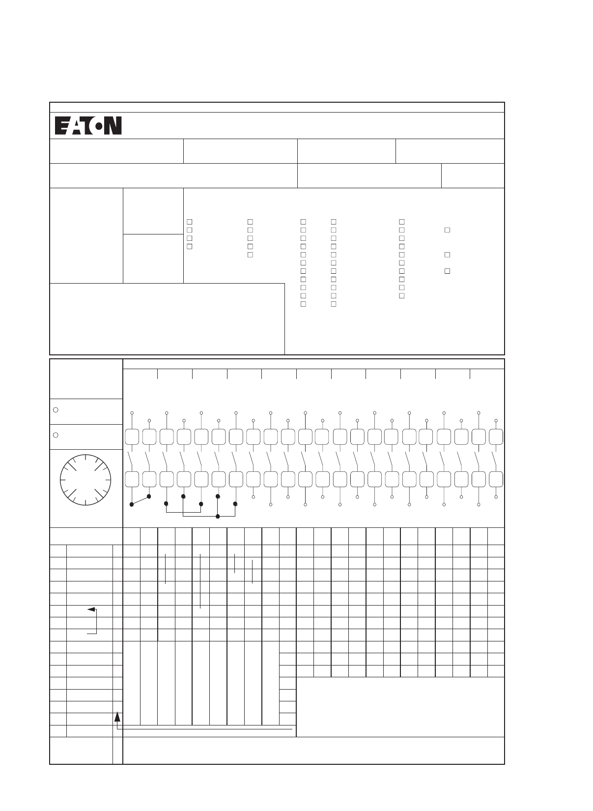
85
Cam switches, switch-disconnectors
T, TM
Non-standard contact sequence ordering example
Binding document for ordering T cam switch combinations for the first time
Order No.:
123456
Item:
7
Office:
Cologne
Author:
HWS
Customer:
Sample Company
Customer no.:
A4711/2004
Date:
29.2.2004
Quantity: 3Switching angle: Part no.: Number of contacts: Mounting
form:
30 TM 112 E
45 T0 213 EA/SVB EA/SVB-SW
Euros/unit: 60 T3 314 EZ
90 T5B 415 I...
T5 516 I.../SVB I.../SVB-SW
617 IVS
718 V/SVB V/SVB-SW
819 Z
920 + ST-0
10 21 +___________________
11 22
Max. characters per position
Degrees TM-E TM-EZ TM-IVS T0(3) T5(B)
0.18 5 5 6 13 13
30, 210, 330 8 7 4 8 8
45, 135, 225, 315 65467
60, 120, 240, 300 55357
90, 270 5 4 1 4 7
150 44488
Front plate no.
FS ______________
Contact units
1234567891011
Complete rotation
Automatic
spring-return
Inscription
Degrees 1
2
3
4
5
6
7
8
9
10
11
12
13
14
15
16
17
18
19
20
21
22
23
24
25
26
27
28
29
30
31
32
33
34
35
36
37
38
39
40
41
42
43
44
270 1 xxxxxx x
300
315
330 2 xxx x
0x
30 3 xxx
45
60 4 x
90
Contact only closed in
position 1
Switching with
interruption of contact
Switching without
interruption of contact
Contact closed in positions
1 + 3
Contact closed in positions
1 to 3
Fleeting contact
(only with 60° or 90°)
Late-break contact
Early-make contact
Contact with automatic
spring-return
120
135
150 Key withdrawability for ..S-T0 and SVA-T3:
180 Pos. 1: Key withdrawable }In the case of SVA-T3, the unit can
still be switched between
positions 1 and 2 if the key has
been removed..
210 Pos. 2: Key withdrawable
225 Pos. 3: Key withdrawable
240 Pos. 4: Key not withdrawable
Key withdrawable xPart no. for repeat orders (to be filled in by factory) T___________________________________
1
2
3
4
5
6
7
8
9
10
11
12
13
14
15
16
17 19
18
21
20
23
22
25
24
27
26
29
28
31
30
33
32
35
34
37
36
39
38
41
40
43
42 44
330 030
300
270
240 225
210 180 150
135 120
90
60
315 45
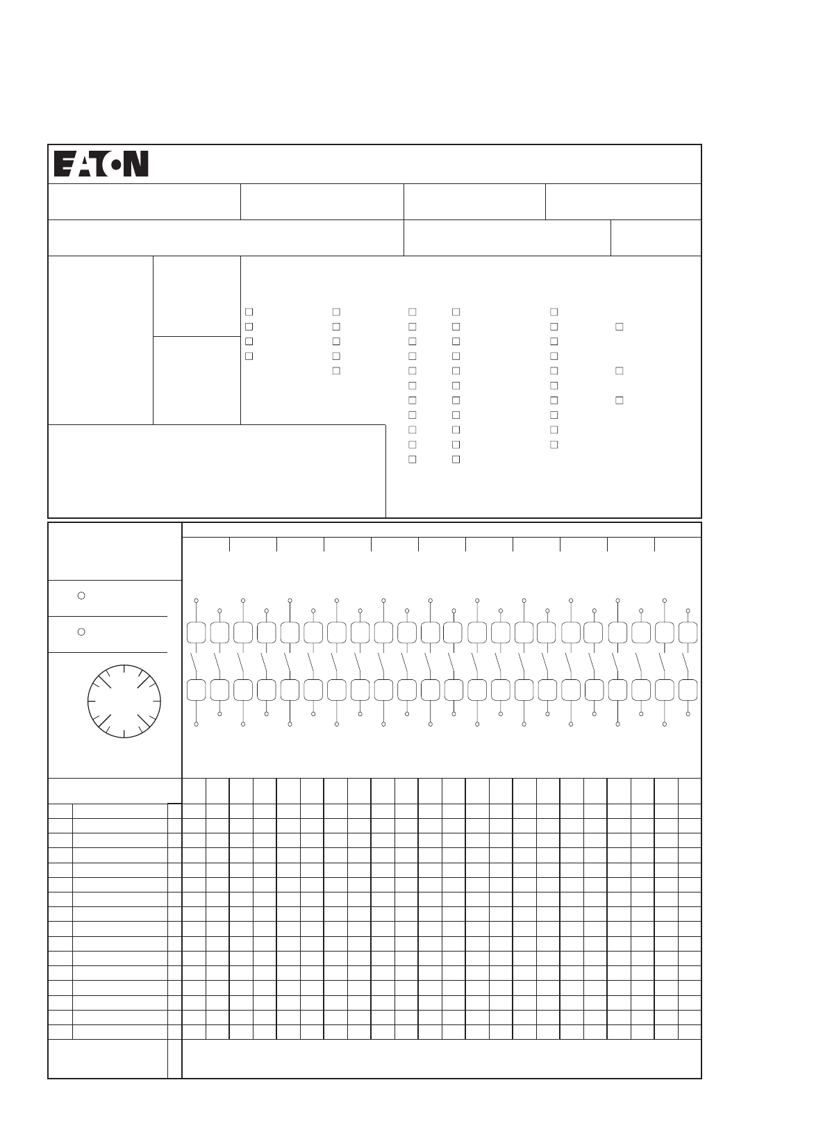
86
Cam switches, switch-disconnectors
Binding document for ordering T cam switch combinations for the first time
:emaN:eciffO:metI:.oNredrO
:etaD:.onremotsuC:remotsuC
Notes:
The number of possible
contacts, as well as the
possible combinations
with mounting forms are
shown in the Main
Catalogue.
Quantity: Switching angle: Part no.: Number of contacts: Mounting
form:
30 TM 1 12 E
45 T0 2 13 EA/SVB EA/SVB-SW
Euros/unit: 60 T3 3 14 EZ
90 T5B 4 15 I...
T5 5 16 I.../SVB I.../SVB-SW
6 17 IVS
7 18 V/SVB V/SVB-SW
8 19 Z
9 20 +____________________
10 21 +____________________
11 22
Max. characters per position
Degrees TM-E TM-EZ TM-IVS T0(3) T5(B)
0.18 5561313
30, 210, 330 8 7 4 8 8
45, 135, 225, 315 6 5 4 6 7
60, 120, 240, 300 5 5 3 5 7
90, 270 54147
150 4 4 4 8 8
Front plate no.
FS _______________
Contact units
1234567891011
Complete rotation
Automatic
Spring-return
Inscription
Degrees 1
2
3
4
5
6
7
8
9
10
11
12
13
14
15
16
17
18
19
20
21
22
23
24
25
26
27
28
29
30
31
32
33
34
35
36
37
38
39
40
41
42
43
44
270
300
315
330
0
30
45
60
90
120
135
150
180
210
225
240
Key withdrawable x Part no. for repeat orders (to be filled in by factory) T__________________________
1
2
3
4
5
6
7
8
9
10
11
12
13
14
15
16
17 19
18
21
20
23
22
25
24
27
26
29
28
31
30
33
32
35
34
37
36
39
38
41
40
43
42 44
330 030
300
270
240 225
210 180 150
135 120
90
60
315 45
T, TM
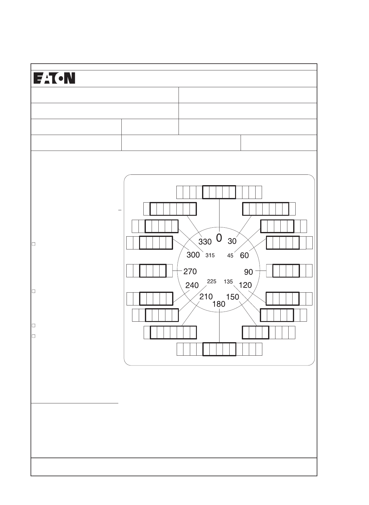
87
Cam switches, switch-disconnectors
FS-SOND
Ordering non-standard front plates
Binding document for ordering non-standard front plates for the first time
:metI:.oNredrO
:emaN:eciffO
:.onremotsuC:remotsuC
:etaD:tinu/soruE:ytitnauQ
The text is always centered in the text block
Non-standard front plates
Inscription:
Front plate with black lettering
Insert text
Note the maximum number of characters
allowed outside the marked areas!
Part no.
FS-SOND-
T0 (T3, P1)
Letter height
≤ 2 Characters
≥ 2 Characters
4 mm
3 mm
FS-SOND-
P3 (T5B, T5)
Letter height
≤ 2 Characters
≥ 2 Characters
8 mm
5 mm
FS-SOND-TM-E
FS-SOND-TM-EZ
≤ 2 Characters approx.
≥ 2 Characters
3.5 mm
3 mm
For P1 and P3, fill out positions 270° and 0° only
Max. possible number of characters
Position
snoisnemiD3P/5T1P/0TZE-MTE-MTseergeD
0, 180 5 5 13 13 Part no. Front plate size
30, 210, 330 8 7 8 8
)03x03emarfrof(mm92x92E/...-MT7656513,522,531,54
)0
3x03emarfrof(mm92x92)...-(ZE/...-MT7555003,042,021,06
)84x84emarfrof(mm54x541P,3T,0T7445072,09
)88x88em
arfrof(mm48x48B5T,5T,3P8844051
Part no. for repeat orders (to be filled in by factory) FS.....................................................................................
88
Cam switches, switch-disconnectors
Characteristic curves
Component lifespan based on breaking current and utilization category
1)
To ensure a reasonable service life in utilization category AC-4 (extreme load: 100 % inching, reversing, or plug braking),
the motor's standstill current must not exceed the rated operational current of the switch for AC-21A.
Notes 1)
AC-3 and AC-21 at 400 V, AC-15 at 230 V
1 2 3 4 5 6 7 8 10 20A
T0
0.5
1
2
3
4
5
6
8
10
Breaking current
As control switch (AC-15)
As motor load switch(AC-3)
As load-break switch(AC-21)
Component lifespan (operations 105)
Breaking current
As motor load switch (AC-3)
As load-break switch (AC-21)
T3
Component lifespan (operations 105)
12 3 4 6 12 A04038
0.5
1
2
3
4
5
6
8
10
16 20 25
0.6
0.8
0.5
T5B
T5B T5
T5
12 3 4 6 12 04038
1
2
3
4
5
6
8
10
16 20
0.6
0.8
60 80 100 A
T5B T5
T5B T5
T5B, T5
Breaking current
As motor load switch (AC-3)
As load-break switch (AC-21)
Component lifespan (operations 105)
Breaking current
As motor load switch (AC-3)
As load-break switch (AC-21)
T6, T8
Component lifespan (operations 105)
468 1612
0.1
0.2
0.3
0.5
1
2
3
5
6020 30 40 100 250A
T6 T8
T6 T8
T6
T8
T6
T8
Breaking current
As motor load switch (AC-3)
As load-break switch (AC-21)
P1
Component lifespan (operations 10 5)
12 3 4 6 12 A04038
0.5
1
2
3
4
5
6
8
10
16 20 25
0.6
0.8
P1-32
P1-25
P1-25 P1-32
P1-25
Breaking current
As motor load switch (AC-3)
As load-break switch (AC-21)
P3
Component lifespan (operations 105)
123 5 20 A0010801
0.1 40 60
0.2
0.3
0.4
0.5
0.6
0.8
1
2
P3-100
P3-63
P3-63 P3-100
P3-100
P3-63

89
Cam switches, switch-disconnectors
Switch-disconnectors
P1, P3
Technical data
P1-25 P1-32 P3-63 P3-100
General
Standards IEC/EN 60947, VDE 0660, IEC/EN 60204, CSA, UL
switch-disconnector to IEC/EN 60947-3
01xsnoitarepOlacinahcem,napsefiL 60.3 0.3 0.1 0.1
h/snoitarepOycneuqerfgnitarepomumixaM 50 50 50 50
Climatic proofing Damp heat, constant, to IEC 60068-2-78;
Damp heat, cyclical, to IEC 60068-2-30
C°nepOerutarepmettneibmA -25 - 50 -25 - 50 -25 - 50 -25 - 50
C°desolcnE -25 - 40 -25 - 40 -25 - 40 -25 - 40
Mounting position Any Any Any Any
Mechanical shock resistance
(IEC/EN60068-2-27)
Half-sinusoidal shock 20 ms g 15 15 15 15
Contacts
Uegatlovlanoitare
podetaR eV AC 690 690 690 690
UegatlovdnatshtiweslupmidetaR imp V AC 6000 6000 6000 6000
Overvoltage category/pollution degree III/3 III/3 III/3 III/3
ItnerrucdetpurretninudetaR uA25 32 63 100
Load rating with intermittent
operation, class 12
IxFD%06BA e1.3 1.3 1.3 1.3
IxFD%04BA e1.6 1.6 1.6 1.6
IxFD%52BA e2222
Lg/GgAesuFgnitartiucric-trohS 25 50 80 100
I)tnerrucs1(tnerrucdnatshtiwemit-trohsdetaR cw Arms 640 640 1260 2000
CAV74906NE/CEIotscitsiretcarahcgnitalosI ≦ 690 ≦ 690 ≦ 690 ≦ 690
Safe isolation according to EN 61140
Safe isolation to VDE 0106 Part 101 and Part 101 A1 between the
auxiliary contacts and main circuits
V AC 440 440 440 440
°elgnagnihctiwS 90 90 90 90
Contacts Number Max. 3 (+N) Max. 3 (+N) Max. 3 (+N) Max. 3 (+N)
Current heat loss per contact at IeW 1.1 1.8 4.5 7.5
Terminal capacity
mmdednartsrodiloS 21 x (1.5 - 6)
2 x (1.5 - 6)
1 x (1.5 - 6)
2 x (1.5 - 6)
1 x (2.5 - 35)
2 x (2.5 - 10)
1 x (2.5 - 35)
2 x (2.5 - 10)
mm82264NIDotelurrefhtiwelbixelF 21 x (1 - 4)
2 x (1 - 4)
1 x (1 - 4)
2 x (1 - 4)
1 x (1.5 - 25)
2 x (1.5 - 6)
1 x (1.5 - 25)
2 x (1.5 - 6)
Terminal screw M4 M4 M5 M5
mNeuqrotgninethgiT 1.6 1.6 3 3
Switching capacity
AC voltage
Rated making capacity cos φA53.0= 240 320 800 950
Rated breaking capacity,
motor load switch cos φ = 0.35
AV032 190 260 640 760
AV514/004 150 300 600 740
AV005 170 290 590 880
AV096 150 250 340 520
Rated operational current 440 V, load-break switch AC-21A IeA25 32 63 100
AC-3 motor load switch motor
rating
WkPV032 5.5 7.5 15 22
WkPV514/004 7.5 13 30 37
WkPV0057.518.53045
WkPV096 7.5 15 30 37
AC-23A motor load switch motor
rating
WkPV032 7 8.5 18.5 30
WkPV514/00413153050
WkPV0051118.53765
WkPV0961118.53045
DC voltage
DC-1, load switch L/R = 1 ms Rated operational current IeA25 32 63 100
Voltage per contact connected in series V 60 60 60 60
DC-23A, motor load switch
L/R = 15 ms
24 V Rated operational current IeA25 25 50 50
rebmuNstcatnoC1111
48 V Rated operational current IeA25 25 50 50
rebmuNstcatnoC2222
60 V Rated operational current IeA25 25 50 50
rebmuNstcatnoC3333
120 V Rated operational current IeA12 12 25 25
rebmuNstcatnoC3333
Notes Main switch characteristics to IEC/EN 60204; positive opening of contacts, operator element positively located on shaft.
Rated uninterrupted current Iu is specified for max. cross-section.
For terminal capacity solid, stranded and flexible: Max. 2 cross-section sizes difference admissible when using 2 conductors.
Unit

90
Cam switches, switch-disconnectors
Switch-disconnectors
P1, P3
P1, P3
P1, P3
Rating data for approved types1)
UL File No. E36332 P1-25 P1-32 P3-63 P3-100
Contacts
Rated operational voltage UeV AC 600 600 600 600
Rated uninterrupted current
Iu
AgnitartnerruC203060100
Pilot Duty A 600P 600 A 600P 600 – –
Switching capacity
AC-3; max. rated power
40 – 60 Hz AC motors
PHCAV002esahp-3 5 7½ 15 20
230 V AC HP 5 10 15 25
460 V AC HP 10 20 40 60
575 V AC HP 15 25 50 75
PHCAV021esahp-elgniS 1½235
200 V AC HP 3 3 7½ 10
230 V ACHP HP 3 5 10 15
Short-circuit rating
AkCAV006dradnatS551010
Aesufpu-kcabhtiW 110 110 150 150
.ontraPsre
kaerb-tiucrichtiW NZMH6 NZMH6 NZMH6 NZMH9
AgnittestnerruC 125 125 125 125
Disconnect in motor circuits 600 V AC kA 10 10 10 –
ssalCesufpu-kcabhtiW 50 A/J 50 A/J 100 A 100 A
Terminal capacity
Terminal capacity
GWA/.niMelbacuC14141414
Max. AWG 8 8 2 2
bl-ni.xaMeuqrotgninethgiT 14.1 14.1 26.5 26.5
HI 11
Auxiliary contacts (1 N/O + 1 N/C)
Pilot Duty P 600
Heavy Pilot Duty A 600
General Use 10 A – 600 V AC
Notes 1) Devices for world markets IEC UL/CSA
UL File No:
UL approved protection types
E36332 UL/NEMA 3R1) UL/NEMA 12 UL/NEMA 13
Switch-disconnectors
P1-.../EA/SVB • • –
P1-.../V/SVB • • –
P3-.../EA/SVB • • •
P3-.../V/SVB • • •
Notes Details of protection types
1) NEMA recommendation
Part no.: P1 P3-63 P3-100
Mounting form
/E; /EA; /EZ
/Z; /V; /IVS
/I2 +NA-I2
105866
/I4 +NA-I4
105868
/I5 +NA-I5
105869
Unit

91
Cam switches, switch-disconnectors
Switch-disconnectors
P5
P5-125 P5-160 P5-250 P5-315
General
Standards IEC/EN 60947, VDE 0660, IEC/EN 60204, CSA, UL
Switch-disconnectors to IEC/EN 60947-3
01xsnoitarepOlacinahcem,napsefiL 60.1 0.1 0.08 0.08
h/snoitarepOycneuqerfgnitarepomumixaM 50 50 50 50
Climatic proofing Damp heat, constant, to IEC 60068-2-78;
Damp heat, cyclical, to IEC 60068-2-30
C°nepOerutarepmettneibmA -25 - 50 -25 - 50 -25 - 50 -25 - 50
C°desolcnE -25 - 40 -25 - 40 -25 - 40 -25 - 40
Mounting position Any Any Any Any
Contacts
Uegatlovlanoitarepode
taR eV AC 690 690 690 690
UegatlovdnatshtiweslupmidetaR imp V AC 8000 8000 8000 8000
Overvoltage category/pollution degree III/3 III/3 III/3 III/3
ItnerrucdetpurretninudetaR uA 125 160 250 315
Load rating with intermittent operation,
class 12
IxFD%06BA e1.3 1.3 1.3 1.3
IxFD%04BA e1.6 1.6 1.6 1.6
IxFD%52BA e222 2
Lg/GgAesuFgnitartiucric-trohS 125 160 250 315
I)tnerrucs1(tnerrucdnatshtiwemit-trohsdetaR cw Arms 2500 3000 4600 5800
CAV74906NE/CEIotscitsiretcarahcgnitalosI ≦ 690 ≦ 690 ≦ 690 ≦ 690
Safe isolation according to EN 61140
Safe isolation to VDE 0106 Part 101 and Part 101 A1 between the
auxiliary contacts and main circuits
V AC 440 440 440 440
°elgnagnihctiwS 90 90 90 90
Contacts Number Max. 3 (+N) Max. 3 (+N) Max. 3 (+N) Max. 3 (+N)
Current heat loss per contact at IeW 8 10 13 16
Terminal capacity
mmdednartsrodiloS 21 x (10 - 95)
2 x (10 - 35)
1 x (10 - 95)
2 x (10 - 35)
1 x (16 - 185)
2 x (16 - 70)
1 x (16 - 185)
2 x (16 - 70)
forebmuNrotcudnoctalf1,pirtsreppoC
layers x width
x thickness
mm 6 x 9 x 0.8 – 6 x 20 x 1 –
mmsrotcudnoctalf2,pirtsreppoC – 6 x 9 x 0.8 – 6 x 20 x 1
mm82264NIDotelurrefhtiwelbi
xelF 21 x (16 - 70)
2 x (16 - 25)
1 x (16 - 70)
2 x (16 - 25)
1 x (25 - 120)
2 x (25 - 50)
1 x (25 - 120)
2 x (25 - 50)
Terminal screw Hexagon
screw 5
Hexagon
screw 5
Hexagon
screw 6
Hexagon
screw 6
mNeuqrotgninethgiT 14 14 16 16
Notes Main switch characteristics to IEC/EN 60204; positive opening of contacts, operator element positively located on shaft
Rated uninterrupted current Iu is specified for max. cross-section.
For terminal capacity solid, stranded, and flexible:
Max. 2 cross-section sizes difference admissible when using 2 conductores.
Unit

92
Cam switches, switch-disconnectors
Switch-disconnectors, auxiliary contacts
P5
P5
Unit
Unit
P5-125 P5-160 P5-250 P5-315
Switching capacity
AC voltage
Rated making capacity cos φA53.0= 850 1050 1700 2050
Rated breaking capacity,
motor load switch cos φ = 0.35
AV032 800 900 1600 1800
AV004 750 850 1380 1650
AV005 650 850 1250 1550
AV096 340 340 400 400
Rated operational current 440 V, load-break switch AC-21A IeA 125 160 250 315
Motor rating
motor load switch AC-3
WkPV03222303745
WkPV00437455575
WkPV09630374545
Motor rating
motor load switch AC-23 A
WkPV03230303755
WkPV004455590110
WkPV09637374545
DC voltage
DC-1, load switch L/R = 1 ms
DC-1, load switch L/R = 1 ms
Rated operational current IeA 125 160 250 315
Voltage per contact connected in series V 42 42 42 42
DC-23A, motor load switch
L/R = 15 ms
24 V Rated operational current IeA 125 160 250 315
rebmuNstcatnoC3333
48 V Rated operational current IeA 125 160 250 315
rebmuNstcatnoC3333
60 V Rated operational current IeA 125 160 250 315
rebmuNstcatnoC3333
120 V Rated operational current IeA40 50 80 100
rebmuNstcatnoC3333
Notes Main switch characteristics to IEC/EN 60204; positive opening of contacts, operator element positively located on shaft
Rated uninterrupted current Iu is specified for max. cross-section.
For terminal capacity solid, stranded, and flexible:
Max. 2 cross-section sizes difference admissible when using 2 conductores.
HI...-P1(P3)... HI...-P5...
Auxiliary contacts
Standards Control circuit isolator to IEC/EN 60947-5
UegatlovnoitalusnidetaR iV AC 500 500
ItnerrucdetpurretninudetaR uA10 10
Rated operational current
IV032ta51-CA eA6 6
IV514/V004 eA– 3
DC-13
IV521 eA 1.1 0.23
IV052 eA0.55 0.1
Short-circuit rating
Max. fuse A gG/gL 10 10
Terminal capacity
Solid mm 21 × 0.75 - 2.5
2 × 0.75 - 1.5
1 × 0.75 - 2.5
2 × 0.75 - 1.5
mm82264NIDotelurrefhtiwelbixelF 21 × 0.5 - 1.5
2 × 0.5 - 1.5
1 × 0.5 - 1.5
2 × 0.5 - 1.5
Tightening torque Nm 0.6 0.8
HytilibaborptluaFAm01,CDV42taytilibailertiucriclortnoC F< 10-5, < 1 failure for 100 000 switching operations

93
Cam switches, switch-disconnectors
P5
P5
Unit
Unit
Rating data for approved types
P5-125 P5-160 P5-250 P5-315UL File No. E36332
Contacts
UegatlovlanoitarepodetaR eV 600 600 600 600
Rated impulse withstand voltage1) Uimp V AC 8000 8000 8000 8000
Rated uninterrupted current2) IuA 125 160 250 300
Rated operational current
Ampere ratingOff switchI Off switch IeA 1252) 1602) 2502) 3002)
Changeover
switches
IeA 1252) 1602) ––
Non inductive and slightly inductive loads
Rated switching duty
DOL rating (similar to AC-3)
3-phase, 3 pole
PHV02115203040
PHV04230406075
PHV084606075100
PHV006606075100
Short-circuit rating
AcitsiretcarahcLg,esufpu-kcab.xaM 125 160 250 315
Rated short-time withstand current (1 s current) A 2500 3000 4600 5800
Terminal capacity
Cu cable
Solid or stranded for box
terminal
AWG 3/0 3/0 – –
MCM – – 350 350
GWAelurreftuohtiwelbixelF2/02/0––
MCM – – 300 300
Connection with cable lug or busbar M10 x M10 x M12 x M12 x
mmw
ercslanimreT20202020
mmhtdiw.xaM20202525
mmrevoclanimrethtiwhtdiw.xaM25253434
Ambient temperature Open on 100 % Iu/Ith 50 °C over 24 hours with peaks up to 55 °C
Enclosed on 100% Ithe 35 °C over 24 hours with peaks up to 40 °C
Notes 1) Valid for mains with grounded star point, overvoltage category III, pollution degree 3
2) Valid for connection with cables for 75°C
HI11 HI21-P5-125(160) HI21-P5-250(315)
Auxiliary contacts
Standards
UegatlovnoitalusnidetaR iV AC 600 600
ItnerrucdetpurretninudetaR uA1010
ItnerruclanoitarepodetaR e
Pilot Duty P600 P600 P600
Heavy Pilot Duty A600 A600 A600
General Use 10 A – 600 V AC – –
Ampere rating
Non inductive and slightly inductive loads – 10 10
Short-circuit rating
AcitsiretcarahcLgesuf.xaM –16 16
Terminal capacity
GWAdednartsrodiloS –12 12
GWAelurreftuohtiwelbixelF –14 14
Notes 1) Devices for world markets IEC UL/CSA

94
Cam switches, switch-disconnectors
Cam switches
T
T0-... T3-...
General
Standards IEC/EN 60947, VDE 0660, IEC/EN 60204, CSA, UL,
Switch-disconnectors to IEC/EN 60947-3
Load-break switch according to IEC/EN 60947-3
01xsnoitarepOlacinahcem,napsefiL 60.5 0.5
h/snoitarepOycneuqerfgnitarepomumixaM 3000 3000
Climatic proofing Damp heat, constant, to IEC 60068-2-78;
Damp heat, cyclic to IEC 60068-2-30
Ambient temperature
Open °C -25 - 50 -25 - 50
Enclosed °C -25 - 40 -25 - 40
Mounting position Any Any
ladiosunis-flaH72-2-86006CEIotecnatsiserkcohslacinah
ceM
shock 20 ms
g> 15 > 15
Contacts
UegatlovlanoitarepodetaR eV AC 690 690
UegatlovdnatshtiweslupmidetaR imp V AC 6000 6000
Overvoltage category/pollution degree III/3 III/3
Rated uninterrupted current
InepO uA20 32
IdesolcnE uA20 32
Load rating with intermittent operation, class 12
AB 25 % DF x Ie22
AB 40 % DF x Ie1.6 1.6
AB 60 % DF x Ie1.3 1.3
Short-circuit rating
Fuse A gG/gL 20 35
I)tnerrucs1(tnerrucdnatshtiwemit-trohsdetaR cw Arms 320 650
Safe isolation according to EN 61140
CAVstcatnocehtneewteB 440 440
Switching angle °90
60
45
30
90
60
45
30
Contact units Max. 11 Max. 11
Contacts with double-break Max. 22 Max. 22
Current heat loss per contact at IeW0.6 1.1
Terminal capacity
Solid or stranded mm21 x (1 - 2.5)
2 x (1 - 2.5)
1 x (1 - 6)
2 x (1 - 6)
mm82264NIDotelurrefhtiwelbixelF 21 x (0.75 - 1.5)
2 x (0.75 - 1.5)
1 x (0.75 - 4)
2 x (0.75 - 4)
Flat terminal for rails mm2
Terminal screw M3.5 M4
Tightening torque Nm 1 2
Notes The following applies for mechanical shock resistance: T3.../I... >12g
Applies to T0(3).../SVB: isolating characteristics to IEC/EN 60947 for rated operational voltage Ue up to 500 VAC
The following applies to rated uninterrupted current Iu of contacts: max. 95 A with T5-4-8344/I5
The following applies for solid, stranded and flexible terminal capacities:
T0(3), (6), (8)...: if 2 conductors are used, a max. difference of 2 cross-section sizes is permissible
T5(B)-...: if 2 conductors are used, a max. difference of one cross-section sizes is permissible
The following applies for part no. T8-3-8342/...: switching angle = 90° and flat conductor connection = 1 flat conductor,
25 x 5, or 2 flat conductors, 20 x 3
Unit

95
Cam switches, switch-disconnectors
Cam switches
T5B-... T5-... T6-3-8212/E/HI12 T6-160-... T8-...
IEC/EN 60947, VDE 0660, IEC/EN 60204, CSA, UL,
Switch-disconnectors to IEC/EN 60947-3
Load-break switch according to IEC/EN 60947-3
0.5 0.5 0.1 0.1 0.1
3000 3000 50 50 50
Damp heat, constant, to IEC 60068-2-78;
Damp heat, cyclic, to IEC 60068-2-30
-25 - 50 -25 - 50 -25 - 50 -25 - 50 -25 - 50
-25 - 40 -25 - 40 -25 - 40 -25 - 40 -25 - 40
Any Any Any Any Any
> 15 > 15
690 690 690 690 690
6000 6000 6000 8000 8000
III/3III/3III/3III/3III/3
63 100 125 160 315
63 100 125 160 275
22222
1.6 1.6 1.6 1.6 1.6
1.3 1.3 1.3 1.3 1.3
80 100 200 160 315
1300 1850 2000 3000 4200
440 440
90
60
45
30
90
60
45
30
90
60
90
60
90
60
Max. 10 Max. 10 Max. 3 Max. 3 Max. 3
Max. 20 Max. 20 Max. 6 Max. 6 Max. 6
4.5 7.5 11 11 11
1 x (2.5 - 35)
2 x (2.5 - 16)
1 x (2.5 - 35)
2 x (2.5 - 16)
1 x 70
2 x 25
1 x 95
2 x 25
150
1 x (1.5 - 25)
2 x (1.5 - 10)
1 x (1.5 - 25)
2 x (1.5 - 10)
1 x 50
2 x 16
1 x 50
2 x 16
120
1 x (25 x 5)
2 x (20 x 3)
M6 M6 M6 M5, hexagon screw M12
445.61425

96
Cam switches, switch-disconnectors
Cam switches
T
T0-... T3-...
Switching capacity
AC voltage
Rated making capacity cos φA53.0= 130 320
Rated breaking capacity,
Motor load switch cos φ = 0.35
AV032100260
AV004110260
AV00580240
AV09660170
Rated operational current
load break switch AC-21A
440 V IeA20 32
Motor rating
Motor load switch AC-3
WkPV03236.5
230 V star-delta P kW 4 11
WkPV514/004412
400 V star-delta P kW 5.5 18.5
WkPV0055.515
500 V star-delta P kW 7.5 22
WkPV096415
690 V star-delta P kW 5.5 22
Motor rating
Motor load switch AC-23A
WkPV0323.57.5
WkPV514/0046.513
WkPV0057.515
WkPV0966.515
Rated operational current
Control switch AC-15
IV032 eA6 10
IV514/004 eA4 6
IV005 eA2 4
DC voltage
DC-1, load switch L/R = 1 ms Rated operational current IeA10 25
Voltage per contact connected in series V 60 60
IV042tnerruclanoitarepodetaRA12-CD eA1 1
rebmuNstcatnocV04211
DC-23A, motor load switch
L/R = 15 ms
24 V Rated operational current IeA10 25
rebmuNstcatnoC11
48 V Rated operational current IeA10 25
rebmuNstcatnoC22
60 V Rated operational current IeA10 25
rebmuNstcatnoC33
120 V Rated operational current IeA5 12
rebmuNstcatnoC33
240 V Rated operational current IeA5 5
rebmuNstcatnoC55
DC-13, control switch L/R = 50 ms Rated operational current IeA10 20
Voltage per contact connected in series V 32 32
HytilibaborptluaFAm01,CDV42taytilibailertiucriclortnoC F< 10 -5, < 1 failure for 100000 switching operations
Auxiliary contacts
Standards
UegatlovnoitalusnidetaR iV AC – –
ItnerrucdetpurretninudetaR uA– –
Rated operational current
IV032ta51-CA eA– –
IV514/V004 eA– –
Short-circuit rating
Max. fuse A gG/gL – –
Terminal capacity
Solid mm2––
mm82264NIDotelurrefhtiwelbixelF 2––
Tightening torque Nm
HytilibaborptluaFAm01,CDV42taytilibailertiucriclortnoC F––
Unit

97
Cam switches, switch-disconnectors
Cam switches
T5B-... T5-... T6-3-8212/E/HI12 T6-160-... T8-...
800 950 1600 1600 2390
520 760 1280 1280 1910
600 740 900 900 1800
480 590 880 880 1200
340 420 340 340 420
63 100 125 160 315
15 22 22 22 22
22 30 22 22 37
22 30 37 45 55
37 45 37 45 55
22 37 37 37 37
37 55 37 37 37
22 30 22 22 37
37 45 22 22 37
15 18.5 37 37 75
22 30 45 55 132
22 37 55 75 132
22 30 30 30 37
16 16 – – –
66–––
44–––
63 80 125 125 315
60 60 42 42 42
50 – 125 125 250
1–111
50 – 125 125 250
2–222
50 – 125 125 125
3–333
25 – 50 50 50
3–333
20 – – – –
6––––
25 – 125 125 250
24 – 24 24
< 10 -5, < 1 failure for 100000 switching operations
Control circuit isolator to
IEC/EN 60947-5 f
Control circuit isolator to IEC/EN 60947-5 f
––500500–
––1010–
––66–
––44–
––1010–
– – 0.75 - 2.5 0.75 - 2.5 –
– – 0.5 - 1.5 0.5 - 1.5 –
0.35 0.35
––< 10
-5, < 1 failure for 100 000 switching operations

98
Cam switches, switch-disconnectors
Miscellaneous switches with "disconnect function"
T
T
Rating data for approved types1)
UL File No. E36332 T0-... T3-... T5B-...
Contacts
Rated operational voltage UeV AC 600 600 600
Rated uninterrupted current Iu
AgnitartnerruC 16 25 65
Pilot Duty A 600
P 600
A 600
Switching capacity
AC-3; max. rated power
40 – 60 Hz AC motors
PHCAV002esahp-3 3515
230 V AC HP 3 7½ 15
460 V AC HP 10 15 40
575 V AC HP 10 15 50
PHCAV511esahp-elgniS 11½3
200 V AC HP 2 3 7½
230 V AC HP 2 3 10
Short-circuit rating
AkCAV006dradnatS 555
Aesufpu-kcabhtiW 50 80 CLASS J
.o
ntraPsrekaerb-tiucrichtiW NZMH6 NZMH6 –
AgnittestnerruC 50 125 –
AkCAV006stiucricrotomnitcennocsiD 10 10 –
ssalCesufpu-kcabhtiW 20 A/J 40 A/J –
Terminal capacity
Terminal capacity
GW
A.niMelbacuC 18 14 12
Max. AWG 14 10 4
bl-ni.xaMeuqrotgninethgiT 8.8 17.6 35.3
Notes 1) Devices for world markets IEC UL/CSA.
Accessories Cam switches for the German market.
If required, order English language front plate from the German market product range.
Do not use AW extension terminals where UL/CSA approval is required.
UL approved protection types
UL/NEMA 1 UL/NEMA 3R UL/NEMA 12
Cam switches
T0-.../E; /Z; /SVB • • •
T3-.../E; /Z; /SVB • • •
T5B-.../E;/Z;/SVB • • •
Notes Protection type explanations Chapter 23, Enclosure
protection types as defined in NEC (NFPA 70), UL, CSA, NEMA
T cam switches in NA version
In its NA version, the cam switch features a terminal inscription in English and/or a terminal inscription deviating from the
IEC standard. Switches in mounting types I2 to I4 feature an additional inscription on the enclosure's front (e.g. part no. and
protection type). Not possible in combination with key operation lock mechanism S-T0; SVA-T3, and SVC-T3.
An overview of these cam switches can be found in the instructional leaflet AWA 1150-2327.
Catalog No.: T0 T3 T5B
Mounting type
/E; /EA; /EZ
/Z; /V; /IVS
+NA
105864
+NA
105864
/I2 +NA-I2
105866
/I4
/I5 +NA-I5
105869
Unit

99
Cam switches, switch-disconnectors
Mini cam switches
TM
TM
General
Standards IEC/EN 60947, VDE 0660 UL, CSA
Control switch to IEC/EN 60947-5-1
Control circuit isolators to IEC/EN 60947-5-1
Control circuit isolator (IEC/EN 60947-5-1) Max. 6 contacts; switching angle: 90°
01xsnoitarepOlacinahcem,napsefiL 6> 1
h/snoitarepOycneuqerfgnitarepomumixaM 3000
Climatic proofing Damp heat, constant, to IEC 60068-2-78;
Damp heat, cyclical, to IEC 60068-2-30
Ambient temperature
Open °C -25.…50
Enclosed °C -25.…40
Mounting position Any
Terminal capacity
Solid mm 21 x 1.5
2 x 1.5
mmelurreftuohtiwelbixelF 21 x 1.5
2 x 1.5
Solid or stranded AWG 1 x 14
2 x 14
Flexible AWG 1 x 16
2 x 16
Terminal screw M2.5
Tightening torque Nm 0.35
Contacts
Mechanical data
Contacts Number Max. 16
Contact units (BE) Max. 8
Switching angle °90
60
45
30
°NO-FFO-NOrofelgnagnihctiwstsellamS 60
Max. switch position ≦ 12
Electrical characteristics
UegatlovlanoitarepodetaR eV AC 500
UegatlovdnatshtiweslupmidetaR imp V AC 4000
Overvoltage category/pollution degree III/3
UegatlovnoitalusnidetaR iV AC 500
CAVASC/LUotegatlovnoitalusnidetaR 300
ItnerrucdetpurretninudetaR uA10
Switching capacity
Wkelop3,CAV032hctiwsdaolrotom32-CA 1.8
Wkelop3,CAV0443
Wkelop1,CAV0320.75
Wkelop1,CAV0441.1
Aelop1,CAV032hctiwslor
tnoc51-CA 2.5
Aelop1,CAV0041.5
Aelop1,CAV0441
DC-13, control switch L/R = 50 ms Rated operational current IeA3
VseiresnidetcennoctcatnocrepegatloV32
Switching capacity
(UL489, CSA 22.2 No. 5.1)
PHelop3,CAV0421
PHelop1,CAV772¾
AytudyvaeHCAV00310
Max. short-circuit protective device
Fuse A gG/gL 10
Hytilibaborptlua
FAm01,CDV42taytilibailertiucriclortnoC F< 10-5, < 1 failure for 100000 switching cycles
Unit
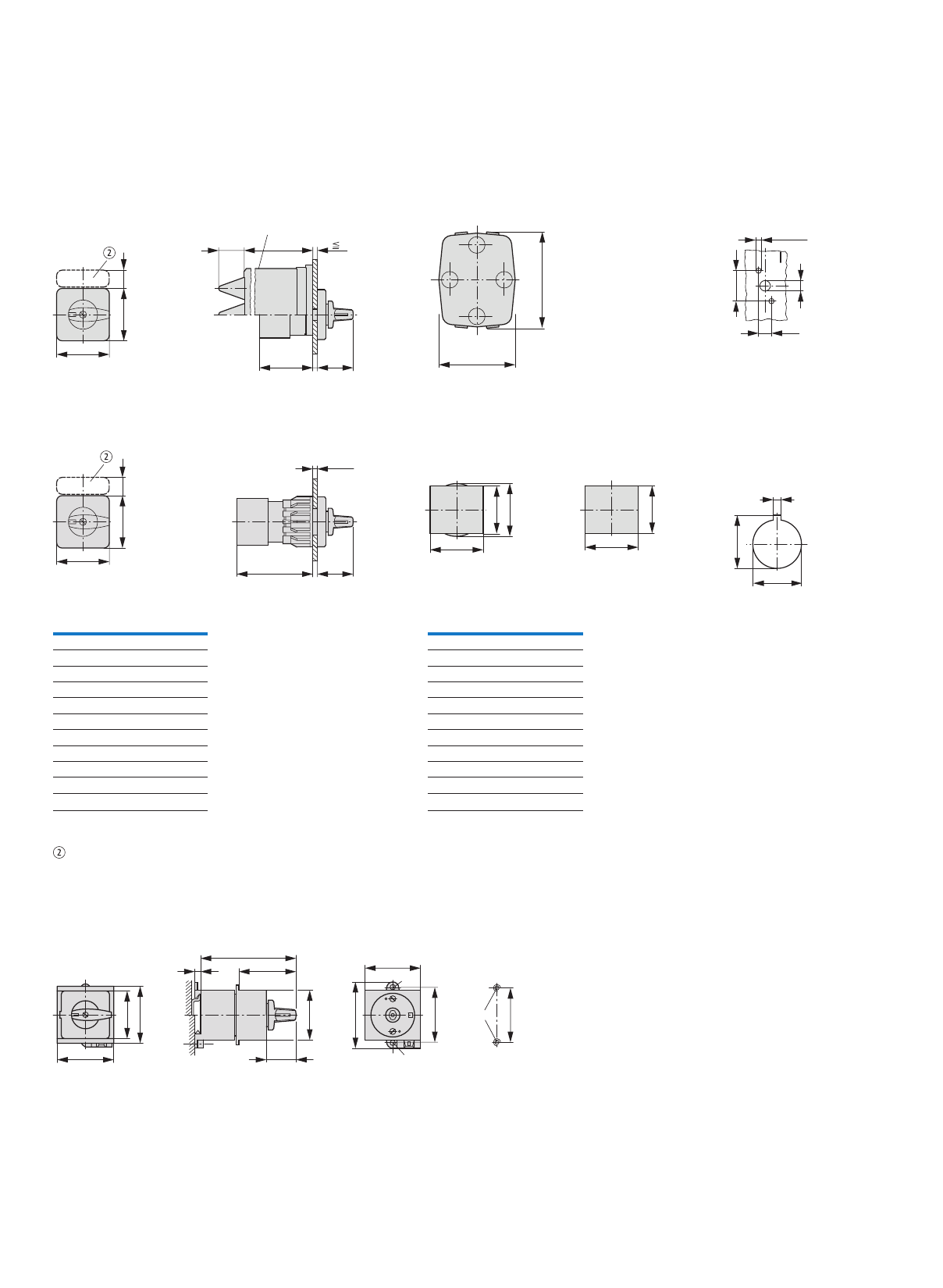
100
Cam switches, switch-disconnectors
Cam switches
Dimensions
Flush mounting
T0.../E (+ H3-T0)
T3.../E (+ H3-T0) Drilling dimensions
Center mounting
T0.../EZ
T3.../EZ
Drilling dimensions
Not included as standard
Service distribution board mounting
T0.../IVS Drilling dimensions
base
75
90
10 – 11
3.1 – 3.5
12.2
30
48
48 17
1.5 – 5
c21 35
T0 T3
45
48
48
54
61
3.2
24.1+0.4
0
22.3 +0.4
0
Part no. c20 c21
T0-1...
T0-2...
T0-3...
T0-4...
T0-5...
T0-6...
T0-7...
T0-8...
T0-9...
T0-10...
T0-11...
41
50
60
69
79
88
98
107
117
126
136
61
70
80
89
99
108
118
127
137
146
156
Depth of one contact unit: 9.5 mm
Part no. c20 c21
T3-1...
T3-2...
T3-3...
T3-4...
T3-5...
T3-6...
T3-7...
T3-8...
T3-9...
T3-10...
T3-11...
44
56
67
79
90
102
113
125
136
148
159
64
76
87
99
110
122
133
145
156
168
179
Depth of one contact unit: 11.5 mm
54
55
45
M4
50
48
60
50
Ø 5
Ø 5
28
45
55
c22
5
48
48 17
5
25 101
c20 35
H3-T0
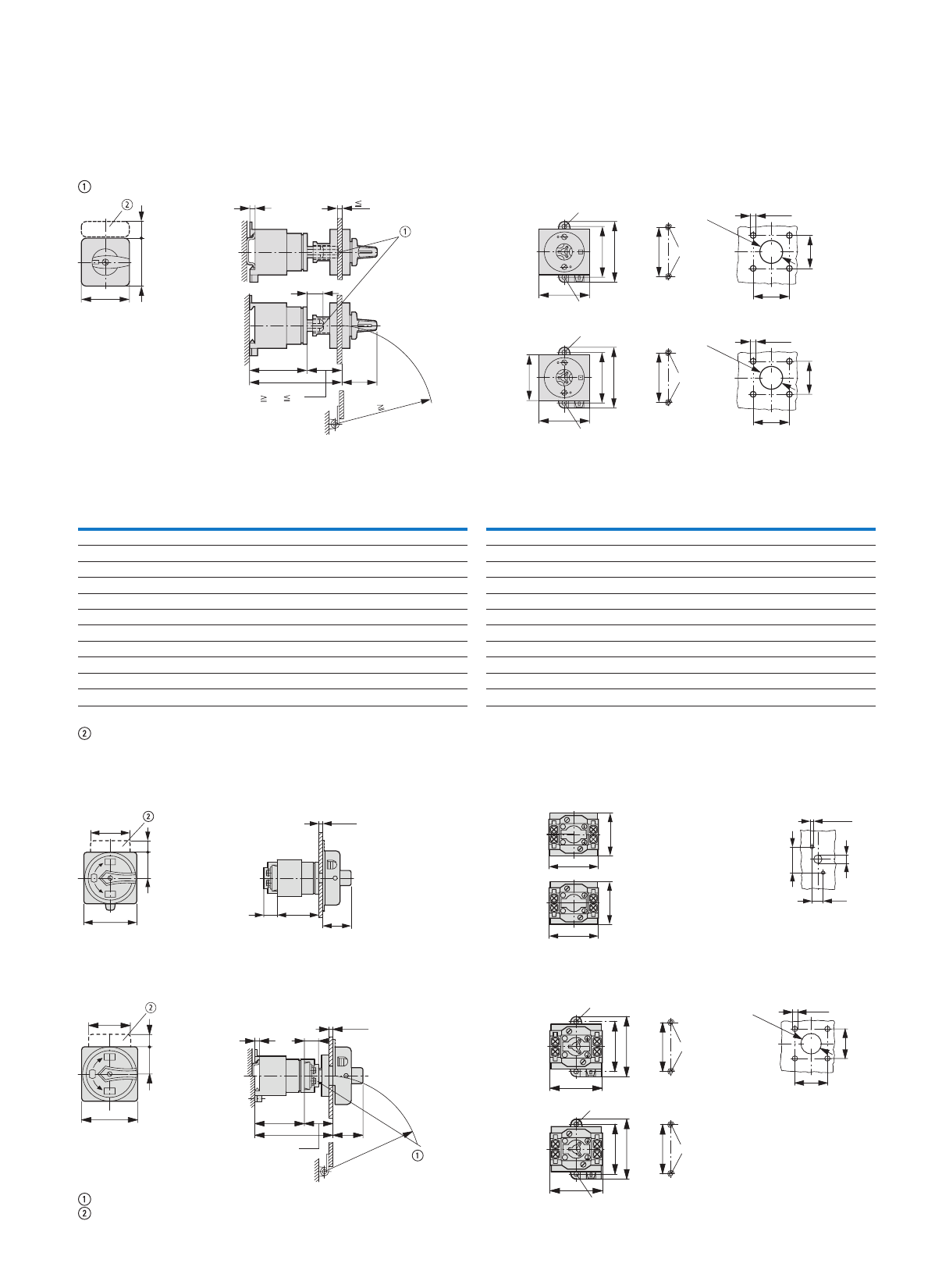
101
Cam switches, switch-disconnectors
Cam switches
Rear mounting
T0.../Z
T3.../Z
Drilling
dimensions
base
Drilling
dimensions
door
Extension with
ZAV-T0 possible,
≦ 4 x 25 = 100 mm
Not included as standard
Flush mounting main switch
T0.../EA/SVB
T3.../EA/SVB
Drilling
dimensions
door
T0
T3
Rear mounting main switches
T0.../V/SVB
T3.../V/SVB
Drilling
dimensions
base
Drilling
dimensions
door
T0
T3
Interlock extension possible with ZVV-T0 + ZAV-T0, F 4 x 25 = 100 mm
Not included as standard
5
48
48 17
M4
50
5 – 5.5
36
36
5 – 5.5
36
36
M4
65
48
50
60
63
65
75
55
55
25
c23
c24 35
Ø5
Ø
Ø
Ø
5
5
38, 54
22.3
+ 0.4
0
22.3
+ 0.4
0
100
R
T3
T0
Part no. c20 c21 c22 c23 c24
≧/≦
c24 with
≦ 4 ZAV
c25
T0-1...
T0-2...
T0-3...
T0-4...
T0-5...
T0-6...
T0-7...
T0-8...
T0-9...
T0-10...
T0-11...
41
50
60
69
79
88
98
107
117
126
136
61
70
80
89
99
108
118
127
137
146
156
77
87
96
106
115
125
134
144
154
163
173
48
57
67
76
86
95
105
114
124
133
143
86 – 102
96 – 112
105 – 121
115 – 131
124 – 140
134 – 150
143 – 159
153 – 169
162 – 178
172 – 188
181 – 197
202
212
221
231
240
250
259
269
278
288
297
72
72
91
91
–
–
–
–
–
–
–
Depth of one contact unit: 9.5 mm
Part no. c20 c21 c22 c23 c24
≧/≦
c24 with
≦ 4 ZAV
c25
T3-1...
T3-2...
T3-3...
T3-4...
T3-5...
T3-6...
T3-7...
T3-8...
T3-9...
T3-10...
T3-11...
44
56
67
79
90
102
113
125
136
148
159
64
76
87
99
110
122
133
145
156
168
179
80
92
103
115
126
138
149
161
172
184
195
51
63
74
86
97
109
120
132
143
155
166
86 – 105
101 – 115
112 – 128
124 – 139
135 – 151
147 – 162
158 – 174
170 – 185
181 – 196
193 – 208
204 – 219
205
216
228
239
251
262
274
285
296
308
319
79
79
101
101
–
–
–
–
–
–
–
Depth of one contact unit: 11.5 mm
65
33 17
48
ON
OFF
OFF
I
o
o
25 c20
35
≦ 5
61
54
49
45
3.1 – 3.5
30
10 – 11
12.2
I
o
o
65
33 17
48
525
c23
c24 35
ON
OFF
OFF
≦ 5
≧ 38, ≦ 54
R
≧ 100
65
75
63
5
5
M4
65
M4
50
Ø
Ø
50
60
49
Ø5
22.3
+ 0.4
0
5 – 5.5
36
36
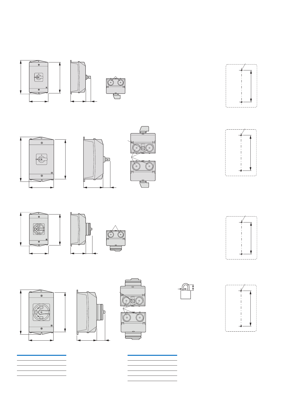
102
Cam switches, switch-disconnectors
Cam switches
Surface mounting
T0.../I1
Drilling dimensions
base
T3.../I2 Drilling dimensions
base
Surface mounting main switches
T0.../I1/padlock facility
Drilling dimensions
base
T3.../I2/SVB Drilling dimensions
base
≦ 3 padlocks
80
120
c25 27
137
M20
127
M4
100
160
c25 c33
180
M20 / M25
8
171
M4
80
120
c25 35
M20
137
I
OFF
o
ON
o
OFF
127
M4
100
160
180
35c25
M20 /M25
Ø
8
I
OFF
o
ON
o
OFF
d
b
d = 4 – 8 mm
b + d
≦ 47 mm
171
M4
Part no. c25
T0-1...
T0-2...
T0-3...
T0-4...
75
75
95
95
Part no. c25 c33
T3-1...
T3-2...
T3-3...
T3-4...
T3-5...
80
80
100
100
145
27
27
35
35
35
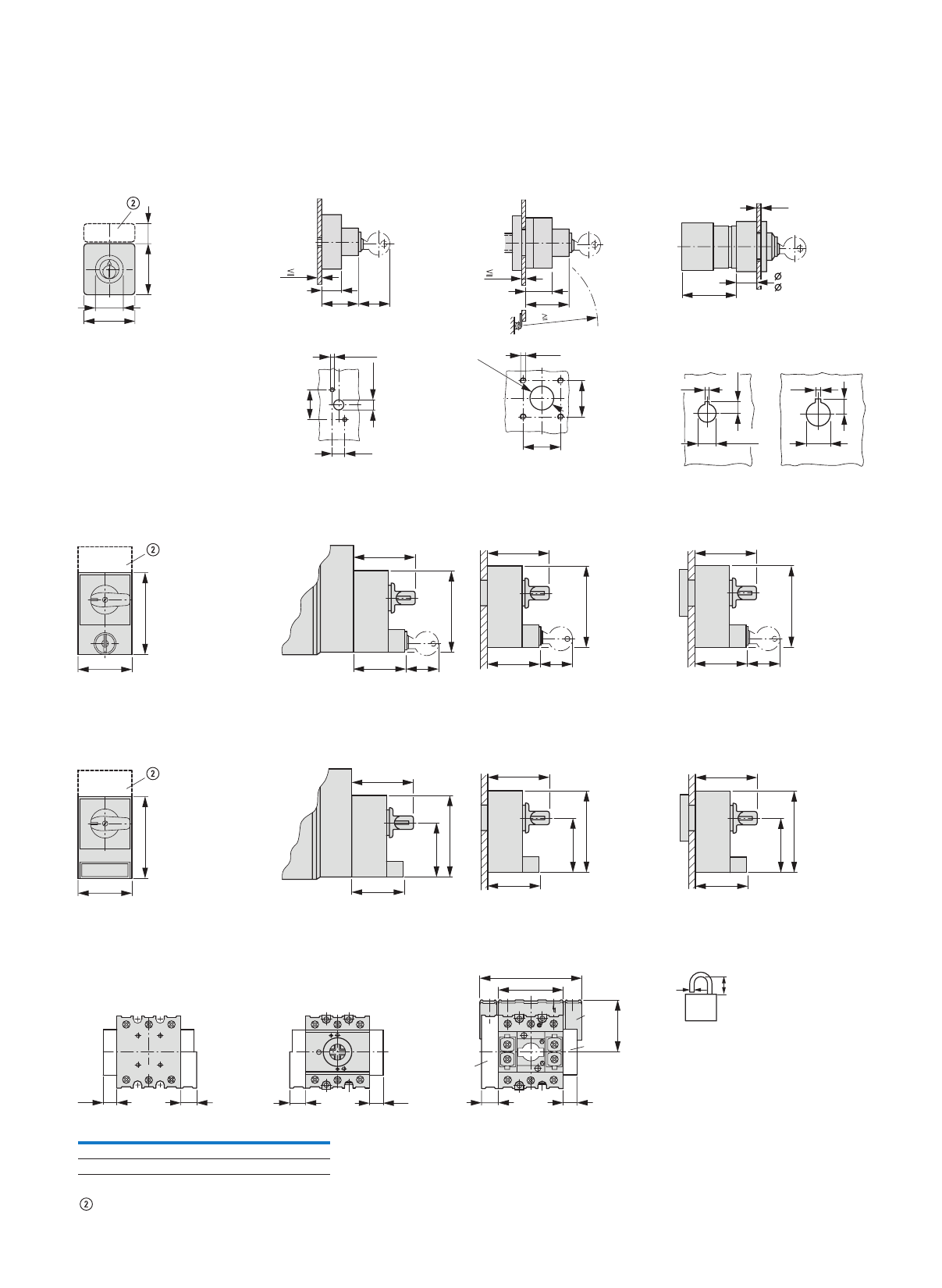
103
Cam switches, switch-disconnectors
Cam switches, switch-disconnectors, accessories
Key operated lock mechanism
S-T0
S-SOND...-T0
T0.../E(I1) + S-(SOND-)T0
T3.../E(I2) + S-(SOND-)T0
T0.../Z + S-(SOND-)T0
T3.../Z + S-(SOND-)T0
T0.../EZ = T0../E + EZ-T0 + S-(SOND-)T0
T3.../EZ = T3../E + EZ-T0 + S-(SOND-)T0
Cylinder lock
SVA-T3 T0.../I1/SVA
T3.../I2/SVA
P1.../12/SVA
T0.../E/SVA...
T3.../E/SVA...
P1.../E/SVA
T0.../Z/SVA...
T3.../Z/SVA...
P1.../Z/SVA
Padlocking feature
SVC-T3 T0.../I1/SVC
T3.../I2/SVC
P1.../12/SVC
T0.../E/SVC...
T3.../E/SVC...
P1.../E/SVC
T0.../Z/SVC...
T3.../Z/SVC...
P1.../Z/SVC
Modules
Switched neutral conductor N-P...
Auxiliary contacts HI 11-P1/P3
≦ 3 padlocks
Not included as standard
17
27
48
48
19
30
5
36
12.2
3.1 – 3.5
30
10...11
5
27
44
5 – 5.5
36
36
22.3
+ 0.4
0
100
R
2 – 5
c20
22:25 – 28
30:23 – 26
3.2
30.5
17
3.2
12.5
22.3
+ 0.4
0
73
48
56
73
46 30
56
73
46 30
56
73
46 30
73
48
56
73
46
48
56
73
46
48
56
73
46
48
L3 L2 L1
T3 T2 T1
642
531
b31
a3
N-P
H-P...
HI 11
N
N
13
246
a32 a31 a32 a32 a31 a32
a33
5
Part no. a3 a31 a32 a33 b31
P1-...
P3-..
49
72
15
18
15
15
83
114
49
60
d
b
d = 4 – 8 mm
b + d
≦ 47 mm
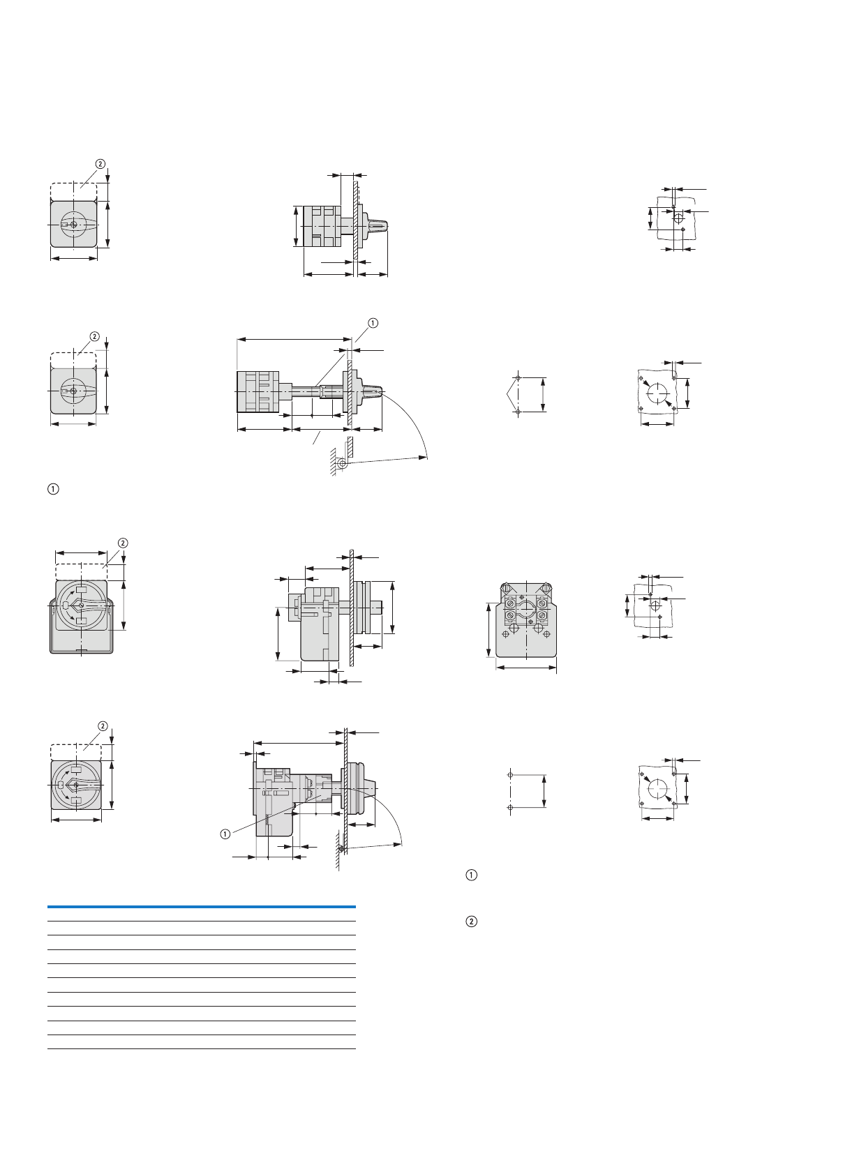
104
Cam switches, switch-disconnectors
Cam switches
Flush mounting
T5(B).../E Drilling dimensions
door
Rear mounting
T5(B).../Z
Drilling dimensions
base
Drilling dimensions
door
Shaft extension possible with ZAV-P3 F 4 x 25 = 100 mm
Flush mounting main switches
T5(B).../EA/SVB
Drilling dimensions
door
Rear mounting main switches
T5(B).../V/SVB
Drilling dimensions
base
Drilling dimensions
door
Extension
possible with ZVV-P3,
≦ 4 x 25 = 100 mm
Not included as standard
18
c2
86
37
≦
5
88
88 27
ON
OFF
I
o
14
37
4.1 – 4.5
12 – 13
ON
OFF
o
I
88
88 27
48
5 - 5.5
48
30.5
c20
73c2
2525
73
M6
≧ 38, ≦ 54
≦ 5
R
≧
100
88
27
88
ON
OFF
OFF
I
o
o
25
c2
88
80/90
40.5
16.5
44
100
80/90
14
37
4.1 – 4.5
12 – 13
≦ 5
ON
OFF
OFF
o
I
o
48
5 – 5.5
48
30.5
27
88
88
12
16.5
c20
5
25 25
40.5
44
73
R
≧
100
≦ 5
Part no. c2 20
≧/≦
c20 with
≦ 4 ZAV
c21 c22
T5(B)-1...
T5(B)-2...
T5(B)-3...
T5(B)-4...
54
71
87
104
92 – 107
109 – 124
125 – 140
142 – 157
207
224
240
257
90
90
123
123
125 (95)
125 (95)
160 (160)
160 (160)
T5(B)-5...
T5(B)-6...
T5(B)-7...
T5(B)-8...
T5(B)-9...
T5(B)-10...
120
137
153
170
186
203
158 – 173
175 – 190
191 – 206
208 – 223
224 – 239
240 – 356
273
290
306
323
339
356
–
–
–
–
–
–
–
–
–
–
–
–
Depth of one contact unit: 16.5 mm
Cam switches T5B and T5 have identical designs, only their contacts are different
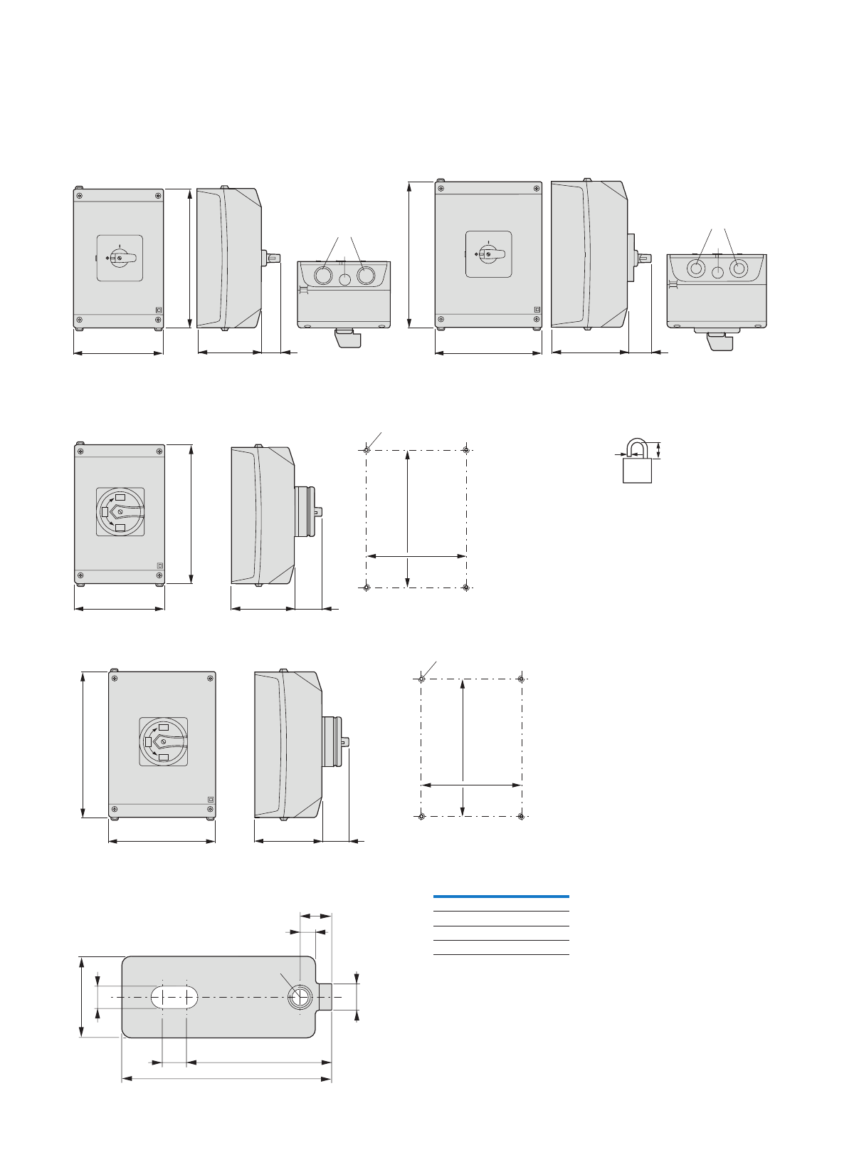
105
Cam switches, switch-disconnectors
Cam switches
Surface mounting
T5B.../I4
Surface mounting main switches
T5B.../I4/SVB Drilling dimensions
≦ 3 padlocks
snoisnemidgnillirDBVS/5I/...5T
External fixing brackets
AB-CI-K415
T5.../I5
160 c22 29
M20
240
280
200 c22 37
M20
M25
M40
M50
M25
M32
160
240
c22 44
193
142
M5
I
OFF
o
ON
o
OFF
d
b
d = 4 – 8 mm
b + d
≦ 47 mm
280
200 c22 44
233
182
M5
I
OFF
o
ON
o
OFF
Part no. c22
T5(B)-1...
T5(B)-2...
T5(B)-3...
T5(B)-4...
125
125
160
160
Depth of one contact unit: 16.5 mm
Cam switches T5B and T5 have identical designs,
only their contacts are different
20
5.5
6.5
52
36
3.8
M5t = 3
7.8
6
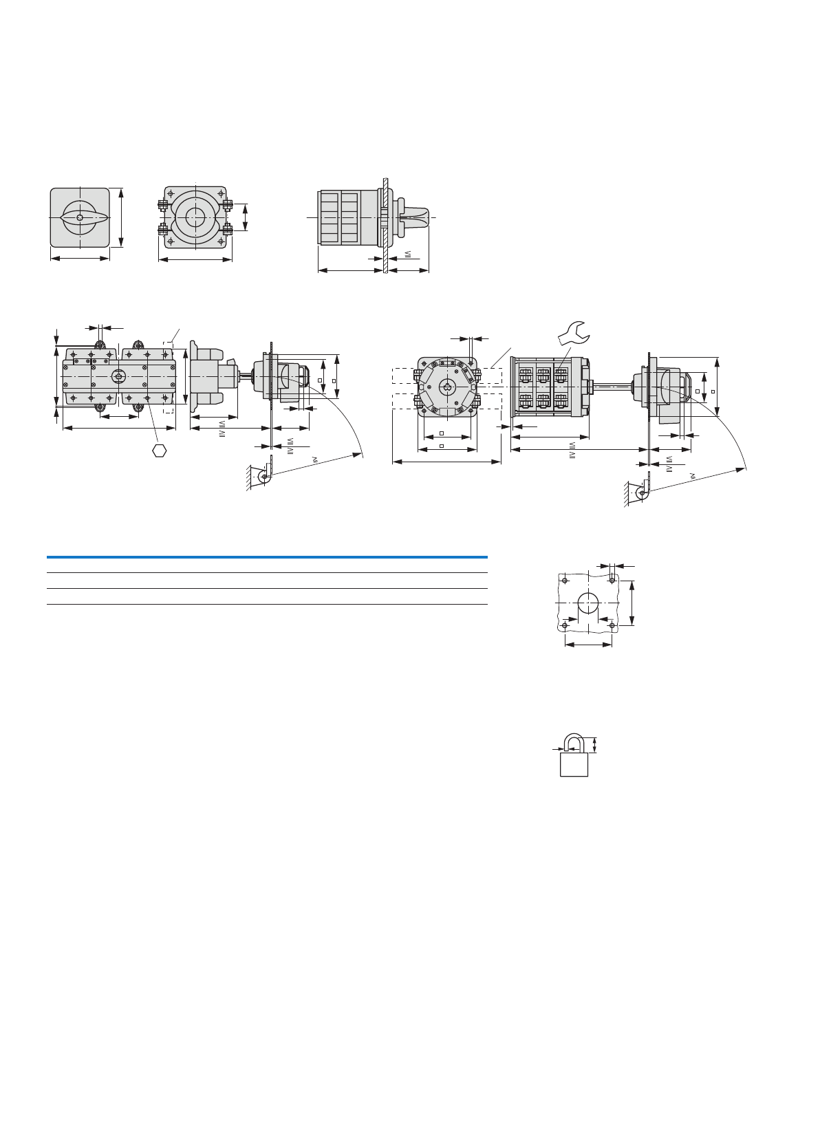
106
Cam switches, switch-disconnectors
Cam switches
Flush mounting
T6-3-8212/E/HI12
T8-3-8212/E/HI12
T8-3-8342/V/SVB-(SW)/HI11T6-160-6/V/SVB-SW/HI11
Drilling dimensions
door
T6: 4 M5 x 20
T8: 4 M6 x 20
≦ 3 padlocks for T.../SVB
150
58
5
c2 c30
b2
a2
9
88
73
5.5
1
93
216
200
5
76
224
6.4 H-T6-100
118 2
2
68
108
100
R
7
130
250
104
4.5
172.8
315
218
9.2
86.5
7
1
130
68
H-T8
19
100
R
Part no. a2 b2 c2 c30 d1 d2 x1 y1
T6-3-8212/E/HI12
T8-3-8212/E/HI12
T8-3-8342/V/SVB-(SW)/HI11
88
130
–
88
130
–
152
173
44
62
–
Ø 26 – 30
Ø 22 – 25
Ø 26 – 30
Ø 6.0
Ø 7.0
Ø 7.0
68
104
68
68
104
68
d2
d1
x1
y1
d
b
d = 4 – 8 mm
b + d
≦ 47 mm
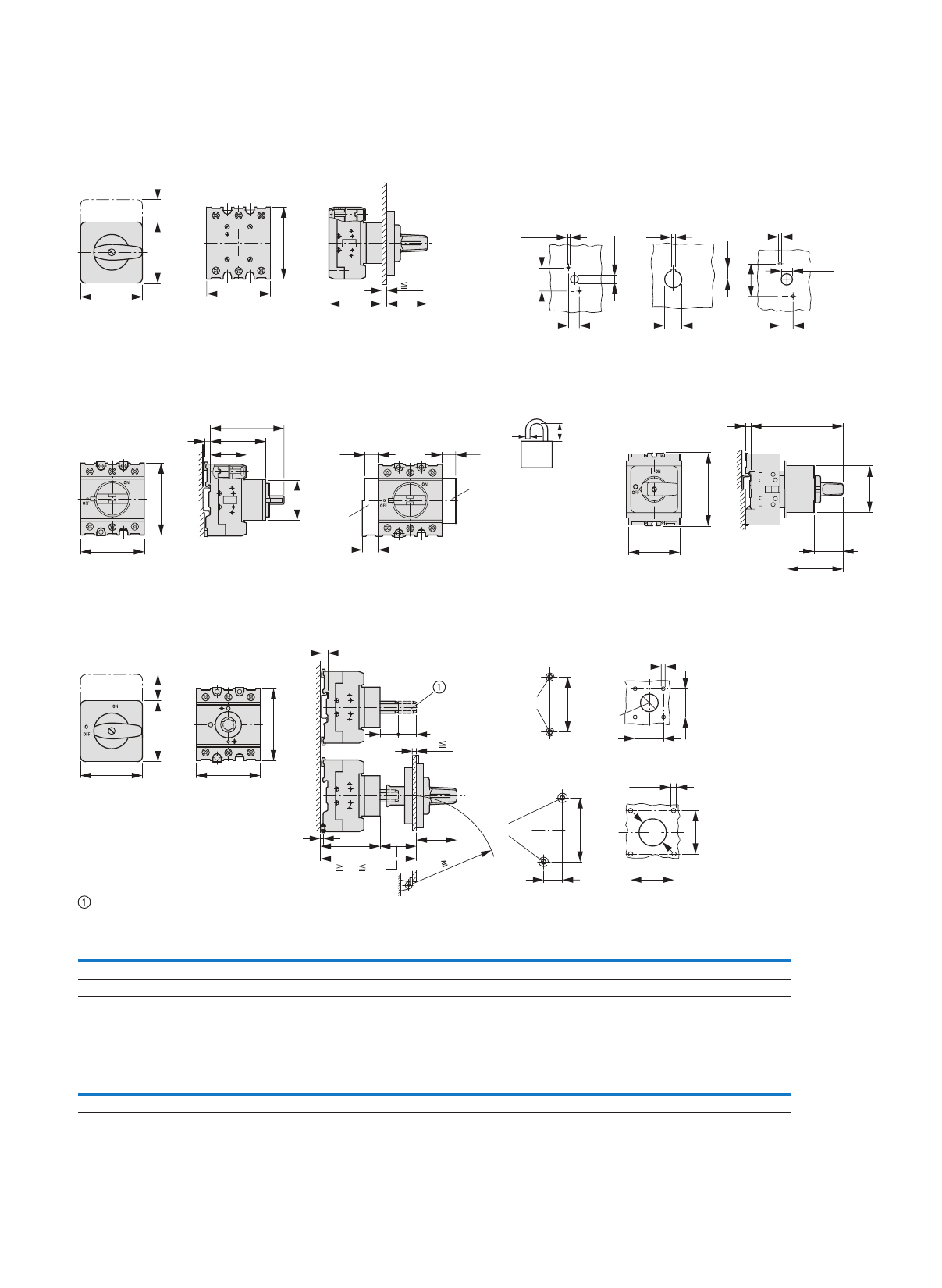
107
Cam switches, switch-disconnectors
Switch-disconnectors
Flush mounting
P.../E
Center mounting
P1.../EZ Drilling dimensions door
P1-.../E P1-.../EZ P3-.../E
Service distribution board flush mounting
P3.../IVS ≦ 3 padlocks P1.../IVS
Rear mounting
P.../Z
Shaft extension with ZAV-... possible ≦ 4 x 25 = 100 mm
Drilling dimensions
base
P1.../Z
P3.../Z
Drilling
dimensions
door
ON
0
I
OFF
a2
b2 b22
b3
a3
L3 L1
T3 T1
L2
T2
1
2
3
4
5
6
5
c2 c21
P1.../EZ = c2 + 5 mm
4.1 – 4.5
3.2
22.3
+0.4
0
12.5
10 – 11
12.2
3.1 – 3.5
30
14
37
12 – 13
b3
a4
c22
c23
c3
5
45
N
HI11
L3L2
L1
T3
T2
T1
L3L2
L1
T3
T2
T1
a32 a32
a31
d
b
d = 4 – 8 mm
b + d
≦ 47 mm
49
L1 L2 L3
T1 T2 T3
55
28
b3
45
5c3
38,
3
5
a3
5
b22
b2
a2
c21
c25
c20
R 100
c31 c32
b3
54
5 – 5.5
M4
65
36
36
22.3
+0.4
0
M4
75
25
5 – 5.5
48
48
30.5
Part no. a2 a3 a4 a21 a22 a23 a31 a32 a33 b2 b3 b21 b22 b23 b24 b31
P1
P3
48
87
49
72
53.5
71.5
65
87
48
87
87
125
15
18
15
15
83
114
48
87
70
83
65
87
17
27
180
175
32
–
49
60
Part no. c2 c3 c20
≧/≦
c20 with
≦ 4
ZAV/ZVV
c21 c22 c23 c24 c25 c27 c28 c31 c32 c33
P1
P3
59
59
86
82
96 – 112
103 – 118
212
218
35
37
32
41
65
63
68
81
58
65
35
44
77
90
25
25
25
25
27
29
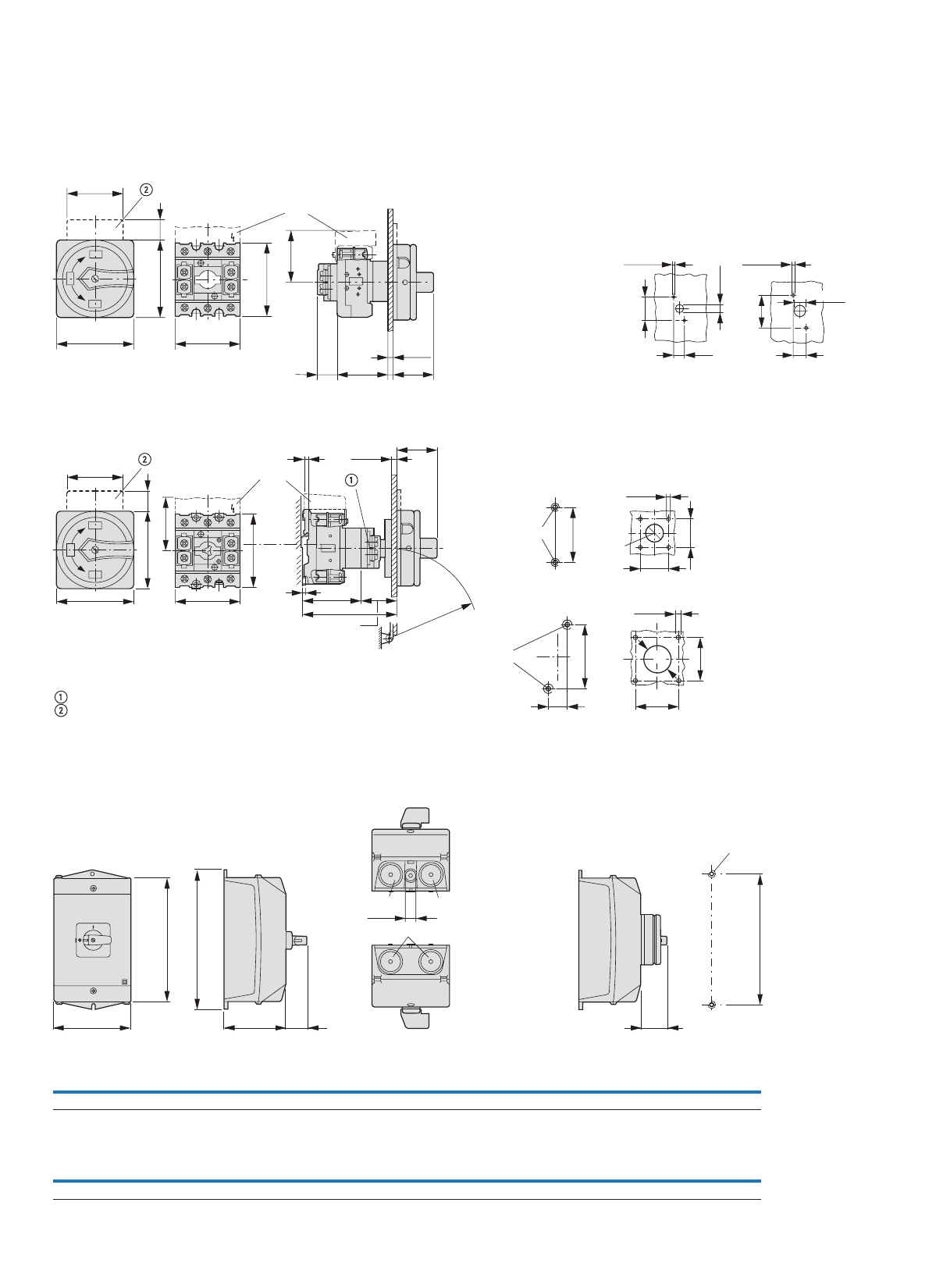
108
Cam switches, switch-disconnectors
Switch-disconnectors
Flush mounting main switches
P.../EA/SVB Drilling dimensions
door
P1... P3
Rear mounting main switches
P.../V/SVB
Interlock extension with ZVV-...+ZAV... possible ≦ 4 x 25 = 100 mm
Not included as standard
Drilling dimensions
base
P1/V/SVB
P3/V/SVB
Drilling dimensions
door
Surface mounting
P1.../I2
Surface mounting main switches/
safety switches
P1.../I2/SVB
P1.../I2/SI
Drilling dimensions
b3
a3
ON
OFF
b22
c27
c2
25
o
o
OFF
I1
2
3
4
5
6
N
Ny
y
a22
b21
a21
b31
H-P...
≦ 5 14
4.1 – 4.5
10 – 11
12.2
3.1 – 3.5
30
37
12 – 13
3
ION
OFF
OFF
5
o
o
1
2
3
4
5
6
N
N
a22
3a12a c25
c20
c27
b22b21
b31
b3
H-P...
≦ 5
R
≧
100
≧ 38, ≦ 54
5 – 5.5
M4
65
36
36
22.3
+0.4
0
M4
75
25
5 – 5.5
48
48
30.5
a23
160
c28 c33
M25
171
c27
M4
b23
M25M25
≦ 8
Part no. a2 a3 a4 a21 a22 a23 a31 a32 a33 b2 b3 b21 b22 b23 b24 b31
P1.../I2 48 49 53.5 65 48 100 15 15 83 48 70 65 17 180 35.5 49
Part no. c2 c3 c20
≧/≦
c20 with
≦ 4
ZAV/ZVV
c21 c22 c23 c24 c25 c27 c28 c31 c32 c33
P1... 59 86 96 – 112 212 35 32 65 68 58 35 80 25 25 27
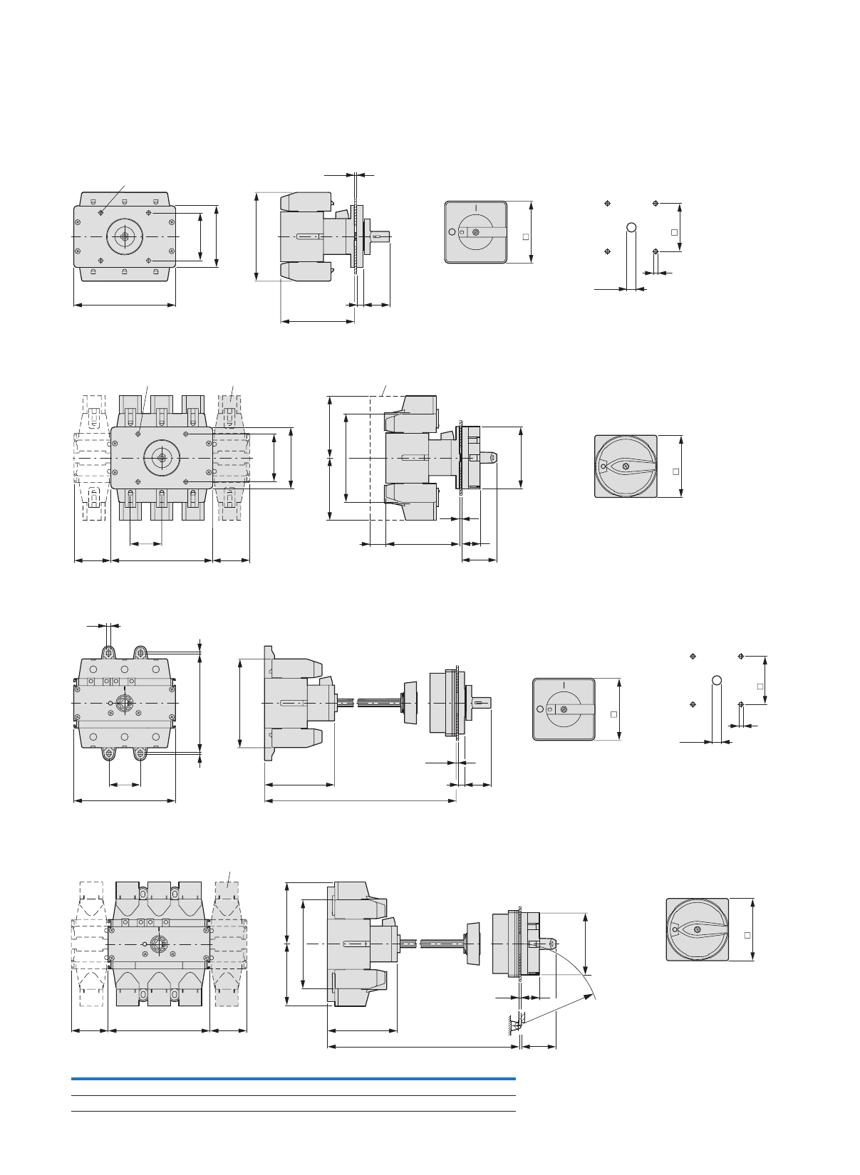
109
Cam switches, switch-disconnectors
Switch-disconnectors
Flush mounting
P5.../E Drilling dimensions
Flush mounting main switches
P5-.../EA/SVB-(SW)
Rear mounting
P5.../Z Drilling dimensions
Rear mounting main switches
P5-.../SVB-(SW)
b
c
835
a
M5
68
88
≦ 5
88
68
26 – 30
6
68
88
26
49.3
88
c21
M5 P5-.../N HI10
a
a1
a2 a2
b2b2
b
≦ 5
88
b
c835
b1 2
2
6.4
a
a1
c1
≦ 5
88
68
26 – 30
6
P5-.../N
b2b2
b
a
a2 a2
88
R
≧
100
c
c1 49.3
26≦ 5
Part no. a a1 a2 b b1 b2 c c1
P5-125/160 112 36 38 108 120 76 91 ≧ 130 ≦ 287
P5-250/315 145 44 52.5 126 144 88 98 ≧ 140 ≦ 280
88
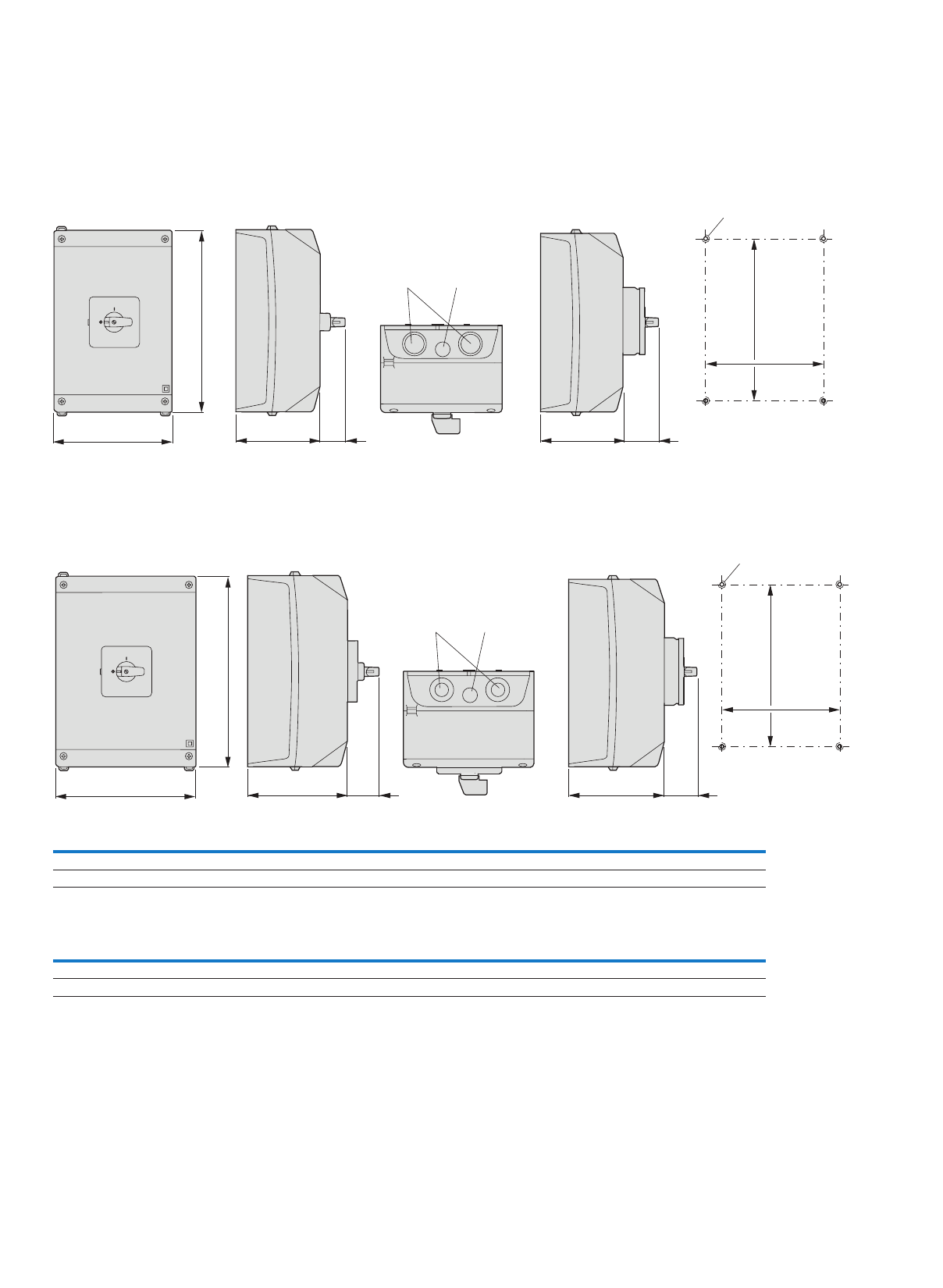
110
Cam switches, switch-disconnectors
Switch-disconnectors
Surface mounting
P3-63/I4
Surface mounting main
switches/safety switches
P3-63/I4/SVB
P3-63/I4/SI
T5B-.../I4/SI
Drilling dimensions
Surface mounting
P3-100/I5
Surface mounting main
switches/safety switches
P3-100/I5/SVB
P3-100/I5/SI
T5-.../I5/SI
Drilling dimensions
a23 95 29
b23
95 44
193
142
M5
M25
M32 M20
a23 125 37 125 44
233
182
M5
M25
M50 M20
b23
Part no. a2 a3 a4 a21 a22 a23 a31 a32 a33 b2 b3 b21 b22 b23 b24 b31
P3-63/I4
P3-100/I5
87
87
72
72
71.5
71.5
87
87
87
87
160
200
18
18
15
15
114
114
87
87
83
83
87
87
27
27
240
280
35.5
35.5
60
60
Part no. c2 c3 c20
≧/≦
c20 with
≦ 4
ZAV/ZVV
c21 c22 c23 c24 c25 c27 c28 c31 c32 c33
P3-63
P3-100
59
59
82
82
103 – 118
103 – 118
218
218
37
37
41
41
63
63
81
81
65
65
44
44
125
125
25
25
25
25
37
37
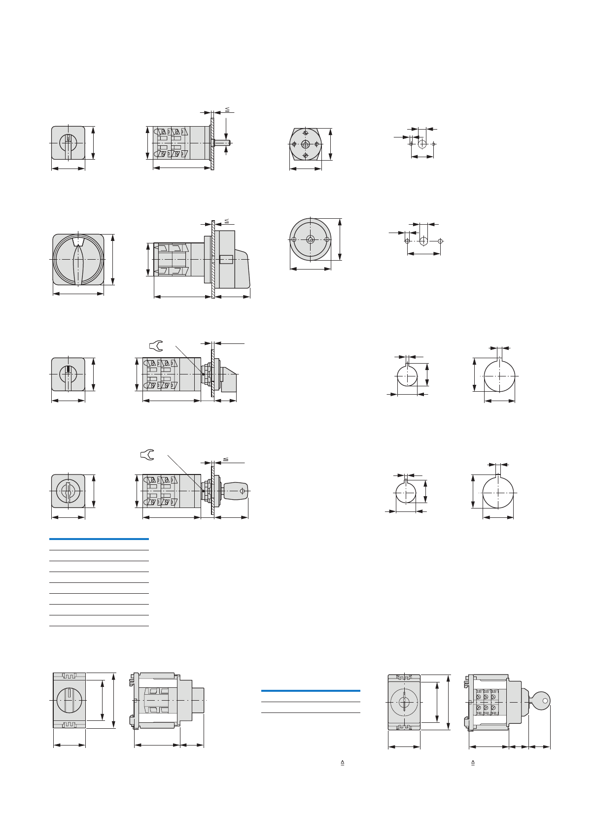
111
Mini cam switches
Flush mounting
TM.../E Drilling dimensions
Control circuit isolators
for 2 padlocks Ø 4 mm or 1 padlock Ø 6 mm
TM-.../E/SVB-(SW) Drilling dimensions
Center mounting
TM-.../EZ Drilling dimensions
1)
Center mounting with key operation
TM-...+EZ/S-.. Drilling dimensions
1)
Service distribution board mounting
TM-.../IVS TM-.../IVS/S
Notes 1)
Drilling dimensions optionally: 16.2 mm = without reduction RMQ16; 22.3 mm = with reduction RMQ Titan
28
c20
3
Ø 4.8
30
30
28
28
M3 M3 3.2
20
8
48
48
28
c21
3
35
38
38
M4 M4
10
4.2
30
≦ 5.5
28
c20 2312
30
30
17/19
1.7
17.9
3.2
24.1
+0.4
0
22.3+0.4
0
16.2
+0.2
0
30
30
5.5
28
c20 3512
17/19
1.7
17.9
3.2
24.1
+0.4
0
22.3+0.4
0
16.2
+0.2
0
Part no. c20 c21
TM-1
TM-2
TM-3
TM-4
TM-5
TM-6
TM-7
TM-8
39
51
63
75
87
99
111
123
42
54
66
Depth of one contact unit: 12 mm
c1 c2
35.5
60
45
Part no. c1 c2
TM-1
TM-2
44
46
21
26.5
Depth of one contact unit 12 mm
42 21.5 24
35.5
60
45

Eaton Industries Pte Ltd
Electrical Sector
4 Loyang Lane #04-01/02
Singapore 508914
Electrical Sector Asia Pacific
No.3, Lane 280, Linhong Road,
Changning District, Shanghai
Eaton is a registered trademark
of Eaton Corporation.
All other trademarks are property
of their respective owners.
© 2012 Eaton Corporation
All Rights Reserved
Printed in Singapore
TP-SEA-EN
July 2012
Eaton is dedicated to ensuring that reliable, efficient and safe
power is available when it’s needed most. With unparalleled
knowledge of electrical power management across industries,
experts at Eaton deliver customized, integrated solutions to
solve our customers’ most critical challenges.
Our focus is on delivering the right solution for the application.
But, decision makers demand more than just innovative products.
They turn to Eaton for an unwavering commitment to personal
support that makes customer success a top priority. For more
information, visit www.eaton.com/electrical.
