Handbuch UCxxx 30GM Xxx IO V15 Installation Directions
2016-09-04
: Pdf 16688-Installationsheet 16688-InstallationSheet B4 unilog
Open the PDF directly: View PDF ![]() .
.
Page Count: 56
MANUAL
FACTORY AUTOMATION
Ultrasonic Sensors
with IO-Link
UC***-30GM-IUEP-IO-V15
UC***-30GM-2EP-IO-V15
Part. No. xxxxxx/ TDOCT2821__ENG / 09/05/2013

UC***-30GM-**EP-IO-V15
1
Issue date 09 /05/2013 Part No. xxxxxx Document No. TDO CT2821__ENG
1 Introduction .......................................................................... 4
1.1 Congratulations.................................................................................. 4
1.2 Contact................................................................................................ 4
1.3 Declaration of Conformity ................................................................. 4
1.4 Purpose of this Documentation ........................................................ 5
1.5 Range of Validity of this Documentation......................................... 5
1.6 Recycling and Disposal ..................................................................... 5
1.7 Intended Use....................................................................................... 5
2 Product Description............................................................. 7
2.1 Function .............................................................................................. 7
2.2 Indicators and Controls..................................................................... 7
2.3 Delivery Scope and Accessories...................................................... 7
3 Installation ............................................................................ 8
3.1 Mounting............................................................................................. 8
3.2 Commissioning .................................................................................. 8
3.3 Electrical Installation ......................................................................... 8
3.3.1
UC***-30GM-2EP-IO-V15 (Two Switching Outputs)........... 8
3.3.2
UC***-30GM-IUEP-IO-V15
(Switching Output + Analog Output) 9
3.3.3 Synchronization of Multiple Sensors.............................................................. 9
4 Settings on the Device....................................................... 11
4.1 General.............................................................................................. 11
4.2 Resetting to the Factory Settings (Reset)...................................... 11
4.3 Sensors with Two Switching Outputs (UC***-30GM-2EP-IO-V15) 12
4.3.1 Adjusting the Switching Points of the Switching Output (Output A1 and A2) 12
4.3.2 Output Function of the Switching Output (Output A1 and A2)...................... 13
4.3.3 Output Type of the Switching Output (Output A1 and A2)............................ 14
4.3.4 Sound Cone Width ....................................................................................... 15
4.3.5 Summary of the Button Operation (UC***-30GM-2EP-IO-V15).................... 17
4.4 Sensors with 1 Switching Output + 1 Analog Output
(UC***-30GM-IUEP-IO-V15) 18
4.4.1 Setting the Switching Output Switching Points (Output A1) ......................... 18
4.4.2 Setting the Limits of the Analog Output (Output A2, Button T2)................... 18
4.4.3 Output Function of the Switching Output (Output A1).................................. 19
4.4.4 Output Function of the Analog Output (Output A2) ...................................... 19
4.4.5 Output Type of the Switching Output (Output A1)........................................ 20
4.4.6 Output Type of the Analog Output (Output A2)............................................ 20
4.4.7 Sound Cone Width ....................................................................................... 21
4.4.8 Summary of the Button Operation (UC***-30GM-IUEP-IO-V15).................. 22

UC***-30GM-**EP-IO-V15
2
Issue date 09/0 5/2013 Part No. xxxxxx Docu ment No. TDOCT2 821__ENG
5 IO-Link ................................................................................. 24
5.1 Process Data..................................................................................... 24
5.2 Summary of Commands .................................................................. 24
5.2.1 UC….-30GM-2EP-IO-V15; Two Switching Outputs...................................... 24
5.2.2 UC...-30GM-IUEP-IO-V15; Switching Output + Analog Output .................... 25
5.2.3 General Settings........................................................................................... 26
5.3 Index Assignment............................................................................. 29
5.3.1 Direct Parameters......................................................................................... 29
5.3.2 Device-Specific Indexes ............................................................................... 30
5.3.3 Device-Specific Parameters ......................................................................... 31
5.4 "Direct Parameters" Page................................................................ 36
5.5 Device-Specific Indexes................................................................... 37
5.6 Adjustable Parameters..................................................................... 37
5.6.1 Assured Operating Distances for Output A1 or A2 (BD1 or BD2) ................ 37
5.6.2 Switching Signal Configuration Output A1 or A2 (DB1 or DB2).................... 38
5.6.3 Switching Type Output A1 or A2 (Subindex 0x01 - SPC
(Switch Point Logic)) 38
5.6.4 Parameters for the Reflex Mode (Barrier Offset).......................................... 40
5.6.5 Timer Function for the Switching Outputs of Output A1 or A2...................... 40
5.6.6 Analog Output Limit Values .......................................................................... 41
5.6.7 Characteristics of the Analog Output............................................................ 41
5.6.8 Summary of the Output Data........................................................................ 42
5.6.9 Measurement Parameters ............................................................................ 42
5.6.10 Evaluation..................................................................................................... 44
5.6.11 Format of the Process Data; Distance Values.............................................. 46
5.6.12 Temperature Compensation......................................................................... 47
5.6.13 Synchronization............................................................................................ 47
5.6.14 Troubleshooting............................................................................................ 48
5.6.15 Releasing Controls during Communication .................................................. 49
5.6.16 Physical Output Configuration...................................................................... 50
5.6.17 Operating Controls........................................................................................ 50
5.6.18 Locator Function........................................................................................... 51
5.6.19 User-Specific Identifiers................................................................................ 51
5.6.20 System Time................................................................................................. 51
5.6.21 Sensor Temperature..................................................................................... 51
5.6.22 Sensor Detection Range............................................................................... 51
5.6.23 Analog Output Present ................................................................................. 51
5.6.24 Event Codes via IO-Link............................................................................... 52
UC***-30GM-**EP-IO-V15
3
Issue date 09 /05/2013 Part No. xxxxxx Document No. TDO CT2821__ENG
Symbols Used
Safety information
Note
The guarantee provided by Pepperl+Fuchs for this product ceases to be valid if
the product is not operated or used as specified by Pepperl+Fuchs.
Modifications to devices or components and the use of defective and incomplete
devices or components are not permitted. Repairs to devices or components may
be perfor med only by authorized workshops or Pepperl+Fuchs. These workshops
are responsible for obtaining the latest technical information about the devices
and components from Pepperl+Fuchs. Pepperl+Fuchs has no influence on re-
pairs made to the product that were not carried out by Pepperl+Fuchs. Our liability
is therefore restricted to the r epair work performed by Pepperl+Fuchs.
The above does not modify the information relating to warranties and liability in
the Pepperl+Fuchs terms of sale and supply.
Observe the general notes on the information in the Pepperl+Fuchs product
catalogs at http://www.pepperl-fuchs.com.
Note on a hazard or immediate danger.
Ignoring this symbol can lead to property damage, serious injur y, or
even fatal injuries.
This symbol warns the user of a potential device failure. Ignoring this
warning can lead to a complete failure of the device or other connected
devices.
Recommendation for the user
Observing this note makes commissioning and handling of this product
easier.
This product must not be used in applications in which the safety of
persons depends on the function of the device.
This product is not a safety component as specified in the EU Machin-
ery Directive.

UC***-30GM-**EP-IO-V15
4
Issue date: 09/05/2013 Part No. xxxxxx Document No . TDOCT2821__ENG
1Introduction
1.1 Congratulations
You have decided to purchase a device from Pepperl+Fuchs.
Pepperl+Fuchs develops, produces, and markets electronic sensors and
interface modules worldwide for the automation technology market.
Before you install this device and put it into operation, please read the ope-
rating instructions thoroughly. The instructions and notes contained in this
operating manual will guide you step-by-step through the installation and
commissioning procedures to ensure trouble-free use of this product. By
doing so, you:
• guarantee safe operation of the device
• can utilize the entire range of device functions
• avoid faulty operation and associated errors
• reduce costs from downtimes and incidental repairs
• increase the effectiveness and operating efficiency of your plant.
Store these instructions somewhere safe in order to have them available
for future work on the device.
Directly after opening the packaging, please ensure that the device is in-
tact and that the package is complete.
1.2 Contact
If you have any questions about the device, its functions, or accessories,
please contact us at:
Pepperl+Fuchs GmbH
Lilienthalstraße 200
68307 Mannheim, Germany
Tel.: +49 (0) 621 776-1111
Fax: +49 (0) 621 776-27-1111
E-mail:fa-info@de.pepperl-fuchs.com
1.3 Declaration of Conformity
This product was developed and manufactured under observance of the
applicable European standards and guidelines.
Note!
A Declaration of Conformity may be requested from the manufacturer.

UC***-30GM-**EP-IO-V15
5
Issue date: 09/05/2 013 Part No. xxxxxx Document No. TDOCT2821_ _ENG
The product manufacturer, Pepperl+Fuchs GmbH, 68307 Mannheim,
Germany, has a certified quality assurance system that conforms to ISO
9001.
1.4 Purpose of this Documentation
These operating instructions contain information necessary for the com-
missioning and use of the UC***-30GM-**EP-IO-V15 ultrasonic sensors.
The documentation is targeted at persons performing the commissioning
who connect the device and programmers who write a PLC program.
1.5 Range of Validity of this Documentation
This documentation is valid for UC***-30GM-**EP-IO-V15 ultrasonic sen-
sors and describes the delivery status from 11/2011.
1.6 Recycling and Disposal
UC***-30GM-**EP-IO-V15 ultrasonic sensors can be recycled. To recycle
and dispose of your old device in an environmentally friendly way, contact
a disposal company accredited in the disposal of electronic waste.
1.7 Intended Use
The ultrasonic sensors from the UC….-30GM Series detect objects using
ultrasonic pulses. Ultrasound is emitted by the sensor and reflected on the
object. The resulting runtime determines the distance of the object. (pulse-
echo principle). Objects in the following forms can be detected: solid, gra-
nular, powder, or liquid. Gases cannot be detected. The color and surface
structure of the objects are irrelevant.
Not a safety component
UC***-30GM-**EP-IO-V15 ultrasonic sensors are not safety compon-
ents in the sense of the EU Machinery Directive 2006/42/EC.
UC***-30GM-**EP-IO-V15 ultrasonic sensors must not be used to
avert risks to persons or body parts.
ISO9001

UC***-30GM-**EP-IO-V15
6
Issue date: 09/05/2013 Part No. xxxxxx Document No . TDOCT2821__ENG
Always operate the device as described in these instructions to ensure that
the device and connected systems function correctly. The protection of
operating personnel and plant is guaranteed only if the device is operated
in accordance with its intended use.
Use the recommended original accessories only.
The responsibility for compliance with locally valid safety regulations is
borne by the operator.
Installation and commissioning of all devices must be performed only by
personnel specially trained for that purpose.
If you open or modify the device yourself, not only are you endangering
yourself and others but you will void any warranty and absolve the manuf-
acturer from any liability. If serious faults occur on the device, switch the
device off. Make sure that the device cannot be switched back on acciden-
tally. If the device needs to be repaired, return it to Pepperl+Fuchs.
UC***-30GM-**EP-IO-V15
7
Issue date: 09/05/2 013 Part No. xxxxxx Document No. TDOCT2821_ _ENG
2 Product Description
2.1 Function
UC***-30GM-**EP-IO-V15 ultrasonic sensors detect objects using ultraso-
nic pulses. Ultrasound is emitted by the sensor and reflected on the object.
The resulting runtime determines the distance of the object. (pulse-echo
principle). Objects in the following forms can be detected: solid, granular,
powder, or liquid. Gases cannot be detected. The color and surface struc-
ture of the objects are irrelevant.
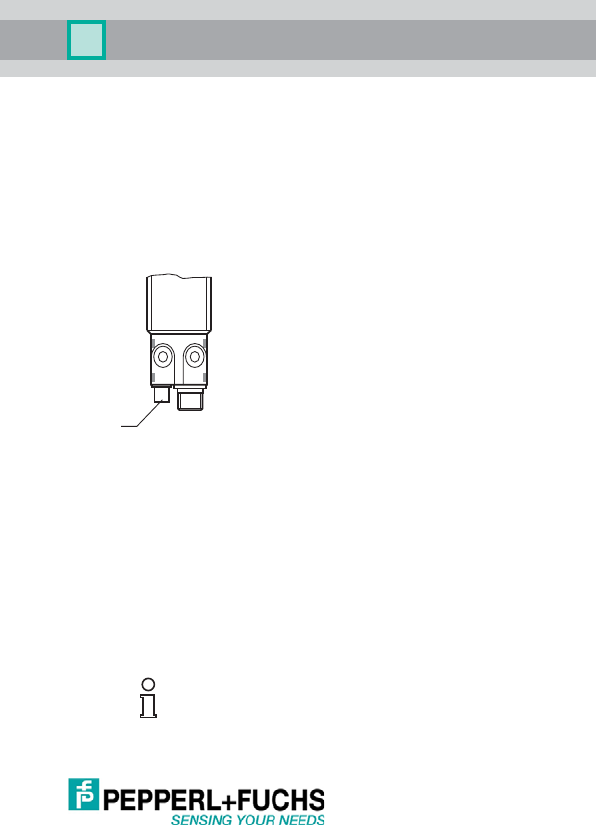
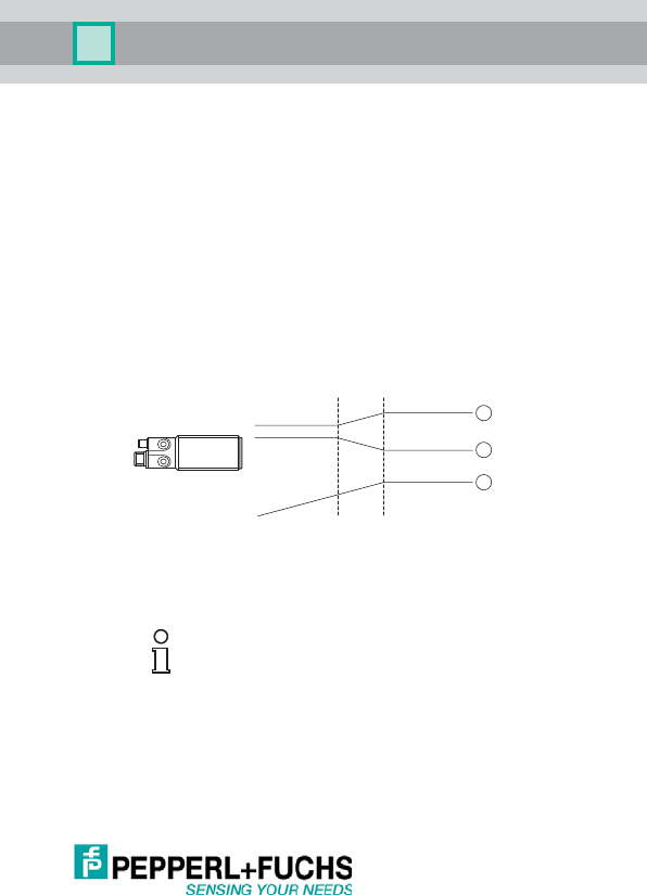
2.2 Indicators and Controls
2.3 Delivery Scope and Accessories
The following are delivered:
•1 sensor
• 2 mounting nuts
• Brief description (product insert)
Accessories for mounting, connecting, or parameterizing must be
purchased separately.
You can find suitable accessories on our website
http://www.pepperl-fuchs.com.
The sensor has LEDs for signaling operating statuses,
two buttons for adjusting the outputs, and an M12 con-
nector plug.
L1, yellow LED Status display for output A1 (pin 4)
L2, yellow LED Status display for output A2 (pin 2)
T1 Button for adjusting output A1
T2 Button for adjusting output A2
L3 Indicates ready for operation (green)
or fault (red)
Tip
In the product search, simply enter the type designation for your
sensor. The product page contains a list of the related products.
L1
L2 T1 T2
L1
L2
L3
UC***-30GM-**EP-IO-V15
8
Issue date: 09/05/2013 Part No. xxxxxx Document No . TDOCT2821__ENG
3 Installation
3.1 Mounting
The sensors are mounted with the nuts supplied. Mounting sets for moun-
ting M30 sensors can be used (optional), e.g., BF 30, BF 30-F, or BF 5-30.
3.2 Commissioning
For commissioning, a voltage in the permitted range is applied to the cor-
responding plug connections. The green LED indicates that the device is
ready for operation and the sensor works with the values set previously.
For initial commissioning, all internal parameters are set to the factory set-
tings.
3.3 Electrical Installation
The ultrasonic sensor is supplied with power via the M12 plug. A voltage in
the range 10 VDC ... 30 VDC (15 V ... 30 V if the voltage output is used)
must be applied between pin 1 (+Ub) and 3 (-Ub, 0 V).
If the IO-Link interface is used, pin 4 (IO-Link, C/Q) is used for communi-
cation.
The following plug assignments apply for both available versions of the
UC***-30GM-**EP-IO-V15:
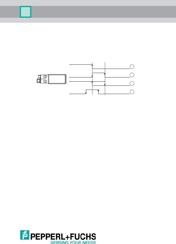
3.3.1 UC***-30GM-2EP-IO-V15 (Two Switching Outputs)
*)
with use of a female single-ended cordset as per EN 60947-5-6
Connection
pin
Assignment
Wire color
*)
1L+ Brown (BN)
2 Switching output A2 White (WH)
3 L- (0 V) Blue (BU)
4 Switching output A1 (IO-Link, C/Q) Black (BK)
5Synchronization Gray (GY)
Analog output
1
5
2
3
4
L+
L-
Sync.
C/Q
Switch output 2
1
5
2
3
4
L+
L-
Sync.
C/Q

UC***-30GM-**EP-IO-V15
9
Issue date: 09/05/2 013 Part No. xxxxxx Document No. TDOCT2821_ _ENG
3.3.2 UC***-30GM-IUEP-IO-V15 (Switching Output + Analog Output)
*)
with use of a f emale single-ended cordset as per EN 60947-5-6
The analog output can be configured as a voltage output or current output.
3.3.3 Synchronization of Multiple Sensors
The sensors are fitted with a synchronization input that suppresses mutual
interference from external ultrasonic signals. If this input is not connected,
the sensors operate with internally generated cycle pulses. They can be
synchronized by creating external rectangular pulses and by setting the
appropriate parameters via the IO-Link interface.
Each falling pulse edge sends an individual ultrasonic pulse.
If the signal at the synchronization input is low for 1 second, the sensor
reverts to the normal, unsynchronized operating mode. This also occurs if
the synchronization input is disconnected from external signals.
If a high signal is applied to the synchronization input for > 1 second, the
sensor switches to standby. This is indicated by the green LED. In this ope-
rating mode, the last recorded output statuses are retained.
If the option of synchronizing is not used, the synchronization input must
be connected to ground (0 V) permanently or the sensor must be operated
with a 4-pin connection cable.
The option of synchronization is not available during the programming pro-
cess. During synchronization, the sensor can switch to programming via
the IO-link interface. This interrupts the synchronization process and the
sensor is no longer synchronized.
Connection
pin
Ass ign ment
Wire color
*)
1L+ Brown (BN)
2 Switching output A2 White (WH)
3 L- (0 V) Bl ue (BU)
4 Switching output A1 (IO-Link, C/Q) Black (BK)
5Synchronization Gray (GY)

UC***-30GM-**EP-IO-V15
10
Issue date: 09/05/2013 Part No. xxxxxx Document No . TDOCT2821__ENG
The following synchronization modes are available:
•Multiplex mode
Up to 10 sensors can be synchr onized by simply connecting their synchro-
nization inputs. In this case, the sensors synchronize themselves in succes-
sion in multiplex mode. Only one sensor sends signals at any one time.
• Master/slave synchronization
Multiple sensors (max. 10) can be synchronized by simply connecting their
synchronization inputs. The sensor interface can be used to parameterize
the sensors so that one functions as a master and the others function as sla-
ves. In this case, the sensors in master/slave mode work synchronously,
i.e., in synchronization, whereby the master sensor plays the role of an in-
telligent external impulse generator.
• External, synchronous operation
Several sensors can be controlled collectively by an external signal. In this
case, the sensors are triggered in parallel and operate synchronously, i.e.,
at the same time. All sensors must be parameterized via the sensor inter-
face so that they are set to external.
• External, multiplex mode
Several sensors are controlled with a time delay by an external signal. In
this case, only one sensor is externally synchronized at any one time. All
sensors must be parameterized via the sensor interface so that they are set
to external.
•Standby
A high signal (+U
B
) or a low signal (-U
B
) at the synchronization input swit-
ches the sensor to standby in the case of external parameterization.

UC***-30GM-**EP-IO-V15
11
Issue date: 09/05/2 013 Part No. xxxxxx Document No. TDOCT2821_ _ENG
4 Settings on the Device
4.1 General
The devices have two outputs: A1 and A2. There are two different device
models:
• UC***-30GM-2EP-IO-V15 2 switching outputs (A1 and A2);
• UC***-30GM-IUEP-IO-V15 1 switching output (A1)
1 analog output (A2).
A button (T1, T2) and two yellow LEDs (L1 and L2) are assigned to each
output.
Two distances (SP1 and SP2) can be taught in for each output. They in-
fluence the switching characteristics or the characteristics of the analog
output.
The buttons allow the following sensor settings:
Switching output
• Teaching in of the distances SP1 and SP2 for each output
• Output function switching output
(switching point, window, hysteresis, barrier)
• Output type (NO contact, NC contact)
• Sound cone width (narrow, medium, wide)
• Reset to the factory settings
Analog output
• Teaching in of the distances SP1 and SP2 for each output.
• Output function analog output
(rising characteristic, falling characteristic, zero point line)
• Output type (current, voltage, high impedance)
• Sound cone width (narrow, medium, wide)
• Reset to the factory settings
Note that you can only change the settings via buttons within the first 5 mi-
nutes after switching the device on (time lock).
You can deactivate this "time lock" (see 5.6.17).
4.2 Resetting to the Factory Settings (Reset)
You can reset the sensor to its initial values by resetting it to the factory set-
tings.
Note that this deletes any settings you may have entered.

UC***-30GM-**EP-IO-V15
12
Issue date: 09/05/2013 Part No. xxxxxx Document No . TDOCT2821__ENG
Procedure:
1. Switch off the power supply on the device
2. Press T1 or T2
3. Switch on the power supply on the device
➟ The yellow and red LEDs flash for 5 seconds (warning)
➟ After 5 seconds, the yellow and green LEDs flash
4. Release the button
➟ Reset is executed
➟ The sensor is reset to its factory settings
4.3 Sensors with Two Switching Outputs (UC***-30GM-2EP-IO-V15)
4.3.1 Adjusting the Switching Points of the Switching Output (Output A1
and A2)
You can use the T1 and T2 keys to Teach-in two distances SP1 and SP2
for each output. One or two switching points are defined. You are free to
choose the setting for SP1 and SP2. The sensor ensures internally that no
invalid input can occur (e.g., through transposition of taught-in values).
Procedure:
1. Switch on the power supply on the device.
➟
The Teach-in process can be triggered within 5 minutes.
T1
teaches in the switching points for
output A1
;
T2
teaches in the swit-
ching points for
output A2
.
2. Press T (> 2 s)
➟ The related yellow LED flashes (red LED flashes if no object is de-
tected).
3. Align the object
4. Press the button briefly
➟ SP1 setting
5. Press and hold the button (approx. 2 s)
➟ SP2 setting
If you continue to press the button (> 10 s), the sensor is NOT reset
(=command cancellation).
Note that you can only change the settings via buttons within the
first 5 minutes after switching the device on.
UC***-30GM-**EP-IO-V15
13
Issue date: 09/05/2 013 Part No. xxxxxx Document No. TDOCT2821_ _ENG
➟ Green LED flashes 3x ➟ Setting completed
➟ Red LED flashes 3x ➟ Fault; repeat setting
The device always saves the distances internally such that the "Long ran-
ge" and the "Close range" are set correctly - irrespective of the order of the
teaching in.
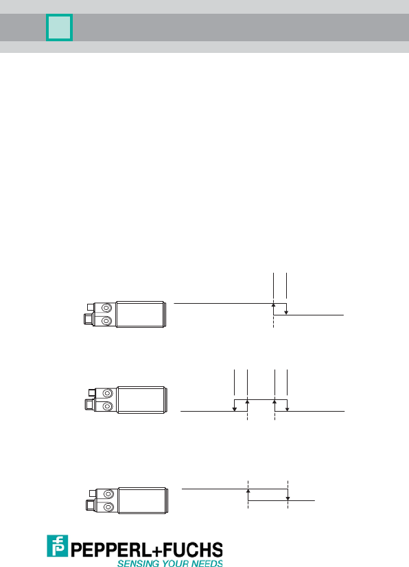
Image 4.1: Definition of the switching points dependent on the output function
(1) Output function <switching point> (only SP1 is considered.)
(2) Output function <window>
(3) Output function <hysteresis>
(4) Output function <reflex mode> (only SP1 is considered.)
4.3.2 Output Function of the Switching Output (Output A1 and A2)
You can use the buttons to set three different output functions:
•
<Switching point>
When an object approaches, the output switches ON at the set distance
SP1
(set: NO contact). Any set distance
SP2
is ignored.
•
<Window>
When an object approaches, the output switches ON at the set distance
SP2
and OFF again at
SP1
. (set: NO contact)
•
<Hysteresis>
When an object approaches, the output switches ON at the set distance
SP1
. If the object moves away again, the output switches OFF again at
SP2
. (set: NO contact)
•
<Reflex mode>
When an object approaches, the output switches ON at the set distance
SP1
+ offset and OFF again at the distance
SP1
- offset. If no object is de-
tected, the output switches ON. (Set: NO contact) Any set distance
SP2
is
ignored.
1
2
3
4
SP1 SP2

UC***-30GM-**EP-IO-V15
14
Issue date: 09/05/2013 Part No. xxxxxx Document No . TDOCT2821__ENG
Procedure:
1. Switch on the power supply on the device.
➟ The Teach-in process can be triggered within 5 minutes.
T1 teaches in the output function for output A1; T2 teaches in the output
function for output A2.
2. Press and hold the T button (approx. 5 seconds)
➟ Green LED flashes
1 x short flash = Switching point mode
2 x short flashes = Window mode
3 x short flashes = Hysteresis mode
4 x short flashes = Reflex mode
3. Press the T button briefly
➟ The output function is advanced. The flashing of the green LED
shows the output function selected.
4. Continue to press the T button until the required output function is se-
lected.
5. To save the selected output function, press the button for longer than
2 seconds and then release.
➟ The sensor now switches to the setting for the output type (see
4.3.3).
4.3.3 Output Type of the Switching Output (Output A1 and A2)
<NO contacts> or <NC contacts> can be set.
Procedure:
1. Switch on the power supply on the device.
➟ The Teach-in process can be triggered within 5 minutes.
T1 teaches in the output type for output A1; T2 teaches in the output
type for output A2.
2. Press and hold the T button (approx. 5 seconds)
➟ Green LED flashes, display of output type set
3. Press the T button (approx. 2 seconds)
➟ Yellow LED flashes
1 x short flash = NO contact
2 x short flashes = NC contact
To exit the setting of the output function without making any chan-
ges, press the button for longer than 10 seconds. The sensor swit-
ches to normal mode.
UC***-30GM-**EP-IO-V15
15
Issue date: 09/05/2 013 Part No. xxxxxx Document No. TDOCT2821_ _ENG
4. Press the T button briefly
➟ The output type is advanced. The flashing of the yellow LED shows
the output type selected.
5. Continue to press the T button until the required output type is selected.
6. To save the selected output type, press the button for longer than
2 seconds and then release.
➟ The sensor now switches to the setting for the sound cone width.
(See 4.3.4)
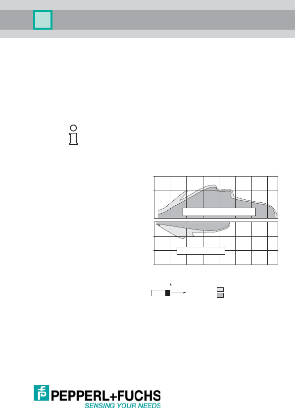
4.3.4 Sound Cone Width
The operating characteris-
tics of the sensor can be
set to three levels. This al-
lows the device to be ad-
apted to different
applications. The detec-
tion ranges are not redu-
ced.
The selection options
available are:
• Narrow sound cone
•
Medium sound cone
•
Wide sound cone
.
Image 4.2: Wi de and narrow sound cone using the example of UC2000-30GM-...
Procedure:
1. Switch on the power supply on the device.
➟ The Teach-in process can be triggered within 5 minutes.
T1 or T2 set the sound cone width of the sensor.
2. Press and hold the T button (approx. 5 seconds)
➟ Green LED flashes (display of the output function set)
To exit the setting of the output type without making any changes,
press the button for longer than 10 seconds. The sensor switches
to normal mode.
600
400
200
0
-200
-400
-600
X
Y
0 500 1000 1500 2000 2500 3000 3500
Distance X [mm]
Distance Y [mm]
flat surface 100 mm x 100 mm
round bar, Ø 25 mm
wide sound lobe
narrow sound lobe

UC***-30GM-**EP-IO-V15
16
Issue date: 09/05/2013 Part No. xxxxxx Document No . TDOCT2821__ENG
3. Press the T button (approx. 2 seconds)
➟ Yellow LED flashes (display of output type set)
4. Press the T button (approx. 2 seconds)
➟ Red LED flashes (display of the sound cone width set)
1 x short flash = narrow sound cone
2 x short flashes = medium sound cone
3 x short flashes = wide sound cone
5. Press the T button briefly
➟ The sound cone width is advanced. The flashing of the red LED
shows the sound cone width selected.
6. Continue to press the T button until the required sound cone width is se-
lected.
7. To save the selected sound cone width, press the button for longer than
2 seconds and then release.
➟ The sensor now switches to normal mode.
To exit the setting of the output type without making any changes,
press the button for longer than 10 seconds. The sensor switches
to normal mode.
UC***-30GM-**EP-IO-V15
17
Issue date: 09/05/2 013 Part No. xxxxxx Document No. TDOCT2821_ _ENG
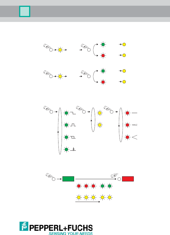
4.3.5 Summary of the Button Operation (UC***-30GM-2EP-IO-V15)
Setting the assured operating distances
Extended configuration
Default settings
If the button is pressed for longer than 10 s, the command is canceled and
the settings are retained.
3x
3x
3x
3x
Object at
position SP1
Teach-In OK
briefly
Output state
Error
Object at
position SP2
Teach-In OK
Output state
Error
green
yellow
yellow
yellow
yellow
yellow
yellow
red
green
red
2 s
T
T
T
T
1x
2x
1x
2x
NO
NC
3x
4x
1x
2x
2x
5 s 2 s 2 s
green yellow red
T T T
5 s
red red red
yellow yellow yellow
green green
yellow yellow
T T
Power ON RESET
UC***-30GM-**EP-IO-V15
18
Issue date: 09/05/2013 Part No. xxxxxx Document No . TDOCT2821__ENG
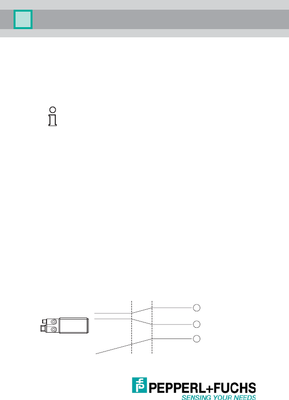
4.4 Sensors with 1 Switching Output + 1 Analog Output
(UC***-30GM-IUEP-IO-V15)
4.4.1 Setting the Switching Output Switching Points (Output A1)
See 4.3.1; "Adjusting the Switching Points of the Switching Output (Output
A1 and A2)" on page 12. You perform the setting with the T1 button.
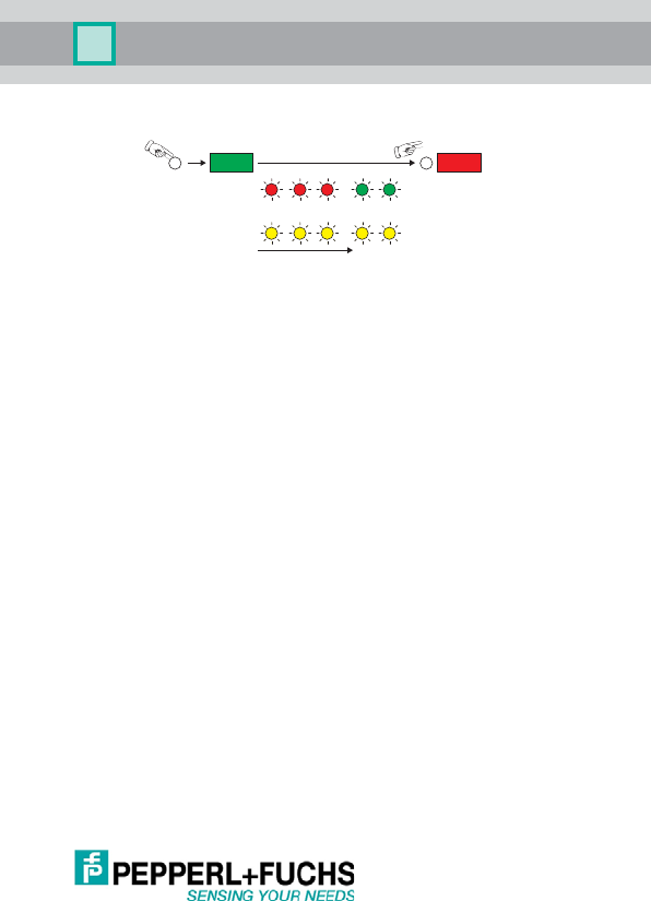
4.4.2 Setting the Limits of the Analog Output (Output A2, Button T2)
Using the T2 button, you can Teach-in a maximum of two distances SP1
and SP2. This is the key data of the characteristics of the analog output.
The "Close range" and "Long range" can be set as required. The sensor
ensures internally that no invalid input can occur (e.g., through transposi-
tion of taught-in values).
Procedure:
1. Switch on the power supply on the device.
➟ The Teach-in process can be triggered within 5 minutes.
T2 sets the limits for analog output A2.
2. Press T2 (> 2 s)
➟ Yellow LED L1 or L2 flashes
3. Align the object
Press the T2 button briefly ➟ SP1 setting
Press and hold T2 (approx. 2 s) ➟ SP2 setting
➟ Green LED flashes 3x ➟ Setting completed
➟ Red LED flashes 3x ➟ Fault; repeat setting
The device always saves the distances internally such that the "Long ran-
ge" and the "Close range" are set correctly - irrespective of the order of the
teaching in.
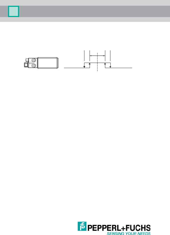
Image 4.3: Definition of the limits of the analog output
Note that you can only change the settings via buttons within the
first 5 minutes after switching the device on.
1
2
3
SP1 SP2
UC***-30GM-**EP-IO-V15
19
Issue date: 09/05/2 013 Part No. xxxxxx Document No. TDOCT2821_ _ENG
4.4.3 Output Function of the Switching Output (Output A1)
See 4.3.2; "Output Function of the Switching Output (Output A1 and A2)"
on page 13.
4.4.4 Output Function of the Analog Output (Output A2)
You can use the T2 button to set three different output characteristics:
•
Rising characteristic
The an alog value rises wit h the increasing distance between
SP1
and
SP2
.
Below
SP1
and above
SP2
, the values remain constant.
•
Falling characteristic
The analog value falls with the increasing distance between
SP1
and
SP2
.
Below
SP1
and above
SP2
, the values remain constant.
•
Zero point line
The analog value rises with increasing distance. The zero point of the
straight line is at distance 0 mm. (Surface of the sensor) Any value set for
SP1
is ignored.
Image 4.4: Output functions of the analog output
(1) Rising characteristic between SP1 and SP2
(2) Falling characteristic between SP1 and SP2
(3) Zero point line; any value set for SP1 is ignored.
Invalid values can occur in the blind zone!
1
2
3
SP1 SP2

UC***-30GM-**EP-IO-V15
20
Issue date: 09/05/2013 Part No. xxxxxx Document No . TDOCT2821__ENG
Procedure:
1. Switch on the power supply on the device.
➟ The Teach-in process can be triggered within 5 minutes.
T2 sets the characteristics for output A2.
2. Press and hold T2 (approx. 5 seconds)
➟ Green LED flashes (display of the output function selected)
1 x short flash = Rising characteristic
2 x short flashes = Falling characteristic
3 x short flashes = Zero point line
3. Press the T2 button briefly
➟ The characteristic is advanced (the flashing of the green LED shows
the characteristic selected).
4. Continue to press the T button until the required output characteristic is
selected.
5. To save the selected output characteristic, press the button for longer
than 2 seconds and then release.
➟ The sensor now switches to the setting
for the output type (see 4.4.6)
.
4.4.5 Output Type of the Switching Output (Output A1)
See 4.3.3; "Output Type of the Switching Output (Output A1 and A2)" on
page 14. You perform the setting with the T1 button.
4.4.6 Output Type of the Analog Output (Output A2)
You can use the T2 button to set three different output types:
•
Current output
The difference is conver ted into current values in the range 4 mA ... 20 mA
and output at output A2.
•
Voltage output
The difference is converted into voltage values in the range 0 V ... 10 V and
output at output A2.
•
High impedance/not active
Analog output A2 is brought into a high impedance state (analog output
deactivated).
To exit the setting of the output type without making any changes,
press the button for longer than 10 seconds. The sensor switches
to normal mode.

UC***-30GM-**EP-IO-V15
21
Issue date: 09/05/2 013 Part No. xxxxxx Document No. TDOCT2821_ _ENG
Procedure:
1. Switch on the power supply on the device.
➟ The Teach-in process can be triggered within 5 minutes.
T2 sets the output type for output 2.
2. Press and hold T2 (approx. 5 seconds)
➟ Green LED flashes (display of the output characteristic set)
3. Press T2 (approx. 2 seconds)
➟ Yellow LED flashes (display of output type set)
1 x short flash = Current [mA]
2 x short flashes = Voltage [V]
3 x short flashes = High impedance/not active
4. Press the T2 button briefly
➟ The output type is advanced (display of output type set)
5. Continue to press the T button until the required output type is selected.
6. To save the selected output type, press the button for longer than
2 seconds and then release.
➟ The sensor now switches
to the setting for the sound cone width. (See
4.3.4)
.
4.4.7 Sound Cone Width
See 4.3.4; "Sound Cone Width" on page 15.
To exit the setting of the output type without making any changes,
press the button for longer than 10 seconds. The sensor switches
to normal mode.
UC***-30GM-**EP-IO-V15
22
Issue date: 09/05/2013 Part No. xxxxxx Document No . TDOCT2821__ENG
4.4.8 Summary of the Button Operation (UC***-30GM-IUEP-IO-V15)
Setting the assured operating distances/analog limit values
Extended configuration for switching output A1 (button T1)
Extended configuration for analog output A2 (button T2)
3x
3x
3x
3x
Object at
position SP1
Teach-In OK
briefly
Output state
Error
Object at
position SP2
Teach-In OK
Output state
Error
green
yellow
yellow
yellow
yellow
yellow
yellow
red
green
red
2 s
T
T
T
T
1x
2x
1x
2x
NO
NC
3x
4x
1x
2x
2x
5 s 2 s 2 s
green yellow red
T T T
1x
2x
0
1x
2x
3x
3x
1x
2x
3x
5 s 2 s 2 s
voltage
high impedance
green yellow red
current
T T T
UC***-30GM-**EP-IO-V15
23
Issue date: 09/05/2 013 Part No. xxxxxx Document No. TDOCT2821_ _ENG
Default settings
If the button is pressed for longer than 10 s, the command is canceled and
the settings are retained.
5 s
red red red
yellow yellow yellow
green green
yellow yellow
T T
Power ON RESET

UC***-30GM-**EP-IO-V15
24
Issue date: 09/05/2013 Part No. xxxxxx Document No . TDOCT2821__ENG
5IO-Link
The sensors correspond to the "Smart Sensor Profile".
5.1 Process Data
Process data is transferred as a 16-bit word.
5.2 Summary of Commands
The following is a summary of the most important parameters of the UC….-
30GM sensors. For a precise description, see Section 5.6. "Adjustable Pa-
rameters" on page 37. There you will also find the description of all possib-
le parameters.
5.2.1 UC….-30GM-2EP-IO-V15; Two Switching Outputs
5.2.1.1 Setting the Assured Operating Distances
Output A1 (switching output 1)
Input of values in [mm]
Output A2 (switching output 2)
Input of values in [mm]
BD1: Switching signal output
A1
bool <true> = output active
<false>= output not active
BD2: Switching signal output
A2
bool <true> = output active
<false>= output not active
AD0...AD13: Offset to object in [mm] 14-bit integer
Three forms of display (for the setti ng, see 5.6.11):
1. <MinDist> - <MaxDi st> Di stance from object, absolute [mm]
2. 0 ... 16000 Distance from object; normalized to end of detec-
tion range
3. 0 – 16000 Normalized between SP1 and SP2 of the analog
output (see 5.6.6)
Fault values: 16383 (-1) No echo;
object outside detection range
BD1 - SET Point Value Index 0x3C hex
Switching point 1 BD1.SP1 (set point 1) Subindex 0x01
Switching point 2 BD1.SP2 (set point 2) Subindex 0x02
BD2 - SET Point Value Index 0x3E hex
Switching point 1 BD2.SP1 (set point 1) Subindex 0x01
Switching point 2 BD2.SP2 (set point 2) Subindex 0x02
11
AD13 AD12 AD11 AD10 AD9 AD8 AD7 AD6 AD5 AD4 AD3 AD2 AD1 AD0 BD2 BD1
14 13 1215 10 9 8 36547210

UC***-30GM-**EP-IO-V15
25
Issue date: 09/05/2 013 Part No. xxxxxx Document No. TDOCT2821_ _ENG
5.2.1.2 Setting the Output Function
Output A1 (switching output 1)
Output A2 (switching output 2)
5.2.1.3 Setting the Output Type
Output A1 (switching output 1)
Output A2 (switching output 2)
5.2.2 UC...-30GM-IUEP-IO-V15; Switching Output + Analog Output
5.2.2.4 Setting the Assured Operating Distances/Analog Limit Values
Output A1 (switching output 1)
Input of values in [mm]
Output A2 (analog output)
Input of values in [mm]
BD1 - Switch Point Configuration Index 0x3D hex
Output function BD1.SPC (switch point mode) Subindex 0x02
01 = Switching point
02 = Window mode
03 = Hysteresis mode
04 = Reflex mode
BD2 - Switch Point Configuration Index 0x3F hex
Output function BD2.SPC (switch point mode) Subindex 0x02
01 = Switching point
02 = Window mode
03 = Hysteresis mode
04 = Reflex mode
BD1 - Switch Point Configuration Index 0x3D hex
Switching type BD1.SPC (switch point logic) Subindex 0x01
00 = NO co ntac t / not invert ed
01 = NC contact / inverted
BD2 - Switch Point Configuration Index 0x3F hex
Switching type BD2.SPC (switch point logic) Subindex 0x01
00 = NO contact / not inverted
01 = NC contact / inverted
BD1 - Switch Point Value Index 0x3C hex
Switching point 1 BD1.SP1 (set point 1) Subindex 0x01
Switching point 2 BD1.SP2 (set point 2) Subindex 0x02
AD - Analog Signal Set Point Value Index 0x42 hex
Analog value 1 AD.SP1 (set point 1) Subindex 0x01
Analog value 2 AD.SP2 (set point 2) Subindex 0x02

UC***-30GM-**EP-IO-V15
26
Issue date: 09/05/2013 Part No. xxxxxx Document No . TDOCT2821__ENG
5.2.2.5 Setting the Output Functions
Output A1 (switching output)
Output A2 (analog output)
5.2.2.6 Setting the Output Type
Output A1 (switching output)
Output A2 (analog output)
5.2.3 General Settings
5.2.3.7 Ultrasonic Sensor Window Width
Input of the values in [%] of set value A1 or A2; 1 % .… 50 %.
If output A2 is an analog output, a setting in subindex 0x02 influences only
the process i mage.
BD1 - Switch Point Configuration Index 0x3D hex
Output function BD1.SPC (switch point mode) Subindex 0x02
01 = Switching point
02 = Window mode
03 = Hyst er esi s mode
04 = Reflex mode
AD - Analog Signal Configuration Index 0x43 hex
Output function Analog output signal mode Subindex 0x02
00 = Rising characteristic
01 = Falling characteristic
02 = Zero point line
BD1 - Switch Point Configuration Index 0x3D hex
Switching type BD1.SPC (switch point logic) Subindex 0x01
00 = NO contact / not inverted
01 = NC contact / inverted
Output Configuration (OCF) Index 0x70 hex
Analog type Analog output type UI Subindex 0x03
00 = Current output [mA]
01 = Voltage output [V]
02 = High impedance / not active
Barrier Offset Configuration Index 0x40 hex
For output A1 Barrier offs et channel 1 Subindex 0x01
For output A2 Barrier offs et channel 2 Subindex 0x02

UC***-30GM-**EP-IO-V15
27
Issue date: 09/05/2 013 Part No. xxxxxx Document No. TDOCT2821_ _ENG
5.2.3.8 Switching Output Time Functions
Input of the values in [number of function cycles] from 0 cycles … 255 cy-
cles
If output A2 is an analog output, a setting in subindexes 0x03 and 0x04 in-
fluences only the process image.
5.2.3.9 Output Configuration
Definition of the physical configuration of the outputs.
Depending on the device model, only the configuration of the second swit-
ching output or the analog output is considered.
5.2.3.10 Sound Cone Width
The sound cone characteristic of the sensor is set. This characteristic ap-
plies for both outputs. This does not influence the detection range.
Barrier Offset Configuration Index 0x41 hex
Output A1 ON delay Switching signal 1 ON del ay Subindex 0x 01
Output A1 OFF delay Switching signal 1 OFF delay Subindex 0x02
Output A2 ON delay Switching signal 2 ON del ay Subindex 0x 03
Output A2 OFF delay Switching signal 2 OFF delay Subindex 0x04
Output Configuration (OCF) Index 0x70 hex
Configuration of A1 (switching output) Output type Q1
00 = Push - pull output
Other values are not allowed.
Subindex 0x01
Configuration of A2 (switching output) Output type Q2
00 = Push - pull output
01 = Negative switching (NPN)
02 = Positive switching (PNP)
03 = High impedance / not active
Subindex 0x02
Configuration of A2 (analog output) Analog output type UI
00 = Current output
01 = Voltage output
02 = High impedance / not active
Subindex 0x03
Measurement Index 0x61 hex
Sound cone Beam width
00 = Narrow sound cone
01 = Medium sound cone
02 = Wide sound cone
Subindex 0x01

UC***-30GM-**EP-IO-V15
28
Issue date: 09/05/2013 Part No. xxxxxx Document No . TDOCT2821__ENG
5.2.3.11 Synchronization
Multiple sensors can be switched via pin 5. This avoids mutual interfe-
rence.
5.2.3.12 Temperature Compensation
The temperature compensation of the devices can be switched on or off.
Synchronization Index 0x65 hex
Setting Synchronization mode
00 = Switched off
01 = I mmedi at e sync hronization; no del ay
02 = Synchronization starts with 1 s delay
03 = Exter nal sync hronizatio n
04 = Device is master; controls the synchronization
05 = Device is slave; is controll ed
Subindex 0x01
Number of devices Number of devices
2 devices … 10 devices are possible
Subindex 0x02
Temperature Index 0x64 hex
Switch on/off Temperature compensation
00 = Off
01 = On
Subindex 0x01

UC***-30GM-**EP-IO-V15
29
Issue date: 09/05/2 013 Part No. xxxxxx Document No. TDOCT2821_ _ENG
5.3 Index Assignment
5.3.1 Direct Parameters
Page 0:
Page 1: Addresses 16 - 31 (0x10 - 0x1F hex)
Not supported
Address
hex
Address
dec
Name Type Data
type
Value
Communi -
cation
Parame-
ters
0x00 0 Master Command R/W uint8
0x01 1 Master Cycle Time R/W uint8
0x02 2 Min. Cycle Time R uint8 UC500: 0x51 (13.2 ms)
UC2000: 0x81 (33.6 ms)
UC4000: 0x91 (59.2 ms)
UC6000: 0x99 (72.0 ms)
0x03 3 Frame Capability R uint8 0x01
0x04 4 IO-Link Version ID R uint8 0x10
0x05 5 Process Data In R uint8 0x50 (16 bit, SIO)
0x06 6 Process Data Out R uint8 0x00
Val id at ion
Parame-
ters
0x07 7 IO-Link Vendor ID 1
(MSB)
R uint8 0x00
0x08 8 IO-Link Vendor ID 2
(MSB)
R uint8 0x01
0x09 9 Device ID 1 (MSB) R uint8 0x30
0x0A 10 Device ID 2 (MSB) R uint8 0x01
0x0B 11 Device ID 3 (MSB) R uint8 UC500: 0x01
UC2000: 0x02
UC4000: 0x03
UC6000: 0x04
0x0C 12 Function ID 1
(MSB)
R/W uint8 0x00
0x0D 13 Function ID 2 (LSB) R/W uint8 0x00
UC***-30GM-**EP-IO-V15
30
Issue date: 09/05/2013 Part No. xxxxxx Document No . TDOCT2821__ENG
5.3.2 Device-Specific Indexes
Standard parameters
Table 0x02: System Command
Table 0x0D: Profile ID
Table 0x0E: PD input descriptor
Index
hex
Index
dec
Name Type Data type Data type
0x02 2 System command W uint8 See Table 0x02
0x0D 13 Profile ID R record See Table 0x0D
0x0E 14 PD Input Descriptor R record See Table 0x0E
0x10 16 Vendor Name R char[18] Pepperl+Fuchs GmbH
0x11 17 Vendor Text R cha r[max. 32] www.pepperl-fuchs.com/io-li nk
0x12 18 Product Name R char[max. 32] <P+F standard> (32 characters)
0x13 19 Product ID R char[11] <P+F standard> (11 characters)
0x14 20 Product Text R char[max. 32] Ultrasonic Distance Sensor
0x15 21 Serial number R char[14] <P+F standard> (14 characters)
0x16 22 Har dware Revision R char[7] HWxx.xx<Release Code>
0x17 23 Firmware Revision R char[7] FWxx.xx<Release Code>
0x18 24 Application-Specific
Name
R/W char[max. 32] default: UC-30GM Series
0x20 32 Error Count R uint16 Not implemented
0x21 33 Last Event R octet string[3] <last event qualifier
and event code>
0x24 36 Device status R uint8 Not implemented <IOL-spec V1.1>
0x28 40 Process data input R uint16 <actual PD input value>
0x29 41 Process Data Output R/W <actual PD output value>
Value hex Value dec Function
0x82 130 Restore factory settings
Subindex Value Function
1 0x0001 Smart Sensor Profile supported
2 0x8000 Devic e identif ica tion
3 0x8001 Binary data channel
4 0x8002 Process data variabl e
Subindex Value Function
1 Se tof Bo ol .2. 0 Binary
2 Se tof Bo ol .2. 0 Anal og

UC***-30GM-**EP-IO-V15
31
Issue date: 09/05/2 013 Part No. xxxxxx Document No. TDOCT2821_ _ENG
5.3.3 Device-Specific Parameters
Index
hex
Sub Name Type Data
type
Value Default Unit
0x3C BD1 - Set
Point Value
(BD1.SPV)
rec ord
0x01 BD1.SP1
(set point 1)
R/W uint16 35 to 1000
80 to 4000
200 to 8000
350 to 10000
50
100
240
400
mm
0x02 BD1.SP2
(set point 2)
R/W uint16 35 to 1000
80 to 4000
200 to 8000
350 to 10000
500
2000
4000
6000
mm
0x3D BD1 - Switch
Point Confi-
guration
(BD1.SPC)
rec ord
0x01 Switch point logic R/W uint8 0x00 - Non inverted
0x01- Inverted
0x00
0x02 Switch point
mode
R/W uint8 0x01 - Single point mode
0x02 - Window mode
0x03 - Two point mode
0x80 - Barrier mode
0x01
0x03 Switch point
hysteresis
R/W ui nt16 0 … 50 1 %
0x3E BD2 - Set
Point Value
(BD2.SPV)
rec ord
0x01 SP1 (set point 1) R/W uint16 35 to 1000
80 to 4000
200 to 8000
350 to 10000
100
100
500
500
mm
0x02 SP2 (set point 2) R/W uint16 35 to 1000
80 to 4000
200 to 8000
350 to 10000
250
1000
2000
3000
mm
0x3F BD2 - Switch
Point Confi-
guration
(BD2.SPC)
rec ord
0x01 Switch point logic R/W uint8 0x00 - Non inverted
0x01- Inverted
0x00
0x02 Switch point
mode
R/W uint8 0x01 - Single-point mode
0x02 - Window mode
0x03 - Two-point mode
0x80 - Barrier mode
0x01
0x03 Switch point hys-
teresis
R/W ui nt16 0 … 50 1 %

UC***-30GM-**EP-IO-V15
32
Issue date: 09/05/2013 Part No. xxxxxx Document No . TDOCT2821__ENG
0x40 Barrier Offset
Configuration
record
0x01 Barrier offset
cha nnel 1
R/ W ui nt8 1 … 50 10 %
0x02 Barrier offset
cha nnel 2
R/ W ui nt8 1 … 50 10 %
0x41 Switching
Delay Confi-
gu r ati on
record
0x01 Switching signal
1 ON de lay
R/W uint8 0 ... 255 0 cycles
0x02 Switching signal
1 OFF delay
R/W uint8 0 ... 255 0 cycles
0x03 Switching signal
2 ON de lay
R/W uint8 0 ... 255 0 cycles
0x04 Switching signal
2 OFF delay
R/W uint8 0 ... 255 0 cycles
0x42 AD - Ana log
Signal Set
Point Value
record
0x01 SP1 ( set point 1) R/W u int16 35 t o 1000
80 t o 4000
200 to 8000
350 to 10000
100
100
500
500
mm
0x02 SP2 ( set point 1) R/W u int16 35 t o 1000
80 t o 4000
200 to 8000
350 to 1000
250
1000
2000
3000
mm
0x43 AD - Ana log
Signal Confi-
gu r ati on
record
0x01 Analog ou tp ut
signal mode
R/W uint8 0x00 - Rising ramp
0x01 - Falling ramp
0x02 - Zero point ramp
0x00
0x5F Measurement
Data Collec-
tion
record
0x01 Absolute dis-
tance evaluat ed
R uint16 <value> mm
0x02 Echo amplitude
(signal quality)
Ruint80 - 255
0x03 Switching signals R uint8 0x00: 1 inactive/2 inactive
0x01: 1 active/2 inactive
0x02: 1 inactive/2 active
0x03: 1 active/2 active
Index
hex
Sub Name Type Data
type
Value Default Unit

UC***-30GM-**EP-IO-V15
33
Issue date: 09/05/2 013 Part No. xxxxxx Docume nt No. TDOCT2821__ENG
Operation mode/state
Index
hex
Sub Name Type Data
type
Value Default Unit
0x61 Measure-
ment
record
0x01 Beam Width R/W uint 8 0x00 - Small
0x01 - Medium
0x02 - Wid e
0x02
0x02 Burst Time R/W uint8 0x00 - Automatic
0x01 - Short
0x02 - Long
0x03 - Dirac
0x00
0x03 Sensor Cycle
Time
R/W uint16 0, 7 - 65535
0, 15 - 6553 5
0, 30 - 6553 5
0, 45 - 6553 5
0ms
0x04 Measurement
Mode
R/W uint8 0x00 - Echo threshold detection
0x01 - Echo peak detect io n
0x00
0x05 Blind Range R/W uint16 0 to 980
0 t o 3950
0 t o 7900
0 t o 9800
0mm
0x06 Range Reduc-
tion
R/W uin t1 6 0 , 70 - 1000
0, 150 - 4000
0, 340 - 8000
0, 600 - 10000
0mm
0x62 Evaluation record
0x01 Evaluation
method
R/W uint 8 0 x00 - Direct
0x01 - Ari thmetic avera ge
0x02 - Low pa ss
0x03 - Adapti ve filter
0x01
0x02 Arithmetic ave-
ragi ng: measu-
rements
& skip count
R/W uint 8 0 x20 - M=2 N=0
0x30 - M=3 N=0
0x31 - M=3 N=1
0x40 - M=4 N=0
0x41 - M=4 N=1
0x50 - M=5 N=0
0x51 - M=5 N=1
0x52 - M=5 N=2
0x60 - M=6 N=0
0x61 - M=6 N=1
0x62 - M=6 N=2
0x70 - M=7 N=0
0x71 - M=7 N=1
0x72 - M=7 N=2
0x73 - M=7 N=3
0x80 - M=8 N=0
0x81 - M=8 N=1
0x82 - M=8 N=2
0x83 - M=8 N=3
0x52

UC***-30GM-**EP-IO-V15
34
Issue date: 09/05/2013 Part No. xxxxxx Document No . TDOCT2821__ENG
0x03 Low pass:
weight
R/W uint16 1 ... 1000 100
0x04 Low pass:
devi ation
R/W uint8 0 ... 15 0
0x05 Low pass: skip
count
R/W uint8 0 ... 15 0
0x06 Adapti ve filter:
fi rst or max
ech o
R/W uint8 0x00 - First echo
0x01 - Max. echo
0x01
0x07 Adapti ve filter:
width of accep-
tance window
R/W uint8 0x00 - Narrow
0x01 - Normal
0x02 - Wide
0x01
0x08 No echo beha-
vior
R/W uint8 0x00 - Ignore
0x01 - Accept with delay
0x02 - Error with delay
0x00
0x09 No Echo On
Delay
R/W uint8 0 ... 255 2 cycles
0x0A No Echo Off
Delay
R/W uint8 0 ... 255 2 cycles
0x63 PDCo ntrol -
Distance
Mode
uint8 0x00 - Absolute distance
0x01 - Zero poi nt ramp
normalized
0x02 - Rising ramp normalized
0x00
0x64 Tem pe r at ur e
record
0x01 Te mperatu re
compensation
R/W uint8 0x00 - Disabled
0x01 - Enabled
0x01
0x02 En abled: Tem-
perature offset
R/W uint8 -50 … 50 29
(IUEP)
20 (2EP)
°C
0x03 Di sab led:
Fixed opera-
ti ng tempera -
ture for
disa ble d tem-
perature com-
pensat io n
R/ W uin t8 - 25 .. . 70 25 °C
0x65 Synchroni-
zation
rec ord
0x01 Sync hro niza-
ti on Mode
R/W uint8 0x00 - Disabled
0x01 - Cyclic quick start
0x02 - Cyclic standard
0x03 - External
0x04 - Master
0x05 - Slave
0x01
0x02 Numb er of
Devices (for
cycl ic synchro-
nization only)
R/W uint8 2 ... 10 5
Index
hex
Sub Name Type Data
type
Value Default Unit

UC***-30GM-**EP-IO-V15
35
Issue date: 09/05/2 013 Part No. xxxxxx Docume nt No. TDOCT2821__ENG
Standard operation control
0x66 E rror Ha nd-
ling
record
0x01 React ion Mode R/W uint8 0x00 - Ignore
0x01 - Warn
0x02 - Error
0x03 - Alarm
0x01
0x04 Output 1 Error
Stat e
R/W uint 8 0 x00 - Freeze
0x01 - Close d
0x02 - Open
0x00
0x05 Output 2 Error
Stat e
R/W uint 8 0 x00 - Freeze
0x01 - Close d
0x02 - Open
0x00
0x06 Analog Output
Error State
R/W uint 8 0 x00 - Freeze
0x01 - Current/ volt age l ow
0x02 - Current/voltage high
0x00
0x07 Op en Loop
Detection
R/W uint 8 0 x00 - Disabled
0x01 - Ena bl ed (re d LE D is flas-
hing)
0x00
0x67 Access
Control
R/W uint8 0x00 - Local contro ls disab-
led in COM mode
0x01 - Local controls enab-
led in COM mode
0x00
Index
hex
Sub Name Type Data
type
Value Default Unit
0x70 Output Confi-
guration
(OCF)
R/W recor d
0x01 Output Type Q1 R/W uint8 0x00 - Push-pull
0x01 - 0xFF - not a llowe d
0x00
0x02 Output Type Q2 R/W uint8 0x00 - Push-pull
0x01 - Low side
0x02 - High side
0x03 - Hi-Z/n.a.
0x00
0x03 Analog output
type UI
R/W uint8 0x00 - I output
0x01 - U output
0x02 - Hi-Z/n.a.
0x00
0x71 Local Con-
trols (LOC)
R/W uint8 0 x00 - Unlocked (locked in
COM)
0x01 - Lo cked
0x02 - Time locked (locked
in COM)
0x02
0x7F Locator Indi-
cation Con-
trol (LIC)
R/W uint8 0 x00 - Normal indication
0x01 - Lo cator indication
0x00
0xC0 User Tag 1
(UT1)
R/W uint32 0x00000000 ...
0xFFFFFFFF
0
0xC1 User Tag 2
(UT2)
R/W uint16 0x0000 ... 0xFFFF 0
Index
hex
Sub Name Type Data
type
Value Default Unit

UC***-30GM-**EP-IO-V15
36
Issue date: 09/05/2013 Part No. xxxxxx Document No . TDOCT2821__ENG
Special function
5.4 "Direct Parameters" Page
This page describes the parameters that are generally valid for the use of
ultrasonic sensors. For the precise description of all parameters, see the
current IO-Link specification.
Index
hex
Sub Name Type Data
type
Value Default Unit
0xE0 System Time Ruint32 0 s … 4294967295 s
0xE1 Operating
Te mpe rat u re
Ruint8 °C
0xE8 Device cha-
racteristics
0x01 Posit ion range
min
Ruint1635
80
200
350
mm
0x02 Posit ion range
max
Ruint16500
2000
4000
8000
mm
Address 0x02 Min. Cycle Time
Minimum cycle time in which the sensors can communicate.
This parameter is dependent on the detection range and cannot be changed.
Address 0x04 IO-Link Version ID
Version of the current IO-Link specifi cation
Address 0x07 IO-Link Vendor ID1
Address 0x08 IO-Link Vendor ID2
Sensor manufacturer; ID 0001 = Pepperl+Fuchs
Address 0x09 Device ID 1 (MSB)
Address 0x0A Device ID 2
Address 0x0B Device ID 3 (LSB)
Sen sor type; 00 00 01 : UC500
00 00 02 : UC2000
00 00 03 : UC4000
00 00 04 : UC6000

UC***-30GM-**EP-IO-V15
37
Issue date: 09/05/2 013 Part No. xxxxxx Docume nt No. TDOCT2821__ENG
5.5 Device-Specific Indexes
This section describes only those parameters that are generally valid for
the use of ultrasonic sensors. For the precise description of all parameters,
see the current IO-Link specification.
5.6 Adjustable Parameters
The following describes the individual parameters in detail. The order cor-
responds to the index of the IO-Link IODD.
5.6.1 Assured Operating Distances for Output A1 or A2 (BD1 or BD2)
Here, the switching thresholds for output A1 or output A2 are set. The func-
tion of the output depends on how it is configured (see 5.6.2).
If the sensor has an analog output, output A2 is not available as a switching
output. In this case, any settings undertaken for output A2 are visible only
in the process image.
Index 0x0D Profile I D
Subindex 1: Smart Sensor Profile supported
The ultrasonic sensor supports the "Smart Sensor
Profile"
Index 0x10 Vendor Name "Pepperl+Fuchs GmbH"
Index 0x11 Vendor Text "www.pepperl-fuchs.com/io-link"
These texts are fixed and cannot be changed.
Index 0x12 Product Name
Model number of the ultrasonic sensor
Index 0x13 Product ID
Order number
Index 0x14 Product Text "Ultrasonic Distance Sensor"
Index 0x15 Serial number
Sequential serial number of the sensor. The number is unique and identifies
the sensor.
Index 0x18 Application Specific Name
default:
"UCxxxx-30GM-xxEP-IO-
V15"
This parameter describes the sensor more precisely.
This enables the sensor to be assigned to an application.
The text (max. 32 characters) can be changed by the user.
Index:
0x3C (60 dec) BD1 - Set Point Value (BD1.SPV)Output A1
Subindex 0x01: BD1.SPV (set point 1): SP1
Subindex 0x02: BD1.SPV (set point 2): SP2
Index:
0x3E (62 dec) BD2 - Set Point Value (BD2.SPV)Output A2
Subindex 0x01: BD1.SPV (set point 1): SP1
Subindex 0x02 BD1.SPV (set point 2): SP2

UC***-30GM-**EP-IO-V15
38
Issue date: 09/05/2013 Part No. xxxxxx Document No . TDOCT2821__ENG
BZ = Blind zone according to data sheet/catalog
SR = End of the detection range according to data sheet
5.6.2 Switching Signal Configuration Output A1 or A2 (DB1 or DB2)
Here, various functions for output 1 or output 2 are set.
5.6.3 Switching Type Output A1 or A2 (Subindex 0x01 - SPC (Switch
Point Logic))
For sensors with an analog output, any value set for output 2 is ignored. In
this case, the status of the second switching output can be accessed logi-
cally only via the process data.
Index: 0x3D
(61 dec)
BD1 - Set Point Configuration (BD1.SPC) Output A1
Subindex 0x01: BD1.SPC (switch point logic) 0x00 Not inverted (factory setting)
0x01 Inverted
Subindex 0x02: BD1.SPC (mode) 0x01
0x02
0x03
0x80
Single point mode (factory setting)
Windows mode
Two po in t m od e
Reflex mode (barri er mode)
Subindex 0x03: BD1.SPC (hysteresis) 0 to 50
Index: 0x3F
(63 dec)
BD2 - Set Point Configuration (BD2.SPC) Output A2
Subindex 0x01: BD2.SPC (switch point logic) 0x00
0x01
Not inverted (factory setting)
Inver ted
Subindex 0x02: BD2.SPC (mode) 0x01
0x02
0x03
0x80
Single point mode (factory setting)
Windows mode
Two po in t m od e
Reflex mode (barri er mode)
Subindex 0x03: BD2.SPC (hysteresis) 0 to 50
SP1
BZ
SP2
SR
UC***-30GM-**EP-IO-V15
39
Issue date: 09/05/2 013 Part No. xxxxxx Docume nt No. TDOCT2821__ENG
A choice of two types is available:
Not inverted (NO contact function)
The BD1 or BD2 bit in the process data is set to <true> if an object is within
the assured operating distances set by SP1 and SP2. In all other cases,
the BD1 or BD2 bit = <false>.
Inverted (NC contact function)
The BD1 or BD2 bit in the process data is set to <false> if an object is within
the assured operating distances set by SP1 and SP2. In all other cases,
the BD1 or BD2 bit = <true>.
5.6.3.13 Output Function Output A1 or A2 (Subindex 0x02 - SPC (mode))
For sensors with an analog output, any value set for output A2 is conside-
red in the process image.
A choice of four functions is available:
Single point mode (switching point mode)
The output switches when an object is closer to the sensor than SP1. Any
value set in SP2 is ignored.
Windows mode
The output switches when an object is between SP1 and SP2.
Two point mode (hysteresis mode)
The output switches when an object is closer to the sensor than SP1 and
switches back again once the object has moved farther away from the sen-
sor than SP2.
SP1
Hysteresis
SP1 SP2
Hysteresis
Hysteresis
SP1 SP2
UC***-30GM-**EP-IO-V15
40
Issue date: 09/05/2013 Part No. xxxxxx Document No . TDOCT2821__ENG
Reflex mode (barrier mode)
The output switches when an object is within a range around SP1 defined
by SP1 and the "barrier offset" (corresponds to window mode with a defi-
ned window width).
5.6.3.14 Hysteresis Output A1 (Subindex 0x03 - SPC (Hysteresis))
The value of the output hysteresis is specified in % of the switching point
set. The range is 0 % ... 50 % of the set value of the switching point.
5.6.4 Parameters for the Reflex Mode (Barrier Offset)
This value can be used to set the width of the detection window in reflex
mode for each switching output. The value is specified in [%] of the set off-
set value.
For sensors with an analog output, any value set for output A2 (barrier off-
set channel 2) is ignored.
5.6.5 Timer Function for the Switching Outputs of Output A1 or A2
For sensors with an analog output, any value set for output 2 is ignored.
Here, an ON delay or an OFF delay can be set for switching outputs A1 or
A2. The times are specified as multiples of the cycle time of the sensor.
The corresponding cycle times can be read at Address 0x02 of the "Di-
rect Parameters".
Index: 0x40 (64 dec) Barrier Offset Configuration
Subindex 0x01: Window width A1 Value: 1 % … 50 % Output A1
Subindex 0x02: Window width A2 Value: 1 % … 50 % Output A2
Index: 0x41 (65
dec)
Switching Delay Configuration
Subindex 0x01: ON delay A1 Value: 0 cycles … 255 cyc-
les
Output A1
Subindex 0x02: OFF delay A1 Value: 0 cycles … 255 cyc-
les
Output A1
Subindex 0x03: ON delay A2 Value: 0 cycles … 255 cyc-
les
Output A2
Subindex 0x04: OFF delay A2 Value: 0 cycles … 255 cyc-
les
Output A2
SP1
Hysteresis
Hysteresis
Offset Offset

UC***-30GM-**EP-IO-V15
41
Issue date: 09/05/2 013 Part No. xxxxxx Docume nt No. TDOCT2821__ENG
5.6.6 Analog Output Limit Values
In addition to the switching output (output A1), the devices in the UC…-
30GM-IUEP-IO-V15 series have an analog output (output A2).
The values are specified in [mm] and can be within the detection range.
The values depend on the device used and can be queried via the "Device
Characteristics" parameters.
Here the values are displayed according to the data sheet.
5.6.7 Characteristics of the Analog Output
The analog output can be operated in different characteristics. The value
influences the voltage or current value output at output A2. The value
transferred in the process image is influenced by Index 0x63 "PDControl
Distance Mode" (see 5.6.11).
0x00 Rising characteristic
The voltage or current value at output A2 rises with the increasing dis-
tance. The minimal analog value is reached at SP1 (set point 1), and the
maximum analog value at SP2 (set point 2).
The distance does not affect the output value.
0x01 Falling characteristic
The voltage or current value at output A2 falls with the increasing distance.
The maximum analog value is reached at SP1 (set point 1), and the mini-
mum analog value at SP2 (set point 2).
The distance does not affect the output value.
0x02 Zer o poin t line
The voltage or current value at output A2 rises with the increasing dis-
tance. Here, the minimum analog value is based on the transducer surface
(0 mm). The maximum analog value is reached at SP2 (set point 2). Any
value set for SP1 (set point 1) is ignored.
Index: 0x42 (66 dec) AD - Analog Signal Set Point Value
Subindex 0x01:
Subindex 0x02:
SP1 (set point 1) [ mm]
SP2 (set point 2) [ mm]
Index: 0xE8 (232 dec) Device characteristics
Subindex 0x01:
Subindex 0x02:
Bl in d zon e
End of the detection range
Index: 0x43 (67 dec) AD - Analog Signal Configuration
Subindex 0x01 0x00
0x01
0x02
Rising characteristic
Falling characteristic
Zero point line

UC***-30GM-**EP-IO-V15
42
Issue date: 09/05/2013 Part No. xxxxxx Document No . TDOCT2821__ENG
5.6.8 Summary of the Output Data
The values specified here indicate the internal state. They are always pre-
sent - regardless of the hardware configuration of the actual device.
Subindex 0x01 Measured Distance
Current distance in [mm]
Subindex 0x02 Echo Amplitude
Echo amplitude of the current signal measured. The amplitude is scaled to
a value range from 0 … 255.
Subindex 0x03 Status of the Outputs
The logical status of the outputs can be read:
5.6.9 Measurement Parameters
Subindex 0x01 Sound Cone Width
The sensor characteristic is set here. By adapting internal values, the sen-
sitivity of the sensor can be changed for lateral approach. This creates the
impression that the width of the sound cone changes.
This characteristic can be set via the buttons using Teach-in, see 4.3.4.
Index: 0x5F (95 dec) Measurement Data Collection
Subindex 0x01
Subindex 0x02
Subindex 0x03
Measured distance i n [ mm]
Echo amplitude between 0 …255
Status of outputs A1 and A2
0x00 A1 not active A2 not active
0x01 A1 active A2 not active
0x02 A1 not active A2 active
0x03 A1 active A2 active
Index: 0x61 (97 dec) Measurement
Subindex 0x 01
Subindex 0x 02
Subindex 0x 03
Subindex 0x 04
Subindex 0x 05
Subindex 0x 06
Beam Width
Burst Time
Sensor Cycle Time
Measurement Mode
Blind Range
Range Reduction
Sound Con e Wi dt h
Type and duration of the send signal
Sensor cycle time
Type of evaluation
Blind zone amplification
Reduction in the detection range
0x00 Narrow sound cone
0x01 Medium sound cone
0x02 Wide sound cone (factory setting)

UC***-30GM-**EP-IO-V15
43
Issue date: 09/05/2 013 Part No. xxxxxx Docume nt No. TDOCT2821__ENG
Subindex 0x02 Type and Duration of the Send Signal
A change in this parameter enables the sensor to change its specified gu-
aranteed detection ranges. This means that list specifications may no lon-
ger be met.
Subindex 0x03 Cy cle Time of the Senso r
This parameter can be used to change the measuring cycle of the sensor.
The measuring cycle can be extended to a maximum of 65535 ms, in
which case a measurement is performed only every 65.5 s.
Attention:
A reduction in the cycle time can lead to sensor malfunctions.
Subindex 0x 04 Type o f Runtime Evaluation
Two types of runtime evaluation of the echo are possible:
Subindex 0x05 Blind Zone Amplification
The blind zone (prohibited area directly in front of the sensor) specified in
the list can be amplified. This enables smaller, interfering objects in front
of the sensor to be hidden.
When the desired object enters this area, it is no longer detected!
Subindex 0x06 Reduction in the Detection Range
The detection range specified in the list can be reduced. This enables in-
terfering objects that are farther away than the desired object to be hidden.
When the desired object enters this area, it is no longer detected!
0x00 Automatic adjustment of the send signal (recommended, factory setting)
0x01 Short send signal (reduction in the detection range possible)
0x 02 Long se nd sign al
0x03 Very short send signal ("Dirac"; reduction in the detection range possi ble)
0x 00 T hreshold detection
The echo signal is compared with an internally generated threshold and the runtime is
determined when this threshol d is exceeded.
0x 01 Peak valu e det e ction
The echo signal is differentiated and the runtime above the peak value of the echo is
determined.

UC***-30GM-**EP-IO-V15
44
Issue date: 09/05/2013 Part No. xxxxxx Document No . TDOCT2821__ENG
5.6.10 Evaluation
Subindex 0x01 Type of Evaluation
Four different evaluation methods are available. Depending on the me-
thod, they improve the detection of the desired objects and can prevent
faults reliably.
Subindex 0x02 Parameters for Arithmetic Mean Value
An initial mean value is calculated from the M last measured values.
From these M measured values, the number of N measured values with
the greatest deviation are removed and from the remaining M-N measured
values, the mean value is transferred as the measured result.
The following values pairs are possible:
Index: 0x62 (98 dec) Evaluation
Subindex 0x01 Type of Evaluation
Subindex 0x02 Parameters for Formation of Mean Val ues
Subindex 0x03 Low-Pass Filtering: Weighting Factor
Subindex 0x04 Low-Pass Fil tering: Acceptance Wi ndow
Subindex 0x05 Low-Pass Filtering: Suppressed Measuring Cycles
Subindex 0x06 Adapti ve Filter Eval uation Met hod
Subindex 0x07 Adapti ve Filt er Width
Subindex 0x08 Reaction to "No Echo"
Subindex 0x09 ON De lay for "N o Echo "
Subindex 0x0A OFF Delay for "No Ec ho"
Index: 0x62
(98 dec)
Evaluation
0x00 Direct evalua tion with no f ilters ap pli ed
0x01 Arithmetic mean value filter Arithmetic mean value filter
0x02 Low-pass filter Setting via subindex 0x03, 0x04, and 0x05
0x03 Adaptive filter Setting via subindex 0x06 and 0x07
0x20 M=2 N=0
0x30 M=3 N=0 0x3 1 M=3 N=1
0x40 M=4 N=0 0x4 1 M=4 N=1
0x50 M=5 N=0 0x5 1 M=5 N=1 0x52 M=5 N=2
0x60 M=6 N=0 0x6 1 M=6 N=1 0x62 M=6 N=2
0x70 M=7 N=0 0x7 1 M=7 N=1 0x72 M=7 N=2
0x73 M=7 N=3
0x80 M=8 N=0 0x8 1 M=8 N=1 0x82 M=8 N=2
0x83 M=8 N=3

UC***-30GM-**EP-IO-V15
45
Issue date: 09/05/2 013 Part No. xxxxxx Docume nt No. TDOCT2821__ENG
The low-pass filter calculates the measurement result from the previous
measurement result and the current measured value according to the fol-
lowing formula:
Measurement result_new = (measurement result_old * W + measured
value * 10) / (W + 10)
An acceptance window (D) can be used as an option. Measured values
that are outside the acceptance window (D) around the current measure-
ment result are suppressed for a certain number (S) of measuring cycles
before they are included in the evaluation calculation.
The adaptive filter always selects the three strongest echoes of a measu-
rement and checks whether they have occurred in the past four measuring
cycles of a certain acceptance window. If this is the case, the related echo
amplitudes are added up and at the end of the evaluation, the strongest or
first echo is selected. In the "Evaluation Method" parameter, you can se-
lect whether the sensor responds to the "first echo" or the "largest echo."
If an echo does not appear for one or more cycles, its historic measure-
ments are still considered and the related amplitudes are added up and in-
cluded in the further evaluation.
Example:
"Wide Filter" setting for an object offset of 3000 mm.
The acceptance window is thus approx. ± 96 mm, meaning that only
echoes in the range from 2904 mm to 3096 mm are accepted.
Other echoes are hidden.
Subindex 0x03 Parameters for Low-Pass Filtering:
Weighting Factor (W)
Range 1 ... 1000
Subindex 0x04 Parameters for Low-Pass Filtering:
Acceptance Window (D)
Range 0 ... 15
Subindex 0x05 Parameters for Low-Pass Filtering: Sup-
pressed Measuring Cycles (S)
Range 0 ... 15
Weighting factor W Range 1 ... 1000
Acceptan ce window D Range 0 ... 1 5 [%]
Number of measuring cycles to be suppressed S Range 0 ... 15
Subindex 0x06 Adaptive Filter Evaluation Method
0x00 First echo
0x01 Largest echo (echo amplitude)
Subindex 0x07 Adaptive Filter Width
0x00 Narrow filter Offset ± 0.8 %
0x01 Standard width of the filter Offset ± 1.6 %
0x02 Wide filter Offset ± 3.2 %

UC***-30GM-**EP-IO-V15
46
Issue date: 09/05/2013 Part No. xxxxxx Document No . TDOCT2821__ENG
Subindex 0x08 Reaction to "No Echo"
This parameter allows you to configure how the sensor behaves if it does
not detect any echo signal, since under certain circumstances, the loss of
the echo represents an error condition.
Subindex 0x09 ON Delay for "No Echo" Range 0 ... 255
Number of measuring cycles by which the signal loss is delayed or sup-
pressed.
Subindex 0x0A OFF Delay for "No Echo" Range 0 ... 255
Number of measuring cycles in which the signal loss must be at least de-
layed.
5.6.11 Format of the Process Data; Distance Values
Index: 0x 63 ( 99dec) PDContr ol Distance Mode
This parameter enables the presentation of the process data to change.
Possible settings for the distance value output:
0x00 Ignore
The sensor ignores an echo loss. The evaluation continues.
0x01 Accept with delay
An echo loss i s delayed by a given number of measuring cycles and only subsequentl y inclu-
ded in the evaluation. This enables i ndividual signal losses to be suppressed.
0x02 Error with delay
An echo loss i s delayed by a given number of measuring cycles and then triggers a fault (red
LED lights up).
If the sensor is in communication mode, an IO-Link event is generated
(see 5.6.24).
0x00 Distance as absolute value in [mm] (factory setting)
Th e measured distan ce i s al ways given i n mm. If no echo is det ected, t he corresponding
fault value is displayed (see 5.1).
0x01 Zero point line; normalized
Th e measured distance to the object normal ized to the valu e range 0 .. . 16 000, whereby t he
maximu m valu e corre sponds to t he end of th e dete cti on range ( e.g., 5 00 mm for UC 500).
0x02 Risi ng characteristic; normalized
If the rising characteristic is selected, the object offset in the area between SP1 and SP2 of
the analog output under 5.6.6 (also for version 2EP) is normalized to the value range
0 .. . 16 000.
This means that the output of the process data can be mapped to a user-defined area.

UC***-30GM-**EP-IO-V15
47
Issue date: 09/05/2 013 Part No. xxxxxx Docume nt No. TDOCT2821__ENG
5.6.12 Temperature Compensation
This setting can be used to activate or deactivate the temperature com-
pensation.
If the temperature compensation is active, the Temperature Offset para-
meter describes the internal temperature increase of the device, enabling
the sensor to derive the current ambient temperature. This calculated am-
bient temperature can be queried as described under 5.6.21.
If the ambient temperature is constant, a fixed ambient temperature can be
specified (see below).
Subindex 0x02 Temperature Offset for the Compensation Range -
50 [°C] ... +50 [°C]
This parameter specifies the temperature offset for the calculation of the
ambient temperature.
This temperature describes the actual internal temperature increase in the
sensor and is used to calculate the current ambient temperature.
Subindex 0x03 Specificat ion o f a Fixed Temperature Ran ge -25
[°C] ... +70 [°C]
If the temperature compensation is deactivated, the temperature set on
this index is used to correct the sound runtime. This means that the tem-
perature can be fixed, increasing the measurement accuracy of the runti-
me measurement at constant ambient temperature.
5.6.13 Synchronization
Index: 0x64 (100 dec) Temperature
Subindex 0x01 Temperatu re compen sation ON/OFF
Subindex 0x02 ON: Tempera tu re off set for th e compensation
Subindex 0x03 OFF: Specification of a fixed temperature
Subindex 0x01 Temperature compensation
Subindex 0x00 Switched off; no automatic temperature compensation
Subindex 0x01 Switched on (factory setting)
Index: 0x65 (101 dec) Synchronization
Subindex 0x01 Synchronizatio n mode Type of synch ronizati on
Subindex 0x02 Number of devices Number of devices
Subindex 0x01 Type of synchronization
0x00 Synchronization switched off
0x01 Multiplex mode; fast (factory setting)
0x02 Multiplex mode; standard
0x03 Ext ernal synchron izati on
0x04 Sensor i s master
0x05 Se nsor i s slave

UC***-30GM-**EP-IO-V15
48
Issue date: 09/05/2013 Part No. xxxxxx Document No . TDOCT2821__ENG
•Multiplex mode
Multiple sensors (max. 10) can be synchronized by simply connecting their
synchronization inputs. In this case, the sensors synchronize themselves
one after the other in multiplex mode. Only one sensor sends signals at
any one time.
• External synchronization
Several sensors can be controlled collectively by an external signal. In this
case, the sensors are triggered in parallel and operate synchronously, i.e.,
at the same time. All sensors must be parameterized via the sensor inter-
face so that they are set to external.
• Master/slave operation
Multiple sensors (max. 10) can be synchronized by simply connecting their
synchronization inputs. The sensor interface can be used to parameterize
the sensors so that one functions as a master and the others function as
slaves. In this case, the sensors in master/slave mode work synchronous-
ly, i.e., in synchronization, whereby the master sensor plays the role of an
intelligent external impulse generator.
Subindex 0x02 Number of Devices Range 2 ... 10
The number of devices connected is specified here.
5.6.14 Troubleshooting
Index: 0x66 ( 102 dec) Troubleshooting
The behavior of the sensor on detection of an error condition can be defi-
ned under this index.
Subindex 0x01 Type of Reaction to Fault
There are four different reaction modes that can be set:
0x00 Ignore Any fault that occu rs i s ignored and displayed neithe r via LE D nor via the com-
mand interface. The sensor continues to work i n normal mode.
0x01 Warn If a fault occurs, the red LED lights up. An event is also set via IO-Link (5.6.24)
and the outputs maintain their current state.
0x02 Error If a fault or error oc curs, the red LED lights up and an event is generated via IO-
Link. The outputs take on the "Error state" configured below.
0x03 alarm The behavior corresponds to that for the "Error" setting. In addition, IO-Link is
informed that the sensor process data is invalid. If this setting is used, the plant
behavior on receipt of invalid process data must be clarified in advance.

UC***-30GM-**EP-IO-V15
49
Issue date: 09/05/2 013 Part No. xxxxxx Docume nt No. TDOCT2821__ENG
Subindex 0x02 Behav ior of O utput A1
This parameter defines the behavior of output A1 in the event of a fault (for
the Error and Alarm settings only).
Subindex 0x03 Behav ior of O utput A2
This parameter defines the behavior of output A2 in the event of a fault (for
the Error and Alarm settings only).
Subindex 0x04 Behavior of Analog Output A2
This parameter defines the behavior of the analog output when a fault is
detected (for the Error and Alarm settings only).
Subindex 0x05 Lead Breakage Detectio n
This parameter can be used to activate the lead breakage detection when
the current output is used. If a lead breakage is detected, the red LED flas-
hes.
5.6.15 Releasing Controls during Communication
Index: 0x67 (103 dec) Access Control
This setting enables temporary access to the sensor controls during com-
munication. The standard setting is that no operation with buttons is pos-
sible during communication.
If a parameter is changed by operation, the sensor triggers an IO-Link
event (see 5.6.24).
Since this parameter is not saved, once the supply voltage has been swit-
ched off, the factory setting is active (controls locked).
0x00 Remain The output retains the last valid state.
0x01 Closed Th e output switch es on (sett ing: NO cont act)
0x02 Open The output switches off (setting : NO co ntact )
0x00 Remain The output retains the last valid state.
0x01 Closed Th e output switch es on (sett ing: NO cont act)
0x02 Open The output switches off (setting : NO co ntact )
0x00 Remain The analog output retains the last valid val ue.
0x01 Current/voltage low Depending on the output configuration, the analog output out-
puts th e maxim um volt age or t h e maximu m current.
0x02 Current/voltage high Depending on the output configuration, the analog output out-
puts th e min imum voltage or the min imum cur ren t.
0x00 I nacti ve Lead breakage dete cti on is deact ivated.
0x01 Active Lead b reakage dete cti on is activated.
0x00 Controls on the sensor are locked during communication (factory setting)
0x01 Controls are released during communication.

UC***-30GM-**EP-IO-V15
50
Issue date: 09/05/2013 Part No. xxxxxx Document No . TDOCT2821__ENG
5.6.16 Physical Output Configuration
Index: 0x 70 ( 112 dec) Ac cess Control
Subindex 0x01 Output Configuration Output A1
All other values are not allowed.
Subindex 0x02 Output Configuration Output A2
Subindex 0x03 Output Configuration Analog Output A2
5.6.17 Operating Controls
Index: 0x 71 ( 113 dec) Local Controls (LOC)
If "Time lock active" is set, settings can be entered with the buttons only
within the first five minutes after switching the device on. The buttons are
then locked. The time is extended each time a button is pressed, i.e., the
buttons are locked five minutes after the last press of a button.
The controls are generally locked during the IO-Link communication. They
can be activated temporarily (see 5.6.15).
Subi ndex 0 x01 Output Co nfiguratio n Ou tput A1
Subi ndex 0 x02 Output Co nfiguratio n Ou tput A2
Subi ndex 0x03 Output Configuration Analog Ou tput A2
0x00 "Push-pull"; the output switches both positively and negatively (pnp/npn) (fac-
tory setting)
0x00 "Push-pull"; the output switches both positively and negatively (pnp/npn) (fac-
tory setting)
0x01 Negative switching output (npn)
0x02 Positive switching output (pnp)
0x03 High impedance output (no function)
0x00 Current output 4 mA ... 20 mA (factory setting)
0x01 Voltage output 0 V .. . 10 V
0x02 High impedance output (no function)
0x00 Operat ion release d on sensor ; Teach-i n buttons ac tive
0x01 Operation locked on sensor; local setting not possible
0x02 Time lock active (factory setting)
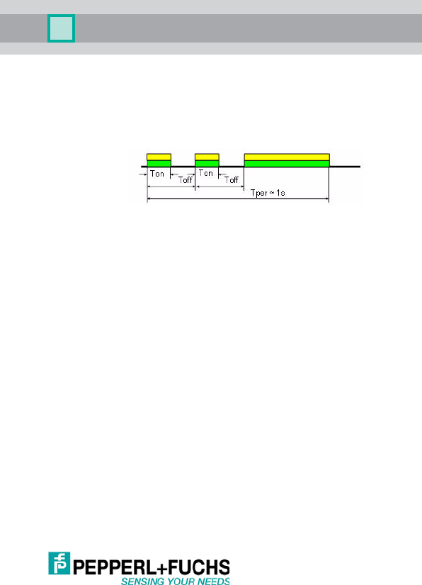
UC***-30GM-**EP-IO-V15
51
Issue date: 09/05/2 013 Part No. xxxxxx Docume nt No. TDOCT2821__ENG
5.6.18 Locator Function
Index: 0x7F (127 dec) Locator Indication Control (LIC)
This function makes it possible to find and identify a sensor in a large plant.
After activation of the "locator function," all yellow and green LEDs flash in
a characteristic pattern.
5.6.19 User-Specific Identifiers
Index: 0xC0 (192 dec)User Tag 1 (UT1) max. 32 bits
Index: 0xC1 (193 def)User Tag 2 (UT2) max. 16 bits
Here the user can define data for identifying the sensor within his project.
5.6.20 System Time
Index: 0xE0 (224 dec) System Time
Sensor runtime since Power-On [s]
5.6.21 Sensor Temperature
Index: 0xE1 (225 dec) Operating Temperature
Current ambient temperature used internally for compensation
5.6.22 Sensor Detection Range
Index: 0xE8 (232 dec) Device Characteristics
5.6.23 Analog Output Present
Index: 0xEF (239 dec) Feature Flag
Indicates whether an analog output is present on output A2. This bit is set
for types UC….-30GM-IUEP-IO-V15.
0x00 Normal LED function; corresponding to the sensor function (factory setting)
0x01 LEDs are used as "locators."
0x01 Blind zone
0x02 End of the sensing range

UC***-30GM-**EP-IO-V15
52
Issue date: 09/05/2013 Part No. xxxxxx Document No . TDOCT2821__ENG
5.6.24 Event Codes via IO-Link
Depending on the parameterization, the sensor sets some events via IO-
Link. These are available only in communicative operation. The following
events are possible:
Standard
Application Events:
Type Mode Event
Qualifier
Event
Code
Details
Parameter changed Message Single
shot
0x54 0x6350 A param eter was ch an ged via
the controls
Pepperl +Fuchs define d
Application Events:
Hardware Error Error Appear 0xF4 0x5010 A device fault has occurred
Hardware Error Error Disappear 0xB4 0x5010 The device fault no longer
exists
No Echo Er ror Warnin g Appea r 0xF4 0x8 CA4 The sensor has lost t he e cho
signal
No Echo Er ror War ning Disappear 0xB4 0x8 CA4 The se nsor is receiving an
ec ho again

UC***-30GM-**EP-IO-V15
53
Issue date: 09/05/2 013 Part No. xxxxxx Docume nt No. TDOCT2821__ENG

Änderungen vorbehalten
Copyright PEPPERL+FUCHS • Printed in Germany
www.pepperl-fuchs.com
Zentrale weltweit
Pepperl+Fuchs GmbH
68307 Mannheim · Deutschland
Tel. +49 621 776-0
E-Mail: info@de.pepperl-fuchs.com
Zentrale USA
Pepperl+Fuchs Inc.
Twinsburg, Ohio 44087 · USA
Tel. +1 330 4253555
E-Mail: sales@us.pepperl-fuchs.com
Zentrale Asien
Pepperl+Fuchs Pte Ltd.
Singapur 139942
Tel. +65 67799091
E-Mail: sales@sg.pepperl-fuchs.com
FABRIKAUTOMATION –
SENSING YOUR NEEDS
Part. No. xxxxxx TDOCT2821__ENG 09/05/2013
