167773 Catalog
193750-Catalog 193750-Catalog 193750-Catalog 095969 Batch5 unilog cesco-content
2016-08-16
: Pdf 167773-Catalog 167773-Catalog B3 unilog
Open the PDF directly: View PDF ![]() .
.
Page Count: 140 [warning: Documents this large are best viewed by clicking the View PDF Link!]
2012
2013
Test Tools Catalog
Digital Multimeters
Clamp Meters
Electrical Testers
Insulation Testers
Earth Ground Testers
Installation Testers
Portable Appliance Testers
Digital Thermometers
Thermal Imagers
Distance Meters
Indoor Air Quality Tools
ScopeMeter® Test Tools
Power Quality Tools
Field Calibrators
Vibration Tester
Radiation Tester
EX Test Tools
Accessories

Fluke web and electronic newsletter .................................................... 1
New from Fluke........................................................................................ 2-3
Fluke Combo Kits ..................................................................................... 4-5
Application/background articles ...................................................... 6
Fluke After Sales Service .................................................................. 7
Fluke where safety is built in .......................................................... 8-9
Fluke web/campaign ......................................................................... 10
Digital Multimeters ............................................................................ 11
DMM Selection Guide ....................................................................... 12
280 Series Digital Multimeters ....................................................... 13
233 Remote Display Multimeter ...................................................... 14
80 Series V Digital Multimeters ....................................................... 15
170 Series Digital Multimeters ........................................................ 16
110 Series II Digital Multimeters .....................................................17
27 II / 28 II Rugged Industrial Multimeters ....................................18
77 IV Digital Multimeter ...................................................................19
88V Automotive Meter ...................................................................... 20
8845A/8846A 6.5 Digit Precision Multimeters ............................... 21
8808A 5.5 Digit Multimeter .............................................................. 22
Thermal Imagers ............................................................................... 58
Ti Series Thermal Imagers ...............................................................59
Ti32/Ti29/Ti27 Industrial Thermal Imagers ...................................60-61
TiR32/TiR29/TiR27 Industrial Thermal Imagers
for Building Diagnostics ................................................................... 62-63
Ti125/Ti110/Ti100 Industrial / Commercial Thermal Imagers ....64-65
TiR125/TiR110/Ti100 Building Diagnostic Thermal Imagers ....... 66-67
Ti9/Ti10/Ti25 Thermal Imagers ....................................................... 68-69
TiS/TiR/TiRx/TiR1 Thermal for Building Inspection ..................... 70-71
Hawk IR CRange IRWindows ........................................................... 72
Digital Thermometers ....................................................................... 49
Infrared Thermometer Selection Guide ......................................... 50
570 Series Precision Infrared Thermometers ................................ 51
60 Series Infrared Thermometers ...................................................52
566/568 Multipurpose Thermometers ............................................ 53
561 Multipurpose Thermometer ..................................................... 54
50 Series II Thermometers ............................................................... 55
1523/1524 Reference Thermometers .............................................. 56
1551A/1552A Ex “Stik” Thermometers ........................................... 57
Installation Testers/Portable Appliance Testers .............................. 43
1650 Series Multifunction Installation Testers.............................. 44-45
6000 Series Portable Appliance Testers .......................................... 46-47
1650/6000 Series Accessories ........................................................... 48
Insulation Testers/Earth Ground Testers .........................................35
Insulation Tester Selection Guide ................................................... 36
1577/1587 Insulation Multimeters ..................................................37
1503/1507 Insulation Testers ...........................................................38
1555/1550C Insulation Resistance Testers ....................................39
1620 Series Earth Ground Testers ................................................... 40
1621 Earth Ground Tester ................................................................. 41
1630 Ground Loop Tester .................................................................. 42
Clamp Meters and Electrical Testers ................................................23
Clamp Meter selection guide ........................................................... 24
381/365 Clamp Meters ...................................................................... 25
370 Series Clamp Meters .................................................................. 26
320 Series / 902 Clamp Meters ......................................................... 27
353/355 AC/DC Clamp Meters .......................................................... 28
360 Current Leakage Clamp Meter ................................................. 29
T100 Series Voltage/Continuity Testers ..........................................30
T5/T5-H5-1AC Kit Electrical Testers ................................................ 31
2AC/1AC-II/LVD1/LVD2 Voltage Detectors ...................................... 32
9040/9062 Phase Rotation Indicators .............................................. 33
2042 Cable Locator ............................................................................34
Indoor Air Quality Tools .................................................................... 75
975 Air Meter ...................................................................................... 76
922 Airflow Meter .............................................................................. 77
971 Temperature Humidity Meter ................................................... 78
983 Particle Counter .......................................................................... 79
Field Calibrators ................................................................................. 101
Field Calibrator Selection Guide ...................................................... 102
750 Series Documenting Process Calibrators ................................ 103
726/725/725Ex Multifunction Process Calibrators ........................ 104
724 Temperature Calibrator ............................................................. 105
712/714 Temperature Calibrators .................................................... 106
914X/418X Drywells/IR Calibrators ................................................. 107
717/718/718Ex/719 Pressure Calibrators ......................................... 108
705/707/707Ex/715 Loop Calibrators ............................................... 109
771/772/773 mA Clamp Meters ........................................................ 110
787/789 ProcessMeters......................................................................111
Field Calibrator Accessories ............................................................. 112
Power Quality Tools ........................................................................... 87
Power Quality Selection Guide ........................................................ 88
345 Power Quality Clamp Meter ...................................................... 89
43B Single-phase Power Quality Analyzer ..................................... 90
1710 Single-Phase Voltage Quality Recorder ................................. 91
430 II Series Three-phase Power Quality Analyzers ..................... 92-93
1735 Power Logger ............................................................................. 94
1740 Series Power Quality Loggers.................................................. 95
1750 Power Recorder ......................................................................... 96
1760 Power Quality Recorder ........................................................... 97
Power Quality Current Clamp Accessories .................................... 98
Norma 4000/5000 Series ................................................................... 99-100
ScopeMeter® Test Tools ...................................................................... 80
ScopeMeter 190 Series II .................................................................. 81-83
ScopeMeter 120 Series ..................................................................... 84
ScopeMeter 225C/S and general specifications ............................ 85
ScopeMeter Accessories ................................................................... 86
Fluke. Keeping your world up and running
Contents
Laser Distance Meters ....................................................................... 73
421D/416D/411D Laser Distance Meters ........................................ 74
General Accessories ........................................................................... 120
Electronic Test Leads, Probes & Clips ............................................. 121
Industrial Test Leads, Probes & Clips .............................................. 122-123-124
Automotive Accessories ................................................................... 125
Current Clamps ................................................................................. 126-127
Temperature Accessories .................................................................128-129
Cases and Holsters ............................................................................ 130-131
Software and Other Accessories ..................................................... 132
Other Accessories .............................................................................. 133
Fuse and Warranty Information......................................................134
ATEX Certified Test Tools .................................................................. 117
A brief look at ATEX .......................................................................... 118
Fluke intrinsically safe tools ............................................................ 119
Vibration Tester .................................................................................. 113
810 Vibration Tester .......................................................................... 114
Radation Meter ...................................................................................115
481 Radation Meter ........................................................................... 116
1
Fluke Web and
Electronic Newsletter
E-Test-it! is Fluke’s regular news
publication for professional test tool
users. It is electronically available 6
times per year. You will be the first to
hear about:
• New Fluke products
• The latest actions and promotions from Fluke
• How to get more out of Fluke tools
• How to use Fluke tools better in your
application
• Exclusive offers, promotions and discounts on
Fluke Merchandizing
• Exclusive offers on Fluke ex-demo equipment
E-Test-it! is free of charge. If at any point in time
you do not want to receive E-Test-it! anymore,
you can unsubscribe with a simple mouse click.
E-Test-it! is small in size (on average about 12
KB) and does not ll up your mailbox or take
long to download.
Try it now and sign-up for your FREE
e-Test-it! subscription.
Go to the Fluke web site and fill in the
on-line subscription form.
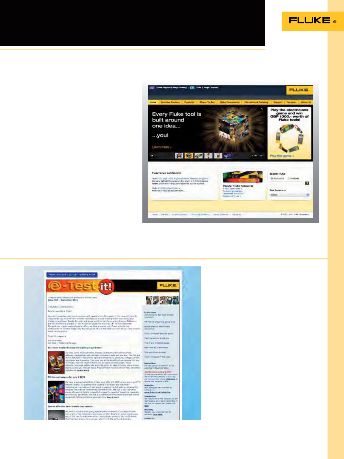
Fluke web
Electronic Newsletter
Fluke web sites are available in all countries around the world and in 18 different languages.
Complete information
The most complete and in-depth resource for
information on Fluke’s products and services
including:
• Product information
• Solution Centers
• Interactive selection guides
• Virtual product demonstrations
• Extended specications
• Application notes
• Product manuals
• Service information
• Promotions
• Prices
• Where to buy
• Distributor and sales ofce locations
Find information fast
To quickly nd more information on Fluke
products, use the “Search by model” box in the
top left corner of our web pages. All you have to
do is type in the model number.
UK: www.fluke.co.uk
IE: www.fluke.ie
Worldwide: www.fluke.com
2
New from Fluke
For the rst time, plant maintenance engineers and technicians can
take a high-performance four-channel scope into the harsh world of
industrial electronics.
See page 81-83.
The new 1654B Installation Tester builds upon the rugged reputation of the earlier
1650 Series, only it’s re-designed to meet your need for more
productive test tools.
See page 44 and 45.
Fluke 750 series process calibrators can help you get the job done faster. It does so
many different tasks, so quickly and so well, it’s the only process calibrator you need
to carry.
See page 103.
The new Fluke 381 does everything you would expect from a clamp meter, and then
lets you remove the display for even more exibility.
See page 25.
Fluke 190 Series II Scopemeter
Fluke 1654B Multifunction Installation Tester
Fluke 750 series Documenting Process Calibrators
Fluke 381 Remote Display True-rms AC/DC ClampMeter with iFlex
Fluke proudly introduces an entry level thermal imager for quick, easy, and
accurate problem identication and troubleshooting designed specically for
the building inspection professional.
See page 70 and 71.
The Fluke 365 is a new, innovative Fluke clamp meter, offering a thin,
small jaw design that makes it easy to get around tightly packed wires.
See page 25.
With this new family of clamp meters, Fluke provides a range of state of-the-art
capabilities to meet users’ most demanding requirements for exibility, safety and
performance.
See page 26.
Fluke TiS Thermal Imaging Scanner
Fluke 365 Detachable Jaw True-rms AC/DC Clamp Meter
Fluke 370 series Clamp Meters

3
New from Fluke
Designed for industrial and commercial environments, the Fluke P3 series of thermal
imagers deliver superior image quality, versatility, and affordability without compromise.
See page 60-63.
The new Fluke 434, 435 and 437 Series II models help locate, predict,
prevent, and troubleshoot power quality problems in three-phase
and single-phase power distribution systems.
See page 92-93.
The new 1555 and redesigned Fluke 1550C insulation resistance testers offer digital
insulation testing up to 10kV, making them ideal for testing a wide range of high
voltage equipment including switchgear, motors, generators and cables.
See page 39.
Fluke Ti27/Ti29 Thermal Imagers
Fluke 430 Series II
Three-Phase Power Quality and Energy Analyzers
Fluke 1555/1550C Insulation Resistance Testers
Fluke proudly introduces ve new thermal imagers specically designed to help you do
more in less time, while being at home in the harshest of environments. A project that
might normally take an hour can now be done in minutes. Our newest imagers are the
lightest, most rugged, easiest-to-use professional imagers you can buy.
See page 64-67.
Accurate and repeatable to ± 0.05 °C over its full range, the 1551A/1552A “Stik”
Thermometer is the new “gold standard” of industrial temperature calibration.
See page 57.
The new Fluke TL175 TwistGuard™ Test Leads are the innovative test leads with adjustable
length test tips for use in different measurement environments.
See page 124.
Ti125/Ti110/Ti100/TiR125/TiR110 Thermal Imagers
1551A Ex and 1552A Ex “Stik” Thermometer
TL175 Twistguard™ Test Leads
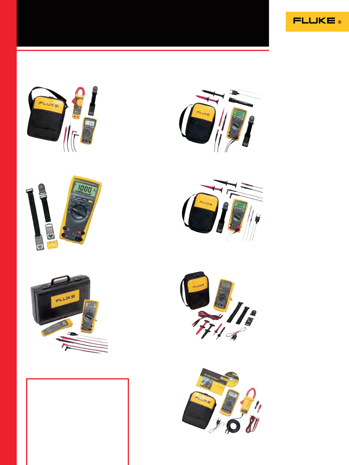
4
Fluke Combo Kits
Fluke 179/TPAK
179/ToolPak Combo Kit
• Fluke 179 True RMS
Multimeter
• TPAK ToolPak Meter Hanging
Kit
Fluke 87V/E2
Industrial Electrician
Combo Kit
• Fluke 87V True RMS
Multimeter
• TL224 SureGrip™ Silicone Test
Lead Set
• TP38 Slim Reach Test Probe
Set (insulated)
• AC220 SureGrip™ Alligator
Clip Set
• TPAK Magnetic Hanger
• 80BK-A Integrated DMM
Temperature Probe
• C35 Soft Meter Case
Fluke 179/EDA2 Kit
Electronics Combo Kit
• Fluke 179 True RMS
Multimeter
• TL224 SureGrip™ Silicone Test
Lead Set
• TL910 Electronic Test Probe
Set
• AC280 SureGrip™ Hook Clip
Set
• TPAK Magnetic Hanger
• 80BK-A Integrated DMM
Temperature Probe
• C35 Soft Meter Case
Fluke 179/61 Kit
Multimeter and Infrared
Thermometer Combo Kit
• Fluke 179 True RMS
Multimeter
• Fluke 61 Infrared
Thermometer
• C550 Hard Meter and
Accessory Case
Fluke 179/MAG2 Kit
Industrial Combo Kit
• Fluke 179 True RMS
Multimeter
• TL224 SureGrip™ Silicone Test
Lead Set
• AC220 SureGrip™ Alligator
Clip Set
• TP74 lantern tip test probe set
• TPAK Magnetic Hanger
• 80BK-A Integrated DMM
Temperature Probe
• C35 Soft Meter Case
• + Maglite ashlight
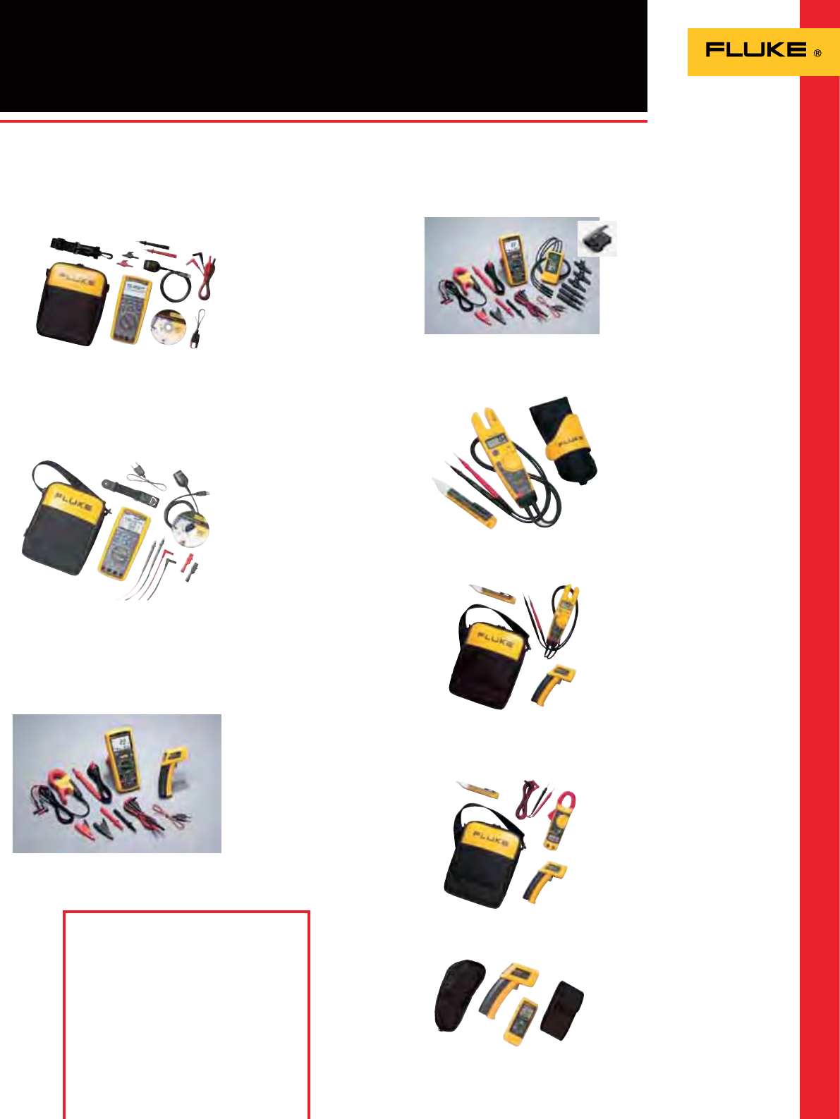
Fluke 117/322 Kit
Electrician’s Combo Kit
• Fluke 117 True RMS
Multimeter
• Fluke 322 Clamp Meter
• Silicon test lead set
• TPAK Magnetic Hanger
• C115 Deluxe carrying case
with shoulder strap
Fluke 87V/i410
Combo Kit for Industrial
Applications
• 87V Industrial Multimeter
• TL75 Test Leads
• AC172 Alligator Clips
• i410 400A AC/DC Current
Clamp
• 80BK-A Temperature Probe
• C115 Soft Carrying Case
(Not available in all countries)
Buy a Combo Kit and save
Ordering Information
Fluke 117/322 Kit
Fluke 179/TPAK
Fluke 179/61 Kit
Fluke 179/MAG2 Kit
Fluke 179/EDA2 Kit
Fluke 87V/E2
Fluke 87V/i410
5
Fluke Combo Kits
Fluke T5-600/62/IAC-E Kit
• Fluke T5-600 Electrical Tester
• Fluke 62 Mini IR Thermometer
• Fluke 1AC-II Volt Alert
• C115 Soft Meter Case
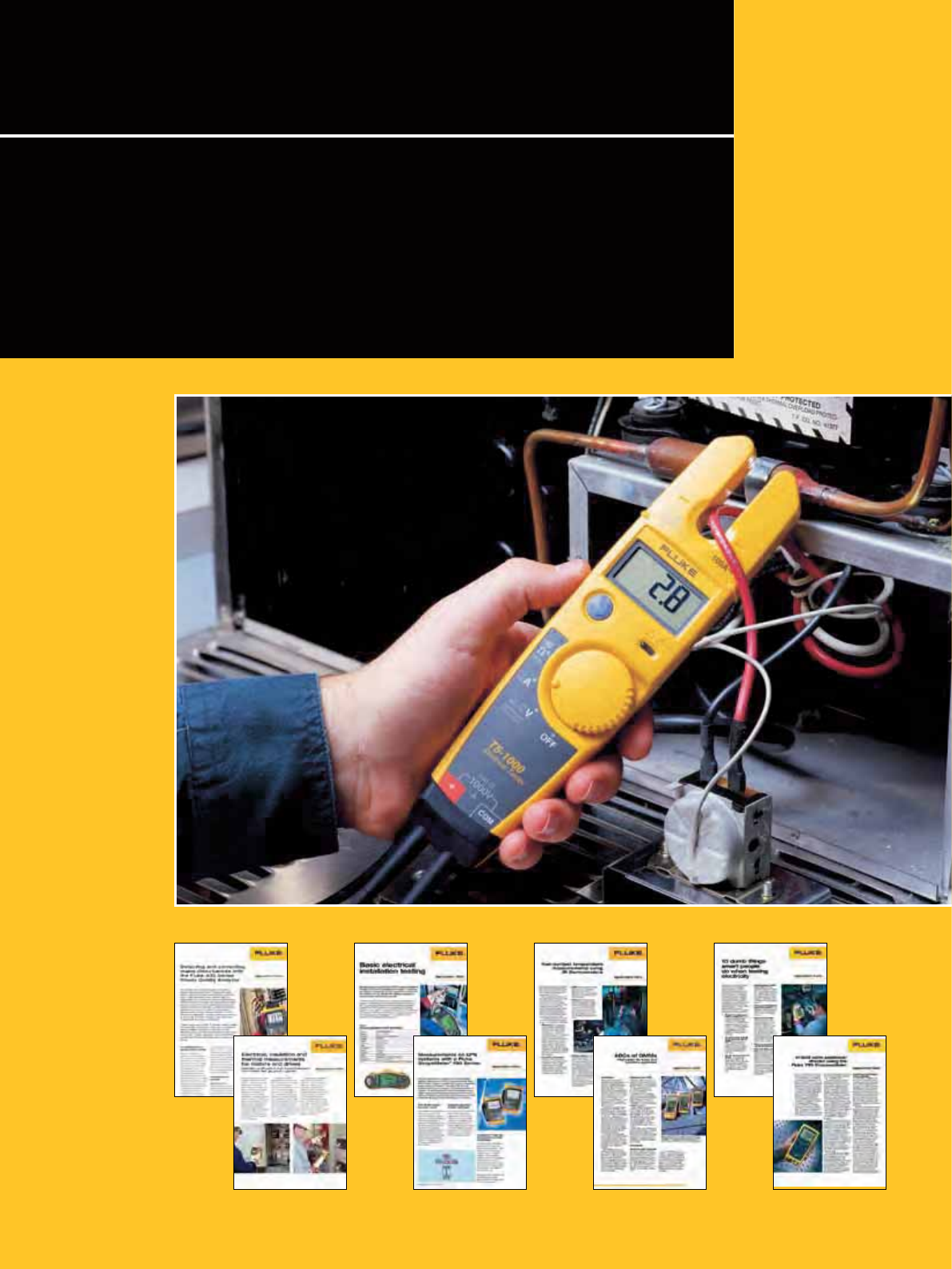
Fluke T5-H5-1AC Kit
• Fluke T5-1000 Electrical Tester
• H5 Holster
• 1AC-II Volt Alert
Fluke 1587/ET Advanced
Electrical Troubleshooting Kit
• Fluke 1587 Insulation Multimeter
• Fluke 62 Mini Infrared
Thermometer
• I400 Current Clamp
Fluke 1587/MDT
Advanced Motor & Drive
Troubleshooting Kit
• Fluke 1587 Insulation
Multimeter
• Fluke 9040 Phase Rotation
Indicator
• I400 Current Clamp
Fluke 62/322/1AC Kit
• Fluke 62 Mini IR Thermometer
• Fluke 322 Clamp Meter
• Fluke 1AC-II Volt Alert
Fluke 411D/62 Kit
• Fluke 411D Laser Distance
Meter
• Fluke 62 Mini IR Thermometer
• Soft case for each model
Fluke 289/FVF Industrial
Logging Multimeter and
Software Combo Kit
• Fluke 289 True-RMS
Multimeter
• FVF-SC2 FlukeView Forms
Software and cable
• Silicon Test Lead Set
• AC172 Alligator Clips
• 80BK-A Integrated DMM
Temperature Probe
• TPAK Magnetic Meter Hanger
for hands-free operation
• C280 Soft Case for meter
protection and accessory
storage
Buy a Combo Kit and save
Ordering Information
Fluke 287/FVF
Fluke 289/FVF
Fluke 1587/ET
Fluke 1587/MDT
Fluke T5-H5-1AC Kit
Fluke T5-600/62/IAC-E Kit
Fluke 62/322/1AC Kit
Fluke 411D/62 Kit
Fluke 287/FVF FlukeView
Forms Combo Kit
• Fluke 287 True RMS Electronic
Logging Multimeter with
TrendCapture
• FVF-SC2 FlukeView Forms
Software and cable
• 80BK-A Thermocouple Probe
• CAT III 1000 V 10 A Modular
Test Leads (red, black)
• CAT II 300 V 5 A Alligator Clips
(red, black)
• C280 Soft Case for meter
protection and accessory
storage
Fluke 1587/MDT
6
Application/
background articles
As part of our commitment to supporting you in your work we do
more than just design and manufacture rugged and versatile test tools:
we also provide application notes which all can be downloaded from
our web site. Furthermore check out our “total solutions” campaigns
on the website. In addition to inspection tips and helpful application
information, these campaigns also offer advice on picking the right tool
for the job.

7
So why should you use Fluke service?
• Original manufacturers’ parts used
• All instruments reviewed for latest updates
• Repair warranty that covers whole unit
• In depth product knowledge
• Accredited calibrations available
• Traceable calibrations available on all
products
• Full check of unit during verication cycle
• Full safety test on mains powered units
What other instruments can we help
you with?
We also offer a range of calibrations and
repairs on other manufacturer’s equipment
upon request. Manufacturers such as:
• Tektronix
• Agilent
• Bruel & Kjaer
• Philips
• Megger
• Seaward
• Kewtech
• Lecroy
• Hioki
• Yokogawa
• Druck
• Iwatzu
• plus many more ...
Did you know that the Fluke after sales
service team can offer you much more
than just repairing and calibrating your
instrument when it is needed? Across
our whole Fluke European service
organization we have a vast range of
capabilities, which can be utilized via
your local service centre. Behind the
scenes Fluke draws on the expertise of
over 150 service staff that are focused
on offering only the best and most
comprehensive after sales service.
What other value added services do
we offer?
• Gold Support for Fluke Networks
• Gold CarePlans for calibration products
• A full range of maintenance contracts
• Extended warranty programs
• Instrument upgrades
• Option retrots
• Asset management
• Calibration reminders
What services do we offer you?
• 5 day repairs on all current products
• 5 days or less on all calibrations (excl.
repairs)
• 3 days for all Gold CarePlan calibrations
• 1-2 days on all Networks Gold calibration
• Pick up services where available
Let Fluke After Sales Service
help you further
Eindhoven Norwich Cologne
Telephone +31 (0)40 267 5300 +44 (0)1603 256620 +49 (0)69 2222 20210
Telefax +31 (0)40 267 5321 +44 (0)1603 256688 +49 (0)69 2222 20211
Email servicedesk@fluke.nl ukservicedesk@fluke.com servicedeskgermany@fluke.com
Address Science Park 5108
Eindhoven
5692 EC Son
Netherlands
52 Hurricane Way
Norwich
Norfolk
NR6 6JB
United Kingdom
Heinrich-Pesch-Str. 9-11
50739 Köln
Germany
Contact Information
Fluke Brands Instrument Types
Fluke Digital Multimeters
Hart Scientific Electrical Standards
Fluke Networks Biomedical Equipment
Fluke Biomedical Data Loggers
Raytek Thermal Imagers
Reliable Power Meters Thermometers
Robin Pressure
LEM Instruments Function Generators
BEHA Oscilloscopes
Norma Installation Testers
Wavetek/Datron PAT Testers
Metron Clamp Meters
DHI Power Analyzers
Comark EX meters
Plus many more
Fluke service centres handle a wide range
of equipment.
As part of Fluke’s continuing focus on improving
our service to our customer we now offer a
comprehensive range of repairs and calibrations
on a vast range of equipment.
Fluke manufactures equipments such as:
On-Line booking in system
Why not use our On-Line booking in system
where you can book your unit in, get pricing
and receive a RMA number for a smooth
return.
www.uke.com/servicerma

8
Table 1
Figure 1. Understanding categories: location
Overvoltage installation categories. IEC 61010-1 applies to low-voltage (< 1000V) test equipment
Fluke: Where safety is built in
Overvoltage category In brief Examples
CAT IV Three-phase at utility connection,
any outdoor conductors • Refers to the “origin of installation”; i.e., where low-voltage connection is made to utility power.
• Electricity meters, primary overcurrent protection equipment.
• Outside and service entrance, service drop from pole to building, run between meter and panel.
• Overhead line to d etached building, underground line to well pump.
CAT III Three-phase distribution, including
single-phase commercial lighting • Equipment in xed installations, such as switchgear and polyphase motors.
• Bus and feeder in industrial plants.
• Feeders and short branch circuits, distribution panel devices.
• Lighting systems in larger buildings.
• Appliance outlets with short connections to service entrance.
CAT II Single-phase receptable
connected loads • Appliance, portable tools, and other household and similar loads.
• Outlet and long branch circuits.
• Outlets at more than 10 meters (30 feet) from CAT III source.
• Outlets at more than 20 meters (60 feet) from CAT IV source.
CAT I Electronic • Protected electronic equipment.
• Equipment connected to (source) circuits in which measures are taken to limit transient overvoltages
to an appropriately low level.
• Any high-voltage, low-energy source derived from a high-winding resistance transformer, such as the
high-voltage section of a copier.
As distribution systems and loads
become more complex, the possibilities
of transient overvoltages increase.
Motors, capacitors and power conversion
equipment such as variable speed drives
can be prime generators of spikes.
Lightning strikes on outdoor transmission
lines also cause extremely hazardous
high-energy transients. If you’re taking
measurements on electrical systems,
these transients are “invisible” and
largely unavoidable hazards. They occur
regularly on low-voltage power circuits,
and can reach peak values in the many
thousands of volts. To protect you against
transients, safety must be built into the
test equipment.
Who Develops Safety Standards?
The IEC (International Electrotechnical
Commission) develops international general
standards for safety of electrical equipment
for measurement, control and laboratory
use. IEC61010-1 is used as the basis for the
following national standards:
• US ANSI/ISA-S82.01-94
• Canada CAN C22.2 No.1010.1-92
• Europe EN61010-1:2001
Overvoltage Installation Categories
IEC61010-1 species categories of
overvoltage based on the distance the piece
of equipment is from the power source
(see Fig. 1 and Table 1) and the natural
damping of transient energy that occurs
in an electrical distribution system. Higher
categories are closer to the power source and
require more protection.
Within each installation category there are
voltage classications. It is the combination of
installation category and voltage classication
which determines the maximum transient
withstand capability of the instrument.
IEC 61010 test procedures take into account
three main criteria: steady-state voltage,
peak impulse transient voltage and source
impedance. These three criteria together will
tell you a multimeter’s true voltage withstand
value.
Within a category, a higher working voltage”
(steadystate voltage) is associated with a
higher transient, as would be expected. For
example, a CAT III 600 V meter is tested
with 6000 V transients while a CAT III 1000 V
meter is tested with 8000 V transients.
So far, so good. What is not as obvious is the
difference between the 6000 V transient for
CAT III 600 V and the 6000 V transient for
CAT II 1000 V. They are not the same. This is
where the source impedance comes in. Ohm’s
Law (Amps = Volts/Ohms) tells us that the 2
test source for CAT III has six times the current
of the 12 test source for CAT II. The CAT III
600 V meter clearly offers superior transient
protection compared to the CAT II 1000 V
meter, even though its so-called “voltage
rating” could be perceived as being lower. See
Table 2.
Independent testing is the key to safety
compliance
How can you tell if you’re getting a genuine
CAT III or CAT II meter? Unfortunately it’s
not always that easy. It is possible for a
manufacturer to self-certify that its meter
is CAT II or CAT III without any independent
verication. The IEC (International
Electrotechnical Commission) develops and
proposes standards, but it is not responsible
for enforcing the standards. Look for the
symbol and listing number of an independent
testing lab such as UL, CSA, VDE, TÜV or other
recognized approval agency.
These symbols can only be used if the product
successfully completed testing to the agency’s
standard, which is based on national and
international standards. UL 3111, for example,
is based on EN61010-1. In an imperfect world,
this is the closest you can come to ensuring
that the meter you choose was actually tested
for safety.
9
Select the right test tool:
• Choose a test tool rated to the highest
category and voltage for which it could
possibly be used (most often 600 or 1000
volt CAT III and/or 600 volt CAT IV).
• Look for the category and voltage marking
near the recessed input connectors of your
test tool and a “double insulated” symbol
on the back.
• Verify your test tool has been tested and
certied by two or more independent
testing laboratories, such as UL in the
United States and VDE or TüV in Europe by
looking for the symbols of these agencies
on (the back of) your test tool.
• Make sure that the test tool is made of
a high-quality, durable non-conductive
material.
• Check the manual to verify that the
ohms, continuity and capacitance circuits
are protected to the same level as the
voltage test circuit, to reduce hazards
when the test tool is used incorrectly in
ohms, continuity or capacitance mode (if
applicable).
• Verify that the test tool has internal
protection to prevent instrument damage
when voltage is incorrectly applied to
an amperage measurement function (if
applicable).
• Make sure that the amperage and
voltage of your test tool’s fuses meets
specications. Fuse voltage must be as high
or higher than the test tool’s voltage rating.
• Be sure to use test leads that have:
- Shrouded connectors
- Finger guards and a non-slip surface
- Category ratings that equal or exceed
those of the test tool
- Double insulation (look for the symbol)
- A minimum of exposed metal on the
probe tips
Safety is everyone’s responsibility but
ultimately it is in your hands.
No tool by itself can guarantee your safety
when working with electricity. It’s the
combination of the right tools and safe
work practices that gives you maximum
protection. Here are a few tips to help you
in your work:
Make sure you always comply with (local)
regulations.
Work on de-energized circuits whenever
possible.
Use proper lock-out/tag-out procedures. If these
procedures are not in place or enforced, assume
that the circuit is live.
Use protective gear when working on live
circuits:
• Use insulated tools
• Wear safety glasses or a face shield
• Wear insulated gloves, remove watches or
jewelry
• Stand on an insulated mat
• Wear ame resistant clothing, not ordinary
work clothes
Inspect and test your test tool:
• Check for a broken case, worn test leads or
a faded display.
• Make sure the batteries still deliver
sufcient power to get reliable readings.
Many test tools have a low battery indicator
on the display.
• Check the test leads resistance for internal
breaks while moving the leads around
(good leads measure 0.1-0.3 Ohm).
• Use the meter’s own test capability to
ensure that the fuses are in place and
working right (see manual for details).
Apply the appropriate working
practices when measuring on live
circuits:
• Hook on the ground clip rst, then make
contact with the hot lead. Remove the hot
lead rst, the ground lead last.
• Use the three-point test method, especially
when checking to see if a circuit is dead.
First test a known live circuit. Second,
test the target circuit. Third, test the live
circuit again. This veries that your test
tool worked properly before and after the
measurement.
• Hang or rest the test tool if possible.
Try to avoid holding it in your hands, to
minimize personal exposure to the effects
of transients.
• Use the old electrician’s trick of keeping
one hand in your pocket. This lessens the
change of a closed circuit across your chest
and through your heart.
Fluke: Where safety is built in
Overvoltage
Installation
Category
Working Voltage
(DC or AC RMS
to ground)
Peak Impulse
Transient
(20 repetitions)
Test Source
(Ω = V/A)
CAT I 600 V 2500 V 30 Ohm source
CAT I 1000 V 4000 V 30 Ohm source
CAT II 600 V 4000 V 12 Ohm source
CAT II 1000 V 6000 V 12 Ohm source
CAT III 600 V 6000 V 2 Ohm source
CAT III 1000 V 8000 V 2 Ohm source
CAT IV 600 V 8000 V 2 Ohm source
Table 2
Use meters with these markings:
1000 V CAT III or 600 V CAT IV
Transient test values for overvoltage installation categories.
(50 V/150 V/300 V values not included)
Use protective equipment such as safety glasses and
insulated gloves

10
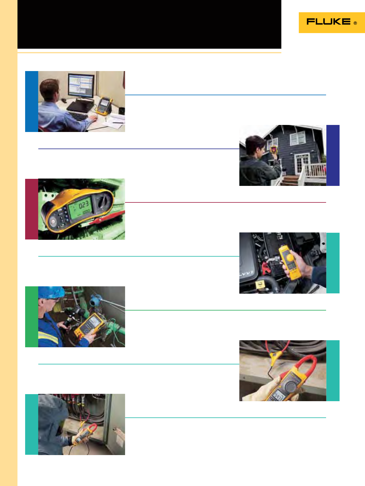
Fluke Solution
Fluke total solutions campaigns
Fluke has launched a total solutions campaign focused on all our products and the benets for you. Discover how Fluke tools can
help you make or save money. You can nd a wide range of useful background information, www.ukesolution.co.uk
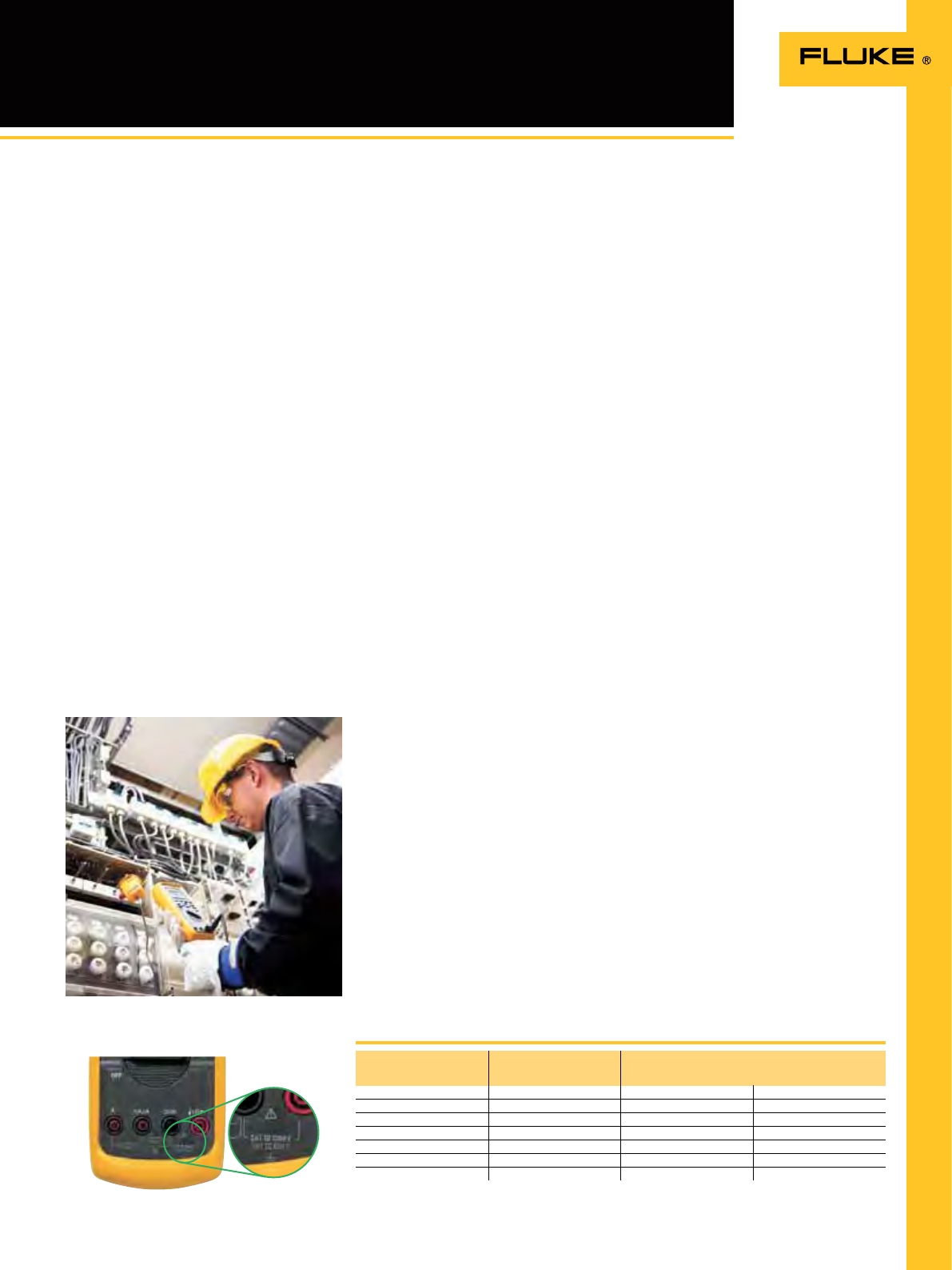
Plant Maintenance
Focus on motors and drives, energy saving and process trouble shooting, where Fluke’s Test & Measurement tools can help you
make the difference. Learn more about our latest developments in for example inspecting motors and drives.
Thermography
Focus on the user experience of our Thermal Imagers and experience the wide-ranging benets of thermal imaging in everyday on-
the-job situations. See what Fluke Thermography has to offer to make your work easier.
Energy
Focus on energy saving benets in the industrial maintenance market. Fluke Test & Measurement tools help you to detect problems
and/or monitoring situations –prevention- before they become critical. Learn how we can help you make or save money in your
plant or industry.
www.flukesolution.co.uk
Visit the full portal to get all your troubleshooting solutions from one source. Every Fluke tool is built around one idea…You!

11
Safety, quality and performance: three words that sum up the benets of
our extensive range of digital multimeters. Designed to help you do your
job faster, more efciently and with greater accuracy, there is a model for
every budget and application. Choose from handheld troubleshooters to
ultra smart instruments packed with features, including the ability to log
and graph data, as well as high-precision bench units.
Digital Multimeters

12
DMM Selection guide
Highest accuracy Remote
display High-end Industrial Industrial maintenance
and field service Electrical HVAC/R Field
Service Basic Electrical Heavy duty
(IP67)
General
Purpose
Auto-
motive Loop calibration Insulation test
Basic features 289 287 233 87V 83V 179 177 175 117 116 115 114 113 27II 28II 77IV 88V 789 787 1587 1577
Counts 50000 50000 6000 20000 6000 6000 6000 6000 6000 6000 6000 6000 6000 6000 20000 6000 20000 4000 4000 6000 6000
True RMS readings AC+DC AC+DC AC AC AC AC AC AC AC AC AC AC AC AC AC AC AC
Basic DC accuracy 0.025% 0.025% 0.25% 0.05% 0.1% 0.09% 0.09% 0.15% 0.5% 0.5% 0.5% 0.5% 2.0% 0.1% 0.05% 0.3% 0.1% 0.1% 0.1% 0.09% 0.2%
Wide bandwidth 100 kHz 100 kHz 20 kHz 5 kHz 20 kHz 50 kHz
Auto/manual ranging
O
/
OO
/
OO
/
OO
/
OO
/
OO
/
OO
/
OO
/
OO
/
OO
/
OO
/
OO
/
OO
/
OO
/
OO
/
OO
/
OO
/
OO
/
OO
/
OO
/
OO
/
O
Measurements
Voltage AC/DC 1000 V 1000 V 1000 V 1000 V 1000 V 1000 V 1000 V 1000 V 600 V 600 V 600 V 600 V 600 V 1000 V 1000 V 1000 V 1000 V 1000 V 1000 V 1000 V 1000 V
Current AC/DC 10 A 10 A 10 A 10 A 10 A 10 A 10 A 10 A 10 A 200 A 10 A 10 A 10 A 10 A 10 A 1 A 1 A 400 mA 400 mA
Resistance 500 MΩ 500 M 40 M 50 M 50 M 50 M 50 M 50 M 40 M 40 M 40 M 40 M 60 k 50 M 50 M 50 M 50 M 40 M 40 M 50 M 50 M
Frequency 1 MHz 1 MHz 50 kHz 200 kHz 200 kHz 100 kHz 100 kHz 100 kHz 50 kHz 50 kHz 50 kHz 200 kHz 200 kHz 100 kHz 200 kHz 20 kHz 20 kHz 100 kHz
Capacitance 100 mF 100 mF 10 mF 10 mF 10 mF 10 mF 10 mF 10 mF 10 mF 10 mF 10 mF 10 mF 10 mF 10 mF 10 mF 10 mF 10 mF
Temperature +1350ºC +1350ºC +400ºC +1090ºC +400ºC +400ºC +1090ºC +1090ºC +500ºC
dB 60 dB 60 dB
Conductance 50 nS 50 nS 60 nS 60 nS 60 nS 60 nS 60 nS
Duty cycle/pulse width
O
/
OO
/
OO
/-
O
/-
O
/
OO
/
OO
/
O
Continuity with beeper/Diode test
O
/
OO
/
OO
/
OO
/
OO
/
OO
/
OO
/
OO
/
OO
/
OO
/
OO
/
OO
/-
O
/
OO
/
OO
/
OO
/
OO
/
OO
/
OO
/
OO
/
O
O
/-
4-20mA loop current as % readout
OO
Motor drive measurement
OO OO
RPM/Dwell
O
/-
VoltAlertTM, Non-contact voltage detection
O
LoZ: low input impedance
OOO O
VCHEKTM LoZ
O
Microamps
OO OO O
Insulation test
OO
Number of insulation test ranges 52
Warranty and safety
Lifetime warranty/warranty (years)
OO
3
OOOOO
33333
OOOO
3333
Input alert
OO OO OO O
Dangerous voltage indication
OOOOOOOOOOOOOOOOO OO
EN61010-1 CAT III 1000 V 1000 V 1000 V 1000 V 1000 V 1000 V 1000 V 1000 V 600 V 600 V 600 V 600 V 600 V 1000 V 1000 V 1000 V 1000 V 1000 V 1000 V 1000 V 1000 V
EN61010-1 CAT IV 600 V 600 V 600 V 600 V 600 V 600 V 600 V 600 V 600 V 600 V 600 V 600 V 600 V 600 V
See catalog page 13 13 14 15 15 16 16 16 17 17 17 17 17 18 18 19 20 111 111 37 37
Display
Dual display
OO OO
Analog bargraph
OO OOOOOOOOOOOOOOO
Backlight
OOOOOOO OOOOOOOOOOOOO
Remote display
O
Data storage and exchange
Min-Max recording/with time stamp
O
/
OO
/
OOO
/-
O
/-
O
/-
O
/-
O
/-
O
/-
O
/-
O
/-
O
/-
O
/-
O
/-
O
/-
O
/-
O
/-
O
/-
O
/-
O
/-
Fast Min-Max 250 µs 250 µs 250 µs 250 µs 250 µs
Display Hold/Auto (Touch) Hold
O
/
OO
/
OOO
/
OO
/
OO
/
OO
/
OO
/
OO
/-
O
/-
O
/-
O
/-
O
/-
O
/
OO
/
O
-/
OO
/
O
-/
O
-/
OO
/
O
Relative
OO OO OO OOO
Stand alone logging/TrendCapture
O
/
OO
/
O
USB interface/RS232 interface
O
/
OO
/
O O
/
O
Readings memories 10000 10000
Other features
Source 4-20mA loop current/24V loop supply
O
/
OO
/-
Automatic selection, AC/DC volts
OO O
Real time clock
OO
Smoothing
OOO O
Integrated holster
OOO OOO OO
Removable holster
OO OOOOOOO O OOO
Closed case calibration
OOOOOOOOOOOOOOOOOO OO
Seperate battry/fuse access
O
/
OO
/
OO
/
OO
/-
O
/-
O
/
OO
/
OO
/
OO
/-
O
/-
O
/-
O
/-
O
/-
O
/
OO
/
OO
/-
O
/
OO
/-
O
/
OO
/
O
Completely sealed/watertight
OO
Automatic power off
OO OOOOOOOOOOOOOOOOOO
Low battery indication
OO OOOOOOOOOOOOOOOOOO

13
Included Accessories
TL175 test leads, AC172 alligator clips, probe
holder, 6 AA batteries (installed), user manual,
Calibration Certicate Sheet.
Ordering Information
Fluke 287 True-RMS Electronic logging
multimeter with TrendCapture
Fluke 289 True-RMS Industrial logging
multimeter with TrendCapture
Fluke 289/FVF Industrial logging multimeter
and Software Combo Kit
(see page 5)
Fluke 287/FVF FlukeView Forms Combo Kit
(see page 5)
FVF-SC2 FlukeView Forms software
including IR/USB cable
287 289
True-RMS measurements AC, AC+DC AC, AC+DC
Bandwidth (voltage/current) 100 kHz / 100 kHz 100 kHz / 100 kHz
Digital display counts (default/selectable) 50.000 / 50.000 50.000 / 50.000
Logging function with TrendCapture
OO
Records events and trends
OO
Internal memory Up to 180 h Up to 180 h
Saves measurements
OO
Optical USB PC communications interface
OO
Low input impedance function (LoZ)
O
Motor winding and low ohm measurement range 50
Low pass filter
O
Field upgradeable/expandable meter
OO
Navigation keys
OO
F1-F4 soft keys/user function menus
OO
I-info button/on board help screens
OO
Multilingual interface
OO
Saves preferred measurement setups
OO
Current measurement: 20 A (30 seconds momentary; 10 A continuous)
OO
Peak capture (records transients as fast as 250 µs)
OO
Continuity measurement
OO
Min/Max/Average with Time Stamp (records signal fluctuations)
OO
IP Rating 54
OO
Functions Maximum Max. resolution 287 and 289**
Voltage DC 1000 V 1 µV ±(0.025% + 5)
Voltage AC 1000 V 1 µV ±(0.4% + 40)
Current DC 10 A 0.01 µA ±(0.15% +2)
Current AC 10 A 0.01 µA ±(0.7% + 5)
Temperature -200 ºC to 1350 ºC 0.1 ºC ±(1.0% + 1 ºC)
Resistance 500 M 0.01 ±(0.05% + 2)
Conductance 50 nS 0.01 nS ±(1.0% + 10)
Capacitance 100 mF 0.001 nF ±(1.0% + 5)
Frequency 1 MHz 0.01 Hz ±(0.005% + 1)
280 Series Digital Multimeters
True RMS
Precise performance View logged data graphically
on screen
Accuracies are best accuracies for each function.
** 287 and 289 accuracy and resolution are stated for 50.000 counts
Advanced diagnostic and logging
functionality for maximizing productivity
Replacing the popular 180 Series, the
Fluke 289 and Fluke 287 represent the
next generation of high-performance
industrial logging multimeters,
including higher accuracy and greater
troubleshooting convenience than ever
before. With the ability to log data and
review it graphically on the large display,
you can solve problems faster and help
minimize downtime, while working at
several locations.
• Large 50,000 count 320 x 240 (1/4 VGA)
dot matrix display
• Logging function with TrendCapture for
easy review of logged data
• Multiple readings per display provide
more information at a glance
• “I”-info button for convenient on-board
help
• PC interface for easy data transfer
In addition, the Fluke 289 provides:
• Lo Pass lter for motor drive
measurements
• LoZ – Low impedance function prevents
false “ghost voltage” readings
• 50 range for motor winding and low
ohm measurements
Features
Specifications
(Check the Fluke web for detailed specifications)
Recommended Accessories
TLK289
See page 123 TL910
See page 121 TLK287
See page 121 TPAK
See page 132 C280
See page 130
Fluke 287
Battery life: 50 hours minimum,
180 hours in logging mode
Size (HxWxD): 222 mm x 102 mm x 60 mm
Weight: 0,871 kg
Lifetime warranty
Fluke 289
14
233
Removable magnetic display
O
True-RMS measurement
O
Digital display counts 6000
Display backlight
O
Built in thermometer
O
Resistance, continuity and diode test
O
Min/Max and average recording
O
Auto power off maximizes battery life
O
Radio transmitter automatically turns off when
the display is connected to the meter
O
Use as conventional multimeter when the display is connected
O
Safety rating CAT IV 600 V / CAT III 1000 V
Auto and manual ranging
O
Display Hold and AutoHOLD®
O
Unsafe voltage alert warns for voltages above 30V
O
2 Low batteries indication
O
Ergonomic case with integrated holster
O
Selectable sleep mode preserves battery life
O
233 Remote Display Multimeter
Included Accessories
Test leads with 4mm lantern tips, AC 172
alligator clips, 80BK-A temperature probe,
CD-ROM, AA batteries and user manual.
Ordering Information
Fluke 233 Remote Display Multimeter
The Fluke 233 remote display digital
multimeter allows you to be in two
places at once. The removable display
solves the problems of holding both
the meter and the test leads to make a
measurement, making measurements
in hard-to-reach places, and making
measurements in machines or panels
that are physically separated from a limit
switch or an isolator switch. Wireless
technology allows the display to be
carried up to 10 meters away from the
point of measurement. The Fluke 233
is also designed to work in areas where
the operator can’t be close to the active
measurement point, like clean rooms or
hazardous areas.
Recommended Accessories
80AK-A
See page 128 80PK-9
See page 128 i410
See page 127 Tpak
See page 132 C35
See page 130
Battery Life: AA alkaline (3 for main body,
2 for display), 400 hrs typical
Size (HxWxD): 193 x 93 x 53 mm
On all inputs
Features
Specifications
Functions Fluke 233
Maximum Max. Resolution Accuracy
Voltage DC 1000 V 0.1 mV ±(0.25% + 2)
Voltage AC 1000 V 0.1 mV ±(1.0% + 3)
Current DC 10 A 1 mA ±(1.0% + 3)
Current AC 10 A 1 mA ±(1.5% + 3)
Resistance 40 M 0.1 ±(0,9% + 1)
Capacitance 9999 F 1 nF ±(1,9% + 2)
Frequency 50.00 kHz 0.01 Hz ±(0,1% + 2)
Temperature -40 ºC to +400 ºC 0,1 ºC ±(1% + 10)
Wireless frequency: 2.4 GHz ISM Band 10 meter range
Weight: 0.6 kg
Three year warranty
Ultimate flexibility with removable display
Accuracies are best accuracies for each function
Fluke 233
True RMS
15
True RMS
80 Series V
Digital Multimeters
Included Accessories
TL175 test leads, AC172 alligator clips, yellow
holster (H80M excl. TPAK), 80BK temperature
probe (87V only), 9 V battery (installed),
CD-ROM (user’s manual and technical notes)
and operator’s guide.
Ordering Information
Fluke 83V Multimeter
Fluke 87V True RMS Multimeter
Fluke 87V Ex Intrinsically safe
True RMS multimeter
Fluke 87V/E2 Industrial Electrician Combo
Kit
See page 4
The Fluke 80 Series V have improved
measurement functions, troubleshooting
features, resolution and accuracy to solve
more problems on motor drives, in plant
automation, power distribution, and
electro-mechanical equipment.
The Fluke 87V has a unique function
for accurate voltage and frequency
measurements on adjustable speed
motor drives and other electrically noisy
equipment. A built-in thermometer
conveniently allows you to take
temperature readings without having to
carry a separate instrument. For 87V Ex
see also page 118 and 119.
Specifications
(Check the Fluke web for detailed specifications)
C25
See page 130 TL238
See page 122 i410/i1010
See page 127 TPAK
See page 132 L215
See page 123
Features
Accuracies are best accuracies for each function.
* 87V accuracy is stated for 6000 counts and resolution for 20000 counts
** 20 A up to 30 seconds
On all inputs
not 87V Ex
Fluke 87V
Fluke 83V
Fluke 87V Ex
83V/87V
Battery Life: Over 400 hours typical (alkaline).
Size (HxWxD):
200 mm x 95 mm x 48 mm
Weight: 0.6 kg
83V/87V: Lifetime Warranty
87V Ex: One Year Warranty
83V 87V / 87V Ex
True-RMS voltage and current for accurate
measurements on non linear signals
O
Bandwidth (voltage/current) 5 kHz 20 kHz
Digital display counts (default/selectable) 6000 20000 / 6000
Selectable filter for accurate voltage and frequency
measurements on motor drives
O
Large display with analog bargraph and 2 level bright
white backlight
OO
Auto and manual ranging for maximum flexibility
OO
Built-in thermometer lets you carry one less tool
O
Peak capture to record transients as fast as 250 µs
O
Relative mode to remove test lead resistance from low
ohms measurements
OO
Min-Max-Average recording with Min/Max Alert to
capture variations automatically
OO
AutoHOLD® to capture stable readings avoiding noisy
signals
OO
Audible continuity, diode test and duty cycle
OO
Input Alert
OO
“Classic” design with new removable holster with built
in test lead and probe storage
OO
Improved selectable sleep mode for long battery life
OO
Easy battery exchange without opening the complete
case
OO
ATEX safety rating II 2 G Eex ia IIC T4 87V Ex
Functions Maximum Range 83V 87V/87V Ex*
Max. resolution Accuracy Max.
resolution Accuracy
Voltage DC 1000 V 0.1 mV ±(0.1%+1) 10 µV ±(0.05%+1)
Voltage AC 1000 V 0.1 mV ±(0.5%+2) 10 µV ±(0.7%+2)
Current DC 10 A ** 0.1 µA ±(0.4%+2) 0.01 µA ±(0.2%+2)
Current AC 10 A ** 0.1 µA ±(1.2%+2) 0.01 µA ±(1.0%+2)
Resistance 50 M 0.1 ±(0.4%+1) 0.01 ±(0.2%+1)
Conductance 60 nS 0.01 nS ±(1.0%+10) 0.001 nS ±(1.0%+10)
Capacitance 9999 µF 0.01 nF ±(1.0%+2) 0.01 nF ±(1.0%+2)
Frequency > 200 kHz 0.01 Hz ±(0.005%+1) 0.01 Hz ±(0.005%+1)
Temperature -200 to 1090 ºC - 0.1 ºC 1.0%
80BK temperature probe -40 to 260 ºC - - 2.2 ºC or 2%
Performance and accuracy for
maximum industrial productivity
Recommended Accessories
(Not for hazardous zones)

16
170 Series Digital Multimeters
Included Accessories
Test leads with 4 mm lantern tips, installed
9V battery and users manual. The 179 also
includes the 80BK temperature probe.
Ordering Information
Fluke 175 True RMS Multimeter
Fluke 177 True RMS Multimeter
Fluke 179 True RMS Multimeter
Fluke 179/EDA2 Kit Electronics Combo Kit
Fluke 179/MAG2 Kit Industrial Combo Kit
See page 4
These meters have the features needed
to nd most electrical, electro-
mechanical and heating and ventilation
problems.
They are simple to use and have
signicant improvements over Fluke’s
original 70 Series like True-RMS, more
measurement functions, conformance to
the latest safety standards, and a much
larger display that’s easier to view.
(Check the Fluke web for detailed specifications)
Recommended Accessories
i400
See page 126 C90
See page 130 TLK-220
See page 122 SV225
See page 133 i410-i1010
See page 127
Features
Accuracies are best accuracies for each function
Battery Life: Alkaline, 200 hrs typical
Size (HxWxD): 190 mm x 85 mm x 45 mm
Fluke 175
Fluke 177
On all inputs
Fluke 179
True RMS
Specifications
175 177 179
True-RMS measurements AC AC AC
Digital display counts, updates 4 times per second 6000 6000 6000
Display backlight
OO
Analog bargraph / 33 segments, updates 40 times per
second
OOO
Auto and Manual ranging
OOO
Display Hold and AutoHOLD®
OOO
Min-Max-Average recording mode with Min/Max Alert
OOO
Temperature readings (bead thermocouple probe
included)
O
Smoothing mode allows filtering of rapidly changing
inputs
OOO
Audible continuity and diode test
OOO
Test lead alert
OOO
Unsafe voltage alert warns for voltages above 30V
OOO
Low battery indication
OOO
Ergonomic case with integrated holster
OOO
Easy battery and fuse exchange without opening the
complete case
OOO
Selectable sleep mode preserves battery life
OOO
Weight: 0.42 kg
Lifetime Warranty
Functions Maximum Max. resolution 175 177 179
Voltage DC 1000 V 0.1 mV ±(0.15%+2) ±(0.09%+2) ±(0.09%+2)
Voltage AC 1000 V 0.1 mV ±(1.0%+3) ±(1.0%+3) ±(1.0%+3)
Current DC 10 A 0.01 mA ±(1.0%+3) ±(1.0%+3) ±(1.0%+3)
Current AC 10 A 0.01 mA ±(1.5%+3) ±(1.5%+3) ±(1.5%+3)
Resistance 50 M 0.1 ±(0.9%+1) ±(0.9%+1) ±(0.9%+1)
Capacitance 10000 µF 1 nF ±(1.2%+2) ±(1.2%+2) ±(1.2%+2)
Frequency 100 kHz 0.01 Hz ±(0.1%+1) ±(0.1%+1) ±(0.1%+1)
Temperature -40 ºC/+400 ºC 0.1 ºC ±(1.0%+10)
Versatile meters for field service or
bench repair
17
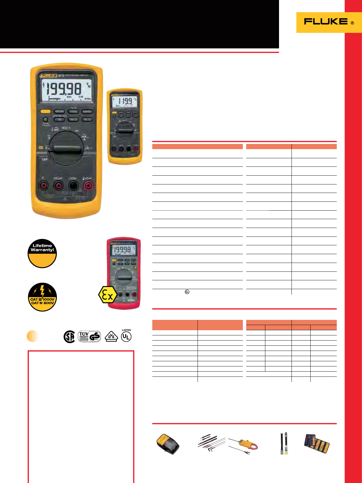
110 Series Digital Multimeters
The Fluke 110 Series has ve true-rms
DMMs, each for specic users. The compact
instruments offer convenient one-handed
operation and a backlit display with large, easy-
to-read digits.
Fluke 117 Electrician’s Multimeter with
Non-Contact Voltage
The 117 is for electricians working in
commercial and non-commercial premises
(like hospitals and schools). It includes extras
like non-contact voltage detection for faster
and safer operation.
Fluke 116 Multimeter with Temperature
and Microamps
The 116 is for heating, ventilation and air
conditioning (HVAC) engineers. It includes
temperature measurement and microamp
current ranges to quickly troubleshoot HVAC
problems.
Fluke 115 Field Service Testing
Multimeter
An everyday multimeter for technicians, the
115 is for electrical and electronic testing in
eld service, industrial, and applications where
more than the basic functions simplify work.
Fluke 114 Electrical Multimeter
The 114 is for electrical troubleshooting and
straightforward ‘go/no-go’ in residential/
commercial testing. It has all the basic
functions plus a special feature to prevent false
readings caused by ghost voltage.
Fluke 113 Multimeter
The 113 is for basic electrical tests and
repairing most electrical problems. Features
include Fluke’s VCHEK™, added measurement
functions, backlight and conformance to the
latest safety standards.
Recommended Accessories
C50
See page 130
(Check the Fluke web for detailed specifications)
TL223-1
See page 122 MC6
See page 133 TPAK
See page 132
Features
Accuracies are best accuracies for each function
Battery type: 9 volt Alkaline, 400 hours typical
Size (HxWxD): 167 mm x 84mm x 46 mm
Specifications
Weight: 0.55 kg (including batteries)
Three Year Warranty
Compact design for ergonomic
one-handed operation
113 114 115 116 117
True RMS readings AC AC AC AC AC
Counts 6000 6000 6000 6000 6000
Backlight
OOOOO
Analog bargraph
OOOOO
AutoVolt: Automatic AC/DC voltage selection
OOO
VoltAlert™, Non-contact voltage detection
O
Built-in thermometer for HVAC applications
O
LoZ: low input impedance to prevent ghost voltage
OOO
VCHEK™ LoZ low impedance measurement function to
simultaneously test for voltage or continuity
O
Min/Max/Average to record signal fluctuations
OOOOO
Resistance, continuity
OOOOO
Frequency, Capacitance, Diode test -/
O
/
O OOO
Microamps to test flame sensors
O
Display hold
OOOOO
Auto/manual ranging
OOOOO
Low battery indication
OOOOO
Compact case with removable holster
OOOOO
Functions Maximum Max. resolution 113 114 115 116 117
Voltage DC 600V 1mV ±(0.5%+2) ±(0.5%+2) ±(0.5%+2) ±(0.5%+2) ±(0.5%+2)
Voltage AC 600V 1mV ±(1.0%+3) ±(1.0%+3) ±(1.0%+3) ±(1.0%+3)
Current DC 10.00A 1mA ±(1.0%+3) ±(1.0%+3)
Current AC 10.00A 0.01A ±(1.5%+3) ±(1.5%+3)
Resistance 40M (113: 60K) 0.1 ±(0.9%+2) ±(0.9%+1) ±(0.9%+1) ±(0.9%+1) ±(0.9%+1)
Capacitance 10000µF 1nF ±(1.9%+2) ±(1.9%+2) ±(1.9%+2) ±(1.9%+2)
Frequency 50kHz 0.01Hz ±(0.1%+2) ±(0.1%+2) ±(0.1%+2)
Temperature -40°C/+400°C 0.1°C ±(1.0%+10)
VCHEK™ 600.0V AC/DC 0.1V ±(2.0%+3)
Fluke 117
Fluke 115
Fluke 116
Fluke 114
True RMS
On all inputs
Fluke 113
Included Accessories
Test leads with 4 mm lantern tips, holster,
installed 9V battery and users manual
Ordering Information
Fluke 113 True RMS Multimeter
Fluke 114 True RMS Multimeter
Fluke 115 True RMS Multimeter
Fluke 116 True RMS Multimeter
Fluke 117 True RMS Multimeter
Fluke 117/322 Kit Electricians Combo Kit
(see page 4)
18
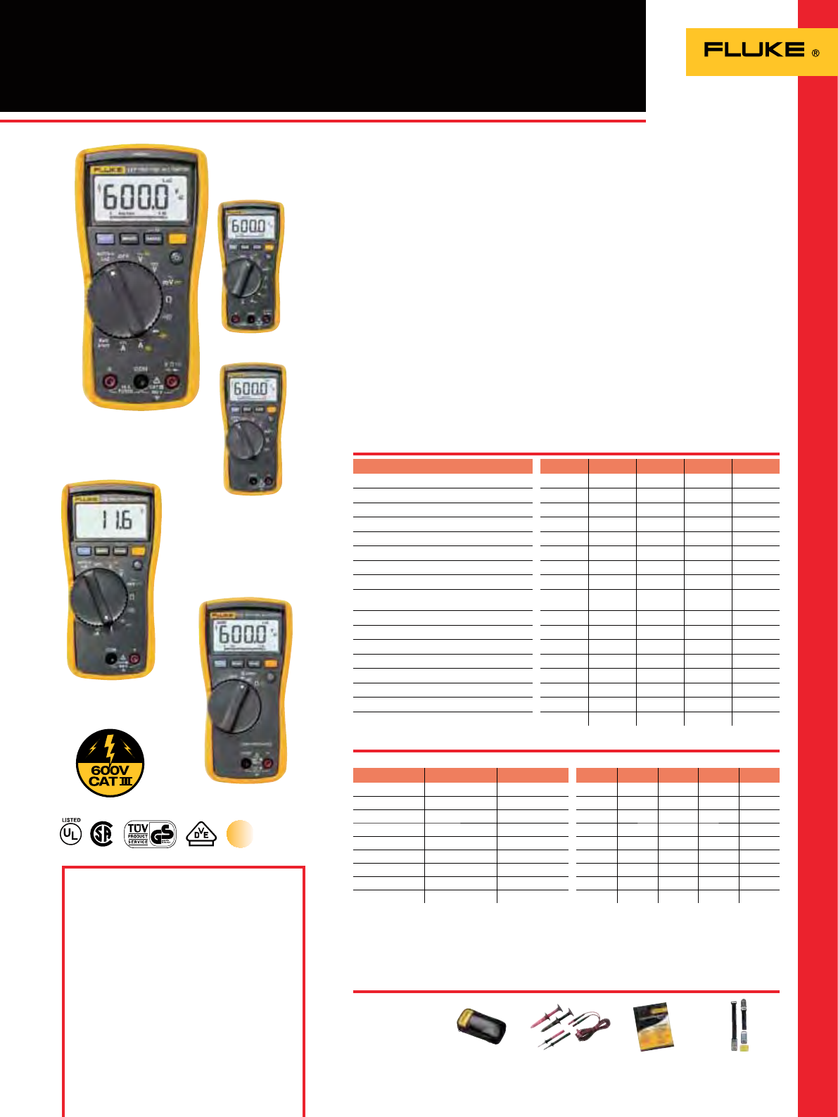
27 II 28 II
IP 67 waterproof & dustproof protection
OO
Withstands 3 meter drop (with holster)
OO
True-RMS measurements
O
Digital display counts 6000 20000/6000
Bright, two-level backlight
OO
Backlit keypad buttons
OO
Reversible, rubber holster
OO
Built-in thermometer
O
Resistance, continuity and diode test
OO
Min/Max and average recording
OO
Improved sleep mode for long battery life
OO
Relative mode to remove test lead resistance
from low ohms measurements
OO
Auto and manual ranging
OO
Safety rating CAT III 1000 V
CAT IV 600 V CAT III 1000 V
CAT IV 600 V
27II / 28II Rugged IP67 Industrial
Multimeters
Included Accessories
TL175 Test leads, AC172 alligator clips,
80BK-A temperature probe (28 II), holster,
manual, CD-ROM, three AA batteries
(installed)
Ordering Information
Fluke 27 II IP 67 Industrial Multimeter
Fluke 28 II IP 67 True-RMS Industrial Multimeter
The Fluke 27 II and 28 II digital
multimeters dene a new standard for
operating in harsh conditions with the
features and accuracy to troubleshoot
most electrical problems. Both meters
have IP 67 (waterproof and dustproof)
rating, MSHA approvals, extended
operating temperature range of -15° C to
+ 55°C and 95% humidity, and a 3-meter
drop. They withstand hazardous 8.000
volt spikes caused by load switching and
faults on industrial circuits and complies
with second edition IEC and ANSI
electrical safety standards.
Furthermore, the 28 II has a unique
function for accurate voltage and
frequency measurements on adjustable
speed motor drives and other electrically
noisy equipment.
The new Fluke 20 series multimeters
are built to work in the toughest
environments.
Recommended Accessories
Battery Life: 3x AA alkaline, 800 hrs typical
Size (HxWxD): 198 x 100 x 63.5 mm
Features
Specifications
Functions Maximum Max.
Resolution 27 II 28 II
Voltage DC 1000 V 0.1 mV ±(0.1% + 1) ±(0.05% + 1)
Voltage AC 1000 V 0.1 mV ±(0.5% + 3) ±(0.7% + 4)
Current DC 10 A 0.1 A ±(0.2% + 4) ±(0.2% + 4)
Current AC 10A 0.1 A ±(1.5% + 2) ±(1.0% + 2)
Temperature -200°C to
+1090°C 0.1°C ±(1% + 10)
Resistance 50M 0.1 ±(0.2% + 1)
Low pass filter (Measurement on VSD’s) yes
Capacitance 9999µF 0.01nF ±(1% + 2)
Frequency 200 kHz 0.01 Hz 0.005% + 1
Peak transient capture 250 S
Weight: 0.75 kg
Lifetime Warranty
Designed to survive water, dust and rough
handling and yet troubleshoot most electrical
problems
Accuracies are best accuracies for each function
On all inputs
Fluke 27 II
Fluke 28 II
True RMS
PV 350
See page 125 i200
See page 126 i410
See page 127 80K-6
See page 133
19
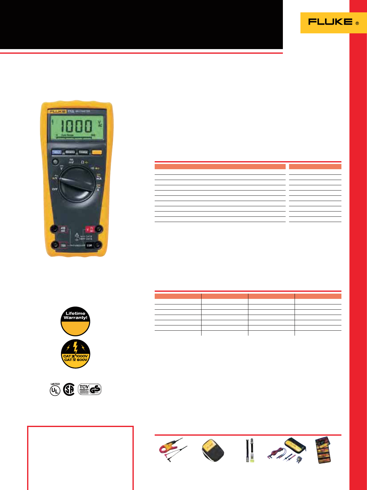
77IV Digital Multimeter
The 77-IV digital multimeter has the
features needed to repair most electrical
and electronic problems. This meter
is simple to use and has signicant
improvements over Fluke’s original
70 Series with more measurement
functions, conformance to the latest
safety standards, and a much larger
display that’s easier to view.
Features
Accuracies are best accuracies for each function.
Battery Life: 400 hours typical
Size (HxWxD): 185 mm x 90 mm x 43 mm
Included Accessories
Test leads with 4mm lantern tips, operator’s
manual, 9V battery (installed)
Ordering Information
Fluke 77IV Multimeter
On all inputs
Function Maximum Max. resolution Accurancy
Voltage DC 1000 V 1 mV ±(0.3%+1)
Voltage AC 1000 V 1 mV ±(2.0%+2)
Current DC 10 A 0.01 mA ±(1.5%+2)
Current AC 10 A 0.01 mA ±(2.5%+2)
Resistance 50 M 0.1 ±(0.5%+1)
Capacitance 9999 µF 1 nF ±(1.2%+2)
Frequency 99.99 kHz 0.01 Hz ±(0.1%+1)
Specifications
77 IV
Digital display counts 6000
Large display with backlight
O
Min-Max-Average recording mode with Min/Max Alert
O
High contrast digital display with large digits
O
Analog bargraph/segments 31
Auto and Manual ranging
O
Automatic Touch Hold®
O
Audible continuity / diode test
O
Ergonomic case with integrated holster
O
Sleep Mode preserves battery life
O
EN 61010-1 safety rating CAT IV 600 V / CAT III 1000 V
Weight: 0.42 kg
Lifetime Warranty
Versatile multimeter for field service
or bench repair
Recommended Accessories
i400
See page 126 C35
See page 130 Tpak
See page 132 TL225
See page 133 TLK-225
See page 123
Fluke 77 IV
20
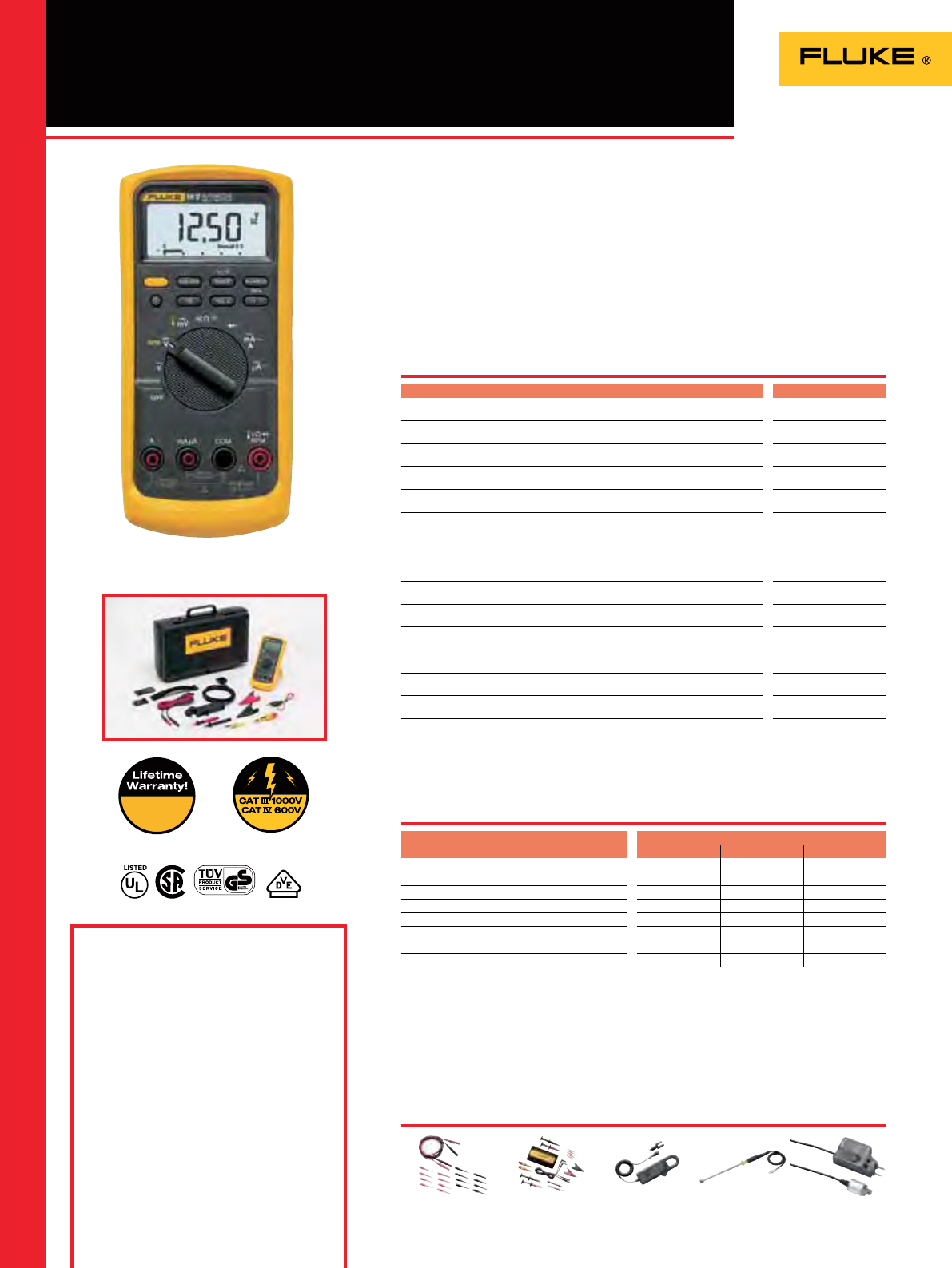
88V/A
Continuity for detecting open and shorts
O
Frequency for “pulsed-DC” and AC tests
O
Duty cycle to verify operation of feedback carburetors
O
Diode test for alternator testing
O
Built-in thermometer; thermocouple probe included
O
Min/Max/Average recording with Min/Max Alert
O
Peak capture to record transients as fast as 250 µs
O
Relative mode to remove test lead resistance from low ohms measurements
O
Millisecond pulse width measurements for fuel injectors
O
AutoHOLD® to capture stable readings
O
Large display with bright, two-level backlight
O
Magnet hanger to attach meter to the vehicle
O
RPM80 Inductive Pickup for both conventional and distributorless (DIS) ignitions
O
Hard Meter Case
O
Safety rating CAT III 1000 V,
CAT IV 600 V
88V Automotive Meter
Included Accessories
H80M Holster with TPAK Meter Hanging
Solution, TL224 SureGrip Silicone Test Lead
Set, TP74 Test Probe Set, AC285 SureGrip
Large Jaw Alligator Clip Set, 80BK Integrated
Temperature Probe, RPM80 Inductive Pick-up
Probe, C800 Hard Case, User’s Manual + Quick
Reference Guide
Ordering Information
Fluke 88V/A Automotive Meter Combo Kit
Perhaps the most important tool you’ll
use in troubleshooting auto electrical
systems is the multimeter. Basic
multimeters measure voltage, current
and resistance, while automotive
multimeters like the Fluke 88V have
features that can check frequency, duty
cycle, make diode tests, and measure
temperature, pressure and vacuum.
Recommended Accessories
TL82
See page 125 TLK-282-1
See page 125 90i-610s
See page 125 80PK-27 (requires 80AK)
See page 128 PV350
See page 125
Battery Life: 88V – Over 400 hours typical
(alkaline)
Size (HxWxD): 88V – 186 mm x 86 mm x 32 mm
Fluke 88V/A
On al inputs
Features
Specifications
Fluke 88V
Range Resolution Accuracy
Voltage DC 1000V 0.1mV 0.1%
Voltage AC 1000V (5 kHz) 0.1mV 0.5%
Current DC 10A 0.1µA 0.4%
Current AC 10A 0.1µA 1.2%
Resistance 50MΩ 0.1Ω 0.4%
Capacitance 10mF 0.01nF 1%
Frequency 200kHz 0.01Hz 0.01%
Temperature 1090ºC 0.1ºC 1%
Weight: 88V – 0.36 kg
Lifetime Warranty
The right meter for auto-electric diagnosis
21
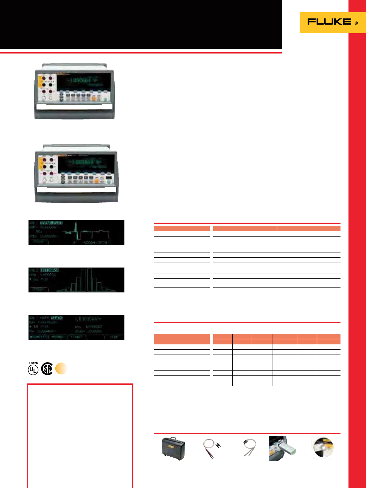
8845A/8846A
6.5 Digit Precision Multimeters
Included Accessories
LCI Line Power Cord, Test Lead Set,
Spare Line Power fuse, Programmers Manual/
User Manual on CD-ROM, 884X-USB USB to
RS232 Cable Adapter, FVF-BASIC FlukeView
Forms Software Basic Version.
Ordering Information
Fluke 8845A 6.5 Digit Precision Multimeter
Fluke 8845A/SU 6.5 Digit Precision
Multimeter (software + cable)
Fluke 8846A 6.5 Digit Precision Multimeter
Fluke 8846A/SU 6.5 Digit Precision
Multimeter (software + cable)
Calibration & Service agreements
The Fluke 8845A and 8846A, 6.5 digit
precision multimeters have the precision
and versatility to handle your most
demanding measurements on the bench
or in a system.
Dual Display offers versatile graphical
capabilities: The 8845A and 8846A
features a unique graphical display that
can reveal signal quality issues like drift,
intermittent and stability by viewing
the measurement data as a real time
TrendPlot™, Histogram or Statistics
using the unique analyze mode.
Wide Measurement Ranges: Resistance
or current has been extended to cover
the widest range possible.
Perform 4-wire measurements easily
with two leads: Patented split terminal
jacks for 2x4 Ohms function allows you
to perform precise 4-wire measurements
with only two leads instead of four.
Optional Kelvin leads accessories are
available to enable you to establish a 4-
wire connection even in tight spaces.
Systems Capabilities: Both instruments
include an RS-232, IEEE-488 and Ethernet
interface as standard, with popular
DMM emulation modes makes systems
integration a simple task.
Software: Transfer data points from your
meter to your PC with the free copy of
FlukeView Forms Basic. To customize
your forms upgrade with FVF-UG.
* Accuracy =+/- (% of reading)
884X-case
Hard case TL2X4W-TWZ
2x4 Wire Ohms Tweezer
Test Leads
TL2X4W-PT II
2x4 Wire Ohms Test
lead 2mm Probe Tip
884X-512M
USB Memory 512M FVF-UG
FlukeView Forms
Software Upgrade
Size (HxWxD): 88 mm x 215 mm x 293 mm
Weight: 3.6 kg
Three Year Warranty
Features
Specifications
Fluke 8846A
(Check the Fluke web for detailed specifications)
Recommended Accessories
Fluke 8845A
8845A 8846A
Function* Range Resolution Accuracy* (%) Range Resolution Accuracy* (%)
Voltage DC 1000 V 100 nV 0.0035 1000 V 100 nV 0.0024
Voltage AC (Freq 300 Hz) 750 V 100 nV 0.06 1000 V 100 nV 0.06
Resistance (2x4 Wire) 100 MΩ 100 µΩ 0.01 1 GΩ 10 µΩ 0.01
Current DC 10 A 100 pA 0.05 10 A 100 pA 0.05
Current AC (Freq. 3Hz-10kHz) 10 A 10 µA 0.10 10 A 100 pA 0.10
Freq/Period 300 kHz 1 µHz 0.01 1 MHz 1 µHz 0.01
Capacitance - - - 1 nF to 100 mF 1 pF 1
Temperature RTD - - - -200 to +600º 0.001º 0.06
True RMS
8845A 8846A
Display Dual VFD Dot Matrix
Resolution 6.5 Digits
Measurement Rate (Rdgs/s) 1000
Continuity / Diode Test Yes
Analytical Functions Statistics, Histogram, TrendPlot™, Limit Compare
Math Functions NULL, Min/Max, dB/dBm
USB Device Port – USB Memory Drive port
Real Time Clock –Yes
Interfaces RS232, IEEE-488.2, Ethernet
Programming Languages/
Emulation Modes SCPI (IEEE-488.2), Agilent 34401A, Fluke 45
Safety Designed to comply with IEC 61010-12000-1, ANSI / ISA-S82.01-1994, CAN /
CSA-C22.2 No.1010.1-92 1000V CATI / 600V CATII
Precision and versatility for bench or
systems applications
Handle even the most demanding measurements with
high accuracy and 6.5 digit resolution
View results in Histogram mode to reveal stability or
noise problems in analog circuits
Use the built-in TrendPlot paperless chart recorder to
graphically identify the extent of drift and intermittent
events in analog circuits
22
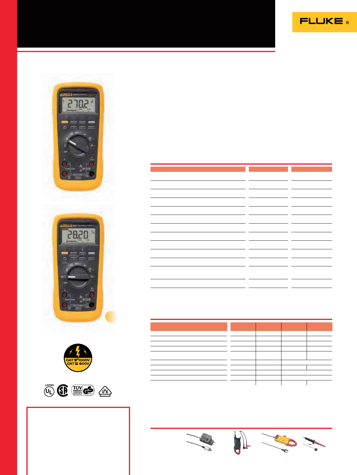
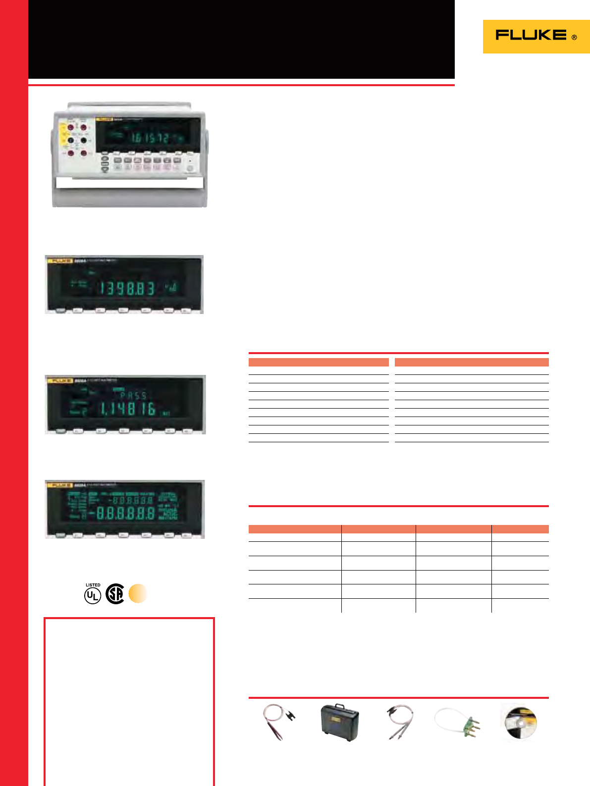
8808A 5.5 Digit Multimeter
Included Accessories
LCI Line Power Cord, Test Lead Set, Spare Line
Power fuse, 884X-USB USB to RS232 Cable
Adapter, FlukeView Forms Software Basic
Version, Programmers Manual/User Manual
on CD-ROM.
Ordering Information
Fluke 8808A 5.5 digit multimeter
Fluke 8808A/SU 5.5 digit multimeter,
(software & cable)
Fluke 8808A/TL 5.5 digit multimeter,
2X4W Test Lead Kit
Manufacturing test, R&D, development
and service applications demand
performance and exibility from a
bench meter. The Fluke 8808A delivers a
wide variety of measurement functions,
including volts, ohms, and amps, plus
frequency - all at superior accuracy and
resolution with a basic V dc accuracy of
0.015 %.
Measure sensitive leakage current: The
Fluke 8808A includes two low impedance
low current ranges for measuring
sensitive leakage currents (i-Leakage).
Perform routine manufacturing
functional tests with consistency:
Use setup keys (S1 – S6) for fast access to
repetitive measurements. Operators no
longer need to press multiple buttons to
make routine measurements.
Eliminate production mistakes: The
8808A has a limit compare mode with
built in display enunciators that clearly
show whether a test is within or out of
limits.
Perform 4-wire measurements with
only two leads: Patented split terminal
jacks for 2x4 Ohms function allow you
to perform precise 4-wire low ohms
measurements with only two leads
instead of four. Optional test lead
accessories are available to enable you
to establish a 4-wire connection even in
tight spaces or on surface mount devices.
* Accuracy = +/- (% of reading)
Size (HxWxD): 88 mm x 217 mm x 297 mm
Weight: 2.1 kg
Three year Warranty
Features
Specifications
The Fluke 8808A includes two low impedance low
current ranges for measuring sensitive leakage
currents
Dual Display
(Check the Fluke web for detailed specifications)
Recommended Accessories
Fluke 8808A
Functions Range Resolution Accuracy*
Voltage DC 200 mV to 1000 V 1 µV 0.015
Voltage AC
(Freq. 10 Hz to 100 kHz) 200 mV to 750 V 1 µV 0.2
Resistance (2x4 Wire) 200 Ω to 100 MΩ 1 mΩ 0.02
Current DC 200 µA to 10 A 1 nA 0.02
Current AC
(Freq. 20 Hz to 2 kHz) 20 mA to 10A 0.1 µA 0.3
Freq. Period 20 Hz to 1 MHz
(Freq. only) 0.1 mHz 0.01
True RMS
8808A
Display VFD multi segment
Resolution 5.5 digits
Measurements V ac, V dc, I dc, I ac, Ω, Cont, Diode
Advanced Measurements 2X4 Wire Ohms, Freq, i-Leakage
Continuity / Diode Test Yes
Analytical Functions Limit Compare
Math Functions dBm, dB, Min, Max
Interfaces RS-232, USB via optional adapter
Programming Languages/Modes Simplified ASCI, Fluke 45
Safety Rating CAT I 1000 V, CAT II 600 V
FVF-UG/SC4/SC5
FlukeView Forms
Software
884X-short
4-Wire Short
TL2X4W-PT II
2x4 Wire Ohms Test
lead 2mm Probe Tip
884X-case
Hard case
TL2X4W-TWZ
2x4 Wire Ohms Tweezer
Test Leads
Versatile multimeter for manufacturing,
development and service applications
Use setup keys (S1-S6) for fast access to repetitive
measurements. Setups can include limit compare mode
with pass/fail indicators

23
The ergonomic clamp meters feature wide opening jaws for safe, fast
non-contact current measurement. The Fluke leakage clamp meter is
ideal for non-invasive checks of insulation resistance.
The range of electrical testers includes two-pole testers for taking quick
measurements in tight spaces, phase rotation indicators to take the
guess work out of checking phase/motor rotation, a multipurpose cable
locator and handy voltage alerts.
The new Fluke iFlex exible current probes expand the measurement
range of select Fluke meters to 2500 A ac and allow technicians to reach
crowded spaces.
Clamp Meters and
Electrical Testers

24
Residential/commercial
electrical General purpose Industrial electrical HVAC/R High end industrial,
utility
iFlex
accessory Leakage
321 322 365 373 374 375 376 381 902 353 355 i2500-10/
i2500-18
360*
Measurements
AC current
OOOOOOOOOOOOO
AC volts
OOOOOOOOO O
Resistance
OOOOOOOOO O
Continuity
OOOOOOOOO O
DC Volts
OOOOOOOO O
DC current
O OOOOOOO
True-rms
OOOOOOOOOO
Frequency
OOO OOO
AC + DC voltage
O
AC + DC current
OO
Min/Max/Avg
OOOOOOOO
Temperature
O
Capacitance
OOOOOO
Special features
Inrush current mode
OOOO OOO
Low Pass filter
OOO OO
Harmonics, power, data logging
18-inch iFlex Flexible Current Probe Optional Optional Included Included
10-inch iFlex Flexible Current Probe Optional Optional Optional Optional
Remote display
O
Flashlight/torch
O
Display
Display hold
OOOOOOOOOOO O
Backlight
OOOOOOOOO O
Graphing display
Specifications
Jaw opening 25.4 mm 25.4 mm 18 mm 32 mm 34 mm 34 mm 34 mm 34 mm 30.5 mm 58 mm 58 mm 7.5 mm coil 40 mm
Current range ac rms 0 to 400.0 A 0 to 400.0 A 0 to 200.0 A 0 to 600.0 A 0 to 600.0 A 0 to 600.0 A 0 to 999.9 A 0 to 999.9 A 0 to 600.0 A 0 to 1400 A 0 to 1400 A 0 to 2500 A 0 to 60 A
Accuracy ac current (50/60 Hz) 1.8 %
± 5 counts 1.8 %
± 5 counts 2 %
± 5 counts 2 %
± 5 counts 2 %
± 5 counts 2 %
± 5 counts 2 %
± 5 counts 2 %
± 5 counts 2 %
± 5 counts 1.5 %
± 5 counts 1.5 %
± 5 counts 3 %
± 5 counts 1 %
± 5 counts
AC Response Averaging Averaging True-rms True-rms True-rms True-rms True-rms True-rms True-rms True-rms True-rms True-rms Averaging
Current range dc 0 to 200 A 0 to 600.0 A 0 to 600.0 A 0 to 999.9 A 0 to 999.9 A 0 to 200 A 0 to 2000 A 0 to 2000 A
Accuracy dc current 2 %
± 5 counts 2 %
± 5 counts 2 %
± 5 counts 2 %
± 5 counts 2 %
± 5 counts 1 %
± 5 counts 1,5 %
± 5 counts 1,5 %
± 5 counts
Voltage range ac 0 to 600.0 V 0 to 600.0 V 0 to 600.0 V 0 to 600.0 V 0 to 600.0 V 0 to 600.0 V 0 to 1000 V 0 to 1000 V 600.0 V 0 to 600.0 V
Accuracy ac voltage 1.2 %
± 5 counts 1.2 %
± 5 counts 2 %
± 5 counts 1 %
± 5 counts 1,5 %
± 5 counts 1,5 %
± 5 counts 1,5 %
± 5 counts 1,5 %
± 5 counts 1 %
± 5 counts 1 %
± 5 counts
Voltage range dc 0 to 600.0 V 0 to 600.0 V 0 to 600.0 V 0 to 600.0 V 0 to 600.0 V 0 to 1000 V 0 to 1000 V 0 to 600.0 V 0 to 1000 V
Accuracy dc voltage 1 %
± 5 counts 2 %
± 5 counts 1 %
± 5 counts 1 %
± 5 counts 1 %
± 5 counts 1 %
± 5 counts 1 %
± 5 counts 1 %
± 5 counts 1 %
± 5 counts
Resistance range 0 to 400 0 to 400 0 to 6000 0 to 6000 0 to 6000 0 to 6000 0 to 60 k 0 to 60 k 0 to 9999 0 to 400 k
Frequency measurement range 500 Hz 500 Hz 500 Hz 5 to 1000 Hz 5 to 1000 Hz 500 Hz
Unit power
Auto off
OO OOOOOOOO O
Warranty and safety
Warranty (years) 2 2 3 3 3 3 3 3 3 3 3 3
1
Category ratings (EN61010-1) CAT III 600 V CAT III 600 V CAT III 600 V CAT III 600 V,
CAT IV 300 V CAT III 1000 V,
CAT IV 600 V CAT III 1000 V,
CAT IV 600 V CAT III 1000 V,
CAT IV 600 V CAT III 1000 V,
CAT IV 600 V CAT III 600 V CAT III 1000 V,
CAT IV 600 V CAT III 1000 V,
CAT IV 600 V CAT III 1000 V,
CAT IV 600 V CAT III 300 V
Clamps Selection Guide
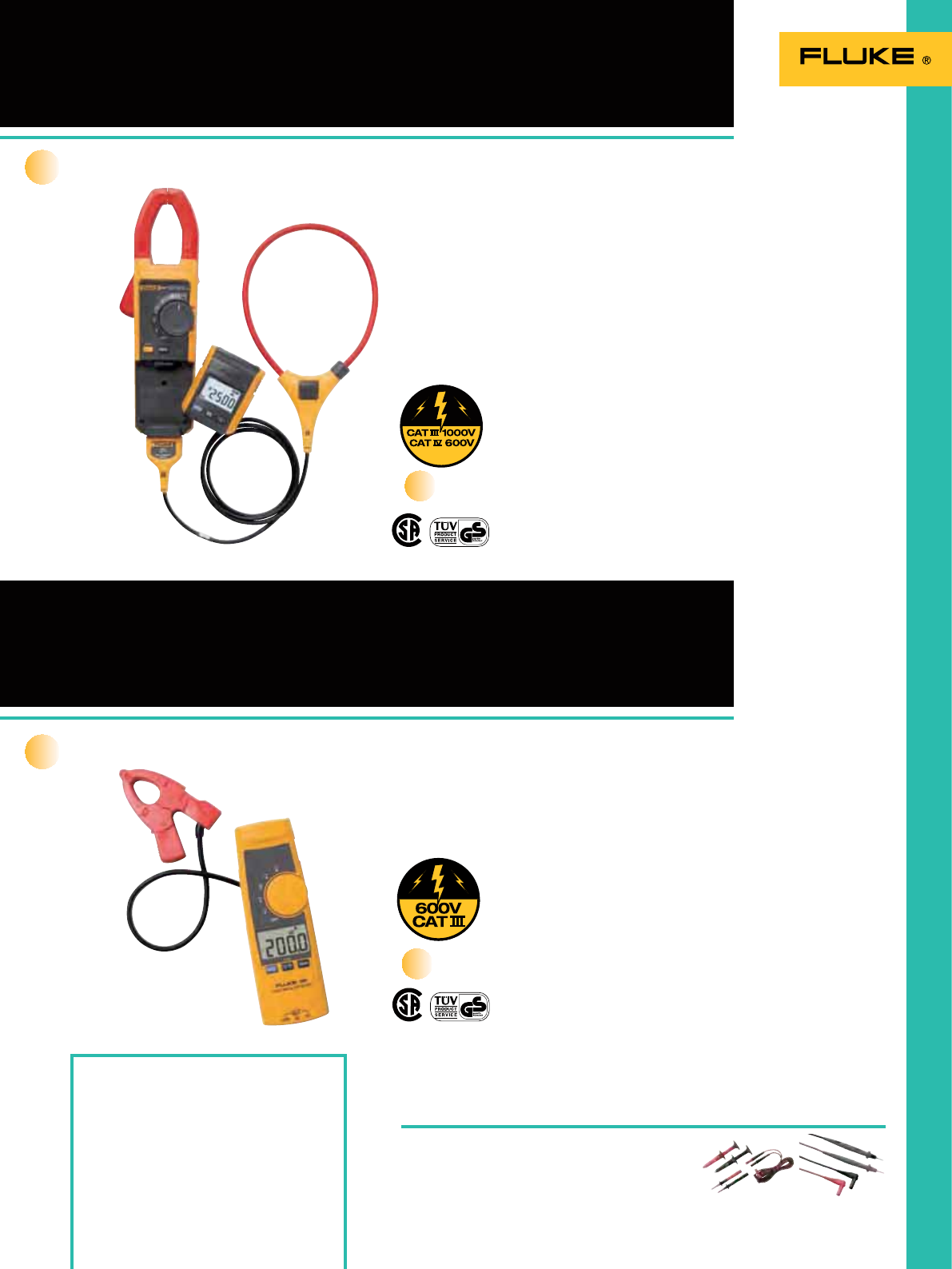
25
381 Remote Display True-rms
AC/DC Clamp Meter with iFlex™
365 Detachable Jaw
True-rms AC/DC Clamp Meter
Included Accessories
18-inch iFlex™ Flexible Current Probe (Fluke
381), test leads, soft carrying case, instruction
card, safety information sheet, two AA
alkaline batteries.
Ordering Information
Fluke 381 Remote Display True-rms
AC/DC Clamp Meter with iFlex™
Fluke 365 Detachable Jaw True-rms
AC/DC Clamp Meter
TL175
See page 124
TL223-1
See page 122
Recommended Accessories
The Fluke 381 Clamp Meter combines
iFlex exibility with remote reading
capability for the ultimate in innovation
and safety.
• Remote display reads measurements
up to 30 feet away
• iFlex exible current probe
included, 18-inch circumference
• 2500 A ac current measurement
with iFlex
• 1000 A ac and dc current measurement
with xed jaw
• 1000 V ac and dc voltage
measurement
• Frequency measurement to 500 Hz
• 60 k resistance measurement
• Min/Max/Avg and inrush recording
• CAT IV 600 V, CAT III 1000 V
• Three-year warranty
See specications chart on page 24.
The Fluke 365 Clamp Meter offers a
small, detachable jaw—with four feet of
coil—that makes it easy to take and read
measurements in tight or hard-to-reach
places.
• 200 A ac and dc current measurement
• 600 V ac and dc voltage measurement
• 6000 resistance measurement
• Built-in ashlight
• Large, easy-to-read backlight display
• Three-year warranty
See specications chart on page 24.
All the bells and whistles
Where rugged meets reliable
New
New
True RMS
True RMS
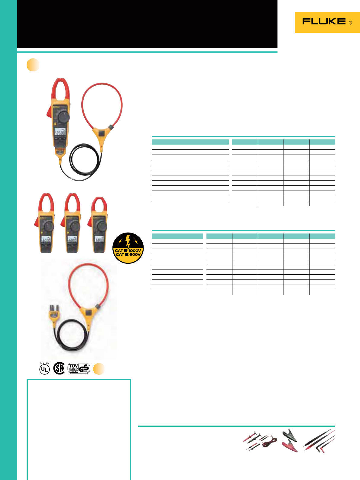
26
370 Series Clamp Meters
Included Accessories
18-inch iFlex™ exible current Probe (Fluke
376), test leads, soft carrying case, instruction
card, safety information sheet,
two AA alkaline batteries.
Ordering Information
Fluke 376 True-rms AC/DC Clamp Meter
with iFlex™
Fluke 375 True-rms AC/DC Clamp Meter
Fluke 374 True-rms AC/DC Clamp Meter
Fluke 373 True-rms AC Clamp Meter
i2500-10 iFlex™
Flexible Current Probe 25 cm (10 in)
i2500-18 iFlex™
Flexible Current Probe 45 cm (18 in)
Our new family of true-rms clamp meters
provides a range of state of-the-
art features to meet even the most
demanding job requirements.
All four of the new clamp meters have
improved base features such as a large,
backlit display, true-rms standard, CAT IV
safety rating and a durably constructed
body. Additionally, the 376, 375 and 374
are compatible with the iFlex exible
current probe (included with the 376,
sold separately for the 375 and 374), and
provide increased measurement readings
to 1000 A and 1000 V ac and dc.
Recommended Accessories
True RMS
Fluke 374 Fluke 373
Fluke 375
Fluke 376
(with i2500)
Fluke i2500
Be ready for anything
iFlex™ Flexible Current Probe
Specifications
New
TL175
See page 124
TL223-1
See page 122 AC285
See page 124
The new Fluke iFlex exible current probes expand the measurement range of select
Fluke meters to 2500 A ac and allow technicians to reach crowded spaces.
• Expands the measurement range to 2500 A ac while providing increased display
exibility, ability to measure awkward sized conductors and improved wire access
• Compatible to Fluke 374, 375, 376 and 381
• CAT IV 600 V, CAT III 1000 V
• 7.5 mm coil diameter allows measurement in tight spaces
• Ergonomic design allows easy operation with one hand
• 1.8 m (6 ft) cable
• Three-year warranty
373 374 375 376
True-rms
OOOO
AC current
OOOO
AC voltage
OOOO
Resistance
OOOO
Continuity
OOOO
DC volts
OOOO
DC current
OOO
Frequency
OO
Low pass filter
OO
Inrush current mode
OOO
18-inch iFlex Flexible Current Probe Optional Optional Included
10-inch iFlex Flexible Current Probe Optional Optional Optional
Functions Range 373 374 375 376
Current AC 0 to 600.0 A 2% ± 5 counts 2% ± 5 counts 2% ± 5 counts
0 to 999.9 A 2% ± 5 counts
Current DC 0 to 600.0 A 2% ± 5 counts 2% ± 5 counts
0 to 999.9 A 2% ± 5 counts
Voltage AC 0 to 600.0 V 1% ± 5 counts 1.5% ± 5 counts 1.5% ± 5 counts 1.5% ± 5 counts
Voltage DC 0 to 600.0 V 1% ± 5 counts 1% ± 5 counts 1% ± 5 counts
0 to 1000 V 1% ± 5 counts
Resistance range 0 to 6000 0 to 6000 0 to 6000 0 to 60 k
Jaw opening 32 mm 34 mm 34 mm 34 mm
Max. wire size 750 MCM 750 MCM 750 MCM 750 MCM
Frequency measurement range 500 Hz 500 Hz
Features
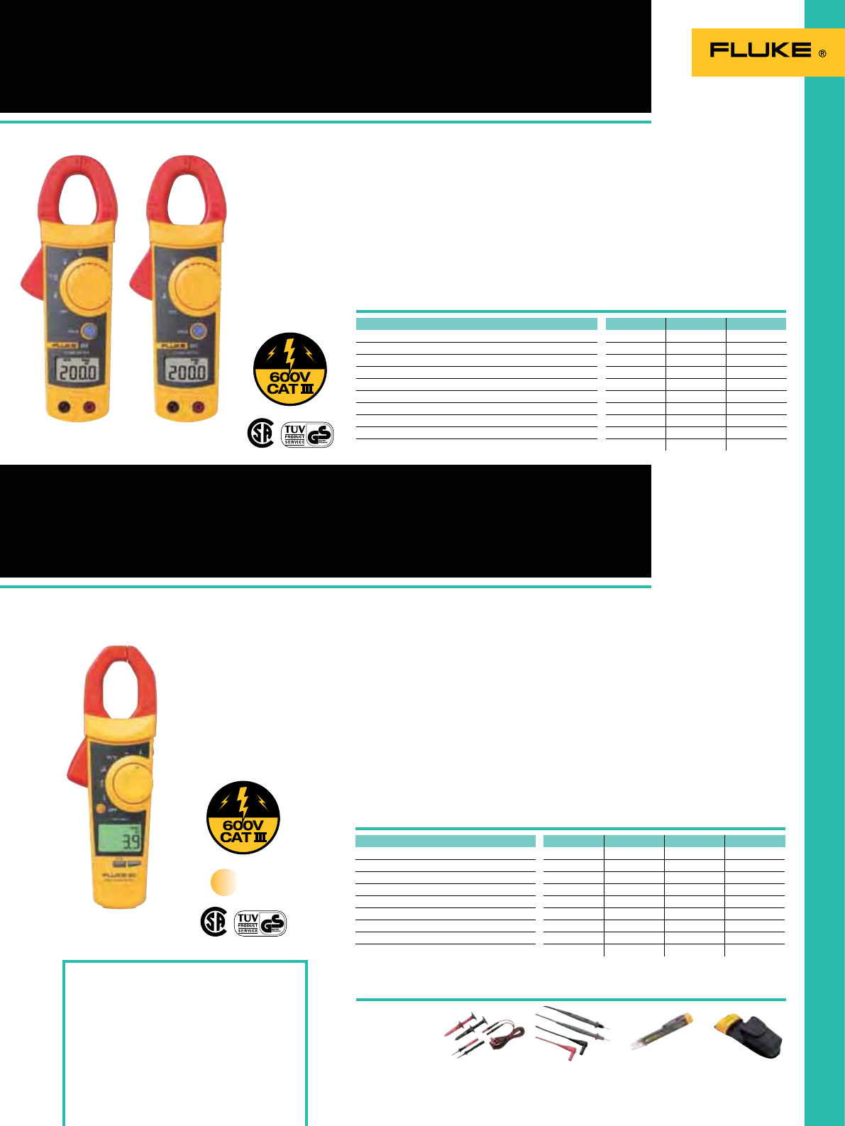
27
320 Series Clamp Meters
902 True-rms HVAC Clamp Meter
Included Accessories
Test leads, temperature probe (Fluke 902), soft
carrying case, instruction card, safety
information sheet, two AA alkaline batteries.
Ordering Information
Fluke 321 Clamp Meter
Fluke 322 Clamp Meter
Fluke 902 True-rms HVAC Clamp Meter
TL175
See page 124 LVD2
See page 32
TL223-1
See page 122 H3
See page 131
Recommended Accessories
The Fluke 321 and 322 are designed
to verify the presence of load current,
ac voltage and continuity of circuits,
switches, fuses and contacts. These small
and rugged clamp meters are ideally
suited for current measurements up to
400 A in tight cable environments.
• Precised measurements with 1.8 % basic
accuracy
• Resolution up to 0.01 A and 0.1 V
• Measures ac current 40.00 A/400.0 A
• Measures ac and dc volts to 600 V
• Resistance measurement to 400
• Continuity for quick checking of shorts
See specications chart on page 24
for details per model.
HVAC (heating, ventilation, air
conditioning) technicians require a service
tool that can consistently keep up with
their demands. The Fluke 902 expands the
existing line of quality Fluke clamp meters
by delivering the features necessary
to diagnose and repair HVAC systems.
Combined with true-rms technology
and a CAT III 600 V rating, the Fluke 902
helps technicians do their jobs safely and
accurately.
• Designed for HVAC applications with
capacitance, dc current (A), and
temperature measurements
• Small body and jaws t perfectly in your
hand and into tight places
• Handy “Display Hold” button keeps
measurements on the display
• Meter controls are positioned so current
measurements can be done with one
hand (index nger on clamp opening
lever and thumb on rotary switch)
• Three-year warranty
See specications chart on page 24.
Get more done
Just for our HVAC pros
True RMS
321 322 902
True-rms
O
AC current
OOO
AC voltage
OOO
Resistance
OOO
Continuity
OOO
DC volts
OO
DC current
O
Min/Max/Avg
O
Temperature
O
Capacitance
O
Functions Range 321 322 902
Current AC 0 to 400.0 A 1.8% ± 5 counts 1.8% ± 5 counts
0 to 600.0 A 2% ± 5 counts
Current DC 0 to 200.0 A 1% ± 5 counts
Voltage AC 0 to 600.0 V 1.2% ± 5 counts 1.2% ± 5 counts
600.0 V 1% ± 5 counts
Voltage DC 0 to 600.0 V 1% ± 5 counts 1% ± 5 counts
Resistance range 0 to 400 0 to 400 0 to 9999
Jaw opening 25.4 mm 25.4 mm 30.5 mm
Max. wire size 500 MCM 500 MCM 750 MCM
Fluke 321Fluke 322
Fluke 902
Features
Specifications
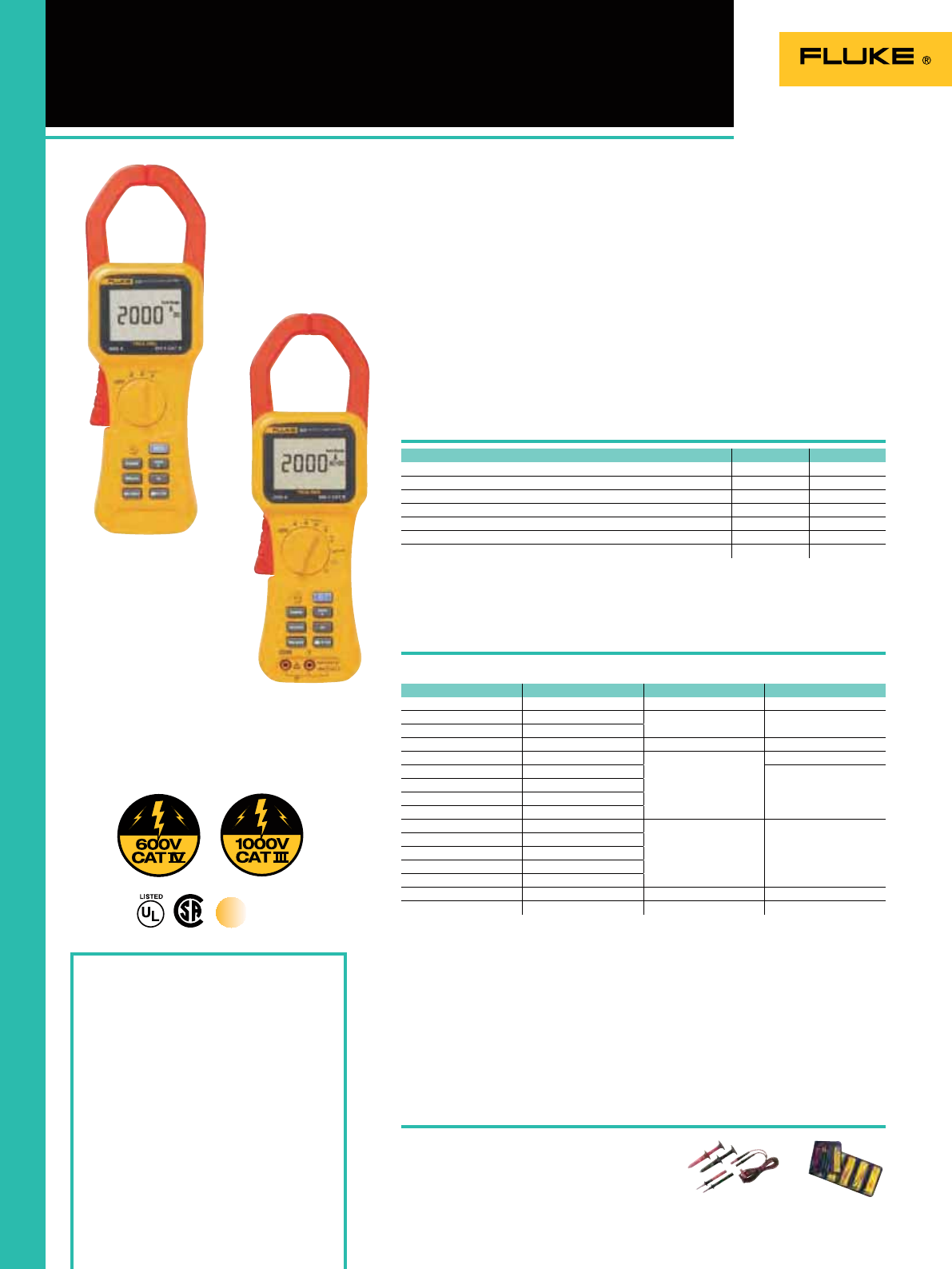
28
Fluke 355
350 Series AC/DC Clamp Meters
Included Accessories
Fluke 353: C43 Soft Meter Case, 6 AA batteries,
users manual
Fluke 355: C43 Soft Meter Case, 6 AA batteries,
TL224 SureGrip® Silicone Test Lead Set, TP2
Slim Reach Test Probe Set (2 mm), AC285
SureGrip® Alligator Clip Set, users manual
Ordering information
Fluke 353 AC/DC Clamp Meter
Fluke 355 AC/DC Clamp Meter
Condently take reliable readings with
the true-rms, Fluke 353/355 Clamp
Meters; the tools of choice for high
current measurement up to 2000 A. The
extra-wide jaw easily clamps around
large conductors, typically found in high
current applications. The rugged design
and CAT IV 600 V, CAT III 1000 V ratings
add an extra element of protection when
taking high-powered measurements.
Accurate peak measurements can be
taken using the in-rush current mode -
ideal for motors and inductive loads. The
355 also measures voltage and resistance,
making this the most versatile tool
for utilities, electrical contractors and
industrial service technicians.
TL223-1 (Fluke 355)
See page 122 L215 (Fluke 355)
See page 123
Features
Recommended Accessories
353 355
True-RMS measurements
OO
Display backlight
OO
Motor start-up current
OO
Min/Max/Average
OO
Voltage AC/DC
O
Resistance measurement
O
Continuity measurement with beeper
O
Specifications
Fluke 353
Power Supply: 6 x 1.5V AA NEDA 15A
or IEC LR6
Battery Life: 100 hours (with typical
usage, backlight off)
Functions Range 353 355
Current AC/DC 0-40.00 A 1.5% ± 15 counts 1.5% ± 15 counts
0-400.0 A 1.5% ± 5 counts 1.5% ± 5 counts
0-2000 A; 1400 AC rms
Crest Factor 2.4 2.4
Voltage AC/DC 0-4.000 V 1% ± 10 counts
0-40.00 V
1% ± 5 counts
0-400.0 V
0-600 V AC rms
0-1000 V DC
Resistance 0-400.0
1.5% ± 5 counts
0-4.000 k
0-40.00 k
0-400.0 k
Continuity beeper Appr. ≤ 30
Frequency 5.0Hz to 100.0Hz 0.2% ± 2 counts
100.1Hz to 999Hz 0.5% ± 5 counts
(Check the Fluke web for detailed specifications)
Size (HxWxD): 300 mm x 98 mm x 52 mm
Jaw opening: 58 mm
Weight: 0.814 kg
Two year warranty
True RMS
True-RMS, 2000 A Clamp Meters
for industrial and utility applications
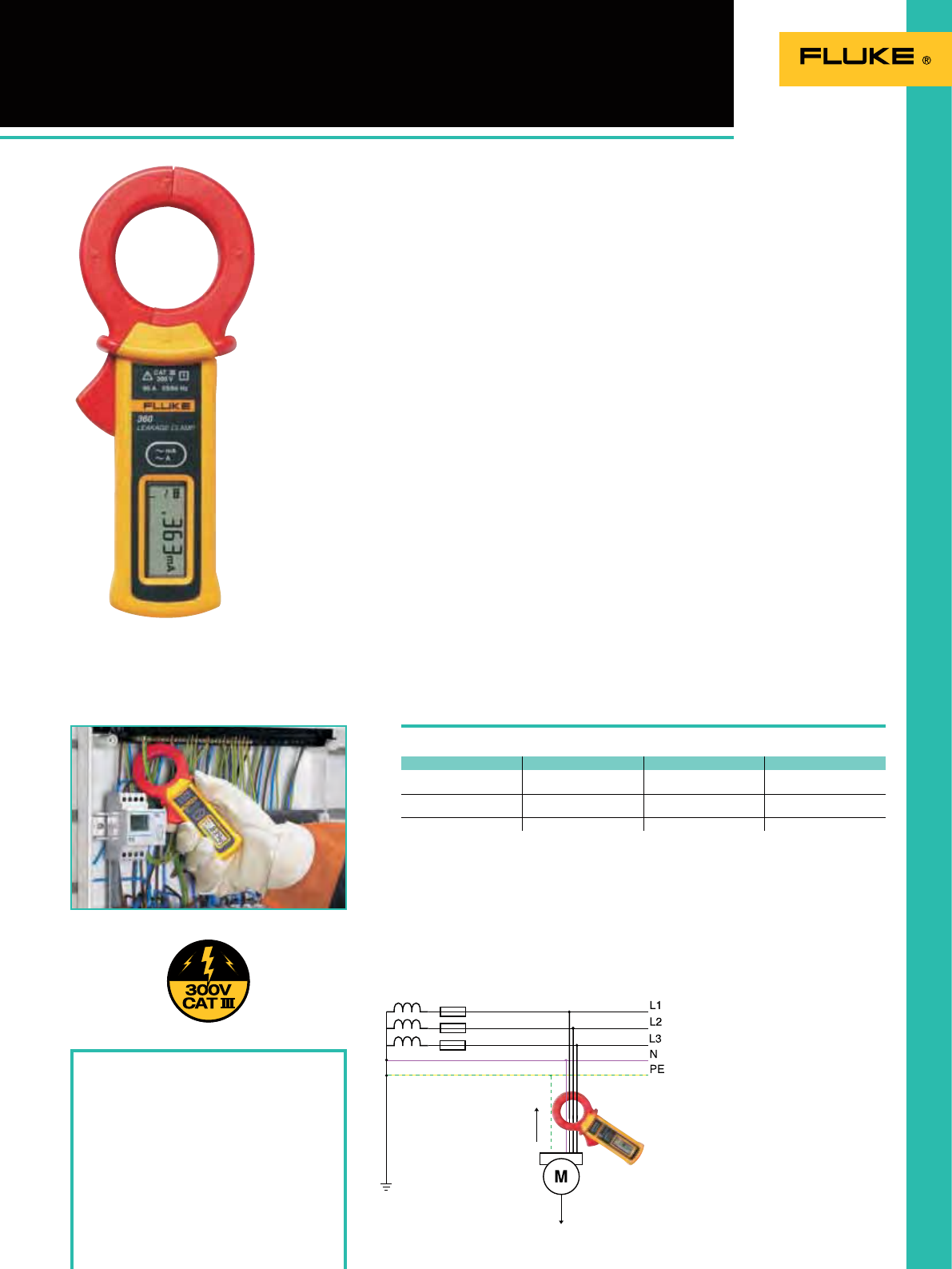
29
360 Leakage Clamp Meter
Included accessories
Soft carrying pouch and users manual
Ordering information
Fluke 360 Leakage Clamp Meter
The Fluke 360 is ideal for non-invasive
checks of insulation resistance.
The unique jaw design eliminates the
inuence of adjacent current conductors.
The ergonomic design of the Fluke 360
ensures easy measuring. The measuring
clamp ts into tight spaces and the
wide display angle clearly shows the
measurement result. The data hold
button keeps the measured value on the
display after removing the clamp for the
measured conductor.
The light Fluke 360 offers the widest
range of current measurement for
maintenance professionals and
contractors.
Features
• Measurement of leakage protectives
conductor and touch current with a
resolution of 1µA
• Advanced shielding to ensure accurate
results when measuring near other
conductors
• Automatic ranging within the manually
selected mA or A range
• Easily viewed measurements on digital
and bargraph display and HOLD when
measuring in hard to see locations
• Broad range of measurements currents
up to 60 A for all installation needs
• Easy carrying, pocket sized clamp with
wide 40 mm jaw size
• Display-Hold for convenience in use
• Auto power off with audible warning
buzzer
• Conformance to IEC61010 and EMC
standard
• Meets all the applications and
performance classes in safety standard
VDE0404-4 and the new VDE0702
leakage
current 0.5mA
ground
Specifications
Fluke 360
Battery type: 3 Volt Lithium, 90 hours typical
Size (HxWxD): 176 mm x 70mm x 25 mm
Weight: 0.2kg
One Year warranty
Functions Range Resolution Accuracy
Current AC 3mA
30mA 0.001A
0.01mA 1% ± 5 counts
30A
60A 0.01A
0.1A 1% ± 5 counts (0~50A)
5% ± 5 counts (50~60A)
Frequency 50 and 60Hz
(Check the Fluke web for detailed specifications)
leakage current
1.2mA (e.g. via
motor shaft)
display: 1.7mA
Leakage current measurements with a tough,
pocket sized clamp meter
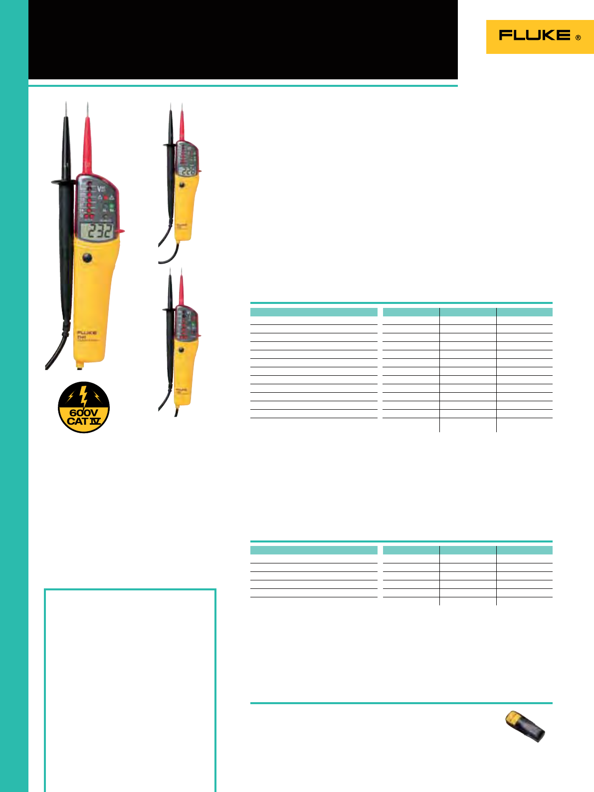
30
T100 Series
Voltage and Continuity Testers
Included Accessories
Two 1.5V batteries and instruction sheet
Ordering Information
Fluke T100 Voltage/Continuity Tester
Fluke T120 Voltage/Continuity Tester
Fluke T140 Voltage/Continuity Tester
UK versions are compliant with GS38
Recommended Accessories
C33 (T100 Series)
See page 130
Size (HxWxD): 240 mm x 56 mm x 24 mm
Case: IP65 (water-jet and dust tight protection)
Weight: 180 g
Two year warranty
Features
Specifications
Fluke T140
Fluke T100
Fluke T120
T100 T120 T140
Display LCD LCD
Led Bargraph 12 LED’s 12 LED’s 12 LED’s
Backlight
O
Resistance measurement
O
Switchable load
O
Voltage test
OOO
Optical and acoustical continuity test
OOO
Rotary field indication
OOO
Single pole test for phase detection
OOO
Indication of polarity
OOO
Electrical torch function
OOO
Probe tip protection
OOO
The voltage display also functions when using
discharged - or o batteries
OOO
T100 T120 T140
Voltage AC/DC 12 - 690 V 12 - 690 V 12 - 690 V
Continuity 0 - 400 k 0 - 400 k 0 - 400 k
Frequency 0 - 400 Hz 0 - 400 Hz 0 - 400 Hz
Phase rotation 100 to 690 V 100 to 690 V 100 to 690 V
Resistance measurement - - Up to 1999
Response time < 0.1 s < 0.1 s < 0.1 s
The fast and easy solution to voltage,
continuity and resistance measurements.
Ideal for site conditions, the 3 models
of the T100 Series 2-pole testers have a
rugged construction and ergonomically
formed housing for perfect handling.
All models offer a patented three-phase
rotation detection system providing
quick phase rotation indication.
Moreover they have a special electrical
torch function for working in low light
level environments and have an ingress
protection rating of IP65. The T100 Series
are compliant with EN 61010-1 and
EN61243-3 requirements.
The fast and easy solution to voltage,
continuity and phase rotation testing

31
T5 Electrical Testers
Included Accessories
2 TP38 detachable probe (CAT III),
2 TP1-1 detachable probe (CAT II),
(detachable GS38 probes for the UK)
and instruction sheet
Ordering Information
Fluke T5-600 Electrical Tester
Fluke T5-1000 Electrical Tester
Fluke T5-H5-1AC Kit Electrical Tester with
holster and IAC
Fluke T5-600/62/1AC-E Electrical Tester,
IR Thermometer,
Voltage Detector Kit
The Fluke T5 testers let you check
voltage, continuity and current with
one compact tool. Select volts, ohms or
current and the instrument does the rest.
Model T5-600 measures 600 volts
AC/DC, model T5-1000 is designed for
1000 volts. OpenJaw™ current technology
lets you check current up to 100 A,
without breaking the circuit. The optional
H5 holster keeps the test probes and
leads ready to test and lets you clip the
T5 onto your belt.
Recommended Accessories
ACC-T5-Kit
See page 123 AC285
See page 124
Features and Specifications
Fluke T5-H5-1AC Kit
Fluke T5-1000
(incl. TP1-1 test probes)
Fluke T5-600
(incl. TP1-1 test probes)
H5
See page 131
Battery life: 400 hours
Size (HxWxD):
203 mm x 51 mm x 30.5 mm
Fluke T5-H5-1AC Kit
The ideal kit for busy electrical
contractors and electricians. The benets
of a voltage and current meter and non-
contact voltage detector all in one kit. A
holster for the T5 is also included.
Kit includes:
- Fluke T5-1000
- H5 holster
- Free Fluke 1AC-II
Fluke T5-600/62/1AC-E Kit
This kit is designed to help electricians
and HVAC technicians solve problems
quicker. Test rst for overheated electrical
devices using an IR thermometer; then
use elecrtrical test tools to nd out more
about the problem.
Kit includes:
• Fluke T5-600
• Fluke 62
• Fluke 1AC II
• C115
T5-600 T5-1000
Display Count 1000 1000
Automatic Selection
OO
Continuity and Bleeper
OO
Sleep Mode
OO
AC Voltage 600 V 1000 V
DC Voltage 600 V 1000 V
AC Current 100 A 100 A
Resistance 1000 1000
Safety range 600V CAT III 1000 V CAT III / 600 V CAT IV
Weight: 0.38 kg
Two year warranty
The fast and easy solution to basic
electrical testing
Fluke T5-600/62/1AC-E Kit
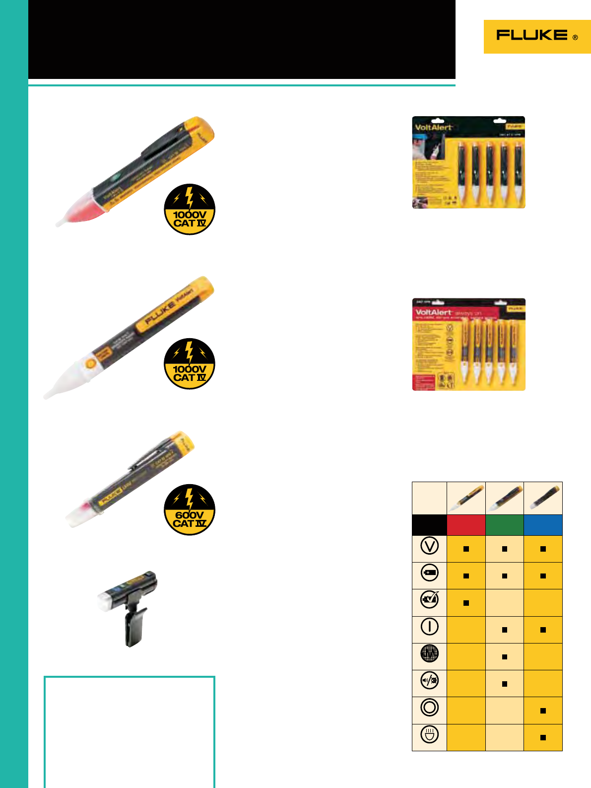
2AC 1AC-II LVD2
32
1AC II/2AC Volt Alerts
LVD1/LVD2 Volt Lights
2AC is the latest addition to the VoltAlert™ ac
non- contact voltage tester family from Fluke
and is designed to be pocket-sized and easy
to use. The 2AC tests for energized circuits
and defective grounds, whether it’s for an
electrician on the factory oor or the do-it-
yourselfer around the house. The tip of the
pocket-sized tester will glow red when within
close proximity of an outlet, terminal strip, or
power cord where voltage is present.
• Voltage detection from 200 to 1000 V ac,
suitable for a wide range of residential,
commercial and industrial needs.
• NEW! Always on, using special low power
circuitry to sustain battery life and ensure
your 2AC is always ready.
• NEW! Innovative ‘Battery Check’ button
function ensures battery is in good
condition*
• Category IV – 1000 V overvoltage rated
product for best in class user protection
• Integrated clip design, optimized for pocket
storage
• Powered by 2x AAA batteries (included)
• Fluke ruggedness and reliability
• Two-year warranty storage.
• Powered by 2x AAA batteries (included)-
Fluke reliability and ruggedness, Two-year
warranty.
LVD2
LVD1
2AC VoltAlert™
Fluke 1AC II
Fluke 2AC VoltAlert™
Ordering Information
Fluke 1AC II Volt Alert
Fluke 1AC II Volt Alert (5-pack)
Fluke 2AC Volt Alert
Fluke 2AC Volt Alert (5-pack)
LVD2 Volt Light
LVD1 Volt Light
Dual sensitivity voltage detector
• Detects voltage from 40 V to 300 V AC
• Blue light means you’re close
• Red light means you’re at the source
• Comes with a versatile clip to secure light
to pocket, hat or even panel door
Combines bright light and voltage detection
in one pen style design
• Dual sensitivity
• Detects voltage from 90 V to 600 V AC
• Blue light means you’re close
• Red light means you’re at the source
• Rated to CAT IV 600 V
LVD1 Volt Light
LVD2 Volt Light
Operating range: 200 – 1000 V AC
Batteries: Two AAA Alkaline
Size (H): 148 mm
Two Year Warranty
Fluke 2AC VoltAlert™ 5-pack
• Buy 4 get 1 FREE
The Fluke VoltAlert AC voltage detector is
very easy to use – just touch the tip to a
terminal strip, outlet or cord. When the tip
glows red and the unit beeps, you know there
is voltage on the line.
• It continually tests its battery and its circuit
integrity with a periodic double ash visual
indication.
• Highest safety rating: CAT IV 1000 V
• Detects voltage without metallic contact
Fluke 1AC II VoltAlert™
Operating range: 200 – 1000 V AC
Batteries: Two AAA Alkaline
Size (H): 148 mm
Two Year Warranty
Fluke 1AC II VoltAlert™ 5-pack
• Buy 4 get 1 FREE
Voltage Detection
On/Off Button
Dual Sensitivity
Battery Check
Audible/Silent
Voltbeat™
LED Flashlight
Battery Included
Features
200-1000 V AC
CAT IV 1000 V
200-1000 V AC
CAT IV 1000 V
90-600 V AC
CAT IV 600 V

33
9040/9062
Phase Rotation Indicators
Included Accessories
Fluke 9040: Alligator clips - black (3)
Standard test probes - black (3)
Flexible test probes - black (3)
Fluke 9062: Alligator clips - black (3)
Flexible test probes - black (3)
Test leads - black (3)
Ordering Information
Fluke 9040 Phase Rotation Indicator
Fluke 9062 Motor and Phase Rotation
Indicator
Fluke 9040
The Fluke 9040 is effective for measuring
phase rotation in all areas where
three-phase supplies are used to feed
motors, drives and electrical systems.
The Fluke 9040 is a rotary eld indicator
and can provide clear indication of the
3 phase via an LCD display and the
phase rotation direction to determine
correct connections. It allows rapid
determination of phase sequence
and has a voltage (up to 700 V) and
frequency range suitable for commercial
and industrial applications. Test probes
supplied with the instrument have a
variable clamping range for safe contact,
especially in industrial sockets.
Fluke 9062
The unique Fluke 9062 provides rotary
eld and motor rotation indication with
the benets of contact-less detection.
Purpose made for commercial and
industrial environments, the Fluke 9062
provides rapid indication of 3 phase
rotation using test leads supplied or can
be used to determine motor rotation on
synchronous and asynchronous 3 phase
motors. The contact-less detection is
ideal for use on motors where the shaft is
not visible.
Test probes supplied with the instrument
have a variable clamping range for safe
contact, especially in industrial sockets.
Recommended Accessories
TLK291
See page 123 C25
See page 130
Features
9040:
TLK290
See page 123
9062:
Specifications
Size (HxWxD) Fluke 9040:
124 mm x 61 mm x 27 mm
Size (HxWxD) Fluke 9062:
124 mm x 61 mm x 27 mm
Fluke 9062 Applications
Determine the rotation of
running motors simply by
placing the instrument on
the motor casing.
Check the correct rotation of
motors prior to connection.
Determine the presence of
phase sequence of multiphase
electrical supplies.
9040 9062
3 phase indication Via LCD Via LED
Indication of phase rotation
OO
Indication of motor rotation direction
O
Contact free determination of the rotation direction of running motors
O
Clear LCD display
O
No battery required
O
9040 9062
Voltage range 40 - 700 V Up to 400 V
Phase display - 120 - 400 V AC
Frequency range 15 - 400 Hz 2-400 Hz
Operating time Continuous Continuous
Power supply 9040: from unit under test
Power supply 9062: 1 x 9V
Weight 9040: 0.20 kg
Weight 9062: 0.15 kg
Two Year Warranty
Take the guess work out of phase/motor
rotation measurements
Fluke 9040
Fluke 9062
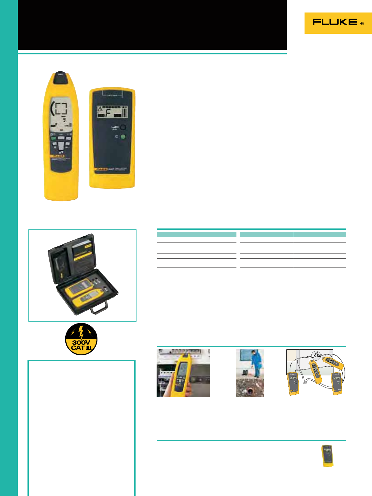
34
2042 Cable Locator
Included Accessories
TL27 Heavy Duty Test Lead Set (2)
TP74 Lantern Tip Test Probe Set
AC285 Alligator Clip Set
Soft carrying case
Hard case
Ordering Information
Fluke 2042 Cable Locator
(transmitter + receiver)
Fluke 2042T Cable Locator Transmitter
The Fluke 2042 is a professional general
purpose cable locator. It is ideal for
tracing cables in walls and underground,
locating fuses/breakers on nal circuits
and locating interruptions and short-
circuits in cables and electrical oor
heating systems.
It can also be used for tracing metallic
water and heating pipes. The unit is
supplied as a complete kit comprising of
a transmitter and receiver in a purpose-
made carry case. The receiver also
incorporates a torch function for working
in dimly lit locations.
• For all applications (live or dead cables)
without additional instruments
• Set includes a transmitter and a
receiver
• Proven digitally coded sender signal
guarantees clear signal identication
• Transmitter with LCD-display for
transmitting level, transmitting code
and external voltage
• Receiver with a backlight LCD-display
for level of receiving signal, code
of receiving signal and live voltage
indication
• Automatic or manual adjustment of
receiving signal sensitivity
• Switchable acoustic receiving signal
• Auto-Power-Off
• Additional torch lamp function for
working in dark environments
• Additional transmitters are available
for extension or to distinguish between
several signals.
Recommended Accessories
Fluke 2042T
Specifications
Receiver
Batteries Transmitter: 6 pc Batteries 1.5V
Batteries Receiver: 1 pc Battery 9V
Size (HxWxD) Transmitter:
190 mm x 85 mm x 50 mm
Size (HxWxD) Receiver:
250 mm x 65 mm x 45mm
Weight Locator: 0.45 kg
Weight Receiver: 0.36 kg
Two Year Warranty
Fluke 2042 applications
Tracing of underground
cables (max. depth 2.5 m)
Precise location of cable
interruptions with additional
transmitter
Location of fuses/breakers
and assignment to circuits
Transmitter
Fluke 2042
Transmitter Receiver
Voltage Measurement Range 12V, 50V,120V, 230V, 400V
Frequency Range 0..60 Hz
Output signal 125 kHz
Voltage Up to 400V AC/DC
Tracing depth cable location 0...2.5m wall/underground
cables
Main voltage detection 0...0.4m
The multipurpose solution to cable location

35
With a 10kV insulation resistance tester and a range of compact hand-
held instruments, we offer a solution for every troubleshooting and
preventive application.
Two of the digital hand-held insulation testers also include full-featured
multimeters.
The Fluke Earth Ground Testers can perform all four types of earth
ground measurement, including stakeless testing with earth ground
loop resistances using only clamps.
Insulation Testers and
Earth Ground Testers

36
Insulation Tester
Selection Guide
1577 1587 1587T 1503 1507 1550C 1555
InstallationTest Functionality
Test voltages 500V, 1000V 50V, 100V, 250V,
500V, 1000V 50V, 100V 500V, 1000V 50V, 100V, 250V,
500V, 1000V 250V, 500V, 1000V,
2500V, 5000V
250V, 500V, 1000V,
2500V, 5000V, 10000V
Insulation Resistance Test Range 0.1M - 600M 0.01 M - 2G 0.01M - 100M 0.1M - 2G 0.01M - 10G 200K - 1T 200K - 2T
Polarization Index/Dielectric
Absorption Ratio
OOO
Auto Discharge
OOOOOOO
Time Ramp test (Breakdown)
OO
Pass/Fail Comparison
O
Estimated Number of
Insulation resistance Tests 1000 1000 1000 1000 1000 1000 @ 5000 V 1000 @ 10000 V
Voltage > 30V Warning
OOOOOOO
Memory (99 locations) (99 locations)
Remote Test Probe
OOOOO
Lo Ohms
OO
Display Digital LCD Digital LCD Digital LCD Digital LCD Digital LCD Digital LCD / Analog
Bar Graph Digital LCD / Analog
Bar Graph
Continuity
OOO
(200mA) (200mA)
Multimeter Functionality
AC/DC Volts
OOOOO
Current
OOO
Resistance
OOOOO
Temperature (contact)
OO
Lo-Pass Filter
OO
Capacitance
OO OO
Diode Test
OO
Frequency
OO
MIN/MAX
OO
Other
Hold/Lock
OOOOOOO
Backlight
OOOOO
Software (Fluke View® Forms
Basic) (Fluke View® Forms
Basic)
Warranty (in years) 3 331133
Battery 4 AA (NEDA 15A or
IEC LR6) 4 AA (NEDA 15A or
IEC LR6) 4 AA (NEDA 15A or
IEC LR6) 4 AA (NEDA 15A or
IEC LR6) 4 AA (NEDA 15A or
IEC LR6) Rechargeable Rechargeable
Fluke 1587/ET Advanced Electrical
Troubleshooting Kit
This kit contains:
• Fluke 1587 Insulation Multimeter
• Fluke 62 Mini Infrared Thermometer
• i400 Current Clamp
Perform insulation tests with the Fluke
1587 plus a wide-range of DMM tasks with
condence and ease. Use the i400 with your
Fluke 1587 to accurately measure AC current
without breaking the circuit. Check for hot
spots and measure temperature with the
Fluke 62 Mini non-contact thermometer.
Fluke 1587/ET
Fluke 1587/MDT
Fluke 1587/MDT Advanced Motor
& Drive Troubleshooting Kit
This kit contains:
• Fluke 1587 Insulation Multimeter
• Fluke 9040 Phase Rotation Indicator
• i400 Current Clamp
Perform insulation tests with the Fluke
1587 plus a wide-range of DMM tasks with
condence and ease. Use the i400 with your
Fluke 1587 to accurately measure AC current
without breaking the circuit. Check the phase-
rotation of three-phase motors easily and
safely with the Fluke 9040.
Buy a Fluke 1587 Combo Kit and save
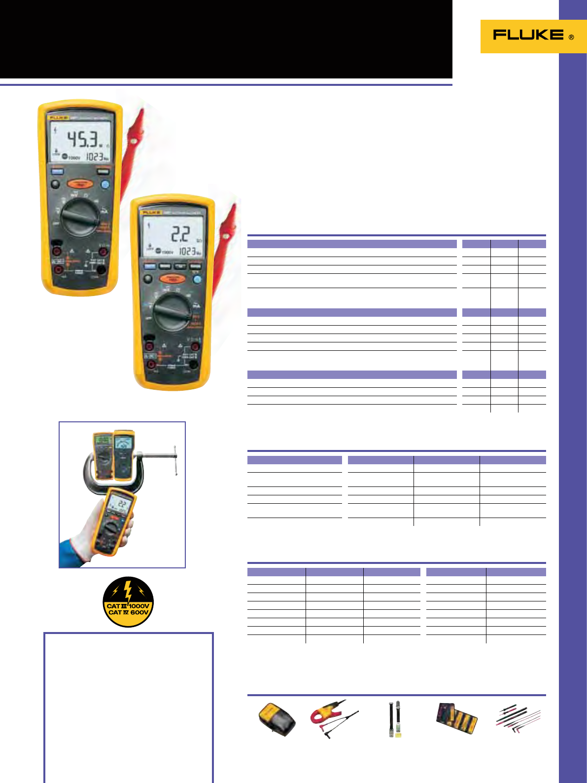
37
Insulation features
User selectable test voltages for many applications
OO
Additional test voltages 50V, 100V, 250V
O
Special remote control probe for easy and safe measurements
OOO
Auto-discharge of capacitive voltage for added user protection
OOO
Live circuit detection prevents insulation test if voltage > 30V is detected for
added user protection
OOO
1577/1587
Insulation Multimeters
Included Accessories
C101 Rugged, utility hard case
TL224 SureGrip Silicone Test Lead Set
AC285 SureGrip Alligator Clip Set
80BK Integrated DMM Temperature Probe
(Type K)
TP165X Remote Test Probe
Ordering Information
Fluke 1577 Insulation Multimeter
Fluke 1587 Insulation Multimeter
Fluke 1587T Insulation Multimeter
(for Telecom)
The Fluke 1587 and 1577 Insulation
Multimeters combine a digital insulation
tester with a full-featured True RMS
digital multimeter in a single compact,
handheld unit, which provides maximum
versatility for both troubleshooting and
preventive maintenance.
Whether you work on motors, generators,
cables, or switch-gear, the
Fluke 1587/1577 Insulation Multimeters
are ideally suited to help you with your
tasks.
The Fluke 1587T is specially designed for
the telecom environment.
Recommended Accessories
TL238
See page 122
Multimeter Specifications
Fluke 1577
Fluke 1587
Fluke 1587T
Features
Insulation Specifications
Battery life: Meter: 1000 hrs,
Insulation Test: >1000 tests
Size (HxWxD):
203 mm x 100 mm x 50 mm
L215
See page 123
TPAK
See page 132
i400
See page 126
C25
See page 130
Multimeter Features 1577 1587 1587T
True RMS Voltage and Current for accurate measurements
OOO
Digital display counts 6000 6000 6000
Autorange and manual range for easy testing.
OOO
Selectable filter for accurate voltage and frequency measurements on motor
drives
OO
Min Max Recording, Diode test, temperature, capacitance & frequency
measurement for maximum flexibility.
OO
Functions 1577 1587 1587T
Measurement range 0.1M to 600M 0.01M to 2G 0.01M to 100M
Test voltages 500V, 1000V 50V, 100V, 250V, 500V,
1000V 50V, 100V
Test voltage accuracy + 20%, -0% + 20%, -0% + 20%, -0 %
Insulation test current 1mA nominal 1 mA nominal 1 mA nominal
Auto discharge Discharge time < 0.5s
for C = 1 µF or less Discharge time <0.5s
for C = 1 µF or less Discharge time <0.5s
for C = 1 µF or less
Maximum capacitive load Up to 1 µF load Up to 1 µF load Up to 1 µF load
General features
Auto Power off to save batteries
OOO
Large display with backlight
OOO
Input Alert to warn for incorrect connections
OOO
Continuity
OOO
Functions Maximum Max. resolution 1577 1587/1587T
Voltage DC 1000V 1 mV ± (0.2% + 2) ± (0.09% + 2)
Voltage AC 1000V 0.1mV ± (2% + 3) ± (2% + 3)
Current DC 400mA 0.01mA ± (1.0% + 2) ± (0.2% + 2)
Current AC 400mA 0.01mA ± (2% + 2) ± (1.5% + 2)
Resistance 50.0MΩ 0.1Ω ± (1.2% + 2) ± (0.9% + 2)
Capacitance 9999µF 1 nF - ± (1.2% + 2)
Frequency 99.99kHz 0.01 Hz - ± (0.1% + 1)
Temperature -40°C to +537°C 0.1°C - ± (1% + 10)
Weight: 0.55 kg
Three Year Warranty
Two powerful tools in one

38
1503/1507 Insulation Testers
Included Accessories
TP165x Remote Test Probe
TL224 SureGrip Silicone Test Lead Set
TP74 Lantern Tip Test Probe Set
Alligator clips
Ordering Information
Fluke 1503 Insulation Tester
Fluke 1507 Insulation Tester
When you need a low cost solution to
general purpose insulation testing look
no further than the new Fluke insulation
tester range. The Fluke 1507 and 1503
Insulation Testers are compact, rugged,
reliable and easy to use.
The multiple test voltages on both
models make them ideal for many
troubleshooting, commissioning and
preventive maintenance applications.
Additional features like the remote
probe save both time and money when
performing tests.
Recommended Accessories
L210
See page 133
Fluke 1503/1507 Applications
Fluke 1503
Features
Specifications
Battery life: Insulation Test: > 1000 tests
Size (HxWxD):
203 mm x 100 mm x 50 mm
AC285
See page 122
TLK 225
See page 123
PAK
See page 132
C101
See page 131
Fluke 1507
Insulation test at a
distribution panel
Wiring test in a small
distribution box –
all in one spot
1503 1507
User selectable test voltages for many applications
OO
Additional test voltages 50V, 100V, 250V
O
Special remote control probe for easy and safe measurements
OO
Auto-discharge of capacitive voltage for added user protection
OO
Live circuit detection prevents insulation test if voltage > 30 V
is detected for added user protection
OO
Save both time and money with Automatic calculation of
Polarization Index and Dielectric Absorption Ratio
O
Auto Power off to save batteries
OO
Large display with backlight
OO
Continuity function (200 mA)
OO
Compare function (pass/fail) for fast repetitive tests
O
Insulation specifications 1503 1507
Insulation test range 0.1 MΩ to 2 GΩ 0.01 MΩ to 10 GΩ
Test voltages 500 V, 1000 V 50 V, 100 V, 250 V, 500 V, 1000 V
Test voltage accuracy + 20 %, - 0 % + 20 %, - 0 %
Insulation test current 1mA nominal 1mA nominal
AC/DC Voltage measurement 600 V (0.1 V resolution) 600 V (0.1 V resolution)
Resistance measurement range 0.01 Ω to 20 kΩ 0.01 Ω to 20 kΩ
Auto discharge Discharge time < 0.5 second
for C = 1 µF or less Discharge time < 0.5 second
for C = 1 µF or less
Maximum capacitive load Up to 1 µF Up to 1 µF
Open circuit test voltage > 4 V , < 8 V > 4 V , < 8 V
Short circuit current > 200 mA > 200 mA
Weight: 0.55 kg
One Year Warranty
Truly portable insulation resistance testers
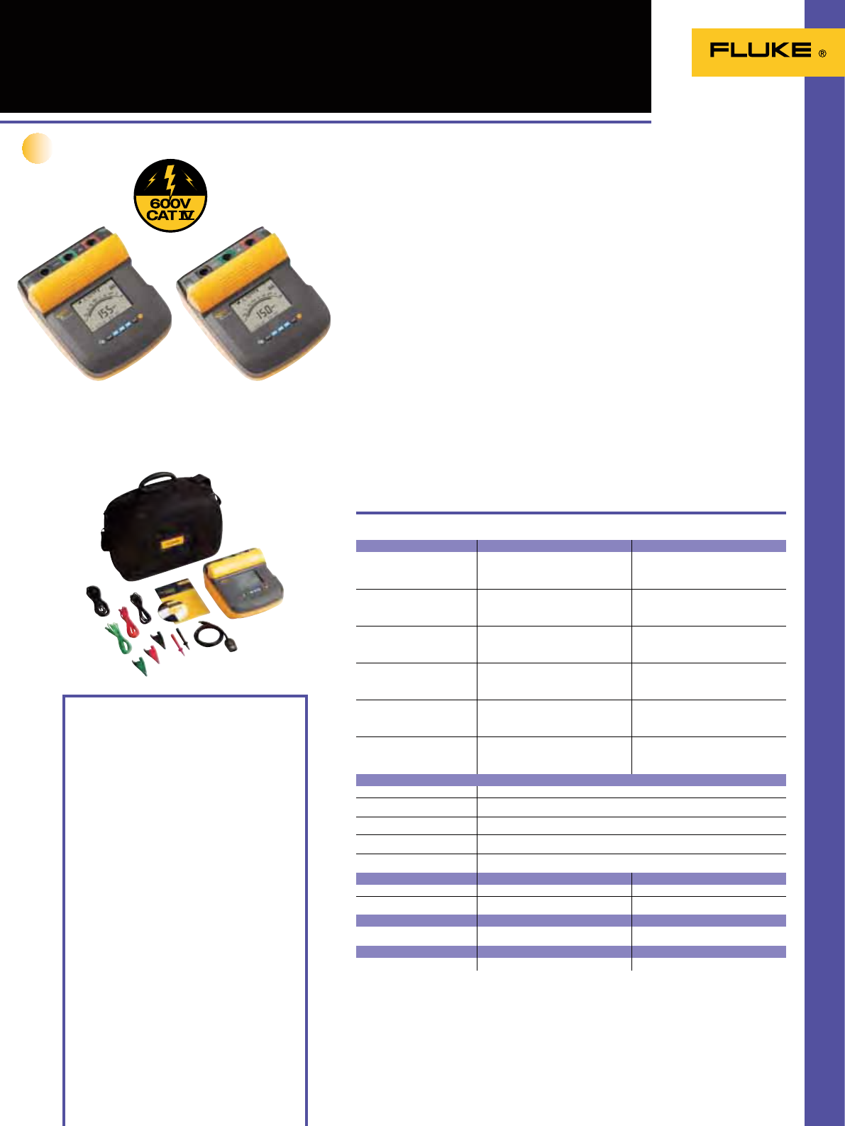
39
1555/1550C
Insulation Resistance Testers
The new 1555 and redesigned Fluke
1550C insulation resistance testers
offer digital insulation testing up to
10kV, making them ideal for testing a
wide range of high voltage equipment
including switchgear, motors, generators
and cables. Fluke insulation testers can
now conduct the entire range of test
voltages specied in IEEE 43-2000 with a
best in class, 3-year warranty and CAT IV
600 V safety rating. With measurement
storage and PC interface, the 1555 and
1550C are perfect tools for preventative
or predictive maintenance programs
designed to identify potential equipment
failures before they occur.
• Test voltages up to 10 kV (1555)
provides solutions for all applications
• CAT III 1000 V, CAT IV 600 V safety rating
• Voltage breakdown detection alerts the
user that voltage is present and gives
the voltage reading up to 600 V ac or dc
for increased user safety
Fluke 1555 Fluke 1550C
Included accessories
Test Cables with Alligator Clips (red, black, green)
Infrared adapter with interface cable
FlukeView Forms Basic CD-ROM
AC Power Cord
Soft Carrying Case (base models only)
English Manual
Users Manual on CD-ROM
Quick Reference Card
Software License Agreement
Registration Card
FlukeView Forms Installation Guide
USB-IR Cable Installation Guide
IP67 Hard Case (kit only)
Certicate of Calibration (kit only)
Ruggedized Alligator Clips (kit and 1555 only)
Software specifications
Fluke ViewForms basic software requires a
PC running Windows 2000, Windows XP and
Windows Vista.
Optional Accessories
TL1550EXT 25 Foot Extended Test Lead Set
Ordering information
Fluke 1550C 5 kV Insulation Tester
Fluke 1555 10 kV Insulation Tester
Fluke 1550C/Kit 5 kV Insulation Tester Kit
Fluke 1555/Kit 10 kV Insulation Tester Kit
Test voltage (dc) Range Accuracy (± reading)
250 V < 200 k
200 k to 5 G
5 G to 50 G
> 50 G
unspecified
5 %
20 %
unspecified
500 V < 200 k
200 k to 10 G
10 G to 100 G
> 100 G
unspecified
5 %
20 %
unspecified
1000 V < 200 k
200 k to 20 G
20 G to 200 G
> 200 G
unspecified
5 %
20 %
unspecified
2500 V < 200 k
200 k to 50 G
50 G to 500 G
> 500 G
unspecified
5 %
20 %
unspecified
5000 V < 200 k
200 k to 100 G
100 G to 1 T
> 1 T
unspecified
5 %
20 %
unspecified
10000 V (1555 only) < 200 k
200 k to 200 G
200 G to 2 T
> 2 T
unspecified
5 %
20 %
unspecified
Bar Graph Range 0 to 1 T & 0 to 2 T (1555 only)
Insulation test voltage accuracy -0 %, +10 % at 1 mA load current
Induced ac mains current rejection 2 mA maximum
Charging rate for capacitive load 5 seconds per F
Discharge rate for capacitive load 1,5 s/F
Range Accuracy
Leakage current measurement 1 nA to 2 mA ± (5% + 2 nA)
Capacitance measurement 0,01 uF to 15,00 F ± (15% rdg + 0,03 µF)
Timer Range Resolution
0 to 99 minutes Setting: 1 minute
Indication: 1 second
Live circuit warning Warning range Voltage accuracy
30 V to 660 V ac/dc, 50/60 Hz ± (15% + 2 V)
Specifications
(Check the Fluke web for detailed specifications)
• Selectable test voltages in 50 V steps
from 250 to 1000 V, and 100 V steps
above 1000 V
• Measurements can be stored in up to 99
memory locations, with each location
assigned a unique, user dened, label
for easy recall
• Long battery life gives the user over 750
tests between charges
• Automatic calculation of Dielectric
Absorption (DAR) and Polarization
Index (PI) with no additional setup
• Guard system eliminates the effect
of surface leakage current on high-
resistance measurements
• Large digital/analog LCD for easy
viewing
• Capacitance and leakage current
measurement
• Ramp function for breakdown testing
• Resistance measurements up to 2T
• Timer settings up to 99 minutes for
timed tests
• 3-year warranty
Digital insulation testing up to 10kV
Temperature (operating):
-20 °C to 50 °C ( -4 °F to 122 °F)
Temperature (storage):
-20 °C to 65 °C (-4 °F a 149 °F)
Humidity: 80 % to 31 ºC decreasing linearly to
50 % at 50 ºC
Enclosure sealing: IP40
Altitude: 0 to 2000 m
Power: 12 V lead-acid rechargeable battery,
Yuasa NP2.8-12
Dimensions: 170 mm x 242 mm x 330 mm
Weight: 3,6 kg (7,94 lb)
3-year warranty
New

40
1620 Series
Earth Ground Testers GEO
The new Fluke 1620 Series Earth Ground
Testers not only measure ground
resistance using the classic ‘fall of
potential test’ but also enable time
saving testing using the ‘selective’ and
‘stakeless’ methods. ‘Selective’ testing
does not require the electrode under
test to be disconnected during the
measurement, thus increasing safety.
The simple ‘stakeless’ method quickly
checks ground connections using two
current transformers (probes) clamped
around the ground conductor under test.
Offering ‘one-button’ simplicity, the 1623
is an all-in-one earth ground tester, while
the 1625 has extra versatility for more
demanding applications.
Earth ground resistance and soil
resistivity should be measured
when:
• Designing earth ground systems
• Installing new ground system and
electrical equipment
• Periodically testing ground and
lightning protection systems
• Installing large electrical equipment
such as transformers, switchgears,
machines, etc.
EI-162BN
320mm Split core
transformer for selective
measurements on high
voltage pylons
Features
Included accessories
Fluke 1623: Protective holster, 2 test leads,
2 alligator clips, users manual
Fluke 1623 Kit: same as above plus stake/reel
Set 4 pole and selective/stakeless clamp set
Fluke 1625: Protective holster, 2 test leads,
2 alligator clips, users manual
Fluke 1625 Kit: same as above plus stake/reel
set 4 pole and selective/stakeless clamp set
Ordering information
Fluke 1623 Basic GEO Earth Ground
Tester
Fluke 1623 Kit Basic GEO Earth Ground
Tester Kit
Fluke 1625 Advanced GEO Earth
Ground Tester
Fluke 1625 Kit Advanced GEO Earth
Ground Tester Kit
Battery type: 6 x AA alkaline cells
Size (HxWxD): 110 mm x 180 mm x 240 mm
Weight – 1623 Geo: 1.1 kg (including batteries)
1625 Geo: 1.1 kg (including batteries)
Two Year Warranty
1623 1625
Resistance ranges 0 to 20 k 0 to 300 k
Operating error ± 5% ± 5%
Test voltage 48 V 20 / 48 V
Short circuit current > 50mA 250 mA
ES-162P4
Stake/reel set for 4 pole
measurements
ES-162P3
Stake/reel set for 3 pole
measurements
EI-1625
Selective/stakeless clamp
set for 1625
EI-1623
Selective/stakeless clamp
set for 1623
1623 1625
One-button measurement concept
O
3- and 4-pole earth ground measurement
OO
4-Pole soil resistivity testing
OO
2-Pole resistance measurement AC
O
2-and 4-pole resistance measurement DC
O
Selective testing, no disconnection of ground conductor (1 clamp)
OO
Stakeless testing, quick ground loop testing (2 clamps)
OO
Measuring frequency 128 Hz
O
Earth impedance measurement at 55 Hz
O
Automatic frequency control (AFC) (94 – 128 Hz)
O
Measuring voltage switchable 20/48V
O
Programmable limits, settings
O
Continuity with buzzer
O
Dust/water resistance IP56 IP56
Safety rating CAT II 300 V CAT II 300 V
Specifications
Recommended Accessories
(Check the Fluke web for detailed specifications)
Advanced technology for all your earth
ground testing applications
Fluke 1625 kit
Fluke 1623
Fluke 1625
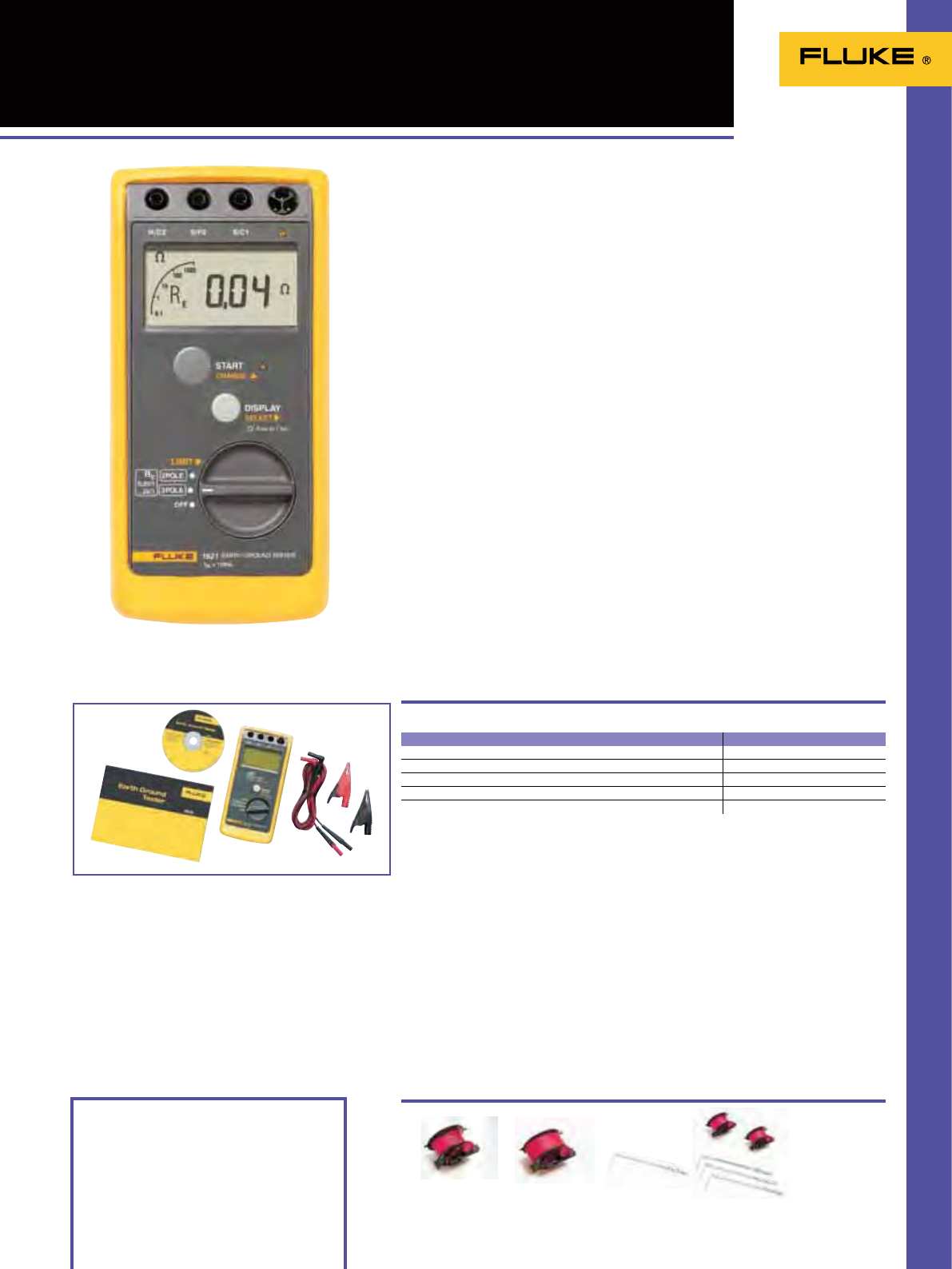
41
1621 Earth Ground Tester
The Fluke 1621 is an easy-to-use
earth ground tester. The rst line of
defense in detecting reliable ground
connections, the unit features basic
ground testing methods including 3-pole
Fall-of-Potential as well as 2-pole ground
resistance. Its convenient size, rugged
holster, and large, clear LCD display make
it an ideal eld earth tester, for most
work environments. With a simple user
interface and intuitive functionality, the
Fluke 1621 is a handy tool for electrical
contractors, utility test engineers, and
earth ground specialists.
Fluke 1621
Included accessories
Two measuring leads with alligator clips -
2 m, protective holster, users manual, CD-ROM
Ordering information
Fluke 1621 Earth Ground Tester
Battery type: 1 x 9 V alkaline (LR61)
Size (HxWxD): 216 mm x 113 mm x 54 mm
Weight: 0.850 kg
Two Year Warranty
1621
Resistance range 0.15 to 2 k
Basic accuracy ± 6% of measured value + 5D
Operating error according EN61557 ± 18% of measured value +5D
Test voltage 23 to 24 V AC
Short circuit current > 50 mA AC
ES-162P3
Stake/reel set for 3 pole
measurements
GEO EARTH STAKE
Ground Earth Stake
GEO CABLE-REEL 50M
Ground Earth Cable Reel
50 M Wire
GEO CABLE-REEL 25M
Ground Earth Cable Reel
25 M Wire
Specifications
Recommended Accessories
(Check the Fluke web for detailed specifications)
Features
• 3-pole Fall-of-Potential earth testing for
basic measurements
• 2-pole resistance measurements for
added versatility
• Easily capture values with single-button
operation
• Ensure accurate measurements with
automatic ‘noise’ voltage detection
• Hazardous voltage warning offers
increased user protection
• Clearly read and record data with a
large, backlit display
• Rugged holster and design for tough
work environments
• Portable size allows for easy
transportation
• Instantly be alerted to measurements
outside of your set limit, when you use
the adjustable limit setting
• Safety rating CAT II 600 V
Handheld earth ground testing
for mobile use

R
g
.....R
n
1630
EARTH GROUND CLAMP
300
V
CAT
mA
A
OFF
HOLD
FUNC REC
R
1
R
2
R
3
R
1
R
g
R
2
.....R
n
1630
EARTH GROUND CLAMP
300
V
CAT
mA
A
OFF
HOLD
FUNC REC
R
g
1630
EA
RTH GROUND CLAMP
300
V
CAT
mA
A
OFF
HOLD
F
UNC REC
42
1630 Earth Ground
Clamp Meter
The Fluke 1630 earth ground clamp
meter simplies ground loop testing and
enables non-intrusive leakage current
measurement. The ground loop testing is
also known as “stakeless” earth ground
testing. To carry out the measurement
there is no need for placing earth stakes
and disconnecting the earth system
from the electrical installation. The Fluke
1630 combines the two current clamps
needed to perform the stakeless ground
loop test in one compact and easy to use
instrument.
• Ground loop resistance testing without
any disconnection or additional earth
stakes
• Earth ground leakage current
measurement for system
troubleshooting
• True RMS AC current measurement
range up to 30 A
Fluke 1630
Included Accessories
Rugged carrying case with belt, Resistance test
loop, 9 V battery, Operating instructions.
Ordering Information
Fluke 1630 Earth Ground Clamp Meter
Weight: 0.64 kg
Conductor Size: 35 mm approx.
Size (HxWxD): 257 mm x 100 mm x 47 mm
Battery type: 9 V IEC 6 LR 61
Two Year Warranty
Range Max. resolution
Resistance 0.025 to 1500 0.002
Cntinuity buzzer < app. 40
Leakage current 0.2 to 1000 mA 0.001 mA
Current 0.2 to 30 A 0.01 A
Specifications
Ground resistance measurements principle
(Check the Fluke web for detailed specifications)
• Rapid evaluation of continuity without
disconnection and audible HI/LO alarm
• Display-HOLD function to freeze
measurements
• Recording function for automatic
storage of measured values, which can
be recalled later on the LCD display
• Automatic self calibration ensures
correct measurement every time
The Fluke 1630 is ideally suited for the
following applications:
• Ground loop checks on any earthing
system
• Continuity tests on earth bonding
circuits and connections
• Inspection of lightning protection
systems
• Leakage current measurement for
troubleshooting on earth ground
systems
Fast and easy earth ground loop testing
Ground resistance measurements principle
Equivalent circuit diagram

43
Our multifunction testers have redened the standards for ease-of-use.
With new features like the fast, high current loop test, RCD Type B
compatibility, extended memory, and the fact they are designed for
ensuring xed wiring installed according to IEC 60364,they perform all
tests required to verify safety. Our Portable Appliance Testers verify the
safety and operation of portable appliances, and are designed for ‘one-
touch’ operation and a fast throughput.”
Installation Testers/
Portable Appliance Testers

44
1650 Series Multifunction
Installation Testers
Safer, easier installation testing. The
new 1650 Series builds on the rugged
reputation of the earlier 1650 Series,
only it’s re-designed to meet your need
for more productive test tools. With
new features like the fast, high current
loop test (including a non-trip test)
and a variable RCD trip current setting,
accuracy is even better and the test
cycle even faster. And with the addition
of a unique zero adapter accessory for
accurate mains test lead compensation,
the 1650 Series continues to set the
standard in installation testers. The
1650 Series testers verify the safety
of electrical installations in domestic,
commercial and industrial applications.
They can ensure that xed wiring is
safe and correctly installed to meet the
requirements of IEC 60364, HD 384 and
BS 7671 17th Edition wiring regulations.
1654B - The complete tester for
advanced users
This is the instrument that has it all, in
a word: it’s complete. From all the test
functions you need to in-built memory
for documenting results. This makes it
the complete solution for professionals,
especially contractors, everyone who
would want to have the best tool
available and always understands (or
know) how to use.
1653B - The ideal tester for
professional trouble-shooters
This is the instrument that is indeed
ideal for professional users due to its
additional functionality. It is also ideal
since even though it has high-end
features, it is still easy to use – even
after longer periods of non-use; because
operating it is intuitive and not forgotten
easily.
1652C - The everyday tester, for
every electrical installer
This is the instrument that can be
used every single day (day in, day out),
and covers all the basic needs. It is the
preferred tester for every front-line
electrician/installer.
Extra functionality, faster testing,
and as rugged as ever
BS7671 17th Edition IEE Wiring
Regulations IEC 60364.6.61, HD 384
Included Accessories
6 AA Cell batteries
C1600 Hard carrying case
Zero Adapter
Mains test cord
TL165X STD Standard Test Lead Set
TL165/UK Fused Test Lead Set (UK only)
Padded carrying strap
Quick reference guide
TP165X Remote control probe and lead
Users manual on CD-ROM
Ordering Information
Fluke 1652C Multifunction Installation Tester
Fluke 1653B Multifunction Installation Tester
Fluke 1654B Multifunction Installation Tester
Check the Fluke website for the various
software modules
Features
Measurement Function 1652C 1653B 1654B
Voltage & Frequency
OOO
OOO
Insulation Resistance
OOO
Continuity & Resistance
OOO
Loop & Line Resistance
OOO
Loop & Line Resistance–m1 resolution
O
Prospective Earth Fault Current (PEFC/IK)
Prospective Short-Circuit current (PSC/IK)
OOO
RCD switching time
OOO
RCD tripping level ramp test
O
ramp test
O
ramp test
O
RCD variable current
OOO
Automatic RCD test sequence
OOO
Test pulse current sensitive RCDs (Type A)
OOO
Test smooth dc sensitive RCDs (Type B)
O
Earth Resistance
OO
Phase Sequence Indicator
OOO
Other Features
Self-test
OOO
Illuminated Display
OOO
Memory, Interface
Memory
OO
Extended Memory
O
Computer Interface
OO
Time and date (When used with FlukeView software)
OO
Software
OO
Included Accessories
Hard case
OOO
Remote control probe
OOO
Zero Adapter
OOO
TLK290 MTC1363 (UK) MTC77 (Europe) ES165X 1653B &1654B FVF-SC2
Fluke 1654B
Fluke 1653B
Fluke 1652C
New
RCD Type B Compatibility
Recommended Accessories
See also page 48 for more details
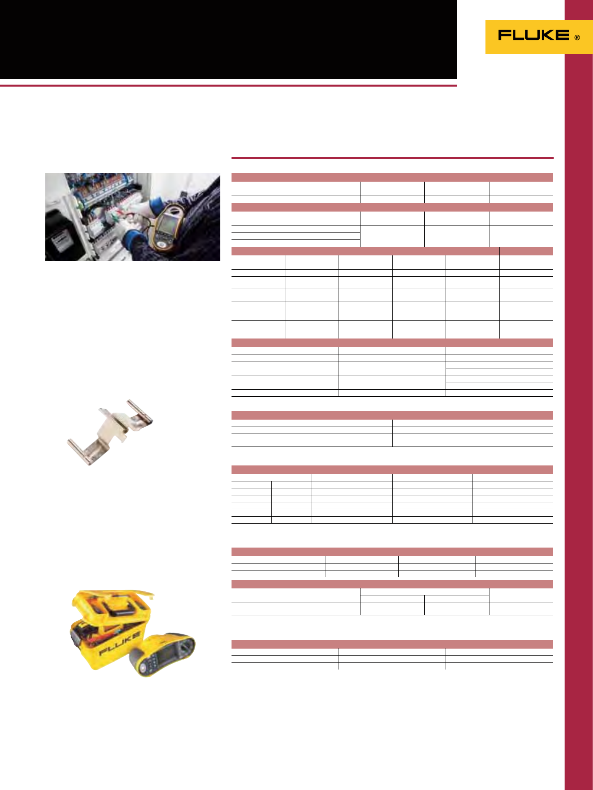
45
1650 Series Multifunction
Installation Testers
Slim probe design
Thanks to its slim probe with integral test button,
you can safely make one-handed measurements
on hard to reach points, while keeping your eyes
on the panel. This remote probe is powered by
the tester so always operable (does not require
additional batteries!).
Complete kit
All 1650 models are equipped with detachable
leads that can be replaced in case of damage
or loss. A durable hard case will protect your
instrument in tough eld conditions.
Zero Adaptersign
For easy, always reliable and accurate
compensation for test leads and mains cords.
This adapter can be used for all different kind
of mains plugs as well as test accessories like
probes, alligator clips etc.
Extra functionality, faster testing,
and as rugged as ever
Specifications
(Check the Fluke web for detailed specifications)
AC Voltage Measurement
Range Resolution Accuracy
50 Hz - 60 Hz
Input Impedance Overload Protection
500 V 0.1 V ± (0.8% + 3 digits) 3.3 M1660 Vrms
RCD Testing
RCD Type [6] Model 1652C Model 1653B Model 1654B
AC [1] G [2] •••
AC S [3] •••
A [4] G•••
AS •••
B [5] G•
BS •
Notes
[1] AC - Responds to ac
[2] G - General, no delay
[3] S - Time delay
[4] A - Responds to pulsed signal
[5] B - Responds to smooth dc
[6] RCD test inhibited for V >265 ac
RCD tests permitted only if the selected current,
multiplied by earthing resistance, is <50 V.
PFC. PSC Test
Range 1000A / 10kA(50kA)
Resolution and Units 1A / 0.1kA
Accuracy Determined by accuracy of loop resistance and mains
voltage measurements
Computation
Prospective Earth Fault Current (PEFC) or Prospective Short Circuit Current (PSC) determined by dividing
measured mains voltage by measured loop (L-PE) resistance or line (L-N) resistance, respectively.
Tripping Time Test (6T)
Current Settings Multiplier Test Current Accuracy Trip Time Accuracy
10, 30, 100, 300, 500, 1000 mA, VAR x 1/2 + 0% - 10% ± (1% Reading + 1 digit)
10, 30, 100 mA X 5 + 10% - 0% ± (1% Reading + 1 digit)
Loop Impedance Measurement
Range Resolution Accuracy [1]
10 10.001 1Hi Current m1 mode: ± (2 % + 15 digits)
20 10.01 1No Trip mode: ± ( 3 % + 6 digits)
Hi Current mode: ± (2 % + 4 digits)
200 10.1 1No Trip mode: ± (3 %)
Hi Current mode: ± (2 %)
2000 11 1±6 % [2]
Notes
[1] Valid for resistance of neutral circuit <20 1 and up to a system phase angle of 30°. Test leads must be zeroed before testing.
[2] Valid for mains voltage >200 V.
Earth Resistance Test (RE) – Fluke 1654B and 1653B only
Range Resolution Accuracy
200 10.1 1± (2% + 5 digits)
2000 11 1± (3.5% + 10 digits)
Continuity Testing
Ratnge
(autoranging)
Resolution Test Current Open Circuit Voltage Accuracy
20 100.1 1
> 200 mA > 4 V ± (1.5%+3 digits)
200 10.1 1
2000 11 1
Tripping Current (Ramp) Test
Current Range Step Size Dwell Time Measurement
Accuracy
Type G Type S
30 % to 110 % of
RCD rated current [1] 10 % of I 6 N [2] 300 ms/step 0 ms/step ±5 %
Notes
[1] 30 % to 150 % for Type A 6 N >10 mA
30 % to 210 % for Type A 6 N =10 mA
20 % to 210 % for Type B
Specified trip current ranges (EN 61008-1):
50 % to 100 % for Type AC
35 % to 140 % for Type A ( >10 mA)
35 % to 200 % for Type A ( )10 mA)
50 % to 200 % for Type B
[2] 5% for Type B
Insulation Resistance Measurement
Model Test Voltage Insulation
Resistance Range
Resolution Test Current Accuracy
1653B / 1654B 50 V 10 k1 to 50 M10.01 M11 mA @ 50 k1± (3%+ 3 digits)
1653B / 1654B 100 V 20 k1 to 100 M10.01 M1
0.1 M1
1 mA @ 100 k1± (3%+ 3 digits)
1653B / 1654B
1653B / 1654B
250 V 20 k1 to 200 M10.01 M1
0.1 M1
1 mA @ 250 k1± (1.5%+ 3 digits)
1653B / 1654B
1652C
1653B / 1654B
500 V 20 M1
200 M1
500 M1
0.01 M1
0.1 M1
1 M1
1 mA @ 500 k1± (1.5%+ 3 digits)
+ 10%
1653B / 1654B
1652C
1000 V 20 M1
200 M1
1000 M1
0.1 M1
1 M1
1 mA @ 1 M1± (1.5%+ 3 digits)
+ 10%
Battery type: Alkaline supplied. usable
with 1.2 V NiCD or NiMH rechargeable
batteries
Size (HxWxD): 100 mm x 250 mm x 125 mm
Weight: 1.3 kg
Three Year Warranty
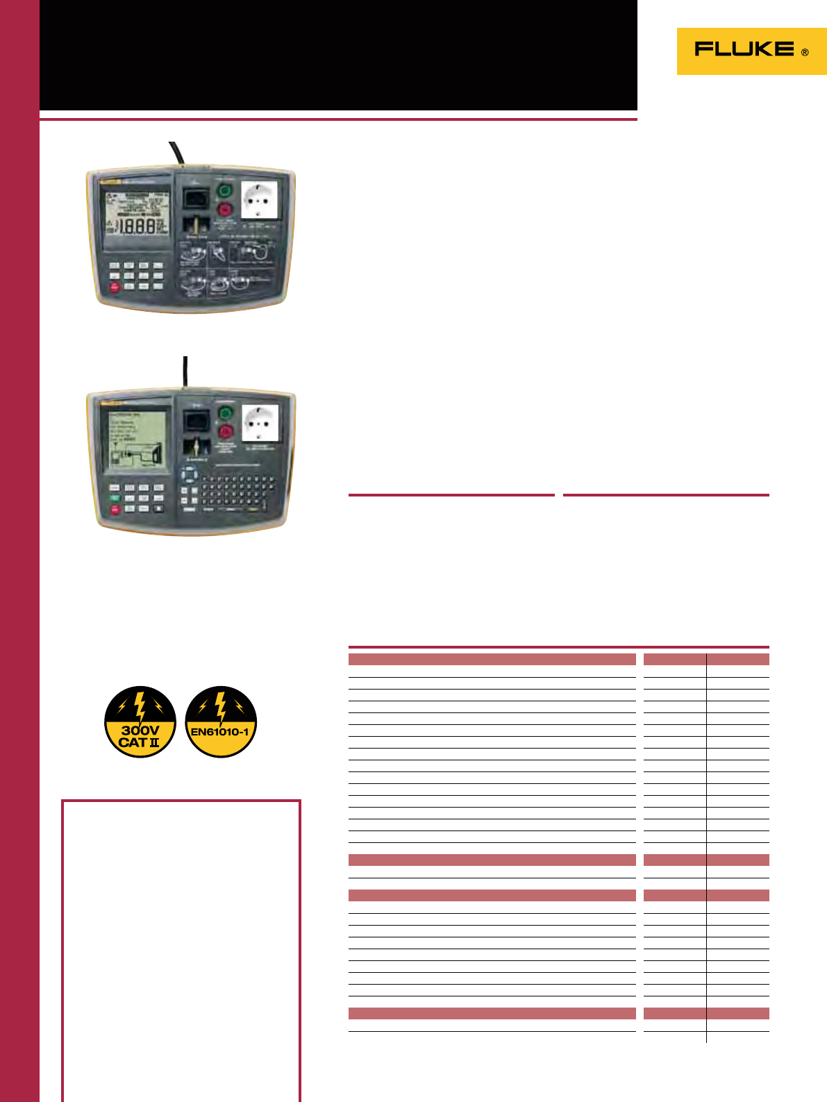
46
6000 Series PAT Testers
The Fluke 6200 and 6500 PAT testers
verify the electrical safety and operation
of portable appliances in accordance
with relevant guidelines and regulations.
With powerful auto test capabilities and
simplied controls they increase the
number of tests you can perform per day
without compromizing results.
A choice of automatic and manual
PAT testers
Both models perform all the tests
required for class I and class II
appliances. For manual testing and low
volume applications, choose the cost-
effective 6200 PAT model. If you need a
more powerful instrument to test large
numbers of appliances, the 6500 is the
right choice.
Fluke simplifies portable
appliance testing
• Compact and lightweight…
Efcient to work with and easy to carry
around– and has extra space in the
hard case for accessories.
• One touch simplicity…
Pre-set and user-denable test routines
are initiated from a single button – to
speed up test procedures and save you
time on site.
• A better way of working…
Rapid data entry via a QWERTY
keyboard (or optional Fluke barcode
scanner) and fast data transfer from
the main memory or the Compact Flash
memory card (6500).
Included Accessories
Test lead, Test probe, Crocodile clip,
Mains cord
Ordering Information
Fluke 6200 PAT Tester
Fluke 6500 PAT Tester
Not available in all countries
Fluke 6500
Fluke 6200
Also available with European mains socket.
Versatile PAT testing at your fingertips
6200 6500
Front panel results management
O
230V BS1363 Test socket / 230V Mains BS1363 input power plug
OO
IEC Lead Test
OO
Auto-testing
O
Pass / Fail Level Programmable Indicators
O
Data Storage
O
Limited Data Storage
O
Polarity Checks
OO
Graphical Help Menu On Line
O
Programme Mode
O
Real time clock
O
External printer output
OO
Front Panel QWERTY Key pad
O
Measurement functions 6200 6500
L N Mains Volts
OO
Outside Limits Indicators
OO
Null out facility for earth bond lead
OO
Protective Earth Resistance PE (200mA)
OO
Protective Earth Resistance PE (25A)
OO
Insulation 500V dc
OO
Protective Earth Conductor Current
OO
Touch Current
OO
Substitute Leakage Current
OO
Appliance Power kVA
OO
Appliance Load Current
OO
Seven Segment Custom LCD
O
Graphical LCD
O
Back Light
OO
Compact Flash Card receptacle
O
Serial Port - Printing / Downloading
OO
Features
• Dedicated key for each test for ‘one-
touch’ testing
• Pre-set pass/fail levels to save time
• Large backlit display for easy reading
As 6200 but also with:
• Integral QWERTY keyboard for rapid
data entry
• Slot for Compact Flash memory card for
back-up data storage and transfer to PC
• Pre-set, auto-test sequences for user
convenience
47
Separate hard case
The compact Fluke PAT testers are supplied with a
hard carrying case that not only offers protection
during transit but also includes extra storage space for
accessories and other tools. They’re extremely light,
weighing approximately 3 kg (without case) and have
integral carrying handles for extra convenience.
Special PAT Kit
If you need a complete PAT tester solution,
a purpose made kit is available.
Fluke 6500/UK Kit Contains:
• 6500, Mainframe
• EXTL 100, Extension lead test adaptor
• SP Scan 15, Barcode scanner
• Fluke PowerPat Plus
• Pass 560R, Appliance pass labels
• Fail 100S, Appliance fail labels APP 1000,
Barcode appliance number labels
(Kit contents may vary per country)
6000 Series PAT Testers
Power-on Test
The test indicates reversed L-N, missing PE, and
measures the mains voltage and frequency.
Display Range 90 V to 264 V
Accuracy at 50 Hz ± (2% + 3 counts)
Resolution 0.1V (1V - model 6200)
Input Impedance > 1 M // 2.2 µF
Maximum Input Mains Voltage 300 V
Insulation Test (Riso)
Display Range 0 to 299 M
Accuracy ± (5% + 2 counts) from 0.1
to 50 M
± (10% + 2 counts) from 50
to 299 M
Resolution 0.01 M (0 to 19.99 M)
0.1 M (20 to 199,9 M)
1 M (200 to 299 M)
Test Voltage 500 V DC - 0% + 25% at
500 k load
Test Current > 1 mA at 500 k load,
< 15 mA at 0
Auto discharge time < 0.5 s for 1 µF
Max. Capacitive Load Operational up to 1 µF
Earth Bond Test
Display Range 0 to 19.99
Accuracy
(after Bond Test zeroing) ± (5% +4 counts)
Resolution 0.01
Test Current 200 mA AC - 0% + 40% into
1.99
25 A AC ± 20% into 25 m
at 230 V
Open Circuit Voltage > 4 V AC, < 24 Vac
Bond Test zeroing can subtract up to 1.99
Touch Current Test
Display Range 0 to 1.99 mA ac
Accuracy ± (4% + 2 counts)
Resolution 0.01 mA
Internal Resistance (via probe) 2 k
Measuring method Probe
The appliance under test is energized at mains potential.
Substitute Leakage Current Test
Display Range 0 to 19.99 mA ac
Accuracy ± (5% + 5 counts)
Resolution 0.01 mA
Test Voltage 35 V AC ± 20%
Operational Error 10%
Load/Leakage Test: Load Current
Display Range 0 to 13 A
Accuracy ± (4% + 2 counts)
Resolution 0.1 A
The appliance under test is energized at mains potential
Load/Leakage Test: Load Power
Display Range 0 to 999 VA
1.0 kVA to 3.2 kVA
Accuracy ± (5% + 3 counts)
Resolution 1 VA (0 to 999 VA)
0.1 kVA (1.0 kVA to 3.2 kVA)
The appliance under test is energized at mains potential
Load/Leakage Test: Leakage Current
Display Range 0.25 to 19.99 mA
Accuracy ± (4% + 4 counts)
Resolution 0.01 mA
The appliance under test is energized at mains potential
PELV Test
Accuracy at 50 Hz ± (2% + 3 counts)
Overload protection 300 Vrms
Warning threshold 25 Vrms
Recommended Accessories
Display Screens
Earth Bond Test (RPE)Substitute Leakage
Current Test
Touch Current TestInsulation Test (RISO)
The accuracy specification for the display range is defined as ± (%reading + digit counts) at 23 °C ± 5 °C, ≤ 75 %
RH. Between 0 °C and 18 °C and between 28 °C and 40 °C, accuracy specifications may degrade by 0.1 x (accuracy
specification) per °C. The measurement range meets the service operating errors specified in EN61557-1: 1997,
EN61557-2: 1997 , EN61557-4: 1997.
Size (HxWxD): 200 mm x 275 mm x 100 mm
Weight: 3 kg
Two Years Warranty
See also page 48 for more details
Specifications
BDST3 Snap Tags
Cable Tie PASS
Appliance 560R
Pass Labels
SP-SCAN-15
Barcode scanner
(6500 Fluke only)
SP1000-02
Mini printer
Fluke PowerPat Plus
software
48
ES165X Earth Spike Test Kit
(Fluke 1653B and 1654B)
Earth Spike Test kit contents:
• Auxiliary earth probes
• Test connection leads and crocodile clips
• Purpose-made carry case
1650 Series/6000 Series
Accessories
FVF-SC2 Fluke ViewForms Software
(Fluke 1653B)
To address the increasing demands for
reporting and documentation, Fluke presents
FlukeView Forms documenting software.
Download the data from the Fluke 1653B and
create an easy report. The Fluke ViewForms
Software also supports other Fluke tools.
See page 132.
TLK 290 Test Probe Kit
• Kit includes three exible socket probes and
a large alligator clip
• To be used on three phase sockets
• Probes have exible width test points that t
securely in 4 to 8 mm sockets
• CAT III 1000 V, 8 A
Mains Test Cord for 1650B series
MTC1363 UK plug
MTC77 Schuko plug
PASS560R Appliance Pass Labels
Quantity 500
APP1000/APP2000 Bar Code Appliance
Number Labels
APP1000: Labels numbered 0001-1000
APP2000: Labels numbers 1001-2000
Label number >2000 on request
BDST3/BDST4 Snap Tags
BDST3: Cable Tie
BDST4: Clip On
Quantity 20. Without labels.
EXTL100 Extension Lead Test Adaptor
Adaptor for testing extension leads. Allows
the earth test lead to be connected to the
extension leads to perform insulation and
earth bond tests.
SPScan15 Barcode Scanner
Easy to use, low current, intelligent barcode
reader. SPScan15 can be used to scan barcodes
attached to curved surfaces or where actual
contact with the barcode surface is difcult.
SP1000 Mini Printer
Without using any additional software the
SP1000 can be used to directly printout stored
test records on to thermal paper. The printer
is compact and easily transported and is ideal
for test professionals who need to issue an
immediate written account of work carried
out. The printer is powered by a rechargeable
battery and comes complete with mains
charger and RS232 Printer Lead.
SP1000 Paper
Replacement thermal paper for the SP1000
Mini Printer
Fluke DMS software for
1650/6000 Series
The Fluke DMS (Data Management Software)
is an efcient program for administration and
reporting of installation tests in compliance
with EN 60364, DIN VDE 0100/0105, BS7671
17th edition wiring resulation and appliance
tests in compliance with DIN VDE 0701/0702,
ÖVE E 8701.
DMS 0100/INST Software for Installation
Tester Fluke 1653B and 1654B
Supporting reports for Austria, Germany, UK,
Switzerland, Netherlands
DMS 0702/PAT Software for Portable
Appliance Tester Fluke 6500
Supporting reports for Austria, Germany, UK,
Netherlands
DMS COMPL PROF Software for the Fluke
1654B, 1653B and Fluke 6500
Supporting reports for Austria, Germany, UK,
Switzerland, Netherlands
EXTL100-02 (Schuko plug)EXTL100-02 (UK plug)
MTC77MTC1363
Accessories for Fluke 1650
Series Installation Testers
Accessories for Fluke 6500 Series
Portable Appliance Testers

49
For troubleshooting systems where temperature is a critical symptom,
our digital thermometers provide you with laboratory accuracy wherever
you need it. We offer a choice of non-contact, laser-guided infrared
thermometers for safely getting at hard-to-reach, electrically live or
particularly hot targets, and contact thermometers with a full range of
thermocouple probes.
Digital Thermometers

50
Infrared Thermometer
Selection Guide
Infrared Thermometer
Selection Guide
Fluke 60 Series Fluke 560 Series Fluke 570 Series
Fluke 61 Fluke 62 Fluke 63 Fluke 561 Fluke 566 Fluke 568 Fluke 572 Fluke 574
Temperature range -18 to 275 ºC -30 to 500 ºC - 32 to 535 ºC - 40 to 550 ºC - 40 to 650 ºC - 40 to 800 ºC - 30 to 900 ºC - 30 to 900 ºC
Accuracy 2% 1.5% 1% 1% 1% 1% 0.75% 0.75%
Response time < 500 mSec < 500 mSec < 500 mSec < 500 mSec < 500 mSec < 500 mSec < 250 mSec < 250 mSec
Optical resolution 8:1 10:1 12:1 12:1 30:1 50:1 60:1 (50:1
with close
focus)
60:1 (50:1
with close
focus)
Close focus model
available
OO
Recommended distance
to spot Up to 2 m Up to 2 m Up to 2.5 m Up to 2.5 m Up to 4.5 m Up to 7.5 m 300 mm
(with close
focus) up to 10.5 m
300 mm
(with close
focus) up to 10.5 m
Laser sighting single-point
laser single-point
laser single-poimt
laser single-point
laser single-point
laser single-point
laser 3-point
laser 3-point
laser
Adjustable emissivity
OOOOO
MIN/MAX readings -/
O
-/
OOOOOO
AVG readings
OO O
DIF readings
OOO O
Backlit LCD
OOOOOOOO
Bar graph display
OO
Audible Hi/Lo alarm
OO
O
/-
O
Visible Hi/Lo alarm
OO
O
/-
O
Includes contact probe
OOO O
Probe input (types) Type K Thermocouple Type K Thermocouple Type K Thermocouple Type K Thermocouple
Data logging
(number of
measurements) 20 points 99 points 100 points
PC interface USB RS232
Compatible with
FlukeView Forms
software
OO
See catalog page 52 52 52 54 53 53 51 51
Recommended Applications
Safety and protection
Fire localization
Hazardous materials
Faulty ballasts
Search and rescue
Smoldering embers
Equipment maintenance
Manufacturing processes
Molding temperature measurement
Printing, paper and converting
Thermoforming plastics
Electronics
Paint curing/drying
Food
Chemical and pharmaceutical
Heating/ventilation/air conditioning/
refrigeration
Leaky ductwork
Thermostats
Temperature balancing
Steam distribution systems
Compressor lines
Plant/facilities maintenance
Preventive and predictive maintenance
Energy audits
Vehicle and fleet maintenance
programs
Faulty electrical/circuit connections
Petrochemical/hazardous locations
Motors, pumps and bearings
Contact thermometers
For our complete range of contact
thermometers, see page 55.

51
570 Series
Precision Infrared Thermometers
572 574
Temperature range -30 to 900ºC
Optical resolution Standard: 60:1
Close focus: 50:1
3 dot laser beam for accurate targeting
OO
Adjustable emissivity
OO
Bar graph display
OO
Backlit LCD display
OO
Use selectable ºC or ºF
OO
Audible and visible Hi/Lo Alarm
O
/-
O
/
O
MIN/MAX
OO
AVG/DIF readings
O
Datalogging (number of measurements) 100
PC interface RS232
572 574
Temperature range -30 to 900°C
Response time 250ms (95 % of reading)
Resolution 0.1°C of reading up to 900°C
Repeatability ±0.5% of reading or ±1°C*
Accuracy: (assumes ambient operating temperature of 23 ºC to 25 ºC ) ±0.75% of reading, ±0.75°C *
Typical distance to target 10,5 m
Emissivity Digitally adjustable from 0.10 to 1.0
by 0.01
*whichever is greater.
Features
Included Accessories
Fluke 572: Hard case, 2 batteries
Fluke 574: Hard case, 2 batteries, Thermocouple
K probe, 220V power supply, IRGraph software,
RS232 cable
Ordering Information
Fluke 572 Precision Infrared Thermometer
Fluke 574 Precision Infrared Thermometer
Fluke 572CF Precision Infrared Thermometer
with close focus option
Fluke 574CF Precision Infrared Thermometer
with close focus option
The Fluke 570 series are the most
advanced IR non-contact thermometers,
and are ideal for predictive and
preventative maintenance applications.
Offering a broad temperature range
and a true dimension laser sighting
system for precise targeting resulting
in more accurate measurements. When
requiring analysis and documentation
use the 100-point data logging and
software for graphing and analysis.
From close-up electrical connections, to
far-distance room balancing checks, the
Fluke 570 series can take IR temperature
measurements with ease and precision.
• Enhanced optics allows measurements
of smaller objects from farther away
• True Dimension™ three-dot laser
sighting system highlights the true
diameter of measurement spots at all
distances
• Adjustable emissivity setting and 30
pre-set common material values for
more accurate measurements
• 100 data point memory for storage of
measurements (Fluke 574).
Specifications
Battery Life: 10 hours typical
Weight: 0.480 kg
Size (HxWxD): 200 mm x 170 mm x 55 mm
Two years warranty
AN5
Analog data cable
Recommended Accessories
Measure temperature with ease and
precision
Fluke 572
Fluke 574
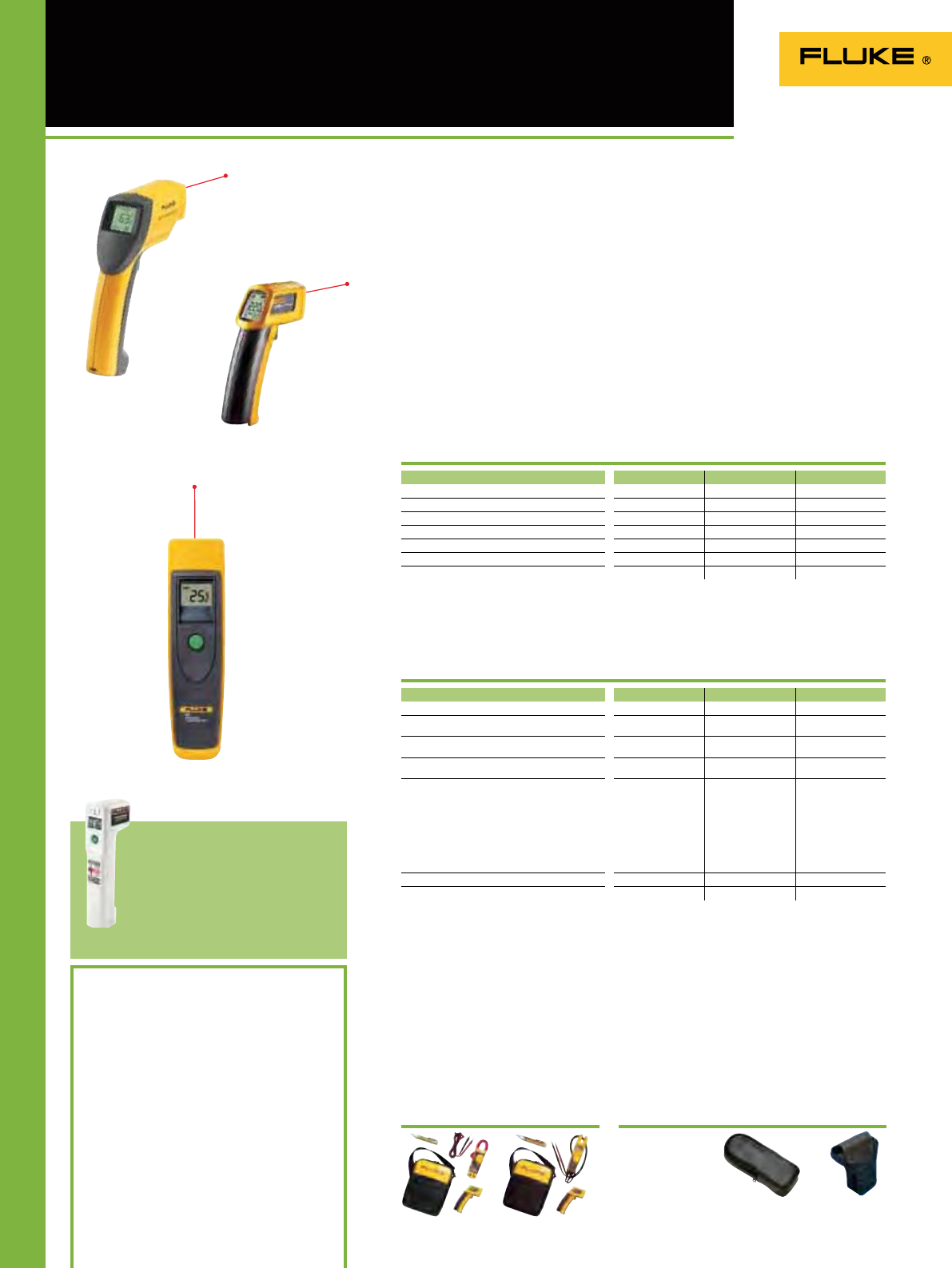
52
61 62 63
Range - 18 to 275ºC - 30 to 500 ºC - 32 to 535 ºC
Response time < 500ms < 500ms
(95 % of reading) ≤ 0.5 second
Resolution 0.2 ºC 0.2 ºC 0.2 ºC
Repeatability
(% of reading) ± 2%
or ± 2 ºC* ± 0.5%
or < ± 1 ºC* ± 0.5%
or ≤ ± 1 ºC*
Accuracy:
(assumes ambient operating temperature of 23ºC) For targets at:
-18 to -1ºC: ± 3ºC
-1 to 275ºC: ± 2% of
reading or ± 2ºC
For targets at:
10 °C to 30 °C: ±1 °C
± 1.5% of reading
or ± 1.5°C whichever
is greater over
the balance of the
range
For targets at:
-32 to -26°C: ± 3°C
-26 to -18°C: ± 2.5°C
-18 to 23°C: ± 2°C
23°C -510°C: ± 1%
of reading or ± 1°C*
For targets
above 510°C:
± 1.5% of reading
Typical distance to target Up to 1m Up to 1.5 m Up to 2 m
Emissivity Fixed at 0.95 Pre-set to 0.95 Fixed at 0.95
61 62 63
Form factor Flat grip Pistol grip Pistol grip
Temperature range -18 to 275°C -30 to 500 °C -32 to 535°C
Optical resolution 8:1 10:1 12:1
Laser beam for accurate targeting
OOO
Backlit LCD display
OOO
Use selectable °C or °F
OOO
Min/max/avg/dif readings Max Max
60 Series
Infrared Thermometers
Battery Life:
Fluke 63: 10 hours with laser and backlight on
Fluke 62: 12 hours with laser and backlight on
Fluke 61: 12 hours with laser and backlight on
Size (HxWxD):
Fluke 63: 200 mm x 160 mm x 55 mm
Fluke 62: 152 mm x 101 mm x 38 mm
Fluke 61: 184 mm x 45 mm x 38 mm
Weight:
Fluke 63: 0.320 kg
Fluke 62: 0.200 kg
Fluke 61: 0.227 kg
Fluke 62: 2 years warranty
Other models: one year warranty
* whichever is greater
Included Accessories
Fluke 61: 9V Battery
Fluke 62: 9V Battery, storage holster
Fluke 63: Hard carrying case, 9V batteries
Ordering information
Fluke 61 Infrared Thermometer
Fluke 62 Mini Infrared Thermometer
Fluke 63 Infrared Thermometer
Fluke 62/322/1AC-E (see page 5)
Fluke T5-600/62/1AC (see page 5)
Fluke FP FoodProTM Food Safety
Thermometer
Fluke FP Plus FoodProTM Plus
Food Safety Thermometer
The Fluke 60 Series non-contact
thermometers are the ideal professional
diagnostic tools for quick and accurate
temperature measurements.
These handheld tools are ideal for
measuring surface temperatures of
rotating, hard-to-reach, electricity live
or dangerously hot targets like electrical
motors and – panels, and heating and
ventilation systems.
The laser sighting system guides
measurements to the right target and in
less than a second, the large temperature
display provides a readout of the surface
temperature.
The 60 Series IR thermometers
feature:
• Laser guided sighting system for easy
targeting with 1% accuracy
• Up to 12:1 optical resolution
• Backlit display for easy reading in the
dark
• Temperatures up to 535°C
The Fluke FoodPro™ thermometer
series provide advanced
temperature measurement solutions
for the foodservice industry. Check
the Fluke web for more information.
Features
Specifications
H6
See page 131
Recommended Accessories
C23
See page 130
Fluke 62/322 kit T5-600/62/1AC-E
Point, press and read temperature
Kits
Fluke 63
Fluke 62
Fluke 61
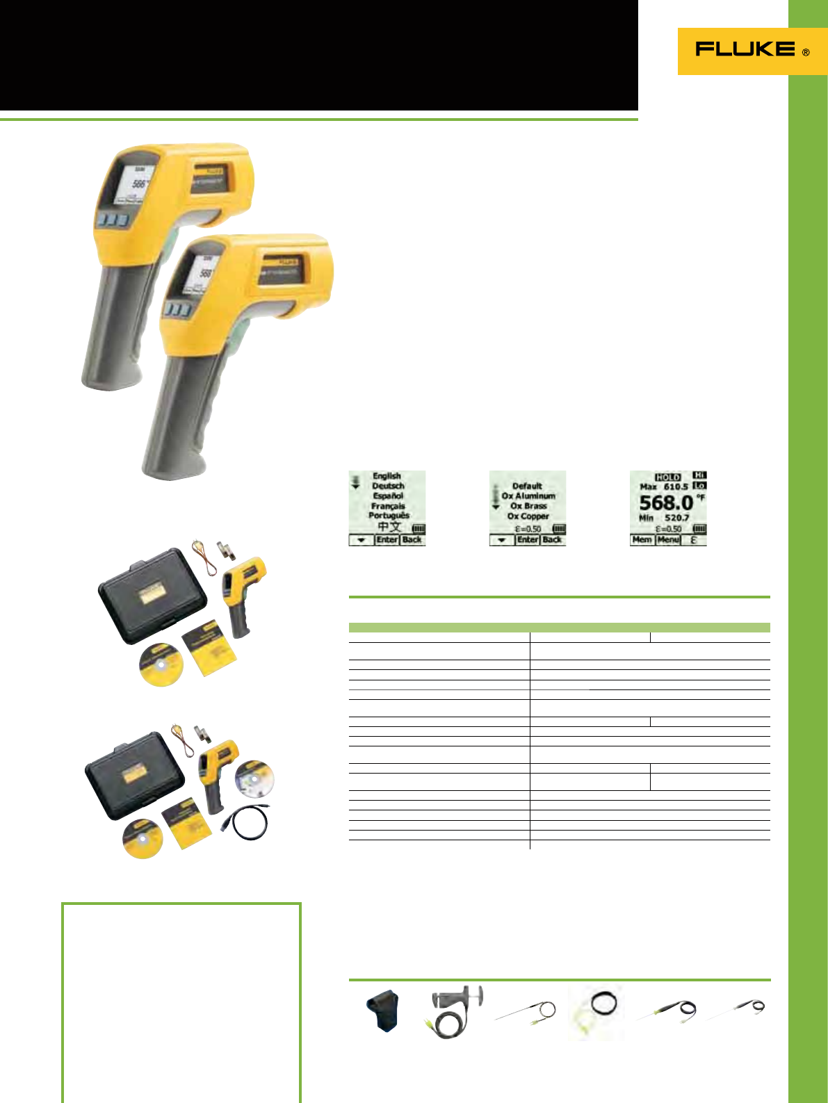
53
566 and 568
Multipurpose Thermometers
Fluke 566
Fluke 568
The Fluke 566 and included accessories
Specifications
Power: 2 AA/LR6 Batteries (566); 2 AA/LR6
Batteries and USB for use with a PC (568)
Battery life: Used continuously; laser and
backlight on: 12 hours; laser and backlight off:
100 hours
Weight: 0.965 kg (566); 1.026 kg (568)
Size (HxLxW): 25.4 cm x 19.1 cm x 6.9 cm
Operating temperature: 0 °C to 50 °C
Storage temperature: -20 °C to 60 °C
Two years warranty
Included accessories
FlukeView® Forms software (568 only), USB
cable (568 only), K-type thermocouple bead
probe, 2 AA batteries, hard carrying case,
quick start guide, and users manual.
Ordering information
Fluke 566 Infrared thermometer
Fluke 568 Infrared thermometer
With a straight-forward, menu-driven
user interface and graphical display,
the Fluke 566 and 568 multipurpose
thermometers make even complex
temperature measurements easy. Quickly
navigate and adjust emissivity, start data
logging, or turn on and off alarms, with
just a few pushes of a button. For added
convenience, both rugged handheld
thermometers combine contact and
non-contact temperature measurement
capability, providing a total temperature
measurement solution for any service
and maintenance program.
• Easily access advanced features with
the soft-key buttons and graphical
display
• Measure smaller targets from farther
away using the IR thermometer
• Adjustable emissivity and built-in table
of common materials for higher IR
accuracy
• Quickly identify problems with the MIN,
MAX, AVG, and DIF functions
• 2-color ashing alarm alerts you
visually when measurements exceed
limits
• Includes Type K thermocouple bead
probe
• Compatible with all standard mini-
connector K-type thermocouples
• Data logging with a date/time stamp
• Soft rubber boot for increased
ruggedness
• User interface available in 6 languages
Choose your language Select the measurement surface See complete measurement details
in seconds
(Check the Fluke web for detailed specifications)
The Fluke 568 and included accessories
566 568
Infrared temperature range -40 °C to 650 °C -40 °C to 800 °C
Infrared accuracy < 0 °C : ± (1.0 °C + 0.1°/1 °C);
> 0 °C : ± 1 % or ± 1.0 °C, whichever is greater
Display resolution 0.1 °C
Infrared spectral response 8 µm to 14 µm
Infrared response time < 500 msec
Input temperature range -270 °C to 1372 °C
Input accuracy -270 °C to -40 °C: ± (1 °C + 0.2 °/1 °C)
-40 °C to 1372 °C: ± 1 % or 1 °C, whichever is greater
D:S (Distance to measurement spot size) 30:1 50:1
Laser sighting Single-point laser < 1 mw output Class 2 (II) operation, 630 nm to 670 nm
Minimum spot size 19 mm
Emissivity adjustment By built-in table of common materials or digitally adjustable
from 0.10 to 1.00 by 0.01
Data logging with Date/Time stamp 20 points 99 points
PC interface and cable None USB 2.0 with FlukeView®
Forms software
Hi/Low alarms Audible and two-color visual
Min/Max/Avg/Dif Yes
Display Dot matrix 98 x 96 pixels with function menus
Backlight Two levels, normal and extra bright for darker environments
Trigger Lock Yes
Switchable between Celsius and Fahrenheit Yes
80PK-26
See page 128
Recommended Accessories
80PK-25
See page 128
80PK-11
See page 128
80PK-9
See page 128
80PK-8
See page 128
H6
See page 131
The two-in-one infrared and contact thermo-
meter with an innovative graphical display

54
561
Multipurpose Thermometer
Fluke 561
The Fluke 561 includes everything you need for
immediate inspections.
Specifications
Temperature range -40° to 550°C
Display resolution 0.1° of reading
D:S (Distance to spot size) 12:1
Easy emissivity selector Adjustable with three settings: low (0.3), medium (0.7), high (0.95)
Display accuracy (Assumes ambient operating
temperature of 23° to 25°C) ± 1.0% of reading or ± 1°C, whichever is greater; below 0°C, ± 1°C, ± 1°/1°
Response time 500 mSec (95% or reading)
Repeatability ± 0.5% of reading or ± 1°C, whichever is greater
Spectral focus 8 µm to 14 µm
Laser sighting Single-point laser
Laser shutoff Laser turns off above ambient temperature of 40°C
Laser power Class 2 (II) operation; output ‹ 1 mW, wavelength 630 nm to 670 nm
Relative humidity 10% to 90% RH non-condensing, at < 30°C
Power 2 AA batteries (alkaline or NiCD)
Display hold 7 seconds
Backlit display Yes, LCD with dual temperatures (current and MAX/MIN/DIF/KTC), low battery,
F/C indicator, and Scan/Hold options
Operating temperature 0° to 50°C
Storage temperature -20 to 65°C
MAX, MIN, DIF temperatures Yes
Thermocouple type K mini-adapter input Yes, compatible with industry standard type K probes with mini-connector
Thermocouple type K Velcro pipe probe Yes, with a temperature range of 0° to 100°C and accuracy of ± 2.2°C
Measurement guide Yes
Battery Life (alkaline): 12 hours
Size (HxLxW): 176,9 mm x 163,6 mm x 51,8 mm Weight: 340 grams
Two years warranty
Included accessories
Thermocouple K-type Velcro pipe probe,
hand carrying case, 2 AA batteries and user
manual with measurement guide.
Ordering information
Fluke 561 HVACPro Thermometer
The Fluke 561 combines the temperature
measurement functions that industrial,
electrical, and HVAC/R professionals
need, all in one tool. It measures both
IR and contact temperature, replacing
several other test tools. It’s fast, efcient,
and easy to use, saving you valuable time
and effort. With the Fluke 561, you can
take contact and ambient temperatures
in the way that’s best for you. Use the IR
thermometer to measure hot, moving,
electrically energized, and hard-to-
reach objects instantly. Check motors,
insulation, breakers, radiant heating,
pipes, corroded connections, and wires.
Plus, scan ducts, and other hard-to-reach
objects from the oor—leave your ladder
in the truck. You can use the Fluke 561’s
handy Velcro® pipe probe or, plug in any
industry standard, K-type mini-connector
thermocouple probe you already own.
• IR thermometer for quick
measurements up close or at a distance
• Single-point laser sighting
• Easy emissivity adjustment for
measuring pipes and ducts more
accurately
• Includes a Velcro pipe probe for super-
heat and sub-cooling as well as other
surface contact measurements
• Also compatible with all standard mini-
connector K-type thermocouples
• MIN, MAX and DIF temperature
readings
• Lightweight (only 340 grams) and
portable
• Includes measurement guide
80PK-8
See page 128 80PK-25
See page 128
Recommended Accessories
80-PK-1
See page 128
H6
Se page 131
Combined Infrared and Contact Thermometer
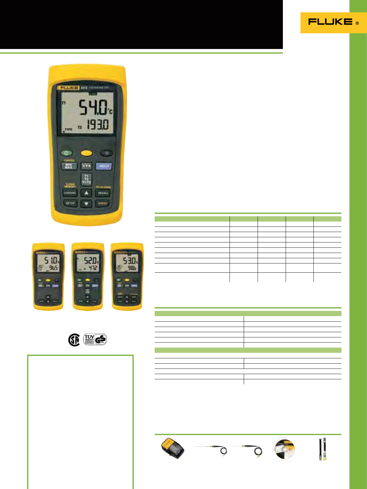
55
50 Series II Thermometers
FVF-SC 2
See page 132 TPAK
See page 132
Recommended Accessories
Fluke 54 II B
Fluke 51 II
Features
80PK-25
See page 128
Battery life: 1000 hours typical, AA
Size (HxWxD): 173 x 86 x 38 mm Weight: 0.4 kg
Three Year Warranty
Included Accessories
Impact absorbing holster
Two bead probe thermocouples 80PK-1 (54+52)
One bead probe thermocouple 80PK-1 (51+53)
Ordering Information
Fluke 51 II Thermometer
Fluke 52 II Thermometer
Fluke 53 II B Thermometer
Fluke 54 II B Thermometer
FVF-SC2 FlukeView Forms Software
including USB interface cable
The Fluke 50 Series II contact
thermometers offer fast response and
laboratory accuracy (0.05% + 0.3°C) in
a rugged handheld test tool.
• Large backlit dual display shows any
combination of T1, T2 (52 and 54 only),
T1-T2 (52 and 54 only) plus MIN, MAX,
or AVG
• Relative time clock on MIN, MAX, and
AVG provides a time reference for major
events
• Electronic Offset function allows
compensation of thermocouple errors
to maximize overall accuracy
• Readout in °C, °F, or Kelvin (K)
• Sleep mode increases battery life
• Battery door allows easy battery
replacement without breaking the
calibration seal
Additional features for the 53 and
54 Series II:
• Data Logging up to 500 points of data
with user adjustable recording interval
• Real time clock captures the exact time
of day when events occur
• Recall function allows logged data to be
easily reviewed on the meter display
• IR communication port allows data to
be exported to optional FlukeView®
PC software
51 II 52 II 53 II B 54 II B
Thermocouple types J,K,T,E J,K,T,E J,K,T,E,N,R,S J,K,T,E,N,R,S
Number of inputs Single Dual Single Dual
Time stamp Relative Time Relative Time Time of Day Time of Day
Splash/Dust resistant
OOOO
Dual display with backlight
OOOO
Min/Max/Avg recording
OOOO
(T1-T2) True differential
OO
Data logging up to 500 points
OO
IR data port for interface
to PC
OO
Compatible with optional
FlukeView Software
OO
80PK-26
See page 128
Fluke 52 II Fluke 53 II B
Specifications
C25
See page 130
**Only the Fluke Models 53 and 54 Series II thermometers are capable of measuring N, R, and S-type
Temperature range:
J-type Thermocouples -210°C to 1200°C
K-type Thermocouples -200°C to 1372°C
T-type Thermocouples -250°C to 400°C
E-type Thermocouples -150°C to 1000°C
N-type** Thermocouples -200°C to 1300°C
R** and S-type** Thermocouples 0°C to 1767°C
Temperature accuracy
Above –100°C (-148°F):
J, K, T, E, and N-type** ± [ 0.05% + 0.3°C ]
R** and S-type** ± [ 0.05% + 0.4°C ]
Below –100°C (-148°F):
J, K, E, and N-types ± [ 0.20% + 0.3°C ]
T-type ± [ 0.50% + 0.3°C ]
Laboratory accuracy. Wherever you go.
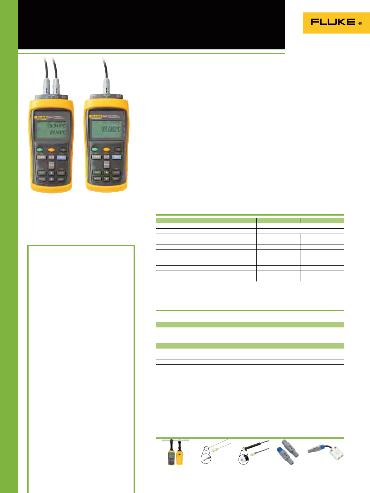
56
1523 and 1524
Reference Thermometers
2384P and 2384T
Spare INFO-CON Adapters 2373-LTC
Universal TC adapter
Recommended Accessories
Fluke 1524
Features
FLK80P3
(80PK-3A with universal
thermocouple adapter)
Battery life (alkaline): 20 hours
Power supply: Universal 12 Vdc
Size (HxWxD): 200 x 96 x 47 mm
Weight: 0.65 kg
Warranty: 1 year
Measure, graph and record three
sensor types with one tool. The Fluke
1523/24 Reference Thermometer deliver
high accuracy, wide measurement
range, logging, and trending, all in a
handheld tool you can take anywhere.
For top accuracy, a memory chip inside
the probe connector feeds probe
calibration information to the readout.
In addition, any thermocouple with
a mini-thermocouple connector can
be read using the optional universal
thermocouple adapter. Choose the 1523
for single channel or the 1524 for dual
channel measurement.
Three sensor types
• PRTs: –200 °C to 1000 °C
• Thermocouples –200 °C to 2315 °C
• Precision thermistors: –50 °C to 150 °C
High accuracy
• PRTs: ±0.011 °C
• Thermocouples: ±0.24 °C for J,K,L,M
• Precision thermistors: ±0.002 °C
Fast measurement
• PRTs: up to 0.45 seconds/sample
• Thermocouples: up to 0.3 seconds/
sample
• Precision thermistors: up to 0.3
seconds/sample
Two models
• 1523: Single channel standard model;
memory for 25 readings & statistics
• 1524: Two channels; memory for 25
readings and statistics plus logging
15,000 measurements; real-time clock
for time and date stamps
1523 1524
Sensor Types PRT & RTD, Thermistor, and Thermocouple
Thermocouple Types B,C,E,J,K,L,M,N,R,S,T,U
Number of inputs Single Dual
Data trending (graphing)
OO
Graphical display with backlight
OO
Min/Max/Avg/Standard deviation recording
OO
High speed measurement
OO
RS-232 PC communications
OO
T1-T2 True differential
O
Data logging up to 15,000 points
O
Time and date stamp
O
FLK80P1
(80PK1 with universal
thermocouple adapter)
Fluke 1523
Specifications
TPAK
Temperature range
Thermocouple –200 °C to 2315 °C
PRT & RTD –200 °C to 1000 °C
Thermistor –50 °C to 150 °C
Resolution and best accuracy
Thermocouple 0.01 °, ±0.24 °C
PRT & RTD 0.001 °, ±0.011 °C
Thermistor 0.001 °, ±0.002 °C
Operating temperature –10 °C to 60 °C
Storage temperature –20 °C to 70 °C
A new standard in
accuracy and versatility.
Included Accessories
NIST traceable certicate of calibration, users
guide, CD-ROM (contains technical manual),
12 V dc universal power supply, RS-232 cable,
9940 I/O ToolKit software
Ordering Information
Fluke 1523* Reference Thermometer
Fluke 1524* Reference Thermometer
Fluke 1523-P1 Reference Thermometer,
PRT(–200 °C to 420 °C, 6.35
mm x 298 mm), Universal
Thermocouple Adapter, TPAK,
and Case
Fluke 1524-P1 Reference Thermometer,
PRT(–200 °C to 420 °C, 6.35
mm x 298 mm), Universal
Thermocouple Adapter, TPAK,
and Case
* Requires an optional probe
Optional Accessories
2384-P INFO-CON Connector, PRT
(Gray Cap), Spare
2384-T INFO-CON Connector,
Thermocouple (Blue Cap),
Spare
2373-LPRT RTD Adapter, Lemo to
Mini Grabbers (4-wire)
Optional probes:
5616-12-P PRT, 6.35 mm x 298 mm,
–200 °C to 420 °C
5615-9-P PRT, 4.76 mm x 229 mm,
–200 °C to 420 °C
5610-9-P Thermistor, 3.2 mm x 229 mm,
0 °C to 100 °C
(Check the Fluke web for detailed specifications)
Note: The 1523/24 are pictured with probes connected which may
be purchased seperately.

57
1551A Ex 1552A Ex
Temperature range –50 °C to 160 °C –80 °C to 300 °C
Accuracy (1 year) ±0.05 °C
Display units °C, °F
Sensor type 100 thin film RTD 100 wire-wound PRT
Probe temperature coefficient 0.00385 //°C nominal
Sensor length ≤ 10 mm ≤ 30 mm
Sensor position (from sheath tip) 3 mm
Minimum immersion depth170 mm 120 mm
Probe sheath material SST
Response time 4.8 mm diameter probe (3/16 in): 14 seconds
6.35 mm diameter probe (1/4 in): 21 seconds
Probe hysteresis ±0.01 °C
Temperature resolution Selectable: 0.1, 0.01, 0.001 (default 0.01)
Sample rate Selectable: 0.5, 1, 2, seconds (default 1)
Operating temperature range of readout –10 to 50 °C
Storage temperature –20 °C to 60 °C , 0 to 95% RH, non-condensing
Optional data logging2 Up to 10k time-stamped readings stored to internal memory
Logging intervals2 2, 5, 10, 30, or 60 seconds; 2, 5, 10, 30, or 60 minutes
Averaging Moving average of most recent 2 to 10 readings, user selectable
(ON/OFF, 2,5,10)
Communications RS-232 stereo jack (access calibration parameters only)
EMC compliance EN61326:2006 Annex C; CISPR II, Edition 5.0-2009; Class “B”
Enclosure rating IP50
Calibration NVLAP accredited, NIST Traceable System Calibration
Characterization CVD ITS-90
1 Per ASTM E 644
2 See ordering information for optional data logging configurations
1551A Ex / 1552A Ex Intrinsically
Safe “Stik” Thermometers
Included Accessories
NVLAP –accredited report of calibration, user’s
guide on CD-ROM, 3 AAA batteries
Ordering Information
1551A-9 “Stik” Thermometer
1551A-12 “Stik” Thermometer
1551A-20 “Stik” Thermometer
1551A-9-DL “Stik” Thermometer with
datalogging
1551A-12-DL “Stik” Thermometer with
datalogging
1551A-20-DL “Stik” Thermometer with
datalogging
1552A-12 “Stik” Thermometer
1552A-12-DL “Stik” Thermometer with
datalogging
Note: Model number appended with a -9, -12, -20
indicates probe sheath length in inches. All probe
diameters are 6.35 mm with the exception of the
1551A-9, which is 4.8 mm diameter
Finally, a digital substitute for your
mercury-in-glass thermometers! Highly
accurate and durable, the Fluke 1551A
Ex/1552A Ex “Stik” Thermometer is soon
to become the new “gold standard” of
industrial temperature calibration.
Whether working outdoors in
environments where potentially
explosive gases may be present or on
the oor of a processing plant, the
intrinsically safe, battery-operated,
portable reference thermometer is
designed to go where you work.
The RTD sensor of the “Stik” Thermometer
is housed in a rugged stainless steel
sheath—you no longer have to worry
about breaking a mercury-in-glass
thermometer and the subsequent
cleanup. The probe and digital readout
are xed together, calibrated as a system,
and accurate to ± 0.05 °C over the full
temperature range. The large backlit
LCD display rotates 90° making it easy
to read from any position. Minimize
measurement errors with the user-
congurable temperature trend/stability
indicator which tells you when your
temperature source is stable or if your
temperature is trending up or down.
• ± 0.05 °C accuracy over full range
• Intrinsically safe (ATEX compliant)
• Display temperature in °C or °F
• Optional data logging to internal
memory
• Temperature trend indicator
• User selectable resolution (0.1, 0.01,
0.001)
• 300 hour battery life
• Percent battery-life and low battery
indicator
• NVLAP accredited calibration
(NIST traceable)
Battery Life: 300 hours typical without LCD, 3 AAA
Size (HxWxD): 114 x 57 x 25 mm
Weight: 196 grams
Warranty: 1 year
Specifications
The new “gold standard” of industrial
temperature calibration
1552A Ex
1551A Ex
1551-CASE
Carrying case 1551-CBL
RS-232 cable
Recommended Accessories
New

5858
Temperature changes can indicate problems in many everyday
applications and a thermal imager makes it quick and easy to visually
check surface temperatures. Often problems can be discovered before
contact measurements even need to be made. Fluke offers a complete
range of handheld thermal imagers for both industrial and building
diagnostic applications. Models are available for any budget.
Thermal Imagers

59
Ti Series Thermal Imagers
Overheating bearing cap
See things both ways - Infrared and
visual (visible light) images fused
together communicating critical
information faster and easier –
traditional infrared images are no longer
enough. Patented IR-Fusion® Technology,
only available from Fluke, simultaneously
captures a digital photo and the infrared
image and fuses them together taking
the mystery out of IR image analysis.
Three-phase switch-gear
load imbalance
Overheated motor Cool corner in a building
SmartView® Software
Fluke SmartView® software is included with each Fluke
Thermal Imager. This powerful software is a modular
suite of tools that annotates, views, edits and analyzes
IR images.
It also generates fully customizable and professional-
looking reports in a few easy steps. The IR-Fusion
technology is fully supported.
FREE webinars/webcasts on
Thermal Imaging
Keep up-to-date on the latest troubleshooting
techniques. Attend a FREE Fluke webinar (web-based
seminar) about thermal imaging applications.
Go to the Fluke website for more information.
Picture-in-Picture Alpha BlendingFull IR
Full Visible Light
Find it, fix it, fast!
Temperature changes can indicate problems
in many areas you see everyday, some
include:
• Inside electrical distribution and service
(Switch gear, panels, controls,
fuses,transformers, receptacles, lighting,
conductors, bus bars, motor control
centers)
• Motors, pumps and mechanical (Electric
motors and generators, pumps,
compressors, evaporators, bearings,
couplings, gearboxes, gaskets/seals, belts,
rollers, disconnects)
• Process (Tanks and vessels, pipes, valves
and traps, reactors, process insulation)
• HVAC/R (air conditioning, heating, air
handlers, refrigeration)
• Outside electrical distribution - utilities
(Transformers, bushings, insulators,
transmission lines, other exterior
conductors, service connections,
disconnects, capacitor banks)
IR/Visible Alarm
IR-Fusion® Technology: Infrared and
visual images fused together in one image
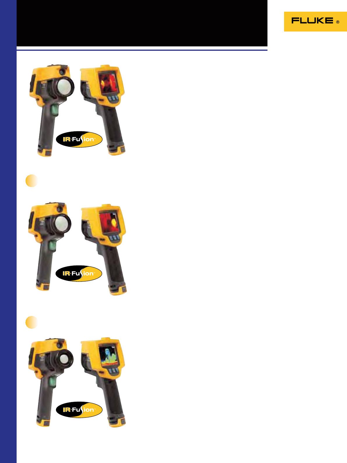
60
Ti32/Ti29/Ti27 Industrial/
Commercial Thermal Imagers
Designed for industrial and commercial environments, the Fluke P3 Series of
thermal imagers deliver superior image quality, versatility, and affordability without
compromise. They also boast superior infrared resolution, industry leading spatial
resolution, and a high denition display creating the sharpest images in their price
classes. Finding a potential problem before it becomes a costly disaster shows you
just how much a Fluke thermal imager can save you in time, money and even lifes.
The New P3 Series from Fluke
• Delivers the clear, crisp images needed to nd problems fast with up to 320 x 240
sensor.
• Identify even the smallest temperature differences that could indicate problems
with industry-leading thermal sensitivity (NETD), down to 45 mK.
• Automatic alignment (parallax correction) of visual and infrared images with Fluke
patented IR-Fusion®.
• Optional telephoto and wide angle lenses available for added versatility and special
applications (easily installable in the eld).
Superior image quality
• Field replaceable batteries give you maximum exibility no matter where your work
takes you.
• Intuitive, three-button menu is easy to use—simply navigate with the push of a
thumb.
• No need to carry pen and paper—record ndings by speaking into the imager. Voice
annotations can be recorded with every image you take. Voice comments are saved
along with individual images for future reference.
• One-handed focus capability, emissivity correction, reected background
temperature compensation, and transmission correction increase the accuracy of
measurements in most situations.
• Adjustable hand strap for left-or right-handed use.
• Everything needed to get started is included.
Easy to use
• Optimized for eld use in challenging work environments.
• Engineered and tested to withstand a 2 m drop for the ultimate peace of mind.
• Withstands dust and water—tested to an IP54 rating.
• With their rugged design, integrated lens cover, protected display and 2 meter drop
test, they are designed to handle the harshest environments.
Rugged
New
New
Fluke Ti32
Fluke Ti29
Fluke Ti27
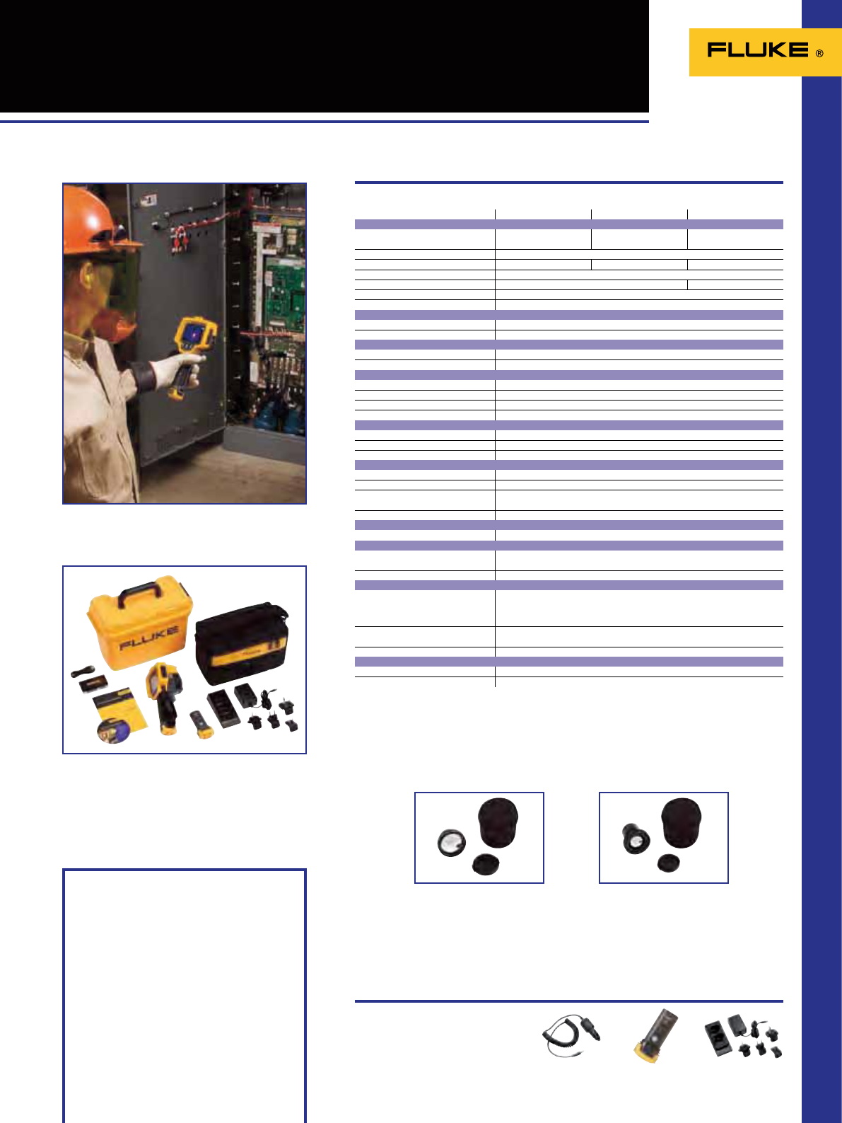
61
Ti32/Ti29/Ti27 Industrial/
Commercial Thermal Imagers
Specifications
Water and dust resistant: IP54
Size (HxWxD): 277 x 122 x 170 mm
Weight: 1.05 kg
Two Years Warranty
Fluke Ti27 Fluke Ti29 Fluke Ti32
Thermal imaging performance
Detector type 240 x 180 Focal Plane Array,
uncooled microbolometer 280 x 210 Focal Plane Array,
uncooled microbolometer 320 x 240 Focal Plane Array,
uncooled microbolometer
Field of view (FOV) 23 º horizontal x 17 º vertical
Spatial resolution (IFOV) 1.67 mRad 1.49 mRad 1.25 mRad
Min focus distance 15 cm
Thermal sensitivity (NETD) ≤0.05 °C at 30 °C (50 mK) ≤0.045 °C at 30 °C (45 mK)
Minimum span (auto/manual) 2.5 °C / 5 °C
Focus Manual
Optional telephot infrared lens type
Field of view (FOV) 11.5” x 8.7”
Minimum focus distance 45 cm
Optional wide-angle infrared lens type
Field of view (FOV) 46” x 34”
Minimum focus distance 7.5 cm
Visual imaging performance
Minimum focus distance 46 cm
On camera operating modes Picture-in-Picture and full screen IR plus Blending
Color Alarm High temperature alarm
Visible light camera 2.0 MegaPixel
Temperature measurement
Temperature range -20 °C to 600 °C
Accuracy
±2 °C or 2%
Measurement modes
Center point and hot and cold markers
Image presentation
Digital display 9.1 cm (3.7”) landscape color VGA (640x480) LCD
LCD backlight Selectable bright or auto
Palettes
Ironbow, Blue-Red, High Contrast, Amber, Amber Inverted, Hot Metal, Grayscale,
Grayscale Inverted
Ultra Contrast Palettes
O
Voice Annotation
Voice annotation
O
Image and data storage
Storage medium 2GB SD Card (3000 .bmp IR images/1200 .IS2 images)
File formats supported JPG, JPEG, JPE, JFIF, BMP, GIF, DIB, PNG, TIF, and TIFF
Controls and adjustments
Set-up controls Date/time, Cº/ºF, language
On screen emissivity correction
On-screen reflected background temperature compensation
On-screen transmission correction
Language selection Eng, ger, fre, spa, por, ita, swe, fin, rus, cze, pol, tur
Image controls Smooth auto scaling and manual scaling
Power
Battery type Two replaceable rechargeable battery packs (Lithium ion)
Battery operating time 4+ hours per battery pack
FLK-LENS/TELE1
Telephoto Infrared Lens FLK/LENS/WIDE
Wide-angle Infrared Lens
FLK-TI-SPB3
Extra battery FLK-TI-SBC3
Charging base
Ti-Car Charger
Car charger
Recommended Accessories
Included Accessories
SmartView® software
2 GB SD card
SD card reader
Rugged hard carrying case
Soft carrying case
Hand strap
Rechargeable battery (extra)
AC charger/power supply
User manual
Ordering Information
Fluke Ti27 Thermal Imager
Fluke Ti29 Thermal Imager
Fluke Ti32 Thermal Imager
Complete package
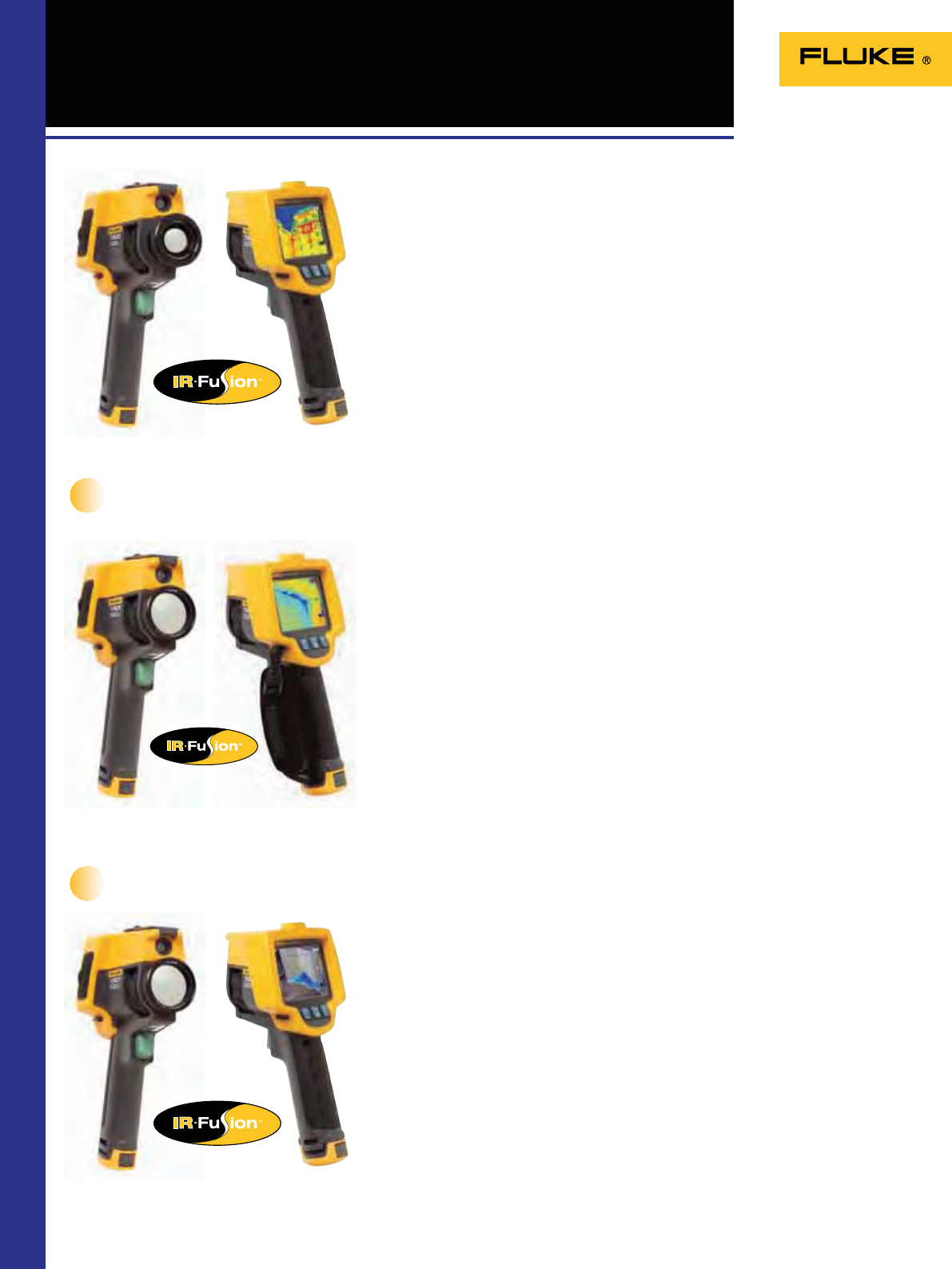
62
TiR32/TiR29/TiR27 Building
Diagnostic Thermal Imagers
Designed specically for the building inspection professional, the Fluke P3 Series
of thermal imagers deliver the perfect balance between performance and price.
They also boast superior infrared resolution, spatial resolution, and high denition
displays. The P3 Series delivers crisp images and impressive reports with the
included professional SmartView® software. Whether you’re searching for energy
waste, leaky roofs or moisture problems, Fluke P3 thermal imagers offer tested and
proven technology that takes the guesswork out of nding problems and provides
solutions.
The New P3 Series from Fluke
• Delivers the clear, crisp images needed to nd problems fast
• Identify even the smallest temperature differences that could indicate problems
with industry-leading thermal sensitivity (NETD), down to 40 mK.
• Automatic alignment (parallax correction) of visual and infrared images with Fluke
patented IR-Fusion®
• Optional telephoto and wide angle lenses available for added versatility and special
applications (easily installable in the eld).
Superior image quality
• Field replaceable batteries give you maximum exibility no matter where your work
takes you.
• Intuitive, three-button menu is easy to use—simply navigate with the push of a
thumb.
• No need to carry pen and paper—record ndings by speaking into the imager. Voice
annotations can be recorded with every image you take. Voice comments are saved
along with individual images for future reference.
• One-handed focus capability, emissivity correction, reected background
temperature compensation, and transmission correction increase the accuracy of
measurements in most situations.
• Adjustable hand strap for left-or right-handed use.
• Everything needed to get started is included.
Easy to use
• Optimized for eld use in challenging work environments.
• Engineered and tested to withstand a 2 m drop for the ultimate peace of mind.
• Withstands dust and water—tested to an IP54 rating.
• With their rugged body, integrated lens cover, protected display and 2 meter drop
test, they are designed to handle the harshest environments.
Rugged
Fluke TiR32
Fluke TiR29
Fluke TiR27
New
New
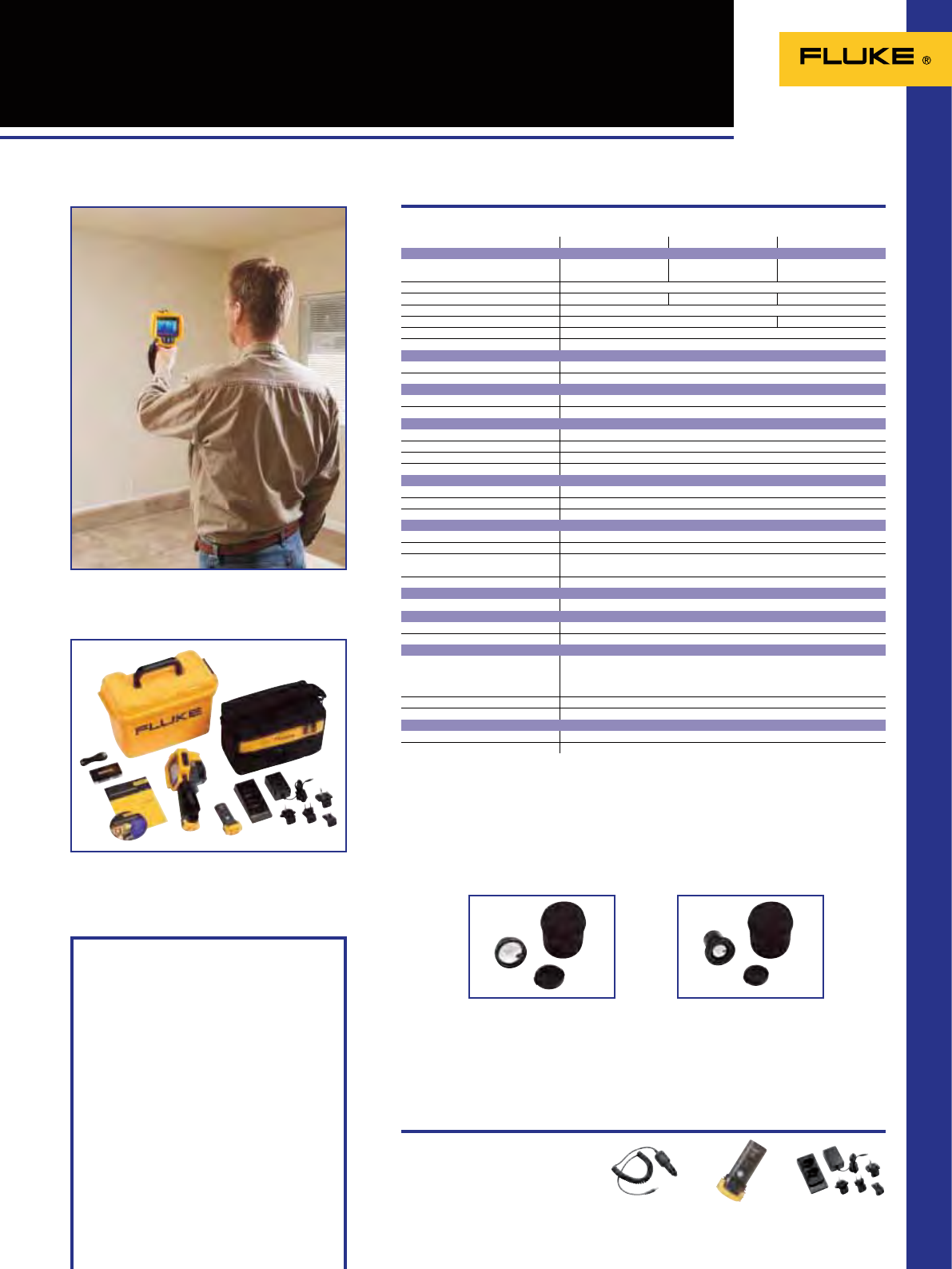
63
TiR32/TiR29/TiR27 Building
Diagnostic Thermal Imagers
Recommended Accessories
FLK-TI-SPB3
Extra battery FLK-TI-SBC3
Charging base
Ti-Car Charger
Car charger
Included Accessories
SmartView® software
2 GB SD card
SD card reader
Rugged hard carrying case
Soft carrying case
Hand strap
Rechargeable battery (extra)
AC charger/power supply
User manual
Ordering Information
Fluke TiR27 Thermal Imager for
Building Diagnostics
Fluke TiR29 Thermal Imager for
Building Diagnostics
Fluke TiR32 Thermal Imager for
Building Diagnostics
Water and dust resistant: IP54
Size (HxWxD): 277 x 122 x 170 mm
Weight: 1.05 kg
Two Years Warranty
Complete package
Specifications
Fluke TiR27 Fluke TiR29 Fluke TiR32
Thermal imaging performance
Detector type 240 x 180 Focal Plane Array,
uncooled microbolometer 280 x 210 Focal Plane Array,
uncooled microbolometer 320 x 240 Focal Plane Array,
uncooled microbolometer
Field of view (FOV) 23 º horizontal x 17 º vertical
Spatial resolution (IFOV) 1.67 mRad 1.49 mRad 1.25 mRad
Min focus distance 15 cm
Thermal sensitivity (NETD) ≤0.045 °C at 30 °C (50 mK) ≤0.040 °C at 30 °C (40 mK)
Minimum span (auto/manual) 2.5 °C / 5 °C
Focus Manual
Optional telephot infrared lens type
Field of view (FOV) 11.5” x 8.7”
Minimum focus distance 45 cm
Optional wide-angle infrared lens type
Field of view (FOV) 46” x 34”
Minimum focus distance 7.5 cm
Visual imaging performance
Minimum focus distance 46 cm
On camera operating modes Picture-in-Picture and full screen IR plus Blending
Color Alarm Dewpoint alarm
Visible light camera 2.0 MegaPixel
Temperature measurement
Temperature range -20 °C to 150 °C
Accuracy
±2 °C or 2%
Measurement modes
Center point and hot and cold markers
Image presentation
Digital display 9.1 cm (3.7”) landscape color VGA (640x480) LCD
LCD backlight Selectable bright or auto
Palettes
Ironbow, Blue-Red, High Contrast, Amber, Amber Inverted, Hot Metal, Grayscale,
Grayscale Inverted
Ultra Contrast Palettes
O
Voice Annotation
Voice annotation
O
Image and data storage
Storage medium 2GB SD Card (3000 .bmp IR images/1200 .IS2 images)
File formats supported JPG, JPEG, JPE, JFIF, BMP, GIF, DIB, PNG, TIF, and TIFF
Controls and adjustments
Set-up controls Date/time, Cº/ºF, language
On screen emissivity correction
On-screen reflected background temperature compensation
On-screen transmission correction
Language selection Eng, ger, fre, spa, por, ita, swe, fin, rus, cze, pol, tur
Image controls Smooth auto scaling and manual scaling
Power
Battery type Two replaceable rechargeable battery packs (Lithium ion)
Battery operating time 4+ hours per battery pack
FLK-LENS/TELE1
Telephoto Infrared Lens FLK/LENS/WIDE
Wide-angle Infrared Lens
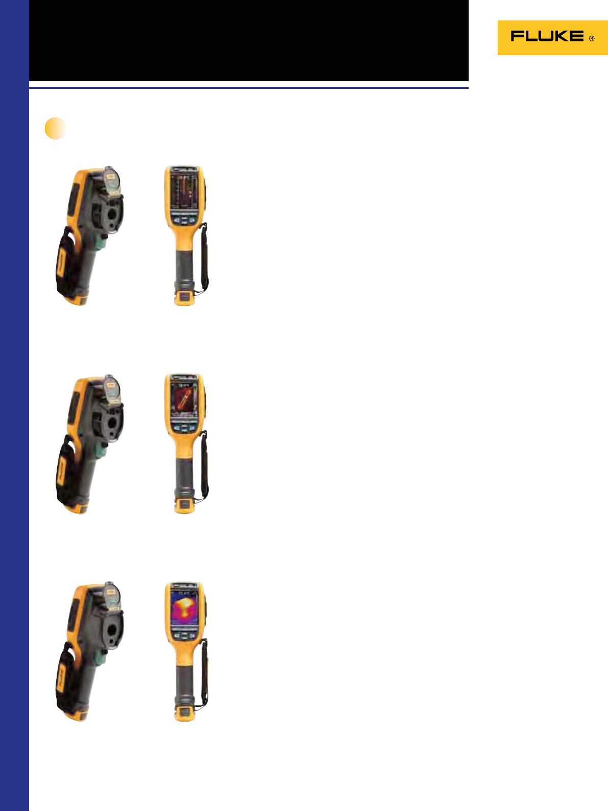
64
Ti125/Ti110/Ti100 Industrial /
Commercial Thermal Imagers
Ti125
Ti110
Ti100
New Industrial and commercial maintenance
made easy
Technology isn’t working for you if it’s slowing you down. Fluke proudly introduces
ve new thermal imagers specically designed to help you do more in less time,
while being at home in the harshest of environments. A project that might normally
take an hour can now be done in minutes. Our newest imagers are the lightest, most
rugged, easiest-to-use professional imagers you can buy.
IR-OptiFlex™ focus system
Discover issues signicantly faster with Fluke’s revolutionary, ultra-rugged focus
system. The IR-OptiFlex focus system gives you optimum focus by combining
focus-free ease-of-use with the exibility of manual focus on the same camera!
IR-Fusion® technology
Enjoy the industry’s best point-and-shoot IR-Fusion camera. Fluke patented
technology blends digital and infrared images into a single image to precisely
document problem areas.
Rugged one-hand operation
Experience the most rugged and reliable, lightweight professional camera around.
One-touch focus, laser pointer, and torch. Point-and-shoot simplicity. No one builds
more rugged, ergonomic tools than Fluke.
Multi-mode video recording
Troubleshoot with the industry’s only thermal imager that records focus-free video in
visible light and infrared with full IR-Fusion capabilities. Monitor processes over time,
easily create infrared video reports, and troubleshoot.
IR-PhotoNotes™ annotation system
Get an exact reference to your problem area by capturing up to three digital photos
per le. Add images of equipment, motor nameplates, workroom doors or any other
useful or critical information.
Electronic compass
Make sure you and others know the location of the problem. Compass readings easily
appear in images and reports.
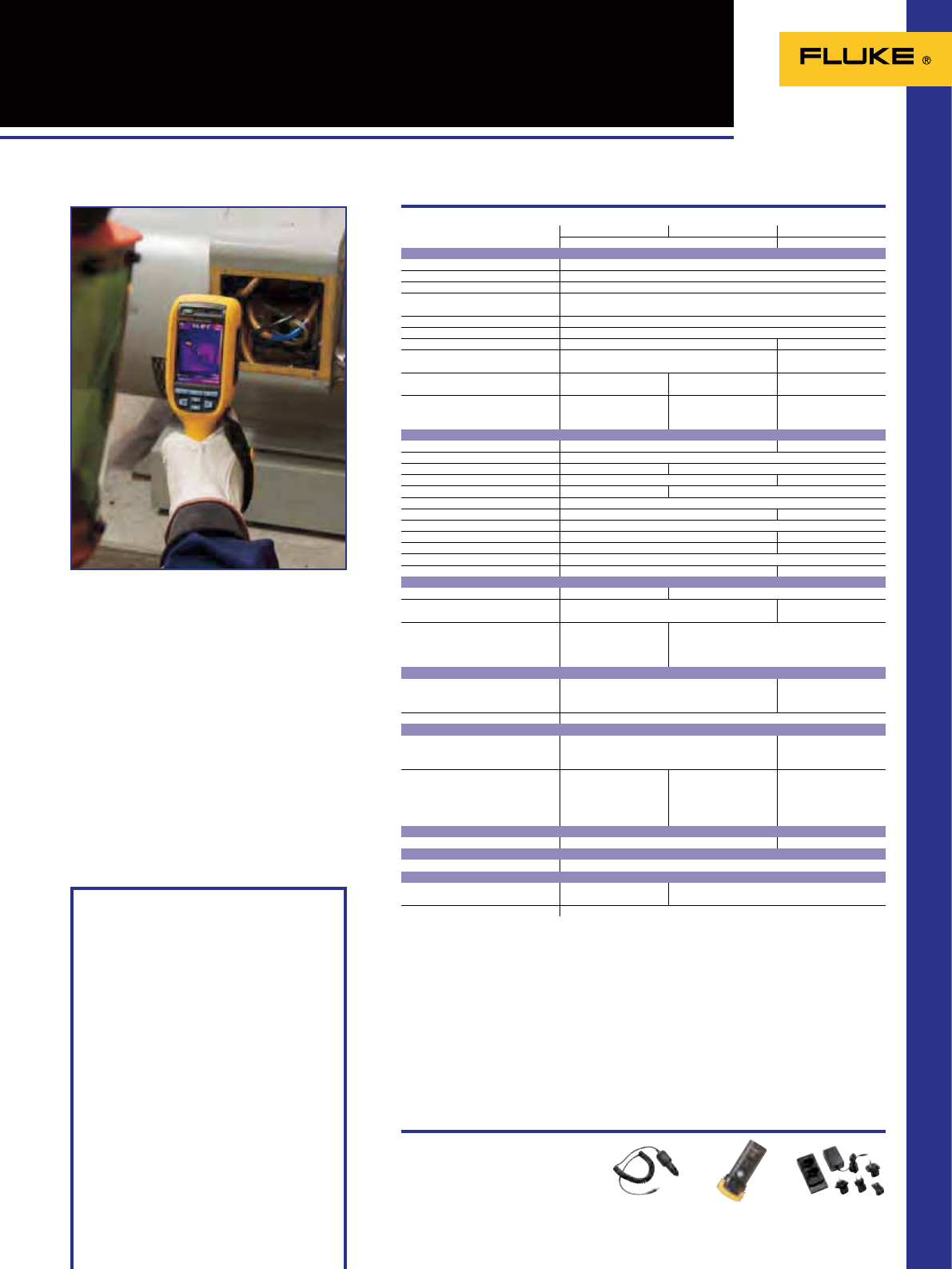
65
Ti125/Ti110/Ti100 Industrial /
Commercial Thermal Imagers
Recommended Accessories
Included Accessories
SmartView® software
AC power adapter
Lithium ion smart battery
USB cable
2 GB SD memory card
Hard carrying case
Soft transport bag
Adjustable hand strap
User manual
Two-bag charging base and multi-format USB
memory card reader (Ti125 only)
Ordering Information
Fluke Ti125 Industrial-Commercial
Thermal Imager
Fluke Ti110 Industrial-Commercial
Thermal Imager
Fluke Ti100 General Use Thermal
Imager
Water and dust resistant: IP54
Size (HxWxD): 284 x 86 x 135 mm
Weight: 0.726 kg
Two Years Warranty
Specifications
Fluke Ti125 Fluke Ti110 Fluke Ti100
Industrial-Commercial General
Thermal imaging performance
IR resolution (FPA size) 160 x 120 FPA Uncooled Microbolometer
Field of view (FOV) 22.5 °H x 31 °V
Spatial resolution (IFOV) 3.39 mRad
Thermal sensitivity (NETD) ≤ 0.10 °C at 30 °C target temp (100 mK)
Minimum span in auto mode 5 °C
Minimum span in manual mode 2.5 °C
Minimum IR focus distance 15.25 cm (6 in) 1.2 m (4 ft)
Focus mechanism IR-OptiFlex™ focus system Focus-free 1.2 m and
beyond
IR-Fusion® technology PIP, FULL IR, FULL VISIBLE,
AutoBlend PIP, FULL IR, FULL VISIBLE No, full IR only
Color alarms High temperature,
low temperature, isotherm High temperature -
Visual imaging performance
Visible camera 2 megapixel industrial-grade n/a
LCD display 3.5 inch diagonal (portrait format)
Hot/Cold markers Yes -
User definable spot markers Three on camera and in SmartView®in SmartView® only
Centerbox (MIN/AVG/MAX) Yes -
Level and span control Manual and auto
IR-PhotoNotes™ annotation system Yes (3 images) -
Laser pointer Yes
Torch Yes -
Electronic (cardinal) compass Yes -
Emissivity correction Yes
Transmission correction Yes -
Video
Multi-mode video output Streaming USB video output -
Multi-mode video recording
(standard AVI with MPEG encoding) Yes (AVI with MPEG encoding) -
Multi-mode video recording
(radiometric .IS3) Yes, radiometric .is3 for
approx.. 2.5 to 5 minutes
depending upon thermal
scene
-
Temperature measurement
Temperature measurement range
(not calibrated below -10° C) -20 °C to +350 °C -20 °C to +250 °C
Accuracy ± 2 °C or 2 % (at 25 °C nominal, whichever is greater)
Image presentation
Standard palettes Blue-Red, Grayscale, Inverted Grayscale, High-contrast,
Hot Metal, Ironbow, Amber, Inverted Amber Blue-Red, Ironbow,
Grayscale, Amber
Ultra Contrast™ palettes Blue-Red, Grayscale,
Inverted Grayscale,
High-contrast, Hot Metal,
Ironbow, Amber,
Inverted Amber
Blue-Red, Grayscale,
Ironbow -
Voice Annotation
Voice annotation Yes (60 seconds) per image -
Image and data storage
Memory storage 2 GB SD memory card
Power
Battery
(field-replaceable, rechargeable) Two One
Battery life 4+ hours (each) (assumes 50% brightness of LCD)
FLK-TI-SPB3
Extra battery FLK-TI-SBC3
Charging base
Ti-Car Charger
Car charger
66
TiR125/TiR110/Ti100 Building
Diagnostic Thermal Imagers
New Building diagnostics made easy
Technology isn’t working for you if it’s slowing you down. Fluke proudly introduces
ve new thermal imagers specically designed to help you do more in less time,
while being at home in the harshest of environments. A project that might normally
take an hour can now be done in minutes. Our newest imagers are the lightest, most
rugged, easiest-to-use professional imagers you can buy.
IR-OptiFlex™ focus system
Discover issues signicantly faster with Fluke’s revolutionary, ultra-rugged focus
system. The IR-OptiFlex focus system gives you optimum focus by combining
focus-free ease-of-use with the exibility of manual focus on the same camera!
IR-Fusion® technology
Enjoy the industry’s best point-and-shoot IR-Fusion camera. Fluke patented
technology blends digital and infrared images into a single image to precisely
document problem areas.
Rugged one-hand operation
Experience the most rugged and reliable, lightweight professional camera around.
One-touch focus, laser pointer, and torch. Point-and-shoot simplicity. No one builds
more rugged, ergonomic tools than Fluke.
Multi-mode video recording
Troubleshoot with the industry’s only thermal imager that records focus-free video in
visible light and infrared with full IR-Fusion capabilities. Monitor processes over time,
easily create infrared video reports, and troubleshoot.
IR-PhotoNotes™ annotation system
Always have references handy – IR-PhotoNotes™ annotation system – quickly
identify and keep track of inspection locations by adding digital images of important
information and surrounding areas (TiR110 and TiR125).
Electronic compass
Make sure you and others know the location of the problem. Compass readings easily
appear in images and reports.
TiR125
TiR110
Ti100
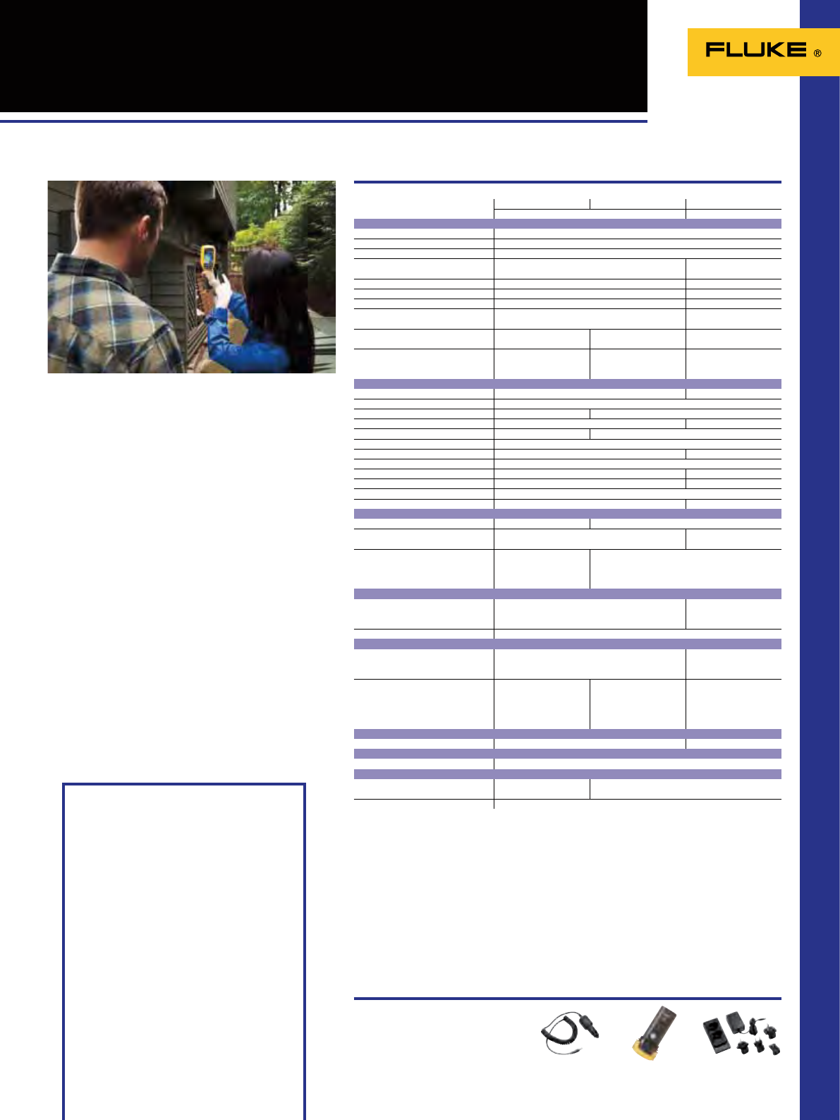
67
Recommended Accessories
Water and dust resistant: IP54
Size (HxWxD): 284 x 86 x 135 mm
Weight: 0.726 kg
Two Years Warranty
Specifications
FLK-TI-SPB3
Extra battery FLK-TI-SBC3
Charging base
Ti-Car Charger
Car charger
TiR125/TiR110/Ti100 Building
Diagnostic Thermal Imagers
Fluke TiR125 Fluke TiR110 Fluke Ti100
Building diagnostics General
Thermal imaging performance
IR resolution (FPA size) 160 x 120 FPA Uncooled Microbolometer
Field of view (FOV) 22.5 °H x 31 °V
Spatial resolution (IFOV) 3.39 mRad
Thermal sensitivity (NETD) ≤ 0.08 °C at 30 °C target temp (80 mK) ≤ 0.10 °C at 30 °C target
temp (100 mK)
Minimum span in auto mode 2.5 °C 5 °C
Minimum span in manual mode 2.0 °C 2.5 °C
Minimum IR focus distance 15.25 cm (6 in) 1.2 m (4 ft)
Focus mechanism IR-OptiFlex™ focus system Focus-free 1.2 m and
beyond
IR-Fusion® technology PIP, FULL IR, FULL VISIBLE,
AutoBlend PIP, FULL IR, FULL VISIBLE No, full IR only
Color alarms High temperature,
low temperature (dewpoint),
and isotherm
Low temperature
(dewpoint) -
Visual imaging performance
Visible camera 2 megapixel industrial-grade n/a
LCD display 3.5 inch diagonal (portrait format)
Hot/Cold markers Yes -
User definable spot markers Three on camera and in SmartView®in SmartView® only
Centerbox (MIN/AVG/MAX) Yes -
Level and span control Manual and auto
IR-PhotoNotes™ annotation system Yes (3 images) -
Laser pointer Yes
Torch Yes -
Electronic (cardinal) compass Yes -
Emissivity correction Yes
Transmission correction Yes -
Video
Multi-mode video output Streaming USB video output -
Multi-mode video recording
(standard AVI with MPEG encoding) Yes (AVI with MPEG encoding) -
Multi-mode video recording
(radiometric .IS3) Yes, radiometric .is3 for
approx.. 2.5 to 5 minutes
depending upon thermal
scene
-
Temperature measurement
Temperature measurement range
(not calibrated below -10° C) -20 °C to +150 °C -20 °C to +250 °C
Accuracy ± 2 °C or 2 % (at 25 °C nominal, whichever is greater)
Image presentation
Standard palettes Blue-Red, Grayscale, Inverted Grayscale, High-contrast,
Hot Metal, Ironbow, Amber, Inverted Amber Blue-Red, Ironbow,
Grayscale, Amber
Ultra Contrast™ palettes Blue-Red, Grayscale,
Inverted Grayscale,
High-contrast, Hot Metal,
Ironbow, Amber,
Inverted Amber
Blue-Red, Grayscale,
Ironbow -
Voice Annotation
Voice annotation Yes (60 seconds) per image -
Image and data storage
Memory storage 2 GB SD memory card
Power
Battery
(field-replaceable, rechargeable) Two One
Battery life 4+ hours (each) (assumes 50% brightness of LCD)
Included Accessories
SmartView® software
AC power adapter
Lithium ion smart battery
USB cable
2 GB SD memory card
Hard carrying case
Soft transport bag
Adjustable hand strap
User manual
Two-bag charging base and multi-format USB
memory card reader (Ti125 only)
Ordering Information
Fluke TiR125 Building Diagnostics
Thermal Imager
Fluke TiR110 Building Diagnostics
Thermal Imager
Fluke Ti100 General Use Thermal Imager
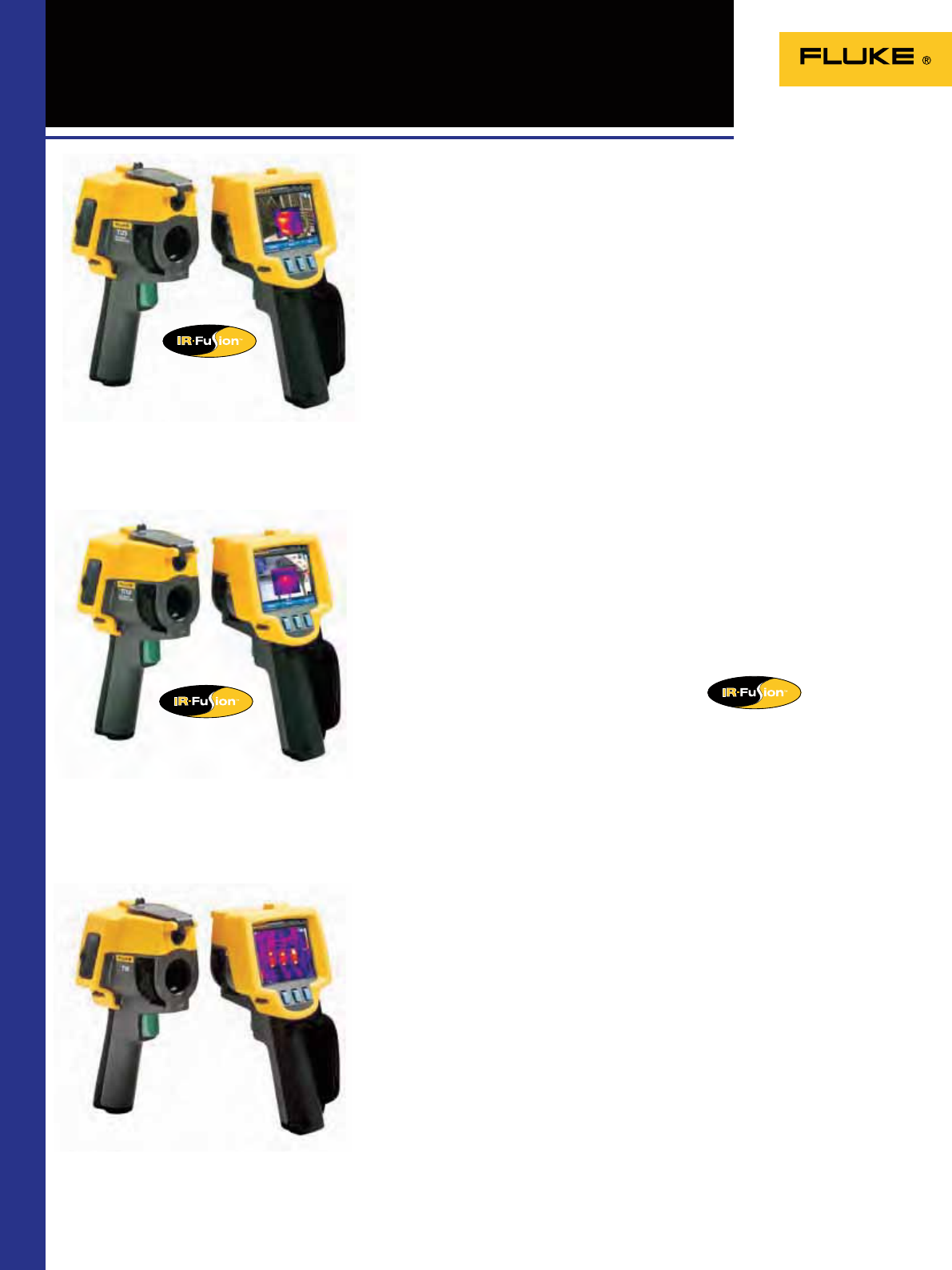
68
Ti9/Ti10/Ti25 Thermal Imagers
Get the full picture instantly with the Fluke Ti9/Ti10/Ti25 thermal imagers. Built for
tough work environments, these fully radiometric imagers are ideal for detecting
problems in a wide range of equipment including switchgear, motor control centers
and lighting systems.
• Delivers the clear images to nd problems fast with its 160x120 sensor
• Even the smallest details become visible with the large, widescreen full color
LCD display
• Optimized for eld use in harsh work environments
- Engineered and tested to withstand a 2 meter drop
- Withstands dust and water – tested to an IP54 rating
- Innovative protective lens cover protects the lens when not in use
• Enhanced problem detection and analysis capabilities with patent pending
IR-Fusion® Technology (Ti10 and Ti25)
• Intuitive, three-button menu is easy to use ... simply navigate with the push
of a thumb
• Store more than 3.000 screen images (.bmp format) or 1.200 fully radiometric
images (.IS2 format) on included 2 GB SD memory card
See things both ways—infrared and visual (visible light) images fused together
communicating critical information faster and easier—traditional infrared images
are no longer enough. IR-Fusion, a patent-pending technology that simultaneously
captures a digital photo in addition to the infrared image and fuses it together taking
the mystery out of IR image analysis. IR-Fusion is standard on Ti10 and Ti25 models.
The Fluke Ti9 can be upgraded to a full Fluke Ti10 with IR-Fusion at a later time.
Fluke Ti10
Fluke Ti9
The rugged and affordable tools for
electricians and technicians
IR-Fusion® Technology
Fluke Ti25
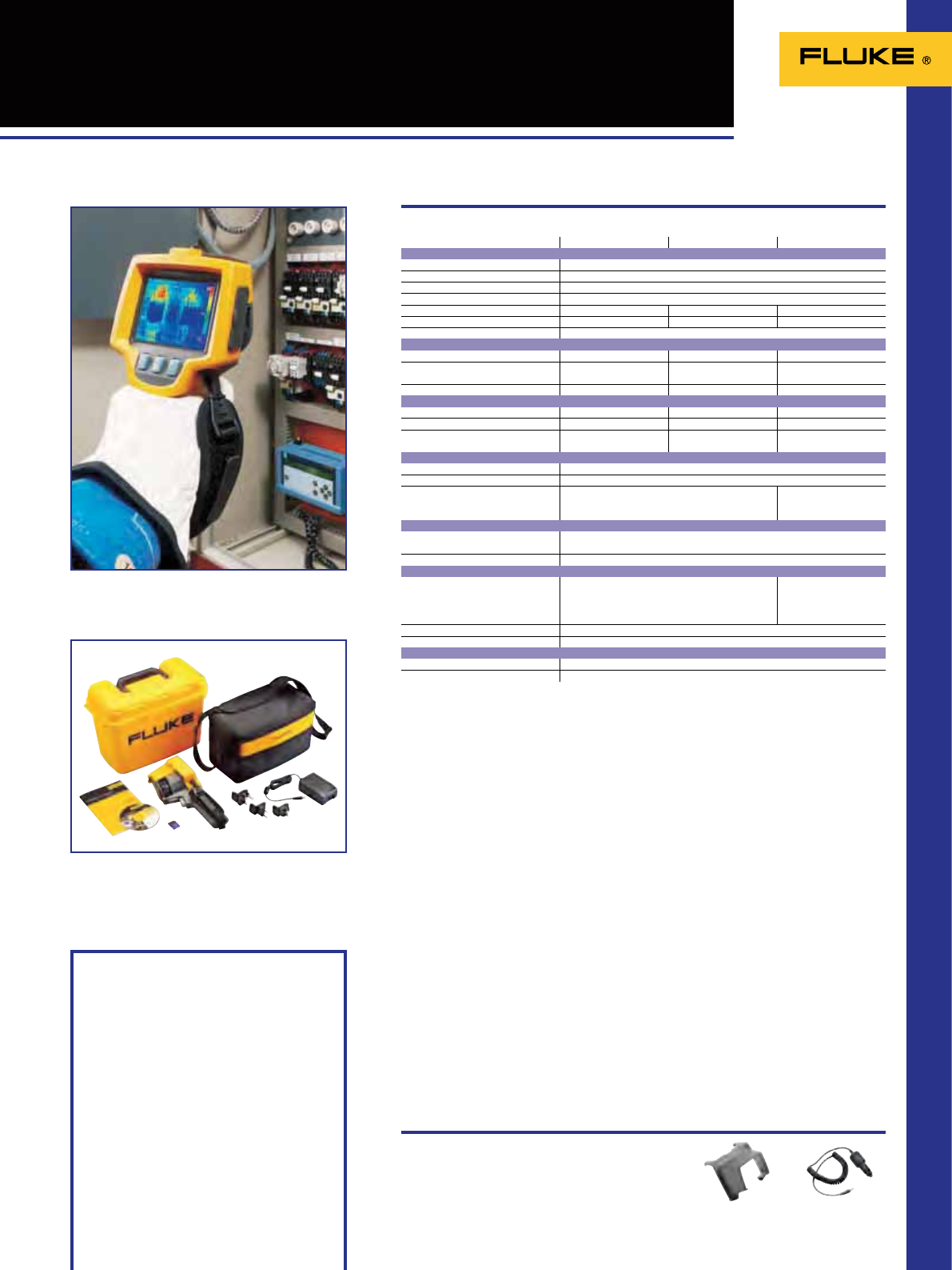
69
Ti9/Ti10/Ti25 Thermal Imagers
Included Accessories
SmartView® software
2 GB SD card
SD card reader
Rugged hard carrying case
Soft carrying case
Hand strap
Rechargeable battery
AC charger/power supply
User manual
Ordering Information
Fluke Ti9 Electrical Thermal Imager
Fluke Ti10 Electrical Thermal Imager
Fluke Ti25 Industrial Thermal Imager
Ti-Visor
Sun Visor
(for complete Ti Series)
Ti-Car Charger
Car charger
Recommended Accessories
Water and dust resistant: IP54
Size (HxWxD): Ti9/Ti10/Ti25: 267 x 127 x 152 mm
Weight: Ti9/Ti10/Ti25: 1.2 kg
Two Years Warranty
Complete package
Specifications
Fluke Ti9 Fluke Ti10 Fluke Ti25
Thermal imaging performance
Detector type 160 x 120 Focal Plane Array, uncooled microbolometer
Field of view (FOV) 23 º horizontal x 17 º vertical
Spatial resolution (IFOV) 2.5 mRad
Min focus distance 15 cm
Thermal sensitivity (NETD) ≤0.2 °C at 30 °C (200 mK) ≤0.13 °C at 30 °C (130 mK) ≤0.09 °C at 30 °C (90 mK)
Minimum span (auto/manual) 10 ˚C / 5 ˚C 10 ˚C / 5 ˚C 2.5 °C / 5 °C
Focus Manual
Visual imaging performance
Minimum focus distance 46 cm 46 cm
On camera operating modes Picture-in-Picture and full
screen IR plus Picture-in-Picture and full
screen IR plus Blending
Visible light camera 1.3 MegaPixel 1.3 MegaPixel
Temperature measurement
Temperature range -20 ˚C to 250 ˚C -20 ˚C to 250 ˚C -20 ˚C to 350 ˚C
Accuracy ± 5 °C or 5% ± 2 °C or 2% ± 2 °C or 2%
Measurement modes
Center point Center point Center point and hot and
cold markers
Image presentation
Digital display 9.1 cm (3.6”) landscape color VGA (640x480) LCD
LCD backlight Selectable bright or auto
Palettes
Ironbow, blue-red, high contrast, grey Ironbow, blue-red, high
contrast, grey, amber and
hot metal
Image and data storage
Storage medium 2GB SD Card (3000 .bmp IR images/1200 .IS2 images)
File formats supported JPG, JPEG, JPE, JFIF, BMP, GIF, DIB, PNG, TIF, and TIFF
Controls and adjustments
Set-up controls Date/time, Cº/ºF, language Date/time, Cº/ºF, language
On screen emissivity
correction On-screen
reflected background
temperature compensation
Language selection Eng, ger, fre, spa, por, ita, swe, fin, rus, cze, pol, tur
Image controls Smooth auto scaling and manual scaling
Power
Battery type Internal rechargeable battery NiMh (included)
Battery operating time 3 to 4 hours continuous operation
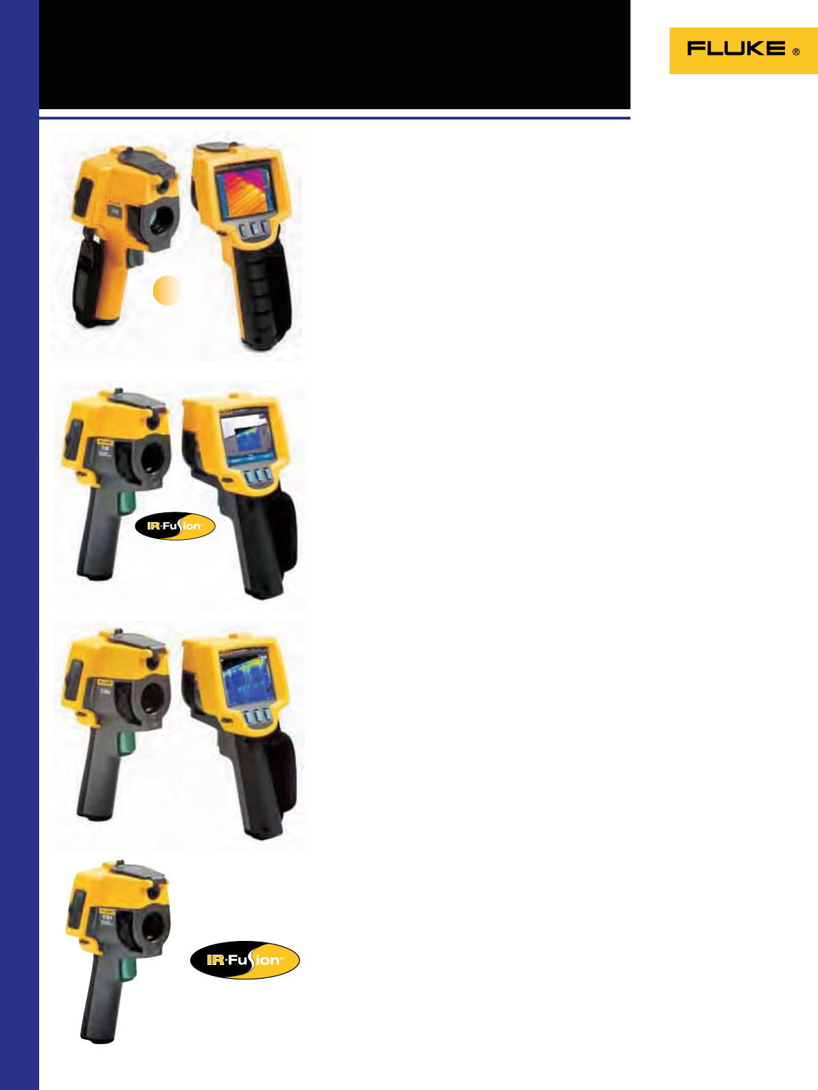
70
TiS/TiR/TiRx/TiR1
Thermal Imagers
for Building Diagnostics
The affordable rugged Fluke TiRx and TiR Thermal Imagers are workhorse tools
for the demands of building envelope, restoration and remediation, inspection
and roong applications. Whether to perform energy audits, locate the origins of
construction problem or to nd roof leaks, the TiRx and TiR offer an economical
solution for complete detection, analysis and documentation.
• Delivers the clear images to nd problems fast with its 160x120 sensor
• Enhanced problem detection and analysis capabilities with patent pending
IR-Fusion® Technology (TiR)
• The Fluke TiRx can be upgraded to a full Fluke TiR with IR-Fusion at a later time.
• NETD 90 mK
The TiR1 Thermal Imager is the professional’s choice for building diagnostics. The
Fluke TiR1 has all the features of the Fluke TiR, but with an NETD of 0.07ºC for the
TiR1 to identify even small temperature differences that could indicate problems.
• IR-Fusion®, full option (combines visible image with IR image in full screen or
picture-in-picture views)
• Voice recording; record ndings by speaking into the camera. Voice annotations
can be recorded with every image you take. Voice comments are saved along with
individual images for future reference
• NETD 70 mK
Fluke TiR
Fluke TiRx
Optimized for energy audits, restoration and
remediation
The professional’s choice
Fluke’s entry level thermal imager for quick, easy, and accurate problem identication
and troubleshooting designed specically for the building inspection professional.
Whether you are a building inspector, plumber, roofer, electrician, energy auditor,
HVAC, insulator, or windows installer the Fluke Thermal Imaging Scanner is the
perfect tool to help you identify hidden building construction issues, nd moisture
intrusion, detect energy loss/missing insulation, and many basic electrical connection
and load problems. Now Fluke quality, durability, and performance are available in a
thermal imager engineered for the valueconscious building professional. The Fluke
TiS Thermal Imaging Scanner is the top-performing imager in its price class.
• Highest resolution (120x120) in price class
• Only imager in price class with versatile, manual focus
• Largest display size (3.7”) in price class.
• Long battery life lasts ~4 hours
• Rugged body engineered to withstand 2 m drop test
• Easy to use—the TiS Thermal Imaging Scanner provides you with a basic,
reliable solution for the building professional
• NETD 100 mK
Entry-level Thermal Imager
Fluke TiR1
Fluke TiS
New
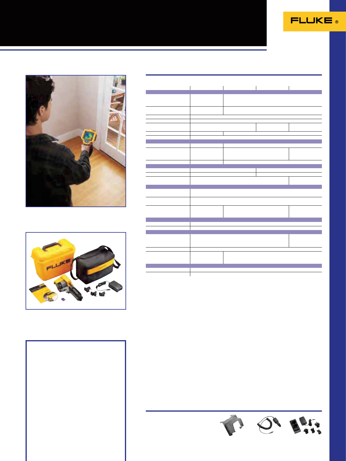
71
TiS/TiR/TiRx/TiR1
Thermal Imagers
for Building Diagnostics
Included Accessories
SmartView® software
2 GB SD card
SD card reader
Rugged hard carrying case
Soft carrying case
Hand strap
Rechargeable battery
AC charger/power supply
User manual
Ordering Information
Fluke TiS Thermal Imaging Scanner
Fluke TiRx Inspector Thermal Imager
Fluke TiR Thermal Imager for Building
Diagnostics
Fluike TiR1 Thermal Imager for Building
Diagnostics
Water and dust resistant: IP54
Size (HxWxD): 267 x 127 x 152 mm
Weight: 1.2 kg
Two Years Warranty
Complete package
Ti-Visor
Sun Visor
(for complete Ti Series)
Ti-Car Charger
Car charger
Recommended Accessories
Fluke TiS Fluke TiRx Fluke TiR Fluke TiR1
Thermal imaging performance
Detector type 120 x 120 Focal Plane
Array, uncooled
microbolometer
160 x 120 Focal Plane Array, uncooled microbolometer
Field of view (FOV) 17 º horizontal x 17 º
vertical 23 º horizontal x 17 º vertical
Spatial resolution (IFOV) 2.5 mRad
Min focus distance 15 cm
Thermal sensitivity (NETD) ≤0.1 °C at 30 °C
(100 mK) ≤0.09 °C at 30 °C
(90 mK) ≤0.07 °C at 30 °C
(70 mK)
Minimum span 5 ˚C (in auto mode) 2.5 ˚C / 5 ˚C (Auto/Manual)
Focus Manual
Visual imaging performance
Minimum focus distance - 46 cm
On camera operating modes - Picture-in-Picture and full screen IR Picture-in-Picture and
full screen IR plus
Blending
Visible light camera 1.3 MegaPixel
Temperature measurement
Temperature range -20 ˚C to 100 ˚C -20 ˚C to 150 ˚C
Accuracy ± 5 °C or 5% ± 2 °C or 2%
Measurement modes
Center point Center point and hot
and cold markers
Image presentation
Digital display 9.1 cm (3.6”) landscape color VGA (640x480) LCD
LCD backlight Selectable bright or auto
Palettes
Ironbow, blue-red,
greyscale Ironbow, blue-red, high contrast, grey Ironbow, blue-red, high
contrast, grey, amber
and hot metal
Image and data storage
Storage medium 2GB SD Card (3000 .bmp IR images/1200 .IS2 images)
File formats supported JPG, JPEG, JPE, JFIF, BMP, GIF, DIB, PNG, TIF, and TIFF
Controls and adjustments
Set-up controls Date/time, Cº/ºF, language Date/time, Cº/ºF, language
On screen emissivity
correction On-screen
reflected background
Language selection Eng, ger, fre, spa, por, ita, swe, fin, rus, cze, pol, tur
Image controls Smooth auto-scaling
and lock of level and
span
Smooth auto scaling and manual scaling
Power
Battery type Internal rechargeable battery NiMh (included)
Battery operating time 3 to 4 hours continuous operation
Specifications
FLK-TI-SBC3
Charging base (Ti32)
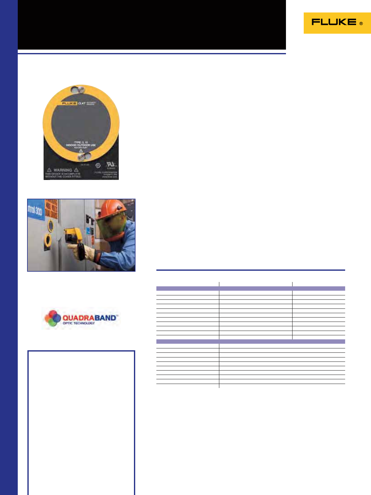
72
CRange IRWindows
Included Accessories
Installation CD, self-adhesive drilling
template, security access key, warranty
statement.
Ordering Information
FLK-075-CLKT 75mm C-Range IR Window,
Kwik Twist
FLK-100-CLKT 100mm C-Range IR Window,
Kwik Twist
IP-200-UK Window Installation Kit
220/240V
Infrared windows mount into panel doors
and covers for switchgear, transformers,
bus bars and other live electrical
equipment, allowing Infrared, Ultraviolet,
Visual and IRfusion technologies to be
used without exposing personnel to live
equipment.
All infrared windows from Fluke use
the unique Quadraband™ multispectral
optic, allowing inspection with any
camera for total exibility both now and
in the future.
• Reduce the arc ash risk associated
with electrical thermography
• Increase efciency as thermographer
can work alone without being
accompanied by an electrician to isolate
and open panels
• Stay safety compliant with NFPA70E
and other safety protocols and leave the
panels closed
• Extend the life of your equipment with
more frequent IR scans
• Easy to install
• Durable enough to withstand extreme
outdoor conditions yet practical for
indoor applications as well.
Specifications
(Check the Fluke web for detailed specifications)
Increase the safety and speed of electrical
thermography
FLK-075-CLKT FLK-100-CLKT
Optic Data
Crystal Insert Diameter 75 mm 100 mm
Viewing Aperture Diameter 68 mm 89 mm
Viewing Aperture Area 3632 mm2 6322 mm2
Thickness 2 mm 4 mm
CLIRVU Coating
OO
Shortwave IR Capable
OO
Midwave IR Capable
OO
Longwave IR Capable
OO
Ultraviolet (UV) Capable
OO
Visual Capable
OO
Fusion Capable
OO
General
Maximum Temperature
Gaskets 250º C
Body 659 º C
Optic 1400º C
Gaskets Low Smoke & Fume (LSF) compliant silicone
IP rating IP65
NEMA rating Typo 3/12 (UL & CSA Third Party Certified)
Vibration rating IEC60068-2-6
Humidity rating IEC60068-2-3
Pull out strength Up to 630 kg
Warranty: Lifetime replacement against manufacturing defects

73
The Fluke Laser Distance Meters bring you the most advanced
measuring technology. Unlike ultrasonic distance meters with laser
pointers, these meters use a precision narrow laser beam that can
avoid the common errors caused by extraneous objects near
measurement targets.
Laser Distance Meters
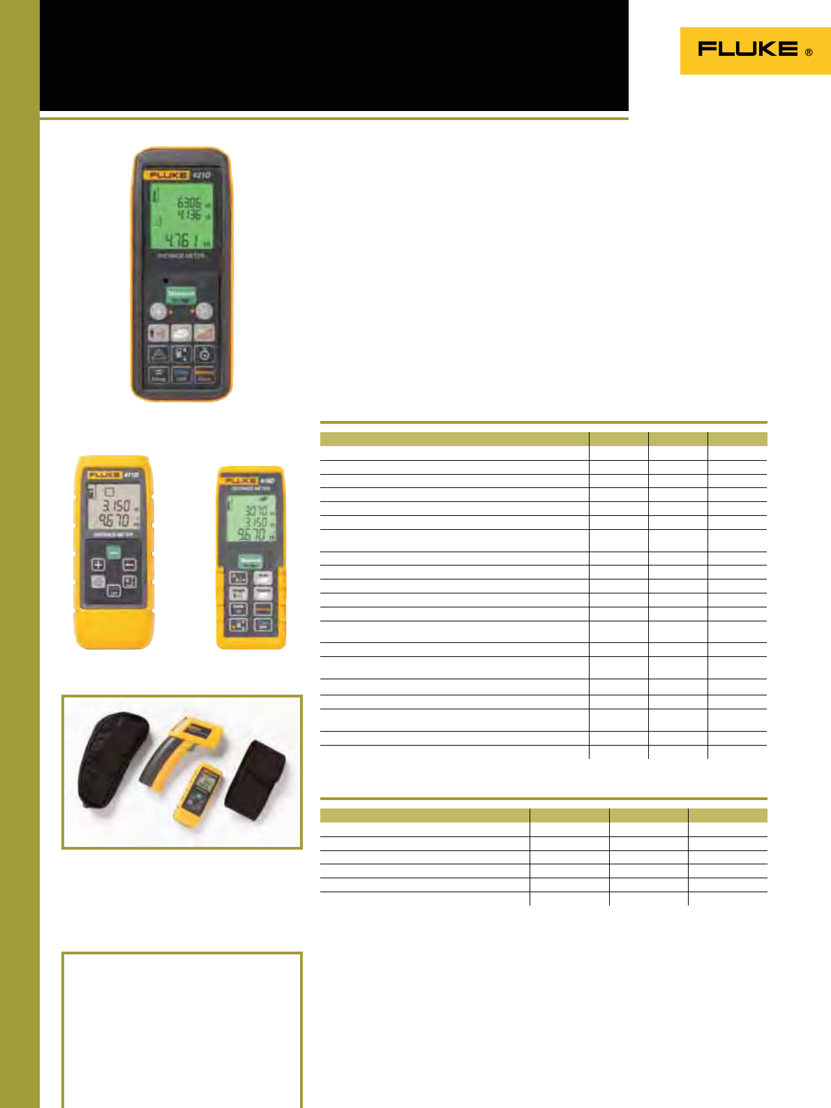
6574
421D, 416D, 411D
Laser Distance Meters
Included Accessories
Two AAA batteries, Users manual on CD,
Quick start guide, Nylon carrying case,
Wrist wrap (421D)
Ordering Information
Fluke 411D Laser Distance Meter
Fluke 416D Laser Distance Meter
Fluke 421D Laser Distance Meter
Professional-grade laser distance
measuring tools that are fast, easy to use,
and fit in your pocket.
The Fluke laser distance meters bring you
the most advanced measuring technology.
These meters are fast, accurate, durable,
and easy to use — just point and shoot.
Their straightforward design and easy,
one-button operation mean you spend less
time measuring. Unlike ultrasonic distance
meters with laser pointers, the Fluke 421D,
416D and 411D use a precision narrow
laser beam that can avoid the common
errors caused by extraneous objects near
measurement targets.
These compact and handy Fluke distance
meters are designed for indoor, and limited
outdoor applications. Addition, subtraction,
area, and volume calculations could not
be simpler. The extra bright laser is clearly
visible so you can see your targeting point
even if an object is hard-to-reach or distant.
The Fluke 421D, 416D and 411D have a large
LCD screen and buttons positioned for one-
handed measurements.
Features
Operating temperature: 0°C to 40°C
Storage temperature: -25°C to 70°C
Operating altitude: up to 3500 m
Battery Life: 411D: up to 3000 readings
416D, 421D: up to 5000 readings
Size (HxWxD):
411D: 123 mm x 50 mm x 26 mm
416D: 135 mm x 46 mm x 31 mm
421D: 127 mm x 52 mm x 25 mm
Weight: 411D: 0.150 kg
416D: 0.110 kg
421D: 0.125 kg
Warranty: 2 years
Fluke 416DFluke 411D
411D 416D 421D
Reduction of estimation errors, saving both time and money OOO
Instant measurement with one-button operation OOO
Easy targeting with bright laser OOO
Quick calculation of area (square footage) and volume OOO
Easy addition and subtraction of measurements OOO
Improved battery life from automatic shut-off feature OOO
Pythagoras calculation for determining distance indirectly from two
other measurements
OOO
Pouch OOO
Ability to view more with large, 3-line display with backlight OO
Ability to measure up to 30 m 60 m 100 m
Storage capacity of measurements for quick recall of distance - 10 20
MIN/MAX function OO
Enhanced Pythagoras calculation for determining distance indi-
rectly from three other measurements
OO
Audible feedback of on and off modes OO
Strong environment protection with IP54 (water spray & dust proof)
sealing
OO
Audible feedback for taking room angle and incremental measurements
O
± 45° Tilt sensor for taking indirect measurements in hard to reach areas
O
Tripod mode allows you to mount to a tripod for measuring long
distances
O
Built in light sensor for activating the backlight saving battery life O
Corner angle feature, allows you to determine the angle of a corner O
Fluke 411D Fluke 416D Fluke 421D
Range (for extended distances, use a target plate) 30 m 60 m 100 m
Accuracy ± 3 mm ± 1.5 mm ± 1.5 mm
Measurement units 00.000 m 00.000 m 00.000 m
Measurement storage 10 locations 20 locations
Backlight OO
Automatic power off After 180 seconds After 180 seconds After 360 seconds
Specifications
(Check the Fluke web for detailed specifications)
411D/62 Kit
Combo kit includes:
- Fluke 62 Mini IR Thermometer
- Fluke 411D Laser Distance Meter
- Soft pouch for each model
Fluke 421D
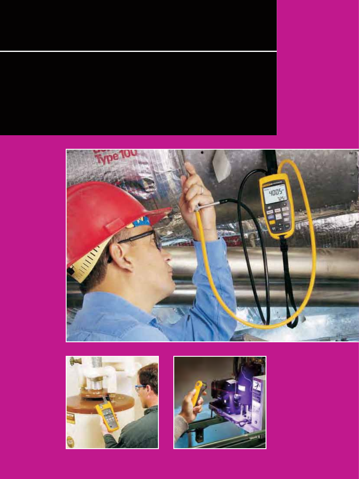
75
In response to the growing importance of air quality in buildings,
workplaces and homes, Fluke offers you a range of tools that monitor
temperature, humidity, air velocity, particulate, and carbon monoxide
levels. These tools help you to quickly and easily troubleshoot and
maintain indoor air quality, as well as to verify the efcient operation of
heating, ventilation and air conditioning systems.
Indoor Air Quality Tools
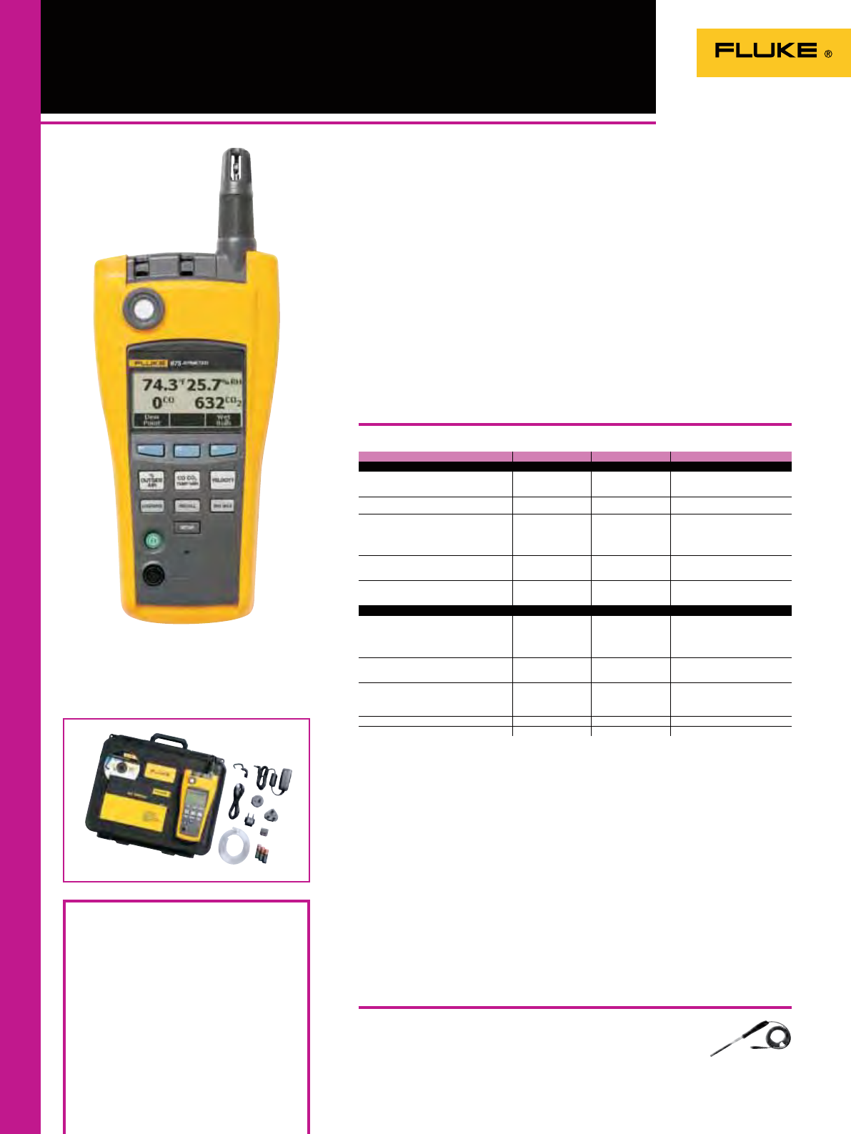
76
975 AirMeter
Operating temperature
(CO and CO2 sensors): -20 °C to 50 °C
Operating temperature
(all other functions): -20 °C to 60 °C
Storage temperature: -20 °C to 60 °C
Humidity: 10% to 90%
Altitude: Up to 2000 m
975VP
AirMeter Velocity Probe
Recommended Accessories
Shock and vibration: MIL-PRF-28800F, Class 2
Battery: Rechargeable Li-Ion (primary), three-
AA (backup)
Weight: 0.544 kg
Size (HxWxD): 28.7 cm x 11.43 cm x 5.08 cm
Data logging: 25,000 records (continuous),
99 records (discrete)
Multilanguage interface: English, French,
Spanish, Portuguese and German
Two-year warranty
The Fluke 975 AirMeter combines ve air
monitoring tools into one, rugged and
easy-to-use handheld tool. Use the Fluke
975 to verify the efcient operation of
heating, ventilation and air conditioning
systems, and test for dangerous carbon
monoxide leaks in all types of buildings.
• Simultaneously measures, logs, and
displays temperature, humidity, CO2,
and CO on a bright, backlit LCD display
• One-touch air ow and velocity
measurements with available probe
• Min/Max/Average on all measured and
calculated readings
• Audible and visual threshold alarms
• Multi-language user interface
• Extensive discrete or continuous data
logging capacity, down-loadable to PC
via USB interface
Specifications
(Check the Fluke web for detailed specifications)
Fluke 975
Included Accessories
A4 alkaline batteries (3), Users Manual,
Calibration Cap, FlukeView Forms Software,
Power Adapter, International Power Plugs,
Air Velocity Probe (Fluke 975V only)
Ordering Information
Fluke 975 AirMeter
Fluke 975V AirMeter with Velocity
975R Regulator
975VP Air Velocity Probe
Feature Range Display resolution Accuracy
Measured specifications
Temperature -20 °C to 60 °C 0.1 °C ± 0.9 °C from 40 °C to 60 °C
± 0.5 °C from 5 °C to 40 °C
± 1.1 °C from -20 °C to 5 °C
Relative humidity 10 % to 90 % RH non-
condensing 1 % ± 2 % RH (10 % RH
to 90 % RH)
Air velocity 50 fpm to 3000 fpm
0.25 m/sec to 15 m/sec 1 fpm
0.005m/sec 4 % or 4 fpm*
3 % or 0.015 m/sec*
whichever is greater
*Accuracy specification only valid
for velocity readings above 50 fpm.
CO20 to 5000 ppm 1 ppm Warm up time 1 min
(5 minutes for full specification)
2.75 % + 75 ppm
CO 0 to 500 ppm 1 ppm ± 5 % or ± 3 ppm,
whichever is greater,
@ 20 °C and 50 % RH
Calculated specifications
Dew point temperature -44 °C to 57 °C 0.1 °C ± 1 °C when temp: -20 °C to 60 °C
RH: 40 % to 90 %
± 2 °C when temp: -20 °C to 60 °C
RH: 20 % to 40 %
± 4 °C when RH: 10 % to 20 %
Wet bulb temperature -16 °C to 57 °C 0.1 °C ± 1.2 °C when RH: 20 % to 90 %
temp: -20 °C to 60 °C
± 2.1 °C when RH: 10 % to 20 %
Volume flow rate (in a duct) 0 to 3,965 M3/m 0 to
140,000 cfm) 0.001 M3/min (1 cfm) N/A: The volume flow
calculation will be a simple average
of the data points times the
duct area
% outside air (based on temperature) 0 to 100 % 0.1 % N/A
% outside air (based on CO2) 0 to 100 % 0.1 % N/A
Combined inspection tool for complete air
quality inspections
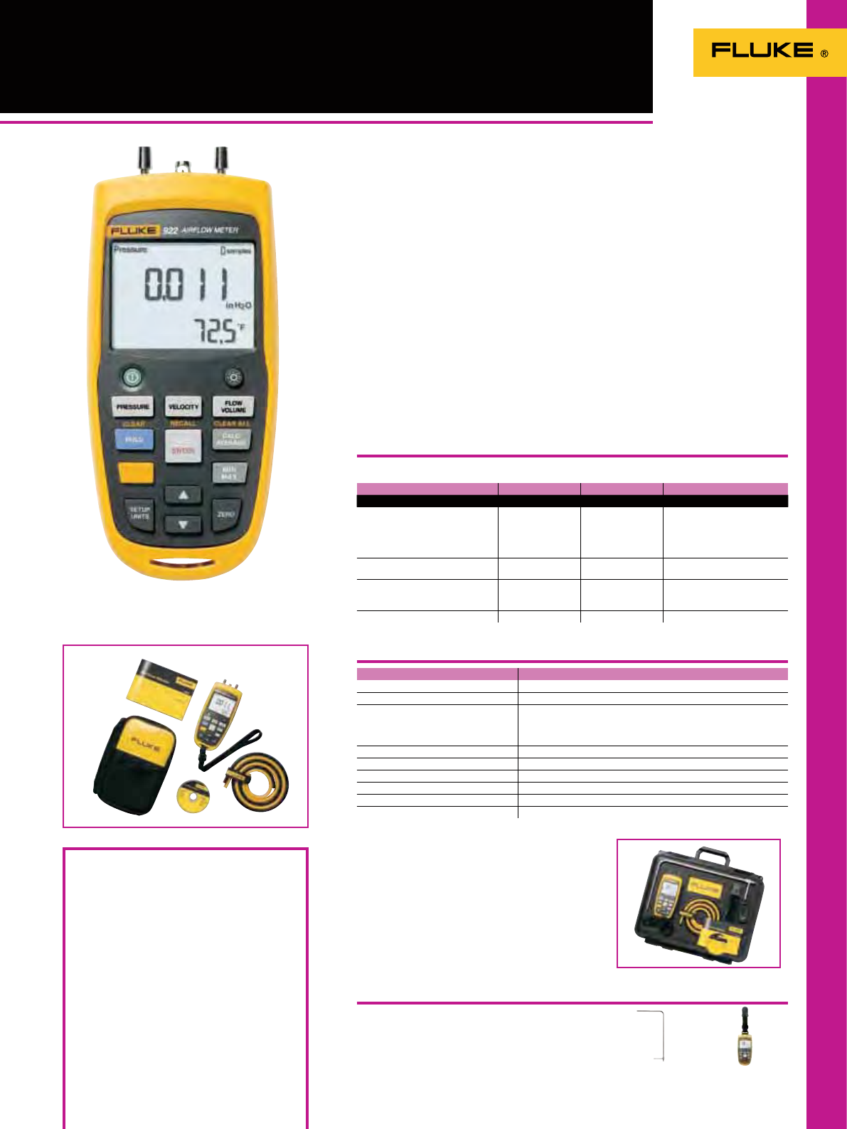
77
922 Airflow Meter
Data Storage: 99 readings
Size (HxWxD): 175 x 775 x 419 mm
Weight: 0.64 kg
Battery: Four AA batteries
Battery Life: 375 hours without backlight,
80 hours with backlight
Two Year Warranty
TPAK
Toolpak
See page 132
Recommended Accessories
Specifications
(Check the Fluke web for detailed specifications)
Fluke 922
Included Accessories
Fluke 922: Two Rubber Hoses, Wrist Strap, Four
AA Batteries 1.5 V Alkaline, Users Manual and
Soft Carrying Case
Fluke 922 Kit Includes: Fluke 922 Airflow Meter,
30.48 cm Pitot tube, ToolPak, Two Rubber
Hoses, Wrist Strap, Four AA Batteries 1.5 V
Alkaline, Users Manual and Hard Carrying
Case
Ordering Information
Fluke 922 Air Flow Meter
Fluke 922/Kit Airflow Meter with
30.48 cm Pitot Tube
General Specifications
Feature Range Resolution Accuracy
Operating Specifications
Air Pressure ± 4000 Pascals
± 16 in H2O
± 400 mm H2O
± 40 mbar
± 0.6 PSI
1 Pascal
0.001 in H2O
0.1 mm H2O
0.01 mbar
0.0001 PSI
± 1% +1 Pascal
± 1% + 0.01 in H2O
± 1% + 0.1 mm H2O
± 1% +0.01 mbar
± 1% + 0.0001 PSI
Air Velocity 250 to 16,000 fpm
1 to 80 m/s 1 fpm
0.001 m/s ± 2.5 % of reading at 10 m/s
(2000 p/min)
Air Flow (Volume) 0 to 99,999 cfm
0 to 99,999 m3/hr
0 to 99,999 l/s
1 cfm
1 m3/hr
1 l/s
Accuracy is a function of
velocity and duct size
Temperature 0 °C to 50 °C 0.1°C ± 1 % + 2 °C
General specifications
Operating Temperature 0 ºC to +50 ºC
Storage Temperature -40 ºC to +60 ºC
Operating Relative Humidity Non condensing (<10 ºC)
90% RH (10 ºC to 30 ºC)
75% RH (30 ºC to 40 ºC)
45% RH (40 ºC to 50 ºC) Without Condensation
IP Rating IP40
Operating Altitude 2000 m
Storage Altitude 12000 m
EMI, RFI, EMC Meets requirements for EN61326-1
Vibration MIL-PREF-28800F, Class 3
Max Pressure at Each Port 10 PSI
Fluke 922/Kit
PT12
Pitot Tube, 30.48 cm
Measures pressure, air flow and velocity for
maintaining balanced and comfortable
ventilation
The Fluke 922 makes airow
measurements easy by combining
pressure, air ow, and velocity into a
single, rugged meter. Compatible with
most Pitot tubes, the Fluke 922 allows
technicians to conveniently enter
their duct shape and dimensions for
maximum measurement accuracy.
Use the Fluke 922 to: Ensure proper air
ow balance and maintain a comfortable
environment; measure pressure drops
across lters and coils; match ventilation
to occupant loads; monitor indoor vs.
outdoor pressure relationships and
manage the building envelope; and
perform duct traversals for accurate
airow readings.
• Provides differential and static pressure,
air velocity and ow readings
• Convenient colored hoses help you
properly diagnose pressure readings
• Bright, backlit display for clear viewing
in all environments
• Min/Max/Average/Hold functions for
easy data analysis
• Auto power off saves battery life

78
971 Temperature Humidity Meter
Carbon Monoxide Meters
Fluke 561
Combined Contact
and Non-contact
Thermometer
See page 54.
Included Accessories
Fluke CO-220: C50 soft carrying case and
battery
Ordering Information
Fluke 971 Temperature Humidity
Meter
Fluke CO-220 Carbon Monoxide Meter
CO-205 Aspirator Kit
Quickly take accurate humidity and
temperature readings in the air.
Temperature and humidity are two
important factors in maintaining
optimal comfort levels and good indoor
air quality. The Fluke 971 is invaluable
for facility maintenance and utility
technicians, HVAC-service contractors,
and specialists who assess indoor air
quality (IAQ). Lightweight, rugged, and
easy to hold, the Fluke 971 is the perfect
tool for monitoring problem areas.
• Simultaneously measures humidity and
temperature
• Measures dew point and wet bulb
• 99 record storage capacity
• Min/Max/Avg Data Hold
• Ergonomic design with built-in belt clip
and protective holster
• Backlit, dual readings display
• Twist-open protective cap
• Low battery indicator
Specifications
Temperature range -20 ºC to 60 ºC
Temperature accuracy
0 ºC to 45 ºC
-20 ºC to 0 ºC and 45 ºC to 60 ºC ± 0.5 0C
± 1.0 ºC
Resolution 0.1 ºC
Response time (temperature) 500 ms
Temperature sensor type NTC
Relative humidity range 5% to 95% R.H.
Relative humidity accuracy
10% to 90% R.H. @ 23 ºC
<10%, >90% R.H. @ 23 ºC ± 2.5 % R.H.
± 5.0 % R.H.
Humidity sensor Electronic capacitance polymer film sensor
Data storage 99 points
Response time (humidity) For 90% of total range - 60 sec with 1 m/s air movement
Operating temperature:
Temperature: -20 °C to 60 °C
Humidity: 0 °C to 60 °C
Storage temperature: : -20 °C to 55 °C
Battery life: 4 AAA alkaline, 200 hours
Safety: Complies with EN61326-1
Weight: 0.188 kg
Size (HxWxD): 194 mm x 60 mm x 34 mm
One Year Warranty
Carbon Monoxide Meters
CO-220 Carbon Monoxide Meter
The CO-220 Carbon Monoxide Meter makes it easy to take quick
and accurate measurements of CO levels. A large, backlit LCD
display shows CO levels from 0 to 1000 PPM. The MAX Hold
function stores and displays the maximum CO level.
1 year warranty.
Fluke 416D
Laser Distance Meter
See page 74 .
Fluke CO-220
Fluke 971
Temperature Humidity Meter
Fluke 971
Other useful tools
CO-205 Aspirator Kit
Allows flue gas samples up to 371°C to be drawn with the
CO-220 for carbon monoxide measurement.
1 year warranty.
Fluke CO-205
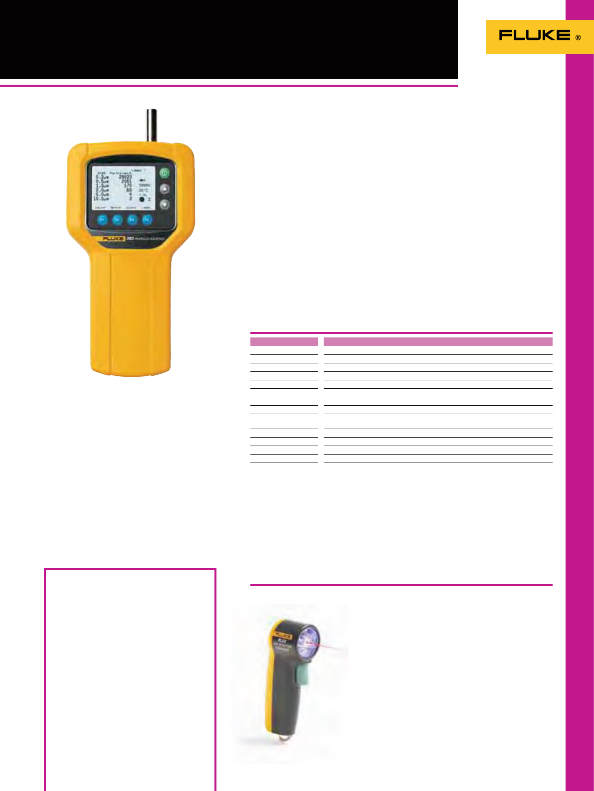
79
983 Particle Counter /
RLD2 Leak Detector Flashlight
6 size channels 0.3, 0.5, 1.0, 2.0, 5.0, 10.0 µm
Flow rate 0.1 cfm (2.83 L/min) controlled by internal pump
Count modes Concentration, totalize, audio
Counting efficiency 50 % @ 0.3 µm; 100 % for particles > 0.45 µm (per JIS B9921:1997)
Zero count 1 count/5 minute (per JIS B9921:1997)
Coincidence loss 5 % at 56,000 particles per m3
Relative humidity ± 7 %, 20 % to 90 %, non-condensing
Temperature ± 3 °C, 10 °C to 40 °C
Data storage 5000 sample records (rotating buffer) of date, time, counts, relative humidity,
temperature, sample volumes, alarms, label
Alarms Counts, low battery, sensor fail
Delay time 0 to 24 hours
Sample inlet Isokinetic probe
Interface RS-232 and RS-485 via RJ-45
Calibration PSL particles in air (NIST traceable)
Included Accessories
Fluke 983:
Certificate of Calibration (NIST)
Isokinetic probe
Zero count filter
Windows-compatible software download
utility
DB9 to RS-232 adapter and cable
High purity tubing
1/8 in. hose barb adapter
Power supply
Operation manual
Hard molded carrying case
Fluke RLD2: Key chain carabiner and batteries.
Ordering Information
Fluke 983 Particle Counter
Fluke RLD2 Leak Detector Flashlight
Specifications
RLD2 Leak Detector Flashlight
Operating temperature: 10 °C to 40 °C, 20 % to
90 % relative humidity, non-condensing
Storage temperature: -10 °C to 50 °C, up to
90 % relative humidity, non-condensing
Power: AC adapter, 90 to 250 V AC, 50 to 60 Hz
Battery life/recharge time: 8 hours/2 hours
Rechargeable battery: NiMH, 4.8V at 4.5 Ah;
replaceable
Size (HxWxD): 209 mm x 114 mm x 57 mm
Weight: 1 kg
Warranty: 1 year
Fluke 983
The Fluke 983 Particle Counter
simultaneously measures and displays
six channels of particle size distribution,
temperature and humidity. This compact,
lightweight, self-contained tool allows
for one-handed operation. As the Fluke
983 doesn’t require level holding, it can
make accurate measurements in any
position. The 8 hour rechargeable battery
together with a large 5000 sample record
allows for complete air quality surveys in
one go. The Fluke 983 is the ideal tool for
determining size distribution of airborne
particles or tracking down a particle
source.
• Simultaneously measure and display 6
channels of particle sizes, temperature
and humidity
• Measure particle size down to 0.3 µm
• Selectable sample time, count data,
programmable delay
• Store 5000 records of date, time, counts,
relative humidity, temperature, sample
volumes, alarms and location label
• Upload stored data to a PC with
included software
• Compact, self-contained package allows
for one-handed operation
• Intuitive, easy-to-use user interface
• Always ready to run, with no uids to
rell
• Backlit LCD for use in any lighting
condition
Easy to use tool for troubleshooting and
maintaining indoor air quality
RLD2 Leak Detector Flashlight.
Leak detection made easy. The compact RLD2
uncovers refrigerant leaks instantly. Use the UV
light to nd the leakage area, then, use the laser
pointer to pinpoint the exact leak location.
• Six UV LEDs detect leak detection dyes
• Laser pointer clearly locates center of the UV
eld for accuracy
• Three LED ashlight with 100,000 hour LED life
• Operating temperature 0ºC to 50ºC
• Four operating modes: ashlight, UV light, laser
light, UV/laser light combination
• One year warranty

8080
ScopeMeter portable oscilloscopes take you into territory standard
bench scopes can’t go: where it’s harsh, hazardous and dirty – without
sacricing any capabilities. They provide you with unmatched speed,
performance and analysis power while working on site.
ScopeMeter® Test Tools
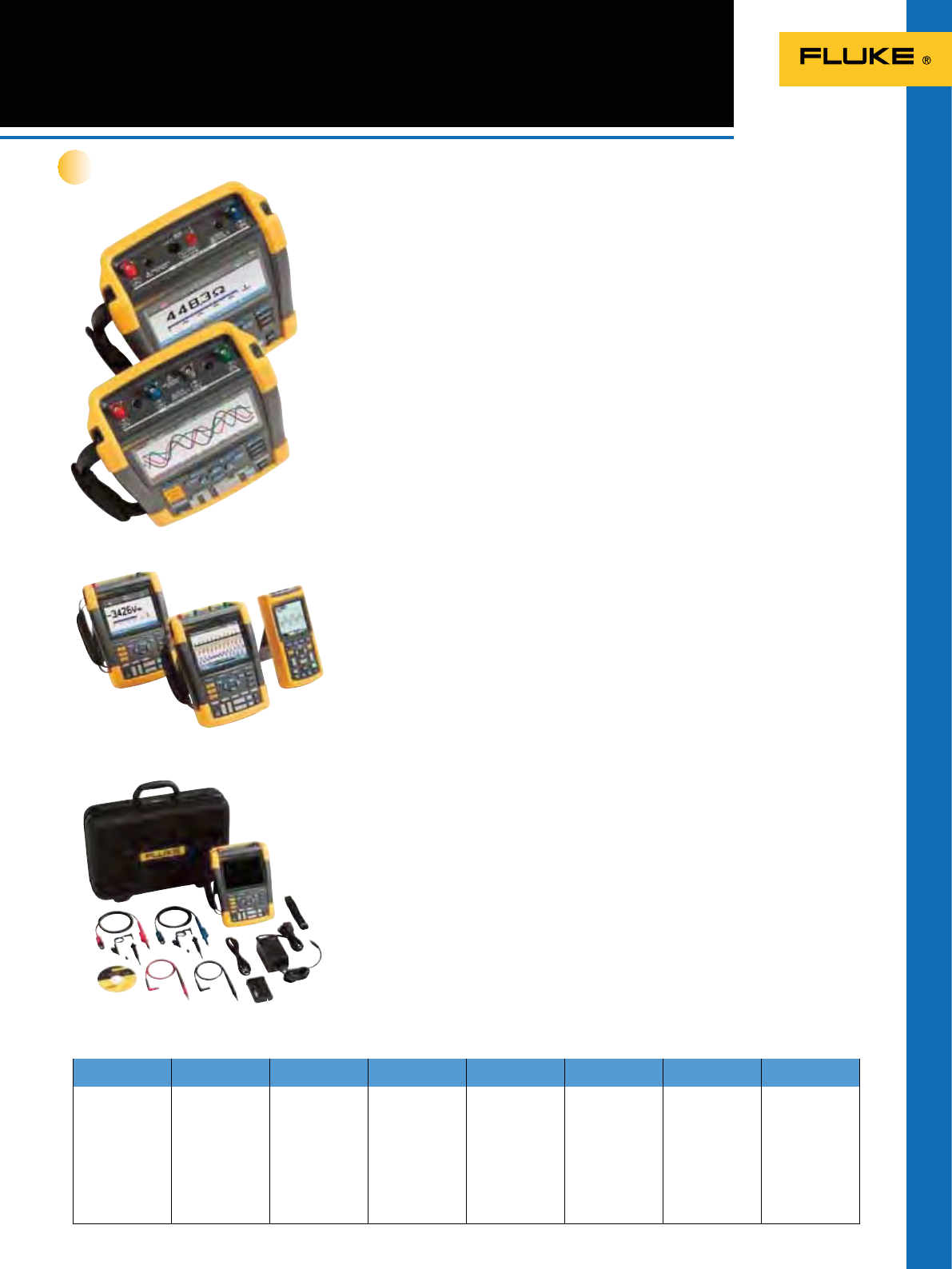
81
ScopeMeter 190 Series II
Combining rugged portability with the
performance of a bench scope, the Fluke 190
Series can take you from troubleshooting
microelectronics all the way into power
electronic applications. See more, x more
and go where you’ve never gone with a scope
before.
The first high-performance two and
four Channel scopes built for harsh
industrial environments.
Introducing the rst high-performance portable
oscilloscopes with 2 or 4 independently
insulated input channels, an IP51 dust- and
drip waterproof rating and a CAT III 1000 V /
CAT IV 600 V safety rating. Choose from 500 MHz,
200 MHz, 100 MHz or 60 MHz bandwidth
models.
Now plant maintenance engineers can take
a four-channel scope into the harsh world
of industrial electronics. Safely troubleshoot
three-phase systems like variable speed drives,
UPS or back-up generators. Measure input,
output and feedback signals simultaneously to
diagnose industrial electronics.
• 4 independent isolated input channels enable
3-axis industrial testing, simultaneous testing
of input signals, output signals and feedback
loops or safety interlocks
• 190-XX4 model with four independent
isolated inputs
• 190-XX2 models with two independenet
isolated scope inputs and DMM input
• Fast sample rate: up to 5 GS/s with up to
200 ps resolution
• Single shot, pulse width and video triggering
• Deep memory: 10,000 points per trace
waveform capture
• CAT III 1000 V / CAT IV 600 V, safety rated
• Up to seven hours of operation with high
performance Li-ion batteries, that extend
usage time plus optional external charger
• Battery door for conveniently swapping out
• Two isolated USB ports, for memory devices
and PC connectivity
• Security slot to lock down instrument using
standard Kensington® lock
• Connect & View™ triggering for intelligent,
automatic triggering on fast, slow and even
complex signals
• Frequency Spectrum using FFT analysis
• Automatic capture and REPLAY of 100 screens
• ScopeRecord™ mode gives 30000 points or
more per input channel for low frequency
signal analysis
• TrendPlot™ paperless recorder mode with
deep memory for long-term automatic
measurements
What could you do with four
channels?
Take multiple measurements simultaneously
to track down the root cause of your most
complex troubleshooting challenges.
• Easily diagnose timing-related issues with
multiple signals
• Real-time inspection of multiple signals
simultaneously
• Meaure a combination of input and output
signals and system safety interlocks and
feedback loops
Fluke 190-502 brings wide
bandwidth test applications in the
palm of your hand!
With the new 500 MHz model, the verication
of telecommunication equipment, high
frequency and wide bandwidth systems such
as radar equipment has become truly portable.
Conveniently verify the systems performance
right ‘on the spot’, fully safely without carrying
bulky lab equipment around. Battery powered
and fully oating – up to 600V CAT III, for each
channel and in between channel references.
Find problems in industrial
systems including:
• Circuit voltage/current overloading
• Attenuation/input impedance mismatch
• Signal uctuation/drift
• Conditioning circuits signal integrity
• Test point verication for critical signals
• Input/output/feedback timing issues
• Induced noise and disturbances
• Random shutdowns/reset
Diagnose VSDs* or power inverters
and converters
• Harmonics, transients and loads in three
phase power input
• Troubleshoot dc to ac converters for faulty
control circuits or output IGBT gate stages
• Cable interface - test PWM output for
reections and transients
• Vpwm measurement to measure the effective
voltage on drive outputs
The toughest portable scopes ever built
Application driven
Technologies Electrical Electromechanical Process Controls Automation Medical Imaging Avionics A/V & Security
Systems
Equipment Switch Gear,
Interlocks,
Motors,
Pumps,
Fans,
Furnaces,
Presses,
Mixers,
Refrigeration
Actuators,
VFD Drives,
Linear Motors,
Pressure-Level-
Flow-Position
Sensors,
Packaging
Equipment
Transducers,
Sensors,
Loop Controllers,
Calibrated Gauges
PLC´s,
Sensors,
Transducers,
Motion
Controllers,
Rotory
Encoders,
Scanners,
Readers,
Printers
XRay,
MRI,
Ultrasound
Imaging
equipment
Flight Line
Navigation
Systems,
Communication
systems,
Radar,
On board
aircraft control
systems
Retail security
devices,
Surveillance and
monitoring
equipment,
RFID
New
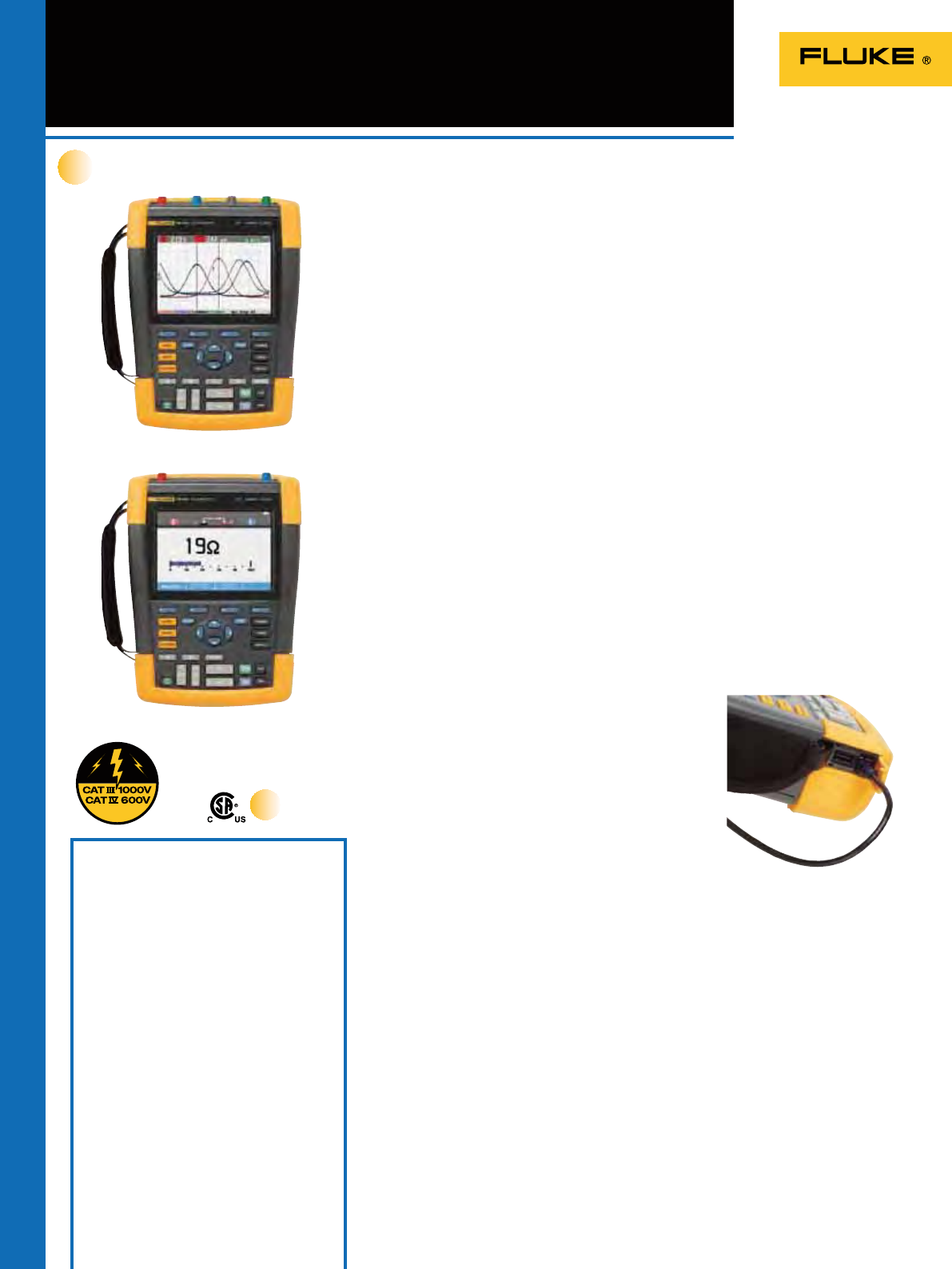
82
ScopeMeter 190 Series II
New
Fluke 190-204
Fluke 190-202
Multiply your diagnostic powers with the new
Fluke 190 Series II portable oscilloscopes
Optional Accessories
C290 Hard shell protective carrying case for
190 Series II
HH290 Hanging Hook for 190 Series II
instruments
SCC290 FlukeView Software (full version) and
C290 Carrying Case kit
VPS410-R Voltage Probe set, 10:1, 300 MHz,
one set red
VPS410-G Voltage Probe set, 10:1, 300 MHz,
one set grey
VPS410-B Voltage Probe set, 10:1, 300 MHz,
one set blue
VPS410-V Voltage Probe set, 10:1, 300 MHz,
one set green
VPS420-R High working voltage probe set 150 MHz,
100:1, CAT III 2000 V (1000 V to earth)
BC190 Mains adapter/battery charger
EBC290 External battery charger for BP290
and BP291
TL175 TwistGuard™ safety designed Test
Leads set (1 red, 1 black)
BP290 Li-Ion battery pack, 2400 mAh
BP291 Li-Ion battery pack, 4800 mAh
SW90W FlukeView® ScopeMeter Software for
Windows®
VPS510-X Wide bandwidth probe set, 10:1,
500 MHz, 600V CAT III
ScopeMeter test tools are rugged solutions built for industrial troubleshooting. The
new Fluke 190 Series II are double-insulated oating oscilloscopes safety rated for
measurements up to CAT III 1000 V/CAT IV 600 V environments. The new 500 MHz
model is rated all the way up to 600 V CAT III.
Rated all the way to CAT IV
Measure from mV to kV safely
Independently isolated inputs allow you to make measurements in mixed circuits
having different ground references reducing the risk of accidental short circuits.
Conventional bench oscilloscopes without special differential probes and isolation
transformers can only reference measurements to line power earth ground. With
standard probes that cover a wide application range from mV to kV, you are ready for
anything from micro-electronics to heavy-duty higher voltage electrical applications.
IP-51 rated for harsh environments
Rugged and shock-proof, ScopeMeter portable oscilloscopes are built for dirty,
hazardous environments. With its sealed case, it can endure dust, drips, humidity and
airborne pollutants. Every time you reach for ScopeMeter you can be condent it will
work reliably wherever your work takes you.
USB connectivity makes it
easy to capture and share
waveforms
The new Fluke 190 Series II offers two USB ports,
electrically isolated from measurement input circuits.
Easily transfer data to a PC. Archive and share
waveforms with OEMs, colleagues and support staff.
Store waveforms, screen captures and instrument
setups onto USB memory devices.
FlukeView ScopeMeter software for
documenting, archiving and analysis
Get more out of your ScopeMeter with FlukeView® ScopeMeter® SW90W Software for
Windows.
• Documentation—transfer waveforms, screens and data to your PC for printing or
importing data into a report
• Add text to ScopeMeter settings—give operators guidance when recalling settings
• Archive—create a library of waveforms for easy reference, waveform comparison, or
pass/fail testing
• Analysis—use cursors, perform spectrum analysis or export data to another
analysis program
True RMS
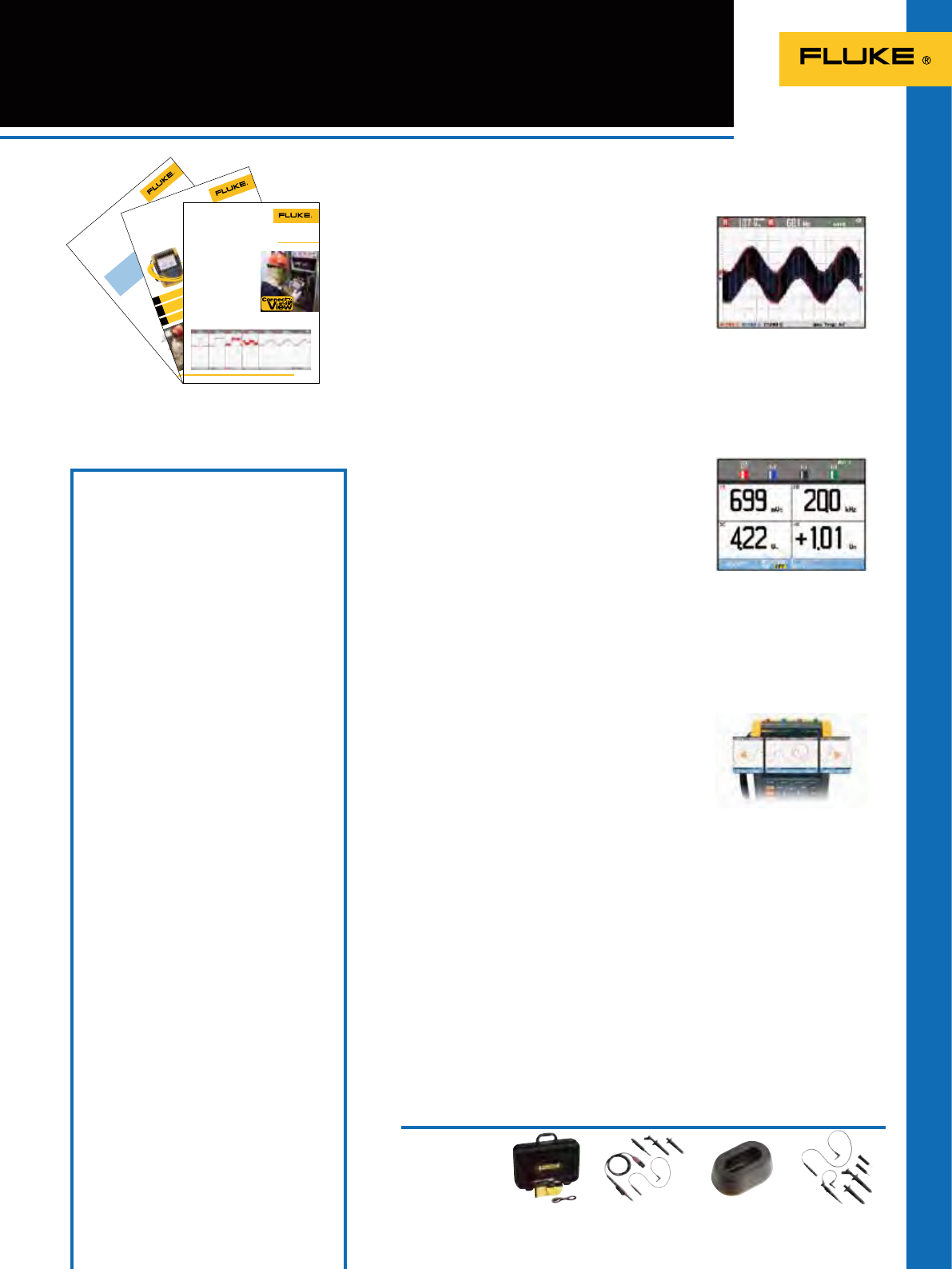
Figure 1. G703 - E1 template
Application Note
From the Fluke Digital Library @ www.fluke.com/library
The G.703 standard
G.703 is a standard origi-
nally introduced for voice and
data transmission over digital
networks. It is an ITU recom-
mendation (formerly CCITT)
that’s associated with the PCM
standard. Analog-voice to digital-
data conversion according to
PCM requires a bandwidth of
64 kb/s (±100 ppm), resulting in
the basic unit for G.703. Through
multiplexing this results in a T1
of 1.544 Mb/s and E1 of
2.048 Mb/s.
The electrical characteristics
of the network interfaces are
described in recommendation
G.703. The signal limits for a
2.048 Mb/s signal are shown in
Figure 1.
Multiple-channel
testing using two
different masks
A balun is used between the
patch panel and a coaxial
transmission line to match the
impedance of the 120 Ω sym-
metrical line to a 75 Ω coaxial
line. The input and output of the
balun each has its specific mask.
The ScopeMeter 190 Series II
portable oscilloscopes can simul-
taneously perform a pass/fail test
at the input and output of the
balun with different masks.
The floating and isolated
inputs of the Fluke ScopeMeter
190 Series II test tools make
these measurements pos-
sible without the risk of making
unwanted groundings. Moreover,
the high impedance probes allow
for direct measurements without
loading the line and without the
need for an external differential
probe.
Testing telecommunication
equipment using Pass/Fail
mask testing with a Fluke
ScopeMeter
®
190 Series II
Editing the pass/fail
templates
With FlukeView we can export
a waveform into a spreadsheet
and a custom template can be
created by editing a waveform
using Excel.
A reference template for
pass/fail testing can be cre-
ated by saving waveforms from
FlukeView in .csv format and
editing the waveform using, for
Figure 2. ISDN30 network
ISDN 30
Patch
Panel
Balun SDH
Distr.
2 Mb/s
120 Ω 2 Mb/s
120 Ω 2 Mb/s
75 Ω
Telephone
Exchange
Nowadays digital communication systems such as Synchronous
Digital Hierarchy (SDH) in Europe and the Synchronous Optical
Network (SONET) in North America require standard test methods.
The electrical signals are tested against the standard ITU pulse
masks. The Fluke ScopeMeter 190 Series II portable oscilloscope
offers a standard pass/fail function that can be used to perform
these tests. The instrument is capable of storing up to 100 “fails”
for further analysis.
Application Note
Demystifying
drive anomalies
using the Fluke 190 Series II 2-Channel
ScopeMeter® portable oscilloscope
From the Fluke Digital Library @ www.fluke.com/library
Vogel, an HVAC technician,
becomes energized when dis-
cussing the return on investment
in his handheld ScopeMeter
®
Test Tool. “Out at one large site,
where we monitor and trouble-
shoot variable frequency drives
(VFDs), component-level repair
can often mean the difference
between a $20 repair part and
a $100,000 repair bill. I know
firsthand, because we recently
documented that very scenario.”
On large VFDs, Vogel uses his
ScopeMeter portable oscilloscope
to uncover capacitance problems,
transistor firing mishaps, and
even bleed-throughs on a gate.
“Of course, a transistor is basi-
cally a lightning-fast switch,”
he says. “It switches back and
forth between open and closed,
and it can sometimes start to
break down. When that happens,
motors will start doing weird
things. For example, at load
stage we’ll actually see
the motor banging back and
forth as if it is not sure which
way to turn.”
Seeing is believing? More aptly, seeing is
understanding.
If anyone can wring every last ounce of functionality out
of a piece of electronic test equipment, it’s Chris Vogel.
At Siemens Building Technologies, Vogel has his work cut
out for him keeping HVAC systems running for the com-
pany’s large commercial customers in Florida’s tropical
weather, which is marked by seemingly nonstop 90 °F
temperatures and 95 % humidity levels. And that’s just
one of the challenges faced by technicians at Siemens
Building Technologies, which plays a more sweeping role
in its customers’ success: ensuring energy efficiency,
comfort, protection against unauthorized access, and
fire safety year-round for every building or office tower
entrusted to it by customers.
Storing a slice of time
It’s important, says Vogel,
that the technician be able to
characterize VFD problems by
capturing a waveform from the
offending drive. His premise: A
signal is much more telling when
presented in a waveform view
than in a single, static volt-
age reading. The signal has a
shape and value that may look
right at a glance, but could just
as easily have a distortion or
rough “edge,” or a momentary
spike almost too short to be
seen. Either problem, or a host
of other signal anomalies, would
be indistinguishable with just a
numeric reading of the signal.
“The scope allows me to
record information, and from a
number of sources—sine waves
on the inputs and outputs of
VFDs, current and voltage—and,
for that matter, make compari-
sons of current and voltage so
that I can derive a power factor
for the circuit.”
Operator: Chris Vogel, HVAC
Technician for Siemens Building
Technologies
Testing
Functions
Case
Study
Measuring tools: 190 Series II
2-Channel ScopeMeter
®
Test Tool
Measurements: Current and voltage
waveform analysis, power factor
Connect the ScopeMeter
test tool and view the
result: the start of every
measurement
It frequently happens t hat service
engineers have to spend a lot of
time adjusting thei r measuring
device such as a portable oscil-
loscope for an optimal s etting.
Valuable time is spent completi ng
this set up, and ideally, this could
be done automatically.
With the introduction of the
new ScopeMeter 190 Series II,
Fluke has revamped it s unique
feature, Connect and Vie w.
Scope users know how d if-
ficult trigger ing can be. Wrong
settings show unstable and
sometimes wrong resu lts. Fluke’s
unique Connect a nd View
recognizes signal patterns, and
automatically sets up cor rect
triggering, attenu ator and time
base settings. S witching on the
ScopeMeter portable oscilloscope
to display correct sig nal patterns
only takes a couple of second s,
and this is exact ly what an
operator wants.
Settings regarding
amplitude,
timebase,
triggering,
etc.
are automatically detec ted and
adjusted, followed by display-
ing the signal in t he correct ratio
with respect to t he horizontal
and vertical ax is. At least 1.5
to 4 periods of the signal a re
measured before the pattern is
shown.
Connect and View prov ides
a stable, reliable and repeat-
able display of virtually any
signal, includi ng motor drive and
control signals, w ithout touch-
ing a button. Signal cha nges are
instantly recog nized and settings
adjusted for, once again, a stable
display. This is all done auto -
matically, but manual overruling
is still possible. If manual over-
ruling is needed, t he ScopeMeter
190 Series will switch from auto-
matic to 1/2 automatic, which is
visible on the dis play.
Figure 1 gives a n example of
the different ty pes of waveforms
which can de detected by
Connect & View. If requir ed the
criteria for best set tings can be
optimized by sw itching on one or
all of the followi ng options:
Automatic trigger
Application Note
From the Fluke Digital Library @ www.fluke.com/library
Figure 1.
AC/DC coupling
Glitch detect
Figure 2 shows the d ifferent
settings.
83
ScopeMeter 190 Series II
AS400
Recommended Accessories
EBC290VPS420-R
SCC290SW90W
If you’ve used other scopes, you know how tricky
triggering can be. If settings are incorrect, results
can be unstable or incorrect. Connect-and-
View™ automatically sets up correct triggering
by recognizing signal patterns. Without touching
a button, you get a stable, reliable and repeatable
display of virtually any signal including motor
drive and control signals. It’s especially fast and
convenient when you’re measuring a number of
test points in rapid succession.
190 Series II models with isolated dual input
scope and dedicated digital multimeter.
Conveniently switch from waveform analysis
to precise multimeter measurements using
the built in 5000 count digital multimeter.
Measurement functions include Vdc, Vac,
Vac+dc, resistance, continuity and diode test.
Measure current and temperature using suitable
shunt, probe or adapter with wide range of
scaling factors.
Scope users know how frustrating it is to see a one-
time anomaly ash by, never to be seen again. Not
with the ScopeMeter 190-series! Now you can look
back in time with the touch of a button. In normal
use, the instrument continuously memorizes the
most recent 100 screens. At any moment in time, you
can ‘freeze’ these latest screens and scroll through
them picture-by-picture or replay them as a ‘live’
animation. Cursors and zoom can be used for further analysis. You can even use
the advanced trigger capabilities to capture up to 100 specic events. Two sets of 100
screens with individual time stamps can be stored for later recall or download to a PC.
See dynamic signal behavior instantly
The digital Persistence mode helps to nd anomalies and to analyze complex
dynamic signals by showing the waveforms amplitude distribution over time using
multiple intensity levels and user selectable decay time – it’s as if you’re looking at
the display of an analog, real time oscilloscope! A fast display update rate reveals
signal changes instantaneously, useful for instance when making adjustments to a
system under test.
Connect-and-View™ captures even the
most complex motor drive signals.
The built in multimeter provides
convenient precision measurements.
Connect-and-View™ triggering for an instant,
stable display
Built-in digital multimeter (2 channel models)
Automatic capture and replay op 100 screens
A range of application notes is available.
See the Fluke website.
Included Accessories
Fluke 190 Series II 4-channel instruments include a set
of four probes, hanging strap, handstrap, USB cable with
mini-B connector, double capacity Li-ion battery BP291,
battery charger/power adapter BC190, a FlukeView demo
package and users manuals on CD-ROM. The /S-versions
also include the C290 hard-shell carrying case and the
FlukeView software package. The 2-channel models come
with two probes plus a set of TL175 test leads and a single
capacity battery BP290. The 190-502 also includes two
pieces TRM50 coaxial feedthrough terminator.
The SCC290 kit includes: C290 hardshell carrying case and
FlukeView
®
for Windows
®
software (full version).
Ordering Information
Fluke-190-502/S Color ScopeMeter (500 MHz,
2 channel), with SCC290-kit
Fluke-190-204/S Color ScopeMeter (200 MHz,
4 channel), with SCC290-kit
Fluke-190-204 Color ScopeMeter (200 MHz, 4 channel)
Fluke-190-202/S Color ScopeMeter (200 MHz,
2 channel), with SCC290-kit
Fluke-190-202 Color ScopeMeter (200 MHz, 2 channel)
Fluke-190-104/S Color ScopeMeter (100 MHz,
4 channel), with SCC290-kit
Fluke-190-104 Color ScopeMeter (100 MHz, 4 channel)
Fluke-190-062/S Color ScopeMeter (60 MHz,
2 channel), with SCC290-kit
Fluke-190-062 Color ScopeMeter (60 MHz, 2 channel)
AS400 Probe Accessory Extension set for
VPS400 Series probes
BP291 Double capacity Li-Ion battery
(4800 mAh) pack for 190C Series II
BP290 Single capacity Li-ion battery
(2400 mAh) pack for 190-series II
C195 Soft padded carrying case for
ScopeMeter and accessories
C290 Protective Carrying Case for Fluke
190-series II
EBC290 External Battery Charger for charging
BP290 or BC291 outside the instrument
HH290 Hanging Hook
RS400 Probe Accessory Replacement set
for VPS400 series probes
RS500 Probe Accessory Replacement set
for VPS510 series probes
SCC290 Software and Case kit for Fluke 190
Series 190 Series II. Includes SW90W
and C290.
SW90W FlukeView
®
ScopeMeter Software for
Windows
®
(full version)
TRM50 Coaxial 50 feedthrough terminator
VPS410-x Probe-set, 10:1, 1000V CAT III / 600V
CAT IV (colors: blue, green, red, grey)
VPS420-R Probe-set, bicolor (r/b), 100:1, 150 MHz,
1000V CAT III / 600V CAT IV, working
voltage (voltage between probe tip and
reference lead): 2000V CAT III / 1200V
CAT IV.
VPS510-x Wide bandwidth probeset, 500 MHz,
10:1, 600V CAT III
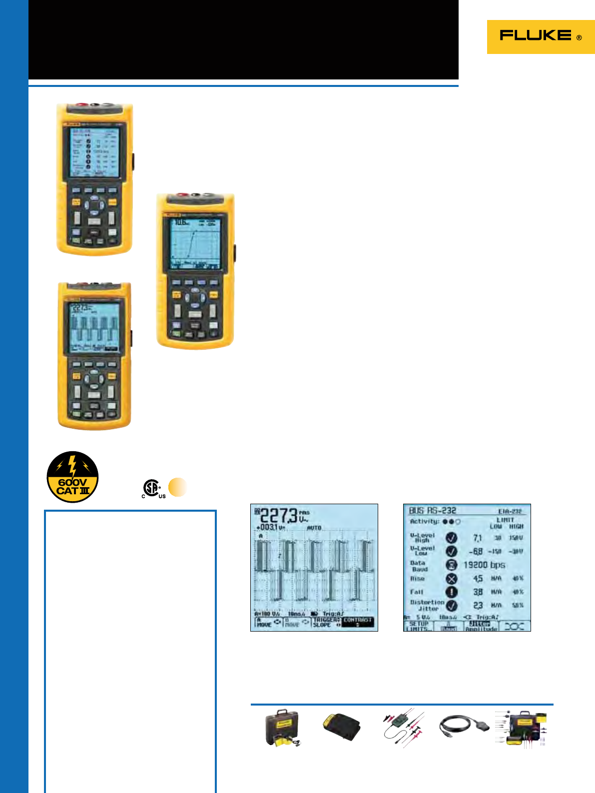
84
ScopeMeter® 120 Series
SCC128
See page 125
Recommended Accessories
Fluke 125
Included Accessories
PM 8907 line adapter/charger, STL120-III
shielded test leads set (1 red, 1 grey) including
hook clips, BB120 shielded BNC adapter,
BP120MH NiMH battery pack, VPS40-III wide
bandwidth Voltage Probe (Fluke 124/125),
TL175 Safe-guard testlead, i400s current
clamp (Fluke 125), Getting Started booklet,
user’s manual (cd-rom)
Ordering Information
Fluke 123 Industrial ScopeMeter® (20MHz)
Fluke 123/S Industrial ScopeMeter® (20MHz)
+ SCC120 kit
Fluke 124 Industrial ScopeMeter® (40MHz)
Fluke 124/S Industrial ScopeMeter® (40MHz)
+ SCC120 kit
Fluke 125 Industrial ScopeMeter (40 MHz)
Fluke 125/S Industrial ScopeMeter (40 MHz) +
SCC120 kit
SCC120 FlukeView® Software + OC4USB
Cable + Carrying Case
OC4USB USB Interface Cable
PM9080 RS-232 Interface Cable
DP120 Differential Voltage Probe
ITP120 Isolated Trigger Probe
SW90W FlukeView Software
BHT190 Set of 3 break-out adapters
(Fluke 125)
OC4USB
See page 86
The compact ScopeMeter 120 Series
is the rugged solution for industrial
troubleshooting and installation
applications. It’s a truly integrated test
tool, with oscilloscope, multimeter and
“paperless” recorder in one affordable,
easy-to-use instrument. Find answers to
problems in machinery, instrumentation,
control and power systems quickly and
easily.
• Dual-input 40 MHz or 20 MHz digital
oscilloscope
• Two 5,000 counts true-RMS digital
multimeters
• A dual-input TrendPlot™ recorder
• Bus Health Test for industrial bus
systems (Fluke 125)
• Connect-and-View™ trigger simplicity
for hands-off operation
• Power Measurements and Harmonics
measurement (Fluke 125)
• Shielded test leads for oscilloscope,
resistance and continuity
measurements
• Up to 7 hours battery operation
• 600 V CAT III safety certied
• Optically isolated interface for PC and
Printer connection (optional)
• Rugged, compact case
Connect-and-View™ triggering for
an instant, stable display
Scope users know how difcult triggering
can be. Wrong settings show unstable
and sometimes wrong results. Fluke’s
unique Connect-and-View recognizes
signal patterns, and automatically
sets up correct triggering. It provides a
stable, reliable and repeatable display
of virtually any signal - including
motordrive and control signals - without
touching a button. Signal changes
are instantly recognized and settings
adjusted for - once again - a stable
display.
Use TrendPlot™ to help find
intermittents fast
The toughest faults to nd are those
that happen only once in a while:
intermittents. They can be caused by
bad connections, dust, dirt, corrosion
or simply broken wiring or connectors.
You may not be around to see it – your
Fluke ScopeMeter will. In this “paperless
recorder” mode, you can plot the
minimum and maximum peak values
and average over time – up to 22 days
(Fluke 190 Series) or 16 days (Fluke 120
Series).
Bus Health mode (Fluke 125)
Bus Health mode gives a clear “Good/
Bad” indication for the electrical signals
on industrial buses and networks, such
as CAN-bus, Pro-bus, RS-232 and many
more. The Fluke 125 validates the quality
of the electrical signals as soon as any
electrical signals are passed along the
network.
Fluke 124
Fluke 123
True RMS
DP120
See page 86
C125
See page 124
SCC120
Connect-and-View captures even the most
complex motor drive signals.
Bus Health mode allows for an analysis of the
signal quality on an industrial network.
See page 85 for specifications.
Three-in-one simplicity
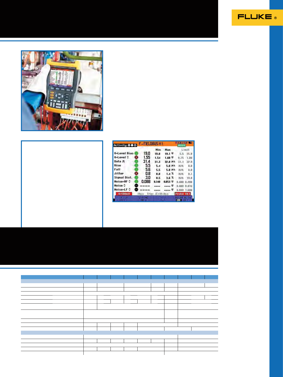
85
ScopeMeterTest Tools
General ScopeMeter
Specifications
Fluke 225C/S Industrial Networks
and Bus Health Test
Built on the Fluke 190C-series, the 225C/S makes Bus Health
Test analysis on the electrical signals on an industrial bus
or network, giving a clear “Good”, “Weak” or “Bad” validation
of the relevant parameters, presented next to the actual
measurement value. The Fluke 225C/S can make the signal
quality validation as soon as electrical signals are passed
along the network, without looking at the data content. It nds
errors like improper cable connections, bad contacts, incorrect
grounding and missing or superuous terminators.
Included Accessories
BHT190 Set of three break-out adapters for
industrial networks
BC190 Mains adapter/Battery charger
BP190 NiMH battery pack (installed)
VPS210 Voltage probe sets (1 red, 1 grey)
TL175 SafeGuard(r) Testlead set
C190 Hard shell protective carrying case
OC4USB Optically insulated USB interface
cable for PC connectivity
SW90W FlukeView software package
(full version)
Ordering Information
225C/S Color ScopeMeter (200 MHz,
2.5 GS/s) with Bus Health Test
capabilities and SCC-kit.
Model: 190-502 190-204 190-202 190-104 190-102 190-062 225C/S 125 124 123
Oscilloscope Specifications
Bandwidth 500 MHz 200 MHz 100 MHz 60 MHz 200 MHz 40 MHz 20 MHz
Max. real time sample rate 5 GS/s 2.5 GS/s 1.25 GS/s 625 MS/s 2.5 GS/s 25 MS/s
Input sensitivity 2 mV/div. 5 mV/div.
Max. timebase speed 1 ns/div. 2 ns/div. 4 ns/div. 10 ns/div. 5 ns/div. 10 ns/div. 20 ns/div.
Inputs and digitizers 2 + Ext.Tr. 4 2 + Ext.Tr. 4 2 + Ext.Tr. 2 + Ext.Tr. 2 + Ext.Tr. 2 (+ Ext.Trig. Optional)
Independently floating isolated inputs 600 V
CAT III 1000 V CAT III,
600 V CAT IV 600 V
CAT III -
Max.record length
…. In Scope mode
…. In ScopeRecord mode 10 000 samples per trace
30 000 min/max pairs 3000
27500 512 min/max pairs per input
Glitch capture 8 ns peak detect at full timebase range 50 ns 40 ns
True RMS multimeter built-in (5000 counts) yes - yes - yes dual 5000 counts DMM
Dedicated test capabilities V/Hz ratio - V/Hz ratio - V/Hz ratio Bus health test -
General Specifications
Mains adapter/battery charger incl. (type) BC 190 PM8907
Battery installed BP291 BP291 BP290 BP291 BP290 BP290 BP190 BP120MH
Size 265 x 190 x70 mm ** 232 x 115 x 50 mm
Weight 2.1 kg 2.2 kg 2.1 kg 2.2 kg 2.1 kg 2 kg 1.2 kg
Safety certified 1000 V CAT III / 600 V CAT IV 600 V CAT III
Typical status overview of a bushealth measurement.
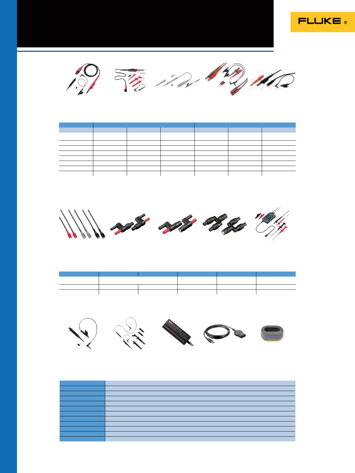
VPS410-X
PM9091/9092
RS400
VPS420-R
PM9081
AS400
VPS510-x
PM9082
BP291
STL120-III
PM9093
OC4USB
VPS40-III
DP120
EBC290
86
ScopeMeter® Accessories
ScopeMeter series 190-series II 120-series
VPS410-x VPS420-R VPS510-x STL120-III VPS40-III DP120
Description Voltage probe High working voltage
probe* Wide bandwidth
voltage probe Shielded Test leads Voltage probe Differential Voltage
Probe
Colors available red, grey, blue, green bicolor (red & black) red, grey, blue, green red + grey (1 set) black red + grey (1 set)
Attenuation 10:1 100:1 10:1
1:1
10:1 200:1 / 20:1
Bandwidth 300 MHz 150 MHz 500 MHz 12.5 MHz 40 MHz 20 MHz
Length 1.2 m 1.2 m 1.2 m 1.2 m 1.2 m 1.5 m (2x)
Safety Rating CAT II -- -- -- 1000 V 1000 V 1000 V
Safety Rating CAT III 1000 V 1000 V* 300 V
600 V
600 V 600 V
Safety Rating CAT IV 600 V 600 V* -- -- -- --
PM9091 PM9092 PM9081 PM9082 PM9093
Description Safety designed 50 BNC Cable set
(1 red, 1 black, 1 grey) Dual banana plug
(m) to female BNC Dual banana jack
(f) to BNC plug (m) BNC (m) to dual
BNC (f) ‘T-piece’
Length 1.5 m each 0.5 m each -- -- --
Safety Rating CAT III 300 V 600 V 600 V
600 V
10:1
* High Working Voltage Probe is specied for working voltages (between probe tip and reference lead) up to 2000V in CAT III or 1200V in CAT IV environments. Reference lead
voltage (between reference lead and earth ground): 1000V in CAT III, 600V in CAT IV. These specication applies only when used with Fluke 190-series II Test Tool.
RS400 Probe Accessory Replacement set for VPS200 and VPS400 series probes
AS400 Accessory Extension set for VPS200 and VPS400 series probes
PM9080 RS232 interface cable for 120-series
OC4USB Optocoupler to USB interface cable for 120 series
BP120MH Ni-MH battery pack for Fluke 120-series and Fluke 43B
BP290 Single capacity Li-ion battery pack for 190-series II
BP291 Double capacity Li-ion battery pack for 190-series II
EBC290 External battery charger for BP290 and BP291
TRM50 Coaxial 50 feedthrough terminator
RS500 Probe Accessory Replacement set for VPS510 series probes
C437-II Hard shell protective carrying case with rollers for 190-II and 430-II
RF-AM90 RF Detector and Demodulation probe
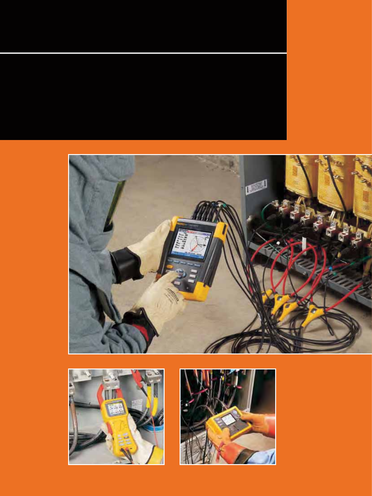
87
We offer an extensive range of power quality test tools for
troubleshooting, predictive maintenance and long-term recording in
industrial and utility applications. For the development and test of
electrical equipment, our high-precision power analyzers enable easy
and reliable use in the eld or as a bench unit in test laboratories.
Additionally, the Fluke-patented energy loss algorithm, Unied Power
Measurement, measures and quanties energy losses due to harmonics
and unbalance issues, allowing the user to pinpoint the origin of energy
waste within a system.
Power Quality Tools and Power
Analyzers
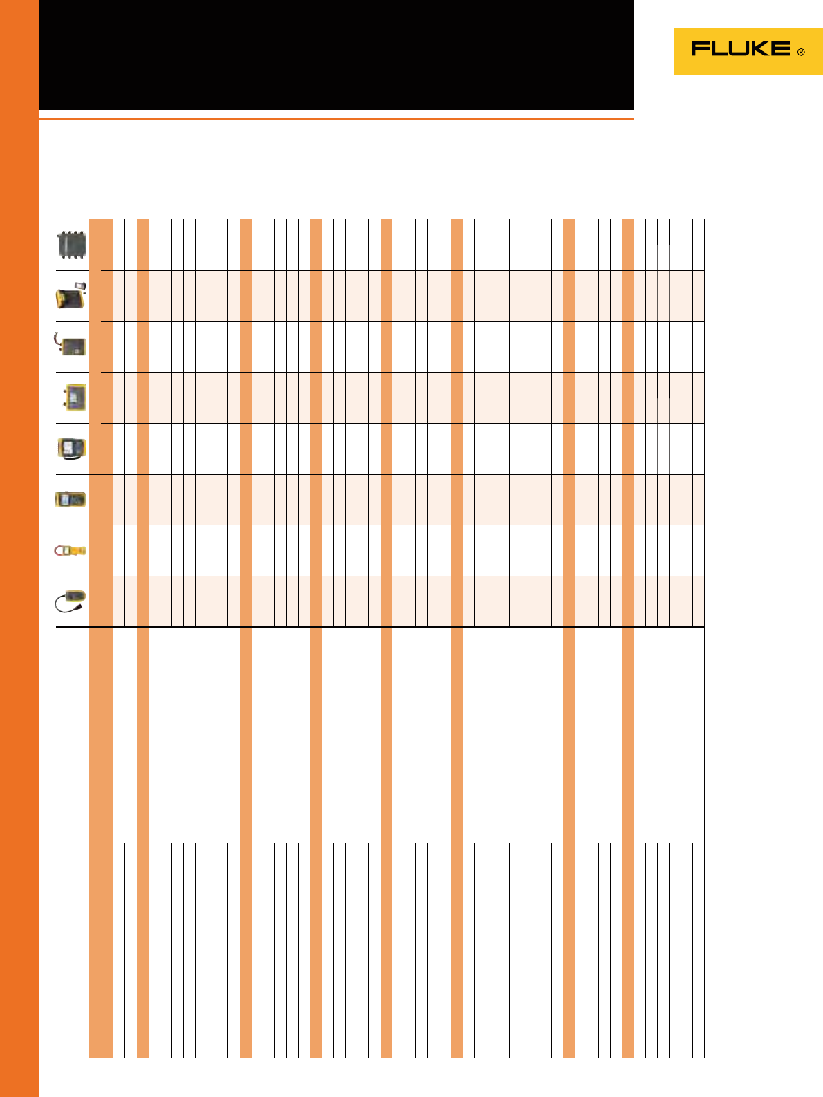
88
Power Quality Selection Guide
Power quality tools help pinpoint problems fast
Basic measurements Application use
Single phase Three phase
VR1710 345 43B 430 II 1735 1740 1750 1760
RMS voltage Detailed RMS trending shows how connected loads
behave.
OOOOOOOO
RMS Current
OOOOOOO
Energy studies
Measure V, I, kW, Cos/DPF, kWhr Get detailed power and energy consumption
profiles during energy audits and pinpoint savings
opportunities.
OOOOOOO
Measure MIN/MAX and AVG values
OOOOOOO
10 day logging
OOOOOOO
Energy aggregation
OOOOOOO
Utility meter pulse input
O
Energy Loss (Eff. kW, Reactive kVAR, Unbalance kVAR,
Distortion kVAR, Neutral kVAR)
OOOOOOO
Energy loss calculator
O
Basic harmonics study
THD measurement (V & I) Discover the source of distortion in your installation, so
that you can filter those loads or move them to separate
circuits.
OOOOOOOO
Harmonics 1 to 25 for V & I
OOOOOO
(not 1743)
OO
Tabular values
OOOOO
Neutral current measurement
OOOOO
Crest factor
OOO OOO
Advanced harmonics study
Full harmonic spectrum If distorting loads are causing problems in your
installation, you need comprehensive data to intentify
the source and create a solution.
OOOOOOO
Power harmonics
OOO OO
Harmonics 1 to 50 and dc
OOO O
(no DC)
(not 1743)
OO
k-factor
OOO OO
%Fundamental and %RMS
OOO OOO
Basic Industrial PQ Troubleshooting
Oscilloscope function When troubleshooting in the field, graphical data
enables you to trace the source of the problem at hand.
OOOO OO
Voltage dips and swells
O OOOOOO
Phasor diagram
OOO
Trend recording
OOOO OO
Inrush current
OOO OO
Advanced industrial PQ troubleshooting
Comprehensive logging capability Complex installations often require a deeper dive into
measurement data. Multiple loads may be interacting
randomly to cause a single problem.
OOOOOOO
Transient capture
OOO OO
Flicker
O O OOO
EN50160 analysis
O OOO
Complex System interaction event capture (manual
threshold setting)
O
Random/variable system event capture (Adaptive
threshold setting)
O
400 Hz
O
(only 437-II)
Utility PQ benchmarking
Phase sequence components Before you install sensitive loads, make sure you
understand the existing quality of power delivered by
your utility. Comparing benchmarks over time can help
pinpoint potential areas of concern.
OOO
Interharmonics
O OOO
Mains signaling
O OOO
IEC61000-4-30 Class A
OO
Software
Power Log To make use of the power data you collect, you need
software that can help analyze your findings and share
them with equipment providers and plant management.
OO OO
PQ Log
O
Power Analyze
O
PQ Analyze
O
FlukeView Forms
O
FSD card (max 32 GB) 8 GB 8 GB
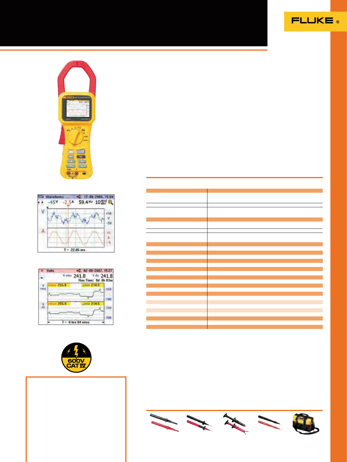
89
345
Power Quality Clamp Meter
Fluke 345
Included Accessories
Soft carrying case, Power Log software,
Test probes, Test leads, Alligator clips,
International ac adapter / battery eliminator,
Printed English User manual, Multi-language
manual on CD
Ordering Information
Fluke 345 Power Quality Clamp Meter
View waveforms for equipment
checking and setup
Log parameters over time
to track down intermittent faults
Recommended Accessories
C550
See page 130
TP1-1
See page 123
AC220
See page 124
TP220-1
See page 123
TLK291
See page 123
The Fluke 345 measures a wide range of
electrical parameters for troubleshooting
power disturbances in single- and
three-phase electrical loads. With a
bright color display to see waveforms
and trends, a low-pass lter to remove
high frequency noise, and a high EMC
immunity design, the Fluke 345 is ideal
for measurements on switching loads
such as variable speed drives, electronic
lighting and UPS systems.
• High safety rating: 600V CAT IV / 1000V
CAT III rated for use at the service
entrance
• ac/dc current measurements: Clamp-
on measurement of ac peak and dc
current up to 2000 A without breaking
the circuit
• Harmonic analysis: Analyze, display
and log harmonics up to the 30th
harmonic (40th harmonic for 15 Hz to
22 Hz)
• Verify batteries: Direct measurement
of dc ripple (%) for battery and dc
systems
Specifications
(Check the Fluke web for detailed specifications)
Power supply: 1.5 V Alkaline AA MN 1500 or IEC LR6
x 6 Battery
Battery life (typical): >10 hours (backlight on full);
>12 hours (backlight reduced)
Safety: IEC 61010-1 600 V CAT IV, 1000V CAT III
(maximum input phase-phase 825V rms) double or
reinforced insulation, pollution degree 2
Protection: IP40; EN60529
Operating temperature: 0 °C to 50 °C
Display: Color transmissive LCD 320 x 240 pixels
(70 mm diagonal) with 2 level backlight
Digital output: USB interface to a PC
Size (HxWxD): 300 mm x 98 mm x 52 mm
Jaw opening: 60 mm
Jaw capacity: 58 mm diameter
Weight (including batteries): 0.82 kg
Two Year Warranty
Current measurement
DC, DC rms, AC rms All measurements DC and 15 Hz to 1 kHz.
Maximum overload 10,000 A or RMS x frequency < 400,000. Amps rms is a true rms
measurement (AC + DC).
Measuring range 0 – 2000 A dc or 1400 AC rms
Harmonics All measurements up to 30th harmonic (40th harmonic for 15 Hz to 22 Hz); Frequency
range F0 : 15 Hz to 22 Hz and 45 Hz to 65 Hz; Iacrms > 10A
Voltage measurement
DC, DC rms, AC rms All measurements DC and 15 Hz to 1 kHz. Maximum overload 1,000 V rms. Volts rms is a
true-rms measurement (AC + DC).
Measuring range 0 – 825 V DC or AC rms
Harmonics All measurements up to 30th harmonic; Frequency range F0 : 15 Hz to 22 Hz and 45 Hz
to 65 Hz; Vacrms > 1V
Watts measurement (single- and three-phase) DC, DC rms, AC rms
Measuring range 0 – 1650 kW DC or 1200 kW ac
VA measurement (single- and three-phase) DC, DC rms, AC rms
Measuring range 0 -1650 kVA DC or 1200 kVA ac
VAR measurement (single- and three-phase)
Measuring range 0 – 1250 kVAR
Power factor (single- and three-phase)
Measuring range 0.3 cap…1.0… 0.3 ind (72.5° cap…0°… 72.5° ind)
Displacement power factor
Measuring range 0.3 cap … 1.0 … 0.3 ind (72.5° cap ... 0° ... 72.5° ind)
Kilowatt Hour (kWHr)
Measuring range 40,000 kWHr
Scope function
Time base 2.5 ms, 5 ms, 10 ms, 25 ms, 50 ms/div
Current management:
Ranges 10 A/20 A/40 A/100 A; 200 A/400 A/1000 A/2000 A
Voltage measurement:
Ranges 4 V/10 V/20 V/40 V/100 V; 200 V/400 V/1000 V
Inrush current function All measurements dc and 15 Hz to 1 kHz
Ranges 40, 400 and 2000 A
Memory Up to 50 screen shots and over 150,000 individual measurement values
The ideal troubleshooting tool for modern
electrical loads
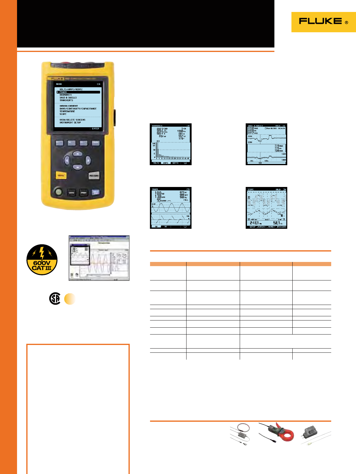
90
43B Single-phase Power
Quality Analyzer
The Fluke 43B is the choice for
diagnosing and troubleshooting power
quality and general equipment failures.
Ease to use thanks to menu selection of
the power modes, it combines the
capabilities of a power quality analyzer, a
20 MHz oscilloscope, a multimeter and a
data recorder in a single instrument.
Specifications
(Check the Fluke web for detailed specifications)
Battery life: Rechargeable Ni-MH pack (charger included), 6 hrs typical (continuous)
Shock & Vibration: Mil 28800E, Type 3, Class III, Style B.
Operating temperature: 0°C to 50°C; Case: IP51 (dust, drip, waterproof)
Size (HxWxD): 232 mm x 115 mm x 50 mm; Weight: 1.1 kg
Three Years Warranty
Included Accessories
TL224 test lead set, AC220 alligator clip set,
TP4 test probe set, BP120MH rechargeable
battery pack, BB120 shielded BNC adapter,
PM8907 line adapter/charger, i400s AC current
clamp, AB200 alligator clip set,
TP1-1 test probe set, C120 hand carrying case,
OC4USB interface cable, SW43W FlukeView
software, VPS 40 voltage probe, Fluke 61 IR
thermometer, user and application manual.
Ordening information
Fluke 43B Power Quality Analyzer
(single-phase)
Recommended Accessories
80TK
See page 128
i1000s
See page 126
i2000flex
See page 126
Fluke 43B
On all inputs
True RMS
Menu items Measurements Ranges Accuracy
Volts/Amps/Hz Volts
Amps
Mains frequency
CF Crest Factor
5.000 V - 1250 V
50.00A - 50.00 kA
40.0 - 70.0 Hz
1,0 à 10,0
±(1%+10)
±(1%+10)
±(0.5%+2)
±(5%+1)
Power Watts, VAR, VA
PF, DPF, COS ƴ 250 W - 1.56 GW
0.25 W-0.9
0.90-1.00
±(4%+4)
±0.04
±0.03
Harmonics Volts
Amps
Watts
K-factor
1 st to 51 st harmonic
1 st to 51 st
1 st to 51 st
1.0 to 30.0
±(3%+2) to ±(15%+5)
±(3%+8) to ±(15%+5)
±(5%+2) to ±(30%+5)
±10%
Sags & Swells Voltage and Current 4 min-16 days selectable ±(2%+10)
Transient Capture 40 ns pulse width
Up to 40 transients Select 20/50/100/200%
above or below line voltage ± 5% of full scale
Inrush Current 1 sec. to 5 min selectable 1 A to 1000 A ± 5% of full scale
Ohms/Continuity/
Capacitance Ohms
Capacitance 500.0 to 30.00 M
50.00 nF to 500.0 µF ± (0.6%+5)
± (2%+10)
Temperature
(with accessory) ºC
ºF -100.0ºC to 400.0ºC
-200.0ºF to 800.0ºF ± (0.5%+5)
Scope DC, AC, AC+DC, peak,
peak-peak, Hz, duty cycle,
phase, pulse width,
crest factor
Sampling rate:
Bandwidth:
Voltage BW (Channel 1)
Current BW (Channel 2)
25 MS/sec
20 MHz
15 kHz
Screen saves All functions 20 screens
Recording V/A/Hz, Power, Harmonics,
Ω/Cap, Temperature, Scope 4 min - 16 days selectable Select any two parameters
display mode in each
The perfect tool for tracking down
single-phase power-related problems
• Voltage, current, and
power harmonics
• Up to 51st harmonic
• Total harmonic distortion
(THD)
• Phase angle of individual
harmonics
• Watts, power factor,
COS
ƴ, VA and VAR
• Voltage and current
waveforms
• Continuously measure
volts and amps on a
cycle-by-cycle basis for up
to 16 days
• Use cursors to read time
and date of sags and
swells
• Connect-and-View™
scope for quick waveform
display
• View voltage and current
channels simultaneously
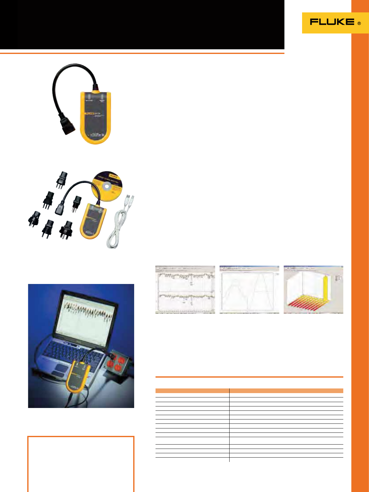
91
VR1710 Single-Phase Voltage
Quality Recorder
The Fluke VR1710 is a single-phase, plug-
in voltage quality recorder that provides
fast and easy recording of voltage trends,
dropouts, harmonics and general power
quality including dips and surges to help
maintenance and facilities management
personnel easily pinpoint the root cause
of voltage problems. Voltage quality
parameters including RMS average,
transients, icker, and harmonics up to
the 32nd are recorded using a user-
selected average period from
1 second to 20 minutes.
• Clear graphical summary of data and
quick overview of key power quality
parameters
• Get the complete picture with Min, Max,
Average RMS values (1/4 cycle) with
time stamps
• See the detailed with actual transient
display (> 100 µs) with time stamp
• Comprehensive analysis of Individual
harmonic and THD values with trends
Specifications
(Check the Fluke web for detailed specifications)
Display: LED
Size (HxWxD): 23 x 19.75 x 22.2 cm
Included Accessories
Plug-in Fluke VR1710, USB cable, PowerLog
software CD, universal power cord adapters.
Ordering Information
Fluke VR1710 Voltage Quality Recorder
Fluke VR1710
Includes PowerLog software
Fluke VR1710 and included accessories
PowerLog Setup – Simple set up of
internal clock, logging periods, and
intervals with default values for
quick results.
PowerLog View – Data presentation
showing RMS voltage and harmonic
trends, actual transients, summary
information and statistics in
accordance with EN50160.
Actual transient display
(> 100 μs) with time stamp–
Quickly identify issues with included
graphical software.
Statistical analysis of voltage event
– reduces analysis time by tracking
event quantities and magnitudes.
Applications
• Voltage recording – Monitors and
records supply voltage; measures RMS
average, minimum and maximum
values, and checks whether the socket
outlet is providing voltage within
tolerance.
• Distortion measurement – Measure
frequency and harmonics; check
whether the distorting loads (UPS
systems, drives, etc.) are affecting your
other equipment.
• Flicker measurement – Quantify the
affects of switching loads on lighting
systems.
• Voltage transients – Capture those
intermittent, momentary events that
may be affecting your equipment; the
full waveform is captured with date,
timestamp, and duration.
Weight: 0.8 kg
Two years warranty
Operating voltage 70 V to 300 V
Min/Max/Avg RMS value Resolution 0.125 V
Number of events 175,000
Dips/Interruptions Yes
Time resolution 5 ms
Voltage resolution) 0.125 V
Over-voltages Yes
Frequency Yes
Harmonics measurement EN 61000-4-7 (up to 32nd)
Flicker measurement EN 61000-4-15
Number of recording channels 1 Phase to Neutral
2 Phase/Neutral to Ground
Recording time 1 day to 339 days depending on average time from 1 second to 20 minutes
Transients Yes (> 100µs)
Frequency range 50 Hz ± 1 Hz and 60 Hz ± 1 Hz
Safety category rating CAT II 300 V
Easy-to-use solution for detecting and
recording voltage quality problems
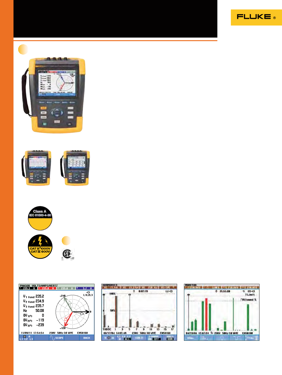
Compliant
Fluke
435 II / 437 II
92
430 Series II Three-Phase Power
Quality and Energy Analyzers
More detailed power quality analysis capability,
and a Fluke-patented energy monetization function
The new Fluke 434, 435 and 437 Series II models
help locate, predict, prevent, and troubleshoot
power quality problems in three-phase and single-
phase power distribution systems. Additionally,
the Fluke-patented energy loss algorithm, Unied
Power Measurement, measures and quanties
energy losses due to harmonics and unbalance
issues, allowing the user to pinpoint the origin of
energy waste within a system.
• Energy loss calculator: Classic active and reactive
power measurements, unbalance and harmonic
power, are quantied to pinpoint true system
energy losses in dollars.
• Power inverter efciency: Simultaneously
measure AC output power and DC input power
for power electronics systems using optional DC
clamp.
• PowerWave data capture: 435 and 437 Series II
analyzers capture fast RMS data, show half-cycle
and waveforms to characterize electrical system
dynamics (generator start-ups, UPS switching
etc.).
• Waveform capture: 435 and 437 Series II models
capture 100/120 cycles (50/60Hz) of each event
that is detected in all modes, without set-up.
• Automatic Transient Mode: 435 and 437 Series II
analyzers capture 200 kHz waveform data on all
phases simultaneously up to 6 kV.
• Fully Class-A compliant: 435 and 437 Series II
analyzer conduct tests according to the stringent
international IEC 61000-4-30 Class-A standard
with 435 and 437 Series II analyzers.
• 400 Hz measurement: 437 Series II analyzer
captures power quality measurements for avionic
and military power systems.
• Troubleshoot real-time: Analyze the trends using
the cursors and zoom tools.
• Highest safety rating in the industry: 600 V CAT IV/
1000 V CAT III rated for use at the service
entrance.
• Automatic Trending: Every measurement is
always automatically recorded, without any
set-up.
• System-Monitor: Ten power quality parameters
on one screen according to EN50160 power
quality standard
• Logger function: Congure for any test condition
with memory for up to 600 parameters at user
dened intervals.
Unified Power Measurement
Fluke’s patented Unied Power Measurement
system (UPM) provides the most comprehensive
view of power available, measuring:
• Parameters of Classical Power (Steinmetz 1897)
and IEEE 1459-2000 Power
• Detailed Loss Analysis
• Unbalance Analysis
• These UPM calculations are used to quantify in
dollars the cost of energy loss caused by power
quality issues.
Energy savings
The cost of power quality could only be
quantied in terms of downtime caused by lost
production and damage to electrical equipment.
The Unied Power Measurement (UPM) method
now goes beyond this to achieve energy savings
by discovering the energy waste caused by
power quality issues. Using the Unied Power
Measurement, Fluke’s Energy Loss Calculator will
determine how much money as facility is losing
due to waste energy.
Unbalance
UPM gives a more comprehensive breakdown of
the energy consumed in the plant. In addition
to measuring reactive power (caused by poor
power factor), UPM also measures the energy
waste caused by unbalance; the effect of unevenly
loading each phase in three-phase systems.
Harmonics
UPM also provides details of the energy wasted
in your facility due to the presence of harmonics.
The presence of harmonics in your facility can
lead to:
• Overheating transformers and conductors
• Nuisance tripping of circuit breakers
• Early failures of electrical equipment
Fluke 437-II
Fluke 435-II Fluke 434-II
True RMS
On all inputs
New
Track harmonics up to the 50th, and measure and record
THD in accordance with IEC61000-4-7 requirements.
The System-Monitor overview gives instant insight into
whether the voltage, harmonics, flicker, frequency and
the number of dips and swells fall outside the set limits.
A detailed list is given of all events falling outside the
set limits.
Phasor diagram.
93
430 Series II Three-Phase Power
Quality and Energy Analyzers
Logging provides instantaneous analysis of user
selectable parameters.
Fluke 437 II with all standard accessories.
Included Accessories
TL430 test lead and alligator clip set,
i430ex-TF, 61 cm, 4 clamps,
BC430 power adapter,
BP290 single capacity Li-ion battery,
International plug adapter set,
WC100 color coding clips and regional decals,
8 GB SD card,
PowerLog on CD
USB cable A-Bmini
C1740 softcase (434-II, 435-II),
C437 hard case (437-II)
Ordering information
Fluke 434-II Three-Phase Energy Analyzer
Fluke 435-II Three-Phase Power Quality
and Energy Analyzer
Fluke 437-II Three-Phase Power Quality
and Energy Analyzer
Battery life: 7 hours operating time per charge on Li-ion battery pack
Safety: EN61010-1 (2nd edition) pollution degree 2; 1000 V CAT III / 600 V CAT IV
Case: Rugged, shock proof with integrated protective holster, IP51 (drip and dust proof)
Shock: 30 g; Vibration: 3g according to MIL-PRF-28800F Class 2
Operating temperature: 0°C to +50°C
Size (HxWxD): 265 mm x 190 mm x 70 mm; Weight: 2.1 kg
Three Years Warranty
BP291
See page 86
Recommended Accessories
i5sPQ3
See page 98
i430-FLEXI-TF-4PK
See page 98
See page 98 for power quality current clamps
Voltage inputs
Number of inputs 4 (3 phase + neutral) dc-coupled
Maximum input voltage 1000 Vrms
Nominal voltage range Selectable 1 V to 1000 V
Max. peak measurement voltage 6 kV (transient mode only)
Input impedance 4 M//5 pF
Bandwidth > 10 kHz, up to 100 kHz for transient mode
Scaling 1:1, 10:1, 100:1, 1,000:1 10,000:1 and variable
Current inputs
Number of inputs 4 (3 phase + neutral) dc- or ac-coupled
Type Clamp or current transformer with mV output or i430flex-TF
Range 0.5 Arms to 600 Arms with included i430flex-TF (with sensitivity 10x)
5 Arms to 6000 Arms with included i430flex-TF (with sensitivity 1x)
0.1 mV/A to 1 V/A and custom for use with optional ac or dc clamps
Input impedance 1 M
Bandwidth > 10 kHz
Scaling 1:1, 10:1, 100:1, 1,000:1 10,000:1 and variable
Measurement modes
Scope 4 voltage waveforms, 4 current waveforms, Vrms, Vfund. Arms, A fund, V @ cursor,
A @ cursor, phase angles
Volts/amps/hertz
Vrms phase to phase, Vrms phase to neutral, Vpeak, V Crest Factor, Arms Apeak, A Crest Factor, Hz
Dips and swells Vrms½, Arms½, Pinst with programmable threshold levels for event detection
Harmonics dc, 1 to 50, up to 9th harmonic
for 400 Hz
Harmonics Volts, THD, Harmonic Amps, K factor Amps, Harmonic Watts, THd Watts, K factor
Watts, Interharmonic Volts, Interharmonic Amps, Vrms, Arms (relative to fundamental or to
total rms)
Power and energy Vrms, Arms, Wfull, Wfund., VAfull, VAfund., VAharmonics, VAunbalance, var, PF, DPF, CosQ,
Efficiency factor, Wforward, Wreverse
Energy loss calculator Wfund, VAharmonics, VAunbalance, var, A, Loss Active, Loss Reactive, Loss Harmonics, Loss
Unbalance, Loss Neutral, Loss Cost (based upon user defined cost / kWh)
Inverter efficiency
(requires optional dc current clamp)
Wfull, Wfund, Wdc, Efficiency, Vdc, Adc, Vrms, Arms, Hz
Unbalance Vneg%, Vzero%, Aneg%, Azero%, Vfund, Afund, V phase angles, A phase angles
Inrush Inrush current, Inrush duration, Arms½, Vrms½
Monitor Vrms, Arms, harmonic Volts, THD Volts, PLT, Vrms½, Arms½, Hz, dips, swells, interruptions, rapid
voltage changes, unbalance and mains signalling. All parameters are measured simultaneously
in accordance with EN50160 Flagging is applied according to IEC61000-4-30 to indicate unreliable
readings due to dips or swells
Flicker (435-II and 437-II only) Pst(1min), Pst, Plt, Pinst, Vrms ½, Arms ½, Hz
Transients (435-II and 437-II only) Transient waveforms 4x Voltage 4x Amps, triggers: Vrms ½, Arms ½, Pinst
Mains Signaling
(435-II and 437-II only)
Relative signaling voltage and absolute signaling voltage averaged over three seconds for up to two
selectable signaling frequencies
UPower Wave
(435-II and 437-II only)
Vrms½, Arms½ W, Hz and scope waveforms for voltage amps and watts
Logger Custom selection of up to 150 PQ parameters measured simultaneously on 4 phases
Input characteristics
Energy Loss Calculator
Useful kilowatts (power) available
Kilowatts made unusable by harmonics
Kilowatts made unusable by unbalance issues
Total billable kilowatt hours wasted
Total cost of wasted kilowatt hours
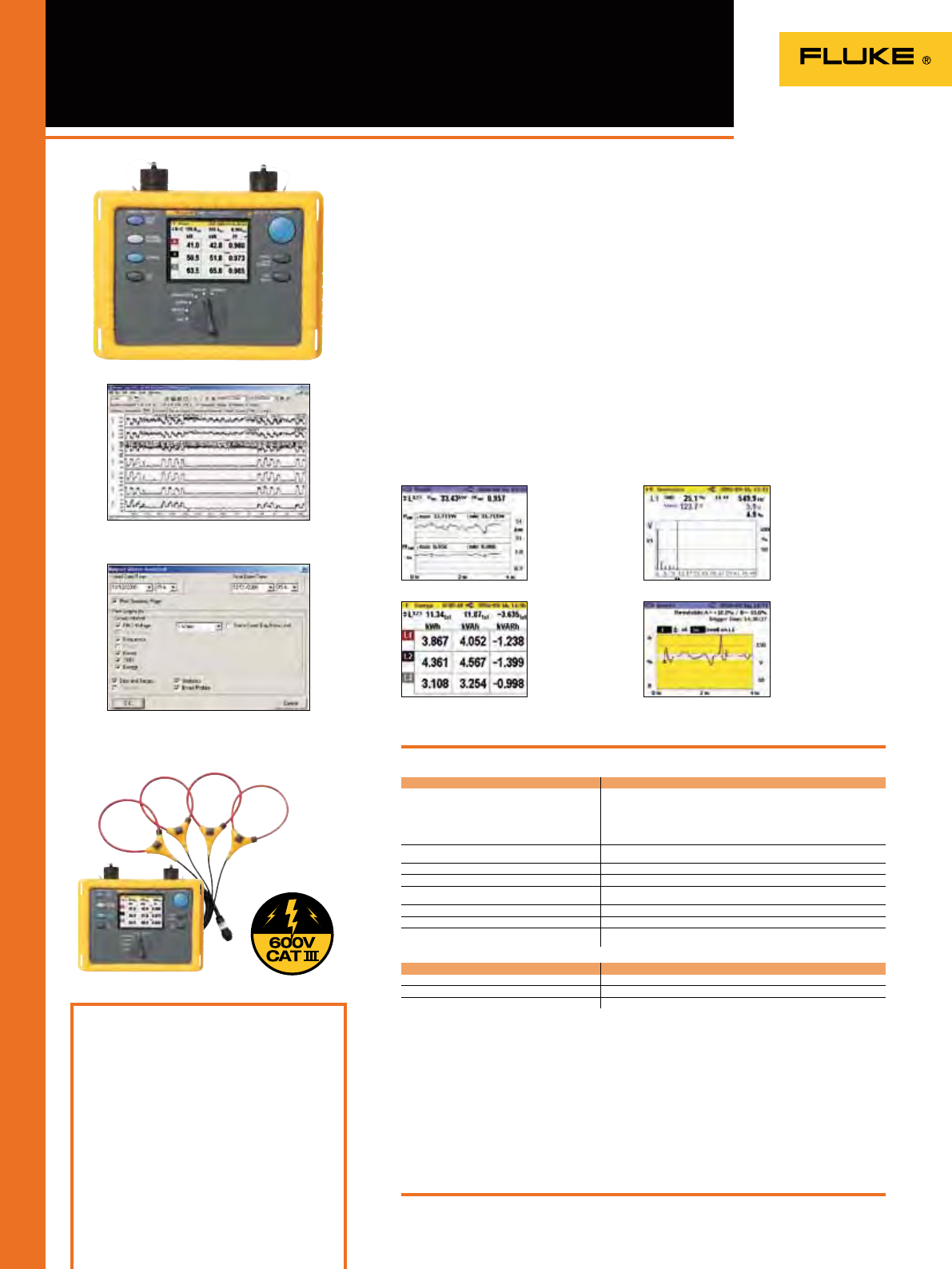
94
1735 Power Logger
Included Accessories
FS17X5-TF 4-phase flexible current clamp
set, VL1735/1745 voltage lead set, Power Log
software, color localization set, PC interface
cable, international ac adapter, BC1735 battery
charger, soft carrying case, printed English
manual and multi-language manual on CD.
Ordering Information
Fluke 1735 Power Logger
FS17X5-TF 4-phase thin flexi current
clamp set, 3000 A
3000/6000A-TF-4 4-phase thin flexi current
clamp set, 6000 A
The Fluke 1735 Power Logger is the ideal
tool for electricians and maintenance
technicians for conducting energy
studies and basic power quality logging.
The 1735 is easy to set up with its color
display and four included new thinner
exible current probes.
The 1735 logs most electrical power
parameters, harmonics and captures
voltage events. View graphs and generate
reports with the included Fluke Power
Log software.
• Record power and associated
parameters for up to 45 days
• Monitor maximum power demand over
user-dened averaging periods
• Prove the benet of efciency
improvements with energy
consumption tests
• Measure harmonic distortion caused by
electronic loads
• Improve reliability by capturing voltage
dips and swells from load switching
• Conrm instrument setup easily with
color display of waveforms and trends
Specifications
Display: VGA Graphic Color transmissive displays
320 x 240 pixels with additional background lighting
and adjustable contrast, text and graphics in color
Interface: USB with Mini USB B socket. Firmware
updates are possible with the USB interface
Housing: IP65; EN60529 (refers only to the main
housing without the battery compartment)
Power supply: NiMH battery-pack, with AC adapter
(15 V to 20 V/0.8 A)
Battery Life: Typical > 16 hours without backlight and
> 6 hours with backlight high
Operating temperature: 0°C to +40°C
Size (HxWxD): 240 mm x 180 mm x 110 mm
Weight: 1.7 kg, including battery
Two Year Warranty
(Check the Fluke web for detailed specifications)
Recommended Accessories
See page 98 for power quality current clamps
Volts rms V-rms wye measurement ranges:
57 V/66 V/110 V/120 V/127 V/220 V/230 V/240 V/260 V/277 V/347 V/380 V/
400 V/417 V/480 V AC
V-rms delta measurement ranges:
100 V/115 V/190 V/208 V/220 V/380 V/400 V/415 V/450 V/480 V/600 V/660 V/
690 V/720 V/830 V AC
Amps rms Flexi set measurement range: 15 A/150 A/3000 A rms (at sine)
Current clamp measurement range: 1 A/10 A
Frequency Measurement range: 46 Hz to 54 Hz and 56 Hz to 64 Hz
Harmonics and THD To 50th harmonic (< 50 % of nom)
Power measurement
(P - Active, S - Apparent, Q - Reactive, D - Distorting) Measuring range: see V-rms and A-rms measurement ranges
Energy Measurement (kWh, KVAh, kVARh) Measuring range: see V-rms and A-rms measurement rangeso
PF (Power factor) 0.000 to 1.000
Events Detection of voltage dips, voltage swells and voltage interruptions with a
10 ms resolution and measuring error of the half period sine wave of rms.
General
Memory 4 MB Flash memory, 3.5 MB for measuring data
Sample rate 10.24 kHz
Line frequency 50 Hz or 60 Hz, user-selectable, with automatic synchronization
Customize the report generator to easily
generate professional looking reports.
Performs electrical load studies, energy
consumption testing, and general power
quality logging
Conduct load studies
for up to 45 days and
view saved data
on-screen or on a
computer.
Quantify energy
consumption quickly
on-screen or log to
memory for extended
periods.
Access voltage and
current harmonics
up to the 50th.
Capture voltage events
using user-defined
thresholds.
Fluke 1735
View recorded data in simple graphs and
tables with Fluke Power Log software.
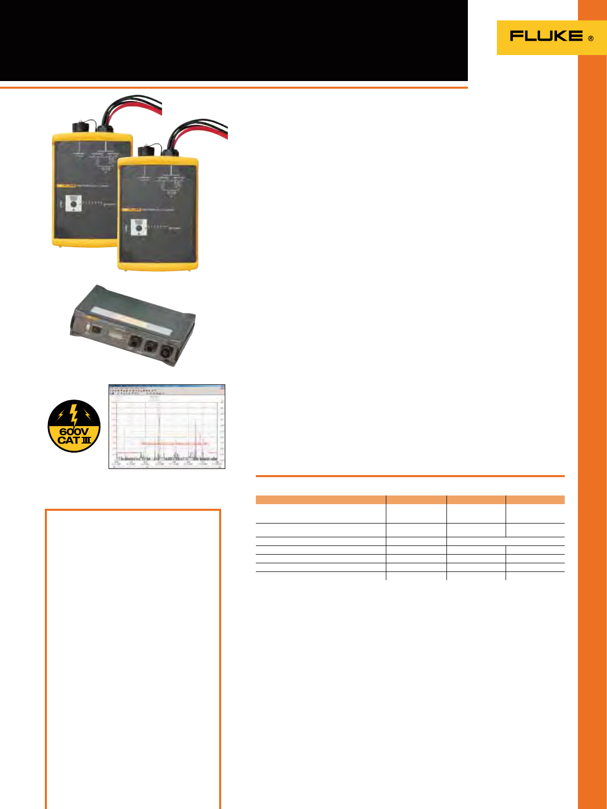
95
1740 Series Three-Phase
Power Quality Loggers Memobox
Included Accessories
Fluke 1743/1744/1745: FS17XX IP65-TF thin
exible current clamp set (1743 & 1744),
FS17X5-TF thin exible current clamp set
(1745), VL1735/1745 voltage lead set (1745
only), Power Log software, RS232 interface
cable and RS232-USB adapter, 4 black dolphin
clips, WC17XX color localization set, carrying
bag, test certicate with measurement values,
printed English manual and multi-language
manual on CD.
Basic models: Excl. current clamps FS17XX-TF
Ordering Information
Fluke 1743 Basic Power Quality Logger
Memobox
Fluke 1743 Power Quality Logger
Memobox
Fluke 1744 Basic Power Quality Logger
Memobox
Fluke 1744 Power Quality Logger
Memobox
Fluke 1745 Power Quality Logger
Memobox
FS17x5-TF 4-phase thin exi current
clamp set, 3000 A
3000/6000A-TF-4 4-phase thin exi current
clamp set, 6000 A
Compact, rugged and reliable, the Fluke
1740 Series three-phase power quality
loggers are everyday instruments for
technicians who troubleshoot and
analyze power distribution systems.
Capable of simultaneously logging up
to 500 parameters for up to 85 days and
capturing events, the Fluke 1740 Series
helps uncover intermittent and hard-to-
nd power quality issues. There are three
models to choose from to meet your
basic or advanced power logging needs.
Fluke 1743: IP65 waterproof monitor
for logging the most common power
parameters including V, A, W, VA, VAR, PF,
energy, icker, voltage events and THD.
Fluke 1744: Includes the same features
as the Fluke 1743. In addition to common
power parameters, the Fluke 1744 also
measures voltage and current harmonics,
interharmonics, mains signaling,
unbalance, and frequency.
Fluke 1745: Advanced IP50 power quality
logger with the same measurement
capability as the 1744, plus real-time LCD,
ve hour UPS.
• Plug and play: Set up in minutes with
automatic current probe detection and
powering
• Installs inside the cabinet: Compact,
fully-insulated housing and accessories
t easily in tight spaces next to live
power
• Monitors power for the long-term:
Data can be downloaded during
recording without interruption
• Measure voltage with premium
accuracy: IEC61000-4-30 Class-A
compliant voltage accuracy (0.1%)
• Quickly validate quality of power:
Assess power quality according to
EN50160 power quality standard with
statistical overview
Specifications
Fluke 1743
1745 1744 1743
Measurement of common power parameters: V, A, W,
VA, VAR, PF, energy, flicker, voltage events (dips, swells,
interruptions), and THD
OOO
Measurement of voltage and current harmonics to the
50th, unbalance, frequency and mains signaling
OO
Dust/water resistance IP 50 IP 65 waterproof
Display LED + LCD LED LED
Memory 8 MB 8 MB 8 MB
UPS ride-through > 5 hrs 3s 3s
EN 50160
OOO
(Check the Fluke web for detailed specifications)
See page 98 for power quality current clamps
Fluke 1745
The included PQ Log software helps you
to quickly identify the root cause of a
disturbance.
Power supply: 88 V … 660 V AC
Safety: IEC/EN 61010-1 600 V CAT III, 300 V
CAT IV, pollution degree 2, double insulation
Housing: Fully insulated housing and accessories
Operating temperature: 0 °C to 35°C
Interface: RS 232, 9600 ... 115 000 Baud, automatic
Baud rate selection, 3-wire communication
Size: Fluke 1745: 282 mm x 216 mm x 74 mm;
Fluke 1743/44: 170 mm x 125 mm x 55 mm
Weight: Fluke 1745 – approx. 3 kg;
Fluke 1743/44: approx. 2 kg
Two Year Warranty
Fluke 1744
Assess power quality and conduct long-term
studies with ease
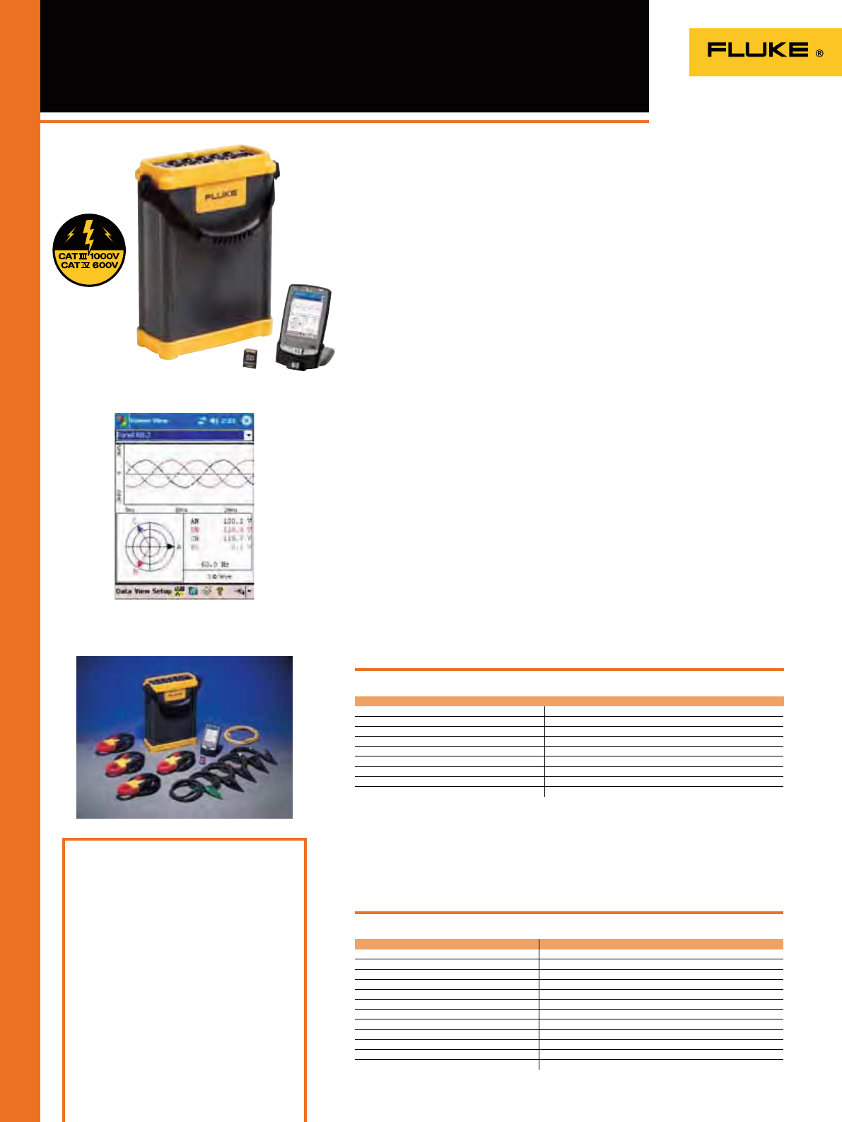
96
1750 Three-Phase Power
Recorder
Included Accessories
PDA and charger power plug adapters,
4 current probes, 5 test leads and clips, SD
memory card., Fluke Power View and Fluke
Power Analyze software, power cord with
international plug set, Ethernet cable, color
localization set, soft carrying case, Printed
Getting Started manual, CD with software and
users manual PDF
Basic model: excl. 4 current probes
Ordering Information
Fluke 1750/B Three-Phase Basic Power
Recorder
Fluke 1750
Three-Phase Power Recorder
With its exclusive threshold-free
measurement system, the Fluke
1750 Power Recorder captures every
measurement, every event, on every cycle,
all the time. Outstanding accuracy and
resolution provide complete visibility into
your installation or distribution system.
• Power quality that meets the standard:
All measurements comply with
IEC61000-4-30 standards for correct
evaluation of all measured values
including voltage, current, power,
harmonics, icker etc.
• Quick and reliable conguration: PDA
wireless “front panel interface” provides
the ability to verify setup without a
laptop along with a window into what
the instrument is recording, even in
awkward test locations.
• Threshold-free setup: Apply thresholds
after data is collected with Fluke Power
Analyzer Software so there is no need to
worry about missed information due to
incorrect set-up.
• Captures everything: Cross-channel
and current triggering capture every
measurement, on every channel, every
time.
• Intuitive PC software: Easily analyze
data and generate reports. Automated
EN50160 reporting and compliance.
• Plug and play: Set up in minutes with
seldentifying current probes and
single-lead voltage connections.
• No need to reconnect wires: Swap
channels internally with the wireless
PDA or PC when connections are not
correct.
• Measure every parameter: Voltage and
current on three phases, neutral, and
ground.
• 5 MHz, 8000 Vpk waveform capture:
Get a detailed picture of even the
shortest events.
• Quickly retrieve data: With included SD
memory card or via the 100BaseT high-
speed Ethernetv connection
Specifications
(Check the Fluke web for detailed specifications)
View measurements real time with wireless PDA interface
Safety: EN 61010-1 2nd Edition; 2000
Weight: 6.3 kg
Size (H x W x D): 215 x 310 x 35 mm
One Year Warranty
Power quality measurement standards
Conformance IEC 61999-1-4 Class 1, IEC 61000-4-30, IEEE519, IEEE1159, IEEE1459 and EN50160
Clock/calendar Leap years, 24-hour clock
Real-time clock accuracy Not more than ± 1 s/day
Internal memory capacity for data At least 1 GB
Maximum recording period At least 31 days
Measurement time control Automatic
Maximum number of events Limited only by the size of the internal memory
Power requirements 100 to 240 V rms ± 10 %, 47-63 Hz, 40 W
Operating time during interruptions (internal UPS operation) 5 minutes per interruption, 60 minutes total operating time without recharging
Recommended Accessories
Model Description
3210-PR-TF 1000A Thin flexible current transformer 61 cm (24") (20 A - 1000 A)
3310-PR-TF 5000A Thin flexible current transformer 61 cm (24") (100 A - 5000 A)
3312-PR-TF 5000A Thin flexible current transformer 122 cm (48") (100 A - 5000 A)
3140-PR Clamp-on current transformer (2 A - 400 A)
i40S-PR Clamp-on current transformer (0,1 A - 40 A)
i4S-PR Clamp-on current transformer (0,01 A - 5 A)
FLUKE-1750/SEAT-L Fluke Power Analyze – Additional SEAT LICENSE
FLUKE-1750/SITE-L Fluke Power Analyze – Additional SITE LICENSE
FLUKE-1750/CASE Hard Case
CS1750 Soft Case
HP IPAQ 2490 Additional Wireless Interface PDA
FLUKE-1750/MC Additional 512 MB SD Memory Card
Never miss capturing a disturbance
On all inputs
97
1760 Three-Phase Power
Quality Recorder Topas
Included Accessories
4 x TPS Flex 24-TF flexible current probe, 4 x TPS
VoltProbe 600V, 2 GB internal flash memory, ST1760
standard Ethernet cable, RS232 interface cable and
RS232-USB adapter, CS1760 crossover Ethernet cable,
1 mains cable, PC software on CD-ROM, WC17xx
color localization set, GPS-time sync (1760TR only)
CS 1750/1760 carrying bag, hardware and software
manual
Basic models: Excl. current clamps TPS Flex 24-TF
Ordering Information
Fluke 1760 Basic Power Quality Recorder Topas
Fluke 1760TR Basic Power Quality Recorder Topas
Fluke 1760 Power Quality Recorder Topas
Fluke 1760TR Power Quality Recorder Topas
The Fluke 1760 Three-Phase Power
Quality Recorder is fully compliant to
IEC 61000-4-30 Class-A, for advanced
power quality analysis and consistent
compliance testing. Designed for analysis
of utility and industrial power distribution
systems, in medium and low-voltage
networks, the Fluke 1760 provides the
exibility to customize thresholds,
algorithms, and measurement selections.
It has 8 input channels (4 currents/4
voltages or 8 voltages), and captures the
most comprehensive details on user
selectable parameters.
• GPS time synchronization: Correlate
data with events or datasets from other
instruments with precision
• Uninterrupted power supply
(40 minutes): Never miss important
events - even record the beginning and
end of interruptions and outages
• 10 MHz, 6000 Vpk waveform capture:
Get a detailed picture of even the
shortest event
• 2 GB data memory: Enables detailed,
simultaneous recording of numerous
power parameters for long periods of
time
• Includes Comprehensive software:
Provides trend diagrams for root cause
analysis, statistical summaries, report
writing and real-time data monitoring
in the online mode
Features
Fluke 1760
(Check the Fluke web for detailed specifications)
The included PQ Analyze software
provides a detailed overview of several
power quality parameters on one
dashboard according to the EN50160
power quality standard. Power supply: 83 V to 264 V, 45 to 65 Hz
Battery pack: NIMH, 7.2 V, 2.7 Ah (up to 40 minutes
back-up power supply)
Safety: 600V CAT IV/1000V CAT III
(Rated for use at the service entrance)
Housing: Fully insulated robust plastic housing
Operating temperature: 0 °C to 35°C
Interfaces: Ethernet (100 MB/s), RS-232, external
modem via RS-232
Size (HxWxD): 325 mm x 300 mm x 65 mm
Weight: Approxiamtely 4.9 kg
Two Year Warranty
1760 Basic 1760TR Basic 1760 1760TR
Power quality statistics according to EN50160
OOOO
Voltage event list (dips, swells and interruptions)
OOOO
Continuous recording of:
Voltage
OOOO
Current
OOOO
Power P, Q, S
OOOO
Power factor
OOOO
kWh
OOOO
Flicker
OOOO
Unbalance
OOOO
Frequency
OOOO
Voltage and current harmonics to the 50th/
Interharmonics
OOOO
THD
OOOO
Mains signaling
OOOO
Triggered recordings
OOOO
Online mode (Oscilloscope, transients and events)
OOOO
Fast transient analysis up to 10 MHz
OO
4 voltage probes
OO
4 dual-range flexible current probes (1000 A / 200 A ac)
OO
GPS time sync receiver
OO
Memory 2 GB Flash memory
Recommended Accessories
(Check the Fluke web for complete accessory list)
Model Description
• TPS VOLTPROBE 10 V 10 V Voltage Probes (Range: 0.1 V to 17 V)
• TPS VOLTPROBE 100 V 100 V Voltage Probes (Range: 1 V to 170 V)
• TPS VOLTPROBE 400 V 400 V Voltage Probes (Range: 4 V to 680 V)
• TPS VOLTPROBE 600 V 600 V Voltage Probes (Range: 10 V to 1000 V)
• TPS VOLTPROBE 1 KV 1000 V Voltage Probes (Range: 10 V to 1700 V)
• TPS FLEX 18-TF Flexible Current Probe (Range: 1 A to 100 A / 5 A to 500 A)
• TPS FLEX 24-TF Flexible Current Probe (Range: 2 A to 200 A / 10 A to 1000 A)
• TPS FLEX 36-TF Flexible Current Probe (Range: 30 A to 3000 A / 60 A to 6000 A)
• TPS CLAMP 10 A / 1 A Clip-on Current Transformer (Range: 0.01 A to 1 A / 0.1 A to 10 A)
• TPS CLAMP 50 A / 5A Clip-on Current Transformer (Range: 0.05 A to 5 A / 0.5 A to 50 A)
• TPS CLAMP 200 A / 20 A Clip-on Current Transformer (Range: 0.2 A to 20 A / 2 A to 200 A)
• TPS SHUNT 20 MA 20 mA ac/dc Shunt (Range: 0 to 55 mA)
• TPS SHUNT 5 A 5 A ac/dc Shunt (Range: 0 to 10 A)
Class-A compliance for the most demanding
power quality tests
i3000 flex-4PK
(4x i3000s flex24)
i400s i430-FLEXI-TF-4PK i5sPQ3
98
Power Quality Current Clamps
Fluke model number i1A/10A
CLAMP PQ3
i1A/10A
CLAMP PQ4
i5A/50A
CLAMP PQ3
i5A/50A
CLAMP PQ4
i20A/200A
CLAMP PQ3
i20A/200A
CLAMP PQ4
3000/6000A-TF-4 FS17X5-TF FS17xx IP65-TF i3000 flex ... 4PK i400s
i430-FLEXI-TF-4PK
i5sPQ3
Description 3 ... phase
1A/10A Mini
current
clamp set
4 ... phase
1A/10A Mini
current
clamp set
3 ... phase
5A/50A Mini
current
clamp set
4 ... phase
5A/50A Mini
current
clamp set
3 ... phase
20A/200A
Mini current
clamp set
4 ... phase
20A/2000A
Mini current
clamp set
4 Phase
flexiset 4 Phase
flexiset,
IP41
4 Phase
flexiset,
IP65
4 ... phase
3000A
Flexible
current
clamp set
Single phase
400A current
clamp
(4 required)
4 ... phase
3000A
Flexible
current
clamp set
3 ... phase 5A
Current
clamp
set
Old Fluke model # CURRENT
CLAMPS 1A
(EPO450A)
MBX CLAMP
1A/10A+N
(EPO451A)
MBX CLAMP
5A/50A
(EPO452A)
MBX CLAMP
5A/50A+N
(EPO453A)
MBX CLAMP
20A/200A
(EPO455A)
MBX CLAMP
20/2000A+N
(EPO456A)
MBX
Lem Flex
(15/150/3000)
(EP0404A)
MBX
Lem Flex
(15/150/3000)
(EP0404A)
Fluke 1735
OOOOOOOOO
Fluke 174X
OOOOOOOOO
Fluke 43X
OOOO
Nominal current range(s) 1 A
10 A AC 1 A
10 A AC 5 A
50 A AC 5 A
50 A AC 20 A
200 A AC 20 A
200 A AC 30A 300A
3000A 6000A
AC
15A 150A
1500A 3000A
AC
15A 150A
1500A 3000A
AC
30 A
300 A
3000 A
40 A
400 A 3000 A 5 A
Cont. AC current range 10 mA ... 1 A
100 mA ...
10 A
10 mA ... 1 A
100 mA ...
10 A
50 mA ... 5 A
500 mA ...
50 A
50 mA ... 5A
500 mA ...
50 A
200 mA ...
20 A
2 A ... 200 A
200 mA ...
20 A
2 A ... 200 A
0.8 ... 6.000 A
AC 450mA …
15A 600mA…
150A 6A…
1500A 12A…
3000A
450mA …
15A 600mA…
150A 6A…
1500A 12A…
3000A
1 A ... 30 A
1 A ... 300 A
1 A ... 2400 A
0.5 A ... 40 A
5 A ... 400 A 30 A ...
3000 A 0.01 A ... 6 A
Highest current 20 A 20 A 100 A 100 A 300 A 300 A 0.8 A 3300 A 3300 A 4000 A 1000 A 100 kA 70 A
Lowest measurable current 10 mA 10 mA 50 mA 50 mA 200 mA 200 mA 450 mA 450 mA 1 A 0.5 A 30 A 10 mA
Basic accuracy (48 ... 65 Hz) 1) 0.5% 0.5% 0.5% 0.5% 0.5% 0.5% 2%+2% position
influence 2%+2% position
influence 2% + 2 A 2% + 0.15 A 1% 1%
Usable frequency 40 Hz ... 10
kHz 40 Hz ... 10
kHz 40 Hz ... 10
kHz 40 Hz ... 10
kHz 40 Hz ... 10
kHz 40 Hz ... 10
kHz 40Hz …5kHz 40Hz …5kHz 10 Hz ... 100
kHz 45 Hz ... 3
kHz 10 Hz ... 7
kHz 40 Hz ... 5
kHz
Requires battery
O
Flex head length 92 cm 61 cm 61 cm Clamp
opening:
32 mm
61 cm Clamp
opening:
15 mm
Output level(s) 75 mV/A 75 mV/A 15 mV/A 15 mV/A 3.75 mV/A 3.75 mV/A 0.1 mV/A 0.1 mV/A 10 mV/A
1 mV/A
0.1 mV/A
10 mV/A
1 mV/A 0.085 mV/A
@50 Hz 400 mV/A
Output cable (m) 2 222224222.12.52.52.5
Safety rating CAT III 600 V CAT III 600 V CAT III 600 V CAT III 600 V CAT III 600 V CAT III 600 V CAT III 1000 V
CAT IV 600V CAT III 1000 V
CAT IV 600V CAT III 1000 V
CAT IV 600V CAT III 600 V CAT III 1000 V
CAT IV 600 V CAT III 1000 V
CAT IV 600 V CAT III 600 V
Connection One
connector One
connector One
connector One
connector One
connector One
connector One
connector One
connector One
connector 4 x BNC 4 x BNC 4 x BNC 3 x BNC
BNC to banana adapters included n/a n/a n/a n/a n/a n/a n/a n/a n/a
O
1 Basic accuracy: % reading plus floorspec.
n/a = not applicable
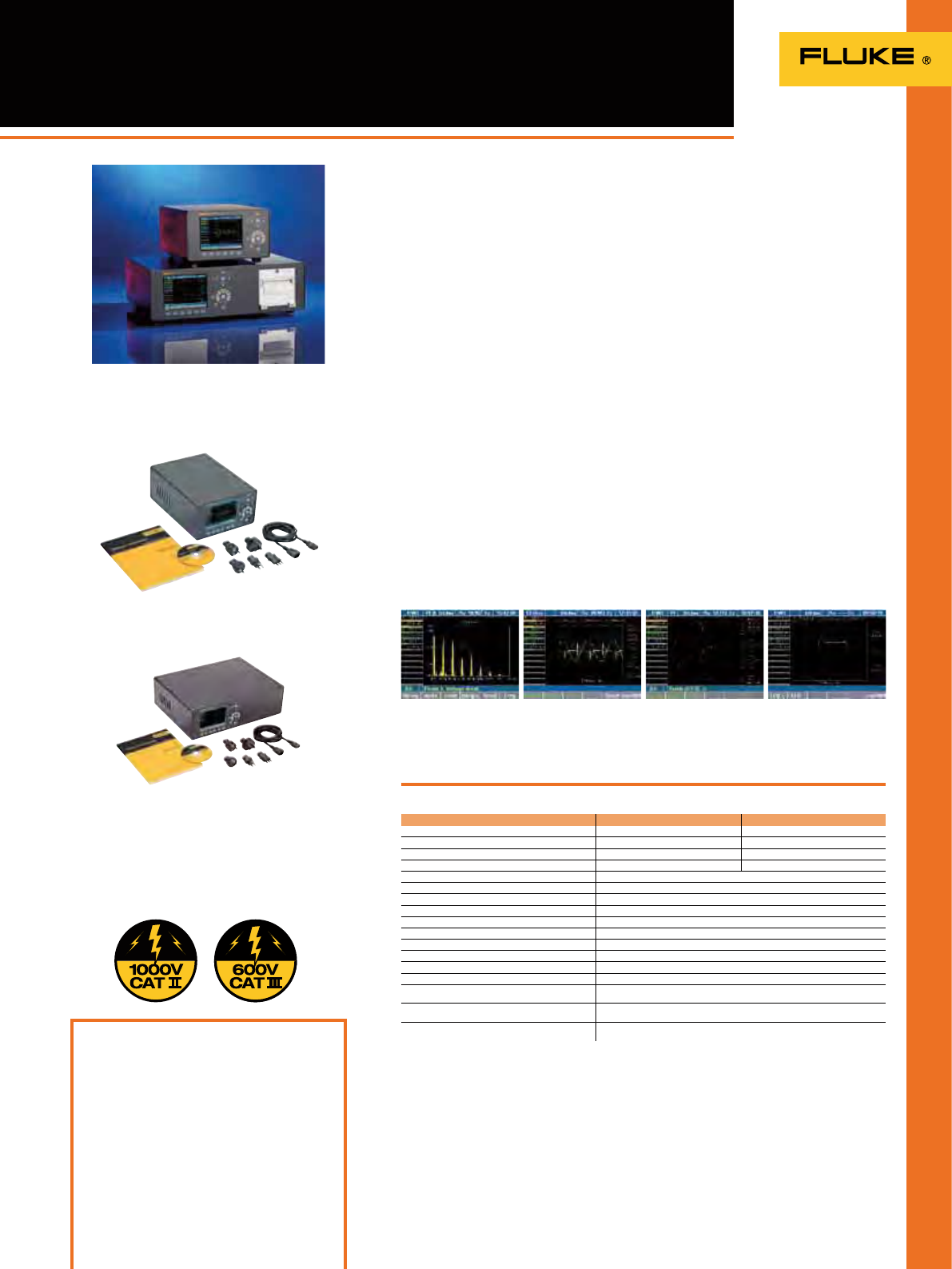
99
Norma 4000/5000
Power Analyzers
The compact Fluke Norma Series
Power Analyzers provide the latest
measurement technology to assist
engineers with the development and
testing of motors, inverters, lighting,
power supplies, transformers and
automotive components.
Based on a patented, high-bandwidth
architecture, the instruments deliver
high-precision measurements of single
or three-phase current and voltage,
harmonics analysis, Fast Fourier
Transformation (FFT) analysis, as well as
calculations of power and other derived
values.
A unique user-congurable system
design with plug-in power phases and
other optional modules provides the
exibility to meet a variety of application
measurement requirements. Recorded
data and waveforms can be viewed
clearly in the large color display and
easily downloaded to a PC for analysis
and report writing.
The Series consists of the Fluke Norma
4000 Three-Phase Power Analyzer and
the Fluke Norma 5000 Six-Phase Power
Analyzer. These rugged analyzers provide
unmatched price performance for easy
and reliable use in the eld, or as a bench
unit in laboratories and on test benches.
• Simple user interface ensures easy,
intuitive operation
• Unique user-congurable modular
design
• Simultaneous parallel acquisition of all
phases
• Voltage, current and power harmonics
up to the 40th
• Includes FFT analysis, vector diagram
display, recorder function, and Digital
Oscilloscope (DSO) mode
• User selectable average time – from
15ms to 3600s
• Expandable on-board memory for
storage of measured values
Specifications
(Check the Fluke web for detailed specifications)
Operating temperature:
+ 5 °C to 35 °C
Storage temperature:
- 20 °C to 50 °C
Climatic class: KYG DIN 40040, maximum
85% relative humidity, non-condensing.
Included Accessories
Power Supply Cable, RS232 Interface and USB
adaptor for Data Download, Fluke NormaView
PC Software, User’s Manual, Test Certificate,
and Calibration Values.
Ordering Information
Fluke Norma 4000 Three-Phase High
Precision Power Analyzer
Fluke Norma 5000 Six-Phase High Precision
Power Analyzer
Fluke Norma Series Power Analyzers
Fast Fourier
Transformation (FFT)
analysis
Fluke Norma 4000
Housing: Solid metal case
Safety: EN 61010-1 / 2nd Edition, 1000 V CAT II
(600 V CAT III)
Two Year Warranty
Fluke Norma 4000 Fluke Norma 5000
Number of Phases 1 or 3 3, 4 or 6
Weight Approx. 5 kg Approx. 7 kg
Size (HxWxD) 15 cm x 23.7 cm x 31.5 cm 15 cm x 44.7 cm x 31.5 cm
On-board Printer No Yes (optional)
Display Color, 5.7“ / 144 mm - 320 x 240 pixel
Bandwidth dc to 3 MHz or dc to 10MHz depending on input module
Basic Accuracy 0.2%, 0.1% or 0.03% depending on input modules
Sampling Rate 0.33 MHz or 1 MHz depending on input modules
Voltage Input Range 0.3 V to 1000 V
Current Input Range (direct, not via shunt) 0.03 mA – 20 A depending on input module
Memory for Configurations 4 MB, expandable to 128 MB
Memory for Settings 0.5 MB
Fast Fourier Transformation (FFT) To the 40th harmonic
RS232 Interface Standard
PI1 Process Interface (8 analog/impulse inputs and
4 analog outputs) Optional
IEEE 488.2 /GPIB Interface (1 MBit/s Ethernet /
10 MBit/s or 100 Mbit/s) Optional
Fluke NormaView PC Software (for data download,
analysis & report writing) Standard
Fluke Norma 5000
Digital Oscilloscop
(DSO) mode
Vector Display Recorder function
Reliable, highly accurate measurements for
the test & development of power electronics
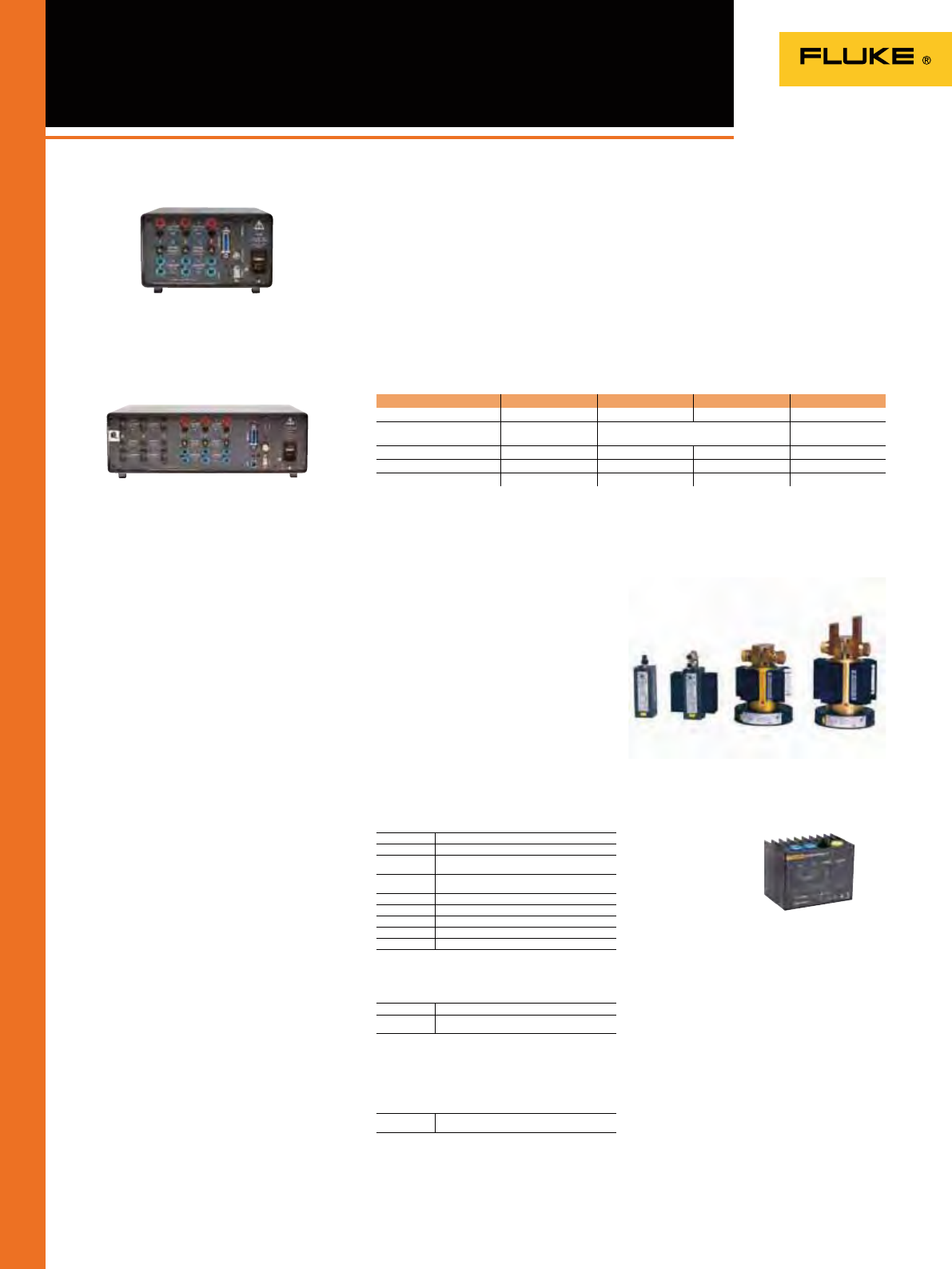
100
Norma 4000/5000
Power Analyzer Accessories
Fluke Norma 4000 (rear view)
Fluke Norma 5000 (rear view)
3024770 3024812 3024820 3024835
Channel PP42 PP50 PP54 PP64
Accuracy 0.2%
(0.1% rd + 0.1% rg) 0.1%
0.05% rd + 0.05% rg 0.03%
(0.02% rg + 0.01% rg)
Current range 20 A 10 A 10 A 10 A
Sampling rate 341 kHz 1 MHz 341 kHz 341 kHz
Bandwidth 3 MHz 10 MHz 3 MHz 3 MHz
Shunts
The input modules can take up to 10 A
or 20 A directly or measure current via
wideband precision shunts. The available
range of shunts enables measurements up
to 1500 A and can be used in conjunction
with all of the available input modules.
Cables & Adaptors
Printer Accessories
3024677 32 A Planar Shunt
3024689 Cables for 32 A Planar Shunt
3024886 10 A Triaxial Shunt with Cables
(0.333 ., 0 to 0.5 MHz)
3024899 30 A Triaxial Shunt with Cables
(0.010 ., 0 to 0.5 MHz)
3024847 100 A Shunt with Cables (0.001 Ω, 0 to 0.5 MHz)
3024858 150 A Shunt with Cables (0.5 mΩ, 0 to 0.5 MHz)
3024864 300 A Shunt with Cables (0.1 mΩ, 0 to 1 MHz)
3024873 500 A Shunt with Cables (0.1 mΩ, 0 to 0.2 MHz)
3024692 LG Shunt Cables for High Current Shunts
3024661 Measurement Cable Set (for one power phase)
3024704 Fluke Norma WYE Adaptor (external accessory
box)
3024650 Printer Cable for Fluke Norma 5000
(RS232-Centronics)
All accessories have a
two-year warranty.
Optional shunts for Fluke Norma Series Power
Analyzers
32 A Planar Shunt
Power Phases
The Fluke Norma 4000 Power Analyzer
can be equipped with up to three power
phases and the Fluke Norma 5000 Power
Analyzer can be equipped with up to six
power phases. Users can select the power
phase best suited for their application.
Specications vary depending on the model
of the power phase.
Each plug-in power phase consists of
a voltage and a current measurement
channel. Each measuring channel is
available for each basic unit.
Power Phase Overview
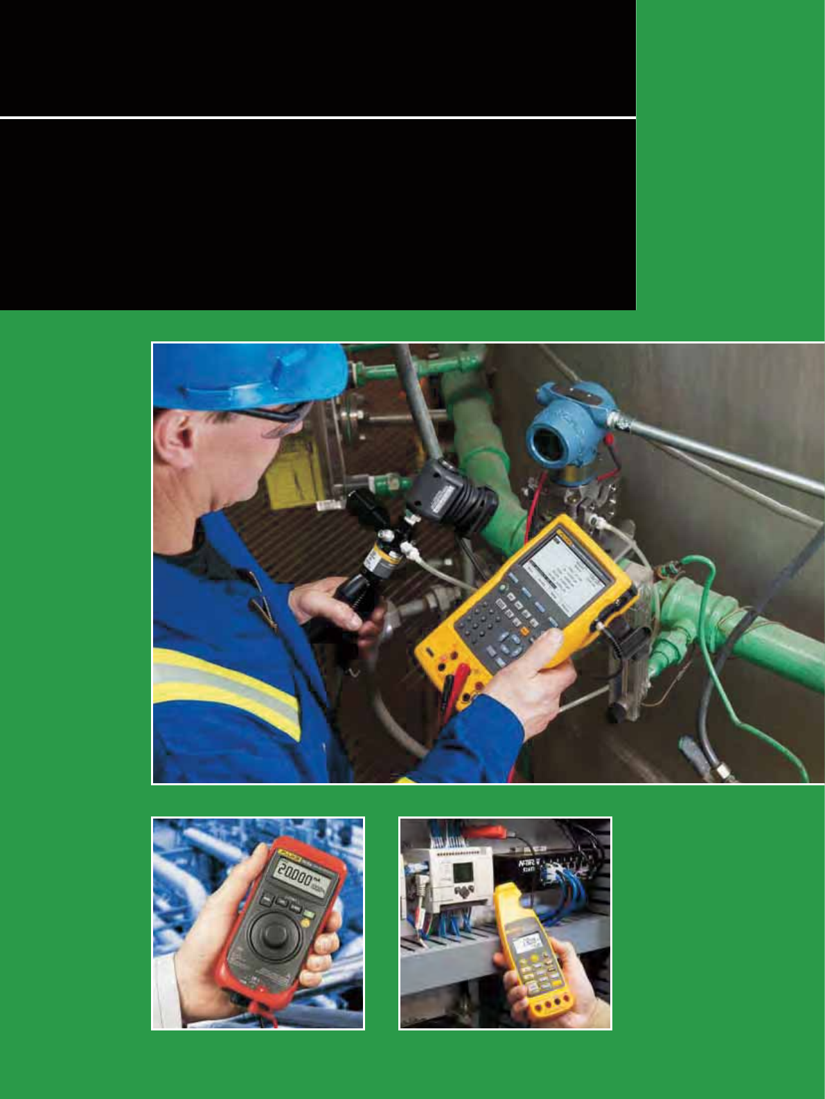
101
Fluke process calibration tools include a full range of calibrators and
troubleshooting tools for instrument technicians working in the process
industries. The range of process calibrators include: Documenting
Process Calibrators, Multifunction Process Calibrators, single function
and multifunction temperature calibrators, a variety of mA loop
calibrators and a range of intrinsically safe products.
Field Calibrators

102
Field Calibrator
Selection Guide
1 Fluke 700 pressure modules required
2 Ranges for the internal sensor.
Ranges for use of Fluke 700 pressure modules, see page 108.
Documenting Process
Calibators
Multifunction Process
Calibrator Temperature Calibrators Pressure Calibrators Loop Calibrators ProcessMeters
Model 754 753 725/725Ex 726 724 714 712 718/718Ex 717 719 715 707/707Ex 771 772 773 705 789 787
Measure
Voltage DC 300 V 300 V 30 V 30V 30 V 75 mV 10 V 28 V 30 V 28 V 1000 V 1000 V
Voltage AC (true RMS) 300 V 300 V 1000 V 1000 V
Resistance 10 kΩ 10 kΩ 3200 Ω 4000 Ω 3200 Ω 3200 Ω 40 MΩ 40 M
Current DC 110 mA 110 mA 24 mA 24 mA 24 mA 24 mA 24 mA 24 mA 24 mA 24 mA 100 mA 100 mA 100 mA 24 mA 30 mA,
1 A 30 mA, 1A
Current AC
O O
Frequency 50 kHz 50 kHz 10 kHz 15 kHz 20 kHz 20 kHz
Pressure
O
1
O
1
O
1
O
168,9 mbar
to 20 bar /
2 to 7 bar2
68,9 mbar
to 345 bar2
2 bar to
7 bar2
Temperature: RTD types 88787 7
Temperature: TC types 13 13 12 12 12 9
Source/Simulate
Voltage DC 15 V 15 V 10 V 20 V 10 V 75 mV 10 V 10 V
Resistance 10 kΩ 10 kΩ 3200 Ω 4000 Ω 3200 Ω 3200 Ω
mA DC/% scale 22 mA 22 mA 24 mA 24 mA
O
24 mA 24 mA 24 mA 24 mA 24 mA 24 mA 24 mA
mA source; auto step, auto ramp
OOOO OO OOOOO
Frequency 50 kHz 50 kHz 10 kHz 15 kHz
Temperature: RTD types 88787 7
Temperature: TC types 13 13 10 10 10 9
Record
Min/Max
OO
OOO OO
Hold
OOO OOO OO
As Found/As Left results
OO
Log data
OO
Upload data to PC
OO O
Remote operation
O
/-
O
Features
Loop supply 26 V 26 V 24 V/12 V 24 V 24 V 24 V/- 24 V 24 V 24 V 24 V 24 V 24 V 24 V 24 V
Hart communication
Integrated hand pressure pump
O
Electric Pump
O
Intrinsically safe (ATEX) 725Ex 718Ex 707Ex
NIST traceable certification
OOOOOOOOOOOO O
Warranty in years 333333333333333333
See catalog page 103 103 104 104 105 106 106 108 108 108 109 109 110 110 110 109 111 111
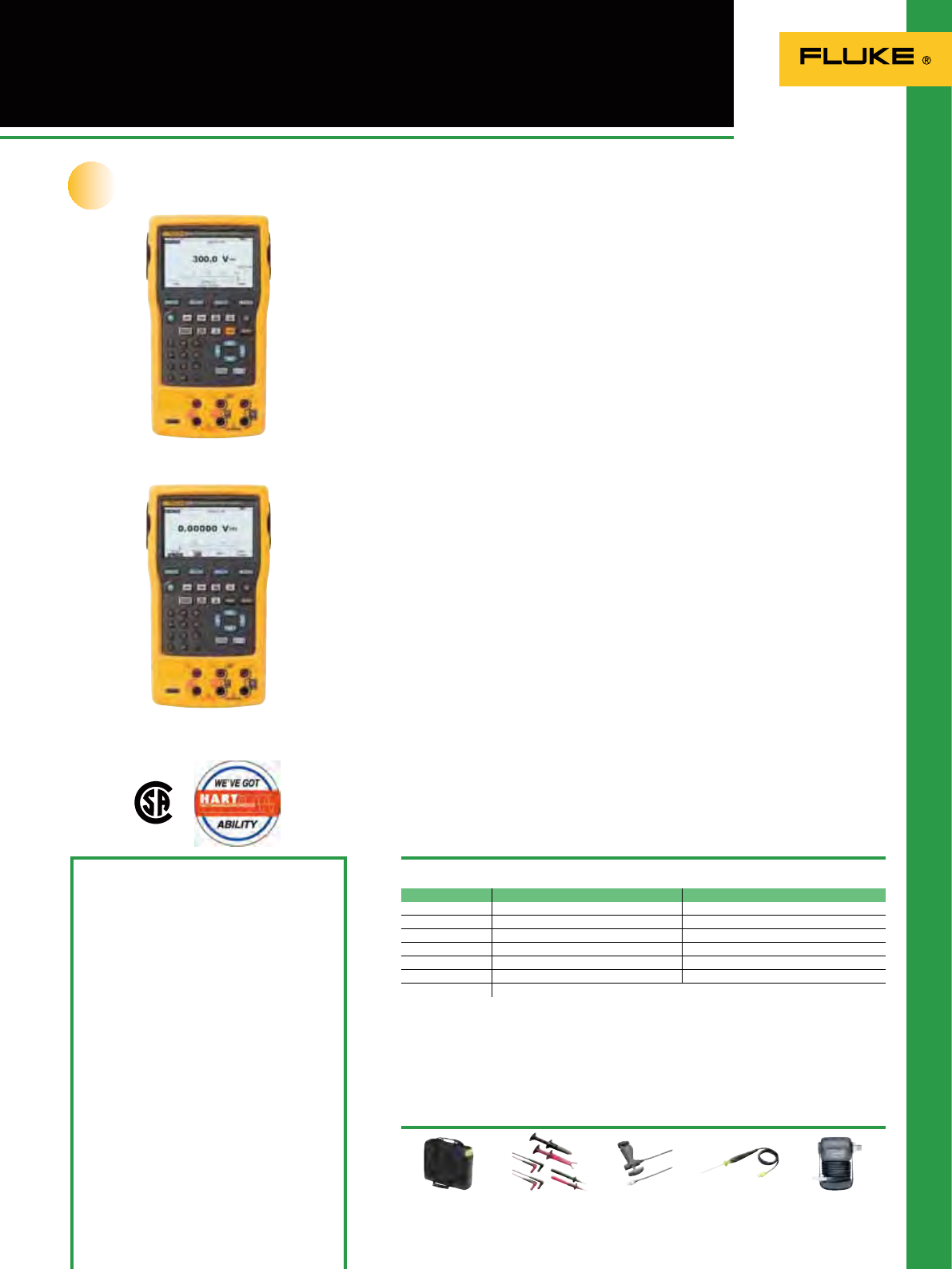
103
750 Series Documenting
Process Calibrators
700P27
See page 112
Recommended Accessories
Included Accessories
Stackable test leads (3 sets), TP220 test probes
(3 sets) with extended tooth” alligator clips
(3 sets), AC280 hook clips (2 sets), BP7240
Li-ion battery pack, BC7240 battery charger,
C799 field soft case, USB communication
cable, getting started guide, instruction
manual on CDROM, NIST traceable certificate
of calibration, DPCTrack™ 2 sample
software that enables upload and printing
of calibration
records. HART communication
cable (754 only).
Ordering Information
Fluke 753 Documenting Process Calibrator
Fluke 754 Documenting Process Calibrator
700 TLK Process test lead kit
BP7240 753/754 Spare battery
750 SW DPC/Track2
BC7240 753/754 Battery charger/eliminator
754HCC 754 HART communication cable
80PK-25
See page 128
80PK-8
See page 128
TL220-1
See page 122
C799
See page 130
Function Measure Sourcing
Voltage DC 0.02% + 0.005 mV 0.01% + 0.005 mV
Current DC 0.01% + 5 µA 0.01% + 0.003 mA
Resistance 0.05% reading + 50 m 0.01% output + 10 m
Frequency 0.05 Hz 0.01 Hz
Thermocouples 0.3ºC 0.2ºC
RTDs 0.07 ºC 0.06 ºC
Pressure To 0.05% of full scale. See Pressure Module specifications.
Specifications
(Check the Fluke web for detailed specifications)
Operating temperature: -10º C to 50º C
Storage temperature: -20º C to 60º C
Safety: CAT II 300V
Battery Life: Typically over eight hours
Internal Battery Pack: li-ion, 7.2V, 4400 mAh,
30 Wh
Fluke 754
Fluke 753
Battery Replacement: Via snap-shut door wit-
hout opening calibrator; no tools required
Weight: 1.2 kg
Size (HxWxD): 245 mm x 136 mm x 63 mm
Three Year Warranty
Whether you’re calibrating instruments,
troubleshooting a problem or running
routine maintenance, Fluke 750 series
process calibrators can help you get the
job done faster. It does so many different
tasks, so quickly and so well, it’s the only
process calibrator you need to carry.
• Measure volts, mA, RTDs,
thermocouples, frequency, and ohms
to test sensors, transmitters and other
instruments
• Source/simulate volts, mA,
thermocouples , RTDs, frequency, ohms,
and pressure to calibrate transmitters
• Power transmitters during test using
loop supply with simultaneous mA
measurement
• Measure/source pressure using any of
29 Fluke pressure modules
• Measure and source simultaneously
with one compact, rugged, reliable tool
• Create and run automated as-found/
as-left procedures to satisfy quality
programs or regulations. Record and
document results
• Advanced features like autostep,
custom units, user entered values
during test, one-point and two-point
switch testing, square root DP ow
testing, programmable measurement
delay and more
• Control the temperature of selected
Hart Scientic Dry Blocks
• Handle fast pulsed RTD transmitters
and PLCs in RTD source mode with
1 ms response time
• English, French, German, Italian, and
Spanish languages
• Three-year warranty
753: A complete documenting
calibrator
The 753 Documenting Process Calibrator
automates calibration procedures and
captures your data. Use the PC interface
for downloading procedures, lists, and
instructions to the 753 and for uploading
data for printing, archiving and analysis.
754: Get HART-ability
The 754 offers all of the capabilities
of the 753, plus integrated HART
communication capability. This rugged,
reliable tool is ideal for calibrating,
maintaining, and troubleshooting HART
and other instrumentation.
Instrumentation Management
Software
The Fluke 753 and 754 are compatible
with Fluke 700SW DPC/TRACK software
and with software from Cornerstone,
Fisher-Rosemont, Honeywell, Yokogawa,
Prime Technologies and On Time Support.
Work smarter. Work faster
New
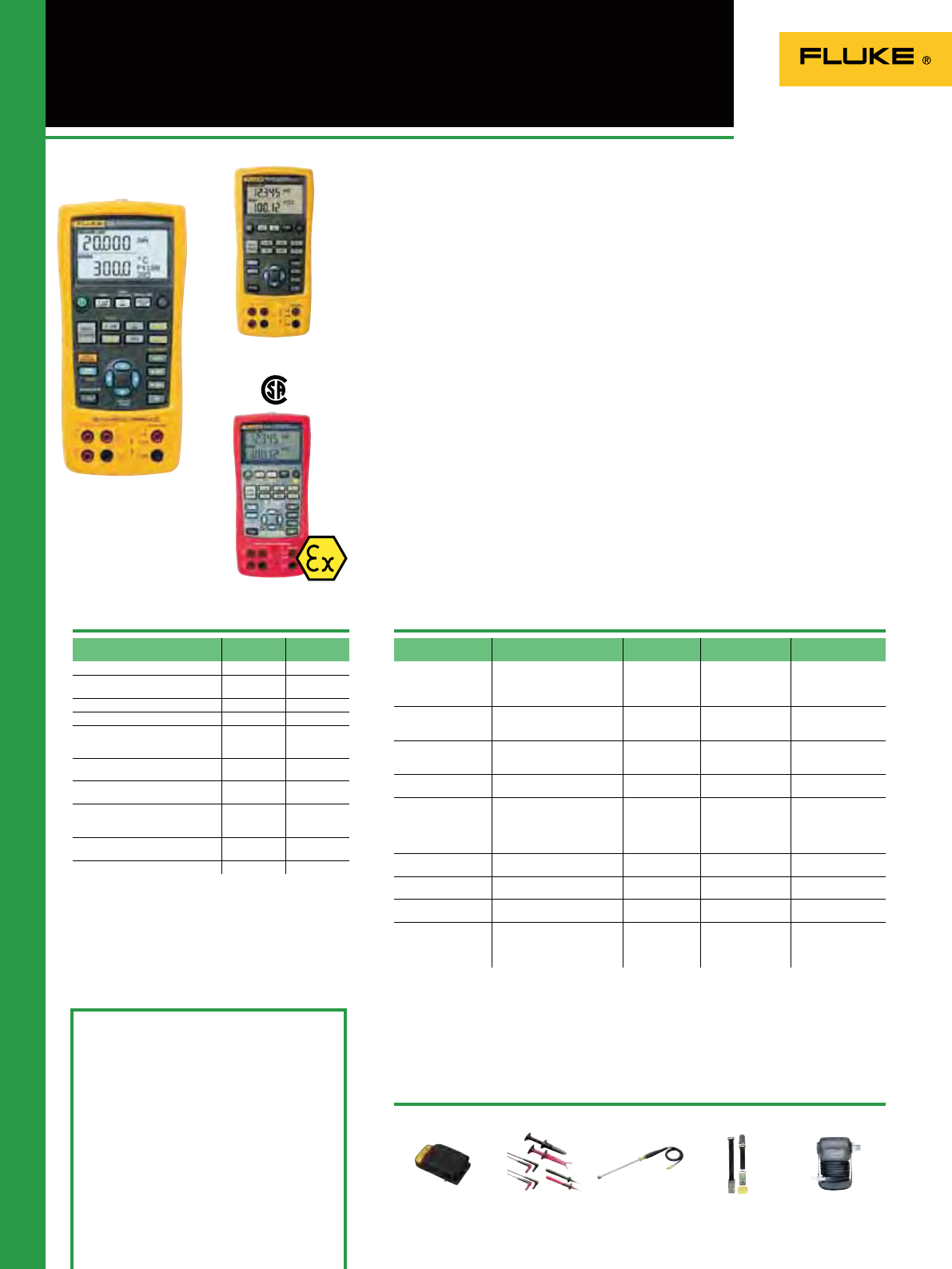
104
725/725Ex/726 Multifunction
Process Calibrators
700P27
See page 112
(Not for hazardous zones)
Specifications
725/725Ex/726 Multifunction
Process Calibrators
• Two separate channels; measure, source
and view process signals simultaneously
• Measure volts, mA, RTDs,
thermocouples, frequency, and
resistance to test sensors and
transmitters
• Source/simulate volts, mA,
thermocouples, RTDs, frequency, and
pressure to calibrate transmitters
• Measure or *source pressure using any
of 29 Fluke 700Pxx Pressure Modules
• Source mA with simultaneous pressure
measurement to conduct valve and I/P
tests
• Perform fast linearity tests with auto
step and auto ramp features
• Power transmitters during test using
24 V loop supply and simultaneous mA
measurement
• Store frequently-used test setups for
later use
• For 725Ex version see also page 118 and
119
726 Precision Multifunction
Process Calibrator
Additional features:
• More precise measurement and
calibration source performance,
accuracies of 0.01%
• Transmitter error% calculation
• Memory storage for up to 8 calibration
results
• Frequency totalizer and frequency
pulse train source mode for enhanced
owmeter testing
• HART mode inserts 250 ohm
resistor in mA measure and source
for compatibility with HART
instrumentation
• Integrated pressure switch test allows
you to capture the set, reset and
deadband of a switch
• Custom RTD curves, add calibration
constants for certied RTD probes for
enhanced temperature measurement
Maximum voltage: 30V
Operating temperature: 10°C to 55°C
Safety: CSA C22.2 No. 1010.1:1992
EMC: EN50082-1:1992 and EN55022:
1994 Class B
Fluke 725
Size (HxWxD): 200 mm x 96 mm x 47 mm
Weight: 0.65 kg
Battery: Four AA alkaline batteries.
Battery life: 25 hours typical; battery door
Warranty: Three years
Included Accessories
Test Leads, AC172 Test Clips, one pair of
stackable test leads, user’s Manuals on
CD-ROM (725Ex also includes CCD control
drawing, Statement of Quality Assurance
Practices, NIST Traceable calibration
certificate)
Ordering Information
Fluke 725 Multifunction Process Calibrator
Fluke 725Ex Intrinsically Safe Multifunction
Process Calibrator
Fluke 726 Precision Multifunction Process
Calibrator
Simultaneous Function
Capability
Channel A Channel B
24.000 mA DC M M or S
24.000 mA DC with
24 V loop supply M M or S
100.00 mV DC M or S
30.000V DC measure M M or S
20.000V DC Measure
10.000V DC Source
20.000V DC Source
M or S
15 to 3200 Ohms
5 to 4000 Ohms
M or S
Thermocouple J, K, T, E, R, S, B, M,
L, U, N, XK, BP M or S
RTD Cu 10, Ni120; Pt100 (392);
Pt100 (JIS); Pt100, 200, 500, 1000
(385)
M or S
Pressure (requires Fluke 700 PXX
Modules) M M used as S
Frequency; 10 kHz; (15 kHz) M or S
Function
Measure or Source
Range or Type Resolution Accuracy Notes
Voltage 0 to 100 mV
725: 0 to 10V (source)
0 to 20V (source)
725/726: 0 to 30V (measure)
0.01 mV
0.001 V
0.001 V
0.001 V
0.01%
0.02% Rdg + 2 LSD Max load, 1 mA
mA 0 to 24 0.001 mA 0.01%; 0.02% Rdg
+2 LSD Max load,
725/726: 1000
725Ex: 250
mV
(TC terminals) -10.00 mV to +75.00 mV 0.01 mV 0.01%
0.02% of range +
1 LSD
Ohms 15 to 3200
5 to 4000
0.01 to 0.1 0.10 to 1.0
0.015%
Hz - CPM 2.0 to 1000 CPM
1 to 1100 Hz
1.0 to 10.0 kHz
10.0 to 15.0 kHz
0.1 CPM
1 Hz
0.1 kHz
0.1 kHz
±0.05%
±0.05%
±0.25%
±0.05%
Source;
5V p-p
1V - 20 V p-p
squarewave,
-0.1 V offset
Loop Supply 725/726: 24 V DC
725Ex: 12 V DC N/A 10%
T/C J, K, T, E, L, N, U, XK 0.1 ºC, 0.1 ºF to 0.7 ºC
to 0.2 ºC
T/C B, R, S, BP 1 ºC, 1 ºF to 1.7 ºC
to 1.2 ºC
RTDs Cu (10), Ni 120 (672)
Pt 100, 200, 500, 1000 (385)
Pt 100 (3916),
Pt 100 (3926)
0.01 ºC
0.01 ºF
0.1 ºC, 0.1 ºF
to 0.15 ºC
to 0.2 ºC
Fluke 725Ex
Fluke 726
Features
M = Measure S = Source/Simulate
Unique 726 features are in bold
725Ex: ATEX cerfified
(Ex ATEX II IG EEX 1a IIB 171°C)
Recommended Accessories
TPAK
See page 132
80PK-27
See page 128
TL220-1
See page 122
C125
See page 130
More calibration power!
*Pressure pump required
Unique 726 features are in bold
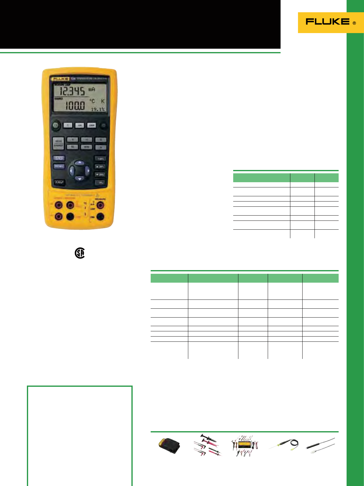
105
724 Temperature Calibrator
80PK-3A
See page 128
Features
The Fluke 724 Temperature Calibrator is
a powerful yet easy-to-use calibrator. Use
the measure and source functions to test
and calibrate almost any temperature
instrument.
• Easy to read dual display lets you view
input and output simultaneously
• Measure RTDs, thermocouples,
ohms, and volts to test sensors and
transmitters
• Source/simulate thermocouples, RTDs,
volts, and ohms to calibrate transmitters
• Perform fast linearity tests with 25% and
100% steps
• Execute remote tests with auto step and
auto ramp
• Power transmitters during test using
loop power supply with simultaneous
mA measurement
• Store frequently-used test setups for
later use
Fluke 724
Included Accessories
Test Leads, AC172 Test Clips, one pair of
stackable test leads.
Ordering Information
Fluke 724 Temperature Calibrator Recommended Accessories
80PK-25
See page 128
TL81A
See page 121
TL220-1
See page 122
C25
See page 130
Maximum voltage: 30V
Operating temperature: -10°C to 55°C
Safety: CSA C22.2 No. 1010.1:1992
EMC: EN50082-1:1992 and EN55022:
1994 Class B
Size (HxWxD): 200 mm x 96 mm x 47 mm
Weight: 0.65 kg
Battery: Four AA alkaline batteries
Battery life: 25 hours typical; battery door
Three Year Warranty
Function
Measure or Source
Range Resolution Accuracy Notes
Voltage 0 to 100 mV
0 to 10V (source)
0 to 30V (measure)
0.01 mV
0.01 V
0.001 V
0.02% Rdg + 2 LSD Max load, 1 mA
mA (measure) 0 to 24 mA 0.001 mA 0.02% Rdg +2 LSD Max load,
1000
mV -10.00 mV to +75.00 mV 0.01 mV 0.025% of range +
1 LSD
Resistance 0 to 3200 (measure)
15 to 3200 (source) 0.01 to 0.1 0.10 to 1.0
Loop Supply 24V DC N/A 10%
Thermocouples J, K, T, E, L, N, U 0.1 ºC to 0.7 ºC
Thermocouples B, R, S 1 ºC to 1.4 ºC
RTDs Ni120 (672)
Pt 100, 200, 500, 1000 (385)
Pt 100 (3916)
Pt 100 (3926)
0.1 ºC to 0.2 ºC
Simultaneous Function
Capability
Channel A Channel B
24.000 mA DC M
24.000 mA DC with 24V loop
supply M
100.00 mV DC M or S
30.000V DC Measure M
20.000V DC Measure 10.000V
DC Source M or S
0 to 3200 Ohms M or S
Thermocouple J, K, T, E, R, S, B,
L, U, N M or S
RTD Ni120; Pt100 (3926); Pt100
(JIS); Pt100, 200, 500, 1000 (385) M or S
Specifications
M = Measure S = Source/Simulate
The temperature solution
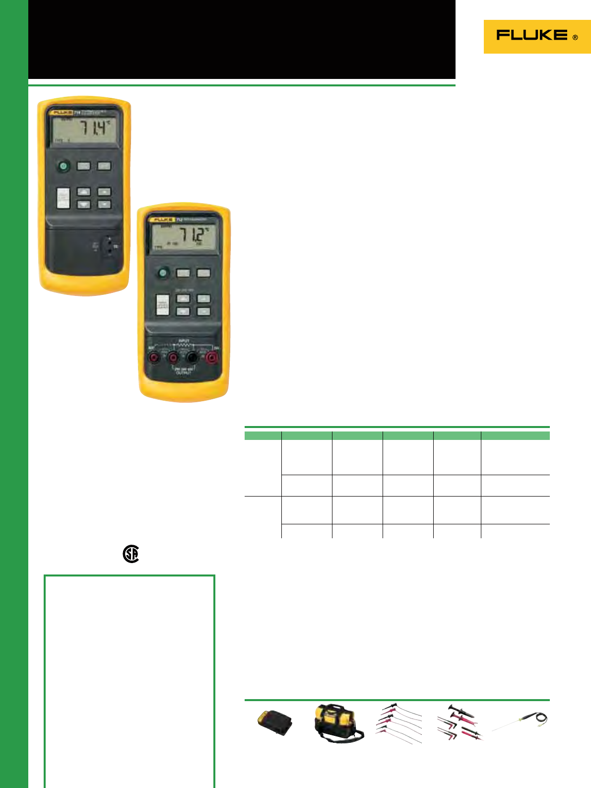
106
712/714 Temperature Calibrators
80PK-24 (714)
See page 128
The Fluke 710 Series Process Calibrators
offer clear new choices in single-function
calibrators. Whatever you want to
measure - temperature, pressure or basic
electrical parameters - you’ll nd one of
these easy-to-carry handheld tools gives
you exactly the functions you need. They
combine the rugged, ready-for-action
package of the proven Fluke 80 Series
DMMs with the easy-to-use pushbutton
operation of the multifunction Fluke 740
Series Documenting Process Calibrators.
These calibrators are EMI tolerant,
dust and splash resistant, and have a
removable battery door for quick battery
changes.
712 RTD Calibrator
• Measure temperature from RTD output
• Simulate RTD output
• Rosemount pulsed RTD transmitter
compatible
• Operates with seven types of RTDs
• Measure additional RTDs using Ohms
measurement function
• Simulate additional RTDs using Ohms
source function
• °F or °C selectable
• Four shrouded banana jacks
714 Thermocouple Calibrator
• Measure temperature from TC output
• Simulate TC output
• Operable with nine types of
thermocouples
• Calibrate linear TC transmitter with
mV source function
• Selectable °F or °C
• Thermocouple mini-jack termination
• Available as accessories; Fluke 700 TC1
and TC2 Thermocouple Mini-plug Kits
Fluke 714
Included Accessories
Yellow Holster (H80M excl. TPAK), Test Leads
and AC172 Alligator Clips (excluding model
714), single 9V alkaline battery and Instruction
Sheet (14 languages)
Ordering Information
Fluke 712 RTD Calibrator
Fluke 714 Thermocouple Calibrator
Recommended Accessories
TL220-1 (714)
See page 122
TL970
See page 121
C550
See page 130
C25
See page 130
Maximum voltage: 30 V
Operating temperature: -10°C to 55°C
Safety: CSA C22.2 No. 1010.1:1992
EMC: EN50082-1:1992 and EN55022:
1994 Class B
Size (HxWxD): 201mm x 98 mm x 52 mm
Weight: 0.6kg
Battery: 9V alkaline
Battery Life: 4 to 20 hours, typical, depending
on functions used
Three Year Warranty
Model Function Range Resolution Accuracy Notes
Fluke 712 Measure/
simulate RTD -200 to 800ºC
(Pt 100) 0.1ºC, 0.1ºF 0.33ºC, 0.6ºF
(Pt 100) Pt; 100, 200, 500,
1000 (385);
Pt 100 (3926);
Pt 100 (3916) JIS;
Ni 120 (672)
Measure/
simulate
Resistance
15 to 3200 0.1 0.1 to 1
Fluke 714 Measure/
simulate
Thermocouple
-200 to 1800ºC,
depending on
type (K, -200 to
1370ºC)
0.1–C or ºF
(1ºC or ºF; BRS) 0.3ºC to 10 µV 9 TC types:
J K T E R S B per NIST
175 and ITS-90, L U per
DIN 43710 and IPTS-68
Measure/
simulate mV -10 to 75 mv 0.01 mV 0.025% +
1 count
Specifications
Fluke 712
The clear choice
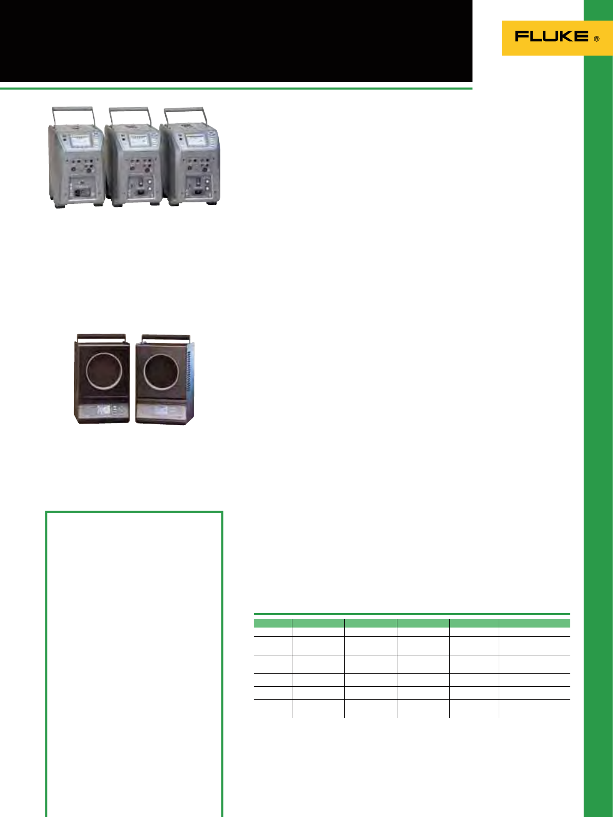
107
9140 Series Field Metrology Wells
4180 Series Infrared Calibrators
9142, 9143, 9144
Field temperature calibration with
precision and speed
The Fluke 9140 series Field Metrology
Wells extend high performance portable
temperature calibration to the industrial
process environment by maximizing
portability, speed, and functionality
with little compromise to metrology
performance.
Offering a broad temperature covered by
three models you can easily cover varied
contact temperature probe workloads
between -25 ºC to 660 ºC.
They are quick to reach temperature set
points, yet they are stable, uniform, and
accurate. These industrial temperature
calibrators are perfect for performing
transmitter loop calibrations, comparison
calibrations, or simple checks of
thermocouple sensors.
Adding the process option means there is
no need to carry additional tools into the
eld. The optional built-in two-channel
readout measures resistance, voltage, and
4–20 mA current with 24V loop power.
• Lightweight, portable, and fast
• Cool to –25 °C in 15 minutes and heat to
660 °C in 15 minutes
• Built-in two-channel readout for PRT,
RTD, thermocouple, 4-20 mA current
• On-board automation and
documentation
• Metrology performance in accuracy,
stability, uniformity, and loading
4180/4181 IR Calibrators
True metrology solution for infrared
Calibration
Now it’s easy to increase your IR
temperature measurement accuracy in
the lab or the eld with the new 4180/81
Precision Infrared Calibrators from Fluke’s
Hart Scientic division.
Their accredited calibrations from Hart’s
IR laboratory help to ensure traceable,
consistent measurements accurate to
+0.25 ºC. Select from eight precongured
Fluke thermometer settings or set up your
own.
The large 152 mm (6 inch) target helps
eliminate errors. So whether you’re
measuring from -15 ºC to 120 ºC (4180)
or from 35 ºC to 500 ºC (4181) you’ll get
a 4:1 TUR.
• High performance, designed for
industrial use
• Guaranteed accuracy specications
• Excellent stability and uniformity
• Large 152 mm targets capture peripheral
vision of IR thermometer
• Portability and speed for eld use -
including convenient bail handle
• Simulates individual IR thermometer
emissivity settings
• No difcult infrared calculations
• Fluke and Raytek thermometer
calibration points can be loaded directly
into the calibrator for convenience
• Calibrated in accredited infrared
laboratory by Hart Scientic, the experts
in temperature calibration
• At least 4 times more accurate than
most IR thermometers
• Calibration includes uncertainties from
surface heat loss and emissivity
Fluke 9142/9143/9144
Included Accessories
914x: 9930 Interface-it Software, Report of
Calibration, Test leads (P Version Only),
6-pin DIN Connector for Reference Probe
(P Version Only)
Ordering Information
Fluke 4180 Precision Infrared
Calibrator, –15 °C to 120 °C
Fluke 4181 Precision Infrared
Calibrator, 35 °C to 500 °C
Fluke 4180-CASE Carrying Case, 4180, 4181
Fluke 4180-DCAS Carrying Case with wheels,
4180, 4181
Fluke 9142-X Field Metrology Well,
Low Temp
Fluke 9143-X Field Metrology Well,
Mid Temp
Fluke 9144-X Field Metrology Well,
High Temp
Add -P to order optional Process option
(914X-X-P). X represents insert type,
A, B, C, D, E or F
9142/9143/9144:
Size (HxWxD): 290 x 185 x 295 mm
Weight: 9142: 8.2 kg, 9143: 7.3 kg, 9144: 7.7 kg
One Year Warranty
4180/4181
Size (HxWxD): 241 x 356 x 241 mm
Weight: 4180: 9.1 kg, 4181: 9.5 kg
One Year Warranty
9142 9143 9144 4180 4181
Temp Range –25 °C to 150 °C 33 °C to 350 °C 50 °C to 660 °C –15 °C to 120 °C 35 °C to 500 °C
Stability ±0.01 °C Full Range ±0.02 °C at 33 °C
±0.02 °C at 200 °C
±0.03 °C at 350 °C
±0.03 °C at 50 °C
±0.04 °C at 420 °C
±0.05 °C at 660 °C
±0.05 °C at 0 °C ±0.2 °C at 250 °C
Uniformity ±0.01 °C Full Range ±0.01 °C at 33 °C
±0.015 °C at 200 °C
±0.02 °C at 350 °C
±0.02 °C at 50 °C
±0.05 °C at 420 °C
±0.15 °C at 660 °C
±0.1 °C at 0 °C ±0.1 °C at 35 °C
Target Size
diameter N/A N/A N/A 152.4 mm
diameter 152.4 mm
Emissivity
Range N/A N/A N/A Preset to 0.95 Preset to 0.95
NIST
Accredited
Calibration
YES YES YES YES YES
Specifications
Fluke 4180/4181
Field Metrology Wells and infrared
calibration targets
For the complete line of Fluke heat sources
check the Fluke website
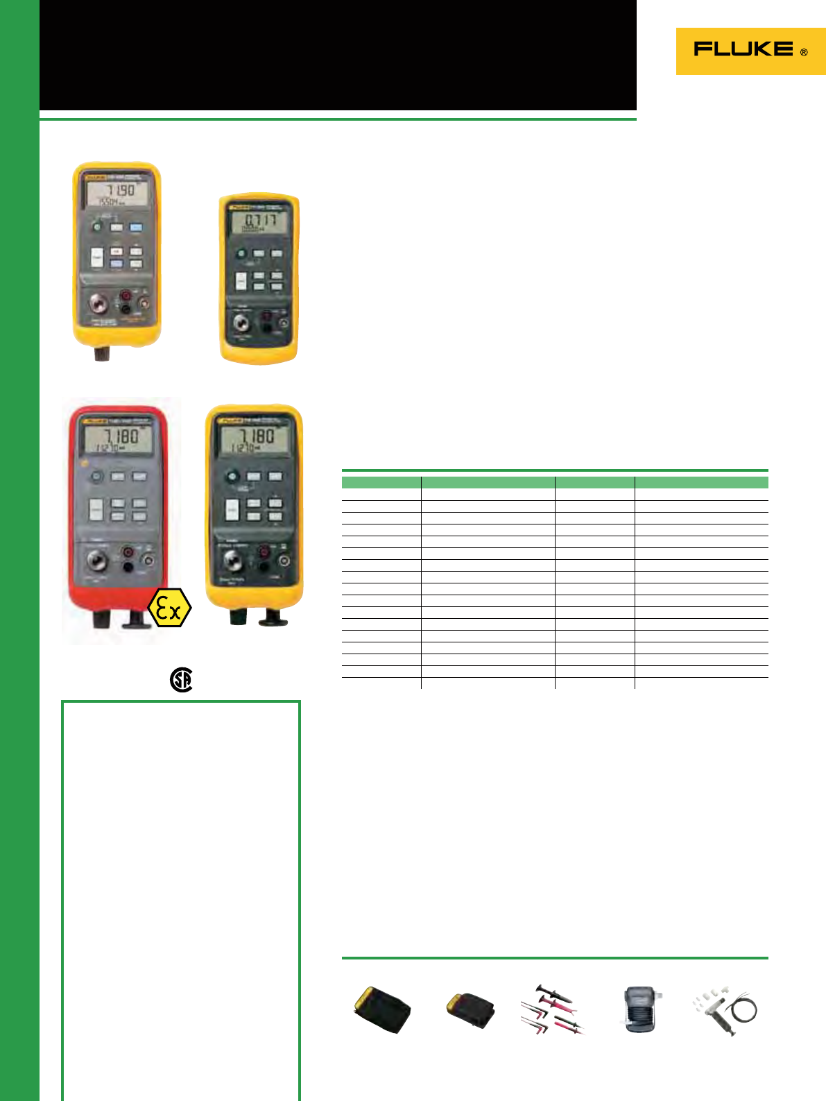
108
717/718/718Ex/719
Pressure Calibrators
700 LTP-1
See page 112
717 Pressure Calibrators
• Measure pressure, 0.025% of full scale
with internal sensor
- 1/8 NPT pressure tting
- Compatible with non-corrosive gasses
and liquids
• Pressure measurement to 690 bar
• Wide range of selectable measurement
units for pressure
• Current measurement with 0.015%
accuracy and 0.001mA resolution
• Simultaneous pressure and current
measurement for easy P/I testing
• 24 volt loop power supply
• Zero, Min-Max, Hold and Damping
functions
• Pressure switch test captures set, reset
and deadband values
718 Pressure Calibrators
Same features as Fluke 717 plus:
• Newly designed built-in pressure/
vacuum hand pump with vernier and
bleed valve helps protect the pump from
damage and is easier to clean
For 718Ex Intrinsically Safe Pressure
Calibrator see chapter on Ex products in
this catalog.
719 Electric Pressure Calibrator
Same features as Fluke 717 plus:
• Electric pump for one handed operation
• mA source for calibrating I/P devices
and 4-20 mA I/O
• Best in class pressure measurement
accuracy of 0.025%
• Programmable pump limit settings can
eliminate overpressurization - set ‘pump
to’ pressure values
Included Accessories
Fluke 717, 718, 718Ex and 719:
Yellow Holster (718Ex red holster), Test leads,
AC172 Alligator Clips, Single 9V alkaline
battery (two 9V batteries in 718 and 719), User
manual on CD ROM.
719 also includes: Push t connectors,
Translucent test hose.
Ordering Information
Fluke 719 30G Electric Pressure Calibrator
Fluke 719 100G Electric Pressure Calibrator
Fluke 718 1G Pressure Calibrator
Fluke 718 30G Pressure Calibrator
Fluke 718 100G Pressure Calibrator
Fluke 718 300G Pressure Calibrator
Fluke 718Ex 30G Intrinsically Safe Pressure
Calibrator
Fluke 718Ex 100G Intrinsically Safe Pressure
Calibrator
Fluke 717 1G Pressure Calibrator
Fluke 717 15G Pressure Calibrator
Fluke 717 30G Pressure Calibrator
Fluke 717 100G Pressure Calibrator
Fluke 717 300G Pressure Calibrator
Fluke 717 500G Pressure Calibrator
Fluke 717 1000G Pressure Calibrator
Fluke 717 1500G Pressure Calibrator
Fluke 717 3000G Pressure Calibrator
Fluke 717 5000G Pressure Calibrator
Fluke 717 10000G Pressure Calibrator
Recommended Accessories
700P27
See page 112
TL220-1
See page 122
C125 (717)
See page 130
C43 (718)
See page 130
717
Size (HxWxD): 201 mm x 98 mm x 52 mm
Weight: 0.6 kg
Three years Warranty
718/718Ex
Size (HxWxD): 216 mm x 94 mm x 66 mm
Weight: 0.992 kg
Warranty: Three years (Pump one year)
719
Size (HxWxD): 210 mm x 87 mm x 60 mm
Weight: 0.912 kg
Three Year Warranty (Pump one year)
Specifications
Pump up the pressure
For Fluke 717/718/719 models: Supported Pressure Units; psi, in. H2O(4°C), in. H2O(20°C), cm
H2O(4°C), cm H2O(20°C), bar mBar, kPa, inHg, mmHg, kg/cm2
Functions: Zero, Min, Max, Hold, Damp functions
Max. Voltage: 30 V
Operating temperature: -10°C to 55°C
Safety: CSA C22.2 No. 1010.1:1992
EMC: EN50082-1:1992 and EN55022:1994 Class B
Fluke 717: For use with non corrosive gasses and liquids
Fluke 718/719: For use with Dry Air only
(Not for hazardous zones)
Fluke 718
Fluke 719 Fluke 717
Fluke 718Ex
Model Range Resolution Over Pressure
719 30G -850 mbar to 2 bar 0.1 mbar Over pressure 2xFS
719 100G -850 mbar to 7 bar 1 mbar Over Pressure 2xFS
718 1G -68.9 mbar to 68.9 mbar 0.001 mbar Over Pressure 5xFS
718 30G -850 mbar to 2 bar 0.1 mbar Over Pressure 2xFS
718 100G -850 mbar to 7 bar 0.1 mbar Over Pressure 2xFS
718 300G -850 mbar to 20 bar 1 mbar Over Pressure 375 PSI, 25 bar
717 1G -68.9 mbar to 68.9 mbar 0.001 mbar Over Pressure 5xFS
717 15G -830 mbar to 1 bar 0.01 mbar Over Pressure 2xFS
717 30G -850 mbar to 2 bar 0.1 mbar Over Pressure 2xFS
717 100G -850 mbar to 7 bar 0.1 mbar Over Pressure 2xFS
717 300G -850 mbar to 20 bar 1 mbar Over Pressure 375 PSI, 25 bar
717 500G 0 mbar to 34.5 bar 1 mbar Over Pressure 2xFS
717 1000G 0 mbar to 69 bar 1 mbar Over Pressure 2xFS
717 1500G 0 bar to 103.4 bar 0.01 bar Over Pressure 2xFS
717 3000G 0 bar to 207 bar 0.01 bar Over Pressure 2xFS
717 5000G 0 bar to 345 bar 0.01 bar Over Pressure 2xFS
717 10000G 0 bar to 690 bar 0.01 bar Over Pressure 2xFS
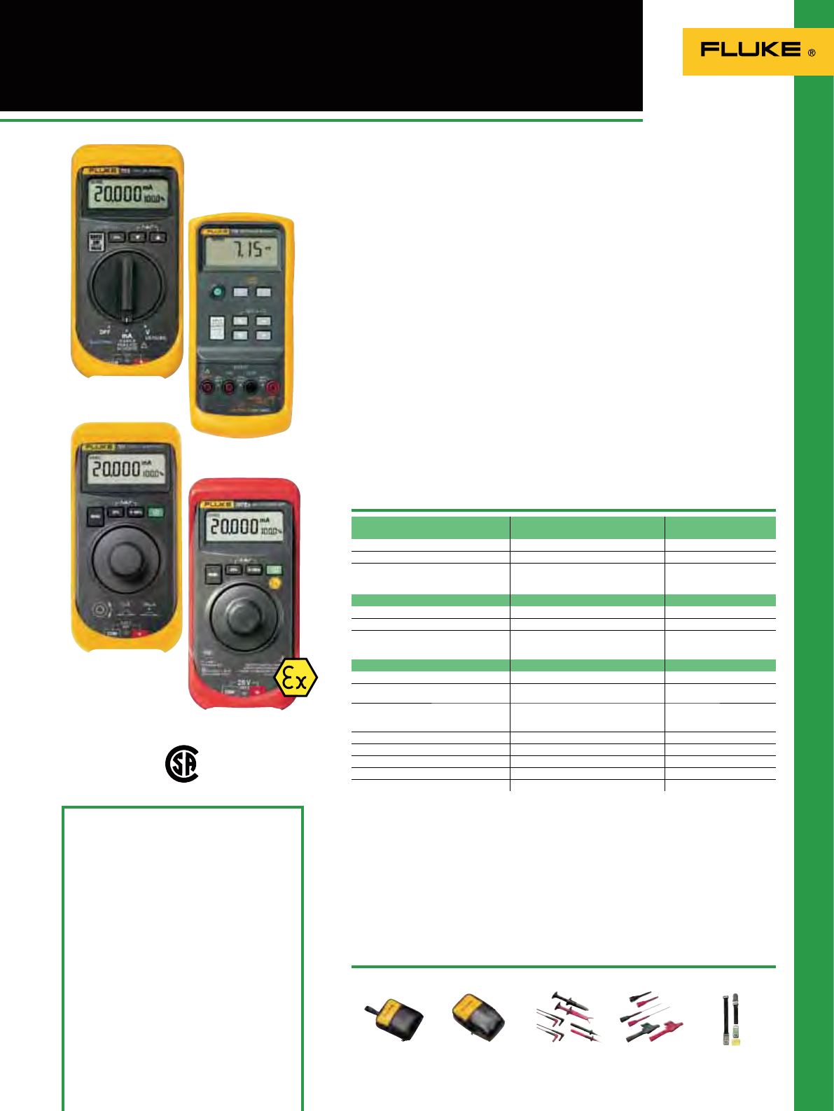
109
705/707/707Ex/715
Loop Calibrators
T PAK (715)
See page 132
Fluke 705
TP920
See page 121
TL220-1
See page 122
C25 (715)
See page 130
C12A (705/707)
See page 130
Functions
Voltage measurement
705/707/707 Ex 715
Range 0-28 V DC 0-200 mV, 0-20 V
Resolution 1 mV 10 µV 1 mV
Accuracy 705: 0.025% Rdg + 2 LSD
707/707Ex: 0.015% Rdg + 2 LSD 0.01% Rdg + 2 LSD
Specifications
Fluke 705, 707, 707Ex
Maximum voltage: 30 V (28 V - 707Ex)
Operating temperature: -10 to 55°C
Safety: CSA C22.2 No. 1010.1: 1992
EMC: EN50082-1:1992 and EN55022: 1994 Class B
Size (HxWxD): 164 mm x 75 mm x 47 mm;
Weight: 0.35 kg
Battery: One 9 V alkaline
Battery life: 18 hours typical, at 12 mA
Three Year Warranty
Fluke 715
715
Size (HxWxD): 201 mm x 98 mm x 52 mm
Weight: 0.6 kg
Battery: One 9V alkaline
Battery life: 4 to 20 hours
Three Year Warranty
705 Loop Calibrator
• Simultaneous mA and %
• mA accuracy of 0.02%
• Measure, source and simulate mA
• Push button 25% steps for fast, easy
linearity checks
• “Span Check” for fast conrmation of
zero and span
• Selectable slow ramp, fast ramp, and
step function
• 24 volt internal loop supply
• 0 - 20 mA or 4 - 20 mA default start up
modes
707 Loop Calibrator
• Features of the Fluke 705
• “Quick Click” detented rotary knob for
one handed operation
• Higher accuracy: 0.015%
• Mains Voltage Input protection
• 250 Ohm loop resistance for with Hart
instrumentation
715 Volt/mA Calibrator
• Measure loop current (0-20 mA,
4-20 mA) signals with 0.015% accuracy
and 0.001 mA resolution
• Measure voltage output process signals
from PLCs, transmitters
• Source or simulate 24 mA loop current
• Source voltage to 100 mV or 10 V
• 24 V loop supply with simultaneous
current measurement
707Ex Intrinsically Safe Loop
Calibrator
• Same features as Fluke 707
• For use in explosion endangered areas
• ATEX certied ( II 2 G Eex ia IIC T4)
4-20 mA, source, measure, simulate
Fluke 707
Fluke 707Ex
Current sourcing
Range 0-20 mA or 4-20 mA10-20 mA or 4-20 mA1
Accuracy 705: 0.025% Rdg + 2 LSD
707/707Ex: 0.015% Rdg + 2 LSD 0.015% + 2 LSD
Drive capability 705: 1000 @ 24 mA
707: 1200 @ 24 mA
707Ex: 700 20 mA
1000 @ 24 mA
Loop power while measuring mA 24 V 24 V
Voltage sourcing N/A 0-100 mV or 0-10 V
Display current and % of span Yes mA or %
Auto step, auto ramp Yes Yes
Span Check Yes Yes
Current measurement
Range 0-24 mA 0-24 mA
Resolution 0.001 mA 0.001 mA
Accuracy 705: 0.025% Rdg + 2 LSD
707/707Ex: 0.015% Rdg + 2 LSD 0.015%
Included Accessories
Fluke 705/707: C10 Yellow Holster, Test Leads,
AC172 Alligator Clips, Single 9V alkaline
battery, Instruction Sheet
Fluke 707Ex: Red Ex-holster, Test Leads, AC172
Alligator Clips, Single 9V alkaline battery,
Instruction Sheet
Fluke 715: Yellow Holster (H80M excl. TPAK),
Test Leads and AC172 Alligator Clips, Single 9V
alkaline battery, Instruction Sheet
Ordering Information
Fluke 705 Loop Calibrator
Fluke 707 Loop Calibrator
Fluke 707Ex Intrinsically Safe Loop Calibrator
Fluke 715 Volt/mA Calibrator
1 will over-range to 24 mA
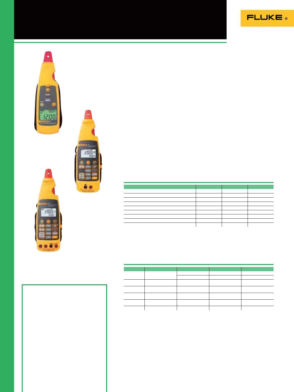
110
771, 772 and 773
mA Process Clamp Meters
Fluke 773
Fluke 771
Included Accessories
Fluke 771: soft carrying case and user’s manual
Fluke 771 + 772: plus test leads, AC172 alligator
clip set and TL940 mini-hook test lead set
Ordering Information
Fluke 771 Milliamp Process Clamp Meter
Fluke 772 Milliamp Process Clamp Meter
Fluke 773 Milliamp Process Clamp Meter
Specifications
Features
Size (HxWxD):
771: 212 mm x 59 mm x 38 mm
772 + 773: 248 mm x 76 mm x 41 mm
Weight: 771: 0.26 kg
772 + 773: 0.42 kg
Battery: 771: 2x 1.5V Alkaline, IEC LR6
772 + 773: 4x 1.5V Alkaline, IEC LR6
Battery Life: 771: 20 hours typical
772 + 773: 12 hours @ 12 mA source into
500 ohms
IP Rating: IP 40
Warranty: 3 years, 1 year on mA clamp
accessory and cable
Fluke 771, 772 and 773
• Measure 4 to 20 mA signals without
”breaking the Loop,” save time and
money troubleshooting 4 to 20 mA
signals
Fluke 772 and 773
• Source 4 to 20 mA signals for testing
control system I/O or I/Ps
• Simulate 4 to 20 mA signals for testing
control system I/O
• Measure 4 to 20 mA signals with in-
circuit measurement
• Power a transmitter with the 24 V loop
power supply
• Automatically ramp and step change
the 4 to 20 mA output for remote
testing
Fluke 773
• DC voltage measurement to verify 24 V
power supplies or voltage I/O signals
• Source dc voltage to test voltage input
devices
• Scaled mA output signal enables a
logging DMM (289) to record 4 to 20 mA
signal without breaking the loop
• mA in/out: simultaneously source a mA
signal while measuring a mA signal
with the clamp
mA measurements without breaking the loop.
Save time. Save money.
Function Resolution and range Accuracy Notes
771, 772, 773 mA measurement 0 to 20.99 mA 0.2 % + 5 counts Measured by clamp
21.0 mA to 100.0 mA 1 % + 5 counts
772 and 773 mA measurement 0 to 24.00 mA 0.2 % + 2 counts Measured in series
with test jacks
772 and 773 mA source 0 to 24.00 mA 0.2 % + 2 counts Maximum mA drive:
24 mA into 1,000 ohms
772 and 773 mA simulate 0 to 24.00 mA 0.2 % + 2 counts Maximum voltage
50 V dc
773 Voltage source 0 to 10.00 V dc 0.2 % + 2 counts 2 mA maximum
drive current
773 Voltage measure 0 to 30.00 V dc 0.2 % + 2 counts
771 772 773
mA measure w/jaw OOO
mA measure In circuit OO
mA source OO
mA sim OO
Loop power 24 V OO
DCV source 0-10 V O
DCV measure 0-30 V O
Scaled mA output to mA input O
mA in/out O
Fluke 772
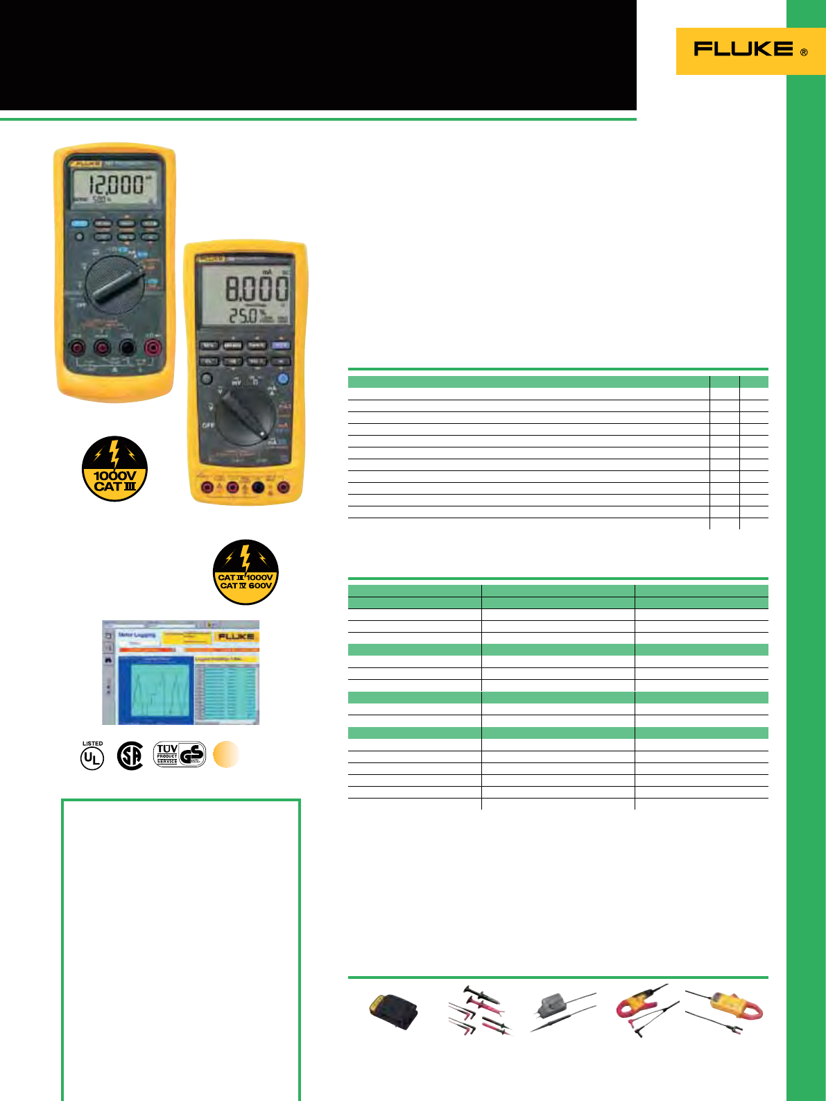
111
787/789 ProcessMeters
Fluke 787
Included Accessories
787: Yellow Holster (H80M excl. TPAK), Hard
Point Test Lead Set plus AC172 Alligator Clips,
one 9V battery, user manual
789: Test Lead Set plus AC172 Alligator Clips,
four 9V AA alkaline batteries, user manual
and quick reference guide.
Ordering Information
Fluke 787 ProcessMeter
Fluke 789 ProcessMeter
FVF-SC2 FlukeView Forms Software
including interface cable
Features
Maximum voltage: 1000 V
Operating temperature: -20 to 55ºC
787
Size (HxWxD): 201 mm x 98 mm x 52 mm
Weight: 0.642 kg
Battery: One 9 V alkaline
Battery life: 12 to 50 hours typical
Three Year Warranty
789
Size (HxWxD): 203 mm x 100 mm x 50 mm
Weight: 0.6 kg
Battery: Four AA alkaline batteries
Battery life: 14 to 140 hours typical
Three Year Warranty
The Fluke 787 and 789 ProcessMeters
combine a Digital Multimeter and a Loop
Calibrator in one rugged handheld tool,
giving process technicians double the
power.
The Fluke 789 has a built-in 24 V loop
supply which reduces the need for
taking a separate power supply when
doing ofine transmitter testing. The
IR communication port of the Fluke
789 allows data to be logged to optional
FlukeView Software for graphical analysis
and reporting.
Double your power
Recommended Accessories
C125
See page 130 TL220-1
See page 122 80T-150U
See page 128 i400
See page 126 i410
See page 127
Specifications
Fluke 789
True RMS
787 789
DMM and Loop Calibrator in one tool
OO
Precision 1000 V, 440 mA True RMS Digital Multimeter
OO
DC current source and Loop Calibrator
OO
24 V Loop power supply
O
Min/Max / Average / Hold / Relative Modes
OO
Diode Test and Continuity Beeper
OO
Manual Step (100%, 25%, Coarse, Fine) plus Auto Step and Auto Ramp
OO
Simultaneous mA and % of scale read-out
OO
Externally accessible battery / fuses
O
/-
O
/
O
HART mode setting with loop power and a built-in 250 resistor
O
0% and 100% buttons to toggle between 4 and 20 mA sourcing for a quick span check
O
Infrared I/O serial port
O
787 789
Voltage measurements
Range 0-1000 V AC or DC 0-1000 V AC or DC
Resolution 0.1 mV to 1.0 V 0.1 mV to 1.0 V
Accuracy 0.1% Rdg+1 LSD (V DC) 0.1% Rdg+1 LSD (V DC)
Other specifications
Max drive capability 500 1200
Loop power N/A 24 V
Resistance measurement To 40 M, 0.2%+1 LSD To 40 M, 0.2%+1 LSD
Frequency To 19.999 kHz, 0.005%+1 LSD To 19.999 kHz, 0.005%+ LSD
Continuity Beeps for resistance < 100 Beeps for resistance < 100
Span Check No Yes
Current measurement
Range 0-1 A 0-30 mA 0-1 A 0-30 mA
Resolution 1 mA 0.001 mA 1 mA 0.001 mA
Accuracy 0.2%+2 LSD 0.05%+2 LSD 0.2%+2 LSD 0.05%+2 LSD
Current Sourcing
Range 0-20 mA or 4-24 mA 0-20 mA or 4-24 mA
Accuracy 0.05% of span 0.05% of span
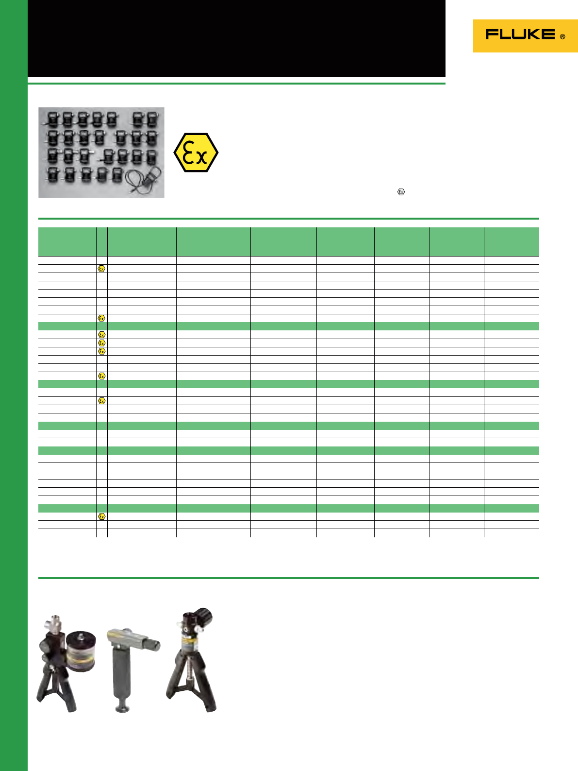
112
Field Calibrator Accessories
Model Range (approx.) Resolution
uncertainty
(23 ± 3°C) (FS)
Reference High side media Low side media Fitting material Max
overpressure2)
Differential
700P00 2.5 mbar 0.001 mbar 0.3 % Dry 1) Dry 1) 316 SS 30x
700P01/700P01Ex 25 mbar 0.01 mbar 0.2 % Dry Dry 316 SS 3x
700P02 70 mbar 0.007 mbar 0.15 % Dry Dry 316 SS 3x
700P22 70 mbar 0.007 mbar 0.1 % 316 SS Dry 316 SS 3x
700P03 340 mbar 0.01 mbar 0.05 % Dry Dry 316 SS 3x
700P23 340 mbar 0.01 mbar 0.025 % 316 SS Dry 316 SS 3x
700P04 1000 mbar 0.1 mbar 0.025 % Dry Dry 316 SS 3x
700P24/700P24Ex 1001 mbar 0.1 mbar 0.025 % 316 SS Dry 316 SS 3x
Gage
700P05/700P05Ex 2 bar 0.1 mbar 0.025 % 316 SS N/A 316 SS 3x
700P06/700P06Ex 7 bar 0.7 mbar 0.025 % 316 SS N/A 316 SS 3x
700P27/700P27Ex 20 bar 1 mbar 0.025 % 316 SS N/A 316 SS 3x
700P07 34 bar 1 mbar 0.025 % 316 SS N/A 316 SS 3x
700P08 70 bar 7 mbar 0.025 % 316 SS N/A 316 SS 3x
700P09/700P09Ex 100 bar 10 mbar 0.025 % 316 SS N/A 316 SS 2x
Absolute
700PA3 340 mbar 0.01 mbar 0.05 % 316 SS N/A 316 SS 3x
700PA4/700PA4Ex 1000 mbar 0.1 mbar 0.05 % 316 SS N/A 316 SS 3x
700PA5 2 bar 0.1 mbar 0.05 % 316 SS N/A 316 SS 3x
700PA6 7 bar 0.7 mbar 0.05 % 316 SS N/A 316 SS 3x
Vacuum
700PV3 -340 mbar 0.01 mbar 0.04 % 316 SS Dry 316 SS 3x
700PV4 -1000 mbar 0.1 mbar 0.04 % 316 SS Dry 316 SS 3x
Dual
700PD2 ± 70 mbar 0.007 mbar 0.15 % 316 SS Dry 316 SS 3x
700PD3 ± 340 mbar 0.01 mbar 0.04 % 316 SS Dry 316 SS 3x
700PD4 ±1000 mbar 0.1 mbar 0.025 % 316 SS Dry 316 SS 3x
700PD5 -1000/+2000 mbar 0.1 mbar 0.025 % 316 SS N/A 316 SS 3x
700PD6 -1000 mbar/+6.9 bar 1 mbar 0.025 % 316 SS N/A 316 SS 3x
700PD7 -1000 mbar/+13.8 bar 1 mbar 0.04 % 316 SS N/A 316 SS 3x
High
700P29/700P29Ex 200 bar 0.01 bar 0.05 % C276 N/A C276 2x
700P30 340 bar 0.01 bar 0.05 % C276 N/A C276 2x
700P31 700 bar 0.07 bar 0.05 % C276 N/A C276 1.5x
• Ranges from 2.5 mbar to 700 bar.
• Gage, differential, dual (compound), absolute
and vacuum modules
• Very high accuracy: up to 0.025% FS
• Features internal temperature compensation
from 0°C to 50°C for full-accuracy
performance
• Pressure readings update twice per second,
and may be displayed in any of 11 different
units
700LTP-1 Low-pressure Test Pump
• For low pressure applications
• Vacuum to -13 psi / -.90 bar
• Pressure to 100 psi / 6.9 bar
• With ne-control, adjustable relief valve
and slow bleed capability
700PTP-1 Pneumatic Test Pump-1
• Handheld pressure pump
• Pressures up to 600 psi, 40 bar
700HTP-2 Hydraulic Test Pump
• Pressures up to 10,000 psi/690 bar.
• Compatible with Fluke 717, 718, 725 and 75x
series.
• Rugged cases protect the modules from
harsh environments
• All modules include NIST traceable
certicate and test data
• ATEX certied Ex versions available
( II 1 Eex ia IIB T4)
700PRV-1 Pressure Relief Valve
• Pressure relief valve for 700HTP-1
• Adjustable from 725 to 5800 PSI
(50 to 200 bar)
700HTH-1 Hydraulic Test Hose
• Hydraulic test hose is a 10,000 psi, 690 bar
700ILF In-Line Filter for the
Fluke 718
700PCK Pressure Module
Calibration Kit
BE9005 Battery Eliminator
Fluke 700 Series Pressure Modules
Other accessories
1)“Dry” indicates dry air or non-corrosive gas as compatible media. “316 S S” indicates media compatible with Type 316 Stainless Steel. “C276” indicates media compatible with Hastelloy C276.
2)Maximum overpressure specification includes common mode pressure.
Fluke 700LTP-1Fluke 700HTP-2 Fluke 700PTP-1

113
With the Fluke 810 Vibration Tester you will be able to control unplanned
downtime, prevent recurring problems, set repair priorities and manage
your resources with an entirely new approach to vibration testing. In three
quick, easy steps, the new Fluke 810 helps you locate and diagnose com-
mon mechanical problems and prioritize their repair actions. The combi-
nation of powerful algorithms and a database of real-world measurement
experience make the Fluke 810 the most advanced troubleshooting tool
for mechanical maintenance teams who need an answer now.
Vibration Tester
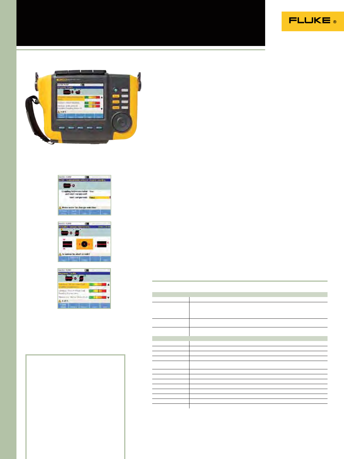
114
810 Vibration Tester
Included Accessories
Tri-axial TEDS accelerometer, accelerometer
magnet mount, accelerometer mounting
pad kit with adhesive, accelerometer quick
disconnect cable, laser tachometer and
storage pouch, smart battery pack with cable
and adapters, shoulder strap, adjustable
hand strap, Viewer PC application software,
mini-USB to USB cable, getting started guide,
illustrated quick reference guide, users
manual CD-ROM, instructional training CD-
ROM, hard carrying case.
Ordering Information
Fluke 810 Vibration Tester
Diagnostic specifications
Standard faults Unbalance, looseness, misalignment and bearing failures
Analysis for Motors, fans, blowers, belts and chain drives, gearboxes, couplings, centrifugal pumps,
piston pumps, sliding vane pumps, propeller pumps, screw pumps, rotary thread/gear/
lobe pumps, piston compressors, centrifugal compressors, screw compressors, closed
coupled machines, spindles
Machine rotational
speed range 200 rpm to 12000 rpm
Diagnosis details Plain-text diagnosis, fault severity (slight, moderate, serious, extreme), repair details,
cited peaks, spectra
Electrical specifications
Ranging Automatic
A/D converter 4 channel, 24 bit
Usable bandwith 2 Hz to 20 kHz
Sampling 51.2 kHz
Digital signal
processing functions Automatically configured anti-alias filter, high-pass filter, decimation, overlapping,
windowing, FFT, and averaging
Sampling rate 2.5 kHz to 50 kHz
Dynamic range 128 dB
Amplitude accuracy ±0.1 dBV
FFT resolution 800 lines
Spectral windows Hanning
Frequency units Hz, orders, cpm
Amplitude units in/sec, mm/sec, VdB (US), VdB (Europe)
Non-volatile nemory SD micro memory card, 2 GB internal + user accessible slot for additional storage
Specifications
(Check the Fluke web for detailed specifications)
Battery type: Lithium-ion, 14.8 V 2.55 Ah
Size (HxWxD): 186 x 267 x 70
Weight: 1.9 kg
Fluke 810
Language support:
eng, ger, fre, ita, spa, por
Warranty: Three years on tester
One year on sensor and tachometer
The Fluke 810 Vibration Tester is the
most advanced troubleshooting tool
for mechanical maintenance teams
who need an answer now. The unique
diagnostic technology helps you quickly
identify and prioritize mechanical
problems, putting the expertise of a
vibration analyst in your hands.
Use the vibration tester to:
• Troubleshoot problem equipment and
understand the root cause of failure
• Survey equipment before and after
planned maintenance and conrm the
repair
• Commission new equipment and
ensure proper installation
• Provide quantiable proof of equipment
condition and drive investment in
repair or replacement
• Prioritize and plan repair activities and
operate more efciently
• Anticipate equipment failures before
they happen and take control of spare
parts inventories
• Train new or less-experienced
technicians and build condence and
skill across the team
Features and benefits
• On-board identication and location of
the most common mechanical faults
(bearings, misalignment, unbalance,
looseness) focus maintenance efforts
on root cause, reducing unplanned
downtime
• Fault severity scale with four severity
levels help you prioritize maintenance
work
• Repair recommendations advise
technicians on corrective action
• On-board context sensitive help provide
real-time tips and guidance to new
users
• 2 GB expandable on-board memory
provide enough space for your
machinery’s data
• Self-test functions ensure optimal
performance and more time on the job
• Laser tachometer for accurate machine
running speed promotes condent
diagnoses
• Tri-axial accelerometer reduces
measurement time by 2/3 over single
axis accelerometers
• Viewer PC Software expands data
storage and tracking capacity
• Color LCD display and intuitive
multilingual, icon-based user interface
promote use right out of the box
Motor diagnosis and repair in three simple steps
Set-up
Measure
Diagnose
115
Radiation safety quality assurance is top of mind for hospitals, nuclear
power facilities, nuclear medicine laboratories, x-ray manufacturers,
government agencies, state inspectors, emergency response and
HAZMAT (hazardous materials) teams, and police and fire departments
around the world.
With the 481 Fluke offers these professionals the versatility they need to
get the job done and the quality they trust in a radiation-safety device.
481 Radiation Detection Meter
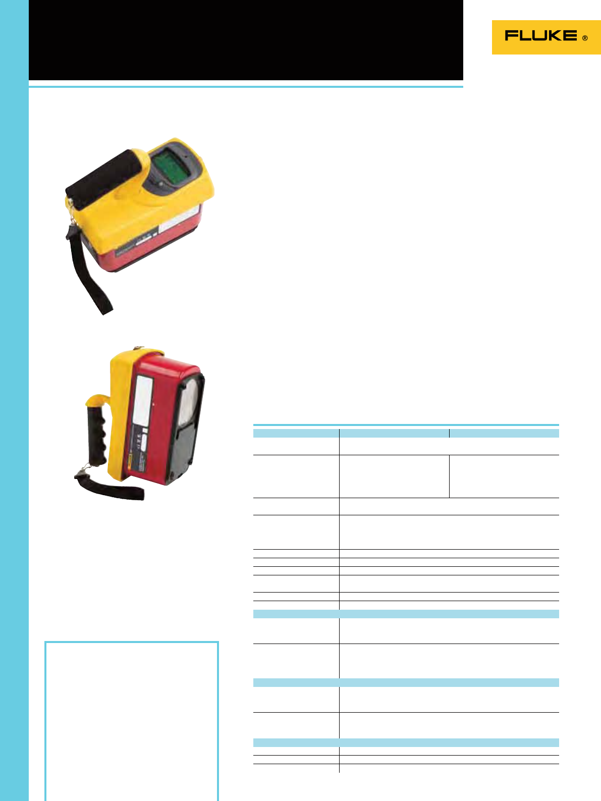
116
481 Radiation Detection Meter
Fluke 481
Ordering Information
Fluke 481 Ion Chamber Survey Meter
Fluke 481-DESI DESI Ion Chamber Survey Meter,
dose equivalent SI
190HPS Single Unit Carrying Case
The Fluke 481 Radiation Detection Meter
is a portable and practical means for
discovering irradiated goods, and for
helping remediate contaminant and
safety issues while minimally affecting
performances. Ideal for detecting
irradiated goods, equipment, surfaces
or environments in industrial settings,
the 481 Radiation Meter helps ascertain
worker safety and compliance to national
regulations.
Use of the Fluke 481 assures employees
that radiation dangers are known,
monitored and calculated for their
security. Whenever radiation is found,
a clear and quantiable result provides
handlers to comply with national
guidelines while avoiding unnecessary
steps that could stop procedures, impact
productivity or lead to missed revenue.
• Detects skin-dose (beta particle)
and deep-dose (gamma) and X-ray
radioactivity
• Requires no adjustments; simple two
button process
• Provides promptly read, correct value
through autoranging capability
• Easily visible inside truck trailers
and other low-light situations with
automated backlight
• Works dependably inside or outside
thanks to sealed case
• 30 % more precise than other available
meters
• Delivers more than one week of
uninterrupted functioning with two
9-volt alkaline batteries
• Proven in use by state and local
governmental emergency response
professionals, state inspectors,
HAZMAT teams and nuclear power
workers
• Measures both dose and dose-rate
• Valuable for contamination-detection,
general radiation area metering,
radiation-level monitoring, and
hazardous materials assessment
• Rugged Fluke design
Fluke 481 Radiation Detection Meter
General specifications Fluke 481 Fluke 481-DESI
Radiation detected Beta > 100 keV
Gamma > 7 keV
Operating ranges 0 mR/h to 5 mR/h (8 sec)
0 mR/h to 50 mR/h (2.5 sec)
0 mR/h to 500 mR/h (2 sec)
0 R/h to 5 R/h (2 sec)
0 R/h to 50 R/h (2 sec)
0 µSv/h to 50 µSv/h (8 sec)
0 µSv/h to 500 µSv/h (2,5 sec)
0 mSv/h to 5 mSv/h (2 sec)
0 mSv/h to 50 mSv/h (2 sec)
0 mSv/h to 500 mSv/h (2 sec)
Accuracy Within 10 % of readings between 10 % and 100 % of full scale indication on any
range, exclusive of energy response
Detector Chamber (cc volume air ionization) 349 cc
Chamber wall (phenolic) 246 mg/cm2
Chamber window (mylar) 6.6 mg/cm2
Beta slide 440 mg/cm2
Automatic features Auto-zeroing, auto-ranging, and auto-backlight
Power requirements Two 9 V alkaline, 200 hours operation
Warm-up time One minute
Battery life Four+ hours continuous use per battery pack
(assumes 50 % brightness of LCD)
Dimensions (W x D x H) 10 cm x 20 cm x 15 cm
Weight 1.11 kg
Display LCD analog/digital with backlight
Analog 100 element bar graph 6.4 cm long. Bar graph is divided into 5 major segments,
each labeled with the appropriate value for the range of the instrument
Digital 2.5 digit display is followed by a significant zero digit depending on the
operating range of the instrument. The units of measurement are indicated
on the display at all times. Digits are 6.4 mm high. Low battery and freeze
indicators are also provided on the display
Modes
Integrate mode Operates continuously 30 seconds after the instrument has been turned on.
Integration is performed even if the instrument is displaying in mR/h or R/h
Freeze mode Will place a tick mark on the bar graph display to hold on the peak displayed
value. The unit will continue to read and display current radiation values
Environmental
Temperature range -20 °C to 50 °C
Relative humidity 0 % to 100 % (at 50 °C)
Geotropism < 1 %
Specifications
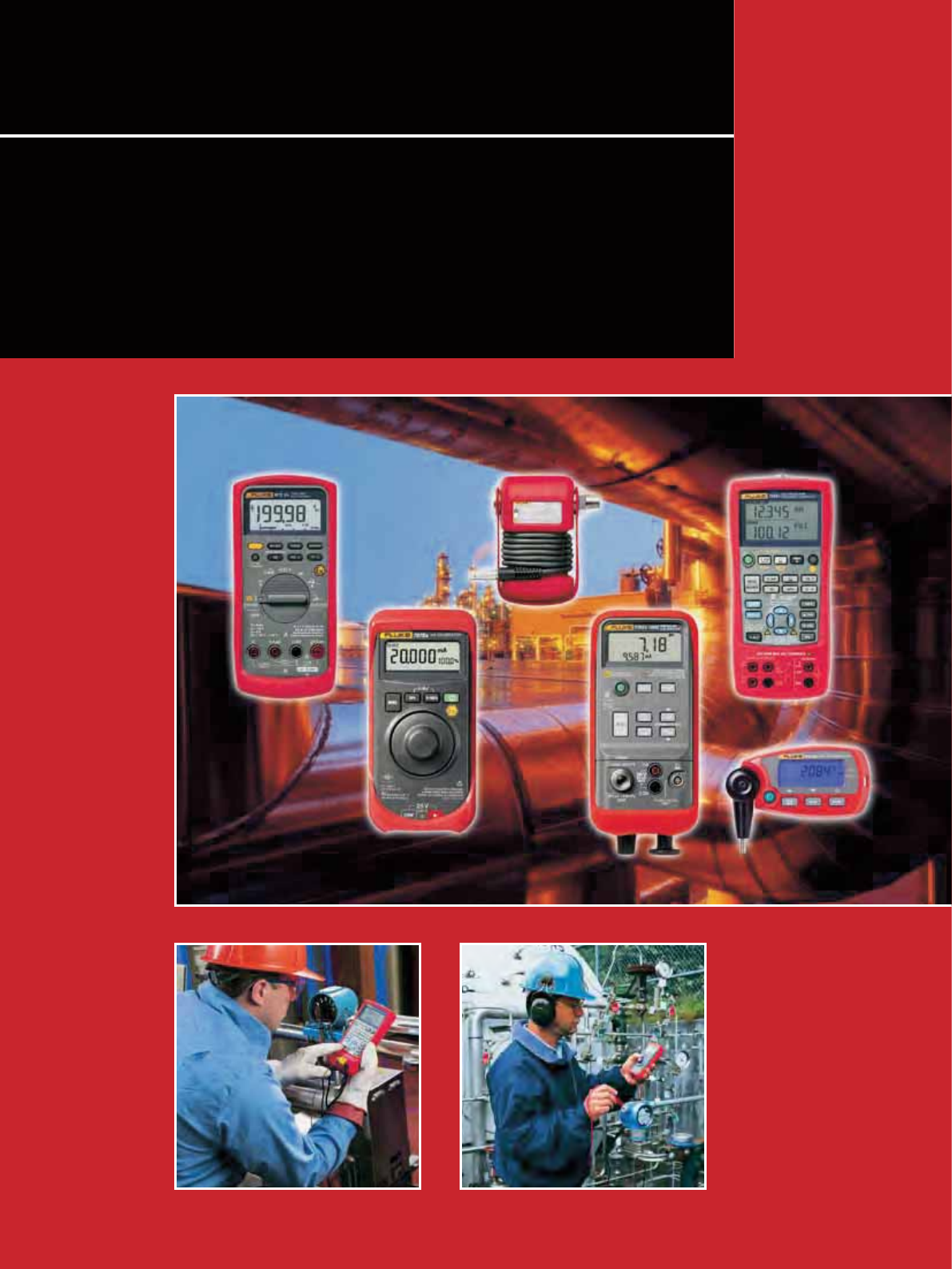
117
The Fluke line of intrinsically safe tools is designed to meet the needs of
technicians working in and around hazardous areas. The tools are ideal
for environments in chemical plants, petro-chemical plants, oil plat-
forms, refineries and other locations where risk of explosion exists. The
products are easily recognizable from standard Fluke products by their
lighter grey colour and red holster.
ATEX Certified Test Tools

118
What is “Intrinsically Safe”?
Intrinsically safe standards apply to all
equipment that can create one or more
of a range of dened potential explosion
sources:
• Electrical sparks
• Electrical arcs
• Flames
• Hot surfaces
• Static electricity
• Electromagnetic radiation
• Chemical reactions
• Mechanical impact
• Mechanical friction
• Compression ignition
• Acoustic energy
• Ionizing radiation
What industries are intrinsically
safe products designed for?
• Petro-chemical
• Oil platforms and reneries
• Pharmaceutical
• Bulk materials (e.g. grain)
• Mining
• Pipelines
• Any environment where explosive gases
are present
What is ATEX?
The primary intrinsically safe standard has
been set in the European Union with the
9/94/EC Directive, commonly called ATEX
(“Atmosphères Explosibles,” French for
explosive atmospheres). The stated goal of
the guidelines is to “help ensure the free
movement of products in the European
Union” by “minimizing the number of
safeguard clause applications, at least those
originating from divergent interpretations
The ATEX rules have been in place as a
voluntary standard since 1 March 1996.
The rules are mandatory on electrical
and electronic equipment for use in
environments subject to explosion hazard
sold in the EU starting 1 July 2003. From
this date onwards, all products sold for
use in explosive atmospheres must have
ATEX certication and carry the distinctive
symbol:
The Fluke Ex (IS) product line
Fluke is among the rst manufacturers to
produce handheld test tools according to
the latest ATEX standards. The Fluke line of
intrinsically safe tools is designed to meet
the needs of technicians working in and
around hazardous areas:
• Install, maintain and troubleshoot
equipment by using the new Fluke 87V Ex
Digital Multimeter
• Maintain and calibrate sensors,
transmitters and control loops with the
line of Ex eld calibrators
The tools are ideal for environments
in petro-chemical plants, oil platforms,
reneries and other locations subject to risk
of explosion.
Apart from having the ATEX markings, the
visual difference between a standard Fluke
tool and the corresponding Ex version is
the different grey body colour and a red,
conductive holster designed specically
to eliminate the potential for electrical
discharge.
Inside, the Fluke Ex tools have been
reengineered to reduce energy avoiding
generation of heat and electrical sparks.
They are premium products designed for
ultimate safety.
Making sense of ATEX certication
Fluke 707Ex is ATEX-compliant and is
certied II 2 G EEx ia IIC T4— but what
exactly does that mean?
Intrinsic safety is a protection standard
employed in potentially explosive
atmospheres. Devices that are certified
as “intrinsically safe” are designed to be
unable to release sufficient energy, by
either thermal or electrical means, to cause
ignition of flammable material (gas, dust/
particulates).
Here a brief explanation of the ATEX
certification designations.
A brief look at ATEX
The ATEX examination mark. This sign is required on all devices used in European hazardous
areas.
II 2 G
The classification of zones.
“II” designates the tool is approved for all non-mining areas.
“2” represents the category of the device, in this case the device is rated for the second most
hazardous areas.
“G” designates atmosphere, in this case gas, vapors and mist.
EEx Explosion protection based on European Ex-regulations.
ia The type of protection from explosion, in this case the energy in a device or connector has
been reduced to a safe value.
IIC Gas Group. “IIC” indicates compatibility with the most dangerous gas group.
T4 Temperature class gives the user the maximum temperature of a surface that may be in
contact to the Ex atmosphere under fault conditions. T4 is rated at 135°C.
ATEX certification 707Ex
A brief look at ATEX
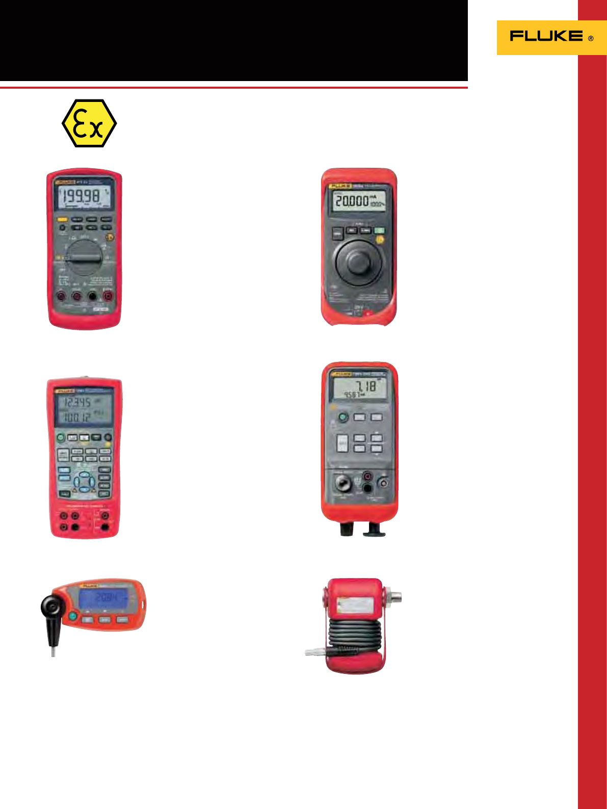
119
Fluke 87V Ex Intrinsically safe
version of the world’s most popular
multimeter
With its high performance, accuracy and
motor drive compatibility, the Fluke 87V
is the most popular industrial multimeter
around. Now Fluke has introduced a new
intrinsically safe version – the 87V Ex – for
measurements in and around hazardous
areas.
The Fluke 87V Ex has all the measurement
and troubleshooting functions of the proven
Fluke 87V. Unlike other ATEX-certified tools,
it can be used both inside and outside the
hazardous zone (ATEX Zones 1 & 2) without
compromising performance or compliance.
So there’s no need to carry different tools
for use in specific zones. It also has a built-
in thermometer with TC probe, further
reducing technicians’ tool counts.
• ATEX safety rating II 2G EEx ia IIC T4
• EN61010-1 CAT III 1000V/CAT IV 600V
electrical safety rating
See also page 15
ATEX-certified Test Tools
Fluke 725Ex Intrinsically safe
Multifunction Process Calibrator
The Fluke 725Ex intrinsically safe
Multifunction Process Calibrator is powerful
yet easy-to-use. Combined with the
Fluke 700PEx Pressure Modules, the 725Ex
is able to calibrate almost any process
instrument likely to need service in any
area where explosive gases may be present.
• ATEX safety rating
II IG EEx ia IIB 171°C
See also page 104
1551A Ex and 1552A Ex “Stik”
Thermometer
Finally, a digital substitute for your
mercury-in-glass thermometers!
Accurate and repeatable to ± 0.05 °C
over its full range, the 1551A/1552A
“Stik Thermometer is the new “gold
standard” of industrial temperature
calibration. Whether working outdoors in
environments where potentially explosive
gases may be present or on the floor of
a processing plant, the intrinsically-safe,
battery operated, portable reference
thermometer is designed to go where you
work.
• ATEX and IECEx compliant
See also page 57
Fluke 707Ex Fast, one-handed tool for
loop checks
The Fluke 707Ex is the ideal, stand alone
tool for calibration and maintenance of 4
to 20 mA control loops. It provides 24V loop
power while measuring mA, and lets you
measure and source/simulate mA with 1 µA
resolution.
• ATEX safety rating
II 2G EEx ia IIC T4
See also page 109
Fluke 718Ex Self-contained Pressure
Calibrator
The Fluke 718Ex offers a convenient,
self contained solution for pressure
measurements and calibration. With its
internal pressure sensor and pump, it’s
ready for immediate, stand alone use. The
pressure range can easily be extended to up
to 200 bar with any of the 8 Fluke 700PEx
Pressure Modules.
• ATEX safety rating
II IG EEx ia IIC T4
See also page 108
Fluke 700Ex Pressure Modules
These intrinsically safe pressure
modules for use with the Fluke 725Ex
Multifunctional Process Calibrator and
Fluke 718Ex Pressure Calibrator cover the
most commonly used pressure calibration
ranges from 0-25 mbar and 0-200 bar.
There’s a choice of 8 gage, differential and
absolute modules.
• ATEX safety rating
II 1G EEx ia IIC T4
See also page 112
Fluke intrinsically safe tools for tough measurement and
calibration tasks
Fluke 87V Ex Fluke 707Ex
Fluke 718Ex
Fluke 700Ex
Fluke 725Ex
1551A Ex/1552 Ex
120120
The best test tools deserve accessories designed and manufactured
to the same high quality and safety standards. So we also provide a
comprehensive range of test leads, probes and clips, current clamps,
temperature accessories and dedicated electronic and automotive
accessories. And to protect your valuable instrument, choose a rugged
Fluke tailor-made holster or case.
General Accessories
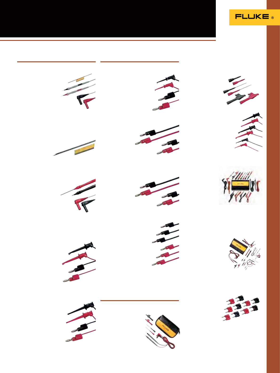
121
TL910 Electronic Test Lead Set
• Very small 1 mm tips to access hard
to reach test points
• Probe tip length up to
100 mm, test lead length:
1 m
• Included: 3 sets of
spring loaded gold tips
and 2 sets of stainless steel tips
• CAT II 1000 V, 3 A rating
Electronic Test Leads,
Probes & Clips
TP912 Replacement Tips for TL910
• Replacement tips for TL910
• Five sets of gold plated and stainless
steel tips
TL40 Retractable Tip Test Lead Set
• One pair (red, black) of test leads with
sharp needle point tips adjustable
to desired length from 0 to
76 mm
• Extra hard probe tips
to provide long service life
• Flexible silicone insulated test
leads
• CAT II 150 V, 3 A rating, UL listed
TL940 Mini-Hook Test Lead Set
• 1 pair (red, black) of test leads with multi-
stacking 4 mm banana plugs and
mini-hooks
• Mini-hooks attach to
component leads up to
1.5 mm diameter
• 90 cm long PVC
insulated leads
• 30 V rms or 60 V DC, 15 A
TL950 Mini-Pincer Test Lead Set
• 1 pair (red, black) of test leads with
multi-stacking 4 mm banana plugs
and mini-pincers
• Mini-pincers open to
2.3 mm
• 90 cm long PVC insulated
leads
• 30 V rms or 60 V DC, 15 A
TL960 Micro-Hook Test Lead Set
• 1 pair (red, black) of test leads with
multi-stacking 4 mm banana
plugs and micro-hooks
• Micro-hooks attach to
component leads up to 1 mm
diameter
• 90 cm long PVC insulated leads
• 30 V rms or 60 V DC, 15 A
TL930 Patch Cord Set (60 cm)
• 1 pair (red, black)
multi-stacking 4 mm banana plug
patch cords
• Nickel-plated banana
plugs
• 61 cm long
PVC insulated leads
• 30 V rms or 60 V DC, 15 A
TL932 Patch Cord Set (90 cm)
• 1 pair (red, black) multi-stacking 4 mm
banana plug patch cords
• Nickel-plated banana
plugs
• 90 cm long
PVC insulated leads
• 30 V rms or 60 V DC, 15 A
TL935 Patch Cord Kit
(60, 90, 120 cm)
• 3 sets (red and black pairs) of
multi-stacking 4 mm banana
plug patch cords
• Nickel-plated banana plugs
• 60 cm, 90 cm, 120 cm long PVC
insulated leads
• 30 V rms or 60 V DC, 15 A
TL80A-1 Basic Electronic Test Lead Kit
• One pair (red, black) each 1 meter long
silicone test lead set,
alligator clip and probe
tip extender.
• C75 soft carrying case
• CAT II 300 V. UL listed
TP920 Test Probe Adapter Kit
• Set of push-on adapters for TL71 and TL75
test probes
• IC test adapters,
extended probe tips,
medium alligator
clips (max.opening
7.6 mm)
• CAT I 300 V, 5 A rating
TL970 Hook and Pincer Kit
• TL940 Mini-Hook Test Lead Set
• TL950 Mini-Pincer Test Lead
Set
• TL960 Micro-Hook Test Lead
Set
TL81A Deluxe Electronic Test Lead Kit
• Includes components of TL80, plus one pair
(red, black) each
modular 1 meter
long silicone test
lead, test probe,
hook-style and
pinch style clip,
alligator clip, IC
probe tip adapter
and spade lugs
• Quadfold soft
carrying case
• CAT II 300 V. UL listed
TLK287 Electronic Master Test Lead Kit
• Includes modular leads, probes (black and
red), minigrabber/jack
set, medium alligator
clips (black and red),
spade lug/banana jack
plated (set), couplers
IEC1010 (black and red),
micrograbbers and
-leads (black and red)
• TL910 Electronic Test
Lead Set
• Quadfold Pouch
• CAT III 1000 V (probes only)
BP980 Double Banana
Plug Kit
• 5 pair (red, black) of
double
4 mm banana plugs
• Each plug has
3.1 mm holes for
mounting wires and
components
• Brass plugs/jack, beryllium copper springs
• 30 V rms or 60 V DC, 15 A
Kits
Test Leads Test Leads / Patch Cords
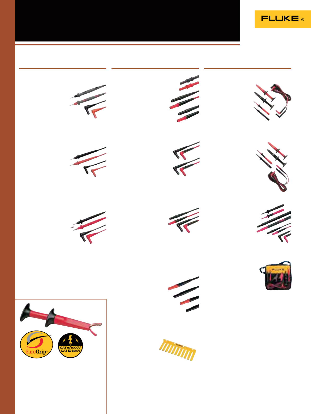
122
TL71-1 Premium Test Lead Set
• One pair (red, black) comfort grip probes
with silicone insulated, right-angle
test leads
• Recommended for µV
measurements
• CAT II 1000 V,
10 A rating. UL listed
Industrial Test Leads,
Probes & Clips
TL75-1 Hard Point™ Test Lead Set
• One pair (red, black) comfort grip probes
with PVC insulated, test leads with
right-angle shrouded banana
plugs
• Recommended for
general purpose
measurements
• CAT II 1000 V,
10 A rating. UL listed
TL76 All-in-one Test Lead Set
• One pair (red, black) 1.5 meter long
silicone test leads with right
angle shrouded banana plug
• Lantern tip (removable)
for use with European
wall sockets (4 mm Ø )
• Lantern tip can be removed
for easy access to terminal
blocks (2 mm Ø)
• Removable, insulated IC caps allow probing
on closely spaced leads and compliance with
GS38.
• Cat IV 600 V, CAT III 1000 V, 10 A rating,
UL listed
SureGrip™ accessories are designed to
improve steadiness in slippery hands.
Rubber overmolded surfaces and finger-
hugging curves give the user a comfortable,
reliable grip on the accessory so they can
focus on making an accurate measurement.
TL221 SureGrip™
Extension Lead Set
• One pair (red, black) of silicone
insulated leads with straight
connectors on both ends
• Reinforced strain relief
• Includes one pair (red, black)
of female couplers
• Extends test leads by 1.5 m
• 600 V CAT IV, 1000 V CAT III,
10 A rating. UL listed
TL222 SureGrip™
Silicone Test Lead Set
• DMM test leads (red, black)
with safety shrouded, standard
diameter banana plugs
• Right angle connector on
both ends
• Reinforced strain relief
• 1.5 meter silicone-insulated
wire resists heat & cold
• CAT IV 600 V, CAT III 1000 V,
10 A rating. UL listed
TL224 SureGrip™
Silicone Test Lead Set
• DMM test leads (red, black)
with safety shrouded,
standard diameter banana
plugs
• Right angle connector on one end and
straight connector on the other
• Reinforced strain relief
• 1.5 meter silicone-insulated wire resists
heat & cold
• CAT IV 600 V, CAT III 1000 V, 10 A rating.
UL listed
TL27 Heavy Duty
Test Lead Set
• DMM test leads (red, black)
with safety shrouded,
standard diameter banana
plugs
• Heavy duty EPDM insulation
• Length 1.5 m
• CAT III 1000V, 10A rating.
UL listed
TL220-1 SureGrip™
Industrial Test Lead Kit
• AC220 SureGrip™
Alligator Clip Set
• TP238 SureGrip™
Insulated Test Probe Set
• TL222 SureGrip™
Silicone Test Lead Set
(right to right)
TL223-1 SureGrip™
Electrical Test Lead Kit
• AC220 SureGrip™
Alligator Clip Set
• TP238 SureGrip™
Insulated Test Probe Set
• TL224 SureGrip™ Silicone
Test Lead Set (straight to
right)
TL238 SureGrip™ High
Energy Test Lead Kit
• TP238 SureGrip™ Insulated Tip Test
Probes with less than 4 mm of
exposed metal (GS38) with
exible removable nger
banner
• TP280 20 cm Test Probe
Extenders
• TL224 SureGrip™ Silicone
Test Lead Set
TLK-220 EUR SureGrip™
Accessory Kit
• AC220 SureGrip™ Alligator
Clip Set
• AC285 SureGrip™ Large Jaw
Alligator Clip Set
• TP74 Test Probe Set (4 mm)
• TL224 SureGrip™ Silicone Test
Lead Set
• Large zippered soft case with moveable
divider
KitsModular Test LeadsTest Leads
H900 Test Lead
Holder
• Heavy duty
construction with
mounting holes
• Holder has 10 slots for wires up to
8 mm in diameter
• Over-all dimensions: 27.9 cm
L x 8.9 cm W x 3.2 cm H

123
T5-KIT-1 Accessory Kit
for use with T5
This kit completes the
offering of a T5 with add-
on probes and
carrying case.
• TP238 SureGrip™
Insulated Test Probe Set
• AC285 SureGrip™ Large
Jaw Alligator Clip Set
• C33 Soft Meter Case
Industrial Test Leads,
Probes & Clips
L215 SureGrip™ Kit
with Probe Light and
Extender
• L200 Probe Light
• TP280 20 cm Test Probe
Extenders
• TP220 SureGrip Test Probes
• TL224 SureGrip Silicon Test Lead Set
• Foldable soft pouch with six pockets and
hook-and-loop
TP74 Lantern Tip Test Probe Set
• One pair (red, black)
• Tips include banana-style spring contacts
with nickel-plated brass ends
• CAT III 1000 V, 10 A rating.
UL listed
TP1-1, TP2-1, TP38
SlimReach Test Probe Sets
• One pair (red, black) of slender probes for
closely spaced or recessed terminals
• TP1-1: Flat blade design to hold
securely in blade type wall
sockets
• TP2-1: 2 mm diameter
tip for electronics work.
Also compatible with AC72.
• TP38: Insulated probe tip
(designed to meet GS38
specs for United Kingdom).
• TP1-1/TP2-1: CAT II 1000 V
TP38: CAT IV 600 V / CAT III 1000 V
10A rating, UL listed
TP80 Electronic Test Probe Set
Recommended for use with TL222
and TL224
•
One pair (red, black)
•
IC insulated cap prevents
shortening of IC legs for
probing high density components or boards
•
CAT III 1000 V, 10 A rating. UL listed
TLK291 Fused Test Probe Set
• One pair (red, black) fused test probes
• Designed to meet GS38 specs for
United Kingdom
• CAT III 1000V, 0.5A
• Fuse rating:
500 mA/1000 V/FF/50 kA
FTP-1 SureGrip™ Fused
Test Probes
• Built-in fuses for added
protection
• 2 mm threaded probe tips include removable
4 mm lantern-style spring contacts
• Removable GS38 insulted IC caps for probing
closely spaced leads
• CAT III 1000 V, CAT IV 600 V, 10A
FTPL-1 SureGrip™
Fused Test Probes
with Leads
• FTP Fused Test Probes with built-in fuses for
added protection
• Includes TL224 Silicone Insulated Test Leads
• CAT III 600 V, CAT IV 600 V, 10 A
AC285-FTP Alligator
Clips and Adapters
for FTP-1 or FTPL-1
Enhance the usage of your Fluke fused test
leads with this large alligator clip set.
This accessory enables the use of AC285
alligator clips with FTP-1 fused probes.
• CAT III 600 V, CAT IV 600 V, 10 A
TP220-1 SureGrip™ Test Probe Set
• One pair (red, black) of Industrial test probes
• Sharp, 12 mm stainless steel tip
provides reliable contact
• Flexible finger barrier improves
grip
• Recommended for use
with TL222 and TL224
test leads
• CAT II 1000 V, 10 A rating. UL listed
TLK290 Test Probe Kit
• Kit includes three flexible socket probes
and a large alligator clip
• To be used on
three phase sockets.
• Probes have flexible width
test points that fit securely in
4 to 8 mm sockets.
• Test probe set to be used on
motor and three phase sockets
• Safe contact e.g. in CEE 16 A
and CEE 32 A plugs
• CAT II 1000 V, 8 A
Kits Modular Test Probes
(for use with Modular Test Leads)
Modular Test Probes
(for use with Modular Test Leads)
All accessories have a one year warranty
TLK-225-1 SureGrip™
Master Accessory Kit
• AC220 SureGrip™ Alligator
Clip Set
• AC280 SureGrip™ Hook
Clip Set
• AC283 SureGrip™ Pincer
Clip Set
•
AC285 SureGrip™ Large Jaw
Alligator Clip Set
• TP238 SureGrip™ Insulated Test
Probe Set
• TL224 SureGrip™ Silicone Test Lead Set
• 6-Pocket Storage Pouch
New
TLK289 EUR Industrial Master
Test Lead Kit
• C116, Soft Case
• AC220 Alligator Clip Set
• AC280 Hook Clip Set
• AC285 Large Jaw
Alligator Clip Set
• TP74 Lantern Tip
Test Probe Set
• TL224 Test Lead Set
• TPAK Hanging Kit
• 80BK-A Temperature Thermocouple

124
Industrial Test Leads,
Probes & Clips
AC220 SureGrip™ Alligator Clip Set
•
One pair (red, black) of small, insulated,
nickel plated jaws
•
Blunt tip grabs round screw heads up
to 9.5 mm
•
Recommended for use with
TL222 and TL224 test leads
•
CAT IV 600 V, CAT III
1000 V, 10 A rating.
UL listed
AC280 SureGrip™ Hook Clip Set
•
One pair (red, black) of nickel plated clips
•
Profile narrows to 5.6 mm at
tip, hook opening 6.4 mm at front,
2 mm at base
•
Recommended for use with
TL222 and TL224 test leads
•
CAT IV 600 V, CAT III 1000 V,
3 A rating. UL listed
AC283 SureGrip™ Pincer Clip Set
•
One pair (red, black) of nickel plated
pincers open to 5 mm
•
11.4 cm flexible insulated shaft
•
Recommended for use with
TL222 and TL224 test
leads
•
CAT IV 600 V, CAT III
1000 V, 1 A rating.
UL listed
AC285 SureGrip™
Large Jaw Alligator Clip Set
• One pair (red, black) of large alligator
clips with nickel-plated steel jaws
• Multi-purpose tooth pattern grips
anything from fine gauge wire to
a 20 mm bolt
• Recommended for use with
TL222 and TL224 test leads
• CAT IV 600 V; CAT III 1000 V, 10 A rating.
UL listed
AC87 Heavy Duty Bus Bar Clip Set
• One pair (red, black) of
flat, right angle design
for connecting to bus
bars
• Adjustable collar
provides 2 ranges of jaw
openings up to 30 mm
• CAT III 600 V, 5 A rating. UL listed
AC89 Heavy Duty Insulation
Piercing Test Clip
• Single probe pierces
0.25 to 1.5 mm insulated wire
• Small pin allows self-healing of the
insulation
• CAT IV 600V, CAT III 1000 V, 5 A rating.
UL listed
AC172 Alligator Clip Set
• Slide-on alligator clips (red,
black) for TL175/TL71/TL75
• Jaws provide 8 mm opening
• CAT IV 600 V, CAT III 1000 V,
• 10 A rating. UL listed
Modular Clips
(for use with Modular Test Leads)
Push-on Clip
(for use with TL71 and TL75 Test Lead Sets)
Modular Clips
(for use with Modular Test Leads)
TL175
TL175E
TP175
• Patented extendable tip sheath that meet new electrical safety requirements to reduce
tip exposure while providing the versatility needed for most measurements
• New WearGuard™ lead wire wear indication. Each test lead is covered by two layers of silicone insulation; inner
contrasting color is exposed when the leads are nicked, scuffed, or otherwise damaged and in need of replacement
• Double insulated silicone leads. TL175 withstands high temperatures and remain exible in cold temperatures.
• Extra-heavy strain relief on both probe-end and plug-end, testing beyond 30,000 bends without failure.
• Universal input plugs compatible with all instruments that accept standard 4 mm shrouded banana plugs
• Ratings: CAT II 1000 V, CAT III 1000 V, CAT IV 600 V, 10 A max., Pollution Degree 2
• TL175E includes removable 4 mm lantern tips for versatility
• Probes always show correct category rating for tip being used
• Environmental ratings: -20 °C to 55 °C, altitude: 2000 m
• Conforms to latest safety standard EN61010-031: 2008
• One-year warranty
• Also available as Test Probe Set, TP175 and TP175E
Fluke TL175 TwistGuard™ Test Leads
TL175 TwistGuard™ Test Leads offer:
The new Fluke Tl175 TwistGuard™ Test Leads are innovative test leads with adjustable length
test tips for use in changing measurement situations. By simply twisting the test lead the
user can change the exposed probe tip length from 19 mm to 4 mm.
All accessories have a one year warranty
Fluke TL175 TwistGuard™ Test Leads
New
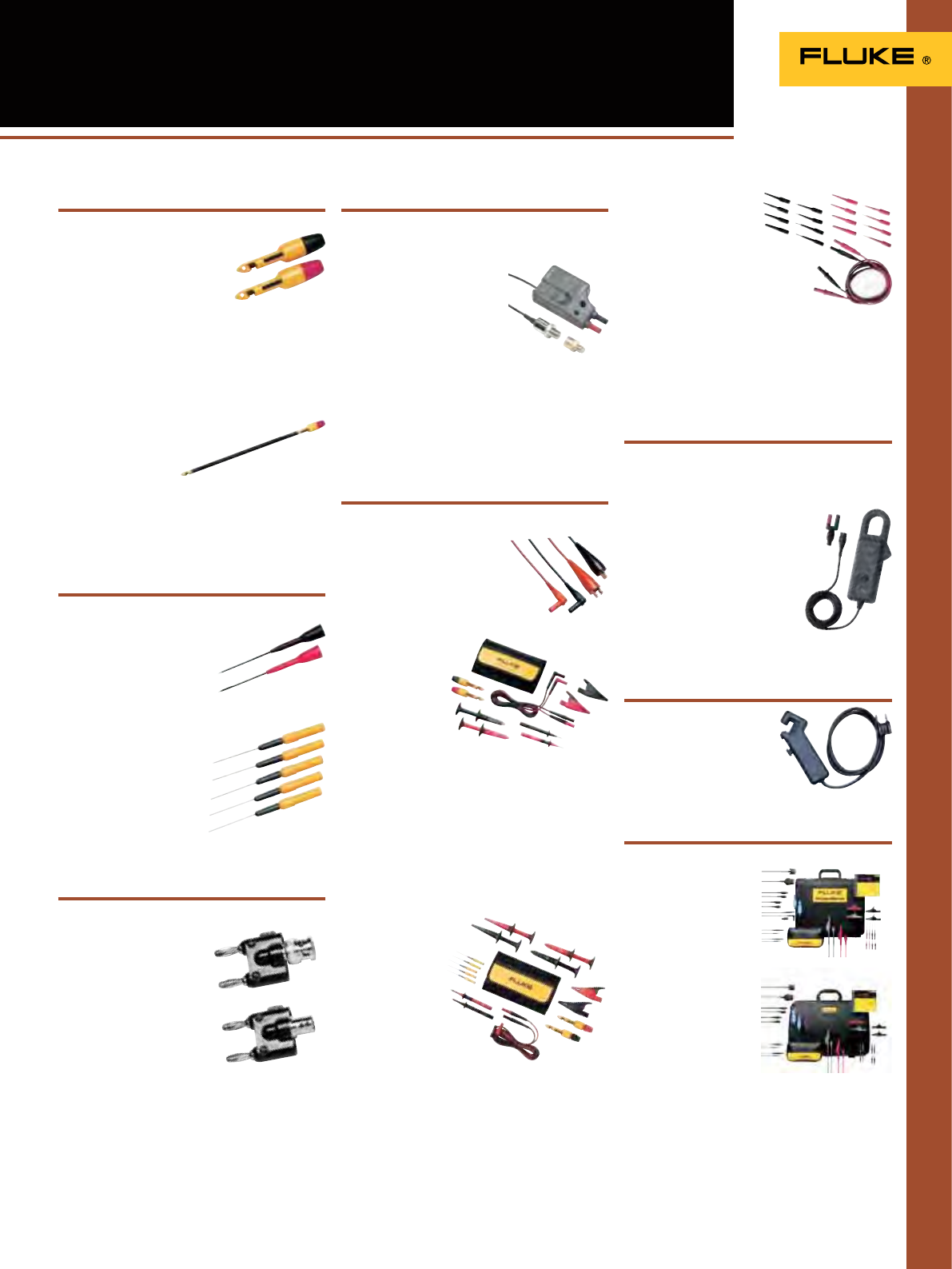
125
TP81 and TP82 Insulation Piercing
Clip Set
• Banana jack accepts all DMM
and banana jack leads
• Available for 4 mm input,
modular connection with
TP81 or available as a 2 mm input to
slip onto probe tips with the TP82
• Tested to 60 V DC
Automotive Accessories
TP84 Oxygen Sensor Insulation
Piercing Clip
• Banana jack accepts
all DMM and banana
jack leads (4 mm)
• Tested to 60 V DC
TP88 Rigid Back Probe Pin Set
• Slides onto test probes measuring
2 mm
• Tested to 60 V DC
TP40 Automotive Back
Probe Pins (five)
• Banana jack accepts all
DMM and banana jack
leads (4 mm)
• Tested to 60 V DC
BP880 BNC to Female Double
Stacking Banana Plug
BP881 BNC to Male
Double Stacking
Banana Plug
• Allows for hands-free
testing in controlled voltage
environments
500 VRMS maximum
• Banana plug is nickel-
plated, beryllium copper for
low contact resistance
• The BNC shell is plated for tarnish resistance
• Operating temperature +50°C maximum
TLK282-1 SureGrip™
Deluxe Automotive
Test Lead Kit
Kit contains:
• TP81 Insulation
Piercing Clip Set
• TP40 Automotive
Back Probe Pins
(five)
• TL224 SuregripTM
Silicone Test Lead Set
• TP238 SuregripTM Insulated Test Probe Set
• AC220 SuregripTM Alligator Clip Set
• AC285 SuregripTM Large Jaw Alligator
Clip Set
• AC280 SuregripTM Hook Clip Set
• Soft Case
PV350 Pressure Vacuum Module
• Compatible with all Fluke and most popular
DMMs
• Digital pressure and
vacuum measurements in
a single module
• Transducer sealed in 316
stainless steel compatible with
variety of liquids and gases
• Measures vacuum to 76 cm Hg
• Display results in English (psig or Hg) or
metric (kPa or cm Hg) units
• Measures pressure to 500 psig (3447 kPa)
TL28A Automotive
Test Lead Set
• Flexible silicone insulated
leads are heat and cold
resistant
• CAT I 30 V, 10 A
TLK281-1 SureGrip™
Automotive
Test Lead Kit
Kit contains:
• TP81 Insulation
Piercing Clip Set
• TL224 SuregripTM
Silicone Test Lead Set
• TP220 SuregripTM Test Probe Set
• AC220 SuregripTM Alligator Clip Set
• AC285 SuregripTM Large Jaw Alligator Clip Set
• Soft Case
TL 82 Automotive
Pin & Socket Adapter
Kit
This set of male and female
adapters allows you to make firm
connection to pin and socket
connectors.
Kit contains:
• Retractable shrouded test lead set
• Complete set of 8 pin-and-socket adapters
with flexible tips
• One red and black in different sizes
• Rated to 60 V DC
90i-610s AC/DC Current Probe (600 A)
• Current Range: 2 to 600A DC or AC Peak
• Basic Accuracy (DC to 400Hz):
± (2% of reading + 1A)
• Output Signal: 100A range:
10mV/A 600A range: 1mV/A
• Frequency Range: 40Hz to
400Hz
• Working Voltage: 600V
AC rms
• Maximum Conductor
Diameter: 34 mm
Piercing Clips
RPM80 Inductive
Pick-up
• Provides RPM readings
SCC128 Automotive
Accessory Kit
(120 Series)
Pressure Module
Probe Pins
Banana Plugs
Test Leads
Current Probe
Inductive Pick-up
ScopeMeter
Accessory Kits
SCC198 Automotive
Accessory Kit
(190 Series)
These kits provide a host of accessories
that allow you to easily and quickly make
measurements on automotive electronic
systems using a 120 or 190 Series ScopeMeter.
BP880
BP881
126
Current Clamps
i5s i50s i200 i200s i400 i400s
Nominal current range(s 5 A 3/30 AC RMS or DC 200 A 20 A
200 A 400 A 40 A
400 A
Continuous AC current range 0.01 A - 6 A 30 A cont. 50 A<10 sec 0.5 A - 200 A 0.1 - 24 A
0.5 A - 200 A 5 A - 400 A 0.5 - 40 A
5 A - 400 A
Highest current 70 A 30 A cont. 50 A<10 sec 240 A 240 A 1000 A 1000 A
Lowest measurable current 10 mA 10 mA 0.5 A 0.5 A 1 A 0.5 A
Basic accuracy (48-65 Hz) 1) 1% ± 5% typical DC
to 100 kHz 1% + 0.5 A 1.5% + 0.5 A 2% + 0.15 2% + 0.15
Useable frequency 40 Hz - 5kHz DC to 50 MHz 40 Hz - 10 kHz 40 Hz - 10 kHz 45 Hz - 3 kHz 45 Hz - 3 kHz
Max. working voltage 600 V AC 300 V AC RMS or DC 600 V AC 600 V AC 1000 V 1000 V
Maximum conductor diameter 15 mm 5 mm 20 mm 20 mm 32 mm 32 mm
Output level(s) 400 mV/A 1/100 mV/A 1 mA/A 100 mV/A
10 mV/A 1 mA /A 10 mV/A
1 mV/A
Batttery, battery life External Power
Output cable (m) 2.5 2 1.5 2.0 1.5 2.5
Shrouded banana plugs OO
BNC connector • OOO
BNC to banana adapter included O
Safety CAT III, 600 V CAT I 300 V CAT III. 600 V CAT III, 600 V CAT III 1000 V /
CAT IV 600 V CAT III 1000 V /
CAT IV 600 V
i800
i10000s i2000 flex i3000s flex-24
i3000s flex-36
i3000s i60000 flex-24
i6000s flex-36
Nominal current range(s) 800 A RMS 10 A
100 A
1000 A
20 A
200 A
2000 A
30 A
300 A
3000 A
30 A
300 A
3000 A
60 A
600 A
6000 A AC
Continuous AC current range 0.1 A - 800 A RMS 0.1 A - 10 A
0.1 A - 100 A
1 A - 1000 A
1 A - 20 A
2 A - 200 A AC RMS
30 A - 2000 A
1 A - 30 A
2 A - 300 A AC RMS
30 A - 3000 A
1 A - 30 A
1 A - 300 A
1 A - 2400 A
1 A - 6000 A AC RMS
Highest current 1500 A 2000 A 2500 A AC RMS 3500 A AC RMS 4000 A 6000 A
Lowest measurable current 0.1 A 0.1 A 1 A 1 A 1 A 1 A
Basic accuracy (48-65 Hz) 1) 0.10% 1% + 1 A 1% 1% 2% + 2 A ± 1% of range
Useable frequency 30 Hz - 10 kHz 5 Hz - 100 kHz 10 Hz - 20 kHz (-3dB) 10 Hz - 50 kHz (-3dB) 10 Hz - 100 kHz 10 Hz to 50 kHz
Max. working voltage 600 V AC RMS or DC 600 V AC 600 V AC RMS 600 V AC RMS 600 V AC 600 V AC RMS or DC
Maximum conductor diameter 54 mm 54 mm 178 mm Flex-24 178 mm
Flex-36 275 mm 64 mm Flex-24 170 mm
Flex-36 275 mm
Output level(s) 1 mA/A 100 mV/A
10 mV/A
1 mV/A
100 mV/A
10 mV/A
1 mV/A
100 mV/A
10 mV/A
1 mV/A
10 mV/A
1 mV/A
0.1 mV/A
50 mV/A
5 mV/A
0.5 mV/A
Batttery, battery life 200 hours 400 hours 400 hours
Output cable (m) 1.6 1.6 0.5 0.5 2.1 0.5
Shrouded banana plugs OO
n/a
BNC connector On/a OOO
BNC to banana adapter included n/a OOO
Safety CAT III, 600 V CAT III, 600 V CAT III, 600 V CAT III, 600 V CAT III, 600 V CAT III, 600 V
i5s i50s i200 i200s i400 i400s
i800 i1000s i2000 flex i3000s flex i3000s i6000s flex
Specifications AC models
1) Basic Accuracy: % reading + floorspec
1) Basic Accuracy: % reading + floorspec
127
Current Clamps
80i-110s i30 i30s i310s i410 i1010
Specifications AC/DC Models
* For specifications of 90i-610s see page 125
1 For DC only
2 Requires PM 9081 (see page 86)
3 Requires PM 9082 (see page 86)
4 115, 117 only
1) Basic Accuracy: % reading + floorspec
80i-110s i30 i30s i310s i410 i1010
Measurement type Hall sensor Hall sensor Hall sensor AC/DC Hall sensor Hall sensor
Nominal current range(s), 10 A, AC/DC
100 A, AC/DC 20 A AC RMS or DC 20 A AC RMS or DC 30/300 A AC RMS
or 45/450 A DC 400 A, AC/DC 600 A, AC
1000 A, DC
Continuous current range 0.1 A - 10 A AC/DC
1 A - 100 A AC/DC 30 A AC Peak 30 A AC Peak 100 mA - 300 A AC
RMS or 450 A DC 1 A - 400 A AC/DC 1 A - 600 A, AC
1 A - 1000 A, DC
Highest current 140 A - 2 kHz 30 A AC Peak 30 A AC Peak 300 A AC RMS or
450 A DC 400 A 1000 A
Lowest measurable current 0.1 A 50 mA 50 mA 100 mA 0.5 A 0.5 A
Basic accuracy 1) 3% + 50 mA (@ 10 A) ± 1% of reading ±2 mA ± 1% of reading ±2 mA ±1% of reading 3.5% + 0.5 A 2% +0.5 A
Useable frequency DC - 100 kHz DC to 20 kHz (-0.5dB) DC to 100 kHz (-0.5dB) DC to 20 kHz DC - 3 kHz DC - 10 kHz
Zero error adjustment
O
manual adjust via
thumbwheel manual adjust via
thumbwheel Manual
OO
Max. working voltage 600 V 300 V AC RMS 300 V AC RMS 300 V AC RMS or DC 600 V 600 V
Maximum conductor diameter 11.8 mm 19 mm 19 mm 19 mm 30 mm
2 x 25 mm 30 mm
2 x 25 mm
Output level(s) 100 mV/A
10 mV/A 100 mV/A 100 mV/A 10/1 mV/A 1 mV/A 1 mV/A
Battery, battery life 9 V, 55 h 30 hours typical 30 hours typical 30 hours 9 V, 60 h 9 V, 60 h
Output cable length (m) 1.6 1.5 2 2 1.6 1.6
Shrouded banana Plugs
O
n/a
OO
BNC connector
O
n/a
OO
BNC to banana adapter included n/a
OO
Safety CAT II, 600 V
CAT III, 300 V CAT III, 300 V CAT III, 300 V CAT III 300 V CAT III, 600 V CAT III, 600 V
Current Clamp Compatibility Chart
AC Models
i5s OOO
i200 4 OOOOOOOOOO O OO
i200s OOOOOOOOOOO OOOO OOO
i400 OOOOOOOOOO O OO
i400s 22222222222OOOOO 2 222
i430 flexi-TF O
i800 4 OOOOOOOOOO O OO
i1000s 22222222222O OOO 2 222
i2000 flex (new version) OOOOOOOOOOO 33333OOO
i3000s OOOOOOOOOOOOOOOOO OOO
i3000s flex OOOOOOOOOOOOOOOOO OOO
i6000s flex OOOOOOOOOOO O O OOO
113/114/115/116/117
175/177/179
187/189
233
287/289
27II / 28II
8845A/8846
8808A
77 IV
83V/87V
88V
43B
430 Series II
123/124
125
190 Series II / 225C/S
1577/1587
715
724
725
753/754
787
789
AC/DC Models
i30 OOOOOOOOOOO O OO
i30s OOOOOOOOOOOOOOOO
80i-110s 22222222222OOOOOO 222
i310s OOOOOOOOOOOOOOOOO OOO
i410 / i410 kit OOOOO OOOOO 333O111OOO
i1010 / i1010 kit OOOOOOOOOOO 333O111OOO
Other
90i-610s* 22222222222 OOO 2 222
All accessories have a one year warranty
i410 Kit AC/DC Current Clamp
(400A) with soft case
i1010 Kit AC/DC Current Clamp
(1000A) with soft case
• Combination of current clamp with
carrying case
• Zipped soft case with moveable
divider
• Soft case is large enough to hold a
meter
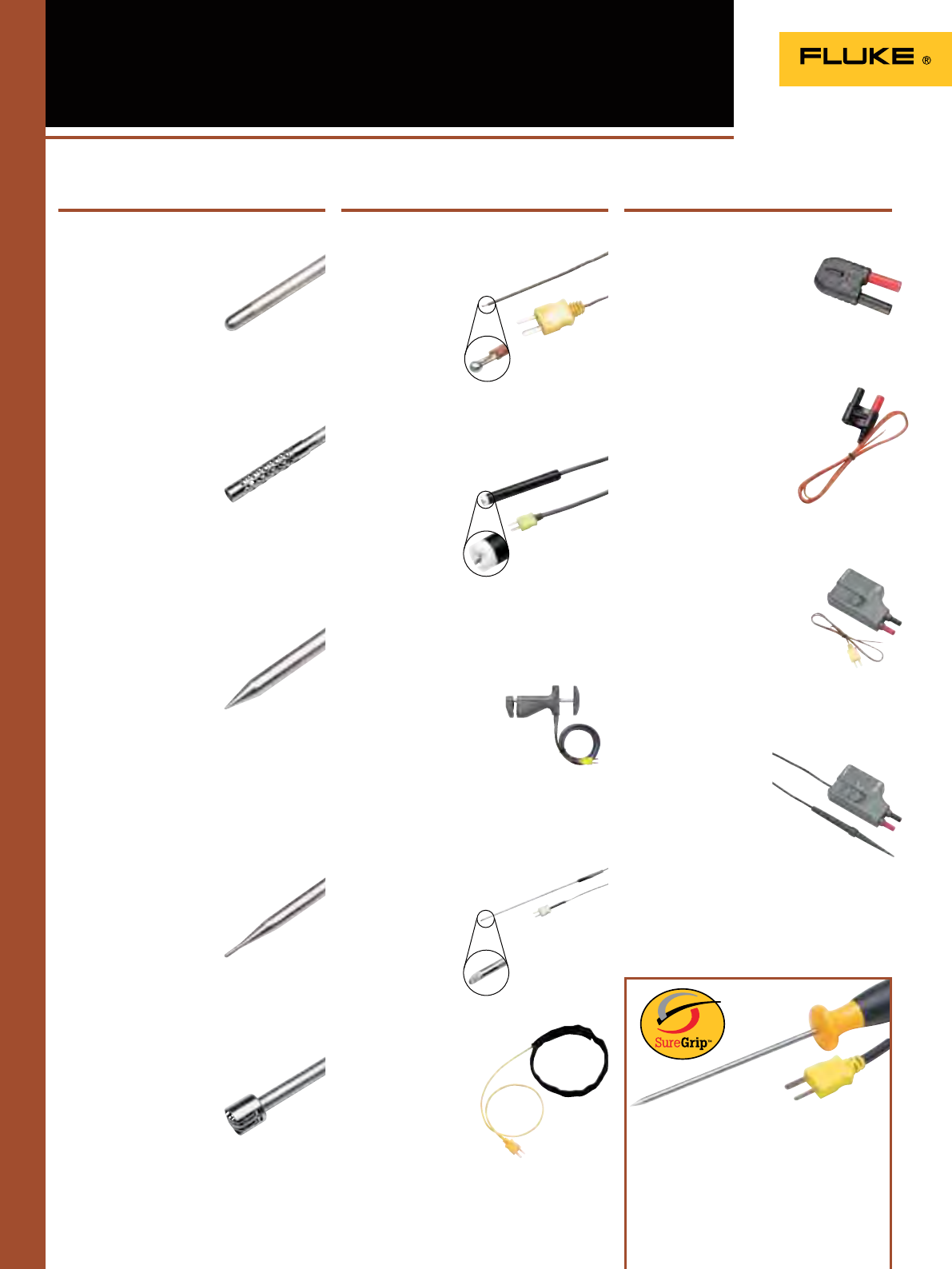
128
80PK-22 SureGrip™ Immersion Probe
• Type-K thermocouple for use in liquids
and gels
• Measurement range:
-40 to 1090°C
• Probe length: 21.3 cm
Temperature Accessories
80PK-24 SureGrip™ Air Probe
• Type-K thermocouple for use in
air and non-caustic gas measurements
• Bead protected by
perforated baffle
• Measurement range:
-40 to 816ºC
• Probe length: 21.6 cm
80PK-25 and 80PT-25 SureGrip™
Piercing Probe
• 80PK-25: Type-K thermocouple suitable for
food industry, liquids and gels
• 80PT-25 operates with T-type
thermometers
• Measurement range:
80PK-25: -40 to 350°C
80PT-25: -196 to 350°C
• Probe length: 10.2 cm
SureGrip™ accessories are designed to
improve steadiness in s lippery hands.
Rubber overmolded surfaces and finger-
hugging curves give the user a comfortable,
reliable grip on the accessory so they can
focus on making an accurate measurement.
80PK-26 SureGrip™ General Purpose
Probe
• Type-K thermocouple with tapered tip
for use in air, non-caustic gas and
surface applications
• Measurement range:
-40 to 816ºC
• Probe length: 21.2 cm
80PK-27 SureGrip™ Industrial Surface
Probe
• Type-K thermocouple for surfaces
in rugged environment
• Durable ribbon sensor
• Measurement range: -127
to 600°C
• Probe length: 20.3 cm
80PK-1 and 80PJ-1 Bead Probe
• 80PK-1: Type-K thermocouple for
general purpose applications
• 80PJ-1 operates with J-type
thermometers
• Measurement range:
-40 to 260°C
• Probe length:
1 m lead wire
80PK-3A Surface Probe
• Type-K thermocouple for flat or
curved surfaces such as
plates and rollers
• Measurement range:
0 to 260°C
• Probe length:
9.5 cm
80PK-8 / 80PK-10 Pipe Clamp
Temperature Probe
• Type-K thermocouple for
fast temperature and
superheat measurements
of pipe surfaces
• Durable ribbon sensor
• Measurement range:
-29 to 149°C for pipe diameters
from 6.4 to 34.9mm (80PK-8) and
32 mm to 64 mm (80PK-10)
80PK-9 and 80PJ-9 General
Purpose Probe
• 80PK-9: Type-K thermocouple surface,
air and non-caustic gases
• 80PJ-9 operates with
J-type thermometers
• Measurement range:
-40°C to 260°C
• Probe length:
15.3 cm
80PK-11 Velcro
Temperature Probe
• Type-K thermocouple
for hands free
measurement of
HVAC temperature
measuring
applications
• Total length of cable:
1m (0.5m in cable, 0.5m
in Velcro cuff insulation material; Hytrel)
• Measurement range: -30ºC to 105ºC
80AK-A Thermocouple Adapter
• Adapts Type-K thermocouple
mini-connector to dual banana
plug inputs
• Measurement range and
accuracy: probe dependent
• Suitable for low voltage applications
(below 30 V AC, 60 V DC)
80BK-A Integrated DMM
Probe
• Type-K thermocouple with
standard banana jack
• Convenient one piece
construction
• Compatible with DMMs
with temperature
measurement functions
• Measurement range:
-40 to 260ºC
Contact Probes
80TK Thermocouple Module
• Converts a DMM to
a thermometer
• For use with type-K
thermocouples in low voltage
applications (below
24 V AC, 60 V DC)
• Measurement range:
-50 to 1000°C (probe dependent)
80T-150UA Universal Temperature Probe
• Compatible with
Fluke DMM
• High accuracy, fast
reading for low voltage
(below 24 V AC, 60 V DC)
applications
• Measurement range:
-50 to 150°C
• Output: 1 mV/°C or 1 mV/°F (switchable)
DMM Probes
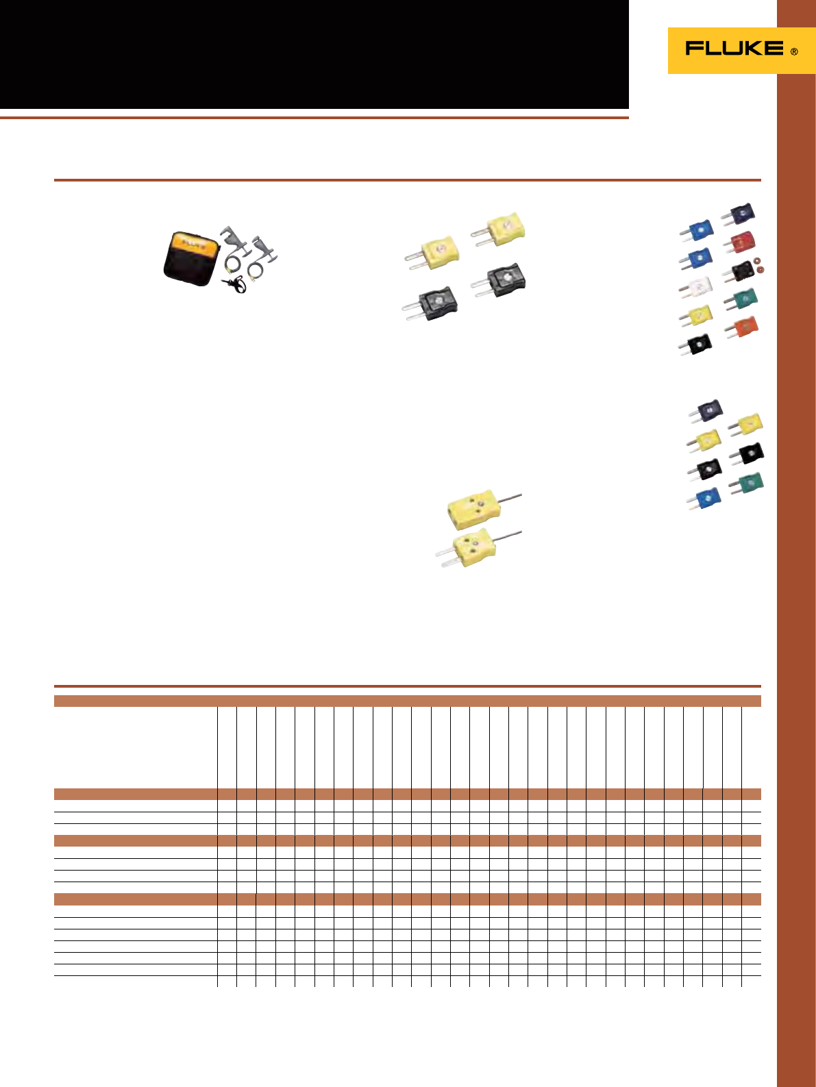
129
Temperature Accessories
Temperature Probe Compatibility Chart
1) Requires 80TK
2) Requires 80AK
3) Fluke 116 only
4) Also requires 80CK-M
Contact Probes
80PK-1 … 80PK-27 1122221112211112
OOO
1
O
1
OOO
11
80PJ-1, 80PJ-9
O O OOO
80PT-25 1
O O OOO
113/114/115/116/117
175/177
179
233
287/289
27II / 28II
8845A/8846A/8808A
77IV
83V
87V
88V
43B
120 Series
190 Series II /225C/S
1577
1587
51/52/53/54 II
561
566/568
66/68
705/707
714
715
724
725
753/754
787
789
All accessories have a one year warranty
DMM probes
80AK-A
O
3)
O
O
O
O
OO O
80BK-A
O
3)
O
O
O
O
OO O
80TK
O OOO OOOO O O OOO
80T-150UA
OO
O
O
O
OOO OOOO O O OOO
Miscellaneous
80CK-M 1122221112211112
OOO
1
O
1
OOO
11
80CJ-M
O O OOO
80PK-EXT4) 1122221112211112
OOO
1
O
1
OOO
11
80PJ-EXT
O O OOO
80PT-EXT
O O OOO
700TC1, 700TC2
O O OOO
80PR-60
O
80PK-18 Pipe Clamp Temperature
Probe Kit
• 80PK-8 Pipe Clamp
Temperature Probe
• 80PK-10 Pipe Clamp
Temperature Probe
• Soft Case
80CK-M & 80CJ-M type K & J Male
Mini-Connectors
• Isothermal screw
terminal for K or J
wire
• Suitable for up to
20 guage
thermocouple wire
• Color coded to
industry standards
(K-yellow, J-black)
• Two per package
Other Temperature Accessories
80PK-EXT, 80PJ-EXT and
80PT-EXT Extension Wire Kits
• Extending and repairing J, K ot T-type
thermocouple wires
• Kit includes 3 meters of thermocouple wire
and 1 pair of male/female mini-connectors
• Maximum continuous exposure temperature:
260ºC
• 80PK-EXT is compatible
with K-type thermometers,
80PJ-EXT is designed for
J-type thermometers and
PT-EXT for T-type
thermometers
700TC2
A kit of 7 mini-plug connectors
Type J (black), two
Type K (yellow), two
Type E (purple), one
Type T (blue), one
Type R/S (green), one
Thermocouple Plug Kits
700TC1
A kit of 10 mini-plug
connectors
Type J (black), one
Type K (yellow), one
Type T (blue), one
Type E (purple), one
Type R/S (green), one
Type B or CU (white), one
Type L (J-DIN) (blue), one
Type U (T-DIN) (brown), one
Type C (red), one
Type N (orange), one
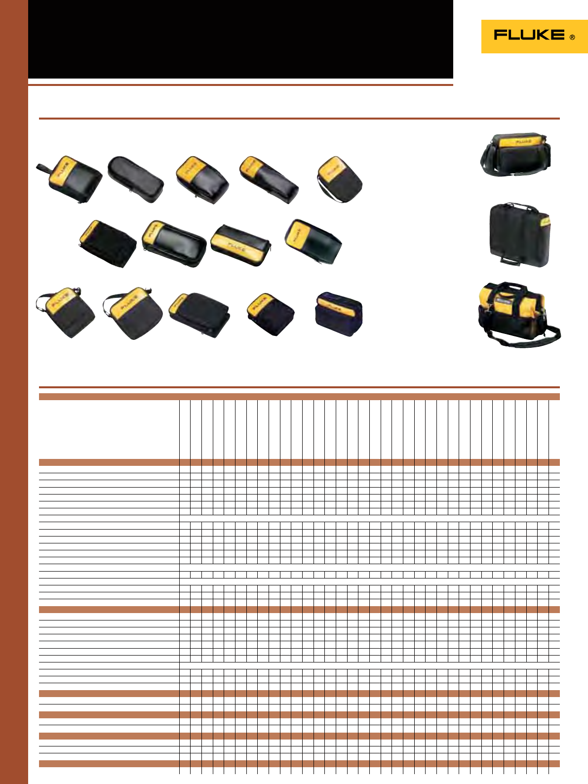
130
Cases and Holsters
Cases & Holsters Compatibility Chart
Soft Cases
C789
• Large fabric carrying case
with 3 compartments,
removable handle and
shoulder strap
C195
• Zipped carrying
case with storage
compartments
• Allows hand or
shoulder use
Zipped carrying cases protect your meter; most cases come with belt loops so your meter is
stored conveniently on your tool belt.
C550 Tool Bag
• Steel reinforced frame
• Rugged ballistic cloth
with heavy duty
hardware
• Large zippered storage
compartment with
25 pockets
• Weather resistant
• Carry all your tools to
the job
113/114/115/116/117
175/177/179
233
287/289
27II / 28II
77 IV
83V/87V/88V
T5
T50
T100 Series
321/322
333/334/335/336/337/902
353/355
1503/1507/1577/1587
9040/9062
1735/1740 Series
430 Series II
43B/120 Series
190 Series II
922
971
51/52/53/54 II
561
566/568
570 Series
61
63/66/68
705/707
712/714/715/717
718
724/725/726
753/754
787
789
Soft Cases Size (HxWxD) mm
C12A 172 x 128 x 38
O O
C23 225 x 95 x 58
OOOO OOO
C25 218 x 128 x 64
OO OO OO OOO O O OO
C33 280 x 115 x 55
OOO O
C35 220 x 140 x 65
OOO OOO O O O OO O
C43 318 x 230 x 90
OO OO
C50 192 x 90 x 38
O O
C75 179 x 103 x 26 For multiple test leads and accessories
C90 205 x 90 x 72
OO O
C115 240 x 205 x 75
OO OO O O O OOO O
C116 240 x 230 x 65
OOOOOOO O O O OO O
C125 192 x 141 x 58
O O O O OO OO
C195 231 x 513 x 231
OOO
C280 230 x 185 x 65
OOOOOOO O O O OOOO OO
C345 240 x 360 x 200 For multiple test leads and accessories
C437-II
OO
C550 333 x 513 x 231 For multiple test leads and accessories
C781 269 x 141 x 90
OOO O O OOO O
C789 308 x 256 x 77
O O OOO
C799 305 x 229 x 165
O
Leather Cases
C510 287 x 179 x 106
OOOO OOOOO
C520A 256 x 154 x 106
O
Holsters
C10 154 x 77 x 45
O
H80M 190 x 95 x 43
OO OO
Other
H3 231 x 90 x 64
OO
H5 192 x 90 x 38
O
H6 302 x 178 x 57
OO O
Hanging Kit (see page 132)
ToolPak
OOOOOOO O O O O O OO
C12A
C115
C23
C43
C116
C25
C50
C125/C781
C33
C75
C280
C35
C90
C345
Hard cases
C20 256 x 154 x 106
C100 397 x 346 x 122
OOOO OO
C101 305 x 360 x 105
OO O OO OOO OO OO O OOOO OO
C120 346 x 397 x 128
O
C290 410 x 474 x 135
O
C435 565 x 476 x 305
OO
C800 230 x 385 x 115
OO OOO OO
C1600 260 x 390 x 200 For multiple test leads and accessories
CXT80 28 x 32 x 13
OOO
CXT170 28 x 32 x 13
OOOOOOO
CXT280 28 x 32 x 13
O
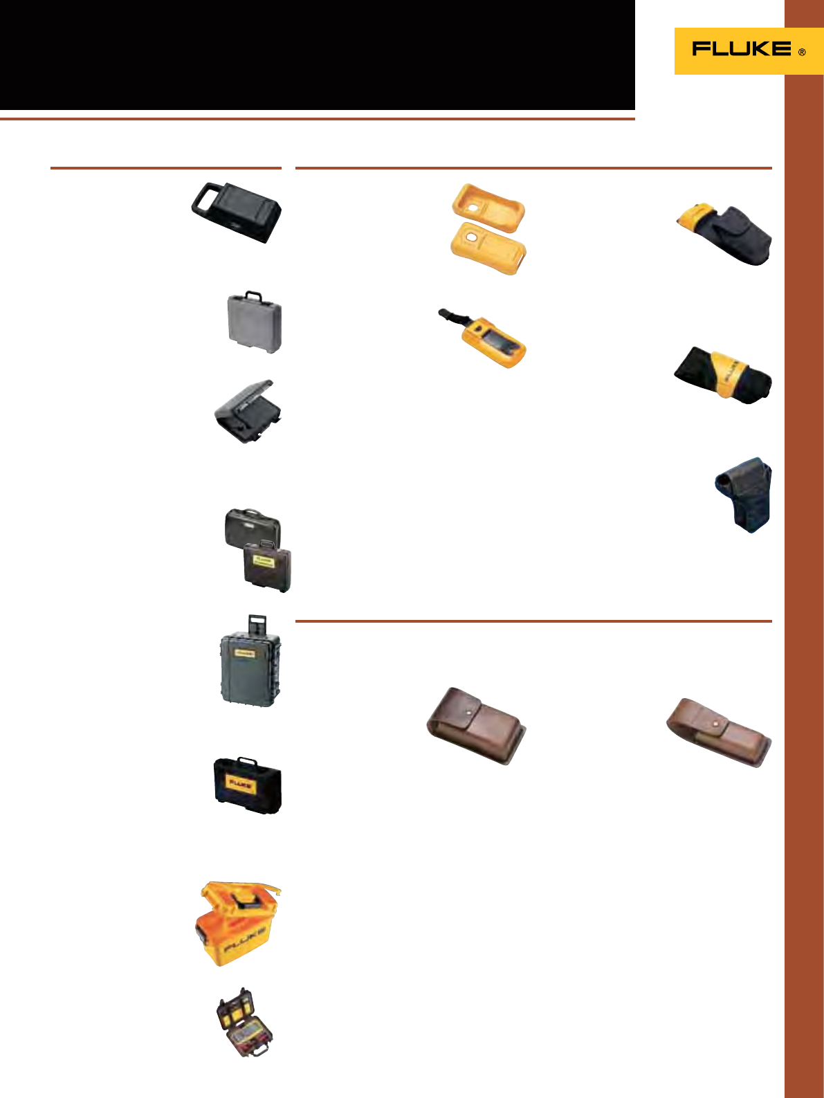
131
C20 Meter Case
• Heavy duty case with
carrying handle and
accessories storage
compartment
• Top cover snaps onto back to
serve as tilt stand
Cases and Holsters
C100 Meter and
Accessory Case
• Tough polyprophylene case
C101 Hard Case
The hard case that fits all Fluke
industrial test tools. Configure
the diced foam interior to store
and protect what you need to
carry with you.
• Tough polyprophylene exterior shell
• Interior cavity measures
C120 and C290 Cases
• Heavy duty cases with accessory
storage compartments
C435 Hard Rolling Case
• Watertight hard case
with rollers for 430 Series,
1735 and 1740 Series
Power Quality products and
accessories. The
configurable foam securely
holds any of these
instruments during transit.
C800 Meter and Accessory Case
• Tough polyprophylene case
• Accessories and manual
compartments
• Detachable lid
C10 Meter Holster
• Snap-on yellow holster
absorbs shocks and protects
meter from rough handling
• Includes built-in stand and
hanger loop
H80M Holster + Magnetic Hanger
• Snap-on yellow
holster absorbs shocks
and protects meter from
rough handling
• Magnet, hook and loop
straps
• General purpose hanger
C510 Leather Meter Case
• Oiled genuine top grain cowhide
• Rugged construction with heavy duty
stitching and reinforced rivets
• Large tool belt loop and
top flap to secure meter
• Holds most Fluke DMMs,
Thermometers, and
Process Calibrators
H3 Clamp Meter Holster
• Fabric holster absorbs
shocks and protects
meter from rough
handling.
• Built-in pocket for lead
storage
• Convenient belt-loop with snap
H5 Electrical Tester Holster
• Rugged fabric holster includes flap for lead
storage and built-in belt
loop
• Fits Fluke T3 and T5
testers
Hard Cases Holsters
H6 Infrared Thermometer Holster
• Durable nylon holster
• For Fluke 63, 66 and 68 Infrared
Thermometers
C520A Leather Tester Case
• Oiled genuine top grain cowhide
• Oil tanned for long life
• Rugged construction with heavy duty
stitching and reinforced rivets
• Large tool belt loop and
top flap to secure tester
• Holds Fluke Electrical
Testers
Leather Cases
All accessories have a one year warranty
C1600 Meter and Accessories Case
• Rugged molded plastic case
• Deep interior large enough to hold
and protect your tools
• Lift out tray keeps
everything organized
• Snap open compartment
on top of lid
CXT80, CXT170, CXT280 Rugged Pelican
Hard Case
• Unbreakable, watertight,
airtight, dustproof, chemical
resistant and corrosion proof
case
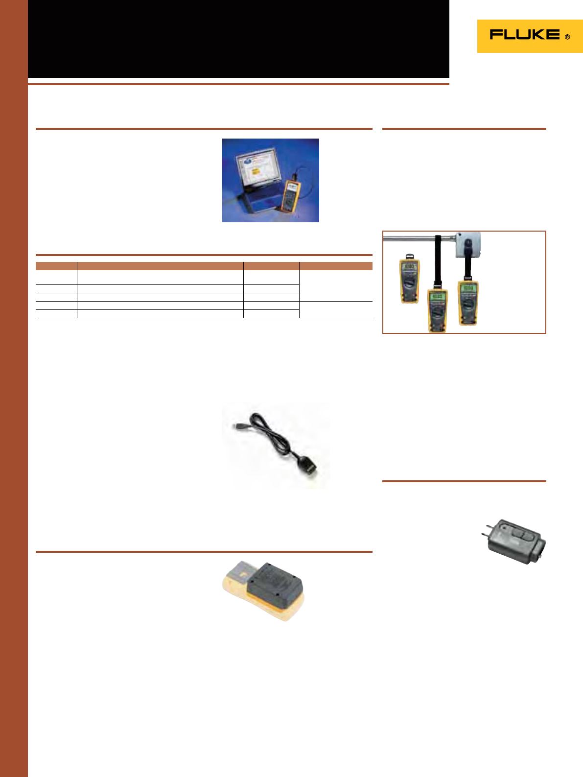
132
FlukeView Forms increases the power of your
Fluke tool by enabling you to document, store
and analyze individual readings or series
of measurements, then convert them into
professional-looking documents. FlukeView
Forms supports the following multimeters:
Software and other Accessories
IR189USB
IR to USB interface cable
(included with FVF-SC2 and FVF-Basic)
• For customers who want to upgrade from
their existing RS232 cable
• Small adapter to connect the cable to the 189,
287, 289, 1653B or the 1550B is included.
BP189 High Capacity Battery Enclosure
(for Fluke 180 Series DMM)
• Expand the battery life of your Fluke
187/189 up to 450 hours (over two weeks of
continuous use).
• Houses 4 ‘C’ cell batteries.
• CAT III 1000 V, CAT IV 600 V
Batteries and meter sold separately
ToolPak (TPAK)
The meter hanging solution
• Kit includes, universal hanger clips (2), hook
& loop straps (2 lengths) and strong magnet
• Combine components to meet most hanging
needs
See page 130 for compatibility chart
Hanging Kit Software FlukeView® Forms
FOM Fiber Optic Meter
The Fluke Fiber Optic Meter (FOM) helps you
test and maintain fiber optic cables without
having to buy a whole new
meter. Plug the FOM
directly into any DMM with
a mV dc function and a
10 M input impedance and
quickly and accurately
verify fiber optic cable system loss. Light
sources and patch cords sold separately.
FOS 850 & FOS 850/1300
Fiber Optic Light Sources
A variety of light sources allow you to test
different cable lengths.
All accessories have a one year warranty
FlukeView Forms Compatibility Chart
Make extended logging easier
Fiber Optics
FVF Option Instrument Cable** Application Level
FVF-UG Software only upgrade, Any instrument that supports
Flukeview Forms Software No Cable included FVF Full
(includes Designer)
FVF-SC2 Fluke 280 Series, 789, 1550B, 1653B, 568,180 Series*, 53B, 54B USB / IR
FVF-SC4 Fluke 8808A, 8845A, 8846A, 45*, 975 USB / Serial
FVF-BASIC Fluke 280 Series, 789, 1550B, 1653B, 180 Series* USB / IR FVF BASIC
FVF-SC5 8808A, 8845A, 8846A, 45* USB / Serial
* Obsolete
** USB cables are not supported for Microsoft Windows NT 4.0
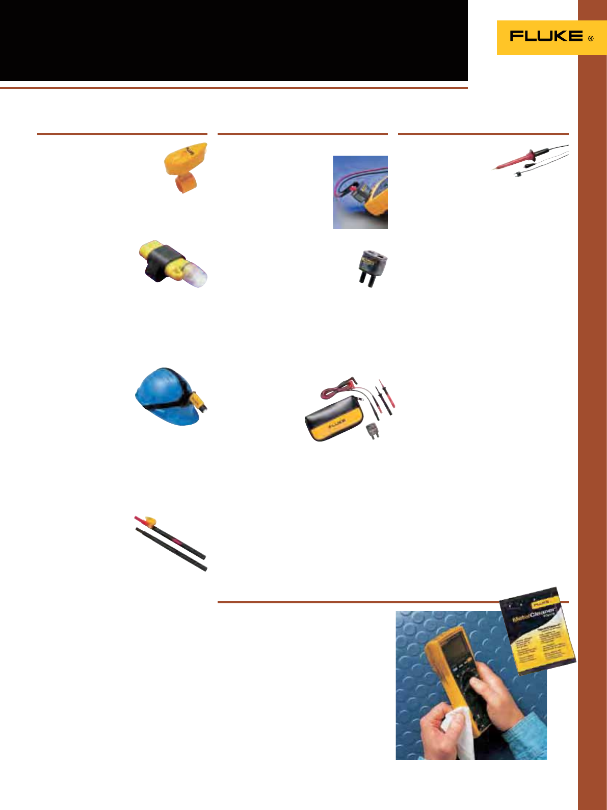
133
L200 Probe Light
• Attaches to any Fluke test probe
• Bright white LED
• 120 hours of battery life
Other Accessories
L205 Mini Hat Light
Rugged high-intensity
Xenon worklight
• Attaches to a baseball cap
• Includes a hat clip
• Includes two AAA
batteries
• Waterproof
L206 Deluxe LED Hat Light
(hard hat not included)
Attach it to a hard hat,
a baseball cap, or even a
panel door for all the light
you need.
• 3 super bright white LEDs
– never burn out
• Special hard-hat attachment included
• 40-hour battery life
• Includes three AAA batteries
L210 Probe Light +
Probe Extender
• Includes L200 Probe Light
and TP280 Test Probe
Extenders
• 20 cm probe extenders
keep hands away from
live circuits
• Extender fits between modular test probe
and test lead (total reach 30 cm)
MC6 MeterCleaner™ Wipes (6-pack)
MC50 MeterCleaner™ Wipes
(50-pack)
• Pre-moistened wipe removes dirt, oil and
grease
• One wipe easily cleans one meter
• Safe on rubber, plastic and for environment
(non-toxic)
SV225 Stray Voltage Adapter
Stray voltage can appear in
electrical installations, due to
the capacity between wires.
This may result in erroneous
readings on high impedance
meters.
The SV225 solves this without
compromising safety.
• On energized wires, the meter will indicate
the real voltage.
• On non-energized circuits the meter
will read close to zero (even if there
are stray voltages).
• It can be used with all modern
meters with standard input spacing.
• Rated CAT III 1000 V, CAT IV 600 V
TL225-1 SureGrip™ Stray Voltage Adapter
Test Lead Kit
Kit includes:
• SV225 Stray Voltage
Eliminator
• TL224 SureGrip™
Silicone Test Lead Set
(right to straight)
• TP238 SureGrip™
Insulated Test Probe Set
• C75 Accessory Case
Lights Stray Voltage Adapter
80K-6 and 80K-40
A high voltage probe that
allows a multimeter to
measure up to 6,000V or
40,000V respectively.
Intended for low energy applications only
High Voltage Probes
All accessories have a one year warranty
Meter Cleaners
134
Fuse and Warranty Information
AVIR
Size
in mm
Part nr
qty 1
63mA (slow) 250V 6.35x32 163030
125mA (slow) 250V 6.35x32 166488
250mA (slow) 250V 6.35x32 166306
315 mA 1000V 10KA 6.35x32 2279339
440mA 1000V 10kA 10.3x34.9 943121
500mA 250V 1500A 5x20 838151
630mA 250V 1500A 5x20 740670
1A 600V 10kA 10.3x34.9 830828
1A 500V 50kA 6.35x 32 2530449
1.25A 600V 6.35x32 2040349
3.15A 500V 6.35x32 2030852
11A 1000V 17kA Replaced by 11A, 1000V, 20kA fuse; 803293
11A 1000V 20kA 10.3x38.1 803293
15A 600V 100kA 10.3x38.1 892583
20A 600V Replaced by 15A, 600V, 100kA fuse; part nr. 892583
See the back of your Fluke test tool or user manual for the fuses installed.
For manuals check the Fluke website in the product section.
For Fuse Replacement Guide check the Fluke website in the service section.
Fuse Replacement Information
Product Warranty
Service
Each Fluke product is warranted to be free from defects
in material and workmanship under normal use and
service, for the warranty period listed unless local law
requires a longer period. The warranty period is listed
in the ordering information section of the product
specification and begins on the date of shipment.
This warranty extends only to the original buyer or
end-user customer of a Fluke authorized reseller, and
does not apply to fuses, disposable batteries or to any
product which, in Fluke’s opinion, has been misused,
altered, neglected or damaged by accident or abnormal
conditions of operation or handling. Fluke warrants that
software will operate substantially in accordance with its
functional specifications for 90 days and that it has been
properly recorded on non-defective media. Fluke does
not warrant that software will be error free or operate
without interruption.
Lifetime Warranty
Each Fluke 20, 70, 80, 170, 180 and 280 Series DMM
purchased after October 1, 1996 will be free from defects
in material and workmanship for its lifetime. This
warranty does not cover fuses, disposable batteries and
damage from accident, neglect, contamination, misuse or
abnormal conditions of operation or handling, including
overvoltage failures caused by use outside the DMM’s
specified rating, or normal wear and tear of mechanical
components. This warranty covers the original purchaser
only and is not transferable. For ten years from the
date of purchase, this warranty also covers the LCD.
Thereafter, for the lifetime of the DMM, Fluke will replace
the LCD for a fee based on then current component
acquisition costs.
To establish original ownership and prove date of
purchase, please complete and return the registration
card accompanying the product.
Fluke will, at its discretion, repair at no charge, replace
or refund the purchase price of a defective product
purchased through a Fluke authorized sales outlet and at
the applicable international price. Fluke reserves the right
to charge for importation costs of repair/replacement
parts if product purchased in one country is sent for
repair elsewhere.
Send defective product with a description of the
problem to the nearest Fluke Authorized Service Center,
postage and insurance prepaid. Fluke will pay return
transportation for product repaired or replaced in-
warranty. Before making any non-warranty repair, Fluke
will estimate cost and obtain authorization, then invoice
you for repair and return transportation.
THIS WARRANTY IS YOUR ONLY REMEDY. NO OTHER
WARRANTIES, SUCH AS FITNESS FOR A PARTICULAR
PURPOSE, ARE EXPRESSED OR IMPLIED. FLUKE IS NOT
LIABLE FOR ANY SPECIAL, INDIRECT, INCIDENTAL OR
CONSEQUENTIAL DAMAGES OR LOSSES, INCLUDING
LOSS OF DATA, ARISING FROM ANY CAUSE OR THEORY.
AUTHORIZED RESELLERS ARE NOT AUTHORIZED TO
EXTEND ANY DIFFERENT WARRANTY ON FLUKE’S
BEHALF.
Since some states do not allow the exclusion or
limitation of an implied warranty or of incidental or
consequential damages, this limitation of liability may
not apply to you.

135

136

© Copyright 2012, Fluke Corporation.
A
ll rights reserved.
P
r
i
nted
i
n the Netherlands, 01
/
1
2
D
ata subject to alteration without notice
.
P
ub_ID: 11882-eng
Fl
u
k
e
.
K
eep
i
ng your worl
d
up
and runnin
g.
®
F
luke Cor
p
orat
i
o
n
P.O.
B
o
x
9090
E
verett, WA USA 9820
6
W
eb
:
www
.
fluke
.
co
m
F
luke Euro
p
e B.V
.
P.O.
B
o
x 11
86
560
2 BD Ein
d
h
o
v
en
Th
e
N
et
h
e
rl
a
n
ds
W
eb
:
www
.f
luke
.
e
u
F
or more information call
:
In the U.S.A.
(
800
)
443-585
3
or Fax
(
425
)
446-511
6
In Europe/M-East/AFrica +31
(
0
)
40 2 675 200
)
or Fax +31 (0)40 2 675 22
2
In Canada (905) 890-760
0
or Fax
(
905
)
890-686
6
F
rom other countries +1
(
425
)
446-550
0
or Fax +1
(
425
)
446-511
6
F
luke
(
UK
)
Ltd.
5
2 Hurricane Wa
y
Norwich
N
o
r
fo
l
k
NR
6
6
J
B
U
nited Kin
g
do
m
Tel.:
(
020
)
7942 0700
F
ax.:
(
020
)
7942 070
1
E
-ma
i
l:
i
ndustr
i
al@uk.
uke.n
l
W
eb
:
www
.
fluke
.
co
.
u
k
