QS Sensor Module (QSM) SPEC 369242 Brochure
2016-10-06
: Pdf 168831-Brochure 168831-Brochure B5 unilog
Open the PDF directly: View PDF ![]() .
.
Page Count: 6
®
SPECIFICATION SUBMITTAL Page
Job Name:
Job Number:
Model Numbers:
QS Sensor Module QSM Sensor Interfaces
369242k 1 12.22.15
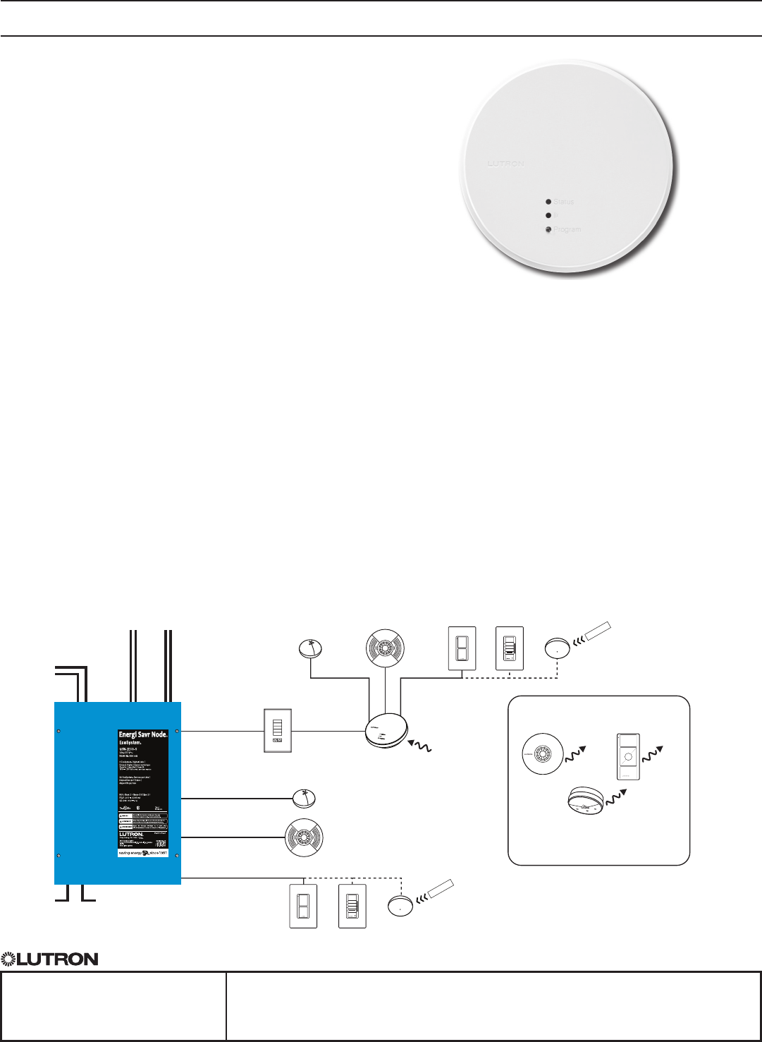
QS Sensor Module
The QS Sensor Module (QSM) is a ceiling-mounted
device that integrates LutronR wireless and wired sensors
and controls through the QS communication link to
Energi Savr NodeTM (ESN) units, GRAFIK EyeR QS
control units, QuantumR systems, SivoiaR QS
shades / draperies, and myRoomT control modules.
Features
• UsesClearConnectR RF Technology for communication
with Radio Powr SavrTM occupancy sensors, Radio
Powr SavrT daylight sensors, and PicoR wireless
controllers.
• QSMconnectstofourLutronR wired sensors or
controls—occupancy sensors, daylight sensors,
EcoSystemR infrared (IR) receivers, or EcoSystemR
wallstations. Does not apply to wireless only models.
• PoweredbytheQSlink—nolinevoltageconnectionsare
required.
• ContactLutronforcompatibilitydetailswiththe
QuantumR system.
• CompatiblewiththeentireESN product family:
— Allows LutronR wired occupancy sensors, daylight
sensors, EcoSystemR wall stations, EcoSystemR
IR receivers, PicoR wireless controllers, Radio Powr
SavrT wireless occupancy sensors and daylight
sensors to control ESN units.
• CompatiblewithGRAFIK EyeR QS control units.
— GRAFIK EyeR QS control unit models starting
with QSGR.
— Allows LutronR wired or Radio Powr SavrT wireless
occupancy sensors and daylight sensors linked to a
QSM to control the GRAFIK EyeR QS control unit.
—ContactLutronforcompatibilitywithPicoR wireless
controllers, EcoSystemR wallstations, and EcoSystemR
infrared (IR) receivers.
• CompatiblewithSivoiaR QS shades / draperies.
— Allows PicoR wireless controllers to control SivoiaR QS
shades / draperies (QSM models with wireless inputs
only).
• CompatiblewithmyRoomT power modules.
— Allows Lutron wired & wireless occupancy sensors to
control power modules.
— Allows PicoR wireless controls to control power
modules.
System Example
LUTRON
LUTRON
QS link
ControlPower
120-277 V~
Emergency
Contact
Closure
Input
Programmable
Contact
Closure
Input
Wireless
Communication
Wired Daylight
Sensors (up to 4) 2
Wired
Daylight
Sensors
(up to 4) 1,2
EcoSystemR
Digital Links
(upto64ballastseach)
Wired Occupancy
Sensors (up to 4)
Wired
Occupancy
Sensors
(up to 4) 1
Wired EcoSystemR
Wallstation or
IR receivers
(up to 4)
Wired EcoSystemR
Wallstation
or IR receivers
(up to 4) 1
QSM
IR Transmitter
IR Transmitter
OR OR
OR OR
seeTouchR QS Wallstation
Radio Powr SavrTM
Occupancy Sensor
(up to 10 per QSM)
Radio Powr SavrT
Daylight Sensor
(up to 10 per QSM)
Pico® Wireless
Controller(upto
10 per QSM)
Apple, iPhone, and iPod touch are trademarks of
AppleInc.,registeredintheU.S.andothercountries.
Notes:
1 Upto4wiredinputstotal(ofanytype).
2 Upto16wireddaylightsensorstotal
per EcoSystemR link.
1
®
SPECIFICATION SUBMITTAL Page
Job Name:
Job Number:
Model Numbers:
QS Sensor Module QSM Sensor Interfaces
369242k 2 12.22.15
Models
Frequency/ChannelCode*
NumberofWiredInputs
QSMX-XW-X
Frequency/ChannelCode*
2—431.5-436.6MHz U.S.A.,CanadaandMexico
3—868.1-869.8MHz EuropeanUnionandUnitedArabEmirates
4—868.1-868.5MHz SingaporeandChina
5—865.5 - 866.5 MHz India
7—433.0 - 434.7 MHz Hong Kong
X—No RF
*ContactLutronforfrequency/channelcodecompatibilitywith
yourparticulargeographicregionifitisnotindicatedabove.
NumberofWiredInputs
4—4
X—None
Mounting Method
C—CeilingMount
J—JunctionBoxCeilingMount
Availability/Compatibility
RefertothechartbelowtodetermineQSMmodelavailabilityand
compatibilitywithdifferentsensormodels.
LutronR Radio Powr SavrT
Models
Available Occupancy / Vacancy Sensors
Daylight
Sensors *
LutronR PicoR
Wireless Controllers
QSM2-4W-C
QSM2-XW-C
QSM2-4W-J
QSM2-XW-J
LRF2-OCRB-P, LRF2-OHLB-P,
LRF2-OKLB-P, LRF2-OWLB-P,
LRF2-VHLB-P, LRF2-VKLB-P,
LRF2-VWLB-P, LRF2-OCR2B-WH,
LRF2-VCR2B-WH
LRF2-DCRB MRF2-3BRL, MRF2-3B,
MRF2-2BRL, MRF2-2B,
QSR4P-3R,
PJ-2B-Gxx-xxx,
PJ-2BRL-Gxx-xxx
PJ-3B-Gxx-xxx
PJ-3BRL-Gx-xxx
QSM3-4W-C
QSM3-XW-C
LRF3-OCRB-P LRF3-DCRB QSRKP-2, QSRKP-2R,
QSRKP-3R
QSM4-4W-C
QSM4-XW-C
LRF4-OCRB-P LRF4-DCRB QSRMP-2, QSRMP-2R,
QSRMP-3R
QSM5-XW-C LRF5-OCRB-P LRF5-DCRB QSRNP-2, QSRNP-2R,
QSRNP-3, QSRNP-3R
QSM7-4W-C
QSM7-XW-C
LRF7-OCR2B-P LRF7-DCRB QSRQP-2, QSRQP-2R
QSRQP-3, QSRQP-3R
QSMX-4W-C N/A N/A N/A
Mounting Method
*Daylightsensorscan'tbeusedaspartofmyRoomT solutions.
2

®
SPECIFICATION SUBMITTAL Page
Job Name:
Job Number:
Model Numbers:
QS Sensor Module QSM Sensor Interfaces
369242k 3 12.22.15
Specifications
QS Sensor Module (QSM)
Power
•24–36V
•Currentdraw:
max400mA(modelswithwiredinput)
max100mA(modelswithoutwiredinput)
•PowerDrawUnits:(PDU)
RefertotheQSLinkPowerDrawUnitsspecication
submittal(LutronR P/N 369405) for information concerning
PDUsontheQSLink.UseonlyLutronR approved power
sources.
•10-yearpowerfailurememory:restoressettingsand
programming after power interruption.
Regulatory
•LutronR Quality Systems registered to ISO 9001.2008.
QSM2 –
•cULUSListed(USAandCanada).
•
FCCCompliant.ComplieswiththelimitsforaClassB
digitaldevice,persuanttoPart15oftheFCCRules(USA).
•ICCertied.(Canada).
•SCTCertied(Mexico).
QSM3 –
•CEMarked(EuropeanUnion).
•TRATypeApproved(UnitedArabEmirates).
QSM5 –
•WPCTypeApproved(India).
QSM7 –
•
FCCCompliant.ComplieswiththelimitsforaClassB
digitaldevice,pursuanttoPart15oftheFCCRules(USA).
Environment
•AmbientTemperatureOperatingRange:32ºFto104ºF
(0ºCto40ºC).
•Relativehumidity:lessthan90%non-condensing.
•Forindooruseonly.
Terminals
•Inputwiring:22AWGto12AWG(0.5mm2 to 4.0 mm2)
•QSlinkwiring:22AWGto12AWG(0.5mm2 to 4.0 mm2)
Mounting
•QSM units shouldbemountedinthemiddleofnon-
metalceilingtileordrywall,visiblefrominsidethespace.
•InstallationnearmetalotherthanaJunctionBoxmay
reduce RF range.
Wireless Communication
(models with wireless inputs only)
•RFRange:60ft(18m)lineofsight,or30ft(9m)
through typical construction materials.
•Toensureoptimalwirelessrange,installtheQSMin
theceilinginavisiblepositionfrominsidethespace.
•LutronR Radio Powr SavrTM Occupancy sensor
(up to 10)
•LutronR Radio Powr SavrT daylight sensor (up to 10)
•LutronR PicoR wireless controllers (up to 10)
Wired Inputs
•Thereare4universalwiredinputs.Eachinputcan
accept one of the following:
- LutronR EcoSystemR wallstations
- LutronR occupancy sensors (LOS- series)
- LutronR daylightsensors(EC-DIR-series)
- LutronR EcoSystemRinfrared(IR)receivers(EC-IR,
EC-DIR-series)
- LutronR Wired PicoR Controls
•Useofboththeinfraredreceiveranddaylightsensor
ontheEC-DIR-seriessensorsisconsideredtwo
wired inputs on a QSM
•Maximumwiringdistance=150ft(46m)
•Onlywired(LOS-series)andwirelessoccupancy
sensorsmaybeusedinmyRoomT; no EcosystemR
wallstations, daylight sensors, EcosystemR IR
receivers or wired PicoR controls
QS Link Limits
•The QS link can have up to 100 devices.
•EachQSMcountsas1devicetowardsthe
100 device limit.
•EachQSMdraws3PowerDrawUnits(PDUs)on
the QS link.
•WiredsensorsaddtothePDUdrawofaQSM.
RefertotheQSLinkPowerDrawUnitsspecication
submittal(LutronR P/N 369405) for information
concerningPDUs.
•QSlinkmaximumwirerunlengthis2000ft(610m).
•Seethecommercialsystemrulesspec(P/N369821)
forsystemspeciclimitations.
3
®
SPECIFICATION SUBMITTAL Page
Job Name:
Job Number:
Model Numbers:
QS Sensor Module QSM Sensor Interfaces
369242k 4 12.22.15
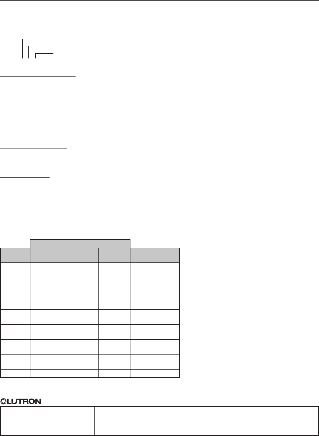
Mechanical Dimensions (All Models)
Front View Side View Back View
(QSM2-4W-Cshown)
Mounted (-C Models) Mounted (-J Models)
1.17 in
(30 mm)
Ceilingthicknessrangefor-Cmodels
Min 0.30 in (8 mm)
to
Max1.20in(30mm)
Ceiling Ceiling
4.04 in
(103 mm)
UseappropriateMudRingforceilingtilethickness
UseMudRingwithhole
spacingshownbelow.
(Mud Ring not included with
any QSM models)
Ceiling Ceiling
2.75 in (70 mm)
4
®
SPECIFICATION SUBMITTAL Page
Job Name:
Job Number:
Model Numbers:
QS Sensor Module QSM Sensor Interfaces
369242k 5 12.22.15
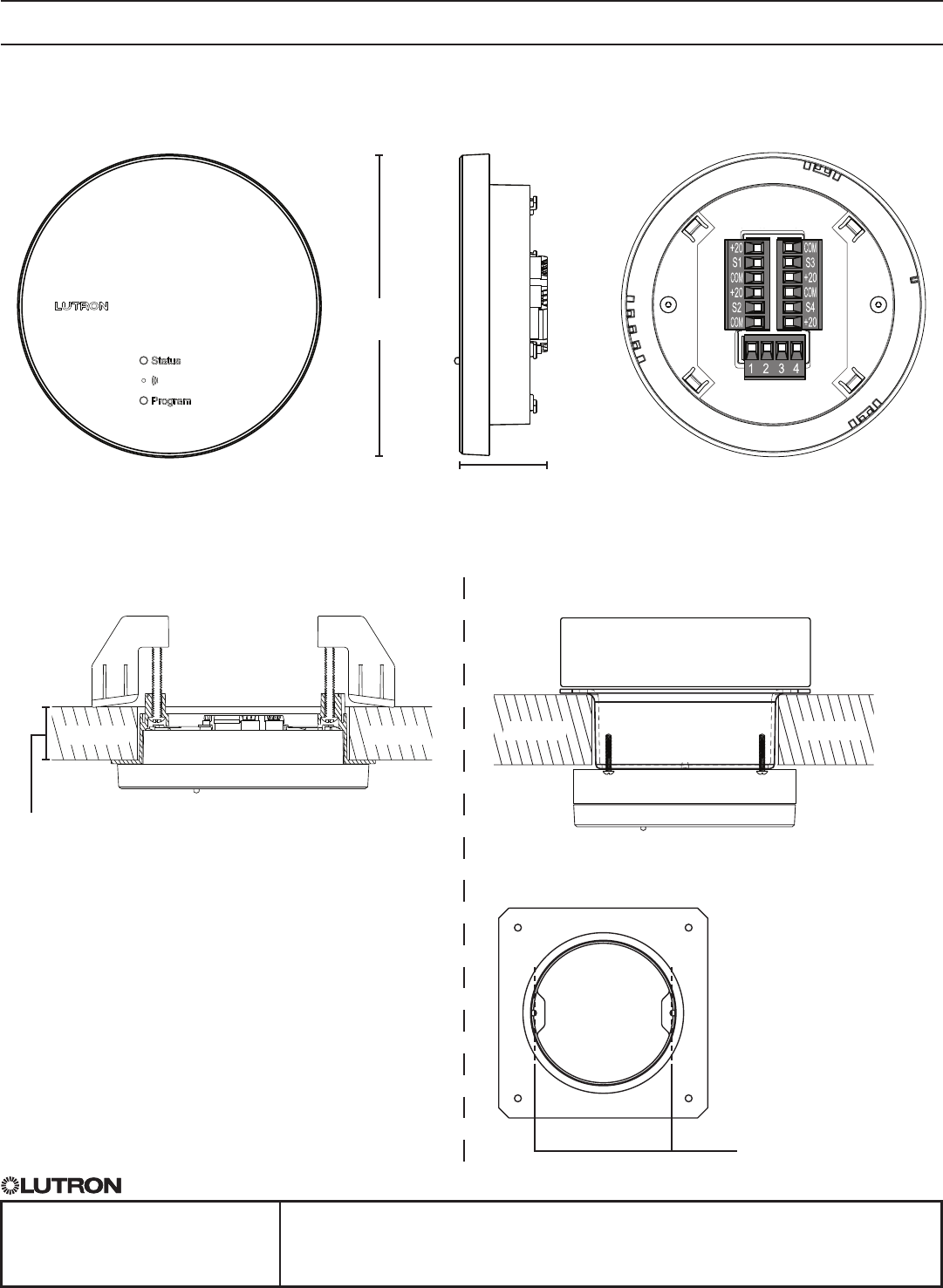
Wiring: QS Link and Wired Inputs1
Input 11,2,3
Daylight sensor
EcoSystemR
infrared (IR) receiver
Occupancy sensor
EcoSystemR
wallstation or
PicoRWiredControls
22 AWG to 14 AWG
(0.5 mm2 to 2.0 mm2)
Lutron®Cable
Standard:C-CBL-522S-WH-1
Plenum:C-PCBL-522S-CL
Max.WiredInputwire
length 150ft (46m)
per input
22 AWG to 14 AWG
(0.5 mm2 to 2.0 mm2)
Lutron®Cable
Standard:C-CBL-522S-WH-1
Plenum:C-PCBL-522S-CL
Max.WiredInputwire
length 150ft (46m)
per input
22 AWG to 14 AWG
(0.5 mm2 to 2.0 mm2)
Max.QSlinkwire
length 2000ft (610m)
Input 31,2
Input 21,2
QS
Link
Input 41,2
Common
V+
MUX
MUX
Red+20–20V
+20–20V
+20–20V
+20–20V
BlackCOM–Common
COM–Common
COM–Common
COM–Common
YellowS1–SignalS2–Signal
S4–Signal S3–Signal Blue or Gray
Black
Red
Red
Red
Black
Black
White
White
1 Only on QSM models with wired inputs.
2 Note: Forreferenceonly.Eachinputisuniversalandcanacceptanyoftheinputsshownabove.
3OnlydaylightsensorsignalconnectedtoQSMshownabove.UseofIRsignalcountsasan
additional input on the QSM.
Back View
(QSM2-4W-Cshown)
5
®
SPECIFICATION SUBMITTAL Page
Job Name:
Job Number:
Model Numbers:
QS Sensor Module QSM Sensor Interfaces
369242k 6 12.22.15
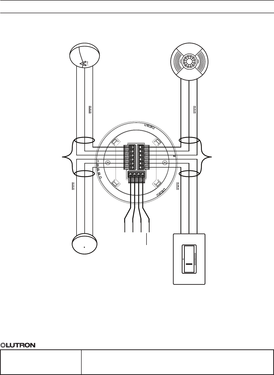
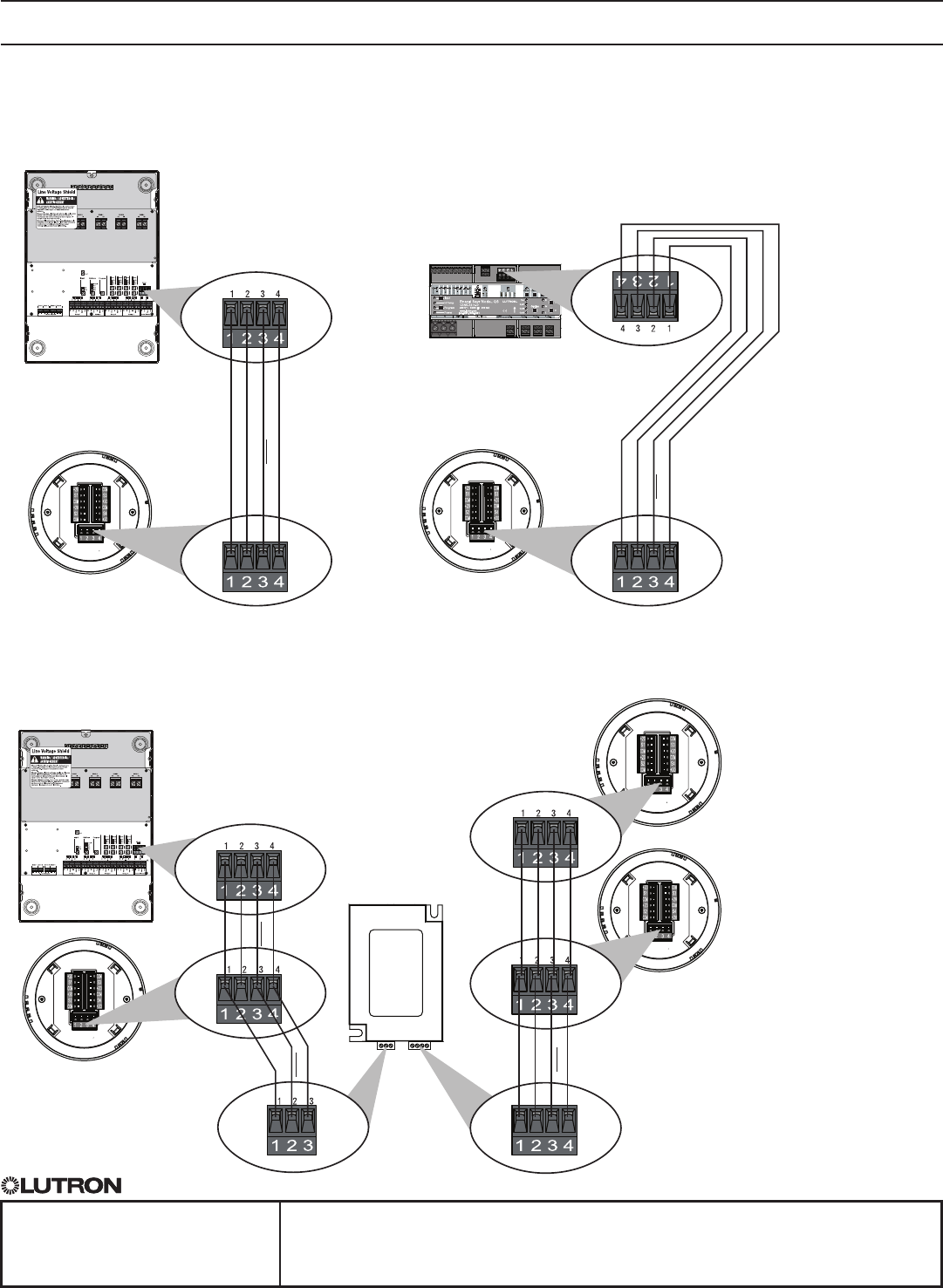
Wiring: Device Power
Single QSM powered by an ESN unit
Multiple QSMs powered by an ESN unit and a QS Link Power Supply
Note:AQSLinkPowerSupplymaybenecessaryifPDUsrequiredbyQSMsexceedavailablePDUsfromthe
device supplying power.
ESN unit
ESN unit
QSM QSM
COM
COM
COM
COM
COM
MUX
MUX
MUX
MUX
MUX
V+
V+
V+
V+
MUX
MUX
MUX
MUX
MUX
ESN unit
QSM A
The ESN unit powers QSM
A; no terminal 2 connection
betweenQSMAandQS
Link Power Supply
The QS Link Power Supply
powersQSMBandC;
QS Link
Power Supply
QSM B
QSMC
MUXand_ occupy
terminals 2 and 3 on the
QS Link Power Supply.
6
